
Columbus Metropolitan Library
774
Job # Date T F 02/09/2015 13220.04 Project Manual Volume 1 of 2 COLUMBUS METROPOLITAN LIBRARY RENOVATION & ADDITION TO THE MAIN LIBRARY 96 SOUTH GRANT AVENUE Columbus, OH 43215 BID 2 / PERMIT
-
Upload
khangminh22 -
Category
Documents
-
view
1 -
download
0
Transcript of Columbus Metropolitan Library

Job #
Date
T F
02/09/2015
13220.04
Project Manual Volume 1 of 2
COLUMBUS METROPOLITAN LIBRARY RENOVATION & ADDITION TO THE MAIN LIBRARY
96 SOUTH GRANT AVENUE Columbus, OH 43215
BID 2 / PERMIT


LIST OF CONSULTANTS 00 01 08 – 1
Renovation & Addition to the Main Library Columbus Metropolitan Library
Schooley Caldwell AssociatesFebruary 9, 2015
DOCUMENT 00 01 08
LIST OF CONSULTANTS TURNER CONSTRUCTION CONSTRUCTION MANAGER 250 West Court Street, Suite 300 Cincinnati, OH 45202 PIZZUTI SOLUTIONS OWNER’S REPRESENTATIVE Two Miranova Place, Suite 200 Columbus, OH 43215 GUND PARTNERSHIP DESIGN ARCHITECT 47 Thorndike Street, Cambridge, MA 02141 SCHOOLEY CALDWELL ASSOCIATES ARCHITECT OF RECORD 300 Marconi Blvd, Suite 100, Columbus, OH 43215 SMBH STRUCTURAL ENGINEERING 1166 Dublin Road, Suite 200 Columbus, OH 43215 HEAPY ENGINEERING MEP ENGINEERING 1400 West Dorothy Lane Dayton, OH 45409 MKSK LANDSCAPE ARCHITECT 462 Ludlow Alley, Columbus, OH 43215 KORDA CIVIL ENGINEERING 1650 Watermark Drive Columbus, OH 45215 TEC STUDIO LIGHTING DESIGN 7510 Slate Ridge Blvd. Columbus, OH 43068


PROJECT MANUAL TABLE OF CONTENTS 00 01 10 – 1
Renovation & Addition to the Main Library Columbus Metropolitan Library
Schooley Caldwell AssociatesFebruary 23, 2015
DOCUMENT 00 01 10
PROJECT MANUAL TABLE OF CONTENTS
VOLUME 1 00 01 00 Project Title Page 00 01 08 List of Consultants 00 01 10 Project Manual Table of Contents
PROCUREMENT / CONTRACTING REQUIREMENTS 00 21 13 Instructions to Bidders 00 24 13 Summary of Work- BP 1 Demolition/Abatement 00 31 13 Project Schedule 00 38 00 Tax Exempt Form 00 41 16 Bid Proposal Form 00 43 39 Business Diversity Statement of Intent Form 00 43 43 Wage Rate Form 00 45 13 Prequalification Criteria 00 52 16 Agreement Between Construction Manager and Subcontractor 00 60 00 Subcontractor Billing Package 00 60 01 Prevailing Wage Package 00 62 16 Certificate of Insurance - Sample 00 63 63 CML CMR CO Breakdown 00 72 00 General Conditions 00 73 00 Special Conditions 00 73 19 Safety Program EEO Policy
DIVISION 01 GENERAL REQUIREMENTS 01 11 00 Summary of Work 01 23 00 Alternates 01 25 00 Substitution Procedures 01 25 00A Project Approval Request Form 01 26 00 Contract Modification Procedures 01 26 13 Requests for Interpretation 01 31 00 Project Coordination 01 33 00 Submittal Procedures 01 42 00 Reference Standards and Definitions 01 43 30 Mockups 01 45 00 Quality Control 01 45 33 Structural Testing and Special Inspections 01 50 00 Temporary Facilities and Controls 01 60 00 Product Requirements 01 73 00 Execution 01 73 29 Cutting and Patching 01 74 19 Construction Waste Management and Disposal 01 78 00 Project Closeout 01 78 23 Operation and Maintenance Data 01 78 39 Record Documents 01 79 00 Demonstrating and Training
DIVISION 02 EXISTING CONDITIONS 02 41 19 Selective Demolition

PROJECT MANUAL TABLE OF CONTENTS 00 01 10 – 2
Renovation & Addition to the Main Library Columbus Metropolitan Library
Schooley Caldwell AssociatesFebruary 23, 2015
DIVISION 03 CONCRETE 03 01 50 Floor Repair 03 30 00 Cast-In-Place Concrete 03 38 16 Unbonded Post-Tensioned Concrete 03 39 05 Concrete Sealers 03 45 00 Architectural Precast Concrete 03 45 01 Pre-cast Architect Site Concrete
DIVISION 04 MASONRY 04 01 40 Stone Cleaning 04 05 13 Masonry Mortar 04 05 16 Masonry Grouting 04 05 19 Masonry Anchorage and Reinforcement 04 22 00 Concrete Unit Masonry
DIVISION 05 METALS 05 12 00 Structural Steel Framing 05 31 00 Steel Decking 05 41 00 Cold-formed Metal Framing 05 50 00 Metal Fabrications 05 51 00 Metal Stairs and Railings 05 52 13 Site Metal Handrails 05 53 00 Metal Grating 05 70 00 Ornamental Metal Grilles 05 73 00 Decorative Metal Railings 05 73 01 Interior Ornamental Stair Railings 05 73 13 Glazed Decorative Metal Stair Railing
DIVISION 06 WOOD, PLASTICS, AND COMPOSITES 06 10 00 Rough Carpentry 06 16 53 Gypsum Sheathing 06 20 00 Finish Carpentry
DIVISION 07 THERMAL AND MOISTURE PROTECTION 07 01 50 Modifications to Existing Warranted Roof System 07 13 26 Sheet Waterproofing 07 14 16 Cold-Applied Fluid Waterproofing 07 17 00 Bentonite Waterproofing 07 21 00 Thermal Insulation 07 21 29 Sprayed Insulation 07 27 00 Air Barriers 07 42 13 Composite Metal Wall Panels 07 54 00 Thermoplastic Membrane Roofing 07 62 00 Sheet Metal Flashing 07 71 00 Roof Specialties 07 81 00 Applied Fireproofing 07 81 23 Intumescent Fireproofing 07 84 00 Firestopping 07 92 00 Joint Sealants 07 95 00 Expansion Control
DIVISION 08 OPENINGS 08 11 10 Metal Doors and Frames 08 14 16 Wood Doors 08 31 00 Access Doors and Frames 08 42 29 Automatic Entrances 08 43 13 Aluminum-Framed Storefronts

PROJECT MANUAL TABLE OF CONTENTS 00 01 10 – 3
Renovation & Addition to the Main Library Columbus Metropolitan Library
Schooley Caldwell AssociatesFebruary 23, 2015
08 43 26 All-Glass Storefront 08 44 13 Glazed Aluminum Curtain Walls 08 44 33 Sloped Glazing Assembly 08 71 00 Door Hardware 08 80 00 Glazing 08 83 00 Mirrors 08 91 00 Louvers 08 95 13 Soffit Vents
DIVISION 09 FINISHES 09 01 70 Stone Repair 09 05 61 Common Work Results for Floor Preparation 09 21 16.23 Gypsum Board Shaft Wall Assemblies 09 22 16 Non-Structural Metal Framing 09 24 13 Portland Cement Plaster Repairs 09 27 13 Glass Fiber Reinforced Plaster Fabrications 09 29 00 Gypsum Board 09 30 13 Ceramic Tiling 09 51 13 Acoustical Panel Ceilings 09 51 26 Acoustical Wood Ceilings 09 65 13 Resilient Base and Accessories 09 65 16 Resilient Sheet Flooring 09 66 00 Terrazzo Flooring 09 68 13 Tile Carpeting 09 72 00 Wall Covering 09 80 00 Acoustical Treatment 09 83 16 Acoustic Finish System 09 91 00 Painting
DIVISION 10 SPECIALTIES 10 11 00 Visual Display Surfaces 10 21 13 Toilet Compartments 10 22 13 Wire Mesh Partition 10 22 39 Folding Panel Partitions 10 26 20 Wall Protection 10 28 13 Toilet Accessories 10 44 00 Fire Protection Specialties
DIVISION 11 EQUIPMENT 11 24 26 Chain Hoist 11 52 13 Projection Screens
DIVISION 12 FURNISHINGS 12 20 00 Roller Window Shades 12 36 61 Solid Surfacing 12 93 00 Site Furnishings 12 93 13 Bicycle Racks
DIVISION 13 SPECIAL CONSTRUCTION Not Used
DIVISION 14 CONVEYING EQUIPMENT 14 21 00 Electric Traction Elevator 14 27 13 Elevator Cab Finishes
DIVISION 15-20 – NOT USED

PROJECT MANUAL TABLE OF CONTENTS 00 01 10 – 4
Renovation & Addition to the Main Library Columbus Metropolitan Library
Schooley Caldwell AssociatesFebruary 23, 2015
VOLUME 2 00 01 00 Project Title Page 00 01 08 List of Consultants 00 01 10 Project Manual Table of Contents
DIVISION 21 FIRE SUPPRESSION 21 05 01 Basic Fire Suppression Requirements 21 05 02 Agreement and Waiver for the Use of Electronic Files 21 05 02a Electronic Files Heapy Release Form to Contractors 21 05 04 Basic Fire Suppression Materials and Methods 21 05 05 Firestopping 21 05 07 Piping Materials and Method for Fire Suppression 21 05 09 Excavation, Backfill and Surface Restoration 21 05 19 Gauges for Fire Suppression Piping 21 05 29 Hangers and Supports for Fire Suppression Piping 21 05 30 Bases and Supports for Fire Suppression Equipment 21 05 53 Identification of Fire Suppression Piping and Equipment 21 13 12 Fire Suppression Piping 21 13 13 Fire Suppression Sprinkler and Standpipe System 21 31 13 Electric Driven Centrifugal Fire Pump Field Assembled
DIVISION 22 PLUMBING 22 05 01 Basic Plumbing Requirements 22 05 02 Agreement and Waiver for the Use of Electronic Files 22 05 02a Electronic Files Heapy Release Form to Contractors 22 05 04 Basic Plumbing Materials and Methods 22 05 05 Firestopping 22 05 07 Piping Materials and Methods 22 05 09 Excavation, Backfill and Surface Restoration 22 05 19 Meters and Gauges for Plumbing Piping 22 05 23 General Duty Valves for Plumbing Piping 22 05 29 Hangers and Supports for Plumbing Piping 22 05 30 Bases and Supports for Plumbing Equipment 22 05 53 Identification of Plumbing Piping and Equipment 22 07 19 Plumbing Piping Insulation 22 10 12 Interior Gas Piping 22 11 16 Interior Domestic Water Piping 22 11 19 Interior Domestic Water Piping Specialties 22 11 23 Water Pressure Booster Pump 22 13 16 Interior Drainage and Vent Systems 22 13 19 Drainage Systems Specialties 22 13 29 Plumbing Pumps - Drainage 22 33 00 Domestic Water Heaters 22 42 00 Plumbing Fixtures
DIVISION 23 HEATING, VENTILATING, AND AIR CONDITIONING 23 05 01 Basic HVAC Requirements 23 05 02 Agreement and Waiver for Use of Electronic Files 23 05 02a Electronic Files - Heapy Release Form To Contractors 23 05 04 Basic HVAC Materials and Methods 23 05 05 Firestopping 23 05 07 Piping Materials and Methods 23 05 09 Excavation, Backfill and Surface Restoration 23 05 13 Electrical Requirements for HVAC Equipment 23 05 14 Adjustable Frequency Motor Controller

PROJECT MANUAL TABLE OF CONTENTS 00 01 10 – 5
Renovation & Addition to the Main Library Columbus Metropolitan Library
Schooley Caldwell AssociatesFebruary 23, 2015
23 05 19 Meters and Gauges for HVAC Piping 23 05 23 General Duty Valves for HVAC Piping 23 05 29 Hangers and Supports for HVAC Piping 23 05 30 Bases and Supports for HVAC Equipment 23 05 31 HVAC Equipment Drives 23 05 49 Vibration Control for HVAC 23 05 50 Flexible HVAC Pipe Connectors 23 05 53 Identification of HVAC Piping and Equipment 23 05 93 Testing, Adjusting and Balancing for HVAC 23 07 13 Duct Insulation 23 07 19 HVAC Pipe Insulation 23 09 23 Direct Digital Control System for HVAC 23 09 25 Instrumentation and Control Devices for HVAC 23 09 45 Control Tubing for HVAC 23 09 47 Control Power and Wiring for HVAC 23 09 93 Sequence of Operations for HVAC Controls 23 09 95 Direct Digital Control System Points List 23 21 13 Hydronic Piping 23 23 00 Refrigerant Piping 23 25 00 Water Treatment Systems 23 31 13 HVAC Ductwork 23 33 00 Air Duct Accessories 23 34 00 HVAC Fans 23 36 16 Air Terminal Units 23 36 18 Fan Powered Air Terminal Units 23 37 00 Air Outlets and Inlets 23 51 17 Breeching, Chimneys and Stacks 23 52 19 Hot Water High Efficiency Non-Condensing Boiler 23 81 23 Variable Refrigerant Flow (VRF) Heat Pump Systems 23 81 24 Ductless Split Air Conditioning Systems 23 81 25 Main Data Room Air Conditioning System 23 82 33 Fin Tube Convectors 23 82 39 Unit Heaters
DIVISION 24-25 – NOT USED
DIVISION 26 ELECTRICAL 26 05 01 Basic Electrical Requirements 26 05 02 Agreement and Waiver for Use of Electronic Files 26 05 02a Electronic Files - Heapy Release Form to Contractors 26 05 04 Basic Electrical Materials and Methods 26 05 05 Firestopping 26 05 09 Excavation, Backfill and Surface Restoration 26 05 11 PCB Equipment Removal 26 05 18 Low-Voltage Electrical Power Conductors – Mineral Insulated (M.I.) Cable 26 05 19 Low-Voltage Electrical Power Conductors – Copper 26 05 26 Grounding and Bonding for Electrical Systems 26 05 33 Raceways and Boxes for Electrical Systems 26 05 53 Identification for Electrical Systems 26 05 65 Specific Wiring Applications 26 05 73 Overcurrent Protective Device Coordination Study 26 09 01 Lighting Control Relay Panels 26 09 23 Lighting Control Devices 26 22 15 Distribution Transformers - Premium Efficient Type 26 24 13 Distribution Switchboard (Below 600 Volts) 26 24 14 Integrated Facility System Switchboard (IFSS)

PROJECT MANUAL TABLE OF CONTENTS 00 01 10 – 6
Renovation & Addition to the Main Library Columbus Metropolitan Library
Schooley Caldwell AssociatesFebruary 23, 2015
26 24 16 Panelboards 26 27 16 Electrical Cabinets and Enclosures 26 27 26 Wiring Devices and Coverplates 26 27 39 Elevator Power Module 26 28 13 Fuses 26 28 16 Disconnect Switches 26 28 17 Enclosed Circuit Breakers 26 29 13 Motor Controllers 26 43 13 Surge Protection Devices (SPDs) for Low-Voltage Electrical Power Circuits 26 50 00 Lighting System 26 52 00 Exit and Emergency Lighting 26 56 00 Exterior Lighting 26 59 43 Network Lighting Controls
DIVISION 27 COMMUNICATIONS 27 05 01 Basic Communications Requirements 27 05 02 Agreement and Waiver for Use of Electronic Files 27 05 02a Electronic Files - Heapy Release Form to Contractors 27 05 04 Basic Communications Materials and Methods 27 05 05 Firestopping 27 05 26 Grounding and Bonding for Communications Systems 27 05 28 Communications Systems Pathways and Support Equipment 27 11 00 Communications Equipment Room Fittings 27 13 13 Communications Copper Backbone Cabling 27 13 23 Communications Optical Fiber Backbone Cabling 27 15 13 Communications Copper Horizontal Cabling
DIVISION 28 ELECTRONIC SAFETY AND SECURITY 28 31 00 Fire Detection and Alarm 28 31 13 Bi-Directional Amplifier (BDA) for Firefighter RF Radio System
DIVISION 29-30 – NOT USED
DIVISION 31 EARTHWORK 31 00 00 Earthwork 31 10 00 Site Clearing 31 23 33 Piped Utilities – Basic Methods 31 25 00 Erosion and Sediment Control
DIVISION 32 EXTERIOR IMPROVEMENTS 32 05 13 Soils for Exterior Improvement 32 12 00 Asphalt Concrete Pavement Walkway 32 13 13 Concrete Paving 32 15 40 Stabilized Aggregate Surfacing 32 31 19 Decorative Metal Fences 32 84 00 Planting Irrigation 32 93 00 Plants
DIVISION 33 UTILITIES 33 40 00 Storm Drainage
END

SUMMARY OF WORK 01 11 00 – 1
Renovation & Addition to the Main Library Columbus Metropolitan Library
Schooley Caldwell AssociatesFebruary 9, 2015
SECTION 01 11 00
SUMMARY OF WORK
TO BE PROVIDED BY TURNER CONSTRUCTION


ALTERNATES 01 23 00 – 1
Renovation & Addition to the Main Library Columbus Metropolitan Library
Schooley Caldwell AssociatesFebruary 23, 2015
SECTION 01 23 00
ALTERNATES
PART 1 – GENERAL
1.01 SUMMARY
A. Provide price for each alternate on the Bid Proposal Form. Include cost of modifications to other work to accommodate each alternate. Include related costs such as overhead and profit.
B. Alternates are described briefly in this section. The Contract Documents also define the requirements for alternates.
C. Coordinate pertinent related work and modify surrounding work as required to properly integrate the work under each alternate and to provide the complete construction required by Contract Documents.
D. Related Sections include the following:
1. Drawings and general provisions of the Contract, including General and Special Conditions and other Division 01 Specification Sections, apply to this Section.
1.02 DEFINITION
A. An alternate is an amount proposed by Bidders and stated on the Bid Proposal Form that will be added to or deducted from Base Bid amount if the Owner decides to accept a corresponding change in either scope of Work or in products, materials, equipment, systems or installation methods described in Contract documents.
B. Accepted alternates will be identified in the Contract.
1.03 COORDINATION
A. Coordinate related Work and modify or adjust adjacent work as required to ensure that Work affected by each accepted alternate is complete and fully integrated in to the project.
B. Immediately following Contract award, prepare and distribute to each party involved, notification of the status of the Alternate, indicating whether alternate has been accepted, rejected or deferred for consideration at a later date.
1.04 DESCRIPTION OF REQUIREMENTS
A. This section identifies alternate by number and describes the basic changes to be incorporated into the work, only when that alternate is made a part of the Work by specific provisions in the Contract.
B. Referenced sections of specifications stipulate pertinent requirements for products and methods to achieve the work stipulated under the alternate.
C. Include all applicable alternates requested in the Bid Proposal Form.
PART 2 – PRODUCTS
Not Used
ALTERNATES 01 23 00 – 2
Renovation & Addition to the Main Library Columbus Metropolitan Library
Schooley Caldwell AssociatesFebruary 23, 2015
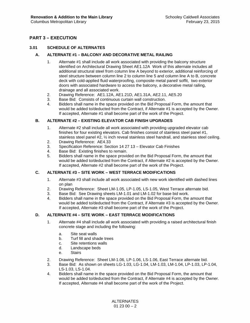
PART 3 – EXECUTION
3.01 SCHEDULE OF ALTERNATES
A. ALTERNATE #1 – BALCONY AND DECORATIVE METAL RAILING
1. Alternate #1 shall include all work associated with providing the balcony structure identified on Architectural Drawing Sheet AE1.12A Work of this alternate includes all additional structural steel from column line A beyond to exterior, additional reinforcing of steel structure between column line 2 to column line 5 and column line A to B, concrete deck with cold-applied fluid waterproofing, composite metal panel/ soffit, two exterior doors with associated hardware to access the balcony, a decorative metal railing, drainage and all associated work.
2. Drawing Reference: AE1.12A, AE1.21D, AE1.31A, AE2.11, AE5.20 3. Base Bid: Consists of continuous curtain wall construction. 4. Bidders shall name in the space provided on the Bid Proposal Form, the amount that
would be added to/deducted from the Contract, if Alternate #1 is accepted by the Owner. If accepted, Alternate #1 shall become part of the work of the Project.
B. ALTERNATE #2 – EXISTING ELEVATOR CAB FINISH UPGRADES
1. Alternate #2 shall include all work associated with providing upgraded elevator cab finishes for four existing elevators. Cab finishes consist of stainless steel panel #1, stainless steel panel #2, ½ inch reveal stainless steel handrail, and stainless steel ceiling.
2. Drawing Reference: AE4.33 3. Specification Reference: Section 14 27 13 – Elevator Cab Finishes 4. Base Bid: Existing finishes to remain. 5. Bidders shall name in the space provided on the Bid Proposal Form, the amount that
would be added to/deducted from the Contract, if Alternate #2 is accepted by the Owner. If accepted, Alternate #2 shall become part of the work of the Project.
C. ALTERNATE #3 – SITE WORK – WEST TERRACE MODIFICATIONS
1. Alternate #3 shall include all work associated with new work identified with dashed lines on plan
2. Drawing Reference: Sheet LM-1.05, LP-1.05, LS-1.05, West Terrace alternate bid. 3. Base Bid: See Drawing sheets LM-1.01 and LM-1.02 for base bid work. 4. Bidders shall name in the space provided on the Bid Proposal Form, the amount that
would be added to/deducted from the Contract, if Alternate #3 is accepted by the Owner. If accepted, Alternate #3 shall become part of the work of the Project.
D. ALTERNATE #4 – SITE WORK – EAST TERRACE MODIFICATIONS
1. Alternate #4 shall include all work associated with providing a raised architectural finish concrete stage and including the following:
a. Site seat walls b. Turf fill and shade trees c. Site retentions walls d. Landscape beds e. Stairs
2. Drawing Reference: Sheet LM-1.06, LP-1.06, LS-1.06, East Terrace alternate bid. 3. Base Bid: As shown on sheets LG-1.03, LG-1.04, LM-1.03, LM-1.04, LP-1.03, LP-1.04,
LS-1.03, LS-1.04. 4. Bidders shall name in the space provided on the Bid Proposal Form, the amount that
would be added to/deducted from the Contract, if Alternate #4 is accepted by the Owner. If accepted, Alternate #4 shall become part of the work of the Project.

ALTERNATES 01 23 00 – 3
Renovation & Addition to the Main Library Columbus Metropolitan Library
Schooley Caldwell AssociatesFebruary 23, 2015
E. ALTERNATE #5 – REPLACE ALL EXISTING CEILINGS IN PUBLIC AREAS
1. Alternate #5 shall include all work associated with removing existing suspended acoustical ceilings including suspension systems in public areas of the building and replacement with new acoustical ceilings.
2. Drawing Reference: Sheets AE.42A, AE1.42B, AE1.42C, AE1.43A, AE1.43B, AE1.43C, EL1.12A, EL1.12B, EL1.13A, EL1.13B.
3. The areas of ceiling affected are defined as follows: Partial areas of the Public Areas on the Second and Third Floors.
4. Base Bid: Existing ceilings remain. 5. Bidders shall name in the space provided on the Bid Proposal Form, the amount that
would be added to/deducted from the Contract, if Alternate #5 is accepted by the Owner. If accepted, Alternate #5 shall become part of the work of the Project.
F. ALTERNATE #6 – GREASE INTERCEPTOR
1. Alternate #6 shall include all work associated with providing a grease interceptor as indicated on the Plumbing drawings.
2. Drawing Reference: Sheet PL1-11A 3. Base Bid: Provide future connections for grease interceptor in the base bid. 4. Bidders shall name in the space provided on the Bid Proposal Form, the amount that
would be added to the Contract, if Alternate #6 is accepted by the Owner. If accepted, Alternate #6 shall become part of the work of the Project.
G. ALTERNATE #7 – DEDUCT STUDY ROOM FIT-OUTS
1. Alternate #7 shall include all work associated with deleting the walls of the individual study rooms on the Second floor near the Administration Offices.
2. Drawing Reference: Sheets AE1.12C, AE1.32C, AE4.27 3. Base Bid: Study Room walls remain in the base bid. 4. Bidders shall name in the space provided on the Bid Proposal Form, the amount that
would be deducted from the Contract, if Alternate #7 is accepted by the Owner. If accepted, Alternate #7 shall become part of the work of the Project.
H. ALTERNATE #8 – REMOVAL AND REPLACEMENT OF CONCRETE SIDEWALK
1. Alternate #8 shall include all work associated with replacement of the concrete sidewalk along Grant Avenue between north and south edges of new site stairs and from property line to existing curb along Grant Avenue.
2. Drawing Reference: Sheets LD-1.01, LG-1.01, LG-1.02, LM-1.01, LM-1.02, LM-1.05, LP-1.01, LS-1.01, LS-1.02
3. Base Bid: No work. 4. Bidders shall name in the space provided on the Bid Proposal Form, the amount that
would be deducted from the Contract, if Alternate #8 is accepted by the Owner. If accepted, Alternate #8 shall become part of the work of the Project.
I. ALTERNATE #9 – BUILDING EAST ELEVATION INTERIOR SHADES
1. Alternate #9 shall include all work associated with providing interior shades along the east building elevation from Column Line 1.3 to Column line 6 on the first, second, and third floors. Alternate includes all motorized single roller shades and all controls for a complete system.
2. Drawing Reference: Sheets AE1.32A, AE1.33A. 3. Base Bid: No shading devices 4. Bidders shall name in the space provided on the Bid Proposal Form, the amount that
would be deducted from the Contract, if Alternate #9 is accepted by the Owner. If accepted, Alternate #9 shall become part of the work of the Project.

ALTERNATES 01 23 00 – 4
Renovation & Addition to the Main Library Columbus Metropolitan Library
Schooley Caldwell AssociatesFebruary 23, 2015
J. ALTERNATE #10 – RE-ALIGNING OF STONE PIERS
1. Alternate #10 shall include all work associated with resetting the granite stone piers on the West side of the building to make the piers plumb.
2. Drawing Reference: Sheet AE2.13 3. Base Bid: Removal of existing sealant at piers and re-sealing only. 4. Bidders shall name in the space provided on the Bid Proposal Form, the amount that
would be added to/deducted from the Contract, if Alternate #10 is accepted by the Owner. If accepted, Alternate #10 shall become part of the work of the Project.
K. ALTERNATE #11 – UPGRADE PUBLIC ADDRESS SYSTEM
1. Alternate #11 shall include all work associated with upgrading the Library’s public address system to provide a new system as specified.
2. Drawing Reference: Bid 2; Addendum 2 3. Base Bid: Reconfiguring the existing public address system to accommodate the new
floor plan layout, adjusting floor plate coverage by moving /adding speakers, re-wiring of existing system.
4. Bidders shall name in the space provided on the Bid Proposal Form, the amount that would be added to/deducted from the Contract, if Alternate #11 is accepted by the Owner. If accepted, Alternate #11 shall become part of the work of the Project.
L. ALTERNATE #12 – LIGHTING FIXTURE SELECTION
1. Alternate #12 shall include all work associated with providing LED lighting luminaires in lieu of the fluorescent luminaires for Lighting fixture types B, D, F, G, G1, H3, J, N4, N2, R, R1, S, and V.
2. Drawing Reference: Refer to “Interior Luminaire Schedule For Add Alternate #12 (LED)” on Drawing Sheets: EL Series
3. Base Bid: Fluorescent fixtures as scheduled. 4. Bidders shall name in the space provided on the Bid Proposal Form, the amount that
would be added to/deducted from the Contract, if Alternate #12 is accepted by the Owner. If accepted, Alternate #12 shall become part of the work of the Project.
M. ALTERNATE #13 – TERRAZZO/ TILE FIRST FLOOR
1. Alternate #13 shall include all work associated with providing a porcelain tile flooring finish in lieu of epoxy terrazzo in the First Floor areas where scheduled.
2. Optional tile:
a. Caesar Contract Solutions:
1) Size: 45 x 90 cm 2) Thickness: 20 cm
3. Drawing Reference: Sheets AE6.20, AE6.21, AF1.11A, AF1.11B, AF1.11C. 4. Base Bid: Epoxy terrazzo finish as scheduled. 5. Bidders shall name in the space provided on the Bid Proposal Form, the amount that
would be added to/deducted from the Contract, if Alternate #13 is accepted by the Owner. If accepted, Alternate #13 shall become part of the work of the Project.
N. ALTERNATE #14 – ACOUSTIC FINISH SYSTEM AT ATRIUM
1. Alternate #14 shall include all work associated with placing acoustical specialty finish to ceiling of atrium space.
2. Drawing Reference: Sheets AE1.33B, AE4.24 3. Bidders shall name in the space provided on the Bid Proposal Form, the amount that
would be added to/deducted from the Contract, if Alternate #14 is accepted by the Owner. If accepted, Alternate #14 shall become part of the work of the Project.
END OF SECTION

SUBSTITUTION PROCEDURES 01 25 00 – 1
Renovation & Addition to the Main Library Columbus Metropolitan Library
Schooley Caldwell AssociatesFebruary 9, 2015
SECTION 01 25 00
SUBSTITUTION PROCEDURES
PART 1 – GENERAL
1.01 SUMMARY
A. Drawings and general provisions of the Contract, including General and Special Conditions and other Division 01 Specification Sections, apply to this Section.
B. Bids shall be based on materials, equipment and systems required by the Contract Documents without exception.
C. The products specified in the Contract Documents establish a standard of required function, dimension, appearance, and quality.
D. Subcontractors wishing to obtain approval to bid non-specified products shall submit written requests to the Architect through the Construction Manager on the Product Approval Request Form included as an attachment to this Section before the date and time indicated on Form 01 25 00A.
1. Each Product Approval Request Form shall include the name of the specified manufacturer and product and a complete description of the proposed product including manufacturer's name and model number or system proposed, drawings, product literature, performance and test data, color selections or limitations, and any other information necessary for evaluation. Include a statement indicating any changes in other materials, equipment, or other work that would be required if the proposed product is incorporated in the work. The burden of proof of the merit of the proposed product is on the proposer. The Architect's decision of approval of a proposed product will be final.
2. The following will be cause for rejection of a Product Approval Request Form:
a. Requests submitted by suppliers and individuals other than prime subcontractors. b. Requests submitted without adequate documentation. c. Requests submitted without the specified Product Approval Request Form. d. Requests received after the specified cut-off date.
3. When the Architect approves a product submission before receipt of bids, the approval will be included in an Addendum and bidders may include the pricing of this product in their bids. Bidders shall not rely on approvals made in any other manner.
E. Specifications are generally written using the following methods:
1. Performance: Where products are identified only by standard performance criteria and reference standards such as Federal Specifications or ASTM numbers, Contractor may bid any item conforming to the material, performance, and specification criteria indicated.
2. Manufacturer Listing: Where specifications specify more than one manufacturer for a product or material, the first manufacturer listed indicates the product or material used as the basis of design for the project. Using one of the other specified manufacturers or products does not relieve the Contractor of the responsibility of the product or material meeting specified requirements. If one of the other listed manufacturers is selected for use by the Contractor for the project, certify the product meets specified requirements, and its performance, operation, size, finish, warranty, accessories, and other specified qualities are equivalent or superior to the specified product, as determined by the Architect.
3. Proprietary: Where specifications specify only one particular manufacturer's product, that product is the basis of the contract without exception.

SUBSTITUTION PROCEDURES 01 25 00 – 2
Renovation & Addition to the Main Library Columbus Metropolitan Library
Schooley Caldwell AssociatesFebruary 9, 2015
F. Related Sections include the following:
1. Section 01 25 00A – Product Approval Request Form 2. Section 01 33 00 – Submittal Procedures (Subcontractor’s and Supplier’s List) 3. Section 01 78 00 – Project Closeout
1.02 DEFINITIONS
A. Products: The term "product" includes the terms "material," "equipment," "system," and terms of similar intent.
B. Substitutions: Changes in materials, equipment, and systems from those required by the Contract Documents and proposed by subcontractor.
1.03 SUBMITTALS
A. Substitution Requests: Submit three copies of each request for consideration.
1. Substitution Request Form: Use Product Approval Request Form (Section 01 25 00A). 2. Documentation: Show compliance with requirements for substitutions.
B. Due Date: Product Approval Request Forms (01 25 00A) must be received by the Architect before the date and time indicated on this form.
PART 2 – PRODUCTS
2.01 PRODUCT SUBSTITUTIONS
A. Conditions: Architect will consider subcontractor's request for substitution after contract award when the following conditions are satisfied. If the following conditions are not satisfied, Architect will return requests without action, except to record noncompliance with these requirements:
1. Requested substitution offers Owner a substantial advantage in cost, time, energy conservation, or other considerations, after deducting additional responsibilities Owner must assume. Owner's additional responsibilities may include compensation to Architect for redesign and evaluation services, increased cost of other construction by Owner, and similar considerations.
2. Requested substitution does not require extensive revisions to the Contract Documents. 3. Requested substitution is consistent with the Contract Documents, meets specified
requirements, and will produce indicated results. 4. Substitution request is fully documented and properly submitted. 5. Requested substitution will not adversely affect Contractor's Construction Schedule. 6. Requested substitution has received necessary approvals of authorities having
jurisdiction. 7. Requested substitution is compatible with other portions of the Work. 8. Requested substitution has been coordinated with other portions of the Work. 9. Requested substitution provides specified warranty. 10. If requested substitution involves more than one subcontractor, requested substitution
has been coordinated with other portions of the Work, is uniform and consistent, is compatible with other products, and is acceptable to all subcontractors involved.
PART 3 – EXECUTION
Not Used
END OF SECTION

PRODUCT APPROVAL REQUEST FORM 01 25 00A – 1
Renovation & Addition to the Main Library Columbus Metropolitan Library
Schooley Caldwell AssociatesFebruary 9, 2015
SECTION 01 25 00A
PRODUCT APPROVAL REQUEST FORM
TO: Schooley Caldwell Associates PROJECT: Renovation & Addition to the Main PH. 614-406-9127 Library, Columbus Metropolitan Library SCA Project No. 13150.20 Due Date: _______________, 2015*at 2:00 p.m.
(refer to Section 01 25 00)
A proposed product is not legally approved and cannot legally be included in a bid or used in the Work until it appears in an Addendum or other Contract Modification as defined in the General Conditions. See “Bid Form” and Section 01 60 00 – Product Requirements.
PROVIDE THE FOLLOWING INFORMATION. FAILURE TO PROVIDE THE INFORMATION COMPLETELY WILL BE CAUSE FOR REJECTION OF THE PROPOSAL.
SPECIFIED PRODUCT:
Specified Product:
Specified Manufacturer:
Specification Section: ____________ Page: __________ Article: __________ Paragraph:
PROPOSED PRODUCT:
Product Name:
Manufacturer Name:
Manufacturer Web site:
QUESTIONS: Answer the following questions using a separate attachment:
In your opinion, is the proposed product equivalent to the specified product?
Are the product characteristics the same as the specified product? (Dimensions, material properties?)
Are the product warranties the same? If not, list differences (Include attachment documenting warranty).
Does the proposed product require modifications to the building construction details?
Color: Is the same color available at no upcharge? Is another color selection required that doesn’t match the specified product?
Will the construction time be affected if this proposed product is approved?
Has the proposed product been used locally?
Name of Facility:
Address :
Contact Person: Phone:
Is product represented locally?
Supplier/Representative: Phone:
Are approved installer(s) available locally?
Approved Installer(s):
Provide an attachment that lists a minimum of three similar projects completed by each installer. Include contact name and telephone number.
ATTACHMENTS:
Supporting Data Attached: Drawings Product Data Samples Tests Reports Other

PRODUCT APPROVAL REQUEST FORM 01 25 00A – 2
Renovation & Addition to the Main Library Columbus Metropolitan Library
Schooley Caldwell AssociatesFebruary 9, 2015
Include the following attachments -
1. Copy of the Project Manual Section where the proposed equal product would be specified, rewritten or red-lined to include any changes necessary to correctly specify the proposed equal product. Identify completely changes necessary to the original Project Manual Section.
2. Copies of details, elevations, cross-sections, and other elements of the Construction Drawings redone as necessary to show changes necessary to accommodate proposed equal product. Identify completely the changes from the original Drawings.
3. Complete product literature and technical data, installation and maintenance instructions, test results, and other information required to show complete conformance with requirements of the Contract Documents.
CERTIFICATION: Signature on this document provides that the proposer certifies that the following statement and accompanying attachments are true:-
1. Proposed equal product has been fully investigated and determined to be equal or superior in all respects to the specified product performance.
2. Same warranty will be furnished for proposed substitution product as for specified product.
3. Same maintenance service and source of replacement parts, as applicable, is available.
4. Proposed equal product will have no effect on other trades and will not affect or delay progress schedule.
5. Proposed equal product does not affect dimensions and functional performance values
6. Payment will be made to the Architect for changes to building design, including Architect design, detailing, and construction costs caused by the substitution.
7. The undersigned further states that the function, appearance, and quality of the proposed product are equivalent or superior to the specified item:
Submitted by:
Signature:
Typed Name:
Company:
Address:
Zip Code:
Telephone: Fax:
Attachments (List):
A/E REVIEW AND ACTION: (For use of the Architect only)
_____ Proposed product accepted. Refer to Addenda Number __________.
_____ Proposed product not in compliance with instructions. Respond to attached comments and resubmit.
_____ Proposed product not acceptable. Use specified product(s).
_____ Not Reviewed. Submission received too late. Use specified product(s).
ADDITIONAL REVIEWER COMMENTS: (For use of the Architect only)
END OF SECTION

CONTRACT MODIFICATION PROCEDURES 01 26 00 – 1
Renovation & Addition to the Main Library Columbus Metropolitan Library
Schooley Caldwell AssociatesFebruary 9, 2015
SECTION 01 26 00
CONTRACT MODIFICATION PROCEDURES
PART 1 – GENERAL
1.01 SUMMARY
A. This Section specifies administrative and procedural requirements for handling and processing Contract modifications.
B. Related Sections include the following:
1. Drawings and general provisions of the Contract, including General and Special Conditions and other Division 01 Specification Sections, apply to this Section.
2. Section 01 60 00 – Product Requirements for administrative procedures for handling requests for substitutions made after Contract award.
1.02 MINOR CHANGES IN THE WORK
A. Per Article 7.4 of the General Conditions, the Owner, Construction Manager or the Architect may issue an order titled “Minor Changes in the Work.”
1.03 BULLETINS
A. Owner-Initiated Bulletins: Architect will issue, through the Construction Manager, a detailed description of proposed changes in the Work that may require adjustment to the Contract Sum or the Contract Time. If necessary, the description will include supplemental or revised Drawings and Specifications.
1. Bulletins issued by Architect are for information only. Do not consider them instructions either to stop work in progress or to execute the proposed change.
2. Within time or on date specified in the bulletin, submit a quotation estimating cost adjustments to the Contract Sum and the Contract Time necessary to execute the change.
a. Include a list of quantities of products required or eliminated and unit costs, with total amount of purchases and credits to be made. If requested, furnish survey data to substantiate quantities.
b. No lump sum amounts are permitted. Detailed breakdown of costs are required, broken down by labor and materials, etc.; and including prime, subcontractor, sub-subcontractor and/or supplier pricings.
c. Indicate applicable taxes, delivery charges, equipment rental, and amounts of trade discounts.
d. Include an updated Contractor's Construction Schedule that indicates the effect of the change, including, but not limited to, changes in activity duration, start and finish times, and activity relationship.
B. Contractor-Initiated Proposals: If latent or changed conditions require modifications to the Contract, Contractor may initiate a claim by submitting a request for a change to the Construction Manager.
1. Include a statement outlining reasons for the change and the effect of the change on the Work. Provide a complete description of the proposed change. Indicate the effect of the proposed change on the Contract Sum and the Contract Time.
2. Include a list of quantities of products required or eliminated and unit costs, with total amount of purchases and credits to be made. If requested, furnish survey data to substantiate quantities.

CONTRACT MODIFICATION PROCEDURES 01 26 00 – 2
Renovation & Addition to the Main Library Columbus Metropolitan Library
Schooley Caldwell AssociatesFebruary 9, 2015
3. Indicate applicable taxes, delivery charges, equipment rental, and amounts of trade discounts.
4. Include costs of labor and supervision directly attributable to the change. 5. Include an updated progress schedule that indicates the effect of the change, including,
but not limited to, changes in activity duration, start and finish times, and activity relationship. Use available total float before requesting an extension of the Contract Time.
1.04 CHANGE ORDER PROCEDURES
A. On Owner's approval of a Request for Proposal, Construction Manager and Architect will issue a Change Order for signatures of Owner and Contractor on Construction Manager’s change order form.
1.05 CONSTRUCTION CHANGE DIRECTIVE
A. Construction Change Directive: Construction Manager and Architect may issue a Construction Change Directive on instructs Contractor to proceed with a change in the Work, for subsequent inclusion in a Change Order.
1. Construction Change Directive contains a complete description of change in the Work. It also designates method to be followed to determine change in the Contract Sum or the Contract Time.
B. Documentation: Maintain detailed records on a time and material basis of work required by the Construction Change Directive.
1. After completion of change, submit an itemized account and supporting data necessary to substantiate cost and time adjustments to the Contract.
2. To expedite decisions about changes, Contractor is strongly encouraged to use digital photographs or still photographs to transmit information about existing conditions to the Architect’s office.
PART 2 – PRODUCTS
Not Used
PART 3 – EXECUTION
Not Used
END OF SECTION

REQUESTS FOR INTERPRETATION 01 26 13 – 1
Renovation & Addition to the Main Library Columbus Metropolitan Library
Schooley Caldwell AssociatesFebruary 9, 2015
SECTION 01 26 13
REQUESTS FOR INTERPRETATION
PART 1 – PRODUCTS
1.01 SUMMARY
A. Administrative and procedural requirements for handling and processing Requests For Information.
B. Drawings and general provisions of the Contract, including General and Special Conditions and other Division 01 Specification Sections, apply to this Section.
1.02 DEFINITIONS
A. Definitions used in this article are not intended to change or modify the meaning of other terms in the Contract Documents.
B. Request for Interpretation (RFI): A request for information by the Contractor to the Architect made through the Construction Manager for clarification of intent of any portion of the Contract Documents after the Award of Contract and during the construction of the Project.
C. The following are NOT Requests for Information:
1. Change Orders. 2. Substitution Request. 3. Bulletin. 4. Field Order. 5. Shop Drawings. 6. Normal questions contained in a typical shop drawing submittal. 7. Clarifications during Bidding.
1.03 REQUESTS FOR INTERPRETATION (RFI'S) DURING CONSTRUCTION
A. RFI’s are logged into the Construction Manager’s TKN Project Site when received by the Construction Manager, not necessarily with same date as indicated by the Contractor on RFI form. The response time will commence upon the date of receipt by the Architect.
B. Requests for Interpretation (RFI): If clarification of any portion of Construction Documents is required, submit a Request for Interpretation (RFI) to the Architect through the Construction Manager in accordance with the following procedures:
1. RFI Format:
a. Submit RFI’s on a standard form developed by the Contractor or provided by the Construction Manager. Refer to Special Conditions #10 Electronic Requirements Prolog Converge, and RFI’s.
b. RFI's shall include the following:
1) Date 2) Project name and number 3) Contractor’s name, address, telephone number and fax number 4) Contract Number 5) Foreseen schedule delays 6) Description of subject and discipline (trade) in question. 7) Adequate space for Architect to respond, sign, and date.

REQUESTS FOR INTERPRETATION 01 26 13 – 2
Renovation & Addition to the Main Library Columbus Metropolitan Library
Schooley Caldwell AssociatesFebruary 9, 2015
C. RFI Inquiry:
1. Clearly state and completely define the issue requiring interpretation. Provide drawing and detail numbers, specification section numbers and paragraphs, sketches and other reference information.
2. Provide potential solutions to issues when possible. 3. Provide cost and schedule implications, if any. 4. Ambiguous RFI’s will be returned to Contractor without action taken.
D. RFI Submission Process:
1. The Contractor shall submit an RFI, in writing, immediately to the Construction Manager when any issue requiring clarification arises. The Construction Manager shall log and review the RFI and then forward to the Architect for response.
a. Unless specifically stated on RFI, the Construction Manager, Architect and the Owner will assume adjustments to the Contract Amount and the Project Schedule are NOT REQUIRED.
2. The Architect will review and respond only to RFI’s received through the Construction Manager’s TKN Project Site.
3. The Contractor shall allow at least seven (7) working days for the Architect to review and respond to the RFI. RFI’s received after 1:00 p.m. will be considered as received the following working day.
4. RFI’s submitted to the Architect of without following these submission procedures will result in rejection of the RFI.
PART 2 – PRODUCTS
Not Used
PART 3 – EXECUTION
Not Used
END OF SECTION

PROJECT COORDINATION 01 31 00 – 1
Renovation & Addition to the Main Library Columbus Metropolitan Library
Schooley Caldwell AssociatesFebruary 9, 2015
SECTION 01 31 00
PROJECT COORDINATION
PART 1 – GENERAL
1.01 SUMMARY
A. Administrative provisions for coordinating construction operations on Project including, but not limited to, the following:
1. General project coordination procedures. 2. Administrative and supervisory personnel. 3. Coordination drawings. 4. Job meetings.
B. Related Sections: The following Sections contain requirements that relate to this Section:
1. Drawings and general provisions of the Contract, including General and Special Condi-tions and other Division 01 Specification Sections, apply to this Section.
2. Section 01 11 00 – Summary of Work. 3. Section 01 26 13 – Requests for interpretation 4. Section 01 33 00 – Submittal Procedures: For preparing and submitting Contractor's
construction schedule. 5. Section 01 73 00 – Execution: For procedures for coordinating general installation and
field-engineering services, including establishment of benchmarks and control points. 6. Section 01 78 00 – Project Closeout: For coordinating closeout of the Contract.
1.02 COORDINATION
A. Coordination: Coordinate construction operations included in different Sections of the Specifi-cations to ensure efficient and orderly installation of each part of the Work. Coordinate construc-tion operations, included in different Sections, that depend on each other for proper installation, connection, and operation.
1. Schedule construction operations in sequence required to obtain the best results where installation of one part of the Work depends on installation of other components, before or after its own installation.
2. Coordinate installation of different components to ensure maximum performance and ac-cessibility for required maintenance, service, and repair.
3. Make adequate provisions to accommodate items scheduled for later installation.
B. Coordination: Each contractor shall coordinate its construction operations with those of other contractors and entities to ensure efficient and orderly installation of each part of the Work. Each contractor shall coordinate its operations with operations, included in different Sections, that depend on each other for proper installation, connection, and operation.
1. Schedule construction operations in sequence required to obtain the best results where installation of one part of the Work depends on installation of other components, before or after its own installation.
2. Coordinate installation of different components with other contractors to ensure maximum performance and accessibility for required maintenance, service, and repair.
3. Make adequate provisions to accommodate items scheduled for later installation.
C. If necessary, prepare memoranda for distribution to each party involved, outlining special pro-cedures required for coordination. Include such items as required notices, reports, and list of at-tendees at meetings.

PROJECT COORDINATION 01 31 00 – 2
Renovation & Addition to the Main Library Columbus Metropolitan Library
Schooley Caldwell AssociatesFebruary 9, 2015
1. Prepare similar memoranda for Owner’s Representative and sub-contractors if coordina-tion of their Work is required.
D. Administrative Procedures: Coordinate scheduling and timing of required administrative proce-dures with other construction activities and activities of other contractors to avoid conflicts and to ensure orderly progress of the Work. Such administrative activities include, but are not lim-ited to, the following:
1. Preparation of Contractor's Construction Schedule. 2. Preparation of the schedule of values. 3. Installation and removal of temporary facilities and controls. 4. Delivery and processing of submittals. 5. Progress meetings. 6. Preinstallation meeting. 7. Project closeout activities. 8. Startup and adjustment of systems. 9. Project closeout activities.
E. Conservation: Coordinate construction activities to ensure that operations are carried out with consideration given to conservation of energy, water, and materials.
1.03 COORDINATION DRAWINGS
A. Coordination Drawings, General: Prepare coordination drawings in accordance with require-ments in individual Sections, where installation is not completely shown on Shop Drawings, where limited space availability necessitates coordination, or if coordination is required to facili-tate integration of products and materials fabricated or installed by more than one entity.
1.04 KEY PERSONNEL
A. Within 10 days of starting construction operations, submit a list of personnel assignments, in-cluding superintendent and other personnel in attendance at Project site. Identify individuals and their duties and responsibilities; list addresses and telephone numbers, including home and office telephone numbers. Provide names, addresses, and telephone numbers of individuals assigned as standbys in the absence of individuals assigned to Project.
B. Post copies of list in project meeting room, in temporary field office, and by each temporary tel-ephone. Keep list current at all times.
1.05 JOB MEETINGS
A. Job Progress/ Coordination Meetings:
1. The Construction Manager will schedule and conduct meetings, take meeting minutes, and conducting meetings at the Project site.
2. Meetings: Refer to Special Conditions.
B. Preconstruction Meeting: Construction Manager will schedule and conduct a Preconstruction Meeting before starting construction.
1. Attendees: Refer to Special Conditions. 2. Agenda: Discuss items of significance that could affect progress, including the following:
a. Construction schedule. b. Phasing. c. Critical work sequencing and long-lead items. d. Designation of key personnel and their duties. e. Procedures for processing field decisions and Change Orders. f. Procedures for RFIs. g. Procedures for testing and inspecting.

PROJECT COORDINATION 01 31 00 – 3
Renovation & Addition to the Main Library Columbus Metropolitan Library
Schooley Caldwell AssociatesFebruary 9, 2015
h. Procedures for processing Applications for Payment. i. Distribution of the Contract Documents. j. Submittal procedures. k. Preparation of record documents. l. Use of the premises m. Work restrictions. n. Working hours. o. Owner's occupancy requirements. p. Responsibility for temporary facilities and controls. q. Procedures for moisture and mold control. r. Procedures for disruptions and shutdowns. s. Construction waste management and recycling. t. Parking availability. u. Office, work, and storage areas. v. Equipment deliveries and priorities. w. First aid. x. Security. y. Progress cleaning.
PART 2 – PRODUCTS
Not Used
PART 3 – EXECUTION
Not Used
END OF SECTION


SUBMITTAL PROCEDURES 01 33 00 – 1
Renovation & Addition to the Main Library Columbus Metropolitan Library
Schooley Caldwell AssociatesFebruary 9, 2015
SECTION 01 33 00
SUBMITTAL PROCEDURES
PART 1 – GENERAL
1.01 SUMMARY
A. Section includes requirements for the submittal schedule and administrative and procedural requirements for submitting Shop Drawings, Product Data, Samples, and other submittals.
B. Related Sections:
1. Refer to other Division 01 sections and other Contract Documents for specifications on administrative, non-work related submittals. Such submittals include, but are not limited to the following items:
a. Special Conditions for submitting Applications for Payment and the Schedule of Values.
b. Section 01 78 00 – Project Closeout: Requirements for closeout submittals. c. Section 01 78 23 – Operation and Maintenance Data for submitting operation and
maintenance manuals. d. Section 01 78 39 – Record Documents for submitting record Drawings, record
Specifications, and record Product Data. e. Section 01 79 00 – Demonstration and Training for submitting video recordings of
demonstration of equipment and training of Owner's personnel.
1.02 DEFINITIONS
A. Action Submittals: Written and graphic information and physical samples that require Architect's responsive action. Action submittals are those submittals indicated in individual Specification Sections as "action submittals."
B. Informational Submittals: Written and graphic information and physical samples that do not require Architect's responsive action. Submittals may be rejected for not complying with requirements. Informational submittals are those submittals indicated in individual Specification Sections as "informational submittals."
1. Quality assurance submittals are a type of information al submittal.
C. File Transfer Protocol (FTP): Communications protocol that enables transfer of files to and from another computer over a network and that serves as the basis for standard Internet protocols. An FTP site is a portion of a network located outside of network firewalls within which internal and external users are able to access files.
D. Portable Document Format (PDF): An open standard file format licensed by Adobe Systems used for representing documents in a device-independent and display resolution-independent fixed-layout document format.
1.03 ELECTRONIC SUBMITTAL PROCEDURES
A. Electronic Submittals: Identify and incorporate information in each electronic submittal file as follows:
1. Assemble complete submittal package into a single indexed file incorporating submittal requirements of a single Specification Section and transmittal form with links enabling navigation to each item.
2. Transmittal Form for Electronic Submittals: Use electronic form provided by the Construction Manager.

SUBMITTAL PROCEDURES 01 33 00 – 2
Renovation & Addition to the Main Library Columbus Metropolitan Library
Schooley Caldwell AssociatesFebruary 9, 2015
B. General Submittal Procedure Requirements: Prepare and submit submittals required by individual Specification Sections. Types of submittals are indicated in individual Specification Sections.
1. Architect will return annotated file. Annotate and retain one copy of file as an electronic Project record document file.
2. Electronic submittals shall be submitted as PDF files directly to the Construction Manager. Refer to Special Conditions #10 Electronic Requirements Prolog Converge, and RFI’s. Construction Manager shall review submittal and notify Architect via email when submittals are posted to the web site and ready to be reviewed.
3. All submittals are to be submitted electronically except for samples, color charts, and mockups.
1.04 SUBMITTAL PROCEDURES
A. Coordinate preparation and processing of submittals with performance of construction activities. To avoid the need to delay installation as a result of the time required to process submittals, allow sufficient time for submittal review, including time for resubmittals. Include additional time required for making corrections or revisions to submittals noted by Architect and Construction Manager and additional time for handling and reviewing submittals required by those corrections.
B. Coordinate each submittal with fabrication, purchasing, testing, delivery, other submittals, and related activities that require sequential activity.
C. Coordinate transmittal of different types of submittals for related elements of the Work so processing will not be delayed by the need to review submittals concurrently for coordination. The Architect will withhold action on a submittal requiring coordination with other submittals until all related submittals are received. No extension of Contract Time will be authorized because of failure to transmit submittals to the Construction Manager/ Architect sufficiently in advance of the Work to permit processing.
D. Prepare each submittal appropriately for transmittal and handling. Transmit each submittal from the Contractor to the Construction Manger using the established transmittal form. The Architect will not accept submittals received from sources other than the Contractor.
E. Each submittal shall include one (1) electronic Submittal Cover Sheet. The Submittal Cover Sheet does not replace the required use of transmittals. The Construction Manager will furnish each Contractor an electronic file of the required Submittal Cover Sheet. All submittals including product data and certifications, color charts, shop drawings, samples, and mock-ups each require a Submittal Cover Sheet.
1. The following will be included on the Submittal Cover Sheet provided by the Construction Manager: Contractor’s name and Project title, the Contractor’s and Architect’s submittal stamps.
2. The Contractor shall electronically enter the following on the Submittal Cover Sheet:
a. Project name b. Date c. Submittal Number. Submittals are to be numbered consecutively. The Construction
Manager will provide numbering instruction at the time the electronic file is forwarded to the contractor. If re-submittals are necessary, the original submittal number is used along with the suffix R1, R2, etc.
d. Name of Contractor/ Subcontractor/ Supplier e. Name of firm or entity that prepared submittal. f. Category and type of submittal. g. Specification section number and title.

SUBMITTAL PROCEDURES 01 33 00 – 3
Renovation & Addition to the Main Library Columbus Metropolitan Library
Schooley Caldwell AssociatesFebruary 9, 2015
h. Specification section, article and paragraph reference; Drawing reference number and detail references, as appropriate.
i. Item(s) Submitted. Provide specific information. (Example: Product data for all plumbing fixtures with the exception of fixture supports).
j. Location(s) where product is to be installed, as appropriate. k. Indication of full or partial submittal. l. Additional Information or Proposed Deviation: The Contractor is required to
specifically identify a proposed deviation contained in a submittal. (Example: Scheduled product is discontinued. Product submitted is the current model #.)
m. Other necessary identification.
F. Additional requirements for submittals are:
1. The Contractors markings on the submittals shall be made in the color green. This does not apply to information on the cover sheet.
2. Submittals that are marked by the Architect as “Not Approved” or “Revise and Resubmit” will be returned to the Contractor. Revise and resubmit submittals as required; identify all changes made since previous submittal.
3. Resubmit submittals until they are marked with approval notation from Architect's action stamp.
4. In addition to the above, clearly indicate the following:
a. Relation to adjacent structure or materials. b. Field dimensions, clearly identified as such. c. Product or material conformance with applicable standards, such as ASTM
standard or Federal Specification.
5. Allow fourteen (14) working days for review by the Architect. Allow additional time if coordination with subsequent submittals is required. Architect will advise Contractor when a submittal being processed must be delayed for coordination.
G. Transmit under a separate cover sheet each material, product, equipment or assembly required in a specification section. Submittals grouping two or more types of unrelated systems or assemblies or submittals from more than a single specification section will not be reviewed and will be returned to the Contractor. Sequentially number the transmittal forms. Re-submittals to have original number with an alphabetic suffix.
H. Apply Contractor's stamp, signed or initialed, certifying that review, verification of products required, field dimensions, adjacent construction Work, and coordination of information are in accordance with the requirements of the Contract Documents.
I. Schedule submittals to expedite the Project and deliver to Architect at business address. Coordinate submission of related items.
J. Distribution: Furnish copies of final submittals to manufacturers, subcontractors, suppliers, fabricators, installers, authorities having jurisdiction, and others as necessary for performance of construction activities. Show distribution on transmittal forms.
K. Use for Construction: Retain complete copies of submittals on Project site. Use only final action submittals that are marked with approval notation from Architect's action stamp.
1.05 SUBMITTAL TYPES
A. Qualification Data: Prepare written information that demonstrates capabilities and experience of firm or person. Include lists of completed projects with project names and addresses, contact information of architects and owners, and other information specified.
B. Manufacturer Certificates: Submit written statements on manufacturer's letterhead certifying that manufacturer complies with requirements in the Contract Documents. Include evidence of manufacturing experience where required.

SUBMITTAL PROCEDURES 01 33 00 – 4
Renovation & Addition to the Main Library Columbus Metropolitan Library
Schooley Caldwell AssociatesFebruary 9, 2015
C. Product Certificates: Submit written statements on manufacturer's letterhead certifying that product complies with requirements in the Contract Documents.
D. Material Certificates: Submit written statements on manufacturer's letterhead certifying that material complies with requirements in the Contract Documents.
E. Material Test Reports: Submit reports written by a qualified testing agency, on testing agency's standard form, indicating and interpreting test results of material for compliance with requirements in the Contract Documents.
F. Product Test Reports: Submit written reports indicating current product produced by manufacturer complies with requirements in the Contract Documents. Base reports on evaluation of tests performed by manufacturer and witnessed by a qualified testing agency, or on comprehensive tests performed by a qualified testing agency.
G. Preconstruction Test Reports: Submit reports written by a qualified testing agency, on testing agency's standard form, indicating and interpreting results of tests performed before installation of product, for compliance with performance requirements in the Contract Documents.
H. Field Test Reports: Submit reports indicating and interpreting results of field tests performed either during installation of product or after product is installed in its final location, for compliance with requirements in the Contract Documents.
I. Maintenance Data: Comply with requirements specified.
1.06 QUALITY ASSURANCE
A. Perform no Work requiring submittal and review of Shop Drawings, Product Data, Samples or similar submittals or order products or materials until the Shop Drawings, Product Data, Samples or similar submittals have been submitted to and approved by the Architect. Work started on products or materials, or fabrication before final approval of the Shop Drawings, Product Data, Samples or other similar submittal by the Architect, shall be under risk that no payment will be made for non-approved Work or product or material and the non-approved Work, product or material will be rejected.
1.07 CONTRACTOR RESPONSIBILITIES
A. Submittals of shop drawings, product literature or data, samples, etc., shall be made for complete assemblies or units of the Work. Submittals which represent only a portion of a part of a larger assembly or unit of work is not acceptable and will be rejected by the Architect.
B. Check shop drawings, project data and samples prior to submission. Shop drawings not indicating evidence of checking by Contractor will be returned without review by the Architect. No time extensions will be permitted for this type of resubmittal.
C. All submittals must bear a stamp indicating that the Contractor and Construction Manager have reviewed the submittal prior to forwarding to the Architect, or they will be returned to the Contractor without action.
D. Coordinate each submittal with requirements of the Work and of Contract Documents.
E. The Contractor shall not be relieved of responsibility for errors or omissions in shop drawings, product data, samples or similar submittals by Architect's approval thereof.
F. The Contractor shall not be relieved of responsibility for deviations from requirements of the Contract Documents by the Architect's approval of shop drawings, product data, samples or similar submittals unless the Contractor has specifically informed the Architect in writing of such deviation at the time of submittal and the Architect has given written approval to the specific deviation.

SUBMITTAL PROCEDURES 01 33 00 – 5
Renovation & Addition to the Main Library Columbus Metropolitan Library
Schooley Caldwell AssociatesFebruary 9, 2015
G. Notify Architect, in writing at time of submission, of deviations in submittals from requirements of Contract Documents.
H. Begin no work which requires submittals until return of submittals with Architect's stamp and initials or signature indicating review.
I. Materials or equipment installed prior to the required shop drawing, product data, or sample approval shall be subject to removal and replacement by the Contractor at no additional cost to the Owner, if in the opinion of the Architect, such materials or equipment do not meet the requirements of the Contract Documents.
J. No xerographic or altered xerographic reproductions of the Contract Documents are permitted as submittals. Facsimiles or copies of facsimiles are not acceptable as required submittals to be furnished under this section.
1.08 ARCHITECT'S AND CONSTRUCTION MANAGER’S ACTIONS
A. Action Submittals: Architect and Construction Manager will review each submittal, make marks to indicate corrections or revisions required, and return it. Architect and Construction Manager will stamp each submittal with an action stamp and will mark stamp appropriately to indicate action, as follows:
1. Approved 2. Approved as Noted 3. Revise and Resubmit. 4. Not Approved 5. Reviewed 6. Not Reviewed
B. Informational Submittals: Architect and Construction Manager will review each submittal and will not return it, or will return it if it does not comply with requirements. Architect and Construction Manager will forward each submittal to appropriate party.
C. Review of submittals is not for the purpose of determining the accuracy or completeness of details, dimensions, or quantities, or for substantiating instructions for installation or performance of equipment or systems.
D. Architect's review is not for approval of safety precautions or of construction means, methods, techniques, sequences, or procedures.
E. Approval of a specific item shall not indicate approval of an assembly of which the item is a component.
F. Partial submittals prepared for a portion of the Work will be reviewed when use of partial submittals has received prior approval from Architect and Construction Manager.
G. Incomplete submittals are unacceptable, will be considered nonresponsive, and will be returned for resubmittal without review.
H. Submittals not required by the Contract Documents may be returned by the Architect without action.
1.09 PROJECT SCHEDULE
A. Refer to the Special Conditions.
1.10 SUBMITTAL SCHEDULE
A. After development and acceptance of the Contractor’s Construction Schedule, prepare a complete schedule of submittals. Submit the schedule within 10 days of receipt of the

SUBMITTAL PROCEDURES 01 33 00 – 6
Renovation & Addition to the Main Library Columbus Metropolitan Library
Schooley Caldwell AssociatesFebruary 9, 2015
Subcontractor Agreement. Schedule will be reviewed and approved by the Architect and Construction Manager.
B. Prepare the schedule in chronological order. Provide the following information:
1. Scheduled data for the first submittal. 2. Related Section number. 3. Submittal category (shop drawings, product data or samples). 4. Name of the subcontractor. 5. Description of the part of the work covered. 6. Scheduled date for re-submittal. 7. Scheduled date for the Architect’s final release or approval.
C. Following response to the initial submittal, print and distribute copies to the Construction Manager, Architect, Owner, and other parties required to comply with scheduled dates. Post copies in the project meeting room and temporary field office.
1. When revisions are made, distribute to the same parties and post in the same locations. Delete parties from distribution when they have completed their assigned portion of the Work and are no longer involved in construction activities.
2. Revise the schedule after each meeting, event, or activity where revisions have been recognized or made. Issue the updated schedule concurrently with the report of each meeting.
1.11 SCHEDULE OF VALUES
A. Coordinate preparation of the schedule of values with the progress schedule.
B. Correlate line items in the schedule of values with other required administrative schedules and forms, including:
1. Contractor's Construction Schedule. 2. Application for payment form. 3. List of subcontractors. 4. Schedule of alternates. 5. List of products. 6. Schedule of submittals.
C. Submit the schedule of values to the Construction Manager at the earliest feasible date, but in no case later than thirty (30) days after receipt of the Subcontractor Agreement.
D. Use the Project Manual Table of Contents as a guide to establish the format for the schedule of values. Include the following Project identification on the schedule of values:
1. Title of project and location. 2. Construction Manager 3. Name of the Architect. 4. Project number. 5. Contractor's name and address. 6. Date of submittal.
E. Arrange the schedule of values in a tabular form with separate columns to indicate the following for each item listed:
1. Generic name. 2. Related specification section. 3. Change Orders (numbers) that have affected value. 4. Dollar value. 5. Percentage of Contract Sum to the nearest one-hundredth percent, adjusted to total 100
percent.
SUBMITTAL PROCEDURES 01 33 00 – 7
Renovation & Addition to the Main Library Columbus Metropolitan Library
Schooley Caldwell AssociatesFebruary 9, 2015
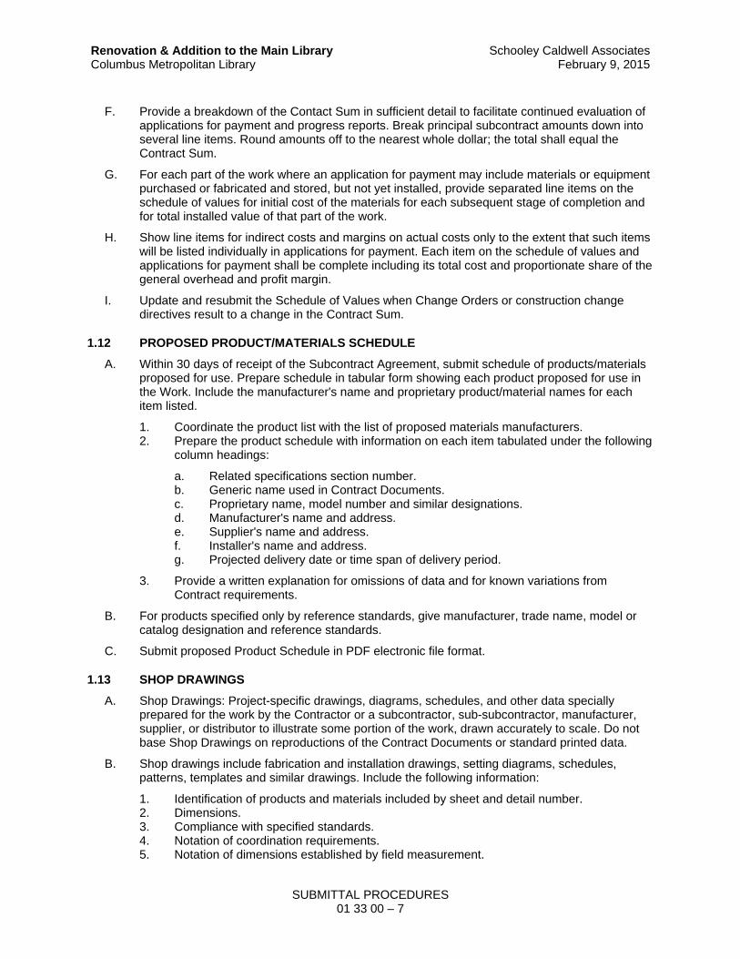
F. Provide a breakdown of the Contact Sum in sufficient detail to facilitate continued evaluation of applications for payment and progress reports. Break principal subcontract amounts down into several line items. Round amounts off to the nearest whole dollar; the total shall equal the Contract Sum.
G. For each part of the work where an application for payment may include materials or equipment purchased or fabricated and stored, but not yet installed, provide separated line items on the schedule of values for initial cost of the materials for each subsequent stage of completion and for total installed value of that part of the work.
H. Show line items for indirect costs and margins on actual costs only to the extent that such items will be listed individually in applications for payment. Each item on the schedule of values and applications for payment shall be complete including its total cost and proportionate share of the general overhead and profit margin.
I. Update and resubmit the Schedule of Values when Change Orders or construction change directives result to a change in the Contract Sum.
1.12 PROPOSED PRODUCT/MATERIALS SCHEDULE
A. Within 30 days of receipt of the Subcontract Agreement, submit schedule of products/materials proposed for use. Prepare schedule in tabular form showing each product proposed for use in the Work. Include the manufacturer's name and proprietary product/material names for each item listed.
1. Coordinate the product list with the list of proposed materials manufacturers. 2. Prepare the product schedule with information on each item tabulated under the following
column headings:
a. Related specifications section number. b. Generic name used in Contract Documents. c. Proprietary name, model number and similar designations. d. Manufacturer's name and address. e. Supplier's name and address. f. Installer's name and address. g. Projected delivery date or time span of delivery period.
3. Provide a written explanation for omissions of data and for known variations from Contract requirements.
B. For products specified only by reference standards, give manufacturer, trade name, model or catalog designation and reference standards.
C. Submit proposed Product Schedule in PDF electronic file format.
1.13 SHOP DRAWINGS
A. Shop Drawings: Project-specific drawings, diagrams, schedules, and other data specially prepared for the work by the Contractor or a subcontractor, sub-subcontractor, manufacturer, supplier, or distributor to illustrate some portion of the work, drawn accurately to scale. Do not base Shop Drawings on reproductions of the Contract Documents or standard printed data.
B. Shop drawings include fabrication and installation drawings, setting diagrams, schedules, patterns, templates and similar drawings. Include the following information:
1. Identification of products and materials included by sheet and detail number. 2. Dimensions. 3. Compliance with specified standards. 4. Notation of coordination requirements. 5. Notation of dimensions established by field measurement.

SUBMITTAL PROCEDURES 01 33 00 – 8
Renovation & Addition to the Main Library Columbus Metropolitan Library
Schooley Caldwell AssociatesFebruary 9, 2015
6. Relationship and attachment to adjoining construction clearly indicated. 7. Seal and signature of professional engineer if specified.
C. Wiring Diagrams: Accompany shop drawings with specific wiring diagrams and instructions on equipment controls or devices which are to be furnished. The diagrams and instructions shall not be of a general nature, but shall be modified to be specific to this Project. Include identical diagrams and instructions for the installation of the equipment and identical diagrams in the operation and maintenance manuals. Wiring diagrams shall indicate interconnection between pieces of electrical equipment.
D. Coordination drawings are a special type of shop drawing that show the relationship and integration of different construction elements that require careful coordination during fabrication or installation to fit in the space provided or function as intended.
1. Preparation of coordination drawings is specified in Section 01 31 00 – Project Coordination, and may include components previously shown in detail on shop drawings or product data.
E. After review, reproduce and distribute in accordance with “Submittal Procedures” above.
F. Submit shop drawings in PDF electronic file format.
1.14 ELECTRONIC DOCUMENTS
A. The Architect will, at his sole discretion and without obligation, make graphic portions of the contract documents available for use by Contractors in electronic format for Contractors’ use in preparing submittals. These electronic documents are available in the .DXF or .DWG format for AutoCAD Release 2000 or higher, at fifty-dollars ($50) per sheet. Refer to AIA Form C106-2013.
B. The Architect will release the project computer files at no cost to contractors for the purpose of contractor(s) returning these as Record Documents. At completion of work, the contractor shall submit As-Built / Record Drawings to the Architect in electronic AutoCAD .dwg format and one set of marked-up Record Prints. Electronic drawings shall be submitted in .dwg format. The following file formats are not acceptable formats (.tif, .jpg, .jpeg, .pdf).
C. Refer to “Computer File Release Application & Electronic Record Drawings Agreement” contained in the Project Manual.
D. The Architect will release the computer files at no cost to the Contractor for the purpose of the Contractor(s) returning these electronic files as record documents. The Contractor shall also submit record drawings to the Architect in hardcopy format, one set of marked-up prints.
1.15 PRODUCT DATA
A. Illustrations, standard schedules, performance charts, instructions, brochures, diagrams, and other information furnished by the Contractor to illustrate materials or equipment for some portion of the work.
1. The data shall be supported by sufficient descriptive material, such as catalog cuts, diagrams, and other data published by the manufacturer, as well as by evidence of compliance with performance standards, to demonstrate conformance to the Specification requirements.
2. Catalog numbers alone are not acceptable. 3. The data shall include, but shall not be limited to, the name and address of the nearest
service and maintenance organization that regularly stocks repair parts. No consideration shall be given to partial lists submitted unless otherwise noted.
4. Review of materials and equipment is tentative, subject to submission of complete shop drawings indicating compliance with the Contract Documents.
5. Cross out information which is not applicable to the work.

SUBMITTAL PROCEDURES 01 33 00 – 9
Renovation & Addition to the Main Library Columbus Metropolitan Library
Schooley Caldwell AssociatesFebruary 9, 2015
6. Supplement standard information to provide additional information which is applicable to the work.
7. Show dimensions and clearances required. 8. Show performance characteristics and capacities.
B. Collect product data into a single submittal for each element of construction or system. Product data includes printed information such as manufacturer's installation instructions, catalog cuts, standard color charts, roughing-in diagrams and templates, standard wiring diagrams and performance curves. Where product data must be specially prepared because standard printed data is not suitable for use, submit as "shop drawings". Do not submit product data until compliance with requirements of the Contract Documents has been confirmed.
C. Mark each copy to show which products and options are applicable. Where printed product data includes information on several products that are not required, mark copies to indicate the applicable information. Include the following information as applicable:
1. Manufacturer's catalog cuts 2. Manufacturer's product specifications 3. Standard color charts 4. Statement of compliance with specified referenced standards. 5. Testing by recognized testing agency. 6. Application of testing agency labels and seals. 7. Availability and delivery time information. 8. For equipment, include the following in addition to the above, as applicable:
a. Wiring diagrams showing factory-installed wiring. b. Printed performance curves. c. Operational range diagrams. d. Clearances required to other construction, if not indicated on accompanying Shop
Drawings.
D. Do not proceed with installation until a copy of product data is in the Installer’s possession.
E. Submit Product Data before or concurrent with Samples.
F. Submit Product Data in PDF electronic file format.
1.16 SAMPLES
A. Submit the required number of physical samples required, the Architect will retain a minimum of two (2) physical Samples, remainder will be returned unless otherwise provided. Cure and finish samples as specified and physically identical with the material or product proposed.
B. Samples may include partial sections of manufactured or fabricated components, cuts or containers of materials, color range sets, and swatches showing colors, texture and pattern. Illustrate functional and aesthetic characteristics of materials, equipment, or workmanship, with integral parts and attachment devices. Coordinate sample submittals for interfacing Work.
C. Mount, display, or package samples in the manner to facilitate review of quantities indicated. Prepare samples to match the Architect's sample. Include the following information attached with label on unexposed side of Samples and include the following:
1. Generic description of the sample. 2. Specification section number and paragraph number reference. 3. Sample source. 4. Product name or name of manufacturer. 5. Compliance with recognized standards. 6. Availability and delivery time.

SUBMITTAL PROCEDURES 01 33 00 – 10
Renovation & Addition to the Main Library Columbus Metropolitan Library
Schooley Caldwell AssociatesFebruary 9, 2015
D. Submit samples for review of size, kind, color, pattern, and texture, for a final check of these characteristics with other elements, and a comparison of these characteristics between the final submittal and the actual component as delivered and installed. Where finishes are not indicated as custom, provide full range of manufacturers' standard finishes.
E. Where variation in color, pattern, texture or other characteristic is inherent in the material or product represented, submit at least 3 multiple units that show approximate limits of the variations.
F. Refer to other Specification sections for requirements for samples that illustrate workmanship, fabrication techniques, details of assembly, connections, operation and similar construction characteristics.
G. Reviewed samples which may be used in the Work are indicated in individual specification sections.
H. Provide corresponding electronic submittal of sample transmittal, digital image file illustrating sample characteristics, and identification information for record.
I. Disposition: Maintain sets of approved samples at Project site, available for quality- control comparisons throughout the course of construction activity. Sample sets may be used to determine final acceptance of construction associated with each set.
J. The Contractor shall furnish additional certification of conformance to the specification requirements as may be requested by the Architect.
1.17 QUALITY ASSURANCE SUBMITTALS
A. General: Submittals that are not listed as submittals for review are quality control submittals. Quality control submittals are submitted for information only and include design data, certifications, manufacturer’s instructions, manufacturer’s field reports, and other quality-control submittals as required under other sections of the specifications.
B. Where other sections of the Specifications require certification that a product, materials, or installation complies with specified requirements, submit a notarized certifications from the manufacturer certifying compliance with specified requirements.
1. Certification shall be signed by an officer of the manufacturer or other individual authorized to sign documents on behalf of the company.
C. Coordination Drawing Submittals: Comply with requirements specified in Section 01 31 00 –Project Coordination.
D. Contractor's Construction Schedule: Comply with requirements specified in the Special Conditions.
E. Test and Inspection Reports and Schedule of Tests and Inspections Submittals: Comply with requirements specified in Section 01 45 00 – Quality Control.
F. Closeout Submittals and Maintenance Material Submittals: Comply with requirements specified in Section 01 78 00 – Project Closeout.
G. Qualification Data: Prepare written information that demonstrates capabilities and experience of firm or person. Include lists of completed projects with project names and addresses, contact information of architects and owners, and other information specified.
H. Installer Certificates: Submit written statements on manufacturer's letterhead certifying that Installer complies with requirements in the Contract Documents and, where required, is authorized by manufacturer for this specific Project.

SUBMITTAL PROCEDURES 01 33 00 – 11
Renovation & Addition to the Main Library Columbus Metropolitan Library
Schooley Caldwell AssociatesFebruary 9, 2015
I. Manufacturer Certificates: Submit written statements on manufacturer's letterhead certifying that manufacturer complies with requirements in the Contract Documents. Include evidence of manufacturing experience where required.
J. Product Certificates: Submit written statements on manufacturer's letterhead certifying that product complies with requirements in the Contract Documents.
K. Material Certificates: Submit written statements on manufacturer's letterhead certifying that material complies with requirements in the Contract Documents.
L. Material Test Reports: Submit reports written by a qualified testing agency, on testing agency's standard form, indicating and interpreting test results of material for compliance with requirements in the Contract Documents.
M. Product Test Reports: Submit written reports indicating that current product produced by manufacturer complies with requirements in the Contract Documents. Base reports on evaluation of tests performed by manufacturer and witnessed by a qualified testing agency, or on comprehensive tests performed by a qualified testing agency.
N. Research Reports: Submit written evidence, from a model code organization acceptable to authorities having jurisdiction, that product complies with building code in effect for Project. Include the following information:
1. Name of evaluation organization. 2. Date of evaluation. 3. Time period when report is in effect. 4. Product and manufacturers' names. 5. Description of product. 6. Test procedures and results. 7. Limitations of use.
O. Preconstruction Test Reports: Submit reports written by a qualified testing agency, on testing agency's standard form, indicating and interpreting results of tests performed before installation of product, for compliance with performance requirements in the Contract Documents.
P. Compatibility Test Reports: Submit reports written by a qualified testing agency, on testing agency's standard form, indicating and interpreting results of compatibility tests performed before installation of product. Include written recommendations for primers and substrate preparation needed for adhesion.
Q. Field Test Reports: Submit written reports indicating and interpreting results of field tests performed either during installation of product or after product is installed in its final location, for compliance with requirements in the Contract Documents.
R. Design Data: Prepare and submit written and graphic information, including, but not limited to, performance and design criteria, list of applicable codes and regulations, and calculations. Include list of assumptions and other performance and design criteria and a summary of loads. Include load diagrams if applicable. Provide name and version of software, if any, used for calculations. Include page numbers.
PART 2 – PRODUCTS
Not Used
PART 3 – EXECUTION
Not Used
END OF SECTION


REFERENCE STANDARDS AND DEFINITIONS 01 42 00 – 1
Renovation & Addition to the Main Library Columbus Metropolitan Library
Schooley Caldwell AssociatesFebruary 9, 2015
SECTION 01 42 00
REFERENCE STANDARDS AND DEFINITIONS
PART 1 – GENERAL
1.01 SUMMARY
A. Section includes general definitions for Specifications and other Contract Documents. Basic contract definitions are included in the Conditions of the Contract.
B. Drawings and general provisions of the Contract, including General and Special Conditions and other Division 01 Specification Sections, apply to this Section.
C. Comply with standards in effect as of date of the Contract Documents except comply with standards having different revision dates as referenced in the codes as indicated on Drawings.
1.02 QUALITY ASSURANCE
A. For products or workmanship specified by association, trade, or Federal Standards, comply with requirements of the standard, except when more rigid requirements are specified or are required by applicable codes.
1.03 GENERAL DEFINITIONS
A. General Explanation: Basic Contract definitions are included in the Construction Agreement of the Contract. Certain terms used in Contract Documents are defined generally in this article. Definitions and explanations that follow are not necessarily either complete or exclusive, but are general for the Work to the extent they are not stated more explicitly in other provisions of the Contract Documents.
B. Approved: The term "approved" where used in conjunction with Architect's action on the Contractor's submittals, requests, and applications, is limited to the Architect's duties and responsibilities as specified in the Conditions of the Contract. In no case will "approval" by Architect be interpreted as a release of Contractor from responsibilities to fulfill requirements of Contract Documents.
C. Bulletin: A document issued by the Architect, after execution of the Contract requesting an proposal from the Contractor which, if approved as provided in the Contract Documents, will cause the execution of a Change Order to modify, amend or alter the Contract Documents.
D. Contract Completion: The date upon which all deficiencies noted in the “punch list” have been corrected, the Contractor’s work is 100 percent complete, and the Contractor has complied with all conditions precedent to final payment and release of retainage.
E. Cutting and Patching: The term "cutting and patching" means cutting into existing construction to provide for the installation or performance of other work and subsequent fitting and patching required to restore surfaces to their original condition.
1. Cutting and patching is performed for coordination of the Work, to uncover work for access or inspection, to obtain samples for testing, to permit alterations to be performed or for other similar purposes.
2. Cutting and patching performed during the manufacturer of products, or during the initial fabrication, erection or installation processes is not considered to be "cutting and patching" under this definition. Drilling of holes to install fasteners and similar operations are also not considered to be "cutting and patching."
F. Demolish: The term "demolish" shall mean to wreck or destroy a structure or building system assembly (such as floor or ceiling system, walls or partitions, etc.) and the removal of wrecked

REFERENCE STANDARDS AND DEFINITIONS 01 42 00 – 2
Renovation & Addition to the Main Library Columbus Metropolitan Library
Schooley Caldwell AssociatesFebruary 9, 2015
materials from the job site. Where new work is not specified for the adjoining surface, selective demolition shall require " cutting and patching" wherever demolished portions of a structure adjoin portions to remain.
G. Directed, Requested, etc.: Terms such as "directed," "requested," "authorized," "selected," "approved," "required," "accepted," and "permitted" mean "directed by Architect" "requested by Architect" and similar phrases. However, no such implied meaning shall be interpreted to extend Architect's responsibility to Contractor's area of construction supervision.
H. "Existing to Remain" or "Retain": Existing items of construction that are not to be removed and that are not otherwise indicated to be removed and salvaged, or removed and reinstalled.
I. Experienced: When used with an entity or individual, 'experienced' means having successfully completed a minimum number of projects similar in nature, size, and extent to this Project; and having a number of years of experience (as defined in the specification section) being familiar with special requirements indicated; and having complied with requirements of building code officials and industry standards.
J. Furnish: Except as otherwise defined in greater detail, term "furnish" is used to mean supply and deliver to Project Site, ready for unloading, unpacking, assembly, installation, and similar operations.
K. Indicated: The term "Indicated" is a cross-reference to graphic representations, notes, or schedules on the Drawings or other paragraphs or Schedules in the Specifications, and to similar requirements in Contract Documents. Where terms such as "shown," "noted," "scheduled," and "specified" are used in lieu of "indicated," it is for purpose of helping reader locate cross-reference, and no limitation of location is intended except as specifically noted.
L. Install: Except as otherwise defined in greater detail, the term "install" describes operations at Project Site including the actual unloading, temporary storage, unpacking, assembly, erecting, placing, anchoring, applying, working to dimension, finishing, curing, protecting, cleaning and similar operations.
M. Installer: An Installer is the Contractor or an entity (person or firm) engaged by the Contractor, either as an employee, subcontractor or contractor of lower tier, to perform a particular construction activity, including installation, erection, application and similar required operations. Installers are required to be experienced in the operations they are engaged to perform.
1. Certain Sections of the Specifications require that specific construction activities shall be performed by specialists who are recognized experts in those operations. The specialists must be engaged for those activities, and their assignments are requirements over which the Contractor has no option. However, the ultimate responsibility for fulfilling contract requirements remains with the Contractor.
N. ORC: The Ohio Revised Code.
O. Project Site: The project site Is the space available to the Contractor for performing construction activities, either exclusively or in conjunction, with others performing either work as part of the Project. The extent of the Project Site is shown on the Drawings and may or may not be identical with the description of the land upon which the Project is to be built.
P. Protect: The term "protect" shall mean to cover, enclose, shield or take other designated measures to avoid damage or harm. Items protected will either remain in place, or will be salvaged for re-installation in the Work. The type of protection shall be as specified. Where the type of protection is not specified, items shall be protected from any and all damage, scratches, marking, overspray, dripping, deterioration, or movement from any and all activities scheduled to take place on this Project, and/or would be typical to a Project site such as this one.
Q. Provide: Except as otherwise defined in greater detail, the term "provide" means to furnish and install, complete and ready for the intended use.

REFERENCE STANDARDS AND DEFINITIONS 01 42 00 – 3
Renovation & Addition to the Main Library Columbus Metropolitan Library
Schooley Caldwell AssociatesFebruary 9, 2015
R. Re-install: The term "re-install" or "re-installation" shall mean to install a salvaged or stored item or material in the Work.
S. Remove: The term "remove" shall mean to detach or separate an item, component or assembly from its installed location, and dispose of off-site, unless indicated to be removed and salvaged or removed and reinstalled . Removal shall be accomplished without damage to adjacent materials, components or systems that are to remain. Damage that must be incurred during removal shall be repaired as cutting and patching.
T. Repair:
1. The term "repair" shall be defined as “Replacement of component(s), either damaged or missing, which are part of a larger assembly, to return an existing material as closely as possible to its original form, structural integrity and condition.” Generally, the types of work required to achieve a “repaired” condition are the following:
a. Disassembly of existing components or construction for the purpose if installing new components.
b. Removal of the component or portion of an assembly designated for repair. c. Preparation of the adjacent surfaces to receive the repair. d. Installation and securing the repaired component in the assembly. e. Preparation of the assembly to receive a finish as specified in the finishing or
painting specification.
U. Replace: To duplicate and replace entire features with new material in kind. Replacement includes the following conditions:
1. The term "replace" shall be defined as providing in a former position or place. 2. The term may be combined with such terms as “with existing” or “with new” which define
exactly what is to be replaced.
a. Duplication: Includes replacing elements damaged beyond repair or missing. Original material is indicated as the pattern for creating new duplicated elements.
b. Replacement with New Materials: Includes replacement with new material when original material is not available as patterns for creating new duplicated elements.
3. Reference individual specification sections for further definition of “replace” as it relates to a specific application or condition.
V. Restore:
1. The term "restore" shall be defined as a general term for the process of returning a material, component, system or portion of work as nearly as possible to its original form or condition when it was new.
2. The term "restore" when used in a general sense may include the process of ‘repair’ defined above.
3. Refer to individual specification sections for further definition of “restore” as it relates to a specific application or condition.
4. Generally , the process involved with “restore” or “restoration” include the following:
a. Removal of applied items or materials which are not to be part of the restored work.
b. Stripping or other types of removal of surface applied coatings (i.e., paint). c. Modifying the material if it is required to accommodate new work. d. Replacement of portions of components or materials that cannot be restored
because of condition, including those that are deteriorated or otherwise damaged. Replacement is typically done with dutchmen.
e. Reinforcing broken components when this procedure is acceptable in lieu of “repair.”
f. Tightening and securing open or loose joints.

REFERENCE STANDARDS AND DEFINITIONS 01 42 00 – 4
Renovation & Addition to the Main Library Columbus Metropolitan Library
Schooley Caldwell AssociatesFebruary 9, 2015
g. Patching or plugging holes or other severe loss of the existing material. h. Filling of minor holes, scratches, dents, or other deformation not associated with
normal wear and tear. i. Sanding of the repaired surfaces smooth as a result of the restore process, prior to
final surface preparation for finishing.
5. Minor surface preparation of a reconditioned surface prior to other finishing or painting is not considered part of the “restore” process, and is specified as preparation in the finishing or painting specification.
6. It is not the intent of the “restore” process to return a material that shows normal wear to an original “like new” appearance or condition. Rather, such wear is considered a normal part of the use and life of the particular material, and as such does not require “restoring”
W. Regulations: The term "regulations" includes laws, ordinances, statutes, and lawful orders issued by authorities having jurisdiction, as well as rules, conventions, and agreements within the construction industry that control performance of the Work.
X. Salvage: The term "salvage" shall mean the removal of items, components, equipment or materials from their installed location, and protection and storage of such items, components, equipment or materials. Salvaged items will be designated either to be re-installed in the Work, stored, or turned over to the Owner or other designated entity, plus such other work as described.
Y. Store: The term "store" shall mean to protect and place in a designated area. Where an area is not designated, the Contractor responsible for the item shall provide adequate and reasonable facilities acceptable to the Architect.
Z. Testing Agencies: A testing agency is an independent entity engaged to perform specific inspections or tests, either at the Project site or elsewhere, and to report on and, if required, to interpret results of those inspections or tests.
1.04 SPECIFICATION FORMAT AND CONTENT EXPLANATION
A. The Specifications are organized into Divisions and Sections based on the Construction Specifications Institute's 2014 MASTERFORMAT (April 2014 Update) numbering system.
B. This Specification uses certain conventions regarding the style of language and the intended meaning of certain terms, words, and phrases when used in particular situations or circumstances. These conventions are explained as follows:
1. Language used in Specifications and other Contract Documents is abbreviated. Words and meanings shall be interpreted as appropriate. Words that are implied, but not stated, shall be interpolated as the sense requires. Singular words will be interpreted as plural and plural words interpreted as singular where applicable as the context of the Contract Documents indicate.
2. Imperative and streamlined language is used generally in the Specifications. Requirements expressed in the imperative mood are to be performed by the Contractor. At certain locations in the Text, subjective language is used for clarity to describe responsibilities that must be fulfilled indirectly by the Contractor, or by others when so noted.
3. The words "shall be" are implied where a colon (:) is used within a sentence or phrase.
1.05 INDUSTRY STANDARDS
A. Applicability of Standards: Unless the Contract Documents include more stringent requirements, applicable construction industry standards have the same force and effect as if bound or copied directly into the Contract Documents to the extent referenced. Such standards are made a part of the Contract Documents by reference.

REFERENCE STANDARDS AND DEFINITIONS 01 42 00 – 5
Renovation & Addition to the Main Library Columbus Metropolitan Library
Schooley Caldwell AssociatesFebruary 9, 2015
1. Referenced standards (referenced directly in Contract Documents or by governing regulations) have precedence over non-referenced standards which are recognized in industry for applicability to Work.
2. Publication Dates: Comply with standard in effect as of the date of the Contract Documents, unless otherwise indicated.
3. Copies of Standards: Each entity engaged in construction on the Project is required to be familiar with industry standards applicable to its construction activity. Copies of applicable standards are not bound with the Contract Documents. Where copies of standards are needed to perform a required construction activity, obtain copies directly from the publication source.
4. Abbreviations and Names: Trade association names and titles of general standards are frequently abbreviated. Where such acronyms or abbreviations are used in the Specifications or other Contract Documents, they mean the recognized name of the trade association, standards-generating organization, authority having jurisdiction, or other entity applicable to the content of the text provision.
B. Industry Organizations: Where abbreviations and acronyms are used in Specifications or other Contract Documents, they shall mean the recognized name of the entities in the following list. Names, telephone numbers, and Web sites are subject to change and are believed to be accurate and up-to-date as of the date of the Contract Documents.
1. AABC - Associated Air Balance Council; www.aabc.com. 2. AAMA - American Architectural Manufacturers Association; www.aamanet.org. 3. AASHTO - American Association of State Highway and Transportation Officials;
www.transportation.org. 4. ACI - American Concrete Institute; (Formerly: ACI International); www.concrete.org. 5. AF&PA - American Forest & Paper Association; www.afandpa.org. 6. AGA - American Gas Association; www.aga.org. 7. AI - Asphalt Institute; www.asphaltinstitute.org. 8. AIA - American Institute of Architects (The); www.aia.org. 9. AISC - American Institute of Steel Construction; www.aisc.org. 10. AISI - American Iron and Steel Institute; www.steel.org. 11. AITC - American Institute of Timber Construction; www.aitc-glulam.org. 12. AMCA - Air Movement and Control Association International, Inc.; www.amca.org. 13. ANSI - American National Standards Institute; www.ansi.org. 14. APA - APA - The Engineered Wood Association; www.apawood.org. 15. APA - Architectural Precast Association; www.archprecast.org. 16. API - American Petroleum Institute; www.api.org. 17. ARI - Air-Conditioning & Refrigeration Institute; (See AHRI). 18. ARI - American Refrigeration Institute; (See AHRI). 19. ARMA - Asphalt Roofing Manufacturers Association; www.asphaltroofing.org. 20. ASCE - American Society of Civil Engineers; www.asce.org. 21. ASCE/SEI - American Society of Civil Engineers/Structural Engineering Institute; (See
ASCE). 22. ASHRAE - American Society of Heating, Refrigerating and Air-Conditioning Engineers;
www.ashrae.org. 23. ASME - ASME International; (American Society of Mechanical Engineers);
www.asme.org. 24. ASTM - ASTM International; (American Society for Testing and Materials International);
www.astm.org. 25. AWI - Architectural Woodwork Institute; www.awinet.org. 26. AWPA - American Wood Protection Association; (Formerly: American Wood-Preservers'
Association); www.awpa.com. 27. AWS - American Welding Society; www.aws.org. 28. AWWA - American Water Works Association; www.awwa.org. 29. BHMA - Builders Hardware Manufacturers Association; www.buildershardware.com.

REFERENCE STANDARDS AND DEFINITIONS 01 42 00 – 6
Renovation & Addition to the Main Library Columbus Metropolitan Library
Schooley Caldwell AssociatesFebruary 9, 2015
30. BIA - Brick Industry Association (The); www.gobrick.com. 31. BOCA - BOCA; (Building Officials and Code Administrators International Inc.); (See ICC). 32. CDA - Copper Development Association; www.copper.org. 33. CISCA - Ceilings & Interior Systems Construction Association; www.cisca.org. 34. CISPI - Cast Iron Soil Pipe Institute; www.cispi.org. 35. CLFMI - Chain Link Fence Manufacturers Institute; www.chainlinkinfo.org. 36. CPA - Composite Panel Association; www.pbmdf.com. 37. CRI - Carpet and Rug Institute (The); www.carpet-rug.org. 38. CRSI - Concrete Reinforcing Steel Institute; www.crsi.org. 39. CSI - Construction Specifications Institute (The); www.csinet.org. 40. DHI - Door and Hardware Institute; www.dhi.org. 41. FM Approvals - FM Approvals LLC; www.fmglobal.com. 42. FM Global - FM Global; (Formerly: FMG - FM Global); www.fmglobal.com. 43. FSC - Forest Stewardship Council U.S.; www.fscus.org. 44. GA - Gypsum Association; www.gypsum.org. 45. GANA - Glass Association of North America; www.glasswebsite.com. 46. HI - Hydraulic Institute; www.pumps.org. 47. HMMA - Hollow Metal Manufacturers Association; (See NAAMM). 48. HPVA - Hardwood Plywood & Veneer Association; www.hpva.org. 49. HPW - H. P. White Laboratory, Inc.; www.hpwhite.com. 50. ICC - International Code Council; www.iccsafe.org. 51. ICRI - International Concrete Repair Institute, Inc.; www.icri.org. 52. IEEE - Institute of Electrical and Electronics Engineers, Inc. (The); www.ieee.org. 53. IES - Illuminating Engineering Society; (Formerly: Illuminating Engineering Society of
North America); www.ies.org. 54. IESNA - Illuminating Engineering Society of North America; (See IES). 55. IEST - Institute of Environmental Sciences and Technology; www.iest.org. 56. IGMA - Insulating Glass Manufacturers Alliance; www.igmaonline.org. 57. ILI - Indiana Limestone Institute of America, Inc.; www.iliai.com. 58. Intertek - Intertek Group; (Formerly: ETL SEMCO; Intertek Testing Service NA);
www.intertek.com. 59. ISO - International Organization for Standardization; www.iso.org. 60. ISSFA - International Solid Surface Fabricators Association; (See ISFA). 61. KCMA - Kitchen Cabinet Manufacturers Association; www.kcma.org. 62. LPI - Lightning Protection Institute; www.lightning.org. 63. MBMA - Metal Building Manufacturers Association; www.mbma.com. 64. MFMA - Maple Flooring Manufacturers Association, Inc.; www.maplefloor.org. 65. MFMA - Metal Framing Manufacturers Association, Inc.; www.metalframingmfg.org. 66. MIA - Marble Institute of America; www.marble-institute.com. 67. MSS - Manufacturers Standardization Society of The Valve and Fittings Industry Inc.;
www.mss-hq.org. 68. NAAMM - National Association of Architectural Metal Manufacturers; www.naamm.org. 69. NAIMA - North American Insulation Manufacturers Association; www.naima.org. 70. NBGQA - National Building Granite Quarries Association, Inc.; www.nbgqa.com. 71. NCAA - National Collegiate Athletic Association (The); www.ncaa.org. 72. NCMA - National Concrete Masonry Association; www.ncma.org. 73. NECA - National Electrical Contractors Association; www.necanet.org. 74. NeLMA - Northeastern Lumber Manufacturers Association; www.nelma.org. 75. NEMA - National Electrical Manufacturers Association; www.nema.org. 76. NFPA - NFPA; (National Fire Protection Association); www.nfpa.org. 77. NFPA - NFPA International; (See NFPA). 78. NFRC - National Fenestration Rating Council; www.nfrc.org. 79. NHLA - National Hardwood Lumber Association; www.nhla.com. 80. NLGA - National Lumber Grades Authority; www.nlga.org. 81. NOFMA - National Oak Flooring Manufacturers Association; (See NWFA).

REFERENCE STANDARDS AND DEFINITIONS 01 42 00 – 7
Renovation & Addition to the Main Library Columbus Metropolitan Library
Schooley Caldwell AssociatesFebruary 9, 2015
82. NOMMA - National Ornamental & Miscellaneous Metals Association; www.nomma.org. 83. NRCA - National Roofing Contractors Association; www.nrca.net. 84. NRMCA - National Ready Mixed Concrete Association; www.nrmca.org. 85. NSF - NSF International; (National Sanitation Foundation International); www.nsf.org. 86. NSPE - National Society of Professional Engineers; www.nspe.org. 87. NTMA - National Terrazzo & Mosaic Association, Inc. (The); www.ntma.com. 88. NWFA - National Wood Flooring Association; www.nwfa.org. 89. PCI - Precast/Prestressed Concrete Institute; www.pci.org. 90. RFCI - Resilient Floor Covering Institute; www.rfci.com. 91. RIS - Redwood Inspection Service; www.redwoodinspection.com. 92. SDI - Steel Deck Institute; www.sdi.org. 93. SDI - Steel Door Institute; www.steeldoor.org. 94. SJI - Steel Joist Institute; www.steeljoist.org. 95. SMACNA - Sheet Metal and Air Conditioning Contractors' National Association;
www.smacna.org. 96. SPFA - Spray Polyurethane Foam Alliance; www.sprayfoam.org. 97. SPIB - Southern Pine Inspection Bureau; www.spib.org. 98. SPRI - Single Ply Roofing Industry; www.spri.org. 99. SSPC - SSPC: The Society for Protective Coatings; www.sspc.org. 100. TCNA - Tile Council of North America, Inc.; (Formerly: Tile Council of America);
www.tileusa.com. 101. TPI - Truss Plate Institute; www.tpinst.org. 102. UL - Underwriters Laboratories Inc.; www.ul.com. 103. USGBC - U.S. Green Building Council; www.usgbc.org. 104. WCLIB - West Coast Lumber Inspection Bureau; www.wclib.org. 105. WDMA - Window & Door Manufacturers Association; www.wdma.com.
1.06 GOVERNING REGULATIONS AND AUTHORITIES
A. The Architect has contacted authorities having jurisdiction where necessary to obtain information to prepare Contract Documents. Contact authorities having jurisdiction directly for information and decisions regarding the Work.
B. For Owner's records, submit copies of permits, licenses, certifications, inspection reports, releases, jurisdictional settlements, notices, receipts of fee payments, judgments, and similar documents, correspondence, and records established in conjunction with compliance with standards and regulations bearing upon performance of the Work.
PART 2 – PRODUCTS
Not Used
PART 3 – EXECUTION
Not Used
END OF SECTION


MOCKUPS 01 43 30 – 1
Renovation & Addition to the Main Library Columbus Metropolitan Library
Schooley Caldwell AssociatesFebruary 9, 2015
SECTION 01 43 30
MOCKUPS
PART 1 – GENERAL
1.01 SUMMARY
A. General: Provide and coordinate mock-up assemblies at project site for Architect's review and acceptance, in accordance with requirements of the Contract Documents. Refer to individual Specification Sections for mock-up requirements. Generally, without limitation, mock-ups on site include the following:
1. Mock-ups of individual pieces of the work, as specified within individual Specification Sections.
B. Contractor is responsible to coordinate the work of the related Specification Sections so that each mock-up meets the specified requirements.
C. Related Sections:
1. Drawings and general provisions of the Contract, including General and Special Conditions and other Division 01 Specification Sections, apply to this Section.
2. Examine Contract Documents for requirements that affect Work of this Section. Other Specification Sections that directly relate to Work of this Section include, but are not limited to:
a. Individual Specification Sections for Submittal Samples.
1.02 DEFINITIONS
A. Freestanding Mock-Ups: Full-size, physical assemblies that are constructed on-site in a protected location.
1. Freestanding mock-ups are not part of the final construction. Freestanding mock-ups will be used to verify selections made under sample submittals, to demonstrate aesthetic effects, qualities of materials and execution, and to review construction, coordination, testing, and operation.
2. Approved freestanding mock-ups establish the standard by which the Work will be judged.
3. Approved freestanding mock-ups remain on site during the balance of construction and are demolished and removed from site at completion of the Work they represent.
B. In-Place Mock-Ups: Full-size, physical assemblies that are constructed in-place and remain part of final construction.
1. In-place mock-ups will be used to verify selections made under sample submittals, to demonstrate aesthetic effects, qualities of materials and execution, and to review construction, coordination, testing, or operation.
2. Approved in-place mock-ups establish the standard by which the Work will be judged. 3. Approved mock-ups remain part of the completed Work.
1.03 SUBMITTALS
A. Schedule: Contractor shall submit a schedule of mock-up construction, including dates for mock-up review by the Architect.
1. Mock-up schedule shall be reviewed at each progress meeting, revised and resubmitted as required.

MOCKUPS 01 43 30 – 2
Renovation & Addition to the Main Library Columbus Metropolitan Library
Schooley Caldwell AssociatesFebruary 9, 2015
2. Schedule shall allow sufficient time for mock-ups which are not accepted to be reconstructed and reviewed until accepted by the Architect.
B. Shop Drawings of Mock-Ups: Provide large scale shop drawings for fabrication, installation and erection of all parts of each mock-up. Provide plans, elevations, and details of anchorage, connections and accessory items.
C. Photographs of Mock-Ups: Submit photographs of mock-ups after completion of installation and acceptance of each mock-up.
D. Submittal Samples: Refer to individual Specification Sections for submittal requirements of mock-up components and coordinate accordingly.
1.04 PRECONSTRUCTION TESTING
A. Where testing agency is indicated to perform preconstruction testing for compliance with specified requirements and test methods, comply with the following:
1. Contractor responsibilities include the following:
a. Provide test mockups representative of proposed products and construction. b. Submit test mockups in a timely manner with sufficient time for testing and
analyzing results to prevent delaying the work. c. Provide sizes and configurations of test mockups to adequately demonstrate
capability of products to comply with performance requirements. d. Build site-assembled test mockups when required in individual specification
sections, using installers who will perform the same tasks for Project.
1.05 QUALITY ASSURANCE
A. Design Modifications: Make design modifications to mock-up only as required to meet performance requirements and to coordinate the work. Indicate proposed design modifications on shop drawings. Maintain original design concept without altering profiles and alignments indicated.
PART 2 – PRODUCTS
2.01 MATERIALS AND PRODUCTS
A. Provide materials, components, and products for mock-ups as specified in individual Specification Sections.
PART 3 – EXECUTION
3.01 GENERAL
A. Refer to PART 3, EXECUTION portions of the various Specification Sections for specific requirements regarding condition of surfaces, erection, and erection tolerances.
3.02 MOCK-UPS
A. Provide mock-ups of types and sizes required by individual Specification Sections to evaluate and set the standard of quality for that work. Obtain Architect's acceptance of visual qualities prior to commencing work that individual mock-up is intended to represent. Protect and maintain approved mock-ups throughout the work of the Contract. Locate mock-ups at the Project site as directed by the Architect.
1. Provide as many mock-ups as required until Architect's approval has been received.

MOCKUPS 01 43 30 – 3
Renovation & Addition to the Main Library Columbus Metropolitan Library
Schooley Caldwell AssociatesFebruary 9, 2015
2. When indicated in individual Specification Sections, approved mock-ups may be incorporated into the finish work.
B. Integrated Exterior Mockups: Construct integrated exterior mockup according to approved Shop Drawings .
1. Coordinate installation of exterior envelope materials and products for which mockups are required in individual Specification Sections, along with supporting materials.
C. Room Mockups: Construct room mockups incorporating required materials and assemblies, finished according to requirements. Provide required lighting and additional lighting where required to enable Architect to evaluate quality of the Work.
3.03 REPAIR AND PROTECTION
A. General: On completion of testing, inspecting, sample taking, and similar services, repair and restore substrates and finishes.
1. Provide materials and comply with installation requirements specified in other Specification Sections. Restore patched areas and extend restoration into adjoining areas with durable seams that are as non-visible as possible.
B. Protect construction exposed by or for quality-control service activities.
3.04 REMOVAL AND DISPOSAL
A. Demolish and remove freestanding mock-ups from site at the completion of the Project. Legally dispose of demolished mock-up materials. Comply with requirements of Section 01 74 19 – Construction Waste Management and Disposal.
END OF SECTION


QUALITY CONTROL 01 45 00 – 1
Renovation & Addition to the Main Library Columbus Metropolitan Library
Schooley Caldwell AssociatesFebruary 9, 2015
SECTION 01 45 00
QUALITY CONTROL
PART 1 – GENERAL
1.01 SUMMARY
A. This section includes administrative and procedural requirements for quality assurance and quality-control services.
B. Quality control services include inspections, tests, and related actions, including reports performed by Contractor, by independent agencies, and by governing authorities. They do not include contract enforcement activities performed by the Architect.
C. Testing and inspecting services are required to verify compliance with requirements specified or indicated. These services do not relieve Contractor of responsibility for compliance with the Contract Document requirements.
1. Specific quality-control requirements for individual construction activities are specified in the Sections that specify those activities. Requirements in those Sections may also cover production of standard products.
2. Specified tests, inspections, and related actions do not limit Contractor’s quality-control procedures that facilitate compliance with the Contract Document requirements.
3. Requirements for Contractor to provide quality-control services required by Architect, Owner, or authorities having jurisdiction are not limited by provisions of this Section.
D. Related Documents/ Sections:
1. Drawings and general provisions of the Contract, including General and Special Conditions and other Division 01 Specification Sections, apply to this Section.
2. Section 01 33 00 – Submittal Procedures: Submission of manufacturers' instructions and certificates.
3. Section 01 73 29 – Cutting and Patching: Requirements for repair and restoration of construction disturbed by inspection and testing activities.
4. Divisions 02 through 50 Sections for specific test and inspection requirements.
1.02 DEFINITIONS
A. Quality-Assurance Services: Activities, actions, and procedures performed before and during execution of the Work to guard against defects and deficiencies and ensure that proposed construction complies with requirements.
B. Quality-Control Services: Tests, inspections, procedures, and related actions during and after execution of the Work to evaluate that completed construction complies with requirements. Services do not include contract enforcement activities performed by Architect.
C. Field Quality-Control Testing: Tests and inspections that are performed on-site for installation of the Work and for completed Work.
D. Mockups: Full-size, physical example assemblies to illustrate finishes and materials. Mockups are used to verify selections made under Sample submittals, to demonstrate aesthetic effects and, where indicated, qualities of materials and execution, and to review construction, coordination, testing, or operation; they are not Samples. Mockups establish the standard by which the Work will be judged.
1. Integrated Exterior Mockups: Mockups of the exterior envelope erected separately from the building but on Project site, consisting of multiple products, assemblies, and subassemblies.

QUALITY CONTROL 01 45 00 – 2
Renovation & Addition to the Main Library Columbus Metropolitan Library
Schooley Caldwell AssociatesFebruary 9, 2015
2. Room Mockups: Mockups of typical interior spaces complete with wall, floor, and ceiling finishes, doors, windows, millwork, casework, specialties, furnishings and equipment, and lighting.
E. Preconstruction Testing: Tests and inspections performed specifically for Project before products and materials are incorporated into the Work, to verify performance or compliance with specified criteria.
F. Product Testing: Tests and inspections that are performed by an NRTL, an NVLAP, or a testing agency qualified to conduct product testing and acceptable to authorities having jurisdiction, to establish product performance and compliance with specified requirements.
G. Source Quality-Control Testing: Tests and inspections that are performed at the source, e.g., plant, mill, factory, or shop.
H. Field Quality-Control Testing: Tests and inspections that are performed on-site for installation of the Work and for completed Work.
I. Testing Agency: An entity engaged to perform specific tests, inspections, or both. Testing laboratory shall mean the same as testing agency.
J. Installer/Applicator/Erector: Contractor or another entity engaged by Contractor as an employee, Subcontractor, or Sub-subcontractor, to perform a particular construction operation, including installation, erection, application, and similar operations.
1. Use of trade-specific terminology in referring to a trade or entity does not require that certain construction activities be performed by accredited or unionized individuals, or that requirements specified apply exclusively to specific trade(s).
K. Experienced: When used with an entity or individual, "experienced" means having successfully completed a minimum of five previous projects similar in nature, size, and extent to this Project; being familiar with special requirements indicated; and having complied with requirements of authorities having jurisdiction.
1.03 CONFLICTING REQUIREMENTS
A. Referenced Standards: If compliance with two or more standards is specified and the standards establish different or conflicting requirements for minimum quantities or quality levels, comply with the most stringent requirement. Refer conflicting requirements that are different, but apparently equal, to Architect for a decision before proceeding.
1.04 SUBMITTALS
A. Schedule of Tests and Inspections: Prepare in tabular form and include the following:
1. Specification Section number and title. 2. Description of test and inspection. 3. Identification of applicable standards. 4. Identification of test and inspection methods. 5. Number of tests and inspections required. 6. Time schedule or time span for tests and inspections. 7. Entity responsible for performing tests and inspections. 8. Requirements for obtaining samples. 9. Unique characteristics of each quality-control service.
B. Contractor's Quality-Control Plan: For quality-assurance and quality-control activities and responsibilities:

QUALITY CONTROL 01 45 00 – 3
Renovation & Addition to the Main Library Columbus Metropolitan Library
Schooley Caldwell AssociatesFebruary 9, 2015
C. Reports: Prepare and submit certified written reports that include the following:
1. Date of issue. 2. Project title and number. 3. Name, address, and telephone number of testing agency. 4. Dates and locations of samples and tests or inspections. 5. Names of individuals making tests and inspections. 6. Description of the Work and test and inspection method. 7. Identification of product and Specification Section. 8. Complete test or inspection data. 9. Test and inspection results and an interpretation of test results. 10. Ambient conditions at time of sample taking and testing and inspecting. 11. Comments or professional opinion on whether tested or inspected Work complies with
the Contract Document requirements. 12. Name and signature of laboratory inspector. 13. Recommendations on retesting and reinspecting.
D. Permits, Licenses, and Certificates: For Owner's records, submit copies of permits, licenses, certifications, inspection reports, releases, jurisdictional settlements, notices, receipts for fee payments, judgments, correspondence, records, and similar documents, established for compliance with standards and regulations bearing on performance of the Work.
1.05 CONTRACTOR'S QUALITY-CONTROL PLAN
A. Quality-Control Plan, General: Submit quality-control plan within 10 days of Notice of Award and not less than five days prior to preconstruction meeting. Submit in format acceptable to Construction Manager. Identify personnel, procedures, controls, instructions, tests, records, and forms to be used to carry out Contractor's quality-assurance and quality-control responsibilities. Coordinate with construction schedule.
B. Quality-Control Personnel Qualifications: Engage qualified full-time personnel trained and experienced in managing and executing quality-assurance and quality-control procedures similar in nature and extent to those required for Project.
1. Project quality-control manager shall not serve as Project superintendent, but may have other Project responsibilities.
C. Submittal Procedure: Describe procedures for ensuring compliance with requirements through review and management of submittal process. Indicate qualifications of personnel responsible for submittal review.
D. Testing and Inspection: In quality-control plan, include a comprehensive schedule of Work requiring testing or inspection, including the following:
1. Contractor-performed tests and inspections including subcontractor-performed tests and inspections. Include required tests and inspections and Contractor-elected tests and inspections.
2. Special inspections required by authorities having jurisdiction and indicated in “Structural Testing and Special Inspections.”
3. Owner-performed tests and inspections indicated in the Contract Documents.
E. Continuous Inspection of Workmanship: Describe process for continuous inspection during construction to identify and correct deficiencies in workmanship in addition to testing and inspection specified. Indicate types of corrective actions to be required to bring work into compliance with standards of workmanship established by Contract requirements and approved mockups.
F. Monitoring and Documentation: Maintain testing and inspection reports including log of approved and rejected results. Include work Architect has indicated as nonconforming or
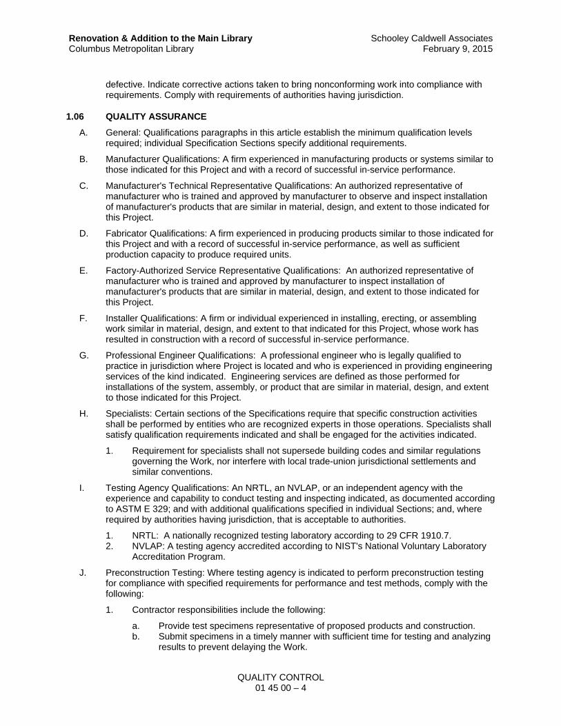
QUALITY CONTROL 01 45 00 – 4
Renovation & Addition to the Main Library Columbus Metropolitan Library
Schooley Caldwell AssociatesFebruary 9, 2015
defective. Indicate corrective actions taken to bring nonconforming work into compliance with requirements. Comply with requirements of authorities having jurisdiction.
1.06 QUALITY ASSURANCE
A. General: Qualifications paragraphs in this article establish the minimum qualification levels required; individual Specification Sections specify additional requirements.
B. Manufacturer Qualifications: A firm experienced in manufacturing products or systems similar to those indicated for this Project and with a record of successful in-service performance.
C. Manufacturer's Technical Representative Qualifications: An authorized representative of manufacturer who is trained and approved by manufacturer to observe and inspect installation of manufacturer's products that are similar in material, design, and extent to those indicated for this Project.
D. Fabricator Qualifications: A firm experienced in producing products similar to those indicated for this Project and with a record of successful in-service performance, as well as sufficient production capacity to produce required units.
E. Factory-Authorized Service Representative Qualifications: An authorized representative of manufacturer who is trained and approved by manufacturer to inspect installation of manufacturer's products that are similar in material, design, and extent to those indicated for this Project.
F. Installer Qualifications: A firm or individual experienced in installing, erecting, or assembling work similar in material, design, and extent to that indicated for this Project, whose work has resulted in construction with a record of successful in-service performance.
G. Professional Engineer Qualifications: A professional engineer who is legally qualified to practice in jurisdiction where Project is located and who is experienced in providing engineering services of the kind indicated. Engineering services are defined as those performed for installations of the system, assembly, or product that are similar in material, design, and extent to those indicated for this Project.
H. Specialists: Certain sections of the Specifications require that specific construction activities shall be performed by entities who are recognized experts in those operations. Specialists shall satisfy qualification requirements indicated and shall be engaged for the activities indicated.
1. Requirement for specialists shall not supersede building codes and similar regulations governing the Work, nor interfere with local trade-union jurisdictional settlements and similar conventions.
I. Testing Agency Qualifications: An NRTL, an NVLAP, or an independent agency with the experience and capability to conduct testing and inspecting indicated, as documented according to ASTM E 329; and with additional qualifications specified in individual Sections; and, where required by authorities having jurisdiction, that is acceptable to authorities.
1. NRTL: A nationally recognized testing laboratory according to 29 CFR 1910.7. 2. NVLAP: A testing agency accredited according to NIST's National Voluntary Laboratory
Accreditation Program.
J. Preconstruction Testing: Where testing agency is indicated to perform preconstruction testing for compliance with specified requirements for performance and test methods, comply with the following:
1. Contractor responsibilities include the following:
a. Provide test specimens representative of proposed products and construction. b. Submit specimens in a timely manner with sufficient time for testing and analyzing
results to prevent delaying the Work.

QUALITY CONTROL 01 45 00 – 5
Renovation & Addition to the Main Library Columbus Metropolitan Library
Schooley Caldwell AssociatesFebruary 9, 2015
c. Provide sizes and configurations of test assemblies, mockups, and laboratory mockups to adequately demonstrate capability of products to comply with performance requirements.
d. When testing is complete, obtain approvals to remove test specimens, assemblies, and mockups; do not reuse products on Project.
2. Testing Agency Responsibilities: Submit a certified written report of each test, inspection, and similar quality-assurance service to Architect and Commissioning Authority, with copy to Contractor. Interpret tests and inspections and state in each report whether tested and inspected work complies with or deviates from the Contract Documents.
1.07 QUALITY CONTROL
A. Owner Responsibilities: Where quality-control services are indicated as Owner's responsibility, Owner will engage a qualified testing agency to perform these services.
1. Owner will furnish Contractor with names, addresses, and telephone numbers of testing agencies engaged and a description of types of testing and inspecting they are engaged to perform.
2. Costs for retesting and reinspecting construction that replaces or is necessitated by work that failed to comply with the Contract Documents will be charged to Contractor, and the Contract Sum will be adjusted by Change Order.
B. Contractor Responsibilities: Tests and inspections not explicitly assigned to Owner are Contractor's responsibility. Perform additional quality-control activities required to verify that the Work complies with requirements, whether specified or not..
1. Where services are indicated as Contractor’s responsibility, engage a qualified testing agency to perform these quality-control services.
a. Contractor shall not employ same entity engaged by Owner, unless agreed to in writing by Owner.
2. Notify testing agencies at least 24 hours in advance of time when Work that requires testing or inspecting will be performed.
3. Where quality-control services are indicated as Contractor's responsibility, submit a certified written report, in duplicate, of each quality-control service.
4. Testing and inspecting requested by Contractor and not required by the Contract Documents are Contractor's responsibility.
5. Submit additional copies of each written report directly to authorities having jurisdiction, when they so direct.
C. Costs for retesting and reinspecting construction that replaces or is necessitated by work that failed to comply with the Contract Documents will be charged to Contractor, and the Contract Price will be adjusted by Change Order.
D. Manufacturer's Field Services: Where indicated, engage a factory-authorized service representative to inspect field-assembled components and equipment installation, including service connections. Report results in writing.
E. Retesting/Reinspecting: Regardless of whether original tests or inspections were Contractor's responsibility, provide quality-control services, including retesting and reinspecting, for construction that revised or replaced Work that failed to comply with requirements established by the Contract Documents.
F. Testing Agency Responsibilities: Cooperate with Architect, Commissioning Authority and Contractor in performance of duties. Provide qualified personnel to perform required tests and inspections.

QUALITY CONTROL 01 45 00 – 6
Renovation & Addition to the Main Library Columbus Metropolitan Library
Schooley Caldwell AssociatesFebruary 9, 2015
1. Notify Architect, Commissioning Authority, and Contractor promptly of irregularities or deficiencies observed in the Work during performance of its services.
2. Determine the location from which test samples will be taken and in which in-situ tests are conducted.
3. Conduct and interpret tests and inspections and state in each report whether tested and inspected work complies with or deviates from requirements.
4. Submit a certified written report, in duplicate, of each test, inspection, and similar quality-control service through Contractor.
5. Do not release, revoke, alter, or increase the Contract Document requirements or approve or accept any portion of the Work.
6. Do not perform any duties of Contractor.
G. Associated Services: Cooperate with agencies performing required tests, inspections, and similar quality- control services, and provide reasonable auxiliary services as requested. Notify agency sufficiently in advance of operations to permit assignment of personnel. Provide the following:
1. Access to the Work. 2. Incidental labor and facilities necessary to facilitate tests and inspections. 3. Adequate quantities of representative samples of materials that require testing and
inspecting. Assist agency in obtaining samples. 4. Facilities for storage and field curing of test samples. 5. Preliminary design mix proposed for use for material mixes that require control by testing
agency. 6. Security and protection for samples and for testing and inspecting equipment at Project
site.
H. Coordination: Coordinate sequence of activities to accommodate required quality-assurance and quality-control services with a minimum of delay and to avoid necessity of removing and replacing construction to accommodate testing and inspecting.
1. Schedule times for tests, inspections, obtaining samples, and similar activities.
I. Schedule of Tests and Inspections: Prepare a schedule of tests, inspections, and similar quality-control services required by the Contract Documents. Submit schedule within 30 days of date established for the Notice to Proceed.
1. Distribution: Distribute schedule to Construction Manager, Architect, testing agencies, and each party involved in performance of portions of the Work where tests and inspections are required.
1.08 SPECIAL TESTS AND INSPECTIONS
A. Special Tests and Inspections: Owner will engage a qualified testing agency to conduct special tests and inspections required by authorities having jurisdiction as the responsibility of Owner, and as follows:
1. Verifying that manufacturer maintains detailed fabrication and quality-control procedures and reviews the completeness and adequacy of those procedures to perform the Work.
2. Notifying Construction Manager, Architect, Commissioning Authority, and Contractor promptly of irregularities and deficiencies observed in the Work during performance of its services.
3. Submitting a certified written report of each test, inspection, and similar quality-control service to Construction Manager, Architect and Commissioning Authority with copy to Contractor and to authorities having jurisdiction.
4. Submitting a final report of special tests and inspections at Substantial Completion, which includes a list of unresolved deficiencies.

QUALITY CONTROL 01 45 00 – 7
Renovation & Addition to the Main Library Columbus Metropolitan Library
Schooley Caldwell AssociatesFebruary 9, 2015
5. Interpreting tests and inspections and stating in each report whether tested and inspected work complies with or deviates from the Contract Documents.
6. Retesting and reinspecting corrected work.
1.09 MOCK-UPS
A. Refer to Section 01 43 30 – Mockups.
1.10 REFERENCES
A. Conform to reference standard by date specified in product sections, or if not indicated, the date of issue current on date of Contract Documents.
B. Obtain copies of standards when required by Contract Documents.
C. Should specified reference standards conflict with Contract Documents, request clarification for Architect before proceeding.
D. The contractual relationship of the parties to the Contract shall not be altered from the Contract Documents by mention or inference otherwise in any reference document.
1.11 PROJECT LAYOUT AND CONTROL
A. Layout of all work shall be the responsibility of the Contractor. Layout and establishment of elevations shall be by a registered engineer or registered surveyor.
B. Maintain control points accessible to all contractors and personnel, set permanent monuments.
1.12 MANUFACTURERS' FIELD SERVICES AND REPORTS
A. When specified in individual specification Sections, require material or product suppliers or manufacturers to provide qualified staff personnel to observe site conditions, conditions of surfaces and installation, quality of workmanship, testing, and adjustment as applicable, and to initiate instructions when necessary.
B. Individuals to report observations and site decisions or instructions given to applicators or installers that are supplemental or contrary to manufacturers' written instructions.
C. Submit report in duplicate within 30 days of observation to Construction Manager and Architect for review.
PART 2 – PRODUCTS
Not Used
PART 3 – EXECUTION
3.01 REPAIR AND PROTECTION
A. General: On completion of testing, inspecting, sample taking, and similar services, repair damaged construction and restore substrates and finishes.
1. Provide materials and comply with installation requirements specified in other Sections of these Specifications. Restore patched areas and extend restoration into adjoining areas in a manner that eliminates evidence of patching.
2. Comply with the Contract Document requirements for Section 01 73 29 – Cutting and Patching.

QUALITY CONTROL 01 45 00 – 8
Renovation & Addition to the Main Library Columbus Metropolitan Library
Schooley Caldwell AssociatesFebruary 9, 2015
B. Protect construction exposed by or for quality-control service activities.
C. Repair and protection are Contractor's responsibility, regardless of the assignment of responsibility for quality-control services.
END OF SECTION

STRUCTURAL TESTING AND SPECIAL INSPECTIONS 01 45 33 – 1
Renovation & Addition to the Main Library Columbus Metropolitan Library
Schooley Caldwell AssociatesFebruary 9, 2015
SECTION 01 45 33
STRUCTURAL TESTING AND SPECIAL INSPECTIONS
PART 1 – GENERAL
1.01 SUMMARY
A. Drawings and general provisions of the Contract, including General and Special Conditions and other Division 01 Specification Sections, apply to this Section.
B. Pursuant to Ohio Building Code (OBC) Chapter 17, Section 1704 "Special Inspections," the Owner will provide third party testing and inspection for the following portions of the work:
1. Steel Construction: OBC §1704.3. 2. Concrete Construction: OBC §1704.4. 3. Masonry Construction: OBC §1704.5. 4. Soils: OBC §1704.7 5. Sprayed-Fire Resistant Materials: OBC §1704.11. 6. Smoke Control Systems: OBC §1704.14.
C. Tests and inspections shall be performed in accordance with noted OBC requirements, specific referenced standards, or in the absence thereof, applicable industry standards approved by authorities having jurisdiction. These tests and inspections are in addition to and separate from testing and inspections provided by the Contractor.
D. The Contractor shall coordinate the Owner's testing and inspection agency's work with the overall Project Schedule to ensure sufficient notification of Owner's testing agency, and allow proper completion of required testing and inspections.
E. Third Party Testing and Inspection Agency: An established and recognized agency regularly engaged in conducting tests and/or furnishing inspection services, when such agency has been approved in accordance with the rules of the Ohio Board of Building Standards, and hired by the Owner.
F. Special testing and inspections provided under this Section do not negate or supersede testing and inspection requirements contained within individual material Sections, or those required by legal authorities having jurisdiction over the entire scope of the Work.
1. Refer to Division 02 through 50 Sections for testing and inspections provided under that Section.
2. Refer to local regulations regarding type and frequency of inspections required by authorities having jurisdiction.
3. Refer to individual sections and Division 01 Section "Quality Control" for additional information.
1.02 SUBMITTALS
A. Testing and Inspection Agency: Construction manager will submit to the Contractor the testing and inspection agency's name, contact person, address, phone number and other pertinent data he may request to allow the Contractor to properly coordinate his work with that of the Owner's testing and inspection agency's work.
B. Testing and Inspection Schedule: Contractor to prepare and submit to Construction Manager, Owner, Architect and agency a proposed schedule of testing and inspection dates for the various portions of the Work. Contractor to submit updated schedules each month.

STRUCTURAL TESTING AND SPECIAL INSPECTIONS 01 45 33 – 2
Renovation & Addition to the Main Library Columbus Metropolitan Library
Schooley Caldwell AssociatesFebruary 9, 2015
C. Testing and Inspection Agency Reports: Agency shall submit reports in accordance with the requirements of OBC §1704.1.2. and the following:
1. One (1) copy to the Building Official (plans examiner). 2. One (1) copy to the Construction Manager, Owner, Architect and Contractor. 3. One (1) copy of Final report to the Building Official (plans examiner), Construction
Manager, Owner, Architect and Contractor. 4. One copy of all reports contained in a 3-ring binder to the Owner at the completion of the
Project.
PART 2 – PRODUCTS
2.01 TESTING AND INSPECTION REPORTS
A. Regular Reports: Prepare separate reports on each item noted in Part 1.01. A above.
1. Reports to state work inspected or tested was in compliance with approved Construction Documents (Drawings and Specifications), or contains noted discrepancies.
B. Final Report: Prepare final reports on each item inspected or tested. Include correction of discrepancies and other pertinent data.
C. Reports Binder: Assemble all reports into a heavy-duty, 3-ring, vinyl-covered, loose- leaf binders, in thickness necessary to accommodate contents, sized to hold 8½" x 11" paper; with clear plastic sleeve on spine to hold label describing contents and with pockets inside covers to hold folded oversize sheets.
1. Organization: Organize each manual into separate sections for each item inspected or tested. Within each section, place reports in chronological order. Provide a title page and table of contents.
2. Title Page: Enclose title page in transparent plastic sleeve. Include the following information:
a. Date of submittal. b. Subject matter included in manual. c. Name and address of Project. d. Name and address of Owner. e. Name and address of the Construction Manager. f. Name and address of Agency. g. Name, address, and telephone number of Contractor. h. Name, address, and telephone number of Installer for each product and system
inspected or tested. i. Name and address of Architect.
3. Identify binder on front and spine, with printed title "TESTING AND INSPECTION MANUAL," Project title or name, and subject matter of contents.
PART 3 – EXECUTION
3.01 EXECUTION
A. The Construction Manager will coordinate and schedule the Owner's testing and inspection agency's work. Provide minimum three (3) days’ notice prior to required testing and inspection work.
B. Testing and inspection agency to perform testing and inspections required by the Ohio Building Code (OBC) Chapter 17, Section 1704 "Special Inspection" for the following portions of the Work.

STRUCTURAL TESTING AND SPECIAL INSPECTIONS 01 45 33 – 3
Renovation & Addition to the Main Library Columbus Metropolitan Library
Schooley Caldwell AssociatesFebruary 9, 2015
C. Structural Load Bearing Member Fabrications: OBC §1704.2.
1. Special inspections not required where fabricator is approved in accordance with OBC §1704.2.2. If fabricator is approved, Owner's testing and inspection agency's shall obtain copies of approvals provided by Contractor's subcontractor, and submit them with report stating such.
2. Inspected Materials: Structural load bearing members and assemblies. 3. Performed Inspections:
a. Detailed fabrication and quality control procedure verification. b. Inspection control of workmanship, conformance to approved construction
documents and referenced standards.
D. Steel Construction: OBC §1704.3.
1. Special inspections not required where fabrication processes and workman qualifications comply with OBC exceptions 1704.3.1 and 1704.3.2. If fabrication processes and workman qualifications comply with noted exceptions, Owner's testing and inspection agency's to obtain copies of fabrication processes and workman qualifications provided by Contractor's subcontractor, and submit them with report stating such.
2. Inspected Materials: Steel framing members in accordance with OBC Table 1704.3, Welding and Bolts.
3. Performed Inspections: In accordance with the following:
a. Steel Framing Members: OBC §1704.3 and Table 1704.3. b. Welding: OBC §1704.3.1. c. Details: OBC §1704.3.2. d. High Strength Bolts: OBC §1704.3.3 as applicable.
E. Concrete Construction: OBC §1704.4.
1. Special inspections not required for conditions noted in OBC §1704.4.1 thru .5. If any or all conditions comply with noted exceptions, Owner's testing and inspection agency's to note conditions not requiring special inspections and submit with report stating such.
2. Inspected Materials: Concrete, steel and accessory materials noted in OBC Table 1704.4, Required Verification and Inspection of Concrete.
3. Performed Inspections: In accordance with OBC Table 1704.4.
F. Masonry Construction: OBC §1704.5.
1. Special inspections not required for conditions noted in OBC §1704.5.1 and .2. If any or all conditions comply with noted exceptions, Owner's testing and inspection agency's to note conditions not requiring special inspections and submit with report stating such.
2. Inspected Materials: Concrete unit masonry, steel reinforcement and accessory materials noted in OBC Tables 1704.5.1 and 1704.5.3.
3. Performed Inspections: In accordance with OBC Tables 1704.5.1 and 1704.5.3 and as determined by building classification, structure or occupancy.
G. Soils: OBC §1704.7.
1. Special inspections not required during placement of fill 12" or less in depth. If placement of fill is 12" or less in depth, Owner's testing and inspection agency's to state such in report.
2. Inspected Materials: Fill and granular base materials. 3. Performed Inspections:
a. Subgrade Surfaces: Verify subgrade surfaces are prepared in accordance with approved Owner's soils report.
b. Compaction Operations: Full time inspection and testing during fill placement and compaction operations. Test each lift to verify compaction meets specified

STRUCTURAL TESTING AND SPECIAL INSPECTIONS 01 45 33 – 4
Renovation & Addition to the Main Library Columbus Metropolitan Library
Schooley Caldwell AssociatesFebruary 9, 2015
requirements. Periodic inspection and testing performed during other construction operations.
c. Foundation Excavations: Verify bearing surfaces are adequate and meet or exceed design bearing values.
d. Fill and Granular Base Materials: Test proposed materials to verify suitability for use, gradation of material, moisture density relation by ASTM D698 (Standard Proctor) and percent of organic materials.
H. Mastic and Intumescent Fire-Resistant Coatings: OBC §1704.11
I. Sprayed-Fire Resistant Materials: OBC §1704.10.
1. Inspected Materials: Sprayed-fire resistant materials. 2. Performed Inspections:
a. Surface conditions. b. Materials application. c. Materials thickness. d. Materials density. e. Bond strength.
J. Smoke Control Systems: OBC §1704.14.
1. Inspected Materials: Ductwork and detection and control devices. 2. Performed Inspections:
a. Ductwork b. Leakage testing c. Final system verification.
END OF SECTION

TEMPORARY FACILITIES AND CONTROLS 01 50 00 – 1
Renovation & Addition to the Main Library Columbus Metropolitan Library
Schooley Caldwell AssociatesFebruary 9, 2015
SECTION 01 50 00
TEMPORARY FACILITIES AND CONTROLS
PART 1 – GENERAL
1.01 SUMMARY
A. Section includes requirements for temporary utilities, support facilities, and security and protec-tion facilities. Provide construction facilities and temporary utilities as shown and specified.
B. Related Sections:
1. Drawings and general provisions of the Contract, including General and Special Condi-tions and other Division 01 Specification Sections, apply to this Section.
2. Section 01 11 00 – Summary of Contracts: General requirements and description of pro-ject and procedures.
3. Section 01 60 00 – Product Requirements: Product storage and protection. 4. Section 01 73 29 – Cutting and Patching. 5. Section 01 78 00 – Project Closeout
1.02 DEFINITIONS
A. "Maintain" shall mean to keep in service and operation; and to provide such repairs as required to keep in continued service and safe, sound condition until and only if directed by the Architect to be removed.
1.03 INFORMATIONAL SUBMITTALS
A. Site Plan: Show temporary facilities, utility hookups, staging areas, and parking areas for con-struction personnel.
B. Fire‐Safety Program: Show compliance with requirements of NFPA 241 and authorities having jurisdiction. Indicate Contractor personnel responsible for management of fire‐prevention pro-gram.
C. Moisture‐Protection Plan: Describe procedures and controls for protecting materials and con-struction from water absorption and damage.
1. Describe delivery, handling, and storage provisions for materials subject to water absorp-tion or water damage.
2. Indicate procedures for discarding water‐damaged materials, protocols for mitigating wa-ter intrusion into completed Work, and replacing water‐damaged Work.
3. Indicate sequencing of work that requires water, such as sprayed fire‐resistive materials, plastering, and terrazzo grinding, and describe plans for dealing with water from these operations.
D. Dust‐ and HVAC‐Control Plan: Submit coordination drawing and narrative that indicates the dust‐ and HVAC‐control measures proposed for use, proposed locations, and proposed time frame for their operation. Identify further options if proposed measures are later determined to be inadequate. Include the following:
1. Locations of dust‐control partitions at each phase of work. 2. HVAC system isolation schematic drawing. 3. Location of proposed air‐filtration system discharge. 4. Waste handling procedures. 5. Other dust‐control measures.

TEMPORARY FACILITIES AND CONTROLS 01 50 00 – 2
Renovation & Addition to the Main Library Columbus Metropolitan Library
Schooley Caldwell AssociatesFebruary 9, 2015
1.04 USE CHARGES
A. General: Cost or use charges for temporary facilities are not chargeable to Owner except as stated herein and shall be included in the Contract Price. Allow other entities to use temporary services and facilities without cost, including, but not limited to the following:
1. Owner's construction forces. 2. Testing agencies. 3. Personnel of authorities having jurisdiction.
B. Water Service: Use water from Owner’s existing water system without metering and without payment of use charges.
C. Electric Power Service: Use electric power from Owner's existing service without metering and without payment of use charges.
D. All services not identified as furnished by the Owner are to be furnished and paid for by the Contractor requiring such service as needed.
1.05 DEFINITIONS
A. "Maintain" shall mean to keep in service and operation; and to provide such repairs as required to keep in continued service and safe, sound condition until and only if directed by the Architect to be removed.
1.06 DESCRIPTION OF REQUIREMENTS
A. Provide all materials, labor and related items necessary to complete the Work indicated on the drawings and specified.
B. Definitions: Specific administrative and procedural minimum actions are specified in this section, as extensions of provisions in General Conditions and other Contract Documents. These re-quirements have been included for special purposes as indicated. Nothing in this section is in-tended to limit types and amounts of temporary Work required, and no omission from this sec-tion will be recognized as an indication by Architect that such temporary activity is not required for successful completion of the Work and compliance with requirements of Contract Docu-ments.
C. Provisions of this section are applicable to, but not by way of limitation, utility services, construc-tion facilities, security/protection provisions and support facilities.
D. Provide and maintain temporary construction facilities and control as specified herein and as required for the progress and completion of the Work. Terminate and remove when no longer required for proper performance of the Work, or when permanent facilities are available for use.
E. Provide, maintain, and protect temporary construction facilities and controls as specified herein in a manner which does not interfere with the permanent construction; which is safe, non-hazardous, sanitary, and which adequately protects the public, workmen, and the Work.
F. Provide materials and equipment adequate in capacity for the intended use, which will not cre-ate unsafe conditions, and that conform to applicable codes and standards.
G. Contractors requiring one of the temporary services or controls before it can be provided shall provide such service as suits Contractor's needs at Contractor's own expense.
1.07 QUALITY ASSURANCE
A. Comply with industry standards and applicable laws and regulation of authorities having jurisdic-tion including, but not limited to, the following:
1. Building code requirements. 2. Environmental protection regulations.

TEMPORARY FACILITIES AND CONTROLS 01 50 00 – 3
Renovation & Addition to the Main Library Columbus Metropolitan Library
Schooley Caldwell AssociatesFebruary 9, 2015
3. Health and safety regulations. 4. Utility company regulations. 5. Police and fire department rules.
B. Comply with the following standards:
1. NFPA 241 “Standard for Safeguarding Construction, Alterations, and Demolition Opera-tions.”
2. ANSI A10 Series standards for “Safety Requirements for Construction and Demolition,” and ANSI A10.6, NECA's "Temporary Electrical Facilities."
3. Comply with NEMA, NECA, and UL standards and regulation for temporary electrical service. Install service in compliance with NFPA 70 “National Electrical Code.”
C. Standards: Comply with ANSI A10.6, NECA's "Temporary Electrical Facilities," and NFPA 241.
1. Trade Jurisdictions: Assigned responsibilities for installation and operation of temporary utilities are not intended to interfere with trade regulations and union jurisdictions.
D. Protect, stairs, ramps, walks, and other wearing surfaces from traffic, dirt, wear, damage, or movement of heavy objects, by protecting with durable sheet materials as specified in this sec-tion and illustrated on the drawings.
E. Tests and Inspections: Arrange for authorities having jurisdiction to test and inspect each tem-porary utility before use. Obtain required certifications and permits.
F. Install, operate, maintain and protect temporary facilities in a manner and a location which will be safe, non-hazardous, sanitary and protective of persons and property and free of deleterious effects.
G. Protect work against damage and maintain work, materials, apparatus and fixtures free from in-jury or damage in accordance with the General and Special Conditions during the entire con-struction period. Protect installed work and provide special protection where specified in individ-ual specification sections. Work likely to be damaged shall be covered or protected at the end of each day's work. Work damaged by failure to provide protection required, shall be removed and replaced with new work at the Contractor's expense.
H. The Owner will provide for the security of the existing building during periods when work is not being performed, and at times when the building is exposed to the exterior. Coordinate access barrier locations within the existing buildings which can be secured with a lock to prohibit access during these periods.
I. Protect existing finished floors, stairs, and other wearing surfaces from traffic, dirt, wear, dam-age, or movement of heavy objects, by protecting with durable sheet materials as specified in this section and as noted on the drawings.
1.08 PROJECT CONDITIONS
A. Conditions of Use: The following conditions apply to use of temporary services and facilities by all parties engaged in the Work:
1. Keep temporary services and facilities clean and neat. 2. Relocate temporary services and facilities as required by progress of the Work. 3. Temporary facilities and controls shall be removed by the designated Contractor respon-
sible for the temporary facility and/or controls upon completion of the work, unless other-wise indicated.
B. Prepare a schedule indication dates for implementation and termination of each temporary fa-cility. Establish and initiate use of each temporary facility at time first reasonably required for proper performance of the Work. Terminate use and remove facilities at earliest reasonable time, when no longer needed or when permanent facilities have, with authorized use, replaced the need.

TEMPORARY FACILITIES AND CONTROLS 01 50 00 – 4
Renovation & Addition to the Main Library Columbus Metropolitan Library
Schooley Caldwell AssociatesFebruary 9, 2015
C. Operate temporary facilities in a safe and efficient manner. Do not overload facilities or permit them to interfere with progress. Take necessary fire-prevention measures. Do not allow hazard-ous, dangerous, or unsanitary conditions, or public nuisances to develop or persist on-site.
PART 2 – PRODUCTS
2.01 MATERIALS
A. Provide new temporary materials. If acceptable to the Architect, Contractor may use undam-aged, previously used materials in serviceable condition. Provide materials suitable for intended use.
B. Lumber, General: Comply with DOC PS 20, “American Softwood Lumber Standard,” and with applicable grading rules of inspection agencies certified by ALSC’s Board of Review.
1. Factory mark each piece of lumber with grade stamp of grading agency. 2. Where nominal sizes are indicated, provide actual sizes required by DOC PS 20 for mois-
ture content specified. Where actual sizes are indicated, they are minimum dressed sizes for dry lumber.
3. Provide dressed seasoned lumber, S4S, unless otherwise indicated. 4. Provide kiln-dry lumber with 19 percent maximum moisture content at time of dressing for
2-inch nominal thickness or less, unless otherwise indicated. 5. Grade: Construction or No. 2 grade 6. Species:
a. Douglas fir-larch; WCLIB or WWPA. b. Douglas fir-larch (north); NLGA. c. Hem-fir; WCLIB or WWPA. d. Hem-fir (north); NLGA. e. Spruce-pine-fir (south); NELMA, WCLIB, or WWPA. f. Spruce-pine-fir; NLGA.
C. Tarpaulins: Provide waterproof, fire-resistant, UL-labeled tarpaulins with flame-spread rating of 15 or less. For temporary weather protection and other uses, provide translucent, nylon-reinforced, laminated polyethylene or polyvinyl chloride, fire-retardant tarpaulins.
D. Portable Chain‐Link Fencing: Minimum 2‐inch, 0.148‐inch‐thick, galvanized‐steel, chain‐link fab-ric fencing; minimum 6 feet high with galvanized‐steel pipe posts; minimum 2‐3/8‐inch‐OD line posts and 2‐7/8‐inch‐OD corner and pull posts, with 1‐5/8‐inch‐OD top and bottom rails. Provide galvanized‐steel bases for supporting posts.
E. Fasteners: Provide fasteners of size and type indicated that comply with requirements specified in this Article for material and manufacturer.
1. Bolts: Steel bolts complying with ASTM A307, Grade A; with ASTM A563 hex nuts and, where indicated, flat washers.
2. Lag Bolts: ASME B18.2.1. 3. Wood Screws: ASME B18.6.1. 4. Nails, Wire, Brads and Staples: FS FF-N-105.
2.02 EQUIPMENT
A. General: Provide equipment suitable for use intended.
B. Fire Extinguishers: Hand carried, portable, UL rated. Provide class and extinguishing agent as indicated or a combination of extinguishers of NFPA-recommended classes for exposures.
1. Comply with NFPA 10 and NFPA 241 for classification, extinguishing agent, and size re-quired by location and class of fire exposure.

TEMPORARY FACILITIES AND CONTROLS 01 50 00 – 5
Renovation & Addition to the Main Library Columbus Metropolitan Library
Schooley Caldwell AssociatesFebruary 9, 2015
PART 3 – EXECUTION
3.01 INSTALLATION, GENERAL
A. Use qualified personnel for installation of temporary facilities. Locate facilities where they will serve the Project adequately and result in minimum interference with performance of the Work. Relocate and modify facilities as required.
B. Provide each facility ready for use when needed to avoid delay. Maintain and modify as re-quired. Do not remove until facilities are no longer needed or are replaced by authorized use of completed permanent facilities.
3.02 TEMPORARY CONSTRUCTION TRAILERS
A. Refer to the Special Conditions.
3.03 TEMPORARY FIRE PROTECTION
A. Refer to the Special Conditions.
3.04 TEMPORARY WATER FOR CONSTRUCTION USE
A. Water is available at the existing building. Connect to Owner's existing water service facilities. Consumption charges are to be paid by the Owner.
B. Furnish the necessary hoses, nozzles, connectors, accessories and temporary extensions to properly service his own requirements, and be responsible for damage resulting from his care-less use of water.
3.05 TEMPORARY ELECTRIC AND LIGHTING
A. The Owner will pay all electrical consumption charges associated with electrical services.
B. Furnish the necessary extension cords for temporary electric and lighting to properly service the Contractor’s requirements. Contractors shall be responsible for the proper use and maintenance of their cord sets and cord-and-plug connected equipment. Do not fasten to floor or wall finish-es.
C. Lighting: Provide temporary lighting with local switching that provides adequate illumination for construction operations, observations, and inspections.
1. Install and operate temporary lighting that fulfills security and protection requirements without operating entire system.
3.06 TEMPORARY HEATING AND COOLING
A. Provide temporary heating and cooling required by construction activities for curing or drying of completed installations or for protecting installed construction from adverse effects of low tem-peratures or high humidity. Select equipment that will not have a harmful effect on completed installations or elements being installed.
B. Ventilation and Humidity Control: Provide temporary ventilation required by construction activi-ties for curing or drying of completed installations or for protecting installed construction from adverse effects of high humidity. Select equipment that will not have a harmful effect on com-pleted installations or elements being installed. Coordinate ventilation requirements to produce ambient condition required and minimize energy consumption.
1. Provide dehumidification systems when required to reduce substrate moisture levels to level required to allow installation or application of finishes.

TEMPORARY FACILITIES AND CONTROLS 01 50 00 – 6
Renovation & Addition to the Main Library Columbus Metropolitan Library
Schooley Caldwell AssociatesFebruary 9, 2015
3.07 TEMPORARY TELEPHONE / COMMUNICATION DEVICES
A. Contractors shall be responsible for providing their own telephone service.
3.08 TEMPORARY SANITARY FACILITIES
A. Sanitary Facilities: Provide temporary toilets, wash facilities, and drinking water for use of con-struction personnel. Comply with requirements of authorities having jurisdiction for type, num-ber, location, operation, and maintenance of fixtures and facilities.
B. Permanent toilet facilities in the existing building shall not be used by construction personnel.
3.09 PROTECTION OF WORK AND PROPERTY
A. The Contractor shall protect his own work and existing or adjacent property against weather, to maintain their work, materials, apparatus and fixtures free from injury or damage in accordance with the General Conditions during the entire construction period. Work likely to be damaged shall be covered or protected at the end of each day's work. Work damaged by failure to pro-vide protection required, shall be removed and replace with new work at the Contractor's ex-pense.
B. Protect installed Work and provide special protection where specified in individual specification Sections.
C. Provide temporary and removable protection for installed products. Control activity in immediate work area to minimize damage.
D. Utility Protection:
1. Existing utility lines and structures indicated or known, and utility lines constructed for this Project shall be protected from damage during construction operations by the Contractor.
2. Locate and flag lines and structures before beginning excavation and other construction operations.
3. When utility lines and structures that are to be removed or relocated are encountered within the area of operations, notify the affected utility in ample time for the necessary measures to be taken to prevent interruption of the services.
4. Damage to existing utility lines or structures not indicated or known shall be reported im-mediately to the affected utility.
3.10 DEWATERING FACILITIES
A. Dewatering Facilities and Drains: Comply with requirements of authorities having jurisdiction. Maintain Project site, excavations, and construction free of water.
1. Extract and dispose of groundwater and rainwater in a lawful manner that will not result in flooding Project or adjoining properties or endanger permanent Work or temporary facili-ties.
2. Remove snow and ice as required to minimize accumulations.
3.11 SECURITY AND PROTECTION FACILITIES INSTALLATION
A. Environmental Protection: Provide protection, operate temporary facilities, and conduct con-struction in ways and by methods that comply with environmental regulations and that minimize possible air, waterway, and contamination or pollution or other undesirable effects. Avoid using tools and equipment that produce harmful noise or vibration.
B. Security: The Owner will be maintain responsibility for building security. Comply with Owner’s required security requirements while performing the Work.
C. Barricades: Erect and maintain temporary barricades to limit public access to hazardous areas. Whenever safe public access to paved areas such as roads, parking areas or sidewalks is pre-

TEMPORARY FACILITIES AND CONTROLS 01 50 00 – 7
Renovation & Addition to the Main Library Columbus Metropolitan Library
Schooley Caldwell AssociatesFebruary 9, 2015
vented by construction activities or as otherwise necessary to ensure the safety of both pedes-trian and vehicular traffic, barricades will be required. Securely place barricades clearly visible with adequate illumination to provide sufficient visual warning of the hazard during both day and night.
D. Temporary Enclosures: Provide temporary enclosures for protection of construction, in progress and completed, from exposure, foul weather, other construction operations, and similar activi-ties. Provide temporary weathertight enclosure for building exterior.
1. Where heating or cooling is needed and permanent enclosure is incomplete, insulate temporary enclosures.
3.12 MOISTURE AND MOLD CONTROL
A. Contractor's Moisture-Protection Plan: Avoid trapping water in finished work. Document visible signs of mold that may appear during construction.
B. Partially Exposed Construction Phase: After opening and exposure of building interior, when in-stalled materials are still subject to infiltration of moisture and ambient mold spores, protect as follows:
1. Protect porous materials from water damage. 2. Protect stored and installed material from flowing or standing water. 3. Keep porous and organic materials from coming into prolonged contact with concrete. 4. Remove standing water from decks. 5. Keep deck openings covered or dammed. 6. Do not load or install gypsum board or other porous materials or components, or items
with high organic content, into partially enclosed building. 7. Keep interior spaces reasonably clean and protected from water damage. 8. Periodically collect and remove waste containing cellulose or other organic matter. 9. Do not install material that is wet. 10. Discard or replace water-damaged material. 11. Discard, replace, or clean stored or installed material that begins to grow mold. 12. Perform work in a sequence that allows any wet materials adequate time to dry before
enclosing the material in drywall or other interior finishes.
C. Controlled Construction Phase of Construction: After completing and sealing of the building en-closure but prior to the full operation of permanent HVAC systems, maintain as follows:
1. Control moisture and humidity inside building by maintaining effective dry-in conditions. 2. Use permanent HVAC system to control humidity. 3. Comply with manufacturer's written instructions for temperature, relative humidity, and
exposure to water limits.
a. Hygroscopic materials that may support mold growth, including wood and gypsum-based products, that become wet during the course of construction and remain wet for 48 hours are considered defective.
b. Measure moisture content of materials that have been exposed to moisture during construction operations or after installation. Record readings beginning at time of exposure and continuing daily for 48 hours. Identify materials containing moisture levels higher than allowed. Report findings in writing to Architect.
c. Remove materials that cannot be completely restored to their manufactured mois-ture level within 48 hours.
3.13 TEMPORARY BARRIERS
A. Provide fencing along the construction site at all open excavations and tunnels to control access by unauthorized people.

TEMPORARY FACILITIES AND CONTROLS 01 50 00 – 8
Renovation & Addition to the Main Library Columbus Metropolitan Library
Schooley Caldwell AssociatesFebruary 9, 2015
B. Prior to the start of construction, provide temporary construction barricades, to separate con-struction activities from the public for safety and liability protection. Locations to be subject to Construction Manager’s approval and will vary from time to time as construction progress and need dictates. Comply with standards and code requirements for erecting structurally adequate barricades. Paint with appropriate colors, graphics, and warning signs to inform personnel and the public of the hazard being protected against.
3.14 TEMPORARY INTERIOR PARTITIONS
A. Temporary Partitions: Provide floor‐to‐ceiling dustproof partitions to limit dust and dirt migration and to separate areas occupied by Owner from fumes and noise.
1. Construct dustproof partitions with gypsum wallboard with joints taped on occupied side, and fire‐retardant‐treated plywood on construction operations side.
2. Seal joints and perimeter. Equip partitions with gasketed dustproof doors and security locks where openings are required.
3. Provide walk-off mats at each entrance through temporary partition.
3.15 PROJECT SIGNAGE
A. Refer to the Special Conditions.
3.16 TEMPORARY EGRESS
A. Accessible Temporary Egress: Comply with applicable provisions in the building code.
3.17 MAINTENANCE OF TRAFFIC
A. Coordinate traffic control with the Construction Manager for City of Columbus requirements and conditions and State and Local Regulations.
B. Conduct operations in a manner that will not close adjacent street or interfere in any way with traffic on streets except with written permission of the Construction Manager at least 15 calen-dar days prior to the proposed modification date. Provide a Traffic Control Plan detailing the proposed controls to traffic movement for approval of the City. The plan must be in accordance with State and local regulations. Make all notifications and obtain any permits required for modi-fication to traffic movements.
C. Conduct work so as to minimize temporary obstruction of traffic, and maintain traffic on the roadway width at all times. Obtain approval from the Construction Manager prior to starting any activity that will obstruct traffic in accordance with the approved Traffic Control Plan.
3.18 CONSTRUCTION AIDS
A. Architect’s access to the Work: Facilitate access for the Architect and Construction Manager examination of all portions of the Work while in progress, and during closeout phase of the work. The Architect will communicate the dates of site visits near the completion of the work. The Contractor shall either maintain such cranes, hoists, ladders, scaffold towers, swing stages, and planking for areas of the work requiring inspection, or shall provide and operate such equipment at the time of notice of such an inspection. Such equipment shall remain available until notified by the Architect.
B. Existing Elevator Use: Use of Owner's existing elevators will be permitted, provided elevators are cleaned and maintained in a condition acceptable to Owner. At Substantial Completion, re-store elevators to condition existing before initial use, including replacing worn cables, guide shoes, and similar items of limited life.
1. Do not load elevators beyond their rated weight capacity.

TEMPORARY FACILITIES AND CONTROLS 01 50 00 – 9
Renovation & Addition to the Main Library Columbus Metropolitan Library
Schooley Caldwell AssociatesFebruary 9, 2015
2. Provide protective coverings, barriers, devices, signs, or other procedures to protect ele-vator car and entrance doors and frame. If, despite such protection, elevators become damaged, engage elevator Installer to restore damaged work so no evidence remains of correction work. Return items that cannot be refinished in field to the shop, make re-quired repairs and refinish entire unit, or provide new units as required.
C. Existing Stair Usage: Use of Owner's existing stairs will be permitted, provided stairs are cleaned and maintained in a condition acceptable to Owner. At Substantial Completion, restore stairs to condition existing before initial use.
1. Provide protective coverings, barriers, devices, signs, or other procedures to protect stairs and to maintain means of egress. If stairs become damaged, restore damaged are-as so no evidence remains of correction work.
2. Temporary Egress: Maintain temporary egress from existing occupied facilities as indi-cated and as required by authorities having jurisdiction.
D. Temporary Use of Permanent Stairs: Use of new stairs for construction traffic will be permitted, provided stairs are protected and finishes restored to new condition at time of Substantial Com-pletion.
E. Provide construction aids necessary for proper and efficient movement of materials, and operat-ing personnel as required for the performance of the Work by all trades. Such apparatus and equipment shall meet requirements of labor laws, federal safety regulations, and other applica-ble codes, laws, and regulations of authorities having jurisdiction.
F. Protect permanent construction from damage, staining, or marring due to use of hoists, scaf-folds, staging, etc. Do not free-drop materials, rubbish or debris.
G. Provide temporary cranes, hoists, chutes, scaffold and scaffold towers, swing stages, planking, ladders, and similar items necessary for proper and efficient movement of materials, and oper-ating personnel as required for the performance of the Work by all trades. Such apparatus and equipment shall meet requirements of labor laws, federal safety regulations, and other applica-ble codes, laws, and regulations of authorities having jurisdiction.
H. Shoring and Bracing: Provide, erect, and maintain adequate shoring and bracing required for public and project safety and proper execution of the work. . Each Contractor shall shore and brace the structure as required to accomplish their work.
3.19 DEBRIS REMOVAL
A. Daily cleanup of the Contractor's debris is mandatory for this project and is to be included in the Contract. Contractor is responsible to properly transport general debris to the dumpster or trash container locations and compaction of debris into said containers in a manner that allows con-tainers to be fully utilized. Materials not removed by the Contractor or improperly stored, will be discarded, as directed by the Architect, at the delinquent Contractor's expense, including re-placement of material, if required.
B. Materials not removed by the Contractor or improperly stored, will be discarded, as directed by the Architect, at the delinquent Contractor's expense, including replacement of material, if re-quired.
3.20 DUMPSTERS
A. Provide dumpsters as required to service the project. Contractors failing to load dumpsters properly and/or failing to break down cartons, ductwork, etc. will be charged for removal of par-tially filled dumpsters.
B. Only normal construction debris may be discarded in the dumpsters. Any hazardous materials shall be removed from the project by the Contractor creating or responsible for the debris.

TEMPORARY FACILITIES AND CONTROLS 01 50 00 – 10
Renovation & Addition to the Main Library Columbus Metropolitan Library
Schooley Caldwell AssociatesFebruary 9, 2015
3.21 JOBSITE MAINTENANCE
A. Comply with all governing traffic control regulations. Clean streets, sidewalks, paved areas, etc., during progress of the work.
B. Cleaning:
1. Keep the premises free at all times from all waste materials, packaging materials and other rubbish accumulated in connection with the execution of the work by collecting and depositing said materials and rubbish in locations or containers as designated.
2. Clean and remove from own work soiling, staining, mortar, concrete or dirt caused by the execution of the work and make good additional defects resulting there from.
3. At the completion of portions of the Work and the entire completion of Project, remove all tools, equipment, scaffolds, shanties, and surplus materials. Execute all required final cleaning.
C. Depositing rubbish, scrap materials, debris, etc., in dumpsters (in a specified location). Abso-lutely no burning of debris or trash will be allowed.
3.22 OPERATION, TERMINATION, AND REMOVAL
A. Enforce strict discipline in use of temporary facilities. Maintain facilities in good operating condi-tion until removal. Materials and facilities that constitute temporary facilities are property of Con-tractor.
B. Maintain operation of temporary enclosures, heating, cooling, humidity control, ventilation, and similar facilities on a 24-hour basis where required to achieve indicated results and to avoid possibility of damage.
C. Termination and Removal: Remove each temporary facility when need for its service has end-ed, when it has been replaced by authorized use of a permanent facility, or no later than Sub-stantial Completion. Complete or, if necessary, restore permanent construction that may have been delayed because of interference with temporary facility. Repair damaged Work, clean ex-posed surfaces, and replace construction that cannot be satisfactorily repaired.
1. Materials and facilities that constitute temporary facilities are property of Contractor. 2. At Substantial Completion, repair, renovate, and clean permanent facilities used during
construction period. Comply with final cleaning requirements specified in Sec-tion 01 78 00 – Project Closeout.
END OF SECTION

PRODUCT REQUIREMENTS 01 60 00 – 1
Renovation & Addition to the Main Library Columbus Metropolitan Library
Schooley Caldwell AssociatesFebruary 9, 2015
SECTION 01 60 00
PRODUCT REQUIREMENTS
PART 1 – GENERAL
1.01 SUMMARY
A. This Section includes administrative and procedural requirements for selection of products for use in the Project; product delivery, storage, and handling; project compliance and selection procedures, manufacturers’ standard warranties on products; special warranties; comparable products and general installation procedures.
B. Related Sections/Documents:
1. Drawings and general provisions of the Contract, including General and Special Conditions and other Division 01 Specification Sections, apply to this Section.
2. Section 01 33 00 – Submittal Procedures: Requirements for submittals. 3. Section 01 42 00 – Reference Standards, and Definitions for applicable industry
standards for products specified. 4. Section 01 78 00 – Project Closeout for submitting warranties for contract closeout.
1.02 DEFINITIONS
A. Definitions in this paragraph are not intended to change the meaning of other terms used in Contract Documents, such as "specialties," "systems," "structure," "finishes," "accessories," "furnishings," "special construction," and similar terms. Such terms are self-explanatory and have well-recognized meanings in the construction industry.
B. “Basis-of-Design” or “Standards” Product Specification: A specification in which a specific manufacturer's product is named and accompanied by the words "basis-of-design product," including make or model number or other designation, to establish the significant qualities related to type, function, dimension, in-service performance, physical properties, appearance, and other characteristics for purposes of evaluating equivalent products of additional manufacturers named in the specification.
C. "Products" are items purchased for incorporation in the Work. The term “product” includes the terms “material,” “equipment,” “system,” and terms of similar intent.
D. "Named Products" are items identified by manufacturer's product name, including make or model number or other designation, shown or listed the manufacturer's published product literature, that is current as of the date of the Contract Documents.
E. “Comparable Product” is a product that is demonstrated and approved through the submittal process, or where indicated as a product substitution, to have the indicated qualities related to type, function, dimension, in-service performance, physical properties, appearance, and other characteristics that equal or exceed those of specified standard or basis-of-design product.
F. "Materials" are products substantially cut, shaped, worked, mixed, finished, refined or otherwise fabricated, processed, or installed to form part of the Work.
G. "Equipment" is defined as products with operational parts, whether motorized or manually operated, that requires service connections such as wiring or piping.
1.03 SUBMITTALS
A. Within 30 days after execution of the Subcontract, and in accordance with the Special Conditions submit the proposed ”Standards.” Provide a written explanation for omissions of data and for known variations from Contract requirements.

PRODUCT REQUIREMENTS 01 60 00 – 2
Renovation & Addition to the Main Library Columbus Metropolitan Library
Schooley Caldwell AssociatesFebruary 9, 2015
B. Prepare a schedule of “Standards” showing products specified in tabular form acceptable to the Architect. Include the manufacturer’s name and proprietary product names for each item listed. Coordinate product list with the Contractor’s Construction Schedule and the Schedule of Submittals.
1. Prepare product list with information on each item tabulated under the following column headings:
a. Related Specification Section number. b. Generic name used in Contract Documents. c. Proprietary name, model number, and similar designations. d. Manufacturer’s named and address. e. Supplier’s name and address. f. Installer’s name and address. g. Projected delivery date or time span of delivery period.
C. Substitution Requests: Refer to Section 01 25 00 – Substitution Procedures.
1.04 QUALITY ASSURANCE
A. Source Limitations: To the greatest extent possible for each unit of Work, provide products, materials or equipment of a singular generic kind and from a single source.
B. When specified products are available only from sources that do not or cannot produce a quantity adequate to complete project requirements in a timely manner, consult with the Architect for a determination of the most important product qualities before proceeding. Qualities may include attributes relating to visual appearance, strength, durability, or compatibility. When a determination has been made, select products from sources that produce products that possess these qualities, to the fullest extent possible.
C. When the Contractor is given the option of selecting between two (2) or more products for use on the Project, the product selected shall be compatible with products previously selected, even if previously selected products were also options.
1.05 PRODUCT DELIVERY, STORAGE, AND HANDLING
A. Deliver, handle and store products according to the manufacturer's recommendations using methods and means that will prevent damage, deterioration, and loss, including theft.
1. Schedule delivery to minimize long-term storage at the site and to prevent overcrowding of construction spaces.
2. Coordinated delivery with installation time to assure minimum holding time for items that are flammable, hazardous, easily damaged, or sensitive to deterioration, theft, and other losses.
3. Deliver products to the site in the manufacturer's original sealed container or other packaging system, complete with labels and instructions for handling, storing, unpacking, protecting and installing.
4. Inspect products upon delivery to ensure compliance with the Contract Documents, and to ensure that products are undamaged and properly protected.
5. Store products to allow for inspection and measurement of quantity or counting of units. 6. Store materials in a manner that will not endanger Project structure. 7. Store products that are subject to damage by the elements, under cover in a weathertight
enclosure above ground, with ventilation adequate to prevent condensation. 8. Store foam plastic from exposure to sunlight, except to extent necessary for period of
installation and concealment. 9. Comply with product manufacturer's written instructions for temperature, humidity,
ventilation, and weather-protection requirements for storage. 10. Protect stored products from damage and liquids from freezing.

PRODUCT REQUIREMENTS 01 60 00 – 3
Renovation & Addition to the Main Library Columbus Metropolitan Library
Schooley Caldwell AssociatesFebruary 9, 2015
1.06 PRODUCT WARRANTIES
A. Warranties specified in other Sections shall be in addition to, and run concurrent with, other warranties required by the Contract Documents. Manufacturer's disclaimers and limitations on product warranties do not relieve Contractor of obligations under requirements of the Contract Documents.
1. Manufacturer's Warranty: Written warranty furnished by individual manufacturer for a particular product and specifically endorsed by manufacturer to Owner.
2. Special Warranty: Written warranty required by the Contract Documents to provide specific rights for the Owner.
B. Special Warranties: Prepare a written document that contains appropriate terms and identification, ready for execution.
1. Manufacturer's Standard Form: Modified to include Project-specific information and properly executed.
2. Specified Form: When specified forms are included with the Specifications, prepare a written document using indicated form properly executed.
3. Refer to Divisions 02 through 50. Sections for specific content requirements and particular requirements for submitting special warranties.
C. Submittal Time: Comply with requirements in Division 01 Section governing project closeout procedures.
PART 2 – PRODUCTS
2.01 GENERAL PRODUCT COMPLIANCE
A. General: The compliance requirements, for individual products as indicated in Contract Documents, are multiple in nature and may include generic, descriptive, proprietary, performance, prescriptive, compliance with standards, compliance with codes, conformance with graphic details and other similar forms and methods of indicating requirements, all of which must be complied with.
1. Provide products that comply with the requirements of the Contract Documents, which are undamaged and, new at the time of installation. Select products, materials, or equipment in accordance with “Product Selection Procedure”.
2. Provide products complete with accessories, trim, finish, safety guards, and other devices and details needed for a complete installation and for the intended use and effect.
3. Where available, provide standard products of types that have been produced and used successfully in similar situations on other projects.
2.02 PRODUCT SELECTION PROCEDURE
A. General Product Requirements:
1. Provide products complete with accessories, trim, finish, fasteners, and other items needed for a complete installation and indicated use and effect.
2. Standard Products: If available, and unless custom products or nonstandard options are specified, provide standard products of types that have been produced and used successfully in similar situations on other projects.
3. Owner reserves the right to limit selection to products with warranties not in conflict with requirements of the Contract Documents.
4. Where products are accompanied by the term "as selected," Architect will make selection.
5. Where products are accompanied by the term "match sample," sample to be matched is Architect's.

PRODUCT REQUIREMENTS 01 60 00 – 4
Renovation & Addition to the Main Library Columbus Metropolitan Library
Schooley Caldwell AssociatesFebruary 9, 2015
6. Descriptive, performance, and reference standard requirements in the Specifications establish "salient characteristics" of products.
7. As Approved: When one or more manufacturers' products are specified followed by the words "as approved," or words to that effect, including “or equal” and “equal to,” comply with specified submittal and approval requirements for product substitutions.
8. Or Equal: Where products are specified by name and accompanied by the term "or equal" or "or approved equal" or "as approved," comply with provisions in Part 2 "Comparable Products" Article to obtain approval for use of an unnamed product.
B. Product Selection Procedures:
1. Basis-of-Design Product: Where Specifications or Drawings name a product and include a list of other acceptable manufacturers, provide the specified or indicated product or an equivalent product by one of the other named manufacturers. Drawings and Specifications indicate sizes, profiles, dimensions, and other characteristics that are based on the product named. Comply with requirements in "Comparable Products" Article for consideration of an unnamed product by one of the other named manufacturers. Where no other manufacturers are named for basis-of-design specifications, products of other manufacturers may be submitted; comply with “Comparable Products” requirements.
2. Named Product: Where Specifications name a single product and manufacturer, provide the named product that complies with requirements.
3. Products: Where Specifications include a list of names of both products and manufacturers, provide one of the products listed that complies with requirements.
4. Manufacturers: Where Specifications include a list of manufacturers' names, provide a product by one of the manufacturers listed that complies with requirements.
5. Manufacturer/Source: Where Specifications name a single manufacturer or source, provide a product by the named manufacturer or source that complies with requirements.
6. Available Products: Where Specifications include a list of names of both products and manufacturers, provide one of the products listed, or an unnamed product, that complies with requirements. Comply with provisions in Part 2 Article for consideration of an unnamed product.
7. Available Manufacturers: Where Specifications include a list of manufacturers, provide a product by one of the manufacturers listed, or an unnamed manufacturer, that complies with requirements. Comply with provisions in Part 2 Article for consideration of an unnamed product.
8. Visual Matching Specification: Where Specifications require matching an established Sample, select a product that complies with requirements and matches Architect's sample. Architect's decision will be final on whether a proposed product matches.
9. Visual Selection Specification: Where Specifications include the phrase "as selected from manufacturer's colors, patterns, textures" or a similar phrase, select a product that complies with other specified requirements.
a. Standard Range: Where Specifications include the phrase "standard range of colors, patterns, textures" or similar phrase, Architect will select color, pattern, density, or texture from manufacturer's product line that does not include premium items.
b. Full Range: Where Specifications include the phrase "full range of colors, patterns, textures" or similar phrase, Architect will select color, pattern, density, or texture from manufacturer's product line that includes both standard and premium items.
c. Custom Color or Range: Where Specifications include the phrase "custom color, patterns, textures" or similar phrase, Architect will select color, pattern, density, or texture from a palate separate from manufacturer's standard and premium items.

PRODUCT REQUIREMENTS 01 60 00 – 5
Renovation & Addition to the Main Library Columbus Metropolitan Library
Schooley Caldwell AssociatesFebruary 9, 2015
2.03 COMPARABLE PRODUCTS
A. Conditions for Consideration: Architect will consider Contractor's request for a comparable product when the following conditions are satisfied. If the following conditions are not satisfied, Architect may return requests without action, except to record noncompliance with these requirements:
1. The product option and selection procedure, as described in this Section, governing the specified product:
a. allows the Contractor to make comparable product requests. b. does not require the use of the product substitution procedure.
2. Evidence that the proposed product does not require revisions to the Contract Documents, that it is consistent with the Contract Documents and will produce the indicated results, and that it is compatible with other portions of the Work.
3. Detailed comparison of significant qualities of proposed product with those named in the Specifications.
4. Significant qualities include attributes such as performance, weight, size, durability, visual effect, and specific features and requirements indicated.
5. Evidence that proposed product provides specified warranty. 6. List of similar installations for completed projects with project names and addresses and
names and addresses of architects and owners, if requested. 7. Samples, if requested. 8. By proposing a product that is not listed, for consideration as a comparable product, the
Contractor affirms that it meets requirements, except where clearly indicated otherwise. Approval, if granted, will be contingent upon the product meeting requirements as comparable product. In the absence of clear indication of non-compliance in product submittal, approval of the comparable product by Architect, will be based on Contractor’s affirmation, whether explicit or implicit.
PART 3 – EXECUTION
Not Used
END OF SECTION


EXECUTION 01 73 00 – 1
Renovation & Addition to the Main Library Columbus Metropolitan Library
Schooley Caldwell AssociatesFebruary 9, 2015
SECTION 01 73 00
EXECUTION
PART 1 – GENERAL
1.01 SUMMARY
A. This Section includes general procedural requirements governing execution of the Work including, but not limited to, the following:
1. Construction layout. 2. Field engineering and surveying. 3. Installation of the Work. 4. Starting and adjusting. 5. Protection of installed construction. 6. Correction of the Work.
B. Related Sections include the following:
1. Drawings and general provisions of the Contract, including General and Special Conditions and other Division 01 Specification Sections, apply to this Section.
2. Section 01 73 29 – Cutting and Patching for procedural requirements for cutting and patching necessary for the installation or performance of other components of the Work.
3. Section 02 41 19 – Selective Demolition for demolition and removal of selected portions of the building.
1.02 SUBMITTALS
A. Before installing new utility connections, review location of utilities in the field with each utility company and submit utility company approval to the Owner.
1.03 QUALITY ASSURANCE
A. Land Surveyor Qualifications: A professional land surveyor who is legally qualified to practice in jurisdiction where Project is located and who is experienced in providing land-surveying services of the kind indicated.
B. Manufacturer's Installation Instructions: Obtain and maintain on-site manufacturer's written recommendations and instructions for installation of products and equipment.
PART 2 – PRODUCTS
Not Used
PART 3 – EXECUTION
3.01 EXAMINATION
A. Existing Conditions: The existence and location of site improvements, utilities, and other construction indicated as existing are not guaranteed. Before beginning work, investigate and verify the existence and location of underground utilities and other construction affecting the Work.
1. Before construction, verify the location and invert elevation at points of connection of storm sewer, and water-service piping; underground electrical services, and other utilities.
2. Furnish location data for work related to Project that must be performed by public utilities serving Project site.
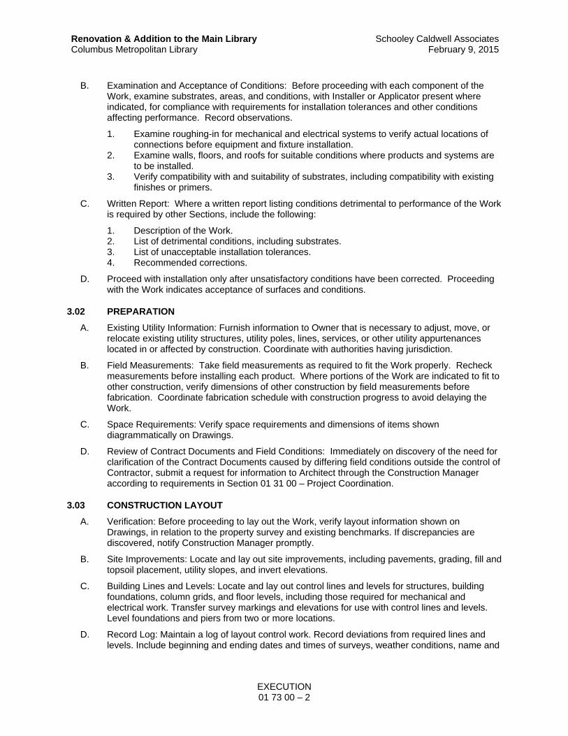
EXECUTION 01 73 00 – 2
Renovation & Addition to the Main Library Columbus Metropolitan Library
Schooley Caldwell AssociatesFebruary 9, 2015
B. Examination and Acceptance of Conditions: Before proceeding with each component of the Work, examine substrates, areas, and conditions, with Installer or Applicator present where indicated, for compliance with requirements for installation tolerances and other conditions affecting performance. Record observations.
1. Examine roughing-in for mechanical and electrical systems to verify actual locations of connections before equipment and fixture installation.
2. Examine walls, floors, and roofs for suitable conditions where products and systems are to be installed.
3. Verify compatibility with and suitability of substrates, including compatibility with existing finishes or primers.
C. Written Report: Where a written report listing conditions detrimental to performance of the Work is required by other Sections, include the following:
1. Description of the Work. 2. List of detrimental conditions, including substrates. 3. List of unacceptable installation tolerances. 4. Recommended corrections.
D. Proceed with installation only after unsatisfactory conditions have been corrected. Proceeding with the Work indicates acceptance of surfaces and conditions.
3.02 PREPARATION
A. Existing Utility Information: Furnish information to Owner that is necessary to adjust, move, or relocate existing utility structures, utility poles, lines, services, or other utility appurtenances located in or affected by construction. Coordinate with authorities having jurisdiction.
B. Field Measurements: Take field measurements as required to fit the Work properly. Recheck measurements before installing each product. Where portions of the Work are indicated to fit to other construction, verify dimensions of other construction by field measurements before fabrication. Coordinate fabrication schedule with construction progress to avoid delaying the Work.
C. Space Requirements: Verify space requirements and dimensions of items shown diagrammatically on Drawings.
D. Review of Contract Documents and Field Conditions: Immediately on discovery of the need for clarification of the Contract Documents caused by differing field conditions outside the control of Contractor, submit a request for information to Architect through the Construction Manager according to requirements in Section 01 31 00 – Project Coordination.
3.03 CONSTRUCTION LAYOUT
A. Verification: Before proceeding to lay out the Work, verify layout information shown on Drawings, in relation to the property survey and existing benchmarks. If discrepancies are discovered, notify Construction Manager promptly.
B. Site Improvements: Locate and lay out site improvements, including pavements, grading, fill and topsoil placement, utility slopes, and invert elevations.
C. Building Lines and Levels: Locate and lay out control lines and levels for structures, building foundations, column grids, and floor levels, including those required for mechanical and electrical work. Transfer survey markings and elevations for use with control lines and levels. Level foundations and piers from two or more locations.
D. Record Log: Maintain a log of layout control work. Record deviations from required lines and levels. Include beginning and ending dates and times of surveys, weather conditions, name and

EXECUTION 01 73 00 – 3
Renovation & Addition to the Main Library Columbus Metropolitan Library
Schooley Caldwell AssociatesFebruary 9, 2015
duty of each survey party member, and types of instruments and tapes used. Make the log available for reference by Architect and Construction Manager.
3.04 FIELD ENGINEERING
A. Contractor shall engage the services of a land surveyor if required to lay out the Work using accepted surveying practices.
1. Establish benchmarks and control points to set lines and levels at each story of construction and elsewhere as needed to locate each element of Project.
2. Establish limits on use of Project site. 3. Establish dimensions within tolerances indicated. Do not scale Drawings to obtain
required dimensions. 4. Inform installers of lines and levels to which they must comply. 5. Check the location, level and plumb, of major elements as the Work progresses. 6. Notify Architect and Construction Manager when deviations from required lines and levels
exceed allowable tolerances. 7. Close site surveys with an error of closure equal to or less than the standard established
by authorities having jurisdiction.
B. Identification: Owner will identify existing benchmarks, control points, and property corners. The General Contractor shall verify locations by survey before commencing work.
C. Reference Points: Locate existing permanent benchmarks, control points, and similar reference points before beginning the Work. Preserve and protect permanent benchmarks and control points during construction operations.
1. Do not change or relocate existing benchmarks or control points without prior written approval of Construction Manager. Report lost or destroyed permanent benchmarks or control points promptly.
2. Report the need to relocate permanent benchmarks or control points to Construction Manager before proceeding.
3. Replace lost or destroyed permanent benchmarks and control points promptly. Base replacements on the original survey control points.
D. Benchmarks: Establish and maintain a minimum of two permanent benchmarks on Project site, referenced to data established by survey control points. Comply with authorities having jurisdiction for type and size of benchmark.
1. Record benchmark locations, with horizontal and vertical data, on Project Record Documents.
2. Where the actual location or elevation of layout points cannot be marked, provide temporary reference points sufficient to locate the Work.
3. Remove temporary reference points when no longer needed. Restore marked construction to its original condition.
E. Certified Survey: On completion of work requiring field-engineering services, prepare a certified survey as required by authorities having jurisdiction showing dimensions, locations, angles, and elevations of construction and sitework.
3.05 INSTALLATION
A. General: Locate the Work and components of the Work accurately, in correct alignment and elevation, as indicated.
1. Make vertical work plumb and make horizontal work level. 2. Where space is limited, install components to maximize space available for maintenance
and ease of removal for replacement. 3. Conceal pipes, ducts, and wiring in finished areas, unless otherwise indicated.

EXECUTION 01 73 00 – 4
Renovation & Addition to the Main Library Columbus Metropolitan Library
Schooley Caldwell AssociatesFebruary 9, 2015
B. Comply with manufacturer's written instructions and recommendations for installing products in applications indicated.
C. Install products at the time and under conditions that will ensure the best possible results. Maintain conditions required for product performance until Substantial Completion.
D. Conduct construction operations so no part of the Work is subjected to damaging operations or loading in excess of that expected during normal conditions of occupancy.
E. Sequence the Work and allow adequate clearances to accommodate movement of construction items on site and placement in permanent locations.
F. Tools and Equipment: Do not use tools or equipment that produce harmful noise levels.
G. Templates: Obtain and distribute to the parties involved templates for work specified to be factory prepared and field installed. Check Shop Drawings of other work to confirm that adequate provisions are made for locating and installing products to comply with indicated requirements.
H. Attachment: Provide blocking and attachment plates and anchors and fasteners of adequate size and number to securely anchor each component in place, accurately located and aligned with other portions of the Work. Where size and type of attachments are not indicated, verify size and type required for load conditions.
1. Mounting Heights: Where mounting heights are not indicated, mount components at heights directed by Architect.
2. Allow for building movement, including thermal expansion and contraction. 3. Coordinate installation of anchorages. Furnish setting drawings, templates, and directions
for installing anchorages, including sleeves, concrete inserts, anchor bolts, and items with integral anchors, that are to be embedded in concrete or masonry. Deliver such items to Project site in time for installation.
I. Joints: Make joints of uniform width. Where joint locations in exposed work are not indicated, arrange joints for the best visual effect. Fit exposed connections together to form hairline joints.
J. Hazardous Materials: Use products, cleaners, and installation materials that are not considered hazardous.
3.06 STARTING AND ADJUSTING
A. Start equipment and operating components to confirm proper operation. Remove malfunctioning units, replace with new units, and retest.
B. Adjust equipment for proper operation. Adjust operating components for proper operation without binding.
C. Test each piece of equipment to verify proper operation. Test and adjust controls and safeties. Replace damaged and malfunctioning controls and equipment.
D. Manufacturer's Field Service: If a factory-authorized service representative is required to inspect field-assembled components and equipment installation, comply with qualification requirements in Section 01 45 00 – Quality Control.
3.07 PROTECTION OF INSTALLED CONSTRUCTION
A. Provide final protection and maintain conditions that ensure installed Work is without damage or deterioration at time of Substantial Completion.
B. Comply with manufacturer's written instructions for temperature and relative humidity.

EXECUTION 01 73 00 – 5
Renovation & Addition to the Main Library Columbus Metropolitan Library
Schooley Caldwell AssociatesFebruary 9, 2015
3.08 CORRECTION OF THE WORK
A. Repair or remove and replace defective construction. Restore damaged substrates and finishes. Comply with requirements in Section 01 73 29 – Cutting and Patching.
1. Repairing includes replacing defective parts, refinishing damaged surfaces, touching up with matching materials, and properly adjusting operating equipment.
B. Restore permanent facilities used during construction to their specified condition.
C. Remove and replace damaged surfaces that are exposed to view if surfaces cannot be repaired without visible evidence of repair.
D. Repair components that do not operate properly. Remove and replace operating components that cannot be repaired.
E. Remove and replace chipped, scratched, and broken glass or reflective surfaces.
END OF SECTION


CUTTING AND PATCHING 01 73 29 – 1
Renovation & Addition to the Main Library Columbus Metropolitan Library
Schooley Caldwell AssociatesFebruary 9, 2015
SECTION 01 73 29
CUTTING AND PATCHING
PART 1 – GENERAL
1.01 SUMMARY
A. Section includes requirements and limitations for cutting, demolition, removal work, patching and restoration of work as necessary to accomplish and complete all work under the Contract, including relocation or reuse of existing materials, equipment, systems, or other work, as well as the disposition of salvaged materials or debris.
1. This Section applies to all work under the Contract, including general construction, mechanical and electrical work.
B. Related Sections:
1. Drawings and general provisions of the Contract, including General and Special Conditions and other Division 01 Specification Sections, apply to this Section.
2. Section 01 33 00 – Submittal Procedures. 3. Divisions 3 through 50 Sections for specific requirements and limitations applicable to
cutting and patching individual parts of the Work.
1.02 DEFINITIONS
A. "Cutting and patching" includes cutting into existing construction to provide for the installation or performance of other work and subsequent fitting and patching required to restore surfaces to their original condition.
1. "Cutting and patching" is performed for coordination of the Work, to uncover work for access or inspection, to obtain samples for testing, to permit alterations to be performed or for other similar purposes.
a. Cutting and patching performed during the manufacturer of products, or during the initial fabrication, erection or installation processes is not considered to be "cutting and patching" under this definition. Drilling of holes to install fasteners and similar operations are also not considered to be "cutting and patching."
2. "Selective Demolition" is a related but separate category of work which may or may not require cutting and patching required in this section; refer to individual specification sections.
1.03 SUBMITTALS
A. Procedural Proposal for Cutting and Patching: Prior approval of cutting and patching is required for work which is not identified or inferred from the Contract Documents; therefore, submit proposed procedures for this work well in advance of the time work will be performed and request approval to proceed. Include the following information, as applicable, in the submittal.
1. Describe nature of the work and how it is to be performed, indicating why cutting and patching cannot be avoided. Describe anticipated results of the work in terms of changes to existing work, including structural, operational and visual changes as well as other significant elements.
2. List products, equipment, and techniques to be used and firms that will perform work. 3. Give a schedule of dates when work is expected to be performed. 4. List products, equipment, and techniques to be used and firms that will perform work. 5. Where cutting and patching of structural work involves the addition of reinforcement it
shall be integrated with original structure to satisfy requirements.

CUTTING AND PATCHING 01 73 29 – 2
Renovation & Addition to the Main Library Columbus Metropolitan Library
Schooley Caldwell AssociatesFebruary 9, 2015
6. Approval by the Construction Manager to proceed with cutting and patching work does not waive the Construction Manager’s right to later require complete removal and replacement of work found to be cut and patched in an unsatisfactory manner.
7. Furnish protection from dust and noise to occupied areas. 8. Furnish adequate collection and removal of water for concrete cutting and coring.
1.04 QUALITY ASSURANCE
A. Before cutting and patching decorative finish material to remain in the work, obtain the Construction Manager’s approval to proceed. Review cut and patch procedures involved in the work with the Construction Manager prior to start of such work.
B. Do not cut and patch operational elements or safety related components in a manner that would result in a reduction of their capacity to perform in the manner intended, included energy performance, or that would result in increased maintenance, or decreased operational life or decreased safety.
C. Cut and patch in a manner that is compatible with the building’s aesthetic qualities. Do not cut and patch work in a manner that would result in substantial visual evidence of cut and patch work. Review cut and patch procedures involved in the work with the Architect prior to start of such work. Remove and replace construction that has been cut and patched in a visually unsatisfactory manner.
D. Structural Elements: Do not cut and patch structural elements in a manner that could change their load-carrying capacity or load-deflection ratio.
E. Operational Elements: Do not cut and patch operating elements and related components in a manner that results in reducing their capacity to perform as intended or which results in increased maintenance or decreased operational life or safety.
F. Miscellaneous Elements: Do not cut and patch the following elements or related components in a manner that could change their load-carrying capacity, that results in reducing their capacity to perform as intended, or that results in increased maintenance or decreased operational life or safety.
1. Water, moisture, or vapor barriers. 2. Membranes and flashings. 3. Equipment supports. 4. Piping, ductwork, vessels, and equipment. 5. Noise- and vibration-control elements and systems.
1.05 COORDINATION
A. Provide cutting of existing construction for the installation of the work, to uncover work for access or inspection, for coordination with other work, or for similar purposes, and provide for patching required to restore surfaces to original or modified condition.
B. Contractor is responsible for the coordination of the cutting and patching required for installation of the work of all trades, except as otherwise shown on the drawings.
C. Coordinate the location and size of openings required for the work of all trades.
D. Coordinate the locations and installation of sleeves and supporting devices to be installed in the construction for the installation of the work of all trades.

CUTTING AND PATCHING 01 73 29 – 3
Renovation & Addition to the Main Library Columbus Metropolitan Library
Schooley Caldwell AssociatesFebruary 9, 2015
PART 2 – PRODUCTS
2.01 MATERIALS
A. Provide same products or types of construction as that in existing structure, as needed to patch, extend, or match existing work. Generally, Contract Documents do not define product or standards of workmanship present in existing construction; Contractor shall determine products by inspection and necessary testing and workmanship by use of the existing as a sample for comparison.
B. Materials for patching shall match existing adjacent surfaces to the fullest extent possible with regard to visual effect and installed performance characteristics.
C. Presence of a product, finish, or type of construction, required that patching extending, or matching shall be performed as necessary to make work complete and result in equal or better standards of quality.
PART 3 – EXECUTION
3.01 INSPECTION
A. Before cutting existing surfaces, examine the surfaces to be cut and patched and the conditions under which the work is to be performed. If unsafe or otherwise unsatisfactory conditions are encountered, take corrective action before proceeding with the work.
B. Before the start of cutting work, coordinate layout of the work and resolve potential conflicts before proceeding.
1. Compatibility: Before patching, verify compatibility with and suitability of substrates, including compatibility with existing finishes or primers.
2. Proceed with installation only after unsafe or unsatisfactory conditions have been corrected.
3.02 PREPARATION
A. Temporary Support: Provide temporary support to ensure structural integrity of affected portions of Work.
1. Provide devices and methods to protect other portions of Project from damage. 2. Provide materials and control operations to prevent spread of dust in surrounding area.
Provide drop cloths or other suitable barriers.
B. Protect in place construction during cutting and patching to prevent damage. Provide protection from adverse weather conditions for that part of the project that may be exposed during cutting and patching operations.
C. Take precautions not to cut existing pipe scheduled to be removed or relocated until provisions have been made to bypass them.
3.03 CUTTING REQUIREMENTS
A. Perform cutting and removal of existing construction to provide for installation of other components or performance of other construction activities and the subsequent fitting and patching required to restore surfaces to their original condition.
B. Employ skilled workmen capable of matching existing quality of existing construction to perform cutting and patching work. Proceed with cutting and patching at the earliest feasible time and complete work without delay.

CUTTING AND PATCHING 01 73 29 – 4
Renovation & Addition to the Main Library Columbus Metropolitan Library
Schooley Caldwell AssociatesFebruary 9, 2015
C. Cut, fit and patch, including excavation and backfill, to complete Work and to:
1. Fit several parts together, to integrate with other work. 2. Uncover portions of work to provide for installation of ill-timed work. 3. Remove and replace defective work. 4. Remove and replace work not conforming to requirements of Contract Documents. 5. Remove samples of installed work as necessary for testing. 6. Provide openings in elements of work for penetrations of plumbing, mechanical, and
electrical work. 7. Uncover work to allow for Architect’s observation of covered work which has been
covered up prior to required observation by Architect.
D. Perform cutting and removal work to remove minimum materials and surfaces necessary using methods that are least likely to damage elements to be retained. Protect adjoining finishes to remain from damage.
1. In general, where cutting is required, use hand or small power tools designed for sawing or grinding, not hammering and chopping. Cut through masonry using a cutting machine such as a carborundum saw or diamond core drill to ensure a neat hole. Cut finish surfaces such as masonry, clay tiles or metals using methods to terminate surfaces in a straight line at a natural point of division. Cut holes and slots neatly to size required with minimum disturbance of adjacent surfaces. To avoid marring existing finished surfaces, cut or drill from the exposed or finished side into concealed surfaces. Temporarily cover openings when not in use.
2. By-pass utility services such as pipe, before cutting, where such utility services are shown or required to be removed, relocated or abandoned. Cut off pipe in walls or partitions to be removed. After by-pass and cutting; cap, valve or plug and seal tight remaining portion of pipe and conduit to prevent entrance of moisture or other foreign matter.
3. Remove existing construction as noted or required to be removed in order to accommodate new work.
3.04 PATCHING REQUIREMENTS
A. Patch or otherwise restore disturbed existing construction to restore the work and surfaces. Patching or restoration shall be carried to natural breaks (i.e., corners) wherever possible. Where existing construction is removed, cut or otherwise disturbed by Work of the Project, patch defective and incomplete surfaces. Repair any damage to existing construction which is to remain.
B. Patching work shall be done by skilled mechanics experienced in the particular type of work involved. Patching work shall conform to the standards of the Specifications where applicable and where not specified, work shall conform to the highest standards of the trade.
C. Patch with durable seams that are as invisible as possible. Comply with specified tolerances for the work.
1. Patch construction by filling, repairing, refinishing, closing up, and similar operations following performance of other Work.
2. Inspect and test patched areas to verify integrity of the installation. 3. Restore surfaces and conditions exposed by removal of existing equipment, features and
items, i.e., holes, recesses, interruption of continuity of finishes, etc. 4. Exterior Building Enclosure: Patch components in a manner that restores enclosure to a
weathertight condition.
D. Restoration: Restore exposed finishes of patched areas to match existing and where necessary extend finish restoration into retained adjoining surfaces in manner which will eliminate evidence of patching. Thoroughly clean surfaces prior to application of paint and other finishes.

CUTTING AND PATCHING 01 73 29 – 5
Renovation & Addition to the Main Library Columbus Metropolitan Library
Schooley Caldwell AssociatesFebruary 9, 2015
1. Where patching occurs in previously painted surface, provide appropriate prime coat followed by first finish coat of paint. Provide final finish coat over entire area containing patch; for continuous surface extend to nearest vertical break or intersection, for an assembly refinish entire unit. Except where indicated otherwise, finish in sheen and color is to match existing.
3.05 CLEANING
A. Thoroughly clean areas and spaces where cutting and patching work is performed or used as access to work. Completely remove mortar, debris, oils, putty and items of similar nature. Thoroughly clean piping, conduit and similar features before painting or other finishing is applied. Restore damaged pipe covering to its original condition.
END OF SECTION


CONSTRUCTION WASTE MANAGEMENT AND DISPOSAL 01 74 19 – 1
Renovation & Addition to the Main Library Columbus Metropolitan Library
Schooley Caldwell AssociatesFebruary 9, 2015
SECTION 01 74 19
CONSTRUCTION WASTE MANAGEMENT AND DISPOSAL
PART 1 – GENERAL
1.01 SUMMARY
A. Work of this Section includes a complete program for implementation of waste management controls and systems for the duration of the Work.
B. Related Sections:
1. Drawings and general provisions of the Contract, including General and Special Conditions and other Division 01 Specification Sections, apply to this Section.
1.02 DEFINITIONS
A. Waste: For the purpose of this section, the term applies to all excess building materials. Waste includes materials that can be salvaged, returned, recycled, or reused.
B. Trash (or Garbage): That part of the waste that cannot be returned, reused, recycled, or salvaged.
C. Construction, Demolition, and Land-clearing Waste (CDL): All non-hazardous solid wastes resulting from construction, demolition, and land-clearing activities. CDL waste includes, but is not limited to, building materials, demolition rubble, landscaping materials, soils, packaging materials, debris, and trash.
D. Proper Disposal: As defined by the jurisdiction receiving the waste.
E. Landfill: Public or private business involved in the practice of trash disposal.
F. Hazardous Waste: Any material or byproduct of construction that is regulated by AHJ and that may not be disposed in landfill or other waste end-source without adherence to applicable laws.
G. Material Recovery Facility (MRF): A general term used to describe a waste-sorting facility. Mechanical, hand-separation, or a combination of both procedures are used to recover recyclable materials from other waste, which is then disposed of as trash.
H. Recycling: The collection, reprocessing, marketing and use of materials that were recovered from the solid waste stream and diverted from landfill disposal or incineration. Recyclable materials include, but are not limited to, the following:
1. Metals: Ferrous (iron, steel, stainless steel, galvanized steel) and nonferrous (copper, brass, bronze, aluminum) types and containers made from metals such as pails, buckets and beverage cans.
2. Asphaltic concrete paving. 3. Concrete. 4. Gypsum wallboard. 5. Paper products such as generated from field office activities and clean corrugated
packaging cardboard. 6. Wood products, including untreated dimensional lumber, plywood, oriented strand
board, hardboard, particleboard and crates and pallets made from wood products. 7. Brick and stone masonry. 8. Carpet and padding. 9. Plastics and containers made from plastics such as pails, buckets, and beverage
bottles. 10. Wire and cable.

CONSTRUCTION WASTE MANAGEMENT AND DISPOSAL 01 74 19 – 2
Renovation & Addition to the Main Library Columbus Metropolitan Library
Schooley Caldwell AssociatesFebruary 9, 2015
11. Glass: Glass beverage containers, window and mirror glass 12. Clean and uncontaminated, excavated soils not intended for other on-site use. 13. Stumps, trees, and green materials removed as a part of land clearing operations.
I. Recycling Facility: An operation that can legally accept materials for the purpose of processing the materials into an altered form for the manufacture of a new product. Recycling facilities have their own specifications for accepting materials. Depending on the type of facility, it may accept source-separated waste or co-mingled waste or both.
J. Recycling Services. Types of services include:
1. Source-Separated: Construction waste is sorted on the job-site in separate containers as it is generated. The recycling hauler takes the materials directly to a recycler or a transfer site.
2. Co-mingled: This service allows contractors to put select recyclables such as wood, cardboard, and metals in one container. The recycling hauler takes the materials to a sorting facility where the materials are separated for recycling.
3. Reuse or Salvage: A products that could have been disposed of as solid waste, having completed its life cycle as a consumer item, but otherwise is refurbished for reuse without substantial alteration of its form. Examples of refurbished products include repaired office furniture and reconditioned carpet.
K. Source-Separated Materials: Materials that are sorted at the site for the purpose of reuse or recycling.
L. Co-mingled Materials: Mixed recyclable CDL material that has not been source-separated. Some facilities will separate co-mingled materials off-site for recycling.
M. Waste Reduction: Construction practices that achieve the most efficient use of resources and materials; uses water efficiently; avoids practices such as over-packaging, improper storage, ordering errors, poor planning, breakage, mishandling and contamination.
N. Non-Recyclable Materials: Construction and demolition materials not capable of being reused or processed for recycling, exclusive of the recyclable materials listed above.
1.03 INTENT
A. General Intent:
1. The Owner has established that this Project shall generate the least amount of waste practical and that processes that ensure the generation of as little waste as possible due to error, poor planning, breakage, mishandling, contamination, or other factors shall be employed.
2. Of the waste that is generated, as much of the waste materials as is economically feasible shall be reused, salvaged, or recycled.
a. Waste disposal in landfills shall be minimized to the greatest extent practical.
3. With regard to these goals the Contractor shall develop, for Owner's review, a Waste Management Plan for this Project.
4. A minimum of 75% of total Project construction waste (by weight) shall be diverted from landfill, with a target of 95%. The following waste categories are likely candidates to be included in the diversion plan for this project:
a. Concrete b. Concrete masonry units (CMU) c. Metals (e.g., banding, stud trim, ductwork, piping, rebar, roofing, other trim,
steel, iron, galvanized, stainless steel, aluminum, copper, zinc, brass, bronze) d. Cardboard, packaging e. Clean dimensional wood

CONSTRUCTION WASTE MANAGEMENT AND DISPOSAL 01 74 19 – 3
Renovation & Addition to the Main Library Columbus Metropolitan Library
Schooley Caldwell AssociatesFebruary 9, 2015
f. Drywall g. Carpet and pad
B. As part of the bid submittal, the Contractor shall develop and submit to the Owner for review a draft Construction Waste Management Plan (CWMP).
1. The CWMP shall include:
a. Types and estimated quantities (where reasonably available) of salvageable materials that are expected to be generated during demolition. Calculations may be based on dry weight or volume, but must be consistent throughout.
b. The method to be used to recycle these materials. Methods shall include one or more of the following options: contracting with a demolition specialist to salvage all or most of materials generated, selective salvage as part of demolition contractor’s work, or reuse of materials on-site or in new construction. Use the recycling rates and list of material accepted provided by Miami Department of Solid Waste Management to determine which waste materials on this project will be source-separated or co- mingled in each construction phase.
c. Types and estimated quantities (where reasonably available) of recyclable materials expected to be generated during construction in significant amounts including but not limited to wood, concrete, metals, cardboard, and drywall. Calculations may be based on weight or volume, but must be consistent throughout.
d. The method to be used to recycle these materials. Methods shall include one or more of the following options:
1) Requiring subcontractors to take materials back for recycling at a permitted facility
2) Contracting with a full service recycling service to recycle all or most materials at a permitted facility
3) Processing or reusing materials on-site.
2. At a minimum, the Construction Waste Management Plan shall be designed to divert the following construction waste categories from the landfill:
a. Concrete and concrete masonry units (CMU’s) b. Masonry c. Excavated soils d. Gypsum drywall (clean, unpainted) e. Roofing f. Insulation g. Unused (leftover) paint h. Piping i. Electrical conduit j. Window glass k. Wood (clean, unpainted, untreated wood scrap including pallets and engineered
wood) l. Job-shack wastes, including office paper, blueprints, cans and bottles, and office
cardboard. m. Packaging: Regardless of salvage/recycle goals for the project, salvage or
recycle 100 percent of the following uncontaminated packaging materials:
1) Paper 2) Cardboard 3) Boxes 4) Plastic sheet and film 5) Polystyrene packaging

CONSTRUCTION WASTE MANAGEMENT AND DISPOSAL 01 74 19 – 4
Renovation & Addition to the Main Library Columbus Metropolitan Library
Schooley Caldwell AssociatesFebruary 9, 2015
6) Wood crates 7) Plastic pails
3. At a minimum, the Construction Waste Management Plan shall be designed to divert the following demolition waste categories from the landfill:
a. Paving, concrete, and masonry:
1) Asphaltic concrete paving 2) Concrete 3) Brick
b. Concrete masonry units c. Metals:
1) Structural and miscellaneous steel 2) Rough hardware 3) Concrete reinforcing steel 4) Metal studs 5) Door hardware
d. Wood and wood products:
1) Wood studs 2) Wood joists 3) Plywood and oriented strand board 4) Wood paneling 5) Wood trim
e. Roofing f. Insulation g. Doors and frames h. Windows i. Glazing j. Gypsum board k. Demountable partitions l. Equipment m. Cabinets n. Mechanical:
1) Piping 2) Supports and hangers 3) Valves 4) Sprinklers 5) Mechanical equipment 6) Refrigerants 7) Plumbing fixtures
o. Electrical:
1) Electrical conduit 2) Copper wiring 3) Lighting fixtures 4) Fluorescent tubes and ballasts (if not recycled, designate as hazardous
waste) 5) Lamps 6) Electrical devices 7) Switchgear and panelboards 8) Transformers
CONSTRUCTION WASTE MANAGEMENT AND DISPOSAL 01 74 19 – 5
Renovation & Addition to the Main Library Columbus Metropolitan Library
Schooley Caldwell AssociatesFebruary 9, 2015
4. The Construction Waste Management Plan shall include process and methods for reclamation of the following:
a. Acoustical ceiling tiles b. Carpet and carpet pad
C. Final Construction Waste Management Plan. Within 14 days after Owner has determined that the recycling options addressed in the draft Construction Waste Management Plan are acceptable and prior to waste removal, submit the final Construction Waste Management Plan.
D. Waste Reduction Progress Reports: Concurrent with each Application for Payment, submit four copies of report. Include separate reports for demolition waste, construction waste, and reclaimed materials. Include the following information:
1. Material category 2. Generation point of waste 3. Total quantity of waste in tons 4. Quantity of waste salvaged, both estimated and actual in tons 5. Quantity of waste recycled, both estimated and actual in tons 6. Total quantity of waste recovered (salvaged plus recycled) in tons 7. Total quantity of waste recovered (salvaged plus recycled) as a percentage of total
waste 8. Include up-to-date records of donations, sales, recycling and landfill/incinerator
manifests, weight tickets, hauling receipts, and invoices. 9. The Contractor shall be responsible for providing such information whether directly
involved in recycling the materials or not (whether the Contractor performs recycling tasks or hires or requires others to do so, such as subcontractors to haul their own drywall or metal).
E. Waste Reduction Calculations: Before request for Substantial Completion, submit calculated end-of-project rates for salvage, recycling, and disposal as a percentage of total waste generated by the Work in a form acceptable to the Construction Manager.
1. Records of Donations: Indicate receipt and acceptance of salvageable waste donated to individuals and organizations. Indicate whether organization is tax-exempt.
2. Records of Sales: Indicate receipt and acceptance of salvageable waste sold to individuals and organizations. Indicate whether organization is tax-exempt.
3. Recycling and Processing Facility Records: Indicate receipt and acceptance of recyclable waste by recycling and processing facilities licensed to accept them. Include
4. Landfill and Incinerator Disposal Records: Indicate receipt and acceptance of waste by landfills (or transfer stations) and incinerator facilities licensed to accept them. Include manifests, weight tickets, receipts, and invoices.
1.04 QUALITY ASSURANCE
A. Waste Management Meetings: Conduct an initial conference at Project Site to comply with requirements in Section 01 31 00 – Project Coordination. Contractor shall include discussions on construction waste management requirements in the preconstruction meeting. Contractor shall include discussions on construction waste management requirements in the regular job meetings conducted during the course of the Project; at these meetings, review methods and procedures related to waste management including, but not limited to, the following:
1. Review and discuss waste management plan including responsibilities of the Waste Management Coordinator.
2. Review requirements for documenting quantities of each type of waste and its disposition.

CONSTRUCTION WASTE MANAGEMENT AND DISPOSAL 01 74 19 – 6
Renovation & Addition to the Main Library Columbus Metropolitan Library
Schooley Caldwell AssociatesFebruary 9, 2015
3. Review and finalize procedures for materials separation and verify availability of containers and bins needed to avoid delays.
4. Review procedures for periodic waste collection and transportation to recycling and disposal facilities.
5. Review waste management requirements for each trade.
B. Construction Waste Management and Recycling: Prepare a Solid Waste Management and Recycling Plan that minimizes waste and diverts construction and demolition materials from landfills and incinerators by facilitating their reuse or recycling.
1. Name the solid waste material and recycling processors who will accept the construction and demolition materials, the condition of the construction and demolition materials required by the solid waste material and recycling processors, the method proposed to provide the construction and demolition materials in suitable condition and in a quantity acceptable to the disposal sites and solid waste material and recycling processors that will receive them, and any impact on the Project Schedule.
2. Contractor is responsible for implementation of each special program involving rebates or similar incentives related to the recycling of waste.
a. Revenues or other savings obtained from sale, reuse, and recycling operations will accrue to the Contractor.
C. Disposal Sites and Solid Waste Material Recycling Processors: Use only facilities that can legally accept construction and demolition material for disposal, recycling and waste processing issued by the jurisdictions in which they are located.
D. Pre-Construction Meeting: Prior to beginning site preparation, schedule and conduct a meeting to review the Contractor’s Waste Management and Recycling Plan.
1. Meeting shall include the Contractor, the Architect of Record, the Construction Manager, and each subcontractor or supplier whose work will interface with the program.
2. Agenda shall include a discussion of procedures, schedules and specific requirements for construction and demolition materials, sale, reuse, recycling, and disposal.
3. Make revisions to the Plan that are agreed to as a result of the meeting and submit the revised Plan and the meeting minutes to the Owner for his record.
1.05 REVENUES
A. Revenues or other savings obtained from recycled, reused, or salvaged materials shall accrue to Contractor unless otherwise noted in the Contract Documents.
PART 2 – PRODUCTS
Not Used
PART 3 – EXECUTION
3.01 COMMUNICATION
A. Designate an on-site party (or parties) responsible for instructing workers and overseeing and documenting results of the Construction Waste Management Plan for the Project.
B. Distribute copies of the Construction Waste Management Plan to each entity performing work at the site.
C. Use safety meetings, signage, and subcontractor agreements to communicate the goals of the waste reduction plan, including instruction about appropriate separation, handling separation,

CONSTRUCTION WASTE MANAGEMENT AND DISPOSAL 01 74 19 – 7
Renovation & Addition to the Main Library Columbus Metropolitan Library
Schooley Caldwell AssociatesFebruary 9, 2015
handling, and recycling, salvage, reuse and return methods to be used by all parties at the appropriate stages of the Project.
3.02 MATERIALS CONSERVATION
A. Include in supply agreements a waste reduction provision specifying a preference for reduced, returnable, and/or recyclable packaging.
B. Use detailed take-offs and use to identify location and use in structure to reduce risk of unplanned and potentially wasteful cuts.
3.03 RECYCLING
A. Metal, including but not limited to aluminum stairs, structural beams and sections, and reinforcing steel shall be recycled.
B. Wood that is not painted and does not contain preservatives (i.e. creosote, arsenic, and chromium-containing preservatives) shall be segregated and recycled.
C. Trees and brush removed during the demolition shall be chipped and stockpiled on-site and cut for firewood and lumber and removed from the site.
3.04 MATERIALS HANDLING
A. Designate specific area(s) to facilitate separation of materials for potential recycling, salvage, reuse and return. Maintain recycling and waste bin areas clean and clearly marked to avoid co- mingling of materials. Bins shall be protected during non-working hours from off-site contamination.
1. Separate recycling waste in accordance with requirements of recycling facility/hauler.
B. Protect materials to be recycled or reused from contamination. Handle, store, and transport materials in a manner that meets the requirements of the designated acceptance facility.
C. Separately store and dispose of hazardous wastes according to local regulations.
D. As part of regular clean-up, schedule and conduct visual inspections of dumpsters and recycling bins to identify potential contamination of materials.
3.05 WASTE MANAGEMENT PLAN IMPLEMENTATION
A. General: For the duration of the Work, implement and maintain construction waste management and recycling. During the prosecution of the Work encourage the practice of efficient waste reduction when sizing, cutting, and installing products and materials.
1. Distribution: Distribute copies of the Solid Waste Management and Recycling Plan to the Job Site Foreman, each Subcontractor, the Construction Manager and the Architect.
2. Contractor shall be responsible for instructing workers and overseeing and documenting results of the Waste Management Plan for the Project.
3. Hazardous Wastes: Existing hazardous wastes are to have been removed prior to the start of demolition.
a. Contractor furnished hazardous construction waste and unforeseen hazardous wastes shall be separated, stored, and disposed of according to local regulations of authorities having jurisdiction, and as directed by the Owner.
B. Transportation: Arrange for the regular collection, transport from the site, and delivery of the construction wastes and materials to the designated recyclers, and waste material processors and disposal sites, using waste haulers that are permitted by local authorities to transport construction and demolition materials.

CONSTRUCTION WASTE MANAGEMENT AND DISPOSAL 01 74 19 – 8
Renovation & Addition to the Main Library Columbus Metropolitan Library
Schooley Caldwell AssociatesFebruary 9, 2015
C. Separation Facilities: Provide on-site instruction of appropriate separation, handling separation, handling, and recycling, salvage, reuse and return methods to be used by each party at the appropriate stages of the Work.
1. Provide and designate an area for the separation of construction and demolition materials for reuse and recycling.
a. Locate the area so that non-recyclable materials will not contaminate materials to be reused or recycled.
2. Provide containers and bins in the designated area to facilitate separation, storage and handling which are clearly and appropriately marked.
3. Cut all items to lengths and sizes to fit within the containers or bins provided. 4. Where there is sufficient quantity of a specific recyclable materials type (for example;
salvaged metal doors and frames or duct work), make arrangements for items to be bundled, banded or tied, and stack in a designated location for a special pick-up.
5. Maintain the separation facilities in an orderly condition to prevent contamination of materials placed therein and to maximize reuse and recyclability of materials.
6. Separate construction and demolition materials at the project site by one of the following methods:
a. Source Separated Method: Construction and demolition materials, that are reusable and recyclable, are separated from non-recyclable materials and sorted into appropriately marked separated containers or bins and then transported to the designated recycling facility for further processing. Non-recyclable materials are transported to a landfill or incinerator. Mark recycling containers in Spanish, English, and other languages as required.
b. Co-Mingled Method: All construction and demolition materials are placed into containers or bins and then transported to a recycling facility where recyclable and salvageable materials are removed, sorted, and processed, recovered, and the remaining debris is transported to a landfill or incinerator.
END OF SECTION

PROJECT CLOSEOUT 01 78 00 – 1
Renovation & Addition to the Main Library Columbus Metropolitan Library
Schooley Caldwell AssociatesFebruary 9, 2015
SECTION 01 78 00
PROJECT CLOSEOUT
PART 1 – GENERAL
1.01 SUMMARY
A. Section includes administrative and procedural requirements for contract closeout including, but not limited to the following:
1. Inspection procedures. 2. Cleaning during construction 3. Pre-requisites to acceptance and completion 4. Operating and maintenance manual submittals 5. Warranty requirements 6. Final cleaning
B. Related Sections/Documents:
1. Drawings and general provisions of the Contract, including General and Special Conditions and other Division 01 Specification Sections, apply to this Section.
1.02 DESCRIPTION OF REQUIREMENTS
A. Definitions: Closeout is hereby defined to include general requirements near end of Contract Time, in preparation for final acceptance, final payment, normal termination of contract, occupancy by Owner and similar actions evidencing completion of the Work.
1. Specified requirements for individual units of Work are specified in sections of Division 01 through 50.
2. Time of closeout is directly related to "Substantial Completion," and therefore may be either a single time period for entire Work or a series of time periods for individual parts of the Work which have been certified as substantially complete at different dates. That time variation (if any) shall be applicable to other provisions of this section.
1.03 CLEANING DURING CONSTRUCTION
A. Clean and protect construction in progress and adjoining materials in place during handling and installation. Apply protective covering where required to assure protection from damage or deterioration until Substantial Completion.
B. Deposit rubbish, scrap materials, debris, etc., in dumpsters (in a specified location). The Contractor shall be responsible for the removal from the jobsite and proper disposal of the waste materials. Absolutely no burning of debris or trash will be allowed.
C. During the progress of the work, remove all waste materials and rubbish and deposit such waste in the project dumpster. Perform daily broom cleaning in the area of the Contractor’s work. Clean and maintain completed construction as frequently as necessary through the remainder of the construction period.
1. Keep the premises free at all times from all waste materials, packaging materials and other rubbish accumulated in connection with the execution of work by collecting and depositing said materials and rubbish in locations or containers as designated by the Contractor.
2. Clean and remove from own work soiling, staining, mortar, concrete or dirt caused by the execution of work and make good additional defects resulting therefrom.

PROJECT CLOSEOUT 01 78 00 – 2
Renovation & Addition to the Main Library Columbus Metropolitan Library
Schooley Caldwell AssociatesFebruary 9, 2015
3. At the completion of portions of the Work and the entire completion of work, remove all tools, equipment, scaffolds, shanties, and surplus materials. Execute all required final cleaning.
1.04 PRE-REQUISITES TO SUBSTANTIAL COMPLETION
A. General: Prior to requesting inspection for certification of substantial completion (for either entire Work or portions thereof), complete the following and list known exceptions in request:
1. In progress payment request, coincident with or first following date claimed, show either 100 percent completion for portion of Work claimed as "substantially complete," or list incomplete items, value of incompleteness, and reasons for being incomplete.
2. Submit statement showing accounting of changes to the Contract Sum.
B. Inspection Procedures: Upon receipt of Contractor's request, Construction Manager and Architect will either proceed with inspection or advise Contractor of pre-requisites not fulfilled. Following initial inspection, Construction Manager/Architect will either prepare certificate of substantial completion, or advise Contractor of Work which must be performed prior to issuance of certificate; and repeat inspection when requested and assured that Work has been substantially completed. Results of completed inspection will form initial "punch-list" for final acceptance.
1.05 PRE-REQUISITES TO FINAL ACCEPTANCE
A. General: Prior to requesting final inspection for certification of final acceptance and final payment, as required by Contract Conditions, complete the following as applicable and list known exceptions (if any) in request:
1. Submit final payment request with final releases and supporting documentation not previously submitted and accepted. Include certificates of insurance for products and completed operations where required.
2. Submit updated final statement, accounting for additional (final) changes to Contract Sum.
3. Submit certified prevailing wage reports for entire project. 4. Submit copy of final punch-list of itemized Work to be completed or corrected, stating that
each item has been completed or otherwise resolved for acceptance, endorsed and dated by the Architect and Construction Manager.
5. Revise and submit evidence of final, continuing insurance coverage complying with insurance requirements.
6. Submit specific warranties, workmanship/maintenance bonds, maintenance agreements, final certifications and similar documents.
7. Obtain and submit releases enabling Owner's full and unrestricted use of Work and access to services and utilities, including (where required) occupancy permits, operating certificates, and similar releases.
8. Submit record drawings, maintenance manuals, and similar final record information. 9. Complete final cleaning up requirements.
B. Re-inspection procedure: Upon receipt of Contractor's notice that the Work has been completed, including punch-list items resulting from earlier inspections, and excepting incomplete items delayed because of acceptable circumstances, Construction Manager and Architect will re-inspect the Work. Upon completion of re-inspection, Construction Manager and Architect will either prepare certificate of final acceptance or advise Contractor of Work not completed or obligations not fulfilled as required for final acceptance. If necessary, procedure will be repeated.

PROJECT CLOSEOUT 01 78 00 – 3
Renovation & Addition to the Main Library Columbus Metropolitan Library
Schooley Caldwell AssociatesFebruary 9, 2015
1.06 LIST OF INCOMPLETE ITEMS (PUNCH LIST)
A. Preparation: Submit three copies of list. Include name and identification of each space and area affected by construction operations for incomplete items and items needing correction including, if necessary, areas disturbed by Contractor that are outside the limits of construction.
1. Organize list of spaces in sequential order proceeding from lowest floor to highest floor. 2. Organize items applying to each space by major element, including categories for ceiling,
individual walls, floors, equipment, and building systems. 3. Include the following information at the top of each page:
a. Project name. b. Date. c. Name of Construction Manager. d. Name of Architect. e. Name of Contractor. f. Page number.
B. Re-inspection procedure: Upon receipt of Contractor's notice that the Work has been completed, including punch-list items resulting from earlier inspections, and excepting incomplete items delayed because of acceptable circumstances, Construction Manager and Architect will re-inspect the Work. Upon completion of re-inspection, Construction Manager and Architect will either prepare certificate of final acceptance or advise Contractor of Work not completed or obligations not fulfilled as required for final acceptance. If necessary, procedure will be repeated.
1.07 OPERATING AND MAINTENANCE MANUALS
A. Each Contractor shall organize operating manual information into suitable sets of manageable size, and bind into individual binders properly identified and indexed (thumb-tabbed).
B. Submit two (2) copies to Construction Manager prior to final inspection, bound in 8-1/2 x 11 inch three D side ring capacity expansion binders with durable, hard covers. Internally subdivide the binder contents with permanent heavy-weight divider sheets, logically organized as described below; with tab titling clearly printed under reinforced laminated plastic tabs.
C. Prepare binder covers with printed title "OPERATION AND MAINTENANCE INSTRUCTIONS," title of project, and subject matter of binder when multiple binders are required.
D. Contents: Prepare a Table of Contents for each volume, with each product or system description identified, type on 24 pound white paper.
1. Fold all materials larger than 8-1/2 inches by 11 inches in accordance with accepted practice and reinforce the binding edges with vinyl or mylar tape prior to punching.
2. Reproductions shall be high quality photographic, offset, xerographic or diazo copies. Copies on plastic surfaced electrostatic materials will not be acceptable.
E. Part 1: Directory, listing names, addresses, and telephone numbers of Architect, Construction Manager, Contractor, Subcontractors, and major equipment suppliers.
F. Part 2: Operation and maintenance instructions, arranged by CSI 2014 MasterFormat specification section (Divisions 01 through 50) in chronological order, and subdivided by submittal type. Arrange each section in the following order:
Product Data Shop Drawings Schedules Color Charts Certifications

PROJECT CLOSEOUT 01 78 00 – 4
Renovation & Addition to the Main Library Columbus Metropolitan Library
Schooley Caldwell AssociatesFebruary 9, 2015
Material test reports Warranty (Other required submittals)
G. For project documentation and certification, including the following:
1. Shop drawings, product data and similar information. Include copies of the approved shop drawings, corrected to reflect changes made during construction, in each manual.
2. Certificates. 3. Photocopies of warranties and bonds.
H. In addition to the above provide the following information with equipment submittals. All information shall apply only to specific units incorporated in the work. Identify the following:
1. Common operating problems and remedies. 2. Care and preventive maintenance procedures and schedules. 3. List of equipment. 4. Complete parts list for each component. 5. Spare parts list. 6. Wiring diagrams. 7. Significant design criteria. 8. Operating and maintenance instructions for equipment and systems. 9. Supplemental drawings and diagrams to show system operation and servicing and
maintenance points. 10. Inspection procedures. 11. Maintenance instructions for special finishes, including recommended cleaning methods
and materials and special precautions identifying detrimental agents.
I. In order to assure the correctness of information in the manuals, carefully remove operating and maintenance instructions shipped with the units immediately upon receipt and assemble such instructions in a job site file. Such file shall be maintained complete and shall be available at all times for the Owner's inspection.
J. Submit one (1) copy of the Operating and Maintenance Manual ten (10) days prior to substantial completion. This copy will be returned after review by Construction Manager and Architect with their comments. Revise content of documents as noted prior to final submittal. Submit final volumes revised, within ten days after final inspection.
K. Final payment and retainage will not be released to the Contractor until all requirements stated are completed.
1.08 OPERATING AND MAINTENANCE INSTRUCTIONS/MATERIALS
A. Operation and Maintenance Instructions: Arrange for each Installer of equipment that requires regular maintenance to meet with the Owner’s personnel to provide instruction in proper operation and maintenance. Provide instruction by manufacturer's representatives if installers are not experienced in operation and maintenance procedures. Include a detailed review of the following items:
1. Maintenance manuals. 2. Record documents. 3. Spare parts and materials. 4. Tools. 5. Lubricants. 6. Fuels. 7. Identification systems. 8. Control sequences. 9. Hazards. 10. Cleaning.

PROJECT CLOSEOUT 01 78 00 – 5
Renovation & Addition to the Main Library Columbus Metropolitan Library
Schooley Caldwell AssociatesFebruary 9, 2015
11. Warranties and bonds. 12. Maintenance agreements and similar continuing commitments.
B. Provide products, spare parts, maintenance and extra materials in quantities specified in individual specification Sections.
1.09 WARRANTY REQUIREMENTS
A. Refer to individual sections of Divisions 02 through 50 for the determination of units of Work which are required to be specifically or individually warranted, and for the specific requirements and terms of those warranties (or guarantees).
B. Manufacturer’s disclaimers and limitations on product warranties do not relieve the Contractor of the warranty on the Work that incorporates the products. Manufacturer’s disclaimers and limitations on product warranties do not relieve suppliers, manufacturers, and subcontractors required to countersign special warranties with the Contractor.
C. Related Damages and Losses: When correcting failed or damaged warranted construction, remove and replace construction that has been damaged as a result of such failure or must be removed and replaced to provide access for correction of warranted construction.
D. Reinstatement of Warranty: When work covered by a warranty has failed and been corrected by replacement or rebuilding, reinstate the warranty by written endorsement. The reinstated warranty shall be equal to the original warranty with an equitable adjustment for depreciation.
E. Replacement Cost: Upon determination that Work covered by the warranty has failed, replace or rebuild the Work to an acceptable condition complying with requirement of the Contract Documents. The Contractor is responsible for the cost of replacing or rebuilding defective work regardless of whether the Owner has benefited from use of the Work through a portion of its anticipated useful service life.
F. Owner’s Recourse: Expressed warranties made to the Owner are in addition to implied warranties and shall not limit the duties, obligations, rights, and remedies otherwise available under the law. Expressed warranty periods shall not be interpreted as limitations on the time in which the Owner can enforce such other duties, obligations. rights, or remedies.
1. The Owner reserves the right to reject warranties and to limit selection to products with warranties not in conflict with requirements of the Contract Documents.
G. When the Contract documents require a special warranty, or similar commitment on the Work or part of the Work, the Owner reserves the right to refuse to accept the Work, until the Contractor presents evidence that entities required to countersign such commitments are willing to do so.
H. Submit written warranties to the Construction Manager prior to the date for Final Completion. If the Certificate of Final completion designates a commencement date for warranties other than the date of Substantial Completion for the Work, or a designated portion of the work, submit written warranties upon request of the Construction Manager.
I. When the Contract documents require the Contractor, or the Contractor and a subcontractor, supplier or manufacturer to execute a special warranty, prepare a written document that contains appropriate terms and identification, ready for execution by the required parties. Submit a draft to the Owner, through the Construction Manager, for approval prior to final execution. Refer to Divisions 02 through 50 sections for specific content requirements and particular requirements for submitting special warranties.
J. Submit 10 days prior to completion, 2 copies of each required warranty properly executed by the Contractor, or by the Contractor, subcontractor, supplier, or manufacturer. Organize the warranty documents into and orderly sequence based on the table of contents of the Project Manual. When warranted construction requires operation and maintenance manuals provide additional copies of each required warranty, as necessary, for inclusion in each manual.

PROJECT CLOSEOUT 01 78 00 – 6
Renovation & Addition to the Main Library Columbus Metropolitan Library
Schooley Caldwell AssociatesFebruary 9, 2015
PART 2 – PRODUCTS
Not Used
PART 3 – EXECUTION
3.01 FINAL CLEANING
A. General: Special cleaning for specific units of Work is specified in sections of Divisions 01 through 50.
B. Provide final cleaning of the Work employing experienced workers or a professional cleaning company for final cleaning. Clean each surface or unit of work in the work area to the condition expected from a commercial building cleaning and maintenance program. Comply with manufacturer's specific instructions for cleaning operations for materials installed and specified herein.
C. Complete the following cleaning operations before requesting inspection for Certification of Substantial Completion for the entire Project or for a portion of the Project.
1. Clean Project Site, including landscape development areas of rubbish, waste materials, litter and foreign substances. Sweep paved areas to broom clean condition; remove stains, chemical spills, and other foreign deposits. Rake grounds which are neither planted or paved, to a smooth, even textured surface. Remove stains, spills and other foreign deposits.
2. Remove tools, construction equipment, machinery and surplus materials from the site. 3. Clean interior hard-surfaced finishes affected by the work to a dirt-free condition, free of
dust, stains, films and similar foreign substances. 4. Damp Wiping: Use a clean damp cloth or sponge to remove all dirt, spots, streaks and
smudges from walls, doors (both wood and metal), glass and other specified surfaces. When dry, the surfaces shall have a polished appearance. The wetting solution shall contain an appropriate cleaning agent.
5. Remove debris and surface dust from limited access spaces including plenums, shafts, equipment vaults, and similar spaces.
6. Remove glazing compounds and other substances that are noticeable vision-obscuring materials. Replace chipped or broken glass and other damaged transparent materials. Clean transparent materials, including mirrors and glass in doors and windows. All glass shall be clean and free of dirt, grime, streaks, excessive moisture and shall not be cloudy Polish mirrors and glass, taking care not to scratch the surfaces.
7. Metal surfaces such as hardware, frames, cover plates, shall be cleaned with a damp cloth and polished where required.
8. For all operations where furniture or equipment is moved, no chairs, waste baskets or other similar items shall be stacked on desks, tables or window sills. Upon completion of work, all furniture and equipment must be returned to its original position or as directed by the Construction Manager.
9. Remove labels that are not permanent labels. Clean all permanent labels. 10. Touch-up and otherwise repair and restore marred exposed finishes and surfaces.
Replace finishes and surfaces which cannot be satisfactorily repaired or restored, or show visible evidence or repair or restoration. Do not paint over UL and similar labels including mechanical and electrical identification plates.
11. Wipe surfaces of mechanical and electrical equipment, elevator equipment and similar equipment clean. Remove excess lubrication, paint and other foreign substances.
12. Overhead items, such as louvers, grilles, pipes, molding, etc., shall be dusted, vacuumed and spot cleaned.
13. Supply vents, exhaust grilles and room fan coil units shall be thoroughly vacuumed and cleaned.
14. Clean exposed unpainted ductwork of all foreign matter.

PROJECT CLOSEOUT 01 78 00 – 7
Renovation & Addition to the Main Library Columbus Metropolitan Library
Schooley Caldwell AssociatesFebruary 9, 2015
15. Replace disposable air filters and clean permanent air filters. Clean exposed surfaces of diffusers, registers and grilles. Clean ducts, blowers and coils if units were operated without filters during construction.
16. Light fixtures, including glass and plastic lenses, ceiling and wall-mounted lights, cover panels, side panels, louvers, fixture frames and lamps, shall be vacuumed and cleaned with a damp cloth.
17. Light fixture lamps are to function with full efficiency. Replace burned out bulbs and defective and noisy starters in fluorescent fixtures.
18. Leave Project clean and ready for occupancy.
D. At the completion of the Work, remove all tools, equipment, scaffolds, shanties, and surplus materials.
E. Removal of Protection: Remove temporary protection devices and facilities which were installed during course of the Work to protect previously completed Work during remainder of construction period.
F. Leave each area of the Project clean and ready for occupancy by the Owner. Maintain cleaning until acceptance by the Owner.
END OF SECTION


OPERATION AND MAINTENANCE DATA 01 78 23 – 1
Renovation & Addition to the Main Library Columbus Metropolitan Library
Schooley Caldwell AssociatesFebruary 9, 2015
SECTION 01 78 23
OPERATION AND MAINATENANCE DATA
PART 1 – GENERAL
1.01 SUMMARY
A. Section includes administrative and procedural requirements for preparing operation and maintenance manuals, including the following:
1. Operation manuals for systems, subsystems, and equipment. 2. Product maintenance manuals. 3. Systems and equipment maintenance manuals.
B. Related Sections/Documents:
1. Drawings and general provisions of the Contract, including General and Special Conditions and other Division 01 Specification Sections, apply to this Section.
2. Section 01 33 00 – Submittal Procedures: For submitting copies of submittals for operation and maintenance manuals.
3. Section 01 78 00 – Project Closeout 4. Divisions 02 through 50 Sections for specific operation and maintenance manual
requirements for the Work in those Sections.
1.02 DEFINITIONS
A. System: An organized collection of parts, equipment, or subsystems united by regular interaction.
B. Subsystem: A portion of a system with characteristics similar to a system.
1.03 CLOSEOUT SUBMITTALS
A. Manual Content: Operations and maintenance manual content is specified in individual specification sections to be reviewed at the time of Section submittals. Submit reviewed manual content formatted and organized as required by this Section.
1. Where applicable, clarify and update reviewed manual content to correspond to modifications and field conditions.
B. Format: Submit operations and maintenance manuals in the following format:
1. Three paper copies. Include a complete operation and maintenance directory. 2. Enclose title pages and directories in clear plastic sleeves. Architect will return two
copies.
C. Initial Manual Submittal: Submit draft copy of each manual at least 30 days before commencing demonstration and training. Construction Manager and Architect and Commissioning Agent will comment on whether general scope and content of manual are acceptable.
D. Final Manual Submittal: Submit each manual in final form prior to requesting inspection for Substantial Completion and at least 15 days before commencing demonstration and training. Construction Manager and Architect and Commissioning Agent will return copy with comments.
1. Correct or modify each manual to comply with Construction Manager and Architect's and Commissioning Agent's comments. Submit copies of each corrected manual within 15 days of receipt of Construction Manager’s and Architect's and Commissioning Agent's comments and prior to commencing demonstration and training.

OPERATION AND MAINTENANCE DATA 01 78 23 – 2
Renovation & Addition to the Main Library Columbus Metropolitan Library
Schooley Caldwell AssociatesFebruary 9, 2015
PART 2 – PRODUCTS
2.01 OPERATION AND MAINTENANCE DOCUMENTATION DIRECTORY
A. Directory: Prepare a single, comprehensive directory of emergency, operation, and maintenance data and materials, listing items and their location to facilitate ready access to desired information. Include a section in the directory for each of the following:
1. List of documents. 2. List of systems. 3. List of equipment. 4. Table of contents.
B. List of Systems and Subsystems: List systems alphabetically. Include references to operation and maintenance manuals that contain information about each system.
C. List of Equipment: List equipment for each system, organized alphabetically by system. For pieces of equipment not part of system, list alphabetically in separate list.
D. Tables of Contents: Include a table of contents for each operation and maintenance manual.
E. Identification: In the documentation directory and in each operation and maintenance manual, identify each system, subsystem, and piece of equipment with same designation used in the Contract Documents. If no designation exists, assign a designation according to ASHRAE Guideline 4, "Preparation of Operating and Maintenance Documentation for Building Systems."
2.02 OPERATION MANUALS
A. Content: In addition to requirements in this Section, include operation data required in individual Specification Sections and the following information:
1. System, subsystem, and equipment descriptions. Use designations for systems and equipment indicated on Contract Documents.
2. Performance and design criteria if Contractor is delegated design responsibility. 3. Operating standards. 4. Operating procedures. 5. Operating logs. 6. Wiring diagrams. 7. Control diagrams. 8. Piped system diagrams. 9. Precautions against improper use. 10. License requirements including inspection and renewal dates.
B. Descriptions: Include the following:
1. Product name and model number. Use designations for products indicated on Contract Documents.
2. Manufacturer's name. 3. Equipment identification with serial number of each component. 4. Equipment function. 5. Operating characteristics. 6. Limiting conditions. 7. Performance curves. 8. Engineering data and tests. 9. Complete nomenclature and number of replacement parts.
C. Operating Procedures: Include the following, as applicable:
1. Startup procedures. 2. Equipment or system break-in procedures.

OPERATION AND MAINTENANCE DATA 01 78 23 – 3
Renovation & Addition to the Main Library Columbus Metropolitan Library
Schooley Caldwell AssociatesFebruary 9, 2015
3. Routine and normal operating instructions. 4. Regulation and control procedures. 5. Instructions on stopping. 6. Normal shutdown instructions. 7. Seasonal and weekend operating instructions. 8. Required sequences for electric or electronic systems. 9. Special operating instructions and procedures.
D. Systems and Equipment Controls: Describe the sequence of operation, and diagram controls as installed.
E. Piped Systems: Diagram piping as installed, and identify color-coding where required for identification.
2.03 PRODUCT MAINTENANCE MANUALS
A. Content: Organize manual into a separate section for each product, material, and finish. Include source information, product information, maintenance procedures, repair materials and sources, and warranties, as described below.
B. Source Information: List each product included in manual, identified by product name and arranged to match manual's table of contents. For each product, list name, address, and telephone number of Installer or supplier and maintenance service agent, and cross-reference Specification Section number and title in Project Manual and drawing or schedule designation or identifier where applicable.
C. Product Information: Include the following, as applicable:
1. Product name and model number. 2. Manufacturer's name. 3. Color, pattern, and texture. 4. Material and chemical composition. 5. Reordering information for specially manufactured products.
D. Maintenance Procedures: Include manufacturer's written recommendations and the following:
1. Inspection procedures. 2. Types of cleaning agents to be used and methods of cleaning. 3. List of cleaning agents and methods of cleaning detrimental to product. 4. Schedule for routine cleaning and maintenance. 5. Repair instructions.
E. Repair Materials and Sources: Include lists of materials and local sources of materials and related services.
F. Warranties: Include copies of warranties and lists of circumstances and conditions that would affect validity of warranties or bonds.
1. Include procedures to follow and required notifications for warranty claims.
2.04 SYSTEMS AND EQUIPMENT MAINTENANCE MANUALS
A. Content: For each system, subsystem, and piece of equipment not part of a system, include source information, manufacturers' maintenance documentation, maintenance procedures, maintenance and service schedules, spare parts list and source information, maintenance service contracts, and warranty and bond information, as described below.
B. Source Information: List each system, subsystem, and piece of equipment included in manual, identified by product name and arranged to match manual's table of contents. For each product, list name, address, and telephone number of Installer or supplier and maintenance service

OPERATION AND MAINTENANCE DATA 01 78 23 – 4
Renovation & Addition to the Main Library Columbus Metropolitan Library
Schooley Caldwell AssociatesFebruary 9, 2015
agent, and cross-reference Specification Section number and title in Project Manual and drawing or schedule designation or identifier where applicable.
C. Manufacturers' Maintenance Documentation: Manufacturers' maintenance documentation including the following information for each component part or piece of equipment:
1. Standard maintenance instructions and bulletins. 2. Drawings, diagrams, and instructions required for maintenance, including disassembly
and component removal, replacement, and assembly. 3. Identification and nomenclature of parts and components. 4. List of items recommended to be stocked as spare parts.
D. Maintenance Procedures: Include the following information and items that detail essential maintenance procedures:
1. Test and inspection instructions. 2. Troubleshooting guide. 3. Precautions against improper maintenance. 4. Disassembly; component removal, repair, and replacement; and reassembly instructions. 5. Aligning, adjusting, and checking instructions. 6. Demonstration and training video recording, if available.
E. Maintenance and Service Schedules: Include service and lubrication requirements, list of required lubricants for equipment, and separate schedules for preventive and routine maintenance and service with standard time allotment.
1. Scheduled Maintenance and Service: Tabulate actions for daily, weekly, monthly, quarterly, semiannual, and annual frequencies.
2. Maintenance and Service Record: Include manufacturers' forms for recording maintenance.
F. Spare Parts List and Source Information: Include lists of replacement and repair parts, with parts identified and cross-referenced to manufacturers' maintenance documentation and local sources of maintenance materials and related services.
G. Maintenance Service Contracts: Include copies of maintenance agreements with name and telephone number of service agent.
H. Warranties: Include copies of warranties and lists of circumstances and conditions that would affect validity of warranties or bonds.
1. Include procedures to follow and required notifications for warranty claims.
PART 3 – EXECUTION
3.01 MANUAL PREPARATION
A. Operation and Maintenance Documentation Directory: Prepare a separate manual that provides an organized reference to emergency, operation, and maintenance manuals.
B. Product Maintenance Manual: Assemble a complete set of maintenance data indicating care and maintenance of each product, material, and finish incorporated into the Work.
C. Operation and Maintenance Manuals: Assemble a complete set of operation and maintenance data indicating operation and maintenance of each system, subsystem, and piece of equipment not part of a system.
1. Engage a factory-authorized service representative to assemble and prepare information for each system, subsystem, and piece of equipment not part of a system.
2. Prepare a separate manual for each system and subsystem, in the form of an instructional manual for use by Owner's operating personnel.

OPERATION AND MAINTENANCE DATA 01 78 23 – 5
Renovation & Addition to the Main Library Columbus Metropolitan Library
Schooley Caldwell AssociatesFebruary 9, 2015
D. Manufacturers' Data: Where manuals contain manufacturers' standard printed data, include only sheets pertinent to product or component installed. Mark each sheet to identify each product or component incorporated into the Work. If data include more than one item in a tabular format, identify each item using appropriate references from the Contract Documents. Identify data applicable to the Work and delete references to information not applicable.
1. Prepare supplementary text if manufacturers' standard printed data are not available and where the information is necessary for proper operation and maintenance of equipment or systems.
E. Drawings: Prepare drawings supplementing manufacturers' printed data to illustrate the relationship of component parts of equipment and systems and to illustrate control sequence and flow diagrams. Coordinate these drawings with information contained in record Drawings to ensure correct illustration of completed installation.
1. Do not use original project record documents as part of operation and maintenance manuals.
2. Comply with requirements of newly prepared record Drawings in Section 01 78 39 –Record Documents.
F. Comply with Section 01 78 00 – Project Closeout for schedule for submitting operation and maintenance documentation.
END OF SECTION


RECORD DOCUMENTS 01 78 39 – 1
Renovation & Addition to the Main Library Columbus Metropolitan Library
Schooley Caldwell AssociatesFebruary 9, 2015
SECTION 01 78 39
RECORD DOCUMENTS
PART 1 – GENERAL
1.01 SUMMARY
A. Section includes administrative and procedural requirements for project record documents.
1. Additional project record document requirements are specified in individual Sections in Division 01 through 50.
B. Related Sections:
1. Drawings and general provisions of the Contract, including General and Special Conditions and other Division 01 Specification Sections, apply to this Section.
2. Section 01 33 00 – Submittal Procedures: Electronic document submittal requirements. 3. Section 01 78 00 – Project Closeout for general closeout procedures. 4. Section 01 78 23 – Operation and Maintenance Data for operation and maintenance
manual requirements. 5. Divisions 02 through 50 Sections for specific requirements for project record documents
of the Work in those Sections.
1.02 DEFINITIONS
A. Project Record Documents: Contract drawings, specifications, and shop drawings, indicating "As-Built" conditions and actual products selected for use.
1.03 RECORD DOCUMENT SUBMITTALS
A. General: Do not use record documents for construction purposes, protect from deterioration and loss in a secure, fire-resistive location; provide access to record documents for Architect's reference during normal working hours.
B. Record Drawings: Maintain a clean, undamaged set of blue or black line white-prints of Contract Drawings and Shop Drawings. Mark set to show the actual installation where installation varies substantially from Work originally shown. Mark whichever drawing is most capable of showing conditions fully and accurately; where Shop Drawings are used, record a cross-reference at the corresponding location on the Contract Drawings. Give particular attention to concealed elements difficult to measure and record at a later date.
1. Mark record sets with red erasable pencil; use other colors to distinguish between variations in separate categories of Work.
2. Mark new information important to Owner, but not shown on Contract Drawings or Shop Drawings, including the following:
a. Changes made by addenda, change orders, supplemental instructions, or other modifications.
b. Significant changes and selections made during the construction process. c. Significant detail not shown in the original Contract Documents. d. Physical measurements locating underground utilities and appurtenances,
dimensionally referenced to permanent surface improvements. e. Location of internal utilities and appurtenances concealed in building structure,
referenced to visible and accessible features of the building.
3. Note related Change Order numbers, Field Order numbers, and other contract modifications, where applicable.

RECORD DOCUMENTS 01 78 39 – 2
Renovation & Addition to the Main Library Columbus Metropolitan Library
Schooley Caldwell AssociatesFebruary 9, 2015
4. Organize record drawing sheets into manageable sets, bind with durable paper cover sheets, and print suitable titles, dates and other identification on the cover of each set.
C. Electronic Submittals: Record Drawings:
1. Initial Submittal: Submit one set(s) of corrected Record CAD Drawings in electronic AutoCAD .dwg format and one set(s) of marked up Record prints. The following file formats will not be accepted: (.tif, .jpg, .jpeg, .pdf). Architect will initial and date each Record CAD drawing and mark whether general scope of changes, additional information recorded, and quality of drafting are acceptable. Architect will return Record Drawings and prints for organizing into sets, printing, binding, and final submittal.
2. Final Submittal: Submit one set(s) of Record CAD Drawings, one set of marked-up Record prints, and three copies printed form Record CAD drawings. Print each drawing, whether or not changes and additional information were recorded.
D. Record Specifications: Maintain one complete copy of the Project Manual, including addenda, and one copy of other written construction documents such as Change Orders and modifications issued in printed form during construction. Mark these documents to show substantial variations in actual Work performed in comparison with the text of the Specifications and modifications.
1. Legibly mark and record at each “Product” section of each Specification Section, the description of the actual products installed, including the following:
a. Manufacturer’s name and product model and number. b. Product substitutions or alternates utilized. c. Changes made by Addenda or Bulletin.
2. Upon completion of the Work, submit record Specifications to Architect for Owner's records.
E. Record Product Data: Maintain one copy of each Product Data submittal. Mark these documents to show significant variations in actual Work performed in comparison with information submitted. Include variations in products delivered to the site, and from manufacturer's installation instructions and recommendations.
1. Legibly mark each Product Data submittal indicating actual product number and model installed in the Work.
2. Note related Change Orders. 3. Markup applicable record drawings and Specifications. 4. Upon completion of markup, submit complete set of record Product Data to Architect for
Owner's records.
F. Maintenance Manuals: Organize operating and maintenance data into suitable sets of manageable size.
1. At a minimum, Operation and Maintenance Manuals shall contain:
a. Manual index cross referencing specification numbers for each item. b. Operating instructions. c. Emergency instructions. d. Spare parts list. e. Copies of warranties. f. Wiring diagrams. g. Recommended maintenance procedures and “turn around” cycles. h. Inspection and system-test procedures. i. Copies of applicable Shop Drawings. j. Copies of applicable Product data. k. Fixture lamping schedule.

RECORD DOCUMENTS 01 78 39 – 3
Renovation & Addition to the Main Library Columbus Metropolitan Library
Schooley Caldwell AssociatesFebruary 9, 2015
l. Maintenance drawings and diagrams. m. Listing of required maintenance materials. n. Precautions against improper maintenance. o. All organized by Specification Section. p. Names and addresses of nearest service outlets, distributors, or factory outlets for
each piece of equipment.
2. Commence preparation of manuals after Shop Drawings and Product Data submittals have been accepted.
3. Finished manuals shall be heavy-duty loose-leaf type 3-ring binders with hardboard covers and titled tabs identifying each particular portion or item of Work.
a. Provide binders with pocket folders for folded sheet information. b. Provide each binder a detailed Table of Contents referring to index tabs.
4. For each titled item or work portion, manual must provide names, addresses, and phone numbers of the following parties:
a. Contractor/installer. b. Manufacturer. c. Nearest dealer/supplier. d. Nearest agency capable of supplying parts and service.
5. Each manual label on front cover or spine shall indicate the following information.
a. Project name and address. b. Owner’s name. c. Name and address of Architect. d. Name and address of Contractor. e. Name and address of Subcontractor. f. Date of Submission.
6. Submit three copies of maintenance manuals to Architect for Owner's records.
G. Miscellaneous Record Submittals: Refer to other specification sections for requirements of miscellaneous record keeping and submittals in connection with actual performance of the work. Immediately prior to the date or dates of final completion, complete miscellaneous records and place in good order. Identify miscellaneous records properly and bind or file, ready for continued use and reference. Submit to the Architect for the Owner’s records.
PART 2 – PRODUCTS
Not Used
PART 3 – EXECUTION
Not Used
END OF SECTION

DEMONSTRATION AND TRAINING 01 79 00 – 1
Renovation & Addition to the Main Library Columbus Metropolitan Library
Schooley Caldwell AssociatesFebruary 9, 2015
SECTION 01 79 00
DEMONSTRATION AND TRAINING
PART 1 – GENERAL
1.01 SUMMARY
A. This Section includes administrative and procedural requirements for instructing Owner's personnel, including the following:
1. Demonstration of operation of systems, subsystems, and equipment. 2. Training in operation and maintenance of systems, subsystems, and equipment.
B. Related Sections include the following:
1. Drawings and general provisions of the Contract, including General and Special Conditions and other Division 01 Specification Sections, apply to this Section.
2. Section 01 31 00 – Project Coordination for requirements for pre-instruction conferences.
3. Divisions 02 through 50 Sections for specific requirements for demonstration and training for products in those Sections.
1.02 SUBMITTALS
A. Instruction Program: Submit two copies of outline of instructional program for demonstration and training, including a schedule of proposed dates, times, length of instruction time, and instructors' names for each training module. Include learning objective and outline for each training module.
1. At completion of training, submit one complete training manual(s) for Owner's use.
B. Attendance Record: For each training module, submit list of participants and length of instruction time.
C. Demonstration and Training Videotapes: Submit two copies within seven Insert number days of end of each training module.
1. Identification: On each copy, provide an applied label with the following information:
a. Name of Project. b. Name and address of photographer. c. Name of Architect. d. Name of Contractor. e. Date videotape was recorded. f. Description of vantage point, indicating location, direction (by compass point),
and elevation or story of construction.
2. Transcript: Prepared on 8-1/2-by-11-inch paper, punched and bound in heavy-duty, 3-ring, vinyl-covered binders. Mark appropriate identification on front and spine of each binder. Include a cover sheet with same label information as the corresponding videotape. Include name of Project and date of videotape on each page.
1.03 QUALITY ASSURANCE
A. Instructor Qualifications: A factory-authorized service representative, complying with requirements in Section 01 45 00 – Quality Control experienced in operation and maintenance procedures and training.

DEMONSTRATION AND TRAINING 01 79 00 – 2
Renovation & Addition to the Main Library Columbus Metropolitan Library
Schooley Caldwell AssociatesFebruary 9, 2015
1.04 COORDINATION
A. Coordinate instruction schedule with Owner's operations. Adjust schedule as required to minimize disrupting Owner's operations.
B. Coordinate instructors, including providing notification of dates, times, length of instruction time, and course content.
C. Coordinate content of training modules with content of approved emergency, operation, and maintenance manuals. Do not submit instruction program until operation and maintenance data has been reviewed and approved by Architect.
PART 2 – PRODUCTS
2.01 INSTRUCTION PROGRAM
A. Program Structure: Develop an instruction program that includes individual training modules for each system and equipment not part of a system, as required by individual Specification Sections.
B. Training Modules: Develop a learning objective and teaching outline for each module. Include a description of specific skills and knowledge that participant is expected to master. For each module, include instruction for the following as applicable to the system, equipment, or component:
1. Basis of System Design, Operational Requirements, and Criteria: Include the following:
a. System, subsystem, and equipment descriptions. b. Performance and design criteria if Contractor is delegated design responsibility. c. Operating standards. d. Regulatory requirements. e. Equipment function. f. Operating characteristics. g. Limiting conditions. h. Performance curves.
2. Documentation: Review the following items in detail:
a. Emergency manuals. b. Operations manuals. c. Maintenance manuals. d. Project Record Documents. e. Identification systems. f. Warranties and bonds. g. Maintenance service agreements and similar continuing commitments.
3. Emergencies: Include the following, as applicable:
a. Instructions on meaning of warnings, trouble indications, and error messages. b. Instructions on stopping. c. Shutdown instructions for each type of emergency. d. Operating instructions for conditions outside of normal operating limits. e. Sequences for electric or electronic systems. f. Special operating instructions and procedures.
4. Operations: Include the following, as applicable:
a. Startup procedures. b. Equipment or system break-in procedures. c. Routine and normal operating instructions.

DEMONSTRATION AND TRAINING 01 79 00 – 3
Renovation & Addition to the Main Library Columbus Metropolitan Library
Schooley Caldwell AssociatesFebruary 9, 2015
d. Regulation and control procedures. e. Control sequences. f. Safety procedures. g. Instructions on stopping. h. Normal shutdown instructions. i. Operating procedures for emergencies. j. Operating procedures for system, subsystem, or equipment failure. k. Seasonal and weekend operating instructions. l. Required sequences for electric or electronic systems. m. Special operating instructions and procedures.
5. Adjustments: Include the following:
a. Alignments. b. Checking adjustments. c. Noise and vibration adjustments. d. Economy and efficiency adjustments.
6. Troubleshooting: Include the following:
a. Diagnostic instructions. b. Test and inspection procedures.
7. Maintenance: Include the following:
a. Inspection procedures. b. Types of cleaning agents to be used and methods of cleaning. c. List of cleaning agents and methods of cleaning detrimental to product. d. Procedures for routine cleaning e. Procedures for preventive maintenance. f. Procedures for routine maintenance. g. Instruction on use of special tools.
8. Repairs: Include the following:
a. Diagnosis instructions. b. Repair instructions. c. Disassembly; component removal, repair, and replacement; and reassembly
instructions. d. Instructions for identifying parts and components. e. Review of spare parts needed for operation and maintenance.
PART 3 – EXECUTION
3.01 PREPARATION
A. Assemble educational materials necessary for instruction, including documentation and training module. Assemble training modules into a combined training manual organized in coordination with requirements in Section 01 78 00 – Project Closeout.
B. Set up instructional equipment at instruction location.
3.02 INSTRUCTION
A. Facilitator: Engage a qualified facilitator to prepare instruction program and training modules, to coordinate instructors, and to coordinate between Contractor and Owner for number of participants, instruction times, and location.

DEMONSTRATION AND TRAINING 01 79 00 – 4
Renovation & Addition to the Main Library Columbus Metropolitan Library
Schooley Caldwell AssociatesFebruary 9, 2015
B. Engage qualified instructors to instruct Owner's personnel to adjust, operate, and maintain systems, subsystems, and equipment not part of a system.
1. Owner will furnish Contractor with names and positions of participants.
C. Scheduling: Provide instruction at mutually agreed on times. For equipment that requires seasonal operation, provide similar instruction at start of each season.
1. Schedule training with Owner with at least ten days' advance notice.
D. Training Location and Reference Material: Conduct on-site in the completed and fully operational facility using the actual equipment in‐place. Conduct training using final operation and maintenance data submittals.
E. Evaluation: At conclusion of each training module, assess and document each participant's mastery of module by use of a demonstration performance‐based test.
F. Cleanup: Collect used and leftover educational materials and remove from Project site.
G. Remove instructional equipment. Restore systems and equipment to condition existing before initial training use.
END OF SECTION

SELECTIVE DEMOLITION 02 41 19 – 1
Renovation & Addition to the Main Library Columbus Metropolitan Library
Schooley Caldwell AssociatesFebruary 9, 2015
SECTION 02 41 19
SELECTIVE DEMOLITION
PART 1 – GENERAL
1.01 SUMMARY
A. This section includes the following:
1. Demolition and removal of selected portions of building or structure. 2. Demolition and removal of selected site elements. 3. Salvage of existing items to be reused, turned over to the Owner, or reused in the work.
B. Related Sections:
1. Section 01 33 00 – Submittal Procedures 2. Section 01 50 00 – Temporary Facilities and Controls: Temporary Utilities and Protection
requirements during construction operations. 3. Section 01 73 29 – Cutting and Patching 4. Section 01 78 00 – Project Closeout: Project Record Documents
1.02 DEFINITIONS
A. Demolish: The term "demolish" shall mean to wreck or destroy a structure or building system assembly (such as floor or ceiling system, walls or partitions, etc.) and the removal of wrecked materials from the job site. Where new work is not specified for the adjoining surface, selective demolition shall require "cutting and patching" wherever demolished portions of a structure adjoin portions to remain.
B. Remove: The term "remove" shall mean to detach or separate an item, component or assembly from its installed location, and dispose of same. Removal shall be accomplished without damage to adjacent materials, components or systems that are to remain. Damage that must be incurred during removal shall be repaired as cutting and patching.
C. Salvage: The term "salvage" shall mean the removal of items, components, equipment or materials from their installed location, and protection and storage of such items, components, equipment or materials. Salvaged items will be designated either to be re-installed in the Work, stored, or turned over to the Owner or other designated entity, plus such other work as described.
D. Protect: The term "protect" shall mean to cover, enclose, shield or take other designated measures to avoid damage or harm. Items protected will either remain in place, or will be salvaged for re-installation in the Work. The type of protection shall be as specified. Where the type of protection is not specified, items shall be protected from any and all damage, scratches, marking, overspray, dripping, deterioration, or movement from any and all activities scheduled to take place on this Project, and/or would be typical to a Project site such as this one.
E. Store: The term "store" shall mean to protect and place in a designated area. Where an area is not designated, the Contractor responsible for the item shall provide adequate and reasonable facilities acceptable to the Owner’s representative.
F. Remove and Reinstall: Detach items from existing construction, prepare them for reuse, and reinstall them where indicated.
G. Existing to Remain: Existing items of construction that are not to be removed and that are not otherwise indicated to be removed, removed and salvaged, or removed and reinstalled.

SELECTIVE DEMOLITION 02 41 19 – 2
Renovation & Addition to the Main Library Columbus Metropolitan Library
Schooley Caldwell AssociatesFebruary 9, 2015
1.03 SUBMITTALS
A. Submit under provisions of Section 01 33 00 – Submittal Procedures.
B. Proposed Protection Measures: Submit report, including Drawings, that indicates the measures proposed for protecting individuals and property, for dust and noise control. Indicate proposed locations and construction of barriers.
C. Prior to commencement of demolition work, contractors shall submit a schedule of work detailing all anticipated demolition and removal procedures and operations. Schedule shall be approved by the Architect. Indicate the following:
1. Detailed sequence of selective demolition and removal work, with starting and ending dates for each activity. Ensure building’s staff on-site operations are uninterrupted.
2. Interruption of utility services. Indicate how long utility services will be interrupted. 3. Coordination for shutoff, capping, and continuation of utility services. 4. Use of elevator and stairs. 5. Coordination of Owner's continuing occupancy of portions of existing building and of
Owner's partial occupancy of completed Work. 6. Means of protection for items to remain and items in path of waste removal from building.
D. Prepare and submit for approval, drawings of the portions of existing building where openings will be cut in existing construction, showing size and location of openings to be made in existing construction.
E. Inventory: Submit a list of items to be removed and salvaged and deliver to Owner prior to start of selective demolition.
1.04 QUALITY ASSURANCE
A. Applicable federal law and local codes shall apply to work under this section including, but not limited to, the following:
1. National Fire Protection Association 2. National Electric Code
B. Regulatory Requirements: Comply with governing EPA notification regulations before beginning selective demolition. Comply with hauling and disposal regulations of authorities having jurisdiction.
C. Do not use jack hammers or other heavy duty impacting type tools for demolition work without permission of the Architect.
D. Verify that utility supply lines have been shut off before removal.
E. Provide fire extinguishers on site of multi-use type during demolition work.
F. Comply with applicable safety codes for demolition work.
G. Pay all required fees and obtain all necessary permits and licenses required for demolition work.
1.05 PREINSTALLATION MEETINGS
A. Predemolition Conference: Conduct conference at Project site.
1. Inspect and discuss condition of construction to be selectively demolished. 2. Review items to be salvaged. 3. Review structural load limitations of existing structure. 4. Review and finalize selective demolition schedule and verify availability of materials,
demolition personnel, equipment, and facilities needed to make progress and avoid delays.

SELECTIVE DEMOLITION 02 41 19 – 3
Renovation & Addition to the Main Library Columbus Metropolitan Library
Schooley Caldwell AssociatesFebruary 9, 2015
5. Review requirements of work performed by other trades that rely on substrates exposed by selective demolition operations.
6. Review areas where existing construction is to remain and requires protection.
1.06 REGULATORY REQUIREMENTS
A. Conform to the applicable requirements of the Ohio Building Code, Ohio EPA regulations, for demolition of structures, safety of adjacent structures, dust control, and disposal procedures.
B. Obtain necessary permits from authorities having jurisdiction.
C. Notify affected utility companies before starting work and comply with their requirements.
D. Conform to applicable regulatory procedures when discovering hazardous or contaminated materials.
E. Do not close or obstruct egress width to exits. Maintain protected egress and access at all times.
1.07 PROJECT CONDITIONS
A. Owner will occupy portions of building immediately adjacent to selective demolition area. Conduct selective demolition so Owner's operations will not be disrupted.
B. Refer to the Drawings for extent of selective demolition and removal work.
C. Contractor shall examine all adjoining work which may affect in any way selective demolition work.
D. Provide for and coordinate temporary utility services to existing building as indicated on the drawings or specified.
E. Notify Architect of discrepancies between existing conditions and Drawings before proceeding with selective demolition.
F. Location of existing fixtures, utility lines, ductwork, conduits, etc., shall be verified at the job site prior to start of demolition work.
G. Carefully inspect the construction work area and items designated to be removed or preserved. Refer questions to the Architect before proceeding with the work.
1.08 PROJECT RECORD DOCUMENTS
A. Submit under provisions of Section 01 78 00 – Project Closeout.
B. Accurately record actual locations of capped utilities, subsurface obstructions, and utility lines, on project record documents.
1.09 WARRANTY
A. Existing Warranties: Remove, replace, patch, and repair materials and surfaces cut or damaged during selective demolition, by methods and with materials so as not to void existing warranties. Notify warrantor before proceeding.
B. Notify warrantor on completion of selective demolition, and obtain documentation verifying that existing system has been inspected and warranty remains in effect. Submit documentation at Project closeout.
PART 2 – PRODUCTS
Not Used

SELECTIVE DEMOLITION 02 41 19 – 4
Renovation & Addition to the Main Library Columbus Metropolitan Library
Schooley Caldwell AssociatesFebruary 9, 2015
PART 3 – EXECUTION
3.01 EXAMINATION
A. Verify that utilities have been disconnected and capped in accordance with drawing notes.
B. Survey existing conditions and correlate with requirements indicated to determine extent of selective demolition required.
C. Inventory and record the condition of items to be removed and reinstalled and items to be removed and salvaged.
3.02 SALVAGE ITEMS
A. The following items shall be salvaged from existing construction and turned tover to the Owner:
1. Fire Extinguishers 2. De-Fib 3. Security cameras 4. Other items as designated by the Owner.
3.03 UTILITY SERVICES
A. Existing Utilities: Maintain services indicated to remain if any, and protect them against damage during selective demolition operations.
B. When unanticipated mechanical, electrical, or structural elements that conflict with intended function or design are encountered, investigate and measure the nature and extent of conflict. Promptly submit a written report to Architect.
C. Utility Requirements: Locate, identify, disconnect, and seal or cap off indicated utilities serving areas to be selectively demolished in accordance with drawing notes.
1. If utility services are required to be removed, relocated, or abandoned, before proceeding with selective demolition provide temporary utilities that bypass area of selective demolition and that maintain continuity of service to other parts of building.
2. Cut off pipe or conduit in walls or partitions to be removed. Cap, valve, or plug and seal remaining portion of pipe or conduit after bypassing.
3.04 PROTECTION REQUIREMENTS
A. Selective Demolition Protection Procedures:
1. Provide protective measures required by this specification in excess of those requirements for temporary protection specified under Section 01 50 00 – Temporary Facilities and Controls.
2. Provide interior and exterior shoring, bracing, or support to prevent movement, settlement, or collapse of structure or element to be demolished, and adjacent facilities or work to remain. Ensure safe passage around areas of demolition. Prevent injury to adjacent facilities. Erect temporary covered passageways as required by authorities having jurisdiction.
3. Protect from damage existing finish work that is to remain in place and becomes exposed during demolition operations.
4. Remove temporary protections required by this section at completion of selective demolition work.
B. Protect, support and maintain all conduits, drains, sewers, pipes, and wires to remain and which are subject to damage by construction activities.

SELECTIVE DEMOLITION 02 41 19 – 5
Renovation & Addition to the Main Library Columbus Metropolitan Library
Schooley Caldwell AssociatesFebruary 9, 2015
1. Notify Architect if wires, conduits, pipes or other utilities serving building functions will be affected by demolition or remodeling before commencing such operations.
2. Disconnect and cap pipes and utilities as required and as necessary for demolition and alteration work.
3. Identify and indicate capping locations on Project Record Documents.
C. Provide protection for existing building surfaces and building components such that there is no possibility of damage to same, from demolition operations caused by impact, nicking, scratching, staining, or spillage of materials.
D. The protection system selected shall not be anchored to existing building finish surfaces or building components.
E. Protect items to be reused and relocated in construction. Refer to drawing notes.
F. Protection of Existing Surfaces:
1. Provide at minimum, protection levels specified in Section 01 50 00 – Temporary Facilities and Controls.
2. When removing portions of walls, partitions, or other vertical construction, or portions of vertical construction which is not to be totally demolished, provide floor covering protection on both sides of construction being demolished a distance of at least 4 feet or to the adjacent wall, whichever is the lesser distance.
3.05 PREPARATION
A. Site Access and Temporary Controls: Conduct selective demolition and debris-removal operations to ensure minimum interference with roads, streets, walks, walkways, and other adjacent occupied and used facilities.
1. Do not close or obstruct streets, walks, walkways, or other adjacent occupied or used facilities without permission from Construction Manager and authorities having jurisdiction. Provide alternate routes around closed or obstructed traffic ways if required by governing regulations.
2. Erect temporary protection, such as walks, fences, railings, canopies, and covered passageways, where required by authorities having jurisdiction.
3. Protect existing site improvements, appurtenances, and landscaping to remain.
B. Temporary Facilities: Provide temporary barricades and other protection required to prevent injury to people and damage to adjacent buildings and facilities to remain.
1. Provide protection to ensure safe passage of people around selective demolition area and to and from occupied portions of building.
2. Provide temporary weather protection, during interval between selective demolition of existing construction on exterior surfaces and new construction, to prevent water leakage and damage to structure and interior areas.
3. Protect walls, ceilings, floors, and other existing finish work that are to remain or that are exposed during selective demolition operations.
4. Cover and protect furniture, furnishings, and equipment that have not been removed. 5. Comply with requirements for temporary enclosures, dust control, heating, and cooling
specified in Section 01 50 00 – Temporary Facilities and Controls.
C. Temporary Enclosures: Provide temporary enclosures for protection of existing building and construction, in progress and completed, from exposure, foul weather, other construction operations, and similar activities. Provide temporary weathertight enclosure for building exterior.
D. Temporary Shoring: Provide and maintain interior and exterior shoring, bracing, or structural support to preserve stability and prevent movement, settlement, or collapse of construction to

SELECTIVE DEMOLITION 02 41 19 – 6
Renovation & Addition to the Main Library Columbus Metropolitan Library
Schooley Caldwell AssociatesFebruary 9, 2015
remain, and to prevent unexpected or uncontrolled movement or collapse of construction being demolished.
1. Strengthen or add new supports when required during progress of selective demolition.
E. Existing Facilities: Comply with specification requirements for using and protecting elevators, stairs, walkways, loading docks, building entries, and other building facilities during selective demolition operations.
3.06 SELECTIVE DEMOLITION, GENERAL
A. General: Demolish and remove existing construction only to the extent required by new construction and as indicated. Use methods required to complete the Work within limitations of governing regulations and as follows:
1. Proceed with selective demolition systematically, from higher to lower level. Complete selective demolition operations above each floor or tier before disturbing supporting members on the next lower level.
2. Neatly cut openings and holes plumb, square, and true to dimensions required. Use cutting methods least likely to damage construction to remain or adjoining construction. Use hand tools or small power tools designed for sawing or grinding, not hammering and chopping, to minimize disturbance of adjacent surfaces. Temporarily cover openings to remain.
3. Cut or drill from the exposed or finished side into concealed surfaces to avoid marring existing finished surfaces.
4. Do not use cutting torches until work area is cleared of flammable materials. At concealed spaces, such as duct and pipe interiors, verify condition and contents of hidden space before starting flame-cutting operations. Maintain fire watch and portable fire-suppression devices during flame-cutting operations.
5. Maintain adequate ventilation when using cutting torches. 6. Remove decayed, vermin-infested, or otherwise dangerous or unsuitable materials and
promptly dispose of off-site. 7. Remove construction debris and lower to ground by method suitable to avoid free fall and
to prevent ground impact or dust generation. 8. Locate selective demolition equipment and remove debris and materials so as not to
impose excessive loads on supporting walls, floors, or framing. 9. Dispose of demolished items and materials promptly.
B. Remove all hangers, supports, miscellaneous framing and similar items used to support work to be demolished and removed.
C. Removed and Salvaged Items: Comply with the following:
1. Clean salvaged items. 2. Pack or crate items after cleaning. Identify contents of containers. 3. Store items in a secure area until delivery to authorized storage are. 4. Protect items from damage during transport and storage. 5. Clean and repair items to functional condition adequate for intended reuse. Paint
equipment to match new equipment. 6. Pack or crate items after cleaning and repairing. Identify contents of containers. 7. Protect items from damage during transport and storage.
D. Existing Items to Remain: Protect construction indicated to remain against damage and soiling during selective demolition.
E. Concrete: Demolish in sections. Cut concrete full depth at junctures with construction to remain and at regular intervals, using power-driven saw, then remove concrete between saw cuts.

SELECTIVE DEMOLITION 02 41 19 – 7
Renovation & Addition to the Main Library Columbus Metropolitan Library
Schooley Caldwell AssociatesFebruary 9, 2015
F. Masonry: Demolish in small sections. Cut masonry at junctures with construction to remain, using power-driven saw, then remove masonry between saw cuts.
G. Concrete Slabs-on-Grade: Saw-cut perimeter of area to be demolished, then break up and remove.
3.07 DISPOSITION OF DEMOLISHED MATERIALS
A. As work progresses, remove from site and legally dispose of all materials, products and debris removed during demolition work and not scheduled to be either salvaged or re-used.
B. Do not store or permit debris to accumulate on-site. Burning or burying of materials or debris on the site will not be permitted.
C. Clean interior and exterior areas used for removal routes of debris.
D. Remove temporary work related to selective demolition operations upon completion of the work.
E. Upon completion of work, leave premises clean, neat and orderly and acceptable to the Architect.
3.08 SUMMARY OF ITEMS TO BE SALVAGED
A. Clocks All existing to be salvaged
B. Defibrillators All existing to be salvaged
C. Egress Signage (exit signs) As identified on Electrical Demolition Sheets
D. Plumbing Fixtures As identified on Plumbing Demolition Sheets
E. Lighting Fixtures As identified on Architectural Demolition and Electrical Demolition Sheets
F. Mechanical Fixtures As identified on Mechanical Demolition Sheets
G. Monumental Lights As identified on Electrical Demolition Sheets
H. Security Cameras, Card Readers As identified on Technology Demolition Sheets
I. Wall Mounted Air Conditioning Units As identified on Mechanical Demolition Sheets
J. Mirrors All existing to be salvaged
K. Lockers As identified on Architectural Demolition Sheets
L. Automated Logic BAS Equipment, Sensors, Controllers, T-Stats All existing to be salvaged
M. Hvac Equipment As identified on Mechanical Demolition Sheets
N. Any Occupancy or Vacancy Sensors/Switches All existing to be salvaged
O. Fire Pull Stations, Audio/Visual Devices, Sensors All existing to be salvaged
P. Fire Extinguishers All existing to be salvaged
Q. Medeco Cylinders All existing to be salvaged

SELECTIVE DEMOLITION 02 41 19 – 8
Renovation & Addition to the Main Library Columbus Metropolitan Library
Schooley Caldwell AssociatesFebruary 9, 2015
R. Exterior Landscape Items Such As Benches, Planters As identified on Sheets LD-1.01 and LD1.02
S. Operable Glass Partition As identified on Sheet AD1.13B
END OF SECTION

FLOOR REPAIR 03 01 50 – 1
Renovation & Addition to the Main Library Columbus Metropolitan Library
Schooley Caldwell AssociatesFebruary 9, 2015
SECTION 03 01 50
FLOOR REPAIR
PART 1 – GENERAL
1.01 SUMMARY
A. Section Includes: Floor underlayment, for application of new flooring over existing floor exceeding finish floor tolerances as indicated in related Sections. Work does not apply to exposed to view concrete slabs.
B. Work under this Section includes the following:
1. Underlayment fill to eliminate depressions, and leveling damaged concrete areas approved by the Architect. Repairing of minor holes, cracks, and transition areas is specified under respective finish flooring sections.
2. Grinding of ridges or other uneven surfaces smooth to prevent telegraphing, bulges or protrusions after resilient material or carpeting is laid.
3. Sanding for concrete floors with drum sander to remove scale, curing compounds, and other foreign materials which would interfere with bonding of adhesive. Remove lumps of paint, drywall joint compounds, and plaster.
4. Skim coating of existing substrates to receive new finish flooring materials.
1.02 SUBMITTALS
A. General: Make submittals in accordance with Section 01 33 00 – Submittal Procedures.
B. Product Data: Submit manufacturer's product data and installation instructions for each material and product used.
1.03 QUALITY ASSURANCE
A. Installer's Qualifications: Cementitious underlayment shall be installed by applicators approved by the manufacturer of the material.
B. Test for Compatibility: Perform small test sample of skim coat leveling compound after proper cleaning to determine adequacy of cleaning and preparation of each existing substrate.
1.04 ENVIRONMENTAL CONDITIONS
A. General: In accordance with manufacturer's recommendations. Use mechanical means as necessary to maintain required conditions.
PART 2 – PRODUCTS
2.01 MATERIALS
A. General: Use materials for repair work that are of a type which are appropriate for the conditions and totally compatible with subsequent finish flooring material. In all cases, the type of material must be approved for use beneath finish flooring material (e.g. carpet, resilient floor tile, sheet vinyl, etc. as indicated in individual technical sections), and have physical properties which are suitable for intended floor usage.
1. Type: Use materials of a type which will not shrink, crack or spall. 2. Compressive Strength: 4,000 psi., minimum, in accordance with ASTM C109.

FLOOR REPAIR 03 01 50 – 2
Renovation & Addition to the Main Library Columbus Metropolitan Library
Schooley Caldwell AssociatesFebruary 9, 2015
B. Self Leveling Underlayment, for General Areas to Receive Floor Finishes: Portland cement based product; products with gypsum content greater than 1 percent are not permitted.
1. Mapei; "Novo/Plan 2". 2. Dayton-Superior; "LeveLayer 1". 3. Ardex Inc., "K-15", Self-leveling Floor Underlayment. 4. USG "Levelrock, Floor Underlayment 4500". 5. Euclid Chemical "Super Flo-Top Supreme". 6. U.S. Spec "Self-Leveling Underlayment".
C. Hand Troweled Patching Compound: Products as follows:
1. Master Builders "Set Cement" and "Acrly-Set." 2. Euclid Chemical "Verticoat Supreme" (one component, microsilica and latex modified). 3. U.S. Spec "Thinpatch", or approved equal latex cement mixture.
D. Repair Mortar For Slopes and Leveling:
1. Master Builders "Emaco R310." 2. Euclid Chemical 'Thin Top Supreme" or "Versaspeed." 3. U.S. Spec "H2 Fine." 4. Substitution in accordance with Section 01 25 00 – Substitution Procedures. Supplement
with aggregate as recommended by repair mortar manufacturer and meeting following:
a. Compressive Strength (ASTM C109): 28-day 7500 psi. b. Permeability (ASTM C1202): Maximum 365 Coulombs. c. Drying Shrinkage: Maximum 0.1% at 29 days. d. Abrasion Resistance (ASTM C779 at 28 days): Maximum Wear, 30 min. 0.009
inch.
E. Self Leveling Floor Topping For Wearing Surfaces To Remain Exposed: Portland cement based product similar to one of the flowing:
1. Dayton Superior "Leveler Ill." 2. US Spec "Flow-Top HD (interior only). 3. Substitution in accordance with Section 01 25 00 – Substitution Procedures with
compressive strength of 7,000 p.s.i., minimum at 28 days, in accordance with ASTM C109.
4. Applications For Use: Exterior and interior locations.
F. Skim Coat, Leveling Compound For Use Over Existing Substrates and for Feathering Edges:
1. Ardex "SD-F." 2. Euclid "Polypatch." 3. US Spec 'Thinpatch." 4. Working Characteristics:
a. No priming, except as required by manufacturer. b. Compressive Strength: Approx. 4200 PSI after 28 days per ASTM C109/modified. c. Flexural Strength: Approx. 1000 psi after 28 days per ASTM 349. d. Flammability (Flame Spread/Fuel Contribution/Smoke Development): 0/0/0 per
ASTM E84.
5. Applications For Use: Concrete, wood, terrazzo, tile (ceramic and vinyl) and old adhesives.
G. Accessory Materials:
1. Primer: Include primer and other materials and accessories recommended by underlayment manufacturer for a complete installation as shown.

FLOOR REPAIR 03 01 50 – 3
Renovation & Addition to the Main Library Columbus Metropolitan Library
Schooley Caldwell AssociatesFebruary 9, 2015
H. Aggregate for Deep Pours: Provide as recommended by underlayment manufacturer for thickness of underlayment required.
PART 3 – EXECUTION
3.01 PREPARATION
A. Prepare substrate, clean and prime as recommended by underlayment manufacturer.
1. Remove wax, oil, sealers and contaminants using course abrasive pad and vacuum all residues and thoroughly clean.
2. Repair minor holes, cracks and transitions areas. 3. Grind ridges and other uneven surfaces smooth to prevent telegraphing, bulges or
protrusions after finish flooring is installed. 4. Sand concrete floors with drum sander to remove scale, sealers, and other foreign
materials which would interfere with bonding of adhesive. 5. Remove lumps or paints, hardened drywall joint compounds and adhesives. Remaining
residue from adhesive must be thin and well bonded. 6. Where underlayment finished edge stops within aisle or traffic area, provide keyed edge
by cutting recess, 114 inch minimum, into slab and grinding fill side of substrate, prior to placing underlayment.
3.02 INSTALLATION
A. General: Apply underlayment in accordance with manufacturer's printed instructions.
1. Install underlayment to thickness required for a flush and level surface; where required, add aggregate within permissible quantities without affecting performance of product.
2. Pour each area to form a monolithic underlayment free of cold joints. 3. Feather edges to match other concrete floor elevations. 4. Finish surfaces shall be smooth, flat, and without surface defects. 5. Allow materials to set and properly cure prior to foot traffic. 6. Install shim coat leveling compound over existing substrates to receive new floor finishes
as indicated. New flooring may be installed as soon as leveling coat is hard enough to walk on without imprinting or undercutting by notched trowels.
B. Curing: Protect mortar from premature evaporation. Cure finished repair mortar by one of following methods:
1. Substrates to Receive Coatings: Continuous moistened by water soon as mortar surface is hardened (thumb print hard), for a minimum of two (2) days.
2. Substrates to Receive Coverings: Apply curing compound compatible with patching and repair mortars. Coverage and number of coats as recommended by the patching and repair mortar manufacturer.
3. Substrates to Remain Exposed to View: Apply curing sealer and hardener in accordance with Section 03 30 00 – Cast-In-Place Concrete.
C. Finish Tolerance: Finished surface tolerances shall be 1/8" using a 10' straight edge, measuring in any direction.
END OF SECTION


Renovation & Addition to the Main Library Columbus Metropolitan Library
Schooley Caldwell AssociatesFebruary 9, 2015
CAST-IN-PLACE CONCRETE 03 30 00 – 1
SECTION 03 30 00
CAST-IN-PLACE CONCRETE
PART 1 – GENERAL
1.01 RELATED DOCUMENTS
A. Drawings and general provisions of the Contract, including General and Supplementary Conditions and Division 01 Specification Sections, apply to this Section.
1.02 SUMMARY
A. Section includes cast-in-place concrete, including formwork, reinforcement, concrete materials, mixture design, placement procedures, and finishes, for the following:
1. Footings. 2. Foundation walls. 3. Slabs-on-grade. 4. Suspended slabs. 5. Concrete toppings. 6. Building frame members. 7. Building walls.
B. Related Sections:
1. Section 03 45 00 "Architectural Precast Concrete" for general building applications of specially finished formed concrete.
2. Section 31 00 00 "Earthwork" for drainage fill under slabs-on-grade. 3. Section 32 13 13 "Concrete Paving" for concrete pavement and walks.
1.03 DEFINITIONS
A. Cementitious Materials: Portland cement alone or in combination with one or more of the following: blended hydraulic cement, fly ash and other pozzolans, ground granulated blast-furnace slag, and silica fume; subject to compliance with requirements.
1.04 ACTION SUBMITTALS
A. Product Data: For each type of product indicated.
B. Design Mixtures: For each concrete mixture. Submit alternate design mixtures when characteristics of materials, Project conditions, weather, test results, or other circumstances warrant adjustments.
1. Indicate amounts of mixing water to be withheld for later addition at Project site.
C. Steel Reinforcement Shop Drawings: Placing drawings that detail fabrication, bending, and placement. Include bar sizes, lengths, material, grade, bar schedules, stirrup spacing, bent bar diagrams, bar arrangement, splices and laps, mechanical connections, tie spacing, hoop spacing, and supports for concrete reinforcement.
D. Formwork Shop Drawings: Prepared by or under the supervision of a qualified professional engineer detailing fabrication, assembly, and support of formwork.
1. Shoring and Reshoring: Indicate proposed schedule and sequence of stripping formwork, shoring removal, and reshoring installation and removal.
E. Samples: For waterstops vapor retarder Insert products.

Renovation & Addition to the Main Library Columbus Metropolitan Library
Schooley Caldwell AssociatesFebruary 9, 2015
CAST-IN-PLACE CONCRETE 03 30 00 – 2
1.05 INFORMATIONAL SUBMITTALS
A. Qualification Data: For Installer manufacturer testing agency.
B. Welding certificates.
C. Material Certificates: For each of the following, signed by manufacturers:
1. Cementitious materials. 2. Admixtures. 3. Form materials and form-release agents. 4. Steel reinforcement and accessories. 5. Waterstops. 6. Curing compounds. 7. Floor and slab treatments. 8. Bonding agents. 9. Adhesives. 10. Semirigid joint filler. 11. Joint-filler strips. 12. Repair materials.
D. Material Test Reports: For the following, from a qualified testing agency, indicating compliance with requirements:
1. Aggregates.
E. Floor surface flatness and levelness measurements indicating compliance with specified tolerances.
F. Field quality-control reports.
G. Minutes of preinstallation conference.
1.06 QUALITY ASSURANCE
A. Installer Qualifications: A qualified installer who employs on Project personnel qualified as ACI-certified Flatwork Technician and Finisher and a supervisor who is an ACI-certified Concrete Flatwork Technician.
B. Manufacturer Qualifications: A firm experienced in manufacturing ready-mixed concrete products and that complies with ASTM C 94/C 94M requirements for production facilities and equipment.
1. Manufacturer certified according to NRMCA's "Certification of Ready Mixed Concrete Production Facilities."
C. Testing Agency Qualifications: An independent agency,[ acceptable to authorities having jurisdiction,] qualified according to ASTM C 1077 and ASTM E 329 for testing indicated.
1. Personnel conducting field tests shall be qualified as ACI Concrete Field Testing Technician, Grade 1, according to ACI CP-1 or an equivalent certification program.
2. Personnel performing laboratory tests shall be ACI-certified Concrete Strength Testing Technician and Concrete Laboratory Testing Technician
3. Grade I. Testing Agency laboratory supervisor shall be an ACI-certified Concrete Laboratory Testing Technician – Grade II.
D. Source Limitations: Obtain each type or class of cementitious material of the same brand from the same manufacturer's plant, obtain aggregate from single source, and obtain admixtures from single source from single manufacturer.

Renovation & Addition to the Main Library Columbus Metropolitan Library
Schooley Caldwell AssociatesFebruary 9, 2015
CAST-IN-PLACE CONCRETE 03 30 00 – 3
E. ACI Publications: Comply with the following unless modified by requirements in the Contract Documents:
1. ACI 301, "Specifications for Structural Concrete," Sections 1 through 5. 2. ACI 117, "Specifications for Tolerances for Concrete Construction and Materials."
F. Concrete Testing Service: Engage a qualified independent testing agency to perform material evaluation tests and to design concrete mixtures.
G. Preinstallation Conference: Conduct conference at Project site.
1. Before submitting design mixtures, review concrete design mixture and examine procedures for ensuring quality of concrete materials. Require representatives of each entity directly concerned with cast-in-place concrete to attend, including the following:
a. Contractor's superintendent. b. Independent testing agency responsible for concrete design mixtures. c. Ready-mix concrete manufacturer. d. Concrete subcontractor. e. Special concrete finish subcontractor.
2. Review special inspection and testing and inspecting agency procedures for field quality control, construction contraction and isolation joints, and joint-filler strips, semirigid joint fillers, vapor-retarder installation, steel reinforcement installation, and concrete protection.
1.07 DELIVERY, STORAGE, AND HANDLING
A. Steel Reinforcement: Deliver, store, and handle steel reinforcement to prevent bending and damage.
B. Waterstops: Store waterstops under cover to protect from moisture, sunlight, dirt, oil, and other contaminants.
PART 2 – PRODUCTS
2.01 FORM-FACING MATERIALS
A. Smooth-Formed Finished Concrete: Form-facing panels that will provide continuous, true, and smooth concrete surfaces. Furnish in largest practicable sizes to minimize number of joints.
1. Plywood, metal, or other approved panel materials.
B. Rough-Formed Finished Concrete: Plywood, lumber, metal, or another approved material. Provide lumber dressed on at least two edges and one side for tight fit.
C. Forms for Cylindrical Columns, Pedestals, and Supports: Metal, glass-fiber-reinforced plastic, paper, or fiber tubes that will produce surfaces with gradual or abrupt irregularities not exceeding specified formwork surface class. Provide units with sufficient wall thickness to resist plastic concrete loads without detrimental deformation.
D. Void Forms: Biodegradable paper surface, treated for moisture resistance, structurally sufficient to support weight of plastic concrete and other superimposed loads.
E. Chamfer Strips: Wood, metal, PVC, or rubber strips, 3/4 by 3/4 inch, minimum.
F. Form-Release Agent: Commercially formulated form-release agent that will not bond with, stain, or adversely affect concrete surfaces and will not impair subsequent treatments of concrete surfaces.
1. Formulate form-release agent with rust inhibitor for steel form-facing materials.

Renovation & Addition to the Main Library Columbus Metropolitan Library
Schooley Caldwell AssociatesFebruary 9, 2015
CAST-IN-PLACE CONCRETE 03 30 00 – 4
G. Form Ties: Factory-fabricated, removable or snap-off metal or glass-fiber-reinforced plastic form ties designed to resist lateral pressure of fresh concrete on forms and to prevent spalling of concrete on removal.
1. Furnish units that will leave no corrodible metal closer than 1 inch to the plane of exposed concrete surface.
2. Furnish ties that, when removed, will leave holes no larger than 1 inch in diameter in concrete surface.
3. Furnish ties with integral water-barrier plates to walls indicated to receive dampproofing or waterproofing.
2.02 STEEL REINFORCEMENT
A. Reinforcing Bars: ASTM A 615/A 615M, Grade 60, deformed.
B. Plain-Steel Wire: ASTM A 82/A 82M, as drawn.
C. Plain-Steel Welded Wire Reinforcement: ASTM A 185/A 185M, plain, fabricated from as-drawn steel wire into flat sheets.
D. Shear Stud Rails
1. Material Properties – shear studs
a. Yield Strength: 51,000 psi minimum b. Tensile Strength: 65,000 psi minimum c. Elongation in 2 in: 20% minimum d. Reduction in Area: 50% minimum
2. Material Properties – shear rails
a. Yield Strength: 44,000 psi minimum b. Tensile Strength: 65,000 psi minimum c. Elongation in 8 in: 20% minimum
3. All welding shall be performed in accordance with AWS D1.1. 4. The area of the stud head shall be 10 times the stem area. The base profile shall be as
shown in ASTM A1044. 5. The complete assembly shall be ICC ES evaluated and welding shall take place in an
ICC ES audited facility and conform to the latest version of ASTM A1044.
2.03 REINFORCEMENT ACCESSORIES
A. Joint Dowel Bars: ASTM A 615/A 615M, Grade 60, plain-steel bars, cut true to length with ends square and free of burrs.
B. Bar Supports: Bolsters, chairs, spacers, and other devices for spacing, supporting, and fastening reinforcing bars and welded wire reinforcement in place. Manufacture bar supports from steel wire, plastic, or precast concrete according to CRSI's "Manual of Standard Practice," of greater compressive strength than concrete and as follows:
1. For concrete surfaces exposed to view where legs of wire bar supports contact forms, use CRSI Class 1 plastic-protected steel wire or CRSI Class 2 stainless-steel bar supports.
2.04 CONCRETE MATERIALS
A. Cementitious Material: Use the following cementitious materials, of the same type, brand, and source, throughout Project:

Renovation & Addition to the Main Library Columbus Metropolitan Library
Schooley Caldwell AssociatesFebruary 9, 2015
CAST-IN-PLACE CONCRETE 03 30 00 – 5
1. Portland Cement: ASTM C 150, Type I/II, . Supplement with the following:
a. Fly Ash: ASTM C 618, Class F or C. b. Ground Granulated Blast-Furnace Slag: ASTM C 989, Grade 100 or 120.
B. Normal-Weight Aggregates: ASTM C 33, Class 3S coarse aggregate or better, graded. Provide aggregates from a single source.
1. Maximum Coarse-Aggregate Size: 1 inch nominal. 2. Fine Aggregate: Free of materials with deleterious reactivity to alkali in cement.
C. Water: ASTM C 94/C 94M.
2.05 ADMIXTURES
A. Air-Entraining Admixture: ASTM C 260.
B. Chemical Admixtures: Provide admixtures certified by manufacturer to be compatible with other admixtures and that will not contribute water-soluble chloride ions exceeding those permitted in hardened concrete. Do not use calcium chloride or admixtures containing calcium chloride.
1. Water-Reducing Admixture: ASTM C 494/C 494M, Type A. 2. Retarding Admixture: ASTM C 494/C 494M, Type B. 3. Water-Reducing and Retarding Admixture: ASTM C 494/C 494M, Type D. 4. High-Range, Water-Reducing Admixture: ASTM C 494/C 494M, Type F. 5. High-Range, Water-Reducing and Retarding Admixture: ASTM C 494/C 494M, Type G. 6. Plasticizing and Retarding Admixture: ASTM C 1017/C 1017M, Type II.
a. Prairie Material; FiberMax Macro
2.06 WATERSTOPS
A. Self-Expanding Rubber Strip Waterstops: Manufactured rectangular or trapezoidal strip, bentonite-free hydrophilic polymer modified chloroprene rubber, for adhesive bonding to concrete, 3/8 by 3/4 inch.
1. Products: Subject to compliance with requirements, available products that may be incorporated into the Work include, but are not limited to, the following:
a. Adeka Ultra Seal/OCM, Inc.; Adeka Ultra Seal. b. Greenstreak; Hydrotite. c. Vinylex Corp.; Swellseal.
2.07 CURING MATERIALS
A. Evaporation Retarder: Waterborne, monomolecular film forming, manufactured for application to fresh concrete.
1. Products: Subject to compliance with requirements, available products that may be incorporated into the Work include, but are not limited to, the following:
a. Axim Italcementi Group, Inc.; CATEXOL CimFilm. b. BASF Construction Chemicals – Building Systems; Confilm. c. ChemMasters; SprayFilm. d. Conspec by Dayton Superior; Aquafilm. e. Dayton Superior Corporation; Sure Film (J-74). f. Edoco by Dayton Superior; BurkeFilm. g. Euclid Chemical Company (The), an RPM company; Eucobar. h. Kaufman Products, Inc.; Vapor-Aid. i. Lambert Corporation; LAMBCO Skin.

Renovation & Addition to the Main Library Columbus Metropolitan Library
Schooley Caldwell AssociatesFebruary 9, 2015
CAST-IN-PLACE CONCRETE 03 30 00 – 6
j. L&M Construction Chemicals, Inc.; E-CON. k. Meadows, W. R., Inc.; EVAPRE. l. Metalcrete Industries; Waterhold. m. Nox-Crete Products Group; MONOFILM. n. Sika Corporation; SikaFilm. o. SpecChem, LLC; Spec Film. p. Symons by Dayton Superior; Finishing Aid. q. TK Products, Division of Sierra Corporation; TK-2120 TRI-FILM. r. Unitex; PRO-FILM. s. Vexcon Chemicals, Inc.; Certi-Vex Envio Set.
B. Absorptive Cover: AASHTO M 182, Class 2, burlap cloth made from jute or kenaf, weighing approximately 9 oz./sq. yd. when dry.
C. Moisture-Retaining Cover: ASTM C 171, polyethylene film or white burlap-polyethylene sheet.
D. Water: Potable.
E. Clear, Waterborne, Membrane-Forming Curing Compound: ASTM C 309, Type 1, Class B, dissipating.
1. Products: Subject to compliance with requirements, [provide the following] [provide one of the following] [available products that may be incorporated into the Work include, but are not limited to, the following]:
a. Anti-Hydro International, Inc.; AH Curing Compound #2 DR WB. b. BASF Construction Chemicals – Building Systems; Kure 200. c. ChemMasters; Safe-Cure Clear. d. Conspec by Dayton Superior; W.B. Resin Cure. e. Dayton Superior Corporation; Day-Chem Rez Cure (J-11-W). f. Edoco by Dayton Superior; Res X Cure WB. g. Euclid Chemical Company (The), an RPM company; Kurez W VOX; TAMMSCURE
WB 30C. h. Kaufman Products, Inc.; Thinfilm 420. i. Lambert Corporation; AQUA KURE – CLEAR. j. L&M Construction Chemicals, Inc.; L&M Cure R. k. Meadows, W. R., Inc.; 1100-CLEAR. l. Nox-Crete Products Group; Resin Cure E. m. Right Pointe; Clear Water Resin. n. SpecChem, LLC; Spec Rez Clear. o. Symons by Dayton Superior; Resi-Chem Clear. p. TK Products, Division of Sierra Corporation; TK-2519 DC WB. q. Vexcon Chemicals, Inc.; Certi-Vex Enviocure 100.
2.08 RELATED MATERIALS
A. Expansion- and Isolation-Joint-Filler Strips: ASTM D 1751, asphalt-saturated cellulosic fiber.
B. Semirigid Joint Filler: Two-component, semirigid, 100 percent solids, epoxy resin with a Type A shore durometer hardness of 80 per ASTM D 2240.
C. Bonding Agent: ASTM C 1059/C 1059M, Type II, non-redispersible, acrylic emulsion or styrene butadiene.
D. Epoxy Bonding Adhesive: ASTM C 881, two-component epoxy resin, capable of humid curing and bonding to damp surfaces, of class suitable for application temperature and of grade to suit requirements, and as follows:
1. Types IV and V, load bearing, for bonding hardened or freshly mixed concrete to hardened concrete.

Renovation & Addition to the Main Library Columbus Metropolitan Library
Schooley Caldwell AssociatesFebruary 9, 2015
CAST-IN-PLACE CONCRETE 03 30 00 – 7
2.09 REPAIR MATERIALS
A. Repair Underlayment: Cement-based, polymer-modified, self-leveling product that can be applied in thicknesses from 1/8 inch and that can be feathered at edges to match adjacent floor elevations.
1. Cement Binder: ASTM C 150, portland cement or hydraulic or blended hydraulic cement as defined in ASTM C 219.
2. Primer: Product of underlayment manufacturer recommended for substrate, conditions, and application.
3. Aggregate: Well-graded, washed gravel, 1/8 to 1/4 inch or coarse sand as recommended by underlayment manufacturer.
4. Compressive Strength: Not less than 4100 psi at 28 days when tested according to ASTM C 109/C 109M.
B. Repair Overlayment: Cement-based, polymer-modified, self-leveling product that can be applied in thicknesses from 1/4 inch and that can be filled in over a scarified surface to match adjacent floor elevations.
1. Cement Binder: ASTM C 150, portland cement or hydraulic or blended hydraulic cement as defined in ASTM C 219.
2. Primer: Product of topping manufacturer recommended for substrate, conditions, and application.
3. Aggregate: Well-graded, washed gravel, 1/8 to 1/4 inch or coarse sand as recommended by topping manufacturer.
4. Compressive Strength: Not less than 5000 psi at 28 days when tested according to ASTM C 109/C 109M.
2.10 CONCRETE MIXTURES, GENERAL
A. Prepare design mixtures for each type and strength of concrete, proportioned on the basis of laboratory trial mixture or field test data, or both, according to ACI 301.
1. Use a qualified independent testing agency for preparing and reporting proposed mixture designs based on laboratory trial mixtures.
B. Limit water-soluble, chloride-ion content in hardened concrete to 0.15 percent by weight of cement.
C. Admixtures: Use admixtures according to manufacturer's written instructions.
1. Use water-reducing high-range water-reducing or plasticizing admixture in concrete, as required, for placement and workability.
2. Use water-reducing and retarding admixture when required by high temperatures, low humidity, or other adverse placement conditions.
3. Use water-reducing admixture in pumped concrete, concrete for heavy-use industrial slabs and parking structure slabs, concrete required to be watertight, and concrete with a water-cementitious materials ratio below 0.50.
2.11 CONCRETE MIXTURES FOR BUILDING ELEMENTS
A. Footings: Proportion normal-weight concrete mixture as follows:
1. Minimum Compressive Strength: 3000 psi at 28 days.
B. Foundation Walls: Proportion normal-weight concrete mixture as follows:
1. Minimum Compressive Strength: 3000 psi at 28 days.
C. Slabs-on-Grade: Proportion normal-weight concrete mixture as follows:
1. Minimum Compressive Strength: 3500 psi at 28 days.

Renovation & Addition to the Main Library Columbus Metropolitan Library
Schooley Caldwell AssociatesFebruary 9, 2015
CAST-IN-PLACE CONCRETE 03 30 00 – 8
D. Suspended Slabs: Proportion normal-weight concrete mixture as follows:
1. Minimum Compressive Strength: 3500 psi at 28 days.
E. Building Frame Members: Proportion normal-weight concrete mixture as follows:
1. Minimum Compressive Strength: 4000 psi at 28 days. 2. 3/8" maximum aggregate size.
F. Building Walls: Proportion normal-weight concrete mixture as follows:
1. Minimum Compressive Strength: 3000 psi at 28 days.
G. Exterior Concrete: Proportion normal-weight concrete mixture as follows:
1. Minimum Compressive Strength: 4000 psi at 28 days. 2. Air Content: 5 percent, plus or minus 1 percent
2.12 FABRICATING REINFORCEMENT
A. Fabricate steel reinforcement according to CRSI's "Manual of Standard Practice."
2.13 CONCRETE MIXING
A. Ready-Mixed Concrete: Measure, batch, mix, and deliver concrete according to ASTM C 94/C 94M, and furnish batch ticket information.
1. When air temperature is between 85 and 90 deg F, reduce mixing and delivery time from 1-1/2 hours to 75 minutes; when air temperature is above 90 deg F, reduce mixing and delivery time to 60 minutes.
B. Project-Site Mixing: Measure, batch, and mix concrete materials and concrete according to ASTM C 94/C 94M. Mix concrete materials in appropriate drum-type batch machine mixer.
1. For mixer capacity of 1 cu. yd. or smaller, continue mixing at least 1-1/2 minutes, but not more than 5 minutes after ingredients are in mixer, before any part of batch is released.
2. For mixer capacity larger than 1 cu. yd., increase mixing time by 15 seconds for each additional 1 cu. yd..
3. Provide batch ticket for each batch discharged and used in the Work, indicating Project identification name and number, date, mixture type, mixture time, quantity, and amount of water added. Record approximate location of final deposit in structure.
PART 3 – EXECUTION
3.01 FORMWORK
A. Design, erect, shore, brace, and maintain formwork, according to ACI 301, to support vertical, lateral, static, and dynamic loads, and construction loads that might be applied, until structure can support such loads.
B. Construct formwork so concrete members and structures are of size, shape, alignment, elevation, and position indicated, within tolerance limits of ACI 117.
C. Construct forms tight enough to prevent loss of concrete mortar.
D. Fabricate forms for easy removal without hammering or prying against concrete surfaces. Provide crush or wrecking plates where stripping may damage cast concrete surfaces. Provide top forms for inclined surfaces steeper than 1.5 horizontal to 1 vertical.
1. Install keyways, reglets, recesses, and the like, for easy removal. 2. Do not use rust-stained steel form-facing material.

Renovation & Addition to the Main Library Columbus Metropolitan Library
Schooley Caldwell AssociatesFebruary 9, 2015
CAST-IN-PLACE CONCRETE 03 30 00 – 9
E. Set edge forms, bulkheads, and intermediate screed strips for slabs to achieve required elevations and slopes in finished concrete surfaces. Provide and secure units to support screed strips; use strike-off templates or compacting-type screeds.
F. Provide temporary openings for cleanouts and inspection ports where interior area of formwork is inaccessible. Close openings with panels tightly fitted to forms and securely braced to prevent loss of concrete mortar. Locate temporary openings in forms at inconspicuous locations.
G. Do not chamfer exterior corners and edges of permanently exposed concrete.
H. Form openings, chases, offsets, sinkages, keyways, reglets, blocking, screeds, and bulkheads required in the Work. Determine sizes and locations from trades providing such items.
I. Clean forms and adjacent surfaces to receive concrete. Remove chips, wood, sawdust, dirt, and other debris just before placing concrete.
J. Retighten forms and bracing before placing concrete, as required, to prevent mortar leaks and maintain proper alignment.
K. Coat contact surfaces of forms with form-release agent, according to manufacturer's written instructions, before placing reinforcement.
3.02 EMBEDDED ITEMS
A. Place and secure anchorage devices and other embedded items required for adjoining work that is attached to or supported by cast-in-place concrete. Use setting drawings, templates, diagrams, instructions, and directions furnished with items to be embedded.
1. Install anchor rods, accurately located, to elevations required and complying with tolerances in Section 7.5 of AISC's "Code of Standard Practice for Steel Buildings and Bridges."
2. Install reglets to receive waterproofing and to receive through-wall flashings in outer face of concrete frame at exterior walls, where flashing is shown at lintels, shelf angles, and other conditions.
3. Install dovetail anchor slots in concrete structures as indicated.
3.03 REMOVING AND REUSING FORMS
A. General: Formwork for sides of beams, walls, columns, and similar parts of the Work that does not support weight of concrete may be removed after cumulatively curing at not less than 50 deg F for 24 hours after placing concrete. Concrete has to be hard enough to not be damaged by form-removal operations and curing and protection operations need to be maintained.
1. Leave formwork for beam soffits, joists, slabs, and other structural elements that supports weight of concrete in place until concrete has achieved at least 70 percent of its 28-day design compressive strength.
2. Remove forms only if shores have been arranged to permit removal of forms without loosening or disturbing shores.
B. Clean and repair surfaces of forms to be reused in the Work. Split, frayed, delaminated, or otherwise damaged form-facing material will not be acceptable for exposed surfaces. Apply new form-release agent.
C. When forms are reused, clean surfaces, remove fins and laitance, and tighten to close joints. Align and secure joints to avoid offsets. Do not use patched forms for exposed concrete surfaces unless approved by Architect.

Renovation & Addition to the Main Library Columbus Metropolitan Library
Schooley Caldwell AssociatesFebruary 9, 2015
CAST-IN-PLACE CONCRETE 03 30 00 – 10
3.04 SHORES AND RESHORES
A. Comply with ACI 318 and ACI 301 for design, installation, and removal of shoring and reshoring.
1. Do not remove shoring or reshoring until measurement of slab tolerances is complete.
3.05 VAPOR RETARDERS
A. Sheet Vapor Retarders: Place, protect, and repair sheet vapor retarder according to ASTM E 1643 and manufacturer's written instructions.
1. Lap joints 6 inches and seal with manufacturer's recommended tape.
B. Bituminous Vapor Retarders: Place, protect, and repair bituminous vapor retarder according to manufacturer's written instructions.
C. Granular Course: Cover vapor retarder with granular fill [fine-graded granular material], moisten, and compact with mechanical equipment to elevation tolerances of plus 0 inch or minus 3/4 inch.
1. Place and compact a 1/2-inch- thick layer of fine-graded granular material over granular fill.
3.06 STEEL REINFORCEMENT
A. General: Comply with CRSI's "Manual of Standard Practice" for placing reinforcement.
1. Do not cut or puncture vapor retarder. Repair damage and reseal vapor retarder before placing concrete.
B. Clean reinforcement of loose rust and mill scale, earth, ice, and other foreign materials that would reduce bond to concrete.
C. Accurately position, support, and secure reinforcement against displacement. Locate and support reinforcement with bar supports to maintain minimum concrete cover. Do not tack weld crossing reinforcing bars.
D. Set wire ties with ends directed into concrete, not toward exposed concrete surfaces.
E. Install welded wire reinforcement in longest practicable lengths on bar supports spaced to minimize sagging. Lap edges and ends of adjoining sheets at least one mesh spacing. Offset laps of adjoining sheet widths to prevent continuous laps in either direction. Lace overlaps with wire.
3.07 JOINTS
A. General: Construct joints true to line with faces perpendicular to surface plane of concrete.
B. Construction Joints: Install so strength and appearance of concrete are not impaired, at locations indicated or as approved by Architect.
1. Place joints perpendicular to main reinforcement. Continue reinforcement across construction joints unless otherwise indicated. Do not continue reinforcement through sides of strip placements of floors and slabs.
2. Form keyed joints as indicated. Embed keys at least 1-1/2 inches into concrete. 3. Locate joints for beams, slabs, joists, and girders in the middle third of spans. Offset
joints in girders a minimum distance of twice the beam width from a beam-girder intersection.
4. Locate horizontal joints in walls and columns at underside of floors, slabs, beams, and girders and at the top of footings or floor slabs.

Renovation & Addition to the Main Library Columbus Metropolitan Library
Schooley Caldwell AssociatesFebruary 9, 2015
CAST-IN-PLACE CONCRETE 03 30 00 – 11
5. Space vertical joints in walls as indicated. Locate joints beside piers integral with walls, near corners, and in concealed locations where possible.
6. Use a bonding agent at locations where fresh concrete is placed against hardened or partially hardened concrete surfaces.
7. Use epoxy-bonding adhesive at locations where fresh concrete is placed against hardened or partially hardened concrete surfaces.
C. Contraction Joints in Slabs-on-Grade: Form weakened-plane contraction joints, sectioning concrete into areas as indicated. Construct contraction joints for a depth equal to at least one-fourth of concrete thickness as follows:
1. Grooved Joints: Form contraction joints after initial floating by grooving and finishing each edge of joint to a radius of 1/8 inch. Repeat grooving of contraction joints after applying surface finishes. Eliminate groover tool marks on concrete surfaces.
2. Sawed Joints: Form contraction joints with power saws equipped with shatterproof abrasive or diamond-rimmed blades. Cut 1/8-inch- wide joints into concrete when cutting action will not tear, abrade, or otherwise damage surface and before concrete develops random contraction cracks.
D. Isolation Joints in Slabs-on-Grade: After removing formwork, install joint-filler strips at slab junctions with vertical surfaces, such as column pedestals, foundation walls, grade beams, and other locations, as indicated.
1. Extend joint-filler strips full width and depth of joint, terminating flush with finished concrete surface unless otherwise indicated.
2. Terminate full-width joint-filler strips not less than 1/2 inch or more than 1 inch below finished concrete surface where joint sealants, specified in Section 079200 "Joint Sealants," are indicated.
3. Install joint-filler strips in lengths as long as practicable. Where more than one length is required, lace or clip sections together.
E. Doweled Joints: Install dowel bars and support assemblies at joints where indicated. Lubricate or asphalt coat one-half of dowel length to prevent concrete bonding to one side of joint.
3.08 WATERSTOPS
A. Self-Expanding Strip Waterstops: Install in construction joints and at other locations indicated, according to manufacturer's written instructions, adhesive bonding, mechanically fastening, and firmly pressing into place. Install in longest lengths practicable.
3.09 CONCRETE PLACEMENT
A. Before placing concrete, verify that installation of formwork, reinforcement, and embedded items is complete and that required inspections have been performed.
B. Do not add water to concrete during delivery, at Project site, or during placement unless approved by Architect.
C. Before test sampling and placing concrete, water may be added at Project site, subject to limitations of ACI 301.
1. Do not add water to concrete after adding high-range water-reducing admixtures to mixture.
D. Deposit concrete continuously in one layer or in horizontal layers of such thickness that no new concrete will be placed on concrete that has hardened enough to cause seams or planes of weakness. If a section cannot be placed continuously, provide construction joints as indicated. Deposit concrete to avoid segregation.

Renovation & Addition to the Main Library Columbus Metropolitan Library
Schooley Caldwell AssociatesFebruary 9, 2015
CAST-IN-PLACE CONCRETE 03 30 00 – 12
1. Deposit concrete in horizontal layers of depth to not exceed formwork design pressures and in a manner to avoid inclined construction joints.
2. Consolidate placed concrete with mechanical vibrating equipment according to ACI 301. 3. Do not use vibrators to transport concrete inside forms. Insert and withdraw vibrators
vertically at uniformly spaced locations to rapidly penetrate placed layer and at least 6 inches into preceding layer. Do not insert vibrators into lower layers of concrete that have begun to lose plasticity. At each insertion, limit duration of vibration to time necessary to consolidate concrete and complete embedment of reinforcement and other embedded items without causing mixture constituents to segregate.
E. Deposit and consolidate concrete for floors and slabs in a continuous operation, within limits of construction joints, until placement of a panel or section is complete.
1. Consolidate concrete during placement operations so concrete is thoroughly worked around reinforcement and other embedded items and into corners.
2. Maintain reinforcement in position on chairs during concrete placement. 3. Screed slab surfaces with a straightedge and strike off to correct elevations. 4. Slope surfaces uniformly to drains where required. 5. Begin initial floating using bull floats or darbies to form a uniform and open-textured
surface plane, before excess bleedwater appears on the surface. Do not further disturb slab surfaces before starting finishing operations.
F. Cold-Weather Placement: Comply with ACI 306.1 and as follows. Protect concrete work from physical damage or reduced strength that could be caused by frost, freezing actions, or low temperatures.
1. When average high and low temperature is expected to fall below 40 deg F for three successive days, maintain delivered concrete mixture temperature within the temperature range required by ACI 301.
2. Do not use frozen materials or materials containing ice or snow. Do not place concrete on frozen subgrade or on subgrade containing frozen materials.
3. Do not use calcium chloride, salt, or other materials containing antifreeze agents or chemical accelerators unless otherwise specified and approved in mixture designs.
G. Hot-Weather Placement: Comply with ACI 301 and as follows:
1. Maintain concrete temperature below 90 deg F at time of placement. Chilled mixing water or chopped ice may be used to control temperature, provided water equivalent of ice is calculated to total amount of mixing water. Using liquid nitrogen to cool concrete is Contractor's option.
2. Fog-spray forms, steel reinforcement, and subgrade just before placing concrete. Keep subgrade uniformly moist without standing water, soft spots, or dry areas.
3.10 FINISHING FORMED SURFACES
A. Rough-Formed Finish: As-cast concrete texture imparted by form-facing material with tie holes and defects repaired and patched. Remove fins and other projections that exceed specified limits on formed-surface irregularities.
1. Apply to concrete surfaces not exposed to public view.
B. Smooth-Formed Finish: As-cast concrete texture imparted by form-facing material, arranged in an orderly and symmetrical manner with a minimum of seams. Repair and patch tie holes and defects. Remove fins and other projections that exceed specified limits on formed-surface irregularities.
1. Apply to concrete surfaces exposed to public view, to receive a rubbed finish,.

Renovation & Addition to the Main Library Columbus Metropolitan Library
Schooley Caldwell AssociatesFebruary 9, 2015
CAST-IN-PLACE CONCRETE 03 30 00 – 13
C. Rubbed Finish: Apply the following to smooth-formed finished as-cast concrete where indicated:
1. Smooth-Rubbed Finish: Not later than one day after form removal, moisten concrete surfaces and rub with carborundum brick or another abrasive until producing a uniform color and texture. Do not apply cement grout other than that created by the rubbing process.
D. Related Unformed Surfaces: At tops of walls, horizontal offsets, and similar unformed surfaces adjacent to formed surfaces, strike off smooth and finish with a texture matching adjacent formed surfaces. Continue final surface treatment of formed surfaces uniformly across adjacent unformed surfaces unless otherwise indicated.
3.11 FINISHING FLOORS AND SLABS
A. General: Comply with ACI 302.1R recommendations for screeding, restraightening, and finishing operations for concrete surfaces. Do not wet concrete surfaces.
B. Scratch Finish: While still plastic, texture concrete surface that has been screeded and bull-floated or darbied. Use stiff brushes, brooms, or rakes to produce a profile amplitude of 1/4 inch in one direction.
1. Apply scratch finish to surfaces to receive mortar setting beds for bonded cementitious floor finishes.
C. Float Finish: Consolidate surface with power-driven floats or by hand floating if area is small or inaccessible to power driven floats. Restraighten, cut down high spots, and fill low spots. Repeat float passes and restraightening until surface is left with a uniform, smooth, granular texture.
1. Apply float finish to surfaces to receive trowel finish.
D. Trowel Finish: After applying float finish, apply first troweling and consolidate concrete by hand or power-driven trowel. Continue troweling passes and restraighten until surface is free of trowel marks and uniform in texture and appearance. Grind smooth any surface defects that would telegraph through applied coatings or floor coverings.
1. Apply a trowel finish to surfaces exposed to view to be covered with resilient flooring, carpet, ceramic or quarry tile set over a cleavage membrane, paint, or another thin-film-finish coating system.
2. Finish surfaces to the following tolerances, according to ASTM E 1155, for a randomly trafficked floor surface:
a. Specified overall values of flatness, F(F) 25; and of levelness, F(L) 20; with minimum local values of flatness, F(F) 17; and of levelness, F(L) 15.
E. Broom Finish: Apply a broom finish to exterior concrete platforms, steps, ramps, and elsewhere as indicated.
1. Immediately after float finishing, slightly roughen trafficked surface by brooming with fiber-bristle broom perpendicular to main traffic route. Coordinate required final finish with Architect before application.
3.12 MISCELLANEOUS CONCRETE ITEMS
A. Filling In: Fill in holes and openings left in concrete structures after work of other trades is in place unless otherwise indicated. Mix, place, and cure concrete, as specified, to blend with in-place construction. Provide other miscellaneous concrete filling indicated or required to complete the Work.

Renovation & Addition to the Main Library Columbus Metropolitan Library
Schooley Caldwell AssociatesFebruary 9, 2015
CAST-IN-PLACE CONCRETE 03 30 00 – 14
B. Curbs: Provide monolithic finish to interior curbs by stripping forms while concrete is still green and by steel-troweling surfaces to a hard, dense finish with corners, intersections, and terminations slightly rounded.
C. Equipment Bases and Foundations: Provide machine and equipment bases and foundations as shown on Drawings. Set anchor bolts for machines and equipment at correct elevations, complying with diagrams or templates from manufacturer furnishing machines and equipment.
D. Steel Pan Stairs: Provide concrete fill for steel pan stair treads, landings, and associated items. Cast-in inserts and accessories as shown on Drawings. Screed, tamp, and trowel finish concrete surfaces.
3.13 CONCRETE PROTECTING AND CURING
A. General: Protect freshly placed concrete from premature drying and excessive cold or hot temperatures. Comply with ACI 306.1 for cold-weather protection and ACI 301 for hot-weather protection during curing.
B. Evaporation Retarder: Apply evaporation retarder to unformed concrete surfaces if hot, dry, or windy conditions cause moisture loss approaching 0.2 lb/sq. ft. x h before and during finishing operations. Apply according to manufacturer's written instructions after placing, screeding, and bull floating or darbying concrete, but before float finishing.
C. Formed Surfaces: Cure formed concrete surfaces, including underside of beams, supported slabs, and other similar surfaces. If forms remain during curing period, moist cure after loosening forms. If removing forms before end of curing period, continue curing for the remainder of the curing period.
D. Unformed Surfaces: Begin curing immediately after finishing concrete. Cure unformed surfaces, including floors and slabs, concrete floor toppings, and other surfaces.
E. Cure concrete according to ACI 308.1, by one or a combination of the following methods:
1. Moisture Curing: Keep surfaces continuously moist for not less than seven days with the following materials:
a. Water. b. Continuous water-fog spray. c. Absorptive cover, water saturated, and kept continuously wet. Cover concrete
surfaces and edges with 12-inch lap over adjacent absorptive covers.
2. Moisture-Retaining-Cover Curing: Cover concrete surfaces with moisture-retaining cover for curing concrete, placed in widest practicable width, with sides and ends lapped at least 12 inches, and sealed by waterproof tape or adhesive. Cure for not less than seven days. Immediately repair any holes or tears during curing period using cover material and waterproof tape.
a. Moisture cure or use moisture-retaining covers to cure concrete surfaces to receive floor coverings.
b. Moisture cure or use moisture-retaining covers to cure concrete surfaces to receive penetrating liquid floor treatments.
c. Cure concrete surfaces to receive floor coverings with either a moisture-retaining cover or a curing compound that the manufacturer certifies will not interfere with bonding of floor covering used on Project.
3. Curing Compound: Apply uniformly in continuous operation by power spray or roller according to manufacturer's written instructions. Recoat areas subjected to heavy rainfall within three hours after initial application. Maintain continuity of coating and repair damage during curing period.

Renovation & Addition to the Main Library Columbus Metropolitan Library
Schooley Caldwell AssociatesFebruary 9, 2015
CAST-IN-PLACE CONCRETE 03 30 00 – 15
a. Removal: After curing period has elapsed, remove curing compound without damaging concrete surfaces by method recommended by curing compound manufacturer[ unless manufacturer certifies curing compound will not interfere with bonding of floor covering used on Project].
3.14 JOINT FILLING
A. Prepare, clean, and install joint filler according to manufacturer's written instructions.
1. Defer joint filling until concrete has aged at least one six month(s). Do not fill joints until construction traffic has permanently ceased.
B. Remove dirt, debris, saw cuttings, curing compounds, and sealers from joints; leave contact faces of joint clean and dry.
C. Install semirigid joint filler full depth in saw-cut joints and at least 2 inches deep in formed joints. Overfill joint and trim joint filler flush with top of joint after hardening.
3.15 CONCRETE SURFACE REPAIRS
A. Defective Concrete: Repair and patch defective areas when approved by Architect. Remove and replace concrete that cannot be repaired and patched to Architect's approval.
B. Patching Mortar: Mix dry-pack patching mortar, consisting of one part portland cement to two and one-half parts fine aggregate passing a No. 16 sieve, using only enough water for handling and placing.
C. Repairing Formed Surfaces: Surface defects include color and texture irregularities, cracks, spalls, air bubbles, honeycombs, rock pockets, fins and other projections on the surface, and stains and other discolorations that cannot be removed by cleaning.
1. Immediately after form removal, cut out honeycombs, rock pockets, and voids more than 1/2 inch in any dimension to solid concrete. Limit cut depth to 3/4 inch. Make edges of cuts perpendicular to concrete surface. Clean, dampen with water, and brush-coat holes and voids with bonding agent. Fill and compact with patching mortar before bonding agent has dried. Fill form-tie voids with patching mortar or cone plugs secured in place with bonding agent.
2. Repair defects on surfaces exposed to view by blending white portland cement and standard portland cement so that, when dry, patching mortar will match surrounding color. Patch a test area at inconspicuous locations to verify mixture and color match before proceeding with patching. Compact mortar in place and strike off slightly higher than surrounding surface.
3. Repair defects on concealed formed surfaces that affect concrete's durability and structural performance as determined by Architect.
D. Repairing Unformed Surfaces: Test unformed surfaces, such as floors and slabs, for finish and verify surface tolerances specified for each surface. Correct low and high areas. Test surfaces sloped to drain for trueness of slope and smoothness; use a sloped template.
1. Repair finished surfaces containing defects. Surface defects include spalls, popouts, honeycombs, rock pockets, crazing and cracks in excess of 0.01 inch wide or that penetrate to reinforcement or completely through unreinforced sections regardless of width, and other objectionable conditions.
2. After concrete has cured at least 14 days, correct high areas by grinding. 3. Correct localized low areas during or immediately after completing surface finishing
operations by cutting out low areas and replacing with patching mortar. Finish repaired areas to blend into adjacent concrete.
4. Correct other low areas scheduled to receive floor coverings with a repair underlayment. Prepare, mix, and apply repair underlayment and primer according to manufacturer's

Renovation & Addition to the Main Library Columbus Metropolitan Library
Schooley Caldwell AssociatesFebruary 9, 2015
CAST-IN-PLACE CONCRETE 03 30 00 – 16
written instructions to produce a smooth, uniform, plane, and level surface. Feather edges to match adjacent floor elevations.
5. Correct other low areas scheduled to remain exposed with a repair topping. Cut out low areas to ensure a minimum repair topping depth of 1/4 inch to match adjacent floor elevations. Prepare, mix, and apply repair topping and primer according to manufacturer's written instructions to produce a smooth, uniform, plane, and level surface.
6. Repair defective areas, except random cracks and single holes 1 inch or less in diameter, by cutting out and replacing with fresh concrete. Remove defective areas with clean, square cuts and expose steel reinforcement with at least a 3/4-inch clearance all around. Dampen concrete surfaces in contact with patching concrete and apply bonding agent. Mix patching concrete of same materials and mixture as original concrete except without coarse aggregate. Place, compact, and finish to blend with adjacent finished concrete. Cure in same manner as adjacent concrete.
7. Repair random cracks and single holes 1 inch or less in diameter with patching mortar. Groove top of cracks and cut out holes to sound concrete and clean off dust, dirt, and loose particles. Dampen cleaned concrete surfaces and apply bonding agent. Place patching mortar before bonding agent has dried. Compact patching mortar and finish to match adjacent concrete. Keep patched area continuously moist for at least 72 hours.
E. Perform structural repairs of concrete, subject to Architect's approval, using epoxy adhesive and patching mortar.
F. Repair materials and installation not specified above may be used, subject to Architect's approval.
3.16 FIELD QUALITY CONTROL
A. Testing and Inspecting: Owner will engage a [special inspector] and [qualified testing and inspecting agency] to perform field tests and inspections and prepare test reports.
B. Testing and Inspecting: Engage a qualified testing and inspecting agency to perform tests and inspections and to submit reports.
C. Inspections:
1. Steel reinforcement placement. 2. Headed bolts and studs. 3. Verification of use of required design mixture. 4. Concrete placement, including conveying and depositing. 5. Curing procedures and maintenance of curing temperature. 6. Verification of concrete strength before removal of shores and forms from beams and
slabs.
D. Concrete Tests: Testing of composite samples of fresh concrete obtained according to ASTM C 172 shall be performed according to the following requirements:
1. Testing Frequency: Obtain one composite sample for each day's pour of each concrete mixture exceeding 5 cu. yd., but less than 25 cu. yd., plus one set for each additional 50 cu. yd. or fraction thereof.
2. Testing Frequency: Obtain at least one composite sample for each 100 cu. yd. or fraction thereof of each concrete mixture placed each day.
a. When frequency of testing will provide fewer than five compressive-strength tests for each concrete mixture, testing shall be conducted from at least five randomly selected batches or from each batch if fewer than five are used.

Renovation & Addition to the Main Library Columbus Metropolitan Library
Schooley Caldwell AssociatesFebruary 9, 2015
CAST-IN-PLACE CONCRETE 03 30 00 – 17
3. Slump: ASTM C 143/C 143M; one test at point of placement for each composite sample, but not less than one test for each day's pour of each concrete mixture. Perform additional tests when concrete consistency appears to change.
4. Air Content: ASTM C 231, pressure method, for normal-weight concrete; one test for each composite sample, but not less than one test for each day's pour of each concrete mixture.
5. Concrete Temperature: ASTM C 1064/C 1064M; one test hourly when air temperature is 40 deg F and below and when 80 deg F and above, and one test for each composite sample.
6. Compressive-Strength Tests: ASTM C 39/C 39M; test one set of two laboratory-cured specimens at 7 days and one set of two specimens at 28 days.
a. Test one set of two field-cured specimens at 7 days and one set of two specimens at 28 days.
b. A compressive-strength test shall be the average compressive strength from a set of two specimens obtained from same composite sample and tested at age indicated.
7. When strength of field-cured cylinders is less than 85 percent of companion laboratory-cured cylinders, Contractor shall evaluate operations and provide corrective procedures for protecting and curing in-place concrete.
8. Strength of each concrete mixture will be satisfactory if every average of any three consecutive compressive-strength tests equals or exceeds specified compressive strength and no compressive-strength test value falls below specified compressive strength by more than 500 psi.
9. Test results shall be reported in writing to Architect, concrete manufacturer, and Contractor within 48 hours of testing. Reports of compressive-strength tests shall contain Project identification name and number, date of concrete placement, name of concrete testing and inspecting agency, location of concrete batch in Work, design compressive strength at 28 days, concrete mixture proportions and materials, compressive breaking strength, and type of break for both 7- and 28-day tests.
10. Nondestructive Testing: Impact hammer, sonoscope, or other nondestructive device may be permitted by Architect but will not be used as sole basis for approval or rejection of concrete.
11. Additional Tests: Testing and inspecting agency shall make additional tests of concrete when test results indicate that slump, air entrainment, compressive strengths, or other requirements have not been met, as directed by Architect. Testing and inspecting agency may conduct tests to determine adequacy of concrete by cored cylinders complying with ASTM C 42/C 42M or by other methods as directed by Architect.
12. Additional testing and inspecting, at Contractor's expense, will be performed to determine compliance of replaced or additional work with specified requirements.
13. Correct deficiencies in the Work that test reports and inspections indicate do not comply with the Contract Documents.
E. Measure floor and slab flatness and levelness according to ASTM E 1155 within 24 hours of finishing.
3.17 PROTECTION OF LIQUID FLOOR TREATMENTS
A. Protect liquid floor treatment from damage and wear during the remainder of construction period. Use protective methods and materials, including temporary covering, recommended in writing by liquid floor treatments installer.
END OF SECTION


Renovation & Addition to the Main Library Columbus Metropolitan Library
Schooley Caldwell AssociatesFebruary 9, 2015
UNBONDED POST-TENSIONED CONCRETE 03 38 16 – 1
SECTION 03 38 16
UNBONDED POST-TENSIONED CONCRETE
PART 1 – GENERAL
1.01 RELATED DOCUMENTS
A. Drawings and general provisions of the Contract, including General and Supplementary Conditions and Division 01 Specification Sections, apply to this Section.
1.02 SUMMARY
A. Section Includes:
1. Post-tensioning reinforcement and accessories including prestressing tendons, pocket formers, support bars, bar chairs, and slab bolsters.
2. Post-tensioning operations including stressing, recording tendon elongations and gage pressures, and finishing tendons.
1.03 DEFINITIONS
A. Strand Tail: Excess strand length extending past the anchorage device.
B. Stressing Pocket: Void formed by pocket former at stressing-end anchorage to provide required cover over wedges and strand tail.
C. Wedge Cavity: Cone-shaped hole in anchorage device designed to hold the wedges that anchor the strand.
1.04 COORDINATION
A. Attachments and Penetrations:
1. Attach permanent construction such as curtain-wall systems, handrails, fire-protection equipment, lights, and security devices to the post-tensioned slab using embedded anchors.
2. Drilled anchors, power-driven fasteners, and core drilling for sleeves or other penetrations are not allowed unless authorized in writing by Architect.
3. Form penetrations within 18 inches of an anchorage with ASTM A 53/A 53M, Schedule 40 steel pipe.
1.05 PREINSTALLATION MEETINGS
A. Preinstallation Conference: Conduct conference at Project site.
1. Review methods and procedures related to installation and stressing of post-tensioning tendons including, but not limited to, the following:
a. Construction schedule and availability of materials, personnel, and equipment needed to make progress and avoid delays.
b. Storage of post-tensioning materials on-site. c. Structural load limitations. d. Coordination of post-tensioning installation drawings and nonprestressed
reinforcing steel placing drawings. e. Horizontal and vertical tolerances on tendons and nonprestressed reinforcement
placement. f. Marking and measuring of elongations.

Renovation & Addition to the Main Library Columbus Metropolitan Library
Schooley Caldwell AssociatesFebruary 9, 2015
UNBONDED POST-TENSIONED CONCRETE 03 38 16 – 2
g. Submittal of stressing records and requirements for tendon finishing. h. Removal of formwork.
1.06 ACTION SUBMITTALS
A. Product Data: For the following:
1. Post-tensioning coating. 2. Tendon sheathing. 3. Anchorage devices. 4. Bar and tendon supports. 5. Pocket formers. 6. Sheathing repair tape. 7. Stressing-pocket patching material. 8. Encapsulation system.
B. Shop Drawings: Include the following, prepared by or under the supervision of a qualified professional engineer, detailing tendon layout and installation procedures:
1. Installation drawings including plans, elevations, sections, and details. 2. Numbers, arrangement, and designation of post-tensioning tendons. 3. Tendon profiles and method of tendon support including chair heights and locations.
Show tendon profiles at sufficient scale to clearly indicate all support points, with their associated heights.
4. Tendon anchorage details including bundled tendon flaring. 5. Tendon clearances around slab openings and penetrations. 6. Stressing procedures and jacking force to result in final effective forces used in
determining number of tendons required. 7. Calculated elongations for each tendon. 8. Locations of nonprestressed reinforcement required for installing post-tensioning tendons
including, but not limited to, the following:
a. Support bars. b. Backup bars and hairpins at anchorages. c. Hairpins at locations of horizontal curvature. d. Supplemental reinforcement at blockouts.
1.07 INFORMATIONAL SUBMITTALS
A. Qualification Data: For Installer manufacturer testing agency. Include resume of individual supervising installation and stressing of post-tensioning tendons.
B. Product Certificates:
1. For each type of anchorage device. 2. For each type of encapsulation system.
C. Field quality-control reports.
D. Procedures Statement: Procedures for cutting excess strand tail and patching stressing pocket.
E. Stressing Jack Calibration: Calibration certificates for jacks and gages to be used on Project. Calibrate each jack-and-gage set as a pair.
F. Stressing Records: Submit the same day as stressing operations.
1.08 QUALITY ASSURANCE
A. Manufacturer Qualifications: Fabricating plant certified by PTI according to procedures set forth in PTI's "Manual for Certification of Plants Producing Unbonded Single Strand Tendons."

Renovation & Addition to the Main Library Columbus Metropolitan Library
Schooley Caldwell AssociatesFebruary 9, 2015
UNBONDED POST-TENSIONED CONCRETE 03 38 16 – 3
B. Installer Qualifications: A qualified installer whose full-time Project superintendent has successfully completed PTI's Level 1 – Field Fundamentals course or has equivalent verifiable experience and knowledge acceptable to Architect.
1. Superintendent must receive training from post-tensioning supplier in the operation of stressing equipment to be used on Project.
C. Testing Agency Qualifications: Qualified according to ASTM E 329 for testing indicated.
1. Testing Agency Inspector: Personnel performing field inspections and measuring elongations shall have successfully completed PTI's Level 1 – Field Fundamentals course or shall have equivalent verifiable experience and knowledge acceptable to Architect.
1.09 DELIVERY, STORAGE, AND HANDLING
A. Deliver, store, and handle post-tensioning materials according to PTI's "Field Procedures Manual for Unbonded Single Strand Tendons."
B. Immediately remove damaged components from Project site.
PART 2 – PRODUCTS
2.01 MANUFACTURERS
A. Source Limitations: Obtain post-tensioning materials and equipment from single source.
1. Stressing jacks not provided by post-tensioning supplier must be calibrated and approved for use on Project by post-tensioning supplier.
2.02 PRESTRESSING TENDONS
A. ACI Publications: Comply with ACI 423.6, "Specification for Unbonded Single Strand Tendons," unless otherwise indicated in the Contract Documents.
B. Prestressing Strand: ASTM A 416/A 416M, Grade 270, uncoated, seven-wire, low-relaxation, 0.5-inch-diameter strand.
C. Post-Tensioning Coating: Compound with friction-reducing, moisture-displacing, and corrosion-inhibiting properties; chemically stable and nonreactive with prestressing steel, nonprestressed reinforcement, sheathing material, and concrete.
1. Minimum Coating Weight: 2.5 lb for 0.5-inch- 3 lb for 0.6-inch-diameter strand per 100 feet of strand.
2. Completely fill annular space between strand and sheathing over entire tendon length with post-tensioning coating.
D. Tendon Sheathing:
1. Minimum Thickness: 0.050 inch for polyethylene or polypropylene with a minimum density of 0.034 lb/cu. in.
2. Continuous over length of tendon between anchorages to prevent intrusion of cement paste or loss of coating for a non-encapsulated system.
E. Anchorage Device and Coupler Assembly: Assembly of strand, wedges, and anchorage device or coupler complying with static and fatigue testing requirements and capable of developing 95 percent of actual breaking strength of strand.
1. Anchorage Bearing Stresses: Comply with ACI 423.6 for stresses at transfer load and service load.

Renovation & Addition to the Main Library Columbus Metropolitan Library
Schooley Caldwell AssociatesFebruary 9, 2015
UNBONDED POST-TENSIONED CONCRETE 03 38 16 – 4
2. Fixed-End Anchorage Device Assemblies: Plant fabricated with wedges seated at a load of not less than 80 percent and not more than 85 percent of breaking strength of strand.
F. Encapsulation System: Watertight encapsulation of prestressing strand consisting of the following:
1. Wedge-Cavity Caps: Attached to anchorages with a positive mechanical connection and completely filled with post-tensioning coating.
a. Caps for Fixed- and Stressing-End Anchorage Devices: Designed to provide watertight encapsulation of wedge cavity. Sized to allow required extension of strand past the wedges.
1) Attach cap for fixed-end anchorage device in fabricating plant.
b. Caps at Intermediate Anchorages: Open to allow passage of strand.
2. Sleeves: Attached to anchorage device with positive mechanical connection; overlapped a minimum of 4 inches with sheathing and completely filled with post-tensioning coating.
2.03 NONPRESTRESSED STEEL BARS
A. Supports: Bolsters, chairs, spacers, and other devices for spacing, supporting, and fastening tendons and tendon support bars in place. Manufacture bar supports, according to CRSI's "Manual of Standard Practice," from steel wire, plastic, or precast concrete of greater compressive strength than concrete, and as follows:
1. For uncoated bars, use CRSI Class 1 plastic-protected bar supports. 2. For epoxy-coated bars, use CRSI Class 1A epoxy-coated or other
dielectric-polymer-coated-wire bar supports.
2.04 ACCESSORIES
A. Pocket Formers: Capable of completely sealing wedge cavity; sized to provide the required cover over the anchorage and allow access for cutting strand tail.
B. Anchorage Fasteners: Uncoated-steel nails, wires, and screws used to attach anchorage devices to formwork.
C. Sheathing Repair Tape: Elastic, self-adhesive, moistureproof tape with minimum width of 2 inches in contrasting color to tendon sheathing; nonreactive with sheathing, coating, or prestressing steel.
1. Products: Subject to compliance with requirements, provide one of the following:
a. Adhesive Tape Products, Ltd.; PWT-20. b. Covalence Adhesives; Polyken 826. c. 3M; Tape 226.
2.05 PATCHING MATERIAL
A. One-component, polymer-modified, premixed patching material containing selected silica aggregates and portland cement, suitable for vertical and overhead applications. Do not use material containing chlorides or other chemicals known to be deleterious to prestressing steel or material that is reactive with prestressing steel, anchorage device material, or concrete.
1. Products: Subject to compliance with requirements, provide one of the following:
a. BASF Construction Chemicals, LLC – Building Systems; Emaco R350 CI. b. Euclid Chemical Company (The); Verticoat Supreme.

Renovation & Addition to the Main Library Columbus Metropolitan Library
Schooley Caldwell AssociatesFebruary 9, 2015
UNBONDED POST-TENSIONED CONCRETE 03 38 16 – 5
c. Fox Industries, Inc.; FX-228. d. Kaufman Products, Inc.; Patchwell Kit V/O. e. Sika Corporation, Inc.; SikaMonoTop 611.
PART 3 – EXECUTION
3.01 FORMWORK
A. Provide formwork for post-tensioned elements as specified Section 033000 "Cast-in-Place Concrete." Design formwork to support load redistribution that may occur during stressing operation. Ensure that formwork does not restrain elastic shortening, camber, or deflection resulting from application of prestressing force.
B. Do not remove forms supporting post-tensioned elements until tendons have been fully stressed and elongations have been approved by Architect.
C. Do not place concrete in supported floors until tendons on supporting floors have been stressed and elongations have been approved by Architect.
3.02 NONPRESTRESSED STEEL REINFORCEMENT PLACEMENT
A. Placement of nonprestressed steel reinforcement is specified in Section 033000 "Cast-in-Place Concrete." Coordinate placement of nonprestressed steel reinforcement with installation of post-tensioning tendons.
3.03 TENDON INSTALLATION
A. Install tendons according to installation drawings and procedures stated in PTI's "Field Procedures Manual for Unbonded Single Strand Tendons."
1. Tolerances: Comply with tolerances in ACI 423.6 for beams and slabs.
B. Tendon Supports: Provide continuous slab bolsters or bars supported on individual high chairs spaced at a maximum of 42 inches o.c. to ensure tendons remain in their designated positions during construction operations and concrete placement.
1. Support tendons as required to provide profiles shown on installation drawings. Position supports at high and low points and at intervals not exceeding 48 inches. Ensure that tendon profiles between high and low points are smooth parabolic curves.
2. Attach tendons to supporting chairs and reinforcement without damaging tendon sheathing.
3. Support slab tendons independent of beam reinforcement.
C. Maintain tendon profile within maximum allowable deviations from design profile as follows:
1. 1/4 inch for member depth less than or equal to 8 inches. 2. 3/8 inch for member depth greater than 8 inches and less than or equal to 24 inches. 3. 1/2 inch for member depth greater than 24 inches.
D. Maintain minimum radius of curvature of 480-strand diameters for lateral deviations to avoid openings, ducts, and embedded items. Maintain a minimum of 2 inches of separation between tendons at locations of curvature.
E. Limit tendon bundles to five tendons. Do not twist or entwine tendons within a bundle. Maintain a minimum distance of 12 inches between center of adjacent bundles.
F. If tendon locations conflict with nonprestressed reinforcement or embedded items, tendon placement governs. Obtain Architect's approval before relocating tendons or tendon anchorages that interfere with one another.

Renovation & Addition to the Main Library Columbus Metropolitan Library
Schooley Caldwell AssociatesFebruary 9, 2015
UNBONDED POST-TENSIONED CONCRETE 03 38 16 – 6
G. Deviations in horizontal spacing and location of slab tendons are permitted when required to avoid openings and inserts.
H. Installation of Anchorage Devices:
1. Place anchorage devices at locations shown on approved installation drawings. 2. Do not switch fixed- and stressing-end anchorage locations. 3. Attach pocket formers, intermediate anchorage devices, and stressing-end anchorage
devices securely to bulkhead forms. Install stressing-end and intermediate anchorage devices perpendicular to tendon axis.
4. Install tendons straight, without vertical or horizontal curvature, for a minimum of 12 inches behind stressing-end and intermediate anchorages.
5. Embed intermediate anchorage devices at construction joints in first concrete placed at joint.
6. Minimum splice length in reinforcing bars at anchorages is 24 inches. Stagger splices a minimum of 60 inches.
7. Place fixed-end anchorage devices in formwork at locations shown on installation drawings. Support anchorages firmly to avoid movement during concrete placement.
8. Remove loose caps on fixed-end anchorages, refill with post-tensioning coating, and re-attach caps to achieve a watertight enclosure.
I. Maintain minimum concrete cover as follows:
1. From Exterior Edge of Concrete to Wedge Cavity: 2 inches. 2. From Exterior Edge of Concrete to Strand Tail: 3/4 inch. 3. From Exterior Edge of Concrete to Wedge-Cavity Cap: 1 inch. 4. Top, Bottom, and Edge Cover for Anchorage Devices: 1-1/2 inches.
J. Maintain minimum clearance of 6 inches between tendons and openings.
K. Prior to concrete placement, mark tendon locations on formwork with spray paint.
L. Do not install sleeves within 36 inches of anchorages after tendon layout has been inspected.
M. Do not install conduit, pipe, or embeds requiring movement of tendons after tendon layout has been inspected.
N. Do not use couplers unless location has been approved by Architect.
3.04 SHEATHING INSPECTION AND REPAIR
A. Inspect sheathing for damage after installing tendons. Repair damaged areas by restoring post-tensioning coating and repairing or replacing tendon sheathing.
1. Ensure that sheathing is watertight and there are no air voids. 2. Follow tape repair procedures in PTI's "Field Procedures Manual for Unbonded Single
Strand Tendons."
B. Maximum length of exposed strand behind anchorages is as follows:
1. Fixed End: 12 inches. 2. Intermediate and Stressing End: 1 inch.
a. Cover exposed strand with sheathing repair tape to prevent contact with concrete.
C. Immediately remove and replace tendons that have damaged strand.
3.05 CONCRETE PLACEMENT
A. Do not place concrete until placement of tendons and nonprestressed-steel reinforcement has been inspected by testing agency.
B. Provide Architect and testing agency a minimum of 48 hours' notice before concrete placement.

Renovation & Addition to the Main Library Columbus Metropolitan Library
Schooley Caldwell AssociatesFebruary 9, 2015
UNBONDED POST-TENSIONED CONCRETE 03 38 16 – 7
C. Place concrete as specified in Section 033000 "Cast-in-Place Concrete." Ensure compaction of concrete around anchorages.
D. Ensure that position of tendon and nonprestressed-steel reinforcement does not change during concrete placement. Reposition tendons and nonprestressed-steel reinforcement moved during concrete placement to original location.
E. Ensure that method of concrete placement does not damage tendon sheathing. Do not support pump lines, chutes, or other concrete-placing equipment on tendons.
3.06 TENDON STRESSING
A. Calibrate stressing jacks and gages at start of project and at least every six months thereafter. Keep copies of calibration certificates for each jack-and-gage pair on Project site that are available for inspection. Exercise care in handling stressing equipment to ensure that proper calibration is maintained.
B. Stress tendons only under supervision of a qualified post-tensioning superintendent.
C. Do not begin stressing operations until concrete strength has reached 3000 psi as indicated by compression tests of field-cured cylinders.
D. Complete stressing within 96 hours of concrete placement.
E. If concrete has not reached required strength, obtain Architect's approval to partially stress tendons and delay final stressing until concrete has reached required strength.
F. If detensioning and restressing of tendon is required, discard wedges used in original stressing and provide new wedges.
G. Mark and measure elongations according to PTI's "Field Procedures Manual for Unbonded Single Strand Tendons." Measure elongations to closest 1/8 inch.
H. Submit stressing records within one day of completion of stressing. If discrepancies between measured and calculated elongations exceed plus or minus 7 percent, resolve these discrepancies to satisfaction of Architect.
I. Prestressing will be considered acceptable if gage pressures shown on stressing record correspond to required stressing force and calculated and measured elongations agree within 7 percent.
J. If measured elongations deviate from calculated elongations by more than 7 percent, additional testing, restressing, strengthening, or replacing of affected elements may be required.
K. Stressing Records: Testing agency shall record the following information during stressing operations:
1. Name of Project. 2. Date of approved installation drawings used for installation and stressing. 3. Floor number and concrete placement area. 4. Date of stressing operation. 5. Weather conditions including temperature and rainfall. 6. Name and signature of inspector. 7. Name of individual in charge of stressing operation. 8. Serial or identification numbers of jack and gage. 9. Date of jack-and-gage calibration certificates. 10. Gage pressure to achieve required stressing force per supplied calibration chart. 11. Tendon identification mark. 12. Calculated tendon elongation. 13. Actual tendon elongation. 14. Actual gage pressure.

Renovation & Addition to the Main Library Columbus Metropolitan Library
Schooley Caldwell AssociatesFebruary 9, 2015
UNBONDED POST-TENSIONED CONCRETE 03 38 16 – 8
3.07 TENDON FINISHING
A. Do not cut strand tails or cover anchorages until stressing records have been reviewed and approved by Architect.
B. Cut strand tails as soon as possible after approval of elongations.
C. Cut strand tail between 1/2 and 3/4 inch from wedges. Do not damage tendon or concrete during removal of strand tail. Acceptable methods of cutting strand tail include the following:
1. Oxyacetylene flame. 2. Abrasive wheel. 3. Hydraulic shears. 4. Plasma cutting.
D. Install caps and sleeves on intermediate anchorages within one day of stressing.
E. Cut strand tails and install caps on stressing-end anchorages within one day of Architect's acceptance of elongations.
F. Patch stressing pockets within one day of cutting strand tail. Clean inside surface of pocket to remove laitance or post-tensioning coating before installing patch material. Finish patch material flush with adjacent concrete.
3.08 FIELD QUALITY CONTROL
A. Testing Agency: Owner will engage a qualified testing agency to perform tests and inspections.
1. Before concrete placement, special inspector will inspect the following for compliance with post-tensioning installation drawings and the Contract Documents:
a. Location and number of tendons. b. Tendon profiles and cover. c. Installation of backup bars, hairpins, and other nonprestressed reinforcement
shown on post-tensioning installation drawings. d. Installation of pocket formers and anchorage devices. e. Repair of damaged sheathing. f. Connections between sheathing and anchorage devices.
2. Testing agency will record tendon elongations during stressing. 3. Testing agency will immediately report deviations from the Contract Documents to
Architect.
3.09 PROTECTION
A. Do not expose tendons to electric ground currents, welding sparks, or temperatures that would degrade components.
B. Protect exposed components within one workday of their exposure during installation.
C. Prevent water from entering tendons during installation and stressing.
D. Provide weather protection to stressing-end anchorages if strand tails are not cut within 10 days of stressing the tendons.

Renovation & Addition to the Main Library Columbus Metropolitan Library
Schooley Caldwell AssociatesFebruary 9, 2015
UNBONDED POST-TENSIONED CONCRETE 03 38 16 – 9
3.10 REPAIRS
A. Submit repair procedure to Architect for evaluation and approval.
B. Do not proceed with repairs requiring removal of concrete unless authorized in writing by Architect.
END OF SECTION


CONCRETE SEALERS 03 39 05 – 1
Renovation & Addition to the Main Library Columbus Metropolitan Library
Schooley Caldwell AssociatesFebruary 9, 2015
SECTION 03 39 05
CONCRETE SEALERS
PART 1 – GENERAL
1.01 SUMMARY
A. Section includes colorless, odorless VOC compliant curing and sealer compounds for exposed interior concrete slabs with steel trowel finishes as scheduled on drawings. Coordinate with Section 03 30 00 – Cast-in-Place Concrete and the following:
1. Dustproofer and sealer for floor areas indicated to be left exposed to view.
B. Drawing Keynote: 0339 S
C. Related Sections:
1. Section 03 30 00 – Cast-In-Place Concrete
1.02 SUBMITTALS
A. General: Make submittals in accordance with Section 01 33 00 – Submittal Procedures.
B. Product Data: Submit manufacturer's specifications and application instructions for each product. Include data substantiating that materials are recommended by manufacturer for applications indicated. Include the following information for installation instructions:
1. Methods and equipment which will be used in application of curing and sealer. 2. Refer to article "Quality Assurance" of this Section for those forms and inspection reports
which are to be furnished by the curing and sealer manufacturer's authorized representative.
1.03 QUALITY ASSURANCE
A. Applicator's Qualifications: Engage an experienced Applicator who employs only persons trained and approved by curing and sealer manufacturer for application of products and issuance of special warranty.
B. Manufacturer’s Qualifications and Responsibilities: Firm regularly engaged in manufacturing curing and sealer which have been used on similar projects with successful results, and that retains factory-trained, authorized technical representatives who are available for consultation and job-site inspections and assistance at no additional cost. Authorized representative to be responsible for the following:
1. Furnish curing and sealer manufacturer's required forms to the applicator and Owner which must be completed for issuance of special warranty; return completed documents to the curing and sealer manufacturer.
2. Attend pre-construction meeting and other meetings as required. 3. Be present during test application, initial application; approve conditions of the substrate
prior to sealing; determine actual coverage rates to be used for issuance of special warranty; and approve application techniques and equipment.
4. Be present thereafter, at various intervals during application to ensure that adequate quality controls procedures are in force and that workmanship techniques employed meet manufacturer's recommendations. Frequency of job inspections as mutually agreed upon between applicator, product manufacturer and Architect.
5. Complete required field inspection reports for issuance of special warranty.

CONCRETE SEALERS 03 39 05 – 2
Renovation & Addition to the Main Library Columbus Metropolitan Library
Schooley Caldwell AssociatesFebruary 9, 2015
1.04 DELIVERY, STORAGE AND HANDLING
A. General: Comply with requirements specified in Section 01 60 00 – Product Requirements.
B. Deliver materials to site in sealed, original, labeled containers bearing manufacturer's name, type of material, brand name, and instructions for mixing. Store materials off-ground, and under cover. Conform to any additional recommendations of the manufacturer regarding storage and handling of the materials.
C. Architect and Owner reserve the right to inspect the containers prior to their opening, to review accompanying bills of lading, and to reject materials in opened containers.
1.05 PROJECT CONDITIONS
A. Work shall be done only under optimum conditions as recommended by manufacturer. Surfaces over which sealer is to be applied shall be completely dry (minimum 30 days since concrete placement) and thoroughly clean. Maximum moisture content is 8 percent.
B. Substrate and ambient temperature shall be between 60 and 90 degrees Fahrenheit (15 to 32 degrees Celsius).
1.06 WARRANTY
A. General: Refer to Division 01 for additional requirements.
B. Dustproofer and Sealer Warranty: Furnish manufacturer's single source labor and materials warranty, signed by an officer of the manufacturing company, for a period of ten (10) years for concrete surfaces. Warranties shall start on date of Substantial Completion. Include in warranty the following:
1. Failure of the dustproofer and sealer to retain its dustproofer capability caused by defective material, from application or from the ordinary wear and tear.
2. Failure of dustproofer and sealer to prevent damage to concrete evident within the warranty period.
3. Warranty shall not be limited to the original cost of materials and labor. 4. This warranty shall be in addition to, and not a limitation of, other rights the Owner may
have against the Contractor under the Contract Documents.
PART 2 – PRODUCTS
2.01 MANUFACTURER/ PRODUCTS
A. Concrete Dustproofer and Sealer:
1. Dayton Superior "Safe Cure & Seal (J-18) 2. Euclid Chemicals "Aqua-Cure VOX” 3. L&M Construction Chemicals "Cure and Seal1OOE/150E" 4. Substitution approved by architect in accordance with Section 01 25 00 – Substitution
Procedures.
PART 3 – EXECUTION
3.01 EXAMINATION
A. General: Hardener, dustproofer and sealer manufacturer's authorized technical representative shall approved all concrete surfaces after cleaning and prior to application of hardener, dustproofer and sealer.

CONCRETE SEALERS 03 39 05 – 3
Renovation & Addition to the Main Library Columbus Metropolitan Library
Schooley Caldwell AssociatesFebruary 9, 2015
B. Do not proceed with dustproofer and sealer application until unsatisfactory conditions have been corrected in a manner acceptable to manufacturer's technical representative and the Architect.
3.02 PREPARATION
A. General: Surfaces shall be free of dirt, oils, efflorescence, mildew staining, and other contaminants. Perform washing with 2,000 psi pressure cold water wash to all areas. Do not start application of dustproofer and sealer until moisture content of substrate (after final cleaning) is within dustproofer and sealer manufacturer’s recommendations as determined by moisture meter. Allow concrete to cure a minimum of 28 days prior to applying penetration dustproofer and sealer.
B. Protection: Protect glass, windows, doors, metal trim and other surfaces from contact with dustproofer and sealer by covering with polyethylene sheeting and waterproof masking tape. Exercise care when installing protection material so as to prevent any pin holes or gaps which will allow dustproofer and sealer to get behind the protective surface.
1. Remove protection material immediately upon completion of an area where the chance of overspray or contact with dustproofer and sealer no longer exists.
2. Immediately remove dustproofer and sealer upon contact with metal or glass; use cleaning materials and methods which do not damage surfaces or permanent finishes.
3.03 INSTALLATION OF DUSTPROOFER AND SEALER
A. Application (General): Apply dustproofer and sealer in accordance with manufacturer's directions using low pressure airless spray equipment to ensure thorough saturation of concrete surfaces. Do not dilute or alter materials. Apply at same coverage rates as determined on test application as may be required to qualify for special warranty.
1. Apply dustproofer and sealer uniformly, in a 2-step, single application to point of rejection, working it in using a soft bristle broom or mechanical scrubber.
a. Application Rates:
1) First Coat (Curing): 200 square feet per gallon. 2) Second Coat (Sealer): 400-600 square feet per gallon.
2. Work in this manner until the product begins to gel, usually in 15-30 minutes, then rewet with water and work for another 5-10 minutes.
3. Thoroughly rinse and then squeegee or brush off excess material until dry.
3.04 CLEAN-UP
A. Remove and dispose of necessary masking materials following completion of curing and sealer application.
B. Clean-up any over spray from adjacent surfaces with cleaner as recommended by the curing and sealer manufacturer which will not damage surfaces.
END OF SECTION


ARCHITECTURAL PRECAST CONCRETE 03 45 00 – 1
Renovation & Addition to the Main Library Columbus Metropolitan Library
Schooley Caldwell AssociatesFebruary 9, 2015
SECTION 03 45 00
ARCHITECTURAL PRECAST CONCRETE
PART 1 – GENERAL
1.01 SUMMARY
A. Work Included: Provide labor, materials and equipment necessary to complete the work of this Section, including but not limited to the following:
1. New architectural precast concrete panels, sill, and trim. 2. Steel inserts, anchors, plates, dowels and items cast into or connected to structural
elements of building. 3. Loose steel connection, angles, and supplementary framing components required to
connect precast concrete units to structural elements of building and to make connec-tions between precast concrete units.
4. Accessories necessary to complete Work.
B. The work includes removing existing architectural precast panels on the roof penthouse of the Library building, to accommodate installation of louvers in the wall. New architectural precast shall anchored/fastened to the new structural steel.
C. Drawing Keynote: 0345 P:
1. Color 1: Precast sills and base at grade 2. Color 2: Lightweight precast at fan room
D. Related Sections:
1. Section 05 12 00 – Structural Steel Framing for furnishing and installing connections at-tached to structural-steel framing.
2. Section 07 92 00 – Joint Sealants for sealant at precast joints.
1.02 DEFINITION
A. Design Reference Sample: Sample of approved architectural precast concrete color, finish, and texture, preapproved by Architect.
1.03 PERFORMANCE REQUIREMENTS
A. Structural Performance: Provide architectural precast concrete units and connections capable of withstanding the following design loads within limits and under conditions indicated.
1. Wind Loads: As defined in structural notes. 2. Units: Withstand gravity loads, superimposed dead loads, design live loads, seismic,
wind, combinations of loads, and loads during handling and erection. 3. Connections: Transmit loads to building structure, while allowing for deflections of
building structure. 4. Units: Withstand loads and thermal movements within deflection limitations governed
by attached elements. 5. Units: Accommodate volume changes due to temperature change, shrinkage and
creep. 6. Installation shall resist forces resulting from volume change when elements are re-
strained from movement. 7. Components: Accommodate movements between adjacent panels and between panels
and adjacent elements without damage to panels, joints and attached elements. 8. Temperature Change: Expansion and contraction resulting from surface temperature
differential of 180 F.

ARCHITECTURAL PRECAST CONCRETE 03 45 00 – 2
Renovation & Addition to the Main Library Columbus Metropolitan Library
Schooley Caldwell AssociatesFebruary 9, 2015
9. Installation: Accommodate building movements due to wind and seismic loads, shrinkage and creep without damage to panels, joints and elements attached to panels.
B. Design Requirements:
1. Employ registered professional engineer, licensed to practice structural engineering in jurisdiction where Project is located, to engineer each component of architectural precast concrete system. Included are drawings, development of testing program, interpretation of test results, and comprehensive engineering analysis showing compliance with per-formance and other Specification requirements.
2. Precast concrete fabricator is responsible for preparing drawings and fabricating precast concrete units, including anchorage to structural system, provisions for receiving alumi-num window wall system, and necessary modifications to meet specified requirements and maintain visual design concepts.
3. Drawings: Intended to establish basic dimension of units, sight lines, profiles of precast panels, and locations for connections to structure.
4. Make design modifications only to meet field conditions and to ensure proper fitting of Work. Obtain Architect's approval of modifications
5. Obtain Architect's approval for connections to building elements at locations other than indicated on Drawings.
6. Maintain general design concept without increasing or decreasing sizes of members or altering profiles and alignment.
C. Performance Requirements:
1. Fabricate system to drain exterior face of wall. 2. Provide exterior weather sealant and interior air sealant for double sealant at joints. 3. Sealant Performance and Requirements: Section 07 92 00.
1.04 SUBMITTALS
A. Product Data: For each type of product indicated.
B. Design Mixtures: For each precast concrete mixture. Include compressive strength and water-absorption tests.
C. Shop Drawings: Detail fabrication and installation of new architectural precast concrete units. Indicate locations, plans, elevations, dimensions, shapes, and cross sections of each unit. Indi-cate joints, reveals, drip edges and extent and location of each surface finish. Indicate details at building corners.
1. Indicate separate face and backup mixture locations and thicknesses. 2. Indicate welded connections by AWS standard symbols. Detail loose and cast-in hard-
ware and connections, including built-in anchors for window and louver panning. 3. Indicate locations, tolerances, and details of anchorage devices to be embedded in or at-
tached to structure or other construction. 4. Indicate locations, extent, and treatment of dry joints if two-stage casting is proposed. 5. Include plans and elevations showing unit location and sequence of erection for special
conditions. 6. Indicate location of each architectural precast concrete unit by same identification mark
placed on panel.
a. Indicate locations of fixtures and devices cast into panels.
7. Indicate relationship of architectural precast concrete units to adjacent materials. 8. Design Modifications: If design modifications are proposed to meet performance require-
ments and field conditions, submit design calculations and Shop Drawings. Do not ad-versely affect the appearance, durability, or strength of units when modifying details or materials and maintain the general design concept.
ARCHITECTURAL PRECAST CONCRETE 03 45 00 – 3
Renovation & Addition to the Main Library Columbus Metropolitan Library
Schooley Caldwell AssociatesFebruary 9, 2015
9. Comprehensive engineering analysis signed and sealed by the qualified professional en-gineer registered in Ohio responsible for its preparation. Show governing panel types, connections, and types of reinforcement, including special reinforcement. Indicate loca-tion, type, magnitude, and direction of loads imposed on the building structural frame from architectural precast concrete.
10. Submit for components of each wall assembly containing components specified in this section simultaneously.
D. Samples: For each type of finish indicated on exposed surfaces of architectural precast con-crete units, in sets of 3, illustrating full range of finish, color, and texture variations expected; approximately 12 by 12 by 2 inches.
1. When other faces of precast concrete unit are exposed, include Samples illustrating workmanship, color, and texture of backup concrete as well as facing concrete.
E. Welding certificates.
F. Qualification Data: For Installer and fabricator
G. Material Test Reports: For aggregates.
H. Material Certificates: Include statements of material properties indicating compliance with re-quirements including compliance with standards and type designations within standards. Pro-vide for each type and size of the following:
1. Cementitious materials. 2. Reinforcing materials and prestressing tendons. 3. Admixtures. 4. Bearing pads. 5. Structural-steel shapes and hollow structural sections.
I. Source quality-control test reports.
J. Field quality-control test and special inspection reports.
1.05 QUALITY ASSURANCE
A. Design Standards: Comply with ACI 318 and design recommendations of PCI MNL 120, "PCI Design Handbook – Precast and Prestressed Concrete," applicable to types of architectural precast concrete units indicated.
B. Quality-Control Standard: For manufacturing procedures and testing requirements, quality-control recommendations, and dimensional tolerances for types of units required, comply with PCI MNL 117, "Manual for Quality Control for Plants and Production of Architectural Precast Concrete Products."
C. Welding: Qualify procedures and personnel according to AWS D1.1/D.1.1M, "Structural Welding Code – Steel"; and AWS D1.4, "Structural Welding Code – Reinforcing Steel."
D. Sample Panels (for verification): Before fabricating architectural precast unit mockup, produce a minimum of 3 samples panels 12 inches by 12 inches of each texture and finish for review by Architect. Incorporate full scale details of architectural features, finishes, textures and transitions in sample panels.
E. Preinstallation Conference: Conduct conference at Project site to comply with requirements in Division 01. Review methods and procedures related to architectural precast concrete, but not limited to, the following:
1. Review and finalize construction schedule and verify availability of materials, Installer's personnel, equipment, and facilities needed to make progress and avoid delays.
2. Review and discuss the finishing of field modifications that are required to be coordinated with new curtain wall work.

ARCHITECTURAL PRECAST CONCRETE 03 45 00 – 4
Renovation & Addition to the Main Library Columbus Metropolitan Library
Schooley Caldwell AssociatesFebruary 9, 2015
3. Review, discuss, and coordinate the interrelationship of precast concrete with other exte-rior wall components. Include provisions for structural anchorage.
4. Review and discuss the sequence of work required to construct a watertight and weather-tight exterior building envelope.
5. Inspect and discuss the condition of substrate and other preparatory work performed by other trades.
1.06 QUALIFICATIONS
A. Fabricator Qualifications: A firm that assumes responsibility for engineering architectural precast concrete units to comply with performance requirements. This responsibility includes prepara-tion of Shop Drawings and comprehensive engineering analysis by a qualified professional en-gineer registered in Ohio.
1. Participates in PCI's plant certification program and is designated a PCI-certified plant for Group A, Category A1 – Architectural Cladding and Load Bearing Units.
2. Coordinate plant visit for Architect to view sample panels and mock-ups.
B. Firm shall be regularly engaged in production of architectural precast concrete similar in nature, materials, design, and extent to this work as specified in each section, and that has completed a minimum of five (5) recent projects with a record of successful in-service performance that demonstrate the firm's qualifications to perform this work. Provide the following information for each project:
1. Project Name 2. Project Address 3. Client/Owner Name 4. Client/Owner Contact Information 5. Architect’s Name 6. Architect’s Contact Information 7. Total value of overall construction 8. Total value of work provided by this proposed firm 9. Photographs of completed work performed by the proposed firm 10. Links to websites or other relevant information about the project.
C. Field Supervisor Qualifications: Full-time supervisors experienced in work similar in nature, ma-terial, design, and extent to that indicated for this Project. Supervisors shall be on Project site during times work is in progress. Supervisors shall not be changed during Project except for causes beyond the control of the specialist firm.
D. Installer Qualifications: A precast concrete erector qualified and designated by PCI's Certificate of Compliance to erect Category A (Architectural Systems) for non-load-bearing members.
E. Professional Engineer Qualifications: A professional engineer who is legally qualified to practice in the jurisdiction where Project is located and who is experienced in providing engineering ser-vices of the kind indicated. Engineering services are defined as those performed for installations of architectural precast concrete that are similar to those indicated for this Project in material, design, and extent.
F. Testing Agency Qualifications: An independent testing agency, acceptable to authorities having jurisdiction, qualified according to ASTM C 1077 and ASTM E 329 for testing indicated.
1.07 DELIVERY, STORAGE, AND HANDLING
A. Deliver architectural precast concrete units in such quantities and at such times to limit unload-ing units temporarily on the ground.
B. Support units during shipment on nonstaining shock-absorbing material.
ARCHITECTURAL PRECAST CONCRETE 03 45 00 – 5
Renovation & Addition to the Main Library Columbus Metropolitan Library
Schooley Caldwell AssociatesFebruary 9, 2015
C. Ship and store units with adequate dunnage and bracing and protect units to prevent contact with soil, to prevent staining, and to prevent cracking, distortion, warping or other physical dam-age.
D. Place stored units so identification marks are clearly visible, and units can be inspected.
E. Handle and transport units in a position consistent with their shape and design in order to avoid excessive stresses which would cause cracking or damage.
F. Lift and support units only at designated points shown on Shop Drawings.
1.08 SEQUENCING
A. Furnish loose connection hardware and anchorage items to be embedded in or attached to oth-er construction without delaying the Work. Provide locations, setting diagrams, templates, in-structions, and directions, as required, for installation.
1.09 WARRANTY
A. Warranty: Prepare and submit in accordance with Section 01 78 00.
1. Five year written warranty agreeing to repair defects which develop within warranty period immediately after written notice is received.
2. Defects include, but are not limited to, failure of system to maintain specified require-ments, spalling, faulty sealant, cracking, splitting, deformation, loosening of aggregates, and improper materials, workmanship or arrangement.
3. Remedy includes labor, materials, equipment, and services necessary to repair defect including removing and replacing superimposed work without additional compensation and at times agreeable with Owner.
PART 2 – PRODUCTS
2.01 MOLD MATERIALS
A. Molds: Rigid, dimensionally stable, non-absorptive material, warp and buckle free, that will pro-vide continuous and true precast concrete surfaces within fabrication tolerances indicated; non-reactive with concrete and suitable for producing required finishes.
1. Mold-Release Agent: Commercially produced liquid-release agent that will not bond with, stain or adversely affect precast concrete surfaces and will not impair subsequent surface or joint treatments of precast concrete.
B. Form Liners: Units of face design, texture, arrangement, and configuration indicated. Furnish with manufacturer's recommended liquid-release agent that will not bond with, stain, or adverse-ly affect precast concrete surfaces and will not impair subsequent surface or joint treatments of precast concrete.
C. Surface Retarder: Chemical set retarder, capable of temporarily delaying final hardening of newly placed concrete mixture to depth of reveal specified.
2.02 REINFORCING MATERIALS
A. Reinforcing Bars: ASTM A 615/A 615M, Grade 60, deformed. bars
B. Plain-Steel Welded Wire Reinforcement: ASTM A 185/A 185M, fabricated from galvanized-steel wire into flat sheets.
C. Steel Wire: ASTM A82.

ARCHITECTURAL PRECAST CONCRETE 03 45 00 – 6
Renovation & Addition to the Main Library Columbus Metropolitan Library
Schooley Caldwell AssociatesFebruary 9, 2015
D. Supports: Suspend reinforcement from back of mold or use bolsters, chairs, spacers, and other devices for spacing, supporting, and fastening reinforcing bars and welded wire reinforcement in place according to PCI MNL 117.
2.03 CONCRETE MATERIALS
A. Portland Cement: ASTM C 150, Type I, white.
1. For surfaces exposed to view in finished structure, mix white cement, of same type, brand, and mill source.
B. Normal-Weight Aggregates: Except as modified by PCI MNL 117, ASTM C 33, with coarse ag-gregates complying with Class 5S. Stockpile fine and coarse aggregates for each type of ex-posed finish from a single source (pit or quarry) for Project.
1. Face-Mixture-Coarse Aggregates: Selected, hard, and durable; free of material that re-acts with cement or causes staining; to match selected finish sample. Free of ferrous content.
a. Gradation: To match design reference sample.
2. Face-Mixture-Fine Aggregates: Selected, natural or manufactured sand of same material as coarse aggregate, unless otherwise approved by Architect.
C. Lightweight Aggregates: Except as modified by PCI MNL 117, ASTM C 330/C 330M, with ab-sorption less than 11 percent.
D. Coloring Admixture: ASTM C 979, synthetic or natural mineral-oxide pigments or colored water-reducing admixtures, temperature stable, and nonfading.
E. Water: Potable; free from deleterious material that may affect color stability, setting, or strength of concrete and complying with chemical limits of PCI MNL 117.
F. Air-Entraining Admixture: ASTM C 260, certified by manufacturer to be compatible with other required admixtures.
2.04 STAINLESS-STEEL CONNECTION MATERIALS
A. Stainless-Steel Shapes: ASTM A 276, Type 304 or 316.
B. Stainless-Steel Plate: ASTM A 666, Type 304, of grade suitable for application.
C. Stainless-Steel Tubing (HSS posts): ASTM A 554 of grade suitable for application.
D. Stainless-Steel Bolts and Studs: ASTM F 593, Alloy 304 or 316, hex-head bolts and studs; stainless-steel nuts; and flat, stainless-steel washers.
1. Lubricate threaded parts of stainless-steel bolts with an antiseize thread lubricant during assembly.
E. Stainless-Steel-Headed Studs: ASTM A 276, with minimum mechanical properties of PCI MNL 117, Table 3.2.3.
F. Expansion Anchors (Anchoring posts into concrete beams and slabs): Group 1 or 2 alloy, ASTM F 593 Group 1 for bolts and ASTM F 594 for nuts, of grade suitable for application.
G. Welding Rods and Bare Electrodes: Comply with AWS standards.
H. Provide all framing and supports back to building structure. No miscellaneous metal fabrications will be provided by others.

ARCHITECTURAL PRECAST CONCRETE 03 45 00 – 7
Renovation & Addition to the Main Library Columbus Metropolitan Library
Schooley Caldwell AssociatesFebruary 9, 2015
2.05 BEARING PADS
A. Provide one of the following bearing pads for architectural precast concrete units as recom-mended by precast fabricator for application:
1. Elastomeric Pads: AASHTO M 251, plain, vulcanized, 100 percent polychloroprene (neo-prene) elastomer, molded to size or cut from a molded sheet, Type A durometer hard-ness of 50 to 70, ASTM D 2240, minimum tensile strength 2250 psi, ASTM D 412.
2. Random-Oriented, Fiber-Reinforced Elastomeric Pads: Preformed, randomly oriented synthetic fibers set in elastomer. Type A durometer hardness of 70 to 90, ASTM D 2240; capable of supporting a compressive stress of 3000 psi with no cracking, splitting, or de-laminating in the internal portions of pad. Test one specimen for every 200 pads used in Project.
3. Cotton-Duck-Fabric-Reinforced Elastomeric Pads: Preformed, horizontally layered cot-ton-duck fabric bonded to an elastomer; Type A durometer hardness of 80 to 100, ASTM D 2240; complying with AASHTO's "AASHTO Load and Resistance Factor Design (LRFD) Bridge Design Specifications, Division II, Section 18.10.2, or with MIL-C-882E.
4. Frictionless Pads: Tetrafluoroethylene (Teflon), glass-fiber reinforced, bonded to stainless or mild-steel plate, of type required for in-service stress.
5. High-Density Plastic: Multimonomer, nonleaching, plastic strip.
2.06 ACCESSORIES
A. Reglets: Stainless steel, Type 302 or 304, felt or fiber filled, or with face opening of slots cov-ered.
B. Precast Accessories: Provide clips, hangers, plastic or steel shims, neoprene inserts, and other accessories required to install architectural precast concrete units.
2.07 GROUT MATERIALS
A. Nonmetallic, Nonshrink Grout: Premixed, nonmetallic, noncorrosive, nonstaining grout contain-ing selected silica sands, portland cement, shrinkage-compensating agents, plasticizing and water-reducing agents, complying with ASTM C 1107, Grade A for drypack and Grades B and C for flowable grout and of consistency suitable for application within a 30-minute working time.
2.08 CONCRETE MIXTURES
A. Prepare design mixtures for each type of precast concrete required.
B. Design mixtures may be prepared by a qualified independent testing agency or by qualified pre-cast plant personnel at architectural precast concrete fabricator's option.
C. Limit water-soluble chloride ions to maximum percentage by weight of cement permitted by ACI 318 or PCI MNL 117 when tested according to ASTM C 1218/C 1218M.
D. Normal-Weight Concrete Mixtures: Proportion face and backup mixtures by either laboratory tri-al batch or field test data methods according to ACI 211.1, with materials to be used on Project, to provide normal-weight concrete with the following properties:
1. Compressive Strength (28 Days): 5000 psi minimum. 2. Maximum Water-Cementitious Materials Ratio: 0.45.
E. Water Absorption: 6 percent by weight or 14 percent by volume, tested according to PCI MNL 117.
F. Add air-entraining admixture at manufacturer's prescribed rate to result in concrete at point of placement having an air content complying with PCI MNL 117.
G. When included in design mixtures, add other admixtures to concrete mixtures according to manufacturer's written instructions.

ARCHITECTURAL PRECAST CONCRETE 03 45 00 – 8
Renovation & Addition to the Main Library Columbus Metropolitan Library
Schooley Caldwell AssociatesFebruary 9, 2015
2.09 MOLD FABRICATION
A. Molds: Accurately construct molds, mortar tight, of sufficient strength to withstand pressures due to concrete-placement operations and temperature changes and for prestressing and de-tensioning operations. Coat contact surfaces of molds with release agent before reinforcement is placed. Avoid contamination of reinforcement and prestressing tendons by release agent.
1. Place form liners accurately to provide finished surface texture indicated. Provide solid backing and supports to maintain stability of liners during concrete placement. Coat form liner with form-release agent.
B. Maintain molds to provide completed architectural precast concrete units of shapes, lines, and dimensions indicated, within fabrication tolerances specified.
1. Form joints are not permitted on faces exposed to view in the finished work. 2. Edge and Corner Treatment: Uniformly chamfered.
2.10 FABRICATION
A. Cast-in Anchors, Inserts, Plates, Angles, and Other Anchorage Hardware: Fabricate anchorage hardware with sufficient anchorage and embedment to comply with design requirements. Accu-rately position for attachment of loose hardware, and secure in place during precasting opera-tions. Locate anchorage hardware where it does not affect position of main reinforcement or concrete placement.
1. Weld-headed studs and deformed bar anchors used for anchorage according to AWS D1.1/D1.1M and AWS C5.4, "Recommended Practices for Stud Welding."
2. Conceal anchors and connections from view.
B. Furnish loose hardware items including steel plates, clip angles, seat angles, anchors, dowels, cramps, hangers, and other hardware shapes for securing architectural precast concrete units to supporting and adjacent construction.
C. Cast-in reglets, slots, holes, and other accessories in architectural precast concrete units as in-dicated on the Drawings.
D. Cast-in openings larger than 10 inches in any dimension. Do not drill or cut openings or reinforc-ing without Architect's approval.
E. Reinforcement: Comply with recommendations in PCI MNL 117 for fabricating, placing, and supporting reinforcement.
1. Clean reinforcement of loose rust and mill scale, earth, and other materials that reduce or destroy the bond with concrete. .
2. Accurately position, support, and secure reinforcement against displacement during con-crete-placement and consolidation operations. Completely conceal support devices to prevent exposure on finished surfaces.
3. Place reinforcement to maintain at least 3/4-inch minimum coverage. Arrange, space, and securely tie bars and bar supports to hold reinforcement in position while placing concrete. Direct wire tie ends away from finished, exposed concrete surfaces.
4. Place reinforcing steel to maintain at least 3/4-inch minimum concrete cover. Increase cover requirements for reinforcing steel to 1-1/2 inches when units are exposed to corro-sive environment or severe exposure conditions. Arrange, space, and securely tie bars and bar supports to hold reinforcement in position while placing concrete. Direct wire tie ends away from finished, exposed concrete surfaces.
5. Install welded wire fabric in lengths as long as practicable. Lap adjoining pieces at least one full mesh spacing and wire tie laps, where required by design. Offset laps of adjoin-ing widths to prevent continuous laps in either direction.

ARCHITECTURAL PRECAST CONCRETE 03 45 00 – 9
Renovation & Addition to the Main Library Columbus Metropolitan Library
Schooley Caldwell AssociatesFebruary 9, 2015
F. Reinforce architectural precast concrete units to resist handling, transportation, and erection stresses.
G. Comply with requirements in PCI MNL 117 and requirements in this Section for measuring, mix-ing, transporting, and placing concrete. After concrete batching, no additional water may be added.
H. Place concrete in a continuous operation to prevent seams or planes of weakness from forming in precast concrete units.
I. Thoroughly consolidate placed concrete by internal and external vibration without dislocating or damaging reinforcement and built-in items, and minimize pour lines, honeycombing, or en-trapped air on surfaces. Use equipment and procedures complying with PCI MNL 117.
1. Place self-consolidating concrete without vibration according to PCI TR-6, "Interim Guide-lines for the Use of Self-Consolidating Concrete in Precast/Prestressed Concrete Institute Member Plants."
J. Comply with PCI MNL 117 for hot- and cold-weather concrete placement.
K. Identify pickup points of architectural precast concrete units and orientation in structure with permanent markings, complying with markings indicated on Shop Drawings. Imprint or perma-nently mark casting date on each architectural precast concrete unit on a surface that will not show in finished structure.
L. Cure concrete, according to requirements in PCI MNL 117, by moisture retention without heat or by accelerated heat curing using low-pressure live steam or radiant heat and moisture. Cure units until compressive strength is high enough to ensure that stripping does not have an effect on performance or appearance of final product.
M. Discard and replace architectural precast concrete units that do not comply with requirements, including structural, manufacturing tolerance, and appearance, unless repairs meet require-ments in PCI MNL 117 and Architect's approval.
1. Protect panels at the manufacturer’s plant and during transportation from exposure to sun, water and the elements. Protect panels with non-staining wrap.
2.11 FABRICATION TOLERANCES
A. Fabricate new architectural precast concrete units straight and true to size and shape with ex-posed edges and corners precise and true so each finished panel complies with PCI MNL 117 product tolerances as well as position tolerances for cast-in items.
B. Position Tolerances: For cast-in items measured from datum line location, as indicated on Shop Drawings.
1. Weld Plates: Plus or minus 1 inch. 2. Inserts: Plus or minus 1/2 inch. 3. Handling Devices: Plus or minus 3 inches. 4. Reinforcing Steel and Welded Wire Fabric: Plus or minus 1/4 inch where position has
structural implications or affects concrete cover; otherwise, plus or minus 1/2 inch. 5. Location of Rustication Joints: Plus or minus 1/8 inch. 6. Location of Bearing Surface from End of Member: Plus or minus 1/4 inch. 7. Position of Sleeve: Plus or minus 1/2 inch.
2.12 FINISHES
A. Panel faces shall be free of joint marks, grain, and other obvious defects. Corners, including false joints shall be uniform, straight, and sharp. Finish exposed-face surfaces of architectural precast concrete units to match approved sample panels and as follows:

ARCHITECTURAL PRECAST CONCRETE 03 45 00 – 10
Renovation & Addition to the Main Library Columbus Metropolitan Library
Schooley Caldwell AssociatesFebruary 9, 2015
1. Acid-Etched Finish: Use acid and hot-water solution, equipment, application techniques, and cleaning procedures. Do not expose aggregate and surrounding matrix surfaces. Protect hardware, connections, and insulation from acid attack.
2. Textured Finish (Color 1 and Color 2): To match existing building precast panels. Note that textural differences exist in the existing precast panels.
a. Sand Or Abrasive Blast Finish: Use silica sand free from deleterious substances such as clay.
B. Finish exposed top and bottom surfaces of architectural precast concrete units to match face-surface finish.
C. Finish exposed back surfaces of architectural precast concrete units by smooth, steel-trowel fin-ish.
2.13 SOURCE QUALITY CONTROL
A. Quality-Control Testing: Test and inspect precast concrete according to PCI MNL 117 require-ments. If using self-consolidating concrete, also test and inspect according to PCI TR-6, "Interim Guidelines for the Use of Self-Consolidating Concrete in Precast/Prestressed Concrete Institute Member Plants."
B. Contractor shall employ an independent testing agency to evaluate architectural precast con-crete fabricator's quality-control and testing methods.
1. Allow Owner's testing agency access to material storage areas, concrete production equipment, concrete placement, and curing facilities. Cooperate with Owner's testing agency and provide samples of materials and concrete mixtures as may be requested for additional testing and evaluation.
C. Strength of precast concrete units will be considered deficient if units fail to comply with ACI 318 requirements for concrete strength.
D. Testing: If there is evidence that strength of precast concrete units may be deficient or may not comply with ACI 318 requirements, precaster will employ an independent testing agency to ob-tain, prepare, and test cores drilled from hardened concrete to determine compressive strength according to ASTM C 42/C 42M.
1. A minimum of three representative cores will be taken from units of suspect strength, from locations directed by Architect.
2. Cores will be tested in an air-dry condition. 3. Strength of concrete for each series of 3 cores will be considered satisfactory if average
compressive strength is equal to at least 85 percent of 28-day design compressive strength and no single core is less than 75 percent of 28-day design compressive strength.
4. Test results will be made in writing on same day that tests are performed, with copies to Architect, Contractor, and precast concrete fabricator. Test reports will include the follow-ing:
a. Project identification name and number. b. Date when tests were performed. c. Name of precast concrete fabricator. d. Name of concrete testing agency. e. Identification letter, name, and type of precast concrete unit(s) represented by core
tests; design compressive strength; type of break; compressive strength at breaks, corrected for length-diameter ratio; and direction of applied load to core in relation to horizontal plane of concrete as placed.

ARCHITECTURAL PRECAST CONCRETE 03 45 00 – 11
Renovation & Addition to the Main Library Columbus Metropolitan Library
Schooley Caldwell AssociatesFebruary 9, 2015
E. Patching: If core test results are satisfactory and precast concrete units comply with require-ments, clean and dampen core holes and solidly fill with precast concrete mixture that has no coarse aggregate, and finish to match adjacent precast concrete surfaces.
F. Appearance Acceptability: The following items may be cause for panel rejection, if not cleaned, patched or repaired properly:
1. Irregular edges, patch. 2. Air voids, 5/8 inch diameter or smaller, patch. 3. Non-matching panel returns, replace. 4. Lines from casting, aggregate or forms, replace. 5. Topical rust stains, clean. 6. Rust stains due to reinforcing or erection steel, replace. 7. Foreign material in panel, replace 8. Telegraphing rebar or erection steel, replace. 9. Cracks, repair or replace. 10. Spalling, replace. 11. Form liner not plumb or square, replace. 12. Discoloration, clean. 13. Efflorescence, clean.
PART 3 – EXECUTION
3.01 EXAMINATION
A. Examine supporting structural frame or foundation and conditions for compliance with require-ments for installation tolerances, true and level bearing surfaces, and other conditions affecting performance.
B. Proceed with installation only after unsatisfactory conditions have been corrected.
C. Do not install precast concrete units until supporting cast-in-place building structural framing has attained minimum allowable design compressive strength or supporting steel or other structure is complete.
3.02 INSTALLATION
A. Install clips, hangers, bearing pads, and other accessories required for connecting architectural precast concrete units to supporting members and backup materials.
B. Erect architectural precast concrete level, plumb, and square within specified allowable toler-ances. Provide temporary supports and bracing as required to maintain position, stability, and alignment as units are being permanently connected.
1. Install temporary steel or plastic spacing shims or bearing pads as precast concrete units are being erected. Tack weld steel shims to each other to prevent shims from separating.
2. Maintain horizontal and vertical joint alignment and uniform joint width as erection pro-gresses.
3. Remove projecting lifting devices and grout fill voids within recessed lifting devices flush with surface of adjacent precast surfaces when recess is exposed.
4. Unless otherwise indicated, maintain uniform joint widths of 3/4 inch.
C. Connect architectural precast concrete units in position by bolting, welding, grouting, or as oth-erwise indicated on Shop Drawings. Remove temporary shims, wedges, and spacers as soon as practical after connecting and grouting are completed.
1. Do not permit connections to disrupt continuity of roof flashing.
D. Welding: Comply with applicable AWS D1.1/D1.1M and AWS D1.4 for welding, welding elec-trodes, appearance, quality of welds, and methods used in correcting welding work.

ARCHITECTURAL PRECAST CONCRETE 03 45 00 – 12
Renovation & Addition to the Main Library Columbus Metropolitan Library
Schooley Caldwell AssociatesFebruary 9, 2015
1. Avoid welding on-site if possible. Take special care to protect air barrier system from damage.
2. Protect architectural precast concrete units and bearing pads from damage by field weld-ing or cutting operations, and provide noncombustible shields as required.
3. Welds not specified shall be continuous fillet welds, using no less than the minimum fillet as specified by AWS.
4. Clean weld-affected metal surfaces with chipping hammer followed by brushing, and ap-ply a minimum 4.0-mil- thick coat of galvanized repair paint to galvanized surfaces ac-cording to ASTM A 780.
5. Remove, re-weld, or repair incomplete and defective welds.
E. At bolted connections, use lock washers, tack welding, or other approved means to prevent loosening of nuts after final adjustment.
1. Where slotted connections are used, verify bolt position and tightness. For sliding con-nections, properly secure bolt but allow bolt to move within connection slot. For friction connections, apply specified bolt torque and check 25 percent of bolts at random by cali-brated torque wrench.
F. Grouting Connections: Grout connections where required or indicated. Retain grout in place un-til hard enough to support itself. Pack spaces with stiff grout material, tamping until voids are completely filled. Place grout to finish smooth, level, and plumb with adjacent concrete surfaces. Keep grouted joints damp for not less than 24 hours after initial set. Promptly remove grout ma-terial from exposed surfaces before it affects finishes or hardens.
G. Joint Sealants: Provide sealants at joints between panels and between units and adjacent construction with custom color silicone sealant in accordance with Section 07 92 00.
1. Panel Joints: Provide joint sealant at each panel face (double joint sealant) with air chamber between. Seal both joint sealants from one side when one side is not accessi-ble. Provide weeps from air chamber to exterior at base of vertical joints.
3.03 ERECTION TOLERANCES
A. Erect architectural precast concrete units level, plumb, square, true, and in alignment without exceeding the noncumulative erection tolerances of PCI MNL 117, Appendix I.
B. Erect architectural precast concrete units level, plumb, square, and true, aligned with existing precast to remain, without exceeding the following noncumulative erection tolerances:
1. Plan Location from Building Grid Datum: Plus or minus 1/2 inch. 2. Plan Location from Centerline of Steel: Plus or minus 1/2 inch. 3. Top Elevation from Nominal Top Elevation: As follows:
a. Exposed Individual Panel: Plus or minus 1/4 inch. b. Exposed Panel Relative to Adjacent Panel: 1/4 inch.
4. Support Elevation from Nominal Support Elevation: As follows:
a. Maximum Low: 1/2 inch. b. Maximum High: 1/4 inch.
5. Maximum Jog in Alignment of Matching Edges: 1/4 inch. 6. Joint Width (Governs over Joint Taper): Plus or minus 1/4 inch. 7. Maximum Joint Taper: 3/8 inch. 8. Joint Taper in 10 Feet: 1/4 inch. 9. Maximum Jog in Alignment of Matching Faces: 1/4 inch.
C. Do not make final connections until tolerances are verified.

ARCHITECTURAL PRECAST CONCRETE 03 45 00 – 13
Renovation & Addition to the Main Library Columbus Metropolitan Library
Schooley Caldwell AssociatesFebruary 9, 2015
3.04 FIELD QUALITY CONTROL
A. Special Inspections: Contractor shall engage a qualified special inspector to perform the follow-ing special inspections and prepare reports:
1. Erection of precast concrete members.
B. Testing Agency: Contractor shall engage a qualified testing agency to perform tests and inspec-tions and prepare test reports.
C. Field welds will be subject to visual inspections and nondestructive testing according to ASTM E 165 or ASTM E 709. High-strength bolted connections will be subject to inspections.
D. Testing agency will report test results promptly and in writing to Contractor and Architect.
E. Repair or remove and replace work where tests and inspections indicate that it does not comply with specified requirements.
F. Additional testing and inspecting, at Contractor's expense, will be performed to determine com-pliance of replaced or additional work with specified requirements.
3.05 REPAIRS
A. Repair architectural precast concrete units if permitted by Architect. The Architect reserves the right to reject repaired units that do not comply with requirements.
B. Mix patching materials and repair units so cured patches blend with color, texture, and uniformi-ty of adjacent exposed surfaces and show no apparent line of demarcation between original and repaired work, when viewed in typical daylight illumination from a distance of 20 feet.
C. Prepare and repair damaged galvanized coatings with galvanizing repair paint according to ASTM A 780.
D. Wire brush, clean, and paint damaged prime-painted components with same type of shop pri-mer.
E. Remove and replace damaged architectural precast concrete units when repairs do not comply with requirements.
3.06 CLEANING
A. Clean surfaces of precast concrete units exposed to view.
B. Clean mortar, plaster, fireproofing, weld slag, and other deleterious material from concrete sur-faces and adjacent materials immediately.
C. Clean exposed surfaces of precast concrete units after erection and completion of joint treat-ment to remove weld marks, other markings, dirt, and stains.
1. Perform cleaning procedures, if necessary, according to precast concrete fabricator's recommendations. Clean soiled precast concrete surfaces with detergent and water, us-ing stiff fiber brushes and sponges, and rinse with clean water. Protect other work from staining or damage due to cleaning operations.
2. Do not use cleaning materials or processes that could change the appearance of ex-posed concrete finishes or damage adjacent materials.
END OF SECTION

Renovation & Addition to the Main Library Schooley Caldwell Associates Columbus Metropolitan Library February 9, 2015
PRE-CAST ARCHITECTURAL SITE CONCRETE 03 45 01 – 1
SECTION 03 45 01
PRE-CAST ARCHITECTURAL SITE CONCRETE
PART 1 – GENERAL
1.01 RELATED DOCUMENTS
A. Drawings and general provisions of the Contract, General and Supplementary Conditions and Division 01 Specification Sections, apply to this Section.
1.02 SUMMARY
A. This Section includes the following:
1. Architectural precast concrete for seating.
B. Related Sections include the following:
1. Division 03 Section "Cast-In-Place Concrete" for installing connection anchors in concrete.
1.03 DEFINITION
A. Design Reference Sample: Sample of approved architectural precast concrete color, finish and texture, preapproved by Architect.
1.04 SUBMITTALS
A. Product Data: For each type of product indicated.
B. Design Mixtures: For each precast concrete mixture. Include compressive strength and water-absorption tests.
C. Shop Drawings: Detail fabrication and installation of architectural precast concrete units. Indicate locations, plans, elevations, dimensions, shapes, and cross sections of each unit. Indicate joints, reveals, and extent and location of each surface finish. Indicate details at building corners.
1. Indicate welded connections by AWS standard symbols. Detail loose and cast-in hardware and connections.
2. Indicate locations, tolerances, and details of anchorage devices to be embedded in or attached to structure or other construction.
3. Include plans and elevations showing unit location and sequence of erection for special conditions.
4. Indicate location of each architectural precast concrete unit by same identification mark placed on panel.
5. Indicate locations and details of stone facings, anchors, and joint widths. 6. Drawings showing detailed steel reinforcement—dowels and bars.
D. Samples: For each type of finish indicated on exposed surfaces of architectural precast concrete units, in sets of 3, illustrating full range of finish, color, and texture variations expected; approximately 6’’ by 6’’.
1. When other faces of precast concrete unit are exposed, include Samples illustrating workmanship, color, and texture of backup concrete as well as facing concrete.
2. Samples for each unit required, showing full range of color and texture expected. Include Sample showing color and texture of joint treatment.
a. Grout Samples for Verification: Showing color and texture of joint treatment.

Renovation & Addition to the Main Library Schooley Caldwell Associates Columbus Metropolitan Library February 9, 2015
PRE-CAST ARCHITECTURAL SITE CONCRETE 03 45 01 – 2
E. Welding certificates.
F. Qualification Data: For Installer and fabricator.
G. Material Test Reports: For aggregates.
H. Material Certificates: For the following items:
1. Cementitious materials. 2. Reinforcing materials. 3. Admixtures. 4. Bearing pads. 5. Stone anchors.
1.05 QUALITY ASSURANCE
A. Installer Qualifications: A precast concrete erector qualified and designated by PCI's Certificate of Compliance to erect Category A (Architectural Systems) for non-load-bearing members.
B. Fabricator Qualifications: A firm that assumes responsibility for engineering architectural precast concrete units to comply with performance requirements. This responsibility includes preparation of Shop Drawings.
PART 2 – PRODUCTS
2.01 MANUFACTURERS
A. Fabricators: Basis of Design. Subject to compliance with requirements, provide products by one but not limited to the following:
1. Oberfields, Delaware, Ohio. 2. Baxter Pre-cast, Pataskala, Ohio 3. Wausau Tile, Wausau, WI
2.02 MOLD MATERIALS
A. Molds: Rigid, dimensionally stable, non-absorptive material, warp and buckle free, that will provide continuous and true precast concrete surfaces within fabrication tolerances indicated; nonreactive with concrete and suitable for producing required finishes.
B. Surface Retarder: Chemical set retarder, capable of temporarily delaying final hardening of newly placed concrete mixture to depth of reveal specified.
2.03 REINFORCING MATERIALS
A. Reinforcing Bars: ASTM A 615/A 615M, Grade 60, deformed.
2.04 CONCRETE MATERIALS
A. Portland Cement: ASTM C 150, Type I or Type III, gray, unless otherwise indicated.
1. For surfaces exposed to view in finished structure, mix gray with white cement, of same type, brand, and mill source.
B. Supplementary Cementitious Materials:
1. Fly Ash: ASTM C 618, Class C or F, with maximum loss on ignition of 3 percent. 2. Metakaolin Admixture: ASTM C 618, Class N. 3. Silica Fume Admixture: ASTM C 1240, with optional chemical and physical requirement. 4. Ground Granulated Blast-Furnace Slag: ASTM C 989, Grade 100 or 120.

Renovation & Addition to the Main Library Schooley Caldwell Associates Columbus Metropolitan Library February 9, 2015
PRE-CAST ARCHITECTURAL SITE CONCRETE 03 45 01 – 3
C. Normal-Weight Aggregates: Except as modified by PCI MNL 117, ASTM C 33, with coarse aggregates complying with Class 5S. Stockpile fine and coarse aggregates for each type of exposed finish from a single source (pit or quarry) for Project.
1. Face-Mixture-Fine Aggregates: Selected, natural or manufactured sand of same material as coarse aggregate, unless otherwise approved by Architect.
D. Coloring Admixture: ASTM C 979, synthetic or natural mineral-oxide pigments or colored water-reducing admixtures, temperature stable, and nonfading. Color (Basis of Design)--Oberfields PC-230.
E. Water: Potable; free from deleterious material that may affect color stability, setting, or strength of concrete and complying with chemical limits of PCI MNL 117.
F. Air-Entraining Admixture: ASTM C 260, certified by manufacturer to be compatible with other required admixtures.
G. Chemical Admixtures: Certified by manufacturer to be compatible with other admixtures and to not contain calcium chloride, or more than 0.15 percent chloride ions or other salts by weight of admixture.
1. Water-Reducing Admixtures: ASTM C 494/C 494M, Type A. 2. Retarding Admixture: ASTM C 494/C 494M, Type B. 3. Water-Reducing and Retarding Admixture: ASTM C 494/C 494M, Type D. 4. Water-Reducing and Accelerating Admixture: ASTM C 494/C 494M, Type E. 5. High-Range, Water-Reducing Admixture: ASTM C 494/C 494M, Type F. 6. High-Range, Water-Reducing and Retarding Admixture: ASTM C 494/C 494M, Type G. 7. Plasticizing and Retarding Admixture: ASTM C 1017/C 1017 M.
2.05 STAINLESS-STEEL CONNECTION MATERIALS
A. Stainless-Steel Bolts and Studs: ASTM F 593, Alloy 304 or 316, hex-head bolts and studs; stainless-steel nuts; and flat, stainless-steel washers.
1. Lubricate threaded parts of stainless-steel bolts with an antiseize thread lubricant during assembly.
B. Stainless-Steel-Headed Studs: ASTM A 276, with minimum mechanical properties of PCI MNL 117, Table 3.2.3.
2.06 GROUT MATERIALS
A. Sand-Cement Grout: Portland cement, ASTM C 150, Type I, and clean, natural sand, ASTM C 144 or ASTM C 404. Mix at ratio of 1 part cement to 2-1/2 parts sand, by volume, with minimum water required for placement and hydration.
B. Nonmetallic, Nonshrink Grout: Premixed, nonmetallic, noncorrosive, nonstaining grout containing selected silica sands, portland cement, shrinkage-compensating agents, plasticizing and water-reducing agents, complying with ASTM C 1107, Grade A for drypack and Grades B and C for flowable grout and of consistency suitable for application within a 30-minute working time.
C. Bond Breaker: Preformed, compressible, resilient, nonstaining, nonwaxing, closed-cell polyethylene foam pad, nonabsorbent to liquid and gas, thickness appropriate to application.
2.07 FABRICATION
A. Cast-in Anchors, Inserts, Plates, Angles, and Other Anchorage Hardware: Fabricate anchorage hardware with sufficient anchorage and embedment to comply with design requirements. Accurately position for attachment of loose hardware, and secure in place during precasting

Renovation & Addition to the Main Library Schooley Caldwell Associates Columbus Metropolitan Library February 9, 2015
PRE-CAST ARCHITECTURAL SITE CONCRETE 03 45 01 – 4
operations. Locate anchorage hardware where it does not affect position of main reinforcement or concrete placement.
1. Weld-headed studs and deformed bar anchors used for anchorage according to AWS D1.1/D1.1M and AWS C5.4, "Recommended Practices for Stud Welding."
B. Furnish loose hardware items including steel plates, clip angles, seat angles, anchors, dowels, cramps, hangers, and other hardware shapes for securing architectural precast concrete units to supporting and adjacent construction.
C. Cast-in reglets, slots, holes, and other accessories in architectural precast concrete units as indicated on the Contract Drawings.
D. Cast-in openings larger than 10 inches in any dimension. Do not drill or cut openings or prestressing strand without Architect's approval.
E. Reinforcement: Comply with recommendations in PCI MNL 117 for fabricating, placing, and supporting reinforcement.
1. Clean reinforcement of loose rust and mill scale, earth, and other materials that reduce or destroy the bond with concrete. When damage to epoxy-coated reinforcing exceeds limits specified in ASTM A 775/A 775M, repair with patching material compatible with coating material and epoxy coat bar ends after cutting.
2. Accurately position, support, and secure reinforcement against displacement during concrete-placement and consolidation operations. Completely conceal support devices to prevent exposure on finished surfaces.
3. Place reinforcement to maintain at least 3/4-inch minimum coverage. Arrange, space, and securely tie bars and bar supports to hold reinforcement in position while placing concrete. Direct wire tie ends away from finished, exposed concrete surfaces.
4. Place reinforcing steel and prestressing strand to maintain at least 3/4-inch minimum concrete cover. Increase cover requirements for reinforcing steel to 1-1/2 inches when units are exposed to corrosive environment or severe exposure conditions. Arrange, space, and securely tie bars and bar supports to hold reinforcement in position while placing concrete. Direct wire tie ends away from finished, exposed concrete surfaces.
5. Install welded wire fabric in lengths as long as practicable. Lap adjoining pieces at least one full mesh spacing and wire tie laps, where required by design. Offset laps of adjoining widths to prevent continuous laps in either direction.
F. Reinforce architectural precast concrete units to resist handling, transportation, and erection stresses.
G. Place concrete in a continuous operation to prevent seams or planes of weakness from forming in precast concrete units.
H. Thoroughly consolidate placed concrete by internal and external vibration without dislocating or damaging reinforcement and built-in items, and minimize pour lines, honeycombing, or entrapped air on surfaces. Use equipment and procedures complying with PCI MNL 117.
I. Identify pickup points of architectural precast concrete units and orientation in structure with permanent markings, complying with markings indicated on Shop Drawings. Imprint or permanently mark casting date on each architectural precast concrete unit on a surface that will not show in finished structure.
J. Cure concrete, according to requirements in PCI MNL 117, by moisture retention without heat or by accelerated heat curing using low-pressure live steam or radiant heat and moisture. Cure units until compressive strength is high enough to ensure that stripping does not have an effect on performance or appearance of final product.

Renovation & Addition to the Main Library Schooley Caldwell Associates Columbus Metropolitan Library February 9, 2015
PRE-CAST ARCHITECTURAL SITE CONCRETE 03 45 01 – 5
K. Discard and replace architectural precast concrete units that do not comply with requirements, including structural, manufacturing tolerance, and appearance, unless repairs meet requirements in PCI MNL 117 and Architect's approval.
2.08 FABRICATION TOLERANCES
A. Fabricate architectural precast concrete units straight and true to size and shape with exposed edges and corners precise and true so each finished panel complies with PCI MNL 117 product tolerances as well as position tolerances for cast-in items.
B. Fabricate architectural precast concrete units straight and true to size and shape with exposed edges and corners precise and true so each finished panel complies with the following product tolerances:
1. Overall Height and Width of Units, Measured at the Face Exposed to View: As follows:
a. 10 feet or under, plus or minus 1/8 inch. b. Each additional 10 feet, plus or minus 1/16 inch.
2. Total Thickness or Flange Thickness: Plus 1/4 inch, minus 1/8 inch. 3. Variation from Square or Designated Skew (Difference in Length of the Two Diagonal
Measurements): Plus or minus 1/8 inch per 72 inches or 1/2 inch total, whichever is greater.
4. Length and Width of Block-outs and Openings within One Unit: Plus or minus 1/4 inch. 5. Dimensions of Haunches: Plus or minus 1/4 inch. 6. Haunch Bearing Surface Deviation from Specified Plane: Plus or minus 1/8 inch. 7. Difference in Relative Position of Adjacent Haunch Bearing Surfaces from Specified
Relative Position: Plus or minus 1/4 inch. 8. Bowing: Plus or minus L/360, maximum 1 inch. 9. Local Smoothness: 1/4 inch per 10 feet. 10. Warping: 1/16 inch per 12 inches of distance from nearest adjacent corner. 11. Dimensions of Architectural Features and Rustications: Plus or minus 1/8 inch.
C. Position Tolerances: For cast-in items measured from datum line location, as indicated on Shop Drawings.
1. Inserts: Plus or minus 1/2 inch. 2. Handling Devices: Plus or minus 3 inches. 3. Reinforcing Steel and Welded Wire Fabric: Plus or minus 1/4 inch where position has
structural implications or affects concrete cover; otherwise, plus or minus 1/2 inch. 4. Reinforcing Steel Extending out of Member: Plus or minus 1/2 inch of plan dimensions.
2.09 FINISHES
A. Exposed faces shall be free of joint marks, grain, and other obvious defects. Corners, including false joints shall be uniform, straight, and sharp. Finish exposed-face surfaces of architectural precast concrete units as indicated on Drawings and to match approved mockups and as follows:
1. Light Abrasive-Blast or Acid Etched Finish: Use abrasive grit, equipment, application techniques, and cleaning procedures to lightly expose aggregate and surrounding matrix surfaces. Surfaces should have a sandy-like appearance.
2. Smooth Finish: Use continuous mechanical abrasion with fine grit, followed by filling and rubbing procedures
B. Finish unexposed surfaces of architectural precast concrete units by standard float or form finish.

Renovation & Addition to the Main Library Schooley Caldwell Associates Columbus Metropolitan Library February 9, 2015
PRE-CAST ARCHITECTURAL SITE CONCRETE 03 45 01 – 6
PART 3 – EXECUTION
3.01 INSTALLATION
A. Install pins, hangers, and other accessories required for connecting architectural precast concrete units to supporting members and backup materials.
B. Erect architectural precast concrete level, plumb, and square within specified allowable tolerances. Provide temporary supports and bracing as required to maintain position, stability, and alignment as units are being permanently connected.
1. Maintain horizontal and vertical joint alignment and uniform joint width as erection progresses.
2. Remove projecting lifting devices and grout fill voids within recessed lifting devices flush with surface of adjacent precast surfaces when recess is exposed.
3. Unless otherwise indicated, maintain uniform joint widths of 3/8 inch.
3.02 FIELD QUALITY CONTROL
A. Repair or remove and replace work where tests and inspections indicate that it does not comply with specified requirements.
B. Additional testing and inspecting, at Contractor's expense, will be performed to determine compliance of replaced or additional work with specified requirements.
3.03 REPAIRS
A. Repair architectural precast concrete units if permitted by Architect. The Architect reserves the right to reject repaired units that do not comply with requirements.
B. Mix patching materials and repair units so cured patches blend with color, texture, and uniformity of adjacent exposed surfaces and show no apparent line of demarcation between original and repaired work, when viewed in typical daylight illumination from a distance of 20 feet.
C. Remove and replace damaged architectural precast concrete units when repairs do not comply with requirements.
3.04 CLEANING
A. Clean surfaces of precast concrete units exposed to view.
3.05 SCHEDULE OF MATERIALS:
A. Pre-cast Wall. Size: per plans and details. Color: Buff. Finish: Light Sandblast.
END OF SECTION

STONE CLEANING 04 01 40 – 1
Renovation & Addition to the Main Library Columbus Metropolitan Library
Schooley Caldwell AssociatesFebruary 9, 2015
SECTION 04 01 40
STONE CLEANING
PART 1 – GENERAL
1.01 SUMMARY
A. Work of this Section includes the cleaning of the existing interior marble surface on the Carne-gie façade, work as identified on the Drawings and specified herein.
1. Cleaning of existing and relocated interior stone surfaces on Carnegie building.
1.02 SUBMITTALS
A. Submit product data for each product indicated. Include recommendations for application and use. Include test reports and certifications substantiating that products comply with require-ments.
1. Submit certifications by the producers of the materials, stating that materials supplied comply with the requirements of these specifications and the appropriate standards.
2. Submit written verification that specified items will be used and provide purchase orders, shipping tickets, receipts, etc. to verify that specified materials were ordered and re-ceived.
B. Qualification Data: For firms and persons specified in "Quality Assurance" Article to demon-strate their capabilities and experience. Include lists of completed projects with project names and addresses, names and addresses of architects and owners, and other information speci-fied.
C. Restoration program for each phase of the restoration process, including protection of surround-ing materials on the structure and Project site during operations. Describe in detail the materi-als, methods, equipment, and sequence of operations to be used for each phase of the restora-tion work.
1. If alternative materials and methods to those indicated are proposed for a phase of resto-ration work, provide a written description, including evidence of successful use on other comparable projects, and a testing program to demonstrate their effectiveness for this Project.
2. Cleaning program indicating cleaning process, including protection of surrounding mate-rials on structure and Project site, and control of runoff during operations. Describe in de-tail the materials, methods, and equipment to be used.
1.03 QUALITY ASSURANCE
A. Protection of Site and Historic Properties
1. All work shall be performed in accordance with the “Secretary of the Interior’s Standards for Rehabilitation, “U.S. Department of the Interior, National Park Service, 1995.” They can be found at http://www.nps.gov/hps/tps/standguide/rehab/rehab_standards.htm
B. Restoration Specialist: Engage an experienced stone restoration and cleaning firm that has completed work similar in material, design, and extent to that indicated for this Project and with a record of successful in-service performance.
1. Field Supervision: Require restoration specialist firms to maintain an experienced full-time supervisor on the Project site during times that stone restoration and cleaning are in progress.
C. Qualifications for Workmen:

STONE CLEANING 04 01 40 – 2
Renovation & Addition to the Main Library Columbus Metropolitan Library
Schooley Caldwell AssociatesFebruary 9, 2015
1. Use adequate numbers of skilled workmen thoroughly trained and experienced in the necessary crafts, all of whom have five years’ experience and are familiar with the speci-fied requirements of restoration of historic buildings and the methods needed for proper performance of work of this section.
2. Superintendents shall have at least five years previous experience in historical masonry cleaning restoration work.
D. Chemical Manufacturer Qualifications: A company regularly engaged in producing masonry cleaners that have been used for similar applications with successful results, and with factory-trained representatives who are available for consultation and Project site inspection and assis-tance at no additional cost.
1. Manufacturer's Approval of Methods: Obtain written approval from the cleaning materials manufacturer for proposed cleaning methods, specifically referencing this Project. Re-quire chemical cleaning manufacturer's representative to visit site to evaluate the pro-posed methods.
2. A representative of the chemical cleaning manufacturer shall inspect the progress of the work at critical stages to determine that conditions for cleaning is progressing in accord-ance with manufacturer’s approved procedures. Critical stages are defined as com-mencement of cleaning operations, once during progress of cleaning, and at completion of cleaning. Provide copy of chemical cleaning manufacturer’s inspection reports for each of the critical stages within seven days of the commencement of work.
E. Quality of craftsmanship is essential to the success of the restoration of the exterior of this build-ing. Careful attention must be paid to every aspect of the process; the proper preparation and protection, positioning of apparatus, dwell time for water mist application, and cleanup. Shoddy or inexact installation will not be permitted.
1.04 MOCK-UPS
A. Prepare field mockups for cleaning procedures to demonstrate aesthetic effects and qualities of materials and execution. Use materials and methods proposed for completed Work and pre-pare mockups under same weather conditions to be expected during remainder of Work.
B. Mockups: Prepare field samples for cleaning procedures to demonstrate aesthetic effects and qualities of materials and execution. Use materials and methods proposed for completed Work and prepare samples under same conditions to be expected during remainder of Work.
1. Cleaning: Prepare sample approximately 25 sq. ft. in area for each type of stone and surface condition. a. Test cleaners and methods on samples of adjacent materials for possible adverse
reactions, unless cleaners and methods are known to have a deleterious effect. Allow a waiting period of not less than 7 days after completion of sample cleaning to permit a study of sample panels for negative reactions.
b. Alter methods, compound concentration, or dwell time to obtain a final appearance satisfactory to the Architect will be considered only after test treatments as speci-fied herein have been performed. Demonstrate the methods are appropriate and be prepared to alter methods if methods do not achieve acceptable results.
2. Obtain from the manufacturer a written statement referencing this Project in which the manufacturer states that, in their opinion and after field inspection of the masonry to be cleaned, the products specified are correct and appropriate for use with the application method specified in Part III of this Section.
3. An adequate and clean supply of water must be established prior to Work. Use only clean, potable water, free from minerals, oils, acids, salts, and organic materials that could cause staining or leave detrimental residues on surfaces of the masonry.
4. Maintain mockups during construction in an undisturbed condition as a standard for judg-ing the completed Work.

STONE CLEANING 04 01 40 – 3
Renovation & Addition to the Main Library Columbus Metropolitan Library
Schooley Caldwell AssociatesFebruary 9, 2015
1.05 PRE-CONSTRUCTION CONFERENCE
A. Convene a conference two weeks prior to commencing work of this section. Require attend-ance of parties directly affecting Work of this Section. Review conditions of preparation for in-stallation, installation procedures, and coordination with related Work.
1.06 DELIVERY, STORAGE, AND HANDLING
A. Carefully pack, handle, and ship stone and accessories strapped together in suitable packs or pallets or in crates or heavy-duty containers.
B. Deliver other materials to Project site in manufacturer’s original and unopened containers, la-beled with type and name of product and manufacturer.
C. Comply with manufacturer’s written instructions for minimum and maximum temperature re-quirements for storage.
1.07 SEQUENCING AND SCHEDULING
A. Perform stone restoration work in the following sequence:
1. Repair existing stonework, including replacing existing stone with new stone materials. 2. Clean stone surfaces. Remove paint before general cleaning.
PART 2 – PRODUCTS
2.01 APPROVED MANUFACTURERS/PRODUCTS
A. The products indicated in the following paragraph represent the least aggressive cleaners that would be acceptable to produce the desired level of masonry cleaning. However, actual formu-lations and application procedures will be established through in-place mockups per the re-quirements in the Article “Mock-Ups”.
B. Nonacidic Liquid Cleaner: Manufacturer's standard mildly alkaline liquid cleaner formulated for removing mold, mildew, and other organic soiling from ordinary building materials, including pol-ished stone, brick, aluminum, plastics, and wood.
C. Products for general surface cleaning: Subject to compliance with requirements, provide one of the following:
1. PROSOCO; Enviro Klean 2010 All Surface Cleaner. 2. Diedrich Technologies Inc.; Diedrich 910PM Polished Marble Cleaner. 3. Dominion Restoration Products, Inc.; Bio-Cleanse. 4. Dumond Chemicals, Inc.; Safe n' Easy Architectural Cleaner/Restorer.
D. Products for copper staining:
1. PROSOCO; SureKlean Light Duty Restoration Cleaner.
2.02 CLEANING MATERIALS
A. Water: Clean, non-alkaline, and Potable.
B. Hot Water: Water heated to a temperature of 140 to 160 deg F.
C. General: Provide masonry cleaning materials and equipment as scheduled herein, but in all cases verify the suitability of the cleaning compound with the manufacturer prior to beginning work.
1. Obtain from the manufacturer a written statement referencing this Project in which the manufacturer states that, in their opinion and after field inspection of the masonry to be

STONE CLEANING 04 01 40 – 4
Renovation & Addition to the Main Library Columbus Metropolitan Library
Schooley Caldwell AssociatesFebruary 9, 2015
cleaned, the products specified are correct and appropriate for use with the application technique specified in Part 3 of this section.
2. The named products have been field tested under controlled conditions and produce the desired aesthetic effect when applied according to these specifications.
D. Liquid Strippable Masking Agent: Manufacturer's standard liquid, film-forming, strippable mask-ing material for protecting glass, metal, and polished stone surfaces from damaging effects of acidic and alkaline masonry cleaners.
1. Available Products:
a. ProSoCo; Sure Klean Strippable Masking. b. American Building Restoration Products, Inc.; LM 130 Acid Shield. c. Diedrich Technologies Inc.; Diedrich Acid Guard. d. Price Research, Ltd.; Price Mask.
E. Miscellaneous Materials and Equipment:
1. Water: Clean, potable and free from minerals, oils, acids, salts and organic materials that could cause staining or leave detrimental residues.
2. Tools: Plastic, wooden or stainless steel. 3. Pressure washer: Standard pressure water rinsing equipment operated at 400-800 psi, 4
gallons/min with a stainless steel fan tip with a 30-45 degree spray nozzle. 4. Brushes: Soft bristled nylon, coarse nylon bristle, soft and hard natural fiber brushes of
assorted size and geometry.
2.03 CHEMICAL CLEANING SOLUTIONS
A. Dilute chemical cleaners with water to produce solutions of concentration recommended by the preconstruction testing, unless otherwise indicated.
B. Acidic Cleaner Solution for Unpolished Stone: Unless otherwise indicated, dilute with water to produce a hydrofluoric acid content of 3 percent or less, but not greater than that recommended by chemical cleaner manufacturer.
C. Acidic Cleaner for Polished Stone: Dilute with water to a concentration demonstrated by testing that does not etch or otherwise damage the polished surface, but not greater than that recom-mended by chemical cleaner manufacturer.
PART 3 – EXECUTION
3.01 PREPARATION
A. General: Comply with chemical cleaner manufacturer’s written instructions for protecting build-ing surfaces against damage from exposure to their products.
B. Protect adjacent surfaces from strippers and cleaners. Mask off and cover immediately adja-cent surfaces. Cover nearby surfaces and elements, or shield work area against splattering.
C. Follow manufacturers recommended precautions regarding safety and protection with chemi-cals. Use necessary safety equipment such as face masks, safety gloves, resilient apparel and footwear for example.
D. Protect adjacent surfaces from contact with chemical cleaners by covering them with a liquid strippable masking agent or polyethylene film and waterproof masking tape. Apply masking agent to comply with manufacturer’s written instructions.
1. In areas where aggressive compounds are employed, apply masking compounds to all vulnerable wood, glass and metal

STONE CLEANING 04 01 40 – 5
Renovation & Addition to the Main Library Columbus Metropolitan Library
Schooley Caldwell AssociatesFebruary 9, 2015
E. Provide wet vac to immediately collect excess water used in washing and rinsing. Ensure water does not runoff and damage adjacent materials.
3.02 CLEANING STONE, GENERAL
A. Use only those cleaning methods indicated for each stone material and location.
1. Use natural-fiber brushes only. 2. For chemical cleaner spray application, use a low-pressure tank or chemical pump suita-
ble for chemical cleaner indicated, equipped with a cone-shaped spray tip. 3. For water spray application, use a fan-shaped spray tip that disperses water at an angle
of 25 to 50 degrees.
B. Perform each cleaning method indicated in a manner that results in uniform coverage of all sur-faces, including corners, moldings, and interstices, and that produces an even effect without streaking or damaging stone surfaces.
C. Chemical Cleaner Application Methods: Apply chemical cleaners to stone surfaces to comply with chemical cleaner manufacturer’s written instructions; use brush or spray application meth-ods, at Contractor’s option, unless otherwise indicated. Do not allow chemicals to remain on surface for periods longer than those indicated from mock up test panels, or recommended by manufacturer.
D. Verify results of cleaning mockup on each type of existing stone to determine the proper clean-ing procedures before beginning full-scale cleaning operations to be cleaned. Clean stone with a nonacidic liquid cleaner applied as follows:
1. Follow manufacturer's recommended procedures when applying this product. 2. Provide a test panel for each marble type (minimum 4' x 4') to determine the proper
cleaning procedures before beginning full-scale cleaning operations. 3. Protect all surrounding surfaces with a drop cloth or polyethylene film. Immediately re-
move water and residues from floor not protected. 4. Apply Cleaner using a soft bristled nylon brush. 5. Allow Cleaner to remain on the surface for 5 to 15 minutes, not allowing the gel to dry. 6. Sponge rinse the surface thoroughly using fresh, clean water. Change rinse water fre-
quently. 7. Repeat cleaning procedure above where required to produce the cleaning effect estab-
lished by mockup. Do not apply more than twice.
E. Cleaning Quality Control:
1. Compile and maintain test results pertaining to the relative acidity or alkalinity of the cleaned surfaces of the structure for examination by the Architect.
2. The greatest prospect for damage to the substrate is the leaving of chemical residues as-sociated with the cleaning process. The minimal chemical strength in cleaning is a pri-mary objective of the restoration project.
3. Prevent damage to the masonry substrate from the use of excessive pressure during wa-ter rinsing. Excessive pressure is pressure that does harm to the substrate being cleaned.
4. The manufacturer of the cleaning agent has developed the cleaner to perform certain tasks. Deviation from the prescribed methods and procedures might compromise the end results.
Note: In addition to these procedures read the manufacturer's procedures and follow all neces-sary recommendations and safety precautions.
3.03 FINAL CLEANING
A. Keep work areas free of surplus cleaning compounds and debris by daily clean-up.

STONE CLEANING 04 01 40 – 6
Renovation & Addition to the Main Library Columbus Metropolitan Library
Schooley Caldwell AssociatesFebruary 9, 2015
3.04 FIELD QUALITY CONTROL
A. Architect’s project representative will evaluate and observe progress and quality of portion of the Work completed. Allow Architect's Project representative use of scaffolding, as needed, to observe progress and quality of portion of the Work completed.
B. Notify Architect's Project representatives in advance of times when lift devices and scaffolding will be relocated. Do not relocate lift devices and scaffolding until Architect's Project repre-sentatives have had reasonable opportunity to make inspections and observations of work are-as at lift device or scaffold location.
END OF SECTION
MASONRY MORTAR 04 05 13 – 1
Renovation & Addition to the Main Library Columbus Metropolitan Library
Schooley Caldwell AssociatesFebruary 9, 2015
SECTION 04 05 13
MASONRY MORTAR
PART 1 – GENERAL
1.01 SUMMARY
A. This Section specifies the mortar for unit masonry materials specified in Section 04 20 00 – Concrete Unit Masonry.
1.02 SUBMITTALS
A. Refer to Section 01 33 00 – Submittal Procedures for submittal requirements.
B. Product data for each mortar mix indicated.
C. Material certificates for the following signed by manufacturer and Contractor certifying that each material complies with requirements.
1. Each different cement product required for mortar including name of manufacturer, brand, type, and weight slips at time of delivery.
D. Material test reports interpreting test results relative to compliance of the following proposed masonry materials with requirements indicated:
1. Mortar complying with property requirements of ASTM C270 including test results from mortar cube breaks reporting compressive strength of mortar to be used.
1.03 QUALITY ASSURANCE
A. Codes and Specifications: Comply with the provisions of the following codes, specifications, and standards, except as otherwise shown or specified.
1. Code Requirements: ACI 530/ASCE 5/TMS 402 Building Code Requirements for Masonry Structures.
2. Masonry Standard: ACI ACI 530.1/ASCE 6/TMS 602 Specifications for Masonry Structures.
a. Maintain one copy of the standard in project field office at all times during construction. Contractor’s supervisory personnel shall be thoroughly familiar with this material as it applies to project.
3. NCMA-TEK 9-1 Mortars for Concrete Masonry. 4. American Society for Testing and Materials:
a. ASTM C91, Masonry Cement. b. ASTM C144, Aggregate for Masonry Mortar. c. ASTM C150, Portland Cement. d. ASTM C207, Hydrated Lime for Masonry Purposes. e. ASTM C270, Mortar for Unit Masonry. f. ASTM C780, Preconstruction and Construction Evaluation of Mortars Plain and
Reinforced Unit Masonry.
B. Field Quality Control:
1. Materials may require testing and retesting, as directed by the Architect during the progress of the Work. Allow free access to material stockpiles and facilities.

MASONRY MORTAR 04 05 13 – 2
Renovation & Addition to the Main Library Columbus Metropolitan Library
Schooley Caldwell AssociatesFebruary 9, 2015
2. Do not change source or brands of masonry mortar materials during the course of the Work. If changes become necessary, resubmit data for material being changed and for tests of materials in which the changed material is an ingredient.
C. Source Limitations for Mortar Materials: Obtain mortar ingredients of a uniform quality, including color for exposed masonry, from a single manufacturer.
1.04 DELIVERY, STORAGE, AND HANDLING
A. Store mortar materials off the ground, under cover, using tarpaulins, felt paper, or polyethylene sheets in a dry location.
B. Deliver and store manufactured products in original unopened containers.
C. Store cementitious ingredients in weathertight enclosures and protect against contamination.
D. Stock pile and handle aggregates to prevent contamination from foreign materials.
1.05 PROJECT CONDITIONS
A. Hot and Cold Weather Precautions: Comply with NCMA TEK 3-1A (1995) requirements and the following:
1. Do not use frozen materials or materials mixed or coated with ice or frost. 2. Do not build on frozen work. Remove and replace masonry work damaged by frost or
freezing. 3. Protect completed masonry work against freezing after laying.
B. Comply with cold weather construction requirements contained in ACI 530.1/ASCE 6/TMS 602 and the following:
1. To assure mortar temperatures between 40 degrees F and 120 degrees F until used, heat mixing water or aggregates when air temperature is between 32 degrees F and 40 degrees F. When the air temperature is between 25 degrees F and 32 degrees F, heat both water and aggregate.
C. Produce subsequent mortar batches within plus or minus 10 degrees of first batch.
D. Do not heat water or sand above 160 degrees F.
PART 2 – PRODUCTS
2.01 MATERIALS
A. Portland Cement: ASTM C150, Type I or Type III may be used for cold weather, nonstaining, without air entrainment and of natural color or white, to produce the required color of mortar.
B. Hydrated Lime: ASTM C207, Type S.
C. Aggregate for Mortar: ASTM C 144; except for joints less than 1/4 inch thick, use aggregate graded with 100 percent passing the No. 16 sieve.
D. Water: Potable.
2.02 MIXES
A. Portland Cement Lime Mix: Pre-packaged blend of Portland cement complying with ASTM C150, Type I or III, Type S hydrated lime complying with ASTM C207, and admixtures.

MASONRY MORTAR 04 05 13 – 3
Renovation & Addition to the Main Library Columbus Metropolitan Library
Schooley Caldwell AssociatesFebruary 9, 2015
1. Available Manufacturers: Subject to compliance with requirements, products that may be incorporated into the Work include, but are not limited to the following:
a. Blue Circle Cement, Marietta, GA. b. Essroc Cement Corp., Nazareth, PA. c. Holnam, Inc., Dundee, MI. d. Lafarge Corp., Reston, VA. e. Lehigh Portland Cement Co., Allentown, PA. f. Riverton Corp., Front Royal, VA.
2. Available Products: Subject to compliance with requirements, products that may be incorporated into the Work include, but are not limited to the following:
a. Eaglebond; Blue Circle Cement, Marietta, GA. b. Color Mortar Blend; Glen-Gery Corp., Wyomissing, PA. c. Rainbow Mortarmix Custom Color Cement/Lime; Holnam, Inc., Dundee, MI. d. Centurion Colorbond PL; Lafarge Corp., Reston, VA. e. Lehigh Custom Color Portland/Lime; Lehigh Portland Cement Co., Allentown, PA. f. Riverton Portland Cement Lime Custom Color; Riverton Corp., Front Royal, VA.
B. Water: Clean, free of deleterious materials which would impair strength or bond and potable.
C. Cold Weather Admixtures: Not acceptable.
2.03 MORTAR MIXES
A. Do not add admixtures, air-entraining agents, accelerators, retarders, water repellent agents, anti-freeze compounds, or other admixtures, unless otherwise indicated or approved by Architect in writing.
1. Do not use calcium chloride in mortar or grout.
B. Mortar for Unit Masonry: Comply with ASTM C270, Property Specification, for job mixed mortar, or ASTM C1142 for ready mixed mortar of types indicated below:
1. Type S: 1800 psi average compressive strength at 28 days. Refer to Structural Notes.
C. Use natural (noncolored) mortar.
PART 3 – EXECUTION
3.01 INSTALLATION
A. Refer to Section 04 20 00 – Concrete Unit Masonry.
END OF SECTION


MASONRY GROUTING 04 05 16 – 1
Renovation & Addition to the Main Library Columbus Metropolitan Library
Schooley Caldwell AssociatesFebruary 9, 2015
SECTION 04 05 16
MASONRY GROUTING
PART 1 – GENERAL
1.01 SUMMARY
A. This Section specifies the grouting of concrete unit masonry as indicated. Section includes masonry grout for unit masonry materials specified in the following Section:
1. Section 04 20 00 – Concrete Unit Masonry
1.02 SUBMITTALS
A. Approved manufacturers published complete product data for proposed Portland cement.
B. Proposed grout mix designs for both fine and coarse grouts including complete identities and proportions of ingredients as well as adherences to standards where so specified.
1. Weight of each ingredient including water. 2. Measured slump 3. Water/cement ratio 4. Sieve analysis for aggregates. 5. Superplastisizer
C. Submit compression test results from an independent certified testing laboratory from grout samples made from the proposed grout mix design. Test results to be for a total of 30 tests within the past 12 months. Supply standard deviation and average strength in accordance with Article 3.9 of ACI 301.
1.03 QUALITY ASSURANCE
A. Codes and Standards: Comply with the provisions of the following codes, specifications, and standards, except as otherwise shown or specified:
1. Code Requirements: ACI 530/ASCE 5/TMS 402 Building Code Requirements for Masonry Structures.
2. Masonry Standard: ACI ACI 530.1/ASCE 6/TMS 602 Specifications for Masonry Structures.
3. American Society for Testing and Materials:
a. ASTM C39-10, Test method for Compressive Strength of Cylindrical Conrete Specimens.
b. ASTM C91-05, Masonry Cement c. ASTM C109-08, Test Method for Compressive Strength of Hydraulic Cement
Mortars d. ASTM C143-10, Test method for Slump of Hydraulic Cement Concrete e. ASTM C150-09, Portland Cement f. ASTM C404-07, Specification for Aggregates for Masonry Grout g. ASTM C476-10, Specification for Grout for Masonry h. ASTM C617-10, Standard Practice for Capping Cylindrical Concrete Specimens i. ASTM C618-08, Coal Fly Ash and Raw of Calcined Natural Pozzolan for Use in
Concrete j. ASTM C1019-09, Test Method for Sampling and Testing Grout
4. NCMA-TEK 3-2 Grouting for Concrete Masonry Walls. 5. NCMA-TEK 9-4 Grout for Concrete Masonry

MASONRY GROUTING 04 05 16 – 2
Renovation & Addition to the Main Library Columbus Metropolitan Library
Schooley Caldwell AssociatesFebruary 9, 2015
B. Field Quality Control:
1. Materials may require testing and retesting, as directed by the Architect, during the progress of the Work. Allow free access to material stockpiles and facilities.
2. Do not change source or brand of masonry grout materials during the course of the Work. If changes become necessary, resubmit data for material being changed and for tests of materials in which the changed material is an ingredient.
1.04 DELIVERY, STORAGE AND HANDLING
A. Store grout materials off the ground, under cover, using tarpaulins, felt paper, or polyethylene sheets and in a dry location.
PART 2 – PRODUCTS
2.01 MATERIALS
A. Portland Cement: ASTM C150, Type I, unless otherwise acceptable to Architect.
B. Flyash: ASTM C618-89a, Type C or F may be substituted for up to 20 percent of the total cementitious materials in the grout mix.
C. Fine Aggregates: ASTM C404, clean, sharp, natural sand free from loam, clay lumps, or other deleterious substances.
D. Coarse Aggregates: ASTM C404, clean, uncoated, pea gravel containing no clay, mud, loam, or foreign matter. Maximum aggregate size 3/4 inch.
E. Water: Clean, potable, free of deleterious materials which should impair strength or bond.
2.02 GROUT MIXES
A. General: Do not use admixtures, including pigment, air-entraining agents, accelerators, retarders, water repellent agents, antifreeze compounds, or other admixtures, unless otherwise indicated.
1. Do not use calcium chloride in mortar or grout.
B. Grout mixes shall be plant mix or factory blended (dry mix with water added at the site).
1. Field mixed grout designs are not acceptable.
C. Grout for Concrete Unit Masonry: Comply with ASTM C476.
1. Fine Grout: 3000 psi average compressive strength at 28 days for 6 inches and smaller hollow concrete masonry units and between 2 wythes of masonry where space is less than 2 inches in width.
2. Coarse Grout: 3000 psi average compressive strength at 28 days for 8 inches and larger hollow concrete masonry units and between 2 wythes of masonry where space is 2 inches in width or wider.
D. Grout Proportions (by volume): Comply with Table 1, ASTM C476.
1. Fine Grout: 1 part portland cement, 0 to 1/10 part hydrated lime or lime putty, 2-1/4 to 3 parts fine aggregate.
2. Coarse Grout: 1 part portland cement, 0 to 1/10 part hydrated lime or lime putty, 2-1/4 parts fine aggregate, 1 to 2 parts coarse aggregate.
E. Grout Slump: Properly proportioned grout shall have a slump of 7 inches as measured according to ASTM C143.
F. Provide superplastisizer in all mix.
MASONRY GROUTING 04 05 16 – 3
Renovation & Addition to the Main Library Columbus Metropolitan Library
Schooley Caldwell AssociatesFebruary 9, 2015
PART 3 – EXECUTION
3.01 INSTALLATION
A. Refer to Section 04 20 00 – Concrete Unit Masonry.
3.02 FIELD QUALITY CONTROL
A. Sampling and Testing of Grout: ASTM C1019. Standard Method for Sampling and Testing Grout:
1. Place a piece of wood 1-5/8 inch thick and 3 inch square on a level surface. For masonry units with permeable paper, such as absorptive paper toweling, taped to one face shell are placed around the wood block to form the mold. The resulting mold is approximately 3 inches square by 6 inches high.
2. Measure and record the slump of the grout in accordance with Test Method C143. Pour grout into the mold in two layers. Rod each layer 15 times with a tamping rod to eliminate air bubbles. Rod the bottom layer throughout its depth. Distribute the strokes uniformly over the cross-section of the mold. For the upper layer, allow the stick to penetrate about 1/2 inch into the underlying layer. After the second lift is puddled, level the top of the specimen with a straightedge and immediately cover the specimens with wet burlap or similar material to keep it damp.
3. Protect the specimens against disturbance and extreme changes in temperature, and after 48 hours, remove the masonry units and carefully pack the specimens for transport to the laboratory where they will be stored in a moist room until tested.
4. Cap the specimens in accordance with the applicable provisions of "Method of Capping Cylindrical Concrete Specimens," ASTM C617. The specimens should be tested in a damp condition in accordance with the applicable provisions of ASTM C39 "Methods of Test for Compressive Strength of Molded Concrete Cylinders."
5. Three test specimens shall be made and tested for each type of grout to be used in the work. Refer to Section 01 45 00 – Quality Control for grout testing during masonry work.
END OF SECTION


MASONRY ANCHORAGE AND REINFORCEMENT 04 05 19 – 1
Renovation & Addition to the Main Library Columbus Metropolitan Library
Schooley Caldwell AssociatesFebruary 9, 2015
SECTION 04 05 19
MASONRY ANCHORAGE AND REINFORCEMENT
PART 1 – GENERAL
1.01 SUMMARY
A. This Section includes masonry accessories for unit masonry materials specified in the following Sections:
1. Section 04 20 00 – Concrete Unit Masonry
B. The types of masonry accessories required include the following:
1. Continuous wire reinforcing and ties. 2. Individual metal ties. 3. Masonry anchors 4. Anchoring devices. 5. PVC control joint. 6. Reinforcing bars. 7. Intersecting masonry wall joint reinforcing. 8. Caging devices and centering clips for alignment of vertical reinforcing bars. 9. Adhesive anchor bolts. 10. Masonry wall clamp. 11. Thermal break.
1.02 REFERENCES
A. ASCE/ACI 530.1 – Specifications for Masonry Structures.
B. ASTM A 153/A 153M – Standard Specification for Zinc Coating (Hot-Dip) on Iron and Steel Hardware.
C. ASTM A 580/A 580M – Standard Specification for Stainless Steel Wire.
1.03 SUBMITTALS
A. Submit under provisions of Section 01 33 00 – Submittal Procedures prior to the start of masonry construction. Indicate specifically where each item is to be used.
B. Approved manufacturer's published, complete product data, with particular items to be provided, clearly marked thereon, for:
1. Proposed masonry joint reinforcements, anchor, tie, and metal accessory. 2. Proposed neoprene expansion joint filler. 3. Proposed PVC control joint. 4. Proposed column isolation, grout stop and thermal break material. 5. Adhesive anchor bolts, including load capacities.
C. Complete shop drawings by approved fabricator for:
1. Proposed masonry lintel and wall reinforcement. Shop drawings shall conform to Section 04 20 00 and ACI 315. Walls with openings and/or special reinforcing shall be shown in elevation.
2. Shop drawings of dowels and headed studs.
D. Complete samples at project site for review and approval by A/E of proposed masonry ties and anchoring devices.

MASONRY ANCHORAGE AND REINFORCEMENT 04 05 19 – 2
Renovation & Addition to the Main Library Columbus Metropolitan Library
Schooley Caldwell AssociatesFebruary 9, 2015
1.04 DELIVERY, STORAGE, AND HANDLING
A. Store masonry accessories including metal items to prevent corrosion and accumulation of dirt and oil.
PART 2 – PRODUCTS
2.01 MANUFACTURERS
A. Products of the following manufacturers will be considered, providing their products equal or exceed the quality specified; and they can provide products of the type, size, function, and arrangement required:
1. AA Wire Products, Chicago, IL 2. Dur-O-Wal, Inc., Arlington Heights, IL 3. Masonry Reinforcing Corporation of America, Charlotte, NC 4. Hohmann & Barnard, Inc., Hauppauge, NY 5. Heckmann Building Products Inc., Melrose Park, IL 6. National Wire, Baltimore, MD 7. Southern Construction Products, Inc., Birmingham, AL 8. Sandell Construction Solutions, Schenectady, NY
2.02 MATERIALS
A. Uncoated Steel Reinforcing Bars: ASTM A 615/A 615M or ASTM A 996/A 996M, Grade 60 (Grade 420).
B. Masonry Joint Reinforcement, General: ASTM A 951/A 951M.
1. Interior Walls: Hot-dip galvanized, carbon steel. 2. Exterior Walls: Hot-dip galvanized, carbon steel. 3. Wire Size for Side Rods: 0.148-inch (3.77-mm) diameter. 4. Wire Size for Cross Rods: 0.148-inch (3.77-mm diameter. 5. Spacing of Cross Rods, Tabs, and Cross Ties: Not more than 16 inches (407 mm) o.c. 6. Provide in lengths of not less than 10 feet (3 m), with prefabricated corner and tee units.
C. Masonry Joint Reinforcement for Single-Wythe Masonry: Ladder type with single pair of side rods.
D. Masonry Joint Reinforcement for Multiwythe Masonry:
1. Ladder type with 1 side rod at each face shell of hollow masonry units more than 4 inches (100 mm) wide, plus 1 side rod at each wythe of masonry 4 inches (100 mm) wide or less.
2.03 TIES AND ANCHORS
A. Materials: Provide ties and anchors specified in this article that are made from materials that comply with the following:
1. Hot-Dip Galvanized, Carbon-Steel Wire: ASTM A 82/A 82M; with ASTM A 153/A 153M, Class B-2 coating.
2. Steel Sheet, Galvanized after Fabrication: ASTM A 1008/A 1008M, Commercial Steel, with ASTM A 153/A 153M, Class B coating.
3. Steel Plates, Shapes, and Bars: ASTM A 36/A 36M.
B. Anchoring Devices for Masonry to Structural Steel:
1. Rigid Anchors: Where masonry is to be rigidly anchored to structural steel beams, provide galvanized steel straps, bars or rods welded to the steel beam and extending into

MASONRY ANCHORAGE AND REINFORCEMENT 04 05 19 – 3
Renovation & Addition to the Main Library Columbus Metropolitan Library
Schooley Caldwell AssociatesFebruary 9, 2015
the mortar joint. Straps shall be not less than 14 gauge in thickness. Bars and rods shall be not less than 1/4 inch in diameter.
2. Flexible Anchors: Where masonry is to be laterally supported from structural steel, while permitting only vertical movement or both vertical and horizontal movement, provide flexible anchors consisting of 2 different components as follows:
a. Weld-On Anchors: Shall be formed straps of 12 gauge galvanized steel or formed rods of 1/4 inch plain steel with 3/8 inch offsets and 4 inch adjustment for ties specified below. Anchors shall be continuous wherever possible.
b. Flexible anchor ties shall be one of the following: Web Ties or Beam Ties: Shall be 3/16 inch galvanized steel wire, ASTM A82, 12 inches long with width being approximately 2 inches less than nominal wall thickness. Provide ties with blunt end when used with strap anchors, and provide ties with tapered end when used with rod anchors. This type tie shall permit only vertical movement and shall be installed parallel to masonry walls that abut steel columns. The following products are acceptable:
1) 315 or 317 Weld on Anchors with 318 Web Ties: Heckmann Building Products, Inc., Chicago, IL
2) 315-B or 317-B Weld on Anchors with 316 Triangular Ties: Heckmann Building Products, Inc., Chicago, IL
3) 359 or 359-C Weld on Anchors with 301W Web Ties: Hohmann & Barnard, Inc., Hauppauge, NY
4) 359F or 359F-C Weld on Anchors with 302W Web Ties: Hohmann & Barnard, Inc., Hauppauge, NY
5) 1000 Weld on Anchors with 1200 Web Ties: Masonry Reinforcing Corp. of America, Charlotte, NC
6) 1001 Weld on Anchors with 1201 Web Ties: Masonry Reinforcing Corp. of America, Charlotte, NC
7) AA401G Weld on Anchors with AA400W/T Type A Web Ties: AA Wire Products Company, Chicago, IL
8) AA401B Weld on Anchors with AA400W/T Type B Web Ties: AA Wire Products Company, Chicago, IL
c. Triangular Ties: Shall be 3/16 inch galvanized steel wire, ASTM A82, lengths as required to extend to within 5/8 inch of opposite face of masonry. Closed end shall be 1 inch wide, and split-end opening shall be 1/2 inch. This type tie shall permit both vertical and horizontal movement and shall be installed where masonry by-passes steel columns, and where masonry is parallel and adjacent to steel beams and joists.
3. Dowels on Lintels: Where masonry is supported on the top of lintels and plates, provide #4 reinforcing bar by 6 inch or 1/2 inch diameter by 6 inch headed studs at 16 inch spacing, unless otherwise noted, welded to top of steel and extending into cores or cavity of masonry above. Grout entire first course above lintel.
4. Masonry Wall Stabilizing Anchors: Anchoring top of wall to structure while allowing vertical deflection, where indicated. The following products are acceptable:
a. No. 419; 12 gauge plate with 3/8 inch diameter pin; plate anchored to structure overhead; pin sliding in plastic tube embedded in mortar at top of wall; Heckmann Building Products, Inc., Chicago, IL
b. Dur-O-Wal Masonry Wall-Top Stabilizing Anchor; Dur-O-Wal, Inc., Arlington Heights, IL
c. PTA Series; Hohmann & Barnard, Inc., Hauppauge, NY

MASONRY ANCHORAGE AND REINFORCEMENT 04 05 19 – 4
Renovation & Addition to the Main Library Columbus Metropolitan Library
Schooley Caldwell AssociatesFebruary 9, 2015
C. Intersecting Masonry Wall Joint Reinforcing:
1. Where interior masonry walls supported on slabs intersect masonry walls, provide stabilization anchors at walls spanning horizontally. The following products are acceptable:
a. D/A 2200; Dur-O-Wal, Inc., Arlington Heights, IL b. Control Joint Anchor 1700; Wire Bond, Charlotte, NC c. Slip Set Stabilizer; Hohmann & Barnard, Inc., Hauppauge, NY
D. Caging Devices and Centering Clips:
1. In hollow concrete masonry cores or brick cavities to be reinforced with vertical reinforcing steel bars and filled with grout, provide 9 gauge galvanized steel caging devices. The following products are acceptable:
a. Rebar Positioner AA225 or AA239; AA Wire Products Company, Chicago, IL b. Rebar Positioner 3401 or 3402 (double rebar); Masonry Reinforcing of America,
Charlotte, NC c. Spider Type Rebar Positioner; National Wire Products Industries, Baltimore, MD d. Horizontal Bar Positioner D/A 811 or D/A 812 or D/A 816 (double rebar); Dur-O-
Wal, Inc., Arlington Heights, IL e. Rebar Positioner, Type B, Southern Construction Products Inc. f. Rebar Positioner, #RB or #RB-TWIN (double rebar); Hohmann & Barnard, Inc.,
Hauppauge, NY g. Reinforcing Bar Positioner, No. 374 STEEL-WICH; Heckmann Building Products,
Chicago, IL
2.04 MISCELLANEOUS ANCHORS
A. Unit Type Inserts in Concrete: Cast-iron or malleable-iron wedge-type inserts.
B. Adhesive Anchor Bolts:
1. In solid grouted CMU: Chemically grouted adhesive anchor systems. Anchor diameter as indicted in Structural General Notes. Subject to compliance with the specified requirements, provide one of the following:
a. HIT HY150 Adhesive Anchors, Hilti, Inc., Tulsa, OK b. EPCON System, ITW/Ramset/Redhead, Wood Dale, IL c. Chem-Stud Adhesive Anchors, Powers Fasteners, Inc., New Rochelle, NY d. Simpson Set Epoxy-Tie Adhesive Anchors, Simpson Strong-Tie Company, Inc.,
Pleasanton, CA
2. Anchors to be ASTM A193, Grade B7 galvanized steel threaded rods (Fy = 105 ksi) 3. Where noted on the drawings, anchors to be ASTM F593, Condition CW stainless steel
threaded rods (Fy = 65 ksi for diameters 3/8 inch through 5/8 inch and Fy = 45 ksi for diameters 3/4 inch through 1-1/4 inch).
4. Anchors to be installed in strict conformance to manufacturer’s installation instructions. 5. Adhesive anchor bolt suppliers shall submit product data, including certified test results
showing the ultimate and allowable shear and tension load capacities for all anchors sizes and types to be furnished.
2.05 MISCELLANEOUS MASONRY ACCESSORIES
A. PVC Control Joints:
1. Provide PVC control joints designed for standard sash block in CMU walls where control joints (CJ) are indicated and as specified in Section 04 20 00.

MASONRY ANCHORAGE AND REINFORCEMENT 04 05 19 – 5
Renovation & Addition to the Main Library Columbus Metropolitan Library
Schooley Caldwell AssociatesFebruary 9, 2015
2. Unit Masonry. The following products are acceptable components:
a. Blok-Tite AA2000; AA Wire Products Company, Chicago, IL b. Vulco 8101; Vulcan Metal Products, Inc., Birmingham, AL c. Vinylex Type CJ-A; Vinylex Corporation, Knoxville, TN d. Masonry Reinforcing Corp. of America 2901, Charlotte, NC e. VS-Standard; Hohman & Barnard, Inc., Hauppauge, NY f. Regular D/A 2002 Rapid Poly-Joint; Dur-O-Wal, Inc., Arlington Heights, IL g. Greenstreak 673, St. Louis, MO h. Southern Construction Products, Inc. #9101;, Birmingham, AL
B. Masonry Wall Clamp:
1. Masonry "Wall Cover Clamp" #AA3000 as manufactured by AA Wire Products Company, Chicago, IL. Wall cover clamp shall be used to clamp over nonstaining membrane over top of partially completed masonry walls.
C. Thermal Break:
1. Where indicated in masonry walls, provide 1/2 inch expansion joint filler. 2. The following products are acceptable components:
a. Ceramar Flexible-Foam; W.R. Meadows. Hampshire, IL b. Everlastic, EJ-200; Williams Products, Inc., Troy, MI
PART 3 – EXECUTION
3.01 INSTALLATION
A. Refer to Section 04 20 00 – Concrete Unit Masonry for installation of masonry accessories specified under this Section.
END OF SECTION


CONCRETE UNIT MASONRY 04 20 00 – 1
Renovation & Addition to the Main Library Columbus Metropolitan Library
Schooley Caldwell AssociatesFebruary 9, 2015
SECTION 04 20 00
CONCRETE UNIT MASONRY
PART 1 – GENERAL
1.01 SUMMARY
A. Section includes providing labor, materials and equipment necessary to complete the work of this section, including but not limited to the following:
1. New reinforced concrete unit masonry walls. 2. Patching and repairing existing masonry construction.
B. Drawing keynote: 0420M, 0420 S1
C. Related Sections:
1. Section 04 05 13 – Masonry Mortar 2. Section 04 05 16 – Masonry Grouting 3. Section 04 05 19 – Masonry Anchorage and Reinforcement 4. Section 05 50 00 – Metal Fabrications: Placement of steel lintels and steel anchors for
support of masonry. 5. Section 08 11 00 – Metal Doors and Frames
1.02 DEFINITIONS
A. Reinforced Masonry: Masonry containing reinforcing steel in grouted cells.
1.03 SUBMITTALS
A. Refer to Section 01 33 00 – Submittal Procedures for submittal requirements.
B. Product Data: Submit manufacturer's product data for each type of concrete masonry unit required.
C. Shop Drawings: For the following:
1. Masonry Units: Show sizes, profiles, coursing, and locations of special shapes. 2. Reinforcing Steel: Detail bending and placement of unit masonry reinforcing bars.
Comply with ACI 315, "Details and Detailing of Concrete Reinforcement."
D. Submit manufacturer's certification of each type of masonry unit required certifying that units supplied for the work comply with specification requirements, including type, grade, curing, moisture content, and performance requirements.
1.04 QUALITY ASSURANCE
A. Codes and Standards: Comply with the provisions of the following codes, specifications, and standards, except as otherwise shown or specified:
1. Unit Masonry Standard: Comply with ACI 530.1/ASCE 6 “Specifications for Masonry Structures,” except as otherwise indicated. Revise ACI 530.1/ASCE 6 to exclude Sections 1.4 and 1.7; Parts 2.1.2, 3.1.2, and 4.1.2; Articles 1.5.1.2, 1.5.1.3, 2.1.1.1, 2.1.1.2, and 2.3.3.9 and to modify Article 2.1.1.4 by deleting requirements for installing vent pipes and conduits built into masonry.
2. ASTM C 140-02: Test Methods for Sampling and Testing Concrete Masonry Units and Related Units.

CONCRETE UNIT MASONRY 04 20 00 – 2
Renovation & Addition to the Main Library Columbus Metropolitan Library
Schooley Caldwell AssociatesFebruary 9, 2015
B. Concrete Unit Masonry Construction: Comply with National Concrete Masonry Association (NCMA) “TEK Bulletins” and as specified.
1. NCMA TEK Bulletin 3-02A "Grouting Concrete Masonry Walls." 2. NCMA TEK Bulletin 7-1 “Fire Resistance Rating of Concrete Masonry Assemblies.”
C. Obtain masonry units from a single manufacturing source to assure uniform texture and color, for each type required, for each continuous area and visually related areas.
D. Unit Masonry Producer Qualifications: Producer shall be a member in good standing of the National Concrete Masonry Association (NCMA).
E. Fire Performance Characteristics: Where indicated, provide materials and construction identical to those of assemblies whose fire resistance has been determined in accordance with ASTM E119 by a testing and inspecting organization, by equivalent concrete masonry thickness, or by another means, as acceptable to authorities having jurisdiction.
F. Consult other trades and make provisions to permit installation of their work in a manner to avoid cutting and patching. Build in work specified under other Sections, as necessary, and as work progresses.
1.05 DELIVERY, STORAGE, AND HANDLING
A. Deliver materials to Project Site in manufacturer's original and unopened containers and packaging, bearing labels as to type and names of products and manufacturers.
B. Protect grout, mortar, and other materials from deterioration by moisture and temperature. Store in a dry place or in waterproof containers. Keep containers tightly closed and away from open flames. Protect liquid components from freezing.
C. Store masonry in a dry place, off the ground on prepared platforms in a manner to promote air circulation through and around units.
1. Carefully stack all masonry units, and protect with shed or tarpaulin. 2. Protect anchors, ties, and reinforcement from elements. 3. Protect concrete masonry units from moisture absorption so that, at the time of
installation, the moisture content is not more than the maximum allowed at the time of delivery.
D. Handle all masonry units carefully at all times. Do not build units with chipped edges, spalls, or other damage to their appearance into the work.
1.06 PROJECT CONDITIONS
A. This structure is designed to be self-supporting and stable after the building is fully completed. Protect masonry walls against wind damage by bracing as required until support of walls is integral with the completed building structure. This includes the addition of whatever temporary bracing, guys, or tie-downs that might be necessary. Such material is not shown on the Drawings. If applied, they shall be removed as conditions permit, and shall remain the Contractor’s property.
1. Safety: It is solely the Contractor’s responsibility to follow all applicable safety codes and regulations governing this Work.
B. Prevent grout, mortar, and soil from staining the face of masonry to be left exposed or painted. Immediately remove grout, mortar, and soil that come in contact with such masonry.
C. Cold-Weather Requirements: Do not use frozen materials or materials mixed or coated with ice or frost. Do not build on frozen substrates. Remove and replace unit masonry damaged by frost or by freezing conditions. Comply with cold-weather construction requirements contained in ACI 530.1/ASCE 6/TMS 602.

CONCRETE UNIT MASONRY 04 20 00 – 3
Renovation & Addition to the Main Library Columbus Metropolitan Library
Schooley Caldwell AssociatesFebruary 9, 2015
D. Hot-Weather Requirements: Comply with hot-weather construction requirements contained in ACI 530.1/ASCE 6/TMS 602.
E. Masonry Construction Tolerances: Comply with masonry construction tolerances as required by ACI 530.1
F. Protect sills, ledges, and projections from mortar droppings.
G. Prevent grout, mortar, and soil from staining the face of masonry. Immediately remove grout, mortar, and soil that come in contact with such masonry.
1.07 EXTRA MATERIALS
A. Furnish, fabricate, and place, additional masonry reinforcement and grout in quantity indicated on structural drawings, as directed by the Architect.
PART 2 – PRODUCTS
2.01 MASONRY UNITS – GENERAL
A. Manufacturer: Obtain masonry units from one manufacturer of uniform texture and color for each kind required, for each continuous area and visually related areas.
B. Comply with referenced unit masonry standard and other requirements specified in this Section applicable to each material indicated.
2.02 CONCRETE MASONRY UNITS
A. Concrete Masonry Units: All CMU on this project to have minimum compressive strength of 2170 psi on net area).
1. Manufacturer: Shall be a member of the National Concrete Masonry Association (NCMA).
2. Concrete Masonry Units: All CMU on this project shall have minimum compressive strength of 2170 psi on net area.
3. Weight Classification: Normal weight. 4. Size: Manufactured to the actual dimensions listed below (within tolerances specified in
the applicable referenced ASTM specification) for the corresponding nominal sizes indicated on the drawings.
a. 4 inch nominal: 3-5/8 inch actual. b. 6 inch nominal: 5-5/8 inch actual. c. 8 inch nominal: 7-5/8 inch actual. d. 12 inch nominal: 11-5/8 inch actual.
5. Special Shapes: Provide, where shown and where required, lintels, corners, jambs, sash, control joints, headers, bond beams, bullnose, and other special conditions.
6. Exposed Face: Manufacturer's standard color and texture, unless otherwise indicated. 7. Fire Resistance: Furnish units with specified fire resistance classification, where
indicated on Drawings, based on the equivalent thickness method to determine fire-resistance classification as published in the National Concrete Masonry Association's TEK 7-01C (2009) (Fire Resistance Ratings of Concrete Masonry Assemblies).
8. Integral Water Repellent: Provide integral water repellent at all exterior CMU, complying with ASTM E514 wind driven rain water permeance Class E rating.
a. “Krete HQ Plus” Krete industries, Butler, WI. b. "Dryblock," Grace Construction Products, Cambridge, MD c. "Rheopel WR," Master Builders, Inc., Cleveland, OH d. "Acme-Shield," Acme-Hardesty Co., Blue Bell, PA

CONCRETE UNIT MASONRY 04 20 00 – 4
Renovation & Addition to the Main Library Columbus Metropolitan Library
Schooley Caldwell AssociatesFebruary 9, 2015
9. Bond beam units shall be such that where two reinforcing steel bars are required in the bond beams, bars may be located not greater than 2-5/8 inch from both faces of the unit. Bond beam units which do not allow the two bars to be separated and to be within 2 5/8” of each face will not be acceptable.
B. Load-Bearing CMU: Provide units complying with ASTM C90, with a minimum compressive strength of 2170 psi on the net section.
1. Normal Weight Units: ASTM C33 concrete aggregates for a dry net weight of not less than 125 pounds per cu. ft. Strength shall be as indicated above.
2. Curing: Cure units to comply with ASTM C90.
C. Non-Load-Bearing CMU: Provide units complying with ASTM C90 as follows:
1. Lightweight Units: Lightweight aggregate shall be 100% expanded shale produced by the rotary kiln process complying with ASTM C331 with a gradation of No. 4 to 0, Table 1 of ASTM C331, aggregate. Dry net weight of less than 90 pcf, blended with normal weight aggregate conforming to ASTM C33.
D. Concrete Building Brick: ASTM C55 and as follows:
1. Unit Compressive Strength: Provide units with minimum average net-area compressive strength of 2,500 psi.
2. Weight Classification: Normal weight. 3. Size: Manufactured to the actual dimensions listed below (within tolerances specified in
the applicable referenced ASTM specification) for the corresponding nominal sizes indicated on the drawings.
a. Modular: 3-5/8 inches thick by 2-1/4 inches high by 7-5/8 inches long. b. Exposed Faces: Manufacturer’s standard color and texture, unless otherwise
indicated.
2.03 MASONRY LINTELS
A. Masonry Lintels: Prefabricated or built-in-place masonry lintels made from bond beam concrete masonry units with reinforcing bars placed as indicated and filled with coarse grout. Cure precast lintels before handling and installing. Temporarily support built-in-place lintels until cured.
2.04 MORTAR AND GROUT MATERIALS
A. Refer to Section 04 05 13 – Masonry Mortar and 04 05 16 – Masonry Grouting.
2.05 REINFORCING STEEL AND JOINT REINFORCEMENT
A. Refer to Section 04 05 19 – Masonry Anchorage and Reinforcement.
2.06 FOAMED IN-PLACE INSULATION
A. (0420 S1): Foamed-in-place masonry foam insulation shall be a two-component insulation produced by combining a plastic resin and catalyst foaming agent surfactant which, when mixed together in proper ratio and propelled by compressed air produces a cold-setting foam insulation suitable to inject to fill the core spaces of concrete masonry wall assemblies.
B. Physical Characteristics and Properties shall equal or exceed the following:
1. Surface Burning Characteristics and Fire Resistance Classification: Class A per ASTM E84 - Flame Spread ≤ 75, Smoke Developed ≤ 450 as required by code.
2. Combustion Characteristics: NFPA 259 Potential Heat ≤ 6500 Btu/lb. 3. Thermal Resistance: R-4.4/inch @ 75°F and R-4.9/inch @ 25ºF per ASTM C177 or
ASTM C518.

CONCRETE UNIT MASONRY 04 20 00 – 5
Renovation & Addition to the Main Library Columbus Metropolitan Library
Schooley Caldwell AssociatesFebruary 9, 2015
4. VOC emissions of Cured Foam ≤ 100 ppb. 5. Sound Abatement: Achieves Sound Transmission Class (STC) ≥ 50 db in an 8” CMU
wall assembly per ASTM E90-90 or per NCMA TEK 13-1B, Table 1 (2008 Edition). 6. Moisture Vapor Transmission: Permeance ≤ 12 perms; foam is not a vapor retarder.
2.07 FLASHING
A. Provide concealed flashing, shown to be built into masonry. Do not use concealed flashing to form drip edge. Provide sheet metal drip edge.
B. Provide one of the following types of flashing materials:
1. Copper-Fabric Laminate: Copper sheet of 3 ounce bonded with asphalt between 2 layers of glass fiber cloth. Products: Subject to compliance with requirements, provide one of the following:
a. Copper Fabric; Afco Products, Inc., Somerville, MD. b. Type FCC-Fabric Covered Copper; Phoenix Building Products, Horsham, PA. c. Copper Fabric Flashing; Sandell Manufacturing Co., Inc., Amsterdam, NY. d. York Copper Fabric Flashing; York Manufacturing, Inc., Sanford, Maine. e. Copper Fabric; Polytite Manufacturing Corporation, Cambridge, MD. f. H&B C-Fab Flashing; Hohmann & Barnard, Inc., Hauppauge, NY. g. Application: Where flashing is fully concealed in masonry wall.
2. Rubber Asphalt Sheet Flashing: Manufacturer's standard composite flashing product consisting of 32 mil thick pliable and highly adhesive rubberized asphalt compound bonded completely and integrally to 8 mil thick, high density, cross laminated polyethylene film to produce an overall thickness of 40 mils. Provide termination mastic and accessories as recommended by membrane manufacturer. Manufacturer: Provide proprietary flashing as manufactured by one of the following:
a. Perm-A-Barrier Wall Flashing; W.R. Grace & Company, Cambridge, MD. b. IPCO Wall Flashing; Illinois Products Corporation, West Chicago, IL. c. Polyguard 300 Membrane; Polyguard Products, Inc., Ennis, TX. d. Miradri TWF; Miradri, Norcross, GA. e. CCW 705 TWF; Carlisle Coatings and Waterproofing, Sapulpa, Oklahoma. f. Dur-O-Barrier; Dur-O-Wall, Inc., Arlington Heights, IL. g. Textroflash; Hohmann & Barnard, Inc., Hauppauge, NY. h. Poly-Barrier Self-Adhering Wall Flashing; Polytite Manufacturing Corp.,
Cambridge, MD. i. Everlastic MF-40; Williams Products, Inc., Troy, MI. j. Sando-Seal; Sandell Manufacturing Co., Amsterdam, NY. k. Application: Where flashing is fully concealed in masonry wall.
C. Sheet Metal Drip Edge: Fabricated from 26 gauge stainless steel with hemmed edge. Comply with requirements specified in Section 07 62 00 – Sheet Metal Flashing.
1. Product: Similar to Model #1008 Heckman Building Products, Chicago, IL, or IPCO stainless steel drip edge, Illinois Products Corporation, as indicated.
2. Application: Where drip edge is required in accordance with recommendations of NCMA-TEK 19-4 and in accordance with Section 04 20 00 – Concrete Unit Masonry and as indicated.
2.08 MISCELLANEOUS
A. General: Provide ties and anchors, specified in subsequent articles, made from materials that comply with this Article, unless otherwise indicated.
B. Hot-Dip Galvanized Carbon-Steel Wire: ASTM A 82; with ASTM A 153, Class B-2 coating.

CONCRETE UNIT MASONRY 04 20 00 – 6
Renovation & Addition to the Main Library Columbus Metropolitan Library
Schooley Caldwell AssociatesFebruary 9, 2015
C. Steel Sheet, Galvanized after Fabrication: ASTM A 1008 cold-rolled, carbon-steel sheet hot-dip galvanized after fabrication to comply with ASTM A 153.
D. Steel Plates, Shapes, and Bars: ASTM A 36.
E. Anchoring Devices: Provide strap anchors, ties, inserts, bolts, and rods of type and size required.
1. Masonry to Masonry: Strap anchors 1/4-inch x 1-1/4 inches x 24 inches galvanized steel with bent ends.
a. Standard: Dur-O-Wal or one of the following: “301Z” Heckman “272 Rigid Steel Anchor” Hohmann & Barnard, Inc. #344 Rigid Partition Anchor, or approved equal.
2. Masonry to Steel: AA Flex-O-Lok AA400, 3/16 inch diameter triangular wire ties and AA 401 1/4 inch diameter wire weld at anchors.
3. Finish: ASTM A153, 1.5 ounce hot-dip galvanized finish for exterior walls; standard mill finish for remaining areas.
F. Reinforcing Bar Positioners: Wire units designed to fit into mortar bed joints spanning masonry unit cells with loops for holding reinforcing bars in center of cells. Units are formed from 0.187-inch steel wire, hot-dip galvanized after fabrication.
1. Provide units with either two loops or four loops as needed for number of bars indicated. 2. Reinforcing Bar Positioners:
a. Dur-O-Wal, Inc. b. Heckman Building Products, Inc. c. Hohmann & Barnard, Inc.
G. Anchor Bolts: Steel bolts complying with ASTM A 307, Grade A; with ASTM A 563 hex nuts and, where indicated, flat washers; hot-dip galvanized to comply with ASTM A 153, Class C; of diameter and length indicated and in the following configurations:
1. Headed bolts. 2. Nonheaded bolts, bent in manner indicated.
H. Postinstalled Anchors: Anchors as described below, with capability to sustain, without failure, load imposed within factors of safety indicated, as determined by testing in accordance with ASTM E 488, conducted by a qualified independent testing agency.
1. Type: Expansion anchors. 2. Corrosion Protection: Stainless-steel components complying with ASTM F 593 and
ASTM F 594, Alloy Group 1 or 2 for bolts and nuts; ASTM A 666 or ASTM A 276, Type 304 or 316, for anchors.
PART 3 – EXECUTION
3.01 EXAMINATION
A. Examine the areas and conditions under which masonry is to be installed and notify the Architect in writing of conditions detrimental to the proper and timely completion of the work.
1. Examine surfaces which are to support masonry work to assume completion to proper lines and grades. Remove all dirt, laitance, loose aggregates, and other deleterious material.
2. Examine rough-in and built-in construction to verify actual locations prior to installation.
B. Do not proceed with the work until unsatisfactory conditions have been corrected in a manner acceptable to masonry installer.
C. Verify that field conditions are acceptable and are ready to receive work.

CONCRETE UNIT MASONRY 04 20 00 – 7
Renovation & Addition to the Main Library Columbus Metropolitan Library
Schooley Caldwell AssociatesFebruary 9, 2015
3.02 PREPARATION
A. Remove dirt, ice, loose rust, and scale from metal components prior to installation.
B. Protect base of exterior walls from splattering of mortar, soil, mud and other materials that might stain the masonry up to 4 feet above grade with a membrane similar to 45 mil EPDM or plywood sheathing material. Maintain protection for the entire duration of the project.
C. Protect all sills, ledges, and projections from droppings of mortar. Protect door jambs and corners from damage during masonry construction.
D. Confirm that masonry to be insulated is ready to receive foamed-in-place insulation in accordance with manufacturer’s published instructions.
3.03 INSTALLATION – GENERAL
A. Thickness: Build masonry construction to the full thickness shown, except, build single-wythe walls to the actual thickness of the masonry units, using units of nominal thickness shown or specified.
B. Build chases and recesses as shown and as required for the work of other trades. Provide not less than 8 inches of masonry between chases or recess and jamb of openings, and between adjacent chases and recesses.
C. Cut masonry units with motor-driven saw designed to cut masonry with clean, sharp, unchipped edges. Cut units as required to provide pattern shown and to fit adjoining work neatly. Use full units without cutting wherever possible.
D. Install foamed-in-place insulation from the interior side of exterior walls prior to installation of interior finish work and after masonry and structural concrete work are in place.
3.04 PLACING AND BONDING
A. Build composite walls and other masonry construction to the full thickness shown. Note rustication coursing.
B. Lay solid masonry units in full bed of mortar, with full head and collar joints, uniformly jointed with other work. Use full size units without cutting whenever possible. Provide 100 percent solid units where webs or cores would be exposed.
C. Lay hollow masonry units with full mortar coverage on horizontal and vertical face shells. Bed webs in mortar in first course on footings and foundation walls, and adjacent to cells or cavities to be filled with grout. Fill collar joints between wythes solid with mortar in exterior walls of multiple wythe construction.
D. Buttering corners of joints or excessive furrowing of mortar joints are not permitted.
E. Remove excess mortar as work progresses.
F. Do not shift or tap masonry units after mortar has achieved initial set. Where adjustment must be made, after mortar has started to harden, remove mortar and replace with fresh mortar.
G. Perform job site cutting of masonry units with proper tools to provide straight, clean, unchipped edges. Prevent broken masonry unit corners or edges.
H. Leave openings for equipment which is to be installed later in construction. After installation of equipment, complete masonry work to match work adjacent to the openings.
I. Cut neatly around pipes, conduit, and ducts. Fill cracks with mortar.
J. Isolate top joint of non-loadbearing masonry partitions from horizontal structural framing members and slabs or decks with compressible joint filler, and seal.

CONCRETE UNIT MASONRY 04 20 00 – 8
Renovation & Addition to the Main Library Columbus Metropolitan Library
Schooley Caldwell AssociatesFebruary 9, 2015
K. Cut joints flush for masonry walls which are to be concealed or to be covered by other materials, unless otherwise shown.
L. Rake out mortar in preparation for application of caulking or sealants where required.
3.05 COURSING
A. Establish lines, levels, and coursing indicated. Protect from displacement.
B. Maintain masonry courses to uniform dimension. Form vertical and horizontal joints of uniform thickness.
C. Lay-up walls plumb and true and with courses level, accurately spaced, within specified tolerances, and coordinated with other work. Do not wedge partitions tight against structural ceiling or beams, but provide a caulk or insulation filled joint between masonry and the structural roof deck, structural steel framing or structural floor deck at nonrated conditions. At rated walls, provide firestopping.
D. Lay concrete masonry units in running bond unless otherwise noted with vertical joint in each course centered on units in courses above and below. Provide coursing as indicated on drawings.
1. Form concave tooled mortar joints in all exposed work. 2. Compress and cut joints flush for masonry walls which are below grade, concealed, or
covered by other materials. 3. Provide 3/8 inch joint widths, except for minor variations required to maintain bond
alignment. 4. Lay concealed masonry with all units in a wythe in running bond or bonded by lapping not
less than 2 inches. Bond and interlock each course of each wythe at corners. Do not use units with less than nominal 4 inch horizontal face dimensions at corners or jambs.
E. Build non-load-bearing interior partitions full height of story to underside of solid floor structure above, unless otherwise indicated.
1. Install compressible filler in joint between top of partition and underside of structure above.
2. Wedge non-load-bearing partitions against structure above with small pieces of tile, slate, or metal. Fill joint with mortar after dead-load deflection of structure above approaches final position.
3. At fire-rated partitions, install firestopping in joint between top of partition and underside of structure above to comply with Section 07 84 00 – Firestopping.
F. Align unit cells or cores that are to be grouted.
G. Bond and interlock each course of each wythe at corners. Do not use units with less than 4 inches of horizontal face dimensions at corners or jambs.
1. Provide special coursing where indicated. 2. Provide uniform color blending in walls of exposed concrete masonry units to avoid
patchy effect. 3. Stop horizontal runs at end of work day by racking back 1/2 unit length in each course. 4. When joining fresh masonry to set or partially set masonry, remove loose unit and mortar,
and clean and lightly, wet exposed surface of set masonry prior to laying fresh masonry.
H. Stopping and Resuming Work: Step back 1/2 masonry unit length in each course; do not tooth. Clean exposed surfaces of set masonry, and remove loose masonry units and mortar prior to laying fresh masonry.

CONCRETE UNIT MASONRY 04 20 00 – 9
Renovation & Addition to the Main Library Columbus Metropolitan Library
Schooley Caldwell AssociatesFebruary 9, 2015
3.06 BUILT-IN WORK
A. As work progresses, build in metal frames, anchor bolts, bearing plates, reinforcement, inserts, sleeves and other items furnished by other sections. Form chases and openings required for other work.
B. Where built-in items are to be embedded in cores of hollow masonry units, place a layer of metal lath in the joint below and rod grout into core.
C. Provide solid masonry bearing for all lintels, beams, and load-bearing members. Provide solid masonry units or hollow units filled solid.
D. Build in items plumb and level.
E. Build in work of other trades without weakening or defacing masonry.
F. Obtain exact sizes of openings for ducts, grilles, louvers, piping, and other work furnished by other trades and properly build around same.
G. Locate pipe and conduit in walls accurately so as not to weaken the strength of the masonry.
H. Machine cut masonry neatly for installation of outlet boxes and similar equipment.
I. Provide anchoring devices of the type indicated and specified for anchoring masonry work. Provide open space not less than 1/2 inch width between masonry and structural member. Keep space free of mortar or other materials.
J. Install adjustable hollow metal frame anchors, locating anchors on jambs in horizontal bed courses near the top and bottom of each frame and at intermediate points not over 24 inches apart. Draw anchors tight and fill frame voids solid with grout. Fill adjacent masonry cores with grout minimum 12 inches from framed openings.
1. Rake joints around exterior side of exterior hollow metal door frames for sealant. 2. Protect concealed faces of door frames in exterior masonry walls, using fibered asphalt
emulsion coating. Apply over shop primer approximately 1/8 inch thick and allow to dry before handling.
3. Where hollow metal frames do not wrap around masonry jambs and heads, rub exposed corners of block to remove sharp, irregular edges.
4. Fill cores in hollow concrete masonry units with grout 3 courses (24 inches) under bearing plates, beams, lintels, posts, and similar items, unless otherwise indicated.
K. Provide anchoring devices of the type indicated and specified for anchoring masonry work. Provide open space not less than 1/2 inch width between masonry and structural member. Keep space free of mortar or other materials.
3.07 HORIZONTAL JOINT REINFORCEMENT
A. Provide continuous horizontal joint reinforcement in all unit masonry walls as follows:
1. Place reinforcing spaced at 16 inches on center vertically, full height of wall and every block course shown on the drawings, except at control/expansion joints.
2. Place masonry joint reinforcement in first horizontal joint above and below openings. Extend minimum 24 inches each side of opening.
3. Place joint reinforcement continuous except at control joints. 4. Provide continuity at corners and wall intersections by use of prefabricated "L" and "T"
sections. Cut and bend units as directed by manufacturer for continuity at returns, offsets, pipe enclosures and other special conditions.
5. Lap joint reinforcement ends minimum 6 inches at splices, and provide preformed corners.
B. Install reinforcing steel and concrete grout specified in Section 03 30 00. Support and secure reinforcing bars from displacement. Comply with drawing details for steel size and spacing.

CONCRETE UNIT MASONRY 04 20 00 – 10
Renovation & Addition to the Main Library Columbus Metropolitan Library
Schooley Caldwell AssociatesFebruary 9, 2015
Support and secure reinforcing bars from displacement. Maintain position of reinforcing within 1/2 inch of dimensioned position.
C. Embed anchors attached to structural steel members and grout solid.
3.08 FOAMED-IN-PLACE INSULATION
A. Apply insulation in accordance with manufacturer’s directions.
B. Install in a manner to assure complete cavity fill without voids. Patch damaged areas.
C. Follow manufacturer’s instructions for curing time. Do not permit subsequent construction work to disturb applied insulation.
3.09 MASONRY FLASHINGS
A. Install embedded (concealed) flashing and cell vents in masonry at shelf angles, lintels, ledges, in the first course above grade and at other obstructions to the downward flow of water in the wall, and where indicated.
B. Prepare masonry surfaces so they are smooth and free from projections that could puncture flashing.
C. Carefully place flashing on sloping bed of mortar and cover with mortar. Seal penetrations in flashing with adhesive/sealant/tape as recommended by flashing manufacturer before covering with mortar. Carefully fit flashing around projections, columns, walls, etc. Install flashing continuous around inside and outside corners using prefabricated corner boots where possible. End laps shall be a minimum of 6 inches and side laps 4 inches all sealed with manufacturers recommended mastic.
D. Form flashing to correct profile without wrinkles or buckles, and protect from punctures and tears during installation. Install flashing so as to force any moisture entering the wall to the outside and as follows:
1. Extend flashing to outside face of wall and terminate as indicated. 2. Provide concealed flashing in first course above grade or where wall extends above roof
and is exposed. Coordinate with roof termination. 3. Provide cell vents in the head joints in exterior wythes of the first course of masonry
immediately above embedded flashing. 4. Provide cell vents (ventilator) at the top of the cavity. Space approximately 32 inches on
center. 5. Install reglets and nailers for flashing and other related work where shown to be built into
masonry work. Refer to Section 07 62 00 – Sheet Metal Flashing for reglets.
E. Install flashing as follows:
1. At multiwythe masonry walls, extend flashing from exterior face of outer wythe of masonry, through outer wythe, turned up a minimum of 8 inches, and through inner wythe to within 1/2 inch of the interior face of the wall in exposed masonry. Where interior surface of inner wythe is concealed by furring, carry flashing completely through inner wythe and turn flashing up approximately 2 inches, unless otherwise indicated.
2. At masonry-veneer walls, extend flashing from exterior face of veneer, through veneer, up face of sheathing at least 8 inches, and behind air-infiltration barrier or building paper.
3. At lintels and shelf angles, extend flashing a minimum of 4 inches into masonry at each end. At heads and sills, extend flashing 4 inches at ends and turn flashing up not less than 2 inches to form a pan.
4. Extend sheet metal flashing 1/2 inch beyond face of masonry at exterior and turn flashing down to form a drip.
5. Install metal drip edges beneath flashing at exterior face of wall. Stop flashing 1/2 inch back from outside face of wall and adhere flashing to top of metal drip edge.

CONCRETE UNIT MASONRY 04 20 00 – 11
Renovation & Addition to the Main Library Columbus Metropolitan Library
Schooley Caldwell AssociatesFebruary 9, 2015
F. Provide end dams at least 4 inches high where flashing is not continuous at wall openings, building expansion joints, and where masonry meets adjacent wall materials and systems. Install flashing in veneer walls carrying flashing up face of sheathing at least 8 inches and behind building felt paper. Bond and seal end dam flashing to wall flashing and seal end dam flashing against end brick.
G. Extend flashing continuous around corners. Cut, overlap and seal all corner flashing. Extend flashing continuous across vertical control joints. Lap flashing at joint a minimum of 6 inches and seal with joint sealant.
H. Install concealed flashing in accordance with BIA Technical Notes 7 and SMACNA "Architectural and Sheet Metal Manual" Plates 52 and 53. Extend flashings beyond edge of lintels and sills at least 4 inches. Extend flashing vertically at least 8 inches and build into or anchor to back-up for a complete watertight installation. Seal top edge of flashing anchored to back-up sheathing and stud framing.
I. Install weep vents in the head joints in exterior wythes of the first course of masonry immediately above embedded flashing and as follows:
1. Space weep holes 24 inches o.c.
J. Install reglets and nailers for flashing and other related construction where they are shown to be built into masonry.
3.10 REINFORCED CONCRETE MASONRY
A. Grout filled or steel reinforced concrete block masonry foundations or masonry walls shall be reinforced and grouted as detailed on approved shop drawings.
B. Grout with 3000 psi grout (slump 7 inches) in the block cavities, completely fill each cavity with homogenous grout, extending from the lowest course to the top of the reinforced portion of the foundation or wall. Mortar shall not be used as grout for CMU.
C. Verify that locations of bond beams, pilasters, and other grouted components are as indicated on Drawings.
D. Reinforce bond beams as indicated. Comply with drawing details for steel size, quantity, and spacing.
E. Lap splices minimum 24 bar diameters. Caging devices and centering clips shall be spaced vertically such that every section of vertical reinforcing steel bar is restrained by 2 clips or devices, one near its top and one near its bottom. Maintain position within 1/2 inch of dimensioned position.
F. The low-lift grouting procedure shall be used as described in the Drawings and in NCMA- TEK 3-02A (2005) Grouting Concrete Masonry Walls. Maximum height of grouting shall be 4 feet. Work grout into masonry cores and cavities to fill all voids.
G. At bearing locations, fill all masonry cores solid with coarse grout fill to dimensions indicated on the drawings.
3.11 ANCHORING MASONRY TO STRUCTURAL MEMBERS
A. Anchor masonry to structural members where masonry abuts or faces structural members to comply with the following:
1. Provide an open space not less than 1 inch in width between masonry and structural member, unless otherwise indicated. Keep open space free of mortar and other rigid materials.
2. Anchor masonry to structural members with anchors embedded in masonry joints and attached to structure.

CONCRETE UNIT MASONRY 04 20 00 – 12
Renovation & Addition to the Main Library Columbus Metropolitan Library
Schooley Caldwell AssociatesFebruary 9, 2015
3. Space anchors as indicated, but not more than 24 inches o.c. vertically and 36 inches o.c. horizontally.
3.12 LINTELS
A. Install loose steel lintels over window openings, door openings, opening for mechanical ductwork, and at other locations shown. Do not bond masonry work to bearing support ends of lintels.
B. Install masonry lintels in locations indicated.
3.13 CONTROL JOINTS
A. Construct control joints where shown. Do not continue horizontal joint reinforcement through control and expansion joints.
1. If not shown on drawings, provide vertical control joints at intervals not more than 30 feet on center, and at all offsets, returns, openings, and intersections with dissimilar materials and as follows to prevent cracking:
a. At change from wall setting on foundation to wall setting on floor slab. b. At change from exterior wall to interior wall. c. At walls setting on floors that cross floor construction and control joints. d. At columns within masonry walls. e. At changes in wall thickness.
2. Stop joint reinforcement bars on either side of control joints. Extend reinforcing bars in bond beams continuously through control joints and sleeves for bond break 18 inches each side of joint.
3. Install control joints in concrete masonry units with prefabricated shear key. 4. At end of lintel bearing on one end of openings less than or equal to 6'-4" and at both
ends of openings greater than 6'-4".
B. Install preformed control joint device in continuous lengths. Rake out mortar in preparation for sealants. Seal butt and corner joints in accordance with manufacturer's instructions.
C. Size control joint in accordance with Section 07 92 00 – Joint Sealants, for sealant performance.
3.14 CONCRETE UNIT MASONRY REMOVAL AND REPLACEMENT
A. At locations indicated, remove units to allow for modifications to the existing wall construction. Carefully demolish or remove entire units from joint to joint, without damaging surrounding masonry, in a manner that permits replacement with full-size units.
1. When removing single units, remove material from center of masonry unit and work toward outside edges.
B. Support and protect remaining masonry that surrounds removal area. Maintain flashing, reinforcement, lintels, and adjoining construction in an undamaged condition.
C. Notify Architect of unforeseen detrimental conditions including voids, cracks, bulges, and loose units in existing masonry backup, including deteriorated items.
D. Remove mortar, loose particles, and soil from masonry by cleaning with hand chisels, brushes, and water.
E. Clean masonry units surrounding removal areas by removing mortar, dust, and loose particles in preparation for replacement with new masonry units. Replacement with demolished units is not permitted.
F. Replace removed units with new unit masonry matching existing, including type of block, color matching, size matching, texture matching.

CONCRETE UNIT MASONRY 04 20 00 – 13
Renovation & Addition to the Main Library Columbus Metropolitan Library
Schooley Caldwell AssociatesFebruary 9, 2015
G. Install replacement masonry units and tooth-in to bonding and coursing pattern of existing masonry. If cutting is required, use a motor-driven saw designed to cut masonry with clean, sharp, unchipped edges.
1. Maintain joint width for replacement units to match existing joints.
H. Lay replacement unit masonry with completely filled bed, head, and collar joints. Butter ends with sufficient mortar to fill head joints and shove into place.
1. Tool exposed mortar joints in repaired areas to match joints of surrounding existing unit masonry.
2. In colored split-face masonry, match color of mortar to existing mortar surrounding repair area.
3.15 CUTTING AND FITTING
A. Cut and fit for chases, pipes, conduit, and sleeves. Coordinate with other Sections of work to provide correct size, shape, and location. Sleeves to be Schedule 40 pipe, grouted in place.
B. Obtain Architect's approval prior to cutting or fitting masonry work not indicated or where appearance or strength of masonry work may be impaired.
3.16 FIELD QUALITY CONTROL
A. Upon completion of the installation, provide 4-color infrared thermal images of all insulated wall surfaces to the Architect to confirm that foamed-in-place masonry insulation completely fills all CMU core cells required to be insulated. If the thermal imagery shows voids, the contract installer shall inject foam to correct the deficiency at no added cost to the Owner.
3.17 REPAIR
A. Remove and replace units which are loose, chipped, broken, stained, or otherwise damaged. Provide new masonry units to match adjoining units and install in fresh mortar pointed to eliminate evidence of replacement.
1. Provide new units to match adjoining units that cannot be successfully patched and install in fresh mortar, pointed to eliminates evidence of replacement
2. Provide a 100 square foot area of patched CMU for Architect's review. Do not proceed with patching until area is approved. Wall shall appear uniform from a distance of 5 feet. If masonry units are colored, coordinate blend with unit manufacturer.
B. Pointing: During the tooling of joints, enlarge any voids or holes, except weep holes, and completely fill with mortar. Point-up all joints at corners, openings, and adjacent work to provide a neat, uniform appearance, properly prepared for application of caulking or sealant compounds.
C. At completion of masonry work, cut out any defective joints or holes in exposed masonry and repoint with fresh mortar, tooling to match adjacent joints.
D. Dry brush masonry surface after mortar has set at the end of each day's work and after final pointing. Remove excess mortar and mortar smears.
3.18 CLEANING
A. Final Cleaning: After mortar is thoroughly set and cured, clean exposed masonry as follows:
1. Remove large mortar particles by hand with wooden paddles and nonmetallic scrape hoes or chisels.
2. Test cleaning methods on area as indicated by Architect and allow test area to dry 3 to 7 days. Obtain Architect's approval of sample cleaning before proceeding with cleaning of masonry. Record methods.

CONCRETE UNIT MASONRY 04 20 00 – 14
Renovation & Addition to the Main Library Columbus Metropolitan Library
Schooley Caldwell AssociatesFebruary 9, 2015
3. Cover adjacent non-masonry surfaces from contact with cleaner by covering them with liquid strippable masking agent, polyethylene film, or waterproof masking tape.
4. Wet wall surfaces with water prior to application of cleaners; remove cleaners promptly by rinsing thoroughly with clean water.
a. If chemical cleaners are to be sprayed on, the pressure shall not exceed 50 psi.
5. Clean exposed CMU masonry by dry brushing after final pointing and at the end of each day's work to remove mortar spots and droppings in accordance with cleaning methods recommended in NCMA TEK 8-2 applicable to type of stain present.
a. If additional cleaning is necessary for special or prefaced CMU, consult with masonry unit manufacturer for approved method. Test method and gain Architect approval before proceeding.
b. Water application method shall never exceed 400 psi without approval of Architect.
6. Concrete unit masonry shall be fully cleaned and approved prior to application of masonry sealer.
END OF SECTION

Renovation & Addition to the Main Library Columbus Metropolitan Library
Schooley Caldwell AssociatesFebruary 9, 2015
STRUCTURAL STEEL FRAMING 05 12 00 – 1
SECTION 05 12 00
STRUCTURAL STEEL FRAMING
PART 1 – GENERAL
1.01 RELATED DOCUMENTS
A. Drawings and general provisions of the Contract, including General and Supplementary Conditions and Division 01 Specification Sections, apply to this Section.
1.02 SUMMARY
A. Section Includes:
1. Structural steel. 2. Grout.
B. Related Sections:
1. Section 05 31 00 "Steel Decking" for field installation of shear connectors through deck. 2. Section 05 50 00 "Metal Fabrications" for steel lintels and shelf angles not attached to
structural-steel frame miscellaneous steel fabrications other metal items not defined as structural steel.
3. Section 09 91 00 "Painting” for surface-preparation and priming requirements.
1.03 DEFINITIONS
A. Structural Steel: Elements of structural-steel frame, as classified by AISC 303, "Code of Standard Practice for Steel Buildings and Bridges."
1.04 PERFORMANCE REQUIREMENTS
A. Connections: Provide details of simple shear connections required by the Contract Documents to be selected or completed by structural-steel fabricator, including comprehensive engineering analysis by a qualified professional engineer, to withstand loads indicated and comply with other information and restrictions indicated.
1. Select and complete connections using AISC 360. 2. Use ASD; data are given at service-load level.
B. Moment Connections: Type PR, partially FR, fully restrained.
C. DOMESTIC STEEL USE REQUIREMENTS AS SPECIFIED IN SECTION 153.011 OF THE REVISED CODE APPLY TO THIS PROJECT. COPIES OF SECTION 153.011 MAY BE OBTAINED FROM ANY OF THE OFFICES OF THE DEPARTMENT OF ADMINISTRATIVE SERVICES.
1.05 ACTION SUBMITTALS
A. Product Data: For each type of product indicated.
B. Shop Drawings: Show fabrication of structural-steel components.
1. Include details of cuts, connections, splices, camber, holes, and other pertinent data. 2. Include embedment drawings. 3. Indicate welds by standard AWS symbols, distinguishing between shop and field welds,
and show size, length, and type of each weld. Show backing bars that are to be removed and supplemental fillet welds where backing bars are to remain.

Renovation & Addition to the Main Library Columbus Metropolitan Library
Schooley Caldwell AssociatesFebruary 9, 2015
STRUCTURAL STEEL FRAMING 05 12 00 – 2
4. Indicate type, size, and length of bolts, distinguishing between shop and field bolts. Identify pretensioned and slip-critical high-strength bolted connections.
5. For structural-steel connections indicated to comply with design loads, include structural analysis data signed and sealed by the qualified professional engineer responsible for their preparation.
6. The following statements shall be placed on the front cover or initial sheet of each shop drawing submittal:
a. Steel Fabricator Certification: The steel fabricator identified below certifies that for this project all load-bearing structural steel (as defined by the State of Ohio Department of Administrative Services, Directive Number 01-30, dated August 31, 2001) has been fabricated or produced, to the best of its knowledge, only from steel made in the United States in accordance with Sections 153.011 and 153.99, of the Ohio Revised Code (ORC). Further, the steel fabricator hereby certifies that it has read and understands that a monetary penalty for violations may be imposed under the authority of the referenced sections of the ORC. [Printed or Typed Name of Fabrication Company] by [Printed or typed Name of Company Official] Signature of Company Official _______________________________ Date _______________
1.06 INFORMATIONAL SUBMITTALS
A. Qualification Data: For qualified Installer fabricator professional engineer testing agency.
B. Welding certificates.
C. Paint Compatibility Certificates: From manufacturers of topcoats applied over shop primers, certifying that shop primers are compatible with topcoats.
D. Mill test reports for structural steel, including chemical and physical properties.
E. Product Test Reports: For the following:
1. Bolts, nuts, and washers including mechanical properties and chemical analysis. 2. Direct-tension indicators. 3. Tension-control, high-strength bolt-nut-washer assemblies. 4. Shear stud connectors. 5. Shop primers. 6. Nonshrink grout.
F. Source quality-control reports.
1.07 QUALITY ASSURANCE
A. Fabricator Qualifications: A qualified fabricator that participates in the AISC Quality Certification Program and is designated an AISC-Certified Plant, Category STD.
B. Fabricator Qualifications: A qualified fabricator with not less than (10) years of successful experience in comparable installation projects and employing personnel skilled in the fabrication processes and operations indicated.
C. Installer Qualifications: A qualified installer who participates in the AISC Quality Certification Program and is designated an AISC-Certified Erector, Category [ACSE] [CSE].
D. Installer Qualifications: A qualified installer with not less than (10) years of successful experience in comparable installation projects and employing personnel skilled in the installation processes and operations indicated.
E. Shop-Painting Applicators: Qualified according to AISC's Sophisticated Paint Endorsement P1 P2 P3 or SSPC-QP 3, "Standard Procedure for Evaluating Qualifications of Shop Painting Applicators."

Renovation & Addition to the Main Library Columbus Metropolitan Library
Schooley Caldwell AssociatesFebruary 9, 2015
STRUCTURAL STEEL FRAMING 05 12 00 – 3
F. Welding Qualifications: Qualify procedures and personnel according to AWS D1.1/D1.1M, "Structural Welding Code – Steel."
G. Comply with applicable provisions of the following specifications and documents:
1. AISC 303. 2. AISC 360. 3. RCSC's "Specification for Structural Joints Using ASTM A 325 or A 490 Bolts." 4. AWS D1.1 Structural Welding Code – Steel
H. Preinstallation Conference: Conduct conference at Project site.
1.08 DELIVERY, STORAGE, AND HANDLING
A. Store materials to permit easy access for inspection and identification. Keep steel members off ground and spaced by using pallets, dunnage, or other supports and spacers. Protect steel members and packaged materials from corrosion and deterioration.
1. Do not store materials on structure in a manner that might cause distortion, damage, or overload to members or supporting structures. Repair or replace damaged materials or structures as directed.
B. Store fasteners in a protected place in sealed containers with manufacturer's labels intact.
1. Fasteners may be repackaged provided Owner's testing and inspecting agency observes repackaging and seals containers.
2. Clean and relubricate bolts and nuts that become dry or rusty before use. 3. Comply with manufacturers' written recommendations for cleaning and lubricating ASTM
F 1852 fasteners and for retesting fasteners after lubrication.
1.09 COORDINATION
A. Coordinate selection of shop primers with topcoats to be applied over them. Comply with paint and coating manufacturers' recommendations to ensure that shop primers and topcoats are compatible with one another.
B. Coordinate installation of anchorage items to be embedded in or attached to other construction without delaying the Work. Provide setting diagrams, sheet metal templates, instructions, and directions for installation.
PART 2 – PRODUCTS
2.01 STRUCTURAL-STEEL MATERIALS
A. W-Shapes: ASTM A 992/A 992M.
B. Channels, Angles-Shapes: ASTM A 36/A 36M.
C. Plate and Bar: ASTM A 36/A 36M.
D. Corrosion-Resisting Structural-Steel Shapes, Plates, and Bars: ASTM A 588/A 588M, Grade 50.
E. Cold-Formed Hollow Structural Sections: ASTM A 500, Grade B, structural tubing.
F. Corrosion-Resisting Cold-Formed Hollow Structural Sections: ASTM A 847/A 847M, structural tubing.
G. Steel Pipe: ASTM A 53/A 53M, Type E or S, Grade B.
1. Weight Class: As Indicated . 2. Finish: Black except where indicated to be galvanized.

Renovation & Addition to the Main Library Columbus Metropolitan Library
Schooley Caldwell AssociatesFebruary 9, 2015
STRUCTURAL STEEL FRAMING 05 12 00 – 4
H. Steel Castings: ASTM A 216/A 216M, Grade WCB with supplementary requirement S11.
I. Steel Forgings: ASTM A 668/A 668M.
J. Welding Electrodes: Comply with AWS requirements.
2.02 BOLTS, CONNECTORS, AND ANCHORS
A. High-Strength Bolts, Nuts, and Washers: ASTM A 325, Type 1, heavy-hex steel structural bolts; ASTM A 563, Grade C, heavy-hex carbon-steel nuts; and ASTM F 436, Type 1, hardened carbon-steel washers; all with plain finish.
1. Direct-Tension Indicators: ASTM F 959, Type 325, compressible-washer type with plain finish.
B. Zinc-Coated High-Strength Bolts, Nuts, and Washers: ASTM A 325, Type 1, heavy-hex steel structural bolts; ASTM A 563, Grade DH heavy-hex carbon-steel nuts; and ASTM F 436, Type 1, hardened carbon-steel washers.
1. Finish: Hot-dip zinc coating. 2. Direct-Tension Indicators: ASTM F 959, Type 325, compressible-washer type with
mechanically deposited zinc coating finish.
C. Tension-Control, High-Strength Bolt-Nut-Washer Assemblies: ASTM F 1852, Type 1, heavy-hex head assemblies consisting of steel structural bolts with splined ends, heavy-hex carbon-steel nuts, and hardened carbon-steel washers.
1. Finish: Mechanically deposited zinc coating.
D. Shear Connectors: ASTM A 108, Grades 1015 through 1020, headed-stud type, cold-finished carbon steel; AWS D1.1/D1.1M, Type B.
E. Unheaded Anchor Rods: ASTM F 1554, Grade 36.
1. Configuration: Straight. 2. Nuts: ASTM A 563 hex carbon steel. 3. Plate Washers: ASTM A 36/A 36M carbon steel. 4. Washers: ASTM F 436, Type 1, hardened carbon steel. 5. Finish: Plain or Hot-dip zinc coating, ASTM A 153/A 153M, Class C.
F. Headed Anchor Rods: ASTM F 1554, Grade 36, straight.
1. Nuts: ASTM A 563 hex carbon steel. 2. Plate Washers: ASTM A 36/A 36M carbon steel. 3. Washers: ASTM F 436, Type 1, hardened carbon steel. 4. Finish: Plain or Hot-dip zinc coating, ASTM A 153/A 153M, Class C.
G. Threaded Rods: ASTM A 36/A 36M.
1. Nuts: ASTM A 563 hex carbon steel. 2. Washers: ASTM A 36/A 36Mcarbon steel. 3. Finish: Plain or Hot-dip zinc coating, ASTM A 153/A 153M, Class C.
H. Clevises and Turnbuckles: Made from cold-finished carbon steel bars, ASTM A 108, Grade 1035.
I. Structural Slide Bearings: Low-friction assemblies, of configuration indicated, that provide vertical transfer of loads and allow horizontal movement perpendicular to plane of expansion joint while resisting movement within plane of expansion joint.
1. Manufacturers: Subject to compliance with requirements, available manufacturers offering products that may be incorporated into the Work include, but are not limited to, the following:

Renovation & Addition to the Main Library Columbus Metropolitan Library
Schooley Caldwell AssociatesFebruary 9, 2015
STRUCTURAL STEEL FRAMING 05 12 00 – 5
2. Basis-of-Design Product: Subject to compliance with requirements, provide product indicated on Drawings or comparable product by one of the following:
a. Amscot Structural Products Corp. b. Fluorocarbon Company Limited. c. R.J. Watson Bridge & Structural Engineered Systems. d. Seismic Energy Products, L.P.
3. Mating Surfaces: PTFE and PTFE. 4. Coefficient of Friction: Not more than 0.05. 5. Design Load: Not less than 5,000 psi. 6. Total Movement Capability: 2 inches.
2.03 PRIMER
A. Low-Emitting Materials: Paints and coatings shall comply with the testing and product requirements of the California Department of Health Services' "Standard Practice for the Testing of Volatile Organic Emissions from Various Sources Using Small-Scale Environmental Chambers."
B. Primer: Comply with Section 09 91 00 "Painting."
C. Primer: SSPC-Paint 25, Type I, Type II, zinc oxide, alkyd, linseed oil primer.
D. Primer: SSPC-Paint 25 BCS, Type I, Type II, zinc oxide, alkyd, linseed oil primer.
E. Primer: SSPC-Paint 23, latex primer.
F. Primer: Fabricator's standard lead- and chromate-free, nonasphaltic, rust-inhibiting primer complying with MPI#79 and compatible with topcoat.
G. Galvanizing Repair Paint: MPI#18, MPI#19, or SSPC-Paint 20.
2.04 GROUT
A. Nonmetallic, Shrinkage-Resistant Grout: ASTM C 1107, factory-packaged, nonmetallic aggregate grout, noncorrosive and nonstaining, mixed with water to consistency suitable for application and a 30-minute working time.
2.05 FABRICATION
A. Structural Steel: Fabricate and assemble in shop to greatest extent possible. Fabricate according to AISC's "Code of Standard Practice for Steel Buildings and Bridges" and AISC 360.
1. Camber structural-steel members where indicated. 2. Fabricate beams with rolling camber up. 3. Identify high-strength structural steel according to ASTM A 6/A 6M and maintain
markings until structural steel has been erected. 4. Mark and match-mark materials for field assembly. 5. Complete structural-steel assemblies, including welding of units, before starting
shop-priming operations.
B. Thermal Cutting: Perform thermal cutting by machine to greatest extent possible.
1. Plane thermally cut edges to be welded to comply with requirements in AWS D1.1/D1.1M.
C. Bolt Holes: Cut, drill, mechanically thermal cut, or punch standard bolt holes perpendicular to metal surfaces.
D. Finishing: Accurately finish ends of columns and other members transmitting bearing loads.
Renovation & Addition to the Main Library Columbus Metropolitan Library
Schooley Caldwell AssociatesFebruary 9, 2015
STRUCTURAL STEEL FRAMING 05 12 00 – 6
E. Cleaning: Clean and prepare steel surfaces that are to remain unpainted according to SSPC-SP 3, "Power Tool Cleaning."
F. Shear Connectors: Prepare steel surfaces as recommended by manufacturer of shear connectors. Use automatic end welding of headed-stud shear connectors according to AWS D1.1/D1.1M and manufacturer's written instructions.
G. Holes: Provide holes required for securing other work to structural steel and for other work to pass through steel framing members.
1. Cut, drill, or punch holes perpendicular to steel surfaces. Do not thermally cut bolt holes or enlarge holes by burning.
2. Baseplate Holes: Cut, drill, mechanically thermal cut, or punch holes perpendicular to steel surfaces.
3. Weld threaded nuts to framing and other specialty items indicated to receive other work.
2.06 SHOP CONNECTIONS
A. Weld Connections: Comply with AWS D1.1/D1.1M[ and AWS D1.8/D1.8M] for tolerances, appearances, welding procedure specifications, weld quality, and methods used in correcting welding work.
1. Assemble and weld built-up sections by methods that will maintain true alignment of axes without exceeding tolerances in AISC 303 for mill material.
2.07 SHOP PRIMING
A. Shop prime steel surfaces except the following:
1. Surfaces embedded in concrete or mortar. Extend priming of partially embedded members to a depth of 2 inches.
2. Surfaces to be field welded. 3. Surfaces to be high-strength bolted with slip-critical connections. 4. Surfaces to receive sprayed fire-resistive materials (applied fireproofing). 5. Galvanized surfaces.
B. Surface Preparation: Clean surfaces to be painted. Remove loose rust and mill scale and spatter, slag, or flux deposits. Prepare surfaces according to the following specifications and standards:
1. SSPC-SP 2, "Hand Tool Cleaning." 2. SSPC-SP 3, "Power Tool Cleaning."
C. Priming: Immediately after surface preparation, apply primer according to manufacturer's written instructions and at rate recommended by SSPC to provide a minimum dry film thickness of 1.5 mils. Use priming methods that result in full coverage of joints, corners, edges, and exposed surfaces.
2.08 GALVANIZING
A. Hot-Dip Galvanized Finish: Apply zinc coating by the hot-dip process to structural steel according to ASTM A 123/A 123M.
1. Fill vent and drain holes that will be exposed in the finished Work unless they will function as weep holes, by plugging with zinc solder and filing off smooth.
2. Galvanize lintels shelf angles welded door frames attached to structural-steel frame and located in exterior walls.

Renovation & Addition to the Main Library Columbus Metropolitan Library
Schooley Caldwell AssociatesFebruary 9, 2015
STRUCTURAL STEEL FRAMING 05 12 00 – 7
2.09 SOURCE QUALITY CONTROL
A. Testing Agency: Owner will engage an independent testing and inspecting agency to perform shop tests and inspections and prepare test reports.
1. Provide testing agency with access to places where structural-steel work is being fabricated or produced to perform tests and inspections.
B. Correct deficiencies in Work that test reports and inspections indicate does not comply with the Contract Documents.
C. Bolted Connections: Shop-bolted connections will be tested and inspected according to RCSC's "Specification for Structural Joints Using ASTM A 325 or A 490 Bolts."
D. Welded Connections: In addition to visual inspection, shop-welded connections will be tested and inspected according to AWS D1.1/D1.1M and the following inspection procedures, at testing agency's option:
1. Liquid Penetrant Inspection: ASTM E 165. 2. Magnetic Particle Inspection: ASTM E 709; performed on root pass and on finished
weld. Cracks or zones of incomplete fusion or penetration will not be accepted. 3. Ultrasonic Inspection: ASTM E 164. 4. Radiographic Inspection: ASTM E 94.
E. In addition to visual inspection, shop-welded shear connectors will be tested and inspected according to requirements in AWS D1.1/D1.1M for stud welding and as follows:
1. Bend tests will be performed if visual inspections reveal either a less-than-continuous 360-degree flash or welding repairs to any shear connector.
2. Tests will be conducted on additional shear connectors if weld fracture occurs on shear connectors already tested, according to requirements in AWS D1.1/D1.1M.
PART 3 – EXECUTION
3.01 EXAMINATION
A. Verify, with steel Erector present, elevations of concrete- and masonry-bearing surfaces and locations of anchor rods, bearing plates, and other embedments for compliance with requirements.
1. Prepare a certified survey of bearing surfaces, anchor rods, bearing plates, and other embedments showing dimensions, locations, angles, and elevations.
B. Proceed with installation only after unsatisfactory conditions have been corrected.
3.02 PREPARATION
A. Provide temporary shores, guys, braces, and other supports during erection to keep structural steel secure, plumb, and in alignment against temporary construction loads and loads equal in intensity to design loads. Remove temporary supports when permanent structural steel, connections, and bracing are in place unless otherwise indicated.
1. Do not remove temporary shoring supporting composite deck construction until cast-in-place concrete has attained its design compressive strength.
3.03 ERECTION
A. Set structural steel accurately in locations and to elevations indicated and according to AISC 303 and AISC 360.

Renovation & Addition to the Main Library Columbus Metropolitan Library
Schooley Caldwell AssociatesFebruary 9, 2015
STRUCTURAL STEEL FRAMING 05 12 00 – 8
B. Base Bearing and Leveling Plates: Clean concrete- and masonry-bearing surfaces of bond-reducing materials, and roughen surfaces prior to setting plates. Clean bottom surface of plates.
1. Set plates for structural members on wedges, shims, or setting nuts as required. 2. Weld plate washers to top of baseplate. 3. Snug-tighten anchor rods after supported members have been positioned and plumbed.
Do not remove wedges or shims but, if protruding, cut off flush with edge of plate before packing with grout.
4. Promptly pack grout solidly between bearing surfaces and plates so no voids remain. Neatly finish exposed surfaces; protect grout and allow to cure. Comply with manufacturer's written installation instructions for shrinkage-resistant grouts.
C. Maintain erection tolerances of structural steel within AISC's "Code of Standard Practice for Steel Buildings and Bridges."
D. Align and adjust various members that form part of complete frame or structure before permanently fastening. Before assembly, clean bearing surfaces and other surfaces that will be in permanent contact with members. Perform necessary adjustments to compensate for discrepancies in elevations and alignment.
1. Level and plumb individual members of structure. 2. Make allowances for difference between temperature at time of erection and mean
temperature when structure is completed and in service.
E. Splice members only where indicated.
F. Do not use thermal cutting during erection[ unless approved by Architect. Finish thermally cut sections within smoothness limits in AWS D1.1/D1.1M].
G. Do not enlarge unfair holes in members by burning or using drift pins. Ream holes that must be enlarged to admit bolts.
H. Shear Connectors: Prepare steel surfaces as recommended by manufacturer of shear connectors. Use automatic end welding of headed-stud shear connectors according to AWS D1.1/D1.1M and manufacturer's written instructions.
3.04 FIELD CONNECTIONS
A. High-Strength Bolts: Install high-strength bolts according to RCSC's "Specification for Structural Joints Using ASTM A 325 or A 490 Bolts" for type of bolt and type of joint specified.
1. Joint Type: Snug tightened.
B. Weld Connections: Comply with AWS D1.1/D1.1M[ and AWS D1.8/D1.8M] for tolerances, appearances, welding procedure specifications, weld quality, and methods used in correcting welding work.
1. Comply with AISC 303 and AISC 360 for bearing, alignment, adequacy of temporary connections, and removal of paint on surfaces adjacent to field welds.
3.05 FIELD QUALITY CONTROL
A. Testing Agency: Owner will engage a qualified independent testing and inspecting agency to inspect field welds and high-strength bolted connections.
B. Bolted Connections: Bolted connections will be[ tested and] inspected according to RCSC's "Specification for Structural Joints Using ASTM A 325 or A 490 Bolts."

Renovation & Addition to the Main Library Columbus Metropolitan Library
Schooley Caldwell AssociatesFebruary 9, 2015
STRUCTURAL STEEL FRAMING 05 12 00 – 9
C. Welded Connections: Field welds will be visually inspected according to AWS D1.1/D1.1M.
1. In addition to visual inspection, field welds will be tested and inspected according to AWS D1.1/D1.1M and the following inspection procedures, at testing agency's option:
a. Liquid Penetrant Inspection: ASTM E 165. b. Magnetic Particle Inspection: ASTM E 709; performed on root pass and on
finished weld. Cracks or zones of incomplete fusion or penetration will not be accepted.
c. Ultrasonic Inspection: ASTM E 164. d. Radiographic Inspection: ASTM E 94.
D. In addition to visual inspection, test and inspect field-welded shear connectors according to requirements in AWS D1.1/D1.1M for stud welding and as follows:
1. Perform bend tests if visual inspections reveal either a less-than-continuous 360-degree flash or welding repairs to any shear connector.
2. Conduct tests on additional shear connectors if weld fracture occurs on shear connectors already tested, according to requirements in AWS D1.1/D1.1M.
E. Correct deficiencies in Work that test reports and inspections indicate does not comply with the Contract Documents.
3.06 REPAIRS AND PROTECTION
A. Galvanized Surfaces: Clean areas where galvanizing is damaged or missing and repair galvanizing to comply with ASTM A 780.
B. Touchup Painting: Immediately after erection, clean exposed areas where primer is damaged or missing and paint with the same material as used for shop painting to comply with SSPC-PA 1 for touching up shop-painted surfaces.
1. Clean and prepare surfaces by SSPC-SP 2 hand-tool cleaning or SSPC-SP 3 power-tool cleaning.
END OF SECTION


Renovation & Addition to the Main Library Columbus Metropolitan Library
Schooley Caldwell AssociatesFebruary 9, 2015
STEEL DECKING 05 31 00 – 1
SECTION 05 31 00
STEEL DECKING
PART 1 – GENERAL
1.01 RELATED DOCUMENTS
A. Drawings and general provisions of the Contract, including General and Supplementary Conditions and Division 01 Specification Sections, apply to this Section.
1.02 SUMMARY
A. Section Includes:
1. Roof deck. 2. Composite floor deck.
B. Related Requirements:
1. Section 03 30 00 "Cast-in-Place Concrete" for normal-weight and lightweight structural concrete fill over steel deck.
2. Section 05 12 00 "Structural Steel Framing" for shop- and field-welded shear connectors. 3. Section 05 50 00 "Metal Fabrications" for framing deck openings with miscellaneous steel
shapes. 4. Section 09 91 00 "Painting" for repair painting of primed deck and finish painting of deck.
1.03 ACTION SUBMITTALS
A. Product Data: For each type of deck, accessory, and product indicated.
B. Shop Drawings:
1. Include layout and types of deck panels, anchorage details, reinforcing channels, pans, cut deck openings, special jointing, accessories, and attachments to other construction.
1.04 INFORMATIONAL SUBMITTALS
A. Welding certificates.
B. Product Certificates: For each type of steel deck.
C. Product Test Reports: Based on evaluation of comprehensive tests performed by a qualified testing agency, indicating that each of the following complies with requirements:
1. Power-actuated mechanical fasteners.
D. Evaluation Reports: For steel deck.
E. Field quality-control reports.
1.05 QUALITY ASSURANCE
A. Welding Qualifications: Qualify procedures and personnel according to AWS D1.3, "Structural Welding Code – Sheet Steel."
1.06 DELIVERY, STORAGE, AND HANDLING
A. Protect steel deck from corrosion, deformation, and other damage during delivery, storage, and handling.

Renovation & Addition to the Main Library Columbus Metropolitan Library
Schooley Caldwell AssociatesFebruary 9, 2015
STEEL DECKING 05 31 00 – 2
B. Stack steel deck on platforms or pallets and slope to provide drainage. Protect with a waterproof covering and ventilate to avoid condensation.
1. Protect and ventilate acoustical cellular roof deck with factory-installed insulation to maintain insulation free of moisture.
PART 2 – PRODUCTS
2.01 PERFORMANCE REQUIREMENTS
A. AISI Specifications: Comply with calculated structural characteristics of steel deck according to AISI's "North American Specification for the Design of Cold-Formed Steel Structural Members."
B. Fire-Resistance Ratings: Comply with ASTM E 119; testing by a qualified testing agency. Identify products with appropriate markings of applicable testing agency.
1. Indicate design designations from UL's "Fire Resistance Directory" or from the listings of another qualified testing agency.
2.02 ROOF DECK
A. Manufacturers: Subject to compliance with requirements, provide products by one of the following:
1. ASC Profiles, Inc.; a Blue Scope Steel company. 2. Canam United States; Canam Group Inc. 3. CMC Joist & Deck. 4. Consolidated Systems, Inc.; Metal Dek Group. 5. Cordeck. 6. DACS, Inc. 7. Epic Metals Corporation. 8. Marlyn Steel Decks, Inc. 9. New Millennium Building Systems, LLC. 10. Nucor Corp.; Vulcraft Group. 11. Roof Deck, Inc. 12. Valley Joist; Subsidiary of EBSCO Industries, Inc. 13. Verco Manufacturing Co. 14. Wheeling Corrugating Company; Div. of Wheeling-Pittsburgh Steel Corporation.
B. Roof Deck: Fabricate panels, without top-flange stiffening grooves, to comply with "SDI Specifications and Commentary for Steel Roof Deck," in SDI Publication No. 31, and with the following:
1. Prime-Painted Steel Sheet: ASTM A 1008/A 1008M, Structural Steel (SS), Grade 33 minimum, shop primed with manufacturer's standard baked-on, rust-inhibitive primer.
a. Color: Manufacturer's standard.
2. Galvanized-Steel Sheet: ASTM A 653/A 653M, Structural Steel (SS), Grade 33, G60 and G90 zinc coating.
3. Galvanized and Shop-Primed Steel Sheet: ASTM A 653/A 653M, Structural Steel (SS), Grade 33, G60 zinc coating; cleaned, pretreated, and primed with manufacturer's standard baked-on, rust-inhibitive primer.
a. Color: Manufacturer's standard.
4. Deck Profile: As indicated. 5. Profile Depth: As indicated. 6. Design Uncoated-Steel Thickness: As indicated. 7. Span Condition: As indicated.

Renovation & Addition to the Main Library Columbus Metropolitan Library
Schooley Caldwell AssociatesFebruary 9, 2015
STEEL DECKING 05 31 00 – 3
8. Side Laps: Overlapped or interlocking seam at Contractor's option.
2.03 COMPOSITE FLOOR DECK
A. Manufacturers: Subject to compliance with requirements, provide products by one of the following:
1. ASC Profiles, Inc.; a Blue Scope Steel company. 2. Canam United States; Canam Group Inc. 3. CMC Joist & Deck. 4. Consolidated Systems, Inc.; Metal Dek Group. 5. Cordeck. 6. DACS, Inc. 7. Epic Metals Corporation. 8. Marlyn Steel Decks, Inc. 9. New Millennium Building Systems, LLC. 10. Nucor Corp.; Vulcraft Group. 11. Roof Deck, Inc. 12. Verco Manufacturing Co. 13. Wheeling Corrugating Company; Div. of Wheeling-Pittsburgh Steel Corporation.
B. Composite Floor Deck: Fabricate panels, with integrally embossed or raised pattern ribs and interlocking side laps, to comply with "SDI Specifications and Commentary for Composite Steel Floor Deck," in SDI Publication No. 31, with the minimum section properties indicated, and with the following:
1. Prime-Painted Steel Sheet: ASTM A 1008/A 1008M, Structural Steel (SS), Grade 33 minimum, with top surface phosphatized and unpainted and underside surface shop primed with manufacturers' standard gray or white baked-on, rust-inhibitive primer.
2. Galvanized-Steel Sheet: ASTM A 653/A 653M, Structural Steel (SS), Grade 33, G30 zinc coating.
3. Galvanized and Shop-Primed Steel Sheet: ASTM A 653/A 653M, Structural Steel (SS), Grade 33, G30 zinc coating; with unpainted top surface and cleaned and pretreated bottom surface primed with manufacturer's standard gray baked-on, rust-inhibitive primer.
4. Profile Depth: As indicated. 5. Design Uncoated-Steel Thickness: As indicated. 6. Retain span used in design from "Span Condition" Subparagraph below. 7. Span Condition: Triple span or more.
2.04 ACCESSORIES
A. General: Provide manufacturer's standard accessory materials for deck that comply with requirements indicated.
B. Mechanical Fasteners: Corrosion-resistant, low-velocity, power-actuated or pneumatically driven carbon-steel fasteners; or self-drilling, self-threading screws.
C. Side-Lap Fasteners: Corrosion-resistant, hexagonal washer head; self-drilling, carbon-steel screws, No. 10 minimum diameter.
D. Flexible Closure Strips: Vulcanized, closed-cell, synthetic rubber.
E. Miscellaneous Sheet Metal Deck Accessories: Steel sheet, minimum yield strength of 33,000 psi), not less than 0.0359-inch design uncoated thickness, of same material and finish as deck; of profile indicated or required for application.
F. Pour Stops and Girder Fillers: Steel sheet, minimum yield strength of 33,000 psi, of same material and finish as deck, and of thickness and profile recommended by SDI Publication No. 31 for overhang and slab depth.

Renovation & Addition to the Main Library Columbus Metropolitan Library
Schooley Caldwell AssociatesFebruary 9, 2015
STEEL DECKING 05 31 00 – 4
G. Column Closures, End Closures, Z-Closures, and Cover Plates: Steel sheet, of same material, finish, and thickness as deck unless otherwise indicated.
H. Piercing Hanger Tabs: Piercing steel sheet hanger attachment devices for use with floor deck.
I. Weld Washers: Uncoated steel sheet, shaped to fit deck rib, 0.0598 inch thick, with factory-punched hole of 3/8-inch minimum diameter.
J. Flat Sump Plates: Single-piece steel sheet, 0.0747 inch thick, of same material and finish as deck. For drains, cut holes in the field.
K. Recessed Sump Pans: Single-piece steel sheet, 0.0747 inch thick, of same material and finish as deck, with 3-inch-wide flanges and level recessed pans of 1-1/2-inch minimum depth. For drains, cut holes in the field.
L. Galvanizing Repair Paint: ASTM A 780 SSPC-Paint 20 or MIL-P-21035B, with dry film containing a minimum of 94 percent zinc dust by weight.
M. Repair Paint: Manufacturer's standard rust-inhibitive primer of same color as primer.
PART 3 – EXECUTION
3.01 EXAMINATION
A. Examine supporting frame and field conditions for compliance with requirements for installation tolerances and other conditions affecting performance.
B. Proceed with installation only after unsatisfactory conditions have been corrected.
3.02 INSTALLATION, GENERAL
A. Install deck panels and accessories according to applicable specifications and commentary in SDI Publication No. 31, manufacturer's written instructions, and requirements in this Section.
B. Install temporary shoring before placing deck panels if required to meet deflection limitations.
C. Locate deck bundles to prevent overloading of supporting members.
D. Place deck panels on supporting frame and adjust to final position with ends accurately aligned and bearing on supporting frame before being permanently fastened. Do not stretch or contract side-lap interlocks.
E. Place deck panels flat and square and fasten to supporting frame without warp or deflection.
F. Cut and neatly fit deck panels and accessories around openings and other work projecting through or adjacent to deck.
G. Provide additional reinforcement and closure pieces at openings as required for strength, continuity of deck, and support of other work.
H. Comply with AWS requirements and procedures for manual shielded metal arc welding, appearance and quality of welds, and methods used for correcting welding work.
I. Mechanical fasteners may be used in lieu of welding to fasten deck. Locate mechanical fasteners and install according to deck manufacturer's written instructions.
3.03 ROOF-DECK INSTALLATION
A. Fasten roof-deck panels to steel supporting members by arc spot (puddle) welds of the surface diameter indicated or arc seam welds with an equal perimeter that is not less than 1-1/2 inches long, and as follows:
1. Weld Diameter: 5/8 inch, nominal.

Renovation & Addition to the Main Library Columbus Metropolitan Library
Schooley Caldwell AssociatesFebruary 9, 2015
STEEL DECKING 05 31 00 – 5
2. Weld Spacing: Weld edge and interior ribs of deck units with a minimum of two welds per deck unit at each support. Space welds 12 inches apart in the field of roof and 6 inches apart in roof corners and perimeter, based on roof-area definitions in FMG Loss Prevention Data Sheet 1-28 as indicated.
3. Weld Washers: Install weld washers at each weld location.
B. Side-Lap and Perimeter Edge Fastening: Fasten side laps and perimeter edges of panels between supports, at intervals not exceeding the lesser of 1/2 of the span or 36 inches, and as follows:
1. Mechanically fasten with self-drilling, No. 10 diameter or larger, carbon-steel screws. 2. Fasten with a minimum of 1-1/2-inch-long welds.
C. End Bearing: Install deck ends over supporting frame with a minimum end bearing of 1-1/2 inches, with end joints as follows:
1. End Joints: Butted.
D. Roof Sump Pans and Sump Plates: Install over openings provided in roof deck and mechanically fasten flanges to top of deck. Space mechanical fasteners not more than 12 inches apart with at least one weld at each corner.
1. Install reinforcing channels or zees in ribs to span between supports and mechanically fasten.
E. Miscellaneous Roof-Deck Accessories: Install ridge and valley plates, finish strips, end closures, and reinforcing channels according to deck manufacturer's written instructions. Weld or mechanically fasten to substrate to provide a complete deck installation.
1. Weld cover plates at changes in direction of roof-deck panels unless otherwise indicated.
F. Flexible Closure Strips: Install flexible closure strips over partitions, walls, and where indicated. Install with adhesive according to manufacturer's written instructions to ensure complete closure.
3.04 FLOOR-DECK INSTALLATION
A. Fasten floor-deck panels to steel supporting members by arc spot (puddle) welds of the surface diameter indicated and as follows:
1. Weld Diameter: 5/8 inch, nominal. 2. Weld Spacing: Weld edge ribs of panels at each support. Space additional welds an
average of 12 inches apart, but not more than 18 inches apart. 3. Weld Spacing: Space and locate welds as indicated. 4. Weld Washers: Install weld washers at each weld location.
B. Side-Lap and Perimeter Edge Fastening: Fasten side laps and perimeter edges of panels between supports, at intervals not exceeding the lesser of half of the span or 36 inches, and as follows:
1. Mechanically fasten with self-drilling, No. 10 diameter or larger, carbon-steel screws. 2. Fasten with a minimum of 1-1/2-inch-long welds.
C. End Bearing: Install deck ends over supporting frame with a minimum end bearing of 1-1/2 inches, with end joints as follows:
1. End Joints: Lapped or butted at Contractor's option.
D. Pour Stops and Girder Fillers: Weld steel sheet pour stops and girder fillers to supporting structure according to SDI recommendations unless otherwise indicated.
E. Install piercing hanger tabs at 14 inches apart in both directions, within 9 inches of walls at ends, and not more than 12 inches from walls at sides unless otherwise indicated.

Renovation & Addition to the Main Library Columbus Metropolitan Library
Schooley Caldwell AssociatesFebruary 9, 2015
STEEL DECKING 05 31 00 – 6
3.05 FIELD QUALITY CONTROL
A. Testing Agency: Owner will engage a qualified testing agency to perform tests and inspections.
B. Field welds will be subject to inspection.
C. Testing agency will report inspection results promptly and in writing to Contractor and Architect.
D. Remove and replace work that does not comply with specified requirements.
E. Additional inspecting, at Contractor's expense, will be performed to determine compliance of corrected work with specified requirements.
3.06 PROTECTION
A. Galvanizing Repairs: Prepare and repair damaged galvanized coatings on top surface of deck with galvanized repair paint according to ASTM A 780 and manufacturer's written instructions.
B. Repair Painting: Wire brush and clean rust spots, welds, and abraded areas on both surfaces top surface of prime-painted deck immediately after installation, and apply repair paint.
1. Apply repair paint, of same color as adjacent shop-primed deck, to bottom surfaces of deck exposed to view.
C. Repair Painting: Wire brushing, cleaning, and repair painting of rust spots, welds, and abraded areas of both deck surfaces are included in Section 09 91 00 " Painting."
D. Provide final protection and maintain conditions to ensure that steel deck is without damage or deterioration at time of Substantial Completion.
END OF SECTION

COLD-FORMED METAL FRAMING 05 41 00 – 1
Renovation & Addition to the Main Library Columbus Metropolitan Library
Schooley Caldwell AssociatesFebruary 23, 2015
SECTION 05 41 00
COLD-FORMED METAL FRAMING
PART 1 – GENERAL
1.01 SUMMARY
A. Work Included: Provide labor, materials and equipment necessary to complete the work of this Section, including but not limited to the following:
1. Exterior non-load-bearing wall framing.
B. Drawing Keynote: 0540 F
C. Related Sections:
1. Section 05 50 00 – Metal Fabrications for masonry shelf angles and connections. 2. Section 06 16 53 – Gypsum Sheathing for exterior sheathing applied to cold-formed met-
al framing. 3. Section 09 29 00 – Gypsum Board for interior non-load-bearing, metal-stud framing and
ceiling-suspension assemblies.
1.02 PERFORMANCE REQUIREMENTS
A. Delegated Design: Design framing, including comprehensive engineering analysis by a quali-fied professional engineer, using performance requirements and design criteria indicated.
B. Structural Performance: Provide cold-formed metal framing capable of withstanding design loads within limits and under conditions indicated.
1. Design Loads: Refer to Structural Drawings. 2. Deflection Limits: Design framing systems to withstand design loads within deflections
greater than the following:
a. Exterior Non-Load-Bearing Framing:
1) Horizontal deflection of l/240 of the wall height for metal panel systems.
3. Design framing systems to provide for movement of framing members without damage or overstressing, sheathing failure, connection failure, undue strain on fasteners and an-chors, or other detrimental effects when subject to a maximum ambient temperature change of 120 deg F.
4. Design framing system to maintain clearances at openings, to allow for construction tol-erances, and to accommodate live load, plus superimposed dead load, deflection of pri-mary building structure.
C. Cold-Formed Steel Framing, General: Design according to AISI's "Standard for Cold-Formed Steel Framing
D. General Provisions." A manufacturer’s certificate of compliance with American Iron & Steel In-stitute (AISI) specifications SG02-1 North American Specifications for the Design of Cold-Formed Steel Structural /Members and SG-973 Cold–Formed Steel Design Manual is required.
1. Design exterior non-load-bearing wall framing to accommodate horizontal deflection without regard for contribution of sheathing materials.
1.03 SUBMITTALS
A. Product Data: For each type of cold-formed metal framing product and accessory indicated.

COLD-FORMED METAL FRAMING 05 41 00 – 2
Renovation & Addition to the Main Library Columbus Metropolitan Library
Schooley Caldwell AssociatesFebruary 23, 2015
B. Shop Drawings: Show layout, spacings, sizes, thicknesses, and types of cold-formed metal framing; fabrication; and fastening and anchorage details, including mechanical fasteners. Show reinforcing channels, opening framing, supplemental framing, strapping, bracing, bridging, splices, accessories, connection details, and attachment to adjoining work.
1. For cold-formed metal framing indicated to comply with design loads, include structural analysis data signed and sealed by the qualified professional engineer licensed in the ju-risdiction where Project is located responsible for their preparation.
C. Shop Drawings for Mock-Up: Submit separate shop drawings for mock-up, including all items included in the Shop Drawing paragraph.
D. Delegated-Design Submittal: For framing indicated to comply with performance requirements and design criteria, including analysis data signed and sealed by the qualified professional en-gineer responsible for their preparation.
E. Welding certificates.
F. Qualification Data: For professional engineer.
G. Product Test Reports: From a qualified testing agency, unless otherwise stated, indicating that each of the following complies with requirements, based on evaluation of comprehensive tests for current products:
1. Steel sheet. 2. Expansion anchors. 3. Power-actuated anchors. 4. Mechanical fasteners. 5. Vertical deflection clips. 6. Miscellaneous structural clips and accessories.
1.04 QUALITY ASSURANCE
A. Engineering Responsibility: Preparation of Shop Drawings, design calculations, and other structural data by a qualified professional engineer.
B. Professional Engineer Qualifications: A professional engineer who is legally qualified to prac-tice in the jurisdiction where Project is located and who is experienced in providing engineering services of the kind indicated. Engineering services are defined as those performed for installa-tions of cold-formed metal framing that are similar to those indicated for this Project in material, design, and extent.
C. Product Tests: Mill certificates or data from a qualified independent testing agency, or in-house testing with calibrated test equipment indicating steel sheet complies with requirements, includ-ing base-metal thickness, yield strength, tensile strength, total elongation, chemical require-ments, ductility, and metallic-coating thickness.
D. Welding: Qualify procedures and personnel according to AWS D1.1/D1.1M, "Structural Welding Code--Steel," and AWS D1.3, "Structural Welding Code--Sheet Steel."
E. AISI Specifications and Standards: Comply with AISI's "North American Specification for the Design of Cold-Formed Steel Structural Members" and its "Standard for Cold-Formed Steel Framing – General Provisions."
1. Comply with AISI's "Standard for Cold-Formed Steel Framing – Truss Design." 2. Comply with AISI's "Standard for Cold-Formed Steel Framing – Header Design."
F. Preinstallation Conference: Conduct conference at Project site to comply with requirements in Division 01.

COLD-FORMED METAL FRAMING 05 41 00 – 3
Renovation & Addition to the Main Library Columbus Metropolitan Library
Schooley Caldwell AssociatesFebruary 23, 2015
1.05 DELIVERY, STORAGE, AND HANDLING
A. Protect cold-formed metal framing from corrosion, deformation, and other damage during deliv-ery, storage, and handling.
B. Store cold-formed metal framing, protect with a waterproof covering, and ventilate to avoid con-densation.
PART 2 – PRODUCTS
2.01 MANUFACTURERS
A. Available Manufacturers: Subject to compliance with requirements, manufacturers offering cold-formed metal framing that may be incorporated into the Work include, but are not limited to, the following:
1. Clark Steel Framing. 2. Consolidated Fabricators Corp.; Building Products Division. 3. Dietrich Metal Framing; a Worthington Industries Company. 4. MarinoWare; a division of Ware Industries. 5. Super Stud Building Products Inc.
2.02 MATERIALS
A. Recycled Content of Steel Products: Provide products with an average recycled content of steel products so postconsumer recycled content plus one-half of preconsumer recycled content is not less than 25 percent.
B. Steel Sheet: ASTM A 1003/A 1003M, Structural Grade, Type H, metallic coated, of grade and coating weight as follows:
1. Grade: As required by structural performance. 2. Coating: G90.
C. Steel Sheet for Vertical Deflection Clips: ASTM A 653/A 653M, structural steel, zinc coated, of grade and coating as follows:
1. Grade: As required by structural performance. 2. Coating: G90 (Z275).
2.03 EXTERIOR NON-LOAD-BEARING WALL FRAMING
A. Steel Studs: Manufacturer's standard C-shaped steel studs, of web depths indicated, punched, with stiffened flanges, and as follows:
1. Minimum Base-Metal Thickness: 0.0538 inch (16 gauge).
B. Steel Track: Manufacturer's standard U-shaped steel track, of web depths indicated, un-punched, with unstiffened flanges, and as follows:
1. Minimum Base-Metal Thickness: Matching steel studs. 2. Flange Width: 1-1/4 inches.
C. Vertical Deflection Clips: Manufacturer's standard clips, capable of accommodating upward and downward vertical displacement of primary structure through positive mechanical attachment to stud web.
1. Available Manufacturers: Subject to compliance with requirements, manufacturers offer-ing products that may be incorporated into the Work include, but are not limited to, the following:
a. Dietrich Metal Framing; a Worthington Industries Company.

COLD-FORMED METAL FRAMING 05 41 00 – 4
Renovation & Addition to the Main Library Columbus Metropolitan Library
Schooley Caldwell AssociatesFebruary 23, 2015
b. MarinoWare, a division of Ware Industries. c. The Steel Network, Inc.
2.04 FRAMING ACCESSORIES
A. Fabricate steel-framing accessories from steel sheet, ASTM A 1003/A 1003M, Structural Grade, Type H, metallic coated, of same grade and coating weight used for framing members.
B. Provide accessories of manufacturer's standard thickness and configuration, unless otherwise indicated.
2.05 ANCHORS, CLIPS, AND FASTENERS
A. Steel Shapes and Clips: ASTM A 36/A 36M, zinc coated by hot-dip process according to ASTM A 123/A 123M.
B. Anchor Bolts: ASTM F 1554, threaded carbon-steel bolts, and carbon-steel nuts; and flat, hard-ened-steel washers; zinc coated by hot-dip process according to ASTM A 153/A 153M, Class C.
C. Expansion Anchors: Fabricated from corrosion-resistant materials, with capability to sustain, without failure, a load equal to 5 times design load, as determined by testing per ASTM E 488 conducted by a qualified independent testing agency.
1. Acceptable Manufacturers: Kwik-Bolt 3 by Hilti, Inc., TruBolt Wedge Anchor by ITW Red Head or Power-Stud by Powers Fasteners.
D. Power-Actuated Anchors: Fastener system of type suitable for application indicated, fabricated from corrosion-resistant materials, with capability to sustain, without failure, a load equal to 10 times design load, as determined by testing per ASTM E 1190 conducted by a qualified inde-pendent testing agency.
E. Mechanical Fasteners: ASTM C 1513, corrosion-resistant-coated, self-drilling, self-tapping steel drill screws.
1. Head Type: Low-profile head beneath sheathing, manufacturer's standard elsewhere.
F. Welding Electrodes: Comply with AWS standards.
2.06 MISCELLANEOUS MATERIALS
A. Galvanizing Repair Paint: SSPC-Paint 20 or DOD-P-21035 or ASTM A 780.
1. Provide interior, field-applied paint with a VOC content of 250 g/L or less, when calculat-ed according to 40 CFR 59, Subpart D (EPA Method 24).
B. Nonmetallic, Nonshrink Grout: Premixed, nonmetallic, noncorrosive, nonstaining grout contain-ing selected silica sands, portland cement, shrinkage-compensating agents, and plasticizing and water-reducing agents, complying with ASTM C 1107, with fluid consistency and 30-minute working time.
C. Shims: Load bearing, high-density multimonomer plastic, nonleaching.
D. Sealer Gaskets: Closed-cell neoprene foam, 1/4 inch thick, selected from manufacturer's standard widths to match width of bottom track or rim track members.
PART 3 – EXECUTION
3.01 EXAMINATION
A. Examine supporting substrates and abutting structural framing for compliance with requirements for installation tolerances and other conditions affecting performance.

COLD-FORMED METAL FRAMING 05 41 00 – 5
Renovation & Addition to the Main Library Columbus Metropolitan Library
Schooley Caldwell AssociatesFebruary 23, 2015
1. Proceed with installation only after unsatisfactory conditions have been corrected.
3.02 PREPARATION
A. Before sprayed fire-resistive materials are applied, attach continuous angles, supplementary framing, or tracks to structural members indicated to receive sprayed fire-resistive materials.
B. After applying sprayed fire-resistive materials, remove only as much of these materials as needed to complete installation of cold-formed framing without reducing thickness of fire-resistive materials below that are required to obtain fire-resistance rating indicated. Protect re-maining fire-resistive materials from damage.
C. Install sealer gaskets to isolate the underside of wall bottom track or rim track and the top of foundation wall or slab at stud or joist locations.
3.03 INSTALLATION, GENERAL
A. Cold-formed metal framing may be shop or field fabricated for installation, or it may be field as-sembled.
B. Install cold-formed metal framing according to AISI's "Standard for Cold-Formed Steel Framing – General Provisions" and to manufacturer's written instructions unless more stringent require-ments are indicated.
C. Install cold-formed metal framing and accessories plumb, square, and true to line, and with connections securely fastened.
1. Cut framing members by sawing or shearing; do not torch cut. 2. Fasten cold-formed metal framing members by welding, screw fastening, clinch fas-
tening, or riveting. Wire tying of framing members is not permitted.
D. Install framing members in one-piece lengths unless splice connections are indicated for track or tension members.
E. Install temporary bracing and supports to secure framing and support loads comparable in in-tensity to those for which structure was designed. Maintain braces and supports in place, un-disturbed, until entire integrated supporting structure has been completed and permanent con-nections to framing are secured.
F. Do not bridge building expansion and control joints with cold-formed metal framing. Inde-pendently frame both sides of joints.
G. Fasten hole reinforcing plate over web penetrations that exceed size of manufacturer's standard punched openings.
H. Erection Tolerances: Install cold-formed metal framing level, plumb, and true to line to a maxi-mum allowable tolerance variation of 1/8 inch in 10 feet and as follows:
1. Space individual framing members no more than plus or minus 1/8 inch from plan loca-tion. Cumulative error shall not exceed minimum fastening requirements of sheathing or other finishing materials.
3.04 NON-LOAD-BEARING WALL INSTALLATION
A. Install continuous tracks sized to match studs. Align tracks accurately and securely anchor to supporting structure as indicated.
B. Fasten both flanges of studs to top and bottom track, unless otherwise indicated. Space studs as follows:
1. Stud Spacing: 16 inches maximum. Provide closer spacing at curved shapes as re-quired.

COLD-FORMED METAL FRAMING 05 41 00 – 6
Renovation & Addition to the Main Library Columbus Metropolitan Library
Schooley Caldwell AssociatesFebruary 23, 2015
C. Set studs plumb, except as needed for diagonal bracing or required for nonplumb walls or warped surfaces and similar requirements.
D. Isolate non-load-bearing steel framing from building structure to prevent transfer of vertical loads while providing lateral support.
E. Install horizontal bridging in wall studs, spaced in rows indicated on Shop Drawings but not more than 48 inches apart. Fasten at each stud intersection.
F. Install miscellaneous framing and connections, including stud kickers, web stiffeners, clip an-gles, continuous angles, anchors, fasteners, and stud girts, to provide a complete and stable wall-framing system.
3.05 FIELD QUALITY CONTROL
A. Testing: Engage a qualified independent testing and inspecting agency to perform field tests and inspections and prepare test reports.
B. Field and shop welds will be subject to testing and inspecting.
C. Testing agency will report test results promptly and in writing to Contractor and Architect.
D. Remove and replace work where test results indicate that it does not comply with specified re-quirements.
E. Additional testing and inspecting, at Contractor's expense, will be performed to determine com-pliance of replaced or additional work with specified requirements.
3.06 REPAIRS AND PROTECTION
A. Galvanizing Repairs: Prepare and repair damaged galvanized coatings on fabricated and in-stalled cold-formed metal framing with galvanized repair paint according to ASTM A 780 and manufacturer's written instructions.
B. Provide final protection and maintain conditions, in a manner acceptable to manufacturer and Installer, that ensure that cold-formed metal framing is without damage or deterioration at time of Substantial Completion.
END OF SECTION
METAL FABRICATIONS 05 50 00 – 1
Renovation & Addition to the Main Library Columbus Metropolitan Library
Schooley Caldwell AssociatesFebruary 9, 2015
SECTION 05 50 00
METAL FABRICATIONS
PART 1 – GENERAL
1.01 SUMMARY
A. Shop fabricated metal items including the following items:
1. Loose steel lintels 2. Elevator pit access ladders 3. Pipe handrails and railings 4. Steel framing and supports for applications where framing and supports are not specified
in other Sections.
B. Related Sections:
1. Section 03 30 00 – Cast-In-Place Concrete. 2. Section 04 20 00 – Concrete Unit Masonry. 3. Section 05 12 00 – Structural Steel Framing for structural-steel framing system
components. 4. Section 05 53 00 – Metal Gratings 5. Section 09 91 00 – Painting: Field-applied painted finish.
1.02 REFERENCE STANDARDS
A. Comply with the provisions of applicable building codes as well as the following specific requirements:
1. AISC "Code of Standard Practice for Steel Buildings and Bridges." 2. AISC "Specifications for the Design, Fabrication, and Erection of Structural Steel for
Buildings" and including the "Commentary of the AISC Specification," and the current supplements.
3. AISC "Specifications for Structural Joints using ASTM A325 Bolts" approved by the Research Council on Riveted and Bolted Structural Joints of the Engineering Foundation.
4. AWS D1.1, “Structural Welding Code – Steel. 5. OSHA: 29 CFR 1910.23 (e) (1)(e) (3) (iv); 29 CFR 1910.502 (b) (1) – (b) (14), all
applicable state, local and regional codes.
B. National Ornamental & Miscellaneous Metals Association:
1. NOMMA Guideline 1-Joint Finishes.
1.03 PERFORMANCE REQUIREMENTS
A. Structural Performance of Handrails and Railings: Handrail assemblies and guards shall be designed to resist a load of 50 pounds per linear foot applied in any direction at the top and to transfer this load through the supports to the structure.
1. Concentrated Load: Handrail assemblies and guards shall be able to resist a single concentrated load of 200 pounds, applied in any direction at any point along the top, and have attachment devices and supporting structure to transfer this loading to the appropriate structural elements of the building. This load need not be assumed to act concurrently with the loads specified in the preceding paragraph.
2. Components: Intermediate rails (all those except handrails), balusters and panel fillers shall be designed to withstand a horizontally applied normal load of 50 pounds on an area not to exceed 1 square foot including openings and space between rails. Reactions

METAL FABRICATIONS 05 50 00 – 2
Renovation & Addition to the Main Library Columbus Metropolitan Library
Schooley Caldwell AssociatesFebruary 9, 2015
due to this loading are not required to be super imposed with those of either preceding paragraph.
3. Stress Increase: Where handrails and guards are designed in accordance with the provisions for allowable stress design (working stress design) exclusively for the loads specified above, the allowable stress for the members and their attachments are permitted to be increased by one-third.
B. Regulatory Requirements: Comply with the requireemtns of the Occupational Safety and Health Standards (OSHA), the American Disabilities Act (ADA), and local regulatory requirements as applicable to stairs, handrails and the protection of openings; where regulatory requirements conflict the more stringent shall apply.
C. Exterior Metal Fabrications: All exterior pipe and tube railings shall be fabricated and installed to prevent buckling, opening up of joints and overstressing of welds and fasteners under the following temperature conditions:
1. Base fabrication on a temperature of +70 degrees F. at time of installation with allowance made for an exposed metal surface temperature range of -5 degrees F. to +180 degrees F. Make all necessary adjustments and provisions for concealed expansion.
D. Control of Corrosion: Prevent galvanic action and other forms of corrosion by insulating metals and other materials from direct contact with incompatible materials.
1.04 SUBMITTALS
A. Submit under provisions of Section 01 33 00 – Submittal Procedures.
B. Submit shop drawings for fabrication and erection of metal fabrications. Indicate profiles, sizes, connection attachments, reinforcing, anchorage, size and type of fasteners, and accessories. Provide template for anchor and bolt installation by other trades.
1. Show all field connections and field measurements. 2. Do not proceed with fabrication before shop drawings acceptance.
C. Include erection drawings, elevations, and details where applicable.
D. Indicate welded connections using standard AWS A2.0 welding symbols. Indicate net weld length.
E. Submit shop paint composition and proof of compliance with specified requirements.
1.05 QUALITY ASSURANCE
A. Comply with governing codes and regulations. Provide products of acceptable manufacturers which have been in satisfactory use in similar service for three years. Use experienced installers. Deliver, handle, and store materials in accordance with manufacturer's instructions.
B. Fabricator/Installer Qualifications: A firm experienced in producing metal fabrications similar to those indicated for this Project for a minimum of 5 years, with a record of successful in-service performance, with sufficient production capacity to produce required units without causing delay in the work.
C. Preassemble items in shop to greatest extent possible to minimize field splicing and assembly. Preassemble units only as necessary for shipping and handling limitations. Clearly mark units for reassembly and coordinated installation.
D. Welding: Comply with American Welding Society (AWS) “Structural Welding Code.” Qualify welding processes and welding operators in accordance with AWS “Standard Qualification Procedure” as follows:
1. AWS D1.1, “Structural Welding Code – Steel.” 2. AWS D1.3, "Structural Welding Code--Sheet Steel."

METAL FABRICATIONS 05 50 00 – 3
Renovation & Addition to the Main Library Columbus Metropolitan Library
Schooley Caldwell AssociatesFebruary 9, 2015
3. Certify that each welder has satisfactorily passed AWS qualification tests for welding processes involved and, if pertinent, has undergone recertification.
E. Finish joints in accordance with NOMMA Guideline 1.
1.06 DELIVERY, STORAGE, AND HANDLING
A. Deliver, store and handle metal fabrications to prevent damage and deterioration. Protect from damage after installation.
1.07 PROJECT CONDITIONS
A. Verify at the project site conditions affecting work of this section, and obtain accurate dimensions for incorporation in shop drawings submitted before fabrication of the work.
B. Coordinate delivery of anchor bolts and other anchorage devices to be built into other work, to avoid delay. Furnish templates as required for accurate locations.
C. Field Measurements: Verify dimensions by field measurement before fabrication.
D. Established Dimensions: Where field measurements cannot be made without delaying the Work, indicate established dimensions on shop drawing submittal and proceed with fabrication. Coordinate construction to ensure that actual dimensions correspond to established dimensions.
1.08 COORDINATION
A. Coordinate installation of anchorages for metal fabrications. Furnish setting drawings, templates, and directions for installing anchorages, including sleeves, concrete inserts, anchor bolts, and items with integral anchors, that are to be embedded in concrete or masonry. Deliver such items to Project site in time for installation.
PART 2 – PRODUCTS
2.01 MATERIALS
A. Metal Surfaces, General: For metal fabrications exposed to view in the completed Work, provide materials with smooth, flat surfaces without blemishes. Do not use materials with exposed pitting, seam marks, roller marks, rolled trade names, or roughness.
2.02 FERROUS METALS
A. Steel Plates, Shapes, and Bars: ASTM A 36/A 36M.
B. Steel Tubing: Cold-formed steel tubing complying with ASTM A 500.
C. Steel Pipe: ASTM A 53; finish, type, and weight class as follows:
1. Black finish, unless otherwise indicated. Provide galvanized finish for exterior installations.
2. Type S – Seamless, Grade A suitable for close coiling or cold bending, standard weight (Schedule 40) minimum, unless otherwise indicated or required to satisfy performance requirements..
D. Cast-in-Place Anchors in Concrete: Anchors of type indicated below, fabricated from corrosion-resistant materials capable of sustaining, without failure, the load imposed within a safety factor of 4, as determined by testing in accordance with ASTM E 488, conducted by a qualified independent testing agency.

METAL FABRICATIONS 05 50 00 – 4
Renovation & Addition to the Main Library Columbus Metropolitan Library
Schooley Caldwell AssociatesFebruary 9, 2015
1. Threaded or wedge type; galvanized ferrous castings, either ASTM A 47 malleable iron or ASTM A 27 cast steel. Provide bolts, washers, and shims as needed, hot-dip galvanized in accordance with ASTM A 153.
E. Welding Rods and Bare Electrodes: Select according to AWS specifications for metal alloy welded.
F. Metal Shop Primer Paint: SSPC Paint 15, Type 1, red oxide, for shop application and field touch-up.
G. Touch-up Primer for Galvanized Surfaces: FS TT-P-645, zinc rich primer paint.
H. Galvanized Finishes:
1. ASTM A153 for galvanizing iron and steel hardware. 2. ASTM A123 for galvanizing rolled, pressed and forged steel shapes, plates, bars and
strips 1/8 inch thick and heavier.
2.03 FASTENERS
A. Bolts and Nuts: Regular hexagon-head bolts, ASTM A 307, Grade A (ASTM F 568M, Property Class 4.6); with hex nuts, ASTM A 563 (ASTM A 563M); and, where indicated, flat washers.
B. Anchor Bolts: ASTM F 1554, Grade 36.
C. Machine Screws: ASME B18.6.3 (ASME B18.6.7M).
D. Lag Bolts: ASME B18.2.1 (ASME B18.2.3.8M).
E. Wood Screws: Flat head, carbon steel, ASME B18.6.1.
F. Plain Washers: Round, carbon steel, ASME B18.22.1 (ASME B18.22M).
G. Lock Washers: Helical, spring type, carbon steel, ASME B18.21.1 (ASME B18.21.2M).
H. Expansion Anchors: Anchor bolt and sleeve assembly of material indicated below with capability to sustain, without failure, a load equal to six times the load imposed when installed in unit masonry and equal to four times the load imposed when installed in concrete, as determined by testing in accordance with ASTM E 488, conducted by a qualified independent testing agency.
1. Material: Stainless steel components to comply with ASTM F 594, Alloy Group 1 and 2.
2.04 GROUT
A. Nonshrink, Nonmetallic Grout: Factory-packaged, nonstaining, noncorrosive, nongaseous grout complying with ASTM C 1107. Provide grout specifically recommended by manufacturer for interior and exterior applications.
2.05 FABRICATION
A. Shop fabricate items complete and ready for installation. Fabricate metal items of material, size, and thickness indicated as required to produce the strength and durability in the finished assembly for the use intended. Work to the dimensions shown on approved shop drawings. Use type of materials shown or specified for various components of the work. Meet structural requirements considered structural in nature.
B. Form work true to line and level with accurate angles and surfaces and straight sharp edges. Ease exposed edges to a radius of approximately 1/32 inch unless otherwise shown. Form bent-metal corners to the smallest radius possible without causing grain separation or otherwise impairing the work.
C. Weld shop connections, except as otherwise indicated. Weld corners and seams continuously, complying with AWS recommendations. Grind exposed welds smooth and flush, to minimize

METAL FABRICATIONS 05 50 00 – 5
Renovation & Addition to the Main Library Columbus Metropolitan Library
Schooley Caldwell AssociatesFebruary 9, 2015
joint width and to match and blend with adjoining surfaces, so that no roughness shows after finishing and joints and welds are not visible .
D. Use concealed fasteners wherever possible. Provide phillips flathead (countersunk) screws or bolts for exposed fasteners unless otherwise indicated or specified.
E. Prepare metal work for anchorage of the type indicated, coordinated with the supporting structure. Fabricate and space anchoring devices as indicated or as required to provide adequate support of the intended use of the work.
F. Cut, reinforce, drill and tap miscellaneous metal work as required to receive finish hardware and other appurtenant items.
G. Drill or punch all holes required for attachment of work of other trades and for bolted connections. Burned holes are not acceptable.
H. Fabricate joint which will be exposed to the weather in a manner to exclude water.
I. Allow for thermal movement resulting from the following maximum change (range) in ambient and surface temperatures by preventing buckling, opening up of joints, overstressing of components, failure of connections, and other detrimental effects. Base engineering calculation on surface temperatures of materials due to both solar heat gain and nighttime-sky heat loss.
J. Form exposed work true to line and level with accurate angles and surfaces and straight sharp edges.
K. Remove sharp or rough areas on exposed traffic surfaces.
L. Form exposed connections with hairline joints, flush and smooth, using concealed fasteners where possible. Use exposed fasteners of type indicated or, if not indicated, Phillips flat-head (countersunk) screws or bolts. Locate joints where least conspicuous.
2.06 FACTORY-APPLIED FINISH – STEEL
A. Preparation for Shop Priming: Prepare uncoated ferrous metal surfaces to comply with minimum requirements indicated below for SSPC surface preparation specifications and environmental exposure conditions of installed metal fabrications:
1. Exteriors (SSPC Zone 1B): SSPC-SP 6/NACE No. 3, “Commercial Blast Cleaning”. 2. Interiors (SSPC Zone 1A): SSPC-SP3, “Power Tool Cleaning”.
B. Apply shop primer to uncoated surfaces of metal fabrications, except those with galvanized finishes and those to be embedded in concrete, sprayed-on fireproofing, or masonry, unless otherwise indicated. Comply with SSPC-PA 1, “Paint Application Specification No. 1”, for shop painting.
1. Immediately after surface preparation, brush or spray on primer in accordance with manufacturer’s instructions, and at a rate to provide uniform dry film thickness of 2.0 mils for each coat. Use painting methods which will result in full coverage of joints, corners, edges, and exposed surfaces. Prime paint items with one coat except where galvanizing is specified.
2. Apply one shop coat to fabricated metal items, except apply two coats of paint to surfaces inaccessible after assembly or erection and on all lintels and other members built into exterior masonry walls. Change color of second coat to distinguish it from the first.
3. Metal fabrications that are indicated to be field painted shall be primed painted again with the coating systems specified in Section 09 91 00, and finished painted with specified coating system.
C. Galvanizing: ASTM A123/A123M; minimum 1.2oz/sq ft coating thickness; galvanize after fabrication.

METAL FABRICATIONS 05 50 00 – 6
Renovation & Addition to the Main Library Columbus Metropolitan Library
Schooley Caldwell AssociatesFebruary 9, 2015
PART 3 – EXECUTION
3.01 INSTALLATION
A. Examine substrates, supporting structure and installation conditions. Do not proceed with metal fabrication installation until unsatisfactory conditions have been corrected.
B. Installation constitutes acceptance of existing conditions and responsibility of satisfactory performance.
3.02 PREPARATION
A. Coordinate and furnish anchorages, setting drawings, diagrams, templates and instructions for installation of anchorages which are required to be cast into concrete or embedded in masonry construction.
3.03 INSTALLATION
A. Provide anchorage devices and fasteners necessary for securing metal fabrications to in-place construction; including threaded fasteners for concrete and masonry inserts, toggle bolts, through-bolts, lag bolts, wood screws and other connectors as required.
1. Conceal fasteners whenever possible. 2. Secure metal to wood with lag screws of adequate size, with appropriate washers. 3. Secure metal to concrete with embedded anchors, sleeves, setting components or setting
grout. 4. Use expansion bolts, toggle bolts or screws for light duty service only. 5. Provide all fabricated items complete with attachment devices required for installation.
B. Perform cutting, drilling and fitting required for installation of metal fabrications. Set work accurately in location, alignment and elevation, plumb, level true and free of rack, measured from established lines and levels. Provide temporary bracing or anchors in formwork for items which are to be built into concrete, masonry or similar construction.
C. Fit exposed connections accurately together to form hairline joints. Weld connections which are not to be left as exposed joints. Grind exposed joints smooth and touch-up shop paint coat. Do not weld, cut, or abrade the surfaces of exterior units which have been hot-dipped galvanized after fabrication and are intended for bolted or screwed field connections.
D. Field Welding: Comply with AWS Code for procedures of manual shielded metal-arc welding, appearance and quality of welds made and methods used in correcting welding work.
3.04 SCHEDULE
A. Provide and install items listed in Schedule and shown on Drawings with anchorage and attachments necessary for installation.
B. Loose Bearing And Leveling Plates:
1. Provide loose bearing and leveling plates for steel items bearing on masonry or concrete construction. Drill plates to receive anchor bolts and for grouting.
2. Prime plates with zinc-rich primer.
C. Loose Steel Lintels:
1. Fabricate loose structural-steel lintels from steel angles and shapes of size indicated for openings and recesses in masonry walls and partitions at locations indicated.
2. Weld adjoining members together to form a single unit where indicated. 3. Size loose lintels to provide bearing length at each side of openings equal to one-twelfth
of clear span, but not less than 8 inches, unless otherwise indicated. 4. Galvanize loose steel lintels located in exterior walls.
METAL FABRICATIONS 05 50 00 – 7
Renovation & Addition to the Main Library Columbus Metropolitan Library
Schooley Caldwell AssociatesFebruary 9, 2015
D. Elevator Pit Access Ladder: Steel, all welded construction.
1. Fabricate for the location indicated, length and anchorages as required to suit installation conditions and to comply with ANSI A14.3 requirements.
2. Siderails: Continuous steel bar rails, 3/8 inch x 2 inches, with eased edges, spaced 16 inches apart.
3. Bar rungs: Round steel bars, 3/4 inch diameter as detailed, spaced 2’-0” feet on center. Fit rungs in centerline of side rails, plug weld and grind smooth on outer rail faces.
4. Support ladder at top and bottom and at intermediate points spaced not more than 5 foot 0 inches on center by means of welded or bolted steel angle brackets.
a. Size brackets to support required design dead and live loads and to hold centerline of ladder rungs clear of the wall surface by 4-1/2 inches.
b. Extend side rails 48 inches above top rung and return rails to wall or structure unless other secure handholds are provided.
5. Provide nonslip surface on top of each rung, either by coating the rung with aluminum-oxide granules set in epoxy-resin adhesive, or by coating each rung with abrasive material metallically bonded to the rung by a proprietary process.
6. Galvanize ladder, including brackets and fasteners.
E. Grating Frames and Supports:
1. Frames and Supports for Metal Gratings: Fabricate from metal shapes, plates, and bars of welded construction to sizes, shapes, and profiles indicated and as necessary to receive gratings. Miter and weld connections for perimeter angle frames. Cut, drill, and tap units to receive hardware and similar items.
a. Unless otherwise indicated, fabricate from same basic metal as gratings. b. Galvanize steel frames.
F. Pipe Railings: Steel pipe, all welded construction. Designs indicated.
1. Comply with NAAMM "Pipe Railing Manual" recommendations for materials, fabrications, and installation.
2. Rails and posts: Top rails and posts 1-1/4 inch IPS (1.66 inch outside diameter).
a. Sized as scheduled as noted on drawings.
3. Weld posts to metal support framing. 4. Fabricate railings with no projections preventing a hand from sliding along entire length. 5. Cables: Stainless steel wire rope, Type 302 or 304; Mil-DTL-83420, Composition B,
unjacketed, oil-free.
a. Straight Runs: 1x19 cable, 1/8 inch diameter.
6. Cable Fittings: Stainless steel, Type 302 or 304; sizes to suit cable.
a. Cable Terminals: Ball end, 5/8 inch diameter, threaded onto end fitting, for 11/32 inch diameter hole in support.
b. Turnbuckles: Threaded connection at one end, cable terminal at other; minimum 1-1/2 inch adjustment.
G. Miscellaneous Framing and Supports:
1. Provide miscellaneous steel framing and supports which are not a part of structural steel framework, as required to complete the work.
2. Fabricate miscellaneous units to sizes, shapes and profiles shown or, if not shown, of required dimensions to receive adjacent other work to be retained by framing. Except as otherwise shown, fabricate from structural steel shapes and plates and steel bars, of welded construction using mitered joints for field connection. Cut, drill and tap units to receive hardware and similar items.

METAL FABRICATIONS 05 50 00 – 8
Renovation & Addition to the Main Library Columbus Metropolitan Library
Schooley Caldwell AssociatesFebruary 9, 2015
3. Provide interior miscellaneous framing and supports shop primed, exterior items galvanized. Painting as scheduled in Section 09 91 00 – Painting.
4. Miscellaneous items cast-in concrete; galvanized finish.
END OF SECTION

METAL STAIRS AND RAILINGS 05 51 00 – 1
Renovation & Addition to the Main Library Columbus Metropolitan Library
Schooley Caldwell AssociatesFebruary 9, 2015
SECTION 05 51 00
METAL STAIRS AND RAILINGS
PART 1 – GENERAL
1.01 SUMMARY
A. Work Included: Provide labor, materials and equipment necessary to complete the work of this Section, including but not limited to the following:
1. Interior Steel Stairs:
a. Steel stairs with precast terrrazzo treads and perforated metal risers. b. Steel guardrails, handrails, and railings.
B. Drawing Keynote: 0573 P
C. Related Work: The following items are not included in this Section and are specified under the designated Sections:
1. Section 06 10 00 – Rough Carpentry for wood blocking for anchoring railings. 2. Section 09 29 00 – Gypsum Board for metal backing for anchoring railings. 3. Section 09 91 00 – Painting for field painting work of this section.
1.02 PERFORMANCE REQUIREMENTS
A. Delegated Design: Design stairs and railings, including comprehensive engineering analysis by a qualified professional engineer, using performance requirements and design criteria indicated.
B. Structural Performance of Stairs: Provide metal stairs capable of withstanding the effects of gravity loads and the following loads and stresses within limits and under conditions indicated:
1. Uniform Load and Concentrated Loads: As required by Code. 2. Stair Framing: Capable of withstanding stresses resulting from railing loads in addition to
loads specified above. 3. Limit deflection of treads, platforms, and framing members to L/360 or 1/4 inch,
whichever is less.
C. Structural Performance of Railings: Provide railings capable of withstanding the effects of gravity loads and Code required loads and stresses within limits and under conditions indicated.
D. Seismic Performance: Provide metal stairs capable of withstanding the effects of earthquake motions determined according to Code.
1.03 SUBMITTALS
A. Product Data: For metal stairs and the following:
1. Site-filled metal-pan stair treads. 2. Paint products. 3. Grout.
B. Shop Drawings: Include plans, elevations, sections, details, and attachments to other work.
1. Provide templates for anchors and bolts specified for installation under other Sections. 2. For installed products indicated to comply with design loads, include structural analysis
data signed and sealed by the qualified professional engineer, licensed in the jurisdiction where Project is located, responsible for their preparation.

METAL STAIRS AND RAILINGS 05 51 00 – 2
Renovation & Addition to the Main Library Columbus Metropolitan Library
Schooley Caldwell AssociatesFebruary 9, 2015
C. Delegated-Design Submittal: For installed products indicated to comply with performance requirements and design criteria, including analysis data signed and sealed by the qualified professional engineer responsible for their preparation.
D. Welding certificates.
E. Qualification Data: For professional engineer licensed in the jurisdiction where Project is located.
1.04 QUALITY ASSURANCE
A. Engineering Responsibility: Preparation of Shop Drawings, design calculations, and other structural data by a qualified professional engineer.
B. Professional Engineer Qualifications: A professional engineer who is legally qualified to practice in the jurisdiction where Project is located and who is experienced in providing engineering services of the kind indicated. Engineering services are defined as those performed for installations of metal railings that are similar to those indicated for this Project in material, design, and extent.
1. Engineering Responsibility: Prepare calculation data for metal stairs assemblies, including drawings, based on testing and engineering analysis of manufacturers standard units in assemblies similar to those indicated for this project.
C. Installer Qualifications: Fabricator of products.
D. NAAMM Stair Standard: Comply with "Recommended Voluntary Minimum Standards for Fixed Metal Stairs" in NAAMM AMP 510, "Metal Stairs Manual," for class of stair designated, unless more stringent requirements are indicated.
1. Ornamental Stairs: Architectural class.
E. Welding: Qualify procedures and personnel according to the following:
1. AWS D1.1, "Structural Welding Code--Steel." 2. AWS D1.3, "Structural Welding Code--Sheet Steel."
1.05 PROJECT CONDITIONS
A. Field Measurements: Verify actual locations of walls and other construction contiguous with railings by field measurements before fabrication and indicate measurements on Shop Drawings.
1. Established Dimensions: Where field measurements cannot be made without delaying the Work, establish dimensions and proceed with fabricating railings without field measurements. Coordinate wall and other contiguous construction to ensure that actual dimensions correspond to established dimensions.
1.06 COORDINATION
A. Coordinate installation of anchorages for metal stairs and railings. Furnish setting drawings, templates, and directions for installing anchorages, including sleeves, anchor bolts, and items with integral anchors, that are to be embedded in concrete or masonry. Deliver such items to Project site in time for installation.

METAL STAIRS AND RAILINGS 05 51 00 – 3
Renovation & Addition to the Main Library Columbus Metropolitan Library
Schooley Caldwell AssociatesFebruary 9, 2015
PART 2 – PRODUCTS
2.01 METALS, GENERAL
A. Metal Surfaces, General: Provide materials with smooth, flat surfaces, unless otherwise indicated. For components exposed to view in the completed Work, provide materials without seam marks, roller marks, rolled trade names, or blemishes.
2.02 FERROUS METALS
A. Recycled Content of Steel Products: Provide products with average recycled content of steel products so postconsumer recycled content plus one-half of preconsumer recycled content is not less than 25 percent.
B. Steel Plates, Shapes, and Bars: ASTM A 36/A 36M.
C. Steel Tubing: ASTM A 500 (cold formed) or ASTM A 513, Type 5 (mandrel drawn).
D. Uncoated, Hot-Rolled Steel Sheet: ASTM A 1011/A 1011M either commercial steel, Type B, or structural steel, Grade 30, unless another grade is required by design loads.
E. Galvanized Steel Sheet: ASTM A 653/A 653M, G90 coating, either commercial steel, Type B, or structural steel, Grade 33, unless another grade is required by design loads.
2.03 FASTENERS
A. General: Provide zinc-plated fasteners with coating complying with ASTM B 633, Class Fe/Zn 25 for exterior use, and Class Fe/Zn 5 where built into exterior walls. Select fasteners for type, grade, and class required.
2.04 MISCELLANEOUS MATERIALS
A. Welding Rods and Bare Electrodes: Select according to AWS specifications for metal alloy welded.
B. Shop Primers: Provide primers that comply with Section 09 91 00 – Painting.
C. Zinc-Rich Primer: Complying with SSPC-Paint 20 or SSPC-Paint 29 and compatible with topcoat.
D. Galvanizing Repair Paint: High-zinc-dust-content paint for regalvanizing welds in steel, complying with SSPC-Paint 20.
1. Use primer with a VOC content of 420 g/L (3.5 lb/gal.) or less when calculated according to 40 CFR 59, Subpart D (EPA Method 24).
2. Provide interior, field-applied paint with a VOC content of 250 g/L or less, when calculated according to 40 CFR 59, Subpart D (EPA Method 24).
E. Bituminous Paint: Cold-applied asphalt emulsion complying with ASTM D 1187.
2.05 FABRICATION, GENERAL
A. Provide complete stair assemblies, including metal framing, hangers, struts, railings, clips, brackets, bearing plates, and other components necessary to support and anchor stairs and platforms on supporting structure.
1. Join components by welding, unless otherwise indicated. 2. Use connections that maintain structural value of joined pieces.
B. Preassembled Stairs: Assemble stairs in shop to greatest extent possible. Disassemble units only as necessary for shipping and handling limitations. Clearly mark units for reassembly and coordinated installation.

METAL STAIRS AND RAILINGS 05 51 00 – 4
Renovation & Addition to the Main Library Columbus Metropolitan Library
Schooley Caldwell AssociatesFebruary 9, 2015
C. Cut, drill, and punch metals cleanly and accurately. Remove burrs and ease edges to a radius of approximately 1/32 inch, unless otherwise indicated. Remove sharp or rough areas on exposed surfaces.
D. Form bent-metal corners to smallest radius possible without causing grain separation or otherwise impairing work.
E. Form exposed work true to line and level with accurate angles and surfaces and straight edges.
F. Weld connections to comply with the following:
1. Use materials and methods that minimize distortion and develop strength and corrosion resistance of base metals.
2. Obtain fusion without undercut or overlap. 3. Remove welding flux immediately. 4. Weld exposed corners and seams continuously, unless otherwise indicated. 5. At exposed connections, finish exposed welds and surfaces smooth and blended so no
roughness shows after finishing and contour of welded surface matches that of adjacent surface.
G. Form exposed connections with hairline joints, flush and smooth, using concealed fasteners where possible. Where exposed fasteners are required, use Phillips flat-head (countersunk) screws or bolts unless otherwise indicated. Locate joints where least conspicuous.
H. Comply with “Guideline 1: Joint Finishes”, by National Ornamental & Miscellaneous Metals Association (NOMMA), as follows:
1. Typical Railing: Type 2 or better, unless otherwise indicated.
2.06 STEEL-FRAMED STAIRS
A. Stair Framing:
1. Fabricate stringers of steel plates steel tubes as detailed. Provide closures for exposed ends of stringers.
2. Construct platforms of steel plate or channel headers and miscellaneous framing members as needed to comply with performance requirements.
3. Weld stringers to headers; weld framing members to stringers and headers.
B. Metal-Pan Stairs: Form subtread pans, and subplatforms to configurations shown from steel sheet of thickness needed to comply with performance requirements but not less than 0.0677 inch.
1. Steel Sheet: Uncoated hot-rolled steel sheet, unless otherwise indicated. 2. Directly weld metal pans to stringers; locate welds on top of subtreads where they will be
concealed by terrazzo fill. Do not weld risers to stringers. 3. Shape metal pans to include nosing integral with riser. 4. Provide subplatforms of configuration indicated or, if not indicated, the same as
subtreads. Weld subplatforms to platform framing.
C. Perforated Metal Stair Risers:
1. Perforated Metal (0573 P): McNichols 1/2" Dia hole on 11/16" Stg. Centers. Item No. 1812613141. Furnish with U-edging.
a. Product Type: Round hole b. Material: 3/16 inch, Type 304 Stainless Steel c. Hole Size: 0.500 d. Hole Centers: 0.6875 e. Hole Pattern: Staggered f. Straight Rows: Position horizontally

METAL STAIRS AND RAILINGS 05 51 00 – 5
Renovation & Addition to the Main Library Columbus Metropolitan Library
Schooley Caldwell AssociatesFebruary 9, 2015
2. Install in accordance with manufacturer's instructions. 3. Provide suitable means of anchorage acceptable to stair manufacturer such as dowels,
anchor clips, bar anchors, expansion bolts and shields, and toggles. 4. Anchor supports securely with allowance for necessary thermal movement and structural
support. 5. Erect metalwork square, plumb, straight, and true, accurately fitted, with tight joints and
intersections.
2.07 STEEL RAILINGS
A. General: Fabricate railings to comply with requirements indicated for design, dimensions, details, finish, and member sizes, including wall thickness of tube, post spacings, and anchorage, but not less than that needed to withstand indicated loads.
B. Welded Connections: Fabricate railings with welded connections. Cope components at connections to provide close fit, or use fittings designed for this purpose. Weld all around at connections, including at fittings.
C. Form changes in direction of railings as detailed on the Drawings.
D. Form simple and compound curves by bending members in jigs to produce uniform curvature for each repetitive configuration required; maintain cross section of member throughout entire bend without buckling, twisting, cracking, or otherwise deforming exposed surfaces of components.
E. Close exposed ends of railing members with prefabricated end fittings.
F. Provide wall returns at ends of wall-mounted handrails, unless otherwise indicated. Close ends of returns unless clearance between end of rail and wall is 1/4 inch or less.
G. Brackets, Flanges, Fittings, and Anchors: Provide wall brackets, end closures, flanges, miscellaneous fittings, and anchors for interconnecting components and for attaching to other work. Furnish inserts and other anchorage devices for connecting to concrete or masonry work.
1. Connect posts to stair framing by direct welding, unless otherwise indicated. 2. For galvanized railings, provide galvanized fittings, brackets, fasteners, sleeves, and
other ferrous-metal components. 3. For nongalvanized railings, provide nongalvanized ferrous-metal fittings, brackets,
fasteners, and sleeves, except galvanize anchors embedded in exterior masonry and concrete construction.
H. Fillers: Provide fillers made from steel plate, or other suitably crush-resistant material, where needed to transfer wall bracket loads through wall finishes to structural supports. Size fillers to suit wall finish thicknesses and to produce adequate bearing area to prevent bracket rotation and overstressing of substrate.
2.08 FINISHES
A. Comply with NAAMM's "Metal Finishes Manual for Architectural and Metal Products" for recommendations for applying and designating finishes.
B. Finish metal stairs after assembly.
2.09 STEEL AND IRON FINISHES
A. Galvanizing: Hot-dip galvanize items as indicated to comply with applicable standard listed below:
1. ASTM A 123/A 123M, for galvanizing steel and iron products. 2. ASTM A 153/A 153M, for galvanizing steel and iron hardware.

METAL STAIRS AND RAILINGS 05 51 00 – 6
Renovation & Addition to the Main Library Columbus Metropolitan Library
Schooley Caldwell AssociatesFebruary 9, 2015
3. Fill vent and drain holes that will be exposed in finished Work, unless indicated to remain as weep holes, by plugging with zinc solder and filing off smooth.
4. Handrails: Galvanizing shall exhibit a rugosity (smoothness) not greater than 4 rug (16- 20 microns of variation) when measured by a profilometer over a 1 inch straight line on the surface of the railings.
B. Preparation for Shop Priming: Prepare uncoated ferrous-metal surfaces to comply with minimum requirements indicated below for SSPC surface preparation specifications and environmental exposure conditions of installed products:
1. Interior Stairs (SSPC Zone 1A): SSPC-SP 3, "Power Tool Cleaning."
C. Apply shop primer to uncoated surfaces of metal stair components, except those with galvanized finishes and those to be embedded in concrete or masonry unless otherwise indicated. Comply with SSPC-PA 1, "Paint Application Specification No. 1: Shop, Field, and Maintenance Painting of Steel," for shop painting.
PART 3 – EXECUTION
3.01 EXAMINATION
A. Examine plaster and gypsum board assemblies, where reinforced to receive anchors, to verify that locations of concealed reinforcements have been clearly marked for Installer. Locate reinforcements and mark locations if not already done.
3.02 INSTALLATION, GENERAL
A. Fastening to In-Place Construction: Provide anchorage devices and fasteners where necessary for securing metal stairs to in-place construction. Include threaded fasteners for concrete and masonry inserts, through-bolts, lag bolts, and other connectors.
B. Cutting, Fitting, and Placement: Perform cutting, drilling, and fitting required for installing metal stairs. Set units accurately in location, alignment, and elevation, measured from established lines and levels and free of rack.
C. Install metal stairs by welding stair framing to steel structure or to weld plates cast into concrete, unless otherwise indicated.
D. Provide temporary bracing or anchors in formwork for items that are to be built into concrete, masonry, or similar construction.
E. Fit exposed connections accurately together to form hairline joints. Weld connections that are not to be left as exposed joints but cannot be shop welded because of shipping size limitations.
F. fabrication and are for bolted or screwed field connections.
G. Field Welding: Comply with the following requirements:
1. Use materials and methods that minimize distortion and develop strength and corrosion resistance of base metals.
2. Obtain fusion without undercut or overlap. 3. Remove welding flux immediately. 4. At exposed connections, finish exposed welds and surfaces smooth and blended so no
roughness shows after finishing and contour of welded surface matches that of adjacent surface.
H. Place and finish terrazzo for treads and platforms to comply with Section 09 66 00 – Terrazzo Flooring.

METAL STAIRS AND RAILINGS 05 51 00 – 7
Renovation & Addition to the Main Library Columbus Metropolitan Library
Schooley Caldwell AssociatesFebruary 9, 2015
3.03 INSTALLING STEEL RAILINGS
A. Adjust railing systems before anchoring to ensure matching alignment at abutting joints. Space posts at spacing indicated or, if not indicated, as required by design loads. Plumb posts in each direction. Secure posts and rail ends to building construction as follows:
1. Anchor posts to steel by welding directly to steel supporting members.
B. Attach handrails to wall with wall brackets. Provide bracket with 1-1/2-inch clearance from inside face of handrail and finished wall surface. Locate brackets as indicated or, if not indicated, at spacing required to support structural loads. Secure wall brackets to building construction as follows:
1. Use type of bracket with flange tapped for concealed anchorage to threaded hanger bolt. 2. For concrete and solid masonry anchorage, use drilled-in expansion shields and hanger
or lag bolts. 3. For hollow masonry anchorage, use toggle bolts. 4. For steel-framed gypsum board assemblies, fasten brackets directly to steel framing or
concealed steel reinforcements using self-tapping screws of size and type required to support structural loads.
3.04 ADJUSTING AND CLEANING
A. Touchup Painting: Immediately after erection, clean field welds, bolted connections, and abraded areas of shop paint, and paint exposed areas with the same material as used for shop painting to comply with SSPC-PA 1 for touching up shop-painted surfaces.
1. Apply by brush or spray to provide a minimum 2.0-mil dry film thickness.
B. Galvanized Surfaces: Clean field welds, bolted connections, and abraded areas and repair galvanizing to comply with ASTM A 780.
END OF SECTION


Renovation & Addition to the Main Library Schooley Caldwell Associates Columbus Metropolitan Library February 23, 2015
SITE METAL HANDRAILS 05 52 13 – 1
SECTION 05 52 13
SITE METAL HANDRAILS
PART 1 – GENERAL
1.01 RELATED DOCUMENTS
A. Drawings and general provisions of the Contract, including General and Supplementary Condi-tions and Division 01 Specification Sections, apply to this Section.
1.02 SUMMARY
A. This Section includes the following:
1. Stainless steel handrailings, lit or unlit.
B. Related Sections:
1. Division 32 Section ‘Concrete Paving’ for concrete subslab 2. Division 26, Section ‘Lighting and Electrical’ for lit railings
1.03 PERFORMANCE REQUIREMENTS
A. General: In engineering railings to withstand structural loads indicated, determine allowable de-sign working stresses of railing materials based on the following:
1. Steel: 72 percent of minimum yield strength.
B. Structural Performance: Provide railings capable of withstanding the effects of gravity loads and the following loads and stresses within limits and under conditions indicated:
1. Top Rails of Guards
a. Uniform load of 50 lbf/ft. (0.73 kN/m) applied in any direction. b. Concentrated load of 200 lbf (0.89 kN) applied in any direction. c. Uniform and concentrated loads need not be assumed to act concurrently.
C. Thermal Movements: Provide exterior railings that allow for thermal movements resulting from the following maximum change (range) in ambient and surface temperatures by preventing buckling, opening of joints, overstressing of components, failure of connections, and other det-rimental effects. Base engineering calculation on surface temperatures of materials due to both solar heat gain and nighttime-sky heat loss.
1. Temperature Change (Range): 120 deg F (67 deg C), ambient; 180 deg F (100 deg C), material surfaces.
D. Control of Corrosion: Prevent galvanic action and other forms of corrosion by insulating metals and other materials from direct contact with incompatible materials.
1.04 SUBMITTALS
A. Product Data: For each type of product indicated.
B. Shop Drawings: Include plans, elevations, sections, details, and attachments to other work.
1. For installed products indicated to comply with design loads, include structural analysis data signed and sealed by the qualified professional engineer responsible for their prepa-ration.

Renovation & Addition to the Main Library Schooley Caldwell Associates Columbus Metropolitan Library February 23, 2015
SITE METAL HANDRAILS 05 52 13 – 2
C. Samples for Verification: For each type of exposed finish required.
1. Assembled samples of railing system, made from full-size components, including top rail, post, handrail, and infill. Submit 36” in length for each railing system
a. Show method of finishing and connecting members at intersections..
D. Welding certificates.
E. Qualification Data: For professional engineer.
1.05 QUALITY ASSURANCE
A. Source Limitations: Obtain each type of railing through one source from a single manufacturer.
B. Welding: Qualify procedures and personnel according to the following:
1. AWS D1.1, “Structural Welding Code—Steel”. 2. AWS D1.2, “Structural Welding Code—Aluminum”. 3. AWS D1.6, “Structural Welding Code—Stainless Steel”.
1.06 PROJECT CONDITIONS
A. Field Measurements: Verify handrail and railing dimensions by field measurements before fab-rication and indicate measurements on Shop Drawings. Coordinate fabrication schedule with construction progress to avoid delaying the Work.
1. Established Dimensions: Where field measurements cannot be made without delaying the Work, establish dimensions and proceed with fabricating railings without field meas-urements. Coordinate wall and other contiguous construction to ensure that actual di-mensions correspond to established dimensions.
2. Provide allowance for trimming and fitting at site.
PART 2 – PRODUCTS
2.01 METALS, GENERAL
A. Metal Surfaces, General: Provide materials with smooth surfaces, without seam marks, roller marks, rolled trade names, stains, discolorations, or blemishes.
B. Brackets, Flanges, and Anchors: Cast or formed metal of same type of material and finish as supported rails, unless otherwise indicated.
2.02 STEEL AND IRON
A. Plates, Shapes, and Bars: ASTM A 36/A 36M.
B. Castings: Either gray or malleable iron, unless otherwise indicated.
1. Gray Iron: ASTM A 48/A 48M, Class 30, unless another class is indicated or required by structural loads.
2. Malleable Iron: ASTM A 47/A 47M.
2.03 FASTENERS
A. General: Provide the following:
1. Stainless Steel Railings: Plated steel fasteners complying with ASTM B 633, stainless steel fasteners.

Renovation & Addition to the Main Library Schooley Caldwell Associates Columbus Metropolitan Library February 23, 2015
SITE METAL HANDRAILS 05 52 13 – 3
B. Fasteners for Anchoring Railings to Other Construction: Select fasteners of type, grade, and class required to produce connections suitable for anchoring railings to other types of construc-tion indicated and capable of withstanding design loads.
C. Fasteners for Interconnecting Railing Components:
1. Provide concealed fasteners for interconnecting railing components and for attaching them to other work, unless exposed fasteners are unavoidable or are the standard fas-tening method for railings indicated.
2. Provide tamper-resistant flat-head machine screws for exposed fasteners, unless other-wise indicated.
D. Anchors: Provide chemical or torque-controlled expansion anchors fabricated from corrosion-resistant materials with capability to sustain, without failure, a load equal to six times the load imposed when installed in unit masonry and equal to four times the load imposed when installed in concrete, as determined by testing per ASTM E 488 conducted by a qualified independent testing agency.
2.04 MISCELLANEOUS MATERIALS
A. Welding Rods and Bare Electrodes: Select according to AWS specifications for metal alloy welded.
B. Nonshrink, Nonmetallic Grout: Factory-packaged, nonstaining, noncorrosive, nongaseous grout complying with ASTM C 1107. Provide grout specifically recommended by manufacturer for ex-terior applications.
C. Anchoring Cement: Factory-packaged, nonshrink, nonstaining, hydraulic-controlled expansion cement formulation for mixing with water at Project site to create pourable anchoring, patching, and grouting compound.
1. Water-Resistant Product: At exterior locations provide formulation that is resistant to erosion from water exposure without needing protection by a sealer or waterproof coating and that is recommended by manufacturer for exterior use.
2.05 FABRICATION
A. General: Fabricate railings to comply with requirements indicated for design, dimensions, member sizes and spacing, details, finish, and anchorage, but not less than that required to support structural loads.
B. Assemble railings in the shop to greatest extent possible to minimize field splicing and assem-bly. Disassemble units only as necessary for shipping and handling limitations. Clearly mark units for reassembly and coordinated installation. Use connections that maintain structural val-ue of joined pieces.
C. Cut, drill, and punch metals cleanly and accurately. Remove burrs and ease edges to a radius of approximately 1/32 inch (1mm), unless otherwise indicated. Remove sharp or rough areas on exposed surfaces.
D. Form work true to line and level with accurate angles and surfaces.
E. Fabricate connections that will be exposed to weather in a manner to exclude water. Provide weep holes where water may accumulate.
F. Cut, reinforce, drill, and tap as indicated to receive finish hardware, screws, and similar items.
G. Connections: Fabricate railings with either welded or nonwelded connections, unless otherwise indicated.
H. Welded Connections: Cope components at connections to provide close fit, or use fittings de-signed for this purpose. Weld all around at connections, including at fittings.

Renovation & Addition to the Main Library Schooley Caldwell Associates Columbus Metropolitan Library February 23, 2015
SITE METAL HANDRAILS 05 52 13 – 4
1. Use materials and methods that minimize distortion and develop strength and corrosion resistance of base metals.
2. Obtain fusion without undercut or overlap. 3. Remove flux immediately. 4. At exposed connections, finish exposed surfaces smooth and blended so no roughness
shows after finishing and welded surface matches contours of adjoining surfaces.
I. Nonwelded Connections: Connect members with concealed mechanical fasteners and fittings. Fabricate members and fittings to produce flush, smooth, rigid, hairline joints.
J. Form changes in direction as follows:
1. As detailed in drawings.
K. Form simple and compound curves by bending members in jigs to produce uniform curvature for each repetitive configuration required; maintain cross section of member throughout entire bend without buckling, twisting, cracking, or otherwise deforming exposed surfaces of compo-nents.
L. Close exposed ends of railing members with prefabricated end fittings.
M. Provide wall returns at ends of wall-mounted handrails, unless otherwise indicated. Close ends of returns, unless clearance between end of railing and wall is 1/4 inch (6mm) or less.
N. Brackets, Flanges, Fittings, and Anchors: Provide wall brackets, flanges, miscellaneous fittings, and anchors to interconnect railing members to other work, unless otherwise indicated.
O. Provide inserts and other anchorage devices for connecting railings to concrete or masonry work. Fabricate anchorage devices capable of withstanding loads imposed by railings. Coordi-nate anchorage devices with supporting structure.
2.06 FINISHES, GENERAL
A. Comply with NAAMM's "Metal Finishes Manual for Architectural and Metal Products" for rec-ommendations for applying and designating finishes. Stainless steel finishes to receive a brushed finish.
B. Provide exposed fasteners with finish matching appearance, including color and texture, of rail-ings.
PART 3 – EXECUTION
3.01 INSTALLATION, GENERAL
A. Fit exposed connections together to form tight, hairline joints.
B. Perform cutting, drilling, and fitting required for installing railings. Set railings accurately in loca-tion, alignment, and elevation; measured from established lines and levels and free from rack.
1. Do not weld, cut, or abrade surfaces of railing components that have been coated or fin-ished after fabrication and that are intended for field connection by mechanical or other means without further cutting or fitting.
2. Set posts plumb within a tolerance of 1/18 inch in 3 feet (4mm in 1m). 3. Align rails so variations from level for horizontal members and variations from parallel
with rake of steps and ramps for sloping members do not exceed 1/4 inch in 12 feet (5mm in 3m).
3.02 RAILING CONNECTIONS
A. Nonwelded Connections: Use mechanical or adhesive joints for permanently connecting railing components. Use wood blocks and padding to prevent damage to railing members and fittings.

Renovation & Addition to the Main Library Schooley Caldwell Associates Columbus Metropolitan Library February 23, 2015
SITE METAL HANDRAILS 05 52 13 – 5
Seal recessed holes of exposed locking screws using plastic cement filler colored to match fin-ish of railings.
B. Welded Connections: Use fully welded joints for permanently connecting railing components. Comply with requirements for welded connections in Part 2 "Fabrication" Article whether weld-ing is performed in the shop or in the field.
C. Expansion Joints: Install expansion joints not farther apart than required to accommodate thermal movement. Provide slip-joint internal sleeve extending 2 inches (50mm) beyond joint on either side, fasten internal sleeve securely to one side, and locate joint within 6 inches (150mm) of post.
3.03 ANCHORING POSTS
A. Core-drill holes thru brick pavers at into topping slab concrete at the depth indicated on draw-ings and large enough for installing and setting of anchor bolts for installing posts on pavers. Clean holes of loose material, insert anchor bolts and tighten to achieve strength needed.
3.04 ADJUSTING AND CLEANING
A. Touchup Painting: Immediately after erection, clean field welds, bolted connections, and abraded areas of shop paint, and paint exposed areas with same material as used for shop painting to comply with SSPC-PA 1 for touching up shop-painted surfaces..
3.05 PROTECTION
A. Protect finishes of railings from damage during construction period with temporary protective coverings approved by railing manufacturer. Remove protective coverings at the time of Sub-stantial Completion.
B. Restore finishes damaged during installation and construction period so no evidence remains of correction work. Return items that cannot be refinished in the field to the shop; make required alterations and refinish entire unit, or provide new units.
3.06 SCHEDULE OF RAILINGS
A. Steel handrailing at Steps
1. Size: As indicated on drawings 2. Finish: as indicated on drawings
END OF SECTION


METAL GRATING 05 53 00 – 1
Renovation & Addition to the Main Library Columbus Metropolitan Library
Schooley Caldwell AssociatesFebruary 9, 2015
SECTION 05 53 00
METAL GRATING
PART 1 – PRODUCTS
1.01 SUMMARY
A. This Section includes galvanized steel bar gratings for roof platforms and stairs.
1. Steel grating 2. Stair treads 3. Miscellaneous steel support framing 4. Anchorage of grating to steel supporting structure.
B. Drawing keynote: 0550 G
C. Related Sections:
1. Sections within Division 01 – General Requirements are a part of this Section of the Specifications.
2. Section 05 12 00 – Structural Steel Framing: Steel framing and support for grating and pipe railings.
3. Section 05 50 00 – Metal Fabrications: Steel framing and support for grating and pipe railings.
1.02 REFERENCES
A. Reference Standards: See Section 01 42 00. In addition to requirements shown or specified, comply with applicable provisions of following for design, materials, fabrication, and installation of component parts:
1. Standard-Duty Metal Bar Gratings: NAAMM MBG 531 – Metal Bar Grating Manual for Steel, Stainless Steel, and Aluminum Gratings and Stair Treads.
1.03 SYSTEM DESCRIPTION
A. Design Requirements:
1. Manufacturer: Responsible for designing system, including anchorage to structural system and necessary modifications to meet specified requirements and maintain visual design concepts.
2. Employ registered professional engineer, licensed to practice engineering in jurisdiction where Project is located, to engineer each component of grating system.
3. Drawings: Diagrammatic and intended to establish basic dimension of units, sight lines, and profiles of units.
B. Structural Performance: Provide gratings capable of withstanding following structural loads without exceeding allowable design working stress of materials involved, including anchors and connections:
1. Roof Walkways: Capable of withstanding uniform load of 100 LB/SF. Limit deflection to L/360 or 1/4 inch, whichever is less.
1.04 SUBMITTALS
A. General: Submit in accordance with Section 01 33 00 – Submittal Procedures.
B. Product Data: Submit following:
1. Product data for gratings and accessories.

METAL GRATING 05 53 00 – 2
Renovation & Addition to the Main Library Columbus Metropolitan Library
Schooley Caldwell AssociatesFebruary 9, 2015
C. Shop Drawings:
1. Submit plans, elevations, sections, and details of all gratings 2. Stamp with seal and signature of professional engineer responsible for design.
1.05 QUALITY ASSURANCE
A. Comply with applicable provisions and recommendations of the NAAMM Metal Bar Grating Manual, MBG 531.
B. Single Source Responsibility:
1. Furnish each product from one manufacturer, unless otherwise acceptable to Architect. 2. Provide each grating as complete unit, including accessory items necessary for proper
installation.
C. Engineer Qualifications: Registered professional engineer licensed to practice structural engineering in jurisdiction where Project is located, with minimum of five years’ experience in design of gratings.
D. Certifications:
1. Manufacturer’s certification that products furnished for Project meet or exceed specified requirements.
2. Engineering Certifications.
E. Welding Qualifications: Qualify procedures and personnel according to AWS D1.1/D1.1M, "Structural Welding Code – Steel."
F. Welding Qualifications: Qualify procedures and personnel according to the following:
1. AWS D1.1/D1.1M, "Structural Welding Code – Steel."
1.06 COORDINATION
A. Take field measurements prior to preparation of shop drawings and fabrication where required, to ensure proper fitting of the work.
PART 2 – PRODUCTS
2.01 MANUFACTURERS
A. Manufacturers: Subject to compliance with requirements, available manufacturers offering products that may be incorporated into the Work include, but are not limited to, the following:
1. Basis of Design: Ohio Gratings, Inc.. 2. IKG Industries; a division of Harsco Corporation. 3. Alabama Metal Industries Corporation; a Gibraltar Industries company. 4. Seidelhuber Metal Products; Division of Brodhead Steel Products. 5. BarnettBates Corporation. 6. Borden Metal Products (Canada) Limited. 7. Substitution approved by architect in accordance with Section 01 25 00 – Substitution
Procedures.
2.02 MATERIALS
A. Recycled Steel: Maximize use of recycled steel with 50 to 100 percent recycle content.
B. Structural Steel: ASTM A36/A36M.

METAL GRATING 05 53 00 – 3
Renovation & Addition to the Main Library Columbus Metropolitan Library
Schooley Caldwell AssociatesFebruary 9, 2015
C. Rolled Steel Bars, Plates, and Shapes: ASTM A6/A6M
D. Steel Bar Grating: ASTM A1011
2.03 STEEL BAR GRATINGS
A. Design Requirements:
1. Manufacturer is responsible for designing system, including anchorage to structural system and necessary modifications to meet specified requirements and maintain visual design concepts.
2. Employ registered professional engineer, licensed to practice structural engineering in jurisdiction where Project is located, to engineer each component of grating system.
3. Minimum Live Load: 100PSF. 4. Minimum Open/Free Area: 77 percent.
B. Type: Pedestrian.
C. Acceptable Product:
1. Carbon Steel Light Duty Welded Bar Grating type 19-W-4: Ohio Gratings Inc., Canton, OH or equivalent product of the other named manufacturers.
a. Bearing bar depth: Based on loading requirements and clear span b. Bearing bar thickness: 3/16 inch to provide 1 inch spacing between bars. c. Bearing bar spacing: 1-3/16 inch centers d. Cross bar spacing: 4 inch centers e. Traffic Surface: Serrated. f. Steel Finish: Hot-dip galvanized with a coating weight of not less than 1.8
oz./sq. ft. of coated surface.
2. Substitution approved by architect in accordance with Section 01 25 00 – Substitution Procedures.
D. Stair Tread Gratings:
1. Stair treads shall be of the same type and spacing as steel bar grating specified herein.
a. Tread Surface: Serrated
2. Bearing bar size shall be based on tread length and selected in accordance with the NAAMM Metal bar grating manual.
3. Nosing: Algrip nosing (Ohio Gratings). 4. Carrier End Plates: Welded
2.04 FABRICATION
A. Shop Assembly: Fabricate grating sections in shop to greatest extent possible to minimize field splicing and assembly. Disassemble units only as necessary for shipping and handling limitations. Use connections that maintain structural value of joined pieces. Clearly mark units for reassembly and coordinated installation.
B. Cut, drill, and punch material cleanly and accurately. Remove burrs and ease edges to a radius of approximately 1/32 inch unless otherwise indicated. Remove sharp or rough areas on exposed surfaces.
C. Form from materials of size, thickness, and shapes indicated, but not less than that needed to support indicated loads.
D. Size to fit opening with no gaps or spaces around perimeter of opening.
E. Fit exposed connections accurately together to form hairline joints.

METAL GRATING 05 53 00 – 4
Renovation & Addition to the Main Library Columbus Metropolitan Library
Schooley Caldwell AssociatesFebruary 9, 2015
F. Welding: Comply with AWS recommendations and the following:
1. Use materials and methods that minimize distortion and develop strength and corrosion resistance of base metals.
2. Obtain fusion without undercut or overlap. 3. Remove welding flux immediately.
G. Provide for anchorage of type indicated; coordinate with supporting structure. Fabricate and space anchoring devices to secure gratings, frames, and supports rigidly in place and to support indicated loads.
H. Include clips and fasteners of type indicated, or if not indicated, as recommended by manufacturer for attachment to support.
I. Provide not less than 4 saddle clips for each section with each clip designed and fabricated to fit over 2 bearing bars.
J. Furnish threaded bolts with nuts and washers for each clip required.
K. Fabricate cutouts in grating sections for penetration. Arrange layout of cutouts to permit grating removal without disturbing items penetrating gratings.
L. Edge band openings in grating which interrupt four or more bearing bars with bars of same size and material as bearing bars.
M. Do not notch bearing bars at supports to maintain elevation.
2.05 FASTENERS
A. General: Unless otherwise indicated, provide Type 304 stainless-steel fasteners for exterior use. Select fasteners for type, grade, and class required.
B. Steel Bolts and Nuts: Regular hexagon-head bolts, ASTM A 307, Grade A; with hex nuts, ASTM A 563; and, where indicated, flat washers.
C. Anchor Bolts: ASTM F 1554, Grade 36, of dimensions indicated; with nuts, ASTM A 563; and, where indicated, flat washers.
1. Hot-dip galvanize or provide mechanically deposited, zinc coating where item being fastened is indicated to be galvanized.
D. Plain Washers: Round, ASME B18.22.1.
E. Lock Washers: Helical, spring type, ASME B18.21.1.
2.06 MISCELLAANEOUS MATERIALS
A. Welding Rods and Bare Electrodes: Select according to AWS specifications for metal alloy that is welded.
2.07 GALVANIZING
A. Galvanizing: Hot-dip galvanize items as indicated to comply with ASTM A 153/A 153M for steel and iron hardware and with ASTM A 123/A 123M for other steel and iron products.
PART 3 – EXECUTION
3.01 EXAMINATION
A. Examine conditions and proceed with work in accordance with Section 01 73 00 – Execution.
B. Prior to grating installation, contractor shall inspect supports for correct alignment and conditions for proper attachment and support of the gratings.

METAL GRATING 05 53 00 – 5
Renovation & Addition to the Main Library Columbus Metropolitan Library
Schooley Caldwell AssociatesFebruary 9, 2015
3.02 PREPARATION
A. Coat concealed surfaces of steel that will come into contact with grout, concrete, masonry, wood, or dissimilar metals with heavy coat of bituminous paint.
3.03 METAL BAR GRATINGS
A. General: Install gratings to comply with recommendations of referenced metal bar grating standards that apply to grating types and bar sizes indicated, including installation clearances and standard anchoring details.
B. Attach grating units to supporting members by bolting.
C. Grating Sections: Attach to supporting members with type and size of clips and fasteners as recommended by grating manufacturer for type of installation conditions.
D. Attach removable units to supporting members with type and size of clips and fasteners indicated or, if not indicated, as recommended by grating manufacturer for type of installation conditions shown.
E. Attach nonremovable units to supporting members by welding where both materials are same; otherwise, fasten by bolting as indicated above.
3.04 ADJUSTING AND CLEANING
A. Galvanized Surfaces: Clean field welds, bolted connections, and abraded areas and repair galvanizing to comply with ASTM A780.
END OF SECTION


ORNAMENTAL METAL GRILLES 05 70 00 – 1
Renovation & Addition to the Main Library Columbus Metropolitan Library
Schooley Caldwell AssociatesFebruary 9, 2015
SECTION 05 70 00
ORNAMENTAL METAL GRILLES
PART 1 – GENERAL
1.01 SUMMARY
A. Bar Grilles.
B. Related Sections:
1. Section 05 50 00 – Metal Fabrications. 2. Section 23 30 00 – HVAC Air Distribution.
1.02 SUBMITTALS
A. Submit under provisions of Section 01 30 00.
B. Shop Drawings: Submit the following:
1. Full size templates for products requiring templates for fabrication. 2. Drawings indicating locations of products of this section in project. 3. Drawings and details indicating sizes, materials and thicknesses, fabrication and
installation techniques, provisions for reinforcement and anchoring.
1.03 DELIVERY, STORAGE, AND HANDLING
A. Packing, Shipping, Handling and Unloading: Pack products of this section to prevent damage to products and finishes.
B. Storage and Protection:
1. Store products in manufacturer's unopened packaging until installation. 2. Maintain dry, heated storage area for products until installation.
1.04 SCHEDULING
A. Supply full size templates for products requiring templates for fabrication to manufacturer of products of this section in time for scheduled fabrication.
PART 2 – PRODUCTS
2.01 MANUFACTURERS
A. Basis of Design: Architectural Grille, Brooklyn, NY 11215.
B. Substitution in accordance with Section 01 25 00 – Substitution Procedures.
2.02 PRODUCTS
A. Bar Grilles:
1. Core: Type AG30; 3/4 inch (19 mm) deep rectangular metal bars, cross-section flared 15 degrees both sides, 1/4 inch (6.5 mm) thick across flared face, spaced 1/2 inch (12.7 mm) on center, interlocked and welded to 1/8 inch (3 mm) thick by 1/2 inch (12.7 mm) deep rectangular metal bar crosspieces spaced 10 inches (25.4 mm) on center. a. Aluminum:
1) Satin No. 4 finish. 2) Mirror Polish No. 8 finish.

ORNAMENTAL METAL GRILLES 05 70 00 – 2
Renovation & Addition to the Main Library Columbus Metropolitan Library
Schooley Caldwell AssociatesFebruary 9, 2015
3) Prime finish. 4) Anodized finish:
a) Gold. b) Clear. c) Duranodic.
5) Baked Enamel Colors (As selected by Architect).
PART 3 – EXECUTION
3.01 EXAMINATION
A. Verification of Conditions:
1. Verify openings and substrates are prepared to receive products of this section. 2. Notify Architect of unsuitable conditions. 3. Beginning construction activities of this section indicates installer's acceptance of
conditions.
3.02 INSTALLATION
A. Install in accordance with the manufacturers recommendations and the approved shop drawings.
B. Where appropriate, supply products of this section for installation by installers of products of other sections.
3.03 PROTECTION
A. Protect installed products from damage by subsequent construction activities.
B. Replace products damaged by subsequent construction activities.
3.04 SCHEDULES
A. Schedules:
END OF SECTION

DECORATIVE METAL RAILINGS 05 73 00 – 1
Renovation & Addition to the Main Library Columbus Metropolitan Library
Schooley Caldwell AssociatesFebruary 23, 2015
SECTION 05 73 00
DECORATIVE METAL RAILINGS
PART 1 – GENERAL
1.01 SUMMARY
A. Section Includes:
1. Steel decorative railings with panels of stainless steel mesh. 2. Cable Rail at curtainwall smoke evacuation doors (Railing R3)
B. Drawing Keynote: 0551 G
C. Related Sections:
1. Section 05 51 00 – Metal Stairs and Railings for steel stairs. 2. Section 08 44 13 – Glazed Aluminum Curtain Walls: Interface for cable-rail
1.02 DEFINITION
A. Railings: Guards, handrails, and similar devices used for protection of occupants at open-sided floor areas, pedestrian guidance and support, visual separation, or wall protection
1.03 PERFORMANCE REQUIREMENTS
A. Delegated Design: Design railings, including anchorage as a comprehensive engineering analysis by a qualified professional engineer, using performance requirements and design criteria indicated.
B. Structural Performance: Railings and cable rail shall withstand the effects of gravity loads and the following loads and stresses within limits and under conditions indicated:
1. Handrails and Top Rails of Guards:
a. Uniform load of 50 lbf/ ft. applied in any direction 50 lbf/ ft. applied horizontally and concurrently with 100 lbf/ ft. applied vertically downward.
b. Concentrated load of 200 lbf applied in any direction. c. Uniform and concentrated loads need not be assumed to act concurrently.
2. Infill of Guards:
a. Concentrated load of 50 lbf applied horizontally on an area of 1 sq. ft.. b. Uniform load of 25 lbf/sq. ft. applied horizontally. c. Infill load and other loads need not be assumed to act concurrently.
C. Control of Corrosion: Prevent galvanic action and other forms of corrosion by insulating metals and other materials from direct contact with incompatible materials.
1.04 ACTION SUBMITTALS
A. Product Data: For the following:
1. Manufacturer's product lines of railings assembled from standard components. 2. Grout, anchoring cement, and paint products.
B. Shop Drawings: Include plans, elevations, sections, details, and attachments to other work.
1. For installed products indicated to comply with design loads, include structural analysis data signed and sealed by the qualified professional engineer responsible for their preparation

DECORATIVE METAL RAILINGS 05 73 00 – 2
Renovation & Addition to the Main Library Columbus Metropolitan Library
Schooley Caldwell AssociatesFebruary 23, 2015
C. Samples: For each type of exposed finish required.
1. Sections of each distinctly different linear railing member, including handrails, top rails, posts, and balusters.
2. Fittings and brackets. 3. Welded connections. 4. Assembled Samples of railing systems, made from full-size components, including top
rail, post, handrail, and infill. Show method of finishing members at intersections. Samples need not be full height.
D. Delegated-Design Submittal: For installed products indicated to comply with performance requirements and design criteria, including analysis data and calculations signed and sealed by the qualified professional engineer responsible for their preparation.
1.05 INFORMATIONAL SUBMITTALS
A. Qualification Data: For qualified professional engineer.
B. Product Test Reports: Based on evaluation of comprehensive tests performed by a qualified testing agency, according to ASTM E 894 and ASTM E 935.
C. Preconstruction test reports.
1.06 QUALITY ASSURANCE
A. Product Options: Information on Drawings and in Specifications establishes requirements for system's aesthetic effects and performance characteristics. Do not modify intended aesthetic effects, as judged solely by Architect, except with Architect's approval.
B. Engineering Responsibility: Preparation of Shop Drawings, design calculations, and other structural data by a qualified professional engineer.
C. Professional Engineer Qualifications: A professional engineer who is legally qualified to practice in the jurisdiction where Project is located and who is experienced in providing engineering services of the kind indicated. Engineering services are defined as those performed for installations of metal stairs that are similar to those indicated for this Project in material, design, and extent.
D. Installer Qualifications: Fabricator of products.
E. Coordinate structural reinforcing of curtainwall mullion to accept tension of cable rail.
F. Welding: Qualify procedures and personnel according to the following:
1. AWS D1.1, "Structural Welding Code – Steel"
1.07 MOCKUP
A. Mockups: Build mockups to verify selections made under sample submittals and to demonstrate aesthetic effects and set quality standards for fabrication and installation.
1. Build mockups for each form and finish of railing consisting of two posts, top rail, infill area, and anchorage system components that are full height and are not less than 24 inches (600 mm) in length.
1.08 PROJECT CONDITIONS
A. Field Measurements: Verify actual locations of walls and other construction contiguous with railings by field measurements before fabrication and indicate measurements on Shop Drawings.

DECORATIVE METAL RAILINGS 05 73 00 – 3
Renovation & Addition to the Main Library Columbus Metropolitan Library
Schooley Caldwell AssociatesFebruary 23, 2015
1. Established Dimensions: Where field measurements cannot be made without delaying the W work, establish dimensions and proceed with fabricating railings without field measurements. Coordinate wall and other contiguous construction to ensure that actual dimensions correspond to established dimensions.
1.09 COORDINATION AND SCHEDULING
A. Coordinate installation of anchorages for railings. Furnish setting drawings, templates, and directions for installing anchorages, including sleeves, concrete inserts, anchor bolts, and items with integral anchors, that are to be embedded in concrete or masonry. Deliver such items to Project site in time for installation.
B. Schedule installation so wall attachments are made only to completed walls. Do not support railings temporarily by any means that do not satisfy structural performance requirements.
PART 2 – PRODUCTS
2.01 METALS, GENERAL
A. Metal Surfaces, General: Provide materials with smooth surfaces, without seam marks, roller marks, rolled trade names, stains, discolorations, or blemishes.
B. Brackets, Flanges, and Anchors: Same metal and finish as supported rails unless otherwise indicated.
2.02 STEEL
A. Tubing: ASTM A 500 (cold formed) or ASTM A 513.
B. Bars: Hot-rolled, carbon steel complying with ASTM A 29/A 29M, Grade 1010.
C. Plates, Shapes, and Bars: ASTM A 36/A 36M.
D. Pipe: ASTM A 312/A 312M, Grade TP 316L
2.03 STAINLESS STEEL
A. Components:
1. Clamps and End Blocks: Stainless steel, Grade UNS 1.4305, Type 304; surface shall have 240 grainlgrit finish.
B. Castings: ASTM A 743, Grade CF 8 or CF 20.
C. Stainless steel mesh Infill Panels: 3/4-inch square on 1-inch straight row perforated stainless steel, 16 gauge, as manufactured by W.S. Tyler, or equivalent.
D. Brackets, Flanges, and Anchors: Same metal and finish as supported rails, unless otherwise indicated.
1. Provide cast-metal brackets with flange tapped for concealed anchorage to threaded hanger bolt.
2. Provide either formed- or cast-metal brackets with predrilled hole for exposed bolt anchorage.
3. Provide formed-steel brackets with predrilled hole for bolted anchorage and with snap-on cover that matches rail finish and conceals bracket base and bolt head.
2.04 CABLE RAIL AT SMOKE EVACUATION DOORS (RAILING R3)
A. Manufacturer: Feeney, Inc., Oakland, CA.
1. Product: CableRail by Feeney cable assemblies and fittings.

DECORATIVE METAL RAILINGS 05 73 00 – 4
Renovation & Addition to the Main Library Columbus Metropolitan Library
Schooley Caldwell AssociatesFebruary 23, 2015
2. Substitution in accordance with Section 01 25 00 – Substitution Procedures.
B. Cable: 1/8 inch (3.2 mm) diameter, 1x19 construction, Type 316 stainless steel.
C. Fittings:
1. Quick-Connect® Style: Type 316 stainless steel Quick-Connect® terminals, turnbuckles, adjusters, and fixed ends and other hardware as recommended by manufacturer for installation conditions.
D. Accessories: Stainless steel protector sleeves, rubber grommets, bushings, beveled washers and additional accessories as recommended by manufacturer for installation conditions.
2.05 MISCELLANEOUS MATERIALS
A. Shop Primers: Provide primers that comply with Section 09 91 00 – Painting.
B. Nonshrink, Nonmetallic Grout: Factory-packaged, nonstaining, noncorrosive, nongaseous grout complying with ASTM C 1107. Provide grout specifically recommended by manufacturer for interior and exterior applications.
2.06 FASTENERS
A. General: Provide the following:
1. Stainless-Steel Components: Type 316 stainless-steel fasteners. 2. Dissimilar Metals: Type 316 stainless-steel fasteners.
B. Fasteners for Anchoring Railings to Other Construction: Select fasteners of type, grade, and class required to produce connections suitable for anchoring railings to other types of construction indicated and capable of withstanding design loads.
C. Provide concealed fasteners for interconnecting railing components and for attaching railings to other work, unless exposed fasteners are the standard fastening method for railings indicated.
D. Anchors: Provide anchors, fabricated from corrosion-resistant materials with capability to sustain, without failure, a load equal to six times the load imposed when installed in unit masonry and equal to four times the load imposed when installed in concrete, as determined by testing per ASTM E 488 conducted by a qualified independent testing agency.
E. Fastener Materials: Unless otherwise indicated, provide the following
1. Uncoated Steel Components: Plated-steel fasteners complying with ASTM B 633, Class Fe/Zn 25 for electrodeposited zinc coating where concealed; Type 304 stainless- steel fasteners where exposed.
2. Dissimilar Metals: Type 304 stainless-steel fasteners.
2.07 FABRICATION
A. General: Fabricate railings to comply with requirements indicated for design, dimensions, member sizes and spacing, details, finish, and anchorage, but not less than that required to support structural loads.
B. Assemble railings in the shop to greatest extent possible to minimize field splicing and assembly. Disassemble units only as necessary for shipping and handling limitations. Clearly mark units for reassembly and coordinated installation. Use connections that maintain structural value of joined pieces.
C. Connections: Fabricate railings with welded connections unless otherwise indicated.
D. Welded Connections: Cope components at connections to provide close fit, or use fittings designed for this purpose. Weld all around at connections, including at fittings.

DECORATIVE METAL RAILINGS 05 73 00 – 5
Renovation & Addition to the Main Library Columbus Metropolitan Library
Schooley Caldwell AssociatesFebruary 23, 2015
1. At exposed connections, finish exposed welds to comply with NOMMA's "Voluntary Joint Finish Standards" for Type 1 welds: no evidence of a welded joint.
E. Brazed Connections: Connect copper-alloy railings by brazing. Cope components at connections to provide close fit, or use fittings designed for this purpose. Braze corners and seams continuously.
1. At exposed connections, finish exposed surfaces smooth and blended so no roughness shows after finishing and brazed surface matches contours of adjoining surfaces.
F. Mechanical Connections: Connect members with concealed mechanical fasteners and fittings.
G. Form changes in direction By bending or by inserting prefabricated elbow fittings.
H. Bend members in jigs to produce uniform curvature for each configuration required; maintain cross section of member throughout entire bend without buckling, twisting, cracking, or otherwise deforming exposed surfaces of components.
I. Close exposed ends of hollow railing members with prefabricated end fittings.
J. Provide wall returns at ends of wall-mounted handrails unless otherwise indicated.
K. Brackets, Flanges, Fittings, and Anchors: Provide wall brackets, flanges, miscellaneous fittings, and anchors to interconnect railing members to other work unless otherwise indicated.
L. Perforated-Metal Infill Panels: Fabricate infill panels from perforated metal made from stainless steel.
1. Edge panels with U-shaped channels made from metal sheet, of same metal as perforated metal and not less than 0.043 inch thick.
2.08 FINISHES, GENERAL
A. Comply with NAAMM's "Metal Finishes Manual for Architectural and Metal Products" for recommendations for applying and designating finishes.
B. Protect mechanical finishes on exposed surfaces from damage by applying a strippable, temporary protective covering before shipment.
C. Appearance of Finished W work: Variations in appearance of abutting or adjacent pieces are acceptable if they are within one-half of the range of approved Samples. Noticeable variations in same piece are not acceptable. Variations in appearance of other components are acceptable if they are within the range of approved Samples and are assembled or installed to minimize contrast.
D. Preparing Nongalvanized Items for Shop Priming: Prepare uncoated ferrous-metal surfaces to comply with SSPC-SP 6/NACE No. 3, "Commercial Blast Cleaning." Should grease or oils be present, they shall be removed with solvent prior to abrasive blasting according to SSPC-SP1 Solvent Cleaning.
E. Primer Application: Apply shop primer to prepared surfaces of railings unless otherwise indicated. Comply with requirements in SSPC-PA 1. The application shall be completed prior to surface rusting after the blast cleaning procedures. The primer may be applied by air or airless spray methods and should be done in a manner to assure no runs or sags in the coating and an overall uniform application.
2.09 STAINLESS STEEL FINISHES
A. Remove tool and die marks and stretch lines or blend into finish.
B. Grind and polish surfaces to produce uniform finish indicated, free of cross scratches.
1. Run grain of directionally textured finishes with long dimension of each piece.

DECORATIVE METAL RAILINGS 05 73 00 – 6
Renovation & Addition to the Main Library Columbus Metropolitan Library
Schooley Caldwell AssociatesFebruary 23, 2015
C. Directional Satin Finish: No. 4.
D. When polishing is completed, passivate and rinse surfaces. Remove embedded foreign matter and leave surfaces chemically clean.
2.10 COATING SYSTEM AND APPLICATION
A. Coating System and Application – Carbon Steel (Interior):
1. Shop Primer: Tnemec Series 1 Omnithane at 2.5 – 3.5 mils DFT 2. Field Intermediate: Series 135 Chembuild at 3.0 – 5.0 mils DFT 3. Field Finish Series 1026 Enduratone at 2.0- 3.0 mils DFT
B. Coating System and Application – Galvanized Steel, (Exterior)
1. Shop Primer: Tnemec Series 1 Omnithane at 2.5 – 3.5 mils DFT 2. Field Intermediate: Series 135 Chembuild at 3.0 – 5.0 mils DFT 3. Exterior Field Finish: Series 1072 Fluoronar at 2.0 -3.0 mils DFT
C. The primer application shall be completed prior to any surface rusting after the blast cleaning procedures.
D. The primer and finish coat may be applied by air or airless spray methods and must be done in a manner to assure no runs or sags in the coating and an overall uniform application.
E. Welds, seams and repaired areas shall be given an initial worked-in brush coat prior to full spray application of the Primer. This also apply to all areas inaccessible by spray gun, as necessary to achieve the specified dry film thickness and a surface free of imperfections.
F. Interior and inaccessible areas need only to be coated with Series 27 Typoxy in the shop and touched up in the field.
PART 3 – EXECUTION
3.01 INSTALLATION
A. Perform cutting, drilling, and fitting required for installing railings. Set railings accurately in location, alignment, and elevation; measured from established lines and levels and free of rack.
1. Set posts plumb within a tolerance of 1/16 inch in 3 feet. 2. Align rails so variations from level for horizontal members and variations from parallel
with rake of steps and ramps for sloping members do not exceed 1/4 inch in 12 feet.
B. Anchor posts to metal surfaces as indicated using fittings designed and engineered for this purpose.
C. Attach handrails to walls with wall brackets except where end flanges are used.
1. Use type of bracket with predrilled hole for exposed bolt anchorage. 2. Locate brackets as indicated or, if not indicated, at spacing required to support structural
loads.
D. Secure wall brackets and railing end flanges to building construction as follows:
1. For steel-framed railings, fasten brackets directly to steel framing or concealed steel reinforcements using self-tapping screws of size and type required to support structural loads.
E. Field Surface Preparation and Touchup Painting: Remove all abraded or otherwise damaged paint, all weld spatter, residues, rust, dirt, and other foreign matter according to SSPC-SP1 Solvent Cleaning and SSPC-SP11 Power Tool Cleaning to Bare Metal. Sandpaper the entire treated area smooth. Feather the edges of the surrounding undamaged prime coat and spot

DECORATIVE METAL RAILINGS 05 73 00 – 7
Renovation & Addition to the Main Library Columbus Metropolitan Library
Schooley Caldwell AssociatesFebruary 23, 2015
prime with Tnemec Series 135 Chembuild for both exterior and interior steel. Use a #2 black china bristle brush for all field touch up and brush applied coating applications. Complete the work in a manner so as to eliminate evidence of repair.
3.02 ATTACHING HANDRAILS TO WALLS
A. Attach handrails to walls with wall brackets. Provide brackets with 1-1/2-inch clearance from inside face of handrail and finished wall surface.
B. Locate brackets as indicated or, if not indicated, at spacing required to support structural loads.
C. Secure wall brackets to building construction as follows:
1. steel-framed partitions, fasten brackets directly to steel framing or concealed steel reinforcements using self-tapping screws of size and type required to support structural loads.
3.03 CABLE RAIL (RAILING R3)
A. Install system in accordance with manufacturer’s instructions and approved shop drawings.
B. Examine work to which cables will be anchored or will penetrate. Coordinate with responsible entity to perform corrective work as necessary.
C. Verify post size and cable spacing are in accordance with manufacturer’s recommendations.
D. Take field measurements and compare installation conditions to shop drawings. Notify manufacturer if field measurements vary from shop drawings.
E. Tension cables in sequence with uniform tension in accordance with manufacturer’s instructions.
3.04 CLEANING
A. Clean aluminum and stainless steel by washing thoroughly with clean water and soap, rinsing with clean water, and wiping dry.
3.05 PROTECTION
A. Protect finishes of railings from damage during construction period with temporary protective coverings approved by railing manufacturer. Remove protective coverings at time of Substantial Completion.
B. Restore finishes damaged during installation and construction period so no evidence remains of correction work. Return items that cannot be refinished in field to shop; make required alterations and refinish entire unit, or provide new units.
END OF SECTION


INTERIOR ORNAMENTAL RAILINGS 05 73 01 – 1
Renovation & Addition to the Main Library Columbus Metropolitan Library
Schooley Caldwell AssociatesFebruary 9, 2015
SECTION 05 73 01
INTERIOR ORNAMENTAL RAILINGS
PART 1 – GENERAL
1.01 SUMMARY
A. This Section includes interior ornamental railings. Work includes:
1. Functional design, structural engineering, custom fabrication and site erection for the following:
a. Interior custom fabricated structural glass guardrail and stainless steel railing system.
b. Interior floor and wall mounted stainless steel hand railings. c. Stainless steel railings with Interior glass walls.
2. Metal connector fittings, mounting mouldings, glass panels, handrails and metal trim. 3. Glazing materials, adhesives, anchors and accessories to complete the work.
B. Related Sections:
1. Section 05 51 00 – Metal Stairs and Railings 2. Section 08 80 00 – Glazing
1.02 PERFORMANCE REQUIREMENTS
A. Delegated Design: Design railings, including comprehensive engineering analysis by a qualified professional engineer, using performance requirements and design criteria indicated.
1. Handrails shall be designed and constructed in accordance with the Ohio Building Code Section 1012 and 1607.7
2. Guard railings shall be designed and constructed in accordance with the Ohio Building Code Section 1013 and 1607.7 and comply with Ohio Building Code Section 2407 where glass is used to provide the guard railing.
1.03 SUBMITTALS
A. Submit manufacturer's product data for all proposed components, materials, products, and accessories.
1. For each type of glass, provide maximum allowable stressed in both horizontal and vertical directions.
2. Provide photographs or drawings for fittings and hardware..
B. Submit shop drawings showing fabrication and installation of each type of ornamental metalwork system.
1. Include plans, elevations, component details, and attachments to other Work. Indicate materials and profiles of each ornamental metal member, fittings, joinery, finishes, fasteners, anchorages, and accessory items. Include setting drawings, templates, and directions for installing anchor bolts and other anchorages
2. Do not proceed with fabrication before shop drawing acceptance. 3. Submit structural computations, material properties, and other information needed for
structural analysis that has been signed and sealed by the qualified professional engineer responsible for their preparation.
C. Submit samples prepared on components indicated below and of same thickness and metal indicated for the Work.

INTERIOR ORNAMENTAL RAILINGS 05 73 01 – 2
Renovation & Addition to the Main Library Columbus Metropolitan Library
Schooley Caldwell AssociatesFebruary 9, 2015
1. 6 inch long sections of each different linear railing member, including handrails, top rails, posts, balusters, and wire cloth.
2. Fittings and brackets. 3. Welded connections. 4. Assembled samples of railings, made from full-size components, including top rail, post,
handrail, and infill. Show method of finishing members at intersections. Samples need not be full height.
D. Submit welder certificates signed by Contractor certifying welders comply with requirements specified under "Quality Assurance" article.
E. Submit qualification data specified in "Quality Assurance". Include list of completed projects with project name, addresses, names of Architects and Owners, and other information specified.
F. Submit manufacturer's maintenance instructions, including cleaning material and method recommendations for each type of exposed material.
1.04 QUALITY ASSURANCE
A. Fabricator Qualifications: A firm experienced in successfully producing metal fabrications similar to that indicated for this Project, with sufficient production capacity to produce required units without causing delay in the Work.
B. Installer Qualifications: Arrange for installation of metal fabrications specified in this section by same firm that fabricated them.
C. Source Limitations: Obtain each type of handrail and railing system through one source from a single manufacturer.
D. Qualify welding processes and welding operators in accordance with AWS D1.1 "Structural Welding Code – Steel," AWS D1.2 "Structural Welding Code – Aluminum" and AWS D1.6 “Structural Welding Code – Stainless Steel”.
1. Certify each welder has satisfactorily passed AWS qualification tests for welding processes involved and, if pertinent, has undergone recertification.
E. Engineer Qualifications: A professional engineer licensed to practice in the State of Ohio and experienced in providing engineering services of type indicated resulting in the successful installation of metal fabrications similar in material, design, and extent to that indicated for this Project.
1.05 DELIVERY, STORAGE AND HANDLING
A. Verify handrail and railing dimensions by field measurements before fabrication and indicate measurements on final shop drawings. Coordinate fabrication schedule with construction progress to avoid delaying the Work.
B. Coordinate installation of anchorages for handrails and railings. Furnish setting drawings, templates, and directions for installing anchorages, including sleeves, concrete inserts, anchor bolts, and items with integral anchors that are to be embedded in concrete. Deliver such items to Project site in time for installation.
1.06 SEQUENCING AND SCHEDULING
A. Sequence and coordinate installation of wall handrails as follows:
1. Mount handrails only on completed walls. Do not support handrails temporarily by any means not satisfying structural performance requirements.
2. Mount handrails only on gypsum board assemblies reinforced to receive anchors, and where location of concealed anchor plates has been clearly marked for benefit of Installer.

INTERIOR ORNAMENTAL RAILINGS 05 73 01 – 3
Renovation & Addition to the Main Library Columbus Metropolitan Library
Schooley Caldwell AssociatesFebruary 9, 2015
PART 2 – PRODUCTS
2.01 GLASS RAILING AND HANDRAIL COMPONENTS
A. Structural Glass Railing and Guardrails: Custom fabricated free-standing structural glass rails without posts. Design indicated.
1. Glass Panels: Ultra-Clear (Low-Iron) Float Glass: 1/2 inch thick, fully tempered. Acceptable Products:
a. AFG Industries Inc.: Krystal Klear b. Pilkington Building Products North America: Optiwhite c. PPG Industries, Inc.: Starphire
B. Glass handrail system and floor and wall mounted handrails: Round stainless steel, 1.90” ID, and 2.00“ ID #4 satin finish
C. Brackets, Flanges, and Anchors: Cast or formed metal of the same type material and finish as supported rails, unless otherwise indicated.
D. Fasteners: Use metals compatible and non-corrosive with metals joined. Provide concealed fasteners wherever possible. Type, grade and class required. Exposed fasteners, Phillips head, finished to match adjacent surfaces.
E. Joint Sealants: One component silicone rubber based joint sealant complying with ASTM C920 requirements and meeting VOC requirements specified in Division 01. Type recommended by manufacturer for non-porous bond surfaces.
2.02 FABRICATION
A. General: Fabricate handrails and railing systems to comply with requirements indicated for design, dimensions, details, finish, and member sizes, including wall thickness of hollow members, bracket spacings, and anchorage, but not less than that required to support structural loads.
B. Assemble railing systems in shop to the greatest extent possible to minimize field splicing and assembly. Disassemble units only as necessary for shipping and handling limitations. Clearly mark units for reassembly and coordinated installation. Use connections that maintain structural value of joined pieces.
C. Welded Connections: Fabricate railing systems and handrails for connecting members by welding. For connections made during fabrication, weld corners and seams continuously to comply with the following:
1. Use materials and methods that minimize distortion and develop strength and corrosion resistance of base metals.
2. Obtain fusion without undercut or overlap. 3. Remove welding flux immediately. 4. Exposed Connections: Comply with National Ornamental & Miscellaneous Metals
Association (NOMMA) Guideline 1 – Joint Finishes and provide “Finish 1” with no evidence of a welded joint.
D. Ease exposed edges to a radius of approximately 1/32 inch, unless otherwise indicated. Form bent-metal corners to the smallest radius possible without causing grain separation or otherwise impairing work.
E. Cut, reinforce, drill, and tap components, as indicated, to receive finish hardware, screws, and similar items.
F. Provide wall returns at ends of railing-mounted handrails, as indicated. Close ends of returns with finish to match handrail.

INTERIOR ORNAMENTAL RAILINGS 05 73 01 – 4
Renovation & Addition to the Main Library Columbus Metropolitan Library
Schooley Caldwell AssociatesFebruary 9, 2015
G. Trim and Accessories: Provide as required to complete the work. Finish matching handrail finish.
1. All trim materials shall be finished after fabrication, unfinished exposed edges at holes and trim terminations are not acceptable.
PART 3 – EXECUTION
3.01 EXAMINATION
A. Examine substrates, supporting structure and installation conditions. Do not proceed with glass railing system erection until unsatisfactory conditions have been corrected.
B. Installation constitutes acceptance of existing conditions and responsibility for satisfactory performance.
3.02 PREPARATION
A. Coordinate and furnish anchorages, setting drawings, diagrams, templates, instructions, and directions for installation of anchorages, including concrete inserts, sleeves, anchor bolts, and miscellaneous items having integral anchors that are to be embedded in concrete or masonry construction. Coordinate delivery of such items to project site.
B. Protect glass and metalwork components from edge damage at all times during and after installation. Do not cut, drill, or alter glass panels in the field. Remove damaged panels from the site and replace with undamaged panels.
3.03 GLASS RAILING SYSTEM INSTALLATION
A. Provide anchorage devices and fasteners where necessary for securing miscellaneous metal fabrications to in-place construction; include threaded fasteners for concrete and masonry inserts, toggle bolts, through-bolts, lag bolts, wood screws, and other connectors as required.
B. Perform fitting required for installation of railing system. Set metal fabrication accurately in location, alignment, and elevation; with edges and surfaces level, plumb, true, and free of rack; and measured from established lines and levels.
C. Fit exposed connections accurately together to form hairline joints. Weld connections that are not to be left as exposed joints, but cannot be shop welded because of shipping size limitations.
D. Field Welding: Comply with AWS Code for procedures of manual shielded metal-arc welding, appearance and quality of welds made, methods used in correcting welding work, and specified fabrication requirements.
3.04 INSTALLATION OF PIPE RAILINGS AND HANDRAILS
A. Adjust railings before anchoring in place to ensure matching alignment throughout their lengths and at abutting joints. Leveling tolerance is plus or minus 1/8 inch. Alignment tolerance is plus or minus 1/8 inch.
B. Secure handrails to glass with wall brackets and end fittings. Provide bracket with not less than 1-1/2 inch clearance from inside face of handrail and glass surface. Locate brackets at spacing required to support structural loads. Secure wall brackets to construction.
3.05 CLEANING
A. Protect glass panels, handrails and metal trim finishes from damage during construction by use of temporary protective coverings approved by railing manufacturer. Remove protective coverings at project completion or when acceptable to Architect.

INTERIOR ORNAMENTAL RAILINGS 05 73 01 – 5
Renovation & Addition to the Main Library Columbus Metropolitan Library
Schooley Caldwell AssociatesFebruary 9, 2015
B. Restore finishes damaged during installation and construction period so no evidence remains of correction work. Return items that cannot be refinished in field to shop; make required alterations and refinish entire unit, or provide new units.
C. Not more than four days before acceptance of the work, clean ornamental metalwork in accordance with manufacturer's instructions, exercising care to avoid damage of the glass panels, handrails and metal trim finish coatings.
END OF SECTION


GLAZED DECORATIVE METAL STAIR RAILINGS 05 73 13 – 1
Renovation & Addition to the Main Library Columbus Metropolitan Library
Schooley Caldwell AssociatesFebruary 9, 2015
SECTION 05 73 13
GLAZED DECORATIVE METAL STAIR RAILINGS
PART 1 – GENERAL
1.01 SUMMARY
A. This Section includes glass-supported stair railings, including stainless steel handrailing. Work includes:
1. Functional design, structural engineering, custom fabrication and site erection for the following:
a. Interior custom fabricated structural glass guardrail and stainless steel railing system.
b. Stand-alone wall mounted stainless steel hand railings.
2. Metal connector fittings, mounting mouldings, glass panels, handrails and metal trim. 3. Glazing materials, adhesives, anchors and accessories to complete the work.
B. Related Sections:
1. Section 05 51 00 – Metal Stairs 2. Section 08 80 00 – Interior Glass and Glazing
1.02 PERFORMANCE REQUIREMENTS
A. Delegated Design: Design railings, including comprehensive engineering analysis by a qualified professional engineer, using performance requirements and design criteria indicated.
1. Handrails shall be designed and constructed in accordance with the Ohio Building Code Section 1012 and 1607.7
2. Guard railings shall be designed and constructed in accordance with the Ohio Building Code Section 1013 and 1607.7 and comply with Ohio Building Code Section 2407 where glass is used to provide the guard railing.
B. Structural Performance: Railings, including attachment to building construction, shall withstand the effects of gravity loads and the following loads and stresses within limits and under conditions indicated:
1. Handrails:
a. Uniform load of 50 lbf/ft. applied in any direction. b. Concentrated load of 200 lbf applied in any direction. c. Uniform and concentrated loads need not be assumed to act concurrently.
2. Infill of Guards:
a. Concentrated load of 50 lbf applied horizontally on an area of 1 sq. ft.. b. Infill load and other loads need not be assumed to act concurrently.
3. Glass-Supported Railings: Support each section of top rail by a minimum of three glass panels or by other means so top rail will remain in place if any one panel fails.
1.03 SUBMITTALS
A. Submit manufacturer's product data for all proposed components, materials, products, and accessories.

GLAZED DECORATIVE METAL STAIR RAILINGS 05 73 13 – 2
Renovation & Addition to the Main Library Columbus Metropolitan Library
Schooley Caldwell AssociatesFebruary 9, 2015
1. For each type of glass, provide maximum allowable stressed in both horizontal and vertical directions.
2. Provide photographs or drawings for fittings and hardware..
B. Submit shop drawings showing fabrication and installation of each type of ornamental metalwork system.
1. Include plans, elevations, component details, and attachments to other Work. Indicate materials and profiles of each ornamental metal member, fittings, joinery, finishes, fasteners, anchorages, and accessory items. Include setting drawings, templates, and directions for installing anchor bolts and other anchorages
2. Do not proceed with fabrication before shop drawing acceptance. 3. Submit structural computations, material properties, and other information needed for
structural analysis that has been signed and sealed by the qualified professional engineer responsible for their preparation.
C. Submit samples prepared on components indicated below and of same thickness and metal indicated for the Work.
1. 6 inch long sections of each different linear railing member, including handrails, handrail brackets.
2. Fittings and brackets. 3. Welded connections. 4. Assembled samples of railings, made from full-size components, including top rail, post,
handrail, and infill. Show method of finishing members at intersections. Samples need not be full height.
D. Submit welder certificates signed by Contractor certifying welders comply with requirements specified under "Quality Assurance" article.
E. Submit qualification data specified in "Quality Assurance". Include list of completed projects with project name, addresses, names of Architects and Owners, and other information specified.
F. Submit manufacturer's maintenance instructions, including cleaning material and method recommendations for each type of exposed material.
G. Delegated-Design Submittal: For installed products indicated to comply with performance requirements and design criteria, including analysis data signed and sealed by the qualified professional engineer responsible for their preparation.
1.04 QUALITY ASSURANCE
A. Fabricator Qualifications: A firm experienced in successfully producing metal fabrications similar to that indicated for this Project, with sufficient production capacity to produce required units without causing delay in the Work.
B. Installer Qualifications: Arrange for installation of metal fabrications specified in this section by same firm that fabricated them.
C. Source Limitations: Obtain each type of handrail and railing system through one source from a single manufacturer.
D. Qualify welding processes and welding operators in accordance with AWS D1.1 "Structural Welding Code – Steel," and AWS D1.6 “Structural Welding Code – Stainless Steel”.
1. Certify each welder has satisfactorily passed AWS qualification tests for welding processes involved and, if pertinent, has undergone recertification.
E. Engineer Qualifications: A professional engineer licensed to practice in the State of Ohio and experienced in providing engineering services of type indicated resulting in the successful

GLAZED DECORATIVE METAL STAIR RAILINGS 05 73 13 – 3
Renovation & Addition to the Main Library Columbus Metropolitan Library
Schooley Caldwell AssociatesFebruary 9, 2015
installation of metal fabrications similar in material, design, and extent to that indicated for this Project.
1.05 MOCKUP
A. Mockups: Build mockups to verify selections made under Sample submittals, to demonstrate aesthetic effects, and to set quality standards for fabrication and installation.
1. Build mockups for each form and finish of railing consisting of two posts, top rail, infill area, and anchorage system components that are full height and are not less than 24 inches in length.
2. Subject to compliance with requirements, approved mockups may become part of the completed Work if undisturbed at time of Substantial Completion.
1.06 DELIVERY, STORAGE AND HANDLING
A. Verify handrail and railing dimensions by field measurements before fabrication and indicate measurements on final shop drawings. Coordinate fabrication schedule with construction progress to avoid delaying the Work.
B. Coordinate installation of anchorages for handrails and railings. Furnish setting drawings, templates, and directions for installing anchorages, including sleeves, concrete inserts, anchor bolts, and items with integral anchors that are to be embedded in concrete. Deliver such items to Project site in time for installation.
1.07 SEQUENCING AND SCHEDULING
A. Sequence and coordinate installation of wall handrails as follows:
1. Mount handrails only on completed walls. Do not support handrails temporarily by any means not satisfying structural performance requirements.
2. Mount handrails only on gypsum board assemblies reinforced to receive anchors, and where location of concealed anchor plates has been clearly marked for benefit of Installer.
1.08 COORDINATION
A. Coordinate installation of anchorages for railings. Furnish setting drawings, templates, and directions for installing anchorages, including sleeves, concrete inserts, anchor bolts, and items with integral anchors, that are to be embedded in concrete or masonry. Deliver items to Project site in time for installation.
B. Field Measurements: Verify actual locations of walls and other construction contiguous with railings by field measurements before fabrication and indicate measurements on Shop Drawings.
PART 2 – PRODUCTS
2.01 METALS, GENERAL
A. Metal Surfaces, General: Provide materials with smooth surfaces, without seam marks, roller marks, rolled trade names, stains, discolorations, or blemishes.
B. Brackets, Flanges, and Anchors: Same metal and finish as supported rails unless otherwise indicated.
2.02 STAINLESS STEEL
A. Tubing: ASTM A 554, Grade MT 304.

GLAZED DECORATIVE METAL STAIR RAILINGS 05 73 13 – 4
Renovation & Addition to the Main Library Columbus Metropolitan Library
Schooley Caldwell AssociatesFebruary 9, 2015
B. Castings: ASTM A 743/A 743M, Grade CF 8 or CF 20.
C. Sheet, Strip, Plate, and Flat Bar: ASTM A 666 or ASTM A 240/A 240M, Type 304.
D. Bars and Shapes: ASTM A 276, Type 304.
2.03 GLASS RAILING AND HANDRAIL COMPONENTS
A. Structural Glass Railing and Guardrails: Custom fabricated free-standing structural glass rails without posts. Design indicated.
B. Safety Glazing: Glazing shall comply with 16 CFR 1201, Category II.
C. Tempered Glass: ASTM C 1048, Kind FT (fully tempered), Condition A (uncoated), Type 1 (transparent flat glass), Quality-Q3. Provide products that have been tested for surface and edge compression according to ASTM C 1048 and for impact strength according to 16 CFR 1201 for Category II materials.
1. Glass Color: Clear. 2. Thickness for Structural Glass Balusters: As required by structural loads, but not less
than 12.0 mm. 3. Glass Panels: Ultra-Clear (Low-Iron) Float Glass: ½ inch thick, fully tempered.
Acceptable Products: a. AFG Industries Inc.: Krystal Klear b. Pilkington Building Products North America: Optiwhite c. PPG Industries, Inc.: Starphire
D. Safety Glazing Labeling: Permanently mark glass with certification label of the SGCC.
E. Label shall indicate manufacturer's name, type of glass, thickness, and safety glazing standard with which glass complies.
F. Glazing Cement and Accessories for Structural Glazing: Glazing cement, setting blocks, shims, and related accessories as recommended or supplied by railing manufacturer for installing structural glazing in metal subrails.
1. Glazing Cement: Nonshrinking organic cement designed for curing by passing an electric current through metal subrail holding glass panel, as standard with manufacturer.
G. Glass handrail system and floor and wall mounted handrails: Round stainless steel, 1.90” OD, and 2.00” OD; #4 satin finish.
H. Brackets, Flanges, and Anchors: Cast or formed metal of the same type material and finish as supported rails, unless otherwise indicated.
I. Fasteners: Use metals compatible and non-corrosive with metals joined. Provide concealed fasteners wherever possible. Type, grade and class required. Exposed fasteners, Phillips head, finished to match adjacent surfaces.
J. Joint Sealants: One component silicone rubber based joint sealant complying with ASTM C920 requirements and meeting VOC requirements specified in Division 01. Type recommended by manufacturer for non-porous bond surfaces.
2.04 FABRICATION
A. General: Fabricate handrails and railing systems to comply with requirements indicated for design, dimensions, details, finish, and member sizes, including wall thickness of hollow members, bracket spacings, and anchorage, but not less than that required to support structural loads.
B. Assemble railing systems in shop to the greatest extent possible to minimize field splicing and assembly. Disassemble units only as necessary for shipping and handling limitations. Clearly

GLAZED DECORATIVE METAL STAIR RAILINGS 05 73 13 – 5
Renovation & Addition to the Main Library Columbus Metropolitan Library
Schooley Caldwell AssociatesFebruary 9, 2015
mark units for reassembly and coordinated installation. Use connections that maintain structural value of joined pieces.
C. Welded Connections: Fabricate railing systems and handrails for connecting members by welding. For connections made during fabrication, weld corners and seams continuously to comply with the following:
1. Use materials and methods that minimize distortion and develop strength and corrosion resistance of base metals.
2. Obtain fusion without undercut or overlap. 3. Remove welding flux immediately. 4. Exposed Connections: Comply with National Ornamental & Miscellaneous Metals
Association (NOMMA) Guideline 1 – Joint Finishes and provide “Finish 1” with no evidence of a welded joint.
D. Ease exposed edges to a radius of approximately 1/32 inch, unless otherwise indicated. Form bent-metal corners to the smallest radius possible without causing grain separation or otherwise impairing work.
E. Cut, reinforce, drill, and tap components, as indicated, to receive finish hardware, screws, and similar items.
F. Provide wall returns at ends of railing-mounted handrails, as indicated. Close ends of returns with finish to match handrail.
G. Trim and Accessories: Provide as required to complete the work. Finish matching handrail finish.
1. All trim materials shall be finished after fabrication, unfinished exposed edges at holes and trim terminations are not acceptable.
2.05 GLAZED PANEL FABRICATION
A. General: Fabricate to sizes and shapes required; provide for proper edge clearance and bite on glazing panels.
1. Clean-cut or flat-grind edges at butt-glazed sealant joints to produce square edges with slight chamfers at junctions of edges and faces.
2. Grind smooth exposed edges, including those at open joints, to produce square edges with slight chamfers at junctions of edges and faces.
B. Structural Glass Balusters: Factory-bond glass to stainless steel channels in railing manufacturer's plant using glazing cement to comply with manufacturer's written specifications, unless field glazing is standard with manufacturer.
C. Structural Balusters: Provide tempered glass panels.
2.06 STAINLESS STEEL FINISHES
A. Surface Preparation: Remove tool and die marks and stretch lines, or blend into finish.
B. Polished Finishes: Grind and polish surfaces to produce uniform finish, free of cross scratches. 1. Run grain of directional finishes with long dimension of each piece.
C. Directional Satin Finish: No. 4.
D. When polishing is completed, passivate and rinse surfaces. Remove embedded foreign matter and leave surfaces chemically clean.

GLAZED DECORATIVE METAL STAIR RAILINGS 05 73 13 – 6
Renovation & Addition to the Main Library Columbus Metropolitan Library
Schooley Caldwell AssociatesFebruary 9, 2015
PART 3 – EXECUTION
3.01 EXAMINATION
A. Examine substrates, supporting structure and installation conditions. Do not proceed with glass railing system erection until unsatisfactory conditions have been corrected.
B. Installation constitutes acceptance of existing conditions and responsibility for satisfactory performance.
3.02 PREPARATION
A. Coordinate and furnish anchorages, setting drawings, diagrams, templates, instructions, and directions for installation of anchorages, including concrete inserts, sleeves, anchor bolts, and miscellaneous items having integral anchors that are to be embedded in concrete or masonry construction. Coordinate delivery of such items to project site.
B. Protect glass and metalwork components from edge damage at all times during and after installation. Do not cut, drill, or alter glass panels in the field. Remove damaged panels from the site and replace with undamaged panels.
3.03 GLASS RAILING SYSTEM INSTALLATION
A. Glass-Supported Railings: Install assembly to comply with railing manufacturer's written instructions.
1. Attach base channel to building structure, then insert and connect factory- fabricated and assembled glass panels if glass was bonded to base and top-rail channels in factory.
2. Attach base channel to building structure, then insert glass into base channel and bond with glazing cement unless glass was bonded to base and top-rail channels in factory.
a. Support glass panels in base channel at quarter points with channel- shaped setting blocks that also act as shims to maintain uniform space for glazing cement. Fill remaining space in base channel with glazing cement for uniform support of glass.
3. Adjust spacing of glass panels so gaps between panels are equal before securing in position.
4. Erect glass railings under direct supervision of manufacturer's authorized technical personnel.
3.04 INSTALLATION OF PIPE RAILINGS AND HANDRAILS
A. Adjust railings before anchoring in place to ensure matching alignment throughout their lengths and at abutting joints. Leveling tolerance is plus or minus 1/8 inch. Alignment tolerance is plus or minus 1/8 inch.
B. Secure handrails to glass with wall brackets and end fittings. Provide bracket with not less than 1-1/2 inch clearance from inside face of handrail and glass surface. Locate brackets at spacing required to support structural loads. Secure wall brackets to construction.
3.05 CLEANING
A. Protect glass panels, handrails and metal trim finishes from damage during construction by use of temporary protective coverings approved by railing manufacturer. Remove protective coverings at project completion or when acceptable to Architect.
B. Restore finishes damaged during installation and construction period so no evidence remains of correction work. Return items that cannot be refinished in field to shop; make required alterations and refinish entire unit, or provide new units.

GLAZED DECORATIVE METAL STAIR RAILINGS 05 73 13 – 7
Renovation & Addition to the Main Library Columbus Metropolitan Library
Schooley Caldwell AssociatesFebruary 9, 2015
C. Not more than four days before acceptance of the work, clean ornamental metalwork in accordance with manufacturer's instructions, exercising care to avoid damage of the glass panels, handrails and metal trim finish coatings.
D. Clean and polish glass as recommended in writing by manufacturer. Wash both exposed surfaces in each area of Project not more than four days before date scheduled for inspections that establish date of Substantial Completion.
E. Clean stainless steel by washing thoroughly with water and soap, rinsing with clean water, and wiping dry.
END OF SECTION


ROUGH CARPENTRY 06 10 00 – 1
Renovation & Addition to the Main Library Columbus Metropolitan Library
Schooley Caldwell AssociatesFebruary 23, 2015
SECTION 06 10 00
ROUGH CARPENTRY
PART 1 – GENERAL
1.01 SUMMARY
A. This section includes rough carpentry work including the following:
1. Concealed blocking for support of accessories, equipment, fixtures, specialty items, trim and facing materials.
2. Miscellaneous rough carpentry including wood plates, nailers, and blocking: 3. Rough hardware and accessory materials.
B. Wood Treatment including the following:
1. Preservative treatment. 2. Fire retardant treatment.
C. Drawing Keynotes: 0610 B, 0610 S
D. Related Sections:
1. Section 07 54 00 – Thermoplastic Membrane Roofing 2. Section 09 29 00 – Gypsum Board: Blocking.
1.02 DEFINITIONS
A. Rough Carpentry: Carpentry work not specified in other Sections and not exposed, unless otherwise indicated.
B. Lumber grading agencies, and the abbreviations used to reference them, include the following:
1. APA – The Engineered Wood Association:
a. APA Product Guide – "Grades and Specifications," Form No. J20 b. APA Design/Construction Guide: "Residential and Commercial," Form No. E30P
(April 1996). c. APA PRP-108 – “Performance Standards and Policies for Structural-Use Panels.”
2. AWPA – American Wood Protection Association:
a. AWPA Standard U1
3. NELMA: Northeastern Lumber Manufacturers Association:
a. 2012 Standard Grading Rules.
4. NLGA – National Lumber Grades Authority. 5. SPIB – Southern Pine Inspection Bureau:
a. Standard Grading Rules for Southern Pine Lumber.
6. U.S. Department of Commerce, National Institute of Standards and Technology; Product Standards (PS): Softwood Lumber and Plywood Standards:
a. DOC PS1 – "Construction and Industrial Plywood." b. DOC PS2 – "Performance Standard for Wood-based Structural Use Panels." c. DOC PS20 – "American Softwood Lumber Standard."

ROUGH CARPENTRY 06 10 00 – 2
Renovation & Addition to the Main Library Columbus Metropolitan Library
Schooley Caldwell AssociatesFebruary 23, 2015
1.03 SUBMITTALS
A. Refer to Section 01 33 00 – Submittal Procedures for submittal requirements.
B. Product Data for the following products:
1. Engineered wood products.
C. Material certificates for dimension lumber specified to comply with minimum allowable unit stresses. Indicate species and grade selected for each use and design values approved by the American Lumber Standards Committee's (ALSC) Board of Review.
D. Wood treatment data as follows, including chemical treatment manufacturer's instructions for handling, storing, installing, and finishing treated materials:
1. For each type of preservative-treated wood product, include certification by treating plant stating type of preservative solution and pressure process used, net amount of preservative retained, and compliance with applicable standards.
2. For waterborne-treated products, include statement that moisture content of treated materials was reduced to levels indicated before shipment to Project site.
E. Material test reports from a qualified independent testing agency indicating and interpreting test results relative to compliance of fire-retardant-treated wood products with requirements indicated.
1.04 QUALITY ASSURANCE
A. Comply with governing codes and regulations. Provide products of acceptable manufacturers which have been in satisfactory use in similar service for three years. Use experienced installers. Deliver, handle, and store materials in accordance with manufacturer's instructions.
B. Lumber shall conform to, "American Softwood Lumber Standards PS20-10."
1. Lumber grades shall conform to grading rules of association under which lumber is produced and shall bear official grade and trademark of the inspection bureau of the association.
C. Construction Panel Standards: “Performance Standards for Structural-Use Panels APA PRP-108.”
D. Preservative Treatment: AWPA Standard U1; waterborne pressure treatment. Provide for wood in contact with soil, concrete, masonry, roofing, flashing, dampproofing and waterproofing or where indicated.
1.05 DELIVERY, STORAGE, AND HANDLING
A. Stack lumber and plywood well off the ground to ensure proper ventilation and drainage. Cover top and sides and protect from the elements, dampness, high humidity, damage and breakage. For lumber and plywood pressure treated with waterborne chemicals, place spacers between each bundle to provide air circulation.
B. Store, handle, and protect treated lumber and plywood materials in accordance with AWPA M4 "Care of Pressure-Treated Wood Products."
1.06 COORDINATION
A. Fit rough carpentry to other work. Scribe and cope for accurate fit. Coordinate location of furring, nailers, blocking, grounds, and similar supports to allow proper attachment of other work.

ROUGH CARPENTRY 06 10 00 – 3
Renovation & Addition to the Main Library Columbus Metropolitan Library
Schooley Caldwell AssociatesFebruary 23, 2015
PART 2 – PRODUCTS
2.01 MATERIALS
A. Lumber, General: Comply with DOC PS 20, “American Softwood Lumber Standard,” and with applicable grading rules of inspection agencies certified by ALSC’s Board of Review.
B. Inspection Agencies: Inspection agencies, and the abbreviations used to reference them, include the following:
1. NELMA – Northeastern Lumber Manufacturers Association. 2. SPIB – Southern Pine Inspection Bureau. 3. WCLIB – West Coast Lumber Inspection Bureau. 4. WWPA – Western Wood Products Association.
C. Grade Stamps: Provide lumber with each piece factory marked with grade stamp of inspection agency evidencing compliance with grading rule requirements and identifying grading agency, grade, species, moisture content at time of surfacing, and mill.
1. For exposed lumber, furnish pieces with grade stamps applied to ends or back of each piece.
D. Where nominal sizes are indicated, provide actual sizes required by DOC PS 20 for moisture content specified. Where actual sizes are indicated, they are minimum dressed sizes for dry lumber.
1. Provide dressed seasoned dimensioned lumber, S4S, kiln-dried. 2. Provide dry lumber with 19 percent maximum moisture content at time of dressing for
2-inch nominal thickness or less, unless otherwise indicated.
E. Quality Mark: Treated wood members shall bear an end tag or permanent ink stamp indicating the following:
1. Name of wood treating company. 2. Treatment plant city and state. 3. Symbol of chemicals used. 4. Preservative retention level. 5. Approved use. 6. Code report number.
2.02 PRESERVATIVE WOOD TREATMENT BY PRESSURE PROCESS
A. General: Where lumber or plywood is indicated as preservative treated or is specified to be treated, comply with applicable requirements of AWPA Standard U1 Use Category UC2 for interior construction not in contact with the ground, Use Category UC3b for exterior construction not in contact with the ground, and Use Category UC4a for items in contact with the ground. Mark each treated item with the Quality Mark Requirements of and inspection agency approved by ALSC’s Board of Review.
1. Preservative Chemicals: Acceptable to authorities having jurisdiction and containing no arsenic or chromium. Do not use inorganic boron (SBX) for sill plates.
B. Kiln-dry lumber after treatment to a maximum moisture content of 19 percent. Do not use material that is warped or that does not comply with requirements for untreated material.
C. Mark lumber with treatment quality mark of an inspection agency approved by the ALSC Board of Review.
D. Treat indicated items and the following:
1. Wood cants, sleepers, blocking, furring, stripping, and similar concealed members in contact with masonry and concrete.

ROUGH CARPENTRY 06 10 00 – 4
Renovation & Addition to the Main Library Columbus Metropolitan Library
Schooley Caldwell AssociatesFebruary 23, 2015
2. Wood framing members less than 18 inches above grade. 3. Wood floor plates installed over concrete slabs directly in contact with earth.
E. Sill plates shall be treated in accordance with AWPA Standard U1 to the requirements of Use Category 2 (UC2).
2.03 FIRE RETARDANT WOOD TREATMENT
A. General: Where fire retardant treated wood is indicated, pressure impregnate lumber and plywood with chemicals to comply with AWPA C20 and C27, respectively, for treatment type indicated; identify fire retardant treated wood with appropriate classification marking of Underwriters Laboratories, Inc., U.S. Testing, Timber Products Inspection, Inc. or other testing and inspecting agency acceptable to authorities having jurisdiction.
1. Interior lumber and plywood shall be fire retardant treated and bear label certifying the fire-hazard classification is less than 25 for flame spread, fuel contributed, and smoke generation when tested in accordance with UL Test 723, ASTM E 84 or NFPA Test 355.
B. Interior Type A: Arch Wood Protection “Dricon,” a chemical formulation that produces treated lumber and plywood with the following properties under conditions present after installation:
1. No reduction takes place in bending strength, stiffness, and fastener holding capacities below values published by chemical formulation manufacturer that are based on tests by a qualified independent testing laboratory of treated wood products identical to those indicated for this Project under elevated temperature and humidity conditions simulating installed conditions.
2. No other form of degradation occurs due to acid hydrolysis or other causes related to manufacture and treatment.
3. No corrosion of metal fasteners results from their contact with treated wood. 4. Acceptable component products of Hoover or Osmose.
C. Exterior Type: Hoover Treated Wood Products “Exterior Fire-X,” a fire retardant treatment specifically formulated for use at exterior locations.
D. Inspect each piece of treated lumber or plywood after drying and discard damaged or defective pieces.
2.04 MISCELLANEOUS LUMBER
A. General: Provide lumber of grade indicated according to ALSC National Grading Rule (NGR) provisions, for support or attachment of the construction, including rooftop equipment curbs and support bases, cant strips, bucks, nailers, blocking, furring, grounds, stripping, and similar members.
1. Grade: No. 2. 2. Species:
a. Spruce-pine-fir south; NELMA. b. Southern pine; SPIB. c. Douglas-fir-larch: WCLIB or WWPA. d. Hem-fir: WCLIB or WWPA.
3. Fabricate miscellaneous lumber from dimension lumber of sizes indicated and into shaped shown.
4. Moisture Content: 19 percent maximum for lumber items not specified to receive wood preservative treatment.

ROUGH CARPENTRY 06 10 00 – 5
Renovation & Addition to the Main Library Columbus Metropolitan Library
Schooley Caldwell AssociatesFebruary 23, 2015
2.05 WOOD-BASED STRUCTURAL-USE PANELS, GENERAL
A. Where structural-use panels are indicated for the following concealed types of applications, provide APA-performance rated panels complying with requirements designated under each application for grade, span rating, exposure durability classification, and edge detail.
1. Thickness Provide panels meeting requirements specified but not less than the thickness indicated.
2. Span Ratings: Provide panels with span ratings required to meet “Code Plus” provisions of APA Design/Construction Guide: "Residential and Commercial," Form No. E30.
B. Construction Panels:
1. Plywood: DOC PS 1, unless otherwise indicated. 2. Thickness: As needed to comply with requirements specified but not less than thickness
indicated. 3. Factory mark panels according to indicated standard.
2.06 PLYWOOD BACKING PANELS
A. Equipment Backing Panels: DOC PS 1, Exterior, C-C Plugged , fire-retardant treated, in thickness indicated or, if not indicated, not less than 3/4-inch nominal thickness.
2.07 PREFABRICATED BLOCKING/ BACKING
A. Basis-of-Design Product: Subject to compliance with requirements, provide ClarkDietrich Building Systems; Danback Fire-Treated Wood Backing Plate D16F.
2.08 FASTENERS
A. General: Provide fasteners of size and type indicated that comply with requirements specified in this Article for material and manufacturer.
1. Where rough carpentry is exposed to weather, in ground contact, or in area of high relative humidity, provide fasteners with a hot-dip zinc-coating in accordance with ASTM A153 or of Type 304 stainless steel.
2. Nails, Brads, and Staples: ASTM F 1667. 3. Power-Driven Fasteners: NES NER-272. 4. Wood Screws: ASME B18.6.1. 5. Lag Bolts: ASME B18.2.1. 6. Bolts: Steel bolts complying with ASTM A307, Grade A; with ASTM A563 hex nuts and,
where indicated, flat washers.
B. Screws for Fastening to Cold-Formed Metal Framing: ASTM C 954, except with wafer heads and reamer wings, length as recommended by screw manufacturer for material being fastened.
C. Expansion Anchors: Anchor bolt and sleeve assembly of material indicated below with capability to sustain, without failure, a load equal to 6 times the load imposed when installed in unit masonry assemblies and equal to 4 times the load imposed when installed in concrete as determined by testing in accordance with ASTM E 488 conducted by a qualified independent testing and inspecting agency.
1. Material: Carbon-steel components, zinc plated to comply with ASTM B 633, Class Fe/Zn 5.

ROUGH CARPENTRY 06 10 00 – 6
Renovation & Addition to the Main Library Columbus Metropolitan Library
Schooley Caldwell AssociatesFebruary 23, 2015
PART 3 – EXECUTION
3.01 INSTALLATION
A. Set rough carpentry to required levels and lines, with members plumb, true to line, cut, and fitted. Fit rough carpentry to other construction; scribe and cope as needed for accurate fit. Locate nailers, blocking, and similar supports to comply with requirements for attaching other construction
B. Securely attach rough carpentry work to substrate by anchoring and fastening as indicated, complying with the following:
1. “Table 2304.9.1 – Fastening Schedule” of the Ohio Building Code.
C. Use common wire nails, unless otherwise indicated. Select fasteners of size that will not fully penetrate members where opposite side will be exposed to view or will receive finish materials. Make tight connections between members. Install fasteners without splitting wood; do not countersink nail heads, unless otherwise indicated. Install fasteners without splitting wood; predrill as required.
D. Use hot-dip galvanized or stainless steel nails where rough carpentry is exposed to weather, on ground contact, or in area of high relative humidity.
E. Apply field treatment complying with AWPA M4 to cut surfaces of preservative treated lumber and plywood.
3.02 CONCEALED BLOCKING
A. Provide blocking concealed in partitions at every location where a fixture or other appurtenance is supported by the partition. Blocking shall be installed horizontally from stud to stud and be positively connected to each stud in a manner so that it supports each fixture or appurtenance.
1. For fixtures or other appurtenances which weigh 25 lbs. or less attach directly to a minimum 0.033 inch thick, 3 5/8” wide steel stud section or a 16 gauge cold rolled steel plate, minimum 6” wide.
2. For fixtures or other appurtenances which weigh more than 25 lbs. but less than 250 lbs. attach directly to one of the following:
a. Prefabricated wood blocking/ backing plate:
1) Subject to compliance with requirements, provide ClarkDietrich Building Systems; Danback Flexible Wood Backing Plate, D16F or D24F system as compatible with framing spacing.
b. Provide 2 x 10 nominal fire-treated wood blocking; attach blocking to each stud with minimum three 1¼” long #10 wood screws; space top and bottom wood screws ½” from end of wood; do not attach screws into wood end grain; avoid wood end grain by providing a minimum 0.033 inch thick steel clip angle; install minimum three #8-18 sheet metal screws to connect steel clip angle to stud; kerf blocking to accommodate stud lip.
c. Provide ¾ inch x 24 inches minimum wide fire-treated plywood blocking; attach blocking to each stud with minimum four 1” long #10 wood screws; space top and bottom wood screws ½” from end of wood; do not attach screws into wood end grain; avoid wood end grain by providing a minimum 0.033 inch thick steel clip angle; install minimum four #8-18 sheet metal screws to connect steel clip angle to stud; kerf blocking to accommodate stud lip.
B. Form to shapes and cut as required for true line and level of attached work. Coordinate locations with other work involved. Install blocking for support of all fixtures and other appurtenances including but not limited to toilet partitions, wall cabinets, countertops, casework,

ROUGH CARPENTRY 06 10 00 – 7
Renovation & Addition to the Main Library Columbus Metropolitan Library
Schooley Caldwell AssociatesFebruary 23, 2015
millwork, handrails, bumper rails, shelving, toilet accessories, mirrors, wall mounted equipment, hardware including wall door stops, and other wall mounted items.
3.03 WOOD GROUNDS, NAILERS, AND SLEEPERS
A. Install wood grounds, nailers, blocking and sleepers where shown and where required for screeding or attaching other work. Install in accurate locations and elevations for attachment of other materials, plumb and level, accurately aligned, cut and fit. Form to shapes shown and cut as required for true line and level of attached work. Coordinate locations with other work involved.
B. Attach to substrates to support applied loading. Recess bolts and buts flush with surfaces, unless otherwise indicated. Build into masonry during installation of masonry work. Where possible, anchor to formwork before concrete placement. Provide wood blocking between studs at height of door stop, behind stop, at door openings in stud framing.
C. Install permanent grounds of dressed, preservative-treated, key beveled lumber not less than 1-1/2 inches wide and of thickness required to bring face of ground to exact thickness of finish material. Remove temporary grounds where no longer required.
D. Provide wood bucks around mechanical openings as required, sized so flanges will cover buck.
1. Anchor to walls and partitions with 3/8 inch bolts. 2. Verify flange dimensions with concerned trades.
E. Install appropriate concealed blocking, headers, and supports, to receive fixtures, accessories and similar items mounted on gypsum board partitions as may be required.
3.04 INSTALLATION OF STRUCTURAL-USE PANELS
A. Comply with applicable recommendations contained in APA Form No. E30, “APA Design/Construction Guide: Residential & Commercial,” for types of structural-use panels and applications indicated.
B. Fastening Methods: Fasten panels as indicated below:
1. Plywood Backing Panels: Nail or screw to supports.
END OF SECTION


GYPSUM SHEATHING 06 16 53 – 1
Renovation & Addition to the Main Library Columbus Metropolitan Library
Schooley Caldwell AssociatesFebruary 23, 2015
SECTION 06 16 53
GYPSUM SHEATHING
PART 1 – GENERAL
1.01 SUMMARY
A. Provide gypsum board exterior sheathing applied to exterior metal stud wall framing.
B. Drawing keynote: 0616 M
C. Related Sections:
1. Section 05 41 00 – Cold Formed Metal Framing: Steel framing supporting gypsum sheathing.
2. Section 07 27 00 – Air Barriers for water-resistive barrier applied over wall sheathing.
1.02 SUBMITTALS
A. Product Data: Submit manufacturer's product data and installation instructions for each material and product used.
1.03 QUALITY ASSURANCE
A. Comply with governing codes and regulations. Provide products of acceptable manufacturers which have been in satisfactory use in similar service for three years. Use experienced installers. Deliver, handle, and store materials in accordance with manufacturer's instructions.
B. Fire Resistance for Fire-Rated Assemblies: ASTM E 119.
C. Testing Agency Qualifications: For testing agency providing classification marking for fire- retardant-treated material, an inspection agency acceptable to authorities having jurisdiction that periodically performs inspections to verify that the material bearing the classification marking is representative of the material tested.
D. Fire-Test-Response Characteristics: For assemblies with fire-resistance ratings, provide materials and construction identical to those of assemblies tested for fire resistance per ASTM E 119 by a testing and inspecting agency acceptable to authorities having jurisdiction
1. Fire-Resistance Ratings: Indicated by design designations from UL's "Fire Resistance Directory" or GA-600, "Fire Resistance Design Manual.".
1.04 DELIVERY, STORAGE, AND HANDLING
A. Stack panels flat with spacers beneath and between each bundle to provide air circulation. Protect sheathing from weather by covering with waterproof sheeting, securely anchored. Provide for air circulation around stacks and under coverings.
PART 2 – PRODUCTS
2.01 MATERIALS
A. Gypsum Board Sheathing:
1. Paper-Surfaced Gypsum Wall Sheathing: ASTM C 1396/C 1396M, gypsum sheathing; with water-resistant-treated core and with water-repellent paper bonded to core's face, back, and long edges.
2. Manufacturers: Georgia Pacific; National Gypsum Co.; United States Gypsum Company, or substitution in accordance with Section 01 25 00 – Substitution Procedures.

GYPSUM SHEATHING 06 16 53 – 2
Renovation & Addition to the Main Library Columbus Metropolitan Library
Schooley Caldwell AssociatesFebruary 23, 2015
3. Available Products:
a. Dens-Glass Gold Exterior Sheathing, G-P Gypsum Corporation. b. GlasRoc, Certainteed Corporation. c. Gold Bond e2XP Exterior Sheathing, National Gypsum Company. d. Securock, USG Corp.
4. Thickness: 5/8 inch. 5. Size: 4 feet by 10 feet. 6. Facing: Water-resistant glass mat on both face and back surfaces. 7. Core: Regular gypsum core 8. Water Absorption: less than 10% when tested in accordance with ASTM C473 9. R-Value: 0.43 when tested in accordance with ASTM C518. 10. Mold/Mildew Resistance: 10 when tested in accordance with ASTM D 3273. 11. Flame spreads/Smoke Developed: 5/0 when tested in accordance with ASTM E84. 12. Flexural Strength 13. Parallel: 80 lbs, when tested in accordance with ASTM C473. 14. Long Edges: Wrapped with water-repellant glass mat. 15. Joint Treatment: ASTM C474 and ASTM C840, 3-coat system, paper or fiberglass tape. 16. Auxiliary Materials:
a. Corner bead, edge trim and control joints. b. Gypsum board screws, Steel drill screws, in length recommended by sheathing
manufacturer for thickness of sheathing board to be attached
2.02 FASTENERS
A. General: Provide fasteners of size and type indicated that comply with requirements specified in this article for material and manufacture.
1. For wall sheathing, provide fasteners with hot-dip zinc coating complying with ASTM A 153/A 153M.
B. Screws for Fastening Gypsum Sheathing to Cold-Formed Metal Framing: Steel drill screws, in length recommended by sheathing manufacturer for thickness of sheathing board to be attached, with organic-polymer or other corrosion-protective coating having a salt-spray resistance of more than 800 hours according to ASTM B 117.
1. For steel framing less than 0.0329 inch (0.835 mm) thick, attach sheathing to comply with ASTM C 1002.
2. For steel framing from 0.033 to 0.112 inch (0.84 to 2.84 mm) thick, attach sheathing to comply with ASTM C 954.
2.03 SHEATHING JOINT-AND-PENETRATION TREATMENT MATERIALS
A. Sealant for Glass-Mat Gypsum Sheathing: Elastomeric, medium-modulus, neutral-curing silicone joint sealant compatible with joint substrates formed by gypsum sheathing and other materials, recommended by sheathing manufacturer for application indicated and complying with requirements for elastomeric sealants specified in Section 07 92 00 – Joint Sealants.
B. Sealant for Glass-Mat Gypsum Sheathing: Silicone emulsion sealant complying with ASTM C 834, compatible with sheathing tape and sheathing and recommended by tape and sheathing manufacturers for use with glass-fiber sheathing tape and for covering exposed fasteners.
1. Sheathing Tape: Self-adhering glass-fiber tape, minimum 2 inches (50 mm) wide, 10 by 10 or 10 by 20 threads/inch (390 by 390 or 390 by 780 threads/m), of type recommended by sheathing and tape manufacturers for use with silicone emulsion sealant in sealing joints in glass-mat gypsum sheathing and with a history of successful in-service use.

GYPSUM SHEATHING 06 16 53 – 3
Renovation & Addition to the Main Library Columbus Metropolitan Library
Schooley Caldwell AssociatesFebruary 23, 2015
PART 3 – EXECUTION
3.01 INSTALLATION, GENERAL
A. Do not use materials with defects that impair quality of sheathing or pieces that are too small to use with minimum number of joints or optimum joint arrangement. Arrange joints so that pieces do not span between fewer than three support members.
B. Cut panels at penetrations, edges, and other obstructions of work; fit tightly against abutting construction, unless otherwise indicated.
C. Securely attach to substrate by fastening as indicated, complying with the following:
1. NES NER-272 for power-driven fasteners. 2. Table 2304.9.1, "Fastening Schedule," in ICC's "International Building Code."
D. Use common wire nails unless otherwise indicated. Select fasteners of size that will not fully penetrate members where opposite side will be exposed to view or will receive finish materials. Make tight connections. Install fasteners without splitting wood.
E. Coordinate wall sheathing installation with flashing and joint-sealant installation so these materials are installed in sequence and manner that prevent exterior moisture from passing through completed assembly.
F. Do not bridge building expansion joints; cut and space edges of panels to match spacing of structural support elements.
G. Coordinate sheathing installation with installation of materials installed over sheathing so sheathing is not exposed to precipitation or left exposed at end of the workday when rain is forecast.
3.02 GYPSUM SHEATHING INSTALLATION
A. Comply with GA-253 and with manufacturer's written instructions.
1. Fasten gypsum sheathing to wood framing with nails. 2. Fasten gypsum sheathing to cold-formed metal framing with screws. 3. Install boards with a 3/8-inch (9.5-mm) gap where non-load-bearing construction abuts
structural elements. 4. Install boards with a 1/4-inch (6.4-mm) gap where they abut masonry or similar materials
that might retain moisture, to prevent wicking.
B. Apply fasteners so heads bear tightly against face of sheathing, but do not cut into facing.
C. Horizontal Installation: Install sheathing with V-grooved edge down and tongue edge up. Interlock tongue with groove to bring long edges in contact with edges of adjacent boards without forcing. Abut ends of boards over centers of studs, and stagger end joints of adjacent boards not less than one stud spacing. Attach boards at perimeter and within field of board to each steel stud.
1. Space fasteners approximately 8 inches (200 mm) o.c. and set back a minimum of 3/8 inch (9.5 mm) from edges and ends of boards.
2. For sheathing under stucco cladding, boards may be initially tacked in place with screws if overlying self-furring metal lath is screw-attached through sheathing to studs immediately after sheathing is installed.
D. Vertical Installation: Install board vertical edges centered over studs. Abut ends and edges of each board with those of adjacent boards. Attach boards at perimeter and within field of board to each stud.
1. Space fasteners approximately 8 inches (200 mm) o.c. and set back a minimum of 3/8 inch (9.5 mm) from edges and ends of boards.

GYPSUM SHEATHING 06 16 53 – 4
Renovation & Addition to the Main Library Columbus Metropolitan Library
Schooley Caldwell AssociatesFebruary 23, 2015
2. For sheathing under stucco cladding, boards may be initially tacked in place with screws if overlying self-furring metal lath is screw-attached through sheathing to studs immediately after sheathing is installed.
E. Seal sheathing joints according to sheathing manufacturer's written instructions.
1. Apply elastomeric sealant to joints and fasteners and trowel flat. Apply sufficient amount of sealant to completely cover joints and fasteners after troweling. Seal other penetrations and openings.
2. Apply glass-fiber sheathing tape to glass-mat gypsum sheathing joints and apply and trowel silicone emulsion sealant to embed entire face of tape in sealant. Apply sealant to exposed fasteners with a trowel so fasteners are completely covered. Seal other penetrations and openings.
END OF SECTION

FINISH CARPENTRY 06 20 00 – 1
Renovation & Addition to the Main Library Columbus Metropolitan Library
Schooley Caldwell AssociatesFebruary 9, 2015
SECTION 06 20 00
FINISH CARPENTRY
PART 1 – GENERAL
1.01 SUMMARY
A. This Section includes specific items of interior carpentry.
1. Standing and running trim including moldings and trim. 2. Wood base
B. Related Sections include the following:
1. Section 06 10 00 – Rough Carpentry for blocking, shims, and hanging strips. 2. Section 09 91 00 – Painting
1.02 QUALITY ASSURANCE
A. Comply with governing codes and regulations. Provide products of acceptable manufacturers which have been in satisfactory use in similar service for three years. Use experienced install-ers. Deliver, handle, and store materials in accordance with manufacturer's instructions.
B. Fabricator and Installer Qualifications: An experienced fabricator and installer, who have com-pleted architectural woodwork similar in material, design, and extent to that indicated for this Project, and whose work has resulted in construction with a record of successful in-service per-formance.
C. Quality Standard: Unless otherwise indicated, comply with AWI’s “Architectural Woodwork Quality Standards” for grades of architectural woodwork, construction, finishes, and other re-quirements.
D. With regard to aesthetic effect, where the drawings are more stringent than the AWI Quality Standard specification referenced herein, the drawings shall take precedent. With regard to construction and constructability, AWI specifications shall govern.
1.03 DELIVERY, STORAGE, AND HANDLING
A. Protect materials against weather and contact with damp or wet surfaces. Stack lumber, ply-wood, and other panels. Provide for air circulation within and around stacks and under tempo-rary coverings.
B. Deliver interior finish carpentry only when environmental conditions meet requirements specified for installation areas. If finish carpentry must be stored in other than installation areas, store on-ly where environmental conditions meet requirements specified for installation areas.
C. Comply with manufacturer's written instructions for storage and handling of structural fiberglass column units.
1.04 PROJECT CONDITIONS
A. Environmental Limitations: Do not deliver or install woodwork until building is enclosed, wet work is complete, and HVAC system is operating and maintaining temperature and relative hu-midity at occupancy levels during the remainder of the construction period.
B. Do not install finish carpentry materials that are wet, moisture damaged, or mold damaged.
1. Indications that materials are wet or moisture damaged include, but are not limited to, discoloration, sagging, or irregular shape.

FINISH CARPENTRY 06 20 00 – 2
Renovation & Addition to the Main Library Columbus Metropolitan Library
Schooley Caldwell AssociatesFebruary 9, 2015
2. Indications that materials are mold damaged include, but are not limited to, fuzzy or splotchy surface contamination and discoloration.
C. Field Measurements: Where woodwork is indicated to fit to other construction, verify dimen-sions of other construction by field measurements before fabrication and indicate measure-ments on Shop Drawings. Coordinate fabrication schedule with construction progress to avoid delaying the Work.
1. Locate concealed framing, blocking, and reinforcements that support woodwork by field measurements before being enclosed and indicate measurements on Shop Drawings.
1.05 COORDINATION
A. Coordinate sizes and locations of framing, blocking, furring, reinforcements, and other related units of Work specified in other Sections to ensure that architectural woodwork can be support-ed and installed as indicated.
PART 2 – PRODUCTS
2.01 MATERIALS
A. General: Provide materials that comply with requirements of the AWI quality standard for each type of woodwork and quality grade specified, unless otherwise indicated.
B. Wood Products: Comply with the following:
1. Hardboard: AHA A135.4. 2. Medium-Density Fiberboard: ANSI A208.2, Grade MD, made with binder containing no
urea formaldehyde. 3. Softwood Plywood: DOC PS I , Medium Density Overlay.
C. Hardwood Finish Lumber for Opaque Finish (Painted): Grade I in accordance with AWI 100-S-1; kiln dried, maximum permissible moisture content in accordance with AWI 100-S-3.
1. Exposed; opaque finish: Grade I Poplar or Birch. 2. Concealed: Mill option. Strength to be equal to exposed hardwood for strength and di-
mensional stability.
D. Moldings for Painted Finish: WMMPA WM 4, P-grade wood moldings. Made from kiln-dried stock to patterns included in WMMPA WM 12.
1. Species: Eastern white, Idaho white, lodgepole, ponderosa, radiata, or sugar pine. 2. Finger Jointing: Not allowed.
2.02 FABRICATION, GENERAL
A. Woodwork Grade: Provide Custom grade woodwork complying with the referenced quality standard.
B. Wood Moisture Content: Comply with requirements of referenced quality standard for wood moisture content in relation to ambient relative humidity during fabrication and in installation ar-eas.
C. Fabricate woodwork to dimensions, profiles, and details indicated. Ease edges to radius indi-cated for the following:
1. Edges of Solid-Wood (Lumber) Members and Rails: 1/16-inch. 2. Edges of rails and similar members more than 1 inch in nominal thickness: 1/8 inch.

FINISH CARPENTRY 06 20 00 – 3
Renovation & Addition to the Main Library Columbus Metropolitan Library
Schooley Caldwell AssociatesFebruary 9, 2015
D. Back out or kerf backs of the following members, except members with ends exposed in fin-ished work:
1. Interior standing and running trim, except molds.
E. Complete fabrication, including assembly, finishing, and hardware application, to maximum ex-tent possible, before shipment to Project site. Disassemble components only as necessary for shipment and installation. Where necessary for fitting at site, provide ample allowance for scrib-ing, trimming, and fitting.
1. Trial fit assemblies at fabrication shop that cannot be shipped completely assembled. In-stall dowels, screws, bolted connectors, and other fastening devices that can be removed after trial fitting. Verify that various parts fit as intended and check measurements of as-semblies against field measurements indicated on Shop Drawings before disassembling for shipment.
2.03 MISCELLANEOUS ITEMS
A. Fabricate miscellaneous architectural woodwork items in accordance with AWSI “Custom” Grade quality standards and drawing details.
1. Where details are not shown, comply with applicable Quality Standard. 2. Fabricate exposed edges of shelving with matching materials. 3. Provide hardware and accessories as indicated or required. Finish: Bronze.
B. Fabricate finished work properly framed, closely fit and accurately set to required lines and levels and rigidly secured in place.
C. Fabricate work straight, plumb, level and in true alignment; scribed and thoroughly secured. Miters and other joints shall be planed and sanded. All work shall be left clean and free from warp, twist, open joints and other defects.
D. Provide finished woodwork dressed and sanded free from machine and tool marks, abrasions, raised grain or other defects on surfaces exposed to view in finished work. Exposed wood surfaces to receive transparent finishes shall be uniform in color and grain.
E. Assemble finish carpentry items at the shop in largest possible sections and deliver to the site ready for installation. Shop fit work that cannot be shop assembled.
2.04 FASTENERS AND ANCHORS
A. Screws: Select material, type, size, and finish required for each use. Comply with FS FF-S-111 for applicable requirements.
1. For metal framing supports, provide screws as recommended by metal framing manufac-turer.
B. Anchors: Select material, type, size, and finish required by each substrate for secure anchor-age. Provide nonferrous metal or hot-dip galvanized anchors and inserts on inside face of exte-rior walls and elsewhere as required for corrosion resistance. Provide toothed steel or lead ex-pansion bolt devices for drilled-in-place anchors. Furnish inserts and anchors, as required, to be set into concrete or masonry work for subsequent woodwork anchorage.
PART 3 – EXECUTION
3.01 PREPARATION
A. Condition finish carpentry and millwork materials and products for not less than 48 hours to av-erage prevailing humidity conditions prior to installation.

FINISH CARPENTRY 06 20 00 – 4
Renovation & Addition to the Main Library Columbus Metropolitan Library
Schooley Caldwell AssociatesFebruary 9, 2015
B. Before installing wood carpentry, examine shop-fabricated work for completion and complete work as required, including removal of packing and backpriming.
C. Verify dimension before proceeding and obtain measurements for work to be accurately fitted to other construction.
D. Coordinate work with other trades affected by this installation. Promptly install supporting members and provide wood grounds, nailers, and blocking so as not to delay job progress.
E. Before installation, prime paint surfaces of items or assemblies to be in contact with cementi-tious materials.
F. Scribe and cut work to fit adjoining work and refinish cut surfaces or repair damaged finish at cuts.
3.02 INSTALLATION
A. Quality Standard: Install woodwork to comply with AWI Section 1700 for the same grade speci-fied in Part 2 of this Section for type of woodwork involved.
B. Do not use materials that are unsound, warped, improperly treated or finished, inadequately seasoned, or too small to fabricate with proper jointing arrangements.
C. Install finish carpentry level, plumb, true, and aligned with adjacent materials. Use concealed shims where necessary for alignment.
1. Scribe and cut finish carpentry to fit adjoining work. Refinish and seal cuts as recom-mended by manufacturer.
2. Countersink fasteners, fill surface flush, and sand where face fastening is unavoidable. 3. Install to tolerance of 1/8 inch in 96 inches for level and plumb. Install adjoining finish
carpentry with 1/32-inch maximum offset for flush installation and 1/16-inch maximum offset for reveal installation.
4. Coordinate finish carpentry with materials and systems in or adjacent to it. Provide cut-outs for mechanical and electrical items that penetrate finish carpentry.
D. Anchor woodwork to anchors or blocking built in or directly attached to substrates. Secure with countersunk, concealed fasteners and blind nailing as required for complete installation. Use fi-ne finishing nails or finishing screws for exposed fastening, countersunk and filled flush with woodwork and matching final finish if transparent finish is indicated.
3.03 ADJUSTING AND CLEANING
A. Repair damaged and defective woodwork, where possible, to eliminate functional and visual de-fects; where not possible to repair, replace woodwork. Adjust joinery for uniform appearance.
B. Clean, lubricate, and adjust hardware.
C. Clean woodwork on exposed and semiexposed surfaces. Touch up shop-applied finishes to re-store damaged or soiled areas.
END OF SECTION

MODIFICATIONS TO EXISTING WARRANTIED ROOF SYSTEM 07 01 50 – 1
Renovation & Addition to the Main Library Columbus Metropolitan Library
Schooley Caldwell AssociatesFebruary 9, 2015
SECTION 07 01 50
MODIFICATIONS TO EXISTING WARRANTIED ROOF SYSTEM
PART 1 – GENERAL
1.01 SUMMARY
A. The Work of this Section consists of minor modifications to the existing warrantied roof system.
1. Existing Type of Roof System:
a. Adhered thermoplastic
2. Existing Roof System Manufacturer:
a. Sarnifil
B. Related Sections
1. Wood Nailers and Blocking: Section 06 10 00. 2. Flashing and Trim: Section 07 62 00.
1.02 SUBMITTALS
A. Waiver of Submittals: The "Waiver of Certain Submittal Requirements" in Section 01 33 00 does not apply to this Section.
B. Submittals Package: Submit the product data and quality control submittals specified below at the same time in one complete package. Partial submittal will not be considered.
C. Product Data:
1. Membrane manufacturer's installation instructions and details for the Work of this Section.
2. Manufacturer's data sheets for all materials required for the Work of this Section.
D. Quality Control Submittals:
1. Applicator's Certification: Letter from the existing roof system manufacturer certifying that the applicator is licensed or approved to perform the Work of this Section.
2. Material Certification: Letter from the existing roof system manufacturer certifying that the materials used for the Work of this Section are approved for use with the existing system.
3. Warranty Certification: Letter from the existing roof system manufacturer certifying that the Work of this Section will not modify or void the existing warranty.
1.03 QUALITY ASSURANCE
A. Applicator's Qualifications: The Work of this Section shall be performed by an applicator licensed or approved by the existing roof system manufacturer.
B. Material Certification: The materials used for the Work of this Section shall be approved by the existing roof system manufacturer.
C. Warranty Certification: The Work of this Section shall not modify or void the existing roof system warranty.
1. Submit a copy of the Contract Documents to the existing roof system manufacturer for review and approval.
D. Pre-Installation Conference: At the discretion of the Director's Representative, a conference may be called before the Work is scheduled to commence for the purpose of reviewing the Drawings and the Specifications and discussing requirements for the Work. The conference

MODIFICATIONS TO EXISTING WARRANTIED ROOF SYSTEM 07 01 50 – 2
Renovation & Addition to the Main Library Columbus Metropolitan Library
Schooley Caldwell AssociatesFebruary 9, 2015
shall be attended by the Contractor, the authorized roofing applicator and if necessary, a representative of the existing roof system manufacturer.
1.04 DELIVERY, STORAGE, AND HANDLING
A. Delivery: Deliver materials to the site in the manufacturer's labeled, unbroken containers.
B. Storage and Handling: Store materials in a dry, well ventilated place protected from the weather.
1. Volatile liquids shall be stored in a separate storage building or trailer, or removed from the Site at the end of each work day.
2. Store volatile liquids at temperatures recommended by the manufacturer. 3. Store adhesives at temperatures between 60 degrees F and 80 degrees F.
1.05 PROJECT CONDITIONS
A. Do not execute the Work of this Section unless the Director's Representative is present, unless otherwise directed in writing.
B. Do not execute the Work of this Section unless the substrate is dry and free of dirt and debris.
C. Moisture Protection:
1. Cover, seal or otherwise protect the roof and flashings so that water cannot accumulate or flow under completed portions. When and where necessary to accomplish this, provide temporary water cut-offs in accordance with the membrane manufacturer's written specifications.
2. Limit the removal of existing materials to areas that can be completely re-roofed or temporarily protected within the same day.
D. Do not smoke or use open flames near volatile materials.
PART 2 – PRODUCTS
2.01 MATERIALS
A. Provide all the materials required to complete the Work of this Section. All materials shall be approved by the existing roof system manufacturer.
PART 3 – EXECUTION
3.01 INSTALLATION
A. Install the Work of this Section as shown on the Contract Drawings and in accordance with the existing roof system manufacturer's written instructions.
1. Install the Work of this Section so that the watertight integrity of the existing system is not compromised.
END OF SECTION

SHEET WATERPROOFING 08 13 26 – 1
Renovation & Addition to the Main Library Columbus Metropolitan Library
Schooley Caldwell AssociatesFebruary 23, 2015
SECTION 07 13 26
SHEET WATERPROOFING
PART 1 – GENERAL
1.01 SUMMARY
A. Section Includes:
1. Self-adhering rubberized asphalt sheet membrane waterproofing for waterproofing exterior walls and horizontal offsets at grade.
B. Drawing Keynote: 0713 D, 0713 F, 0713 S
C. Related Sections:
1. Section 31 00 00 – Earthwork: Drainage matting and backfilling at below grade surfaces; foundation drains.
2. Section 33 40 00 – Storm Drainage Piping: Footing drains
1.02 PREINSTALLATION MEETINGS
A. Preinstallation Conference: Conduct conference at Project site.
1. Review waterproofing requirements including surface preparation, substrate condition and pretreatment, minimum curing period, forecasted weather conditions, special details and sheet flashings, installation procedures, testing and inspection procedures, and protection and repairs.
2. Review all installation details. 3. Review installation requirements for other work including concrete conditions,
penetrations, and joint conditions. 4. Review installation requirements including environmental conditions, crack preparation,
water and trash removal, storage of materials, and protection of surrounding surfaces. 5. Establish waterproofing protection procedures after installation. 6. Request that all conditions which would prevent the satisfactory installation of the
waterproof membrane be mentioned.
B. Record: Record all decisions, and send each attendee a copy of the meeting record prior to installation.
1.03 ACTION SUBMITTALS
A. Product Data: For each type of product.
1. Include construction details, material descriptions, and tested physical and performance properties of waterproofing.
2. Include manufacturer's written instructions for evaluating, preparing, and treating substrate.
B. Shop Drawings: Show locations and extent of waterproofing and details of substrate joints and cracks, sheet flashings, penetrations, inside and outside corners, tie-ins with adjoining waterproofing, and other termination conditions.
1.04 INFORMATIONAL SUBMITTALS
A. Qualification Data: For Installer.
B. Sample Warranties: For special warranties.

SHEET WATERPROOFING 08 13 26 – 2
Renovation & Addition to the Main Library Columbus Metropolitan Library
Schooley Caldwell AssociatesFebruary 23, 2015
1.05 QUALITY ASSURANCE
A. Installer Qualifications: An entity that employs installers and supervisors who are trained and approved by waterproofing manufacturer for installation of waterproofing required for this Project.
1.06 FIELD CONDITIONS
A. Environmental Limitations: Apply waterproofing within the range of ambient and substrate temperatures recommended by waterproofing manufacturer. Do not apply waterproofing to a damp or wet substrate.
1. Do not apply waterproofing in snow, rain, fog, or mist.
B. Maintain adequate ventilation during preparation and application of waterproofing materials.
1.07 WARRANTY
A. Manufacturer's Warranty: Manufacturer's standard materials-only warranty in which manufacturer agrees to furnish replacement waterproofing material for waterproofing that does not comply with requirements or that fails to remain watertight within specified warranty period.
1. Warranty Period: Five (5) years from date of Substantial Completion.
B. Installer's Special Warranty: Specified form, signed by Installer, covering Work of this Section, for warranty period of two (2) years.
PART 2 – PRODUCTS
2.01 MATERIALS, GENERAL
A. Source Limitations for Waterproofing System: Obtain waterproofing materials, protection course, and molded-sheet drainage panels from single source from single manufacturer.
2.02 MODIFIED BITUMINOUS SHEET WATERPROOFING
A. Modified Bituminous Sheet: Minimum 60-mil nominal thickness, self-adhering sheet consisting of 56 mils of rubberized asphalt laminated on one side to a 4-mil-thick, polyethylene-film reinforcement, and with release liner on adhesive side; formulated for application with primer or surface conditioner that complies with VOC limits of authorities having jurisdiction.
1. Products: Subject to compliance with requirements, provide one of the following:
a. Basis of Design: Grace, W. R. & Co. – Conn; Bituthene 3000. b. Carlisle Coatings & Waterproofing, Inc.; CCW MiraPLY V. c. CETCO Building Materials Group, a subsidiary of AMCOL International Corp.;
Envirosheet. d. Meadows, W. R., Inc.; SealTight Mel-Rol. e. Polyguard Products, Inc.; Polyguard 650.
2. Physical Properties:
a. Tensile Strength, Membrane: 250 psi minimum; ASTM D 412, Die C, modified. b. Ultimate Elongation: 300 percent minimum; ASTM D 412, Die C, modified. c. Low-Temperature Flexibility: Pass at minus 20 deg F; ASTM D 1970. d. Crack Cycling: Unaffected after 100 cycles of 1/8-inch movement; ASTM C 836. e. Puncture Resistance: 40 lbf minimum; ASTM E 154 f. Water Absorption: 0.2 percent weight-gain maximum after 48-hour immersion at 70
deg F; ASTM D 570.

SHEET WATERPROOFING 08 13 26 – 3
Renovation & Addition to the Main Library Columbus Metropolitan Library
Schooley Caldwell AssociatesFebruary 23, 2015
g. Water Vapor Permeance: Method. 0.05 perms maximum; ASTM E 96/E 96M, Water Hydrostatic-Head Resistance: 200 feet minimum; ASTM D 5385.
3. Sheet Strips: Self-adhering, rubberized-asphalt strips of same material and thickness as sheet waterproofing.
4. Water Absorption: 0.5 percent maximum; ASTM D 570.
B. Mastic, Adhesives, and Detail Tape: Liquid mastic and adhesives, and adhesive tapes recommended by waterproofing manufacturer.
2.03 AUXILIARY MATERIALS
A. General: Furnish auxiliary materials recommended by waterproofing manufacturer for intended use and compatible with sheet waterproofing.
1. Furnish liquid-type auxiliary materials that comply with VOC limits of authorities having jurisdiction.
B. Primer: Liquid waterborne primer recommended for substrate by sheet-waterproofing material manufacturer.
C. Surface Conditioner: Liquid, waterborne surface conditioner recommended for substrate by sheet-waterproofing material manufacturer.
D. Liquid Membrane: Elastomeric, two-component liquid, cold fluid applied, of trowel grade or low viscosity.
E. Substrate Patching Membrane: Low-viscosity, two-component, modified asphalt coating.
F. Metal Termination Bars: Aluminum bars, approximately 1 by 1/8 inch thick, predrilled at 9-inch centers.
G. Protection Course: Molded-polystyrene board insulation, ASTM C 578, Type I, 0.90-lb/cu. ft. minimum density, 1-1/2-inch minimum thickness.
2.04 MOLDED-SHEET DRAINAGE PANELS
A. Nonwoven-Geotextile-Faced, Molded-Sheet Drainage Panel: Composite subsurface drainage panel consisting of a studded, nonbiodegradable, molded-plastic-sheet drainage core; with a nonwoven, needle-punched geotextile facing with an apparent opening size not exceeding No. 70 sieve laminated to one side of the core; and with a vertical flow rate of 9 to 15 gpm per ft..
1. Products: Subject to compliance with requirements, provide one of the following:
a. American Hydrotech, Inc.; Hydrodrain 400. b. Carlisle Coatings & Waterproofing, Inc.; CCW MiraDRAIN 6000. c. Grace, W. R. & Co. – Conn; Hydroduct 220.
PART 3 – EXECUTION
3.01 EXAMINATION
A. Examine substrates, areas, and conditions, with Installer present, for compliance with requirements and other conditions affecting performance of the waterproofing.
1. Verify that concrete has cured and aged for minimum time period recommended in writing by waterproofing manufacturer.
2. Verify that substrate is visibly dry and within the moisture limits recommended in writing by manufacturer. Test for capillary moisture by plastic sheet method according to ASTM D 4263.

SHEET WATERPROOFING 08 13 26 – 4
Renovation & Addition to the Main Library Columbus Metropolitan Library
Schooley Caldwell AssociatesFebruary 23, 2015
3. Verify that compacted subgrade is dry, smooth, sound, and ready to receive waterproofing sheet.
B. Proceed with installation only after unsatisfactory conditions have been corrected.
3.02 SURFACE PREPARATION
A. Clean, prepare, and treat substrates according to manufacturer's written instructions. Provide clean, dust-free, and dry substrates for waterproofing application.
B. Mask off adjoining surfaces not receiving waterproofing to prevent spillage and overspray affecting other construction.
C. Remove grease, oil, bitumen, form-release agents, paints, curing compounds, and other penetrating contaminants or film-forming coatings from concrete.
D. Remove fins, ridges, mortar, and other projections and fill honeycomb, aggregate pockets, holes, and other voids.
E. Prepare, fill, prime, and treat joints and cracks in substrates. Remove dust and dirt from joints and cracks according to ASTM D 4258.
1. Install sheet strips of width according to manufacturer's written instructions and center over treated construction and contraction joints and cracks exceeding a width of 1/16 inch.
F. Bridge and cover isolation joints discontinuous deck-to-wall and deck-to-deck joints with overlapping sheet strips of widths according to manufacturer's written instructions.
1. Invert and loosely lay first sheet strip over center of joint. Firmly adhere second sheet strip to first and overlap to substrate.
G. Corners: Prepare, prime, and treat inside and outside corners according to ASTM D 6135.
1. Install membrane strips centered over vertical inside corners. Install 3/4-inch fillets of liquid membrane on horizontal inside corners and as follows:
a. At footing-to-wall intersections, extend liquid membrane in each direction from corner or install membrane strip centered over corner.
H. Prepare, treat, and seal vertical and horizontal surfaces at terminations and penetrations through waterproofing and at drains and protrusions according to ASTM D 6135.
3.03 MODIFIED BITUMINOUS SHEET-WATERPROOFING APPLICATION
A. Install modified bituminous sheets according to waterproofing manufacturer's written instructions and recommendations in ASTM D 6135.
B. Apply primer to substrates at required rate and allow it to dry. Limit priming to areas that will be covered by sheet waterproofing in same day. Reprime areas exposed for more than 24 hours.
C. Apply and firmly adhere sheets over area to receive waterproofing. Accurately align sheets and maintain uniform 2-1/2-inch- minimum lap widths and end laps. Overlap and seal seams, and stagger end laps to ensure watertight installation.
1. When ambient and substrate temperatures range between 25 and 40 deg F, install self- adhering, modified bituminous sheets produced for low-temperature application. Do not use low-temperature sheets if ambient or substrate temperature is higher than 60 deg F.
D. Apply continuous sheets over already-installed sheet strips, bridging substrate cracks, construction, and contraction joints.
E. Seal edges of sheet-waterproofing terminations with mastic.

SHEET WATERPROOFING 08 13 26 – 5
Renovation & Addition to the Main Library Columbus Metropolitan Library
Schooley Caldwell AssociatesFebruary 23, 2015
F. Install sheet-waterproofing and auxiliary materials to tie into adjacent waterproofing.
G. Repair tears, voids, and lapped seams in waterproofing not complying with requirements. Slit and flatten fishmouths and blisters. Patch with sheet waterproofing extending 6 inches beyond repaired areas in all directions.
H. Immediately install protection course with butted joints over waterproofing membrane.
1. Molded-sheet drainage panels may be used in place of a separate protection course to vertical applications when approved by waterproofing manufacturer and installed immediately.
3.04 MOLDED-SHEET DRAINAGE-PANEL INSTALLATION
A. Place and secure molded-sheet drainage panels, with geotextile facing away from wall or deck substrate, according to manufacturer's written instructions. Use adhesives or other methods that do not penetrate waterproofing. Lap edges and ends of geotextile to maintain continuity. Protect installed molded-sheet drainage panels during subsequent construction.
1. For vertical applications, install protection course before installing drainage panels.
3.05 FIELD QUALITY CONTROL
A. Owner will engage a site representative qualified by waterproofing membrane manufacturer to inspect substrate conditions, surface preparation, membrane application, flashings, protection, and drainage components, and to furnish daily reports to Owner.
3.06 PROTECTION, REPAIR, AND CLEANING
A. Do not permit foot or vehicular traffic on unprotected membrane.
B. Protect waterproofing from damage and wear during remainder of construction period.
C. Protect installed insulation drainage panels from damage due to UV light, harmful weather exposures, physical abuse, and other causes. Provide temporary coverings where insulation is subject to abuse and cannot be concealed and protected by permanent construction immediately after installation.
D. Correct deficiencies in or remove waterproofing that does not comply with requirements; repair substrates, reapply waterproofing, and repair sheet flashings.
E. Clean spillage and soiling from adjacent construction using cleaning agents and procedures recommended by manufacturer of affected construction.
END OF SECTION


COLD-APPLIED FLUID WATERPROOFING 07 14 16 – 1
Renovation & Addition to the Main Library Columbus Metropolitan Library
Schooley Caldwell AssociatesFebruary 23, 2015
SECTION 07 14 16
COLD FLUID-APPLIED WATERPROOFING
PART 1 – GENERAL
1.01 SUMMARY
A. Adhered fully reinforced, cold fluid-applied, polyurethane liquid resin waterproofing membrane system including membrane, penetration flashings, base flashings, and expansion joints.
1. Substrate preparation, cleaning, leveling and patching 2. Priming 3. Waterproofing membrane installation 4. Protective surfacing
B. Drawing Keynote: 0713 W
C. Related Sections:
1. Section 01 23 00 – Alternates 2. Section 03 30 00 – Cast-In-place Concrete
1.02 REFERENCES
A. National Roofing Contractors Association (NRCA) Roofing and Waterproofing Manual.
B. ACI-308 – Recommended Practice for Curing Concrete
C. ASTM International:
1. ASTM D638 – Test Methods for Tensile Properties of Plastics 2. ASTM D4258 – Standard Practice for Surface Cleaning Concrete for Coatings 3. ASTM D4259 – Standard Practice for Abrading Concrete 4. ASTM D4541 – Method for Pull-Off Strength of Coatings using Portable Adhesion Tester 5. ASTM E96(A) – Test Methods of Moisture Transmission of Material 6. ASTM E-108 – ANSI/UL 790 for fire resistance.
D. International Concrete Repair Institute Guideline 03732 Concrete Surface Preparation
1.03 ACTION SUBMITTALS
A. Product Data: For each type of product.
1. Include construction details, material descriptions, and tested physical and performance properties of waterproofing.
2. Include manufacturer's written instructions for evaluating, preparing, and treating substrate.
B. Shop Drawings: Show locations and extent of waterproofing and details of substrate joints and cracks, sheet flashings, penetrations, inside and outside corners, tie-ins with adjoining waterproofing, and other termination conditions.
1.04 INFORMATIONAL SUBMITTALS
A. Qualification Data: For Installer.
B. Sample Warranties: For special warranties.

COLD-APPLIED FLUID WATERPROOFING 07 14 16 – 2
Renovation & Addition to the Main Library Columbus Metropolitan Library
Schooley Caldwell AssociatesFebruary 23, 2015
1.05 QUALITY ASSURANCE
A. Membrane Manufacturer: Company specializing in manufacturing fully reinforced cold fluid applied liquid resin waterproofing membrane systems with a minimum of ten (10) years of documented applications in the United States. Membrane Manufacturer shall submit the following certifications for review:
1. Substrates and conditions are acceptable for purpose of providing specified warranty. 2. Materials supplied shall meet the specified requirements.
B. Applicator: Company specializing in performing the work of this section with (3) years documented experience and approved by system manufacturer for warranted membrane installation. Applicator shall submit the following certification for review:
1. Applicator shall submit documentation from the membrane manufacturer to verify contractor’s status as an approved applicator for warranted installations.
1.06 MOCKUPS
A. Mock-ups: Build mock-ups for each form of construction and finish required to verify selections made under sample Submittals and to demonstrate aesthetic effects and qualities of materials and execution.
1. Obtain Architect’s approval of mock-ups before starting waterproofing installation. 2. Maintain mock-ups during construction in an undisturbed condition as standard for
judging completed Work. 3. Approved mock-ups may become part of completed Work if undisturbed at time of
Substantial Completion.
1.07 PRE-INSTALLATION MEETING
A. Preinstallation Conference: Conduct conference at Project site.
1. Review waterproofing requirements including surface preparation, substrate condition and pretreatment, minimum curing period, forecasted weather conditions, special details and sheet flashings, installation procedures, testing and inspection procedures, and protection and repairs.
2. Review all installation details. 3. Review installation requirements for other work including concrete conditions,
penetrations, and joint conditions. 4. Review installation requirements including environmental conditions, crack preparation,
water and trash removal, storage of materials, and protection of surrounding surfaces. 5. Establish waterproofing protection procedures after installation. 6. Request that all conditions which would prevent the satisfactory installation of the
waterproof membrane be mentioned.
B. Record: Record all decisions, and send each attendee a copy of the meeting record prior to installation.
1.08 DELIVERY, STORAGE, AND HANDLING
A. Follow manufacturer's directions for protection of materials prior to and during installation. Do not use materials that have been damaged to the point that they will not perform as specified. Fleece reinforcing materials must be clean, dry and free of all contaminants.
1.09 PROJECT CONDITIONS
A. Do not apply roofing/waterproofing membrane during or with the threat of inclement weather.

COLD-APPLIED FLUID WATERPROOFING 07 14 16 – 3
Renovation & Addition to the Main Library Columbus Metropolitan Library
Schooley Caldwell AssociatesFebruary 23, 2015
B. Application of cold fluid-applied reinforced polyurethane roofing/waterproofing membrane may proceed while air temperature is between 40°F (5°C) and 85°F (30°C) providing the substrate is a minimum of 5°F above the dew point.
C. When ambient temperatures are at or expected to fall below 50°F (10°C), or reach 85°F (30°C) or higher, follow Membrane System Manufacturer's recommendations for weather related additives and application procedures.
D. Ensure that substrate materials are dry and free of contaminants. DO NOT commence with the application unless substrate conditions are suitable. Contractor shall demonstrate that substrate conditions are suitable for the application of the materials.
1.10 WARRANTY
A. Manufacturer's Warranty: Manufacturer's standard materials-only warranty in which manufacturer agrees to furnish replacement waterproofing material for waterproofing that does not comply with requirements or that fails to remain watertight within specified warranty period.
1. Warranty Period: Twenty (20) years from date of Substantial Completion.
B. Installer's Special Warranty: Specified form, signed by Installer, covering Work of this Section, for warranty period of five (5) years.
PART 2 – PRODUCTS
2.01 MANUFACTURERS
A. Basis of Design: Kemper System “Balcony Waterproofing with Surfacing Assembly.”
2.02 MATERIALS, GENERAL
A. Source Limitations for Waterproofing System: Obtain waterproofing materials, protection course, and molded-sheet drainage panels from single source from single manufacturer.
2.03 COMPONENTS
A. Membrane: Two-component, cold fluid-applied reinforced polyurethane waterproofing membrane with a 360 degree needle punched non-woven 165 g/m2 polyester reinforcing fleece, for a finished dry film membrane thickness of .070 inch nominal per ply. Provide products manufactured and supplied by the following.
1. Basis-of-Design Product: Kemper System America’s Kemperol 2K-PUR resin for use in an adhered waterproofing system.
B. Physical Properties:
Property Value Test MethodColor Gray-Green - Physical state Cures to solid - Nominal thickness (165 fleece) 70 mils - Tensile strength @ break 120 lb/in ASTM D-751Elongation 50% ASTM D-751Tearing strength 5.0 lbs ASTM D-751Puncture resistance 140 lbf FTMS 101-2031Dimensional stability 0.1% ASTM D-1204Water absorption 2.2% ASTM D-471Surface hardness Shore A 85 ASTM D-2240Water vapor transmission 0.04 perms ASTM E-96

COLD-APPLIED FLUID WATERPROOFING 07 14 16 – 4
Renovation & Addition to the Main Library Columbus Metropolitan Library
Schooley Caldwell AssociatesFebruary 23, 2015
C. Polyurethane Primer: Two-component, solvent-free polyurethane resin for use in improving adhesion of membrane to wood, metal and bituminous substrate surfaces, as provided by the following manufacturer:
1. Basis-of-Design Product: Kemper System America, Inc.’s Kempertec D primer.
D. Epoxy Primer: Two-component, solvent-free epoxy resin for use in improving adhesion of membrane to cementitious/masonry substrate surfaces, as provided by the following manufacturer:
1. Basis-of-Design Product: Kemper System America, Inc.’s Kempertec EP/EP5 primer.
2.04 SURFACING
A. Alkalinity Protection: Alkalinity surface protection consisting of one application of EP primer and one application of approved broadcast mineral aggregate surfacing shall be applied wherever stone, concrete, or masonry elements will be placed directly over the flashing.
2.05 AGGREGATE
A. Topcoat Surfacing Aggregate: Silica sand, ceramic-coated quartz, or specialty aggregate shall be washed, kiln-dried, and dust-free with the following size specification:
1. Aesthetic/Pedestrian Traffic: 0.4 – 1.0 mm
PART 3 – EXECUTION
3.01 EXAMINATION
A. Examine substrates, areas, and conditions, with Installer present, for compliance with requirements and other conditions affecting performance of the waterproofing.
1. Verify that concrete has cured and aged for minimum time period recommended in writing by waterproofing manufacturer.
2. Verify that substrate is visibly dry and within the moisture limits recommended in writing by manufacturer. Test for capillary moisture by plastic sheet method according to ASTM D 4263.
3. Verify that compacted subgrade is dry, smooth, sound, and ready to receive waterproofing sheet.
B. Proceed with installation only after unsatisfactory conditions have been corrected.
3.02 SURFACE PREPARATION
A. Clean, prepare, and treat substrates according to manufacturer's written instructions. Provide clean, dust-free, and dry substrates for waterproofing application.
B. Mask off adjoining surfaces not receiving waterproofing to prevent spillage and overspray affecting other construction.
3.03 STRUCTURAL CONCRETE
A. New or existing concrete shall be dry with a maximum moisture content of five (5) percent.
B. Determinations of moisture content shall be performed by the Contractor. Contractor shall be responsible to perform periodic evaluations of moisture content during the work. Moisture evaluation results shall be submitted in writing to the Owner or his designated Representative and Waterproofing manufacturer for acceptance.
C. Where required, concrete shall be abrasively cleaned in accordance with ASTM D4259 to provide a sound substrate free from laitance. Achieve an open concrete surface in accordance

COLD-APPLIED FLUID WATERPROOFING 07 14 16 – 5
Renovation & Addition to the Main Library Columbus Metropolitan Library
Schooley Caldwell AssociatesFebruary 23, 2015
with ICRI surface profiles CSP 3-5. When using mechanical methods to remove existing waterproofing products or surface deterioration, the surface profile is not to exceed ¼ inch (peak to valley).
D. The substrate shall be sound and all spalls, voids and blow holes on vertical or horizontal surfaces must be repaired prior to placement of the primer coat. Spalls and other deterioration shall be repaired in accordance with the requirements of the Owner or his designated Representative and Membrane manufacturer. Install sheet strips of width according to manufacturer's written instructions and center over treated construction and contraction joints and cracks exceeding a width of 1/16 inch.
E. Areas of minor surface deterioration of 0.25” (6 mm) or greater in depth shall be repaired to prevent possible pooling of the liquid applied materials, leading to excessive usage of primer and resin.
3.04 PRIMER APPLICATION
A. Mix and apply single and two-component primer in strict accordance with written instructions of Membrane Manufacturer. Use only proprietary materials, as supplied by the membrane manufacturer.
B. The substrate surface must be dry, with any remaining dust or loose particles removed using clean, dry, oil-free compressed air, industrial vacuum, cloth wipe or a combination of methods.
C. Mix and apply primer in accordance with manufacturer’s instructions.
3.05 MEMBRANE APPLICATION
A. Mix and apply cold fluid-applied reinforced polyurethane waterproofing membrane in strict accordance with written instructions of Membrane Manufacturer. Use only proprietary membrane resins and materials, as supplied by the membrane manufacturer.
B. The primed substrate surface shall be dry, with any remaining dust or loose particles removed using clean, dry, oil-free compressed air, industrial vacuum, cloth-wipe or a combination.
C. Protect all areas where membrane has been installed. Do not work off installed membrane during application of remaining work before forty-eight (48) hours of curing. Movement of materials and equipment across installed membrane is not acceptable. If movement is necessary, provide complete protection of affected areas.
D. Mixing of Kemperol 2K-PUR Resin:
1. Mix resin Component A (cream formulation) with a spiral agitator until the liquid is a uniform cream color. If the ambient temperature is below 50°F (10°C), then a weather related additive should be combined and mixed into the Component A
2. Add accelerator if required by manufacturer instructions. 3. Pour resin Component B into Component A at a 4:1 ratio (by weight) and thoroughly mix
the components with a clean spiral agitator. The Resin solution should be a uniform color, with no light or dark streaks present.
4. Mix only that amount of resin components A & B that can be used in 30 minutes.
E. Application of Resin/Fleece:
1. Apply mixed resin to the prepared surface at the manufacturer’s recommended application rate.
2. Roll or brush resin liberally and evenly onto the surface using a broad, even stroke. Cover one working area at a time, between 15 – 20 ft.2 (1.4 – 1.9 m2).
3. Roll out dry polyester fleece onto the liquid resin mix, avoiding any folds and wrinkles. Use a medium nap roller or brush to work the resin into the fleece, saturating from the bottom up, and eliminating air bubbles, wrinkles, etc..

COLD-APPLIED FLUID WATERPROOFING 07 14 16 – 6
Renovation & Addition to the Main Library Columbus Metropolitan Library
Schooley Caldwell AssociatesFebruary 23, 2015
4. Apply additional liquid resin mix on top of fleece at the manufacturer’s recommended application rate to finish the saturation of the fleece. The final resin coating should be smooth and uniform.
5. Approximately 2/3 of the total resin should be applied to the substrate below the fleece reinforcement, and 1/3 of the total resin should be applied over the fleece reinforcement.
6. Prevent contact between mixed/unmixed resin and new/existing membrane. If any unmixed resin contacts membrane surface remove immediately and clean thoroughly with a cloth rag.
7. At all fleece seams, allow a 2” (5 cm) overlap for all side joints and a 4” (10 cm) overlap for all end joints.
8. At membrane tie-offs, clean in-place membrane with MEK (methyl ethyl ketone) solvent or acetone once resin has cured. Allow solvents to fully evaporate before application of new resin.
F. Drains:
1. Acceptable drain and scupper materials are cast iron, cast aluminum, and copper. 2. Membrane material shall extend four (4) inches minimum onto drain or scupper flange
and into drain/scupper body. 3. Install clamping ring if provided as part of the drain or scupper design. Install a strainer
basket to prevent debris from clogging the drainage line.
3.06 MEMBRANE PREPARATION FOR SURFACINGS AND COATINGS
A. Membrane must be clean and dry, and free of all contaminants that may interfere with the adhesion of the surfacing and coating to the membrane surface.
B. Membrane exposed less than 48 hours prior to application of surfacing and coating materials does not require special surface preparation. It is highly recommended that all surfacing and coating materials be applied to the membrane surface within 48 hours.
C. Membrane exposed longer than 48 hours will require sanding/scuffing of the surface to remove the hard gloss finish, followed by an MEK or acetone solvent wipe.
3.07 SURFACINGS AND COATINGS
A. Color Coating: Single-component, water-borne acrylic-based coating suitable for use as a colored coating, as provided by the manufacturer:
1. Kemper System America, Inc.’s Kemperdur BSF-R Finish (Two Coats). 2. Only at Walkway: Apply kiln dried sand to excess in layer of 2K-PUR bonding resin. Coat
with BSF-R Finish (Two Coats)
3.08 FIELD QUALITY CONTROL
A. Owner will engage a site representative qualified by waterproofing membrane manufacturer to inspect substrate conditions, surface preparation, membrane application, flashings, protection, and drainage components, and to furnish daily reports to Owner.
3.09 PROTECTION, REPAIR, AND CLEANING
A. Do not permit foot or vehicular traffic on unprotected membrane.
B. Protect waterproofing from damage and wear during remainder of construction period.
C. Protect installed insulation drainage panels from damage due to UV light, harmful weather exposures, physical abuse, and other causes. Provide temporary coverings where insulation is subject to abuse and cannot be concealed and protected by permanent construction immediately after installation.

COLD-APPLIED FLUID WATERPROOFING 07 14 16 – 7
Renovation & Addition to the Main Library Columbus Metropolitan Library
Schooley Caldwell AssociatesFebruary 23, 2015
D. Correct deficiencies in or remove waterproofing that does not comply with requirements; repair substrates, reapply waterproofing, and repair sheet flashings.
E. Clean spillage and soiling from adjacent construction using cleaning agents and procedures recommended by manufacturer of affected construction.
END OF SECTION


BENTONITE WATERPROOFING 07 17 00 – 1
Renovation & Addition to the Main Library Columbus Metropolitan Library
Schooley Caldwell AssociatesFebruary 9, 2015
SECTION 07 17 00
BENTONITE WATERPROOFING
PART 1 – GENERAL
1.01 SUMMARY
A. This Section includes composite geotextile/bentonite polymer alloy (BPA) membrane waterproofing foundation walls below grade.
1. Preparation of substrate 2. Waterproofing system for below grade walls, on lagging, before concrete is poured and
after concrete is poured 3. Mechanical fasteners/anchors for fastening to substrate 4. Various accessory materials, including termination bars, cants, interply mastics, and seals 5. Prefabricated drainage composite 6. Protection board 7. Waterstops within concrete (specified in Section 03 30 00) 8. Independent inspection program for warranty enforcement.
B. Drawing keynote: 0717 B
C. Related Sections:
1. Section 03 30 00 – Cast-In-Place Concrete: Surfaces to be waterproofed. 2. Division 22 – Plumbing: Coordination with requirements for pipe penetrations. 3. Division 26 – Electrical: Coordination with requirements for conduit penetrations. 4. Section 31 00 00 – Earthwork: Excavation and backfill.
1.02 SYSTEM PERFORMANCE
A. Provide waterproofing products that prevents the passage of liquid water under hydrostatic pressure and complies with physical requirements of ASTM C 836 as demonstrated by testing performed by an independent testing agency of manufacturer’s current waterproofing formulations.
B. System shall consist of manufactured mats or panels, containing granular bentonite clay, installed under slabs and against retaining walls below grade, including all accessories. Installed system shall be capable of resisting hydrostatic head in the applications indicated, and form an envelope around the subgrade portion of the building which will prevent water migration to the building interior.
1.03 SUBMITTALS
A. Submit product data for each type of waterproofing specified, including manufacturer’s printed instructions for evaluating, preparing, and treating substrate, technical data, and tested physical and performance properties.
B. Submit installation instructions, use limitations and recommendations. Include certification of data.
C. Submit shop drawings showing locations and extent of waterproofing, including details for substrate joints and cracks, sheet flashings, penetrations, tie-ins with adjoining construction, and other termination conditions.
D. Manufacturer shall certify compatibility of all portions of system with other materials to be used and shall certify the appropriateness of use of the material.
E. Manufacturer shall certify that the waterproofing subcontractor is currently an approved applicator.

BENTONITE WATERPROOFING 07 17 00 – 2
Renovation & Addition to the Main Library Columbus Metropolitan Library
Schooley Caldwell AssociatesFebruary 9, 2015
F. Qualification Data: For Installer.
G. Product Test Reports: For waterproofing, based on evaluation of comprehensive tests performed by a qualified testing agency.
H. Field quality-control reports.
I. Warranty: Provide sample warranty at time of bid with verification that if the project is installed in accordance with Contract Documents the final warranty will be provided.
1.04 QUALITY ASSURANCE
A. Single Source Responsibility: Obtain bentonite waterproofing system from a single manufacturer. Obtain accessory products used in conjunction with bentonite waterproofing from sources acceptable to the bentonite waterproofing manufacturer.
B. Installer Qualifications: A firm that has at least five (5) years experience in work of the type required by this section and who is an Approved Applicator as determined by waterproofing system manufacturer.
C. Obtain water samples from the site at approximate locations where waterproofing will be installed and have the waterproofing manufacturer test for acids, alkalies, brine, or other contaminants that may inhibit the performance of untreated bentonite. Comply with manufacturer’s recommendations resulting from these tests.
D. Manufacturer’s Representative: Make arrangements necessary to have a trained employee of the manufacturer on-site periodically during waterproofing work to review installation procedures.
E. Pre-Construction Meeting:
1. Prior to the installation of the bentonite waterproofing work, meet at the project site with the waterproofing subcontractor, the Installer of each component of associated work, the Installers of substrate construction to receive waterproofing, the Installers of other Work around walls that must follow the waterproofing work, a factory trained employee of the manufacturer, the Architect and other representatives directly concerned with performance of the Work. Record (by Contractor) the discussions of the conference and the decisions and agreements (or disagreements) reached and furnish a copy of the record to each party attending. Review foreseeable methods and procedures related to the waterproofing work including, but not necessarily limited to, the following:
a. Review project requirements (Drawings, Specifications, and other Contract Documents).
b. Review required submittals, both completed and yet to be completed. c. Review status of substrate work (not by the Waterproofing Installer), including
drying, structural loading limitations, and similar considerations. d. Review required inspection, testing, certifying, and accounting procedures. e. Review regulations concerning code compliance, environmental protection, health,
safety, fire, and similar considerations. f. Consider each party's extant judgment, as advanced in the interest of successful
completion of the Work.
1.05 DELIVERY, STORAGE AND HANDLING
A. Deliver materials in manufacturer's original, unopened containers with labels intact and legible. Materials having fire resistance classifications shall be delivered to the Project with labels attached, as required. Deliver materials in sufficient quantity to allow continuity of Work.
B. Provide continuous protection of products during delivery, storage, handling, and application.

BENTONITE WATERPROOFING 07 17 00 – 3
Renovation & Addition to the Main Library Columbus Metropolitan Library
Schooley Caldwell AssociatesFebruary 9, 2015
C. Store and handle in strict compliance with manufacturer's instructions, recommendations, and material safety data sheets. Protect from damage from sunlight, weather, excessive temperatures, and construction operations.
1.06 PROJECT CONDITIONS
A. Proceed with installation of waterproofing only after openings, penetrations, and projections through the substrate have been installed, and substrate construction completed and sealed.
B. Do not apply waterproofing materials to surface on which ice or frost is visible. Bentonite clay in panel of loose form may be placed on damp surfaces. Do not apply waterproofing materials in areas with standing water.
C. Waterproofing materials shall NOT get wet prior to pouring of the concrete. Waterproofing must be constrained to work properly.
D. If ground water or soil contains strong acids, alkalies or is of a conductivity of 10,000 μmhos/cm or greater, water/soil samples must be submitted to the manufacturer for compatibility testing.
E. Comply with manufacturer’s recommendations regarding weather conditions before and during installation, condition of the substrate to receive waterproofing, and protection of the installed waterproofing system.
F. Environmental Limitations: Apply waterproofing within the range of ambient and substrate temperatures recommended by waterproofing manufacturer. Do not apply waterproofing to a damp or wet substrate, when relative humidity exceeds 85 percent, or when temperatures are less than 5 deg F (3 deg C) above dew point.
1.07 WARRANTY
A. Provide written warranty, executed by the manufacturer and applicator, agreeing to replace/ repair components of bentonite waterproofing system that fail in materials or workmanship within the specified warranty period.
B. Warranty: From manufacturer, provide ten (10) year labor and material warranty that the waterproofing system installed by the approved waterproofing applicator will be free of leaks. Warranty shall cover defects in material, workmanship and installation and the manufacturer agrees to repair any leaks that develop within the system during that period.
C. Where this waterproofing is in contact with other waterproofing, the above warranty shall be a joint warranty provided by both manufacturers which shall include both waterproofing materials and transitions.
PART 2 – PRODUCTS
2.01 GEOTEXTILE/BENTONITE SHEETS
A. Geotextile/Bentonite Waterproofing: Minimum of 1.0 lb/sq. ft. (5 kg/sq. m) of bentonite clay granules between two layers of geotextile polypropylene fabric, one woven and one nonwoven, needle punched and heat fused together.
1. Basis of Design – (CETCO), Volclay Ultraseal BPA (bentonite polymer alloy):
a. CETCO; Hoffman Estates, IL b. Carlisle Coatings & Waterproofing; CCW MiraCLAY
2. ULTRASEAL SP MEMBRANE: 200-mil thick composite membrane consisting of a BPA impregnated geotextile encapsulated by a polyethylene liner and a geotextile using a proprietary mechanical process. ULTRASEAL SP is designed for use under structural slabs and property line retention wall applications where the concrete is poured onto or against the installed material.

BENTONITE WATERPROOFING 07 17 00 – 4
Renovation & Addition to the Main Library Columbus Metropolitan Library
Schooley Caldwell AssociatesFebruary 9, 2015
a. Ultraseal SP performance properties:
PROPERTY TEST METHOD TYPICAL VALUE Peel Adhesion to Concrete ASTM D 903 mod. 10 lbs. /in. Hydrostatic Pressure ASTM D 5385 mod. 231 ft. (70 m) Permeability ASTM D 5084 <1 x 10-11 cm/sec. Grab Tensile Strength ASTM D 4632 100 lbs. Puncture Resistance ASTM D 4833 75 lbs. Low Temperature Flexibility ASTM D 1970 Unaffected at -25°F (-Elongation ASTM D 4632 70%
2.02 MATERIALS, GENERAL
A. Bentonite: Granular bentonite clay (sodium bentonite), minimum 85 percent montmorillonite (hydrated aluminum silicate), with a minimum of 90 percent passing a 20-mesh sieve.
B. Bentonite Mastic: Trowable consistency, bentonite compound, specifically formulated for application at joints and penetrations.
2.03 ACCESSORIES
A. Nonwoven-Geotextile-Faced, Molded-Sheet Drainage Panel: Manufactured composite subsurface drainage panels consisting of a nonwoven, needle-punched geotextile facing with an apparent opening size not exceeding No. 70 sieve laminated to one side with a polymeric film bonded to the other side of a studded, nonbiodegradable, molded-plastic-sheet drainage core, with a vertical flow rate of 9 to 15 gpm per foot.
B. Bentonite Mastic: Trowelable consistency, bentonite compound, specifically formulated for application at joints and penetrations.
C. Termination Bar: Extruded-aluminum or formed-stainless-steel bars with upper flange to receive sealant.
D. Protection Course: 2 inches thick, 40 PSI Expanded Polystyrene Insulation; as manufactured by Insulfoam.
E. Cement Grout Patching Material: Manufacturer's recommended grout mix compatible with substrate being patched.
F. Masonry Fasteners: Case-hardened nails or hardened-steel, powder-actuated fasteners. Depending on manufacturer's written requirements, provide 1/2- or 1-inch- (13- or 25-mm-) diameter washers under fastener heads.
G. Sealants: As recommended in writing by waterproofing manufacturer. Comply with requirements specified in Section 07 92 00 – Joint Sealants.
H. Tapes: Waterproofing manufacturer's recommended tape for joints between sheets, membranes, or panels.
I. Adhesive: Water-based adhesive used to secure waterproofing to both vertical and horizontal surfaces.
PART 3 – EXECUTION
3.01 INSPECTION
A. Verify items which penetrate surfaces to receive waterproofing are rigidly installed.
B. Verify surfaces are free of cracks, depressions, waves, or projections which may be detrimental to successful installation.

BENTONITE WATERPROOFING 07 17 00 – 5
Renovation & Addition to the Main Library Columbus Metropolitan Library
Schooley Caldwell AssociatesFebruary 9, 2015
C. Do not apply waterproofing to damp, frozen, dirty, dusty, or deck surfaces unacceptable to manufacturer.
D. Beginning of installation means acceptance of existing surfaces and responsibility for satisfactory performance of the waterproofing system.
3.02 PREPARATION
A. Coordinate work in the vicinity of waterproofing to ensure proper conditions for installing the waterproofing system and to prevent damage to waterproofing after installation.
B. Formed Concrete Surfaces: Remove fins and projections. Fill voids, rock pockets, form-tie holes, and other defects with bentonite mastic or cement grout patching material according to manufacturer's written instructions.
C. Excavation Support and Protection System: If water is seeping, use plastic protection sheets or other suitable means to prevent wetting the bentonite waterproofing. Fill minor gaps and spaces 1/8 inch (3 mm) wide or wider with wood, metal, concrete, or other appropriate filling material. Cover or fill large voids and crevices with cement mortar according to manufacturer's written instructions.
3.03 INSTALLATION
A. Install membrane waterproofing materials in accordance with manufacturer's instructions.
1. Apply granular bentonite around penetrations in horizontal surfaces and changes in plane according to manufacturer's details in preparation for granular bentonite tubes and mastic.
2. Apply granular bentonite tubes, bentonite mastic, or both at changes of plane, construction joints in substrate, projections, and penetrations.
B. Protect waterproofing from damage and wetting before and during subsequent construction operations. Repair punctures, tears, and cuts according to manufacturer's written instructions.
C. Install protection course before backfilling or placing overburden when recommended by waterproofing manufacturer.
3.04 GEOTEXTILE/BENTONITE SHEET INSTALLATION
A. Underslab Installation:
1. Install membrane prior to concrete pour. Lay Ultraseal SP membrane over the properly prepared substrate with the geotextile side up. Overlap adjoining edges a minimum of 6 inches . Stagger end seams a minimum of 24 inches. Prior to overlap, apply a bead of Bentoseal between the seams. Mechanically fasten the material 6 inches o.c. to prevent movement during concrete placement.
2. Detail all penetrations with 2 inch cant of granular bentonite under the membrane and seal the penetration with trowel grade bentonite. Cut and secure Ultraseal SP tightly around pipe penetrations. Then cut and secure an extra section of Ultraseal SP around the penetration; extending outward from the edge of the penetration a minimum 12 inch radius. Detail around penetration with 3/4 inch thick cant of Bentoseal mastic. Extend Bentoseal outward over membrane a minimum 3 inch radius at minimum 1/4 inch thickness. With sleeved penetrations, work shall include filling the gap between the pipe and the sleeve with nonshrink cementitious grout and Waterstop-RX.
3. Waterproof all footings, pits, grade beams, etc., with waterproof membrane. Lap material 6 inches minimum.
4. Provide a minimum of 8 inch overlap between underslab and vertical wall waterproofing. 5. Inspect finished Ultraseal SP installation and repair any damaged material prior to
concrete placement.

BENTONITE WATERPROOFING 07 17 00 – 6
Renovation & Addition to the Main Library Columbus Metropolitan Library
Schooley Caldwell AssociatesFebruary 9, 2015
B. Slab/Backfilled Wall Footing Edge Transition Course:
1. Provide a minimum of 8 inches overlap between underslab and vertical wall waterproofing. Install Bentoseal in seams in between overlaps. Secure overlaps with washer-head fasteners at 12 inches on center maximum and apply Bentoseal to the fastener heads and to the overlap edge.
2. At the slab/footing form edge, secure Ultraseal SP sheet horizontally oriented (poly side down; tan geotextile facing installer) to the top inside edge of the exterior slab/footing form with the sheet conforming to the interior form sides and then extending out onto the horizontal slab substrate a minimum 12 inches . Overlap edges of adjacent Ultraseal SP sheets a minimum 6 inch detail with Bentoseal and secure to prevent sheet movement during construction or concrete placement.
C. Excavation Support and Protection (Permanent Shoring): Encase tieback rods, nuts, and plates, using bentonite mastic and waterproofing sheets, according to waterproofing manufacturer's written instructions for each configuration.
1. Install a layer of waterproofing sheets, with ends and edges lapped and nailed to shoring. Cover waterproofing with plastic protection sheets if needed for protection from precipitation; remove plastic sheets before placing concrete.
2. Inspect and repair waterproofing after reinforcing steel has been placed. Coordinate and control concrete placement to avoid damage to waterproofing.
3.05 MOLDED-SHEET DRAINAGE PANEL INSTALLATION
A. Place and secure molded-sheet drainage panels, with geotextile facing away from wall or deck substrate. Use adhesives that do not penetrate waterproofing. Lap edges and ends of geotextile to maintain continuity. Protect installed molded-sheet drainage panels during subsequent construction.
B. After completion of waterproofing, immediately install prefabricated drainage system and insulation protection board.
C. Install the prefabricated drainage composite where a foundation/footing drain is indicated. Waterproofing shall NOT get wet prior to backfilling or pouring of adjacent concrete. Waterproofing must be restrained to work properly.
D. The protection board prefabricated drainage system shall be backfilled within 2 weeks after installation. Backfill material shall be placed in 12 inch lifts and compacted to 95% compaction (ASTM D 1557 modified Proctor) using hand compactors.
E. Secure protection board and/or prefabricated drainage composite to waterproofing with two sided tape or compatible adhesive. Install insulation protection board with butt tight joints. Overlap prefabricated drainage composite panels a minimum 4 inches with overlaps at the dimples and snap together. Run geotextile continuously over panels and wrap free ends with geotextile fabric to prevent intrusion of soil
3.06 PREPARATION AT TERMINATIONS AND PENETRATIONS
A. Prepare vertical and horizontal surfaces at terminations and penetrations through waterproofing and at expansion joints, drains, and sleeves according to ASTM C 898 and manufacturer's written instructions.
B. Prime substrate unless otherwise instructed by waterproofing manufacturer.
3.07 FIELD QUALITY CONTROL
A. Inspections – Waterproofing installation shall be inspected by the independent inspection firm to verify material and installation procedures are in accordance with Construction Documents, submittals and manufacturer's requirements so as to provide the warranty as
BENTONITE WATERPROOFING 07 17 00 – 7
Renovation & Addition to the Main Library Columbus Metropolitan Library
Schooley Caldwell AssociatesFebruary 9, 2015
specified. Inspections at a minimum shall occur at the following intervals and shall be coordinated with the Contractor and schedule of work:
1. Immediately prior to installation of waterproofing to verify acceptability of substrate. 2. Immediately prior to and during pouring of concrete to verify acceptability and
certify waterproofing installation. 3. Immediately prior to and during backfill to verify acceptability and certify waterproofing. 4. The independent inspector approved by the waterproofing systems manufacturer shall
be present full time during the waterproofing installation and during concrete pours and backfill operations to provide the certifications. A preliminary schedule for inspections shall be set by the waterproofing manufacturer at the prebid meeting and the number of inspections adjusted during construction.
3.08 CLEANING
A. After completion, remove masking materials and clean spillage, stains, and soiling from exposed surfaces caused by waterproofing installation.
3.09 PROTECTION
A. Protect completed waterproofing systems from damage and deterioration during the remainder of the construction period as recommended by the waterproofing manufacturer.
B. Protect installed drainage panels from damage due to ultraviolet light, harmful weather exposures, physical abuse, and other causes. Immediately after installation, provide temporary coverings where insulation will be subject to abuse and cannot be concealed and protected by permanent construction.
END OF SECTION


THERMAL INSULATION 07 21 00 – 1
Renovation & Addition to the Main Library Columbus Metropolitan Library
Schooley Caldwell AssociatesFebruary 23, 2015
SECTION 07 21 00
THERMAL INSULATION
PART 1 – GENERAL
1.01 SUMMARY
A. Work Included: Provide labor, materials and equipment necessary to complete the work of this Section, including but not limited to the following:
B. Building thermal insulation and accessories, including but not limited to the following:
1. Rigid board thermal insulation at perimeter foundation wall. 2. Batt and semi-rigid batt and board insulation for thermal applications. 3. Membrane vapor barrier and insulation accessories.
C. Drawing Keynotes: 0721 B1, 0721 B2, 0721 R, 0721 R2.
D. Related Sections:
1. Section 09 29 00 – Gypsum Board: Metal framing for partition systems; sound attenuation insulation.
2. Division 23, Mechanical: Insulation for ducts, heating, air conditioning, ventilating, and plumbing work shall be furnished and installed by the respective Mechanical Contractor.
1.02 SUBMITTALS
A. Product Test Reports: Based on evaluation of comprehensive tests performed by a qualified testing agency, for insulation products.
B. Submit manufacturer’s certification that products meet or exceed specified requirements.
1.03 QUALITY ASSURANCE
A. Single Source Responsibility: Furnish each insulation type from one manufacturer for entire Project.
B. Insulation Thermal Properties: Thermal resistance R-values indicated are values at 75 degree mean temperature. Where insulation is identified by R-value, provide thickness required to achieve indicated R-value. Foam plastic insulation R-values are “aged” thermal values in accordance with RIC/TIMA conditioning procedure.
C. Fire-Test-Response Characteristics: Provide insulation and related materials with the fire-test-response characteristics indicated on Drawings or specified elsewhere in this Section as determined by testing identical products in accordance with test method indicated below by UL or another testing and inspecting agency acceptable to authorities having jurisdiction. Identify materials with appropriate markings of applicable testing and inspecting agency.
1. Surface-Burning Characteristics: ASTM E 84.
D. Foam plastic insulation: Foam plastic insulation cores, coatings and facings shall meet the following classification requirements when tested in accordance with ASTM E84.
1.04 DELIVERY, STORAGE AND HANDLING
A. Insulation shall be legibly marked with the following data:
1. Its "R" value per inch and the mean test temperature. 2. The manufacturer's name. 3. The insulation type and its tradename.

THERMAL INSULATION 07 21 00 – 2
Renovation & Addition to the Main Library Columbus Metropolitan Library
Schooley Caldwell AssociatesFebruary 23, 2015
4. Water vapor transmission (perm inch average). 5. UL rating – flame spread, fuel contribution, smoke developed (ASTM E84 and D1692).
B. Deliver insulation materials in manufacturer's original, unopened, and labeled packages.
C. Provide adequate protection for all materials stored on site and after installation. Protect insulation from physical damage, and from becoming wet and soiled.
D. Protect plastic insulation as follows:
1. Do not expose to sunlight, except to extent necessary for period of installation and concealment.
2. Protect against ignition at all times. Do not deliver plastic insulating materials to Project site before installation time.
3. Complete installation and concealment of plastic materials as rapidly as possible in each area of construction.
PART 2 – PRODUCTS
2.01 MANUFACTURERS
A. Manufacturers: Subject to compliance with requirements, provide products by one of the following:
1. Extruded Polystyrene Board Insulation:
a. Dow Chemical Company, Midland, MI. b. Owens-Corning Co., Parsippany, NJ. c. Kingspan Insulation (Pactiv), Smyrna, GA. d. DiversiFoam Products.
2. Mineral and Glass Fiber Insulation:
a. CertainTeed Corp., Valley Forge, PA. b. Owens-Corning Fiberglass Corp., Toledo, OH. c. Knauf Fiber Glass GmbH, Shelbyville, IN. d. Johns Manville, Denver, CO.
3. Foamed-in-place Sealants:
a. Fomo Products, Inc. Norton OH. b. The Dow Chemical Company Midland, MI. c. Hilti Corp. Tulsa, OK.
2.02 INSULATION MATERIALS
A. Provide insulating materials that comply with requirements and with referenced standards; sized to fit applications indicated, selected from manufacturer’s standard thickness, widths, and lengths.
B. Batt (Blanket) Insulation: Faced (0721 B1); Glass or other inorganic fibers and resinous binders formed into flexible batts or blankets.
1. Maximize use of recycled material with minimum of 20 percent recycled glass cullet. 2. Batt Insulation Vapor Retarder: Glass fiber composition with integral fire retardant foil
laminate with scrim reinforced kraft (FSK) vapor retarder complying with ASTM C1165, Type II.
a. Thermal Resistance (R-Values) as scheduled. b. Classification: ASTM C665, Type III, Class B, Category 1. c. Density: 1 PCF minimum.

THERMAL INSULATION 07 21 00 – 3
Renovation & Addition to the Main Library Columbus Metropolitan Library
Schooley Caldwell AssociatesFebruary 23, 2015
d. Thermal Resistance: ASTM C518, R value of 3.2 per inch of thickness at 75 F mean temperature.
e. Permeance: 0.02 perms maximum. f. Fire Rating: ASTM E84, Flame spread 25 or less and smoke development 50 or
less. g. Acceptable Products:
1) “Flame Spread 25” from Owens-Corning. 2) “FSK-25 Faced Batts” from Johns-Manville. 3) “CertaPro Thermal FSK-25 Faced Batts” from Certainteed.
C. Batt Insulation: Unfaced (0721 B1); Glass or other inorganic fibers and resinous binders formed into flexible batts or blankets.
1. Maximize use of recycled material with minimum of 20 percent recycled glass cullet.
a. Thermal Resistance (R-Values): As scheduled. b. Classification: ASTM C665, Type I. c. Density: 1 PCF minimum. d. Thermal Resistance: ASTM C518, R Value of 3.2 per inch of thickness at 75 F
mean temperature. e. Fire Rating: ASTM E84, Flame spread 25 or less and smoke development 50 or
less. f. Locations: Interior acoustically rated walls and ceilings. g. Acceptable Components:
1) Commercial Blanket Insulation, CertainTeed Corp. 2) Unfaced Commercial Insulation, Johns Manville. 3) Unfaced Light Density Thermal Insulation, Owens Corning.
D. Extruded Polystyrene Board Insulation (0721 B2): Rigid closed-cell, polystyrene thermal board insulation formed from polystyrene base resin by an extrusion process using hydrochlorofluorocarbons as blowing agent to comply with ASTM C578 for type and with other requirements indicated below:
1. Foundation Perimeter Walls: 2 inches thick; R=10.0 (Standard: Dow “Styrofoam Brand Score Board”)
a. Type IV, density of 1.6 lb/cu ft. minimum density. b. Surface-burning characteristics: Maximum flame spread and smoke-developed
indices of 75 and 450, respectively. c. Recycled Content: Not less than 50 percent blend of post consumer and
recovered polystyrene resins. d. Size: 24” x 96” e. Acceptable Products:
1) Styrofoam SE Extruded Polystyrene Insulation, Dow Chemical. 2) Foamular 250 by Owens Corning. 3) GreenGuard® Type IV 25 PSI Insulation Board, Kingspan Insulation
(Pactiv).
E. Mineral Wood Batt Insulation (0721 B2):
1. Material Quality Standard: ASTM C 665, Type I. 2. Description: Unfaced mineral-fiber blanket insulation produced by combining mineral
fibers of rock or slag with thermosetting resins. 3. Surface Burning Characteristics: According to ASTM E 84/NFPA 255/UL 723:
a. Flame Spread: Class A “ no greater than 25. b. Smoke Developed: No greater than 50.

THERMAL INSULATION 07 21 00 – 4
Renovation & Addition to the Main Library Columbus Metropolitan Library
Schooley Caldwell AssociatesFebruary 23, 2015
4. Thickness: Not less than 3 in (75 mm), unless otherwise indicated. 5. Density: Not less than nominal 2.5 pounds per cubic foot. 6. Manufacturers:
a. Fibrex Insulations, Inc. b. Rock Wool Manufacturing Co. c. Roxul. d. Thermafiber LLC.
F. Safing Insulation : Unfaced, Slag-Wool-Fiber/Rock-Wool-Fiber Blanket Insulation consisting of fibers; with maximum flame-spread and smoke-developed indexes of 25 and 0, respectively; passing ASTM E 136 for combustion characteristics and the following:
1. Classification: ASTM C665, Type IA & IB (blankets without membrane facing 2. Nominal density of 4 lb/cu. Ft., Types IA and IB, thermal resistivity of 4 deg F x h x sq.
ft./Btu x in. at 75 deg F. 3. Thickness: As required for rated assembly. 4. Acceptable Components:
a. Thermafiber Safing Insulation Type SAF, of Thermafiber, LLP b. Fibrex Insulations Inc. c. Owens Corning.
G. Foamed-In-Place Polyurethane Sealant:
1. Sealant System: Self-contained portable polyurethane foam dispensing system; single-component system; one of the following.
a. Fomo Products, Inc. Norton OH "Handi Seal Window and Door Sealant." b. The Dow Chemical Company Midland, MI "Great Stuff" or "Great Stuff Pro Window
& Door." c. Hilti Corp. Tulsa, OK "CF 812 Window & Door Pro Foam."
2. Sprayed Foam Insulation: Water-cure closed cell polyurethane containing no urea formaldehyde and no CFCs.
a. Minimum density of 0.4 lb/cu. ft., thermal resistivity of 3.4 deg F x h x sq. ft./Btu x in. at 75 deg F.
2.03 VAPOR RETARDERS
A. Reinforced-Polyethylene Vapor Retarders: 2 outer layers of polyethylene film laminated to an inner reinforcing layer consisting of either nylon cord or polyester scrim and weighing not less than 25 lb/1000 sq. ft., with maximum permeance rating of 0.0507 perm.
1. Acceptable Components:
a. Raven Industries Inc.; DURA-SKRIM 6WW. b. Reef Industries, Inc.; Griffolyn T-65.
B. Vapor-Retarder Tape: Pressure-sensitive tape of type recommended by vapor-retarder manufacturer for sealing joints and penetrations in vapor retarder.
2.04 AUXILIARY INSULATING MATERIALS
A. Rigid Board Adhesives: Provide insulation manufacturer's recommended adhesives for sealing joints and bonding insulation to substrates shown. Adhesives shall be compatible with insulation materials secured.
B. Tape: Self-adhering pressure sensitive, compatible with insulation, foil type recommended by manufacturer of insulation.

THERMAL INSULATION 07 21 00 – 5
Renovation & Addition to the Main Library Columbus Metropolitan Library
Schooley Caldwell AssociatesFebruary 23, 2015
C. Impaling Fasteners: Impale clip of galvanized steel, with steel spindle or prong type pins with washers, mechanically fastened to surface to receive insulation, length to suit insulation thickness and substrate, capable of securely and rigidly fastening insulation in place.
1. Acceptable Components:
a. Stic-Klip Mfg. Co., "Stic-Klip." b. Miracle Adhesives Corp., "Stuck Up." c. H. A. Jones, "Insul-Anchors."
D. Supplementary Support: Galvanized steel hexagonal wire mesh where required for supplementary support of insulation in permanent proper location. Provide manufacturer's recommended fasteners.
PART 3 – EXECUTION
3.01 EXAMINATION
A. Examine substrates and conditions, with Installer present, for compliance with requirements of Sections in which substrates and related work are specified and to determine if other conditions affecting performance of insulation are satisfactory. Do not proceed with installation until unsatisfactory conditions have been corrected.
3.02 PREPARATION
A. Prepare surfaces and areas to receive insulation material as required by the manufacturer. Do not install materials in unsatisfactory areas or to improperly prepared surfaces.
B. Clean substrates of substances harmful to insulations or vapor retarders, including removing projections capable of puncturing vapor retarders or that interfere with insulation attachment.
C. Verify substrate and conditions under which insulation work is to be performed. Do not proceed with installation until unsatisfactory conditions have been corrected.
D. Verify substrate surface is clean, flat, dry, free of irregularities, and ready to receive insulation materials.
E. Verify insulation boards are dry, unbroken, and free of damage.
3.03 INSTALLATION – GENERAL
A. Apply insulation units to substrates by method indicated, complying with manufacturer's written instructions. If no specific method is indicated, bond units to substrate with adhesive or use mechanical anchorage to provide permanent placement and support of units.
B. Coordinate application of insulation with the appropriate building trades involved.
C. Seal joints between closed-cell (nonbreathing) insulation units by applying adhesive, mastic, or sealant to edges of each unit to form a tight seal as units are shoved into place. Fill voids in completed installation with adhesive, mastic, or sealant as recommended by insulation manufacturer.
D. Set vapor-retarder-faced units with vapor retarder to warm side of construction. Do not obstruct ventilation spaces, except for firestopping.
1. Tape joints and ruptures in vapor retarder, and seal each continuous area of insulation to surrounding construction to ensure airtight installation.
E. Install glass and mineral-fiber blankets in cavities formed by framing members according to the following requirements:

THERMAL INSULATION 07 21 00 – 6
Renovation & Addition to the Main Library Columbus Metropolitan Library
Schooley Caldwell AssociatesFebruary 23, 2015
1. Use blanket widths and lengths that fill cavities formed by framing members. Where more than one length is required to fill cavity, provide lengths that will produce a snug fit between ends.
2. Place blankets in cavities formed by framing members to produce a friction fit between edges of insulation and adjoining framing members.
3. For wood-framed construction with faced blankets having stapling flanges, position insulation to produce 1/2-inch continuous air space between insulation facing and inner surface of concealing finish material. Secure insulation by inset, stapling flanges to sides of framing members.
F. The installer doing the insulation work shall furnish adhesives or attaching means, if required, so that insulation material will be properly held in alignment and permanently attached to the surfaces which they are to be applied without damaging surface.
1. Install insulation that is undamaged, dry, unsoiled, and has not been exposed at any time to ice and snow.
G. Extend insulation in thickness indicated to envelop entire area to be insulated. Cut and fit tightly around obstructions and fill voids with insulation. Remove projections that interfere with placement.
1. Apply single layer of insulation to product thickness indicated. 2. Set vapor-retarder-faced units with vapor retarder to warm side of construction.
3.04 INSTALLATION – RIGID BOARD INSULATION
A. Foundation Insulation: Install board insulation on foundation perimeter with adhesive in accordance with manufacturer's instructions.
1. Stagger board joints. 2. Butt edges and ends tight to adjacent board and to protrusions. 3. Extend boards over expansion joints, unbonded on one side of joint.
B. Curtain Wall Insulation: Install in largest practical sizes.
1. Tightly butt joints. 2. Provide 1 inch minimum air space between glass spandrels and insulation using clips or
other devices. 3. Do not use clips or devices secured to glass. 4. Tape: Tape seal butt joints.
a. Tape seal perimeter where insulation abuts curtain wall components and adjacent construction.
C. On vertical surfaces, set units in adhesive applied according to manufacturer's written instructions. Use adhesive recommended by insulation manufacturer.
1. Bond with adhesive to vertical substrate. Stagger all joints. Butt edges and ends tight to adjacent board with no protrusions.
2. Protect insulation from displacement and damage during backfilling and slab placement.
3.05 INSTALLATION – BATT AND BLANKET INSULATION
A. Provide batt insulation where indicated and where the insulation is not part of another specification section. Install insulation after plumbing, mechanical, and electrical services have been installed.
B. Install mineral fiber blankets/batts in cavities formed by framing members according to the following requirements:

THERMAL INSULATION 07 21 00 – 7
Renovation & Addition to the Main Library Columbus Metropolitan Library
Schooley Caldwell AssociatesFebruary 23, 2015
1. Where more than one length is required to fill cavity, provide lengths that will produce a snug fit between ends. Use batts free of damage and stagger butt joints.
2. Place blankets/batts in cavities formed by members to produce a friction fit between edges of insulation and adjoining framing members.
3. Provide mechanical fasteners, wire mesh, or other accessories to ensure insulation remains in specified position.
4. Fit insulation tight within spaces and tight to exterior side of plumbing, mechanical, and electric services within plane of insulation leaving no gaps or voids.
5. Cut and fit tightly around all obstructions and fill all voids around all cutouts for lights, cabinets, pipes and plumbing, HVAC ducts, electrical boxes, and other irregularities. Provide 3 inch clearance around non-IC recessed light fixtures unless lighting fixtures are rated for contact with insulation.
6. Install insulation within metal framing systems full height and width. Do not allow voids or openings to occur. Insulation is required for full width between studs, including cavity of each stud.
7. Cut insulation oversize to ensure tight butt joints when installed. Cut insulation to fit around protrusions and irregularly shaped projections.
C. Batt Insulation with Vapor Barrier: Friction fit between studs; secure in place to prevent sagging or settling.
1. Install insulation with factory applied barrier facing “warm-in-winter” side of building spaces.
2. Tape: Tape seal butt ends and lapped side flanges. Tape and seal tears and cuts in barrier.
D. Stuff glass fiber loose fill insulation into miscellaneous voids and cavity spaces where shown. Compact to approximately 40 percent of normal maximum volume (to a density of approximately 2.5 pcf).
3.06 INSTALLATION – SAFING INSULATION
A. Install safing insulation in accordance with manufacturer's instructions to maintain fire separations indicated.
B. Install safing insulation of proper sizes and thickness with brackets or safing clips spaced as needed and not more than 24 inches on center. Fill safe-off area between floor slabs and exterior wall system components. Fill all voids. Provide continuity of fire safety systems as indicated.
3.07 INSTALLATION OF VAPOR RETARDERS
A. General: Extend vapor retarder to extremities of areas to be protected from vapor transmission. Secure in place with adhesives or other anchorage system as indicated. Extend vapor retarder to cover miscellaneous voids in insulated substrates, including those filled with loose-fiber insulation.
B. Seal vertical joints in vapor retarders over framing by lapping not less than 2 wall studs. Fasten vapor retarders to framing at top, end, and bottom edges; at perimeter of wall openings; and at lap joints. Space fasteners 16 inches o.c.
C. Seal overlapping joints in vapor retarders with adhesives or vapor-retarder tape according to vapor retarder manufacturer's instructions. Seal butt joints and fastener penetrations with vapor-retarder tape. Locate all joints over framing members or other solid substrates.
D. Before installing vapor retarder, apply urethane sealant to flanges of metal framing including runner tracks, metal studs, and framing around door and window openings. Seal overlapping joints in vapor retarders with vapor-retarder tape according to vapor-retarder manufacturer's

THERMAL INSULATION 07 21 00 – 8
Renovation & Addition to the Main Library Columbus Metropolitan Library
Schooley Caldwell AssociatesFebruary 23, 2015
written instructions. Seal butt joints with vapor-retarder tape. Locate all joints over framing members or other solid substrates.
E. Firmly attach vapor retarders to substrates with mechanical fasteners or adhesives as recommended by vapor retarder manufacturer.
F. Seal joints caused by pipes, conduits, electrical boxes, and similar items penetrating vapor retarders with vapor-retarder tape to create an airtight seal between penetrating objects and vapor retarder.
G. Repair any tears or punctures in vapor retarders immediately before concealment by other work. Cover with vapor-retarder tape or another layer of vapor retarder.
3.08 FOAM SEALANT
A. Install per manufacturers instruction to maintain air barrier at opening perimeters and around penetrations.
3.09 PROTECTION
A. Protect installed insulation and vapor retarders from harmful weather exposures and from possible physical abuses, where possible non-delayed installation of concealing work, or where that is not possible, by temporary covering or enclosure.
B. Seal all cuts, punctures and penetration of integral insulation vapor barriers with vapor barrier tape before installing surface finishes.
END OF SECTION

SPRAYED INSULATION 07 21 29 – 1
Renovation & Addition to the Main Library Columbus Metropolitan Library
Schooley Caldwell AssociatesFebruary 23, 2015
SECTION 07 21 29
SPRAYED INSULATION
PART 1 – GENERAL
1.01 SUMMARY
A. Section Includes: Renewable-based, medium density, closed-cell flexible, all water- blown polyurethane foam insulation.
B. Drawing Keynote: 0721 S2
C. Related Sections:
1. Section 09 29 00 – Gypsum Board: Insulation installed in metal-framed partition systems.
1.02 REFERENCES
A. American Society for Testing and Materials International (ASTM):
1. ASTM C 518: Standard Test Method for Steady-State Thermal Transmission Properties by Means of the Heat Flow Meter Apparatus.
2. ASTM C 1338: Standard Test Method for Determining Fungi Resistance of Insulation Materials and Facings.
3. ASTM D 6866: Standard Test Methods for Determining the Biobased Content of Solid, Liquid, and Gaseous Samples Using Radiocarbon Analysis.
4. ASTM E 84: Test Method for Surface Burning Characteristics of Building Materials. 5. ASTM E 96: Standard Test Methods for Water Vapor Transmission of Materials. 6. ASTM E 283: Standard Test Method for Determining Rate of Air Leakage Through
Exterior Windows, Curtain Walls, and Doors Under Specified Pressure Differences Across the Specimen.
7. ASTM E 2178: Standard Test Method for Air Permeance of Building Materials.
1.03 SUBMITTALS
A. Product Data for each type of insulation product specified.
B. Product test reports performed by a qualified independent testing agency evidencing compliance of insulation products with specified requirements including those for thermal resistance, fire-test-response characteristics, water-vapor transmission, water absorption, and other properties, based on comprehensive testing of current products.
C. Evaluation Report: Evidence of compliance of foam-plastic insulations with International Building Code (IBC), International Residential Code (IRC), International Energy Conservation Code (IECC).
D. Manufacturer’s certificate certifying insulation provided meets or exceeds specified requirements.
E. Installer’s certificate showing the manufacturer’s installation certification.
1.04 QUALITY ASSURANCE
A. Manufacturer’s Qualifications: Product produced in an ISO 9001 registered factory.
B. Single Source Responsibility: Single source product from one manufacturer.
C. Installer Qualifications: Engage a manufacturer’s Licensed Dealer (installer) who has been trained and certified by the manufacturer.

SPRAYED INSULATION 07 21 29 – 2
Renovation & Addition to the Main Library Columbus Metropolitan Library
Schooley Caldwell AssociatesFebruary 23, 2015
D. Fire-Test-Response Characteristics: Provide materials specified as determined by testing identical products per test method indicated below by a testing and inspecting agency acceptable to authorities having jurisdiction. Identify materials with appropriate markings of applicable testing and inspecting agency.
1. Surface-Burning Characteristics: ASTM E 84
E. Toxicity/Hazardous Materials:
1. Provide products that contain no urea-formaldehyde 2. Products and equipment requiring or using CFCs, HCFCs, or HFCs during the
manufacturing or installation process will not be permitted 3. Provide products that contain no PBDE’s 4. Provide products that are “Low-emitting”
1.05 MOCKUP
A. Comply with Section 01 45 00 – Quality Control.
B. Mockups: Before beginning installation of spray foam insulation, build mockup to demonstrate preparation and application of spray polyethylene foam insulation.
C. Provide a full-coat thickness of sprayed insulation to exterior metal framed furred wall assembly.
1. Provide mockup on at least 100 sq. ft. of wall surface. 2. Execute all work under favorable conditions suitable for the production of good, durable
work. 3. Demonstrate quality of installation and consistent coverage in accordance with
manufacturer’s requirements. 4. Acceptance will be based on a final inspection of work by the A/E made at one time. 5. If the A/E determines mockup does not comply with requirements, reconstruct mockup
until approved. 6. Approved mockup may become part of the completed Work if undisturbed at time of
Substantial Completion.
1.06 PREINSTALLATION CONFERENCE
A. Before installation of sprayed-applied insulation and associated work, meet at project site, with Installer, Contractor, Construction Manager and A/E, to review substrates for acceptability, method of application, applied thicknesses, inspection procedures, and other issues. Record discussions and agreements and furnish copy to each participant. Provide at least 72 hours' advance notice to participants before holding the sprayed-on installation pre-installation conference.
1.07 DELIVERY, STORAGE, AND HANDLING
A. Comply with manufacturers written instructions for handling and protection prior to and during installation.
B. Store both components in a temperature controlled area between 60 deg F (15 deg C) and 90 deg F (32 deg C). Do not allow product to freeze.
C. Use only those components that are supplied by the Manufacturer.
1.08 PROJECT CONDITIONS
A. Do not expose to sunlight, except to extent necessary for period of installation and concealment.

SPRAYED INSULATION 07 21 29 – 3
Renovation & Addition to the Main Library Columbus Metropolitan Library
Schooley Caldwell AssociatesFebruary 23, 2015
1.09 WARRANTY
A. Manufacturer’s standard limited lifetime warranty.
PART 2 – PRODUCTS
2.01 SPRAY POLYURETHANE FOAM INSULATION
A. Closed-Cell Polyurethane Foam Insulation: ASTM C 1029, Type II, with maximum flame-spread and smoke-developed indexes of 75 and 450, respectively, per ASTM E 84.
1. Manufacturers: Subject to compliance with requirements, provide products by one of the following:
a. BASF Corporation. b. Icynene. c. Dow Chemical Company (The). d. NCFI; Division of Barnhardt Mfg. Co.
2. Minimum density of 1.5 lb/cu. ft., thermal resistivity of 6.2 deg F x h x sq. ft./Btu x in. at 75 deg F.
3. Provide insulating materials that comply with requirements and with referenced standards.
a. Minimum density of 0.4 lb/cu. ft. thermal resistivity of 3.4 deg F x h x sq. ft./Btu x in. at 75 deg F.
b. Air Permeance (for 3 inches of material): ASTM E 283: less than 0.02 L/s-m2 @ 75 Pa.
c. Water Vapor Transmission (for 2 inches of material): ASTM E 96; 17 perms d. Flame Spread and Smoke Developed Rating: ASTM E 84
1) Flame Spread: Less than 25 2) Smoke Development: Less than 450
e. Bacterial and Fungal Growth and Food Value: ASTM C 1338; not a source of food for mold (no growth).
PART 3 – EXECUTION
3.01 EXAMINATION
A. Examine substrates and conditions, under which work is to be performed. Do not proceed until unsatisfactory conditions have been corrected.
1. Review placement area to determine final location will not be within 3 inches of heat emitting devices where the temperature is in excess of 200 deg F as per ASTM C 411 or in accordance with applicable codes.
2. Review placement area to determine final location will not be on the exterior.
3.02 PREPARATION
A. Clean substrates and cavities of loose materials capable of interfering with insulation installation.
3.03 APPLICATION
A. Site apply liquid components manufactured. and installed by an manufacturer’s Licensed Dealer.
B. Apply insulation to substrates in compliance with manufacturer's written instructions.

SPRAYED INSULATION 07 21 29 – 4
Renovation & Addition to the Main Library Columbus Metropolitan Library
Schooley Caldwell AssociatesFebruary 23, 2015
C. Apply insulation to produce thickness required for indicated R Value.
1. R-13 is achieved at 3 1/2 inches 2. R-20 is achieved at 5 1/2 inches
D. Extend insulation in thickness indicated to envelop entire area to be insulated.
E. Water-Piping Coordination: If water piping is located within insulated exterior walls, coordinate location of piping to ensure that it is placed on warm side of insulation and insulation encapsulates piping.
3.04 PROTECTION
A. Protect installed insulation from damage due to harmful weather exposures, physical abuse, and other causes. Provide temporary coverings where insulation is subject to abuse.
END OF SECTION

AIR BARRIERS 07 27 00 – 1
Renovation & Addition to the Main Library Columbus Metropolitan Library
Schooley Caldwell AssociatesFebruary 9, 2015
SECTION 07 27 00
AIR BARRIERS
PART 1 – GENERAL
1.01 SUMMARY
A. Section includes vapor permeable weather barrier, associated seam tapes, flashings and fasteners. including but not limited to the following:
1. Self-adhering, vapor-retarding, modified bituminous sheet air barrier 2. Transition strips to adjacent and penetrating materials.
B. Drawing Keynote: 0725 B
C. Related Sections:
1. Section 01 45 00 – Quality Control: Requirements for field mockup of exterior wall assembly.
2. Section 06 16 53 – Gypsum Sheathing for sheathing substrate for air barrier system. 3. Section 08 44 13 – Glazed Aluminum Curtain Walls
1.02 DEFINITIONS
A. Air Barrier Assembly: The collection of air barrier materials and auxiliary materials applied to an opaque wall or soffit, including joints and junctions to abutting construction, to control air movement through the wall.
1.03 PERFORMANCE REQUIREMENTS
A. General: Air barrier shall be capable of performing as a continuous vapor-retarding air barrier and as a liquid-water drainage plane flashed to discharge to the exterior incidental condensation or water penetration. Air barrier assemblies shall be capable of accommodating substrate movement and of sealing substrate expansion and control joints, construction material changes, penetrations, and transitions at perimeter conditions without deterioration and air leakage exceeding specified limits.
B. Air Barrier Assembly Air Leakage: Not to exceed 0.03 cfm/sq. ft. of surface area at 1.57 lbf/sq. ft., ASTM E 283.
1. Assembly shall be capable of withstanding combined positive and negative design wind, fan and stack pressures on the envelope without damage or displacement, and shall transfer the load to the structure.
2. Assembly shall not displace adjacent materials under full load. 3. Assembly shall be joined in an airtight and flexible manner to the air barrier material of
adjacent assemblies, allowing for the relative movement of assemblies due to thermal and moisture variations and creep, and anticipated seismic movement.
C. Connections to Adjacent Materials: Provide connections to prevent air leakage at the following locations:
1. Foundation and walls, including penetrations, ties and anchors. 2. Walls, windows, curtain walls, storefronts, louvers or doors. 3. Different wall assemblies, and fixed openings within those assemblies. 4. Wall and roof connections and penetrations. 5. Walls, floor and roof across construction, control and expansion joints. 6. Walls, floors and roof to utility, pipe and duct penetrations. 7. Expansion joints.

AIR BARRIERS 07 27 00 – 2
Renovation & Addition to the Main Library Columbus Metropolitan Library
Schooley Caldwell AssociatesFebruary 9, 2015
8. All other leakage pathways in the building envelope .
1.04 SUBMITTALS
A. Product Data: Include manufacturer's written instructions for evaluating, preparing, and treating substrate; technical data; and tested physical and performance properties of air barrier.
1. Submit letter from primary materials manufacturer indicating approval of products not manufactured by primary manufacturer.
2. Include statement that materials are compatible with adjacent materials proposed for use. 3. Submit reports indicating that field peel-adhesion test on all materials to which sealants
are adhered have been performed and the changes made, if required, to other approved materials, in order to achieve successful adhesion.
B. Shop Drawings: Show locations and extent of air barrier. Include details for substrate joints and cracks, counterflashing strip, penetrations, inside and outside corners, terminations, and tie-ins with adjoining construction.
1. Include details of interfaces with other materials that form part of air barrier. 2. Include details of mockups. 3. Include isometric drawings of intersections, details and connections with adjacent
materials. 4. Include details of deflection joints.
C. Product Certificates: For air barriers, certifying compatibility of air barrier and accessory materials with Project materials that connect to or that come in contact with air barrier; signed by product manufacturer.
D. Qualification Data: For Applicator. Submit five project references in writing.
E. Product Test Reports: Based on evaluation of comprehensive tests performed by a qualified testing agency, for air barriers.
1.05 QUALITY ASSURANCE
A. Applicator Qualifications: A firm with at least 5 years experience in applying air barrier materials similar in material, design, and extent to those indicated for this Project, whose work has resulted in applications with a record of successful in-service performance.
B. Preinstallation Conference: Conduct conference at Project site.
1. Include installers of other construction connecting to air barrier, such as roofing, architectural precast concrete, masonry, joint sealants, windows, glazed curtain walls, and door frames.
2. Review air barrier requirements including surface preparation, substrate condition and pretreatment, minimum substrate curing period, forecasted weather conditions, special details and sheet flashings, mockups, installation procedures, sequence of installation, testing and inspecting procedures, and protection and repairs.
1.06 DELIVERY, STORAGE, AND HANDLING
A. Deliver materials to Project site in original packages with seals unbroken, labeled with manufacturer's name, product, date of manufacture, date of shelf life, and directions for storage.
1. Do not use products beyond the expiration of their shelf life. 2. Handle materials in accordance with manufacturer’s recommendations and to prevent
damage.
B. Protect and store materials in their original undamaged packages in a clean, dry, protected location and within temperature range required by air and vapor barrier membrane manufacturer. Protect stored materials from direct sunlight.

AIR BARRIERS 07 27 00 – 3
Renovation & Addition to the Main Library Columbus Metropolitan Library
Schooley Caldwell AssociatesFebruary 9, 2015
1. Store materials on pallets and cover with waterproof canvas tarpaulins completely, from top to bottom. Polyethylene covers are not acceptable.
2. Store materials in a secure area designated by the Owner, with adequate tie-downs against wind gusts.
3. Store flammable materials in a cool, dry, protected area, away from sparks and open flames.
4. Store elastomeric materials, adhesives, solvents, and sealants in their original containers between 60 and 80 degrees F. If exposed to lower temperatures, restore to a uniform temperature of not less than 60 degrees F prior to use.
1.07 PROJECT CONDITIONS
A. Temperature: Install air and vapor barrier within range of ambient and substrate temperatures recommended by air and vapor barrier manufacturer. Do not apply air and vapor barrier to a damp or wet substrate.
B. Field Conditions: Do not install air and vapor barrier in snow, rain, fog, or mist. Do not install air and vapor barrier when the temperature of substrate surfaces and surrounding air temperatures are below those recommended by the manufacturer.
1.08 WARRANTY
A. Material Warranty: Provide manufacturer’s standard product warranty, for a minimum 3 years from date of Contract Completion.
B. Installation Warranty: Provide installer’s 2 year warranty from date of Contract Completion, including all components of the air and vapor barrier assembly, against failures including loss of air tight seal, loss of watertight seal, loss of adhesion, loss of cohesion, failure to cure properly.
PART 2 – PRODUCTS
2.01 VAPOR PERMEABLE SHEET AIR BARRIER
A. Modified Bituminous Sheet: 40-mil-thick, self-adhering sheet consisting of 36 mils of rubberized asphalt laminated to a 4-mil-thick, cross-laminated polyethylene film with release liner on adhesive side.
1. Available Products: Subject to compliance with requirements, products that may be incorporated into the Work include, but are not limited to, the following:
a. Henry Company; Blueskin VP160 b. Grace, W.R. & Co.; Perm-A-Barrier.
2. Physical and Performance Properties:
a. Membrane Air Permeance: Not to exceed 0.004 cfm/sq. ft. of surface area at 1.57-lbf/sq. ft. pressure difference; ASTM E 2178.
b. Tensile Strength: 29 lbf; ASTM D 828. c. Low-Temperature Flexibility: Pass at minus 20 deg F, ASTM D 1970. d. Crack Cycling: Unaffected after 100 cycles at -20 degrees F; ASTM C 836. e. Vapor Permeance: 29 perms, ASTM E 96, Water Method.
2.02 NON-PERMEABLE SHEET AIR BARRIER
A. Modified Bituminous Sheet: 40-mil-thick, self-adhering sheet consisting of 36 mils of rubberized asphalt laminated to a 4-mil-thick, cross-laminated polyethylene film with release liner on adhesive side.

AIR BARRIERS 07 27 00 – 4
Renovation & Addition to the Main Library Columbus Metropolitan Library
Schooley Caldwell AssociatesFebruary 9, 2015
1. Available Products: Subject to compliance with requirements, products that may be incorporated into the Work include, but are not limited to, the following:
a. Henry Company; Blueskin SA. b. Carlisle Coatings & Waterproofing; CCW-705. c. Grace, W.R. & Co.; Perm-A-Barrier. d. W.R. Meadows; Air-Shield
2. Physical and Performance Properties:
a. Membrane Air Permeance: Not to exceed 0.0001 cfm/sq. ft. of surface area at 1.57-lbf/sq. ft. pressure difference; ASTM E 2178.
b. Tensile Strength: 500 psi minimum; ASTM D 412, Die C, modified. c. Ultimate Elongation: 200 percent minimum; ASTM D 412, Die C, modified. d. Low-Temperature Flexibility: Pass at minus -30 deg F, ASTM D 1970. e. Puncture Resistance: 40 lbf minimum; ASTM E 154. f. Water Absorption: 0.1 percent weight-gain maximum after 48-hour immersion at
70 deg F; ASTM D 570. g. Vapor Permeance: 0.03 perms, ASTM E 96, Water Method.
2.03 TRANSITION MEMBRANE
A. Transition Membrane:
1. Self-adhering membrane consisting of an SBS rubberized asphalt compound, integrally laminated to polyethylene film.
2. Thickness: 40 mils. 3. Performance Characteristics:
a. Tensile Strength: ASTM D412 modified, 500 psi. b. Minimum Puncture Resistance: ASTM E154, 40 lbf. c. Elongation: ASTM D412, 200 percent.
4. Compatible with manufacturer of applied air/vapor barrier. 5. Transition Primer: As recommended by manufacturer for compatibility with transition
membrane. 6. Acceptable Products:
a. Basis of Design: Blueskin SA, Henry Co. b. Air-Shield, W.R. Meadows c. Perm-A-Barrier Detail Membrane, WR Grace. d. Substitutions in accordance with Section 01 25 00 – Substitution Procedures.
2.04 AUXILIARY MATERIALS
A. General: Auxiliary materials recommended by air barrier manufacturer for intended use and compatible with air barrier. Liquid-type auxiliary materials shall comply with VOC limits of authorities having jurisdiction.
B. Primer: Liquid waterborne or solvent-borne primer recommended for substrate by manufacturer of air barrier material.
C. Counterflashing Strip: Modified bituminous 40-mil-thick, self-adhering sheet consisting of 32 mils of rubberized asphalt laminated to an 8-mil-thick, crosslaminated polyethylene film with release liner backing.
D. Butyl Strip at Termination with EPDM or TPO Roofing Membrane: Vapor-retarding, 30- to 40 mil-thick, self-adhering; polyethylene-film-reinforced top surface laminated to layer of butyl adhesive, with release liner backing.

AIR BARRIERS 07 27 00 – 5
Renovation & Addition to the Main Library Columbus Metropolitan Library
Schooley Caldwell AssociatesFebruary 9, 2015
E. Modified Bituminous Strip To Cover Cracks and Joints and Terminate Air Barrier to Compatible Roofing Membrane: Vapor-retarding, 40-mil-thick, smooth-surfaced, self-adhering; consisting of 36 mils of rubberized asphalt laminated to a 4-mil- polyethylene film with release liner backing.
F. Termination Mastic: Cold fluid-applied elastomeric liquid; trowel grade.
G. Substrate Patching Membrane: Manufacturer's standard trowel-grade substrate filler.
H. Adhesive and Tape: Air barrier manufacturer's standard adhesive and pressure-sensitive adhesive tape.
I. Stainless-Steel Sheet: ASTM A 240/A 240M, Type 304, 0.0187 inch thick, and Series 300 stainless-steel fasteners.
J. Sprayed Polyurethane Foam Sealant to Fill Gaps at Penetrations and Openings: 1- or 2-component, foamed-in-place, polyurethane foam sealant, 1.5 to 2.0 lb/cu. ft. density; flame spread index of 25 or less according to ASTM E 162; with primer and noncorrosive substrate cleaner recommended by foam sealant manufacturer.
K. Modified Bituminous Transition Strip to Seal Air Barrier Terminations with Glazing Systems: Vapor-retarding, 40-mil-thick, smooth-surfaced, self-adhering; consisting of 36 mils of rubberized asphalt laminated to a 4-mil-thick polyethylene film with release liner backing.
L. Seal Air Barrier Terminations with Glazing Systems: EPDM.
M. Joint Sealant: ASTM C 920, single-component, neutral-curing silicone; Class 100/50 (low-modulus), Grade NS, Use NT related to exposure, and, as applicable to joint substrates indicated, Use O. Comply with Section 07 92 00
N. Joint Sealants.
PART 3 – EXECUTION
3.01 EXAMINATION
A. Examine substrates, areas, and conditions, with Installer present, for compliance with requirements and other conditions affecting performance.
1. Verify that substrates are sound and free of oil, grease, dirt, excess mortar, or other contaminants.
2. Verify that concrete has cured and aged for minimum time period recommended by air barrier manufacturer.
3. Verify that concrete is visibly dry and free of moisture. Test for capillary moisture by plastic sheet method according to ASTM D 4263.
4. Verify that masonry joints are flush and completely filled with mortar. 5. Proceed with installation only after unsatisfactory conditions have been corrected.
3.02 SURFACE PREPARATION
A. Clean, prepare, and treat substrate according to manufacturer's written instructions. Provide clean, dust-free, and dry substrate for air barrier application.
B. Mask off adjoining surfaces not covered by air barrier to prevent spillage and overspray affecting other construction.
C. Remove grease, oil, bitumen, form-release agents, paints, curing compounds, and other penetrating contaminants or film-forming coatings from concrete.
D. Remove fins, ridges, mortar, and other projections and fill honeycomb, aggregate pockets, holes, and other voids in concrete with substrate-patching membrane.
E. Remove excess mortar from masonry ties, shelf angles, and other obstructions.

AIR BARRIERS 07 27 00 – 6
Renovation & Addition to the Main Library Columbus Metropolitan Library
Schooley Caldwell AssociatesFebruary 9, 2015
F. Prepare, fill, prime, and treat joints and cracks in substrates. Remove dust and dirt from joints and cracks according to ASTM D 4258.
1. Install modified bituminous strips and center over treated construction and contraction joints and cracks exceeding a width of 1/16 inch.
G. Bridge and cover isolation joints expansion joints and discontinuous deck-to-wall and deck-to-deck joints with overlapping modified bituminous strips.
H. At changes in substrate plane, apply sealant or termination mastic beads at sharp corners and edges to form a smooth transition from one plane to another.
I. Cover gaps in substrate plane and form a smooth transition from one substrate plane to another with stainless-steel sheet mechanically fastened to structural framing to provide continuous support for air barrier.
3.03 TRANSITION STRIP INSTALLATION
A. Install strips, transition strips, and auxiliary materials according to air barrier manufacturer's written instructions to form a seal with adjacent construction and maintain a continuous air barrier.
1. Coordinate the installation of air barrier with installation of roofing membrane and base flashing to ensure continuity of air barrier with roofing membrane.
2. Install butyl or modified bituminous strip on roofing membrane or base flashing so that a minimum of 3 inches of coverage is achieved over both substrates.
B. Apply primer to substrates at required rate and allow to dry. Limit priming to areas that will be covered by air barrier sheet in same day. Reprime areas exposed for more than 24 hours.
1. Prime glass-fiber-surfaced gypsum sheathing with number of prime coats needed to achieve required bond, with adequate drying time between coats.
C. Connect and seal exterior wall air barrier membrane continuously to roofing membrane air barrier, concrete below-grade structures, floor-to floor construction, exterior glazing and window systems, glazed curtain-wall systems, storefront systems, exterior louvers, exterior door framing, and other construction used in exterior wall openings, using accessory materials.
D. At end of each working day, seal top edge of strips and transition strips to substrate with termination mastic.
E. Apply joint sealants forming part of air barrier assembly within manufacturer's recommended application temperature ranges. Consult manufacturer when sealant cannot be applied within these temperature ranges.
F. Wall Openings: Prime concealed perimeter frame surfaces of windows, curtain walls, storefronts, and doors. Apply modified bituminous transition strip so that a minimum of 3 inches of coverage is achieved over both substrates. Maintain 3 inches of full contact over firm bearing to perimeter frames with not less than 1 inch of full contact.
1. Transition Strip: Roll firmly to enhance adhesion. 2. Elastomeric Flashing Sheet: Apply adhesive to wall, frame, and flashing sheet. Install
flashing sheet and termination bars, fastened at 6 inches o.c. Apply lap sealant over exposed edges and on cavity side of flashing sheet.
G. Transition at Windows and Curtain Wall: Wrap self-adhered sheet membrane into rough opening. Adhere EPDM to glazing pocket of curtain wall. Adhere EPDM to self-adhered sheet membrane.
H. Fill gaps in perimeter frame surfaces of windows, curtain walls, storefronts, and doors, and miscellaneous penetrations of air barrier membrane with foam sealant.

AIR BARRIERS 07 27 00 – 7
Renovation & Addition to the Main Library Columbus Metropolitan Library
Schooley Caldwell AssociatesFebruary 9, 2015
I. Seal strips and transition strips around masonry reinforcing or ties and penetrations with termination mastic.
J. Seal top of through-wall flashings to air barrier with an additional 6-inch-wide, modified bituminous strip.
K. Seal exposed edges of strips at seams, cuts, penetrations, and terminations not concealed by metal counterflashings or ending in reglets with termination mastic.
L. Repair punctures, voids, and deficient lapped seams in strips and transition strips. Slit and flatten fishmouths and blisters. Patch with transition strips extending 6 inches beyond repaired areas in strip direction.
3.04 INSTALLATION OF SELF-ADHERING SHEET MEMBRANE
A. Install modified bituminous sheets according to air barrier manufacturer's written instructions and according to recommendations in ASTM D 6135.
1. When ambient and substrate temperatures range between 25 and 40 deg F, install self-adhering, modified bituminous air barrier sheets produced for low-temperature application. Do not use low-temperature sheets if ambient or substrate temperature is higher than 60 deg F.
B. Corners: Prepare, prime, and treat inside and outside corners according to ASTM D 6135.
1. Install modified bituminous strips centered over vertical inside corners. Install 3/4-inch fillets of termination mastic on horizontal inside corners.
C. Prepare, treat, and seal vertical and horizontal surfaces at terminations and penetrations with termination mastic and according to ASTM D 6135.
D. Apply primer to substrates at required rate and allow to dry. Limit priming to areas that will be covered by air barrier sheet in same day. Reprime areas exposed for more than 24 hours.
1. Prime glass-fiber-surfaced gypsum sheathing with number of prime coats needed to achieve required bond, with adequate drying time between coats.
E. Apply and firmly adhere modified bituminous sheets horizontally over area to receive air barrier sheets. Accurately align sheets and maintain a uniform 2-1/2-inch-minimum lap widths and end laps. Overlap and seal seams with liquid membrane and stagger end laps to ensure airtight installation.
1. Apply sheets in a shingled manner to shed water without interception by any exposed sheet edges.
2. Roll sheets firmly to enhance adhesion to substrate. 3. Apply termination mastic on any horizontal, field-cut or non-factory edges.
F. Apply continuous modified bituminous sheets over modified bituminous strips bridging substrate cracks, construction, and contraction joints.
G. Seal top of non-metallic through-wall flashings to air barrier sheet with an additional 6-inch- wide strip.
H. Seal exposed edges of metallic sheets at seams, cuts, penetrations, and terminations not concealed by metal counterflashings or ending in reglets with termination mastic.
I. Install air barrier sheets and auxiliary materials to form a seal with adjacent construction and to maintain a continuous air barrier.
1. Coordinate the installation of air barrier with installation of roofing membrane and base flashing to ensure continuity of air barrier with roofing membrane.
2. Install compatible strip on roofing membrane or base flashing so that a minimum of 3 inches of coverage is achieved over both substrates.

AIR BARRIERS 07 27 00 – 8
Renovation & Addition to the Main Library Columbus Metropolitan Library
Schooley Caldwell AssociatesFebruary 9, 2015
J. Connect and seal exterior wall air barrier membrane continuously to roofing membrane air barrier, concrete below-grade structures, floor-to floor construction, exterior glazing and window systems, glazed curtain-wall systems, storefront systems, exterior louvers, exterior door framing, and other construction used in exterior wall openings using accessory materials.
K. Wall Openings: Prime concealed perimeter frame surfaces of windows, curtain walls, storefronts, and doors. Apply membrane specified below so that a minimum of 3 inches of coverage is achieved over both substrates. Maintain 3 inches of full contact over firm bearing to perimeter frames with not less than 1 inch of full contact.
1. Modified Bituminous Transition Strip: Roll firmly to enhance adhesion. 2. Elastomeric Flashing Sheet: Apply adhesive to wall, frame, and flashing sheet. Install
flashing sheet and termination bars, fastened at 6 inches o.c. Apply lap sealant over exposed edges and on cavity side of flashing sheet.
L. Fill gaps in perimeter frame surfaces of windows, curtain walls, storefronts, doors, and miscellaneous penetrations of air barrier membrane with foam sealant.
M. At end of each working day, seal top edge of membrane to substrate with termination mastic.
N. Apply joint sealants forming part of air barrier assembly within manufacturer's recommended application temperature ranges. Consult manufacturer when sealant cannot be applied within these temperature ranges.
O. Repair punctures, voids, and deficient lapped seams in air barrier. Slit and flatten fishmouths and blisters. Patch with air barrier sheet extending 6 inches beyond repaired areas in all directions.
P. Do not cover air barrier until it has been tested and inspected by Owner’s testing agency.
Q. Correct deficiencies in or remove air barrier that does not comply with requirements; repair substrates and reapply air barrier components. Repair air pockets and delaminated areas.
3.05 FIELD QUALITY CONTROL
A. Testing Agency: Engage a qualified testing agency to perform tests and inspections and prepare test reports.
B. Inspections: Air barrier materials and installation are subject to inspection for compliance with requirements. Inspections may include the following:
1. Continuity of air barrier system has been achieved throughout the building envelope with no gaps or holes.
2. Continuous structural support of air barrier system has been provided. 3. Masonry and concrete surfaces are smooth, clean, and free of cavities, protrusions, and
mortar droppings. 4. Site conditions for application temperature and dryness of substrates have been
maintained. 5. Maximum exposure time of materials to UV deterioration has not been exceeded. 6. Surfaces have been primed. 7. Laps in sheet materials have complied with the minimum requirements and have been
shingled in the correct direction (or mastic applied on exposed edges), with no fishmouths.
8. Termination mastic has been applied on cut edges. 9. Air barrier has been firmly adhered to substrate. 10. Compatible materials have been used. 11. Transitions at changes in direction and structural support at gaps have been provided. 12. Connections between assemblies (membrane and sealants) have complied with
requirements for cleanliness, preparation, and priming of surfaces, structural support, integrity, and continuity of seal.

AIR BARRIERS 07 27 00 – 9
Renovation & Addition to the Main Library Columbus Metropolitan Library
Schooley Caldwell AssociatesFebruary 9, 2015
13. All penetrations have been sealed.
C. Tests:
1. Qualitative Testing: Air barrier assemblies will be tested for evidence of air leakage according to ASTM E 1186.
2. Quantitative Air Leakage Testing: Testing not to exceed the test pressure differential, positive and negative, indicated in "Performance Requirements" Article for air barrier assembly air leakage according to ASTM E 283.
D. Remove and replace deficient air barrier components and retest as specified above.
3.06 CLEANING AND PROTECTION
A. Protect air barrier system from damage during application and remainder of construction period, according to manufacturer's written instructions.
1. Protect air barrier from exposure to UV light and harmful weather exposure as required by manufacturer. Remove and replace air barrier exposed to these conditions for more than 30 days.
2. Protect air barrier from contact with creosote, uncured coal-tar products, TPO, EPDM, flexible PVC membranes, and sealants not approved by air barrier manufacturer.
B. Clean spills, stains, and soiling from adjacent construction that would be exposed in the completed work using cleaning agents and procedures recommended by manufacturer of affected construction.
END OF SECTION


COMPOSITE METAL WALL PANELS 07 42 13 – 1
Renovation & Addition to the Main Library Columbus Metropolitan Library
Schooley Caldwell AssociatesFebruary 23, 2015
SECTION 07 42 13
COMPOSITE METAL WALL PANELS
PART 1 – GENERAL
1.01 SUMMARY
A. Section includes metal-faced composite wall panels and attachment systems and aluminum plate panel systems.
B. Drawing Keynote: 0742 M
C. Related Sections:
1. Section 05 41 00 – Cold-Formed Metal Framing for secondary support framing supporting metal wall panels.
2. Section 07 21 00 – Thermal Insulation. 3. Section 07 62 00 – Sheet Metal Flashing for copings, flashings, and other sheet metal
work not part of metal wall panel assemblies. 4. Section 07 92 00 – Joint Sealants for field-applied sealants not otherwise specified in this
Section.
1.02 DEFINITION
A. Metal-Faced Composite Wall Panel Assembly: Metal-faced composite wall panels, attachment system components, miscellaneous metal framing, and accessories necessary for a complete weathertight wall system.
1.03 PERFORMANCE REQUIREMENTS
A. General Performance: Metal-faced composite wall panel assemblies shall comply with performance requirements without failure due to defective manufacture, fabrication, installation, or other defects in construction.
B. Air Infiltration: Air leakage through assembly of not more than 0.06 cfm/sq. ft. (0.3 L/s per sq. m) of wall area when tested according to ASTM E 283 at the following test-pressure difference:
1. Test-Pressure Difference: 1.57 lbf/sq. ft.
C. Water Penetration Under Static Pressure: No water penetration when tested according to ASTM E 331 at the following test-pressure difference:
1. Test-Pressure Difference: 6.24 lbf/sq. ft.
D. Structural Performance: Provide metal wall panel assemblies capable of withstanding the effects of gravity loads and loads and stresses within limits and under conditions indicated, based on testing according to ASTM E 1592 and ASTM E 330 as applicable:
1. Wind Loads: Determine loads based on the following minimum design wind pressures:
a. Uniform pressure as indicated on Drawings.
2. Deflection Limits: Metal-faced composite wall panel assemblies shall withstand wind loads with horizontal deflections no greater than 1/175 of the span at the perimeter and 1/60 of the span anywhere in the panel.

COMPOSITE METAL WALL PANELS 07 42 13 – 2
Renovation & Addition to the Main Library Columbus Metropolitan Library
Schooley Caldwell AssociatesFebruary 23, 2015
E. Thermal Movements: Allow for thermal movements from ambient and surface temperature changes by preventing buckling, opening of joints, overstressing of components, failure of joint sealants, failure of connections, and other detrimental effects. Base calculations on surface temperatures of materials due to both solar heat gain and nighttime-sky heat loss.
1. Temperature Change (Range): 120 deg F, ambient; 180 deg F material surfaces.
1.04 SUBMITTALS
A. Product Data: For each type of product indicated. Include construction details, material descriptions, dimensions of individual components and profiles, and finishes for each type of metal-faced composite wall panel and accessory.
B. Shop Drawings: Show fabrication and installation layouts of metal-faced composite wall panels; details of edge conditions, joints, panel profiles, corners, anchorages, attachment system, trim, flashings, closures, and accessories; and special details. Distinguish among factory-, shop-, and field-assembled work.
1. Accessories: Include details of the following items, at a scale of not less than 1-1/2 inches per 12 inches:
a. Flashing and trim. b. Anchorage systems.
C. Samples for Initial Selection: For each type of metal-faced composite wall panel indicated with factory-applied color finishes.
1. Include similar Samples of trim and accessories involving color selection. 2. Include manufacturer's color charts consisting of strips of cured sealants showing the full
range of colors available for each sealant exposed to view.
D. Samples for Verification: For each type of exposed finish required, prepared on Samples of size indicated below:
1. Metal-Faced Composite Wall Panels: Minimum 12 x 12 inches. Include fasteners, closures, and other metal-faced composite wall panel accessories.
a. Composite Panels: Include four-way joint.
2. Trim and Closures: 12 inches long. Include fasteners and other exposed accessories. 3. Accessories: 12-inch- long Samples for each type of accessory. 4. Exposed Gaskets: 12 inches long. 5. Exposed Sealants: For each type and color of joint sealant required. Install joint sealants
in 1/2-inch- wide joints formed between two 6-inch- long strips of material matching the appearance of metal-faced composite wall panels adjacent to joint sealants.
E. Coordination Drawings: Exterior elevations, drawn to scale, on which the following items are shown and coordinated with each other, using input from installers of the items involved:
1. Wall panels and attachments. 2. Girts. 3. Wall-mounted items including doors, windows, louvers, and lighting fixtures. 4. Penetrations of wall by pipes and utilities.
F. Compatibility and Adhesion Test Reports: From sealant manufacturer, indicating the following:
1. Materials forming joint substrates and joint-sealant backings have been tested for compatibility and adhesion with joint sealants.
2. Interpretation of test results and written recommendations for primers and substrate preparation needed for adhesion.

COMPOSITE METAL WALL PANELS 07 42 13 – 3
Renovation & Addition to the Main Library Columbus Metropolitan Library
Schooley Caldwell AssociatesFebruary 23, 2015
G. Product Test Reports: Based on evaluation of comprehensive tests performed by a qualified testing agency, for each product.
H. Field quality-control reports.
I. Maintenance Data: For metal wall panels to include in maintenance manuals.
J. Warranties: Samples of special warranties.
1.05 QUALITY ASSURANCE
A. Testing Agency Qualifications: Qualified according to ASTM E 329 for testing indicated.
B. Source Limitations: Obtain each type of metal-faced composite wall panel from single source from single manufacturer.
A. Installer Qualifications: An employer of workers trained and approved by manufacturer, with at least 5 years experience in work of this type.
1. Installer's responsibilities include fabricating and installing metal wall panel assemblies and providing professional engineering services needed to assume engineering responsibility.
2. Engineering Responsibility: Preparation of Shop Drawings and comprehensive engineering analysis by a qualified professional engineer.
B. Fabricator Qualifications: Certified by metal-faced composite wall panel manufacturer to fabricate and install manufacturer's wall panel system.
C. Preconstruction Compatibility and Adhesion Testing: Submit samples of materials that will contact joint sealants to joint-sealant manufacturers for testing indicated in subparagraphs below:
1. Use manufacturer's standard test methods to determine whether priming and other specific joint preparation techniques are required to obtain rapid, optimum adhesion of joint sealants to joint substrates.
a. Perform tests under environmental conditions replicating those that will exist during installation.
2. Submit no fewer than nine pieces of each type of material, including joint substrates shims, joint-sealant backings, secondary seals, and miscellaneous materials.
3. Schedule enough time for testing and analyzing results to prevent delaying the Work. 4. For materials failing tests, obtain joint-sealant manufacturer's written instructions for
corrective measures, including use of specially formulated primers.
D. Mockups: Build mockups to verify selections made under sample submittals and to demonstrate aesthetic effects and set quality standards for fabrication and installation.
1. Build mockup of typical wall, corner panel as will be part of the mock-up included with curtain wall.
E. Preinstallation Conference: Conduct conference at Project site.
1. Meet with Owner, Architect, Owner's insurer if applicable, testing and inspecting agency representative, metal-faced composite wall panel Installer, metal-faced composite wall panel manufacturer's representative, structural-support Installer, and installers whose work interfaces with or affects metal-faced composite wall panels including installers of doors, windows, and louvers.
2. Review and finalize construction schedule and verify availability of materials, Installer's personnel, equipment, and facilities needed to make progress and avoid delays.
3. Review methods and procedures related to metal-faced composite wall panel installation, including manufacturer's written instructions.

COMPOSITE METAL WALL PANELS 07 42 13 – 4
Renovation & Addition to the Main Library Columbus Metropolitan Library
Schooley Caldwell AssociatesFebruary 23, 2015
4. Examine support conditions for compliance with requirements, including alignment between and attachment to structural members.
5. Review flashings, special siding details, wall penetrations, openings, and condition of other construction that will affect metal-faced composite wall panels.
6. Review governing regulations and requirements for insurance, certificates, and tests and inspections if applicable.
7. Review temporary protection requirements for metal-faced composite wall panel assembly during and after installation.
8. Review wall panel observation and repair procedures after metal-faced composite wall panel installation.
1.06 DELIVERY, STORAGE, AND HANDLING
A. Deliver components, sheets, metal-faced composite wall panels, and other manufactured items so as not to be damaged or deformed. Package metal-faced composite wall panels for protection during transportation and handling.
B. Unload, store, and erect metal-faced composite wall panels in a manner to prevent bending, warping, twisting, and surface damage.
C. Store metal-faced composite wall panels vertically, covered with suitable weathertight and ventilated covering. Store metal-faced composite wall panels to ensure dryness, with positive slope for drainage of water. Do not store metal-faced composite wall panels in contact with other materials that might cause staining, denting, or other surface damage. Do not allow storage space to exceed 120 deg F.
D. Retain strippable protective covering on metal-faced composite wall panel for period of panel installation.
1.07 PROJECT CONDITIONS
A. Weather Limitations: Proceed with installation only when existing and forecasted weather conditions permit assembly of metal-faced composite wall panels to be performed according to manufacturer's written instructions and warranty requirements.
B. Field Measurements: Verify locations of structural members and wall opening dimensions by field measurements before metal-faced composite wall panel fabrication and indicate measurements on Shop Drawings.
1.08 COORDINATION
A. Coordinate metal-faced composite wall panel assemblies with rain drainage work, flashing, trim, and construction of studs, soffits, and other adjoining work to provide a leakproof, secure, and noncorrosive installation.
1.09 WARRANTY
A. Special Warranty: Manufacturer's standard form in which manufacturer agrees to repair or replace components of metal-faced composite wall panel assemblies that fail in materials or workmanship within specified warranty period.
1. Failures include, but are not limited to, the following:
a. Structural failures, including rupturing, cracking, or puncturing. b. Deterioration of metals and other materials beyond normal weathering.
2. Warranty Period: One year from date of Substantial Completion.

COMPOSITE METAL WALL PANELS 07 42 13 – 5
Renovation & Addition to the Main Library Columbus Metropolitan Library
Schooley Caldwell AssociatesFebruary 23, 2015
B. Special Warranty on Panel Finishes: Manufacturer's standard form in which manufacturer agrees to repair finish or replace metal-faced composite wall panels that show evidence of deterioration of factory-applied finishes within specified warranty period.
1. Exposed Panel Finish: Deterioration includes, but is not limited to, the following:
a. Color fading more than 5 Hunter units when tested according to ASTM D 2244. b. Chalking in excess of a No. 8 rating when tested according to ASTM D 4214. c. Cracking, checking, peeling, or failure of paint to adhere to bare metal.
2. Finish Warranty Period: 20 years from date of Substantial Completion.
PART 2 – PRODUCTS
2.01 METAL-FACED COMPOSITE WALL PANELS
A. General: Provide factory-formed and -assembled, metal-faced composite wall panels fabricated from two metal facings bonded, using no glues or adhesives, to solid, extruded thermoplastic core; formed into profile for installation method indicated. Include attachment system components and accessories required for weathertight system.
1. Subject to compliance with requirements, but are not limited to, the following:
a. Alcan Composites USA Inc.; Alucobond. (Basis of Design) b. Reynobond, ALCOA, c. ALPOLIC, division of Mitsubishi Plastic Composites America, Inc.
1) Aluminum-Faced Composite Wall Panels. Formed with 0.020-inch- thick, coil- aluminum sheet facings with finishes as noted below:
2. Panel Thickness: 0.236 inch 3. Core: Standard. 4. Exterior Finish:
a. Exterior: Metallic fluoropolymer.
1) (Color 0800 F1): Kawneer 789G018 Sterling Gray.
B. Attachment System Components: Formed from material compatible with panel facing.
1. Include manufacturer's standard perimeter extrusions with integral weather stripping, panel stiffeners, panel clips and anchor channel.
2.02 PANEL MATERIALS
A. Aluminum Sheet: Coil-coated sheet, ASTM B 209, alloy as standard with manufacturer, with temper as required to suit forming operations and structural performance required.
1. Surface: Smooth, flat finish. 2. Exposed Coil-Coated Finishes:
a. Three-Coat Fluoropolymer: AAMA 620. Fluoropolymer finish containing not less than 70 percent PVDF resin by weight in both color coat and clear topcoat. Prepare, pretreat, and apply coating to exposed metal surfaces to comply with coating and resin manufacturers' written instructions.
3. Concealed Finish: Apply pretreatment and manufacturer's standard white or light- colored acrylic or polyester backer finish, consisting of prime coat and wash coat with a minimum total dry film thickness of 0.5 mil.
B. Panel Sealants:

COMPOSITE METAL WALL PANELS 07 42 13 – 6
Renovation & Addition to the Main Library Columbus Metropolitan Library
Schooley Caldwell AssociatesFebruary 23, 2015
1. Joint Sealant: ASTM C 920; elastomeric polyurethane, polysulfide, or silicone sealant; of type, grade, class, and use classifications required to seal joints in metal-faced composite wall panels and remain weathertight; and as recommended in writing by panel manufacturer.
2.03 ALUMINUM PLATE PANEL SYSTEM
A. Basis of Design: Sobotec Ltd., Hamilton, ON
B. Material: Sobotec SL-2000p; 3 mm thick aluminum plate.
1. Panel joints: Aluminum perimeter frame with integral weather stripping as detailed on drawings.
2. Panel Clips: As recommended by manufacturer. 3. Subgirts: Minimum 1.2mm (.050 in) Z275 galvanized steel as per manufacturer’s
requirements for panel attachment system.
C. Location: Circular column feature at east canopy (Column line 8.3).
D. Quantities: Size, profile, configuration, layout, and extent of aluminum plate panels is as shown on the drawings.
E. Color: Column enclosure of aluminum plate will receive a contrasting custom color finish which will be an accent color different that the color specified for composite metal panels specified herein.
2.04 MISCELLANEOUS METAL FRAMING
A. Miscellaneous Metal Framing, General: ASTM C 645, cold-formed metallic-coated steel sheet, ASTM A 653/A 653M, G40 hot-dip galvanized or coating with equivalent corrosion resistance unless otherwise indicated.
B. Zee Clips: 0.079-inch nominal thickness.
C. Base or Sill Angles: 0.079-inch nominal thickness.
D. Fasteners for Miscellaneous Metal Framing: Of type, material, size, corrosion resistance, holding power, and other properties required to fasten miscellaneous metal framing members to substrates.
2.05 MISCELLANEOUS MATERIALS
A. Aluminum Extrusions: ASTM B 221, alloy and temper recommended by manufacturer for type of use and finish indicated.
B. Fasteners: Self-tapping screws, bolts, nuts, self-locking rivets and bolts, end-welded studs, and other suitable fasteners designed to withstand design loads. Provide exposed fasteners with heads matching color of metal-faced composite wall panels by means of plastic caps or factory- applied coating. Provide EPDM, PVC, or neoprene sealing washers.
2.06 ACCESSORIES
A. Wall Panel Accessories: Provide components required for a complete metal-faced composite wall panel assembly including trim, copings, fasciae, mullions, sills, corner units, clips, flashings, sealants, gaskets, fillers, closure strips, and similar items. Match material and finish of metal-faced composite wall panels unless otherwise indicated.
B. Flashing and Trim: Formed from 0.018-inch- minimum thickness, zinc-coated (galvanized) steel sheet or aluminum-zinc alloy-coated steel sheet prepainted with coil coating. Provide flashing and trim as required to seal against weather and to provide finished appearance. Locations include, but are not limited to, bases, drips, sills, jambs, corners, endwalls, framed openings,

COMPOSITE METAL WALL PANELS 07 42 13 – 7
Renovation & Addition to the Main Library Columbus Metropolitan Library
Schooley Caldwell AssociatesFebruary 23, 2015
rakes, fasciae, parapet caps, soffits, reveals, and fillers. Finish flashing and trim with same finish system as adjacent metal-faced composite wall panels.
2.07 FABRICATION
A. General: Fabricate and finish metal-faced composite wall panels and accessories at the factory to greatest extent possible, by manufacturer's standard procedures and processes, as necessary to fulfill indicated performance requirements demonstrated by laboratory testing. Comply with indicated profiles and with dimensional and structural requirements.
B. Fabricate metal-faced composite wall panels in a manner that eliminates condensation on interior side of panel and with joints between panels designed to form weathertight seals.
C. Metal-Faced Composite Wall Panels: Factory form panels in a continuous process with no glues or adhesives between dissimilar materials. Trim and square edges of sheets with no displacement of face sheets or protrusion of core material.
1. Form panel lines, breaks, and angles to be sharp and true, with surfaces free from warp and buckle.
2. Fabricate panels with sharply cut edges, with no displacement of face sheets or protrusion of core material.
3. Fabricate panels with panel stiffeners, as required to comply with deflection limits, attached to back of panels with structural silicone sealant or bond tape.
4. Dimensional Tolerances:
a. Panel Bow: 0.8 percent maximum of panel length or width. b. Squareness: 0.25 inch maximum.
D. Aluminum Plate Panel System:
1. Machine fabricated all material in accordance with reviewed shop drawings with straight lines, square corners or smooth bends, free from twists, kinks, warps, dents, and other imperfections which may affect appearance or serviceability.
2. Provide reinforced panels as required to meet the tolerances specified above. 3. System shall have a flush appearance from the exterior with no reveal other than module
joint width. 4. Panels shall be aligned with no lap or reveal other than joint width to permit expansion
and contraction. 5. Thickness of the metal and details of assembly and support shall provide sufficient
strength and stiffness to resist distortion of finish surface. Exposed edges and ends of metal shall be dressed smooth, free from sharp edges and with no uniform minimum radius corners. Connections and joints exposed to weather shall be constructed to exclude water.
6. Fasteners shall be concealed. 7. Back of panels shall be sealed to framing with continuous bead of silicone sealant. 8. All necessary holes shall be drilled and clip attachments applied before application of
finish. 9. Trim and flashing shall be factory-fabricated ready for assembly. 10. Design and fabricate appropriate type, size, quantity and spacing of all sub-connectors,
girts, fasteners and other anchorage devices as required to suit the specified standards. 11. Subgirts shall be perforated at regular intervals to permit drainage of cavity.
E. Sheet Metal Accessories: Fabricate flashing and trim to comply with recommendations in SMACNA's "Architectural Sheet Metal Manual" that apply to design, dimensions, metal, and other characteristics of item indicated.
1. Form exposed sheet metal accessories that are without excessive oil canning, buckling, and tool marks and that are true to line and levels indicated, with exposed edges folded back to form hems.

COMPOSITE METAL WALL PANELS 07 42 13 – 8
Renovation & Addition to the Main Library Columbus Metropolitan Library
Schooley Caldwell AssociatesFebruary 23, 2015
2. Seams for Aluminum: Fabricate nonmoving seams with flat-lock seams. Form seams and seal with epoxy seam sealer. Rivet joints for additional strength.
3. Seams for Other Than Aluminum: Fabricate nonmoving seams in accessories with flat- lock seams. Tin edges to be seamed, form seams, and solder.
4. Sealed Joints: Form nonexpansion but movable joints in metal to accommodate elastomeric sealant to comply with SMACNA standards.
5. Conceal fasteners and expansion provisions where possible. Exposed fasteners are not allowed on faces of accessories exposed to view.
6. Fabricate cleats and attachment devices from same material as accessory being anchored or from compatible, noncorrosive metal recommended by metal-faced composite wall panel manufacturer.
a. Size: As recommended by SMACNA's "Architectural Sheet Metal Manual" or metal-faced composite wall panel manufacturer for application, but not less than thickness of metal being secured.
2.08 GENERAL FINISH REQUIREMENTS
A. Comply with NAAMM's "Metal Finishes Manual for Architectural and Metal Products" for recommendations for applying and designating finishes.
B. Protect mechanical and painted finishes on exposed surfaces from damage by applying a strippable, temporary protective covering before shipping.
C. Appearance of Finished Work: Noticeable variations in same piece are not acceptable.
D. Variations in appearance of abutting or adjacent pieces are acceptable if they are within one-half of the range of approved Samples. Variations in appearance of other components are acceptable if they are within the range of approved Samples and are assembled or installed to minimize contrast.
PART 3 – EXECUTION
3.01 EXAMINATION
A. Examine substrates, areas, and conditions, with Installer present, for compliance with requirements for installation tolerances, metal-faced composite wall panel supports, and other conditions affecting performance of the Work.
1. Examine wall framing to verify that girts, angles, channels, studs, and other structural panel support members and anchorage have been installed within alignment tolerances required by metal-faced composite wall panel manufacturer.
2. Examine wall sheathing to verify that sheathing joints are supported by framing or blocking and that installation is within flatness tolerances required by metal-faced composite wall panel manufacturer.
3. Verify that weather-resistant sheathing paper has been installed over sheathing or backing substrate to prevent air infiltration or water penetration.
B. Examine roughing-in for components and systems penetrating metal-faced composite wall panels to verify actual locations of penetrations relative to seam locations of panels before panel installation.
C. Proceed with installation only after unsatisfactory conditions have been corrected.
3.02 PREPARATION
A. Miscellaneous Framing: Install subgirts, base angles, sills, furring, and other miscellaneous wall panel support members and anchorage according to ASTM C 754 and metal-faced composite wall panel manufacturer's written instructions.
COMPOSITE METAL WALL PANELS 07 42 13 – 9
Renovation & Addition to the Main Library Columbus Metropolitan Library
Schooley Caldwell AssociatesFebruary 23, 2015
3.03 METAL-FACED COMPOSITE WALL PANEL AND ALUMNUM PLATE PANEL INSTALLATION
A. General: Install metal-faced composite wall panels according to manufacturer's written instructions in orientation, sizes, and locations indicated on Drawings. Install panels perpendicular to girts and subgirts unless otherwise indicated. Anchor panels and other components of the Work securely in place, with provisions for thermal and structural movement.
1. Commence metal-faced composite wall panel installation and install minimum of 300 sq. ft. in presence of factory-authorized representative.
2. Shim or otherwise plumb substrates receiving metal-faced composite wall panels. 3. Flash and seal metal-faced composite wall panels at perimeter of all openings. Do not
begin installation until weather barrier and flashings that will be concealed by panels are installed.
4. Install flashing and trim as metal-faced composite wall panel work proceeds. 5. Apply elastomeric sealant continuously between metal base channel (sill angle) and
concrete, and elsewhere as indicated or, if not indicated, as necessary for waterproofing. 6. Provide weathertight escutcheons for pipe and conduit penetrating exterior walls.
B. Fasteners:
1. Aluminum Wall Panels: Use aluminum or stainless-steel fasteners for surfaces exposed to the exterior and aluminum or galvanized-steel fasteners for surfaces exposed to the interior.
C. Metal Protection: Where dissimilar metals will contact each other or corrosive substrates, protect against galvanic action as recommended by metal-faced composite wall panel manufacturer.
D. Joint Sealers: Install gaskets, joint fillers, and sealants where indicated and where required for weathertight performance of metal-faced composite wall panel assemblies. Provide types of gaskets, fillers, and sealants indicated or, if not indicated, types recommended by panel manufacturer.
E. Attachment System Installation, General: Install attachment system required to support metal- faced composite wall panels and to provide a complete weathertight wall system, including subgirts, perimeter extrusions, tracks, drainage channels, panel clips, and anchor channels.
1. Include attachment to supports, panel-to-panel joinery, panel-to-dissimilar-material joinery, and panel-system joint seals.
2. Do not begin installation until weather barrier and flashings that will be concealed by composite panels are installed.
F. Clip Installation: Attach panel clips to supports at each metal-faced composite wall panel joint at locations, spacings, and with fasteners recommended by manufacturer. Attach routed-and- returned flanges of wall panels to panel clips with manufacturer's standard fasteners.
1. Seal horizontal and vertical joints between adjacent panels with sealant backing and sealant. Install sealant backing and sealant according to requirements specified in Section 07 92 00 – Joint Sealants.
G. Track-Support Installation: Provide manufacturer's standard horizontal and vertical tracks that provide support and complete secondary drainage system, draining to the exterior at horizontal joints. Install support system at locations, spacings, and with fasteners recommended by manufacturer. Attach panels to wall by interlocking tracks with perimeter extrusions attached to wall panels. Fully engage integral gaskets and leave horizontal and vertical joints with open reveal.
1. Attach routed-and-returned flanges of wall panels to perimeter extrusions with manufacturer's standard fasteners.

COMPOSITE METAL WALL PANELS 07 42 13 – 10
Renovation & Addition to the Main Library Columbus Metropolitan Library
Schooley Caldwell AssociatesFebruary 23, 2015
2. Attach flush wall panels to perimeter extrusions by engaging panel edges and by attaching with manufacturer's standard structural silicone adhesive.
3. Install wall panels to allow individual panels to "free float" and be installed and removed without disturbing adjacent panels.
4. Do not apply sealants to joints unless otherwise indicated on Drawings.
H. Rainscreen-Principle Installation: Provide manufacturer's standard pressure-equalized, rainscreen-principle system with vertical channel that provides support and complete secondary drainage system, draining at base of wall. Notch vertical channel to receive support pins. Install vertical channels supported by channel brackets or adjuster angles and at locations, spacings, and with fasteners recommended by manufacturer. Attach wall panels by engaging horizontal support pins into notches in vertical channels and into flanges of wall panels. Leave horizontal and vertical joints with open reveal.
1. Install wall panels to allow individual panels to "free float" and be installed and removed without disturbing adjacent panels.
2. Do not apply sealants to joints unless otherwise indicated on Drawings.
3.04 ACCESSORY INSTALLATION
A. General: Install accessories with positive anchorage to building and weathertight mounting and provide for thermal expansion. Coordinate installation with flashings and other components.
1. Install components required for a complete metal-faced composite wall panel assembly including trim, copings, corners, seam covers, flashings, sealants, gaskets, fillers, closure strips, and similar items.
B. Flashing and Trim: Comply with performance requirements, manufacturer's written installation instructions, and SMACNA's "Architectural Sheet Metal Manual." Provide concealed fasteners where possible, and set units true to line and level as indicated. Install work with laps, joints, and seams that will be permanently watertight and weather resistant.
1. Install exposed flashing and trim that is without excessive oil canning, buckling, and tool marks and that is true to line and levels indicated, with exposed edges folded back to form hems. Install sheet metal flashing and trim to fit substrates and to result in waterproof and weather-resistant performance.
2. Expansion Provisions: Provide for thermal expansion of exposed flashing and trim.
C. Space movement joints at a maximum of 10 feet (3 m) with no joints allowed within 24 inches (610 mm) of corner or intersection. Where lapped expansion provisions cannot be used or would not be sufficiently weather resistant and waterproof, form expansion joints of intermeshing hooked flanges, not less than 1 inch (25 mm) deep, filled with mastic sealant (concealed within joints).
3.05 ERECTION TOLERANCES
A. Installation Tolerances: Shim and align metal-faced composite wall panel units within installed tolerance of 1/4 inch in 20 feet, nonaccumulative, on level, plumb, and location lines as indicated and within 1/8-inch offset of adjoining faces and of alignment of matching profiles.
3.06 CLEANING
A. Remove temporary protective coverings and strippable films, if any, as metal-faced composite wall panels are installed unless otherwise indicated in manufacturer's written installation instructions. On completion of metal-faced composite wall panel installation, clean finished surfaces as recommended by panel manufacturer. Maintain in a clean condition during construction.

COMPOSITE METAL WALL PANELS 07 42 13 – 11
Renovation & Addition to the Main Library Columbus Metropolitan Library
Schooley Caldwell AssociatesFebruary 23, 2015
B. After metal-faced composite wall panel installation, clear weep holes and drainage channels of obstructions, dirt, and sealant.
C. Replace metal-faced composite wall panels that have been damaged or have deteriorated beyond successful repair by finish touchup or similar minor repair procedures.
END OF SECTION


THERMOPLASTIC MEMBRANE ROOFING 07 54 00 – 1
Renovation & Addition to the Main Library Columbus Metropolitan Library
Schooley Caldwell AssociatesFebruary 23, 2015
SECTION 07 54 00
THERMOPLASTIC MEMBRANE ROOFING
PART 1 – GENERAL
1.01 SUMMARY
A. The Work of this Section consists of additions to the existing warrantied Sarnafil roof system to accommodate new construction and includes the following:
1. Sarnafil Adhered Thermoplastic PVC roof membrane system 2. Removal of portions for existing roofing and insulation (as required for new work) 3. Substrate preparation 4. Roof drains 5. Wood blocking 6. Insulation 7. Integration with vapor and air barrier membranes 8. Membrane Flashings 9. Walkways 10. Coordination with metal flashings
B. Drawing keynote reference: 0754 T, 0754 C, 0754 I, 0754 V
C. Related Sections:
1. Section 05 31 00 – Steel Decking 2. Section 06 10 00 – Rough Carpentry for wood nailers, curbs, and blocking. 3. Section 07 01 50 – Modifications to Existing Warranted Roof System 4. Section 07 62 00 – Sheet Metal Flashing for penetration flashings, flashings, and
counterflashings not provided herein. 5. Section 07 71 00 – Roofing Specialties
1.02 DEFINITIONS
A. Roofing Terminology: See ASTM D 1079 and glossary in NRCA "The NRCA Roofing and Waterproofing Manual" for definitions of terms related to roofing work in this Section.
1.03 PERFORMANCE REQUIREMENTS
A. General Performance: Installed membrane roofing and base flashings shall withstand specified uplift pressures, thermally induced movement, and exposure to weather without failure due to defective manufacture, fabrication, installation, or other defects in construction. Membrane roofing and base flashings shall remain watertight.
B. Material Compatibility: Provide roofing materials that are compatible with one another under conditions of service and application required, as demonstrated by membrane roofing manufacturer based on testing and field experience.
C. Roofing System Design: Provide membrane roofing system that is identical to systems that have been successfully tested by a qualified testing and inspecting agency to resist uplift pressure calculated according to ASCE/SEI 7.
D. FM Approvals Listing: Provide membrane roofing, base flashings, and component materials that comply with requirements in FM Approvals 4450 and FM Approvals 4470 as part of a membrane roofing system, and that are listed in FM Approvals' "RoofNav" for Class 1 or noncombustible construction, as applicable. Identify materials with FM Approvals markings.
1. Fire/Windstorm Classification: Class 1A-90.

THERMOPLASTIC MEMBRANE ROOFING 07 54 00 – 2
Renovation & Addition to the Main Library Columbus Metropolitan Library
Schooley Caldwell AssociatesFebruary 23, 2015
1.04 SUBMITTALS
A. Product Data: Submit manufacturer's product data and installation instructions for each material and product used.
B. Shop Drawings: For roofing system. Include plans, elevations, sections, details, and attachments to other work. Include flashings, tie-ins, edges, terminations, expansion joints, penetrations and joints. Provide shop drawings for assemblies indicated below.
1. Layout and quantity of walkway pads. Include plans, dimensions, connection to roof, and relationship to adjacent roofing appurtenances.
2. All membrane-clad sheet metal configurations. 3. Layout of crickets including, but not limited to, slope, heights from drain,
connections/securement to structural deck.
C. Warranty: Submit manufacturer’s standard warranty. Include labor and materials to repair or replace defective materials.
1. Warranty Period: 20 years.
1.05 QUALITY ASSURANCE
A. Comply with governing codes and regulations. Provide products of acceptable manufacturers which have been in satisfactory use in similar service for three years. Use experienced installers. Deliver, handle, and store materials in accordance with manufacturer's instructions.
B. Installer Qualifications: Installer shall meet or exceed the qualifications listed below and indicated elsewhere in the Contract Documents.
1. A qualified firm that is authorized by the membrane manufacturer prior to execution of agreement with minimum five years of documented experience as a certified applicator to install manufacturer's products for the specified warranty.
2. Installer personnel trained and authorized by the manufacturer shall complete all work pertaining to the installation of the Work of this Section, including membrane and flashings.
3. Use adequate amounts of such qualified workmen who are thoroughly trained in the crafts and techniques required to properly install the type of roofing system specified and other work required to complete the Work specified and within the specified time.
C. Materials: For each type of material required for the Work of this Section, provide materials which are the products of the roofing manufacturer. For products indicated that are not manufactured by the roofing manufacturer, provide products approved by the roofing manufacturer.
D. Suitability of Contract Documents: Verify that the Contract Documents are workable and not in conflict with the manufacturers’ recommendations and instructions prior to the start of the Work. Start of the Work constitutes acceptance of project conditions and requirements.
E. Thermoplastic membrane roofing and associated Work shall be in compliance with NRCA recommendations. Where requirements of the Contract Documents are more stringent, the more stringent shall apply.
1.06 PREINSTALLATION CONFERENCE
A. At least two working days prior to starting the application of the roofing system and insulation, conduct and coordinate a preinstallation meeting with the CM, Architect, installer including personnel directly responsible for the installation, manufacturer's representative, and installers whose work interfaces with or affects the Work of this Section including installers of roof accessories.

THERMOPLASTIC MEMBRANE ROOFING 07 54 00 – 3
Renovation & Addition to the Main Library Columbus Metropolitan Library
Schooley Caldwell AssociatesFebruary 23, 2015
1.07 DELIVERY, STORAGE, AND HANDLING
A. Deliver roofing materials to Project site in original containers with seals unbroken and labeled with manufacturer's name, product brand name and type, date of manufacture, approval or listing agency markings, and directions for storing and mixing with other components.
B. Store liquid materials in their original undamaged containers in a clean, dry, protected location and within the temperature range required by roofing system manufacturer. Protect stored liquid material from direct sunlight.
1. Discard and legally dispose of liquid material that cannot be applied within its stated shelf life.
C. Protect roof insulation materials from physical damage and from deterioration by sunlight, moisture, soiling, and other sources. Store in a dry location. Comply with insulation manufacturer's written instructions for handling, storing, and protecting during installation.
D. Handle and store roofing materials and place equipment in a manner to avoid permanent deflection of deck.
1.08 PROJECT CONDITIONS
A. Perform work only when existing and forecasted weather conditions are within the limits established by the manufacturer of the materials and products used. Do not apply roofing to damp or wet substrates.
B. Proceed with installation only when substrate construction and preparation work is complete and in condition to receive roofing.
C. Only as much of the roofing as can be made weathertight each day, including all flashing and detail work, shall be installed. All seams shall be cleaned and heat-welded before leaving the job site that day.
D. All work shall be scheduled and executed without exposing the interior building areas to the effects of inclement weather. The existing building and its contents shall be protected against all risks.
E. New and temporary construction, including equipment and accessories, shall be secured in such a manner as to preclude wind blow-off and subsequent roof or equipment damage.
F. Uninterrupted waterstops shall be installed at the end of each day’s work and shall be completely removed before proceeding with the next day’s work. Waterstops shall not emit dangerous or unsafe fumes and shall not remain in contact with the finished roof as the installation progresses.
G. Arrange work sequence to avoid use of newly constructed roofing as a walking surface or for equipment movement and storage. Where such access is absolutely required, provide all necessary protection and barriers to segregate the work area and to prevent damage to adjacent areas. A substantial protection layer consisting of plywood over insulation board shall be provided for all new and existing roof areas which receive rooftop traffic during construction.
1.09 WARRANTY
A. Special Warranty: Manufacturer's standard or customized form, without monetary limitation, in which manufacturer agrees to repair or replace components of membrane roofing system that fail in materials or workmanship within specified warranty period.
1. Special warranty includes membrane roofing, base flashings, tapered insulation, fasteners, cover boards and other components of membrane roofing system.
2. Warranty Period: 20 years from date of Substantial Completion.

THERMOPLASTIC MEMBRANE ROOFING 07 54 00 – 4
Renovation & Addition to the Main Library Columbus Metropolitan Library
Schooley Caldwell AssociatesFebruary 23, 2015
B. Special Project Warranty: Submit roofing Installer's warranty, on warranty form at end of this Section, signed by Installer, covering the Work of this Section, including all components of membrane roofing system such as membrane roofing, base flashing, tapered insulation, fasteners, cover boards, for the following warranty period:
1. Warranty Period: Two years from date of Substantial Completion. 2. Warranty shall include all corrective actions necessary to repair damage to the roof
membrane and components caused by roof leaks or improper application. 3. Warranty shall cover damage to building and contents resulting from failure to resist
penetration of water.
PART 2 – PRODUCTS
2.01 MATERIALS
A. Membrane shall conform to ASTM D4434 "Standard for Polyvinyl Chloride Sheet Roofing", Type II, Grade I.
B. Basis-of-Design Product:
1. Sarnafil membrane (to match existing roofing).
C. Membrane:
1. (0754 T ) Sarnafil G410-15 thermoplastic membrane with fiberglass reinforcement. 2. Thickness: Minimum 60 mils nominal. 3. Exposed Face Color: Energy Smart white.
D. Typical Physical Properties:
Parameters ASTM Test Method Physical Requirements
Reinforcing Material Fiberglass Overall Thickness(1), min., inches D638 0.069 inches Thickness Above Scrim 0.023 (avg.) Tensile Strength, min., psi (MPa) D638 1600 (11.1) Elongation at Break, min. (machine/transverse) D638 250% / 220% Seam strength (2) min. (% of tensile strength) D638 80 Retention of Properties After Heat Aging D3045 Tensile Strength, min., (% of original) D638 95 Elongation, min., (% of original) D638 90 Tearing Resistance, min., lbf D1004 14 Low Temperature Bend, -40º F D2136 Pass Accelerated Weathering Test G154 10,000 Hours Cracking (7x magnification None Discoloration (by observation) Negligible Crazing (7x magnification) None Linear Dimensional Change D1204 0.02% Weight Change After Immersion in Water D570 2.5% Static Puncture Resistance, 33 lbf D5602 Pass Dynamic Puncture Resistance, 7.3 ft-lbf D5635 Pass Initial Solar Reflectance E903 0.83 Emissivity E408, C1371, Other 0.90 Solar Reflective Index (SRI) E1980 104 Recycled Content (5 & 10 ft. sheets only) 8 to 12% Pre-Consumer / Up to 1% Post-Consumer

THERMOPLASTIC MEMBRANE ROOFING 07 54 00 – 5
Renovation & Addition to the Main Library Columbus Metropolitan Library
Schooley Caldwell AssociatesFebruary 23, 2015
2.02 FLASHING MATERIALS
A. Wall/Curb Flashing:
1. Fiberglass reinforced membrane adhered to approved substrate using adhesive approved by manufacturer: Sarnafil G410 Membrane.
B. Membrane Clad Metal Flashing:
1. Product: Sarnafil Sarnacled 2. Manufacturer’s 24 gauge G90 hot dip galvanized steel with manufacturer’s unreinforced
20 mil thermoplastic membrane laminated on one side. 3. Color: As selected from manufacturers full color range offerings.
a. Two different colors of Sarnacled are required.
C. Miscellaneous Flashing:
1. Heavy-duty, extruded aluminum flashing termination reglet, produced from 6063-T5, 0.10inch.
2. 0.12 inch thick extruded aluminum a 2-1/4 inch deep profile; provided in 10 foot lengths and with mitered inside and outside corners where walls intersect: Sarnafil Sarnareglet.
3. Prefabricated vent pipe flashing made from 0.048 inch thick Sarnafil G410 membrane: Sarnafil Sarnastack.
4. Prefabricated outside and inside flashing corners made of 0.060 inch thick membrane heat-welded to membrane or base flashings: Sarnafil Sarnacorners – Universal.
5. Reactivating-type adhesive used to attach membrane to flashing substrate: Sarnafil Stabond Adhesive.
6. Non-woven polyester or polypropylene mat cushion layer used flashing membrane when the flashing substrates are rough or incompatible with the flashing membrane: Sarnafil Sarnafelt.
2.03 COVER BOARDS
A. Cover Board (0754 C): ASTM C1177, glass-mat, water-resistant gypsum substrate, 1/4 inch thick.
1. Products: Subject to compliance with requirements, available products that may be incorporated into the Work include, but are not limited to, the following:
a. GP – Dens Deck Prime.
2.04 WOOD BLOCKING
A. All nailers and blocking material to be free of wane, shake, decay or checks, and pressure treated with water-borne preservatives for above ground use, AWPB LP-2, per Section 06 10 00.
2.05 ATTACHMENT COMPONENTS
A. Membrane Adhesive.
1. VOC compliant, low solvent-based reactivating-type adhesive used to attach the membrane to the substrate, either horizontally or vertically.
a. Sarnafil 2170 VC or 2121 Sarnacol Adhesive
2. Factory- Recover Board Fasteners. coated steel fasteners, No. 12, and metal or plastic plates listed in FM “Approval Guide” designed for fastening recover boards to deck for Class 1-90 (high wind exposure).

THERMOPLASTIC MEMBRANE ROOFING 07 54 00 – 6
Renovation & Addition to the Main Library Columbus Metropolitan Library
Schooley Caldwell AssociatesFebruary 23, 2015
B. Termination Bars: Manufacturer's standard, flat aluminum termination bars, approximately 1 inch wide by 1/8 inch thick; with anchors. Aluminum shall be pre-punched with holes to allow various fastener spacing options.
2.06 WALKWAYS
A. Membrane Walkway Protection:
1. Crossgrip Walkway Mat; Sika Sarnifil 2. Polyester reinforced, 0.096 inch (96 mil/2.4 mm), weldable membrane with surface
embossment. 3. Used as a protection layer from rooftop traffic. 4. Rolls of 39.3 inches (1.0 m) wide and 32.8 feet (10 m) long.
2.07 ROOF INSULATION
A. General: Preformed roof insulation boards approved by thermoplastic membrane roofing manufacturer, selected from manufacturer's standard sizes suitable for application, of thicknesses indicated and that produce FM Approvals-approved roof insulation.
B. Polyisocyanurate Board Insulation (0754 I): ASTM C 1289, Type II, Class 1, Grade 2, felt or glass-fiber mat facer on both major surfaces.
1. Approved Manufacturers:
a. Apache Products Company. b. Atlas Roofing Corporation. c. Celotex Corporation. d. Firestone Building Products Company. e. GAF Materials Corporation. f. Johns Manville International, Inc. g. Koppers Industries. h. RMAX.
2.08 TAPERED INSULATION
A. General: Preformed tapered insulation boards manufactured or approved by membrane roofing manufacturer, selected from manufacturer's standard sizes suitable for application, and that produce FM Approvals-approved roof insulation.
B. Tapered roof insulation shall be rigid polyisocyanurate foam insulation, with specially formulated organic/inorganic facers as manufactured by Dyplast Products Company, Celotex Building Products, or G.A.F.
C. The roof insulation shall provide 1/4 inch minimum per foot slope and provide minimum R30 insulation value. The tapered insulation shall consist of polyisocyanurate foam panels, chemically bonded during the foaming process to special organic/inorganic facers on the top and bottom surfaces.
2.09 VAPOR BARRIER
A. Sarnavap Self-Adhered Vapor Barrier: 32 mil self-adhesive vapor barrier.
B. Primer: Solvent-based primer designed for use with Sarnavap self-adhered vapor barrier to promote adhesion to most substrates.
2.10 MISCELLANEOUS ACCESSORIES
A. Aluminum Tape: 2 inch wide pressure-sensitive aluminum tape.
B. Sealing Tape Strip: Compressible foam with pressure-sensitive adhesive on one side.

THERMOPLASTIC MEMBRANE ROOFING 07 54 00 – 7
Renovation & Addition to the Main Library Columbus Metropolitan Library
Schooley Caldwell AssociatesFebruary 23, 2015
C. Multi-Purpose Tape: A high performance sealant tape used with metal flashings.
D. Solvent Cleaner: Sarnafil Sarnasolv.
E. All fasteners, anchors, nails, straps, bars, etc. shall be post-galvanized steel, aluminum or stainless steel.
1. Assemble metal types and methods of contact in such a manner as to avoid galvanic corrosion.
2. Fasteners for attachment of metal to masonry shall be expansion type fasteners with stainless steel pins.
3. All concrete fasteners and anchors shall have a minimum embedment of 1-1/4 inch and shall be approved for such use by the fastener manufacturer.
4. All miscellaneous wood fasteners and anchors used for flashings shall have a minimum embedment of 1 inch and shall be approved for such use by the fastener manufacturer.
PART 3 – EXECUTION
3.01 EXAMINATION
A. Examine substrates, areas, and conditions, with Installer present, for compliance with the following requirements and other conditions affecting performance of roofing system:
1. Verify that roof openings and penetrations are in place and curbs are set and braced and that roof drain bodies are securely clamped in place.
2. Verify that wood blocking, curbs, and nailers are securely anchored to roof deck at penetrations and terminations and that nailers match thicknesses of insulation
B. Proceed with installation only after unsatisfactory conditions have been corrected.
3.02 PREPARATION
A. Clean substrate of dust, debris, moisture, and other substances detrimental to roofing installation according to roofing system manufacturer's written instructions. Remove sharp projections.
B. Prevent materials from entering and clogging roof drains and conductors and from spilling or migrating onto surfaces of other construction. Remove roof-drain plugs when no work is taking place or when rain is forecast.
C. Complete terminations and base flashings and provide temporary seals to prevent water from entering completed sections of roofing system at the end of the workday or when rain is forecast. Remove and discard temporary seals before beginning work on adjoining roofing.
D. Install roof deck rib insulation strips, specified in Section 05 31 00 – Steel Decking according to roof deck manufacturer's written instructions, immediately before installation of overlying construction and to remain dry.
3.03 VAPOR BARRIER/ AIR BARRIER INSTALLATION
A. Primer Application: Install in accordance with manufacturer’s recommendations. The substrate must be clean, dry and free of dust, grease or other contaminants.
B. Install Self-Adhered vapor barrier over a clean and dry substrate in accordance with manufacturer’s recommendations. In concrete deck applications concrete must be fully dry. Do not install when it is raining, snowing, or on wet/humid surfaces. Install in temperatures 14°F (-10°C) and above. On metal decks use a metal plate (6 x 42 inches
C. 15 x 106 cm) to support the membrane end lap between metal flutes ensuring a complete end lap seal.

THERMOPLASTIC MEMBRANE ROOFING 07 54 00 – 8
Renovation & Addition to the Main Library Columbus Metropolitan Library
Schooley Caldwell AssociatesFebruary 23, 2015
3.04 INSULATION INSTALLATION
A. Coordinate installing membrane roofing system components so insulation is not exposed to precipitation or left exposed at the end of the workday.
B. Comply with membrane roofing system and insulation manufacturer's written instructions for installing roof insulation.
C. Do not install more insulation board than can be covered with Sarnafil membrane by the end of the day or the onset of inclement weather. Insulation shall be neatly cut to fit around penetrations and projections.
D. Fasteners Insulation shall be installed according to insulation manufacturer's instructions.
E. Use at least 2 layers of insulation when the total insulation thickness exceeds 2-1/2 inches (64 mm). Stagger joints at least 12 inches between layers.
F. Install insulation with long joints of insulation in a continuous straight line with end joints staggered between rows, abutting edges and ends between boards. Fill gaps exceeding 1/4 inch with insulation.
G. Mechanical Attachment:
1. Boards shall be mechanically fastened to the deck with approved fasteners and plates at a rate according to the board manufacturer's and Sika Corporation's recommendations for fastening rates and patterns. The quantity and locations of the fasteners and plates shall also cause the boards to rest evenly on the roof deck/substrate so that there are no significant and avoidable air spaces between the boards and the substrate.
2. Fasteners must be tight enough so plates do not turn, but not so tight as to deform them. 3. Fasteners are to be installed consistently in accordance with fastener manufacturer's
recommendations. Fasteners are to have minimum penetration into structural deck recommended by the fastener manufacturer and Sika Corporation.
4. Use fastener tools with a depth locator and torque-limiting attachment as recommended or supplied by fastener manufacturer to ensure proper installation.
H. Install tapered insulation under area of roofing to conform to slopes indicated and required.
I. Trim surface of insulation where necessary at roof drainage devices so completed surface is flush and does not restrict flow of water.
J. Adhered Insulation: Install insulation and adhere to substrate as follows:
1. Set each layer of insulation in a uniform coverage of full-spread insulation adhesive, firmly pressing and maintaining insulation in place.
3.05 COVER BOARD
A. Install cover boards over insulation with long joints in continuous straight lines with end joints staggered between rows. Offset joints of insulation below a minimum of 6 inches in each direction. Loosely butt cover boards together.
1. Fasten cover boards according to requirements in FM Approvals' "RoofNav" for specified Windstorm Resistance Classification.
2. Fasten cover boards to resist uplift pressure at corners, perimeter, and field of roof.
3.06 ADHERED MEMBRANE ROOFING INSTALLATION
A. Inspect the surface of the substrate boards prior to installation of the roof membrane. The substrate shall be clean, dry, free from debris and smooth with no surface roughness or contamination. Remove and replace broken, delaminated, wet or damaged substrate boards.

THERMOPLASTIC MEMBRANE ROOFING 07 54 00 – 9
Renovation & Addition to the Main Library Columbus Metropolitan Library
Schooley Caldwell AssociatesFebruary 23, 2015
B. Adhesive Installation:
1. Pour adhesive over properly installed and prepared substrate and spread using notched 1/4-inch x 1/4-inch x 1/4-inch rubber squeegees. Application will be by roller at about ¾ gallon per square in accordance with manufacturer’s requirements. Do not apply adhesive to the back of the membrane. Do not allow adhesive to skin-over or surface-dry prior to installation of membrane.
2. Immediately unroll roof membrane into the wet adhesive. Overlap adjacent rolls over previous rolls by 3 inches. Repeat this process throughout the roof area. Immediately after application into adhesive, press each roll firmly into place with a water-filled, foam- covered lawn roller by frequent rolling in two directions. Do not allow adhesive to skin- over or surface-dry prior to installation of membrane.
3. Weld membrane cover strips at all membrane seams that do not have a factory selvage edge.
3.07 HOT-AIR WELDING SEAM OVERLAPS
A. General:
1. Hot-air weld all seams. Seam overlaps shall be 3 inches wide when automatic machine- welding and 4 inches wide when hand-welding.
2. Welding equipment shall be provided by or approved by roof manufacturer. All mechanics intending to use the equipment shall have successfully completed a training course provided by a roof manufacturer technical representative prior to welding.
3. All membrane to be welded shall be clean and dry.
B. Hand-Welding: Complete hand-welded seams in two stages. Allow hot-air welding equipment to warm up for at least one minute prior to welding.
1. Weld the back edge of the seam with a narrow, continuous weld to prevent loss of hot air during the final welding.
2. Insert nozzle into the seam at a 45 degree angle to the edge of the membrane. When the proper welding temperature has been reached and the membrane begins to "flow, position the hand roller perpendicular to the nozzle and roll lightly.
a. Use a 1-1/2 inch wide nozzle for straight seams. b. Use a 3/4 inch wide nozzle for corners and compound connections.
C. Machine Welding:
1. Achieve machine welded seams by the use of roof manufacturer’s automatic welding equipment. Follow manufacturer’s instructions and applicable code requirements for electric supply, grounding and over current protection.
2. Metal tracks may be used over the deck membrane and under the machine welder to minimize or eliminate wrinkles.
D. Quality Control of Welded Seams.
1. Check all welded seams for continuity using a rounded screwdriver. Visible evidence that welding is proceeding correctly is smoke during the welding operation, shiny membrane surfaces, and an uninterrupted flow of dark grey material from the underside of the top membrane.
2. Make daily on-site evaluation of welded seams at locations as directed by the Owner's representative or roof manufacturer’s representative.
3. Take one-inch wide cross-section samples of welded seams at least three times a day. 4. Correct welds will display failure from shearing of the membrane prior to separation of
the weld. 5. Patch each test cut at no extra cost to the Owner.

THERMOPLASTIC MEMBRANE ROOFING 07 54 00 – 10
Renovation & Addition to the Main Library Columbus Metropolitan Library
Schooley Caldwell AssociatesFebruary 23, 2015
3.08 MEMBRANE FLASHINGS
A. General:
1. Install flashings concurrently with the roof membrane as the job progresses. 2. Temporary flashings are not allowed without the prior written approval of the Owner's
representative and roof manufacturer. Approval shall only be for specific locations on specific dates.
3. Adhere flashing to compatible, dry, smooth, and solvent-resistant surfaces.
B. Adhesive for Membrane Flashings:
1. Apply adhesive over the properly installed and prepared flashing substrate, according to manufacturer’s instructions. Apply adhesive in smooth, even coats with no gaps, globs or similar inconsistencies.
2. Flash only an area which can be completely covered in the same day's operations. 3. Press bonded sheet firmly in place with a hand roller. 4. Do not apply adhesive in seam areas that are to be welded.
C. Install flashing with approved fasteners into the structural deck at the base of parapets, walls and curbs according to the shop drawings.
D. Extend all flashings a minimum of 8 inches above roofing level unless otherwise accepted in writing by the Owner's representative and roof manufacturer.
E. Consistently adhered all flashing membranes to substrates. Cut and hot-air weld into place interior and exterior corners and miters. No bitumen shall be in contact with the membrane.
F. Mechanically fasten flashing membranes along the counter-flashed top edge at 6-8 inches on center.
G. Terminate flashings according to manufacturer’s recommended details.
H. Provide additional fastening of all flashings that exceed 30 inches in height in accordance with manufacturer’s instructions.
3.09 METAL FLASHINGS
A. Metal details, fabrication practices and installation methods shall conform to the applicable requirements of the following:
1. Factory Mutual Loss Prevention “Data Sheet 1-49” (current issue). 2. Sheet Metal and Air Conditioning Contractors National Association, Inc. (SMACNA)
“Architectural Sheet Metal Manual” (current issue).
B. Complete all metal work in conjunction with roofing and flashings so that a watertight condition exists daily.
C. Install metal to provide adequate resistance to bending to allow for normal thermal expansion and contraction.
D. Metal joints shall be watertight.
E. Securely fasten metal flashings into solid wood blocking. Fasteners shall penetrate the wood nailer a minimum of 1 inch.
F. Provide airtight and continuous metal hook strips behind metal fascias. Fasten hook strips 12 inches on center into the wood nailer or masonry wall.
G. Counter flashings shall overlap base flashings 4 inches minimum.
H. Extend hook strips past wood nailers over wall surfaces by 1-1/2 inch minimum; securely seal from air entry.

THERMOPLASTIC MEMBRANE ROOFING 07 54 00 – 11
Renovation & Addition to the Main Library Columbus Metropolitan Library
Schooley Caldwell AssociatesFebruary 23, 2015
3.10 PERIMETER EDGE FLASHING
A. Cut the roof membrane at the edge of the roof. Weld one side of a strip of roof membrane along that perimeter edge to the top of the cut membrane. Position the membrane coverstrip over the roof edge and down outside face of wall, completely covering wood nailer(s), allowing 1/2 inch excess membrane. Hot-air weld all seams making sure there are no voids in welds.
B. Fasten base rail into the side of the nailer at 12 inches on center using #12 x 1-5/8 inch corrosion-resistant fasteners. Field cut sections as necessary.
C. Install fascia covers from right to left as seen from rooftop. Position fascia cover on top of base rail and overlap preceding panel by 1 inch at notches provided. Snap covers into place. Field cut where necessary.
D. Apply a liberal bead of sealant to the sealant shelf located at the top of the flashing.
3.11 WALKWAY PAD INSTALLATION
A. Install walkway pads in accordance with manufacturer’s written instructions and recommendations. Install where indicated on the Contract Drawings.
B. Roofing membrane to receive walkway pads shall be clean and dry.
C. Place chalk lines on deck sheet to indicate location of walkway pads.
D. Inspect all existing deck membrane seams that are to be covered by walkway pads with rounded screwdriver and re-weld any inconsistencies before walkway pad installation. Area to receive walkway pads shall be reviewed and approved by the Architect and manufacturer prior to the installation of the walkway pad.
E. Provide 2-inch gap between walkway pads and between walkway and roof mounted items.
3.12 FIELD QUALITY CONTROL
A. Final Roof Inspection: Arrange for roofing system manufacturer's technical personnel to inspect roofing installation on completion.
B. Repair or remove and replace components of membrane roofing system where inspections indicate that they do not comply with specified requirements.
C. Additional inspections, at Contractor's expense, will be performed to determine compliance of replaced or additional work with specified requirements.
3.13 PROTECTING AND CLEANING
A. Protect membrane roofing system from damage and wear during remainder of construction period. When remaining construction will not affect or endanger roofing, inspect roofing for deterioration and damage, describing its nature and extent in a written report, with copies to Architect and Owner.
B. Correct deficiencies in or remove membrane roofing system that does not comply with requirements, repair substrates and repair or reinstall membrane roofing system to a condition free of damage and deterioration at time of Substantial Completion and according to warranty requirements.
C. Clean overspray and spillage from adjacent construction using cleaning agents and procedures recommended by manufacturer of affected construction.
END OF SECTION


SHEET METAL FLASHING 07 62 00 – 1
Renovation & Addition to the Main Library Columbus Metropolitan Library
Schooley Caldwell AssociatesFebruary 23, 2015
SECTION 07 62 00
SHEET METAL FLASHING
PART 1 – GENERAL
1.01 SUMMARY
A. Section includes sheet metal flashing and trim for the following applications:
1. Through-wall flashing. 2. Formed wall flashing and trim. 3. Formed low-slope roof flashing and trim.
B. Drawing Keynote: 0762 F
C. Related Sections:
1. Section 06 10 00 – Rough Carpentry for wood nailers, curbs, and blocking 2. Section 07 42 13 – Composite Metal Wall Panels for factory-formed metal wall panels
and flashing and trim not part of sheet metal flashing and trim. 3. Section 07 54 00 – Thermoplastic Membrane Roofing for installing sheet metal flashing
and trim integral with roofing membrane. 4. Section 07 71 00 – Roof Specialties for all brake-metal copings, reglets and
counterflashings. 5. Section 07 92 00 – Joint Sealants for field-applied sheet metal flashing and trim sealants. 6. Section 07 95 00 – Expansion Control For manufactured sheet metal expansion-joint
covers. 7. Section 08 44 13 – Glazed Aluminum Curtain Walls.
1.02 PERFORMANCE REQUIREMENTS
A. General: Install sheet metal flashing and trim to withstand wind loads, structural movement, thermally induced movement, and exposure to weather without failing, rattling, leaking, and fastener disengagement.
B. Fabricate and install roof edge flashing and copings capable of resisting the following forces required by Code according to recommendations in FMG Loss Prevention Data Sheet 1-49:
C. Thermal Movements: Provide sheet metal flashing and trim that allow for thermal movements resulting from the following maximum change (range) in ambient and surface temperatures by preventing buckling, opening of joints, hole elongation, overstressing of components, failure of joint sealants, failure of connections, and other detrimental effects. Provide clips that resist rotation and avoid shear stress as a result of sheet metal and trim thermal movements. Base engineering calculation on surface temperatures of materials due to both solar heat gain and nighttime-sky heat loss.
1. Temperature Change (Range): 120 deg F, ambient; 180 deg F material surfaces.
D. Water Infiltration: Provide sheet metal flashing and trim that do not allow water infiltration to building interior.
1.03 SUBMITTALS
A. Product Data: For each type of product indicated. Include construction details, material descriptions, dimensions of individual components and profiles, and finishes.
B. Shop Drawings: Show layouts of sheet metal flashing and trim, including plans and elevations. Distinguish between shop- and field-assembled work. Include the following:

SHEET METAL FLASHING 07 62 00 – 2
Renovation & Addition to the Main Library Columbus Metropolitan Library
Schooley Caldwell AssociatesFebruary 23, 2015
1. Identify material, thickness, weight, and finish for each item and location in Project. 2. Details for forming sheet metal flashing and trim, including profiles, shapes, seams, and
dimensions. 3. Details for fastening, joining, supporting, and anchoring sheet metal flashing and trim,
including fasteners, clips, cleats, and attachments to adjoining work. 4. Details of expansion-joint covers, including showing direction of expansion and
contraction.
C. Shop Drawings for Mock-Up: Submit separate shop drawings for mock-up, including all items included in the Shop Drawing paragraph.
D. Samples for Verification: For each type of exposed finish required, prepared on Samples of size indicated below:
1. Sheet Metal Flashing: 12 inches long. Include fasteners, cleats, clips, closures, and other attachments.
2. Trim: 12 inches long. Include fasteners and other exposed accessories. 3. Accessories: Full-size Sample.
1.04 QUALITY ASSURANCE
A. Sheet Metal Flashing and Trim Standard: Comply with SMACNA's "Architectural Sheet Metal Manual." Conform to dimensions and profiles shown unless more stringent requirements are indicated.
B. Preinstallation Conference: Conduct conference at Project site to comply with requirements in Division 01.
1. Meet with the Owner, Architect and Owner’s insurer if applicable, Installer, and installers whose work interfaces with or affects sheet metal flashing and trim including installers of roofing materials, roof accessories, unit skylights, and roof-mounted equipment.
2. Review methods and procedures related to sheet metal flashing and trim. 3. Examine substrate conditions for compliance with requirements, including flatness and
attachment to structural members. 4. Document proceedings, including corrective measures and actions required, and furnish
copy of record to each participant.
1.05 DELIVERY, STORAGE, AND HANDLING
A. Deliver sheet metal flashing materials and fabrications undamaged. Protect sheet metal flashing and trim materials and fabrications during transportation and handling.
B. Unload, store, and install sheet metal flashing materials and fabrications in a manner to prevent bending, warping, twisting, and surface damage.
C. Stack materials on platforms or pallets, covered with suitable weathertight and ventilated covering. Do not store sheet metal flashing and trim materials in contact with other materials that might cause staining, denting, or other surface damage.
D. Protect strippable protective covering from exposure to sunlight and high humidity, except to extent necessary for period of installation.
1.06 COORDINATION
A. Coordinate installation of sheet metal flashing and trim with interfacing and adjoining construction to provide a leakproof, secure, and noncorrosive installation.

SHEET METAL FLASHING 07 62 00 – 3
Renovation & Addition to the Main Library Columbus Metropolitan Library
Schooley Caldwell AssociatesFebruary 23, 2015
PART 2 – PRODUCTS
2.01 SHEET METALS AND FLASHINGS
A. Stainless Steel (Keynote 762S): ASTM A666, minimum 26 gage.
B. Aluminum Sheet (Keynote 762A): ASTM B 209, Alloy 3003, 3004, 3105, or 5005. Thickness as specified in this Section. Temper suitable for forming and structural performance required, but not less than H14, finished as follows:
1. High-Performance Organic Finish: AA-C12C42R1x (Chemical Finish: cleaned with inhibited chemicals; Chemical Finish: acid-chromate-fluoride-phosphate conversion coating; Organic Coating: manufacturer's standard 3-coat, thermocured system consisting of specially formulated inhibitive primer, fluoropolymer color coat, and clear fluoropolymer topcoat, with both color coat and clear topcoat containing not less than 70 percent polyvinylidene fluoride resin by weight). Prepare, pretreat, and apply coating to exposed metal surfaces to comply with AAMA 2605 and with coating and resin manufacturers' written instructions.
a. Color and Gloss: Kawneer Permadize “Sterling Gray (789G018)”.
C. Membrane Flashing: Self-adhering 40 mil Permabarrier Wall Flashing by Grace Construction Products or equal; 60 mil EPDM may be used for non-self-adhering applications.
2.02 UNDERLAYMENT MATERIALS
A. Felts: ASTM D 226, Type II (No. 30), asphalt-saturated organic felt, nonperforated.
B. Slip Sheet: Rosin-sized paper, minimum 3 lb/100 sq. ft.
C. Bituminous Sheet: Self-adhering, high-temperature, 40 mils thick.
2.03 MISCELLANEOUS MATERIALS
A. General: Provide materials and types of fasteners, solder, welding rods, protective coatings, separators, sealants, and other miscellaneous items as required for complete sheet metal flashing and trim installation.
B. Fasteners: Wood screws, annular threaded nails, self-tapping screws, self-locking rivets and bolts, and other suitable fasteners designed to withstand design loads.
1. Exposed Fasteners: Heads matching color of sheet metal by means of plastic caps or factory-applied coating.
2. Fasteners for Flashing and Trim: Blind fasteners or self-drilling screws, gasketed, with hex washer head.
3. Blind Fasteners: High-strength aluminum or stainless-steel rivets, 300 series stainless steel.
C. Solder:
1. For Stainless Steel: ASTM B 32, Grade Sn60, with acid flux of type recommended by stainless-steel sheet manufacturer.
2. For Zinc-Tin Alloy-Coated Copper: ASTM B 32, 100 percent tin.
D. Sealing Tape: Pressure-sensitive, 100 percent solids, polyisobutylene compound sealing tape with release-paper backing. Provide permanently elastic, nonsag, nontoxic, nonstaining tape.
E. Elastomeric Sealant: ASTM C 920, elastomeric polyurethane polymer sealant; of type, grade, class, and use classifications required to seal joints in sheet metal flashing and trim and remain watertight.

SHEET METAL FLASHING 07 62 00 – 4
Renovation & Addition to the Main Library Columbus Metropolitan Library
Schooley Caldwell AssociatesFebruary 23, 2015
F. Epoxy Seam Sealer: Two-part, noncorrosive, aluminum seam-cementing compound, recommended by aluminum manufacturer for exterior nonmoving joints, including riveted joints.
G. Bituminous Coating: ASTM D 1187, cold-applied asphalt mastic, SSPC-Paint 12, compounded for 15-mil dry film thickness per coat. Provide inert-type noncorrosive compound free of asbestos fibers, sulfur components, and other deleterious impurities.
H. Asphalt Roofing Cement: ASTM D 4586, asbestos free, of consistency required for application.
2.04 FABRICATION, GENERAL
A. General: Custom fabricate sheet metal flashing and trim to comply with recommendations in SMACNA's "Architectural Sheet Metal Manual" that apply to design, dimensions, metal, and other characteristics of item indicated. Shop fabricate items where practicable. Obtain field measurements for accurate fit before shop fabrication.
B. Fabricate sheet metal flashing and trim in thickness or weight needed to comply with performance requirements, but not less than that specified for each application and metal.
C. Fabricate sheet metal flashing and trim without excessive oil canning, buckling, and tool marks and true to line and levels indicated, with exposed edges folded back to form hems.
1. Seams for Aluminum: Fabricate nonmoving seams with flat-lock seams. Form seams and seal with epoxy seam sealer. Rivet joints for additional strength.
2. Seams for Other Than Aluminum: Fabricate nonmoving seams in accessories with flat-lock seams. Tin edges to be seamed, form seams, and solder.
D. Sealed Joints: Form nonexpansion but movable joints in metal to accommodate elastomeric sealant to comply with SMACNA recommendations.
E. Expansion Provisions: Where lapped or bayonet-type expansion provisions in the Work cannot be used, form expansion joints of intermeshing hooked flanges, not less than 1 inch deep, filled with elastomeric sealant concealed within joints.
F. Conceal fasteners and expansion provisions where possible on exposed-to-view sheet metal flashing and trim, unless otherwise indicated.
G. Fabricate cleats and attachment devices from same material as accessory being anchored or from compatible, noncorrosive metal.
1. Thickness: As recommended by SMACNA's "Architectural Sheet Metal Manual" for application but not less than thickness of metal being secured.
2.05 WALL SHEET METAL FABRICATIONS
A. Through-Wall Flashing: Fabricate continuous flashings in minimum 96-inch-long, but not exceeding 12 foot long, sections, under copings, at shelf angles, and where indicated. Fabricate discontinuous lintel, sill, and similar flashings to extend 6 inches beyond each side of wall openings. Form with 2-inch-high end dams.
2.06 FINISHES
A. Comply with NAAMM's "Metal Finishes Manual for Architectural and Metal Products" for recommendations for applying and designating finishes.
B. Protect mechanical and painted finishes on exposed surfaces from damage by applying a strippable, temporary protective covering before shipping.
C. Appearance of Finished Work: Variations in appearance of abutting or adjacent pieces are acceptable if they are within one-half of the range of approved Samples. Noticeable variations in the same piece are not acceptable. Variations in appearance of other components are

SHEET METAL FLASHING 07 62 00 – 5
Renovation & Addition to the Main Library Columbus Metropolitan Library
Schooley Caldwell AssociatesFebruary 23, 2015
acceptable if they are within the range of approved Samples and are assembled or installed to minimize contrast.
PART 3 – EXECUTION
3.01 EXAMINATION
A. Examine substrates, areas, and conditions, with Installer present, to verify actual locations, dimensions and other conditions affecting performance of work.
1. Verify that substrate is sound, dry, smooth, clean, sloped for drainage, and securely anchored.
2. Proceed with installation only after unsatisfactory conditions have been corrected.
3.02 INSTALLATION, GENERAL
A. General: Anchor sheet metal flashing and trim and other components of the Work securely in place, with provisions for thermal and structural movement. Use fasteners, solder, welding rods, protective coatings, separators, sealants, and other miscellaneous items as required to complete sheet metal flashing and trim system.
1. Torch cutting of sheet metal flashing and trim is not permitted.
B. Metal Protection: Where dissimilar metals will contact each other or corrosive substrates, protect against galvanic action by painting contact surfaces with bituminous coating or by other permanent separation as recommended by fabricator or manufacturers of dissimilar metals.
1. Coat side of stainless-steel sheet metal flashing and trim with bituminous coating where flashing and trim will contact wood, ferrous metal, or cementitious construction.
2. Underlayment: Where installing metal flashing directly on cementitious or wood substrates, install a course of felt underlayment and cover with a slip-sheet or install a course of polyethylene underlayment.
3. Bed flanges in thick coat of asphalt roofing cement where required for waterproof performance.
C. Install exposed sheet metal flashing and trim without excessive oil canning, buckling, and tool marks.
D. Install sheet metal flashing and trim true to line and levels indicated. Provide uniform, neat seams with minimum exposure of solder, welds, and elastomeric sealant.
E. Install sheet metal flashing and trim to fit substrates and to result in watertight performance. Verify shapes and dimensions of surfaces to be covered before fabricating sheet metal.
1. Space cleats not more than 12 inches apart. Anchor each cleat with two fasteners. Bend tabs over fasteners.
F. Expansion Provisions: Provide for thermal expansion of exposed flashing and trim. Space movement joints at a maximum of 10 feet with no joints allowed within 24 inches of corner or intersection. Where lapped or bayonet-type expansion provisions cannot be used or would not be sufficiently watertight, form expansion joints of intermeshing hooked flanges, not less than 1 inch deep, filled with elastomeric sealant concealed within joints.
G. Fasteners: Use fasteners of sizes that will penetrate substrate not less than 1-1/4 inches for nails and not less than 3/4 inch for wood screws. Use stainless steel only.
H. Seal joints with elastomeric sealant as required for watertight construction.
1. Where sealant-filled joints are used, embed hooked flanges of joint members not less than 1 inch into sealant. Form joints to completely conceal sealant. When ambient temperature at time of installation is moderate, between 40 and 70 deg F set joint

SHEET METAL FLASHING 07 62 00 – 6
Renovation & Addition to the Main Library Columbus Metropolitan Library
Schooley Caldwell AssociatesFebruary 23, 2015
members for 50 percent movement either way. Adjust setting proportionately for installation at higher ambient temperatures. Do not install sealant-type joints at temperatures below 40 deg F.
2. Prepare joints and apply sealants to comply with requirements in Section 07 92 00 – Joint Sealants.
I. Soldered Joints: Clean surfaces to be soldered, removing oils and foreign matter. Pretin edges of sheets to be soldered to a width of 1-1/2 inches except where pretinned surface would show in finished Work.
1. Do not solder aluminum sheet. 2. Stainless-Steel Soldering: Pretin edges of uncoated sheets to be soldered using solder
recommended for stainless steel and phosphoric acid flux. Promptly wash off acid flux residue from metal after soldering.
3. Do not use open-flame torches for soldering. Heat surfaces to receive solder and flow solder into joints. Fill joints completely. Completely remove flux and spatter from exposed surfaces.
J. Aluminum Flashing: Rivet or weld joints in uncoated aluminum where necessary for strength.
3.03 ROOF FLASHING INSTALLATION
A. General: Install sheet metal roof flashing and trim to comply with performance requirements, sheet metal manufacturer's written installation instructions, and SMACNA's "Architectural Sheet Metal Manual." Provide concealed fasteners where possible, set units true to line, and level as indicated. Install work with laps, joints, and seams that will be permanently watertight.
B. Pipe or Post Counterflashing: Install counterflashing umbrella with close-fitting collar with top edge flared for elastomeric sealant, extending a minimum of 4 inches (100 mm) over base flashing. Install stainless steel draw band and tighten.
C. Counterflashing: Coordinate installation of counterflashing with installation of base flashing. Insert counterflashing in reglets or receivers and fit tightly to base flashing. Extend counterflashing 4 inches over base flashing. Lap counterflashing joints a minimum of 4 inches and bed with elastomeric sealant.
1. Secure in a waterproof manner by means of snap-in installation and sealant.
D. Roof-Penetration Flashing: Coordinate installation of roof-penetration flashing with installation of roofing and other items penetrating roof. Install flashing as follows:
1. Seal with elastomeric sealant and clamp flashing to pipes penetrating roof except for flashing on vent piping.
3.04 WALL FLASHING INSTALLATION
A. General: Install sheet metal wall flashing to intercept and exclude penetrating moisture according to SMACNA recommendations and as indicated. Coordinate installation of wall flashing with installation of wall-opening components such as windows, doors, and louvers.
B. Through-Wall Flashing: Installation of through-wall flashing is specified in Division 04 sections.
C. Opening Flashings: Install continuous head, sill, jamb and similar flashings to extend 4 inches beyond wall openings and a required to maintain continuity of air/vapor barrier line to point of perimeter seals.
3.05 CLEANING AND PROTECTION
A. Clean exposed metal surfaces of substances that interfere with uniform oxidation and weathering.

SHEET METAL FLASHING 07 62 00 – 7
Renovation & Addition to the Main Library Columbus Metropolitan Library
Schooley Caldwell AssociatesFebruary 23, 2015
B. Clean and neutralize flux materials. Clean off excess solder and sealants.
C. Remove temporary protective coverings and strippable films as sheet metal flashing and trim are installed. On completion of installation, clean finished surfaces, including removing unused fasteners, metal filings, pop rivet stems, and pieces of flashing. Maintain in a clean condition during construction.
D. Replace sheet metal flashing and trim that have been damaged or that have deteriorated beyond successful repair by finish touchup or similar minor repair procedures.
END OF SECTION


ROOF SPECIALTIES 07 71 00 – 1
Renovation & Addition to the Main Library Columbus Metropolitan Library
Schooley Caldwell AssociatesFebruary 9, 2015
SECTION 07 71 00
ROOF SPECIALTIES
PART 1 – GENERAL
1.01 SUMMARY
A. Work Included: Provide labor, materials and equipment necessary to complete the work of this Section, including but not limited to the following:
1. Copings. 2. Counterflashings and reglets.
B. Drawing Keynote: 0771 C
C. Related Sections:
1. Section 06 10 00 – Rough Carpentry for wood nailers, curbs, and blocking. 2. Section 07 62 00 – Sheet Metal Flashing for custom and site-fabricated wall and roof
flashing. 3. Section 07 92 00 – Joint Sealants for field-applied sealants.
1.02 DEFINITIONS
A. Prefabricated or Manufactured Roof Specialties: Items that will be plant manufactured ready for installation on a roof or parapet. Edge securement for low-slope roofs shall demonstrate compliance with ANSI/SPRI ES-1.
1.03 PERFORMANCE REQUIREMENTS
A. General Performance: Roof specialties shall withstand exposure to weather and resist thermally induced movement without failure, rattling, leaking, or fastener disengagement due to defective manufacture, fabrication, installation, or other defects in construction.
B. SPRI Wind Design Standard: Manufacture and install copings and roof edge flashings tested according to SPRI ES-1 and capable of resisting design wind pressures calculated in accordance with ASCE 7 (“Minimum Design Loads for Buildings and Other Structures”): Section 6.0 (“Wind Loads”).
1. Basic Wind Speed: 90 mph, unless otherwise noted. 2. Horizontal Design Pressure: 20 psf, unless otherwise noted
C. Thermal Movements: Provide manufactured roof specialties that allow for thermal movements resulting from the following maximum change (range) in ambient and surface temperatures by preventing buckling, opening of joints, hole elongation, overstressing of components, failure of joint sealants, failure of connections, and other detrimental effects. Provide clips that resist rotation and avoid shear stress as a result of thermal movements. Base engineering calculation on surface temperatures of materials due to both solar heat gain and nighttime-sky heat loss.
1. Temperature Change (Range): 120 deg F, ambient; 180 deg F, material surfaces.
D. Water Infiltration: Provide manufactured roof specialties that do not allow water infiltration to building interior.
E. Roof Specialties: Comply with NRCA's "The NRCA Roofing Manual" and SMACNA's "Architectural Sheet Metal Manual" requirements for dimensions and profiles shown unless more stringent requirements are indicated.

ROOF SPECIALTIES 07 71 00 – 2
Renovation & Addition to the Main Library Columbus Metropolitan Library
Schooley Caldwell AssociatesFebruary 9, 2015
1.04 SUBMITTALS
A. Product Data: For each type of product.
1. Include construction details, material descriptions, dimensions of individual components and profiles, and finishes.
B. Shop Drawings: For roof specialties.
1. Include plans, elevations, expansion-joint locations, keyed details, and attachments to other work. Distinguish between plant- and field-assembled work.
2. Include details for expansion and contraction; locations of expansion joints, including direction of expansion and contraction.
3. Indicate profile and pattern of seams and layout of fasteners, cleats, clips, and other attachments.
4. Detail termination points and assemblies, including fixed points. 5. Include details of special conditions.
C. Samples for Initial Selection: For each type of roof specialty indicated with factory-applied color finishes.
D. Samples for Verification:
1. Include Samples of each type of roof specialty to verify finish and color selection, in manufacturer's standard sizes.
2. Include copings, roof-edge specialties made from 12-inch (300-mm) lengths of full-size components in specified material, and including fasteners, cover joints, accessories, and attachments.
1.05 INFORMATIONAL SUBMITTALS
A. Qualification Data: For manufacturer.
B. Product Certificates: For each type of roof specialty.
C. Product Test Reports: For copings and roof-edge flashings, for tests performed by a qualified testing agency.
1.06 CLOSEOUT SUBMITTALS
A. Maintenance Data: For roofing specialties to include in maintenance manuals.
B. Warranty: Special warranty specified in this Section.
1.07 QUALITY ASSURANCE
A. Manufacturer Qualifications: A qualified manufacturer offering products meeting requirements that are FM Approvals listed for specified class.
B. Source Limitations: Obtain roof specialties approved by manufacturer providing roofing-system warranty specified in Section 07 54 00 – Thermoplastic Membrane Roofing.
C. Mockups: Build mockups to verify selections made under Sample submittals, to demonstrate aesthetic effects, and set quality standards for fabrication and installation.
1. Build mockup of each roof edge, approximately 10 feet (3.0 m)long, including supporting construction, seams, attachments, underlayment, and accessories.
2. Approval of mockups does not constitute approval of deviations from the Contract Documents contained in mockups unless Architect specifically approves such deviations in writing.
3. Subject to compliance with requirements, approved mockups may become part of the completed Work if undisturbed at time of Substantial Completion.

ROOF SPECIALTIES 07 71 00 – 3
Renovation & Addition to the Main Library Columbus Metropolitan Library
Schooley Caldwell AssociatesFebruary 9, 2015
D. Preinstallation Conference: Conduct conference at Project site.
1. Meet with Owner, Architect, Owner's insurer if applicable, Installer, and installers whose work interfaces with or affects roof specialties including installers of roofing materials and accessories.
2. Examine substrate conditions for compliance with requirements, including flatness and attachment to structural members.
3. Review special roof details, roof drainage, and condition of other construction that will affect roof specialties.
1.08 DELIVERY, STORAGE, AND HANDLING
A. Deliver sheet metal flashing materials and fabrications undamaged. Protect sheet metal flashing and trim materials and fabrications during transportation and handling.
B. Unload, store, and install sheet metal flashing materials and fabrications in a manner to prevent bending, warping, twisting, and surface damage.
C. Stack materials on platforms or pallets, covered with suitable weathertight and ventilated covering. Do not store sheet metal flashing and trim materials in contact with other materials that might cause staining, denting, or other surface damage. Store roof specialties away from uncured concrete and masonry.
D. Protect strippable protective covering on roof specialties from exposure to sunlight and high humidity, except to extent necessary for the period of roof-specialty installation.
1.09 FIELD CONDITIONS
A. Field Measurements: Verify profiles and tolerances of roof-specialty substrates by field measurements before fabrication, and indicate measurements on Shop Drawings.
B. Coordination: Coordinate roof specialties with flashing, trim, and construction of parapets, roof deck, roof and wall panels, and other adjoining work to provide a leakproof, secure, and noncorrosive installation.
1.10 WARRANTY
A. Roofing-System Warranty: Roof specialties are included in warranty provisions in Section 07 54 00 – Thermoplastic Membrane Roofing.
B. Special Warranty on Painted Finishes: Manufacturer agrees to repair finish or replace roof specialties that show evidence of deterioration of factory-applied finishes within specified warranty period.
1. Fluoropolymer Finish: Deterioration includes, but is not limited to, the following:
a. Color fading more than 5 Hunter units when tested according to ASTM D 2244. b. Chalking in excess of a No. 8 rating when tested according to ASTM D 4214. c. Cracking, checking, peeling, or failure of paint to adhere to bare metal.
2. Finish Warranty Period: 20 years from date of Substantial Completion.
PART 2 – PRODUCTS
2.01 ROOF-EDGE SPECIALTIES
A. Metal Copings: Manufactured coping system consisting of formed-metal coping cap in section lengths not exceeding 12 feet, concealed anchorage, concealed splice plates with same finish as coping caps, mitered corner units, and end cap units. Splice plates shall include butyl sealant

ROOF SPECIALTIES 07 71 00 – 4
Renovation & Addition to the Main Library Columbus Metropolitan Library
Schooley Caldwell AssociatesFebruary 9, 2015
strips capable of providing a weathertight seal. Provide endwall flashing splice plates where parapet terminates into wall.
1. Acceptable Products:
a. Presto-Lock; Johns Manville or equivalent from one of the following: b. W.P. Hickman Company c. Metal-Era d. Approved by roofing system manufacturer
2. Coping Caps: Snap-on, fabricated from the following exposed metal:
a. Formed Aluminum: In thickness that will satisfy calculated wind-load requirements and NRCA guidelines.
3. Coping Cap Color: Color to match composite metal panels. 4. Corners: Continuously welded or mechanically clinched and sealed watertight. 5. Accessories: End wall flashing, concealed splice plates, 8-inch minimum wide, finished to
match finish of coping cap with factory applied butyl sealant strips. 6. Coping-Cap Attachment Method: Snap-on, fabricated from coping-cap material. 7. Snap-on Coping Anchor Plates: Concealed, galvanized steel sheet, 12 inches wide, 20
gauge, with integral cleats. 8. Fabrication: Taper coping from front to back, unless otherwise noted. Coping may be
attached to a nailer as recommended by the roof specialty manufacturer for application indicated.
2.02 MATERIALS
A. Prepainted, Metallic-Coated Steel Sheet, unless indicated only: Steel sheet metallic coated by the hot-dip process and pre-painted by the coil-coating process to comply with ASTM A755. Provide one of the following base metals:
1. Aluminum-Zinc Alloy-Coated Steel Sheet: ASTM A792, Class AZ50 coating designation, Grade 40 (Class AZM150 coating designation, Grade 275); structural quality.
2. Zinc-Coated Steel Sheet: ASTM A 653, G90 (Z275) coating designation, structural quality, and prepainted by the coil-coating process to comply with ASTM A 755.
3. Surface: Smooth finish.
2.03 CONCEALED METALS
A. Stainless-Steel Sheet: ASTM A 240 or ASTM A 666, Type 304.
B. Zinc-Coated (Galvanized) Steel Sheet: ASTM A 653, G90 (Z275) coating designation; structural quality.
C. Aluminum-Zinc Alloy-Coated Steel Sheet: ASTM A792, Class AZ50 coating designation, Grade 40 (Class AZM150 coating designation, Grade 275); structural quality.
2.04 UNDERLAYMENT MATERIALS
A. Self-Adhering, High-Temperature Sheet: Minimum 30 to 40 mils (0.76 to 1.0 mm) thick, consisting of slip-resisting polyethylene-film top surface laminated to layer of butyl or SBS- modified asphalt adhesive, with release-paper backing; cold applied. Provide primer when recommended by underlayment manufacturer.
1. Thermal Stability: ASTM D 1970/D 1970M; stable after testing at 240 deg F (116 deg C). 2. Low-Temperature Flexibility: ASTM D 1970/D 1970M; passes after testing at minus 20
deg F (29 deg C).
ROOF SPECIALTIES 07 71 00 – 5
Renovation & Addition to the Main Library Columbus Metropolitan Library
Schooley Caldwell AssociatesFebruary 9, 2015
3. Products: Subject to compliance with requirements, available products that may be incorporated into the Work include, but are not limited to, the following:
a. Carlisle Coatings & Waterproofing; CCW WIP 300HT. b. Grace Construction Products, a unit of W. R. Grace & Co.; Grace Ice and Water
Shield HT. c. Henry Company; Blueskin PE200 HT. d. Metal-Fab Manufacturing, LLC; MetShield. e. Owens Corning; WeatherLock Metal High Temperature Underlayment.
2.05 MISCELLANEOUS MATERIALS
A. General: Provide materials and types of fasteners, protective coatings, separators, sealants, and other miscellaneous items required by manufacturer for a complete installation.
B. Fasteners: Manufacturer's recommended fasteners, suitable for application and designed to meet performance requirements. Furnish the following unless otherwise indicated:
1. Exposed Penetrating Fasteners: Gasketed screws with hex washer heads matching color of sheet metal.
2. Fasteners for Zinc-Coated (Galvanized) Steel Sheet: Series 300 stainless steel.
C. Elastomeric Sealant: ASTM C 920, elastomeric [polyurethane] [silicone] polymer sealant of type, grade, class, and use classifications required by roofing-specialty manufacturer for each application.
D. Butyl Sealant unless otherwise noted: ASTM C 1311, single-component, solvent-release butyl rubber sealant, polyisobutylene plasticized, heavy bodied for hooked-type expansion joints with limited movement.
E. Bituminous Coating: Cold-applied asphalt mastic, ASTM D 1187 or SSPC-Paint 12, compounded for 15-mil dry film thickness per coat. Provide inert-type noncorrosive compound free of asbestos fibers, sulfur components, and other deleterious impurities.
2.06 FINISHES
A. Comply with NAAMM's "Metal Finishes Manual for Architectural and Metal Products" for recommendations for applying and designating finishes.
B. Protect mechanical and painted finishes on exposed surfaces from damage by applying a strippable, temporary protective covering before shipping.
C. Appearance of Finished Work: Noticeable variations in same piece are unacceptable. Variations in appearance of adjoining components are acceptable if they are within the range of approved Samples and are assembled or installed to minimize contrast.
D. Coil-Coated Aluminum Sheet Finishes:
1. High-Performance Organic Finish: Prepare, pretreat, and apply coating to exposed metal surfaces to comply with coating and resin manufacturers' written instructions.
a. Three-Coat Metallic Fluoropolymer: AAMA 2605. Fluoropolymer finish with suspended metallic flakes containing not less than 70 percent PVDF resin by weight in both color coat and clear topcoat. Prepare, pretreat, and apply coating to exposed metal surfaces to comply with coating and resin manufacturers' written instructions.
1) Color: Color to match curtainwall and composite metal panel finish.
b. Concealed Surface Finish: Apply pretreatment and manufacturer's standard acrylic or polyester backer finish consisting of prime coat and wash coat with a minimum total dry film thickness of 0.5 mil (0.013 mm).

ROOF SPECIALTIES 07 71 00 – 6
Renovation & Addition to the Main Library Columbus Metropolitan Library
Schooley Caldwell AssociatesFebruary 9, 2015
PART 3 – EXECUTION
3.01 EXAMINATION
A. Examine substrates, areas, and conditions, with Installer present, to verify actual locations, dimensions, and other conditions affecting performance of the Work.
B. Examine walls, roof edges, and parapets for suitable conditions for roof specialties.
C. Verify that substrate is sound, dry, smooth, clean, sloped for drainage where applicable, and securely anchored.
D. Proceed with installation only after unsatisfactory conditions have been corrected.
3.02 UNDERLAYMENT INSTALLATION
A. Self-Adhering Sheet Underlayment: Apply primer if required by manufacturer. Comply with temperature restrictions of underlayment manufacturer for installation. Apply wrinkle free, in shingle fashion to shed water, and with end laps of not less than 6 inches (152 mm) staggered 24 inches (610 mm) between courses. Overlap side edges not less than 3-1/2 inches (90 mm). Roll laps with roller. Cover underlayment within 14 days.
1. Apply continuously under copings. 2. Coordinate application of self-adhering sheet underlayment under roof specialties with
requirements for continuity with adjacent air barrier materials.
3.03 INSTALLATION, GENERAL
A. General: Install roof specialties according to manufacturer's written instructions. Anchor roof specialties securely in place, with provisions for thermal and structural movement. Use fasteners, solder, protective coatings, separators, underlayments, sealants, and other miscellaneous items as required to complete roof-specialty systems.
1. Install roof specialties level, plumb, true to line and elevation; with limited oil-canning and without warping, jogs in alignment, buckling, or tool marks.
2. Provide uniform, neat seams with minimum exposure of solder and sealant. 3. Install roof specialties to fit substrates and to result in weathertight performance. Verify
shapes and dimensions of surfaces to be covered before manufacture. 4. Torch cutting of roof specialties is not permitted. 5. Do not use graphite pencils to mark metal surfaces.
B. Metal Protection: Protect metals against galvanic action by separating dissimilar metals from contact with each other or with corrosive substrates by painting contact surfaces with bituminous coating or by other permanent separation as recommended by manufacturer.
1. Coat concealed side of uncoated aluminum roof specialties with bituminous coating where in contact with wood, ferrous metal, or cementitious construction.
2. Bed flanges in thick coat of asphalt roofing cement where required by manufacturers of roof specialties for waterproof performance.
C. Expansion Provisions: Allow for thermal expansion of exposed roof specialties.
1. Space movement joints at a maximum of 12 feet (3.6 m) with no joints within 18 inches (450 mm) of corners or intersections unless otherwise indicated on Drawings.
2. When ambient temperature at time of installation is between 40 and 70 deg F (4 and 21 deg C), set joint members for 50 percent movement each way. Adjust setting proportionately for installation at higher ambient temperatures.
D. Fastener Sizes: Use fasteners of sizes that penetrate wood blocking or sheathing not less than 1-1/4 inches (32 mm) for nails and not less than 3/4 inch (19 mm) for wood screws.

ROOF SPECIALTIES 07 71 00 – 7
Renovation & Addition to the Main Library Columbus Metropolitan Library
Schooley Caldwell AssociatesFebruary 9, 2015
E. Seal joints as required for weathertight construction. Place sealant to be completely concealed in joint. Do not install sealants at temperatures below 40 deg F (4 deg C).
3.04 ROOF-EDGE SPECIALTIES INSTALLATION
A. Anchor roof edgings with manufacturer's required devices, fasteners, and fastener spacing to meet performance requirements.
3.05 CLEANING AND PROTECTION
A. Remove temporary protective coverings and strippable films as roof specialties are installed. On completion of installation, clean finished surfaces, including removing unused fasteners, metal filings, pop rivet stems, and pieces of flashing. Maintain roof specialties in a clean condition during construction.
B. Replace roof specialties that have been damaged or that cannot be successfully repaired by finish touchup or similar minor repair procedures.
END OF SECTION


APPLIED FIREPROOFING 07 81 00 – 1
Renovation & Addition to the Main Library Columbus Metropolitan Library
Schooley Caldwell AssociatesFebruary 9, 2015
SECTION 07 81 00
APPLIED FIREPROOFING
PART 1 – GENERAL
1.01 SUMMARY
A. This Section includes the following:
1. Concealed SFRM.
B. Drawing keynote: 0781 F
C. Related Sections include the following:
1. Section 05 12 00 – Structural Steel Framing for surface conditions required for structural steel receiving SFRM.
2. Section 07 84 00 – Firestopping for fire-penetration seals insulation.
1.02 DEFINITIONS
A. SFRM: Sprayed fire-resistive material.
B. Concealed: Fire-resistive materials applied to surfaces that are concealed from view behind other construction when the Work is completed.
1.03 SUBMITTALS
A. Submit product data for each sprayed-on fireproofing product indicated, including manufacturer’s installation instructions for proper application of cementitious fireproofing.
B. Submit shop drawings in form of structural framing plans indicating the following:
1. Where and what kinds of surface preparations are required before applying fireproofing. 2. Extent of sprayed-on fireproofing for each different construction and fire-resistance rating
including the following:
a. Applicable fire-resistive design designations of inspecting and testing agency acceptable to authorities having jurisdiction.
b. Minimum thicknesses needed to achieve required fire-resistance ratings of structural components and assemblies.
3. Treatment of fireproofing after its application.
C. Submit evidence the manufacturer’s sprayed-on fireproofing has been subjected to full-scale ASTM E 119 fire testing at Underwriters Laboratories Inc. or other approved testing laboratory.
D. Installer Certificates: Signed by manufacturer certifying that installers comply with specified requirements.
E. Qualification Data: For firms and persons specified in "Quality Assurance" Article to demonstrate their capabilities and experience. Include lists of completed projects with project names and addresses, names and addresses of architects and owners, and other information specified.
F. Compatibility and Adhesion Test Reports: From SFRM manufacturer indicating the following:
1. Materials have been tested for bond with substrates. 2. Materials have been verified by SFRM manufacturer to be compatible with substrate
primers and coatings.

APPLIED FIREPROOFING 07 81 00 – 2
Renovation & Addition to the Main Library Columbus Metropolitan Library
Schooley Caldwell AssociatesFebruary 9, 2015
3. Interpretation of test results and written recommendations for primers and substrate preparation needed for adhesion.
G. Product Test Reports: Indicate that physical properties of proposed sprayed fire-resistive materials comply with specified requirements based on comprehensive testing of current product formulations by a qualified testing and inspecting agency according to requirements specified in "Quality Assurance" Article.
1.04 QUALITY ASSURANCE
A. SFRM Testing: By a qualified testing and inspecting agency engaged by Contractor or manufacturer to test for compliance with specified requirements for performance and test methods.
1. SFRMs are randomly selected for testing from bags bearing the applicable classification marking of UL or another testing and inspecting agency acceptable to authorities having jurisdiction.
2. Testing is performed on specimens of SFRMs that comply with laboratory testing requirements specified in Part 2 and are otherwise identical to installed fire-resistive materials, including application of accelerant, sealers, topcoats, tamping, troweling, rolling, and water overspray, if any of these are used in final application.
B. Source Limitations: Obtain each type of sprayed fire-resistive material from one source and by a single manufacturer.
C. Fire-Test-Response Characteristics: Provide sprayed fire-resistive materials and assemblies identical to those tested for the following fire-test-response characteristics per test method indicated below by UL or another testing and inspecting agency acceptable to authorities having jurisdiction. Identify packages (bags) containing sprayed fire-resistive material with appropriate markings of applicable testing and inspecting agency.
1. Fire-Resistance Ratings: As indicated by reference to fire-resistive designs listed in UL's "Fire Resistance Directory," or in the comparable publication of another testing and inspecting agency acceptable to authorities having jurisdiction, for sprayed fire-resistive material serving as direct-applied protection, tested per ASTM E 119.
2. Surface-Burning Characteristics: As indicated for each sprayed fire-resistive product required, tested per ASTM E 84.
D. Installer Qualifications: Engage an experienced installer certified, licensed, or otherwise qualified by sprayed fire-resistive material manufacturer as having the necessary experience, staff, and training to install manufacturer's products according to specified requirements. A manufacturer's willingness to sell its sprayed fire-resistive materials to Contractor or to an installer engaged by Contractor does not in itself confer qualification on the buyer.
E. Submit product certificates from fireproofing manufacturers that each sprayed-on fireproofing product indicated for Project complies with specified requirements including those for fire-test-response characteristics and compatibility with substrates indicated to receive fireproofing.
F. Single-Source Responsibility: Obtain sprayed-on fireproofing materials from a single manufacturer for the entire project.
G. Results from tests and inspections performed by independent testing agency will be reported promptly to ARCHITECT, Construction Manager, and Contractor.
H. Provide products containing no detectable asbestos as determined according to the method specified in 40 CFR, Part 763, Subpart E, Appendix E, Section 1, "Polarized Light Microscopy."

APPLIED FIREPROOFING 07 81 00 – 3
Renovation & Addition to the Main Library Columbus Metropolitan Library
Schooley Caldwell AssociatesFebruary 9, 2015
1.05 DELIVERY, STORAGE, AND HANDLING
A. Deliver products to Project site in original, unopened packages with intact and legible manufacturers' labels identifying product and manufacturer; date of manufacture; shelf life, if applicable; and fire-resistance ratings applicable to Project.
B. Use materials with limited shelf life within period indicated. Remove from Project site and discard materials whose shelf life has expired.
C. Store materials inside, under cover, aboveground, so they are kept dry until ready for use. Remove from Project site and discard materials that have deteriorated.
1.06 PROJECT CONDITIONS
A. Environmental Limitations: Do not apply sprayed fire-resistive material when ambient or substrate temperatures are 40 deg F or lower, unless temporary protection and heat is provided to maintain temperatures at or above this level for 24 hours before, during, and for 24 hours after product application.
B. Ventilation: Ventilate building spaces during and after application of sprayed fire-resistive material. Use natural means or, where this is inadequate, forced-air circulation until fire-resistive material dries thoroughly.
1.07 COORDINATION
A. Pre-Installation Conference: Before installation of sprayed-on fireproofing and associated work, meet at project site, or other mutually agreed location, with Installer, Contractor, and other entities concerned with fireproofing performance, including test agencies, governing authorities, Architect to review substrates for acceptability, method of application, applied thicknesses, inspection procedures, and other issues. Record discussions and agreements and furnish copy to each participant. Provide at least 72 hours' advance notice to participants before holding the sprayed-on fireproofing pre-installation conference.
B. Sequence and coordinate application of SFRM with other related work specified in other Sections to comply with the following requirements:
1. Provide temporary enclosures for interior applications to prevent deterioration of fire-resistive material due to exposure to unfavorable environmental conditions.
2. Avoid unnecessary exposure of fire-resistive material to abrasion and other damage likely to occur during construction operations subsequent to its application.
3. Do not begin applying fire-resistive material until new structural steel attachments are complete, clips, hangers, supports, sleeves, and other items penetrating fire protection are in place.
4. Defer installing ducts, piping, and other items that would interfere with applying fire-resistive material until application of fire protection is completed.
5. Do not install enclosing or concealing construction until after fire-resistive material has been applied, inspected, tested, and corrections have been made to defective applications.
1.08 WARRANTY
A. Submit a written warranty, executed by Contractor and cosigned by Installer, agreeing to repair or replace sprayed-on fireproofing that has failed within the specified warranty period. Failures include but are not limited to the following:
1. Cracking, flaking, eroding in excess of specified requirements, peeling, and delaminating of sprayed-on fireproofing from substrates due to defective materials and workmanship within the specified warranty period.

APPLIED FIREPROOFING 07 81 00 – 4
Renovation & Addition to the Main Library Columbus Metropolitan Library
Schooley Caldwell AssociatesFebruary 9, 2015
2. Not covered under the warranty are failures attributable to damage by occupants and the Owner's maintenance personnel, exposure to environmental conditions other than those investigated and approved during fire-response testing, and to other causes not reasonably foreseeable under conditions of normal use.
3. Warranty Period: 2 years from date of Substantial Completion.
PART 2 – PRODUCTS
2.01 PRODUCT STANDARD
A. Basis of Design: Grace, W. R. & Co., Construction Products Div.; MK-6 cementitious fireproofing.
B. Acceptable products of the following manufacturers are acceptable:
1. Concealed Cementitious SFRM:
a. Carboline Co., Fireproofing Products Div. b. Isolatek International Corp. c. Southwest Vermiculite Co., Inc.
2.02 CONCEALED SPRAYED FIRE-RESISTIVE MATERIALS
A. General: For concealed applications of sprayed fire-resistive materials, provide manufacturer's standard products complying with requirements indicated in this Article for material composition and physical properties representative of installed products.
B. Material Composition: As follows:
1. Concealed Sprayed-Fiber Fire-Resistive Material: Factory-mixed, dry formulation of inorganic binders, mineral fibers, fillers, and additives conveyed in a dry state by pneumatic equipment and mixed with water at spray nozzle to form a damp, as-applied product.
C. Physical Properties: Minimum values, or higher values required to attain designated fire-resistance ratings, measured per standard test methods referenced with each property listed below:
1. Bond Strength: 200 lbf per sq. ft. as determined per ASTM E 736 under the following conditions:
a. Field test sprayed-on fireproofing that is applied to flanges of wide-flange structural steel members on surfaces matching those that will exist for remainder of steel receiving fireproofing.
b. If surfaces of structural steel receiving sprayed-on fireproofing are primed or otherwise painted, perform series of bond tests specified in UL "Fire Resistance Directory" for coating materials.
c. Minimum sprayed-on fireproofing thickness tested in laboratory shall be 0.75 inch.
2. Compressive Strength: The fireproofing shall not deform more than 10 percent when subjected to compressive forces of 1200 psf when tested in accordance with ASTM E 761. Minimum sprayed-on fireproofing thickness tested shall be 0.75 inch and the minimum dry density shall be as specified, but not less than 15 pcf.
3. Corrosion Resistance: No evidence of corrosion as determined per ASTM E 937. 4. Deflection: No cracking, spalling, delamination or the like as determined per ASTM E
759. 5. Effect of Impact on Bonding: No cracking, spalling, delamination or the like as determined
per ASTM E 760.

APPLIED FIREPROOFING 07 81 00 – 5
Renovation & Addition to the Main Library Columbus Metropolitan Library
Schooley Caldwell AssociatesFebruary 9, 2015
6. Air Erosion: Maximum weight loss of 0.002 gram per sq. ft. in 24 hours as determined per ASTM E 859. For laboratory tests, the minimum sprayed-on fireproofing thickness is 0.75 inch, the maximum dry density is 15 pcf, test specimens are not prepurged by mechanically induced air velocities, and tests are terminated after 24 hours.
7. Dry Density: 15 pcf for average and individual densities regardless of density indicated in referenced fire-resistive design, or greater if required to attain fire-resistance ratings indicated, as determined per ASTM E 605 or Appendix A "Alternate Method for Density Determination" of AWCI Technical Manual 12-A.
8. Thickness: Provide minimum average thickness required for fire-resistive design indicated according to the following criteria, but not less than 0.375 inch, as determined per ASTM E 605.
a. Where the referenced fire-resistive design lists a thickness of 1 inch or greater, the minimum allowable individual sprayed-on fireproofing thickness is the design thickness minus 0.25 inch.
b. Where the referenced fire-resistive design lists a thickness of less than 1 inch but more than 0.375 inch, the minimum allowable individual sprayed-on fireproofing thickness is the greater of 0.375 inch or 75 percent of the design thickness.
c. No reduction in average thickness is permitted for those fire-resistive designs whose fire resistance ratings were established at densities of less than 15 pcf.
9. Abrasion Resistance: No more than 15 cubic cm shall be abraded or removed from the fireproofing substrate when tested in accordance with the test methods developed by the City of San Francisco, Bureau of Building Inspection.
10. Impact Penetration: The fireproofing material shall not show a loss of more than 6 cubic cm when subjected to impact penetration tests in accordance with the test methods developed by the City of San Francisco, Bureau of Building Inspection.
11. Resistance to Mold: The fireproofing material shall contain an integral mold inhibitor (formulated at the time of manufacturing). Fireproofing material shall be tested in accordance with ASTM G 21 and shall show resistance to mold growth for a period of 28 days for general use and 60 days for materials installed in plenums.
12. Surface-Burning Characteristics: Maximum flame-spread value of 0 and smoke-developed value of 0.
D. Mixing Water: Clean, fresh, and suitable for domestic consumption and free from amounts of mineral or organic substances that would affect the set of the fireproofing materials.
2.03 AUXILIARY FIRE-RESISTIVE MATERIALS
A. General: Provide auxiliary fire-resistive materials that are compatible with sprayed fire-resistive materials and substrates and are approved by UL or another testing and inspecting agency acceptable to authorities having jurisdiction for use in fire-resistive designs indicated.
B. Substrate Primers: For use on each substrate and with each sprayed fire-resistive product, provide primer that complies with one or more of the following requirements:
1. Primer's bond strength complies with requirements specified in UL's "Fire Resistance Directory" for coating materials based on a series of bond tests per ASTM E 736.
2. Primer is identical to those used in assemblies tested for fire-test-response characteristics of sprayed fire-resistive material per ASTM E 119 by UL or another testing and inspecting agency acceptable to authorities having jurisdiction.
C. Adhesive for Bonding Fire-Resistive Material: Product approved by manufacturer of sprayed fire-resistive material.

APPLIED FIREPROOFING 07 81 00 – 6
Renovation & Addition to the Main Library Columbus Metropolitan Library
Schooley Caldwell AssociatesFebruary 9, 2015
2.04 SOURCE QUALITY CONTROL
A. Submit evidence that the sprayed-on fireproofing has been subjected to full scale testing in accordance with ASTM E 119 by Underwriters Laboratories Inc. Include evidence that the fire testing was sponsored by the manufacturer and that the material tested was produced at the manufacturer’s facility under the supervision of UL personnel. Letters documenting classification status are not acceptable evidence of compliance with this Section.
PART 3 – EXECUTION
3.01 EXAMINATION
A. Examine substrates, with Installer present, to determine whether they are in satisfactory condition to receive sprayed fire-resistive material. A substrate is in satisfactory condition if it complies with the following:
1. Substrates comply with requirements in the Section where the substrate and related materials and construction are specified.
2. Substrates are free of oil, grease, rolling compounds, incompatible primers, loose mill scale, dirt, or other foreign substances capable of impairing bond of fire-resistive material with substrate under conditions of normal use or fire exposure.
3. Objects penetrating fire-resistive material, including clips, hangers, support sleeves, and similar items, are securely attached to substrates.
4. Substrates are not obstructed by ducts, piping, equipment, and other suspended construction that will interfere with applying fire-resistive material.
B. Conduct tests according to fire-resistive material manufacturer's written recommendations to verify that substrates are free of oil, rolling compounds, and other substances capable of interfering with bond.
C. Do not proceed with installation of fire-resistive material until unsatisfactory conditions have been corrected.
3.02 PREPARATION
A. Cover other work subject to damage from fallout or overspray of fire-resistive materials during application.
B. Clean substrates of substances that could impair bond of fire-resistive material, including dirt, oil, grease, release agents, rolling compounds, mill scale, loose scale, and incompatible primers, paints, and encapsulants.
C. Prime substrates where recommended in writing by fire-resistive material manufacturer, unless compatible shop primer has been applied and is in satisfactory condition to receive fire-resistive material.
D. Install clips, hangers, support sleeves and other attachments required to penetrate the fireproofing before start of sprayed-on fireproofing application.
E. Cover other work subject to damage from fallout or overspray of fire-resistive materials during application. Provide temporary enclosure as required to confine spraying operations, protect the environment, and ensure maintenance of adequate ambient conditions for temperature and ventilation.
3.03 APPLICATION, GENERAL
A. Comply with fire-resistive material manufacturer's written instructions for mixing materials, application procedures, and types of equipment used to convey and spray on fire-resistive

APPLIED FIREPROOFING 07 81 00 – 7
Renovation & Addition to the Main Library Columbus Metropolitan Library
Schooley Caldwell AssociatesFebruary 9, 2015
material, as applicable to particular conditions of installation and as required to achieve fire-resistance ratings indicated.
1. Apply a discontinuous textured spray in accordance with manufacturer’s instructions to all cellular steel floor units with flat plate on the bottom and to roof deck assemblies as required to meet fire resistance ratings, before application of sprayed-on fireproofing to those surfaces.
B. Apply SFRM that is identical to products tested as specified in Part 1 "Quality Assurance" Article and substantiated by test reports, with respect to rate of application, accelerator use, sealers, topcoats, tamping, troweling, water overspray, or other materials and procedures affecting test results.
C. Extend fire-resistive material in full thickness over entire area of each substrate to be protected. Unless recommended in writing by fire-resistive material manufacturer, install body of fire-resistive covering in a single course.
D. Spray apply fire-resistive materials to maximum extent possible. Following the spraying operation in each area, complete the coverage by trowel application or other placement method recommended in writing by SFRM manufacturer.
3.04 APPLICATION, CONCEALED SPRAYED FIRE-RESISTIVE MATERIALS
A. Apply concealed fire-resistive material in thicknesses and densities indicated, but not less than those required to achieve fire-resistance ratings designated for each condition, and comply with requirements for thickness specified in Part 2 "Concealed Sprayed Fire-Resistive Materials" Article.
B. Cure concealed SFRM according to product manufacturer's written recommendations.
3.05 FIELD QUALITY CONTROL
A. Testing Agency: A qualified independent testing agency employed and paid by the Construction Manager will perform field quality-control testing. Refer to Section 01 45 00 for testing agency identification and requirements.
B. Testing of completed fireproofing will take place in successive stages in areas of extent described below. Do not proceed with fireproofing of next area until test results for previously completed fireproofing show compliance with requirements.
1. Testing for thickness, bond strength, and density shall be conducted for each UL Design number.
2. Extent of Thickness Measurements Test Area: One of every four bays or similar units shall be inspected, but in no case shall a bay or similar unit exceed 2,500 square feet in area. Divide each bay or unit into quarters. Lay out a 12 inch square in each quarter and take a thickness measurement at each corner. Average the measurements in each quarter and report as a single measurement. When more than one thickness is required for a UL Design number, follow the same procedure for each thickness.
a. Measurements for thickness on beams and columns shall be done on the structural member which adjoins the roof or floor tested for thickness.
3. Extent of Density Measurement Test Area: One sample from each 10,000 square feet of floor area with at least two samples taken for each floor. No density test shall be less than the required density.
4. Extent of Bond Strength Measurement Test Area: Each bond strength test shall be performed on thoroughly dried material from areas adjoining thickness and density test sections and shall consist of one test for beams and one for roof and floor decks for each 10,000 square feet of floor area with no less than two combination tests conducted per floor.

APPLIED FIREPROOFING 07 81 00 – 8
Renovation & Addition to the Main Library Columbus Metropolitan Library
Schooley Caldwell AssociatesFebruary 9, 2015
5. Within each area, testing agency will randomly select one structural member of each type (primary beam, secondary beam, joist, truss, steel deck, and column) and test fireproofing as follows:
a. Test for bond strength, cohesion and adhesion in accordance with ASTM E 736. b. Test for thickness in accordance with ASTM E 605. c. Lower flanges and webs of beams, column webs, column flanges, and floor deck
for density in accordance with ASTM E 605 or Appendix A "Alternate Method for Density Determination" of AWCI Technical Manual 12-A.
d. When testing determines fireproofing is not in compliance with requirements, testing agency will perform additional random testing to determine extent of noncompliance.
C. Testing agency will report test results promptly and in writing to Construction Manager, Contractor and Architect.
D. Remove and replace fireproofing where test results indicate that it does not comply with specified requirements for cohesion and adhesion or for density or both.
E. Apply additional fireproofing, at no additional cost to the Owner, in accordance with manufacturer's directions where test results indicate thickness does not comply with specified requirements.
F. Additional Testing: Where fireproofing is removed and replaced or repaired, additional testing will be performed to determine compliance with specified requirements.
3.06 CLEANING, PROTECTING, AND REPAIR
A. Cleaning: Immediately after completing spraying operations in each containable area of Project, remove material overspray and fallout from surfaces of other construction and clean exposed surfaces to remove evidence of soiling.
B. Protect fire-resistive material, according to advice of product manufacturer and Installer, from damage resulting from construction operations or other causes so fire protection will be without damage or deterioration at the time of Substantial Completion.
C. Coordinate application of fire-resistive material with other construction to minimize the need to cut or remove fire protection. As installation of other construction proceeds, inspect fire-resistive material and patch any damaged or removed areas.
D. Repair or replace work that has not been successfully protected.
END OF SECTION

INTUMESCENT FIREPROOFING 07 81 23 – 1
Renovation & Addition to the Main Library Columbus Metropolitan Library
Schooley Caldwell AssociatesFebruary 9, 2015
SECTION 07 81 23
INTUMESCENT FIREPROOFING
PART 1 – GENERAL
1.01 SUMMARY
A. Section Includes: Intumescent fireproofing for structural steel: This specification requires the use of intumescent mastic fire-resistive coating “Spray-Applied Fire Resistive Materials” (SFRM) as defined by ASTM E1513 as shown on Drawings and as specified herein.
1. Concealed sprayed fire-resistive materials.
B. Drawing keynote: 0781 I
1.02 SUBMITTALS
A. See Section 01 33 00 – Submittal Procedures.
B. Product Data: Provide data indicating product characteristics.
1. Data indicating physical properties of all proposed products. 2. Include product information for all densities proposed for use on project; Describe where
each will be used. 3. Complete UL design data for systems selected. 4. Thickness schedule of sprayed fireproofing for specific structural elements.
C. Submit shop drawings in form of structural framing plans indicating the following:
1. Where and what kinds of surface preparations are required before applying fireproofing. 2. Extent of sprayed-on fireproofing for each different construction and fire-resistance rat-
ing including the following:
a. Applicable fire-resistive design designations of inspecting and testing agency ac-ceptable to authorities having jurisdiction.
b. Minimum thicknesses needed to achieve required fire-resistance ratings of struc-tural components and assemblies.
a. Designation of restrained and unrestrained conditions based on definitions in ASTM E119, Appendix X3 as determined by a qualified professional engineer
3. Treatment of sprayed fire-resistive material after application.
D. Test Reports: Reports from reputable independent testing agencies for proposed products, indi-cating compliance with specified criteria, conducted under conditions similar to those on project, for:
1. Bond Strength per ASTM E736 2. Compressive strength per ASTM E761 3. Bond Impact Per ASTM E760 4. Deflection per ASTM E759 5. High Speed Air Erosion per ASTM E859 6. Corrosion resistance per ASTM E937 7. Density per ASTM E605. 8. Fire tests using substrate materials similar those on project.
E. Manufacturer's Installation Instructions: Indicate special procedures for installation of firestop-ping materials.
F. Manufacturer's Certificate: Product certificates from fireproofing manufacturers that each Sprayed Fire Resistive Material product indicated for Project complies with specified require-

INTUMESCENT FIREPROOFING 07 81 23 – 2
Renovation & Addition to the Main Library Columbus Metropolitan Library
Schooley Caldwell AssociatesFebruary 9, 2015
ments including those for fire-test response characteristics and compatibility with adhesives, primers, and other surface coatings on substrates indicated to receive fireproofing.
G. Compatibility and Adhesion Test Reports: From sprayed fire-resistive material manufacturer in-dicating the following:
1. Materials have been tested for bond with substrates. 2. Materials have been verified by sprayed fire-resistive material manufacturer to be com-
patible with substrate primers and coatings. 3. Interpretation of test results and written recommendations for primers and substrate
preparation needed for adhesion.
1.03 QUALITY ASSURANCE
A. Manufacturer Qualifications: Company specializing in manufacturing products specified in this section, with not less than three years of documented experience.
B. Fire-Test-Response Characteristics: Provide sprayed fire-resistive materials with the fire-test-response characteristics indicated, as determined by testing identical products per test method indicated below by UL or another testing and inspecting agency acceptable to authorities having jurisdiction. Identify bags containing sprayed fire-resistive materials with appropriate markings of applicable testing and inspecting agency.
1. Fire-Resistance Ratings: Indicated by design designations from UL's "Fire Resistance Directory" or from the listings of another testing and inspecting agency acceptable to au-thorities having jurisdiction, for sprayed fire-resistive material serving as direct-applied protection tested per ASTM E 119.
2. Surface-Burning Characteristics: ASTM E 84, limits in accordance with Ohio Building Code.
C. Installer Qualifications: A firm or individual certified, licensed, or otherwise qualified by sprayed fire-resistive material manufacturer as experienced and with sufficient trained staff to install manufacturer's products according to specified requirements. A manufacturer's willingness to sell its sprayed fire-resistive materials to Contractor or to an installer engaged by Contractor does not in itself confer qualification on the buyer.
D. Single Source Responsibility: Obtain sprayed-on fireproofing materials from a single manufac-turer for the entire project.
E. Pre-Installation Conference: Before start of sprayed-on fireproofing and associated work, meet at project site, with Installer, Contractor, and other entities concerned with fireproofing perfor-mance, including test agencies, governing authorities, Construction Manager, Architect, and Owner’s Representative to review the substrates for acceptability, method of application, ap-plied thicknesses, inspection procedures, and other issues. Record discussions and agree-ments and furnish copy to each participant.
F. Special Inspector Qualifications: Special inspector performing Field Quality Control Special In-spections shall be a qualified person having a minimum of 5 years documented experience in the successful installation and inspection of spray-applied fire resistive materials similar to work of this Project, and approved by the Building Official. Special Inspector will be hired by the Owner.
1.04 MOCK-UP
A. Apply sample section of 10 sq. ft. in size to representative substrates on site.
B. Comply with project requirements as to thickness, density of application, fire rating, and finish texture.

INTUMESCENT FIREPROOFING 07 81 23 – 3
Renovation & Addition to the Main Library Columbus Metropolitan Library
Schooley Caldwell AssociatesFebruary 9, 2015
C. Examine installation within one hour of application to determine variance due to shrinkage, tem-perature, and humidity.
D. If accepted, mockup will demonstrate minimum standard for the Work. Mockup may remain as part of the Work.
1.05 DELIVERY, STORAGE, AND HANDLING
A. Deliver products to Project site in original, unopened packages with intact and legible manufac-turers' labels identifying product and manufacturer, date of manufacture, shelf life if applicable, and fire-resistance ratings applicable to Project.
B. Use materials with limited shelf life within period indicated. Remove from Project site and dis-card materials whose shelf life has expired.
C. Store materials inside, under cover, aboveground, and kept dry until ready for use. Remove from Project site and discard wet or deteriorated materials.
1.06 PROJECT CONDITIONS
A. Environmental Limitations: Do not apply sprayed fire-resistive material when ambient or sub-strate temperature is 40 deg F or lower unless temporary protection and heat is provided to maintain temperature at or above this level for 24 hours before, during, and for 24 hours after product application.
B. Ventilation: Ventilate building spaces during and after application of sprayed fire-resistive mate-rial. Use natural means or, if they are inadequate, forced-air circulation until fire-resistive mate-rial dries thoroughly. Comply with manufacturer’s recommended ventilation procedures.
1.07 COORDINATION
A. Sequence and coordinate application of sprayed fire-resistive materials with other related work specified in other Sections to comply with the following requirements:
1. Provide temporary enclosure as required to confine spraying operations and protect the environment.
2. Provide temporary enclosures for applications to prevent deterioration of fire-resistive material due to exposure to weather and to unfavorable ambient conditions for humidity, temperature, and ventilation.
3. Avoid unnecessary exposure of fire-resistive material to abrasion and other damage likely to occur during construction operations subsequent to its application.
4. Do not begin applying fire-resistive material until clips, hangers, supports, sleeves, and other items penetrating fire protection are in place.
1.08 WARRANTY
A. Submit a written warranty, executed by Contractor and cosigned by Installed, agreeing to repair or replace sprayed-on fireproofing that has failed within the specified warranty period. Failures include but are not limited to the following.
1. Cracking, flaking, spalling, or eroding in excess of specified requirements; peeling; or de-laminating of sprayed fire-resistive materials from substrates.
2. Not covered under the warranty are failures due to damage by occupants and the Own-er's maintenance personnel, exposure to environmental conditions other than those in-vestigated and approved during fire-response testing, and other causes not reasonably foreseeable under conditions of normal use.
3. Reinstall or repair failures that occur within warranty period.
B. Warranty Period: Two years from date of Contract Completion.

INTUMESCENT FIREPROOFING 07 81 23 – 4
Renovation & Addition to the Main Library Columbus Metropolitan Library
Schooley Caldwell AssociatesFebruary 9, 2015
PART 2 – PRODUCTS
2.01 ACCEPTABLE MANUFACTURERS
A. Intumescent Fireproofing:
1. Albi Manufacturing Division of StanChem Inc: www.albi.com 2. Isolatek International Inc. www.isolatek.com 3. Carboline Company. www.carboline.com
B. Manufacturer's standard, factory-mixed, multicomponent system consisting of intumescent base coat and topcoat, and complying with indicated fire-resistance design.
1. Products: Subject to compliance with requirements, available products that may be incor-porated into the Work include the following:
a. Albi Manufacturing, Division of StanChem Inc.; Albi Clad 800 and TF. b. Carboline Company, subsidiary of RPM International, Fireproofing Products Div.;
AD Firefilm III, Nullifire S605, Nullifire S606, Nullifire S607, Thermo-Lag 3000- A, Thermo-Lag 3000-FC, Thermo-Lag 3000-P, Thermo-Lag 3000-SA and Thermo-Lag 3000-SP.
c. Isolatek International; Cafco SprayFilm-WB 3 and Cafco SprayFilm-WB 4.
2. Application: Designated for "interior general purpose" and "conditioned interior space purpose" use by a qualified testing agency acceptable to authorities having jurisdiction.
3. Thickness: As required for fire-resistance design indicated, measured according to re-quirements of fire-resistance design.
4. Surface-Burning Characteristics: Comply with ASTM E 84; testing by a qualified testing agency. Identify products with appropriate markings of applicable testing agency.
a. Flame-Spread Index: 25 or less. b. Smoke-Developed Index: 450 or less.
5. Hardness: Not less than 80, Type D durometer, according to ASTM D 2240. 6. Finish: As selected by Architect from manufacturer's standard finishes.
a. Color and Gloss: As selected by Architect from manufacturer's full range.
2.02 EXPOSED INTUMESCENT MASTIC FIRE-RESISTIVE COATINGS
A. Exposed Intumescent Mastic Fire-Resistive Materials:
1. Conditioned Interior Space Conditions: Coatings limited to interior climate controlled spaces having no exposure to condensation, and where the relative humidity and tem-perature are controlled according to the manufacturers recommendations or to not more than 75 percent, whichever is less, during the application and curing of the coating, the construction and the occupancy of the building.
2. Thin-Film Fire-Resistive Intumescent Mastic Coating: Factory-mixed formulation.
a. Approved by manufacturer and authorities having jurisdiction for interior or exterior use.
b. Multicomponent system consisting of primer, intumescent base coat and topcoat. c. Systems shall comply with applicable VOC requirements and meet OTC emission
regulations.
B. Color and Gloss: As selected by Architect.

INTUMESCENT FIREPROOFING 07 81 23 – 5
Renovation & Addition to the Main Library Columbus Metropolitan Library
Schooley Caldwell AssociatesFebruary 9, 2015
2.03 AUXILIARY FIRE-RESISTIVE MATERIALS
A. General: Provide auxiliary fire-resistive materials that are compatible with sprayed fire-resistive materials and substrates and are approved by UL or another testing and inspecting agency ac-ceptable to authorities having jurisdiction for use in fire-resistance designs indicated.
B. Substrate Primers: For use on each substrate and with each sprayed fire-resistive product, provide primer that complies with one or more of the following requirements:
1. Primer's bond strength complies with requirements specified in UL's "Fire Resistance Di-rectory," for coating materials based on a series of bond tests per ASTM E 736.
2. Primer is identical to those used in assemblies tested for fire-test-response characteris-tics of sprayed fire-resistive material per ASTM E 119 by UL or another testing and in-specting agency acceptable to authorities having jurisdiction.
C. Adhesive for Bonding Fire-Resistive Material: Product approved by manufacturer of sprayed fire-resistive material.
D. Reinforcing Fabric: Glass-fiber fabric of type, weight, and form required to comply with fire-resistance designs indicated, approved by manufacturer of intumescent mastic coating fire-resistive material.
PART 3 – EXECUTION
3.01 EXAMINATION
A. Examine substrates, areas, and conditions, with Installer present, for compliance with require-ments for substrates and other conditions affecting performance of work. A substrate is in satis-factory condition if it complies with the following:
1. Substrates comply with requirements in the Section where the substrate and related ma-terials and construction are specified.
2. Substrates are free of dirt, oil, grease, release agents, rolling compounds, mill scale, loose scale, incompatible primers, incompatible paints, incompatible encapsulants, or other foreign substances capable of impairing bond of fire-resistive materials with sub-strates under conditions of normal use or fire exposure.
3. Objects penetrating fire-resistive material, including clips, hangers, support sleeves, and similar items, are securely attached to substrates.
4. Substrates are not obstructed by ducts, piping, equipment, and other suspended con-struction that will interfere with applying fire-resistive material.
B. Conduct tests according to fire-resistive material manufacturer's written recommendations to verify that substrates are free of substances capable of interfering with bond.
C. Proceed with installation only after unsatisfactory conditions have been corrected.
3.02 PREPARATION
A. Cover other work subject to damage from fall-out or overspray of fireproofing materials during application by masking or using drop clothes or other satisfactory covering. Provide temporary enclosure as required to confine spraying operations, protect the environment, and ensure maintaining adequate ambient conditions for temperature and ventilation.
B. Clean substrates of substances that could impair bond of fire-resistive material, including dirt, oil, grease, release agents, rolling compounds, mill scale, loose scale, and incompatible pri-mers, paints, and encapsulants.

INTUMESCENT FIREPROOFING 07 81 23 – 6
Renovation & Addition to the Main Library Columbus Metropolitan Library
Schooley Caldwell AssociatesFebruary 9, 2015
3.03 APPLICATION, GENERAL
A. Apply sprayed fire-resistive material that is identical to products tested as specified in Part 1 "Quality Assurance" Article and substantiated by test reports, with respect to rate of application, accelerator use, sealers, topcoats, tamping, troweling, water overspray, or other materials and procedures affecting test results.
B. Comply with fire-resistive material manufacturer's written instructions for mixing materials, ap-plication procedures, and types of equipment used to mix, convey, and spray on fire-resistive material, as applicable to particular conditions of installation and as required to achieve fire-resistance ratings indicated.
C. Coat substrates with bonding adhesive before applying fire-resistive material where required to achieve fire-resistance rating or as recommended in writing by sprayed fire-resistive material manufacturer for material and application indicated.
D. Extend fire-resistive material in full thickness over entire area of each substrate to be protected. Unless otherwise recommended in writing by sprayed fire-resistive material manufacturer, install body of fire-resistive covering in a single course.
E. Spray apply fire-resistive materials to maximum extent possible. Following the spraying opera-tion, complete the coverage by trowel application or other placement method recommended in writing by sprayed fire-resistive material manufacturer.
F. Apply intumescent fireproofing material at maximum wet film thickness (WFT) per coat. Subse-quent coats are applied until dry film thickness (DFT) is achieved for required fire resistance rat-ing. Final DFT is measured with a dry film thickness gauge.
G. Where sealers are used, apply products that are tinted to differentiate them from sprayed fire-resistive material over which they are applied.
3.04 FIELD QUALITY CONTROL
A. Special Inspections: Engage a qualified special inspector to perform specific field tests and inspections and prepare test reports required by the Ohio Building Code.
B. Remove and replace applications of sprayed fire-resistive material that do not pass tests and inspections for cohesion and adhesion, for density, or for both and retest as specified above.
C. Apply additional sprayed fire-resistive material, per manufacturer's written instructions, where test results indicate that thickness does not comply with specified requirements, and retest as specified above.
3.05 CLEANING, PROTECTING, AND REPAIR
A. Cleaning: Immediately after completing spraying operations in each containable area of Pro-ject, remove material overspray and fallout from surfaces of other construction and clean ex-posed surfaces to remove evidence of soiling.
B. Protect sprayed fire-resistive material, according to advice of product manufacturer and Install-er, from damage resulting from construction operations or other causes so fire protection will be without damage or deterioration at time of Contract Completion.
C. Coordinate application of sprayed fire-resistive material with other construction to minimize need to cut or remove fire protection. As installation of other construction proceeds, inspect sprayed fire-resistive material and patch any damaged or removed areas.
D. Repair or replace work that has not successfully protected steel.

INTUMESCENT FIREPROOFING 07 81 23 – 7
Renovation & Addition to the Main Library Columbus Metropolitan Library
Schooley Caldwell AssociatesFebruary 9, 2015
3.06 FIRE PROTECTION REQUIREMENTS FOR STRUCTURAL MEMBER
COMPONENT FIRE RESISTANCE RATING
Structural Steel Columns 2 hour
Structural Steel beams, girders 2 hour
END OF SECTION


FIRESTOPPING 07 84 00 – 1
Renovation & Addition to the Main Library Columbus Metropolitan Library
Schooley Caldwell AssociatesFebruary 9, 2015
SECTION 07 84 00
FIRESTOPPING
PART 1 – GENERAL
1.01 SUMMARY
A. Provide firestop systems consisting of a material, or combination of materials installed to retain the integrity of fire resistance rated construction by maintaining an effective barrier against the spread of flame, smoke and/or hot gases through penetrations, fire resistive joints, and perimeter openings.
B. Firestop systems shall be used in locations including, but not limited to, the following:
1. Penetrations through fire resistance rated floor and roof assemblies including both empty openings and openings containing penetrants.
2. Penetrations through fire resistance rated wall assemblies including both empty openings and openings containing penetrants.
3. Membrane penetrations in fire resistance rated wall assemblies where items penetrate one side of the barrier.
4. Joints between fire resistance rated assemblies. 5. Perimeter gaps between rated floors/roofs and an exterior wall assembly.
C. Drawing Keynote: 0784 F
D. Related Sections:
1. Coordinate Work of this Section with work of other Sections as required to properly execute the work and as necessary to maintain satisfactory progress of the work of other Sections, including:
a. Section 04 20 00 – Concrete Unit Masonry: For masonry for joints in nonfire and fire resistive rated masonry construction.
b. Section 07 92 00 – Joint Sealants: For sealants for nonfire resistive rated joint sealants.
c. Section 09 29 00 – Gypsum Board d. Division 21 – Fire Suppression e. Division 22 – Plumbing f. Division 23 – Heating, Ventilating and Air Conditioning g. Division 26 – Electrical h. Division 27 – Communications i. Division 28 – Electrical Safety and Security
1.02 REFERENCES
A. ASTM International:
1. ASTM E84 – Standard Test Method for Surface Burning Characteristics of Building Materials
2. ASTM E119 – Standard Test Methods for Fire Tests of Building Construction and Materials
3. ASTM E814 –Standard Test Method for Fire Tests of Through-Penetration Fire Stops
B. Underwriters Laboratories Inc.:
1. UL 263 – Fire Tests of Building Construction and Materials 2. UL 723 – Tests for Surface Burning Characteristics of Building Materials 3. UL 1479 – Fire Tests of Through-Penetration Firestops

FIRESTOPPING 07 84 00 – 2
Renovation & Addition to the Main Library Columbus Metropolitan Library
Schooley Caldwell AssociatesFebruary 9, 2015
4. UL 2079 – Tests for Fire Resistance of Building Joint Systems 5. UL – Fire Resistance Directory
C. Factory Mutual Research Approval Guide:
1. Wall and Floor Penetration Fire Stops
D. Warnock Hersey:
1. WH – Certification Listings
1.03 DEFINITIONS
A. Firestopping (Through-Penetration Fire Stop System): An assembly of one or more materials, placed in an opening through a fire-rated barrier to arrest movement of fire, smoke, heat, and hot gases through the fire-rated barrier, to maintain the fire-resistant integrity of the fire-rated barrier in which it is installed.
1.04 SYSTEM DESCRIPTION
A. General: Provide firestopping systems that are produced and installed to resist the spread of fire, according to requirements indicated, and the passage of smoke and other gases.
B. Fire Resistive Joint Sealants: Provide joint sealants with fire resistance ratings indicated, as determined per ASTM E119, UL 1479 and UL 2079 but not less than that equaling or exceeding the fire resistance rating of the construction in which the joint occurs.
C. Through-penetration fire stop systems shall have been tested in accordance with ASTM E814 or ANSI/UL 1479 to achieve fire ratings of adjacent construction shown on the Drawings.
D. Through-penetration fire stop systems shall be Listed by Underwriters Laboratories or Warnock-Hersey, or Approved by Factory Mutual.
E. Through-penetration fire stop systems shall conform to applicable requirements for flame spread and smoke developed ratings.
1.05 SUBMITTALS
A. Refer to Section 01 33 00 – Submittal Procedures for requirements.
B. Product Data: Manufacturer's specifications and technical data for each material including the composition and limitations, documentation of UL or other nationally recognized independent testing laboratories for firestop systems to be used, and manufacturer's installation instructions.
1. Manufacturer’s certification must verify that firestopping materials are free of asbestos, lead and contain volatile organic compounds (VOCs) within limits of the local jurisdiction.
C. Engineering Judgements: For conditions not covered by UL or FM or WH listed designs, submit proposed system design, evaluation and judgment by the product manufacturer’s engineering department or a licensed professional engineer suitable for presentation to authority having jurisdiction for acceptance as meeting code fire protection requirements.
D. Shop drawings detailing materials, installation methods, and relationships to adjoining construction for each through-penetration firestop system, and each kind of penetrating item. Include firestop design designation of qualified testing and inspecting agency evidencing compliance with requirements for each condition indicated.
1. Submit documentation, including illustrations, from a qualified testing and inspecting agency that is applicable to each through-penetration firestop configuration for construction and penetrating items.

FIRESTOPPING 07 84 00 – 3
Renovation & Addition to the Main Library Columbus Metropolitan Library
Schooley Caldwell AssociatesFebruary 9, 2015
2. Where project conditions require modification of qualified testing and inspecting agency's illustration to suit a particular through-penetration firestop condition, submit illustration approved by firestopping manufacturer with modifications marked.
E. Product certificates signed by manufacturers of firestopping products certifying that their products and installation comply with specified requirements. Certification shall be signed by the Installer.
F. Certification is required from manufacturer that Installer has been trained in the handling and installation of their products.
G. The Firestopping Contractor shall provide a letter of certification stating that all firestopping systems have been installed in accordance with the Contract Documents.
H. Fire Resistive Joint System Schedule: Submit a fire resistive joint system schedule indicating the type of fire resistive joint system to be installed for each joint. Indicate each kind of construction condition in which joints are installed; also show relationships to adjoining construction. Include fire-resistive joint system design designation of testing and inspecting agency acceptable to authorities having jurisdiction that demonstrates compliance with requirements for each condition indicated. Schedule shall include the following information:
1. Manufacturer’s product reference numbers and/or drawing numbers. 2. Listing agency’s design number. 3. Penetrating Item Description/Limits: Material, size, insulated or uninsulated, and
combustibility. 4. Maximum allowable annular space or maximum size opening. 5. Wall type construction. 6. Floor type construction. 7. Hourly Fire resistance rating of wall or floor. 8. F rating. 9. T, L, and W rating, if applicable.
I. Firestop Application Log: A separate binder shall be prepared and kept on site for use by the Inspection Agency and the Authority Having Jurisdiction. The binder shall contain the following:
1. The binder shall be a three (3) ring binder. 2. Fire-Resistive Joint System Schedule 3. All approved firestopping assemblies including engineering judgments shall be provided
and organized by trade. 4. Copy of manufacturer’s installation instruction for each firestop assembly. 5. A matrix or table of contents listing each assembly shall be provided. 6. The binder shall be updated as new firestop assemblies or EJ’s are added. 7. The binder shall be kept on-site at a location approved by the Construction Manager.
1.06 QUALITY ASSURANCE
A. Proposed firestop materials and methods shall conform to applicable governing codes having local jurisdiction.
B. Meet requirements of ASTM E814 or UL1479 tested assemblies that provide a fire rating equal to that of construction being penetrated and other ASTM Standards as applicable for the installation.
1. ASTM E84 "Test Method for Surface Burning Characteristics of Building Materials." 2. ASTM E119 "Test Methods for Fire Tests of Building Construction and Materials."
C. Installer Qualifications: Firestopping shall be installed by a single subcontractor specializing in firestopping regardless of craft responsible for penetration. Installer shall be a company that has been appropriately trained by the manufacturer to install products specified in this section having (3) years experience (both Company and technicians) installing similar products in

FIRESTOPPING 07 84 00 – 4
Renovation & Addition to the Main Library Columbus Metropolitan Library
Schooley Caldwell AssociatesFebruary 9, 2015
similar locations]. A manufacturer's willingness to sell its firestopping products to the Contractor or to an Installer engaged by the Contractor does not itself confer qualification on the buyer.
D. Single Source Responsibility: Obtain through-penetration firestop systems for kind of penetration and construction condition indicated from a single manufacturer.
E. Provide products containing no detectable asbestos as determined by the method specified in 40 CFR Part 763, Subpart F, Appendix A, Section 1, "Polarized Light Microscopy".
F. Do not use any product containing solvents that require hazardous waste disposal or which after curing dissolve in water.
G. Coordinating Work: Coordinate construction of openings and penetrating items to ensure that designated through-penetration firestop systems are installed per specified requirements.
H. Fire-Test-Response Characteristics: Provide through-penetration firestop systems that comply with the following requirements and those specified in "Performance Requirements" article:
1. Firestopping tests are performed by a qualified testing and inspecting agency. A qualified testing and inspecting agency is UL or another agency performing test and follow-up inspection services for firestop systems acceptable to authorities having jurisdiction.
2. Through-penetration firestop systems are identical to those tested per ASTM E 814. Provide rated systems complying with the following requirements:
a. Products bear classification marking of qualified testing and inspecting agency. b. Firestop systems correspond to those indicated by reference to through-
penetration firestop system listed by the UL in "Fire Resistance Directory".
1.07 DELIVERY, STORAGE, AND HANDLING
A. Deliver undamaged products to project site in original, unopened containers or packages with intact and legible manufacturers' labels identifying product and manufacturer; date of manufacturer; lot number; shelf life, if applicable; qualified testing and inspecting agency's classification marking applicable to Project; curing time; and mixing instructions for multicomponent materials.
1. Comply with recommended procedures, precautions, or remedies described in material safety data sheets as applicable.
B. Store and handle materials to prevent their deterioration or damage due to moisture, temperature changes, contaminants, or other causes.
C. Do not use damaged or expired materials.
1.08 PROJECT CONDITIONS
A. Environmental Conditions: Do not install products when ambient or substrate temperatures are outside limits permitted by firestopping manufacturers or when substrates are wet due to rain, frost, condensation, or other causes.
B. Ventilation: Ventilate firestopping per manufacturers' instructions by natural means or, where this is inadequate, forced air circulation.
1.09 SEQUENCING AND SCHEDULING
A. Coordinate this Work as required with work of other trades. Coordinate sizing of sleeves, openings, core-drilled holes, or cut openings to accommodate through-penetration firestop systems.
B. Do not cover up those installations that will become concealed behind other construction until Owner's inspection agency and authorities having jurisdiction, if required, have examined each installation.

FIRESTOPPING 07 84 00 – 5
Renovation & Addition to the Main Library Columbus Metropolitan Library
Schooley Caldwell AssociatesFebruary 9, 2015
PART 2 – PRODUCTS
2.01 MANUFACTURERS
A. Manufacturers: Subject to compliance with through-penetration firestop systems (XHEZ) listed in Volume II of the UL Fire Resistance Directory, provide products by one of the following manufacturers:
1. Hilti Construction Chemicals, Tulsa, OK 2. 3M Fire Protection Products, St. Paul, MN 3. Specified Technologies, Inc., (STI), Sommerville, NJ 4. The Rectorseal Corp, Houston, TX 5. Tremco, Inc., Beachwood, OH
B. Product Description: Different types of products by multiple manufacturers are acceptable as required to meet specified system description and performance requirements; provide only one type for each similar application.
2.02 FIRESTOPPING, GENERAL
A. Compatibility: Provide products composed of components that are compatible with each other, the substrates forming openings, and the items, if any, penetrating the firestopping under conditions of service and application, as demonstrated by manufacturer based on testing and field experience.
1. All materials shall comply with ASTM E814 or E119 (UL 1429), and shall be manufactured of nontoxic, nonhazardous, asbestos free materials, and unaffected by water or moisture when cured.
2. Primers: Conform to manufacturer’s recommendations for primers required for various substrates and conditions.
3. Dam Materials: Where a dam material will be a permanent part of the installation, use dam material as required by the manufacturer. Where there manufacturer does not specify a dam material, use one of the following as appropriate.
a. Mineral fiberboard. b. Mineral fiber matting. c. Sheet metal. d. Alumina silicate fire board.
B. Installation Accessories: Provide components for each system that are needed to install fill materials and to comply with "System Performance Requirements" in Part 1. Use only components specified by the manufacturer and approved by the qualified testing and inspecting agency for the designated fire resistance rated systems. Accessories include but are not limited to the following items:
1. Permanent forming/damming/backing materials must be noncombustible and may include the following:
a. Semirefractory fiber (mineral wool) insulation. b. Sealants used in combination with other forming/damming materials to prevent
leakage of fill materials in liquid state. c. Joint fillers for joint sealants.
2. Temporary forming materials. 3. Substrate primers. 4. Collars. 5. Steel sleeves.

FIRESTOPPING 07 84 00 – 6
Renovation & Addition to the Main Library Columbus Metropolitan Library
Schooley Caldwell AssociatesFebruary 9, 2015
2.03 FIRESTOPPING, MATERIALS
A. Use only products that have been UL 1479 or ASTM E814 tested for specific fire rated construction conditions conforming to construction assembly type, penetrating item type, annular space requirements, and fire rating involved for each separate instance.
B. For penetrations by noncombustible items including steel pipe, copper pipe, rigid steel conduit, and electrical metallic tubing (EMT), the following materials are acceptable:
1. Hilti FS 601 Elastomeric Firestop Sealant or FS-ONE High Performance Intumescent Firestop Sealant
2. 3M; Fire Barrier CP25 or Firestop Sealant 2000 3. STI SpecSeal; Sealant SSS 100 4. The RectorSeal Corporation Metacaulk; 1000, 950, 835, Putty, & Mortar or Biofireshield
K10 and K2 Mortar, Biostop 500+, Biootherm 100/200 & Biostop Putty. 5. Tremco, Inc.; Tremstop Fyre-Sil Sealant
C. For penetrations by combustible items (penetrants consumed by high heat and flame) including insulated metal pipe, PVC jacketed, flexible cable or cable bundles and plastic pipe (closed piping systems), the following materials are acceptable:
1. Hilti; CP 642 Firestop Jacket or FS-ONE High Performance Intumescent Firestop Sealant.
2. 3M; Fire Barrier FS-195 Wrap Strip or Fire Barrier CP 25 3. STI; Wrap Strip SSW12 4. Rector Seal; Metacaulk Wrap Strip, Firestop Collars, Metacaulk 1000, 950, & 835 or
Biostop Wrap Strip, Collar, and Biostop 500+. 5. Tremco; Tremstop WBM Intumescent Firestop Sealant.
D. For large size/complex penetrations made to accommodate cable trays, multiple steel and copper pipes, electrical busways in raceways, the following materials are acceptable:
1. Hilti; FS635 Trowelable Firestop Compound or FIREBLOCK. 2. 3M; Fire Barrier CS-195 Composite Sheet or Firestop Foam 2001. 3. STI; SpecSeal lightweight mortar SSM22B or putty. 4. Rector Seal; Biofireshield K-10 & K2 Mortar or Metacaulk Firestop Mortar. 5. Tremco; PS Pillow System.
E. For fire rated construction joints and other gaps with movement the following materials are acceptable:
1. Hilti FS601 Elastomeric Firestop Sealant or FS 604 Self-Leveling Elastomeric Firestop Sealant.
2. 3M; (Dow Corning Fire Stop Sealant 2000) or Fire Barrier CP 25. 3. STI Pensil 300 4. Biofireshield, Biostop 700, Biostop 500+ or Metacaulk 1000 & 1100. 5. Tremco, Inc.; Tremstop Acrylic SP Sealant.
F. Provide a firestopping system with an "F" rating as determined by UL 1479 or ASTM E814 which is equal to the time rating of construction being penetrated.
G. Provide a firestop system with an assembly rating as determined by UL 2079 which is equal to the time rating of construction being penetrated.
2.04 MIXING
A. For those products requiring mixing before application, comply with manufacturer's written instructions for accurate proportioning of materials, water (if required), type of mixing equipment, selection of mixer speeds, mixing containers, mixing time, and other items or

FIRESTOPPING 07 84 00 – 7
Renovation & Addition to the Main Library Columbus Metropolitan Library
Schooley Caldwell AssociatesFebruary 9, 2015
procedures needed to produce products of uniform quality with optimum performance characteristics for application indicated.
PART 3 – EXECUTION
3.01 EXAMINATION
A. Examine substrates and conditions, with Installer present, for compliance with requirements for opening configurations, penetrating items, substrates, and other conditions affecting performance of firestopping. Do not proceed with installation until unsatisfactory conditions have been corrected.
1. Verify penetrations are properly sized and in suitable condition for application of materials.
3.02 PREPARATION
A. Surface Cleaning: Clean out openings and joints immediately prior to installing firestopping to comply with recommendations of the manufacturer and the following requirements:
1. Remove all foreign materials from surfaces of opening and joint substrates and from penetrating items that could interfere with adhesion of firestopping.
2. Clean opening and joint substrates and penetrating items to produce clean, sound surfaces capable of developing optimum bond with firestopping. Remove loose particles remaining from cleaning operation.
3. Remove laitance and form release agents from concrete. 4. Priming: Prime substrates where recommended in writing by through-penetration firestop
system manufacturer using that manufacturer's recommended products and methods. Confine primers to areas of bond; do not allow spillage and migration onto exposed surfaces.
5. Masking Tape: Use masking tape to prevent through-penetration firestop systems from contacting adjoining surfaces that will remain exposed on completion of work and that would otherwise be permanently stained or damaged by such contact or by cleaning methods used to remove smears from firestop system materials. Remove tape as soon as possible without disturbing firestop systems seal with substances.
3.03 INSTALLING THROUGH-PENETRATION FIRESTOPS
A. General: Comply with the "System Performance Requirements" in Part 1 and the through-penetration manufacturer's installation instructions and drawings pertaining to products and applications indicated.
B. Apply firestopping material in accordance with manufacturer’s instructions to achieve required fire rating.
C. Install forming/damming materials and other accessories of types required to support fill materials during their application and in the position needed to produce the cross sectional shapes and depths required to achieve fire ratings of designated through- penetration firestop systems. After installing fill materials, remove combustible forming materials and other accessories not indicated as permanent components of firestop systems.
D. Install fill materials for firestop systems by proven techniques to produce the following results:
1. Completely fill voids and cavities formed by openings, forming materials, accessories, and penetrating items.
2. Apply materials so they contact and adhere to substrates formed by openings and penetrating items.
3. For fill materials that will remain exposed after completing Work, finish to produce smooth, uniform surfaces that are flush with adjoining finishes.

FIRESTOPPING 07 84 00 – 8
Renovation & Addition to the Main Library Columbus Metropolitan Library
Schooley Caldwell AssociatesFebruary 9, 2015
3.04 INSTALLING FIRE RESISTIVE JOINT SEALANTS
A. General: Comply with the "System Performance Requirements" in Part 1, with ASTM C1193, and with the sealant manufacturer's installation instructions and drawings pertaining to products and applications indicated.
B. Install joint fillers to provide support of sealants during application and at position required to produce the cross sectional shapes and depths of installed sealants relative to joint widths that allow optimum sealant movement capability and develop fire resistance rating required.
C. Install sealants by proven techniques that result in sealants directly contacting and fully wetting joint substrates, completely filling recesses provided for each joint configuration, and providing uniform, cross sectional shapes and depths relative to joint width that optimum sealant movement capability. Install sealants at the same time joint fillers are installed.
D. Tool nonwage sealants immediately after sealant application and prior to the time skinning or curing begins. Form smooth, uniform beads of configuration indicated or required to produce fire resistance rating, as well as to eliminate air pockets, and to ensure contact and adhesion of sealants with sides of joint. Remove excess sealant from surfaces adjacent to joint. Do not use tooling agents that discolor sealants or adjacent surfaces or are not approved by sealant manufacturer.
3.05 IDENTIFICATION
A. Identify firestop systems with pressure-sensitive, self-adhesive, preprinted vinyl labels. Attach labels permanently to surfaces of penetrated construction on both sides of each firestop system installation where labels will be visible to anyone seeking to remove penetrating items or firestop systems. Include the following information on labels:
1. The words "Warning – Through-Penetration Firestop System – Do Not Disturb. Notify Building Management of Any Damage".
2. Contractor's name, address, and phone number. 3. Through-penetration firestop system designation of applicable testing and inspecting
agency. 4. Date of installation. 5. Through-penetration firestop system manufacturer's name. 6. Installer's name.
3.06 CLEANING
A. Clean off excess fill materials and sealants adjacent to openings and joints as work progresses by methods and with cleaning materials approved by manufacturers of firestopping products and of products in which opening and joints occur.
B. Provide final protection and maintain conditions during and after installation that ensure through-penetration firestop systems are without damage or deterioration at time of Substantial Completion. If, despite such protection, damage or deterioration occurs, cut out and remove damaged or deteriorated through-penetration firestop systems immediately and install new materials to produce through-penetration firestop system complying with specified requirements.
3.07 THROUGH-PENETRATION FIRESTOP SYSTEM SCHEDULE
CONCRETE FLOORS UL-CLASSIFIED SYSTEMS TYPE OF PENETRANT F-RATING HR HILTI STI 3M BIO-FIRE
CIRCULAR BLANK 1 FA 0006, CAJ 0070
C-AJ-0094, C-AJ-0100
CAJ 0009 CAJ 0056

FIRESTOPPING 07 84 00 – 9
Renovation & Addition to the Main Library Columbus Metropolitan Library
Schooley Caldwell AssociatesFebruary 9, 2015
OPENINGS 2 FA 0006, CAJ 0070
C-AJ-0094, C-AJ-0100
CAJ 0009 CAJ 0056
3 CAJ 0055 C-AJ-0014 CAJ 0009 CAJ 0056
SINGLE METAL PIPES OR CONDUIT
1 CAJ 1226, CAJ 1278, FA 1017
C-AJ-1080, C-AJ-1240, F-A-1110
CAJ 1058 CAJ 1264
2 CAJ 1226, CAJ 1278, FA 1017
C-AJ-1080, C-AJ-1240, F-A-1110
CAJ 1058 CAJ 1264
3 CAJ 1226, CAJ 1278, FA 1017
C-AJ-1080, C-AJ-1240, F-A-1110
CAJ 1058 CAJ 1264
4 CAJ 8095, CBJ 1034
C-AJ-1217 CAJ 1044 N/A
SINGLE NON- METALLIC PIPE OR CONDUIT (I.E. PVC, CPVC, ABS, ENT)
1 CAJ 2109, CAJ 2168, FA 2054, FA 2067
C-AJ-2297, F-A-2192, F-A-2210
CAJ 2189, CAJ 2117, CAJ 2027
CAJ 2131
2 CAJ 2109, CAJ 2168, FA 2054, FA 2067
C-AJ-2297, F-A-2192, F-A-2210
CAJ 2189, CAJ 2117
CAJ 2131
3 CAJ 2109, CAJ 2168, FA 2054,
C-AJ-2297, F-A-2192
CAJ 2005, CAJ 2117
CAJ 2152
4 N/A* C-AJ-2364 N/A* N/A
CONCRETE FLOORS UL-CLASSIFIED SYSTEMS SINGLE OR BUNDLED
CABLES 1 FA 3007,
CAJ 3095, C-AJ-3154,
F-A-3021, F-A-3037
CAJ 3021 CAJ 3103
2 FA 3007, CAJ 3095,
C-AJ-3154, F-A-3021, F-A-3037
CAJ 3021 CAJ 3103
3 FA 3007, CAJ 3095,
C-AJ-3154, F-A-3021, F-A-3037
CAJ 3030 CAJ 3103
4 N/A* C-AJ-3154, C-AJ-3214
N/A* N/A
CABLE TRAY 1 CAJ 4034, CAJ 4054, CAJ 4017
C-AJ-4029, C-AJ-4088
CAJ 4003 CAJ 4048
2 CAJ 4034, CAJ 4054, CAJ 4017
C-AJ-4029, C-AJ-4088
CAJ 4003 CAJ 4048
3 CAJ 4034, CAJ 4017
C-AJ-4029, C-AJ-4060
CAJ 4003 CAJ 4048
4 N/A* N/A* N/A* N/A
CONCRETE FLOORS UL-CLASSIFIED SYSTEMS TYPE OF PENETRANT F-RATING HR HILTI STI 3M BIO-FIRE
SINGLE INSULATED PIPES
1 FA 5016, FA 5017,
CAJ 5090, CAJ 5091,
C-AJ-5079, C-AJ-5087, F-A-5041
CAJ 5080, CAJ 5024, CAJ 5017
CAJ 5082

FIRESTOPPING 07 84 00 – 10
Renovation & Addition to the Main Library Columbus Metropolitan Library
Schooley Caldwell AssociatesFebruary 9, 2015
2 FA 5016, FA 5017
CAJ 5090, CAJ 5091,
C-AJ-5079, C-AJ-5087, F-A-5041
CAJ 5080, CAJ 5024, CAJ 5017
CAJ 5082
3 FA5016, CAJ 5061, CAJ 5090,
C-AJ-5079, C-AJ-5029, F-A-5041
CAJ 5024, CAJ 5017
CAJ 5006
4 CBJ 5006 N/A* N/A* N/A
ELECTRICAL BUSWAY 1 CAJ 6006, CAJ 6017
C-AJ-6003, C-AJ-6019
CAJ 6001, CAJ 6002
CAJ 6026
2 CAJ 6006, CAJ 6017
C-AJ-6003, C-AJ-6019
CAJ 6001, CAJ 6002
CAJ 6026
3 CAJ 6006, CAJ 6017
C-AJ-6003, C-AJ-6019
CAJ 6001, CAJ 6002
N/A
NON-INSULATED MECHANICAL
DUCTWORK WITHOUT DAMPERS
1 CAJ 7046 CAJ 7051
C-AJ-7023, C-AJ-7027
CAJ 7003, CAJ 7021
CAJ 7036
2 CAJ 7046 CAJ 7051
C-AJ-7023, C-AJ-7027
CAJ 7003, CAJ 7021
N/A
3 CAJ 7046 CAJ 7051
C-AJ-7023, C-AJ-7027
CAJ 7003, CAJ 7021
N/A

FIRESTOPPING 07 84 00 – 11
Renovation & Addition to the Main Library Columbus Metropolitan Library
Schooley Caldwell AssociatesFebruary 9, 2015
CONCRETE FLOORS UL-CLASSIFIED SYSTEMS MIXED PENETRANTS 1 CAJ 8056,
CAJ 8095, CAJ 8099
C-AJ-8093, C-AJ-8113, C-AJ-8181
CAJ 8001, CAJ 8013
CAJ 8051
2 CAJ 8056, CAJ 8095, CAJ 8099
C-AJ-8093, C-AJ-8113, C-AJ-8181
CAJ 8001, CAJ 8013
CAJ 8051
3 CAJ 8056, CAJ 8095, CAJ 8099
C-AJ-8093, C-AJ-8113, C-AJ-8181
CAJ 8001, CAJ 8013
CAJ 8051
4 CAJ 8095 N/A* N/A* N/A
CONCRETE OR BLOCK WALLS UL-CLASSIFIED SYSTEMS TYPE OF PENETRANT F-RATING HILTI STI 3M BIO-FIRE
CIRCULAR BLANK OPENINGS
1 CAJ 0055, CAJ 0070
C-AJ-0094, C-AJ-0100
CAJ 0009 CAJ 0056
2 CAJ 0055, CAJ 0070
C-AJ-0094, C-AJ-0100
CAJ 0009 CAJ 0056
3 CAJ 0055 C-AJ-0014 CAJ 0009 CAJ 0056
SINGLE METAL PIPES OR CONDUIT
1 CAJ 1226, CAJ 1278,
C-AJ-1080 CAJ 1058 CAJ 1264
2 CAJ 1226, CAJ 1278,
C-AJ-1080 CAJ 1058 CAJ 1264
3 CAJ 1226, CAJ 1278,
C-AJ-1080 CAJ 1058 CAJ 1264
4 CAJ 8095, CBJ 1034, WJ 1042
W-J-1170 CAJ 1044 WJ 1064
SINGLE NON- METALLIC PIPE OR CONDUIT (I.E. PVC, CPVC, ABS, ENT)
1 CAJ 2109, WJ 2108, WJ 2121
W-J-2076, C- AJ-2297
CAJ 2189, CAJ 2117, CAJ 2027
CAJ 2131
2 CAJ 2109, WJ 2108, WJ 2121
W-J-2076, C- AJ-2297
CAJ 2189, CAJ 2117, CAJ 2027
CAJ2131
3 CAJ 2109, CAJ 2168, WJ 2091
C-AJ-2297, W-J-2085
CAJ 2005, CAJ 2117, CAJ 2027
CAJ2152
4 WJ 2091 W-J-2085, W-J-2217
N/A* N/A
SINGLE OR BUNDLED CABLES
1 CAJ 3095, WJ 3060 WJ 3074
W-J-3090, W-J-3180
CAJ 3021 WJ 3071
2 CAJ 3095, WJ 3060 WJ 3074
W-J-3090, W-J-3180
CAJ 3021 WJ 3071
3 CAJ 3095, WJ 3050
C-AJ-3154, C-AJ-3214
CAJ 3030 CAJ 3103
4 WJ 3050 C-AJ-3154, C-AJ-3214
N/A* N/A

FIRESTOPPING 07 84 00 – 12
Renovation & Addition to the Main Library Columbus Metropolitan Library
Schooley Caldwell AssociatesFebruary 9, 2015
CONCRETE OR BLOCK WALLS UL-CLASSIFIED SYSTEMS TYPE OF PENETRANT F-RATING HILTI STI 3M BIO-FIRE
CABLE TRAY 1 CAJ 4034, CAJ 4054, WJ 4016,
C-AJ-4029, C-AJ-4088
CAJ 4003 CAJ 4048
2 CAJ 4034, CAJ 4054, WJ 4016,
C-AJ-4029, C-AJ-4088
CAJ 4003 CAJ 4048
3 CAJ 4034, WJ 8007
C-AJ-4029, W-J-4068
CAJ 4003 CAJ 4048
4 WJ 8007 W-J-4066, W-J-4068
N/A* N/A
SINGLE INSULATED PIPES
1 CAJ 5090, CAJ 5091, WJ 5042
W-J-5005, W-J-5012
CAJ 5080, CAJ 5024, CAJ 5017
CAJ 5082
2 CAJ 5090, CAJ 5091, WJ 5042
W-J-5005, W-J-5012
CAJ 5080, CAJ 5024, CAJ 5017
CAJ 5082
3 CAJ 5090, CAJ 5091,
C-AJ-5079, C-AJ-5029
CAJ 5024, CAJ 5017
CAJ 5006
4 WJ 5028, CBJ 5006
W-J-5072 N/A* N/A
ELECTRICAL BUSWAY 1 CAJ 6006, CAJ 6017
C-AJ-6003, C-AJ-6019
CAJ 6001, CAJ 6002
CAJ 6026
2 CAJ 6006, CAJ 6017
C-AJ-6003, C-AJ-6019
CAJ 6001, CAJ 6002
CAJ 6026
3 CAJ 6006, CAJ 6017
C-AJ-6003, C-AJ-6019
CAJ 6001, CAJ 6002
N/A
NON-INSULATED MECHANICAL
DUCTWORK WITHOUT DAMPERS
1 CAJ 7046, WJ 7029, WJ 7022
W-J-7089, W- J-7005, W-J-
7092
CAJ 7003, CAJ 7021
CAJ 7036
2 CAJ 7046, WJ 7029, WJ 7022
W-J-7089, W-J-7005, W-J-7092
CAJ 7003, CAJ 7021
CAJ 7036
3 CAJ 7046 CAJ 7051
C-AJ-7023, C-AJ-7027
CAJ 7003, CAJ 7021
N/A
MIXED PENETRANTS 1 CAJ 8096, CAJ 8099 WJ 8007
C-AJ-8093, C-AJ-8113, C-AJ-8181
CAJ 8001, CAJ 8013
CAJ 8051
2 CAJ 8096, CAJ 8099 WJ 8007
C-AJ-8093, C-AJ-8113, C-AJ-8181
CAJ 8001, CAJ 8013
CAJ 8051
3 CAJ 8099 WJ 8007
C-AJ-8093, C- AJ-8113, C-
AJ-8181
CAJ 8001, CAJ 8013
CAJ 8051
4 WJ 8007 N/A* N/A* N/A
END OF SECTION
JOINT SEALANTS 07 92 00 – 1
Renovation & Addition to the Main Library Columbus Metropolitan Library
Schooley Caldwell AssociatesFebruary 9, 2015
SECTION 07 92 00
JOINT SEALANTS
PART 1 – GENERAL
1.01 SUMMARY
A. Section includes joint sealants and fillers for the applications specified with the products in this Section and as indicated on Drawings. Provide labor, materials and equipment necessary to complete the work of this Section, including but not limited to the following:
1. Joint sealants and fillers, interior and exterior including silicone, urethane and latex joint sealants.
B. Related Sections:
1. Section 07 84 00 – Firestopping. 2. Section 07 95 00 – Expansion Control for building expansion joints. 3. Section 08 80 00 – Glazing for glazing sealants. 4. Section 09 29 00 – Gypsum Board for acoustical joint sealants. 5. Section 09 30 13 – Ceramic Tiling for sealing tile joints.
1.02 SYSTEM PERFORMANCE REQUIREMENTS
A. Provide elastomeric joint sealants that establish and maintain watertight and airtight continuous joint seals without staining or deteriorating joint substrates.
B. Provide joint sealants for interior applications produced and installed to establish and maintain airtight continuous seals that are water resistant and cause no staining or deterioration of joint substrates.
1.03 ACTION SUBMITTALS
A. Submit product data including catalog cuts, specification data, installation details, and manufacturer's certificate for each type of sealant required under the provisions of Section 01 33 00 – Submittal Procedures.
B. Product/Location List: Submit for approval a detailed list of locations where materials will be used, types of sealants which will be used at each location, and names of manufacturers of compounds, primers, and fillers which will be used. Submit manufacturer's certificate attesting that their products comply with specification requirements and are suitable and recommended for the use indicated.
C. Samples for Initial Selection: Manufacturer's color charts consisting of strips of cured sealants showing the full range of colors available for each product exposed to view.
D. Samples for Verification: For each kind and color of joint sealant required, provide Samples with joint sealants in 1/2-inch- (13-mm-) wide joints formed between two 6-inch- (150-mm-) long strips of material matching the appearance of exposed surfaces adjacent to joint sealants.
E. Joint-Sealant Schedule: Include the following information:
1. Joint-sealant application, joint location, and designation. 2. Joint-sealant manufacturer and product name. 3. Joint-sealant formulation. 4. Joint-sealant color.

JOINT SEALANTS 07 92 00 – 2
Renovation & Addition to the Main Library Columbus Metropolitan Library
Schooley Caldwell AssociatesFebruary 9, 2015
1.04 INFORMATIONAL SUBMITTALS
A. Qualification Data: For qualified Installer and testing agency.
B. Product Certificates: For each kind of joint sealant and accessory, from manufacturer.
C. Product Test Reports: Based on evaluation of comprehensive tests performed by a qualified testing agency, indicating that sealants comply with requirements.
D. Preconstruction Compatibility and Adhesion Test Reports: From sealant manufacturer, indicating the following:
1. Materials forming joint substrates and joint-sealant backings have been tested for compatibility and adhesion with joint sealants.
2. Interpretation of test results and written recommendations for primers and substrate preparation needed for adhesion.
E. Preconstruction Field-Adhesion Test Reports: Indicate which sealants and joint preparation methods resulted in optimum adhesion to joint substrates based on testing specified in "Preconstruction Testing" Article.
F. Field-Adhesion Test Reports: For each sealant application tested.
G. Warranties: Sample of special warranties.
1.05 QUALITY ASSURANCE
A. Qualifications: Manufacturer's authorized representative who is trained and approved for installation of units required for this Project.
B. Source Limitations: Obtain each kind of joint sealant from single source from single manufacturer.
C. Product Testing: Test joint sealants using a qualified testing agency.
1. Testing Agency Qualifications: An independent testing agency qualified according to ASTM C 1021 to conduct the testing indicated.
D. Preinstallation Conference: Conduct conference at Project site.
1.06 MOCKUPS
A. Mockups and Sample Installations: Provide mockups and sample installations of sealants at locations indicated or required by the Architect.
B. Mockups and sample installations shall represent the primary types of materials, substrate surfaces, joint size, exposure, and other conditions to be encountered in the work.
C. Preparation, priming, application. and curing, shall comply with manufacturer's recommendations and actual proposed methods.
D. Schedule the applications, with allowance for sufficient curing time, so that samples may be examined and necessary adjustments made at least 1 week prior to date scheduled for commencing installation of the work.
1. The mockups and sample installations shall be visually examined for staining, dirt pickup, shrinkage, color, general workmanship and appearance. Cut and pull the sealant from each sample joint to examine for internal bubbles or voids, adhesion, and general compatibility with substrate.
1.07 PRECONSTRUCTION TESTING
A. Preconstruction Compatibility and Adhesion Testing (All Exterior Wall and Exterior Assembly Sealants Only) : Submit to joint sealant manufacturers, prior to full size building sample

JOINT SEALANTS 07 92 00 – 3
Renovation & Addition to the Main Library Columbus Metropolitan Library
Schooley Caldwell AssociatesFebruary 9, 2015
installation(s), samples of materials that will contact or affect, by direct or indirect chemical or mechanical means, exterior wall joint sealants for compatibility and adhesion testing below.
1. General: Test results confirming compatibility and adhesion are mandatory for all concealed and exposed sealant materials in contact with exterior glazing, curtainwall framing, exterior precast, exterior stone cladding, metal panels, face brick, other sealants, flashings, metal framing, and shims, prior to the construction of full sized sample installation(s).
a. Schedule sufficient time for testing and analysis of results to prevent delay in the progress of the work.
b. Investigate materials that fail compatibility and adhesion testing and obtain sealant manufacturer's written recommendations for corrective measures, which may include the use of primers, cleaners, cleaning measures, curing time, temperature limitations (surface and air), humidity conditions, moisture content of substrate, etc.
c. Definitions:
1) Compatibility: The capability of the sealant materials and substrates to be placed in direct contact with each other and maintain their required physical, chemical and visual qualities with the absence of softening, staining, oil exudation, discoloration or other detrimental, deleterious or degradative effects caused by chemical interactions.
2) Adhesion: The mechanical or chemical ability of the sealant materials and substrates to adhere or bond together at their interface.
2. Adhesion in Peel Testing:
a. Test Methods:
1) Comply with ASTM C794 'Adhesion and Peel of Elastomeric Joint Sealants'. modified to include project specific substrates and to report cohesive or adhesive failure mode. Samples of each exterior precast, exterior stone cladding, exterior face brick, other sealants, flashings, metal framing in contact with the concealed and exposed sealant materials are required to be tested.
2) Comply with ASTM C1135 'Determining Tensile Adhesion Properties of Structural Sealants', modified to include project specific substrates and the following. Sealant manufacturer's modified interpretations of ASTM C 1135 will not be permitted. Samples of each exterior structural glazing and metal framing in contact with the structural sealant materials are required to be tested. In addition to the testing being performed under the standard environmental conditioning required of ASTM C1135; the Contractor shall prepare, and test, additional specimens for each project specific environmental condition under which the sealant will be applied and cured.
b. All specimens shall be tested for primed and unprimed performance. c. Report:
1) Date(s) of testing. 2) Project identification. 3) Test method (as identified herein). 4) Specimen substrate(s) tested. 5) Sealant(s) tested. 6) Substrate preparation (cleaning materials, methods and primers used). 7) Test results for each specimen tested (type of failure 8) adhesive or cohesive-force measured at failure in pounds per lineal inch).
JOINT SEALANTS 07 92 00 – 4
Renovation & Addition to the Main Library Columbus Metropolitan Library
Schooley Caldwell AssociatesFebruary 9, 2015
9) Recommendations. Where testing shows equal or better performance without a primer, a primer will not be required.
10) Additional remarks, if any (i.e., color change of substrate or sealant, voids in the body of the sealant when examined in cross section, blistering. bubbling, sealant softening, or evidence of improperly mixed or cured sealant).
3. Preconstruction Field-Adhesion Testing: Before installing exposed exterior elastomeric sealants, field test their adhesion to joint substrates as follows:
a. Locate test joints where indicated or, if not indicated, as directed by Architect. b. Conduct field tests for each type of exposed exterior elastomeric sealant and
joint substrate indicated.
1) Perform 10 tests for the first 1000 feet of joint length for each type of exposed exterior wall sealant and joint substrate.
2) Perform one test for each 1000 feet of joint length thereafter.
c. The Architect and manufacturer's technical representative, shall be present when joints are tested.
d. Test Method: Test exterior elastomeric joint sealants by hand-pull method described below:
1) Install joint sealants in 60-inch long joints using same materials and methods for joint preparation and joint-sealant installation in accordance with manufacturer's final laboratory testing recommendations. Allow sealants to cure.
2) Make knife cuts from one side of joint to the other, followed by two cuts approximately 3-inch) long at sides of joint and meeting cross cut at one end. Place a mark l-inch from cross-cut end of 3-inch piece.
3) Use fingers to grasp 3-inch piece of sealant between cross- cut end and l-inch mark; pull firmly down at a 90-degree angle to the joint and hold sealant in this position for ten seconds; following the ten second time duration pull sealant at a 180 degree angle parallel to the joint and hold the sealant in this position for ten seconds. Pull sealant away from joint to the distance recommended by sealant manufacturer for testing adhesion.
4) Repair joint as recommended by the sealant manufacturer.
e. Sealants evidencing adhesive failure with one or both substrates during testing, and/or a level of elongation prior to failure that is not in compliance with the performance characteristics specified herein or otherwise published by the sealant manufacturer will be subject to rejection by the Architect. Discontinue use of joint sealants, cleaning agents, primers, and application methods associated with failures documented during testing and immediately notify manufacturer and Architect for further review.
4. Report: Provide written summary of each compatibility and adhesion test.
1.08 PROJECT CONDITIONS
A. Do not proceed with installation of joint sealants under the following conditions:
1. When ambient and substrate temperature conditions are outside limits permitted by joint-sealant manufacturer or are below 40 deg F (5 deg C).
2. When joint substrates are wet. 3. Where joint widths are less than those allowed by joint-sealant manufacturer for
applications indicated. 4. Where contaminants capable of interfering with adhesion have not yet been removed
from joint substrates.

JOINT SEALANTS 07 92 00 – 5
Renovation & Addition to the Main Library Columbus Metropolitan Library
Schooley Caldwell AssociatesFebruary 9, 2015
B. Apply joint sealants as late as possible in the construction, preceding application of water repellent coatings if any, and painting and following cleaning operations.
C. Do not install solvent curing sealants in unventilated building spaces.
1.09 WARRANTY
A. Special Installer's Warranty: Manufacturer's standard form in which Installer agrees to repair or replace joint sealants that do not comply with performance and other requirements specified in this Section within specified warranty period.
1. Warranty Period: Two years from date of Substantial Completion.
B. Special Manufacturer's Warranty: Manufacturer's standard form in which joint sealant manufacturer agrees to furnish joint sealants to repair or replace those that do not comply with performance and other requirements specified in this Section within specified warranty period.
1. Warranty Period Silicone Sealants: 20 years from date of Substantial Completion. 2. Warranty Period Urethane Sealants: 5 years from date of Substantial Completion.
C. Special warranties specified in this article exclude deterioration or failure of joint sealants from the following:
1. Movement of the structure caused by structural settlement or errors attributable to design or construction resulting in stresses on the sealant exceeding sealant manufacturer's written specifications for sealant elongation and compression.
2. Disintegration of joint substrates from natural causes exceeding design specifications. 3. Mechanical damage caused by individuals, tools, or other outside agents. 4. Changes in sealant appearance caused by accumulation of dirt or other atmospheric
contaminants.
PART 2 – GENERAL
2.01 MANUFACTURERS
A. Specified Manufacturers and Products: To establish a standard of quality, design and function desired, Drawings and specifications have been based on the products specified under this section for each individual sealant type, for the applications scheduled at the end of Section, and as may be additionally identified on the Drawings.
B. Acceptable Manufacturers: Subject to compliance with the requirements specified herein, manufacturers offering products which may be incorporated in the work include the following, or approved equal:
1. BASF Construction Chemicals (Sonneborn), Shakopee MN 2. Dow Corning Corporation, Midland MI 3. Momentive Performance Materials (GE Silicones), Waterford NY 4. Pecora Corporation, Harleysville PA 5. Sika Corp, Lyndhurst NJ 6. Tremco, Inc., Beachwood OH 7. United States Gypsum Company (USG), Chicago IL 8. Bostik, Middleton, MA
2.02 JOINT SEALANT MATERIALS, GENERAL
A. Compatibility: Provide joint sealants, backings, and other related materials that are compatible with one another and with joint substrates under conditions of service and application, as demonstrated by joint-sealant manufacturer, based on testing and field experience.

JOINT SEALANTS 07 92 00 – 6
Renovation & Addition to the Main Library Columbus Metropolitan Library
Schooley Caldwell AssociatesFebruary 9, 2015
B. Low-Emitting Interior Sealants: Sealants and sealant primers used inside the weatherproofing system shall comply with the testing and product requirements of the California Department of Health Services' "Standard Practice for the Testing of Volatile Organic Emissions from Various Sources Using Small-Scale Environmental Chambers.
C. Liquid-Applied Joint Sealants: Comply with ASTM C 920 and other requirements indicated for each liquid-applied joint sealant specified, including those referencing ASTM C 920 classifications for type, grade, class, and uses related to exposure and joint substrates.
D. Stain-Test-Response Characteristics: Where sealants are specified to be nonstaining to porous substrates, provide products that have undergone testing according to ASTM C 1248 and have not stained porous joint substrates indicated for Project.
E. Suitability for Contact with Food: Where sealants are indicated for joints that will come in repeated contact with food, provide products that comply with 21 CFR 177.2600.
F. Colors of Exposed Joint Sealants: Match Architect's samples.
2.03 SEALANT MATERIALS
A. Joint Sealer Type AA (Acrylic acoustical): One component acrylic latex, permanently elastic, non-staining, non-shrinking, non-migrating and paintable.
1. Tremco, product “Tremco Acoustical Sealant” 2. USG, product “USG Acoustical Sealant” 3. Pecora, product “ AC-20 FTR”
B. Joint Sealer Type AP (Acrylic painters caulk): One component acrylic latex caulking compound, conforming to FS 19-TP-21M and ASTM C 834 Type P, Grade NF, paintable within 24 hours after application, with a minimum movement capability of ±12.5 percent, equal to one of the following:
1. BASF (Sonneborn), product, “Sonolac” 2. Tremco, product, “Tremflex 834” 3. Bostik, product, “Chem-Calk 600” 4. Pecora, product “ AC-20+”
C. Joint Sealer Type B (Butyl): Gun-grade modified butyl and polyisobutylene sealant, conforming to FS TT-S-001657, Type I, and ASTM C-834, with a movement capability of ±10 percent or better and a Shore A hardness of 24 to 28, equal to one of the following:
1. Tremco, product “Butyl Sealant” 2. Pecora, product “BC-158”.
D. Joint Sealer Type HL1 (Horizontal-self-Leveling, 1-component): Pouring grade self-leveling modified urethane or neutral cure silicone sealant, conforming to FS TT-S-000230C, Type I, Class A, and ASTM C 920 Type S, Grade P, Class 25, with a minimum movement capability of ±25 percent, equal to the following:
1. BASF (Sonneborn), product, “SL1” (urethane) 2. GE silicones, product “Tosseal 817” (silicone) 3. Sika, product, “Sikaflex 1CSL” (urethane) 4. Tremco, product “Vulkem 45” / 45 SSL (urethane)
E. Joint Sealer Type HL2 (Horizontal-self-Leveling, 2-component): Pouring grade self-leveling multi-component urethane sealant, conforming to FS TT-S-000227E, Type I, Class A, and ASTM C 920, with a minimum movement capability of ±25 percent, equal to the following:
1. BASF (Sonneborn), product, “SL2” 2. Sika, product, “Sikaflex 2CSL” 3. Tremco, product, “THC-900 / THC-901”

JOINT SEALANTS 07 92 00 – 7
Renovation & Addition to the Main Library Columbus Metropolitan Library
Schooley Caldwell AssociatesFebruary 9, 2015
F. Joint Sealer Type HT (Horizontal-Trowel): Trowel grade multi-component modified-urethane or neutral-cure silicone paste sealant, conforming to FS TT-S-000227E, Type I, Class A, and ASTM C 920, with a minimum movement capability of ±25 percent, equal to the following:
1. BASF (Sonneborn), product “SL2 (slope grade)” (urethane) 2. GE silicones, product “Tosseal 811” (silicone) 3. Pecora, product “Dynatred” (urethane) 4. Sika, product “Sikaflex 2CTG” (urethane) 5. Tremco, product “THC-901” (urethane)
G. Joint Sealer Type P1 (Polyurethane 1-component): Low modulus single component gun- grade polyurethane sealant, non-sagging, conforming to FS TT-S-000230C, Type I, Class A, and ASTM C 920, Type S, Class 12-1/2, Grade NS, use NT,M, A and O with a minimum movement capability of ±25 percent, equal to the following:
1. BASF (Sonneborn), product “Sonolastic NP1” 2. Pecora, product “Dynatrol I” 3. Sika, product “Sikaflex” 4. Tremco, product “Vulkem 116”, or “Dymonic”
H. Joint Sealer Type P1+ (Polyurethane 1-component): Low modulus single component gun- grade polyurethane sealant, non-sagging, conforming to FS TT-S-000230C, Type I, Class A, and ASTM C 920, Type S, Class 50, Grade NS, use NT,M, A and O with a minimum movement capability of +100/-50 percent, equal to the following:
1. Tremco, product “DymonicFC”
I. Joint Sealer Type P2 (Polyurethane, Multi-component): Low modulus type, Multi-component non-sagging gun-grade polyurethane sealant, conforming to FS TT-S-000227E, Type II, Class A, and ASTM C 920, Type M, Class 25, Grade NS, use NT,M, A and O with a minimum movement capability of ±25 percent, equal to the following:
1. BASF (Sonneborn), product “Sonolastic NP2” 2. Tremco, product “Dymeric 240 / Dymeric 240FC” 3. Pecora, product “Dynatrol II” 4. Sika, product “Sikaflex 2CNS”
J. Joint Sealer Type SC (Silicone, general construction): One-part medium modulus, natural cure, synthetic sealant, having a useful life expectancy of at least 20 years, conforming to ASTM C 920, Type S, NS, Class 25, use NT, G, A, M, O with a minimum movement capability of ±50 percent, equal to the following:
1. Dow Corning, product, “791” 2. GE Silicones, product, “Silpruf” 3. Pecora, product, “895” 4. Sika, product, “Sika Sil-C 995” 5. Tremco, product, “Spectrem 2”
K. Joint Sealer Type SE (Silicone, Exterior construction): One-part low modulus, moisture curing, synthetic rubber sealant, having a useful life expectancy of at least 20 years, conforming to ASTM C 920, Type S, NS, Class 25, FS TT-S-001543A, Type, Class A with a minimum movement capability of +100 percent and -50 percent, equal to the following:
1. Dow Corning, product, “790” 2. Sika, product “Sika Sil-C 990” 3. Tremco, product “Spectrem 1”
L. Sealer Type SM (Silicone, Mildew-resistant): USDA approved one component acetoxy silicone rubber, mildew resistant, acceptable to local health officials, conforming to U.S. Food and Drug Administration regulation 21 CFR 177.2600, FS TT-S-001543A, Type Non-Sag,

JOINT SEALANTS 07 92 00 – 8
Renovation & Addition to the Main Library Columbus Metropolitan Library
Schooley Caldwell AssociatesFebruary 9, 2015
Class A, and FS TT-S-00230C, Type II, Class A and ASTM C 920, Type S, Class 25, Grade NS, use NT,G and A with a minimum movement capability of ±25 percent, and a Shore A hardness of 20, equal to the following:
1. BASF (Sonneborn), product "Sonolastic – OmniPlus" 2. Dow Corning, product "786" 3. GE Silicones, product "Sanitary 1700" 4. Tremco, product "Tremsil 200" 5. Pecora, product "898"
2.04 ACCESSORIES
A. Compressible joint bead back-up: Compressible closed cell polyethylene, extruded polyolefin or polyurethane foam rod complying with ASTM C 1330, Type C, 1/3 greater in diameter than width of joint. Shape and size of compressible back-up shall be as recommended by manufacturer for the specific condition used. Provide one of the following, or equal.
1. Nomaco, Inc., Zebulon, NC, product “Green Rod” 2. Industrial Thermo Polymers Ltd., Brampton, Ontario CN, product “ITP Standard
Backer Rod” 3. BASF Construction Chemicals (Sonneborn), Shakopee MN, product "Sonolastic
Closed Cell Backer Rod" 4. W.R. Meadows Inc., Hampshire, IL, product “Sealtight Kool-Rod”
B. Primers: Furnish and install joint primers of the types, and to the extent, recommended by the respective sealant manufacturers for the specific joint materials and joint function.
C. Bond-breaker tape, and temporary masking tape: Of types as recommended by the manufacturer of the specific sealant and caulking material used at each application, and completely free from contaminants which would adversely affect the sealant and caulking materials.
PART 3 – EXECUTION
3.01 EXAMINATION
A. Examine joints indicated to receive joint sealants, with Installer present, for compliance with requirements for joint configuration, installation tolerances, and other conditions affecting joint-sealant performance.
B. Proceed with installation only after unsatisfactory conditions have been corrected.
3.02 PREPARATION
A. General:
1. Weather conditions must be dry and of the temperature, as recommended by sealant manufacturer, during application operations.
2. Surface receiving work of this section must be absolutely dry and dust free. All joints receiving sealant/caulking materials and primers shall be subject to the approval of the sealant manufacturer for proper use of specified materials.
B. Thoroughly clean all joints, removing all loose mortar, oil, grease, dust, frost, and other foreign materials that will prevent proper adhesion of primers and sealant materials.
1. Clean ferrous metals of all rust and coatings by wire brush, grinding or sandblasting. 2. Remove oil, grease and protective coatings with cleaners recommended by sealant
manufacturer.
JOINT SEALANTS 07 92 00 – 9
Renovation & Addition to the Main Library Columbus Metropolitan Library
Schooley Caldwell AssociatesFebruary 9, 2015
C. Prime joint substrates, as recommended in writing by joint-sealant manufacturer, as based on preconstruction joint-sealant-substrate tests or as based upon prior experience. Apply primer to comply with joint-sealant manufacturer's written instructions. Confine primers to areas of joint-sealant bond; do not allow spillage or migration onto adjoining surfaces.
D. Verify that joint backing and release tapes are compatible with sealant.
E. Perform preparation in accordance with ASTM C 804 and C 790 for solvent and latex base solvents, respectively.
3.03 INSTALLATION
A. General: Conform to SWRI requirements, and sealant manufacturer’s written requirements for installation.
B. Install joint bead back-up in all joints in excess of 5/8-inch depth, and joints that have no back-up therein, placing the joint bead in the joint in a manner that will assure a constant depth 1/8 inch greater than the sealant and caulking material depth tolerances.
1. Set beads into joints continuously, by slightly stretching during placement, to permit compression against sides of joint, without surface wrinkles or buckles.
2. Do not stretch back-up material into joints.
C. Install bond breaker in joints where shown in the Drawings and wherever recommended by the sealant manufacturer to prevent bond of the sealant to surfaces where such bond might impair the Work.
D. Apply masking tape or other precautions to prevent migration or spillage of materials onto adjoining surfaces.
E. Apply urethane sealant and latex caulking materials into joints in accordance with manufacturer's instructions, using mechanical or power caulking gun equipped with nozzle of appropriate size, with sufficient pressure to completely fill the joints.
1. The depth of sealant and caulking materials shall be in accordance with manufacturer's recommendations for the specific joint function, but in no case exceed 1/2-inch in depth, nor less than 1/4-inch, regardless of the joint width.
2. Maintain the outer edge of the sealant and caulking materials, where side faces of joints are in the same plane, back 1/8-inch from the faces.
3. Apply sealant in continuous beads without open joints, voids or air pockets so as to provide a watertight and airtight seal for the entire joint length.
4. After placement of the sealant and caulking materials, concave-tool the surfaces to uniform density, using a water-wet tool. Do not use detergents or soapy water for the tooling operations.
5. Remove the temporary masking tape immediately after tooling, and before the sealant or caulking material has taken initial set.
F. Take care not to block-off weep tubes or any through wall opening constructed to allow weeping of accumulated water.
G. Apply pouring self-leveling urethane sealant (Sealant designation HL) into horizontal joints in accordance with manufacturer's instructions, to a level approximately 1/16 inch below adjacent surfaces.
1. Apply sealant without open joints, voids or air pockets so as to provide a watertight and airtight seal for the entire joint length.
2. After placement of the sealant and caulking materials, concave-tool the surfaces to uniform density, using a water-wet tool. Do not use detergents or soapy water for the tooling operations.

JOINT SEALANTS 07 92 00 – 10
Renovation & Addition to the Main Library Columbus Metropolitan Library
Schooley Caldwell AssociatesFebruary 9, 2015
3. Remove the temporary masking tape immediately after tooling, and before the sealant has taken initial set.
3.04 INSTALLATION PRE-FORMED FOAM SEALANTS
A. General: The joint configuration and the joint surfaces shall be as detailed in the Drawings and in accordance with the current material Tech Data available from the Manufacturer. Field measurements of the depth and width of the joint shall be supplied to manufacturer before material is ordered.
B. Joint sealer/expansion joint material to be installed in strict accordance with the manufacturer's instructions.
1. Installed each length of sealant immediately after removing protective wrapping, taking care not to pull or stretch material.
2. Install in manner to provide seal continuity at ends, turns and intersections of joints. 3. Provide additional wet seal joints where required by manufacturer.
C. Remove all strip-off waste materials and excess foam sealant from site immediately upon completion of work.
3.05 CLEANING
A. Clean all surfaces of adjacent surfaces which have been marked or soiled by the work of this Section, removing all excess sealant and caulking materials with solvents which will not damage the surfaces in any way.
3.06 PROTECTION
A. During the operation of sealant work, protect the work of other trades against undue soilage and damage by the exercise of reasonable care and precautions. Repair or replace any work so damaged and soiled.
3.07 SCHEDULE
A. General: Seal joints indicated and all interior and exterior joints, seams, and intersections between dissimilar materials.
B. Sealant Colors:
1. Colors for Sealant Types “P2” and “HL2”: Match colors furnished by the Architect, or match other building materials as directed. Should such custom colors not be available from the approved manufacturer, except at additional charge, provide all such colors at no change in Contract Sum.
2. Colors for Sealant Types “P1”, “HL1”, “HT”, “SC”, “SE”, and “SM”: As selected by the Architect from manufacturer’s standard colors.
3. Color for Sealant Types “AA” and “AP”: White. 4. Color for Sealant Type “B”: Black. 5. In concealed installation, and in partially or fully exposed installation where so
approved by the Architect, standard gray or black sealant may be used.

JOINT SEALANTS 07 92 00 – 11
Renovation & Addition to the Main Library Columbus Metropolitan Library
Schooley Caldwell AssociatesFebruary 9, 2015
C. Exterior joints (Listed by primary building material abutting sealant joints):
1. Concrete (including precast):
JOINT CONDITION SEALANT TYPE
Concrete to concrete, vertical control joints: P2 or SE Concrete to concrete vertical expansion joints greater than 2 inch width
FC
Concrete foundation walls to abutting concrete, and other non-bituminous pavements, steps, platforms, and ends of ramp, (horizontal joints):
HL2
Concrete slabs on grade to abutting non-bituminous pavements (horizontal joints, including pedestrian traffic surfaces)
HL2
Concrete to concrete saw cut and tooled control and isolation joints in horizontal surfaces including pedestrian traffic surfaces
HL1 or HL2
Concrete and non-bituminous sloped (5% to 12%) pavement ramps (horizontal joint) at abutting concrete or masonry foundation walls
HT
Concrete to all items which penetrate exterior concrete walls, including, but not necessarily limited to, door frames, louver frames, pipes, vents, and similar items
P1
Precast concrete to abutting materials (vertical joints) P2
2. Exterior Masonry:
JOINT CONDITION SEALANT TYPE
Masonry to masonry, expansion and control joints P2
Masonry to masonry, expansion joints greater than 2 inch width FC Masonry to abutting non-porous materials (painted metals, anodized aluminum, mill finished aluminum, PVC, glass, and similar materials):
SE or P2
Masonry to abutting masonry, stone or concrete: P2 Masonry to all items which penetrate exterior masonry walls, including, but not necessarily limited to, door frames, louver frames, pipes, vents, and similar items
SE
3. Exterior Metal:
JOINT CONDITION SEALANT TYPE
Metal to Metal P1 or SE
Metal to Glass SE
D. Interior joints (Listed by primary building material abutting sealant joints):
1. Interior Concrete:
JOINT CONDITION SEALANT TYPE
Concrete to concrete (including precast), vertical joints: SC
Concrete to concrete: horizontal walkable surfaces: HL2 Concrete and non-bituminous pavement ramps (5 to 12 Percent) horizontal joints at abutting vertical concrete or masonry surfaces:
HT
Concrete to all items which penetrate concrete walls, including, but not necessarily limited to, door frames, louver frames, pipes, vents, and similar items
SC
Precast concrete to abutting materials (vertical joints): SC

JOINT SEALANTS 07 92 00 – 12
Renovation & Addition to the Main Library Columbus Metropolitan Library
Schooley Caldwell AssociatesFebruary 9, 2015
2. Interior Masonry: * Includes interior side of exterior masonry walls
JOINT CONDITION SEALANT TYPE
Masonry to masonry control joints P2
Masonry to Gypsum Board SC Masonry to all items which penetrate masonry walls, including, but not necessarily limited to, window frames, door frames, louver frames, and similar items:
SC
Masonry to all pipes, conduit and vents which penetrate non-rated masonry walls
SC
3. Gypsum Board:
JOINT CONDITION SEALANT TYPE
Gypsum board to metal or wood trim: AP Gypsum board to abutting surfaces at exposed tops and bottoms partitions and walls
AA
Gypsum board to masonry: SC Gypsum board to interior door and window frames, penetrating conduits and piping, light-fixtures, electrical cover plates, building specialty items, ductwork, grilles, supply diffusers, faucets, piping, escutcheon plates and similar items
AP
Gypsum board to plumbing fixtures: SM
4. Architectural Millwork and Casework:
JOINT CONDITION SEALANT TYPE Casework to abutting materials, kitchens, toilet rooms and similar “wet spaces”:
SM
Casework to abutting surfaces (except in “wet” spaces): AP
Countertops to abutting wall surfaces and to abutting casework: SM
Countertops to plumbing fixtures and fittings: SM
5. Interior Metal:
JOINT CONDITION SEALANT TYPE
Metal to metal SC
Bedding of metal thresholds B
6. Interior Floor Drains:
JOINT CONDITION SEALANT TYPE
Floor drains to concrete slab SE
Floor drains to resilient sheet flooring SE
7. Acoustical ceilings:
JOINT CONDITION SEALANT TYPE
Acoustical ceiling edge angle to irregular wall surface AP
8. Tile:
JOINT CONDITION SEALANT TYPE
Tile to tile vertical, and horizontal non-traffic joints: SM
Tile to tile, horizontal pedestrian traffic joints: HL2

JOINT SEALANTS 07 92 00 – 13
Renovation & Addition to the Main Library Columbus Metropolitan Library
Schooley Caldwell AssociatesFebruary 9, 2015
9. Interior Wood:
JOINT CONDITION SEALANT TYPE
Wood to wood (natural or stained finishes) SC
Wood to wood (painted opaque finishes) AP or SC
Wood to metal SC
Wood base to wall surfaces SC
END OF SECTION


EXPANSION CONTROL 07 95 00 – 1
Renovation & Addition to the Main Library Columbus Metropolitan Library
Schooley Caldwell AssociatesFebruary 9, 2015
SECTION 07 95 00
EXPANSION CONTROL
PART 1 – GENERAL
1.01 SUMMARY
A. Section includes fire rated and non fire rated expansion joint assemblies for interior floor, interior wall, ceiling and soffit surfaces and exterior wall and roofing surfaces.
B. Drawing Keynote: 0795 E.
C. Related Sections:
1. Section 03 30 00 – Cast-In-Place Concrete for block-outs for architectural joint systems in concrete floors, decks, and walls.
2. Section 07 92 00 – Joint Sealants for elastomeric sealants and preformed compressed-foam sealants without metal frames.
1.02 DEFINITIONS
A. Architectural Joint System: Any filler or cover used to span, fill, cover, or seal a joint, except expanding foam seals and poured or foamed in-place sealants.
B. Cyclic Movement: Periodic change between widest and narrowest joint widths in an automati-cally mechanically controlled system.
C. Fire Barriers: Any material or material combination, when fire tested after cycling, designated to resist passage of flame and hot gases through a movement joint.
D. Maximum Joint Width: Widest linear gap a joint system tolerates and performs its designed function without damaging its functional capabilities.
E. Minimum Joint Width: Narrowest linear gap a joint system tolerates and performs its designed function without damaging its functional capabilities.
F. Movement Capability: Value obtained from the difference between widest and narrowest widths of a joint opening typically expressed in numerical values (mm or inches) or a percentage of nominal value of joint width.
G. Nominal Joint Width: Width of linear gap indicated as representing the conditions existing when architectural joint systems will be installed or, if no nominal joint width is indicated, a width equal to the sum of maximum and minimum joint widths divided by two.
1.03 PERFORMANCE REQUIREMENTS
A. General: Provide factory-fabricated architectural joint systems capable of withstanding the types of loads and of accommodating the kinds of movement, and the other functions for which they are designed including those specified below, without failure. Types of failure include those listed in Appendix X3 of ASTM E 1399.
1. Vehicular Traffic Joints: Support vehicular traffic across joint, including construction equipment and full-loaded fire apparatus.
2. Pedestrian Traffic Joints: Support pedestrian traffic across joint. 3. Exterior Joints: Maintain continuity of weather enclosure and air barrier. 4. Joints in Fire-Resistance-Rated Assemblies: Maintain fire-resistance ratings of assem-
blies. 5. Joints in Smoke Barriers: Maintain integrity of smoke barrier. 6. Joints in Acoustically Rated Assemblies: Inhibit passage of airborne noise.

EXPANSION CONTROL 07 95 00 – 2
Renovation & Addition to the Main Library Columbus Metropolitan Library
Schooley Caldwell AssociatesFebruary 9, 2015
7. Other Joints: Provide joint systems that prevent penetration of water, moisture, and other substances deleterious to building components or content.
8. Seismic Joints: Remain in place on exposure to seismic activity (movement). 9. Joints in Surfaces with Architectural Finishes: Serve as finished architectural joint clo-
sures.
1.04 SUBMITTALS
A. Product Data: Include manufacturer's product specifications, construction details, material and finish descriptions, and dimensions of individual components and seals.
B. Shop Drawings: For each joint system specified, provide the following:
1. Placement Drawings: Include line diagrams showing entire route of each joint system, plans, elevations, sections, details, joints, splices, locations of joints and splices, and at-tachments to other Work. Where joint systems change planes, provide Isometric Draw-ings depicting how components interconnect to achieve continuity of joint covers and fill-ers.
C. Samples for Verification: Full-size units 6 inches long of each type of joint system indicated; in sets for each finish, color, texture, and pattern specified, showing the full range of variations ex-pected in these characteristics.
D. Product Test Reports: From a qualified testing agency indicating architectural joint systems comply with requirements, based on comprehensive testing of current products.
1.05 QUALITY ASSURANCE
A. Source Limitations: Obtain architectural joint systems through one source from a single manu-facturer. Coordinate compatibility with adjoining joint systems specified in other Sections.
B. Fire-Test-Response Characteristics: Provide joint systems incorporating fire barriers that are identical to those of assemblies tested for fire resistance per ASTM E 119 and ASTM E 814, in-cluding hose-stream test of vertical wall assemblies, by a testing and inspecting agency ac-ceptable to authorities having jurisdiction.
1.06 DELIVERY, STORAGE AND HANDLING
A. Keep materials dry while transported, stored and delivered. Deliver materials in manufacturer’s unbroken containers.
B. Handle materials to avoid damage. Promptly remove from site any materials rejected by the Architect
1.07 PROJECT CONDITIONS
A. Verify site conditions and dimensions by measurements in the field. Notify Architect of incon-sistencies between field conditions and those shown in in the Contract Drawings.
PART 2 – PRODUCTS
2.01 MANUFACTURERS/PRODUCTS
A. Provide one of the following:
1. Basis of Design: Balco Inc. 2. Construction Specialties, Inc. 3. MM Systems Corporation. 4. Watson Bowman Acme Corp.; a BASF Construction Chemicals business.

EXPANSION CONTROL 07 95 00 – 3
Renovation & Addition to the Main Library Columbus Metropolitan Library
Schooley Caldwell AssociatesFebruary 9, 2015
2.02 MATERIALS
A. Aluminum: ASTM B 221, alloy 6063-T5 for extrusions; ASTM B 209, alloy 6061-T6 for sheet and plate.
1. Apply manufacturer's standard protective coating on aluminum surfaces to be placed in contact with cementitious materials.
B. Stainless Steel: ASTM A 666, Type 304 with No. 2B finish, unless otherwise indicated, for plates, sheet, and strips.
C. Preformed Seals: Single or multicellular extruded elastomeric seals designed with or without continuous, longitudinal, internal baffles. Formed to be installed in frames or with anchored flanges, in custom color to match window and curtain wall frames.
D. Strip Seals: Elastomeric membrane or tubular extrusions with a continuous longitudinal internal baffle system throughout complying with ASTM E 1783; used with compatible frames, flanges, and molded-rubber anchor blocks.
E. Compression Seals: Preformed, elastomeric extrusions having internal baffle system complying with ASTM E 1612 in sizes and profiles indicated or as recommended by manufacturer.
F. Preformed Cellular Foams: Nonextruded, low-density, crosslinked, nitrogen-blown ethylene-vinyl-acetate copolymer extruded, compressible foam.
G. Fire Barriers: Any material or material combination, when fire tested after cycling, designated to resist the passage of flame and hot gases through a movement joint.
H. Accessories: Manufacturer's standard anchors, clips, fasteners, set screws, spacers, flexible moisture barrier and filler materials, drain tubes, lubricants, adhesives, and other accessories compatible with material in contact, as indicated or required for complete installations.
I. EPDM: Provide reinforced cured EPDM backup flashing with continuity in air and water barrier. Provide uncured EPDM to tie joints into adjoining roof/wall.
2.03 ARCHITECTURAL JOINT SYSTEMS
A. General: Provide joint systems of design, basic profile, materials, and operation indicated. Provide units with the capability to accommodate joint widths indicated and variations in adja-cent surfaces.
1. Furnish units in longest practicable lengths to minimize number of end joints. Provide hairline mitered corners where joint changes directions or abuts other materials.
2. Include closure materials and transition pieces, tee-joints, corners, curbs, cross-connections, and other accessories as required to provide continuous joint systems.
3. Frames for Strip Seals: Designed with semiclosed cavity that provides a mechanical lock for seals of type indicated.
4. Public Area Seals: Non-slip seals designed for installation on treads and risers and to lie flat with adjacent surfaces, and complying with ADA guidelines for public areas.
2.04 FINISHES, GENERAL
A. Comply with NAAMM's "Metal Finishes Manual for Architectural and Metal Products" for rec-ommendations for applying and designating finishes.
B. Protect mechanical finishes on exposed surfaces from damage by applying a strippable, tempo-rary protective covering before shipping.
2.05 ALUMINUM FINISHES
A. Finish: PPG Duranar XL as specified in the window and curtain wall specifications. Color of Santoprene gaskets shall be a custom color selected by the Architect.

EXPANSION CONTROL 07 95 00 – 4
Renovation & Addition to the Main Library Columbus Metropolitan Library
Schooley Caldwell AssociatesFebruary 9, 2015
2.06 STAINLESS-STEEL FINISHES
A. Remove tool and die marks and stretch lines or blend into finish.
B. Grind and polish surfaces to produce uniform, directionally textured, polished finish indicated, free of cross scratches. Run grain with long dimension of each piece.
C. Bright, Directional Polish: No. 4 finish.
D. When polishing is completed, passivate and rinse surfaces. Remove embedded foreign matter and leave surfaces chemically clean.
PART 3 – EXECUTION
3.01 PREPARATION
A. Prepare substrates according to architectural joint system manufacturer's written instructions.
B. Coordinate and furnish anchorages, Placement Drawings, and instructions for installing joint systems to be embedded in or anchored to concrete or to have recesses formed into edges of concrete slab for later placement and grouting-in of frames.
C. Fastening to In-Place Construction: Provide anchorage devices and fasteners where necessary to secure joint systems to in-place construction, including threaded fasteners with drilled-in ex-pansion shields for masonry and concrete where anchoring members are not embedded in con-crete. Provide fasteners of metal, type, and size to suit type of construction indicated and to provide for secure attachment of joint systems.
3.02 INSTALLATION
A. Comply with manufacturer's written instructions for handling and installing architectural joint as-semblies and materials, unless more stringent requirements are indicated.
B. Coordinate installation of architectural joint assembly materials and associated work so com-plete assemblies comply with assembly performance requirements.
C. Terminate exposed ends of exterior architectural joint assemblies with factory-fabricated termi-nation devices to maintain waterproof system.
D. Install factory-fabricated transitions between building expansion-joint cover assemblies and roof expansion-joint assemblies to provide continuous, uninterrupted, watertight construction.
E. Coordinate EPDM flashing installation before installing the surface cover.
F. Cutting, Fitting, and Placement: Perform cutting, drilling, and fitting required to install joint sys-tems.
1. Install joint cover assemblies in true alignment and proper relationship to joints and ad-joining finished surfaces measured from established lines and levels.
2. Allow adequate free movement for thermal expansion and contraction of metal to avoid buckling.
3. Set covers in horizontal surfaces at elevations that place exposed surfaces flush with ad-joining finishes.
4. Locate covers in continuous contact with adjacent surfaces. 5. Securely attach in place with required accessories. 6. Locate anchors at interval recommended by manufacturer, but not less than 3 inches
from each end and not more than 24 inches o.c.
G. Continuity: Maintain continuity of joint systems with a minimum number of end joints and align metal members. Cut and fit ends to produce joints that will accommodate thermal expansion and contraction of metal to avoid buckling of frames. Adhere flexible filler materials, if any, to frames with adhesive or pressure-sensitive tape as recommended by manufacturer.

EXPANSION CONTROL 07 95 00 – 5
Renovation & Addition to the Main Library Columbus Metropolitan Library
Schooley Caldwell AssociatesFebruary 9, 2015
H. Extruded Preformed Seals: Install seals to comply with manufacturer's written instructions and with minimum number of end joints.
1. For straight sections, provide preformed seals in continuous lengths. 2. Vulcanize or heat-weld field splice joints in preformed seal material to provide watertight
joints using procedures recommended by manufacturer. 3. Apply adhesive, epoxy, or lubricant adhesive approved by manufacturer to both frame in-
terfaces before installing preformed seals. 4. Seal transitions according to manufacturer's written instructions. 5. Install foam seals with adhesive recommended by manufacturer and heat seal all splices.
I. Joint Systems with Seals: Seal end joints within continuous runs and joints at transitions ac-cording to manufacturer's written instructions to provide a watertight installation.
J. Seismic Seals: Install interior seals in continuous lengths. Install exterior seal in standard lengths and vulcanize or heat-weld field splice joints to provide watertight joints using manufac-turer's recommended procedures. Seal transitions and end joints according to manufacturer's written instructions.
K. Fire Barriers: Install fire barriers to provide continuous, uninterrupted fire resistance throughout length of joint, including transitions and end joints.
3.03 CLEANING AND PROTECTION
A. Do not remove protective covering until finish work in adjacent areas is complete. When protec-tive covering is removed, clean exposed metal surfaces to comply with manufacturer's written instructions.
3.04 EXPANSION JOINT SCHEDULE
A. The following are basis of design products of Balco Inc:
B. EJ1 – Floor-to-Floor Joint System
1. Basis-of-Design Product: Balco SAA-1 2. Movement: 50 percent 3. Type: Cover plate
a. Exposed Metal: Aluminum; mill finish
C. EJ2 – Floor-to-Wall Joint System
1. Basis-of-Design Product: Balco SLA-1 2. Movement: 50 percent 3. Type: Cover plate
a. Exposed Metal: Aluminum; mill finish
D. EJ3 – Wall-to-Wall Joint System
1. Basis-of-Design Product: Balco 75FWG-1 2. Movement: 25 percent 3. Type: Seal 4. Seal color: As selected
a. Retainer Exposed Metal: Aluminum; mill finish
E. EJ4 – Ceiling to Ceiling Joint System
1. Basis-of-Design Product: Balco AC-1 2. Movement: 100 percent

EXPANSION CONTROL 07 95 00 – 6
Renovation & Addition to the Main Library Columbus Metropolitan Library
Schooley Caldwell AssociatesFebruary 9, 2015
3. Type: Cover plate 4. Seal color: As selected
a. Retainer Exposed Metal: Aluminum, mill finish
F. EJ5 – Ceiling-to-Wall Joint System (Lay-in)
1. Basis-of-Design Product: Balco ACWL-2 2. Movement: 100 percent 3. Type: Seal 4. Seal color: As selected
a. Retainer Exposed Metal: Aluminum; mill finish
G. EJ6 – Ceiling-to-Wall Joint System (Gypsum)
1. Basis-of-Design Product: Balco 75FWGC-1 2. Movement: 25 percent 3. Type: Seal 4. Seal color: As selected
a. Retainer Exposed Metal: Aluminum; mill finish
H. EJ7 – Exterior Expansion Joint System
1. Basis-of-Design Product: Watson Bowman Acme, “Wabo Seismic WeatherSeal”- SWS 150.
2. Movement: +/- 50 percent 3. Joint Size: 0,75 inch 4. Type: Weather Seal
a. Seal Material: Polymer with silicone facing
5. Seal color: As selected
I. EJ8 – Roof to Roof Expansion Joint System
1. Basis-of-Design Product: Balco FR-2 2. Movement: 100 percent 3. Type: Cover plate:
a. Exposed Metal: Aluminum, mill finish
J. EJ9 – Roof to Wall Expansion Joint System
1. Basis-of-Design Product: Balco FRE-2 2. Movement: 100 percent 3. Type: Cover plate:
a. Exposed Metal: Aluminum, mill finish
END OF SECTION

METAL DOORS AND FRAMES 08 11 00 – 1
Renovation & Addition to the Main Library Columbus Metropolitan Library
Schooley Caldwell AssociatesFebruary 9, 2015
SECTION 08 11 00
METAL DOORS AND FRAMES
PART 1 – GENERAL
1.01 SUMMARY
A. This section includes standard hollow metal doors, frames, sidelights and borrowed light frames.
B. Related Sections: The following Sections contain requirements that relate to this Section:
1. Section 04 20 00 – Concrete Unit Masonry 2. Section 08 71 00 – Door Hardware 3. Section 08 80 00 – Glazing. 4. Section 09 91 00 – Painting: Field painting doors and frames. 5. Division 26 Sections for electrical connections including conduit and wiring for door
controls and operators.
1.02 SUBMITTALS
A. Shop Drawings: Show the following:
1. Elevations of each door and frame design. 2. Frame details for each frame type including dimensioned profiles. 3. Details and locations of reinforcement and preparations for hardware. 4. Details of each different wall opening condition. 5. Details of anchorages, accessories, joints, and connections. 6. Details of conduit and preparations for power, signal, and control systems. 7. Coordination of glazing frames and stops with glass and glazing requirements.
B. Door Schedule: Submit schedule of doors and frames using same reference numbers for details and openings as those on Contract Drawings.
1.03 QUALITY ASSURANCE
A. Standard Hollow Metal Work: Hollow metal work fabricated according to ANSI/SDI A250.8.
B. Provide doors and frames complying with ANSI/SDI 100 "Recommended Specifications for Standard Steel Doors and Frames" and as specified.
C. Doors shall be provided to conform with the Americans with Disabilities Act Accessibility Guidelines (ADAAG) and State and Local Regulations. These requirements supersede Technical Specifications in this Section.
D. Fire rated door and frame construction to conform to NFPA 80 for fire rated class indicated in the door schedule; and shall have been tested, listed and labeled in accordance with ASTM E152. Provide doors compatible with existing labeled frames, resulting in an approved, labeled assembly.
E. Thermal Rated assemblies: ASTM C1363.
F. Glazing: GANA Glazing Manual.
1.04 DELIVERY, STORAGE, AND HANDLING
A. Deliver doors and frames cardboard-wrapped or crated to provide protection during transit and job storage. Provide additional protection to prevent damage to finish of factory-finished doors and frames.
METAL DOORS AND FRAMES 08 11 00 – 2
Renovation & Addition to the Main Library Columbus Metropolitan Library
Schooley Caldwell AssociatesFebruary 9, 2015
B. Inspect doors and frames on delivery for damage. Minor damages may be repaired provided refinished items match new work and are acceptable to Architect; otherwise, remove and replace damaged items as directed.
C. Store doors and frames at building site under cover. Place units on minimum 4-inch high wood blocking. Avoid using nonvented plastic or canvas shelters that could create a humidity chamber. If cardboard wrappers on doors become wet, remove cartons immediately. Provide minimum 1/4-inch (6-mm) spaces between stacked doors to promote air circulation.
1.05 WARRANTY
A. Warrant steel doors and frames for 5 years against deformation under anticipated loads, deterioration of metals and protective coatings, delamination of sagging, joint defects and warping.
PART 2 – PRODUCTS
2.01 MANUFACTURERS
A. Basis of Design: Steelcraft by American Standard, Cincinnati, OH.
B. Equivalent products of the following manufacturers shall comply with the provisions of Section 01 60 00:
1. The Ceco Corp., Chicago, IL 2. Curries of Kidde, Mason City, IA 3. Pioneer Industries, Carlstadt, NJ 4. Republic Builders Products Corporation, McKenzie, TN
2.02 MATERIALS
A. Cold-Rolled Steel Sheets: Conform to ASTM designations A1008, and A568.
B. Galvanized Steel Sheets: Hot dipped zinc coated steel shall be of the alloyed type and comply with ASTM designations A924 and A653.
C. Supports and Anchors: Fabricated from not less than 0.0478-inch- thick steel sheet; 0.0516-inch-thick galvanized steel where used with galvanized steel frames.
D. Inserts, Bolts, and Fasteners: Manufacturer's standard units. Where items are to be built into exterior walls, hot-dip galvanize complying with ASTM A 153, Class C or D as applicable.
2.03 STEEL DOORS
A. General: Provide doors of design indicated, not less than thickness indicated; fabricated with smooth surfaces, without visible joints or seams on exposed faces unless otherwise indicated. Comply with ANSI/SDI A250.8.
1. Design: Flush panel 2. Core Construction: Manufacturer's standard kraft-paper honeycomb, polystyrene,
polyurethane, polyisocyanurate, mineral-board, or vertical steel-stiffener core.
a. Fire Door Core: As required to provide fire-protection and temperature-rise ratings indicated.
3. Vertical Edges for Single-Acting Doors: Beveled edge
a. Beveled Edge: 1/8 inch in 2 inches.
4. Top and Bottom Edges: Closed with flush or inverted 0.042-inch thick, end closures or channels of same material as face sheets.

METAL DOORS AND FRAMES 08 11 00 – 3
Renovation & Addition to the Main Library Columbus Metropolitan Library
Schooley Caldwell AssociatesFebruary 9, 2015
5. Tolerances: Comply with SDI 117, "Manufacturing Tolerances for Standard Steel Doors and Frames."
B. Interior Doors: Provide Level 2 – Heavy duty at all openings with minimum 18 gauge face sheet.
1. Stiffen core and internal vertical reinforcement 6 inches on center full length, spot weld to face sheets 5 inches on center maximum and fill with mineral rack wool sound deadening insulation.
2. Mortise, reinforce, drill and tap in factory for mortise type templated hardware. 3. Doors having labeled construction shall have an approved non-combustible insulation,
other doors shall have sound deadening inserts. 4. Attach UL fire rated label to each rated door unit. 5. Verify door clearance requirements with floor material thickness. 6. Hardware reinforcements: Meet or exceed SDI 107 requirements. 7. Edge profile:1/8 inch bevel in 2 inches on hinge and lock edges.
2.04 STEEL FRAMES
A. Provide hollow metal frames of size and profile indicated. Comply with ANSI/SDI A250.11
1. Set frames accurately in position, plumbed, aligned, and braced securely until permanent anchors are set. After wall construction is complete, remove temporary braces, leaving surfaces smooth and undamaged.
a. At fire-protection-rated openings, install frames according to NFPA 80. b. At metal framed construction provide metal frames with drywall double return.
2. Transom Bar Frames: Provide closed tubular members with no visible face seams or joints, fabricated from same material as door frame. Fasten members at crossings and to jambs by butt welding.
B. Frames for interior door openings 16 gauge, fabricated from cold rolled sheet steel, with 1 and 2 inch face at jambs, heads and mullions, unless otherwise indicated.
C. Welded Frames: Frames for masonry and steel stud and drywall construction shall be mitered or butted and set-up and welded, "SUW" with welds on exposed surfaces, dressed smooth and flush. Provide a temporary spreader bar securely fastened to the bottom of each frame.
D. Door Silencers: Except on weather-stripped frames, fabricate stops to receive three silencers on strike jambs of single-door frames and two silencers on heads of double-door frames.
E. Plaster Guards: Provide 0.016-inch- thick, steel sheet plaster guards or mortar boxes to close off interior of openings; place at back of hardware cutouts where mortar or other materials might obstruct hardware operation.
F. Inserts, Bolts, and Fasteners: Manufacturer's standard units. Where zinc-coated items are to be built into exterior walls, comply with ASTM A 153/A 153M, Class C or D as applicable.
G. Shop apply bituminous coating as back-coating in hollow metal frames that are installed in concrete or masonry walls, and filled with grout.
1. Bituminous Coating: Automotive undercoating such as 3M Undercoating Black 08881. 2. Exception: Do not apply bituminous coating to fire-rated openings. A factory-applied
baked-on epoxy complying with ANSI A224.1 may be provided for this application.
H. Grout: Portland cement mortar used as grout for hollow metal frames, maximum 4-inch slump.
2.05 ACCESSORIES
A. Provide bituminous coating, sealants, firestopping and grout to suit application.

METAL DOORS AND FRAMES 08 11 00 – 4
Renovation & Addition to the Main Library Columbus Metropolitan Library
Schooley Caldwell AssociatesFebruary 9, 2015
2.06 FABRICATION
A. General: Fabricate steel door and frame units to comply with ANSI A250.8 and to be rigid, neat in appearance, and free from defects including warp and buckle. Where practical, fit and assemble units in manufacturer's plant. Clearly identify work that cannot be permanently factory assembled before shipment, to assure proper assembly at Project site.
B. Interior Door Faces: Fabricate exposed faces of doors from cold-rolled steel sheet.
C. Core Construction: ANSI/SDI A250.8, “SDI-100, Recommended Specifications for Standard Steel Doors and Frames”, Section 2.3.2
D. Single-Acting, Door-Edge Profile: Square edge, unless beveled edge is indicated..
E. Tolerances: Comply with SDI 117, "Manufacturing Tolerances for Standard Steel Doors and Frames."
F. Fabricate concealed stiffeners, reinforcement, edge channels, and moldings from either cold- or hot-rolled steel sheet.
G. Exposed Fasteners: Unless otherwise indicated, provide countersunk flat or oval heads for exposed screws and bolts.
H. Frame Construction: Fabricate frames to shape shown.
1. Fabricate frames with mitered or coped and continuously welded corners and seamless face joints.
2. Provide welded frames with temporary spreader bars.
I. Reinforce doors and frames to receive surface-applied hardware. Drilling and tapping for surface-applied hardware may be done at Project site.
J. Door Hardware Preparation:
1. Prepare hollow metal units to receive mortised and concealed door hardware, including cutouts, steel reinforcing, drilling, and tapping in accordance with final door hardware schedule and templates provided by hardware supplier. Comply with applicable requirements of ANSI A115 "Specifications for Door and Frame Preparation."
2. Reinforce hollow metal units to receive surface applied hardware. Hardware installer shall drill and tap for surface applied hardware.
3. Locate finish hardware as shown on final shop drawings, or if not shown, in accordance with recommended hardware locations specified in " ANSI A250.8-1998, Recommended Specifications, Standard Steel Doors and Frames," as published by the Steel Door Institute.
2.07 FINISHES
A. Shop Painting:
1. Clean steel surfaces of mill scale, rust, oil, grease, dirt, and other foreign materials before the application of the shop coat of paint.
2. Clean, treat, and paint exposed surfaces of fabricated hollow metal doors and frames. 3. Apply shop primer that complies with ANSI A250.10 acceptance criteria, is compatible
with finish paint systems indicated, and has capability to provide a sound foundation for field-applied topcoats. Apply primer immediately after surface preparation and pretreatment.
4. Apply shop coat of prime paint of not less than 1.0 mil without runs, smears, or bare spots ready to receive field applied paint.
B. Factory Priming for Field-Painted Finish: Apply shop primer that complies with ANSI A250.10 acceptance criteria, is compatible with finish paint systems indicated, and has capability to

METAL DOORS AND FRAMES 08 11 00 – 5
Renovation & Addition to the Main Library Columbus Metropolitan Library
Schooley Caldwell AssociatesFebruary 9, 2015
provide a sound foundation for field-applied primer and topcoats. Apply shop primer immediately after surface preparation and pretreatment.
C. Field finishing of doors and frames is specified in Section 09 91 00 – Painting, and consists of primer plus two finish coats per the finish schedule.
PART 3 – EXECUTION
3.01 INSTALLATION
A. General: Install steel doors, frames, and accessories according to Shop Drawings, manufacturer's data, and as specified.
B. Steel Frames: Install hollow metal frames of size and profile indicated. Comply with ANSI/SDI A250.11. Set frames accurately in position, plumbed, aligned, and braced securely until permanent anchors are set.
1. Except for frames to be located in existing concrete, masonry, or gypsum board assembly construction, place frames before constructing enclosing walls and ceilings.
2. In existing concrete or masonry construction, provide at least three completed opening anchors per jamb; install adjacent to hinge location on hinge jamb and at corresponding heights on strike jamb. Set frames and secure to adjacent construction with bolts and masonry anchorage devices.
3. In masonry construction, install at least 3 wall anchors per jamb adjacent to hinge location on hinge jamb and at corresponding heights on strike jamb. Acceptable anchors include masonry wire anchors and masonry T-shaped anchors.
4. In-place concrete or masonry construction: Secure frames in place with postinstalled expansion anchors. Countersink anchors, and fill and make smooth, flush, and invisible on exposed faces.
5. In-place gypsum board partitions: Secure frames in place with postinstalled expansion anchors through floor anchors at each jamb. Countersink anchors, and fill and make smooth, flush, and invisible on exposed faces.
6. Ceiling Struts: Extend struts vertically from top of frame at each jamb to overhead structural supports or substrates above frame unless frame is anchored to masonry or to other structural support at each jamb. Bend top of struts to provide flush contact for securing to supporting construction. Provide adjustable wedged or bolted anchorage to frame jamb members.
7. Metal-Stud Partitions: Solidly pack mineral-fiber insulation behind door frames.
a. At fire-protection-rated openings, install frames according to NFPA 80. b. Where frames are fabricated in sections because of shipping or handling
limitations, field splice at approved locations by welding face joint continuously; grind, fill, dress, and make splice smooth, flush, and invisible on exposed faces.
c. Install frames with removable glazing stops located on secure side of opening. d. Install door silencers in frames. e. Remove temporary braces necessary for installation only after frames have been
properly set and secured. f. Check plumbness, squareness, and twist of frames as walls are constructed.
Shim as necessary to comply with installation tolerances.
8. Floor Anchors: Provide floor anchors for each jamb and mullion that extends to floor, and secure with postinstalled expansion anchors.
9. Installation Tolerances: Adjust hollow metal door frames for squareness, alignment, twist, and plumb to the following tolerances:
a. Squareness: Plus or minus 1/16 inch, measured at door rabbet on a line 90 degrees from jamb perpendicular to frame head.

METAL DOORS AND FRAMES 08 11 00 – 6
Renovation & Addition to the Main Library Columbus Metropolitan Library
Schooley Caldwell AssociatesFebruary 9, 2015
b. Alignment: Plus or minus 1/16 inch, measured at jambs on a horizontal line parallel to plane of wall.
c. Twist: Plus or minus 1/16 inch, measured at opposite face corners of jambs on parallel lines, and perpendicular to plane of wall.
d. Plumbness: Plus or minus 1/16 inch, measured at jambs at floor.
C. Door Installation: Comply with ANSI A250.8. Fit hollow-metal doors accurately in frames, within clearances specified in ANSI A250.8. Shim as necessary to comply with SDI 122 and ANSI/DHI A115.1G.
1. Fire-Rated Doors: Install doors with clearances according to NFPA 80.
3.02 ADJUSTING AND CLEANING
A. Final Adjustments: Check and readjust operating hardware items immediately before final inspection. Leave work in complete and proper operating condition. Remove and replace defective work, including hollow metal work that is warped, bowed, or otherwise unacceptable.
B. Remove grout and other bonding material from hollow metal work immediately after installation.
C. Prime-Coat Touchup: Immediately after erection, sand smooth rusted or damaged areas of prime coat and apply touchup of compatible air-drying, rust-inhibitive primer.
END OF SECTION

WOOD DOORS 08 14 16 – 1
Renovation & Addition to the Main Library Columbus Metropolitan Library
Schooley Caldwell AssociatesFebruary 23, 2015
SECTION 08 14 16
WOOD DOORS
PART 1 – GENERAL
1.01 SUMMARY
A. Work Included: Provide labor, materials and equipment necessary to complete the work of this Section, including but not limited to the following:
1. Solid-core doors with wood-veneer faces. 2. Factory finishing for wood doors. 3. Factory fitting flush wood doors to frames and factory machining for hardware.
B. Related Sections:
1. Section 08 11 00 – Metal Doors and Frames 2. Section 08 71 00 – Door Hardware for hardware for wood doors. 3. Section 08 80 00 – Glazing for glazing.
1.02 SUBMITTALS
A. Product Data: For each type of door. Include details of core and edge construction, louvers, and trim for openings. Include factory-finishing specifications.
B. Shop Drawings: Indicate location, size, and hand of each door; elevation of each kind of door; construction details not covered in Product Data; location and extent of hardware blocking; and other pertinent data.
1. Indicate dimensions and locations of mortises and holes for hardware. 2. Indicate dimensions and locations of cutouts. 3. Indicate requirements for veneer matching. 4. Indicate doors to be factory finished and finish requirements. 5. Indicate fire ratings for fire doors.
C. Samples for Verification:
1. Factory finishes applied to actual door face materials, approximately 8 by 10 inches for each material and finish. For each wood species and transparent finish, provide set of three samples showing typical range of color and grain to be expected in the finished work.
2. Frames for light openings, 6 inches long, for each material, type, and finish required.
1.03 QUALITY ASSURANCE
A. Source Limitations: Obtain flush wood doors through one source from a single manufacturer.
B. Quality Standard: Comply with AWI's "Architectural Woodwork Quality Standards Illustrated."
1. Provide AWI Quality Certification Labels or an AWI letter of licensing for Project indicating that doors comply with requirements of grades specified.
C. Fire-Rated Wood Doors: Doors complying with NFPA 80 that are listed and labeled by a testing and inspecting agency acceptable to authorities having jurisdiction, for fire ratings indicated, based on testing according to NFPA 252.
D. Preinstallation Conference: Conduct conference at Project site to comply with requirements in Division 01.

WOOD DOORS 08 14 16 – 2
Renovation & Addition to the Main Library Columbus Metropolitan Library
Schooley Caldwell AssociatesFebruary 23, 2015
1.04 DELIVERY, STORAGE, AND HANDLING
A. Comply with requirements of referenced standard and manufacturer's written instructions.
B. Package doors individually in plastic bags.
C. Mark each door on top and bottom rail with opening number used on Shop Drawings.
1.05 PROJECT CONDITIONS
A. Environmental Limitations: Do not deliver or install doors until building is enclosed, wet work is complete, and HVAC system is operating and will maintain temperature and relative humidity at occupancy levels during the remainder of the construction period.
1.06 WARRANTY
A. Special Warranty: Manufacturer's standard form, signed by manufacturer, Installer, and Con-tractor, in which manufacturer agrees to repair or replace doors that are defective in materials or workmanship, have warped (bow, cup, or twist) more than 1/4 inch in a 42-by-84-inch section, or show telegraphing of core construction in face veneers exceeding 0.01 inch in a 3-inch span.
1. Warranty shall also include installation and finishing that may be required due to repair or replacement of defective doors.
2. Warranty shall include hardware installation and replacement of glass and glazing. 3. Warranty shall be in effect during the following period of time from date of Substantial
Completion:
a. Solid-Core Interior Doors: Life of installation.
PART 2 – PRODUCTS
2.01 MANUFACTURERS
A. Available Manufacturers: Subject to compliance with requirements, manufacturers offering products that may be incorporated into the Work include, but are not limited to, the following:
1. Flush Wood Doors:
a. Algoma Hardwoods Inc. b. Eggers Industries; Architectural Door Division. c. Marshfield Door Systems. d. VT Industries Inc.
2.02 DOOR CONSTRUCTION, GENERAL
A. Low-Emitting Materials: Provide doors made with adhesives and composite wood products that contain no added urea formaldehyde.
B. Doors for Transparent Finish:
1. Grade: Premium, with AWI Grade A faces. 2. Species and Cut: Plain sliced white maple. 3. Match between Veneer Leaves: Slip match. 4. Stiles: Same species as faces. 5. Cross-Banding: 1/8 in. high density fiberboard, urea formaldehyde free.
2.03 SOLID-CORE DOORS
A. Cores: Comply with the following requirements:
1. Particle Core: ANSI A 208.1, Grade 1-LD-2.

WOOD DOORS 08 14 16 – 3
Renovation & Addition to the Main Library Columbus Metropolitan Library
Schooley Caldwell AssociatesFebruary 23, 2015
2. Structural Composite Lumber Core: Timberstrand LSL. 3. Provide doors with structural composite lumber cores instead of particleboard cores at lo-
cations where exit devices are indicated or where light or louver cutouts exceed 40% of the door area.
B. Interior Veneer-Faced Doors:
1. Construction: Five plies, hot-pressed, with stiles and rails bonded to core, then entire unit abrasive planed before veneering.
C. Fire-Rated Doors:
1. Construction: Construction and core specified above for type of face indicated or manu-facturer's standard mineral-core construction as needed to provide fire rating indicated.
a. Fire Retardant Mineral Core with urea formaldehyde free cross-banding.
2. Blocking: For mineral-core doors, provide composite blocking with improved screw-holding capability approved for use in doors of fire ratings indicated as needed to elimi-nate through-bolting hardware.
3. Edge Construction: At hinge stiles, provide manufacturer's standard laminated-edge construction with improved screw-holding capability and split resistance and with outer stile matching face veneer.
4. Provide stiles with concealed intumescent seals at single or pairs of doors with a 90 mi-nute rating.
5. Pairs: Provide fire-rated pairs with fire-retardant stiles matching face veneer that are la-beled and listed for kinds of applications indicated without formed-steel edges and astra-gals.
D. Doors for Transparent Finish:
1. Grade: AWI Premium, with AWI Grade A faces. 2. Species and Cut: Clear White Maple, quarter sawn. 3. Match between Veneer Leaves: Slip match. 4. Assembly of Veneer Leaves on Door Faces: Center balanced. 5. Pair and Set Match: Provide for doors hung in same opening or separated only by mulli-
ons. 6. Transom Match: Continuous match. 7. Stiles: Same species as faces. 8. Cross-Banding: 1/8 in. high density fiberboard, urea formaldehyde free.
E. Doors for Opaque Finish:
1. Grade: Custom. 2. Face Veneer: Medium-density overlay. 3. Thickness: 1-3/4 inch (45-mm) unless otherwise indicated. 4. Materials:
a. Particleboard Core Material: Complying with ANSI A208.1, Grade 1-LD-1 or 1-LD-2.
b. Blocking: 5-1/2 inch (138-mm) wide minimum top-rail blocking at doors with closers and bottom rail blocking at doors with kickplates consisting of minimum 1/2 inch (13-mm) wide single length structural composite lumber (SCL) outer band and sin-gle length SCL inner band.
c. Vertical Edges: 1-3/8 inch (35 -mm) wide minimum prior to fitting, 2 ply laminated wood construction consisting of a single piece hardwood outer band, without fin-gerjoints, and an inner band of SCL. Trim non-rated door width equally on both jamb edges.
d. Crossbanding: Minimum 1/16 inch (1.5 -mm) thick, low density hardwood, compo-site, or high density hardboard.

WOOD DOORS 08 14 16 – 4
Renovation & Addition to the Main Library Columbus Metropolitan Library
Schooley Caldwell AssociatesFebruary 23, 2015
5. Construction: AWI Section 1300, PC-5 CE. Stiles, rails, and blocking bonded to core then entire unit abrasive planed before veneering. Crossbanding materials shall extend full width of door with grain running horizontally, tapeless spliced without voids or show through (telegraphing), and directly glued to core and blocking. Sand cross banding be-fore application of face veneer. Face veneer shall extend full height of door with grain running vertically, tapeless spliced without voids or show through (telegraphing), and di-rectly glued to cross band. Glue lines between face veneer, crossbanding, and blocking shall be of a type to comply with the specified warranty using the hot plate process.
2.04 LIGHT FRAMES
A. Wood Beads for Light Openings in Wood Doors: Provide manufacturer's standard wood beads unless otherwise indicated.
1. Wood Species: Same species as door faces. 2. Profile: Manufacturer's standard shape. 3. At 20-minute, fire-rated, wood-core doors, provide wood beads and metal glazing clips
approved for such use.
B. Wood-Veneered Beads for Light Openings in Fire Doors: Manufacturer's standard wood-veneered noncombustible beads matching veneer species of door faces and approved for use in doors of fire rating indicated. Include concealed metal glazing clips where required for open-ing size and fire rating indicated.
2.05 FABRICATION
A. Factory fit doors to suit frame-opening sizes indicated, with the following uniform clearances and bevels, unless otherwise indicated:
1. Comply with clearance requirements of referenced quality standard for fitting. Comply with requirements in NFPA 80 for fire-rated doors.
2. Door with Solid-Surfacing-Material Panels: Fully adhere panels to door faces.
B. Factory machine doors for hardware that is not surface applied. Locate hardware to comply with DHI-WDHS-3. Comply with final hardware schedules, door frame Shop Drawings, DHI A115-W series standards, and hardware templates.
1. Coordinate measurements of hardware mortises in metal frames to verify dimensions and alignment before factory machining. Drill pilot holes for screws for butt hinges and lock fronts at the factory.
2. Metal Astragals: Premachine astragals and formed-steel edges for hardware for pairs of fire-rated doors to receive concealed vertical rod exit devices.
C. Transom and Side Panels: Fabricate matching panels with same construction, exposed surfac-es, and finish as specified for associated doors. Finish bottom edges of transoms and top edg-es of rabbeted doors same as door stiles.
1. Fabricate door and transom panels with full-width, solid-lumber meeting rails. Provide factory-installed spring bolts for concealed attachment into jambs of metal doorframes.
D. Openings: Cut and trim openings through doors to comply with applicable requirements of ref-erenced standards for kind(s) of door(s) required.
1. Light Openings: Trim openings with moldings of material and profile indicated. 2. Louvers: Factory install louvers in prepared openings.
2.06 FACTORY FINISHING
A. General: Comply with AWI's "Architectural Woodwork Quality Standards Illustrated" for factory finishing.

WOOD DOORS 08 14 16 – 5
Renovation & Addition to the Main Library Columbus Metropolitan Library
Schooley Caldwell AssociatesFebruary 23, 2015
B. Finish doors at factory that are indicated to receive transparent finish. Factory prime and pre-pare for field finish doors indicated to receive opaque finish.
C. Transparent Finish:
1. Grade: Premium. 2. Finish: Finish: Manufacturer's standard catalyzed polyurethane finish with performance
comparable to AWS System 11. Provide two finish coats. 3. Staining: As selected by Architect from manufacturer's full range. 4. Effect: Semifilled finish. 5. Sheen: Satin.
PART 3 – EXECUTION
3.01 EXAMINATION
A. Examine doors and installed door frames before hanging doors.
1. Verify that frames comply with indicated requirements for type, size, location, and swing characteristics and have been installed with level heads and plumb jambs.
2. Reject doors with defects.
B. Proceed with installation only after unsatisfactory conditions have been corrected.
3.02 INSTALLATION
A. Hardware: For installation, see Section 08 71 00 – Door Hardware.
B. Manufacturer's Written Instructions: Install doors to comply with manufacturer's written instruc-tions, referenced quality standard, and as indicated.
1. Install fire-rated doors in corresponding fire-rated frames according to NFPA 80.
C. Factory-Fitted Doors: Align in frames for uniform clearance at each edge.
3.03 ADJUSTING
A. Operation: Rehang or replace doors that do not swing or operate freely.
B. Protection: Provide temporary protection to ensure work being without damage or deterioration at time of final acceptance. Remove protections and reclean as necessary immediately before final acceptance.
C. Finished Doors: Replace doors that are damaged or do not comply with requirements. Doors may be repaired or refinished if work complies with requirements and shows no evidence of re-pair or refinishing.
END OF SECTION


ACCESS DOORS AND FRAMES 08 31 00 – 1
Renovation & Addition to the Main Library Columbus Metropolitan Library
Schooley Caldwell AssociatesFebruary 23, 2015
SECTION 08 31 00
ACCESS DOORS AND FRAMES
PART 1 – GENERAL
1.01 SUMMARY
A. Section includes metal access door assemblies installed in floor, wall and ceiling construction to provide access to concealed equipment, mechanical devices, plumbing fittings, and building components required to be accessed for maintenance or operational functions.
1. Wall access doors and frames 2. Fire-rated wall access doors and frames
B. Drawing Keynotes: 0831 A1 through A6
C. Related Sections:
1. Section 08 71 00 – Door Hardware: For mortise or rim cylinder locks. 2. Section 09 29 00 – Gypsum Board 3. Section 09 91 00 – Painting: Requirements for field paint finish. 4. Divisions 22 and 23 – Mechanical: Mechanical components requiring access. 5. Division 26 – Electrical: Electrical components requiring access
1.02 SUBMITTALS
A. Submit under provisions of Section 01 33 00 – Submittal Procedures.
B. Product Data: Submit manufacturer’s technical data and installation instructions for each type of access door assembly, including setting drawings, templates, instructions and directions for installation of anchorage devices.
1. Include complete schedule, including types, general locations, sizes, wall and ceiling construction details, finishes, latching or locking provisions, and other data pertinent to installation.
C. Shop Drawings: Submit shop drawings for custom fabricated units, including details of each frame type, elevation of unit, anchorage, and accessory items. Indicate exact position of all access units.
1.03 QUALITY ASSURANCE
A. Provide each type of access door assembly manufactured as a complete unit, by one manufacturer, complete with hardware, accessories and mounting components and ready for installation.
B. Fire-Resistance Ratings: Wherever a fire-resistance classification is indicated, provide access door assembly with panel door, frame, hinge, and latch from manufacturer listed in Underwriters Laboratories, Inc.; “Building Materials Directory” for rating shown. Provide UL label on each fire-rated access door.
1. Rating: 2 hour “B” label.
C. Size Variations: Obtain Architect’s acceptance of manufacturer’s standard size units which may vary slightly from sizes indicated.

ACCESS DOORS AND FRAMES 08 31 00 – 2
Renovation & Addition to the Main Library Columbus Metropolitan Library
Schooley Caldwell AssociatesFebruary 23, 2015
1.04 COORDINATION
A. Furnish inserts and anchoring devices which must be built into other work for installation of access doors. Coordinate delivery with other work to avoid delay. Provide blocking required for installation of access doors.
B. Coordinate the work with mechanical and electrical work requiring access units. The extent, location, and size of each type of access door required shall be determined by the final locations of all equipment and devices. Field verify exact locations.
C. Confirm flange and frame type for flush appearance to adjacent surfaces, unless otherwise indicated.
PART 2 – PRODUCTS
2.01 MANUFACTURERS
A. Products of the following manufacturers will be considered, providing their products equal or exceed the quality specified; and they can provide products of the type, size, function, and arrangement required.
1. Acudor Product Inc., Fairfield, NJ 2. Bauco Access Panel Solutions, Victoria, BC 3. Cierra Products, Minneapolis, MN 4. J.L. Industries, Bloomington, MN 5. Karp Associates, Inc., Maspeth, NY 6. Larsen's Manufacturing Co., Minneapolis, MN 7. MIFAB Manufacturing, Inc., Chicago, IL 8. Milcor, Carol Stream, IL 9. Nystrom Building Products, Brooklyn Park, MN
2.02 MATERIALS
A. Steel Plates, Shapes, and Bars: ASTM A 36/A 36M.
B. Hot-Rolled Steel Sheets: ASTM A 569/A 569M, Commercial Steel (CS), Type B; free of scale, pitting, and surface defects; pickled and oiled; with minimum thickness indicated representing specified nominal thickness according to ASTM A 568/A 568M.
C. Cold-Rolled Steel Sheets: ASTM A 366/A 366M, Commercial Steel (CS), or ASTM A 620/A 620M, Drawing Steel (DS), Type B; stretcher-leveled standard of flatness; with minimum thickness indicated representing specified nominal thickness according to ASTM A 568/A 568M. Electrolytic zinc-coated steel sheet, complying with ASTM A 591/A 591M, Class C coating, may be substituted at fabricator's option.
D. Stainless-Steel Sheet, Strip, Plate, and Flat Bars: ASTM A 666, Type 304. Remove tool and die marks and stretch lines or blend into finish. Finish: Directional Satin Finish No. 4.
E. Aluminum Extrusions: ASTM B 221 (ASTM B 221M), Alloy 6063-T6, mill finish.
F. Aluminum-Alloy Rolled Tread Plate: ASTM B 632/B 632M, Alloy 6061-T6, mill finish.
G. Aluminum Sheet: ASTM B 209 (ASTM B 209M), alloy and temper recommended by aluminum producer and finisher for type of use and finish indicated, and with not less than strength and durability properties of Alloy 5005-H15; with minimum sheet thickness according to ANSI H35.2 (ANSI H35.2M).

ACCESS DOORS AND FRAMES 08 31 00 – 3
Renovation & Addition to the Main Library Columbus Metropolitan Library
Schooley Caldwell AssociatesFebruary 23, 2015
2.03 WALL AND CEILING ACCESS DOOR TYPES
A. Non-Rated:
1. Material: 16 gauge steel frame with 14 gauge door panel. 2. Type: Standard access panel with exposed 1” flange perimeter for mounting in all types
of wall surfaces. 3. Hinge: concealed pin type, spring loaded to allow for door removal, set to open to 175
degree swing. 4. Lock: screw driver operated cam 5. Size: smallest size practical to provide necessary access as approved by Architect 6. Finish: phosphate dipped and factory applied prime coated 7. Product: Style "NT" flush non-rated Standard panel as manufactured by Nystrom Building
Products or approved equal.
B. Fire-Rated:
1. Material: 16 gauge steel frame with 14 gauge door panel 2. Type: Standard access panel with 1” flange perimeter for installation in all wall surfaces. 3. Hinge: flush continuous piano hinge 4. Lock: knurled knob with flush key operated latch bolt. 5. Size: smallest size practical to provide necessary access as approved by Architect 6. Finish: phosphate dipped and factory applied prime coated 7. Fire Rating: compatible with wall rating, and labeled with certification 8. Automatic closure: integral automatic spring closure device. 9. Product: Style "UT" flush fire rated Standard panel as manufactured by Nystrom Building
Products or approved equal.
C. Wall Access Doors:
1. Masonry construction:
a. "UF-5000"; Acudor b. "BAR-300"; Barco c. "C-NT"; Cierra d. "Model TM"; J.L. Industries e. "DSC-214M"; Karp f. "L-MP"; Larsen g. "Style M"; Prime Painted, Milcor h. "NW"; Nystrom i. "WB-GP"; Williams Bros. j. Finish: prime painted for field finishing.
2. Gypsum wallboard:
a. "DW-5040"; Acudor b. "BAR-300"; Bar-Co c. "C-NW"; Cierra d. "Model WB"; J.L. Industries e. "KDW"; Karp f. "L-DWC"; Larsen g. "Style DW"; Milcor h. "NW"; Nystrom i. "WB-DW"; Williams Bros. j. Finish: prime painted for field finishing.
3. Steel, fire-rated:
a. Acudor Model FB-5060 b. J.L. Industries Model FD

ACCESS DOORS AND FRAMES 08 31 00 – 4
Renovation & Addition to the Main Library Columbus Metropolitan Library
Schooley Caldwell AssociatesFebruary 23, 2015
c. Karp Associates "KRP-150FR” d. Larsen’s Model L-FRAP e. Cierra "C-UT" f. Milcor Style UFR g. Nystrom Type IT h. Rating: Class B (1-1/2 hour), UL labeled. i. Finish: Prime painted for field finishing.
D. Wall Access Door for Tile:
1. Recessed:
a. Nystrom “RUTK Series,” Nystrom
E. Ceiling Access Doors:
1. Recessed, Gypsum Wallboard:
a. "Bauco-Plus II for Drywall"; Baucor
F. Floor Access Doors:
1. Two-Hour Fire-Rated:
a. "Model FCRM"; Nystrom
2.04 FABRICATION
A. General: Furnish each access door assembly manufactured as an integral unit, complete with all parts and ready for installation. Obtain Architect's approval of manufacturer's standard size unit which may vary slightly from sizes indicated on drawings.
B. Provide access doors in sizes shown on the drawings, where not sized of sufficient size to provide the necessary access.
C. Door and Frame Units: Formed steel at gypsum board walls and ceilings and masonry openings; stainless steel at ceramic tile walls and wainscots.
D. Steel Access Doors and Frames: Continuous welded construction. Grind welds smooth and flush with adjacent surfaces. Furnish attachment devices and fasteners of type required to secure access panels to types of supports indicated.
E. Fire-rated Access Doors: Provide manufacturer’s standard insulated flush panel/doors, with continuous piano hinge and self-closing mechanism; provide safety release latch on inside of self-closing door. For recessed panel doors, provide access sleeves for each locking device. Furnish plastic grommets and install in holes cut through finish.
F. Exposed Flange: Nominal 3/4 inch wide around perimeter of frame.
G. For gypsum board assemblies, furnish frames with edge trim for gypsum board or gypsum base.
H. For installation in masonry construction, furnish frames with adjustable metal masonry anchors.
I. Locking Devices: Provide flush locks with number required to hold door in flush, smooth plane when closed.
2.05 FINISHES
A. Steel Surfaces: Baked-on prime coat over a protective phosphate coating. Prime and finish coats per Section 09 91 00 – Painting.

ACCESS DOORS AND FRAMES 08 31 00 – 5
Renovation & Addition to the Main Library Columbus Metropolitan Library
Schooley Caldwell AssociatesFebruary 23, 2015
PART 3 – EXECUTION
3.01 EXAMINATION
A. Examine substrates, verify rough openings and installation conditions for proper preparation for access door installation.
B. Beginning of installation means acceptance of existing conditions and responsibility for satisfactory performance.
3.02 PREPARATION
A. Advise Installers of other work about specific requirements relating to access door installation, including size of openings to receive access door and frame, as well as locations of supports, inserts, and anchoring devices. Furnish inserts and anchoring devices for access doors that must be built into other construction. Coordinate delivery with other work to avoid delay.
3.03 INSTALLATION
A. Comply with manufacturer's instructions for installation of access doors.
B. Coordinate installation with work of other trades.
C. Set frames accurately in position and securely attach to supports with face panels plumb or level in relation to adjacent finish surfaces. Floor access panels shall be flush with adjacent surfaces.
D. Position to provide convenient access to concealed work requiring access.
E. Secure rigidly in place in accordance with manufacturer’s instructions.
3.04 ADJUSTING AND CLEANING
A. Adjust hardware and panels after installation for proper operation.
B. Remove and replace panels or frames which are warped, bowed, or otherwise damaged.
END OF SECTION


AUTOMATIC ENTRANCES 08 42 29 – 1
Renovation & Addition to the Main Library Columbus Metropolitan Library
Schooley Caldwell AssociatesFebruary 23, 2015
SECTION 08 42 29
AUTOMATIC ENTRANCES
PART 1 – GENERAL
1.01 SUMMARY
A. Section includes exterior and interior, sliding, power-operated automatic entrances.
B. Drawing Keynote: 0842 S
1.02 DEFINITIONS
A. AAADM: American Association of Automatic Door Manufacturers.
B. Activation Device: A control that, when actuated, sends an electrical signal to the door operator to open the door.
C. IBC: International Building Code.
D. Safety Device: A control that, to avoid injury, prevents a door from opening or closing.
E. For automatic door terminology, refer to BHMA A156.10 for definitions of terms.
1.03 COORDINATION
A. Coordinate sizes and locations of recesses in concrete floors for recessed sliding tracks that control automatic entrances. Concrete, reinforcement, and formwork requirements are speci-fied elsewhere.
B. Templates: Distribute for doors, frames, and other work specified to be factory prepared for in-stalling automatic entrances.
C. Coordinate hardware with doors, frames, and related work to ensure proper size, thickness, hand, function, and finish. Coordinate hardware for automatic entrances with hardware required for rest of Project.
D. Electrical System Roughing-in: Coordinate layout and installation of automatic entrances with connections to power supplies.
1.04 PREINSTALLATION MEETINGS
A. Preinstallation Conference: Conduct conference at Project site.
1.05 ACTION SUBMITTALS
A. Product Data: For each type of product.
1. Include construction details, material descriptions, dimensions of individual components and profiles, and finishes for automatic entrances.
2. Include rated capacities, operating characteristics, electrical characteristics, and fur-nished specialties and accessories.
B. Shop Drawings: For automatic entrances.
1. Include plans, elevations, sections, hardware mounting heights, and attachment details. 2. Indicate dimensions, weights, loads, required clearances, method of field assembly,
components, and location and size of each field connection. 3. Include diagrams for power, signal, and control wiring.

AUTOMATIC ENTRANCES 08 42 29 – 2
Renovation & Addition to the Main Library Columbus Metropolitan Library
Schooley Caldwell AssociatesFebruary 23, 2015
4. Indicate locations of activation and safety devices. 5. Include hardware schedule and indicate hardware types, functions, quantities, and loca-
tions.
C. Samples for Initial Selection: For units with factory-applied color.
1. Include Samples of hardware and accessories involving color or finish selection.
1.06 INFORMATIONAL SUBMITTALS
A. Qualification Data: For Installer
B. Product Certificates: Include emergency-exit features of automatic entrances serving as a re-quired means of egress.
C. Product Test Reports: For each type of automatic entrance, for tests performed by a qualified testing agency.
D. Field quality-control reports.
E. Sample Warranties: For manufacturer's special warranties.
1.07 CLOSEOUT SUBMITTALS
A. Operation and Maintenance Data: For automatic entrances, safety devices, and control sys-tems to include in operation and maintenance manuals.
1.08 QUALITY ASSURANCE
A. Manufacturer Qualifications: A manufacturer with company certificate issued by AAADM indi-cating that manufacturer has a Certified Inspector on staff.
B. Installer Qualifications: Manufacturer's authorized representative who is trained and approved for installation and maintenance of units required for this Project.
1. Maintenance Proximity: Not more than two hours' normal travel time from Installer's place of business to Project site.
C. Certified Inspector Qualifications: Certified by AAADM.
1.09 WARRANTY
A. Special Warranty: Manufacturer agrees to repair or replace components of automatic entrances that fail in materials or workmanship within specified warranty period.
1. Failures include, but are not limited to, the following:
a. Structural failures including, but not limited to, excessive deflection. b. Faulty operation of operators, controls, and hardware. c. Deterioration of metals, metal finishes, and other materials beyond normal weath-
ering and use.
2. Warranty Period: Two years from date of Contract Completion.
B. Special Finish Warranty: Manufacturer agrees to repair or replace components on which finish-es fail in materials or workmanship within specified warranty period.
1. Deterioration includes, but is not limited to, the following:
a. Color fading more than 5 Hunter units when tested according to ASTM D 2244. b. Chalking in excess of a No. 8 rating when tested according to ASTM D 4214. c. Cracking, checking, peeling, or failure of paint to adhere to bare metal.
2. Warranty Period: Twenty years from date of Contract Completion.

AUTOMATIC ENTRANCES 08 42 29 – 3
Renovation & Addition to the Main Library Columbus Metropolitan Library
Schooley Caldwell AssociatesFebruary 23, 2015
PART 2 – PRODUCTS
2.01 SLIDING AUTOMATIC ENTRANCES
A. General: Provide manufacturer's standard automatic entrances including doors, sidelites, tran-soms, framing, headers, carrier assemblies, roller tracks, door operators, controls, and accesso-ries required for a complete installation.
B. Sliding Automatic Entrance:
1. Basis-of-Design Product: Subject to compliance with requirements, provide Horton Au-tomatics, “Proslide 2003 Belt Drive System” or acceptable component product by one of the following manufacturers:
a. Biparting Sliding Units:
1) Besam Entrance Solutions; Subsidiary of ASSA ABLOY Entrance Systems. 2) Nabco Entrances Inc. 3) Stanley Access Technologies, LLC; Division of Stanley Security Solutions.
2. Configuration: Biparting-sliding doors with two sliding leaves, transom, and sidelites on each side.
a. Traffic Pattern: Two way. b. Emergency Breakaway Capability: Sliding leaves only c. Mounting: Surface.
3. Operator Features:
a. Power opening and closing. b. Drive System: belt. c. Adjustable opening and closing speeds. d. Adjustable hold-open time between zero and 30 seconds. e. Obstruction recycle. f. On-off/hold-open switch to control electric power to operator, key operated.
4. Sliding-Door Carrier Assemblies and Overhead Roller Tracks: Carrier assembly that al-lows vertical adjustment; consisting of nylon- or delrin-covered, ball-bearing-center steel wheels operating on a continuous roller track, or ball-bearing-center steel wheels operat-ing on a nylon- or delrin-covered, continuous roller track. Support doors from carrier as-sembly by cantilever and pivot assembly.
a. Rollers: Minimum of two ball-bearing roller wheels and two antirise rollers for each active leaf.
5. Sliding-Door Threshold: Threshold members and bottom-guide-track system with stain-less-steel, ball-bearing-center roller wheels.
a. Configuration: Saddle-type threshold across door opening and recessed guide-track system at sidelites.
6. Controls: Activation and safety devices according to BHMA standards.
a. Activation Device: Motion sensor mounted on each side of door header to detect pedestrians in activating zone and to open door.
b. Safety Device: Two photoelectric beams mounted in sidelite jambs on each side of door to detect pedestrians in presence zone and to prevent door from closing.
c. Safety Device: Presence sensor mounted on each side of door header and two photoelectric beams mounted in sidelite jambs on one side of the door to detect pedestrians in presence zone and to prevent door from closing.

AUTOMATIC ENTRANCES 08 42 29 – 4
Renovation & Addition to the Main Library Columbus Metropolitan Library
Schooley Caldwell AssociatesFebruary 23, 2015
d. Opening-Width Control: Two-position switch that in the normal position allows slid-ing doors to travel to full opening width and in the alternate position reduces open-ing to a selected partial opening width.
7. Finish: Finish framing, door(s), and header with high-performance organic finish (three-coat fluoropolymer), color matching adjacent curtain wall and storefront.
2.02 AUTOMATIC ENTRANCE ASSEMBLIES
A. Source Limitations: Obtain sliding automatic entrances from single source from single manufac-turer.
B. Electrical Components, Devices, and Accessories: Listed and labeled as defined in NFPA 70, by a qualified testing agency, and marked for intended location and application.
C. Power-Operated Door Standard: BHMA A156.10.
2.03 PERFORMANCE REQUIREMENTS
A. Structural Performance: Automatic entrances shall withstand the effects of gravity loads and the following loads and stresses within limits and under conditions indicated according to ASCE/SEI 7.
B. Thermal Movements: Allow for thermal movements from ambient and surface temperature changes.
1. Temperature Change: 120 deg F (67 deg C), ambient; 180 deg F (100 deg C), material surfaces.
C. Operating Temperature Range: Automatic entrances shall operate within minus 20 to plus 122 deg F.
D. Air Infiltration: Maximum air leakage through fixed glazing and framing areas of 1.25 cfm/sq. ft. (6.4 L/s x sq. m) of fixed entrance-system area when tested according to ASTM E 283 at a min-imum static-air-pressure difference of 1.57 lbf/sq. ft. (75 Pa).
E. Opening Force:
1. Power-Operated Doors: Not more than 50 lbf required to manually set door in motion if power fails, and not more than 15 lbf required to open door to minimum required width.
2. Breakaway Device for Power-Operated Doors: Not more than 50 lbf (222 N) required for a breakaway door or panel to open.
F. Entrapment-Prevention Force:
1. Power-Operated Sliding Doors: Not more than 30 lbf required to prevent stopped door from closing.
2.04 ENTRANCE COMPONENTS
A. Framing Members: Extruded aluminum, minimum 0.125 inch thick and reinforced as required to support imposed loads.
1. Nominal Size: 1-3/4 by 4-inches. 2. Extruded Glazing Stops and Applied Trim: Minimum 0.062-inch wall thickness.
B. Stile and Rail Doors: 1-3/4-inch-thick, glazed doors with minimum 0.125-inch-thick, extruded-aluminum tubular stile and rail members. Mechanically fasten corners with reinforcing brackets that are welded, or incorporate concealed tie-rods that span full length of top and bottom rails.
1. Glazing Stops and Gaskets: Square, snap-on, extruded-aluminum stops and preformed gaskets.
AUTOMATIC ENTRANCES 08 42 29 – 5
Renovation & Addition to the Main Library Columbus Metropolitan Library
Schooley Caldwell AssociatesFebruary 23, 2015
2. Stile and Rail Design: As indicated on Drawings. 3. Muntin Bars: Horizontal tubular rail member for each door; match stile design and finish.
C. Sidelites and Transom: 1-3/4-inch-deep with minimum 0.125-inch-thick, extruded-aluminum tubular stile and rail members matching door design.
1. Glazing Stops and Gaskets: Same materials and design as for stile and rail door. 2. Muntin Bars: Horizontal tubular rail members for each sidelite; match stile design.
D. Headers: Fabricated from minimum 0.125-inch-thick extruded aluminum and extending full width of automatic entrance units to conceal door operators and controls. Provide hinged or removable access panels for service and adjustment of door operators and controls. Secure panels to prevent unauthorized access.
1. Mounting: Surface mounted. 2. Capacity: Capable of supporting doors up to 175 lb per leaf over spans up to 14 feet
without intermediate supports.
E. Brackets and Reinforcements: High-strength aluminum with nonstaining, nonferrous shims for aligning system components.
F. Signage: As required by cited BHMA standard.
1. Application Process: Decals. 2. Provide sign materials with instructions for field application after glazing is installed.
2.05 MATERIALS
A. Aluminum: Alloy and temper recommended by manufacturer for type of use and finish indicat-ed.
1. Extrusions: ASTM B 221. 2. Sheet: ASTM B 209.
B. Steel Reinforcement: Reinforcement with corrosion-resistant primer complying with SSPC-PS Guide No. 12.00 applied immediately after surface preparation and pretreatment. Use surface preparation methods according to recommendations in SSPC-SP COM and prepare surfaces according to applicable SSPC standard.
C. Glazing: As specified in Section 08 80 00 – Glazing.
D. Sealants and Joint Fillers: As specified in Section 07 92 00 – Joint Sealants.
E. Nonmetallic, Shrinkage-Resistant Grout: Premixed, nonmetallic, noncorrosive, nonstaining grout; complying with ASTM C 1107/C 1107M; of consistency suitable for application.
F. Fasteners and Accessories: Corrosion-resistant, nonstaining, nonbleeding fasteners and ac-cessories compatible with adjacent materials.
2.06 DOOR OPERATORS AND CONTROLS
A. General: Provide operators and controls, which include activation and safety devices, accord-ing to BHMA standards, for condition of exposure, and for long-term, maintenance-free opera-tion under normal traffic load for type of occupancy indicated.
B. Door Operators: Provide door operators of size recommended by manufacturer for door size, weight, and movement.
1. Door Operator Performance: Door operators shall open and close doors and maintain them in fully closed position when subjected to Project's design wind loads.
2. Electromechanical Operators: Concealed, self-contained, overhead unit powered by fractional-horsepower, permanent-magnet dc motor; with closing speed controlled me-

AUTOMATIC ENTRANCES 08 42 29 – 6
Renovation & Addition to the Main Library Columbus Metropolitan Library
Schooley Caldwell AssociatesFebruary 23, 2015
chanically by gear train and dynamically by braking action of electric motor; with solid-state microprocessor controller; UL 325; and with manual operation with power off.
C. Motion Sensors: Self-contained, K-band-frequency, microwave-scanner units; fully enclosed by its plastic housing; adjustable to provide detection-field sizes and functions required by BHMA A156.10.
1. Provide capability for switching between bidirectional and unidirectional detection. 2. For one-way traffic, sensor on egress side shall not be active when doors are fully closed.
D. Presence Sensors: Self-contained, active-infrared scanner units; adjustable to provide detec-tion-field sizes and functions required by BHMA A156.10. Sensors shall remain active at all times.
E. Photoelectric Beams: Pulsed infrared, sender-receiver assembly for recessed mounting. Beams shall not be active when doors are fully closed.
F. Electrical Interlocks: Unless units are equipped with self-protecting devices or circuits, provide electrical interlocks to prevent activation of operator when door is locked, latched, or bolted.
2.07 HARDWARE
A. General: Provide units in sizes and types recommended by automatic entrance and hardware manufacturers for entrances and uses indicated. Finish exposed parts to match door finish.
B. Breakaway Device for Power-Operated Doors: Device that allows door to swing out in direction of egress to full 90 degrees from any operating position. Maximum force to open door shall be as stipulated in "Performance Requirements" Article. Interrupt powered operation of door oper-ator while in breakaway mode.
C. Automatic Locking: Electrically controlled device mounted in header that automatically locks sliding door against sliding when in closed position. Provide fail safe operation if power fails.
1. Include concealed, vertical-rod exit devices, UL 305, with latching into threshold and overhead carrier assembly and released by full-width panic bar; and that prevent emer-gency breakaway doors from swinging unless released to permit emergency egress.
D. Weather Stripping: Replaceable components.
1. Sliding Type: AAMA 701, made of wool, polypropylene, or nylon woven pile with nylon-fabric or aluminum-strip backing.
2.08 FABRICATION
A. General: Factory fabricate automatic entrance components to designs, sizes, and thicknesses indicated and to comply with indicated standards.
1. Form aluminum shapes before finishing. 2. Weld in concealed locations to greatest extent possible to minimize distortion or discolor-
ation of finish. Remove weld spatter and welding oxides from exposed surfaces by de-scaling or grinding.
3. Use concealed fasteners to greatest extent possible. Where exposed fasteners are re-quired, use countersunk Phillips flat-head machine screws, finished to match framing.
a. Where fasteners are subject to loosening or turning out from thermal and structural movements, wind loads, or vibration, use self-locking devices.
b. Reinforce members as required to receive fastener threads.
4. Where aluminum will contact dissimilar metals, protect against galvanic action by painting contact surfaces with primer or by applying sealant or tape recommended by manufac-turer for this purpose.

AUTOMATIC ENTRANCES 08 42 29 – 7
Renovation & Addition to the Main Library Columbus Metropolitan Library
Schooley Caldwell AssociatesFebruary 23, 2015
B. Framing: Provide automatic entrances as prefabricated assemblies. Complete fabrication, as-sembly, finishing, hardware application, and other work before shipment to Project site.
1. Fabricate tubular and channel frame assemblies with welded or mechanical joints. Pro-vide subframes and reinforcement as required for a complete system to support required loads.
2. Perform fabrication operations in manner that prevents damage to exposed finish surfac-es.
3. Form profiles that are sharp, straight, and free of defects or deformations. 4. Provide components with concealed fasteners and anchor and connection devices. 5. Fabricate components with accurately fitted joints with ends coped or mitered to produce
hairline joints free of burrs and distortion. 6. Fabricate exterior components to drain condensation and water passing joints within sys-
tem to the exterior. 7. Provide anchorage and alignment brackets for concealed support of assembly from build-
ing structure. 8. Allow for thermal expansion of exterior units.
C. Doors: Factory fabricated and assembled in profiles indicated. Reinforce as required to sup-port imposed loads and for installing hardware.
D. Door Operators: Factory fabricated and installed in headers, including adjusting and testing.
E. Glazing: Fabricate framing with minimum glazing edge clearances for thickness and type of glazing indicated, according to GANA's "Glazing Manual."
F. Hardware: Factory install hardware to greatest extent possible; remove only as required for fi-nal finishing operation and for delivery to and installation at Project site. Cut, drill, and tap for factory-installed hardware before applying finishes.
1. Provide sliding-type weather stripping, mortised into door, at perimeter of doors.
G. Controls:
1. General: Factory install activation and safety devices in doors and headers as required by BHMA A156.10 for type of door and direction of travel.
2. Install photoelectric beams in vertical jambs of sidelites, with dimension above finished floor as follows:
a. Top Beam: 48 inches b. Bottom Beam: 24 inches.
2.09 GENERAL FINISH REQUIREMENTS
A. Protect mechanical finishes on exposed surfaces from damage by applying a strippable, tempo-rary protective covering before shipping.
B. Appearance of Finished Work: Noticeable variations in same piece are not acceptable. Varia-tions in appearance of adjoining components are acceptable if they are within the range of ap-proved Samples and are assembled or installed to minimize contrast.
2.10 ALUMINUM FINISHES
A. General: Comply with NAAMM's "Metal Finishes Manual for Architectural and Metal Products" for recommendations for applying and designating finishes.

AUTOMATIC ENTRANCES 08 42 29 – 8
Renovation & Addition to the Main Library Columbus Metropolitan Library
Schooley Caldwell AssociatesFebruary 23, 2015
B. High-Performance Organic Finish (Exterior): 2-coat fluoropolymer finish complying with AAMA 2604 and containing not less than 50 percent PVDF resin by weight in both color coat. Prepare, pretreat, and apply coating to exposed metal surfaces to comply with coating and resin manufacturers' written instructions.
1. (Color 0800 F1): Color and Gloss: Kawneer Permadize “Sterling Gray (789G018).”
PART 3 – EXECUTION
3.01 EXAMINATION
A. Examine conditions, with Installer present, for compliance with requirements for installation tol-erances, header support, and other conditions affecting performance of automatic entrances.
B. Examine roughing-in for electrical systems to verify actual locations of power connections be-fore automatic entrance installation.
C. Proceed with installation only after unsatisfactory conditions have been corrected.
3.02 INSTALLATION
A. General: Install automatic entrances according to manufacturer's written instructions and cited BHMA standard for direction of pedestrian travel, including signage, controls, wiring, and con-nection to the building's power supply.
1. Do not install damaged components. Fit frame joints to produce hairline joints free of burrs and distortion. Rigidly secure nonmovement joints. Seal joints watertight.
2. Where aluminum will contact dissimilar metals, protect against galvanic action by painting contact surfaces with primer or by applying sealant or tape recommended by manufac-turer for this purpose.
3. Where aluminum will contact concrete or masonry, protect against corrosion by painting contact surfaces with bituminous coating.
B. Entrances: Install automatic entrances plumb and true in alignment with established lines and grades without warp or rack of framing members and doors. Anchor securely in place.
1. Install surface-mounted hardware using concealed fasteners to greatest extent possible. 2. Set headers, carrier assemblies, tracks, operating brackets, and guides level and true to
location with anchorage for permanent support. 3. Install components to drain water passing joints, condensation occurring within framing
members, and moisture migrating within system to exterior. 4. Level recesses for recessed thresholds using nonshrink grout.
C. Door Operators: Connect door operators to electrical power distribution system.
D. Controls: Install and adjust activation and safety devices according to manufacturer's written instructions and cited BHMA standard for direction of pedestrian travel.
E. Glazing: Install glazing as specified in Section 08 80 00 – Glazing.
F. Sealants: Comply with requirements specified in Section 07 92 00 – Joint Sealants to provide weathertight installation.
1. Set thresholds, and bottom-guide-track system, framing members and flashings in full sealant bed.
2. Seal perimeter of framing members with sealant.
G. Signage: Apply signage on both sides of each door as required by cited BHMA standard for di-rection of pedestrian travel.

AUTOMATIC ENTRANCES 08 42 29 – 9
Renovation & Addition to the Main Library Columbus Metropolitan Library
Schooley Caldwell AssociatesFebruary 23, 2015
H. Wiring within Automatic Entrance Enclosures: Bundle, lace, and train conductors to terminal points with no excess and without exceeding manufacturer's written limitations on bending radii. Provide and use lacing bars and distribution spools.
3.03 FIELD QUALITY CONTROL
A. Certified Inspector: Engage a Certified Inspector to test and inspect components, as-semblies, and installations, including connections.
B. Perform the following tests and inspections with the assistance of a factory-authorized service representative:
1. Test and inspect each automatic entrance, using AAADM inspection forms, to determine compliance of installed systems with applicable BHMA standards.
C. Automatic entrances will be considered defective if they do not pass tests and inspections.
D. Prepare test and inspection reports.
3.04 ADJUSTING
A. Adjust hardware, moving parts, door operators, and controls to function smoothly, and lubricate as recommended by manufacturer; comply with requirements of applicable BHMA standards.
1. Adjust exterior doors for weathertight closure.
B. Readjust door operators and controls after repeated operation of completed installation equiva-lent to three days' use by normal traffic (100 to 300 cycles).
C. Occupancy Adjustments: When requested within 12 months of date of Contract Completion, provide on-site assistance in adjusting system to suit actual occupied conditions. Provide up to two visits to Project during other-than-normal occupancy hours for this purpose.
3.05 CLEANING
A. Clean glass and metal surfaces promptly after installation. Remove excess glazing and sealant compounds, dirt, and other substances. Repair damaged finish to match original finish.
1. Comply with requirements in Section 08 80 00 – Glazing for cleaning and maintaining glass.
3.06 MAINTENANCE SERVICE
A. Initial Maintenance Service: Beginning at Contract Completion, maintenance service shall in-clude 12 months' full maintenance by skilled employees of automatic entrance Installer. Include quarterly preventive maintenance, repair or replacement of worn or defective components, lu-brication, cleaning, and adjusting as required for proper automatic entrance operation. Parts and supplies shall be manufacturer's authorized replacement parts and supplies.
1. Engage a Certified Inspector to perform safety inspection after each adjustment or repair and at end of maintenance period. Furnish completed inspection reports to Owner.
2. Perform maintenance, including emergency callback service, during normal working hours.
3.07 DEMONSTRATION
A. Engage a factory-authorized service representative to train Owner's maintenance personnel to adjust, operate, and maintain automatic entrances.
END OF SECTION


ALUMINUM FRAMED STOREFRONTS 08 43 13 – 1
Renovation & Addition to the Main Library Columbus Metropolitan Library
Schooley Caldwell AssociatesFebruary 23, 2015
SECTION 08 43 13
ALUMINUM-FRAMED STOREFRONTS
PART 1 – GENERAL
1.01 SUMMARY
A. Work Included: Provide labor, materials and equipment necessary to complete the work of this Section, including but not limited to the following:
1. Aluminum framed entrances including entrance doors and frames.
B. Drawing Keynote: 0843 S
C. Related Sections:
1. Section 07 92 00 – Joint Sealants for installation of joint sealants installed with aluminum-framed systems and for sealants to the extent not specified in this Section.
2. Section 08 44 13 – Glazed Aluminum Curtain Walls for curtain-wall systems that mechanically retain glazing.
3. Section 08 71 00 – Door Hardware for lock cylinders and keying. 4. Section 08 88 00 – Glazing for glazing requirements to the extent not specified in this
Section.
1.02 SUBMITTALS
A. Product Data: Include construction details, material descriptions, dimensions of individual components and profiles, and finishes for each type of product indicated.
B. Shop Drawings: For aluminum-framed systems. Include plans, elevations, sections, details, and attachments to other work.
1. For entrances, include hardware schedule and indicate operating hardware types, functions, quantities, and locations.
C. Samples for Verification: For each type of exposed finish required, in manufacturer's standard sizes.
D. Qualification Data: For Installer.
E. Product Test Reports: Based on evaluation of comprehensive tests performed by a qualified testing agency, for aluminum-framed systems.
F. Maintenance Data: For aluminum-framed systems to include in maintenance manuals.
G. Warranties: Special warranties specified in this Section.
1.03 QUALITY ASSURANCE
A. Installer Qualifications: Capable of assuming engineering responsibility and performing work of this Section and who is acceptable to manufacturer.
B. Accessible Entrances: Comply with authorities having jurisdiction, local state building code and the U.S. Architectural & Transportation Barriers Compliance Board's "Americans with Disabilities Act (ADA), Accessibility Guidelines for Buildings and Facilities (ADAAG)."
1.04 PROJECT CONDITIONS
A. Field Measurements: Verify actual locations of structural supports for aluminum-framed systems by field measurements before fabrication and indicate measurements on Shop Drawings.

ALUMINUM FRAMED STOREFRONTS 08 43 13 – 2
Renovation & Addition to the Main Library Columbus Metropolitan Library
Schooley Caldwell AssociatesFebruary 23, 2015
1. Established Dimensions: Where field measurements cannot be made without delaying the Work, establish dimensions and proceed with fabricating aluminum-framed systems without field measurements. Coordinate construction to ensure that actual dimensions correspond to established dimensions.
1.05 WARRANTY
A. Special Finish Warranty: Manufacturer's standard form in which manufacturer agrees to repair or replace components on which finishes fail within specified warranty period. Warranty does not include normal weathering.
1. Warranty Period: 10 years from date of Substantial Completion.
PART 2 – PRODUCTS
2.01 MANUFACTURERS
A. Available Manufacturers: Subject to compliance with requirements, manufacturers offering products that may be incorporated into the Work include, but are not limited to, the following:
1. EFCO, a Pella Company. 2. Kawneer North America 3. Vistawall Oldcastle Building Products 4. YKK AP America Inc.
2.02 MATERIALS
A. Aluminum: Alloy and temper recommended by manufacturer for type of use and finish indicated.
1. Sheet and Plate: ASTM B 209. 2. Extruded Bars, Rods, Profiles, and Tubes: ASTM B 221. 3. Extruded Structural Pipe and Tubes: ASTM B 429. 4. Structural Profiles: ASTM B 308/B 308M. 5. Welding Rods and Bare Electrodes: AWS A5.10/A5.10M.
2.03 GLAZING SYSTEMS
A. Glazing: As specified in Section 08 80 00 – Glazing.
B. Glazing Gaskets: Manufacturer's standard compression types, replaceable, molded or extruded, that maintain uniform pressure and watertight seal.
C. Spacers and Setting Blocks: Manufacturer's standard elastomeric types.
2.04 DOORS
A. Doors: Manufacturer's standard glazed doors, for manual swing operation.
1. Door Construction: Mechanical clip fastening, SIGMA deep penetration plus welds and 1-1/8 inch long fillet welds inside and outside of all four corners. Glazing stops shall be hook-in type and EPDM glazing gaskets reinforced with non-stretchable cord.
2.05 DOOR HARDWARE
A. General: Provide heavy-duty units in sizes and types recommended by entrance system and hardware manufacturers for entrances and uses indicated.

ALUMINUM FRAMED STOREFRONTS 08 43 13 – 3
Renovation & Addition to the Main Library Columbus Metropolitan Library
Schooley Caldwell AssociatesFebruary 23, 2015
1. Opening-Force Requirements:
a. Egress Doors: Not more than 30 lbf required to set door in motion and not more than 15 lbf required to open door to minimum required width.
b. Accessible Interior Doors: Not more than 5 lbf.
B. Hardware: Provide as specified in Section 08 71 00 – Door Hardware.
2.06 ACCESSORY MATERIALS
A. Joint Sealants: For installation at perimeter of aluminum-framed systems, as specified in Section 07 92 00
B. JOINT SEALANTS.
C. Bituminous Paint: Cold-applied asphalt-mastic paint complying with SSPC-Paint 12 requirements except containing no asbestos, formulated for 30-mil thickness per coat.
2.07 FABRICATION
A. Form aluminum shapes before finishing.
B. Weld in concealed locations to greatest extent possible to minimize distortion or discoloration of finish. Remove weld spatter and welding oxides from exposed surfaces by descaling or grinding.
C. Framing Members, General: Fabricate components that, when assembled, have the following characteristics:
1. Profiles that are sharp, straight, and free of defects or deformations. 2. Accurately fitted joints with ends coped or mitered. 3. Means to drain water passing joints, condensation occurring within framing members,
and moisture migrating within the system to exterior. 4. Physical and thermal isolation of glazing from framing members. 5. Accommodations for thermal and mechanical movements of glazing and framing to
maintain required glazing edge clearances. 6. Fasteners, anchors, and connection devices that are concealed from view to greatest
extent possible.
D. Mechanically Glazed Framing Members: Fabricate for flush glazing (without projecting stops).
E. Door Frames: Reinforce as required to support loads imposed by door operation and for installing hardware.
1. At exterior doors, provide compression weather stripping at fixed stops. 2. At interior doors, provide silencers at stops to prevent metal-to-metal contact. Install
three silencers on strike jamb of single-door frames and two silencers on head of frames for pairs of doors.
F. Doors: Reinforce doors as required for installing hardware.
1. At pairs of exterior doors, provide sliding weather stripping retained in adjustable strip mortised into door edge.
2. At exterior doors, provide weather sweeps applied to door bottoms.
G. Hardware Installation: Factory install hardware to the greatest extent possible. Cut, drill, and tap for factory-installed hardware before applying finishes.
H. After fabrication, clearly mark components to identify their locations in Project according to Shop Drawings.

ALUMINUM FRAMED STOREFRONTS 08 43 13 – 4
Renovation & Addition to the Main Library Columbus Metropolitan Library
Schooley Caldwell AssociatesFebruary 23, 2015
2.08 ALUMINUM FINISHES
A. General: Comply with NAAMM's "Metal Finishes Manual for Architectural and Metal Products" for recommendations for applying and designating finishes.
B. High-Performance Organic Finish (Exterior): 2-coat fluoropolymer finish complying with AAMA 2604 and containing not less than 50 percent PVDF resin by weight in both color coat. Prepare, pretreat, and apply coating to exposed metal surfaces to comply with coating and resin manufacturers' written instructions.
1. (Color 0800 F1): Color and Gloss: Kawneer Permadize “Sterling Gray (789G018).”
PART 3 – EXECUTION
3.01 EXAMINATION
A. Examine areas, with Installer present, for compliance with requirements for installation tolerances and other conditions affecting performance of work.
1. Proceed with installation only after unsatisfactory conditions have been corrected.
3.02 INSTALLATION
A. General:
1. Comply with manufacturer's written instructions. 2. Do not install damaged components. 3. Fit joints to produce hairline joints free of burrs and distortion. 4. Rigidly secure nonmovement joints. 5. Install anchors with separators and isolators to prevent metal corrosion and electrolytic
deterioration. 6. Seal joints watertight, unless otherwise indicated.
B. Metal Protection:
1. Where aluminum will contact dissimilar metals, protect against galvanic action by painting contact surfaces with primer or by applying sealant or tape or installing nonconductive spacers as recommended by manufacturer for this purpose.
2. Where aluminum will contact concrete or masonry, protect against corrosion by painting contact surfaces with bituminous paint.
C. Install components to drain water passing joints, condensation occurring within framing members, and moisture migrating within the system to exterior.
D. Set continuous sill members and flashing in full sealant bed as specified in Section 07 92 00 – Joint Sealants and to produce weathertight installation.
E. Install components plumb and true in alignment with established lines and grades, without warp or rack.
F. Install glazing as specified in Section 088000 – GLAZING.
1. Structural-Sealant Glazing:
a. Prepare surfaces that will contact structural sealant according to sealant manufacturer's written instructions to ensure compatibility and adhesion. Preparation includes, but is not limited to, cleaning and priming surfaces.
b. Install weatherseal sealant according to Section 07 92 00 – Joint Sealants and according to sealant manufacturer's written instructions to produce weatherproof joints. Install joint filler behind sealant as recommended by sealant manufacturer.

ALUMINUM FRAMED STOREFRONTS 08 43 13 – 5
Renovation & Addition to the Main Library Columbus Metropolitan Library
Schooley Caldwell AssociatesFebruary 23, 2015
G. Entrances: Install to produce smooth operation and tight fit at contact points.
1. Exterior Entrances: Install to produce tight fit at weather stripping and weathertight closure.
2. Field-Installed Hardware: Install surface-mounted hardware according to hardware manufacturers' written instructions using concealed fasteners to greatest extent possible.
H. Erection Tolerances: Install aluminum-framed systems to comply with the following maximum tolerances:
1. Location and Plane: Limit variation from true location and plane to 1/8 inch in 12 feet; 1/4 inch over total length.
2. Alignment:
a. Where surfaces abut in line, limit offset from true alignment to 1/16 inch. b. Where surfaces meet at corners, limit offset from true alignment to 1/32 inch.
3. Diagonal Measurements: Limit difference between diagonal measurement to 1/8 inch.
3.03 ADJUSTING
A. Entrances: Adjust operating hardware for smooth operation according to hardware manufacturers' written instructions.
1. For doors accessible to people with disabilities, adjust closers to provide a 3-second closer sweep period for doors to move from a 70-degree open position to 3 inches from the latch measured to the leading door edge.
END OF SECTION


ALL-GLASS STOREFRONT 08 43 26 – 1
Renovation & Addition to the Main Library Columbus Metropolitan Library
Schooley Caldwell AssociatesFebruary 9, 2015
SECTION 08 43 26
ALL-GLASS STOREFRONT
PART 1 – GENERAL
1.01 SUMMARY
A. Work Included: Provide labor, materials and equipment necessary to complete the work of this Section, including but not limited to the following:
1. Interior all-glass storefront systems.
B. Related Work: The following items are not included in this Section and are specified under the designated Sections:
1. Section 05 50 00 – Metal Fabrications for overhead steel support for all-glass systems. 2. Section 07 92 00 – Joint Sealants for joint sealants installed at interface of all-glass
systems and other building components. 3. Section 08 80 00 – Glazing for glass requirements to the extent not specified in this
Section.
1.02 PERFORMANCE REQUIREMENTS
A. Delegated Design: Design all-glass storefront system, including comprehensive engineering analysis by a qualified professional engineer, using performance requirements and design criteria indicated.
B. Provide systems, including anchorage, capable of withstanding loads indicated without structural failure, deflection exceeding specified limit, support components transferring stresses to glazing, and glazing-to-glazing or glazing-to-support contact as determined by structural analysis.
1. Deflection Normal to Glazing Plane: Limited to 1/120 of clear span or 3/4 inch whichever is smaller.
C. Acoustical Requirements: Sound reduction tested in accordance with BS 2750: Part 3: 1980 and rated in accordance with BS 5281: Part 1: 1984.
1.03 SUBMITTALS
A. Product Data: Include construction details, material descriptions, dimensions of individual components and profiles, and finishes.
B. Shop Drawings: Show fabrication and installation details, including the following:
1. Plans, elevations, and sections. 2. Details of fittings and glazing. 3. Hardware quantities, locations, and installation requirements. 4. For installed products indicated to comply with design loads, include structural analysis
data signed and sealed by the qualified professional engineer responsible for their preparation.
C. Samples for Verification: For each type of exposed finish required, prepared on Samples of size indicated below.
1. Metal Finishes: 6-inch-long sections of patch fittings, rails, and other items. 2. Glass: 6 inches square, showing exposed-edge finish.
D. Qualification Data: For professional engineer.

ALL-GLASS STOREFRONT 08 43 26 – 2
Renovation & Addition to the Main Library Columbus Metropolitan Library
Schooley Caldwell AssociatesFebruary 9, 2015
1.04 QUALITY ASSURANCE
A. Professional Engineer Qualifications: A professional engineer who is legally qualified to practice in the jurisdiction where Project is located and who is experienced in providing engineering services of the kind indicated. Engineering services are defined as those performed for installations of storefront systems that are similar to those indicated for this Project in material, design, and extent.
B. Installer Qualifications: Capable of assuming engineering responsibility and performing work of this Section and who is acceptable to manufacturer.
C. Regulatory Requirements: Comply with applicable provisions of ICC A117.1 and the Americans with Disabilities Act (ADA), "Accessibility Guidelines for Buildings and Facilities (ADAAG) for compartment door operating hardware and compartments designated as accessible."
D. Product Options: Information on Drawings and in Specifications establishes requirements for aesthetic effects and performance characteristics of assemblies. Aesthetic effects are indicated by dimensions, arrangements, alignment, and profiles of components and assemblies as they relate to sightlines, to one another, and to adjoining construction.
1. Do not change intended aesthetic effects, as judged solely by Architect, except with Architect's approval. If changes are proposed, submit comprehensive explanatory data to Architect for review.
E. Preinstallation Conference: Conduct conference at Project site.
1.05 PROJECT CONDITIONS
A. Field Measurements: Verify actual locations of walls and other construction contiguous with all- glass systems by field measurements before fabrication and indicate measurements on Shop Drawings.
1. Established Dimensions: Where field measurements cannot be made without delaying the Work, establish dimensions and proceed with fabricating all-glass systems without field measurements. Coordinate wall and other contiguous construction to ensure that actual dimensions correspond to established dimensions.
1.06 WARRANTY
A. Special Warranty: Manufacturer's standard form in which manufacturer agrees to repair or replace components of all-glass systems that fail in materials or workmanship within specified warranty period. Failures include, but are not limited to, the following:
1. Structural failures. 2. Deterioration of metals, metal finishes, and other materials beyond normal weathering. 3. Failure of operating components to function normally.
B. Warranty Period: Two years from date of Substantial Completion.
PART 2 – PRODUCTS
2.01 MANUFACTURERS
A. Available Manufacturers: Subject to compliance with requirements, manufacturers offering products that may be incorporated into the Work include, but are not limited to, the following:
1. ACI Distribution. 2. Arch Aluminum & Glass Co., Inc. 3. Avanti Systems USA. 4. Blumcraft of Pittsburgh; a division of C.R. Laurence. 5. Dorma Glas, Inc.

ALL-GLASS STOREFRONT 08 43 26 – 3
Renovation & Addition to the Main Library Columbus Metropolitan Library
Schooley Caldwell AssociatesFebruary 9, 2015
6. Oldcastle BuildingEnvelope. 7. Virginia Glass Products Corp.
B. Basis of Design: Avanti Systems; Solare AVS 2-01 double glazed system and AVS 1-37A single glazed system.
2.02 MATERIALS
A. Glass: ASTM C 1048, Kind FT (fully tempered), Condition A (uncoated surfaces), Type I (transparent), tested for surface and edge compression per ASTM C 1048 and for impact strength per 16 CFR 1201 for Category II materials.
1. Class 1: Clear.
a. Thickness: 1/2 inch minimum.
2. Exposed Edges: Flat polished. 3. Butt Edges: Flat ground. 4. Corner Edges: Mitered.
B. Aluminum: ASTM B 221, with strength and durability characteristics of not less than alloy 6063- T5.
2.03 COMPONENTS
A. Channels: Recessed head, wall, and sill channels for concealed support.
1. Extruded aluminum, 2 piece glazing channels with seals.
a. Provide flush inserts for gypsum wallboard locations.
2. Accessories: Matching end covers and caps.
B. Anchors and Fastenings: Concealed.
2.04 BUTT-GLAZING SEALANTS
A. Single-Component, Nonsag, Acid-Curing Silicone Joint Sealant: ASTM C 920, Type S, Grade NS, Class 25, for Uses NT, G, and A; as recommended by all-glass entrance and storefront manufacturer.
1. Sealants used inside the weatherproofing system shall have a VOC content of not more than 250 g/L when calculated according to 40 CFR 59, Subpart D (EPA Method 24).
2.05 FABRICATION
A. Provide holes and cutouts in glass to receive hardware, fittings, rails, and accessories before tempering glass. Do not cut, drill, or make other alterations to glass after tempering.
1. Fully temper glass using horizontal (roller-hearth) process and fabricate so, when installed, roll-wave distortion is parallel with bottom edge of lite.
2. Factory assemble components and factory install hardware to greatest extent possible.
PART 3 – EXECUTION
3.01 EXAMINATION
A. Examine areas and conditions, with Installer present, for compliance with requirements for installation tolerances and other conditions affecting performance of work.
B. Proceed with installation only after unsatisfactory conditions have been corrected.

ALL-GLASS STOREFRONT 08 43 26 – 4
Renovation & Addition to the Main Library Columbus Metropolitan Library
Schooley Caldwell AssociatesFebruary 9, 2015
3.02 INSTALLATION
A. Install all-glass systems and associated components according to manufacturer's written instructions.
B. Set units level and plumb.
C. Maintain uniform clearances between adjacent components.
D. Install butt-joint sealants according to manufacturer's instructions and as specified in Section 07 92 00 – Joint Sealants.
E. Installation Tolerances:
1. Maximum variation from plumb or level: 1/8 inch in 3 feet or 1/4 inch in any 10 feet, whichever is less.
2. Maximum misalignment of members abutting end to end: 1/16 inch.
F. Remove excess sealant and glazing compounds and dirt from surfaces.
END OF SECTION
GLAZED ALUMINUM CURTAIN WALLS 08 44 13 – 1
Renovation & Addition to the Main Library Columbus Metropolitan Library
Schooley Caldwell AssociatesFebruary 23, 2015
SECTION 08 44 13
GLAZED ALUMINUM CURTAIN WALLS
PART 1 – GENERAL
1.01 SUMMARY
A. Section Includes:
1. (0844 C1): Field-glazed, four-sided captured curtain-wall assemblies. 2. (0844 C2): Field-glazed, four-sided structural-sealant-glazed curtain-wall assemblies. 3. Custom fabricated aluminum coping matching curtain wall to top of curtain wall and all
parapet conditions on the building.
B. Related Sections:
1. Section 01 23 00 – Alternates: Add Alternate 01 2. Section 01 43 30 – Mockups: Mockup requirements. 3. Section 02 41 19 – Selective Demolition 4. Section 05 73 00 – Decorative Metal Railings: Cable Rail 5. Section 07 62 00 – Sheet Metal Flashing and Trim: Stainless steel flashing installed as
part of the curtain wall system. 6. Section 07 84 00 – Firestopping for perimeter fire-containment systems (safing insulation)
field installed with glazed aluminum curtainwall systems. 7. Section 07 92 00 – Joint Sealants for installation of joint sealants installed with glazed
aluminum curtain-wall systems and for sealants to the extent not specified in this Section. 8. Section 08 71 00 – Door Hardware: Furnishing of hardware, including provisions for wiring
and cable in aluminum framing for blow-out doors. 9. Section 08 80 00 – Glazing for glass and glazing of aluminum curtainwall systems.
C. Drawing keynotes:
1. 0844 C1, 0844 C2
1.02 REFERENCE STANDARDS
A. The following Standards are incorporated into these Specifications. Unless otherwise noted, comply with the current version of these Standards.
B. American Architectural Manufacturers Association (AAMA):
1. Aluminum Curtain Wall Manual No. 10, “Care and Handling of Architectural Aluminum from Shop to Site”
2. Curtain Wall Design Guide Manual, AAMA CW-DG-1, and the AAMA Metal Curtain Wall Manual
3. 501 – Methods of Tests for Exterior Walls 4. 501.2 – Quality Assurance and Diagnostic Water Leakage Field Check of Installed
Storefronts, Curtain Walls, and Sloped Glazing Systems 5. 501.3 – Field Check of Metal Storefronts, Curtain Walls, and Sloped Glazing by Uniform
Air Pressure Difference 6. 502 – Voluntary Specification for Field Testing of Windows and Sliding Glass Doors 7. 806-1 – Specification for Bonding Type Back Bedding Glazing Tapes for Use with
Architectural Aluminum 8. 1503.1 – Voluntary Test Method for Thermal Transmittance and Condensation
Resistance of Windows, Doors and Glazed Wall Sections

GLAZED ALUMINUM CURTAIN WALLS 08 44 13 – 2
Renovation & Addition to the Main Library Columbus Metropolitan Library
Schooley Caldwell AssociatesFebruary 23, 2015
C. American Society for Testing and Materials (ASTM):
1. C920 – Specification for Elastomeric Sealant Joints 2. E283 – Test Method for Determining the Rate of Air Leakage through Exterior Windows,
Curtain Walls, and Doors under Specified Pressure Differences Across the Specimen 3. E330 – Test Method for Structural Performance of Exterior Windows, Curtain Walls, and
Doors by Uniform Static Air Pressure Difference 4. E331 – Test Method for Water Penetration of Exterior Windows, Curtain Walls, and
Doors by Uniform Static Air Pressure Difference 5. E783 – Test Method for Field Measurement of Air Leakage through Installed Exterior
Windows and Doors 6. E1105 – Field Determination of Installed Exterior Windows, Curtain Walls, and Doors by
Uniform or Cyclic Static Air Pressure Difference 7. E448 – Standard Practice for Scleroscope Hardness Testing of Metallic Materials 8. E774 – Standard Specification for the Classification of the Durability of Sealed Insulating
Glass Units National Association of Architectural Metal Manufacturer’s (NAAMM) Metal Finishes Manual for Architectural and Metal Product
D. Glass Association of American (GANA):
1. Glazing Manual and Sealant Manual
E. The Aluminum Association:
1. Specification for Aluminum Structures – Allowable Stress Design Specification and Commentary
F. American Society of Civil Engineers:
1. ASCE-7 – Minimum Design Loads for Buildings and Other Structures
1.03 PERFORMANCE REQUIREMENTS
A. Delegated Design: Design structural-sealant-glazed curtain walls, including comprehensive engineering analysis by a qualified professional engineer, using performance requirements and design criteria indicated.
1. Design and provide means to anchor the curtain wall system to the existing building. Curtain wall fabricator/installer shall provide all engineering required to fabricate, attach, and install curtain wall system to edge of slab or other construction. Connections shall be designed to deliver vertical curtain wall loads as gravity load direct to beam without introducing torsion. Minimize out-of-plane wind loading by engaging both top flange and web of spandrels.
B. General: Provide glazed aluminum curtain wall systems meeting or exceeding the following performance requirements:
1. Structural Properties Wind Loads:
a. Exterior Walls: The glazed aluminum curtain wall work, including glass, shall be designed, fabricated and installed to withstand the maximum inward and outward wind pressures as required by OBC (Ohio Building Code) 2011 as follows:
1) Basic Wind Speed: 90 mph (based on 3 second gust wind speed). 2) Exposure Category: B. 3) Building Classification: Category II. 4) Wind Load Importance Factor: 1.0.
b. Interior Walls: The interior entrance and storefront work, including glass, shall be designed, fabricated and installed to withstand a maximum inward and outward

GLAZED ALUMINUM CURTAIN WALLS 08 44 13 – 3
Renovation & Addition to the Main Library Columbus Metropolitan Library
Schooley Caldwell AssociatesFebruary 23, 2015
C. General Performance: Comply with performance requirements specified, as determined by testing manufacturer's standard of structural-sealant-glazed curtain walls representing those indicated for this Project without failure due to defective manufacture, fabrication, installation, or other defects in construction.
1. Glazed curtain walls shall withstand movements of supporting structure indicated on Drawings including, but not limited to, twist, column shortening, long-term creep, and deflection from uniformly distributed and concentrated live loads.
2. Failure also includes the following:
a. Thermal stresses transferring to building structure. b. Framing members transferring stresses, including those caused by thermal and
structural movements, to glazing. c. Deflection exceeding specified limits. d. Glass breakage. e. Water leakage. f. Air leakage exceeding specified maximum value. g. Condensation formation on interior surfaces at thermal design conditions. h. Other structural failure. i. Noise or vibration created by wind and thermal and structural movements. j. Loosening or weakening of fasteners, attachments, and other components k. Failure of operating units. l. Sealant failure (adhesive or cohesive).
D. Structural-Test Performance: Provide structural-sealant-glazed curtain walls tested according to ASTM E 330 as follows:
1. When tested at positive and negative wind-load design pressures, assemblies do not evidence deflection exceeding specified limits.
2. When tested at 150 percent of positive and negative wind-load design pressures, assemblies, including anchorage, do not evidence material failures, structural distress, and permanent deformation of main framing members exceeding 0.2 percent of span.
3. Test Durations: As required by design wind velocity, but not less than 10 seconds.
E. Deflection of Framing Members: At design wind pressure, as follows:
1. Deflection Normal to Wall Plane: Limited to 1/175 of clear span for spans up to 13 feet 6 inches and to 1/240 of clear span plus 1/4 inch for spans greater than 13 feet 6 inches or an amount that restricts edge deflection of individual glazing lites to 3/4 inch, whichever is less.
2. Deflection Parallel to Glazing Plane: Limited to amount not exceeding that which reduces glazing bite to less than 75 percent of design dimension and that which reduces edge clearance between framing members and glazing or other fixed components to less than 1/8 inch.
a. Operable Units: Provide a minimum 1/16-inch clearance between framing members and operable units.
3. Cantilever Deflection: Where framing members overhang an anchor point, limit deflection to 2 times the length of cantilevered member divided by 175.
F. Windborne-Debris-Impact-Resistance Performance: Pass missile-impact and cyclic-pressure tests when tested according to ASTM E 1886 and testing information in ASTM E 1996 for Wind Zone applicable to the Project's locale.
1. Large-Missile Test: For glazed openings located within 30 feet of grade.
G. Water Penetration under Static Pressure: No evidence of water penetration through fixed glazing and framing areas when tested according to ASTM E 331 at a minimum static-air-

GLAZED ALUMINUM CURTAIN WALLS 08 44 13 – 4
Renovation & Addition to the Main Library Columbus Metropolitan Library
Schooley Caldwell AssociatesFebruary 23, 2015
pressure differential of 20 percent of positive wind-load design pressure, but not less than 15 lbf/sq. ft.
H. Water Penetration under Dynamic Pressure: No evidence of water penetration through fixed glazing and framing areas when tested according to AAMA 501.1 at dynamic pressure equal to 20 percent of positive wind-load design pressure, but not less than 15 lbf/sq. ft.
1. Maximum Water Leakage: No uncontrolled water penetrating assemblies or water appearing on assemblies' normally exposed interior surfaces from sources other than condensation. Water leakage does not include water controlled by flashing and gutters that is drained to exterior.
I. Thermal Movements: Design and detail wall and its components to permit thermal movement without causing buckling; glass and glazing system damage or failure; sealant failure; excess stress on framing, anchors and fasteners; reduction of performance or other detrimental effects. Allow for thermal movements resulting from the following maximum change (range) in ambient and surface temperatures:
1. Temperature Change (Range): 120 deg F, ambient; 180 deg F, material surfaces. 2. Test Interior Ambient-Air Temperature: 75 deg F.
J. Energy Performance: Structural-sealant-glazed curtain walls shall have certified and labeled energy performance ratings according to NFRC.
1. Thermal Transmittance (U-Factor): Fixed glazing and framing assemblies shall have U-factor of not more than 0.46 Btu/sq. ft. x h x deg F as determined according to AAMA 1503.
2. Average Solar Transmittance: Provide glazed aluminum curtain wall systems with average solar heat gain coefficient of not more than 0.40 when modeled in accordance with NFRC 200 or physically tested in accordance with NFRC 201.
3. Air Infiltration: Maximum air leakage through fixed glazing and framing areas of 0.06 cfm/sq. ft. of fixed wall area as determined according to ASTM E 283 at a minimum static- air-pressure differential of 6.24 lbf/sq. ft.
4. Condensation Resistance:
a. Design the wall and its components to not develop any visible interior condensation on framing members or glazing.
b. Provide independent laboratory test reports based on AAMA 1503, confirming wall system performance to at least the above criteria.
c. If independent laboratory test reports are unavailable to verify thermal performance, provide computer analysis using Therm 5 and Windows 5 software as developed by Lawrence Berkeley National Laboratory. Include in the analysis at least all principle mullions for sill, jamb, and head conditions for vision lights and spandrel areas.
K. Structural Sealant: Capable of withstanding tensile and shear stresses imposed by structural-sealant-glazed curtain walls without failing adhesively or cohesively. When tested for preconstruction adhesion and compatibility, cohesive failure of sealant shall occur before adhesive failure.
1. Adhesive failure occurs when sealant pulls away from substrate cleanly, leaving no sealant material behind.
2. Cohesive failure occurs when sealant breaks or tears within itself but does not separate from each substrate because sealant-to-substrate bond strength exceeds sealant's internal strength.
L. Structural-Sealant Joints:
1. Design reviewed and approved by structural-sealant manufacturer.

GLAZED ALUMINUM CURTAIN WALLS 08 44 13 – 5
Renovation & Addition to the Main Library Columbus Metropolitan Library
Schooley Caldwell AssociatesFebruary 23, 2015
1.04 PRECONSTRUCTION TESTING
A. Preconstruction Sealant Testing: Perform sealant manufacturer's standard tests for compatibility with and adhesion of each material that will come in contact with sealants and each condition.
1. Test a minimum five production-run samples each of metal, glazing, and other material.
2. Prepare samples using techniques and primers required for installed assemblies. 3. Perform tests under environmental conditions that duplicate those under which
assemblies will be installed. 4. For materials that fail tests, determine corrective measures necessary to prepare each
material to ensure compatibility with and adhesion of sealants including, but not limited to, specially formulated primers. After performing these corrective measures on the minimum number of samples required for each material, retest materials.
1.05 SUBMITTALS
A. Product Data: For each type of product indicated. Include construction details, material descriptions, dimensions of individual components and profiles, and finishes.
B. Shop Drawings: For structural-sealant-glazed curtain walls. Include plans, elevations, sections, full-size details, and attachments to other work.
1. Include details of provisions for assembly expansion and contraction and for draining moisture occurring within the assembly to the exterior.
2. Include full-size isometric details of each vertical-to-horizontal intersection of structural-sealant- glazed curtain walls, showing the following:
a. Details of all shapes and conditions, including intersections. b. Joinery, including concealed welds. c. Reinforcing. d. Anchorage systems. e. Integration with surrounding construction (coordinated with related trades). f. Flashing g. Thermal breaks. h. Glazing and reglazing details. i. Frame seals. j. Water drainage details and flow diagrams. k. Provisions for frame adjustability without compromising frame perimeter seals
(includes inner and outer seals). l. Provisions for expansion and contraction. m. Isometric (three-dimensional) details of complex conditions, such as gutter splices,
gutter transitions, gutter end dams, termination of sill flashing conditions, etc.
3. Include laboratory mockup Shop Drawings, prepared by a qualified preconstruction testing agency, showing details of laboratory mockup.
a. Submit mock-up system Shop Drawings only after substantial approval of wall system Shop Drawings.
b. Resubmit Shop Drawings with changes made to details of structural-sealant-glazed curtain walls, to successfully complete preconstruction testing.
C. Samples for Initial Selection: For units with factory-applied color finishes.

GLAZED ALUMINUM CURTAIN WALLS 08 44 13 – 6
Renovation & Addition to the Main Library Columbus Metropolitan Library
Schooley Caldwell AssociatesFebruary 23, 2015
D. Samples for Verification: For each type of exposed finish required, in manufacturer's standard sizes.
1. Submit 3 sets of labeled Samples of the following.
a. Typical extrusions and formed shapes, 12 inches long, with specified color and finish.
b. Include 2 or more Samples in each set, indicating limits of variation, if any, in color and finish.
c. Typical sheet, plate and panel, 6 inches square, with specified color and finish. Include 2 or more Samples in each set, indicating limits of variation, if any, in color and finish.
E. Fabrication Sample: Of each vertical-to-horizontal intersection of assemblies, made from 12-inch lengths of full-size components and showing details of the following:
1. Joinery, including concealed welds. 2. Anchorage. 3. Expansion provisions. 4. Glazing. 5. Flashing and drainage.
F. Delegated-Design Submittal: For structural-sealant-glazed curtain walls indicated to comply with performance requirements and design criteria, including analysis data signed and sealed by the qualified professional engineer responsible for their preparation.
G. Qualification Data: For qualified Installer and testing agency.
H. Welding certificates.
I. Energy-Performance Certificates: For structural-sealant-glazed curtain walls, accessories, and components, from manufacturer.
1. Basis for Certification: NFRC-certified energy-performance values for each structural-sealant-glazed curtain wall.
J. Product Test Reports: Based on evaluation of comprehensive tests performed by a qualified preconstruction testing agency, for glazed curtain walls, indicating compliance with performance requirements.
K. Preconstruction Test Reports: For structural-sealant-glazed curtain walls and elastomeric glazing sealants, written on sealant manufacturer’s official letterhead.
1. Submit statement for structural glazing sealants, written on sealant manufacturer's official letterhead and signed by the responsible representative, indicating that structural sealants have been tested prior to installation and conform to the requirements of the Contract Documents and the following:
a. The structural sealant meets ASTM C1184. b. The structural sealant is compatible with specified sealant backing and spacer
materials as deter- mined by ASTM C1087. c. The structural sealant is compatible with and does not adhere to specified bond
breaker and spacer materials as determined by ASTM C1087. d. The structural sealant is compatible with the insulating glass unit edge seal. e. The structural sealant is compatible with and has been tested for adequate
adhesion to each respective substrate. f. The details of construction have been reviewed and are approved for use with
the structural seal- ant. g. The design stress of the sealant due to the application of the primary forces
does not exceed 138 kPa (20 psi).

GLAZED ALUMINUM CURTAIN WALLS 08 44 13 – 7
Renovation & Addition to the Main Library Columbus Metropolitan Library
Schooley Caldwell AssociatesFebruary 23, 2015
2. Submit test reports, as partial fulfillment of these requirements, from the manufacturers or an independent laboratory. Testing of structural sealants shall comply with ASTM C1021. Schedule sufficient time for the conducting of testing, certification of results and submission, to not cause a delay in the progress of the Work.
L. Source quality-control reports.
M. Field quality-control reports.
N. Maintenance Data: For structural-sealant-glazed curtain walls to include in maintenance manuals. Include ASTM C 1401 recommendations for post installation-phase quality-control program.
O. Warranties: Sample of special warranties.
1.06 QUALITY ASSURANCE
A. Manufacturer's Qualifications: A minimum of 10 yrs of successful experience in the manufacture of similar glass-and-metal curtain wall systems.
B. Installer Qualifications: Minimum 5-7 yrs of successful experience in the installation of systems similar to those required. Capable of assuming engineering responsibility and performing Work of this Section and who is acceptable to manufacturer.
C. Testing Agency Qualifications: Qualified according to ASTM E 699 for testing indicated.
D. Product Options: Information on Drawings and in Specifications establishes requirements for systems' aesthetic effects and performance characteristics. Aesthetic effects are indicated by dimensions, arrangements, alignment, and profiles of components and assemblies as they relate to sightlines, to one another, and to adjoining construction. Performance characteristics are indicated by criteria subject to verification by one or more methods including preconstruction testing, field-testing, and in-service performance.
1. Do not revise intended aesthetic effects, as judged solely by Architect, except with Architect's approval. If revisions are proposed, submit comprehensive explanatory data to Architect for review.
E. Structural-Sealant Glazing: Comply with ASTM C 1401 for design and installation of structural-sealant- glazed curtain walls.
F. Submit glass manufacturer's wind-load structural analysis, thermal stress analysis, and review of shop drawings stating that details and proposed glass thicknesses are suitable for proposed glass products, and full-size dimensioned drawing of insulating glass and laminated glass edge conditions with identification of all materials. Documents should be prepared (or reviewed) and stamped by an experienced Professional Engineer.
G. Welding Qualifications: Qualify procedures and personnel according to the following:
1. AWS D1.1/D1.1M, "Structural Welding Code – Steel." 2. AWS D1.2/D1.2M, "Structural Welding Code – Aluminum."
H. Energy-Performance Standards: Comply with NFRC for minimum standards of energy performance, materials, components, accessories, and fabrication. Comply with more stringent requirements if indicated.
1. Provide NFRC-certified, structural-sealant-glazed curtain walls with an attached label.
I. Preinstallation Conference: Conduct conference at Project site, at least two weeks prior to fabrication and/or installation of wall system, arrange a meeting at fabrication or Project site with the glazier, sealant, and gasket manufacturers’ technical representatives and any others necessary to review procedures, products to be used, and schedule for the Work. Give at least 2 weeks’ notice to Architect and other concerned parties.

GLAZED ALUMINUM CURTAIN WALLS 08 44 13 – 8
Renovation & Addition to the Main Library Columbus Metropolitan Library
Schooley Caldwell AssociatesFebruary 23, 2015
J. Field Measurements: Verify actual locations of structural supports for structural-sealant-glazed curtain walls by field measurements before fabrication and indicate measurements on Shop Drawings.
1.07 MOCKUPS
A. Mockups: Build mockups to verify selections made under sample submittals and to demonstrate aesthetic effects and set quality standards for fabrication and installation.
1. Furnish all labor and materials to completely erect, at an independent testing laboratory, mock-up units of sufficient size and configuration to demonstrate the performance capabilities of the vertical wall system. Schedule mock-up erection and testing sufficiently in advance of wall system fabrication to cause no delay. Do not install mock-up materials as part of the wall system.
2. After completion of mock-up construction and prior to start of testing sequence one vision glass lite and one spandrel panel are to be removed and replaced to successfully demonstrate project reglazing procedures.
3. Build mockups of typical wall area as shown on Drawings. 4. Mock-up shall have all details complete and identical to those approved on the wall
system shop drawings. Mock-up shall demonstrate quality of materials, finish, and workmanship, as well as compliance with performance requirements.
5. Provide schedule for mock-up fabrication, erection, glazing, sealing and testing a minimum of 30 days in advance of fabrication to permit owner and Architect to coordinate monitoring and observation.
6. Field testing shall be performed on mockups according to requirements in "Field Quality Control" Article.
7. Approval of mockups does not constitute approval of deviations from the Contract Documents contained in mockups unless Architect specifically approves such deviations in writing.
8. Approved mockups may become part of the completed Work if undisturbed at time of Substantial Completion.
1.08 COORDINATION
A. Field Measurements: If possible, verify actual locations of structural supports for glazed-aluminum curtain wall systems by field measurements before fabrication and indicate measurements on Shop Drawings.
1. Established Dimensions: Where field measurements cannot be made without delaying the Work, establish dimensions and proceed with fabricating glazed aluminum curtain wall systems without field measurements. Coordinate construction to ensure that actual dimensions correspond to established dimensions and tolerances. The Contractor assumes full responsibility for establishing existing dimensions and meeting required tolerances and sightlines.
2. Notify Architect in writing if field measurements of structure cannot be performed prior to fabrication.
3. Notify Architect in writing if field measurements of existing construction indicate that the system will exceed any of the tolerances prescribed in “Erection Tolerances.”
4. The proper alignment of the new curtain wall members is critical to the air and watertightness of the system. The Contractor bears full responsibility for performing a detailed field survey prior to issuing shop drawings and beginning fabrication. Should the Contractor need to perform remedial work to the building structure as a result of inadequate field measurements, the Owner shall not bear any additional costs.
B. Work in conjunction with the other trades employed on the project by promptly completing the work of this Section as required to meet the project schedule and so as not to impede other trades.

GLAZED ALUMINUM CURTAIN WALLS 08 44 13 – 9
Renovation & Addition to the Main Library Columbus Metropolitan Library
Schooley Caldwell AssociatesFebruary 23, 2015
1. Coordinate the work of this Section with other trades so that the intent of the Drawings and Specifications is carried out.
2. Coordinate with other trades to maximize efficient use of scaffolding and staging.
C. Coordinate structural reinforcing of curtainwall mullion to accept tension of cable rail (Railing R3).
1.09 DELIVERY, STORAGE, AND HANDLING
A. Handle and protect materials in transit and stored materials from damage due to exposure to moisture, excess heat, sparks, flame, or any other cause. Replace damaged materials.
B. The Contractor is responsible for protecting all materials and equipment stored on the site.
C. All materials to be new. Place materials on pallets. Use waterproof and fireproof canvas tarpaulins (not polyethylene) to cover all stored materials top to bottom.
D. Protect all materials in original, unopened, labeled containers, and packaging and in compliance with manufacturer’s directions. Comply with manufacturer’s recommendations for minimum and maximum time and temperature limits for storage.
E. Promptly remove from the site all materials rejected by the Architect during transportation, storage, handling, and installation.
F. Do not stockpile materials or equipment to overload any building or site component.
G. General: Conform to the handling standards of the AAMA Aluminum Curtain Wall Manual #10, "Care and Handling of Architectural Aluminum from Shop to Site" except where more-stringent requirements are specified herein.
H. Crate curtain wall framing and trim to avoid racking, twisting, or denting. Package components for transit sufficiently to avoid any damage to finish.
I. Protect liquid components (including sealants) and all other materials from damage due to freezing or other damage due to extreme temperatures.
J. Store rolled goods on ends only. Discard rolls that have been flattened, creased, or otherwise damaged. Unroll sheets and allow them to relax prior to use.
K. Do not dilute primers, roofing cements, adhesives, coatings, or sealants. Keep containers closed, except when removing materials. Do not use equipment with remains of previous bitumens other than asphalt.
L. Dispose of debris as required by Owner and all state and local ordinances.
M. Do not allow wrappers, packaging, or other miscellaneous materials to be included in the system.
1.10 WARRANTY
A. Special Assembly Warranty: Standard form in which Installer agrees to repair or replace components of structural-sealant-glazed curtain walls that do not comply with requirements or that fail in materials or workmanship within specified warranty period.
1. Failures include, but are not limited to, the following:
a. Structural failures including, but not limited to, excessive deflection. Failure according to specified Performance Requirements (Para. 1.03).
b. Noise or vibration created by wind and thermal and structural movements. c. Deterioration of metals, metal finishes, and other materials beyond normal
weathering. d. Water penetration through fixed glazing and framing areas.

GLAZED ALUMINUM CURTAIN WALLS 08 44 13 – 10
Renovation & Addition to the Main Library Columbus Metropolitan Library
Schooley Caldwell AssociatesFebruary 23, 2015
2. Warranty Period: 10 years from date of Substantial Completion.
B. Special Finish Warranty: Standard form in which manufacturer agrees to repair finishes or replace aluminum that shows evidence of deterioration of factory-applied finishes within specified warranty period.
1. Deterioration includes, but is not limited to, the following:
a. Color fading more than 5 Hunter units when tested according to ASTM D 2244 b. Chalking in excess of a No. 8 rating when tested according to ASTM D 4214. c. Cracking, checking, peeling, or failure of paint to adhere to bare metal.
2. Warranty Period: 20 years from date of Substantial Completion.
PART 2 – PRODUCTS
2.01 MANUFACTURERS
A. Manufacturers: Subject to compliance with requirements, provide products by one of the following:
1. Kawneer North America; an Alcoa company; (Basis of Design). 2. YKK AP America Inc. 3. EFCO Corp. 4. Vistawall Architectural Products 5. Wausau Window and Wall Systems.
B. Basis of Design:
1. Curtainwall (EGA-1A and EGA-1B, Keynote 0844 C1): Horizontal and Vertical Pressure Plate System:
a. Kawneer 1600 System 1
2. Curtainwall (EGA-2A and EGA-2B, Keynote 0844 C2): Four-sided Structural Sealant Glazed (SSG) System:
a. Kawneer 1600-Clearwall
C. Systems Description: Provide systems as indicated on Drawings, including the following components:
1. Brake Metal Closure Plate: Provide bent ACM panels. 2. Steel reinforcement inside mullions. 3. Extruded Aluminum Sill Extension: 0.050 minimum thickness extension sill at
curtainwall, includes upturned end dams. 4. Aluminum Trim: 0.050 minimum thickness. 5. Transom mullion to receive sliding entry door 6. Aluminum coping to top of curtain wall and all parapets to create a unified appearance. 7. Aluminum back pans to close off and hold insulation.
2.02 MATERIALS
A. Aluminum: Alloy and temper recommended by manufacturer for type of use and finish indicated.
1. Sheet and Plate: ASTM B 209 (ASTM B 209M). 2. Extruded Bars, Rods, Profiles, and Tubes: ASTM B 221 (ASTM B 221M). 3. Extruded Structural Pipe and Tubes: ASTM B 429. 4. Structural Profiles: ASTM B 308/B 308M. 5. Welding Rods and Bare Electrodes: AWS A5.10/A5.10M.

GLAZED ALUMINUM CURTAIN WALLS 08 44 13 – 11
Renovation & Addition to the Main Library Columbus Metropolitan Library
Schooley Caldwell AssociatesFebruary 23, 2015
B. Steel Reinforcement: Manufacturer's standard zinc-rich, corrosion-resistant primer, complying with SSPC- PS Guide No. 12.00; applied immediately after surface preparation and pretreatment. Select surface preparation methods according to recommendations in SSPC-SP COM and prepare surfaces according to applicable SSPC standard.
1. Structural Shapes, Plates, and Bars: ASTM A 36/A 36M. 2. Cold-Rolled Sheet and Strip: ASTM A 1008/A 1008M. 3. Hot-Rolled Sheet and Strip: ASTM A 1011/A 1011M.
2.03 FRAMING MATERIALS
A. Framing Members: Manufacturer's standard formed- or extruded-aluminum framing members of thickness required and reinforced as required to support imposed loads.
1. Open-back mullions are unacceptable for system perimeters such as head, sill and jamb conditions.
B. Fasteners and Accessories: Manufacturer's standard corrosion-resistant, nonstaining, nonbleeding fasteners and accessories compatible with adjacent materials.
1. Use self-locking devices where fasteners are subject to loosening or turning out from thermal and structural movements, wind loads, or vibration.
2. Reinforce members as required to receive fastener threads. 3. No exposed fastenings will be permitted in aluminum work, unless otherwise specified
or indicated.
a. In certain locations where it is impossible or highly impractical, or in locations where exposed but hidden from view, consideration will be given to exposed fastenings where such fastenings are Phillips, flat head, or countersunk machine screws matching the finish of the adjacent wall system member.
C. Anchors: Three-way adjustable anchors, with minimum adjustment of 1 inch, that accommodate fabrication and installation tolerances in material and finish and are compatible with adjoining materials and recommended by manufacturer.
1. Concrete and Masonry Inserts: Hot-dip galvanized cast-iron, malleable-iron, or steel inserts complying with ASTM A 123/A 123M or ASTM A 153/A 153M requirements.
D. Concealed Flashing: Manufacturer's standard corrosion-resistant, nonstaining, nonbleeding flashing compatible with adjacent materials or Dead-soft, 0.018-inch-thick stainless steel, ASTM A 240/A 240M of type recommended by manufacturer.
E. Framing Sealants: Manufacturer's standard sealants with VOC content of 250g/L or less when calculated according to 40 CFR 59, Subpart D (EPA method 24).
2.04 GLAZING SYSTEMS
A. Glazing: Comply with Section 08 80 00 – Glazing.
B. Glazing Gaskets, Spacers, Setting Blocks, Sealant Backings, and Bond Breakers: Manufacturer's standard permanent, nonmigrating types compatible with sealants and suitable for joint movement and assembly performance requirements.
C. Glazing Gaskets, Spacers, Setting Blocks, Sealant Backings, and Bond Breakers: As specified in Section 08 80 00 – Glazing.
D. Glazing Sealants: For structural-sealant-glazed curtain walls, as recommended by manufacturer for joint type, and as follows:
1. Structural Sealant: ASTM C 1184, chemically curing silicone formulation that is compatible with system components with which it comes in contact, specifically

GLAZED ALUMINUM CURTAIN WALLS 08 44 13 – 12
Renovation & Addition to the Main Library Columbus Metropolitan Library
Schooley Caldwell AssociatesFebruary 23, 2015
formulated and tested for use as structural sealant and approved by structural-sealant manufacturer for use in curtain-wall assembly indicated.
a. Provide sealants for use inside of the weatherproofing system that have a VOC content of 100 g/L or less when calculated according to 40 CFR 59, Subpart D (EPA Method 24).
b. Color: As selected by Architect from manufacturer's full range.
2. Weatherseal Sealant: ASTM C 920 for Type S; Grade NS; Class 25; Uses NT, G, A, and O; chemically curing silicone formulation that is compatible with structural sealant and other system components with which it comes in contact; recommended by structural-sealant, weatherseal-sealant, and structural-sealant-glazed curtain-wall manufacturers for this use.
a. Provide sealants for use inside of the weatherproofing system that have a VOC content of 250 g/L or less when calculated according to 40 CFR 59, Subpart D (EPA Method 24).
b. Color: Matching structural sealant.
2.05 CURTAIN WALL INSULATION
A. Extruded-Polystyrene Board Insulation: ASTM C 578, of type and minimum compressive strength indicated below, with maximum flame-spread and smoke-developed indexes of 75 and 450, respectively, per ASTM E 84.
B. Unfaced, Semi-Rigid Mineral-Wool Board Insulation: ASTM C 612; with maximum flame-spread and smoke-developed indexes of 15 and zero, respectively, per ASTM E 84; passing ASTM E 136 for combustion characteristics.
C. Glass-Fiber Loose-Fill Insulation: ASTM C 764, Type II for poured application; with maximum flame- spread and smoke-developed indexes of 5, per ASTM E 84.
2.06 AUTOMATIC ENTRANCES
A. Comply with Section 08 42 29 – Aluminum Entrances.
2.07 SMOKE EVACUATION DOORS
A. First and .second floor level doors as noted on the building elevations:
1. Narrow stile design with 2-1/2 inch rails. 2. Provide extruded aluminum glazing stops of square design, permanently anchored on
security side and removable on opposite side. 3. Glass: 1 inch thick as scheduled. 4. Fittings: Provide are required fitting assemblies required to fit doors into existing curtain
wall assembly. 5. Metal: Extruded aluminum complying with ASTM B221, alloy 6063-T5, 0.125 inch
minimum wall thickness. Match color of adjacent curtain wall. 6. Hardware: Door hardware scheduled in Section 08 71 00 – Door Hardware.
2.08 OTHER GLAZED ALUMINUM CURTAIN WALL COMPONENTS
A. Blind Pockets: Form blind pockets to the profiles shown fabricated from aluminum extrusions with end closures.
B. Coordinate dimensions and attachment methods with blind equipment, window frames, ceiling suspension systems and other related construction to produce coordinated, closely fitting, assembly.

GLAZED ALUMINUM CURTAIN WALLS 08 44 13 – 13
Renovation & Addition to the Main Library Columbus Metropolitan Library
Schooley Caldwell AssociatesFebruary 23, 2015
C. Reinforce pockets for attachment of window treatment equipment and hardware or increase pocket metal thickness. Divide continuous pockets by means of built-in partitions to separate adjoining blind units, to coincide with window mullions, and to receive filler panel at ends of partitions.
2.09 ACCESSORY MATERIALS
A. Perimeter Fire-Containment Systems (Safing Insulation): Specified in Section 07 84 00 – Firestopping.
B. Bituminous Paint: Cold-applied asphalt-mastic paint complying with SSPC-Paint 12 requirements except containing no asbestos, formulated for 30-mil thickness per coat.
C. Cleaning Agent and Cloth: As recommended by structural-sealant manufacturer.
2.10 FABRICATION
A. Form or extrude aluminum shapes before finishing.
B. Weld in concealed locations to greatest extent possible to minimize distortion or discoloration of finish. Remove weld spatter and welding oxides from exposed surfaces by descaling or grinding.
C. Fabricate components that, when assembled, have the following characteristics:
1. Profiles that are sharp, straight, and free of defects or deformations. 2. Accurately fitted joints with ends coped or mitered. 3. Physical and thermal isolation of glazing from framing members. 4. Accommodations for thermal and mechanical movements of glazing and framing to
maintain required glazing edge clearances. 5. Fasteners, anchors, and connection devices that are concealed from view to greatest
extent possible. 6. Provisions for field replacement of glazing from exterior. Include accommodations for
using temporary support device (dutchman) to retain glazing in place while sealant cures.
7. Components curved to indicated radii. 8. Internal guttering systems or other means to drain water passing joints, condensation
occurring within framing members, and moisture migrating within structural-sealant-glazed curtain wall to exterior.
D. Factory-Assembled Frame Units:
1. Rigidly secure nonmovement joints. 2. Prepare surfaces that will contact structural sealant according to sealant
manufacturer's written instructions to ensure compatibility and adhesion. 3. Preparation includes, but is not limited to, cleaning and priming surfaces. 4. Seal joints watertight unless otherwise indicated. 5. Install glazing to comply with requirements in Section 08 80 00 – Glazing.
E. After fabrication, clearly mark components to identify their locations in Project according to Shop Drawings.
F. Trim and Sills:
1. Provide extruded aluminum trim, factory welded and ground smooth at corners and intersections.
2. Provide extruded aluminum sill extensions in profiles shown, with upturned end dams. 3. Caulk return legs shall be incorporated in panning die. Drive-on type caulk returns will
not be acceptable.

GLAZED ALUMINUM CURTAIN WALLS 08 44 13 – 14
Renovation & Addition to the Main Library Columbus Metropolitan Library
Schooley Caldwell AssociatesFebruary 23, 2015
4. Brake metal shapes will not be acceptable. 5. Minimum wall thickness shall be 0.050 inches.
2.11 EXTERIOR PAINTED ALUMINUM FINISH
A. High-Performance Organic Finish (Exterior): 2-coat fluoropolymer finish complying with AAMA 2604 and containing not less than 50 percent PVDF resin by weight in both color coat. Prepare, pretreat, and apply coating to exposed metal surfaces to comply with coating and resin manufacturers' written instructions.
1. (Color 0800 F1): Color and Gloss: Kawneer Permadize “Sterling Gray (789G018).”
2.12 EXTERIOR ANODIZED ALUMINUM FINISH
A. Anodized Finish: AA M12C22A42/A44 (Mechanical Finish: As fabricated, nonspecular; Chemical Finish: Etched, medium matte; Anodic Coating: Class I Architectural, film thicker than 0.7 mil with integral color or electrolytically deposited color) complying with AAMA 606.1 or AAMA 608.1
1. (Color 0800 F2): Dark bronzed exterior anodized finish to match the existing bronze anodized finish.
2.13 INTERIOR ALMINUM FINISH
A. High-Performance Organic Finish (Exterior): 2-coat fluoropolymer finish complying with AAMA 2604 and containing not less than 50 percent PVDF resin by weight in both color coat. Prepare, pretreat, and apply coating to exposed metal surfaces to comply with coating and resin manufacturers' written instructions.
1. (Color 0800 F1): Color and Gloss: Kawneer Permadize “Sterling Gray (789G018).”
2.14 SOURCE QUALITY CONTROL
A. Perform quality-control procedures complying with ASTM C 1401 recommendations including, but not limited to, assembly material qualification procedures, sealant testing, and assembly fabrication reviews and checks.
PART 3 – EXECUTION
3.01 EXAMINATION
A. Examine areas and conditions, with Installer present, for compliance with requirements for installation tolerances and other conditions affecting performance of the Work.
B. Proceed with installation only after unsatisfactory conditions have been corrected.
3.02 INSTALLATION
A. Comply with AAMA guide specification for window walls, and install materials and systems in accordance with manufacturer's instructions and approved submittals. Install materials and systems in proper relation with adjacent construction and with uniform appearance. Coordinate with work of other sections.
B. General:
1. Comply with manufacturer's written instructions. 2. Do not install damaged components. 3. Fit joints to produce hairline joints free of burrs and distortion. 4. Rigidly secure nonmoving joints.

GLAZED ALUMINUM CURTAIN WALLS 08 44 13 – 15
Renovation & Addition to the Main Library Columbus Metropolitan Library
Schooley Caldwell AssociatesFebruary 23, 2015
5. Install anchors with separators and isolators to prevent metal corrosion, electrolytic deterioration, and impediments to movement of joints.
6. Perform field welding under the same requirements specified for shop welding. 7. Weld components in concealed locations to minimize distortion or discoloration of
finish. Protect glazing surfaces from welding. 8. Thoroughly clean welds and adjoining burned areas on primed surfaces and then paint
the areas with priming paint of type used for shop coats, or zinc rich paint for galvanized steel.
9. Seal joints watertight unless otherwise indicated.
C. Metal Protection:
1. Where aluminum will contact dissimilar metals, protect against galvanic action by painting contact surfaces with primer, applying sealant or tape, or installing nonconductive spacers as recommended by manufacturer for this purpose.
2. Where aluminum will contact concrete or masonry, protect against corrosion by painting contact surfaces with bituminous paint.
D. Install components to drain water passing joints, condensation occurring within framing members, and moisture migrating within structural-sealant-glazed curtain walls to exterior.
E. Install components plumb and true in alignment with established lines and grades.
F. Install glazing as specified in Section 08 80 00 – Glazing. Prepare surfaces that will contact structural sealant according to sealant manufacturer's written instructions to ensure compatibility and adhesion. Preparation includes, but is not limited to, cleaning and priming surfaces.
G. Perform no structural-sealant-glazing prior to written certification of adhesion and compatibility test results, review and written approval of glazing details by glass and sealant manufacturers and acceptance of written quality assurance program.
H. Install weatherseal sealant according to Section 07 92 00 – Joint Sealants and according to sealant manufacturer's written instructions to produce weatherproof joints. Install joint filler behind sealant as recommended by sealant manufacturer.
3.03 SMOKE EVACUATION DOORS
A. Doors shall be securely anchored in place to a straight, plumb and level condition, without distortion. Adjust doors to provide a tight fit at contact points for weathertight closure and to operate smoothly, without binding, with hardware functioning properly. Weatherstripping contact, and hardware movement, shall be field tested and final adjustment, and lubrication, made for proper operation and performance of doors.
1. Door Hardware: Refer to Section 08 71 00 – Door Hardware. 2. Set automatic door operator header assemblies, and magnetic locks, level and true to
location with anchorage for permanent support. 3. Install complete door operator system in accordance with door manufacturer’s
instructions including controls, control wiring, and power units.
a. Refer to Division 26 Sections for connection to electrical power distribution system.
3.04 ERECTION TOLERANCES
A. The glazed aluminum curtain wall systems shall be fabricated and erected to accommodate the dimensional tolerances of the structural frame and surrounding cladding while providing the following as installed tolerances.
1. Variation from theoretical calculated position as located in plan or elevation in relation to established floors lines, column lines and other fixed elements of the structure, including

GLAZED ALUMINUM CURTAIN WALLS 08 44 13 – 16
Renovation & Addition to the Main Library Columbus Metropolitan Library
Schooley Caldwell AssociatesFebruary 23, 2015
variations from plumb, level, straight and member size: +/- 1/4 inch max in any 20’-0” run, column-to-column bay, or floor-to-floor height.
2. Alignment: Where surfaces abut in line, and meet at corners, limit offset from true alignment to 1/32 inch.
3. Variation from angle, or plumb, shown: +/- 1/8 inch max in any 10’-0” run or story height, non-cumulative.
4. Variation from slope, or level, shown: +/- 1/8 inch max in any 20’-0” run or column-to-column bay, non-cumulative.
3.05 FIELD QUALITY CONTROL
A. Testing Agency: Engage a qualified testing agency to perform tests and inspections.
B. Testing Services: Testing and inspecting of representative areas of four-sided captured and structural-sealant-glazed curtain walls shall take place as installation proceeds to determine compliance of installed assemblies with specified requirements.
1. Structural-Sealant Adhesion: Test structural sealant according to recommendations in ASTM C 1401, Destructive Test Method A, "Hand Pull Tab (Destructive)," Appendix X2.
a. Test a minimum of two areas on each building facade. b. Repair installation areas damaged by testing.
2. Air Infiltration: Areas shall be tested for air leakage of 1.5 times the rate specified for laboratory testing in "Performance Requirements" Article, but not more than 0.50 cfm/sq. ft., of fixed wall area when tested according to ASTM E 783 at a minimum static-air-pressure differential of 6.24 lbf/sq. ft.
a. Tests: Minimum of three (3) tests in each of the curtain wall areas (0844 C1 and 0844 C2):
b. Test Area: One bay wide, but not less than 30 feet (9.1 m), by one story of structural-sealant- glazed curtain wall.
c. Perform tests in each test area as directed by Architect. Perform at least three tests, prior to 10, 35, and 70 percent completion.
3. Water Penetration: Areas shall be tested according to ASTM E 1105 at a minimum uniform and cyclic static-air-pressure differential of 0.67 times the static-air-pressure differential specified for laboratory testing in "Performance Requirements" Article, but not less than 6.24 lbf/sq. ft., and shall not evidence water penetration.
a. Tests: Minimum of three (3) tests in each of the curtain wall areas (0844 C1 and 0844 C2):
b. Test Area: One bay wide, but not less than 30 feet (9.1 m), by one story of structural-sealant- glazed curtain wall.
c. Perform tests in each test area as directed by Architect. Perform at least three tests, prior to 10, 35, and 70 percent completion.
4. Water Spray Test: Before installation of interior finishes has begun, areas designated by Architect shall be tested according to AAMA 501.2 and shall not evidence water penetration.
a. Tests: Minimum of three (3) tests in each of the curtain wall areas (0844 C1 and 0844 C2):
b. Test Area: A minimum area of 75 feet by one story of structural-sealant-glazed curtain wall.

GLAZED ALUMINUM CURTAIN WALLS 08 44 13 – 17
Renovation & Addition to the Main Library Columbus Metropolitan Library
Schooley Caldwell AssociatesFebruary 23, 2015
C. Glazed aluminum curtain walls will be considered defective if they do not pass tests and inspections.
D. Prepare test and inspection reports.
3.06 PROTECTION AND CLEANING
A. Protect building, new construction, and existing construction scheduled to remain from all weather and damage. Replace all material damaged due to water infiltration, weather, or other causes at no additional cost.
B. Protect materials against damage and contamination. Clean surfaces as required to remove corrosive substances and other substances that may affect the appearance or operation of the system, during and at the conclusion of construction. Remove all evidence of repair and cleaning.
C. Periodically remove from the site debris, excess materials and unused tools and equipment resulting from this work. At conclusion of construction, leave premises in clean condition.
END OF SECTION


SLOPED GLAZING ASSEMBLY 08 44 33 – 1
Renovation & Addition to the Main Library Columbus Metropolitan Library
Schooley Caldwell AssociatesFebruary 9, 2015
SECTION 08 44 33
SLOPED GLAZING ASSEMBLY
PART 1 – GENERAL
1.01 SUMMARY
A. Provide metal framed sloped glazing assembly skylight system including the following:
1. Engineering design, fabrication, and installation of sloped glazing system. 2. Skylight glass and glazing. 3. Skylight related flashings, trims, sealants, anchors, fasteners and accessories.
B. Drawing Keynote: 0863 S
C. Related Sections:
1. Section 05 50 00 – Metal Fabrications 2. Section 07 62 00 – Sheet Metal Flashing 3. Section 07 92 00 – Joint Sealants 4. Section 08 80 00 – Glazing
1.02 REFERENCES
A. Aluminum Association Incorporated (AA):SAS-30 Specifications for Aluminum Structures.
B. American Architectural Manufacturers Association (AAMA):
1. 501.1: Standard Test Method for Metal Curtain Walls for Water Penetration Using Dynamic Pressure.
2. 501.2: Field Check of Metal Curtain Walls for Water Leakage. 3. 501.3: Field Check of Water Penetration Through Installed Exterior Windows, Curtain
Walls and Doors by Uniform Air Pressure Difference. 4. 603.8: Performance Requirements and Test Procedures for Pigmented Organic Coatings
on Extruded Aluminum. 5. 605.2: Specification for High Performance Organic Coatings on Architectural Extrusions
and Panels.
C. American National Standards Institute (ANSI): Z 97.1 -1984- Safety Glazing Materials Used in Buildings -Safety Performance Specifications and Methods of Test.
D. American Society for Testing and Materials (ASTM):
1. A193: Standard Specification for Alloy-Steel and Stainless Steel Bolting Materials for High Temperature Service.
2. A307: Specification for Carbon Steel Bolts and Studs, 60,000 psi Tensile Strength. 3. B209: Specification for Aluminum and Aluminum-Alloy Sheet and Plate. 4. B211: Specification for Aluminum-Alloy Bar, Rod and Wire. 5. B221: Specification for Aluminum and Aluminum-Alloy Extruded Bars, Rods, Wire,
Shapes and Tubes. 6. B316: Specification for Aluminum and Aluminum-Alloy Rivet and Cold-Heading Wire and
Rods. 7. D395: Test Methods for Rubber Property -Compression Set. 8. D412: Test Methods for Rubber Properties in Tension. 9. D1171: Test Method for Rubber Deterioration -Surface Ozone Cracking Outdoors or
Chamber. 10. D2240: Test Method for Rubber Property -Durometer Hardness.

SLOPED GLAZING ASSEMBLY 08 44 33 – 2
Renovation & Addition to the Main Library Columbus Metropolitan Library
Schooley Caldwell AssociatesFebruary 9, 2015
11. E283: Test Method for Rate of Air Leakage Through Exterior Windows, Curtain Walls, and Doors.
12. E330: Test Method for Structural Performance of Exterior Windows, Curtain Walls and Doors by Uniform Static Air Pressure Difference.
13. E331: Standard Test Method for Water Penetration of Exterior Windows, Curtain Walls and Doors by Uniform Static Air Pressure Difference.
14. E783: Method for Field Measurement of Air Leakage Through Installed Exterior Windows and Doors.
E. Consumer Product Safety Commission (CPSC): 16CFR 1202 Architectural Glazing Standards and Related Material.
F. Flat Glass Manufacturers Association (FGMA): Glazing Manual.
G. Insulating Glass Certification Council (IGCC): Classification of Insulating Glass Units.
1.03 SYSTEM DESCRIPTION
A. Design Requirements:
1. Extruded aluminum members with a system of alternate serrations for attachment of exterior glass retainers with 1/4-in. x 20 stainless steel screws and snap-on beauty caps.
2. Condensation guttering system integral with skylight framing members for positive drainage of condensation.
3. Flush glazed exterior horizontal joints with field applied structural silicone. 4. Full silicone wet seals along both sides of all exterior glass retainers.
B. Performance Requirements:
1. Structural Members: Of sufficient sizes to support design loads as prescribed by governing building codes.
2. The deflection of the framing member in a direction normal to the plane of glass when subjected to a uniform load deflection test in accordance with ASTM E330, and per the above specified loads, shall not exceed L/175, up to 1-in. maximum, for clear spans under 20-ft., or L/240 for clear spans greater than 20-ft.
3. The deflection of a framing member in a direction parallel to the plane of glass, when carrying its full dead load, shall not exceed an amount which will reduce the glass or panel bite below 75% of the design dimension and the member shall have a 1/8-in. minimum clearance between itself and the edge of the fixed panel, glass, or component immediately adjacent, nor shall it impair the function of or damage any joint seals.
4. Water Penetration: No water penetration shall occur when the system is tested in accordance with ASTM E331 using a differential static pressure of (20% of the inward acting design wind load pressure, but not less than (12 psf). Water penetration is defined as the appearance of uncontrolled water other than condensation on the interior surface of any part of the skylight.
a. Drain water penetrating at joints, as well as condensation occurring within the system to exterior face of the work.
5. Thermal Movement: Provide for expansion and contraction of component materials as will be caused by an exterior surface temperature range of plus or minus 85 degrees F, ranging from –20 degrees F to 150 degrees F, and an interior surface temperature range of plus or minus 40 degrees F, ranging from 40 degrees F to 120 degrees F. (Adjustments in the exterior and interior temperature ranges should be made, based on specific project locations and conditions). The skylight system should allow for thermal movements without buckling, sealant failure, undue material stress, and other detrimental affects.

SLOPED GLAZING ASSEMBLY 08 44 33 – 3
Renovation & Addition to the Main Library Columbus Metropolitan Library
Schooley Caldwell AssociatesFebruary 9, 2015
6. Where permitted by code, a 1/3 increase in allowable stress for wind or seismic load shall be acceptable, but not in combination with any reduction applied to combined loads. In no case shall allowable values exceed the yield stress.
7. Compression flanges of flexural members may be assumed to receive effective lateral bracing only from anchors to the building structure and horizontal glazing bars or interior trim which are in contact with 50% of the member's total depth.
8. The skylight framing is designed to be self-supporting between the support construction. The skylights will impose reactions to the support construction. All adjacent and support construction must support the transfer of all loads including horizontal and vertical, exerted by the skylights. Design or structural engineering services for the supporting structure or building components not included in the skylight scope are not included under this section.
9. Optional limited reaction design: The skylight framing is to be designed to exert no horizontal reactions under vertical gravity type loads (dead, snow, live). Unbalanced live loads (wind, seismic, etc.), acting upon the skylight will produce horizontal reactions that cannot be controlled by the skylights, but must be resisted by the support structure.
1.04 SUBMITTALS
A. Product Data: Include construction details, material descriptions, dimensions of individual components and profiles, and finishes for metal-framed skylights.
B. Shop Drawings: For metal-framed skylights. Include plans, elevations, sections, details, and attachments to other work.
1. Include structural analysis data signed and sealed by the qualified professional engineer responsible for their preparation.
2. Include details of provisions for assembly expansion and contraction and for draining moisture occurring within the assembly to the exterior.
3. Include glazing requirements. 4. Include isometric details of each vertical-to-horizontal intersection of sloped glazing
assemblies, showing the following:
a. Joinery. b. Anchorage. c. Glazing. d. Flashing and drainage.
C. Samples for Verification: For each type of exposed finish required, in manufacturer's standard sizes.
D. Fabrication Sample: Of each framing intersection of assemblies, made from 12-inch lengths of full-size components and showing details of the following:
1. Joinery. 2. Anchorage. 3. Expansion provisions. 4. Glazing. 5. Flashing and drainage.
E. Product Test Reports: Based on evaluation of comprehensive tests performed by a qualified testing agency, for metal-framed skylights.
F. Maintenance Data: For metal-framed skylights to include in maintenance manuals.
G. Warranties: Special warranties specified in this Section.

SLOPED GLAZING ASSEMBLY 08 44 33 – 4
Renovation & Addition to the Main Library Columbus Metropolitan Library
Schooley Caldwell AssociatesFebruary 9, 2015
1.05 QUALITY ASSURANCE
A. Product Options: Information on Drawings and in Specifications establishes requirements for skylights' aesthetic effects and performance characteristics. Aesthetic effects are indicated by dimensions, arrangements, alignment, and profiles of components and assemblies as they relate to sightlines, to one another, and to adjoining construction. Performance characteristics are indicated by criteria subject to verification by one or more methods including testing conducted by an independent testing agency and in-service performance.
1. Do not modify intended aesthetic effects, as judged solely by Associate, except with Associate's approval. If modifications are proposed, submit comprehensive explanatory data to Associate for review.
B. Work of this Section, including design, engineering, fabrication, finishing, preparation at the job site, erection and glazing of the skylight system shall be the responsibility of the skylight manufacturer. The manufacturer shall be regularly engaged in the preceding phases of construction of skylights and able to demonstrate that he has performed successfully on comparably sized projects and of comparable design complexity over at least the previous ten years.
C. Installer Qualifications: Entity capable of assuming engineering responsibility and performing work of this Section and who is acceptable to manufacturer.
D. Comply with governing codes and regulations. Work of this Section, including design, engineering, fabrication, finishing, preparation at the job site, erection and glazing of the skylight system shall be the responsibility of the skylight manufacturer.
1. Use experienced installers. Deliver, handle, and store materials in accordance with manufacturer's instructions.
2. The manufacturer shall be regularly engaged in the preceding phases of construction of skylights and able to demonstrate that he has performed successfully on comparably sized projects and of comparable design complexity over at least the previous ten years.
E. Glazing Strengths: AAMA Glass Design for Sloped Glazing.
F. Structural Performance: Registered engineer.
G. Preinstallation Conference: Conduct conference at Project site to comply with requirements in Division 1 Section "Project Coordination."
1.06 MOCKUP
A. Mockup: Build mockup to verify selections made under Sample submittals and to demonstrate aesthetic effects and set quality standards for fabrication and installation.
1. Build mockup of typical sloped glazing area. 2. Approval of mockup does not constitute approval of deviations from the Contract
Documents contained in mockup unless Architect specifically approves such deviations in writing.
3. Subject to compliance with requirements, approved mockups may become part of the completed Work if undisturbed at time of Substantial Completion.
1.07 PROJECT CONDITIONS
A. Field Measurements: Indicate measurements on Shop Drawings.
1.08 WARRANTY
A. Special Assembly Warranty: Manufacturer's standard form in which manufacturer agrees to repair or replace components of metal-framed skylights that fail in materials or workmanship within specified warranty period.

SLOPED GLAZING ASSEMBLY 08 44 33 – 5
Renovation & Addition to the Main Library Columbus Metropolitan Library
Schooley Caldwell AssociatesFebruary 9, 2015
1. Failures include, but are not limited to, the following:
a. Structural failures including, but not limited to, excessive deflection. b. Noise or vibration caused by thermal movements. c. Adhesive or cohesive sealant failures. d. Water leakage.
2. Warranty Period: 10 years from date of Substantial Completion.
B. Special Finish Warranty: Manufacturer's standard form in which manufacturer agrees to repair or replace components on which finishes fail within specified warranty period. Warranty does not include normal weathering.
1. Failures include, but are not limited to, checking, crazing, peeling, chalking, and fading of finishes.
2. Warranty Period: 20 years from date of Substantial Completion.
C. Submit manufacturer's warranty certifying that skylight work was furnished and installed in accordance with the Contract Documents.
D. Warrant glass against defective materials, delamination, seal failure, and defects in manufacture per the glass manufacturer's standard warranties. Glass breakage is not warranted.
PART 2 – PRODUCTS
2.01 ACCEPTABLE MANUFACTURERS
A. Product Standard: Kawneer, System 1600 S.G. (Sloped Glazing).
1. Comparable skylight systems by the other named manufacturers, meeting the design and specification requirements in the construction documents will be acceptable subject to the provisions of Section 01 60 00 – Product Requirements.
B. The design for metal-framed skylights is based on Super Sky Products, Inc. Subject to compliance with requirements, provide the product standard or a comparable product by one of the following:
1. EFCO Corp. 2. Wausau Window and Wall Systems 3. YKK America, Inc. 4. Vistawall Architectural Products
2.02 FRAMING SYSTEMS
A. Aluminum: Alloy and temper recommended in writing by manufacturer for type of use and finish indicated.
1. Sheet and Plate: ASTM B 209 (ASTM B 209M). 2. Extruded Bars, Rods, Profiles, and Tubes: ASTM B 221 (ASTM B 221M). 3. Extruded Structural Pipe and Tubes: ASTM B 429.
2.03 MATERIALS
A. Framing:
1. Principal Supporting Members: 0.125-in. minimum thickness extruded aluminum, alloy 6005-T5 or 6061-T6 per ASTM B221. Sizes, shapes and profiles as per manufacturer’s standard components.
2. Snap-on Covers and Miscellaneous Non-supporting Trim: 0.062-in. minimum thickness extruded aluminum, alloy 6063-T5 per ASTM B221.

SLOPED GLAZING ASSEMBLY 08 44 33 – 6
Renovation & Addition to the Main Library Columbus Metropolitan Library
Schooley Caldwell AssociatesFebruary 9, 2015
3. Supporting aluminum gutters: thickness as prescribed by skylight engineer, based on skylight reactions and applied design loads.
B. Glazing Strips:
1. Extruded EDPM rubber designed to comply with the following specifications:
a. Hardness: ASTM D2240 Type A. 50 (+/-5) durometer. b. Tensile Strength: ASTM D412. 800 psi (min.). c. Elongation: 300% (min.). d. Color: Black.
2. Compression Set: ASTM D395 Method B, 22 hours @ 212 degrees F: 25% (max.). 3. Heat Aging Characteristics:
a. 70 hours @ 212 degrees F. b. ASTM D2240 Hardness Change: +5 durometer. c. ASTM D412 Tensile Change: -10%. d. ASTM D412 Elongation Change: -20%.
4. ASTM D1171 Weather Resistance at 1 Part Ozone per Million, 500 hours at 20% Elongation: No cracks.
5. No visual checks, cracks or breaks after completion of tests.
C. Glass: Section 08 80 00 – Glazing
1. Standard Certification Requirements:
a. Heat Treated Glass: ASTM C1048, with surface stress of 5,000 +/- 1500 psi. b. Laminated Glass: Two lites interleaved with polyvinyl butyral (PVB). Units must
meet criteria of ANSI Z97.1- 1984 and CPSC 16 CFR 1201 for safety glazing. Provide PVB layer of 0.030-in. for all glass units unless a coating, and/or frit is applied to the inside face of the laminate thereby necessitating a 0.060-in. PVB layer.
c. Insulating Glass: CBA rated by the Insulating Glass Certification Council (IGCC) when tested in accordance with ASTM E773 and ASTM E774. Dual edge seals with the secondary seal being silicone. Exterior lite of (heat strengthened) (fully tempered) glass and interior lite of laminated glass.
2. Performance Requirements:
a. Probability of breakage not to exceed 8/1000 for vertical glass and 1/1000 for sloped glass upon first application of design wind and live load pressures. For glass selection, design wind pressure for a one minute duration. For loads of longer duration use standard engineering practices for glass selection.
b. Probability of breakage due to anticipated thermal stress not to exceed 8/1000 for vertical glass and 1/1000 for sloped glass.
3. Glazing Unit Composition: Refer to Section 08 80 00 – Glazing.
D. Setting Blocks:
1. Extruded Type II silicone rubber designed to permit adhesion and comply with the following specifications:
a. Hardness: ASTM D2240 Type A 80 (+/-5) durometer. b. Color: Black.

SLOPED GLAZING ASSEMBLY 08 44 33 – 7
Renovation & Addition to the Main Library Columbus Metropolitan Library
Schooley Caldwell AssociatesFebruary 9, 2015
E. Fasteners:
1. For Exterior Cap Retainers: ASTM A193 B8 300 series stainless steel screws. 2. For Framework Connections: ASTM B211 2024-T4 aluminum, ASTM A193 B8 300 series
stainless steel, and ASTM B316 aluminum rivets, as required by connection. 3. For Anchoring Skylight to Support Structure: ASTM A307 zinc plated steel fasteners.
F. Flashing:
1. Exposed Flashing: Manufacturer's standard aluminum components not less than, 0.032 inch minimum thickness.
2. Sheet metal flashings/closures/claddings are to be furnished shop formed to profile in min. 10- ft. lengths. When lengths exceed 10-ft., field trimming of the flashing and field forming the ends is necessary to suit as-built conditions. Sheet metal ends are to overlap 6-in. to 8-in. minimum, set in a full bed of sealant and riveted if required.
G. Sealants:
1. Structural Flush Glazed Joints: High performance silicone sealant applied in accordance with manufacturer's recommendations.
2. Non-structural Flush Glazed Joints and Weather Seal Joints: Silicone sealants applied in accordance with manufacturer's recommendations.
3. Structural silicone sealant performance requirements:
a. Hardness: ASTM D2240 Type A, 30 durometer. b. Ultimate Tensile Strength: ASTM D412, 170 psi. c. Tensile at 150% Elongation: ASTM D412, 80 psi. d. Joint Movement Capability after 14 Day Cure: ASTM C719, +/- 50%. e. Peel Strength (aluminum, glass, concrete) after 21 Day Cure: ASTM C794, 50 ppi.
4. Structural silicone shall not be used to support dead weight of vertical glass or panels.
2.04 FABRICATION
A. Fabricate aluminum components before finishing.
B. Construct skylight(s) using extruded aluminum members, and using a continuous aluminum curb with expansion joints as required.
C. Fabricate aluminum components that, when assembled, have the following characteristics:
1. Profiles that are sharp, straight, and free of defects or deformations. 2. Accurately fitted joints with ends coped or mitered. 3. Internal guttering systems or other means to drain water passing joints, condensation
occurring within framing members, and moisture migrating within skylight to exterior. 4. Physical and thermal isolation of glazing from framing members. 5. Accommodations for thermal and mechanical movements of glazing and framing to
maintain required glazing edge clearances.
D. Insofar as practicable, fit and assemble work in the manufacturer's shop. Work which cannot be permanently assembled shall be shop-assembled, marked, and disassembled before shipment to the jobsite.
E. Design rafter bars for slide-in type spline glazing strips.
F. Design glass retainer fasteners to resist uplift loadings. Spacing to be determined by structural calculations, when applicable.
G. Use snap-on beauty caps to conceal glass retainers and glass retainer fasteners.
H. Shop locate drill and bolt, or weld aluminum clips to framing members.
I. Set glass with interior and exterior EDPM glazing strips.

SLOPED GLAZING ASSEMBLY 08 44 33 – 8
Renovation & Addition to the Main Library Columbus Metropolitan Library
Schooley Caldwell AssociatesFebruary 9, 2015
J. Use silicone setting blocks to support glass and to provide edge clearances and glass bites as outlined below, in accordance with FGMA recommendations:
1. Set blocks not less than 6-in. from edge of glass for support unit. 2. Glass Bite: Not less than 1/2-in. nor more than 5/8-in. on any side of glass unit. 3. Maintain 1/4-in. edge clearance between glass and adjacent metal framework. 4. Use rubber spacers to maintain separation of glass and adjacent metal framework.
K. Fabricate aluminum sill closures with weep holes and for installation as continuous component. Locate weep holes in curb to positively drain condensation to exterior of skylight at each rafter connection.
L. Weld aluminum components in concealed locations to greatest extent possible to minimize distortion or discoloration of finish. Remove weld spatter and welding oxides from exposed surfaces by descaling or grinding.
2.05 ALUMINUM FINISHES
A. High-Performance Organic Finish (Exterior): 2-coat fluoropolymer finish complying with AAMA 2604 and containing not less than 50 percent PVDF resin by weight in both color coat. Prepare, pretreat, and apply coating to exposed metal surfaces to comply with coating and resin manufacturers' written instructions.
1. Color and Gloss: Kawneer Permadize “Sterling Gray (789G018).”
PART 3 – EXECUTION
3.01 EXAMINATION
A. Upon arrival to the jobsite for installation of the specified work, the manufacturer’s erector is to examine the structure and substrate to determine that they are properly prepared, dimensionally accurate, and ready to receive the skylight work included herein. Report any discrepancies to the General Contractor. Correction of faulty work to be at the expense of the responsible party/s. The skylight manufacturer is not responsible for faulty structure or substrate.
3.02 PREPARATION
A. Contact between aluminum and dissimilar metals shall receive a protective coating of asphaltic paint for the prevention of electrolytic action and corrosion.
B. Skylight manufacturer and manufacturer’s erector excludes all field measuring, demolition, removal, replacement, or re-work of any existing material.
3.03 INSTALLATION
A. Install skylight frame, glass and accessory items as needed in accordance with manufacturer's instructions.
B. Install skylight system under the direction of the skylight manufacturer's designated erector.
C. Erect system plumb and true, in proper alignment and relation to established lines and grades as shown on approved shop drawings.
D. Anchor skylight to structure in strict accordance with approved shop drawings.
E. Use high performance silicone sealants to seal horizontal joints between glass panels and silicone sealant to wet seal joints between snap-on cap retainers and glass.
F. Apply sealing materials in strict accordance with sealant manufacturer's instructions. Before application, remove mortar dirt, dust, moisture and other foreign matter from surfaces it will

SLOPED GLAZING ASSEMBLY 08 44 33 – 9
Renovation & Addition to the Main Library Columbus Metropolitan Library
Schooley Caldwell AssociatesFebruary 9, 2015
contact. Mask adjoining surfaces to maintain a clean and neat appearance. Tool sealing compounds to fill the joint and provide a smooth finish.
G. Furnishing of temporary covering and weather-proofing of the skylight openings, if required by the Contractor, and removal of the protective measures during and after the skylight installation is excluded by the manufacturer and the manufacturer’s erector.
3.04 GLAZING, GENERAL
A. Comply with combined written instructions of manufacturers of glass and sloped glazing assembly.
B. Set glass lites in each series with uniform pattern, draw, bow, and similar characteristics.
C. Set glass lites with proper orientation so that coatings face interior as specified.
3.05 GASKET GLAZING (DRY)
A. Provide glazing installation method based upon system incorporated into design of manufacturer’s sloped glazing assembly. Hold glazing in place with sloped glazing assembly manufacturer’s aluminum pressure plates standard for system provided.
B. Install gaskets in accordance with sloped glazing assembly manufacturer’s written instructions.
3.06 TOLERANCES
A. All parts of the work, when completed, shall be within the following tolerances:
1. Maximum variation from plane or location shown on approved shop drawings: 1/8-in. per 12-ft.length, or 1/2-in. in total length.
2. Maximum offset from true alignment between two members abutting end-to-end, edge-to edge in line or separated by less than 3-in.: 1/32-in.
3.07 FIELD QUALITY CONTROL
A. Water Leakage: Field check in accordance with AAMA 501.2 in proportionate areas. There shall be no uncontrolled water leakage as defined in AAMA 501.2. Water supply to the skylights, with adequate water pressure, is to be furnished by the General Contractor. Tests are to be conducted upon completion of the installation with no remobilization or down. Testing is to be performed by the manufacturer’s authorized personnel. Independent laboratory testing and reports, if required, are to be ordered and directed by the University and/or General Contractor.
3.08 CLEANING
A. Install skylight frame and associated metal to avoid soiling or smudging the finish.
B. Clean glass and frame at time of installation. Final cleaning, if required, subsequent to completion of project, is not to be performed by the manufacturer.
3.09 PROTECTION
A. The skylight manufacturer does not provide, nor does it include any temporary protection to the skylight and its materials after the installation is complete. Protection of the skylight from ongoing work by other trades shall be the responsibility of the General Contractor. The manufacturer is responsible only for the damage caused by the personnel under its control and responsibility.
END OF SECTION


DOOR HARDWARE 08 71 00 – 1
Renovation & Addition to the Main Library Columbus Metropolitan Library
Schooley Caldwell AssociatesFebruary 9, 2015
SECTION 08 71 00
DOOR HARDWARE
PART 1 – GENERAL
1.01 SUMMARY
A. This section includes the following:
1. Commercial door hardware. 2. Cylinders for doors and openings specified in other sections. 3. Electrified door hardware.
B. Furnishing templates to 08 11 00 – Metal Doors and Frames for door and frame preparation.
C. Related Sections:
1. Section 08 11 00 – Metal Doors and Frames: Door preparation for hardware. 2. Division 26 Sections: Electrical requirements and interface with hardware components.
1.02 COORDINATION
A. Coordinate work of this Section with other directly affected Sections, informing manufacturer of any internal door reinforcement required for door hardware.
1. This project requires close coordination with the door manufacturer/fabricator. 2. Provide all hardware items and accessories required to fully complete project hardware
requirements and provide fully functional and operational door hardware system. 3. A coordination meeting for the electrical contractor and the hardware supplier is required
prior to the creation of shop drawings on projects that require card readers or similar electronic access devices.
1.03 SUBMITTALS
A. Product Data: For each product indicated.
B. Door Hardware Schedule: Prepared by or under the supervision of supplier, detailing fabrication and assembly of door hardware, as well as procedures and diagrams. Coordinate the final Door Hardware Schedule with doors, frames, and related work to ensure proper size, thickness, hand, function, and finish of door hardware.
1. Format: Comply with scheduling sequence and vertical format in DHI’s “Sequence and Format for the Hardware Schedule.”
2. Organization: Organize the Door Hardware Schedule into door hardware sets indicating complete designations of every item required for each door or opening.
a. Organize door hardware sets in same order as in the Door Hardware Schedule at the end of Part 3.
3. Content: Include the following information:
a. Identification number, location, hand, fire rating, and material of each door and frame
b. Type, style, function, size, label, hand, and finish of each door hardware item. c. Manufacturer of each item. d. Fastenings and other pertinent information. e. Location of each door hardware set, cross-referenced to Drawings, both on floor
plans and in door and frame schedule. f. Explanation of abbreviations, symbols, and codes contained in schedule.

DOOR HARDWARE 08 71 00 – 2
Renovation & Addition to the Main Library Columbus Metropolitan Library
Schooley Caldwell AssociatesFebruary 9, 2015
g. Mounting locations for door hardware. h. Door and frame sizes and materials. i. Description of each electrified door hardware function, including location,
sequence of operation, and interface with other building control systems.
1) Sequence of Operation: Include description of component functions that occur in the following situations: authorized person wants to enter; authorized person wants to exit; unauthorized person wants to enter; unauthorized person wants to exit.
j. List of related door devices specified in other Sections for each door and frame.
4. Submittal Sequence: Submit the final Door Hardware Schedule at earliest possible date, particularly where approval of the Door Hardware Schedule must precede fabrication of other work that is critical in the Project construction schedule. Include Product Data, Samples, Shop Drawings of other work affected by door hardware, and other information essential to the coordinated review of the Door Hardware Schedule.
C. Keying Schedule: Prepared by or under the supervision of an Architectural Hardware Consultant, detailing Owner’s final keying instructions for locks. Include schematic keying diagram and index each key set to unique door designations.
D. Qualification Data: For firms and persons specified in “Quality Assurance” Article.
1. Include lists of completed projects with project names and addresses of architects and owners, and other information specified.
E. Templates: The hardware supplier shall provide necessary templates to door and frame manufacturers in order to prepare their materials or product to receive the hardware items. When factory installation if required, ship prepaid to the manufacturer.
F. Warranties: Special warranties specified in this Section.
G. Operation & Maintenance Manual: Include the following:
1. Operation Narratives for each opening. 2. Elevation Drawings for each opening showing actual locations.
1.04 QUALITY ASSURANCE
A. Supplier Qualifications: Person who is or employs a qualified DHI Architectural hardware Consultant.
B. Installer Qualifications: An experienced installer who has completed door hardware similar in material, design, and extent to that indicated for this Project and whose work has resulted in construction with a record of successful in-service performance.
1. Installer's responsibilities include supplying and installing door hardware and providing a qualified Architectural Hardware Consultant available during the course of the Work to consult with Contractor, Architect, and Owner about door hardware and keying.
2. Electrified Door Hardware Consultant Qualifications: A qualified Architectural Hardware Consultant who is experienced in providing consulting services for electrified door hardware installations.
3. Installer shall have warehousing facilities in Project's vicinity. 4. Scheduling Responsibility: Preparation of door hardware and keying schedules. 5. Engineering Responsibility: Preparation of data for electrified door hardware, including
Shop Drawings, based on testing and engineering analysis of manufacturer's standard units in assemblies similar to those indicated for this Project.

DOOR HARDWARE 08 71 00 – 3
Renovation & Addition to the Main Library Columbus Metropolitan Library
Schooley Caldwell AssociatesFebruary 9, 2015
C. Finish hardware specified in this Section shall meet the standards of the American National Standards Institute, Inc., which is sponsored by the Builders’ Hardware Manufacturers Association, Inc. (BHMA). The standards latest revision will be in effect.
1. Standard: Comply with BHMA A156 series standards, Grade 1.
D. Source Limitations: Obtain each type and variety of door hardware from the single manufacturer specified, unless otherwise indicated. Obtain electrified door hardware from same manufacturer as mechanical door hardware, unless otherwise indicated.
E. Keying Conference: Conduct conference at Project site to comply with requirements in General Conditions. In addition to Owner, Contractor, and Architect, conference participants shall also include Installer's Architectural Hardware Consultant. Incorporate keying conference decisions into final keying schedule after reviewing door hardware keying system including, but not limited to, the following:
1. Function of building, flow of traffic, purpose of each area, degree of security required, and plans for future expansion.
2. Preliminary key system schematic diagram. 3. Requirements for key control system. 4. Address for delivery of keys.
F. Preinstallation Conference: Conduct conference at Project site to comply with requirements in General Conditions. Review methods and procedures related to electrified door hardware including, but not limited to, the following:
1. Review sequence of operation for each type of electrified door hardware. 2. Review and finalize construction schedule and verify availability of materials, Installer's
personnel, equipment, and facilities needed to make progress and avoid delays. 3. Review required testing, inspecting, and certifying procedures.
G. Fire-Rated Door Assemblies: Assemblies complying with NFPA 80 that are listed and labeled by a testing and inspecting agency acceptable to authorities having jurisdiction, for fire ratings indicated, based on testing according to NFPA 252.
1.05 DELIVERY, STORAGE, AND HANDLING
A. Package hardware items individually; label and identify package with door opening code to match hardware schedule,
B. Inventory door hardware on receipt and provide secure lock-up for door hardware delivered to Project site.
C. Tag each item or package separately with identification related to the final Door Hardware Schedule, and include basic installation instructions with each item or package.
D. Deliver keys to Owner’s Representative by registered mail.
1.06 COORDINATION
A. Templates: Obtain and distribute to the parties involved templates for doors, frames, and other work specified to be factory prepared for installing door hardware. Check Shop Drawings of other work to confirm that adequate provisions are made for locating and installing door hardware to comply with indicated requirements.
B. Coordinate lockset trim design with door manufacturer’s door design to insure that door stiles are of adequate width to permit installation of lockset, and that there are no hardware operation problems caused by door manufacturer’s door panel design.

DOOR HARDWARE 08 71 00 – 4
Renovation & Addition to the Main Library Columbus Metropolitan Library
Schooley Caldwell AssociatesFebruary 9, 2015
C. Electrical System Roughing-in: Coordinate layout and installation of electrified door hardware with connections to power supplies, fire alarm system and detection devices, access control system, and security system.
D. Co-ordinate instruction of all electrified hardware opening with installer for compliance with manufacturer’s instructions and point-to-point systems wiring diagrams to insure proper operation.
E. Existing Openings: Where new hardware components are scheduled for application to existing construction or where modifications to existing door hardware are required, field verify existing conditions and coordinate installation of door hardware to suit opening conditions and to provide for proper operation.
F. Where "verify in field" is noted in the construction documents, the hardware supplier is responsible for field investigation existing conditions, and for the appropriate modification of the specified product to meet the project requirements. The Owner will not be responsible for costs associated with new hardware that is not compatible with existing conditions.
1.07 WARRANTY
A. Special Warranty: Manufacturer's standard form in which manufacturer agrees to repair or replace components of door hardware which fail in materials or fabrication within warranty period. Warranty period are from date of Substantial Completion as follows:
1. Locks: 7 years. 2. Manual Closers: 10 years. 3. Exit Devices: 3 years. 4. All other hardware: 1 year. 5. All other hardware: 1 year
1.08 MAINTENANCE SERVICE
A. Maintenance Service: Beginning at Contract Completion, provide six months’ full maintenance by skilled employees of door hardware Installer. Include quarterly preventive maintenance, repair or replacement of worn or defective components, lubrication, cleaning, and adjusting as required for proper door hardware operation. Provide parts and supplies as used in the manufacture and installation of original products.
1.09 ATTIC STOCK
A. Locksets and Door Closers: 1 each of each type and hand.
PART 2 – PRODUCTS
2.01 SCHEDULED DOOR HARDWARE
A. General: Provide door hardware for each door to comply with requirements in this Section and the Door Hardware Schedule at the end of Part 3.
1. Door Hardware Sets: Provide quantity, item, size, finish or color indicated, and named manufacturer’s products.
B. Designations: Requirements for design, grade, function, finish, size, and other distinctive qualities of each type of door hardware are indicated in the Door Hardware Schedule at the end of Part 3. Products are identified by using door hardware designations, as follows:

DOOR HARDWARE 08 71 00 – 5
Renovation & Addition to the Main Library Columbus Metropolitan Library
Schooley Caldwell AssociatesFebruary 9, 2015
1. Named Manufacturer’s Products: Product designation and manufacturer are listed for each door hardware type required for the purpose of establishing minimum requirements. Manufacturers’ names are abbreviated in the Door Hardware Schedule.
C. Basis-of-Design Product: Product named for each door hardware item indicated in Door Hardware Sets establishes the basis of design. Provide either the named product or a comparable product by one of the manufacturers specified under “Acceptable Equals” for each type of hardware item.
D. Products/ Manufacturers:
Products Basis of Design Manufacturer Acceptable Manufacturers Hinges Ives Hager, Stanley Continuous Hinges Ives Roton, Select Locksets Schlage No substitutions Closers LCN 4041XP No substitutions Overhead Stops Glynn Johnson Rixson, ABH Flushbolts, Stops Ives Hager, Rockwood Thresholds/Seals National Guard Hager, Pemko Power Transfers/Supplies
Von Duprin No substitutions
Auto. Operators LCN No substitutions Cylinders Medeco No substitutions Magnetic Locks Schlage Electronics No substitutions
2.02 HINGES
A. General: Provide only template-produced units.
B. Hinge Base Metal: Unless otherwise indicated, provide the following:
1. Exterior Hinges: Stainless steel, with stainless-steel pin. 2. Interior Hinges: Steel, with steel pin. 3. Hinges for Fire-Rated Assemblies: Steel, with steel pin.
C. Non-removable Pins: Provide set screw in hinge barrel that prevents removal of pin while door is closed; for out-swinging exterior doors.
D. Screws: Phillips flat-head screws; screw heads finished to match surface of hinges.
1. Metal Doors and Frames: Machine screws (drilled and tapped holes). 2. Wood Doors and Frames: Wood screws.
E. Metal Doors and Frames: Machine screw (drilled and tapped holes).
2.03 MECHANICAL LOCKS AND LATCHES
A. Mortise Locks: Locks shall be ANSI A156.13, Grade 1 mortise locksets, manufactured from heavy gauge steel, containing components of steel with a zinc dichromate plating for corrosion resistance.
B. Furnish standard 2-3/4 inch backset with a full 3/4 inch throw stainless steel mechanical anti-friction latch bolt. Deadbolt shall be a full 1 inch throw, constructed of stainless steel.
C. Lever trim shall be cast or forged in the design specified, with 2-1/8 inch diameter roses. Levers to be thru-bolted to assure proper alignment. Trim shall be applied by threaded bushing “no exposed screws”.

DOOR HARDWARE 08 71 00 – 6
Renovation & Addition to the Main Library Columbus Metropolitan Library
Schooley Caldwell AssociatesFebruary 9, 2015
D. Strikes: Manufacturer's standard strike with strike box for each latchbolt or lock bolt, with curved lip extended to protect frame, finished to match door hardware set, and as follows:
1. Strikes for Bored Locks and Latches: BHMA A156.2. 2. Strikes for Mortise Locks and Latches: BHMA A156.13. 3. Strikes for Auxiliary Deadlocks: BHMA A156.5. 4. Strikes for Auxiliary Deadlocks: BHMA A156.5.
E. Accessibility Requirements: Where indicated to comply with accessibility requirements, comply with the U.S. Architectural & Transportation Barriers Compliance Board's "Americans with Disabilities Act (ADA), Accessibility Guidelines for Buildings and Facilities (ADAAG)”
2.04 BOLTS
A. Shall have forged bronze faceplate with extruded brass lever wrought brass guide and strike. Flush bolts for hollow metal doors shall be extension rod type door up to 7’-6” in height shall have 12 inch steel or brass rods, manual flush bolts for doors over 7’-6” in height shall be increased by 6 inch for each additional 6 inch of door height. Provide dust proof strikes for all bottom bolts.
2.05 EXIT DEVICES
A. Panic Exit Devices: Listed and labeled for panic protection, based on testing according to UL 305.
B. Fire Exit Devices: Complying with NFPA 80 that are listed and labeled for fire and panic protection, based on testing according to UL 305 and NFPA 252.
C. All lever design shall match mortise or cylindrical lock lever designs.
D. All devices to incorporate a security dead-latching feature. Provide roller strikes for all rim and surface mounted vertical rod devices, ASA strikes for mortise devices, and manufacturer’s standard strikes for concealed vertical rod devices.
E. Removable Mullions: BHMA A156.3.
1. Fire-Exit Removable Mullions: Complying with NFPA 80 that are listed and labeled for fire and panic protection, based on testing according to UL 305 and NFPA 252. Mullions shall be used only with exit devices for which they have been tested.
F. Carry-Open Bars: Provide carry-open bars for inactive leaves of pairs of doors, unless automatic or self-latching bolts are used.
2.06 CLOSERS
A. Surface-Mounted Closers: Spring power shall be continuously adjustable over the full range of closer sizes, and allow for reduced opening force for the physically handicapped. Hydraulic regulation shall be by tamper-proof, non-critical valves. Closers shall have separate adjustment for latch speed, general speed, and back check.
B. All closers will not be seen on the public side or hallway side of the door. The appropriate drop plate or mounting plates will be used as conditions dictate.
2.07 PROTECTIVE TRIM UNITS
A. Protective Trim Units: Sized 2 inches less than door width on push side and 1 inch less than door width on pull side, by height scheduled or indicated. Fasten with exposed machine or self-tapping screws.

DOOR HARDWARE 08 71 00 – 7
Renovation & Addition to the Main Library Columbus Metropolitan Library
Schooley Caldwell AssociatesFebruary 9, 2015
2.08 STOPS AND HOLDERS
A. Stops and Holders: Provide floor stops for doors, unless wall or other type stops are scheduled or indicated. Do not mount floor stops where they will impede traffic. Where floor or wall stops are not appropriate, provide overhead holders.
B. Silencers for Door Frames: Neoprene or rubber; fabricated for drilled-in application to frame.
2.09 DOOR GASKETING AND THRESHOLDS
A. Door Gasketing: Provide continuous weather-strip gasketing on exterior doors and provide smoke, light, or sound gasketing on interior doors where indicated or scheduled. Provide non-corrosive fasteners for exterior applications and elsewhere as indicated.
1. Smoke-Labeled Gasketing: Assemblies complying with NFPA 105 that are listed and labeled, based on testing according to UL 1784.
2. Fire-Labeled Gasketing: Assemblies complying with NFPA 80 that are listed and labeled, based on testing according to UL 10B or NFPA 252.
3. Sound-Rated Gasketing: Assemblies that are listed and labeled, based on testing according to ASTM E 1408.
4. Gasketing Materials: Comply with ASTM D 2000 and AAMA 701/702.
2.10 CYLINDERS
A. Cylinders: Manufacturer's standard tumbler type, constructed from brass or bronze, stainless steel, or nickel silver, and complying with the following:
1. Mortise Type: Threaded cylinders with rings and straight- or clover-type cam. 2. Rim Type: Cylinders with back plate, flat-type vertical or horizontal tailpiece, and raised
trim ring. 3. Bored-Lock Type: Cylinders with tailpieces to suit locks.
B. Permanent Cores: Manufacturer's standard; finish face to match lockset; complying with the following:
C. Interchangeable Cores: Core insert, removable by use of a special key; usable with other manufacturers' cylinders.
2.11 KEYING
A. The Architectural Hardware Consultant (AHC) shall be available to assist the Owner in making final keying decisions for the project.
B. Keying System: To existing Medeco ley system
2.12 MISCELLANEOUS DOOR HARDWARE
A. Filler Materials: Provide door edge fillers and filler plates required for existing door modifications requiring same. Verify requirements in field unless specifically scheduled in hardware schedule. Provide metal fillers (shims) for adjustment of door in frame to meet clearance standards. Cardboard shims are not permitted.
B. Door edge fillers are to cover existing openings in door or frames that are not required in new configuration. Provide plates on both sides of doors where lockset is removed and not replaced.
2.13 FABRICATION
A. Base Metals: Furnish metals of a quality equal to or greater than that of specified door hardware units and BHMA A156.18 for finishes. Do not furnish manufacturer's standard materials if different from specified standard.

DOOR HARDWARE 08 71 00 – 8
Renovation & Addition to the Main Library Columbus Metropolitan Library
Schooley Caldwell AssociatesFebruary 9, 2015
B. Fasteners: Phillips flat-head screws with finished heads to match surface of door hardware, unless otherwise indicated. Provide steel machine or wood screws or steel through bolts for fire-rated applications.
C. Furnish screws for installation, with each hardware item. Provide Phillips flat-head screws except as otherwise indicated. Finish exposed (exposed under any condition) screws, spacers, or sex bolts to match hardware finish except as follows:
1. Screws, spacers, sex bolts in exposed faces of painted doors: Paint exposed bolt head same color as door.
2. Screws, spacers, sex bolts in exposed faces of stained wood doors: Paint exposed bolt head to match color of wood door.
D. Spacers or Sex Bolts: For through bolting of hollow metal doors.
E. Fasteners for Wood Doors: Comply with requirements of DHI WDHS.2, "Recommended Fasteners for Wood Doors."
F. Finishes: Comply with BHMA A156.18, except as noted herein.
PART 3 – EXECUTION
3.01 INSPECTION
A. Examine doors and frames for compliance with requirements for installation tolerances, labeled fire door assembly construction, wall and floor construction, and other conditions affecting performance.
B. Verify that doors and frames are ready to receive work and dimensions are as indicated on shop drawings.
C. Proceed with installation only after unsatisfactory conditions have been corrected.
3.02 PREPARATION
A. Steel Doors and Frames: For surface applied door hardware, drill and tap doors and frames according to ANSI/SDI A250.6.
3.03 INSTALLATION
A. Steel Door and Frame Preparation: Comply with DHI A115 series. Drill and tap doors and frames for surface-applied hardware according to SDI 107.
B. Mounting Heights: Mount door hardware units at heights to comply with the following or required to comply with governing regulations
1. Standard Steel Doors and Frames: ANSI/SDI A250.8.
C. Install each door hardware item to comply with manufacturer's written instructions. Where cutting and fitting are required to install door hardware onto or into surfaces that are later to be painted or finished in another way, coordinate removal, storage, and reinstallation of surface protective trim units with finishing. Do not install surface-mounted items until finishes have been completed on substrates involved.
1. Set units level, plumb, and true to line and location. Adjust and reinforce attachment substrates as necessary for proper installation and operation.
2. Drill and countersink units that are not factory prepared for anchorage fasteners. Space fasteners and anchors according to industry standards.
D. Hinges: Install types and in quantities indicated in door hardware schedule but not fewer than the number recommended by manufacturer for application indicated or one hinge for every 30

DOOR HARDWARE 08 71 00 – 9
Renovation & Addition to the Main Library Columbus Metropolitan Library
Schooley Caldwell AssociatesFebruary 9, 2015
inches of door height, whichever is more stringent, unless other equivalent means of support for door, such as spring hinges or pivots, are provided.
E. Lock Cylinders: Install construction cores to secure building and areas during construction period.
1. Replace construction cores with permanent cores as directed by Owner.
F. Thresholds: Set thresholds for exterior doors and other doors indicated in full bed of sealant complying with requirements specified in Section 07 92 00 – Joint Sealants.
G. Perimeter Gasketing: Apply to head and jamb, forming seal between door and frame.
H. Meeting Stile Gasketing: Fasten to meeting stiles, forming seal when doors are closed.
3.04 FIELD QUALITY CONTROL
A. Independent Architectural Hardware Consultant: Engage a qualified independent Architectural Hardware Consultant to perform inspections and to prepare inspection reports.
1. Independent Architectural Hardware Consultant will inspect door hardware and state in each report whether installed work complies with or deviates from requirements, including whether door hardware is properly installed and adjusted.
3.05 ADJUSTING
A. Initial Adjustment: Adjust and check each operating item of door hardware and each door to ensure proper operation or function of every unit. Replace units that cannot be adjusted to operate as intended. Adjust door control devices to compensate for final operation of heating and ventilating equipment and to comply with referenced accessibility requirements.
1. Door Closers: Adjust sweep period to comply with accessibility requirements and requirements of authorities having jurisdiction.
3.06 CLEANING AND PROTECTION
A. Clean adjacent surfaces soiled by door hardware installation.
B. Clean operating items as necessary to restore proper function and finish.
C. Provide final protection and maintain conditions that ensure that door hardware is without damage or deterioration at time of Substantial Completion.
3.07 DOOR HARDWARE SCHEDULE
Hardware Group No. 01
Each To Have:
Qty Description Catalog Number Finish Mfr 3 EA HW HINGE 5BB1HW 5 X 4.5 652 IVE 1 EA STOREROOM LOCK L9080L 02A 626 SCH 1 EA CYLINDER AS REQUIRED 626 MED 1 EA SURFACE CLOSER 4040XP REG OR PA AS REQ 689 LCN 1 EA KICK PLATE 8400 8" X 2" LDW 630 IVE 1 EA WALL STOP WS406/407CVX 630 IVE

DOOR HARDWARE 08 71 00 – 10
Renovation & Addition to the Main Library Columbus Metropolitan Library
Schooley Caldwell AssociatesFebruary 9, 2015
Hardware Group No. 02
Each To Have:
Qty Description Catalog Number Finish Mfr 2 EA HINGE 5BB1 4.5 X 4.5 652 IVE 1 EA ELECTRIC HINGE 5BB1 4.5 X 4.5 TW8 652 IVE 1 EA EU MORTISE LOCK L9092LEU 02A RX 626 SCH 1 EA CYLINDER AS REQUIRED 626 MED 1 EA SURFACE CLOSER 4040XP CUSH 689 LCN
CARD READER FURNISHED ELSEWHERE EA NOTE: POWER SUPPLY FURN. ELSEWHERE
Hardware Group No. 03
Each To Have:
Qty Description Catalog Number Finish Mfr 3 EA HINGE 5BB1 4.5 X 4.5 652 IVE 1 EA STOREROOM LOCK L9080L 02A 626 SCH 1 EA CYLINDER AS REQUIRED 626 MED 1 EA SURFACE CLOSER 4040XP CUSH 689 LCN 1 SET SEALS 5050CL CLR NGP
Hardware Group No. 04
Each To Have:
Qty Description Catalog Number Finish Mfr 2 EA HINGE 5BB1 4.5 X 4.5 652 IVE 1 EA ELECTRIC HINGE 5BB1 4.5 X 4.5 TW8 652 IVE 1 EA EU MORTISE LOCK L9092LEU 02A RX 626 SCH 1 EA CYLINDER AS REQUIRED 626 MED 1 EA SURFACE CLOSER 4040XP REG OR PA AS REQ 689 LCN 1 EA WALL STOP WS406/407CVX 630 IVE 2 SET SEALS 5050CL (DOOR 1092, B055A) CLR NGP 1 EA DOOR BOTTOM 522N (DOOR 1092, B055A) AL NGP
CARD READER FURNISHED ELSEWHERE EA NOTE: POWER SUPPLY FURN. ELSEWHERE
Hardware Group No. 05
Each To Have:
Qty Description Catalog Number Finish Mfr 5 EA HINGE 5BB1 4.5 X 4.5 652 IVE 1 EA ELECTRIC HINGE 5BB1 4.5 X 4.5 TW8 652 IVE 1 SET AUTO FLUSH BOLT FB41P 630 IVE 1 EA DUST PROOF STRIKE DP2 626 IVE 1 EA EU MORTISE LOCK L9092LEU 02A RX 626 SCH 1 EA CYLINDER AS REQUIRED 626 MED 1 EA COORDINATOR COR X FL 628 IVE 1 EA OH STOP 100S 630 GLY 2 EA SURFACE CLOSER 4040XP REG OR PA AS REQ 689 LCN 2 EA KICK PLATE 8400 8" X 1" LDW 630 IVE 1 EA WALL STOP WS406/407CVX 630 IVE
CARD READER FURNISHED ELSEWHERE EA NOTE: POWER SUPPLY FURN. ELSEWHERE

DOOR HARDWARE 08 71 00 – 11
Renovation & Addition to the Main Library Columbus Metropolitan Library
Schooley Caldwell AssociatesFebruary 9, 2015
Hardware Group No. 06
Each To Have:
Qty Description Catalog Number Finish Mfr 5 EA HINGE 5BB1 4.5 X 4.5 652 IVE 1 EA ELECTRIC HINGE 5BB1 4.5 X 4.5 TW8 652 IVE 1 SET AUTO FLUSH BOLT FB31P 630 IVE 1 EA DUST PROOF STRIKE DP2 626 IVE 1 EA EU MORTISE LOCK L9092LEU 02A RX 626 SCH 1 EA CYLINDER AS REQUIRED 626 MED 1 EA COORDINATOR COR X FL 628 IVE 2 EA MOUNTING BRACKET MB 689 IVE 2 EA SURFACE CLOSER 4040XP CUSH 689 LCN 2 EA KICK PLATE 8400 8" X 1" LDW 630 IVE
CARD READER FURNISHED ELSEWHERE EA NOTE: POWER SUPPLY FURN. ELSEWHERE
Hardware Group No. 07
Each To Have:
Qty Description Catalog Number Finish Mfr 2 EA HINGE 5BB1 4.5 X 4.5 652 IVE 1 EA ELECTRIC HINGE 5BB1 4.5 X 4.5 TW8 652 IVE 1 EA EU MORTISE LOCK L9092LEU 02A RX 626 SCH 1 EA CYLINDER AS REQUIRED 626 MED 1 EA OH STOP 100S 630 GLY 1 EA SURFACE CLOSER 4040XP REG OR PA AS REQ 689 LCN 1 EA KICK PLATE 8400 8" X 2" LDW 630 IVE 2 SET SEALS 5050CL (DOOR B055B, 3053, 3055) CLR NGP 1 EA DOOR BOTTOM 522N (DOOR B055B, 3053, 3055) AL NGP
CARD READER FURNISHED ELSEWHERE EA NOTE: POWER SUPPLY FURN. ELSEWHERE
Hardware Group No. 08
Each To Have:
Qty Description Catalog Number Finish Mfr 1 EA CONT. HINGE 112HD 628 IVE 2 EA SHEAR LOCK GF3000 335 SCE 1 EA CONC. AUTO
OPERATOR 2613 689 LCN
1 EA RELAY MAKE-ON-MARK 1 EA POWER SUPPLY PS902 FA900 LGR SCE
EA SEALS BY DOOR SUPPLIER
Hardware Group No. 09
Each To Have:
Qty Description Catalog Number Finish Mfr 1000 FT PNEUMATIC TUBING 925 (VERIFY FOOTAGE REQ’D) CLR LCN
7 EA BLOW-OPEN BOX 7949ES NA LCN 1 EA COMPRESSOR 923 115V NA LCN
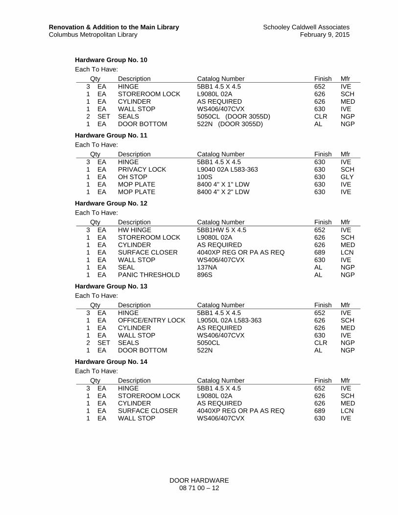
DOOR HARDWARE 08 71 00 – 12
Renovation & Addition to the Main Library Columbus Metropolitan Library
Schooley Caldwell AssociatesFebruary 9, 2015
Hardware Group No. 10
Each To Have:
Qty Description Catalog Number Finish Mfr 3 EA HINGE 5BB1 4.5 X 4.5 652 IVE 1 EA STOREROOM LOCK L9080L 02A 626 SCH 1 EA CYLINDER AS REQUIRED 626 MED 1 EA WALL STOP WS406/407CVX 630 IVE 2 SET SEALS 5050CL (DOOR 3055D) CLR NGP 1 EA DOOR BOTTOM 522N (DOOR 3055D) AL NGP
Hardware Group No. 11
Each To Have:
Qty Description Catalog Number Finish Mfr 3 EA HINGE 5BB1 4.5 X 4.5 630 IVE 1 EA PRIVACY LOCK L9040 02A L583-363 630 SCH 1 EA OH STOP 100S 630 GLY 1 EA MOP PLATE 8400 4" X 1" LDW 630 IVE 1 EA MOP PLATE 8400 4" X 2" LDW 630 IVE
Hardware Group No. 12
Each To Have:
Qty Description Catalog Number Finish Mfr 3 EA HW HINGE 5BB1HW 5 X 4.5 652 IVE 1 EA STOREROOM LOCK L9080L 02A 626 SCH 1 EA CYLINDER AS REQUIRED 626 MED 1 EA SURFACE CLOSER 4040XP REG OR PA AS REQ 689 LCN 1 EA WALL STOP WS406/407CVX 630 IVE 1 EA SEAL 137NA AL NGP 1 EA PANIC THRESHOLD 896S AL NGP
Hardware Group No. 13
Each To Have:
Qty Description Catalog Number Finish Mfr 3 EA HINGE 5BB1 4.5 X 4.5 652 IVE 1 EA OFFICE/ENTRY LOCK L9050L 02A L583-363 626 SCH 1 EA CYLINDER AS REQUIRED 626 MED 1 EA WALL STOP WS406/407CVX 630 IVE 2 SET SEALS 5050CL CLR NGP 1 EA DOOR BOTTOM 522N AL NGP
Hardware Group No. 14
Each To Have:
Qty Description Catalog Number Finish Mfr 3 EA HINGE 5BB1 4.5 X 4.5 652 IVE 1 EA STOREROOM LOCK L9080L 02A 626 SCH 1 EA CYLINDER AS REQUIRED 626 MED 1 EA SURFACE CLOSER 4040XP REG OR PA AS REQ 689 LCN 1 EA WALL STOP WS406/407CVX 630 IVE

DOOR HARDWARE 08 71 00 – 13
Renovation & Addition to the Main Library Columbus Metropolitan Library
Schooley Caldwell AssociatesFebruary 9, 2015
Hardware Group No. 15
Each To Have:
Qty Description Catalog Number Finish Mfr 6 EA HINGE 5BB1 4.5 X 4.5 652 IVE 1 SET AUTO FLUSH BOLT FB31P 630 IVE 1 EA DUST PROOF STRIKE DP2 626 IVE 1 EA CLASSROOM LOCK L9070L 02A 626 SCH 1 EA CYLINDER AS REQUIRED 626 MED 1 EA COORDINATOR COR X FL 628 IVE 2 EA MOUNTING BRACKET MB 689 IVE 2 EA SURFACE CLOSER 4040XP CUSH 689 LCN 1 SET SEALS 5050CL CLR NGP 1 SET SEALS 9550DKB DKB NGP
Hardware Group No. 16
Each To Have:
Qty Description Catalog Number Finish Mfr 1 EA BIFOLD SET 9870 HAG
Hardware Group No. 17
Each To Have:
Qty Description Catalog Number Finish Mfr 8 EA HINGE 5BB1 4.5 X 4.5 652 IVE 1 EA MANUAL FLUSH BOLT FB458 626 IVE 1 EA MANUAL FLUSH BOLT FB458 24" (TOP ROD) 626 IVE 1 EA DUST PROOF STRIKE DP2 626 IVE 1 EA OFFICE LOCK 8548 1-1/4" BS 626 ACC 1 EA TRIM/SPINDLES/ROSE
S AS REQUIRED 626 SCH
1 EA CYLINDER AS REQUIRED 626 MED 2 EA OH STOP 100S 630 GLY 1 EA SURFACE CLOSER 4040XP REG OR PA AS REQ
D.P. X 61 (ACT. LEAF) 689 LCN
Hardware Group No. 18
Each To Have:
Qty Description Catalog Number Finish Mfr ALL HARDWARE BY DOOR SUPPLIER
Hardware Group No. 19
Each To Have:
Qty Description Catalog Number Finish Mfr 3 EA HINGE 5BB1 4.5 X 4.5 652 IVE 1 EA POWER TRANSFER EPT10 689 VON 1 EA EXIT DEVICE RX 99L-BE-F 02 ALK 626 VON 1 EA CYLINDER AS REQUIRED 626 MED 1 EA SURFACE CLOSER 4040XP REG OR PA AS REQ 689 LCN 1 EA KICK PLATE 8400 8" X 2" LDW 630 IVE 1 EA WALL STOP WS406/407CVX 630 IVE 1 SET SEALS 5050CL CLR NGP 1 EA POWER SUPPLY PS902 FA900 LGR SCE
CARD READER FURNISHED ELSEWHERE

DOOR HARDWARE 08 71 00 – 14
Renovation & Addition to the Main Library Columbus Metropolitan Library
Schooley Caldwell AssociatesFebruary 9, 2015
Hardware Group No. 20
Each To Have:
Qty Description Catalog Number Finish Mfr 3 EA HINGE 5BB1 4.5 X 4.5 652 IVE 1 EA PASSAGE SET L9010 02A 626 SCH 1 EA SURFACE CLOSER 4040XP REG OR PA AS REQ 689 LCN 1 EA MOP PLATE 8400 4" X 1" LDW 630 IVE 1 EA KICK PLATE 8400 8" X 2" LDW 630 IVE 1 EA WALL STOP WS406/407CVX 630 IVE 1 SET SEALS 5050CL CLR NGP
Hardware Group No. 21
Each To Have:
Qty Description Catalog Number Finish Mfr 3 EA HINGE 5BB1 4.5 X 4.5 652 IVE 1 EA PRIVACY LOCK L9040 02A L583-363 626 SCH 1 EA SURFACE CLOSER 4040XP REG OR PA AS REQ 689 LCN 1 EA MOP PLATE 8400 4" X 1" LDW 630 IVE 1 EA KICK PLATE 8400 8" X 2" LDW 630 IVE 1 EA WALL STOP WS406/407CVX 630 IVE 1 SET SEALS 5050CL CLR NGP
Hardware Group No. 22
Each To Have:
Qty Description Catalog Number Finish Mfr 3 EA HINGE 5BB1 4.5 X 4.5 652 IVE 1 EA STOREROOM LOCK L9080L 02A 626 SCH 1 EA CYLINDER AS REQUIRED 626 MED 1 EA MOP PLATE 8400 4" X 1" LDW 630 IVE 1 EA WALL STOP WS406/407CVX 630 IVE
Hardware Group No. 23
Each To Have:
Qty Description Catalog Number Finish Mfr 3 EA HINGE 5BB1 4.5 X 4.5 652 IVE 1 EA POWER TRANSFER EPT10 689 VON 1 EA ELEC FIRE EXIT
HARDWARE RX-EL-99-L-F-02 626 VON
1 EA CYLINDER AS REQUIRED 626 MED 1 EA SURFACE CLOSER 4040XP REG OR PA AS REQ 689 LCN 1 EA KICK PLATE 8400 8" X 2" LDW 630 IVE 1 EA WALL STOP WS406/407CVX 630 IVE 1 SET SEALS 5050CL CLR NGP 1 EA POWER SUPPLY PS914 LGR VON
CARD READER FURNISHED ELSEWHERE
Hardware Group No. 24
Each To Have:
Qty Description Catalog Number Finish Mfr 3 EA HINGE 5BB1 4.5 X 4.5 652 IVE 1 EA OFFICE/ENTRY LOCK L9050L 02A L583-363 626 SCH 1 EA CYLINDER AS REQUIRED 626 MED 1 EA OH STOP & HOLDER 100H 630 GLY

DOOR HARDWARE 08 71 00 – 15
Renovation & Addition to the Main Library Columbus Metropolitan Library
Schooley Caldwell AssociatesFebruary 9, 2015
Hardware Group No. 25
Each To Have:
Qty Description Catalog Number Finish Mfr 6 EA HW HINGE 5BB1HW 4.5 X 4.5 652 IVE 1 EA PANIC HARDWARE CD-9927-L-DT-LBR-02 626 VON 1 EA PANIC HARDWARE CD-9927-L-LBR-02 626 VON 3 EA CYLINDER AS REQUIRED 626 MED 2 EA OH STOP 100S 630 GLY 2 EA SURFACE CLOSER 4040XP REG OR PA AS REQ 689 LCN 2 EA KICK PLATE 8400 8" X 1" LDW 630 IVE 1 EA SEAL 137NA AL NGP 2 SET SEALS 5050CL CLR NGP 1 EA ASTRAGAL 136N AL NGP 2 EA DOOR BOTTOM 522N AL NGP
Hardware Group No. 26
Each To Have:
Qty Description Catalog Number Finish Mfr 8 EA HW HINGE 5BB1HW 4.5 X 4.5 652 IVE 1 EA PANIC HARDWARE CD-3347A-EO 626 VON 1 EA PANIC HARDWARE CD-3347A-NL-OP-388 626 VON 3 EA CYLINDER AS REQUIRED 626 MED 2 EA 90 DEG OFFSET PULL 8190HD 12" O 630 IVE 2 EA OH STOP 100S 630 GLY 2 EA SURFACE CLOSER 4040XP REG OR PA AS REQ
X D.P. X 61 689 LCN
EA SEALS BY DOOR SUPPLIER
Hardware Group No. 27
Each To Have:
Qty Description Catalog Number Finish Mfr 3 EA HINGE 5BB1 4.5 X 4.5 652 IVE 1 EA STOREROOM LOCK L9080L 02A 626 SCH 1 EA CYLINDER AS REQUIRED 626 MED 1 EA SURFACE CLOSER 4040XP HCUSH 689 LCN 1 EA KICK PLATE 8400 8" X 2" LDW 630 IVE
Hardware Group No. 28
Each To Have:
Qty Description Catalog Number Finish Mfr 2 EA HINGE 5BB1 4.5 X 4.5 652 IVE 1 EA ELECTRIC HINGE 5BB1 4.5 X 4.5 TW8 652 IVE 1 EA EU MORTISE LOCK L9092LEU 02A RX 626 SCH 1 EA CYLINDER AS REQUIRED 626 MED 1 EA OH STOP 100S 630 GLY 1 EA SURFACE CLOSER 4040XP REG OR PA AS REQ 689 LCN 1 EA KICK PLATE 8400 8" X 2" LDW 630 IVE 2 SET SEALS 5050CL CLR NGP 1 EA DOOR BOTTOM 522N AL NGP
CARD READER FURNISHED ELSEWHERE EA NOTE: POWER SUPPLY FURN. ELSEWHERE

DOOR HARDWARE 08 71 00 – 16
Renovation & Addition to the Main Library Columbus Metropolitan Library
Schooley Caldwell AssociatesFebruary 9, 2015
Hardware Group No. 29
Each To Have:
Qty Description Catalog Number Finish Mfr 3 EA HINGE 5BB1 4.5 X 4.5 652 IVE 1 EA CLASSROOM LOCK L9070L 02A 626 SCH 1 EA CYLINDER AS REQUIRED 626 MED 1 EA WALL STOP WS406/407CVX 630 IVE 2 SET SEALS 5050CL CLR NGP 1 EA DOOR BOTTOM 522N AL NGP
Hardware Group No. 30
Each To Have:
Qty Description Catalog Number Finish Mfr 3 EA HINGE 5BB1 4.5 X 4.5 652 IVE 1 EA PANIC HARDWARE CD-99-L-02 626 VON 2 EA CYLINDER AS REQUIRED 626 MED 1 EA SURFACE CLOSER 4040XP REG OR PA AS REQ 689 LCN 1 EA KICK PLATE 8400 8" X 2" LDW 630 IVE 1 EA WALL STOP WS406/407CVX 630 IVE 2 SET SEALS 5050CL CLR NGP 1 EA DOOR BOTTOM 522N AL NGP
Hardware Group No. 31
Each To Have:
Qty Description Catalog Number Finish Mfr 3 EA HINGE 5BB1 4.5 X 4.5 652 IVE 1 EA PRIVACY LOCK L9040 02A L583-363 626 SCH 1 EA SURFACE CLOSER 4040XP REG OR PA AS REQ 689 LCN 1 EA KICK PLATE 8400 8" X 2" LDW 630 IVE 1 EA WALL STOP WS406/407CVX 630 IVE
Hardware Group No. 32
Each To Have:
Qty Description Catalog Number Finish Mfr 3 EA HINGE 5BB1 4.5 X 4.5 652 IVE 1 EA CLASSROOM LOCK L9070L 02A 626 SCH 1 EA CYLINDER AS REQUIRED 626 MED 1 EA OH STOP & HOLDER 100H 630 GLY 2 SET SEALS 5050CL CLR NGP 1 EA DOOR BOTTOM 522N AL NGP
Hardware Group No. 33
Each To Have:
Qty Description Catalog Number Finish Mfr 6 EA HINGE 5BB1 4.5 X 4.5 651 IVE 2 EA MANUAL FLUSH BOLT FB458 625 IVE 1 EA DUST PROOF STRIKE DP2 625 IVE 1 EA STOREROOM LOCK L9080L 02A 625 SCH 1 EA CYLINDER AS REQUIRED 626 MED 1 EA CYLINDER AS REQUIRED 625 MED 2 EA OH STOP & HOLDER 100H 629 GLY

DOOR HARDWARE 08 71 00 – 17
Renovation & Addition to the Main Library Columbus Metropolitan Library
Schooley Caldwell AssociatesFebruary 9, 2015
Hardware Group No. 34
Each To Have:
Qty Description Catalog Number Finish Mfr 3 EA HINGE 5BB1 4.5 X 4.5 652 IVE 1 EA PASSAGE SET L9010 02A 626 SCH 1 EA WALL STOP WS406/407CVX 630 IVE 2 SET SEALS 5050CL CLR NGP 1 EA DOOR BOTTOM 522N AL NGP
Hardware Group No. 35
Each To Have:
Qty Description Catalog Number Finish Mfr 3 EA HINGE 5BB1 4.5 X 4.5 652 IVE 1 EA POWER TRANSFER EPT10 689 VON 1 EA ELEC FIRE EXIT
HARDWARE RX-EL-99-L-F-02 (SPLIT FINISH 626 X 625)
626 VON
1 EA CYLINDER AS REQUIRED 626 MED 1 EA SURFACE CLOSER 4040XP REG OR PA AS REQ 689 LCN 1 EA KICK PLATE 8400 8" X 2" LDW 629 IVE 1 EA WALL STOP WS406/407CVX 630 IVE 1 EA POWER SUPPLY PS914 LGR VON
CARD READER FURNISHED ELSEWHERE
Hardware Group No. 36
Each To Have:
Qty Description Catalog Number Finish Mfr 3 EA HINGE 5BB1 4.5 X 4.5 652 IVE 1 EA FACULTY RESTROOM L9485L 02A L583-363 626 SCH 1 EA CYLINDER AS REQUIRED 626 MED 1 EA SURFACE CLOSER 4040XP REG OR PA AS REQ 689 LCN 1 EA KICK PLATE 8400 8" X 2" LDW 630 IVE 1 EA WALL STOP WS406/407CVX 630 IVE
Hardware Group No. 37
Each To Have:
Qty Description Catalog Number Finish Mfr 3 EA HINGE 5BB1 4.5 X 4.5 652 IVE 1 EA STOREROOM LOCK L9080L 02A 625 SCH 1 EA CYLINDER AS REQUIRED 626 MED 1 EA OH STOP & HOLDER 100H 630 GLY 1 EA MOP PLATE 8400 4" X 2" LDW 630 IVE
Hardware Group No. 38
Each To Have:
Qty Description Catalog Number Finish Mfr 3 EA HINGE 5BB1 4.5 X 4.5 652 IVE 1 EA PANIC HARDWARE CD-99-L-02 626 VON 2 EA CYLINDER AS REQUIRED 626 MED 1 EA OH STOP 100S 630 GLY 1 EA SURFACE CLOSER 4040XP REG OR PA AS REQ 689 LCN 1 EA KICK PLATE 8400 8" X 2" LDW 630 IVE

DOOR HARDWARE 08 71 00 – 18
Renovation & Addition to the Main Library Columbus Metropolitan Library
Schooley Caldwell AssociatesFebruary 9, 2015
Hardware Group No. 39
Each To Have:
Qty Description Catalog Number Finish Mfr 4 EA HINGE 5BB1 4.5 X 4.5 652 IVE 1 EA OFFICE LOCK 8548 1-1/4" BS 626 ACC 1 EA TRIM/SPINDLES/ROSE
S AS REQUIRED 626 SCH
1 EA CYLINDER AS REQUIRED 626 MED 1 EA OH STOP & HOLDER 100H 630 GLY 1 EA SURFACE CLOSER 4040XP REG OR PA AS REQ 689 LCN
Hardware Group No. 40
Each To Have:
Qty Description Catalog Number Finish Mfr 2 EA HINGE 5BB1 4.5 X 4.5 652 IVE 1 EA ELECTRIC HINGE 5BB1 4.5 X 4.5 TW8 652 IVE 1 EA EU MORTISE LOCK L9092LEU 02A RX 626 SCH 1 EA CYLINDER AS REQUIRED 626 MED 1 EA SURFACE CLOSER 4040XP REG OR PA AS REQ 689 LCN 1 EA KICK PLATE 8400 8" X 2" LDW 630 IVE 1 EA WALL STOP WS406/407CVX 630 IVE 1 SET SEALS 5050CL CLR NGP
CARD READER FURNISHED ELSEWHERE EA NOTE: POWER SUPPLY FURN. ELSEWHERE
Hardware Group No. 41
Each To Have:
Qty Description Catalog Number Finish Mfr 2 EA HW HINGE 5BB1HW 4.5 X 4.5 652 IVE 1 EA ELECTRIC HW HINGE 5BB1HW 4.5 X 4.5 TW8 652 IVE 1 EA EU MORTISE LOCK L9092LEU 02A RX 626 SCH 1 EA CYLINDER AS REQUIRED 626 MED 1 EA SURFACE CLOSER 4040XP REG OR PA AS REQ 689 LCN 1 EA KICK PLATE 8400 8" X 2" LDW 630 IVE 1 EA WALL STOP WS406/407CVX 630 IVE
CARD READER FURNISHED ELSEWHERE EA NOTE: POWER SUPPLY FURN. ELSEWHERE
Hardware Group No. 42
Each To Have:
Qty Description Catalog Number Finish Mfr 6 EA HINGE 5BB1 4.5 X 4.5 652 IVE 1 EA PANIC HARDWARE CD-9927-L-DT-LBR-02 626 VON 1 EA PANIC HARDWARE CD-9927-L-LBR-02 626 VON 3 EA CYLINDER AS REQUIRED 626 MED 2 EA OH STOP 100S 630 GLY 2 EA SURFACE CLOSER 4040XP REG OR PA AS REQ 689 LCN 2 EA KICK PLATE 8400 8" X 1" LDW 630 IVE 1 SET SEALS 5050CL CLR NGP 1 EA ASTRAGAL 136N AL NGP 2 EA DOOR BOTTOM 522N AL NGP
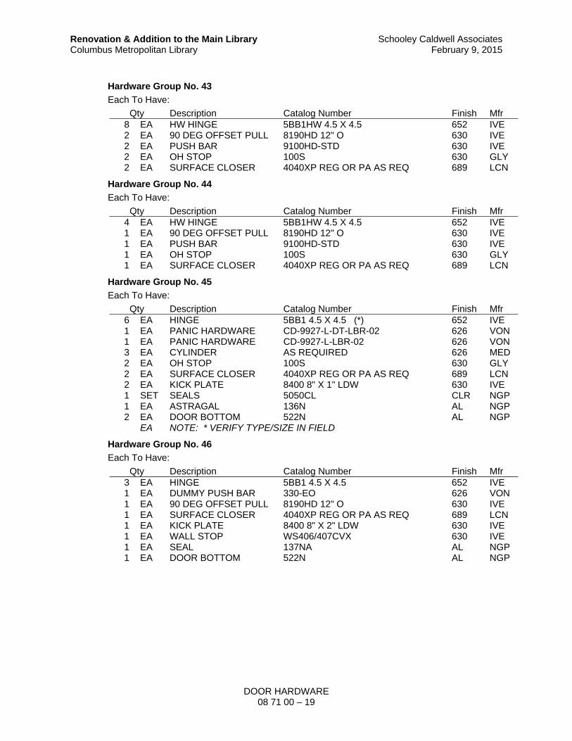
DOOR HARDWARE 08 71 00 – 19
Renovation & Addition to the Main Library Columbus Metropolitan Library
Schooley Caldwell AssociatesFebruary 9, 2015
Hardware Group No. 43
Each To Have:
Qty Description Catalog Number Finish Mfr 8 EA HW HINGE 5BB1HW 4.5 X 4.5 652 IVE 2 EA 90 DEG OFFSET PULL 8190HD 12" O 630 IVE 2 EA PUSH BAR 9100HD-STD 630 IVE 2 EA OH STOP 100S 630 GLY 2 EA SURFACE CLOSER 4040XP REG OR PA AS REQ 689 LCN
Hardware Group No. 44
Each To Have:
Qty Description Catalog Number Finish Mfr 4 EA HW HINGE 5BB1HW 4.5 X 4.5 652 IVE 1 EA 90 DEG OFFSET PULL 8190HD 12" O 630 IVE 1 EA PUSH BAR 9100HD-STD 630 IVE 1 EA OH STOP 100S 630 GLY 1 EA SURFACE CLOSER 4040XP REG OR PA AS REQ 689 LCN
Hardware Group No. 45
Each To Have:
Qty Description Catalog Number Finish Mfr 6 EA HINGE 5BB1 4.5 X 4.5 (*) 652 IVE 1 EA PANIC HARDWARE CD-9927-L-DT-LBR-02 626 VON 1 EA PANIC HARDWARE CD-9927-L-LBR-02 626 VON 3 EA CYLINDER AS REQUIRED 626 MED 2 EA OH STOP 100S 630 GLY 2 EA SURFACE CLOSER 4040XP REG OR PA AS REQ 689 LCN 2 EA KICK PLATE 8400 8" X 1" LDW 630 IVE 1 SET SEALS 5050CL CLR NGP 1 EA ASTRAGAL 136N AL NGP 2 EA DOOR BOTTOM 522N AL NGP
EA NOTE: * VERIFY TYPE/SIZE IN FIELD
Hardware Group No. 46
Each To Have:
Qty Description Catalog Number Finish Mfr 3 EA HINGE 5BB1 4.5 X 4.5 652 IVE 1 EA DUMMY PUSH BAR 330-EO 626 VON 1 EA 90 DEG OFFSET PULL 8190HD 12" O 630 IVE 1 EA SURFACE CLOSER 4040XP REG OR PA AS REQ 689 LCN 1 EA KICK PLATE 8400 8" X 2" LDW 630 IVE 1 EA WALL STOP WS406/407CVX 630 IVE 1 EA SEAL 137NA AL NGP 1 EA DOOR BOTTOM 522N AL NGP

DOOR HARDWARE 08 71 00 – 20
Renovation & Addition to the Main Library Columbus Metropolitan Library
Schooley Caldwell AssociatesFebruary 9, 2015
Hardware Group No. 47
Each To Have:
Qty Description Catalog Number Finish Mfr 2 EA HINGE 5BB1 4.5 X 4.5 652 IVE 1 EA ELECTRIC HINGE 5BB1 4.5 X 4.5 TW8 652 IVE 1 EA EU MORTISE LOCK L9092LEU 02A RX 626 SCH 1 EA CYLINDER AS REQUIRED 626 MED 1 EA SURFACE CLOSER 4040XP CUSH 689 LCN 1 EA KICK PLATE 8400 8" X 2" LDW 630 IVE 1 SET SEALS 5050CL CLR NGP
CARD READER FURNISHED ELSEWHERE EA NOTE: POWER SUPPLY FURN. ELSEWHERE
Hardware Group No. 48
Each To Have:
Qty Description Catalog Number Finish Mfr 3 EA HINGE 5BB1 4.5 X 4.5 652 IVE 1 EA CLASSROOM LOCK 8556 1-1/4" BS 626 ACC 1 EA TRIM/SPINDLES/ROSE
S AS REQUIRED 626 SCH
1 EA CYLINDER AS REQUIRED 626 MED 1 EA OH STOP 100S 630 GLY 1 EA SURFACE CLOSER 4040XP REG OR PA AS REQ
X D.P. X 61 689 LCN
EA SEALS BY DOOR SUPPLIER
Hardware Group No. 49
Each To Have:
Qty Description Catalog Number Finish Mfr 3 EA HW HINGE 5BB1HW 5 X 4.5 652 IVE 1 EA 2 CYL. LOCK 8522 1-1/4" BS 626 ACC 1 EA TRIM/SPINDLES/
ROSES AS REQUIRED 626 SCH
2 EA CYLINDER AS REQUIRED 626 MED 1 EA OH STOP 100S 630 GLY 1 EA SURFACE CLOSER 4040XP REG OR PA AS REQ 689 LCN 1 EA PANIC THRESHOLD 896S AL NGP
EA SEALS BY DOOR SUPPLIER
Hardware Group No. 50
Each To Have:
Qty Description Catalog Number Finish Mfr 3 EA HINGE 5BB1 4.5 X 4.5 651 IVE 1 EA OFFICE/ENTRY LOCK L9050L 02A L583-363 625 SCH 1 EA CYLINDER AS REQUIRED 625 MED 1 EA WALL STOP WS406/407CVX 625 IVE 2 SET SEALS 5050CL CLR NGP 1 EA DOOR BOTTOM 522N AL NGP

DOOR HARDWARE 08 71 00 – 21
Renovation & Addition to the Main Library Columbus Metropolitan Library
Schooley Caldwell AssociatesFebruary 9, 2015
Hardware Group No. 51
Each To Have:
Qty Description Catalog Number Finish Mfr 3 EA HINGE 5BB1 4.5 X 4.5 651 IVE 1 EA CLASSROOM LOCK L9070L 02A 625 SCH 1 EA CYLINDER AS REQUIRED 625 MED 1 EA WALL STOP WS406/407CVX 625 IVE 2 SET SEALS 5050CL CLR NGP 1 EA DOOR BOTTOM 522N AL NGP
Hardware Group No. 52
Each To Have:
Qty Description Catalog Number Finish Mfr 3 EA HINGE 5BB1 4.5 X 4.5 651 IVE 1 EA PASSAGE SET L9010 02A 625 SCH 1 EA WALL STOP WS406/407CVX 625 IVE 1 SET SEALS 5050CL (DOOR 2084A) CLR NGP 1 EA DOOR BOTTOM 522N (DOOR 2084A) AL NGP
Hardware Group No. 53
Each To Have:
Qty Description Catalog Number Finish Mfr 2 EA HINGE 5BB1 4.5 X 4.5 651 IVE 1 EA ELECTRIC HINGE 5BB1 4.5 X 4.5 TW8 651 IVE 1 EA EU MORTISE LOCK L9092LEU 02A RX (SPLIT FINISH
626 X 625) 626 SCH
1 EA CYLINDER AS REQUIRED 626 MED 1 EA SURFACE CLOSER 4040XP REG OR PA AS REQ 689 LCN 1 EA KICK PLATE 8400 8" X 2" LDW 630 IVE 1 EA WALL STOP WS406/407CVX 625 IVE
CARD READER FURNISHED ELSEWHERE EA NOTE: POWER SUPPLY FURN. ELSEWHERE
Hardware Group No. 54
Each To Have:
Qty Description Catalog Number Finish Mfr 2 EA HW HINGE 5BB1HW 5 X 4.5 651 IVE 1 EA ELECTRIC HW HINGE 5BB1HW 5 X 4.5 TW8 651 IVE 1 EA EU MORTISE LOCK L9092LEU 02A RX
(SPLIT FINISH 626 X 625) 626 SCH
1 EA CYLINDER AS REQUIRED 626 MED 1 EA OH STOP 100S 629 GLY 1 EA SURFACE CLOSER 4040XP REG OR PA AS REQ 689 LCN 1 EA KICK PLATE 8400 8" X 2" LDW 630 IVE
CARD READER FURNISHED ELSEWHERE EA NOTE: POWER SUPPLY FURN. ELSEWHERE

DOOR HARDWARE 08 71 00 – 22
Renovation & Addition to the Main Library Columbus Metropolitan Library
Schooley Caldwell AssociatesFebruary 9, 2015
Hardware Group No. 55
Each To Have:
Qty Description Catalog Number Finish Mfr 4 EA HINGE 5BB1 4.5 X 4.5 652 IVE 1 EA OFFICE LOCK 8548 1-1/4" BS 626 ACC 1 EA TRIM/SPINDLES/ROSE
S AS REQUIRED 626 SCH
1 EA CYLINDER AS REQUIRED 626 MED 1 EA WALL STOP WS406/407CVX 630 IVE 2 SET SEALS 5050CL CLR NGP 1 EA DOOR BOTTOM 522N AL NGP
Hardware Group No. 56
Each To Have:
Qty Description Catalog Number Finish Mfr 4 EA HINGE 5BB1 4.5 X 4.5 652 IVE 1 EA CLASSROOM LOCK 8556 1-1/4" BS 626 ACC 1 EA TRIM/SPINDLES/ROSE
S AS REQUIRED 626 SCH
1 EA CYLINDER AS REQUIRED 626 MED 1 EA OH STOP & HOLDER 100H 630 GLY 2 SET SEALS 5050CL CLR NGP 1 EA DOOR BOTTOM 522N AL NGP
Hardware Group No. 57
Each To Have:
Qty Description Catalog Number Finish Mfr 4 EA HINGE 5BB1 4.5 X 4.5 652 IVE 1 EA STOREROOM LOCK 8559 1-1/4 BS 626 ACC 1 EA TRIM/SPINDLES/
ROSES AS REQUIRED 626 SCH
1 EA CYLINDER AS REQUIRED 626 MED 1 EA ELECTRIC STRIKE 6211AL FSE DS 630 VON 1 EA OH STOP 100S 630 GLY 1 EA SURFACE CLOSER 4040XP REG OR PA AS REQ
X D.P. X 61 689 LCN
CARD READER FURNISHED ELSEWHERE EA NOTE: POWER SUPPLY FURN. ELSEWHERE
Hardware Group No. 58
Each To Have:
Qty Description Catalog Number Finish Mfr 4 EA HINGE 5BB1 4.5 X 4.5 652 IVE 1 EA PANIC HARDWARE CD-33A-L-02-299-33AWDA 626 VON 2 EA CYLINDER AS REQUIRED 626 MED 1 EA OH STOP 100S 630 GLY 1 EA SURFACE CLOSER 4040XP REG OR PA AS REQ
X D.P. X 61 689 LCN
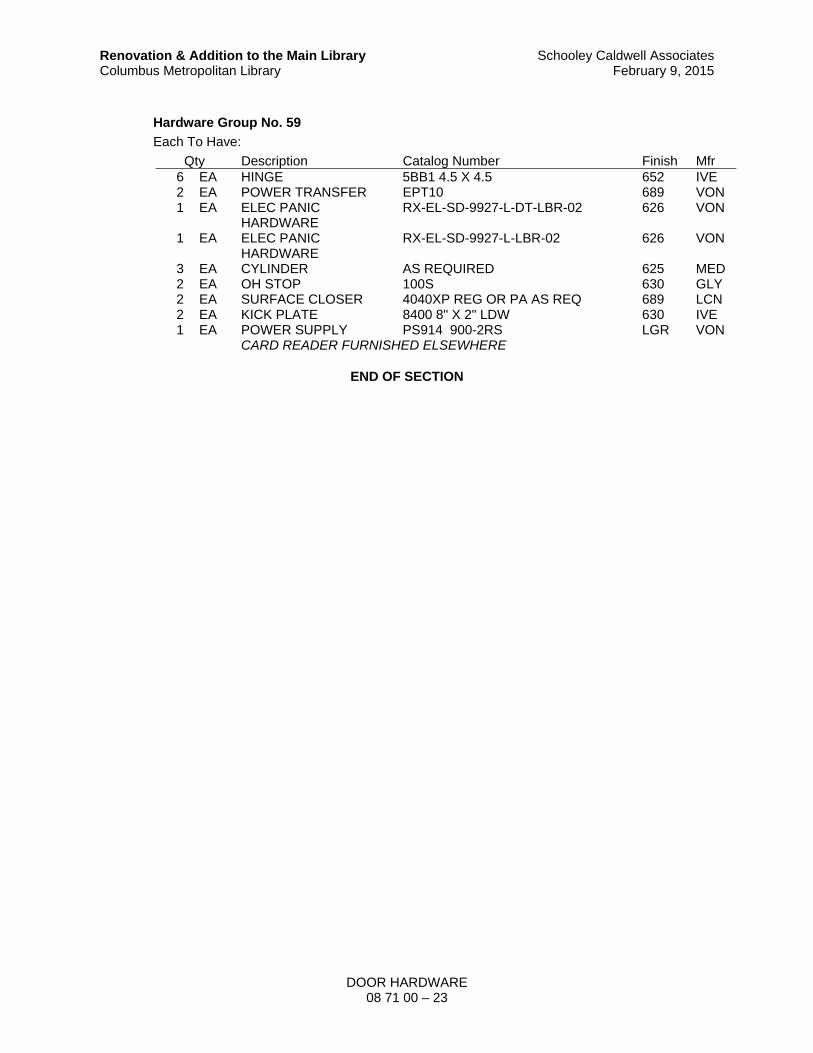
DOOR HARDWARE 08 71 00 – 23
Renovation & Addition to the Main Library Columbus Metropolitan Library
Schooley Caldwell AssociatesFebruary 9, 2015
Hardware Group No. 59
Each To Have:
Qty Description Catalog Number Finish Mfr 6 EA HINGE 5BB1 4.5 X 4.5 652 IVE 2 EA POWER TRANSFER EPT10 689 VON 1 EA ELEC PANIC
HARDWARE RX-EL-SD-9927-L-DT-LBR-02 626 VON
1 EA ELEC PANIC HARDWARE
RX-EL-SD-9927-L-LBR-02 626 VON
3 EA CYLINDER AS REQUIRED 625 MED 2 EA OH STOP 100S 630 GLY 2 EA SURFACE CLOSER 4040XP REG OR PA AS REQ 689 LCN 2 EA KICK PLATE 8400 8" X 2" LDW 630 IVE 1 EA POWER SUPPLY PS914 900-2RS LGR VON
CARD READER FURNISHED ELSEWHERE
END OF SECTION


GLAZING 08 80 00 – 1
Renovation & Addition to the Main Library Columbus Metropolitan Library
Schooley Caldwell AssociatesFebruary 23, 2015
SECTION 08 80 00
GLAZING
PART 1 – GENERAL
1.01 SUMMARY
A. Section includes glass and glazing for the following products and applications:
1. Steel doors, frames and sidelights specified in Section 08 11 00 – Metal Doors And Frames.
2. Wood doors specified in Section 08 14 16 – Wood Doors 3. Glazed entrances and storefronts specified in Section 08 43 13 4. Aluminum- Framed Storefronts. 5. All-glass storefront specified in Section 08 43 26 – All-Glass Storefront 6. Glazed curtain walls specified in Section 08 44 13 – Glazed Aluminum Curtain Walls. 7. Sloped glazing specified in Section 08 44 33 – Sloped Glazing Assembly. 8. Interior borrowed lites. 9. Unframed mirrors.
B. Drawing keynote references:
1. 0880 B1, B2, B3 2. 0880 E1, E2, E3, E4, E5 3. 0880 L 4. 0880 S 5. 0880 M
1.02 DEFINITIONS
A. Manufacturers of Glass Products: Firms that produce primary glass, fabricated glass, or both, as defined in referenced glazing publications.
B. Glass Thicknesses: Indicated by thickness designations in millimeters according to ASTM C 1036.
C. Interspace: Space between lites of an insulating-glass unit that contains dehydrated air or a specified gas.
D. Deterioration of Coated Glass: Defects developed from normal use that are attributed to the manufacturing process and not to causes other than glass breakage and practices for maintaining and cleaning coated glass contrary to manufacturer's written instructions. Defects include peeling, cracking, and other indications of deterioration in metallic coating.
E. Deterioration of Insulating Glass: Failure of hermetic seal under normal use that is attributed to the manufacturing process and not to causes other than glass breakage and practices for maintaining and cleaning insulating glass contrary to manufacturer's written instructions. Evidence of failure is the obstruction of vision by dust, moisture, or film on interior surfaces of glass.
F. Deterioration of Laminated Glass: Defects developed from normal use that are attributed to the manufacturing process and not to causes other than glass breakage and practices for maintaining and cleaning laminated glass contrary to manufacturer's written instructions. Defects include edge separation, delamination materially obstructing vision through glass, and blemishes exceeding those allowed by referenced laminated-glass standard.

GLAZING 08 80 00 – 2
Renovation & Addition to the Main Library Columbus Metropolitan Library
Schooley Caldwell AssociatesFebruary 23, 2015
1.03 PERFORMANCE REQUIREMENTS
A. General: Provide glazing systems capable of withstanding normal thermal movement and wind and impact loads (where applicable) without failure, including loss or glass breakage attributable to the following: defective manufacture, fabrication, and installation; failure of sealants or gaskets to remain watertight and airtight; deterioration of glazing materials; or other defects in construction.
B. Glass Design: Glass thickness designations indicated are minimums and are for detailing only. Confirm glass thicknesses by analyzing Project loads and in-service conditions. Provide glass lites in the thickness designations indicated for various size openings, but not less than thicknesses and in strengths (annealed or heat treated) required to meet or exceed the following criteria:
1. Glass Thicknesses: Select minimum glass thicknesses to comply with ASTM E 1300, according to the following requirements:
a. Specified Design Wind Loads: As required by the Ohio Building Code. b. Specified Design Snow Loads for Sloped Glazing: As required by Code. c. Probability of Breakage for Vertical Glazing: 8 lites per 1000 for lites set vertically
or not more than 15 degrees off vertical and under wind action.
1) Load Duration: 60 seconds or less.
d. Probability of Breakage for Sloped Glazing: 1 lite per 1000 for lites set more than 15 degrees off vertical and under wind and snow action.
1) Load Duration: 30 days.
e. Maximum Lateral Deflection: For the following types of glass supported on all 4 edges, provide thickness required that limits center deflection at design wind pressure to 1/50 times the short side length or 1 inch, whichever is less
1) For monolithic-glass lites heat-treated to resist wind loads. 2) For insulating glass. 3) For laminated-glass lites.
f. Minimum Glass Thickness for Exterior Lites: Not less than 6 mm.
C. Thermal Movements: Provide glazing that allows for thermal movements resulting from the following maximum change (range) in ambient and surface temperatures acting on glass framing members and glazing components. Base engineering calculation on surface temperatures of materials due to both solar heat gain and nighttime-sky heat loss.
1. Temperature Change (Range): 120 deg F, ambient; 180 deg F, material surfaces.
D. Thermal and Optical Performance Properties: Provide glass with performance properties specified based on manufacturer's published test data, as determined according to procedures indicated below:
1. For monolithic-glass lites, properties are based on units with lites 6.0 mm thick. 2. For laminated-glass lites, properties are based on products of construction indicated. 3. For insulating-glass units, properties are based on units with lites 6.0 mm thick and a
nominal 1/2-inch-wide interspace. 4. Center-of-Glass Values: Based on using LBL-44789 WINDOW 6.3 computer program for
the following methodologies:
a. U-Factors: NFRC 100 expressed as Btu/ sq. ft. x h x deg F. b. Solar Heat Gain Coefficient: NFRC 200. c. Solar Optical Properties: NFRC 300.
1.04 SUBMITTALS
A. Product Data: Submit manufacturer's product data and installation instructions for each material and product used.

GLAZING 08 80 00 – 3
Renovation & Addition to the Main Library Columbus Metropolitan Library
Schooley Caldwell AssociatesFebruary 23, 2015
B. Shop Drawings: Submit shop drawings indicating material characteristics, details of construction, connections, and relationship with adjacent construction.
C. Samples: Submit 12-inch square representative samples of each material specified indicating visual characteristics and finish. Include range samples if variation of finish is anticipated.
1. Insulating glass for each designation indicated. 2. Coated vision glass. 3. Ceramic-coated spandrel glass. 4. Fire-resistive glazing products. 5. Each type of laminated glass. 6. For each color (except black) of exposed glazing sealant indicated.
D. Glazing Schedule: Use same designations indicated on Drawings for glazed openings in preparing a schedule listing glass types and thicknesses for each size opening and location.
E. Product Certificates: Signed by manufacturers of glass and glazing products certifying that products furnished comply with requirements.
1. For solar-control low-e-coated glass, provide documentation demonstrating that manufacturer of coated glass is certified by coating manufacturer.
F. Qualification Data: For installers.
G. Preconstruction Adhesion and Compatibility Test Report: From glazing sealant manufacturer indicating glazing sealants were tested for adhesion to glass and glazing channel substrates and for compatibility with glass and other glazing materials.
H. Product Test Reports: For each of the following types of glazing products:
1. Tinted float glass. 2. Coated float glass. 3. Fire-resistive glazing products. 4. Insulating glass. 5. Glazing sealants. 6. Glazing gaskets.
I. Warranty: Submit manufacturer's standard warranty. Include labor and materials to repair or replace defective materials.
1. Coated Glass: Manufacturer's 10-year warranty. 2. Insulating Glass: Manufacturer's 10-year warranty.
1.05 QUALITY ASSURANCE
A. Installer Qualifications: An experienced installer who has completed glazing similar in material, design, and extent to that indicated for this Project; whose work has resulted in glass installations with a record of successful in-service performance..
B. Source Limitations for Glass: Obtain the following through one source from a single manufacturer for each glass type: clear float glass, laminated glass and insulating glass.
C. Source Limitations for Glass Sputter-Coated with Solar-Control Low-E Coatings: Where solar- control low-e coatings of a primary glass manufacturer that has established a certified fabricator program is specified, obtain sputter-coated solar-control low-e-coated glass in fabricated units from a manufacturer that is certified by coated-glass manufacturer.
D. Source Limitations for Glazing Accessories: Obtain glazing accessories through one source from a single manufacturer for each product and installation method indicated.
E. Elastomeric Glazing Sealant Product Testing: Obtain sealant test results for product test reports in "Submittals" Article from a qualified testing agency based on testing current sealant formulations within a 36-month period.

GLAZING 08 80 00 – 4
Renovation & Addition to the Main Library Columbus Metropolitan Library
Schooley Caldwell AssociatesFebruary 23, 2015
1. Sealant Testing Agency Qualifications: An independent testing agency qualified according to ASTM C 1021 to conduct the testing indicated.
2. Test elastomeric glazing sealants for compliance with requirements specified by reference to ASTM C 920, and where applicable, to other standard test methods.
F. Preconstruction Adhesion and Compatibility Testing: Submit to elastomeric glazing sealant manufacturers, for testing indicated below, samples of each glazing material type, tape sealant, gasket, glazing accessory, and glass-framing member that will contact or affect elastomeric glazing sealants:
1. Use ASTM C 1087 to determine whether priming and other specific joint preparation techniques are required to obtain rapid, optimum adhesion of glazing sealants to glass, tape sealants, gaskets, and glazing channel substrates.
2. Submit not fewer than eight pieces of each type of material, including joint substrates, shims, joint-sealant backings, secondary seals, and miscellaneous materials.
3. Schedule sufficient time for testing and analyzing results to prevent delaying the Work. 4. For materials failing tests, obtain sealant manufacturer's written instructions for corrective
measures, including the use of specially formulated primers. 5. Testing will not be required if elastomeric glazing sealant manufacturers submit data
based on previous testing of current sealant products for adhesion to, and compatibility with, glazing materials matching those submitted.
G. Fire-Protection-Rated Glazing: Listed and labeled by a testing agency acceptable to authorities having jurisdiction, for fire-protection ratings indicated, based on positive-pressure testing according to NFPA 257 or UL 9, including the hose-stream test, and shall comply with NFPA 80.
1. Fire-protection-rated glazing required to have a fire-protection rating of 20 minutes shall be exempt from the hose-stream test, unless required by authorities having jurisdiction.
H. Safety Glazing Products: Comply with testing requirements in 16 CFR 1201.
1. Subject to compliance with requirements, obtain safety glazing products permanently marked with certification label of the Safety Glazing Certification Council or another certification agency] acceptable to authorities having jurisdiction.
2. Where glazing units, including Kind FT glass and laminated glass, are specified in Part 2 articles for glazing lites more than 9 sq. ft. in exposed surface area of one side, provide glazing products that comply with Category II materials, for lites 9 sq. ft. or less in exposed surface area of one side, provide glazing products that comply with Category I or II materials, except for hazardous locations where Category II materials are required by 16 CFR 1201 and regulations of authorities having jurisdiction.
I. Glazing Publications: Comply with published recommendations of glass product manufacturers and organizations below, unless more stringent requirements are indicated. Refer to these publications for glazing terms not otherwise defined in this Section or in referenced standards.
1. GANA Publications: GANA Laminated Division's "Laminated Glass Design Guide" and GANA's "Glazing Manual."
2. AAMA Publications: AAMA GDSG-1, "Glass Design for Sloped Glazing," and AAMA TIR- A7, "Sloped Glazing Guidelines."
3. IGMA Publication for Sloped Glazing: IGMA TB-3001, "Sloped Glazing Guidelines." 4. IGMA Publication for Insulating Glass: SIGMA TM-3000, "Glazing Guidelines for Sealed
Insulating Glass Units."
J. Insulating-Glass Certification Program: Permanently marked either on spacers or on at least one component lite of units with appropriate certification label of the following testing and inspecting agency:
1. Insulating Glass Certification Council

GLAZING 08 80 00 – 5
Renovation & Addition to the Main Library Columbus Metropolitan Library
Schooley Caldwell AssociatesFebruary 23, 2015
K. Mockups: Build mockups to verify selections made under sample submittals and to demonstrate aesthetic effects and set quality standards for materials and execution.
1. Build mockup for types of windows indicated, in locations shown on Drawings.
L. Preinstallation Conference: Conduct conference at Project site to comply with requirements in Division 01.
1.06 DELIVERY, STORAGE, AND HANDLING
A. Protect glazing materials according to manufacturer's written instructions and as needed to prevent damage to glass and glazing materials from condensation, temperature changes, direct exposure to sun, or other causes.
B. For insulating-glass units that will be exposed to substantial altitude changes, comply with insulating-glass manufacturer's written recommendations for venting and sealing to avoid hermetic seal ruptures.
1.07 PROJECT CONDITIONS
A. Environmental Limitations: Do not proceed with glazing when ambient and substrate temperature conditions are outside limits permitted by glazing material manufacturers and when glazing channel substrates are wet from rain, frost, condensation, or other causes.
1. Do not install liquid glazing sealants when ambient and substrate temperature conditions are outside limits permitted by glazing sealant manufacturer or below 40 deg F.
1.08 WARRANTY
A. Manufacturer's Special Warranty for Coated-Glass Products: Manufacturer's standard form, made out to the Owner and signed by coated-glass manufacturer agreeing to replace coated- glass units that deteriorate as defined in "Definitions" Article, f.o.b. the nearest shipping point to Project site, within specified warranty period indicated below.
1. Warranty Period: Ten years from date of Substantial Completion.
B. Manufacturer's Special Warranty on Laminated Glass: Manufacturer's standard form, made out to the Owner and signed by laminated-glass manufacturer agreeing to replace laminated-glass units that deteriorate as defined in "Definitions" Article, f.o.b. the nearest shipping point to Project site, within specified warranty period indicated below.
1. Warranty Period: Five years from date of Substantial Completion.
C. Manufacturer's Special Warranty on Insulating Glass: Manufacturer's standard form, made out to the Owner and signed by insulating-glass manufacturer agreeing to replace insulating-glass units that deteriorate as defined in "Definitions" Article, f.o.b. the nearest shipping point to Project site, within specified warranty period indicated below.
1. Warranty Period: Ten years from date of Substantial Completion
PART 2 – PRODUCTS
2.01 MANUFACTURERS
A. Approved Manufacturers:
1. Guardian Industries, (Basis of Design) 2. Viracon, Inc. 3. PPG Industries Inc., Glass Group 4. AFG Industries, Inc.

GLAZING 08 80 00 – 6
Renovation & Addition to the Main Library Columbus Metropolitan Library
Schooley Caldwell AssociatesFebruary 23, 2015
2.02 GLASS PRODUCTS
A. All glazing materials shall be compatible with one another and with all other adjacent materials, including insulating glass hermetic seals. Compatibility shall be verified through testing (or manufacturers’ test results.
B. Thickness: Where glass thickness is indicated, it is a minimum. Provide glass lites in thicknesses as needed to comply with requirements indicated.
1. Minimum Glass Thickness for Exterior Lites: Not less than 6.0 mm.
C. Clear Float Glass: ASTM C1036, Type 1 (transparent glass, flat), Class 1 (clear), Quality q3 (glazing select).
1. Approved Manufacturers:
a. Guardian Industries, (Basis of Design) b. Viracon, Inc. c. PPG Industries Inc., Glass Group d. AFG Industries, Inc.
D. Heat-strengthened glass:
1. ASTM C 1048 Heat Treated Flat Glass-Coated and Uncoated Glass:
a. Heat strengthened: Kind HS b. Tempered: Kind FT
1) 1/2 inch thickness for public areas for sound control. 2) 1/4 inch thickness for staff areas.
2. All tempered glass must be fully heat-soak tested at the place of manufacture. Obtain Architect’s approval before ordering any tempered glass.
3. Heat-treated flat glass by horizontal (roller hearth) process with inherent roller wave distortion parallel to the bottom edge of the glass as installed.
a. Maximum peak to valley roller wave tolerance is 0.003 inches (0.08mm) in the central area, and 0.008 inches (0.20mm) within 10.5 inches (267mm) of the leading and trailing edge.
b. Maximum bow and warp 1/32 inch per linear foot.
4. Provide certification of the glass meeting this standard.
E. Coated Low Emissivity Glass: 1/4", Condition C (other coated glass), Type I (transparent glass, flat), Class I (clear), Quality q3 (glazing select), with coating type and performance characteristics complying with requirements specified below:
1. Low E Coating: Surface #2 on insulated units.
F. Laminated Glass: ASTM C 1172, and complying with testing requirements in 16 CFR 1201 for Category II materials, and with other requirements specified. Use materials that have a proven record of no tendency to bubble, discolor, or lose physical and mechanical properties after fabrication and installation.
1. Construction for Framed Units: Laminate glass with polyvinyl butyral interlayer to comply with interlayer manufacturer's written recommendations.
2. Construction for Units with Exposed Edges: Laminate glass with cast-in-place and cured- transparent-resin interlayer to comply with interlayer manufacturer's written recommendations.
3. Interlayer Thickness: 0.030 inch (0.76 mm) thick for vertical glazing, 0.060 inch (1.52 mm) thick for sloped glazing.
4. Interlayer Color: Clear unless otherwise indicated.

GLAZING 08 80 00 – 7
Renovation & Addition to the Main Library Columbus Metropolitan Library
Schooley Caldwell AssociatesFebruary 23, 2015
G. Insulating Glass: Factory assembled low "E" units consisting of sealed lites of glass separated by a dehydrated interspace, qualified according to ASTM E 2190, complying with requirements of IGCC other requirements specified:
1. Dual-Seal, panes of glass enclosing a hermetically sealed dehydrated air space and complying with ASTM E774 for performance classification indicated as well as with other requirements specified for glass characteristics, air, space, sealing system, sealant, space material, and desiccants.
a. Total Unit Thickness: 1 inch. b. Thickness of Each Pane: 1/4 inch c. Air Space Thickness: 1/2 inch
2. Exterior Pane of Glass: Clear and tinted tempered glass with low-emissivity coating on #2 surface.
3. Interior Pane of Glass: Clear tempered glass; ceramic frit on #4 surface where scheduled.
4. Sealing System: Provide unit edge seals meeting requirement of ASTM E 773, with aluminum spacers having mitered corners and silicone sealant for glass-to-spacer seals. Manufacturer's standard dual seal, with polyisobutylene and silicone polyisobutylene and hotmelt butyl polyisobutylene and polyurethane primary and secondary.
a. Desiccant: Manufacturer's standard. b. Either Molecular Sieve or Silica Gel or blend of both. c. Spacer Material: Manufacturer's standard metal, with anodized finish.
5. Factory glazing shall be in accordance with manufacturer’s standard requirements. Glass shall be factory-labeled. Non-labeled glass will be rejected.
6. Glazing materials shall be compatible with aluminum and those sealants and sealing materials used in the composite structure which have direct contact with the gasket.
7. Standard exterior and interior glazing gaskets shall be a dry glazed elastomer in accordance with ASTM C509-91.
H. Fire-Rated Glazing:
1. Manufacturers: Pilkington; Fire Rated Glazing and Framing Solutions; VETROTECH Saint-Gobain; or approved equal.
2. Type: Fire-rated glazing as vision lights in rated transparent wall and window wall assemblies.
3. Material: Transparent ceramic. 4. Fire Rating: As required for application.
2.03 CURTAIN WALL INSULATED VISION-GLASS UNITS
A. Vision Glass (Type E1): Low-e coated, clear insulating glass: (“SunGuard SNX 62/27,” Guardian)
1. Overall unit Thickness: 1 inch 2. Outdoor Lite: Heat-strengthened float glass
a. Thickness: 1/4 inch b. Low-E Coating: Coating on second (#2) surface
3. Interspace Content: Air
a. Thickness: 1/2 inch
4. Indoor Lite: Heat-strengthened clear float glass
a. Thickness: 1/4 inch
5. Visible Light Transmittance: 62 percent

GLAZING 08 80 00 – 8
Renovation & Addition to the Main Library Columbus Metropolitan Library
Schooley Caldwell AssociatesFebruary 23, 2015
6. Winter Nighttime U-Factor: 0.29 Btu/(hr x sq ft x ºF) 7. Summer Daytime U-Factor: 0.27 Btu/(hr x sq ft x ºF) 8. Shading Coefficient: 0.31 9. Solar Heat Gain Coefficient: 0.27 maximum 10. LSG: 2.30 11. Provide safety glazing labeling.
B. Vision Glass (Type E2): Shadowbox panel assembly with Low-e coated, clear insulating glass: (“SunGuard SN 68,” Guardian)
1. Overall unit Thickness: 1 inch 2. Outdoor Lite: Heat-strengthened float glass
a. Thickness: 1/4 inch b. Low-E Coating: Coating on second (#2) surface
3. Interspace Content: Air
a. Thickness: 1/2 inch
4. Indoor Lite: Heat-strengthened clear float glass
a. Thickness: 1/4 inch b. Guardian “Satin Deco” on third (#3) surface
5. Shadowbox:
a. Perforated Metal Panel Shadowbox (0844 P): McNichols 3/32" Dia hole on 5/32" Stg. Centers. Item No. 1733533241.. Furnish with U-edging.
1) Product Type: Round hole 2) Material: 0.032 inch mil finish aluminum, type 3003-H14 3) Hole Size: 0.0938 4) Hole Centers: 0.1563 5) Hole Pattern: Staggered 6) Straight Rows: Position horizontally
b. Curtain Wall Insulation: 2 or 5 inch thick per detail, 3.5 pound density, mineral fiber with foil facing, secured to metal hat channels.
6. Visible Light Transmittance: 60 percent 7. Winter Nighttime U-Factor: 0.29 Btu/(hr x sq ft x ºF) 8. Summer Daytime U-Factor: 0.28 Btu/(hr x sq ft x ºF) 9. Shading Coefficient: 0.30 10. Solar Heat Gain Coefficient: 0.27 maximum 11. LSG: 2.26 12. Provide safety glazing labeling.
C. Vision Glass (Type E4): Coated insulating glass: (“SunGuard SN 68,” Guardian)
1. Overall unit Thickness: 1 inch 2. Outdoor Lite: Heat-strengthened tinted float glass. Match tint of glazing that is being
removed.
a. Thickness: 1/4 inch b. Low-E Coating: Coating on second (#2) surface
3. Interspace Content: Air
a. Thickness: 1/2 inch
4. Indoor Lite: Heat-strengthened clear float glass
a. Thickness: 1/4 inch

GLAZING 08 80 00 – 9
Renovation & Addition to the Main Library Columbus Metropolitan Library
Schooley Caldwell AssociatesFebruary 23, 2015
b. Coating Location: Third surface. Cut back coating for sealant adhesion. Confirm that opacifier is compatible with setting blocks and gaskets.
c. Opacifier Color: Selected by the Architect from manufacturer’s full color range.
5. Visible Light Transmittance: 68 percent 6. Winter Nighttime U-Factor: 0.29 Btu/(hr x sq ft x ºF) 7. Summer Daytime U-Factor: 0.28 Btu/(hr x sq ft x ºF) 8. Shading Coefficient: 0.43 9. Solar Heat Gain Coefficient: 0.38 maximum 10. LSG: 1.80 11. Provide safety glazing labeling.
D. Vision Glass (Type E5): Coated spandrel insulating glass to match existing adjacent spandrel glass: (“SunGuard SN 68,” Guardian)
1. Overall unit Thickness: 1 inch 2. Outdoor Lite: Heat-strengthened tinted float glass
a. Thickness: 1/4 inch b. Low-E Coating: Coating on second (#2) surface
3. Interspace Content: Air
a. Thickness: 1/2 inch
4. Indoor Lite: Heat-strengthened clear float glass
a. Thickness: 1/4 inch b. Coating Location: Third surface. Cut back coating for sealant adhesion. Confirm
that opacifier is compatible with setting blocks and gaskets. c. Opacifier Color: Selected by the Architect from manufacturer’s full color range.
5. Visible Light Transmittance: 68 percent 6. Winter Nighttime U-Factor: 0.29 Btu/(hr x sq ft x ºF) 7. Summer Daytime U-Factor: 0.28 Btu/(hr x sq ft x ºF) 8. Shading Coefficient: 0.43 9. Solar Heat Gain Coefficient: 0.38 maximum 10. LSG: 1.80 11. Provide safety glazing labeling.
2.04 SLOPED GLAZING UNITS
A. Vision Glass (Type E3): Low-e coated, clear insulating glass: (“SunGuard SN 68,” Guardian)
1. Overall unit Thickness: 1-5/16 inch at Sloped glazing; 1 inch at vertical glazing. 2. Outdoor Lite: Clear, Heat-strengthened
a. Thickness: 1/4 inch b. Low-E Coating: Coating on second (#2) surface
3. Interspace Content: Air
a. Thickness: 1/2 inch
4. Indoor Lite: Laminated clear heat-strengthened float glass
a. Thickness: 1/2 inch with 0.060 Clear PVB b. Warm gray dot silkscreen frit pattern on #3 surface
5. Visible Light Transmittance: 62 percent 6. Winter Nighttime U-Factor: 0.29 Btu/(hr x sq ft x ºF) 7. Summer Daytime U-Factor: 0.26 Btu/(hr x sq ft x ºF) 8. Shading Coefficient: 0.33

GLAZING 08 80 00 – 10
Renovation & Addition to the Main Library Columbus Metropolitan Library
Schooley Caldwell AssociatesFebruary 23, 2015
9. Solar Heat Gain Coefficient: 0.29 maximum 10. LSG: 2.14 11. Provide safety glazing labeling.
2.05 INTERIOR GLASS
A. Interior Glass Types:
1. Interior Glass Type (0880 G1): Minimum 6 mm thick clear, tempered safety glass. 2. Interior Glass Type (0880 G2): Minimum 6 mm thick clear, tempered safety glass. 3. Interior Glass Type (0880 G3): 12 mm (1/2 inch) thick clear, laminated safety glass. 4. Interior Glass Type (0880 G4): 12 mm (1/2 inch) thick clear, tempered safety glass. 5. Interior Glass Type (0880 G5): Existing operable glass partition to be reinstalled 6. Interior Glass Type 3: Fire-rated, laminated glass with intumescent layers; for
temperature-rise openings.
2.06 GLAZING FILM
A. Glazing Films:
1. Manufacturers: 3M Window Film; Lumar Solar Control Films.; or approved equal. 2. Type: Solar and architectural glazing film. 3. Film: Self-adhesive polyester film suitable for application.
2.07 GLAZING SEALANTS
A. General: Provide products of type indicated, complying with the following requirements:
1. Compatibility: Verify glazing sealants that are compatible with one another and with other materials they will contact, including glass products, seals of insulating-glass units, and glazing channel substrates, under conditions of service and application, as demonstrated by sealant manufacturer based on testing and field experience.
2. Suitability: Comply with sealant and glass manufacturers' written instructions for selecting glazing sealants suitable for applications indicated and for conditions existing at time of installation.
3. Colors of Exposed Glazing Sealants: Black or gray from manufacturer's standards. 4. Adhesives and sealants that are used inside the weatherproofing system shall comply
with the following limits for VOC content when calculated according to 40 CFR 59, Subpart D (EPA Method 24):
a. Structural Glazing Adhesives: 100 g/L. b. Architectural Sealants: 250 g/L.
B. Elastomeric Glazing Sealants: Comply with ASTM C 920 and other requirements indicated for each liquid-applied chemically curing sealant specified, including those referencing ASTM C 920 classifications for type, grade, class, and uses related to exposure and joint substrates.
1. Single-Component Neutral- and Basic-Curing Silicone Glazing Sealants:
a. Dow Corning Corporation; 790. b. GE Silicones; SilPruf LM SCS2700 c. Tremco Inc.; Spectrem 1.
C. Structural Silicone Glazing Sealant: ASTM C920 with minimum tensile strength tested in accordance with ASTM C 1184 for Type S, Use G, neutral-curing silicone formulation compatible with system components with which it comes in contact, specifically formulated and tested for use as structural sealant, and approved by structural-sealant manufacturer for use in structural glazed curtain-wall systems indicated.

GLAZING 08 80 00 – 11
Renovation & Addition to the Main Library Columbus Metropolitan Library
Schooley Caldwell AssociatesFebruary 23, 2015
1. Color: Black. 2. Type (Shop-applied): Manufacturer's standard two component. 3. Minimum Tensile Strength: 100 psi (690 kPa). 4. Modulus of Elasticity: As required by structural-sealant-glazed curtain-wall system design
to meet performance requirements. 5. Acceptable Manufacturers: Tremco; Proglaze SG, Dow Corning 995.
D. Structural Silicone Glazing Sealant Solvents: For cleaning aluminum prior to application of sealants, use primer recommended by sealant manufacturer and approved by Architect.
2.08 GLAZING TAPES
A. Back-Bedding Mastic Glazing Tapes: Preformed, butyl-based elastomeric tape with a solids content of 100 percent; nonstaining and nonmigrating in contact with nonporous surfaces; with spacer rod; packaged on rolls with a release paper backing; and complying with ASTM C 1281 and AAMA 800 for project conditions.
B. Expanded Cellular Glazing Tapes: Closed-cell, PVC foam tapes; factory coated with adhesive on both surfaces; packaged on rolls with release liner protecting adhesive; and complying with AAMA 800 for the following types: 1. Type 1, for glazing applications in which tape acts as the primary sealant. 2. Type 2, for glazing applications in which tape is used in combination with a full bead of
liquid sealant.
2.09 MISCELLANEOUS GLAZING MATERIALS
A. General: Provide products of material, size, and shape complying with referenced glazing standard, requirements of manufacturers of glass and other glazing materials for application indicated, and with a proven record of compatibility with surfaces contacted in installation.
B. Cleaners, Primers, and Sealers: Types recommended by sealant or gasket manufacturer.
C. Setting Blocks: Silicone material with a Shore, Type A durometer hardness of 85, plus or minus 5; 4 in. long by minimum 3/16 in. thick, 1/8 in. narrower than the glazing pocket width.
D. Spacers: Silicone blocks or continuous extrusions with a Shore, Type A durometer hardness required by glass manufacturer to maintain glass lites in place for installation indicated.
E. Edge Blocks: Silicone material of hardness needed to limit glass lateral movement (side walking).
F. Interior and Exterior Gaskets: Extruded silicone, 40-60 Shore A Durometer, thickness as required to provide 4 to 10 pli (pounds per lineal inch) of compression on the glass, but not less than 1/8 in. face clearance. Gaskets shall have integral “fins” to fully engage gasket races. All corners to be vulcanized, factory-formed for exterior and interior gaskets. Color: Black.
G. Structural Sealant Backer: Silicone gasket recommended by curtain wall manufacturer for this application.
H. Elastomeric Sealant Backer Rod: Closed cell non-gassing extruded polyolefin foam rod such as "SOF-Rod” by Construction Foam Products. The diameter of the rod is to be approximately 25% in excess of joint width except that quarter round or triangular rod (for fillet joints) shall not be oversized. Surface skin of rod shall be continuous, unbroken, and of sufficient thickness to preclude outgassing and formation of voids in the overlying sealant. Provide various widths as required.
I. Gasket to Prevent Water from Reaching Tops of Insulating Glass Units: Silicone or silicone-compatible EPDM gasket that is sized, sealed, and installed so as to provide a watertight seal between the pressure bar and thermal break at horizontal mullions. All joints to be sealed with a proprietary sealant recommended by the manufacturer. Provide weep holes/slots to allow

GLAZING 08 80 00 – 12
Renovation & Addition to the Main Library Columbus Metropolitan Library
Schooley Caldwell AssociatesFebruary 23, 2015
drainage at sill conditions. Align weep holes/slots with weep holes/slots in aluminum pressure bar.
J. Reticulated Foam Weep Baffle: 30 pores per inch (PPI) UV-resistant PVC-coated reticulated foam designed for use as a baffle in curtain wall and sealant construction.
K. Mirror Mastic: An adhesive setting compound, asbestos-free, produced specifically for setting mirrors and certified by both mirror manufacturer and mastic manufacturer as compatible with glass coating and substrates on which mirrors will be installed.
L. Mirror Hardware, Top and Bottom Aluminum J-Channels: Aluminum extrusions with a return deep enough to produce a glazing channel to accommodate mirrors of thickness indicated and in lengths required to cover bottom and top edges of each mirror in a single piece
M. Provide other accessories recommended by manufacturer, such as molded gasket intersections.
2.10 FABRICATION OF GLAZING UNITS
A. Fabricate glazing units in sizes required to glaze openings indicated for Project, with edge and face clearances, edge and surface conditions, and bite complying with written instructions of product manufacturer and referenced glazing publications, to comply with system performance requirements.
B. Clean-cut or flat-grind vertical edges of butt-glazed monolithic lites in a manner that produces square edges with slight kerfs at junctions with outdoor and indoor faces.
C. Grind smooth and polish exposed glass edges and corners.
2.11 ALUMINUM FINISH AT SUBSTRATE FOR STRUCTURAL SILICONE
A. Mill finish is not acceptable at structural silicone bonding surfaces.
B. Aluminum surface to which structural silicone will be adhered shall have a finish that demonstrates by test the ability to satisfy specified requirements. Subject to testing, acceptable finishes are as follows:
1. Fluoropolymer paint conforming to AAMA 2605. 2. Architectural Class I anodizing conforming to AAMA 611. 3. Alodine conversion coating.
PART 3 – EXECUTION
3.01 EXAMINATION
A. Examine framing glazing, with Installer present, for compliance with the following:
1. Manufacturing and installation tolerances, including those for size, squareness, and offsets at corners.
2. Presence and functioning of weep system. 3. Minimum required face or edge clearances. 4. Effective sealing between joints of glass-framing members.
B. Field Measurements: Verify actual locations of structural supports for glazed curtain wall systems by field measurements (before fabrication) and indicate measurements on Shop Drawings. Notify Architect and General Contractor of any conditions differing from those indicated on Drawings.
C. Verify that structure and site conditions are ready to receive work of this Section. Notify Architect and Contractor in writing of any unsatisfactory conditions.

GLAZING 08 80 00 – 13
Renovation & Addition to the Main Library Columbus Metropolitan Library
Schooley Caldwell AssociatesFebruary 23, 2015
1. Coordinate fabrication and erection tolerance with building structure and related tolerances before beginning the work.
2. Re-measure immediately prior to commencing installation.
D. Proceed with installation only after unsatisfactory conditions have been corrected to the satisfaction of Architect and Contractor.
3.02 PREPARATION
A. Clean glazing channels and other framing members receiving glass immediately before glazing. Remove coatings not firmly bonded to substrates.
B. Examine glazing units to locate exterior and interior surfaces. Label or mark units as needed so that exterior and interior surfaces are readily identifiable. Do not use materials that will leave visible marks in the completed work.
3.03 INSTALLATION, GENERAL
A. Maintain sight lines and profiles shown on Drawings. Install components plumb and true in alignment with established lines and grades.
B. Install units level and plumb and without distortion. Adjust weatherstripping contact and hardware movement to produce proper operation.
C. Install components to drain water passing joints, condensation occurring within framing members, and moisture migrating within the system to exterior.
D. Integrate with all surrounding work to provide continuous air, water, vapor, and thermal protection, as shown in the Drawings and approved shop drawings.
3.04 GLAZING, GENERAL
A. Comply with combined written instructions of manufacturers of glass, sealants, gaskets, and other glazing materials, unless more stringent requirements are indicated, including those in referenced glazing publications and the following:
1. Do not glaze units when ambient air temperature is below that recommended by the manufacturer or in presence of any moisture.
2. Keep the glazing rabbet/pocket clean and dry during installation of glass. 3. All glass shall “float” in the opening and shall be fully separated from contacting mullions,
fasteners, and other rigid components at all times, including while in service. Do not allow the glass to touch the framing system; inspect each lite of glass prior to installing and replace chipped or scratched glass. Use suction cups to move lites of glass.
4. Use a “rolling block” to rotate glass. 5. Set glass so that it is centered in the glazing pocket. Verify that there is at least 1/8 in.
clearance between the sides of the glass and the vertical frame members, and there is at least 1/2 in. bite on the glass by the exterior stops.
B. Verify the production quality of the IGUs prior to installation. Check full extent of hermetic seals for any discontinuities or other defects, and do not install defective units.
C. Glazing channel dimensions, as indicated on Drawings, provide necessary bite on glass, minimum edge and face clearances, and adequate sealant thicknesses, with reasonable tolerances. Adjust as required by Project conditions during installation.
D. Protect glass edges from damage during handling and installation. Remove damaged glass from Project site and legally dispose of off Project site. Damaged glass is glass with edge damage or other imperfections that, when installed, could weaken glass and impair performance and appearance.

GLAZING 08 80 00 – 14
Renovation & Addition to the Main Library Columbus Metropolitan Library
Schooley Caldwell AssociatesFebruary 23, 2015
E. Apply primers to joint surfaces where required for adhesion of sealants, as determined by preconstruction sealant-substrate testing.
F. Install setting blocks in sill rabbets, sized and located to comply with referenced glazing publications, unless otherwise required by glass manufacturer. Set blocks in thin course of compatible sealant suitable for heel bead. . Install setting blocks that provide full support for the insulating glass. Install setting blocks at the one-quarter points of each lite along the horizontal mullions. Temporarily secure setting blocks with 1/8 in. beads of silicone sealant; do not attach setting blocks with screws or other fasteners. Ensure that sealant does not bridge or block the water flow areas between glass edges and the sill of the framing system.
G. Do not exceed edge pressures stipulated by glass manufacturers for installing glass lites.
H. Provide spacers for glass lites where length plus width is larger than 50 inches as follows:
1. Locate spacers directly opposite each other on both inside and outside faces of glass. Install correct size and spacing to preserve required face clearances, unless gaskets and glazing tapes are used that have demonstrated ability to maintain required face clearances and to comply with system performance requirements.
2. Provide 1/8-inch minimum bite of spacers on glass and use thickness equal to sealant width. With glazing tape, use thickness slightly less than final compressed thickness of tape.
I. Provide edge blocking where indicated or needed to prevent glass lites from moving sideways in glazing channel, as recommended in writing by glass manufacturer and according to requirements in referenced glazing publications.
J. Install elastomeric anti-walk blocks at mid-height of jamb in each vision glass opening. Antiwalk blocks shall be 1/8 in. narrower than the space between the glass and vertical mullion. Set blocks in dabs of sealant to hold in place.
K. Set glass lites in each series with uniform pattern, draw, bow, and similar characteristics.
L. Set glass lites with proper orientation so that coatings face exterior or interior as specified.
M. Where wedge-shaped gaskets are driven into one side of channel to pressurize sealant or gasket on opposite side, provide adequate anchorage so gasket cannot walk out when installation is subjected to movement.
N. Provide factory-formed corner gaskets and install in a manner recommended by gasket manufacturer to prevent corners from pulling away; seal corner joints and butt joints with sealant recommended by gasket manufacturer.
3.05 GASKET GLAZING (DRY)
A. Cut compression gaskets to lengths recommended by gasket manufacturer to fit openings exactly, with allowance for stretch during installation.
B. Insert soft compression gasket between glass and frame or fixed stop so it is securely in place with joints miter cut and bonded together at corners. Seal gasket corners with sealant recommended by manufacturer.
C. Installation with Drive-in Wedge Gaskets: Center glass lites in openings on setting blocks and press firmly against soft compression gasket by inserting dense compression gaskets formed and installed to lock in place against faces of removable stops. Start gasket applications at corners and work toward centers of openings. Compress gaskets to produce a weathertight seal without developing bending stresses in glass. Seal gasket joints with sealant recommended by gasket manufacturer.
D. Installation with Pressure-Glazing Stops: Center glass lites in openings on setting blocks and press firmly against soft compression gasket. Install dense compression gaskets and pressure-glazing stops, applying pressure uniformly to compression gaskets. Compress gaskets to

GLAZING 08 80 00 – 15
Renovation & Addition to the Main Library Columbus Metropolitan Library
Schooley Caldwell AssociatesFebruary 23, 2015
produce a weathertight seal without developing bending stresses in glass. Seal gasket joints with sealant recommended by gasket manufacturer.
E. Install gaskets so they protrude past face of glazing stops.
3.06 TAPE GLAZING
A. Position tapes on fixed stops so that, when compressed by glass, their exposed edges are flush with or protrude slightly above sightline of stops.
B. Install tapes continuously, but not necessarily in one continuous length. Do not stretch tapes to make them fit opening.
C. Cover vertical framing joints by applying tapes to heads and sills first and then to jambs. Cover horizontal framing joints by applying tapes to jambs and then to heads and sills.
D. Place joints in tapes at corners of opening with adjoining lengths butted together, not lapped.
E. Seal joints in tapes with compatible sealant approved by tape manufacturer.
F. Do not remove release paper from tape until just before each glazing unit is installed.
G. Center glass lites in openings on setting blocks and press firmly against tape by inserting dense compression gaskets formed and installed to lock in place against faces of removable stops. Start gasket applications at corners and work toward centers of openings.
3.07 SEALANT GLAZING (WET)
A. Install continuous backup rod, quarter-round rod, or bond breaker tape, between glass lites and glazing stops to maintain glass face clearances and to prevent sealant from extruding into glass channel and blocking weep systems until sealants cure. Secure backer rod or bond breaker tape in place and in position to control depth of installed sealant relative to edge clearance for optimum sealant performance.
B. Do not twist backer rods together. Butt ends of rods tightly. Do not touch with fingers or otherwise contaminate the substrate surfaces while inserting the backer rod or bond breaker tape. Do not rupture the skin of the closed-cell backer rod during installation. Do not cut rod lengthwise as substitute for smaller-diameter rod. Remove any rod containing punctures and prepare the surfaces again.
C. For typical sealant joints, place the backer rod or bond breaker so that the sealant depth measured at the center of the joint after tooling is one-half of the sealant joint width, with a minimum depth of 1/4 in. and a maximum depth of 1/2 in. Avoid three-sided adhesion at all sealant joints. Three-sided adhesion constitutes a failed sealant joint.
D. Do not install sealant until the substrate has first been cleaned. Remove all dirt or other foreign substances from surfaces to receive sealant. All surfaces shall be dry before preparation begins. The surface preparation is to be done immediately before insertion of the final backer rod or bond breaker and after any temporary rods or seals are removed.
E. Prepare metal surfaces, including priming, according to manufacturer’s recommendations and field adhesion test results. Apply sealant only to dry surfaces at ambient temperatures required by manufacturer.
F. Fill all joints solidly and continuously with sealant, neatly applied with a standard caulking gun in a continuous motion, using a slight pressure. “Push” the sealant bead ahead of the nozzle; do not “drag” the nozzle.
G. Within 5 min. of sealant application and before skin develops on sealant, dry tool the joint surface with a concave metal tool to insure intimate contact with substrate and to eliminate air bubbles. Do not use any liquid for tooling. Provide a smooth, uniform finished surface.

GLAZING 08 80 00 – 16
Renovation & Addition to the Main Library Columbus Metropolitan Library
Schooley Caldwell AssociatesFebruary 23, 2015
H. Remove masking tape within 10 min. of tooling. Avoid contaminating adjacent surfaces with excess sealant. Remove all traces of smears and droppings on metal or glass surfaces promptly, using a solvent recommended by the sealant manufacturer that will not damage or discolor the building surfaces. Remove smears and droppings on porous surfaces by mechanical means after the initial cure of the sealant.
I. Removal of excess sealant with sharp objects such as razor blades is not permitted.
3.08 FIELD QUALITY CONTROL
A. At intervals recommended by sealant manufacturer, periodically test adhesion of liquid-applied sealants via peel tests and similar methods. Document results and submit to Architect for review. Refer to Quality Assurance paragraph.
B. Architect may elect to perform nondestructive frost-point testing of some or all insulating glass units (can be performed from the interior or exterior). If selected, provide Architect with safe access to all insulating glass units to be tested.
C. For each failure condition discovered (for any test method listed above), make remedial and corrective action approved by the Architect. All failures shall be considered systemic failures requiring corrective work at all similar conditions and locations. Remedial measures shall maintain standards of quality and durability and are subject to approval by the Architect.
3.09 CLEANING AND PROTECTION
A. Protect exterior glass from weather and damage immediately after installation by attaching crossed streamers to framing held away from glass. Do not apply markers to glass surface. Remove nonpermanent labels after inspection by Architect, and clean surfaces. Replace all material damage due to water infiltration, weather, or other causes at no additional cost.
B. Protect glass from contact with contaminating substances resulting from construction operations, including weld splatter. If, despite such protection, contaminating substances do come into contact with glass, remove substances immediately as recommended by glass manufacturer.
C. Examine glass surfaces adjacent to or below exterior concrete and other masonry surfaces at frequent intervals during construction, but not less than once a month, for buildup of dirt, scum, alkaline deposits, or stains; remove as recommended in writing by glass manufacturer.
D. Remove and replace glass that is broken, chipped, cracked, or abraded or that is damaged from natural causes, accidents, and vandalism, during construction period.
END OF SECTION
MIRRORS 08 83 00 – 1
Renovation & Addition to the Main Library Columbus Metropolitan Library
Schooley Caldwell AssociatesFebruary 9, 2015
SECTION 08 83 00
MIRRORS
PART 1 – GENERAL
1.01 SUMMARY
A. Section includes the following types of silvered flat glass mirrors:
1. Annealed monolithic glass mirrors.
1.02 SUBMITTALS
A. Product Data: For each type of product indicated.
1. Mirrors. Include description of materials and process used to produce each type of silvered flat glass mirror specified that indicates sources of glass, glass coating components, edge sealer, and quality-control provisions.
B. Shop Drawings: Include mirror elevations, edge details, mirror hardware, and attachments to other work.
C. Samples: For each type of the following products:
1. Mirrors: 12 inches (300 mm) square, including edge treatment on two adjoining edges. 2. Mirror Clips: Full size. 3. Mirror Trim: 12 inches (300 mm) long.
D. Product Certificates: For each type of mirror and mirror mastic, from manufacturer.
E. Preconstruction Test Reports: From mirror manufacturer indicating that mirror mastic was tested for compatibility and adhesion with mirror backing and substrates on which mirrors are installed.
F. Maintenance Data: For mirrors to include in maintenance manuals.
1.03 QUALITY ASSURANCE
A. Source Limitations for Mirrors: Obtain mirrors from single source from single manufacturer.
B. Source Limitations for Mirror Accessories: Obtain mirror glazing accessories from single source.
C. Glazing Publications: Comply with the following published recommendations:
1. GANA's "Glazing Manual" unless more stringent requirements are indicated. Refer to this publication for definitions of glass and glazing terms not otherwise defined in this Section or in referenced standards.
2. GANA Mirror Division's "Mirrors, Handle with Extreme Care: Tips for the Professional on the Care and Handling of Mirrors."
D. Safety Glazing Products: As may be applicable to the Project, and where local jurisdiction requires safety glazing for mirror installations, provide laminated glass mirrors. Provide products complying with testing requirements in 16 CFR 1201 for Category II materials.
E. Preconstruction Mirror Mastic Compatibility Test: Submit mirror mastic products to mirror manufacturer for testing to determine compatibility of mastic with mirror backing and substrates on which mirrors are installed.

MIRRORS 08 83 00 – 2
Renovation & Addition to the Main Library Columbus Metropolitan Library
Schooley Caldwell AssociatesFebruary 9, 2015
1.04 PROJECT CONDITIONS
A. Protect mirrors according to mirror manufacturer's written instructions and as needed to prevent damage to mirrors from moisture, condensation, temperature changes, direct exposure to sun, or other causes.
B. Comply with mirror manufacturer's written instructions for shipping, storing, and handling mirrors as needed to prevent deterioration of silvering, damage to edges, and abrasion of glass surfaces and applied coatings. Store indoors.
C. Environmental Limitations: Do not install mirrors until ambient temperature and humidity conditions are maintained at levels indicated for final occupancy.
1.05 WARRANTY
A. Special Warranty: Manufacturer's standard form in which mirror manufacturer agrees to replace mirrors that deteriorate within specified warranty period. Deterioration of mirrors is defined as defects developed from normal use that are not attributed to mirror breakage or to maintaining and cleaning mirrors contrary to manufacturer's written instructions. Defects include discoloration, black spots, and clouding of the silver film.
1. Special Warranty Period: Five (5) years from date of Substantial Completion.
PART 2 – PRODUCTS
2.01 FLAT GLASS MIRRORS
A. Glass Mirrors, General: ASTM C 1503; manufactured using copper-free, low-lead mirror coating process.
B. Clear Glass: Mirror Select Quality; ultraclear (low-iron) float glass with a minimum 91 percent visible light transmission.
2.02 MISCELLANEOUS MATERIALS
A. Setting Blocks: Elastomeric material with a Shore, Type A durometer hardness of 85, plus or minus 5.
B. Edge Sealer: Coating compatible with glass coating and approved by mirror manufacturer for use in protecting against silver deterioration at mirrored glass edges.
C. Mirror Mastic: An adhesive setting compound, asbestos-free, produced specifically for setting mirrors and certified by both mirror manufacturer and mastic manufacturer as compatible with glass coating and substrates on which mirrors will be installed.
1. Adhesive shall have a VOC content of not more than 70> g/L when calculated according to 40 CFR 59, Subpart D (EPA Method 24).
2.03 MIRROR HARDWARE
A. Top and Bottom Aluminum J-Channels: Aluminum extrusions with a return deep enough to produce a glazing channel to accommodate mirrors of thickness indicated and in lengths required to cover bottom and top edges of each mirror in a single piece.
1. Bottom Trim: J-channels formed with front leg and back leg not less than 3/8 and 7/8 inch (9.5 and 22 mm) in height, respectively, and a thickness of not less than 0.05 inch (1.3 mm).

MIRRORS 08 83 00 – 3
Renovation & Addition to the Main Library Columbus Metropolitan Library
Schooley Caldwell AssociatesFebruary 9, 2015
2. Top Trim: J-channels formed with front leg and back leg not less than 5/8 and 1 inch (16 and 25 mm) in height, respectively, and a thickness of not less than 0.062 inch (1.57 mm).
3. Finish: Clear bright anodized.
B. Fasteners: Fabricated of same basic metal and alloy as fastened metal and matching it in finished color and texture where fasteners are exposed.
C. Anchors and Inserts: Provide devices as required for mirror hardware installation. Provide toothed or lead-shield expansion-bolt devices for drilled-in-place anchors. Provide galvanized anchors and inserts for applications on inside face of exterior walls and where indicated.
2.04 FABRICATION
A. Mirror Sizes: To suit Project conditions, cut mirrors to final sizes and shapes.
B. Cutouts: Fabricate cutouts for notches and holes in mirrors without marring visible surfaces.
C. Locate and size cutouts so they fit closely around penetrations in mirrors.
D. Mirror Edge Treatment: Flat polished, unless otherwise shown on the Drawings.
1. Seal edges of mirrors with edge sealer after edge treatment to prevent chemical or atmospheric penetration of glass coating.
2. Require mirror manufacturer to perform edge treatment and sealing in factory immediately after cutting to final sizes.
PART 3 – EXECUTION
3.01 EXAMINATION
A. Examine substrates, over which mirrors are to be mounted, with Installer present, for compliance with installation tolerances, substrate preparation, and other conditions affecting performance of the Work.
B. Verify compatibility with and suitability of substrates, including compatibility of mirror mastic with existing finishes or primers.
C. Proceed with installation only after unsatisfactory conditions have been corrected and surfaces are dry.
3.02 PREPARATION
A. Comply with mastic manufacturer's written installation instructions for preparation of substrates, including coating substrates with mastic manufacturer's special bond coating where applicable.
3.03 INSTALLATION
A. Install mirrors to comply with mirror manufacturer's written instructions and with referenced GANA publications. Mount mirrors accurately in place in a manner that avoids distorting reflected images.
B. Provide a minimum air space of 1/8 inch (3 mm) between back of mirrors and mounting surface for air circulation between back of mirrors and face of mounting surface.
C. Wall-Mounted Mirrors: Install mirrors with mirror hardware. If mastic needs to be employed, install with both mastic and mirror hardware. Attach mirror hardware securely to mounting surfaces with mechanical fasteners installed with anchors or inserts as applicable. Install fasteners so heads do not impose point loads on backs of mirrors.
MIRRORS 08 83 00 – 4
Renovation & Addition to the Main Library Columbus Metropolitan Library
Schooley Caldwell AssociatesFebruary 9, 2015
1. Top and Bottom Aluminum J-Channels: Provide setting blocks 1/8 inch (3 mm) thick by 4 inches (100 mm) long at quarter points. To prevent trapping water, provide, between setting blocks, two slotted weeps not less than 1/4 inch (6.4 mm) wide by 3/8 inch (9.5 mm) long at bottom channel.
2. As may be applicable, install mastic as follows:
a. Apply barrier coat to mirror backing where approved in writing by manufacturers of mirrors and backing material.
b. Apply mastic to comply with mastic manufacturer's written instructions for coverage and to allow air circulation between back of mirrors and face of mounting surface.
c. After mastic is applied, align mirrors and press into place while maintaining a minimum air space of 1/8 inch (3 mm) between back of mirrors and mounting surface.
3.04 CLEANING AND PROTECTION
A. Protect mirrors from breakage and contaminating substances resulting from construction operations.
B. Do not permit edges of mirrors to be exposed to standing water.
C. Maintain environmental conditions that will prevent mirrors from being exposed to moisture from condensation or other sources for continuous periods of time.
D. Wash exposed surface of mirrors not more than four days before date scheduled for inspections that establish date of Substantial Completion. Wash mirrors as recommended in writing by mirror manufacturer.
END OF SECTION
LOUVERS 08 91 00 – 1
Renovation & Addition to the Main Library Columbus Metropolitan Library
Schooley Caldwell AssociatesFebruary 23, 2015
SECTION 08 91 00
LOUVERS
PART 1 – GENERAL
1.01 SUMMARY
A. Provide metal louvers of the following type:
1. Drainable fixed extruded louvers.
B. Drawing Keynotes: 0891 L1, 0891 L2
C. Related Sections:
1. Section 07 92 00 – Joint Sealants for sealants installed in perimeter joints between louver frames and adjoining construction.
1.02 REFERENCES
A. Air Movement and Control Association International, Inc.:
1. AMCA Standard 500-L-12 Laboratory Methods of Testing Louvers for Rating 2. AMCA Publication 501 Application Manual for Louvers 3. AMCA Publication 511 AMCA Certified Ratings
B. American Society of Civil Engineers:
1. ASCE/SEI-7, Minimum Design Loads for Buildings and Other Structures
C. American Society for Testing and Materials:
1. ASTM B209, Standard Specification for Aluminum and Aluminum-Alloy Sheet and Plate 2. ASTM B211, Standard Specification for Aluminum and Aluminum-Alloy Rolled or Cold
Finished Bar, Rod, and Wire 3. ASTM B221, Standard Specification for Aluminum and Aluminum-Alloy Extruded Bars,
Rods, Wire, Profiles, and Tubes
D. Architectural Aluminum Manufacturers Association:
1. AAMA 800, Voluntary Specifications and Test Methods for Sealants 2. AAMA 2605, Voluntary Specifications for High Performance Organic Coatings on
Aluminum Extrusions and Panels 3. AAMA TIR A9, Design Guide for Metal Cladding Fasteners
1.03 SUBMITTALS
A. Refer to Section 01 33 00 – Submittal Procedures.
B. Product data for each type of product specified. Submit air performance, water penetration and wind-driven rain ratings for louvers determined in accordance with AMCA Standard 500-L. Manufacturer shall submit documentation that air performance, water penetration and wind-driven rain ratings are based on testing performed in an AMCA certified laboratory.
C. Submit shop drawings of louver units and accessories. Include plans, elevations, sections, and details showing profiles, angles, and spacing of louver blades; unit dimensions related to wall openings and construction; free areas for each size indicated; profiles of frames at jambs, heads, and sills; and anchorage details and locations.
D. Samples: Submit six (6) inch square samples of each required finish. Prepare samples on metal of same gauge and alloy to be used in work. Where normal color and texture variations

LOUVERS 08 91 00 – 2
Renovation & Addition to the Main Library Columbus Metropolitan Library
Schooley Caldwell AssociatesFebruary 23, 2015
are to be expected, include two (2) or more units in each sample showing limits of such variations.
E. Product test reports evidencing compliance of units with performance requirements indicated.
F. Product certificates signed by louver manufacturers certifying that their products comply with the specified requirements and are licensed to bear the AMCA seal based on tests made according to AMCA 500 and complying with the AMCA Certified Ratings Program.
1.04 QUALITY ASSURANCE
A. Product Manufacturer: Louvers shall be manufactured by a single source that has not less than 5-years of experience in the design and manufacture of work similar to that shown and required.
B. Performance Requirements: Air performance, water penetration and wind-driven rain performance for louvers and grilles shall be determined in accordance with AMCA Standard 500-L. Air performance, water penetration and wind-driven rain ratings shall be based on testing performed in an AMCA certified laboratory. Manufacturer shall be a member of Air Movement and Control Association International Inc.
C. Structural Requirements: Design louver to accommodate local requirements for wind loading. Provide engineering calculations to support design. Calculations shall be prepared by a registered engineer licensed in the state where the project is located. Analysis of blade defection to be limited to L/120, 3/4 inch or as required by local code.
D. Professional Engineer Requirements: Drawings and structural calculations shall be signed and stamped by a professional engineer registered in Ohio.
E. Source Limitations: Obtain louvers through one source from a single manufacturer where indicated to be of same type, design, or factory-applied color finish.
1. Basis-of-Design Product: The design for each louver is based on the product named. Subject to compliance with requirements, provide either the named product or a comparable product by one of the other manufacturers specified.
F. Welding: Qualify procedures and personnel according to the following:
1. AWS D1.2, "Structural Welding Code--Aluminum."
G. SMACNA Standard: Comply with recommendations in SMACNA's "Architectural Sheet Metal Manual" for fabrication, construction details, and installation procedures.
H. Field Measurements: Verify size, location and placement of units prior to fabrication.
I. Shop Assembly: Coordinate field measurements and shop drawings with fabrication and shop assembly to minimize field adjustments, splicing, mechanical joints and field assembly of units. Preassemble units in shop to greatest extent possible and disassemble as necessary for shipping and handling limitations. Clearly mark units for reassembly and coordinated installation.
1.05 DELIVERY, STORAGE, AND HANDLING
A. Protection: Use all means necessary to protect the materials of this section before, during, and after installation, and to protect the installed work and materials of all other trades.
B. Replacements: In the event of damage, immediately make all repairs and replacements necessary.
1.06 PROJECT CONDITIONS
A. Field Measurements: Verify louver openings by field measurements before fabrication and indicate measurements on Shop Drawings.

LOUVERS 08 91 00 – 3
Renovation & Addition to the Main Library Columbus Metropolitan Library
Schooley Caldwell AssociatesFebruary 23, 2015
PART 2 – PRODUCTS
2.01 MANUFACTURERS
A. Manufacturers: Specifications are based on products of Construction Specialties, Inc., Cranford, NJ.
1. Comparable louvers manufactured by the following manufacturers, meeting the design and specification requirements in the construction documents will be acceptable subject to the provisions of Section 01 60 00 – Product Requirements.
a. The Airolite Co. b. Ruskin Company; Tomkins PLC.
2.02 MATERIALS
A. Aluminum Extrusions: ASTM B 221, Alloy 6063-T5, 6063-T6, or 6061-T6.
B. Aluminum Sheet: ASTM B 209, Alloy 1100, 3003 or 5005 with temper as required for forming and finishing.
C. Fasteners: Of same basic metal and alloy as fastened metal or 300 Series stainless steel, unless otherwise indicated. Do not use metals that are incompatible with joined materials.
1. Use types and sizes to suit unit installation conditions. 2. Use Phillips flat-head screws for exposed fasteners, unless otherwise indicated.
D. Postinstalled Fasteners for Concrete and Masonry: Torque-controlled expansion anchors, made from stainless-steel components, with capability to sustain, without failure, a load equal to 4 times the loads imposed, for concrete, or 6 times the load imposed, for masonry, as determined by testing in accordance with ASTM E 488, conducted by a qualified independent testing agency.
E. Bituminous Paint: Cold-applied asphalt mastic complying with SSPC-Paint 12 except containing no asbestos fibers.
2.03 FABRICATION
A. Assemble louvers in factory to minimize field splicing and assembly. Disassemble units as necessary for shipping and handling limitations. Clearly mark units for reassembly and coordinated installation.
B. Maintain equal louver blade spacing to produce uniform appearance.
C. Fabricate frames, including integral sills, to fit in openings of sizes indicated, with allowances made for fabrication and installation tolerances, adjoining material tolerances, and perimeter sealant joints.
1. Frame Type: Channel, unless otherwise indicated.
D. Include supports, anchorages, and accessories required for complete assembly.
E. Where indicated, provide subsills made of same material as louvers.
F. Join frame members to each other and to fixed louver blades with fillet welds concealed from view, unless otherwise indicated or size of louver assembly makes bolted connections between frame members necessary.
LOUVERS 08 91 00 – 4
Renovation & Addition to the Main Library Columbus Metropolitan Library
Schooley Caldwell AssociatesFebruary 23, 2015
2.04 FIXED, EXTRUDED-ALUMINUM LOUVERS
A. Aluminum Louver (0891 L1):
1. Product Standard: C/S 7” Storm Resistant Fixed Horizontal Louver Model RS-7705 or a comparable product of one of the other named manufacturers.
2. Louver Depth: 7 inches. 3. Frame and Blade Nominal Thickness: As required to comply with structural performance
requirements, but not less than 0.075 for blades and 0.080 inch for frames. 4. Bird Screen Frame: Provide aluminum square screen mesh screen and frame to interior
side of louver. Screen 0.050” thick expanded and flattened aluminum, 5/8-inch square mesh, in 0.055 inch thick extruded aluminum frame.
5. Sill Flashing: 4 inch high by full depth sill flashing formed from minimum 0.050 inch thick aluminum. Form with welded side panels.
6. Performance Requirements:
a. Free Area: 8.00 sq. ft. (0.743 sq. m.) b. Free area velocity at the point of beginning water penetration: 1,240 FPM (6.30
m/s) c. Maximum recommended air intake velocity: 1040 fpm (5.28 m/s)
1) Pressure drop at 1040 fpm free area velocity: 0.30 in. H2O (74.5 Pa).
d. Maximum recommended air exhaust velocity: 1407 fpm (7.15 m/s)
1) Pressure drop at 1407 fpm free area velocity: 0.50 in. H2O (124.2 Pa).
7. AMCA Seal: Mark units with AMCA Certified Ratings Seal.
B. Aluminum Louver (0891 L2):
1. Product Standard: C/S 4” High Performance Drainable Fixed Mullion Louver Model A4177 or a comparable product of one of the other named manufacturers.
a. Louver shall match the appearance of the remaining existing smoke intake louver in the Atrium.
b. Louver to be installed in an inverted position to serve as a sight barrier.
2. Louver Depth: 4 inches. 3. Frame and Blade Nominal Thickness: As required to comply with structural performance
requirements, but not less than 0.070 for blades and 0.060 inch for frames.
a. Blade Angle: 45 degrees
4. Bird Screen Frame: Provide aluminum square screen mesh screen and frame to interior side of louver. Screen 0.050” thick expanded and flattened aluminum, 5/8-inch square mesh, in 0.055 inch thick extruded aluminum frame.
5. Mullion Width: 1.125 inch 6. Performance Requirements:
a. Free Area: 8.80 sq. ft. (0.82 sq. m.) b. Percent Free Area: 55.0% c. Free area velocity at the point of beginning water penetration: 1,087 FPM (5.52
m/s) d. Maximum recommended air intake velocity: 887 fpm (4.51 m/s)
1) Pressure drop at 887 fpm free area velocity: 0.12 in. H2O (29.8 Pa).
7. AMCA Seal: Mark units with AMCA Certified Ratings Seal.

LOUVERS 08 91 00 – 5
Renovation & Addition to the Main Library Columbus Metropolitan Library
Schooley Caldwell AssociatesFebruary 23, 2015
2.05 FINISHES
A. Finishes, General: Comply with NAAMM "Metal Finishes Manual" for recommendations relative to applying and designating finishes. Finish louvers after assembly.
B. Aluminum Finishes: As follows (finish designations prefixed by AA conform to the system established by the Aluminum Association for designating aluminum finishes):
C. High-Performance Organic Finish (Two-Coat Fluoropolymer): Organic Coating: manufacturer's standard two-coat, thermocured system consisting of specially formulated inhibitive primer, fluoropolymer color coat, and clear fluoropolymer topcoat, with both color coat and clear topcoat containing not less than 70 percent polyvinylidene fluoride resin by weight). Prepare, pretreat, and apply coating to exposed metal surfaces to comply with AAMA 2605 and with coating and resin manufacturers' written instructions.
1. Color (0891 L1): Color and Gloss: Kawneer Permadize “Sterling Gray (789G018).” 2. Color (0891 L2): As selected.
PART 3 – EXECUTION
3.01 EXAMINATION
A. Examine substrates and openings, with Installer present, for compliance with requirements for installation tolerances and other conditions affecting performance.
1. Proceed with installation only after unsatisfactory conditions have been corrected.
3.02 PREPARATION
A. Coordinate setting drawings, diagrams, templates, instructions, and directions for installation of anchorages that are to be embedded in concrete or masonry construction. Coordinate delivery of such items to Project site.
3.03 INSTALLATION
A. Install louvers in accordance with manufacturer’s printed instructions.
B. Verify dimensions of supporting structure at the site by accurate field measurements so that the work will be accurately designed, fabricated and fitted to the structure.
C. Locate and place louvers and vents level, plumb, and at indicated alignment with adjacent work.
D. Use concealed anchorages where possible. Provide brass or lead washers fitted to screws where required to protect metal surfaces and to make a weathertight connection.
E. Form closely fitted joints with exposed connections accurately located and secured.
F. Provide perimeter reveals and openings of uniform width for sealants and joint fillers, as indicated.
G. Repair finishes damaged by cutting, welding, soldering, and grinding operations required for fitting and jointing. Restore finishes so there is no evidence of corrective work. Return items that cannot be refinished in the field to the shop, make required alterations, and refinish entire unit, or provide new units.
H. Protect aluminum and nonferrous-metal surfaces from corrosion or galvanic action by applying a heavy coating of bituminous paint on surfaces that will be in contact with concrete, masonry, or dissimilar metals.
I. Install concealed gaskets, flashings, joint fillers, and insulation as louver installation progresses, where weathertight louver joints are required. Comply with Section 07 92 00 – Joint Sealants for sealants applied during louver installation.

LOUVERS 08 91 00 – 6
Renovation & Addition to the Main Library Columbus Metropolitan Library
Schooley Caldwell AssociatesFebruary 23, 2015
3.04 ADJUSTING AND CLEANING
A. Clean exposed surfaces of louvers that are not protected by temporary covering, to remove fingerprints and soil during construction period. Do not let soil accumulate until final cleaning.
B. Before final inspection, clean exposed surfaces with water and a mild soap or detergent not harmful to finishes. Thoroughly rinse surfaces and dry.
C. Restore louvers damaged during installation and construction so no evidence remains of corrective work. If results of restoration are unsuccessful, as determined by Associate, remove damaged units and replace with new units.
1. Touch up minor abrasions in finishes with air-dried coating that matches color and gloss of, and is compatible with, factory-applied finish coating.
END OF SECTION

SOFFIT VENTS 08 95 13 – 1
Renovation & Addition to the Main Library Columbus Metropolitan Library
Schooley Caldwell AssociatesFebruary 9, 2015
SECTION 08 95 13
SOFFIT VENTS
PART 1 – GENERAL
1.01 SUMMARY
A. Section Includes: Continuous linear soffit grille for installation in composite metal panel soffit construction.
B. Related Section:
1. Section 07 42 13 – Composite Metal Panels
1.02 SUBMITTALS
A. Comply with the requirements of Section 01 33 00 – Submittal Procedures.
B. Shop Drawings: Indicate materials, construction, dimensions, accessories and installation details.
1.03 DELIVERY, STORAGE, AND HANDLING
A. Transport, handle, store, and protect products in compliance with the requirements of Section 01600 and manufacturer's recommendations.
B. Deliver materials to site in manufacturer's original, unopened containers and packaging with labels clearly indicating manufacturer and material.
C. Store materials in a dry area, protected from damage, in accordance with manufacturer's instructions.
D. Protect materials and finishes during handling and installation.
PART 2 – PRODUCTS
2.01 MANUFACTURER
A. Acceptable Manufacturers:
1. Basis of Design – Architectural Grille, Brooklyn , NY.
B. Substitution in accordance with Section 01 25 00 – Substitution Procedures.
2.02 SOFFIT VENTS
A. Continuous Linear Soffit Vent: Clear anodized aluminum vented soffit Model AG-30 bar grille.
1. Depth: 3/4 inch 2. Width: As shown
B. Frame: “D Frame”
C. Finish: Extruded aluminum with Kynar painted finish: color to match composite metal panels.
PART 3 – EXECUTION
3.01 EXAMINATION
A. Inspect areas to receive vents. Do not proceed, if unsatisfactory conditions exist that will not allow for a complete and proper installation. Proceed upon correction.

SOFFIT VENTS 08 95 13 – 2
Renovation & Addition to the Main Library Columbus Metropolitan Library
Schooley Caldwell AssociatesFebruary 9, 2015
3.02 INSTALLATION
A. Install in accordance with manufacturer's instructions. Provide appurtenances required for a complete and proper installation.
B. Install plumb, level, flush, and in alignment with adjacent work.
3.03 CLEANING
A. Remove temporary coverings and protection of adjacent work areas.
B. Clean exposed surfaces that are not protected by temporary covering, to remove fingerprints and soil during construction period. Do not let soil accumulate until final cleaning.
C. Before final inspection, clean exposed surfaces with water and a mild soap or detergent not harmful to finishes.
D. Thoroughly rinse surfaces and dry.
E. Restore items damaged during installation and construction so no evidence remains of corrective work. If results of restoration are unsuccessful as determined by Architect, remove damaged units and replace with new units. Touch up minor abrasions in finishes with air-dried coating that matches color and gloss of, and is compatible with, factory-applied finish coating.
END OF SECTION

STONE REPAIR 09 01 70 – 1
Renovation & Addition to the Main Library Columbus Metropolitan Library
Schooley Caldwell AssociatesFebruary 9, 2015
SECTION 09 01 70
STONE REPAIR
PART 1 – GENERAL
1.01 SUMMARY
A. This Section includes the following:
1. Modifications to Carnegie Building stone facade 2. Repairing and patching of stone facing
B. Related Section:
1. Section 04 01 40 – Stone Cleaning
1.02 SUBMITTALS
A. Product Data: For each variety of stone, stone accessory, and other manufactured products specified.
1. For stone varieties proposed for use on Project, include data on physical properties re-quired by referenced ASTM standards.
B. Shop Drawings: Show details of fabrication and installation of interior stone facing including di-mensions and profiles of stone units; arrangement and details of jointing, supporting, anchoring, and bonding interior stone facing; and details showing relationship with, attachment to, and re-ception of related work.
C. Stone Samples for Verification: Sets for each color, grade, finish, and variety of stone required; not less than 12 inches square. Include 2 or more samples in each set showing the full range of variations in appearance characteristics expected in completed Work.
D. Maintenance Data: For interior stone facing to include in the maintenance manuals specified in Division 01. Include Product Data for stone-care products used or recommended by Installer and names, addresses, and telephone numbers of local sources for products.
E. Repair Materials: Submit the following items in time to prevent delay of the work and to allow adequate time for review, do not order materials or start work before receiving written approval:
1. Product Data: For all specified materials to include the following:
a. Material Safety Data Sheets (MSDS), as appropriate. b. Manufacturer’s instructions for installation and application of products.
2. Material Samples: Before installation of sample to wall, submit the following:
a. Each type of repair material showing proposed surface finish and color.
3. Qualification Data: Submit certificates from the material supplier stating that field supervi-sors and masons installing the replacement material have successfully completed the training workshop for the installation of the stone repair material.
4. Restoration Plan: For each phase of repair work required provide detailed description of materials, methods, approach, tool selection, equipment, sequencing, and include the fol-lowing:
a. Measures for protection of surrounding materials on building and site. b. In-situ masonry preparation prior to repair. c. Material curing methods after installation.

STONE REPAIR 09 01 70 – 2
Renovation & Addition to the Main Library Columbus Metropolitan Library
Schooley Caldwell AssociatesFebruary 9, 2015
1.03 QUALITY ASSURANCE
A. Stone Installer Qualifications: Engage an experienced installer who has completed stonework similar in material, design, and extent to that indicated for Project that has resulted in construc-tion with a record of successful in-service performance for not less than five years.
1. Installer shall assume responsibility for engineering, fabricating, and installing interior stone setting and anchoring systems.
B. Fabricator Qualifications: Engage a firm experienced in producing stonework similar to that in-dicated for this Project and with a record of successful in-service performance for not less than five years, as well as sufficient production capacity to produce required units without delaying the Work.
C. Source Limitations for Stone: Obtain each variety of stone, regardless of finish, from a single quarry with resources to provide materials of consistent quality in appearance and physical properties and to cut and finish material without delaying the Work.
D. Source Limitations for Other Materials: Obtain each type of grout, stone accessory, sealant, and other material from a single manufacturer for each product.
E. Check dimensions of supporting structure at site by accurate field measurements before final submittal of shop drawings and fabrication of stone. Coordinate fabrication schedule with con-struction progress as directed by Contractor to avoid delay of work. Where necessary, proceed without field measurements and coordinate installation tolerances to ensure proper fit of stone-work.
F. Preselection: Prior to fabrication, designate stone to be preselected by Architect for color and uniformity. Contractor to submit samples for this purpose.
G. Standards: All work, methods and materials shall be in conformance with the referenced stand-ards:
1.04 MOCKUPS
A. Mockups: Prepare in situ samples of each type of replacement material using masonry removed from the building where designated by the Architect. Apply replacement material to the wall, or unit to be repaired according to specifications and manufacturer’s instructions. Prepare samples in an area where they will be exposed to the same conditions as will be present on the building during curing. Allow samples to cure at least seven days (or longer, if possible) before obtaining Architects approval for color match. Samples shall be acceptable when viewed from a minimum distance of 10 feet.
1. Retain acceptable mockups in undisturbed condition as a standard for workmanship qual-ity. Mockup to be used for judging completed work as the project progresses. Approval of work will be based upon: cleanliness, material color, texture, and finished profile.
2. Provide in situ mock-ups of repairs to the following materials:
a. Stone patching b. Salvaged stone for re-installation in the work c. New stone
1.05 DELIVERY, STORAGE, AND HANDLING
A. Deliver materials to Project Site in undamaged condition under provisions of Section 01 60 00 – Product Requirements.
B. Store and handle stone and related materials to prevent deterioration or damage due to mois-ture, temperature changes, contaminants, corrosion, breaking, chipping, or other causes.
C. Store cementitious materials off ground, under cover, and in dry location.

STONE REPAIR 09 01 70 – 3
Renovation & Addition to the Main Library Columbus Metropolitan Library
Schooley Caldwell AssociatesFebruary 9, 2015
D. Store setting mortars and grouts in watertight enclosures with elevated floors.
E. Store stone on wood skids or pallets with nonstaining, waterproof covers. Arrange to distribute weight evenly and to prevent damage to stone. Ventilate under covers to prevent condensation.
F. Lift with wide-belt slings; do not use wire rope or ropes that might cause staining. Move stone, if required, using dollies with cushioned wood supports.
1.06 PROJECT CONDITIONS
A. Maintain minimum ambient temperatures of 50 degrees F 24 hours prior to, during installation and for 7 days after completion, unless higher temperatures are required by fabricator’s or sup-plier’s instructions.
B. Protect adjacent surfaces / work from damage by materials and tools used for interior stone work.
PART 2 – PRODUCTS
2.01 REPAIR MATERIALS
A. Available Manufacturers:
1. U.S. Heritage Group, Inc., 3516 North Kostner Avenue, Chicago, IL 60641 Phone: 773-286-2100 Fax: 773-286-1852.
2. Jahn M120-Marble Repair Mortar..
B. Mineral Based Natural Repair Mortar for Marble:
1. Formulation: Pre-blended, mineral-based, single component repair product. 2. Color: Match to the existing in-situ masonry. 3. Texture: Match to existing in-situ masonry. 4. Product: MT15 Heritage Marble & Travertine
C. Admixtures:
1. No synthetic polymers or additives are permitted in the formulation. 2. No air-entraining admixtures are permitted. 3. No antifreeze compounds, chlorides or other additives are permitted. 4. Color pigments are permitted only with prior written approval from the material manufac-
turer.
D. Factory Mixing:
1. Pre-blend all replacement materials into single containers in a factory-controlled envi-ronment.
2. Mixing of individual ingredients at the construction site shall not be permitted. 3. Match color and texture of replacement material to the original material. 4. Mark all containers to include manufacturing date and batch number. Maintain production
sampling procedures for each batch and shipment for quality control tracking purposes.
2.02 MARBLE
A. Provide interior and exterior stone materials to match existing in variety, color, finish and group classification.
B. Existing stone may be quarried only from those areas identified on the demolition drawings. Ex-isting stone shall not be quarried from any other areas.
C. Use only sound material, free from holes, cracks or seams that could impair the structural integ-rity, and free of stains or other foreign matter.

STONE REPAIR 09 01 70 – 4
Renovation & Addition to the Main Library Columbus Metropolitan Library
Schooley Caldwell AssociatesFebruary 9, 2015
D. Select marble for patching to match existing marble color and figuring.
2.03 ANCHORS AND ACCESSORIES
A. Miscellaneous: Provide all other anchors and accessories required to complete the total work. Utilize materials which are non-staining and corrosion-resistant.
B. Setting Shims: Resilient plastic shims, nonstaining to stone, sized to suit joint thickness.
C. Cleaner: Provide stone cleaners specifically formulated for stone varieties, finishes, and appli-cations indicated as recommended by stone producer. Do not use cleaning compounds con-taining acids, caustics, harsh fillers, or abrasives.
2.04 STONE FABRICATION
A. General: Fabricate interior stone facing in sizes and shapes required to comply with require-ments indicated, including details on Drawings and Shop Drawings.
1. For marble, comply with recommendations of Marble Institute of America’s (MIA) “Dimen-sional Stone Design Manual IV.”
B. Unless otherwise noted, all stone shall receive finish, to match finish on existing stone of same material and application. Finish all exposed faces and edges of stone.
C. Relocation of Existing Stone Facing: Mark panels of existing stone facing with sequence num-bers, prior to removing it from the wall. To the extent possible, relocate existing stone panels in same sequence. Group relocated panels together and avoid integrating these panels with new material where possible.
D. New Stone Facing shall be grouped together. Avoid integrating these panels with existing relo-cated material.
E. Pattern Arrangement of Stone Facing: Fabricate and arrange panels with veining and other natural markings to comply with the following requirements:
1. Cut stone from one block or contiguous, matched blocks in which natural markings occur. 2. Arrange panels with veining to match existing orientation. 3. Once layout is accepted by the Architect, correct sequence numbers based on accepted
layout and indicate orientation of units for completed Work. Transfer all information to Shop Drawings.
a. Layout may be done one elevation at a time for approval by the Architect. b. Notify Architect 7 days in advance of the date and time when layout will be availa-
ble for viewing. c. Rearrange slabs as directed by Architect until layout is accepted.
4. Thickness of Interior Stone Facing: Provide thickness to match thickness of existing stone.
5. Control depth and thickness of stone to maintain minimum clearances indicated between backs of stone units and surfaces or projections of structural members, fireproofing (if any), back-up walls, and other work behind stone. Do not back check stone less than 1-inch thick.
6. Dress joints (bed and vertical) straight and at right angle to face, unless otherwise indi-cated.
7. Cut stone to produce joints of uniform width and in locations indicated. Joint widths shall match existing joints.
8. Clean saw backs of stones to remove rust stains and iron particles.
F. Cut and drill sinkages and holes in stone for anchors, fasteners, supports, and lifting devices as indicated or needed to set stone securely in place; shape beds to fit supports.

STONE REPAIR 09 01 70 – 5
Renovation & Addition to the Main Library Columbus Metropolitan Library
Schooley Caldwell AssociatesFebruary 9, 2015
G. Contiguous Work: Provide chases, reveals, reglets, openings, and similar features as required to accommodate contiguous work.
H. Fabricate molded work to produce stone shapes with a uniform profile throughout entire unit length and with precisely formed arris slightly eased to prevent snipping, and matched at joints between units.
1. Produce moldings with machines having abrasive shaping wheels made to reverse con-tour of molding shape; do not sculpt moldings.
2. Miter moldings at corners, except where otherwise indicated, with edges of miters slightly eased at outside corners.
I. Carefully inspect finished stone units at fabrication plant for compliance with requirements for appearance, material, and fabrication. Replace defective units.
1. Grade and mark stone for overall uniform appearance when assembled in place. Natural variations in appearance are acceptable if installed stone units match range of colors and other appearance characteristics represented in approved samples and mockups.
PART 3 – EXECUTION
3.01 EXAMINATION
A. Examine surfaces indicated to receive stone facing and conditions under which interior stone facing will be installed, with Installer present, for compliance with requirements for installation tolerances and other conditions affecting performance.
1. For the record, prepare written report, endorsed by Installer, listing conditions detrimental to performance of interior stone facing.
2. Proceed with installation only after unsatisfactory conditions have been corrected.
3.02 PREPARATION – NEW OR RELOCATED STONE
A. Clean dirty or stained stone surfaces by removing soil, stains, and foreign materials before setting. Clean stone by thoroughly scrubbing with fiber brushes and then drenching with clear water. Use only mild cleaning compounds that contain no caustic or harsh materials or abrasives.
3.03 PREPARATION FOR REPAIRS
A. Remove all loose mortar and masonry prior to installation of the repair mortar. “Sound” masonry with a hammer to verify its integrity. If necessary, cut away an additional 1/2” of the substrate to ensure the surface to be repaired is solid and stable. Remove any sealant residue.
B. Where cramp anchors, threaded rod anchors, or dowels have been cut and pieces remain em-bedded in the substrate: Anchors that are free of rust, solidly embedded, and do not project be-yond the surface of the masonry unit may remain. All others should be removed.
C. Cut the edges of the repair area to provide a minimum depth of 1/4”. The edges of the repair should be square cut. Do not allow any feathered edges in the repair area.
D. Install mechanical anchors in all repair areas if specified on the Contract Drawing or as other-wise directed by the Specifier.
E. Clean all dust from surface and pores of the substrate, using clean water and a scrub brush.
F. For very dry or porous surfaces, pre-wet the substrate ahead of time to prevent the substrate from drawing moisture out of the repair too quickly. Re-wet the surface immediately before ap-plying the repair material.
STONE REPAIR 09 01 70 – 6
Renovation & Addition to the Main Library Columbus Metropolitan Library
Schooley Caldwell AssociatesFebruary 9, 2015
3.04 REMOVING EXISTING STONE
A. Existing stone may be quarried from only those areas identified where new construction replac-es existing stone. Existing stone shall not be quarried from any other areas.
B. Mark panels of existing stone with sequence numbers and orientation symbols prior to removing it from the wall.
C. Protect adjacent surfaces to remain during quarrying process.
D. Remove stone using approved methods per Marble Institute of America.
E. Store quarried stone in upright position with proper protection to eliminate breakage.
3.05 PATCHING HOLES
A. Patch holes in existing stone in designated areas as indicated on the drawings, including holes that have been improperly patched in the past. Remove all foreign materials from holes, includ-ing but not limited to old epoxy, grout, mortar and plastic anchors.
B. Remove or replace patches with hairline cracks, those that show separation from stone, or those that do not match adjacent stone in color or texture.
1. Method of patching is dependant on the size of the hole:
a. For holes 1-inch in diameter or greater, provide a Dutchman, using stone that matches in color and finish.
b. For holes less than 1-inch in diameter, provide an epoxy patch, colored to blend with the stone color.
3.06 SETTING STONE – GENERAL
A. Do necessary field cutting as stone is set. Use power saws with diamond blades to cut stone. Cut lines straight and true, with edges eased slightly to prevent snipping.
B. Contiguous Work: Provide reveals and openings as required to accommodate contiguous work.
C. Set stone to comply with requirements indicated on Drawings and Shop Drawings. Install anchors, supports, fasteners, and other attachments indicated or necessary to secure stone in place. Shim and adjust anchors, supports, and accessories to set stone accurately in locations indicated, with edges and faces aligned according to established relationships and indicated tolerances.
D. Erect stone units level, plumb, and true with uniform joint widths. Use temporary shims to maintain joint width.
E. Provide expansion, control, and pressure-relieving joints of widths and at locations indicated.
1. Sealing of expansion, control, and pressure-relieving joints is specified in Section 07 92 00 – Joint Sealants.
F. Construction Tolerances:
1. Variation in Joint Width: Do not vary joint thickness more than 1/16-inch or one-fourth of nominal joint width, whichever is less.
2. Variation in Plane between Adjacent Panels (Lipping): Do not exceed 1/32-inch differ-ence between planes of adjacent units.
3.07 POINTING JOINTS WITH MORTAR
A. Prepare stone-joint surfaces for pointing with mortar by removing temporary shims, dust, and mortar particles. Where setting spots occur at joints, rake out excess mortar to a depth of not less than 1/2 inch.

STONE REPAIR 09 01 70 – 7
Renovation & Addition to the Main Library Columbus Metropolitan Library
Schooley Caldwell AssociatesFebruary 9, 2015
B. Point stone joints by placing pointing mortar in layers not more than 3/8 inch. Compact each layer thoroughly and allow to become thumbprint hard before applying next layer. Apply mortar first to areas where depths are greater than surrounding areas until a uniform depth is formed.
C. Tool joints when pointing mortar is thumbprint hard. Match profile of existing mortar that remains.
3.08 ADJUSTING AND CLEANING
A. Remove and replace interior stone facing of the following description:
1. Broken, chipped, stained, or otherwise damaged stone. Stone may be repaired if meth-ods and results are approved by Architect.
2. Defective joints and seams. 3. Interior stone facing and joints not matching approved samples and mockups. 4. Interior stone facing not complying with other requirements indicated.
B. Replace in a manner that results in interior stone facing’s matching approved samples and mockups, complying with other requirements, and showing no evidence of replacement.
C. In-Progress Cleaning: Clean interior stone facing as work progresses. Remove mortar and grout smears before tooling joints.
3.09 PROTECTION
A. Protect stone surfaces, edges, and corners from construction damage. Use securely fastened untreated wood, plywood, or heavy cardboard to prevent damage.
B. Before inspection for Contract Completion, remove protective covering and clean surfaces.
END OF SECTION


COMMON WORK RESULTS FOR FLOOR PREPARATION 09 05 61 – 1
Renovation & Addition to the Main Library Columbus Metropolitan Library
Schooley Caldwell AssociatesFebruary 9, 2015
SECTION 09 05 61
COMMON WORK RESULTS FOR FLOOR PREPARATION
PART 1 – GENERAL
1.01 SUMMARY
A. Section Includes: Construction and testing requirements for interior floor slabs and supplements requirements of Section 03 30 00 – Cast-in-Place Concrete and the Structural Drawings for the following:
1. Concrete materials. 2. Slab finish. 3. Curing of slabs. 4. Concrete Moisture and pH testing. 5. Moisture and pH control (remediation as needed).
B. Provide floor slab surfaces suitable for installation of floorcovering materials. No contract adjustments are allowed, since the Contractor controls construction schedule, concrete work, timing of building enclosure, and temporary facilities such as construction drying.
C. Related Sections:
1. Section 01 31 00 – Project Coordination: Preconstruction conference. 2. Section 03 30 00 – Cast-In-Place Concrete 3. Division 09 – Flooring Sections.
1.02 SLAB DRYNESS PRECEDENT TO ADHESIVE FLOORING INSTALLATION
A. Correlation of Slab Relative Humidity to Moisture Vapor Emission: For purposes of this contract, the fallowing correlation applies.
Slab Relative Humidity Slab Relative Humidity
Moisture Emissions lbs/1000 sf/24 hoursMoisture Emissions lbs/1000 s.f./24hrs
95% 20 lbs. 90% 15 lbs.85% 10 lbs. 80% 7 lbs. 78% 5 lbs.75% 3 lbs.
B. General: Follow floor covering manufacturer's recommendations for slab dryness. In the absence of such recommendations, the following guidelines apply.
C. Maximum 3-Pound Emission and pH of 9 or less: Suitable for installation of any type floor covering using normal adhesives.
D. Maximum 5-Pound Emission and pH of 9 or less: Suitable for installation of:
1. Carpet with vapor permeable backing (e.g. jute). 2. Other floor coverings using special adhesives approved by floor covering manufacturer.
E. Maximum 7-Pound Emission:
1. Suitable for installation of thin-set ceramic tile and similar materials using Portland cement base mortar.
2. Remediation or special adhesives required for installation of other floor coverings Verify pH within limits specified by adhesive manufacturer.

COMMON WORK RESULTS FOR FLOOR PREPARATION 09 05 61 – 2
Renovation & Addition to the Main Library Columbus Metropolitan Library
Schooley Caldwell AssociatesFebruary 9, 2015
F. More than 7- Pound Emission: Remediation or additional drying required.
1.03 SUBMITTALS
A. Qualification Data: Submit for testing agency. Submittal is for information only.
B. Field Test Reports: Submit layout plan and test results for each location tested indicating time and date of each test. Report test results in chart form.
1. Calcium Chloride Test Method: Indicate test dates, start/stop time, start/stop weight, weight gain in grams, water vapor emission rate, and pH levels.
2. Relative Humidity Test Method: Indicate test dates, time, depth of test well, in-situ temperature, relative humidity and pH levels.
3. Submit record of ambient air temperature, ambient relative humidity, and floor slab surface temperature when test sites are prepared, start of test, and end of test.
4. Indicate condition of building enclosure including position of operable windows and exterior doors when test sites are prepared, start of test, and end of test.
5. Indicate operational status of HVAC systems maintaining environmental condition of spaces where tests are conducted when test sites are prepared, start of test, and end of test.
C. Product Data: Submit for each type of floor slab moisture remediation product proposed for use.
D. Warranty: Submit specimen warranty for each type of floor covering material installed.
1.04 QUALITY ASSURANCE
A. Preinstallation Conference: Conduct conference at Project site to comply with requirements in Section 01 31 00 – Project Coordination.
B. Scheduling: Schedule work to permit concrete moisture testing to be completed minimum one week and maximum 3 weeks before floor coverings are installed.
C. Testing Agency Qualifications: At a minimum, testing agency or individuals shall demonstrate verifiable experience in vapor emission and pH testing, or be certified by recognized organizations, such as the Institute of Inspection, Cleaning and Restoration Certification (IICRC), or equivalent.
D. Contractor shall be responsible for obtaining confirmation from the respective finish flooring manufacturer that floor covering installation may proceed under the guidelines stated in this section, without invalidating the warranty of each respective floor covering material manufacturer.
1. Additional testing by floor covering installer to determine suitability of slab is recommended but not required.
1.05 PROJECT CONDITIONS
A. Ambient Conditions:
1. Do not perform concrete moisture testing until building is enclosed and HVAC system is operational.
B. Substrate: Proceed with testing only after the following conditions have been attained:
1. Concrete is properly cured, 28-days, minimum. 2. Concrete has been cleaned to remove curing compounds and sealer, and is dry. 3. Concrete has been maintained at the same temperature and humidity conditions as the
final floor covering will be exposed to for 48 hours before, during, and continuously after conducting testing.

COMMON WORK RESULTS FOR FLOOR PREPARATION 09 05 61 – 3
Renovation & Addition to the Main Library Columbus Metropolitan Library
Schooley Caldwell AssociatesFebruary 9, 2015
1.06 WARRANTY
A. Warrant floor covering installations against failure due to slab moisture emissions and pH.
B. Warranty to include labor and materials required to remove failed flooring, remedy slab emissions, and install new flooring. Warranty may be underwritten by flooring manufacturer, remediation system manufacturer, Contractor, or a combination of those entities.
1. Warranty period: 2 years.
PART 2 – PRODUCTS
2.01 FLOOR SLAB MOISTURE REMEDIATION PRODUCTS
A. Systems listed below are recommended by their respective manufacturer to reduce the moisture emissions from the named maximum to 3 lbs 1000 s.f./24 hours.
B. Acceptable Manufacturers:
1. Ardex: Ardex MC 2. CreteSeal: CS 2000 2-day system. 3. Floor Seal Technology: System 300 4. Koster: VAP 1 2000. 5. Vexcon Chemical: "Moisturebloc Emulsion Vapor Reduction" 6. W.F. Taylor "Lockdown Moisture Control System":
PART 3 – EXECUTION
3.01 EXAMINATION
A. Verify new concrete floors have cured minimum 28 days.
3.02 PREPARATION
A. When a building HVAC system is not operational and maintaining test areas at design operational conditions, install recording hygrometer or data logger in each separate test area to record ambient temperature and relative humidity beginning 48 hours before start of tests until completion of tests within each area.
B. Identify three moisture test sites for first 1,000 sf and one moisture test site for each additional 1,000 sf of floor area receiving floor covering on each separate floor slab.
1. Layout test site locations uniformly distributed throughout each test area.
C. Mechanically clean each test site to remove oils, laitance, curing compounds, adhesives, and other contaminates affecting water vapor emissions.
1. Remove cleaning residue. 2. Do not apply water or other liquid to floor slabs and test sites.
3.03 FIELD QUALITY CONTROL
A. Testing Agency: Owner will engage a qualified testing and inspecting agency to perform concrete moisture tests and inspections and prepare test reports:
B. Acceptance Criteria:
1. Concrete floor slabs will be considered acceptable for installation of floor finishes when:
a. Calcium Chloride Test Result: 3 lb of water/1000 sf in 24 hours maximum moisture vapor transmission rate.

COMMON WORK RESULTS FOR FLOOR PREPARATION 09 05 61 – 4
Renovation & Addition to the Main Library Columbus Metropolitan Library
Schooley Caldwell AssociatesFebruary 9, 2015
b. Relative Humidity Test Result: 75 percent maximum relative humidity. c. pH Test Result: Within alkalinity range of 7.0 to 9.0.
2. When concrete floors do not meet acceptance criteria, obtain recommendations from floor finish manufacturers for remediation measures necessary to permit successful floor finish installation.
C. Concrete Moisture Testing – General:
1. Conduct calcium chloride test and relative humidity test at each test site. 2. Conduct one pH test at each test site. 3. Moisture testing requires controlled environment of 65 to 85 F and 40 to 60% R.H. for
minimum 48 hours before test until completion of test 4. Conduct pH tests per ASTM F 710 concurrent with moisture testing. Consistent readings
of pH 9 or less require no action; for higher pH levels consult manufacture of product (adhesive or remediation system) in contact with slab surface for correction requirements.
D. Calcium Chloride Testing: Acceptable Method ASTM F 1869
E. Standard Test Method for Measuring Moisture Vapor Emission Rate of Concrete Subfloor using Anhydrous Calcium Chloride.
1. Emission rate test may be used to confirm performance of proprietary moisture remediation systems.
2. Film forming curing compounds and remediation systems require emission rate test to verify performance and suitability to receive flooring. Sampling frequency reduced to 2 tests per representative area.
3. For floor finishes requiring scarification (e.g. shotblasting) of the slab surface, perform emission testing after scarification.
F. Relative Humidity Testing: Perform tests in accordance with ASTM F 2170 – Standard Test Method for Determining Relative Humidity in Concrete Floor Slabs Using In-Situ Probes.
1. Recommended product: Wagner Electronics "Rapid RH" probes. 2. Probe depth below top surface: 40 percent of slab thickness for slab on grade and slab
on metal deck. 3. Drill test hole at each test site to accommodate test sleeve.
a. Hole Diameter: In accordance with test equipment manufacturer’s instructions. b. Drilling Fluids: Not permitted.
4. Vacuum dust and debris from test hole. 5. Insert sleeve, to the full depth of test hole. Cap or plug sleeve to prevent test hole
contamination. 6. Permit the test site to acclimate for minimum 72 hours before measuring relative
humidity. 7. Remove sleeve plug and insert probe to bottom of test hole. Allow test probe to reach
temperature equilibration with concrete slab. 8. Measure and record temperature and relative humidity at the test site.
G. Test Reports: In addition to information specified by ASTM standard, calculate results normalized to 75 degrees F and 50 percent R.H. ambient conditions and slab temperature.
3.04 FLOOR SLAB MOISTURE REMEDIATION APPLICATION
A. General: Comply with remediation product manufacturer's recommendations for surface preparation, application, curing, and protection of moisture remediation system.
END OF SECTION

GYPSUM BOARD SHAFT WALL ASSEMBLIES 09 21 16.23 – 1
Renovation & Addition to the Main Library Columbus Metropolitan Library
Schooley Caldwell AssociatesFebruary 9, 2015
SECTION 09 21 16.23
GYPSUM BOARD SHAFT WALL ASSEMBLIES
PART 1 – GENERAL
1.01 SUMMARY
A. This section includes gypsum board shaft-wall assemblies for the following:
1. Fire-rated mechanical chase assemblies
B. Related Section:
1. Section 09 22 16 – Non-Structural Metal Framing: Steel framing systems to receive gypsum board.
2. Section 09 29 00 – Gypsum Board for gypsum board and trim accessories applied to shaft wall system.
1.02 DEFINITIONS
A. Gypsum Board Construction Terminology: Refer to ASTM C11 for definitions of terms related to gypsum board assemblies not defined in this Section or in other referenced standards.
1.03 REFERENCE STANDARDS
A. In addition to requirements shown or specified, comply with applicable provisions of following for design, materials, fabrication, and installation of component parts:
1. GA 216 – Application and Finishing of Gypsum Board by Gypsum Association. 2. GA 214 – Recommended Levels of Gypsum Board Finish by Gypsum Association. 3. GA 600 – Fire Resistance Design Manual by Gypsum Association
1.04 SYSTEM DESCRIPTION
A. Performance Requirements, Shaftwall: Provide gypsum board shaftwall systems complying with performance requirements specified, as demonstrated by pretesting manufacturer's corresponding stock systems.
1. Fire-Resistance Ratings: Where indicated, provide materials and construction which are identical to those of assemblies, including those incorporating elevator door and other framing, whose fire resistance has been determined per ASTM E 119 by a testing and inspecting organization acceptable to authorities having jurisdiction.
2. Structural Performance Characteristics: Provide gypsum board shaftwall systems engineered to withstand the following lateral design loadings (air pressures), applied transiently and cyclically, for maximum heights of partitions required, within the following deflection limits, verified by pretesting for deflection characteristics:
a. Lateral Loading: As indicated, but not less than 10 psf. b. Deflection Limit: As indicated, but not less than L/240 of partition height.
1.05 SUBMITTALS
A. Refer to Section 09 29 00 – Gypsum Board for requirements.

GYPSUM BOARD SHAFT WALL ASSEMBLIES 09 21 16.23 – 2
Renovation & Addition to the Main Library Columbus Metropolitan Library
Schooley Caldwell AssociatesFebruary 9, 2015
1.06 QUALITY ASSURANCE
A. Fire-Resistance-Rated Assemblies: Provide materials and construction identical to those tested in assembly indicated according to ASTM E119 by an independent testing and inspecting agency acceptable to authorities having jurisdiction.
1. Provide fire-resistance-rated assemblies identical to those indicated by reference to GA 600 "Fire Resistance Design Manual", to design designations in U.L. "Fire Resistance Directory", to FMG’s “Approval Guide, Building Products”, or in listing of other testing and agencies acceptable to authorities having jurisdiction.
B. STC-Rated Assemblies: For gypsum board shaft wall assemblies indicated to have STC ratings, provide assembly materials and construction complying with requirements of assemblies whose STC ratings were determined according to ASTM E 90 and classified according to ASTM E 413 by a qualified independent testing agency.
C. Preinstallation Conference: Conduct conference at Project site to comply with requirements of Division 01. Review methods and procedures for installing work related to gypsum board shaft wall assemblies including, but not limited to, the following:
1. Fasteners proposed for anchoring steel framing to building structure. 2. Sprayed fire-resistive materials applied to structural framing. 3. Elevator equipment, including hoistway doors, elevator call buttons, and elevator floor
indicators. 4. Wiring devices in shaft wall assemblies. 5. Doors and other items penetrating shaft wall assemblies. 6. Items supported by shaft wall-assembly framing. 7. Mechanical work enclosed within shaft wall assemblies
1.07 DELIVERY, STORAGE AND HANDLING
A. Deliver materials in original packages, containers, and bundles bearing brand name and identification of manufacturer or supplier.
B. Store materials inside under cover and keep them dry and protected against damage from weather, direct sunlight, surface contamination, corrosion, construction traffic, and other causes.
C. Stack panels flat on leveled supports off floor or slab to prevent sagging.
1.08 PROJECT CONDITIONS
A. Comply with requirements for environmental conditions, room temperatures, and ventilation specified in Section 09 29 00 – Gypsum Board Assemblies.
B. Do not install interior products until installation areas are enclosed and conditioned.
C. Do not install panels that are wet, moisture damaged, or mold damaged.
1. Indications that panels are wet or moisture damaged include, but are not limited to, discoloration, sagging, and irregular shape.
2. Indications that panels are mold damaged include, but are not limited to, fuzzy or splotchy surface contamination and discoloration
PART 2 – PRODUCTS
2.01 MANUFACTURERS
A. Manufacturers: Subject to compliance with requirements, provide products by one of the following:

GYPSUM BOARD SHAFT WALL ASSEMBLIES 09 21 16.23 – 3
Renovation & Addition to the Main Library Columbus Metropolitan Library
Schooley Caldwell AssociatesFebruary 9, 2015
1. United States Gypsum Co., Chicago, IL. 2. National Gypsum Co., Charlotte, NC. 3. Certainteed, Tampa, FL. 4. Georgia-Pacific Gypsum Corp., Atlanta, GA.
2.02 GYPSUM BOARD SHAFT-WALL ASSEMBLIES, GENERAL
A. Provide materials and components complying with requirements of fire-resistance-rated assemblies indicated.
1. Provide panels in maximum lengths available to eliminate or minimize end-to-end butt joints.
2. Provide auxiliary materials complying with gypsum board shaft-wall assembly manufacturer's written recommendations.
2.03 PANEL PRODUCTS
A. Gypsum Liner Panels: Comply with ASTM C 442/C 442M.
1. Type X: Manufacturer's proprietary liner panels with moisture-resistant paper faces.
a. Core: 1 inch thick. b. Long Edges: Double bevel.
2. Products: Subject to compliance with requirements, provide one of the following :
a. G-P Gypsum Corporation, “Dens-Glass Ultra Shaftliner” b. National Gypsum Company; Gold Bond Brand Fire‐Shield Shaftliner. c. USG Corporation; Sheetrock Brand Gypsum Liner Panel.
B. Gypsum Wallboard: ASTM C36 or ASTM C1396, core type as required by fire-resistance rated assembly indicated.
1. Refer to Section 09 29 00 – Gypsum Board.
2.04 NON-LOAD-BEARING STEEL FRAMING
A. Steel Framing: Comply with ASTM C645 requirements for metal and ASTM C754 for conditions indicated.
1. Protective Coating: ASTM A 653/A 653M, G60, hot-dip galvanized, unless otherwise indicated.
2.05 AUXILIARY MATERIALS
A. General: Provide auxiliary materials that comply with referenced product standards and manufacturer's written recommendations.
B. Trim Accessories: Cornerbead, edge trim, and control joints of material and shapes specified in Section "Gypsum Board Assemblies" that comply with gypsum board shaft-wall assembly manufacturer's written recommendations for application indicated.
C. Gypsum Board Joint-Treatment Materials: As specified in Section "Gypsum Board."
D. Laminating Adhesive: Adhesive or joint compound recommended by manufacturer for directly adhering gypsum face-layer panels and gypsum-base face-layer panels to backing-layer panels in multilayer construction.
1. Use adhesives that have a VOC content of 50 g/L or less when calculated according to 40 CFR 59, Subpart D (EPA Method 24).
E. Steel Drill Screws: ASTM C 1002, unless otherwise indicated.

GYPSUM BOARD SHAFT WALL ASSEMBLIES 09 21 16.23 – 4
Renovation & Addition to the Main Library Columbus Metropolitan Library
Schooley Caldwell AssociatesFebruary 9, 2015
F. Track Fasteners: Power-driven fasteners of size and material required to withstand loading conditions imposed on shaft-wall assemblies without exceeding allowable design stress of track, fasteners, or structural substrates in which anchors are embedded.
1. Expansion Anchors: Fabricated from corrosion-resistant materials, with capability to sustain, without failure, a load equal to 5 times design load, as determined by testing per ASTM E 488 conducted by a qualified testing agency.
2. Power-Actuated Anchors: Fastener system of type suitable for application indicated, fabricated from corrosion-resistant materials, with capability to sustain, without failure, a load equal to 10 times design load, as determined by testing per ASTM E 1190 conducted by a qualified testing agency.
G. Sound Attenuation Blankets: ASTM C 665, Type I (blankets without membrane facing), produced by combining thermosetting resins with mineral fibers manufactured from glass, slag wool, or rock wool.
1. Fire-Resistance-Rated Assemblies: Comply with mineral-fiber requirements of assembly.
2.06 GYPSUM BOARD SHAFT-WALL ASSEMBLIES
A. Shaftwall System Description: Provide assemblies consisting of gypsum shaftwall boards inserted between U or J shaped metal floor and ceiling tracks with specially shaped studs engaged in tracks and fitted between shaftwall boards, and gypsum boards on finished side or sides applied to studs in number of layers, thicknesses, and arrangements indicated.
1. Shaftwall Board Thickness: 1 inch. 2. Stud Shape: C-H or I. 3. Stud Thickness: Minimum 25 gage. 4. Stud Depth: As indicated. 5. Room Side Finish: Two layers 1/2 inch thick fire rated gypsum board.
B. Fire-Resistance Rating: As indicated.
C. Studs: Manufacturer's standard profile for repetitive members, corner and end members, and fire-resistance-rated assembly indicated.
1. Depth: As indicated. 2. Minimum Base-Metal Thickness: 0.0359 inch (nominal 20 gauge).
D. Runner Tracks: Manufacturer's standard J-profile track with long-leg length as standard with manufacturer, but at least 2 inches long and in depth matching studs.
1. Minimum Base-Metal Thickness: Matching steel studs.
E. Firestop Tracks: Top runner manufactured to allow partition heads to expand and contract with movement of structure while maintaining continuity of fire-resistance- rated assembly indicated; in thickness not less than indicated for studs and in width to accommodate depth of studs.
1. Available Products: Subject to compliance with requirements, products that may be incorporated into the Work include, but are not limited to, the following:
2. Products: Subject to compliance with requirements, provide one of the following:
a. Dietrich Metal Framing; The System by Metal-Lite, Inc. b. Fire Trak Corp.; Fire Trak attached to studs with Fire Trak Slip Clip.
F. Jamb Struts: Manufacturer's standard J-profile strut with long-leg length of 3 inches, in depth matching studs, and not less than 0.0329 inch thick.
G. Room-Side Finish: As indicated.
H. Shaft-Side Finish: As indicated by fire-resistance-rated assembly design designation.
I. Insulation: Sound attenuation blankets.

GYPSUM BOARD SHAFT WALL ASSEMBLIES 09 21 16.23 – 5
Renovation & Addition to the Main Library Columbus Metropolitan Library
Schooley Caldwell AssociatesFebruary 9, 2015
PART 3 – EXECUTION
3.01 EXAMINATION
A. Examine substrates to which gypsum board shaft-wall assemblies attach or abut, with Installer present, including hollow-metal frames, cast-in anchors, and structural framing. Examine for compliance with requirements for installation tolerances and other conditions affecting performance.
B. Examine panels before installation. Reject panels that are wet, moisture damaged, or mold damaged.
C. Proceed with installation only after unsatisfactory conditions have been corrected.
3.02 PREPARATION
A. Sprayed Fire-Resistive Materials: Coordinate with gypsum board shaft-wall assemblies so both elements of Work remain complete and undamaged. Patch or replace sprayed fire-resistive materials removed or damaged during installation of shaft-wall assemblies to comply with requirements specified in Section 07 81 00 – Applied Fireproofing.
1. Before sprayed fire-resistive materials are applied, attach offset anchor plates or ceiling runner tracks to surfaces indicated to receive sprayed fire-resistive materials. Where offset anchor plates are required, provide continuous plates fastened to building structure not more than 24 inches o.c.
B. After sprayed fire-resistive materials are applied, remove only to extent necessary for installation of gypsum board shaft-wall assemblies and without reducing the fire- resistive material thickness below that which is required to obtain fire-resistance rating indicated. Protect remaining fire-resistive materials from damage.
3.03 INSTALLATION
A. General: Install gypsum board shaft-wall assemblies to comply with requirements of fire-resistance-rated assemblies indicated, manufacturer's written installation instructions, and the following:
1. ASTM C 754 for installing steel framing except comply with framing spacing indicated. 2. Section 09 29 00 – Gypsum Board for applying and finishing panels.
B. Do not bridge architectural or building expansion joints with shaft-wall assemblies; frame both sides of expansion joints with furring and other support.
C. Install supplementary framing in gypsum board shaft-wall assemblies around openings and as required for blocking, bracing, and support of gravity and pullout loads of fixtures, equipment, services, heavy trim, furnishings, and similar items that cannot be supported directly by shaft-wall assembly framing.
1. Where handrails directly attach to gypsum board shaft-wall assemblies, provide galvanized steel reinforcing strip with 0.0312-inch minimum thickness of base (uncoated) metal, accurately positioned and secured behind at least 1 face-layer panel.
D. At penetrations in shaft wall, maintain fire-resistance rating of shaft-wall assembly by installing supplementary steel framing around perimeter of penetration and fire protection behind boxes containing wiring devices, and similar items.
E. Isolate perimeter of gypsum panels from building structure to prevent cracking of panels, while maintaining continuity of fire-rated construction.
F. Firestop Tracks: Where indicated, install to maintain continuity of fire-resistance-rated assembly indicated.

GYPSUM BOARD SHAFT WALL ASSEMBLIES 09 21 16.23 – 6
Renovation & Addition to the Main Library Columbus Metropolitan Library
Schooley Caldwell AssociatesFebruary 9, 2015
G. Control Joints: Install control joints according to ASTM C 840 and in specific locations, while maintaining fire-resistance rating of gypsum board shaft- wall assemblies.
H. Seal gypsum board shaft walls with acoustical sealant at perimeter of each assembly where it abuts other work and at joints and penetrations within each assembly. Install acoustical sealant to withstand dislocation by air-pressure differential between shaft and external spaces; maintain an airtight and smoke-tight seal; and comply with ASTM C 919 requirements or with manufacturer's written instructions, whichever are more stringent.
I. Installation Tolerance: Install each framing member so fastening surfaces vary not more than 1/8 inch from the plane formed by faces of adjacent framing.
3.04 FINISHING GYPSUM BOARD SHAFT WALL ASSEMBLIES
A. General: Treat gypsum board joints, interior angles, edge trim, control joints, penetrations, fastener heads, surface defects, and elsewhere as required to prepare gypsum board surfaces for decoration. Promptly remove residual joint compound from adjacent surfaces.
B. Prefill open joints, rounded or beveled edges, and damaged surface areas.
C. Apply joint tape over gypsum board joints, except those with trim having flanges not intended for tape.
D. Gypsum Board Finish Levels: Finish panels to levels indicated below:
1. Level 1: Ceiling plenum areas and concealed areas not exposed to view. 2. Level 2: Panels that are substrate for tile. 3. Level 4: Panel surfaces that will be exposed to view (typical panels). 4. Level 5: Where indicated on Drawings.
3.05 PROTECTION
A. Protect installed products from damage from weather, condensation, direct sunlight, construction, and other causes during remainder of the construction period.
B. Remove and replace panels that are wet, moisture damaged, or mold damaged.
1. Indications that panels are wet or moisture damaged include, but are not limited to, discoloration, sagging, and irregular shape.
2. Indications that panels are mold damaged include, but are not limited to, fuzzy or splotchy surface contamination and discoloration.
END OF SECTION

NON-STRUCTURAL METAL FRAMIING 09 22 16 – 1
Renovation & Addition to the Main Library Columbus Metropolitan Library
Schooley Caldwell AssociatesFebruary 23, 2015
SECTION 09 22 16
NON-STRUCTURAL METAL FRAMING
PART 1 – GENERAL
1.01 SUMMARY
A. Section includes non-load-bearing steel framing members for the following applications:
1. Non-load bearing Interior framing systems for interior gypsum board assemblies. 2. Interior suspension systems for interior gypsum ceilings, soffits, and grid systems.
B. Drawing keynote: 0922 F, 0922 H
C. Related Sections:
1. Section 09 29 00 – Gypsum Board 2. Section 09 21 16.23 – Gypsum Board Shaft Wall Assemblies
1.02 SUBMITTALS
A. Product Data: For each type of product indicated.
1.03 PERFORMANCE REQUIREMENTS
A. General: Manufacturer’s non-load-bearing steel framing members, including anchorage and accessories, capable of withstanding the effects of the following performance criteria:
1. Walls/Partitions:
a. Steel Studs and Runners: Minimum 20 gage; depth as indicated, and in accordance with the following performance requirements.
b. Interior Metal Stud/Gypsum Board Assemblies, Typical Locations: Withstand lateral loading (air pressure) of 5 psf with deflection limit not more than L/240 of partition height.
c. Interior Metal Stud/Gypsum Board Assemblies at Vertical Shafts, exceeding 15’-0” height. Withstand lateral loading (air pressure) of 10 psf with deflection limit not more than L/240 of partition height.
d. At jambs of door and other openings provide full-height double studs at each side of opening.
e. Where partition heights exceed stud manufacturer’s recommended spans, provide one of the following:
1) Heavier stud gage. 2) Closer stud spacing. 3) Deeper stud size (space permitting; as approved by Architect). 4) Above ceiling bracing, anchored to structure above. Coordinate with MEP
systems.
2. Ceilings: Limited to deflection of suspended metal stud ceiling system with gypsum board finish of L/240, and/or suspended metal stud ceiling system with gypsum board and tile finish of L/360.
3. Soffits: Limited to deflection of metal stud framing system with gypsum board finish of L/360.
4. Grid Suspension System (Ceiling): Limited to deflection of main beams and cross furring of L/240.

NON-STRUCTURAL METAL FRAMIING 09 22 16 – 2
Renovation & Addition to the Main Library Columbus Metropolitan Library
Schooley Caldwell AssociatesFebruary 23, 2015
B. Framing Members, General: Comply with ASTM C 754 for conditions indicated.
1. Steel Sheet Components: Comply with ASTM C 645 requirements for metal unless otherwise indicated.
2. Protective Coating: ASTM A 653/A 653M, G60, hot-dip galvanized unless otherwise indicated.
3. Steel Studs and Runners: Minimum base-metal thickness: 20 gage unless indicated otherwise on Drawings.
1.04 QUALITY ASSURANCE
A. Fire-Test-Response Characteristics: For fire-resistance-rated assemblies that incorporate non-load-bearing steel framing, provide materials and construction identical to those tested in assembly indicated according to ASTM E 119 by an independent testing agency.
1. Products used in a fire-resistance-rated assembly shall carry a classification label from a testing laboratory acceptable to authority having jurisdiction.
B. Manufacturer/Fabricator/Supplier Requirements:
1. Work of this Section is to be designed, fabricated, and supplied by a company with a minimum of ten (10) years of continuous, uninterrupted experience in manufacturing, fabricating, and supplying products or systems similar to those indicated for this Project and with a record of successful in-service performance, as well as sufficient production capacity to produce required units within constraints of Construction Schedule.
2. Member of the Steel Stud Manufacturers Association (SSMA).
PART 2 – PRODUCTS
2.01 MANUFACTURERS
A. Provide products of one of the following manufacturers:
1. Steel Framing and Furring:
a. Clark/Dietrich Building Systems, West Chester, OH. b. Marino\WARE, South Plainfield, NJ. c. Current Members in good standing of the Steel Stud Manufacturers Association
(SSMA).
2.02 NON-LOAD-BEARING STEEL FRAMING, GENERAL
A. Recycled Content of Steel Products: Provide products with average recycled content of steel products such that postconsumer recycled content plus one-half of preconsumer recycled content is not less than 25 percent.
B. Framing Members, General: Comply with ASTM C 754 for conditions indicated.
1. Steel Sheet Components: Comply with ASTM C 645 requirements for metal, unless otherwise indicated.
2. Protective Coating: Meet requirements of ASTM C645; roll-formed from hot- dipped galvanized steel; complying with ASTM A1003/A1003M and ASTM A 653/A 653M, G60. No equivalent corrosion resistant coatings permitted.
2.03 SUSPENSION SYSTEM COMPONENTS
A. Tie Wire: ASTM A 641/A 641M, Class 1 zinc coating, soft temper, 0.0625-inch-diameter wire, or double strand of 0.0475-inch- diameter wire.
B. Wire Hangers: ASTM A 641/A 641M, Class 1 zinc coating, soft temper, 0.162-inch diameter.
C. Flat Hangers: Steel sheet, in size indicated on Drawings.

NON-STRUCTURAL METAL FRAMIING 09 22 16 – 3
Renovation & Addition to the Main Library Columbus Metropolitan Library
Schooley Caldwell AssociatesFebruary 23, 2015
D. Carrying Channels: Cold-formed, commercial-steel sheet with a base-metal thickness of 0.0538 inch and minimum 1/2-inch- wide flanges.
1. Depth: 2-1/2 inches.
E. Furring Channels (Furring Members): 0922 H
1. Cold-Formed Channels: 0.0538-inch bare-steel thickness, with minimum 1/2- inch- wide flanges, 3/4 inch deep.
2. Steel Studs: ASTM C 645.
a. Minimum Base-Metal Thickness: 0.0312 inch or 20-gauge equivalent. b. Depth: As indicated on Drawings.
3. Hat-Shaped, Rigid Furring Channels: ASTM C 645, 7/8 inch deep.
a. Minimum Base Metal Thickness: 0.0312 inch or 20-gauge equivalent.
F. Resilient Furring Channels: 0922 R
1. Manufacturer's standard product designed to reduce sound transmission, complying with ASTM C645 for material, finish and widths of face and fastening flange, fabricated to form 1/2-inch deep channel of the following configuration:
a. Double-Leg Configuration: Hat-shaped channel, with 1-1/2-inch wide face connected to flanges by double slotted or expanded metal legs (webs).
G. Grid Suspension System for Ceilings: ASTM C 645, direct-hung system composed of main beams and cross-furring members that interlock.
1. Products: Subject to compliance with requirements, provide one of the following:
a. Armstrong World Industries, Inc.; Drywall Grid Systems. b. Chicago Metallic Corporation; 660-C Drywall Furring System. c. USG Corporation; Drywall Suspension System.
2.04 STEEL FRAMING FOR FRAMED ASSEMBLIES
A. Steel Studs and Runners: ASTM C 645.
1. Minimum Base-Metal Thickness: 0.312 inch or 20-gauge equivalent. 2. Depth: As indicated on Drawings
B. Slip-Type Head Joints: When attached to structural components or where indicated, provide one of the following:
1. Single Long-Leg Runner System: ASTM C 645 top runner with 2-inch- deep flanges in thickness not less than indicated for studs, installed with studs friction fit into top runner and with continuous bridging or cold-formed channel with clop angles located within 12 inches of the top of studs to provide lateral bracing.
a. Products: Subject to compliance with requirements, provide one of the following:
1) Dietrich Metal Framing; Spazzer® 9200 Bridging and Spacing Bar.
2. Double-Runner System: ASTM C 645 top runners, inside runner with 2-inch- deep flanges in thickness not less than indicated for studs and fastened to studs, and outer runner sized to friction fit inside runner.
3. Deflection Track: Steel sheet top runner manufactured to prevent cracking of finishes applied to interior partition framing resulting from deflection of structure above; in thickness not less than indicated for studs and in width to accommodate depth of studs.

NON-STRUCTURAL METAL FRAMIING 09 22 16 – 4
Renovation & Addition to the Main Library Columbus Metropolitan Library
Schooley Caldwell AssociatesFebruary 23, 2015
a. Products: Subject to compliance with requirements, provide one of the following:
1) Dietrich Metal Framing; SLP-TRK® Slotted Deflection Track by Brady Innovations
2) Steel Network Inc. (The); VertiClip SLD or VTD Series. 3) Superior Metal Trim; Superior Flex Track System (SFT).
4. Deflection and Firestop Track: Ceiling runner designed to allow head-of-walls to compress or extend with movement of structure above while maintaining the fire-rating of the wall assembly by a factory applied cured intumescent fire stop material affixed to steel profile. Comply with requirements of ASTM C 645, of thickness indicated for studs and of width to accommodate depth of studs indicated. The fire-rated assembly shall be capable of one inch of unencumbered movement as required and indicated on the drawings. The assemblies shall have been tested and listed in accordance with UL 2079, ASTM E1966, ASTM E814, and ULC S115‐M95.
a. Product: Subject to compliance with the requirements, provide “Blazeframe” manufactured by Blazeframe Industries, Redmond, WA.
C. Flat Strap and Backing Plate: Steel sheet for blocking and bracing in length and width indicated.
1. Minimum Base-Metal Thickness: 0.0179 inch.
D. Channel Bridging and Bracing: 0.0538-inch bare-steel thickness, with minimum 1/2- inch- wide flanges.
1. Depth: 1-1/2 inches. 2. Clip Angle: Not less than 1-1/2 by 1-1/2 inches, 0.068-inch- thick, galvanized steel.
E. Hat-Shaped, Rigid Furring Channels (0922 H): ASTM C 645.
1. Minimum Base Metal Thickness: 0.0312 inch. 2. Depth: 7/8 inch
2.05 AUXILIARY MATERIALS
A. General: Provide auxiliary materials that comply with referenced installation standards.
1. Fasteners for Metal Framing: Of type, material, size, corrosion resistance, holding power, and other properties required to fasten steel members to substrates.
B. Isolation Strip at Exterior Walls: Provide one of the following:
1. Asphalt-Saturated Organic Felt: ASTM D 226, Type I (No. 15 asphalt felt), nonperforated. 2. Foam Gasket: Adhesive-backed, closed-cell vinyl foam strips that allow fastener
penetration without foam displacement, 1/8 inch thick, in width to suit steel stud size.
PART 3 – EXECUTION
3.01 EXAMINATION
A. Examine areas and substrates, with Installer present, and including welded hollow- metal frames, cast-in anchors, and structural framing, for compliance with requirements and other conditions affecting performance.
B. Proceed with installation only after unsatisfactory conditions have been corrected.

NON-STRUCTURAL METAL FRAMIING 09 22 16 – 5
Renovation & Addition to the Main Library Columbus Metropolitan Library
Schooley Caldwell AssociatesFebruary 23, 2015
3.02 PREPARATION
A. Suspended Assemblies: Coordinate installation of suspension systems with installation of overhead structure to ensure that inserts and other provisions for anchorages to building structure have been installed to receive hangers at spacing required to support the Work and that hangers will develop their full strength.
1. Furnish concrete inserts and other devices indicated to other trades for installation in advance of time needed for coordination and construction.
3.03 INSTALLATION, GENERAL
A. Installation Standard: ASTM C 754, except comply with framing sizes and spacing indicated.
1. Gypsum Board Assemblies: Also comply with requirements in ASTM C 840 that apply to framing installation.
B. Install supplementary framing, and blocking to support fixtures, equipment services, heavy trim, grab bars, toilet accessories, furnishings, or similar construction.
C. Install bracing at terminations in assemblies.
D. Do not bridge building control and expansion joints with non-load-bearing steel framing members. Frame both sides of joints independently.
3.04 INSTALLING FRAMED ASSEMBLIES
A. Where studs are installed directly against exterior masonry walls or dissimilar metals at exterior walls, install isolation strip between studs and exterior wall.
B. Install studs so flanges within framing system point in same direction.
1. Space studs as follows:
a. Single-Layer Application: 16 inches o.c., unless otherwise indicated. b. Multilayer Application: 16 inches o.c., unless otherwise indicated. c. Tile backing panels: 16 inches o.c., unless otherwise indicated.
C. Install tracks (runners) at floors and overhead supports. Extend framing full height to structural supports or substrates above suspended ceilings, except where partitions are indicated to terminate at suspended ceilings. Continue framing around ducts penetrating partitions above ceiling.
1. Slip-Type Head Joints: Where framing extends to overhead structural supports, install to produce joints at tops of framing systems that prevent axial loading of finished assemblies.
2. Door Openings: Screw vertical studs at jambs to jamb anchor clips on door frames; install runner track section (for cripple studs) at head and secure to jamb studs.
a. Install two studs at each jamb, unless otherwise indicated. b. Install cripple studs at head adjacent to each jamb stud, with a minimum 1/2-
inch clearance from jamb stud to allow for installation of control joint in finished assembly.
c. Extend jamb studs through suspended ceilings and attach to underside of overhead structure.
3. Other Framed Openings: Frame openings other than door openings the same as required for door openings, unless otherwise indicated. Install framing below sills of openings to match framing required above door heads.
4. Fire-Resistance-Rated Partitions: Install framing to comply with fire-resistance-rated assembly indicated and support closures and to make partitions continuous from floor to underside of solid structure.

NON-STRUCTURAL METAL FRAMIING 09 22 16 – 6
Renovation & Addition to the Main Library Columbus Metropolitan Library
Schooley Caldwell AssociatesFebruary 23, 2015
a. Firestop Track: Where indicated, install to maintain continuity of fire-resistance-rated assembly indicated.
5. Sound-Rated Partitions: Install framing to comply with sound-rated assembly indicated. Direct Furring:
6. Attach to concrete or masonry with stub nails, screws designed for masonry attachment, or powder-driven fasteners spaced 24 inches o.c.
D. Direct Furring:
1. Attach to concrete or masonry with stub nails, screws designed for masonry attachment, or powder-driven fasteners spaced 24 inches o.c.
E. Installation Tolerance: Install each framing member so fastening surfaces vary not more than 1/8 inch from the plane formed by faces of adjacent framing.
3.05 INSTALLING SUSPENSION SYSTEMS
A. Install suspension system components in sizes and spacings indicated on Drawings, but not less than those required by referenced installation standards for assembly types and other assembly components indicated.
B. Isolate suspension systems from building structure where they abut or are penetrated by building structure to prevent transfer of loading imposed by structural movement.
C. Suspend hangers from building structure as follows:
D. Install hangers plumb and free from contact with insulation or other objects within ceiling plenum that are not part of supporting structural or suspension system.
1. Splay hangers only where required to miss obstructions and offset resulting horizontal forces by bracing, countersplaying, or other equally effective means.
2. Where width of ducts and other construction within ceiling plenum produces hanger spacings that interfere with locations of hangers required to support standard suspension system members, install supplemental suspension members and hangers in the form of trapezes or equivalent devices.
a. Size supplemental suspension members and hangers to support ceiling loads within performance limits established by referenced installation standards.
3. Wire Hangers: Secure by looping and wire tying, either directly to structures or to inserts, eye screws, or other devices and fasteners that are secure and appropriate for substrate, and in a manner that will not cause hangers to deteriorate or otherwise fail.
4. Flat Hangers: Secure to structure, including intermediate framing members, by attaching to inserts, eye screws, or other devices and fasteners that are secure and appropriate for structure and hanger, and in a manner that will not cause hangers to deteriorate or otherwise fail.
5. Do not attach hangers to steel roof deck. 6. Do not attach hangers to permanent metal forms. Furnish cast-in-place hanger inserts
that extend through forms. 7. Do not attach hangers to rolled-in hanger tabs of composite steel floor deck. 8. Do not connect or suspend steel framing from ducts, pipes, or conduit.
E. Grid Suspension Systems: Attach perimeter wall track or angle where grid suspension systems meet vertical surfaces. Mechanically join main beam and cross-furring members to each other and butt-cut to fit into wall track.
F. Installation Tolerances: Install suspension systems that are level to within 1/8 inch in 12 feet measured lengthwise on each member that will receive finishes and transversely between parallel members that will receive finishes.
END OF SECTION

PORTLAND CEMENT PLASTER REPAIRS 09 24 90 – 1
Renovation & Addition to the Main Library Columbus Metropolitan Library
Schooley Caldwell AssociatesFebruary 9, 2015
SECTION 09 24 90
PORTLAND CEMENT PLASTER REPAIRS
PART 1 – GENERAL
1.01 SUMMARY
A. Provide replacement of existing exterior cement plaster ceiling.
B. Related Sections:
1. Section 02 41 19 – Selective Demolition 2. Section 09 91 00 – Painting
1.02 REFERENCES
A. American Society of Testing and Materials:
1. C 150 – Portland Cement 2. C 207 – Hydrated Lime for Masonry Purposes 3. C 897 – Aggregate for Job-Mixed Portland Cement-Based Plaster. 4. C 926 – Application of Portland Cement-Based Plaster. 5. C 932 – Surface-Applied Bonding Agents for Exterior Plastering.
B. American Concrete Institute: ACI 524 – Guide to Portland Cement Plastering.
C. Portland Cement Association: Portland Cement Plaster (Stucco) Manual.
D. Northwest Wall and Ceiling Bureau: Stucco Resource Guide.
E. The Plaster and Drywall Systems Manual by Gorman, Jaffe, Pruter, and Rose, 3rd Edition, BNI Books, Los Angeles, CA, 1988.
1.03 SUBMITTALS
A. Manufacturer’s written specifications including physical characteristics and product limitations.
B. Certification of compliance of materials with the requirements of the referenced standards.
C. Manufacturer’s installation instructions including required preparation.
D. Evidence of applicator’s experience including project identification.
E. Samples of materials specified in Part 2 that will become part of the final assembly.
1.04 QUALITY ASSURANCE
A. Applicator Qualifications: Engage an experienced installer who has a minimum of five years of experience with successfully completed work described in this Section.
B. Pre-Installation Conference: Prior to commencing the work of this Section, conduct a pre- installation conference at project site with the Owner, Architect, Engineer, General Contractor, Plaster Applicator, and other involved trades to discuss requirements of the Contract Documents, application, and installation procedures. This includes, but is not limited to, substrate preparation, forecast weather conditions, special details, inspections procedures, protection, and repair.
1.05 DELIVERY, STORAGE AND HANDLING
A. Deliver manufactured materials in original unopened packages or containers, fully identified with manufacturer’s label intact and legible.
PORTLAND CEMENT PLASTER REPAIRS 09 24 90 – 2
Renovation & Addition to the Main Library Columbus Metropolitan Library
Schooley Caldwell AssociatesFebruary 9, 2015
B. Keep cement and lime dry, stored above ground, under cover and keep away from damp surfaces.
C. Store other materials in a similar manner to keep them dry and protected from weather, direct sunlight, surface contamination, corrosion, construction traffic, and other causes.
D. Remove wet, deteriorated, or damaged materials from project site.
1.06 PROJECT CONDITIONS
A. Comply with ASTM C 926 requirements.
B. Apply and cure cement plaster to prevent drying out during curing period. Use procedures required by climatic conditions, including moist curing, providing coverings, and providing barriers to deflect sunlight and wind.
C. Do not apply cement plaster when ambient temperature is less than 40q F.
D. Protect cement plaster coats from freezing for not less than 48 hours after set has occurred.
E. Protect adjacent finished surfaces by covering with plastic sheets, non-staining Kraft paper, removable type masking tape, non-staining petroleum jelly, or other appropriate means. Maintain protection in place until completion of plastering.
1.07 HAZARDOUS MATERIALS
A. Lead-Based Paint:
1. Prior to proceeding with demolition operations, collect samples of the existing paint layer(s) and send to a certified laboratory to determine if they are lead containing.
2. If paint contains actionable lead content, the Owner shall retain a Certified Industrial Hygienist to develop and monitor abatement procedures. A licensed lead abatement contractor shall be used to conduct this work.
PART 2 – PRODUCTS
2.01 PLASTER MATERIALS
A. Portland Cement: ASTM C 150, Type I or Type II.
B. Lime: ASTM C 207, Type S.
C. Aggregate:
1. Scratch and Brown Coats: ASTM C 897, natural or manufactured sand. 2. Finish Coat: ASTM C 897, natural or manufactured sand, graded to pass No. 25 mesh
sieve, light colored.
D. Water: Potable and free from impurities.
E. Bonding Agent: Thorobond as manufactured by BASF Building Systems.
2.02 CEMENT PLASTER MIXES
A. General: Comply with ASTM C 926 for applications indicated.
B. Mixing:
1. General:
a. Size mixer to produce batches that will be applied within maximum of 1�1/2 hours after mixing.

PORTLAND CEMENT PLASTER REPAIRS 09 24 90 – 3
Renovation & Addition to the Main Library Columbus Metropolitan Library
Schooley Caldwell AssociatesFebruary 9, 2015
b. Accurately proportion materials for initial plaster mixture using measuring devices of known volume. Shovelsful of sand can be used after mixer is calibrated with known volumes of materials including water.
c. Use damp, loose sand. d. Retempering of basecoat cement plaster is permitted one time only after initial
mixing. Plaster not used within 1�1/2 hours of initial mixing shall be discarded. e. Retempering of finish coat cement plaster is not permitted.
2. Mechanical Mixing:
a. Mix each batch separately; double batching with single batch discharge shall not be permitted.
b. Maintain mixer in clean condition before, during and after plaster preparation. c. Remove partially set and hardened plaster from mixer drum before next batch. If
mixer has been previously used in preparing gypsum plaster, thoroughly clean prior to use to prepare cement plaster.
d. Maintain mixer in continuous operation while charging mixer. Mix dry materials to uniform color before adding water. Add water to bring plaster to desired consistency. Continue mixing for 3 to 5 minutes after all ingredients have been added to the mixer.
3. Hand Mixing: Hand mixing is not permitted.
C. Mix Proportions:
1. Scratch Coat: 1 part portland cement and 3 parts sand, proportioned by volume. 2. Brown Coat: 1 part portland cement and 3 parts sand, proportioned by volume 3. Finish Coat: 1 part portland cement, 1 part hydrated lime and 6 parts sand, proportioned
by volume.
D. Thickness: Nominal 5/8 in. thick, 3-coat plaster parge, including bonding agent on substrate, on each end and the inboard side of the parapets and at other areas as shown on the Drawings. Provide plaster by traditionally mixing separate volumes of portland cement, lime, aggregate (sand), and water. Use of ready-mixed plaster is permitted.
2.03 CRACK REPAIR MATERIALS
A. Cracks less than 1/16 in. wide: Elasto-Mastic 352 as manufactured by Edison Coatings.
B. Cracks up to 1/8 in. wide: Elasto-Fill 354 as manufactured by Edison Coatings.
C. Cracks wider than 1/8 in.: Polyurethane sealant as approved by the Architect.
PART 3 – EXECUTION
3.01 PLASTER DEMOLITION
A. Provide saw cut edges, normal to the face of the surrounding wall, at the boundary between plaster to be removed and existing plaster to remain. Depth of saw cuts shall correspond to the thickness of the existing plaster. Make saw cuts only after sufficient plaster is removed by other means to determine its actual thickness. Do not cut into the substrate. Vary depth of saw cut to variation in plaster thickness as required.
B. If chipping hammers are used, limit the weight class to that capable of controlled removal of plaster without damaging the substrate, and without causing debonding of adjacent plaster to remain. Perform initial plaster removal using nominal 30 lb class chipping hammers. Use nominal 15�lb class chipping hammers for finish demolition work such as at edges of mock-up areas. Do not use chipping hammers heavier than nominal 30 lb class.
C. Remove all loose particles and deleterious materials from the exposed concrete walls.

PORTLAND CEMENT PLASTER REPAIRS 09 24 90 – 4
Renovation & Addition to the Main Library Columbus Metropolitan Library
Schooley Caldwell AssociatesFebruary 9, 2015
D. If unanticipated mechanical, electrical, or structural elements are encountered, investigate and measure both nature and extent of condition. Submit written report to the Architect providing accurate detail. Pending direction from the Architect, rearrange plaster demolition schedule as necessary to continue overall job progress without undue delay.
3.02 PREPARATION
A. Provide a roughened, textured substrate surface to ensure good mechanical bond with plaster. Care shall be taken to avoid removal of the substrate beyond that amount necessary to provide proper bond of plaster to substrate. A roughness standard shall be determined in the field.
B. Substrate surface shall be free of laitance, oil, grease, and other materials incompatible with new plaster. Surface shall also be free of loosely adhering concrete or plaster, dirt, and dust particles. Particular care shall be taken to ensure complete washing down and neutralization
C. of the substrate after using a cleaning agent or other chemical treatment of the surface that can adversely affect the adhesive bond with plaster. Acids and corrosives shall not be permitted for cleaning.
3.03 EXAMINATION
A. Verify that surfaces to receive plaster conform to the requirements of ASTM C 926.
B. Verify that areas and conditions under which work is to be performed permit proper and timely completion of the work.
C. Notify the Architect in writing if conditions are not acceptable.
3.04 CRACK DETAILING
A. All surface cracks wider than .008 in. shall be repaired in accordance with this Section.
B. Cracks less than 1/16 in. wide: Seal crack after cleaning has been performed using Edison Coatings Elasto-Mastic 352. Crack shall be cleared of all loose debris and dirt and widened slightly at the surface to accommodate Elasto-Mastic 352 application. Apply Elasto-Mastic 352 by knifing into the crack or gunning over the crack surface, followed by tooling to match adjacent surface profile, pressing the sealant into the crack cavity to fill completely.
C. Cracks up to 1/8 in. wide: Rout crack to 1/4 in. wide by 1/4 in. deep minimum, or until sound surrounding plaster is reached. Fill crack with Edison Coatings Elasto-Fill 354 and finish surface to match profile of surrounding plaster.
D. Cracks wider than 1/8 in.: Rout crack to 1/4 in. wide by 1/4 in. deep minimum, or until sound surrounding plaster is reached, in accordance with proper expansion joint detailing and geometry. Fill crack with approved polyurethane sealant and finish surface to match profile of surrounding plaster.
3.05 GENERAL INSTALLATION
A. Protect adjacent areas from soiling, spattering, moisture deterioration, and other harmful effects caused by plastering.
B. Do not apply new materials until the surfaces to receive plaster are clean, dry, and smooth.
C. Do not work in rain or presence of water, temperatures below 40qF or above 80qF, or in wind gusts over 30 mph.
D. Hot weather (above 65qF): Protect plaster from direct sunlight and exposure to wind. Avoid rapid evaporation of water in plaster mix before, during, and after application.
E. Do not use tools, buckets, or other implements that are rusty or contain other foreign matter to mix or apply plaster.

PORTLAND CEMENT PLASTER REPAIRS 09 24 90 – 5
Renovation & Addition to the Main Library Columbus Metropolitan Library
Schooley Caldwell AssociatesFebruary 9, 2015
F. Do not allow wrappers, packaging materials, or other debris or impurities to be included in or behind the plaster.
G. Remove tools, buckets, and materials from work areas and store neatly at a central location daily at the end of work.
H. Clean adjacent surfaces of excess plaster and debris from the work on a daily basis.
I. Comply with plaster application installation procedures in ASTM C 926 and "The Plaster and Drywall Systems Manual", except where they conflict with these Specifications.
3.06 PLASTERING
A. Apply plaster in accordance with ASTM C 926 and “The Plaster and Drywall Systems Manual”.
B. Permit each plaster coat to cure before the next coat is applied. Dampen plaster coats that have become dry evenly with water prior to applying subsequent coats to obtain uniform suction. There shall be no visible water on the surface when plaster is applied.
C. Float edges of new plaster abutting existing plaster to match the thickness, profile and texture of the existing plaster.
D. Scratch Coat: nominal 1/4 in. thick:
1. Apply bonding agent to the brick masonry substrate according to the manufacturer's written instructions.
2. Apply scratch coat with sufficient material and force to insure tight contact with the brick masonry. Bring the surface to a true even plane with a rod or straight edge, filling any defects in plane with plaster and darbying.
3. As soon as the scratch coat becomes firm, the entire surface shall be scored in one direction only. The vertical surfaces shall be scored horizontally.
E. Brown Coat: nominal 1/4 in. thick:
1. Apply to a pre-damped, but still absorptive, scratch coat. There shall be no visible water on the surface when plaster is applied.
2. Apply with sufficient material and force to insure tight contact with the scratch coat. 3. Bring the surface to a true even plane with a rod or straight edge, filling any defects in
plane with plaster and darbying. 4. Float brown coat sufficiently rough to provide adequate bond for the finish coat. Float
only after pausing to allow the plaster to lose sufficient moisture so that the surface sheen has disappeared, but not so much that it cannot be moved under the float. Test the timing for commencing floating by placing a finishing trowel against the surface; the trowel should not stick to unworked plaster at the beginning of the floating operation.
F. Finish Coat: nominal 1/8 in. thick:
1. Apply to a pre-damped, but still absorptive, brown coat. There shall be no visible water on the surface when plaster is applied.
2. Apply with sufficient material and force to bond to and cover the brown coat. 3. Finish to match the existing plaster on adjacent surfaces.
G. Curing:
1. Moist or fog cure plaster to permit continuous hydration of the cementitious materials. 2. Protect plaster from drying out by direct exposure from sun and wind by use of a tarp
barrier or other means.
H. Time Between Coats:
1. Sufficient time between coats shall be allowed to permit each coat to cure or develop enough rigidity to resist cracking or other physical damage when the next coat is applied.

PORTLAND CEMENT PLASTER REPAIRS 09 24 90 – 6
Renovation & Addition to the Main Library Columbus Metropolitan Library
Schooley Caldwell AssociatesFebruary 9, 2015
3.07 TOLERANCE
A. Complete plaster work such that the deviation from true plane (exclusive of texture) is no greater than 1/8 in. as measured from line of a 10�ft straightedge placed at any location on surface.
3.08 CUTTING AND PATCHING
A. Cut, patch, point, and repair plaster as necessary to restore cracks, dents, and imperfections.
B. Repair or replace work to eliminate blisters, buckles, crazing, check cracking, dry-outs, efflorescence, sweat-outs, and similar defects.
C. Finish cutting and patching to match undamaged plaster.
3.09 CLEANING
A. Remove protective materials masking adjacent surfaces.
B. Promptly remove plaster from surfaces not indicated to be plastered.
C. Repair surfaces stained, marred, or otherwise damaged during plastering.
END OF SECTION

GLASS-FIBER REINFORCED PLASTER FABRICATIONS 09 27 13 – 1
Renovation & Addition to the Main Library Columbus Metropolitan Library
Schooley Caldwell AssociatesFebruary 9, 2015
SECTION 09 27 13
GLASS-FIBER REINFORCED PLASTER FABRICATIONS
PART 1 – GENERAL
1.01 SUMMARY
A. This Section includes factory-molded, glass-fiber-reinforced plaster (GFRP) fabrications for interior applications.
B. Drawing Keynote: 0927 C
C. Related Sections:
1. Section 09 22 16 – Non-Structural Metal Framing for steel framing, blocking, and bracing supporting GFRP fabrications.
2. Section 09 29 00 – Gypsum Board Assemblies for steel framing, blocking, and bracing supporting GFRG fabrications,
1.02 SUBMITTALS
A. Product Data: For each type of product indicated. Include construction details, material descriptions, weights, dimensions of individual components and profiles, and finishes.
B. Shop Drawings: Show profiles, thicknesses, embedded supports, and anchorage details for fabrications. Indicate requirements for joint treatment, clearances, and attachment to supports.
C. Coordination Drawings: Reflected ceiling plans, drawn to scale, on which the following items are shown and coordinated with each other, based on input from installers of the items involved:
1. Ceiling suspension assembly members. 2. Method of attaching hangers to GFRP fabrications and to building structure. 3. Ceiling-mounted items including lighting fixtures, diffusers, grilles, speakers, sprinklers,
access panels, and moldings.
D. Samples: For each exposed product in each profile and size required, and as follows:
1. Linear Moldings: 24-inch- long section with finished joint. Show complete pattern. 2. Full-size unit. 3. Column covers.
1.03 QUALITY ASSURANCE
A. Mockups: Build mockups to set quality standard for fabrication and installation.
1. Build mockups of each type of GFRP fabrication. 2. Paint mockups to match final decoration scheduled or indicated and to comply with
requirements specified in other Division 09 Sections. 3. Approved mockups may become part of the completed Work if undisturbed at time of
Substantial Completion.
1.04 DELIVERY, STORAGE, AND HANDLING
A. Comply with ASTM C 1467/C 1467M.

GLASS-FIBER REINFORCED PLASTER FABRICATIONS 09 27 13 – 2
Renovation & Addition to the Main Library Columbus Metropolitan Library
Schooley Caldwell AssociatesFebruary 9, 2015
1.05 PROJECT CONDITIONS
A. Environmental Conditions:
1. Comply with requirements in ASTM C 1467/C 1467M. 2. Do not deliver or install GFRP fabrications until building is enclosed, wet work is
complete, and HVAC system is operating and continuously maintaining temperature and relative humidity at levels intended for building occupants.
B. Conditioning: Acclimatize GFRP fabrications to ambient temperature and humidity of spaces in which they will be installed. Remove packaging and move units into installation spaces not less than 48 hours before installing them.
C. Field Measurements: Where GFRP fabrications are indicated to fit to other construction, verify dimensions of other construction by field measurements before fabrication and indicate measurements on Shop Drawings. Coordinate fabrication schedule with construction progress to avoid delaying the Work.
1.06 COORDINATION
A. Coordinate layout and installation of GFRP fabrications with support components specified in other Sections.
PART 2 – PRODUCTS
2.01 GFRP FABRICATIONS
A. Fabrications: Molded, glass-fiber-reinforced plaster-glass-reinforced gypsum units complying with ASTM C 1381.
1. Manufacturers: Subject to compliance with requirements, provide products by one of the following:
a. Architectural Reproductions Inc. b. Casting Designs, Inc. c. DEC Associates d. Formglas Inc. e. Plastrglas, Incorporated
B. Embedments: Cold-rolled steel channels with ASTM 653/A 653M, G60 hot-dip galvanized coating.
C. Finish: Smooth for paint finish.
2.02 AUXILIARY MATERIALS
A. Adhesives: As recommended in GFRP fabrication manufacturer's written instructions.
1. Use adhesives that have a VOC content of 70 g/L or less when calculated according to 40 CFR 59, Subpart D (EPA Method 24).
B. Steel Drill Screws: Of sufficient length and size to securely fasten GFRP fabrications to framing members, and as follows:
1. Screws complying with ASTM C 1002 for fastening GFRP fabrications to steel members less than 0.033 inch thick.
2. Screws complying with ASTM C 1002 for fastening GFRP fabrications to wood members. 3. Screws complying with ASTM C 954 for fastening GFRP fabrications to steel members
from 0.033 to 0.112 inch thick.
C. Joint-Treatment Materials: ASTM C 475/C 475M.

GLASS-FIBER REINFORCED PLASTER FABRICATIONS 09 27 13 – 3
Renovation & Addition to the Main Library Columbus Metropolitan Library
Schooley Caldwell AssociatesFebruary 9, 2015
D. Control Joints: ASTM C 1047, one-piece control joint with V-shaped slot and removable strip covering the slot opening.
1. Material: Steel sheet zinc-coated by hot-dip process.
2.03 FABRICATION
A. Fabricate GFRP units to comply with ASTM C 1381, with smooth-finished surfaces; repair hollows, voids, scratches, and other surface imperfections. Fabricate units in lengths and sizes that will minimize number of joints between abutting units.
B. Embedments: Incorporate embedments into units to develop the full strength of GFRP fabrications. Cover embedments with not less than 3/16-inch thickness of GFRP composite.
C. Connection Hardware: Designed and fabricated to support and connect GFRP fabrications to hangers, support framing, and substrates.
PART 3 – EXECUTION
3.01 EXAMINATION
A. Examine substrates, areas, and conditions, with Installer present, for compliance with requirements for installation tolerances and other conditions affecting performance of work.
1. Proceed with installation only after unsatisfactory conditions have been corrected.
3.02 GFRP INSTALLATION
A. Comply with requirements in ASTM C 1467/C 1467M.
B. Install GFRP fabrications level, plumb, true, and aligned with adjacent materials. Use concealed shims where required for alignment.
C. Attach GFRP fabrications to framing and substrates with steel drill screws, unless otherwise indicated. Do not use pneumatic staple guns. Countersink screw heads below adjoining finished surface.
1. Predrill fastener holes in units. Clean fastener holes to remove dirt and oil. 2. Locate fasteners not less than 5/16 inch from edges or ends of units.
D. Where GFRP fabrications are joined to form composite units, join fabrications with adhesive. Band or brace units together until adhesive cures.
E. Install control joints between GFRP fabrications where indicated.
F. Use joint-treatment materials to finish GFRP fabrications to produce surfaces ready to receive primers and paint finishes specified in other Division 09 Sections.
1. Finish joints between units, other than control joints, and countersunk fastener heads to comply with ASTM C 840 for Level 5 and to match surface texture of units.
2. Repair hollows, voids, scratches, and other surface imperfections on units.
END OF SECTION


GYPSUM BOARD 09 29 00 – 1
Renovation & Addition to the Main Library Columbus Metropolitan Library
Schooley Caldwell AssociatesFebruary 23, 2015
SECTION 09 29 00
GYPSUM BOARD
PART 1 – GENERAL
1.01 SUMMARY
A. Section Includes: Interior gypsum board faced walls, partitions, and ceiling assemblies, and supplementary items necessary for installation.
B. Drawing Keynote: 0929 G, 0929 A
C. Related Section:
1. Section 09 21 16.23 Gypsum Board Shaft Wall Assemblies 2. Section 09 22 16 – Non-Structural Metal Framing
1.02 DEFINITIONS
A. Gypsum Board Construction Terminology: Refer to ASTM C 11 for definitions of terms not defined in this Section or in other referenced quality standards.
B. Damage: Stored or installed paperfaced gypsum board materials not specifically manufactured as “moisture-resistant products” shall be classified as defective and nonconforming Work if they have been exposed to wetness or dampness at any time prior to Substantial Completion or if they exhibit evidence of active or dormant mold or mildew.
1.03 SUBMITTALS
A. Product Data: Manufacturer’s technical literature for each product and system indicated.
1. Include manufacturer's specifications for materials, finishes, construction details, installation instructions, and recommendations for maintenance.
B. Shop Drawings: Show details of fabrication and installation, including plans, elevations, sections, details of components and attachments to other work. Include scaled and dimensioned drawings showing locations of control joints.
1. Gypsum Board Location Schedule: Provide detailed schedule in format similar to “Gypsum Board Schedule” at end of this Section indicating gypsum board products to be installed and their respective locations.
C. Shop Drawings for Engineered Gypsum Board Assemblies
D. Concentrated Loads: Scaled and dimensioned drawings showing locations, fabrication, and installation of gypsum board assemblies required to support concentrated loads, including plans, elevations, sections, details of components, and attachments to building structure; include seal and signature of delegated engineering professional responsible for their preparation.
E. Product Test Reports: Written reports based on evaluation of comprehensive tests performed by qualified testing agency indicating that each product complies with requirements.
F. Field Quality Control Reports: Written report of testing and inspection required by “Field Quality Control”.
G. Manufacturer’s Project Acceptance Document: Certification by the manufacturer that its product(s) are approved, acceptable, suitable for use in specific locations, for specific details, and for applications indicated, specified, or required.

GYPSUM BOARD 09 29 00 – 2
Renovation & Addition to the Main Library Columbus Metropolitan Library
Schooley Caldwell AssociatesFebruary 23, 2015
H. Qualification Data:
1. For professional engineer. 2. For manufacturer and installer. 3. For firms and persons specified in "Quality Assurance" Article to demonstrate their
capabilities and experience. Include lists of completed projects with project names and addresses, names and addresses of Architects and Owners, and other information specified.
4. Architect may waive Submittal of Qualification Data for Available Manufacturers listed in this Section.
1.04 QUALITY ASSURANCE
A. Manufacturer Qualifications: Manufacturer with not less than 5 years’ experience with successful production of products and systems similar to scope of this Project, with a record of successful in-service performance and completion of projects for a period of not less than 5 years, and with sufficient production capability, facilities and personnel, to produce required Work.
B. Installer Qualifications:
1. Experience: Installer with not less than 5 years’ experience in performing specified Work similar to scope of this Project, with a record of successful in-service performance and completion of projects for a period of not less than 5 years and with sufficient production capability, facilities, and personnel to produce required Work.
2. Supervision: Installer shall maintain a competent supervisor who is at Project site during times specified Work is in progress that is experienced in installing systems similar to type and scope required for Project.
C. Manufacturer’s Technical Representative Qualifications: Direct employee of technical services department of manufacturer with minimum of 5 years’ experience in providing recommendations, observations, evaluations, and problem diagnostics. Sales representatives are not acceptable.
D. Mock-ups: Prior to fabrication and installation, build mock-up for each form of construction and finish required to verify selections made under sample Submittals and to demonstrate aesthetic effects and qualities of materials and execution. Build mock-up to comply with the following requirements, using materials indicated for the completed Work:
1. Build mock-up in the location and of the size indicated or, if not indicated, as directed by Architect. Contractor shall provide structural support framework.
a. Show typical components, attachments to building structure, and requirements of installation.
b. Field Samples for Gypsum Board Finishing: Build 10 ft (3 m) square gypsum board (attached to metal studs) area for each finish level specified. Include not less than one tapered-to-tapered edge gypsum board joint and cut edge-to-cut edge gypsum board joint.
2. Clean exposed faces of mock-up. 3. Notify Architect seven days in advance of the dates and times when mock-up will be
installed. 4. Demonstrate the proposed range of aesthetic effects and workmanship. 5. Protect accepted mock-up from the elements with weather-resistant membrane. 6. Obtain Architect's acceptance of mockups before starting fabrication. 7. Maintain mock-ups during construction in an undisturbed condition as a standard for
review of the completed Work.

GYPSUM BOARD 09 29 00 – 3
Renovation & Addition to the Main Library Columbus Metropolitan Library
Schooley Caldwell AssociatesFebruary 23, 2015
8. Acceptance of mock-ups does not constitute approval of deviations from the Contract Documents contained in mock-ups unless such deviations are specifically noted by Contractor, submitted to Architect in writing, and accepted by Architect in writing.
9. Demolish and remove mock-ups when directed by Architect unless accepted to become part of the completed Work.
E. Fire Resistance Rated Assembly Characteristics: Provide materials and construction identical to those tested according to ASTM E 119/NFPA 251/UL 263 by one of following independent testing and inspecting agency as evidenced by design designation included in their associated approval manual:
1. UL – “Fire Resistance Directory”, Category BXUV. 2. GA 600 – “Fire Resistance Design Manual”. 3. Other agency acceptable to authorities having jurisdiction.
F. Smoke Resistance Rated Assembly Characteristics: Provide materials and construction identical to those tested according to indicated fire resistance rated assemblies by independent testing and inspecting agency acceptable to authorities having jurisdiction.
G. Sound (STC) Resistance Rated Assembly Characteristics: Provide materials and construction identical to those tested according to ASTM E 90 and classified according to ASTM E 413 by independent and testing agency acceptable to authorities having jurisdiction.
1.05 PRE-INSTALLATION CONFERENCE
A. Pre-Installation Conference: Before Work begins, conduct conference at Project site to comply with requirements of applicable Division 01 Sections.
1. Required Attendees:
a. Owner. b. Architect. c. Contractor, including superintendent. d. Installer, including project manager and supervisor. e. Manufacturer’s qualified technical representative. f. Installers of other construction interfaced with Work.
2. Minimum Agenda: Installer shall demonstrate understanding of the Work required by describing detailed procedures for preparing, installing, and cleaning the Work. Demonstration shall include, but not be limited to, following topics:
a. Tour representative areas of Work, inspect and discuss condition of substrate, and other preparatory work performed by other trades.
b. Review Work requirements (Drawings, Specifications, and other Contract Documents).
c. Review required submittals, both completed and yet to be completed. d. Review and finalize construction schedule related to Work and verify availability of
materials, installer's personnel, equipment, and facilities needed to make progress and avoid delays.
e. Review required inspection, testing, certifying, and material usage accounting procedures.
f. Review environmental conditions and procedures for coping with unfavorable conditions.
g. Resolve deviations or differences between Contract Documents and the manufacturer’s specifications.
3. Contractor shall record discussions of conference, including decisions and agreements reached, and furnish copy of record to each party attending. If substantial disagreements

GYPSUM BOARD 09 29 00 – 4
Renovation & Addition to the Main Library Columbus Metropolitan Library
Schooley Caldwell AssociatesFebruary 23, 2015
exist at conclusion of conference, determine how disagreements will be resolved and set date for reconvening conference.
1.06 DELIVERY, STORAGE, AND HANDLING
A. Store materials inside under cover and keep them dry and protected against weather, condensation, direct sunlight, construction traffic, and other potential causes of damage. Stack panels flat and supported on risers on a flat platform to prevent sagging.
1.07 PROJECT CONDITIONS
A. Environmental Conditions: Comply with ASTM C 840 requirements or respective gypsum board manufacturer’s written recommendations, whichever are more stringent.
1.08 COORDINATION
A. Coordinate installation of products and systems with interfacing and adjoining construction to provide a successful installation without failure.
PART 2 – PRODUCTS
2.01 MANUFACTURERS AND PRODUCTS
A. Available Manufacturers and Products: Subject to compliance with requirements of Contract Documents as judged by the Architect, manufacturers offering products that may be incorporated into the Work include, but are not limited to, those listed.
B. Basis of Design (Product Standard): Contract Documents are based on products and systems specified to establish a standard of quality. Other available manufacturers offering products having equivalent characteristics may be considered, provided deviations are minor and comply with requirements of Contract Documents as judged by the Architect.
2.02 MATERIALS, GENERAL
A. Single Source Responsibility: Furnish each type of product from single manufacturer. Provide secondary materials only as recommended by manufacturer of primary materials.
2.03 PERFORMANCE REQUIREMENTS
A. General Performance: Engineer products and systems to withstand loads within limits of allowable working stresses of the materials involved under conditions indicated and without permanent deformation or failure of materials.
B. Design Loads: Engineer to withstand design loads including but not limited to gravity, wind, seismic, and erection design loads established by authorities having jurisdiction, applicable local building codes, and as indicated.
1. Structural Movement: Engineer to withstand movements of structure including, but not limited to, drift, twist, column shortening, long-term creep and deflection from uniformly distributed and concentrated live loads. Contractor shall obtain required design data and identify movements accommodated on submittal drawings.
a. Accommodate plus or minus 3/8 in (10 mm) differential vertical deflection of floors.
C. Dimensional Tolerances: Engineer products and systems to accommodate dimensional tolerances of framing members and adjacent construction.

GYPSUM BOARD 09 29 00 – 5
Renovation & Addition to the Main Library Columbus Metropolitan Library
Schooley Caldwell AssociatesFebruary 23, 2015
2.04 GYPSUM BOARD PRODUCTS
A. Sizes: Maximum lengths and widths available that will minimize short edge-to-short edge butt joints and to correspond to support system indicated.
B. Typical Paper-Faced Gypsum Board Products:
1. Paper-Faced Type X Gypsum Board:
a. Material Quality Standard: ASTM C 1396 / C 1396M, Type X. b. Description: Noncombustible fire resistant gypsum core with paper surfacing on
face, back, and long edges; tapered long edges; 5/8 in (15 mm) thick. c. Manufacturers and Products:
1) CertainTeed Corporation; ProRoc Type X Gypsum Board. 2) Georgia-Pacific Gypsum LLC; ToughRock Fireguard Gypsum Board. 3) National Gypsum Properties, LLC; Gold Bond Fire-Shield Gypsum board. 4) Temple-Inland; Gypsum Board Fire-Resistant Panels. 5) United States Gypsum Company (USG); Sheetrock Firecode Core. 6) Continental Building Products (Lafarge), Reston, VA
2. Abuse-Resistant Paper-Faced Gypsum Board:
a. Material Quality Standard: ASTM C 1396 / C 1396M, Type X. b. Description: Specially formulated, noncombustible, gypsum core with heavy liner
paper on back and smooth, heavy abrasive-resistant face paper on face and long edges; manufactured to produce greater resistance to surface indentation and through-penetration than typical gypsum panels; tapered long edges; 5/8 in (15 mm) thick.
c. Manufacturers and Products:
1) CertainTeed Corporation; ProRoc Abuse Resistant Type X Gypsum Board. 2) National Gypsum Properties LLC; Gold Bond Hi-Abuse XP Gypsum board. 3) Temple-Inland; Comfort Guard AR Abuse-Resistant Gypsum Board. 4) United States Gypsum Company (USG); Sheetrock Abuse-Resistant
Gypsum Board. 5) Continental Building Products (Lafarge), Reston, VA
C. Moisture-Resistant Gypsum Board Products:
1. Moisture-Resistant Paper-Faced Gypsum Board:
a. Material Quality Standard: ASTM C 1396 / C 1396M, Type X. b. Description: Enhanced moisture-resistant, noncombustible gypsum core, with
moisture-resistant paper surfacing on face, back and long edges; tapered long edges; score of 10 according to ASTM D 3273; 5/8 in (15 mm) thick.
c. Manufacturers and Products:
1) CertainTeed Corporation; ProRoc Moisture and Mold Resistant Type X Gypsum Board.
2) National Gypsum Properties LLC; Gold Bond XP Gypsum Board. 3) Temple-Inland; Comfort Guard Water- and Mold-Resistant Gypsum Board. 4) United States Gypsum Company (USG); Sheetrock Mold Tough Firecode
Gypsum Board. 5) Continental Building Products (Lafarge), Reston, VA

GYPSUM BOARD 09 29 00 – 6
Renovation & Addition to the Main Library Columbus Metropolitan Library
Schooley Caldwell AssociatesFebruary 23, 2015
2. Moisture-Resistant Paper-Faced Shaft-Liner Gypsum Board:
a. Material Quality Standard: ASTM C1396, Type X b. Description: Enhanced moisture-resistant, noncombustible gypsum core with
moisture-resistant paper surfacing on face, back and long edges; tapered long edges; score of 10 according to ASTM D 3273; 1 in (25 mm) thick.
c. Manufacturers and Products:
1) National Gypsum Co.; Gold Bond 1• Fire-Shield Shaftliner XP. 2) USG Corp.; SHEETROCK Mold Tough Gypsum Liner Panels.
3. Moisture-Resistant Paperless Glass-Mat Shaft-Liner Gypsum Board:
a. Material Quality Standard: ASTM C 1396 / C 1396M. b. Description: Enhanced moisture-resistant, noncombustible gypsum core with
inorganic, embedded fiberglass mat on both faces, double bevel long edges; score of 10 according to ASTM D 3273; 1 in (25 mm) thick.
c. Manufacturers and Products:
1) Georgia-Pacific Gypsum LLC; DensGlass Shaftliner. 2) Temple-Inland; GreenGlass Shaftliner. 3) USG Corp.; SHEETROCK Glass-Mat Liner Panels
4. Moisture-Resistant Paperless Glass-Mat Shaft-Liner Gypsum Board:
a. Material Quality Standard: ASTM C 1178 / C 1178M. b. Description: Enhanced moisture-resistant, noncombustible, gypsum core with
inorganic, embedded fiberglass mat on both sides; outside face coated with heat-cured copolymer water-resistant coating; square edges; score or 10 according to ASTM D 3273; 5/8 in (15 mm) thick.
c. Manufacturers and Products:
1) Georgia-Pacific Gypsum LLC; DensShield Tile Backer. 2) Temple-Inland; GreenGlass Tile Backer.
2.05 SUSPENDED GRID SYSTEM FOR INTERIOR CEILINGS
A. Suspension System:
1. Material Quality Standard: ASTM C 645, heavy-duty rating. 2. Description: Manufacturer's standard direct-hung suspended grid system composed of
main beams and cross furring .members that interlock to form a modular supporting network for application of gypsum board.
3. Protective Coating – Standard Applications: ASTM A 653/A 653M, not less than G40 (Z120), hot-dip galvanized coating, unless otherwise indicated.
4. Main Beams: Inverted T-shaped profile of single or double mounting flange; minimum 1 1/2 in (38 mm) profile height with top bulb and minimum 1-3/8 in (35 mm) wide knurled mounting flange; factory punched for hanger wire, and to receive cross furring members.
5. Cross Furring Members:
a. Tees: Inverted T-shaped profile of single or double mounting flange; 1-1/2 in (38 mm) profile height with top bulb and minimum 1-3/8 in (35 mm) wide knurled mounting flange; with ends formed for positive interlocking with main beam.
b. Channels: Inverted hat shaped profile; minimum 7/8 in (21 mm) profile height and minimum 1-3/8 in (35 mm) wide knurled mounting flange; with ends formed for positive interlocking with main beam.
6. Wall Angle: Angle shaped profile with each leg not less than 1-1/4 in (32 mm). 7. Curved Members: Where curved ceilings are indicated, members shall be rolled by
manufacturer; field fabricated curved members not permitted.
GYPSUM BOARD 09 29 00 – 7
Renovation & Addition to the Main Library Columbus Metropolitan Library
Schooley Caldwell AssociatesFebruary 23, 2015
8. Accessories: Specifically designed as an integral part of suspended grid system. 9. Manufacturers and Products:
a. Armstrong World Industries Inc.; Drywall Grid System. b. Chicago Metallic Corporation; 650-C/670-C Fire-Rated Drywall Grid System. c. United States Gypsum Company (USG Interiors, Inc.); Drywall Suspension
System.
B. Wire:
1. Material Quality Standard: ASTM A 641 / A 641M, Class 1, zinc-coated, soft annealed, mild steel wire.
2. Tie Wire Minimum Size: Single 0.0625 in (16 gage) (1.6 mm) diameter strand, or double 0.0475 in (18 gage) (1.2 mm) diameter strands. Preformed furring channel clips are acceptable.
3. Hanger Wire Minimum Size: 0.1620 in (8 gage) (4.12 mm) diameter.
C. Rod Hangers: ASTM A 1008 / A 1008M, 7/32 in (0.56 mm) diameter mild carbon steel rod, with primer painted finish.
D. Flat Hangers: ASTM A 1008 / A 1008M, 1 in by 3/16 in (25 mm by 5 mm) by length indicated or required, with primer painted finish.
E. Angle Hangers: ASTM A 36 / A 36M, rolled steel angle, 2 in by 2 in (50 mm by 50 mm), with primer painted finish.
2.06 TRIM ACCESSORIES
A. Typical Drywall Trim Accessories:
1. Material Quality Standard: ASTM C 1047. 2. Description: Trim profile fabricated of galvanized steel sheet; of size suitable for gypsum
board thickness; with recessed, perforated flange formed to receive joint compound. 3. Trim Products:
a. Cornerbead:
1) Purpose: For protecting outside (external) corners. 2) Basis of Design: United States Gypsum Company (USG); Dur-A-Bead
Corner Bead, 103.
b. LC-Bead (J-Bead):
1) Purpose: For protecting exposed edges of gypsum board where back flange can be used.
2) Basis of Design: United States Gypsum Company (USG); J-Trim, 200-A.
c. L-Bead:
1) Purpose: For protecting exposed edges of gypsum board where back flange cannot be used.
2) Basis of Design: United States Gypsum Company (USG); L-Trim, 200-B
d. J-Stop:
1) Purpose: For protecting edges of gypsum board that does not require finishing.
2) Basis of Design: United States Gypsum Company (USG); J-Stop, 402.
e. Control Joint:
1) Description: One-piece trim formed with V-shaped slot, with removable strip covering slot opening.

GYPSUM BOARD 09 29 00 – 8
Renovation & Addition to the Main Library Columbus Metropolitan Library
Schooley Caldwell AssociatesFebruary 23, 2015
2) Purpose: For conditions requiring expansion and contraction stresses of large areas of gypsum board to be relieved.
3) Basis of Design: United States Gypsum Company (USG); Control Joint, 093.
f. Other Trim or Special Shapes: Products as required by condition.
4. Manufacturers:
a. Dietrich Industries, Inc.; Unimast. b. Fry Reglet Architectural Metals. c. Marino Ware; Division of Ware Industries. d. Niles Building Products Co. e. Superior Metal Trim; Division of Delta Star, Inc. f. United States Gypsum Company (USG)
2.07 FASTENERS
A. Limitations: Nails and staples are not permitted.
B. Metal Framing Screws: Screw fasteners of type, material, size, corrosion resistance, holding power, and other properties required to fasten metal framing and furring members securely to substrates involved; complying with recommendations of gypsum board manufacturers for applications indicated.
C. Gypsum Board Screws:
1. Material Quality Standards:
a. Metal Framing Members less than 0.03 in (0.75 mm) Thick: ASTM C 1002, Type S.
b. Metal Framing Members from 0.033 in to 0.112 in (0.79 mm to 2.9 mm) Thick: ASTM C 954, Type S-12.
2. Product Description – Standard Applications: Bugle head, self-drilling, self-tapping, steel screws with Phillips-head recess of size, holding power, and other properties recommended by respective gypsum board manufacturer; minimum 1 in (25 mm) long; with corrosion-protective coating having a salt-spray resistance of more than 800 hours according to ASTM B 117.
3. Product Description – High Moisture / Humidity Applications: Bugle head, self-drilling, self-tapping, stainless steel screws with Phillips-head recess of size, holding power, and other properties recommended by respective gypsum board manufacturer; for use at high moisture areas such as Kitchens, Showers and Tub Enclosures, Saunas, Steam Rooms, and Pool Enclosures.
D. Miscellaneous Fasteners: For conditions not indicated, fasteners shall be type, finish, size, and holding power recommended by respective gypsum board manufacturer and conditions.
2.08 JOINT TREATMENT MATERIALS
A. Material Quality Standard: ASTM C 475 / C 475M.
B. Joint Tape:
1. Paper Tape: Nominal 2 in (50 mm) wide cross-fibered paper tape with finish suitable for bonding, creased in center for easy folding, and compatible with joint compound.
2. Mesh Tape: Nominal 2 in (50 mm) wide self-adhering 10-by-10 fiberglass mesh tape.
C. Joint Compound:
1. Setting-Type: Job-mixed powder for mixing with water, chemical-hardening compound; includes taping types.

GYPSUM BOARD 09 29 00 – 9
Renovation & Addition to the Main Library Columbus Metropolitan Library
Schooley Caldwell AssociatesFebruary 23, 2015
2. Drying-Type: Ready-mixed or job-mixed powder for mixing with water, air-drying, vinyl based compounds; includes taping, topping, and all-purpose types.
2.09 RELATED MATERIALS
A. General: Provide auxiliary materials for gypsum board construction that comply with referenced quality standards and recommendations of gypsum board manufacturer.
B. Firestopping Products at Penetrations: As specified in Section 07 84 00 –Firestopping.
C. Fiberglass Sound Attenuation Blankets:
1. Material Quality Standard: ASTM C 665, Type I. 2. Description: Unfaced blankets produced by bonding inorganic glass fibers with a
thermosetting binder. 3. Surface Burning Characteristics: According to ASTM E 84/NFPA 255/UL 723:
a. Flame Spread: Class A no greater than 25. b. Smoke Developed: No greater than 50.
4. Thickness: Not less than 2-1/2 in (62 mm), unless otherwise indicated. 5. Manufacturers and Products:
a. CertainTeed Corporation; CertaPro AcoustaTherm Batts. b. Johns Manville Building Insulation Div.; Sound Control Batts. c. Knauf Fiber Glass; QuietTherm. d. Owens Corning; Sound Attenuation Batts.
D. Mineral Wool Sound Attenuation Blankets:
1. Material Quality Standard: ASTM C 665, Type I. 2. Description: Unfaced mineral-fiber blanket insulation produced by combining mineral
fibers of rock or slag with thermosetting resins. 3. Surface Burning Characteristics: According to ASTM E 84/NFPA 255/UL 723:
a. Flame Spread: Class A “ no greater than 25. b. Smoke Developed: No greater than 50.
4. Thickness: Not less than 3 in (75 mm), unless otherwise indicated. 5. Density: Not less than nominal 2.5 pounds per cubic foot. 6. Manufacturers:
a. Fibrex Insulations, Inc. b. Rock Wool Manufacturing Co. c. Roxul. d. Thermafiber LLC.
E. Acoustical Sealant for Non-Fire Resistance Rated Joints:
1. Description: Nonsag, paintable, nonstaining latex sealant complying with ASTM C 834 that is effective in reducing airborne sound transmission through perimeter joints and openings in building construction as demonstrated by testing representative assemblies per ASTM E 90.
2. Manufacturers and Products:
a. Hilti Inc.; CP 506 Acoustical Sealant and CP 572 Acoustical Spray b. Pecora Corp.; AC-20 FTR Acoustical and Insulation Sealant. c. United States Gypsum Company (USG); Sheetrock Acoustical Sealant.

GYPSUM BOARD 09 29 00 – 10
Renovation & Addition to the Main Library Columbus Metropolitan Library
Schooley Caldwell AssociatesFebruary 23, 2015
F. Fire-Resistance Rated and Acoustical Putty Pads:
1. Product Quality Standard: UL 1479. 2. Description: Fire-rated, non-hardening, moldable, intumescent compound formed into
sheets designed to seal penetrations, construction gaps, and around electrical boxes against spread of fire, smoke, and toxic gases.
3. Manufacturers and Products:
a. Grace Construction Products; Flamesafe FSP 1077 Putty Pads. b. Hilti; CP 617 Intumescent Acoustic Putty Pads. c. KnaufDrywall; Putty Pads. d. Specified Technologies, Inc; Series SSP Putty Pads. e. Tremco; TREMstop Electrical Box Insert. f. 3M; Fire Barrier Moldable Putty+Pads.
G. Extruded Aluminum Partition Closure:
1. Extruded aluminum partition closures, pre-assembled and spring loaded to provide a tight fit for vertical junctures of partitions and curtain walls.
2. Finish: Acrylic-Polyester powder coat paint finish to match curtainwall color. 3. STC: Tested to a 38 STC rating with optional acoustical batts for sound attenuation. 4. Aluminum extrusions: 6063-T5 temper, tensile strength 31 KSI (ASTM B 221, ASTM B
221 M). ' 5. Accessories: Acoustical Batts for sound attenuation (as specified). 6. Manufacturers and Products:
a. MULLION MATE extruded aluminum partition closure, Gordon Interior Specialties Division, Gordon, Inc., Bossier City, LA.
b. Substitution in accordance with Section 01 25 00 – Product Substitutions.
H. Fire Resistive Sealants: Intumescent elastomeric sealant as specified in Section 07 84 00 –Firestopping.
I. Sealants: Sealant as specified in Section 07 92 00 – Joint Sealants.
PART 3 – EXECUTION
3.01 EXAMINATION
A. Acceptance of Surfaces and Conditions: Examine substrates to receive products and systems and associated work for compliance with requirements and other conditions affecting performance. Proceed only when unsatisfactory conditions have been corrected in a manner complying with Contract Documents. Starting work within a particular area will be construed as acceptance of surface conditions.
1. Verify rough-in utilities and blocking is in proper position.
3.02 PREPARATION
A. General: Comply with manufacturer’s instructions, recommendations and specifications for cleaning and surface preparation. Surfaces shall have no defects, contaminants, or errors which would result in poor or potentially defective installation or would cause latent defects in Work.
B. Suspended Gypsum Ceilings: Coordinate installation of ceiling suspension systems with installation of overhead structure to ensure that inserts and other provisions for anchorages to building structure have been installed to receive hanger wires at spacing required to support ceilings and that hangers will develop their full strength.

GYPSUM BOARD 09 29 00 – 11
Renovation & Addition to the Main Library Columbus Metropolitan Library
Schooley Caldwell AssociatesFebruary 23, 2015
C. Coordination with Sprayed Fire-Resistance Materials:
1. Pre-Application Coordination: Before sprayed fire-resistance materials are applied, attach Z shaped clips and offset mounting plates to structural steel members with powder actuated fasteners, leaving portion of flange exposed outside of sprayed fire-resistive materials to attach head of wall track for gypsum board assembly.
2. Post-Application Coordination: After sprayed fire-resistive materials are applied, remove materials only to extent necessary for installation of gypsum board assemblies, attach Z shaped clips and offset mounting plates to structural steel members with powder actuated fasteners, leaving portion of flange exposed outside of sprayed fire-resistive materials to attach head of wall track for gypsum board assembly, and patch with fire-resistive material specified in Section 07 81 00 – Applied Fireproofing that is required to obtain fire-resistance rating indicated.
D. Items Which Require Backer Plates or Blocking: Coordinate sizes and locations.
1. Install additional studs for attachment of backer plates and blocking in required locations to receive surface mounted accessories as indicated or as required by accessory manufacturer.
2. Elimination of backer plates and blocking is not permitted. 3. Direct attachment of items to studs is not permitted.
3.03 INSTALLATION, GENERAL
A. Installation Quality Standards: In addition to standards listed elsewhere, perform Work according to following, unless otherwise specified:
1. Respective Manufacturer’s written installation instructions. 2. Accepted submittals. 3. Contract Documents. 4. Gypsum Association GA 216. 5. United States Gypsum Company (USG); Gypsum Construction Handbook, if no other
installation quality standard applies to condition.
B. Control of Corrosion: Prevent galvanic action and other forms of corrosion by isolating metals and other materials from direct contact with incompatible materials.
3.04 INSTALLATION – SOUND ATTENUATION INSULATION
A. Install interior wall sound attenuation insulation at interior partitions and elsewhere as indicated.
1. Install in cavity friction-fit, and snug against the back of the partition or wall facing material, to fill entire stud cavity.
2. If stud cavity is less than 96 inches in height, cut lengths to friction fit against floor and ceiling tracks.
3. Install sound attenuation insulation tight between framing members. Cut and fit tightly around all obstructions and fill all voids around all cutouts for lights, cabinets, pipes and plumbing, HVAC ducts, electrical boxes, and other irregularities.
3.05 REPAIR WORK AT EXISTING GYPSUM BOARD SYSTEMS
A. Prepare all openings indicated on drawings to be removed in existing work to permit access for new work.
B. Cut back existing gypsum board to rectangular shape for opening to the nearest stud or blocking. Provide supplementary metal framing to support edges of gypsum board on all sides of openings.
GYPSUM BOARD 09 29 00 – 12
Renovation & Addition to the Main Library Columbus Metropolitan Library
Schooley Caldwell AssociatesFebruary 23, 2015
C. Remove all existing trim pieces, tape and joint filler that will interface with providing a smooth surface in the new work.
D. Infill openings with metal stud framing where the opening size exceeds the stud spacing established elsewhere in this section. Set new studs so as to allow the finished face of the new gypsum board to be flush and even with the existing. For ceiling assemblies, provide additional framing to support new gypsum board infill.
E. Install and finish new gypsum board to be smooth and flush with existing work, such that infill will be unnoticeable in finished condition.
F. On walls which are decorated with vinyl wall covering, peel back covering to allow for gypsum board patching. Re-apply covering at completion of gypsum board work.
G. After taping and finishing has been completed, and before decoration, repair all damaged and defective work, including nondecorated surfaces.
H. Patch holes or openings 1/2 inch or less in diameter, or equivalent size, with a setting type finishing compound or patching plaster.
I. Repair holes or openings over 1/2 inch diameter, or equivalent size, with 5/8 inch thick gypsum board secured in such a manner as to provide solid substrate equivalent to undamaged surface.
J. Tape and refinish scratched, abraded or damaged finish surfaces including cracks and joints in non decorated surface to provide continuity of surface and such that defect is not visible when painted is completed.
3.06 INSTALLATION OF GYPSUM BOARD ASSEMBLIES
A. Gypsum Board Installation Requirements: Comply with ASTM C840.
1. Do not proceed with gypsum board installation until blocking, framing, bracing, and other supports for subsequently applied work have been reviewed, installed, and accepted by the Architect.
2. Do not install gypsum board until thermal and acoustical insulation, membrane vapor barriers, and other work concealed by gypsum board have been installed.
B. Resistance Rated Partitions: Construct fire resistance rated, smoke resistance rated, and sound resistance rated partitions according to respective assembly test reports. Ensure every material used within an assembly shall comply with manufacturers listed and product qualities indicated in respective assembly test report.
C. Penetrations and Openings: Construct within gypsum board assemblies work as required to properly form penetration or opening to receive firestopping materials specified in following Sections:
1. Section 07 84 00 – Firestopping.
D. Control Joints: Install control joints at locations indicated on Drawings, in specific locations approved by Architect for visual effect and according to the following:
1. Spaced not more than 30 feet in either direction for uninterrupted straight planes of ceilings and walls.
2. Where different substrates occur at ceilings and walls. 3. Where control joints occur in substrates at ceilings and walls. 4. Where ceilings and walls abut inside face of exterior walls. 5. Where L, U, or T shaped ceiling configurations are joined. 6. Where less-than-ceiling-height door frames occur on walls more than 30 feet in length;
extend control joints from top of frame up to ceiling at corner of hinge side of door

GYPSUM BOARD 09 29 00 – 13
Renovation & Addition to the Main Library Columbus Metropolitan Library
Schooley Caldwell AssociatesFebruary 23, 2015
7. Where less-than-ceiling-height borrowed lites occur on walls more than 30 feet in length; extend control joints from top of frame up to ceiling and from bottom of frame to floor at both corners.
E. Isolation from Building Structure: Isolate gypsum board assemblies from building structure to prevent transfer of loading imposed by structural movement.
1. Provide isolation joints as indicated or required by installation quality standards. 2. Isolate ceiling assemblies abutting or penetrated by building structure. 3. Isolate partition framing and wall furring abutting or penetrated by building structure,
except at floor.
F. Fire-Resistance Rated and Acoustical Putty Pads: Hand apply pads to surfaces indicated, packing tightly into gaps and openings, in such a manner that pad will remain secured to surface; pinch pleat excess material together to close gaps.
G. One-Piece Barrier Box: Install in accordance with manufacturer's recommendations as indicated on the Drawings.
H. Supplemental Accessories: Install supplementary framing, blocking, reinforcing, and bracing in gypsum board assemblies to support fixtures, equipment services, heavy trim, grab bars, toilet accessories, hand rails, furnishings, or similar construction. Comply with details indicated and recommendations of installation quality standards or manufacturer.
3.07 INSTALLING SUSPENDED GRID SYSTEM FOR INTERIOR CEILINGS
A. Installation Quality Standard: In addition to standards listed elsewhere, perform suspended ceiling work according to following, unless otherwise specified in this Section:
1. ASTM C635 and ASTM C 636 / C 636M. 2. CISCA – "Recommendations for Direct-Hung Acoustical Tile and Lay-In Ceilings –
Seismic Zones 0 – 2", except as may be modified by building code.
B. Pattern: Lay out spaces and arrange suspension system in a regular pattern, parallel or perpendicular to surrounding walls.
C. Hangers for Ceiling System: Suspend hangers from building structural members and as follows:
1. Install hangers plumb and free from contact with mechanical and electrical equipment, insulation or other objects within ceiling plenum that are not part of supporting structural frame or ceiling suspension system. Within limitations allowed by installation quality standards, splay hangers only where required to miss obstructions and offset resulting horizontal forces by bracing, countersplaying, or other equally effective means.
2. Where width of ducts and other construction within ceiling plenum produces hanger spacings that interfere with location of hangers required to support suspension system members, install supplemental suspension members and hangers in form of trapezes or equivalent devices. Size supplemental suspension members and hangers to support ceiling loads within performance limits established by installation quality standards.
3. Secure wire hangers by looping and wire-tying, either directly to structures or to inserts, eyescrews, or other devices and fasteners that are secure and appropriate for substrate, and in a manner that will not cause them to deteriorate or otherwise fail.
4. Secure the appropriate hangers to structure, including intermediate framing members, by attaching to inserts, eyescrews, or other devices and fasteners that are secure and appropriate for structure and hanger, and in a manner that will not cause hangers to deteriorate or otherwise fail.
5. Install metal framing components for suspended ceilings so that members are level to within 1/8 in in 12 ft (3 mm in 3.6 m) as measured both lengthwise on each member and transversely between parallel members.

GYPSUM BOARD 09 29 00 – 14
Renovation & Addition to the Main Library Columbus Metropolitan Library
Schooley Caldwell AssociatesFebruary 23, 2015
6. Attach hangers to structural members. 7. Do not connect or suspend any ceiling components from ducts, pipes or conduit.
D. Perimeters: Using gypsum board screws through gypsum board into metal studs, attach perimeter wall angle where suspended grid system meets vertical surfaces unless otherwise indicated; cut main beams and cross furring members to fit into wall angle.
E. Main Beams:
1. Suspend main beams spaced 48 in (1200 mm) on center from structure with wire hangers spaced not greater than 48 in (1200 mm) on center.
2. Install main beams level within 1/8 in in 12 ft (3 mm in 3.6 m) with hanger wire taut and tightly wrapped to prevent vertical movement or rotation.
3. Do not make local kinks or bends in hanger wires as a means of leveling.
F. Cross Furring Members:
1. Install cross furring members at right angles to main beams, spaced as required and join to main beams with positive interlock.
2. Install cross furring members to within 1/32 in (0.8 mm) of their required location and within 0.015 in (0.38 mm) of same horizontal plane as main beam, and never below continuous member.
3. Install additional cross furring members at right angles to beams and cross furring members to support ends of recessed light fixtures, diffusers or grilles.
G. Concentrated Load Conditions: Provide additional hanger wires at each corner of recessed light fixtures and other concentrated load conditions to prevent excess deflection.
H. Seismic Conditions: Install bracing wires, compression struts, and other components as required by installation quality standard.
3.08 INSTALLING GYPSUM BOARD PRODUCTS
A. General Requirements:
1. Install type of gypsum board at location indicated by gypsum board schedule at end of this Section.
2. Do not install damaged gypsum boards. 3. Install gypsum boards with finishable face side out. 4. Butt gypsum boards together for a light contact at edges and ends with not more than
1/16 in (1.5 mm) of open space between panels. 5. Do not force gypsum boards into place. 6. Do not place tapered edges against cut edges or ends.
B. Isolation from Building Structure:
1. Isolate perimeter of walls and partitions at structural abutments, except floors. 2. Provide 1/4 in to 1/2 in (6 mm in 12 mm) wide spaces at these locations and trim edges
with edge trim where edges of gypsum boards are exposed. 3. Seal joints between edges and abutting structural surfaces with acoustical sealant.
C. Single-Layer Board Assemblies:
1. At typical conditions, install gypsum board vertically (long dimension parallel to metal framing), to minimize short end-to-short end joints unless otherwise indicated or required by assembly fire test reports.
2. At interior of stairwells and other high walls, install gypsum boards horizontally, unless otherwise indicated or required by assembly fire test reports. Stagger abutting end joints not less than one framing member in alternate courses of gypsum boards.

GYPSUM BOARD 09 29 00 – 15
Renovation & Addition to the Main Library Columbus Metropolitan Library
Schooley Caldwell AssociatesFebruary 23, 2015
D. Multi-Layer Board Assemblies: Apply base layers and face layers vertically (long dimension parallel to metal framing) with joints of base layers located over stud or furring member and face layer joints offset at least one stud space from base layer joints, unless otherwise indicated or required by assembly fire test reports. Stagger joints on opposite sides of partitions.
E. Ceiling Applications:
1. Apply gypsum board at right angles to main beams of suspension framing to minimize number of abutting end joints and avoid abutting end joints in central area of each ceiling.
2. Stagger abutting end joints of adjacent panels not less than one framing member. 3. Locate both edge or end joints of gypsum boards over intermediate supports or gypsum
board back-blocking where metal framing is not present.
F. Typical Wall Applications:
1. Attach gypsum boards to metal studs so that leading edge or end of each board is attached to open (unsupported) edges of stud flanges first.
2. Stagger vertical joints on opposite sides of partitions. 3. Do not make joints other than control joints at corners of framed openings. 4. Attach gypsum boards to framing provided at doors, openings and cutouts. Install
gypsum boards over door heads and extend to not less than one stud space – 16 in (400 mm) at each side of door or opening.
5. Cover both faces of metal framing with gypsum boards as indicated, except in chase walls that are braced internally.
6. Cut and fit gypsum boards around ducts, pipes, conduits, and other penetrations to form proper annular joint to receive firestopping.
7. Where partitions intersect open building structure members projecting below underside of floor slabs and roof decks, cut to fit profile formed by coffers, joists, beams, and other structural members; form proper annular joint to receive firestopping.
8. Support both edge and end joints of gypsum boards over metal framing.
G. Screw Attachments:
1. Attach gypsum board to metal framing with screw fasteners of type appropriate for gypsum board materials and installation conditions:
a. Length shall be as required by condition and penetrating metal framing not less than 3/8 in (10 mm).
b. Spacing shall be as recommended by installation quality standard, gypsum board manufacturer, or respective assembly test report.
c. Use properly adjusted, positive-clutch electric power tool equipped with adjustable screw-depth head and a Phillips bit. Nails and staples are not permitted.
2. Drive screws to slightly dimple surface without breaking face paper, fracturing core, or stripping metal framing member around screw shank.
3. Space screws for non-fire resistance rated partitions and ceilings as recommended by installation quality standards.
4. Space screws for fire resistance rated partitions as required by assembly fire test reports. 5. Start field screwing near center and work towards edges. 6. Space screws not less than 3/8 in (10 mm) from gypsum boards edges. 7. Do not attach gypsum boards to top runner where wall or partition extends to building
structure unless required by fire test reports.
H. Control Joints: Form control joints and expansion joints at locations indicated with required space between edges of adjoining gypsum boards.
I. Sound Attenuation Blankets: Install blankets within stud cavities set so that they are held in place by friction with metal studs; ensure blankets are secure within cavity and will not become displaced when second gypsum board side is closed.

GYPSUM BOARD 09 29 00 – 16
Renovation & Addition to the Main Library Columbus Metropolitan Library
Schooley Caldwell AssociatesFebruary 23, 2015
J. Elevator Shaft Cants: Where gypsum board shaftwall assemblies cannot be positioned within 4 in (100 mm) of shaft face of structural beams, floor edges, and similar projections into shaft, install 5/8 in (15 mm) thick gypsum board cants covering tops of projections.
1. Slope cant panels at least 75 degrees from horizontal. Set base edge of panels in adhesive and secure top edges to shaft walls at 24 in (600 mm) on centers with screws fastened to shaftwall framing.
2. Where steel framing is required to support gypsum board cants, install framing at 24 in (600 mm) on centers and extend studs from projection to shaftwall framing.
K. Sealant:
1. Comply with ASTM C 919 and manufacturers written recommendations for closing off sound-flanking paths around or through gypsum board assemblies, including sealing partitions above acoustical ceilings.
2. Seal wall assemblies at perimeters, behind control joints, and at openings and penetrations with a continuous bead of sealant material according to following:
a. Fire Resistance Sealant: Joints within fire resistance rated assemblies. b. Water Resistance Sealant: Joints within non-fire resistance rated assemblies
exposed to possible water infiltration. c. Acoustical Sealant: All other joints.
3.09 INSTALLING TRIM ACCESSORIES
A. General: Fasten trim accessories continuously according to accessory manufacturer's instructions using gypsum board screws; installation by clinch-on tool and staples not permitted.
B. Typical Trim Accessories:
1. Corner Beads: Install trim at external corners; use screws at each flange at 9 in (225 mm) on centers, opposite each other.
2. Edge Trim: Install trim where gypsum boards abut dissimilar material, and where edge of gypsum boards would otherwise be exposed; use screws at flange at 9 in (225 mm) on centers.
a. LC-Bead (J-Bead): Install trim at exposed conditions where back flange can be attached to framing or supporting substrate before gypsum board installation.
b. L-Bead: Install trim at exposed conditions where trim can only be installed after gypsum board installation.
c. J-Stop: Install trim at concealed conditions where trim can only be installed after gypsum board installation.
3. Control Joints: Install trim at appropriate locations, ensuring gypsum board is not continuous over joint; use screws at each flange at 6 in (150 mm) on centers.
3.10 FINISHING GYPSUM BOARD PRODUCTS
A. General: Treat board joints, interior angles, edge trim, control joints, penetrations, fastener heads, surface defects, and elsewhere as required to prepare surfaces for decoration.
B. Joint Tape: Finish joints according to following:
1. Typical Paper-Faced Gypsum Board: Paper. 2. Moisture-Resistant Paper-Faced Gypsum Board: Mesh tape.
C. Finishing: Finish boards an units to achieve specified level of finish as indicted in schedule at end of section.
1. Typical Paper-Faced Gypsum Board: Either or combination of the following as recommended by manufacturer:

GYPSUM BOARD 09 29 00 – 17
Renovation & Addition to the Main Library Columbus Metropolitan Library
Schooley Caldwell AssociatesFebruary 23, 2015
a. Setting-type joint compounds. b. Drying-type joint compounds.
2. Moisture-Resistant Paper-Faced Gypsum Board: Setting-type joint compounds.
3.11 FIELD QUALITY CONTROL
A. Manufacturer’s Field Service: Manufacturer’s qualified technical representative shall inspect first day’s Work and periodically inspect Work to ensure installation is proceeding in accordance with manufacturer’s designs, recommendations, and instructions. Representative shall submit written reports of each visit indicating observations, findings, and conclusions of inspection.
3.12 ADJUSTMENTS
A. Damaged Materials: Stored or installed paper-faced gypsum board materials not specifically manufactured as “moisture-resistant products” shall be classified as damaged, defective, and nonconforming Work if they have been exposed to wetness or dampness at any time prior to Substantial Completion or if they exhibit evidence of active or dormant mold or mildew. Damaged materials and assemblies shall be replaced with new and dry materials and assemblies.
3.13 PROTECTION
A. Procedures: Protect products and systems from damage during installation and remainder of construction period according to manufacturer's instructions.
3.14 GYPSUM BOARD SCHEDULE
A. Gypsum Board Schedule, General: Install the designated gypsum board product based on exposure classification to water and / or moisture and applied finish system as follows, unless otherwise indicated or scheduled on the Drawings.
B. No Exposure: Surfaces not normally exposed to water and / or moisture sources including but not limited to the following:
1. Typical walls and ceilings.
a. Paint and Wall Coverings Only: Typical paper-faced gypsum board. b. Tile and Adhered Sheet/Panel Coverings: Moisture-resistant coated-glass-mat
gypsum board.
2. Abuse-resistant walls as indicated in the Drawings:
a. Paint and Wall Coverings Only: Abuse-resistant paper-faced gypsum board.
3. Shaft-Side Face of Shaft-Liner Assemblies:
a. No Finish Required: Moisture-resistant paper-faced shaft liner gypsum board or moisture resistant paperless glass mat shaft liner gypsum board.
C. Incidental Exposure: Surfaces immediately adjacent to water and / or moisture sources including, but not limited to, the following locations:
1. Top of walls above ceilings adjacent to mechanical equipment in corridors. 2. Walls and ceilings in mechanical equipment rooms and janitor closets. 3. Walls within 24 inches of centerline of drinking fountains, isolated wall-hung lavatories,
and countertop sinks and other similar water sources. 4. Interior face of exterior walls. 5. Acceptable gypsum board products for the above listed conditions:
a. Paint and Wall Coverings: Moisture-resistant paper-faced or moisture-resistant paperless glass-mat gypsum board.

GYPSUM BOARD 09 29 00 – 18
Renovation & Addition to the Main Library Columbus Metropolitan Library
Schooley Caldwell AssociatesFebruary 23, 2015
b. Tile and Adhered Sheet/Panel Coverings: Moisture-resistant coated-glass-mat gypsum board.
D. Direct Exposure: Surfaces normally soaked, saturated, or regularly and frequently exposed to water and / or moisture including, but not limited to, the following locations:
1. Walls and ceilings in toilet rooms and bathrooms including bathtubs and showers:
a. Paint and Wall Coverings: Moisture-resistant paper-faced or moisture-resistant paperless glass-mat gypsum board.
b. Tile and Adhered Sheet/Panel Coverings: Moisture-resistant coated-glass-mat gypsum board.
3.15 GYPSUM BOARD FINISHING SCHEDULE
A. Gypsum Board Finishing Schedule, General: Finish panels to Levels of Finish indicated below. Apply joint tape over panel joints, except those with trim having flanges not intended for tape. Sand between coats and after last coat to produce a surface free of defects and ready for applied finish system.
B. Preparation: Apply joint compound at open joints, panel edges, and damaged surface areas.
C. Level 1: At following locations, embed tape at joints in joint compound unless a higher level of finish is required for fire resistance rated assemblies:
1. Ceiling plenum areas above ceilings. 2. Concealed areas. 3. Substrate for interior woodwork.
D. Level 2: At following locations, embed tape and apply separate first coat of joint compound to tape, fasteners, and trim flanges:
1. Substrate for tiling.
E. Level 3: At following locations, embed tape and apply separate first and second coats of joint compound to tape, fasteners, and trim flanges:
1. Mechanical, electrical, data and elevator equipment rooms.
F. Level 4: At following locations, embed tape and apply separate first, fill, and finish coats of joint compound to tape, fasteners, and trim flanges:
1. Areas to receive paint with eggshell/satin sheen or light texture. 2. Areas to receive Type II vinyl wall coverings. 3. Areas to receive fabric wall coverings.
G. Level 5: At following locations, embed tape and apply separate first, fill, and finish coats of joint compound to tape, fasteners, and trim flanges, and apply skim coat of joint compound or Level 5 Primer and Surfacer over entire surface:
1. Areas to receive lightweight Type I vinyl wall coverings. 2. Areas to receive un-backed vinyl wall coverings. 3. Areas where critical lighting conditions occur. 4. Areas as indicated on the Drawings.
END OF SECTION

CERAMIC TILING 09 30 13 – 1
Renovation & Addition to the Main Library Columbus Metropolitan Library
Schooley Caldwell AssociatesFebruary 23, 2015
SECTION 09 30 13
CERAMIC TILING
PART 1 – GENERAL
1.01 SUMMARY
A. The Work required under this Section consists of tile work, accessories, and related items necessary to complete the Work indicated.
1. Floor tile (0930 F1). 2. Wall tile (0930 W1 through 0930 W19). 3. Base (0930 B1). 4. Porcelain tile accessories (0930 A). 5. Marble Thresholds 6. Waterproofing membrane for thin-set tile installations. 7. Setting bed, grout, and accessories for complete installation (0930 G1, G2, G3). .
B. Related Section:
1. Section 03 01 50 – Floor Repair 2. Section 03 30 00 – Cast in Place Concrete: Floor substrate. 3. Section 07 92 00 – Joint Sealants: For sealing of expansion, contraction, control, and
isolation joints in tile surfaces. 4. Section 09 29 00 – Gypsum Board for cementitious backer units installed as part of
gypsum wallboard systems.
1.02 REFERENCES
A. American National Standards Institute (ANSI):
1. A108.1 – Ceramic Tile Installed with Portland Cement Mortar. 2. A108.5 – Installation of Ceramic Tile With Dry-Set Portland Cement Mortar or Latex-
Portland Cement Mortar. 3. A108.6 – Installation of Ceramic Tile With Chemical-Resistant, Water Cleanable Tile-
Setting and Grouting Epoxy. 4. A108.10 – Installation of Grout in Tilework. 5. A108.13 – Installation of Load Bearing, Bonded, Waterproof Membranes for Thin-Set
Ceramic Tile and Dimension Stone. 6. A118.3 – Chemical Resistant Water Cleanable Tile-Setting and Grouting Epoxy. 7. A118.4 – Latex-Portland Cement Mortar. 8. A118.10 – Standard for Load Bearing, Bonded, Waterproof Membranes for Thin-set
Ceramic Tile and Dimension Stone Installation. 9. A137.1 – Ceramic Tile
B. American Society for Testing and Materials (ASTM):
1. C144 – Aggregate for Masonry Mortar. 2. C150 – Portland Cement. 3. C206 – Finishing Hydrated Lime. 4. C207 – Hydrated Lime for Masonry Purposes.
C. Tile Council of North America (TCNA):
1. Handbook of for Ceramic Tile Installation, current edition.

CERAMIC TILING 09 30 13 – 2
Renovation & Addition to the Main Library Columbus Metropolitan Library
Schooley Caldwell AssociatesFebruary 23, 2015
1.03 PERFORMANCE REQUIREMENTS
A. Static Coefficient of Friction: For tile installed on walkway surfaces, provide products with the following values as determined by testing identical products in accordance with ASTM C1028:
1. Level Surfaces: Minimum 0.6. 2. Step Treads: Minimum 0.6. 3. Ramp Surfaces: Minimum 0.8.
1.04 SUBMITTALS
A. Product data for each type of product specified.
B. Shop drawings indicating tile patterns and locations and widths of expansion, contraction, control, and isolation joints in tile substrates and finished tile surfaces.
1. Locate precisely each joint and crack in tile substrates by measuring, record measurements on shop drawings, and coordinate them with tile joint locations, in consultation with Architect.
C. Samples for initial selection purposes in form of manufacturer's color charts consisting of actual tiles or sections of tile showing full range of colors, textures, and patterns available for each type and composition of tile indicated. Include samples of grout and accessories involving color selection.
D. Samples for Verification: Of each item listed below, prepared on Sample of size and construction indicated. Where products involve normal color and texture variations, include sample sets showing the full range of variations expected.
1. Each type and composition of tile and for each color and texture required, at least 12 inches square, mounted on braced cementitious backer units, and with grouted joints using product complying with specified requirements and approved for completed work in color or colors selected by Architect.
E. Grout Samples for Initial Selection: Manufacturer’s color charts consisting of actual sections of grout showing the full range of colors available for each type of grout indicated.
F. Maintenance Guide: Submit, in duplicate the tile manufacturer’s maintenance instructions.
G. Manufacturer’s Certificate: Submit certificate indicating that the mortar, adhesive, and grout meet ANSI standards and are suitable for the proposed use.
H. Master Grade Certificate: Certification that the tile conforms to ANSI/TCNA A137.1 for standard grade tile for use on this specific work.
1.05 QUALITY ASSURANCE
A. Pre-Installation Conference:
1. In accordance with Section 01 31 00, schedule and administer a meeting to review and discuss the tile installation a minimum of one week (7 calendar days) prior to start of setting tile.
2. Require in attendance, the Architect, the tile installer, and other parties affected by work of this Section.
3. Agenda: Address installation scheduling and procedures, coordination, preparation and protection requirements, grout and expansion joint locations, tile quantities required, material and installation tolerances, overage required for waste, overage for maintenance stock, sealant joint locations.
B. Installer Qualifications: Engage an experienced installer who has completed tile installations similar in material, design, and extent to that indicated for this Project and with a record of successful in-service performance.

CERAMIC TILING 09 30 13 – 3
Renovation & Addition to the Main Library Columbus Metropolitan Library
Schooley Caldwell AssociatesFebruary 23, 2015
C. Source Limitations for Tile: Obtain each color, grade, finish, type, composition, and variety of tile from one source with resources to provide products from the same production run for each contiguous area of consistent quality in appearance and physical properties without delaying the Work.
D. Source Limitations for Setting and Grouting Materials: Obtain ingredients of a uniform quality for each mortar, adhesive, and grout component from a single manufacturer and each aggregate from one source or producer.
E. Source Limitations for Other Products: Obtain each of the following products specified in this Section from a single manufacturer for each product:
1. Waterproof membrane. 2. Crack isolation membrane. 3. Joint sealants. 4. Backer units. 5. Metal edge strips.
F. Mockups: Build mockups to verify selections made under sample submittals and to demonstrate aesthetic effects and set quality standards for materials and execution.
1. Build mockup of each type of wall tile installation. 2. Approved mockups may become part of the completed Work if undisturbed at time of
Substantial Completion.
1.06 DELIVERY, STORAGE, AND HANDLING
A. Deliver materials in manufacturer’s original sealed containers and as follows:
1. Labels legible and intact identifying brand name and contents. 2. Tile cartons grade-sealed by manufacturer in accordance with ANSI A137.1. 3. Grade-seals unbroken. 4. Manufactured mortars and grouts shall contain hallmarks certifying compliance with
reference standards and are types recommended by tile manufacturer for application.
B. Deliver manufactured mortar and grout materials in sealed, moisture proof containers.
C. Store materials under cover in manner to prevent damage or contamination.
1.07 PROJECT CONDITIONS
A. Protect adjacent surfaces from damage, soiling, and adherence of bonding materials or grout.
B. In area of tile installation, close off to traffic and other work during and for a minimum of 72 hours after the completion of tile work. Provide and maintain protective coverage of tiled area until acceptance.
C. Provide adequate lighting and ventilation during installation and cleanup. Do not install adhesives in a closed, unventilated environment.
D. Maintain environmental conditions and protect work during and after installation to comply with referenced standards and manufacturer's printed recommendations.
1.08 ATTIC STOCK
A. Tiling: 3% of installed quantity for each type, composition, color, pattern and size. Not less than one full box. 3% of installed grout for each type, composition and color. Not less than one full bag.
B. Porcelain Tile: 3% of installed quantity for each type, composition, color, pattern and size from same production run or batch as original tile and installation materials. Not less than one full box. 3% of installed grout for each type, composition and color. Not less than one full bag.

CERAMIC TILING 09 30 13 – 4
Renovation & Addition to the Main Library Columbus Metropolitan Library
Schooley Caldwell AssociatesFebruary 23, 2015
PART 2 – PRODUCTS
2.01 MANUFACTURERS
A. Porcelain Tile: Basis of design is based on the following manufacturers:
1. Floor Tile: Crossville, Inc. 2. Base Tile: Crossville, Inc. 3. Wall Tile: Dal Tile Corp., Dallas, TX. 4. Acceptable Components: Products of the following manufacturers will be considered for
acceptance provided they equal or exceed the material requirements and functional qualities of the specified manufacturers. Requests for Architect's approval must be accompanied by complete technical data for evaluation. The inability to provide an acceptable pattern or color match to the “Basis of Design” product will be cause for rejection of the product.
a. American Olean Tile Co., Dallas, TX b. U.S. Ceramic Tile Co. North Canton, OH c. These acceptable component manufacturers shall meet or exceed specification
requirements for the “Basis of Design” product. Pattern and color will be selected by the Architect.
B. Setting and Grouting Materials:
1. Bostic – Hydroment (Basis of Design) 2. Comparable Products: Subject to compliance with requirements, provide the “Basis of
Design” product or a comparable product by one of the following:
a. American Olean Tile Co., Dallas, TX b. Bonsal American (ProSpec), Charlotte, NC c. Dal-Tile Corp., Dallas, TX d. Laticrete International, Inc., Bethany, CT e. Mapei Corp., Deerfield Beach, FL f. Summitville Tiles, Inc., Summitville, OH g. TEC Specialty Construction Brands, Aurora, IL
C. Mortar and Thin Sets: Products of the following mortar manufacturer’s will be acceptable, providing their products equal or exceed the type and quality of the specified products.
1. Latex Portland Cement Mortar:
a. Bostick: Tile-Mate 710/713/Hydroment 425 b. Bonsal American: Floor Thin-set Mortar/B-730 Acrylic Additive c. C-Cure: 911 Thinset/939 Cure Crylic Premium d. Laticrete: Laticrete 317/Laticrete 3701 Grant & Mortar Admix e. Mapei: Keraset/Keraply f. TEC: Thin-set Mortar 335/336/Full Bond
2.02 CERAMIC TILE
A. Provide standard grade ceramic glazed wall tile conforming to ANSI 137.1 (latest revision).
B. Wall Tile: Conforming to ANSI A137.1, and as follows:
1. Basis of Design Product: “U-Color” Series as supplied by Specialty Tile Products, Atlanda GA.
2. Mositure Absorption: Less than .5 percent to less than 20 percent. 3. Size and Shape: 3 by 12 inch nominal, by 3/8 inch thick 4. Edges: Cushioned. 5. Trim Units: Bullnose and other shapes coordinated with the field tile shapes.

CERAMIC TILING 09 30 13 – 5
Renovation & Addition to the Main Library Columbus Metropolitan Library
Schooley Caldwell AssociatesFebruary 23, 2015
6. Surface Finish: Semi-gloss. 7. Colors: Refer to finish schedule.
2.03 SETTING MATERIALS
A. Latex-Portland Cement Mortar (Thin Set): ANSI A118.4.
1. Manufacturers: Subject to compliance with requirements, provide products by one of the following:
a. Custom Building Products. b. Laticrete International, Inc. "211 Crete Filler Powder" with "4237 Latex Thin-set
Mortar Additive" c. MAPEI Corporation "Kerabond" with "Universal Keralastic” d. Bostic, Hydroment"Tile-Mate Premium" with "447 Flex-a-lastic"
2. Prepackaged, dry-mortar mix combined with liquid-latex additive. 3. For wall applications, provide nonsagging mortar.
B. Medium-Bed, Latex-Portland Cement Cured Mortar Bed: Comply with requirements in ANSI A118.4. Provide product that is approved by manufacturer for application thickness from feather edge to 4 inches thick.
1. Manufacturers: Subject to compliance with requirements, provide products by one of the following:
a. Custom Building Products. b. Laticrete International, Inc. "211 Crete Filler Powder" with "3701 Latex Mortar
Admix" and "101 Rapid Set Latex"(proportions as recommended by the manufacturer for the setting time required).
c. MAPEI Corporation. "Grani/Rapid"
2. Provide prepackaged, dry-mortar mix combined with acrylic resin or styrene-butadiene-rubber liquid-latex additive at Project site.
3. Provide factory packaged slurry coat mix as recommended by manufacturer for bonding mortar bed to substrate.
C. Thick Bed Mortar:
1. Cement: ASTM C150, Type I. 2. Hydrated Lime: ASTM C206, Type S, or ASTM C207, Type S. 3. Sand: ASTM C144. 4. Water: Clean and free from amounts of matter deleterious to setting bed materials. 5. Proportioning: In accordance with TCNA Handbook.
2.04 GROUTING MATERIALS
A. Sand-Portland Cement Grout: ANSI A108.10.
1. Manufacturers: Subject to compliance with requirements, provide products by one of the following:
a. Custom Building Products. b. Laticrete International, Inc. "1500 Series Sanded Grout" with "1776 Grout Admix
Plus", c. MAPEI Corporation. "Ultra/Color" "Keracolor S" d. Bostik Hydroment"Ceramic Tile Grout /Joint Filler" with "425 Flexible Grout
Admixture"
2. Polymer Type: Liquid-latex form for addition to prepackaged dry-grout mix. 3. Colors: Per Material/ Finish Schedule.

CERAMIC TILING 09 30 13 – 6
Renovation & Addition to the Main Library Columbus Metropolitan Library
Schooley Caldwell AssociatesFebruary 23, 2015
B. Unsanded Grout:
1. Manufacturers: Subject to compliance with requirements, provide products by one of the following:
a. Custom Building Products. b. Laticrete International, Inc. "1600 Series Unsanded Grout" with "1776 Grout Admix
Plus" c. MAPEI Corporation. "Keracolor U" d. Bostik Hydroment "Ceramic Tile Grout /Joint Filler" with "425 Flexible Grout
Admixture"
2. Colors: Per Material/ Finish Schedule.
C. Epoxy Grout:
1. Mapei "Kerapoxy," 2. Bostik Hydroment “100% Solids Epoxy Grout,” 3. LaticreteInternational Inc. "Latapoxy SP100," or approved.
2.05 WATERPROOFING MEMBRANE
A. Fabric-Reinforced, Fluid-Applied Waterproofing and Crack Suppression Membrane: System consisting of liquid-latex waterproofing or elastomeric polymer and continuous fabric reinforcement for use under thin-set ceramic tile, exceeding the requirements of ANSI A118.10 and A118.12.
1. Laticrete International Inc.; Laticrete 9235 Waterproof Membrane with Laticrete Reinforcing Fabric.
2. MAPEI Corporation; Mapelastic 400 Waterproofing and Crack Isolation Membrane. 3. Bostik Hydroment Ultra-Set Advanced Waterproofing and Crack Isolation Membrane 4. Custom Building Products; 9240 Waterproofing and Anti-Fracture Membrane.
2.06 CRACK-SUPPRESSION MEMBRANES FOR THIN-SET TILE INSTALLATIONS
A. Fabric-Reinforced, Fluid-Applied Waterproofing and Crack Suppression Membrane: System consisting of liquid-latex rubber, with a VOC content of 65 g/L or less when calculated according to 40 CFR 59, Subpart D (EPA Method 24), and fabric reinforcement.
1. LATICRETE International Inc.; Laticrete 9235 Waterproof Membrane. 2. MAPEI Corporation; PRP M19. 3. Custom Building Products; 9240 Waterproofing and Anti-Fracture Membrane. 4. Summitville Tiles, Inc.; S-9000.
B. Corrugated-Polyethylene Product: Corrugated polyethylene with dovetail-shaped corrugations for adhering to latex-portland cement mortar and with anchoring webbing on the underside; 39 inches (1000 mm) wide by 3/16-inch (4-mm) nominal thickness.
1. Product: Schluter Systems L.P.; DITRA.
2.07 THRESHOLDS
A. Marble Thresholds: ASTM C 503, with a minimum abrasion resistance of 10 per ASTM C 1353 or ASTM C 241 and with honed finish.
1. Description: Uniform, fine- to medium-grained white stone with gray veining.

CERAMIC TILING 09 30 13 – 7
Renovation & Addition to the Main Library Columbus Metropolitan Library
Schooley Caldwell AssociatesFebruary 23, 2015
2.08 ACCESSORY MATERIALS
A. Trowelable Underlayments and Patching Compounds: Latex-modified, portland-cement-based formulation provided or approved by manufacturer of tile-setting materials for installations indicated.
B. Metal Edge and Transition Strips for Tile: Refer to finish schedule and drawing details for type and locations . Angle or L-shape, height to match tile and setting thickness, designed specifically for wall applications; stainless steel material.
1. Approved Manufacturer: Schluter Systems (800-574-8481).
a. Schluter Schiene: L-shaped profile with 1/8 inch wide visable surface with integrated grout joint spacer.
1) Use at vertical wall corner transitions.
b. Schluter Quadec: L-shaped profile with square visible surface, integrated trapezoid-perforated anchoring leg, and integrated grout joint spacer..
1) Use at horizontal bottom edge of wall tile.
c. Miter corners and angles. Install in longest lengths possible with closely fitted and aligned butt joints, and with horizontal leg keyed into the mortar bed. Top edge shall be set flush with finished tile. Clean and remove any mortar stains.
C. Tile Cleaner: A neutral cleaner capable of removing soil and residue without harming tile and grout surfaces, specifically approved for materials and installations indicated by tile and grout manufacturers.
2.09 MIXING MORTARS AND GROUT
A. Mix mortars and grouts to comply with referenced standards and mortar and grout manufacturer’s written instructions.
B. Add materials, water, and additives in accurate proportions.
C. Obtain and use type of mixing equipment, mixer speeds, mixing containers, mixing time, and other procedures to produce mortars and grouts of uniform quality with optimum performance characteristics for installations indicated.
PART 3 – EXECUTION
3.01 EXAMINATION
A. Examine substrates, areas, and conditions where tile will be installed, with Installer present, for compliance with requirements for installation tolerances and other conditions affecting performance of installed tile.
1. Verify that substrates for setting tile are firm; dry; clean; free from oil, waxy films, and curing compounds; and within flatness tolerances required by referenced ANSI A108 series of tile installation standards for installations indicated.
2. Verify that concrete substrates for tile floors installed with bonded mortar bed or thin-set mortar comply with surface finish requirements in ANSI A108.01 for installations indicated.
a. Verify that surfaces that received a steel trowel finish have been mechanically scarified.
b. Verify that protrusions, bumps, and ridges have been removed by sanding or grinding.

CERAMIC TILING 09 30 13 – 8
Renovation & Addition to the Main Library Columbus Metropolitan Library
Schooley Caldwell AssociatesFebruary 23, 2015
3. Verify that installation of grounds, anchors, recessed frames, electrical and mechanical units of work, and similar items located in or behind tile has been completed before installing tile.
4. Verify that joints and cracks in tile substrates are coordinated with tile joint locations; if not coordinated, adjust latter in consultation with Architect.
5. Verify that cementitious backing board is Installed in accordance with the manufacturer's installation instructions, firmy supported and fastened, and installed with fiberglass reinforcing tape at joints between panels completely embedded in thin-set mortar.
6. Where cementitious tile backing board is indicated as substrate for wainscot, ensure that backing board has been properly shimmed to align with gypsum board above.
B. Do not proceed with installation until unsatisfactory conditions have been corrected.
3.02 PREPARATION
A. Remove coatings, including curing compounds, and other substances that contain soap, wax, oil, or silicone and are incompatible with tile-setting materials by using a terrazzo or concrete grinder, a drum sander, or a polishing machine equipped with a heavy-duty wire brush.
B. Provide concrete substrates for tile floors installed with dry-set or latex-portland cement mortars that comply with flatness tolerances specified in referenced ANSI A108 series of tile installation standards for installations indicated.
1. Use trowelable leveling and patching compounds in accordance with tile-setting material manufacturer’s written instructions to fill cracks, holes, and depressions.
2. Remove protrusions, bumps, and ridges by sanding or grinding.
C. Blending: For tile exhibiting color variations within the ranges selected during Sample submittals, verify that tile has been blended in the factory and packaged so tile units taken from one package show the same range in colors as those taken from other packages and match approved Samples. If not factory blended, either return to manufacturer or blend tiles at Project site before installing.
D. Field-Applied Temporary Protective Coating: If indicated under tile type or needed to prevent grout from staining or adhering to exposed tile surfaces, precoat them with continuous film of temporary protective coating, taking care not to coat unexposed tile surfaces.
3.03 CRACK ISOLATION MEMBRANE INSTALLATION
A. Omit crack isolation at floors indicated for waterproof membrane.
B. Provide crack isolation membrane at following locations:
1. At control and construction joints in concrete floors. 2. At changes in substrate materials. 3. Surfaces of suspended slabs minimum 15 inches each side of building column grid lines
(total of 30 inches, minimum). 4. On each side of building floor joint cover assemblies installed in grouted pockets; extend
a minimum of 12 inches beyond grouted pocket. 5. Shrinkage cracks 1/16 inch or larger in slabs as directed by the Architect. Include a
minimum of 200 sq ft of crack isolation membrane in the Contract amount.
C. Extend a minimum of 12 inches each side of crack or joint.
D. Do not apply crack isolation membrane at joints which will be reflected as expansion joints in the tile.
E. Substrate Examination:
1. Substrates are subject to examination by the Owner and the Architect prior to installation of tile or slab leveling materials. Furnish a minimum of 7 days notice.

CERAMIC TILING 09 30 13 – 9
Renovation & Addition to the Main Library Columbus Metropolitan Library
Schooley Caldwell AssociatesFebruary 23, 2015
2. The examination will determine the need for additional crack isolation membrane at shrinkage cracks and other special conditions.
3. Provide additional crack isolation membrane in locations as directed, up to the minimum quantity specified.
F. Install crack isolation membrane to comply with ANSI A108.17 and manufacturer's written instructions to produce membrane of uniform thickness and bonded securely to substrate.
G. Do not install tile or setting materials over crack isolation membrane until membrane has cured.
3.04 SLAB LEVELING
A. Prior to installation of thinset floor tile, where local irregularities in the substrate surface would prevent level installation of the tile, the substrate shall be brought to plane surface with variations not to exceed 1/8 inch in 4 feet (cumulative) and 1/4 inch in 10 feet (non-cumulative). Smooth abrupt changes in plane.
B. Use thinset mortar or other filler for slab leveling. Other fillers are subject to endorsement by the setting mortar manufacturer. Submit manufacturer's letter of approval to the Architect.
C. Screed or float to appropriate thickness and specified surface tolerance. Allow to set prior to proceeding with installation. Do not exceed the maximum thicknesses for thin bed mortar as recommended by the manufacturer.
3.05 WATERPROOFING INSTALLATION
A. Install waterproofing to comply with ANSI A108.13 and manufacturer's written instructions to produce waterproof membrane of uniform thickness and bonded securely to substrate.
B. Locations: Install waterproofing membrane below floor tiles in wet areas, showers, and areas with floor drains. Install waterproof membrane into clamping ring of floor drain.
C. Install waterproof membranes at tiled floors on suspended slabs. Install waterproof membrane completely over floor surfaces indicated, and up the wall.
D. Do not install tile or setting materials over waterproofing until waterproofing has cured and been tested to determine that it is watertight.
3.06 INSTALLATION – GENERAL
A. Use products in strict accordance with recommendations and directions of manufacturer.
B. ANSI Tile Installation Standards: Comply with parts of ANSI A108 series of tile installation standards in “Specifications for Installation of Ceramic Tile” that apply to types of setting and grouting materials and to methods indicated in ceramic tile installation schedules.
C. TCNA Installation Guidelines: TCNA’s “Handbook for Ceramic Tile Installation.” Comply with TCNA installation methods indicated in ceramic tile installation schedules.
D. Extend tile work into recesses and under or behind equipment and fixtures to form a complete covering without interruptions, unless otherwise indicated. Terminate work neatly at obstructions, edges, and corners without disrupting pattern or joint alignments.
E. Accurately form intersections and returns. Perform cutting and drilling of tile without marring visible surfaces. Carefully grind cut edges of tile abutting trim, finish, or built-in items for straight aligned joints. Fit tile closely to electrical outlets, piping, fixtures, and other penetrations so plates, collars, or covers overlap tile.
F. Jointing Pattern: Lay tile in grid pattern, unless otherwise indicated. Align joints when adjoining tiles on floor, base, walls, and trim are the same size. Lay out tile work and center tile fields in both directions in each space or on each wall area. Adjust to minimize tile cutting. Provide uniform joint widths, unless otherwise indicated.

CERAMIC TILING 09 30 13 – 10
Renovation & Addition to the Main Library Columbus Metropolitan Library
Schooley Caldwell AssociatesFebruary 23, 2015
G. Expansion Joints: Locate expansion joints and other sealant-filled joints, including control, contraction, and isolation joints, during installation of setting materials, mortar beds, and tile. Do not saw-cut joints after installing tiles.
1. Locate joints in tile surfaces directly above joints in concrete substrates. 2. Prepare joints and apply sealants to comply with requirements of Section 07 92 00 –
Joint Sealants.
3.07 LAYOUT
A. Locate expansion joints and other sealant filled joints, including control, contraction, and isolation joints, during installation of setting materials, mortar beds, and tile. Do not saw cut joints after installation of tiles.
1. Locate joints in tile surfaces directly above joints in concrete surfaces. 2. Prepare joints and apply sealants to comply with requirements of Specification Section
07 92 00 – Joint Sealants.
B. Lay out tilework so as to minimize cuts less than one-half tile in size.
C. Locate cuts in both walls and floors so as to be least conspicuous.
D. Align wall joints to give straight, uniform grout lines, plumb and level.
E. Align floor joints to give straight, uniform grout lines parallel with walls.
F. Make joints between tile sheets same width as joints within sheets so extent of each sheet is not apparent in finished work.
3.08 FLOOR TILE INSTALLATION
A. Install tile as indicated on drawings and in compliance with requirements of TCNA F113 (uncoupling method) installation methods (cement mortar coat applied to crack suppression membrane over concrete slab) and ANSI A108 series of tile installation standards.
B. Joint Widths: Install tile on floors with the following joint widths:
1. Porcelain Tile: 1/16-inch.
C. Metal Edge Strips: Install at locations indicated or where exposed edge of tile flooring meets carpet, wood, or other flooring that finishes flush with top of tile.
3.09 WALL TILE INSTALLATION
A. Install types of tile designated for wall installations to comply with requirements in the Ceramic Tile Wall Installation Schedule, including those referencing TCNA installation methods and ANSI setting-bed standards.
B. Joint Widths: Install tile on walls with the following joint widths:
1. Wall tile: 1/16-inch.
3.10 GROUTING
A. Grouting shall be installed in accordance with ANSI A108.10 and the manufacturer's recommended procedures and precautions during application and cleaning, unless noted otherwise
B. Grout tile to comply with the requirements of the following tile installation standards:
1. For ceramic tile grouts (sand-portland cement, dry-set, commercial portland cement, and latex-portland cement grouts), comply with ANSI A108.10.

CERAMIC TILING 09 30 13 – 11
Renovation & Addition to the Main Library Columbus Metropolitan Library
Schooley Caldwell AssociatesFebruary 23, 2015
C. Remove excess grout from tile surfaces in accordance with the grout and tile manufacturer's recommendations. Do not use excess amounts of water.
D. Rinse tilework thoroughly with clean water before and after using chemical cleaners.
E. Protect adjacent surfaces from damage caused by cleaning agents. Do not use cleaners which would damage tile or grout surfaces.
F. Do not grout joints indicated to receive sealants, including inside right angle corner joints between floors and walls of column bases. Grout joints perpendicular to expansion joints shall be finished flush with tile edges.
3.11 CURING
A. Cure installation in accordance with the grout manufacturer's recommendations. Protect tile and grout during curing operations.
B. Test cured grout, in the presence of the Architect, to confirm complete and proper hydration. Remove and replace with new, grout which fails to cure properly.
3.12 CLEANING AND PROTECTING
A. Cleaning: On completion of placement, grouting and stripping, clean all ceramic tile surfaces so they are free of foreign matter.
1. Remove latex-portland cement grout residue from tile as soon as possible. 2. Clean grout smears and haze from tile according to tile and grout manufacturer's written
instructions but no sooner than 10 days after installation. Use only cleaners recommended by tile and grout manufacturers and only after determining that cleaners are safe to use by testing on samples of tile and other surfaces to be cleaned. Protect metal surfaces and plumbing fixtures from effects of cleaning. Flush surfaces with clean water before and after cleaning.
3. Unglazed tile may be cleaned with acid solutions only when permitted by tile and grout manufacturer’s written instructions, but no sooner than 10 days after installation. Protect metal surfaces, cast iron, and vitreous plumbing fixtures from effects of acid cleaning. Flush surface with clean water before and after cleaning.
B. Finished Tile Work: Leave finished installation clean and free of cracked, chipped, broken, unbonded, and otherwise defective tile work.
C. Provide final protection and maintain conditions, in a manner acceptable to manufacturer and Installer, to ensure tile is maintained without damage or deterioration at the time of Contract Ccompletion.
1. When recommended by tile manufacturer, apply a protective coat of neutral protective cleaner to completed tile walls and floors. Protect installed tile work with kraft paper or other heavy covering during construction period to prevent staining, damage, and wear.
2. Prohibit foot and wheel traffic from tiled floors for at least 7 days after grouting is completed.
D. Before final inspection, remove protective coverings and rinse neutral cleaner from tile surfaces.
3.13 FLOOR TILE INSTALLATION SCHEDULE
A. Porcelain Tile (CT):
1. Porcelain Tile over Concrete: Thin-set mortar.
a. TCNA Installation Methods:
1) F122/122A: For thinset over waterproofing membrane. 2) F125-Full: For thinset over crack isolation membrane.

CERAMIC TILING 09 30 13 – 12
Renovation & Addition to the Main Library Columbus Metropolitan Library
Schooley Caldwell AssociatesFebruary 23, 2015
b. Tile Type: As indicated. c. Thin-Set Mortar for Cured-Bed Method: Latex-portland cement mortar. d. Grout: Polymer-modified unsanded grout.
2. Porcelain Tile over Concrete Sloped to Drain (Medium Bed): Cured Mortar Bed
a. TCNA Installation Method: F112 b. Tile Type: As indicated. c. Waterproof Membrane: ANSI A118.10. d. Thin-Set Mortar for Cured-Bed Method: Latex-portland cement mortar e. Grout: Polymer-modified unsanded grout.
3.14 PORCELAIN TILE WALL INSTALLATION SCHEDULE
A. Porcelain Tile Wall Installation CT-2: Where ceramic tile is installed over clean, flush, sound, dimensionally stable masonry or concrete, comply with the following:
1. Installation Method: TCNA W202 (thin-set mortar bed over sound, dimensionally stable masonry or concrete).
a. Tile Type: As indicated. b. Thin-Set Mortar: Latex-portland cement mortar. c. Grout: Polymer-modified unsanded grout.
B. Porcelain Tile Wall Installation CT-3: Where ceramic tile is installed over cementitious backerboard, comply with the following:
1. Installation Method: TCNA W244: For thinset over tile backer board
a. Tile Type: As indicated. b. Thin-Set Mortar: Latex-portland cement mortar. c. Grout: Polymer-modified unsanded grout.
END OF SECTION

ACOUSTICAL PANEL CEILINGS 09 51 13 – 1
Renovation & Addition to the Main Library Columbus Metropolitan Library
Schooley Caldwell AssociatesFebruary 23, 2015
SECTION 09 51 13
ACOUSTICAL PANEL CEILINGS
PART 1 – GENERAL
1.01 SUMMARY
A. This section includes the following:
1. Acoustical lay-in panel ceilings and exposed suspended metal grid ceiling system. 2. Perimeter trim and accessories. 3. Pockets for window treatment. 4. Salvage and reinstallation of suspended acoustical panels.
B. Drawing Keynotes:
1. Acoustical Panels: 0951 A1, A2, A3, A4 2. Suspension Systems: 0951 S1 and S2 3. Transitions and Perimeter systems: 0951 T1, T2, T3, T4, T5, T6, T7 and T8
C. Related Sections:
1. Section 07 92 00 – Joint Sealants. 2. Section 08 44 13 – Glazed Aluminum Curtain Walls 3. Section 12 20 00 – Roller Window Shades 4. Division 23 – Air Diffusion Devices in Ceiling System. 5. Division 26 – Lighting Fixtures in Ceiling System.
1.02 SUBMITTALS
A. Product Data: Submit manufacturer’s technical data for each type of acoustical ceiling unit and suspension system required.
B. Shop Drawings: Layout and details of acoustical ceilings. Show locations of items which are to be coordinated with, or supported by the ceilings.
C. Reflected ceiling plans illustrating location of each access panels with identification of the type of access panel, as coordinated in the field with the Architect.
D. Qualification Data: For firms and persons specified in “Quality Assurance” Article to demonstrate their capabilities and experience. Include lists of completed projects with project names and address, names and addresses of Architects and Owner, and other information specified.
E. Certification: Manufacturers certifications that products comply with specified requirements, including laboratory reports showing compliance with specified tests and standards. For acoustical performance, each carton of material must carry and approved independent laboratory classification or NRC, CAAC and AC.
1.03 QUALITY ASSURANCE
A. Installer Qualifications: Engage an experienced installer who has completed acoustical ceilings similar in material, design, and extent to that indicated for this Project and with a record of successful in-service performance.
B. Source Limitations for Ceiling Units: Obtain each acoustical ceiling tile from one source with resources to provide products of consistent quality in appearance and physical properties without delaying the Work.

ACOUSTICAL PANEL CEILINGS 09 51 13 – 2
Renovation & Addition to the Main Library Columbus Metropolitan Library
Schooley Caldwell AssociatesFebruary 23, 2015
C. Source Limitations for Suspension System: Obtain each suspension system from one source with resources to provide products of consistent quality in appearance and physical properties without delaying the Work.
D. Fire-Test Response Characteristics: Provide acoustical tile ceilings that comply with the following requirements:
1. Fire Resistance Rating: Test in accordance with ASTM E 119, UL Classified and listed in UL "Fire Resistance Directory."
2. Refer to Fire Resistance Directory for specified UL Design Number and related assembly construction data.
3. Surface-burning characteristics of acoustical tiles comply with ASTM E 1264 for Class A material as determined by testing identical products in accordance with ASTM E 84.
1.04 DELIVERY, STORAGE, AND HANDLING
A. Deliver acoustical ceiling units and suspension system components to Project site in original, unopened packages and store them in a fully enclosed space where they will be protected against damage from moisture, direct sunlight, surface contamination or other causes.
B. Before installing acoustical tiles, permit them to reach room temperature and stabilized moisture content.
C. Handle acoustical ceiling units carefully to avoid chipping edges or damaging units in any way.
1.05 PROJECT CONDITIONS
A. Environmental Limitations: Do not install acoustical tile ceilings until spaces are enclosed and weatherproof, wet-work in spaces is complete and dry, work above ceilings is complete, and ambient temperature and humidity conditions are maintained at the levels indicated for Project when occupied for its intended use.
B. Areas receiving ceiling work shall be broom-clean and uninterrupted for free movement of rolling scaffold.
1.06 SEQUENCING AND SCHEDULING
A. Coordinate layout and installation of acoustical tiles and suspension system with other construction that penetrates ceilings or is supported by them, including light fixtures, HVAC equipment, fire-suppression system, and partition assemblies.
1.07 ATTIC STOCK
A. Furnish extra material described below that match products installed, are packaged with protective covering for storage, and are identified with labels describing contents.
B. 1% of quantity installed. (for each type, composition, color, pattern and size). Not less than one full box of each.
1.08 WARRANTY
A. Acoustical Panel: Submit a written warranty executed by the manufacturer, agreeing to repair or replace acoustical panels that fail within the warranty period. Failures include, but are not limited to:
1. Acoustical Panels: Sagging and warping 2. Grid System: Rusting and manufacturer's defects
B. The Warranty shall not deprive the Owner of other rights the Owner may have under other provisions of the Contract Documents and will be in addition to and run concurrent with other warranties made by the Contractor under the requirements of the Contract Documents.

ACOUSTICAL PANEL CEILINGS 09 51 13 – 3
Renovation & Addition to the Main Library Columbus Metropolitan Library
Schooley Caldwell AssociatesFebruary 23, 2015
PART 2 – PRODUCTS
2.01 MANUFACTURERS
A. Manufacturer – Acoustical Products:
1. Basis of design: Acoustic Panel Ceilings: Armstrong World Industries, Inc. 2. Acceptable Components: Products of the following “acceptable component” manufacturer
shall provide an acoustical product in accordance with the specification requirements. Requests for Architect's approval must be accompanied by complete technical data for evaluation.
a. USG Interiors, Inc.
B. Manufacturer – Suspension Products:
1. Basis of design: Suspension System: Armstrong World Industries, Inc., grid systems. 2. Acceptable Components: Products of the following “acceptable component”
manufacturers shall provide suspension systems in accordance with the specification requirements. Requests for Architect's approval must be accompanied by complete technical data for evaluation.
a. USG Interiors, Inc. b. Chicago Metallic Corporation
2.02 ACOUSTICAL SYSTEMS
A. Acoustical Tiles – Type 0951 A1 (ACT-1):
1. Surface Texture: Fine, no pattern with factory-applied latex paint 2. Composition: Mineral fiber, Wet-formed. 3. Color: White 4. Size: 24 inch by 48 inch by 3/4inch 5. Edge Profile: Beveled tegular for interface with compatible Armstrong grid. 6. Noise Reduction Coefficient (NRC): ASTM C 423; Classified with UL label on product
carton, 0.70 7. Ceiling Attenuation Class (CAC): 35. 8. Flame Spread: ASTM E 1264; Class A (UL) 9. Light Reflectance (LR): ASTM E 1477; White Panel: Light Reflectance: 0.90 10. ASTM Classification: Type IV, Form 2, Pattern E 11. Basis of Design Product: Armstrong Ultima Beveled Tegular (Item #1915). Refer to Finish
Plans for locations.
B. Acoustical Tiles – Type 0951 A2 (ACT-2):
1. Surface Texture: Fine, no pattern with factory-applied latex paint 2. Composition: Mineral fiber, Wet-formed. 3. Color: White 4. Size: 24 inch by 72 inch by 3/4inch 5. Edge Profile: Beveled tegular for interface with compatible Armstrong grid. 6. Noise Reduction Coefficient (NRC): ASTM C 423; Classified with UL label on product
carton, 0.70 7. Ceiling Attenuation Class (CAC): 35. 8. Flame Spread: ASTM E 1264; Class A (UL) 9. Light Reflectance (LR): ASTM E 1477; White Panel: Light Reflectance: 0.90 10. ASTM Classification: Type IV, Form 2, Pattern E 11. Basis of Design Product: Armstrong Ultima Beveled Tegular (Item #1982). Refer to Finish
Plans for locations.

ACOUSTICAL PANEL CEILINGS 09 51 13 – 4
Renovation & Addition to the Main Library Columbus Metropolitan Library
Schooley Caldwell AssociatesFebruary 23, 2015
C. Acoustical Tiles – Type 0951 A3 (ACT-3):
1. Surface Texture: Fine, no pattern with factory-applied latex paint 2. Composition: Mineral fiber, Wet-formed. 3. Color: White 4. Size: 24 inch by 48 inch by 3/4inch 5. Edge Profile: Square Tegular for interface with compatible Armstrong grid. 6. Noise Reduction Coefficient (NRC): ASTM C 423; Classified with UL label on product
carton, 0.75 7. Ceiling Attenuation Class (CAC): N/A. 8. Flame Spread: ASTM E 1264; Class A (UL) 9. Light Reflectance (LR): ASTM E 1477; White Panel: Light Reflectance: 0.90 10. ASTM Classification: Type XII, Form 2, Pattern E 11. Basis of Design Product: Armstrong Optima Square Tegular (Item #3257). Refer to Finish
Plans for locations.
D. Acoustical Tiles – Type 0951 A4 (ACT-4):
1. Surface Texture: Fine, no pattern with factory-applied latex paint 2. Composition: Mineral fiber, Wet-formed. 3. Color: White 4. Size: 24 inch by 48 inch by 3/4inch 5. Edge Profile: Square Lay-In for interface with compatible Armstrong grid. 6. Noise Reduction Coefficient (NRC): ASTM C 423; Classified with UL label on product
carton, 0.70 7. Ceiling Attenuation Class (CAC): 35. 8. Flame Spread: ASTM E 1264; Class A (UL) 9. Light Reflectance (LR): ASTM E 1477; White Panel: Light Reflectance: 0.90 10. ASTM Classification: Type IV, Form 2, Pattern E 11. Basis of Design Product: Armstrong Ultima Square Lay-In (Item #1913). Refer to Finish
Plans for locations.
2.03 SUSPENSION SYSTEM
A. Components: Main beams and cross tees shall be commercial quality hot-dipped galvanized (galvanized steel, aluminum, or stainless steel) in accordance with ASTM A 653. Main beams and cross tees are double-web steel construction with type exposed flange design. Exposed surfaces chemically cleansed, capping pre-finished galvanized steel in baked polyester paint.
1. Structural Classification: ASTM C 635, Heavy Duty. 2. Color: White Aluminum and match the actual color of the selected ceiling tile, unless
noted otherwise. 3. Grid Materials: Commercial quality steel with hot dipped galvanized coating. 4. Grid Finish: Factory applied baked polyester paint finish; Color: White. 5. Time-Rated Fire Resistance Assembly: UL Design Number as specified for Acoustical
Ceiling Units. 6. All main runners and cross tees must bear appropriate UL Classification Markings. 7. Attachment Devices: Size for 5 times design load indicated in ASTM C635, Table 1,
direct-hung, unless otherwise indicated. 8. Wire for Hangers and Ties: Zinc-coated carbon-steel wire, ASTM A641 Class 1 zinc
coating, soft temper. Select wire diameter so its stress at three times hanger design load (ASTM C635, Table 1, direct-hung) will be less than yield stress of wire, but provide not less than 12 gauge-diameter wire.
9. Sheet Metal Edge Moldings and Trim: Type and profile indicated or, if not indicated, manufacturer’s standard moldings for edges and penetrations that fit acoustical panel edge details and suspension systems indicated; formed from sheet metal of same material and finish as that used for exposed flanges of suspension system runners.

ACOUSTICAL PANEL CEILINGS 09 51 13 – 5
Renovation & Addition to the Main Library Columbus Metropolitan Library
Schooley Caldwell AssociatesFebruary 23, 2015
10. Support Channels and Hangers: Galvanized steel, size and type to suit application, to rigidly secure acoustic ceiling system including integral mechanical and electrical components with maximum deflection of 1/360.
11. Accessories: Hanger clips, splices, and hold down clips required for suspended grid system.
12. Basis of Design Product: Armstrong Prelude (15/16-inch) exposed tee grid system, minimum 0.020 metal thickness, or equal system of the other listed manufacturers.
B. Finish: All steel parts shall be chemically cleansed electro galvanized steel.
1. Wall Molding Color: To match the actual color of the ceiling panel unless otherwise specified.
C. Hanger Wire: Hanger wire shall be galvanized carbon steel per ASTM A 641, soft temper, pre-stretched, with a yield stress load of at least three (3) times design load, but not less than 12 gauge (0.106”) diameter.
2.04 METAL SUSPENSION SYSTEM FOR ACOUSTICAL PANEL CEILING ACT-4
A. Products: subject to compliance with requirements, provide one of the following:
1. Armstrong World Industries: Prelude XL 15/16” Exposed Tee
B. Double-web, Fire-Rated Steel Suspension system: Main runners and cross runners roll formed. Main beams shall have double-web steel construction with 15/16 inch type exposed flange design. Main beams and cross tees shall have rotary stitching.
1. Structural Classification: Intermediate-duty system. 2. End Condition of Cross Runners: stepped or butt-edge type. 3. Cap Material: Steel cold-rolled sheet.
2.05 METAL SUSPENSION SYSTEM FOR ACOUSTICAL PANEL CEILING ACT-1, ACT-2, ACT-3
A. Products: subject to compliance with requirements, provide the following:
1. Armstrong World Industries: Suprafine 9/16” Exposed Tee.
B. Double-web, Fire-Rated Steel Suspension system: Main runners and cross runners roll formed. Main beams shall have double-web steel construction with 9/16 IN type exposed flange design. Main beams and cross tees shall have rotary stitching.
1. Structural Classification: Intermediate-duty system. 2. End Condition of Cross Runners: stepped or butt-edge type. 3. Cap Material: Steel cold-rolled sheet.
2.06 POCKETS FOR WINDOW TREATMENT
A. Products: subject to compliance with requirements, provide the following:
1. Armstrong World Industries:
a. Three-sided Perimeter Pocket (0951 T1): AXP355 Acoustical/drywall transition (5” x 5” x 5” dimension).with accessories.
b. Axiom Perimeter Extension(0951 T2): AXPEP4 (4 inch leg) c. Two-sided Perimeter Pocket (0951 T4): AXP255 with acoustical/drywall transition
(5” x 5” dimension).
B. Form pockets from metal of type and thickness indicated below, with end closures. Coordinate dimensions and attachment methods with window treatment equipment, window frames, ceiling suspension system, and other related construction to produce a coordinated, closely fitting assembly.

ACOUSTICAL PANEL CEILINGS 09 51 13 – 6
Renovation & Addition to the Main Library Columbus Metropolitan Library
Schooley Caldwell AssociatesFebruary 23, 2015
1. Aluminum Sheet: 0.063 inch thickness
a. Finish: Baked enamel or powder coat.
C. Reinforce pockets for attaching window treatment equipment and hardware, or increase metal thickness.
D. Divide continuous pockets with built-in partitions located to separate adjoining drapery and blind units, to coincide with window mullions, and to receive filler panels at ends of partitions.
2.07 TRANSITION MOLDINGS
A. Products: subject to compliance with requirements, provide the following:
1. Armstrong World Industries:
a. Perimeter Molding (0951 T3): 7901 9/16 inch Shadow Reveal Transition Molding, 3/8 inch shadow reveal, 9/16 horizontal flange.
b. Perimeter Molding (0951 T4): 7907 9/16 inch Tegular Transition Molding, 9/16 horizontal flange.
c. Horizontal Trim Molding (0951 T6): AXPDFP d. Vertical Transition Molding (0951 T7): 7906; vertical transition, acoustical lay-in to
vertical gypsum board. e. Perimeter Trim (0951 T8): Axiom Classic Trim; AXSTR, AXCUR, AXTRSTR. f. Two-Sided Perimeter Pocket Trim (0951 T5): AXP255
2.08 MISCELLANEOUS MATERIALS
A. Acoustical Sealant for Concealed Joints: Manufacturer’s standard nondrying, nonhardening, nonskinning, nonstaining, gunnable, synthetic-rubber sealant recommended for sealing interior concealed joints to reduce airborne sound transmission. Refer to Section 07 92 00 – Joint Sealants.
PART 3 – EXECUTION
3.01 INSPECTION
A. Examine substrates and structural framing to which acoustical tile ceilings attach or abut, with Installer present, for compliance with requirements specified in this and other Sections that affect ceiling installation and anchorage, and other conditions affection performance of acoustical tile ceilings.
1. Proceed with installation only after unsatisfactory conditions have been corrected.
3.02 PREPARATION
A. Coordination: Furnish layouts for preset inserts, clips, and other ceiling anchors whose installation is specified in other Sections.
B. Testing Substrates: Before installing adhesively-applied tiles on wet-placed substrates such as cast-in-place concrete or plaster, test and verify that moisture level is below tile manufacturer’s recommended limits.
C. Measure each ceiling area and establish layout of acoustical tiles to balance border widths at opposite edges of each ceiling. Avoid using less-than-half-width units at borders, and comply with layout shown on reflected ceiling plans.
D. In areas where existing ceilings will remain but be modified, salvage tile and grid for reinstallation in existing ceiling system. Modified ceilings shall have like-new appearance.

ACOUSTICAL PANEL CEILINGS 09 51 13 – 7
Renovation & Addition to the Main Library Columbus Metropolitan Library
Schooley Caldwell AssociatesFebruary 23, 2015
3.03 INSTALLATION
A. General: Install acoustical panel ceilings to comply with ASTM C 636 and seismic design requirements indicated, in accordance with manufacturer's written instructions and CISCA's "Ceiling Systems Handbook."
1. Fire-Rated Assembly: Install fire-rated ceiling systems according to tested fire-rated design.
B. Suspend ceiling hangers from building’s structural members and as follows:
1. Install hangers plumb and free from contact with insulation or other objects within ceiling plenum that are not part of supporting structure or of ceiling suspension system.
2. Splay hangers only where required and, if permitted with fire-resistance-rated ceilings, to miss obstructions; offset resulting horizontal forces by bracing, countersplaying, or other equally effective means.
3. Where width of ducts and other construction within ceiling plenum produces hanger spacings that interfere with location of hangers at spacings required to support standard suspension system members, install supplemental suspension members and hangers in form of trapezes or equivalent devices. Size supplemental suspension members and hangers to support ceiling loads within performance limits established by referenced standards and publications.
4. Secure wire hangers to ceiling suspension members and to supports above with a minimum of three tight turns. Connect hangers directly either to structures or to inserts, eye screws, or other devices that are secure; that are appropriate for substrate; and that will not deteriorate or otherwise fail due to age, corrosion, or elevated temperatures.
5. Space hangers not more than 48 inches o.c. along each member supported directly from hangers, unless otherwise indicated; and provide hangers not more than 8 inches rom ends of each member.
C. Install edge molding and trim of type indicated at perimeter of acoustical ceiling area and where necessary to conceal edges of acoustical units.
1. Provide mitered corners with edge molding. 2. Apply acoustical sealant in a continuous ribbon concealed on back of vertical legs of
moldings before they are installed. 3. Screw attach moldings to substrate at intervals not more than 16 inches o.c. and not
more than 3 inches from ends, leveling with ceiling suspension system to a tolerance of 1/8-inch in 12 feet. Miter corners accurately and connect securely.
4. Do not use expose fasteners, including pop rivets, on moldings and trim. 5. Paint cut edges of molding and trim after installation; match color of grid using coating
recommended in writing for this purpose by suspension system manufacturer.
D. Install suspension system runners so they are square and securely interlocked with one another. Remove and replace dented, bent, or kinked members.
1. Coordinate location of suspension system to facilitate access to cable trays located above the ceiling, while respecting the layout of lighting and other ceiling penetrations. Access to trays should occur directly adjacent to the tray. Ceiling panels directly below the tray will not removed for access.
2. Align new suspension system with existing system that is to remain.
E. Coordinate the locations of upward ceiling access panels and downward ceiling access panels in the field with other disciplines and the Architect. Identify each access panel with a small black dot discreetly located and securely attached to the ceiling.
F. Arrange directionally-patterned acoustical tiles as follows as indicated on reflected ceiling plans.

ACOUSTICAL PANEL CEILINGS 09 51 13 – 8
Renovation & Addition to the Main Library Columbus Metropolitan Library
Schooley Caldwell AssociatesFebruary 23, 2015
G. Install lay-in acoustical panels with undamaged edges and fitted accurately into suspension system runners and edge moldings. Scribe and cut panels at borders and penetrations to provide a neat, precise fit.
1. For square-edged panels, install panels with edges fully hidden from view by flanges of suspension system runners and moldings.
2. For reveal-edged panels on suspension system runners, install panels with bottom of reveal in firm contact with top surface of runner flanges.
3. For reveal-edged panels on suspension system members with box-shaped flanges, install panels with reveal surfaces in firm contact with suspension system surfaces and panel faces flush with bottom face of runners.
4. Paint cut panel edges remaining exposed after installation; match color of exposed panel surfaces using coating recommended in writing for this purpose by acoustical panel manufacturer.
5. Comply with UL Design Number for acceptable component and hanger wire spacing, number and size of acoustical panels, fixture protection and other installation requirements.
6. Install hold-down clips in areas indicated, in areas required by authorities having jurisdiction, and for fire-resistance ratings; space as recommended by panel manufacturer’s written instructions, unless otherwise indicated required.
7. Protect lighting fixtures and air ducts to comply with requirements indicated for fire-resistance-rated assembly.
3.04 TOLERANCES
A. Variation from Flat and Level Surface: 1/8-inch in 12 feet.
B. Variation from Plumb of Grid Members Caused by Eccentric Loads: Two degrees maximum.
3.05 CLEANING
A. Clean exposed surfaces of acoustical tile ceilings, including trim, edge moldings, and suspension system members. Comply with manufacturer’s written instructions for cleaning and touchup of minor finish damage. Remove and replace tiles and other ceiling components that cannot be successfully cleaned and repaired to permanently eliminate evidence of damage.
END OF SECTION

ACOUSTICAL WOOD CEILINGS 09 73 00 – 1
Renovation & Addition to the Main Library Columbus Metropolitan Library
Schooley Caldwell AssociatesFebruary 23, 2015
SECTION 09 51 26
ACOUSTICAL WOOD CEILINGS
PART 1 – GENERAL
1.01 SUMMARY
A. Section includes wood veneer acoustical panels and exposed suspension systems for ceilings.
B. Drawing Keynote: 0961 A5 (ACT-5)
1.02 ACTION SUBMITTALS
A. Product Data: For each type of product.
B. Samples: For each exposed product and for each color and texture specified, 6 inches (150 mm) in size.
1. Acoustical Panel: Set of (4) 12” x 12”- (300-mm-) square Samples of each type, color, pattern, and texture showing maximum variance in panel color and appearance for approval by Architect as match to flush wood doors specified in Section 081416.
2. Exposed Suspension-System Members, Moldings, and Trim: Set of 6-inch- (150- mm-) long Samples of each type, finish, and a set of color samples for manufacturer’s standard color selection availability.
1.03 CLOSEOUT SUBMITTALS
A. Maintenance Data: For finishes to include in maintenance manuals.
1.04 QUALITY ASSURANCE
A. Installer Qualifications: The installer shall be a firm with a minimum of two (2) years of successful experience in installation of products with similar requirements to this project.
1.05 WARRANTIES
A. Manufacturer: All materials supplied by the Ceiling Panel manufacturer shall be guaranteed against manufacturing defects for one (1) year.
1. Exclusions: Because of differing site conditions, wood stains and coloring variations over time can change with age and are excluded from warranty (initially, appearance match shall be within approved submittal variation).
1.06 MAINTENANCE MATERIAL SUBMITTALS
A. Furnish extra materials that match products installed and that are packaged with protective covering for storage and identified with labels describing contents.
1. Acoustical Ceiling Panels: Full-size panels equal to 2 percent of quantity installed.
1.07 DELIVERY, STORAGE, AND HANDLING
A. Deliver wood acoustical panels, suspension-system components, and accessories to Project site in original, unopened packages and store them in a fully enclosed, conditioned space where they will be protected against damage from moisture, humidity, temperature extremes, direct sunlight, surface contamination, and other causes.

ACOUSTICAL WOOD CEILINGS 09 73 00 – 2
Renovation & Addition to the Main Library Columbus Metropolitan Library
Schooley Caldwell AssociatesFebruary 23, 2015
1. Store panels in the room in which they will be installed with temperature and humidity conditions matching those that will exist when the building is occupied.
2. Store panels for a minimum of seventy-two (72) hours immediately prior to installation. 3. Store panels off the floor.
B. Before installing wood acoustical panels, permit them to reach room temperature and a stabilized moisture content.
C. Handle acoustical panels carefully to avoid chipping edges or damaging units in any way.
1.08 FIELD CONDITIONS
A. Environmental Limitations: Do not install acoustical panel ceilings until spaces are enclosed and weatherproof, wet work in spaces is complete and dry, work above ceilings is complete, and ambient temperature and humidity conditions are maintained at the levels indicated for Project when occupied for its intended use.
B. Mechanical, electrical, and other utility service installations behind the ceiling plane shall have been completed. No materials should rest, wraparound, or be supported by the ceiling suspension components or connecting hangers.
PART 2 – PRODUCTS
2.01 ACOUSTICAL PANELS (WD)
A. Manufacturers: Subject to compliance with requirements, available manufacturers offering products that may be incorporated into the Work include, but are not limited to, the following:
1. Basis-of-Design Product: Woodworks Vector with natural variations as manufactured by Armstrong World Industries.
2. or substitution in accordance with Section 01 25 00 – Substitution Procedures
B. NWP-Wood Panel with natural variations manufactured by Norton Industries.
C. Surface Texture: Smooth, Unperforated
D. Composition: Wood
E. Finish/Color: Clear or tinted semigloss coating, “Light Cherry”
F. Size: 2’ x 4’ panels NRC: ASTM C423, .85
G. Flame Spread: Class C
H. Accessories:
1. Infill Panel: 1/2” acoustical infill panel; Item No. 6093; 2’ x 2’ x 1/2”; Black matte.
2.02 METAL SUSPENSION SYSTEMS, GENERAL
A. Metal Suspension-System Standard: Provide manufacturer's standard direct-hung metal suspension systems of types, structural classifications, and finishes indicated that comply with applicable requirements in ASTM C 635/C 635M.
1. High-Humidity Finish: Comply with ASTM C 635/C 635M requirements for "Coating Classification for Severe Environment Performance" where high- humidity finishes are indicated.
B. Finishes and Colors, General: Comply with NAAMM's "Metal Finishes Manual for Architectural and Metal Products" for recommendations for applying and designating finishes. Provide manufacturer's standard factory-applied finish for type of system indicated.

ACOUSTICAL WOOD CEILINGS 09 73 00 – 3
Renovation & Addition to the Main Library Columbus Metropolitan Library
Schooley Caldwell AssociatesFebruary 23, 2015
C. Attachment Devices: Size for five times the design load indicated in ASTM C 635/C 635M, Table 1, "Direct Hung," unless otherwise indicated. Comply with seismic design requirements.
1. Corrosion Protection: Carbon-steel components zinc plated to comply with ASTM B 633, Class Fe/Zn 5 (0.005 mm) for Class SC 1 service condition.
D. Wire Hangers, Braces, and Ties: Provide wires complying with the following requirements:
1. Zinc-Coated, Carbon-Steel Wire: ASTM A 641/A 641M, Class 1 zinc coating, soft temper.
2. Size: Select wire diameter so its stress at three times hanger design load (ASTM C 635/C 635M, Table 1, "Direct Hung") will be less than yield stress of wire.
2.03 METAL SUSPENSION SYSTEM
A. Manufacturers: Subject to compliance with requirements, available manufacturers offering products that may be incorporated into the Work include, but are not limited to, the following: 1. Basis-of-Design Product: Prelude grid system, 15/16”, as manufactured by Armstrong
World Industries.
B. Wide-Face, Capped, Double-Web, Hot-Dip Galvanized, G60 (Z180), Steel Suspension System: Main and cross runners roll formed from cold-rolled steel sheet; hot-dip galvanized according to ASTM A 653/A 653M, G60 (Z180) coating designation; with prefinished, cold-rolled, 15/16-inch- (24-mm-) wide aluminum caps on flanges.
1. Structural Classification: Intermediate-duty system. 2. End Condition of Cross Runners: butt-edge type. 3. Face Design: Flat, flush. 4. Cap Material: Steel cold-rolled sheet. 5. Cap Finish: Painted (black) 6. Accessories:
a. Backer Clips; Item No. 5687 – 3/8” x 11/16” x 7/8”
PART 3 – EXECUTION
3.01 EXAMINATION
A. Examine substrates, areas, and conditions, including structural framing to which wood acoustical panel ceilings attach or abut, with Installer present, for compliance with requirements specified in this and other Sections that affect ceiling installation and anchorage and with requirements for installation tolerances and other conditions affecting performance of acoustical panel ceilings.
B. Examine wood acoustical panels before installation. Reject acoustical panels that are wet, moisture damaged, or damaged.
C. Proceed with installation only after unsatisfactory conditions have been corrected.
3.02 PREPARATION
A. Measure each ceiling area and establish layout of wood acoustical panels to balance border widths at opposite edges of each ceiling. Avoid using less-than-half-width panels at borders, and comply with layout shown on reflected ceiling plans.

ACOUSTICAL WOOD CEILINGS 09 73 00 – 4
Renovation & Addition to the Main Library Columbus Metropolitan Library
Schooley Caldwell AssociatesFebruary 23, 2015
3.03 INSTALLATION
A. General: Install acoustical panel ceilings to comply with ASTM C 636/C 636M.
B. Suspend ceiling hangers from building's structural members and as follows:
1. Install hangers plumb and free from contact with insulation or other objects within ceiling plenum that are not part of supporting structure or of ceiling suspension system.
2. Splay hangers only where required to miss obstructions; offset resulting horizontal forces by bracing, countersplaying, or other equally effective means.
3. Where width of ducts and other construction within ceiling plenum produces hanger spacings that interfere with location of hangers at spacings required to support standard suspension-system members, install supplemental suspension members and hangers in form of trapezes or equivalent devices.
4. Secure wire hangers to ceiling-suspension members and to supports above with a minimum of three tight turns. Connect hangers directly either to structures or to inserts, eye screws, or other devices that are secure and appropriate for substrate and that will not deteriorate or otherwise fail due to age, corrosion, or elevated temperatures.
5. Do not attach hangers to steel roof deck. Attach hangers to structural members. 6. Space hangers not more than 48 inches (1200 mm) o.c. along each member
supported directly from hangers unless otherwise indicated; provide hangers not more than 8 inches (200 mm) from ends of each member.
C. Install edge moldings and trim of type indicated at perimeter of acoustical ceiling area and where necessary to conceal edges of acoustical panels.
D. Install suspension-system runners so they are square and securely interlocked with one another. Remove and replace dented, bent, or kinked members.
1. For square-edged panels, install panels with edges fully hidden from view by flanges of suspension-system runners and moldings.
E. Cut panel edges that are exposed to view will have to be treated to look like factory edges. Utilize pre-finished peel and stick edge banding for this purpose.
3.04 CLEANING
A. Clean exposed surfaces of wood acoustical panel ceiling assemblies, including trim, edge moldings, and suspension-system members. Comply with manufacturer's written instructions for cleaning and touchup of minor finish damage. Remove and replace ceiling components that cannot be successfully cleaned and repaired to permanently eliminate evidence of damage.
END OF SECTION

RESILIENT BASE AND ACCESSORIES 09 65 13 – 1
Renovation & Addition to the Main Library Columbus Metropolitan Library
Schooley Caldwell AssociatesFebruary 23, 2015
SECTION 09 65 13
RESILIENT BASE AND ACCESSORIES
PART 1 – GENERAL
1.01 SUMMARY
A. Provide labor, materials, and equipment necessary for complete resilient base and accessory work, including the following:
1. Preparation of existing substrate. 2. Rubber base. 3. Vinyl edge strips. 4. Rubber stair treads and risers. 5. Metal transition strips.
B. Drawing Keynotes: 0963 B1, B2
C. Related Section:
1. Section 09 29 00 – Gypsum Board: Wall materials to receive base.
1.02 SUBMITTALS
A. Submit product data, samples, and certificates under provision of Section 01 33 00 – Submittal Procedures.
B. Product Data: For each type of product specified, describing physical and performance requirements, sizes, patterns, and colors available.
C. Samples for Initial Selection: Manufacturer’s colors charts consisting of units or sections of units showing the full range of colors and patterns available for each type of product indicated.
D. Product Certificates: Signed by manufacturers of resilient wall base and accessories certifying that each product furnished complies with requirements.
E. Maintenance Data: Include in operating and maintenance manual specified in Section 01 78 00 – Project Closeout.
1.03 QUALITY ASSURANCE
A. Provide each type of resilient flooring and accessories as produced by a single manufacturer, including recommended primers, adhesives, sealants, and leveling compounds.
B. Installer Qualifications: Engage an experienced installer to perform work of this Section who has specialized in installing resilient products similar to those required for this Project and with a record of successful in-service performance.
C. Fire-Test-Response Characteristics: Provide products with the following fire-test-response characteristics as determined by testing identical products per test method indicated below by a testing and inspection agency acceptable to authorities having jurisdiction.
1. Critical Radiant Flux: 0.45 W/sq. cm or greater when tested per ASTM E 648. 2. Smoke Density: Maximum specific optical density of 450 or less when tested per ASTM E
662.
D. Materials shall be from a single production run and indicated on the carton label bearing the manufacturers color code. The color shall be uniform throughout.

RESILIENT BASE AND ACCESSORIES 09 65 13 – 2
Renovation & Addition to the Main Library Columbus Metropolitan Library
Schooley Caldwell AssociatesFebruary 23, 2015
1.04 DELIVERY, STORAGE, AND HANDLING
A. Deliver products to Project site in manufacturer’s original, unopened cartons and containers, each bearing name of product and manufacturer, Project identification, and shipping and handling instructions.
B. Store products in dry spaces protected from the weather, with ambient temperatures maintained between 50 and 90 degrees F (10 and 32 degrees C).
C. Store tiles on flat surfaces.
D. Move products into spaces where they will be installed at least 48 hours before installation, unless manufacturer recommends longer conditioning period in writing.
1.05 OPERATION AND MAINTENANCE DATA
A. Submit cleaning and maintenance information including maintenance procedures, recommended maintenance materials, and suggested schedule for cleaning, stripping and re-waxing.
1.06 PROJECT CONDITIONS
A. Install tiles and accessories after other finishing operations, including painting, have been completed.
B. Do not install flooring over concrete slabs until slabs have cured and are sufficiently dry to bond with adhesive, as determined by flooring manufacturer’s recommended bond and moisture test.
C. Maintain a temperature of not less than 70 degrees F (21 degrees C) or more than 95 degrees F (35 degrees C) in spaces to receive products for at least 48 hours before installation, during installation, and for at least 48 hours after installation, unless manufacturer’s written recommendations specify longer time periods. After postinstallation period, maintain a temperature of not less than 55 degrees F (13 degrees C) or more that 95 degrees F (35 degrees C).
D. Do not install products until they are at the same temperature as the space where they are to be installed.
E. Close spaces to traffic during flooring installation and for time period after installation recommended in writing by manufacturer.
1.07 ATTIC STOCK
A. Package each type of material separately, distinctly marked, and adequately protected against deterioration.
B. Not less than 10 linear feet for every 500 linear feet (installed) of each type, color, pattern and size.
PART 2 – PRODUCTS
2.01 MANUFACTURERS
A. Products have been selected from the manufacturers named. Refer to Finish Schedule.
B. Basis of Design: Specifications are based on products of the following manufacturers;
1. Wall base selections are based on product by Johnsonite, of Chagrin Falls, OH. 2. Vinyl Edge Strips selections are based on product by Johnsonite, of Chagrin Falls, OH.

RESILIENT BASE AND ACCESSORIES 09 65 13 – 3
Renovation & Addition to the Main Library Columbus Metropolitan Library
Schooley Caldwell AssociatesFebruary 23, 2015
3. Resilient stair accessory selections are based on product by Nora Systems, Inc. of Lawrence, MA.
4. Transition strips are based on Schluter Systems of Platsburgh, NY.
C. Acceptable Manufactuerers: Products of other manufacturers may be considered subject to compliance with the specification requirements and Architect’s approval of material properties, patterns and colors. Pattern and color will be selected by the Architect. The inability to provide an acceptable pattern or color match to the “Basis of Design” product will be cause for rejection of the product.
2.02 WALL BASE MATERIALS
A. Basis of Design: Johnsonite Traditional Rubber Wall Base – Traditional profile, rubber (DC).
B. Hardness: ASTM D 2240 Rubber – 85 Shore A.
C. Flexibility: Will not crack, break or show any signs of fatigue when bent around a 1/4” diameter cylinder.
1. Meets or exceeds the performance requirements for resistance to heat/light aging, chemicals, and dimensional stability when tested to the methods, as described, in ASTM F-1861.
D. Fire Resistance:
1. ASTM E 84/NFPA 255 (Flame/Smoke) – Class A, < 450 2. ASTM E 648 (NFPA 253): Critical Radiant Flux – Class 1
E. Minimum Thickness: 0.125 inch.
F. Height: 4 inches, coils in manufacturer's standard length.
G. Coved at resilient tile and concrete (0965 B1), straight at carpet (0965 B2).
H. Base Accessories: Premolded end stops and external corners of same material, size and color as base.
I. Color: To be determined.
2.03 VINYL EDGE STRIPS
A. Basis of Design: Selected profile and height required to protect exposed edge of carpet and vinyl tile, and of maximum lengths to minimize running joints.
B. Color: Colors to blend with flooring materials, as selected by the Architect from manufacturer’s full range.
2.04 TRANSITION STRIPS
A. Basis of Design: Schluter Systems of Platsburgh, NY.
2.05 INSTALLATION ACCESSORIES
A. Primers and Adhesives: Water-resistant type recommended by manufacturer to suit resilient products and substrate conditions indicated.
PART 3 – EXECUTION
3.01 EXAMINATION
A. Examine substrates, areas, and conditions where installation of resilient products will occur, with Installer present, for compliance with manufacturer’s requirements. Verify that substrates

RESILIENT BASE AND ACCESSORIES 09 65 13 – 4
Renovation & Addition to the Main Library Columbus Metropolitan Library
Schooley Caldwell AssociatesFebruary 23, 2015
and conditions are satisfactory for resilient product installation and comply with requirements specified.
B. Concrete Subfloors: Verify that concrete slabs comply with ASTM F 710 and the following:
1. Slab substrates are dry and free of curing compounds, sealers, hardeners, and other materials that may interfere with adhesive bond. Determine adhesion and dryness characteristics by performing bond and moisture test recommended by flooring manufacturer.
2. Subfloor finishes comply with requirements specified in Section 03 30 00 – Cast-in-Place Concrete for slabs receiving resilient flooring.
3. Subfloors are free of cracks, ridges, depressions, scale, and foreign deposits.
C. Do not proceed with installation until unsatisfactory conditions have been corrected. Beginning of installation means acceptance of existing substrate underlayment and site conditions.
3.02 PREPARATION
A. General: Comply with resilient product manufacturer’s written installation instructions for preparing substrates indicated to receive resilient products.
B. Remove all remnants of existing abrasive safety strips and adhesive from stairs.
C. Use trowelable leveling and patching compounds, according to manufacturer’s written instruction, to fill cracks, holes, and depressions in substrates.
D. Broom and vacuum clean substrates to be covered immediately before product installation. After cleaning, examine substrates for moisture, alkaline salts, carbonation, or dust. Do no proceed with installation until unsatisfactory conditions have been corrected.
3.03 RESILIENT ACCESSORY INSTALLATION
A. General: Install resilient accessories according to manufacturer’s written installation instructions.
B. Apply resilient wall base to walls, columns, pilasters, casework and cabinets in toe spaces, and other permanent fixtures in rooms and areas where base is required.
1. Install wall base in lengths as long as practicable without gaps at seams and with tops of adjacent pieces aligned.
2. Tightly adhere wall base to substrate throughout length of each piece, with base in continuous contact with horizontal and vertical substrates.
3. Do not stretch base during installation. 4. On masonry surfaces or other similar irregular substrates, fill voids along top edge of
resilient wall base with manufacturer’s recommended adhesive filler material. 5. RB: Cut wall base to finished length and miter cut the ends for inside and outside
corners. 6. Form inside corners on job, from straight pieces of maximum lengths possible, by cutting
an inverted V-shaped notch in toe of wall base at the point where corner is formed. Shave back of base where necessary to produce a snug fit to substrate.
C. Place resilient accessories so they are butted to adjacent materials and bond to substrates with adhesive. Install reducer strips at edges of flooring that would otherwise be exposed.
3.04 CLEANING AND PROTECTING
A. Perform the following operations immediately after installing resilient products:
1. Remove adhesive and other surface blemishes using cleaner recommended by resilient product manufacturers.
2. Sweep, vacuum or damp mop resilient accessories thoroughly.

RESILIENT BASE AND ACCESSORIES 09 65 13 – 5
Renovation & Addition to the Main Library Columbus Metropolitan Library
Schooley Caldwell AssociatesFebruary 23, 2015
B. Protect accessories against mars, marks, indentations, and other damage from construction operations and placement of equipment and fixtures during the remainder of construction period. Use protection methods indicated or recommended in writing by product manufacturer.
END OF SECTION


RESILIENT SHEET FLOORING 09 65 16 – 1
Renovation & Addition to the Main Library Columbus Metropolitan Library
Schooley Caldwell AssociatesFebruary 23, 2015
SECTION 09 65 16
RESILIENT SHEET FLOORING
PART 1 – GENERAL
1.01 SUMMARY
A. Section includes rubber sheet flooring.
B. Drawing Keynote: 0963 R
C. Related Sections:
1. Section 03 01 50 – Floor Repair 2. Section 03 30 00 – Cast-In-Place Concrete; concrete substrate; slab surface tolerances. 3. Section 09 05 61 – Common Work Results for Floor Preparation 4. Section 09 65 13 – Resilient Base and Accessories for resilient base, reducer strips, and
other accessories installed with resilient floor coverings.
1.02 ACTION SUBMITTALS
A. Product Data: For each type of product.
B. Shop Drawings: For each type of floor covering. Include floor covering layouts, locations of seams, edges, columns, doorways, enclosing partitions, built-in furniture, cabinets, and cutouts.
1. Show details of special patterns.
C. Samples for Verification: In manufacturer's standard size, but not less than 3-by-3-inch sections of each different color and pattern of resilient sheet flooring required.
1. For heat-welding bead, manufacturer's standard-size Samples, but not less than 9 inches long, of each color required.
1.03 INFORMATIONAL SUBMITTALS
A. Qualification Data: For Installer.
A. Maintenance Data: For each type of floor covering to include in maintenance manuals.
1.04 CLOSEOUT SUBMITTALS
A. Maintenance Data: For each type of resilient sheet flooring to include in maintenance manuals.
1.05 QUALITY ASSURANCE
A. Installer Qualifications: A qualified installer who employs workers for this Project who are competent in techniques required by manufacturer for resilient sheet flooring installation and seaming method indicated.
1. Engage an installer who employs workers for this Project who are trained or certified by resilient sheet flooring manufacturer for installation techniques required.
1.06 DELIVERY, STORAGE, AND HANDLING
A. Store resilient sheet flooring and installation materials in dry spaces protected from the weather, with ambient temperatures maintained within range recommended by manufacturer, but not less than 50 deg F or more than 90 deg F. Store rolls upright.

RESILIENT SHEET FLOORING 09 65 16 – 2
Renovation & Addition to the Main Library Columbus Metropolitan Library
Schooley Caldwell AssociatesFebruary 23, 2015
1.07 PROJECT CONDITIONS
A. Maintain ambient temperatures within range recommended by manufacturer, but not less than 68 deg F or more than 85 deg F, in spaces to receive resilient sheet flooring during the following time periods:
1. 48 hours before installation. 2. During installation. 3. 48 hours after installation.
B. After installation and until Substantial Completion, maintain ambient temperatures within range recommended by manufacturer, but not less than 55 deg F or more than 95 deg F.
C. Close spaces to traffic during resilient sheet flooring installation.
D. Close spaces to traffic for 48 hours after resilient sheet flooring installation.
E. Install resilient sheet flooring after other finishing operations, including painting, have been completed.
1.08 ATTIC STOCK
A. Furnish extra materials that match products installed and that are packaged with protective covering for storage and identified with labels describing contents.
B. 2% of installed quantity for each type, color, pattern and size from same production run or batch as original tile installation materials. Not less than one full box. 2% of installed grout for each type, composition and color. Not less than one full bag.
PART 2 – PRODUCTS
2.01 UNBACKED RUBBER SHEET FLOORING
A. Products: Subject to compliance with requirements, provide the following:
1. Nora Systems, Inc., Salem, NH; Basis of Design: Noraplan Sentica
B. Product Standard: ASTM F1859.
1. Type: Type I (homogeneous rubber sheet).
C. Material Characteristics: 1. Thickness: 3 mm. 2. Material Size: 39.37 feet by 48 inches. 3. Wearing Surface: Smooth. 4. Hardness: manufacturer’s standard hardness, measured using Shore, Type A durometer
per ASTM D 2240. 5. Bacteria Resistance: ASTM E2180 and ASTM G21, resistant to bacteria, fungi, and
micro-organism activity. 6. Slip Resistance: ASTM D2047 Static coefficient of friction, Neolite dry 0.96, Neolite wet
0.88 achieved, 7. Smoke Density: ASTM E662; NFPA 258; NBS, 376 (flaming) and 256 (non-flaming)
achieved, < 450 is required. 8. Flammability: ASTM E648; NFPA 253; NBSIR 75 950, 1.03 achieved, ≥ 0.45 watts/sq.
cm for Class 1 is required.
D. Seamless-Installation Method: Heat welded.
E. Colors and Patterns: As selected by Architect from full range of industry colors.

RESILIENT SHEET FLOORING 09 65 16 – 3
Renovation & Addition to the Main Library Columbus Metropolitan Library
Schooley Caldwell AssociatesFebruary 23, 2015
2.02 FLOORING TRANSITIONS
Carpet Terrazzo Resilient Exposed Concrete
Carpet N N Terrazzo A G Resilient C B N Exposed Concrete D E F N Ceramic Tile N F
Key Item Remarks
A Metal Schluter SCHIENE Size appropriate for material thicknesses. B Resilient Johnsonite CRS-XX-A 0 inch to 1/4 inch C Resilient Johnsonite CTA-XX-A 1/8 inch to 1/4 inch D Resilient Johnsonite CTA-XX-J 0 inch to 1/4 inch E Resilient Johnsonite CRS-XX-B 0 inch to 3/8 inch. F Resilient Johnsonite RRS-XX-D 0 inch to 1/8 inch G Terrazzo divider strip N No transition required
2.03 INSTALLATION MATERIALS
A. Trowelable Leveling and Patching Compounds: Latex-modified, portland cement based or blended hydraulic-cement-based formulation provided or approved by resilient sheet flooring manufacturer for applications indicated.
B. Adhesives: Water-resistant type recommended by flooring and adhesive manufacturers to suit resilient sheet flooring and substrate conditions indicated.
C. Seamless-Installation Accessories:
1. Heat-Welding Bead: Manufacturer's solid-strand product for heat welding seams.
a. Color: As selected by Architect from manufacturer's full range to contrast with floor covering, Match floor covering.
PART 3 – EXECUTION
3.01 EXAMINATION
A. Examine substrates, with Installer present, for compliance with requirements for maximum moisture content and other conditions affecting performance of the Work.
1. Verify that finishes of substrates comply with tolerances and other requirements specified in other Sections and that substrates are free of cracks, ridges, depressions, scale, and foreign deposits that might interfere with adhesion of resilient sheet flooring.
B. Proceed with installation only after unsatisfactory conditions have been corrected.
3.02 PREPARATION
A. Prepare substrates according to resilient sheet flooring manufacturer's written instructions to ensure adhesion of resilient sheet flooring.
B. Retain the services of an independent testing laboratory to verify that concrete substrates are dry and moisture-vapor emissions are within acceptable levels according to epoxy resin manufacturer's written instructions:
1. Comply with requirements of Section 09 05 61. Perform three moisture tests and relative humidity tests for each first 1,000 sq.ft. and one moisture test and relative humidity test

RESILIENT SHEET FLOORING 09 65 16 – 4
Renovation & Addition to the Main Library Columbus Metropolitan Library
Schooley Caldwell AssociatesFebruary 23, 2015
for each 1,000 sq.ft. after that on each floor where the terrazzo will be installed before the start of the floor system installation.
2. Moisture Test: Perform the moisture test in accordance with ASTM F 1869 test methods. 3. Relative Humidity Test: Perform the relative humidity test in accordance with ASTM
F 2170 test methods.
C. Fill cracks, holes, and depressions in substrates with trowelable leveling and patching compound; remove bumps and ridges to produce a uniform and smooth substrate.
D. Do not install resilient sheet flooring until it is the same temperature as the space where it is to be installed.
1. At least 48 hours in advance of installation, move flooring and installation materials into spaces where they will be installed.
E. Immediately before installation, sweep and vacuum clean substrates to be covered by resilient sheet flooring.
3.03 RESILIENT SHEET FLOORING INSTALLATION
A. Comply with manufacturer's written instructions for installing resilient sheet flooring.
B. Unroll resilient sheet flooring and allow it to stabilize before cutting and fitting.
C. Lay out resilient sheet flooring as follows:
1. Maintain uniformity of flooring direction. 2. Minimize number of seams; place seams in inconspicuous and low-traffic areas, at least
6 inches away from parallel joints in flooring substrates. 3. Match edges of flooring for color shading at seams. 4. Avoid cross seams.
D. Scribe and cut resilient sheet flooring to butt neatly and tightly to vertical surfaces, permanent fixtures, and built-in furniture including cabinets, pipes, outlets, and door frames.
E. Extend resilient sheet flooring into toe spaces, door reveals, closets, and similar openings.
F. Maintain reference markers, holes, and openings that are in place or marked for future cutting by repeating on resilient sheet flooring as marked on substrates. Use chalk or other nonpermanent marking device.
G. Install resilient sheet flooring on covers for telephone and electrical ducts and similar items in installation areas. Maintain overall continuity of color and pattern between pieces of flooring installed on covers and adjoining flooring. Tightly adhere flooring edges to substrates that abut covers and to cover perimeters.
H. Adhere resilient sheet flooring to substrates using a full spread of adhesive applied to substrate to produce a completed installation without open cracks, voids, raising and puckering at joints, telegraphing of adhesive spreader marks, and other surface imperfections.
I. Seamless Installation:
1. Heat-Welded Seams: Comply with ASTM F 1516. Rout joints and use welding bead to permanently fuse sections into a seamless floor covering. Prepare, weld, and finish seams to produce surfaces flush with adjoining floor covering surfaces.
3.04 CLEANING AND PROTECTION
A. Comply with manufacturer's written instructions for cleaning and protecting resilient sheet flooring.

RESILIENT SHEET FLOORING 09 65 16 – 5
Renovation & Addition to the Main Library Columbus Metropolitan Library
Schooley Caldwell AssociatesFebruary 23, 2015
B. Perform the following operations immediately after completing resilient sheet flooring installation:
1. Remove adhesive and other blemishes from surfaces. 2. Sweep and vacuum surfaces thoroughly. 3. Damp-mop surfaces to remove marks and soil.
C. Protect resilient sheet flooring from mars, marks, indentations, and other damage from construction operations and placement of equipment and fixtures during remainder of construction period.
D. Floor Polish: Remove soil, visible adhesive, and surface blemishes from floor covering before applying liquid floor polish.
1. Apply number of coats recommended by flooring manufacturer for each product indicated.
E. Cover resilient sheet flooring until Substantial Completion.
END OF SECTION


TERRAZZO FLOORING 09 66 00 – 1
Renovation & Addition to the Main Library Columbus Metropolitan Library
Schooley Caldwell AssociatesFebruary 23, 2015
SECTION 09 66 00
TERRAZZO FLOORING
PART 1 – GENERAL
1.01 SUMMARY
A. Provide labor, materials, and equipment necessary for complete terrazzo work, including accessories as indicated and the following:
1. Epoxy-resin, thin-set terrazzo floor system with divider strips. 2. Precast terrazzo base. 3. Precast epoxy stair treads 4. Preparation of concrete substrates to receive terrazzo.
B. Drawing keynote references:
1. 0966 F, 0966 F2, 0966 F3 2. 0966 A1, 0966 A2, 0966 A3
C. Related Sections:
1. Section 03 01 50 – Floor Repair 2. Section 03 30 00 – Cast-In-Place Concrete: Concrete substrate 3. Section 09 05 61 – Common Work Results for Floor Preparation
1.02 PERFORMANCE REQUIREMENTS
A. The completed terrazzo floor system shall comply with the following minimum performance requirements:
1. Hardness: ASTM D 2240, Shore D Durometer hardness 85/65. 2. Compressive Strength: ASTM D 695, 13,000 psi. 3. Tensile Strength: ASTM D 638, 6,000 psi. 4. Adhesion: ACI 503R, 350 psi, 100 percent concrete failure. 5. Flexural Strength: ASTM D 790, 10,000 psi.
1.03 SUBMITTALS
A. Submit product data for each type of terrazzo, component material, and accessory specified. Include manufacturer’s specifications for cured system and individual components, including physical and performance properties, test results, and material safety data sheets.
B. Submit manufacturer’s installation and finishing instructions including special procedures for installation of control and expansion joints, perimeter conditions requiring special attention, requirements for preparation of substrate, and final finishing and protection.
C. Submit shop drawings. Show terrazzo fabrication and installation requirements including plans, elevations, sections, component details, and attachments to other work. Show layout of the following:
1. Divider strips. 2. Control-joint strips. 3. Accessory strips. 4. Precast terrazzo jointing and edge configurations. 5. Stair treads and landings 6. Terrazzo patterns.

TERRAZZO FLOORING 09 66 00 – 2
Renovation & Addition to the Main Library Columbus Metropolitan Library
Schooley Caldwell AssociatesFebruary 23, 2015
D. Samples to establish colors & pattern: Develop and submit samples per the Architect’s direction for each type, material, color and pattern of terrazzo and accessory required, showing the full range of color, texture and pattern variations expected. Develop the color pallet through coordination with the Architect to achieve the desired coloration and pattern. Multiple rounds of samples may be required to achieve the final color and pattern. The Contractor shall anticipate a minimum of 6 submittals (2 samples of each submittal for a total of 12 samples) Label each terrazzo sample to identify manufacturer’s matrix color and aggregate types, sizes and proportions. Prepare samples of same thickness and from same material to be used for the Work in size indicated below:
1. Epoxy Terrazzo: Minimum 6 inch x 6 inch sample of each color and type of terrazzo. 2. Precast Epoxy Terrazzo Base: minimum 6 inch x 6 inch sample of each color and type of
terrazzo. 3. Precast Epoxy Terrazzo Stair Treads: Minimum 6 inch x 6 inch sample of each color and
type of terrazzo. 4. Accessories: 6 inch length (of each kind of divider strip, stop strip and control joint strip
required.
E. Submit names of firms and persons specified in the "Quality Assurance" Article. Include lists of completed projects with project names and addresses, names and addresses of architects and owners, and other information specified.
F. Submit manufacturer’s certification that system components comply with specified requirements.
1. Include calculations and packing slips for the project, signed by a company officer, verifying the quantity of material being furnished will achieve the required coverage and thickness.
G. Submit manufacturer’s protection and maintenance instructions.
1.04 QUALITY ASSURANCE
A. Manufacturer’s Qualifications: Obtain floor system components from a single manufacturer specializing in manufacturing the specified products with not less than 10 years of documented experience.
1. Manufacturer shall be a current member of the National Terrazzo and Mosaic Association (NTMA) and provide materials which comply with NTMA standards.
2. Manufacturer shall provide a qualified representative at the site as needed to advise the applicator in examining, accepting, and preparing the substrate, to advise material applicators during initial application, and to resolve application problems as the work progresses.
B. Installer: A company certified in writing by the flooring system manufacturer with skilled mechanics having not less than five years of satisfactory experience in installation of flooring systems of the type required for this project.
1. Submit a list of similar flooring projects installed within the past 5 years. Include the project name, type and size of installed terrazzo flooring, and a contact person with telephone number.
2. Installer shall be a contractor member of NTMA or be certified in writing by NTMA.
C. Single Source Responsibility:
1. Obtain adhesive, epoxy resin matrix, hardening agents, and finish coats from a single manufacturer acceptable to the terrazzo manufacturer.
2. Obtain aggregates, divider strips, cleaners and sealers and other secondary materials from a source recommended by the terrazzo manufacturer.

TERRAZZO FLOORING 09 66 00 – 3
Renovation & Addition to the Main Library Columbus Metropolitan Library
Schooley Caldwell AssociatesFebruary 23, 2015
3. Obtain pigments, marble and glass chips, and other materials from single sources in sufficient quantity to complete the entire work.
D. Terrazzo Standards: Terrazzo Contractor shall furnish materials and install terrazzo according to NTMA's “Terrazzo Specifications and Design Guide” and with written recommendations for terrazzo type indicated unless more stringent requirements are specified.
E. Mockups: Build mockup to verify selections made under sample submittals and to demonstrate aesthetic effects and set quality standards for materials and execution.
1. Build mockup for terrazzo including accessories.
a. Size: Minimum 100 sq. ft. of typical poured-in-place flooring and base condition for each color and pattern in locations indicated.
2. Approved mockups may become part of the completed Work if undisturbed at time of Contract Completion.
F. Pre-Installation Conference: Before start of the terrazzo installation, conduct a pre-installation conference at the project site with the terrazzo manufacturer, installer, Construction Manager, and other interested entities. Review methods and procedures related to the terrazzo work including, but not limited to, the following:
1. Inspect and discuss condition of substrate and other preparatory work performed by other trades.
2. Review and finalize construction schedule and verify availability of materials, Installer's personnel, equipment, and facilities needed to make progress and avoid delays.
3. Review dust control procedures. 4. Review inspecting, testing, and certifying procedures.
1.05 DELIVERY, STORAGE, AND HANDLING
A. Deliver materials in manufacturer’s undamaged, unopened containers clearly marked with the following information. Examine delivered materials to verify quantities, conformance to requirements, and undamaged condition.
1. Product name and number. 2. Manufacturer name and contact information. 3. Component designation. 4. Produce mix ratio. 5. Material safety and data sheets.
B. Handle materials using methods to prevent damage.
C. Store materials in accordance with manufacturer’s instructions, keeping seals and labels intact and legible. Maintain temperatures within allowance range. Do not use materials beyond manufacturer’s maximum recommended shelf life.
1.06 PROJECT CONDITIONS
A. The minimum slab temperature shall be conditioned to 50 degrees F. for 72 hours before, during, and after the terrazzo installation.
B. Do not start installation until the permanent lighting system has been completed and is operational. Maintain lighting at a minimum uniform level of 50 footcandles in areas where the terrazzo flooring system is being installed.
C. Subfloor Moisture Conditions:
1. Moisture emission rate of not more than 3 lb/1000 sq. ft./24 hours when tested by calcium chloride moisture test in compliance with CRI 104, 6.2.1, with subfloor temperatures not less than 55 degrees F.

TERRAZZO FLOORING 09 66 00 – 4
Renovation & Addition to the Main Library Columbus Metropolitan Library
Schooley Caldwell AssociatesFebruary 23, 2015
2. Relative humidity using the RH probe test (ASTM F2170)shall not exceed 70 percent. 3. Where subfloor conditions do not meet requirements above, provide moisture control
system.
D. Control and collect dust produced by grinding operations. Protect adjacent construction from detrimental effects of grinding operations.
1. Provide dustproof partitions and temporary enclosures to limit dust and migration and to separate areas from noise.
E. Provide permanent lighting or, if permanent lighting is not in place, simulate permanent lighting conditions during terrazzo installation.
F. Close spaces to traffic during terrazzo application and for not less than 24 hours after application unless manufacturer recommends a longer period.
PART 2 – PRODUCTS
2.01 MANUFACTURER
A. Basis of Design: General Polymers Corp. System No. 1100.
B. Acceptable manufacturers:
1. Subject to compliance with requirements, provide the “Basis of Design” product or a product by one of the following manufacturers:
a. Key Resin Company; Key Epoxy Terrazzo. b. Polymerica Incorporated; MasterPiece ETS. c. TEC Specialty Construction Brands, Inc.; Tuff-Lite Epoxy Terrazzo. d. Terrazzo & Marble Supply Companies; Terroxy Resin Systems.
2.02 MATERIALS
A. Primer: As recommended by Epoxy Resin Supplier
B. Epoxy Thin-Set Terrazzo Floor System: General Polymers Corp. System No. 1100 epoxy thin-set terrazzo, 3/8 inch thickness, composed of the following components:
1. Epoxy Primer: No. 3579 low viscosity, low modulus epoxy primer. 2. Flexible Membrane: No. 3556 EPO-FLEX gray flexible epoxy membrane. 3. Binder Resin: No. 3520 Epoxy Terrazzo Matrix binder resin. 4. Filler: No. 5270 Epoxy Filler. 5. Aggregates: Refer to “Mix” for stone aggregates and colors.
2.03 AUXILIARY MATERIALS
A. Metal Divider and Stop Strips:
1. Bottom Strip: 16 gauge white alloy of zinc in accordance with ASTM B209. 2. Exposed portion: Zinc 3. Width: 3/16 inch 4. Depth: Conform to finished thickness of terrazzo.
B. Control Strips: Double or split units, 1/8 inch wide of same material and color as divider strips with 1/4 inch wide full depth filler between strips.
1. Filler: Elastomeric sealant.
C. Expansion-Joint Strips: Separate double L-type angles, positioned back to back with minimum 1/8” width between. Fill area between strips with semi-flexible joint filler. Match material, thickness and color of divider strips and depth required for topping thickness indicated.

TERRAZZO FLOORING 09 66 00 – 5
Renovation & Addition to the Main Library Columbus Metropolitan Library
Schooley Caldwell AssociatesFebruary 23, 2015
D. Accessory Strips: Match divider strip width, material, and color unless otherwise indicated. Use the following types of accessory strips as required to provide a complete installation.
1. Edge-bead strips for exposed edges of terrazzo.
E. Anchoring Devices:
1. Strips: Provide mechanical anchoring devices for strip materials as required for secure attachment to substrate.
2. Precast Terrazzo: Provide mechanical anchoring devices as recommended by fabricator for proper anchorage and support of units for conditions of installation and support.
F. Setting Materials for Precast Terrazzo: One of the following acceptable to the manufacturer of precast terrazzo units:
1. Latex-Portland Cement Mortar (Thin Set): ANSI A118.4 2. Epoxy Adhesive: Two component, compatible with terrazzo units and substrate.
G. Primer: As recommended by epoxy resin supplier.
H. Moisture Control System: Moisture Mitigation: Two-component, high solids, moisture tolerant, high density, low odor, epoxy-based product produced by epoxy terrazzo resin manufacturer specifically recommended to reduce alkalinity levels and moisture emission to acceptable levels.
I. Neutral Cleaner: Liquid neutral chemical type cleaner, free from crystallizing salts or water soluble alkaline salts as recommended by terrazzo system manufacturer.
J. Sealer: Terrazzo Contractor shall provide a non-ambering, clear sealer that is chemically neutral; does not impair terrazzo aesthetics or physical properties; is recommended by terrazzo matrix manufacturer. Sealers shall comply with the following:
1. Surface Friction: Not less than 0.6 (ADA) according to ASTM D 2047. 2. Water Based Sealer Properties: With pH factor between 7 and 10.
2.04 PRECAST TERRAZZO
A. Precast Epoxy-resin Terrazzo Base Units: 3/8-inch thick, cast in maximum lengths possible, but not less than 36 inches, with rounded tops and ends.
1. Type: Coved. 2. Height: 4-inches. 3. Outside Corner Units: With finished returned edges at outside corner. 4. Color, Pattern, and Finish: Match adjacent epoxy terrazzo.
B. Precast Terrazzo Finishing:
1. Finish exposed-to-view edges or reveals to match face finish. 2. Ease exposed edges to 1/8-inch radius.
2.05 PRECAST TERRAZZO STAIR TREAD UNITS
A. Precast Epoxy Terrazzo Tread (0966 F3): Match terrazzo material for flooring;
1. Comply with precast manufacturer’s written recommendations for fabricating precast terrazzo units in sizes and profiles indicated. Reinforce units as required by unit sizes, profiles, and thicknesses and as recommended by manufacturer. Finish exposed-to-view edges and reveals to match face finish. Ease exposed edges to 1/8-inch radius.
2. Treads: As detailed on drawings for continuous setting-bed installation. Allow for field cutting for fit. Provide recessed holes to receive grouted steel pins in steel structural treads.
3. Shape and size exactly as indicated on drawings.

TERRAZZO FLOORING 09 66 00 – 6
Renovation & Addition to the Main Library Columbus Metropolitan Library
Schooley Caldwell AssociatesFebruary 23, 2015
B. Provide the following types of precast stair units:
1. Stair treads 2. Stair landings
C. Abrasive Inserts for Stair Treads: Abrasive strips consisting of aluminum oxide, silicon carbide, or a combination of both, in an epoxy-resin binder, fabricated for installing in routed grooves of stair treads to provide slip resistance. Provide epoxy-resin installation adhesive compatible with inserts.
1. Width: 1/4 inch 2. Depth: 1/2 inch 3. Length: 4 inches
D. Stainless steel Inserts for Stair Treads: Stainless strips, fabricated for installation in top and bottom tread of stairs and at landings. Sizes and locations as detailed.
2.06 MIX
A. Proportion, charge, and mix epoxy terrazzo in accordance with the epoxy terrazzo manufacturer’s instructions and recommendations.
B. Color:
1. Matrix shall match Terroxy – Sequoia Dusk 2. Stones:
a. Mother of Pearl #3’s: 15 percent b. Persian Cream #0.#1, and #2’s: 42.5 percent c. China White #0, #1, and #2’s: 42.5 percent
2.07 FLOORING TRANSITIONS
Carpet Terrazzo Resilient Exposed Concrete
Carpet N N Terrazzo A G Resilient C B N Exposed Concrete D E F N Ceramic Tile N F
Key Item Remarks
A Metal Schluter SCHIENE Size appropriate for material thicknesses. B Resilient Johnsonite CRS-XX-A 0 inch to 1/4 inch C Resilient Johnsonite CTA-XX-A 1/8 inch to 1/4 inch D Resilient Johnsonite CTA-XX-J 0 inch to 1/4 inch E Resilient Johnsonite CRS-XX-B 0 inch to 3/8 inch. F Resilient Johnsonite RRS-XX-D 0 inch to 1/8 inch G Terrazzo divider strip N No transition required
PART 3 – EXECUTION
3.01 EXAMINATION
A. Examine substrates and areas, with Installer present, for compliance with requirements for installation tolerances and other conditions affecting performance of terrazzo. Do not proceed with installation until unsatisfactory conditions, including levelness tolerances, have been corrected.

TERRAZZO FLOORING 09 66 00 – 7
Renovation & Addition to the Main Library Columbus Metropolitan Library
Schooley Caldwell AssociatesFebruary 23, 2015
B. Inspection and verification shall include:
1. Substrates are dry and clean. 2. Substrates are free of depressions, raised areas, or other defects which would telegraph
through installed flooring. 3. Slab Flatness Tolerance: Subfloor is not to vary more than 1/4 inch from true plane in a
10 foot span. 4. Moisture content of concrete is within levels recommended by the terrazzo system
manufacturer. 5. Concrete has not been cured with or otherwise coated with any material that would
adversely affect the terrazzo flooring. 6. Cracks: Locate cracks and joints in concrete substrates. Verify location of control joints
and expansion joints in epoxy terrazzo flooring. a. If required to prevent cracks in concrete substrates transmitting through epoxy
terrazzo flooring, the Terrazzo Contractor shall make a written recommendation to install a crack suppression membrane and include specific recommendations on type and location.
C. Start of work constitutes acceptance of conditions of the substrate and preparatory work as satisfactory for proper installation of terrazzo and responsibility for satisfactory performance.
3.02 PREPARATION
A. Clean substrates of substances, including oil, grease, and curing compounds, that might impair terrazzo bond. Provide clean, dry, and neutral substrate for terrazzo application.
B. Concrete Slabs:
1. Provide sound concrete surfaces free of laitance, glaze, efflorescence, curing compounds, form-release agents, dust, dirt, grease, oil, and other contaminants incompatible with terrazzo.
2. Shot-blast surfaces with an apparatus that abrades the concrete surface, contains the dispensed shot within the apparatus, and re-circulates the shot by vacuum pickup.
3. Repair damaged and deteriorated concrete according to terrazzo manufacturer's written recommendations.
4. Use patching and fill material to fill holes and depressions in substrates according to terrazzo manufacturer's written instructions.
C. After completion of cleaning and blasting, allow concrete surfaces to air dry before start of terrazzo floor installation. Blowers and oil free compressed air may be used. Flame drying methods are prohibited.
D. Retain the services of an independent testing laboratory to verify that concrete substrates are dry and moisture-vapor emissions are within acceptable levels according to epoxy resin manufacturer's written instructions:
1. Comply with requirements of Section 09 05 61. Perform three moisture tests and relative humidity tests for each first 1,000 sq.ft. and one moisture test and relative humidity test for each 1,000 sq.ft. after that on each floor where the terrazzo will be installed before the start of the floor system installation.
2. Moisture Test: Perform the moisture test in accordance with ASTM F 1869 test methods. 3. Relative Humidity Test: Perform the relative humidity test in accordance with ASTM F
2170 test methods.
E. Prepare edge conditions in accordance with final shop drawings.
F. Apply primer in accordance with terrazzo system manufacturer’s written installation instructions.
G. Apply flexible membrane over areas to receive terrazzo in accordance with terrazzo system manufacturer’s written installation instructions.

TERRAZZO FLOORING 09 66 00 – 8
Renovation & Addition to the Main Library Columbus Metropolitan Library
Schooley Caldwell AssociatesFebruary 23, 2015
3.03 EPOXY-RESIN TERRAZZO INSTALLATION
A. Install divider and control joint strips in locations and patterns indicated at proper elevation. Strips shall be straight and level. Install control joint strips above expansion joints.
B. Install strips in adhesive setting bed without voids below strips or mechanically anchor strips as required to attach strips to substrate.
1. Control-Joint Strips: Separate double L-type angles back to back with minimum 1/8” width between. Fill joint and area between strips with semi-flexible joint filler. Match material, thickness and color of divider strips and depth required for topping thickness indicated.
2. Construction-Joint (Cold-Joint) Strips: Separate double L-type angles back to back with minimum 1/8” width between. Fill joint and area between strips with semi-flexible joint filler. Match material, thickness and color of divider strips and depth required for topping thickness indicated.
3. Expansion-Joint Strips: Separate double L-type angles, positioned back to back with minimum 1/8” width between. Fill area between strips with semi-flexible joint filler. Match material, thickness and color of divider strips and depth required for topping thickness indicated. Install expansion-joint strips directly above substrate expansion joints and according to NTMA's written recommendations.
C. Comply with NTMA’s written recommendations for terrazzo and accessory installation. Install each component of the epoxy thin-set terrazzo flooring system in accordance with the terrazzo manufacturer’s written installation instructions and final shop drawings.
1. Place, rough grind, grout, cure grout, fine grind, and finish terrazzo according to manufacturer's written instructions and NTMA's "Terrazzo Specifications and Design Guide."
2. Comply with manufacturer’s published mixing methods and limitations on recoating windows, cure times, and environmental conditions.
D. Place terrazzo mix over prepared substrate to achieve minimum finished thickness of 3/8 inch.
E. Cure thin-set epoxy terrazzo in accordance with the terrazzo manufacturer’s instructions, taking care to prevent contamination.
F. Cut out and replace terrazzo areas that show a lack of bond with substrate, including areas that emit a "hollow" sound when tapped. Cut out terrazzo areas in panels defined by strips and replace to match adjacent terrazzo, or repair panels according to NTMA's written recommendations, as approved by Architect.
G. Construction Tolerances: Limit terrazzo surfaces variation from level to 1/4 inch in 10 feet.
H. Where new terrazzo is to meet adjacent floor finishes, coordinate and adjust the finished elevation of terrazzo to provide smooth transition to adjacent finished floor materials.
1. Adjust slope of terrazzo. Ensure that the slope is distributed over an adequate distance so it is not obvious. Standard acceptable distance is a 1/2-inch drop over 36-inches.
2. Ensure that adequate terrazzo thickness is maintained as the material tapers.
3.04 FINISHING
A. Produce final surface to match approved samples.
B. Grind terrazzo surfaces with power disc machine, sequencing from coarse to fine grit abrasive, using a wet method.
1. Ensure fluids from grinding operations do not react with divider and control-joint strips and stain marble chips. Delay fine grinding until heavy trade work is complete and construction traffic through area is restricted.

TERRAZZO FLOORING 09 66 00 – 9
Renovation & Addition to the Main Library Columbus Metropolitan Library
Schooley Caldwell AssociatesFebruary 23, 2015
C. Clean floor with clean water and rinse thoroughly. Remove excess rinse water and machine or hand apply grout mix using epoxy grout, color and pigments as used in the terrazzo floor system to fill honeycomb exposed during grinding process. Remove patch mix by grinding with fine grit abrasive.
3.05 PRECAST TERRAZZO INSTALLATION
A. Install precast terrazzo units using method recommended NTMA and manufacturer unless otherwise indicated.
B. Installation Tolerance: Set units with alignment level and true to dimensions, varying 1/8-inch maximum in length, height, or width; noncumulative.
C. Do not install units that are chipped, cracked, discolored, or not properly finished.
D. Seal joints between units with joint compound matching precast terrazzo matrix.
E. Precast Terrazzo Base: Use latex-portland cement mortar or epoxy adhesive] to install precast terrazzo base over substrates indicated according to ANSI 108.5 or ANSI 108.6.
F. Precast Terrazzo Stair Units: Use epoxy adhesive to install treads and landings over steel substrates according to ANSI 108.6
3.06 CLEANING
A. Remove grinding dust from installation and adjacent areas.
B. Clean and scrub epoxy terrazzo surfaces with cleaner in accordance with NTMA's written recommendations and epoxy terrazzo manufacturer's written instructions. Rinse with clean water and allow to dry thoroughly.
C. Immediately after drying, apply sealer in accordance with NTMA's written recommendations and terrazzo manufacturer's written instructions.
3.07 PROTECTION
A. Protect installed terrazzo flooring materials from damage and wear during construction operations.
B. Where temporary cover is required, comply with manufacturer’s recommendations for protective materials and the method of their application. Remove temporary covering immediately before final cleaning.
1. Acceptable temporary protection includes plastic sheeting, taped firmly together and applied over terrazzo with plywood panels applied over plastic sheeting. Tape plywood joints to seal.
2. Clean terrazzo of all dirt, spills, grit, and other deleterious materials before placement of plastic sheeting.
C. Clean epoxy terrazzo flooring immediately before Contract Completion. Use materials and procedures recommended by the terrazzo floor system manufacturer.
END OF SECTION


TILE CARPETING 09 68 13 – 1
Renovation & Addition to the Main Library Columbus Metropolitan Library
Schooley Caldwell AssociatesFebruary 23, 2015
SECTION 09 68 13
TILE CARPETING
PART 1 – GENERAL
1.01 SUMMARY
A. This section includes the following:
1. Carpet tile for quick-release glue applications as scheduled. 2. Adhesives, and accessories to complete the work. 3. Preparation of floor surfaces to receive carpet tile.
B. Drawing keynote references:
1. 0968 A1, A2, A3, A4 2. 0968 N1, N2, N3, N4 3. 0968 T
C. Related Sections:
1. Section 03 01 50 – Floor Repair 2. Section 09 05 61 – Common Work Results for Floor Preparation 3. Section 09 65 00 – Resilient Sheet Flooring 4. Section 09 65 13 – Resilient Base and Accessories: Wall base and transition strips.
1.02 SUBMITTALS
A. Product Data: For each type of product indicated. Include manufacturer’s written data on physical characteristics, durability, and fade resistance. Include installation recommendations for each type of substrate required.
B. Samples: For each of the following products and for each color and texture required. Label each Sample with manufacturer’s name, material description, color, pattern, and designation indicated on Drawings and in schedules.
1. Carpet tile: Full-size samples.
C. Shop Drawings: Show the following:
1. Columns, doorways, enclosing walls or partitions, built-in cabinets, and locations where cutouts are required in carpet.
2. Carpet type, color, and dye lot. 3. Seam locations, types, and methods. 4. Type of subfloor. 5. Type of installation. 6. Pattern installation. 7. Pattern type, repeat size, location, direction, and starting point. 8. Pile direction. 9. Type, color, and location of edge, transition, and other accessory strips. 10. Transition details to other flooring materials.
D. Product Schedule: Use same room and product designations indicated on Drawings and in schedules.
E. Maintenance Data: For carpet to include in maintenance manuals specified in Division 01. Include the following:
1. Methods for maintaining carpet, including cleaning and stain-removal products and procedures and manufacturer’s recommended maintenance schedule.

TILE CARPETING 09 68 13 – 2
Renovation & Addition to the Main Library Columbus Metropolitan Library
Schooley Caldwell AssociatesFebruary 23, 2015
2. Precautions for cleaning materials and methods that could be detrimental to carpet.
F. Certificate of warranty for installation work.
1.03 QUALITY ASSURANCE
A. Installer Qualifications: Engage an experienced installer to perform work of this Section who has specialized in installing resilient products similar to those required for this Project and with a record of successful in-service performance.
B. Installation shall conform to CRI 104-96.
C. Provide materials complying with carpet manufacturer’s recommendations.
D. Fire test performance: Provide materials complying with referenced standard fire tests.
1. ASTM E84 (Tunnel Test): Flame spread less than 75 (Class B). 2. ASTM E662: Specific optical density, less than 450. 3. ASTM E684 (Radiant Panel): Critical Radiant Flux, Class 1, greater than 0.45 Watts/sq.
cm.
E. Materials shall be from a single production run and colors shall be uniform throughout.
1.04 MOCK-UPS
A. Mockups: Provide mockups of carpet tiles, to verify selections made under sample submittals, to verify aesthetic effects of seaming pattern and to set quality standards for installation. A purchase order for materials shall not be issued until mock-ups have been approved by the Owner and Architect.
B. Provide mock-ups of 9 full tiles of each pattern.
1.05 DELIVERY, STORAGE, AND HANDLING
A. Deliver carpeting to the job site in original mill wrappings with each roll having its register number properly attached.
B. Store carpeting and all accessories in an enclosed and dry area protected from damage and soiling.
C. Coordinate delivery schedule and storage space locations with the General Contractor.
D. Store materials for three days prior to installation in area of installation to achieve temperature stability.
1.06 PROJECT CONDITIONS
A. General: Comply with CRI 104, Section 6.1, “Site Conditions; Temperature and Humidity.”
B. Environmental Limitations: Do not install carpet until wet work in spaces is complete and dry, and ambient temperature and humidity conditions are maintained at the levels indicated for Project when occupied for its intended use.
C. Substrate Conditions:
1. No condensation shall occur on underside of 4 foot by 4 foot polyethylene sheet after 48 hours, fully taped at perimeter.
2. Ph of 9 or less when substrate wetted with potable water and pHydrion paper applied.
1.07 WARRANTY
A. General Warranty: Special warranty specified in this Article shall not deprive Owner of other rights Owner may have under other provisions of the Contract Documents and shall be in

TILE CARPETING 09 68 13 – 3
Renovation & Addition to the Main Library Columbus Metropolitan Library
Schooley Caldwell AssociatesFebruary 23, 2015
addition to, and run concurrent with, other warranties made by Contractor under requirements of the Contract Documents.
B. Special Carpet Warranty: Written warranty, signed by carpet manufacturer agreeing to replace carpet that does not comply with requirements or that fails within specified warranty period. Warranty does not include deterioration or failure of carpet due to unusual traffic, failure of substrate, vandalism, or abuse. Failures include, but are not limited to, more than 10 percent loss of face fiber, edge raveling, snags, runs, and delamination.
1.08 ATTIC STOCK
A. Furnish extra material described below, before installation begins, that match products installed and that are packaged with protective covering for storage and identified with labels describing contents.
B. 3% of installed quantity for each type, composition, color, pattern and size, from same production run or batch as original tile and installation materials. Not less than one full box.
PART 2 – PRODUCTS
2.01 MANUFACTURERS
A. Manufacturers:
1. Basis of Design: Shaw, Tandus, or Milliken. Refer to Carpet Tile Schedule. 2. Substitutions: Subject to compliance with Project requirements; refer to Section 01 25 00
–Product Substitution Procedures.
2.02 MATERIALS
A. Carpet Tile Schedule:
Keynote Color
Designation Basis of Design
Size Color
CPT Tile-1 Staff and Public
0968 T Modular Tile - typical
Shaw Block Print Tile /59572, 24” x 24”
TBD
CPT Tile-2 Existing Relocated
CPT Tile-3C Accent – Children’s
0968 A1 Accent Color 1 Shaw Saturate/ 5T109 TBD
0968 N1 Neutral Color 1 Shaw Saturate/ 5T109; 9” x 36”
TBD
0968 N2 Neutral Color 2 Shaw Saturate/ 5T109; 9” x 36”
TBD
0968 N3 Neutral Color 3 Shaw Saturate/ 5T109; 9” x 36”
TBD
CPT Tile-3E Accent – Event and Cafe
0968 N2 Neutral Color 2 Shaw Color Form 9”x36” TBD
0968 N3 Neutral Color 3 Shaw Color Form 9”x36” TBD 0968 N4 Neutral Color 4 Shaw Overlay Tile 18”x36” TBD

TILE CARPETING 09 68 13 – 4
Renovation & Addition to the Main Library Columbus Metropolitan Library
Schooley Caldwell AssociatesFebruary 23, 2015
CPT Tile-3T Accent - Teens
0968 A4 Accent Color 4 Shaw Color Form 9”x36” TBD
0968 N2 Neutral Color 2 Shaw Color Form 9”x36” TBD 0968 N3 Neutral Color 3 Shaw Color Form 18”x36” TBD 0968 N4 Neutral Color 4 Shaw Overlay Tile 18”x36” TBD
B. Carpet Tile-1: (0968 T)
1. Manufacturer: Shaw Contract Group 2. Style Name: Color Frame Tile 3. Construction: Multi-level pattern loop 4. Fiber: Eco solution q nylon 5. Dye Method: 100% solution dyed 6. Tufted Weight: 18 7. Gauge: 1/12 8. Finished pile thickness: 0.090 9. Total Thickness: 0.220 10. Product Size: 24” x 24” 11. Radient Panel: Class 1 12. Smoke Developed: Less than 450. 13. Sustainable Design: CRI Green Label; or approved equal.
C. Carpet Tile-2:
1. Existing tile to be salvaged and reinstalled.
D. Carpet Tile-3C, 3E, 3T: (0968 A1, A2, A3, A4, N1, N2, N3)
1. Manufacturer: Shaw Contract Group 2. Style Name: Color Form 9x36 3. Construction: Multi-level pattern loop 4. Fiber: Eco solution q nylon 5. Dye Method: 100% solution dyed 6. Tufted Weight: 17 7. Gauge: 1/12 8. Finished pile thickness: 0.094 9. Total Thickness: 0.220 10. Product Size: 9” x 36” 11. Radient Panel: N/A 12. Smoke Developed: Less than 450. 13. Sustainable Design: CRI Green Label; or approved equal.
E. Carpet Tile-3E, 3T: (0968 N4)
1. Manufacturer: Shaw Contract Group 2. Style Name: Overlay Tile 3. Construction: Multi-level pattern loop 4. Fiber: Eco solution q nylon 5. Dye Method: 100% solution dyed 6. Tufted Weight: 24 7. Gauge: 1/12 8. Finished pile thickness: 0.127 9. Total Thickness: 0.256 10. Product Size: 18” x 36” 11. Radient Panel: Class 1 12. Smoke Developed: Less than 450. 13. Sustainable Design: CRI Green Label; or approved equal.

TILE CARPETING 09 68 13 – 5
Renovation & Addition to the Main Library Columbus Metropolitan Library
Schooley Caldwell AssociatesFebruary 23, 2015
2.03 FLOORING TRANSITIONS
Carpet Terrazzo Resilient Exposed Concrete
Carpet N N Terrazzo A G Resilient C B N Exposed Concrete D E F N Ceramic Tile N F
Key Item Remarks
A Metal Schluter SCHIENE Size appropriate for material thicknesses. B Resilient Johnsonite CRS-XX-A 0 inch to 1/4 inch C Resilient Johnsonite CTA-XX-A 1/8 inch to 1/4 inch D Resilient Johnsonite CTA-XX-J 0 inch to 1/4 inch E Resilient Johnsonite CRS-XX-B 0 inch to 3/8 inch. F Resilient Johnsonite RRS-XX-D 0 inch to 1/8 inch G Terrazzo divider strip N No transition required
2.04 INSTALLATION ACCESSORIES
A. Sub‐Floor Filler: White premix latex; type recommended by flooring material manufacturer.
B. Trowelable Leveling and Patching Compounds: Latex-modified, hydraulic-cement-based formulation provided by or recommended by the following:
1. Carpet manufacturer: For direct glue installation.
C. Adhesives: Acceptable to carpet tile manufacturer, compatible with materials being adhered; maximum VOC of 50 g/L; CRI Green Label certified; in lieu of labeled product, independent test report showing compliance is acceptable and that is recommended by the carpet manufacturer.
PART 3 – EXECUTION
3.01 EXAMINATION
A. Examine substrates, areas and conditions for compliance with requirements for maximum moisture content, alkalinity range, installation tolerances, and other conditions affecting carpet performance. Verify that substrates and conditions are satisfactory for carpet installation and comply with requirements specified.
B. Concrete Subfloors: Verify that concrete slabs comply with the requirements of Section 09 05 61 – Common Work Results for Floor Preparation:
1. Slab substrates are dry and free of curing compounds, sealers, hardeners, and other materials that may interfere with adhesive bond. Determine adhesion and dryness characteristics by performing bond and moisture tests recommended by the following:
a. Carpet manufacturer.
2. Subfloor finishes comply with requirements specified in Section 03 30 00 – Cast-in-Place Concrete for slabs receiving carpet.
3. Subfloors are free of cracks, ridges, depressions, scale, and foreign deposits.
C. Proceed with installation only after unsatisfactory conditions have been corrected.

TILE CARPETING 09 68 13 – 6
Renovation & Addition to the Main Library Columbus Metropolitan Library
Schooley Caldwell AssociatesFebruary 23, 2015
3.02 PREPARATION
A. General: Comply with CRI 104, Section 6.2, “Site Conditions; Floor Preparation,” and carpet manufacturer’s written installation for preparing substrates indicated to receive carpet installation.
B. Retain the services of an independent testing laboratory to verify that concrete substrates are dry and moisture-vapor emissions are within acceptable levels according to epoxy resin manufacturer's written instructions:
1. Comply with requirements of Section 09 05 61. Perform three moisture tests and relative humidity tests for each first 1,000 sq.ft. and one moisture test and relative humidity test for each 1,000 sq.ft. after that on each floor where the terrazzo will be installed before the start of the floor system installation.
2. Moisture Test: Perform the moisture test in accordance with ASTM F 1869 test methods. 3. Relative Humidity Test: Perform the relative humidity test in accordance with ASTM F
2170 test methods.
C. Use trowelable leveling and patching compounds, according to manufacturer’s written instructions, to fill cracks, holes, and depressions in substrates.
D. Remove coatings, including curing compounds, and other substances that are incompatible with adhesives and that contain soap, wax, oil, or silicone, without using solvents. Remove residual from old adhesives to obtain a smooth substrate. Proceed with installation only after unsatisfactory conditions have been corrected.
3.03 INSTALLATION
A. Starting installation constitutes acceptance of sub‐floor conditions. Install carpet tile in accordance with manufacturer's instructions and CRI Carpet Installation Standard.
B. Install carpet in accordance with carpet manufacturer’s written recommendations for seam locations and direction of carpet; maintain uniformity of pattern direction and lay of pile throughout the installation. At doorways, center seams under the door in closed position. Locate change of color or pattern between rooms under door centerline.
C. Blend carpet from different cartons to ensure minimal variation in color match. Install modules in the order they were manufactured; this is easily accomplished by selecting pallets in sequential order and following the numbers located on each bundle.
D. Lay carpet tile in herringbone pattern or as indicated on drawings, with pile direction parallel to next unit, set aligned as indicated on shop drawings.
E. Do not bridge building expansion joints with carpet.
F. Cut and fit carpet cleanly to butt tightly to vertical surfaces, permanent fixtures, and built-in furniture including cabinets, pipes, outlets, edgings, thresholds, and nosings. Bind or seal cut edges as recommended by carpet manufacturer.
G. Extend carpet into toe spaces, door reveals, closets, open-bottomed obstructions, removable flanges, alcoves, and similar openings.
H. Maintain reference markers, holes, and openings that are in place or marked for future cutting by repeating on finish flooring as marked on subfloor. Use nonpermanent, nonstaining marking device.
3.04 CLEANING AND PROTECTION
A. Perform the following operations immediately after installing carpet:
1. Remove excess adhesive, seam sealer, and other surface blemishes using cleaner recommended by carpet manufacturer.

TILE CARPETING 09 68 13 – 7
Renovation & Addition to the Main Library Columbus Metropolitan Library
Schooley Caldwell AssociatesFebruary 23, 2015
2. Remove yarns that protrude from carpet surface. 3. Vacuum carpet using commercial machine with face-beater element.
B. Protect installed carpet to comply with CRI 104, Section 15, “Protection of Indoor Installations.”
C. Protect carpet against damage from construction operations and placement of equipment and fixtures during the remainder of construction period. Use protection methods indicated or recommended in writing by carpet manufacturer.
END OF SECTION


WALL COVERING 09 72 00 – 1
Renovation & Addition to the Main Library Columbus Metropolitan Library
Schooley Caldwell AssociatesFebruary 23, 2015
SECTION 09 72 00
WALL COVERING
PART 1 – GENERAL
1.01 SUMMARY
A. This Section includes wall coverings.
B. Drawing Keynotes: 0972 W1, W2, W3, and W4
1.02 SUBMITTALS
A. Product Data: For each product indicated.
B. Shop Drawings: Include location and extent of each wall covering type, seam locations and termination points.
C. Samples: For each for each wall covering and for each color, pattern. and texture required.
D. Include sample sets with specified treatments applied. Show complete pattern repeat. Mark top and face of material.
E. Product Schedule: Use same room designations as indicated on Drawings.
F. Maintenance data.
1.03 QUALITY ASSURANCE
A. Fire-Test-Response Characteristics: Provide products tested per test method indicated by a testing agency acceptable to authorities having jurisdiction:
1. Surface Burning: Flame-spread and smoke-developed indices of 25 and 450, respectively, per ASTM E 84.
2. Fire Growth Contribution: Complying with test protocol and criteria of the IBC, and tested as follows:
1.04 PROJECT CONDITIONS
A. Space Enclosure and Environmental Limitations: Do not install wall covering until space is enclosed and weatherproof. wet-work in space is completed and nominally dry, work above ceilings is complete, and ambient temperature and humidity conditions are and will be continuously maintained at values near those indicated for final occupancy.
B. Lighting: Do not install wall covering until a lighting level of not less than 15 foot-candles (160 lux l is provided on the surfaces to receive wall covering.
C. Ventilation: Provide continuous ventilation during installation and for not less than the time recommended by the wall covering manufacturer tor full drying or curing.
1.05 ATTIC STOCK
A. Furnish extra materials described below that match products installed and that are packaged with protective covering for storage and identified with labels describing contents.
1. Wall Covering: Full-width rolls of wall covering of each type installed, but not less than 1 full roll.
1.06 WARRANTY
A. Special Warranty: Manufacturer's standard form in which manufacturer agrees to replace wall

WALL COVERING 09 72 00 – 2
Renovation & Addition to the Main Library Columbus Metropolitan Library
Schooley Caldwell AssociatesFebruary 23, 2015
covering that does not comply with requirements or that fails within two years from date of Substantial Completion. Warranty does not include deterioration or failure of wall covering from failure of substrate, vandalism, or abuse. Failures include, but are not limited to, blistering, fading, fraying, seam delamination. and discoloration.
PART 2 – PRODUCTS
2.01 TEXTILE WALL COVERING
A. Products: Subject to compliance with requirements. provide the following:
1. Xorel, Carnegie 2. Color and Pattern: See Finish Schedule
2.02 ACCESSORIES
A. Adhesive: Mildew-resistant, nonstaining, strippable adhesive, for use with specific wall covering and substrate application, as recommended in writing by wall-covering manufacturer..
B. Primer/ Sealer: Mildew-resistant primer/ sealer recommended in writing by wall-covering manufacturer for intended substrate.
PART 3 – EXECUTION
3.01 INSTALLATION
A. Preparation:
1. Comply with manufacturers' written instructions for surface preparation. 2. Clean substrates of substances that could impair wall covering's bond. including mold,
mildew, oil. grease, incompatible primers. and dirt. 3. Prepare substrates to achieve a smooth, dry. clean surface free of flaking. unsound
coatings, cracks, and defects. 4. Painted Surfaces: Treat areas susceptible to pigment bleeding. 5. Metals: If not factory primed, clean and apply rust-inhibitive zinc primer. 6. Prime new gypsum board with primer recommended by wall covering manufacturer. 7. Check painted surfaces for pigment bleeding. Sand gloss. semigloss, and eggshell
finishes with fine sandpaper. 8. Acclimatize wall covering materials by removing them from packaging in the installation
areas not less than 24 hours before installation.
B. Cut panels in roll number sequence. Change run numbers at partition breaks and corners only.
C. Install seams vertical and plumb, with no horizontal seams.
D. Match pattern 72 inches above finish floor.
E. Cover plates shall be covered with wall covering. Match pattern to make cover plates inconspicuous.
F. Install metal moldings true to line with contact adhesive. Use full stock lengths. Keep joints to a minimum. Butt joints to form tight hairline cracks. Miter corners.
G. Remove excess adhesive at finished seams, perimeter edges, and adjacent surfaces using cleaning methods recommended by wall covering manufacturer. Replace strips that cannot be cleaned.
END OF SECTION

ACOUSTICAL TREATMENT 09 80 00 – 1
Renovation & Addition to the Main Library Columbus Metropolitan Library
Schooley Caldwell AssociatesFebruary 9, 2015
SECTION 09 80 00
ACOUSTICAL TREATMENT
PART 1 – GENERAL
1.01 SUMMARY
A. Section includes fabric-wrapped acoustical wall panels.
B. Drawing Keynotes: 0984 P1, 0984 P2
1.02 SUBMITTALS
A. Shop drawings prepared by the manufacturer showing location of each item, dimensioned plans and elevations, large scale details, attachment devices, and other components. Dimensions to be field verified and may be revised by Architect.
B. Samples for verification purposes of each type of exposed finish require, prepared on samples of size indicated below and of same thickness and material indicated for final unit of Work.
1. Submit manufacturers standard 12” X 12” sample panels of each type of product as specified.
C. Submit a certificate of compliance to specified acoustical and fire performance criteria as stated in this Specification, signed by an officer of the panel manufacturer and attach independent laboratory test results for each product used, showing that the products supplied as components and complete assemblies, meet or exceed the specified requirements.
1.03 QUALITY ASSURANCE
A. Installer Qualifications: Firm manufacturing and installing the specified product shall have adequate capacity required for Projects listed and have successfully completed similar Projects for a period of not less than five (5) years.
B. Performance Characteristics: Provide acoustical wall panels that are identical to those tested for the following fire-performance and acoustical performance characteristics, per ASTM test method indicated below, by UL or other testing and inspecting organizations acceptable to authorities having jurisdiction.
1. Surface Burning Characteristics: Provide wall panels with surface-burning characteristics as determined by testing full assemblies (component tests unacceptable) of identical materials and construction in accordance with ASTM E-84.
a. Flame Spread: 25 or less. b. Smoke Developed: 450 or less. c. Fire Hazard Classification: Class “A”: or “1”.
2. Acoustical Performance Characteristics: Provide wall panels with acoustical absorption characteristics as indicated in Part 2, which have been determined by testing fully assembled production material in accordance with ASTM-C-423 (Type “A” mounting method as defined by ASTM E795). Approved testing organization must be independent of the manufacturer.
C. Single-Source Responsibility for Acoustical Wall Panel Units: Obtain each type of acoustical ceiling unit from a single source with resources to provide products of consistent quality in appearance and physical properties without delaying progress of the Work.

ACOUSTICAL TREATMENT 09 80 00 – 2
Renovation & Addition to the Main Library Columbus Metropolitan Library
Schooley Caldwell AssociatesFebruary 9, 2015
D. Coordination of Work: Coordinate layout and installation of acoustical wall panel units and attachment components with other construction that penetrates partition or is supported by them, including, but not limited to, wiring devices, light fixtures, and audio/visual equipment.
1.04 MOCKUPS
A. Mock-ups: Before installing acoustical wall panels, build mock-ups for each form of construction and finish required to verify selections made under sample Submittals and to demonstrate aesthetic effects and qualities of materials and execution.
1. Obtain Architect’s approval of mock-ups before starting acoustical wall panel fabrication. 2. Maintain mock-ups during construction in an undisturbed condition as standard for
judging completed Work. 3. Approved mock-ups may become part of completed Work if undisturbed at time of
Substantial Completion.
1.05 DELIVERY, STORAGE, AND HANDLING
A. Deliver fabricated units and related components to the Site for installation in accordance with a reasonable schedule furnished by the Contractor.
B. On-Site storage shall be such as to assure that all panels and associated materials are protected from damage and the outside elements.
1.06 PROJECT CONDITIONS
A. Environmental Requirements: Maintain temperature and humidity in area of installation as recommended by acoustical unit manufacturer.
B. The work area must be free of all wet and dusty trades and the climatic conditions stabilized to normal operational levels. Panels shall be allowed to stabilize on-site 24 hours prior to installation.
C. Coordination: Coordinate acoustical panel work with Mechanical and Electrical work, for proper and timely installation of work.
1.07 EXTRA MATERIALS
A. Deliver extra materials to Owner. Furnish extra materials described below that match products installed, are packaged with protective covering for storage, and are identified with appropriate labels.
B. Maintenance stock of fabric finishes used in an identical Dye lot, an amount equal to 2% of the total yardage required..
PART 2 – PRODUCTS
2.01 MANUFACTURERS
A. Acceptable Manufacturer:
1. Decoustics Ltd., Getzville, NY
2.02 MATERIALS
A. Core: Constructed of not less than 7 lb./cu.ft. density semi-rigid glass fiber core.
1. Provide boards free of surface defects and face sanded to a uniform thickness which will not vary by more than 0.010 inches.

ACOUSTICAL TREATMENT 09 80 00 – 3
Renovation & Addition to the Main Library Columbus Metropolitan Library
Schooley Caldwell AssociatesFebruary 9, 2015
2. Boards shall fabricated to sizes required by field dimensions supplied by the installing contractor and will not vary from determined sizes by more than 0.020 inches vertically, horizontally and corner to corner.
B. Edges:
1. Edges shall be hardened using a modified polyester resin. 2. Edge penetration of the glass fiber panel shall be not less than 0.1875 inches in depth.
The cure resin shall achieve a Barcol hardness of 34. 3. Edges shall be filled and sanded as required to ensure straightness and a square profile.
Soft and non-framed edge treatments are not acceptable.
C. Fabric Covering:
1. Fabric: Guilford of Maine Sensa 9218 2. Color: White 0 3. The fabric shall be stretched over the panel face and edges and returned a minimum of
one inch on the back of the panel. 4. Fabric shall be bonded to panel face and edges and returned a minimum of one inch
on the back of the panel. The finish shall be flat and wrinkle free and fully tailored at corners with no exposed darting. All finishes shall be tested for suitability and approved for use by the panel manufacturer prior to fabrication.
5. Fabric Performance:
a. Breaking Strength (ASTM D5034): 200 lbf min. warp and 150 lbf min. fill b. Tear (ASTM D2261): 25 lbf min. warp and fill c. Colorfastness to light (AATCC 16 Option 3): Grade 4 min. at 40 hours d. Colorfastness to crocking (AATCC 8): Grade 4 min. dry & Grade 3 min. wet e. Flammability: ASTM E84 Class 1 or A f. NRC of anechoic termination: 1.00 g. NRC of fabric in front of anechoic termination: .95
D. Suspension System:
1. Manufacturers standard concealed mechanical panel clips factory-attached to back of panels and concealed wall-clips attached to wall surface.
2. Hook and Loop System 3. Impaling Clips
2.03 ACOUSTICAL WALL PANELS
A. Acoustical Wall Panels (0984 P1): Decoustics type AP-1 panels by Decoustics Limited, fabric wrapped rigid tackable panel with resin-hardened edges.
1. Core: 6 to 7 pcf medium density acoustical core 2. Thickness: 1 inch. 3. Size: As indicated 4. Edge: Square. 5. Finish: Fabric: Woven polyester. 6. Acoustical Data (ASTM C423): Panels shall have noise reduction coefficient values of
not less than the following when tested in accordance with “Acoustical Performance Characteristics” section of this Specification.
HZ 125 250 500 1000 2000 4000 NRC
0.03 0.37 0.89 1.10 1.09 1.05 0.85
B. Acoustical Wall Panels – High Impact Resilient (0984 P2): Decoustics High Impact Resilient Wall Panel (H.I.R. #2) by Decoustics Limited, fabric wrapped high impact resilient control component with resin-hardened edges.

ACOUSTICAL TREATMENT 09 80 00 – 4
Renovation & Addition to the Main Library Columbus Metropolitan Library
Schooley Caldwell AssociatesFebruary 9, 2015
1. Core: 6 to 7 pcf medium density acoustical core. 2. Thickness: 1 inch. 3. Size: As indicated 4. Edge: Square. 5. Finish: Fabric: Woven polyester. 1. Acoustical Data (ASTM C423): Panels shall have noise reduction coefficient values of
not less than the following when tested in accordance with “Acoustical Performance Characteristics” section of this Specification.
HZ 125 250 500 1000 2000 4000 NRC
0.03 0.37 0.89 1.10 1.09 1.05 0.85
PART 3 – EXECUTION
3.01 EXAMINATION
A. Examine substrates and structural framing to which panel system attaches or abuts, with Installer present, for compliance with requirements specified in this and other Sections that affect installation and anchorage of the panel system. Do no proceed with installation until unsatisfactory conditions have been corrected.
3.02 INSTALLATION
A. Take field measurements prior to fabrication where practical. Do not delay job progress. Comply with ASTM C 636.
B. Install acoustical wall panels in accordance with manufacturer's instructions and approved shop drawing submittals. Install materials and systems in proper relation with adjacent construction and with uniform appearance. Coordinate with work of other trades.
C. Installation shall be by use of manufacturer’s standard concealed mechanical panel clips factory-attached to the back of the panels and prepainted or galvanized removable wall clips fastened as required to maintain consistent alignment of joints and of finished panel faces.
D. Provide for shimming and adjustments as required to maintain consistent alignment of joints and of finished panel faces.
E. Attach facing materials securely to produce installed panels with visible surfaces fully covered and free from wrinkles, sags, blisters, seams, adhesive or other foreign matter.
3.03 CLEANING
A. Clean exposed surfaces of acoustical wall panel units. Comply with manufacturer’s instructions for cleaning and repair of minor finish damage. Remove and replace Work that cannot be successfully cleaned and repaired to permanently eliminate evidence of damage..
END OF SECTION

ACOUSTIC FINISH SYSTEM 09 83 16 – 1
Renovation & Addition to the Main Library Columbus Metropolitan Library
Schooley Caldwell AssociatesFebruary 9, 2015
SECTION 09 83 16
ACOUSTIC FINISH SYSTEM
PART 1 – GENERAL
1.01 SUMMARY
A. Provide labor, materials, and equipment necessary for the complete installation of spray-applied acoustic finish system.
1.02 DEFINITIONS
A. LR: Light Reflectance coefficient.
B. NRC: Noise Reduction Coefficient as determined by ASTM C 423.
1.03 SUBMITTALS
A. Product Data: Submit manufacturer’s technical data for acoustical finish system.
B. Samples: Minimum 6 inch x 6 inch samples of specified acoustical finish.
C. Shop Drawings: Layout and details of acoustical ceiling. Show locations of items which are to be coordinated with, or supported by the ceilings.
D. Qualification Data: For firms and persons specified in “Quality Assurance” Article to demonstrate their capabilities and experience. Include lists of completed projects with project names and address, names and addresses of Architects and School District Board, and other information specified.
E. Certification: Manufacturers certifications that products comply with specified requirements, including laboratory reports showing compliance with specified tests and standards. For acoustical performance, each carton of material must carry and approved independent laboratory classification or NRC, CAAC and AC.
F. Submit 2 copies of the test reports indicating compliance with the following:
1. NRC values per ASTM C-423 conducted by a NVLAP certified testing laboratory:
SonaSpray “fc” on Solid Backing Inches 125 HZ 250 HZ 500 HZ 1000 HZ 2000 HZ 4000 HZ NRC 0.50” .08 .16 .46 .87 1.07 1.12 .65 1.00” .12 .38 .88 1.15 1.15 1.15 .90
2. Flame Spread Index: 5 ASTM E-84/UL 723 3. Smoke Developed: 5 ASTM E-84/UL 723 4. Bond Strength:
a. SonaSpray “fc” >600 psf ASTM E-736
5. Compression Strength:
a. SonaSpray “fc” >400 psf ASTM E-761
G. Submit one copy of the manufacturer’s written certification that the materials contain no asbestos, fiberglass or other man-made mineral fibers.
H. Coordination Drawings: Reflected ceiling plans and other details, drawn to scale, on which the following items are shown and coordinated with each other, using input from installers of the items involved:

ACOUSTIC FINISH SYSTEM 09 83 16 – 2
Renovation & Addition to the Main Library Columbus Metropolitan Library
Schooley Caldwell AssociatesFebruary 9, 2015
1. Items penetrating or covered by sound-absorbing ceiling units including the following:
a. Lighting fixtures. b. Air outlets and inlets. c. Speakers. d. Alarms. e. Sprinklers. f. Access panels.
1.04 QUALITY ASSURANCE
A. Installing applicator must be trained and certified by manufacturer. Installing Contractor: submit copy of SonaSpray license as provided by the manufacturer.
B. Mockups: Build mockups to verify selections made under Sample submittals and to demonstrate aesthetic effects and set quality standards for materials, fabrication, and installation
1. Construct one field sample panel, 10’x10’, to specified thickness to illustrate texture and color.
2. Prepare the sample using the same tools and techniques to be used for the actual application.
3. Locate the sample where directed. 4. The applicator will inform the project architect when the sample is ready for review. 5. Do not start the actual application until the Architect has approved the field sample.
C. Fire-Test Response Characteristics: Provide acoustical ceiling system that complies with the following requirements:
1. Fire Resistance Rating: Test in accordance with ASTM E 119, UL Classified and listed in UL "Fire Resistance Directory."
2. Refer to Fire Resistance Directory for specified UL Design Number and related assembly construction data.
3. Surface-burning characteristics of acoustical tiles comply with ASTM E 1264 for Class A material as determined by testing identical products in accordance with ASTM E 84.
1.05 DELIVERY, STORAGE AND HANDLING
A. Deliver in original, unopened containers bearing name of manufacturer and product identification.
B. Store materials dry, off ground and under cover.
C. Protect liquid adhesive, sealers & additives from freezing.
1.06 PROJECT CONDITIONS
A. Comply with coating manufacturers' written instructions for minimum and maximum temperature and humidity requirements for shipment, storage, and handling.
B. Deliver materials and units in unopened bundles and store in a temperature-controlled dry place with adequate air circulation.
1.07 PROJECT SCHEDULING
A. Environmental Limitations: Do not install ceiling finish until spaces are enclosed and weathertight, wet work in spaces is complete and dry, work at and above ceilings is complete, and ambient temperature and humidity conditions are maintained at the levels indicated for Project when occupied for its intended use.

ACOUSTIC FINISH SYSTEM 09 83 16 – 3
Renovation & Addition to the Main Library Columbus Metropolitan Library
Schooley Caldwell AssociatesFebruary 9, 2015
B. Clips, hangers, supports, sleeves and other attachments to the substrate are to be placed by other trades prior to the application of acoustical finish.
C. Ducts, piping, conduit or other suspended equipment shall not be positioned until after the application.
PART 2 – PRODUCTS
2.01 ACCEPTABLE MANUFACTURERS
A. Available Manufacturers: Subject to compliance with requirements in these specifications, manufacturers offering products that may be incorporated into the Work include, but are not limited to, the following:
1. Basis-of-Design: SonaSpray “fc” by International Cellulose.
2.02 MATERIALS
A. SonaSpray™ Acoustical Finish System
B. Primer SonaPrep or as required by manufacturer.
C. Water – Potable
D. Color: As selected by Architect.
PART 3 – EXECUTION
3.01 EXAMINATION
A. Examine the substrate surfaces and report unsatisfactory conditions in writing. Do not proceed until unsatisfactory conditions are corrected.
B. Verify surfaces to receive spray insulation to determine if priming/sealing is required to ensure bonding and/or to prevent discoloration caused by migratory stains.
C. Verify compatibility and bond requirements of all surfaces to receive spray applied acoustic coating.
3.02 PREPARATION
A. Provide masking, drop cloths or other satisfactory coverings for
B. Provide and install masking, drop cloths or other suitable coverings to prevent overspray from coming into contact with materials/surfaces that are not to receive acoustical finish.
C. Coordinate the installation of the acoustical finish with work of other trades.
D. Prime surfaces as required by manufacturer’s instructions or as determined by examination.
3.03 APPLICATION
A. Install the acoustical finish according to the manufacturer’s written instructions.
B. Install to a thickness to achieve an NRC of 0.90.
C. Cure the material with continuous natural or mechanical ventilation.
D. Remove and dispose of over spray.
ACOUSTIC FINISH SYSTEM 09 83 16 – 4
Renovation & Addition to the Main Library Columbus Metropolitan Library
Schooley Caldwell AssociatesFebruary 9, 2015
3.04 FIELD QUALITY CONTROL
A. Manufacturer's Field Service: Engage a factory-authorized service representative to test and inspect components, assemblies being installed. Test for the average thickness to achieve an NRC of 0.70 or greater.
B. Prepare inspection reports.
3.05 PROTECTION
A. Remove and replace products that are wet, moisture damaged, or mold damaged.
B. Protect finished installation under provisions of Division 01.
END OF SECTION

PAINTING 09 91 00 – 1
Renovation & Addition to the Main Library Columbus Metropolitan Library
Schooley Caldwell AssociatesFebruary 9, 2015
SECTION 09 91 00
PAINTING
PART 1 – GENERAL
1.01 SUMMARY
A. This Section includes surface preparation and field painting and finishing of interior and exterior surfaces including:
1. Exposed interior surfaces including exposed interior piping, ducts, and conduit 2. Scheduled and otherwise identified exterior surfaces 3. Surface preparation, priming, and finish coats specified in this section are in addition to
shop priming and surface treatment specified in other sections, and include sealers, primers, stains, fillers and other applied materials used as prime or intermediate coats.
4. Touch-up and finish painting of shop primed structural steel, metal joists, metal decking, cold-formed metal framing, metal fabrications, metal stairs, metal doors and frames and metal windows.
B. Exterior and interior items and surfaces not requiring painting, unless noted otherwise:
1. Where specifically omitted. 2. Items and surfaces permanently concealed in inaccessible areas such as above ceilings;
including pipe, pipe covering, hangers, and conduit. 3. Prefinished or naturally finished items such as exposed ornamental metalwork, sheet
metal work, bronze, stainless steel, aluminum, and other prefinished materials. 4. Labels, including code-required labels, equipment name, identification, performance
rating or nomenclature plates. 5. Operating parts. 6. Surfaces where finishing is specified under other sections of the specifications. 7. Items with factory applied finishes. 8. Brick, stone, ceramic tile, plastic laminate. 9. Moving parts of operating units. 10. Acoustical ceilings.
C. Paint exposed surfaces, except where the paint schedules indicate that a surface or material is not to be painted or is to remain natural. If the paint schedules do not specifically describe a particular item or a surface for a coating or color, paint the item or surface the same as similar adjacent equipment, materials or surfaces. If the schedules do not indicate color or finish, the Architect will select from standard colors and finishes available.
1. Painting includes field painting of exposed bare and covered pipes and ducts (including color coding), hangers, exposed steel and iron work, and primed metal surfaces of mechanical and electrical equipment.
D. Drawing Keynote: 0991 I
1.02 DEFINITIONS
A. "Paint" as used herein means coating system materials including primers, emulsions, epoxy, enamels, sealers, fillers, and other applied materials whether used as prime, intermediate, or finish coats.

PAINTING 09 91 00 – 2
Renovation & Addition to the Main Library Columbus Metropolitan Library
Schooley Caldwell AssociatesFebruary 9, 2015
B. Conform to PDCA Glossary for interpretation of terms used in this Section except as modified below.
1. EXPOSED SURFACES : Surfaces of products, assemblies, and components visible from any angle after final installation. Includes internal surfaces visible when operable doors, panels or drawers are open, and surfaces visible behind registers, grilles, or louvers.
2. CONCEALED SURFACES : Surfaces permanently hidden from view in finished construction and which are only visible after removal or disassembly of part or all of product or assembly.
3. INACCESSIBLE SPACES : Spaces not intended for human use. 4. Spaces listed below are defined as CONCEALED or INACCESSIBLE:
a. Space between suspended ceilings and floor or roof construction above. b. Inside furred spaces. c. Inside of partitions d. Mechanical and electrical items enclosed within casework or equipment. e. Foundation spaces. f. Crawl spaces. g. Trenches and manholes. h. Mechanical shafts or chases. i. Enclosed elevator shafts (unless otherwise noted) j. Utility tunnels.
1.03 COLOR SCHEDULE
A. The color schedule for painting is will be furnished by the Architect.
1. Obtain schedule in advance of commencing work. 2. Omissions in the color schedule shall not relieve the Contractor from performance in
accordance with requirements of the Contract Documents. 3. Obtain Architect's color, texture and sheen approval for painting unscheduled surfaces, if
any.
1.04 SUBMITTALS
A. Submit in accordance with Section 01 33 00 – Submittal Procedures.
B. Product Data:
1. Submit complete schedule of products proposed for use, by brand name and/or number including manufacturer's label analysis and description of products and their suitability for intended use for approval.
a. Identify each material by manufacturer’s catalog number, product name, and generic classification.
b. Include typewritten list identifying paint systems and colors applied to each room, space, or item.
2. Specifically include percent solids by volume, VOC content (pound/gallon).
C. Samples for Color and Sheen: Prepare one sample of each opaque finish paint specified in each color and sheen scheduled for appearance verification.
1. Apply to 12 inch by 12 inch by 1/4 inch hardboard. Apply sufficient paint thickness to provide proper hiding and appearance.
2. Label each sample to indicate material, color, by color formulation designation, and sheen.
3. On one-half of the sample show the completed treatment, and on the other half show the successive steps taken in producing the finish.

PAINTING 09 91 00 – 3
Renovation & Addition to the Main Library Columbus Metropolitan Library
Schooley Caldwell AssociatesFebruary 9, 2015
a. Step back each coat and process at least on inch to show bare substrate and each coat and process in system build-up.
b. Label each sample to indicate materials, color sheen, DFT or each coat applied, and total system DFT.
4. Approved samples will be so marked; one set will be returned for the painter's use. 5. Approved samples shall be standard of finish and color to be selected. 6. No finishes shall be applied on the work until samples are approved.
D. Informational Submittals: Submit the following separate for other submittals:
1. Certification specified in Quality Assurance article. 2. Manufacturer’s instructions.
1.05 QUALITY ASSURANCE
A. Applicator Qualifications: Engage an experienced applicator who has completed painting system applications similar in material and extent to that indicated for this Project with a record of successful in-service performance.
B. Single Source Responsibility: Provide products of a single manufacturer for use in each paint system. Do not mix product of different manufacturers without approval or Architect and manufacturers involved.
1.06 PRECONSTRUCTION CONFERENCE
A. Conduct pre-installation conference in accordance with Section 01 31 00 – Project Coordination.
B. Conference attendance by Owner, Architect, Contractor, Installer, and manufacturer’s representative authorized to certify Installer as an approved applicator.
C. Tentative agenda:
1. Discuss sequence and scheduling, installation procedures and interface with other trades.
2. Review requirements and conditions which could possibly interfere with successful performance of work.
3. Preview project specification and drawings. 4. Review basis and coordination to determine acceptability of surfaces to receive paints
and coatings. 5. Review environmental and ventilation requirements. 6. Where required by warranty requirements, include scheduling requirements for
manufacturer representative to confirm acceptability of surfaces. Include surface preparation to receive paints and coating, acceptable application methods and techniques for painting and coating, and acceptable completion of work to permit issuance of warranty.
1.07 FIELD SAMPLES
A. Field Quality Control: Provide benchmark samples of paint coatings under provisions of Section 01 45 00 – Quality Control.
B. Benchmark Samples (Mockups): Provide a full-coat benchmark finish sample of each type of coating and substrate required on the Project. Duplicate finish of approved Drawdown and Verification Sample submittals.
1. The Architect will select one room or surface to represent surfaces and conditions for each type of coating and substrate to be painted. Finish the area in accordance with specification requirements for applicable substrate surfaces and items.

PAINTING 09 91 00 – 4
Renovation & Addition to the Main Library Columbus Metropolitan Library
Schooley Caldwell AssociatesFebruary 9, 2015
a. Ceiling and Wall Surfaces: Provide field sample panel of minimum 100 square feet in size for wall and ceiling surfaces
b. Small Areas and Items: The Architect will designate an item or area as required.
2. Apply Benchmark Samples, according to requirements for the completed Work. Provide required sheen, color, texture, color intensity, and technique on each surface.
a. A color will be selected from the color palette to be used in the project. b. After finishes are accepted, Architect will use the surface to evaluate coating
systems of a similar nature.
3. After temporary lighting and other environmental services have been activated, apply coatings to each surface according to the Paint and Coatings Schedules at the end of this section. Provide required sheen, color, and texture on each surface.
a. After finishes of mockups are accepted by the Architect, the Architect will use the approved mockup as the project standard for painting and coating work.
4. Execute all work under favorable conditions suitable for the production of good, durable work.
5. Acceptance will be based on a final inspection of work by the Architect made at one time. 6. Final approval of colors will be from job-applied samples.
1.08 DELIVERY, STORAGE, AND HANDLING
A. Comply with Section 01 60 00 – Product Requirements.
B. Deliver materials in sealed containers, premixed and packaged by the manufacturer (or his authorized distributor), bearing the manufacturer's standard label showing trade name and number, label analysis, and directions for use.
1. Label containers to indicate manufacturer’s name, Product name and type of paint, brand code or stock number, date of manufacturer, coverage, surface preparation, drying time, cleanup, color designation, and instructions for mixing and reducing.
2. Do not open containers until contents are to be used.
C. Store materials not in use in tightly covered containers in a well-ventilated area at a minimum ambient temperature of 45 degrees F and maximum 90 degrees F. Maintain containers used in storage in a clean condition, free of foreign materials and residue, and with labels maintained in legible condition.
D. Upon completion of work, leave storage area clean and in same condition as remainder of work.
1.09 ENVIRONMENTAL REQUIREMENTS
A. Environmental Conditions: Comply with the more restrictive of the following or manufacturer’s requirements under which systems can be applied.
1. Provide continuous ventilation and heating facilities to maintain surface and ambient temperatures within specified limits and to exhaust hazardous fumes.
2. Maintain temperature and humidity conditions for minimum 24 hours before, during, and 48 hours after application of finishes, unless longer times are required by manufacturer.
3. Do not permit wide variations in ambient temperatures which might result in condensation on freshly coated surfaces.
4. Apply water-based paints only when surface temperature and surrounding air temperatures in each room are between 50 degrees F and 95 degrees F, unless otherwise permitted by paint manufacturer’s printed instructions.
5. Apply solvent-thinned paints only when surface temperature and surrounding air temperatures in each room are between 45 degrees F and 95 degrees F, unless otherwise permitted by paint manufacturer’s printed instructions.

PAINTING 09 91 00 – 5
Renovation & Addition to the Main Library Columbus Metropolitan Library
Schooley Caldwell AssociatesFebruary 9, 2015
B. Do not apply exterior coatings when relative humidity is outside the humidity ranges required by the paint product manufacturer.
C. Do not apply interior coatings under any of the following conditions:
1. When surface is not within the allowable moisture content as permitted by the paint manufacturer.
2. When relative humidity is less that 20 percent or exceeds 85 percent. 3. When temperature is less that 5 degrees F above dew point. 4. When dust may be generated before paints have dried.
D. Provide lighting level of 80 foot candles measured mid-height at substrate surface during application of paints.
1.10 COORDINATION
A. Review other section specifying prime coats to ensure compatibility of the total paint system for various substrates.
1. Upon request from other trades, furnish information on characteristics for finish materials proposed for use to ensure compatibility of various parts.
2. Test compatibility of existing coating, including shop applied primers and previously applied coating, buy applying specified paint to small, inconspicuous area.
3. If specified paint lifts or blisters existing coating, apply barrier or tie coat as recommended by paint manufacturer.
4. If no compatible barrier or tie coat exists, remove existing coating completely and apply paint system as specified for new work.
1.11 ATTIC STOCK
A. Exterior Paint: 5% but not less than 1 gallon of each material and color applied.
B. Interior Paint: 5% but not less than 1 gallon of each material and color applied.
PART 2 – PRODUCTS
2.01 MANUFACTURERS
A. Except for any special coatings specified or indicated elsewhere, provide painting products of one of the following manufacturers:
1. Pittsburgh Paints, PPG Industries, Pittsburgh, PA 2. Benjamin Moore & Co., Montvale, NJ 3. Glidden Professional, Cleveland, OH 4. Sherwin-Williams Co., Cleveland, OH
2.02 PAINT MATERIALS
A. General:
1. Provide manufacturer’s first line professional quality paint/ coating materials for the coating systems specified. Paint-material containers not displaying manufacturer’s product identification will not be acceptable.
2. Paints: Ready-mixed, factory tinted, with the following characteristics:
a. Fully ground pigments to maintain soft paste consistency in vehicle. b. Capable of being dispersed into uniform, homogeneous mixture. c. Possess good flowing and brushing properties. d. Capable of drying or curing free of streaks or sags, and yielding specified finish.

PAINTING 09 91 00 – 6
Renovation & Addition to the Main Library Columbus Metropolitan Library
Schooley Caldwell AssociatesFebruary 9, 2015
e. Paints formulated with formaldehyde, halogenated solvents, mercury or mercury compounds, or tinted with pigments of lead, cadmium, chromium VI and their oxides not allowed.
1) Water Based Paints formulated with aromatic hydrocarbons (organic solvent with benzene ring in its molecular structure) not allowed.
2) Solvent Based Paints formulated with more than 10 percent aromatic hydrocarbons by weight not allowed.
2.03 HIGH-PERFORMANCE COATINGS, GENERAL
A. Material Compatibility:
1. Provide materials for use within each coating system that are compatible with one another and substrates indicated, under conditions of service and application as demonstrated by manufacturer, based on testing and field experience.
2. Provide products of same manufacturer for each coat in a coating system.
2.04 ACCESSORY MATERIALS
A. Muriatic Acid, Mildewcide, TSP (Tri-Sodium Phosphate), Acidic-Detergent, Zinc Sulfate, Sodium Metasilicate, And Solvent: Commercially available, non-damaging to surface being cleaned; as specified in PDCA Specification Manual; acceptable to paint manufacturer.
B. Metal Conditioner: Proprietary phosphoric acid based, etching type solution; acceptable to paint manufacturer.
C. Rust Inhibitor: Water containing 0.32 percent of sodium nitrite and 1.28 percent by weight of secondary ammonium phosphate (dibasic); or water containing 0.2 percent by weight of chromic acid or sodium chromate or sodium dichromate or potassium dichromate.
D. Compounds: Spackling compound, putty, plastic wood filler, liquid de-glosser, latex patching plaster, latex base filler, thinners, and other materials not specifically indicated but required to achieve finishes specified. Pure, of highest commercial quality, compatible with paints and acceptable to paint manufacturer.
E. Provide related materials, such as linseed oil, shellac, turpentine, or other accessory materials of the highest quality approved for use by the manufacturer of the paint and used within paint manufacturers recommended limits.
2.05 MIXING
A. Use factory prepared colors matching approved samples. Site tinting is not permitted.
1. Thoroughly mix and stir paints before use to ensure homogeneous dispersion of ingredients. Prior to application, blend multiple containers of same material and color by pouring from one container to another several times to ensure uniform consistency, color, and smoothness.
2. Mix only in clean mixing pails of material recommended by manufacturer to avoid contamination.
3. Remove film which may form on surface of material in containers and strain material before using. Stir frequently during use to maintain pigments in suspension. Do not stir film into material.
4. Apply paints of consistency recommended by manufacturer. Thin only within recommended limits using thinners approved by paint manufacturer.

PAINTING 09 91 00 – 7
Renovation & Addition to the Main Library Columbus Metropolitan Library
Schooley Caldwell AssociatesFebruary 9, 2015
PART 3 – EXECUTION
3.01 INSPECTION
A. Examine substrates, areas, and conditions, with the applicator present, under which painting will be performed for compliance with paint application requirements.
1. Do not begin to apply paint until unsatisfactory conditions have been corrected and surfaces receiving paint are thoroughly dry.
2. Start of painting will be construed as the Applicator’s acceptance of surfaces and conditions within a particular area.
B. Review other Sections in which primers are provided to ensure compatibility of the total system for various substrates. On request, furnish information on characteristics of finish materials to ensure use of compatible primers.
1. Notify the Architect of anticipated problems in application, system specifications, or possible incompatibility of coatings over substrates which are pre-primed or primed by others.
C. Notify Architect a minimum of one working day prior to painting about possible problems resulting from using the specified materials over previously finished substrates.
D. Conduct alkali testing with litmus paper on exposed plaster, cementitious, and masonry surfaces, and do not begin painting if surfaces exceed alkalinity allowed by paint manufacturer.
E. Test moisture content of surfaces using an electronic moisture meter. Do not begin application of coatings unless moisture content of exposed surfaces is below the following maximum values:
1. Gypsum Wallboard: 12 percent. 2. Plaster: 12 percent. 3. Masonry Surfaces: 12 percent. 4. Finish Woodwork: 7 to 10 percent moisture content. 5. Wood Surfaces: 15 percent. 6. Vertical Concrete Surfaces: 12 percent. 7. Horizontal Concrete Surfaces: 8 percent.
3.02 SURFACE-PREPARATION FOR NEW PAINTED SURFACES
A. General: Use the cleaning methods specified in this article, using the gentlest appropriate method necessary to clean the surface.
B. Wash surfaces by hand cleaning using clean rags, sponges, water, and detergent.
C. Hand-Tool Cleaning: Use wet sanding and wet scraping methods only. Lightly mist substrate before sanding or scraping. Acceptable hand-tools include scrapers, wire brushes, sandpaper, steel wool, nonmetallic pads, and dusters. Because of varying substrates, selection of tools shall be the responsibility of Contractor. After hand-cleaning is attempted, power tool cleaning may be required to complete cleaning and surface preparation.
D. Solvent Cleaning: Solvent cleaning may be used to remove oil, grease, smoke, tar, and asphalt from painted or unpainted surfaces before preparation work begins. In addition, if necessary, spot-solvent cleaning may be employed just prior to the commencement of paint application, provided enough time is allowed for complete evaporation. Clean solvent and clean rags shall be used for the final wash to ensure that all foreign materials have been removed.
E. General:
1. Remove hardware and hardware accessories, plates, machined surfaces, lighting fixtures, and similar items already installed that are not to be painted. If removal is

PAINTING 09 91 00 – 8
Renovation & Addition to the Main Library Columbus Metropolitan Library
Schooley Caldwell AssociatesFebruary 9, 2015
impractical or impossible because of the size or weight of the item, provide surface-applied protection before surface preparation and painting.
2. Protect elements surrounding the work of this section from damage or disfigurement. Provide drop cloths, shields, and protection methods to prevent spray or droppings from disfiguring other surfaces.
3. Protect floors and adjacent work and materials. Remove and properly place temporary protection and coverings removed from the work area. Repair damage to other surfaces caused by work of this section.
4. Remove empty paint containers from the site. Dispose in accordance with local disposal requirements.
F. Clean and prepare substrate surfaces in accordance with manufacturer’s instructions for each particular substrate condition. Remove oil and grease before mechanical cleaning. Clean and correct defects and deficiencies in substrate surfaces to be painted before applying paint or finish treatments.
1. Do not paint over dirt, rust, scale, grease, oil, moisture, or marred surfaces, mildewed surfaces or other conditions detrimental to formation of a durable paint film.
2. Correct minor defects and clean surfaces which affect work of this Section. 3. Seal marks which may bleed through surface finishes. 4. Remove mildew by scrubbing with solution of tri-sodium phosphate and bl0each solution.
Rinse with clean water and allow surface to dry thoroughly. 5. Schedule cleaning and painting so dust and other contaminants from the cleaning
process will not fall on wet, newly painted surfaces.
G. Shop Primed Steel and Ferrous Metal Surfaces:
1. Bare Metal Solvent Cleaning: Clean with solvents to remove oil, grease, and other contaminants before other cleaning treatments are used. Do not use solvents, including primer thinner and turpentine, which leave residue.
2. Shop Primed Steel Surfaces: Surfaces shall be clean and dry. Fill any open joints or deep abrasions in shop prime coat with filler, feather edges, sand smooth, and touch-up with metal primer compatible with shop primer, extending primer beyond treated area.
3. Ferrous Metals: Clean ungalvanized ferrous-metal surfaces; remove rust, oil, grease, dirt, and other foreign substances. Use removal or cleaning methods that comply with paint manufacturer's written recommendations.
a. Touch up bare areas and prime coats that have been damaged. Wire-brush, clean with solvents recommended by paint manufacturer, and touch up with same primer as shop coat.
4. Galvanized Surfaces: Clean galvanized surfaces with nonpetroleum-based solvents until surfaces are free of oil and surface contaminants.
a. Pretreat surfaces prior to application of prime coat with phosphate pretreatment. Strictly follow manufacturer’s directions as to cleaning prior to treatment, application of treatment, and after-rinse.
b. Thoroughly clean all surfaces receiving directly applied prime coat with solvent or chemical washes, to remove oil, grease and other film. Wipe dry with clean cloths. Prime with zinc oxide primer.
5. Conditioner (Apply to Bare Metal): Apply phosphoric acid-based, etching-type surface treatments after solvent cleaning and according to manufacturers' written instructions. Rinse with clear water when reaction is complete. Allow at least 15 to 30 minutes but not less time than recommended by manufacturer for metal conditioner to condition the metal surface. Do not allow conditioner to dry before rinsing. If white rust (zinc oxide) appears after drying, wash clean with denatured alcohol immediately before priming.

PAINTING 09 91 00 – 9
Renovation & Addition to the Main Library Columbus Metropolitan Library
Schooley Caldwell AssociatesFebruary 9, 2015
H. Concrete Block Masonry Surfaces and Monolithic Concrete:
1. Prepare surfaces by removing efflorescence, chalk, dust, dirt, grease, oils, and release agents dirt, dust, loose mortar, scale, salt or alkali powder, and oil or grease stains. Cracks, abrasions, and other defects shall be cut out, patched flush, and sanded smooth and sealed before applying prime coat.
a. If surfaces are sufficiently alkaline to cause the finish paint to blister and burn, correct this condition before applying paint.
2. Cementitious Materials: Prepare concrete, concrete masonry block, cement plaster, surfaces to be painted. Remove efflorescence, chalk, dust, dirt, grease, oils, and release agents. Roughen as required to remove glaze. If hardeners or sealers have been used to improve curing, use mechanical methods of surface preparation.
a. Use abrasive blast-cleaning methods if recommended by paint manufacturer. b. Determine alkalinity and moisture content of surfaces by performing appropriate
tests. If surfaces are sufficiently alkaline to cause the finish paint to blister and burn, correct this condition before application. Do not paint surfaces where moisture content exceeds that permitted in manufacturer's written instructions.
I. Concrete Floors:
1. Existing Floor Surfaces: Thoroughly clean surface of any substance that could interfere with the bond of the installation material, including dirt, paint, tar, asphalt, wax, oil, grease, latex compounds, form release agents, laitance, loose toppings, foreign substances and any other residues.
a. If there is no evidence of efflorescence, scrub with mild detergent solution. Remove dirt and other foreign matter. Remove oil and grease by solvent cleaning.
b. Concrete surfaces must be mechanically profiled and prepared by shot-blasting, sandblasting, waterjetting, scarifying or other engineer-approved methods to obtain profile. Reference ICRI CSP Standards for acceptable profile heights. Unless noted otherwise, create profile in existing surface by shotblast or grinding to achieve a surface profile equivalent to 100 grit sandpaper.
J. Wood to Receive Painted Finish: Wood to be painted shall be back-primed on sides and edges. Use wood primer for back-priming, where opaque finish is specified. Fill voids and nail holes using filler compatible with the finishing system. Sand between coats.
K. Gypsum Board:
1. New gypsum board must be clean and dry. All nail heads must be set and spackled. Joints must be taped and spackled and finished with joint compound. All dust must be removed prior to painting.
2. Rout out surface cracks to remove loose, unsound material; fill with patching compound and wet sand; spot-prime with specified primer.
L. New Plaster, Patched Existing Plaster Surfaces:
1. New plaster shall be dried thoroughly at least 30 days before painting and shall be cured and hard. Repair damaged areas with appropriate patching material.
2. Fill minor cracks and defects in existing plaster with spackle compound; fill large cracks and defects with patching plaster. Acid wash or neutralize high alkalinity or “hot spots.” Prime all bare, filled and patched plaster with primer-sealer specified for new plaster. .
3. Neutralize surface of plaster with mild acid solution as recommended by paint manufacturer. In lieu of acid neutralization, provide manufacturer's written recommendation for plaster primer over alkaline plaster surfaces.

PAINTING 09 91 00 – 10
Renovation & Addition to the Main Library Columbus Metropolitan Library
Schooley Caldwell AssociatesFebruary 9, 2015
3.03 SURFACE PREPARATION FOR EXISTING PAINTED SURFACES
A. General: Remove hardware and hardware accessories, plates, machined surfaces, and similar items previously installed that are not to be painted. If removal is impractical or impossible because of the size or weight of the item, provide surface-applied protection before surface preparation and painting. Protect floors, adjacent work and surrounding elements and materials.
1. Remove mildew by scrubbing with mildewcide. Rinse thoroughly with clean water. 2. After completing painting operations in each space or area, reinstall items removed using
workers skilled in the trades involved. Remove protection and coverings.
B. Surface Preparation: Clean and prepare surfaces to be painted according to manufacturer's written instructions for each particular substrate condition and as specified.
1. Existing Surfaces: Condition, clean, sand, prime, seal and prepare existing surfaces per manufacturer’s recommendations for application of finish materials specified.
a. Remove chalk deposits and loose, blistered, scaling, or crazed finish to bare base material or sound substrate by scraping and sanding.
b. Repair imperfections, nail holes, and irregularities in substrate with filler or materials compatible with substrate. Fill paint loss on existing surfaces with filler or materials compatible with substrate and finish. Match surface texture of repair and filled areas to non-damaged adjacent surface.
c. Wash surfaces with a solution of TSP to remove wax, oil, grease, and other foreign material; rinse and allow to dry.
d. Abrade glossy surfaces by sanding or wiping with liquid deglosser. e. Remove mildew as specified above. f. Neutralize and prime repairs, filled areas and bare spots. g. Test compatibility of existing coatings by applying new paint to small,
inconspicuous area. If new paints lift or blister existing coatings, request recommendation from Architect before proceeding.
h. Provide finish coats only over existing surfaces except where condition or type of surface requires priming and sealing. Provide finish materials for existing surfaces same as new surfaces and as scheduled under Paint and Coatings Schedule.
2. Provide barrier coats over incompatible primers or remove and reprime. 3. Cementitious Materials: Prepare concrete, concrete masonry block, cement plaster, and
mineral-fiber-reinforced cement panel surfaces to be re-painted. Remove efflorescence, chalk, dust, dirt, grease, oils, and release agents. Roughen as required to remove glaze.
a. Use abrasive blast-cleaning methods if recommended by paint manufacturer. b. Determine alkalinity and moisture content of surfaces by performing appropriate
tests. If surfaces are sufficiently alkaline to cause the finish paint to blister and burn, correct this condition before application. Do not paint surfaces where moisture content exceeds that permitted in manufacturer's written instructions.
c. Clean concrete floors to be painted with a 5 percent solution of muriatic acid or other etching cleaner. Flush the floor with clean water to remove acid, neutralize with ammonia, rinse, allow to dry, and vacuum before painting.
C. Wood to Receive Painted Finish:
1. Fill voids and nail holes using filler compatible with the finishing system. Sand between coats.
2. Sandpaper smooth or use liquid de-glosser to remove gloss and to provide a "tooth" for finish bonding. Prime bare spots with primer specified for new work. Fill all cracks, nail holes and other irregularities using filler compatible with the finishing system. Provide colored filler material to match stain for transparent finishes. Sand smooth and flush with adjacent surfaces.

PAINTING 09 91 00 – 11
Renovation & Addition to the Main Library Columbus Metropolitan Library
Schooley Caldwell AssociatesFebruary 9, 2015
3. Clean surfaces of dirt, oil, and other foreign substances with scrapers, mineral spirits, and sandpaper, as required. Sand surfaces exposed to view smooth and dust off. Confirm moisture level is below 12 percent before beginning paint work.
D. Metals to Receive Painted Finish:
1. Ferrous Metals: Use solvent or mechanical cleaning methods that comply with the Steel Structures Painting Council's (SSPC/NACE) recommendations.
a. Treat shop fabricated metals with sandblasted or pickled clean metal with a metal treatment wash coat before priming.
b. Touch up bare areas and shop-applied prime coats that have been damaged. Wire-brush, clean with solvents recommended by paint manufacturer, and touch up with the same primer as the shop coat.
2. Galvanized Surfaces: Clean galvanized surfaces with nonpetroleum-based solvents so surface is free of oil and surface contaminants. Remove pretreatment from galvanized sheet metal fabricated from coil stock by mechanical methods.
E. Deteriorated Paint: The following classifications of deteriorated paint films shall be used to determine the degree of surface preparation required. Measure adhesion by ASTM D 3359 Method A, tape test (multiply results by 2 to correlate with the 0 to 10 rating system).
1. Sound Existing Paint, Including Tightly Adhered Paint Film: No evidence of cracking, checking, blistering, or lack of adhesion; slight chalking and mildew may be present.
a. Adhesion: Rating of 10. b. Wash areas to be repainted; use mild detergent solution, and rinse with clean
water until all detergent has been removed. c. Remove dirt and chalking from the surface without damaging the substrates or
adjacent areas. d. Allow washed areas to dry before painting.
2. Slightly to Moderately Deteriorated Paint Including Cracked or Loose Paint Film: Moderate cracking, checking, blistering, erosion, and loss of adhesion.
a. Adhesion: Rating of 6 to 8. b. Treat areas as specified for sound existing paint above. c. After washing, carefully examine surface for cracking, blistering, peeling, or flaking
paint. d. Remove cracked, blistered, and nonadhering paint. e. Wipe surface clean to remove remaining dust.
3. Severely Deteriorated Paint Including Extensive Cracked and Loose Paint Film: Considerable cracking, checking, blistering, erosion, loss of adhesion, and severe chalking or mildew.
a. Adhesion: Rating of 0 to 4. b. Remove old paint film down to bare substrate by using hand-tool removal, scraping
and sanding, chemical removal, or a combination of all three methods.
F. Cleaning: Before applying paint or other surface treatments, clean the substrates of substances that could impair the bond of the various coatings.
1. Schedule cleaning and painting so dust and other contaminants from the cleaning process will not fall on wet, newly painted surfaces.
G. Materials Preparation: Mix and prepare paint materials according to manufacturer's written instructions.
1. Maintain containers used in mixing and applying paint in a clean condition, free of foreign materials and residue.

PAINTING 09 91 00 – 12
Renovation & Addition to the Main Library Columbus Metropolitan Library
Schooley Caldwell AssociatesFebruary 9, 2015
2. Stir material before application to produce a mixture of uniform density. Stir as required during application. Do not stir surface film into material. If necessary, remove surface film and strain material before using.
3. Use only thinners approved by paint manufacturer and only within recommended limits.
H. Tinting: Tint each undercoat a lighter shade to simplify identification of each coat when multiple coats of the same material are applied. Tint undercoats to match the color of the finish coat, but provide sufficient differences in shade of undercoats to distinguish each separate coat.
3.04 PROTECTION AND MASKING
A. Remove hardware and hardware accessories, plates, machined surfaces, lighting fixtures, and similar items already installed that are not to be finished and that have not been removed by others. If removal is impractical or impossible because of the size or weight of the item, provide surface-applied protection before surface preparation and finishing. After completing finishing operations in each space or area, reinstall items removed unless otherwise indicated.
B. Take particular care to protect the following:
1. Adjacent surfaces. 2. Masonry surfaces. 3. Metal surfaces. 4. Wood surfaces.
C. Protect elements to retain their original finishes from damage by paint or paint removal products. Mask, tape, and take great care when applying finish materials to areas adjacent to original finishes. Mask off building elements and equipment not to be finished with masking film or polyethylene sheeting adhered with preservation tape.
D. Safeguard the building’s lighting fixtures, floors, decorative art glass, stonework and equipment and materials to remain.
E. Protect areas retaining their original finishes from damage and overpaint.
F. Protect the work of other trades against any overpainting, marring, masking residue, or other damage.
G. If accessibility to surfaces is restricted, it is the paint contractor’s responsibility to request that the obstructing materials be moved.
H. All trades shall be responsible for making good any damage for which they are responsible. Correct damage by cleaning, repairing, or replacing, and repainting, as acceptable to the Architect.
3.05 APPLICATION
A. General: Apply paint according to manufacturer's written instructions. Use applicators and techniques best suited for substrate and type of material being applied. Coat all surfaces specified, scheduled, illustrated, and otherwise exposed unless specifically noted otherwise.
1. Apply paint of type, color, and sheen as scheduled. 2. Number of coats specified is the minimum number acceptable. 3. Do not paint over dirt, rust, scale, grease, moisture, scuffed surfaces, or conditions
detrimental to formation of a durable paint film. 4. Provide finish coats that are compatible with primers used. 5. The term "exposed surfaces" includes areas visible when permanent or built-in fixtures,
convector covers, covers for finned-tube radiation, grilles, and similar components are in place. Extend coatings in these areas, as required, to maintain the system integrity and provide desired protection.

PAINTING 09 91 00 – 13
Renovation & Addition to the Main Library Columbus Metropolitan Library
Schooley Caldwell AssociatesFebruary 9, 2015
6. Paint surfaces behind movable equipment and furniture the same as similar exposed surfaces. Before the final installation of equipment, paint surfaces behind permanently fixed equipment or furniture with prime coat only.
7. Paint interior surfaces of ducts with a flat, nonspecular black paint where visible through registers or grilles.
8. Paint back sides of access panels and removable or hinged covers to match exposed surfaces.
9. Finish doors on tops, bottoms, and side edges the same as face surfaces. 10. Finish edges of paints adjoining other materials or colors sharp and clean, without
overlapping. 11. Provide specified primer and finish coats on all surfaces of window frames and stops.
Concealed ends and edges of window sashes are to receive primer and first coat of finish.
12. Finish interior of wall and base cabinets and similar field-finished casework to match exterior.
13. Sand lightly between each succeeding enamel or varnish coat.
B. Paint exposed surfaces, except where the paint schedules indicate that a surface or material is not to be painted or is to remain natural. If the room treatment schedule or the paint schedules do not specifically mention an item or a surface, paint the item or surface the same as similar adjacent materials or surfaces whether or not schedules indicate colors. If the schedules do not indicate a paint coating system for a particular substrate, defer to the Architect for selection of finish system and color.
1. Items such as doors and door frames that are exposed on two faces and which occur between two room or spaces are to be finished/ painted on both sides unless otherwise noted.
2. Painting includes field painting of exposed bare and covered pipes and ducts (including color coding), hangers, exposed steel and iron work, and primed metal surfaces of mechanical and electrical equipment.
C. Scheduling Painting: Apply first coat to surfaces that have been cleaned, pretreated, or otherwise prepared for painting as soon as practicable after preparation and before subsequent surface deterioration.
1. The number of coats and the film thickness required are the same regardless of application method. Do not apply succeeding coats until the previous coat has cured as recommended by the manufacturer. If sanding is required to produce a smooth, even surface according to manufacturer's written instructions, sand between applications.
2. Omit primer on metal surfaces that have been shop primed and touchup painted with compatible materials.
3. If undercoats, stains, or other conditions show through final coat of paint, apply additional coats until paint film is of uniform finish, color, and appearance. Give special attention to ensure edges, corners, crevices, welds, and exposed fasteners receive a dry film thickness equivalent to that of flat surfaces.
4. Allow sufficient time between successive coats to permit proper drying. Do not recoat surfaces until paint has dried to where it feels firm, does not deform or feel sticky under moderate thumb pressure, and where application of another coat of paint does not cause the undercoat to lift or lose adhesion.
D. Application Methods: Apply paints and coatings by brush, roller, spray, or other applicators according to manufacturer's written instructions.
1. Brushes: Use brushes best suited for the type of material applied. Use brush of appropriate size for the surface or item being painted.
2. Rollers: Use rollers of carpet, velvet back, or high-pile sheep's wool as recommended by the manufacturer for the material and texture required.

PAINTING 09 91 00 – 14
Renovation & Addition to the Main Library Columbus Metropolitan Library
Schooley Caldwell AssociatesFebruary 9, 2015
3. Spray Equipment: Use airless spray equipment with orifice size as recommended by the manufacturer for the material and texture required.
E. Apply paint systems to total dry film thickness scheduled. Apply material at not less than manufacturer’s recommended spreading rate. Do not exceed maximum single coat thickness recommendation by paint manufacturer. Do not double-back with spray equipment by building up film thickness of two coats in one pass. Ensure that edges, corners, crevices, welds, and exposed fasteners receive dry film thickness equivalent of flat surfaces.
F. Block Fillers: Apply block fillers to concrete masonry block at a rate to ensure complete coverage with pores filled.
G. Prime Coats: Before applying finish coats, apply a prime coat of material, as recommended by the manufacturer, to material that is required to be painted or finished and that has not been prime coated by others. Recoat primed and sealed surfaces where evidence of suction spots or unsealed areas in first coat appears, to ensure a finish coat with no burn through or other defects due to insufficient sealing.
H. Pigmented (Opaque) Finishes: Completely cover surfaces as necessary to provide a smooth, opaque surface of uniform finish, color, appearance, and coverage. Cloudiness, spotting, holidays, laps, brush marks, runs, sags, ropiness, or other surface imperfections will not be acceptable.
I. Transparent (Clear) Finishes: Use multiple coats to produce a glass-smooth surface film of even luster. Provide a finish free of laps, runs, cloudiness, color irregularity, brush marks, orange peel, nail holes, or other surface imperfections.
1. Provide satin finish for final coats.
J. Completed Work: Match approved samples for color, texture, and coverage. Remove, refinish, or repaint work not complying with requirements.
3.06 FINISHING MECHANICAL AND ELECTRICAL EQUIPMENT
A. Mechanical items to be painted include (where exposed) , but are not limited to, the following:
1. Uninsulated metal piping, pipe hangers, and supports. 2. Heat exchangers. 3. Tanks. 4. Ductwork. 5. Insulation. 6. Motors and mechanical equipment. 7. Accessory items. 8. Shop primed equipment. 9. Shop primed finish items such as louvers, grilles, covers and other similar items.
B. Electrical items to be painted (where exposed) include, but are not limited to, the following:
1. Metal conduit, boxes and fittings. 2. Switchgear. 3. Panelboards.
C. Refer to Divisions 21, 22, 23, and 26 for schedule of color coating and identification banding of equipment, ductwork, piping, and conduit. Conform to Owner’s color requirements for identification of piping by color. Coordinate with Owner.
D. Paint shop primed equipment.
E. Remove unfinished louvers, grilles, covers, and access panels on mechanical and electrical components and paint separately. Metal and/or plastic devices such as exposed raceways, fire horn and strobe, diffuser and grilles, radiators and cabinet heaters shall be spray painted.

PAINTING 09 91 00 – 15
Renovation & Addition to the Main Library Columbus Metropolitan Library
Schooley Caldwell AssociatesFebruary 9, 2015
F. Prime and paint insulated and exposed pipes, conduit, boxes, insulated and exposed ducts, hangers, brackets, collars and supports, except where items are indicated not to be finished.
G. Paint interior surfaces of air ducts, and convector and baseboard heating cabinets that are visible through grilles and louvers with one coat of flat black paint, to limit of sight line. Paint dampers exposed behind louvers, grilles, and convector and baseboard cabinets to match face panels.
H. Paint both sides and edges of plywood backboards for electrical and telephone equipment before installing equipment.
I. Replace electrical plates, hardware, light fixture trim, and fittings removed prior to finishing.
3.07 FIELD QUALITY CONTROL
A. General: Comply with the requirements of Section 01 45 00 – Quality Control.
1. Periodically test film thickness of each coat with wet film gage to ensure paints are being applied to proper thickness.
2. Request review of each applied coat by Architect before application of successive coats. 3. Only reviewed coats will be considered in determining number of coats applied. 4. Immediately prior to Contract Completion, perform detailed inspection of painted surfaces
and repair or refinish abraded, stained, or otherwise disfigured surfaces.
3.08 DEFINITION OF SHEEN
A. General: Standard coating terms defined in ASTM D16 apply to this Section:
1. Flat refers to a lusterless or matte finish with a gloss range below 15 when measured at an 85-degree meter.
2. Satin or Eggshell refers to low-sheen finish with a gloss range between 20 and 35 when measured at a 60-degree meter.
3. Semigloss refers to medium-sheen finish with a gloss range between 35 and 70 when measured at a 60-degree meter.
4. Full gloss refers to high-sheen finish with a gloss range more than 70 when measured at a 60-degree meter.
B. Sheens for surfaces to be painted in this section: are in accordance with the following schedule unless otherwise noted in the documents:
Surface Sheen Walls and Ceilings Eggshell Wood and Metal Semi-gloss
3.09 CLEANING AND PROTECTION
A. Cleaning: Comply with Section 01 78 00 – Project Closeout. Promptly remove spilled, splashed, or spattered paints. Clean spots, oil, and other soiling from finished surfaces using cleaning agents and methods which will not damage materials.
1. If completed construction is damaged beyond normal cleaning or repair by painting operations, replace damaged items at no additional cost to Owner.
2. Maintain premises and storage areas free of unnecessary accumulation of tools, equipment, surplus materials, and debris.
3. Collect waste, cloths, and material which may constitute fire hazards and place in closed metal containers; remove from site daily along with empty containers.

PAINTING 09 91 00 – 16
Renovation & Addition to the Main Library Columbus Metropolitan Library
Schooley Caldwell AssociatesFebruary 9, 2015
B. Protection: Protect finished work in accordance with Section 01 50 00 – Temporary Facilities and Controls.
1. Protect work of other trades against damage from paint activities. Correct damage by cleaning, repairing, replacing, and repaint as acceptable to Architect.
2. Provide "Wet Paint" signs and other methods to protect newly coated surfaces. Remove when directed or when no longer needed.
3.10 EXTERIOR PAINT AND COATINGS SCHEDULE
A. Exterior Ferrous Metals (Galvanized):
1 coat: SW ProCryl Universal Metal Primer B66W310 2 coats: SW A-100 Exterior Latex Gloss
1 coat: P&L S/D 1009 SuPrime 9 Alkyd Metal Primer 2 coats: P&L S 4500 Series Tech-Gard Maintenance Gloss Enamel
1 coat: BM Ironclad Retardo Rust-Inhibitive Paint (163) 2 coats: BM Impervo Enamel (133)
1 coat: Glidden Professional 4360 Devguard Low Voc Primer 2 coats: Glidden Professional 4208 Devflex Interior Exterior Waterborne Gloss Enamel
1 coat: PPG 6-208 Speedhide Alkyd Metal Primer 2 coats: PPG 6-282 Series Speedhide Alkyd Gloss Enamel
B. Existing Exterior Ferrous Metals:
Apply primer to bare meal areas; restore existing base coats and paint loss and apply:
1 coat P&L S/D 1009 SuPrime 9 Alkyd Metal Primer 2 coats P&L S 4500 Series Tech-Gard Maintenance Gloss Enamel
1 coat BM Ironclad Retardo Rust-Inhibitive Paint (163) 2 coats BM Impervo Enamel (133)
1 coat SW ProCryl Universal Metal Primer B66W310 1 coat SW A-100 Exterior Latex Gloss
1 coat Glidden Professional4360 Devguard Low Voc Primer 2 coats Glidden Professional 4208 Devflex Interior Exterior Waterborne Gloss Enamel
1 coat PPG 6-208 Speedhide Alkyd Metal Primer
2 coats PPG 6-282 Series Speedhide Alkyd Gloss Enamel
3.11 INTERIOR PAINT AND COATINGS SCHEDULE
A. Interior Hollow Metal Doors, Frames, and other Ferrous Metal Surfaces:
1. First Coat: Primer (NOTE: Primer also required on galvanized surfaces. All shop primed surfaces shall be reprimed with proper primer per manufacturer’s instructions prior to applying coatings scheduled herein).
(Latex System): 2. Interior Latex Enamel: Factory-formulated latex enamel for interior applications:
a. 1 coat: Benjamin Moore; ECO SPEC® Interior Latex Primer Sealer (W231), applied at a dry film thickness of not less than 1.0 mils 2 coats: Benjamin Moore; ECO SPEC® Interior Latex Semi-Gloss Enamel (224), applied at a dry film thickness of not less than 1.4 mils
PAINTING 09 91 00 – 17
Renovation & Addition to the Main Library Columbus Metropolitan Library
Schooley Caldwell AssociatesFebruary 9, 2015
b. 1 coat GP 4360 Devguard Low Voc Primer Applied at a dry film thickness of not less than 2.0 mils 2 coats GP 4206 Devflex Interior Exterior Waterborne Semi Gloss Enamel Applied at a dry film thickness of not less than 1.7 mils.
c. 1 coat: Pittsburgh® Paints; 90-712 Series Pitt-Tech Int/Ext Industrial DTM Primer/Finish Enamel (123 g/L VOC compliant as anti-corrosive product); 2.0 to 3.0 Dry Mils 2 coats: Pittsburgh® Paints; 6-1510 Series Speedhide Alkyd WB Gloss Enamel
d. 1 coat: S-W ProCryl Universal Primer, B66-W310 Series, (2-4 mils dry) 2 coats: S-W ProClassic Waterborne Acrylic Semi-Gloss, B31 Series, (4 mils wet, 1.4 mils dry per coat)
B. Interior Wood Trim for Opaque Finish: (Acrylic-Enamel and Semigloss Alkyd-Enamel Finishes: Factory-formulated alkyd- or acrylic-latex based interior wood primer)
1. 1 coat Benjamin Moore; Benjamin Moore; ECO SPEC® Interior Latex Primer Sealer (W231), applied at a dry film thickness of not less than 1.0 mils 2 coats Benjamin Moore; ECO SPEC® Interior Latex Semi-Gloss Enamel (224), applied at a dry film thickness of not less than 1.4 mils
2. 1 coat GP 3210 Gripper Multipurpose Waterbase Interior Exterior Primer Sealer: Applied at a dry film thickness of not less than 1.8 mils (.046 mm). 2 coats GP 1406N Ultra Hide 250 Semi-Gloss Wall & Trim Enamel: Applied at a dry film thickness of not less than 1.5 mils
3. 1 coat: Pittsburgh® Paints; 17-921 Seal Grip® Int/ Ext Acrylic Latex Stain Blocking Primer (96 g/L VOC); 1.2 to 1.5 Dry Mils 2 coats: Pittsburgh® Paints; 6-500 Series SpeedHide® Interior Semi-gloss Acrylic Latex (46 g/L VOC); 0.9 to 1.4 Dry Mils.
4. 1 coat: S-W Harmony Low Odor Interior Latex Primer, B11W900, (4 mils wet, 1.3 mils dry per coat) 2 coats: S-W ProClassic Waterborne Acrylic Semi-Gloss, B31 Series, (4 mils wet, 1.4 mils dry per coat)
C. Existing Plaster Walls:
1. 1 coat Benjamin Moore; ECO SPEC® Interior Latex Primer Sealer (W231), applied at a dry film thickness of not less than 1.0 mils 2 coats Benjamin Moore; Eco Spec® Interior Latex Eggshell Enamel, applied at a dry film thickness of not less than 1.4 mils
2. 1 coat GP 3210 Gripper Multi-Purpose Water Based Interior Exterior Primer Sealer: Applied at a dry film thickness of not less than 1.8 mils 2 coats GP 1402N- Ultra Hide 250 Acrylic Eggshell Wall & Trim Paint Applied at a dry film thickness of not less than 1.4 mils
3. 1 coat Pittsburgh® Paints; 4-603 Perma-Crete® Int/ Ext Alkali Resistant Primer (99 g/L VOC); 1.2 to 1.5 Dry Mils 2 coats Pittsburgh® Paints; 6-411 Series SpeedHide® Interior Enamel Eggshell Latex (45 g/L VOC); 1.2 to 1.5 Dry Mils
4. 1 coat: S-W Harmony Low Odor Interior Latex Primer, B11W900, (4 mils wet, 1.3 mils dry per coat) 2 coats: S-W Harmony Low Odor Interior Latex Eg-Shel, B9 Series, (4 mils wet, 1.6 mils dry per coat)

PAINTING 09 91 00 – 18
Renovation & Addition to the Main Library Columbus Metropolitan Library
Schooley Caldwell AssociatesFebruary 9, 2015
D. Existing Plaster Ceilings:
1. 1 coat: Benjamin Moore; ECO SPEC® Interior Latex Primer Sealer (W231), applied at a dry film thickness of not less than 1.0 mils 2 coats: Benjamin Moore; ECO SPEC® Interior Latex Flat (219), applied at a dry film thickness of not less than 1.4 mils
2. 1 coat GP 3210 Gripper Multi-Purpose Water Base Interior Exterior Primer Sealer Applied at a dry film thickness of not less than 1.8 mils 2 coats GP 1200N Ultra Hide 250 Acrylic Interior Flat : Applied at a dry film thickness of not less than 1.4 mils
3. 1 coat: Pittsburgh® Paints; 4-603 Perma-Crete® Int/ Ext Alkali Resistant Primer (99 g/L VOC); 1.2 to 1.5 Dry Mils 2 coats: Pittsburgh® Paints; 6-70 Series SpeedHide® Interior Wall Flat Latex (16 g/L VOC); 1.1 to 1.3 Dry Mils
4. 1 coat: S-W Harmony Low Odor Interior Latex Primer, B11W900, (4 mils wet, 1.3 mils dry per coat) 2 coats: S-W Harmony Low Odor Interior Latex Flat, B5 Series, (4 mils wet, 1.6 mils dry per coat)
E. New Gypsum Board Wall Surfaces:
1. 1 coat Benjamin Moore; ECO SPEC® Interior Latex Primer Sealer (W231), applied at a dry film thickness of not less than 1.0 mils 2 coats: Benjamin Moore; Eco Spec® Interior Latex Eggshell Enamel, applied at a dry film thickness of not less than 1.4 mils
2. 1 coat GP 1030 PVA Wall Primer: Applied at a dry film thickness of not less than 1.8 mils 2 coats GP 1402N-Ultra Hide 250Acrylic Eggshell Wall & Trim Paint: Applied at a dry film thickness of not less than 1.4 mils
3. 1 coat: Pittsburgh® Paints; 6-2 Speedhide Latex Primer Sealer (48 g/L VOC); 1.0 Dry Mils 2 coats: Pittsburgh® Paints; 6-411 Series SpeedHide® Interior Satin Acrylic Latex (45 g/L VOC); 1.2 Dry Mils
4. 1 Coat: S-W Harmony Low Odor Interior Latex Primer, B11W900, (4 mils wet, 1.3 mils dry per coat). 2 Coats: S-W Harmony Low Odor Interior Latex Eg-Shel, B9 Series, (4 mils wet, 1.6 mils dry per coat)
F. New Gypsum Board Ceiling Surfaces:
1. 1 coat Benjamin Moore; ECO SPEC® Interior Latex Primer Sealer (W231), applied at a dry film thickness of not less than 1.0 mils 2 coats: Benjamin Moore; ECO SPEC® Interior Latex Flat (219), applied at a dry film thickness of not less than 1.4 mils

PAINTING 09 91 00 – 19
Renovation & Addition to the Main Library Columbus Metropolitan Library
Schooley Caldwell AssociatesFebruary 9, 2015
2. 1 coat GP 1030 PVA Waterbased Primer: Applied at a dry film thickness of not less than 1.8 mils 2 coats GP 1200N Ultra Hide 250 Acrylic Interior Flat: Applied at a dry film thickness of not less than 1.4 mils
3. 1 coat: Pittsburgh® Paints; 6-2 Speedhide Latex Primer Sealer (48 g/L VOC); 1.0 Dry Mils 2 coats: Pittsburgh® Paints; 6-70 Series SpeedHide® Interior Wall Flat Latex (16 g/L VOC); 1.1 to 1.3 Dry Mils
4. 1 coat: S-W Harmony Low Odor Interior Latex Primer, B11W900, (4 mils wet, 1.3 mils dry per coat) 2 coats: S-W Harmony Low Odor Interior Latex Flat, B5 Series, (4 mils wet, 1.6 mils dry per coat)
G. Lining of Mechanical Equipment, Convector Cabinets, Unit Ventilators or Ducts Visible Through Grilles or Louvers:
1. 2 coats BM Satin Impervo Enamel (235).
2. 2 coats GP 1210-9990 Ultra Hide Flat Black
3. 2 coats PP Speedhide 6-753, Flat Black Latex Paint
4. 2 coats SW Industrial Enamel, B54 Series.
H. Exposed Insulated Piping, Ductwork, Vessels:
1. 1 coat Benjamin Moore; Moorcraft Super Spec Latex Enamel Undercoater & Primer Sealer No. 253: Applied at a dry film thickness of not less than 1.2 mils. 2 coats BM (Finish same as adjoining walls or ceiling).
2. 1 coat GP; 4360 Devguard Low Voc Primer Applied at a dry film thickness of not less than 2.0 mils 2 coats GP (Finish same as adjoining walls or ceiling)
3. 1 coat Pittsburgh Paints; PPG 17-921 Seal Grip Primer 2 coats PP (Finish same as adjoining walls or ceiling)
4. 1 coat Sherwin-Williams; PrepRite Masonry Primer B28W300: Applied at a dry film thickness of not less than 3.0 mils 2 coats SW (Finish same as adjoining walls or ceiling)
I. Exposed Uninsulated Piping:
Interior Semigloss Alkyd Enamel: Factory-formulated semigloss alkyd enamel for interior application
1. 1 coat Benjamin Moore; Moore’s IMC Alkyd Metal Primer No. M06: Applied at a dry film thickness of not less than 2.0 mils 2 coats BM (Finish same as adjoining walls or ceiling)
2. 1 coat GP 1030 PVA Waterbased Primer: Applied at a dry film thickness of not less than 1.9 mils 2 coats GP (Finish same as adjoining walls).
3. 1 coat Pittsburgh Paints; 90-709 Pitt-Tech One Pack Interior/Exterior Primer/Finish DTM Industrial Enamel: Applied at a dry film thickness of not less than 1.5 mils 2 coats SW 2 coats PP (Finish same as adjoining walls or ceiling)

PAINTING 09 91 00 – 20
Renovation & Addition to the Main Library Columbus Metropolitan Library
Schooley Caldwell AssociatesFebruary 9, 2015
4. 1 coat SW Kem Bond HS Alkyd Universal Metal Primer Applied at a dry film thickness of not less than 3.0 mils 2 coats SW (Finish same as adjoining walls or ceiling)
END OF SECTION

VISUAL DISPLAY SURFACES 10 11 00 – 1
Renovation & Addition to the Main Library Columbus Metropolitan Library
Schooley Caldwell AssociatesFebruary 23, 2015
SECTION 10 11 00
VISUAL DISPLAY SURFACES
PART 1 – GENERAL
1.01 SUMMARY
A. Provide visual display boards.
B. Drawing keynote references:
1. 1011 M1, M2, M3, M4 2. 1011 T
1.02 SUBMITTALS
A. Product Data: Submit manufacturer's product data and installation instructions for each material and product used.
B. Shop Drawings: Submit shop drawings indicating material characteristics, details of construction, connections, and relationship with adjacent construction.
1.03 QUALITY ASSURANCE
A. Comply with governing codes and regulations. Provide products of acceptable manufacturers which have been in satisfactory use in similar service for three years. Use experienced installers. Deliver, handle, and store materials in accordance with manufacturer's instructions.
PART 2 – PRODUCTS
2.01 MATERIALS
A. Tackboards:
1. Manufacturers: Claridge Products & Equipment; Greensteel; Marsh Industries, Inc.; or substitution in accordance with Section 01 25 00 – Substitution Procedures.
2. Materials: Fabric wrapped cork. 3. Operation: Fixed. 4. Trim: Metal frame and tray, anodized or powder coated finish.
B. Glass Markerboards:
1. Manufacturers: Clarus Glassbords; Skyline Design or substitution in accordance with Section 01 25 00 – Substitution Procedures.
2. Sizes: As indicated. 3. Thickness: As recommended by manufacturer for application, but not less than 1/4-inch
thick. 4. Markerboard Assembly: White opaque, 2.0 gauge white laminate sheet.
a. Glass: PPG Starphire, low-iron, optically clear glass b. Glass Edge: Polished; rounded corners.
5. Accessories: Provide markerboards with the following accessories: 6. Mounting:
a. Stainless steel standoffs; 1 inch length, 1 inch diameter.

VISUAL DISPLAY SURFACES 10 11 00 – 2
Renovation & Addition to the Main Library Columbus Metropolitan Library
Schooley Caldwell AssociatesFebruary 23, 2015
PART 3 – EXECUTION
3.01 INSTALLATION
A. Take field measurements before fabrication where possible; do not delay progress.
B. Install materials and systems in accordance with manufacturer's instructions and approved submittals. Install materials and systems in proper relation with adjacent construction and with uniform appearance. Coordinate with work of other sections.
C. Tolerances: 1/16 inch in 20 feet from true plumb, level and alignment. Limit flush variation between adjacent panels to 1/16 inch. Provide tight and closed gaps between panels unless detailed otherwise.
D. Restore damaged finishes. Clean and protect work from damage.
END OF SECTION

TOILET COMPARTMENTS 10 21 13 – 1
Renovation & Addition to the Main Library Columbus Metropolitan Library
Schooley Caldwell AssociatesFebruary 23, 2015
SECTION 10 21 13
TOILET COMPARTMENTS
PART 1 – GENERAL
1.01 SUMMARY
A. Section includes overhead-braced toilet partitions:
1. Solid-phenolic toilet compartments configured as toilet enclosures. 2. Operating hardware and attachment accessories.
B. Drawing Keynote: 1021 T
C. Related Sections:
1. Section 06 10 00 – Rough Carpentry: Coordination of wood blocking in walls to secure partition panels.
2. Section 10 28 13 – Toilet Accessories: Accessories mounted to toilet partitions. 3. Section 09 30 13 – Ceramic Tiling
1.02 REFERENCES
A. American Society for Testing and Materials Standards:
1. ASTM E84-01 Standard Test Method for Surface Burning Characteristics of Building Material.
2. ASTM D2794-93 Standard Test Method for Resistance of Organic Coatings to the Effects of Rapid Deformation (Impact).
3. ASTM D2197-98 Standard Test Method for Adhesion of Organic Coatings by Scrape Adhesion.
4. ASTM D6578 Standard Practice for Determination of Graffiti Resistance.
B. ICC/ANSI A117.1 – Specifications for Making Buildings and Facilities Accessible To and Usable by Physically Handicapped People.
C. Ohio Building Code – Chapter 11 – Accessibility.
1.03 SUBMITTALS
A. Shop Drawings: For toilet compartments. Include plans, elevations, sections, details, and attachments to other work.
1. Show locations of reinforcements for compartment-mounted grab bars. 2. Show locations of centerlines of toilet fixtures
B. Product Data: For each type of product indicated. Include construction details, material descriptions, dimensions of individual components and profiles, and finishes.
C. Samples for Verification: For the following products, in manufacturer’s standard sizes unless otherwise indicated:
1. Each type of material, color, and finish required for units, prepared on 6-inch- square Samples of same thickness and material indicated for Work.
2. Each type of hardware and accessory.

TOILET COMPARTMENTS 10 21 13 – 2
Renovation & Addition to the Main Library Columbus Metropolitan Library
Schooley Caldwell AssociatesFebruary 23, 2015
1.04 QUALITY ASSURANCE
A. Surface-Burning Characteristics: As determined by testing identical products according to ASTM E 84, or another standard acceptable to authorities having jurisdiction, by a qualified testing agency. Identify products with appropriate markings of applicable testing agency.
1. Flame-Spread Index: 75 or less. (Class B) 2. Smoke-Developed Index: 450 or less. (Class B)
B. Regulatory Requirements: For toilet compartments designated as accessible, comply with applicable provisions of the following:
1. ADA Accessibility Guidelines.
C. Components of toilet partitions shall be sourced from one single source manufacturer who certifies that materials meet or exceed specifications.
D. Installation: Installer shall have a history of completed jobs of similar size and scope, and shall be qualified.
1.05 PROJECT CONDITIONS
A. Take field measurements prior to preparation of shop drawings and fabrication, to ensure proper fitting of work.
B. Verify that adequate blocking exists. If necessary, furnish inserts and anchorages which must be built into other work for installation of toilet partitions and related work; coordinate delivery with other work to avoid delay.
C. Building shall be enclosed and provide complete protection from outside weather. Temperature within building shall be above a minimum of 60 degrees Fahrenheit.
1.06 DELIVERY, STORAGE AND HANDLING
A. Deliver materials to the project site in the manufacturers original containers with labels indicating brand names, colors and quality designations, legible and intact.
B. All doors, panels and pilasters shall arrive at the job site with factory applied protective masking.
C. Store and protect accepted materials in accordance with the manufacturer’s direction and recommendations.
1.07 COORDINATION
A. Coordinate sizes and locations of framing, blocking, furring, reinforcements, and other related units of Work specified in other Sections to ensure that toilet compartments and screens can be supported and installed as indicated.
1.08 WARRANTY
A. Provide manufacturer’s standard written warranty against defects in the manufacture of toilet compartments and all related components, including doors, panels, pilasters, benches, hardware, and accessories.
1. Warranty Period: 15 years from date of Substantial Completion.
TOILET COMPARTMENTS 10 21 13 – 3
Renovation & Addition to the Main Library Columbus Metropolitan Library
Schooley Caldwell AssociatesFebruary 23, 2015
PART 2 – PRODUCTS
2.01 MANUFACTURER
A. Basis of Design: Model numbers for toilet partitions manufactured by Bobrick Washroom Equipment, Inc. are listed to establish a standard of quality for design, function, materials, workmanship, and appearance.
B. Toilet Partitions (Basis of Design):
1. Overhead-Braced Series (1082 Duraline™ Series)
2.02 COMPONENTS/MATERIALS
A. Stiles, Panels, Doors, and Screen: Stiles, Panels, Doors, and Screens shall be all be manufactured from manufacturer’s solid phenolic material.
B. Toilet Partition Material: Solid phenolic material constructed of solidly fused plastic laminate with matte-finish melamine surfaces, colored face sheets, and black phenolic -resin core that are integrally bonded. Edges shall be black..
1. Panels: 1/2-inch thick 2. Doors and Stiles: 3/4-inch thick
C. Pilaster Shoe: 4 inch high one-piece shoe of 22 gauge, type 304 satin finish stainless steel shall be secured by concealed retainer clips.
D. Brackets/Fittings:
1. Full-Height (Continuous) Type: Manufacturer’s standard design.
E. Hardware: 1082 Institutional hardware (.67), 18-8 Type 304 stainless steel hardware and fasteners necessary to complete the installation shall be provided.
1. Hinges:
a. Cam shall be adjustable in the field to permit door to be fully closed or partially open when compartment is unoccupied.
b. Hinges shall be attached to door and stile by theft-resistant, pin-in-head Torx stainless steel machine screws into factory-installed, threaded brass inserts.
c. Fasteners secured directly into the core are not acceptable. d. Door shall be furnished with two 11-gauge vandal-resistant stainless steel door
stop plates with attached rubber bumpers to resist door from being kicked in/out beyond stile.
e. Door stops and hinges shall be secured with stainless steel, pin-in-head Torx machine screws into threaded brass inserts.
f. Threaded brass inserts shall withstand a direct pull force exceeding 1,500 lbs per insert.
g. Hinges to allow for removal of door, if required for maintenance.
2. Latch and Keeper: Concealed slide latch shall provide emergency egress, shall not require any twisting motion and shall be ADA compliant.
a. Sliding door latch shall be 16 gauge and shall slide on nylon track. b. Sliding door latch shall require less than 5-lb force to operate. Twisting latch
operation will not be acceptable. c. Latch track shall be attached to door by machine screws into factory-installed
threaded brass inserts. d. Latch handle shall have rubber bumper to act as door stop.

TOILET COMPARTMENTS 10 21 13 – 4
Renovation & Addition to the Main Library Columbus Metropolitan Library
Schooley Caldwell AssociatesFebruary 23, 2015
e. Through bolted, stainless steel, pin-in-head Torx sex bolt fasteners shall be used at latch keeper-to-stile connections and shall withstand direct pull force exceeding 1,000 lbs. per fastener.
3. Door Pull: Manufacturer’s standard U-shaped unit at out-swinging doors that complies with regulatory requirements for accessibility.
F. Anchorages and Fasteners:
1. Screws and Bolts: Manufacturer’s standard exposed fasteners of stainless steel, finished to match the items they are securing, with theft-resistant-type heads. Provide sex-type bolts for through-bolt applications. For concealed anchors, use stainless steel, hot-dip galvanized steel, or other rust-resistant, protective-coated steel.
2. Expansion Anchors: Fabricated from corrosion-resistant materials, with capability to sustain, without failure, a load equal to five times design load, as determined by testing per ASTM E 488 conducted by a qualified independent testing agency.
a. Material: Stainless steel with bolts and nuts complying with ASTM F 593 and ASTM F 594, Alloy Group 1 or 2.
2.03 FABRICATION
A. Floor anchored Units: Provide manufacturer’s standard corrosion-resistant supports, leveling mechanism, and anchors at pilasters to suit floor conditions. Provide shoes at pilasters to conceal supports and leveling mechanism.
1. Leveling Device shall be 3/16" hot rolled steel bar; chromate-treated and zinc-plated; through-bolted to base of solid phenolic stile.
B. Dimensions: Fabricate to following dimensions, unless indicated otherwise.
1. Toilet Compartments:
a. Panels and Pilasters: 58 inches high, with bottom edge mounted at 12 inches above floor.
C. Door Size and Swings: Unless otherwise indicated, provide 24-inch wide, in- swinging doors for standard toilet compartments and 36-inch wide, out-swinging doors with a minimum 34-inch-wide clear opening for side-entry compartments designated as accessible.
D. Hardware Mounting Locations:
1. Latch and Keeper for Toilet Compartment Door: 40 inches above floor. 2. Coat Hook for Toilet Compartment Door:
a. 60 inches above floor at standard (non-accessible) toilet compartments. b. 40 inches above floor at toilet compartments designated as accessible.
E. Door Pulls: Directly below latch.
PART 3 – EXECUTION
3.01 EXAMINATION
A. Verify that site conditions are ready to receive work and opening dimensions are as indicated on shop drawings.
B. Verify spacing of plumbing fixtures and drains.
C. Verify correct location of built-in framing, anchorage, and bracing, where required.
D. Beginning of installation means acceptance of existing surfaces.

TOILET COMPARTMENTS 10 21 13 – 5
Renovation & Addition to the Main Library Columbus Metropolitan Library
Schooley Caldwell AssociatesFebruary 23, 2015
3.02 INSTALLATION
A. General: Comply with manufacturer’s written installation instructions. Install units rigid, straight, level, and plumb. Secure units in position with manufacturer’s recommended anchoring devices.
1. Maximum Clearances:
a. Pilasters and Panels: 1/2 inch. b. Panels and Walls: 1 inch.
B. Floor-anchored Units: Secure pilasters to floor and level, plumb, and tighten. Set pilasters with anchors penetrating not less than 1-3/4 inches into structural floor unless otherwise indicated in manufacturer’s written instructions. Hang doors to align tops of doors with tops of panels, and adjust so tops of doors are parallel with floor when doors are in closed position.
C. Attach panel brackets securely to walls using anchor devices. Verify location of blocking within metal framed walls to assure positive anchorage of anchors into blocking. Account for differences in thickness of wall surface finishes with brackets, such that panels a set plumb.
D. Attach panels and pilasters to bracket with through sleeve tamperproof bolts and nuts.
E. Provide adjustment for variations with no less than one level adjusting bolt on the bottom of the pilaster. Conceal floor fastenings with pilaster shoes.
F. Equip each door with two hinges, one door latch, and bumper.
G. Install outswinging door bumper on adjacent wall to stop and cushion the door pull at full door open position.
H. Install door strike and keeper with door bumper on each pilaster in alignment with door latch.
I. Adjust hinges to locate doors in partial opening position when unlatched. Return outswing doors to close position.
J. No evidence of drilling, cutting or patching shall be visible in the finished work.
3.03 ADJUSTING/CLEANING
A. Adjust, lubricate, and align hardware to uniform clearance at vertical edge of doors, not exceeding 1/4-inch.
B. Replace damaged or scratched materials with new materials.
C. Remove protective maskings. Clean surfaces.
D. Protect installation during remainder of construction.
END OF SECTION


SCA 13220.00 WIRE MESH PARTITION 10 22 13 – 1
Renovation & Addition to the Main Library Columbus Metropolitan Library
Schooley Caldwell AssociatesFebruary 9, 2015
SECTION 10 51 43
WIRE MESH PARTITIONS
PART 1 – GENERAL
1.01 SUMMARY
A. Provide labor, materials, and equipment necessary for complete installation of wire mesh partition enclosure for bicycle storage area in Loading Dock.
1. Standard duty mesh partitions. 2. Mounting accessories, fittings, and fastenings.
B. Drawing Keynote: 1022F, 1022G
1.02 SUBMITTALS
A. Submit product data for each type of product specified, consisting of manufacturer’s specifications, technical data, and installation instructions.
B. Submit shop drawings showing fabrication and installation of wire mesh partitions, including plans, elevations, and large-scale details showing anchorage and accessory items. Provide location template drawings for items supported or anchored to permanent construction.
C. Submit samples of a 12 by 12 inch wire mesh panel constructed of specified frame members, each type of wire mesh, and color charts.
1.03 PROJECT CONDITIONS
A. Field Measurements: Check actual locations for wire mesh products by accurate field measurements before fabrication and show recorded measurements on shop drawings. Coordinate fabrication and delivery schedules with construction progress to avoid delaying the Work.
PART 2 – PRODUCTS
2.01 MANUFACTURERS
A. Subject to compliance with requirements, provide products by one of the following:
1. Acorn Wire and Iron Works, Chicago, IL 2. G-S Company Wire and Iron Works, Baltimore, MD 3. Indiana Wire Products Inc., Greensburg, IN 4. Kentucky Metal Products Co., Louisville, KY 5. Miller Wire Works, Inc., Birmingham, AL 6. Wire and Iron Products Inc., Litchfield, MI 7. Western Wire & Iron Works, Chicago, IL 8. Wire Crafters, LLC, Louisville, KY
2.02 MATERIALS
A. Steel Wire: ASTM A 510 (ASTM A 510M).
B. Steel Plates, Channels, Angles, and Bars: ASTM A 36/A 36M.
C. Cold-Rolled Steel Sheet: ASTM A 1008/A 1008M, Commercial Steel (CS), Type B.
D. Square Steel Tubing: ASTM A 500, cold-formed structural-steel tubing.

SCA 13220.00 WIRE MESH PARTITION 10 22 13 – 2
Renovation & Addition to the Main Library Columbus Metropolitan Library
Schooley Caldwell AssociatesFebruary 9, 2015
E. Panel-to-Panel Fasteners: Manufacturer's standard steel bolts, nuts, and washers.
F. Postinstalled Expansion Anchors: With capability to sustain, without failure, load imposed within factors of safety indicated, as determined by testing per ASTM E 488, conducted by a qualified independent testing agency.
1. Carbon Steel: Zinc plated to comply with ASTM B 633, Class Fe/Zn 5 (0.005 mm) for Class SC 1 service condition (mild).
2.03 STANDARD DUTY MESH PARTITIONS
A. Mesh: 0.135-inch- diameter, intermediate-crimp steel wire woven into 1-1/2-inch diamond mesh.
B. Vertical Panel Framing: 1-1/4 by 5/8 by 0.097-inch cold-rolled, C-shaped steel channels with 1/4-inch- diameter bolt holes spaced not more than 18 inches o.c. along center of framing.
C. Horizontal Panel Stiffeners: 2 cold-rolled steel channels, not less than 1 by 3/8 by 1/8 inch, bolted or riveted toe to toe through mesh or 1-by-1/2-by-1/8-inch cold-rolled steel channels with wire woven through.
D. Top Capping Bars: 2-1/4 by 1-inch cold-rolled steel channels.
E. Posts for Other-Than-90-Degree Corners: Manufacturer's standard steel pipe or tubing with 1/4-inch- diameter bolt holes aligning with bolt holes in vertical framing.
1. Partitions up to 12 Feet High: 1-1/4-inch OD.
F. Adjustable Corner Posts: 2, manufacturer's standard steel pipe or tubing posts connected by steel hinges at 36 inches o.c. attached to posts; with 1/4-inch diameter bolt holes aligning with bolt holes in vertical framing.
G. Line Posts: 3-inch by 4.1 lb or 3-1/2 by 1-1/4 by 0.127-inch (steel channels; with 5 by 18 by 1/4-inch steel base plates punched for attachment to floor.
H. Three-Way Intersection Posts: 1-1/4 by 1-1/4-inch tubular steel, with 1/4-inch diameter bolt holes aligned for bolting to adjacent panels.
I. Floor Shoes: Steel, cast iron, or cast aluminum, not less than 2 inches high; sized to suit vertical framing, drilled for attachment to floor, and with set screws for leveling adjustment.
J. Swinging Doors: Fabricated from same mesh as partitions, with framing fabricated from 1-1/4 by 1/2 by 1/8-inch steel channels or C-channels, banded with 1-1/4 by 1/8-inch flat steel bar cover plates on 3 sides, and with 1/8-inch thick angle strike bar and cover on strike jamb.
1. Hinges: Full-surface type, 3 by 3-inch steel, 1-1/2 pairs per door; bolted, riveted, or welded to door and jamb framing.
2. Padlock Lug: Mortised into door framing and enclosed with steel cover. 3. Cylinder Lock: Mortise type with manufacturer's standard cylinder; operated by key
outside and recessed turn knob inside.
K. Accessories:
1. Adjustable Filler Panels: Not less than 0.060-inch- thick, cold-rolled steel sheet; capable of filling openings from 2 to 12 inches.
2. Wall Clips: Manufacturer's standard, cold-rolled steel sheet[; allowing up to 1 inch of adjustment.
L. Finish for Uncoated Ferrous Steel: Powder-coated finish unless otherwise indicated.
1. Color: As selected by Architect from manufacturer's full range.

SCA 13220.00 WIRE MESH PARTITION 10 22 13 – 3
Renovation & Addition to the Main Library Columbus Metropolitan Library
Schooley Caldwell AssociatesFebruary 9, 2015
2.04 FABRICATION
A. General: Fabricate wire mesh items from components of sizes not less than those indicated. Use larger-sized components as recommended by wire mesh item manufacturer. As required for complete installation, provide bolts, hardware, and accessories with manufacturer's standard finishes.
1. Fabricate wire mesh items to be readily disassembled. 2. Welding: Weld corner joints of framing and grind smooth, leaving no evidence of joint.
B. Standard Duty Wire Mesh Partitions: Fabricate wire mesh partitions with cutouts for pipes, ducts, beams, and other items indicated. Finish edges of cutouts to provide a neat, protective edge.
1. Mesh: Securely clinch mesh to framing. 2. Framing: Fabricate framing with mortise and tenon corner construction.
a. Provide horizontal stiffeners as indicated or, if not indicated, as required by panel height and as recommended by wire mesh partition manufacturer. Weld horizontal stiffeners to vertical framing.
b. Fabricate three-way intersections using intersection posts. c. Fabricate partition and door framing with slotted holes for connecting adjacent
panels.
3. Fabricate wire mesh partitions with 3 inches (of clear space) between finished floor and bottom horizontal framing.
4. Doors: Align bottom of door with bottom of adjacent panels.
a. For doors that do not extend full height of partition, provide transom over door, fabricated from same mesh and framing as partition panels.
5. Hardware Preparation: Mortise, reinforce, drill, and tap doors and framing as required to install hardware.
2.05 GENERAL FINISH REQUIREMENTS
A. Comply with NAAMM's "Metal Finishes Manual for Architectural and Metal Products" for recommendations for applying and designating finishes.
B. Protect mechanical finishes on exposed surfaces from damage by applying a strippable, temporary protective covering before shipping.
2.06 STEEL AND IRON FINISHES
A. Preparation for Shop Priming: Prepare uncoated ferrous-metal surfaces to comply with minimum requirements indicated below for SSPC surface-preparation specifications and environmental exposure conditions of installed metal fabrications:
1. Interiors (SSPC Zone 1A): SSPC-SP 3, "Power Tool Cleaning."
B. Shop Priming: Apply shop primer to uncoated surfaces of metal fabrications, except those with galvanized finishes and those to be embedded in concrete or masonry, unless otherwise indicated. Comply with SSPC-PA 1, "Paint Application Specification No. 1: Shop, Field, and Maintenance Painting of Steel," for shop painting.
1. Stripe paint corners, crevices, bolts, welds, and sharp edges.
C. Powder-Coat Finish: Immediately after cleaning and pretreating, apply manufacturer's standard 2-coat, baked-on finish, suitable for use indicated, consisting of prime coat and thermosetting topcoat, with a minimum dry film thickness of 1 mil for topcoat.
1. Color and Gloss: As selected by Architect from manufacturer's full range.

SCA 13220.00 WIRE MESH PARTITION 10 22 13 – 4
Renovation & Addition to the Main Library Columbus Metropolitan Library
Schooley Caldwell AssociatesFebruary 9, 2015
PART 3 – EXECUTION
3.01 EXAMINATION
A. Examine areas, with Installer present, for compliance with requirements for installation tolerances and other conditions affecting performance of the Work.
B. Examine floors for suitable conditions where wire mesh items will be installed.
C. Examine walls to which wire mesh items will be attached for properly located blocking, grounds, and other solid backing for attachment of support fasteners.
D. Proceed with installation only after unsatisfactory conditions have been corrected.
3.02 INSTALLATION
A. Anchor wire mesh partitions to floor with 3/8-inch- diameter, postinstalled expansion anchors at 12 inches o.c. through anchor clips located at each post and corner. Shim anchor clips as required to achieve level and plumb installation.
B. Erect partitions plumb, rigid, properly aligned, and securely fastened in place, complying with Drawings and manufacturer’s recommendations. Limit fasteners penetrating concrete floor to the smallest appropriate anchors possible.
C. Provide additional field bracing as shown or necessary for rigid, secure installation. Installer to provide additional clips and bracing as required.
D. Anchor vertical frames to wall and floor sockets to floor with expansion anchors.
E. Install doors complete with door hardware.
3.03 ADJUSTING AND CLEANING
A. Adjust moving components for smooth operation without binding.
B. Touch up damaged finish after completing installation using field applied paint to match color of shop applied finish.
END OF SECTION

FOLDING PANEL PARTITIONS 10 22 39 – 1
Renovation & Addition to the Main Library Columbus Metropolitan Library
Schooley Caldwell AssociatesFebruary 9, 2015
SECTION 10 22 39
FOLDING PANEL PARTITIONS
PART 1 – GENERAL
1.01 SUMMARY
A. Work Included: Provide labor, materials and equipment necessary to complete the work of this Section, including but not limited to the following:
1. Manually-operated, individual panel partitions.
B. Drawing Keynote: 1022 P
C. Related Sections: The following items are not included in this Section and will be performed under the designated Sections:
1. Section 05 50 00 – Metal Fabrications for miscellaneous framing and supports.
1.02 PERFORMANCE REQUIREMENTS
A. Acoustical Performance: Provide operable panel partitions tested by a qualified testing agency for the following acoustical properties according to test methods indicated:
1. Sound Transmission Requirements: Operable panel partition assembly tested in a full- scale opening, 14 by 9 feet for laboratory sound transmission loss performance according to ASTM E 90, determined by ASTM E 413, and rated for not less than the STC indicated.
1.03 SUBMITTALS
A. Product Data: For each type of product indicated.
B. Shop Drawings: Include plans, elevations, sections, details, and attachments to other work.
1. Indicate storage and operating clearances. Indicate location and installation requirements for hardware and track, blocking, and direction of travel.
C. Coordination Drawings: Reflected ceiling plans, drawn to scale, on which the following items are shown and coordinated with each other, based on input from installers of the items involved:
1. Suspended ceiling components. 2. Structural members to which suspension systems will be attached. 3. Size and location of initial access modules for acoustical tile. 4. Items penetrating finished ceiling, including the following:
a. Lighting fixtures. b. Air outlets and inlets. c. Speakers. d. Sprinklers. e. Access panels.
D. Setting Drawings: For embedded items and cutouts required in other work, including support- beam punching template.
E. Samples for Verification: For each type of finish, covering, or facing indicated, prepared on Samples of size indicated below.
1. Applied Facing: Full width by not less than 36-inch-long section of fabric from dye lot to be used for the Work, with specified treatments applied. Show complete pattern repeat.

FOLDING PANEL PARTITIONS 10 22 39 – 2
Renovation & Addition to the Main Library Columbus Metropolitan Library
Schooley Caldwell AssociatesFebruary 9, 2015
F. Product Test Reports: Based on evaluation of comprehensive tests performed by a qualified testing agency, for each operable panel partition.
G. Maintenance Data: For operable panel partitions to include in maintenance manuals.
1. Panel finish facings and finishes for exposed trim and accessories. Include precautions for cleaning materials and methods that could be detrimental to finishes and performance.
2. Seals, hardware, track, carriers, and other operating components.
H. Warranty: Special warranty specified in this Section.
1.04 QUALITY ASSURANCE
A. Installer Qualifications: An employer of workers trained and approved by manufacturer.
B. Fire-Test-Response Characteristics: Provide operable panel partitions with the following surface-burning characteristics as determined by testing identical products per ASTM E 84 by UL or another testing and inspecting agency acceptable to authorities having jurisdiction:
1. Flame-Spread Index: 25 or less. 2. Smoke-Developed Index: 450 or less.
C. Preinstallation Conference: Conduct conference at Project site to comply with requirements in Division 01.
1.05 DELIVERY, STORAGE, AND HANDLING
A. Protectively package and sequence panels in order for installation. Clearly mark packages and panels with numbering system used on Shop Drawings. Do not use permanent markings on panels.
1.06 PROJECT CONDITIONS
A. Field Measurements: Verify operable panel partition openings by field measurements before fabrication and indicate measurements on Shop Drawings.
1.07 WARRANTY
A. Special Warranty: Manufacturer's standard form in which manufacturer agrees to repair or replace components of operable panel partitions that fail in materials or workmanship within specified warranty period.
1. Failures include, but are not limited to, the following:
a. Faulty operation of operable panel partitions. b. Deterioration of metals, metal finishes, and other materials beyond normal wear.
2. Warranty Period: Five years from date of Substantial Completion.
PART 2 – PRODUCTS
2.01 MANUFACTURERS
A. Available Products: Subject to compliance with requirements, products that may be incorporated into the Work include, but are not limited to, the following:
1. Advanced Equipment Corporation. 2. FolDoor, Holcomb & Hoke Mfg. Co., Inc. 3. Hufcor. 4. Modernfold, Inc.

FOLDING PANEL PARTITIONS 10 22 39 – 3
Renovation & Addition to the Main Library Columbus Metropolitan Library
Schooley Caldwell AssociatesFebruary 9, 2015
B. Basis of Design: Modernfold; Acoustiseal 931.
2.02 MATERIALS
A. Steel Frame: Steel sheet, manufacturer's standard nominal specified thickness for uncoated steel.
B. Steel Face/Liner Sheets: Tension-leveled steel sheet, manufacturer's standard thickness.
C. Gypsum Board: ASTM C 36/C 36M.
2.03 OPERABLE PANELS
A. Panel Construction: Nominal 3-inch thick panels in manufacturer’s standard 48-inch widths. All panel horizontal and vertical framing members fabricated from minimum 18-gage formed steel with overlapped and welded corners for rigidity. Top channel is reinforced to support suspension system components. Frame is designed so that full vertical edges of panels are of formed steel and provide concealed protection of the edges of the panel skin.
B. Dimensions: Fabricate operable panel partitions to form an assembled system of dimensions indicated and verified by field measurements.
C. STC: Not less than 52.
D. NRC: Not less than 0.65.
E. Panel Closure: Manufacturer's standard.
F. Hardware: Manufacturer's standard as required to operate operable panel partition and accessories; with decorative, protective finish.
2.04 SEALS
A. General: Provide types of acoustical seals indicated that produce operable panel partitions complying with acoustical performance requirements and the following:
1. Manufacturer's standard seals. 2. Seals made from materials and in profiles that minimize sound leakage. 3. Seals fitting tight at contact surfaces and sealing continuously between adjacent panels
and between operable panel partition perimeter and adjacent surfaces, when operable panel partition is extended and closed.
B. Vertical Seals: Deep-nesting, interlocking astragals mounted on each edge of panel, with continuous PVC acoustical seal.
C. Horizontal Bottom Seals: PVC-faced, mechanical, retractable, constant force-contact seal exerting uniform constant pressure on floor when extended, ensuring horizontal and vertical sealing and resisting panel movement.
1. Automatically Operated: Extension and retraction of bottom seal automatically operated by movement of partition, with operating range not less than 1-inch between retracted seal and floor finish.
2.05 FINISH FACING
A. General: Provide finish facings that comply with indicated fire-test-response characteristics and that are factory applied to operable panel partitions with appropriate backing, using mildew-resistant nonstaining adhesive as recommended by facing manufacturer's written instructions.
B. Facing: Fabric and wall carpet finishes as selected by Architect.

FOLDING PANEL PARTITIONS 10 22 39 – 4
Renovation & Addition to the Main Library Columbus Metropolitan Library
Schooley Caldwell AssociatesFebruary 9, 2015
C. Trimless Edges: Fabricate exposed panel edges so finish facing wraps uninterrupted around panel, covering edge and resulting in an installed partition with facing visible on vertical panel edges, without trim, for minimal sightlines at panel-to-panel joints.
2.06 SUSPENSION SYSTEMS
A. Suspension Tracks: Steel or aluminum adjustable steel hanger rods for overhead support, designed for type of operation, size, and weight of operable panel partition indicated. Size track to support partition operation and storage without damage to suspension system, operable panel partitions, or adjacent construction. Limit track deflection to no more than 0.10 inch between bracket supports. Provide a continuous system of track sections and accessories to accommodate configuration and layout indicated for partition operation and storage.
B. Carriers: Trolley system as required for configuration type, size, and weight of partition and for easy operation; with ball-bearing wheels.
C. Track Intersections, Switches, and Accessories: As required for type of operation, storage, track configuration, and layout indicated for operable panel partitions, and compatible with partition assembly specified. Fabricate track intersections and switches from steel or aluminum.
D. Aluminum Finish: Mill finish or manufacturer's standard, factory-applied, decorative finish, unless otherwise indicated.
E. Steel Finish: Factory-applied, corrosion-resistant, protective coating, unless otherwise indicated.
2.07 ACCESSORIES
A. Pass Doors: Fabricated to comply with recommendations in Americans with Disabilities Act (ADA), "Accessibility Guidelines for Buildings and Facilities (ADAAG)." Swinging door built into and matching panel materials, construction, acoustical qualities, finish, and thickness, complete with frames and operating hardware. Hinges finished to match other exposed hardware.
1. Single Pass Door: 36 by 80 inches with the following:
a. Door Seals: Mechanically operated floor seal on panels containing pass doors. b. Panic hardware. c. Concealed door closer. d. Door Viewer: Installed with view in direction of swing. e. Exit Sign: Recessed, self-illuminated. f. Lock: Key-operated lock cylinder, keyed to master key system, operable from both
sides of door. Include two keys per lock.
B. Storage Pocket Door: Full height at end of partition runs to conceal stacked partition; of same materials, finish, construction, thickness, and acoustical qualities as panels; complete with operating hardware and acoustical seals at soffit, floor, and jambs. Hinges in finish to match other exposed hardware.
1. Manufacturer's standard method to secure pocket door in closed position.
PART 3 – EXECUTION
3.01 EXAMINATION
A. Examine flooring, structural support, and opening, with Installer present, for compliance with requirements for installation tolerances and other conditions affecting performance of operable panel partitions.
1. Proceed with installation only after unsatisfactory conditions have been corrected.

FOLDING PANEL PARTITIONS 10 22 39 – 5
Renovation & Addition to the Main Library Columbus Metropolitan Library
Schooley Caldwell AssociatesFebruary 9, 2015
3.02 INSTALLATION
A. General: Comply with operable panel partition manufacturer's written installation instructions.
B. Install operable panel partitions and accessories after other finishing operations, including painting, have been completed.
C. Broken, cracked, chipped, deformed, or unmatched panels are not acceptable.
3.03 ADJUSTING
A. Adjust operable panel partitions to operate smoothly, without warping or binding. Lubricate hardware and other moving parts.
B. Adjust pass doors and pocket doors to operate smoothly and easily, without binding or warping. Check and readjust operating hardware. Confirm that latches and locks engage accurately and securely without forcing or binding.
3.04 FIELD QUALITY CONTROL
A. Light Leakage Test: Illuminate one side of partition installation and observe vertical joints and top and bottom seals for voids; adjust partitions for acceptable fit.
B. NIC Testing: The Owner may engage a qualified independent testing and inspecting agency to perform field tests and inspections and prepare test reports.
C. Testing Methodology: Perform testing of installed operable panel partition for noise isolation according to ASTM E 336, determined by ASTM E 413, and rated for not less than the NIC indicated. Adjust and fit partitions to comply with NIC test method requirements.
D. Testing Extent: Testing agency shall randomly select one operable panel partition installation(s) for testing.
E. Repair or replace operable panel partitions within areas where test results indicate partitions do not comply with requirements, and retest partitions.
F. Additional testing and inspecting, at Contractor's expense, will be performed to determine compliance of repaired, replaced, or additional work with specified requirements.
3.05 CLEANING
A. Clean soiled surfaces of operable panel partitions to remove dust, loose fibers, fingerprints, adhesives, and other foreign materials according to manufacturer's written instructions.
3.06 DEMONSTRATION
A. Engage a factory-authorized service representative to train the Owner's maintenance personnel to adjust, operate, and maintain operable panel partitions.
END OF SECTION


WALL PROTECTION 10 26 20 – 1
Renovation & Addition to the Main Library Columbus Metropolitan Library
Schooley Caldwell AssociatesFebruary 9, 2015
SECTION 10 26 20
WALL PROTECTION
PART 1 – GENERAL
1.01 SUMMARY
A. Work Included: Provide labor, materials and equipment necessary to complete the work of this Section, including but not limited to the following:
1. Corner guards: Drawing Keynotes 1026 G1 and G2 2. Solid surfacing wall protection
1.02 SUBMITTALS
A. Product Data: For each type of product indicated.
B. Samples for Verification: For each type of exposed finish required, prepared on Samples of size indicated below.
1. Corner Guards: 12 inches long. Include examples of top and bottom caps. 2. Solid surface Wall Protection: 6 inch by 6 inch sample, including finished edge.
1.03 QUALITY ASSURANCE
A. Source Limitations: Obtain impact-resistant wall-protection units through one source from a single manufacturer.
1.04 DELIVERY, STORAGE, AND HANDLING
A. Store impact-resistant wall-protection units in original undamaged packages and containers in-side well-ventilated area protected from weather, moisture, soiling, extreme temperatures, and humidity.
1. Maintain room temperature within storage area at not less than 60 deg F during the peri-od materials are stored.
a. Store corner-guard covers in a vertical position. b. Store sheet wall protection flat.
1.05 PROJECT CONDITIONS
A. Environmental Limitations: Do not deliver or install impact-resistant wall-protection units until building is enclosed and weatherproof, wet work is complete and dry, and HVAC system is op-erating and maintaining temperature at 70 deg F for not less than 72 hours before beginning in-stallation and for the remainder of the construction period.
B. Field Measurements: Verify actual locations of walls, columns, and other construction contigu-ous with impact-resistant wall-protection units by field measurements before fabrication and in-dicate measurements on Shop Drawings.
PART 2 – PRODUCTS
2.01 MATERIALS
A. Aluminum Extrusions: ASTM B221, alloy and temper best suited to application.

WALL PROTECTION 10 26 20 – 2
Renovation & Addition to the Main Library Columbus Metropolitan Library
Schooley Caldwell AssociatesFebruary 9, 2015
B. Plastic:
1. ASTM D1784, Class 1, textured, chemical and stain resistant, high impact resistant PVC or acrylic modified vinyl plastic, integral color throughout.
2. Impact resistance: Minimum 25 foot-pound force per inch of notch, tested to ASTM D256, Test Method A.
3. Fire hazard characteristics:
a. Self-extinguishing, tested to ASTM D635. b. Flame spread/smoke developed index: Maximum 25/450, tested to ASTM E84.
C. Fasteners: Aluminum, nonmagnetic stainless-steel, or other noncorrosive metal screws, bolts, and other fasteners compatible with items being fastened. Use security-type fasteners where exposed to view.
2.02 CORNER GUARDS
A. Surface Mounted Corners Guards (G1):
1. Basis-of-Design Manufacturer: InPro Corp. Model 150 Corner Guard or acceptable com-ponent product by Construction Specialties.
2. Cover: Rigid 0.080 inch thick plastic, color to be selected from manufacturer's full color range.
a. Aluminum Retainer: 0.070 inch continuous. b. Wing Size: 3 inches, 90 degree. c. Height: One piece, full height of wall.
B. Flush Mounted Corners Guards (G2):
1. Basis-of-Design Manufacturer: InPro Corp. Model 150F Corner Guard or acceptable component product by Construction Specialties.
2. Cover: Rigid 0.080 inch thick plastic, color to be selected from manufacturer's full color range.
a. Aluminum Retainer: 0.070 inch continuous. b. Wing Size: 3 inches, 90 degree. c. Height: One piece, full height of wall.
2.03 SOLID SURFACE WALL PROTECTION
A. Grade: Custom.
B. Solid-Surfacing-Material Thickness: 1/4 inch.
C. Fabricate wall panels in sizes, profiles and configuration as indicated on Drawings.
PART 3 – EXECUTION
3.01 EXAMINATION
A. Examine substrates and wall areas, with Installer present, for compliance with requirements for installation tolerances and other conditions affecting performance of work.
1. Examine walls to which impact-resistant wall protection will be attached for blocking, grounds, and other solid backing that have been installed in the locations required for se-cure attachment of support fasteners.
2. Proceed with installation only after unsatisfactory conditions have been corrected.

WALL PROTECTION 10 26 20 – 3
Renovation & Addition to the Main Library Columbus Metropolitan Library
Schooley Caldwell AssociatesFebruary 9, 2015
3.02 PREPARATION
A. Complete finishing operations, including painting, before installing impact-resistant wall-protection system components.
B. Before installation, clean substrate to remove dust, debris, and loose particles.
3.03 WALL PROTECTION
A. General: Install impact-resistant wall protection units level, plumb, and true to line without distor-tions. Do not use materials with chips, cracks, voids, stains, or other defects that might be visi-ble in the finished Work.
3.04 SOLID SURFACING
A. Grade: Install solid-surfacing-materials to comply with requirements for the same grade speci-fied in Part 2 for fabrication of type of solid-surfacing-materials involved.
B. Assemble solid-surfacing-materials and complete fabrication at Project site to comply with re-quirements for fabrication in Part 2, to extent that it was not completed in the shop.
C. Install solid-surfacing-materials level, plumb, true, and straight. Shim as required with con-cealed shims. Install level and plumb (including tops) to a tolerance of 1/8 inch in 96 inches.
D. Scribe and cut fabrications to fit adjoining work, refinish cut surfaces, and repair damaged finish at cuts.
E. Anchor fabrications to anchors or blocking built in or directly attached to substrates. Secure with countersunk, concealed fasteners and blind nailing as required for complete installation.
3.05 CLEANING
A. Immediately after completion of installation, clean surfaces by washing thoroughly with clean water and soap, rinsing with clean water, and wiping dry.
B. Remove excess adhesive using methods and materials recommended by the manufacturer.
C. Remove surplus materials, rubbish, and debris, resulting from installation, on completion of work and leave installation areas in neat, clean condition.
END OF SECTION


TOILET ACCESSORIES 10 28 13 – 1
Renovation & Addition to the Main Library Columbus Metropolitan Library
Schooley Caldwell AssociatesFebruary 9, 2015
SECTION 10 28 13
TOILET ACCESSORIES
PART 1 – GENERAL
1.01 SUMMARY
A. Section includes the following:
1. Commercial quality toilet and custodial accessories including attachment hardware, mounting devices, anchors and accessories.
B. Related Sections:
1. Section 06 10 00 – Rough Carpentry: Blocking behind accessories. 2. Section 08 80 00 – Glazing: For frameless applications of mirrored glass. 3. Section 09 29 00 – Gypsum Board: For required wood or metal supports within metal
stud wall system. 4. Section 09 30 00 – Ceramic Tile. 5. Refer to Drawing Sheet AE4.40 for product information and accessory mounting heights.
1.02 REFERENCES
A. ADAAG: Americans with Disabilities Act Accessibility Guidelines.
B. ANSI A117.1 – Specifications for Making Buildings and Facilities Accessible To and Usable by Physically Handicapped People.
C. Ohio Building Code – Chapter 11 – Accessibility.
1.03 SYSTEM DESCRIPTION
A. Toilet accessories shall be provided to conform with the Americans with Disabilities Act Accessibility Guidelines (ADAAG) and State and Local Regulations. These requirements supersede Technical Specifications in this Section.
1. Product data on accessories indicating quality, describing size, finish, details of function, attachment methods.
2. Schedule indicating types, quantities, sizes, and installation locations (by room) for each toilet accessory item to be provided for project.
3. Setting drawings, templates, instructions, and directions for installation of anchorage devices and cut-out requirements in other work.
4. Maintenance instructions including replaceable parts and service recommendations.
1.04 SUBMITTALS
A. Product Data: For each type of product indicated. Include the following:
1. Construction details and dimensions. 2. Anchoring and mounting requirements, including requirements for cutouts in other work
and substrate preparation. 3. Material and finish descriptions. 4. Features that will be included for Project. 5. Manufacturer's warranty.

TOILET ACCESSORIES 10 28 13 – 2
Renovation & Addition to the Main Library Columbus Metropolitan Library
Schooley Caldwell AssociatesFebruary 9, 2015
B. Shop Drawings:
1. Plans: Locate each specified unit in project. 2. Elevations: Indicate mounting height of each product. 3. Details: Indicate anchoring and fastening details, required locations and types of anchors
and reinforcement, and materials required for installation of specified products.
C. Verification Samples: One sample chips of each specified color and finish.
D. Manufacturer's printed installation instructions for each specified product.
E. Closeout Submittals: Warranty, issued and executed by manufacturer, and countersigned by Contractor.
1. One set of special adjusting or installation tools unique to the products furnished under this section.
2. Keys to accessories furnished under this section.
1.05 QUALITY ASSURANCE
A. Source Limitations: For products listed together in the same articles in Part 3, provide products of same manufacturer unless otherwise scheduled or approved by Architect.
B. Furnish accessory manufacturer's inserts and anchoring devices for use in masonry or concrete; coordinate delivery with other work to avoid delay.
C. Electrical Components, Devices, and Accessories: Listed and labeled as defined in NFPA 70, Article 100, by a testing agency acceptable to authorities having jurisdiction, and marked for intended use.
D. Design, fabricate, and install handicapped toilet compartment grab bars capable of withstanding a downward dead load of at least 250 lb. per foot without damage or permanent set to grab bar members or anchors.
E. Exercise care to prevent damage to existing surfaces or equipment. At time of completion, accessories shall be in perfect condition, well anchored, and in proper alignment at the location indicated.
1.06 DELIVERY, STORAGE, AND HANDLING
A. Delivery and Storage: Deliver accessories in manufacturer's original containers and store in same until installation.
B. Keys: Furnish 2 keys for each accessory item required to have a lock. Seal in clearly marked envelopes and turn over to Owner prior to building acceptance.
1.07 PROJECT CONDITIONS
A. Coordinate accessory locations, installation, and sequencing with other work to avoid interference and to assure proper installation, operation, adjustment, cleaning, and servicing of toilet accessory items.
1.08 COORDINATION
A. Coordinate accessory locations with other work to prevent interference with clearances required for access by people with disabilities, and for proper installation, adjustment, operation, cleaning, and servicing of accessories.
B. Coordinate locations, dimensions, and other pertinent details with installation of backing, blocking, and electrical connections.

TOILET ACCESSORIES 10 28 13 – 3
Renovation & Addition to the Main Library Columbus Metropolitan Library
Schooley Caldwell AssociatesFebruary 9, 2015
C. Deliver inserts and anchoring devices set into concrete or masonry as required to prevent delaying the Work.
1.09 WARRANTY
A. Provide manufacturer's standard warranty against defects in materials and fabrication.
B. Submit a written warranty executed by mirror manufacturer, agreeing to replace mirrors that develop visible silver spoilage defects within warranty period.
1. Warranty Period: 15 years from date of Substantial Completion.
PART 2 – PRODUCTS
2.01 MANUFACTURERS
A. Basis of Design: Toilet accessories shall be manufactured by Bobrick Washroom Equipment, Inc., Clifton Park, NY; specified as the type, size and function as described in the Toilet Accessory Schedule.
B. Products of the following manufacturers will be considered, providing their products equal or exceed the quality specified; and they can provide products of the type, size, function, and arrangement required:
1. Bradley Corporation, Menomonee Falls, WI 2. American Specialties Inc., Yonkers, NY
2.02 MATERIALS: TOILET ACCESSORIES
A. Stainless Steel: ASTM A 666, Type 304, 0.0312-inch (0.8-mm) minimum nominal thickness, unless otherwise indicated.
B. Brass: ASTM B 19 flat products; ASTM B 16 (ASTM B 16M), rods, shapes, forgings, and flat products with finished edges; or ASTM B 30, castings.
C. Steel Sheet: ASTM A 1008/A 1008M, Designation CS (cold rolled, commercial steel), 0.0359-inch (0.9-mm) minimum nominal thickness.
D. Galvanized Steel Sheet: ASTM A 653/A 653M, with G60 (Z180) hot-dip zinc coating.
E. Galvanized Steel Mounting Devices: ASTM A 153/A 153M, hot-dip galvanized after fabrication.
F. Chrome Plating: ASTM B 456, Service Condition Number SC 2 (moderate service).
G. Mirrors: ASTM C 1503, Mirror Glazing Quality, clear-glass mirrors, nominal 6.0 mm thick.
1. Provide tempered glass, where indicated.
H. Galvanized Steel Mounting Devices: ASTM A153, hot dip galvanized after fabrication.
I. Fasteners and Anchors: Non-corrosive, theft-resistant, screws, bolts and other fastening devices of same material as accessory unit or of galvanized steel where concealed.
1. Provide mounting kits with stainless steel screws for accessories requiring same. 2. Mounting kits shall include toggle nuts for hollow walls and expansion shields for solid
walls. Provide 2 fasteners at each mounting plate. 3. Provide 12 gauge, 3 inches wide, steel concealed anchor plates with tapped holes for
installation of grab bars on walls constructed with metal studs. 4. Provide concealed anchors for installation of grab bars on solid walls. Anchor assembly
shall consist of tapped 12 gauge anchor plate, 10 gauge back plate, and 3/8 inch diameter thru-wall bolt.

TOILET ACCESSORIES 10 28 13 – 4
Renovation & Addition to the Main Library Columbus Metropolitan Library
Schooley Caldwell AssociatesFebruary 9, 2015
J. Keys: Provide universal keys for access to toilet accessory units requiring internal access for servicing and resupply.
2.03 FABRICATION
A. Recessed and modified surface mounted dispensing and disposal cabinets shall be constructed as follows:
1. Exposed surfaces shall be of 22 gauge type 304 stainless steel with concealed stainless steel piano hinge on doors.
2. There shall be 1/4 inch return on face trim. 3. Each cabinet shall be provided with pin tumbler type locks (to match existing if possible)
and two keys with the exception of the napkin vendors, which shall have door locks and coin box locks, keyed differently.
4. Cabinets shall have a common fascia with grain on exposed surfaces, lapped in one direction to a #4 satin finish.
5. Dispensers shall be equipped with sight or mechanical gauge for easier refill. 6. Disposals shall be completely enclosed and removable plastic; waste receptacles shall
be constructed of heavy duty polyvinyl.
B. Surface mounted accessories shall be constructed in the following manner.
1. Accessories to be attached to tenon plates with concealed socket set screws requiring special tool for removal.
2. Provide required tenon plate(s), escutcheon(s), post(s), tubing, and permanent mounting templates for masonry, tile, or plaster wall construction.
3. Escutcheon to be made of stainless steel satin finish. Post to be made of machined stainless steel satin finish. Stainless accessories shall be polished to a satin finish.
C. Framed Mirror Units, General: Fabricate frames for glass mirror units to accommodate wood, felt, plastic, or other glass edge protection material. Provide mirror backing and support system that will permit rigid, tamperproof glass installation and prevent moisture accumulation, as follows:
1. Provide galvanized steel backing sheet, not less than 0.034 inch and full mirror size, with nonabsorptive filler material. Corrugated cardboard is not an acceptable filler material.
D. Mirror Unit Hangers: Provide system for mounting mirror units that will permit rigid, tamperproof, and theftproof installation, as follows:
1. One piece, galvanized steel, wall hanger device with spring action locking mechanism to hold mirror unit in position with no exposed screws or bolts.
E. Keys: Provide universal keys for access to toilet accessory units requiring internal access for servicing, resupply, etc. Provide minimum of 6 keys to Owner's representative.
2.04 FACTORY FINISHING
A. Galvanizing: ASTM A123 to 1.25 ounce/square yard.
B. Shop Primed Ferrous Metals: Pretreat and clean, spray apply one coat primer and bake.
C. Stainless Steel Finish: Satin finish, except as otherwise indicated.
D. Provide exposed stainless steel surfaces with manufacturer’s No. 4 satin finish.

TOILET ACCESSORIES 10 28 13 – 5
Renovation & Addition to the Main Library Columbus Metropolitan Library
Schooley Caldwell AssociatesFebruary 9, 2015
PART 3 – EXECUTION
3.01 EXAMINATION
A. Verify that site conditions are ready to receive work and dimensions are as indicated on shop drawings.
B. Beginning of installation means acceptance of existing conditions.
3.02 PREPARATION
A. Deliver inserts and rough-in frames to site at appropriate time for building-in.
B. Provide templates and rough-in measurements as required.
C. Verify exact location of accessories for installation.
3.03 INSTALLATION
A. Install accessories in accurate locations as noted on drawings; securely anchored to substrate surfaces.
B. Install items in accordance with manufacturer's recommendation.
1. Wall mounted items to be secured with devices suitable for the wall construction. Lead, plastic, wood, or fiber plugs are not acceptable.
2. Accessories not located on drawings shall be installed where directed by the Architect. 3. Provide theft resistant type exposed fasteners.
C. Install accessories plumb, level, straight, and properly aligned with adjacent surfaces.
1. Install accessory units to accommodate the physically handicapped, with operating areas of coin slots, openings for dispensers and waste not more than 40 inches above the floor.
2. Mount grab bars at not greater than 36 inches above the floor, and anchor to comply with specified performance requirements. Install to withstand a downward load of at least 250 lbf, when tested according to method in ASTM F 446.
3. Comply with ANSI A117.1 accessibility requirements.
D. Accessories shall have concealed mounting and fastening devices for types of partitions as follows:
1. Concrete masonry units: Integral anchors. 2. Gypsum board and metal stud partitions: Screws or bolts secured to metal plates
anchored to studs.
E. Coordinate installation of accessories in toilet compartments and work of other trades to allow proper operation. Notify the Architect in case of conflict.
3.04 ADJUSTING AND CLEANING
A. Adjust toilet accessories for proper operation and verify that mechanisms function smoothly. Replace damaged or defective items.
B. Clean and polish all exposed surfaces in strict accordance with manufacturer's recommendations after removing temporary labels and protective coatings.
END OF SECTION


FIRE PROTECTION SPECIALTIES 10 44 00 – 1
Renovation & Addition to the Main Library Columbus Metropolitan Library
Schooley Caldwell AssociatesFebruary 23, 2015
SECTION 10 44 00
FIRE PROTECTION SPECIALTIES
PART 1 – GENERAL
1.01 SUMMARY
A. Provide fire extinguishers, cabinets and accessories.
B. Drawing Keynotes: 1044 C and 1044 F
1.02 SUBMITTALS
A. Submit the following in accordance with Section 01 33 00 – Submittal Procedures:
1. Product data for extinguishers indicating UL ratings and classification, physical dimensions, operational features and installation details.
2. Product data for cabinets including physical dimensions, rough-in dimensions, relationships of box and trim to surrounding construction, operational features, anchorage details, door hardware, and cabinet type, trim style, and panel style.
3. Submit manufacturer's operation and maintenance data including test, refill or recharge schedules, procedures, and re-certification requirements.
B. Product Data: Include construction details, material descriptions, dimensions of individual components and profiles, and finishes for fire-protection specialties.
1. Fire Extinguishers: Include rating and classification. 2. Cabinets: Include roughing-in dimensions, details showing mounting methods,
relationships of box and trim to surrounding construction, door hardware, cabinet type, trim style, and panel style.
C. Samples for Verification: For each type of exposed cabinet finish required, prepared on Samples of size indicated below and of same thickness and material indicated for the Work. If finishes involve normal color and texture variations, include sample sets showing the full range of variations expected.
1. Size: 6-by-6-inch square samples.
1.03 QUALITY ASSURANCE
A. Comply with governing codes and regulations. Provide products of acceptable manufacturers which have been in satisfactory use in similar service for three years. Use experienced installers. Deliver, handle, and store materials in accordance with manufacturer's instructions.
B. NFPA Compliance: Fabricate and label fire extinguishers to comply with NFPA 10, "Portable Fire Extinguishers."
C. Fire Extinguishers: Listed and labeled for type, rating, and classification by an independent testing agency acceptable to authorities having jurisdiction.
1. Provide fire extinguishers approved, listed, and labeled by FMG.
D. Fire-Rated Fire-Protection Cabinets: Listed and labeled to comply with requirements of ASTM E 814 for fire-resistance rating of walls where they are installed.
1.04 DELIVERY, STORAGE AND HANDLING
A. Deliver firefighting devices in manufacturer's protective packaging as required by project sequencing for installation. Fill and service extinguishers as required before installation.

FIRE PROTECTION SPECIALTIES 10 44 00 – 2
Renovation & Addition to the Main Library Columbus Metropolitan Library
Schooley Caldwell AssociatesFebruary 23, 2015
B. Store and handle with care to prevent damage.
1.05 COORDINATION
A. Coordinate size of fire-protection cabinets to ensure that type and capacity of fire extinguishers indicated are accommodated.
B. Coordinate size of fire-protection cabinets to ensure that type and capacity of fire hoses, hose valves, and hose racks indicated are accommodated.
PART 2 – PRODUCTS
2.01 FIRE EXTINGUISHERS
A. Manufacturers: Basis of design: The design for each fire extinguisher is based on the product named. Subject to compliance with the requirements in this Section, other manufacturer’s listed may provide products.
1. Amerex Corporation. 2. Ansul Incorporated. 3. Badger; Div. of Figgie Fire Protection Systems. 4. J.L. Industries, Inc. 5. Kidde: Walter Kidde, The Fire Extinguisher Co. 6. Larsen's Manufacturing Company. 7. Potter-Roemer; Div. of Smith Industries, Inc.
B. (1044 F) Basis of Design (MP10): Larsen's MP Series Multi-Purpose Dry Chemical Type UL rated 4A-80B:C; 10 pounds nominal capacity; in red enameled steel container; for Class A, Class B, and Class C fires.
1. Furnish manufacturer's standard surface brackets for the surface mounted extinguishers. 2. Fire extinguishers shall be furnished complete with charge services and ready for
operation.
C. Extinguishers shall be charged and bear inspection tag with charge date.
2.02 FIRE EXTINGUISHER CABINETS
A. (1044 C) Cabinet Construction: Provide manufacturer's standard box (tub), with trim, frame, door, and hardware to suit cabinet type, trim style, and door style indicated. Weld joints and grind smooth. Miter and weld perimeter door frames.
1. Manufacturer/Standard: The following cabinets are acceptable:
a. Basis of Design: Larsen’s Architectural Series, Model 2409-R2 (recessed); Model 2402-6R (semi-recessed).
b. J. L. Industries Ambassador Series. c. Potter-Roemer Alta Series
B. Fire-Rated Cabinets: Listed and labeled to meet requirements of ASTM E814 for fire-resistance rating of wall where it is installed. Construct fire-rated cabinets with double walls fabricated from 0.0478-inch (1.2-mm) thick, cold-rolled steel sheet lined with minimum 5/8-inch (16-mm) thick, fire-barrier material. Provide factory drilled mounting holes.
1. Rating: 1-hour fire rated. 2. Cabinet Metal: Enameled-steel sheet. 3. Shelf: Same metal and finish as cabinet.

FIRE PROTECTION SPECIALTIES 10 44 00 – 3
Renovation & Addition to the Main Library Columbus Metropolitan Library
Schooley Caldwell AssociatesFebruary 23, 2015
C. Cabinet Mounting: Suitable for the following:
1. Recessed: Cabinet box recessed in walls of sufficient depth to suit style of trim indicated.
a. Exposed Flat Trim: One-piece combination trim and perimeter door frame overlapping surrounding wall surface with exposed trim face and wall return at outer edge (backbend).
2. Semi recessed: Cabinet box partially recessed in walls of shallow depth to suit style of trim indicated. Provide where walls are of insufficient depth for recessed cabinets but are of sufficient depth to accommodate semi recessed cabinet installation.
a. Square-Edge Trim: 1-1/4- to 1-1/2-inch backbend depth.
3. Surface Mounted: : Cabinet box fully exposed and mounted directly on wall with no trim. Provide where walls are of insufficient depth for semi recessed cabinet installation.
D. Cabinet Size: Suitable for the following:
1. Fire extinguisher specified. 2. If Owner’s existing fire extinguishers are to be reused, verify extinguisher size with
fire extinguisher cabinet dimensions specified to ensure compatibility.
E. Cabinet Trim Style: Fabricate cabinet trim in one piece with corners mitered, welded, and ground smooth.
1. Trim Material: Sheet steel.
F. Door Style and Material: Manufacturer's standard, as follows:
1. Door Material: Sheet steel. 2. Door Glazing: Clear Float Glass, ASTM C1036, Type 1, Class 1. 3. Door Style: Vertical duo panel with frame. 4. Door Construction: Provide a minimum 1/2-inch thick door frames.
G. Door Hardware: Provide manufacturer's standard door-operating hardware of proper type for cabinet type, trim style, and door material and style indicated. Provide either lever handle with cam-action latch, or exposed door pull handle and friction latch. Provide concealed or continuous-type hinge permitting door to open 180 degrees.
1. Door hardware shall comply with ADA requirements for wall projection.
H. Cabinet and Door Finishes: Provide manufacturer’s standard baked-enamel paint for the exterior and interior of the cabinet and doors.
I. Identification: Lettering complying with authorities having jurisdiction for letter style, size, spacing, and location. Locate as indicated by Architect.
1. Identify fire extinguisher in fire-protection cabinet with the words "FIRE EXTINGUISHER.”
a. Location: Applied to cabinet door. b. Application Process: Silk-screened c. Lettering: Black, 2 inch lettering d. Orientation: Vertical
2.03 FIRE EXTINGUISHER MOUNTING BRACKETS
A. Mounting Brackets: Manufacturer's standard galvanized steel, designed to secure fire extinguisher to wall or structure, of sizes required for types and capacities of fire extinguishers indicated, with plated or baked-enamel finish.

FIRE PROTECTION SPECIALTIES 10 44 00 – 4
Renovation & Addition to the Main Library Columbus Metropolitan Library
Schooley Caldwell AssociatesFebruary 23, 2015
1. Color: Black. 2. Manufacturers:
a. Larsen b. JL Industries / Activar, Inc.. c. Potter Roemer d. Nystrom Building Products.
2.04 EMERGENCY KEY BOX
A. (0871 H1) Product and Manufacturer: Knox-Box 3200 Series key box by Knox Company. Recess- mounted, hinged door, weather resistant door gasket, aluminum color Knox-Coat finish.
1. Coordinate with local emergency departments for master keying. 2. Coordinate with building alarm system.
2.05 FABRICATION
A. Fire-Protection Cabinets: Provide manufacturer's standard box (tub), with trim, frame, door, and hardware to suit cabinet type, trim style, and door style indicated.
1. Weld joints and grind smooth. 2. Construct fire-rated cabinets with double walls fabricated from 0.0428-inch- thick, cold-
rolled steel sheet lined with minimum 5/8-inch- thick, fire-barrier material.
a. Provide factory-drilled mounting holes.
B. Cabinet Doors: Fabricate doors according to manufacturer's standards, from materials indicated and coordinated with cabinet types and trim styles selected.
1. Fabricate door frames with tubular stiles and rails and hollow-metal design, minimum 1/2 inch thick.
2. Miter and weld perimeter door frames.
C. Cabinet Trim: Fabricate cabinet trim in one piece with corners mitered, welded, and ground smooth.
PART 3 – EXECUTION
3.01 EXAMINATION
A. Examine roughing-in for hose valves and cabinets to verify actual locations of piping connections before cabinet installation.
B. Examine walls and partitions for suitable framing depth and blocking where recessed and semi- recessed cabinets will be installed.
C. Examine fire extinguishers for proper charging and tagging.
1. Remove and replace damaged, defective, or undercharged units.
D. Proceed with installation only after unsatisfactory conditions have been corrected.
3.02 INSTALLATION
A. Install fire protection specialties and accessories according to reviewed shop drawings and manufacturer instructions.
B. Fire-Protection Cabinets: Fasten fire-protection cabinets to structure, square and plumb.
1. Provide inside latch and lock for break-glass panels. 2. Fasten mounting brackets to inside surface of fire-protection cabinets, square and plumb.

FIRE PROTECTION SPECIALTIES 10 44 00 – 5
Renovation & Addition to the Main Library Columbus Metropolitan Library
Schooley Caldwell AssociatesFebruary 23, 2015
C. Mounting Brackets: Fasten mounting brackets to surfaces, square and plumb, at locations indicated.
D. Install in locations and at mounting heights indicated or, if not indicated, at heights to comply with applicable regulations of governing authorities.
E. Install portable fire extinguishers on the hanger or in the bracket supplied, or place in the fire extinguisher cabinets provided. Verify that the extinguisher operating instructions face outward.
F. Comply with manufacturer’s written instructions for installing fire extinguishers and mounting brackets.
G. Prepare recesses in walls for cabinets as required by type and size of cabinet and style of trim and to comply with manufacturer's instructions.
H. Identification: Apply lettering at locations indicated.
3.03 ADJUSTING AND CLEANING
A. Remove temporary protective coverings and strippable films, if any, as fire-protection specialties are installed, unless otherwise indicated in manufacturer's written installation instructions.
B. Adjust fire-protection cabinet doors to operate easily without binding. Verify that integral locking devices operate properly.
C. On completion of fire-protection cabinet installation, clean interior and exterior surfaces as recommended by manufacturer.
D. Touch up marred finishes, or replace fire-protection cabinets that cannot be restored to factory- finished appearance. Use only materials and procedures recommended or furnished by fire- protection cabinet manufacturer.
E. Replace fire-protection cabinets that have been damaged or have deteriorated beyond successful repair by finish touchup or similar minor repair procedures.
END OF SECTION


CHAIN HOIST 11 24 26 – 1
Renovation & Addition to the Main Library Columbus Metropolitan Library
Schooley Caldwell AssociatesFebruary 9, 2015
SECTION 11 24 26
CHAIN HOIST
PART 1 – GENERAL
1.01 SUMMARY
A. Section includes manual chain hoist equipment and trolley.
1.02 WORK INCLUDES THE FOLLOWING
A. Detailed design of completed system, including hoists, cabling, controls, and all appurtenances specified hereinafter.
B. Shop drawings.
C. Inspection and shop testing.
D. Documentation and schedules.
1.03 QUALITY ASSURANCE
A. The Electric Chain Hoist Manufacturer shall maintain and have available on file a Quality Process Management System.
1.04 REFERENCES
A. Equipment furnished under this section shall comply in all respects with the applicable requirements of the following standards:
1. OSHA Occupational Safety and Health Administration, Part 1926.554, Overhead Hoists
2. ANSI / ASME American National Standards Institute / American Society of Mechanical Engineers ANSI / ASME HST-1, Performance Standard For Electric Chain Hoists, ANSI / ASME B30.16 – 2003 Overhead Hoists (Underhung)
3. NEMA National Electric Manufacturer’s Association 4. NEC National Electric Code – 1999; Article 100, Article 240-1, Article 430-31,
Article 430-51, Article 610-1, Article 610-31
1.05 SUBMITTALS
A. Shop drawings and equipment data:
1. Manufacturer’s catalog data for hoist. 2. Dimensional drawings and details for complete system.
B. Operations and Maintenance Manuals:
1. Equipment function, normal operating characteristics, and limiting conditions. 2. Assembly, installation, alignment, and maintenance instructions. 3. Lubrication and maintenance instructions. 4. Guide to “troubleshooting”. 5. Parts list. 6. Test results.
1.06 APPLICABLE STANDARDS
A. Contractor shall adhere to OSHA, state, and local safety guidelines, laws, rules, and regulations.

CHAIN HOIST 11 24 26 – 2
Renovation & Addition to the Main Library Columbus Metropolitan Library
Schooley Caldwell AssociatesFebruary 9, 2015
B. Contractor shall conform to all applicable ANSI and HMI specifications and/or standards.
1.07 WARRANTIES
A. Provide two-year hoist warranty.
PART 2 – PRODUCTS
2.01 ACCEPTABLE PRODUCTS
A. Manufacturer: Columbus McKinnin Corp., Amherst, NY PH (800) 888-0985
1. Chain Hoist Product: Series 622 Hand Chain Hoist 2. Trolley Product: CBTP Plain Trolley
B. Equivalent products by Harrington , Yale
2.02 CHAIN HOIST
A. Product Type: Hand Chain Hoist
B. Brand: CM Hoist
C. Capacity : 1 Ton
D. Lift : 30'
E. Hoist Model: 622
F. Headroom: 13"
G. Load Limiter Included: No
H. Spark-Resistant: No
I. Chain Overhaul: 37'
J. Chain Pull Force: 77 lbs
K. Reeving: 1
L. Mounting Type: Hook
M. Warranty: 1-Year
N. Metric Rated: Yes
O. Hand Chain Drop: 28'
2.03 TROLLEY
A. Product Type: Manual Trolley
B. Brand: Coffing
C. Capacity : 1 Ton
D. Hoist Model: CBT
E. Type : Plain Trolley
F. Finish: Black Enamel
G. Flange Range: 2.3" – 8.7"
H. Beam Height: 5" – 24"

CHAIN HOIST 11 24 26 – 3
Renovation & Addition to the Main Library Columbus Metropolitan Library
Schooley Caldwell AssociatesFebruary 9, 2015
I. Spark-Resistant: No
J. Minimum Radius Curve: 36"
K. Metric Rated: Yes
L. Mounting Type: Hook
M. Warranty: Lifetime
N. Wheel Type: Dual Tread
PART 3 – EXECUTION
3.01 INSTALLATION AND INSPECTION
A. Inspect system for conformance with reviewed shop drawings and contract documents prior to installation of equipment. Bring nonconforming work to the attention of the customer prior to proceeding with installation. Non-conforming installation must be corrected prior to testing of system. Costs of delays or additional work due to nonconformance will be reimbursed by the University.
B. Provide all necessary accessories to make the system complete, usable, and capable of meeting the operating requirements specified in the Operating Requirements. Test, adjust and clean equipment for acceptance by University.
3.02 TESTING
A. All hoist equipment shall be operated through a complete lift and lowering cycle to determine that the equipment shall perform smoothly and safely. Any defects shall be corrected by the hoist provider without any expense to the Owner.
3.03 USE BY CONTRACTOR
A. If the hoist is used by the Contractor, it shall be repaired, repainted, and otherwise refurbished to like new condition prior to its acceptance. The Contractor assumes all responsibility for operation and maintenance until the system has been accepted by the Owner.
END OF SECTION


PROJECTION SCREENS 11 52 13 – 1
Renovation & Addition to the Main Library Columbus Metropolitan Library
Schooley Caldwell AssociatesFebruary 23, 2015
SECTION 11 52 13
PROJECTION SCREENS
PART 1 – GENERAL
1.01 SUMMARY
A. The work consists of furnishing and installing the following type of projection screens, their accessories, and necessary mounting and installation hardware.
1. Electrically operated, ceiling recessed, front projection screens.
B. Related Section:
1. Section 06 10 00 – Rough Carpentry: Wood blocking for mounting projection screens. 2. Section 09 22 16 – Non-Structural Metal Framing: Suspension Systems: Supports and
trim for suspended ceilings. 3. Section 09 51 13 – Acoustical Tile and Panel Ceilings: Ceiling for recessed screen
installation. 4. Division 26 – Electrical: Electrical wiring, connections, and installation of remote control
switches for electrically operated projection screens.
1.02 SUBMITTALS
A. Submit product data for each type of screen specified including the following:
1. Model numbers and locations. 2. Wiring diagram for electrically operated units. 3. Manufacturer’s installation and maintenance instructions.
B. Submit shop drawings indicating layout and types of projection screens. Show the following:
1. Location of screen centerline. 2. Location of wiring connections. 3. Seams in viewing surfaces. 4. Connections to suspension system for recessed-mounted screens. 5. Anchorage details 6. Accessories. 7. Gauges or thickness of metal components.
C. Samples: For each finish product specified, two samples, minimum size 6 inches square, representing actual product, color, and patterns. for selection by Architect.
1.03 QUALITY ASSURANCE
A. Source Limitations for Projection Screens: Obtain projection screens from single manufacturer as a complete unit. Obtain accessories, including necessary mounting hardware, from screen manufacturer.
B. Motorized projection screens shall be certified for use in the United States and Canada by Underwriters Laboratory (UL), Inc. and shall bear UL label.
1.04 DELIVERY, STORAGE, AND HANDLING
A. Environmental Limitations: Do not deliver or install projection screens until spaces are enclosed and weathertight, wet work in spaces is complete and dry, and temporary HVAC system is operating and maintaining ambient temperature and humidity conditions at occupancy levels during the remainder of the construction period.

PROJECTION SCREENS 11 52 13 – 2
Renovation & Addition to the Main Library Columbus Metropolitan Library
Schooley Caldwell AssociatesFebruary 23, 2015
B. Protect screens from damage during delivery, handling, storage, and installation.
1.05 COORDINATION
A. Coordinate layout and installation of projection screens with adjacent construction, including ceiling suspension systems, light fixtures, HVAC equipment, fire-suppression system, and partitions.
PART 2 – PRODUCTS
2.01 MANUFACTURERS
A. Basis of Design: Specifications are based on product manufactured by Draper Inc., of Spiceland, IN.
1. Subject to compliance with requirements, provide the named product or a product by one of the following:
a. Da-Lite Screen Company; Warsaw, Indiana. b. Bretford Manufacturing, Inc; Franklin Park, Illinois.
2. Products of the other named manufacturer shall provide a warrantable projection screen in accordance with the specification requirements. Differences in product or materials properties between the named “Basis of Design” and other named manufacturers shall be accommodated and provided.
2.02 FRONT-VIEW ELECTRICALLY OPERATED PROJECTION SCREENS
A. Basis of Design: “Access/Series E,” as manufactured by Draper, Inc. Electrically motor operated projection screen for ceiling installation consisting of extruded aluminum case, screen, motor, controls, electric brake, limit switches, mounting accessories, and other components necessary for complete installation.
B. Method of Installation:
1. Ceiling Mount: Recessed UL rated case to be installed during the “rough-in” stages of construction. The fabric assembly is to be installed during the finish stage.
C. Components:
1. Screen case:
a. Extruded aluminum housing with white painted finish and stamped steel end caps suitable for installation in return air plenums. Bottom closure panel forms slot for passage of viewing surface and is removable for access to operating mechanism and viewing surface. Bottom perimeter flange provides trim for acoustic lay-in ceiling.
b. Housing shall be symmetrical allowing for left and right hand motor locations and for viewing surface to unroll off front or back of roller.
c. Housing designed with internal junction box and plug-in wiring connections to allow housing to be installed and connected to building power supply separately from motor and viewing surface.
2. Roller: Site installed 3 inch diameter steel or aluminum tube mounted on zinc plated brackets with double row radial ball bearings. Roller mounted on vibration insulators.
3. Viewing Surface:
a. Material: Matt white vinyl surface laminated on woven fiberglass base, as manufactured by Draper, Inc. Surface shall be washable, flame resistant and mildew resistant.
b. Back of screen: Black for opacity Edge treatment.

PROJECTION SCREENS 11 52 13 – 3
Renovation & Addition to the Main Library Columbus Metropolitan Library
Schooley Caldwell AssociatesFebruary 23, 2015
c. Joints: Viewing surfaces shall contain no seams. d. Edge treatment: 2-inch wide black masking borders. e. Screen Sizes:
1) At Rooms B064 and 1065:
a) Viewing Surface: 16:9 HDTV Video Format @ 65 inches high by 116 inches wide.
b) Overall: Bottom of screen to extend to 3 feet above finished floor. Ceiling height is shown on Reflected Ceiling Plans.
4. Motor:
a. Type: UL Certified, 110-120 VAC, 60 HZ, 3 wire, instantly reversible, lifetime lubricated, and equipped with internal thermal overload protector, electric brake, and pre-set accessible limit switches.
b. Mount inside screen roller on rubber vibration insulators.
5. Motor Screen Controls:
a. Provide one control station to lower, raise, stop and reverse projection screen at any point.
b. Low voltage control: Control station with 3 button switches for up, down and stop functions. Wiring from switches or receivers to low voltage control unit to be 24V.
c. Provide controls with required boxes and stainless steel cover plates. d. Serial control (RS232): Interface to allow motorized screen to be controlled via
RS232, an manufactured by Draper, inc. Equip interface with override switch permitting independent operation of screen.
e. Network control: Interface to allow motorized screen to be controlled via IP as manufactured by Draper, Inc.
PART 3 – EXECUTION
3.01 EXAMINATION
A. Do not begin installation until substrates have been properly prepared.
B. Verify rough-in openings are properly prepared.
C. If substrate preparation is the responsibility of another installer, notify Architect of unsatisfactory preparation before proceeding.
3.02 PREPARATION
A. Coordinate layout and installation of recessed projection screens with suspended ceiling construction and related components penetrating or above ceilings such as lighting fixtures, mechanical equipment, ductwork and fire suppression system.
B. Coordinate requirements for blocking, structural supports, and bracing to ensure adequate means for installation of screens.
C. Coordinate requirements for power supply conduit, and wiring required for projection screen motors and controls. Prior to installation, verify type and location of power supply.
D. Coordinate interface and installation of screen controls with provision of Audio-Video Master Control System.

PROJECTION SCREENS 11 52 13 – 4
Renovation & Addition to the Main Library Columbus Metropolitan Library
Schooley Caldwell AssociatesFebruary 23, 2015
3.03 INSTALLATION
A. Install projection screens at locations indicated to comply with screen manufacturer's written instructions and final shop drawings. Provide additional supports or attachments required for installation.
B. Install screen housing and make electrical connections in conjunction with installation of suspended ceiling system. After interior construction is essentially complete, install viewing surface and drive assembly in housing.
C. Install projection screens with screen cases in position and relationship to adjoining construction indicated. Securely anchor to supporting substrate in a manner that produces a smoothly operating screen with vertical edges plumb and viewing surface flat when screen in lowered.
3.04 TESTING AND DEMONSTRATION
A. Test motorized projection screens to verify that screen, controls, limit switches, closure and other operating components are in optimum functioning condition. Ensure that screen is level and viewing surface plumb when extended.
1. Demonstrate operation of screen to Owner’s designated representatives.
B. Test electrically operated units to verify that screen operating components are in optimum functioning condition.
3.05 PROTECTION
A. Protect projection screens after installation from damage during construction. If damage occurs, remove and replace damaged components or entire unit as required to provide units in their original, undamaged condition.
END OF SECTION

ROLLER WINDOW SHADES 12 20 00 – 1
Renovation & Addition to the Main Library Columbus Metropolitan Library
Schooley Caldwell AssociatesFebruary 23, 2015
SECTION 12 20 00
ROLLER WINDOW SHADES
PART 1 – GENERAL
1.01 SUMMARY
A. Section Includes:
1. Motorized interior solar roller shades. 2. Shade accessories. 3. Control systems.
B. Drawing Keynote: 1220 S1, 1220 S2, 1220 S3
C. Related Sections:
1. Section 06 10 00 – Rough Carpentry: Blocking for support of window shade brackets and pocket assemblies.
2. Section 09 29 00 – Gypsum Board: Gypsum board substrate for window shade systems. 3. Section 09 51 00 – Acoustical Panel Ceilings: Shade pockets, pocket closures, and
accessories. 4. Section 26 00 00 – Electrical: Connections to electrical motor control system and lighting
control system components.
1.02 REFERENCES
A. American National Standards Institute/Institute of Electrical and Electronic Engineers (ANSI/IEEE):
1. C62.41-1991-Recommended Practice for Surge Voltages in Low-Voltage AC Power Circuits.
2. D4674 -02a Standard Test Method for Accelerated Testing for Color Stability of Plastics Exposed to Indoor Fluorescent Lighting and Window-Filtered Daylight.
B. Association of Electrical and Medical Imaging Equipment Manufacturers (NEMA) WD1-1999 (R2005)- General Color requirements for Wiring Devices.
C. ASTM International (ASTM):
1. D4674-89- Standard Test Method for Accelerated Testing for Color Stability of Plastics Exposed to Indoor Fluorescent Lighting and Window-Filtered Daylight.
2. G21-96 (2002)- Standard Practice for Determining Resistance of Synthetic Polymeric Materials to Fungi.
3. G22-76 (1996)- Standard Practice for Determining Resistance of Plastics to Bacteria.
D. European Commission (CE)- Harmonized European Standard:
1. IEC/EN 55014-1(2000)- Emission Test for Electrical Motor-Operated and Thermal Appliances for Household and Similar Purposes, Electrical Tools and Similar Electrical Apparatus.
2. IEC/EN 61000-3-2 (2000)- Limits for Harmonic Currents Emissions. 3. IEC/EN 61000-3-3 (1995)- Limitation of Voltage Fluctuations and Flicker. 4. IEC/EN 55014-2 (1997)- Immunity Test for Household Appliances Electrical Tools and
Similar Electrical Appliances. 5. IEC/EN 60335-1(2004)- Household and Similar Electrical Appliances- General
Requirements. 6. IEC/ EN 60335-2-97 (2002)- Household and Similar Electrical Appliances- Particular
Requirements for Drives for Roller Shutters, Awnings, Blinds, and Similar Equipment.

ROLLER WINDOW SHADES 12 20 00 – 2
Renovation & Addition to the Main Library Columbus Metropolitan Library
Schooley Caldwell AssociatesFebruary 23, 2015
E. National Fire Protection Association (NFPA) 701(2004)- Standard Methods of Fire Tests for Flame Propagation.
F. Norma Official Mexicana (NOM) NOM-003-SCFl-2000- Electrical Product Specifications of Safety.
G. Underwriters Laboratories, Inc. (UL):
1. 1310- Class 2 Power Units. 2. 508- Industrial Control Equipment.
1.03 SYSTEM DESCRIPTION
A. Roller Shade System: Ultra-quiet, precision-controlled electronic drive unit contained within head tube, controlling shade movement.
B. Controls: Wall mounted.
1.04 SUBMITTALS
A. Submittals for Review:
1. Shop Drawings; include:
a. Shade schedule indicating room number, opening sizes, quantities and key to details.
b. Head, jamb and sill details, and mounting dimension requirements for each product and mounting condition.
c. One-line wiring system diagrams including connection details and overall arrangement of shades and control locations.
2. Samples:
a. Fabric samples showing manufacturer's full range of available colors. b. Samples showing available color and finish selections for controls.
3. Product Data; include:
a. Descriptive literature and details for each product type including, materials, finishes, construction, and dimensions of individual components, profiles, and mounting requirements.
b. Wiring diagrams, details on integration to lighting control systems, AV systems, and building management systems, installation instructions, and operating instructions.
c. Current certificates showing that line voltage components of system are either UL Listed or UL recognized.
B. Quality Control Submittals:
1. Test Reports: Indicating compliance with specified fabric properties. 2. Certification: Morton International Laboratory Report for PVC coated fabrics and bacterial
and mildew resistance.
1.05 QUALITY ASSURANCE
A. Manufacturer Qualifications:
1. Minimum 5 years’ experience in manufacture of precision-engineered, low-voltage motorized shading systems.
2. Assign responsibility for design, engineering, installation, and performance of window shade system to single manufacturer and their qualified dealers and installers.

ROLLER WINDOW SHADES 12 20 00 – 3
Renovation & Addition to the Main Library Columbus Metropolitan Library
Schooley Caldwell AssociatesFebruary 23, 2015
3. Furnish shading system and electrical control equipment for complete installation and single source responsibility of shading and lighting control.
4. Qualified to supply specified products and to honor claims against product presented in accordance with warranty.
B. Installer Qualifications: Qualified to install and commission specified products by prior factory training, experience, demonstrated performance, and acceptance of any requirement of the manufacturer, subsidiary of the manufacturer, or licensed agent.
1.06 DELIVERY, STORAGE, AND HANDLING
A. Store products in manufacturer's unopened packaging until ready for installation.
B. Do not deliver shades until concrete, masonry, plaster, painting, and other wet work is complete and dry.
C. Deliver shades to project in protective packaging, labeled to identity each shade for each opening.
D. Include installation, programming, and maintenance instructions.
1.07 PROJECT CONDITIONS
A. Maintain environmental conditions in installation areas within manufacturer's recommended limits:
1. Ambient operating temperature: 32 to 104 degrees F. 2. Humidity: 0 to 90 percent, non-condensing
B. Do not install products under environmental conditions outside manufacturer's absolute limits.
C. Do not install shade system until building is operating at ambient temperature and humidity ranges that are consistent with those intended for buildings ultimate use.
1.08 COORDINATION
A. Coordinate pre-wiring of system utilizing manufacturer's approved low voltage wiring to each shade drive location.
B. Fabricate shades after obtaining field dimensions for each opening.
C. Coordinate construction of surrounding conditions to allow for timely field dimension verification.
1.09 WARRANTY
A. Provide manufacturer's 2 year parts and labor and 8 years limited parts warranty for defective equipment.
B. Provide manufacturer's 10 year warranty providing for repair or replacement of defective equipment.
1.10 MAINTENANCE
A. Make ordering of new equipment for expansions, replacements, and spare parts available to qualified dealer or installer.
B. Make replacement parts available for minimum of ten years after date of manufacture.
C. Provide 24-hour, 7-day a week technical support to troubleshoot system wiring and aid in system programming.
D. Provide on-site service support within 24 hours anywhere in continental United States and within 72 hours worldwide except where special visas are required.

ROLLER WINDOW SHADES 12 20 00 – 4
Renovation & Addition to the Main Library Columbus Metropolitan Library
Schooley Caldwell AssociatesFebruary 23, 2015
E. Offer renewable service contract on yearly basis to include parts, factory labor, and annual training visits. Make service contracts available up to ten years after date of system startup completion.
PART 2 – PRODUCTS
2.01 MANUFACTURERS
A. Contract Documents are based on Sivoia QS by Lutron Electronics Co., Inc.; 7200 Suter Road, Coopersburg, PA 18036-1299 Telephone (800) 523-9466.
1. Model : Roller 300 Lift 2. Grouping of Controls should be on a room by room basis 3. Mounting : Inside Mount, Right Drive Side 4. Fabric Drop : Reverse Roll 5. Bottom Bar: Half Wrap 6. Fabric : Sheer 7. Bracket : Fascia Mounted 8. Other: In-Line Coupled System 9. See I.D. Plans for Locations
B. Substitutions: Under provisions of Section 01 25 00.
1. All proposed substitutions (clearly delineated as such) must be submitted in writing for approval by the design professional a minimum of10 working days prior to the bid date and must be made available to all bidders. Proposed substitutes must be accompanied by a review of the specification noting compliance on a line-by-line basis.
2. By using pre-approved substitutions, the Contractor accepts responsibility and associated costs for all required modifications to circuitry, devices, and wiring. The Contractor shall provide complete engineered shop drawings (including power wiring) with deviations for the original design highlighted in an alternate color to the engineer for review and approval prior to rough-in.
2.02 SYSTEM REQUIREMENTS
A. System Description:
1. Ultra-quiet, precision-controlled electronic drive unit housed inside roller tube, controlling shade movement.
2. Audible noise: Maximum 44 dBA measured 3 feet from electronic drive unit. No audible clicks when motor starts or stops.
3. Allow for maximum of 100 devices including roller shades, skylight shades, drapery tracks, keypads, lighting controls, and power supplies.
4. Allow for 100 zones including roller shades, skylight shades, drapery tracks, and lighting zones.
5. Operate independently, without use of external group controllers. 6. Control shade speed for tracking within plus or minus 0.0625 inch throughout entire
travel. 7. Include 10 year power failure memory for preset stops, open and close limits, shade
grouping and subgroup in and system configuration. 8. Integrate directly with skylight shades, roman shades and drapery tracks incorporating
electronic drive units. 9. Systems with multiple electronic drive units electronically synchronized to start, stop, and
move in unison.

ROLLER WINDOW SHADES 12 20 00 – 5
Renovation & Addition to the Main Library Columbus Metropolitan Library
Schooley Caldwell AssociatesFebruary 23, 2015
B. Grouping:
1. Keypads and contact closure inputs can control any electronic drive unit without separate group controller.
2. System groups and subgroups configured at point of control without rewiring and without access to electronic drive unit.
3. System may contain multiple electronic drive units. 4. Keypads and interfaces able to operate any group or subgroup of electronic drive units.
C. Integration:
1. Electronic drive units integrate with lighting controls by same manufacturer without interfaces.
2. Contact closure, RS232, and Ethernet interfaces available to interface with audio/ visual equipment and security systems.
D. System Controls:
1. Shades controlled by built-in shade columns on lighting control or by keypad. 2. Electronic drive units, keypads, and lighting controls contain microprocessors, allowing
high level programming from any source. 3. System devices, including shades and lighting controls, connected through common
communication link.
E. System Performance:
1. One-touch control of shades by means of keypad, lighting control, or infrared remote. 2. Capable of stopping within accuracy of 0.125 inch at any point between open and close
limits. 3. Store over 250 programmable stop points, including open, close, and any other position. 4. Presets set by 5-second button push and hold from keypad, lighting control, or handheld
remote control. 5. Presets recalled by keypad, contact closure input, infrared receiver, or other lighting
control system interface. 6. Open and close limits programmable from electronic drive unit, lighting control, wall-
mounted keypad, or handheld remote control. 7. System components electro static discharge protected.
2.03 ROLLER SHADES
A. Mounting:
1. Brackets to provide symmetrical light gaps of 0.75 inch on each side of shade. 2. Roller shade leveling adjustment allowing leveling adjustment while roller shades are
mounted to brackets. 3. Allow side-to-side adjustment up to 0.375 inch on each side while shade is mounted to
bracket. 4. Projection adjustment up to 0.50 inch. 5. Two-piece mounting bracket providing level, projection, and shade centering adjustments
from mounting bracket. 6. Inside mount with right drive side. 7. Coupling:
a. Single electronic drive unit capable of driving multiple shades with coupling pin. b. Pin allows for precision adjustment of bottom bar levels without removing roller
from installed point or fabric from roller tube.
B. Shade Tube: Fabric connected to tube using double-sided adhesive strip with minimum of one turn of fabric on roller before working section of fabric starts.

ROLLER WINDOW SHADES 12 20 00 – 6
Renovation & Addition to the Main Library Columbus Metropolitan Library
Schooley Caldwell AssociatesFebruary 23, 2015
C. Fabric:
1. Pass NFPA 701large and small scale tests. 2. Where applicable, seal shade fabric or treat PVC-coated fabric edges to prevent fraying. 3. Minimum 5 mm "No Growth Contact Area", tested to ASTM G22 for ATCC6538
(Staphylococcus aureus) and ATCC13388 (Pseudomonas aeroginosa). 4. No growth, tested to ASTM G21for ATCC9642, ATCC9348, and ATCC9645. 5. Fabric selection: Solar, color to be selected from manufacturer's standards. 6. Custom printing: not applicable.
D. Bottom Bar:
1. End cap color coordinated with fabric selection. 2. Contain spline groove at top to receive and secure fabric. 3. Half wrap, with fabric wrapped around interior room side of bottom bar.
E. Bottom Bar:1inch wide x 0.1875 inch thick extruded aluminum enclosed on all sides in thermally sealed pocket across bottom of shading fabric.
2.04 ACCESSORIES
A. Wall Mounted Controls:
1. Low voltage keypads with faceplates attached without visible means of attachments, product color to match NEMA WD1, with backlit buttons.
2. Visible parts ultraviolet color stabilized, tested to ASTM D4674. 3. Type: Three button with raise/lower.
B. Infrared Interfaces:
1. Interface to other control system via dry contact closure input device.
C. Power Supplies:
1. Electronic drive units powered with 24 VDC from approved power supply; power supply via NEC Class 2 power source.
2. Provide power panel including 10 individual outputs.
2.05 SOURCE QUALITY CONTROL
A. Perform full-function testing on completed assemblies prior to shipment.
PART 3 – EXECUTION
3.01 INSTALLATION
A. Install in accordance with manufacturer's instructions and approved Shop Drawings.
B. Install shades to provide smooth operation.
C. Locate controls where directed.
D. Connect to power supply and control wiring.
E. Connect to lighting control system.
3.02 ADJUSTING
A. Adjust level, projection, and shade centering from mounting brackets.
B. Adjust fabric on tube if visibly telescoping.

ROLLER WINDOW SHADES 12 20 00 – 7
Renovation & Addition to the Main Library Columbus Metropolitan Library
Schooley Caldwell AssociatesFebruary 23, 2015
3.03 DEMONSTRATION
A. Demonstrate proper operation and maintenance of window shade system to Owner.
3.04 SCHEDULE
A. Shade Type 1220 S1: Sun Screen Manual
1. Euroveil Basket Weave 5300 Series 2. Color: White.
B. Shade Type 1220 S2: Sun Screen Motorized
1. Euroveil Basket Weave 5300 Series 2. Color: White.
C. Shade Type 1220 S3: Black-Out – Motorized
1. Equinox Blacko9ut 0100 Series 2. Color: White.
END OF SECTION


SOLID SURFACING 12 36 61 – 1
Renovation & Addition to the Main Library Columbus Metropolitan Library
Schooley Caldwell AssociatesFebruary 23, 2015
SECTION 12 36 61
SOLID SURFACING
PART 1 – GENERAL
1.01 SUMMARY
A. This Section includes the following:
1. Quartz solid-surfacing-material for countertops, wall surfacing, book drop and window sills.
B. Drawing Keynotes: 1236 S1, S2, S3, and S4
C. Related Sections:
1. Section 06 10 00 – Rough Carpentry for wood furring, blocking, required for installing solid surfacing and concealed within other construction before installation.
2. Section 06 40 23 – Architectural Casework, for countertops related to casework.
1.02 SUBMITTALS
A. Product Data: For solid-surfacing material.
B. Samples for Verification:
1. Solid-surfacing materials, 6 inches square in color specified.
C. Shop Drawings: Show location of each item, dimensioned plans and elevations, large-scale details, attachment devices, and other components.
1. Show locations and sizes of furring, blocking, and hanging strips, including concealed blocking and reinforcement specified in other Sections.
2. Show locations and sizes of cutouts and holes for plumbing fixtures installed in the work.
1.03 QUALITY ASSURANCE
A. Installer: Installation of solid surfacing materials shall be by a firm that is authorized by the manufacturer to fabricated and install the material.
1.04 DELIVERY, STORAGE, AND HANDLING
A. Protect materials against weather and contact with damp or wet surfaces. Stack lumber, ply-wood, and solid surfacing materials and other panels. Provide for air circulation within and around stacks and under temporary coverings.
1.05 WARRANTY
A. Quartz Surfacing: Provide manufacturer’s ten year warranty against defective materials and fabrication.
PART 2 – PRODUCTS
2.01 MATERIALS
A. Quartz Agglomerate: Solid sheets consisting of quartz aggregates bound together with a matrix of filled plastic resin and complying with the "Physical Characteristics of Materials" Article of ANSI SS1.

SOLID SURFACING 12 36 61 – 2
Renovation & Addition to the Main Library Columbus Metropolitan Library
Schooley Caldwell AssociatesFebruary 23, 2015
1. Manufacturers: Subject to compliance with requirements, available manufacturers offer-ing products that may be incorporated into the Work include, but are not limited to, the following:
a. Cambria USA, Eden Prairie, MN. b. Colors and Patterns: As indicated on Drawings.
2.02 QUARTZ AGGLOMERATE COUNTERTOPS
A. Configuration: Provide countertops with the following front and backsplash style:
1. Front: Straight, slightly eased at top unless indicated otherwise. 2. D Backsplash: Straight, slightly eased at corner.
B. Countertops: 1/2-inch- thick, quartz agglomerate with front edge built up with same material.
C. Backsplashes: 1/2-inch- thick, quartz agglomerate.
2.03 FABRICATION
A. Fabrication: Fabricate tops in one piece with shop-applied edges unless otherwise indicated. Comply with quartz agglomerate manufacturer's written instructions for adhesives, sealers, fab-rication, and finishing.
1. Fabricate tops with shop-applied edges of materials and configuration indicated and with shop-applied backsplashes.
2. Provide as detailed, solid surface bonded to 3/4 inch engineered board with 0.050 inch backer sheet. Provide backing on bottom edge of backsplash in contact with countertop. Scribe and trim as required.
3. Joints shall be flush sealed with joint adhesive where required. Provide seam block under all seams in accordance with manufacturer’s instructions. Ease top and front edges and corners.
4. Fabricate to field measurements. 5. Provide shop fabricated integrally molded coves at back and ends where against walls or
other vertical surfaces, with 3/8 inch radius between top and splash. Finish shall be standard of the manufacturer for the type of surface specified.
6. Cutouts for sinks furnished by others shall be smooth and uniform without saw marks, Finish top and bottom of sink openings smooth. Corners of sink cutouts must be a mini-mum of 1/4 inch radius. Coordinate work with plumbing work. Obtain fixture templates as required to perform the work.
PART 3 – EXECUTION
3.01 EXAMINATION
A. Examine substrates to receive solid surfacing. Identify conditions detrimental to proper or timely installation. Do not commence installation until conditions have been corrected.
3.02 PREPARATION
A. Precondition solid surfacing in accordance with manufacturer’s printed installation instructions.
3.03 INSTALLATION
A. Install components plumb, level and rigid, scribed to adjacent finishes, in accordance with ap-proved shop drawings and product data.
SOLID SURFACING 12 36 61 – 3
Renovation & Addition to the Main Library Columbus Metropolitan Library
Schooley Caldwell AssociatesFebruary 23, 2015
1. Form field joints using manufacturer’s recommended adhesive, with joints inconspicuous in finished work.
a. Exposed joints/seams shall not be allowed.
2. Reinforce field joints with solid surface strips extending a minimum of 1 inch on either side of the seam with the strip being the same thickness as the top.
3. Cut and finish component edges with clean, sharp returns. 4. Rout radii and contours to template. 5. Anchor securely to base cabinets or other supports. 6. Align adjacent countertops and form seams to comply with manufacturer’s written rec-
ommendations using adhesive in color to match countertop. 7. Carefully dress joints smooth, remove surface scratches and clean entire surface. 8. Install countertops with no more than 1/8-inch (3 mm) sag, bow or other variation from a
straight line.
B. Coved backsplashes and applied sidesplashes:
1. Install applied sidesplashes using manufacturer’s standard color-matched silicone seal-ant.
2. Adhere applied sidesplashes to countertops using manufacturer’s standard color-matched silicone sealant.
3.04 ADJUSTING AND CLEANING
A. Clean all solid surfacing, immediately after installation.
B. Clean up debris and cuttings on a regular periodic basis. Remove and dispose of excess mate-rials and debris created by carpentry work.
C. Provide temporary covers and protect installed work until final acceptance.
END OF SECTION


Renovation & Addition to the Main Library Schooley Caldwell Associates Columbus Metropolitan Library February 9, 2015
SITE FURNISHINGS 12 93 00 – 1
SECTION 12 93 00
SITE FURNISHINGS
PART 1 – GENERAL
1.01 RELATED DOCUMENTS
A. Drawings and general provisions of the Contract, General and Supplementary Conditions and Division 1 Specification Sections, apply to this Section.
1.02 SUMMARY
A. This Section includes the following site furnishings:
1. Litter receptacles 2. Benches 3. Bike Racks
B. Related Sections include the following:
1. Division 3 Section "Concrete Pavement" for concrete footings. 2. Division 32, Section “Metal Handrailings”
C. Products furnished, but not installed under this Section, include pipe sleeves or anchor bolts to be cast in concrete footings.
1.03 SUBMITTALS
A. Product Data: For each type of product indicated. Include construction details, material de-scriptions, dimensions of individual components and profiles, finishes, field-assembly require-ments, and installation details.
B. Samples for Verification: For each type of exposed finish required, prepared on Samples of size indicated below.
1. Size: Not less than 4-inch long linear components and 4-inch square sheet components.
C. Product Schedule: For site furnishings, see schedule at the end of this section.
PART 2 – PRODUCTS
2.01 MANUFACTURERS
A. Products: See schedule of Site Furnishings at the end of this section.
2.02 MATERIALS
A. Anchors, Fasteners, Fittings, and Hardware: Manufacturer's or industry standard, powder coat-ed; commercial quality; vandal and theft resistant; concealed, recessed, and capped or plugged. Provide as required for site and street furnishings' assembly, mounting, and secure attachment.
1. Angle Anchors: For inconspicuously bolting legs of site and street furnishings to on-grade substrate; one per leg.
B. Nonshrink, Nonmetallic Grout: Premixed, factory-packaged, nonstaining, noncorrosive, non-gaseous grout complying with ASTM C 1107. Provide grout, recommended in writing by manu-facturer, for exterior applications.

Renovation & Addition to the Main Library Schooley Caldwell Associates Columbus Metropolitan Library February 9, 2015
SITE FURNISHINGS 12 93 00 – 2
2.03 FABRICATION
A. Metal Components: Form to required shapes and sizes with true, consistent curves, lines, and angles. Separate metals from dissimilar materials to prevent electrolytic action.
B. Welded Connections: Weld connections continuously. Weld solid members with full-length, full-penetration welds and hollow members with full-circumference welds. At exposed connec-tions, finish surfaces smooth and blended so no roughness or unevenness shows after finishing and welded surface matches contours of adjoining surfaces.
C. Steel and Iron Components: Powder-coated color where shown. Bare metal steel or iron com-ponents are not permitted.
D. Exposed Surfaces: Polished, sanded, or otherwise finished; smooth all surfaces, free from burrs, barbs, splinters, and sharpness; all edges and ends rolled, rounded, or capped.
2.04 FINISHES, GENERAL
A. Comply with NAAMM's "Metal Finishes Manual for Architectural and Metal Products" for rec-ommendations for applying and designating finishes.
B. Appearance of Finished Work: Variations in appearance of abutting or adjacent pieces are ac-ceptable if they are within one-half of the range of approved Samples. Noticeable variations in the same piece are not acceptable. Variations in appearance of other components are ac-ceptable if they are within the range of approved Samples and are assembled or installed to minimize contrast.
PART 3 – EXECUTION
3.01 EXAMINATION
A. Examine areas and conditions, with Installer present, for compliance with requirements for cor-rect and level finished grade, mounting surfaces, installation tolerances, and other conditions af-fecting performance.
B. Proceed with installation only after unsatisfactory conditions have been corrected.
3.02 INSTALLATION, GENERAL
A. Comply with manufacturer's written installation instructions, unless more stringent requirements are indicated. Complete field assembly of site and street furnishings, where required.
B. Unless otherwise indicated, install site and street furnishings after landscaping and paving have been completed.
C. Install site and street furnishings level, plumb, true, and securely anchored at locations indicated on Drawings.
3.03 CLEANING
A. After completing site and street furnishing installation, inspect components. Remove spots, dirt, and debris. Repair damaged finishes to match original finish or replace component.
3.04 SCHEDULE OF SITE FURNISHINGS
A. Basis of Design--Comparable products of the named manufactures shall meet or exceed speci-fication requirements for the “Basis of design” product. Differences in product or materials properties between the named “Basis of Design” product and other named manufactures shall be accommodated and provided for items listed below.

Renovation & Addition to the Main Library Schooley Caldwell Associates Columbus Metropolitan Library February 9, 2015
SITE FURNISHINGS 12 93 00 – 3
1. Bench: East side (back of CML) along Library Park North by east dropoff--Landscape Forms model ‘Parc Vue’ backless with seat divider. Bench is 72” long. Surface mount, powdercoat black.
2. Bench: Pre-cast concrete—see details. 3. Bench: West front lawn and plaza--Landscape Forms Plainwell, black with center and
end arms--96” length for benches adjacent to the front lawn, 72’’ length for benches at the west drop-off along Library Park North.
4. Litter receptacles: Landscape Forms model ‘Plainwell’ on the front plaza. 5. Litter receptacles: East Terrace--TBD 6. Bike racks: Landscape Forms model ‘Ring’ bike rack, powdercoated black, for both the
West Lawn and East area by vehicular dropoff. Imbedded mounting.
END OF SECTION


BICYCLE RACKS 12 93 13 – 1
Renovation & Addition to the Main Library Columbus Metropolitan Library
Schooley Caldwell AssociatesFebruary 9, 2015
SECTION 12 93 13
BICYCLE RACKS
PART 1 – GENERAL
1.01 SUMMARY
A. Provide wall hung bicycle racks.
B. Drawing Keynote: 1293 I
1.02 SUBMITTALS
A. Product Data: Submit manufacturer's product data and installation instructions for each material and product used.
B. Shop Drawings: Submit shop drawings indicating material characteristics, details of construction, connections, and relationship with adjacent construction.
C. Samples: Submit two representative samples of each material specified indicating visual characteristics and finish. Include range samples if variation of finish is anticipated.
1.03 QUALITY ASSURANCE
A. Comply with governing codes and regulations. Provide products of acceptable manufacturers, which have been in satisfactory use in similar service for three years. Use experienced installers. Deliver, handle, and store materials in accordance with manufacturer's instructions.
1.04 DELIVERY, STORAGE, AND HANDLING
A. Store bicycle parking racks in original undamaged packaging and containers until ready for installation.
B. Handle bicycle parking racks with sufficient care to prevent scratching or damaging the finish.
1.05 WARRANTY
A. Special Warranty: Submit written agreement on manufacturer's standard form, signed by manufacturer, installer, and contractor, agreeing to repair or replace defective parts and components that do not comply with referenced quality standards. 1. Warranty Period: one year from date of Substantial Completion.
PART 2 – PRODUCTS
2.01 MANUFACTURERS
A. Available Manufacturers: Subject to compliance with requirements, manufacturers offering products that may be incorporated into the Work include, but are not limited to, the following:
1. Park A Bike, Sacramento, CA. 2. Substitutions will be considered according to Section 01 25 00 – Substitution Procedures.
2.02 MATERIALS
A. Bicycle Racks:
1. Manufacturers: Park A Bike 2. Product: Offset Vertical Bike Rack, VR2 3. Materials: Steel.

BICYCLE RACKS 12 93 13 – 2
Renovation & Addition to the Main Library Columbus Metropolitan Library
Schooley Caldwell AssociatesFebruary 9, 2015
4. Finish Application: Factory-finished. 5. Fasteners: Manufacturers wedge sleeve anchors for mounting to concrete substrates. 6. Accessories: Tread Guard for wall protection.
B. Steel:
1. Pipe: ASTM A53, Type F or Type S, Grade A. 2. Plate, Shapes and Bars: ASTM A36. 3. Powder-Coat Finish: AAMA 2603 except with a minimum dry film thickness of 1.5 mils.
Comply with coating manufacturer's written instructions.
2.03 FABRICATION
A. Fabricate units with welded connections.
B. Provide inserts and other anchorage devices for connecting bicycle racks to substrate.
C. Provide exposed fasteners with stainless materials.
PART 3 – EXECUTION
3.01 PREPARATION
A. Field measure prior to ordering rack length. Refer to drawings for bike rack location and subsequent length. Verify clearances and access to bicycle parking rack meet manufacturer’s recommendations.
3.02 INSTALLATION
A. Install materials and systems in accordance with manufacturer's instructions and approved submittals. Install materials and systems in proper relation with adjacent construction and with uniform appearance, mounting dimensions per manufacturers instructions. Coordinate with work of other sections.
B. Damaged, cracked, chipped, deformed or marred bicycle racks are not acceptable. Field touch-up minor imperfections in accordance with manufacturer’s instructions.
C. Clean and protect work from damage.
END OF SECTION

Renovation & Addition to the Main Library Columbus Metropolitan Library
Schooley Caldwell AssociatesFebruary 9, 2015
ELECTRIC TRACTION ELEVATOR 14 21 00 – 1
SECTION 14 21 00
ELECTRIC TRACTION ELEVATOR
PART 1 – GENERAL
1.01 SUMMARY
A. Section Includes: One (1) Gearless Traction Elevator. Elevator work includes:
1. Commercial, standard electric passenger elevator. 2. Elevator car enclosures, hoistway entrances and signal equipment. 3. Operation and control systems. 4. Accessibility provisions for physically disabled persons. 5. Equipment, machines, controls, systems and devices as required for safely operating the
specified elevator at rated speed and capacity. 6. Materials and accessories as required to complete the elevator installation.
B. Drawing Keynote: 1421 E
C. Related Section:
1. Section 14 27 13 – Elevator Cab Finishes
D. Products Supplied But Not Installed Under this Section:
1. Hoist Beam. Coordinate with shop drawings 2. Pit Ladder. Coordinate with shop drawings. 3. Inserts mounted in block walls for rail attachments.
1.02 RELATED WORK PROVIDED IN OTHER SECTIONS
A. Hoistway and pit:
1. Temporary lighting, include in hoistway for machine space with switch located in hoistway on the strike jamb side of top landing door.
2. Hoistway ventilation shall be in accordance with local building code requirements. Temperature within machine and control spaces shall be maintained between 41 degrees F and 104 degrees F. With a maximum allowable humidity of 95% non-condensing.
3. Guide Rail Support shall be structurally adequate to extend from pit floor to top of hoistway, with spans in accordance with requirements of authority having jurisdiction.
4. Supports at each floor for car and counterweight guide rail fastening including supports for car guide rail fastening above top landing. Intermediate car guide rail support when floor heights exceed 14'-0" or as designated on contract drawings.
5. Intermediate counterweight guide rail supports where floor heights exceed 16'-0". 6. Building supports not to deflect in excess of 1/8" under normal conditions. 7. Installation of guide rail bracket supports in concrete. Inserts or embeds, if used, will be
furnished under this Section. 8. Hoist machine supports including two (2) additional horizontal supports above the top
terminal landing on the machine side of the hoistway. Locate as required for selected Contractors’ equipment.
9. Wall blockouts and fire rated closure for control and signal fixture boxes which penetrate walls.
10. Cutting and patching walls and floors. 11. Concrete wall pockets and/or structural steel beams for support of hoist machine, rope
sheaves, and dead-end hitch beams. Support deflection shall not exceed 1/1666 of span under static load.
12. Erect front hoistway wall after elevator entrances are installed.

Renovation & Addition to the Main Library Columbus Metropolitan Library
Schooley Caldwell AssociatesFebruary 9, 2015
ELECTRIC TRACTION ELEVATOR 14 21 00 – 2
13. Grout floor up to hoistway sills and around hoistway entrances. 14. Pit access stationary ladder for each elevator. 15. Structural support at pit floor for buffer impact loads, guide rail loads. 16. Waterproof pit. Indirect waste drain with flush grate. Drain capacity minimum
3000 gallons per hour, per elevator. 17. Protect car enclosure, hoistway entrance assemblies, and special metal finishes from
damage. 18. Hoistway smoke relief venting. 19. Hoist machine ventilation, heating, and/or cooling. Maintain minimum temperature of
55°F, maximum 90°F at the location of the hoist machine. 20. Seal fireproofing to prevent flaking. 21. Removable barricades at all hoistway openings, in compliance with OSHA 29
CFR 1926.502 in addition to any local code requirements. 22. Lifeline attachments capable of withstanding 5000 lb load in accordance with
OSHA 29 CFR 1926.502. Provide a minimum of 2 at the top, front of each hoistway. 23. Pit lighting: Fixture with switch and guards. Provide illumination level equal to or greater
than that required by ASME A17.1/CSA B44 2000, or applicable version. 24. Control space lighting with switch. Coordinate switch with lighting for machine space as
allowable by code. 25. Access Doors: As required for access to governor and machine. Access door shall be
self-closing, self-locking if necessary and operable from the inside without a key.
B. Electrical Service, Conductors, and Devices:
1. Lighting and GFCI convenience outlets in pit, controller space, and overhead machinery spaces. Provide one additional non-GFCI convenience outlet in pit for sump pump.
2. Three-phase mainline copper power feeder with true earthen grounding to terminals of each elevator controller in the controller space with protected lockable “open” disconnecting means.
3. Single-phase copper power feeder to each elevator controller for car lighting and exhaust blower with individual protected lockable “open” disconnecting means located in the controller space.
4. Emergency telephone line to designated elevator control panel in elevator controller space.
5. Fire alarm initiating devices in each elevator lobby for each group of elevators or single elevator and each controller space to initiate firefighters’ return feature. Device at top of hoistway if sprinklered. Provide alarm initiating signal wiring from hoistway or controller space connection point to elevator controller terminals. Device in machine room and at top of hoistway to provide signal for general alarm and discrete signal for Phase II firefighters’ operation.
6. Temporary power and illumination to install, test, and adjust elevator equipment. 7. Means to automatically disconnect power to affected elevator drive unit and controller
prior to activation of the controller space fire sprinkler system, and/or hoistway fire sprinkler system. Manual shut-off means shall be located outside bounds of the controller space.
8. When sprinklers are provided in the hoistway all electrical equipment, located less than 4'-0" above the pit floor shall be identified for use in wet locations. Exception: seismic protection devices.
9. Single-phase power feeders to controller(s) for CCTV with lockable “open” disconnecting means.
C. Related Sections:
1. Section 01 50 00 – Temporary Facilities and Controls for temporary use of elevators for construction purposes.
2. Section 03 30 00 – Cast-in-Place Concrete for setting sleeves, inserts, and anchoring devices in concrete.

Renovation & Addition to the Main Library Columbus Metropolitan Library
Schooley Caldwell AssociatesFebruary 9, 2015
ELECTRIC TRACTION ELEVATOR 14 21 00 – 3
3. Section 04 20 00 – Concrete Unit Masonry for setting sleeves, inserts, and anchoring devices in masonry and for grouting elevator entrance frames installed in masonry walls.
4. Section 05 50 00 – Metal Fabrications for attachment plates and angle brackets for supporting guide-rail brackets and pit ladder.
5. Section 07 17 00 – Bentonite Waterproofing 6. Division 23 – Heating, Ventilating, and Air Conditioning 7. Division 26 – Electrical 8. Section 28 31 00 – Fire Detection and Alarm 9. Section 31 23 00 – Excavation and Fill
1.03 REFERENCES
A. Compliance with Regulatory Agencies: Comply with most stringent applicable provisions of following codes, laws, and/or authorities, including revisions and changes in effect:
1. Safety Code for Elevators and Escalators, ASME A17.1 2. Guide for Inspection of Elevators, Escalators, and Moving Walks, ASME A17.2 3. Elevator and Escalator Electrical Equipment, ASME A17.5 4. National Electrical Code, NFPA 70 5. Americans with Disabilities Act, ADA 6. Local Fire Authority 7. Life Safety Code, NFPA 101 8. State of Ohio Elevator Inspection Division
B. Comply with applicable building codes and elevator codes at the project site, including but not limited to the following:
1. ICC/ANSI A117.1 Accessible and Usable Buildings and Facilities 2. ADAAG – Accessibility Guidelines for Buildings and Facilities 3. ANSI/NFPA 70, National Electrical Code 4. ANSI/NFPA 80, Standard for Fire Doors and Fire Windows 5. ASME/ANSI A17.1, Safety Code for Elevators and Escalators.
1.04 DESCRIPTION OF ELEVATOR
A. Elevator Equipment: KONE MonoSpaceTM Gearless Electric Traction Elevator:
1. Equipment Control: KCM831. 2. Drive: Regenerative. 3. Quantity of Elevators: 1. 4. Number of Landings: 6. 5. Number of Openings: 6.
a. Front: 3. b. Rear: 3.
6. Travel: 64'-11". 7. Rated Capacity/Speed:
a. 4500 pounds, 200 fpm (2041 kg, 1.0 m/sec.).
8. Car Inside: (Dimensions include interior raised panels):
a. Front & Rear Opening:
1) 5’ 8-1/2” wide x 8’ 0-3/4” deep (1740 mm x 2445mm).
9. Cab Height: 9'. 10. The clear height under ceiling shall be _________________________.

Renovation & Addition to the Main Library Columbus Metropolitan Library
Schooley Caldwell AssociatesFebruary 9, 2015
ELECTRIC TRACTION ELEVATOR 14 21 00 – 4
11. Entrance Width & Type:
a. 4’ 6” x 7’ 0” (1219 mm x 2134 mm) Front/Back Left Opening.
12. Main Power Supply: 208 Volts + 10% of normal, 3 Phase, with a separate equipment grounding conductor.
13. Operation: Simplex. 14. Machine Location: Inside the hoistway mounted on car guide rail. 15. Control Space Location: Remote Closet. 16. Maintenance Service Period: 12 Months.
1.05 PERFORMANCE REQUIREMENTS
A. Car Performance:
1. Car Speed ± 5% of contract speed under any loading condition or direction of travel. 2. Car Capacity: Safely lower, stop and hold (per code) up to 125% of rated load.
B. System Performance:
1. Vertical Vibration (maximum): 15-17 mg 2. Horizontal Vibration (maximum): 10-12 mg 3. Jerk Rate (maximum): 3.3 – 5.25 ft/sec³ 4. Acceleration (maximum) 1.6 – 2.6ft/sec² 5. In Car Noise: = 55 dB(A) 6. Leveling Accuracy: ± 3 mm 7. Starts per hour (maximum): 240
1.06 SUBMITTALS
A. Within 30 calendar days after award of contract and before beginning equipment fabrication submit shop drawings, and required material samples for review.
B. Shop Drawings:
1. Clearances and travel of car. 2. Clear inside hoistway and pit dimensions. 3. Location and layout of equipment and signals. 4. Car, guide rails, buffers and other components in hoistway. 5. Maximum rail bracket spacing. 6. Maximum loads imposed on building structure. 7. Hoist beam requirements. 8. Location and sizes of access doors. 9. Location and details of hoistway door and frames. 10. Electrical characteristics and connection requirements.
C. Samples:
1. Fixtures: Cuts, samples, or shop drawings. 2. Finish Material: Submit 3" x 12" samples of actual finished material for review of color,
pattern, and texture. Compliance with other requirements is the exclusive responsibility of the Contractor. Include, if requested, signal fixtures, lights, graphics, Braille plates, and detail of mounting provisions.
3. Design Information: Provide calculations verifying the following:
a. Adequacy of existing electrical provisions. b. Shaft and machine room heat emissions in B.T.U. c. Requirement for elevator machine beams.
4. Written Maintenance Control Program (MCP) specifically designed for the equipment included under this contract. Include any unique or product specific procedures or
Renovation & Addition to the Main Library Columbus Metropolitan Library
Schooley Caldwell AssociatesFebruary 9, 2015
ELECTRIC TRACTION ELEVATOR 14 21 00 – 5
methods required to inspect or test the equipment. In addition, identify weekly, bi-weekly, monthly, quarterly, and annual maintenance procedures, including statutory and other required equipment tests.
D. Submittal review shall not be construed as an indication that submittal is correct or suitable or that the work represented by submittal complies with the Contract Documents. Compliance with Contract Documents, Code requirements, dimensions, fit, and interface with other work is Contractor’s responsibility.
E. Acknowledge and/or respond to review comments within 14 calendar days of return. Promptly incorporate required changes due to inaccurate data or incomplete definition so that delivery and installation schedules are not affected. Identify and cloud drawing revisions including Contractor elective revisions on each re-submittal. Contractor’s revision response time is not justification for equipment delivery or installation delay.
F. See Final Contract Compliance Review Section as described herein.
G. Closeout Submittals:
1. Manufacturer's operation and maintenance manuals. 2. Inspection Certificates and Permits. 3. Manufacturer Warranty
1.07 PERMIT, TEST AND INSPECTION
A. Obtain and pay for permit, license, and inspection fee necessary to complete installation.
B. Perform test required by Governing Authority in accordance with procedure described in ASME A17.2 Guide for Inspection of Elevators, Escalators, and Moving Walks in the presence of Authorized Representative.
C. Supply personnel and equipment for test and final review by Consultant as required.
1.08 QUALITY ASSURANCE
A. Manufacturer: Minimum of ten years experience in the fabrication, installation and service of elevators of the type and performance of the specified. The manufacturer shall have a documented quality assurance program.
B. Installer: The elevator equipment manufacturer shall install the elevator.
C. Inspection and Testing: In accordance with requirements of local jurisdiction, obtain required permits, inspections and tests.
1.09 DELIVERY, STORAGE AND HANDLING
A. If the construction site is not prepared to receive the elevator equipment at the agreed upon ship date, the General Contractor shall be responsible to provide a safe, dry and easily accessible storage area on or off the premises. Additional labor costs for double handling will be the responsibility of the general contractor.
B. Delivered elevator materials shall be stored in a protected environment in accordance with manufacturer recommendations including. Minimum storage area of 10 feet by 20 feet per elevator is required adjacent to hoistway.
1.10 COORDINATION
A. Contractor is to review Contract Documents and site conditions for compatibility with its product prior to submittal of quotation. Review existing structural, electrical, and mechanical provisions for compatibility with Contractor’s products. Owner will be responsible for and will

Renovation & Addition to the Main Library Columbus Metropolitan Library
Schooley Caldwell AssociatesFebruary 9, 2015
ELECTRIC TRACTION ELEVATOR 14 21 00 – 6
not pay for changes to structural, mechanical, electrical, or other systems required to accommodate Contractor’s equipment.
1.11 WARRANTY
A. Provide Manufacturer warranty for a period of one year. Warranty period to begin upon elevator final acceptance. Warranty covers defects in materials and workmanship. Damage due to ordinary use, vandalism, improper or insufficient maintenance, misuse, or neglect does not constitute defective material or workmanship.
1.12 WARRANTY MAINTENANCE SERVICE
A. The elevator manufacturer shall provide preventive maintenance and 24-hour emergency callback service for one (1) year commencing on date of final acceptance by Owner. Systematically examine, adjust, clean, and lubricate all equipment. Repair or replace defective parts using parts produced by the Contractor of installed equipment. Maintain elevator machine room, hoistway, and pit in clean condition.
B. Use competent personnel, supervised and employed by Contractor.
C. The warranty maintenance period shall be extended one (1) month for each three (3) month period in which equipment related failures average more than .25 per unit per month.
D. Temporary Use: Temporary use for the elevator if required shall be in accordance with terms and conditions of the elevator contractors temporary use agreement.
PART 2 – PRODUCTS
2.01 MANUFACTURER
A. Provide AC gearless machine room-less elevator systems subject to compliance with the design and performance requirements of this specification. Elevator manufacturers may include but are not limited to one of the following:
1. Basis of Design: MonoSpace® traction elevator by KONE, Inc. www.kone.com 2. Acceptable manufacturers: Otis, Schindler, Fujitec, ThyssenKrupp
B. Contract Documents were prepared around pit and shaft sizes of KONE, Inc. If selection of different manufacturer requires dimensional change of surrounding construction, indicate changes on Shop Drawings and perform approved changes at no additional cost to Owner.
C. Acceptable elevator systems manufactured by one of the above listed manufacturers, meeting design and specification requirements in the construction documents will be acceptable with the following caveats:
1. Elevator manufacturers shall inspect the documents carefully and include in their bid, costs for differences in the structural, mechanical, and electrical requirements to accommodate their product (elevator system) in the installation shown for this project.
2. Additional provisions for the general work, electrical systems, fire protection, HVAC, or plumbing systems which exceed those shown on the documents and required to provide a complete, code-compliant elevator systems which is fully functional, operational, and a warrantable installation, shall be included in the bid.
3. Nothing specified herein shall supersede the manufacturers mechanical and electrical system requirements and specifications based on their standard equipment sizes, capacities, etc., for the “Basis of Design” product specified.
Renovation & Addition to the Main Library Columbus Metropolitan Library
Schooley Caldwell AssociatesFebruary 9, 2015
ELECTRIC TRACTION ELEVATOR 14 21 00 – 7
2.02 MATERIALS
A. Steel:
1. Sheet Steel (Furniture Steel for Exposed Work): Stretcher-leveled, cold-rolled, commercial quality carbon steel, complying with ASTM A366, matte finish.
2. Sheet Steel (for Unexposed Work): Hot-rolled, commercial quality carbon steel, pickled and oiled, complying with ASTM A568/A568M-03.
3. Structural Steel Shapes and Plates: ASTM A36.
B. Stainless Steel: Type 302 or 304 complying with ASTM A240, with standard tempers and hardness required for fabrication, strength and durability. Apply mechanical finish on fabricated work in the locations shown or specified, Federal Standard and NAAMM nomenclature, with texture and reflectivity required to match Architect’s sample. Protect with adhesive paper covering.
1. No. 4 Satin: Directional polish finish. Graining directions as shown or, if not shown, in longest dimension.
C. Aluminum: Extrusions per ASTM B221; sheet and plate per ASTM B209.
D. Fire-Retardant Treated Particle Board Panels: Minimum 3/4" thick backup for natural finished wood and plastic laminate veneered panels, edged and faced as shown, provided with suitable anti-warp backing; meet ASTM E84 Class “I” rating with a flame-spread rating of 25 or less, registered with Local Authorities for elevator finish materials.
E. Paint: Clean exposed metal parts and assemblies of oil, grease, scale, and other foreign matter and factory paint one shop coat of standard rust-resistant primer. After erection, provide one finish coat of industrial enamel paint. Galvanized metal need not be painted.
F. Prime Finish: Clean all metal surfaces receiving a baked enamel paint finish of oil, grease, and scale. Apply one coat of rust-resistant primer followed by a filler coat over uneven surfaces. Sand smooth and apply final coat of primer.
G. Baked Enamel Finish: Prime finish per above. Unless specified “prime finish” only, apply and bake three (3) additional coats of enamel in the selected solid color.
2.03 EQUIPMENT: CONTROL COMPONENTS AND CONTROL SPACE
A. Controller:
1. Provide microprocessor-based control system with AC Drive to perform the functions of safe elevator motion. Included shall be all of the hardware required to connect, transfer and interrupt power, and to protect the motor against overloading. The system shall also perform car and duplex operational control.
2. Each controller cabinet containing memory equipment shall be properly shielded from line pollution. The microcomputer system shall be designed to accept reprogramming with minimum system down time.
3. All high voltage (110V or above) contact points inside the controller cabinet shall be protected from accidental contact in a situation where the controller doors are open.
B. Auto-transformer: Provide auto-transformer to adjust the main-line supply to the 400V required by the controller and drive.
C. Drive: Provide Variable Voltage Variable Frequency drive system to develop high starting torque with low staring current. The drive will be set up for regeneration of AC power back into the building grid.
D. Controller Location: Remote Closet

Renovation & Addition to the Main Library Columbus Metropolitan Library
Schooley Caldwell AssociatesFebruary 9, 2015
ELECTRIC TRACTION ELEVATOR 14 21 00 – 8
2.04 EQUIPMENT: HOISTWAY COMPONENTS
A. Machine: AC gearless machine, with permanent magnet synchronous motor, direct current electro-mechanical disc brakes and integral traction drive sheave, mounted to the car guide rail at the top of the hoistway.
B. Governor: Friction type over-speed governor rated for the duty of the elevator specified.
C. Buffers: Car and Counterweight
D. Hoistway Operating Devices:
1. Emergency stop switch in the pit 2. Terminal stopping switches 3. Emergency stop switch on the machine
E. Positioning System: System consisting of magnets and proximity switches
F. Guide Rails and Attachments: Steel rails with brackets and fasteners.
2.05 EQUIPMENT: HOISTWAY ENTRANCES
A. Hoistway Entrances
1. Frames: sheet steel, bolted construction. 2. Typical Sill Entrance Finish Aluminum. 3. Doors: Hollow metal construction with vertical internal channel reinforcements. 4. Fire Rating: Entrance and doors shall be UL fire-rated for 1-1/2 hour. 5. Typical Entrance Finish: Brushed stainless steel. 6. Entrance Markings Jamb Plates: Provide standard entrance jamb tactile markings on
both jambs, at all floors. 7. Plate mounting: Refer to manufacturer drawings.
2.06 EQUIPMENT CAR COMPONENTS
A. Car Frame: Provide care frame with adequate bracing to support the platform and car enclosure.
B. Car Safeties: Device will be provided and mounted under the car platform, securely bolted to the Car Frame. The safety will be actuated by a centrifugal governor mounted at the top of the hoistway. The Safety is designed to operate in case the car attains excessive descending speed.
C. Platform, Heavy Loading Type: The car platform shall be arranged to accommodate one-piece loads weighing up to 25% of the rated capacity.
D. Car Guides shall be provided and mounted to the top and bottom of both the car and counterweight frame. Each roller guide assembly shall be arranged to maintain constant contact on the rail surfaces. Provide retainers in areas with seismic design requirements
E. Cab Finishes: Section 14 27 13.
F. Emergency Car Signals:
1. Emergency Siren: Siren mounted on top of cab that is activated when the alarm button in the car operating panel is engaged. Siren shall have rated sound pressure level of 80 dB(A) at a distance of three feet from device. Siren shall respond with a delay of not more than one second after activation of alarm button.
2. Emergency Car Lighting: Provide emergency power unit employing a 12-volt sealed rechargeable battery and totally static circuits shall illuminate the elevator car and provide current to the alarm bell in the event of building power failure.
G. Ventilation: Fan.

Renovation & Addition to the Main Library Columbus Metropolitan Library
Schooley Caldwell AssociatesFebruary 9, 2015
ELECTRIC TRACTION ELEVATOR 14 21 00 – 9
2.07 EQUIPMENT: SIGNAL DEVICES AND FIXTURES
A. Car Operating Panel: Provide car operating panel with all push buttons, key switches, and message indicators for elevator operation. Fixture finish to be: Brushed Stainless Steel.
1. Flush car operating panel shall contain a bank of round, mechanical, illuminated buttons marked to correspond to landings served, emergency call button, door open button, door close button, and key switches for lights, inspection, and exhaust fan. Buttons have amber illumination (halo) and shall be {flat flush / 1/4 inch projecting targets}. All buttons to have raised text and Braille marking on left hand side. The car operating display panel shall be amber Scrolling DOT-matrix. All texts, when illuminated, shall be amber. The car operating panel shall have a bushed stainless steel finish.
2. Additional features of car operating panel shall include:
a. Car Position Indicator within operating panel (amber). b. Elevator Data Plate marked with elevator capacity and car number on car top. c. Help button markings with raised markings. d. In car stop switch per local code. e. Firefighter's hat. f. Firefighter's Phase II Key-switch. g. Call Cancel Button. h. Emergency Two Way Communication Device. i. Independent Service. j. Firefighter's Phase II emergency in-car operating instructions.
B. Hall Fixtures: Wall mounted hall fixtures shall be provided with necessary push buttons and key switches for elevator operation.
1. Hall fixtures shall feature round, mechanical, illuminated buttons in raised fixture housings. Hall fixtures shall correspond to options available from that landing.
C. Pre-programmed integrated ADA phone (complete description of krms features included as standard).
1. Help Button/Communicator. Activation of help button will initiate two-way communication between car and a location inside the building, switching over to alternate location if call is unanswered, where personnel are available to take the appropriate action. Visual indicators are provided for call initiation and call acknowledgement.
D. Car Lantern and Chime: A directional lantern visible from the corridor shall be provided in the car entrance. When the car stops and the doors are opening, the lantern shall indicate the direction in which the car is to travel and a chime will sound. The chime will sound once for up and twice for down.
2.08 EQUIPMENT: ELEVATOR OPERATION AND CONTROLLER:
A. Simplex Collective Operation: Using a microprocessor-based controller, operation shall be automatic by means of the car and hall buttons. If all calls in the system have been answered, the car shall park at the last landing served.
B. Standard Operating Features to include:
1. Full Collective Operation 2. Fan and Light Control. 3. Load Weighing Bypass. 4. Ascending Car Uncontrolled Movement Protection 5. Top of Car Inspection Station.

Renovation & Addition to the Main Library Columbus Metropolitan Library
Schooley Caldwell AssociatesFebruary 9, 2015
ELECTRIC TRACTION ELEVATOR 14 21 00 – 10
C. Additional Operating Features to include:
1. Independent Service. 2. Emergency Battery Power Supply: When the main line power is lost for longer than 5
seconds the emergency battery power supply provides power automatically to the elevator controller. The elevator will rise or lower to the first available landing, open the doors, and shut down. The elevator will return to service upon the return of normal main line power. An auxiliary contact on the main line disconnect and shunt trip breaker ( if used ) will be provided by others.
D. Elevator Control System for Inspections and Emergency:
1. Provide devices within controller to run the elevator in inspection operation. 2. Provide devices on car top to run the elevator in inspection operation. 3. Provide within controller an emergency stop switch to disconnect power from the brake
and prevents motor from running. 4. Provide the means from the controller to mechanically lift and control the elevator brake
to safely bring car to nearest available landing when power is interrupted. 5. Provide the means from the controller to reset the governor over speed switch and also
trip the governor. 6. Provide the means from the controller to reset the emergency brake when set because of
an unintended car movement or ascending car over speed.
2.09 EQUIPMENT: DOOR OPERATOR EQUIPMENT
A. Door Operator: A closed loop permanent magnet PWM high-performance door operator shall be provided to open and close the car and hoistway doors simultaneously. Door movement shall be cushioned at both limits of travel. Electro-mechanical interlock shall be provided at each hoistway entrance to prevent operation of the elevator unless all doors are closed and locked. An electric contact shall be provided on the car at each car entrance to prevent the operation of the elevator unless the car door is closed.
B. The door operator shall be arranged so that, in case of interruption or failure of electric power, the doors can be readily opened by hand from within the car, in accordance with applicable code. Emergency devices and keys for opening doors from the landing shall be provided as required by the local code.
C. Doors shall open automatically when the car has arrived at or is leveling at the respective landings. Doors shall close after a predetermined time interval or immediately upon pressing of a car button. A door open button shall be provided in the car. Momentary pressing of this button shall reopen the doors and reset the time interval.
D. Door hangers and tracks shall be provided for each car and hoistway door. Tracks shall be contoured to match the hanger sheaves. The hangers shall be designed for power operation with provisions for vertical and lateral adjustment. Hanger sheaves shall have polyurethane tires and pre-lubricated sealed-for-life bearings.
E. Electronic Door Safety Device. The elevator car shall be equipped with an electronic protective device extending the full height of the car. When activated, this sensor shall prevent the doors from closing or cause them to stop and reopen if they are in the process of closing. The doors shall remain open as long as the flow of traffic continues and shall close shortly after the last person passes through the door opening.
PART 3 – EXECUTION
3.01 EXAMINATION
A. Field measure and examine substrates, supports, and other conditions under which elevator work is to be performed.

Renovation & Addition to the Main Library Columbus Metropolitan Library
Schooley Caldwell AssociatesFebruary 9, 2015
ELECTRIC TRACTION ELEVATOR 14 21 00 – 11
B. Do not proceed with work until unsatisfactory conditions are corrected
C. Prior to start of Work; verify the following:
1. Verify hoistway is in accordance with shop drawings. Dimensional tolerance of hoistway from shop drawings: -0 inches +2 inches. Do not begin work of this section until dimensions are within tolerances.
2. Verify projections greater than 2 inches (4 inches if ASME A17.1/CSA B44 2000 applies) must be beveled not less than 75 degrees from horizontal.
3. Verify landings have been prepared for entrance sill installation. Traditional sill angle or concrete sill support shall not be required.
4. Verify elevator pit has been constructed in accordance with requirements, is dry and reinforced to sustain vertical forces, as indicated in approved submittal.
a. Verify that sumps or sump pumps located within pit will not interfere with installed elevator equipment.
5. Verify control space has been constructed in accordance with requirements, with access coordinated with elevator shop drawings, including:
a. Sleeves and penetrations.
6. Verify installation of GFCI protected 15-amp in pit and adjacent to each signal control cabinet in control space.
3.02 PREPARATION
A. Coordinate installation of anchors, bearing plates, brackets and other related accessories.
3.03 INSTALLATION
A. Install equipment, guides, controls, car and accessories in accordance with manufacturer installation methods, referenced codes, specification, and approved submittals.
B. Properly locate guide rails and related supports at locations in accordance with manufacturer’s recommendations and approved shop drawings. Anchor to building structure using isolation system to minimize transmission of vibration to structure.
C. All hoistway frames shall be securely fastened to fixing angles mounted in the hoistway. Coordinate installation of sills and frames with other trades.
D. Lubricate operating system components in accordance with manufacturer recommendations.
E. Perform final adjustments, and necessary service prior to substantial completion.
3.04 CONSTRUCTION
A. Interface with Other Work:
1. Guide rail brackets attached to steel shall be installed prior to application of fireproofing. 2. Coordinate construction of entrance walls with installation of door frames and sills.
Maintain front wall opening until elevator equipment has been installed.
a. Ensure adequate support for entrance attachment points at all landings.
3. Coordinate wall openings for hall push buttons, signal fixtures and sleeves. Each elevator requires sleeves within the hoistway wall.
4. Coordinate emergency power transfer switch and power change pending signals as required for termination at the primary elevator signal control cabinet in each group.
5. Coordinate interface of elevator and fire alarm system. 6. Coordinate interface of dedicated telephone line.

Renovation & Addition to the Main Library Columbus Metropolitan Library
Schooley Caldwell AssociatesFebruary 9, 2015
ELECTRIC TRACTION ELEVATOR 14 21 00 – 12
3.05 TESTING AND INSPECTIONS
A. Perform recommended and required testing in accordance with authority having jurisdiction.
B. Work at jobsite will be checked during course of installation. Full cooperation with reviewing personnel is mandatory. Accomplish corrective work required prior to performing further installation.
C. Have Code Authority acceptance inspection performed and complete corrective work.
D. Obtain required permits and provide originals to Owner’s Representative.
3.06 FINAL CLEANING
A. Contractual requirements governing site cleaning. As a minimum:
1. Elevator hoistways and all equipment therein shall be cleaned and left free of rust, filings, welding slag, rubbish, loose plaster, mortar drippings, extraneous construction materials, dirt, and dust. Include walls, building beams, sill ledges, and hoistway divider beams.
2. Care shall be taken by workpersons not to mark, soil, or otherwise deface existing or new surfaces. Clean and restore such surfaces to their original condition.
3. Clean down surfaces and areas which require final painting and finishing work. Cleaning includes removal of rubbish, broom cleaning of floors, removal of any loose plaster or mortar, dust and other extraneous materials from finish surfaces, and surfaces which will remain visible after the work is complete.
3.07 DEMONSTRATION
A. Prior to substantial completion, instruct Owner’s Representative on the proper function and required daily maintenance of elevator. Instruct personnel on emergency procedures.
END OF SECTION

ELEVATOR CAB FINISHES 14 27 13 – 1
Renovation & Addition to the Main Library Columbus Metropolitan Library
Schooley Caldwell AssociatesFebruary 9, 2015
SECTION 14 27 13
ELEVATOR CAB FINISHES
PART 1 – GENERAL
1.01 SUMMARY
A. Section Includes: Pre-engineered elevator interior system including rear and side wall panels, handrail, bases, ceiling and lighting. Elevator interior system comes “ready to install” with fas-teners, adhesives, and other materials required for a complete assembly.
1. New Elevator: New elevator cab finishes including floors, walls ceilings.
a. Location: Between column lines 7.7 and 8; E.1 and F.
2. Existing Elevators: Existing elevator cab modernizations with new cab finishes (Alternate #2).
a. Location: Between column lines 7.7 and 8; D and E.
B. Related Sections:
1. Section 01 23 00 – Alternates: Alternate #2. 2. Section 14 21 00 – Electric Traction Elevator. 3. Division 26 – Electrical. General requirements for electrical and lighting specified in this
Section.
1.02 REFERENCES
A. ASTM International: E84 – Surface Burning Characteristics of Building Materials.
B. ASME A17.1 – Safety Code for Elevators and Escalators.
1.03 SUBMITTALS
A. Provide submittals in accordance with Section 01 33 00 – Submittal Procedures.
B. Submit manufacturer’s shop drawings, installation drawings, installation instructions and maintenance instructions.
C. Submit samples no less than 4" x 4" for all specified material finishes.
D. Submit panel edge extrusion samples no less than 4” of specified finish.
E. Manufacturer information:
1. Provide overview literature describing manufacturer’s overall scope of products and manufacturing capabilities.
1.04 QUALITY ASSURANCE
A. Manufacturers Qualifications:
1. Minimum 10 years of experience in the manufacture of elevator cab interiors and archi-tectural surface materials.
B. Installer Qualifications:
1. Minimum three years of experience in the installation of elevators or elevator interiors.

ELEVATOR CAB FINISHES 14 27 13 – 2
Renovation & Addition to the Main Library Columbus Metropolitan Library
Schooley Caldwell AssociatesFebruary 9, 2015
1.05 DELIVERY, STORAGE, AND HANDLING
A. Deliver materials to installation site in manufacturer’s original packaging. Handle products in ac-cordance with manufacturer’s instructions. Store in dry, secure location, protected against direct sunlight and excessive heat. Protect finished surfaces with strippable film.
1.06 WARRANTY
A. Provide manufacturer’s standard warranty
1. Warranty terms: one year against defects in materials and workmanship.
PART 2 – PRODUCTS
2.01 MANUFACTURER
A. Provide a complete pre-engineered elevator interior system by one of the following manufactur-ers:
1. Forms+Sufaces, Pittsburgh, PA, website: www.forms-surfaces.com. 2. Substitution in accordance with Section 01 25 00.
2.02 MATERIALS
A. General:
1. Provide interlocking grid panel system with inset panels mounted in extruded aluminum frames on fire-rated structural backer.
2. Panel configuration 105. See drawing elevations for panel layout. 3. Provide inset panels in the finishes specified. 4. Weight per square foot: average 2.40 lbs. to 3.04 lbs. 5. Provide interlocking, self-revealing grid frame system comprising no more than five dis-
tinct extruded profiles, one to be used as the visible inset panel frame and one to be used as the concealed framed mounting bracket.
6. Total thickness of installed grid frame and mounting bracket shall be no more than 1.125".
B. Inset Materials:
1. Stainless Steel Panels:
a. Material: Stainless Steel. b. Finish: Forms+Surfaces Seastone with Ceramiloc-upper panels (SS Panel #1), Di-
amond stainless steel for lower panels (SS Panel #2). c. Fire rating: NFPA and IBC class A fire rated and UBC class 1 fire rated.
C. Base:
1. Stainless Steel Panels
a. Material: Stainless Steel. b. Finish: Forms+Surfaces Diamond
D. Panel Frames and Reveals:
1. Material: Extruded, anodized aluminum 2. Finish: Clear
E. Handrails:
1. Provide ADA compliant handrails on rear and side walls of single opening cars, and on side walls of dual opening cars.

ELEVATOR CAB FINISHES 14 27 13 – 3
Renovation & Addition to the Main Library Columbus Metropolitan Library
Schooley Caldwell AssociatesFebruary 9, 2015
2. Style: Forms+Surfaces Rectangular Series 3. Material: Stainless steel 4. Finish: Satin
F. Ceiling System:
1. Provide Forms+Surfaces LEVELe Ceiling with inset panels mounted in extruded alumi-num ceiling frame on fire-rated polycarbonate backer and integral lighting system.
2. Provide removable exit hatch as per ASME A17.1 for emergency egress. 3. Ceiling Materials:
a. Ceiling Inset Material:
1) Material: Stainless Steel 2) Finish: Seastonet5r
b. Panel Frame Finish:
1) Material: Extruded, anodized aluminum 2) Finish: Clear
c. Lighting:
1) Recessed low-voltage LED downlights per drawings
G. Associated Components:
1. Materials for car operating panels, return panels, doors, jambs, transoms, and floor are included in Section 14 21 00.
PART 3 – EXECUTION
3.01 PREPARATION
A. Protect elevator finishes, fixtures and equipment from damage caused by work of this Section.
3.02 INSTALLATION
A. Do not make structural changes to elevator cab. Do not install work in a manner that interferes with the safe operation of elevator.
B. Install in accordance with elevator interior system manufacturer’s instructions.
3.03 CLEANING AND PROTECTION
A. Remove strippable film. Clean exposed surface in accordance with manufacturer’s instructions.
B. Protect exposed surfaces from damage by subsequent construction.
END OF SECTION