College Management System
42
A PROJECT REPROT ON “AUTOMATION MANAGEMENT SYSTEM” Submitter for the partial fulfillment of the degree Of Bachelor of Technology In COMPUTER SCIENCE Submitted by Manish Kumar Kushwaha And Manish Sharma (RAJDHANI COLLEGE, UNIVERSITY OF DELHI) (NEW DELHI) COMPUTER SCIENCE DEPARTMENT
-
Upload
independent -
Category
Documents
-
view
0 -
download
0
Transcript of College Management System

A
PROJECT REPROT
ON
“AUTOMATION MANAGEMENT SYSTEM”Submitter for the partial fulfillment of the degree
Of
Bachelor of Technology
In
COMPUTER SCIENCE
Submitted by
Manish Kumar Kushwaha
And
Manish Sharma
(RAJDHANI COLLEGE, UNIVERSITY OF DELHI)(NEW DELHI)
COMPUTER SCIENCE DEPARTMENT

CertificateThis is to certify that the project report entitled “Automation management system” done by Manish Kumar Kushwaha, Roll no. 4155441021 and Manish Sharma, Roll no. 4155441016 under the guidance of Mrs. DIKSHA GROVER, lecturer Rajdhani College, Delhi University. The matter embodied in this project work has not beensubmitted earlier for the award of any degree to the best of my knowledge and belief.
Date: Lecturer Name:
Mrs. Diksha Grover

AcknowledgementI would sincerely like to thank for the constructive criticism, support, encouragement, valuable comments, suggestions, timely helps and many innovative ideas given to me by my project supervisor Mrs. Diksha Grover in carrying out the project and thereport.
I must convey my gratitude to Mrs. Diksha Grover for giving me the constant source of inspiration and help in preparing the project, personally correcting my work and providing encouragement throughout the project.
I also thank all my faculty members for steering me through the tough as well as easy phases of the project in result oriented manner with concern attention.

IndexTable of contents:I. Problem statement
II. Process Model
III.Requirement Analysis1. Information gathering
a) Questionnaireb) Interview
2. Software Requirement Specificationa) Introductionb) Overall Descriptionc) Specific Requirements
3. Data flow diagrama) Level 0 DFD

b) Level 1 DFDc) Level 2 DFD
4. Data Dictionary5. Use cases
IV. Function Points
V. Effort Estimation
VI. Timeline Chart
VII. Risk table
VIII. Architectural Design
IX. Testing Basis Path Testing
X. Bibliography
Problem StatementToday all works at the time of the admission of the students is done manually by ink and paper, which is very slow and consuming much efforts and time. It is required to design of the computerized Automation Management system, to speed up and make it easy to use system.
The present system is the manual one. Hence all the information about the student and faculty details maintained in the files. The whole session attendance is stored in the registers and at the end of the session the report are generated. It becomes very difficult to generate the report in the middle of the session or as per requirement because it takes more time in calculation. At the end of the session the student who don’t have 75% attendance

are get a notice. It is unfair to those students if they would have short attendance so that they could take regular classes.
The ‘Automation Management System’ software overcomes this problem since the data is stored in computer using DBMS, we can retrieve the record of any student whenever we requires it. It also reduces the manpower needed to perform the entire admission and administration task by reducing the paper works needed.

Process ModelThe Process Model used in our projects “College Management System” is waterfall model.
The Waterfall Model: The waterfall model is a sequential design process, used in software development processes, in which progress is seen as flowing steadily downwards (like a waterfall) through the phases of Conception, Initiation, Analysis, Design, Construction, Testing, Production/Implementation and Maintenance.
The waterfall development model originates in the manufacturing and construction industries: highly structured physical environments in which after-the-fact changes are prohibitively costly, if not impossible. Since no formal software development methodologies existed at the time, this hardware-oriented model was simply adapted for software development.
Diagram:
Reason the waterfall model in the software development cycle:
Since we have well known, clean and fixed requirements therefore it best suits for our software development. Our product definitions is stable.Technology is clearly understood.

The project is short.
Advantages of the waterfall model:This model is simple and easy to understand and use.In, this model phases are processed and completed one at a time and phases do not overlap.Waterfall model works well for smaller projects where sequence are very well understood.
Disadvantages of the waterfall model:Once an application is in the testing stage, it is very difficult to go back and change something that was not well throughout in the concept stage.High amount of the risk and uncertainty.Poor model for long and ongoing projects.
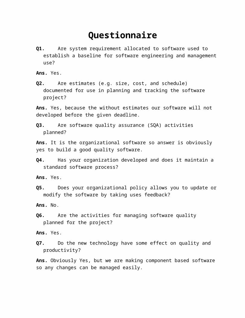
QuestionnaireQ1. Are system requirement allocated to software used to
establish a baseline for software engineering and managementuse?
Ans. Yes.
Q2. Are estimates (e.g. size, cost, and schedule) documented for use in planning and tracking the software project?
Ans. Yes, because the without estimates our software will not developed before the given deadline.
Q3. Are software quality assurance (SQA) activities planned?
Ans. It is the organizational software so answer is obviously yes to build a good quality software.
Q4. Has your organization developed and does it maintain a standard software process?
Ans. Yes.
Q5. Does your organizational policy allows you to update ormodify the software by taking uses feedback?
Ans. No.
Q6. Are the activities for managing software quality planned for the project?
Ans. Yes.
Q7. Do the new technology have some effect on quality and productivity?
Ans. Obviously Yes, but we are making component based softwareso any changes can be managed easily.

Q8. How much pressure it puts on you to develop a cost effective, reliable software in a limited amount of the timeand how you handle this?
Ans. Not very much, because we will not include any unnecessary features so that it will be cost effective and developed in given time.

InterviewQ1. Do you want restore and backup property in the
software?
Ans. Yes.
Q2. What kinds of the interface you expects from this software?
Ans. It should be simple and user friendly. So that a common person or student can operate it easily.
Q3. Can you provide any kinds of suggestion to reduce its cost?
Ans. If the system works efficiently then, cost doesn’t matter. But yeah you can reduce cost, by not imposing extra taxes and not adding unnecessary features.
Q4. Do you want online support in your system or should ewedesign it for offline works only?
Ans. No, we do want this software to work online. So that student and faculties access it from anywhere.
Q5. Do you want this software to work on a specific computing environment?
Ans. No, software should work on most of the common operating systems. It should have latest technology

Software Requirements Specification(SRS)
I. IntroductionPurposeScopeNeed for the proposed system
II. Overall DescriptionProduct Perspective
User Interface Hardware Interface Software Interface Communication Interface Memory Constraints Operations Site Adaption RequirementsProduct FunctionsConstraintsAssumptions
III. Specific RequirementsUser Class and CharacteristicsFunctional RequirementsPerformance RequirementsNon-Functional RequirementsExternal Interface Requirements
User Interface Hardware Interface Software InterfaceSoftware System Attributes

Introduction:Today all the work at the time of admission of the students is done manually by ink and paper, which is very, slow and consumingmuch efforts and time. It is required to Design of Computerized Automated Management System, to speed up and make it easy to use system. It reduces the manpower needed to perform the entire admission and administration task by reducing the paper works needed. The main goal of the system is to automate the process carried out in the organization with improved performance and realize the vision of paperless work.
1. Purpose:Its purpose is to automate and centralize the whole system of thedepartment. We are attempting to improve our existing system thatruns on pen and papers. The main goal of the system is to automate the process carried out in the organization with improved performance and realize the vision of paperless works.
2. Scope:It is more efficient and convenient for the colleges. It reduces the manpower needed to perform the entire administration task by reducing the paper works needed. If all the work is done by the computer there will be no chance of errors.
Moreover storing and retrieving of the information is easy, so work can be done speedily and in time.
3. Need for the proposed system:Automation for management system will use the centralized database of the whole system of the department.
Features and Benefits:User friendly Report are easily generated Very less paper works
Computer operator control

Overall Description1) Product Perspective:
I. User interface: The application that will be developing will have a user friendly and menu based interface.Following screens will be provided:
A login screen for entering the username and passwords, so that the authorized user can have an access without any problems.There will be a screen which will be displaying the major tasks that the system will be performing e.g. add details, delete, view details of the students.All the major tasks mentioned above will have their separate forms and will perform the desired actions.
II. Hardware Interface:Intel Pentium 4 or higher processor1.5Ghz512MB of RAM or More
III. Software Interface:Operating system: Window XP,Vista,7,8,8.1 and higherPlatform: .NETDatabase: SQL serverLanguage: Visual Studio 2013 (ASP.NET & C#)
IV. Communication Interface: The communication between the different parts of the system is important they depend on each other.
V. Memory Constraints:At least 512MB RAM and 4GB of the Hard disk space will berequired for running the application.
VI. Operations:The system will have the user-friendly interfaces. The system will maintain the records of the studentsand staff.Only the admin can perform the operations on the databases. User can only see their details or information’s.

There will be additional backup for any kind damagesor data lost.
VII. Site Adaptation Requirements:The centralized database is used so that the system can communicate to retrieve the information.
2) Product Function:There will be user name and password to allow access only toauthorized users (Admin). The user can take only theirinformation.Software will perform the following functions:
Only the admin can modify the data.Student can only retrieve their information.
3) Constraints:There is a backup for system.GUI feature available.
4) Assumptions:The product require a computer with internet connectivity.The system must be able to respond to the database Softwarewithin reasonable time.

Specific Requirements:1) User class and characteristics:
Administrator: The admin keeps tracks of entries of newstudents to department, entries of new staff to thedepartment, entry of the attendance information etc.Admin can modify the data.User: User can retrieve the information from database bysending the queries.
2) Functional Requirement:The basic service that the automation for management systemincludes:
Entry of the new student to the department.Entry of new staff to the department.Entry of the attendance information.Entry of the examination marks.Provide individual and class-wise report.Update the student profile depending on attendance andexam status.Workloads.System shall provide for password protected administratoraccess to add, delete and modify the basic serviceoffered by the system.
3) Non-functional Requirement:a) Performance Requirements:The proposed system that we are going to develop will be usedas the chief performance system for providing help to thedepartment in managing the whole database of the studentstudying in the department. Therefore, it is expected that thedatabase would perform functionally all the requirement thatare specified.
The system should be easy to handle.System should give expected performance results.The response time should be small.
b) Security Requirement:

We are going to develop a secured database. There aredifferent categories of the users namely administrator,restricted users who will viewing either all or somespecific information from the database.Depending upon the category of the user the accessrights are decided. It means if the user is anadministrator then he can be able to modify the data,append etc. All other user have the rights to retrievethe information about database.
c) Safety Requirement:The database may get crashed at any time certain time due tovirus or OS failure. Therefore, it is required to take thedatabase backup.
4) External Interface Requirement:a) User Interface:
The application that will be developing will have a userfriendly and menu based interface.Following screens will be provided:
A login screen for entering the user name and passwordso that the authorized user can have an access todatabase without any problems.There will be a screen which will be displaying themajor tasks that system will be performing i.e. adddetails, delete, details, view details of the student.All the major tasks mentioned above will have theirseparate forms and will perform the desired actions.There will be another screen for users for viewing theinformation.
b) Software Interface:Operating system: Window XP,Vista,7,8,8.1 and higherPlatform: .NETDatabase: SQL serverLanguage: Visual Studio 2013 (ASP.NET & C#)
c) Hardware Interface:Intel Pentium 4 or higher processor1.5 GHz

512MB of RAM or More5) Software System Attributes:
The application is easy to interact and communicate with user.This application provides better user interface for ease of working.

Data Flow Diagram(DFD’s)


Data DictionaryStudent info = [Name + Roll No. + D.O.B + Address + Course]
Performance = [Internal marks + Assignment Marks | Project marks]
Faculty info = [Name + ID No. + D.O.B + Department + Address]
Working Days Status = [Total working days + No. of leaves]

Use casesIn software engineering, a use case is a list of steps, typicallydefining interaction between a role (known in Unified modeling language (UML) as an “actor”) and a system to achieve a goal.
In system engineering use cases are used at a higher level that within software engineering, often representing missions or stakeholders goals.
Use case 1: Update an entry of the student.
Primary Actor: Admin
Precondition: Admin has logged in.
Main Success Scenario:
1. Admin checks all the previously filled data.2. Admin retrieve the student data which is meant to update.3. Admin updated the selected student data from the database.4. System confirm the modification.
Exception Scenario:
-2a) There is no such student data, which the searched for.
System shows error message.
Use case 1: Update an entry of the student.
Primary Actor: Admin
Precondition: Admin has logged in.
Main Success Scenario:
1. Admin checks all the previously filled data.2. Admin retrieve the student data which is meant to update.3. Admin updated the selected student data from the
database.4. System confirm the modification.
Exception Scenario:
-2a) There is no such student data, which the searched for.
Use case 2: View Attendance.
Primary Actor: User (Student).
Precondition: User should be student of that college.
Main Success Scenario:
1. Student is asked to fill his roll no. by the software.2. Now the student’s record displayed on the screen.3. Student is asked to choose various options (Name,
Address, Attendance etc.).4. Student choose his attendance.5. Attendance displayed on the screen.
Exception Scenario:
-1a) Student data is missing.
System shows error message.
-5a) The attendance is not up to date.

Function PointFunction point (FP) analysis is a structural technique of problemsolving. FP is a method to break system into small components so that they can better understand and analyzed.
Function point analysis is a unique measure for software.
Function point can used to Estimate the cost or effort required to design, code
and test the software. Predict the numbers of the errors that will encountered
during the testing. Forecast the number of component and/or the number of
projected source code lines in the implemented system.FP are derived using an empirical relationship based on
Countable (direct) measures of the software’s information domain.
Assessments of the software’s complexity.
Information domain values:
Number of the External inputs (EIs): EIs is an elementary process in which data crosses the
boundary from outside to inside. This data is coming external to the application. The data may come from a data input screen or another application. The data may be used tomaintain one or more internal logical files. The data can beeither control information or business information. If the data is control information it does not have to maintain an internal logical file. If an external input adds, changes
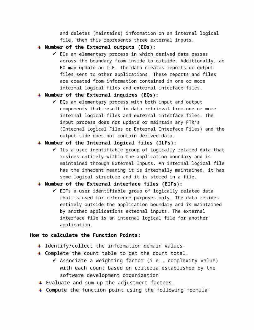
and deletes (maintains) information on an internal logical file, then this represents three external inputs.
Number of the External outputs (EOs): EOs an elementary process in which derived data passes
across the boundary from inside to outside. Additionally, anEO may update an ILF. The data creates reports or output files sent to other applications. These reports and files are created from information contained in one or more internal logical files and external interface files.
Number of the External inquires (EQs): EQs an elementary process with both input and output
components that result in data retrieval from one or more internal logical files and external interface files. The input process does not update or maintain any FTR’s (Internal Logical Files or External Interface Files) and theoutput side does not contain derived data.
Number of the Internal logical files (ILFs): ILs a user identifiable group of logically related data that
resides entirely within the application boundary and is maintained through External Inputs. An internal logical filehas the inherent meaning it is internally maintained, it hassome logical structure and it is stored in a file.
Number of the External interface files (EIFs): EIFs a user identifiable group of logically related data
that is used for reference purposes only. The data resides entirely outside the application boundary and is maintained by another applications external inputs. The external interface file is an internal logical file for another application.
How to calculate the Function Points:
Identify/collect the information domain values.Complete the count table to get the count total.
Associate a weighting factor (i.e., complexity value) with each count based on criteria established by the software development organization
Evaluate and sum up the adjustment factors. Compute the function point using the following formula:

FP = count total*[0.65 + (0.01* (Fi))]∑
Value Adjustment Factors:
Rate each factor (Fi, i=1 to14) on a scale of 0 to 5:
1. DOES THE SYSTEM REQUIRE RELIABLE BACKUP AND RECOVERY? 52. ARE SPECIALIZED DATA COMMUNICATIONS REQUIRED TO TRANSFER INFORMATION
TO OR FROM THE APPLICATION? 3
3. ARE THERE DISTRIBUTED PROCESSING FUNCTIONS? 04. IS PERFORMANCE CRITICAL? 35. WILL THE SYSTEM IS AN EXISTING, HEAVILY UTILIZED OPERATIONAL
ENVIRONMENT?3
6. DOES THE SYSTEM REQUIRE ONLINE DATA ENTRY? 57. DOES THE ONLINE DATA ENTRY REQUIRE THE INPUT TRANSACTION TO BE
BUILT OVER MULTIPLE SCREENS OR OPERATIONS?5
8. ARE THE ILFS UPDATED ONLINE? 49. ARE THE INPUTS, OUTPUTS, FILES, OR INQUIRIES COMPLEX? 210.
IS THE INTERNAL PROCESSING COMPLEX? 3
11.
IS THE CODE DESIGNED TO BE REUSABLE? 3
12.
ARE CONVERSION AND INSTALLATION INCLUDED IN THE DESIGN? 2
13.
IS THE SYSTEM DESIGNED FOR MULTIPLE INSTALLATIONS IN DIFFERENT ORGANIZATIONS?
3
14.
IS THE APPLICATION DESIGNED TO FACILITATE CHANGE AND EASE OF USE BYTHE USER?
4
Total: 45

Calculating FP:Consider the value of the above question be simple.
Weighting FactorInformation Domain Values
Count Simple
Average
Complex
External Inputs (EIs) 2 x
3 4 6 6
External Outputs (Eos) 1 x
4 5 7 4
External Inquiries (EQs) 6 x
3 4 6 18
Internal Logical Files (ILFs) 2 x
7 10 15 14
External interface Files (EIFs) 2 x
5 7 10 10
Count Total: 52
Since complexity is simple so,
(F∑ i) = 45,
And project FP is 57.2.

Effort EstimationWork effort is the labor required to complete an activity. Work effort is typically the amount of focused an uninterrupted labor time required to compute an activity.
FP-based Estimation: Decomposition for FP-based estimation focuses on information domain values rather than software functions.
FP estimated =57.2
To derive an estimate of effort on computed FP value, “productivity rate” must be derived.
The organizational average productivity rate for system of this type is 6.5 FP/pm.
An estimate of the project effort is computed using:
Estimated Effort = FP/PROD
= 57.2/6.5
= 8.8

Time Line Chart

Risk TableRisks Catego
ryProbabil
ityImpact
Size estimate may be significantly low
PS 60% 2
Larger number of the user than planned
PS 30% 3
Less reuse than planned PS 70% 2
End-user resist system BU 40% 3
Delivery deadline will be requirements
BU 50% 2
Funding will be lost CU 40% 1
Customer will change requirements
PS 80% 2
Technology will not meet expectations
TE 30% 1
Look of training on tools DE 80% 3
Staff inexperienced ST 30% 2
Staff turnover will be high
ST 60% 2

Architectural Design
Admin Software
User
Hardware
ViewinfoGetinfo
Manage data
Generate Report
Admin
Login
ModifRemov
User ID/ password
Editing entry
Deleting entry

Basis Path TestingBasis path testing, or structured testing, is a white box method for designing test cases. The method analyzes the control flow graph of a program to find a set of linearly independent paths ofexecution. The method normally uses cyclomatic complexity to determine the number of linearly independent paths and then generates test cases for each path thus obtained. Basis path testing guarantees complete branch coverage (all CFG edges), but achieves that without covering all possible CFG paths—the latter is usually too costly. Basis path testing has been widely used and studied.
To measure the logical complexity of our software we consider thefollowing procedure:
void view_info(){
cout<<"Select option: \n";
cout<<"1.Student info.\n";
cout<<"2.Faculty info. \n";
char ch;
cin>>ch;
if(ch==1){
cout<<"Select option: \n";
cout<<"1.Student Profile.\n";
cout<<"2.Student Performance.\n";
cout<<"3.Attendance.\n";
cout<<"4.Fee details.\n";
char ch;
cin>>ch;
if(ch==1){
User
View
Generate
View details
Print Report

cout<<"Student Profile: \n";
obj.profile();
}else if(ch==2){
cout<<"Student Performance: ";
obj.perfrm();
}else if(ch==3){
cout<<"Attendance: ";
obj.attendance();
}else{
cout<<"Fee Details: ";
obj.pay();
}
}else{
cout<<"Select option: \n";
cout<<"1.Profile\n";
cout<<"2.Working Days\n";
char ch;
cin>>ch;
if(ch==1){
cout<<"Profile";
obj.profile();
}else{
cout<<"Working Days";
obj.wday();
}

}
}

Flow Graph of the above procedure:
1
2
3
4
6 5
78
1
1
11
1
91

Cyclomatic complexity: Cyclomatic complexity V (G) for a flowgraph G is defined as
V (G) =E-N+2
=19-15+2 = 6
So that no. of the independent path is 6.
Path 1: 1-2-3-4-5-15
Path 2: 1-2-3-4-6-7-15
Path 3: 1-2-3-4-6-8-9-15
Path 4: 1-2-3-4-6-8-10-15
Path 5: 1-2-11-12-13-15
Path 6: 1-2-11-14-15
Test Cases:Test
Scenario
Requirements Test cases Test Data Result
CheckLogin
Functionality
All correct combinations entered in login/password field will let user in.
All other combinations will be rejected.
Login includes
Check response on entering valid username andpassword.
Username:mohit0749Password:temp@123
Login successful
Check response on entering invalid username andpassword.
Username: MOHITPassword: temp
username is invalid

minimum 8 letters and 4digits/special characters or both (except spacecharacter).
Login is not case sensitive.
Password cannot be less than any8 characters (except spacecharacter).
Password is not case sensitive.
“Login in “button is disable unless both fields typed in.
Check response when username andpassword field is empty and login buttonis pressed.
Username: Password:
Username andpassword invalid
Screen ShotsAdmin Section:
Automation Management System
Username:
Password:
Administrator Login Area

FacultyStudent
Enter Student name:
1234
Find
Enter Student Roll No.:
XYZ
Automation Management System
Select Course:
Cance
None
Search

User Section:
Edit
Automation Management System
ChangePhoto
Attendance Performance
Profile Fee details
Remove
Name: XYZFather Name: ABCMother Name: DEFCourse: B.tech computer ScienceYear: Second Roll No.: 1234Mob. No.: +91-1234567890Address: New Delhi
FacultyStudent
Detai
Automation ManagementSystem
Select Course:Enter your name:
XYZ
1234Enter Your Roll No.:
Submi
All
Automation Management Systemhttp://www.mysite.edu/ams/ams.php/

Automation Management Systemhttp://www.mysite.edu/ams/ams.php/
AttendanceProfile
PerformanceFee details
Automation ManagementSystem
Name: XYZFather Name: ABCMother Name: DEFCourse: B.tech computer ScienceYear: Second Roll No.: 1234Mob. No.: +91-1234567890Address: New Delhi
Generate
Detai

BibliographyBooks
[1] R.S. Pressman, Software Engineering: A Practitioner’s Approach, McGraw-Hill, Ed 7, 2010.
[2] P. Jalote, an Integrated Approach to Software Engineering, Narosa Publishing House, Edition 3, 2011.
Other References[1] https://en.wikipedia.org/ [2] https://www.google.co.in/ [3] https://creately.com/