
Cluster Server 7.1 Configuration and Upgrade Guide - Solaris
359
Cluster Server 7.1 Configuration and Upgrade Guide - Solaris April 2016
-
Upload
khangminh22 -
Category
Documents
-
view
0 -
download
0
Transcript of Cluster Server 7.1 Configuration and Upgrade Guide - Solaris

Cluster Server 7.1Configuration and UpgradeGuide - Solaris
April 2016
Cluster Server Configuration and Upgrade GuideLast updated: 2016-04-27
Document version: 7.1 Rev 0
Legal NoticeCopyright © 2016 Veritas Technologies LLC. All rights reserved.
Veritas, the Veritas Logo, and NetBackup are trademarks or registered trademarks of VeritasTechnologies LLC or its affiliates in the U.S. and other countries. Other names may betrademarks of their respective owners.
This product may contain third party software for which Veritas is required to provide attributionto the third party (“Third Party Programs”). Some of the Third Party Programs are availableunder open source or free software licenses. The License Agreement accompanying theSoftware does not alter any rights or obligations you may have under those open source orfree software licenses. Refer to the third party legal notices document accompanying thisVeritas product or available at:
https://www.veritas.com/about/legal/license-agreements
The product described in this document is distributed under licenses restricting its use, copying,distribution, and decompilation/reverse engineering. No part of this document may bereproduced in any form by any means without prior written authorization of Veritas TechnologiesLLC and its licensors, if any.
THE DOCUMENTATION IS PROVIDED "AS IS" AND ALL EXPRESS OR IMPLIEDCONDITIONS, REPRESENTATIONS AND WARRANTIES, INCLUDING ANY IMPLIEDWARRANTY OF MERCHANTABILITY, FITNESS FOR A PARTICULAR PURPOSE ORNON-INFRINGEMENT, ARE DISCLAIMED, EXCEPT TO THE EXTENT THAT SUCHDISCLAIMERS ARE HELD TO BE LEGALLY INVALID. VERITAS TECHNOLOGIES LLCSHALL NOT BE LIABLE FOR INCIDENTAL OR CONSEQUENTIAL DAMAGES INCONNECTION WITH THE FURNISHING, PERFORMANCE, OR USE OF THISDOCUMENTATION. THE INFORMATION CONTAINED IN THIS DOCUMENTATION ISSUBJECT TO CHANGE WITHOUT NOTICE.
The Licensed Software and Documentation are deemed to be commercial computer softwareas defined in FAR 12.212 and subject to restricted rights as defined in FAR Section 52.227-19"Commercial Computer Software - Restricted Rights" and DFARS 227.7202, et seq."Commercial Computer Software and Commercial Computer Software Documentation," asapplicable, and any successor regulations, whether delivered by Veritas as on premises orhosted services. Any use, modification, reproduction release, performance, display or disclosureof the Licensed Software and Documentation by the U.S. Government shall be solely inaccordance with the terms of this Agreement.
Veritas Technologies LLC500 E Middlefield RoadMountain View, CA 94043

http://www.veritas.com
Technical SupportTechnical Support maintains support centers globally. All support services will be deliveredin accordance with your support agreement and the then-current enterprise technical supportpolicies. For information about our support offerings and how to contact Technical Support,visit our website:
https://www.veritas.com/support
You can manage your Veritas account information at the following URL:
https://my.veritas.com
If you have questions regarding an existing support agreement, please email the supportagreement administration team for your region as follows:
[email protected] (except Japan)
DocumentationMake sure that you have the current version of the documentation. Each document displaysthe date of the last update on page 2. The document version appears on page 2 of eachguide. The latest documentation is available on the Veritas website:
https://sort.veritas.com/documents
Documentation feedbackYour feedback is important to us. Suggest improvements or report errors or omissions to thedocumentation. Include the document title, document version, chapter title, and section titleof the text on which you are reporting. Send feedback to:
You can also see documentation information or ask a question on the Veritas community site:
http://www.veritas.com/community/
Veritas Services and Operations Readiness Tools (SORT)Veritas Services and Operations Readiness Tools (SORT) is a website that provides informationand tools to automate and simplify certain time-consuming administrative tasks. Dependingon the product, SORT helps you prepare for installations and upgrades, identify risks in yourdatacenters, and improve operational efficiency. To see what services and tools SORT providesfor your product, see the data sheet:
https://sort.veritas.com/data/support/SORT_Data_Sheet.pdf

Section 1 Configuring Cluster Server using thescript-based installer ......................................... 13
Chapter 1 I/O fencing requirements ................................................. 14
I/O fencing requirements ................................................................ 14Coordinator disk requirements for I/O fencing ............................... 14CP server requirements ........................................................... 15Non-SCSI-3 I/O fencing requirements ......................................... 17
Chapter 2 Preparing to configure VCS clusters for dataintegrity ........................................................................... 19
About planning to configure I/O fencing ............................................. 19Typical VCS cluster configuration with disk-based I/O fencing ...
2 3........................................................................................... 24Recommended CP server configurations ..................................... 25
Setting up the CP server ................................................................ 27Planning your CP server setup .................................................. 28Installing the CP server using the installer ................................... 29Setting up shared storage for the CP server database .................... 29Configuring the CP server using the installer program .................... 30Configuring the CP server manually ........................................... 39Configuring CP server using response files .................................. 44Verifying the CP server configuration .......................................... 48
Chapter 3 Configuring VCS ................................................................ 49
Overview of tasks to configure VCS using the product installer .............. 50Starting the software configuration ................................................... 50Specifying systems for configuration ................................................. 51Configuring the cluster name .......................................................... 52Configuring private heartbeat links ................................................... 52Configuring the virtual IP of the cluster .............................................. 55Configuring VCS in secure mode ..................................................... 58
Contents
Setting up trust relationships for your VCS cluster ............................... 58Configuring a secure cluster node by node ........................................ 60
Configuring the first node ......................................................... 60Configuring the remaining nodes ............................................... 61Completing the secure cluster configuration ................................. 62
Adding VCS users ........................................................................ 64Configuring SMTP email notification ................................................. 65Configuring SNMP trap notification ................................................... 67Configuring global clusters ............................................................. 68Completing the VCS configuration ................................................... 69Verifying and updating licenses on the system .................................... 70
Checking licensing information on the system .............................. 70Updating product licenses ........................................................ 71
Chapter 4 Configuring VCS clusters for data integrity ................ 73
Setting up disk-based I/O fencing using installer ................................. 73Initializing disks as VxVM disks ................................................. 73Configuring disk-based I/O fencing using installer ......................... 74Refreshing keys or registrations on the existing coordination points
for disk-based fencing using the installer ............................... 77Checking shared disks for I/O fencing ......................................... 78
Setting up server-based I/O fencing using installer .............................. 82Refreshing keys or registrations on the existing coordination points
for server-based fencing using the installer ............................ 90Setting the order of existing coordination points for server-based
fencing using the installer ................................................... 91Setting up non-SCSI-3 I/O fencing in virtual environments using
installer ................................................................................ 95Setting up majority-based I/O fencing using installer ............................ 96Enabling or disabling the preferred fencing policy ................................ 98
Section 2 Automated configuration using responsefiles ............................................................................... 101
Chapter 5 Performing an automated VCS configuration ......... 102
Configuring VCS using response files ............................................. 102Response file variables to configure VCS ........................................ 103Sample response file for configuring Cluster Server ........................... 112
5Contents

Chapter 6 Performing an automated I/O fencingconfiguration using response files ........................ 114
Configuring I/O fencing using response files ..................................... 114Response file variables to configure disk-based I/O fencing ................. 115Sample response file for configuring disk-based I/O fencing ................ 118Response file variables to configure server-based I/O fencing .............. 119Sample response file for configuring server-based I/O fencing ............. 121Response file variables to configure non-SCSI-3 I/O fencing ................ 122Sample response file for configuring non-SCSI-3 I/O fencing ............... 123Response file variables to configure majority-based I/O fencing ............ 124Sample response file for configuring majority-based I/O fencing ........... 124
Section 3 Manual configuration ............................................. 126
Chapter 7 Manually configuring VCS ............................................. 127
About configuring VCS manually .................................................... 127Configuring LLT manually ............................................................. 128
Setting up /etc/llthosts for a manual installation ........................... 128Setting up /etc/llttab for a manual installation .............................. 128About LLT directives in /etc/llttab file ......................................... 130Additional considerations for LLT for a manual installation ............. 131
Configuring GAB manually ............................................................ 132Configuring VCS manually ............................................................ 132
Configuring the cluster UUID when creating a clustermanually ....................................................................... 134
Configuring VCS in single node mode ............................................. 134Disabling LLT, GAB, and I/O fencing on a single node
cluster .......................................................................... 135Enabling LLT, GAB, and I/O fencing on a single node cluster ......... 136
Starting LLT, GAB, and VCS after manual configuration ...................... 138About configuring cluster using VCS Cluster Configuration wizard ........ 139Before configuring a VCS cluster using the VCS Cluster Configuration
wizard ................................................................................ 140Launching the VCS Cluster Configuration wizard ............................... 141Configuring a cluster by using the VCS cluster configuration
wizard ................................................................................ 141Adding a system to a VCS cluster .................................................. 145Modifying the VCS configuration .................................................... 147
Configuring the ClusterService group ........................................ 147
6Contents

Chapter 8 Manually configuring the clusters for dataintegrity ......................................................................... 148
Setting up disk-based I/O fencing manually ...................................... 148Identifying disks to use as coordinator disks ............................... 149Setting up coordinator disk groups ........................................... 149Creating I/O fencing configuration files ...................................... 150Modifying VCS configuration to use I/O fencing ........................... 151Verifying I/O fencing configuration ............................................ 152
Setting up server-based I/O fencing manually ................................... 153Preparing the CP servers manually for use by the VCS
cluster .......................................................................... 154Generating the client key and certificates manually on the client
nodes .......................................................................... 156Configuring server-based fencing on the VCS cluster
manually ....................................................................... 158Configuring CoordPoint agent to monitor coordination points ......... 164Verifying server-based I/O fencing configuration .......................... 166
Setting up non-SCSI-3 fencing in virtual environments manually ........... 166Sample /etc/vxfenmode file for non-SCSI-3 fencing ...................... 168
Setting up majority-based I/O fencing manually ................................ 172Creating I/O fencing configuration files ...................................... 172Modifying VCS configuration to use I/O fencing ........................... 172Verifying I/O fencing configuration ............................................ 174Sample /etc/vxfenmode file for majority-based fencing .................. 175
Section 4 Upgrading VCS ......................................................... 176
Chapter 9 Planning to upgrade VCS .............................................. 177
About upgrading to VCS 7.1 .......................................................... 177Upgrading VCS in secure enterprise environments ............................ 178Supported upgrade paths ............................................................. 179Considerations for upgrading secure VCS 6.x clusters to VCS
7.1 ..................................................................................... 180Considerations for upgrading VCS to 7.1 on systems configured with
an Oracle resource ............................................................... 181Considerations for upgrading secure VCS clusters to VCS 7.1 ............. 181Considerations for upgrading CP servers ......................................... 182Considerations for upgrading CP clients .......................................... 182Using Install Bundles to simultaneously install or upgrade full releases
(base, maintenance, rolling patch), and individual patches ............ 182
7Contents

Chapter 10 Performing a VCS upgrade using theinstaller .......................................................................... 185
Before upgrading VCS using the script-based installer ........................ 185Upgrading VCS using the product installer ....................................... 185Upgrading to 2048 bit key and SHA256 signature certificates ............... 187Tasks to perform after upgrading to 2048 bit key and SHA256 signature
certificates ........................................................................... 188Deleting certificates of non-root users after upgrading to 2048 bit
key and SHA256 signature certificates ................................ 188Re-establishing WAC communication in global clusters after
upgrading to 2048 bit key and SHA256 signaturecertificates ..................................................................... 189
Re-establishing CP server and CP client communication afterupgrading to 2048 bit key and SHA256 signaturecertificates ..................................................................... 190
Re-establishing trust with Steward after upgrading to 2048 bit keyand SHA256 signature certificates ...................................... 191
Upgrading Steward to 2048 bit key and SHA256 signaturecertificates ........................................................................... 191
Chapter 11 Performing an online upgrade ..................................... 194
Limitations of online upgrade ......................................................... 194Upgrading VCS online using the installer ......................................... 194
Chapter 12 Performing a phased upgrade of VCS ...................... 197
About phased upgrade ................................................................ 197Prerequisites for a phased upgrade .......................................... 197Planning for a phased upgrade ................................................ 198Phased upgrade limitations ..................................................... 198Phased upgrade example ....................................................... 198Phased upgrade example overview .......................................... 199
Performing a phased upgrade using the product installer .................... 200Moving the service groups to the second subcluster ..................... 200Upgrading the operating system on the first subcluster ................. 203Upgrading the first subcluster .................................................. 204Preparing the second subcluster .............................................. 206Activating the first subcluster ................................................... 210Upgrading the operating system on the second subcluster ............ 211Upgrading the second subcluster ............................................. 211Finishing the phased upgrade ................................................. 213
8Contents

Chapter 13 Performing an automated VCS upgrade usingresponse files .............................................................. 216
Upgrading VCS using response files ............................................... 216Response file variables to upgrade VCS .......................................... 217Sample response file for upgrading VCS ......................................... 218
Chapter 14 Upgrading VCS using Live Upgrade and BootEnvironment upgrade ............................................... 220
About Live Upgrade .................................................................... 220Cluster Server exceptions for Live Upgrade ................................ 221
About ZFS Boot Environment (BE) upgrade ..................................... 221Supported upgrade paths for Live Upgrade and Boot Environment
upgrade .............................................................................. 222Performing Live Upgrade on Solaris 10 systems ............................... 223
Before you upgrade VCS using Solaris Live Upgrade ................... 224Creating a new Solaris 10 boot environment on the alternate boot
disk .............................................................................. 225Upgrading VCS using the installer for Solaris 10 Live
Upgrade ....................................................................... 230Completing the Solaris 10 Live Upgrade .................................... 231Verifying the Solaris 10 Live Upgrade of VCS ............................. 232Administering boot environments in Solaris 10 Live Upgrade ......... 233
Performing Boot Environment upgrade on Solaris 11 systems .............. 235Creating a new Solaris 11 BE on the primary boot disk ................. 235Upgrading VCS using the installer for upgrading BE on Solaris
11 ................................................................................ 236Completing the VCS upgrade on BE on Solaris 11 ....................... 238Verifying Solaris 11 BE upgrade .............................................. 238Administering BEs on Solaris 11 systems .................................. 239
Section 5 Adding and removing cluster nodes ........... 242
Chapter 15 Adding a node to a single-node cluster ..................... 243
Adding a node to a single-node cluster ............................................ 243Setting up a node to join the single-node cluster .......................... 244Installing and configuring Ethernet cards for private network .......... 245Configuring the shared storage ................................................ 246Bringing up the existing node .................................................. 246Installing the VCS software manually when adding a node to a
single node cluster .......................................................... 247
9Contents

Creating configuration files ..................................................... 247Starting LLT and GAB ............................................................ 247Reconfiguring VCS on the existing node .................................... 247Verifying configuration on both nodes ....................................... 249
Chapter 16 Adding a node to a multi-node VCS cluster ............. 250
Adding nodes using the VCS installer ............................................. 250Manually adding a node to a cluster ................................................ 253
Setting up the hardware ......................................................... 253Installing the VCS software manually when adding a node ............ 254Setting up the node to run in secure mode ................................. 255Configuring LLT and GAB when adding a node to the cluster ......... 258Configuring I/O fencing on the new node ................................... 261Adding the node to the existing cluster ...................................... 263Starting VCS and verifying the cluster ....................................... 264Adding a node using response files .......................................... 265
Chapter 17 Removing a node from a VCS cluster ....................... 267
Removing a node from a VCS cluster ............................................. 267Verifying the status of nodes and service groups ......................... 268Deleting the departing node from VCS configuration .................... 269Modifying configuration files on each remaining node ................... 272Removing the node configuration from the CP server ................... 273Removing security credentials from the leaving node .................. 274Unloading LLT and GAB and removing Veritas InfoScale
Availability or Enterprise on the departing node ..................... 274
Section 6 Installation reference ............................................. 277
Appendix A Services and ports ........................................................... 278
About InfoScale Enterprise services and ports .................................. 278
Appendix B Configuration files ............................................................ 280
About the LLT and GAB configuration files ....................................... 280About the AMF configuration files ................................................... 283About the VCS configuration files ................................................... 284
Sample main.cf file for VCS clusters ......................................... 285Sample main.cf file for global clusters ....................................... 287
About I/O fencing configuration files ................................................ 288Sample configuration files for CP server .......................................... 291
10Contents

Sample main.cf file for CP server hosted on a single node thatruns VCS ...................................................................... 292
Sample main.cf file for CP server hosted on a two-node SFHAcluster .......................................................................... 294
Sample CP server configuration (/etc/vxcps.conf) file output .......... 297Packaging related SMF services on Solaris 11 .................................. 297Tuning LLT variables for FSS environments ..................................... 298
Tuning LLT variables for Ethernet links ...................................... 298
Appendix C Configuring LLT over UDP ............................................ 299
Using the UDP layer for LLT .......................................................... 299When to use LLT over UDP .................................................... 299
Manually configuring LLT over UDP using IPv4 ................................. 299Broadcast address in the /etc/llttab file ...................................... 300The link command in the /etc/llttab file ....................................... 301The set-addr command in the /etc/llttab file ................................ 301Selecting UDP ports .............................................................. 302Configuring the netmask for LLT .............................................. 303Configuring the broadcast address for LLT ................................. 303Sample configuration: direct-attached links ................................ 304Sample configuration: links crossing IP routers ........................... 306
Manually configuring LLT over UDP using IPv6 ................................. 308The link command in the /etc/llttab file ....................................... 309The set-addr command in the /etc/llttab file ................................ 310Selecting UDP ports .............................................................. 310Sample configuration: direct-attached links ................................ 311Sample configuration: links crossing IP routers ........................... 313
LLT over UDP sample /etc/llttab ..................................................... 315
Appendix D Configuring the secure shell or the remote shellfor communications ................................................... 317
About configuring secure shell or remote shell communication modesbefore installing products ........................................................ 317
Manually configuring passwordless ssh ........................................... 318Setting up ssh and rsh connection using the installer -comsetup
command ............................................................................ 322Setting up ssh and rsh connection using the pwdutil.pl utility ................ 323Restarting the ssh session ............................................................ 326Enabling and disabling rsh for Solaris ............................................. 327
11Contents

Appendix E Installation script options ............................................... 329
Installation script options .............................................................. 329
Appendix F Troubleshooting VCS configuration ........................... 335
Restarting the installer after a failed network connection ..................... 335Cannot launch the cluster view link ................................................ 336Starting and stopping processes for the Veritas InfoScale products
......................................................................................... 336Installer cannot create UUID for the cluster ...................................... 337LLT startup script displays errors .................................................... 337The vxfentsthdw utility fails when SCSI TEST UNIT READY command
fails .................................................................................... 338Issues during fencing startup on VCS cluster nodes set up for
server-based fencing ............................................................. 338
Appendix G Sample VCS cluster setup diagrams for CPserver-based I/O fencing ......................................... 340
Configuration diagrams for setting up server-based I/O fencing ............ 340Two unique client clusters served by 3 CP servers ....................... 340Client cluster served by highly available CPS and 2 SCSI-3
disks ............................................................................ 341Two node campus cluster served by remote CP server and 2
SCSI-3 disks .................................................................. 343Multiple client clusters served by highly available CP server and
2 SCSI-3 disks ............................................................... 345
Appendix H Reconciling major/minor numbers for NFS shareddisks ............................................................................... 347
Reconciling major/minor numbers for NFS shared disks ..................... 347Checking major and minor numbers for disk partitions .................. 348Checking the major and minor number for VxVM volumes ............. 351
Appendix I Upgrading the Steward process .................................. 354
Upgrading the Steward process ..................................................... 354
Index .................................................................................................................. 357
12Contents

Configuring Cluster Serverusing the script-basedinstaller
■ Chapter 1. I/O fencing requirements
■ Chapter 2. Preparing to configure VCS clusters for data integrity
■ Chapter 3. Configuring VCS
■ Chapter 4. Configuring VCS clusters for data integrity
1Section

I/O fencing requirementsThis chapter includes the following topics:
■ I/O fencing requirements
I/O fencing requirementsDepending on whether you plan to configure disk-based fencing or server-basedfencing, make sure that you meet the requirements for coordination points:
■ Coordinator disksSee “Coordinator disk requirements for I/O fencing” on page 14.
■ CP serversSee “CP server requirements” on page 15.
To configure disk-based fencing or to configure server-based fencing with at leastone coordinator disk, make sure a version of Veritas Volume Manager (VxVM) thatsupports SCSI-3 persistent reservations (SCSI-3 PR) is installed on the VCS cluster.
See the Veritas InfoScale™ Installation Guide.
If you have installed Veritas InfoScale Enterprise in a virtual environment that isnot SCSI-3 PR compliant, review the requirements to configure non-SCSI-3 fencing.
See “Non-SCSI-3 I/O fencing requirements” on page 17.
Coordinator disk requirements for I/O fencingMake sure that the I/O fencing coordinator disks meet the following requirements:
■ For disk-based I/O fencing, you must have at least three coordinator disks orthere must be odd number of coordinator disks.
■ The coordinator disks must be DMP devices.
■ Each of the coordinator disks must use a physically separate disk or LUN.
1Chapter

Veritas recommends using the smallest possible LUNs for coordinator disks.
■ Each of the coordinator disks should exist on a different disk array, if possible.
■ The coordinator disks must support SCSI-3 persistent reservations.
■ Coordinator devices can be attached over iSCSI protocol but they must be DMPdevices and must support SCSI-3 persistent reservations.
■ Veritas recommends using hardware-based mirroring for coordinator disks.
■ Coordinator disks must not be used to store data or must not be included in diskgroups that store user data.
■ Coordinator disks cannot be the special devices that array vendors use. Forexample, you cannot use EMC gatekeeper devices as coordinator disks.
■ The coordinator disk size must be at least 128 MB.
CP server requirementsVCS 7.1 clusters (application clusters) support coordination point servers (CPservers) that are hosted on the following VCS and SFHA versions:
■ VCS 6.1 or later single-node cluster
■ SFHA 6.1 or later cluster
Upgrade considerations for CP servers
■ Upgrade VCS or SFHA on CP servers to version 7.1 if the current release versionis prior to version 6.1.
■ You do not need to upgrade CP servers to version 7.1 if the release version is6.1 or later.
■ CP servers on version 6.1 or later support HTTPS-based communication withapplication clusters on version 6.1 or later.
■ CP servers on version 6.1 to 7.0 support IPM-based communication withapplication clusters on versions before 6.1.
■ You need to configure VIPs for HTTPS-based communication if release versionof application clusters is 6.1 or later.
Make sure that you meet the basic hardware requirements for the VCS/SFHA clusterto host the CP server.
See the Veritas InfoScale™ Installation Guide.
15I/O fencing requirementsI/O fencing requirements
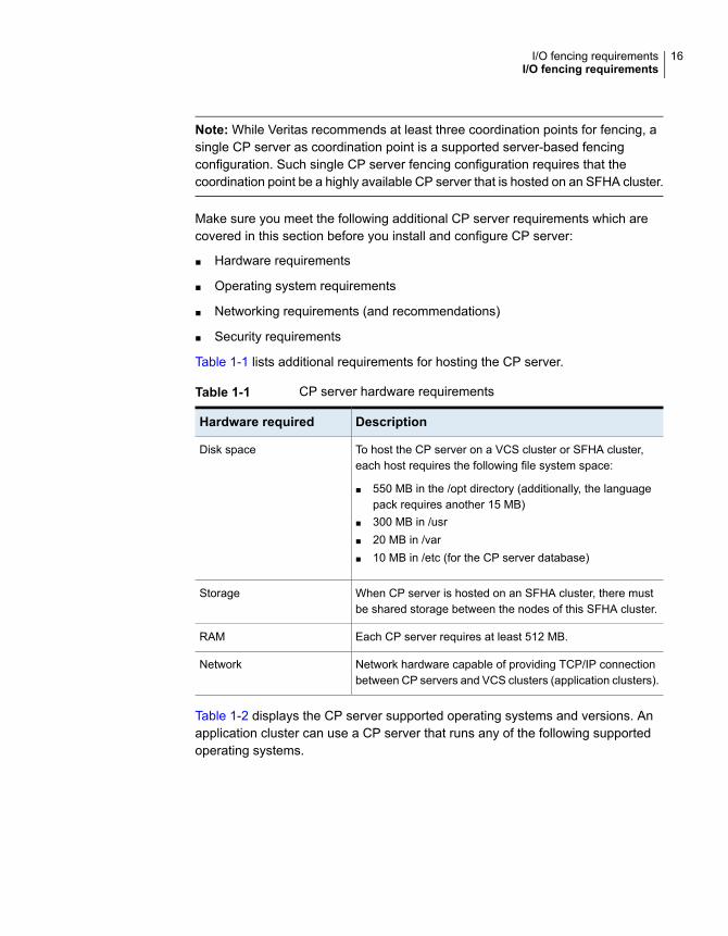
Note: While Veritas recommends at least three coordination points for fencing, asingle CP server as coordination point is a supported server-based fencingconfiguration. Such single CP server fencing configuration requires that thecoordination point be a highly available CP server that is hosted on an SFHA cluster.
Make sure you meet the following additional CP server requirements which arecovered in this section before you install and configure CP server:
■ Hardware requirements
■ Operating system requirements
■ Networking requirements (and recommendations)
■ Security requirements
Table 1-1 lists additional requirements for hosting the CP server.
Table 1-1 CP server hardware requirements
DescriptionHardware required
To host the CP server on a VCS cluster or SFHA cluster,each host requires the following file system space:
■ 550 MB in the /opt directory (additionally, the languagepack requires another 15 MB)
■ 300 MB in /usr■ 20 MB in /var■ 10 MB in /etc (for the CP server database)
Disk space
When CP server is hosted on an SFHA cluster, there mustbe shared storage between the nodes of this SFHA cluster.
Storage
Each CP server requires at least 512 MB.RAM
Network hardware capable of providing TCP/IP connectionbetween CP servers and VCS clusters (application clusters).
Network
Table 1-2 displays the CP server supported operating systems and versions. Anapplication cluster can use a CP server that runs any of the following supportedoperating systems.
16I/O fencing requirementsI/O fencing requirements

Table 1-2 CP server supported operating systems and versions
Operating system and versionCP server
CP server supports any of the following operating systems:
■ Oracle Solaris 10■ Oracle Solaris 11
Review other details such as supported operating systemlevels and architecture for the supported operating systems.
See the Veritas InfoScale 7.1 Release Notes for that platform.
CP server hosted on a VCSsingle-node cluster or on anSFHA cluster
Following are the CP server networking requirements and recommendations:
■ Veritas recommends that network access from the application clusters to theCP servers should be made highly-available and redundant. The networkconnections require either a secure LAN or VPN.
■ The CP server uses the TCP/IP protocol to connect to and communicate withthe application clusters by these network paths. The CP server listens formessages from the application clusters using TCP port 443 if the communicationhappens over the HTTPS protocol. TCP port 443 is the default port that can bechanged while you configure the CP server.Veritas recommends that you configure multiple network paths to access a CPserver. If a network path fails, CP server does not require a restart and continuesto listen on all the other available virtual IP addresses.
■ The CP server only supports Internet Protocol version 4 (IPv4) whencommunicating with the application clusters over the HTTPS protocol.
■ When placing the CP servers within a specific network configuration, you musttake into consideration the number of hops from the different application clusternodes to the CP servers. As a best practice, Veritas recommends that thenumber of hops and network latency from the different application cluster nodesto the CP servers should be equal. This ensures that if an event occurs thatresults in an I/O fencing scenario, there is no bias in the race due to differencein number of hops or network latency between the CPS and various nodes.
For communication between the VCS cluster (application cluster) and CP server,review the following support matrix:
For information about establishing secure communications between the applicationcluster and CP server, see the Cluster Server Administrator's Guide.
Non-SCSI-3 I/O fencing requirementsSupported virtual environment for non-SCSI-3 fencing:
17I/O fencing requirementsI/O fencing requirements

■ Refer to Supported Solaris operating systems section in Veritas InfoScale 7.1Release Notes.
■ Refer to Supported Oracle VM Server for SPARC section in Veritas InfoScale7.1 Release Notes
Make sure that you also meet the following requirements to configure fencing inthe virtual environments that do not support SCSI-3 PR:
■ VCS must be configured with Cluster attribute UseFence set to SCSI3
■ For server-based I/O fencing, all coordination points must be CP servers
18I/O fencing requirementsI/O fencing requirements

Preparing to configureVCS clusters for dataintegrity
This chapter includes the following topics:
■ About planning to configure I/O fencing
■ Setting up the CP server
About planning to configure I/O fencingAfter you configure VCS with the installer, you must configure I/O fencing in thecluster for data integrity. Application clusters on release version 7.1 (HTTPS-basedcommunication) only support CP servers on release version 6.1 and later.
You can configure disk-based I/O fencing, server-based I/O fencing, ormajority-based I/O fencing. If your enterprise setup has multiple clusters that useVCS for clustering, Veritas recommends you to configure server-based I/O fencing.
The coordination points in server-based fencing can include only CP servers or amix of CP servers and coordinator disks.
Veritas also supports server-based fencing with a single coordination point whichis a single highly available CP server that is hosted on an SFHA cluster.
2Chapter

Warning: For server-based fencing configurations that use a single coordinationpoint (CP server), the coordination point becomes a single point of failure. In suchconfigurations, the arbitration facility is not available during a failover of the CPserver in the SFHA cluster. So, if a network partition occurs on any applicationcluster during the CP server failover, the application cluster is brought down. Veritasrecommends the use of single CP server-based fencing only in test environments.
You use majority fencing mechanism if you do not want to use coordination pointsto protect your cluster. Veritas recommends that you configure I/O fencing in majoritymode if you have a smaller cluster environment and you do not want to investadditional disks or servers for the purposes of configuring fencing.
Note: Majority-based I/O fencing is not as robust as server-based or disk-basedI/O fencing in terms of high availability. With majority-based fencing mode, in rarecases, the cluster might become unavailable.
If you have installed VCS in a virtual environment that is not SCSI-3 PR compliant,you can configure non-SCSI-3 fencing.
See Figure 2-2 on page 22.
Figure 2-1 illustrates a high-level flowchart to configure I/O fencing for the VCScluster.
20Preparing to configure VCS clusters for data integrityAbout planning to configure I/O fencing

Figure 2-1 Workflow to configure I/O fencing
Initialize disks as VxVM disks
Check disks for I/O fencingcompliance
Manually configure disk-based I/Ofencing
Preparatory tasksvxdiskadm or vxdisksetup utilities
vxfenadm and vxfentsthdw utilities
Configuredisk-basedfencing (scsi3mode)
Configureserver-based fencing(customized mode)
Configuration tasksUse one of the following methods
Edit the values in the response fileyou created and use them withinstaller -responsefile command
Install and configure VCS or SFHA on CP serversystems
Establish TCP/IP connection between CP server andVCS cluster
Edit the values in the response file you created anduse them with installer -responsefile command
Manually configure server-based I/O fencing
Preparatory tasksIdentify an existing CP server
Configuration tasksUse one of the following methods
Run the installer -fencing, choose option 1, andfollow the prompts
If the CP server is clustered, set up shared storagefor the CP server
Run -configcps and follow the prompts (or) Manuallyconfigure CP server
Coordinationpoints for I/O
fencing?
Threedisks
At least one CPserver
Initialize disks as VxVM disks andCheck disks for I/O fencing compliance
For the disks that will serve as coordination points
Install and configure VCS
Run the installer -fencing, chooseoption 2, and follow the prompts
(OR)Set up a CP server
Establish TCP/IP connection between CP server andVCS cluster
or
or
or
orRun the installer -fencing, chooseoption 3, and follow the prompts
Configuration tasksNo coordination points
Figure 2-2 illustrates a high-level flowchart to configure non-SCSI-3 I/O fencing forthe VCS cluster in virtual environments that do not support SCSI-3 PR.
21Preparing to configure VCS clusters for data integrityAbout planning to configure I/O fencing

Figure 2-2 Workflow to configure non-SCSI-3 I/O fencing
Install and configure VCS or SFHAon CP server systems
Establish TCP/IP connectionbetween CP server and VCS cluster
Preparatory tasksIdentify existing CP servers
Configuration tasksUse one of the following methods
If the CP server is clustered, set upshared storage for the CP server
Run -configcps and followthe prompts (or) Manually configureCP server
VCS in non-SCSI3compliant virtualenvironment ?
(OR)Set up CP server
Establish TCP/IP connectionbetween CP server and VCS cluster
or
or
Configuration tasks
Configure majority-based fencing(without coordination points)
Run the installer -fencing, choose option 1,enter n to confirm that storage is not SCSI3-compliant, and follow the prompts
Run the installer -fencing,choose option 3,
enter n to confirm that storageis not SCSI3- compliant,and follow the prompts
Edit the values in the response file youcreated and use them with theinstaller -responsefile command
Manually configure non-SCSI3 server-based I/O fencing
Configure server-basedfencing (customized mode)
with CP servers
After you perform the preparatory tasks, you can use any of the following methodsto configure I/O fencing:
22Preparing to configure VCS clusters for data integrityAbout planning to configure I/O fencing

See “Setting up disk-based I/O fencing using installer” on page 73.
See “Setting up server-based I/O fencing using installer” on page 82.
See “Setting up non-SCSI-3 I/O fencing in virtual environments usinginstaller” on page 95.
See “Setting up majority-based I/O fencing using installer” on page 96.
Using the installer
See “Response file variables to configure disk-based I/O fencing”on page 115.
See “Response file variables to configure server-based I/O fencing”on page 119.
See “Response file variables to configure non-SCSI-3 I/O fencing”on page 122.
See “Response file variables to configure majority-based I/O fencing”on page 124.
See “Configuring I/O fencing using response files” on page 114.
Using response files
See “Setting up disk-based I/O fencing manually” on page 148.
See “Setting up server-based I/O fencing manually” on page 153.
See “Setting up non-SCSI-3 fencing in virtual environments manually”on page 166.
See “Setting up majority-based I/O fencing manually ” on page 172.
Manually editing configuration files
You can also migrate from one I/O fencing configuration to another.
See the Storage foundation High Availability Administrator's Guide for more details.
Typical VCS cluster configuration with disk-based I/O fencingFigure 2-3 displays a typical VCS configuration with two nodes and shared storage.The configuration uses three coordinator disks for I/O fencing.
23Preparing to configure VCS clusters for data integrityAbout planning to configure I/O fencing

Figure 2-3 Typical VCS cluster configuration with disk-based I/O fencing
Public network
Private network
Shared storage
sys1 sys2
coordinatordisk1
data disksDisk array
coordinatordisk2
coordinatordisk3
VxVM-managed and SCSI3 PR-compliant
Figure 2-4 displays a configuration using a VCS cluster (with two nodes), a singleCP server, and two coordinator disks. The nodes within the VCS cluster areconnected to and communicate with each other using LLT links.
Figure 2-4 CP server, VCS cluster, and coordinator disks
Coordinator disk Coordinator disk
CP server
Client Cluster
Node 1 Node 2
Application Storage
LLT links
TCP/IP
Fiber channel
24Preparing to configure VCS clusters for data integrityAbout planning to configure I/O fencing

Recommended CP server configurationsFollowing are the recommended CP server configurations:
■ Multiple application clusters use three CP servers as their coordination pointsSee Figure 2-5 on page 26.
■ Multiple application clusters use a single CP server and single or multiple pairsof coordinator disks (two) as their coordination pointsSee Figure 2-6 on page 26.
■ Multiple application clusters use a single CP server as their coordination pointThis single coordination point fencing configuration must use a highly availableCP server that is configured on an SFHA cluster as its coordination point.See Figure 2-7 on page 27.
Warning: In a single CP server fencing configuration, arbitration facility is notavailable during a failover of the CP server in the SFHA cluster. So, if a networkpartition occurs on any application cluster during the CP server failover, theapplication cluster is brought down.
Although the recommended CP server configurations use three coordination points,you can use more than three coordination points for I/O fencing. Ensure that thetotal number of coordination points you use is an odd number. In a configurationwhere multiple application clusters share a common set of CP server coordinationpoints, the application cluster as well as the CP server use a Universally UniqueIdentifier (UUID) to uniquely identify an application cluster.
Figure 2-5 displays a configuration using three CP servers that are connected tomultiple application clusters.
25Preparing to configure VCS clusters for data integrityAbout planning to configure I/O fencing

Figure 2-5 Three CP servers connecting to multiple application clusters
Public networkTCP/IP
TCP/IP
CP servers hosted on a single-node VCS cluster(can also be hosted on an SFHA cluster)
application clusters(clusters which run VCS, SFHA, SFCFS, or SF Oracle RAC toprovide high availability for applications)
Figure 2-6 displays a configuration using a single CP server that is connected tomultiple application clusters with each application cluster also using two coordinatordisks.
Figure 2-6 Single CP server with two coordinator disks for each applicationcluster
CP server hosted on a single-node VCS cluster
Public network
TCP/IP
TCP/IP
Fibre channelPublic networkTCP/IP
application clusters(clusters which run VCS, SFHA, SFCFS, or SF Oracle RAC toprovide high availability for applications)
Fibre channel
coordinator diskscoordinator disks
(can also be hosted on an SFHA cluster)
26Preparing to configure VCS clusters for data integrityAbout planning to configure I/O fencing

Figure 2-7 displays a configuration using a single CP server that is connected tomultiple application clusters.
Figure 2-7 Single CP server connecting to multiple application clusters
Public networkTCP/IP
TCP/IP
CP server hosted on an SFHA cluster
application clusters(clusters which run VCS, SFHA, SFCFS, or SF Oracle RAC to provide high availability for applications)
See “Configuration diagrams for setting up server-based I/O fencing” on page 340.
Setting up the CP serverTable 2-1 lists the tasks to set up the CP server for server-based I/O fencing.
Table 2-1 Tasks to set up CP server for server-based I/O fencing
ReferenceTask
See “Planning your CP server setup”on page 28.
Plan your CP server setup
See “Installing the CP server using theinstaller” on page 29.
Install the CP server
Configure the CP server cluster in securemode
See “Setting up shared storage for the CPserver database” on page 29.
Set up shared storage for the CP serverdatabase
27Preparing to configure VCS clusters for data integritySetting up the CP server

Table 2-1 Tasks to set up CP server for server-based I/O fencing(continued)
ReferenceTask
See “ Configuring the CP server using theinstaller program” on page 30.
See “Configuring the CP server manually”on page 39.
See “Configuring CP server using responsefiles” on page 44.
Configure the CP server
See “Verifying the CP server configuration”on page 48.
Verify the CP server configuration
Planning your CP server setupFollow the planning instructions to set up CP server for server-based I/O fencing.
To plan your CP server setup
1 Decide whether you want to host the CP server on a single-node VCS cluster,or on an SFHA cluster.
Veritas recommends hosting the CP server on an SFHA cluster to make theCP server highly available.
2 If you host the CP server on an SFHA cluster, review the following information.Make sure you make the decisions and meet these prerequisites when youset up the CP server:
■ You must set up shared storage for the CP server database during yourCP server setup.
■ Decide whether you want to configure server-based fencing for the VCScluster (application cluster) with a single CP server as coordination pointor with at least three coordination points.Veritas recommends using at least three coordination points.
3 Set up the hardware and network for your CP server.
See “CP server requirements” on page 15.
4 Have the following information handy for CP server configuration:
■ Name for the CP serverThe CP server name should not contain any special characters. CP servername can include alphanumeric characters, underscore, and hyphen.
28Preparing to configure VCS clusters for data integritySetting up the CP server

■ Port number for the CP serverAllocate a TCP/IP port for use by the CP server.Valid port range is between 49152 and 65535. The default port number forHTTPS-based communication is 443.
■ Virtual IP address, network interface, netmask, and networkhosts for theCP serverYou can configure multiple virtual IP addresses for the CP server.
Installing the CP server using the installerPerform the following procedure to install Veritas InfoScale Enterprise and configureVCS or SFHA on CP server systems.
To install Veritas InfoScale Enterprise and configure VCS or SFHA on the CPserver systems
◆ Depending on whether your CP server uses a single system or multiple systems,perform the following tasks:
Install Veritas InfoScale Enterprise or Veritas InfoScale Availability and configure VCS tocreate a single-node VCS cluster.
Proceed to configure the CP server.
See “ Configuring the CP server using the installer program” on page 30.
See “Configuring the CP server manually” on page 39.
CP server setup uses asingle system
Install Veritas InfoScale Enterprise and configure SFHA to create an SFHA cluster. Thismakes the CP server highly available.
See the Veritas InfoScale Installation Guide for instructions on installing SFHA.
See the Storage Foundation and High Availability Configuration and Upgrade Guide forconfiguring SFHA.
Proceed to set up shared storage for the CP server database.
CP server setup usesmultiple systems
Setting up shared storage for the CP server databaseIf you configured SFHA on the CP server cluster, perform the following procedureto set up shared storage for the CP server database.
The installer can set up shared storage for the CP server database when youconfigure CP server for the SFHA cluster.
Veritas recommends that you create a mirrored volume for the CP server databaseand that you use the VxFS file system type.
29Preparing to configure VCS clusters for data integritySetting up the CP server

To set up shared storage for the CP server database
1 Create a disk group containing the disks. You require two disks to create amirrored volume.
For example:
# vxdg init cps_dg disk1 disk2
2 Create a mirrored volume over the disk group.
For example:
# vxassist -g cps_dg make cps_vol volume_size layout=mirror
3 Create a file system over the volume.
The CP server configuration utility only supports vxfs file system type. If youuse an alternate file system, then you must configure CP server manually.
Depending on the operating system that your CP server runs, enter the followingcommand:
# mkfs -F vxfs /dev/vx/rdsk/cps_dg/cps_volumeSolaris
Configuring the CP server using the installer programUse the configcps option available in the installer program to configure the CPserver.
Perform one of the following procedures:
See “To configure the CP server on a single-node VCS cluster”on page 30.
For CP servers onsingle-node VCScluster:
See “To configure the CP server on an SFHA cluster” on page 34.For CP servers on anSFHA cluster:
To configure the CP server on a single-node VCS cluster
1 Verify that the VRTScps package is installed on the node.
2 Run the installer program with the configcps option.
# /opt/VRTS/install/installer -configcps
30Preparing to configure VCS clusters for data integritySetting up the CP server

3 Installer checks the cluster information and prompts if you want to configureCP Server on the cluster.
Enter y to confirm.
4 Select an option based on how you want to configure Coordination Point server.
1) Configure Coordination Point Server on single node VCS system
2) Configure Coordination Point Server on SFHA cluster
3) Unconfigure Coordination Point Server
5 Enter the option: [1-3,q] 1.
The installer then runs the following preconfiguration checks:
■ Checks to see if a single-node VCS cluster is running with the supportedplatform.The CP server requires VCS to be installed and configured before itsconfiguration.
The installer automatically installs a license that is identified as a CPserver-specific license. It is installed even if a VCS license exists on the node.CP server-specific key ensures that you do not need to use a VCS license onthe single-node. It also ensures that Veritas Operations Manager (VOM)identifies the license on a single-node coordination point server as a CPserver-specific license and not as a VCS license.
6 Restart the VCS engine if the single-node only has a CP server-specific license.
A single node coordination point server will be configured and
VCS will be started in one node mode, do you want to
continue? [y,n,q] (y)
7 Communication between the CP server and application clusters is secured byusing the HTTPS protocol from release 6.1.0 onwards.
Enter the name of the CP Server.
Enter the name of the CP Server: [b] cps1
31Preparing to configure VCS clusters for data integritySetting up the CP server

8 Enter valid virtual IP addresses for the CP Server with HTTPS-based securecommunication. A CP Server can be configured with more than one virtual IPaddress. For HTTPS-based communication, only IPv4 addresses are supported.
Enter Virtual IP(s) for the CP server for HTTPS,
separated by a space: [b] 10.200.58.231 10.200.58.232
10.200.58.233
Note: Ensure that the virtual IP address of the CP server and the IP addressof the NIC interface on the CP server belongs to the same subnet of the IPnetwork. This is required for communication to happen between client nodesand CP server.
9 Enter the corresponding CP server port number for each virtual IP address orpress Enter to accept the default value (443).
Enter the default port '443' to be used for all the
virtual IP addresses for HTTPS communication or assign the
corresponding port number in the range [49152, 65535] for
each virtual IP address. Ensure that each port number is
separated by a single
space: [b] (443) 54442 54443 54447
10 Enter the absolute path of the CP server database or press Enter to acceptthe default value (/etc/VRTScps/db).
Enter absolute path of the database: [b] (/etc/VRTScps/db)
11 Verify and confirm the CP server configuration information.
CP Server configuration verification:
-------------------------------------------------
CP Server Name: cps1
CP Server Virtual IP(s) for HTTPS: 10.200.58.231, 10.200.58.232,
10.200.58.233
CP Server Port(s) for HTTPS: 54442, 54443, 54447
CP Server Database Dir: /etc/VRTScps/db
-------------------------------------------------
Is this information correct? [y,n,q,?] (y)
32Preparing to configure VCS clusters for data integritySetting up the CP server

12 The installer proceeds with the configuration process, and creates a vxcps.confconfiguration file.
Successfully generated the /etc/vxcps.conf configuration file
Successfully created directory /etc/VRTScps/db on node
13 Configure the CP Server Service Group (CPSSG) for this cluster.
Enter how many NIC resources you want to configure (1 to 2): 2
Answer the following questions for each NIC resource that you want toconfigure.
14 Enter a valid network interface for the virtual IP address for the CP serverprocess.
Enter a valid network interface on sys1 for NIC resource - 1: e1000g0
Enter a valid network interface on sys1 for NIC resource - 2: e1000g1
15 Enter the NIC resource you want to associate with the virtual IP addresses.
Enter the NIC resource you want to associate with the virtual IP 10.200.58.231 (1 to 2): 1
Enter the NIC resource you want to associate with the virtual IP 10.200.58.232 (1 to 2): 2
16 Enter the networkhosts information for each NIC resource.
Veritas recommends configuring NetworkHosts attribute to ensure NIC resource
to be always online
Do you want to add NetworkHosts attribute for the NIC device e1000g0
on system sys1? [y,n,q] y
Enter a valid IP address to configure NetworkHosts for NIC e1000g0
on system sys1: 10.200.56.22
Do you want to add another Network Host? [y,n,q] n
17 Enter the netmask for virtual IP addresses. If you entered an IPv6 address,enter the prefix details at the prompt.
Note that if you are using HTTPS-based communication, only IPv4 addressesare supported.
Enter the netmask for virtual IP for
HTTPS 192.169.0.220: (255.255.252.0)
33Preparing to configure VCS clusters for data integritySetting up the CP server
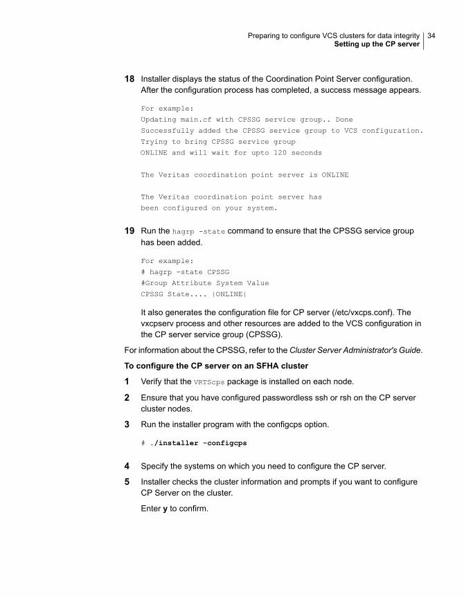
18 Installer displays the status of the Coordination Point Server configuration.After the configuration process has completed, a success message appears.
For example:
Updating main.cf with CPSSG service group.. Done
Successfully added the CPSSG service group to VCS configuration.
Trying to bring CPSSG service group
ONLINE and will wait for upto 120 seconds
The Veritas coordination point server is ONLINE
The Veritas coordination point server has
been configured on your system.
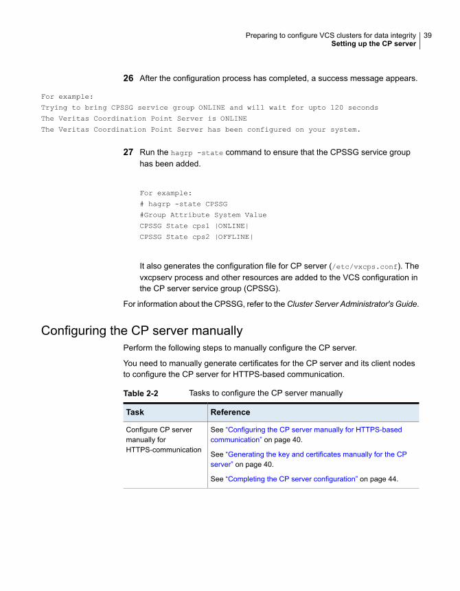
19 Run the hagrp -state command to ensure that the CPSSG service grouphas been added.
For example:
# hagrp -state CPSSG
#Group Attribute System Value
CPSSG State.... |ONLINE|
It also generates the configuration file for CP server (/etc/vxcps.conf). Thevxcpserv process and other resources are added to the VCS configuration inthe CP server service group (CPSSG).
For information about the CPSSG, refer to the Cluster Server Administrator's Guide.
To configure the CP server on an SFHA cluster
1 Verify that the VRTScps package is installed on each node.
2 Ensure that you have configured passwordless ssh or rsh on the CP servercluster nodes.
3 Run the installer program with the configcps option.
# ./installer -configcps
4 Specify the systems on which you need to configure the CP server.
5 Installer checks the cluster information and prompts if you want to configureCP Server on the cluster.
Enter y to confirm.
34Preparing to configure VCS clusters for data integritySetting up the CP server

6 Select an option based on how you want to configure Coordination Point server.
1) Configure Coordination Point Server on single node VCS system
2) Configure Coordination Point Server on SFHA cluster
3) Unconfigure Coordination Point Server
7 Enter 2 at the prompt to configure CP server on an SFHA cluster.
The installer then runs the following preconfiguration checks:
■ Checks to see if an SFHA cluster is running with the supported platform.The CP server requires SFHA to be installed and configured before itsconfiguration.
8 Communication between the CP server and application clusters is secured byHTTPS from Release 6.1.0 onwards.
Enter the name of the CP server.
Enter the name of the CP Server: [b] cps1
9 Enter valid virtual IP addresses for the CP Server. A CP Server can beconfigured with more than one virtual IP address. For HTTPS-basedcommunication, only IPv4 addresses are supported.
Enter Virtual IP(s) for the CP server for HTTPS,
separated by a space: [b] 10.200.58.231 10.200.58.232 10.200.58.233
10 Enter the corresponding CP server port number for each virtual IP address orpress Enter to accept the default value (443).
Enter the default port '443' to be used for all the virtual IP addresses
for HTTPS communication or assign the corresponding port number in the range [49152,
65535] for each virtual IP address. Ensure that each port number is separated by
a single space: [b] (443) 65535 65534 65537
11 Enter absolute path of the database.
CP Server uses an internal database to store the client information.
As the CP Server is being configured on SFHA cluster, the database should reside
on shared storage with vxfs file system. Please refer to documentation for
information on setting up of shared storage for CP server database.
Enter absolute path of the database: [b] /cpsdb
35Preparing to configure VCS clusters for data integritySetting up the CP server

12 Verify and confirm the CP server configuration information.
CP Server configuration verification:
CP Server Name: cps1
CP Server Virtual IP(s) for HTTPS: 10.200.58.231, 10.200.58.232,
10.200.58.233
CP Server Port(s) for HTTPS: 65535, 65534, 65537
CP Server Database Dir: /cpsdb
Is this information correct? [y,n,q,?] (y)
13 The installer proceeds with the configuration process, and creates a vxcps.confconfiguration file.
Successfully generated the /etc/vxcps.conf configuration file
Copying configuration file /etc/vxcps.conf to sys0....Done
Creating mount point /cps_mount_data on sys0. ... Done
Copying configuration file /etc/vxcps.conf to sys0. ... Done
Press Enter to continue.
14 Configure CP Server Service Group (CPSSG) for this cluster.
Enter how many NIC resources you want to configure (1 to 2): 2
Answer the following questions for each NIC resource that you want to configure.
15 Enter a valid network interface for the virtual IP address for the CP serverprocess.
Enter a valid network interface on sys1 for NIC resource - 1: e1000g0
Enter a valid network interface on sys1 for NIC resource - 2: e1000g1
16 Enter the NIC resource you want to associate with the virtual IP addresses.
Enter the NIC resource you want to associate with the virtual IP 10.200.58.231 (1 to 2): 1
Enter the NIC resource you want to associate with the virtual IP 10.200.58.232 (1 to 2): 2
36Preparing to configure VCS clusters for data integritySetting up the CP server

17 Enter the networkhosts information for each NIC resource.
Veritas recommends configuring NetworkHosts attribute to ensure NIC resource
to be always online
Do you want to add NetworkHosts attribute for the NIC device e1000g0
on system sys1? [y,n,q] y
Enter a valid IP address to configure NetworkHosts for NIC e1000g0
on system sys1: 10.200.56.22
Do you want to add another Network Host? [y,n,q] n
Do you want to apply the same NetworkHosts for all systems? [y,n,q] (y)
18 Enter the netmask for virtual IP addresses. If you entered an IPv6 address,enter the prefix details at the prompt.
Note that if you are using HTTPS-based communication, only IPv4 addressesare supported.
Enter the netmask for virtual IP for
HTTPS 192.168.0.111: (255.255.252.0)
19 Configure a disk group for CP server database. You can choose an existingdisk group or create a new disk group.
Veritas recommends to use the disk group that has at least
two disks on which mirrored volume can be created.
Select one of the options below for CP Server database disk group:
1) Create a new disk group
2) Using an existing disk group
Enter the choice for a disk group: [1-2,q] 2
20 Select one disk group as the CP Server database disk group.
Select one disk group as CP Server database disk group: [1-3,q] 3
1) mycpsdg
2) cpsdg1
3) newcpsdg
37Preparing to configure VCS clusters for data integritySetting up the CP server

21 Select the CP Server database volume.
You can choose to use an existing volume or create new volume for CP Serverdatabase. If you chose newly created disk group, you can only choose to createnew volume for CP Server database.
Select one of the options below for CP Server database volume:
1) Create a new volume on disk group newcpsdg
2) Using an existing volume on disk group newcpsdg
22 Enter the choice for a volume: [1-2,q] 2.
23 Select one volume as CP Server database volume [1-1,q] 1
1) newcpsvol
24 After the VCS configuration files are updated, a success message appears.
For example:
Updating main.cf with CPSSG service group .... Done
Successfully added the CPSSG service group to VCS configuration.
25 If the cluster is secure, installer creates the softlink/var/VRTSvcs/vcsauth/data/CPSERVER to /cpsdb/CPSERVER and check ifcredentials are already present at /cpsdb/CPSERVER. If not, installer createscredentials in the directory, otherwise, installer asks if you want to reuse exstingcredentials.
Do you want to reuse these credentials? [y,n,q] (y)
38Preparing to configure VCS clusters for data integritySetting up the CP server
26 After the configuration process has completed, a success message appears.
For example:
Trying to bring CPSSG service group ONLINE and will wait for upto 120 seconds
The Veritas Coordination Point Server is ONLINE
The Veritas Coordination Point Server has been configured on your system.
27 Run the hagrp -state command to ensure that the CPSSG service grouphas been added.
For example:
# hagrp -state CPSSG
#Group Attribute System Value
CPSSG State cps1 |ONLINE|
CPSSG State cps2 |OFFLINE|
It also generates the configuration file for CP server (/etc/vxcps.conf). Thevxcpserv process and other resources are added to the VCS configuration inthe CP server service group (CPSSG).
For information about the CPSSG, refer to the Cluster Server Administrator's Guide.
Configuring the CP server manuallyPerform the following steps to manually configure the CP server.
You need to manually generate certificates for the CP server and its client nodesto configure the CP server for HTTPS-based communication.
Table 2-2 Tasks to configure the CP server manually
ReferenceTask
See “Configuring the CP server manually for HTTPS-basedcommunication” on page 40.
See “Generating the key and certificates manually for the CPserver” on page 40.
See “Completing the CP server configuration” on page 44.
Configure CP servermanually forHTTPS-communication
39Preparing to configure VCS clusters for data integritySetting up the CP server

Configuring the CP server manually for HTTPS-basedcommunicationPerform the following steps to manually configure the CP server in HTTPS-basedmode.
To manually configure the CP server
1 Stop VCS on each node in the CP server cluster using the following command:
# hastop -local
2 Edit the main.cf file to add the CPSSG service group on any node. Use theCPSSG service group in the sample main.cf as an example:
See “Sample configuration files for CP server” on page 291.
Customize the resources under the CPSSG service group as per yourconfiguration.
3 Verify the main.cf file using the following command:
# hacf -verify /etc/VRTSvcs/conf/config
If successfully verified, copy this main.cf to all other cluster nodes.
4 Create the /etc/vxcps.conf file using the sample configuration file providedat /etc/vxcps/vxcps.conf.sample.
Veritas recommends enabling security for communication between CP serverand the application clusters.
If you configured the CP server in HTTPS mode, do the following:
■ Edit the /etc/vxcps.conf file to set vip_https with the virtual IP addressesrequired for HTTPS communication.
■ Edit the /etc/vxcps.conf file to set port_https with the ports used forHTTPS communication.
5 Manually generate keys and certificates for the CP server.
See “Generating the key and certificates manually for the CP server”on page 40.
Generating the key and certificates manually for the CPserverCP server uses the HTTPS protocol to establish secure communication with clientnodes. HTTPS is a secure means of communication, which happens over a securecommunication channel that is established using the SSL/TLS protocol.
40Preparing to configure VCS clusters for data integritySetting up the CP server

HTTPS uses x509 standard certificates and the constructs from a Public KeyInfrastructure (PKI) to establish secure communication between the CP server andclient. Similar to a PKI, the CP server, and its clients have their own set of certificatessigned by a Certification Authority (CA). The server and its clients trust the certificate.
Every CP server acts as a certification authority for itself and for all its client nodes.The CP server has its own CA key and CA certificate and a server certificategenerated, which is generated from a server private key. The server certificate isissued to the Universally Unique Identifier (UUID) of the CP server. All the IPaddresses or domain names that the CP server listens on are mentioned in theSubject Alternative Name section of the CP server’s server certificate
The OpenSSL library must be installed on the CP server to create the keys orcertificates.. If OpenSSL is not installed, then you cannot create keys or certificates.The vxcps.conf file points to the configuration file that determines which keys orcertificates are used by the CP server when SSL is initialized. The configurationvalue is stored in the ssl_conf_file and the default value is/etc/vxcps_ssl.properties.
To manually generate keys and certificates for the CP server:
1 Create directories for the security files on the CP server.
# mkdir -p /var/VRTScps/security/keys /var/VRTScps/security/certs
2 Generate an OpenSSL config file, which includes the VIPs.
The CP server listens to requests from client nodes on these VIPs. The servercertificate includes VIPs, FQDNs, and host name of the CP server. Clients canreach the CP server by using any of these values. However, Veritasrecommends that client nodes use the IP address to communicate to the CPserver.
The sample configuration uses the following values:
■ Config file name: https_ssl_cert.conf
■ VIP: 192.168.1.201
■ FQDN: cpsone.company.com
■ Host name: cpsone
Note the IP address, VIP, and FQDN values used in the [alt_names] sectionof the configuration file are sample values. Replace the sample values withyour configuration values. Do not change the rest of the values in theconfiguration file.
[req]
distinguished_name = req_distinguished_name
41Preparing to configure VCS clusters for data integritySetting up the CP server

req_extensions = v3_req
[req_distinguished_name]
countryName = Country Name (2 letter code)
countryName_default = US
localityName = Locality Name (eg, city)
organizationalUnitName = Organizational Unit Name (eg, section)
commonName = Common Name (eg, YOUR name)
commonName_max = 64
emailAddress = Email Address
emailAddress_max = 40
[v3_req]
keyUsage = keyEncipherment, dataEncipherment
extendedKeyUsage = serverAuth
subjectAltName = @alt_names
[alt_names]
DNS.1 = cpsone.company.com
DNS.2 = cpsone
DNS.3 = 192.168.1.201
3 Generate a 4096-bit CA key that is used to create the CA certificate.
The key must be stored at /var/VRTScps/security/keys/ca.key. Ensurethat only root users can access the CA key, as the key can be misused tocreate fake certificates and compromise security.
# /usr/bin/openssl genrsa -out /var/VRTScps/security/keys/ca.key
4096
4 Generate a self-signed CA certificate.
# /usr/bin/openssl req -new -x509 -days days -sha256 -key
/var/VRTScps/security/keys/ca.key -subj \
'/C=countryname/L=localityname/OU=COMPANY/CN=CACERT' -out \
/var/VRTScps/security/certs/ca.crt
Where, days is the days you want the certificate to remain valid, countrynameis the name of the country, localityname is the city, CACERT is the certificatename.
42Preparing to configure VCS clusters for data integritySetting up the CP server
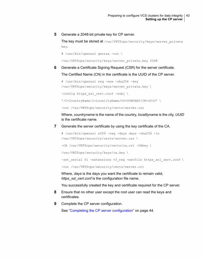
5 Generate a 2048-bit private key for CP server.
The key must be stored at /var/VRTScps/security/keys/server_privatekey.
# /usr/bin/openssl genrsa -out \
/var/VRTScps/security/keys/server_private.key 2048
6 Generate a Certificate Signing Request (CSR) for the server certificate.
The Certified Name (CN) in the certificate is the UUID of the CP server.
# /usr/bin/openssl req -new -sha256 -key
/var/VRTScps/security/keys/server_private.key \
-config https_ssl_cert.conf -subj \
'/C=CountryName/L=LocalityName/OU=COMPANY/CN=UUID' \
-out /var/VRTScps/security/certs/server.csr
Where, countryname is the name of the country, localityname is the city, UUIDis the certificate name.
7 Generate the server certificate by using the key certificate of the CA.
# /usr/bin/openssl x509 -req -days days -sha256 -in
/var/VRTScps/security/certs/server.csr \
-CA /var/VRTScps/security/certs/ca.crt -CAkey \
/var/VRTScps/security/keys/ca.key \
-set_serial 01 -extensions v3_req -extfile https_ssl_cert.conf \
-out /var/VRTScps/security/certs/server.crt
Where, days is the days you want the certificate to remain valid,https_ssl_cert.conf is the configuration file name.
You successfully created the key and certificate required for the CP server.
8 Ensure that no other user except the root user can read the keys andcertificates.
9 Complete the CP server configuration.
See “Completing the CP server configuration” on page 44.
43Preparing to configure VCS clusters for data integritySetting up the CP server

Completing the CP server configurationTo verify the service groups and start VCS perform the following steps:
1 Start VCS on all the cluster nodes.
# hastart
2 Verify that the CP server service group (CPSSG) is online.
# hagrp -state CPSSG
Output similar to the following appears:
# Group Attribute System Value
CPSSG State cps1.example.com |ONLINE|
Configuring CP server using response filesYou can configure a CP server using a generated responsefile.
On a single node VCS cluster:
◆ Run the installer command with the responsefile option to configure theCP server on a single node VCS cluster.
# /opt/VRTS/install/installer -responsefile '/tmp/sample1.res'
On a SFHA cluster:
◆ Run the installer command with the responsefile option to configure the CPserver on a SFHA cluster.
# /opt/VRTS/install/installer -responsefile '/tmp/sample1.res'
Response file variables to configure CP serverTable 2-3 describes the response file variables to configure CP server.
Table 2-3 describes response file variables to configure CP server
DescriptionList orScalar
Variable
This variable performs CP serverconfiguration task
ScalarCFG{opt}{configcps}
44Preparing to configure VCS clusters for data integritySetting up the CP server

Table 2-3 describes response file variables to configure CP server(continued)
DescriptionList orScalar
Variable
This variable describes if the CP serverwill be configured on a singlenode VCScluster
ScalarCFG{cps_singlenode_config}
This variable describes if the CP serverwill be configured on a SFHA cluster
ScalarCFG{cps_sfha_config}
This variable describes if the CP serverwill be unconfigured
ScalarCFG{cps_unconfig}
This variable describes the name of theCP server
ScalarCFG{cpsname}
This variable describes the absolute pathof CP server database
ScalarCFG{cps_db_dir}
This variable describes if reusing theexisting credentials for the CP server
ScalarCFG{cps_reuse_cred}
This variable describes the virtual IPaddresses for the CP server configuredfor HTTPS-based communication
ListCFG{cps_https_vips}
This variable describes the port numberfor the virtual IP addresses for the CPserver configured for HTTPS-basedcommunication
ListCFG{cps_https_ports}
This variable describes the NICs of thesystems for the virtual IP address
ListCFG{cps_nic_list}{cpsvip<n>}
This variable describes the netmasks forthe virtual IP addresses
ListCFG{cps_netmasks}
This variable describes the prefix lengthfor the virtual IP addresses
ListCFG{cps_prefix_length}
This variable describes the network hostsfor the NIC resource
ListCFG{cps_network_hosts}{cpsnic<n>}
This variable describes the NIC resourceto associate with the virtual IP address
ScalarCFG{cps_vip2nicres_map}{<vip>}
45Preparing to configure VCS clusters for data integritySetting up the CP server

Table 2-3 describes response file variables to configure CP server(continued)
DescriptionList orScalar
Variable
This variable describes the disk group forthe CP server database
ScalarCFG{cps_diskgroup}
This variable describes the volume for theCP server database
ScalarCFG{cps_volume}
This variable describes the disks to beused to create a new disk group for theCP server database
ListCFG{cps_newdg_disks}
This variable describes the volume sizeto create a new volume for the CP serverdatabase
ScalarCFG{cps_newvol_volsize}
This variable describes if deleting thedatabase of the CP server during theunconfiguration
ScalarCFG{cps_delete_database}
This variable describes if deleting theconfig files and log files of the CP serverduring the unconfiguration
ScalarCFG{cps_delete_config_log}
This variable defines if the CP server willbe reconfigured
ScalarCFG{cps_reconfig}
Sample response file for configuring the CP server onsingle node VCS clusterReview the response file variables and their definitions.
See Table 2-3 on page 44.
# Configuration Values:
#
our %CFG;
$CFG{cps_db_dir}="/etc/VRTScps/db";
$CFG{cps_https_ports}=[ 443 ];
$CFG{cps_https_vips}=[ "192.168.59.77" ];
$CFG{cps_netmasks}=[ "255.255.248.0" ];
$CFG{cps_network_hosts}{cpsnic1}=
46Preparing to configure VCS clusters for data integritySetting up the CP server

[ "10.200.117.70" ];
$CFG{cps_nic_list}{cpsvip1}=[ "en0" ];
$CFG{cps_singlenode_config}=1;
$CFG{cps_vip2nicres_map}{"192.168.59.77"}=1;
$CFG{cpsname}="cps1";
$CFG{opt}{configcps}=1;
$CFG{opt}{configure}=1;
$CFG{opt}{noipc}=1;
$CFG{opt}{redirect}=1;
$CFG{prod}="AVAILABILITY71";
$CFG{systems}=[ "Solaris1" ];
$CFG{vcs_clusterid}=23172;
$CFG{vcs_clustername}="clus72";
1;
Sample response file for configuring the CP server onSFHA clusterReview the response file variables and their definitions.
See Table 2-3 on page 44.
#
# Configuration Values:
#
our %CFG;
$CFG{cps_db_dir}="/cpsdb";
$CFG{cps_diskgroup}="cps_dg1";
$CFG{cps_https_ports}=[ qw(50006 50007) ];
$CFG{cps_https_vips}=[ qw(10.198.90.6 10.198.90.7) ];
$CFG{cps_netmasks}=[ qw(255.255.248.0 255.255.248.0 255.255.248.0) ];
$CFG{cps_network_hosts}{cpsnic1}=[ qw(10.198.88.18) ];
$CFG{cps_network_hosts}{cpsnic2}=[ qw(10.198.88.18) ];
$CFG{cps_newdg_disks}=[ qw(emc_clariion0_249) ];
$CFG{cps_newvol_volsize}=10;
$CFG{cps_nic_list}{cpsvip1}=[ qw(e1000g0 e1000g0) ];
$CFG{cps_sfha_config}=1;
$CFG{cps_vip2nicres_map}{"10.198.90.6"}=1;
$CFG{cps_volume}="volcps";
$CFG{cpsname}="cps1";
47Preparing to configure VCS clusters for data integritySetting up the CP server

$CFG{opt}{configcps}=1;
$CFG{opt}{configure}=1;
$CFG{opt}{noipc}=1;
$CFG{prod}="ENTERPRISE71";
$CFG{activecomponent}=[qw(SFHA71)];
$CFG{systems}=[ qw(cps1 cps2) ];
$CFG{vcs_clusterid}=49604;
$CFG{vcs_clustername}="sfha2233";
1;
Verifying the CP server configurationPerform the following steps to verify the CP server configuration.
To verify the CP server configuration
1 Verify that the following configuration files are updated with the informationyou provided during the CP server configuration process:
■ /etc/vxcps.conf (CP server configuration file)
■ /etc/VRTSvcs/conf/config/main.cf (VCS configuration file)
■ /etc/VRTScps/db (default location for CP server database for a single-nodecluster)
■ /cps_db (default location for CP server database for a multi-node cluster)
2 Run the cpsadm command to check if the vxcpserv process is listening on theconfigured Virtual IP.
If the application cluster is configured for HTTPS-based communication, noneed to provide the port number assigned for HTTP communication.
# cpsadm -s cp_server -a ping_cps
where cp_server is the virtual IP address or the virtual hostname of the CPserver.
48Preparing to configure VCS clusters for data integritySetting up the CP server

Configuring VCSThis chapter includes the following topics:
■ Overview of tasks to configure VCS using the product installer
■ Starting the software configuration
■ Specifying systems for configuration
■ Configuring the cluster name
■ Configuring private heartbeat links
■ Configuring the virtual IP of the cluster
■ Configuring VCS in secure mode
■ Setting up trust relationships for your VCS cluster
■ Configuring a secure cluster node by node
■ Adding VCS users
■ Configuring SMTP email notification
■ Configuring SNMP trap notification
■ Configuring global clusters
■ Completing the VCS configuration
■ Verifying and updating licenses on the system
3Chapter

Overview of tasks to configure VCS using theproduct installer
Table 3-1 lists the tasks that are involved in configuring VCS using the script-basedinstaller.
Table 3-1 Tasks to configure VCS using the script-based installer
ReferenceTask
See “Starting the software configuration”on page 50.
Start the software configuration
See “Specifying systems for configuration”on page 51.
Specify the systems where you want toconfigure VCS
See “Configuring the cluster name”on page 52.
See “Configuring private heartbeat links”on page 52.
Configure the basic cluster
See “Configuring the virtual IP of the cluster”on page 55.
Configure virtual IP address of the cluster(optional)
See “Configuring VCS in secure mode”on page 58.
Configure the cluster in secure mode(optional)
See “Adding VCS users” on page 64.Add VCS users (required if you did notconfigure the cluster in secure mode)
See “Configuring SMTP email notification”on page 65.
Configure SMTP email notification (optional)
See “Configuring SNMP trap notification”on page 67.
Configure SNMP email notification (optional)
See “Configuring global clusters” on page 68.Configure global clusters (optional)
See “Completing the VCS configuration”on page 69.
Complete the software configuration
Starting the software configurationYou can configure VCS using the product installer.
50Configuring VCSOverview of tasks to configure VCS using the product installer

Note: If you want to reconfigure VCS, before you start the installer you must stopall the resources that are under VCS control using the hastop command or thehagrp -offline command.
To configure VCS using the product installer
1 Confirm that you are logged in as a superuser.
2 Start the configuration using the installer.
# /opt/VRTS/install/installer -configure
The installer starts the product installation program with a copyright messageand specifies the directory where the logs are created.
3 Select the component to configure.
4 Continue with the configuration procedure by responding to the installerquestions.
Specifying systems for configurationThe installer prompts for the system names on which you want to configure VCS.The installer performs an initial check on the systems that you specify.
To specify system names for configuration
1 Enter the names of the systems where you want to configure VCS.
Enter the operating_system system names separated
by spaces: [q,?] (sys1) sys1 sys2
2 Review the output as the installer verifies the systems you specify.
The installer does the following tasks:
■ Checks that the local node running the installer can communicate withremote nodesIf the installer finds ssh binaries, it confirms that ssh can operate withoutrequests for passwords or passphrases. If ssh binaries cannot communicatewith remote nodes, the installer tries rsh binaries. And if both ssh and rshbinaries fail, the installer prompts to help the user to setup ssh or rshbinaries.
■ Makes sure that the systems are running with the supported operatingsystem
■ Makes sure the installer started from the global zone
51Configuring VCSSpecifying systems for configuration

■ Checks whether Veritas InfoScale Enterprise is installed
■ Exits if Veritas InfoScale Enterprise7.1 is not installed
3 Review the installer output about the I/O fencing configuration and confirmwhether you want to configure fencing in enabled mode.
Do you want to configure I/O Fencing in enabled mode? [y,n,q,?] (y)
See “ About planning to configure I/O fencing” on page 19.
Configuring the cluster nameEnter the cluster information when the installer prompts you.
To configure the cluster
1 Review the configuration instructions that the installer presents.
2 Enter a unique cluster name.
Enter the unique cluster name: [q,?] clus1
Configuring private heartbeat linksYou now configure the private heartbeat links that LLT uses.
VCS provides the option to use LLT over Ethernet or LLT over UDP (User DatagramProtocol). Veritas recommends that you configure heartbeat links that use LLT overEthernet for high performance, unless hardware requirements force you to use LLTover UDP. If you want to configure LLT over UDP, make sure you meet theprerequisites.
You must not configure LLT heartbeat using the links that are part of aggregatedlinks. For example, link1, link2 can be aggregated to create an aggregated link,aggr1. You can use aggr1 as a heartbeat link, but you must not use either link1 orlink2 as heartbeat links.
See “Using the UDP layer for LLT” on page 299.
The following procedure helps you configure LLT heartbeat links.
To configure private heartbeat links
1 Choose one of the following options at the installer prompt based on whetheryou want to configure LLT over Ethernet or LLT over UDP.
■ Option 1: Configure the heartbeat links using LLT over Ethernet (answerinstaller questions)
52Configuring VCSConfiguring the cluster name

Enter the heartbeat link details at the installer prompt to configure LLT overEthernet.Skip to step 2.
■ Option 2: Configure the heartbeat links using LLT over UDP (answer installerquestions)Make sure that each NIC you want to use as heartbeat link has an IPaddress configured. Enter the heartbeat link details at the installer promptto configure LLT over UDP. If you had not already configured IP addressesto the NICs, the installer provides you an option to detect the IP addressfor a given NIC.Skip to step 3.
■ Option 3: Automatically detect configuration for LLT over EthernetAllow the installer to automatically detect the heartbeat link details toconfigure LLT over Ethernet. The installer tries to detect all connected linksbetween all systems.Skip to step 5.
Note: Option 3 is not available when the configuration is a single nodeconfiguration.
2 If you chose option 1, enter the network interface card details for the privateheartbeat links.
The installer discovers and lists the network interface cards.
Answer the installer prompts. The following example shows different NICsbased on architecture:
■ For Solaris SPARC:You must not enter the network interface card that is used for the publicnetwork (typically net0.)
Enter the NIC for the first private heartbeat link on sys1:
[b,q,?] net1
Would you like to configure a second private heartbeat link?
[y,n,q,b,?] (y)
Enter the NIC for the second private heartbeat link on sys1:
[b,q,?] net2
Would you like to configure a third private heartbeat link?
[y,n,q,b,?](n)
Do you want to configure an additional low priority heartbeat
link? [y,n,q,b,?] (n)
53Configuring VCSConfiguring private heartbeat links

■ For Solaris x64:You must not enter the network interface card that is used for the publicnetwork (typically e1000g0.)
Enter the NIC for the first private heartbeat link on sys1:
[b,q,?] e1000g1
Would you like to configure a second private heartbeat link?
[y,n,q,b,?] (y)
Enter the NIC for the second private heartbeat link on sys1:
[b,q,?] e1000g2
Would you like to configure a third private heartbeat link?
[y,n,q,b,?](n)
3 If you chose option 2, enter the NIC details for the private heartbeat links. Thisstep uses examples such as private_NIC1 or private_NIC2 to refer to theavailable names of the NICs.
Enter the NIC for the first private heartbeat
link on sys1: [b,q,?] private_NIC1
Do you want to use address 192.168.0.1 for the
first private heartbeat link on sys1: [y,n,q,b,?] (y)
Enter the UDP port for the first private heartbeat
link on sys1: [b,q,?] (50000)
Would you like to configure a second private
heartbeat link? [y,n,q,b,?] (y)
Enter the NIC for the second private heartbeat
link on sys1: [b,q,?] private_NIC2
Do you want to use address 192.168.1.1 for the
second private heartbeat link on sys1: [y,n,q,b,?] (y)
Enter the UDP port for the second private heartbeat
link on sys1: [b,q,?] (50001)
Do you want to configure an additional low priority
heartbeat link? [y,n,q,b,?] (n) y
Enter the NIC for the low priority heartbeat
link on sys1: [b,q,?] (private_NIC0)
Do you want to use address 192.168.3.1 for
the low priority heartbeat link on sys1: [y,n,q,b,?] (y)
Enter the UDP port for the low priority heartbeat
link on sys1: [b,q,?] (50004)
54Configuring VCSConfiguring private heartbeat links
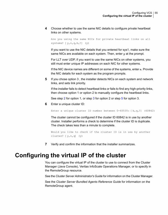
4 Choose whether to use the same NIC details to configure private heartbeatlinks on other systems.
Are you using the same NICs for private heartbeat links on all
systems? [y,n,q,b,?] (y)
If you want to use the NIC details that you entered for sys1, make sure thesame NICs are available on each system. Then, enter y at the prompt.
For LLT over UDP, if you want to use the same NICs on other systems, youstill must enter unique IP addresses on each NIC for other systems.
If the NIC device names are different on some of the systems, enter n. Providethe NIC details for each system as the program prompts.
5 If you chose option 3 , the installer detects NICs on each system and networklinks, and sets link priority.
If the installer fails to detect heartbeat links or fails to find any high-priority links,then choose option 1 or option 2 to manually configure the heartbeat links.
See step 2 for option 1, or step 3 for option 2 or step 5 for option 3.
6 Enter a unique cluster ID:
Enter a unique cluster ID number between 0-65535: [b,q,?] (60842)
The cluster cannot be configured if the cluster ID 60842 is in use by anothercluster. Installer performs a check to determine if the cluster ID is duplicate.The check takes less than a minute to complete.
Would you like to check if the cluster ID is in use by another
cluster? [y,n,q] (y)
7 Verify and confirm the information that the installer summarizes.
Configuring the virtual IP of the clusterYou can configure the virtual IP of the cluster to use to connect from the ClusterManager (Java Console), Veritas InfoScale Operations Manager, or to specify inthe RemoteGroup resource.
See theCluster Server Administrator's Guide for information on the Cluster Manager.
See the Cluster Server Bundled Agents Reference Guide for information on theRemoteGroup agent.
55Configuring VCSConfiguring the virtual IP of the cluster

To configure the virtual IP of the cluster
1 Review the required information to configure the virtual IP of the cluster.
2 When the system prompts whether you want to configure the virtual IP, entery.
3 Confirm whether you want to use the discovered public NIC on the first system.
Do one of the following:
■ If the discovered NIC is the one to use, press Enter.
■ If you want to use a different NIC, type the name of a NIC to use and pressEnter.
Active NIC devices discovered on sys1: net0
Enter the NIC for Virtual IP of the Cluster to use on sys1:
[b,q,?](net0)
4 Confirm whether you want to use the same public NIC on all nodes.
Do one of the following:
■ If all nodes use the same public NIC, enter y.
■ If unique NICs are used, enter n and enter a NIC for each node.
Is net0 to be the public NIC used by all systems
[y,n,q,b,?] (y)
5 Enter the virtual IP address for the cluster.
You can enter either an IPv4 address or an IPv6 address.
56Configuring VCSConfiguring the virtual IP of the cluster

■ Enter the virtual IP address.
Enter the Virtual IP address for the Cluster:[b,q,?] 192.168.1.16
■ Confirm the default netmask or enter another one:
Enter the netmask for IP 192.168.1.16: [b,q,?](255.255.240.0)
■ Verify and confirm the Cluster Virtual IP information.
Cluster Virtual IP verification:
NIC: net0IP: 192.168.1.16Netmask: 255.255.240.0
Is this information correct? [y,n,q] (y)
For IPv4:
■ Enter the virtual IP address.
Enter the Virtual IP address for the Cluster:[b,q,?] 2001:454e:205a:110:203:baff:feee:10
■ Enter the prefix for the virtual IPv6 address you provided. Forexample:
Enter the Prefix for IP2001:454e:205a:110:203:baff:feee:10: [b,q,?] 64
■ Verify and confirm the Cluster Virtual IP information.
Cluster Virtual IP verification:
NIC: net0IP: 2001:454e:205a:110:203:baff:feee:10Prefix: 64
Is this information correct? [y,n,q] (y)
For IPv6
If you want to set up trust relationships for your secure cluster, refer to the followingtopics:
See “Setting up trust relationships for your VCS cluster” on page 58.
See “Configuring a secure cluster node by node” on page 60.
57Configuring VCSConfiguring the virtual IP of the cluster
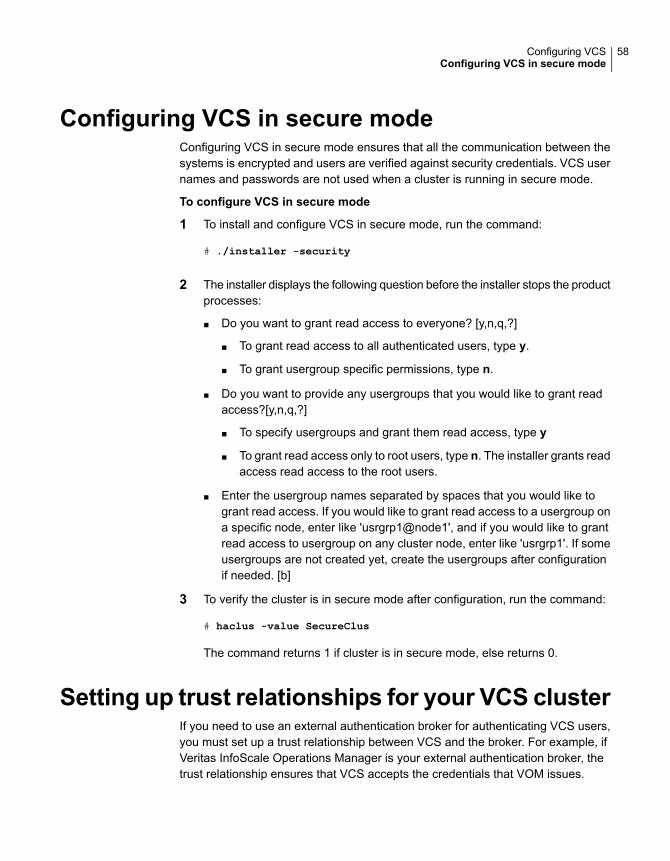
Configuring VCS in secure modeConfiguring VCS in secure mode ensures that all the communication between thesystems is encrypted and users are verified against security credentials. VCS usernames and passwords are not used when a cluster is running in secure mode.
To configure VCS in secure mode
1 To install and configure VCS in secure mode, run the command:
# ./installer -security
2 The installer displays the following question before the installer stops the productprocesses:
■ Do you want to grant read access to everyone? [y,n,q,?]
■ To grant read access to all authenticated users, type y.
■ To grant usergroup specific permissions, type n.
■ Do you want to provide any usergroups that you would like to grant readaccess?[y,n,q,?]
■ To specify usergroups and grant them read access, type y
■ To grant read access only to root users, type n. The installer grants readaccess read access to the root users.
■ Enter the usergroup names separated by spaces that you would like togrant read access. If you would like to grant read access to a usergroup ona specific node, enter like 'usrgrp1@node1', and if you would like to grantread access to usergroup on any cluster node, enter like 'usrgrp1'. If someusergroups are not created yet, create the usergroups after configurationif needed. [b]
3 To verify the cluster is in secure mode after configuration, run the command:
# haclus -value SecureClus
The command returns 1 if cluster is in secure mode, else returns 0.
Setting up trust relationships for your VCS clusterIf you need to use an external authentication broker for authenticating VCS users,you must set up a trust relationship between VCS and the broker. For example, ifVeritas InfoScale Operations Manager is your external authentication broker, thetrust relationship ensures that VCS accepts the credentials that VOM issues.
58Configuring VCSConfiguring VCS in secure mode

Perform the following steps to set up a trust relationship between your VCS clusterand a broker.
To set up a trust relationship
1 Ensure that you are logged in as superuser on one of the nodes in the cluster.
2 Enter the following command:
# /opt/VRTS/install/installer -securitytrust
The installer specifies the location of the log files. It then lists the clusterinformation such as cluster name, cluster ID, node names, and service groups.
3 When the installer prompts you for the broker information, specify the IPaddress, port number, and the data directory for which you want to establishtrust relationship with the broker.
Input the broker name of IP address: 15.193.97.204
Input the broker port: (14545)
Specify a port number on which broker is running or press Enter to accept thedefault port.
Input the data directory to setup trust with: (/var/VRTSvcs/
vcsauth/data/HAD)
Specify a valid data directory or press Enter to accept the default directory.
4 The installer performs one of the following actions:
■ If you specified a valid directory, the installer prompts for a confirmation.
Are you sure that you want to setup trust for the VCS cluster
with the broker 15.193.97.204 and port 14545? [y,n,q] y
The installer sets up trust relationship with the broker for all nodes in thecluster and displays a confirmation.
Setup trust with broker 15.193.97.204 on cluster node1
........Done
Setup trust with broker 15.193.97.204 on cluster node2
........Done
The installer specifies the location of the log files, summary file, andresponse file and exits.
59Configuring VCSSetting up trust relationships for your VCS cluster

■ If you entered incorrect details for broker IP address, port number, ordirectory name, the installer displays an error. It specifies the location ofthe log files, summary file, and response file and exits.
Configuring a secure cluster node by nodeFor environments that do not support passwordless ssh or passwordless rsh, youcannot use the -security option to enable secure mode for your cluster. Instead,you can use the -securityonenode option to configure a secure cluster node bynode. Moreover, to enable security in fips mode, use the -fips option together with-securityonenode.
Table 3-2 lists the tasks that you must perform to configure a secure cluster.
Table 3-2 Configuring a secure cluster node by node
ReferenceTask
See “Configuring the first node” on page 60.Configure security on one node
See “Configuring the remaining nodes” on page 61.Configure security on theremaining nodes
See “Completing the secure cluster configuration”on page 62.
Complete the manualconfiguration steps
Configuring the first nodePerform the following steps on one node in your cluster.
60Configuring VCSConfiguring a secure cluster node by node

To configure security on the first node
1 Ensure that you are logged in as superuser.
2 Enter the following command:
# /opt/VRTS/install/installer -securityonenode
The installer lists information about the cluster, nodes, and service groups. IfVCS is not configured or if VCS is not running on all nodes of the cluster, theinstaller prompts whether you want to continue configuring security. It thenprompts you for the node that you want to configure.
VCS is not running on all systems in this cluster. All VCS systems
must be in RUNNING state. Do you want to continue? [y,n,q] (n) y
1) Perform security configuration on first node and export
security configuration files.
2) Perform security configuration on remaining nodes with
security configuration files.
Select the option you would like to perform [1-2,q.?] 1
Warning: All VCS configurations about cluster users are deleted when youconfigure the first node. You can use the /opt/VRTSvcs/bin/hauser commandto create cluster users manually.
3 The installer completes the secure configuration on the node. It specifies thelocation of the security configuration files and prompts you to copy these filesto the other nodes in the cluster. The installer also specifies the location of logfiles, summary file, and response file.
4 Copy the security configuration files from the location specified by the installerto temporary directories on the other nodes in the cluster.
Configuring the remaining nodesOn each of the remaining nodes in the cluster, perform the following steps.
61Configuring VCSConfiguring a secure cluster node by node

To configure security on each remaining node
1 Ensure that you are logged in as superuser.
2 Enter the following command:
# /opt/VRTS/install/installer -securityonenode
The installer lists information about the cluster, nodes, and service groups. IfVCS is not configured or if VCS is not running on all nodes of the cluster, theinstaller prompts whether you want to continue configuring security. It thenprompts you for the node that you want to configure. Enter 2.
VCS is not running on all systems in this cluster. All VCS systems
must be in RUNNING state. Do you want to continue? [y,n,q] (n) y
1) Perform security configuration on first node and export
security configuration files.
2) Perform security configuration on remaining nodes with
security configuration files.
Select the option you would like to perform [1-2,q.?] 2
Enter the security conf file directory: [b]
The installer completes the secure configuration on the node. It specifies thelocation of log files, summary file, and response file.
Completing the secure cluster configurationPerform the following manual steps to complete the configuration.
To complete the secure cluster configuration
1 On the first node, freeze all service groups except the ClusterService servicegroup.
# /opt/VRTSvcs/bin/haconf -makerw
# /opt/VRTSvcs/bin/hagrp -list Frozen=0
# /opt/VRTSvcs/bin/hagrp -freeze groupname -persistent
# /opt/VRTSvcs/bin/haconf -dump -makero
2 On the first node, stop the VCS engine.
# /opt/VRTSvcs/bin/hastop -all -force
62Configuring VCSConfiguring a secure cluster node by node
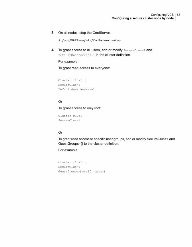
3 On all nodes, stop the CmdServer.
# /opt/VRTSvcs/bin/CmdServer -stop
4 To grant access to all users, add or modify SecureClus=1 andDefaultGuestAccess=1 in the cluster definition.
For example:
To grant read access to everyone:
Cluster clus1 (
SecureClus=1
DefaultGuestAccess=1
)
Or
To grant access to only root:
Cluster clus1 (
SecureClus=1
)
Or
To grant read access to specific user groups, add or modify SecureClus=1 andGuestGroups={} to the cluster definition.
For example:
cluster clus1 (
SecureClus=1
GuestGroups={staff, guest}
63Configuring VCSConfiguring a secure cluster node by node

5 Modify /etc/VRTSvcs/conf/config/main.cf file on the first node, and add-secure to the WAC application definition if GCO is configured.
For example:
Application wac (
StartProgram = "/opt/VRTSvcs/bin/wacstart -secure"
StopProgram = "/opt/VRTSvcs/bin/wacstop"
MonitorProcesses = {"/opt/VRTSvcs/bin/wac -secure"}
RestartLimit = 3
)
6 On all nodes, create the /etc/VRTSvcs/conf/config/.secure file.
# touch /etc/VRTSvcs/conf/config/.secure
7 On the first node, start VCS. Then start VCS on the remaining nodes.
# /opt/VRTSvcs/bin/hastart
8 On all nodes, start CmdServer.
# /opt/VRTSvcs/bin/CmdServer
9 On the first node, unfreeze the service groups.
# /opt/VRTSvcs/bin/haconf -makerw
# /opt/VRTSvcs/bin/hagrp -list Frozen=1
# /opt/VRTSvcs/bin/hagrp -unfreeze groupname -persistent
# /opt/VRTSvcs/bin/haconf -dump -makero
Adding VCS usersIf you have enabled a secure VCS cluster, you do not need to add VCS users now.Otherwise, on systems operating under an English locale, you can add VCS usersat this time.
64Configuring VCSAdding VCS users

To add VCS users
1 Review the required information to add VCS users.
2 Reset the password for the Admin user, if necessary.
Do you wish to accept the default cluster credentials of
'admin/password'? [y,n,q] (y) n
Enter the user name: [b,q,?] (admin)
Enter the password:
Enter again:
3 To add a user, enter y at the prompt.
Do you want to add another user to the cluster? [y,n,q] (y)
4 Enter the user’s name, password, and level of privileges.
Enter the user name: [b,q,?] smith
Enter New Password:*******
Enter Again:*******
Enter the privilege for user smith (A=Administrator, O=Operator,
G=Guest): [b,q,?] a
5 Enter n at the prompt if you have finished adding users.
Would you like to add another user? [y,n,q] (n)
6 Review the summary of the newly added users and confirm the information.
Configuring SMTP email notificationYou can choose to configure VCS to send event notifications to SMTP emailservices. You need to provide the SMTP server name and email addresses ofpeople to be notified. Note that you can also configure the notification afterinstallation.
Refer to the Cluster Server Administrator’s Guide for more information.
65Configuring VCSConfiguring SMTP email notification
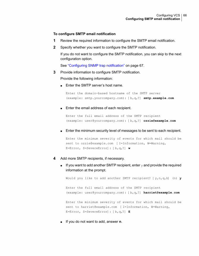
To configure SMTP email notification
1 Review the required information to configure the SMTP email notification.
2 Specify whether you want to configure the SMTP notification.
If you do not want to configure the SMTP notification, you can skip to the nextconfiguration option.
See “Configuring SNMP trap notification” on page 67.
3 Provide information to configure SMTP notification.
Provide the following information:
■ Enter the SMTP server’s host name.
Enter the domain-based hostname of the SMTP server
(example: smtp.yourcompany.com): [b,q,?] smtp.example.com
■ Enter the email address of each recipient.
Enter the full email address of the SMTP recipient
(example: [email protected]): [b,q,?] [email protected]
■ Enter the minimum security level of messages to be sent to each recipient.
Enter the minimum severity of events for which mail should be
sent to [email protected] [I=Information, W=Warning,
E=Error, S=SevereError]: [b,q,?] w
4 Add more SMTP recipients, if necessary.
■ If you want to add another SMTP recipient, enter y and provide the requiredinformation at the prompt.
Would you like to add another SMTP recipient? [y,n,q,b] (n) y
Enter the full email address of the SMTP recipient
(example: [email protected]): [b,q,?] [email protected]
Enter the minimum severity of events for which mail should be
sent to [email protected] [I=Information, W=Warning,
E=Error, S=SevereError]: [b,q,?] E
■ If you do not want to add, answer n.
66Configuring VCSConfiguring SMTP email notification

Would you like to add another SMTP recipient? [y,n,q,b] (n)
5 Verify and confirm the SMTP notification information.
SMTP Address: smtp.example.com
Recipient: [email protected] receives email for Warning or
higher events
Recipient: [email protected] receives email for Error or
higher events
Is this information correct? [y,n,q] (y)
Configuring SNMP trap notificationYou can choose to configure VCS to send event notifications to SNMP managementconsoles. You need to provide the SNMP management console name to be notifiedand message severity levels.
Note that you can also configure the notification after installation.
Refer to the Cluster Server Administrator’s Guide for more information.
To configure the SNMP trap notification
1 Review the required information to configure the SNMP notification feature ofVCS.
2 Specify whether you want to configure the SNMP notification.
If you skip this option and if you had installed a valid HA/DR license, the installerpresents you with an option to configure this cluster as global cluster. If youdid not install an HA/DR license, the installer proceeds to configure VCS basedon the configuration details you provided.
See “Configuring global clusters” on page 68.
3 Provide information to configure SNMP trap notification.
Provide the following information:
■ Enter the SNMP trap daemon port.
Enter the SNMP trap daemon port: [b,q,?] (162)
■ Enter the SNMP console system name.
Enter the SNMP console system name: [b,q,?] sys5
67Configuring VCSConfiguring SNMP trap notification

■ Enter the minimum security level of messages to be sent to each console.
Enter the minimum severity of events for which SNMP traps
should be sent to sys5 [I=Information, W=Warning, E=Error,
S=SevereError]: [b,q,?] E
4 Add more SNMP consoles, if necessary.
■ If you want to add another SNMP console, enter y and provide the requiredinformation at the prompt.
Would you like to add another SNMP console? [y,n,q,b] (n) y
Enter the SNMP console system name: [b,q,?] sys4
Enter the minimum severity of events for which SNMP traps
should be sent to sys4 [I=Information, W=Warning,
E=Error, S=SevereError]: [b,q,?] S
■ If you do not want to add, answer n.
Would you like to add another SNMP console? [y,n,q,b] (n)
5 Verify and confirm the SNMP notification information.
SNMP Port: 162
Console: sys5 receives SNMP traps for Error or
higher events
Console: sys4 receives SNMP traps for SevereError or
higher events
Is this information correct? [y,n,q] (y)
Configuring global clustersYou can configure global clusters to link clusters at separate locations and enablewide-area failover and disaster recovery. The installer adds basic global clusterinformation to the VCS configuration file. You must perform additional configurationtasks to set up a global cluster.
See the Cluster Server Administrator’s Guide for instructions to set up VCS globalclusters.
Note: If you installed a HA/DR license to set up replicated data cluster or campuscluster, skip this installer option.
68Configuring VCSConfiguring global clusters

To configure the global cluster option
1 Review the required information to configure the global cluster option.
2 Specify whether you want to configure the global cluster option.
If you skip this option, the installer proceeds to configure VCS based on theconfiguration details you provided.
3 Provide information to configure this cluster as global cluster.
The installer prompts you for a NIC, a virtual IP address, and value for thenetmask.
You can also enter an IPv6 address as a virtual IP address.
Completing the VCS configurationAfter you enter the VCS configuration information, the installer prompts to stop theVCS processes to complete the configuration process. The installer continues tocreate configuration files and copies them to each system. The installer alsoconfigures a cluster UUID value for the cluster at the end of the configuration. Afterthe installer successfully configures VCS, it restarts VCS and its related processes.
To complete the VCS configuration
1 If prompted, press Enter at the following prompt.
Do you want to stop InfoScale Enterprise processes now? [y,n,q,?] (y)
2 Review the output as the installer stops various processes and performs theconfiguration. The installer then restarts VCS and its related processes.
69Configuring VCSCompleting the VCS configuration

3 Enter y at the prompt to send the installation information to Veritas.
Would you like to send the information about this installation
to us to help improve installation in the future?
[y,n,q,?] (y) y
4 After the installer configures VCS successfully, note the location of summary,log, and response files that installer creates.
The files provide the useful information that can assist you with the configurationand can also assist future configurations.
Describes the cluster and its configured resources.summary file
Details the entire configuration.log file
Contains the configuration information that can be used to performsecure or unattended installations on other systems.
See “Configuring VCS using response files” on page 102.
response file
Verifying and updating licenses on the systemAfter you install Veritas InfoScale Enterprise, you can verify the licensing informationusing the vxlicrep program. You can replace the demo licenses with a permanentlicense.
See “Checking licensing information on the system” on page 70.
See “Updating product licenses” on page 71.
Checking licensing information on the systemYou can use the vxlicrep program to display information about the licenses on asystem.
To check licensing information
1 Navigate to the /sbin folder containing the vxlicrep program and enter:
# vxlicrep
2 Review the following output to determine the following information:
■ The license key
■ The type of license
70Configuring VCSVerifying and updating licenses on the system

■ The product for which it applies
■ Its expiration date, if any. Demo keys have expiration dates. Permanentkeys and site keys do not have expiration dates.
License Key = xxx-xxx-xxx-xxx-xxx
Product Name = Veritas InfoScale Availability
Serial Number = xxxxx
License Type = PERMANENT
OEM ID = xxxxx
Features :=
Platform = Solaris
Version = 7.1
Tier = 0
Reserved = 0
Mode = VCS
CPU_Tier = 0
Updating product licensesYou can use the ./installer -license command or the vxlicinstupgrade -k
to add the Veritas InfoScale Enterprise license key on each node. If you have VeritasInfoScale Enterprise already installed and VCS configured and you use a demolicense, you can replace the demo license.
See “Replacing a Veritas InfoScale Enterprise demo license with a permanentlicense” on page 72.
To update product licenses using the installer command
1 On any one node, enter the license key using the command:
# ./installer -license
2 At the prompt, enter your license number.
To update product licenses using the vxlicinst command
◆ On each node, enter the license key using the command:
# vxlicinstupgrade -k license key
71Configuring VCSVerifying and updating licenses on the system

Replacing a Veritas InfoScale Enterprise demo licensewith a permanent licenseWhen a VCS demo key license expires, you can replace it with a permanent licenseusing the vxlicinstupgrade(1) program.
To replace a demo key
1 Make sure you have permissions to log in as root on each of the nodes in thecluster.
2 Shut down VCS on all nodes in the cluster:
# hastop -all -force
This command does not shut down any running applications.
3 Enter the permanent license key using the following command on each node:
# vxlicinstupgrade -k license key
4 Make sure demo licenses are replaced on all cluster nodes before startingVCS.
# vxlicrep
5 Start VCS on each node:
# hastart
72Configuring VCSVerifying and updating licenses on the system
Configuring VCS clustersfor data integrity
This chapter includes the following topics:
■ Setting up disk-based I/O fencing using installer
■ Setting up server-based I/O fencing using installer
■ Setting up non-SCSI-3 I/O fencing in virtual environments using installer
■ Setting up majority-based I/O fencing using installer
■ Enabling or disabling the preferred fencing policy
Setting up disk-based I/O fencing using installerYou can configure I/O fencing using the -fencing option of the installer.
On Solaris 10 x64, disk-based I/O fencing is to be used when Storage Foundationand InfoScale Availability products co-exist.
Initializing disks as VxVM disksPerform the following procedure to initialize disks as VxVM disks.
To initialize disks as VxVM disks
1 List the new external disks or the LUNs as recognized by the operating system.On each node, enter:
# vxdisk list
2 To initialize the disks as VxVM disks, use one of the following methods:
4Chapter
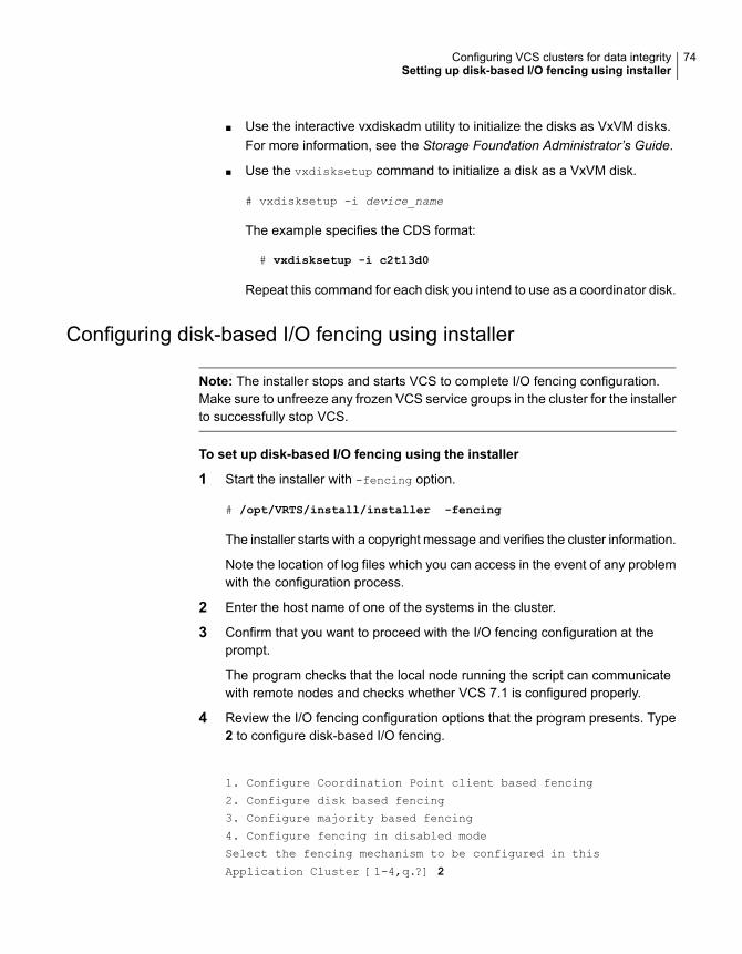
■ Use the interactive vxdiskadm utility to initialize the disks as VxVM disks.For more information, see the Storage Foundation Administrator’s Guide.
■ Use the vxdisksetup command to initialize a disk as a VxVM disk.
# vxdisksetup -i device_name
The example specifies the CDS format:
# vxdisksetup -i c2t13d0
Repeat this command for each disk you intend to use as a coordinator disk.
Configuring disk-based I/O fencing using installer
Note: The installer stops and starts VCS to complete I/O fencing configuration.Make sure to unfreeze any frozen VCS service groups in the cluster for the installerto successfully stop VCS.
To set up disk-based I/O fencing using the installer
1 Start the installer with -fencing option.
# /opt/VRTS/install/installer -fencing
The installer starts with a copyright message and verifies the cluster information.
Note the location of log files which you can access in the event of any problemwith the configuration process.
2 Enter the host name of one of the systems in the cluster.
3 Confirm that you want to proceed with the I/O fencing configuration at theprompt.
The program checks that the local node running the script can communicatewith remote nodes and checks whether VCS 7.1 is configured properly.
4 Review the I/O fencing configuration options that the program presents. Type2 to configure disk-based I/O fencing.
1. Configure Coordination Point client based fencing
2. Configure disk based fencing
3. Configure majority based fencing
4. Configure fencing in disabled mode
Select the fencing mechanism to be configured in this
Application Cluster [1-4,q.?] 2
74Configuring VCS clusters for data integritySetting up disk-based I/O fencing using installer

5 Review the output as the configuration program checks whether VxVM isalready started and is running.
■ If the check fails, configure and enable VxVM before you repeat thisprocedure.
■ If the check passes, then the program prompts you for the coordinator diskgroup information.
6 Choose whether to use an existing disk group or create a new disk group toconfigure as the coordinator disk group.
The program lists the available disk group names and provides an option tocreate a new disk group. Perform one of the following:
■ To use an existing disk group, enter the number corresponding to the diskgroup at the prompt.The program verifies whether the disk group you chose has an odd numberof disks and that the disk group has a minimum of three disks.
■ To create a new disk group, perform the following steps:
■ Enter the number corresponding to theCreate a new disk group option.The program lists the available disks that are in the CDS disk format inthe cluster and asks you to choose an odd number of disks with at leastthree disks to be used as coordinator disks.Veritas recommends that you use three disks as coordination points fordisk-based I/O fencing.
■ If the available VxVM CDS disks are less than the required, installerasks whether you want to initialize more disks as VxVM disks. Choosethe disks you want to initialize as VxVM disks and then use them tocreate new disk group.
■ Enter the numbers corresponding to the disks that you want to use ascoordinator disks.
■ Enter the disk group name.
7 Verify that the coordinator disks you chose meet the I/O fencing requirements.
You must verify that the disks are SCSI-3 PR compatible using the vxfentsthdwutility and then return to this configuration program.
See “Checking shared disks for I/O fencing” on page 78.
8 After you confirm the requirements, the program creates the coordinator diskgroup with the information you provided.
9 Verify and confirm the I/O fencing configuration information that the installersummarizes.
75Configuring VCS clusters for data integritySetting up disk-based I/O fencing using installer

10 Review the output as the configuration program does the following:
■ Stops VCS and I/O fencing on each node.
■ Configures disk-based I/O fencing and starts the I/O fencing process.
■ Updates the VCS configuration file main.cf if necessary.
■ Copies the /etc/vxfenmode file to a date and time suffixed file/etc/vxfenmode-date-time. This backup file is useful if any future fencingconfiguration fails.
■ Updates the I/O fencing configuration file /etc/vxfenmode.
■ Starts VCS on each node to make sure that the VCS is cleanly configuredto use the I/O fencing feature.
11 Review the output as the configuration program displays the location of the logfiles, the summary files, and the response files.
12 Configure the Coordination Point Agent.
Do you want to configure Coordination Point Agent on
the client cluster? [y,n,q] (y)
13 Enter a name for the service group for the Coordination Point Agent.
Enter a non-existing name for the service group for
Coordination Point Agent: [b] (vxfen) vxfen
14 Set the level two monitor frequency.
Do you want to set LevelTwoMonitorFreq? [y,n,q] (y)
15 Decide the value of the level two monitor frequency.
Enter the value of the LevelTwoMonitorFreq attribute: [b,q,?] (5)
Installer adds Coordination Point Agent and updates the main configurationfile.
16 Enable auto refresh of coordination points.
Do you want to enable auto refresh of coordination points
if registration keys are missing
on any of them? [y,n,q,b,?] (n)
See “Configuring CoordPoint agent to monitor coordination points” on page 164.
76Configuring VCS clusters for data integritySetting up disk-based I/O fencing using installer

Refreshing keys or registrations on the existing coordination pointsfor disk-based fencing using the installer
You must refresh registrations on the coordination points in the following scenarios:
■ When the CoordPoint agent notifies VCS about the loss of registration on anyof the existing coordination points.
■ A planned refresh of registrations on coordination points when the cluster isonline without having an application downtime on the cluster.
Registration loss may happen because of an accidental array restart, corruption ofkeys, or some other reason. If the coordination points lose the registrations of thecluster nodes, the cluster may panic when a network partition occurs.
Warning: Refreshing keys might cause the cluster to panic if a node leavesmembership before the coordination points refresh is complete.
To refresh registrations on existing coordination points for disk-based I/Ofencing using the installer
1 Start the installer with the -fencing option.
# /opt/VRTS/install/installer -fencing
The installer starts with a copyright message and verifies the cluster information.
Note down the location of log files that you can access if there is a problemwith the configuration process.
2 Confirm that you want to proceed with the I/O fencing configuration at theprompt.
The program checks that the local node running the script can communicatewith the remote nodes and checks whether VCS 7.1 is configured properly.
3 Review the I/O fencing configuration options that the program presents. Typethe number corresponding to refresh registrations or keys on the existingcoordination points.
Select the fencing mechanism to be configured in this
Application Cluster [1-6,q]
4 Ensure that the disk group constitution that is used by the fencing modulecontains the same disks that are currently used as coordination disks.
77Configuring VCS clusters for data integritySetting up disk-based I/O fencing using installer

5 Verify the coordination points.
For example,
Disk Group: fendg
Fencing disk policy: dmp
Fencing disks:
emc_clariion0_62
emc_clariion0_65
emc_clariion0_66
Is this information correct? [y,n,q] (y).
Successfully completed the vxfenswap operation
The keys on the coordination disks are refreshed.
6 Do you want to send the information about this installation to us to help improveinstallation in the future? [y,n,q,?] (y).
7 Do you want to view the summary file? [y,n,q] (n).
Checking shared disks for I/O fencingMake sure that the shared storage you set up while preparing to configure VCSmeets the I/O fencing requirements. You can test the shared disks using thevxfentsthdw utility. The two nodes must have ssh (default) or rsh communication.To confirm whether a disk (or LUN) supports SCSI-3 persistent reservations, twonodes must simultaneously have access to the same disks. Because a shared diskis likely to have a different name on each node, check the serial number to verifythe identity of the disk. Use the vxfenadm command with the -i option. Thiscommand option verifies that the same serial number for the LUN is returned onall paths to the LUN.
Make sure to test the disks that serve as coordinator disks.
The vxfentsthdw utility has additional options suitable for testing many disks. Reviewthe options for testing the disk groups (-g) and the disks that are listed in a file (-f).You can also test disks without destroying data using the -r option.
See the Cluster Server Administrator's Guide.
Checking that disks support SCSI-3 involves the following tasks:
■ Verifying the Array Support Library (ASL)See “Verifying Array Support Library (ASL)” on page 79.
■ Verifying that nodes have access to the same diskSee “Verifying that the nodes have access to the same disk” on page 79.
78Configuring VCS clusters for data integritySetting up disk-based I/O fencing using installer

■ Testing the shared disks for SCSI-3See “Testing the disks using vxfentsthdw utility” on page 80.
Verifying Array Support Library (ASL)Make sure that the Array Support Library (ASL) for the array that you add is installed.
To verify Array Support Library (ASL)
1 If the Array Support Library (ASL) for the array that you add is not installed,obtain and install it on each node before proceeding.
The ASL for the supported storage device that you add is available from thedisk array vendor or Veritas technical support.
2 Verify that the ASL for the disk array is installed on each of the nodes. Run thefollowing command on each node and examine the output to verify theinstallation of ASL.
The following output is a sample:
# vxddladm listsupport all
LIBNAME VID PID
===========================================================
libvx3par.so 3PARdata VV
libvxCLARiiON.so DGC All
libvxFJTSYe6k.so FUJITSU E6000
libvxFJTSYe8k.so FUJITSU All
libvxap.so Oracle All
libvxatf.so VERITAS ATFNODES
libvxcompellent.so COMPELNT Compellent Vol
libvxcopan.so COPANSYS 8814, 8818
3 Scan all disk drives and their attributes, update the VxVM device list, andreconfigure DMP with the new devices. Type:
# vxdisk scandisks
See the Veritas Volume Manager documentation for details on how to add andconfigure disks.
Verifying that the nodes have access to the same diskBefore you test the disks that you plan to use as shared data storage or ascoordinator disks using the vxfentsthdw utility, you must verify that the systems seethe same disk.
79Configuring VCS clusters for data integritySetting up disk-based I/O fencing using installer

To verify that the nodes have access to the same disk
1 Verify the connection of the shared storage for data to two of the nodes onwhich you installed Veritas InfoScale Enterprise.
2 Ensure that both nodes are connected to the same disk during the testing. Usethe vxfenadm command to verify the disk serial number.
# vxfenadm -i diskpath
Refer to the vxfenadm (1M) manual page.
For example, an EMC disk is accessible by the /dev/rdsk/c1t1d0s2 path onnode A and the /dev/rdsk/c2t1d0s2 path on node B.
From node A, enter:
# vxfenadm -i /dev/rdsk/c1t1d0s2
Vendor id : EMC
Product id : SYMMETRIX
Revision : 5567
Serial Number : 42031000a
The same serial number information should appear when you enter theequivalent command on node B using the /dev/rdsk/c2t1d0s2 path.
On a disk from another manufacturer, Hitachi Data Systems, the output isdifferent and may resemble:
Vendor id : HITACHI
Product id : OPEN-3
Revision : 0117
Serial Number : 0401EB6F0002
Testing the disks using vxfentsthdw utilityThis procedure uses the /dev/rdsk/c1t1d0s2 disk in the steps.
If the utility does not show a message that states a disk is ready, the verificationhas failed. Failure of verification can be the result of an improperly configured diskarray. The failure can also be due to a bad disk.
If the failure is due to a bad disk, remove and replace it. The vxfentsthdw utilityindicates a disk can be used for I/O fencing with a message resembling:
The disk /dev/rdsk/c1t1d0s2 is ready to be configured for I/O Fencing on
node sys1
80Configuring VCS clusters for data integritySetting up disk-based I/O fencing using installer

For more information on how to replace coordinator disks, refer to the Cluster ServerAdministrator's Guide.
To test the disks using vxfentsthdw utility
1 Make sure system-to-system communication functions properly.
See “About configuring secure shell or remote shell communication modesbefore installing products” on page 317.
2 From one node, start the utility.
3 The script warns that the tests overwrite data on the disks. After you reviewthe overview and the warning, confirm to continue the process and enter thenode names.
Warning: The tests overwrite and destroy data on the disks unless you usethe -r option.
******** WARNING!!!!!!!! ********
THIS UTILITY WILL DESTROY THE DATA ON THE DISK!!
Do you still want to continue : [y/n] (default: n) y
Enter the first node of the cluster: sys1
Enter the second node of the cluster: sys2
4 Review the output as the utility performs the checks and reports its activities.
5 If a disk is ready for I/O fencing on each node, the utility reports success foreach node. For example, the utility displays the following message for the nodesys1.
The disk is now ready to be configured for I/O Fencing on node
sys1
ALL tests on the disk /dev/rdsk/c1t1d0s2 have PASSED
The disk is now ready to be configured for I/O fencing on node
sys1
6 Run the vxfentsthdw utility for each disk you intend to verify.
Note: Only dmp disk devices can be used as coordinator disks.
81Configuring VCS clusters for data integritySetting up disk-based I/O fencing using installer
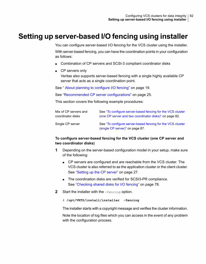
Setting up server-based I/O fencing using installerYou can configure server-based I/O fencing for the VCS cluster using the installer.
With server-based fencing, you can have the coordination points in your configurationas follows:
■ Combination of CP servers and SCSI-3 compliant coordinator disks
■ CP servers onlyVeritas also supports server-based fencing with a single highly available CPserver that acts as a single coordination point.
See “ About planning to configure I/O fencing” on page 19.
See “Recommended CP server configurations” on page 25.
This section covers the following example procedures:
See “To configure server-based fencing for the VCS cluster(one CP server and two coordinator disks)” on page 82.
Mix of CP servers andcoordinator disks
See “To configure server-based fencing for the VCS cluster(single CP server)” on page 87.
Single CP server
To configure server-based fencing for the VCS cluster (one CP server andtwo coordinator disks)
1 Depending on the server-based configuration model in your setup, make sureof the following:
■ CP servers are configured and are reachable from the VCS cluster. TheVCS cluster is also referred to as the application cluster or the client cluster.See “Setting up the CP server” on page 27.
■ The coordination disks are verified for SCSI3-PR compliance.See “Checking shared disks for I/O fencing” on page 78.
2 Start the installer with the -fencing option.
# /opt/VRTS/install/installer -fencing
The installer starts with a copyright message and verifies the cluster information.
Note the location of log files which you can access in the event of any problemwith the configuration process.
82Configuring VCS clusters for data integritySetting up server-based I/O fencing using installer

3 Confirm that you want to proceed with the I/O fencing configuration at theprompt.
The program checks that the local node running the script can communicatewith remote nodes and checks whether VCS 7.1 is configured properly.
4 Review the I/O fencing configuration options that the program presents. Type1 to configure server-based I/O fencing.
Select the fencing mechanism to be configured in this
Application Cluster [1-3,b,q] 1
5 Make sure that the storage supports SCSI3-PR, and answer y at the followingprompt.
Does your storage environment support SCSI3 PR? [y,n,q] (y)
6 Provide the following details about the coordination points at the installer prompt:
■ Enter the total number of coordination points including both servers anddisks. This number should be at least 3.
Enter the total number of co-ordination points including both
Coordination Point servers and disks: [b] (3)
■ Enter the total number of coordinator disks among the coordination points.
Enter the total number of disks among these:
[b] (0) 2
7 Provide the following CP server details at the installer prompt:
■ Enter the total number of virtual IP addresses or the total number of fullyqualified host names for each of the CP servers.
How many IP addresses would you like to use to communicate
to Coordination Point Server #1?: [b,q,?] (1) 1
■ Enter the virtual IP addresses or the fully qualified host name for each ofthe CP servers. The installer assumes these values to be identical as viewedfrom all the application cluster nodes.
Enter the Virtual IP address or fully qualified host name #1
for the HTTPS Coordination Point Server #1:
[b] 10.209.80.197
83Configuring VCS clusters for data integritySetting up server-based I/O fencing using installer

The installer prompts for this information for the number of virtual IPaddresses you want to configure for each CP server.
■ Enter the port that the CP server would be listening on.
Enter the port that the coordination point server 10.209.80.197
would be listening on or accept the default port
suggested: [b] (443)
8 Provide the following coordinator disks-related details at the installer prompt:
■ Choose the coordinator disks from the list of available disks that the installerdisplays. Ensure that the disk you choose is available from all the VCS(application cluster) nodes.The number of times that the installer asks you to choose the disks dependson the information that you provided in step 6. For example, if you hadchosen to configure two coordinator disks, the installer asks you to choosethe first disk and then the second disk:
Select disk number 1 for co-ordination point
1) c1t1d0s2
2) c2t1d0s2
3) c3t1d0s2
Please enter a valid disk which is available from all the
cluster nodes for co-ordination point [1-3,q] 1
■ If you have not already checked the disks for SCSI-3 PR compliance instep 1, check the disks now.The installer displays a message that recommends you to verify the disksin another window and then return to this configuration procedure.Press Enter to continue, and confirm your disk selection at the installerprompt.
■ Enter a disk group name for the coordinator disks or accept the default.
Enter the disk group name for coordinating disk(s):
[b] (vxfencoorddg)
84Configuring VCS clusters for data integritySetting up server-based I/O fencing using installer

9 Verify and confirm the coordination points information for the fencingconfiguration.
For example:
Total number of coordination points being used: 3
Coordination Point Server ([VIP or FQHN]:Port):
1. 10.209.80.197 ([10.209.80.197]:443)
SCSI-3 disks:
1. c1t1d0s2
2. c2t1d0s2
Disk Group name for the disks in customized fencing: vxfencoorddg
Disk policy used for customized fencing: dmp
The installer initializes the disks and the disk group and deports the disk groupon the VCS (application cluster) node.
10 Verify and confirm the I/O fencing configuration information.
CPS Admin utility location: /opt/VRTScps/bin/cpsadm
Cluster ID: 2122
Cluster Name: clus1
UUID for the above cluster: {ae5e589a-1dd1-11b2-dd44-00144f79240c}
11 Review the output as the installer updates the application cluster informationon each of the CP servers to ensure connectivity between them. The installerthen populates the /etc/vxfenmode file with the appropriate details in each ofthe application cluster nodes.
Updating client cluster information on Coordination Point Server 10.209.80.197
Adding the client cluster to the Coordination Point Server 10.209.80.197 .......... Done
Registering client node sys1 with Coordination Point Server 10.209.80.197...... Done
Adding CPClient user for communicating to Coordination Point Server 10.209.80.197 .... Done
Adding cluster clus1 to the CPClient user on Coordination Point Server 10.209.80.197 .. Done
Registering client node sys2 with Coordination Point Server 10.209.80.197 ..... Done
Adding CPClient user for communicating to Coordination Point Server 10.209.80.197 .... Done
Adding cluster clus1 to the CPClient user on Coordination Point Server 10.209.80.197 ..Done
Updating /etc/vxfenmode file on sys1 .................................. Done
Updating /etc/vxfenmode file on sys2 ......... ........................ Done
See “About I/O fencing configuration files” on page 288.
85Configuring VCS clusters for data integritySetting up server-based I/O fencing using installer

12 Review the output as the installer stops and restarts the VCS and the fencingprocesses on each application cluster node, and completes the I/O fencingconfiguration.
13 Configure the CP agent on the VCS (application cluster). The CoordinationPoint Agent monitors the registrations on the coordination points.
Do you want to configure Coordination Point Agent on
the client cluster? [y,n,q] (y)
Enter a non-existing name for the service group for
Coordination Point Agent: [b] (vxfen)
14 Additionally the coordination point agent can also monitor changes to theCoordinator Disk Group constitution such as a disk being accidently deletedfrom the Coordinator Disk Group. The frequency of this detailed monitoringcan be tuned with the LevelTwoMonitorFreq attribute. For example, if you setthis attribute to 5, the agent will monitor the Coordinator Disk Group constitutionevery five monitor cycles.
Note that for the LevelTwoMonitorFreq attribute to be applicable there mustbe disks as part of the Coordinator Disk Group.
Enter the value of the LevelTwoMonitorFreq attribute: (5)
15 Enable auto refresh of coordination points.
Do you want to enable auto refresh of coordination points
if registration keys are missing
on any of them? [y,n,q,b,?] (n)
16 Note the location of the configuration log files, summary files, and responsefiles that the installer displays for later use.
17 Verify the fencing configuration using:
# vxfenadm -d
18 Verify the list of coordination points.
# vxfenconfig -l
86Configuring VCS clusters for data integritySetting up server-based I/O fencing using installer
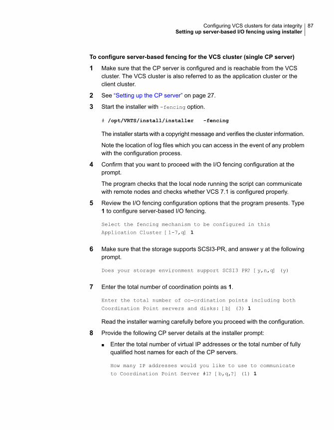
To configure server-based fencing for the VCS cluster (single CP server)
1 Make sure that the CP server is configured and is reachable from the VCScluster. The VCS cluster is also referred to as the application cluster or theclient cluster.
2 See “Setting up the CP server” on page 27.
3 Start the installer with -fencing option.
# /opt/VRTS/install/installer -fencing
The installer starts with a copyright message and verifies the cluster information.
Note the location of log files which you can access in the event of any problemwith the configuration process.
4 Confirm that you want to proceed with the I/O fencing configuration at theprompt.
The program checks that the local node running the script can communicatewith remote nodes and checks whether VCS 7.1 is configured properly.
5 Review the I/O fencing configuration options that the program presents. Type1 to configure server-based I/O fencing.
Select the fencing mechanism to be configured in this
Application Cluster [1-7,q] 1
6 Make sure that the storage supports SCSI3-PR, and answer y at the followingprompt.
Does your storage environment support SCSI3 PR? [y,n,q] (y)
7 Enter the total number of coordination points as 1.
Enter the total number of co-ordination points including both
Coordination Point servers and disks: [b] (3) 1
Read the installer warning carefully before you proceed with the configuration.
8 Provide the following CP server details at the installer prompt:
■ Enter the total number of virtual IP addresses or the total number of fullyqualified host names for each of the CP servers.
How many IP addresses would you like to use to communicate
to Coordination Point Server #1? [b,q,?] (1) 1
87Configuring VCS clusters for data integritySetting up server-based I/O fencing using installer
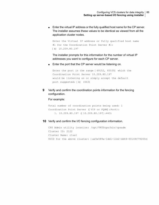
■ Enter the virtual IP address or the fully qualified host name for the CP server.The installer assumes these values to be identical as viewed from all theapplication cluster nodes.
Enter the Virtual IP address or fully qualified host name
#1 for the Coordination Point Server #1:
[b] 10.209.80.197
The installer prompts for this information for the number of virtual IPaddresses you want to configure for each CP server.
■ Enter the port that the CP server would be listening on.
Enter the port in the range [49152, 65535] which the
Coordination Point Server 10.209.80.197
would be listening on or simply accept the default
port suggested: [b] (443)
9 Verify and confirm the coordination points information for the fencingconfiguration.
For example:
Total number of coordination points being used: 1
Coordination Point Server ([VIP or FQHN]:Port):
1. 10.209.80.197 ([10.209.80.197]:443)
10 Verify and confirm the I/O fencing configuration information.
CPS Admin utility location: /opt/VRTScps/bin/cpsadm
Cluster ID: 2122
Cluster Name: clus1
UUID for the above cluster: {ae5e589a-1dd1-11b2-dd44-00144f79240c}
88Configuring VCS clusters for data integritySetting up server-based I/O fencing using installer

11 Review the output as the installer updates the application cluster informationon each of the CP servers to ensure connectivity between them. The installerthen populates the /etc/vxfenmode file with the appropriate details in each ofthe application cluster nodes.
The installer also populates the /etc/vxfenmode file with the entry single_cp=1for such single CP server fencing configuration.
Updating client cluster information on Coordination Point Server 10.209.80.197
Adding the client cluster to the Coordination Point Server 10.209.80.197 .......... Done
Registering client node sys1 with Coordination Point Server 10.209.80.197...... Done
Adding CPClient user for communicating to Coordination Point Server 10.209.80.197 .... Done
Adding cluster clus1 to the CPClient user on Coordination Point Server 10.209.80.197 .. Done
Registering client node sys2 with Coordination Point Server 10.209.80.197 ..... Done
Adding CPClient user for communicating to Coordination Point Server 10.209.80.197 .... Done
Adding cluster clus1 to the CPClient user on Coordination Point Server 10.209.80.197 .. Done
Updating /etc/vxfenmode file on sys1 .................................. Done
Updating /etc/vxfenmode file on sys2 ......... ........................ Done
See “About I/O fencing configuration files” on page 288.
12 Review the output as the installer stops and restarts the VCS and the fencingprocesses on each application cluster node, and completes the I/O fencingconfiguration.
13 Configure the CP agent on the VCS (application cluster).
Do you want to configure Coordination Point Agent on the
client cluster? [y,n,q] (y)
Enter a non-existing name for the service group for
Coordination Point Agent: [b] (vxfen)
14 Enable auto refresh of coordination points.
Do you want to enable auto refresh of coordination points
if registration keys are missing
on any of them? [y,n,q,b,?] (n)
15 Note the location of the configuration log files, summary files, and responsefiles that the installer displays for later use.
89Configuring VCS clusters for data integritySetting up server-based I/O fencing using installer

Refreshing keys or registrations on the existing coordination pointsfor server-based fencing using the installer
You must refresh registrations on the coordination points in the following scenarios:
■ When the CoordPoint agent notifies VCS about the loss of registration on anyof the existing coordination points.
■ A planned refresh of registrations on coordination points when the cluster isonline without having an application downtime on the cluster.
Registration loss might occur because of an accidental array restart, corruption ofkeys, or some other reason. If the coordination points lose registrations of the clusternodes, the cluster might panic when a network partition occurs.
Warning: Refreshing keys might cause the cluster to panic if a node leavesmembership before the coordination points refresh is complete.
To refresh registrations on existing coordination points for server-based I/Ofencing using the installer
1 Start the installer with the -fencing option.
# /opt/VRTS/install/installer -fencing
The installer starts with a copyright message and verifies the cluster information.
Note the location of log files that you can access if there is a problem with theconfiguration process.
2 Confirm that you want to proceed with the I/O fencing configuration at theprompt.
The program checks that the local node running the script can communicatewith the remote nodes and checks whether VCS 7.1 is configured properly.
3 Review the I/O fencing configuration options that the program presents. Typethe number corresponding to the option that suggests to refresh registrationsor keys on the existing coordination points.
Select the fencing mechanism to be configured in this
Application Cluster [1-7,q] 6
90Configuring VCS clusters for data integritySetting up server-based I/O fencing using installer

4 Ensure that the /etc/vxfentab file contains the same coordination pointservers that are currently used by the fencing module.
Also, ensure that the disk group mentioned in the /etc/vxfendg file containsthe same disks that are currently used by the fencing module as coordinationdisks.
5 Verify the coordination points.
For example,
Total number of coordination points being used: 3
Coordination Point Server ([VIP or FQHN]:Port):
1. 10.198.94.146 ([10.198.94.146]:443)
2. 10.198.94.144 ([10.198.94.144]:443)
SCSI-3 disks:
1. emc_clariion0_61
Disk Group name for the disks in customized fencing: vxfencoorddg
Disk policy used for customized fencing: dmp
6 Is this information correct? [y,n,q] (y)
Updating client cluster information on Coordination Point Server
IPaddress
Successfully completed the vxfenswap operation
The keys on the coordination disks are refreshed.
7 Do you want to send the information about this installation to us to help improveinstallation in the future? [y,n,q,?] (y).
8 Do you want to view the summary file? [y,n,q] (n).
Setting the order of existing coordination points for server-basedfencing using the installer
This section describes the reasons, benefits, considerations, and the procedure toset the order of the existing coordination points for server-based fencing.
About deciding the order of existing coordination pointsYou can decide the order in which coordination points can participate in a raceduring a network partition. In a network partition scenario, I/O fencing attempts to
91Configuring VCS clusters for data integritySetting up server-based I/O fencing using installer

contact coordination points for membership arbitration based on the order that isset in the vxfentab file.
When I/O fencing is not able to connect to the first coordination point in the sequenceit goes to the second coordination point and so on. To avoid a cluster panic, thesurviving subcluster must win majority of the coordination points. So, the order mustbegin with the coordination point that has the best chance to win the race and mustend with the coordination point that has the least chance to win the race.
For fencing configurations that use a mix of coordination point servers andcoordination disks, you can specify either coordination point servers beforecoordination disks or disks before servers.
Note:Disk-based fencing does not support setting the order of existing coordinationpoints.
Considerations to decide the order of coordination points
■ Choose the coordination points based on their chances to gain membership onthe cluster during the race and hence gain control over a network partition. Ineffect, you have the ability to save a partition.
■ First in the order must be the coordination point that has the best chance to winthe race. The next coordination point you list in the order must have relativelylesser chance to win the race. Complete the order such that the last coordinationpoint has the least chance to win the race.
Setting the order of existing coordination points using theinstallerTo set the order of existing coordination points
1 Start the installer with -fencing option.
# /opt/VRTS/install/installer -fencing
The installer starts with a copyright message and verifies the cluster information.
Note the location of log files that you can access if there is a problem with theconfiguration process.
2 Confirm that you want to proceed with the I/O fencing configuration at theprompt.
The program checks that the local node running the script can communicatewith remote nodes and checks whether VCS 7.1 is configured properly.
92Configuring VCS clusters for data integritySetting up server-based I/O fencing using installer

3 Review the I/O fencing configuration options that the program presents. Typethe number corresponding to the option that suggests to set the order of existingcoordination points.
For example:
Select the fencing mechanism to be configured in this
Application Cluster [1-7,q] 7
Installer will ask the new order of existing coordination points.
Then it will call vxfenswap utility to commit the
coordination points change.
Warning: The cluster might panic if a node leaves membership before thecoordination points change is complete.
4 Review the current order of coordination points.
Current coordination points order:
(Coordination disks/Coordination Point Server)
Example,
1) /dev/vx/rdmp/emc_clariion0_65,/dev/vx/rdmp/emc_clariion0_66,
/dev/vx/rdmp/emc_clariion0_62
2) [10.198.94.144]:443
3) [10.198.94.146]:443
b) Back to previous menu
5 Enter the new order of the coordination points by the numbers and separatethe order by space [1-3,b,q] 3 1 2.
New coordination points order:
(Coordination disks/Coordination Point Server)
Example,
1) [10.198.94.146]:443
2) /dev/vx/rdmp/emc_clariion0_65,/dev/vx/rdmp/emc_clariion0_66,
/dev/vx/rdmp/emc_clariion0_62
3) [10.198.94.144]:443
93Configuring VCS clusters for data integritySetting up server-based I/O fencing using installer
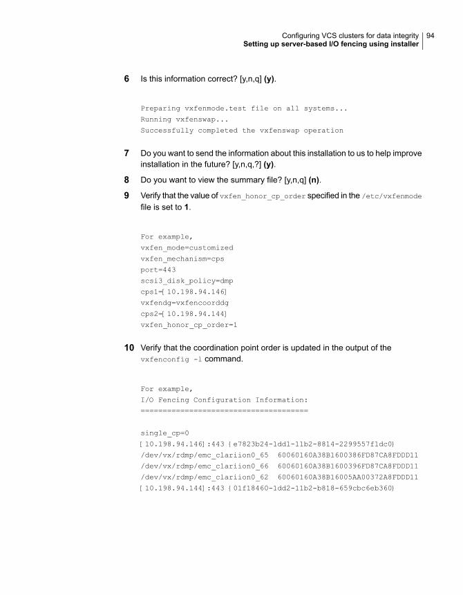
6 Is this information correct? [y,n,q] (y).
Preparing vxfenmode.test file on all systems...
Running vxfenswap...
Successfully completed the vxfenswap operation
7 Do you want to send the information about this installation to us to help improveinstallation in the future? [y,n,q,?] (y).
8 Do you want to view the summary file? [y,n,q] (n).
9 Verify that the value of vxfen_honor_cp_order specified in the /etc/vxfenmode
file is set to 1.
For example,
vxfen_mode=customized
vxfen_mechanism=cps
port=443
scsi3_disk_policy=dmp
cps1=[10.198.94.146]
vxfendg=vxfencoorddg
cps2=[10.198.94.144]
vxfen_honor_cp_order=1
10 Verify that the coordination point order is updated in the output of thevxfenconfig -l command.
For example,
I/O Fencing Configuration Information:
======================================
single_cp=0
[10.198.94.146]:443 {e7823b24-1dd1-11b2-8814-2299557f1dc0}
/dev/vx/rdmp/emc_clariion0_65 60060160A38B1600386FD87CA8FDDD11
/dev/vx/rdmp/emc_clariion0_66 60060160A38B1600396FD87CA8FDDD11
/dev/vx/rdmp/emc_clariion0_62 60060160A38B16005AA00372A8FDDD11
[10.198.94.144]:443 {01f18460-1dd2-11b2-b818-659cbc6eb360}
94Configuring VCS clusters for data integritySetting up server-based I/O fencing using installer

Setting up non-SCSI-3 I/O fencing in virtualenvironments using installer
If you have installed Veritas InfoScale Enterprise in virtual environments that donot support SCSI-3 PR-compliant storage, you can configure non-SCSI-3 fencing.
To configure I/O fencing using the installer in a non-SCSI-3 PR-compliantsetup
1 Start the installer with -fencing option.
# /opt/VRTS/install/installer -fencing
The installer starts with a copyright message and verifies the cluster information.
2 Confirm that you want to proceed with the I/O fencing configuration at theprompt.
The program checks that the local node running the script can communicatewith remote nodes and checks whether VCS 7.1 is configured properly.
3 For server-based fencing, review the I/O fencing configuration options that theprogram presents. Type 1 to configure server-based I/O fencing.
Select the fencing mechanism to be configured in this
Application Cluster
[1-7,q] 1
4 Enter n to confirm that your storage environment does not support SCSI-3 PR.
Does your storage environment support SCSI3 PR?
[y,n,q] (y) n
5 Confirm that you want to proceed with the non-SCSI-3 I/O fencing configurationat the prompt.
6 For server-based fencing, enter the number of CP server coordination pointsyou want to use in your setup.
7 For server-based fencing, enter the following details for each CP server:
■ Enter the virtual IP address or the fully qualified host name.
■ Enter the port address on which the CP server listens for connections.The default value is 443. You can enter a different port address. Valid valuesare between 49152 and 65535.
The installer assumes that these values are identical from the view of the VCScluster nodes that host the applications for high availability.
95Configuring VCS clusters for data integritySetting up non-SCSI-3 I/O fencing in virtual environments using installer

8 For server-based fencing, verify and confirm the CP server information thatyou provided.
9 Verify and confirm the VCS cluster configuration information.
Review the output as the installer performs the following tasks:
■ Updates the CP server configuration files on each CP server with thefollowing details for only server-based fencing, :
■ Registers each node of the VCS cluster with the CP server.
■ Adds CP server user to the CP server.
■ Adds VCS cluster to the CP server user.
■ Updates the following configuration files on each node of the VCS cluster
■ /etc/vxfenmode file
■ /etc/default/vxfen file
■ /etc/vxenviron file
■ /etc/llttab file
■ /etc/vxfentab (only for server-based fencing)
10 Review the output as the installer stops VCS on each node, starts I/O fencingon each node, updates the VCS configuration file main.cf, and restarts VCSwith non-SCSI-3 fencing.
For server-based fencing, confirm to configure the CP agent on the VCS cluster.
11 Confirm whether you want to send the installation information to us.
12 After the installer configures I/O fencing successfully, note the location ofsummary, log, and response files that installer creates.
The files provide useful information which can assist you with the configuration,and can also assist future configurations.
Setting up majority-based I/O fencing usinginstaller
You can configure majority-based fencing for the cluster using the installer .
96Configuring VCS clusters for data integritySetting up majority-based I/O fencing using installer

Perform the following steps to confgure majority-based I/O fencing
1 Start the installer with the -fencing option.
# /opt/VRTS/install/installer -fencing
Where version is the specific release version. The installer starts with acopyright message and verifies the cluster information.
Note: Make a note of the log file location which you can access in the eventof any issues with the configuration process.
2 Confirm that you want to proceed with the I/O fencing configuration at theprompt. The program checks that the local node running the script cancommunicate with remote nodes and checks whether VCS is configuredproperly.
3 Review the I/O fencing configuration options that the program presents. Type3 to configure majority-based I/O fencing.
Select the fencing mechanism to be configured in this
Application Cluster [1-7,b,q] 3
Note: The installer will ask the following question. Does your storageenvironment support SCSI3 PR? [y,n,q,?] Input 'y' if your storage environmentsupports SCSI3 PR. Other alternative will result in installer configuringnon-SCSI3 fencing(NSF).
4 The installer then populates the /etc/vxfenmode file with the appropriate detailsin each of the application cluster nodes.
Updating /etc/vxfenmode file on sys1 ................... Done
Updating /etc/vxfenmode file on sys2 ................... Done
5 Review the output as the installer stops and restarts the VCS and the fencingprocesses on each application cluster node, and completes the I/O fencingconfiguration.
6 Note the location of the configuration log files, summary files, and responsefiles that the installer displays for later use.
7 Verify the fencing configuration.
# vxfenadm -d
97Configuring VCS clusters for data integritySetting up majority-based I/O fencing using installer

Enabling or disabling the preferred fencing policyYou can enable or disable the preferred fencing feature for your I/O fencingconfiguration.
You can enable preferred fencing to use system-based race policy, group-basedrace policy, or site-based policy. If you disable preferred fencing, the I/O fencingconfiguration uses the default count-based race policy.
Preferred fencing is not applicable to majority-based I/O fencing.
To enable preferred fencing for the I/O fencing configuration
1 Make sure that the cluster is running with I/O fencing set up.
# vxfenadm -d
2 Make sure that the cluster-level attribute UseFence has the value set to SCSI3.
# haclus -value UseFence
3 To enable system-based race policy, perform the following steps:
■ Make the VCS configuration writable.
# haconf -makerw
■ Set the value of the cluster-level attribute PreferredFencingPolicy as System.
# haclus -modify PreferredFencingPolicy System
■ Set the value of the system-level attribute FencingWeight for each node inthe cluster.For example, in a two-node cluster, where you want to assign sys1 fivetimes more weight compared to sys2, run the following commands:
# hasys -modify sys1 FencingWeight 50
# hasys -modify sys2 FencingWeight 10
■ Save the VCS configuration.
# haconf -dump -makero
■ Verify fencing node weights using:
# vxfenconfig -a
98Configuring VCS clusters for data integrityEnabling or disabling the preferred fencing policy

4 To enable group-based race policy, perform the following steps:
■ Make the VCS configuration writable.
# haconf -makerw
■ Set the value of the cluster-level attribute PreferredFencingPolicy as Group.
# haclus -modify PreferredFencingPolicy Group
■ Set the value of the group-level attribute Priority for each service group.For example, run the following command:
# hagrp -modify service_group Priority 1
Make sure that you assign a parent service group an equal or lower prioritythan its child service group. In case the parent and the child service groupsare hosted in different subclusters, then the subcluster that hosts the childservice group gets higher preference.
■ Save the VCS configuration.
# haconf -dump -makero
5 To enable site-based race policy, perform the following steps:
■ Make the VCS configuration writable.
# haconf -makerw
■ Set the value of the cluster-level attribute PreferredFencingPolicy as Site.
# haclus -modify PreferredFencingPolicy Site
■ Set the value of the site-level attribute Preference for each site.
For example,
# hasite -modify Pune Preference 2
■ Save the VCS configuration.
# haconf -dump –makero
6 To view the fencing node weights that are currently set in the fencing driver,run the following command:
# vxfenconfig -a
99Configuring VCS clusters for data integrityEnabling or disabling the preferred fencing policy

To disable preferred fencing for the I/O fencing configuration
1 Make sure that the cluster is running with I/O fencing set up.
# vxfenadm -d
2 Make sure that the cluster-level attribute UseFence has the value set to SCSI3.
# haclus -value UseFence
3 To disable preferred fencing and use the default race policy, set the value ofthe cluster-level attribute PreferredFencingPolicy as Disabled.
# haconf -makerw
# haclus -modify PreferredFencingPolicy Disabled
# haconf -dump -makero
100Configuring VCS clusters for data integrityEnabling or disabling the preferred fencing policy
Automated configurationusing response files
■ Chapter 5. Performing an automated VCS configuration
■ Chapter 6. Performing an automated I/O fencing configuration using responsefiles
2Section

Performing an automatedVCS configuration
This chapter includes the following topics:
■ Configuring VCS using response files
■ Response file variables to configure VCS
■ Sample response file for configuring Cluster Server
Configuring VCS using response filesTypically, you can use the response file that the installer generates after you performVCS configuration on one cluster to configure VCS on other clusters.
To configure VCS using response files
1 Make sure the Veritas InfoScale Availability or Enterprise packages are installedon the systems where you want to configure VCS.
2 Copy the response file to one of the cluster systems where you want toconfigure VCS.
See “Sample response file for configuring Cluster Server” on page 112.
5Chapter

3 Edit the values of the response file variables as necessary.
To configure optional features, you must define appropriate values for all theresponse file variables that are related to the optional feature.
See “Response file variables to configure VCS” on page 103.
4 Start the configuration from the system to which you copied the response file.For example:
# /opt/VRTS/install/installer -responsefile
/tmp/response_file
Where /tmp/response_file is the response file’s full path name.
Response file variables to configure VCSTable 5-1 lists the response file variables that you can define to configure VCS.
Table 5-1 Response file variables specific to configuring VCS
DescriptionList or ScalarVariable
Performs the configuration if thepackages are already installed.
(Required)
Set the value to 1 to configure VCS.
ScalarCFG{opt}{configure}
Specifies whether you agree withEULA.pdf on the media.
(Required)
ScalarCFG{accepteula}
Defines the component to beconfigured.
The value is VCS7.1 for VCS.
(Required)
ListCFG{activecomponent}
CFG{keys}{keyless} gives a listof keyless keys to be registered onthe system.
CFG{keys}{license} gives a listof user defined keys to be registeredon the system.
(Optional)
ListCFG{keys}{keyless}
CFG{keys}{license}
103Performing an automated VCS configurationResponse file variables to configure VCS

Table 5-1 Response file variables specific to configuring VCS (continued)
DescriptionList or ScalarVariable
List of systems on which the productis to be configured.
(Required)
ListCFG{systems}
Defines the product for operations.
The value is AVAILABILITY71 forVeritas InfoScale Availability.
(Required)
ScalarCFG{prod}
Defines the location of an ssh keyfilethat is used to communicate with allremote systems.
(Optional)
ScalarCFG{opt}{keyfile}
Defines that rsh must be usedinstead of ssh as the communicationmethod between systems.
(Optional)
ScalarCFG{opt}{rsh}
Mentions the location where the logfiles are to be copied. The defaultlocation is /opt/VRTS/install/logs.
Note: The installer copies theresponse files and summary filesalso to the specified logpathlocation.
(Optional)
ScalarCFG{opt}{logpath}
Defines a Boolean value 0 or 1.
The value 1 indicates that theinstallation logs are uploaded to theVeritas website.
The value 0 indicates that theinstallation logs are not uploaded tothe Veritas website.
(Optional)
ScalarCFG{uploadlogs}
Note that some optional variables make it necessary to define other optionalvariables. For example, all the variables that are related to the cluster service group
104Performing an automated VCS configurationResponse file variables to configure VCS
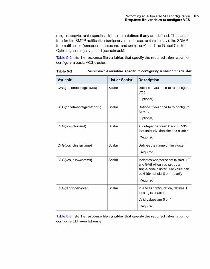
(csgnic, csgvip, and csgnetmask) must be defined if any are defined. The same istrue for the SMTP notification (smtpserver, smtprecp, and smtprsev), the SNMPtrap notification (snmpport, snmpcons, and snmpcsev), and the Global ClusterOption (gconic, gcovip, and gconetmask).
Table 5-2 lists the response file variables that specify the required information toconfigure a basic VCS cluster.
Table 5-2 Response file variables specific to configuring a basic VCS cluster
DescriptionList or ScalarVariable
Defines if you need to re-configureVCS.
(Optional)
ScalarCFG{donotreconfigurevcs}
Defines if you need to re-configurefencing.
(Optional)
ScalarCFG{donotreconfigurefencing}
An integer between 0 and 65535that uniquely identifies the cluster.
(Required)
ScalarCFG{vcs_clusterid}
Defines the name of the cluster.
(Required)
ScalarCFG{vcs_clustername}
Indicates whether or not to start LLTand GAB when you set up asingle-node cluster. The value canbe 0 (do not start) or 1 (start).
(Required)
ScalarCFG{vcs_allowcomms}
In a VCS configuration, defines iffencing is enabled.
Valid values are 0 or 1.
(Required)
ScalarCFG{fencingenabled}
Table 5-3 lists the response file variables that specify the required information toconfigure LLT over Ethernet.
105Performing an automated VCS configurationResponse file variables to configure VCS

Table 5-3 Response file variables specific to configuring private LLT overEthernet
DescriptionList or ScalarVariable
Defines the NIC to be used for aprivate heartbeat link on eachsystem. At least two LLT links arerequired per system (lltlink1 andlltlink2). You can configure up to fourLLT links.
You must enclose the system namewithin double quotes.
(Required)
ScalarCFG{vcs_lltlink#}
{"system"}
Defines a low priority heartbeat link.Typically, lltlinklowpri is used on apublic network link to provide anadditional layer of communication.
If you use different media speed forthe private NICs, you can configurethe NICs with lesser speed aslow-priority links to enhance LLTperformance. For example,lltlinklowpri1, lltlinklowpri2, and soon.
You must enclose the system namewithin double quotes.
(Optional)
ScalarCFG{vcs_lltlinklowpri#}
{"system"}
Table 5-4 lists the response file variables that specify the required information toconfigure LLT over UDP.
Table 5-4 Response file variables specific to configuring LLT over UDP
DescriptionList or ScalarVariable
Indicates whether to configureheartbeat link using LLT over UDP.
(Required)
ScalarCFG{lltoverudp}=1
106Performing an automated VCS configurationResponse file variables to configure VCS

Table 5-4 Response file variables specific to configuring LLT over UDP(continued)
DescriptionList or ScalarVariable
Stores the IP address (IPv4 or IPv6)that the heartbeat link uses onnode1.
You can have four heartbeat linksand <n> for this response filevariable can take values 1 to 4 forthe respective heartbeat links.
(Required)
ScalarCFG{vcs_udplink<n>_address}
{<sys1>}
Stores the IP address (IPv4 or IPv6)that the low priority heartbeat linkuses on node1.
You can have four low priorityheartbeat links and <n> for thisresponse file variable can takevalues 1 to 4 for the respective lowpriority heartbeat links.
(Required)
ScalarCFG
{vcs_udplinklowpri<n>_address}
{<sys1>}
Stores the UDP port (16-bit integervalue) that the heartbeat link useson node1.
You can have four heartbeat linksand <n> for this response filevariable can take values 1 to 4 forthe respective heartbeat links.
(Required)
ScalarCFG{vcs_udplink<n>_port}
{<sys1>}
Stores the UDP port (16-bit integervalue) that the low priority heartbeatlink uses on node1.
You can have four low priorityheartbeat links and <n> for thisresponse file variable can takevalues 1 to 4 for the respective lowpriority heartbeat links.
(Required)
ScalarCFG{vcs_udplinklowpri<n>_port}
{<sys1>}
107Performing an automated VCS configurationResponse file variables to configure VCS

Table 5-4 Response file variables specific to configuring LLT over UDP(continued)
DescriptionList or ScalarVariable
Stores the netmask (prefix for IPv6)that the heartbeat link uses onnode1.
You can have four heartbeat linksand <n> for this response filevariable can take values 1 to 4 forthe respective heartbeat links.
(Required)
ScalarCFG{vcs_udplink<n>_netmask}
{<sys1>}
Stores the netmask (prefix for IPv6)that the low priority heartbeat linkuses on node1.
You can have four low priorityheartbeat links and <n> for thisresponse file variable can takevalues 1 to 4 for the respective lowpriority heartbeat links.
(Required)
ScalarCFG{vcs_udplinklowpri<n>_netmask}
{<sys1>}
Table 5-5 lists the response file variables that specify the required information toconfigure virtual IP for VCS cluster.
Table 5-5 Response file variables specific to configuring virtual IP for VCScluster
DescriptionList or ScalarVariable
Defines the NIC device to use on asystem. You can enter ‘all’ as asystem value if the same NIC isused on all systems.
(Optional)
ScalarCFG{vcs_csgnic}
{system}
Defines the virtual IP address forthe cluster.
(Optional)
ScalarCFG{vcs_csgvip}
Defines the Netmask of the virtualIP address for the cluster.
(Optional)
ScalarCFG{vcs_csgnetmask}
108Performing an automated VCS configurationResponse file variables to configure VCS
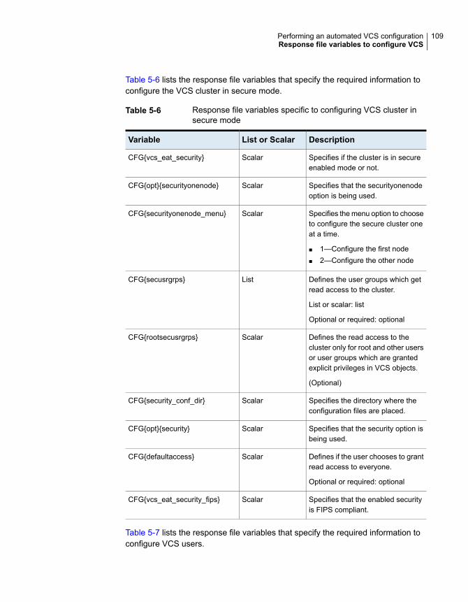
Table 5-6 lists the response file variables that specify the required information toconfigure the VCS cluster in secure mode.
Table 5-6 Response file variables specific to configuring VCS cluster insecure mode
DescriptionList or ScalarVariable
Specifies if the cluster is in secureenabled mode or not.
ScalarCFG{vcs_eat_security}
Specifies that the securityonenodeoption is being used.
ScalarCFG{opt}{securityonenode}
Specifies the menu option to chooseto configure the secure cluster oneat a time.
■ 1—Configure the first node■ 2—Configure the other node
ScalarCFG{securityonenode_menu}
Defines the user groups which getread access to the cluster.
List or scalar: list
Optional or required: optional
ListCFG{secusrgrps}
Defines the read access to thecluster only for root and other usersor user groups which are grantedexplicit privileges in VCS objects.
(Optional)
ScalarCFG{rootsecusrgrps}
Specifies the directory where theconfiguration files are placed.
ScalarCFG{security_conf_dir}
Specifies that the security option isbeing used.
ScalarCFG{opt}{security}
Defines if the user chooses to grantread access to everyone.
Optional or required: optional
ScalarCFG{defaultaccess}
Specifies that the enabled securityis FIPS compliant.
ScalarCFG{vcs_eat_security_fips}
Table 5-7 lists the response file variables that specify the required information toconfigure VCS users.
109Performing an automated VCS configurationResponse file variables to configure VCS

Table 5-7 Response file variables specific to configuring VCS users
DescriptionList or ScalarVariable
List of encoded passwords for VCSusers
The value in the list can be"Administrators Operators Guests"
Note: The order of the values forthe vcs_userenpw list must matchthe order of the values in thevcs_username list.
(Optional)
ListCFG{vcs_userenpw}
List of names of VCS users
(Optional)
ListCFG{vcs_username}
List of privileges for VCS users
Note: The order of the values forthe vcs_userpriv list must match theorder of the values in thevcs_username list.
(Optional)
ListCFG{vcs_userpriv}
Table 5-8 lists the response file variables that specify the required information toconfigure VCS notifications using SMTP.
Table 5-8 Response file variables specific to configuring VCS notificationsusing SMTP
DescriptionList or ScalarVariable
Defines the domain-basedhostname (example:smtp.example.com) of the SMTPserver to be used for webnotification.
(Optional)
ScalarCFG{vcs_smtpserver}
List of full email addresses(example: [email protected]) ofSMTP recipients.
(Optional)
ListCFG{vcs_smtprecp}
110Performing an automated VCS configurationResponse file variables to configure VCS

Table 5-8 Response file variables specific to configuring VCS notificationsusing SMTP (continued)
DescriptionList or ScalarVariable
Defines the minimum severity levelof messages (Information, Warning,Error, SevereError) that listed SMTPrecipients are to receive. Note thatthe ordering of severity levels mustmatch that of the addresses ofSMTP recipients.
(Optional)
ListCFG{vcs_smtprsev}
Table 5-9 lists the response file variables that specify the required information toconfigure VCS notifications using SNMP.
Table 5-9 Response file variables specific to configuring VCS notificationsusing SNMP
DescriptionList or ScalarVariable
Defines the SNMP trap daemon port(default=162).
(Optional)
ScalarCFG{vcs_snmpport}
List of SNMP console systemnames
(Optional)
ListCFG{vcs_snmpcons}
Defines the minimum severity levelof messages (Information, Warning,Error, SevereError) that listed SNMPconsoles are to receive. Note thatthe ordering of severity levels mustmatch that of the SNMP consolesystem names.
(Optional)
ListCFG{vcs_snmpcsev}
Table 5-10 lists the response file variables that specify the required information toconfigure VCS global clusters.
111Performing an automated VCS configurationResponse file variables to configure VCS
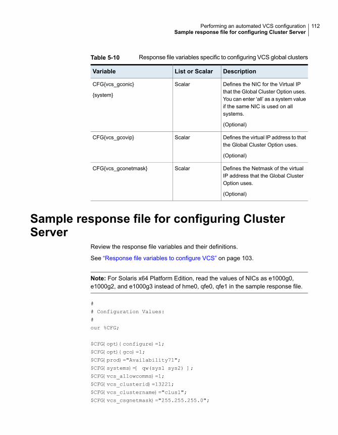
Table 5-10 Response file variables specific to configuring VCS global clusters
DescriptionList or ScalarVariable
Defines the NIC for the Virtual IPthat the Global Cluster Option uses.You can enter ‘all’ as a system valueif the same NIC is used on allsystems.
(Optional)
ScalarCFG{vcs_gconic}
{system}
Defines the virtual IP address to thatthe Global Cluster Option uses.
(Optional)
ScalarCFG{vcs_gcovip}
Defines the Netmask of the virtualIP address that the Global ClusterOption uses.
(Optional)
ScalarCFG{vcs_gconetmask}
Sample response file for configuring ClusterServer
Review the response file variables and their definitions.
See “Response file variables to configure VCS” on page 103.
Note: For Solaris x64 Platform Edition, read the values of NICs as e1000g0,e1000g2, and e1000g3 instead of hme0, qfe0, qfe1 in the sample response file.
#
# Configuration Values:
#
our %CFG;
$CFG{opt}{configure}=1;
$CFG{opt}{gco}=1;
$CFG{prod}="Availability71";
$CFG{systems}=[ qw(sys1 sys2) ];
$CFG{vcs_allowcomms}=1;
$CFG{vcs_clusterid}=13221;
$CFG{vcs_clustername}="clus1";
$CFG{vcs_csgnetmask}="255.255.255.0";
112Performing an automated VCS configurationSample response file for configuring Cluster Server

$CFG{vcs_csgnic}{all}="net0";
$CFG{vcs_csgvip}="10.10.12.1";
$CFG{vcs_gconetmask}="255.255.255.0";
$CFG{vcs_gcovip}="10.10.12.1";
$CFG{activecomponent}=[ qw(VCS71) ]
$CFG{vcs_lltlink1}{sys1}="net1";
$CFG{vcs_lltlink1}{sys2}="net1";
$CFG{vcs_lltlink2}{sys1}="net2";
$CFG{vcs_lltlink2}{sys2}="net2";
$CFG{vcs_smtprecp}=[ qw([email protected]) ];
$CFG{vcs_smtprsev}=[ qw(SevereError) ];
$CFG{vcs_smtpserver}="smtp.example.com";
$CFG{vcs_snmpcons}=[ qw(neptune) ];
$CFG{vcs_snmpcsev}=[ qw(SevereError) ];
$CFG{vcs_snmpport}=162;
1;
113Performing an automated VCS configurationSample response file for configuring Cluster Server
Performing an automatedI/O fencing configurationusing response files
This chapter includes the following topics:
■ Configuring I/O fencing using response files
■ Response file variables to configure disk-based I/O fencing
■ Sample response file for configuring disk-based I/O fencing
■ Response file variables to configure server-based I/O fencing
■ Sample response file for configuring server-based I/O fencing
■ Response file variables to configure non-SCSI-3 I/O fencing
■ Sample response file for configuring non-SCSI-3 I/O fencing
■ Response file variables to configure majority-based I/O fencing
■ Sample response file for configuring majority-based I/O fencing
Configuring I/O fencing using response filesTypically, you can use the response file that the installer generates after you performI/O fencing configuration to configure I/O fencing for VCS.
6Chapter

To configure I/O fencing using response files
1 Make sure that VCS is configured.
2 Based on whether you want to configure disk-based or server-based I/O fencing,make sure you have completed the preparatory tasks.
See “ About planning to configure I/O fencing” on page 19.
3 Copy the response file to one of the cluster systems where you want toconfigure I/O fencing.
See “Sample response file for configuring disk-based I/O fencing” on page 118.
See “Sample response file for configuring server-based I/O fencing” on page 121.
See “Sample response file for configuring non-SCSI-3 I/O fencing” on page 123.
See “Sample response file for configuring majority-based I/O fencing”on page 124.
4 Edit the values of the response file variables as necessary.
See “Response file variables to configure disk-based I/O fencing” on page 115.
See “Response file variables to configure server-based I/O fencing” on page 119.
See “Response file variables to configure non-SCSI-3 I/O fencing” on page 122.
See “Response file variables to configure majority-based I/O fencing”on page 124.
5 Start the configuration from the system to which you copied the response file.For example:
# /opt/VRTS/install/installer
-responsefile /tmp/response_file
Where /tmp/response_file is the response file’s full path name.
Response file variables to configure disk-basedI/O fencing
Table 6-1 lists the response file variables that specify the required information toconfigure disk-based I/O fencing for VCS.
115Performing an automated I/O fencing configuration using response filesResponse file variables to configure disk-based I/O fencing

Table 6-1 Response file variables specific to configuring disk-based I/Ofencing
DescriptionList orScalar
Variable
Performs the I/O fencing configuration.
(Required)
ScalarCFG{opt}{fencing}
Specifies the I/O fencing configurationmode.
■ 1—Coordination Point Server-basedI/O fencing
■ 2—Coordinator disk-based I/Ofencing
■ 3—Disabled-based I/O fencing■ 4—Online fencing migration■ 5—Refresh keys/registrations on the
existing coordination points■ 6—Change the order of existing
coordination points■ 7—Majority-based fencing
(Required)
ScalarCFG{fencing_option}
Specifies the disk group for I/O fencing.
(Optional)
Note: You must define thefencing_dgname variable to use anexisting disk group. If you want to createa new disk group, you must use both thefencing_dgname variable and thefencing_newdg_disks variable.
ScalarCFG{fencing_dgname}
Specifies the disks to use to create anew disk group for I/O fencing.
(Optional)
Note: You must define thefencing_dgname variable to use anexisting disk group. If you want to createa new disk group, you must use both thefencing_dgname variable and thefencing_newdg_disks variable.
ListCFG{fencing_newdg_disks}
116Performing an automated I/O fencing configuration using response filesResponse file variables to configure disk-based I/O fencing

Table 6-1 Response file variables specific to configuring disk-based I/Ofencing (continued)
DescriptionList orScalar
Variable
Specifies the frequency at which theCoordination Point Agent monitors forany changes to the Coordinator DiskGroup constitution.
Note: Coordination Point Agent canalso monitor changes to the CoordinatorDisk Group constitution such as a diskbeing accidently deleted from theCoordinator Disk Group. The frequencyof this detailed monitoring can be tunedwith the LevelTwoMonitorFreq attribute.For example, if you set this attribute to5, the agent will monitor the CoordinatorDisk Group constitution every fivemonitor cycles. If LevelTwoMonitorFreqattribute is not set, the agent will notmonitor any changes to the CoordinatorDisk Group. 0 means not to monitor theCoordinator Disk Group constitution.
ScalarCFG{fencing_cpagent_monitor_freq}
Enter '1' or '0' depending upon whetheryou want to configure the CoordinationPoint agent using the installer or not.
Enter "0" if you do not want to configurethe Coordination Point agent using theinstaller.
Enter "1" if you want to use the installerto configure the Coordination Pointagent.
ScalarCFG {fencing_config_cpagent}
Name of the service group which willhave the Coordination Point agentresource as part of it.
Note: This field is obsolete if thefencing_config_cpagent field is givena value of '0'.
ScalarCFG {fencing_cpagentgrp}
117Performing an automated I/O fencing configuration using response filesResponse file variables to configure disk-based I/O fencing

Table 6-1 Response file variables specific to configuring disk-based I/Ofencing (continued)
DescriptionList orScalar
Variable
Enable the auto refresh of coordinationpoints variable in case registration keysare missing on any of CP servers.
ScalarCFG{fencing_auto_refresh_reg}
Sample response file for configuring disk-basedI/O fencing
Review the disk-based I/O fencing response file variables and their definitions.
See “Response file variables to configure disk-based I/O fencing” on page 115.
# Configuration Values:
#
our %CFG;
$CFG{fencing_config_cpagent}=1;
$CFG{fencing_auto_refresh_reg}=1;
$CFG{fencing_cpagent_monitor_freq}=5;
$CFG{fencing_cpagentgrp}="vxfen";
$CFG{fencing_dgname}="fencingdg1";
$CFG{fencing_newdg_disks}=[ qw(emc_clariion0_155
emc_clariion0_162 emc_clariion0_163) ];
$CFG{fencing_option}=2;
$CFG{opt}{configure}=1;
$CFG{opt}{fencing}=1;
$CFG{fencing_cpagent_monitor_freq}=5;
$CFG{prod}="AVAILABILITY71";
$CFG{activecomponent}=[qw(VCS71)];
$CFG{systems}=[ qw(sys1sys2)];
$CFG{vcs_clusterid}=32283;
$CFG{vcs_clustername}="clus1";
1;
118Performing an automated I/O fencing configuration using response filesSample response file for configuring disk-based I/O fencing

Response file variables to configure server-basedI/O fencing
You can use a coordination point server-based fencing response file to configureserver-based customized I/O fencing.
Table 6-2 lists the fields in the response file that are relevant for server-basedcustomized I/O fencing.
Table 6-2 Coordination point server (CP server) based fencing responsefile definitions
DefinitionResponse file field
Enter '1' or '0' depending upon whetheryou want to configure the CoordinationPoint agent using the installer or not.
Enter "0" if you do not want to configurethe Coordination Point agent using theinstaller.
Enter "1" if you want to use the installerto configure the Coordination Pointagent.
CFG {fencing_config_cpagent}
Name of the service group which willhave the Coordination Point agentresource as part of it.
Note: This field is obsolete if thefencing_config_cpagent field isgiven a value of '0'.
CFG {fencing_cpagentgrp}
Virtual IP address or Virtual hostnameof the CP servers.
CFG {fencing_cps}
119Performing an automated I/O fencing configuration using response filesResponse file variables to configure server-based I/O fencing
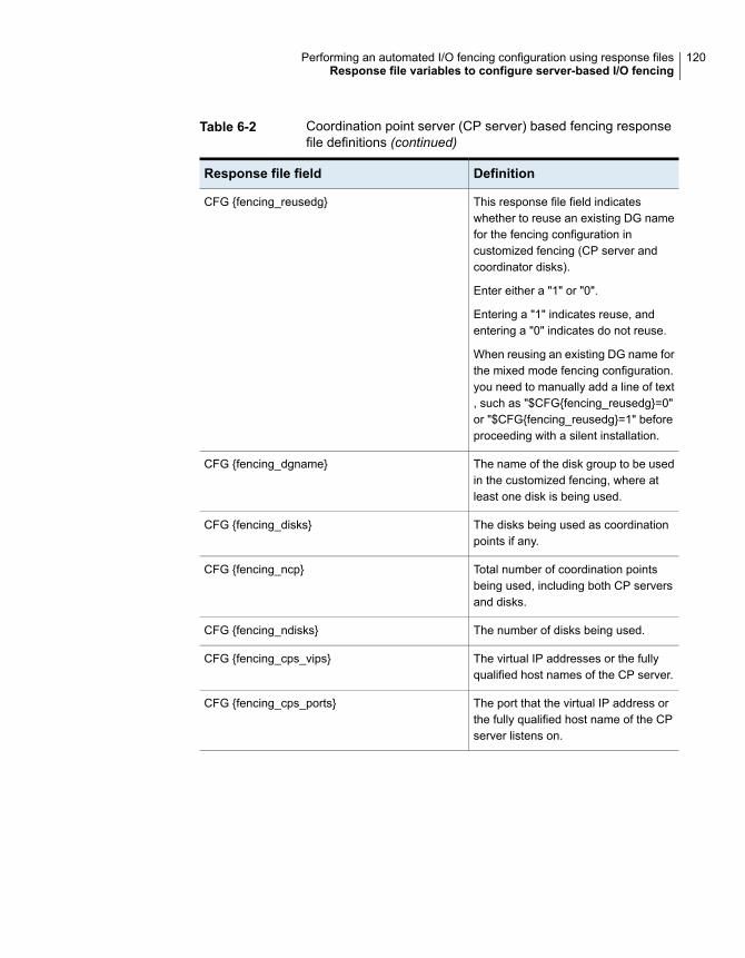
Table 6-2 Coordination point server (CP server) based fencing responsefile definitions (continued)
DefinitionResponse file field
This response file field indicateswhether to reuse an existing DG namefor the fencing configuration incustomized fencing (CP server andcoordinator disks).
Enter either a "1" or "0".
Entering a "1" indicates reuse, andentering a "0" indicates do not reuse.
When reusing an existing DG name forthe mixed mode fencing configuration.you need to manually add a line of text, such as "$CFG{fencing_reusedg}=0"or "$CFG{fencing_reusedg}=1" beforeproceeding with a silent installation.
CFG {fencing_reusedg}
The name of the disk group to be usedin the customized fencing, where atleast one disk is being used.
CFG {fencing_dgname}
The disks being used as coordinationpoints if any.
CFG {fencing_disks}
Total number of coordination pointsbeing used, including both CP serversand disks.
CFG {fencing_ncp}
The number of disks being used.CFG {fencing_ndisks}
The virtual IP addresses or the fullyqualified host names of the CP server.
CFG {fencing_cps_vips}
The port that the virtual IP address orthe fully qualified host name of the CPserver listens on.
CFG {fencing_cps_ports}
120Performing an automated I/O fencing configuration using response filesResponse file variables to configure server-based I/O fencing

Table 6-2 Coordination point server (CP server) based fencing responsefile definitions (continued)
DefinitionResponse file field
Specifies the I/O fencing configurationmode.
■ 1—Coordination Point Server-basedI/O fencing
■ 2—Coordinator disk-based I/Ofencing
■ 3—Disabled-based I/O fencing■ 4—Online fencing migration■ 5—Refresh keys/registrations on the
existing coordination points■ 6—Change the order of existing
coordination points■ 7—Majority-based fencing
(Required)
CFG{fencing_option}
Enable this variable if registration keysare missing on any of the CP servers.
CFG{fencing_auto_refresh_reg}
Sample response file for configuring server-basedI/O fencing
The following is a sample response file used for server-based I/O fencing:
$CFG{fencing_config_cpagent}=0;
$CFG{fencing_cps}=[ qw(10.200.117.145) ];
$CFG{fencing_cps_vips}{"10.200.117.145"}=[ qw(10.200.117.145) ];
$CFG{fencing_dgname}="vxfencoorddg";
$CFG{fencing_disks}=[ qw(emc_clariion0_37 emc_clariion0_13
emc_clariion0_12) ];
$CFG{fencing_scsi3_disk_policy}="dmp";
$CFG{fencing_ncp}=3;
$CFG{fencing_ndisks}=2;
$CFG{fencing_cps_ports}{"10.200.117.145"}=443;
$CFG{fencing_reusedg}=1;
$CFG{opt}{configure}=1;
$CFG{opt}{fencing}=1;
$CFG{prod}="AVAILABILITY71";
$cfg{activecomponent}=[qw(VCS71)];
121Performing an automated I/O fencing configuration using response filesSample response file for configuring server-based I/O fencing

$CFG{systems}=[ qw(sys1 sys2) ];
$CFG{vcs_clusterid}=1256;
$CFG{vcs_clustername}="clus1";
$CFG{fencing_option}=1;
Response file variables to configure non-SCSI-3I/O fencing
Table 6-3 lists the fields in the response file that are relevant for non-SCSI-3 I/Ofencing.
Table 6-3 Non-SCSI-3 I/O fencing response file definitions
DefinitionResponse file field
Defines whether to configure non-SCSI-3 I/O fencing.
Valid values are 1 or 0. Enter 1 to configure non-SCSI-3I/O fencing.
CFG{non_scsi3_fencing}
Enter '1' or '0' depending upon whether you want toconfigure the Coordination Point agent using theinstaller or not.
Enter "0" if you do not want to configure theCoordination Point agent using the installer.
Enter "1" if you want to use the installer to configurethe Coordination Point agent.
Note: This variable does not apply to majority-basedfencing.
CFG {fencing_config_cpagent}
Name of the service group which will have theCoordination Point agent resource as part of it.
Note: This field is obsolete if thefencing_config_cpagent field is given a value of'0'. This variable does not apply to majority-basedfencing.
CFG {fencing_cpagentgrp}
Virtual IP address or Virtual hostname of the CPservers.
Note: This variable does not apply to majority-basedfencing.
CFG {fencing_cps}
122Performing an automated I/O fencing configuration using response filesResponse file variables to configure non-SCSI-3 I/O fencing

Table 6-3 Non-SCSI-3 I/O fencing response file definitions (continued)
DefinitionResponse file field
The virtual IP addresses or the fully qualified hostnames of the CP server.
Note: This variable does not apply to majority-basedfencing.
CFG {fencing_cps_vips}
Total number of coordination points (CP servers only)being used.
Note: This variable does not apply to majority-basedfencing.
CFG {fencing_ncp}
The port of the CP server that is denoted by cps .
Note: This variable does not apply to majority-basedfencing.
CFG {fencing_cps_ports}
Enable this variable if registration keys are missing onany of the CP servers.
CFG{fencing_auto_refresh_reg}
Sample response file for configuring non-SCSI-3I/O fencing
The following is a sample response file used for non-SCSI-3 I/O fencing :
$CFG{fencing_config_cpagent}=0;
$CFG{fencing_cps}=[ qw(10.198.89.251 10.198.89.252 10.198.89.253) ];
$CFG{fencing_cps_vips}{"10.198.89.251"}=[ qw(10.198.89.251) ];
$CFG{fencing_cps_vips}{"10.198.89.252"}=[ qw(10.198.89.252) ];
$CFG{fencing_cps_vips}{"10.198.89.253"}=[ qw(10.198.89.253) ];
$CFG{fencing_ncp}=3;
$CFG{fencing_ndisks}=0;
$CFG{fencing_cps_ports}{"10.198.89.251"}=443;
$CFG{fencing_cps_ports}{"10.198.89.252"}=443;
$CFG{fencing_cps_ports}{"10.198.89.253"}=443;
$CFG{non_scsi3_fencing}=1;
$CFG{opt}{configure}=1;
$CFG{opt}{fencing}=1;
$CFG{prod}="AVAILABILITY71";
$cfg{activecomponent}=[qw(VCS71)];
$CFG{systems}=[ qw(sys1 sys2) ];
$CFG{vcs_clusterid}=1256;
123Performing an automated I/O fencing configuration using response filesSample response file for configuring non-SCSI-3 I/O fencing

$CFG{vcs_clustername}="clus1";
$CFG{fencing_option}=1;
Response file variables to configuremajority-based I/O fencing
Table 6-4 lists the response file variables that specify the required information toconfigure disk-based I/O fencing for VCS.
Table 6-4 Response file variables specific to configuring majority-based I/Ofencing
DescriptionList orScalar
Variable
Performs the I/O fencing configuration.
(Required)
ScalarCFG{opt}{fencing}
Specifies the I/O fencing configurationmode.
■ 1—Coordination Point Server-basedI/O fencing
■ 2—Coordinator disk-based I/Ofencing
■ 3—Disabled-based fencing■ 4—Online fencing migration■ 5—Refresh keys/registrations on the
existing coordination points■ 6—Change the order of existing
coordination points■ 7—Majority-based fencing
(Required)
ScalarCFG{fencing_option}
Sample response file for configuringmajority-based I/O fencing
$CFG{fencing_option}=7;
$CFG{config_majority_based_fencing}=1;
$CFG{opt}{configure}=1;
$CFG{opt}{fencing}=1;
124Performing an automated I/O fencing configuration using response filesResponse file variables to configure majority-based I/O fencing

$CFG{prod}="AVAILABILITY71";
$cfg{activecomponent}=[qw(VCS71)];
$CFG{systems}=[ qw(sys1 sys2) ];
$CFG{vcs_clusterid}=59082;
$CFG{vcs_clustername}="clus1";
125Performing an automated I/O fencing configuration using response filesSample response file for configuring majority-based I/O fencing

Manual configuration
■ Chapter 7. Manually configuring VCS
■ Chapter 8. Manually configuring the clusters for data integrity
3Section

Manually configuring VCSThis chapter includes the following topics:
■ About configuring VCS manually
■ Configuring LLT manually
■ Configuring GAB manually
■ Configuring VCS manually
■ Configuring VCS in single node mode
■ Starting LLT, GAB, and VCS after manual configuration
■ About configuring cluster using VCS Cluster Configuration wizard
■ Before configuring a VCS cluster using the VCS Cluster Configuration wizard
■ Launching the VCS Cluster Configuration wizard
■ Configuring a cluster by using the VCS cluster configuration wizard
■ Adding a system to a VCS cluster
■ Modifying the VCS configuration
About configuring VCS manuallyThis section describes the procedures to manually configure VCS.
Note: For manually configuring VCS in single node mode, you can skip steps aboutconfiguring LLT manually and configuring GAB manually.
7Chapter

Configuring LLT manuallyVCS uses the Low Latency Transport (LLT) protocol for all cluster communicationsas a high-performance, low-latency replacement for the IP stack. LLT has two majorfunctions.
It handles the following tasks:
■ Traffic distribution
■ Heartbeat traffic
To configure LLT over Ethernet, perform the following steps on each node in thecluster:
■ Set up the file /etc/llthosts.See “Setting up /etc/llthosts for a manual installation” on page 128.
■ Set up the file /etc/llttab.See “Setting up /etc/llttab for a manual installation” on page 128.
■ Edit the following file on each node in the cluster to change the values of theLLT_START and the LLT_STOP environment variables to 1:/etc/default/llt
You can also configure LLT over UDP.
See “Using the UDP layer for LLT” on page 299.
Setting up /etc/llthosts for a manual installationThe file llthosts(4) is a database. It contains one entry per system that links the LLTsystem ID (in the first column) with the LLT host name. You must ensure thatcontents of this file are identical on all the nodes in the cluster. A mismatch of thecontents of the file can cause indeterminate behavior in the cluster.
Use vi or another editor, to create the file /etc/llthosts that contains the entries thatresemble:
0 sys1
1 sys2
Setting up /etc/llttab for a manual installationThe /etc/llttab file must specify the system’s ID number (or its node name), its clusterID, and the network links that correspond to the system. In addition, the file cancontain other directives. Refer also to the sample llttab file in /opt/VRTSllt.
See “About LLT directives in /etc/llttab file” on page 130.
128Manually configuring VCSConfiguring LLT manually

Run the dladm show-dev command to query all NICs.
Use vi or another editor to create the file /etc/lltab that contains the entries thatresemble the following:
■ For Solaris 10 SPARC:
set-node sys1
set-cluster 2
link net1 net:0 - ether - -
link net2 net:1 - ether - -
■ For Solaris 11 SPARC:
set-node sys1
set-cluster 2
link net1 /dev/net/net0 - ether - -
link net2 /dev/net/net1 - ether - -
Use vi or another editor to create the file /etc/lltab that contains the entries thatresemble the following:
■ For x64:
set-node sys1
set-cluster 2
link e1000g0 /dev/e1000g:0 - ether - -
link e1000g1 /dev/e1000g:1 - ether - -
The first line must identify the system where the file exists. In the example, thevalue for set-node can be: sys1, 0, or the file name /etc/nodename. The file needsto contain the name of the system (sys1 in this example). The next line, beginningwith the set-cluster command, identifies the cluster number, which must be aunique number when more than one cluster is configured on the same physicalnetwork connection.The next two lines, beginning with the link command, identifythe two private network cards that the LLT protocol uses. The order of directivesmust be the same as in the sample llttab file in /opt/VRTSllt.
If you use different media speed for the private NICs, Veritas recommends that youconfigure the NICs with lesser speed as low-priority links to enhance LLTperformance. For example:
Use vi or another editor to create the file /etc/lltab that contains the entries thatresemble the following:
129Manually configuring VCSConfiguring LLT manually

■ For SPARC:
set-node sys1
set-cluster 2
link net1 net:0 - ether - -
link net2 net:1 - ether - -
link-lowpri qfe2 qfe:2 - ether - -
Use vi or another editor to create the file /etc/lltab that contains the entries thatresemble the following:
■ For x64:
set-node sys1
set-cluster 2
link e1000g0 /dev/e1000g:0 - ether - -
link e1000g1 /dev/e1000g:1 - ether - -
link-lowpri e1000g2 /dev/e1000g:2 - ether - -
About LLT directives in /etc/llttab fileTable 7-1 lists the LLT directives in /etc/llttab file for LLT over Ethernet.
Table 7-1 LLT directives
DescriptionDirective
Assigns the system ID or symbolic name. The system ID numbermust be unique for each system in the cluster, and must be inthe range 0-63. The symbolic name corresponds to the systemID, which is in /etc/llthosts file.
Note that LLT fails to operate if any systems share the same ID.
set-node
Assigns a unique cluster number. Use this directive when morethan one cluster is configured on the same physical networkconnection. LLT uses a default cluster number of zero.
set-cluster
130Manually configuring VCSConfiguring LLT manually

Table 7-1 LLT directives (continued)
DescriptionDirective
Attaches LLT to a network interface. At least one link is required,and up to eight are supported.
LLT distributes network traffic evenly across all available networkconnections unless you mark the link as low-priority using thelink-lowpri directive or you configured LLT to usedestination-based load balancing.
The first argument to link is a user-defined tag shown in thelltstat(1M) output to identify the link. It may also be used inllttab to set optional static MAC addresses.
The second argument to link is the device name of the networkinterface. Its format is device_name:device_instance_number.
The remaining four arguments to link are defaults; thesearguments should be modified only in advanced configurations.There should be one link directive for each network interface.LLT uses an unregistered Ethernet SAP of 0xcafe. If the SAP isunacceptable, refer to the llttab(4) manual page forinformation on how to customize SAP. Note that IP addressesdo not need to be assigned to the network device; LLT does notuse IP addresses in LLT over Ethernet mode.
link
Use this directive in place of link for public network interfaces.This directive prevents VCS communication on the public networkuntil the network is the last link, and reduces the rate of heartbeatbroadcasts.
If you use private NICs with different speed, use "link-lowpri"directive in place of "link" for all links with lower speed. Use the"link" directive only for the private NIC with higher speed toenhance LLT performance. LLT uses low-priority network linksfor VCS communication only when other links fail.
link-lowpri
For more information about the LLT directives, refer to the llttab(4) manual page.
Additional considerations for LLT for a manual installationYou must attach each network interface that is configured for LLT to a separateand distinct physical network.
By default, Oracle systems assign the same MAC address to all interfaces. Thus,connecting two or more interfaces to a network switch can cause problems. Considerthe following example. You configure an IP on one public interface and LLT onanother. Both interfaces are connected to a switch. The duplicate MAC address on
131Manually configuring VCSConfiguring LLT manually

the two switch ports can cause the switch to incorrectly redirect IP traffic to the LLTinterface and vice versa. To avoid this issue, configure the system to assign uniqueMAC addresses by setting the eeprom(1M) parameter local-mac-address? to true.
Configuring GAB manuallyVCS uses the Group Membership Services/Atomic Broadcast (GAB) protocol forcluster membership and reliable cluster communications. GAB has two majorfunctions.
It handles the following tasks:
■ Cluster membership
■ Cluster communications
To configure GAB
1 Set up an /etc/gabtab configuration file on each node in the cluster using vi oranother editor. The following example shows an /etc/gabtab file:
/sbin/gabconfig -c -nN
Where the -c option configures the driver for use. The -nN option specifiesthat the cluster is not formed until at least N systems are ready to form thecluster. Veritas recommends that you set N to be the total number of systemsin the cluster.
Warning: Veritas does not recommend the use of the -c -x option or -x optionfor /sbin/gabconfig. Using -c -x or -x can lead to a split-brain condition.
2 Edit the following file on each node in the cluster to change the values of theGAB_START and the GAB_STOP environment variables to 1:
/etc/default/gab
Configuring VCS manuallyVCS configuration requires the types.cf and main.cf files on each system in thecluster. Both of the files are in the /etc/VRTSvcs/conf/config directory.
132Manually configuring VCSConfiguring GAB manually

The main.cf configuration file requires the following minimum essentialelements:
■ An "include" statement that specifies the file, types.cf, which definesthe VCS bundled agent resource type definitions.
■ The name of the cluster.■ The name of the systems that make up the cluster.
main.cf file
Note that the "include" statement in main.cf refers to the types.cf file.This text file describes the VCS bundled agent resource type definitions.During new installations, the types.cf file is automatically copied in tothe /etc/VRTSvcs/conf/config directory.
types.cf file
When you manually install VCS, the file /etc/VRTSvcs/conf/config/main.cf containsonly the line:
include "types.cf"
For a full description of the main.cf file, and how to edit and verify it, refer to theCluster Server Administrator's Guide.
To configure VCS manually
1 Log on as superuser, and move to the directory that contains the configurationfile:
# cd /etc/VRTSvcs/conf/config
2 Use vi or another text editor to edit the main.cf file, defining your cluster nameand system names. Refer to the following example.
An example main.cf for a two-node cluster:
include "types.cf"
cluster VCSCluster2 ( )
system sys1 ( )
system sys2 ( )
An example main.cf for a single-node cluster:
include "types.cf"
cluster VCSCluster1 ( )
system sn1 ( )
3 Save and close the main.cf file.
133Manually configuring VCSConfiguring VCS manually

Configuring the cluster UUID when creating a cluster manuallyYou need to configure the cluster UUID when you manually create a cluster.
To configure the cluster UUID when you create a cluster manually
◆ On one node in the cluster, perform the following command to populate thecluster UUID on each node in the cluster.
# /opt/VRTSvcs/bin/uuidconfig.pl -clus -configure nodeA
nodeB ... nodeN
Where nodeA, nodeB, through nodeN are the names of the cluster nodes.
Configuring VCS in single node modeIn addition to the steps mentioned in the manual configuration section, completethe following steps to configure VCS in single node mode.
See “Configuring VCS manually” on page 132.
To configure VCS in single node mode
1 Disable the VCS SMF service imported by VRTSvcs package.
# svcadm disable -s system/vcs:default
2 Delete the VCS SMF service configuration.
# svccfg delete -f system/vcs:default
3 Edit the following file to change the value of the ONENODE environmentvariable to yes.
/etc/default/vcs
4 Import the SMF service for vcs-onenode.
# svccfg import /etc/VRTSvcs/conf/vcs-onenode.xml
5 If the single node is intended only to manage applications, you can disableLLT, GAB, I/O fencing kernel modules.
Note: Disabling VCS kernel modules means that you cannot make theapplications highly available across multiple nodes.
See “Disabling LLT, GAB, and I/O fencing on a single node cluster” on page 135.
134Manually configuring VCSConfiguring VCS in single node mode

See “Enabling LLT, GAB, and I/O fencing on a single node cluster” on page 136.
Disabling LLT, GAB, and I/O fencing on a single node clusterThis section discusses how to disable kernel modules on a single node VCS cluster.
Typically, LLT, GAB, and I/O fencing kernel modules are loaded on a node whenyou install VCS. However, you can disable LLT, GAB, and I/O fencing modules ifyou do not require high availability for the applications. You can continue to manageapplications on the single node and use the application restart capabilities of VCS.
If you later decide to extend the cluster to multiple nodes, you can enable thesemodules and make the applications highly available across multiple nodes.
Note: If VCS engine hangs on the single node cluster with GAB disabled, GABcannot detect the hang state and cannot take action to restart VCS. For such acondition, you need to detect that VCS engine has hung and take corrective action.For more information, refer to the ‘About GAB client process failure’ section in theCluster Server Administrator’s Guide.
See “Disabling LLT, GAB, and I/O fencing on Oracle Solaris 10 and 11” on page 135.
Disabling LLT, GAB, and I/O fencing on Oracle Solaris 10and 11Complete the following procedures to disable the kernel modules.
To disable I/O fencing
1 Edit the following file to set the value of VXFEN_START and VXFEN_STOP to 0.
/etc/default/vxfen
2 Run the following commands.
# svcadm disable -s system/vxfen
# svccfg delete -f system/vxfen
# rem_drv vxfen
# modinfo | grep -w vxfen
# modunload -i <mod id>
Where, mod id is the module ID
135Manually configuring VCSConfiguring VCS in single node mode

To disable GAB
1 Edit the following file to set the value of GAB_START and GAB_STOP to 0.
/etc/default/gab
2 Run the following commands.
# svcadm disable -s system/gab
# svccfg delete -f system/gab
# rem_drv gab
# modinfo | grep -w gab
# modunload -i <mod id>
Where, mod id is the module ID.
To disable LLT
1 Edit the following file to set the value of LLT_START and LLT_STOP to 0.
/etc/default/llt
2 Run the following commands.
# svcadm disable -s system/llt
# svccfg delete -f system/llt
# rem_drv llt
# modinfo | grep -w llt
# modunload -i <mod id>
Where, mod id is the module ID.
Enabling LLT, GAB, and I/O fencing on a single node clusterThis section provides the steps to enable the kernel modules on a single nodecluster.
Enabling LLT, GAB, and I/O fencing on Solaris 11Complete the following procedures to enable the kernel modules.
136Manually configuring VCSConfiguring VCS in single node mode

To enable LLT:
1 In the /etc/default/llt file, ensure LLT_START=1.
2 Run the following commands.
# /usr/sbin/add_drv -v -f -m '* 0600 root sys' llt
# svccfg -s system/llt delcust
# svccfg disable system/llt
# svccfg enable system/llt
To enable GAB:
1 In the /etc/default/gab file, ensure GAB_START=1.
2 Run the following commands:
# /usr/sbin/add_drv -v -f -m '* 0600 root sys' gab
# svccfg -s system/gab delcust
# svccfg disable system/gab
# svccfg enable system/gab
To enable I/O fencing:
1 In the /etc/default/vxfen file, ensure VXFEN_START=1.
2 Run the following commands:
# /usr/sbin/add_drv -v -f -m '* 0600 root sys' vxfen
# svccfg -s system/vxfen delcust
# svccfg disable system/vxfen
# svccfg enable system/vxfen
3 Reboot the nodes.
Enabling LLT, GAB, and I/O fencing on Solaris 10Complete the following procedures to enable the kernel modules.
To enable LLT:
1 In the /etc/default/llt file, ensure LLT_START=1.
2 Run the following commands.
#/usr/sbin/add_drv -v -f -m '* 0600 root sys' llt
#/usr/sbin/svccfg import /var/svc/manifest/system/llt.xml
#/usr/sbin/svcadm enable -s system/llt
137Manually configuring VCSConfiguring VCS in single node mode

To enable GAB:
1 In the /etc/default/gab file, ensure GAB_START=1.
2 Run the following commands:
#/usr/sbin/add_drv -v -f -m '* 0600 root sys' gab
#/usr/sbin/svccfg import /var/svc/manifest/system/gab.xml
#/usr/sbin/svcadm enable -s system/gab
To enable I/O fencing:
1 In the /etc/default/vxfen file, ensure VXFEN_START=1.
2 Run the following commands:
#/usr/sbin/add_drv -v -f -m '* 0600 root sys' vxfen
#/usr/sbin/svccfg import /var/svc/manifest/system/vxfen.xml
#/usr/sbin/svcadm enable -s system/vxfen
3 Reboot the nodes.
Starting LLT, GAB, and VCS after manualconfiguration
After you have configured LLT, GAB, and VCS, use the following procedures tostart LLT, GAB, and VCS.
To start LLT
1 On each node, run the following command to start LLT:
# svcadm enable llt
If LLT is configured correctly on each node, the console output resembles:
Jun 26 19:04:24 sys1 kernel: [1571667.550527] LLT INFO V-14-1-10009 LLT 6.0.100.000-SBLD Protocol available
2 On each node, run the following command to verify that LLT is running:
# /sbin/lltconfig
LLT is running
138Manually configuring VCSStarting LLT, GAB, and VCS after manual configuration
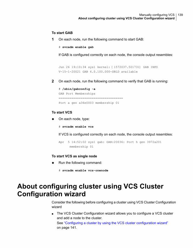
To start GAB
1 On each node, run the following command to start GAB:
# svcadm enable gab
If GAB is configured correctly on each node, the console output resembles:
Jun 26 19:10:34 sys1 kernel: [1572037.501731] GAB INFO
V-15-1-20021 GAB 6.0.100.000-SBLD available
2 On each node, run the following command to verify that GAB is running:
# /sbin/gabconfig -a
GAB Port Memberships
===================================
Port a gen a36e0003 membership 01
To start VCS
◆ On each node, type:
# svcadm enable vcs
If VCS is configured correctly on each node, the console output resembles:
Apr 5 14:52:02 sys1 gab: GAB:20036: Port h gen 3972a201
membership 01
To start VCS as single node
◆ Run the following command:
# svcadm enable vcs-onenode
About configuring cluster using VCS ClusterConfiguration wizard
Consider the following before configuring a cluster using VCS Cluster Configurationwizard
■ The VCS Cluster Configuration wizard allows you to configure a VCS clusterand add a node to the cluster.See “Configuring a cluster by using the VCS cluster configuration wizard”on page 141.
139Manually configuring VCSAbout configuring cluster using VCS Cluster Configuration wizard

■ Veritas recommends that you first configure application monitoring using thewizard before using VCS commands to add additional components or modifythe existing configuration. Apart from configuring application availability, thewizard also sets up the other components required for successful applicationmonitoring.
Before configuring a VCS cluster using the VCSCluster Configuration wizard
Ensure that you complete the following tasks before launching the VCS ClusterConfiguration wizard to configure a VCS cluster:
■ Install InfoScale Availability or InfoScale Enterprise on the system on which youwant to configure the VCS cluster.
■ You must have the following user privileges when you attempt to configure theVCS cluster:
■ Configure Application Monitoring (Admin) privileges when you launch thewizard from the vSphere client.
■ Admin role privileges if you launch the wizard through VOM
■ Install the application and the associated components that you want to monitoron the system.
■ If you have configured a firewall, ensure that your firewall settings allow accessto ports used by Cluster Server installer, wizards, and services.Verify that the following ports are not blocked by the firewall:
5634, 14161, 14162, 14163, and 14164 Atleast one port from 14161, 14162, 14163,and 14164 must be open.
Physical environment
■ You must not select bonded interfaces for cluster communication. A bondedinterface is a logical NIC, formed by grouping several physical NICs together.All NICs in a bond have an identical MAC address, due to which you mayexperience the following issues:
■ Single Sign On (SSO) configuration failure.
■ The wizard may fail to discover the specified network adapters.
■ The wizard may fail to discover or validate the specified system name.
■ The host name of the system must be resolvable through the DNS server orlocally, using /etc/hosts file entries.
140Manually configuring VCSBefore configuring a VCS cluster using the VCS Cluster Configuration wizard

Launching the VCS Cluster Configuration wizardYou must launch the VCS Cluster Configuration wizard from the system where thedisk residing on the shared datastore is attached.
You can launch the VCS Cluster Configuration wizard from:
■ A browser windowSee Launching the VCS Cluster Configuration wizard from a browser window.
Launching the VCS Cluster Configuration wizard from abrowser windowYou can launch the VCS Cluster Configuration wizard from the Veritas HighAvailability view.
1 Open a browser window and enter the following URL:
https://<IP_or_HostName>:5634/vcs/admin/application_health.html
where <IP_or_HostName> is the IP address or host name of the system onwhich you want to configure the cluster.
2 Click the Configure cluster link on the Veritas High Availability view page tolaunch the wizard.
Note: At various stages of cluster configuration, the Veritas High Availability viewoffers different configuration options. These options launch appropriate wizardpanels based on the tasks that you choose to perform.
See “Configuring a cluster by using the VCS cluster configuration wizard”on page 141.
See “Adding a system to a VCS cluster” on page 145.
Refer to the Administering application monitoring from the Veritas High Availabilityview section in Cluster Server Administrator's Guide for more information on theconfigurations possible from the Veritas High Availability view.
Configuring a cluster by using the VCS clusterconfiguration wizard
Perform the following steps to configure a Cluster Server (VCS) cluster by usingthe VCS Cluster Configuration wizard.
141Manually configuring VCSLaunching the VCS Cluster Configuration wizard

To configure a VCS cluster
1 Access the Veritas High Availability view (for any system belonging the requiredcluster).
See “Launching the VCS Cluster Configuration wizard” on page 141.
2 Review the information on the Welcome panel and click Next.
The Configuration Inputs panel appears.
The local system is by default selected as a cluster system.
3 If you do not want to add more systems to the cluster, skip this step. You canadd systems later using the same wizard.
To add a system to the cluster, click Add System.
In the Add System dialog box, specify the following details for the system thatyou want to add to the VCS cluster and click OK.
Specify the name or IP address of thesystem that you want to add to the VCScluster.
System Name or IP address
Specify the user account for the system.
Typically, this is the root user. The rootuser should have the necessary privileges.
User name
Specify the password for the user accountyou specified.
Password
Select this check box to use the specifieduser account on all the cluster systems thathave the same user name and password.
Use the specified user account on allsystems
4 On the Configuration Inputs panel, do one of the following actions:
■ To add another system to the cluster, click Add System and repeat step 3.
■ To modify the specified User name or Password for a cluster system, usethe edit icon.
■ Click Next
5 If you do not want to modify the security settings for the cluster, click Next, andproceed to step 7.
By default, the wizard configures single sign-on for secure clustercommunication. If you want to modify the security settings for the cluster, clickAdvanced Settings.
142Manually configuring VCSConfiguring a cluster by using the VCS cluster configuration wizard

6 In the Advanced settings dialog box, specify the following details and click OK.
Select to configure single sign-on usingVCS Authentication Service for clustercommunication.
This option is enabled by default.
Use Single Sign-on
Select to configure a user withadministrative privileges to the cluster.
Specify the username and password andclick OK.
Use VCS user privileges
7 On the Network Details panel, select the type of network protocol to configurethe VCS cluster network links (Low Latency Transport or LLT module), andthen specify the adapters for network communication.
The wizard configures the VCS cluster communication links using theseadapters. You must select a minimum of two adapters per cluster system.
Note: By default, the LLT links are configured over Ethernet.
Select Use MAC address for cluster communication (LLT over Ethernet)or select Use IP address for cluster communication (LLT over UDP), andspecify the following details for each cluster system.
■ To configure LLT over Ethernet, select the adapter for each networkcommunication link. You must select a different network adapter for eachcommunication link.
■ To configure LLT over UDP, select the type of IP protocol (IPv4 or IPv6),and then specify the required details for each communication link.
Select a network adapter for thecommunication links.
You must select a different networkadapter for each communication link.
Network Adapter
Displays the IP address.IP Address
143Manually configuring VCSConfiguring a cluster by using the VCS cluster configuration wizard

Specify a unique port number for eachlink.
For IPv4 and IPv6, the port range is from49152 to 65535.
A specified port for a link is used for allthe cluster systems on that link.
Port
Displays the subnet mask details.Subnet mask (IPv4)
Displays the prefix details.Prefix (IPv6)
By default, one of the links is configured as a low-priority link on a public networkinterface. The second link is configured as a high-priority link.
To change a high-priority link to a low-priority link, click Modify. In the Modifylow-priority link dialog box, select the link and click OK.
Note: Veritas recommends that you configure one of the links on a publicnetwork interface. You can assign the link on the public network interface asa low-priority link for minimal VCS cluster communication over the link.
8 On the Configuration Summary panel, specify a cluster name and unique clusterID and then click Validate.
Note: If multiple clusters exist in your network, the wizard validates if thespecified cluster ID is a unique cluster ID among all clusters accessible fromthe current system. Among clusters that are not accessible from the currentsystem, you must ensure that the cluster ID you specified is unique
9 Review the VCS Cluster Configuration Details and then click Next to proceedwith the configuration
10 On the Implementation panel, the wizard creates the VCS cluster.
The wizard displays the status of the configuration task. After the configurationis complete, click Next.
If the configuration task fails, click Diagnostic information to check the detailsof the failure. Rectify the cause of the failure and run the wizard again toconfigure the VCS cluster.
11 On the Finish panel, click Finish to complete the wizard workflow.
This completes the VCS cluster configuration.
144Manually configuring VCSConfiguring a cluster by using the VCS cluster configuration wizard

Adding a system to a VCS clusterPerform the following steps to add a system to a Cluster Server (VCS) cluster byusing the VCS Cluster Configuration wizard.
The system from where you launch the wizard must be part of the cluster to whichyou want to add a new system.
To add a system to a VCS cluster
1 Access the Veritas High Availability view (for any system belonging to therequired cluster).
See “Launching the VCS Cluster Configuration wizard” on page 141.
2 Click Actions > Add System to VCS Cluster.
The VCS Cluster Configuration Wizard is launched.
3 Review the information on the Welcome panel and click Next.
The Configuration Inputs panel appears, along with the cluster name, and atable of existing cluster systems.
4 To add a system to the cluster, click Add System.
5 In the Add System dialog box, specify the following details for the system thatyou want to add to the VCS cluster and click OK.
Specify the name or IP address of thesystem that you want to add to the VCScluster.
System Name or IP address
Specify the user account for the system.
Typically, this is the root user. The rootuser should have the necessary privileges.
User name
Specify the password for the user accountyou specified.
Password
Select this check box to use the specifieduser account on all the cluster systems thathave the same user name and password.
Use the specified user account on allsystems
6 On the Configuration Inputs panel, do one of the following actions:
■ To add another system to the cluster, click Add System and repeat step4.
■ To modify the User name or Password for a cluster system, use the editicon.
145Manually configuring VCSAdding a system to a VCS cluster
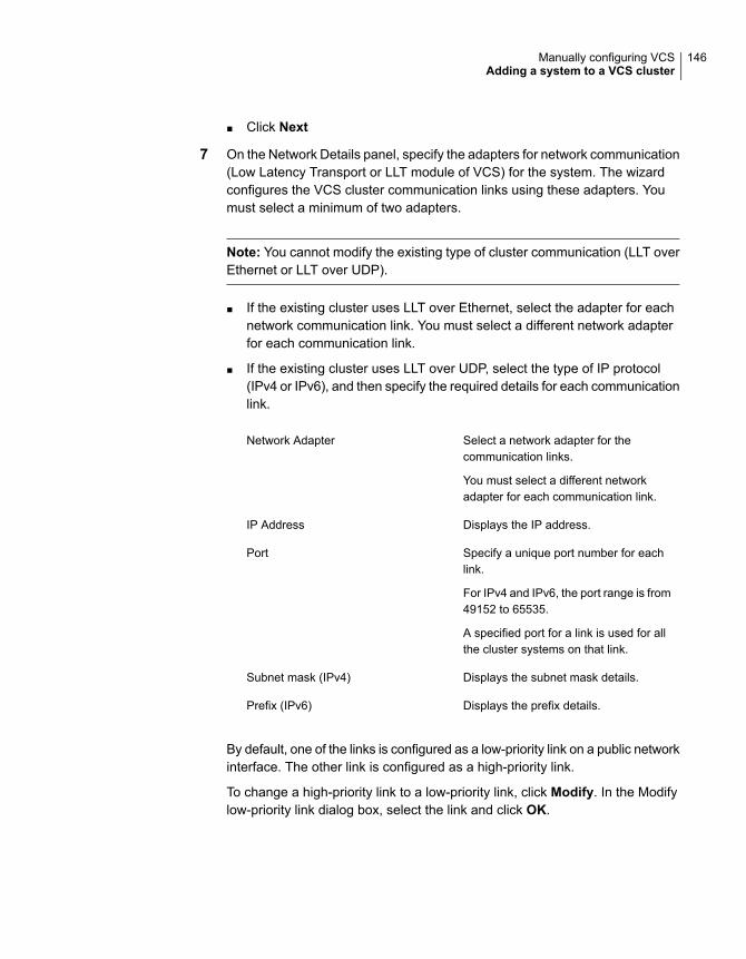
■ Click Next
7 On the Network Details panel, specify the adapters for network communication(Low Latency Transport or LLT module of VCS) for the system. The wizardconfigures the VCS cluster communication links using these adapters. Youmust select a minimum of two adapters.
Note: You cannot modify the existing type of cluster communication (LLT overEthernet or LLT over UDP).
■ If the existing cluster uses LLT over Ethernet, select the adapter for eachnetwork communication link. You must select a different network adapterfor each communication link.
■ If the existing cluster uses LLT over UDP, select the type of IP protocol(IPv4 or IPv6), and then specify the required details for each communicationlink.
Select a network adapter for thecommunication links.
You must select a different networkadapter for each communication link.
Network Adapter
Displays the IP address.IP Address
Specify a unique port number for eachlink.
For IPv4 and IPv6, the port range is from49152 to 65535.
A specified port for a link is used for allthe cluster systems on that link.
Port
Displays the subnet mask details.Subnet mask (IPv4)
Displays the prefix details.Prefix (IPv6)
By default, one of the links is configured as a low-priority link on a public networkinterface. The other link is configured as a high-priority link.
To change a high-priority link to a low-priority link, click Modify. In the Modifylow-priority link dialog box, select the link and click OK.
146Manually configuring VCSAdding a system to a VCS cluster

Note: Veritas recommends that you configure one of the links on a publicnetwork interface. You can assign the link on the public network interface asa low-priority link for minimal VCS cluster communication over the link.
8 On the Configuration Summary panel, review the VCS Cluster ConfigurationDetails.
9 On the Implementation panel, the wizard creates the VCS cluster.
The wizard displays the status of the configuration task. After the configurationis complete, click Next.
If the configuration task fails, click Diagnostic information to check the detailsof the failure. Rectify the cause of the failure and run the wizard again to addthe required system to the VCS cluster.
10 On the Finish panel, click Finish to complete the wizard workflow.
Modifying the VCS configurationAfter the successful installation of VCS, you can modify the configuration of VCSusing several methods. You can dynamically modify the configuration from thecommand line, Veritas InfoScale Operations Manager, or the Cluster Manager (JavaConsole). For information on management tools, refer to the Cluster ServerAdministrator’s Guide.
You can also edit the main.cf file directly. For information on the structure of themain.cf file, refer to the Cluster Server Administrator’s Guide.
Configuring the ClusterService groupWhen you have installed VCS, and verified that LLT, GAB, and VCS work, you cancreate a service group to include the optional features. These features include theVCS notification components and the Global Cluster option. If you manually addedVCS to your cluster systems, you must manually create the ClusterService group.You can refer to the configuration examples of a system with a ClusterServicegroup. See the Cluster Server Administrator's Guide for more information.
See “Sample main.cf file for VCS clusters” on page 285.
147Manually configuring VCSModifying the VCS configuration

Manually configuring theclusters for data integrity
This chapter includes the following topics:
■ Setting up disk-based I/O fencing manually
■ Setting up server-based I/O fencing manually
■ Setting up non-SCSI-3 fencing in virtual environments manually
■ Setting up majority-based I/O fencing manually
Setting up disk-based I/O fencing manuallyTable 8-1 lists the tasks that are involved in setting up I/O fencing.
Table 8-1
ReferenceTask
See “Initializing disks as VxVM disks” on page 73.Initializing disks as VxVM disks
See “Identifying disks to use as coordinator disks”on page 149.
Identifying disks to use ascoordinator disks
See “Checking shared disks for I/O fencing” on page 78.Checking shared disks for I/Ofencing
See “Setting up coordinator disk groups” on page 149.Setting up coordinator diskgroups
See “Creating I/O fencing configuration files” on page 150.Creating I/O fencingconfiguration files
8Chapter

Table 8-1 (continued)
ReferenceTask
See “Modifying VCS configuration to use I/O fencing”on page 151.
Modifying VCS configuration touse I/O fencing
See “Configuring CoordPoint agent to monitor coordinationpoints” on page 164.
Configuring CoordPoint agentto monitor coordination points
See “Verifying I/O fencing configuration” on page 152.Verifying I/O fencingconfiguration
Identifying disks to use as coordinator disksMake sure you initialized disks as VxVM disks.
See “Initializing disks as VxVM disks” on page 73.
Review the following procedure to identify disks to use as coordinator disks.
To identify the coordinator disks
1 List the disks on each node.
For example, execute the following commands to list the disks:
# vxdisk -o alldgs list
2 Pick three SCSI-3 PR compliant shared disks as coordinator disks.
See “Checking shared disks for I/O fencing” on page 78.
Setting up coordinator disk groupsFrom one node, create a disk group named vxfencoorddg. This group must containthree disks or LUNs. You must also set the coordinator attribute for the coordinatordisk group. VxVM uses this attribute to prevent the reassignment of coordinatordisks to other disk groups.
Note that if you create a coordinator disk group as a regular disk group, you canturn on the coordinator attribute in Volume Manager.
Refer to the Storage Foundation Administrator’s Guide for details on how to createdisk groups.
The following example procedure assumes that the disks have the device namesc1t1d0s2, c2t1d0s2, and c3t1d0s2.
149Manually configuring the clusters for data integritySetting up disk-based I/O fencing manually

To create the vxfencoorddg disk group
1 On any node, create the disk group by specifying the device names:
# vxdg init vxfencoorddg c1t1d0s2 c2t1d0s2 c3t1d0s2
2 Set the coordinator attribute value as "on" for the coordinator disk group.
# vxdg -g vxfencoorddg set coordinator=on
3 Deport the coordinator disk group:
# vxdg deport vxfencoorddg
4 Import the disk group with the -t option to avoid automatically importing it whenthe nodes restart:
# vxdg -t import vxfencoorddg
5 Deport the disk group. Deporting the disk group prevents the coordinator disksfrom serving other purposes:
# vxdg deport vxfencoorddg
Creating I/O fencing configuration filesAfter you set up the coordinator disk group, you must do the following to configureI/O fencing:
■ Create the I/O fencing configuration file /etc/vxfendg
■ Update the I/O fencing configuration file /etc/vxfenmode
To update the I/O fencing files and start I/O fencing
1 On each nodes, type:
# echo "vxfencoorddg" > /etc/vxfendg
Do not use spaces between the quotes in the "vxfencoorddg" text.
This command creates the /etc/vxfendg file, which includes the name of thecoordinator disk group.
2 On all cluster nodes specify the use of DMP disk policy in the /etc/vxfenmode
file.
■ # cp /etc/vxfen.d/vxfenmode_scsi3_dmp /etc/vxfenmode
150Manually configuring the clusters for data integritySetting up disk-based I/O fencing manually

3 To check the updated /etc/vxfenmode configuration, enter the followingcommand on one of the nodes. For example:
# more /etc/vxfenmode
4 Ensure that you edit the following file on each node in the cluster to changethe values of the VXFEN_START and the VXFEN_STOP environment variablesto 1:
/etc/default/vxfen
Modifying VCS configuration to use I/O fencingAfter you add coordination points and configure I/O fencing, add the UseFence =SCSI3 cluster attribute to the VCS configuration file/etc/VRTSvcs/conf/config/main.cf.
If you reset this attribute to UseFence = None, VCS does not make use of I/Ofencing abilities while failing over service groups. However, I/O fencing needs tobe disabled separately.
To modify VCS configuration to enable I/O fencing
1 Save the existing configuration:
# haconf -dump -makero
2 Stop VCS on all nodes:
# hastop -all
3 To ensure High Availability has stopped cleanly, run gabconfig -a.
In the output of the commans, check that Port h is not present.
4 If the I/O fencing driver vxfen is already running, stop the I/O fencing driver.
# svcadm disable -t vxfen
5 Make a backup of the main.cf file on all the nodes:
# cd /etc/VRTSvcs/conf/config
# cp main.cf main.orig
151Manually configuring the clusters for data integritySetting up disk-based I/O fencing manually

6 On one node, use vi or another text editor to edit the main.cf file. To modifythe list of cluster attributes, add the UseFence attribute and assign its valueas SCSI3.
cluster clus1(
UserNames = { admin = "cDRpdxPmHpzS." }
Administrators = { admin }
HacliUserLevel = COMMANDROOT
CounterInterval = 5
UseFence = SCSI3
)
Regardless of whether the fencing configuration is disk-based or server-based,the value of the cluster-level attribute UseFence is set to SCSI3.
7 Save and close the file.
8 Verify the syntax of the file /etc/VRTSvcs/conf/config/main.cf:
# hacf -verify /etc/VRTSvcs/conf/config
9 Start the I/O fencing driver and VCS. Perform the following steps on each node:
■ Start the I/O fencing driver.The vxfen startup script also invokes the vxfenconfig command, whichconfigures the vxfen driver to start and use the coordination points that arelisted in /etc/vxfentab.
# svcadm enable vxfen
■ Start VCS on the node where main.cf is modified.
# /opt/VRTS/bin/hastart
■ Start VCS on all other nodes once VCS on first node reaches RUNNINGstate.
# /opt/VRTS/bin/hastart
Verifying I/O fencing configurationVerify from the vxfenadm output that the SCSI-3 disk policy reflects the configurationin the /etc/vxfenmode file.
152Manually configuring the clusters for data integritySetting up disk-based I/O fencing manually

To verify I/O fencing configuration
1 On one of the nodes, type:
# vxfenadm -d
Output similar to the following appears if the fencing mode is SCSI3 and theSCSI3 disk policy is dmp:
I/O Fencing Cluster Information:
================================
Fencing Protocol Version: 201
Fencing Mode: SCSI3
Fencing SCSI3 Disk Policy: dmp
Cluster Members:
* 0 (sys1)
1 (sys2)
RFSM State Information:
node 0 in state 8 (running)
node 1 in state 8 (running)
2 Verify that the disk-based I/O fencing is using the specified disks.
# vxfenconfig -l
Setting up server-based I/O fencing manuallyTasks that are involved in setting up server-based I/O fencing manually include:
Table 8-2 Tasks to set up server-based I/O fencing manually
ReferenceTask
See “Preparing the CP servers manually for use by theVCS cluster” on page 154.
Preparing the CP servers foruse by the VCS cluster
See “Generating the client key and certificates manuallyon the client nodes ” on page 156.
Generating the client key andcertificates on the client nodesmanually
153Manually configuring the clusters for data integritySetting up server-based I/O fencing manually

Table 8-2 Tasks to set up server-based I/O fencing manually (continued)
ReferenceTask
See “Configuring server-based fencing on the VCS clustermanually” on page 158.
Modifying I/O fencingconfiguration files to configureserver-based I/O fencing
See “Modifying VCS configuration to use I/O fencing”on page 151.
Modifying VCS configuration touse I/O fencing
See “Configuring CoordPoint agent to monitor coordinationpoints” on page 164.
Configuring Coordination Pointagent to monitor coordinationpoints
See “Verifying server-based I/O fencing configuration”on page 166.
Verifying the server-based I/Ofencing configuration
Preparing the CP servers manually for use by the VCS clusterUse this procedure to manually prepare the CP server for use by the VCS clusteror clusters.
Table 8-3 displays the sample values used in this procedure.
Table 8-3 Sample values in procedure
Sample nameCP server configuration component
cps1CP server
sys1Node #1 - VCS cluster
sys2Node #2 - VCS cluster
clus1Cluster name
{f0735332-1dd1-11b2}Cluster UUID
154Manually configuring the clusters for data integritySetting up server-based I/O fencing manually

To manually configure CP servers for use by the VCS cluster
1 Determine the cluster name and uuid on the VCS cluster.
For example, issue the following commands on one of the VCS cluster nodes(sys1):
# grep cluster /etc/VRTSvcs/conf/config/main.cf
cluster clus1
# cat /etc/vx/.uuids/clusuuid
{f0735332-1dd1-11b2-bb31-00306eea460a}
2 Use the cpsadm command to check whether the VCS cluster and nodes arepresent in the CP server.
For example:
# cpsadm -s cps1.example.com -a list_nodes
ClusName UUID Hostname(Node ID) Registered
clus1 {f0735332-1dd1-11b2-bb31-00306eea460a} sys1(0) 0
clus1 {f0735332-1dd1-11b2-bb31-00306eea460a} sys2(1) 0
If the output does not show the cluster and nodes, then add them as describedin the next step.
For detailed information about the cpsadm command, see the Cluster ServerAdministrator's Guide.
155Manually configuring the clusters for data integritySetting up server-based I/O fencing manually

3 Add the VCS cluster and nodes to each CP server.
For example, issue the following command on the CP server(cps1.example.com) to add the cluster:
# cpsadm -s cps1.example.com -a add_clus\
-c clus1 -u {f0735332-1dd1-11b2}
Cluster clus1 added successfully
Issue the following command on the CP server (cps1.example.com) to add thefirst node:
# cpsadm -s cps1.example.com -a add_node\
-c clus1 -u {f0735332-1dd1-11b2} -h sys1 -n0
Node 0 (sys1) successfully added
Issue the following command on the CP server (cps1.example.com) to add thesecond node:
# cpsadm -s cps1.example.com -a add_node\
-c clus1 -u {f0735332-1dd1-11b2} -h sys2 -n1
Node 1 (sys2) successfully added
See “Generating the client key and certificates manually on the client nodes ”on page 156.
Generating the client key and certificates manually on the clientnodes
The client node that wants to connect to a CP server using HTTPS must have aprivate key and certificates signed by the Certificate Authority (CA) on the CP server
The client uses its private key and certificates to establish connection with the CPserver. The key and the certificate must be present on the node at a predefinedlocation. Each client has one client certificate and one CA certificate for every CPserver, so, the certificate files must follow a specific naming convention. Distinctcertificate names help the cpsadm command to identify which certificates have tobe used when a client node connects to a specific CP server.
The certificate names must be as follows: ca_cps-vip.crt and client _cps-vip.crt
Where, cps-vip is the VIP or FQHN of the CP server listed in the /etc/vxfenmode
file. For example, for a sample VIP, 192.168.1.201, the corresponding certificatename is ca_192.168.1.201.
156Manually configuring the clusters for data integritySetting up server-based I/O fencing manually

To manually set up certificates on the client node
1 Create the directory to store certificates.
# mkdir -p /var/VRTSvxfen/security/keys
/var/VRTSvxfen/security/certs
Note: Since the openssl utility might not be available on client nodes, Veritasrecommends that you access the CP server using SSH to generate the clientkeys or certificates on the CP server and copy the certificates to each of thenodes.
2 Generate the private key for the client node.
# /usr/bin/openssl genrsa -out client_private.key 2048
3 Generate the client CSR for the cluster. CN is the UUID of the client's cluster.
# /usr/bin/openssl req -new -key -sha256 client_private.key\
-subj '/C=countryname/L=localityname/OU=COMPANY/CN=CLUS_UUID'\
-out client_192.168.1.201.csr
Where, countryname is the country code, localityname is the city, COMPANYis the name of the company, and CLUS_UUID is the certificate name.
4 Generate the client certificate by using the CA key and the CA certificate. Runthis command from the CP server.
# /usr/bin/openssl x509 -req -days days -sha256 -in
client_192.168.1.201.csr\
-CA /var/VRTScps/security/certs/ca.crt -CAkey\
/var/VRTScps/security/keys/ca.key -set_serial 01 -out
client_192.168.10.1.crt
Where, days is the days you want the certificate to remain valid, 192.168.1.201is the VIP or FQHN of the CP server.
157Manually configuring the clusters for data integritySetting up server-based I/O fencing manually

5 Copy the client key, client certificate, and CA certificate to each of the clientnodes at the following location.
Copy the client key at/var/VRTSvxfen/security/keys/client_private.key. The client is commonfor all the client nodes and hence you need to generate it only once.
Copy the client certificate at/var/VRTSvxfen/security/certs/client_192.168.1.201.crt.
Copy the CA certificate at/var/VRTSvxfen/security/certs/ca_192.168.1.201.crt
Note: Copy the certificates and the key to all the nodes at the locations thatare listed in this step.
6 If the client nodes need to access the CP server using the FQHN and or thehost name, make a copy of the certificates you generated and replace the VIPwith the FQHN or host name. Make sure that you copy these certificates to allthe nodes.
7 Repeat the procedure for every CP server.
8 After you copy the key and certificates to each client node, delete the clientkeys and client certificates on the CP server.
Configuring server-based fencing on the VCS cluster manuallyThe configuration process for the client or VCS cluster to use CP server as acoordination point requires editing the /etc/vxfenmode file.
You need to edit this file to specify the following information for your configuration:
■ Fencing mode
■ Fencing mechanism
■ Fencing disk policy (if applicable to your I/O fencing configuration)
■ CP server or CP servers
■ Coordinator disk group (if applicable to your I/O fencing configuration)
■ Set the order of coordination points
158Manually configuring the clusters for data integritySetting up server-based I/O fencing manually

Note: Whenever coordinator disks are used as coordination points in your I/Ofencing configuration, you must create a disk group (vxfencoorddg). You mustspecify this disk group in the /etc/vxfenmode file.
See “Setting up coordinator disk groups” on page 149.
The customized fencing framework also generates the /etc/vxfentab file whichhas coordination points (all the CP servers and disks from disk group specified in/etc/vxfenmode file).
To configure server-based fencing on the VCS cluster manually
1 Use a text editor to edit the following file on each node in the cluster:
/etc/default/vxfen
You must change the values of the VXFEN_START and the VXFEN_STOP
environment variables to 1.
2 Use a text editor to edit the /etc/vxfenmode file values to meet yourconfiguration specifications.
■ If your server-based fencing configuration uses a single highly availableCP server as its only coordination point, make sure to add the single_cp=1
entry in the /etc/vxfenmode file.
■ If you want the vxfen module to use a specific order of coordination pointsduring a network partition scenario, set the vxfen_honor_cp_order valueto be 1. By default, the parameter is disabled.
The following sample file output displays what the /etc/vxfenmode file contains:
See “Sample vxfenmode file output for server-based fencing” on page 159.
3 After editing the /etc/vxfenmode file, run the vxfen init script to start fencing.
For example:
# svcadm enable vxfen
Sample vxfenmode file output for server-based fencingThe following is a sample vxfenmode file for server-based fencing:
#
# vxfen_mode determines in what mode VCS I/O Fencing should work.
#
# available options:
159Manually configuring the clusters for data integritySetting up server-based I/O fencing manually

# scsi3 - use scsi3 persistent reservation disks
# customized - use script based customized fencing
# disabled - run the driver but don't do any actual fencing
#
vxfen_mode=customized
# vxfen_mechanism determines the mechanism for customized I/O
# fencing that should be used.
#
# available options:
# cps - use a coordination point server with optional script
# controlled scsi3 disks
#
vxfen_mechanism=cps
#
# scsi3_disk_policy determines the way in which I/O fencing
# communicates with the coordination disks. This field is
# required only if customized coordinator disks are being used.
#
# available options:
# dmp - use dynamic multipathing
#
scsi3_disk_policy=dmp
#
# vxfen_honor_cp_order determines the order in which vxfen
# should use the coordination points specified in this file.
#
# available options:
# 0 - vxfen uses a sorted list of coordination points specified
# in this file,
# the order in which coordination points are specified does not matter.
# (default)
# 1 - vxfen uses the coordination points in the same order they are
# specified in this file
# Specify 3 or more odd number of coordination points in this file,
# each one in its own line. They can be all-CP servers,
# all-SCSI-3 compliant coordinator disks, or a combination of
# CP servers and SCSI-3 compliant coordinator disks.
# Please ensure that the CP server coordination points
# are numbered sequentially and in the same order
160Manually configuring the clusters for data integritySetting up server-based I/O fencing manually

# on all the cluster nodes.
#
# Coordination Point Server(CPS) is specified as follows:
#
# cps<number>=[<vip/vhn>]:<port>
#
# If a CPS supports multiple virtual IPs or virtual hostnames
# over different subnets, all of the IPs/names can be specified
# in a comma separated list as follows:
#
# cps<number>=[<vip_1/vhn_1>]:<port_1>,[<vip_2/vhn_2>]:<port_2>,
...,[<vip_n/vhn_n>]:<port_n>
#
# Where,
# <number>
# is the serial number of the CPS as a coordination point; must
# start with 1.
# <vip>
# is the virtual IP address of the CPS, must be specified in
# square brackets ("[]").
# <vhn>
# is the virtual hostname of the CPS, must be specified in square
# brackets ("[]").
# <port>
# is the port number bound to a particular <vip/vhn> of the CPS.
# It is optional to specify a <port>. However, if specified, it
# must follow a colon (":") after <vip/vhn>. If not specified, the
# colon (":") must not exist after <vip/vhn>.
#
# For all the <vip/vhn>s which do not have a specified <port>,
# a default port can be specified as follows:
#
# port=<default_port>
#
# Where <default_port> is applicable to all the <vip/vhn>s for
# which a <port> is not specified. In other words, specifying
# <port> with a <vip/vhn> overrides the <default_port> for that
# <vip/vhn>. If the <default_port> is not specified, and there
# are <vip/vhn>s for which <port> is not specified, then port
# number 14250 will be used for such <vip/vhn>s.
#
# Example of specifying CP Servers to be used as coordination points:
# port=57777
161Manually configuring the clusters for data integritySetting up server-based I/O fencing manually

# cps1=[192.168.0.23],[192.168.0.24]:58888,[cps1.company.com]
# cps2=[192.168.0.25]
# cps3=[cps2.company.com]:59999
#
# In the above example,
# - port 58888 will be used for vip [192.168.0.24]
# - port 59999 will be used for vhn [cps2.company.com], and
# - default port 57777 will be used for all remaining <vip/vhn>s:
# [192.168.0.23]
# [cps1.company.com]
# [192.168.0.25]
# - if default port 57777 were not specified, port 14250
# would be used for all remaining <vip/vhn>s:
# [192.168.0.23]
# [cps1.company.com]
# [192.168.0.25]
#
# SCSI-3 compliant coordinator disks are specified as:
#
# vxfendg=<coordinator disk group name>
# Example:
# vxfendg=vxfencoorddg
#
# Examples of different configurations:
# 1. All CP server coordination points
# cps1=
# cps2=
# cps3=
#
# 2. A combination of CP server and a disk group having two SCSI-3
# coordinator disks
# cps1=
# vxfendg=
# Note: The disk group specified in this case should have two disks
#
# 3. All SCSI-3 coordinator disks
# vxfendg=
# Note: The disk group specified in case should have three disks
# cps1=[cps1.company.com]
# cps2=[cps2.company.com]
# cps3=[cps3.company.com]
# port=443
162Manually configuring the clusters for data integritySetting up server-based I/O fencing manually
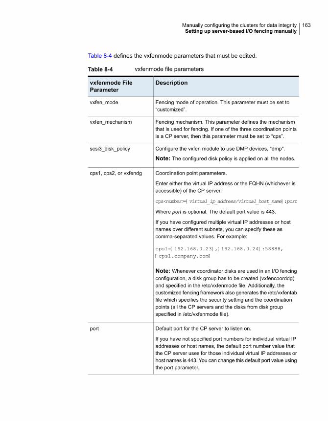
Table 8-4 defines the vxfenmode parameters that must be edited.
Table 8-4 vxfenmode file parameters
Descriptionvxfenmode FileParameter
Fencing mode of operation. This parameter must be set to“customized”.
vxfen_mode
Fencing mechanism. This parameter defines the mechanismthat is used for fencing. If one of the three coordination pointsis a CP server, then this parameter must be set to “cps”.
vxfen_mechanism
Configure the vxfen module to use DMP devices, "dmp".
Note: The configured disk policy is applied on all the nodes.
scsi3_disk_policy
Coordination point parameters.
Enter either the virtual IP address or the FQHN (whichever isaccessible) of the CP server.
cps<number>=[virtual_ip_address/virtual_host_name]:port
Where port is optional. The default port value is 443.
If you have configured multiple virtual IP addresses or hostnames over different subnets, you can specify these ascomma-separated values. For example:
cps1=[192.168.0.23],[192.168.0.24]:58888,[cps1.company.com]
Note: Whenever coordinator disks are used in an I/O fencingconfiguration, a disk group has to be created (vxfencoorddg)and specified in the /etc/vxfenmode file. Additionally, thecustomized fencing framework also generates the /etc/vxfentabfile which specifies the security setting and the coordinationpoints (all the CP servers and the disks from disk groupspecified in /etc/vxfenmode file).
cps1, cps2, or vxfendg
Default port for the CP server to listen on.
If you have not specified port numbers for individual virtual IPaddresses or host names, the default port number value thatthe CP server uses for those individual virtual IP addresses orhost names is 443. You can change this default port value usingthe port parameter.
port
163Manually configuring the clusters for data integritySetting up server-based I/O fencing manually

Table 8-4 vxfenmode file parameters (continued)
Descriptionvxfenmode FileParameter
Value 1 for single_cp parameter indicates that the server-basedfencing uses a single highly available CP server as its onlycoordination point.
Value 0 for single_cp parameter indicates that the server-basedfencing uses at least three coordination points.
single_cp
Set the value to 1 for vxfen module to use a specific order ofcoordination points during a network partition scenario.
By default the parameter is disabled. The default value is 0.
vxfen_honor_cp_order
Configuring CoordPoint agent to monitor coordination pointsThe following procedure describes how to manually configure the CoordPoint agentto monitor coordination points.
The CoordPoint agent can monitor CP servers and SCSI-3 disks.
See the Cluster Server Bundled Agents Reference Guide for more information onthe agent.
To configure CoordPoint agent to monitor coordination points
1 Ensure that your VCS cluster has been properly installed and configured withfencing enabled.
2 Create a parallel service group vxfen and add a coordpoint resource to thevxfen service group using the following commands:
# haconf -makerw
# hagrp -add vxfen
# hagrp -modify vxfen SystemList sys1 0 sys2 1
# hagrp -modify vxfen AutoFailOver 0
# hagrp -modify vxfen Parallel 1
# hagrp -modify vxfen SourceFile "./main.cf"
# hares -add coordpoint CoordPoint vxfen
# hares -modify coordpoint FaultTolerance 0
# hares -override coordpoint LevelTwoMonitorFreq
# hares -modify coordpoint LevelTwoMonitorFreq 5
# hares -modify coordpoint Enabled 1
# haconf -dump -makero
164Manually configuring the clusters for data integritySetting up server-based I/O fencing manually

3 Configure the Phantom resource for the vxfen disk group.
# haconf -makerw
# hares -add RES_phantom_vxfen Phantom vxfen
# hares -modify RES_phantom_vxfen Enabled 1
# haconf -dump -makero
4 Verify the status of the agent on the VCS cluster using the hares commands.For example:
# hares -state coordpoint
The following is an example of the command and output::
# hares -state coordpoint
# Resource Attribute System Value
coordpoint State sys1 ONLINE
coordpoint State sys2 ONLINE
5 Access the engine log to view the agent log. The agent log is written to theengine log.
The agent log contains detailed CoordPoint agent monitoring information;including information about whether the CoordPoint agent is able to access allthe coordination points, information to check on which coordination points theCoordPoint agent is reporting missing keys, etc.
To view the debug logs in the engine log, change the dbg level for that nodeusing the following commands:
# haconf -makerw
# hatype -modify Coordpoint LogDbg 10
# haconf -dump -makero
The agent log can now be viewed at the following location:
/var/VRTSvcs/log/engine_A.log
Note: The Coordpoint agent is always in the online state when the I/O fencingis configured in the majority or the disabled mode. For both these modes theI/O fencing does not have any coordination points to monitor. Thereby, theCoordpoint agent is always in the online state.
165Manually configuring the clusters for data integritySetting up server-based I/O fencing manually

Verifying server-based I/O fencing configurationFollow the procedure described below to verify your server-based I/O fencingconfiguration.
To verify the server-based I/O fencing configuration
1 Verify that the I/O fencing configuration was successful by running the vxfenadm
command. For example, run the following command:
# vxfenadm -d
Note: For troubleshooting any server-based I/O fencing configuration issues,refer to the Cluster Server Administrator's Guide.
2 Verify that I/O fencing is using the specified coordination points by running thevxfenconfig command. For example, run the following command:
# vxfenconfig -l
If the output displays single_cp=1, it indicates that the application cluster usesa CP server as the single coordination point for server-based fencing.
Setting up non-SCSI-3 fencing in virtualenvironments manually
To manually set up I/O fencing in a non-SCSI-3 PR compliant setup
1 Configure I/O fencing either in majority-based fencing mode with no coordinationpoints or in server-based fencing mode only with CP servers as coordinationpoints.
See “Setting up server-based I/O fencing manually” on page 153.
See “Setting up majority-based I/O fencing manually ” on page 172.
2 Make sure that the VCS cluster is online and check that the fencing mode iscustomized mode or majority mode.
# vxfenadm -d
3 Make sure that the cluster attribute UseFence is set to SCSI-3.
# haclus -value UseFence
166Manually configuring the clusters for data integritySetting up non-SCSI-3 fencing in virtual environments manually

4 On each node, edit the /etc/vxenviron file as follows:
data_disk_fencing=off
5 On each node, edit the /kernel/drv/vxfen.conf file as follows:
vxfen_vxfnd_tmt=25
6 On each node, edit the /etc/vxfenmode file as follows:
loser_exit_delay=55
vxfen_script_timeout=25
Refer to the sample /etc/vxfenmode file.
7 On each node, set the value of the LLT sendhbcap timer parameter value asfollows:
■ Run the following command:
lltconfig -T sendhbcap:3000
■ Add the following line to the /etc/llttab file so that the changes remainpersistent after any reboot:
set-timer senhbcap:3000
8 On any one node, edit the VCS configuration file as follows:
■ Make the VCS configuration file writable:
# haconf -makerw
■ For each resource of the type DiskGroup, set the value of theMonitorReservation attribute to 0 and the value of the Reservation attributeto NONE.
# hares -modify <dg_resource> MonitorReservation 0
# hares -modify <dg_resource> Reservation "NONE"
■ Run the following command to verify the value:
# hares -list Type=DiskGroup MonitorReservation!=0
# hares -list Type=DiskGroup Reservation!="NONE"
The command should not list any resources.
167Manually configuring the clusters for data integritySetting up non-SCSI-3 fencing in virtual environments manually

■ Modify the default value of the Reservation attribute at type-level.
# haattr -default DiskGroup Reservation "NONE"
■ Make the VCS configuration file read-only
# haconf -dump -makero
9 Make sure that the UseFence attribute in the VCS configuration file main.cf isset to SCSI-3.
10 To make these VxFEN changes take effect, stop and restart VxFEN and thedependent modules
■ On each node, run the following command to stop VCS:
# svcadm disable -t vcs
■ After VCS takes all services offline, run the following command to stopVxFEN:
# svcadm disable -t vxfen
■ On each node, run the following commands to restart VxFEN and VCS:
# svcadm enable vxfen
Sample /etc/vxfenmode file for non-SCSI-3 fencing
#
# vxfen_mode determines in what mode VCS I/O Fencing should work.
#
# available options:
# scsi3 - use scsi3 persistent reservation disks
# customized - use script based customized fencing
# disabled - run the driver but don't do any actual fencing
#
vxfen_mode=customized
# vxfen_mechanism determines the mechanism for customized I/O
# fencing that should be used.
#
# available options:
168Manually configuring the clusters for data integritySetting up non-SCSI-3 fencing in virtual environments manually

# cps - use a coordination point server with optional script
# controlled scsi3 disks
#
vxfen_mechanism=cps
#
# scsi3_disk_policy determines the way in which I/O fencing
# communicates with the coordination disks. This field is
# required only if customized coordinator disks are being used.
#
# available options:
# dmp - use dynamic multipathing
#
scsi3_disk_policy=dmp
#
# Seconds for which the winning sub cluster waits to allow for the
# losing subcluster to panic & drain I/Os. Useful in the absence of
# SCSI3 based data disk fencing loser_exit_delay=55
#
# Seconds for which vxfend process wait for a customized fencing
# script to complete. Only used with vxfen_mode=customized
# vxfen_script_timeout=25
#
# vxfen_honor_cp_order determines the order in which vxfen
# should use the coordination points specified in this file.
#
# available options:
# 0 - vxfen uses a sorted list of coordination points specified
# in this file, the order in which coordination points are specified
# does not matter.
# (default)
# 1 - vxfen uses the coordination points in the same order they are
# specified in this file
# Specify 3 or more odd number of coordination points in this file,
# each one in its own line. They can be all-CP servers, all-SCSI-3
# compliant coordinator disks, or a combination of CP servers and
# SCSI-3 compliant coordinator disks.
# Please ensure that the CP server coordination points are
# numbered sequentially and in the same order on all the cluster
# nodes.
169Manually configuring the clusters for data integritySetting up non-SCSI-3 fencing in virtual environments manually
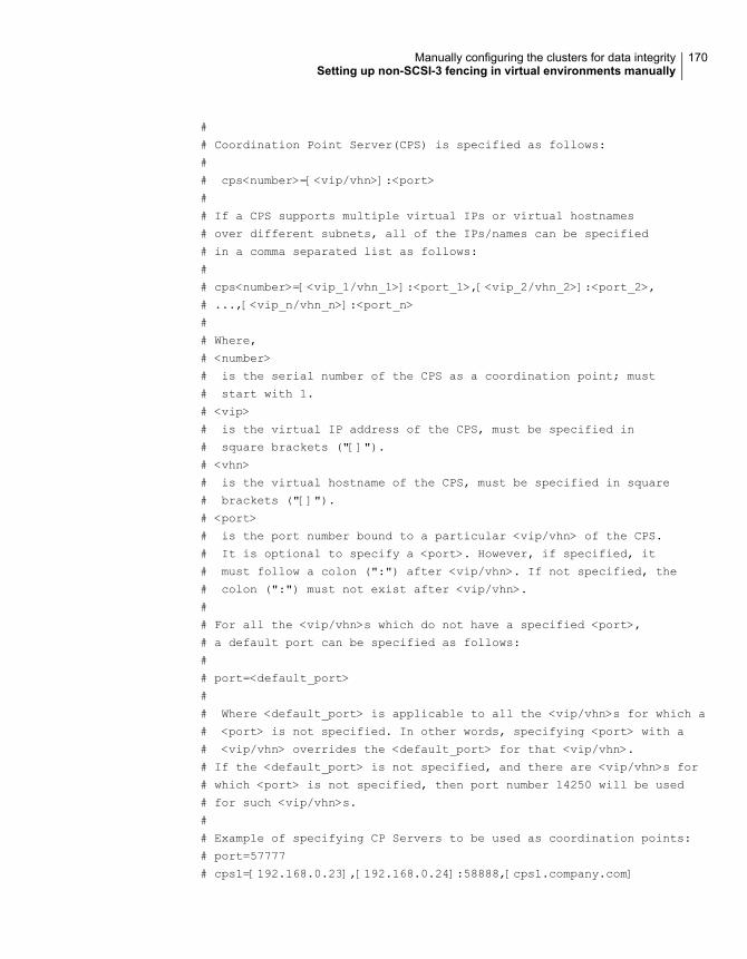
#
# Coordination Point Server(CPS) is specified as follows:
#
# cps<number>=[<vip/vhn>]:<port>
#
# If a CPS supports multiple virtual IPs or virtual hostnames
# over different subnets, all of the IPs/names can be specified
# in a comma separated list as follows:
#
# cps<number>=[<vip_1/vhn_1>]:<port_1>,[<vip_2/vhn_2>]:<port_2>,
# ...,[<vip_n/vhn_n>]:<port_n>
#
# Where,
# <number>
# is the serial number of the CPS as a coordination point; must
# start with 1.
# <vip>
# is the virtual IP address of the CPS, must be specified in
# square brackets ("[]").
# <vhn>
# is the virtual hostname of the CPS, must be specified in square
# brackets ("[]").
# <port>
# is the port number bound to a particular <vip/vhn> of the CPS.
# It is optional to specify a <port>. However, if specified, it
# must follow a colon (":") after <vip/vhn>. If not specified, the
# colon (":") must not exist after <vip/vhn>.
#
# For all the <vip/vhn>s which do not have a specified <port>,
# a default port can be specified as follows:
#
# port=<default_port>
#
# Where <default_port> is applicable to all the <vip/vhn>s for which a
# <port> is not specified. In other words, specifying <port> with a
# <vip/vhn> overrides the <default_port> for that <vip/vhn>.
# If the <default_port> is not specified, and there are <vip/vhn>s for
# which <port> is not specified, then port number 14250 will be used
# for such <vip/vhn>s.
#
# Example of specifying CP Servers to be used as coordination points:
# port=57777
# cps1=[192.168.0.23],[192.168.0.24]:58888,[cps1.company.com]
170Manually configuring the clusters for data integritySetting up non-SCSI-3 fencing in virtual environments manually
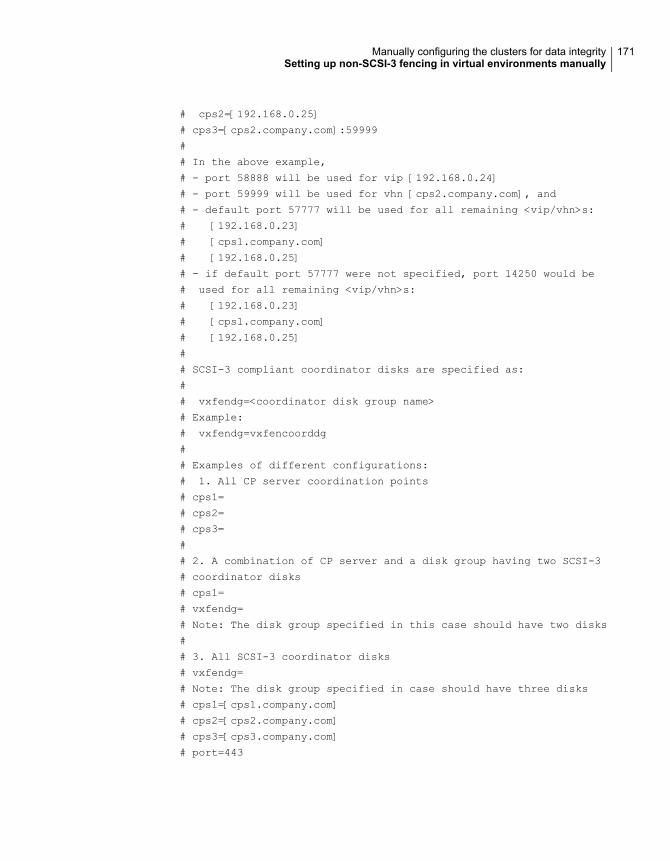
# cps2=[192.168.0.25]
# cps3=[cps2.company.com]:59999
#
# In the above example,
# - port 58888 will be used for vip [192.168.0.24]
# - port 59999 will be used for vhn [cps2.company.com], and
# - default port 57777 will be used for all remaining <vip/vhn>s:
# [192.168.0.23]
# [cps1.company.com]
# [192.168.0.25]
# - if default port 57777 were not specified, port 14250 would be
# used for all remaining <vip/vhn>s:
# [192.168.0.23]
# [cps1.company.com]
# [192.168.0.25]
#
# SCSI-3 compliant coordinator disks are specified as:
#
# vxfendg=<coordinator disk group name>
# Example:
# vxfendg=vxfencoorddg
#
# Examples of different configurations:
# 1. All CP server coordination points
# cps1=
# cps2=
# cps3=
#
# 2. A combination of CP server and a disk group having two SCSI-3
# coordinator disks
# cps1=
# vxfendg=
# Note: The disk group specified in this case should have two disks
#
# 3. All SCSI-3 coordinator disks
# vxfendg=
# Note: The disk group specified in case should have three disks
# cps1=[cps1.company.com]
# cps2=[cps2.company.com]
# cps3=[cps3.company.com]
# port=443
171Manually configuring the clusters for data integritySetting up non-SCSI-3 fencing in virtual environments manually

Setting up majority-based I/O fencing manuallyTable 8-5 lists the tasks that are involved in setting up I/O fencing.
ReferenceTask
Creating I/O fencing configuration filesCreating I/O fencing configuration files
Modifying VCS configuration to use I/Ofencing
Modifying VCS configuration to use I/Ofencing
Verifying I/O fencing configurationVerifying I/O fencing configuration
Creating I/O fencing configuration filesTo update the I/O fencing files and start I/O fencing
1 On all cluster nodes, run the following command
# cp /etc/vxfen.d/vxfenmode_majority /etc/vxfenmode
2 To check the updated /etc/vxfenmode configuration, enter the followingcommand on one of the nodes.
# cat /etc/vxfenmode
3 Ensure that you edit the following file on each node in the cluster to changethe values of the VXFEN_START and the VXFEN_STOP environment variables to1.
/etc/sysconfig/vxfen
Modifying VCS configuration to use I/O fencingAfter you configure I/O fencing, add the UseFence = SCSI3 cluster attribute to theVCS configuration file /etc/VRTSvcs/conf/config/main.cf.
If you reset this attribute to UseFence = None, VCS does not make use of I/Ofencing abilities while failing over service groups. However, I/O fencing needs tobe disabled separately.
172Manually configuring the clusters for data integritySetting up majority-based I/O fencing manually

To modify VCS configuration to enable I/O fencing
1 Save the existing configuration:
# haconf -dump -makero
2 Stop VCS on all nodes:
# hastop -all
3 To ensure High Availability has stopped cleanly, run gabconfig -a.
In the output of the commans, check that Port h is not present.
4 If the I/O fencing driver vxfen is already running, stop the I/O fencing driver.
# svcadm disable -t vxfen
5 Make a backup of the main.cf file on all the nodes:
# cd /etc/VRTSvcs/conf/config
# cp main.cf main.orig
6 On one node, use vi or another text editor to edit the main.cf file. To modifythe list of cluster attributes, add the UseFence attribute and assign its valueas SCSI3.
cluster clus1(
UserNames = { admin = "cDRpdxPmHpzS." }
Administrators = { admin }
HacliUserLevel = COMMANDROOT
CounterInterval = 5
UseFence = SCSI3
)
For fencing configuration in any mode except the disabled mode, the value ofthe cluster-level attribute UseFence is set to SCSI3.
7 Save and close the file.
8 Verify the syntax of the file /etc/VRTSvcs/conf/config/main.cf:
# hacf -verify /etc/VRTSvcs/conf/config
173Manually configuring the clusters for data integritySetting up majority-based I/O fencing manually

9 Using rcp or another utility, copy the VCS configuration file from a node (forexample, sys1) to the remaining cluster nodes.
For example, on each remaining node, enter:
# rcp sys1:/etc/VRTSvcs/conf/config/main.cf \
/etc/VRTSvcs/conf/config
10 Start the I/O fencing driver and VCS. Perform the following steps on each node:
■ Start the I/O fencing driver.The vxfen startup script also invokes the vxfenconfig command, whichconfigures the vxfen driver.
# svcadm enable vxfen
■ Start VCS on the node where main.cf is modified.
# /opt/VRTS/bin/hastart
■ Start VCS on all other nodes once VCS on first node reaches RUNNINGstate.
# /opt/VRTS/bin/hastart
Verifying I/O fencing configurationVerify from the vxfenadm output that the fencing mode reflects the configuration inthe /etc/vxfenmode file.
174Manually configuring the clusters for data integritySetting up majority-based I/O fencing manually

To verify I/O fencing configuration
◆ On one of the nodes, type:
# vxfenadm -d
Output similar to the following appears if the fencing mode is majority:
I/O Fencing Cluster Information:
================================
Fencing Protocol Version: 201
Fencing Mode: MAJORITY
Cluster Members:
* 0 (sys1)
1 (sys2)
RFSM State Information:
node 0 in state 8 (running)
node 1 in state 8 (running)
Sample /etc/vxfenmode file for majority-based fencing
#
# vxfen_mode determines in what mode VCS I/O Fencing should work.
#
# available options:
# scsi3 - use scsi3 persistent reservation disks
# customized - use script based customized fencing
# majority - use majority based fencing
# disabled - run the driver but don't do any actual fencing
#
# vxfen_mode=majority
175Manually configuring the clusters for data integritySetting up majority-based I/O fencing manually

Upgrading VCS
■ Chapter 9. Planning to upgrade VCS
■ Chapter 10. Performing a VCS upgrade using the installer
■ Chapter 11. Performing an online upgrade
■ Chapter 12. Performing a phased upgrade of VCS
■ Chapter 13. Performing an automated VCS upgrade using response files
■ Chapter 14. Upgrading VCS using Live Upgrade and Boot Environment upgrade
4Section

Planning to upgrade VCSThis chapter includes the following topics:
■ About upgrading to VCS 7.1
■ Upgrading VCS in secure enterprise environments
■ Supported upgrade paths
■ Considerations for upgrading secure VCS 6.x clusters to VCS 7.1
■ Considerations for upgrading VCS to 7.1 on systems configured with an Oracleresource
■ Considerations for upgrading secure VCS clusters to VCS 7.1
■ Considerations for upgrading CP servers
■ Considerations for upgrading CP clients
■ Using Install Bundles to simultaneously install or upgrade full releases (base,maintenance, rolling patch), and individual patches
About upgrading to VCS 7.1When you upgrade to VCS 7.1, you need not reconfigure application monitoringwith VCS. All existing monitoring configurations are preserved.
You can upgrade VCS using one of the following methods:
■ Typical upgrade using product installerSee “Upgrading VCS using the product installer” on page 185.
■ Performing an online upgradePerform a script-based online upgrade of your installation to upgrade VCSwithout stopping your applications. The supported upgrade paths for the online
9Chapter

upgrades are same as those documented under the script and web-basedupgrades.See “Upgrading VCS online using the installer” on page 194.
■ Automated upgrade using response filesSee “Upgrading VCS using response files” on page 216.
■ Upgrade using supported native operating system utilityLive UpgradeSee “About Live Upgrade” on page 220.
You can upgrade VCS to InfoScale Availability 7.1 using the product installer orresponse files.
See the Veritas InfoScale Installation Guide.
Note: In a VMware virtual environment, you can use the vSphere Client to directlyinstall VCS and supported high availability agents (together called guestcomponents) on the guest virtual machines. For details, see the High AvailabilitySolution Guide for VMware.
If zones are present on the system, make sure that all non-global zones are in therunning state before you use the Veritas product installer to upgrade the StorageFoundation products in the global zone, so that any packages present insidenon-global zones also gets updated automatically. For Oracle Solaris 10, if thenon-global zones are in configured state at the time of the upgrade, you must attachthe zone with -U option to upgrade the SFHA packages inside non-global zone.For Oracle Solaris 11.1, If the non-global zone has previous version of VCSpackages (VRTSperl, VRTSvlic, VRTSvcs, VRTSvcsag, VRTSvcsea) alreadyinstalled, then during upgrade of the VCS packages in global zone, packages insidenon-global zone are automatically upgraded if the zone is in running state. Ifnon-global zones are not in running state, you must set the publisher inside theglobal zone and also attach the zone with -u option to upgrade the SFHA packagesinside non-global zone.
UpgradingVCS in secure enterprise environmentsIn secure enterprise environments, ssh or rsh communication is not allowed betweensystems. In such cases, the installer program can upgrade VCS only on systemswith which it can communicate (most often the local system only).
178Planning to upgrade VCSUpgrading VCS in secure enterprise environments

To upgrade VCS in secure enterprise environments with no rsh or sshcommunication
1 Run the installer program on each node to upgrade the cluster to VCS 7.1.
On each node, the installer program updates the configuration, stops the cluster,and then upgrades VCS on the node. The program also generates a clusterUUID on the node. Each node may have a different cluster UUID at this point.
2 Start VCS on the first node.
# hastart
VCS generates the cluster UUID on this node. Run the following command todisplay the cluster UUID on the local node:
# /opt/VRTSvcs/bin/uuidconfig.pl -clus -display systemname
3 On each of the other nodes, perform the following steps:
■ Set the value of the VCS_HOST environment variable to the name of thefirst node.
■ Display the value of the CID attribute that stores the cluster UUID value:
# haclus -value CID
■ Copy the output of the CID attribute to the file /etc/vx/.uuids/clusuuid.
■ Update the VCS_HOST environment variable to remove the set value.
■ Start VCS.The node must successfully join the already running nodes in the cluster.
Supported upgrade pathsTable 9-1 lists the supported upgrade paths.
Table 9-1 Supported upgrade paths
To componentTo productversion
To OS versionFrom OSversion
Fromproductversion
VCSVeritas InfoScaleAvailability 7.1
Solaris 10 Update9 or later
Solaris 106.0
179Planning to upgrade VCSSupported upgrade paths

Table 9-1 Supported upgrade paths (continued)
To componentTo productversion
To OS versionFrom OSversion
Fromproductversion
VCSVeritas InfoScaleAvailability 7.1
Solaris 10 Update9 or later
Solaris 106.0.1
6.0.3
6.0.5 VCSVeritas InfoScaleAvailability 7.1
Solaris 11 Update1 or later
Solaris 11
VCSVeritas InfoScaleAvailability 7.1
Solaris 10 Update9 or later
Solaris 10(SPARC)
6.1, 6.1.1
6.2, 6.2.1
VCSVeritas InfoScaleAvailability 7.1
Solaris 11 Update1 or later
Solaris 11(SPARC)
VCSVeritas InfoScaleAvailability 7.1
Solaris 10 Update9 or later
Solaris 10(SPARC)
7.0
VCSVeritas InfoScaleAvailability 7.1
Solaris 11 Update1 or later
Solaris 11
VCSVeritas InfoScaleAvailability 7.1
Solaris 10 Update9 or later
Solaris 107.0.1
VCSVeritas InfoScaleAvailability 7.1
Solaris 11 Update1 or later
Solaris 11
Considerations for upgrading secure VCS 6.xclusters to VCS 7.1
When you upgrade a secure VCS 6.x cluster to VCS 7.1, the upgrade does notmigrate the old broker configuration to the new broker because of the change inarchitecture. Both the old broker (/opt/VRTSat/bin/vxatd) and new broker(/opt/VRTSvcs/bin/vcsauth/vcsauthserver/bin/vcsauthserver) continue torun. In such a scenario, you must consider the following:
■ The HA commands that you run in VCS 7.1 are processed by the new brokerby default. To ensure that the HA commands are processed by the old broker,set the VCS_REMOTE_BROKER environment variable as follows:
# export VCS_REMOTE_BROKER=localhost IP,2821
■ VCS 7.1 does not prompt non-root users who run HA commands for passwords.In 6.x, non-root users required a password to run HA commands. If you want
180Planning to upgrade VCSConsiderations for upgrading secure VCS 6.x clusters to VCS 7.1

non-root users to enter passwords before they run HA commands, set theVCS_DOMAINTYPE environment variable to unixpwd.
■ Trust relationships are not migrated during the upgrade. If you had configuredsecure GCO or secure steward, ensure that trust relationships are recreatedbetween the clusters and the steward.See “Setting up trust relationships for your VCS cluster” on page 58.
■ For Zones, the HA commands run within the container and use credentials thatwere deployed by the old broker. However, you can migrate to the newercredentials from the new broker by running hazonesetup again.
When the old broker is not used anymore, you can delete the old VRTSat package.
Considerations for upgrading VCS to 7.1 onsystems configured with an Oracle resource
If you plan to upgrade VCS running on systems configured with an Oracle resource,set the MonitorOption attribute to 0 (zero) before you start the upgrade.
For more information on enabling the Oracle health check, see the Cluster ServerAgent for Oracle Installation and Configuration Guide.
Considerations for upgrading secure VCS clustersto VCS 7.1
1. When you upgrade a secure VCS cluster which version is prior to 6.2 to VCS7.1, you need to configure one of the following attributes to enable guest accessto the cluster.
■ DefaultGuestAccess: Set the value of this attribute to 1 to enable guestaccess for any authenticated user.
■ GuestGroups: This attribute contains of list of user groups who have readaccess to the cluster. Configure this attribute to control the guest accessto the cluster.
2. The non-root and zone users need to regenerate their credentials again if youperform an upgrade on a cluster in secure mode from VCS 6.x to VCS 7.1. Fornon-root users, run halogin command to regenerate the credentials. Run thehazonesetup command to update the credentials of zone users.
Refer to the Performing maintenance tasks section under Configuring VCS inzones chapter of Storage Foundation and High Availability SolutionsVirtualization Guide for steps on how regenerate the credentials.
181Planning to upgrade VCSConsiderations for upgrading VCS to 7.1 on systems configured with an Oracle resource

Considerations for upgrading CP serversFrom release 7.0.1 onwards, VCS does not support IPM-based ( Veritas ProductAuthentication Services) secure communication between clusters.
The only supported communication protocol is HTTPS-based communication. ForHTTPS communication, you do not need to consider setting up trust relationshipsbetween CP servers and clients.
Considerations for upgrading CP clientsPasswordless communication from CP clients to CP server must exist for the installerto reconfigure fencing. If passwordless communication does not exist, you mustreconfigure fencing manually.
See “Setting up disk-based I/O fencing manually” on page 148.
See “Setting up server-based I/O fencing manually” on page 153.
Using Install Bundles to simultaneously install orupgrade full releases (base, maintenance, rollingpatch), and individual patches
Beginning with version 6.1, you can easily install or upgrade your systems directlyto a base, maintenance, patch level or a combination of multiple patches andpackages together in one step using Install Bundles. With Install Bundles, theinstaller has the ability to merge so that customers can install or upgrade directlyto maintenance or patch levels in one execution. The various scripts, packages,and patch components are merged, and multiple releases are installed together asif they are one combined release. You do not have to perform two or more installactions to install or upgrade systems to maintenance levels or patch levels.
Releases are divided into the following categories:
Table 9-2 Release Levels
Downloadlocation
Releasetypes
Applies toForm factorContentLevel
FileConnectMajor, minor,Service Pack(SP), PlatformRelease (PR)
All productspackagesFeaturesBase
182Planning to upgrade VCSConsiderations for upgrading CP servers

Table 9-2 Release Levels (continued)
Downloadlocation
Releasetypes
Applies toForm factorContentLevel
VeritasServices andOperationsReadinessTools (SORT)
MaintenanceRelease(MR), RollingPatch (RP)
All productspackagesFixes, newfeatures
Maintenance
SORT,Support site
P-Patch,Private Patch,Public patch
Singleproduct
packagesFixesPatch
When you install or upgrade using Install Bundles:
■ Veritas InfoScale products are discovered and assigned as a single version tothe maintenance level. Each system can also have one or more patches applied.
■ Base releases are accessible from FileConnect that requires customer serialnumbers. Maintenance and patch releases can be automatically downloadedfrom SORT.
■ Patches can be installed using automated installers from the 6.0.1 version orlater.
■ Patches can now be detected to prevent upgrade conflict. Patch releases arenot offered as a combined release. They are only available from Veritas TechnicalSupport on a need basis.
You can use the -base_path and -patch_path options to import installation codefrom multiple releases. You can find packages and patches from different mediapaths, and merge package and patch definitions for multiple releases. You can usethese options to use new task and phase functionality to correctly perform requiredoperations for each release component. You can install the packages and patchesin defined phases using these options, which helps you when you want to performa single start or stop process and perform pre and post operations for all level in asingle operation.
Four possible methods of integration exist. All commands must be executed fromthe highest base or maintenance level install script.
In the example below:
■ 7.1 is the base version
■ 7.1.1 is the maintenance version
■ 7.1.1.100 is the patch version for 7.1.1
183Planning to upgrade VCSUsing Install Bundles to simultaneously install or upgrade full releases (base, maintenance, rolling patch),
and individual patches

■ 7.1.0.100 is the patch version for 7.1
1. Base + maintenance:
This integration method can be used when you install or upgrade from a lowerversion to 7.1.1.
Enter the following command:
# installmr -base_path <path_to_base>
2. Base + patch:
This integration method can be used when you install or upgrade from a lowerversion to 7.1.0.100.
Enter the following command:
# installer -patch_path <path_to_patch>
3. Maintenance + patch:
This integration method can be used when you upgrade from version 7.1 to7.1.1.100.
Enter the following command:
# installmr -patch_path <path_to_patch>
4. Base + maintenance + patch:
This integration method can be used when you install or upgrade from a lowerversion to 7.1.1.100.
Enter the following command:
# installmr -base_path <path_to_base>
-patch_path <path_to_patch>
Note: From the 6.1 or later release, you can add a maximum of five patchesusing -patch_path <path_to_patch> -patch2_path <path_to_patch> ...-patch5_path <path_to_patch>
184Planning to upgrade VCSUsing Install Bundles to simultaneously install or upgrade full releases (base, maintenance, rolling patch),
and individual patches

Performing a VCSupgrade using the installer
This chapter includes the following topics:
■ Before upgrading VCS using the script-based installer
■ Upgrading VCS using the product installer
■ Upgrading to 2048 bit key and SHA256 signature certificates
■ Tasks to perform after upgrading to 2048 bit key and SHA256 signaturecertificates
■ Upgrading Steward to 2048 bit key and SHA256 signature certificates
Before upgrading VCS using the script-basedinstaller
As a result of OS upgrade, if VCS is not in running state before upgrade, the installerdoes not start VCS after the upgrade is completed. You need to manually start itor restart the cluster nodes. Before you upgrade VCS, you first need to removedeprecated resource types and modify changed values.
If the non-global zones were not in the running state at the time of upgrade onSolaris 10, attach the zone with -U option to upgrade the packages inside thenon-global zone. On Solaris 11, set the publisher for the packages on the globalzone and attach the zone with -u option.
Upgrading VCS using the product installerYou can use the product installer to upgrade VCS.
10Chapter

To upgrade VCS using the product installer
1 Log in as superuser and mount the product disc.
2 Start the installer.
# ./installer
The installer starts the product installation program with a copyright message.It then specifies where it creates the logs. Note the log's directory and name.
3 Select the product you want to upgrade.
4 Choose 1 for full upgrade.
5 Enter the names of the nodes that you want to upgrade. Use spaces to separatenode names. Press the Enter key to proceed.
6 When the verification checks are complete, the installer asks if you agree withthe terms of the End User License Agreement. Press y to agree and continue.
7 The installer displays the following question before the install stops the productprocesses. If the cluster was not configured in secure mode before the upgrade,these questions are not displayed.
■ Do you want to generate certificates for the Veritas InfoScale Enterprisecomponents with 2048 bit encryption keys and SHA256 signatures? [y,n,q,?]You can enter y and upgrade to 2048 bit key and SHA256 signaturecertificates at this stage or perform the upgrade later.
Note: The installer will not show the subsequent questions regarding readaccess if you are upgrading VCS from versions 6.2 or later.
■ Do you want to grant read access to everyone? [y,n,q,?]
■ To grant read access to all authenticated users, type y.
■ To grant usergroup specific permissions, type n.
■ Do you want to provide any usergroups that you would like to grant readaccess?[y,n,q,?]
■ To specify usergroups and grant them read access, type y
■ To grant read access only to root users, type n. The installer grants readaccess to the root users.
■ Enter the usergroup names separated by spaces to whom you want to grantread access. If you want to grant read access to a usergroup on a specificnode, enter like 'usrgrp1@node1', and if you would like to grant read access
186Performing a VCS upgrade using the installerUpgrading VCS using the product installer

to usergroup on any cluster node, enter like 'usrgrp1'. If some usergroupsare not created yet, create the usergroups after configuration if needed. [b]
8 The installer asks if you want to stop VCS processes. Press the Enter key tocontinue.
The installer stops VCS processes, uninstalls packages, installs or upgradespackages, and configures VCS.
The installer lists the nodes that Veritas recommends you to restart.
9 The installer asks if you want to send the information about this installation tous to help improve installation in the future. Enter your response.
The installer displays the location of log files, summary file, and response file.
10 If you want to upgrade CP server systems that use VCS or SFHA to VCS 7.1,make sure that you first upgrade all application clusters to version VCS 7.1.Then, upgrade VCS or SFHA on the CP server systems.
For instructions to upgrade SFHA, see the Storage Foundation and HighAvailability Configuration and Upgrade Guide.
If you did not upgrade to 2048 bit key and SHA256 signature certificates in theabove procedure, refer to Upgrading to 2048 bit key and SHA256 signaturecertificates when you upgrade the certificates later.
See “Upgrading to 2048 bit key and SHA256 signature certificates” on page 187.
Upgrading to 2048 bit key and SHA256 signaturecertificates
Perform the following steps to upgrade to 2048 bit key and SHA256 signaturecertificates:
1 Run the following command to begin the upgrade:
# /opt/VRTS/install/installer -security
The system displays the following message:
Would you like to configure secure mode on the cluster? [y,n,q]
2 Enter y. The system displays the message that you have to re-establish thetrust relationships between components after upgrading the certificates.
187Performing a VCS upgrade using the installerUpgrading to 2048 bit key and SHA256 signature certificates

3 Enter 1 to begin the upgrade.
4 The system displays the following message after the security upgrade:
Security reconfiguration completed successfully.
You can optionally view the upgrade logs.
Tasks to perform after upgrading to 2048 bit keyand SHA256 signature certificates
Note that you must perform the following tasks after upgrading to 2048 bit key andSHA256 signature certificates:
■ Delete certificates of non-root users after upgrading to 2048 bit key and SHA256signature certificates.See “Deleting certificates of non-root users after upgrading to 2048 bit key andSHA256 signature certificates” on page 188.
■ Re-establish WAC communication in global clusters after upgrading to 2048 bitkey and SHA256 signature certificates.See “Re-establishing WAC communication in global clusters after upgrading to2048 bit key and SHA256 signature certificates” on page 189.
■ Re-establish communication between Steward and upgraded clusters.See “Re-establishing trust with Steward after upgrading to 2048 bit key andSHA256 signature certificates” on page 191.
Note: The cluster communication between global clusters breaks if the cluster onone site is running VCS 7.1 and the other is on VCS version lower than 6.0.5. Ifyou upgrade to 2048 bit key and SHA256 signature certificates in such aconfiguration, the communication will not be restored even after performing theessential tasks after the upgrade. The only workaround for this is to upgrade VCSto version 6.0.5 or above on clusters which are running on VCS versions lower than6.0.5.
Deleting certificates of non-root users after upgrading to 2048 bit keyand SHA256 signature certificates
After upgrading to 2048 bit key and SHA256 signature certificates, thecertificates of non-root users become obsolete and must be deleted in order
188Performing a VCS upgrade using the installerTasks to perform after upgrading to 2048 bit key and SHA256 signature certificates

to allow non-root users to log in. Perform the following steps to delete thenon-root certificates for each non-root user:
1 Delete .VRTSat from the home directory of the users.
# rm -rf /user_home_directory/.VRTSat
2 If the non-root user was not a cluster user prior to upgrade, add user to Clusterwith appropriate Privilege.
# hauser -add <user name> -priv <Privilege>
3 Log in with non-root user and create new certificates.
# /opt/VRTS/bin/halogin <non_root_user> <password>
4 You must delete certificates related to Zone since they also become obsoleteafter the upgrade. You must delete them using the following command on eachZone.
# rm -rf /var/VRTSvcs/vcsauth/data/CLIENT
5 Recreate the certificates using the following command.
#/opt/VRTS/bin/hazonesetup -g zone_grp -r <zone_resname> \
-z <zone_name> -u <zone_user> -p <password> -a -s sys1,sys2
Re-establishing WAC communication in global clusters afterupgrading to 2048 bit key and SHA256 signature certificates
During the upgrade, the vcsauthserver gets 2048 bit SHA256 certificates and thetrust information gets deleted, which causes the WAC communication to break. Toestablish the communication again, you must set up trust for WAC on each nodeof every cluster. The remote site has to set up trust with the local site as a newbroker certificate is created on the local site. The local site also has to set up trustwith the remote site as the trust certificate gets deleted during the upgrade.
189Performing a VCS upgrade using the installerTasks to perform after upgrading to 2048 bit key and SHA256 signature certificates

Perform the following steps to establish trust between the clusters:
1 On each node of the first cluster, run the following command:
# export EAT_DATA_DIR=/var/VRTSvcs/vcsauth/data/WAC;
/opt/VRTSvcs/bin/vcsat setuptrust -b
IP_address_of_any_node_from_the_second_cluster:14149 -s high
The command obtains and displays the security certificate and other detailsof the root broker of the second cluster. If the details are correct, enter y at thecommand prompt to establish trust.
For example: The hash of above credential isb36a2607bf48296063068e3fc49188596aa079bb
Do you want to trust the above?(y/n) y
2 On each node of the second cluster, run the following command:
# export EAT_DATA_DIR=/var/VRTSvcs/vcsauth/data/WAC;
/opt/VRTSvcs/bin/vcsat setuptrust -b
IP_address_of_any_node_from_the_first_cluster:14149 -s high
The command obtains and displays the security certificate and other detailsof the root broker of the first cluster. If the details are correct, enter y at thecommand prompt to establish trust.
Re-establishing CP server and CP client communication afterupgrading to 2048 bit key and SHA256 signature certificates
In case of CP server, when you upgrade the CP server cluster to use the enhancedsecurity, the vcsauthserver gets 2048 bit SHA256 certificates and the trustinformation is no longer valid on the client clusters. This breaks the communicationbetween CP server and CP client. To reinstate the communication, you must setuptrust between CP server and CP client.
For each client node on VCS 6.0 and later, run the following command:
EAT_DATA_DIR=/var/VRTSvcs/vcsauth/data/CPSADM \
/opt/VRTSvcs/bin/vcsat setuptrust -b cpserver_ip_address:14149 -s high
190Performing a VCS upgrade using the installerTasks to perform after upgrading to 2048 bit key and SHA256 signature certificates

Re-establishing trust with Steward after upgrading to 2048 bit keyand SHA256 signature certificates
In case of Steward, when you upgrade the cluster to use the enhanced security,the vcsauthserver gets 2048 bit SHA256 certificates and the trust information getsdeleted. This breaks the communication between cluster and Steward.
To reinstate the communication, you must setup trust between each node ofthe upgraded cluster and Steward.
1 Set up trust on all nodes of the GCO clusters:
# export EAT_DATA_DIR=/var/VRTSvcs/vcsauth/data/WAC
# vcsat setuptrust -b IP_of_Steward:14149 -s high
2 Set up trust on the Steward:
# export EAT_DATA_DIR=/var/VRTSvcs/vcsauth/data/STEWARD
# vcsat setuptrust -b VIP_of_upgraded_cluster:14149 -s high
Upgrading Steward to 2048 bit key and SHA256signature certificates
To upgrade Steward configured on Solaris 10 systems in secure mode:
1 Log on to the Steward system as a root user.
2 Stop the Steward process.
# steward -stop -secure
3 Uninstall the VRTSvcs and VRTSperl packages.
4 Install the VRTSvcs and VRTSperl packages for VCS VCS 7.1.
5 Remove the old certificates using the following command:
# rm -rf /var/VRTSvcs/vcsauth/data/STEWARD
191Performing a VCS upgrade using the installerUpgrading Steward to 2048 bit key and SHA256 signature certificates

6 Run the following command:
# ./installvcs -securityonenode
The installer prompts for a confirmation if VCS is not configured or if VCS isnot running on all nodes of the cluster.
7 Enter y when the installer prompts whether you want to continue configuringsecurity.
8 Run the following command:
# /opt/VRTSvcs/bin/steward_secure.pl
9 Set up trust on all nodes of the GCO clusters.
# export EAT_DATA_DIR=/var/VRTSvcs/vcsauth/data/WAC
# vcsat setuptrust -b IP_of_Steward:14149 -s high
10 Set up trust on the Steward for every GCO cluster.
# export EAT_DATA_DIR=/var/VRTSvcs/vcsauth/data/STEWARD
# vcsat setuptrust -b VIP_of_remote_cluster1:14149 -s high
# vcsat setuptrust -b VIP_of_remote_cluster2:14149 -s high
11 Start the Steward process.
# /opt/VRTSvcs/bin/steward -start -secure
To upgrade Steward configured on Solaris 11 systems in secure mode:
1 Log on to the Steward system as a root user.
2 Stop the Steward process.
# steward -stop -secure
3 Upgrade the VRTSvcs and VRTSperl packages.
# pkg set-publisher -p <path to p5p package Veritas
# pkg install --accept --no-backup-be VRTSperl VRTSvcs
# pkg unset-publisher Veritas
4 Remove /var/VRTSvcs/vcsauth/data/STEWARD.
# rm -rf /var/VRTSvcs/vcsauth/data/STEWARD
192Performing a VCS upgrade using the installerUpgrading Steward to 2048 bit key and SHA256 signature certificates

5 Run the following command:
# ./installer -securityonenode
The installer prompts for a confirmation if VCS is not configured or if VCS isnot running on all nodes of the cluster.
6 Enter y when the installer prompts whether you want to continue configuringsecurity.
7 Run the following command:
# /opt/VRTSvcs/bin/steward_secure.pl
8 Set up trust on all nodes of the GCO clusters.
# export EAT_DATA_DIR=/var/VRTSvcs/vcsauth/data/WAC
# vcsat setuptrust -b IP_of_Steward:14149 -s high
9 Set up trust on the Steward for every GCO cluster.
# export EAT_DATA_DIR=/var/VRTSvcs/vcsauth/data/STEWARD
# vcsat setuptrust -b VIP_of_remote_cluster1:14149 -s high
# vcsat setuptrust -b VIP_of_remote_cluster2:14149 -s high
10 Start the Steward process.
# /opt/VRTSvcs/bin/steward -start -secure
193Performing a VCS upgrade using the installerUpgrading Steward to 2048 bit key and SHA256 signature certificates

Performing an onlineupgrade
This chapter includes the following topics:
■ Limitations of online upgrade
■ Upgrading VCS online using the installer
Limitations of online upgrade■ Online upgrade is available only for VCS. If you have Storage Foundation, SFHA,
SFCFSHA, or any other solution with VxVM and VxFS installed, then the onlineupgrade process is not supported.
■ The non-Veritas applications running on the node have zero down time duringthe online upgrade.
■ VCS does not monitor the applications when online upgrade is in progress.
■ For upgrades from VCS versions lower than 6.1, upgrade the CP server beforeperforming the online upgrade.
See “Upgrading VCS online using the installer” on page 194.
Upgrading VCS online using the installerYou can use the product installer to upgrade VCS online. The supported upgradepaths are same as those for the installer.
11Chapter

To upgrade VCS online using the product installer
1 Log in as superuser and mount the product disc.
2 Start the installer.
# ./installer
The installer starts the product installation program with a copyright message.It then specifies where it creates the logs.
Note the directory name and path where the logs get stored.
3 Choose 2 for Online Upgrade from the upgrade options.
4 After selecting the online upgrade method, enter any one system name fromthe cluster on which you want to perform the online upgrade.
Even if you specify a single node from the cluster, the installer asks whetheryou want to perform online upgrade of VCS on the entire cluster, keeping yourapplications online. After you enter the system name, the installer performssome verification checks and asks the following question:
Online upgrade supports application zero downtime.
Would you like to perform online upgrade on the
whole cluster? [y,n,q](y)
5 Enter y to initiate the online upgrade.
Note: You can either exit the installer with the option q or cancel the upgradeusing n and select any other cluster to upgrade in this step.
The installer runs some verification checks on the nodes and subsequentlyasks if you agree with the terms of the End User License Agreement.
6 Enter y to agree and continue.
7 The installer displays the following question before the installer stops the productprocesses. If the cluster was configured in secure mode and the version isprior to 6.2 before upgrade, these questions will be displayed.
■ Do you want to grant read access to everyone? [y,n,q,?]
■ To grant read access to all authenticated users, type y.
■ To grant usergroup specific permissions, type n.
■ Do you want to provide any usergroups that you would like to grant readaccess?[y,n,q,?]
■ To specify usergroups and grant them read access, type y
195Performing an online upgradeUpgrading VCS online using the installer

■ To grant read access only to root users, type n. The installer grants readaccess to the root users.
■ Enter the usergroup names separated by spaces that you want to grantread access. If you want to grant read access to a usergroup on a specificnode, enter like 'usrgrp1@node1', and if you want to grant read access tousergroup on any cluster node, enter like 'usrgrp1'. If some usergroups arenot created yet, create the usergroups after configuration if needed. [b]
8 The installer asks if you want to stop VCS processes. Enter y to stop the VCSprocess.
It stops the VCS processes, uninstalls packages, reinstalls or upgradespackages, again configures VCS, and starts the processes.
9 The installer asks if you want to stop VCS processes. Enter y to stop the VCSprocess.
196Performing an online upgradeUpgrading VCS online using the installer

Performing a phasedupgrade of VCS
This chapter includes the following topics:
■ About phased upgrade
■ Performing a phased upgrade using the product installer
About phased upgradePerform a phased upgrade to minimize the downtime for the cluster.
Depending on the situation, you can calculate the approximate downtime as follows:
Table 12-1
DowntimeFail over condition
Downtime equals the time that is taken tooffline and online the service groups.
You can fail over all your service groups tothe nodes that are up.
Downtime for that service group equals thetime that is taken to perform an upgrade andrestart the node.
You have a service group that you cannot failover to a node that runs during upgrade.
Prerequisites for a phased upgradeBefore you start the upgrade, confirm that you have licenses for all the nodes thatyou plan to upgrade.
12Chapter

Planning for a phased upgradePlan out the movement of the service groups from node-to-node to minimize thedowntime for any particular service group.
Some rough guidelines follow:
■ Split the cluster into two subclusters of equal or near equal size.
■ Split the cluster so that your high priority service groups remain online duringthe upgrade of the first subcluster.
■ Before you start the upgrade, back up the VCS configuration files main.cf andtypes.cf which are in the /etc/VRTSvcs/conf/config/ directory.
■ Before you start the upgrade make sure that all the disk groups have the latestbackup of configuration files in the /etc/vx/cbr/bk directory. If not, then runthe following command to take the latest backup.
# /etc/vx/bin/vxconfigbackup -| [dir] [dgname|dgid]
Phased upgrade limitationsThe following limitations primarily describe not to tamper with configurations orservice groups during the phased upgrade:
■ While you perform the upgrades, do not start any modules.
■ When you start the installer, only select VCS.
■ While you perform the upgrades, do not add or remove service groups to anyof the nodes.
■ After you upgrade the first half of your cluster (the first subcluster), you need toset up password-less ssh or rsh. Create the connection between an upgradednode in the first subcluster and a node from the other subcluster. The node fromthe other subcluster is where you plan to run the installer and also plan toupgrade.
■ Depending on your configuration, you may find that you cannot upgrade multiplenodes at the same time. You may only be able to upgrade one node at a time.
■ For very large clusters, you might have to repeat these steps multiple times toupgrade your cluster.
Phased upgrade exampleIn this example, you have a secure cluster that you have configured to run on fournodes: node01, node02, node03, and node04. You also have four service groups:
198Performing a phased upgrade of VCSAbout phased upgrade

sg1, sg2, sg3, and sg4. For the purposes of this example, the cluster is split intotwo subclusters. The nodes node01 and node02 are in the first subcluster, whichyou first upgrade. The nodes node03 and node04 are in the second subcluster,which you upgrade last.
Figure 12-1 Example of phased upgrade set up
node01 node04node03node02
First subcluster Second subcluster
sg1
sg2
sg3
sg1
sg2
sg4
sg1
sg2
sg1
sg2
Each service group is running on the nodes as follows:
■ sg1 and sg2 are parallel service groups and run on all the nodes.
■ sg3 and sg4 are failover service groups. sg3 runs on node01 and sg4 runs onnode02.
In your system list, you have each service group that fails over to other nodes asfollows:
■ sg1 and sg2 are running on all the nodes.
■ sg3 and sg4 can fail over to any of the nodes in the cluster.
Phased upgrade example overviewThis example's upgrade path follows:
■ Move all the failover service groups from the first subcluster to the secondsubcluster.
■ Take all the parallel service groups offline on the first subcluster.
■ Upgrade the operating system on the first subcluster's nodes, if required.
■ On the first subcluster, start the upgrade using the installation program.
■ Get the second subcluster ready.
■ Activate the first subcluster. After activating the first cluster, switch the servicegroups online on the second subcluster to the first subcluster.
■ Upgrade the operating system on the second subcluster's nodes, if required.
■ On the second subcluster, start the upgrade using the installation program.
199Performing a phased upgrade of VCSAbout phased upgrade

■ Activate the second subcluster.
See “Performing a phased upgrade using the product installer” on page 200.
Performing a phased upgrade using the productinstaller
This section explains how to perform a phased upgrade of VCS on four nodes withfour service groups. Note that in this scenario, VCS and the service groups cannotstay online on the second subcluster during the upgrade of the second subcluster.Do not add, remove, or change resources or service groups on any nodes duringthe upgrade. These changes are likely to get lost after the upgrade.
An example of a phased upgrade follows. It illustrates the steps to perform a phasedupgrade. The example makes use of a secure VCS cluster.
You can perform a phased upgrade from VCS 6.0 to VCS 7.1.
See “About phased upgrade” on page 197.
See “Phased upgrade example” on page 198.
Moving the service groups to the second subclusterPerform the following steps to establish the service group's status and to switchthe service groups.
200Performing a phased upgrade of VCSPerforming a phased upgrade using the product installer

To move service groups to the second subcluster
1 On the first subcluster, determine where the service groups are online.
# hagrp -state
The output resembles:
#Group Attribute System Value
sg1 State node01 |ONLINE|
sg1 State node02 |ONLINE|
sg1 State node03 |ONLINE|
sg1 State node04 |ONLINE|
sg2 State node01 |ONLINE|
sg2 State node02 |ONLINE|
sg2 State node03 |ONLINE|
sg2 State node04 |ONLINE|
sg3 State node01 |ONLINE|
sg3 State node02 |OFFLINE|
sg3 State node03 |OFFLINE|
sg3 State node04 |OFFLINE|
sg4 State node01 |OFFLINE|
sg4 State node02 |ONLINE|
sg4 State node03 |OFFLINE|
sg4 State node04 |OFFLINE|
2 Offline the parallel service groups (sg1 and sg2) from the first subcluster. Switchthe failover service groups (sg3 and sg4) from the first subcluster (node01 andnode02) to the nodes on the second subcluster (node03 and node04). ForSFHA, vxfen sg is the parallel service group.
# hagrp -offline sg1 -sys node01
# hagrp -offline sg2 -sys node01
# hagrp -offline sg1 -sys node02
# hagrp -offline sg2 -sys node02
# hagrp -switch sg3 -to node03
# hagrp -switch sg4 -to node04
201Performing a phased upgrade of VCSPerforming a phased upgrade using the product installer

3 On the nodes in the first subcluster, unmount all the VxFS file systems thatVCS does not manage, for example:
# df -k
Filesystem kbytes used avail capacity Mounted on
/dev/dsk/c1t0d0s0 66440242 10114415 55661425 16% /
/devices 0 0 0 0% /devices
ctfs 0 0 0 0% /system/contract
proc 0 0 0 0% /proc
mnttab 0 0 0 0% /etc/mnttab
swap 5287408 1400 5286008 1% /etc/svc/volatile
objfs 0 0 0 0% /system/object
sharefs 0 0 0 0% /etc/dfs/sharetab
/platform/sun4u-us3/lib/libc_psr/libc_psr_hwcap1.so.1
66440242 10114415 55661425 16% /platform/sun4u-us3/lib/
libc_psr.so.1
/platform/sun4u-us3/lib/sparcv9/libc_psr/libc_psr_hwcap1.so.1
66440242 10114415 55661425 16% /platform/sun4u-us3/lib/
sparcv9/libc_psr.so.1
fd 0 0 0 0% /dev/fd
swap 5286064 56 5286008 1% /tmp
swap 5286056 48 5286008 1% /var/run
swap 5286008 0 5286008 0% /dev/vx/dmp
swap 5286008 0 5286008 0% /dev/vx/rdmp
3.0G 18M 2.8G 1% /mnt/dg2/dg2vol1
/dev/vx/dsk/dg2/dg2vol2
1.0G 18M 944M 2% /mnt/dg2/dg2vol2
/dev/vx/dsk/dg2/dg2vol3
10G 20M 9.4G 1% /mnt/dg2/dg2vol3
# umount /mnt/dg2/dg2vol1
# umount /mnt/dg2/dg2vol2
# umount /mnt/dg2/dg2vol3
4 On the nodes in the first subcluster, stop all VxVM volumes (for each diskgroup) that VCS does not manage.
5 Make the configuration writable on the first subcluster.
# haconf -makerw
202Performing a phased upgrade of VCSPerforming a phased upgrade using the product installer

6 Freeze the nodes in the first subcluster.
# hasys -freeze -persistent node01
# hasys -freeze -persistent node02
7 Dump the configuration and make it read-only.
# haconf -dump -makero
8 Verify that the service groups are offline on the first subcluster that you wantto upgrade.
# hagrp -state
Output resembles:
#Group Attribute System Value
sg1 State node01 |OFFLINE|
sg1 State node02 |OFFLINE|
sg1 State node03 |ONLINE|
sg1 State node04 |ONLINE|
sg2 State node01 |OFFLINE|
sg2 State node02 |OFFLINE|
sg2 State node03 |ONLINE|
sg2 State node04 |ONLINE|
sg3 State node01 |OFFLINE|
sg3 State node02 |OFFLINE|
sg3 State node03 |ONLINE|
sg3 State node04 |OFFLINE|
sg4 State node01 |OFFLINE|
sg4 State node02 |OFFLINE|
sg4 State node03 |OFFLINE|
sg4 State node04 |ONLINE|
Upgrading the operating system on the first subclusterYou can perform the operating system upgrade on the first subcluster, if required.
Before performing operating system upgrade, it is better to prevent LLT from startingautomatically when the node starts. For example, you can do the following:
# mv /etc/llttab /etc/llttab.save
or you can change the /etc/default/llt file by setting LLT_START = 0.
203Performing a phased upgrade of VCSPerforming a phased upgrade using the product installer

After you finish upgrading the OS, remember to change the LLT configuration toits original configuration.
Refer to the operating system's documentation for more information.
Upgrading the first subclusterYou now navigate to the installer program and start it.
To start the installer for the phased upgrade
1 Confirm that you are logged on as the superuser and you mounted the productdisc.
2 Make sure that you can ssh or rsh from the node where you launched theinstaller to the nodes in the second subcluster without requests for a password.
3 Navigate to the folder that contains installvcs.
# cd cluster_server
4 Start the installvcs program, specify the nodes in the first subcluster (node1and node2).
# ./installer node1 node2
The program starts with a copyright message and specifies the directory whereit creates the logs.
5 Enter y to agree to the End User License Agreement (EULA).
Do you agree with the terms of the End User License Agreement
as specified in the
cluster_server/EULA/<lang>/EULA_SFHA_Ux_<version>.pdf
file present on media? [y,n,q,?] y
204Performing a phased upgrade of VCSPerforming a phased upgrade using the product installer

6 Review the available installation options.
Installs only the minimal required VCS packages that provides basic functionalityof the product.
1
Installs the recommended VCS packages that provide complete functionality ofthe product. This option does not install the optional VCS packages.
2
Note that this option is the default.
Installs all the VCS packages.3
You must choose this option to configure any optional VCS feature.
Displays the VCS packages for each option.4
For this example, select 3 for all packages.
Select the packages to be installed on all systems? [1-4,q,?] (2) 3
7 The installer performs a series of checks and tests to ensure communications,licensing, and compatibility.
8 When you are prompted, reply y to continue with the upgrade.
Do you want to continue? [y,n,q] (y)
9 The installer displays the following question before the install stops the productprocesses. If the cluster was not configured in secure mode before the upgrade,these questions are not displayed.
■ Do you want to grant read access to everyone? [y,n,q,?]
■ To grant read access to all authenticated users, type y.
■ To grant usergroup specific permissions, type n.
■ Do you want to provide any usergroups that you would like to grant readaccess?[y,n,q,?]
■ To specify usergroups and grant them read access, type y
■ To grant read access only to root users, type n. The installer grants readaccess read access to the root users.
■ Enter the usergroup names separated by spaces that you would like togrant read access. If you would like to grant read access to a usergroup ona specific node, enter like 'usrgrp1@node1', and if you would like to grantread access to usergroup on any cluster node, enter like 'usrgrp1'. If some
205Performing a phased upgrade of VCSPerforming a phased upgrade using the product installer

usergroups are not created yet, create the usergroups after configurationif needed. [b]
10 When you are prompted, reply y to stop appropriate processes.
Do you want to stop VCS processes? [y,n,q] (y)
11 The installer ends for the first subcluster with the following output:
Configuring VCS: 100%
Estimated time remaining: 0:00 1 of 1
Performing VCS upgrade configuration .................... Done
Symantec Cluster Server Configure completed successfully
You are performing phased upgrade (Phase 1) on the systems.
Follow the steps in install guide to upgrade the remaining
systems.
Would you like to send the information about this installation to
Symantec to help improve installation in the future? [y,n,q,?] (y)
The upgrade is finished on the first subcluster. Do not reboot the nodes in thefirst subcluster until you complete the Preparing the second subclusterprocedure.
12 In the /etc/default/llt file, set LLT_START = 0.
Preparing the second subclusterPerform the following steps on the second subcluster before rebooting nodes inthe first subcluster.
206Performing a phased upgrade of VCSPerforming a phased upgrade using the product installer

To prepare to upgrade the second subcluster
1 Get the summary of the status of your resources.
# hastatus -summ
-- SYSTEM STATE
-- System State Frozen
A node01 EXITED 1
A node02 EXITED 1
A node03 RUNNING 0
A node04 RUNNING 0
-- GROUP STATE
-- Group System Probed AutoDisabled State
B SG1 node01 Y N OFFLINE
B SG1 node02 Y N OFFLINE
B SG1 node03 Y N ONLINE
B SG1 node04 Y N ONLINE
B SG2 node01 Y N OFFLINE
B SG2 node02 Y N OFFLINE
B SG2 node03 Y N ONLINE
B SG2 node04 Y N ONLINE
B SG3 node01 Y N OFFLINE
B SG3 node02 Y N OFFLINE
B SG3 node03 Y N ONLINE
B SG3 node04 Y N OFFLINE
B SG4 node01 Y N OFFLINE
B SG4 node02 Y N OFFLINE
B SG4 node03 Y N OFFLINE
B SG4 node04 Y N ONLINE
207Performing a phased upgrade of VCSPerforming a phased upgrade using the product installer

2 Unmount all the VxFS file systems that VCS does not manage, for example:
# df -k
Filesystem kbytes used avail capacity Mounted on
/dev/dsk/c1t0d0s0 66440242 10114415 55661425 16% /
/devices 0 0 0 0% /devices
ctfs 0 0 0 0% /system/contract
proc 0 0 0 0% /proc
mnttab 0 0 0 0% /etc/mnttab
swap 5287408 1400 5286008 1% /etc/svc/volatile
objfs 0 0 0 0% /system/object
sharefs 0 0 0 0% /etc/dfs/sharetab
/platform/sun4u-us3/lib/libc_psr/libc_psr_hwcap1.so.1
66440242 10114415 55661425 16% /platform/sun4u-us3/
lib/libc_psr.so.1
/platform/sun4u-us3/lib/sparcv9/libc_psr/libc_psr_hwcap1.so.1
66440242 10114415 55661425 16% /platform/sun4u-us3/
lib/sparcv9/libc_psr.so.1
fd 0 0 0 0% /dev/fd
swap 5286064 56 5286008 1% /tmp
swap 5286056 48 5286008 1% /var/run
swap 5286008 0 5286008 0% /dev/vx/dmp
swap 5286008 0 5286008 0% /dev/vx/rdmp
3.0G 18M 2.8G 1% /mnt/dg2/dg2vol1
/dev/vx/dsk/dg2/dg2vol2
1.0G 18M 944M 2% /mnt/dg2/dg2vol2
/dev/vx/dsk/dg2/dg2vol3
10G 20M 9.4G 1% /mnt/dg2/dg2vol3
# umount /mnt/dg2/dg2vol1
# umount /mnt/dg2/dg2vol2
# umount /mnt/dg2/dg2vol3
3 Take the service groups offline on node03 and node04.
# hagrp -offline sg1 -sys node03
# hagrp -offline sg1 -sys node04
# hagrp -offline sg2 -sys node03
# hagrp -offline sg2 -sys node04
# hagrp -offline sg3 -sys node03
# hagrp -offline sg4 -sys node04
208Performing a phased upgrade of VCSPerforming a phased upgrade using the product installer

4 Verify the state of the service groups.
# hagrp -state
#Group Attribute System Value
SG1 State node01 |OFFLINE|
SG1 State node02 |OFFLINE|
SG1 State node03 |OFFLINE|
SG1 State node04 |OFFLINE|
SG2 State node01 |OFFLINE|
SG2 State node02 |OFFLINE|
SG2 State node03 |OFFLINE|
SG2 State node04 |OFFLINE|
SG3 State node01 |OFFLINE|
SG3 State node02 |OFFLINE|
SG3 State node03 |OFFLINE|
SG3 State node04 |OFFLINE|
5 Stop all VxVM volumes (for each disk group) that VCS does not manage.
6 Stop VCS, I/O Fencing, GAB, and LLT on node03 and node04.
■ Solaris 9:
# /opt/VRTSvcs/bin/hastop -local
# /etc/init.d/vxfen stop
# /etc/init.d/gab stop
# /etc/init.d/llt stop
■ Solaris 10 and 11:
# svcadm disable -t /system/vcs
# svcadm disable -t /system/vxfen
# svcadm disable -t /system/gab
# svcadm disable -t /system/llt
7 Make sure that the VXFEN, GAB, and LLT modules on node03 and node04are not configured.
■ Solaris 9:
# /etc/init.d/vxfen status
VXFEN: loaded
# /etc/init.d/gab status
GAB: module not configured
209Performing a phased upgrade of VCSPerforming a phased upgrade using the product installer

# /etc/init.d/llt status
LLT: is loaded but not configured
■ Solaris 10 and 11:
# /lib/svc/method/vxfen status
VXFEN: loaded
# /lib/svc/method/gab status
GAB: module not configured
# /lib/svc/method/llt status
LLT: is loaded but not configured
Activating the first subclusterGet the first subcluster ready for the service groups.
Note: These steps fulfill part of the installer's output instructions, see Upgradingthe first subcluster step 11.
To activate the first subcluster
1 Start LLT and GAB on one node in the first half of the cluster..
# svcadm enable system/llt
# svcadm enable system/gab
2 Seed node01 in the first subcluster.
# gabconfig -x
3 On the first half of the cluster, start VCS:
# cd /opt/VRTS/install
# ./installer -start sys1 sys2
4 Start VCS in first half of the cluster:
# svcadm enable system/vcs
210Performing a phased upgrade of VCSPerforming a phased upgrade using the product installer

5 Make the configuration writable on the first subcluster.
# haconf -makerw
6 Unfreeze the nodes in the first subcluster.
# hasys -unfreeze -persistent node01
# hasys -unfreeze -persistent node02
7 Dump the configuration and make it read-only.
# haconf -dump -makero
8 Bring the service groups online on node01 and node02.
# hagrp -online sg1 -sys node01
# hagrp -online sg1 -sys node02
# hagrp -online sg2 -sys node01
# hagrp -online sg2 -sys node02
# hagrp -online sg3 -sys node01
# hagrp -online sg4 -sys node02
Upgrading the operating system on the second subclusterYou can perform the operating system upgrade on the second subcluster, if required.
Before performing operating system upgrade, it is better to prevent LLT from startingautomatically when the node starts. For example, you can do the following:
# mv /etc/llttab /etc/llttab.save
or you can change the /etc/default/llt file by setting LLT_START = 0.
After you finish upgrading the OS, remember to change the LLT configuration toits original configuration.
Refer to the operating system's documentation for more information.
Upgrading the second subclusterPerform the following procedure to upgrade the second subcluster (node03 andnode04).
211Performing a phased upgrade of VCSPerforming a phased upgrade using the product installer

To start the installer to upgrade the second subcluster
1 Confirm that you are logged on as the superuser and you mounted the productdisc.
2 Navigate to the folder that contains installvcs.
# cd cluster_server
3 Confirm that VCS is stopped on node03 and node04. Start the installvcsprogram, specify the nodes in the second subcluster (node3 and node4).
# ./installer node3 node4
The program starts with a copyright message and specifies the directory whereit creates the logs.
4 Enter y to agree to the End User License Agreement (EULA).
Do you agree with the terms of the End User License Agreement
as specified in the
cluster_server/EULA/<lang>/EULA_VCS_Ux_<version>.pdf
file present on media? [y,n,q,?] y
5 Review the available installation options.
Installs only the minimal required VCS packages that provides basic functionalityof the product.
1.
Installs the recommended VCS packages that provide complete functionality ofthe product. This option does not install the optional VCS packages.
2.
Note that this option is the default.
Installs all the VCS packages.3.
You must choose this option to configure any optional VCS feature.
Displays the VCS packages for each option.4.
For this example, select 3 for all packages.
Select the packages to be installed on all systems? [1-4,q,?] (2) 3
6 The installer performs a series of checks and tests to ensure communications,licensing, and compatibility.
212Performing a phased upgrade of VCSPerforming a phased upgrade using the product installer

7 When you are prompted, reply y to continue with the upgrade.
Do you want to continue? [y,n,q] (y)
8 When you are prompted, reply y to stop VCS processes.
Do you want to stop VCS processes? [y,n,q] (y)
9 Monitor the installer program answering questions as appropriate until theupgrade completes.
Finishing the phased upgradeComplete the following procedure to complete the upgrade.
To finish the upgrade
1 Verify that the cluster UUID is the same on the nodes in the second subclusterand the first subcluster. Run the following command to display the cluster UUID:
# /opt/VRTSvcs/bin/uuidconfig.pl
-clus -display node1 [node2 ...]
If the cluster UUID differs, manually copy the cluster UUID from a node in thefirst subcluster to the nodes in the second subcluster. For example:
# /opt/VRTSvcs/bin/uuidconfig.pl [-rsh] -clus
-copy -from_sys node01 -to_sys node03 node04
2 On the second half of the cluster, start VCS:
# cd /opt/VRTS/install
# ./installer -start sys3 sys4
3 For nodes that use Solaris 10, start VCS in first half of the cluster:
# svcadm enable system/vcs
4 Check to see if VCS and its components are up.
# gabconfig -a
GAB Port Memberships
===============================================================
Port a gen nxxxnn membership 0123
Port b gen nxxxnn membership 0123
Port h gen nxxxnn membership 0123
213Performing a phased upgrade of VCSPerforming a phased upgrade using the product installer

5 Run an hastatus -sum command to determine the status of the nodes, servicegroups, and cluster.
# hastatus -sum
-- SYSTEM STATE
-- System State Frozen
A node01 RUNNING 0
A node02 RUNNING 0
A node03 RUNNING 0
A node04 RUNNING 0
-- GROUP STATE
-- Group System Probed AutoDisabled State
B sg1 node01 Y N ONLINE
B sg1 node02 Y N ONLINE
B sg1 node03 Y N ONLINE
B sg1 node04 Y N ONLINE
B sg2 node01 Y N ONLINE
B sg2 node02 Y N ONLINE
B sg2 node03 Y N ONLINE
B sg2 node04 Y N ONLINE
B sg3 node01 Y N ONLINE
B sg3 node02 Y N OFFLINE
B sg3 node03 Y N OFFLINE
B sg3 node04 Y N OFFLINE
B sg4 node01 Y N OFFLINE
B sg4 node02 Y N ONLINE
B sg4 node03 Y N OFFLINE
B sg4 node04 Y N OFFLINE
6 After the upgrade is complete, start the VxVM volumes (for each disk group)and mount the VxFS file systems.
In this example, you have performed a phased upgrade of VCS. The service groupswere down when you took them offline on node03 and node04, to the time VCSbrought them online on node01 or node02.
214Performing a phased upgrade of VCSPerforming a phased upgrade using the product installer

Note: If you want to upgrade the application clusters that use CP server basedfencing to version 6.1 and later, make sure that you first upgrade VCS or SFHA onthe CP server systems to version 6.1 and later. And then, from 7.0.1 onwards, CPserver supports only HTTPS based communication with its clients and IPM-basedcommunication is no longer supported. CP server needs to be reconfigured if youupgrade the CP server with IPM-based CP server configured.
215Performing a phased upgrade of VCSPerforming a phased upgrade using the product installer

Performing an automatedVCS upgrade usingresponse files
This chapter includes the following topics:
■ Upgrading VCS using response files
■ Response file variables to upgrade VCS
■ Sample response file for upgrading VCS
Upgrading VCS using response filesTypically, you can use the response file that the installer generates after you performVCS upgrade on one system to upgrade VCS on other systems.
To perform automated VCS upgrade
1 Make sure the systems where you want to upgrade VCS meet the upgraderequirements.
2 Make sure the pre-upgrade tasks are completed.
3 Copy the response file to the system where you want to upgrade VCS.
See “Sample response file for upgrading VCS” on page 218.
4 Edit the values of the response file variables as necessary.
See “Response file variables to upgrade VCS” on page 217.
13Chapter
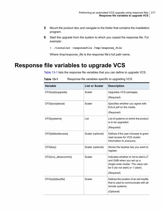
5 Mount the product disc and navigate to the folder that contains the installationprogram.
6 Start the upgrade from the system to which you copied the response file. Forexample:
# ./installer -responsefile /tmp/response_file
Where /tmp/response_file is the response file’s full path name.
Response file variables to upgrade VCSTable 13-1 lists the response file variables that you can define to upgrade VCS.
Table 13-1 Response file variables specific to upgrading VCS
DescriptionList or ScalarVariable
Upgrades VCS packages.
(Required)
ScalarCFG{opt}{upgrade}
Specifies whether you agree withEULA.pdf on the media.
(Required)
ScalarCFG{accepteula}
List of systems on which the productis to be upgraded.
(Required)
ListCFG{systems}
Defines if the user chooses to grantread access for VCS clusterinformation to everyone.
Scalar (optional)CFG{defaultaccess}
Stores the keyless key you want toregister.
Scalar (optional)CFG{key}
Indicates whether or not to start LLTand GAB when you set up asingle-node cluster. The value canbe 0 (do not start) or 1 (start).
(Required)
ScalarCFG{vcs_allowcomms}
Defines the location of an ssh keyfilethat is used to communicate with allremote systems.
(Optional)
ScalarCFG{opt}{keyfile}
217Performing an automated VCS upgrade using response filesResponse file variables to upgrade VCS

Table 13-1 Response file variables specific to upgrading VCS (continued)
DescriptionList or ScalarVariable
Defines a location, typically an NFSmount, from which all remotesystems can install productpackages. The location must beaccessible from all target systems.
(Optional)
ScalarCFG{opt}{pkgpath}
Defines the location where aworking directory is created to storetemporary files and the packagesthat are needed during the install.The default location is /var/tmp.
(Optional)
ScalarCFG{opt}{tmppath}
Defines the user groups which getread access to the cluster.
(Optional)
ListCFG{secusrgrps}
Mentions the location where the logfiles are to be copied. The defaultlocation is /opt/VRTS/install/logs.
Note: The installer copies theresponse files and summary filesalso to the specified logpathlocation.
(Optional)
ScalarCFG{opt}{logpath}
Defines that rsh must be usedinstead of ssh as the communicationmethod between systems.
(Optional)
ScalarCFG{opt}{rsh}
Set the value to 1 for onlineupgrades.
ScalarCFG{opt}{online_upgrade}
Sample response file for upgrading VCSReview the response file variables and their definitions.
See “Response file variables to upgrade VCS” on page 217.
218Performing an automated VCS upgrade using response filesSample response file for upgrading VCS

#
# Configuration Values:
#
our %CFG;
$CFG{accepteula}=1;
$CFG{secusrgrps}=qw{staff [email protected]}
$CFG{vcs_allowcomms}=1;
$CFG{opt}{upgrade}=1;
$CFG{prod}="Availability71";
$CFG{opt}{online_upgrade}=1;
$CFG{systems}=[ qw( sys1 sys2) ];
1;
219Performing an automated VCS upgrade using response filesSample response file for upgrading VCS

Upgrading VCS using LiveUpgrade and BootEnvironment upgrade
This chapter includes the following topics:
■ About Live Upgrade
■ About ZFS Boot Environment (BE) upgrade
■ Supported upgrade paths for Live Upgrade and Boot Environment upgrade
■ Performing Live Upgrade on Solaris 10 systems
■ Performing Boot Environment upgrade on Solaris 11 systems
About Live UpgradeSolaris Live Upgrade provides a method of upgrading a system while the systemcontinues to operate. This is done by creating an alternate boot environment (ABE)from the current boot environment and then upgrading the ABE. Once the ABE isupgraded, you can activate the ABE and then reboot the system.
On Solaris 10, you can use Live Upgrade technology to reduce downtime associatedwith the OS upgrade and VCS product upgrade by creating a boot environment ona alternate boot disk.
■ See “Performing Live Upgrade on Solaris 10 systems” on page 223.
Figure 14-1 illustrates an example of an upgrade from 6.0 to 7.1, and the operatingsystem from Solaris 10 Update9 to Solaris 10 Update11 using Live Upgrade.
14Chapter

Figure 14-1 Live Upgrade process
Create the alternate bootenvironment from theprimary boot environmentwhile the server runs.
Solaris 10Update9
Veritas 6.0
Otherpackages
Solaris 10Update9
Veritas 6.0
Otherpackages
Primarybootenvironment
Alternatebootenvironment
The server now runs thenew primary bootenvironment.
Solaris 10Update11
Veritas 7.1
Otherpackages
Solaris 10Update9
Veritas 6.0
Otherpackages
Primarybootenvironment
Alternatebootenvironment
Upgrade the Veritasproduct in the alternateboot environment usingthe installer or manually.
Solaris 10Update9
Veritas 6.0
Otherpackages
Solaris 10Update11
Veritas 7.1
Otherpackages
Primarybootenvironment
Alternatebootenvironment
Restart the server
Upgrade the OS and theproduct in the alternateboot environment usingthe installer.
Some service groups (failover and parallel) may be online in this cluster and theLive Upgrade process does not affect them. Downtime is experienced only whenthe server is restarted to boot into the alternate boot environment.
Cluster Server exceptions for Live UpgradeIf you have configured Veritas File System or Veritas Volume Manager, use theLive Upgrade instructions in the Storage Foundation and High Availability InstallationGuide.
About ZFS Boot Environment (BE) upgradeA Boot Environment (BE) is a bootable instance of the Oracle Solaris operatingsystem image along with any other application software packages installed into thatimage. System administrators can maintain multiple BEs on their systems, andeach BE can have different software versions installed. Upon the initial installationof the Oracle Solaris 11 release onto a system, a BE is created.
On Solaris 11, you can use the beadm utility to create and administer additional BEson your system.
221Upgrading VCS using Live Upgrade and Boot Environment upgradeAbout ZFS Boot Environment (BE) upgrade

Figure 14-2 Boot Environment upgrade process
Create the alternate bootenvironment from theprimary boot environmentwhile the server runs.
Solaris 11
Veritas6.0.1
Otherpackages
Solaris 11
Veritas6.0.1
Otherpackages
Primarybootenvironment
Alternatebootenvironment
The server now runs thenew primary bootenvironment.
Solaris 11
Veritas 7.1
Otherpackages
Solaris 11
Veritas6.0.1
Otherpackages
Primarybootenvironment
Alternatebootenvironment
Upgrade the Veritasproduct in the alternateboot environment usingthe installer or manually.
Solaris 11
Veritas6.0.1
Otherpackages
Solaris 11
Veritas 7.1
Otherpackages
Primarybootenvironment
Alternatebootenvironment
Restart the server
Upgrade the product in thealternate boot environmentusing the installer.
Supported upgrade paths for Live Upgrade andBoot Environment upgrade
The systems where you plan to use Live Upgrade must run Solaris 10. BootEnvironment upgrade can be used on Solaris 11 system only.
Veritas requires that both global and non-global zones run the same version ofVeritas InfoScale products.
You can use Live Upgrade or Boot Environment upgrade in the following virtualizedenvironments:
222Upgrading VCS using Live Upgrade and Boot Environment upgradeSupported upgrade paths for Live Upgrade and Boot Environment upgrade
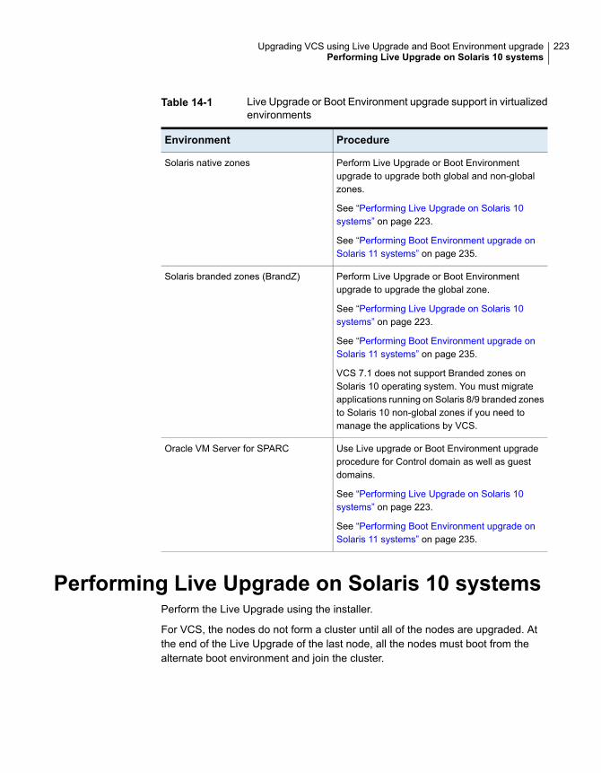
Table 14-1 Live Upgrade or Boot Environment upgrade support in virtualizedenvironments
ProcedureEnvironment
Perform Live Upgrade or Boot Environmentupgrade to upgrade both global and non-globalzones.
See “Performing Live Upgrade on Solaris 10systems” on page 223.
See “Performing Boot Environment upgrade onSolaris 11 systems” on page 235.
Solaris native zones
Perform Live Upgrade or Boot Environmentupgrade to upgrade the global zone.
See “Performing Live Upgrade on Solaris 10systems” on page 223.
See “Performing Boot Environment upgrade onSolaris 11 systems” on page 235.
VCS 7.1 does not support Branded zones onSolaris 10 operating system. You must migrateapplications running on Solaris 8/9 branded zonesto Solaris 10 non-global zones if you need tomanage the applications by VCS.
Solaris branded zones (BrandZ)
Use Live upgrade or Boot Environment upgradeprocedure for Control domain as well as guestdomains.
See “Performing Live Upgrade on Solaris 10systems” on page 223.
See “Performing Boot Environment upgrade onSolaris 11 systems” on page 235.
Oracle VM Server for SPARC
Performing Live Upgrade on Solaris 10 systemsPerform the Live Upgrade using the installer.
For VCS, the nodes do not form a cluster until all of the nodes are upgraded. Atthe end of the Live Upgrade of the last node, all the nodes must boot from thealternate boot environment and join the cluster.
223Upgrading VCS using Live Upgrade and Boot Environment upgradePerforming Live Upgrade on Solaris 10 systems

Table 14-2 Upgrading VCS using Solaris 10 Live Upgrade
DescriptionStep
Prepare to upgrade using Solaris Live Upgrade.
See “Before you upgrade VCS using Solaris Live Upgrade”on page 224.
Step 1
Create a new boot environment on the alternate boot disk.
See “Creating a new Solaris 10 boot environment on the alternateboot disk” on page 225.
Step 2
Upgrade VCS using the installer.
See “Upgrading VCS using the installer for Solaris 10 LiveUpgrade” on page 230.
Step 3
To upgrade only Solaris
See the Oracle documentation on Solaris 10 operating system
Note: A new boot environment is created on the alternate bootdisk by cloning the primary boot environment. If you choose toupgrade the operating system, the Solaris operating system onthe alternate boot environment is upgraded.
Switch the alternate boot environment to be the new primary.
See “Completing the Solaris 10 Live Upgrade” on page 231.
Step 4
Verify Live Upgrade of VCS.
See “Verifying the Solaris 10 Live Upgrade of VCS” on page 232.
Step 5
Before you upgrade VCS using Solaris Live UpgradeBefore you upgrade, perform the following procedure.
To prepare for the Live Upgrade
1 Make sure that the VCS installation media and the operating system installationimages are available and on hand.
2 On the nodes to be upgraded, select an alternate boot disk that is at least thesame size as the root partition of the primary boot disk
If the primary boot disk is mirrored, you need to break off the mirror for thealternate boot disk.
224Upgrading VCS using Live Upgrade and Boot Environment upgradePerforming Live Upgrade on Solaris 10 systems
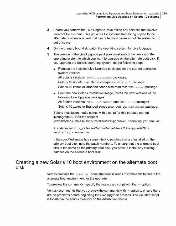
3 Before you perform the Live Upgrade, take offline any services that involvenon-root file systems. This prevents file systems from being copied to thealternate boot environment that can potentially cause a root file system to runout of space.
4 On the primary boot disk, patch the operating system for Live Upgrade.
5 The version of the Live Upgrade packages must match the version of theoperating system to which you want to upgrade on the alternate boot disk. Ifyou upgrade the Solaris operating system, do the following steps:
■ Remove the installed Live Upgrade packages for the current operatingsystem version:All Solaris versions: SUNWluu, SUNWlur packages.Solaris 10 update 7 or later also requires: SUNWlucfg package.Solaris 10 zones or Branded zones also requires: SUNWluzone package.
■ From the new Solaris installation image, install the new versions of thefollowing Live Upgrade packages:All Solaris versions: SUNWluu, SUNWlur, and SUNWlucfg packages.Solaris 10 zones or Branded zones also requires: SUNWluzone package.
Solaris installation media comes with a script for this purpose namedliveupgrade20. Find the script at/cdrom/solaris_release/Tools/Installers/liveupgrade20. If scripting, you can use:
# /cdrom/solaris_release/Tools/Installers/liveupgrade20 \
-nodisplay -noconsole
If the specified image has some missing patches that are installed on theprimary boot disk, note the patch numbers. To ensure that the alternate bootdisk is the same as the primary boot disk, you have to install any missingpatches on the alternate boot disk.
Creating a new Solaris 10 boot environment on the alternate bootdisk
Veritas provides the vxlustart script that runs a series of commands to create thealternate boot environment for the upgrade.
To preview the commands, specify the vxlustart script with the -V option.
Veritas recommends that you preview the commands with -V option to ensure thereare no problems before beginning the Live Upgrade process. The vxlustart scriptis located in the scripts directory on the distribution media.
225Upgrading VCS using Live Upgrade and Boot Environment upgradePerforming Live Upgrade on Solaris 10 systems

Note: This step can take several hours to complete. Do not interrupt the sessionas it may leave the boot environment unstable.
# cd /cdrom/scripts
# ./vxlustart -V -u targetos_version -s osimage_path -d diskname
Table 14-3
Usagevxlustart option
Lists the commands to be executed duringthe upgrade process without executing themand pre-checks the validity of the command.
If the operating system is upgraded, the useris prompted to compare the patches that areinstalled on the image with the patchesinstalled on the primary boot disk. Thisdetermines if any critical patches are notpresent from the new operating systemimage.
-V
Indicates verbose, print commands beforeexecuting them.
-v
Forces the vtoc creation on the disk.-f
Indicates a default yes with no questionsasked.
-Y
Uses the already existing vtoc on the disk.-m
Prints with debug option on, and is fordebugging.
-D
Specifies that only the Storage Foundationproducts are upgraded. The operating systemis cloned from the primary boot disk.
-U
Specifies the DG to which the rootdiskbelongs. Optional.
-g
Indicates the name of the alternate boot diskc#t#d#s2 on which you intend to upgrade.The default disk is mirrordisk.
-d
226Upgrading VCS using Live Upgrade and Boot Environment upgradePerforming Live Upgrade on Solaris 10 systems

Table 14-3 (continued)
Usagevxlustart option
Specifies the operating system version forthe upgrade on the alternate boot disk. Forexample, use 7.9 for Solaris 9 and 7.10 forSolaris 10.
If you want to upgrade only SF products,specify the current OS version.
-u
Specifies the root disk's file system, wherethe default is ufs.
-F
Specifies the path to the Solaris image. It canbe a network/directory path. If the installationuses the CD, this option must not bespecified. See Solaris Live Upgradeinstallation guide for more information aboutthe path.
-S
Specifies that if the computer crashes orrestarts before the vxlufinish commandis run, the alternate disk is remounted usingthis option.
-r
Specifies the location of file containingauto-registration information. This file isrequired by luupgrade(1M) for OS upgradeto Solaris 10 9/10 or a later release.
-k
Excludes file from newly created BE.(lucreate -x option)
-x
Excludes file list from newly created BE.(lucreate -f option
-X
Includes file from newly created BE.(lucreate -y option)
-i
Includes file list from newly created BE.(lucreate -Y option)
-I
Filters file list from newly created BE.(lucreate -z option)
-z
Specifies additional mount points. (lucreate-m option)
-w
227Upgrading VCS using Live Upgrade and Boot Environment upgradePerforming Live Upgrade on Solaris 10 systems

Table 14-3 (continued)
Usagevxlustart option
Specifies additional mount points in a file(lucreate -M option
-W
If the -U option is specified, you can omit the -s option. The operating system iscloned from the primary boot disk.
For example, to preview the commands to upgrade only the Veritas InfoScaleproduct:
# ./vxlustart -V -u 7.10 -U -d disk_name
In the procedure examples, the primary or current boot environment resides onDisk0 (c0t0d0s2) and the alternate or inactive boot environment resides on Disk1(c0t1d0s2).
At the end of the process:
■ A new boot environment is created on the alternate boot disk by cloning theprimary boot environment.
■ The Solaris operating system on the alternate boot disk is upgraded, if you havechosen to upgrade the operating system.
To create a new boot environment on the alternate boot disk
Perform the steps in this procedure on each node in the cluster.
228Upgrading VCS using Live Upgrade and Boot Environment upgradePerforming Live Upgrade on Solaris 10 systems

1 Navigate to the install media for the Veritas InfoScale products:
# cd /cdrom/scripts
2 Before you upgrade, make sure that you exclude the file system mount pointson a shared storage that applications use from getting copied to the new bootenvironment. To prevent these shared mount points from being copied to thenew boot environment, create a temporary file containing the file systemmountpoints that need to be excluded.
# cat /var/tmp/file_list
- /ora_mnt
- /sap_mnt
Where /var/tmp/file_list is a temporary file that contains the list of mountpoints to be excluded from the new boot environment. The items in the file listare preceded either by a '+' or '-' symbol. The '+' symbol indicates that themount point is included in the new boot environment. The '-' symbol indicatesthat the mount point is excluded from the new boot environment.
Apart from file system mount points, you may choose to include or excludeother files. If you have non-global zone in running state in the current bootenvironment and zone root path is on a shared storage, setup another disk ofsame or more size for each zone root in alternate boot environment.
3 Run one of the following commands to create the alternate boot environment.
For example: To upgrade the operating system:
# ./vxlustart -v -u 7.10 -s /mnt/sol10u9 -d
c0t1d0s2 -z /var/tmp/file_list
Where /mnt/sol10u9 is the path to the operating system image that containsthe .cdtoc file.
To clone the operating system of current boot environment:
# ./vxlustart -v -u 7.10 -U -d c0t1d0s2 -z /var/tmp/file_list
If you have non-global zone with zone root path on shard storage, then toupgrade the OS:
# ./vxlustart -v -u 7.10 -U -d c0t1d0s2 -z /var/tmp/file_list -w
/zone1-rootpath:/dev/dsk/<new disk>/:<type of fs>
Where zone1-rootpath is root path of zone in present boot environment.
229Upgrading VCS using Live Upgrade and Boot Environment upgradePerforming Live Upgrade on Solaris 10 systems

4 Update the permissions, user name, and group name of the mount points(created on the ABE) to match that of the existing directories on the primaryboot environment.
5 If zone root path is on shared storage, update the/altroot.7.10/etc/VRTSvcs/conf/config/main.cf file with new blockdevice created in step 2 for all zones to reflect the ABE zone root paths.
6 Review the output and note the new mount points. If the system is restartedbefore completion of the upgrade or if the mounts become unmounted, youmay need to remount the disks.
If you need to remount, run the command:
# vxlustart -r -u targetos_version -d disk_name
7 After the alternate boot disk is created and mounted on /altroot.7.10, installany operating system patches or packages on the alternate boot disk that arerequired for the Veritas InfoScale product installation.
# pkgadd -R /altroot.7.10 -d pkg_dir
Upgrading VCS using the installer for Solaris 10 Live UpgradeYou can use the Veritas InfoScale product installer to upgrade VCS as part of theLive Upgrade.
On a node in the cluster, run the installer on the alternate boot disk to upgrade VCSon all the nodes in the cluster. The program uninstalls the existing version of VCSon the alternate boot disk during the process.
At the end of the process, VCS 7.1 is installed on the alternate boot disk.
To perform Live Upgrade of VCS using the installer
1 Insert the product disc with VCS 7.1 or access your copy of the software onthe network.
2 Run the installer script specifying the root path as the alternate boot disk:
# ./installer -upgrade -rootpath /altroot.7.10
3 Enter the names of the nodes that you want to upgrade to VCS 7.1.
The installer displays the list of packages to be installed or upgraded on thenodes.
4 Press Return to continue with the installation.
230Upgrading VCS using Live Upgrade and Boot Environment upgradePerforming Live Upgrade on Solaris 10 systems

During Live Upgrade, if the OS of the alternate boot disk is upgraded, theinstaller does not update the VCS configurations for Oracle, Netlsnr, and Sybaseresources. If cluster configurations include these resources, you are promptedto run a list of commands to manually update the configurations after the clusterrestarts from the alternate boot disks.
5 Verify that the version of the Veritas packages on the alternate boot disk is 7.1.
# pkginfo -R /altroot.7.10 -l VRTSpkgname
For example:
# pkginfo -R /altroot.7.10 -l VRTSvcs
Review the installation logs at /altroot.7.10/opt/VRTS/install/logs.
Completing the Solaris 10 Live UpgradeAt the end of the process:
■ The alternate boot environment is activated.
■ The system is booted from the alternate boot disk.
To complete the Live Upgrade
1 Complete the Live upgrade process. Enter the following command on all nodesin the cluster.
# ./vcslufinish -u target_os_version
Live Upgrade finish on the Solaris release <7.10>
2 After the successful completion of vxlustart, if the system crashes or restartsbefore Live Upgrade completes successfully, you can remount the alternatedisk using the following command:
# ./vxlustart -r -u target_os_version
Then, rerun the vcslufinish command from step 1
# ./vcslufinish -u target_os_version
3 For Solaris x86-64 systems, restore the original PrivNIC.cf file:
# cp /mnt/etc/VRTSvcs/conf/config/PrivNIC.cf
/tmp/PrivNIC.cf.save
231Upgrading VCS using Live Upgrade and Boot Environment upgradePerforming Live Upgrade on Solaris 10 systems

4 Restart all the nodes in the cluster. The boot environment on the alternate diskis activated when you restart the nodes.
Note:Do not use the reboot, halt, or uadmin commands to restart the system.Use either the init or the shutdown commands to enable the system to bootusing the alternate boot environment.
You can ignore the following error if it appears: Error: boot environment<dest.13445> already mounted on </altroot.7.10>.
# shutdown -g0 -y -i6
5 If you want to upgrade the CP server systems that use VCS or SFHA to thisversion, make sure that you have upgraded all application clusters to thisversion. Then, upgrade VCS or SFHA on the CP server systems.
For instructions to upgrade VCS or SFHA on the CP server systems, see therelevant Installation Guide.
Verifying the Solaris 10 Live Upgrade of VCSTo ensure that Live Upgrade has completed successfully, verify that all the nodeshave booted from the alternate boot environment and joined the cluster.
To verify that Live Upgrade completed successfully
1 Verify that the alternate boot environment is active.
# lustatus
If the alternate boot environment fails to be active, you can revert to the primaryboot environment.
See “Reverting to the primary boot environment on a Solaris 10 system”on page 233.
2 Make sure that GAB ports a and h are up.
# gabconfig -a
Port a gen 39d901 membership 01
Port h gen 39d909 membership 01
3 Perform other verification as required to ensure that the new boot environmentis configured correctly.
4 In a zone environment, verify the zone configuration.
232Upgrading VCS using Live Upgrade and Boot Environment upgradePerforming Live Upgrade on Solaris 10 systems

Administering boot environments in Solaris 10 Live UpgradeUse the following procedures to perform relevant administrative tasks for bootenvironments.
Reverting to the primary boot environment on a Solaris10 systemIf the alternate boot environment fails to start, you can revert to the primary bootenvironment.
On each node, start the system from the primary boot environment in the PROMmonitor mode.
ok> boot disk0
where disk0 is the primary boot disk.
Failure to perform this step can result in the operating system booting from thealternate boot environment after the restart.
The vcslufinish script displays the way to revert to primary boot environment.Here is a sample output.
Notes:
******************************************************************
In case of a failure while booting to the target BE, the following
process needs to be followed to fallback to the currently working
boot environment:
1. Enter the PROM monitor (ok prompt).
2. Change the boot device back to the original boot environment
by typing:
setenv boot-device /pci@1c,600000/scsi@2/disk@0,0:a
3. Boot to the original boot environment by typing:
boot
*******************************************************************
Switching the boot environment for Solaris 10 SPARCYou do not have to perform the following procedures to switch the boot environmentwhen you use the vxlustart and vcslufinish scripts to process Live Upgrade.You must perform the following procedures if vxlufinish script does not getexecuted successfully
233Upgrading VCS using Live Upgrade and Boot Environment upgradePerforming Live Upgrade on Solaris 10 systems

To switch the boot environment
1 Display the status of Live Upgrade boot environments.
# lustatus
Boot Environment Is Active Active Can Copy
Name Complete Now On Reboot Delete Status
---------------- -------- ------ --------- ------ ------
source.2657 yes yes yes no -
dest.2657 yes no no yes -
In this example, the primary boot environment is currently (source.2657). Youwant to activate the alternate boot environment (dest.2657).
2 Unmount any file systems that are mounted on the alternate boot environment(dest.2657).
# lufslist dest.2657
boot environment name: dest.2657
Filesystem fstype device size Mounted on Mount Options
----------------- ------ ------------ ---------- -------------
/dev/dsk/c0t0d0s1 swap 4298342400 - -
/dev/dsk/c0t0d0s0 ufs 15729328128 / -
/dev/dsk/c0t0d0s5 ufs 8591474688 /var -
/dev/dsk/c0t0d0s3 ufs 5371625472 /vxfs -
# luumount dest.2657
3 Activate the Live Upgrade boot environment.
# luactivate dest.2657
4 Restart the system.
# shutdown -g0 -i6 -y
The system automatically selects the boot environment entry that was activated.
234Upgrading VCS using Live Upgrade and Boot Environment upgradePerforming Live Upgrade on Solaris 10 systems

Performing Boot Environment upgrade on Solaris11 systems
For VCS, the nodes do not form a cluster until all of the nodes are upgraded. Atthe end of the BE upgrade of the last node, all the nodes must boot from the alternateBE and join the cluster.
Table 14-4 Upgrading VCS using BE upgrade
DescriptionStep
Create a new BE on the primary boot disk.
See “Creating a new Solaris 11 BE on the primary boot disk”on page 235.
Step 1
Upgrade VCS using the installer on the new BE.
See “Upgrading VCS using the installer for upgrading BE onSolaris 11” on page 236.
Step 2
To upgrade only Solaris
See the Oracle documentation on Oracle Solaris 11 operatingsystem.
Switch the alternate BE to be the new primary.
See “Completing the VCS upgrade on BE on Solaris 11”on page 238.
Step 3
Verify Upgrade of VCS.
See “Verifying Solaris 11 BE upgrade ” on page 238.
Step 4
Creating a new Solaris 11 BE on the primary boot diskAt the end of the process, a new BE is created on the primary boot disk by cloningthe primary BE.
To create a new BE on the primary boot disk
Perform the steps in this procedure on each node in the cluster.
235Upgrading VCS using Live Upgrade and Boot Environment upgradePerforming Boot Environment upgrade on Solaris 11 systems

1 View the list of BE in the primary disk.
# beadm list
2 If you have solaris brand zones in running state for which zone root is on sharedstorage, set AutoStart to 0 for the service group containing zone resource.
# hagrp -modify <group> AutoStart 0
# haconf -dump
3 Create a new BE in the primary boot disk.
# beadm create beName
# beadm mount beName mountpoint
4 Reset AutoStart to 1 for the service group containing zone resource in step2
# hagrp -modify <group> AutoStart 1
# haconf -dump
If VVR is configured, it is recommended that <beName> should have the valuealtroot.7.11 and <mountpoint> should have the value /altroot.7.11.
Upgrading VCS using the installer for upgrading BE on Solaris 11You can use the Veritas InfoScale product installer to upgrade VCS on a BE.
On a node in the cluster, run the installer on the primary boot disk to upgrade VCSon all the nodes in the cluster.
At the end of the process, the VCS 7.1 is installed on the alternate BE.
236Upgrading VCS using Live Upgrade and Boot Environment upgradePerforming Boot Environment upgrade on Solaris 11 systems

To perform BE upgrade of VCS using the installer
1 Insert the product disc with VCS 7.1 or access your copy of the software onthe network.
2 If you had the solaris brand zones in running state in the present BE when youcreated alternate BE, set the publisher for package repository for BEs of eachof the zones.
# /usr/bin/pkg -R /altrootpath/zone-root/root
set-publisher -g /<path>/VRTSpkgs.p5p Veritas
For example:
# /usr/bin/pkg -R /altroot.7.11/export/home/zone1/root
set-publisher -g /mnt/VRTSpkgs.p5p Veritas
3 Run the installer script specifying the root path as the alternate BE:
# ./installer -upgrade -rootpath /altroot.7.11
4 Enter the names of the nodes that you want to upgrade to VCS 7.1.
The installer displays the list of packages to be installed or upgraded on thenodes.
5 Press Return to continue with the installation.
During BE upgrade, if the OS of the alternate BE is upgraded, the installerdoes not update the VCS configurations for Oracle, Netlsnr, and Sybaseresources. If cluster configurations include these resources, you are promptedto run a list of commands to manually update the configurations after the clusterrestarts from the alternate BE.
6 Verify that the version of the Veritas packages on the alternate BE is 7.1.
# pkg -R /altroot.7.11 list VRTS\*
For example:
# pkg -R /altroot.7.11 list VRTSvcs
Review the installation logs at /altroot.7.11/opt/VRTS/install/logs.
7 Unset the publisher set in step 2.
# /usr/bin/pkg -R /altrootpath/zone-root/root
unset-publisher Veritas
237Upgrading VCS using Live Upgrade and Boot Environment upgradePerforming Boot Environment upgrade on Solaris 11 systems

Completing the VCS upgrade on BE on Solaris 11At the end of the process:
■ The alternate BE is activated.
■ The system is booted from the alternate BE.
To complete the BE upgrade
1 Activate the alternate BE.
# beadm activate altroot.7.11
2 Stop application and VCS on all nodes.
# hastop -all
3 Restart all the nodes in the cluster. The BE on the alternate disk is activatedwhen you restart the nodes.
Note:Do not use the reboot, halt, or uadmin commands to restart the system.Use either the init or the shutdown commands to enable the system to bootusing the alternate BE.
# shutdown -g0 -y -i6
4 If you want to upgrade the CP server systems that use VCS or SFHA to thisversion, make sure that you upgrade all application clusters to this version.Then, upgrade VCS or SFHA on the CP server systems.
For instructions to upgrade VCS or SFHA on the CP server systems, see theVCS or SFHA Installation Guide.
Verifying Solaris 11 BE upgradeTo ensure that BE upgrade has completed successfully, verify that all the nodeshave booted from the alternate BE and joined the cluster.
238Upgrading VCS using Live Upgrade and Boot Environment upgradePerforming Boot Environment upgrade on Solaris 11 systems
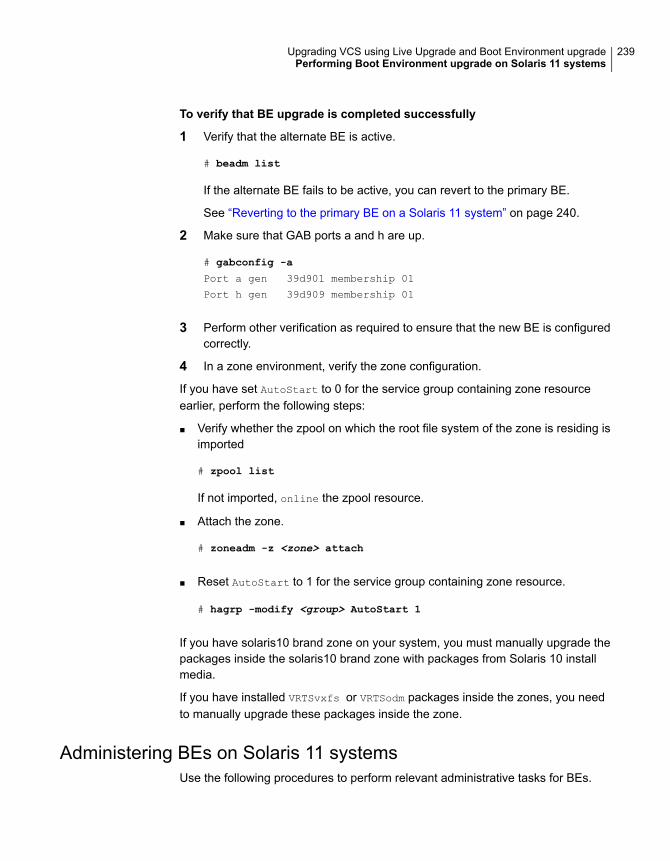
To verify that BE upgrade is completed successfully
1 Verify that the alternate BE is active.
# beadm list
If the alternate BE fails to be active, you can revert to the primary BE.
See “Reverting to the primary BE on a Solaris 11 system” on page 240.
2 Make sure that GAB ports a and h are up.
# gabconfig -a
Port a gen 39d901 membership 01
Port h gen 39d909 membership 01
3 Perform other verification as required to ensure that the new BE is configuredcorrectly.
4 In a zone environment, verify the zone configuration.
If you have set AutoStart to 0 for the service group containing zone resourceearlier, perform the following steps:
■ Verify whether the zpool on which the root file system of the zone is residing isimported
# zpool list
If not imported, online the zpool resource.
■ Attach the zone.
# zoneadm -z <zone> attach
■ Reset AutoStart to 1 for the service group containing zone resource.
# hagrp -modify <group> AutoStart 1
If you have solaris10 brand zone on your system, you must manually upgrade thepackages inside the solaris10 brand zone with packages from Solaris 10 installmedia.
If you have installed VRTSvxfs or VRTSodm packages inside the zones, you needto manually upgrade these packages inside the zone.
Administering BEs on Solaris 11 systemsUse the following procedures to perform relevant administrative tasks for BEs.
239Upgrading VCS using Live Upgrade and Boot Environment upgradePerforming Boot Environment upgrade on Solaris 11 systems

Switching the BE for Solaris SPARC
1 Display the status of Live Upgrade boot environments.
# beadm list
BE Active Mountpoint Space Policy Created
-- ------ --------- ----- ------ -------
solaris NR / 13.08G static 2012-11-14 10:22
altroot.7.11 - - 3.68G static 2013-01-06 18:41
In this example, the primary boot disk is currently solaris. You want to activatethe alternate boot disk altroot.7.11.
2 Activate the Live Upgrade boot environment.
# beadm activate altroot.7.11
3 Restart the system to complete the BE activation.
# shutdown -g0 -i6 -y
The system automatically selects the BE entry that was activated.
4 You can destroy an existing BE.
# beadm destroy altroot.7.11
Reverting to the primary BE on a Solaris 11 systemBoot the system to ok prompt.
View the available BEs.
To view the BEs, enter the following:
ok> boot -L
Select the option of the original BE to which you need to boot.
To boot to the BE, enter the following:
# boot -Z <path to boot env>
For example:
{0} ok boot -L
Boot device: /virtual-devices@100/channel-devices@200/disk@0:a
File and args: -L
1 Oracle Solaris 11 11/11 SPARC
240Upgrading VCS using Live Upgrade and Boot Environment upgradePerforming Boot Environment upgrade on Solaris 11 systems

2 solaris-backup-1
Select environment to boot: [ 1 - 2 ]: 1
To boot the selected entry, enter the following:
boot [<root-device>] -Z rpool/ROOT/solaris
Program terminated
{0} ok boot -Z rpool/ROOT/solaris
241Upgrading VCS using Live Upgrade and Boot Environment upgradePerforming Boot Environment upgrade on Solaris 11 systems

Adding and removingcluster nodes
■ Chapter 15. Adding a node to a single-node cluster
■ Chapter 16. Adding a node to a multi-node VCS cluster
■ Chapter 17. Removing a node from a VCS cluster
5Section

Adding a node to asingle-node cluster
This chapter includes the following topics:
■ Adding a node to a single-node cluster
Adding a node to a single-node clusterAll nodes in the new cluster must run the same version of VCS. The exampleprocedure refers to the existing single-node VCS node as Node A. The node thatis to join Node A to form a multiple-node cluster is Node B.
Table 15-1 specifies the activities that you need to perform to add nodes to asingle-node cluster.
Table 15-1 Tasks to add a node to a single-node cluster
ReferenceTask
See “Setting up a node to join the single-nodecluster” on page 244.
Set up Node B to be compatible withNode A.
See “Installing and configuring Ethernet cards forprivate network” on page 245.
■ Add Ethernet cards for privateheartbeat network for Node B.
■ If necessary, add Ethernet cards forprivate heartbeat network for NodeA.
■ Make the Ethernet cable connectionsbetween the two nodes.
See “Configuring the shared storage” on page 246.Connect both nodes to shared storage.
15Chapter
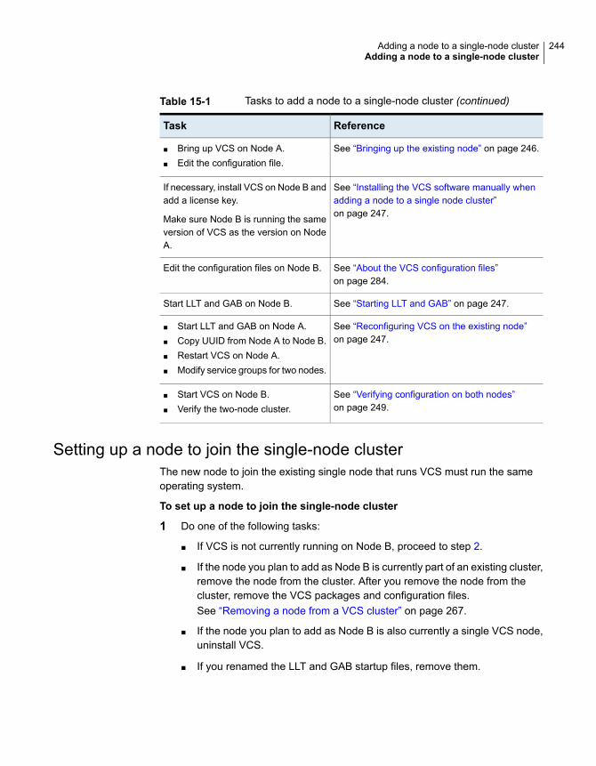
Table 15-1 Tasks to add a node to a single-node cluster (continued)
ReferenceTask
See “Bringing up the existing node” on page 246.■ Bring up VCS on Node A.■ Edit the configuration file.
See “Installing the VCS software manually whenadding a node to a single node cluster”on page 247.
If necessary, install VCS on Node B andadd a license key.
Make sure Node B is running the sameversion of VCS as the version on NodeA.
See “About the VCS configuration files”on page 284.
Edit the configuration files on Node B.
See “Starting LLT and GAB” on page 247.Start LLT and GAB on Node B.
See “Reconfiguring VCS on the existing node”on page 247.
■ Start LLT and GAB on Node A.■ Copy UUID from Node A to Node B.■ Restart VCS on Node A.■ Modify service groups for two nodes.
See “Verifying configuration on both nodes”on page 249.
■ Start VCS on Node B.■ Verify the two-node cluster.
Setting up a node to join the single-node clusterThe new node to join the existing single node that runs VCS must run the sameoperating system.
To set up a node to join the single-node cluster
1 Do one of the following tasks:
■ If VCS is not currently running on Node B, proceed to step 2.
■ If the node you plan to add as Node B is currently part of an existing cluster,remove the node from the cluster. After you remove the node from thecluster, remove the VCS packages and configuration files.See “Removing a node from a VCS cluster” on page 267.
■ If the node you plan to add as Node B is also currently a single VCS node,uninstall VCS.
■ If you renamed the LLT and GAB startup files, remove them.
244Adding a node to a single-node clusterAdding a node to a single-node cluster

2 If necessary, install VxVM and VxFS.
See “Installing VxVM or VxFS if necessary” on page 245.
Installing VxVM or VxFS if necessaryIf you have either VxVM or VxFS with the cluster option installed on the existingnode, install the same version on the new node.
Refer to the appropriate documentation for VxVM and VxFS to verify the versionsof the installed products. Make sure the same version runs on all nodes where youwant to use shared storage.
Installing and configuring Ethernet cards for private networkBoth nodes require Ethernet cards (NICs) that enable the private network. If bothNode A and Node B have Ethernet cards installed, you can ignore this step.
For high availability, use two separate NICs on each node. The two NICs provideredundancy for heartbeating.
To install and configure Ethernet cards for private network
1 Shut down VCS on Node A.
# hastop -local
2 Shut down the node to get to the OK prompt:
# sync;sync;init 0
3 Install the Ethernet card on Node A.
If you want to use aggregated interface to set up private network, configureaggregated interface.
4 Install the Ethernet card on Node B.
If you want to use aggregated interface to set up private network, configureaggregated interface.
5 Configure the Ethernet card on both nodes.
6 Make the two Ethernet cable connections from Node A to Node B for the privatenetworks.
7 Restart the nodes.
245Adding a node to a single-node clusterAdding a node to a single-node cluster
Configuring the shared storageMake the connection to shared storage from Node B. Configure VxVM on Node Band reboot the node when you are prompted.
Bringing up the existing nodeBring up the node.
To bring up the node
1 Start the operating system. On a SPARC node (Node A) enter the command:
ok boot -r
2 Log in as superuser.
3 Make the VCS configuration writable.
# haconf -makerw
4 Display the service groups currently configured.
# hagrp -list
5 Freeze the service groups.
# hagrp -freeze group -persistent
Repeat this command for each service group in step 4.
6 Make the configuration read-only.
# haconf -dump -makero
7 Stop VCS on Node A.
# hastop -local -force
8 If you have configured I/O Fencing, GAB, and LLT on the node, stop them.
# /usr/sbin/svcadm disable -t gab
# /usr/sbin/svcadm disable -t llt
246Adding a node to a single-node clusterAdding a node to a single-node cluster
Installing the VCS software manually when adding a node to a singlenode cluster
Install the VCS 7.1 packages manually and install the license key.
Refer to the following sections:
■
Creating configuration filesCreate the configuration files for your cluster.
To create the configuration files
1 Create the file /etc/llttab for a two-node cluster
See “Setting up /etc/llttab for a manual installation” on page 128.
2 Create the file /etc/llthosts that list both the nodes.
See “Setting up /etc/llthosts for a manual installation” on page 128.
3 Create the file /etc/gabtab.
See “Configuring GAB manually” on page 132.
Starting LLT and GABOn the new node, start LLT and GAB.
To start LLT and GAB
1 Start LLT on Node B.
# /usr/sbin/svcadm enable llt
2 Start GAB on Node B
# /usr/sbin/svcadm enable gab
Reconfiguring VCS on the existing nodeReconfigure VCS on the existing nodes.
247Adding a node to a single-node clusterAdding a node to a single-node cluster

To reconfigure VCS on existing nodes
1 On Node A, create the files /etc/llttab, /etc/llthosts, and /etc/gabtab. Use thefiles that are created on Node B as a guide, customizing the /etc/llttab for NodeA.
2 Start LLT on Node A.
# /usr/sbin/svcadm enable llt
3 Start GAB on Node A.
# /usr/sbin/svcadm enable gab
4 Check the membership of the cluster.
# gabconfig -a
5 Copy the cluster UUID from the existing node to the new node:
# /opt/VRTSvcs/bin/uuidconfig.pl -clus -copy -from_sys \
node_name_in_running_cluster -to_sys new_sys1 ... new_sysn
Where you are copying the cluster UUID from a node in the cluster(node_name_in_running_cluster) to systems from new_sys1 through new_sysnthat you want to join the cluster.
6 Delete the VCS one-node SMF configuration from SMF respository.
# svccfg -f delete vcs-onenode
7 Import the VCS SMF configuration to SMF respository.
# svccfg import /etc/VRTSvcs/conf/vcs.xml
Note: To start VCS using SMF service, use the svcadm enable vcs command.
8 Start VCS on Node A.
# hastart
9 Make the VCS configuration writable.
# haconf -makerw
248Adding a node to a single-node clusterAdding a node to a single-node cluster

10 Add Node B to the cluster.
# hasys -add sysB
11 Add Node B to the system list of each service group.
■ List the service groups.
# hagrp -list
■ For each service group that is listed, add the node.
# hagrp -modify group SystemList -add sysB 1
Verifying configuration on both nodesVerify the configuration for the nodes.
To verify the nodes' configuration
1 On Node B, check the cluster membership.
# gabconfig -a
2 Start the VCS on Node B.
# hastart
3 Verify that VCS is up on both nodes.
# hastatus
4 List the service groups.
# hagrp -list
5 Unfreeze the service groups.
# hagrp -unfreeze group -persistent
6 Save the new two-node configuration.
# haconf -dump -makero
249Adding a node to a single-node clusterAdding a node to a single-node cluster

Adding a node to amulti-node VCS cluster
This chapter includes the following topics:
■ Adding nodes using the VCS installer
■ Manually adding a node to a cluster
Adding nodes using the VCS installerThe VCS installer performs the following tasks:
■ Verifies that the node and the existing cluster meet communication requirements.
■ Verifies the products and packages installed on the new node.
■ Discovers the network interfaces on the new node and checks the interfacesettings.
■ Creates the following files on the new node:/etc/llttab
/etc/VRTSvcs/conf/sysname
■ Updates the following configuration files and copies them on the new node:/etc/llthosts
/etc/gabtab
/etc/VRTSvcs/conf/config/main.cf
■ Copies the following files from the existing cluster to the new node/etc/vxfenmode/etc/vxfendg/etc/vx/.uuids/clusuuid/etc/default/llt
16Chapter

/etc/default/gab/etc/default/vxfen
■ Configures disk-based or server-based fencing depending on the fencing modein use on the existing cluster.
At the end of the process, the new node joins the VCS cluster.
Note: If you have configured server-based fencing on the existing cluster, makesure that the CP server does not contain entries for the new node. If the CP serveralready contains entries for the new node, remove these entries before adding thenode to the cluster, otherwise the process may fail with an error.
To add the node to an existing VCS cluster using the VCS installer
1 Log in as the root user on one of the nodes of the existing cluster.
2 Run the VCS installer with the -addnode option.
# cd /opt/VRTS/install
# ./installer -addnode
The installer displays the copyright message and the location where it storesthe temporary installation logs.
3 Enter the name of a node in the existing VCS cluster. The installer uses thenode information to identify the existing cluster.
Enter the name of any one node of the InfoScale Availability cluster where you
would like to add one or more new nodes: sys1
4 Review and confirm the cluster information.
5 Enter the name of the systems that you want to add as new nodes to the cluster.
Enter the system names separated by spaces
to add to the cluster: sys5
The installer checks the installed products and packages on the nodes anddiscovers the network interfaces.
251Adding a node to a multi-node VCS clusterAdding nodes using the VCS installer

6 Enter the name of the network interface that you want to configure as the firstprivate heartbeat link.
Note: The LLT configuration for the new node must be the same as that of theexisting cluster. If your existing cluster uses LLT over UDP, the installer asksquestions related to LLT over UDP for the new node.
See “Configuring private heartbeat links” on page 52.
Enter the NIC for the first private heartbeat
link on sys5: [b,q,?] net0
7 Enter the name of the network interface that you want to configure as thesecond private heartbeat link.
Enter the NIC for the second private heartbeat link
on sys5: [b,q,?] net1
8 Depending on the number of LLT links configured in the existing cluster,configure additional private heartbeat links for the new node.
The installer verifies the network interface settings and displays the information.
9 Review and confirm the information.
10 If you have configured SMTP, SNMP, or the global cluster option in the existingcluster, you are prompted for the NIC information for the new node.
Enter the NIC for VCS to use on sys5: net2
11 If you have enabled security on the cluster, the installer displays the followingmessage:
Since the cluster is in secure mode, check the main.cf
whether you need to modify the usergroup that you would
like to grant read access. If needed, use the following
commands to modify:
haconf -makerw
hauser -addpriv <user group> GuestGroup
haconf -dump -makero
252Adding a node to a multi-node VCS clusterAdding nodes using the VCS installer

Manually adding a node to a clusterThe system you add to the cluster must meet the hardware and softwarerequirements.
Table 16-1 specifies the tasks that are involved in adding a cluster. The exampledemonstrates how to add a node saturn to already existing nodes, sys1 and sys2.
Table 16-1 Tasks that are involved in adding a node to a cluster
ReferenceTask
See “Setting up the hardware” on page 253.Set up the hardware
See “Configuring LLT and GAB when adding a node to thecluster” on page 258.
Configure LLT and GAB
See “Reconfiguring VCS on the existing node” on page 247.Copy the UUID
See “Adding the node to the existing cluster” on page 263.Add the node to the existingcluster
See “Starting VCS and verifying the cluster” on page 264.Start VCS and verify thecluster
Setting up the hardwareFigure 16-1 shows that before you configure a new system on an existing cluster,you must physically add the system to the cluster.
253Adding a node to a multi-node VCS clusterManually adding a node to a cluster
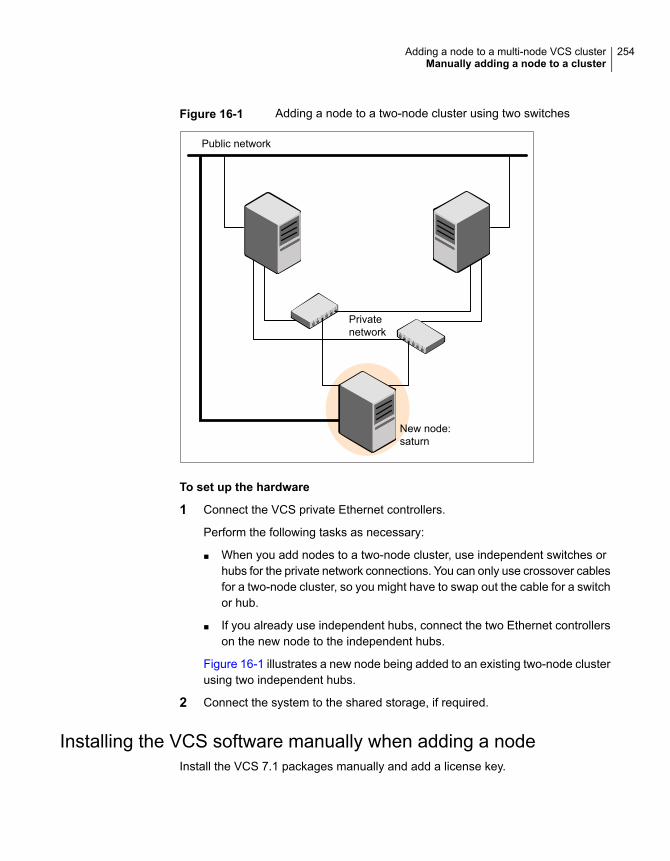
Figure 16-1 Adding a node to a two-node cluster using two switches
Public network
Privatenetwork
New node:saturn
To set up the hardware
1 Connect the VCS private Ethernet controllers.
Perform the following tasks as necessary:
■ When you add nodes to a two-node cluster, use independent switches orhubs for the private network connections. You can only use crossover cablesfor a two-node cluster, so you might have to swap out the cable for a switchor hub.
■ If you already use independent hubs, connect the two Ethernet controllerson the new node to the independent hubs.
Figure 16-1 illustrates a new node being added to an existing two-node clusterusing two independent hubs.
2 Connect the system to the shared storage, if required.
Installing the VCS software manually when adding a nodeInstall the VCS 7.1 packages manually and add a license key.
254Adding a node to a multi-node VCS clusterManually adding a node to a cluster

Setting up the node to run in secure modeYou must follow this procedure only if you are adding a node to a cluster that isrunning in secure mode. If you are adding a node to a cluster that is not running ina secure mode, proceed with configuring LLT and GAB.
See “Configuring LLT and GAB when adding a node to the cluster” on page 258.
Table 16-2 uses the following information for the following command examples.
Table 16-2 The command examples definitions
FunctionFully-qualified hostname (FQHN)
Name
The new node that you areadding to the cluster.
sys5.nodes.example.comsys5
255Adding a node to a multi-node VCS clusterManually adding a node to a cluster

Configuring the authentication broker on node sys5To configure the authentication broker on node sys5
1 Extract the embedded authentication files and copy them to temporary directory:
# mkdir -p /var/VRTSvcs/vcsauth/bkup
# cd /tmp; gunzip -c /opt/VRTSvcs/bin/VxAT.tar.gz | tar xvf -
2 Edit the setup file manually:
# cat /etc/vx/.uuids/clusuuid 2>&1
The output is a string denoting the UUID. This UUID (without { and }) is usedas the ClusterName for the setup file.
{UUID}
# cat /tmp/eat_setup 2>&1
The file content must resemble the following example:
AcceptorMode=IP_ONLY
BrokerExeName=vcsauthserver
ClusterName=UUID
DataDir=/var/VRTSvcs/vcsauth/data/VCSAUTHSERVER
DestDir=/opt/VRTSvcs/bin/vcsauth/vcsauthserver
FipsMode=0
IPPort=14149
RootBrokerName=vcsroot_uuid
SetToRBPlusABorNot=0
SetupPDRs=1
SourceDir=/tmp/VxAT/version
256Adding a node to a multi-node VCS clusterManually adding a node to a cluster

3 Set up the embedded authentication file:
# cd /tmp/VxAT/version/bin/edition_number; \
./broker_setup.sh/tmp/eat_setup
# /opt/VRTSvcs/bin/vcsauth/vcsauthserver/bin/vssregctl -s -f
/var/VRTSvcs/vcsauth/data/VCSAUTHSERVER/root/.VRTSat/profile \
/VRTSatlocal.conf -b 'Security\Authentication \
\Authentication Broker' -k UpdatedDebugLogFileName \
-v /var/VRTSvcs/log/vcsauthserver.log -t string
4 Copy the broker credentials from one node in the cluster to sys5 by copyingthe entire bkup directory.
The bkup directory content resembles the following example:
# cd /var/VRTSvcs/vcsauth/bkup/
# ls
CMDSERVER HAD VCS_SERVICES WAC
5 Import the VCS_SERVICES domain.
# /opt/VRTSvcs/bin/vcsauth/vcsauthserver/bin/atutil import -z \
/var/VRTSvcs/vcsauth/data/VCSAUTHSERVER -f /var/VRTSvcs/vcsauth/bkup \
/VCS_SERVICES -p password
6 Import the credentials for HAD, CMDSERVER, and WAC.
# /opt/VRTSvcs/bin/vcsauth/vcsauthserver/bin/atutil import -z \
/var/VRTSvcs/vcsauth/data/VCS_SERVICES -f /var/VRTSvcs/vcsauth/bkup \
/HAD -p password
7 Start the vcsauthserver process on sys5.
# /opt/VRTSvcs/bin/vcsauth/vcsauthserver/bin/vcsauthserver.sh
257Adding a node to a multi-node VCS clusterManually adding a node to a cluster

8 Perform the following tasks:
# mkdir /var/VRTSvcs/vcsauth/data/CLIENT
# mkdir /var/VRTSvcs/vcsauth/data/TRUST
# export EAT_DATA_DIR='/var/VRTSvcs/vcsauth/data/TRUST'
# /opt/VRTSvcs/bin/vcsauth/vcsauthserver/bin/vssat setuptrust -b \
localhost:14149 -s high
9 Create the /etc/VRTSvcs/conf/config/.secure file:
# touch /etc/VRTSvcs/conf/config/.secure
Configuring LLT and GAB when adding a node to the clusterCreate the LLT and GAB configuration files on the new node and update the fileson the existing nodes.
To configure LLT when adding a node to the cluster
1 Create the file /etc/llthosts on the new node. You must also update it on eachof the current nodes in the cluster.
For example, suppose you add sys5 to a cluster consisting of sys1 and sys2:
■ If the file on one of the existing nodes resembles:
0 sys1
1 sys2
■ Update the file for all nodes, including the new one, resembling:
0 sys1
1 sys2
2 sys5
2 Create the file /etc/llttab on the new node, making sure that line beginning"set-node" specifies the new node.
The file /etc/llttab on an existing node can serve as a guide.
The following example describes a system where node sys2 is the new nodeon cluster ID number 2:
■ For Solaris 10 SPARC:
258Adding a node to a multi-node VCS clusterManually adding a node to a cluster
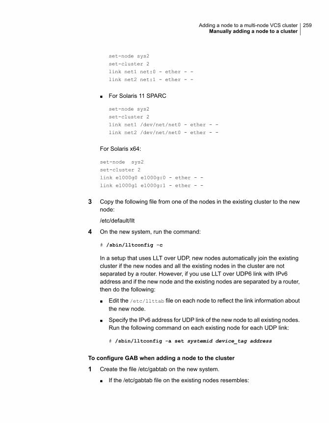
set-node sys2
set-cluster 2
link net1 net:0 - ether - -
link net2 net:1 - ether - -
■ For Solaris 11 SPARC
set-node sys2
set-cluster 2
link net1 /dev/net/net0 - ether - -
link net2 /dev/net/net0 - ether - -
For Solaris x64:
set-node sys2
set-cluster 2
link e1000g0 e1000g:0 - ether - -
link e1000g1 e1000g:1 - ether - -
3 Copy the following file from one of the nodes in the existing cluster to the newnode:
/etc/default/llt
4 On the new system, run the command:
# /sbin/lltconfig -c
In a setup that uses LLT over UDP, new nodes automatically join the existingcluster if the new nodes and all the existing nodes in the cluster are notseparated by a router. However, if you use LLT over UDP6 link with IPv6address and if the new node and the existing nodes are separated by a router,then do the following:
■ Edit the /etc/llttab file on each node to reflect the link information aboutthe new node.
■ Specify the IPv6 address for UDP link of the new node to all existing nodes.Run the following command on each existing node for each UDP link:
# /sbin/lltconfig -a set systemid device_tag address
To configure GAB when adding a node to the cluster
1 Create the file /etc/gabtab on the new system.
■ If the /etc/gabtab file on the existing nodes resembles:
259Adding a node to a multi-node VCS clusterManually adding a node to a cluster

/sbin/gabconfig -c
The file on the new node should be the same. Veritas recommends thatyou use the -c -nN option, where N is the total number of cluster nodes.
■ If the /etc/gabtab file on the existing nodes resembles:
/sbin/gabconfig -c -n2
The file on all nodes, including the new node, should change to reflect thechange in the number of cluster nodes. For example, the new file on eachnode should resemble:
/sbin/gabconfig -c -n3
The -n flag indicates to VCS the number of nodes that must be ready toform a cluster before VCS starts.
2 Copy the following file from one of the nodes in the existing cluster to the newnode:
/etc/default/gab
3 On the new node, to configure GAB run the command:
# /sbin/gabconfig -c
To verify GAB
1 On the new node, run the command:
# /sbin/gabconfig -a
The output should indicate that port a membership shows all nodes includingthe new node. The output should resemble:
GAB Port Memberships
====================================
Port a gen a3640003 membership 012
2 Run the same command on the other nodes (sys1 and sys2) to verify that theport a membership includes the new node:
# /sbin/gabconfig -a
GAB Port Memberships
====================================
Port a gen a3640003 membership 012
Port h gen fd570002 membership 01
Port h gen fd570002 visible ; 2
260Adding a node to a multi-node VCS clusterManually adding a node to a cluster

Configuring I/O fencing on the new nodeIf the existing cluster is configured for I/O fencing, perform the following tasks onthe new node:
■ Prepare to configure I/O fencing on the new node.See “Preparing to configure I/O fencing on the new node” on page 261.
■ If the existing cluster runs server-based fencing, configure server-based fencingon the new node.See “Configuring server-based fencing on the new node” on page 262.If the existing cluster runs disk-based fencing, you need not perform anyadditional step. Skip to the next task. After you copy the I/O fencing files andstart I/O fencing, disk-based fencing automatically comes up.
■ Copy the I/O fencing files from an existing node to the new node and start I/Ofencing on the new node.See “Starting I/O fencing on the new node” on page 263.
If the existing cluster is not configured for I/O fencing, perform the procedure to addthe new node to the existing cluster.
See “Adding the node to the existing cluster” on page 263.
Preparing to configure I/O fencing on the new nodePerform the following tasks before you configure and start I/O fencing on the newnode.
To prepare to configure I/O fencing on the new node
1 Determine whether the existing cluster runs disk-based or server-based fencingmechanism. On one of the nodes in the existing cluster, run the followingcommand:
# vxfenadm -d
If the fencing mode in the output is SCSI3, then the cluster uses disk-basedfencing.
If the fencing mode in the output is CUSTOMIZED, then the cluster usesserver-based fencing.
2 In the following cases, install and configure Veritas Volume Manager (VxVM)on the new node.
■ The existing cluster uses disk-based fencing.
■ The existing cluster uses server-based fencing with at least one coordinatordisk.
261Adding a node to a multi-node VCS clusterManually adding a node to a cluster

You need not perform this step if the existing cluster uses server-based fencingwith all coordination points as CP servers.
See the Veritas InfoScale Installation Guide for installation instructions.
Configuring server-based fencing on the new nodeThis section describes the procedures to configure server-based fencing on a newnode.
To configure server-based fencing on the new node
1 Log in to each CP server as the root user.
2 Update each CP server configuration with the new node information:
# cpsadm -s cps1.example.com \
-a add_node -c clus1 -h sys5 -n2
Node 2 (sys5) successfully added
3 Verify that the new node is added to the CP server configuration:
# cpsadm -s cps1.example.com -a list_nodes
The new node must be listed in the output.
4 Copy the certificates to the new node from the peer nodes.
See “Generating the client key and certificates manually on the client nodes ”on page 156.
Adding the new node to the vxfen service groupPerform the steps in the following procedure to add the new node to the vxfenservice group.
262Adding a node to a multi-node VCS clusterManually adding a node to a cluster
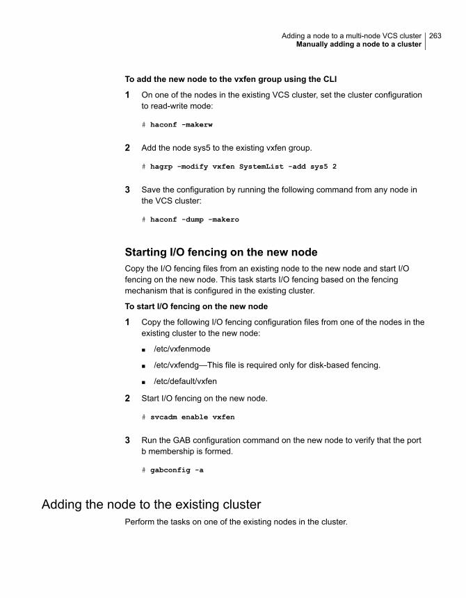
To add the new node to the vxfen group using the CLI
1 On one of the nodes in the existing VCS cluster, set the cluster configurationto read-write mode:
# haconf -makerw
2 Add the node sys5 to the existing vxfen group.
# hagrp -modify vxfen SystemList -add sys5 2
3 Save the configuration by running the following command from any node inthe VCS cluster:
# haconf -dump -makero
Starting I/O fencing on the new nodeCopy the I/O fencing files from an existing node to the new node and start I/Ofencing on the new node. This task starts I/O fencing based on the fencingmechanism that is configured in the existing cluster.
To start I/O fencing on the new node
1 Copy the following I/O fencing configuration files from one of the nodes in theexisting cluster to the new node:
■ /etc/vxfenmode
■ /etc/vxfendg—This file is required only for disk-based fencing.
■ /etc/default/vxfen
2 Start I/O fencing on the new node.
# svcadm enable vxfen
3 Run the GAB configuration command on the new node to verify that the portb membership is formed.
# gabconfig -a
Adding the node to the existing clusterPerform the tasks on one of the existing nodes in the cluster.
263Adding a node to a multi-node VCS clusterManually adding a node to a cluster
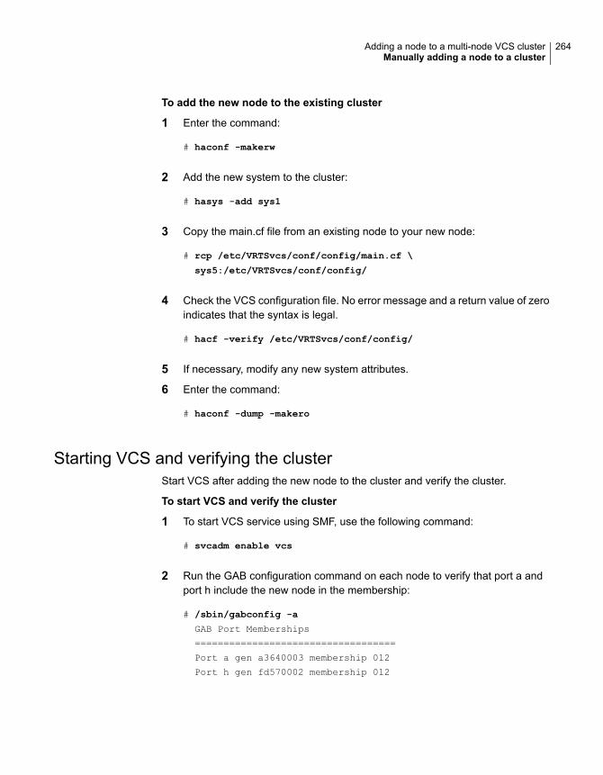
To add the new node to the existing cluster
1 Enter the command:
# haconf -makerw
2 Add the new system to the cluster:
# hasys -add sys1
3 Copy the main.cf file from an existing node to your new node:
# rcp /etc/VRTSvcs/conf/config/main.cf \
sys5:/etc/VRTSvcs/conf/config/
4 Check the VCS configuration file. No error message and a return value of zeroindicates that the syntax is legal.
# hacf -verify /etc/VRTSvcs/conf/config/
5 If necessary, modify any new system attributes.
6 Enter the command:
# haconf -dump -makero
Starting VCS and verifying the clusterStart VCS after adding the new node to the cluster and verify the cluster.
To start VCS and verify the cluster
1 To start VCS service using SMF, use the following command:
# svcadm enable vcs
2 Run the GAB configuration command on each node to verify that port a andport h include the new node in the membership:
# /sbin/gabconfig -a
GAB Port Memberships
===================================
Port a gen a3640003 membership 012
Port h gen fd570002 membership 012
264Adding a node to a multi-node VCS clusterManually adding a node to a cluster

Adding a node using response filesTypically, you can use the response file that the installer generates on one systemto add nodes to an existing cluster.
To add nodes using response files
1 Make sure the systems where you want to add nodes meet the requirements.
2 Make sure all the tasks required for preparing to add a node to an existing VCScluster are completed.
3 Copy the response file to one of the systems where you want to add nodes.
See “Sample response file for adding a node to a VCS cluster” on page 266.
4 Edit the values of the response file variables as necessary.
See “Response file variables to add a node to a VCS cluster” on page 265.
5 Mount the product disc and navigate to the folder that contains the installationprogram.
6 Start adding nodes from the system to which you copied the response file. Forexample:
# ./installer -responsefile /tmp/response_file
Where /tmp/response_file is the response file’s full path name.
Depending on the fencing configuration in the existing cluster, the installerconfigures fencing on the new node. The installer then starts all the requiredprocesses and joins the new node to cluster. The installer indicates the locationof the log file and summary file with details of the actions performed.
Response file variables to add a node to a VCS clusterTable 16-3 lists the response file variables that you can define to add a node to anVCS cluster.
Table 16-3 Response file variables for adding a node to an VCS cluster
DescriptionVariable
Adds a node to an existing cluster.
List or scalar: scalar
Optional or required: required
$CFG{opt}{addnode}
265Adding a node to a multi-node VCS clusterManually adding a node to a cluster

Table 16-3 Response file variables for adding a node to an VCS cluster(continued)
DescriptionVariable
Specifies the new nodes to beadded to the cluster.
List or scalar: list
Optional or required: required
$CFG{newnodes}
Sample response file for adding a node to a VCS clusterThe following example shows a response file for adding a node to a VCS cluster.
our %CFG;
$CFG{clustersystems}=[ qw(sys1) ];
$CFG{newnodes}=[ qw(sys5) ];
$CFG{opt}{addnode}=1;
$CFG{opt}{configure}=1;
$CFG{opt}{vr}=1;
$CFG{prod}=" AVAILABILITY71";
$CFG{systems}=[ qw(sys1 sys5) ];
$CFG{vcs_allowcomms}=1;
$CFG{vcs_clusterid}=101;
$CFG{vcs_clustername}="clus1";
$CFG{vcs_lltlink1}{sys5}="net0";
$CFG{vcs_lltlink2}{sys5}="net1";
1;
266Adding a node to a multi-node VCS clusterManually adding a node to a cluster

Removing a node from aVCS cluster
This chapter includes the following topics:
■ Removing a node from a VCS cluster
Removing a node from a VCS clusterTable 17-1 specifies the tasks that are involved in removing a node from a cluster.In the example procedure, the cluster consists of nodes sys1, sys2, and sys5; nodesys5 is to leave the cluster.
Table 17-1 Tasks that are involved in removing a node
ReferenceTask
See “Verifying the status of nodes andservice groups” on page 268.
■ Back up the configuration file.■ Check the status of the nodes and the service
groups.
See “Deleting the departing node fromVCS configuration” on page 269.
■ Switch or remove any VCS service groups onthe node departing the cluster.
■ Delete the node from VCS configuration.
See “Modifying configuration files oneach remaining node” on page 272.
Modify the llthosts(4) and gabtab(4) files to reflectthe change.
See “Removing security credentials fromthe leaving node ” on page 274.
For a cluster that is running in a secure mode,remove the security credentials from the leavingnode.
17Chapter

Table 17-1 Tasks that are involved in removing a node (continued)
ReferenceTask
See “Unloading LLT and GAB andremoving Veritas InfoScale Availabilityor Enterprise on the departing node”on page 274.
On the node departing the cluster:
■ Modify startup scripts for LLT, GAB, and VCSto allow reboot of the node without affectingthe cluster.
■ Unconfigure and unload the LLT and GAButilities.
■ Remove the Veritas InfoScale packages.
Verifying the status of nodes and service groupsStart by issuing the following commands from one of the nodes to remain in thecluster node sys1 or node sys2 in our example.
268Removing a node from a VCS clusterRemoving a node from a VCS cluster

To verify the status of the nodes and the service groups
1 Make a backup copy of the current configuration file, main.cf.
# cp -p /etc/VRTSvcs/conf/config/main.cf\
/etc/VRTSvcs/conf/config/main.cf.goodcopy
2 Check the status of the systems and the service groups.
# hastatus -summary
-- SYSTEM STATE
-- System State Frozen
A sys1 RUNNING 0
A sys2 RUNNING 0
A sys5 RUNNING 0
-- GROUP STATE
-- Group System Probed AutoDisabled State
B grp1 sys1 Y N ONLINE
B grp1 sys2 Y N OFFLINE
B grp2 sys1 Y N ONLINE
B grp3 sys2 Y N OFFLINE
B grp3 sys5 Y N ONLINE
B grp4 sys5 Y N ONLINE
The example output from the hastatus command shows that nodes sys1,sys2, and sys5 are the nodes in the cluster. Also, service group grp3 isconfigured to run on node sys2 and node sys5, the departing node. Servicegroup grp4 runs only on node sys5. Service groups grp1 and grp2 do not runon node sys5.
Deleting the departing node from VCS configurationBefore you remove a node from the cluster you need to identify the service groupsthat run on the node.
You then need to perform the following actions:
■ Remove the service groups that other service groups depend on, or
■ Switch the service groups to another node that other service groups dependon.
269Removing a node from a VCS clusterRemoving a node from a VCS cluster

To remove or switch service groups from the departing node
1 Switch failover service groups from the departing node. You can switch grp3from node sys5 to node sys2.
# hagrp -switch grp3 -to sys2
2 Check for any dependencies involving any service groups that run on thedeparting node; for example, grp4 runs only on the departing node.
# hagrp -dep
3 If the service group on the departing node requires other service groups—if itis a parent to service groups on other nodes—unlink the service groups.
# haconf -makerw
# hagrp -unlink grp4 grp1
These commands enable you to edit the configuration and to remove therequirement grp4 has for grp1.
4 Stop VCS on the departing node:
# hastop -sys sys5
To stop VCS using SMF, run the following command:
# svcadm disable vcs
270Removing a node from a VCS clusterRemoving a node from a VCS cluster

5 Check the status again. The state of the departing node should be EXITED.Make sure that any service group that you want to fail over is online on othernodes.
# hastatus -summary
-- SYSTEM STATE
-- System State Frozen
A sys1 RUNNING 0
A sys2 RUNNING 0
A sys5 EXITED 0
-- GROUP STATE
-- Group System Probed AutoDisabled State
B grp1 sys1 Y N ONLINE
B grp1 sys2 Y N OFFLINE
B grp2 sys1 Y N ONLINE
B grp3 sys2 Y N ONLINE
B grp3 sys5 Y Y OFFLINE
B grp4 sys5 Y N OFFLINE
6 Delete the departing node from the SystemList of service groups grp3 andgrp4.
# haconf -makerw
# hagrp -modify grp3 SystemList -delete sys5
# hagrp -modify grp4 SystemList -delete sys5
Note: If sys5 was in the autostart list, then you need to manually add anothersystem in the autostart list so that after reboot, the group comes onlineautomatically.
7 For the service groups that run only on the departing node, delete the resourcesfrom the group before you delete the group.
# hagrp -resources grp4
processx_grp4
processy_grp4
# hares -delete processx_grp4
# hares -delete processy_grp4
271Removing a node from a VCS clusterRemoving a node from a VCS cluster

8 Delete the service group that is configured to run on the departing node.
# hagrp -delete grp4
9 Check the status.
# hastatus -summary
-- SYSTEM STATE
-- System State Frozen
A sys1 RUNNING 0
A sys2 RUNNING 0
A sys5 EXITED 0
-- GROUP STATE
-- Group System Probed AutoDisabled State
B grp1 sys1 Y N ONLINE
B grp1 sys2 Y N OFFLINE
B grp2 sys1 Y N ONLINE
B grp3 sys2 Y N ONLINE
10 Delete the node from the cluster.
# hasys -delete sys5
11 Save the configuration, making it read only.
# haconf -dump -makero
Modifying configuration files on each remaining nodePerform the following tasks on each of the remaining nodes of the cluster.
272Removing a node from a VCS clusterRemoving a node from a VCS cluster

To modify the configuration files on a remaining node
1 If necessary, modify the /etc/gabtab file.
No change is required to this file if the /sbin/gabconfig command has onlythe argument -c. Veritas recommends using the -nN option, where N is thenumber of cluster systems.
If the command has the form /sbin/gabconfig -c -nN, whereN is the numberof cluster systems, make sure that N is not greater than the actual number ofnodes in the cluster. When N is greater than the number of nodes, GAB doesnot automatically seed.
Veritas does not recommend the use of the -c -x option for /sbin/gabconfig.
2 Modify /etc/llthosts file on each remaining nodes to remove the entry of thedeparting node.
For example, change:
0 sys1
1 sys2
2 sys5
To:
0 sys1
1 sys2
Removing the node configuration from the CP serverAfter removing a node from a VCS cluster, perform the steps in the followingprocedure to remove that node's configuration from the CP server.
Note: The cpsadm command is used to perform the steps in this procedure. Fordetailed information about the cpsadm command, see the Cluster ServerAdministrator's Guide.
273Removing a node from a VCS clusterRemoving a node from a VCS cluster

To remove the node configuration from the CP server
1 Log into the CP server as the root user.
2 View the list of VCS users on the CP server.
If the CP server is configured to use HTTPS-based communication, run thefollowing command:
# cpsadm -s cp_server -a list_users
Where cp_server is the virtual IP/ virtual hostname of the CP server.
3 Remove the node entry from the CP server:
# cpsadm -s cp_server -a rm_node -h sys5 -c clus1 -n 2
4 View the list of nodes on the CP server to ensure that the node entry wasremoved:
# cpsadm -s cp_server -a list_nodes
Removing security credentials from the leaving nodeIf the leaving node is part of a cluster that is running in a secure mode, you mustremove the security credentials from node sys5. Perform the following steps.
To remove the security credentials
1 Stop the AT process.
# /opt/VRTSvcs/bin/vcsauth/vcsauthserver/bin/vcsauthserver.sh \
stop
2 Remove the credentials.
# rm -rf /var/VRTSvcs/vcsauth/data/
Unloading LLT and GAB and removing Veritas InfoScale Availabilityor Enterprise on the departing node
Perform the tasks on the node that is departing the cluster.
You can use script-based installer to uninstall Veritas InfoScale Availability orEnterprise on the departing node or perform the following manual steps.
If you have configured VCS as part of the InfoScale products, you may have todelete other dependent packages before you can delete all of the following ones.
274Removing a node from a VCS clusterRemoving a node from a VCS cluster

To unconfigure and unload LLT and GAB and remove InfoScale Availabilityor Enterprise
1 If you had configured I/O fencing in enabled mode, then stop I/O fencing.
# svcadm disable -s vxfen
2 Unconfigure GAB and LLT:
# /sbin/gabconfig -U
# /sbin/lltconfig -U
3 Unload the GAB and LLT modules from the kernel.
■ Determine the kernel module IDs:
# modinfo | grep gab
# modinfo | grep llt
The module IDs are in the left-hand column of the output.
■ Unload the module from the kernel:
# modunload -i gab_id
# modunload -i llt_id
4 Disable the startup files to prevent LLT, GAB, or InfoScale Availability orEnterprise from starting up:
# /usr/sbin/svcadm disable -s vcs
# /usr/sbin/svcadm disable -s gab
# /usr/sbin/svcadm disable -s llt
5 To determine the packages to remove, enter:
# pkginfo | grep VRTS
275Removing a node from a VCS clusterRemoving a node from a VCS cluster

6 To permanently remove the InfoScale Availability or Enterprise packages fromthe system, use the pkgrm command. Start by removing the following packages,which may have been optionally installed, in the order shown below.
On Solaris10:
# pkgrm VRTSvcsea
# pkgrm VRTSvcswiz
# pkgrm VRTSvbs
# pkgrm VRTSsfmh
# pkgrm VRTSvcsag
# pkgrm VRTScps
# pkgrm VRTSvcs
# pkgrm VRTSamf
# pkgrm VRTSvxfen
# pkgrm VRTSgab
# pkgrm VRTSllt
# pkgrm VRTSspt
# pkgrm VRTSsfcpi
# pkgrm VRTSvlic
# pkgrm VRTSperl
On Solaris 11:
# pkg uninstall VRTSvcsea VRTSvcswiz VRTSvbs
VRTSsfmh VRTSvcsag VRTScps VRTSvcs VRTSamf VRTSvxfen
VRTSgab VRTSllt VRTSspt VRTSsfcpi VRTSperl VRTSvlic
7 Remove the LLT and GAB configuration files.
# rm /etc/llttab
# rm /etc/gabtab
# rm /etc/llthosts
8 Remove the language packages and patches.
276Removing a node from a VCS clusterRemoving a node from a VCS cluster

Installation reference
■ Appendix A. Services and ports
■ Appendix B. Configuration files
■ Appendix C. Configuring LLT over UDP
■ Appendix D. Configuring the secure shell or the remote shell for communications
■ Appendix E. Installation script options
■ Appendix F. Troubleshooting VCS configuration
■ Appendix G. Sample VCS cluster setup diagrams for CP server-based I/Ofencing
■ Appendix H. Reconciling major/minor numbers for NFS shared disks
■ Appendix I. Upgrading the Steward process
6Section

Services and portsThis appendix includes the following topics:
■ About InfoScale Enterprise services and ports
About InfoScale Enterprise services and portsIf you have configured a firewall, ensure that the firewall settings allow access tothe services and ports used by InfoScale Enterprise.
Table A-1 lists the services and ports used by InfoScale Enterprise .
Note: The port numbers that appear in bold are mandatory for configuring InfoScaleEnterprise.
Table A-1 SFHA services and ports
ProcessDescriptionProtocolPort Number
vxioVVR Connection ServerVCS Cluster Heartbeats
TCP/UDP4145
xprtldVeritas Storage FoundationMessaging Service
HTTPS5634
vrasVolume ReplicatorAdministrative Service
TCP8199
vxreserverVVR Resync UtilityTCP8989
AAppendix

Table A-1 SFHA services and ports (continued)
ProcessDescriptionProtocolPort Number
hadVeritas High AvailabilityEngine
Veritas Cluster Manager(Java console)(ClusterManager.exe)
VCS Agent driver(VCSAgDriver.exe)
TCP14141
NotifierVCS NotificationTCP/UDP14144
vcsauthserverVCS AuthenticationTCP/UDP14149
CmdServerVeritas Command ServerTCP14150
wacVCS Global Cluster Option(GCO)
TCP/UDP14155
stewardVCS Steward for GCOTCP/UDP14156
VxcpservCoordination Point ServerTCP443
User configurable portscreated at kernel level byvxio.sys file
Volume Replicator PacketsTCP/UDP49152-65535
279Services and portsAbout InfoScale Enterprise services and ports

Configuration filesThis appendix includes the following topics:
■ About the LLT and GAB configuration files
■ About the AMF configuration files
■ About the VCS configuration files
■ About I/O fencing configuration files
■ Sample configuration files for CP server
■ Packaging related SMF services on Solaris 11
■ Tuning LLT variables for FSS environments
About the LLT and GAB configuration filesLow Latency Transport (LLT) and Group Membership and Atomic Broadcast (GAB)are VCS communication services. LLT requires /etc/llthosts and /etc/llttab files.GAB requires /etc/gabtab file.
Table B-1 lists the LLT configuration files and the information that these files contain.
BAppendix

Table B-1 LLT configuration files
DescriptionFile
This file stores the start and stop environment variables for LLT:
■ LLT_START—Defines the startup behavior for the LLT module after a system reboot.Valid values include:1—Indicates that LLT is enabled to start up.0—Indicates that LLT is disabled to start up.
■ LLT_STOP—Defines the shutdown behavior for the LLT module during a systemshutdown. Valid values include:1—Indicates that LLT is enabled to shut down.0—Indicates that LLT is disabled to shut down.
The installer sets the value of these variables to 1 at the end of VCS configuration.
If you manually configured VCS, make sure you set the values of these environmentvariables to 1.
/etc/default/llt
The file llthosts is a database that contains one entry per system. This file links the LLTsystem ID (in the first column) with the LLT host name. This file must be identical on eachnode in the cluster. A mismatch of the contents of the file can cause indeterminate behaviorin the cluster.
For example, the file /etc/llthosts contains the entries that resemble:
0 sys11 sys2
/etc/llthosts
281Configuration filesAbout the LLT and GAB configuration files

Table B-1 LLT configuration files (continued)
DescriptionFile
The file llttab contains the information that is derived during installation and used by theutility lltconfig(1M). After installation, this file lists the private network links that correspondto the specific system. For example, the file /etc/llttab contains the entries that resemblethe following:
■ For Solaris 10 SPARC:
set-node sys1set-cluster 2link net1 /dev/net:0 - ether - -link net2 /dev/net:1 - ether - -
■ For Solaris 11 SPARC :
set-node sys1set-cluster 2link net1 /dev/net/net1 - ether - -link net2 /dev/net/net2 - ether - -
For Solaris x64:
set-node sys1set-cluster 2link e1000g1 /dev/e1000g:1 - ether - -link e1000g2 /dev/e1000g:2 - ether - -
The first line identifies the system. The second line identifies the cluster (that is, the clusterID you entered during installation). The next two lines begin with the link command.These lines identify the two network cards that the LLT protocol uses.
If you configured a low priority link under LLT, the file also includes a "link-lowpri" line.
Refer to the llttab(4) manual page for details about how the LLT configuration may bemodified. The manual page describes the ordering of the directives in the llttab file.
/etc/llttab
Table B-2 lists the GAB configuration files and the information that these filescontain.
282Configuration filesAbout the LLT and GAB configuration files

Table B-2 GAB configuration files
DescriptionFile
This file stores the start and stop environment variables for GAB:
■ GAB_START—Defines the startup behavior for the GAB moduleafter a system reboot. Valid values include:1—Indicates that GAB is enabled to start up.0—Indicates that GAB is disabled to start up.
■ GAB_STOP—Defines the shutdown behavior for the GAB moduleduring a system shutdown. Valid values include:1—Indicates that GAB is enabled to shut down.0—Indicates that GAB is disabled to shut down.
The installer sets the value of these variables to 1 at the end of VCSconfiguration.
If you manually configured VCS, make sure you set the values of theseenvironment variables to 1.
/etc/default/gab
After you install VCS, the file /etc/gabtab contains a gabconfig(1)command that configures the GAB driver for use.
The file /etc/gabtab contains a line that resembles:
/sbin/gabconfig -c -nN
The -c option configures the driver for use. The -nN specifies that thecluster is not formed until at least N nodes are ready to form the cluster.Veritas recommends that you set N to be the total number of nodes inthe cluster.
Note: Veritas does not recommend the use of the -c -x option for/sbin/gabconfig. Using -c -x can lead to a split-brain condition.Use the -c option for /sbin/gabconfig to avoid a split-braincondition.
/etc/gabtab
About the AMF configuration filesAsynchronous Monitoring Framework (AMF) kernel driver provides asynchronousevent notifications to the VCS agents that are enabled for intelligent resourcemonitoring.
Table B-3 lists the AMF configuration files.
283Configuration filesAbout the AMF configuration files

Table B-3 AMF configuration files
DescriptionFile
This file stores the start and stop environment variables for AMF:
■ AMF_START—Defines the startup behavior for the AMF moduleafter a system reboot or when AMF is attempted to start usingthe init script. Valid values include:1—Indicates that AMF is enabled to start up. (default)0—Indicates that AMF is disabled to start up.
■ AMF_STOP—Defines the shutdown behavior for the AMFmodule during a system shutdown or when AMF is attemptedto stop using the init script. Valid values include:1—Indicates that AMF is enabled to shut down. (default)0—Indicates that AMF is disabled to shut down.
/etc/default/amf
After you install VCS, the file /etc/amftab contains aamfconfig(1) command that configures the AMF driver for use.
The AMF init script uses this /etc/amftab file to configure theAMF driver. The /etc/amftab file contains the following line bydefault:
/opt/VRTSamf/bin/amfconfig -c
/etc/amftab
About the VCS configuration filesVCS configuration files include the following:
■ main.cfThe installer creates the VCS configuration file in the /etc/VRTSvcs/conf/configfolder by default during the VCS configuration. The main.cf file contains theminimum information that defines the cluster and its nodes.See “Sample main.cf file for VCS clusters” on page 285.See “Sample main.cf file for global clusters” on page 287.
■ types.cfThe file types.cf, which is listed in the include statement in the main.cf file, definesthe VCS bundled types for VCS resources. The file types.cf is also located inthe folder /etc/VRTSvcs/conf/config.Additional files similar to types.cf may be present if agents have been added,such as OracleTypes.cf.
Note the following information about the VCS configuration file after installing andconfiguring VCS:
284Configuration filesAbout the VCS configuration files

■ The cluster definition includes the cluster information that you provided duringthe configuration. This definition includes the cluster name, cluster address, andthe names of users and administrators of the cluster.Notice that the cluster has an attribute UserNames. The installer creates a user"admin" whose password is encrypted; the word "password" is the defaultpassword.
■ If you set up the optional I/O fencing feature for VCS, then the UseFence =SCSI3 attribute is present.
■ If you configured the cluster in secure mode, the main.cf includes "SecureClus= 1" cluster attribute.
■ The installer creates the ClusterService service group if you configured thevirtual IP, SMTP, SNMP, or global cluster options.
The service group also has the following characteristics:
■ The group includes the IP and NIC resources.
■ The service group also includes the notifier resource configuration, which isbased on your input to installer prompts about notification.
■ The installer also creates a resource dependency tree.
■ If you set up global clusters, the ClusterService service group contains anApplication resource, wac (wide-area connector). This resource’s attributescontain definitions for controlling the cluster in a global cluster environment.Refer to the Cluster Server Administrator's Guide for information aboutmanaging VCS global clusters.
Refer to the Cluster Server Administrator's Guide to review the configurationconcepts, and descriptions of main.cf and types.cf files for Solaris systems.
Sample main.cf file for VCS clustersThe following sample main.cf file is for a three-node cluster in secure mode.
include "types.cf"
include "OracleTypes.cf"
include "OracleASMTypes.cf"
include "Db2udbTypes.cf"
include "SybaseTypes.cf"
cluster vcs02 (
SecureClus = 1
)
285Configuration filesAbout the VCS configuration files

system sysA (
)
system sysB (
)
system sysC (
)
group ClusterService (
SystemList = { sysA = 0, sysB = 1, sysC = 2 }
AutoStartList = { sysA, sysB, sysC }
OnlineRetryLimit = 3
OnlineRetryInterval = 120
)
NIC csgnic (
Device = net0
NetworkHosts = { "10.182.13.1" }
)
NotifierMngr ntfr (
SnmpConsoles = { sys4" = SevereError }
SmtpServer = "smtp.example.com"
SmtpRecipients = { "[email protected]" = SevereError }
)
ntfr requires csgnic
// resource dependency tree
//
// group ClusterService
// {
// NotifierMngr ntfr
// {
// NIC csgnic
// }
// }
286Configuration filesAbout the VCS configuration files

Sample main.cf file for global clustersIf you installed VCS with the Global Cluster option, note that the ClusterServicegroup also contains the Application resource, wac. The wac resource is requiredto control the cluster in a global cluster environment.
In the following main.cf file example, bold text highlights global cluster specificentries.
include "types.cf"
cluster vcs03 (
ClusterAddress = "10.182.13.50"
SecureClus = 1
)
system sysA (
)
system sysB (
)
system sysC (
)
group ClusterService (
SystemList = { sysA = 0, sysB = 1, sysC = 2 }
AutoStartList = { sysA, sysB, sysC }
OnlineRetryLimit = 3
OnlineRetryInterval = 120
)
Application wac (
StartProgram = "/opt/VRTSvcs/bin/wacstart -secure"
StopProgram = "/opt/VRTSvcs/bin/wacstop"
MonitorProcesses = { "/opt/VRTSvcs/bin/wac -secure" }
RestartLimit = 3
)
IP gcoip (
Device = net0
Address = "10.182.13.50"
NetMask = "255.255.240.0"
)
287Configuration filesAbout the VCS configuration files

NIC csgnic (
Device = net0
NetworkHosts = { "10.182.13.1" }
)
NotifierMngr ntfr (
SnmpConsoles = { sys4 = SevereError }
SmtpServer = "smtp.example.com"
SmtpRecipients = { "[email protected]" = SevereError }
)
gcoip requires csgnic
ntfr requires csgnic
wac requires gcoip
// resource dependency tree
//
// group ClusterService
// {
// NotifierMngr ntfr
// {
// NIC csgnic
// }
// Application wac
// {
// IP gcoip
// {
// NIC csgnic
// }
// }
// }
About I/O fencing configuration filesTable B-4 lists the I/O fencing configuration files.
288Configuration filesAbout I/O fencing configuration files

Table B-4 I/O fencing configuration files
DescriptionFile
This file stores the start and stop environment variables for I/O fencing:
■ VXFEN_START—Defines the startup behavior for the I/O fencing module after a systemreboot. Valid values include:1—Indicates that I/O fencing is enabled to start up.0—Indicates that I/O fencing is disabled to start up.
■ VXFEN_STOP—Defines the shutdown behavior for the I/O fencing module during a systemshutdown. Valid values include:1—Indicates that I/O fencing is enabled to shut down.0—Indicates that I/O fencing is disabled to shut down.
The installer sets the value of these variables to 1 at the end of VCS configuration.
If you manually configured VCS, you must make sure to set the values of these environmentvariables to 1.
/etc/default/vxfen
This file includes the coordinator disk group information.
This file is not applicable for server-based fencing and majority-based fencing.
/etc/vxfendg
289Configuration filesAbout I/O fencing configuration files

Table B-4 I/O fencing configuration files (continued)
DescriptionFile
This file contains the following parameters:
■ vxfen_mode■ scsi3—For disk-based fencing.■ customized—For server-based fencing.■ disabled—To run the I/O fencing driver but not do any fencing operations.■ majority— For fencing without the use of coordination points.
■ vxfen_mechanismThis parameter is applicable only for server-based fencing. Set the value as cps.
■ scsi3_disk_policy■ dmp—Configure the vxfen module to use DMP devices
The disk policy is dmp by default. If you use iSCSI devices, you must set the disk policyas dmp.
Note: You must use the same SCSI-3 disk policy on all the nodes.
■ List of coordination pointsThis list is required only for server-based fencing configuration.Coordination points in server-based fencing can include coordinator disks, CP servers, orboth. If you use coordinator disks, you must create a coordinator disk group containing theindividual coordinator disks.Refer to the sample file /etc/vxfen.d/vxfenmode_cps for more information on how to specifythe coordination points and multiple IP addresses for each CP server.
■ single_cpThis parameter is applicable for server-based fencing which uses a single highly availableCP server as its coordination point. Also applicable for when you use a coordinator diskgroup with single disk.
■ autoseed_gab_timeoutThis parameter enables GAB automatic seeding of the cluster even when some clusternodes are unavailable.This feature is applicable for I/O fencing in SCSI3 and customized mode.0—Turns the GAB auto-seed feature on. Any value greater than 0 indicates the number ofseconds that GAB must delay before it automatically seeds the cluster.-1—Turns the GAB auto-seed feature off. This setting is the default.
/etc/vxfenmode
290Configuration filesAbout I/O fencing configuration files

Table B-4 I/O fencing configuration files (continued)
DescriptionFile
When I/O fencing starts, the vxfen startup script creates this /etc/vxfentab file on each node.The startup script uses the contents of the /etc/vxfendg and /etc/vxfenmode files. Any time asystem is rebooted, the fencing driver reinitializes the vxfentab file with the current list of all thecoordinator points.
Note: The /etc/vxfentab file is a generated file; do not modify this file.
For disk-based I/O fencing, the /etc/vxfentab file on each node contains a list of all paths toeach coordinator disk along with its unique disk identifier. A space separates the path and theunique disk identifier. An example of the /etc/vxfentab file in a disk-based fencing configurationon one node resembles as follows:
■ DMP disk:
/dev/vx/rdmp/c1t1d0s2 HITACHI%5F1724-100%20%20FAStT%5FDISKS%5F600A0B8000215A5D000006804E795D075/dev/vx/rdmp/c2t1d0s2 HITACHI%5F1724-100%20%20FAStT%5FDISKS%5F600A0B8000215A5D000006814E795D076/dev/vx/rdmp/c3t1d0s2 HITACHI%5F1724-100%20%20FAStT%5FDISKS%5F600A0B8000215A5D000006824E795D077
For server-based fencing, the /etc/vxfentab file also includes the security settings information.
For server-based fencing with single CP server, the /etc/vxfentab file also includes the single_cpsettings information.
This file is not applicable for majority-based fencing.
/etc/vxfentab
Sample configuration files for CP serverThe /etc/vxcps.conf file determines the configuration of the coordination pointserver (CP server.)
See “Sample CP server configuration (/etc/vxcps.conf) file output” on page 297.
The following are example main.cf files for a CP server that is hosted on a singlenode, and a CP server that is hosted on an SFHA cluster.
■ The main.cf file for a CP server that is hosted on a single node:See “Sample main.cf file for CP server hosted on a single node that runs VCS”on page 292.
■ The main.cf file for a CP server that is hosted on an SFHA cluster:
291Configuration filesSample configuration files for CP server

See “Sample main.cf file for CP server hosted on a two-node SFHA cluster”on page 294.
The example main.cf files use IPv4 addresses.
Sample main.cf file for CP server hosted on a single node that runsVCS
The following is an example of a single CP server node main.cf.
For this CP server single node main.cf, note the following values:
■ Cluster name: cps1
■ Node name: cps1
include "types.cf"
include "/opt/VRTScps/bin/Quorum/QuorumTypes.cf"
// cluster name: cps1
// CP server: cps1
cluster cps1 (
UserNames = { admin = bMNfMHmJNiNNlVNhMK, haris = fopKojNvpHouNn,
"cps1.example.com@root@vx" = aj,
"[email protected]" = hq }
Administrators = { admin, haris,
"cps1.example.com@root@vx",
SecureClus = 1
HacliUserLevel = COMMANDROOT
)
system cps1 (
)
group CPSSG (
SystemList = { cps1 = 0 }
AutoStartList = { cps1 }
)
IP cpsvip1 (
Critical = 0
Device @cps1 = bge0
Address = "10.209.3.1"
292Configuration filesSample configuration files for CP server

NetMask = "255.255.252.0"
)
IP cpsvip2 (
Critical = 0
Device @cps1 = bge1
Address = "10.209.3.2"
NetMask = "255.255.252.0"
)
NIC cpsnic1 (
Critical = 0
Device @cps1 = bge0
PingOptimize = 0
NetworkHosts @cps1 = { "10.209.3.10 }
)
NIC cpsnic2 (
Critical = 0
Device @cps1 = bge1
PingOptimize = 0
)
Process vxcpserv (
PathName = "/opt/VRTScps/bin/vxcpserv"
ConfInterval = 30
RestartLimit = 3
)
Quorum quorum (
QuorumResources = { cpsvip1, cpsvip2 }
)
cpsvip1 requires cpsnic1
cpsvip2 requires cpsnic2
vxcpserv requires quorum
// resource dependency tree
//
// group CPSSG
// {
// IP cpsvip1
293Configuration filesSample configuration files for CP server

// {
// NIC cpsnic1
// }
// IP cpsvip2
// {
// NIC cpsnic2
// }
// Process vxcpserv
// {
// Quorum quorum
// }
// }
Sample main.cf file for CP server hosted on a two-node SFHA clusterThe following is an example of a main.cf, where the CP server is hosted on anSFHA cluster.
For this CP server hosted on an SFHA cluster main.cf, note the following values:
■ Cluster name: cps1
■ Nodes in the cluster: cps1, cps2
include "types.cf"
include "CFSTypes.cf"
include "CVMTypes.cf"
include "/opt/VRTScps/bin/Quorum/QuorumTypes.cf"
// cluster: cps1
// CP servers:
// cps1
// cps2
cluster cps1 (
UserNames = { admin = ajkCjeJgkFkkIskEjh,
"cps1.example.com@root@vx" = JK,
"cps2.example.com@root@vx" = dl }
Administrators = { admin, "cps1.example.com@root@vx",
"cps2.example.com@root@vx" }
SecureClus = 1
)
system cps1 (
294Configuration filesSample configuration files for CP server
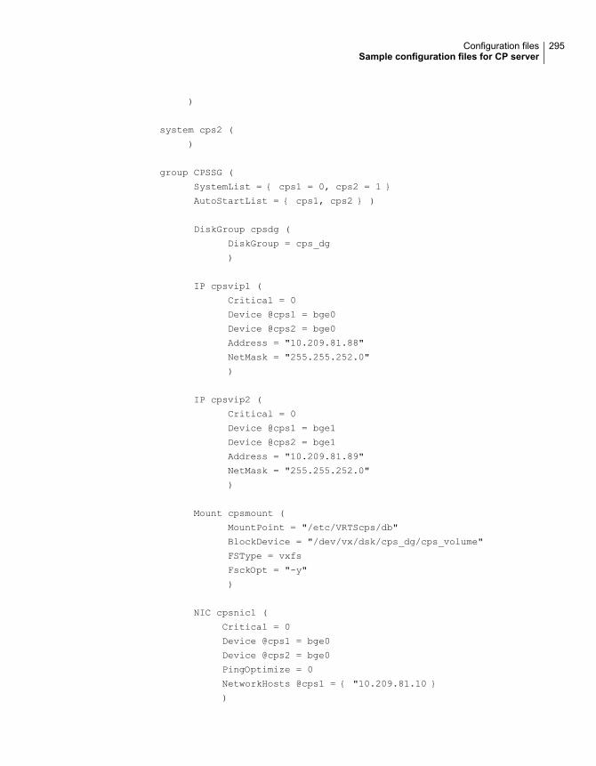
)
system cps2 (
)
group CPSSG (
SystemList = { cps1 = 0, cps2 = 1 }
AutoStartList = { cps1, cps2 } )
DiskGroup cpsdg (
DiskGroup = cps_dg
)
IP cpsvip1 (
Critical = 0
Device @cps1 = bge0
Device @cps2 = bge0
Address = "10.209.81.88"
NetMask = "255.255.252.0"
)
IP cpsvip2 (
Critical = 0
Device @cps1 = bge1
Device @cps2 = bge1
Address = "10.209.81.89"
NetMask = "255.255.252.0"
)
Mount cpsmount (
MountPoint = "/etc/VRTScps/db"
BlockDevice = "/dev/vx/dsk/cps_dg/cps_volume"
FSType = vxfs
FsckOpt = "-y"
)
NIC cpsnic1 (
Critical = 0
Device @cps1 = bge0
Device @cps2 = bge0
PingOptimize = 0
NetworkHosts @cps1 = { "10.209.81.10 }
)
295Configuration filesSample configuration files for CP server

NIC cpsnic2 (
Critical = 0
Device @cps1 = bge1
Device @cps2 = bge1
PingOptimize = 0
)
Process vxcpserv (
PathName = "/opt/VRTScps/bin/vxcpserv"
)
Quorum quorum (
QuorumResources = { cpsvip1, cpsvip2 }
)
Volume cpsvol (
Volume = cps_volume
DiskGroup = cps_dg
)
cpsmount requires cpsvol
cpsvip1 requires cpsnic1
cpsvip2 requires cpsnic2
cpsvol requires cpsdg
vxcpserv requires cpsmount
vxcpserv requires quorum
// resource dependency tree
//
// group CPSSG
// {
// IP cpsvip1
// {
// NIC cpsnic1
// }
// IP cpsvip2
// {
// NIC cpsnic2
// }
// Process vxcpserv
// {
296Configuration filesSample configuration files for CP server

// Quorum quorum
// Mount cpsmount
// {
// Volume cpsvol
// {
// DiskGroup cpsdg
// }
// }
// }
// }
Sample CP server configuration (/etc/vxcps.conf) file outputThe following is an example of a coordination point server (CP server) configurationfile /etc/vxcps.conf output.
## The vxcps.conf file determines the
## configuration for Veritas CP Server.
cps_name=cps1
vip=[10.209.81.88]
vip=[10.209.81.89]:56789
vip_https=[10.209.81.88]:55443
vip_https=[10.209.81.89]
port=14250
port_https=443
security=1
db=/etc/VRTScps/db
ssl_conf_file=/etc/vxcps_ssl.properties
Packaging related SMF services on Solaris 11After installing packages on Solaris 11 system, the following SMF services arepresent in online state. These SMF services are meant for proper package operationduring uninstall operation. Veritas recommends you to not disable these services.
svc:/system/gab-preremove:default
svc:/system/llt-preremove:default
svc:/system/vxfen-preremove:default
297Configuration filesPackaging related SMF services on Solaris 11

Tuning LLT variables for FSS environmentsIn an FSS environment, you can improve application IO performance and alsoimprove memory consumption by tuning a LLT variable. The settings are differentfor LLT communication over RDMA supported hardware and LLT over Ethernetsupported hardware.
Tuning LLT variables for Ethernet linksPerform the steps below to tune LLT variables for Ethernet links.
1 Append the /etc/llttab file with the following values.
set-flow highwater:10000
set-flow lowwater:8000
set-flow window:5000
set-flow rporthighwater:10000
set-flow rportlowwater:8000
2 Verify whether the LLT file is updated.
# lltconfig -F query
3 Restart the SFCFS or SFCFSHA stack for changes to take effect.
298Configuration filesTuning LLT variables for FSS environments

Configuring LLT over UDPThis appendix includes the following topics:
■ Using the UDP layer for LLT
■ Manually configuring LLT over UDP using IPv4
■ Manually configuring LLT over UDP using IPv6
■ LLT over UDP sample /etc/llttab
Using the UDP layer for LLTVCS provides the option of using LLT over the UDP (User Datagram Protocol) layerfor clusters using wide-area networks and routers. UDP makes LLT packets routableand thus able to span longer distances more economically.
When to use LLT over UDPUse LLT over UDP in the following situations:
■ LLT must be used over WANs
■ When hardware, such as blade servers, do not support LLT over Ethernet
LLT over UDP is slower than LLT over Ethernet. Use LLT over UDP only when thehardware configuration makes it necessary.
Manually configuring LLT over UDP using IPv4The following checklist is to configure LLT over UDP:
■ Make sure that the LLT private links are on separate subnets. Set the broadcastaddress in /etc/llttab explicitly depending on the subnet for each link.
CAppendix

See “Broadcast address in the /etc/llttab file” on page 300.
■ Make sure that each NIC has an IP address that is configured before configuringLLT.
■ Make sure the IP addresses in the /etc/llttab files are consistent with the IPaddresses of the network interfaces.
■ Make sure that each link has a unique not well-known UDP port.See “Selecting UDP ports” on page 302.
■ Set the broadcast address correctly for direct-attached (non-routed) links.See “Sample configuration: direct-attached links” on page 304.
■ For the links that cross an IP router, disable broadcast features and specify theIP address of each link manually in the /etc/llttab file.See “Sample configuration: links crossing IP routers” on page 306.
Broadcast address in the /etc/llttab fileThe broadcast address is set explicitly for each link in the following example.
■ Display the content of the /etc/llttab file on the first node sys1:
sys1 # cat /etc/llttab
set-node sys1
set-cluster 1
link link1 /dev/udp - udp 50000 - 192.168.9.1 192.168.9.255
link link2 /dev/udp - udp 50001 - 192.168.10.1 192.168.10.255
Verify the subnet mask using the ifconfig command to ensure that the two linksare on separate subnets.
■ Display the content of the /etc/llttab file on the second node sys2:
sys2 # cat /etc/llttab
set-node sys2
set-cluster 1
link link1 /dev/udp - udp 50000 - 192.168.9.2 192.168.9.255
link link2 /dev/udp - udp 50001 - 192.168.10.2 192.168.10.255
Verify the subnet mask using the ifconfig command to ensure that the two linksare on separate subnets.
300Configuring LLT over UDPManually configuring LLT over UDP using IPv4

The link command in the /etc/llttab fileReview the link command information in this section for the /etc/llttab file. See thefollowing information for sample configurations:
■ See “Sample configuration: direct-attached links” on page 304.
■ See “Sample configuration: links crossing IP routers” on page 306.
Table C-1 describes the fields of the link command that are shown in the /etc/llttabfile examples. Note that some of the fields differ from the command for standardLLT links.
Table C-1 Field description for link command in /etc/llttab
DescriptionField
A unique string that is used as a tag by LLT; for example link1,link2,....
tag-name
The device path of the UDP protocol; for example /dev/udp.device
Nodes using the link. "-" indicates all cluster nodes are to beconfigured for this link.
node-range
Type of link; must be "udp" for LLT over UDP.link-type
Unique UDP port in the range of 49152-65535 for the link.
See “Selecting UDP ports” on page 302.
udp-port
"-" is the default, which has a value of 8192. The value may beincreased or decreased depending on the configuration. Use thelltstat -l command to display the current value.
MTU
IP address of the link on the local node.IP address
■ For clusters with enabled broadcasts, specify the value of thesubnet broadcast address.
■ "-" is the default for clusters spanning routers.
bcast-address
The set-addr command in the /etc/llttab fileThe set-addr command in the /etc/llttab file is required when the broadcast featureof LLT is disabled, such as when LLT must cross IP routers.
See “Sample configuration: links crossing IP routers” on page 306.
Table C-2 describes the fields of the set-addr command.
301Configuring LLT over UDPManually configuring LLT over UDP using IPv4

Table C-2 Field description for set-addr command in /etc/llttab
DescriptionField
The node ID of the peer node; for example, 0.node-id
The string that LLT uses to identify the link; for example link1,link2,....
link tag-name
IP address assigned to the link for the peer node.address
Selecting UDP portsWhen you select a UDP port, select an available 16-bit integer from the range thatfollows:
■ Use available ports in the private range 49152 to 65535
■ Do not use the following ports:
■ Ports from the range of well-known ports, 0 to 1023
■ Ports from the range of registered ports, 1024 to 49151
To check which ports are defined as defaults for a node, examine the file/etc/services. You should also use the netstat command to list the UDP portscurrently in use. For example:
# netstat -a | more
UDP
Local Address Remote Address State
-------------------- -------------------- -------
*.sunrpc Idle
*.* Unbound
*.32771 Idle
*.32776 Idle
*.32777 Idle
*.name Idle
*.biff Idle
*.talk Idle
*.32779 Idle
.
.
.
*.55098 Idle
*.syslog Idle
302Configuring LLT over UDPManually configuring LLT over UDP using IPv4

*.58702 Idle
*.* Unbound
Look in the UDP section of the output; the UDP ports that are listed under LocalAddress are already in use. If a port is listed in the /etc/services file, its associatedname is displayed rather than the port number in the output.
Configuring the netmask for LLTFor nodes on different subnets, set the netmask so that the nodes can access thesubnets in use. Run the following command and answer the prompt to set thenetmask:
# ifconfig interface_name netmask netmask
For example:
■ For the first network interface on the node sys1:
IP address=192.168.9.1, Broadcast address=192.168.9.255,
Netmask=255.255.255.0
For the first network interface on the node sys2:
IP address=192.168.9.2, Broadcast address=192.168.9.255,
Netmask=255.255.255.0
■ For the second network interface on the node sys1:
IP address=192.168.10.1, Broadcast address=192.168.10.255,
Netmask=255.255.255.0
For the second network interface on the node sys2:
IP address=192.168.10.2, Broadcast address=192.168.10.255,
Netmask=255.255.255.0
Configuring the broadcast address for LLTFor nodes on different subnets, set the broadcast address in /etc/llttab dependingon the subnet that the links are on.
An example of a typical /etc/llttab file when nodes are on different subnets. Notethe explicitly set broadcast address for each link.
303Configuring LLT over UDPManually configuring LLT over UDP using IPv4
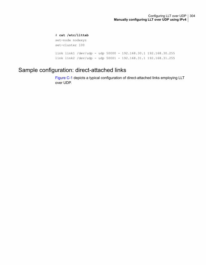
# cat /etc/llttab
set-node nodexyz
set-cluster 100
link link1 /dev/udp - udp 50000 - 192.168.30.1 192.168.30.255
link link2 /dev/udp - udp 50001 - 192.168.31.1 192.168.31.255
Sample configuration: direct-attached linksFigure C-1 depicts a typical configuration of direct-attached links employing LLTover UDP.
304Configuring LLT over UDPManually configuring LLT over UDP using IPv4

Figure C-1 A typical configuration of direct-attached links that use LLT overUDP
UDP Endpoint qfe1UDP Port = 50001IP = 192.1.3.1Link Tag = link2
UDP Endpoint qfe0UDP Port = 50000IP = 192.1.2.1Link Tag = link1
qfe1192.1.3.2Link Tag = link2
qfe0192.1.2.2Link Tag = link1
Switches
Node0 Node1Solaris SPARC
Solaris x64UDP Endpoint e1000g1UDP Port = 50001IP = 192.1.3.1Link Tag = link2
UDP Endpoint e1000g0UDP Port = 50000IP = 192.1.2.1Link Tag = link1
e1000g1192.1.3.2Link Tag = link2
e1000g0192.1.2.2Link Tag = link1
Switches
Node0 Node1
The configuration that the /etc/llttab file for Node 0 represents has directly attachedcrossover links. It might also have the links that are connected through a hub orswitch. These links do not cross routers.
LLT sends broadcast requests to peer nodes to discover their addresses. So theaddresses of peer nodes do not need to be specified in the /etc/llttab file using theset-addr command. For direct attached links, you do need to set the broadcast
305Configuring LLT over UDPManually configuring LLT over UDP using IPv4

address of the links in the /etc/llttab file. Verify that the IP addresses and broadcastaddresses are set correctly by using the ifconfig -a command.
set-node Node0
set-cluster 1
#configure Links
#link tag-name device node-range link-type udp port MTU \
IP-address bcast-address
link link1 /dev/udp - udp 50000 - 192.1.2.1 192.1.2.255
link link2 /dev/udp - udp 50001 - 192.1.3.1 192.1.3.255
The file for Node 1 resembles:
set-node Node1
set-cluster 1
#configure Links
#link tag-name device node-range link-type udp port MTU \
IP-address bcast-address
link link1 /dev/udp - udp 50000 - 192.1.2.2 192.1.2.255
link link2 /dev/udp - udp 50001 - 192.1.3.2 192.1.3.255
Sample configuration: links crossing IP routersFigure C-2 depicts a typical configuration of links crossing an IP router employingLLT over UDP. The illustration shows two nodes of a four-node cluster.
306Configuring LLT over UDPManually configuring LLT over UDP using IPv4
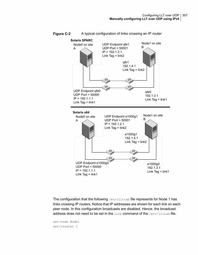
Figure C-2 A typical configuration of links crossing an IP router
UDP Endpoint qfe1UDP Port = 50001IP = 192.1.2.1Link Tag = link2
UDP Endpoint qfe0UDP Port = 50000IP = 192.1.1.1Link Tag = link1
qfe1192.1.4.1Link Tag = link2
qfe0192.1.3.1Link Tag = link1
Node0 on siteA
Node1 on siteB
Solaris SPARC
Solaris x64UDP Endpoint e1000g1UDP Port = 50001IP = 192.1.2.1Link Tag = link2
UDP Endpoint e1000g0UDP Port = 50000IP = 192.1.1.1Link Tag = link1
e1000g1192.1.4.1Link Tag = link2
e1000g0192.1.3.1Link Tag = link1
Node0 on siteA
Node1 on siteB
The configuration that the following /etc/llttab file represents for Node 1 haslinks crossing IP routers. Notice that IP addresses are shown for each link on eachpeer node. In this configuration broadcasts are disabled. Hence, the broadcastaddress does not need to be set in the link command of the /etc/llttab file.
set-node Node1
set-cluster 1
307Configuring LLT over UDPManually configuring LLT over UDP using IPv4

link link1 /dev/udp - udp 50000 - 192.1.3.1 -
link link2 /dev/udp - udp 50001 - 192.1.4.1 -
#set address of each link for all peer nodes in the cluster
#format: set-addr node-id link tag-name address
set-addr 0 link1 192.1.1.1
set-addr 0 link2 192.1.2.1
set-addr 2 link1 192.1.5.2
set-addr 2 link2 192.1.6.2
set-addr 3 link1 192.1.7.3
set-addr 3 link2 192.1.8.3
#disable LLT broadcasts
set-bcasthb 0
set-arp 0
The /etc/llttab file on Node 0 resembles:
set-node Node0
set-cluster 1
link link1 /dev/udp - udp 50000 - 192.1.1.1 -
link link2 /dev/udp - udp 50001 - 192.1.2.1 -
#set address of each link for all peer nodes in the cluster
#format: set-addr node-id link tag-name address
set-addr 1 link1 192.1.3.1
set-addr 1 link2 192.1.4.1
set-addr 2 link1 192.1.5.2
set-addr 2 link2 192.1.6.2
set-addr 3 link1 192.1.7.3
set-addr 3 link2 192.1.8.3
#disable LLT broadcasts
set-bcasthb 0
set-arp 0
Manually configuring LLT over UDP using IPv6The following checklist is to configure LLT over UDP:
■ For UDP6, the multicast address is set to "-".
308Configuring LLT over UDPManually configuring LLT over UDP using IPv6

■ Make sure that each NIC has an IPv6 address that is configured beforeconfiguring LLT.
■ Make sure the IPv6 addresses in the /etc/llttab files are consistent with the IPv6addresses of the network interfaces.
■ Make sure that each link has a unique not well-known UDP port.See “Selecting UDP ports” on page 310.
■ For the links that cross an IP router, disable multicast features and specify theIPv6 address of each link manually in the /etc/llttab file.See “Sample configuration: links crossing IP routers” on page 313.
The link command in the /etc/llttab fileReview the link command information in this section for the /etc/llttab file. See thefollowing information for sample configurations:
■ See “Sample configuration: direct-attached links” on page 311.
■ See “Sample configuration: links crossing IP routers” on page 313.
Note that some of the fields in Table C-3 differ from the command for standard LLTlinks.
Table C-3 describes the fields of the link command that are shown in the /etc/llttabfile examples.
Table C-3 Field description for link command in /etc/llttab
DescriptionField
A unique string that is used as a tag by LLT; for example link1,link2,....
tag-name
The device path of the UDP protocol; for example /dev/udp6.device
Nodes using the link. "-" indicates all cluster nodes are to beconfigured for this link.
node-range
Type of link; must be "udp6" for LLT over UDP.link-type
Unique UDP port in the range of 49152-65535 for the link.
See “Selecting UDP ports” on page 310.
udp-port
"-" is the default, which has a value of 8192. The value may beincreased or decreased depending on the configuration. Use thelltstat -l command to display the current value.
MTU
IPv6 address of the link on the local node.IPv6 address
309Configuring LLT over UDPManually configuring LLT over UDP using IPv6

Table C-3 Field description for link command in /etc/llttab (continued)
DescriptionField
"-" is the default for clusters spanning routers.mcast-address
The set-addr command in the /etc/llttab fileThe set-addr command in the /etc/llttab file is required when the multicast featureof LLT is disabled, such as when LLT must cross IP routers.
See “Sample configuration: links crossing IP routers” on page 313.
Table C-4 describes the fields of the set-addr command.
Table C-4 Field description for set-addr command in /etc/llttab
DescriptionField
The ID of the peer node; for example, 0.node-id
The string that LLT uses to identify the link; for example link1,link2,....
link tag-name
IPv6 address assigned to the link for the peer node.address
Selecting UDP portsWhen you select a UDP port, select an available 16-bit integer from the range thatfollows:
■ Use available ports in the private range 49152 to 65535
■ Do not use the following ports:
■ Ports from the range of well-known ports, 0 to 1023
■ Ports from the range of registered ports, 1024 to 49151
To check which ports are defined as defaults for a node, examine the file/etc/services. You should also use the netstat command to list the UDP portscurrently in use. For example:
# netstat -a | more
UDP: IPv4
Local Address Remote Address State
-------------------- -------------------- ----------
*.sunrpc Idle
310Configuring LLT over UDPManually configuring LLT over UDP using IPv6

*.* Unbound
*.32772 Idle
*.* Unbound
*.32773 Idle
*.lockd Idle
*.32777 Idle
*.32778 Idle
*.32779 Idle
*.32780 Idle
*.servicetag Idle
*.syslog Idle
*.16161 Idle
*.32789 Idle
*.177 Idle
*.32792 Idle
*.32798 Idle
*.snmpd Idle
*.32802 Idle
*.* Unbound
*.* Unbound
*.* Unbound
UDP: IPv6
Local Address Remote Address State If
------------------------- ------------------------- ---------- -----
*.servicetag Idle
*.177 Idle
Look in the UDP section of the output; the UDP ports that are listed under LocalAddress are already in use. If a port is listed in the /etc/services file, its associatedname is displayed rather than the port number in the output.
Sample configuration: direct-attached linksFigure C-3 depicts a typical configuration of direct-attached links employing LLTover UDP.
311Configuring LLT over UDPManually configuring LLT over UDP using IPv6

Figure C-3 A typical configuration of direct-attached links that use LLT overUDP
UDP Port = 50001IP = fe80::21a:64ff:fe92:1b47Link Tag = link2
UDP Port = 50000IP = fe80::21a:64ff:fe92:1b46Link Tag = link1
fe80::21a:64ff:fe92:1a93Link Tag = link2
fe80::21a:64ff:fe92:1a92Link Tag = link1
Switches
Node0 Node1Solaris SPARC
Solaris x64
UDP Port = 50001IP = fe80::21a:64ff:fe92:1b47Link Tag = link2
UDP Port = 50000IP = fe80::21a:64ff:fe92:1b46Link Tag = link1
fe80::21a:64ff:fe92:1a93Link Tag = link2
fe80::21a:64ff:fe92:1a92Link Tag = link1
Switches
Node0 Node1
The configuration that the /etc/llttab file for Node 0 represents has directly attachedcrossover links. It might also have the links that are connected through a hub orswitch. These links do not cross routers.
LLT uses IPv6 multicast requests for peer node address discovery. So the addressesof peer nodes do not need to be specified in the /etc/llttab file using the set-addr
command. Use the ifconfig -a command to verify that the IPv6 address is setcorrectly.
set-node Node0
set-cluster 1
312Configuring LLT over UDPManually configuring LLT over UDP using IPv6

#configure Links
#link tag-name device node-range link-type udp port MTU \
IP-address mcast-address
link link1 /dev/udp6 - udp6 50000 - fe80::21a:64ff:fe92:1b46 -
link link1 /dev/udp6 - udp6 50001 - fe80::21a:64ff:fe92:1b47 -
The file for Node 1 resembles:
set-node Node1
set-cluster 1
#configure Links
#link tag-name device node-range link-type udp port MTU \
IP-address mcast-address
link link1 /dev/udp6 - udp6 50000 - fe80::21a:64ff:fe92:1a92 -
link link1 /dev/udp6 - udp6 50001 - fe80::21a:64ff:fe92:1a93 -
Sample configuration: links crossing IP routersFigure C-4 depicts a typical configuration of links crossing an IP router employingLLT over UDP. The illustration shows two nodes of a four-node cluster.
313Configuring LLT over UDPManually configuring LLT over UDP using IPv6
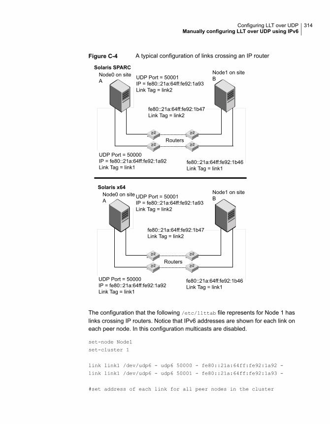
Figure C-4 A typical configuration of links crossing an IP router
UDP Port = 50001IP = fe80::21a:64ff:fe92:1a93Link Tag = link2
UDP Port = 50000IP = fe80::21a:64ff:fe92:1a92Link Tag = link1
fe80::21a:64ff:fe92:1b47Link Tag = link2
fe80::21a:64ff:fe92:1b46Link Tag = link1
Node0 on siteA
Node1 on siteB
Solaris SPARC
Solaris x64
UDP Port = 50001IP = fe80::21a:64ff:fe92:1a93Link Tag = link2
UDP Port = 50000IP = fe80::21a:64ff:fe92:1a92Link Tag = link1
fe80::21a:64ff:fe92:1b47Link Tag = link2
fe80::21a:64ff:fe92:1b46Link Tag = link1
Node0 on siteA
Node1 on siteB
Routers
Routers
The configuration that the following /etc/llttab file represents for Node 1 haslinks crossing IP routers. Notice that IPv6 addresses are shown for each link oneach peer node. In this configuration multicasts are disabled.
set-node Node1
set-cluster 1
link link1 /dev/udp6 - udp6 50000 - fe80::21a:64ff:fe92:1a92 -
link link1 /dev/udp6 - udp6 50001 - fe80::21a:64ff:fe92:1a93 -
#set address of each link for all peer nodes in the cluster
314Configuring LLT over UDPManually configuring LLT over UDP using IPv6
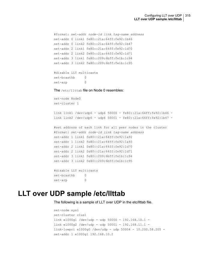
#format: set-addr node-id link tag-name address
set-addr 0 link1 fe80::21a:64ff:fe92:1b46
set-addr 0 link2 fe80::21a:64ff:fe92:1b47
set-addr 2 link1 fe80::21a:64ff:fe92:1d70
set-addr 2 link2 fe80::21a:64ff:fe92:1d71
set-addr 3 link1 fe80::209:6bff:fe1b:1c94
set-addr 3 link2 fe80::209:6bff:fe1b:1c95
#disable LLT multicasts
set-bcasthb 0
set-arp 0
The /etc/llttab file on Node 0 resembles:
set-node Node0
set-cluster 1
link link1 /dev/udp6 - udp6 50000 - fe80::21a:64ff:fe92:1b46 -
link link2 /dev/udp6 - udp6 50001 - fe80::21a:64ff:fe92:1b47 -
#set address of each link for all peer nodes in the cluster
#format: set-addr node-id link tag-name address
set-addr 1 link1 fe80::21a:64ff:fe92:1a92
set-addr 1 link2 fe80::21a:64ff:fe92:1a93
set-addr 2 link1 fe80::21a:64ff:fe92:1d70
set-addr 2 link2 fe80::21a:64ff:fe92:1d71
set-addr 3 link1 fe80::209:6bff:fe1b:1c94
set-addr 3 link2 fe80::209:6bff:fe1b:1c95
#disable LLT multicasts
set-bcasthb 0
set-arp 0
LLT over UDP sample /etc/llttabThe following is a sample of LLT over UDP in the etc/llttab file.
set-node sys1
set-cluster clus1
link e1000g1 /dev/udp - udp 50000 - 192.168.10.1 -
link e1000g2 /dev/udp - udp 50001 - 192.168.11.1 -
link-lowpri e1000g0 /dev/udp - udp 50004 - 10.200.58.205 -
set-addr 1 e1000g1 192.168.10.2
315Configuring LLT over UDPLLT over UDP sample /etc/llttab

set-addr 1 e1000g2 192.168.11.2
set-addr 1 e1000g0 10.200.58.206
set-bcasthb 0
set-arp 0
316Configuring LLT over UDPLLT over UDP sample /etc/llttab

Configuring the secureshell or the remote shellfor communications
This appendix includes the following topics:
■ About configuring secure shell or remote shell communication modes beforeinstalling products
■ Manually configuring passwordless ssh
■ Setting up ssh and rsh connection using the installer -comsetup command
■ Setting up ssh and rsh connection using the pwdutil.pl utility
■ Restarting the ssh session
■ Enabling and disabling rsh for Solaris
About configuring secure shell or remote shellcommunicationmodes before installing products
Establishing communication between nodes is required to install Veritas InfoScalesoftware from a remote system, or to install and configure a system. The systemfrom which the installer is run must have permissions to run rsh (remote shell) orssh (secure shell) utilities. You need to run the installer with superuser privilegeson the systems where you plan to install the Veritas InfoScale software.
You can install products to remote systems using either secure shell (ssh) or remoteshell (rsh). Veritas recommends that you use ssh as it is more secure than rsh.
DAppendix

You can set up ssh and rsh connections in many ways.
■ You can manually set up the ssh and rsh connection with UNIX shell commands.
■ You can run the installer -comsetup command to interactively set up sshand rsh connection.
■ You can run the password utility, pwdutil.pl.
This section contains an example of how to set up ssh password free communication.The example sets up ssh between a source system (sys1) that contains theinstallation directories, and a target system (sys2). This procedure also applies tomultiple target systems.
Note: The product installer supports establishing passwordless communication.
Manually configuring passwordless sshThe ssh program enables you to log into and execute commands on a remotesystem. ssh enables encrypted communications and an authentication processbetween two untrusted hosts over an insecure network.
In this procedure, you first create a DSA key pair. From the key pair, you appendthe public key from the source system to the authorized_keys file on the targetsystems.
Read the ssh documentation and online manual pages before enabling ssh. Contactyour operating system support provider for issues regarding ssh configuration.
Visit the Openssh website that is located at: http://www.openssh.com/ to accessonline manuals and other resources.
318Configuring the secure shell or the remote shell for communicationsManually configuring passwordless ssh

To create the DSA key pair
1 On the source system (sys1), log in as root, and navigate to the root directory.
sys1 # cd /
2 Make sure the /.ssh directory is on all the target installation systems (sys2 inthis example). If that directory is not present, create it on all the target systemsand set the write permission to root only:
Solaris 10:
sys2 # mkdir /.ssh
Solaris 11:
sys2 # mkdir /root/.ssh
Change the permissions of this directory, to secure it.
Solaris 10:
sys2 # chmod go-w /.ssh
Solaris 11:
sys2 # chmod go-w /root/.ssh
3 To generate a DSA key pair on the source system, type the following command:
sys1 # ssh-keygen -t dsa
System output similar to the following is displayed:
Generating public/private dsa key pair.
Enter file in which to save the key (//.ssh/id_dsa):
For Solaris 11:
Your identification has been saved in /root/.ssh/id_dsa.
Your public key has been saved in /root/.ssh/id_dsa.pub.
319Configuring the secure shell or the remote shell for communicationsManually configuring passwordless ssh
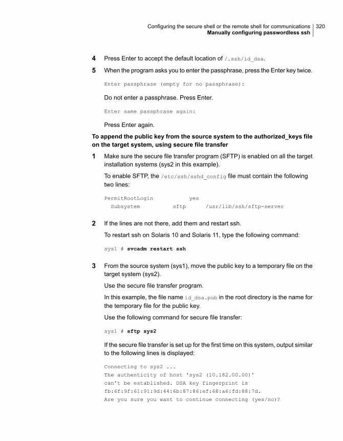
4 Press Enter to accept the default location of /.ssh/id_dsa.
5 When the program asks you to enter the passphrase, press the Enter key twice.
Enter passphrase (empty for no passphrase):
Do not enter a passphrase. Press Enter.
Enter same passphrase again:
Press Enter again.
To append the public key from the source system to the authorized_keys fileon the target system, using secure file transfer
1 Make sure the secure file transfer program (SFTP) is enabled on all the targetinstallation systems (sys2 in this example).
To enable SFTP, the /etc/ssh/sshd_config file must contain the followingtwo lines:
PermitRootLogin yes
Subsystem sftp /usr/lib/ssh/sftp-server
2 If the lines are not there, add them and restart ssh.
To restart ssh on Solaris 10 and Solaris 11, type the following command:
sys1 # svcadm restart ssh
3 From the source system (sys1), move the public key to a temporary file on thetarget system (sys2).
Use the secure file transfer program.
In this example, the file name id_dsa.pub in the root directory is the name forthe temporary file for the public key.
Use the following command for secure file transfer:
sys1 # sftp sys2
If the secure file transfer is set up for the first time on this system, output similarto the following lines is displayed:
Connecting to sys2 ...
The authenticity of host 'sys2 (10.182.00.00)'
can't be established. DSA key fingerprint is
fb:6f:9f:61:91:9d:44:6b:87:86:ef:68:a6:fd:88:7d.
Are you sure you want to continue connecting (yes/no)?
320Configuring the secure shell or the remote shell for communicationsManually configuring passwordless ssh

4 Enter yes.
Output similar to the following is displayed:
Warning: Permanently added 'sys2,10.182.00.00'
(DSA) to the list of known hosts.
root@sys2 password:
5 Enter the root password of sys2.
6 At the sftp prompt, type the following command:
sftp> put /.ssh/id_dsa.pub
The following output is displayed:
Uploading /.ssh/id_dsa.pub to /id_dsa.pub
7 To quit the SFTP session, type the following command:
sftp> quit
8 To begin the ssh session on the target system (sys2 in this example), type thefollowing command on sys1:
sys1 # ssh sys2
Enter the root password of sys2 at the prompt:
password:
9 After you log in to sys2, enter the following command to append the id_dsa.pub
file to the authorized_keys file:
sys2 # cat /id_dsa.pub >> /.ssh/authorized_keys
10 After the id_dsa.pub public key file is copied to the target system (sys2), andadded to the authorized keys file, delete it. To delete the id_dsa.pub publickey file, enter the following command on sys2:
sys2 # rm /id_dsa.pub
321Configuring the secure shell or the remote shell for communicationsManually configuring passwordless ssh

11 To log out of the ssh session, enter the following command:
sys2 # exit
12 Run the following commands on the source installation system. If your sshsession has expired or terminated, you can also run these commands to renewthe session. These commands bring the private key into the shell environmentand make the key globally available to the user root:
sys1 # exec /usr/bin/ssh-agent $SHELL
sys1 # ssh-add
Identity added: //.ssh/id_dsa
This shell-specific step is valid only while the shell is active. You must executethe procedure again if you close the shell during the session.
To verify that you can connect to a target system
1 On the source system (sys1), enter the following command:
sys1 # ssh -l root sys2 uname -a
where sys2 is the name of the target system.
2 The command should execute from the source system (sys1) to the targetsystem (sys2) without the system requesting a passphrase or password.
3 Repeat this procedure for each target system.
Setting up ssh and rsh connection using theinstaller -comsetup command
You can interactively set up the ssh and rsh connections using the installer
-comsetup command.
Enter the following:
# ./installer -comsetup
Input the name of the systems to set up communication:
Enter the <platform> system names separated by spaces:
[q,?] sys2
Set up communication for the system sys2:
Checking communication on sys2 ................... Failed
322Configuring the secure shell or the remote shell for communicationsSetting up ssh and rsh connection using the installer -comsetup command

CPI ERROR V-9-20-1303 ssh permission was denied on sys2. rsh
permission was denied on sys2. Either ssh or rsh is required
to be set up and ensure that it is working properly between the local
node and sys2 for communication
Either ssh or rsh needs to be set up between the local system and
sys2 for communication
Would you like the installer to setup ssh or rsh communication
automatically between the systems?
Superuser passwords for the systems will be asked. [y,n,q,?] (y) y
Enter the superuser password for system sys2:
1) Setup ssh between the systems
2) Setup rsh between the systems
b) Back to previous menu
Select the communication method [1-2,b,q,?] (1) 1
Setting up communication between systems. Please wait.
Re-verifying systems.
Checking communication on sys2 ..................... Done
Successfully set up communication for the system sys2
Setting up ssh and rsh connection using thepwdutil.pl utility
The password utility, pwdutil.pl, is bundled under the scripts directory. Theusers can run the utility in their script to set up the ssh and rsh connectionautomatically.
# ./pwdutil.pl -h
Usage:
Command syntax with simple format:
pwdutil.pl check|configure|unconfigure ssh|rsh <hostname|IP addr>
[<user>] [<password>] [<port>]
323Configuring the secure shell or the remote shell for communicationsSetting up ssh and rsh connection using the pwdutil.pl utility
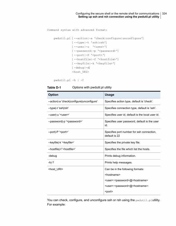
Command syntax with advanced format:
pwdutil.pl [--action|-a 'check|configure|unconfigure']
[--type|-t 'ssh|rsh']
[--user|-u '<user>']
[--password|-p '<password>']
[--port|-P '<port>']
[--hostfile|-f '<hostfile>']
[--keyfile|-k '<keyfile>']
[-debug|-d]
<host_URI>
pwdutil.pl -h | -?
Table D-1 Options with pwdutil.pl utility
UsageOption
Specifies action type, default is 'check'.--action|-a 'check|configure|unconfigure'
Specifies connection type, default is 'ssh'.--type|-t 'ssh|rsh'
Specifies user id, default is the local user id.--user|-u '<user>'
Specifies user password, default is the userid.
--password|-p '<password>'
Specifies port number for ssh connection,default is 22
--port|-P '<port>'
Specifies the private key file.--keyfile|-k '<keyfile>'
Specifies the file which list the hosts.--hostfile|-f '<hostfile>'
Prints debug information.-debug
Prints help messages.-h|-?
Can be in the following formats:
<hostname>
<user>:<password>@<hostname>
<user>:<password>@<hostname>:
<port>
<host_URI>
You can check, configure, and unconfigure ssh or rsh using the pwdutil.plutility.For example:
324Configuring the secure shell or the remote shell for communicationsSetting up ssh and rsh connection using the pwdutil.pl utility

■ To check ssh connection for only one host:
pwdutil.pl check ssh hostname
■ To configure ssh for only one host:
pwdutil.pl configure ssh hostname user password
■ To unconfigure rsh for only one host:
pwdutil.pl unconfigure rsh hostname
■ To configure ssh for multiple hosts with same user ID and password:
pwdutil.pl -a configure -t ssh -u user -p password hostname1
hostname2 hostname3
■ To configure ssh or rsh for different hosts with different user ID and password:
pwdutil.pl -a configure -t ssh user1:password1@hostname1
user2:password2@hostname2
■ To check or configure ssh or rsh for multiple hosts with one configuration file:
pwdutil.pl -a configure -t ssh --hostfile /tmp/sshrsh_hostfile
■ To keep the host configuration file secret, you can use the 3rd party utility toencrypt and decrypt the host file with password.For example:
### run openssl to encrypt the host file in base64 format
# openssl aes-256-cbc -a -salt -in /hostfile -out /hostfile.enc
enter aes-256-cbc encryption password: <password>
Verifying - enter aes-256-cbc encryption password: <password>
### remove the original plain text file
# rm /hostfile
### run openssl to decrypt the encrypted host file
# pwdutil.pl -a configure -t ssh `openssl aes-256-cbc -d -a
-in /hostfile.enc`
enter aes-256-cbc decryption password: <password>
325Configuring the secure shell or the remote shell for communicationsSetting up ssh and rsh connection using the pwdutil.pl utility

■ To use the ssh authentication keys which are not under the default $HOME/.sshdirectory, you can use --keyfile option to specify the ssh keys. For example:
### create a directory to host the key pairs:
# mkdir /keystore
### generate private and public key pair under the directory:
# ssh-keygen -t rsa -f /keystore/id_rsa
### setup ssh connection with the new generated key pair under
the directory:
# pwdutil.pl -a configure -t ssh --keyfile /keystore/id_rsa
user:password@hostname
You can see the contents of the configuration file by using the following command:
# cat /tmp/sshrsh_hostfile
user1:password1@hostname1
user2:password2@hostname2
user3:password3@hostname3
user4:password4@hostname4
# all default: check ssh connection with local user
hostname5
The following exit values are returned:
0 Successful completion.
1 Command syntax error.
2 Ssh or rsh binaries do not exist.
3 Ssh or rsh service is down on the remote machine.
4 Ssh or rsh command execution is denied due to password is required.
5 Invalid password is provided.
255 Other unknown error.
Restarting the ssh sessionAfter you complete this procedure, ssh can be restarted in any of the followingscenarios:
■ After a terminal session is closed
■ After a new terminal session is opened
■ After a system is restarted
326Configuring the secure shell or the remote shell for communicationsRestarting the ssh session

■ After too much time has elapsed, to refresh ssh
To restart ssh
1 On the source installation system (sys1), bring the private key into the shellenvironment.
sys1 # exec /usr/bin/ssh-agent $SHELL
2 Make the key globally available for the user root
sys1 # ssh-add
Enabling and disabling rsh for SolarisThe following section describes how to enable remote shell on Solaris system.
Veritas recommends configuring a secure shell environment for Veritas InfoScaleproduct installations.
See “Manually configuring passwordless ssh” on page 318.
See the operating system documentation for more information on configuring remoteshell.
To enable rsh
1 To determine the current status of rsh and rlogin, type the following command:
# inetadm | grep -i login
If the service is enabled, the following line is displayed:
enabled online svc:/network/login:rlogin
If the service is not enabled, the following line is displayed:
disabled disabled svc:/network/login:rlogin
2 To enable a disabled rsh/rlogin service, type the following command:
# inetadm -e rlogin
3 To disable an enabled rsh/rlogin service, type the following command:
# inetadm -d rlogin
327Configuring the secure shell or the remote shell for communicationsEnabling and disabling rsh for Solaris

4 Modify the .rhosts file. A separate .rhosts file is in the $HOME directory ofeach user. This file must be modified for each user who remotely accessesthe system using rsh. Each line of the .rhosts file contains a fully qualifieddomain name or IP address for each remote system having access to the localsystem. For example, if the root user must remotely access sys1 from sys2,you must add an entry for sys2.companyname.com in the .rhosts file on sys1.
# echo "sys2.companyname.com" >> $HOME/.rhosts
5 After you complete an installation procedure, delete the .rhosts file from eachuser’s $HOME directory to ensure security:
# rm -f $HOME/.rhosts
328Configuring the secure shell or the remote shell for communicationsEnabling and disabling rsh for Solaris

Installation script optionsThis appendix includes the following topics:
■ Installation script options
Installation script optionsTable E-1 shows command line options for the installation script. For an initial installor upgrade, options are not usually required. The installation script options applyto all Veritas InfoScale product scripts, except where otherwise noted.
Table E-1 Available command line options
FunctionCommand Line Option
Adds a node to a high availability cluster.-addnode
The -ai option is supported on Solaris 11 only,and is used to generate Automated Installationmanifest. This can be used by Solaris AutomatedInstallation Server to install the Veritas InfoScaleproduct, along with the Solaris 11 operationsystem.
-ai
Displays all packages required for the specifiedproduct. The packages are listed in correctinstallation order. The output can be used to createscripts for command line installs, or for installationsover a network.
-allpkgs
EAppendix

Table E-1 Available command line options (continued)
FunctionCommand Line Option
The -comcleanup option removes the secureshell or remote shell configuration added byinstaller on the systems. The option is only requiredwhen installation routines that performedauto-configuration of the shell are abruptlyterminated.
-comcleanup
The -comsetup option is used to set up the sshor rsh communication between systems withoutrequests for passwords or passphrases.
-comsetup
The -configcps option is used to configure CPserver on a running system or cluster.
-configcps
Configures the product after installation.-configure
Disables Dynamic Multi-pathing support for thenative LVM volume groups and ZFS pools duringupgrade. Retaining Dynamic Multi-pathing supportfor the native LVM volume groups and ZFS poolsduring upgrade increases package upgrade timedepending on the number of LUNs and native LVMvolume groups and ZFS pools configured on thesystem.
-disable_dmp_native_support
Configures I/O fencing in a running cluster.-fencing
The -fips option is used to enable or disablesecurity with fips mode on a running VCS cluster.It could only be used together with -security or-securityonenode option.
-fips
Specifies the location of a file that contains a listof hostnames on which to install.
–hostfile full_path_to_file
Used to install products on system-install
Used to perform online upgrade. Using this option,the installer upgrades the whole cluster and alsosupports customer's application zero down timeduring the upgrade procedure. Now this optiononly supports VCS and ApplicationHA.
-online_upgrade
330Installation script optionsInstallation script options
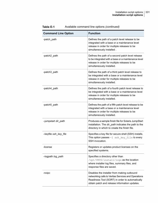
Table E-1 Available command line options (continued)
FunctionCommand Line Option
Defines the path of a patch level release to beintegrated with a base or a maintenance levelrelease in order for multiple releases to besimultaneously installed .
-patch_path
Defines the path of a second patch level releaseto be integrated with a base or a maintenance levelrelease in order for multiple releases to besimultaneously installed.
-patch2_path
Defines the path of a third patch level release tobe integrated with a base or a maintenance levelrelease in order for multiple releases to besimultaneously installed.
-patch3_path
Defines the path of a fourth patch level release tobe integrated with a base or a maintenance levelrelease in order for multiple releases to besimultaneously installed.
-patch4_path
Defines the path of a fifth patch level release to beintegrated with a base or a maintenance levelrelease in order for multiple releases to besimultaneously installed.
-patch5_path
Produces a sample finish file for Solaris JumpStartinstallation. The dir_path indicates the path to thedirectory in which to create the finish file.
–jumpstart dir_path
Specifies a key file for secure shell (SSH) installs.This option passes -I ssh_key_file to everySSH invocation.
–keyfile ssh_key_file
Registers or updates product licenses on thespecified systems.
-license
Specifies a directory other than/opt/VRTS/install/logs as the locationwhere installer log files, summary files, andresponse files are saved.
–logpath log_path
Disables the installer from making outboundnetworking calls to Veritas Services and OperationsReadiness Tool (SORT) in order to automaticallyobtain patch and release information updates.
-noipc
331Installation script optionsInstallation script options

Table E-1 Available command line options (continued)
FunctionCommand Line Option
Allows installation of product packages withoutentering a license key. Licensed features cannotbe configured, started, or used when this option isspecified.
-nolic
Displays product's packages in correct installationorder by group.
-pkgtable
Checks for different HA and file system-relatedprocesses, the availability of different ports, andthe availability of cluster-related service groups.
–postcheck
Performs a preinstallation check to determine ifsystems meet all installation requirements. Veritasrecommends doing a precheck before installing aproduct.
-precheck
Specifies the product for operations.-prod
Specifies the component for operations.-component
Displays progress details without showing theprogress bar.
-redirect
Specifies an installer patch file.-require
Automates installation and configuration by usingsystem and configuration information stored in aspecified file instead of prompting for information.The response_file must be a full path name. Youmust edit the response file to use it for subsequentinstallations. Variable field definitions are definedwithin the file.
–responsefile response_file
Specifies an alternative root directory on which toinstall packages.
On Solaris operating systems, -rootpath passes-R path to pkgadd command.
–rootpath root_path
Specify this option when you want to use RSH andRCP for communication between systems insteadof the default SSH and SCP.
See “About configuring secure shell or remote shellcommunication modes before installing products”on page 317.
-rsh
332Installation script optionsInstallation script options

Table E-1 Available command line options (continued)
FunctionCommand Line Option
The -security option is used to convert a runningVCS cluster between secure and non-securemodes of operation.
-security
The -securityonenode option is used toconfigure a secure cluster node by node.
-securityonenode
The -securitytrust option is used to setuptrust with another broker.
-securitytrust
Specifies that the installation script performs install,uninstall, start, and stop operations on each systemin a serial fashion. If this option is not specified,these operations are performed simultaneously onall systems.
–serial
Specify this option when you want to set tunableparameters after you install and configure aproduct. You may need to restart processes of theproduct for the tunable parameter values to takeeffect. You must use this option together with the-tunablesfile option.
-settunables
Starts the daemons and processes for the specifiedproduct.
-start
Stops the daemons and processes for the specifiedproduct.
-stop
The -timeout option is used to specify thenumber of seconds that the script should wait foreach command to complete before timing out.Setting the -timeout option overrides the defaultvalue of 1200 seconds. Setting the -timeoutoption to 0 prevents the script from timing out. The-timeout option does not work with the -serialoption
-timeout
Specifies a directory other than /var/tmp as theworking directory for the installation scripts. Thisdestination is where initial logging is performedand where packages are copied on remotesystems before installation.
–tmppath tmp_path
333Installation script optionsInstallation script options
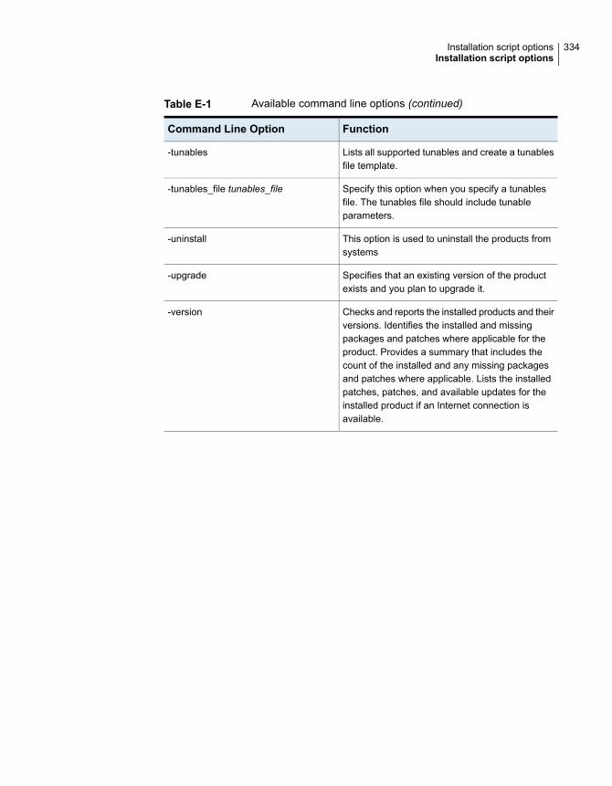
Table E-1 Available command line options (continued)
FunctionCommand Line Option
Lists all supported tunables and create a tunablesfile template.
-tunables
Specify this option when you specify a tunablesfile. The tunables file should include tunableparameters.
-tunables_file tunables_file
This option is used to uninstall the products fromsystems
-uninstall
Specifies that an existing version of the productexists and you plan to upgrade it.
-upgrade
Checks and reports the installed products and theirversions. Identifies the installed and missingpackages and patches where applicable for theproduct. Provides a summary that includes thecount of the installed and any missing packagesand patches where applicable. Lists the installedpatches, patches, and available updates for theinstalled product if an Internet connection isavailable.
-version
334Installation script optionsInstallation script options

Troubleshooting VCSconfiguration
This appendix includes the following topics:
■ Restarting the installer after a failed network connection
■ Cannot launch the cluster view link
■ Starting and stopping processes for the Veritas InfoScale products
■ Installer cannot create UUID for the cluster
■ LLT startup script displays errors
■ The vxfentsthdw utility fails when SCSI TEST UNIT READY command fails
■ Issues during fencing startup on VCS cluster nodes set up for server-basedfencing
Restarting the installer after a failed networkconnection
If an installation is aborted because of a failed network connection, restarting theinstaller will detect the previous installation. The installer prompts to resume theinstallation. If you choose to resume the installation, the installer proceeds from thepoint where the installation aborted. If you choose not to resume, the installationstarts from the beginning.
FAppendix

Cannot launch the cluster view linkIf you launch the cluster view using the URL,https://<hostname_or_ip>:5634/vcs/admin/application_health.html link, the systemresponds with the HTTP 404 NOT FOUND error. This is possible if the xprtldconfiguration has not been set properly. You need to correct the configuration oneach cluster node.
Run the following commands on each cluster node.
# echo 'namespaces vcs=/opt/VRTSvcs/portal/vcs_wizards' >>
/etc/opt/VRTSsfmh/xprtld.conf
# /opt/VRTSsfmh/bin/xprtlc -l \
https://localhost/admin/xprtld/config/namespace/add \
-d namespace=vcs -d document_root="/opt/VRTSvcs/portal/vcs_wizards"
Relaunch the cluster view link.
Starting and stopping processes for the VeritasInfoScale products
After the installation and configuration is complete, the Veritas InfoScale productinstaller starts the processes that the installed products use. You can use the productinstaller to stop or start the processes, if required.
To stop the processes
◆ Use the -stop option to stop the product installation script.
For example, to stop the product's processes, enter the following command:
# ./installer -stop
To start the processes
◆ Use the -start option to start the product installation script.
For example, to start the product's processes, enter the following command:
# ./installer -start
336Troubleshooting VCS configurationCannot launch the cluster view link
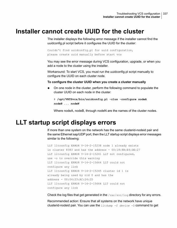
Installer cannot create UUID for the clusterThe installer displays the following error message if the installer cannot find theuuidconfig.pl script before it configures the UUID for the cluster:
Couldn't find uuidconfig.pl for uuid configuration,
please create uuid manually before start vcs
You may see the error message during VCS configuration, upgrade, or when youadd a node to the cluster using the installer.
Workaround: To start VCS, you must run the uuidconfig.pl script manually toconfigure the UUID on each cluster node.
To configure the cluster UUID when you create a cluster manually
◆ On one node in the cluster, perform the following command to populate thecluster UUID on each node in the cluster.
# /opt/VRTSvcs/bin/uuidconfig.pl -clus -configure nodeA
nodeB ... nodeN
Where nodeA, nodeB, through nodeN are the names of the cluster nodes.
LLT startup script displays errorsIf more than one system on the network has the same clusterid-nodeid pair andthe same Ethernet sap/UDP port, then the LLT startup script displays error messagessimilar to the following:
LLT lltconfig ERROR V-14-2-15238 node 1 already exists
in cluster 8383 and has the address - 00:18:8B:E4:DE:27
LLT lltconfig ERROR V-14-2-15241 LLT not configured,
use -o to override this warning
LLT lltconfig ERROR V-14-2-15664 LLT could not
configure any link
LLT lltconfig ERROR V-14-2-15245 cluster id 1 is
already being used by nid 0 and has the
address - 00:04:23:AC:24:2D
LLT lltconfig ERROR V-14-2-15664 LLT could not
configure any link
Check the log files that get generated in the /var/svc/log directory for any errors.
Recommended action: Ensure that all systems on the network have uniqueclusterid-nodeid pair. You can use the lltdump -f device -D command to get
337Troubleshooting VCS configurationInstaller cannot create UUID for the cluster

the list of unique clusterid-nodeid pairs connected to the network. This utility isavailable only for LLT-over-ethernet.
The vxfentsthdwutility fails when SCSI TESTUNITREADY command fails
While running the vxfentsthdw utility, you may see a message that resembles asfollows:
Issuing SCSI TEST UNIT READY to disk reserved by other node
FAILED.
Contact the storage provider to have the hardware configuration
fixed.
The disk array does not support returning success for a SCSI TEST UNIT READY
command when another host has the disk reserved using SCSI-3 persistentreservations. This happens with the Hitachi Data Systems 99XX arrays if bit 186of the system mode option is not enabled.
Issues during fencing startup on VCS clusternodes set up for server-based fencing
Table F-1 Fencing startup issues on VCS cluster (client cluster) nodes
Description and resolutionIssue
If you receive a connection error message after issuing the cpsadm command on the VCScluster, perform the following actions:
■ Ensure that the CP server is reachable from all the VCS cluster nodes.■ Check the /etc/vxfenmode file and ensure that the VCS cluster nodes use the correct
CP server virtual IP or virtual hostname and the correct port number.■ For HTTPS communication, ensure that the virtual IP and ports listed for the server can
listen to HTTPS requests.
cpsadm command onthe VCS cluster givesconnection error
Authorization failure occurs when the nodes on the client clusters and or users are not addedin the CP server configuration. Therefore, fencing on the VCS cluster (client cluster) nodeis not allowed to access the CP server and register itself on the CP server. Fencing fails tocome up if it fails to register with a majority of the coordination points.
To resolve this issue, add the client cluster node and user in the CP server configurationand restart fencing.
See “Preparing the CP servers manually for use by the VCS cluster” on page 154.
Authorization failure
338Troubleshooting VCS configurationThe vxfentsthdw utility fails when SCSI TEST UNIT READY command fails

Table F-1 Fencing startup issues on VCS cluster (client cluster) nodes(continued)
Description and resolutionIssue
If you had configured secure communication between the CP server and the VCS cluster(client cluster) nodes, authentication failure can occur due to the following causes:
■ The client cluster requires its own private key, a signed certificate, and a CertificationAuthority's (CA) certificate to establish secure communication with the CP server. If anyof the files are missing or corrupt, communication fails.
■ If the client cluster certificate does not correspond to the client's private key,communication fails.
■ If the CP server and client cluster do not have a common CA in their certificate chain oftrust, then communication fails.
Authentication failure
339Troubleshooting VCS configurationIssues during fencing startup on VCS cluster nodes set up for server-based fencing

Sample VCS cluster setupdiagrams for CPserver-based I/O fencing
This appendix includes the following topics:
■ Configuration diagrams for setting up server-based I/O fencing
Configuration diagrams for setting upserver-based I/O fencing
The following CP server configuration diagrams can be used as guides when settingup CP server within your configuration:
■ Two unique client clusters that are served by 3 CP servers:See Figure G-1 on page 341.
■ Client cluster that is served by highly available CP server and 2 SCSI-3 disks:
■ Two node campus cluster that is served be remote CP server and 2 SCSI-3disks:
■ Multiple client clusters that are served by highly available CP server and 2SCSI-3 disks:
Two unique client clusters served by 3 CP serversFigure G-1 displays a configuration where two unique client clusters are beingserved by 3 CP servers (coordination points). Each client cluster has its own uniqueuser ID (UUID1 and UUID2).
GAppendix

In the vxfenmode file on the client nodes, vxfenmode is set to customized withvxfen mechanism set to cps.
Figure G-1 Two unique client clusters served by 3 CP servers
NIC
1
Cluster -1node 1
NIC
2
NIC
1
Cluster-1node 2
NIC
2
Ethernet
SwitchEthernet
Switch
NIC
1
Cluster -2node 1
NIC
2
NIC
1
Cluster-2node 2
NIC
2
Ethernet
SwitchEthernet
Switch
NIC
CP Server 1
Ethernet
Switch
Intranet/InternetPublic network
CP Server 2
NIC
CP Server 3
NIC
NIC 3 NIC 3 NIC 3 NIC 3
VCS clientcluster(UUID1)
SFRAC clientcluster(UUID2)
SinglenodeVCSclusterhostingCPS-1
SinglenodeVCSclusterhostingCPS-2
SinglenodeVCSclusterhostingCPS-3
/etc/VRTScps/db/etc/VRTScps/db/etc/VRTScps/db
vxcpserv
VIP 1
vxcpserv
VIP 2
vxcpserv
VIP 3
HBAHBA HBA
HBA
Gig
E
Gig
E
Gig
E
Gig
E Gig
E
Gig
E
Gig
E
Gig
E
VLANPrivatenetwork
VLANPrivatenetwork
cps1.company.com
cps2.company.com
cps3.company.com
vxfenmode= customizedvxfen_mechanism = cpscps1=[cps1.company.com]=14250cps2=[cps2.company.com]=14250cps3=[cps3.company.com]=14250
vxfenmode= customizedvxfen_mechanism = cpscps1=[cps1.company.com]=14250cps2=[cps2.company.com]=14250cps3=[cps3.company.com]=14250
Client cluster served by highly available CPS and 2 SCSI-3 disksFigure G-2 displays a configuration where a client cluster is served by one highlyavailable CP server and 2 local SCSI-3 LUNs (disks).
341Sample VCS cluster setup diagrams for CP server-based I/O fencingConfiguration diagrams for setting up server-based I/O fencing

In the vxfenmode file on the client nodes, vxfenmode is set to customized with vxfenmechanism set to cps.
The two SCSI-3 disks are part of the disk group vxfencoorddg. The third coordinationpoint is a CP server hosted on an SFHA cluster, with its own shared database andcoordinator disks.
Figure G-2 Client cluster served by highly available CP server and 2 SCSI-3disks
SAN
FC Switch
CPS database/etc/VRTScps/db
NIC
1
Cluster -1node 1
NIC
2
NIC
1
Cluster-1node 2
NIC
2Ethernet
SwitchEthernet
Switch
VLANPrivatenetwork
Ethernet
Switch
Intranet/InternetPublic network
NIC 3 NIC 3Client cluster
NIC
1
CPS-Primarynode
NIC
2
NIC
1
CPS-standbynode
NIC
2
Ethernet
Switch Ethernet
Switch
VLANPrivate network
NIC 3NIC 3
SFHAcluster
VIPvxcpserv
vxcp
serv
VIP
DataLUNs
CoordinatorLUNs
SAN
FC Switch
SCSI-3 LUNs as 2coordination points
disk1
disk2
CPS hosted onSFHA clustercp1=[VIP]:14250(port no.)
HBA HBA
HBAHBA
Gig
E
Gig
E
Gig
E Gig
E
Gig
E
Gig
E
Gig
EG
igE
cps1.company.com
cps2.company.com
vxfenmode=customizedvxfen_mechanism=cpscps1=[VIP]:14250vxfendg=vxfencoorddg
The coordinator disk groupspecified in /etc/vxfenmodeshould have these 2 disks.
342Sample VCS cluster setup diagrams for CP server-based I/O fencingConfiguration diagrams for setting up server-based I/O fencing

Two node campus cluster served by remote CP server and 2 SCSI-3disks
Figure G-3 displays a configuration where a two node campus cluster is beingserved by one remote CP server and 2 local SCSI-3 LUN (disks).
In the vxfenmode file on the client nodes, vxfenmode is set to customized withvxfen mechanism set to cps.
The two SCSI-3 disks (one from each site) are part of disk group vxfencoorddg.The third coordination point is a CP server on a single node VCS cluster.
343Sample VCS cluster setup diagrams for CP server-based I/O fencingConfiguration diagrams for setting up server-based I/O fencing
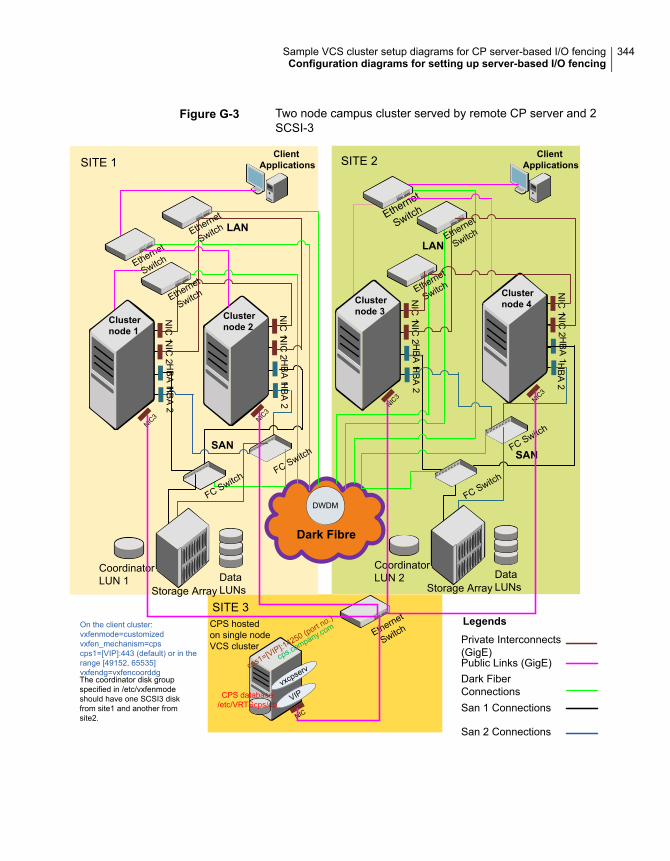
Figure G-3 Two node campus cluster served by remote CP server and 2SCSI-3
LANLAN
Dark Fibre
SITE 1 SITE 2
SITE 3
NIC
1 NIC
2H
BA
2H
BA
1
Clusternode 1
NIC
1 NIC
2H
BA
2H
BA
1
Clusternode 2
NIC
1 NIC
2H
BA
2H
BA
1
Clusternode 3
NIC
1 NIC
2H
BA
2H
BA
1
Clusternode 4
ClientApplications
ClientApplications
Ethernet
Switch
Ethernet
Switch
Ethernet
Switch
Ethernet
Switch
Ethernet
Switch
Ethernet
Switch
FC SwitchFC Switch
FC Switch
FC Switch
CoordinatorLUN 1 Data
LUNsStorage Array
CoordinatorLUN 2 Data
LUNsStorage Array
DWDM
Private Interconnects(GigE)
San 2 Connections
Legends
Dark FiberConnectionsSan 1 Connections
Public Links (GigE)
SANSAN
CPS hostedon single nodeVCS cluster
NIC
VIPvxcpserv
CPS database/etc/VRTScps/db
cps.company.com Ethernet
Switch
NIC3 NIC
3
cps1=[VIP]:14250 (port no.)
NIC3 NIC
3
The coordinator disk groupspecified in /etc/vxfenmodeshould have one SCSI3 diskfrom site1 and another fromsite2.
On the client cluster:vxfenmode=customizedvxfen_mechanism=cpscps1=[VIP]:443 (default) or in therange [49152, 65535]vxfendg=vxfencoorddg
344Sample VCS cluster setup diagrams for CP server-based I/O fencingConfiguration diagrams for setting up server-based I/O fencing

Multiple client clusters served by highly available CP server and 2SCSI-3 disks
Figure G-4 displays a configuration where multiple client clusters are being servedby one highly available CP server and 2 local SCSI-3 LUNS (disks).
In the vxfenmode file on the client nodes, vxfenmode is set to customized withvxfen mechanism set to cps.
The two SCSI-3 disks are are part of the disk group vxfencoorddg. The thirdcoordination point is a CP server, hosted on an SFHA cluster, with its own shareddatabase and coordinator disks.
345Sample VCS cluster setup diagrams for CP server-based I/O fencingConfiguration diagrams for setting up server-based I/O fencing
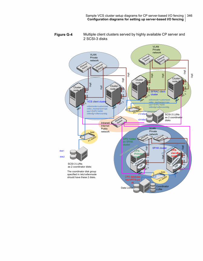
Figure G-4 Multiple client clusters served by highly available CP server and2 SCSI-3 disks
CPS database/etc/VRTScps/
db
NIC
1
Cluster -1node 1
NIC
2
NIC
1
Cluster-1node 2
NIC
2
Ethernet
SwitchEthernet
Switch
VLANPrivatenetwork
Ethernet
SwitchIntranet/InternetPublicnetwork
NIC 3 NIC 3VCS client cluster
NIC
1
CPS-Primarynode
NIC
2
NIC
1
CPS-standbynode
NIC
2
Ethernet
Switch Ethernet
Switch
VLANPrivatenetwork
NIC 3NIC 3
SFHA cluster
VIPvxcpserv
vxcp
serv
VIP
Data LUNs CoordinatorLUNs
SAN
FC Switch
SCSI-3 LUNsas 2 coordinator disks
SAN
FC Switch
disk1
disk2
NIC
1
Cluster -2node 1
NIC
2
NIC
1
Cluster-2node 2
NIC
2
Ethernet
SwitchEthernet
Switch
VLANPrivatenetwork
NIC 3 NIC 3SFRAC clientcluster
SAN
FC Switch
c1t1d0s2
c2t1d0s2
CPS hostedon SFHAcluster
HBA HBA
HBAHBA
HBAHBA
SCSI-3 LUNsas 2 coordinatordisks
Gig
E
Gig
E
Gig
E
Gig
E
Gig
E
Gig
E
Gig
EGig
E
Gig
E
Gig
E
Gig
E
cps1.company.com
cps2.company.com
vxfenmode=customizedvxfen_mechanism=cpscps1=[VIP]:14250vxfendg=vxfencoorddg
vxfenmode=customizedvxfen_mechanism=cpscps1=[VIP]:14250vxfendg=vxfencoorddg
The coordinator disk groupspecified in /etc/vxfenmodeshould have these 2 disks.
346Sample VCS cluster setup diagrams for CP server-based I/O fencingConfiguration diagrams for setting up server-based I/O fencing

Reconciling major/minornumbers for NFS shareddisks
This appendix includes the following topics:
■ Reconciling major/minor numbers for NFS shared disks
Reconcilingmajor/minor numbers for NFS shareddisks
Your configuration may include disks on the shared bus that support NFS. You canconfigure the NFS file systems that you export on disk partitions or on VeritasVolume Manager volumes.
An example disk partition name is /dev/dsk/c1t1d0s2.
An example volume name is /dev/vx/dsk/shareddg/vol3. Each name representsthe block device on which the file system is to be mounted.
In a VCS cluster, block devices providing NFS service must have the same majorand minor numbers on each cluster node. Major numbers identify required devicedrivers (such as a Solaris partition or a VxVM volume). Minor numbers identify thespecific devices themselves. NFS also uses major and minor numbers to identifythe exported file system.
Major and minor numbers must be verified to ensure that the NFS identity for thefile system is the same when exported from each node.
HAppendix

Checking major and minor numbers for disk partitionsThe following sections describe checking and changing, if necessary, the majorand minor numbers for disk partitions used by cluster nodes.
To check major and minor numbers on disk partitions
◆ Use the following command on all nodes exporting an NFS file system. Thiscommand displays the major and minor numbers for the block device.
# ls -lL block_device
The variable block_device refers to a partition where a file system is mountedfor export by NFS. Use this command on each NFS file system. For example,type:
# ls -lL /dev/dsk/c1t1d0s2
Output on Node A resembles:
crw-r----- 1 root sys 32,1 Dec 3 11:50 /dev/dsk/c1t1d0s2
Output on Node B resembles:
crw-r----- 1 root sys 32,1 Dec 3 11:55 /dev/dsk/c1t1d0s2
Note that the major numbers (32) and the minor numbers (1) match,satisfactorily meeting the requirement for NFS file systems.
To reconcile the major numbers that do not match on disk partitions
1 Reconcile the major and minor numbers, if required. For example, if the outputin the previous section resembles the following, perform the instructionsbeginning step 2:
Output on Node A:
crw-r----- 1 root sys 32,1 Dec 3 11:50 /dev/dsk/c1t1d0s2
Output on Node B:
crw-r----- 1 root sys 36,1 Dec 3 11:55 /dev/dsk/c1t1d0s2
2 Place the VCS command directory in your path.
# export PATH=$PATH:/usr/sbin:/sbin:/opt/VRTS/bin
348Reconciling major/minor numbers for NFS shared disksReconciling major/minor numbers for NFS shared disks

3 Attempt to change the major number on System B (now 36) to match that ofSystem A (32). Use the command:
# haremajor -sd major_number
For example, on Node B, enter:
# haremajor -sd 32
4 If the command succeeds, go to step 8.
5 If the command fails, you may see a message resembling:
Error: Preexisting major number 32
These are available numbers on this system: 128...
Check /etc/name_to_major on all systems for
available numbers.
6 Notice that the number 36 (the major number on Node A) is not available onNode B. Run the haremajor command on Node B and change it to 128,
# haremajor -sd 128
7 Run the same command on Node A. If the command fails on Node A, the outputlists the available numbers. Rerun the command on both nodes, setting themajor number to one available to both.
8 Reboot each system on which the command succeeds.
9 Proceed to reconcile the major numbers for your next partition.
To reconcile the minor numbers that do not match on disk partitions
1 In the example, the minor numbers are 1 and 3 and are reconciled by settingto 30 on each node.
2 Type the following command on both nodes using the name of the block device:
# ls -1 /dev/dsk/c1t1d0s2
Output from this command resembles the following on Node A:
lrwxrwxrwx 1 root root 83 Dec 3 11:50
/dev/dsk/c1t1d0s2 -> ../../
devices/sbus@1f,0/QLGC,isp@0,10000/sd@1,0:d,raw
The device name (in bold) includes the slash following the word devices, andcontinues to, but does not include, the colon.
349Reconciling major/minor numbers for NFS shared disksReconciling major/minor numbers for NFS shared disks

3 Type the following command on both nodes to determine the instance numbersthat the SCSI driver uses:
# grep sd /etc/path_to_inst | sort -n -k 2,2
Output from this command resembles the following on Node A:
"/sbus@1f,0/QLGC,isp@0,10000/sd@0,0" 0 "sd"
"/sbus@1f,0/QLGC,isp@0,10000/sd@1,0" 1 "sd"
"/sbus@1f,0/QLGC,isp@0,10000/sd@2,0" 2 "sd"
"/sbus@1f,0/QLGC,isp@0,10000/sd@3,0" 3 "sd"
.
.
"/sbus@1f,0/SUNW,fas@e,8800000/sd@d,0" 27 "sd"
"/sbus@1f,0/SUNW,fas@e,8800000/sd@e,0" 28 "sd"
"/sbus@1f,0/SUNW,fas@e,8800000/sd@f,0" 29 "sd"
In the output, the instance numbers are in the second field.
The instance number that is associated with the device name that matchesthe name for Node A displayed in step 2, is "1."
4 Compare instance numbers for the device in the output on each node.
After you review the instance numbers, perform one of the following tasks:
■ If the instance number from one node is unused on the other— it does notappear in the output of step 3—edit /etc/path_to_inst.You edit this file to make the second node’s instance number similar to thenumber of the first node.
■ If the instance numbers in use on both nodes, edit /etc/path_to_inst onboth nodes. Change the instance number that is associated with the devicename to an unused number. The number needs to be greater than thehighest number that other devices use. For example, the output of step 3shows the instance numbers that all devices use (from 0 to 29). You editthe file /etc/path_to_inst on each node and reset the instance numbersto 30.
5 Type the following command to reboot each node on which /etc/path_to_inst
was modified:
# reboot -- -rv
350Reconciling major/minor numbers for NFS shared disksReconciling major/minor numbers for NFS shared disks
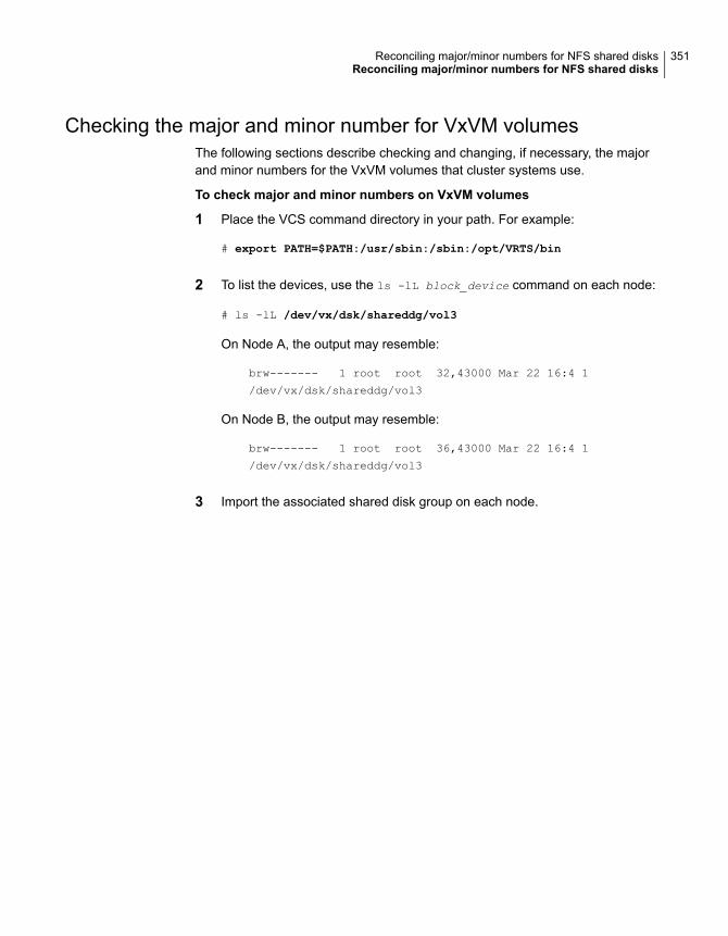
Checking the major and minor number for VxVM volumesThe following sections describe checking and changing, if necessary, the majorand minor numbers for the VxVM volumes that cluster systems use.
To check major and minor numbers on VxVM volumes
1 Place the VCS command directory in your path. For example:
# export PATH=$PATH:/usr/sbin:/sbin:/opt/VRTS/bin
2 To list the devices, use the ls -lL block_device command on each node:
# ls -lL /dev/vx/dsk/shareddg/vol3
On Node A, the output may resemble:
brw------- 1 root root 32,43000 Mar 22 16:4 1
/dev/vx/dsk/shareddg/vol3
On Node B, the output may resemble:
brw------- 1 root root 36,43000 Mar 22 16:4 1
/dev/vx/dsk/shareddg/vol3
3 Import the associated shared disk group on each node.
351Reconciling major/minor numbers for NFS shared disksReconciling major/minor numbers for NFS shared disks

4 Use the following command on each node exporting an NFS file system. Thecommand displays the major numbers for vxio and vxspec that Veritas VolumeManager uses . Note that other major numbers are also displayed, but onlyvxio and vxspec are of concern for reconciliation:
# grep vx /etc/name_to_major
Output on Node A:
vxdmp 30
vxio 32
vxspec 33
vxfen 87
vxglm 91
Output on Node B:
vxdmp 30
vxio 36
vxspec 37
vxfen 87
vxglm 91
5 To change Node B’s major numbers for vxio and vxspec to match those ofNode A, use the command:
haremajor -vx major_number_vxio major_number_vxspec
For example, enter:
# haremajor -vx 32 33
If the command succeeds, proceed to step 8. If this command fails, you receivea report similar to the following:
Error: Preexisting major number 32
These are available numbers on this system: 128...
Check /etc/name_to_major on all systems for
available numbers.
352Reconciling major/minor numbers for NFS shared disksReconciling major/minor numbers for NFS shared disks

6 If you receive this report, use the haremajor command on Node A to changethe major number (32/33) to match that of Node B (36/37). For example, enter:
# haremajor -vx 36 37
If the command fails again, you receive a report similar to the following:
Error: Preexisting major number 36
These are available numbers on this node: 126...
Check /etc/name_to_major on all systems for
available numbers.
7 If you receive the second report, choose the larger of the two available numbers(in this example, 128). Use this number in the haremajor command to reconcilethe major numbers. Type the following command on both nodes:
# haremajor -vx 128 129
8 Reboot each node on which haremajor was successful.
9 If the minor numbers match, proceed to reconcile the major and minor numbersof your next NFS block device.
10 If the block device on which the minor number does not match is a volume,consult the vxdg(1M) manual page. The manual page provides instructions onreconciling the Veritas Volume Manager minor numbers, and gives specificreference to the reminor option.
Node where the vxio driver number have been changed require rebooting.
353Reconciling major/minor numbers for NFS shared disksReconciling major/minor numbers for NFS shared disks

Upgrading the Stewardprocess
This appendix includes the following topics:
■ Upgrading the Steward process
Upgrading the Steward processThe Steward process can be configured in both secure and non-secure mode. Thefollowing procedures provide the steps to upgrade the Steward process.
Upgrading Steward configured in secure mode to 7.0To upgrade Steward configured on Solaris 10 systems in secure mode:
1 Log on to the Steward system as a root user.
2 Stop the Steward process.
# steward -stop -secure
3 Uninstall the VRTSvcs and VRTSperl packages.
4 Install the VRTSvcs and VRTSperl packages.
5 Start the Steward process.
# steward -start -secure
IAppendix

To upgrade Steward configured on Solaris 11 systems in secure mode:
1 Log on to the Steward system as a root user.
2 Stop the Steward process.
# steward -stop -secure
3 Upgrade the VRTSvcs and VRTSperl packages.
# pkg set-publisher -p <path to p5p package> Veritas
# pkg update VRTSperl VRTSvcs
# pkg unset-publisher Veritas
4 Start the Steward process.
# steward -start -secure
Upgrading Steward configured in non-secure mode to 7.0To upgrade Steward configured on Solaris 10 systems in non-secure mode:
1 Log on to the Steward system as a root user.
2 Stop the Steward process.
# steward -stop
3 Uninstall the VRTSvcs and VRTSperl packages.
4 Install the VRTSvcs and VRTSperl packages.
5 Start the Steward process.
# steward -start
To upgrade Steward configured on Solaris 11 systems in non-secure mode:
1 Log on to the Steward system as a root user.
2 Stop the Steward process.
355Upgrading the Steward processUpgrading the Steward process

3 Upgrade the VRTSvcs and VRTSperl package.
# pkg set-publisher -p <path to p5p package> Veritas
# pkg update VRTSperl VRTSvcs
# pkg unset-publisher Veritas
4 Start the Steward process.
# steward -start
Refer to About the Steward process: Split-brain in two-cluster global clusters in theCluster Server Administrator's Guide for more information.
356Upgrading the Steward processUpgrading the Steward process

Symbols/etc/llttab
LLT directives 130
Aadding
ClusterService group 147system to VCS cluster 145users 64
adding nodeto a one-node cluster 243
attributesUseFence 151, 172
Bblock device
partitionsexample file name 347
volumesexample file name 347
Boot Environment (BE) upgradecompleting Solaris 11 upgrade 238upgrading Solaris 11 using the installer 236verifying Solaris 11 upgrade 238
bundled agentstypes.cf file 132
Ccables
cross-over Ethernet 254cluster
removing a node from 267cluster configuration wizard
about 139considerations 140launching 141launching from a browser window 141
ClusterService groupadding manually 147
commandsgabconfig 132lltconfig 280vxdisksetup (initializing disks) 73vxlicinst 71vxlicinstupgrade 72vxlicrep 70
configuration filestypes.cf 132
configuringGAB 132LLT
manual 128configuring VCS
adding users 64event notification 65, 67global clusters 68product installer 50starting 50
coordinator diskssetting up 149
Ddelete
non-root users 188directives
LLT 130disks
adding and initializing 73coordinator 149testing with vxfentsthdw 78verifying node access 79
EEthernet controllers 254
GGAB
manual configuration 132starting 139
Index

gabconfig command 132gabtab file
creating 132verifying after installation 280
global clustersconfiguration 68
Hhubs
independent 254
II/O fencing
checking disks 78setting up 148shared storage 78
I/O fencing requirementsnon-SCSI-3 17
Install Bundlesintegration options 182
installation script options 329installer
online upgrade 194installing
post 69
Llicense keys
adding with vxlicinstupgrade 71replacing demo key 72
licensesinformation about 70
limitationsonline upgrade 194
linksprivate network 280
Live Upgradeadministering boot environment in Solaris 11 239administering Solaris 10 boot environments 233completing Solaris 10 upgrade 231creating new Solaris 11 boot environment
(BE) 235preparing 224reverting to primary boot environment 233Solaris 10 systems 223supported upgrade paths 222Switching boot environment for Solaris
SPARC 233
Live Upgrade (continued)Symantec Cluster Server exceptions 221upgrading Solaris 10 on alternate boot disk 225upgrading Solaris 10 using the installer 230verifying Solaris 10 upgrade 232
LLTdirectives 130manual configuration 128starting 138
LLT directiveslink 130link-lowpri 130set-cluster 130set-node 130
lltconfig command 280llthosts file
verifying after installation 280llttab file
verifying after installation 280
Mmain.cf file
contents after installation 285main.cf files 291major and minor numbers
checking 348, 351shared devices 347
NNFS services
shared storage 347non-SCSI-3 fencing
manual configuration 166setting up 166
non-SCSI-3 I/O fencingrequirements 17
non-SCSI3 fencingsetting up 95using installer 95
Pphased 197phased upgrade 197, 199
example 198post-upgrade tasks 188preparing
Live Upgrade 224
358Index

product installerVCS configuration overview 50
Rre-establish
CP server-client communication 190trust with Steward 191WAC communication 189
removing a system from a cluster 267response files
upgrading 216rsh 51
SSCSI driver
determining instance numbers 349SCSI-3 persistent reservations
verifying 148shared storage
NFS services 347simulataneous install or upgrade 182single-node cluster
adding a node to 243SMTP email notification 65SNMP trap notification 67ssh 51starting configuration
installvcs program 51product installer 51
starting VCS after manual upgrade 138supported upgrade paths
Live Upgrade 222
Ttypes.cf 132
bundled agents 132types.cf file 132
Uupgrade
phased 197, 199upgrade Steward 191upgrading
2048 bit key and SHA256 signaturecertificates 187
phased 197using response files 216
upgrading onlineusing installer 194
upgrading Stewardin secure mode 354in-non-secure mode 354
using Live Upgrade 220
VVCS
configuration filesmain.cf 284
configuring 50coordinator disks 149starting 138–139
Veritas InfoScale productsstarting process 336stopping process 336
vxdisksetup command 73vxlicinst command 71vxlicrep command 70
359Index