Cluster Expansion—Compute-only Nodes - Cisco
46
Cluster Expansion—Compute-only Nodes • Overview, on page 1 • Pre-expansion Checklist, on page 1 • Cluster Expansion— M5 Blade Servers (M.2 SATA) Or M4 Blade Servers (Local SAS Drives), on page 5 • Cluster Expansion— M4 Blade Servers (Fibre Chanel SAN), on page 34 Overview You can add converged or compute-only nodes to expand a Hyper-V cluster. Below is the list of supported converged and compute-only nodes in Hyper-V clusters. • Converged Nodes—HX220c M5, HX240c M5, HX220c AF M5, HX240c AF M5 • Compute-only Nodes—B200 M5, B200 M4 Blade Servers, and C220 M5 C-Series Rack Servers The following procedure describes adding compute-only nodes to expand a Hyper-V cluster. This expansion workflow includes Windows OS installation and is not performed as part of cluster creation using HX Installer. To expand Hyper-V clusters with converged nodes, refer to Cluster Expansion—Converged Nodes. Pre-expansion Checklist To add compute-only nodes to expand your Hyper-V cluster, complete the following pre-expansion checklist that summarizes key requirements, considerations and tasks. Cluster Expansion—Compute-only Nodes 1
-
Upload
khangminh22 -
Category
Documents
-
view
2 -
download
0
Transcript of Cluster Expansion—Compute-only Nodes - Cisco

Cluster Expansion—Compute-only Nodes
• Overview, on page 1• Pre-expansion Checklist, on page 1• Cluster Expansion—M5 Blade Servers (M.2 SATA) Or M4 Blade Servers (Local SAS Drives), on page5
• Cluster Expansion— M4 Blade Servers (Fibre Chanel SAN), on page 34
OverviewYou can add converged or compute-only nodes to expand a Hyper-V cluster. Below is the list of supportedconverged and compute-only nodes in Hyper-V clusters.
• Converged Nodes—HX220c M5, HX240c M5, HX220c AF M5, HX240c AF M5
• Compute-only Nodes—B200 M5, B200 M4 Blade Servers, and C220 M5 C-Series Rack Servers
The following procedure describes adding compute-only nodes to expand a Hyper-V cluster. This expansionworkflow includesWindows OS installation and is not performed as part of cluster creation using HX Installer.To expand Hyper-V clusters with converged nodes, refer to Cluster Expansion—Converged Nodes.
Pre-expansion ChecklistTo add compute-only nodes to expand your Hyper-V cluster, complete the following pre-expansion checklistthat summarizes key requirements, considerations and tasks.
Cluster Expansion—Compute-only Nodes1
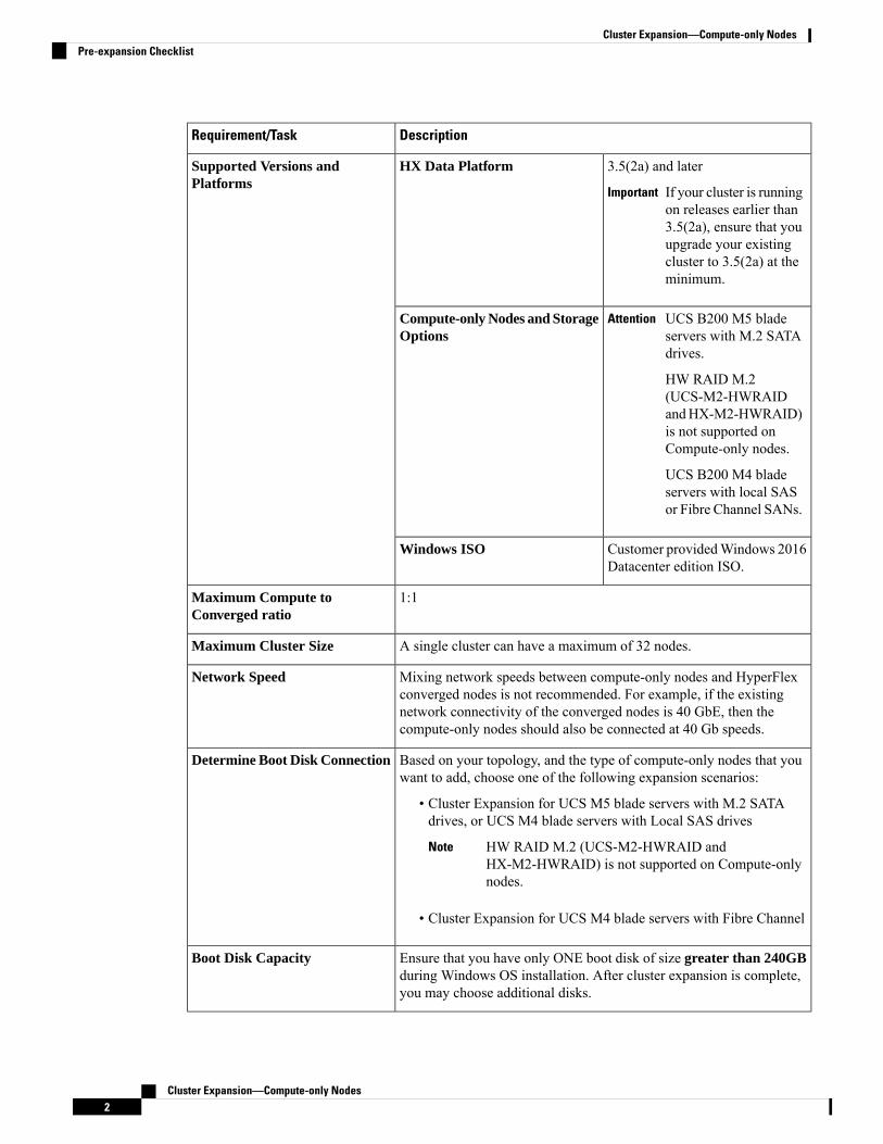
DescriptionRequirement/Task
3.5(2a) and later
If your cluster is runningon releases earlier than3.5(2a), ensure that youupgrade your existingcluster to 3.5(2a) at theminimum.
Important
HX Data PlatformSupported Versions andPlatforms
UCS B200 M5 bladeservers with M.2 SATAdrives.
HW RAID M.2(UCS-M2-HWRAIDandHX-M2-HWRAID)is not supported onCompute-only nodes.
UCS B200 M4 bladeservers with local SASor Fibre Channel SANs.
AttentionCompute-only Nodes and StorageOptions
Customer providedWindows 2016Datacenter edition ISO.
Windows ISO
1:1Maximum Compute toConverged ratio
A single cluster can have a maximum of 32 nodes.Maximum Cluster Size
Mixing network speeds between compute-only nodes and HyperFlexconverged nodes is not recommended. For example, if the existingnetwork connectivity of the converged nodes is 40 GbE, then thecompute-only nodes should also be connected at 40 Gb speeds.
Network Speed
Based on your topology, and the type of compute-only nodes that youwant to add, choose one of the following expansion scenarios:
• Cluster Expansion for UCS M5 blade servers with M.2 SATAdrives, or UCS M4 blade servers with Local SAS drives
HW RAID M.2 (UCS-M2-HWRAID andHX-M2-HWRAID) is not supported on Compute-onlynodes.
Note
• Cluster Expansion for UCS M4 blade servers with Fibre Channel
Determine Boot Disk Connection
Ensure that you have only ONE boot disk of size greater than 240GBduring Windows OS installation. After cluster expansion is complete,you may choose additional disks.
Boot Disk Capacity
Cluster Expansion—Compute-only Nodes2
Cluster Expansion—Compute-only NodesPre-expansion Checklist

DescriptionRequirement/Task
Stage HyperFlex Driver Image
Cluster Expansion—Compute-only Nodes3
Cluster Expansion—Compute-only NodesPre-expansion Checklist
DescriptionRequirement/Task
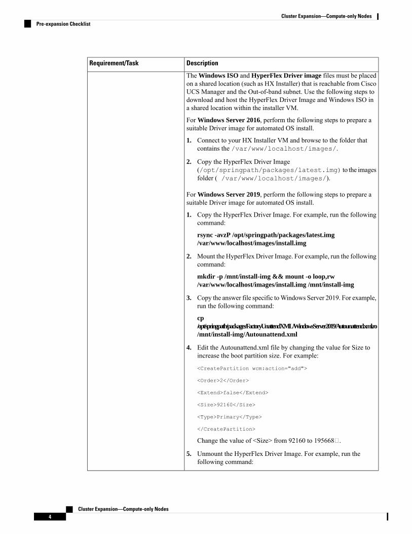
The Windows ISO and HyperFlex Driver image files must be placedon a shared location (such as HX Installer) that is reachable from CiscoUCS Manager and the Out-of-band subnet. Use the following steps todownload and host the HyperFlex Driver Image and Windows ISO ina shared location within the installer VM.
For Windows Server 2016, perform the following steps to prepare asuitable Driver image for automated OS install.
1. Connect to your HX Installer VM and browse to the folder thatcontains the /var/www/localhost/images/.
2. Copy the HyperFlex Driver Image(/opt/springpath/packages/latest.img) to the imagesfolder ( /var/www/localhost/images/).
For Windows Server 2019, perform the following steps to prepare asuitable Driver image for automated OS install.
1. Copy the HyperFlex Driver Image. For example, run the followingcommand:
rsync -avzP /opt/springpath/packages/latest.img/var/www/localhost/images/install.img
2. Mount the HyperFlex Driver Image. For example, run the followingcommand:
mkdir -p /mnt/install-img && mount -o loop,rw/var/www/localhost/images/install.img /mnt/install-img
3. Copy the answer file specific toWindows Server 2019. For example,run the following command:
cp/opt/springpath/packages/FactoryUnattendXML/WindowsServer2019/Autounattend.xml.ro/mnt/install-img/Autounattend.xml
4. Edit the Autounattend.xml file by changing the value for Size toincrease the boot partition size. For example:
<CreatePartition wcm:action="add">
<Order>2</Order>
<Extend>false</Extend>
<Size>92160</Size>
<Type>Primary</Type>
</CreatePartition>
Change the value of <Size> from 92160 to 195668.
5. Unmount the HyperFlex Driver Image. For example, run thefollowing command:
Cluster Expansion—Compute-only Nodes4
Cluster Expansion—Compute-only NodesPre-expansion Checklist

DescriptionRequirement/Task
umount /mnt/install-img
You cannot install Windows Server 2019 or 2016 on SDcards.
Note
The DiskID referenced in autounattend.xml should correctlypoint to the local disk on the compute node where the OS isinstalled.
Note
Do NOT use multipathing with Fibre Channel SANs.Multipathing with Fibre ChannelSAN
Compute-only node expansion is supported only when the computenode are on the same Fabric Interconnects.
Fabric Interconnect Support
Cluster Expansion— M5 Blade Servers (M.2 SATA) Or M4 BladeServers (Local SAS Drives)
Procedure OverviewThe Hyper-V cluster expansion procedure for adding UCS M5 Blade Servers (M.2 SATA) Or M4 BladeServers (Local SAS Drives) consists of the following sequence of tasks:
1. Pre-expansion Checklist
2. Cisco UCS Manager Configuration, on page 5
3. Microsoft OS Installation, on page 12
4. Hypervisor Configuration, HXDP Software Installation and Cluster Expansion, on page 24
5. Perform the following post installation steps:
• Configuring a Static IP Address for Live Migration and VM Network
• (Optional) Post Installation Constrained Delegation
• Configure Local Default Paths
• Checking the Windows Version on the Hyper-V Host
Cisco UCS Manager ConfigurationThe following procedure describes configuring Cisco UCS Manager using HX Installer.
Cluster Expansion—Compute-only Nodes5
Cluster Expansion—Compute-only NodesCluster Expansion— M5 Blade Servers (M.2 SATA) Or M4 Blade Servers (Local SAS Drives)
Procedure
Step 1 Log into the HX Data Platform Installer using the following steps:a) In a browser, enter the URL for the VM where HX Data Platform Installer was installed.b) Use the credentials: username: root, password: Cisco123
Systems ship with a default password of Cisco123 that must be changed during installation.You cannot continue installation unless you specify a new user supplied password.
Important
c) Read the EULA. Click I accept the terms and conditions. Click Login.
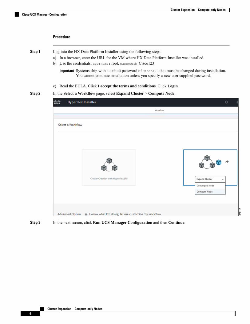
Step 2 In the Select a Workflow page, select Expand Cluster > Compute Node.
Step 3 In the next screen, click Run UCS Manager Configuration and then Continue.
Cluster Expansion—Compute-only Nodes6
Cluster Expansion—Compute-only NodesCisco UCS Manager Configuration

Do not choose any other workflow option at this point.Caution
Step 4 Click Confirm in the pop-up that displays.
Step 5 In the Credentials page, complete the following fields for UCS Manager.
DescriptionField
FQDN or the VIP address of the UCS Manager.UCS Manager Host Name
Administrator user and password or a user with UCSManager administrative privileges.
UCS Manager User Name and Password
Use the following illustration as a reference for entering values in this page.
Cluster Expansion—Compute-only Nodes7
Cluster Expansion—Compute-only NodesCisco UCS Manager Configuration
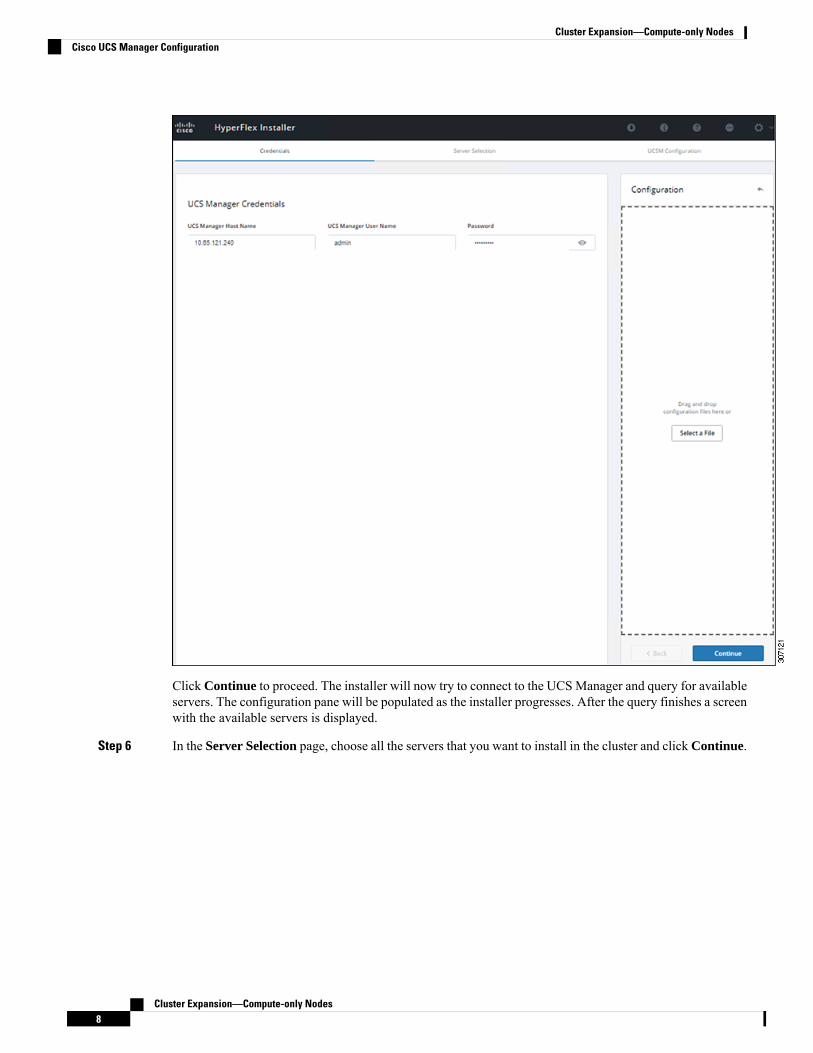
Click Continue to proceed. The installer will now try to connect to the UCSManager and query for availableservers. The configuration pane will be populated as the installer progresses. After the query finishes a screenwith the available servers is displayed.
Step 6 In the Server Selection page, choose all the servers that you want to install in the cluster and click Continue.
Cluster Expansion—Compute-only Nodes8
Cluster Expansion—Compute-only NodesCisco UCS Manager Configuration

Step 7 In the UCSM Configuration page, complete the following fields for VLAN Configuration.
HyperFlex needs to have at least 4 VLANs to function, each needs to be on different IP subnets and extendedfrom the fabric interconnects to the connecting uplink switches, to ensure that traffic can flow from the PrimaryFabric Interconnect (Fabric A) to the Subordinate Fabric Interconnect (Fabric B).
IDUsageName
10Hyper-V andHyperFlexVMmgmt.hx-inband-mgmt
20HyperFlex storage traffichx-storage-data
30Hyper-V Live Migration networkhx-livemigrate
100,101VM guest networkvm-network
Use the following illustration as a reference for entering values in this page.
Cluster Expansion—Compute-only Nodes9
Cluster Expansion—Compute-only NodesCisco UCS Manager Configuration

• Do not use VLAN 1 as it is not best practice and can cause issues with disjoint layer 2.
• vm-network can be multiple VLANs added as a comma separated list.
Note
Renaming the 4 core networks is not supported.Caution
Step 8 Enter the remaining network configuration for MAC Pool, 'hx' IP Pool for Cisco IMC, Cisco IMC accessmanagement (Out of band or in band)
ValueDescriptionField
MAC Pool
00:25:b5:xxMAC address pool for the HXcluster, to be configured in UCSMby the installer. Ensure that the macaddress pool isn’t used anywhereelse in your layer 2 environment.
MAC pool prefix
'hx' IP Pool for Cisco IMC
10.193.211.124-.127The range of IP addresses that areused for Out-Of-Bandmanagementof the HyperFlex nodes.
IP Blocks
255.255.0.0The subnet mask for theOut-Of-Band network
Subnet Mask
10.193.0.1The gateway address for theOut-Of-Band network
Gateway
Cisco IMC access management (Out of band or In band)
Select the option that was used forconverged-nodes cluster creation.
In band (recommended)
Out of Band
Cluster Expansion—Compute-only Nodes10
Cluster Expansion—Compute-only NodesCisco UCS Manager Configuration
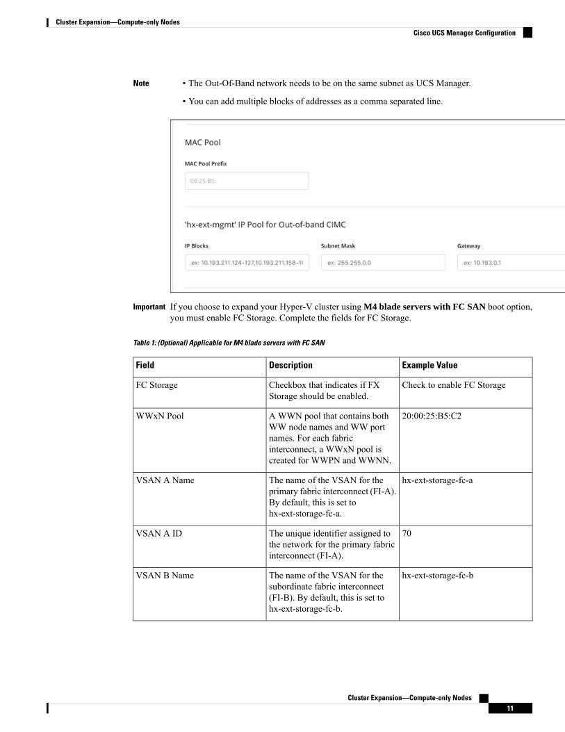
• The Out-Of-Band network needs to be on the same subnet as UCS Manager.
• You can add multiple blocks of addresses as a comma separated line.
Note
If you choose to expand your Hyper-V cluster using M4 blade servers with FC SAN boot option,you must enable FC Storage. Complete the fields for FC Storage.
Important
Table 1: (Optional) Applicable for M4 blade servers with FC SAN
Example ValueDescriptionField
Check to enable FC StorageCheckbox that indicates if FXStorage should be enabled.
FC Storage
20:00:25:B5:C2A WWN pool that contains bothWW node names and WW portnames. For each fabricinterconnect, a WWxN pool iscreated for WWPN and WWNN.
WWxN Pool
hx-ext-storage-fc-aThe name of the VSAN for theprimary fabric interconnect (FI-A).By default, this is set tohx-ext-storage-fc-a.
VSAN A Name
70The unique identifier assigned tothe network for the primary fabricinterconnect (FI-A).
VSAN A ID
hx-ext-storage-fc-bThe name of the VSAN for thesubordinate fabric interconnect(FI-B). By default, this is set tohx-ext-storage-fc-b.
VSAN B Name
Cluster Expansion—Compute-only Nodes11
Cluster Expansion—Compute-only NodesCisco UCS Manager Configuration
Example ValueDescriptionField
70The unique identifier assigned tothe network for the subordinatefabric interconnect (FI-B).
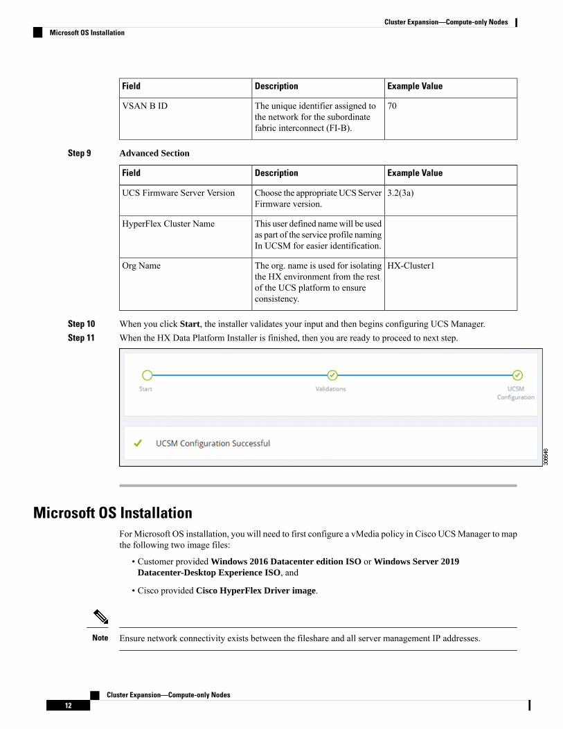
VSAN B ID
Step 9 Advanced Section
Example ValueDescriptionField
3.2(3a)Choose the appropriate UCS ServerFirmware version.
UCS Firmware Server Version
This user defined namewill be usedas part of the service profile namingIn UCSM for easier identification.
HyperFlex Cluster Name
HX-Cluster1The org. name is used for isolatingthe HX environment from the restof the UCS platform to ensureconsistency.
Org Name
Step 10 When you click Start, the installer validates your input and then begins configuring UCS Manager.Step 11 When the HX Data Platform Installer is finished, then you are ready to proceed to next step.
Microsoft OS InstallationFor Microsoft OS installation, you will need to first configure a vMedia policy in Cisco UCSManager to mapthe following two image files:
• Customer provided Windows 2016 Datacenter edition ISO or Windows Server 2019Datacenter-Desktop Experience ISO, and
• Cisco provided Cisco HyperFlex Driver image.
Ensure network connectivity exists between the fileshare and all server management IP addresses.Note
Cluster Expansion—Compute-only Nodes12
Cluster Expansion—Compute-only NodesMicrosoft OS Installation
Procedure
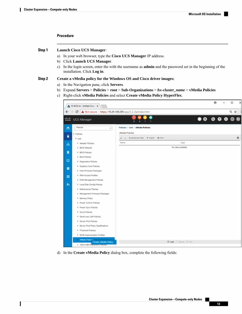
Step 1 Launch Cisco UCS Manager:a) In your web browser, type the Cisco UCS Manager IP address.b) Click Launch UCS Manager.c) In the login screen, enter the with the username as admin and the password set in the beginning of the
installation. Click Log in.
Step 2 Create a vMedia policy for the Windows OS and Cisco driver images:
a) In the Navigation pane, click Servers.b) Expand Servers > Policies > root > Sub-Organizations > hx-cluster_name > vMedia Policiesc) Right-click vMedia Policies and select Create vMedia Policy HyperFlex.
d) In the Create vMedia Policy dialog box, complete the following fields:
Cluster Expansion—Compute-only Nodes13
Cluster Expansion—Compute-only NodesMicrosoft OS Installation

DescriptionField Name
The name of the vMedia policy. For example,HX-vMedia.
This name can be between 1 and 16 alphanumericcharacters. You cannot use spaces or any specialcharacters other than - (hyphen), _ (underscore), :(colon), and . (period), and you cannot change thisname after the object is saved.
Name
A description of the policy. We recommendincluding information about where and when thepolicy should be used. Maximum 115 characters.
Description
Designates if the vMedia will continue mountingwhen a mount failure occurs. This can be:
• Yes
• No
The default setting is Yes. When Yes isselected the remote server will continueto try to mount the vMedia mountprocess until it is successful, or youdisable this option. If you select No, awarning message will appear indicatingretry on mount failure will not work incase of mount failure.
Note
Retry on Mount Failure
Refer to the following screenshot as an example:
Cluster Expansion—Compute-only Nodes14
Cluster Expansion—Compute-only NodesMicrosoft OS Installation

e) On the icon bar under the vMedia Mounts pane, click + Add. In the Create vMedia Mount dialog box,complete the following fields:
Example ValueDescriptionField Name
Windows-ISOName for the mount point.Name
Windows Server 2016 image
or
Windows Server 2019 image
Can be used for more information.Description
CDDType of image that you want tomount. This can be:
• CDD—Scriptable vMediaCD.
• HDD—Scriptable vMediaHDD.
Device Type
HTTPThe protocol used for accessingthe share where the ISO files arelocated.
Protocol
10.101.1.92IP address or FQDN of the serverhosting the images.
Hostname/IP Address
Cluster Expansion—Compute-only Nodes15
Cluster Expansion—Compute-only NodesMicrosoft OS Installation

Example ValueDescriptionField Name
NoneThis value is not used inHyperFlex installation.
Image Name Variable
The filename of the ISO file thatyou want to mount.
Remote File
The path on the remote server towhere the file resides
Remote Path
If you use CIFS or NFS ausername might be necessary
Username
If you use CIFS or NFS apassword might be necessary
Password
Refer to the screenshot below as an example:
f) Click OK. When you click OK, you will now be returned to the vMedia Policies screen, and you shouldsee the information that you just submitted.
Cluster Expansion—Compute-only Nodes16
Cluster Expansion—Compute-only NodesMicrosoft OS Installation

g) Repeat Steps 2e and 2f, however, change the type to HDD and the remote file name to the CiscoHyperFlex driver image.
h) At the end of this step, the two vMedia mounts will be listed in the Create vMedia Policy screen as shownin the following screenshot:
Cluster Expansion—Compute-only Nodes17
Cluster Expansion—Compute-only NodesMicrosoft OS Installation

Step 3 Associate the vMedia Policy to a Service Profile:a) In the Navigation pane, select Servers > Service Profile Templates > root > Sub-Organizations >
hx-cluster_name > Service Template compute-nodes, or compute-nodes-m5
Cluster Expansion—Compute-only Nodes18
Cluster Expansion—Compute-only NodesMicrosoft OS Installation
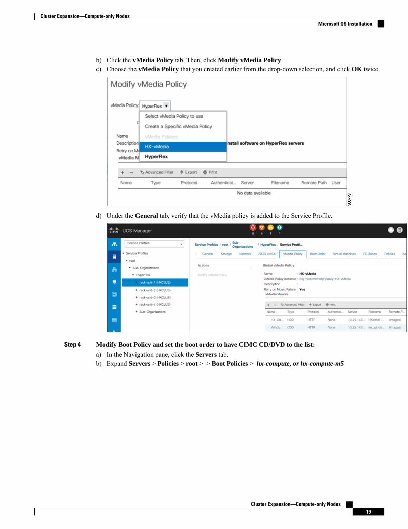
b) Click the vMedia Policy tab. Then, click Modify vMedia Policyc) Choose the vMedia Policy that you created earlier from the drop-down selection, and click OK twice.
d) Under the General tab, verify that the vMedia policy is added to the Service Profile.
Step 4 Modify Boot Policy and set the boot order to have CIMC CD/DVD to the list:
a) In the Navigation pane, click the Servers tab.b) Expand Servers > Policies > root > > Boot Policies > hx-compute, or hx-compute-m5
Cluster Expansion—Compute-only Nodes19
Cluster Expansion—Compute-only NodesMicrosoft OS Installation
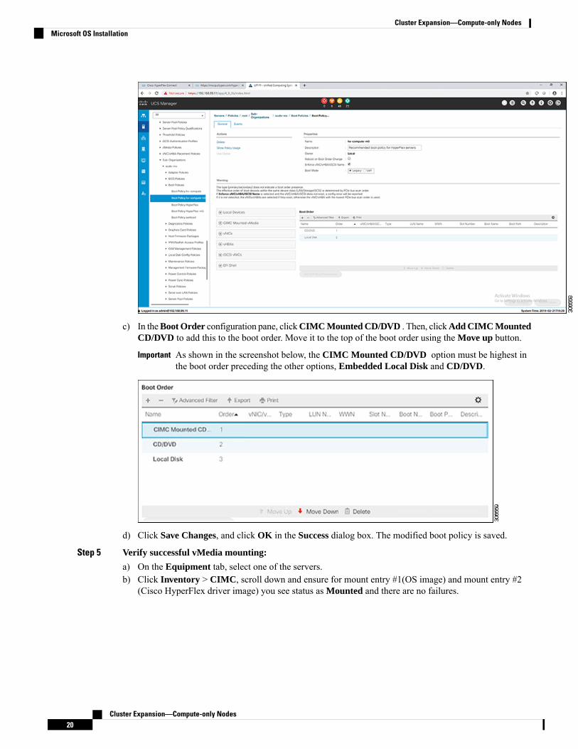
c) In theBoot Order configuration pane, clickCIMC Mounted CD/DVD . Then, clickAdd CIMC MountedCD/DVD to add this to the boot order. Move it to the top of the boot order using the Move up button.
As shown in the screenshot below, the CIMC Mounted CD/DVD option must be highest inthe boot order preceding the other options, Embedded Local Disk and CD/DVD.
Important
d) Click Save Changes, and click OK in the Success dialog box. The modified boot policy is saved.
Step 5 Verify successful vMedia mounting:
a) On the Equipment tab, select one of the servers.b) Click Inventory > CIMC, scroll down and ensure for mount entry #1(OS image) and mount entry #2
(Cisco HyperFlex driver image) you see status as Mounted and there are no failures.
Cluster Expansion—Compute-only Nodes20
Cluster Expansion—Compute-only NodesMicrosoft OS Installation

c) In the menu bar, click Servers and choose the first HyperFlex service profile.d) Click the General tab and choose Actions > KVM Console>>.
The KVM console will try to open in a new browser. Be aware of any pop-up blockers. Allowthe pop-ups and re-open the KVM
Note
Cluster Expansion—Compute-only Nodes21
Cluster Expansion—Compute-only NodesMicrosoft OS Installation

e) Reboot the host, launch the KVMConsole, and power on the server to monitor the progress of theWindowsinstallation. You should see the Loading Files screen appear. Windows should install automaticallywithout user intervention.
The option to install Windows automatically without user intervention is applicable for freshor first-time installations only. For reinstallations, or if the node already contains a Windowspartition, you will need to respond to the prompt to "Press any key to boot from CD/DVD".
Note
You should see a blue screen and within a few moments you should see the Setup is starting message.The host will reboot a few times. If automated installation does not begin, double-check that both imagesare mounted to the server.
f) The installation is complete when you get a clear command prompt at c:\users\administrator>.This is applicable for both Windows Core and Desktop Experience installations. It may take severalminutes for the Driver Image to be copied and installed.
Ignore the prompt with the The system cannot find the file specified message.Note
Ensure that you have completed Steps e and f, on ALL servers that will be part of the HXcluster.
Important
If Microsoft Windows OS is already installed on the node, you must click any key to continuewhen the node boots back up so that the fresh OS installation can happen.
If you haven't clicked any key to continue, and an existing node with a previous OS installedis used to expand, then the new installation is skipped causing further expansion to fail.
Note
g) Login to each server and verify the following:
Run powershell command: Get-ScheduledTask -TaskName HXInstallbootstraplauncherTask. Verifythat the HX Install Bootstrap Launcher task is running. Sample output as follows:
Cluster Expansion—Compute-only Nodes22
Cluster Expansion—Compute-only NodesMicrosoft OS Installation

TaskPath TaskName State-------- -------- -----\ HXInstallbootstraplauncherTask Running
Validate that the log line "Done with HX PostSysPrepSetup" exists inC:\ProgramData\Cisco\HyperFlex\Install\Log\PostSysprepSetup.log.
Run powershell command: Get-Command Get-VMSwitch. Verify that the command runs successfully (noexception). Sample output as follows:
CommandType Name Version Source----------- ---- ------- ------Cmdlet Get-VMSwitch 2.0.0.0 Hyper-V
Step 6 Reset the vMedia policy back to the default HyperFlex policy:
a) Update the vMedia policy for compute nodes. Go to Servers > Service Profile Templates > root >Sub-Organizations > hx-cluster_name > Service Template compute-nodes, or compute-nodes-m5.Then, click on Modify vMedia Policy.
b) Under the vMedia Policy drop-down selection, choose "HyperFlex" policy.
Step 7 Restore the boot order to the one before installation:
a) In the Navigation pane, click the Servers tab.b) Expand Servers > Policies > root > > Boot Policies > hx-compute, or hx-compute-m5c) In the Boot Order configuration pane, use the Move Down button to move CIMC Mounted CD/DVD
option to the bottom of the list.
Step 8 Change the local Administrator password to match the password on the existing cluster.
a) Log in to the newly-installed compute node.b) Open a command prompt.c) Run the following command: net user Administrator <password>.
Step 9 Update the password for HXInstallbootstraplauncherTask and verify that it is Running:
a) Stop the scheduled task "HXInstallbootstraplauncherTask" if it is running.
For example:
Get-ScheduledTask -TaskName "HXInstallbootstraplauncherTask" | Stop-ScheduledTask
b) Update task credentials.
For example:
Get-ScheduledTask -TaskName "HXInstallbootstraplauncherTask" | Set-ScheduledTask -User
"Administrator" -Password <password>
c) Start the scheduled task and verify that it is Running.
For example:
Get-ScheduledTask -TaskName "HXInstallbootstraplauncherTask" | Start-ScheduledTask
Get-ScheduledTask -TaskName "HXInstallbootstraplauncherTask"
Cluster Expansion—Compute-only Nodes23
Cluster Expansion—Compute-only NodesMicrosoft OS Installation

Hypervisor Configuration, HXDP Software Installation and Cluster ExpansionAfter the installation of Windows OS is completed, perform the following steps to configure the hypervisor,install the HX Data Platform Software and expand the cluster.
Procedure
Step 1 Re-open the HX Data Platform Installer and log in.Step 2 You might need to “start over” because the previous workflow was finished. Click on the gear icon in the top
right corner and select Start Over.Step 3 In the Select a Workflow page, select Expand Cluster > Compute Node.
Step 4 In the Select a Workflow page, select Expand HX Cluster. Leave the Is OS installed on the Node, RunHypervisor Configuration and Deploy HX Softwarecheckboxes selected.
Cluster Expansion—Compute-only Nodes24
Cluster Expansion—Compute-only NodesHypervisor Configuration, HXDP Software Installation and Cluster Expansion

Step 5 In the Warning dialog box, click Confirm and Proceed.
Step 6 In the Cluster page, complete the following fields:
Example ValueDescriptionField
10.104.252.135Themanagement IP address for theHX cluster
HX Cluster Management IP
adminAdministrator usernameCluster Admin User
Administrator passwordPassword
Cluster Expansion—Compute-only Nodes25
Cluster Expansion—Compute-only NodesHypervisor Configuration, HXDP Software Installation and Cluster Expansion

Step 7 In the Credentials page, complete the following fields:
Table 2: UCS Manager Credentials
Field
FQDN or the VIP address ofUCSM.
UCS Manager Host Name
Admin user or a user with UCSMadmin rights.
UCS Manager User Name
Password for the UCS ManagerUser Name.
Password
Cluster Expansion—Compute-only Nodes26
Cluster Expansion—Compute-only NodesHypervisor Configuration, HXDP Software Installation and Cluster Expansion
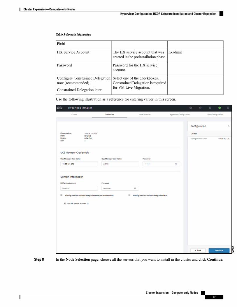
Table 3: Domain Information
Field
hxadminThe HX service account that wascreated in the preinstallation phase.
HX Service Account
Password for the HX serviceaccount.
Password
Select one of the checkboxes.Constrained Delegation is requiredfor VM Live Migration.
Configure Constrained Delegationnow (recommended)
Constrained Delegation later
Use the following illustration as a reference for entering values in this screen.
Step 8 In the Node Selection page, choose all the servers that you want to install in the cluster and click Continue.
Cluster Expansion—Compute-only Nodes27
Cluster Expansion—Compute-only NodesHypervisor Configuration, HXDP Software Installation and Cluster Expansion

Step 9 In theHypervisor Configuration page, complete the following fields forVLAN Configuration,HypervisorSettings, and Hypervisor Credentials.
VLAN Configuration—HyperFlex needs to have at least 4 VLANs, each needs to be on different IP subnetsand extended from the fabric interconnects to the connecting uplink switches, to ensure that traffic can flowfrom the Primary Fabric Interconnect (Fabric A) to the Subordinate Fabric Interconnect (Fabric B).
Use the following illustration as a reference for entering values in this screen.
Cluster Expansion—Compute-only Nodes28
Cluster Expansion—Compute-only NodesHypervisor Configuration, HXDP Software Installation and Cluster Expansion

Hypervisor Settings—If you leave the checkbox Make IP Addresses and Hostnames Sequential as checkedthen the installer will automatically fill the rest of the servers sequential from the first.
Hypervisor Credentials— Enter the Local administrator username on the Hyper-V hosts. Click Continue.
Step 10 In the Node Configuration page, complete the fields for Hypervisor Settings and IP Addresses.
Example ValueDescriptionField
255.255.255.0Subnet mask for the hypervisorhosts management network
Subnet Mask
10.101.251.1Default gateway for the hypervisorhosts management network
Gateway
10.101.251.1Comma separated list for the DNSServers in the AD that thehypervisor hosts are going to bemember.
DNS Servers
Use the following illustration as reference for entering values in this screen.
Cluster Expansion—Compute-only Nodes29
Cluster Expansion—Compute-only NodesHypervisor Configuration, HXDP Software Installation and Cluster Expansion
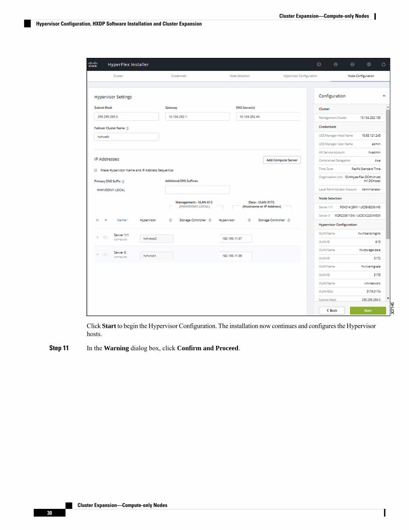
Click Start to begin theHypervisor Configuration. The installation now continues and configures the Hypervisorhosts.
Step 11 In the Warning dialog box, click Confirm and Proceed.
Cluster Expansion—Compute-only Nodes30
Cluster Expansion—Compute-only NodesHypervisor Configuration, HXDP Software Installation and Cluster Expansion

Step 12 The Progress screen displays the status of the hypervisor configuration and cluster expansion.
Cluster Expansion—Compute-only Nodes31
Cluster Expansion—Compute-only NodesHypervisor Configuration, HXDP Software Installation and Cluster Expansion

Step 13 When the process finishes successfully, the Summary page displays the completion status.
Cluster Expansion—Compute-only Nodes32
Cluster Expansion—Compute-only NodesHypervisor Configuration, HXDP Software Installation and Cluster Expansion
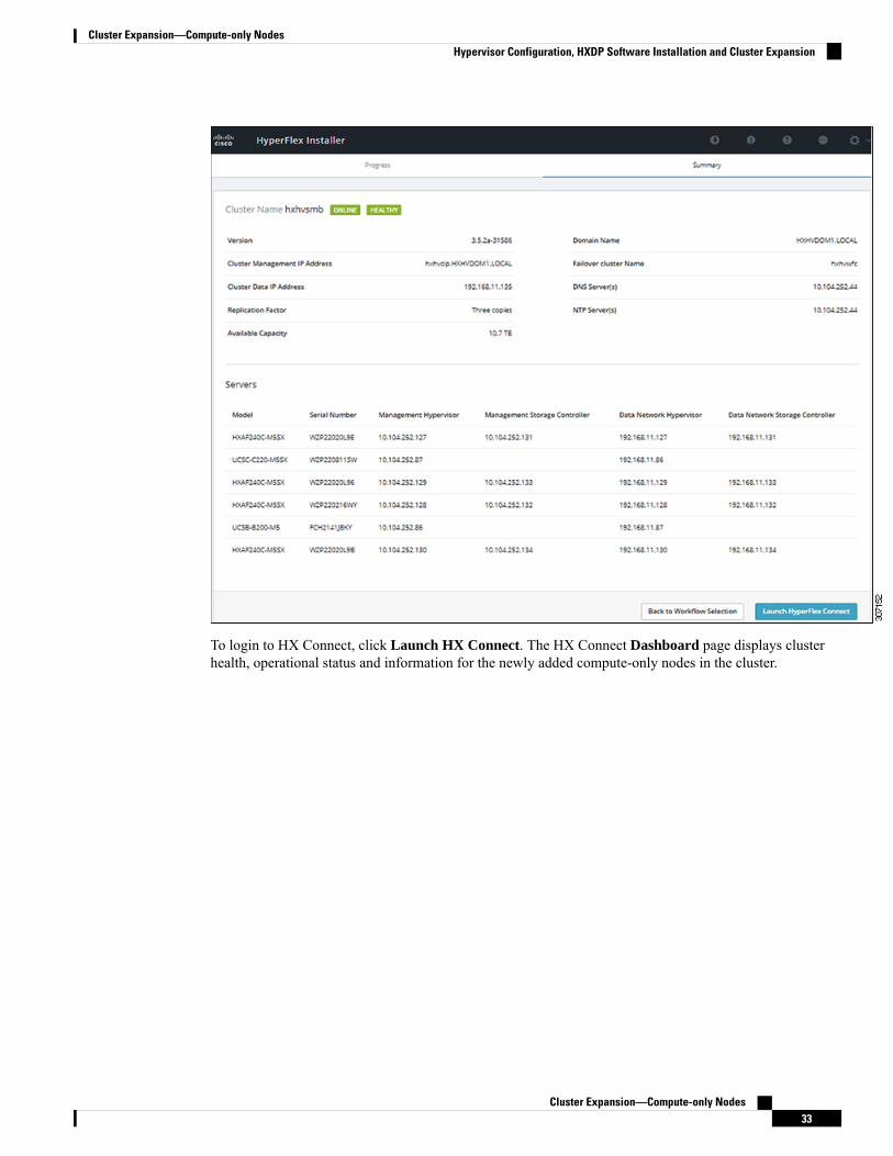
To login to HX Connect, click Launch HX Connect. The HX Connect Dashboard page displays clusterhealth, operational status and information for the newly added compute-only nodes in the cluster.
Cluster Expansion—Compute-only Nodes33
Cluster Expansion—Compute-only NodesHypervisor Configuration, HXDP Software Installation and Cluster Expansion

Cluster Expansion— M4 Blade Servers (Fibre Chanel SAN)
OverviewThe Hyper-V cluster expansion procedure for UCS B200 M4 blade servers with Fibre Channel storageboot option consists of the following sequence of tasks:
1. Pre-expansion Checklist
2. Cisco UCS Manager Configuration
3. Microsoft Windows OS Installation, on page 35
4. Hypervisor Configuration, HXDP Software Installation and Cluster Expansion
5. Perform the following post installation steps:
• Configuring a Static IP Address for Live Migration and VM Network
• (Optional) Post Installation Constrained Delegation
Cluster Expansion—Compute-only Nodes34
Cluster Expansion—Compute-only NodesCluster Expansion— M4 Blade Servers (Fibre Chanel SAN)

• Configure Local Default Paths
• Checking the Windows Version on the Hyper-V Host
Microsoft Windows OS InstallationThis procedure is when you wish to expand your Hyper-V cluster by adding UCS B200 M4 Blade servers(compute-only nodes) and enable Fibre Channel SAN boot option.
Procedure
Step 1 Launch UCS Manager and log in.Step 2 Perform the following steps to clone a Service Profile template:
a) In the Navigation pane, click Servers.b) Expand the node for the organization where you want to clone and select Create a Clonec) In the Create Clone from Service Profile dialog box, enter a name you to use for the new profile in the
Clone Name field (Example: hx-compute. Click OK.
Step 3 Perform the following steps to enable FC Zoning:
a) In the Navigation pane, go to SAN > VSAN.b) Ensure that the Enabled radio-button is selected under FC Zoning.
Step 4 Unbind your blade server from the current Service Profile template, and bind it to the newly created templatein Step 2.
Step 5 Perform the following steps to mount the HyperFlex Driver Image file and modify theautounattend.xml file:a) Connect to your HX Installer VM and navigate to the shared folder that contains the Windows ISO and
HyperFlex Driver Image files.b) Run the following commands to mount the HyperFlex image:
mkdir /mnt/hx-imgmount /var/www/localhost/images/latest.img /mnt/hx-img
c) Open the autounattend.xml file, search for DiskID and change the value from 0 to the value inWindows PE ( WinPE).
Step 6 Perform the following steps to configure a SAN boot policy:a) Select the newly created Service Profile Template from Step 2 and go to theBoot Order tab. ClickModify
Boot Policy. In the Modify Boot Policy page, click Create Boot Policy.b) Expand vHBAs, select Add SAN Boot, and in the name field, type the name of the vHBA(Example:
hx-ext-fc-a).c) Select Primary and click OK.d) In the Add SAN Boot Target, leave the Boot Target LUN set to 0. In the Boot Target WWPN field,
type the WWPN from your storage array. Verify Type is set to Primary and click OK.
Step 7 Create a vMedia policy for the Windows OS and Cisco driver images:
a) In the Navigation pane, click Servers.b) Expand Servers > Policies > root > Sub-Organizations > hx-cluster_name > vMedia Policies
Cluster Expansion—Compute-only Nodes35
Cluster Expansion—Compute-only NodesMicrosoft Windows OS Installation
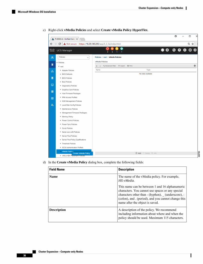
c) Right-click vMedia Policies and select Create vMedia Policy HyperFlex.
d) In the Create vMedia Policy dialog box, complete the following fields:
DescriptionField Name
The name of the vMedia policy. For example,HX-vMedia.
This name can be between 1 and 16 alphanumericcharacters. You cannot use spaces or any specialcharacters other than - (hyphen), _ (underscore), :(colon), and . (period), and you cannot change thisname after the object is saved.
Name
A description of the policy. We recommendincluding information about where and when thepolicy should be used. Maximum 115 characters.
Description
Cluster Expansion—Compute-only Nodes36
Cluster Expansion—Compute-only NodesMicrosoft Windows OS Installation
DescriptionField Name
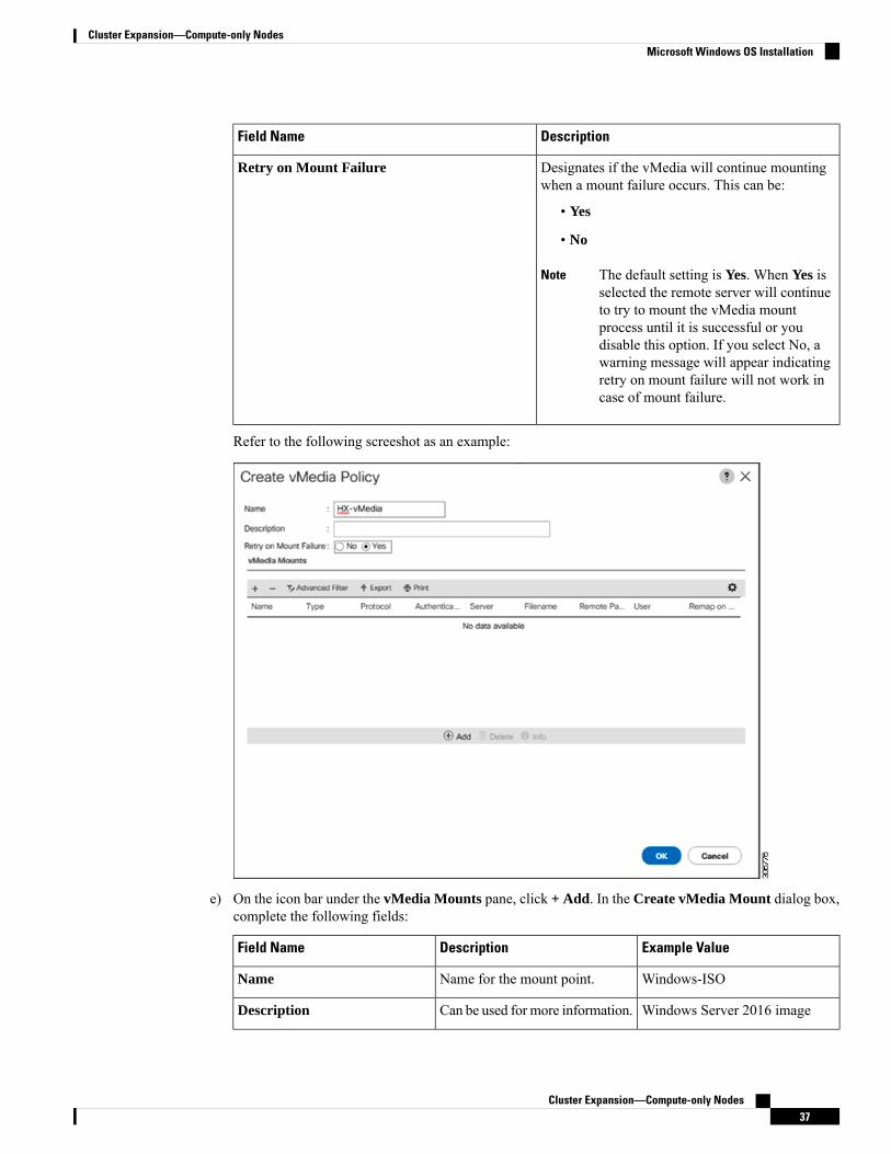
Designates if the vMedia will continue mountingwhen a mount failure occurs. This can be:
• Yes
• No
The default setting is Yes. When Yes isselected the remote server will continueto try to mount the vMedia mountprocess until it is successful or youdisable this option. If you select No, awarning message will appear indicatingretry on mount failure will not work incase of mount failure.
Note
Retry on Mount Failure
Refer to the following screeshot as an example:
e) On the icon bar under the vMedia Mounts pane, click + Add. In the Create vMedia Mount dialog box,complete the following fields:
Example ValueDescriptionField Name
Windows-ISOName for the mount point.Name
Windows Server 2016 imageCan be used for more information.Description
Cluster Expansion—Compute-only Nodes37
Cluster Expansion—Compute-only NodesMicrosoft Windows OS Installation

Example ValueDescriptionField Name
CDDType of image that you want tomount. This can be:
• CDD—Scriptable vMediaCD.
• HDD—Scriptable vMediaHDD.
Device Type
HTTPThe protocol used for accessingthe share where the ISO files arelocated.
Protocol
10.101.1.92IP address or FQDN of the serverhosting the images.
Hostname/IP Address
NoneThis value is not used inHyperFlex installation.
Image Name Variable
The filename of the ISO file thatyou want to mount.
Remote File
The path on the remote server towhere the file resides
Remote Path
If you use CIFS or NFS ausername might be necessary
Username
If you use CIFS or NFS apassword might be necessary
Password
Refer to the screenshot below as an example:
Cluster Expansion—Compute-only Nodes38
Cluster Expansion—Compute-only NodesMicrosoft Windows OS Installation
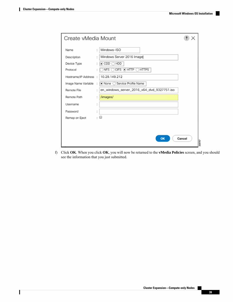
f) Click OK. When you click OK, you will now be returned to the vMedia Policies screen, and you shouldsee the information that you just submitted.
Cluster Expansion—Compute-only Nodes39
Cluster Expansion—Compute-only NodesMicrosoft Windows OS Installation

g) Repeat Steps 2e and 2f, however, change the type to HDD and the remote file name to the CiscoHyperFlex driver image.
h) At the end of this step, the two vMedia mounts will be listed in the Create vMedia Policy screen as shownin the following screenshot:
Cluster Expansion—Compute-only Nodes40
Cluster Expansion—Compute-only NodesMicrosoft Windows OS Installation
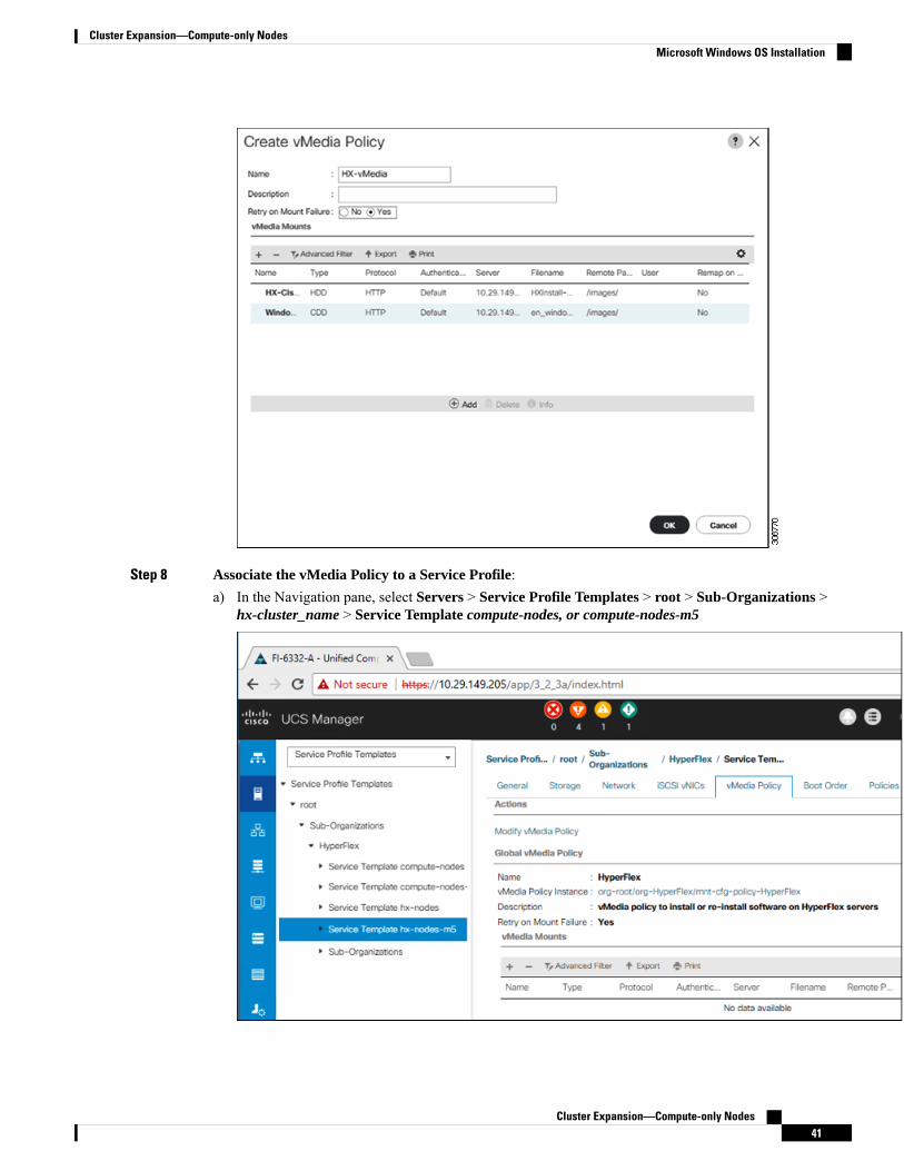
Step 8 Associate the vMedia Policy to a Service Profile:a) In the Navigation pane, select Servers > Service Profile Templates > root > Sub-Organizations >
hx-cluster_name > Service Template compute-nodes, or compute-nodes-m5
Cluster Expansion—Compute-only Nodes41
Cluster Expansion—Compute-only NodesMicrosoft Windows OS Installation

b) Click the vMedia Policy tab. Then, click Modify vMedia Policyc) Choose the vMedia Policy that you created earlier from the drop-down selection, and click OK twice.
d) Under the General tab, verify that the vMedia policy is added to the Service Profile.
Step 9 Modify Boot Policy and set the boot order to have CIMC CD/DVD to the list:
a) In the Navigation pane, click the Servers tab.b) Expand Servers > Policies > root > > Boot Policies > hx-compute, or hx-compute-m5
Cluster Expansion—Compute-only Nodes42
Cluster Expansion—Compute-only NodesMicrosoft Windows OS Installation

c) ( For M5 Servers only) In the Boot Order configuration pane, click CIMC Mounted CD/DVD . Then,click Add CIMC Mounted CD/DVD to add this to the boot order. Move it to the top of the boot orderusing the Move up button.
The CIMC Mounted CD/DVD option must be highest in the boot order preceding the otheroptions, Embedded Local Disk and CD/DVD.
Important
(For M4 Servers with Local SAS Drivers) In the Boot Order configuration pane, click vHBAs. Then,click Add SAN Boot to add this to the boot order.
d) Click Save Changes, and click OK in the Success dialog box. The modified boot policy is saved.
Step 10 Verify successful vMedia mounting:
a) On the Equipment tab, select one of the servers.b) Click Inventory > CIMC, scroll down and ensure for mount entry #1(OS image) and mount entry #2
(Cisco HyperFlex driver image) you see status as Mounted and there are no failures.
Cluster Expansion—Compute-only Nodes43
Cluster Expansion—Compute-only NodesMicrosoft Windows OS Installation
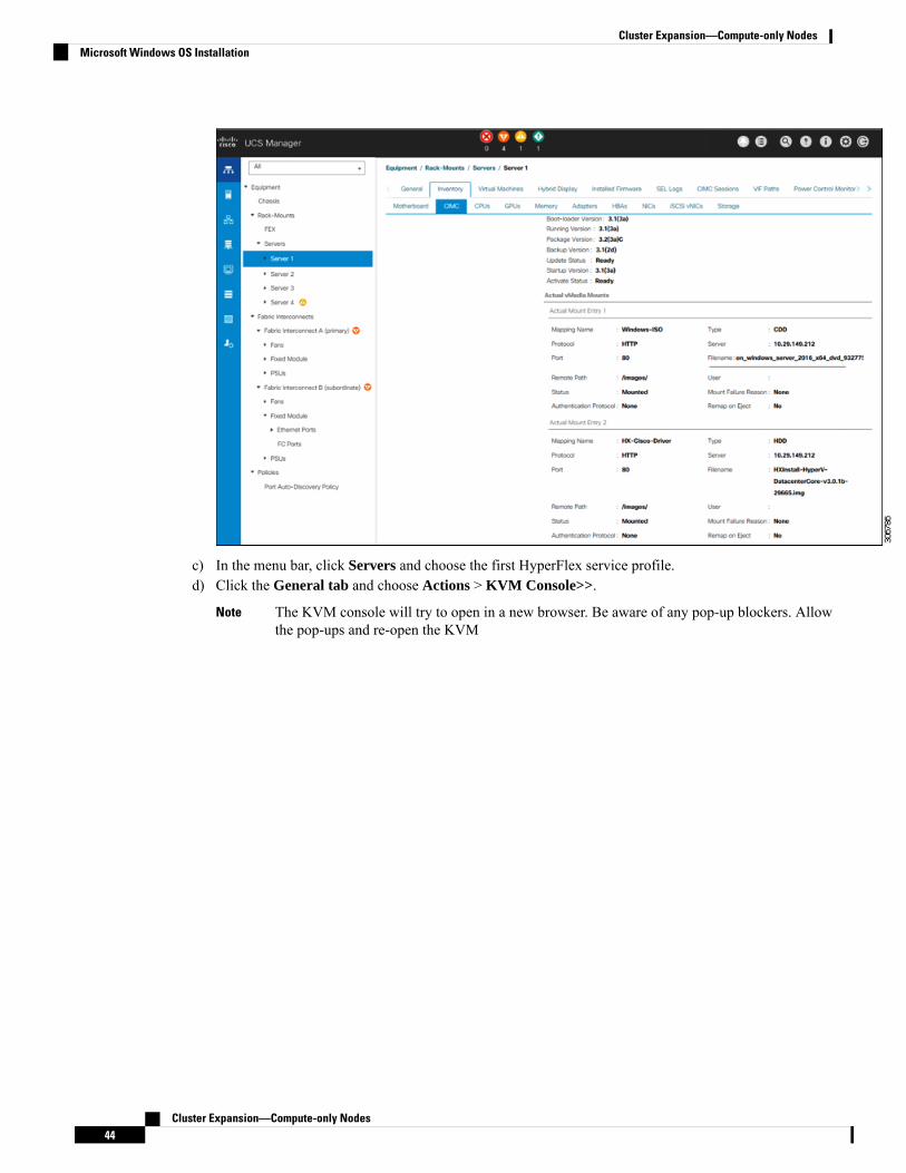
c) In the menu bar, click Servers and choose the first HyperFlex service profile.d) Click the General tab and choose Actions > KVM Console>>.
The KVM console will try to open in a new browser. Be aware of any pop-up blockers. Allowthe pop-ups and re-open the KVM
Note
Cluster Expansion—Compute-only Nodes44
Cluster Expansion—Compute-only NodesMicrosoft Windows OS Installation

e) Reboot the host, launch the KVMConsole, and power on the server to monitor the progress of theWindowsinstallation. You should see the Loading Files screen appear. Windows should install automaticallywithout user intervention. You should see a blue screen and within a few moments you should see theSetup is starting message. If automated installation does not begin, double-check that both images aremounted to the server.
f) Once Windows installation completes, a command prompt will show up. Wait for the installation tocomplete. The host will then reboot a few times. The installation is complete when you get a clear commandprompt at c:\users\administrator>. It may take several minutes and reboot operations for theDriver Image to be copied and installed.
Ignore the prompt with the The system cannot find the file specified message.Note
Ensure that you have completed Steps e and f, on ALL servers that will be part of the HXcluster.
Important
g) Login to each server, enter the command C>Users>Administrator>Get-ScheduledTask and verify thatthe HX Install Bootstrap Launcher task is running.
Step 11 Remove the vMedia policy from the service profile:
a) To un-map the vMedia policy from the service profile, go to Servers > Service Profile Templates >root> Sub-Organizations> hx-cluster_name> Service Template compute-nodes, or compute-nodes-m5.Then, click on Modify vMedia Policy.
b) Under the vMedia Policy drop-down selection, deselect the vMedia policy (HX-vMedia) previously usedto map the two images.
Step 12 Restore the boot order to the one before installation:
a) In the Navigation pane, click the Servers tab.b) Expand Servers > Policies > root > > Boot Policies > hx-compute, or hx-compute-m5
Cluster Expansion—Compute-only Nodes45
Cluster Expansion—Compute-only NodesMicrosoft Windows OS Installation

c) In the Boot Order configuration pane, use the Move Down button to move CIMC Mounted CD/DVDoption to the bottom of the list.
Refer to the screenshot below for the boot order after it is restored in this step:
What to do next
At the end of this procedure, Windows OS is successfully installed. Then, continue to "HypervisorConfiguration, HXDP Software Installation and Cluster Expansion" to complete the remaining steps in thecluster expansion workflow.
Cluster Expansion—Compute-only Nodes46
Cluster Expansion—Compute-only NodesMicrosoft Windows OS Installation


![Bles.ppt [Read-Only]](https://static.fdokumen.com/doc/165x107/633bffc7197a6737f10ceddf/blesppt-read-only.jpg)


![sequential.ppt [Read-Only]](https://static.fdokumen.com/doc/165x107/6319ca5fc51d6b41aa04902b/sequentialppt-read-only.jpg)


![ICND10S08A [Read-Only]](https://static.fdokumen.com/doc/165x107/6316f88cf68b807f880375d2/icnd10s08a-read-only.jpg)