CloudVision CUE User Guide 12.0 - Arista Networks
343
CloudVision Cognitive Unified Edge User Guide 12.0 Arista Networks www.arista.com DOC-05152-03
-
Upload
khangminh22 -
Category
Documents
-
view
3 -
download
0
Transcript of CloudVision CUE User Guide 12.0 - Arista Networks

CloudVision Cognitive Unified Edge
User Guide 12.0
Arista Networks
www .arista.com
DOC-05152-03

© Copyright 2022 Arista Networks, Inc. The information contained herein is subject to change without notice. Arista Networks and the Arista logo are trademarks of Arista Networks, Inc in the United States and other countries. Other product or service names may be trademarks or service marks of others.
Headquarters
5453 Great America ParkwaySanta Clara, CA 95054USA
408 547-5500
www.arista.com
Support
408547-5502866 476-0000
Sales
408 547-5501866 497-0000


Contents
Contents
Chapter 1: What's New in CV-CUE 12.0................................................1
Chapter 2: Access CV-CUE.................................................................... 32.1 Get Details of CV-CUE Version, Build and License Agreement............................................ 32.2 Get Details of Logged In User............................................................................................... 32.3 Sign Out of CV-CUE.............................................................................................................. 42.4 View Open Source Software Licenses...................................................................................4
Chapter 3: Common Operations............................................................53.1 Wi-Fi Network Counters......................................................................................................... 53.2 Search.....................................................................................................................................53.3 Table level Operations........................................................................................................... 6
3.3.1 Freeze Columns........................................................................................................73.3.2 Add/Remove Columns.............................................................................................. 7
3.4 Filters on Widgets...................................................................................................................73.5 IPv6 Support in UI Fields..................................................................................................... 11
Chapter 4: Arista Navigator..................................................................134.1 Managing Navigator..............................................................................................................13
4.1.1 Add a Folder or Floor............................................................................................. 144.1.2 Add Multiple Folders or Floors............................................................................... 154.1.3 Delete Folders and Floors...................................................................................... 154.1.4 Rename Folder or Floor......................................................................................... 164.1.5 Search Folder or Floor........................................................................................... 164.1.6 Set Timezone for Folders....................................................................................... 164.1.7 Set Location Tag.................................................................................................... 16
4.2 Introduction to Groups..........................................................................................................174.2.1 Add a Group........................................................................................................... 174.2.2 Groups Actions....................................................................................................... 18
Chapter 5: Baselines............................................................................. 215.1 Baselines versus Thresholds................................................................................................215.2 How to Read a Baseline Graph?......................................................................................... 215.3 CV-CUE Baselines............................................................................................................... 225.4 Data Reporting and Retention..............................................................................................245.5 Data Point Drill Down...........................................................................................................24
Chapter 6: Dashboards......................................................................... 276.1 Connectivity Dashboard........................................................................................................27
6.1.1 Client Journey......................................................................................................... 276.1.2 Top Locations Affected by Failures........................................................................ 306.1.3 Clients by Most Failed Connections....................................................................... 30
6.2 Performance Dashboard.......................................................................................................316.2.1 Client Health........................................................................................................... 31
iii

6.2.2 Average Latencies.................................................................................................. 326.2.3 Clients by Average Data Rate................................................................................336.2.4 Clients by RSSI...................................................................................................... 336.2.5 Clients with Most Traffic......................................................................................... 346.2.6 Top Locations Affected by Poor Performance........................................................346.2.7 Network Usage....................................................................................................... 356.2.8 Set Data Rate and RSSI Threshold for Folder or Floor..........................................36
6.3 Applications Dashboard........................................................................................................376.3.1 Application Experience............................................................................................376.3.2 Monitor Selected Applications.................................................................................386.3.3 Monitor Custom Applications.................................................................................. 386.3.4 View and Pin Applications on the Dashboard........................................................ 396.3.5 Clients by Application Experience Widget.............................................................. 39
6.4 Logical Categorization of Clients and Failures.....................................................................406.4.1 Drill-Down by Logical Client Category.................................................................... 40
Chapter 7: Monitoring Wi-Fi................................................................. 437.1 Clients................................................................................................................................... 43
7.1.1 Client Connection Logs...........................................................................................467.1.2 Client Events Logs..................................................................................................487.1.3 Top Applications by Traffic in Client Tab................................................................517.1.4 Client Traffic Volume.............................................................................................. 517.1.5 Application Session Logs........................................................................................527.1.6 Devices Seeing This Client.....................................................................................537.1.7 Rename a Client.....................................................................................................54
7.2 Access Points....................................................................................................................... 547.2.1 Access Point Explorer.............................................................................................587.2.2 Clients by Avg. Data Rate for an AP......................................................................597.2.3 Currently Associated Clients for an AP.................................................................. 607.2.4 Top Applications by Traffic for an AP.....................................................................617.2.5 Network Usage....................................................................................................... 617.2.6 Network Usage - Poor Application Experience.......................................................627.2.7 Spectrum Occupancy..............................................................................................637.2.8 Channel Map...........................................................................................................637.2.9 RF Explorer.............................................................................................................647.2.10 Channel Utilization................................................................................................ 647.2.11 AP Health..............................................................................................................657.2.12 Visible Access Points............................................................................................657.2.13 Radios Seeing this AP(Access Point)...................................................................667.2.14 Visible VLANs....................................................................................................... 677.2.15 Visible Clients....................................................................................................... 697.2.16 View Access Point Event Logs.............................................................................697.2.17 View on Floor Map............................................................................................... 707.2.18 Customize Transmit Power or Channel................................................................707.2.19 Customize VLANs to Monitor per AP................................................................... 717.2.20 Move an AP.......................................................................................................... 717.2.21 Reboot Access Points...........................................................................................727.2.22 Rename Access Points.........................................................................................737.2.23 Delete Access Points............................................................................................737.2.24 View Ongoing Activities on AP............................................................................. 737.2.25 View AP Uptime....................................................................................................747.2.26 Assign a Device to a Group from Access Points tab............................................747.2.27 Re-assign a Device to Another Group..................................................................767.2.28 About Device Firmware Update in CV-CUE......................................................... 777.2.29 Access Point Web Shell....................................................................................... 80
iv

Contents
7.3 Radios...................................................................................................................................817.3.1 Turn Radio On or Off............................................................................................. 82
7.4 Active SSIDs.........................................................................................................................827.5 Application Visibility.............................................................................................................. 83
7.5.1 Application Traffic................................................................................................... 847.5.2 Monitoring an Application....................................................................................... 84
7.6 Application Traffic................................................................................................................. 857.6.1 Clients with Most Application Traffic.......................................................................85
7.7 Automated Root Cause Analysis..........................................................................................867.7.1 Root Cause Analysis for a Single Client Vs Total Clients...................................... 867.7.2 Looking for Root Causes........................................................................................877.7.3 Perform Root Cause Analysis for a Single Client...................................................89
Chapter 8: Configure Wi-Fi...................................................................91
Chapter 9: SSID Settings......................................................................959.1 SSID Basic Settings............................................................................................................. 95
9.1.1 Configure SSID Basic Settings...............................................................................969.2 SSID Security Settings......................................................................................................... 96
9.2.1 Configure SSID Security Settings...........................................................................989.2.2 Group PSKs............................................................................................................ 99
9.3 SSID Network Settings.......................................................................................................1009.3.1 Example Use Case...............................................................................................1039.3.2 Configure SSID Network Settings.........................................................................1049.3.3 SSID VLAN Mapping............................................................................................ 105
9.4 SSID Access Control..........................................................................................................1059.4.1 Configure SSID Access Control........................................................................... 1089.4.2 L3-4 Firewall......................................................................................................... 1089.4.3 Application Firewall............................................................................................... 1109.4.4 L3-4 versus Application Firewall Decision Table.................................................. 1119.4.5 Configure Firewall in SSID................................................................................... 1119.4.6 What is Bonjour Gateway?................................................................................... 1129.4.7 How Arista Supports Bonjour Gateway................................................................ 1129.4.8 Configure Bonjour Gateway..................................................................................1139.4.9 DHCP Fingerprinting-based Access Control.........................................................1149.4.10 Configure Redirection in SSID Access Control...................................................1159.4.11 What is a Walled Garden?................................................................................. 1169.4.12 How the Client MAC Allow and Deny Lists Work............................................... 1169.4.13 Requirements for Allow Deny Lists of Client MAC Addresses............................1179.4.14 Google Integration for Client Device Authorization.............................................1179.4.15 Configure Client Authentication.......................................................................... 1179.4.16 Configure Role Based Control............................................................................1189.4.17 Typical RADIUS MAC Authentication Flow........................................................ 1189.4.18 Implementation Using Role Profiles....................................................................119
9.5 SSID Analytics.................................................................................................................... 1239.5.1 HTTP POST Format............................................................................................. 1249.5.2 Configure Analytics in SSID Settings................................................................... 1259.5.3 Analytics Parameter..............................................................................................125
9.6 SSID Captive Portal........................................................................................................... 1279.6.1 Walled Garden Sites for Captive Portal................................................................1299.6.2 Configure AP Hosted Captive Portal.................................................................... 1309.6.3 Configure Cloud Hosted Captive Portal................................................................1319.6.4 Guest Wi-Fi User Authentication with Host Approval........................................... 1329.6.5 Design a Splash Page..........................................................................................134
v

9.6.6 Configure Common Settings for Plugins.............................................................. 1359.6.7 Configure Email Account Settings........................................................................ 1359.6.8 Configure SMS / MMS Account Settings..............................................................1369.6.9 Configure Payment Gateway Settings..................................................................1379.6.10 Configure Clickthrough Plugin............................................................................ 1389.6.11 Access Wi-Fi Using Social Media Plug-Ins.........................................................1399.6.12 Configure Social Media Plugins..........................................................................1399.6.13 Configure Facebook Plug-In............................................................................... 1399.6.14 Configure Twitter Plug-In.................................................................................... 1409.6.15 Configure LinkedIn Plug-In................................................................................. 1409.6.16 Configure Foursquare Plug-In.............................................................................1419.6.17 Configure Google+ Plug-In................................................................................. 1419.6.18 Configure Instagram Plug-In...............................................................................1429.6.19 Configure Okta Plug-In....................................................................................... 1429.6.20 Configure QOS and Redirect Settings................................................................1429.6.21 Configure Username Password Plugin...............................................................1439.6.22 Configure Passcode Through SMS Plugin......................................................... 1449.6.23 Configure Webform Plugin..................................................................................1449.6.24 Configure External RADIUS Plugin.................................................................... 1459.6.25 QoS Settings for Plugins.................................................................................... 1469.6.26 Configure Third-Party Hosted Captive Portal..................................................... 1469.6.27 Request and Response Parameters...................................................................147
9.7 SSID RF Optimization........................................................................................................ 1489.7.1 802.11k - Use Case..............................................................................................1499.7.2 802.11v - Use Case..............................................................................................1519.7.3 Configure RF Optimization in SSID Profile...........................................................1529.7.4 IGMP Snooping.....................................................................................................1529.7.5 Configure IGMP Snooping in SSID Profile........................................................... 154
9.8 SSID Traffic Shaping and QoS.......................................................................................... 1549.8.1 Configure Traffic Shaping..................................................................................... 1579.8.2 Configure Quality of Service (QoS)...................................................................... 157
9.9 SSID Scheduling.................................................................................................................1589.9.1 Configure SSID Scheduling.................................................................................. 158
9.10 Turn an SSID On............................................................................................................. 1599.11 Edit an SSID.....................................................................................................................1619.12 Delete an SSID.................................................................................................................1619.13 Create a Copy of an SSID............................................................................................... 1619.14 Location Based VLAN Mapping....................................................................................... 162
Chapter 10: RADIUS............................................................................ 16310.1 Configure RADIUS Profile................................................................................................ 16310.2 Edit a RADIUS Profile...................................................................................................... 16310.3 Create a Copy of RADIUS Server................................................................................... 16410.4 Delete a RADIUS Profile.................................................................................................. 165
Chapter 11: Role Profile..................................................................... 16711.1 Configure a Role Profile................................................................................................... 16911.2 Configure Inherit from SSID in Role Profile..................................................................... 16911.3 Configure VLAN in Role Profile........................................................................................17011.4 Configure Firewall Rules in Role Profile.......................................................................... 17011.5 Configure User Bandwidth Control in Role Profile........................................................... 17211.6 Configure Redirection in Role Profile............................................................................... 17311.7 Edit a Role Profile............................................................................................................ 17411.8 Create a Copy of Role Profile..........................................................................................174
vi
Contents
11.9 Delete a Role Profile........................................................................................................ 175
Chapter 12: Tunnel Interface..............................................................17712.1 What is EoGRE?.............................................................................................................. 17712.2 What is EoGRE over IPsec?............................................................................................17812.3 What is VXLAN?...............................................................................................................17812.4 What is VXLAN over IPSec?............................................................................................17912.5 MSS Clamping..................................................................................................................17912.6 Configure Tunnel Interface............................................................................................... 179
12.6.1 Configure MSS Clamping................................................................................... 18312.6.2 How an AP Calculates the MSS.........................................................................184
12.7 Tunnel Interface Parameters............................................................................................ 18412.8 Configure an IPSec Tunnel.............................................................................................. 18512.9 How Failover Works in a Tunneled Network....................................................................187
Chapter 13: Remote Access Point.....................................................18913.1 Configure a Remote Access Point................................................................................... 18913.2 Configure IPSec Credentials for Each Remote AP.......................................................... 190
Chapter 14: Radio Settings................................................................ 19314.1 How Unified Client Steering Works.................................................................................. 195
14.1.1 General Considerations...................................................................................... 19614.1.2 Inter AP Sync......................................................................................................19614.1.3 Frequency of Client Steering.............................................................................. 197
14.2 Configure Client Steering Common Parameters in Radio Settings.................................. 19714.2.1 What is Unified Client Steering...........................................................................19814.2.2 Client Steering Parameters.................................................................................198
14.3 Configure Basic Radio Settings........................................................................................19814.3.1 Basic Radio Settings Parameters....................................................................... 199
14.4 Configure 802.11ax Settings............................................................................................ 20014.4.1 MU-MIMO............................................................................................................20014.4.2 OFDMA............................................................................................................... 201
14.5 Configure Transmit Power Selection in Radio Settings....................................................20314.5.1 Transmit Power Selection Parameters............................................................... 203
14.6 Configure Smart Steering in Radio Settings.................................................................... 20414.7 Configure Smart Client Load Balancing in Radio Settings............................................... 20414.8 Configure Band Steering in Radio Settings......................................................................20514.9 Configure WMM Admission Control Policy in Radio Settings...........................................205
Chapter 15: Device Settings...............................................................20715.1 Device Tab........................................................................................................................20715.2 Turn Access Point into a WIPS Sensor........................................................................... 20915.3 Configure Scanning.......................................................................................................... 209
15.3.1 Background Scanning Parameters..................................................................... 21015.4 Configure Inter Access Point Sync for Client Steering in Device Settings........................21015.5 Configure Client RSSI Update Interval in Device Settings............................................... 21115.6 Configure VLAN Extension in Device Settings.................................................................21115.7 Configure Link Aggregation in Device Settings................................................................21115.8 Configure AeroScout Integration...................................................................................... 21215.9 Configure Antenna Settings in Device Settings................................................................21215.10 Configure Device Password in Device Settings............................................................. 21215.11 Configure Device Access Logs in Device Settings........................................................ 213
vii

15.12 Configure IPv4/IPv6 Dual Stack in Device Settings....................................................... 21315.13 Enable SSH IP Allow List...............................................................................................213
15.13.1 SSH IP Allow List Parameters..........................................................................21415.14 Configure NTP in Device Setting................................................................................... 21415.15 Configure Access Radio Exceptions in Device Settings................................................ 21515.16 Device Security Settings.................................................................................................215
15.16.1 How Auto VLAN Monitoring Works...................................................................21515.16.2 Number of VLANs Monitored............................................................................216
15.17 Configure BLE Settings.................................................................................................. 21715.17.1 Example Use Case for BLE..............................................................................21715.17.2 Configure BLE from Device Settings................................................................ 21715.17.3 Customize the BLE Minor of an AP..................................................................217
15.18 Configure Bluetooth Scanning........................................................................................21815.19 Configure VLAN Monitoring in Device Settings..............................................................219
15.19.1 VLAN Monitoring Parameters........................................................................... 21915.20 Configure WIPS Settings in Device Settings..................................................................220
15.20.1 WIPS Settings Parameters............................................................................... 22115.21 Send Device Analytics to a Third-Party Server..............................................................223
Chapter 16: Configure a Group......................................................... 22516.1 Apply configuration to a group by switching on the SSID................................................ 22516.2 Copy Configuration from a Folder/Group......................................................................... 225
Chapter 17: Configure Alerts............................................................. 22717.1 Configure Wi-Fi Alerts...................................................................................................... 22717.2 Configure WIPS Alerts......................................................................................................22917.3 Configure System Alerts...................................................................................................23117.4 Alerts Auto-Deletion..........................................................................................................232
Chapter 18: Monitor Alerts................................................................. 23518.1 Monitor Wi-Fi Alerts..........................................................................................................23518.2 Monitor WIPS Alerts......................................................................................................... 23618.3 Monitor System Alerts...................................................................................................... 23618.4 Security Status..................................................................................................................237
Chapter 19: Monitor Switch................................................................23919.1 Switch Details................................................................................................................... 23919.2 Switch Drill Down............................................................................................................. 240
Chapter 20: Wireless Intrusion Prevention Techniques..................24120.1 Intrusion Prevention Level................................................................................................ 24320.2 Authorized Wi-Fi Policy.................................................................................................... 24320.3 Access Point Auto Classification...................................................................................... 24620.4 Client Prevention.............................................................................................................. 24720.5 Client Auto-Classification..................................................................................................24820.6 Banned Device List.......................................................................................................... 25020.7 WLAN Integration............................................................................................................. 250
20.7.1 Configure WLAN Integration...............................................................................25020.7.2 Controller Settings.............................................................................................. 252
20.8 Monitor Networks..............................................................................................................25320.9 Auto-Deletion Settings...................................................................................................... 254
viii

Contents
20.9.1 Auto-Delete Access Points, Clients, and Network.............................................. 25420.10 WIPS Advanced Settings............................................................................................... 255
Chapter 21: Troubleshooting Wi-Fi................................................... 25921.1 Capture Packet Trace for a Client................................................................................... 25921.2 View Packet Trace History for a Client............................................................................ 26021.3 Capture Packet Trace for an AP......................................................................................26121.4 View Packet Trace History for an AP...............................................................................26321.5 Live Client Debugging...................................................................................................... 264
21.5.1 Start Live Debugging.......................................................................................... 26421.5.2 Stop Live Debugging.......................................................................................... 26621.5.3 View Live Client Debugging................................................................................26621.5.4 Delete Live Client Debugging Logs.................................................................... 26621.5.5 Download Live Client Debugging Logs...............................................................26621.5.6 Blinking LEDs......................................................................................................267
21.6 Audit Logs.........................................................................................................................26721.6.1 Audit Log Types..................................................................................................26721.6.2 Download Audit Logs..........................................................................................26821.6.3 Configure Audit Logs Retention Settings............................................................268
Chapter 22: Floor Plans......................................................................26922.1 Add A Floor Plan..............................................................................................................26922.2 Perform Operations on an AP from Floor Plan................................................................ 270
Chapter 23: Heat Maps....................................................................... 27123.1 Default View......................................................................................................................27123.2 AP Coverage View........................................................................................................... 27223.3 AP Link Speed View.........................................................................................................27223.4 AP Channel Coverage View.............................................................................................27323.5 Resolution and Frequency Filters.....................................................................................274
Chapter 24: Locate Access Points and Clients................................27524.1 Locationing Criteria...........................................................................................................27524.2 Locate an AP or a Client in a Floor Plan.........................................................................27624.3 Drill Down from a Device................................................................................................. 277
24.3.1 Locate a Specific Device.................................................................................... 27824.3.2 What You Can See on the Floor Plan................................................................278
Chapter 25: Reports in CV-CUE.........................................................28125.1 Scheduling Reports.......................................................................................................... 28125.2 On-Demand Generation of Reports................................................................................. 28325.3 Archive a Report...............................................................................................................285
Chapter 26: Third-Party Servers........................................................ 28726.1 Google Integration............................................................................................................ 28726.2 ArcSight Integration.......................................................................................................... 28726.3 SMTP................................................................................................................................ 28826.4 SNMP................................................................................................................................289
26.4.1 SNMP - Alerts.....................................................................................................28926.4.2 SNMP - Server Health........................................................................................291
ix

26.5 Syslog............................................................................................................................... 293
Chapter 27: Advanced System Settings........................................... 29527.1 License Settings for On-Premises Users......................................................................... 29527.2 Language Settings............................................................................................................29527.3 High Availability Status.....................................................................................................29527.4 System Status...................................................................................................................29627.5 Cluster Configurations...................................................................................................... 29627.6 NTP Configuration............................................................................................................ 30027.7 Upgrade Server................................................................................................................ 30027.8 Base URLs for APIs......................................................................................................... 301
Chapter 28: Client Connectivity Test Using a Tri-radio AP.............30328.1 Test Profile........................................................................................................................30328.2 Schedule........................................................................................................................... 30428.3 Results.............................................................................................................................. 304
Chapter 29: Mesh Network................................................................. 30929.1 Key Characteristics of Arista Mesh.................................................................................. 309
29.1.1 Prerequisites for Mesh Access Points................................................................ 31029.2 Features Affected By Mesh Mode....................................................................................31029.3 Set Up Mesh Network...................................................................................................... 31029.4 Deployment and Post-Deployment...................................................................................312
Chapter 30: User Accounts................................................................ 31330.1 User Roles and their Privileges........................................................................................31330.2 Manage Users.................................................................................................................. 31530.3 LDAP Server-based Authentication.................................................................................. 31730.4 RADIUS-based Authentication..........................................................................................32030.5 Certificate-based Authentication....................................................................................... 32130.6 User Password Settings................................................................................................... 32230.7 User Account Suspension................................................................................................ 322
Chapter 31: Introduction to Migration Tool-2................................... 32531.1 How to Launch the Migration Tool................................................................................... 32531.2 Steps to use Migration Tool............................................................................................. 32531.3 How to Analyze Location Tree......................................................................................... 327
Chapter 32: Appendix A: Configure AP Server Key........................ 331
x

Chapter 1
What's New in CV-CUE 12.0
CloudVision WiFi (CVW) is now CloudVision Cognitive Unified Edge (CV-CUE). CV-CUE 12.0introduces the following features and functionalities:
Feature Description
Wi-Fi 6E capabilities CV-CUE now supports configurations for the 6GHz band. You can configure the 6 GHz band inthe SSID settings and radio settings.
Enhanced spectrum analysis Spectrum analysis now includes two additionalcharts — Duty Cycle and Spectrum Density.You can run spectrum analysis from MONITOR> WiFi > Access Points > right click the AP >Spectral Analysis > Run Spectral Scan.
You can run spectrum analysis on all three bands— 2.4, 5, and 6 GHz.
Switch information monitoring from the UI Monitor information related to switches fromMONITOR > Switch. You can monitor detailssuch as Vendor name of the switch, number ofAPs connected to the switch, and number ofclients connected to the switch via AP.
DHCP fingerprinting with OS-based accesscontrol
Configure DHCP fingerprinting to allow or denyclients getting connected to an SSID.
To configure DHCP fingerprinting, navigate toCONFIGURE > WiFi > SSID > Access Control >DHCP Fingerprinting based Access Control.
New CLI commands for AP configuration andmonitoring
New CLI commands available for managing APs.
High AAA/DNS/DHCP latency analysis for singleclient
For the root cause analysis (RCA), CV-CUEidentifies high latency related to AAA/DNS/DHCPfor a single client and displays them as rootcauses.
New baseline charts — Retry Rate and RSSI —added on the Client Details page
Two new baseline charts are available foranalysis — RSSI and Retry Rate %.
To view the baselines, navigate to MONITOR >WiFi > Clients > select a client > Baseline.
Channel change parameters during ACS, DCS,and DFS events
You can view the parameters that triggered thechannel change event on the UI.
1

Copy Policy You can copy policies from one server and reusethem in another server. You can copy policiesfrom System > Advanced Setting > CopyPolicy.
Managing Cluster Configurations You can manage server cluster configurations,manage mount points of servers, fix mismatchedsoftware versions and rectify incorrect licensedetails for a server. You can manage clusterconfigurations from System > AdvancedSettings > Cluster Configurations.
Upgrade Server Network Administrators can check for availableserver upgrades and upgrade it to the latestversion of CV-CUE. You can upgrade your serverfrom System > Advanced Settings > UpgradeServer.
Channel Map Channel Map displays the number of clientsand access points (APs) visible to the manageddevice at a time on a given channel.
VxLAN over IPSec Tunnel CV-CUE now supports VxLAN over IPSec TunnelInterface.
Access Point Explorer Access Point (AP) Explorer helps you view thedistribution of APs by various attributes such asmodel, software version, status, and so on. Youcan view the AP Explorer from WiFi > AccessPoints > Access Point Explorer.
Bluetooth Scanning You can scan nearby bluetooth devices, andcollect and send their data to third-party servers.
2

Chapter 2
Access CV-CUE
CloudVision Cognitive Unified Edge (CV-CUE) is a part of the Arista Cloud services. To access CV-CUE, you must log in to Launchpad.
You get the same user privileges in CV-CUE that were assigned to you for Wireless Manager. Forexample, if you have the Superuser role in Wireless Manager, you will be able to operate and accessCV-CUE as a Superuser.
Perform the following steps to access CV-CUE:
1. Log in to Launchpad.
Refer the Launchpad User Guide for more information.
The services that you have been provided access to are seen as tiles under Services on thedashboard. Similarly, the applications provided in the cloud are also seen as tiles under Apps onthe Dashboard.
2. Click the CV-CUE tile under Apps to access CV-CUE.
CV-CUE is opened on a new browser tab.
2.1 Get Details of CV-CUE Version, Build and License AgreementThe page displays the version number, build number, and the terms and conditions and the licenseagreement for CV-CUE.
To view the CV-CUE version number, build number and license agreement:
1. On the top-left corner of the screen, click the CV-CUE icon.
The following information is displayed on the CV-CUE page:
Option Description
Version Version number of CV-CUE
Build Build number of CV-CUE
Service Build Build number of Wireless Manager
2.2 Get Details of Logged In UserYou can view the basic information of the user who is logged in to CV-CUE.
To view the details of the logged in user, click on the initials of the user on the bottom-left corner of theService menu. The following information is displayed:
Options Description
Login ID The username of the user that has logged in.
User Role The role of the user. For example, Super User,Admin, and so on.
These roles are configured in Wireless Manager.
3

Options Description
Email The Email address of the user.
Note: The Login Id and the Emailaddress of the user can be the same.
Current Time The current time and date on the system.
Timezone The time zone as selected by the user.
2.3 Sign Out of CV-CUEYou can sign out of CV-CUE and its services.
To sign out of CV-CUE, perform the following steps:
1. On the bottom-left corner of the screen, click the icon that has your login name initials belowServices.
2. Click Sign Out.
You will be signed out and redirected to the Launchpad Sign In page.
2.4 View Open Source Software Licenses
You can view the open source software (OSS) licenses from the UI. The licenses are downloaded toyour local drive.
1. Log in to CV-CUE and click the CV-CUE icon at the top-left corner.2. Under OSS Licenses, click the link for each component. The license is downoaded to your local
drive.
4

Chapter 3
Common Operations
3.1 Wi-Fi Network CountersWi-Fi network counters provide network administrators with a quick summary of their Wi-Fi networkinfrastructure for the selected location. The counters are accessible in the top-right corner on the CV-CUE UI and also serve as a shortcut to quickly drill down to more details. The counters provide thefollowing information.
Managed Wi-Fi Devices
Active and inactive status of managed Wi-Fi devices including access points (APs), sensors andnetwork detectors, and if any of the devices are running an outdated firmware version or configuration.
Wi-Fi Clients
Types of clients that are currently connected to the managed Wi-Fi network.
Threat-Posing Devices
Presence of threat-posing devices, e.g., rogue, misconfigured APs, rogue clients, misbehavingauthorized clients.
Alerts
Raised alerts related to Wi-Fi performance and security, and system health.
Tunnels
Up/down status of tunnels, e.g., EoGRE, VxLAN, configured on the Wi-Fi APs.
3.2 SearchGlobal search helps to find a client or AP, by typing the MAC or IP address, user name, or the devicename.
Global search is placed next to Global counters, at the top-right corner of the page, across theDashboard and Access pages.
5

Only those clients/devices that are available on a selected folder or floor can be searched. Therefore, ifa client, say LAP-ATN-424, is not connected to an SSID on the selected folder or floor, then the searchwill not show any results.
When you type the (full or partial) MAC or IP address, User Name, or the device name in the GlobalSearch box, a detailed information of the device is displayed. Refer to Clients and Access Pointssection that provide more information on clients and APs.
You must make a note of the following points when using Global Search:
• Global Search is not case-sensitive.• The search results are segregated for clients and access points. The search result shows the
device/client name, irrespective of the search criteria used.• It lists out the devices/ clients as you type the string or substring. For example, if you type lap, the
search lists only the first 10 instances that have lap as part of their name or username along witha See More link. On clicking See More, you are redirected to the page with the complete searchresults.
• The search results are segregated for clients and access points.• The search result shows the device/client name, irrespective of the search criteria used.• You can search for clients in all categories:
• Clients currently associated to an Arista AP• Clients associated to an Arista AP in the past• Clients that are trying to or have tried to connect (but failed) to an Arista AP
• It does not support pattern-based search with the use of special characters such as * or ?. Forexample, the Global Search will not list any results if you type la*.
3.3 Table level OperationsCV-CUE provides a set of table level operations for the monitoring tables. These operations areavailable for the monitoring tables available on the MONITOR tab. Some or all the operations areapplicable for the tables. These set of operations help users to filter the data or change the view of thetable according to their convenience.
All the operations are available on the right top corner of the table.
Table level operations are:
• Freeze Columns: Freeze Columns operation allows user to freeze or unfreeze the columns on thetable. To know more about this operation refer Freeze Columns.
• Add/Remove Columns: Add/Remove Columns operation is used to add or remove multiplecolumns. To know more about this operation refer Add/Remove Columns.
• Filter: Filter operation helps user to filter the data. This filtering of data helps user to either sortthe data based on certain criteria or search any specific data. Depending on the column on whichfilter is to be applied, the filtering criteria may vary. You can filter the data by providing the range ofvalues, or can always select the appropriate value from the provided options and many more.
• Full Screen: Selecting the Full Screen operation allows user to view the table in full screen mode.The same operation helps user to exit from full screen mode.
6

Common Operations
3.3.1 Freeze ColumnsA vertical line on the monitoring table divides the table in two. The left section contains freeze columns.These columns are locked, making them always visible when scrolling vertically or horizontally in anopen document. The right section contains unfreeze columns. These columns are unlocked.
Freeze Columns operation allows user to freeze or unfreeze these columns. Not more than fivecolumns can be freeze. For every table there are at least two bi-default columns that are always freezeand can never be unfreeze.
To Freeze or unfreeze columns:
1. Click the Freeze Columns icon on the top right corner of the table.
List of all the columns with checkbox adjacent to their names appear.2. Select or unselect the column you prefer to freeze or unfreeze.
3.3.2 Add/Remove ColumnsAdd/Remove Columns operation adds or removes the columns from the table. Bi-default all thecolumns are added in the table.
To add or remove the column:
1. Click the Add/Remove Columns icon on the top right corner of the table.
List of all the columns with checkbox adjacent to their names appear.2. Select or unselect the column you prefer to add or remove.
3.4 Filters on WidgetsWidgets in CV-CUE allow you to view or retrieve the data using the filters. They are available to theright top corner of the widget.
The available filters are:
• SSID Filter• Frequency Band Filter• Duration Filter• Mode of communication• Conferencing Apps Filter• Any Failure• Any Issue
Note: All the filters may not be available for all the widgets. Their availability may vary for everywidget.
SSID Filter
The information for charts or widgets can also be viewed for specific SSID. Selecting a specific SSIDfrom the drop-down provides relevant data for the selected SSID. Selecting All SSIDs option providesaggregated data on a graph for all the SSIDs. The default value is All SSIDs.
7

Frequency Band Filter
The data can be filtered based on frequencies. The data for applications working on the selectedfrequency is provided. The possible values for the frequency band filter are:
• 2.4 GHz• 5 GHz• 6 GHz• All Bands
The default value is All Bands.
Duration Filter
You can view or fetch the information for the following time intervals:
• 2 hours• 4 hours• 8 hours• 12 hours• 1 day• 1 week• 1 month
Selecting the specific time slot will provide data accordingly. For example, selecting 2 hours willprovide statistical data for last 2 hours.
8

Common Operations
Note: All the provided time intervals may not be available for every widget.
Mode of communication
This option is only specific for the Application Latency's baseline graph. Select the mode ofcommunication from the following options:
• Wired/Wireless• Wired• Wireless
The default value is Wired/Wireless.
Conferencing Applications Filter
Conferencing Applications Filter allows viewing the statistical data for a specific conferencing app. Theavailable applications for which the data can be viewed are:
• WebEx• Skype• GoToMeeting• Hangouts• Slack• Microsoft Teams• Zoom
9

Selecting All Conferencing Applications option provides details for all the above-listed applicationsat once.
Any FailureThe Failure filter allows to view or retrieve data based on the available failure type. The applicablevalues are:
• Any failure• Association• Authentication• Network
Selecting Any Failure option provides details for all the above-listed failures at once. The default valueis Any Failure.
Any Issue
The Issue filter provides the output based on the selected issue. The applicable values are:
• Any issue• Low RSSI• Low Data Rate• High Retry %• Sticky Clients
Selecting Any Issue option provides details for all the above listed issues at once. The default value isAny Issue.
10

Common Operations
3.5 IPv6 Support in UI FieldsThe following table lists UI fields that use IP addresses and whether they support only IPv4, or bothIPv4 and IPv6.
UI Element Supports IPv4 Supports IPv6
Configure Tab
Tunnel Interface Primary / Secondaryendpoint
Y Y
RADIUS Profile RADIUS server IPAddress
Y Y
Redirect URL (whenRedirection is enabled)
Y NRole Profile
IP/ Hostname underFirewall Rules
Y N
NTP Server IP/Hostname
Y Y
Syslog server IP/Hostname underDevice Access Logs
Y Y
IP Addresses underEnable SSH IP AllowList
Y N
Device Settings
Server URL underAnalytics Integrationwith Third-Party Server
Y Y
Network tab: IPaddresses under NATConfiguration
Y NSSID
Access Control tab:IP/Hostname underFirewall rules
Y N
11

Access Control tab:Redirect URL whenRedirection is enabled
Y N
Analytics tab: ServerURL when PushAnalytics to Third-PartyServer is enabled
Y Y
Captive Portal tab:Websites that users canaccess before login
Y N
Troubleshoot Tab
URL to test internetaccess under PortalAuthentication Test
Y NClient Connectivity Test
IP Address/Hostnameunder CustomApplication Test
Y N
System Tab
SMTP SMTP Server IP Y N
SNMP-Alerts SNMP Trap DestinationServer IP/Hostname
Y N
Syslog Syslog Server IP/Hostname
Y N
Aruba Controller IP/Hostname
Y NWLAN Integration
Cisco Controller IP/Hostname
Y N
12

Chapter 4
Arista Navigator
4.1 Managing NavigatorArista Navigator enables you to define a hierarchical structure to organize how your WLAN network isdeployed. This hierarchical structure can be based on any criteria, such as the location where the APsare deployed, the organizational departments using a set of APs, Test vs Production network, and soon.
Arista Navigator comprises of folders and floors. Folders can represent any logical grouping such asdepartments of an organization, business units, physical locations such as country, city, and building,and so on. Floors can represent a more granular level of deployment such as a group using a commonset of access points, or a physical location such as a floor in a building where the access points aredeployed. For example, Hawaii Conference Room, Bldg 15-Cubicle G2, or Executive Area.
Click System to view, edit and manage the hierarchy of folders and floors. Only a Superuser,Administrator, and Operator user can edit Arista Navigator. Users with the Viewer role can only viewthe Arista Navigator.
The following figure shows Arista Navigator. Right-click on a folder or a floor to perform various tasksand edit Arista Navigator.
13

4.1.1 Add a Folder or FloorYou can add one or more folders under the root folder or under other folders. You cannot add a folderor a floor to the Unknown folder. Only Superuser, Administrator, and Operator can add a folder or afloor. A Viewer can only view the Arista Navigator.
To add a folder or floor, perform the following steps:
1. Click System.
A hierarchy of folders and floors is displayed.2. Select a folder under which you want to add a new folder or floor. Right-click and select Add a
Folder/Floor.
New Folder/Floor dialog box is displayed.3. Select Folder to add a folder or select Floor to add a floor.4. Type the name of the folder or floor and click Add.
A new folder or floor is added under the selected folder.
Important: You cannot add a folder or floor under a floor.
14

Arista Navigator
4.1.2 Add Multiple Folders or FloorsYou can add multiple folders and floors at the same time. You can add multiple folders under the rootfolder or other folders. You can add multiple floors under a folder. You cannot add folders or floorsunder the Unknown folder.
To add multiple folders or floors, perform the following tasks:
1. Click System.
A hierarchy of folders and floors is displayed.2. Right-click a folder under which you want to add multiple folders and floors and select Add Multiple
Folders/Floors.
New Folders/Floors dialog box is displayed.3. Type the folder and floor names in the given text area that you want to add.
You can have only one name per line.4. To create a hierarchy of folders and floors, use the Tab key.
A sample hierarchy of folders and floors would look like this:
Important: Prefix * to make a floor. You cannot add a folder or floor under a floor.
5. Click Add.
Multiple folders and floors are added under the selected folder.
4.1.3 Delete Folders and FloorsUse this feature to get rid of unwanted and redundant folders and floors that are not applicable.
To delete the folders or floors, perform the following tasks:
1. Click System.
A hierarchy of folders and floors is displayed.2. Select the folders and floors that you want to delete.3. Right-click any of the selected folder or floor and select Delete.
A dialog box for Delete is displayed.4. Click Delete to confirm the deletion.
A message is displayed that confirms the successful deletion of single or multiple folders or floors.
15

Important: Alternatively, you can also the delete the folders and floors in a similar mannerusing the delete icon located above the hierarchy of folders and floors.
4.1.4 Rename Folder or FloorUse this feature to change the name of a single or multiple folders or floors.
To rename a file, perform the following tasks:
1. Click System.
A hierarchy of folders and floors is displayed.2. Select the folders and floors that you want to rename.3. Right-click any of the selected folder or floor and select Rename.
The Rename dialog box is displayed.4. Do the required changes and click Rename to save the changes.
A message is displayed that confirms the successful renaming of the selected folders or floors.
Important: You can also the rename the folders and floors in a similar manner rename iconlocated above the hierarchy of folders and floors.
4.1.5 Search Folder or FloorYou can type a string of letters or the name of a folder or floor to locate it on the Navigator.
To search a folder, perform the following tasks:
1. Click System.
A hierarchy of folders and floors is displayed.2. Enter the text substring matching the name of the folder or floor in Search Folders/Floors text box.
The folders or floors matching the pattern of the text string or substring is displayed along with theparent folder.
Note: Pattern-based search with the use of special characters, such as * and ? is notsupported.
4.1.6 Set Timezone for FoldersSet the appropriate time zone for the selected folder using the System > Navigator page. Only aSuperuser, Administrator, and Operator user can configure the location time zone for a location.
The time zone settings help in accurate analytics. Ensure that you select the correct time zone for theselected folder.
Important: You cannot set a time zone for a floor. The time zone set for the immediate parentfolder of a floor applies to the floor.
To set the timezone for a folder, perform the following tasks:
1. Go to System > Navigator.2. On the Navigator page, right-click the folder name and select Set Timezone.
The Set Timezone dialog box is displayed.3. Select the appropriate timezone from the drop-down list and click Set.
A message is displayed that confirms that the timezone was set successfully.
Important: You can also set the timezone in a similar manner using the Set timezone icon.
4.1.7 Set Location Tag
To assign a location tag to a folder or floor, perform the following steps:
16

Arista Navigator
1. Go to System > Navigator > Folders/Floors.2. Right-click the folder or floor to which you want to assign the tag.3. On the right-click menu, select Location Properties > Location Tag.4. In the Location Tag window, enter the location tag and click Set.5. Select Apply recursively to subfolders if you want the same location tag to be used by child
locations. When selecting this option, keep in mind that mDNS gateways return devices based onthe location tag.
Note: mDNS Packet Tagging uses the location tag to help Wi-Fi clients locate networkservices such as printers. When assigning the location tag, note the following:
• Arista mDNS gateways truncate the location tag to the first 128 characters.• We recommend that you use only numbers, letters, and hyphens in the location tag
because Arista switches do not support special characters in mDNS tags.
4.2 Introduction to GroupsUntil now CV-CUE allowed users to configure only the Wi-Fi configuration for a selected location. Youcouldn't do custom configuration on a device or a set of devices. To overcome this restriction, Groupshave been introduced in CV-CUE.
Groups will facilitate faster customization of Arista APs by allowing you to apply custom configuration(e.g., SSIDs, Radio Settings, and Device Settings) to APs located across different branches of ahierarchical location tree. A group will always have a unique name. You can access a group only if youcan access the folder where the group was created. A user who does not have access to a group canview devices in that group, but cannot perform actions such as rename or delete.
After the group is created, you can configure it. You can configure a group either by turning anSSID ON at the folder where the group was created, or by modifying the Device Settings or RadioSettings.
AP's in a configured group use the same configuration as the group. Moreover, each group hasa single Wi-Fi configuration. APs which are not part of any group will continue to use the Wi-Ficonfiguration of the location on which they are created. When you delete a location, groups at thedeleted location are deleted and devices assigned to the group will be moved to their parent location.
Note: An Arista device can be part of one and only one group at a time.
4.2.1 Add a Group
To add a group, perform the following steps:
1. Go to System > Navigator > Groups .2. Click the Plus Icon to add a group.
17

An Add Group dialog box opens, exposing the location name where the group is created.
3. Type a unique name for the group and click Add.
The group name should be unique across all the available groups and folders.
CV-CUE searches for a common root folder (Root) for all the locations that a user can access andaccordingly creates a group at that folder. If a user does not have permissions on the root folder,then the group will be created at the next topmost folder to which a user has access.
4.2.2 Groups Actions
There are certain actions that can be performed on an individual group. The list of actions is:
• Show Assigned Devices• Rename a Group• Delete
4.2.2.1 Show Assigned Devices
This action results in showing the list of APs assigned to the particular group. Access Point listingwould show columns: Name, MAC Address, Model, Group, and Location with the applicable filters. Toknow more in detail about the specified columns and applicable filters refer the topic Access Points.
Note: This action is not allowed for multiple groups.
To perform this action follow the below steps:
1. Go to System ->Navigator ->Groups.2. Click on the three vertical dots next to the group for whom you choose to see the device list.3. Select Show Assigned Devices option.
Access Point listing grid would be shown for the selected group with the group name.
4.2.2.2 Rename a GroupYou can change the name of a group, if required.
To rename a group, perform the following steps:
1. Go to System > Navigator > Groups.2. Right-click on the name of the group you want to rename or click on the menu icon (three vertical
dots) and click Rename.3. Change the name of the group and click Rename to save the changes.
18

Arista Navigator
A message is displayed that confirms the change in the name of the group.
4.2.2.3 Delete a Group
Deleting a group would impact few of the functionalities:
• If a group is deleted, devices assigned to that group will start using the default Wi-Fi configuration oftheir respective folders.
• Similarly, if you delete a folder, then the groups created under it will also get deleted. And thedevices will start using the default Wi-Fi configuration of their respective folders.
To delete a group, perform the following steps:
1. Go to System > Navigator > Groups.
A list of groups is displayed.2. Right-click on the name of the group you want to delete or click on the menu icon (three vertical
dots) and click Delete.3. Click Yes.
A message is displayed that confirms the deletion of the Group.
19

20

Chapter 5
Baselines
CV-CUE dynamically computes and updates a baseline for normal performance and connectivity ofthe network. The baseline adjusts as the network behavior changes, eliminating the false positive andfalse negative alerts associated with thresholds.
5.1 Baselines versus ThresholdsA baseline is used as a basis against which things are measured. Baselines have been traditionallyused when you want to determine the effect of a change. For example, if you want to optimize yourwireless network, you need to take a baseline of metrics such as retry rates or average data rates sothat you can measure if the changes had a positive or negative impact.
A threshold is a level that must be exceeded to trigger an action. Thresholds are commonly usedin network monitoring systems for alerts. For example, if a retry rate threshold were set at 50%, thesystem would trigger a warning when the retry rate exceeded 50%.
CV-CUE studies the behavior from the historical data of clients, APs and applications, automaticallycalculates a baseline. The baseline is calculated at an interval of 15 minutes. Any behaviour thatdeviates significantly from the baseline is considered to be an anomaly and highlighted in the graph.In controller based network monitoring systems, thresholds are static and the same value gets appliedglobally. This creates problems for network admins because wireless network characteristics can bedifferent in different environments.
Thresholds are good for monitoring information where there is a clear, non-arbitrary delineationbetween acceptable and not acceptable. Thresholds are static. They do not adjust to changingconditions. Wireless networks are dynamic and change over time. The normal level of retry rates maybe very different today and a month from now. Clients change, environments change, applicationschange, and usage changes rapidly. A static threshold is a challenge because it doesn't adapt to whatis normal for the network. Then, if some metric regularly crosses its static threshold, the network adminis bombarded with irrelevant warnings. The network admin must then go in and reset the threshold.The problem lies in determining what the correct threshold is. If the threshold is set low, there will betoo many alarms as to cause alarm fatigue. This is dangerous because valid alarms are lost in the seaof unimportant, false positive alarms. To counter alarm fatigue, many network admins set the thresholdtoo high. This is dangerous because valid problems (false negatives) do not trigger action.
5.2 How to Read a Baseline Graph?CV-CUE takes the idea of the baseline and makes it dynamic. Dynamic baselines determine what isnormal for a network and adjust as network conditions change. For example, retry rates may be lowwhen the Wi-Fi is first set up with only a few clients. Later, when many more clients are added to theWi-Fi network, the retry rate may be very different. Dynamic baselines adjust as networks change. Thisavoids the problem of thresholds while allowing comparisons to the baseline to identify real problems.
Each baseline graphs is made up of these four elements:
• Baseline - Blue line• Deviation Range - the light blue shaded area around the baseline• Observation points - Purple dots are an average of the data at 15 minute intervals• Anomalies - Red dots are observation points that are well outside the norm
21

The Baseline Graph has a provision to filter data. You can zoom in and zoom out the graph to view thegranularity in detail. The zoom feature is at the bottom of the graph.
5.3 CV-CUE BaselinesCV-CUE includes baselines for both connectivity and performance events. The table below lists theavailable baselines and where they can be found on the CV-CUE interface.
Note: Wherever applicable, CV-CUE shows separate baselines for IPv4 and IPv6.
Type Baseline Chart Per Location on CV-CUEUI
Location DASHBOARD >Connectivity
Clients Affected byFailures
AP MONITOR > AccessPoints > AP Drill Down
Baseline - AAA Latency Location Dashboard >Performance > Avg.Latencies Chart > AAADrill Down
Baseline - DHCPLatency
Location Dashboard >Performance > Avg.Latencies Chart >DHCP Drill Down
Connectivity
Baseline - DNS Latency Location Dashboard >Performance > Avg.Latencies Chart > DNSDrill Down
Data Rate Client MONITOR > Clients >Clients Drill Down
RSSI Client MONITOR > Clients >
Clients Drill Down
Performance
Retry Rate % AP MONITOR > AccessPoints > AP Drill Down
22

Baselines
Type Baseline Chart Per Location on CV-CUEUI
Location Dashboard >Performance
Client Affected by PoorPerformance
AP MONITOR > AccessPoints > AP Drill Down
Clients Affected by PoorApp Experience
AP MONITOR > Access
Points > AP Drill Down
Clients Affected Location Dashboard >Applications
% Poor ApplicationExperience
Location Dashboard >Applications
Baseline - ApplicationLatency
Location Dashboard >Performance > Avg.Latencies Chart >Application Drill Down
Note: You can filter the data on each of these widgets. To know more about filters refer Filterson Widgets.
Example 1: Baseline - Clients Affected by Failures (AP Based)
The chart provides a baseline for the clients affected by connection failures for the selected AP.
The data points are determined by the total number of connected clients and the last connectivity stateof clients in a 15-minute interval. When you hover on the data point it provides a tooltip. The tooltipcontains the consolidated information in the percentage that indicates the good and bad experienceof the clients along with the calculated baseline for the given point of time. Click the data point on thegraph to retrieve the detailed information.
Example 2: Baseline - Data Rate
The following image displays the baseline graph for Data Rate:
The graph displays the calculated baseline of the average data rate consumed by an individual client.The anomalies are calculated by comparing the data rate against the globally configurable threshold.Data Rate is a metric where what is acceptable is not unique per network or environment so the use ofa threshold to detect anomalies is appropriate. The baseline and deviation band are still calculated, butanomalies are determined by the data rate threshold.
23

5.4 Data Reporting and Retention
Client connection success and failure with root cause analysis are reported by the AP to Arista Cloudalmost immediately after it occurs. Performance and other data are aggregated and reported every 15minutes.
Except for Client Application Data, the last week's worth of information is retained in the cloud andavailable in CV-CUE.
Data Type AP Reporting Interval Cloud Storage Duration
Client Connection Attempts Immediately 1 week
AAA, DHCP, DNS. & TCPLatencies
Soon after detection 1 week
Client Application Data 15 minutes 12 hours
Client Performance Metrics 15 minutes 1 week
BSSID Performance Metrics 15 minutes 1 week
SSID Application Data 15 minutes 1 week
Baseline Data 15 minutes 1 week
5.5 Data Point Drill DownThe below table contains the attributes specifying the detailed info about the connected clients. Theinfo is available in the tabular format on data point drill down from any baseline chart. The attributeswith no specific name of a baseline chart are common for all the charts.
Option Description
Name Name of the client.
User Name User name of the client.
MAC Address A unique 48-bit IEEE format address of theclient assigned to the network adapter by themanufacturer.
Last Failure Time(Available for Baseline - Clientsaffected by failure)
The latest date and time when the client failed toconnect to the network.
Associated SSID SSID of the WLAN to which the client isconnected.
Associated Access Point The AP with which a client is associated. This isthe AP through which the client communicateswith other clients and devices on the network.
Location Location of the client.
IP Address IP address of the client.
Protocol Indicates the 802.11 protocol used.
Channel Operating channel of the AP to which the clientattempted to connect
OS Name of operating system running on the client.
24

Baselines
Option Description
Average RSSI(dBm) The observed RSSI (Received Signal StrengthIndicator) value for the client.
Up/Down Since The latest date and time since when the client isup or down.
Connected/Disconnected Since (Available forBaseline - Clients Affected by Poor Performancegraphs)
First Detected At The date and time when the client was firstdetected.
Role The role assigned to the client on associating withan SSID.
Google Authorized A boolean value indicating whether the client isin the authorized list of clients imported throughGoogle Integration.
Vendor Name Indicates the vendor name.
Uplink Data (Available for Baseline - ClientsAffected by Poor Performance graphs)
The amount of data transferred by the client.
Downlink Data (Available for Baseline - ClientsAffected by Poor Performance graphs)
The amount of data received by the client.
Retry Rate (Not available for Baseline - Clientsaffected by failure)
The retry rate in percentage.
Sticky (Not available for Baseline - Clientsaffected by failure)
A boolean value indicating if the client is a "stickyclient", i.e., if it is connected to an AP eventhough it sees better signal strength from aneighboring AP.
Application Name (Available for Baseline - PoorApplication Experience)
Name of an application.
Application Usage Time (Available for Baseline -Poor Application Experience)
The time duration for which a client has accessedan application.
Poor Application Experience (Available forBaseline - Poor Application Experience)
The poor application usage experience for a clientconnection.
Uplink Bitrate (Available for Baseline - PoorApplication Experience)
The rate at which the client transmits data (inbits).
Downlink Bitrate (Available for Baseline - PoorApplication Experience)
The rate at which the client receives data (in bits).
Downlink Jitter (Available for Baseline - PoorApplication Experience)
Variation in the delay of packets received by aclient. It is used to measure the quality of VoIPapplications.
Uplink Jitter (Available for Baseline - PoorApplication Experience)
Variation in the delay of packets transferred bya client. It is used to measure the quality of VoIPapplications.
25

26

Chapter 6
Dashboards
CV-CUE provides varied widgets on its Connectivity and Performance dashboards that promoteactual cause of issue, not just related client statistics, to drive faster troubleshooting efforts. WithDashboards, you receive immediate feedback when performing remediation thus democratizing Wi-Fitroubleshooting for level one and junior support staff.
Where applicable, dashboard widgets show values for both IPv4 and IPv6. This gives a more granularview of the network. For example, the Average Latencies widget on the Performance Dashboardshows the latency values for both v4 and v6 paths, helping you identify if the issue lies with only one ofthe IP addresses.
6.1 Connectivity DashboardThe Connectivity Dashboard provides the health of all the clients and devices that are present in aWLAN network, on the selected folder or floor. It comprises of a number of widgets which provideinformation of the connectivity strength in a single glance.
Navigate to Dashboard > Connectivity to view the Connectivity Dashboard.
The Connectivity Dashboard contains the following widgets:
Client Journey It provides an overview of various aspects ofthe client such as number of active clients,associations to the Wi-Fi, successfullyauthenticated clients, total number of clientsconnected to the network, and number of onlineclients.
Clients by Most Failed Connections Lists the number of times a client failed toconnect. The clients are listed in decreasing orderof failed attempts and then alphabetically.
Top Locations Affected by Failures Displays the top five locations which are affectedby association, authentication or network failure.The locations are listed in decreasing order basedon the percentage of connection failures.
Baseline - Clients Affected by Failures CV-CUE calculates a baseline for the percentageof clients that failed due to connectivity issues.The connectivity issues taken into considerationare: Authentication failure, Association failure,and Network failure.
6.1.1 Client JourneyClient Journey depicts the current state of the network for the selected folder or floor. It provides anoverview of various aspects of the client such as number of active clients, associations to the Wi-Fi,
27

successfully authenticated clients, total number of clients connected to the network, and number ofonline clients.
You can hover the mouse over the different phases of the client journey to get additional information.For example, if you hover the mouse over the Authentication phase, a tool tip displays informationsuch as percentage of authenticated clients, number of clients who failed to authenticate, type ofauthentication failure with the number of clients that failed to authenticate for a type of authentication.
You can click on the different phases to view detailed information of each phase. For example, if youclick Association, you will be redirected to a page that provides detailed information of the client healthdisplaying a list of clients that failed to associate.
The client journey is presented on the Connectivity Dashboard as follows:
Total Clients The Total Clients section displays the numberclients that connected or tried to connect to thenetwork. It includes the total number of clientsthat associated with an SSID on the network andthe total number of clients that failed to associate.Click Total Clients to view a list of clients withtheir detailed information.
Association The Association section displays the totalnumber of clients that are successfully associatedto a Wi-Fi network and the total number of clientsthat failed to associate to the Wi-Fi network. ClickAssociations to view a list of clients with failedassociations.
Authentication The Authentication section displays the totalnumber successfully authenticated clients and theclients that failed to authenticate through the Wi-Fi network.
Network The Network section displays the total number ofclients that could successfully access the networkservices like DHCP, DNS and also those thatfailed to access these services.
Online The Online section displays the total number ofonline clients that successfully connected to theWi-Fi network. It also displays the total numberof clients that failed to authenticate, associate oraccess the network.
You can search a client by providing MACaddress, IP address, user name or device name.You get the status of the various phases of thatclient, with the time stamp.
28

Dashboards
Search Icon on Client Journey
You can search an active client by providing MAC address, IP address, user name or device name.You get the status of the last attempted connection, in the various phases of the active client, with atime stamp.
Only those active clients that are available on a selected folder or floor can be searched. Therefore, if aclient with device name, say LAP-ATN-424, is not connected to an SSID of the selected folder or floor,then the search for such a client will show the following:
• No connection records found in currently active clients: No results are displayed because thesearched active client is not available on the selected folder or floor.
• Search historical client records?: A link that suggests to look for the searched client in thehistorical records. This option is displayed when the searched client was active in the past andunavailable at the moment. After clicking on the link, you are redirected to the list of clients and youcan click on the name of the client for a detailed information. Refer Client Connection Logs for moreinformation about the logs. The historical data for the last seven days is available in the logs.
If the searched client is active and connected to an SSID of the selected folder or floor, you can viewthe status of the last attempted connection, in the various phases of the client connection with atimestamp. The following figure shows the various phases of the client connection:
When an active client is searched, the widget displays the following information for the various phases:
Option Description
Tried to connect Name of the client and a link that redirects you tothe Connection log for the searched active client.
Association • Status (Successful or Failed)• The timestamp when the association was
successful• The name of the AP the client is connected to• The name of the SSID
Authentication • Status (Successful or Failed)• The timestamp when the authentication was
successful• The name of the authentication server and the
average latency time
Network • Status (Successful or Failed)• The timestamp of last successful connection• The name of the authentication server and the
average latency time
Online • Status (Successful or Failed)• The timestamp of last successful connection
29

The data on the widget can be filtered using the available filters on the top right corner of the widget.To know more about the filters refer Filters on Widgets.
6.1.2 Top Locations Affected by FailuresThe widget displays a horizontal bar graph depicting the top five locations that are affected byassociation, authentication, or network connection failure. The graph contains the data for the selectedparent and its immediate child folders.
The graph shows the top five locations with highest connection failure percentage in decreasing order.
If you hover the mouse over a bar in the graph, the tool-tip displays the number of clients that areaffected due to the connectivity failure with respect to the total number of clients associated to an APat that location. When you click a bar, on that location, you are redirected to a page that has detailedinformation of the clients affected by the connection failure at that location.
of the four clients
You can select the failure type from the drop-down list given on the top-right corner of the widget. Toknow more about the Any failure filter refer Filters on Widgets.
6.1.3 Clients by Most Failed ConnectionsClients by Most Failed Connections lists the number of times a client failed to connect. The clients arelisted in a decreasing order of failed attempts and then alphabetically.
The data is represented in tabular format displaying the name of the client that failed to connect andthe total number of times the client failed to connect. Refer to the following widget for a sample listing.
When you click on the client name, you are directed to the Client connections log widget, where youget the detailed information of the failures. The maximum duration supported by the graph is 1 week
30

Dashboards
and the minimum duration is 2 hours. You can select the duration from the drop-down list which islocated at the top-right corner of the widget.
6.2 Performance DashboardThe Performance Dashboard provides detailed information about the performance of the Wi-Fi networkwith the help of a number of graphs and widgets.
Navigate to Dashboard > Performance to view the Performance page. The page contains thefollowing graphs and widgets:
Client Health Displays the total number of clients for theselected folder or floor, with Low RSSI, Low DataRate, High Retry %, and Sticky Clients.
Avg Latencies Displays the average latency time (response time)taken by the servers like DHCP, DNS, and AAAservers with respect to the clients on a selectedfolder or floor.
Baseline - Clients Affected by PoorPerformance
Displays the baseline for the percentage of clientsaffected by poor performance for all the clientsover a period of time.
Clients by Avg. Data Rate Displays a bar graph that shows the average datarate of the clients on a selected folder or floor.
Clients by RSSI Displays a bar graph showing the total number ofclients and the RSSI values.
Clients With Most Traffic Displays a horizontal bar graph of clients withhighest data usage.
Top Locations Affected by Poor Performance Displays a horizontal bar graph of locations withhighest performance issues, in a decreasingorder.
Network Usage Displays a line graph showing the number ofclient association and and a bar graph that showsthe traffic volume.
6.2.1 Client HealthClient Health displays, for the selected folder or floor, clients that have Low RSSI, Low Data Rate, HighRetry %, and those that are Sticky Clients. The Total Affected field shows the total number of clients onthis folder or floor affected by these issues. Go to Dashboard > Performance to view the Client Healthwidget.
The values in the Client Health widget are clickable. For example, if you click the Low RSSI value, youwill be redirected to a page that lists all the clients with low RSSI values and their relevant details. Withreference to the image below, if the widget shows four clients with a low RSSI value, then on clickingthe Low RSSI value, you will be redirected to a page that has detailed information of the four clients.The clients could be active or inactive. The information is updated every 2 minutes.
31

The Client Health widget lists the following:
Total Affected Some clients could have more than one issue— for example, both Low RSSI and Low DataRate. Such clients would then appear in bothcategories. CV-CUE ensures that such clientsaren't counted twice and shows the total numberof distinct clients affected by the issues listedbelow in the Total Affected field .
Low RSSI The number of clients that are below the set RSSIthreshold value.
Low Data Rate The number of clients that are below the set datarate value.
High Retry % The number of clients that have the retry rate %more than 20%. Retry rate % is the number ofretry packets divided by the total number of datapackets of a client.
Sticky Clients The number of sticky clients present on theselected folder or floor.
A Sticky Client is a device that tends to stayassociated with an access point, even when thesignal strength is poor, rather than roaming toanother Access point in the vicinity that mightoffer better signal strength.
Note: For more information on setting threshold values, refer Set Threshold for a Folder orFloor
6.2.2 Average LatenciesAverage latencies shows the average latency time (response time) taken by servers like DHCP, DNS,AAA and Network servers with respect to the clients that are present on a selected folder or floor.
The average latency is calculated for the following services:
• DHCP• DNS• AAA• Application
32

Dashboards
When you click on a latency, you can view the baseline graph for that latency.
6.2.3 Clients by Average Data RateClients by Average Data Rate is a widget that displays the average data rate consumed by the clientson the selected folder or floor.
Navigate to Dashboard > Performance to view the Clients by Average Data Rate widget. There area number of clients accessing data through the Wi-Fi network. This widget calculates and displays agraph of the average data rate used by the total number of clients. You can set the threshold for thedata rate.
In the image, you can see a bar graph in three colors; red, green and yellow. The classification is asfollows:
• The clients with data rate, below the set threshold value are in red.• The clients with data rate above the set threshold value are in green.• The clients that are in the bucket where the threshold value falls, are in yellow. For example, in the
above image, a threshold value that is set as 75 Mbps, falls in the bucket of 50 MBps to 100 Mbps.The clients that have threshold values between 50 Mbps and 100 Mbps are marked in yellow.
Refer Set Threshold for a Folder or Floor for more information on how to set a threshold value.
The data on the widget can be filtered using the available filters on the top right corner of the widget.To know more about the filters refer Filters on Widgets.
6.2.4 Clients by RSSIClients by RSSI is a widget that displays the average RSSI (dBm) of the clients on the selected folderor floor.
Navigate to Dashboard > Performance to view the Clients by RSSI widget. Clients accessing thenetwork can have varied RSSI levels. This widget calculates and displays the average RSSI used bythe total number of clients. You can set the threshold for RSSI.
33

In the image, you can see a bar graph in three colors; red, green and yellow. The classification is asfollows:
• The clients with RSSI, below the set threshold value are in red.• The clients with RSSI above the set threshold value are in green.• The clients that are in the bucket where the threshold value falls, are in yellow. For example, in the
above image, a threshold value that is set as -60 dBm, falls in the bucket of -65 dBm to -55 dBm.The clients that have threshold values between -65 dBm and -55 dBm are marked in yellow.
Refer Set Threshold for a Folder or Floor for more information on how to set a threshold value.
6.2.5 Clients with Most TrafficClients with Most Traffic widget displays a bar chart showing clients with highest data usage. The datashown is for clients on the selected folder or floor.
Top 5 clients names with highest data usage in a network are listed in decreasing order. When youclick on the name of the client you are redirected to the Client details page where detailed informationof the client activities is presented. If you hover the mouse over the list, you can view the total amountof data used by a client. You can select the duration from the drop-down list that is located on the top-right corner of the widget.
The data on the widget can be filtered using the available filters on the top right corner of the widget.To know more about the filters refer Filters on Widgets.
6.2.6 Top Locations Affected by Poor PerformanceThe widget displays a horizontal bar graph depicting the top five locations and their clients, that areaffected by poor performance of Wi-Fi network. The graph contains the data for the selected parentand its immediate child folders.
The poor performance is calculated based on the following factors:
• Low RSSI• Low Data Rate• High Retry %• Stickey Clients
34

Dashboards
Top 5 locations with poor performance issues, on the selected folder or floor is listed in a decreasingorder.
If you hover the mouse over the bar in the chart, the tool-tip displays the number of clients affectedby poor performance with respect to the total number of clients on that location. When you click ona bar you are redirected to a page that lists all the clients that are affected by poor performance. Forexample, if you click the Low RSSI value, you will be redirected to a page that lists all the clients withlow RSSI values and their relevant details at that location.
You can select the type of factor from the drop-down list given on the top-right corner of the widget.
The data on the widget can be filtered using the available filters on the top right corner of the widget.To know more about the filters refer Filters on Widgets.
6.2.7 Network UsageYou can access the Network Usage chart in two different ways from CV-CUE UI. If you accessthe chart from the performance dashboard, it displays a line graph showing the number of clientsassociated with the SSID and its traffic volume, for all the clients on the selected folder or floor.Whereas when you access the chart through AP drill down, it displays similar data, but this time for theselected AP.
If you hover over the graph, a tooltip providing quick information like timestamp, the number of clientsassociated and the used traffic volume appears.
You can view or retrieve data using the filters. To know more about these filters refer Filters onWidgets.
The data of the network usage chart can be filtered based on two parameters; a client's data and theamount of data used by an application.
35

Drill down on the data point on the graph, redirects you to the page containing client connectionstable. This table contains the list of all the client connections along with their detailed information forthe selected timestamp. For client details refer, Filtered Network Usage Chart
Drill down on the bar, redirects you to another page that contains:
• Client Connections table - contains the list of all the client connections along with their detailedinformation for the selected timestamp.
• Top Applications - that shows top ten applications with highest data usage. You can select an appfrom the drop-down list given on the top left corner of the table. Along with the selected applicationname it displays application specific data consumption.
• All Application traffic - it displays the total amount of data used by the applications for a selectedAccess Point or a location. This information is shown at the top-right corner of the table.
• Client Connections - selecting client connection displays the list of all the clients using theapplication selected from the top applications list.
• Access Points Distribution - selecting access points distribution displays the list of all theassociated APs.
6.2.8 Set Data Rate and RSSI Threshold for Folder or FloorThresholds are global settings and can be configured only on the root folder. You must be aSuperuser, Administrator, or Operator to set the thresholds. If you have the Viewer privileges, you canonly view the thresholds. The same threshold values are applicable on all the folders and floors in theNavigator.
You can set the threshold values for RSSI and data rate. The range for these are as follows:
Threshold Name Values
Data Rate 20 Mbps to 100 Mbps
For example, if the threshold value is 80, clientsbelow the set Data Rate threshold will beclassified as Low Data Rate clients.
RSSI -45 dBm to -75 dBm
For example, if the threshold value is -60, theclients below the set RSSI threshold will beclassified as Low RSSI clients
To set the threshold values, perform the following tasks:
1. Go to DASHBOARD > Performance.2. Ensure that you are in the correct folder or floor in the Location tree.3. Click Set Thresholds.4. On the Set Thresholds page, type the values for Low RSSI and Low Data Rate, within the
allowed range.5. Save the settings.
CV-CUE uses the threshold values to render various charts, such as Client Health, Clients by AverageData Rate, and so on.
36

Dashboards
6.3 Applications DashboardThe applications dashboard gives you the quality of experience of each monitored application. You getan overall view of top ten applications that have maximum traffic in your network. The baseline givesyou an insight into the percentage of poor application experience over a period of time.
6.3.1 Application ExperienceNavigate to Dashboard > Applications to view the Application Experience chart. You can monitorthe performance of web-based enterprise applications (such as Email applications, HR and ProjectManagement applications, Intranet, Online Drive, and others) along with VOIP-based applicationssuch as Zoom, Hangouts, and others. Arista APs capture essential details of the TCP flows of a webapplication and send it to the server to determine the health of the application. If the overall healthis calculated as poor, CV-CUE displays the percentage of application experience for the duration. Alower percentage indicates a poor application experience whereas a higher percentage indicates agood application experience.
The Clients by Application Experience widget provides a client distribution for aggregatedapplication experience or experience for each application.
Note:
• Web applications running on UDP are not supported for Web Quality of Experience (QoE).• The algorithm only inspects information carried in the IP and TCP headers for each TCP
stream that are related to the monitored applications. It doesn’t inspect the user's data in theprocess.
• Only Wi-Fi 5 and higher APs support QoE monitoring of web-based applications.
By default, the most affected or most used applications are shown in a card view in the Dashboard> Applications tab. If you have a preference for specific applications, you can also pin them to theApplication Experience widget.
In each card, the red bar indicates the percentage of poor application experience, whereas the greenbar indicates the percentage of good application experience. If we take the case of Google APIs andYoutube in the above image, the Google API users faced poor application experience 56% of the time,whereas the YouTube users faced poor application experience 30% of the time.
You can also view the application health for a specific SSID using the SSID filter (it’s set to “All SSIDs”by default). Select All SSIDs to see a graph of the aggregated data for all SSIDs and all applications.
The data can also be filtered based on frequencies. Selecting a band shows you the data for allapplications running on the band. The possible values for frequency filter are:
• 2.4 GHz• 5 GHz• 6 GHz• All Bands
37

When you click any application card, you drill down to application details. The application details areprovided using the following widgets:
• Baseline - %Poor App Experience• Application Traffic• Application Traffic - Clients• Application Traffic - Sessions• Application Traffic - Quality of Experience• Clients using this Application• Clients with Most Application Traffic
6.3.2 Monitor Selected ApplicationsYou can monitor a maximum of 25 applications for application experience, including TCP and VOIP-based applications.
Web QoE is a global setting and you must configure the applications to monitor at the root folder. Youcan’t have a different Web QoE setting for each folder in the Navigation tree.
1. Go to DASHBOARD > Applications tab. Ensure that you are at the root folder.2. On the Application Experience widget, click the Monitor Application Experience icon.3. On the Monitor Application Experience right panel, click Add to monitor the applications. You can
add up to 25 applications for monitoring.4. Save the list of selected applications.
The selected applications are added to the Application Experience widget.
6.3.3 Monitor Custom ApplicationsYour organization may use applications that are not predefined in CV-CUE. You may want to monitorsuch applications for QoE. Add such applications as custom applications and monitor them fromDashboard.
Follow these steps to add and monitor custom applications:.
1. Go to DASHBOARD > Applications tab. Ensure that you are at the root folder.2. On the Application Experience widget, click the Monitor Application Experience icon.3. On the Monitor Application Experience right panel, click Custom Applications.4. Provide the Application Name, IP address and port number used by the application. The application
is added to the Monitor Application Experience right panel. Use the Plus icon to add multipleapplications.
5. Save the applications.
38

Dashboards
6. On the Monitor Application Experience right panel, search the custom application and click Add.
6.3.4 View and Pin Applications on the DashboardOn the landing page of Applications Dashboard, the Application Experience widget displays only 5applications out of 25 in a card view. To see the card view of all 25 applications, click Show All.
You can choose which applications you want to view on the landing page by pinning your desiredapplications. To pin the applications on the Dashboard landing page for default view, click Show All inthe Application Experience widget. Pin the application using the Pin button.
If you don’t pin any applications, then CV-CUE displays the applications based on its usage orapplication experience. Use the Most Affected or Most Used filter to view the applications withoutpining them.
6.3.5 Clients by Application Experience Widget
The widget shows the application QoE by client count for each application in the last 2 hours. Thereis also an aggregated view which shows how many clients had poor experience across all selectedapplications in the last 2 hours. To display the application experience graph for a single application,click All Selected Applications and then select the application from the list.
39

The application QoE is available for the last two hours. For example, in the following image, you canview the application experience for the Google Hangouts application in the last 2 hours. So, fromthe image you can infer that in the past 2 hours, around 10 clients faced poor application experiencebetween 90 to 100 percent of the time, which indicates a bad user experience. Similarly, around 12clients faced poor application experience between 0 to 10 percent of the time, which indicates a gooduser experience.
6.4 Logical Categorization of Clients and FailuresCV-CUE creates logical categories of clients, grouping them based on properties such as theirband of operation (2.4, 5, or 6 GHz), OS type, etc. You can then drill-down from Client Journey andtroubleshoot issues based on these client properties - for example, you can check if Associationfailures occurred for clients on a particular band. The grouping of clients into meaningful logicalcategories speeds up Root Cause Analysis (RCA) of client connectivity issues. You no longer need tospend time trying to extract patterns from a row-column grid of data.
CV-CUE logically groups clients into categories based on the following properties:
• OS Type - The client operating system type, e.g. Android, iOS.• Protocol / Band - The 802.11 protocols or bands the client is operating on, e.g. b/g, ac.• Manufacturer - The client manufacturer, e.g. Apple, Samsung.• Sticky Status - Indicates if it is a "sticky client", i.e., if it is connected to an AP even though it sees
better signal strength from a neighboring AP.
The Dashboard > Connectivity and Performance views show clients grouped by categories.
6.4.1 Drill-Down by Logical Client CategoryYou can drill-down and analyse client Connectivity and Performance issues by filtering on logical clientcategories - for example, you can view all Authentication failures for Windows 10 clients.
To analyse connectivity issues by logical client categories:
1. Go to DASHBOARD > Connectivity>Client Journey.2. Select the stage in the client journey that you want to analyse.
40

Dashboards
For example, to analyse Authentication failures, select Authentication.
You will see the list of clients that failed authentication, with filter tabs for the most prominentcharacteristics, i.e., logical groupings. For example, the following figure shows tabs for clientProtocol, Operating System, Vendor, and Associated Access Point.
3. Select the characteristic (i.e. logical category) by which you want to filter the list of clients.
For example, to see the list of Windows 10 clients that failed authentication, select the MicrosoftWindows10 filter tab.
The following figure shows a filtered list of Windows10 clients that failed authentication.
4. You can see the distribution of clients across logical categories by selecting the pie chart to the rightof the filter tabs.
A Distribution window pane opens up, containing client details grouped by logical categories suchas Manufacturer, OS Type, etc. as shown below. You can then select a category from this windowto filter the list of clients by that category.
41

42

Chapter 7
Monitoring Wi-Fi
The Monitor tab in CV-CUE is primarily used for monitoring the Clients, APs, Radios, WLANs,Applications, and Tunnels in the network. You can perform troubleshooting operations based on theinformation collected for each of the components in the Monitor tab.
Select MONITOR tab from the left panel to get an overall view of your network that is categorized intothe following tabs:
Clients Presents a list of clients connected to and clientsthat failed to connect to Arista devices.
Access Points Lists the Arista devices that are operating in AP orin AP/Sensor mode.
Radios Lists the radios operating on 2.4, 5, and 6 GHzfrequencies.
Active SSIDs (WLANs) Lists the SSID profiles
Application Visibility Lists the applications with details about their datausage for a specific SSID.
Tunnels Lists the tunnels used by the SSIDS to traffic thedata between endpoints.
The global counters at the top-right corner provide you the summary of Clients and Access Points.
You can use global counters to get the count of:
• Total managed devices (access points and sensors)• Total active access points• Total inactive access points• Total currently online clients• Total switches
7.1 ClientsThe Clients tab displays the clients that are connected to Arista devices. The type of Clients differdepending on their association with Arista AP.
The Client grid has drop-down list at the top-right corner, with options Live and All. The clients arelisted on the following criteria:
If you select Live: A list of clients with the following status are displayed :
• Clients that are successfully connected to Arista APs.• Clients that failed to connect.
If you select All: A list of clients with the following status (including Live clients) are displayed:
• Clients that are successfully connected to Arista APs.• Clients that failed to connect.• Clients that are currently visible but not connected to an Arista AP .• Clients that are currently not visible, but connected earlier to an Arista AP .
43

• Clients that are currently not visible and failed to connect in their last attempt.
To know the status, hover the mouse over the Status icon.
When you click the name of a client, you are redirected to the Client Connection Logs widget.
The following properties of clients are displayed in a tabular format:
Property Description
Status Indicates if the client is successfully associated orfailed to connect.
Name Specifies the user-defined name of the client.
User Name Provides Username of the client.
Role After client is connected via any SSID, it isassigned with Role configured in SSID profile.
Google Authorized It is boolean value to represent whether client isauthorized using google integration.
Location Location of the client.
MAC Address Specifies the unique 48-bit IEEE format addressof the client assigned to the network adapter bythe manufacturer.
IP Address IP address of the client.
OS Name of Operating System running on the client.
Associated AP Specifies the AP with which a client is associated.This is the AP through which the clientcommunicates with other clients and devices onthe network.
44

Monitoring Wi-Fi
Property Description
Associated SSID Specifies the operating SSID of the AP with whichthe client is associated.
Avg. data rate Refers to the average amount of data transferredper unit of time
RSSI(dbm) Displays the observed RSSI (Received SignalStrength Indicator) value for the client.
Uplink Data Indicates the amount of data transferred by theclient.
Downlink Data Indicates the amount of data received by theclient.
Protocol Indicates the 802.11 protocol (with or without802.11n or 802.11ac capability) used.
Up/Down Since Date and time since the client is up or down.
First Detected At Indicates the time and day when the client wasfirst detected
Retry Rate (%) Indicates the retry rate in percentage
Sticky Denotes whether client is sticky or not. Stickyclient means if client is connected to AP andwhile roaming it found better AP with more bettersignal strength, still it decides to stay connectedwith older AP.
You can view ongoing activities of a Client using View Ongoing Activities option available to the righttop corner on the Client table. The available activities are:
• Live Client Debugging- The Live Client Debugging feature enables you to troubleshoot clientactivities. Selecting this feature displays the list of the clients, for those any live activities are inprogress.
• Packet Trace- Capture Packet Trace action on a client to intercept a data packet that is crossingor moving over a specific network. Selecting this activity displays the list of those clients for whichpacket trace is in session.
• Prevention- Prevention activity displays the list of all quarantined clients.• None- Selecting None provided the list of all the clients without any filters.
You can perform the following actions on every client, these actions are available on a right click onany client:
Action Description
Rename Client To change the name of a client.
Capture Packet Trace Responsible for intercepting a data packet thatis crossing or moving over a specific computernetwork
45

Action Description
Packet Trace History Displays packet traces captured in the last 30minutes
Start Live Client Debugging Displays live client logs of a client.
Disconnect Disconnects the client.
Click on a client in the Clients list to view the following:
• Client Connection Logs• Client Events Logs• Baseline - Data Rate• Top Applications by Traffic• Client Traffic Volume• Application Session Logs• APs Seeing a Client
7.1.1 Client Connection LogsSelecting a client in the Clients list displays the connection logs.
Client Connection Logs shows the list of successful or failed connection attempts made by client. Thelist provides information about every attempt of connection made by a client. Green color representssuccessful connection. Red color represents failed connections. Client connection logs can beretrieved only for 802.11ac or higher APs.
You can view or fetch the connection logs for the following time intervals:
• 2 hours• 4 hours• 8 hours• 12 hours• 1 day• 1 week
You can view the Client Connection Logs in one of the following views:
• Timeline View• Grid View
The Timeline View appears as follows:
The Timeline View displays the list of connections logs with additional information as follows:
46

Monitoring Wi-Fi
Field Description
Timestamp Indicates the date and time when the clientconnected to an AP.
Average Latencies Average latencies of various stages and theirsub-stages in the Wi-Fi connection for the client.
BSSID BSSID is the MAC address of the AP to which theclient attempted to connect.
AP Name Name of the AP to which the client attempted toconnect.
SSID SSID of the WLAN to which the client isconnected.
Channel Operating channel of the AP to which the clientattempted to connect.
Disconnect Disconnects client from AP.
The Grid View appears as follows:
The Grid View contains detailed information in a tabular format:
Field Description
BSSID BSSID is the MAC address of the AP to which theclient attempted to connect.
AP Name Name of the AP to which the client attempted toconnect.
SSID SSID of the WLAN to which the client is connected.
Channel Operating channel of the AP to which the clientattempted to connect.
Timestamp Indicates the date and time when the client connectedto an AP.
Event Indicates if the client successfully connected.
A red symbol in the Event column of the connection logs denotes client connection failure. Hover onthe red text to know about the failure type. The types of failures are:
Failure Categories Main Failure Type
AP association limit exceededAssociation Failure
Capability mismatch
47

Failure Categories Main Failure Type
Association failure
Eapol 4-way handshake failed
RADIUS authentication failure
Radius server not responding
Incorrect Pre-Shared Key
Authentication Failures
Fast roaming failed
Captive portal - shared secret mismatch
Captive Portal authentication failed
Captive portal - client in blackout period
DHCP failed
Network Failures
DNS failure
You can filter connection logs data in Grid View using the Filter icon on the top right corner. Filter isapplied on the following column:
Column Filtering Criteria Description
All Retrieves all the event logs.
Successful Retrieves only successfulevent logs.
Event
Failed Retrieves onlyunsuccessful event logs.
Filtering Criteria Description
Enter the From and To dates. Retrieves client connection logs between theFrom and To dates.
Check the Long Time Ago check box and enterthe To date.
Retrieves all client connection logs till the Todate.
Enter the From date and check the Now checkbox.
Retrieves client connection logs between theFrom date and the current date.
Check the Long Time Ago and Now check boxes. Retrieves all the available client connection logs.
7.1.2 Client Events LogsYou can view Client Events Logs by navigating to Clients -> Client Connection Logs drop-down menu -> Client Events Logs.
Client Event Logs by default opens in a full screen mode. It lists majority of client events includingconnection attempts. The list provides information about client connectivity events. Green colorrepresents successful connection events. Grey color represents intermediate events. Red colorrepresents failed connection events.
You can view or fetch the connection logs for the following time intervals:
• 2 hours• 4 hours
48

Monitoring Wi-Fi
• 8 hours• 12 hours• 1 day• 1 week
You can view the Client Connection Logs in one of the following views:
• Graph View• Grid View
Graph View
The Graph view displays the connection events of the client at a specific time. When you hover overeach event, some of the information you see in the tooltip is:
Field Description
Timestamp Indicates the date and time when the clientconnected to an AP.
Average Latencies Average latencies of various stages and theirsub-stages in the WiFi connection for the client.This is seen in case of a successful connectionevent.
BSSID BSSID is the MAC address of the AP radio forthat SSID.
AP Name Name of the AP to which the client attempted toconnect.
SSID SSID of the WLAN to which the client isconnected.
Channel Operating channel of the AP to which the clientattempted to connect.
Location Location of the AP to which the client isconnected.
Frequency Band Frequency band of the client connected to theAP.
The Graph view appears as follows:
If you are interested in a specific event, you can apply filters based on various criteria to view thespecific event. The filter is applied on the Grid view but the filter criteria are reflected in the Graph viewas well. You can remove the filter from the Grid view.
49
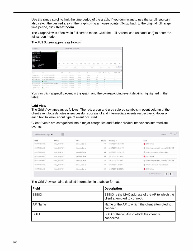
Use the range scroll to limit the time period of the graph. If you don’t want to use the scroll, you canalso select the desired area in the graph using a mouse pointer. To go back to the original full rangetime period, click Reset Zoom.
The Graph view is effective in full screen mode. Click the Full Screen icon (expand icon) to enter thefull screen mode.
The Full Screen appears as follows:
You can click a specific event in the graph and the corresponding event detail is highlighted in thetable.
Grid ViewThe Grid View appears as follows. The red, green and grey colored symbols in event column of theclient event logs denotes unsuccessful, successful and intermediate events respectively. Hover oneach text to know about type of event occurred.
Client Events are categorized into 5 major categories and further divided into various intermediateevents.
The Grid View contains detailed information in a tabular format:
Field Description
BSSID BSSID is the MAC address of the AP to which theclient attempted to connect.
AP Name Name of the AP to which the client attempted toconnect.
SSID SSID of the WLAN to which the client isconnected.
50

Monitoring Wi-Fi
Field Description
Channel Operating channel of the AP to which the clientattempted to connect. The channel is shown asDual for sensor that operates on both 802.11aand 802.11b/g simultaneously .
Timestamp Indicates the date and time when the clientconnected to an AP.
Event Indicates if the client successfully connected.
Packet Capture It provides the link of the wireshark file, thatcontains a packet capture for all failure events.User can open the file in Arista packets ordownload the file.
7.1.3 Top Applications by Traffic in Client Tab
Top Applications by Traffic chart graphically represents data usage for applications. It alwaysrepresents data for top five applications, with highest traffic. To view exact data usage, hover on thespecific bar in the graph.
The data on the widget can be filtered using the available filters on the top right corner of the widget.To know more about the filters refer Filters on Widgets.
7.1.4 Client Traffic VolumeThe Client Traffic Volume graph represents the data traffic sent and received by the client every 15minutes. X-axis in the graph denotes the time period for which the Data Usage is plotted and Y-axisdenotes the Traffic Volume.
51

This data usage includes Uplink Data as well as Downlink Data for all applications. User can choose toview the Client Traffic for:
• 2 hours• 4 hours• 8 hours• 12 hours• 1 day• 1 week
Hovering the mouse on data point provides detail information about data usage.
The graph contains the following details about the data:
• Time stamp: It includes day, date, month, year, and time of data usage.• Uplink Data: It states Uplink Data usage.• Downlink Data: It states Downlink Data usage.• Data Usage: It states Data Usage for all applications.
7.1.5 Application Session LogsApplication Session Logs provides details of the applications used by the client. Select a client fromMONITOR > Clients to view Application Session Logs.
The top left corner denotes the total number of application session logs.
Hover on the pie chart icon to view overall aggregated data. The data provides information about TotalSessions, percentage count of Affected Sessions, Total Experience Time and percentage count forPoor App Experience.
The logs on the widget can be filtered using the available filters on the top right corner of the widget.To know more about the filters refer Filters on Widgets.
52

Monitoring Wi-Fi
Detailed information about session logs is displayed in tabular format:
Property Description
App Name Name of the application.
Start Time Session start time.
End Time Session end time.
Duration(min)x Session duration in minutes.
% of Bad Time Percentage of time for which app experience wasbad for the specified clients.
Location Location at which the client connected.
Potential Cause Potential root cause for application performanceto be poor.
Average Bitrate Uplink Indicates average of the number of bits sent persecond by the client in that session.
Average Bitrate Downlink Indicates average of the number of bits receivedper second by the client in that session.
Average Bitrate Jitter Uplink Average standard deviation in uplink bitrate.
Average Bitrate Jitter Downlink Average standard deviation in downlink bitrate.
Average RSSI(dbm) Average Received Signal Strength Indicator.
Average Retry Rate Average percentage of retry packets out of thetotal packets sent or received by the client.
Average Data Rate Upstream Average upstream data rate.
Average Data Rate Downstream Average downstream data rate.
Roaming Count Number of APs involved during the session.
Associated AP(s) List of APs involved in the client session.
7.1.6 Devices Seeing This ClientDevices Seeing This Client represents list of APs currently watching the client.
The top-left corner denotes the total number of APs seeing the client and the name of the APassociated with the client.
The detailed information is as follows:
Field Description
Name Name of APs seeing the client.
RSSI (dbm) RSSI states signal strength of an AP as seen bythe client.
53

Field Description
Radio 1 Operating Channel Shows the band and channel operating on radio1. Channel is shown in brackets.
Radio 2 Operating Channel Shows the band and channel operating on radio2. Channel is shown in brackets.
Radio 3 Operating Channel Shows the band and channel operating on radio3. Channel is shown in brackets.
2.4 GHz Associations It states number of clients associated with 2.4GHz radio.
5 GHz Associations It states number of clients associated with 5 GHzradio.
6 GHz Association It states number of clients associated with 6 GHzradio.
Clicking on the name of AP takes you to the Access Points Information page.
7.1.7 Rename a ClientYou can change the name of a client.
Perform the following tasks to rename a client:
1. Go to MONITOR > Clients.
A list of clients that are being monitored is displayed.2. Right-click on the name of the client you want to rename or click on the menu icon (three vertical
dots) and select Rename Client.
Rename Client page is displayed.3. Change the name of the client and click Done to save the changes.
A message is displayed that confirms the change in the name of the client.
7.2 Access PointsAccess Point tab provides detailed information of an AP such as its name, IP Address, status, and theswitch it is connected to.
You can view ongoing activities on an AP using View Ongoing Activities option available to the righttop corner on the AP table. The list of live activities that can be viewed for AP are:
• Packet Trace Capture Packet Trace action on an AP capturesthe packet and inspectes it to help diagnoseand solve network problems. Selecting thisactivity displays the list of those devices forwhich packet trace is in session.
• Prevention Prevention activity displays the list of allquarantine devices.
• Client Connectivity Test Client Connectivity Test tis performed totroubleshoot an AP that has client connectivityissues. Client Connectivity Test actiondisplays the list of such devices, for those thetroubleshooting is in progress.
54

Monitoring Wi-Fi
• None Selecting None provided the list of all the APswithout any filters.
You can perform the following actions on every AP, these actions are available on a right click on anyAP:
Action Description
Update Firmware Using this option you can update the firmware onthe AP to the latest or any previously releasedversion.
Access Point Event Logs A log table that maintains event logs of APs.
Run Client Connectivity Test Runs the Client Connectivity Test.
View RF Explorer The RF Explorer shows you information such asthe channels occupied by other APs in the vicinityof the AP and the RSSI values for each of theneighboring APs as seen by the AP.
Capture Packet Trace This option helps troubleshoot Arista devicesoperating in AP or AP/Sensor mode.
Packet Trace History You can view the Packet Trace History for aselected AP.
View on Floor Map This option redirects you to the location on thefloor map where the AP is placed.
Customize Transmit Power or Channel Transmit Power Selection enables you to controlthe transmission power of the AP
Move Using Move operation you can change location ofan AP.
Reboot This operation Reboot's the AP.
Rename Renames the AP.
Delete Deletes the APs from the list of available APs.
Click on an AP in the list on the Monitor > Access Points page to go to the AP details page . The APdetails page shows the event logs of the AP, a list of clients associated with the AP and their details,a graph showing clients by average data rate, top applications by traffic, and network usage. Theselected AP's name is displayed on the top-right of the page. You can select another AP from the drop-down list.
The AP details page provides the following information:
55

Network Usage - Traffic The chart displays a line graph showing thenumber of client association and its traffic volume,for all the clients on the selected folder or floor.
Network Usage - Poor Application Experience This chart provides overall application usageanalysis.
Baseline - Clients Affected By PoorExperience
The Baseline - Clients Affected By PoorPerformance graph calculates the baselinefor the percentage of clients affected by poorperformance, for the selected AP, over a period oftime.
Baseline - Retry Rate% The graph calculates baseline for the Retry Rate% of the clients connected to the selected AP
Baseline - Averge Data Rate The graph calculates the data rates for 2.4 GHz,5 GHz, or 6 GHz for the selected SSID(s) andduration.
Baseline - Clients Affected by Failure Baseline - Clients Affected by Failure chartprovides calculated baseline for the percentage ofclients that failed due to connectivity issues.
Baseline - Clients Affected by Poor AppExperience
Baseline - Clients Affected chart provides thecalculated baseline for the percentage of clientsaffected by poor app experience. This data isprovided for the selected AP.
Clients by Average Data Rate Displays a bar graph of the clients and their datausage, for the selected AP.
Top Applications by Traffic Displays a bar graph of the top 5 applications thathas highest data usage, for the selected AP.
Spectrum Occupancy Shows the number of active radios and clientsacross the Rf spectrum.
Channel Utilization Shows the AP channel utilization.
Currently Associated Clients Currently Associated Clients widget provides thelist of clients that are currently associated with theAP.
Ap Health Shows the CPU and memory utilization of an AP.
Devices Seeing this AP The widget displays the list of managed devicesobserving the selected device.
Visible VLANs The widget displays details of the VLANs visibleto the managed device.
Visible Access Points Provides the list of the APs visible to the selectedAP.
Visible Clients Provides the list of clients visible to the selectedAP.
Note: Views and charts that show information about channels other than the operatingchannels of the AP work best when the AP has a dedicated scanning radio. APs that donot have a dedicated scanning radio use background scanning, where typically an AP goesoff-channel once every 60 seconds to scan one channel for 100 ms. Because backgroundscanning takes a long time to scan all channels in the band, an AP in background scanning
56

Monitoring Wi-Fi
mode has a snapshot of the network that is anywhere between five minutes to an hour old.During this time, the radio environment could have changed significantly.
In the AP details view, you can click on the AP name under the AP icon (when you hover, you see theView Properties tool tip) to open the AP properties right panel. The panel shows you the wired sideproperties and health stats for the AP.
Note: The wired properties of only the primary interface (eth0) of the AP are shown, and LLDPmust be enabled on the switch for current switch properties to be shown.
The following table shows whether, depending on the state of the AP, the wired properties are currentor they reflect the last known values. For example, for active APs, the wired properties shown are thecurrent ones but for inactive APs they’re the last known values. The values are not displayed for APs802.11ac Wave-1 or lower and for APs with firmware older than version 8.9. Some properties (e.g.,Health Stats) are updated at periodic intervals; others (e.g. Switch Name) are updated if and whenneeded.
Switch PropertiesAP State
SwitchName
SwitchVendor
SwitchPort
VLANsDetected
IPv4or IPv6Properties
LinkSpeed
HealthStats
Active Current Current Current Current Current Current Current
Inactive orOffline
LastKnown
LastKnown
LastKnown
LastKnown
LastKnown
LastKnown
LastKnownwith a notein the rightpanel:"Valueswhen APwas lastactive"
(shown"--" in theManagedDevicesand APlisting)
Mesh Root Current Current Current Current Current Current Current
MeshNon-Root(Poweredby DC orPoE brick)
NotDisplayed("--")
NotDisplayed("--")
NotDisplayed("--")
Current Current NotDisplayed("--")
Current
MeshNon-Root(Used fornetworkextensionandconnectedto aswitch)
Current Current Current Current Current Current Current
57

LinkAggregation:eth0 Up(regardlessof whethereth1 is Upor Down)
Current Current Current Current Current Current Current
LinkAggregation:eth0 Downand eth1 isUp
Lastknown
Lastknown
Lastknown
Lastknown
Current Lastknown
Current
Failsafe LastKnown
LastKnown
LastKnown
LastKnown
LastKnown
LastKnown
LastKnownwith a notein the rightpanel:"Valuesbefore APenteredfailsafemode"
(shown"--" in theManagedDevicesand APlisting)
LLDPDisabledon Switch
LastKnown
LastKnown
LastKnown
Current Current Current Current
The wired properties of only the primary interface (eth0) of the AP are shown. Thus, when using linkaggregation, the switch and VLAN wired properties reflect the information available on the primaryinterface only; their values do not depend on the state of the secondary interface (eth1). The IP andhealth stats, however, do not depend on a particular interface; their values are current as long as atleast one of the two interfaces is up.
7.2.1 Access Point Explorer
AP Explorer provides a holistic view of all the APs at a location and provides an easy way for thenetwork administrators to understand AP distribution for each attribute.
To view the AP Explorer,
1. Navigate to Monitor -> WiFi -> Access Points.2. Click Access Point Explorer.
58

Monitoring Wi-Fi
Alternatively, you can also navigate to AP Explorer from Monitor -> WIPS -> Managed DeviceExplorer.
On the AP Explorer chart, you can filter the devices based on the Device Status (All, Active, orInactive). You can use the attribute drop-down menu to view graphical AP distribution based on theselected attribute. For example, you can the AP Explorer chart to get a summary view of AP Health bylooking at the APs based on CPU Utilization or Memory Utilization.
7.2.2 Clients by Avg. Data Rate for an APThe Clients by Avg. Data Rate graph displays clients classified based on data rate. CV-CUE has pre-defined, fixed thresholds for Average Data Rate. Since thresholds are configurable, user may select avalue that falls in between a bucket on the X-axis. For instance, if a user sets the data rate thresholdto 75 Mbps and RSSI threshold to -68 dBm, then these values fall in the “50 to 100 Mbps” data ratebucket and “-65 to -75 dBm” RSSI bucket, respectively.
The following logic is used to determine the color of the bar that falls in such a bucket:
• If all values in the “50 to 100 Mbps” bucket are below 75 Mbps, then the bar in the “50 to 100 Mbps”bucket is red.
59

• If all values in the “50 to 100 Mbps” bucket are above 75 Mbps, then the bar in the “50 to 100 Mbps”bucket is green.
• If some values in the “50 to 100 Mbps” bucket are above and below 75 Mbps, then the bar in the“50 to 100 Mbps” bucket is yellow.
The chart can be observed for the following bands:
• 2.4 GHz• 5 GHz• 6 GHz• All Bands
7.2.3 Currently Associated Clients for an APCurrently Associated Clients widget provides the list of clients that are currently associated to the AP.
The graph displays the following information:
Column Description
Name Name of a device to which AP is connected.
User Name Name of a user.
MAC Address Unique 48-bit address of the AP/ 802.11 PHYmodes used by the AP.
IP Address IP address of the AP
Associated SSID Name of a SSID to which client is connected.
OS Operating System running on the client.
UP/Down Since Up since time or Down since time
RSSI (dBm) Received Signal Strength Indicator.
Sticky Denotes whether client is sticky or not. Stickyclient means if client is connected to AP andwhile roaming it found better AP with more bettersignal strength, still it decides to stay connectedwith older client.
Tx Data Rate Tx Data Rate is Transmission Data Rate of aclient.
Rx Data Rate Rx Data Rate is Received Data Rate of a client.
Avg Data Rate Avg Data Rate is Average Data Rate of a client
Retry Rate (%) Retry Rate (%) is Retransmission rate of a client.
60

Monitoring Wi-Fi
7.2.4 Top Applications by Traffic for an APTop Applications by Traffic chart graphically represents data usage for applications. It alwaysrepresents data for top five applications that have highest data usage (transmit and receive). To viewexact data usage, hover on the specific bar in the graph.
You can choose to view the top applications by traffic for the following time intervals:
• 2 hours• 4 hours• 8 hours• 12 hours• 1 day• 1 week
7.2.5 Network UsageYou can access the Network Usage chart in two different ways from CV-CUE UI. If you accessthe chart from the performance dashboard, it displays a line graph showing the number of clientsassociated with the SSID and its traffic volume, for all the clients on the selected folder or floor.Whereas when you access the chart through AP drill down, it displays similar data, but this time for theselected AP.
If you hover over the graph, a tooltip providing quick information like timestamp, the number of clientsassociated and the used traffic volume appears.
You can view or retrieve data using the filters. To know more about these filters refer Filters onWidgets.
The data of the network usage chart can be filtered based on two parameters; a client's data and theamount of data used by an application.
61

Drill down on the data point on the graph, redirects you to the page containing client connectionstable. This table contains the list of all the client connections along with their detailed information forthe selected timestamp. For client details refer, Filtered Network Usage Chart
Drill down on the bar, redirects you to another page that contains:
• Client Connections table - contains the list of all the client connections along with their detailedinformation for the selected timestamp.
• Top Applications - that shows top ten applications with highest data usage. You can select an appfrom the drop-down list given on the top left corner of the table. Along with the selected applicationname it displays application specific data consumption.
• All Application traffic - it displays the total amount of data used by the applications for a selectedAccess Point or a location. This information is shown at the top-right corner of the table.
• Client Connections - selecting client connection displays the list of all the clients using theapplication selected from the top applications list.
• Access Points Distribution - selecting access points distribution displays the list of all theassociated APs.
7.2.6 Network Usage - Poor Application ExperienceThis chart provides overall application usage analysis. It states the time for which application qualitywas good and the time for which it was bad.
The graph displays poor app experience in red colour and good app experience in green colour. X-axisdisplays time slots and Y-axis displays amount of time app quality was good or bad.
Hover on the graph provides a tool tip with the following information:
• Timestamp• No of associations• Aggregated value for poor app experience in percentage.
Click the data point or bar graph in the chart to view more details.
There are four filters provided on the right corner of the chart to filter the data:
Conferencing Apps Filter
The graph can be viewed for specific conferencing app using All Conferencing Apps filter. Filter canbe applied on the following apps:
• WebEx• Skype• GoToMeeting• Hangouts• Slack• Microsoft Teams• Zoom
62

Monitoring Wi-Fi
Selecting All Conferencing Apps option provides details for all the above listed apps at once.
SSID Filter
The application quality can also be viewed for specific SSID, using All SSIDs filter. Selecting a specificSSID provides a application quality graph for the specified SSID. Selecting All SSIDs provides anaggregated data on a graph for all the SSIDs.
Frequency Filter
The data can be filtered based on frequencies. The data for applications working on the selectedfrequency is represented graphically. The possible values for frequency filter are:
• 2.4 GHz• 5 GHz• 6 GHz• All Bands
Time Filter
You can view or fetch the Application Session Logs for the following time intervals:
• 2 hours• 4 hours• 8 hours• 12 hours• 1 day• 1 week
7.2.7 Spectrum Occupancy
As shown in the following figure, you can filter on a band and duration to see the number of radios andclients that were active in that band in that duration. This can help you identify congested or under-utilized bands.
7.2.8 Channel Map
Channel Map displays the number of clients and access points (APs) visible to the managed deviceat a time on a given channel. Network administrators can use this information to identify congested orunderutilized channels in a given band.
To view Channel Map, select Channel Map from the drop-down menu in Specturm Occupancy chart.
63

In the Channel Map chart, from the right-hand drop-down menu, select the band and use the timeslider to select your time interval to view the number of visible clients and APs. You can view theChannel Map upto 12 hours in the past from the current time. Hover over the chart to view the exactcount of APs and clients on a given channel.
7.2.9 RF Explorer
You can launch the RF Explorer from the Spectrum Occupancy chart or from the AP listing underMonitor > WiFi > Access Points by right-clicking on an AP and selecting Troubleshoot > View RFExlporer.
As seen in the previous figure, the RF Explorer shows you what an AP sees in its RF neighborhood.For example, it shows you the channels occupied by other APs in the vicinity of the AP and the RSSIvalues for each of the neighboring APs as seen by the AP.
You can use the RF Explorer to identify issues such as co-channel and adjacent channel interference,and DFS channels occupied by APs. The grey rectangle stretching across the RSSI axis representsthe operating channel of the AP itself; the heights of the other channel trapezoids indicate the RSSIvalues of those channels as seen by the AP. You can click on an AP from the list of APs to see itschannel details on the chart (as seen in the callout in the previous figure).
7.2.10 Channel Utilization
As shown in the following figure, the channel utilization chart shows the AP channel utilization (as apercentage value) averaged over 15-minute intervals for both the 2.4 GHz and 5 GHz bands, for theselected duration.
64

Monitoring Wi-Fi
The channel utilization chart is available for 2.4, 5, and 6 GHz bands.
7.2.11 AP Health
As shown in the following figure, the chart shows the average CPU and memory utilization of an AP forthe selected duration.
7.2.12 Visible Access PointsThe Visible Access Points widget provides the list of the APs visible to the selected AP. The widgetprovides two different views: one for Managed APs and the other for Unmanaged APs.
Visible Access Points - Managed
Selecting Managed from the drop-down list displays APs that belong to your network and are in thevicinity of the selected AP.
65

Visible Access Points - Un-managed
Selecting un-managed from the drop-down list displays the Access Points that do not belong to yournetwork but are in the vicinity of the selected AP.
7.2.13 Radios Seeing this AP(Access Point)
This widget is available on drilling down from any Wi-Fi device. The widget displays the list of managedWi-Fi device radios observing the selected device with the best RSSI.
66

Monitoring Wi-Fi
7.2.14 Visible VLANsThe visible VLANs widget is available on drilling down from any managed Wi-Fi device. The widgetdisplays details of the VLANs visible to the managed device. "Monitored" in the Status columnindicates that the VLAN is being monitored by that managed device. "Not monitored" indicates that it isbeing monitored by another managed device.
The VLANs that can be seen by the selected device are populated depending on the following:
1. If the VLAN is used by the device to communicate with the Wireless Manager ( aka communicationVLAN); shown marked with an asterisk.
2. If the ID of the VLAN is added while configuring the SSID.
67

3. If you enable Auto VLAN monitoring from CV-CUE > Device Settings > VLAN Monitoring, theactive VLAN is monitored by the device with the highest MAC address.
Thus the monitored VLAN's ID is added to the monitoring device's list and the VLAN's status is setto Monitored .
4. If you choose to enable Monitor Additional VLANs , one needs to specify a comma-separated listof VLANs to be monitored. In this situation, any active VLAN from the specified list is monitored.The device with the highest MAC address monitors the VLAN. The monitored VLAN's ID is addedto the monitoring device's list and VLAN's status is set to Monitored.
68

Monitoring Wi-Fi
7.2.15 Visible ClientsThe Visible Client widget provides the list of clients visible to the selected AP. It also provides the totalnumber of visible clients on the top left corner of the widget.
7.2.16 View Access Point Event LogsAP event logs table maintain event logs of AP. The captured events are from an AP perspective anddo not include data related to clients and their connectivity information. These events are sent by theAP to Wireless Manager in real time and logged at Wireless Manager.
You can view AP Event Logs, by selecting the option View Event logs with a right-click on any APfrom MONITOR > Access Points > Troubleshoot.
69

The detailed information about the event logs is as follows:
Column Description
Category It is a category of event.
Type It is a type of event.
Description It is description of event.
Date Timestamp at which event occurred.
The AP Event Logs details can also be fetched for specified durations using Duration Filter. To knowmore about the duration filter refer Filters on Widgets.
The various types of events that are logged for an AP are:
• AP Memory Status• AP Reboot• AP IP Conflict• AP System Service Crash• AP Ethernet Port Status• AP Upgrade Failure• AP Upgraded• AP CLI config change• AP DHCP lease status, etc.
7.2.17 View on Floor MapView on Floor Map option redirects you to the location on the floor map where the AP is placed.
To view the AP on the Floor Map:
1. Navigate to MONITOR > Access Points.2. Right click on the AP, you wish to locate on the Floor Map.3. Select View on Floor Map.
These option is enabled only if the selected AP is placed on any of the floor maps. Else it isdisabled.
It redirects you to the Floor Map where the selected AP is placed.
7.2.18 Customize Transmit Power or ChannelTransmit Power Control enables you to control the transmission power of the AP. Transmit ControlSettings are configured from Radio Settings. These settings are the generic settings for all the APs.
CV-CUE facilitates AP specific Transmit Control Settings.
70

Monitoring Wi-Fi
To know more about Transmit Power Selection refer Configure Transmit Power Selection in RadioSettings and for Channel settings refer Configure Basic Radio Settings
For AP specific customization:
1. Navigate to MONITOR > Access Points.2. Right click on the AP, for which you wish to customize the settings.3. Select Customize Transmit Power or Channel.
A Customize Transmit Power or Channel window appears to the right of the screen.4. Select appropriate frequency for which you wish to customize the settings.
Possible frequencies are 2.4 GHz, 5 GHz, and 6 GHz.5. Select Customize Transmit Power for transmit power settings.
a. Select Auto or Manual option.
Selection of Manual option enables the Transmit Power text box to provide transmission power ofthe AP in dBm.
6. Select Customize Channel Settings for channel settings.
a. Select Operating Channelas either Auto or Manual.
Selection of Manual option enables the Channel Number text box to provide a channel number.7. Click Save.
The customization settings are saved.
7.2.19 Customize VLANs to Monitor per AP
You can configure custom VLANs for individual APs to monitor. The steps to do so are as follows:
1. Go to MONITOR > WIPS > Managed WiFi Devices or MONITOR > WiFi > Access Points, or goto a floor plan and select an AP on the floor plan.
2. Right click on the AP and click Customize > VLANs. The Customize Access Point VLANs rightpanel appears.
3. Add the VLANs you want the AP to monitor.
Detected VLANs are VLANs that the AP has detected on the network. They might help you selectVLANs to monitor.
4. Select whether you want the VLAN to use a Static IP or DHCP. For the Static IP case, enter the IPnetwork configuration.
5. Select a Communication VLAN from among the monitored VLANs.
The AP communicates with the Wi-Fi server over the Communication VLAN. So the CommunicationVLAN must be one of the VLANs that the AP monitors.
6. Save the configuration.
7.2.20 Move an APCV-CUE provides the facility to change the location of an AP using the Move option.
To move an AP:
1. Go to MONITOR > Access Points.
A list of APs that are being monitored is displayed.2. Right-click on the name of the AP that you want to move and select Move.
Location Navigator is displayed.3. Select the new location, where you wish to move the AP.4. Click Move.
A confirmation window is displayed.5. Select appropriate option to confirm.
71

If you select Yes the selected access points will adopt the configuration applied at the destinationfolder. Also if the AP is currently placed on any of the floor map, then the AP will be removed fromthat map.
An appropriate message is displayed that confirms the change in location.
7.2.20.1 Behavior - Move DevicesWhen you move devices across locations, the behavior of the devices may change depending onmultiple factors.
The factors to be considered are captured below.
Suppose that you select a mix of devices to move, i.e., some are part of a group and others are not.
• For devices that are not part of any group, the behavior is exactly as expected - when moved fromone folder to another, these devices start using the default configuration of the destination folder.
• If the destination folder has no groups, devices from the source groups will be removed from theirrespective groups and all devices will start using the default configuration of the destination folder.
• For devices that were part of some group in the source folder, see the table below.
Source Destination
Is the device in agroup?
Does the group have aconfig?
Is the same groupavailable at thedestination location?
Behavior
Yes Yes Yes All devices becomepart of the destinationgroup but retain theirconfiguration.
Yes Yes No All devices are removedfrom their respectivegroups and start usingthe default configurationof the destination folder.
Yes No Yes All the devices areremoved from theirrespective groupsand become part ofthe destination group.They start using theconfiguration of thedestination group.
Yes No No All devices are removedfrom their respectivegroups and start usingthe default configurationof the destination folder.
7.2.21 Reboot Access PointsYou can reboot an AP, with the help of CV-CUE.
Perform the following tasks to reboot an AP:
1. Go to MONITOR > Access Points.
A list of APs that are being monitored is displayed.
72

Monitoring Wi-Fi
2. Right-click on the name of the AP that you want to reboot and select Reboot.
Reboot dialog box is displayed.3. Click Yes to reboot the AP.
A message is displayed that confirms the reboot. You can check the status after some time.
7.2.22 Rename Access PointsYou can change the name of the AP.
Perform the following tasks to rename an AP:
1. Go to MONITOR > Access Points.
A list of APs that are being monitored is displayed.2. Right-click on the name of the AP that you want to rename and select Rename.
Rename AP page is displayed.3. Change the name of the AP and click Done to save the changes.
A message is displayed that confirms the change in the name of the AP.
7.2.23 Delete Access PointsYou can delete the APs from the list of APs available on Access Points tab.
Perform the following tasks to delete an AP:
1. Go to MONITOR > Access Points.
A list of APs that are being monitored is displayed.2. Right-click on the name of the AP that you want to delete and select Delete.
A Delete dialog box is displayed.3. Click Yes to confirm the deletion.
A message is displayed that confirms the deletion of the AP.
Important: If the AP is physically active on the network after deletion, then:
• CV-CUE marks the AP to Unknown location.• The default device template of the Unknown location is applied.• The default SSIDs are pushed on the active AP, if the AP is configured in the Device
Template.• No SSIDs are applied, if the AP is not configured.
7.2.24 View Ongoing Activities on APView Ongoing Activities is an action available on Access Points screen.
To view the ongoing activities on an AP, perform the following steps:
1. In CV-CUE navigate to Access > Access Points2. Click on View Ongoing Activities action present on the top right hand corner of the screen.3. From the drop-down menu, select one of the following:
• Packet Trace
It displays the list of APs with their information on which the Packet Trace Activity is in progress.• Prevention
It displays the list of APs in quarantined status.• None
It displays the list of APs on which no activity is going on.
73

7.2.25 View AP UptimeAP Uptime indicates how long the AP has been up and running. To view AP Uptime, navigate toMonitor > WIPS > Managed Wi-Fi Device. The Last Booted At column shows the AP Uptime.
7.2.26 Assign a Device to a Group from Access Points tabOne of the ways to assign access points to a group is from the access point list available on theaccess point page.
To assign a device to an existing group, perform the following steps:
1. Go to Monitor > Access Points2. Right-click on the name of a single AP, that you want to assign to a group or click on the menu icon
(three vertical dots) and select Assign/Reassign to a Group.
A Select a Group window appears on the right panel.
3. Select the group to which you want to assign the selected AP.
In case the group is not available in the list, you can add a new group from this panel. The newlyadded group will always be created at the top-most allowed folder of the selected locations. Addinga group option is disabled, if the user does not have access to the folder.
Note: When assigning multiple APs, only those groups which are available to the selectedaccess points' folders will be listed under the Select a Group panel.
74

Monitoring Wi-Fi
4. Click Assign.
7.2.26.1 Assign a Device to a GroupYou can assign one or more access points from a location subtree to a group. It is a method usedto apply a single Wi-Fi configuration to multiple devices across different locations. If a group has noconfiguration, then the assigned devices will use the default Wi-Fi configuration of their respectivelocations. On the other hand, suppose an AP already has custom Wi-Fi configuration applied to it.Then if you assign such an AP to a group it will start using the Wi-Fi configuration of the group.
Assigning a device to a group can be performed from two different tabs:
• Access Points• Folders/Floors Page
7.2.26.2 Assign a Device to a Group from the Folders/Floors PageIn addition to assigning a device to a group from access point’s page, you can also do this from thefolder/floor page.
To assign a device to an existing group, perform the following steps:
1. Go to SYSTEM > Navigator -> Folders/Floors.2. Right-click on the name of a single AP that you want to assign to a group or click on the menu icon
(three vertical dots) and select Show Available Devices option from the list.
A list of available access points available at the selected folder appears on the right panel.3. Right-click on the name of a single AP that you want to assign to a group or click on the menu icon
(three vertical dots) and select Assign/Reassign to a Group.
A Select a Group window appears on the right panel.4. Select the group to which you want to assign to the selected AP.
In case, the group is not available in the list, you can add a new group from this panel. You cannotadd a group if you do not have access to the top-most allowed parent folder. The newly addedgroup will always be created at the top-most allowed parent folder of the selected locations.
5. Click Assign.
75

7.2.27 Re-assign a Device to Another GroupThis operation allows you to move the access points from one group to another. Once reassigned,selected access points will start using target group's Wi-Fi configuration. If the target group doesn'thave Wi-Fi configuration applied to it, access points will use their location's default Wi-Fi configuration.Even if the selected access points were not assigned to any group, reassigning will assign them to thetarget group.
Note: If the device is re-assigned to a group that doesn't have any configuration , then suchdevices will use the default Wi-Fi configuration of the respective folder.
Re-assigning a device to a group can be done from three different tabs:
• Access Points• Folders/Floors• Groups
The first two methods are the same as for assigning a device to a group. The third one is applicableonly to re-assigning devices.
To re-assign a device to another group from one group's page, perform the following steps:
1. Go to System > Groups.2. Right-click on a selected group and select Show Assigned Devices.
A list of Access Points available at the selected location will display on the right panel.
3. Right-click on the name of the AP you want to reassign and click Assign/Reassign to a Group.
A Select a Group window appears at the right side of the screen.
76

Monitoring Wi-Fi
4. Select a group from the list to re-assign that device to the selected group.
5. Click Assign.
7.2.28 About Device Firmware Update in CV-CUEYou can configure an automatic update that includes upgrade or downgrade of Arista devicesdeployed at your enterprise premises. The device update can be configured or scheduled for devicesthat connect to the server for the first time as well as for existing devices that are already placed atvarious locations.
A device firmware update configuration is specific to a location and applies to all Arista devices placedat the location. An individual Arista device cannot have an independent device firmware updateconfiguration.
77

A device firmware update configuration can be created for location folders only. A location floorcannot have its own device firmware update configuration; it inherits the device firmware updateconfiguration from the parent location folder. When you do not recursively apply a device firmwareupdate configuration to the child location folders, the configuration is applied only to the selectedlocation folder and the location floors directly under the selected location folder.
You can choose to apply a device firmware update configuration recursively to the child locationfolders, when you are creating or editing the device firmware update configuration, However, a childlocation folder can have its own device firmware update configuration. If you define the firmwareupdate configuration specific to the child location folder when a schedule for its parent location folder isalready defined, the schedule configured to the child location applies to the child location folder
When an active schedule is deleted or modified for a location, the sensors of that location on which theupdate process is already started or the update command is scheduled would still be upgraded.
The device firmware update setting for a location applies to all active devices deployed at the location.The update can be applied to both existing Arista devices and new devices connecting to the AristaServer for the first time. A schedule can be configured for existing Arista devices at a location. Thedevice firmware update configuration is not tied to release numbers. If a server is updated multipletimes between the creation of the update configuration and scheduled time of device update, thedevices are updated to the latest firmware release.
7.2.28.1 Update AP FirmwareYou can update the firmware on the AP to the latest or any previously released version. The APautomatically reboots after the firmware update is complete.
Perform the following tasks to update the firmware of an AP:
1. Go to MONITOR > Access Points.
A list of APs that are being monitored is displayed.2. Click the Options icon (three vertical dots) or right-click on the name of the AP and select Update
Firmware.3. Select the required firmware version from the Version drop-down list
You can update the AP firmware to any version.4. Click Update.
A message is displayed that confirms that the firmware update is initiated. You can check thefirmware update status after some time.
7.2.28.2 Update Firmware for Multiple APsYou can update the firmware for multiple APs at the same time.
To update the firmware for multiple APs, perform the following steps:
1. Go to MONITOR > Access Points.
A list of APs that are being monitored is displayed.2. Select the required APs, click the Options icon (three vertical dots) and click Update Firmware.
Update Firmware page is displayed as follows:
• The model names of the selected APs.• Number of access points selected for each device model.• Version, drop-down list that contains the available firmware versions for each device model.
3. Select the required version number per AP model, from the Version drop-down list.4. Click Update to update the firmware.
A message is displayed that confirms that the firmware update is initiated. You can check thefirmware update status after some time.
78

Monitoring Wi-Fi
7.2.28.3 Schedule Firmware Update of a Single AP
Follow these steps to create a recurring or one-time schedule to update the AP firmare:
1. Go to MONITOR > WiFi > Access Points.2. Right click the AP and select Update Firmware.3. Select the version from the right panel.
7.2.28.4 Schedule Firmware Update of Multiple APs
Follow these steps to create a recurring or one-time schedule to update the AP firmare:
1. Go to MONITOR > WiFi > Access Points.2. Click the Firmware Update Settings icon.
3. Provide the schedule for update in the Firmware Update Settings right panel.
The following table provides additional information for some of the options the Firmware UpdateSettings panel:
UI Option Description
Apply Update Settings Recursively toSubfolders
Applies the update settings to the selectedfolder location and also to all its subfolders, ifany.
Hitless Update Updates access points with minimum impactto Wi-Fi clients. In certain situations, when theselected AP is the only AP on the floor andthere are no APs around for clients to connect,then the Wi-Fi will be impacted.
Update Window Defines the duration for the firmware update.For example, if the Start Time is 1 hour 15minutes and the Update Window is 20 hours 30minutes, then the update will begin at 1:15 AMand end at 9:45 PM. Firmware updates are notinitiated after the expiry of the Update Window.However, ongoing updates during the UpdateWindow can continue even after the UpdateWindow expires.
The Scheduled state is indicated by an orange calendar icon in the Update column under Monitor > WiFi > Access Points. You can also see which APs are scheduled for a firmware update by clickingon the AP icon of the W-iFi Network Counters as shown in the following figure.
79

7.2.28.5 Cancel Firmware UpdateYou can cancel the firmware update for an AP. When an update is initiated for an Arista AP, the AP isinitially in Active state and changes to Inactive state after a while. You can cancel the update only untilthe Arista AP is in Active state. Once the device is in Inactive state, you cannot cancel the firmwareupdate.
Perform the following tasks to cancel firmware update.
1. Go to MONITOR > Access Points.
A list of APs that are being monitored is displayed.2. Right-click the AP for which you want to cancel the firmware update and select Cancel Update.
A message is displayed that confirms the cancellation of the firmware update .3. Click Yes to cancel the update.
7.2.29 Access Point Web ShellWeb Shell is an online interface to remotely log into an AP via SSH. An administrator or a superusercan open Web Shell for a specific access point (AP) from CV-CUE (CV-CUE). Web Shell is helpful totroubleshoot AP issues, especially if an AP is behind a NAT. The URL for the Web Shell is specific toan AP. You can bookmark the URL to open a shell session to the AP directly instead of opening theshell session from CV-CUE.
Depending on the limit defined in the config parameter, you can open concurrent Web Shell sessionsto an AP. Web Shell is unavailable for inactive APs.
Note:
If the AP is overburdened with data-heavy operations, then there could be a delay with anongoing Web Shell session or a new Web Shell may not open. For example, if you are alreadyperforming a task in the Web Shell, and then you start some data-heavy operations such aspacket capture, generate debug logs, or live client troubleshooting, you would see a latencyin the Web Shell. If you are performing live client debugging (or similar other data-heavyoperations), and then you try to open the Web Shell, you may receive an error and the WebShell may not open.
For the list of APs supporting Web Shell, see the Access Point Feature Matrix article.
You can open an AP web shell from:
• MONITOR > WiFi > Access Points• MONITOR > WIPS > Managed WiFi Devices• Floor Plan
7.2.29.1 Open Access Point Web Shell
You can open the access point (AP) web shell from CV-CUE for an individual AP and perform basicoperations using CLI commands.
To open the AP Web Shell:
80

Monitoring Wi-Fi
1. Got to MONITOR > WiFi > Access Points.2. Right click the AP and go to Troubleshoot > Open Web Shell.
Web Shell opens in a new tab.3. Enter the root credentials and log in to the web shell.
You can now type your AP-CLI commands.
To terminate the session, close the browser.
7.3 RadiosThe Radios tab under MONITOR tab displays a list of all the radios operating on 2.4 GHz, 5 GHz, and6 GHz bands. It displays a list of clients that are recently associated to the selected Radio. The recentassociations are either those that happened in the last 4 hours or the latest 100 clients. This is the totalnumber of associations in the system and not per device.
The Radios tab displays the following information about radios:
Field Description
Status Indicates whether the radio is on or off.
Access Point Name Name of the AP.
Channel Width Displays the width of the operating channel of theradio such as 80 MHz or 40 MHz.
MAC Address Unique 48-bit address of the AP.
IP Address Displays the IP address.
Device Template Indicates the device template applied to thedevice.
Channel Displays the Channel number on which the APradio operates.
Clients Displays the number of clients connected to theradio.
Tx. Power(dBm) Indicates the transmission power.
Frequency Indicates the frequency on which radio isoperating.
RF Utilization (%) Indicates the percentage of transmit and receivetime on the radio.
Upstream Usage Indicates upstream data usage.
Downstream Usage Indicates downstream data usage.
81

Field Description
Worst Client RSSI (dBm) Displays the worst client signal strength.
Retry Rate (%) Indicates the re-transmission rate in percentage.
Location Displays the radio location.
Model Displays the name of the device model.
Noise Floor (dBm) Indicates the measure of the signal created fromthe sum of all the noise sources and unwantedsignals within a measurement system.
Channel Width Shows the width of the operating channel of theradio.
7.3.1 Turn Radio On or Off
You can turn individual access point (AP) radios on or off. To understand the motivation for this,consider a floor where Wi-Fi access points (APs) with both 2.4GHz and 5GHz radios are deployed.Since the 2.4GHz signal propagates better than 5GHz and APs are often deployed to provide high5GHz RSSI all over the floor, some areas on the floor end up having an “excess” of 2.4GHz signal,i.e., these areas get high RSSI signal from multiple 2.4GHz AP radios. This could cause interference inthose areas because the 2.4GHz band has only three non-overlapping channels. You can then simplyturn off the 2.4GHz radio for APs near these high 2.4GHz interference spots on the floor.
You can turn an AP radio on or off only if:
• The AP is active and• The radio is not part of a mesh network.
The steps to turn a radio on or off are as follows:
1. Select the location of the AP whose radio you want to turn on or off.2. Go to Monitor > WiFi > Radios.3. Right-click on the radio and select Turn Radio Off or Turn Radio On.
Note:
• When you turn a radio off, all SSIDs on that radio are turned off. For uninterrupted Wi-Fiin the coverage area of an AP, make sure that at least one AP radio is on.
• Turning a radio on or off can take a few minutes; the radio appears in italics until itsstatus has changed, after which the UI shows the updated status—on or off, as the casemay be.
• A radio that has been turned off manually is not turned on automatically when its APreboots or when an SSID of that AP is scheduled to be on.
7.4 Active SSIDsThe Active SSIDs page displays a list of active SSID profiles.
Go to MONITOR > WiFi > Active SSIDs to view the Active SSIDs page.
82

Monitoring Wi-Fi
The Active SSIDs page displays the following information:
Field Description
SSID Name of the SSID profile.
Security The mode of security used.
Authentication The authentication method used.
2.4Ghz Clients The number of clients connected on the 2.4 GHzfrequency.
5 GHz Clients The number of clients connected on the 5 GHzfrequency.
6 GHz Clients The number of clients connected on the 6 GHzfrequency.
2.4 GHz Radios The number of 2.4 GHz radios on which the SSIDis being broadcasted.
5 GHz Radios The number of 5 GHz radios on which the SSID isbeing broadcasted.
6 GHz Radios The number of 6 GHz radios on which the SSID isbeing broadcasted.
Uplink Data The uplink data usage.
Downlink Data The downlink data usage.
7.5 Application VisibilityApplication information page provides detailed monitoring information for an application selected fromthe Application Visibility tab. It displays a list of top 10 clients using the selected application and aline graph plotting the usage of the selected application over a period of time.
The name of the selected application is displayed on the top-left of the page. You can select anotherapplication from the drop-down list.
83

The application information page displays the following information:
Baseline - Clients Affected
Baseline - % Poor Application Experience
Application Traffic It displays the usage of data of the selectedapplication, over a period of time. ReferApplication Traffic section for more information.
Application Traffic - Clients
Application Traffic - Sessions
Application Traffic - Quality of Experience
Clients Using This Application It displays a list of the top 10 clients with highestdata usage for the selected application alongwith the detailed information of the client likeUsername, MAC address, IP address, RecentlyAssociated SSID and so on. Refer Clients UsingThis Application section for more details.
7.5.1 Application Traffic
7.5.2 Monitoring an ApplicationYou can monitor an application, from the list of applications that are displayed in the ApplicationVisibility tab.
To Monitor an application, perform the following tasks:
1. Go to MONITOR > Application Visibility.
A list of applications that are being monitored is displayed.
84

Monitoring Wi-Fi
2. Click on the name of the application that you want to monitor.
A page providing detailed application information is displayed as follows:
• Top 10 clients using the selected application. Refer Clients with Most Application Traffic sectionfor more details.
• Application Data Usage Over Time . Refer Application Traffic section for more information.
7.6 Application TrafficApplication Data Usage Over Time widget displays the usage of data of the selected application, overa period of time. The data is displayed for clients using the selected application, on the selected folderor floor.
You can view or retrieve data using the three filters SSID, Frequency Filter and Time Filter. To knowmore about these filters refer Filters on Widgets. Use Start Live button for live data.
The graph is plotted at a time interval of 15 minutes. If its live data it is plotted every 3 seconds. If youhover the mouse over the graph, you can get a quick view of the timestamp and the data consumptionby the selected application, at the given time.
7.6.1 Clients with Most Application TrafficThe Clients with Most Application Traffic widget displays a list of the clients with highest usage ofthe selected application along with the detailed information of the client. The number on the top leftcorner indicates the total number of clients with the most traffic.
The widget has a provision to view or retrieve data using the filters. To know more about these filtersrefer Filters on Widgets.
You can modify the view of the table by using the set of tools provided in the top-right corner of thewidget. You can sort the data in an ascending or descending order by clicking on the Name column.
85

7.7 Automated Root Cause Analysis
CV-CUE eliminates the need to manually troubleshoot some commonly occuring network issues. Itspowerful root cause analysis (RCA) engine identifies the root causes of network issues for a singleclient or total clients, and recommends solutions to those problems.
The RCA engine can diagnose and recommend solutions for the following symptoms:
• Low RSSI• Low data rate• High retry
Note that root cause analysis is not supported for sticky clients.
The RCA engine analyzes the following causes to display the matching symptoms:
• Poor Coverage• Low RSSI• Low SNR• High Interference• Low Data Rate• High Retry Rate• High Contention (BSSID/Clients)• Sticky Clients• Client doesn’t support the latest 2.4 GHz, 5 GHz, or 6 GHz protocol• Band Issues such as Client doesn’t support the 5 GHz band, 5 GHz capable client is operating in
2.4 GHz band, No 5 GHz SSID for 5 GHz capable client
The RCA engine finds the root cause of a failure based on the following parameters:
• Symptoms and the number of clients that are showing the symptoms at a location.• The domain knowledge determines the reason because of which an issue has occurred. For
example, frequency band issues, too many clients with high uplink traffic, poor coverage, etc. arepotential reasons for an issue.
• The system knowledge informs you about the Wi-Fi configuration settings that might have causedthe issue. For example: is transmit power set to "Auto"?, is Dynamic Channel Selection enabled?
Note: The RCA engine provides recommendations for some specific root cause types only.There is no recommendation available if the root cause is based on location, SSID, vendorname, OS, or AP.
7.7.1 Root Cause Analysis for a Single Client Vs Total Clients
CV-CUE performs root cause analysis on single clients as well as on the total number of clients facingproblems.
86

Monitoring Wi-Fi
For single clients, you don’t have to run the Inference Engine. You can view the recommendationsfrom Monitor > Clients.
For total clients, you have to run the Inference Engine in the Client Health widget and the root causeanalysis runs based on the locations. You run it from Dashboard > Performance > Client Health >Total Affected.
7.7.2 Looking for Root Causes
The intelligent view is available for performance issues specific to Client Health widget. The generatedview expires after an interval of 60 minutes.
Follow the steps below to generate the intelligent view:
1. Go to Dashboard > Performance > Client Health.2. Select a parameter (Low RSSI,Low Data Rate, High Retry) that you want to analyze. For example,
let's consider "Low Data Rate".3. Click on the value showing the total number of clients facing low data rate.
4. Click Should I look for root causes? This will start the root cause analysis in the background. Youcan continue navigating to other parts of CV-CUE while it is generating the intelligent view.
After the background process is completed, a message containing the number of clients forwhom the root cause analysis is done appears next to the robot icon . Also, an "Ongoing activity"message box linking to the result of the root cause analysis appears in the lower-right corner of thescreen .The link contains the number of clients for which the root cause was found. For example-"Found root causes for 10 out of 20 clients."
5. Click Should I look for root causes? Or click on the link in the Outgoing Activitymessage box toview the result of the root cause analysis.
87

You are redirected to the Intelligent View page that provides the detailed information about thetop affected locations due to the root cause and the top root causes like poor coverage, highcontention, or any more such issues. In the above example, the engine has found that 5 clientswere affected at /Pune/Beta region and 5 clients were affected at /Pune/Gamma region.
6. Click See All Root Causesto view all the results of the analysis at one glance.
The See All Root Causespanel appears on the top right-side of the page.7. To view recommendations, click the bulb icon next to the root cause.
88

Monitoring Wi-Fi
The "Recommendations" appears on the right panel.8. To go back to the normal view, first close the recommendation panel.
Note:
If you do not close the existing ongoing activity message and attempt to look for another set of rootcauses, then the following message appears.
7.7.3 Perform Root Cause Analysis for a Single Client
When you open the details of a single client, you see the symptoms faced by the client and reasonfor the issue. Inference Engine automatically does all the calculations in the background and displaysthe symptoms as well as the probable solution. If there are no issues with the client, then you see aconfirmation message.
89

1. Click MONITOR > WiFi > Clients.2. Click the client name from the list.
If the client is facing any issue, you will see the symptom and the reason below the client details.
3. To view recommendations for the symptom, click the How do I fix this icon (bulb icon) next to theroot cause.
90

Chapter 8
Configure Wi-Fi
CV-CUE provides a convenient way to configure your Wi-Fi network via the Configuration tab.
All configuration in CV-CUE is done at the location level. So when you create an SSID or enable SmartSteering, you do this for a location. This is because most configuration parameters are relevant to alocation rather than a particular device. For example, all devices in an office are likely to broadcast thesame SSID's.
Note: By default, configurations at a location are automatically inherited by its child locations.For example, suppose there is an HQ location with two child locations: Branch 1 and Branch2. Then a configuration applied to HQ automatically applies to Branch 1 and Branch 2. Youcan, however, customize the configuration of a child location so that it is different from that of itsparent.
The Configuration tab allows you to configure the following:
• SSID• RADIUS• Tunnel Interface• Role Profile• Radio Settings• Device Settings• Configure a Group
Service Impact of Configuration Changes
CV-CUE (CV-CUE) warns a user of any service impact caused by settings changed on the UI.
In general, the configuration changes affect the Wi-Fi service as follows:
• Changes to SSID settings cause the SSID to restart.• Changes to RADIUS profiles, Role Profiles, and Tunnel Interfaces cause SSIDs using these profiles
to restart.• Changes to Device and Radio Settings can cause either SSIDs using these settings to restart or
access points (APs) using these settings to reboot.
Exceptions to the general rule exist—settings that do not cause any service interruptions.
The table below is a tab-wise list of the impact that each setting change has on the Wi-Fi service.
Tab and Action Settings Impact of Setting Change
Client Isolation
Hide SSID
SSID Profile Name
No impact.SSID
Any other setting SSID restarts.
Profile Name No impact.Role Profile
Any other setting SSIDs using these settingsrestart.
Tunnel Interface Profile Name No impact.
91

Any other setting SSIDs using these settingsrestart.
Profile Name No impact.RADIUS Profile
Any other setting SSIDs using these settingsrestart.
Wi-Fi Regulatory Domain APs using these settings reboot.Radio Settings
Any other setting SSIDs using these settingsrestart.
- Access Radio Exceptions
- Scanning
- Wi-Fi Scan Duration
- Wi-Fi Access Duration
- Inter-Access Point Sync forClient Steering
- Inter AP Sync Period
SSIDs using these settingsrestart.
Device Settings
- SSID VLAN Monitoring
- IPv4/IPv6 Dual Stack
- Turn Access Points intoDedicated WIPS Sensors
- Link Aggregation
- Transmit Hash Policy
APs using these settings reboot.
Mesh Profile Mesh Profile Enabled
Mesh Profile Disabled
Mesh APs reboot.
Note: When you edit an“enabled” mesh profile, meshlinks are re-established, whichmay disrupt Wi-Fi service toclients.
Monitor > WiFi > Access Points> Customize VLANs
Any setting AP reboots.
Monitor > WiFi > Access Points> Customize Transmit Power orChannel
Any setting SSIDs on the AP restart.
Monitor > WiFi > Access Points> Assign/Reassign to Group ORRemove Access Points fromGroup
Other screens from whichyou can change AP-groupassignment:
• System > Navigator> ShowAvailable Devices
• Floor Plan
The service impact dependson which settings at the currentlocation change because of theoperation.
APs or the SSIDs on these APsmay restart.
92

Configure Wi-Fi
Get Configuration from anotherfolder/group.
The service impact dependson which settings at the currentlocation change because of theoperation.
APs or the SSIDs on these APsmay restart.
Monitor > WiFi > Radios > TurnOff Radio
- All SSIDs on the radio areturned off.
Customize or InheritConfiguration at a Location
The service impact dependson which settings at the currentlocation change because of theoperation.
APs or the SSIDs on these APsmay restart.
Move AP to another location The service impact dependson which settings at the currentlocation change because of theoperation.
APs or the SSIDs on these APsmay restart.
Troubleshoot > Auto PacketTrace
Enable or disable auto packettrace on an SSID
SSIDs for which auto packettrace is enabled or disabled willrestart.
93

94

Chapter 9
SSID Settings
You can configure SSID settings on the Configure > WiFi > SSID tab.
The SSID tab shows all the SSIDs configured on your Wi-Fi network along with their key features. Youcan switch between a Card View, where the SSIDs and their key configurations are shown as cards,and a Table View that lists these items in a table. You can add and edit an SSID. You can also turn anSSID on or off. You can click on an SSID to configure it.
Note: By default, the configuration of a folder is automatically inherited by its child folders. Forexample, suppose there is an HQ folder with two child folders: Branch 1 and Branch 2. Then aconfiguration applied to HQ automatically applies to Branch 1 and Branch 2. You can, however,customize the configuration of a child folder so that it is different from that of its parent.
SSID Configuration Tabs
For each SSID, there are nine functional settings: Basic, Security, Network, Access Control, Analytics,Captive Portal, RF Optimization, SSID Scheduling, and Traffic Shaping and QoS.
Of these, the first three — Basic, Security, and Network — are essential to an SSID, i.e., you mustconfigure these settings before you can save an SSID and turn it on. You can configure the remainingtabs if you need to, otherwise they assume default values.
You can add up to 8 SSIDs on the 2.4GHz band and up to 8 SSIDs on the 5GHz band in each folder.
Add New SSID
To add an SSID, go to Configure > WiFi > SSID, and click Add SSID. Enter the details in each tabsequentially. You must configure at least the Basic, Security, and Network tabs before you can savethe SSID. To configure any of the other SSID tabs, click the three-dot menu next, which is typicallynext to the Network tab, and select the tab you want to configure.
9.1 SSID Basic SettingsThe Basic tab is the first of the three SSID tabs (Basic, Security and Network) that you must configurebefore you can save an SSID and turn it on.
Some of the fields in the Basic tab are self explanatory; the remaining fields are described in thefollowing table:
SSID Profile Name Typically, this is the same as the SSID Name. It isprimarily meant to distinguish between duplicateSSIDs. So, duplicate SSIDs at the same locationhave different profile names. For example, if youduplicate "ABC Corp" at the same location, thenthe new SSID name will be "ABC Corp" but itsprofile name will be "Copy of ABC Corp(1)". Youcan modify the profile name.
SSID Type This could be a Public or a Guest SSID. If youselect Guest, the UI you can see the CaptivePortal tab next to the Network tab, since GuestSSIDs typically use captive portal logins.
95

Hide SSID If you select this, the SSID will be hidden, i.e., itwill not be broadcast on the wireless link.
9.1.1 Configure SSID Basic SettingsThe Basic tab is the first of the three SSID tabs (Basic, Security and Network) that you must configurebefore you can save an SSID and turn it ON.
Enter information on the following fields:
1. Enter the name you want to assign the SSID in Enter SSID Name.
The Enter Profile Name field gets populated automatically with the SSID name, except if this is aduplicate SSID at the same location as the original.
2. Select if you want this to be a Private SSID or a Guest SSID.3. Select Hide SSID if you do not want this SSID to be broadcast.4. The next step depends on whether you are adding a new SSID or updating an existing one:
• If you are adding a new SSID, click Next to move to the Security tab.• If you are updating an existing SSID, click Save or Save & Turn SSID On. In this case, an
"SSID updated successfully" message appears.
9.2 SSID Security SettingsThe Security tab is the second of the three SSID tabs (Basic, Security and Network) that you mustconfigure before you can save an SSID and turn it on.
Select Security Level for Associations
The Security Level defines the authentication mechanisms for users of this SSID. The options are:
Open Open means no security settings are to beapplied. This is the default security setting.
OWE (Enhanced Open) OWE (Enhanced Open), as the name suggests,is an enhancement to open networks. It providesdata security for open networks. Open SSIDnetworks are widely used in coffee shops,shopping malls, airport lounges, and enterpriseguest networks, and OWE offers data security toyour clients with encrypted sessions.
WPA2 The WPA2 security protocol was created to fixthe vulnerabilities of WPA and therefore it is morerobust than WPA. It fully implements the IEEE802.11i standard. You can use WPA2 with PSK(Pre-Shared Key), Group PSKs, or 802.1x, i.e.,RADIUS-based authentication.
WPA / WPA2 Mixed Mode This stands for a mix of the WPA and WPA2protocols. You can use WPA with PSK (Pre-Shared Key), Group PSKs or 802.1x, i.e.,RADIUS-based authentication.
WPA3 The WPA3 security protocol mitigates thevulnerabilities of WPA2. You can use WPA3Personal or WPA3 Enterprise.
96

SSID Settings
WPA3 Personal is typically meant for home users.Its robust password-based authentication and128-bit data AES encryption provides strongersecurity and protection than WPA2. WPA3Personal provides protection against attackssuch as offline dictionary attacks that attemptto guess passwords. WPA3 Enterprise has anoption to use 192-bit encryption and it is meant forenterprises and office networks where the needfor data security and protection is higher.
Management Frame Protection is mandatory forboth WPA3 Enterprise and WPA3 Personal.
WPA2/WPA3 Mixed Mode This stands for a mix of WPA2 and WPA3protocols. If your SSID operates in WPA2/WPA3Mixed Mode, then WPA2-only clients can alsoconnect with the same SSID along with WPA3-supported clients. In this mode, WPA3 clients useWPA3 Personal.
Note: 802.11w and 802.11r are supported in WPA2, WPA3, and WPA2/WPA3 Mixed Mode.WPA/WPA2 Mixed Mode doesn't support 802.11w and 802.11r.
RADIUS Settings
See 802.1X or RADIUS Settings for details.
802.11w
802.11w offers Management Frame Protection (MFP). MFP is an additional security mechanism thatprotects the De-authentication, Disassociation and Robust Action management frames and preventssome spoofing attacks. The Integrity Group Temporal Key (IGTK) is used to provide integrity check formulticast management action frames, while the Pairwise Transient Key (PTK) is used to encrypt andprotect unicast management action frames. The Group Management Cipher Suite is the combinationof security and encryption algorithms used to protect mangement frames. Arista uses the AES-128-CMAC algorithm, so that's what is selected by default.
Association frames are not protected as they need to be open for a client to establish an associationwith an AP. To make sure that a client Association Request isn't spoofed, the AP sends a SecurityAssociation (SA) query to a client requesting association. A genuine client responds to the protectedframes. The SA Query Max Timeout is the time, in seconds, for which the AP waits for a client torespond to an SA query. If the AP receives no response within this period, it ignores the client. Sinceclients that spoof Association Requests don't respond, the AP rejects them. The SA Query RetryTimeout is the time, in milliseconds, for which a client can request to associate with the AP after theSA Query max timeout.
802.11r
With WPA2, you can also enable 802.11r. 802.11r or Fast Transition (FT) allows clients to re-establishsecurity and QoS parameters before associating with a new AP, significantly reducing the interruptionthat the client experiences during the transition.
SelectOver the DS if you want to set a preference for clients to roam by using the Over the DistributionSystem (DS) mode of roaming. Client devices govern the mode of roaming from one AP to another.When you don't select Over the DS, clients roam over the air. Note that this is just a preference. Aclient can roam over the air irrespective of the preference. Select Mixed Mode to allow both 802.11rcompatible and 802.11r non-compatible clients to connect to the SSID.
97

9.2.1 Configure SSID Security SettingsThe Security tab is the second of the three SSID tabs (Basic, Security and Network) that you mustconfigure before you can save an SSID and turn it ON.
Steps to configure the SSID security settings are:
1. Go to the Security tab under CONFIGURE > SSID.2. Select Security Level for Associations for this SSID
• If you select Open, there is nothing more you need to do for security. Click Next to move to theNetwork tab if you are adding a new SSID, or click Save or Save and Turn SSID On if you areupdating an existing SSID.
• If you select OWE (Enhanced Open), there is nothing more you need to do for security. ClickNext to move to the Network tab if you are adding a new SSID, or click Save or Save and TurnSSID On if you are updating an existing SSID.
• If you select WPA2, you need to select either PSK or 802.1x.• If you selected WPA2 and PSK, Enter a Passphrase. You can also enable Group PSK. For
information on Group PSKs, refer to Group PSKs.• If you select WPA2 and 802.1x, you need to enter the RADIUS Settings. RADIUS settings
include:
• The RADIUS servers you want to use as Authentication Server and Accounting Server.You can add up to four RADIUS servers. One is the primary server and the other three arefallback or additional servers. If the Primary server is not reachable, the AP tries to reach thesecond server defined on the UI. If the second RADIUS server is not reachable, then the APtries to reach the third server and so on. The AP follows the same order of hierarchy for theadditional RADIUS servers that you define on the UI.
Note: If you have not yet defined a RADIUS profile to choose as your Authenticationor Accounting server, you can do so by clicking Add / Edit. This opens a RADIUSProfile window on the right pane. You can create the RADIUS profile and return tosecurity settings. See Configure RADIUS Profile for details.
• The Called Station / NAS ID, IDs that the AP or a Network Access Server (NAS) send theRADIUS server.
Note: No two SSIDs on the same AP should use the same NAS ID.
• The Retry Parameters that control how often the AP attempts to authenticate with RADIUS.• Fast Handoff Support which saves clients some authentication time when the roam from
one AP to another.• Dynamic VLANs to enable RADIUS-based assignment of VLANs.• Change of Authorization (CoA) to change a client's authorization. For example, you can
use CoA to assign VLANs to a user or to assign roles to a user when implementing Role-Based Access Control.
Note: For CoA, open Port 3799 on your firewall from the RADIUS server to the AP.
• Enable Prefer Primary RADIUS Server if you want the authentication to fall back to theprimary RADIUS server once it comes back up after a failover. This helps if, for example,your secondary RADIUS servers have lower capacity than the primary servers. Anotherexample where this helps is when enterprises use two data centers, each one configuredas the “secondary” of the other. You would then want the authentication to fall back to theprimary or “home” data center RADIUS server once it comes back up.
Once an AP detects a failover to the secondary RADIUS server, it waits for the Dead Timeinterval before falling back to the primary. This ensures that fallback doesn’t happen toosoon, allowing time for the primary server to stabilize if it had been flapping.
• Select the type of Framed IPv6 Address that you want the RADIUS Accounting messageto report to an authenticated Wi-Fi client. The choice depends on whether your network
98

SSID Settings
uses solicited IPv6 addresses or unsolicited ones obtained via SLAAC (Stateless AddressAutoconfiguration). For solicited IPv6 addresses, select Report Full IPv6 Address; for theunsolicited case, select Report Only IPv6 Prefix.
• If you select WPA2, you can configure 802.11w for Management Frame Protection (MFP),and 802.11r for Fast Transition (FT). If you select PSK, you can enable Group PSK. To enableGroup PSK, select Group PSK and enter the passphrase.
Note: 802.11w and 802.11r are supported only in the WPA2 mode, not in the Open orWPA/WPA2 Mixed Mode.
• If you select WPA/WPA2 Mixed Mode, you need to select either PSK or 802.1x. If you selectPSK, you can enable Group PSK. To enable Group PSK, select Group PSK and enter thepassphrase. You can then proceed in exactly the same manner as when you select WPA2,except that 802.11w and 802.11r are not supported in WPA/WPA2 Mixed Mode.
• If you select WPA3, you need to select either WPA3 Personal or WPA3 Enterprise. WPA3Personal uses Simultaneous Authentication of Equals (SAE) to secure data and it is meant forhome users. WPA3 Enterprise is meant for organizations as it includes an option to add 192-bitsecurity for data security.
3. The next step depends on whether you are adding a new SSID or updating an existing one:
• If you are adding a new SSID, click Next to move to the Network tab.• If you are updating an existing SSID, click Save or Save & Turn SSID On. In this case, an
"SSID updated successfully" message appears.
9.2.2 Group PSKsA single SSID can support up to 32 Group PSKs, each for a group of Wi-Fi clients. To appreciateGroup PSKs, consider the following use cases:
• An enterprise might require IoT devices to connect to the Wi-Fi network. Network administratorsoften want to use the same SSID for different client device categories, but assign different VLANsor access lists to them—for example, they might want to map printers and video cameras toseparate VLANs. IoT devices typically do not support 802.1X-based authentication methods thatenterprises use to segment clients into separate VLANs. With Group PSKs, you can configure thesame SSID with different PSKs: one PSK for printers, another one for video cameras, and so on.You can also assign roles to each Group PSK.
• A small branch office or a retail establishment might want to segment users on the same SSIDby department (HR, finance, legal, etc.). Such establishments typically do not have 802.1Xinfrastructure; they can use Group PSKs to segment users.
Limitations
Group PSKs have the following limitations:
• Group PSKs are supported for only the following security methods:
• WPA2 with PSK and• WPA/WPA2 Mixed Mode with PSK.
• Secondary Authentication (e.g., RADIUS MAC Authentication or Google Authentication) is notsupported for Group PSKs.
• Captive Portal is not supported with Group PSKs.• Group PSKs are not supported for SSIDs using VPN (L3 tunnel) or NAT.
99

9.3 SSID Network SettingsThe Network tab is the third of the three SSID tabs (Basic, Security and Network) that you mustconfigure before you can save an SSID and turn it ON.
You must enter the default VLAN ID for this SSID.
You can have access points on this SSID operate in bridged, NAT or Tunneled modes.
Bridged
Use a bridged network when you want an AP and clients associated with the AP to be on the samesubnet.
NAT
When you want an AP and its clients on separate subnets, use Network Address Translation (NAT).With NAT, clients have a private IP address pool and it is easier to add more clients to the network asthey do not require a public IP address. NAT translates local IP addresses to global ones (and viceversa).
Note: NAT cannot be selected if under SSID Security Settings, you have enabled DynamicVLANs with 802.1X authentication.
To configure NAT, you need to enter the Start IP Address, theEnd IP Address, and the SubnetMask. Together, these define the IP pool from which the AP will assign IP addresses to clients. TheLocal IP Address is the IP address of the AP on the wireless side, i.e., the client-facing IP address.It serves as the gateway for associated clients. Upon successful association, wireless clients get theirDNS information from the list of IP addresses you have entered in the DNS Servers field. You mustenter at least one DNS server IP address. You can enter up to six DNS server IP addresses. TheLease Time is the DHCP lease time in minutes, after which the IP allocated to the client expires.
With Wired Extension, you can extend a NAT-enabled wireless LAN to the wired side using thesecond Ethernet port on the AP. You can do so by creating an isolated wired LAN with one or morewired devices connected through layer-2 switches, and connecting the second Ethernet port of the APto this wired subnet. The wired LAN then becomes an extension of the wireless LAN with this SSIDprofile. All network settings configured on this SSID profile then apply to the wired devices as well.
Note: The second Ethernet port is available only on some Arista AP models.
Tunneled
A Tunnel Interface is useful when you want to route network traffic on the SSID to and from a singleend point, and apply policies at this end point. In the tunneled mode, APs on the SSID route all trafficvia the tunnel to a remote endpoint configured on the Tunnel Interface that you select. See TunnelInterface for details. If you haven't yet defined a Tunnel Interface, you can do it from within the Networktab using the Add / Edit link.
In tunneled networks, the RADIUS server could be located in the private corporate network behind theremote endpoint. When you enable Use Tunnel for RADIUS Messages, CV-CUE tunnels RADIUSmessages between the AP and the RADIUS server. Key characteristics are:
• All types of tunnel interfaces support tunneling of RADIUS messages between APs and a RADIUSserver located behind the tunnel endpoint.
• For tunnel types other than the RAP VPN tunnel, an AP obtains its IP address from the DHCPserver in the remote network on the SSID VLAN. A RAP running an SSID with a VPN tunnel obtainsits VPN IP address from the remote VPN endpoint, e.g., a firewall appliance.
• The RAP VPN tunnel does not support IPv6. So for a RAP to communicate with a RADIUS server,the RADIUS server must have an IPv4 address.
The following RADIUS message types are supported for communication via tunnel:
100

SSID Settings
• Authentication (802.1X or RADIUS MAC Authentication)• Accounting• CoA (Change of Authorization)
With Layer 2 Traffic Inspection and Filtering (L2TIF) enabled on an SSID, Arista APs running theSSID send all packets to a wired endpoint, i.e., a tunnel endpoint or a switch. You can then configurethe wired endpoint to inspect and filter traffic. An effect of enabling L2TIF on an SSID is that twoclients associated with the SSID cannot communicate directly with each other on the wireless link;their packets are sent to the wired endpoint. What happens to these packets depends on the policiesconfigured at the endpoint.
Consider two Wi-Fi clients, Client 1 and Client 2, associated with the same AP and the same SSID. Asshown in the figure below, with L2TIF enabled, packets originating from Client 1 and destined for Client2 are sent to the switch.
Switches typically discard packets whose source and destination are on the same port. If you wishto allow some types of direct Layer 2 communication on your network (for example, peer-to-peer file-sharing applications or access to printers) while still sending all packets to the wired endpoint forinspection, you can do so by configuring appropriate policies at the endpoint.
Note: L2TIF is applicable only to SSIDs in the bridged mode; in the tunneled mode, SSIDtraffic is anyway tunneled to an endpoint. Also, L2TIF is not supported for SSIDs that have NATenabled. This is because an AP running a NAT-ed SSID becomes the gateway node of its ownprivate subnet; its clients are not visible to the wired endpoint.
Inter AP Coordination is the mechanism where Arista APs exchange information with each other.You can select how APs exchange this information by choosing one of the three options:
L2 Broadcast APs broadcast their information over the wirednetwork. L2 broadcast works on the SSID VLANand, if Layer 2 GRE is enabled, it works on thecommunication VLAN. You can Use Tunnelingfor Inter AP Coordination so that informationrelated to inter-AP coordination flows through thetunnel, i.e., from one AP to the tunnel endpoint toanother AP.
RF Neighbors APs exchange information only with their RFneighbors. Dual-radio APs use BackgroundScanning to find their RF neighbors, tri-radio
101

APs use their third radio. If you have not enabledBackground Scanning under Device Settings,CV-CUE prompts you to do so when you turn theSSID ON. You can Use Tunneling for Inter APCoordination so that information related to inter-AP coordination flows through the tunnel, i.e.,from one AP to the tunnel endpoint to another AP.
Note: RF Neighbor can be used only with802.11ac or higher Arista APs.
This Server APs exchange information via the WirelessManager server. The information is shared from aparent location to its child locations.
Note: Since the Arista server is involved,you cannot use the tunneling mode forinter-AP information.
If you select Advertise Client Associations on SSID VLAN, APs on this SSID broadcast their clientassociations to other APs on the same SSID VLAN. This helps clients in fast roaming.
DHCP Option 82 (DHCP Agent Information Option) is generally used in a distributed DHCP serverenvironment to assign IP addresses to clients based on their location. The AP inserts DHCP Option82 in all DHCP packets, such as DHCP Discover and DHCP Request, thereby providing additionalinformation to identify the client's point of attachment. DHCP Option 82 contains a Circuit ID thatyou can configure at this location and on the DHCP server as well. The DHCP server then selects anappropriate IP pool for the Circuit ID it receives, and assigns an IP address to the client from this pool.For an example, see Example Use Case for DHCP Option 82.
Multicast DNS (mDNS) Packet Tagging helps Wi-Fi clients discover network services such asprinters or conference room displays. A Wi-Fi client sends an mDNS packet querying for services onthe network—for example, printers. An Arista AP can tag client mDNS query packets with a locationname. The AP adds its location, i.e. the name of the folder in the location tree, as a tag to the mDNSquery. mDNS gateways running on Arista aggregation switches use the location tag to filter servicesthat they return in response to the mDNS query. This filtering is based on rules configured in themDNS gateway—for example, the mDNS gateway in the following figure can be configured so thatwhen it receives a query tagged with “Floor 1” as the location, it returns only “Printer 1”, the printerlocated on floor 1.
102

SSID Settings
Note:
• mDNS tagging is not supported in NAT or VPN Tunnel modes.• For mDNS tagging to work, make sure your aggregation switch supports mDNS gateways.
See the Supported Features page on the Arista website to check if a particular switch modelsupports an mDNS gateway.
• Make sure you have assigned the correct location tag to each location because mDNSgateways return devices based on location tags. See Set Location Tag for steps on how toassign location tags.
9.3.1 Example Use Case
Let’s consider an enterprise deployment with two branch offices and a single DHCP server hosted inthe data center at the HQ. Only one SSID is configured and the same configuration is assigned to allthe branch office locations. The same VLAN ID is configured but different subnets are assigned to thebranch office locations.
In this case, we create three SSID profiles:
• HQ• Branch1• Branch2
We also configure the appropriate location tags for each location (HQ and branch offices) in thelocation tree.
103

DHCP Option 82 is enabled and the Circuit ID is set to “%l” which sends the location tag to the DHCPserver.
On the DHCP server, we configure policies based on the information received from the DHCP Option82
• If Circuit ID = HQ then assign IP from 172.16.0.0/16 – 172.16.8.255/16 subnet• If Circuit ID = Branch1 then assign IP from 172.16.9.0/16 – 172.16.12.255/16 subnet• If Circuit ID = Branch2 then assign IP from 172.16.13.0/16 – 172.16.15.255/16 subnet
9.3.2 Configure SSID Network SettingsThe Network tab is the third of the three SSID tabs (Basic, Security and Network) that you mustconfigure before you can save an SSID and turn it ON.
Steps to configure the SSID network settings are:
1. Go to CONFIGURE > SSID > Network.2. Enter the default VLAN ID for the SSID.3. Select the AP mode of operation for the SSID.
• If you select Bridged mode, you do not need to configure anything more and you can proceedto the next step.
• If you select NAT, you need to configure the following NAT-related parameters:
• Start IP Address defines the starting IP address of the IP pool from which the AP assigns IPaddresses to clients.
• End IP Address defines the end IP address of the IP pool from which the AP assigns IPaddresses to clients.
• Local IP Address is the local IP address of the APs on the wireless side.• Subnet Mask is the subnet mask for the IP pool.• DNS Servers are the DNS servers that clients will use to get DNS information. You must
enter at least one DNS server IP address. You can enter up to three such DNS server IPaddresses.
• Lease Time is the DHCP lease time in minutes, after which the IP allocated to the clientexpires.
• Select Wired Extension to extend a NAT-enabled wireless LAN to the wired side using thesecond Ethernet port on the AP.
• If you select L2 Tunnel or VPN Tunnel , you need to select the Tunnel Interface whichcontains the endpoint to which the AP will tunnel all traffic. If you have not yet defined a tunnelinterface, you can do so by clicking Add / Edit. This opens a Tunnel Interface window on theright-pane. You can create the interface and return to network settings.
• Enable Use Tunnel for RADIUS Messages if the enterprise RADIUS server is behind thetunnel endpoint and you wish to tunnel RADIUS messags to the endpoint.
Note: Either 802.1X or RADIUS MAC Authentication must be enabled forcommunication with a remote RADIUS server.
• For EoGRE tunnels, you can Synchronize Failover and Fallback of RADIUS Server withEoGRE Interface. This is helpful if the primary and secondary RADIUS servers are bound tothe respective EoGRE interfaces but they do not mutually sync client authentication states. Insuch cases, selecting this prevents a "split-brain" situation, where the client data flows via thesecondary EoGRE tunnel while RADIUS messages are exchanged with the primary RADIUS.
4. Select the Inter AP Coordination mechanism
• If you select L2 Broadcast, APs broadcast their information over the wired network. Select UseTunneling for Inter AP Coordination if you want the inter-AP coordination related informationto flow through the tunnel.
104

SSID Settings
• If you select RF Neighbors, APs exchange information only with their RF neighbors. Select UseTunneling for Inter AP Coordination if you want the inter-AP coordination related informationto flow through the tunnel.
• If you select This Server, APs exchange information via the Wireless Manager server.
Note: Since the Arista server is involved, you cannot use the tunneling mode for inter-AP information.
5. Select Advertise Client Associations on SSID VLAN if you want APs on the SSID to broadcasttheir client associations to other APs on the same SSID VLAN.
6. Select DHCP Option 82 to assign clients IP addresses based on their location in a distributedDHCP server environment.
7. Select Multicast DNS (mDNS) Packet Tagging if you want APs to tag client mDNS query packetswith the location name. mDNS gateways running on the switch return appropriate network services(printers) based on the location tag.
8. Click Save or Save & Turn SSID On.
If you select Save & Turn SSID On, see Turn an SSID On for details.
If you are adding a new SSID, an "SSID created successfully" message appears. If you are updatingan SSID, an "SSID updated successfully" message appears.
9.3.3 SSID VLAN Mapping
To enable SSID VLAN mapping:
1. Go to Configure > WiFi > SSID > Add SSID.2. Click the Network tab.3. In VLAN, select the VLAN Name radio button and provide your VLAN name.4. Provide a fallback VLAN ID.5. Click SSID VLAN Mapping.
A right panel opens where you can map the name to a VLAN ID. You can also see the locationwhere this mapping is used.
6. Add the VLAN name and ID and save the settings.7. Save and turn on the SSID.
9.4 SSID Access ControlThe SSID Access Control tab contains settings that control access to the SSID, for example, Firewalland Client Authentication settings.
You can configure the following firewalls on the Access Control tab:
• L3-4 Firewall• Application Firewall
Note: You can not enable firewall settings if Dynamic VLANs is enabled under CONFIGURE> SSID >Security > 802.1X
To configure the firewall settings, see Configure Firewall Settings.
You can enable Apple's Bonjour Gateway feature that allows access to Apple devices on the network.
Note: Bonjour Gateway does not work when the Network is set to NAT mode. If you have setthe Network to NAT mode, CV-CUE grays out Bonjour Gateway and prompts you to change theNetwork setting from within the Access Control tab.
For details, see How Arista Supports Bonjour Gateway. To configure Bonjour Gateway, see ConfigureBonjour Gateway.
105

You can enable Redirection to redirect either Smartphones & Tablets or all clients of the SSID to theRedirect URL that you specify. This could be useful, for example, in an enterprise network where youmight want smartphones and tablets to be redirected when accessing the SSID, but allow laptops anddesktops to directly start using Wi-Fi. You can also have a Walled Garden of sites that the user canaccess before login.
Note: You must enter at least the Redirect URL in the Walled Garden field, since the usermust be able to access that URL before login.
To configure Redirection, see Configure Redirection in SSID Access Control.
Organizations such as enterprises and educational institutions (K-12 and higher education) oftenimplement a centralized AAA (Authentication, Authorization and Accounting) management to enforceRole Based Control , also called Role Based Access Control (RBAC). RBAC enables networkadministrators to restrict system access to authorized users. Users are granted controlled access tonetwork resources based on the roles assigned to them or the groups to which they belong. Typically,organizations implement this kind of controlled access by using RADIUS. When users connect tothe network, they are first authenticated and then authorized to access appropriate resources on thenetwork.
In the case of a WLAN network, user access restrictions could mean that only specific VLANs or afixed bandwidth is provided to users based on the user roles defined in the RADIUS server. You canalso enforce which applications a user can access over the WLAN network based on the user role.
Arista uses Role Profiles to define various WLAN access roles, and to create RADIUS Vendor SpecificAttribute (VSA) based rules and Google Organizational Unit (OU) rules to authorize Wi-Fi users. Anetwork administrator can define various role profiles that specify the restrictions to be placed on theWi-Fi user to whom the profile is assigned. The administrator can then define multiple VSA rules (forRADIUS) or Google OU rules (for Google Integration) here in SSID Access Control, and assign roleprofiles through these rules to the Wi-Fi users that connect to the SSID.
Let's consider an example. When you define a Rule Type for RBAC, then the OU returned fromGoogle or the role obtained from the RADIUS VSA must contain the string entered in the Enter Valuefield. For example, if the string in the Enter Value field is ‘/*/Elementary School/*/Student’, then this willmatch with ‘/SJUSD/Elementary School/Almaden Elementary/Student’ in Google/VSA.
It could happen that you have different settings in the SSID tabs and different ones in the Role Profilestab. What happens then? For the answer, see Role Profile.
To configure Role Based Control, see Configure Role Based Control.
To control clients that can access this SSID, you can create Allow and Deny lists of client MACaddresses. See How the Client MAC Allow and Deny Lists Work and Requirements for details on thefeature.
With Client Isolation enabled on an SSID, Wi-Fi clients associated with the SSID are allowed tocommunicate only with their gateway; they cannot communicate directly with any other hosts on thesame subnet—including other clients on the same SSID, clients associated with other SSIDs on thesame subnet, and hosts connected to the wired network on the same subnet. An AP running an SSIDwith Client Isolation discards all packets from a client if the destination IP address is on the samenetwork as the client, except for packets destined to the gateway.
Consider two Wi-Fi clients, Client 1 and Client 2, associated with different APs on the same SSID,SSID 1. As shown in the figure below, with Client Isolation enabled, AP1 discards packets originatingfrom Client 1 and destined to Client 2.
106

SSID Settings
If NAT is enabled on an SSID, an AP running the SSID becomes the gateway node of its own privatesubnet. Consider Client 1 and Client 2 in the figure above. If these clients are associated with a NAT-ed SSID, they cannot see each other’s IP address. Thus, it is NAT rather than Client Isolation thatprevents direct connections between these clients; Client Isolation prevents direct connections onlybetween clients of the same AP.
Note that even with a NAT-ed SSID, the net effect of enabling Client Isolation is the same as in thecase of a bridged or tunneled SSID: clients on the same SSID cannot communicate directly witheach other. But the mechanisms that prevent such communication are different: NAT prevents directcommunication between clients on different APs and Client Isolation prevents direct communicationbetween clients of the same AP.
Client Authentication adds another layer of security to your network. It authenticates clients, i.e. userdevices, in addition to mechanisms configured in the SSID Security tab that authenticate users (e.g.WPA2-PSK). Client Authentication uses either Google Integration or RADIUS MAC Authentication.See Google Integration for more information.
Note: If you have configured 802.1X authentication in the SSID Security tab, then CV-CUEgrays out the RADIUS MAC Authentication option, since 802.1X already is a RADIIUS-basedmechanism.
Some Wi-Fi clients send Diassociation messages whenever they enter a "sleep" mode. If the APimmediately sends an Accounting Stop request to the RADIUS server, the RADIUS server clearsthe client info and the client has to reauthenticate when it wakes up. This could cause frequent andunnecessary reauthentication. The Accounting Stop Delay is the number of minutes that the APwaits between the time it receives the Disassociation and the time it sends the Accounting Soptmessage to the RADIUS server. If the client wakes up in the interim and communicates with the AP,the Accounting Stop message is not sent and the client does not need to reauthenticate.
For the other RADIUS settings, seeConfigure SSID Security Settings.
You can choose to either Disconnect or Stay Connected and Assign Role to the user. To assigna role, you need to select one from those defined on the Role Profile tab. You might configure ClientAuthentication before you have created any Role Profile. When you click Add / Edit under SelectRole, a window appears in the right pane, allowing you to define a Role Profile without having to leaveClient Authentication.
107

To configure Client Authentication, see Configure Client Authentication.
9.4.1 Configure SSID Access ControlYou can configure settings that control access to the SSID, for example, Firewall and ClientAuthentication settings.
SSID Access Control consists of the following settings:
1. Configure the Firewall settings.
See Configure Firewall Settings for details.2. Configure Bonjour Gateway settings
See Configure Bonjour Gateway for details.3. Configure Redirection settings.
See Configure Redirection Settings for details.4. Configure Role Based Control settings.
See Configure Role Based Control for details.5. Configure WiFi Clients in Allow List and Deny List settings.
See Configure Allow and Deny Lists of Wi-Fi Clients for details.6. Enable Client Isolation to prevent clients of the same AP from being able to access each other's
data.7. Configure Client Authentication settings.
See Configure Client Authentication for details.8. Click Save or Save & Turn SSID On.
If you select Save & Turn SSID On, see Turn an SSID On for details.
If you are adding a new SSID, an "SSID created successfully" message appears. If you are updatingan SSID, an "SSID updated successfully" message appears.
9.4.2 L3-4 FirewallArista Access Points (APs) have firewall capabilities. The AP firewall monitors the traffic passingthrough the AP and takes actions based on user-defined rules.
The firewall is stateful, that is to say, it keeps track of whether the connection has been opened in theoutgoing direction (wireless to wired-side) or in the incoming direction (wired-side to wireless), andtakes appropriate actions on the packets based on the direction in which the connection was opened.The following image illustrates the conventions used for directions.
Note that this is not the Internet facing firewall. Its main purpose is to facilitate traffic controls, suchas allowing/disallowing access to certain assets and/or applications for wireless users. The firewallrules are defined and enforced on a per SSID basis. Arista APs support multiple SSID profiles, therebyenabling multiple firewall configurations to co-exist.
The following use cases illustrate typical applications for the Arista AP firewall functionality:
• Block guest Wi-Fi users from accessing the private/corporate subnet. This serves as an additionalsecurity control to ensure that guest Wi-Fi users can access only public Internet and nothing in theprivate address space.
• Block or allow access to specific domain names.• Allow guest Wi-Fi users to access only HTTP and HTTPS content in the Internet. This is typically
done to control the type of traffic guest users can generate.• Implement DNS-based content filtering to prevent access to non-family-friendly web sites, security
threats, and peer-to-peer file sharing. The firewall can be used to ensure that Wi-Fi clientsnecessarily use the specified content filtering DNS server, such as Norton ConnectSafe, and cannotbypass it.
• Enforce use of IPsec VPN for wireless clients.
108

SSID Settings
Note:
• When you enable L3-4 Firewall Rules, you can see the default rule Action : Block on theUI. If you enable L3-4 Firewall Rules and do not define any rules at all, the default ruleapplies, i.e., all traffic is blocked.
• The AP compares traffic with rules from top to bottom until it finds the first match. Once itfinds the first match, the AP does not compare the rest of the rules. If it finds no match withany of the defined rules, the AP uses the default rule at the end. You can re-order the rulesusing the drag-and-drop feature to reposition them at the desired level.
In case of a conflict between rules on the L3-4 Firewall and those on the Application Firewall, the APdecides using this Decision Table.
Example Use Case of L3-4 Firewall
Let's look at a rule set that might be found on a Guest SSID in a retail store deployment.
Goal for Retail Store: Allow only HTTP/HTTPS Internet access, with content filtering and no access toprivate subnets.
Table 1: Example Rules Table for Retail Store
RuleNumber
Rule Name IP / Hostname Port Action Protocol Direction
1 Content Filtering DNS1 199.85.126.30 53 Allow UDP Outgoing
2 Content Filtering DNS2 199.85.127.30 53 Allow UDP Outgoing
3 Block All Other DNS * 53 Block UDP Outgoing
4 No Local Access 192.168.0.0/16,172.17.0.0/21,10.0.0.0/8
Block Any Any
5 Allow HTTP / HTTPS * 80, 443 Allow TCP Outgoing
6 Default Block
Rule 1 - Allow outbound UDP port 53 to Content Filtering (Norton) DNS1/199.85.126.30. This ruleimplements DNS-based content filtering to block access to web sites that contain non-family-friendlycontent, pose security risks, and promote file sharing applications. DNS uses UDP port 53. So thisrule allows outgoing UDP connections destined to port 53 on a content filtering DNS server with the199.85.126.30 host IP address.
Because the firewall is stateful, the return path is automatically allowed and you don't need a separaterule for the return path. This is true for the other rules as well.
Rule 2 - Allow outbound UDP port 53 to Content Filtering (Norton) DNS2/199.85.127.30. Like Rule 1,this rule also implements DNS-based content filtering. This rule provides DNS server redundancy.
Rule 3 - Block all outbound UDP 53. This rule blocks all DNS traffic excluding that which is allowedby Rules 1 and 2. This rule prevents users from statically configuring DNS server addresses on theirclients to circumvent content filtering.
Rule 4 - Block traffic to destination 192.168.0.0/16, 172.17.0.0/21 and 10.0.0.0/8. Blocks accessto private/corporate subnets. This rule blocks any wireless traffic addressed to any host in the192.168.0.0/16, 172.17.0.0/21 and 10.0.0.0/8 subnets. The Protocol specified for this rule is Any,which covers any protocol carried over IP. Because there are protocols that do not implement the portconcept (e.g. ICMP), the port number gets grayed out when Any is selected as protocol. This rule isideal for restricting users on the Guest Wi-Fi from accessing private subnets.
109

Rule 5 - Allow any traffic outbound to TCP port 80, 443. Allow clients to open outgoing TCPconnections to port 80 (allows outgoing HTTP connections) and allow clients to open outgoing TCPconnections to port 443 (allows outgoing HTTPS connections). The wildcard character (*) represents“any” hosts.
Rule 6 - Default rule is set to Block, which means that all other kinds of communication, except theones enabled by the rules 1-5, are disallowed.
9.4.3 Application FirewallYou can define firewall rules at the application level.
Note:
• To enable Application Firewall Rules, you must enable Application Visibility under theSSID Analytics tab. CV-CUE prompts you to enable Application Visibility from within theApplication Firewall Settings, so you don't need to navigate to the Analytics tab.
• When you enable Application Firewall Rules, you can see the default rule Action : Blockon the UI. If you enable Application Firewall Rules and do not define any rules at all, thedefault rule applies, i.e., all traffic is blocked.
• The AP tests packets with rules from top to bottom until it finds the first match. Once it findsthe first match, the AP does not compare the rest of the rules. If it finds no match with any ofthe defined rules, the AP uses the default rule at the end. You can re-order the rules usingthe drag-and-drop feature to reposition them at the desired level.
In case of a conflict between rules on the L3-4 Firewall and those on the Application Firewall, the APdecides using this Decision Table.
Example Use Case of Application Firewall
Shown below is a rule for an enterprise that wants to block Facebook and Twitter on their corporateSSID.
Table 2: Example Rule for Enterprise Corporate SSID
Rule Name Category ApplicationName
Action
Block Facebook andTwitter
Social Networking Facebook,FacebookApps,FacebookEvent,FacebookMessages,FacebookPost,FacebookSearch,FacebookVideo,FacebookVideo Chat,Twitter
Block
Default Block
110

SSID Settings
9.4.4 L3-4 versus Application Firewall Decision Table
Table 3: Decision Table for L3-4 Firewall versus Application Firewall
L3 Firewall Action Application Firewall Action Final Action
Deny Any Deny
Allow Deny Deny
Allow No Match Allow
No Match Deny Deny
No Match Allow Allow
No Match No Match Default
Allow and Mark Allow and Mark Allow with App Mark
Allow and Mark Allow Allow with L3 Mark
Allow and Mark No Match Allow with L3 Mark
No Match Allow and Mark Allow with App Mark
No Match No Match Default Mark
9.4.5 Configure Firewall in SSIDYou can configure both L3-4 and Application firewalls.
To configure firewalls:
1. Go to Configure > SSID > Access Control.2. Click Firewall
The Layer 3-4 Firewall Rules and Application Firewall Rules options appear.3. Select Layer 3-4 Firewall Rules to set up a L3-4 firewall.
a. Click the "+" sign to add a new rule to the firewall.b. Configure the following details of the firewall rule:
• Enter the Rule Name, what you want to call the rule.• Enter IP / Hostname to which you want to apply the rule.• Enter the Port number to which you want to apply the rule.• Select the Action, whether you want to Allow, Block, or Allow and Mark the packets under
this rule.• Select the Protocol to which you want to apply the rule.• Select the Direction, whether you want the rule to apply to Any direction, to Incoming
packets or to Outgoing packets.4. Select Application Firewall Rules to set up an application firewall.
a. Click the "+" sign to add a new rule to the firewall.b. Configure the following details of the firewall rule:
• Enter the Rule Name, what you want to call the rule.• Select the application Category to which you want to apply the rule.• Select the Application Name to which you want to apply the rule.• Select the Action, whether you want to Allow, Block, or Allow and Mark the packets under
this rule.
To see what takes precedence between L3-4 and Application Firewall rules, see L3-4 versusApplication Firewall Decision Table.
111

5. Click Save or Save & Turn SSID On.
If you select Save & Turn SSID On, see Turn an SSID On for details.
If you are adding a new SSID, an "SSID created successfully" message appears. If you are updatingan SSID, an "SSID updated successfully" message appears.
9.4.6 What is Bonjour Gateway?
Bonjour is Apple's implementation of zero-configuration networking (Zeroconf). It is used to discoverdevices and services advertised by Bonjour capable devices on a local network using multicastDomain Name System (mDNS).
Generally, Bonjour devices run on local networks and the Bonjour service advertisements do not crossnetwork boundaries. They are restricted to the broadcast domain of a single VLAN / Subnet. Clientsthat are connected on a different VLAN than the one on which the Bonjour devices are connected,cannot discover these services.
Figure 1: Bonjour Devices Running on Local Networks
9.4.7 How Arista Supports Bonjour Gateway
Arista APs provide support for clients to automatically detect and connect to Bonjour capable devicesand the services running on such devices. For the sake of understanding how the clients can connectto Bonjour capable devices over an Arista WLAN, let’s consider just two VLANs as follows:
• A service VLAN on which the Bonjour capable devices are deployed• A client VLAN on which the clients are deployed
112

SSID Settings
Figure 2: Bonjour Gateway Enabled on an SSID
As shown in the figure Bonjour Gateway Enabled on an SSID, after a client connects to an SSID thathas Bonjour Gateway enabled and the service VLAN configured, the AP forwards the mDNS packetsfrom the service VLAN to the client VLAN (i.e. the VLAN ID configured in the SSID) and vice versa.The client now knows about the Bonjour services available on the WLAN and can connect to suchservices.
Note: Bonjour Gateway can be configured only if the Network type on the SSID is set to Bridged. Thisfeature is not available for a NAT type network.
9.4.8 Configure Bonjour GatewayYou can configure Apple's Bonjour Gateway feature that allows access to Apple devices on thenetwork.
To configure Bonjour Gateway:
1. Go to Configure > SSID > Access Control.2. Select Bonjour Gateway.
Note: Bonjour Gateway does not work when the Network is set to NAT mode. If you haveset the Network to NAT mode, CV-CUE grays out Bonjour Gateway and prompts you tochange the Network setting from within the Access Control tab.
3. Enter the Service VLANs.
These are the VLANs with the Bonjour devices. The AP forwards packets from the service VLAN tothe client VLAN (i.e. the VLAN ID configured in the SSID) and vice versa.
4. Click Save or Save & Turn SSID On.
If you select Save & Turn SSID On, see Turn an SSID On for details.
If you are adding a new SSID, an "SSID created successfully" message appears. If you are updatingan SSID, an "SSID updated successfully" message appears.
113

9.4.9 DHCP Fingerprinting-based Access ControlUsing DHCP Fingerprinting-based access control, you can allow or deny clients getting connected toan SSID.
The AP can identify the operating system (OS) of the client based on the DHCP exchange packetsbetween the client and the DHCP server. DHCP has many request parameters; in this case, DHCPuses Option 55 to capture and exchange client OS (Macintosh, Windows, and others). Leveraging thisclient-specific information, you can restrict certain types of clients from connecting to the network.
As a network administrator, you can use DHCP fingerprinting to allow or deny a client from associatingwith an access point (AP), put clients in a specific VLAN, apply bandwidth control or firewall rules, andapply other network policies.
Note that DHCP fingerprinting-based access control is not a per-client configuration. This configurationapplies to all clients matching a particular profile, using a specific OS. So, all clients of a specific OScan be allowed or denied to access the network.
1. Navigate to CONFIGURE > CONFIGURE > WiFi > SSID and click Add SSID.2. Click the Access Control tab and enable the DHCP Fingerprinting based Access Control check
box.3. For Identified Clients, first specify the Default Rule. The OS Type is Any and you cannot change
it. Select either Allow or Deny for Action. The default rule applies to all identified clients.4. (Optional) Specify the exceptions to your default rule, if any. You can add multiple exceptions.5. Click Allow or Deny for Unidentified
clients.6. Save the settings.
114

SSID Settings
9.4.9.1 Identified and Unidentified ClientsThe AP categorizes clients into identified and unidentified based on client information captured fromDHCP exchange request.
When the client tries to connect to the AP the next time, the client data is matched with the fingerprintdatabase.
If the data matches, the client is classified as identified. If not, the client is considered as unidentified.
How the Rules Work for Identified and Unidentified Clients
For unidentified clients, you can specify whether to Allow or Deny such clients to connect to thenetwork. For identified clients, you can specify a default rule and exceptions to the default rule.Exceptions are given priority over the default rule.
In a default rule, the OS type is Any for clients and you cannot change it. You can change the actionas Allow or Deny for such clients. In exceptions, you can specify only the OS type. The action willbe the opposite of what you select in the default rule. For example, if the default rule for an identifiedclient is Allow for Windows OS, and in the exceptions you have added Android as the OS type, thenWindows clients will be allowed to connect to the network but Android clients will be denied connectionto the network.
When a client successfully connects to the network, you can see the status of the client asSuccessfully connected in Monitor > WiFi > Clients. For clients that failed to connect, the status isseen as Failed client. DHCP Fingerprinting Failure. The client events are also captured in the clientevent logs.
9.4.10 Configure Redirection in SSID Access ControlYou can redirect clients of the SSID to a URL of your choice.
To configure Redirection:
1. Go to Configure > SSID > Access Control.2. Select Redirection
Options for the redirection mechanism appear.3. Select whether you want to redirect Smartphones / Tablets only or All Clients.4. Enter the Redirect URL.5. Select HTTPS Redirection if you wish to move to secure version of HTTP.
Enabling HTTPS Redirection enables three fields, these three fields provide the information of thecustomer using the certificate.
• Common Name: Identifies the host name associated with the certificate.• Organization: Name of an organization.• Organization Unit: Name of an organizational unit.
6. Enter the list of Walled Garden sites.
The user can access these sites before login.
Note: You must enter at least the Redirect URL in the Walled Garden field, since the usermust be able to access that URL before login.
7. Click Save or Save & Turn SSID On.
If you select Save & Turn SSID On, see Turn an SSID On for details.
If you are adding a new SSID, an "SSID created successfully" message appears. If you are updatingan SSID, an "SSID updated successfully" message appears.
115

9.4.11 What is a Walled Garden?
Let's understand the concept of a “walled garden” and its typical applications within Arista Wi-Fi. Awalled garden allows Wi-Fi providers to control which destinations users can or cannot access on awireless network.
Walled garden functionality is used in conjunction with Arista’s captive portal. The captive portalfunction serves as a vehicle to interact with users when they log into Wi-Fi network.
When a captive portal is enabled on an SSID, a splash page is presented to the users before allowingthem Wi-Fi access. The splash page serves as a gatekeeper for allowing Wi-Fi access and facilitatesuser interactions such as:
• Asking the user to accept terms and conditions• Facilitating user authentication using a web-based login and password screen• Facilitating logins using social Wi-Fi credentials
Sometimes it is necessary to bypass the gatekeeping function of the splash page and this bypassfunction is facilitated by the walled garden. By defining specific destinations inside the walled garden,it is possible to bypass the splash page allowing a user to access those specified destinations directly.See Figure Splash Page and Walled Garden.
Figure 3: Splash Page and Walled Garden
9.4.12 How the Client MAC Allow and Deny Lists Work
You can define either an Allow list or a Deny list of client MAC addresses on a per SSID basis. It’sbasically an Access Control List for an SSID – you get to decide which devices can or cannot connectto an SSID. For example, you might want to allow only employees on the Corporate SSID. You couldthen create an Allow list of MAC addresses that can connect to the Corporate SSID. Conversely, youmight want to restrict some clients from connecting to an SSID. You could then create a Deny list ofclient MAC addresses for that SSID to prevent those clients from connecting to the SSID. Below arethe definitions of Allow and Deny lists.
Allow list: Only clients in the Allow list can connect to the SSID. No other clients are allowed.
Deny list: Clients in the Deny list cannot connect to the SSID. All other clients are allowed.
116

SSID Settings
9.4.13 Requirements for Allow Deny Lists of Client MAC Addresses
Allow and Deny lists need to meet the following requirements:
• For a given SSID, you can create either an Allow list or a Deny list, but not both• Per SSID Allow list or a Deny list works only for 802.11ac and higher Arista devices• For each SSID, you can add a maximum of 1024 clients to its Allow list or Deny list
9.4.14 Google Integration for Client Device Authorization
Google provides App sets for enterprises (Google for Work) and educational institutions (Google forEducation). These enable users to communicate and collaborate from a single platform. From networkadministrators’ perspective, key functions provided by Google are User and Device Management, andOrganizational Units. Network administrators can create an organizational structure and control whichsettings and policies must be applied to users and devices. User directory offers SSO for all Googleapplications, while device management enables administrators to authorize devices that can accessthe network and restrict access based on the user role. Once a user logs in with his official Googlecredentials, the device MAC is listed on the Google Device Management page. The administrator canthen authorize or reject the device when it attempts to connect to the network.
9.4.15 Configure Client AuthenticationYou can configure client authentication using either Google Integration or RADIUS MACAuthentication.
To configure client authentication:
1. Go to Configure > SSID > Access Control.2. Select Client Authentication
Options for Google Integration or RADIUS MAC Authentication appear.3. Select either Google Integration or RADIUS MAC Authentication
• If you select Google Integration, then select what happens If Client Authentication Fails:
• Select Disconnect to disconnect the client if authentication fails.• Select Stay Connected and Apply Role and select the role you want to assign to the client
if authentication fails. If you want to define a role, click Add / Edit. A right-panel windowappears where you can configure the Role Profile and continue with Client Authentication.See Configure a Role Profile.
• If you select RADIUS MAC Authentication, RADIUS Settings appear.
Note: RADIUS MAC Authentication is not available If you have configured 802.1Xauthentication in the SSID Security tab, since 802.1X already is a RADIIUS-basedmechanism.
The RADIUS Settings for Client Authentication are:
• The Primary and Secondary RADIUS servers you want to use as Authentication Server andAccounting Server.
• The Retry Parameters that control how often the AP attempts to authenticate with RADIUS.• The Username and the Password. For each of these fields, you can select from among the
MAC address formats in the list.• The Called Station / NAS ID, IDs that the AP or a Network Access Server (NAS) send the
RADIUS server.
Note: No two SSIDs on the same AP should use the same NAS ID.
Select what happens If Client Authentication Fails:
• Select Disconnect to disconnect the client if authentication fails.
117

• Select Stay Connected and Apply Role and select the role you want to assign to the clientif authentication fails. If you want to define a role, click Add / Edit. A right-pane windowappears where you can configure the Role Profile and continue with Client Authentication.
4. Click Save or Save & Turn SSID On.
If you select Save & Turn SSID On, see Turn an SSID On for details.
If you are adding a new SSID, an "SSID created successfully" message appears. If you are updatingan SSID, an "SSID updated successfully" message appears.
9.4.16 Configure Role Based ControlYou can assign role profiles to users connecting to the SSID based on the Google Integration orRADIUS rules you define here in Role Based Control.
• To implement Role Based Control using Google, you must enable Google Integration.• To implement Role Based Control using RADIUS, you must enable 802.1x.
You don't have to leave the SSID Access Control tab to configure Google or RADIUS. Just clickChange Settings? under Role Based Control. CV-CUE opens a right-pane window, allowing you toconfigure and save the relevant settings and continue with Role Based Control.
To configure Role Based Control:
1. Select Role Based Control.
• Select RADIUS VSA to assign roles based on rules for the RADIUS server.
• Select the Rule Type. This could be either Arista-Role RADIUS VSA or Custom RADIUSattributes VSA.
• Enter the Vendor ID and Attribute ID if you selected Custom RADIUS attributes VSA. Forthe Arista-Role RADIUS VSA case, the vendor is Arista and the Vendor ID and Attribute IDare pre-defined in the RADIUS server, so you don't have to enter those values here.
• Select the Operand for the string pattern that you want to use for the rule.• Enter the string pattern in the Enter Value field.• Select the role you want to assign for this rule in Assign Role. If you have not yet defined the
role you want to assign, click Add / Edit. A right-pane window appears allowing you to definea role and continue with Role Based Control. See Configure a Role Profile for details.
• Select Google OU to assign roles based on rules for Google OU.
• The Rule Type is preset to Google OU.• Select the Operand for the string pattern that you want to use for the rule.• Enter the string pattern in the Enter Value field.• Select the role you want to assign for this rule in Assign Role. If you have not yet defined the
role you want to assign, click Add / Edit. A right-pane window appears allowing you to definea role and continue with Role Based Control. See Configure a Role Profile for details.
2. Click Save or Save & Turn SSID On.
If you select Save & Turn SSID On, see Turn an SSID On for details.
If you are adding a new SSID, an "SSID created successfully" message appears. If you are updatingan SSID, an "SSID updated successfully" message appears.
9.4.17 Typical RADIUS MAC Authentication Flow
With the 8.8.1 release, you can configure RADIUS MAC Authentication in CV-CUE to assign roles toclients both before and after authentication. Let’s look at a typical use case to understand how thisworks. Consider an SSID that uses RADIUS MAC Authentication to authenticate clients associatingwith it. A typical RADIUS MAC authentication workflow is shown in the figure below.
118

SSID Settings
1. When the client first connects to the SSID, the Wi-Fi access point (AP) sends an AuthenticationRequest containing the client’s MAC address to the RADIUS server.
2. The RADIUS server notifies the AP that the client MAC is unknown. The AP then redirects the clientto a login portal.
3. The user enters a username and password into the portal. The RADIUS server authenticates thesecredentials and registers the client MAC address against this user.
4. The RADIUS server notifies the AP of the successful authentication. The user is now connected tothe network.
Typically, in such cases, subsequent attempts by this client to connect to the SSID are seamless, i.e.,the RADIUS server knows its MAC address and the client is not redirected to the login portal.
Role-based control with RADIUS MAC authentication can be implemented in CV-CUE using any of thefollowing:
• Role Profiles• Captive Portal hosted on the Arista Cloud• Captive Portal hosted on a Third Party server
CV-CUE supports integration with Forescout, ISE and ClearPass.
9.4.18 Implementation Using Role Profiles
To implement Role-based control with RADIUS MAC authentication using Role Profiles, you need todefine two roles in CV-CUE: a Pre-Authentication role and a Post-Authentication role. The workflowusing roles is as shown in the figure below.
119

1. When the client first connects to the SSID, the WiFi access point (AP) sends an AuthenticationRequest containing the client’s MAC address to the RADIUS server.
2. The RADIUS server responds with an Access-Accept message containing the Pre-Authenticationrole. The Pre-Authentication role redirects the client to a web authentication portal hosted on theRADIUS server.
3. The user enters a username and password into the portal. The RADIUS server authenticates thesecredentials and registers the client MAC address against this user.
4. The RADIUS server sends a Change of Authorization (CoA) message containing the Post-Authentication role to the AP. The AP connects the client to the network.
9.4.18.1 Configure Roles with RADIUS MAC AuthenticationLet’s look at how to define the two roles in CloudVisionWiFi to implement the role-based MACauthentication workflow.
RADIUS Profile
Under Configure > WiFi > RADIUS profile, select “Add RADIUSServer” and enter the RADIUS server details as shown below.
Pre-Authentication Role
The Pre-Authentication role profile enables redirection to the URL of the web authentication portal, asshown below.
Note: You must add the web authentication portal URL and ports 80 and 443 to the “WebsitesThat Can Be Accessed Before Authorization” list.
120

SSID Settings
This implements Step 2) from the workflow above, redirecting the client to the RADIUS serverauthentication portal. You need to configure the RADIUS server to return this role in the Access-Acceptmessage it sends to the AP.
121

Post-Authentication Role
The Post-Authentication role profile defines the connection settings (e.g., VLAN, Firewall rules) forsuccessfully authenticated clients as shown below.
You need to configure the RADIUS server to return this role in the Change Of Authorization (CoA)message it sends to the AP.
RADIUS MAC Authentication and Role-Based Control
Note: RADIUS MAC Authentication is available only if the Security Mode is set to Open,WPA2, or Mixed mode. For WPA2 and Mixed mode, PSK must be selected. This option is notavailable with 802.1x.
The steps to configure RADIUS MAC Authentication and Role-Based Control are:
1. Under SSID > Access Control, enable Client Authentication > RADIUS MAC Authentication andselect “Disconnect” if authentication fails. This causes the client to disconnect if authentication fails.If authentication succeeds, roles defined in the SSID are applied.
2. Next, under RADIUS Settings, select the RADIUS server you want to use.
Note: Set the Calling Station ID to %m-%s (MAC Address and SSID), and the NAS ID to“%s” (only the SSID).
122

SSID Settings
3. Finally, enable Role-Based Control on the SSID and assign the two roles via the RADIUS VSA, asshown below.
Note: The VSA and its value may vary depending on the RADIUS server used.
9.5 SSID AnalyticsThe SSID Analytics tab contains settings to control what analytics information is stored and where.
Arista APs collect, process and present useful and easy-to-understand Analytics information. You canchoose to store this information on the Arista server and / or on a third-party server of your choice.Analytics information is broadly classified into Association and Application Visibility analytics.
Association
Association analytics includes information on clients that associate with the SSID and neighboring APsthat are visible to the AP. An Arista AP collects the following data:
• Client MAC address• Protocol• SSID of the network to which the client connects• Location of the client in the Arista Location Hierarchy• Start time of client association with the AP (GMT)• End time of client association with the AP (GMT)
123

• Start time of client association with the AP according to local time of the user• End time of client association with the AP according to local time at the user• Session duration• Data transfer from client device in bytes• Data transfer to client device in bytes• Data rate in Kbps• Smart device type• Local Time Zone• RSSI data of connected clients as well probing clients without the local MAC address• RSSI data of neighboring Arista APs• Channel information with each RSSI record
If you select Association, you can also select Website URLs accessed by WiFi userst analytics.Content analytics include:
• Domain name accessed by the clients• Data transferred to the domain (in bytes)• Data received from the domain (in bytes)
The Arista server stores the data in CSV format so you can download it as reports.
Application Visibility
Application Visibility is where the AP monitors all applications above Layer 2 for this SSID. It tells youwhat applications are most popular on your network. It can also help you identify unwanted or harmfulapplications. You can view these Applications on the Monitor tab in CV-CUE either on a per-Clientbasis or on a per-Application basis.
Note: Application Visibility is not supported on 802.11n devices. Additionally, we recommendthat you do not enable Application Visibility for C-65, C-75, W-68 and O-90 as it might adverselyaffect performance.
You can choose to send the analytics to a third-party server. In this case, when you select HTTPContent, you need to enter the Username and Password for the server. The Send Intervaldetermines how often the data are sent to the server.
You can select which HTTP fields you want to send as part of the analytics. Arista APs send clientMAC and RSSI data as part of the HTTP Post message. For details, see HTTP Post Format.
9.5.1 HTTP POST Format
The curl program is used to post the RSSI values to the server. The command format used is asfollows:
curl <upload_URL>?sensor_mac=<sensor's MAC address>×tamp=<time in seconds> -Fdata=@"<file_on_airtight_device>"
The post command contains two arguments:
• sensor_mac: The MAC address of the Arista device. Example 00:11:74:90:00:1F• timestamp: The time in number of seconds from boot of the Arista device.
The contents of this post command is the upload file, which contains RSSI data of clients. The filename is rssi_data .
Each line in the file is of the following format:
<client_mac>, <RSSI in dBm>, <time in seconds at which RSSI reading was taken>
124

SSID Settings
9.5.2 Configure Analytics in SSID SettingsTo configure Analytics in SSID, includes two steps, one is to store analytics information on the server,and to push analytics information to third-part server.
To know more about parameters required in configuring Analytics in SSID Settings refer AnalyticsParameter.
To configure Analytics in SSID Settings:
1. Navigate to Configure > SSID.2. Configure settings within the Store Analytics on This Server tab to store analytics information on
the server.
a. Select Association for information about the clients that connect to or associate with the AristaAPs.
Selecting this enables HTTP Content field.b. Select HTTP Content to capture information about the internet domains accessed by the clients
associated with the Arista APs.c. Select Application Visibility to turn ON the application visibility feature.
3. Scroll down to Push Analytics to Third-Party Server tab and configure the below settings to pushanalytics data to third-party server.
a. Enter Server URL of the external server .b. Enter Username to log in to external server.c. Enter Password for the user to log in to external server.d. Enter Send Interval in minutes.
4. Select HTTP Content information like Post Request Body, User Agent, Referer that you wouldlike to share with the third party server.
5. Click Save.
If the configuration is correct and saved successfully, CV-CUE displays a success message.
9.5.3 Analytics Parameter
Fields Description
Store Analytics on This Server
Application Visibility This check box turns ON the application visibilityfeature. If you enable Application Visibility fora selected SSID, then a list of all applicationsabove layer 2 for the selected SSID will bedisplayed in the Monitoring > Applications tile.Note: We recommend not to enable ApplicationVisibility feature for C-65, C-75, W68, and O-90.If you enable Application Visibility for thesemodels, then it may impact the AP performance.Application Visibility feature is not supported on802.11n and older devices.
125

Fields Description
Association This check box, if enabled presents informationabout the clients that connect to or associatewith the Arista APs. You can choose to collectanalytics data for reporting purpose about theclient-AP association. Association analyticsand content analytics can be collected if youenable the collection of these analytics in the Wi-Fi profile. Association Analytics comprises thedata related to the client - AP communication.The following data is collected as associationanalytics:
• Client MAC address• Protocol• SSID of the network to which the client
connects• Location of the client• Start time of client association with the AP
(GMT)• End time of client association with the AP
(GMT)• Start time of client association with the AP
according to local time of the user• End time of client association with the AP
according to local time at the user• Session duration• Data transfer from client device in bytes• Data transfer to client device in bytes• Data rate in Kbps• Smart device type• Local Time Zone
HTTP Content This check box captures information aboutthe internet domains accessed by the clientsassociated with the Arista APs. This informationis present in the association analytics file. Thefollowing information is present for each internetdomain as content analytics information:
• Domain name• Data transferred to the domain (in bytes)• Data received from the domain (in bytes)
Push Analytics to Third-Party Server
Server URL URL of the external server where the informationis to be stored.
Username Username to log in to external server.
Password Password for the user to log in to external server.
126
SSID Settings
Fields Description
Send Interval Recurrent time interval, in minutes, after whichthe HTTP content analytics JSON file must besent to the external server. Value can vary from[1 - 60] mins, default value is 10 mins.
HTTP Fields
HTTP Content Arista AP supports the transfer of client HTTPcontent analytics or browsing data from clientsover HTTP or HTTPS to an external server wherethis information can be stored. If this feature isenabled then user has to configure below options.
Post Request Body If checked then include the POST methodrequest body in the JSON file.
User Agent If checked then include the user agent (browser)in the JSON file.
Referer If checked then include the HTTP referrer in theJSON file.
9.6 SSID Captive PortalA Captive Portal is a page that appears when a user attempts to access the SSID. This could be aFacebook login enabled page for a public Wi-Fi network, a simple Terms-of-Use page for a GuestSSID on a corporate network, or a custom-branded page for a coffee shop chain. The Captive Portaltab in CV-CUE is designed so that you can configure all portal related settings for your SSID (socialmedia plugins, splash page, etc.) from this tab.
The captive portal can reside on the Arista AP, on Arista Cloud or on a third-party server. The APHosted portal is the simplest case. It is simply a clickthrough splash page, typically asking a userto accept some terms of use. You can upload a splash page bundle, which is a ".zip" file containingcomponents of the splash page. A Download Sample can help you with creating your own bundle.
A Cloud Hosted captive portal is one that resides on Arista Cloud. You can do a lot with this option,authenticating users via a wide variety of methods — called plugins — and defining Quality of Service(QoS) settings for each authentication method. When you click Select login method for guest Wi-Fiusers, a right-panel window opens up allowing you to choose plugins and define the QoS settings foreach of them. QoS Settings include login and blackout timeouts, and download and upload bandwidthlimits. Below are the plugins through which users can access Arista Cloud hosted captive portal:
• Click-Through: This is basically no authentication, only a Welcome or Terms-of-Use type page onwhich the user can click and access Wi-Fi.
• Social Media Plug-Ins: Users authenticate using their social media login credentials to access theWi-Fi. For details, see Access WiFi Using Social Media Plug-ins. Arista supports the following socialmedia plugins: Facebook, Twitter, LinkedIn, Foursquare, Instagram, and Google+.
• Username and Password: There are two options within this method:
• You can Allow Guest Users to Self-Register. Self-Registration can be for Free Wi-Fi, Paid Wi-Fi, a combination of the two, or with Host Approval. For the Free case, there are options to allowguest users to set their own passwords or to auto-login, to enable "Forgot Password" links, andto activate expired accounts. For the Paid case, Arista uses the Stripe Payment Gateway. Youcan define tiers of payment. So, you can charge different amounts for different session durations— say, $1 for an hour and $3 for 2 hours. The access time must be consumed as soon as it ispurchased. So, if a guest user purchases 1 hour of access for $1, the session will expire afterexactly 1 hour of purchase, irrespective of how much session time the guest actually consumes.
127

Even if the user explicitly logs off, the session continues to be billed. The Free + Paid case isa mixed mode - in addition to combining options from both cases, it allows you to keep the Wi-Fi free for some time and then start charging. For example, many airports offer free Wi-Fi forthe first half an hour and charge users after that. Host Approval is for enterprise setups, whereyou want to authorize the guest Wi-Fi access. The host, whom the guest has come to visit inthe enterprise, can be the authorizer. Host-approved Wi-Fi access ensures that only authorizedusers can access the WLAN network. To understand how host-approved guest access works,see Guest WiFi Authentication with Host Approval.
• Admin Generated Credentials uses the Guestbook method. This is where you maintain aprivate guestbook and allow guest users to log in and access Wi-Fi with guest user accountcredentials that you have defined. The guestbook can include other user-specific information.When you enable this in CV-CUE, it opens up in a new tab once you save the SSID.
• Passcode through SMS: Users provide their mobile number to receive an authentication code viaSMS. They use this code to authenticate and access the Wi-Fi. You can define settings related tothe passcode (such as maximum length) and to the SMS (such as maximum number of times theSMS is resent).
• Web Form: This is an enhanced form of clickthrough. There is no authentication. To access Wi-Fi,users fill out specific information such as their name, e-mail address, and contact number.
• External RADIUS: Authentication happens via an external RADIUS server. You can select aRADIUS server from the ones you have added, or add a new one using the Add / Edit option. CV-CUE allows you to add and save the new RADIUS server and return to the portal settings.
Note: You cannot use the RADIUS plugin with any other plugins. If you select ExternalRADIUS, CV-CUE automatically disables the other plugins.
Important Notes on Payment Gateway
If you use the Paid or the Free + Paid option, you're using a payment gateway. There are a fewimportant things to keep in mind when using a payment gateway:
• Some scripts from the payment gateway do not load in Android native web view (i.e. the nativebrowser that Android uses). To avoid this, you must add ssl.gstatic.com to the Walled Garden list ofthe captive portal. if you don't add this entry to the Walled Garden, the user sees an error messagesaying that the page could not be loaded and asking them to use a different browser.
• For best Wi-Fi user experience, we recommend that you add the general sites mentioned in WalledGarden Sites for Captive Portal to the Walled Garden list of the captive portal. The reason for thisis that when a user attempts to access a Wi-Fi connection, some operating systems (e.g. iOS) tryto reach some sites — let's call them "test sites" — to detect if the user is behind a captive portal.If they're unable to reach the "test sites", these operating systems conclude that the user is behinda captive portal and open the splash page using an "in-app" browser. This could cause problemsbecause, in conventional browsers, the page containing the usage time and the logout optionopens in a separate tab from the splash page. Thus, with an "in-app" browser, users could end upnot being able to see the usage and logout page at all. While users are sent reminders to logoutonce they close their sessions, they could miss these messages or attend to them after a while.This means that users could get billed for time they haven't spent using the Wi-Fi. To avoid suchproblems, it's best to add those "test sites" to your Walled Garden so that users can access the timeand logout tab as well.
• Currently, you can define only time limits on the payment gateway. You cannot define bandwidth ordata limits; usage evaluation based on either bandwidth or data volume is not supported.
• You can define amounts with up to 2 decimal points (e.g. $1.35).
Note: The QoS settings you configure for the plugins override those in the SSID > AccessControl tab.
Apart from the plugins, you can configure Common Settings such as e-mail, SMS and paymentgateway accounts used to communicate with your Wi-Fi users. Common settings are applicable notonly across plugins within an SSID captive portal, but also across SSIDs and across locations. So ifyou define a new location and an SSID at that location, the common settings apply there as well. This
128
SSID Settings
means that Wi-Fi users of an organization see the same e-mail and use the same SMS account, nomatter what location they're at.
You can use a combination of plug-ins on your captive portal. For example, you can use all the socialmedia plugins to provide guests with the option of using any social media account of their choice toauthenticate and access the Wi-Fi. Or, if you are organizing an event and want to provide Wi-Fi accessto guests, you can create a batch of guest user accounts in Guest Manager and provide the accountdetails to the guests to access the Wi-Fi by using these account credentials.
Another use case is to give users the option to access Wi-Fi without any authentication. Say, youhave configured the social media plug-ins on your portal. But you also want to provide Wi-Fi accessto guests who do not have a social media account or do not wish to use their social media accountcredentials. In this case, you can provide a link on the portal page that allows users to access the Wi-Fiby just accepting certain Terms and Conditions. This can be done using the Clickthrough plugin.
Note: The Terms and Conditions are user-defined and not Arista specific. You can choose notto provide any Terms and Conditions.
A Third-Party Hosted captive portal resides on an external server. As such, you must enter theSplash Page URL and the Shared Secret of the server that hosts the portal. You can enable RADIUSAuthentication and enter the 802.1X Settings. See 802.1X RADIUS Settings for details. With third-party hosted portal, you need to configure Advanced Portal Parameters, namely the Request andResponse Attributes that the portal uses for its challenge-response based user authentication.
There are some general fields that apply to AP-hosted, Cloud Hosted and Third-Party hosted portals.For example, you can define Websites that users can access before login and some PostLogin fields such as a URL the user is redirected to after login (for instance, a coupon for the 100thcustomer), and login and blackout times. For a third-party hosted portal, you can define a post-loginService Identifier for the user.
9.6.1 Walled Garden Sites for Captive Portal
For best results with splash pages, there are some sites you need to add to the Walled Garden list ofthe captive portal. Some of these sites are general, for all splash page based captive portals, whileothers are for specific plugins or content type.
General Sites
Add the following sites to the Walled Garden list for your captive portal:
• Host name of the Guest Manager; for example, gms.cloudwifi.com.• akamaihd.net• googleapis.com• gstatic.com• Country specific Google domain where the access point using the SSID profile is deployed. For
example, if an AP deployed in France is using the SSID profile, then you must add google.co.fr tothe walled garden. If the SSID profile is used by access points deployed in different geographies,then the corresponding geography-specific Google domain must be included in the walled garden.
Due to some third-party application issues, some of the plug-ins do not respond properly on AppleiOS clients. To work-around these issues, you must add the following entries in the walled garden forenabling the captive portals to function properly on Apple iOS clients:
• appleiphonecell.com• captive.apple.com• itools.info• ibook.info• airport.us• thinkdifferent.us
129

Note: For an Apple iOS client, if you have a video in the splash page then add the walledgarden entries. However, if there is no video in the splash page and you need AutomaticInternet Detection then do not add the walled garden entries.
Site for Payment Gateway
If you use the Paid or the Free + Paid option, you're using a payment gateway. Some scripts from thepayment gateway do not load in Android native web view (i.e. the native browser that Android uses).To avoid this, you must add ssl.gstatic.com to the Walled Garden list of the captive portal. if you don'tadd this entry to the Walled Garden, users see an error message saying that the page could not beloaded and asking them to use a different browser.
Sites based on Content
Based on the content type used in the splash page, add the following domains to the walled garden.
Content Type Walled Garden Entries
Vimeo vimeo.com
vimeocdn.com
google-analytics.com
PollDaddy polldaddy.com
YouTube youtube.com
googlevideo.com
ytimg.com
google.com
googleusercontent.com (for thumbnail images)
lh5.googleusercontent.com (for thumbnailimages)
9.6.2 Configure AP Hosted Captive Portal
To configure AP Hosted Captive Portal settings:
1. Navigate to CONFIGURE > SSID > Captive Portal.2. Select the Captive Portal check box to display a portal page to be shown to the client on using the
guest network.3. Select the mode of access as AP Hosted to the internet through the captive portal.4. Click Download Sample to download the factory default portal bundle file.
You can download the factory default portal bundle file and use it as a template to create a customportal bundle.
5. Click Upload Custom Splash Page Bundle to upload the bundle.
The bundle must be a .zip file of the portal page along with any other files like images, style sheetsand upload this file. The zip file must satisfy the following requirements for the portal to workcorrectly:
a. The zip file should have a file with the name "index.html" at the root level (i.e., outside of anyother folder). This is the main portal page. It can have other files and folders, (and folder withinfolders) at the root level that are referenced by the index.html file.
b. The total unzipped size of the files in the bundle should be less than 100 KB. In case, largeimages or other content is to be displayed on the page, this content can be placed on an
130

SSID Settings
external web server with references from the index.html file. In this case, the IP address of theexternal web server must be included in the list of exempt hosts (see below).
c. The index.html file must contain the following HTML tags for the portal to work correctly:
• A form element with the exact starting tag: <form method="POST" action="$action">• A submit button inside the above form element with the name "mode_login". For example:
<input type="image" name="mode_login" src="images/login.gif">. The exact tag: <inputtype="hidden" name="redirect" value="$redirect"> inside the above form element.
6. Select HTTPS Redirection if you wish to move to secure version of HTTP.
Enabling HTTPS Redirection enables three fields, these three fields provide the information of thecustomer using the certificate.
• Common Name: Identifies the host name associated with the certificate.• Organization: Name of an organization.• Organization Unit: Name of an organizational unit.
7. Enter the list of Websites that users can access before login.8. For Post Login configuration enter details for the below fields:
a. Specify the Redirect URL.
The browser is redirected to this URL after the user clicks the submit button on the portal page.If left empty, the browser is redirected to the original URL accessed from the browser for whichthe portal page was displayed.
b. Specify Login Timeout, in minutes, for which a wireless user can access the guest networkafter submitting the portal page.
After the timeout, access to guest network is stopped and the portal page is displayed again.The user has to submit the portal page to regain access to the guest network. If the userdisconnects and reconnects to the guest network before his session times out, he does not haveto enter his credentials on the splash page.
c. Specify Blackout Time, in minutes.
This is the time for which a user is not allowed to login after his previous successful session wastimed out. For example, if the session time-out is 1 hour and the blackout time is 30 minutes, auser will be timed out one hour after a successful login. Now after this point, the user will not beable to login again for 30 minutes. At the end of 30 minutes, the user can login again.
d. Select Detect when Internet connection is down and inform guest users, if you want tocheck the internet connectivity and inform guest users in case of loss of Internet connectivity.
9. Click Save.
9.6.3 Configure Cloud Hosted Captive PortalThis is the default option when you first access the SSID > Captive Portal tab. With this option, thecaptive portal is hosted on Arista Cloud.
To configure Cloud Hosted captive portal:
1. Go to SSID > Captive Portal.2. Select Captive Portal.
The Cloud Hosted option appears by default.3. Design the splash page.
See Design a Splash Page for details.4. Configure the plugins you want to use.
The default plugin is Clickthrough. The settings are different for different plugins. For information onthese settings, see:
• Configure Clickthrough Plugin• Configure Social Media Plugins• Configure Username Password Plugin
131

• Configure Passcode Through SMS Plugin• Configure Webform Plugin• Configure External RADIUS Plugin
5. Select Skip Splash Page and the Duration in days, if you want to skip presenting the splash pageto the user for that duration.
6. Select HTTPS Redirection if you wish to move to secure version of HTTP.
Enabling HTTPS Redirection enables Certificate Information section. This section provides theinformation of the customer using the certificate.
7. Enter the valid information for the below fields from Certificate Informationsection.
• Common Name: Identifies the host name associated with the certificate.• Organization: Name of an organization.• Organization Unit: Name of an organizational unit.
8. Enter the Websites that users can access before login.
This is the Walled Garden of sites that you're allowing the user to access before login. For bestresults with captive portal, we recommend that you add some sites to the walled garden. SeeWalled Garden Sites for Captive Portal.
9. Configure the Post Login parameters.
These include:
• Redirect URL to which you want to redirect the user.• Login Timeout after which the user's login expires.• Blackout Time which is the time period for which a user cannot log in to the portal after the last
successful login has timed out.10. Select if you want the AP to detect when the internet is down and inform users.11. Click Save to save the SSID or Save & Turn SSID On to save and turn it on.
9.6.4 Guest Wi-Fi User Authentication with Host Approval
An overview of how the user will gain access to Wi-Fi using the guestbook plugin with host approval isdescribed as follows:
1. The guest user connects to the SSID and is redirected to a splash page. The guest user registerson the splash page by providing his contact information and the email address of the host. Theguest user account information is stored in the guestbook of the portal.
132

SSID Settings
2. The user is shown a message that the request has been sent for approval.
3. The host receives an email for the registration performed by the guest user.
A sample email is displayed as follows:
133

4. Once the host clicks Approve in the email, the guest user will receive an approval message. If theapproval is granted within 5 minutes from the time of request, the guest user can access Wi-Fiwithout logging in again. The login page is displayed as follows:
The guest user is automatically logged in after clicking Continue.5. If the request approval is granted after 5 minutes, the guest user must explicitly log in using the
provided username and password. The guest user must click Click Here to Login to authenticateand access Wi-Fi.
9.6.5 Design a Splash PageThe Cloud Hosted captive portal comes with a default splash page. You can edit this splash page.
You must select Cloud Hosted captive portal under SSID > Captive Portal to edit the splash page.
To edit the splash page:
1. Click the "pen" (edit) icon on the Splash Page section.
A right panel Splash Page window opens up, where you can edit the elements of your splash page.2. Expand the Logo option to add your logo to the splash page.
134

SSID Settings
a. Click Upload Logo Image and select the logo image you want to upload.b. You can use the slider below the image to adjust the size of the logo.
3. Expand the Background Image option to add your background image to the splash page.
a. Click Upload Image and select the background image you want to upload.4. Expand the Background Color option
a. Select the background color from the color bar on the right.
The rectangle on the left shows shades of the color you selected.b. Select the exact shade of the color by clicking at a particular location on the rectangle.c. Set the level of Transparency using the slider below the color pane.
The rgba values below the slider correspond to the color, shade and the transparency levelyou select. RGBA stands for Red, Green, Blue and Alpha, where Alpha is the transparencyparameter (0 - fully transparent, 1 - fully opaque).
5. Expand the Terms of Use option to define the terms of use.
a. Enter the Title for the terms of use.b. Enter the Body of text for the terms of use.
6. Expand the Privacy Policy option.
a. Enter the Title of the privacy policy.b. Enter the Body of the privacy policy.
7. Expand the Text option.
You can use this to enter your caption or welcome message (e.g. "Enjoy Free Wi-Fi") and yourcopyright info.
a. Enter the Plugin Title.
This is your caption or welcome message.b. Enter the Copyright text.
8. Click Save.
You can see a preview of the splash page.
The splash page you have designed appears on the SSID > Captive Portal tab.
9.6.6 Configure Common Settings for PluginsCommon settings are system wide — they're applicable not only across plugins within an SSID captiveportal, but also across SSIDs and across locations. Common settings include settings for email, SMSand payment gateway accounts used to communicate with your Wi-Fi users.
You must select Cloud Hosted captive portal under SSID > Captive Portal to configure commonsettings.
Common settings consist of the following tasks:
• Configure Email Account Settings• Configure SMS / MMS Account Settings• Configure Payment Gateway Settings
9.6.7 Configure Email Account SettingsThis is the email account used to communicate with your Wi-Fi users.
You must select Cloud Hosted captive portal under SSID > Captive Portal to configure commonsettings.
To configure e-mail account settings:
1. On the SSID > Captive Portal tab, click Select login method for guest WiFi users.
135

The Plugins & QoSwindow appears on the right panel.2. Click the "gear" icon for Common Settings
Icons for email, SMS / MMS, payment gateway and country code appear.3. Click the "envelope" icon for Email Account.
The Email Account Settings appear.4. Select the Email Service Type.
• If you select System Email:
• Enter the From Email ID and the From Name. These will appear in the "From" field of theemail the user gets.
• Enter the Return Email ID. This is the email ID to which the user can send a response. Youcan test by clicking Verify to receive a test message on the return ID.
• If you select SMTP Configuration:
• Enter the From Email ID and the From Name. These will appear in the "From" field of theemail the user gets.
• Enter the Return Email ID. This is the email ID to which the user can send a response.• Enter the SMTP Server Host name or IP address.• Enter the Server Port number of the SMTP server.• Select the Login Method for the SMTP server.• Enter the Login Username and the Login Password for the SMTP server.• Select the Connection Security type for the connection to the SMTP server.
5. You can enter a Test Account and click Send Test Email to verify that the configuration works.
If you have configured everything right, this will send a test email with the correct parameters to theaccount you entered.
6. Click Save to save the configuration.
9.6.8 Configure SMS / MMS Account SettingsThis is the SMS / MMS account used to communicate with your Wi-Fi users.
You must select Cloud Hosted captive portal under SSID > Captive Portal to configure commonsettings.
To configure SMS / MMS account settings:
1. On the SSID > Captive Portal tab, click Select login method for guest WiFi users.
The Plugins & QoSwindow appears on the right panel.2. Click the "gear" icon for Common Settings
Icons for email, SMS / MMS, payment gateway and country code appear.3. Click the "message" icon for SMS / MMS Account.
The SMS / MMS Account Settings appear.4. Under the Account option, select an existing account or select Add New to add a new account.5. Enter a Name for the account.6. Select a Service Provider.
You can select Twilio, Msg91 or a custom service provider. The configuration varies depending onyour choice.
• If you select Twilio, enter the Account SID, the Auth Token and the Twilio Number.• If you select Msg91, enter the Username, Password, and Sender ID, and select the SMS
Route.• If you select Custom, enter the Service URL.
7. You can enter a Test Account number and Test SMS Settings to verify that the configurationworks.
136

SSID Settings
If you have configured everything right, this will send a test SMS to the number you entered.8. Click Save to save the configuration.
9.6.9 Configure Payment Gateway SettingsThis is the payment gateway used to bill users when you select Paid or Free + Paid Wi-Fi.
You must select Cloud Hosted captive portal under SSID > Captive Portal to configure commonsettings.
Note: When using Paid or Free + Paid Wi-Fi, we recommend that you add the general sitesmentioned in Walled Garden Sites for Captive Portal to the Walled Garden list in the captiveportal settings. This will ensure that the captive portal isn't suppressed and users are not forcedinto an "in-app" browser.
Arista currently supports only the Stripe payment gateway. To configure payment gateway accountsettings:
1. On the SSID > Captive Portal tab, click Select login method for guest WiFi users.
The Plugins & QoSwindow appears on the right panel.2. Click the "gear" icon for Common Settings
Icons for email, SMS / MMS, payment gateway and country code appear.3. Click the "two coins" icon for Payment Gateway.
The Payment Gateway Settings appear.4. Under the Stripe Account option, select an existing account or select Add New to add a new
account.5. Enter a Name for the account.6. Open the Stripe website in a new tab and login to your Stripe account.7. On the Stripe home page, click API on the left navigation menu.
Note: If you were already logged in to Stripe, you need to logout and log back in to be ableto access the API menu.
8. Copy the Live Publishable Key and the Live Secret Key from the Stripe API menu, and pastethem in the respective fields in the payment gateway settings in CV-CUE.
See Configure Paid Wi-Fi Authentication in CV-CUE.9. Click Save to save the configuration.
137

9.6.10 Configure Clickthrough PluginThe Clickthrough plugin has no authentication, only a Welcome or Terms-of-Use type page on whichthe user can click and access Wi-Fi.
You must select Cloud Hosted captive portal under SSID > Captive Portal to configure plugins.
To configure Clickthrough plugin:
1. On the SSID > Captive Portal tab, click Select login method for guest WiFi users.
The Plugins & QoSwindow appears on the right panel.2. Select Clickthrough and click the edit icon (pencil) to edit settings.
The Clickthrough Settings appear.3. Configure the Common Plugin Settings.4. Click Save.
This takes you back to the Plugin & QoS page.5. Click Save on the Plugin & QoS page to save the clickthrough settings.6. Save the SSID.
138

SSID Settings
9.6.11 Access Wi-Fi Using Social Media Plug-InsThe figure below explains how Arista authenticates the guests using social media plug-ins.
Figure 4: Arista Social Media Login Workflow
When guests try to access the Wi-Fi through an access point (AP), the captive portal page isdisplayed. The portal provides options for authenticating with social media accounts. When a guestchooses a social media to authenticate, the portal redirects the user to the social media login pagefor his social media account credentials. The social media validates the user account credentials. Ifsuccessful, the portal and the social media exchange certain information and perform a handshake.The user is requested for permission to share some of the information in his social media account withthe social media App. The social media checks whether the user Likes or Follows your page on thesocial media and, if not, requests the user to Like or Follow your page. The AP then opens the gate forthe users to access the Internet.
9.6.12 Configure Social Media Plugins
You can configure social media plug-ins on your captive portal. You must configure only the plug-insthat you have selected for your portal. Following are the social media plugins that can be configuredfrom captive portal:
• Facebook• Foursquare• Google+• Instagram• Linkedin• Twitter
9.6.13 Configure Facebook Plug-InTo configure the Facebook plug-in on your captive portal, you need to know App ID and App Secret ofyour Facebook App.
To configure the Facebook plug-in:
1. Navigate to CONFIGURE > SSID > Captive Portal > Authentication Plugins & Quality ofService > Social.
139

2. Select Facebook.3. Enter App ID provided by Facebook to communicate with the Facebook API.4. Enter App Secret.
App Secret that Guest Manager uses to connect to Facebook App.5. Select Display Like Page if you wish the guests must Like your Facebook page when they
authenticate using their Facebook account credentials.
If selected, a text box requesting the user to Follow the facebook page is displayed.6. Enter Like Page URL of the the Facebook page that guests see and can 'Like'.7. Select Extended Profile Permissions if you want to ask the guest user for permission to access
additional information such as email address, birthday, likes and location.
If selected, the user is asked for permissions to access above-mentioned information from theuser profile. Select the check boxes for the information fields(Email address, Birthday, Likes,Location) that you want to request access for from the guest user.
8. Refer Configure Commom Social Media Plugin Settings for Quality of Service and Redirect URLconfiguration.
9. Click Save.
9.6.14 Configure Twitter Plug-InYou can configure Twitter plug-ins on your captive portal. You must have the Administrator role toconfigure the Twitter plug-ins. Before you configure the Twitter plug-in you must ensure that you havecreated your application/ project in the social media.
To configure the Twitter plug-in:
1. Navigate to CONFIGURE > SSID > Captive Portal > Authentication Plugins & Quality ofService > Social.
2. Select Twitter.3. Enter Customer Key provided by Twitter to communicate with the Twitter API.4. Enter Customer Secret.
Secret that Guest Manager uses to connect to Twitter.5. Select Display Follow Page if you wish the guests must Follow you on Twitter when they
authenticate using their Twitter account credentials.
If selected, a text box to provide Follow Page URL is enabled.6. Enter the Follow Page URL for the Twitter page that the guests can see and 'Follow'.7. Refer Configure Commom Social Media Plugin Settings for Quality of Service and Redirect URL
configuration.8. Click Save.
9.6.15 Configure LinkedIn Plug-InYou can configure LinkedIn plug-ins on your captive portal. You must have the Administrator role toconfigure the LinkedIn plug-ins. Before you configure the LinkedIn plug-in you must ensure that youhave created your application/ project in the social media.
To configure the LinkedIn plug-in:
1. Navigate to CONFIGURE > SSID > Captive Portal > Authentication Plugins & Quality ofService > Social.
2. Select LinkedIn.3. Enter App ID provided by LinkedIn to communicate with the LinkedIn API.4. Enter Secret Key.
Secret that Guest Manager uses to connect to LinkedIn.
140

SSID Settings
5. Select Display Follow Page if you wish the guests must Follow you on LinkedIn when theyauthenticate using their LinkedIn account credentials.
If selected, a text box requesting the user to Follow the LinkedIn page is displayed.6. Enter the Follow Page URL to be displayed to the guest.7. Select Extended Profile Permissions if you want to ask the guest user for permission to access
additional information such as Email Address.
If selected, the user is asked for permissions to access above-mentioned information from the userprofile. Select the check boxes for the information fields (Email address) that you want to requestaccess for from the guest user.
8. Refer Configure Commom Social Media Plugin Settings for Quality of Service and Redirect URLconfiguration.
9. Click Save.
9.6.16 Configure Foursquare Plug-In
To configure the Foursquare plug-in:
1. Navigate to CONFIGURE > SSID > Captive Portal > Authentication Plugins & Quality ofService > Social.
2. Select Foursquare.3. Enter Client ID provided by Foursquare to communicate with the Foursquare application that uses
OAuth 2.0 protocol to call Foursquare APIs.4. Enter Client Secret.
Secret that Guest Manager uses to connect to LinkedIn. Secret or passphrase that the portal usesto connect to and communicate securely with Foursquare.
5. Refer Configure Commom Social Media Plugin Settings for Quality of Service and Redirect URLconfiguration.
6. Click Save.
9.6.17 Configure Google+ Plug-In
To configure the Google+ plug-in:
1. Navigate to CONFIGURE > SSID > Captive Portal > Authentication Plugins & Quality ofService > Social.
2. Select Google+.3. Enter the Client ID provided by Google+ to communicate with the Google+ application that uses
OAuth 2.0 protocol to call Google APIs.4. Enter the Client Secret.
Secret or passphrase that the portal uses to connect to and communicate securely with Google+.5. Enter an API Key generated by Google+ for each project and is used to communicate with other
APIs enabled in the project.6. Select Extended Profile Permissions if you want to ask the guest user for permission to access
additional information such as email address, and advanced profiles.
If selected, the user is asked for permissions to access above-mentioned information from the userprofile. Select the check boxes for the information fields(Email address, and Advanced Profiles)that you want to request access for from the guest user.
7. Refer Configure Commom Social Media Plugin Settings for Quality of Service and Redirect URLconfiguration.
8. Click Save.
141

9.6.18 Configure Instagram Plug-In
To configure the Instagram plug-in:
1. Navigate to CONFIGURE > SSID > Captive Portal > Authentication Plugins & Quality ofService > Social.
2. Select Instagram.3. Enter Client ID provided by Instagram to communicate with the Instagram application that uses
OAuth 2.0 protocol to call Instagram APIs.4. Enter Client Secret.
Secret or passphrase that the portal uses to connect to and communicate securely with Instagram.5. Refer Configure Commom Social Media Plugin Settings for Quality of Service and Redirect URL
configuration.6. Click Save.
9.6.19 Configure Okta Plug-InYou must be an Administrator to configure the Okta plug-in on your captive portal. Before youconfigure the plug-in, ensure that you have created your application/ project in the social media.
To configure the Okta plug-in:
1. Log in to CV-CUE, and go to CONFIGURE > WiFi > SSID.2. Create a new SSID or edit an existing SSID. Click the Captive Portal tab.3. Click the Captive Portal check box and then ensure that Cloud Hosted is selected from the drop-
down list.4. Click Social in the Authentication Plugins and Quality of Service tile.5. Select the Okta check box under the Social check box.6. Configure the Client ID, Client Secret and Organization Domain. Use the values that you have
previously noted during Okta Configuration.7. Refer Configure Commom Social Media Plugin Settings for Quality of Service and Redirect URL
configuration.8. Save the Okta configuration and then save the SSID configuration.
9.6.20 Configure QOS and Redirect SettingsQuality of Service and Redirect URL are the two common settings to be configured for every plugin.
To know more about the below configuring parameters refer QoS Settings for Plugins.
To configure Quality of Service and Redirect URL:
1. Scroll down to Quality of Service on Social Media Plugin Settings page.2. Enter the Login Timeout.3. Enter the Blackout Time.4. Enter Limit the maximum download bandwidth to.
The maximum download bandwidth, in Kbps or Mbps for the guest user.5. Enter Limit the maximum upload bandwidth to.
The maximum upload bandwidth, in Kbps or Mbps for the guest user.6. Enter Custom URL in Redirect URL section.
The URL of the page to which a guest must be redirected to on successful authentication.
142

SSID Settings
9.6.21 Configure Username Password PluginWith the Username / Password plugin, you can allow users to self-register or have them useGuestbook, i.e., admin generated credentials.
You must select Cloud Hosted captive portal under SSID > Captive Portal to configure plugins.
To configure Username / Password plugin:
1. On the SSID > Captive Portal tab, click Select login method for guest WiFi users.
The Plugins & QoSwindow appears on the right panel.2. To let users self-register, select Allow Guest Users to Self-Register.
The options for self-registering appear.3. Select the option you want to use for self-registration.
• Select Free Wi-Fi to allow free Wi-Fi access to users. Click on the "gift" icon to configure thefree Wi-Fi. With free Wi-Fi you can:
• Allow self-registered users to set password• Enable Forgot Password Link• Allow guest users to activate expired account• Allow self-registered guest users to auto login• Show credentials to a self-registered guest user on a webpage
• Select Paid Wi-Fi to have users pay for Wi-Fi access. Click on the "$" icon to configure paid Wi-Fi. With paid Wi-Fi, you can do all of the things listed in free Wi-Fi above, such as allow self-registered users to set password, enable forgot password link, etc. Additionally, you can definePayment Tiers for a payment gateway to bill users. The steps are:
• If you have not yet configured a payment gateway, you must do so before you can proceedany further. Click Configure to set up a payment gateway. See Configure Payment GatewaySettings for details.
• Select Currency for payment• Click the "+" icon to Add Tier.• Configure the Amount, and the access Duration for this amount.• Enter the Email Content you want to include as part of the paid Wi-Fi welcome message.• Enter the SMS Content you want to include as part of the paid Wi-Fi welcome message.
• Select Free & Paid Wi-Fi to offer users free access for some time and then charge them. Theconfiguration is essentially a combination of the items in the free Wi-Fi and the paid Wi-Fi cases.The only additional task is that you need to define the initial period for which the Wi-Fi is freeand how often you want to renew this free period. The steps for this task are:
• Expand the Free for first option.• Enter the Free WiFi Duration.• Select Renew Every and enter the period after which you want to renew the free access.
Note: Some scripts from the payment gateway do not load in Android native web view(i.e. the native browser that Android uses). To avoid this, you must add ssl.gstatic.comto the Walled Garden list of the captive portal. if you don't add this entry to the WalledGarden, the user sees an error message saying that the page could not be loaded andasking them to use a different browser.
• Select Host Approval for users to request host approval vie email. To understand how thisworks, see Guest WiFi Authentication with Host Approval. Click on the host approval icon(person with tick mark) to configure the Host Approval Settings. For host approval settings:
• Enter the Email domains to receive approval requests for guest access. With this youcan ensure that requests are only sent to authorized domains.
• You can define approvers by entering Approver Email Addresses.
Additionally, you can:
143

• Allow guest users to skip host's email on splash page• Allow self-registered guest users to auto login• Show credentials to a self-registered guest user on a webpage
4. To use a Guestbook to authorize logins, select Admin Generated Credentials.
Note: You can use the Guestbook icon only after you have saved the SSID.
a. Click on the Guestbook icon.
This opens a new Guest Manager tab in your browser, where you can define new guest Wi-Fiaccounts. For details on how to configure Guestbook, see the Guest Manager User Guide.
5. Click Save.
This takes you back to the Plugin & QoS page.6. Click Save on the Plugin & QoS page to save the plugin settings.7. Save the SSID.
9.6.22 Configure Passcode Through SMS PluginIn this method, users provide their mobile numbers and receive a passcode for Wi-Fi access via SMS.
You must select Cloud Hosted captive portal under SSID > Captive Portal to configure plugins.
To configure Passcode through SMS plugin:
1. On the SSID > Captive Portal tab, click Select login method for guest WiFi users.
The Plugins & QoSwindow appears on the right panel.2. Select Passcode through SMS and click the edit icon (pencil) to edit settings.
The Passcode through SMS Settings appear.3. Select the limit for the maximum number of devices per user.
This is the maximum number of devices that can use the same passcode to access Wi-Fi.4. Select the Passcode Length and the Passcode Validity.
The passcode will expire after the validity time interval elapses.5. Select the parameters for re-sending the SMS: the limit for the maximum number of times you want
the SMS to be re-sent, and the minimum time interval that must elapse before an SMS is re-sent.6. Enter the text to be sent to guest users in the SMS.7. Configure the Quality of Service settings and the Redirect URL. See Common Plugin Settings.8. Click Save.
This takes you back to the Plugin & QoS page.9. Click Save on the Plugin & QoS page to save the clickthrough settings, and then save the SSID.
9.6.23 Configure Webform PluginThis is an enhanced form of clickthrough. There is no authentication but users fill out their details suchas name, email, and contact number.
You must select Cloud Hosted captive portal under SSID > Captive Portal to configure plugins.
To configure Webform plugin:
1. On the SSID > Captive Portal tab, click Select login method for guest WiFi users.
The Plugins & QoSwindow appears on the right panel.2. Select Webform and click the edit icon (pencil) to edit settings.
The Webform Settings appear.3. For each Field (e.g. First Name), select whether you want to Display the field on the webform and
whether you want the field to be Mandatory.4. Configure the Common Plugin Settings.
144

SSID Settings
5. Click Save.
This takes you back to the Plugin & QoS page.6. Click Save on the Plugin & QoS page to save the clickthrough settings.7. Save the SSID.
9.6.24 Configure External RADIUS PluginIn this method, authentication happens via an external RADIUS server.
You must select Cloud Hosted captive portal under SSID > Captive Portal to configure plugins.
Note: You cannot use the RADIUS plugin with any other plugins. If you select ExternalRADIUS, CV-CUE automatically disables the other plugins.
To configure external RADIUS plugin:
1. On the SSID > Captive Portal tab, click Select login method for guest WiFi users.
The Plugins & QoSwindow appears on the right panel.2. Select External RADIUS
The 802.1X Settings appear. For an explanation of these settings, see 802.1X or RADIUSSettings.
3. For common plugin settings, click the edit icon (pencil).
The External RADIUS Settings window appears. For details on these settings, see CommonPlugin Settings.
4. Select the Authentication Server.
If you have not yet added any RADIUS servers, you can do so by clicking Add / Edit. The RADIUSServer Settings window appears. For details on how to add a RADIUS server, see ConfigureRADIUS Profile.
Note: You must select at least one Primary Authentication server. Optionally, you canselect a Primary Accounting sever and Secondary Authentication and Accounting servers aswell.
5. Select the Accounting Server.
If you have not yet added any RADIUS servers, you can do so by clicking Add / Edit. The RADIUSServer Settings window appears. For details on how to add a RADIUS server, see ConfigureRADIUS Profile.
6. Select the Accounting Interval.7. Enter the Called Station and NAS ID values.
Note: No two SSIDs on the same AP should use the same NAS ID.
8. Click Save.
This takes you back to the Plugin & QoS page.9. Click Save on the Plugin & QoS page to save the plugin settings, and then save the SSID.
145

9.6.25 QoS Settings for Plugins
Field Description
Login Timeout The time period after which the guest usersession for the portal expires. The user must re-authenticate with his login credentials if he wantsto continue using the Wi-Fi service. "0" indicatesthat the user session does not timeout and theuser must explicitly log out from the portal. Anon-zero timeout configured on the plug-in takesprecedence over the timeout configured on theSSID profile. The time period, can be specified inHours, Minutes, Days, Weeks or Months.
Blackout Time The time period for which a user cannot log in tothe portal after the last successful login has timedout. "0" indicates no blackout time. The blackouttime configured on the plug-in takes precedenceover the blackout time configured on the SSIDprofile. The time period, can be specified inHours, Minutes, Days, Weeks or Months.
Redirect URL The URL of the page to which the guest usermust be redirected to on successful login from theportal using the plug-in.
Max Download Bandwidth Maximum download bandwidth, in Kbps or Mbps,for this plug-in on the portal.
Max Upload Bandwidth Maximum upload bandwidth, in Kbps or Mbps, forthis plug-in on the portal.
9.6.26 Configure Third-Party Hosted Captive Portal
To configure Third-Party Hosted Captive Portal settings:
1. Navigate to CONFIGURE > SSID > Captive Portal.2. Select Captive Portal to display a portal page to be shown to the client on using the guest network.3. Select the mode of access as Third-Party Hosted.
The guest user is redirected to a portal hosted on an external server.4. To configure basic settings within Third-Party Hosted do the following
a. Select With RADIUS Authentication.
The guest user is authenticated by a RADIUS server, when he logs in to the external portal.Once you select With RADIUS Authentication a link to configure 802.1X Settings.
b. To configure 802.1X Settings, see Configure External RADIUS Plugin.c. Enter Splash Page URL.
Using this URL wireless user will be redirected to external portal.d. Enter a Shared Secret for SSID-external portal communication.e. Select HTTPS Redirection if you wish to move to secure version of HTTP.
Enabling HTTPS Redirection enables three fields, these three fields provide the information ofthe customer using the certificate.
• Common Name: Identifies the host name associated with the certificate.• Organization: Name of an organization.• Organization Unit: Name of an organizational unit.
146

SSID Settings
f. Enter Websites that users can access before login..5. For Post Login configuration enter details for the below fields:
a. Specify the Redirect URL.
The browser is redirected to this URL after the user clicks the submit button on the portal page.If left empty, the browser is redirected to the original URL accessed from the browser for whichthe portal page was displayed.
b. Specify the value of the Service Identifier.
This is a free form parameter that can be passed to the external portal.c. Specify Login Timeout, in minutes, for which a wireless user can access the guest network
after submitting the portal page.
After the timeout, access to guest network is stopped and the portal page is displayed again.The user has to submit the portal page to regain access to the guest network. If the userdisconnects and reconnects to the guest network before his session times out, he does not haveto enter his credentials on the splash page.
d. Specify Blackout Time, in minutes.
This is the time for which a user is not allowed to login after his previous successful session wastimed out. For example, if the session time-out is 1 hour and the blackout time is 30 minutes, auser will be timed out one hour after a successful login. Now after this point, the user will not beable to login again for 30 minutes. At the end of 30 minutes, the user can login again.
e. Select the Detect when Internet connection is down and inform guest users, if you want tocheck the internet connectivity and inform guest users in case of loss of Internet connectivity.
6. To configure Advanced Portal Parameters refer Request and Response Parameters.7. Click Save.
9.6.27 Request and Response Parameters
Request Attributes Description
Request Type Field name for request type field.
Challenge Field name for random text used forauthentication.
Client MAC Address Field name for the MAC address of the client.
Access Point MAC Address Field name for MAC address of the access pointthat is communicating with the external portal.
Access Point IP Address Field name for the IP address of the access pointthat is communicating with the external portal.This should match the field name used by theexternal portal.
Access Point Port Number Field name for the AP port number on which theAP and external server communicate.
Failure Count Field name for the count of the number of failedlogin attempts.
Requested URL Field name for the requested URL that is the URLrequested by the client through the AP, to theexternal server.
Login URL Field name for the login URL.
Logoff URL Field name for the logoff URL.
Remaining Blackout Time Field name for the remaining blackout time.
147

Request Attributes Description
Service Identifier Name of the portal parameter that is used to passthe service identifier value to the external portal.The service identifier value is specified in theCaptive Portal section of the SSID Profile. Thisparameter can be used by the external portal toimplement SSID profile specific functionality likedifferent portals for different SSIDs etc.
Response Attributes
Challenge Field name for the challenge
Response Type Field name for the response type.
Challenge Response Field name for the challenge response.
Redirect URL Field name for the redirect URL
Login Timeout Field name for login timeout.
User name Field name for user name.
Password Field name for password.
9.7 SSID RF OptimizationThe RF (Radio Frequency) Optimization tab is where you can enable RF related optimizations on theSSID.
Arista uses a Unified Client Steering approach. That is, the various client steering mechanisms worktogether to improve the client Quality of Experience (QoE). On the SSID RF Optimization tab, yousimply enable different types of steering for this SSID. To configure the parameters related to clientsteering you need to go to the Radio Settings tab. The Minimum Association RSSI is the minimumRSSI at which a client is allowed to associate with an AP on this SSID. The value comes from theSteering RSSI Threshold in the common steering parameters. See Configure Common SteeringParameters.
Enforce Steering is enabled by default . Some clients directly send Association Request packets bylistening to beacons. Enforce Steering causes an AP to reject such requests on 2.4GHz, thereby force-steering clients to 5GHz.
You can enable 802.11k Neighbor List. This allows clients to request neighbor lists from APs, whichspeeds up roaming. See 802.11k Use Case for details. When you enable 802.11k, you can selectNeighbor List Dual Band if you want the AP to send the client neighbor information on both bands.While 802.11k defines methods that help individualclients understand their radio environment, 802.11vdefines services that help improve overall network performance. See 802.11v Use Case for details.
You can enable or disable 802.11k Neighbour List and 802.11v BSS Transition by navigating to:
Address Resolution Protocol (ARP) is an IPv4 protocol used to resolve a device’s IP address to itsphysical MAC address so communication can occur on the Layer 2 segment. A device sends anARP broadcast packet containing an IP address, in effect asking who on the Layer 2 segment knowswhich MAC address is associated with that IP address. A client may also send an ARP broadcastthat contains its own IP and MAC address to update Layer 2 device ARP tables. IPv6 doesn’t usebroadcast packets, it uses a Neighbor Discovery Protocol (NDP). NDP uses multicast to resolveaddresses and to find other network resources.
An AP can act as a proxy for the wireless clients associated to it. When you enable Proxy ARPand NDP, the AP itself responds to the ARP and NDP requests instead of forwarding them and
148

SSID Settings
transmitting them at a low, basic data rate. Downstream Group-Addressed Forwarding (DGAF) blocksall broadcast/multicast traffic from the wired to the wireless side. It is used only with Hotspot 2.0. Youcan disable it by selecting Disable DGAF.
When you enable Broadcast / Multicast Control, the AP blocks broadcast/multicast packets fromEthernet to wireless. This cleans up the RF airspace is by blocking unnecessary traffic. You can alsoblock broadcast/multicast packets from wireless to Ethernet by selecting Block Wireless to Wired.Broadcast / Multicast Control should be used carefully as many network functions use broadcastpackets for basic operations.
For applications that must be allowed to use broadcast / multicast packets, you can create anexemption by adding the protocol information to the Exemption List.
Bonjour is an Apple protocol designed to make Bonjour-enabled devices and services easy to use andconfigure over the network. Bonjour makes heavy use of broadcast and is essential for Apple products.You can select Allow Bonjour to automatically apply an exemption.
IGMP Snoopingis a mechanism to prune multicast packets so that they are forwarded only to portson which clients have subscribed. This saves bandwidth by avoiding unnecessary packet flows. Fordetails, see IGMP Snooping.
9.7.1 802.11k - Use Case
Consider a client moving from one AP (AP1 in the figure Moving Client Scenario) towards anotherAP (AP2 in the figure below). The strength of the signal received from AP1 gets weaker as theclient moves away from it. Without 802.11k, a client needs to scan several channels before it candetermine which AP has the best signal. Clients typically scan channels at 100ms intervals looking forbeacons. Assuming there are 21 channels available in the 5GHz band (with DFS), a complete scanof all available channels could take as long as 2.1 seconds. Real-time applications have strict timingrequirements (one-way delay must be < 50ms for Voice over Wi-Fi (VoFi)). A complete scan could thusresult in poor user experience. 802.11k provides a better alternative.
149

Figure 5: Moving Client Scenario
The IEEE 802.11k amendment, also called Radio Resource Measurement (RRM), defines methodsallowing stations to inform each other about their respective radio frequency (RF) environments.That way, they can make faster and better informed decisions on roaming. With 802.11k, a client canrequest an Arista AP to send a Neighbor Report. In case of the client in the above figure, it requestsa Neighbor Report from AP1. It's basically asking AP1, “Which APs are advertising my current SSID?What channels are these APs operating on? What are their signal strengths as you see them?” AP1reports on all the APs it can sense that are advertising this SSID. Suppose there are 4 such neighborsin the 5GHz band(AP2 through AP5 in the Moving Client Scenario figure). The client then receives aNeighbor Report containing 4 candidate channels to scan. At 100ms a channel, the client can decidein under half a second which AP to move to. It no longer needs to spend 2.1 seconds scanning allavailable channels for target APs.
Table 4: Scan Times with and without 802.11k
5GHz (w DFS) All Channels 11k Neighbors
Channels to scan 21 4
Scan Time 2.1s 400ms
The Neighbor Report from an Arista AP to a Client figure shows an example of the Neighbor Reportmessage that an Arista AP sends its client. The report informs the client that channels 157 and 11 areavailable on neighboring APs. The client now needs to scan only these channels and pick the AP withthe best signal as its target. This saves time and improves user experience.
150

SSID Settings
Figure 6: Neighbor Report from an Arista AP to a Client
9.7.2 802.11v - Use Case
Consider a client connected to an AP. The signal strength from the client could drop below aconfigured threshold, or the network’s load balancing algorithm might decide that a different AP canserve the client better. In such situations, an AP might disassociate with the client. This can be anunexpected shock to a client, causing it to go through a complete scan before selecting an AP toassociate with. This could cause poor user experience, especially for real-time applications.
The IEEE 802.11v amendment is also called Wireless Network Management (WNM). As the namesuggests, 802.11v has a broader scope than 802.11k. While 802.11k defines methods that helpindividual clients understand their radio environment, 802.11v defines services that help improveoverall network performance.
An important service is BSS Transition Management (BSTM). When an Arista AP decides todisassociate with a client, it sends an 802.11v frame called a BSTM Request. It's basically the APwarning the client, “Beware. I am going to disassociate in 60 seconds.” (The actual time interval isconfigurable.) This is called an Unsolicited Request. It allows a client some time to find and associatewith another AP. The message includes a list of neighboring APs on the same ESS that the client canassociate with. In an 802.11v message called the BSTM Response, the client can accept or reject theAP's request. It can also ask the AP for more time – the BSTM Response message includes a BSSTermination Delay field. Essentially, it’s the client saying, “60 seconds is too short. Let’s disassociateafter 3 minutes”. The AP honors this request.
Note that with 802.11k, only a client can request a Neighbor List. With 802.11v, however, either theclient or the AP can initiate a conversation about transitioning. So, a client can send a BSTM Queryasking an Arista AP, “Should I associate with a different AP? If yes, which one?” Depending on itsimplementation, the client may send this query periodically or based on triggers such as low signalstrength. The AP responds with a BSTM Request - called a Solicited Request - containing the list ofrecommended APs the client can associate with.
151

Every time an Arista AP sends an 802.11v frame, it does not necessarily want to disassociate. It mightsimply want to nudge the client into looking for another AP by sending a BSTM Request with thelist of neighbors but without a disassociation warning. This could happen, for instance, if a neighborAP is less loaded and close enough. Since 802.11v has a network-wide view of things, it mightrecommend (but not force) the client to move to the less loaded AP. To allow this, 802.11v providesa Disassociation Imminent flag bit, which indicates whether the AP intends to disassociate with theclient.
9.7.3 Configure RF Optimization in SSID Profile
To enable RF related optimizations navigate to CONFIGURE > SSID > RF Optimization.
1. Select types of steering you want to enable.
Types of steering are:
• Smart Client Load Balancing• Smart Steering• Min Association RSSI• Band Steering
• Enforce Steering2. You can enable 802.11k Neighbour List and 802.11v BSS Transition. By default these two
standards are disabled. Enabling these standards enables few new sub fields.
• If you enable 802.11k Neighbour List:
• You can also optionally enable Neighbor list for all bands - Both 2.4 GHz, 5 GHz, and 6GHz.
• If you enable 802.11v BSS Transition:
• You must enable the Disassociation Imminent and configure it in the DisassociationTimer field. This is the time after which the client will be disconnected from the AP. TheDisassociation Timer is expressed in number of beacon intervals. The range of theDisassociation Timer should be between 10 to 3000 TBTT (Target Beacon TransmissionTime). Once the Disassociation Timer reaches zero, then the client can be disassociatedbased on the Force Disconnection setting.
• You can select Force Disconnection to forcefully disconnect the client after the disassociationtimer expires. The client will be disconnected even if it responds with a negative BSStransition response. When Force Disconnection is not selected, the AP doesn't disconnectthe client (but waits for the client to disconnect on its own).
3. Select Proxy ARP and NDP.
When you enable Proxy ARP and NDP, then the AP filters downstream ARP (IPv4) and NDP(IPv6) packets and also responds as appropriate on behalf of wireless clients to conserve wirelessbandwidth. Enabling Proxy ARP and NDP enables a field that allows you to Disable DGAF.
4. Select Disable DGAF.
If this option is enabled then AP starts proxy ARP for IPv4 and proxy NDP for IPv6. It also dropsall Multicast and Broadcast packets in the transmit path. Selecting this option disables Broadcast/Multicast control and IGMP Snooping.
5. Click Save.
9.7.4 IGMP Snooping
Multicast is often used to stream video. Multicast packets need to flood the network to reach theirrecipients. Multicast packets are forwarded to many network segments. Video streaming packets, forexample, could end up being sent to segments with no video streaming clients. These packets wastenetwork bandwidth. The Internet Group Membership Protocol (IGMP) protocol was developed to cullsuch wasteful data. IGMP provides a way for a client to inform the Layer 2 device it is connected to
152

SSID Settings
that it wants to receive a multicast stream. A client does this by sending an IGMP Report with themulticast address of the multicast session it wants to join. Layer 2 devices use IGMP Snooping to lookat multicast packets and match them to a list of multicast addresses that clients have joined. IGMP andIGMP snooping are effective ways to prune multicast packets so that they are forwarded only to portson which clients have subscribed. When you enable IGMP Snooping, the AP blocks multicast trafficfrom Ethernet to wireless. To receive multicast packets, a client must send an IGMP Report with theaddress of the multicast group it wants to join (IGMP Report - Join).
The client application is responsible for sending the IGMP Report. If the client application does notsupport IGMP (e.g. legacy applications), you can still enable IGMP snooping. But you need to addthe multicast address that the application uses to the IGMP Snooping Exception List. This will allowmulticast traffic for that application to flow. When you add an address to the exception list, all APsusing the SSID forward all multicast packets with that address, regardless of whether a client sent anIGMP Report to join. You can add a maximum of 30 multicast addresses to the exception list.
When a client receiving multicast packets roams to another AP, the snoop table is forwarded. Theclient does not need to send a new IGMP Report to join. Convert Multicast to Unicast convertsmulticast packets to unicast, except for the addresses in the exception list.
Table 2 – IGMP Snoop Table
Feature Description Default Range
IGMP Snooping Enables IGMPSnooping
Enabled -
IGMP SnoopingException List
Allow multicast to bedelivered without clientsending an IGMPReport (Join)
30 Max
Table 3 – IGMP Snooping Restrictions
Feature Restrictions
IGMP Snooping Enabled by default
Based on client IGMP Report (Join)
Enable – blocks multicast, Disable – forwards allmulticast
Applies to multicast going from Ethernet towireless
Independent of multicast/unicast conversion
Snoop table forwarded when client roams
AP does not send IGMP Query
IGMP Snoop Protected Address Max 30 multicast addresses
Internal protected addresses
224.0.0.1/24 – query for all systems
224.0.0.22/24 – IGMP v3 addresses
Not converted to unicast even if ConvertMulicast to Unicast is enabled.
All packets forwarded on match even if no clientsends an IGMP Report to join
153

9.7.5 Configure IGMP Snooping in SSID ProfileIGMP is Internet Group Management Protocol (IGMP). IGMP snooping is the process of listening toIGMP network traffic. Enabling IGMP Snooping for a selected SSID blocks the multicast packets ifno client joins the multicast group. Enabling the IGMP snooping does not convert the packets frommulticast to unicast until you specifically enable Multicast to Unicast.
To know more about parameters required in configuring IGMP Snooping refer IGMP SnoopingParameters.
To configure IGMP Snooping:
1. Navigate to Configure > SSID.2. Scroll down and select IGMP Snooping.3. Enter IP address in IGMP Snooping Exception List.4. Enter Snoop Timeout in minutes.5. Select Convert Multicast to Unicast
The Convert Multicast to Unicast is disabled by default. You can enable it only if IGMP Snooping isenabled. If you enable Convert Multicast to Unicast, then all the multicast packets are converted toMAC layer unicast packets after passing the snoop check.
6. Select the appropriate value for Tag Packets with Selected Priority.7. Click Save.
9.8 SSID Traffic Shaping and QoSYou can optimize bandwidth utilization and Quality of Service (QoS) settings for this SSID on theTraffic Shaping & QoS tab.
Traffic Shaping
You can restrict the upload and download bandwidths on the SSID. Such restrictions could be reallyuseful for Guest or student SSIDs, for example. You can also limit the number of simultaneousassociations that the SSID allows.
Depending on how you've set up the SSID, the bandwidth limits could come from a source other thanthe Traffic Shaping parameters defined here. For example, enterprise networks often use RADIUSservers to propagate network policies across APs. Users are divided into groups and policies areapplied to each group. So the Sales group might have different bandwidth limits than those of the HRgroup. In such cases, the bandwidth limits could come from the RADIUS server. If an AP doesn't getvalues from the RADIUS server, it uses values defined on the Traffic Shaping & QoS tab.
Below are the possible sources from where an SSID might get its bandwidth control values:
• From a RADIUS server being used for authentication by an external Captive Portal. This is if youhave configured an external Captive Portal on this SSID and that portal uses a RADIUS server topropagate policies.
• From a Captive Portal on Arista Cloud. This is if you have configured the SSID to use a CaptivePortal on Arista Cloud.
• From a RADIUS server when you have configured the SSID to use 802.1X security.• From the values defined here, in the Traffic Shaping & QoS tab on the Arista server.
Typically, only one of the above sources will apply. For example, if you have defined an externalCaptive Portal on this SSID, then obviously there is no portal on the Arista Cloud for this SSID. Theonly possibility is that a RADIUS server or a Captive Portal does not pass bandwidth control values onto an Arista AP, in which case the values defined in Traffic Shaping & QoS apply.
You can limit the data rate for Unicast traffic between a minimum and maximum value. The Setthe data rate for multicast, broadcast and management traffic to parameter sets the Basic or
154

SSID Settings
Mandatory rate of the AP. This not only controls the data rate at which broadcast / multicast packetsare sent but also sets the data rate at which Beacons are sent. You must set this rate carefully.Increasing the basic rate of the AP does reduce the transmission airtime, but it also reduces theeffective coverage area. This could cause problems for the client if the AP's coverage at the client isnot enough for that data rate. For example, real-time streaming of audio and video are applicationsthat commonly use multicast packets for delivery. If clients have problems receiving multicast packetsbecause the AP coverage is not good enough to support higher data rates, they will experience choppyaudio or pixilation and screen freezing.
Select Per User Bandwidth Control to restrict bandwidth on a per-user basis (the bandwidth controlsdiscussed earlier were for a per-SSID basis). The RADIUS attributes used to set per-user bandwidthcontrol fall under vendor-specific attributes, IETF ID:26. The table below shows the mapping of Aristaattributes to RADIUS attributes. The vendor ID for Arista is 16901.
Table 5: Arista to RADIUS - Mapping of Bandwidth Control Attributes
Arista Attribute RADIUS Attribute
Per-user download limit 5
Per-user upload limit 6
QoS
Quality of Service determines the priorities assigned to various types of traffic. Applications such asvoice over IP, video, and online games need a service guarantee. When network bandwidth is shared,defining priorities becomes a must for such applications. You must define the QoS parameters if youare using the SSID for such applications. QoS ensures that applications that need higher priority getit. The service guarantee for such applications is met by allocating adequate bandwidth based on theQoS priority.
QoS is essentially about differentiating between services. So, a QoS mechanism might classify trafficas Background, Best Effort, Video and Voice, in increasing order of priority, i.e., Background traffic hasthe lowest priority while Voice calls have the highest. The main QoS standards in use are:
• Type of Service (TOS) - a field in older versions of IPV4 header.• Differentiated Services Code Point (DSCP) - the TOS field redefined for better QoS differentiation.
DSCP is also specified in the IP header.• 802.1p Class of Service - a field in the Ethernet frame• 802.11e Wi-Fi Multi-Media (WMM) - an 802.11 enhancement that alters MAC-layer behavior based
on the traffic type
These standards differ from each other in how they classify traffic.
Select Enforce WMM Admission Control if you want to enforce the admission control parametersconfigured under SSID Radio Settings > Advanced Radio Settings.
Note: The WMM Admission Control settings configured under Radio Settings override the QoSSettings configured in the Traffic Shaping & QoS tab.
For an 802.11n AP, WMM (Wi-Fi multimedia) is mandatory. For 802.11n APs, if you don't enable QoS,the system uses the default QoS parameters.
The default QoS settings are:
• SSID Priority is Voice.• Priority Type is Ceiling.• Downstream Mapping is DSCP.• Upstream Marking is enabled and the value is 802.1p Marking.
The system applies user-configured QoS settings if you enable QoS.
155

With SSID Priority, you can select which type of traffic — Background, Best Effort, Video or Voice —you want to prioritize. There are two types of priority:
Fixed Select this if you want all traffic transmitted on thisSSID to have the selected priority, irrespectiveof the priority indicated in the 802.1p or IPheader. For example, you could set all traffic toBackground, in which case the SSID treats evenvoice and video packets as Background traffic.
Ceiling Select this if you want traffic on this SSID to havepriorities equal to or lower than the selectedpriority. For example, if you set SSID Priority toVideo and Type to Ceiling, the SSID differentiatesBackground, Best Effort, and Video traffic but notVoice, since that is higher than Video. In effect, ittreats Voice and Video equally.
If you select Fixed, CV-CUE grays out the Downstream Mapping, since all traffic is marked with theselected priority and there is no downstream mapping to be done. If you select Ceiling, however, youcan choose from among DSCP, 802.1p or TOS to map downstream traffic.
An Arista AP translates the traffic class mark from a standard (say, DSCP) to a service guarantee bymapping the downstream traffic to a WMM Access Category, since 802.11e WMM is what inducesMAC-layer behavior to allocate appropriate Wi-Fi bandwidth. So an AP extracts the priority from theselected standard (802.1p, DSCP or TOS) and maps it to the WMM Access Category, subject to amaximum of the selected SSID Priority (i.e. the Ceiling). For downstream traffic, the mapping dependson the first 3 bits (Class selector) of the DSCP value, TOS value, or 802.1p access category. The onlyexception is DSCP value 46 which is mapped to WMM access category 'Voice'. The table below showsdownstream traffic mapping.
DSCP / TOS / 802.1p Class of Service 802.11e/WMM access category
0 (Background) 1 (Background)
1 (Best Effort) 0 (Best Effort)
2 (Excellent Effort) 3 (Best Effort)
3 (Critical Apps) 4 (Video)
4 (Video) 5 (Video)
5 (Voice) 6 (Voice)
6 (Internetwork Ctrl) 7 (Voice)
7 (Network Ctrl) 7 (Voice)
For Upstream Mapping, you can enable both 802.1p and DSCP / TOS Marking, since 802.1p is anEthernet frame field and DSCP / TOS is in the IP header. The table below shows the mapping used forupstream traffic.
802.1p Class of Service DSCP 802.11e/WMM Access Category
1 0 0
0 10 1
0 18 2
2 0 3
3 26 4
156

SSID Settings
802.1p Class of Service DSCP 802.11e/WMM Access Category
4 34 5
5 46 6
6 48 7
9.8.1 Configure Traffic ShapingTraffic Shaping helps in effective utilization of network bandwidth by setting an upload and downloadlimit for the network, restricting the number of client association, band steering etc. You can opt for oneor more of these ways depending on the network traffic, the applications used on the SSID, and theArista device model in use.
To configure Traffic Shaping and QoS:
1. Navigate to Configure > SSID > Traffic Shaping and QOS.2. You can limit the upload and/or download bandwidth on an SSID in SSID Bandwidth Control. To
restrict the upload bandwidth on the SSID:
a. Select Limit the maximum upload bandwith on the SSID to and enter a data rate, from 0through 1024 Kbps, to restrict the upload bandwidth for the SSID to the value specified here.
b. Select Limit the maximum download bandwith on the SSID to and enter a data rate, from 0through 1024 Kbps, to restrict the download bandwidth for the SSID to the value specified here.
3. You can limit the number of clients associating with an SSID per radio. To limit the number ofclients association:
a. Select the Limit maximum number of simultaneous associations to, if you want to specifythe maximum number of clients that can associate with an SSID per radio.
b. Specify the maximum number of clients in the field below to the Limit maximum number ofsimultaneous associations to field.
4. You can specify the minimum and maximum data rate for the AP-client communication in UnicastRate Control. To specify a minimum and maximum data rate:
a. Select Limit the maximum unicast traffic data rate to and Specify the minimum data rate forcommunication in the field below the Limit the minimum unicast traffic data rate to field.
b. Select Limit the maximum data rate for unicast traffic to and Specify the maximum data ratefor communication in the field below the Limit the minimum unicast traffic data rate to field.
Maximum threshold for minimum as well as maximum data rate is 54 Mbps.c. Select Apply to all clients, including 802.11n and higher if you wish to apply the specified
maximum data rate for unicast traffic to all clients, including those that support higher data rate802.11 protocols.
5. Click Save.
9.8.2 Configure Quality of Service (QoS)Quality of Service determines the priorities assigned to various types of traffic. The service guaranteeis imperative in case of streaming multimedia applications, for example, voice over IP, video, onlinegames etc.
Before you configure Quality of Service settings for the SSID, refer SSID Traffic Shaping and QoS tounderstand the Quality of Service concept.
To configure Quality of Service (QoS):
1. Navigate to Configure > SSID > Traffic Shaping and QOS.2. Scroll down and Select QoS to define your own QoS settings for Wi-Fi multimedia on the SSID
profile.
Selecting QoS enables parameters required for QoS settings.
157

3. Select Enforce WMM Admission Control.
This field helps you specify whether the admission control parameters configured in the devicetemplate applied to the Arista device must be enforced for the network. The admission controlparameters are configured under Radio Advanced Settings for Arista devices functioning as accesspoints.
Note: The WMM Admission Control settings configured for the radio on which the Wi-Fiprofile is applied, override the QoS Settings configured in the Wi-Fi profile.
4. Select voice, video, best effort or background as the SSID Priority depending on your requirement.5. Select Priority Type as Fixed or Ceiling.
Priority Type is selected as Fixed if all traffic of this SSID has to be transmitted at the selectedpriority irrespective of the priority indicated in the 802.1p or IP header. Priority Type is selectedas Ceiling if traffic of this SSID can be transmitted at priorities equal to or lower than the selectedpriority.
6. Downstream mapping option is enabled if Priority Type is selected as Ceiling. Select theappropriate Mapping Type.
The priority is extracted from the selected field (802.1p, DSCP or TOS) and mapped to the wirelessaccess category for the downstream traffic subject to a maximum of the selected SSID Priority. Forthe downstream mappings, the mapping depends on the first 3 bits (Class selector) of the DSCPvalue, TOS value or 802.1p access category. The only exception will be DSCP value 46 which willbe mapped to WMM access category 'Voice'.
7. Select the Upstream marking option as per the requirement.
The incoming wireless access category is mapped to a priority subject to a maximum of theselected SSID priority and set in the 802.1p header and the IP header as selected.
8. Click Save.
9.9 SSID SchedulingIf you want to limit the duration for which the SSID is active, you can define a schedule for the SSID.
You can also specify if an SSID is to be permanently active or valid for only a limited time duration.This could be useful if, for example, you have an event coming up for which you want to use a specialGuest SSID with a different splash page. Another use case might be to restrict employee SSID use tooffice hours. When you enable Select Timeslot, CV-CUE shows a calendar view of the week split intodays (rows) and hours (columns). You can then go ahead and select the timeslots when you want theSSID Turned On.
9.9.1 Configure SSID SchedulingAfter you create a SSID profile, by default, the profile remains active throughout until you delete it.However, you can make a SSID available or active only for a limited time period, or only for a limitednumber of hours during the day, by using the SSID scheduling feature.
To configure SSID Scheduling:
1. Navigate to Configure > SSID.2. Click Add New SSID.3. Click menu icon (three vertical dots) next to Network tab.
158

SSID Settings
4. Select SSID Scheduling.5. Select Validity Type as Now to Forever or Custom depending on you want to keep a SSID active
throughout or for specific hours.
Now to Forever indicates that the SSID is deployed permanently. Selecting Custom enables Fromand To fields.
6. If you select Custom as validity type then specify start and end date in From and To fields.
This will deploy SSID for a limited time duration.7. Select Select Timeslot.8. Select the active timeslots for the SSID.
Active timeslots is the time during which the SSID is active. The minimum active time duration thatyou can select is 30 minutes. Click between the squares representing the time of the day (12 a.m. -11 p.m.) to select the desired active intervals. The blue color indicates active duration and the whitecolor indicates inactive duration.
9. Click Save.
9.10 Turn an SSID OnYou need to turn an SSID on before it becomes available for access to users.
1. You can turn on a new SSID once you're done configuring it, or you can turn an existing SSID on.
• If you are adding a new SSID, you can click Save & Turn SSID On after you are doneconfiguring at least the three mandatory SSID tabs (Basic, Security and Network).
• If you are turning an existing SSID on, just go to Configure and click the OFF / ON switch onthe SSID you want to turn on.
A Turn SSID On dialog window opens up.2. Select whether you want the SSID on the 2.4 GHz, 5 GHz , or 6 GHz bands and click Turn
SSID On. You will also see the Dual 5 GHz mode option with Lower 5 GHz and Upper 5 GHz
159

options in the Turn SSID On page if you have enabled Dual 5 GHz in the Radio Settings tab.
• Some features in an SSID depend on Background Scanning under CONFIGURE > Devicesettings. If you have enabled any such features on the SSID, but you have not enabledbackground scanning, then the dialog window prompts you to do so. Click Continue onthe dialog window. This takes you to stage 2, where CV-CUE recommends that you turnbackground scanning on. You can still turn the SSID on without enabling background scanning,but features in the SSID that depend on background scanning might not work properly.
The following message appears : "SSID turned on successfully. It may take some time for thesechanges to take effect on the access points".
160

SSID Settings
9.11 Edit an SSIDYou can modify an existing SSID.
To edit an existing SSID at a location:
1. Go to Configure.
This takes you to the SSID tab by default.2. On the SSID you want to edit, click Edit (the pencil icon).
The Basic tab opens up.3. To modify the settings on any of the SSID tabs, simply click the tab you want to edit.
If the tab you want to edit is not visible, click the Menu icon (three vertical dots) next to the Networktab to see all the SSID tabs.
4. Click Save to save the SSID or click Save & Turn SSID On to save and turn it on.
An "SSID updated successfully" message appears.
9.12 Delete an SSIDYou can delete an SSID from a location
To delete an SSID at a location:
1. Go to Configure.
This takes you to the SSID tab by default.2. On the SSID you want to delete, click the Menu icon (three vertical dots) and select Delete.
A dialog appears confirming that you want to delete the SSID.3. Click Delete.
An "SSID deleted successfully" message appears.
9.13 Create a Copy of an SSIDYou can create a copy of an SSID at the same location or at a different one.
To create a copy of an SSID:
1. Go to Configure.
This takes you to the SSID tab by default.2. On the SSID you want to duplicate, click the Menu icon (three vertical dots) and select Create a
Copy.
A popup dialog appears, asking you if you want to create a copy the SSID in the current folder or adifferent one.
3. Select Currently Selected Folder to create a copy of the SSID in the current folder or At aDifferent Folder to create a copy of it at a different location, and click Continue.
• If you chose Currently Selected Folder, an appropriate message appears and you can see acopied SSID in the current location.
Note: If you copy the SSID at the current location, the SSID Profile Name is different forthe copied copy. For example, if you copy "ABC Corp" at the same location, then the newSSID name will be "ABC Corp" but its profile name will be "Copy of ABC Corp(1)".
• If you chose At a Different Folder, the location hierarchy appears on the right pane window.Select the location where you want the SSID copied and click Create a Copy. An appropriatemessage appears.
161

9.14 Location Based VLAN Mapping
Location-based VLAN mapping takes precedence over SSID VLAN mapping. As VLAN mapping is notinherited, you must map the VLAN ID to VLAN Name for each floor in a location hierarchy.
To enable location-based VLAN mapping:
1. Go to Configure > WiFi.2. Click the three-dot menu and click Location Based VLAN Mapping.3. Add the VLAN name, ID, and provide the location for the mapping.4. Save the settings.
162

Chapter 10
RADIUS
You can create, edit and delete RADIUS servers on the RADIUS tab.
Enterprise networks often use RADIUS (Remote Authentication Dial-In User Service) servers forAuthentication, Authorization and Accounting (AAA) in the network. You can define the IP Addressof the RADIUS server, the port numbers for Authentication and Accounting, and the Shared Secretbetween the APs at this location and the RADIUS server.
You can define multiple RADIUS profiles at a location. You can then directly invoke these RADIUSprofiles in different SSID contexts by just selecting one of them. For example, if you use 802.1XAuthentication in the SSID Security settings or in the SSID Captive Portal settings, you can select fromamong the RADIUS profiles defined here on the RADIUS tab. To take some use cases, an "Employee"SSID and a "Guest" SSID could both use the same RADIUS profile but in different contexts —employees might use WPA2-PSK with 802.1X, while guests might use a captive portal. Or, SSIDs atchild "Branch" locations of an enterprise, for example, could all use the same "HQ RADIUS" profiledefined at the parent HQ location.
10.1 Configure RADIUS ProfileRADIUS server configuration is location hierarchy specific. RADIUS server configuration defined ata specific location is visible at all its child locations. Whereas, vice versa is not true. RADIUS serverlisting is available in the card view layout. You can edit, copy and delete an existing RADIUS serverfrom the card view layout.
To configure a RADIUS Server, follow these steps:
1. Navigate to CONFIGURE -> WiFi CONFIGURE.2. Click theAdd RADIUS Server button.3. Specify a name for the new RADIUS server in RADIUS Server Name field.4. Specify the server IP or hostname in IP Address/Hostname field. The maximum limit for the
hostname is 200 characters.
Note: RADIUS server configured with hostname cannot be used with captive portal.
5. Specify the port number of authenticating RADIUS server in Authentication Port field. TheRADIUS server listens for authentication requests at this port number. The value can be between 1to 65535. The default value is 1812.
6. Specify the port number of accounting RADIUS server in Accounting Port field.The value can bebetween 1 to 65535. The default value is 1813.
7. Specify a Shared Secret key. The primary RADIUS server and the AP identify themselves usingthe shared secret key.
8. Save the settings.
10.2 Edit a RADIUS ProfileAny existing RADIUS profile can be edited at the location it was created. Changes made in profilecreated on the parent location reflect in the inherited profile on the child location.
To know more about parameters required in editing RADIUS Settings refer RADIUS SettingsParameters
163

To edit the RADIUS profile:
1. Click on the options tab (three vertical dots), of the RADIUS profile that is to be edited.2. Select Edit.
• If you are on the location where profile was created, then directly go to step 3.• If you are on the child location and the profile is a inherited profile, then choose the appropriate
option.
Option Description
If you select GO to Parent Folder and Edit. Then perform the Step 2 again and then performstep 3.
If you select Duplicate & Continue. Then a ready to edit duplicate profile getscreated on the child location.
3. Make the necessary changes and click on Save.
Once the Profile is edited successfully, CV-CUE displays a success message.
10.3 Create a Copy of RADIUS ServerAny existing RADIUS server can be copied to same or different locations. The process, creates anexact copy. The copied profile contains name and configured properties as that of the original profile.The copy of a server created on parent location exists on child location as well. Where as vise versa isnot true.
To make a copy of the existing RADIUS server:
1. Click on the options tab (three vertical dots), of the RADIUS server that is to be duplicated.2. Select Create a Copy.3. Select option dependent on location where you would like to copy the RADIUS Server.
• If you select Currently Selected Folder in the above step, then the RADIUS server gets copiedin the current location.
164

RADIUS
• If you select At a Different Folder in the above step, then select the new location from theCreate a Copy window, at which the RADIUS server is to be copied.
4. Click on Copy.
Once the Profile is copied successfully, CV-CUE displays a success message.
10.4 Delete a RADIUS ProfileAn existing RADIUS profile and a duplicate RADIUS profile can be deleted using the delete option.The profile once deleted is removed permanently from its specific location and its child location aswell. Inherited profiles can not be deleted from the child location. Profiles can be deleted only on thelocation, where they were created.
Note: You cannot delete a RADIUS profile that is currently in use on an SSID. You need todisable / remove the RADIUS profile from the SSID configuration before you delete it.
To delete the RADIUS profile:
1. Click on the options tab (three vertical dots), of the RADIUS profile that is to be deleted.2. Select Delete.3. Perform the below location dependent actions:
• If you are on the location where you had created the RADIUS profile, then select Delete.
• If you are on the child location and profile to be deleted is an inherited profile then click on Go toParent Folder & Delete.
This action will divert you to its parent location, with an appropriate message. Once you arediverted to the parent location, perform all the above steps again.
Once the Profile is deleted successfully, CV-CUE displays a success message.
165

166

Chapter 11
Role Profile
A Role Profile defines restrictions such as VLAN, Firewalls and Bandwidth control for users to whomthe role is assigned.
Role Profiles are an Arista way to implement Role Based Access Control (RBAC). RBAC enablesnetwork administrators to restrict system access to authorized users. Users are granted controlledaccess to network resources based on the roles assigned to them or the groups to which they belong.RBAC often involves a RADIUS server that propagates policies to the network.
You can configure these aspects - VLAN, firewall rules and bandwidth controls - in different places.For example, you can set the VLAN ID for an SSID in the SSID > Network tab, the firewall rules in theSSID > Access Control tab, and the bandwidth control values in the SSID > Traffic Shaping & QoS tab.(For information on firewall rules , see L3-4 Firewall and Application Firewall). So, what happens if youhave different settings in one or more of the SSID tabs and different ones here in the Role Profile tab?The answer is that there is a well-defined precedence in which roles are assigned to users. The figurebelow shows this precedence.
The precedence can be summarized as:
• RADIUS settings, if configured, always trump both Role Profile settings and SSID settings• Role Profile settings trump SSID settings unless you select Inherit from SSID.
One way to understand this precedence is to look at the scope of the three contenders: the RADIUSserver and the Role Profile are defined at the level of a location, which could cover multiple SSIDs,while the SSID settings obviously apply only to a single SSID.
Some important things to keep in mind when configuring the Role Profile:
• Inherit from SSID: If you select this option, you can give the SSID settings preference over theRole Profile. But remember: if these settings are defined in the RADIUS server, then those always
167

trump any other settings. By default, it's always RADIUS, Role Profile, and SSID Settings indecreasing order of precedence — this option is the only way you can modify the default behaviorby having the Role Profile inherit its settings from the SSID. You would choose to inherit the SSIDsettings if you do not want to enforce an alternate setting. For example, if you have set the firewallrules in the SSID > Access Control tab, and want the same rules to be applied to all users, thenyou can select this option in the role profile and you need not configure the firewall rules in the roleprofile.
Note: Not selecting the Inherit from SSIDoption has some consequences that you shouldkeep in mind. Suppose you don't select the Inherit from SSID option and you don't specifyany firewall rules. Then, because Role Profile settings trump SSID settings, no firewall rulesare applied to the user at all, even if you have defined rules in the SSID settings.
• VLAN: If you do not configure this setting in the Role Profile, then you must select the Inherit fromSSID option, since the role must have at least one VLAN assigned. Conversely, if you do not selectthe Inherit from SSID, then you must select VLAN.
• Bandwidth Control: If you configure Bandwidth Control in the role profile, then you must selectEnable per user bandwidth control in the SSID > Traffic Shaping & QoS tab.
The following table lists the precedence for each setting if a role profile is applied to a user. Thefootnotes below explain what settings apply to the user's session.
Setting SSID Profile Role Profile Inherit from SSID Precedence
VLAN Yes/No 1 Yes Yes/No Role Profile
VLAN Yes No Yes 2 SSID Profile
Bandwidth Control Yes/No Yes Yes/No Role Profile
Bandwidth Control Yes No Yes SSID Profile
Bandwidth Control Yes Yes 3 Yes Role Profile/ SSIDProfile 3
Bandwidth Control Yes Yes/No 4 No Role Profile
Firewall Rules Yes/No Yes Yes/No Role Profile
Firewall Rules Yes No Yes SSID Profile
Firewall Rules Yes Yes 5 Yes Role Profile/ SSIDProfile 5
Firewall Rules Yes Yes/No 6 No Role Profile
Redirection Yes Yes Yes/No Role Profile
Redirection Yes 7 No Yes SSID Profile
Redirection Yes No No Role Profile
1. If no VLANs are configured in the SSID, the default value of 0 indicating untagged VLAN is set.2. If you have not enabled Inherit from SSID, then you must define VLAN settings in the role profile.3. In Bandwidth Control, you can set the upload and download bandwidth limits. If you don't set any
of these values in the Role Profile, then, because Inherit from SSID is "Yes", the correspondingvalue in the SSID > Traffic Shaping & QoS settings is applied to a user's session.
4. In Bandwidth Control, you can set the upload and download bandwidth limits. If any of thesevalues are not set in the Role Profile, then, because Inherit from SSID is "No", only values definedin the Role Profile are applied to the user's session. Any corresponding values defined in the SSIDsettings are ignored.
168

Role Profile
5. In Firewall, you can enable and configure L3-4 and application firewall rules. If you have notconfigured either of the firewalls in the Role Profile tab, then, because Inherit from SSID is "Yes",the corresponding configuration in the SSID settings is applied to the user's session.
6. In Firewall, you can enable and configure L3-4 and application firewall rules. If you have notconfigured either of the firewalls in the Role Profile tab, then, because Inherit from SSID is "No",only the firewall rules defined in the Role Profile are applied to the user's session. Any firewall ruledefined in the SSID settings is ignored.
7. Redirection in Role Profile maps to Access Control or Captive Portal configuration on the SSID.You can configure either Redirection in Access Control, or Captive Portal settings in an SSID, butnot both. If you do not select Redirection on the Role Profile tab, then, because Inherit from SSIDis "Yes", any Redirection or Captive Portal configuration defined in the SSID settings is applied tothe user's session.
11.1 Configure a Role ProfileA Role Profile is created to enforce Role Based Access Control on Wi-Fi users. Role Profiles defined ata specific location is visible at all its child locations. Whereas vice versa is not true. Role Profile listingis available in Card Grid View layout.
To create a Role Profile:
1. Navigate to CONFIGURE -> Role Profile2. Click Add New Role Profile.3. Enter the role name in Enter Role Name field.
You can use the same role name that you have defined in your RADIUS server for ease ofmapping.
4. Enter a profile name in Enter Profile Name field.5. Click Save.
Once the Profile is configured successfully, CV-CUE displays a success message.
11.2 Configure Inherit from SSID in Role ProfileAll of the above listed configurations are also available in the SSID profile and apply to user thatconnect to the SSID profile. You can choose to inherit the configurations from the SSID profile for oneor more of the above listed settings, if you do not want to enforce an alternate setting. For example,if you have set the firewall rules in the SSID profile and want the same to be applied to all users, thenyou can select this option in the role profile and need not configure the firewall rules in the role profile.
To configure Inherit from SSID:
1. Navigate to CONFIGURE -> Role Profile2. Select Inherit from SSID to inherit the role attributes from the SSID profile.
You can optionally choose to inherit the role profile settings from the SSID profile in which the roleprofile is added to a role based control rule.
3. Click Save.
If the configuration is correct and saved successfully, CV-CUE displays a success message.
169

11.3 Configure VLAN in Role ProfileYou can specify one or more VLANs that the user to whom the profile is assigned can access over theWLAN network. Any VLAN setting configured in the role profile will override the corresponding settingin the SSID profile, when the role is assigned to a Wi-Fi user.
Important: If you do not configure this setting in the Role Profile, then you must select theInherit from SSID option.
SSID Profile Role Profile Inherit from SSID Precedence Notes
Yes / No Yes Yes / No Role Profile If no VLANs areconfigured inthe SSID, thedefault valueof 0 indicatinguntagged VLAN isset.
Yes No Yes SSID Profile If Inherit fromSSID is notenabled in the roleprofile, then VLANsettings must beconfigured in therole profile.
To configure VLAN:
1. Navigate to CONFIGURE -> Role Profile2. In the VLAN section, enable VLAN.3. Specify a VLAN ID that the user can access if the role profiles is assigned to the user.
The VLAN ID range is between 0 to 4094. To map to untagged VLAN in switch port, enter VLAN ID= 0, irrespective of what VLAN ID is assigned to untagged VLAN in switch.
4. Click Save.
If the configuration is correct and saved successfully, CV-CUE displays a success message.
11.4 Configure Firewall Rules in Role ProfileYou can define two sets of firewall rules. The L3 firewall rules that define whether communication to ahost/IP:port is allowed or disallowed using a particular protocol. The communication can be blocked/allowed to or from the client device or in both directions. The second set of firewall rules define whichapplications in each system-defined application category that the client device can access. The rulecan be defined for allowing and disallowing such access. Additionally, you can define the default rulethat must be applied on the client device if none of the defined rules are applicable. The default rule iscommon for L3 and application firewall.
Based on the SSID Profile and Role Profile configurations, the following table lists the precedence forFirewall Rules configuration if a role profile is applied on the user.
SSID Profile Role Profile Inherit from SSID Precedence Notes
Yes / No Yes Yes / No Role Profile -
Yes No Yes SSID Profile -
170

Role Profile
SSID Profile Role Profile Inherit from SSID Precedence Notes
Yes Yes Yes Role Profile / SSIDProfile
In Firewall Rule,you can enableand configure L3and applicationfirewall rules.If either of thefirewall is notconfigured in theRole Profile, thenthe correspondingconfiguration inthe SSID Profile isapplied to the usersession.
Yes Yes / No No Role Profile In Firewall Rule,you can enableand configure L3and applicationfirewall rules.If either of thefirewall is notconfigured in theRole Profile, thenonly the firewallrules defined inthe Role Profileare applied tothe user session.Any firewall ruledefined in theSSID Profile is notapplied to the usersession.
To configure Firewall Rules:
1. Navigate to CONFIGURE -> Role Profile2. Click Firewall.
Enable Firewall and define the L3 firewall rules. For specifying application firewall rules, enableApplication Firewall. If you enable Application Firewall, you must select Application Visibility in theSSID profile
3. Enable and define L3 Firewall Rules.4. Enable and define Application Firewall rules.
If you enable Application Firewall, you must select Application Visibility in the SSID profile.5. In Default Rule section provide an Action.
Action can be one of the following, Allow, Block and Allow and Mark.6. Click Save.
If the configuration is correct and saved successfully, CV-CUE displays a success message.
171

11.5 Configure User Bandwidth Control in Role ProfileBandwidth control lets you define the limits to be applied on the upload and download bandwidthavailable to a user. This can range from 0 Kbps through to 1024 Mbps.
Important: If you configure Bandwidth Control in the role profile then Enable per userbandwidth control must be selected in the Traffic Shaping & QoS section of the SSID Profile.
Based on the SSID Profile and Role Profile configurations, the following table lists the precedence forBandwidth Control configuration if a role profile is applied on the user.
SSID Profile Role Profile Inherit from SSID Precedence Notes
Yes / No Yes Yes / No Role Profile -
Yes No Yes SSID Profile -
Yes Yes / No No Role Profile In BandwidthControl, you canset the uploadand downloadbandwidth. If anyof these valuesare not set itthe Role Profile,then only valuesdefined in theRole Profile areapplied to theuser session. Anycorrespondingvalues defined inthe SSID Profileare ignored.
Yes Yes Yes Role Profile / SSIDProfile
In BandwidthControl, you canset the uploadand downloadbandwidth. If anyof these valuesare not set it theRole Profile, thenthe correspondingvalue configured inthe SSID Profile isapplied to the usersession.
To configure User Bandwidth Control:
1. Navigate toCONFIGURE -> Role Profile2. Scroll down to User Bandwidth Control tab.3. Select Limit the maximun upload bandwith per user to to set the upload limit.4. Enter upload limit value in Kbps.
A value between 0 -1024 should be entered over here.5. Select Limit the maximun download bandwith per user to to set the download limit.
172

Role Profile
6. Enter download limit value in Kbps.
A value between 0 -1024 should be entered over here.7. Click Save.
If the configuration is correct and saved successfully, CV-CUE displays a success message.
11.6 Configure Redirection in Role ProfileYou can specify whether a user to whom the profile is assigned must be redirected to a URL wheneverthe user accesses the SSID. This URL can host an informative page stating what the access the userhas or does not have on the WLAN network. Additionally, you can specify sites in the Walled Gardenthat such a user can access. Any site that is not in the Walled Garden list will not be accessible to theuser.
Based on the SSID Profile and Role Profile configurations, the following table lists the precedence forBandwidth Control configuration if a role profile is applied on the user.
SSID Profile Role Profile Inherit from SSID Precedence Notes
Yes / No Yes Yes / No Role Profile -
Yes No Yes SSID Profile Redirection inRole Profilemaps to BYODor Captive Portalconfiguration onthe SSID Profile.You can configureeith BYOD orCaptive Portalsettings in anSSID Profile, notboth. If Redirectionis not configuredand Inherit fromSSID is selectedin the Role Profile,then any BYODor Captive Portalconfigurationdefined in theSSID Profile isapplied to the usersession.
Yes No No Role Profile -
To configure Redirection:
1. Navigate to CONFIGURE -> Role Profile2. Select Redirection.3. Enter Redirect URL.4. Select HTTPS Redirection if you wish to move to secure version of HTTP.
Enabling HTTPS Redirection enables three fields, these three fields provide the information of thecustomer using the certificate.
• Common Name: Identifies the host name associated with the certificate.
173

• Organization: Name of an organization.• Organization Unit: Name of an organizational unit.
5. Enter the name of website that will be accessible before login in field Websites That Can BeAccessed Before Login.
6. Click Save.
If the configuration is correct and saved successfully, CV-CUE displays a success message.
11.7 Edit a Role ProfileAn existing Role profile can be edited at the location it was created. Changes made in profile createdon parent location reflect in the inherited profile on child location.
To edit the Role Profile:
1. Click on the options tab (three vertical dots), of the Role Profile that is to be edited.2. Select Edit.
• If you are at a specific location where profile was created, then directly go to step 3.• If you are on the child location and the profile is an inherited profile, then choose the appropriate
option.
Option Description
If you select GO to Parent Folder and Edit. Then perform the Step 2 again and then performstep 3.
If you select Duplicate & Continue. Then a duplicate profile gets created and thenyou can edit the profile on the child locationby performing step 2 and then step 3 on theduplicate profile.
3. Make the necessary changes.4. Click Save.
Once the Profile is edited successfully, CV-CUE displays a success message.
11.8 Create a Copy of Role ProfileAny existing Role profile and an inherited profile both can be copied to same or different locations. Theprocess, creates an exact copy of an existing Role Profile. The copy of a profile contains name andconfigured properties as that of the original profile. The copy of a profile created on parent locationexists on child location as well. Where as vise versa is not true.
To make a copy of the existing Role profile:
1. Click on the options tab (three vertical dots), of the Role profile that is to be duplicated.
174

Role Profile
2. Select Create a Copy.3. Select the option dependent on location where you would like to copy the Role Profile.
• If you select Currently Selected Folder in the above step, then the Role profile gets copied tothe current location.
• If you select At a Different Folder in the above step, then select the new location from theCreate a Copy window, at which the Role profile is to be copied.
4. Click on Copy.
Once the Profile is copied successfully, CV-CUE displays a success message.
11.9 Delete a Role ProfileAn existing Role profile and a duplicate Role profile both can be deleted using the delete option.The profile once deleted is removed permanently from its specific location and its child location aswell. Inherited profiles can not be deleted from the child location. Profiles can be deleted only on thelocation, where they were created.
Note: You cannot delete a Role Profile that is currently in use on an SSID. You need todisable / remove the Role Profile from the SSID configuration before you delete it.
To delete the Role profile:
1. Click on the options tab (three vertical dots), of the Role profile that is to be deleted.2. Select Delete.3. Perform the below location dependent actions:
• If you are on the specific location where you had created the Role profile, then select Delete.
• If you are on the child location and profile to be deleted is an inherited profile then click on Go toParent Folder & Delete.
175

This action will divert you to its parent location, with an appropriate message. Once you arediverted to the parent location, perform the step 3 again.
Once the Profile is deleted successfully, CV-CUE displays a success message.
176

Chapter 12
Tunnel Interface
A Tunnel Interface is used to route network traffic on an SSID to and from a single aggregation point orendpoint. For instance, a distributed enterprise can channel Wi-Fi traffic from remote locations to theenterprise HQ for inspection, applying policies, and regulatory compliance.
CV-CUE supports the following types of tunneling protocols:
• EoGRE: Ethernet over GRE. See EoGRE for details.• EoGRE over IPsec: Ethernet over GRE over IPsec where Ethernet frames are encapsulated using
GRE and then encrypted using IPsec. See EoGRE over IPsec for details.• VXLAN (Virtual Extensible LAN): Virtual Extensible LAN (VXLAN) was originally developed to
overcome the limited scalability of VLANs in large network deployments such as datacenters. SeeVXLAN for details.
• VxLAN over IPSec: VXLAN creates a virtual network and IPSec adds a layer of security to theSSID traffic using different encryption methods.
12.1 What is EoGRE?
The Generic Routing Encapsulation (GRE) is a tunneling protocol that can encapsulate a variety ofnetwork layer protocols inside virtual point-to-point links over an IP internetwork. Ethernet over GRE(EoGRE) encapsulates Ethernet frames and provides the ability to set up one or more EoGRE tunnelsfrom an access point to an aggregation device such as a router.
The packet sent by the client contains the following:
• Inner Eth – source: client MAC / destination : gateway MAC address.• Inner IP – source: client IP / destination: IP of the destination the client is trying to reach Data.
The AP appends this packet with the following:
• SSID VLAN (optional) – If a VLAN ID is configured in the SSID, then it is appended to the packet.• GRE – All flags set to 0; Ether-Type set to 0x6558 for native Ethernet• Outer IP source – IP of the AP / IP of the tunnel end-point• N/W VLAN (optional) – If a VLAN is configured for the tunnel, then it is appended to the packet.
177

• Outer Eth source – AP MAC / destination: MAC of the next hop.
A packet layout as seen in Arista Packets is shown below:
12.2 What is EoGRE over IPsec?
EoGRE over IPSec is a method of providing security to the Ethernet packets traversing a GRE tunnel.GRE encapsulates the data packets, while IPSec ensures the security of such encapsulated datapackets by using different encryption methods. Using IPSec, an extra layer of security is addedto the GRE packets in order to protect client’s sensitive information against eavesdropping or anymodification. GRE packets are secured in two phases:
Using IPSec, an extra layer of security is added to the GRE packets in order to protect client’ssensitive information against eavesdropping or any modification.
GRE packets are secured in two phases:
• Phase I: This phase describes different security mechanisms used to authenticate and validate thekeys that are shared between the endpoints.
• Phase II: This phase describes different methods to encrypt the payload of the packet, to provide ahigh level of privacy, confidentiality, and security from spoofing or any possible threat of tampering.
Default Cipher Combination for a Better Throughput
Some cipher combinations consume more computing resources for data encryption. Hence, theyreduce the throughput. Use the following cipher combinations in Phase 1 and Phase 2 for a betterthroughput:
• Aes-128-sha1-modp1024• Aes-128-sha2_256-modp1024• Aes-256-sha1-modp1024• Aes-256-sha2_256-modp1024
These cipher combinations are default options on the CV-CUE UI when you set up an IPSec tunnel.
12.3 What is VXLAN?VXLAN was developed to overcome the limited scalability of VLANs in large network deployments,e.g., datacenter networks. VXLAN creates a virtual network on top of a physical network. Thevirtual network is called an "overlay" while the physical network infrastructure it runs on is called an"underlay." Switches and routers that participate in VXLAN have a special interface called a VTEP.The VTEP provides the connection between the underlay and the overlay. The ethernet framestraveling over the VXLAN tunnel are encapsulated in IP and UDP headers at the source host anddecapsulated at the destination client.
Arista switches support VXLAN to enable scalable virtualized datacenter networking. In addition, AristaWi-Fi access points (APs) also support VXLAN to allow tunneling of data from Wi-Fi APs to a centralaggregation point, e.g., an Arista switch. This allows enterprises to migrate their existing controller-
178

Tunnel Interface
based Wi-Fi networks to Arista's controller-less cloud architecture without having to change the designof their underlying campus network.
12.4 What is VXLAN over IPSec?VXLAN was developed to overcome the limited scalability of VLANs in large network deployments,e.g., datacenter networks. VXLAN creates a virtual network on top of a physical network. The Ethernetframes traveling over the VXLAN tunnel are encapsulated in IP and UDP headers at the source hostand decapsulated at the remote endpoint.
VXLAN creates a virtual network and IPSec adds a layer of security to the SSID traffic using differentencryption methods. Using IPSec, an extra layer of security is added to the VXLAN packets in order toprotect client’s sensitive information against eavesdropping or any modification.
12.5 MSS Clamping
Path maximum transmission unit (MTU) is the lowest of the switch and router MTU values along anetwork path; it basically determines the maximum allowable size of a packet traveling along thepath. Enterprise networks often tunnel Wi-Fi traffic to a wired endpoint. When TCP sessions aretunneled, the frame size of each packet increases by 50 to 200 bytes because of headers added ateach protocol layer. Because the new frame size could be larger than the tunnel MTU, packets mustnow either be fragmented or combined into jumbo frames. Both approaches, however, could poseproblems for tunneled networks.Tunnel endpoints might not support fragmentation and reassembly—for instance, in the case of VXLAN tunnels, Arista switches do not support fragmentation andreassembly—and the underlay network might not support jumbo frames.
With the 8.8.2 release, Arista access points (APs) support maximum segment size (MSS) clampingfor tunneled networks. APs clamp the MSS to a value lower than the tunnel maximum transmissionunit (MTU) value, thereby ensuring that no packet flowing through the tunnel exceeds the tunnel MTUin size. When a Wi-Fi client attempts to set up a TCP connection with an MSS larger than the tunnelMTU, the AP modifies the MSS value in the TCP Syn and Syn-Ack messages so that the packet sizedoes not exceed the tunnel MTU. (See How an AP Calculates the MSS based on the tunnel MTU.)
12.6 Configure Tunnel InterfaceA Tunnel Interface represents the tunnel through which network traffic from the configured SSIDs canbe routed to a remote endpoint. Using this feature you can configure EoGRE (Ethernet over GenericRouting Encapsulation), EoGRE over IPsec (Internet Protocol security), or VXLAN (Virtual ExtensibleLocal Area Network) tunnel.
Multiple such tunnels can be configured. The tunnel Interface configuration is location hierarchyspecific. Tunnel Interface Profile defined at a specific location is visible at all its child locations.
Let's configure a VXLAN tunnel, to understand the process of creating a tunnel interface profile throughCV-CUE.
1. To create a network interface profile navigate to CV-CUE > CONFIGURE > Tunnel Interface.2. Configure primary endpoint as shown below:
179

3. You can optionally configure a secondary endpoint as shown below:
180

Tunnel Interface
4. Create an SSID Profile with a valid VLAN ID (e.g. 10 as discussed above) and add the recentlycreated Remote-vxlan-bridging network profile to it.
181

On successful creation of a tunnel, the Up/Down status of a tunnel can be seen on the Wi-Fi NetworkCounters.
182

Tunnel Interface
12.6.1 Configure MSS Clamping
Arista APs support both automatic and manual tunnel MTU discovery. For reasons described in thefollowing sub-section, manual tunnel MTU discovery is the better of the two options. The steps toconfigure MSS Clamping in CV-CUE are:
1. Go to Configure > WiFi > Tunnel Interface.2. Select theTunnel Type.3. Enable MSS Clamping.4. Select Auto or Manual under Tunnel MTU Discovery.
For the Manual case, set the appropriate tunnel MTU value.5. Add this tunnel interface to the SSID by selecting Tunneled under the SSID > Network tab.
183

12.6.2 How an AP Calculates the MSS
Suppose that the tunnel MTU (TMTU) = 1550 bytes. Depending on whether the tunnel MTU discoverywas set to Auto or Manual, this is the value that the AP discovers (Auto) or the value configured on theUI (Manual).
Then, the MSS = TMTU - { (TUNNEL_HDR) + (IPHDR + TCPHDR) }
If both the overlay and underlay traffic is IPv4,
TUNNEL_HDR = eth + ipv4 + udp + vxlan = 50 bytes
TCP + IPv4 header = (20 + 20) = 40 bytes
The new MSS value, therefore, is 1550 - { (50) + (20 + 20) } = 1460.
This is the value to which the AP clamps client connections.
12.7 Tunnel Interface ParametersThe table below provides information required to configure a Tunnel Interface Profile.
Field Description
Tunnel Interface Name Name of the tunnel interface profile.
Tunnel Type Select appropriate network tunnel type: EoGRE,EoGRE over IPSec, VXLAN, or VXLAN overIPSec.
Primary Endpoint Parameters
Remote Endpoint (IP/Hostname) The IP address or hostname of the primaryremote server or endpoint.
Local Endpoint VLAN This is the VLAN ID with which the tunneledtraffic is tagged. A value between 0 and 4094should be entered here.
Secondary Endpoint Parameters
Enable Secondary Endpoint The secondary endpoint is a remote endpoint towhich the wireless traffic is diverted if the primaryendpoint goes down. Select this checkbox if youwant to enable a secondary endpoint.
Remote Endpoint(IP/Hostname) The IP address or hostname of the secondaryremote server or endpoint.
Local Endpoint VLAN This is the secondary VLAN ID that the tunneledtraffic is tagged with. A value between 0 and 4094should be entered here.
184

Tunnel Interface
Field Description
Prefer Primary Endpoint Select the checkbox if you want the AP to checkfor the availability of the primary tunnel. Thetraffic is bridged to the secondary endpoint if theprimary endpoint fails. If this option is checked,the secondary endpoint checks for the availabilityof the primary endpoint and transfers control backto the primary endpoint once it is up and running.
Retry Parameters (They govern how the AP pings the remote endpoint to check forconnectivity)
Network Probe Interval The interval, in seconds, after which the APchecks connectivity with remote endpoint bysending a ping request packet. This can have avalue between 10 and 3600. The interval mustbe a multiple of 10. It should be greater thanNetwork Ping Timeout.
Network Ping Retry Count Count of ping request packets that the AP sendsto the remote endpoint. The default value is 2.
Network Ping Timeout Time, in seconds, till which the AP waits for aping reply. The default value is 10 seconds.
Ethernet over GRE Parameters
GRE Primary Key This is an optional setting. If configured, the samekey should be used at both ends of the tunnel.
GRE Secondary Key This is an optional setting. If configured, the samekey should be used at both ends of the tunnel.
12.8 Configure an IPSec Tunnel
The configuration considers the Tunnel Mode with IKE Version 2 security association (SA) protocoland ESP IPSec protocol. Refer to IPSec Parameters to know more about the IPSec configurationparameters.
Note: If you are configuring an IPSec tunnel for the first time, then we advise you to enable thehelp before you start the configuration; the tooltips and context-based help will help you in theconfiguration.
(If you are configuring an IPSec tunnel for the first time, then we advise you to enable the help beforeyou start the configuration; the tooltips and context-based help will help you in the configuration. )
1. Navigate to CONFIGURE > WiFi > Tunnel Interface.2. Select the Tunnel Type as EoGRE over IPSec.3. Specify the primary endpoint details such as the remote endpoint, GRE primary key, and VLAN ID.4. Specify the secondary endpoint details so that APs can communicate with it when the primary
endpoint becomes unreachable. Refer to How the Failover Works in an IPSec Tunnel to understandhow the tunnel switches between primary and secondary. The following fields are specific to thesecondary endpoint configuration:
185

• Network Probe Interval: The interval, in seconds, after which the AP checks connectivity withthe remote endpoint by sending a ping request packet. You can define a value between 10 and3600. The interval must be in multiple of 10. Also, the value must be greater than the NetworkPing Timeout value.
• Network Ping Retry Count: Count of ping requests that the AP sends to the remote endpoint.The default value is 2.
• Network Ping Timeout: Time, in seconds, until which the AP waits for a ping reply. The defaultvalue is 10 seconds.
5. Click Configure IPSec.6. Select the mode as Tunnel.7. Enter the IP address or the hostname of the remote endpoint of the GRE tunnel.8. Select the Virtual IP address support checkbox. On selecting this field, the remote endpoint assigns
a virtual IP address for incoming packets.9. Click Phase 1 Parameter. Phase I Parameter consists of IKE Settings and cipher configuration.
10. Specify the Lifetime/IKE keepalive value.
• Internet Key Exchange (IKE) keepalive is the duration (in hours) for which the generated keysare active.
• After the specified time, new keys are generated and get shared between the endpoints.11. Select the authentication method and authentication parameters for Local (Left) and Remote
(Right). The available authentication methods are: PSK and EAP. The authentication parametersvary between PSK and EAP.
12. Select the cipher, hash algorithm, and DH group values.
Note: Use one the following combination of ciphers for the maximum throughput. If you useany other cipher combination, your throughput may decrease.
• Aes-128-sha1-modp1024• Aes-128-sha2_256-modp1024• Aes-256-sha1-modp1024• Aes-256-sha2_256-modp1024
13. Click Phase 2 Parameter. Phase 2 Parameter has cipher configurations.14. Specify the Lifetime/Phase 2 keepalive value.15. Select ESP (Encapsulating Security Payloads) or AH (Authentication Header) protocol, and then
select cipher, hash algorithm, and DH group values.16. Specify the values for MSS Clamping.17. Save the configuration.
186

Tunnel Interface
12.9 How Failover Works in a Tunneled Network
In a global organization, most of the communication happens over a tunneled network. To maintainhigh availability and to report the tunnel health to Access Points (APs), you configure primary andsecondary endpoints in a tunnel. AP uses the tunnel health to detect whether the tunnel is down. If theAP can’t reach the primary endpoint, it connects with the secondary endpoint and, thus, eliminates thenetwork downtime.
APs use ICMP requests and responses to determine whether the endpoint is reachable or not. AnAP that has active clients can suppress ICMP requests, if it receives encapsulated packets from theremote endpoint. If the AP doesn’t have active clients, it may not suppress ICMP requests.
When you configure the secondary endpoint in a tunnel, you can configure the following parameters:
• Network Probe Interval is the time duration between the ping requests. The default value is 10.So, the AP sends the ping 10 seconds apart.
• Network Retry Count is the number of times the AP sends the ping request if it doesn't receive theresponse. By default, the AP sends 2 ping requests in total. After each ping is sent, the AP waitsfor 10 seconds (Network Probe Interval time) and if no response is received, the AP sends the nextping.
• Network Timeout is the time the AP waits to switch the tunnel.
An AP uses these parameters to detect whether the remote endpoint is reachable or not. The APsends an ICMP request at each network probe interval and waits for the ICMP response from theremote endpoint. If there is no ICMP response, the AP retries and sends another ICMP request basedon the Network Ping Retry Count value.
If you have enabled the Prefer Primary Endpoint parameter during the configuration, then everytime the primary endpoint is active, the AP will switch to the primary endpoint. For example, supposethat the AP could not establish a connection with the primary endpoint and, hence, it switched overto the secondary endpoint. At any point, if the primary endpoint starts functioning again and the APcan establish a connection with it, then the AP will disconnect from the secondary endpoint and switchover to the primary endpoint. Also, every time the AP restarts, it tries to establish a connection with theprimary endpoint first. If the AP can’t establish the connection with the primary endpoint, it switchesover to the secondary endpoint.
For example, using defaut values, the failover time is calculated as follows:
Consider the time as T. At time = T0, the AP sends an ICMP echo request and waits for 10 seconds.The default Network Probe Interval is 10 seconds.
At T1 = T0+10, if no response is received, the AP sends another ping. The default Network Ping countis 2. So, the AP sends two pings after T0.
At T2 = T1+10, the AP sends the second ping. If no response is received, the AP starts the NetworkTimeout counter.
At T3 = T2+10 (because the default Network Timeout value is 10 seconds), the AP switches thetunnel.
Note that the above calculation is applicable only after the receiver increment counter stops. So, withthe default values, it takes around 35 seconds for the tunnel to failover from one endpoint to the other.
187

188

Chapter 13
Remote Access Point
The Remote Access Point (RAP) solution enables organizations to extend their Enterprise SSIDs toan Arista AP installed at a remote worker’s home office or a small branch office. The RAP solutionuses industry-standard protocols to securely connect the remote AP deployed at a workplace with theenterprise data center over the public Internet.
The Network Administrators configure the APs with appropriate security and settings, and handoverthe APs to remote employees. Remote employees simply have to install the AP at their location andget connected to the broadcasted Enterprise SSID. All communication between the AP and the remoteendpoint happens over a secure IPSec VPN tunnel. Network administrators can also delete the VPNtunnel for each remote AP when needed. For example, if a remote employee quits the organization,then network administrators can terminate the VPN tunnel for the specific remote AP so that theremote employee can no longer connect to the enterprise network.
13.1 Configure a Remote Access Point
You can configure all Wave 2 and Wi-Fi 6 Arista access points, except C-100 and C-110, to functionas a remote AP using CV-CUE. First you create an IPSec VPN tunnel profile, then you add the IPSecVPN tunnel profile to an SSID, and finally deploy the SSID to the remote AP.
1. In CV-CUE, navigate to the Configure > WiFi > Tunnel Interface and click Add Tunnel InterfaceProfile.
2. From the Tunnel Type dropdown list, select VPN with IPSec.3. Provide the endpoint details for Primary and Secondary servers.
189

4. Click the Use Standard Port checkbox to use the following IKE ports for UDP:
• Port 500, if no NAT detected• Port 4500, if NAT is detected between two endpoints
If you have configured a custom port for IKE connections and want to use it, then clear the UseStandard Port checkbox, and specify the custom port number in the Port field.
5. Provide the details for IPSec Phase 1 and Phase 2 parameters.
Note: For PANOS, when you configure the IKE Version 1 parameters for XAUTHauthentication, you must provide only hexadecimal (hex) strings in Local (Left) Identifier. TheConvert to Hex button appears when you enter any ASCII strings in the Identifier field. ClickConvert to Hex to convert and add the hex strings to the Identifier field. Also, the hex stringmust always begin with @#. The Convert to Hex button automatically prepends the stringwith @#. If you use any other ASCII to Hex convertor, then ensure to prepend the hex stringwith @# before you add the string to the Identifier field.
For more information on other IPSec parameters, see Configure an IPSec Tunnel and TunnelInterface Parameters topics in the CV-CUE User Guide.
13.2 Configure IPSec Credentials for Each Remote AP
Note: When you configure the IPSec credentials for each AP, this setting takes precedenceover the IPSec credentials defined in the Tunnel profile.
The custom IPSec credential per AP provides network administrators the option to disable or breakany tunnel between a remote AP and the enterprise data center. For example, when a remoteemployee quits an organization, network administrators can block the remote AP by changing thecredentials so that the AP can no longer form the tunnel to the enterprise data center.
To configure the IPSec credentials for each AP:
1. In CV-CUE, navigate to the Monitor WiFi Access Points.2. Right-click the AP and select Customize IPSec Credentials.
190

Remote Access Point
3. Click Customize, and provide either PSK or XAUTH/EAP credentials.
Similarly, you can also use the following navigation to access the Customize IPSec Credentials pagefor each AP:
• Monitor > WIPS > Managed WiFi Devices• Floor Plans
191

192

Chapter 14
Radio Settings
The Radio Settings tab allows you to configure settings related to the Wi-Fi access point radios at alocation.
Note: By default, Radio Settings applied to a location are automatically inherited by its childlocations. For example, suppose there is an HQ location with two child locations: Branch 1 andBranch 2. Then a radio setting applied to HQ automatically applies to Branch 1 and Branch 2.You can, however, customize the radio settings of a child location so that they are different fromthose of its parent.
An Arista AP has two radios (except for tri-radio models such as the C-110 and C-130, where a thirdradio acts as a sensor). One of the two radios operates in the 2.4GHz band and the other one in the5GHz band. You can configure radio settings for each of these bands using the 2.4GHz and the 5GHztabs. The newer Wi-Fi 6E APs have four radios, where three radios are dedicated access raios and thefourth radio is a multifunction radio. For more information on AP models and radios, see the AP matrixunder AP Platforms in https://www.arista.com/en/products/cloudvision-cue.
You also have two new tabs to configure the 6 GHz band and Dual 5 GHz band. In the 6 GHz tab, thechannels are arranged based on the UNII bands (UNII-5, UNII-6, etc.) because the number of allowed6 GHz UNII bands varies depending on the regulatory domain. Rest of the options are the same as the5 GHz or 2.4 GHz bands. Dual 5 GHz is hidden by default, but you can access it from the three-dotsmenu. 6 GHz and Dual 5 GHz configurations are applicable only for Wi-Fi 6E APs (such as C-360).
By default, an Arista AP selects its operating channel automatically when in AP mode. It picks achannel with minimum Wi-Fi interference. The AP first selects a channel when it boots. Then, itperiodically looks for a better channel and changes its operating channel if necessary; you can specifythis period in the Selection Interval field. So, once every Selection Interval, the AP checks if the Wi-Fiinterference on the current channel has increased. If the interference has increased, then the AP looksfor a channel with minimum Wi-Fi interference and starts operating on that channel.
In case of the 2.4GHz (i.e. 802.11 b/g/n) radio , you can select some or all of the available candidatechannels. Similarly, for the 5GHz (i.e. 802.11 a/n/ac) and 6 GHz radios, you can select some or all ofthe available DFS channels and/or non-DFS channels as candidate channels. DFS stands for dynamicfrequency selection. It is a mechanism using which interference by RADAR signals in 5GHz and 6 GHzare prevented. The available candidate channels depend on the country selected.
Note: If channel 14 is available as a candidate channel, and it is the only channel selected, werecommended you use the manual option and then select this channel. Channel 14 does notwork with auto mode when it is the only candidate channel selected.
An Arista AP can steer a client to a different band or to another Arista AP. The Client SteeringCommon Parameters link at the bottom of the screen allows you to configure parameters common toboth radios and to the different types of client steering. With these common settings, the different typesof client steering work together towards the common goal of improving client Quality of Experience(QoE). For example, Smart Steering and Band Steering use the Common RSSI threshold as theirreference. See What is Unified Client Steering for details.
Dual 5 GHz
In a dual 5 GHz band configuration, radio 2 operates in the lower 5 GHz band and radio 3 operatesin the upper 5 GHz band. The 5 GHz band has 25 non-overlapping 20 MHz channels, which allowsoperation in the Dual 5 GHz mode without the lower and upper 5 GHz bands interfering with eachother.
193

Figure 7: Dual 5 GHz tab in Radio Settings
When Dual 5 GHz is enabled, those configurations will be given preference over 6 GHz configurations.That is, if you configure all the three radios — 2.4, 5, and 6 GHz, and then configure Dual 5 GHz aswell, then the AP will ignore the configurations defined in 5 GHz and 6 GHz tabs, for C-360 APs.
Advanced Radio Settings
Under Advanced Radio Settings, you can configure transmit power, client steering and load balancingparameters, and admission control policies.
Transmit Power Selection
The Transmit Power value corresponds to the EIRP (Effective Isotropic Radiated Power). This is thevalue radiated by the antenna, i.e., the actual power transmitted "over-the-air". In case of externalantennas, the transmit power at the AP port is adjusted according to the antenna gain to ensure thatthe power radiated over-the-air does not exceed regulatory restrictions.
You can set the Transmit Power Selection to Manual or Auto. In the Auto mode, an Arista APautomatically adjusts its transmit power to minimize interference with neighboring Arista APs.
Note: In addition to the minimum and maximum values specified on the UI, the actual transmitpower used is constrained by the following factors:
• The maximum value allowed in the regulatory domain,• The maximum power supported by the radio, and• The antenna gain.
Smart Steering
Smart Steering solves the "sticky client" problem. A sticky client is one that stays connected to an APwith poor signal strength, even when there is another AP that can offer better signal strength. In suchsituations, an Arista AP smartly steers a client to the better AP. Smart Steering thresholds ensure thatan Arista AP doesn't steer clients too frequently, since that can worsen QoE.
Smart Client Load Balancing
In high-density user environments (Auditoriums, Lecture Halls, Conference Centers, Companymeetings etc.) where APs are densely deployed to provide bandwidth to all clients, a client seesmultiple APs with very good signal strength. Most clients will connect to the AP/band with the bestsignal strength resulting in a few heavily loaded APs. This could result in poor performance. SmartClient Load Balancing corrects this situation by steering clients to less loaded APs with good signalstrength.
Band Steering
Band Steering is when an Arista AP steers a client from the 2.4GHz radio to the 5GHz radio becausethe 5GHz band has more non-overlapping channels and offers better speeds.
194

Radio Settings
Note: Band steering is unidirectional, i.e., clients are always steered from 2.4GHz to 5GHz. Asa result, you can configure Band Steering parameters only on the 2.4GHz tab, and not on the5GHz tab.
WMM Admission Control Policy
Wi-Fi Multi Media (WMM) prioritizes the network traffic based on four access categories - voice, video,best effort and background. You can make Admission Control mandatory. If you do so, you mustconfigure the admission control parameters for voice and video calls — the Maximum Allowed Callscount and the Maximum Share of Medium Time. You also need to set aside a fraction of theseresources for roaming clients, under Roaming Reservation. This ensures that clients that roam onthis SSID are guaranteed some resources when they're on a voice or a video call.
14.1 How Unified Client Steering Works
Table Types of Client Steering shows the different types of client steering. They are classified basedon when the client is steered (pre-association or post-association) and the criteria used to steer theclient (received signal strength (RSSI), load or band).
Table 6: Types of Client Steering
Stage Method Short Description
Min Association RSSI Rejects association request ifclient’s RSSI is less than theconfigured threshold
Band Steering Rejects association requests on2.4 GHz for dual band clients.Band steering is unidirectional.The AP always steers a clientfrom 2.4GHz to 5GHz becausethe 5GHz band has more non-overlapping channels and offershigher speeds.
Pre-Association
Smart Client Load Balancing Rejects association request ifthe client load on an AP is highand less loaded neighbor APsare available
Smart Steering Disconnects client if RSSI dropsbelow a certain threshold
Post-Association
Band Steering When a 5GHz AP radiocomes up after being downfor a while (for example, dueto Radar detection, autochannel selection epoch, orchannel change due to highRF interference detection), APsteers dual band clients thatwere connected to 2.4 GHzwhen 5 GHz was down
Note: Unified Client Steering works only on 11ac Arista devices. It is not supported for 11nArista devices.
195

14.1.1 General Considerations
Unified Client Steering binds different types of steering together in a well-defined, coherent framework.Two general considerations motivate Unified Client Steering:
• APs must have a unified view of the network• Clients should not be steered too frequently
14.1.2 Inter AP Sync
An AP must have a unified, client-aware view of the network. That is, it must know how the networklooks to its neighboring APs and to clients – both its own clients and those of the neighbors. The APcan then make informed steering decisions to ensure optimum client QoE.
To facilitate this, Arista APs periodically exchange information about their respective clients with eachother. An Arista AP sends client RSSI value updates to its RF neighbors on the wired network.. Onlyits RF neighbors update the client RSSI values. So, each Arista AP maintains a database of the RSSIvalues of its clients and of the clients connected to its neighboring Arista APs. The AP incorporatesthis information into its steering algorithms. It steers a client only if the client’s RSSI is above theminimum threshold for at least one RF neighbor, i.e., only if the client has at least one other AP that itcan successfully connect to.
Note: Sharing of client RSSI values among APs works only for tri-radio platforms such asC-130. All other features described in the document work for both dual-radio and tri-radio APs.
Example: Minimum Association RSSI
To appreciate the value of a unified view of the network, consider the client in figure MinimumAssociation RSSI Example . It is located between two APs, AP1 and AP2. Suppose the client’s RSSIvalues, as seen by both APs, are lower than the minimum needed to associate with them. Then,without Unified Client Steering, the client cannot connect because neither AP1 nor AP2 accepts theclient’s association request. With Unified Client Steering, however, AP1 is CV-CUE of the client’s RSSIas seen by AP2 and vice versa. Because AP1 knows that there is no neighboring AP that can seethe client with an RSSI greater than the minimum association threshold, it does not reject the client’sassociation request. This allows the client to connect, improving user experience.
Figure 8: Minimum Association RSSI Example
196

Radio Settings
14.1.3 Frequency of Client Steering
APs must not steer clients too frequently. Clients that are moving or happen to be in the coverageoverlap region of two APs could “ping-pong” between the two APs because of constant back and forthsteering. This is wasteful signaling and could cause poor user experience.
To avoid this, Arista APs should not attempt to steer a client too often. You can configure a SteeringAttempts Threshold parameter that determines the maximum number of attempts to steer a clientallowed in a 10-minute window (see Configuration section for details). The default value is 2. So, if anArista AP has attempted to steer a client twice in 10 minutes, the client enters a configurable BlackoutInterval (default 15 minutes). The AP does not attempt to steer such a client until the Blackout Intervalhas elapsed. An Arista AP shares the steering attempt epochs of its clients with its RF neighbors in itsperiodic wired-side broadcasts.
Example: Smart Steering
Figure Smart Steering Example shows a client located in the coverage overlap region between twoAPs, AP1 and AP2. The client’s RSSI could change quite frequently because of channel fading orbecause it might be moving. Without Unified Client Steering, when the client’s RSSI at AP1 dropsbelow the configured threshold, AP1 steers it to AP2; when the RSSI at AP2 drops, the client issteered in the opposite direction. The client could thus constantly “ping-pong” between two APs. WithUnified Client Steering, after being steered at most twice in 10 minutes, the client enters a 15-minuteBlackout Interval (assuming all default values). This solves the client’s frequent “ping-pong” problem.
Figure 9: Smart Steering Example
14.2 Configure Client Steering Common Parameters in Radio SettingsIn Client Steering Common Parameters, the different types of client steering work together towards thecommon goal of improving client Quality of Experience (QoE).
To know more about parameters required in configuring Client Steering Common Parameters referClient Steering Parameters.
To configure the Client Steering Common Parameters:
1. Navigate to CONFIGURE > WiFi > Radio Settings .2. Click the Client Steering Common Parameters link at the bottom of the screen.
197

3. Enter value for Steering RSSI Threshold.4. Set max number of steering attempts for a client in Steering Attempts Threshold field.5. Set steering suspension period for a client in Steering Blackout Period field.6. Click Save.
14.2.1 What is Unified Client Steering
An Arista AP can steer a client to a different band or to another Arista AP. Clients can be steeredbefore or after association. The decision to steer a client is based on considerations such as signalstrength, load (i.e. number of clients connected to the radio) and the preferred band of operation. Whileclient steering is important for best user Quality of Experience (QoE), frequent and ad-hoc steering ofthe client can in fact worsen the QoE. Arista APs use an approach called Unified Client Steering. Inthis approach, APs exchange information with each other, resulting in a “big picture” view of the clientexperience. Different types of client steering then work together towards the common goal of improvingclient QoE. For example, Smart Steering and Band Steering use the Common RSSI threshold as theirreference.
14.2.2 Client Steering Parameters
Field Description
Client Steering Common Parameters
Client Steering Common Parameters Client Steering Common Parameters can beconfigured only on11ac devices.
Steering RSSI Threshold The steering RSSI threshold can be between -60to - 85 dBm. Default value is -70 dBm.
Steering Attempts Threshold This is the max number of steering attemptsfor a client within a 10 minutes window afterwhich the client's steering is suspended for aperiod specified by Steering Blackout Period.The default value for steering attempts is 2. Theminimum value is 1 and maximum value is 5.
Steering Blackout Period This is the steering suspension period for a client.No steering methods would be employed for aclient if it sojourns within this time period. Thedefault value for steering blackout period is 15minutes. The minimum value is 10 minutes andmaximum is 60 minutes.
14.3 Configure Basic Radio SettingsYou can configure Radio Settings for both 2.4GHz and 5GHz. The configuration is location specific.
To know more about the Radio Settings parameters refer Basic Radio Settings Parameters.
To configure basic radio settings:
1. Navigate to CONFIGURE -> Radio Settings.2. Select the Wi-Fi Regulatory Domain.
Selecting the Wi-Fi Regulatory Domain displays the set of channels available in the 2.4GHz and5GHz bands.
3. Select the frequency band.4. Configure the Operating Channel section.
198

Radio Settings
5. Choose Auto or Manual Channel Selection.
• If Channel Selection is Auto, then provide appropriate values for the fields below.
• Channel Width.• Selection Interval in hours.• Dynamic Channel Selection to enable automatic switching of the current channel to an
available channel with lower interference.• Select Candidate Channels depending on the chosen Wi-Fi Regulatory Domain.
• If Channel Selection is Manual then provide the appropriate Channel Number.6. Click Save.
14.3.1 Basic Radio Settings Parameters
Field Description
Operating Region Contains list of region or country, default it UnitedStates. User is allowed to change it if he has anentitlement or license.
Frequency Band The radio frequency band. You can configure theradio frequency for 2.4 GHz, 5 GHz, 6 GHz, andDual 5 GHz. Default value is 2.4 GHz.
Channel
Operating Channel The operating channel for the radio. By default,the AP automatically selects the operatingchannel as automatically (Auto). User canmanually set the channel if desired. SelectManual, to set the operating channel. Based onthe location selected, a list of channel numbersare presented for manual channel selection. If themanually selected channel is not present in thecountry of operation selected for the device in theapplied AP template, the AP automatically revertsto Auto mode and selects a channel.
Channel Width The channel width for the radio. Possible valuesare 20 MHz or 20 MHz /40 MHz. In case of a/n/acdevices, the 20/40/80+80 MHz and 20/40/80/160MHz options are available. The options areenabled for 2.4 GHz, 5 GHz, and 6 GHz modes.
Selection Interval This field is visible only when the OperatingChannel is set to Auto. This field specifies thetime interval, in hours, at which the channelselection happens. You can enter any value from1 to 48. The channel may change automaticallyafter this time interval if some other channel isfound to have lower interference than the currentchannel.
199

Field Description
Dynamic Channel Selection This field is visible only when the OperatingChannel is set to Auto . Select the DynamicChannel Selection check box to enable automaticswitching of the current channel to an availablechannel with lower interference, when theinterference on the current channel increases.The mechanism is independent of the SelectionInterval, and channel is changed only when theinterference on current channel is very high.
Candidate Channels This field is relevant in case of auto-channelselection. It enhances the behavior of auto-channel selection. The AP dynamically checks ifthe current channel interference has increasedand selects a channel with lower interference anddiverts the traffic to this channel. For countrieswhere channel 13 or above are permittedon the b/g band, only the channels 1,5,9,13are selected, by default. You can modify thecandidate channel list.
14.4 Configure 802.11ax Settings
Until 802.11ac, Wi-Fi standards focussed on increasing peak data rates. With 802.11ax, although thedata rates increase, the focus is on improving Wi-Fi capacity—a must for high-density environments.Given the large number and variety of Wi-Fi devices in dense environments, capacity is no longer justabout the number of simultaneous users supported; it is about optimally allocating resources to meetthe Quality of Service (QoS) requirements for the largest number of users. 802.11ax features such asOFDMA and MU-MIMO are best understood in this light.
Note: All Arista 802.11ax APs do not support all the enhancements. For details on whichAP supports which 802.11ax features, please check the AP datasheet on the https://www.arista.com/en/products/cognitive-wifi page or the AP Feature Matrix on the Wi-Fi HelpPortal.
14.4.1 MU-MIMOMultiple Input Multiple Output (MIMO) refers to the use of multiple antennas on Wi-Fi APs and clientsto increase data rates (via spatial multiplexing) and reduce interference (via spatial diversity). Multipleantennas result in multiple, simultaneous “streams” of data between an AP and a client on thesame channel. Multi-user MIMO (MU-MIMO) uses the multiple-antenna streams not to improve thetransmission to a single user but to simultaneously serve multiple users, i.e., to improve capacity ratherthan user data rates. The figure below shows an example of MU-MIMO where four streams on the APcan simultaneously serve two clients, each with support for two streams.
200

Radio Settings
Downlink MU-MIMO
Depending on the channel conditions of a client, an AP can use Single User MIMO (SU-MIMO) toimprove the client’s data rates or reduce its error rates. Both, however, are per-link improvements.Since dense environments are about capacity and not just individual user data rates, downlink MU-MIMO can help in dense environments by allocating resources (i.e. streams) more efficiently among alarge number of users. 802.11ax supports 8x8 MIMO on the downlink, i.e., an AP can simultaneouslysend data to eight users.
Uplink MU-MIMO
Uplink MU-MIMO is especially useful for uplink-heavy applications such as social media, contentsharing, and video calls. As with the downlink, uplink MU-MIMO increases capacity compared to theSU-MIMO case. This results in a better user experience when uploading content. 802.11ax supports8x8 MIMO on the uplink, i.e., eight users can simultaneously send their data to an AP. Early 802.11axWi-Fi clients might not support uplink MU-MIMO and for the ones that do, the implementation is notyet mature across client manufacturers. If your 802.11ax network has throughput problems, you mightwant to disable uplink MU-MIMO.
14.4.2 OFDMAOrthogonal Frequency Division Multiple Access (OFDMA) divides the Wi-Fi channel into subcarriers,also called “tones”, each 78.125 KHz wide. Tones are combined to form resource units (RUs) ofdifferent widths. As shown in the representation below, an RU can consist of 26, 52, 106, or 242 tones—corresponding to channel widths of approximately 2 MHz, 4 MHz, 8 MHz, and 20 MHz. In eachscheduling interval, OFDMA allocates one or more RUs of different widths to multiple users, resultingin an efficient and flexible use of the channel.
201

802.11ax uses OFDMA to support multiple users simultaneously, but the underlying multiple accessmechanism continues to be CSMA-CA with backoff. Users are scheduled simultaneously, but onlywhen CSMA-CA determines that the medium is available for transmission.
Downlink OFDMA
On the downlink, an 802.11ax Arista AP intelligently schedules clients and allocates resources. Until802.11ac, an entire 20/40/80 MHz channel would be allocated to a single user during one time slot.This is not optimal because the client application may use only a fraction of the channel. DownlinkOFDMA uses the channel much more efficiently by distributing it among clients, allocating only asmuch of the channel to each client as needed and changing the allocation when needed. The resourceallocation and scheduling are based on factors such as the application QoS required and the channelconditions. An 802.11ax AP has the flexibility to allocate any combination of RUs. The figure belowshows an example of an AP allocating RUs in three scheduling intervals.
In the first scheduling interval, the AP allocates two 52-tone RUs to Client 1 and Client 2, and one 26-tone RU to Client 3. In the second interval, it allocates the whole 20 MHz channel—a single, 242-toneRU—to Client 1. And in the third interval, it allocates two 106-tone RUs to Client 2 and Client 3.
Uplink OFDMA
The Wi-Fi uplink is a distributed form of communication because the transmitters (i.e., clients)cannot coordinate their schedules (unlike the downlink, where the AP is both the transmitter and thescheduler). Until 802.11ac, Wi-Fi uplink was uncoordinated: clients contended for the medium and,based on randomly distributed timing, sent packets to the AP. This works reasonably well for single orsparse AP deployments, but for dense deployments, this can cause high uplink contention in presenceof a large number of clients. With 802.11ax, the Wi-Fi uplink is coordinated. The AP manages theuplink resource allocation via mechanisms that essentially coordinate the transmission schedule
202

Radio Settings
among clients while using CSMA-CA to ensure that the medium is available for transmission. Thisleads to reduced uplink contention, thereby improving capacity and user experience. Early 802.11axWi-Fi clients might not support uplink OFDMA and for the ones that do, the implementation is not yetmature across client manufacturers. This may adversely affect the 802.11ax AP throughput. If your802.11ax network has throughput problems, you might want to disable uplink OFDMA.
14.5 Configure Transmit Power Selection in Radio SettingsYou can fix the transmit power of an AP manually or you can configure an AP to automatically adjustits own transmit power.
To know more in detail about the configuring parameters refer Transmit Power Selection Parameters.
To configure Transmit Power Control in radio settings :
1. Navigate to CONFIGURE > Radio Settings.2. Click Advance Radio Settings.3. Move to Transmit Power Selection Settings.
Transmission power settings can be configured auto as well as manually.4. Select Auto option.
Selection of Auto option enables the threshold fields.5. Enter the appropriate values for the following fields.
• Loudness RSSI• Neighbor Count• Minimum Transmit Power• Maximum Transmit Power
6. Select Manual option.
Selecting Manual optional enables a text box to enter the transmission control power in dbm.7. For access points that use an external antenna, select Use External Antennas and enter the
External Antenna Gain in dB.
8. Click Save.
If the configuration is correct and saved successfully, CV-CUE displays a success message.
14.5.1 Transmit Power Selection Parameters
Field Description
Advanced Radio Settings
Transmit Power Selection (Auto and Manualradio buttons)
This field enables you to control the transmissionpower of the AP. It is a mandatory field.
• Manual - Select the Manual option tomanually specify the transmission power ofthe AP in dbm.
• Automatic - Select the Automatic option tohave the AP automatically adjust its transmitpower so as to minimize interference withneighboring Arista APs The neighbor APsmust be connected to the same WirelessManager instance ID (should have sameCUSTOMER ID) and must have at least oneprofile ID.
203

Field Description
Loudness RSSI An AP is considered loud if it can be heard bya neighbor AP with an RSSI greater than thisvalue . Allowed range is-95 dBm to 0 dBm. Thedefault is -75 dBm.
Neighbor Count Maximum number of allowed loud neighbor APs.Allowed range is 1 - 10. The Default value isdefault 3.
Minimum Transmit Power Minimum transmission power. Allowed range is 4- 30 dBm. The Default value is 4 dBm.
Maximum Transmit Power Maximum transmission power. Allowable range is4 - 30 dBm. The Default value is 30 dBm.
14.6 Configure Smart Steering in Radio SettingsSmart Steering feature helps you to resolve the issue of sticky client.
To configure Smart Steering in Radio Settings :
1. Navigate to CONFIGURE > Radio Settings.2. Click Advance Radio Settings.3. In the Smart Steering section enter the time interval, in seconds for Roam Initiation Interval.
Roam Initiation Interval is the time interval, for which the client's signal strength should be lowerthan the Roam Initiation RSSI Threshold for the AP to initiate the roam. The time can range from 5to 900. Default value is 10.
4. Enter the RSSI threshold to disconnect a client in Roam Initiation Packet Threshold field.
When the signal strength of the client is less than this threshold, the AP disconnects the client andinitiates a roam. The packet threshold can be between 5 to 500. Default value is 5.
5. Click Save.
If the configuration is correct and saved successfully, CV-CUE displays a success message.
14.7 Configure Smart Client Load Balancing in Radio SettingsSmart Client Load Balancing is configured per SSID but it acts per radio. The radio is shared by allSSIDs associated with the band (2.4 or 5GHz). Balancing clients across APs provides each clienta larger slice of radio time. The balancing mechanism may deny immediate access to the AP whena client roams. Clients that use real-time applications such as video and voice may be impacted. Itis not recommended that Smart Client Load Balancing be enable on SSIDs that support real-timeapplications.
To configure Smart Client Load Balancing in radio settings :
1. Navigate to CONFIGURE > Radio Settings.2. Click Advance Radio Settings.3. In the Smart Client Load Balancing section enter the minimum number of clients that can connect
to an AP in Minimum Client Load field.
This field lets you specify the minimum number of clients that can connect to an AP before clientload balancing is triggered. The default value for this field is 30 and the threshold is 45. Theminimum client load on each radio is taken into consideration while the load on a single AP ischecked.
204

Radio Settings
4. Enter The minimum difference between the number of clients connected on neighboring APs inMinimum Client Load Difference field.
This minimum difference is considered to balance client load. Default value is 5 and range variesfrom 2 to 10.
5. Click Save.
If the configuration is correct and saved successfully, CV-CUE displays a success message.
14.8 Configure Band Steering in Radio SettingsBand steering is a load balancing feature that lets the Wi-Fi client switch to the other available band tobalance the load of the Arista access point in case more clients are operating on a single band.
To configure Band Steering in Radio Settings :
1. Navigate to CONFIGURE > Radio Settings.2. Click Advance Radio Settings.3. Scroll down to Band Steering section.4. Enter the value for Band Steering Client Load Difference.
It is the load balancing parameter that is useful for tuning the load distribution between 2.4 GHzand 5 GHz bands. If the difference between the number of clients associated in 5 GHz and 2.4 GHzexceeds the threshold, band steering to 5 GHz is not performed until the difference comes belowthe threshold. Default value for this field is 25 and the threshold is 50.
5. Click Save.
If the configuration is correct and saved successfully, CV-CUE displays a success message.
14.9 Configure WMM Admission Control Policy in Radio SettingsWi-Fi Multi Media (WMM) prioritizes the network traffic. Configuration is done for the admissioncontrol parameters for voice and video calls. All the fields involved in configuration will be configureddepending upon the choice made between video or voice calls.
To configure WMM admission control policy in radio settings :
1. Navigate to CONFIGURE -> Radio Settings -> Advanced Radio Settings .2. Scroll Down to WMM Admission Control Policy.3. Select Admission control policy as Voice Calls or Video Calls.4. Select Admission Control Mandatory to make admission control mandatory.5. Select No Ack Policy to enable no acknowledgement policy.
When you enable no acknowledgement policy, the acknowledgement for the unicast QoS datapackets is not required from the receiver. No retransmission take place for the QoS data packetswhen the no ack policy is enabled.
6. Provide the maximum number of allowed voice or video calls depending upon choice in MaximumAllowed Calls field.
Limit for number of voice calls is 127.7. Enter the maximum percentage share of the medium time for voice calls in Maximum Share Of
Medium Time field.
The value for maximum percentage share ranges from 0 to 100. Default value is 0.8. Enter the number of voice calls reserved for roaming clients in Call Reserved field.
The range for this field is from 0 to the number of maximum allowed calls specified in MaximumAllowed Calls field.
9. Enter the percentage share of the medium time reserved for roaming clients in Share Of MediumTime Reserved field.
205

The range for percentage share is from 0 to the percentage share specified in Maximum Share OfMedium Time field.
10. Click Save.
If the configuration is correct and saved successfully, CV-CUE displays a success message.
206

Chapter 15
Device Settings
Under Device Settings, you can configure Device related settings such as Background Scanning andSecurity related settings such as WIPS. Device Settings is available as a submenu in CONFIGURE.
Note: By default, Device Settings applied to a location are automatically inherited by its childlocations. For example, suppose there is an HQ location with two child locations: Branch 1 andBranch 2. Then a device setting applied to HQ automatically applies to Branch 1 and Branch2. You can, however, customize the device settings of a child location so that they are differentfrom those of its parent.
Configurations in Device Settings typically apply to a device, i.e., to all the radios of the device. Sincean Arista AP can operate as an access point and / or as a WIPS sensor, Device Settings in CV-CUE isfurther divided into two tabs: Device tab and Security tab.
You can make changes to Device Settings even when the AP is offline, i.e., not connected to theWireless Manager (WM). WM pushes the changes onto the AP when the AP reconnects with WM.
15.1 Device TabYou can configure device related settings such as Background Scanning on the Device Tab.
You can turn the access point into a WIPS sensor on the Device tab. When you do so, CV-CUEpermanently erases Wi-Fi access related settings (Background Scanning, for example) in that folder.
You can enable Background Scanning on the Device tab. When you enable Background Scanning,an access point radio periodically scans channels in its band (2.4GHz or 5GHz). You can configurefor how long the AP scans channels (say, for 100ms) and how often it does so (say, every 10seconds). An Arista AP uses information obtained during a background scan mainly for two purposes:performance optimization (e.g. Dynamic Channel Selection, Client Steering) and security (e.g. WIPS
207

rogue AP detection). As a result, many of the RF Optimization features require Background Scanningto be enabled.
With Inter-Access Point Sync for Client Steering, APs exchange client information with each other. Thishelps steer clients between APs,
Bluetooth Low Energy (BLE) is used for proximity based services on mobile devices via an applicationecosystem. Arista APs now support the iBeacon BLE standard. You can set the BLE iBeaconparameters in Device Settings.
VLAN Extension applies only to the W-68 model and only when it's in AP mode (i.e. not configured asa sensor). VLAN Extension allows you to map a W-68 LAN port to a VLAN ID. It's essentially a way toextend your wired network - a typical use case could be plugging a laptop in to one of these ports toconnect directly to the wired network.
Note: You can map multiple LAN ports to the same VLAN ID but one LAN port can have onlyone VLAN ID.
Link Aggregation applies only to the Arista C-120 and C-130 models. When you enable LinkAggregation, multiple ports merge into a single logical link. This results in higher aggregate bandwidthon servers with heavy traffic. It also utilizes the bandwidth more efficiently since the logical overheadsare shared between two physical links.
Note: If you enable Link Aggregation, you must use a switch capable of link aggregation.
AeroScout Tags are small, battery-powered devices mounted on equipment or carried by personnel.The AeroScout Engine Server (AES) determines the location of these tags based on the signalstrength information that it receives from Arista Wi-Fi access points (APs).
Antenna Settings allow you to choose whether APs at the location use internal or external antennas.
Device Password allows you to set the username and password for devices at the location.
You can enable Device Access Log and specify the hostname or IP address of a Syslog server towhich you want devices to send their access logs.
IPv4/IPv6 Dual Stack enables both stacks in the devices.
Enable SSH IP Allow List allows you to restrict the IP addresses that are allowed to SSH to Arista APs.
Selecting Disable LEDs will turn off all the LEDs on APs to which you apply this device settings. TheLEDs are turned off once the AP boot-time setup is complete. This is useful in environments where youdo not want the LEDs to be visible - for example, hospitals, classrooms etc.
Note: Only the following platforms support disabling of LEDs: C-100, C-110, C-120 and C-130.
NTP Configuration defines the primary and secondary servers that an Arista device uses to get itsclock reference.
When you enable Analytics Integration with Third Party Server, an Arista device sends analyticsinformation to an external server. You can specify the format in which the analytics information is sent,the server URL, and the interval for sending the analytics.
Access Radio Exceptions apply to Single Radio devices or to dual-radio devices that can operate ina "combo" mode with one radio in access mode and the other one in WIPS mode. For Single Radiodevices, you can select the band you want the device to operate on. For Dual Radio AP-SensorCombo devices, you can select the band of operation of the access radio.
208

Device Settings
15.2 Turn Access Point into a WIPS SensorTurning access points into a WIPS sensors permanently erases Wi-Fi access related settings at theselected folder.
To turn access point into a WIPS sensor:
1. Navigate to CONFIGURE > Device Settings > Device.2. Select Turn Access Point into a WIPS Sensor.
It asks for confirmation.3. Click Continue to turn APs into WIPS sensor.4. Click Save.
If the configuration is correct and saved successfully, CV-CUE displays a success message. TurningAccess Point into a WIPS Sensor skips the configuration for Background Scanning and Client RSSIUpdate Interval settings.
15.3 Configure ScanningArista APs have the capability to scan the radio channels at a periodic interval. The scan duration andthe interval at which the scans must run can be configured.
The available scanning options are:
• Background Scanning• VoIP Scanning• No Scanning
Important: Do not enable background scanning if the radio is being used for Voice over IP(VoIP).
Important: If No scanning is selected, then features such as "Smart Client Load Balancing","RF Neighbors", "Smart Steering, and "Minimum RSSI Based Association" configured in theSSID profile will be rendered non-functional.
Background Scanning
A method where a radio providing Wi-Fi access service scans off-service channelsintermittently. The scan timings are variable and can be configured by the user. By default,the scan duration and access duration is 100ms and 10ms respectively.
For tri-radio devices, background scanning is disabled by default as the one of theradios is always in WIPS mode. To know more about parameters required in configuringBackground Scanning refer Background Scanning Parameters.
VoIP Scanning
209

Background scanning can disrupts high-bandwidth applications like voice and video. Toavoid this disruptive behavior, use VoIP Scanning on radios containing SSIDs that areused for high bandwidth applications.
If VoIP Scanning is enabled, the AP performs a quick scan of channels for a duration of 30ms instead of a full scan.
If a voice or video application is in progress, an access radio, after every 10sec spent onthe service channel to serve Wi-Fi clients will make a visit to a single off-service channelfor 30 ms.
To configure Scanning:
1. Navigate to CONFIGURE > Device Settings > Device.2. Under Scanning, select any of the available options.3. If you select Background Scanning, you can configure the Wi-Fi Scan Duration and Wi-Fi
Access Duration. Refer Background Scanning Parameters..4. Click Save.
If the configuration is correct and saved successfully, CV-CUE displays a success message. EnablingBackground Scanning enables Wi-Fi Security Features and Inter AP Sync for Client Steeringsettings.
15.3.1 Background Scanning ParametersThe below table provides information about parameters of Background Scanning. It includes possiblevalues, behavior, and all the related information about the parameters.
Field Description
Wi-Fi Scan Duration Time duration, in milliseconds, for which the APscans a background channel when backgroundscanning is turned on. Scan duration alternateswith the AP interval. Connected clients remainconnected to the AP for the scan duration.
You can specify a value between 50 and150 milliseconds. The default value is 100milliseconds.
Wi-Fi Access Duration Time duration, in seconds, after which the APscans a background channel when backgroundscanning is turned on. Background scanningdoes not happen during this duration. AP intervalalternates with the scan duration.
You can specify a value between 5 and 3600seconds. The default value is 10 seconds.
15.4 Configure Inter Access Point Sync for Client Steering in DeviceSettings
Inter Access Point Sync if enabled syncs with neighboring APs to share client visibility information foran improved steering experience.
You should enable inter Access Point sync for multiple AP deployments only.
Background scanning must be turned on all AP radios except for the devices with 3rd scanning radio.
210

Device Settings
To configure Inter Access Point Sync for Client Steering:
1. Navigate to CONFIGURE > Device Settings > Device.2. Select Inter Access Point Sync for Client Steering.3. Enter Sync Period in seconds.
Sync Period is the time interval specified to broadcast periodic Sync messages. The time intervalcan be minimum 10 seconds and maximum 60 seconds.
4. Click Save.
If the configuration is correct and saved successfully, CV-CUE displays a success message.
15.5 Configure Client RSSI Update Interval in Device SettingsThis feature provides Client RSSI Update after every specific interval.
To configure Client RSSI Update Interval:
1. Navigate to CONFIGURE > Device Settings > Device.2. Scroll down to Client RSSI Update Interval tab.3. Enter Interval in seconds.
Device updates the RSSI of visible Wi-Fi clients with this periodicity.4. Click Save.
If the configuration is correct and saved successfully, CV-CUE displays a success message.
15.6 Configure VLAN Extension in Device SettingsEnabling VLAN Extension takes precedence over the Wired Extension configured in the NetworkProfile in SSID settings.
To configure VLAN Extension:
1. Navigate to CONFIGURE > Device Settings > Device.2. Select VLAN Extension.3. Select the LAN port and specify the VLAN ID.
The applicable values are 0 through 4094, where 0 indicates an untagged VLAN. A LAN port canbe mapped to only one VLAN ID. But, the same VLAN ID can be mapped with more than one LANport.
4. Save the settings.
If the configuration is correct and saved successfully, the UI displays a success message.
15.7 Configure Link Aggregation in Device SettingsEnabling Link Aggregation allows multiple ports to merge logically in a single link. This leads tominimizing the wastage of bandwidth as the full bandwidth of each physical link is available. Linkaggregation offers higher aggregate bandwidth on servers having heavy traffic.
If you enable Link Aggregation for the device, the Enable Wired Extension option in the SSID profile, ifset, will be ignored and not take effect. This option is applicable only for C-120 and C-130 devices.
To configure Link Aggregation:
1. Navigate to CONFIGURE > Device Settings > Device.2. Select Link Aggregation.3. Select the Transmit Hash Policy.
211

You can choose from one of the following options to define the transmit hash policy:
• Layer 2 (MAC)• Layer 3+4 (IP+Port)• Layer 2+3 (MAC+IP)
Note: If you enable link aggregation, then you must use a switch that is capable of linkaggregation.
4. Click Save.
If the configuration is correct and saved successfully, CV-CUE displays a success message.
15.8 Configure AeroScout Integration
Configuring CV-CUE for integration with AeroScout comprises the following steps:
1. Make sure the APs at the locations where you want Aeroscout to work are broadcasting at leastone SSID on the 2.4 GHz band. AeroScout tags use this band to communicate with Wi-Fi APs. Youcan set up SSIDs under Configure > WiFi.
2. To enable integration with AeroScout, go to Configure > Device Settings. Enable the AeroScoutcheckbox and set the port number (1144) to be used for the AP-AeroScout communication.
Note: Make sure that the port (1144) is open for bidirectional UDP communication betweenthe AES and the APs.
3. Make sure that APs at this location use only channels 1, 6, and 11 on the 2.4 GHz band. AeroScouttags typically use these channels to communicate with Wi-Fi APs. You can configure ChannelSettings under Configure > WiFi > Radio Settings.
15.9 Configure Antenna Settings in Device SettingsThis configuration is applicable for C-50, C-60, C-10, SS-200-AT-01. User can select internal orexternal antenna depending on preferences.
To configure Antenna Settings:
1. Navigate to CONFIGURE > Device Settings > Device.2. Scroll down to Antenna Settings.3. Select the Antenna Type.
This field has 2 values-internal and external. If you want to work with internal antennas, selectInternal. If you want to work with external antennas, select External.
4. Click Save.
If the configuration is correct and saved successfully, CV-CUE displays a success message.
15.10 Configure Device Password in Device SettingsDevice Password configuration helps you manage the password for the Arista device. By defininga password in this setting, you can manage the password for a group of devices without having tochange it on each device separately.
To configure Device Password:
1. Navigate to CONFIGURE > Device Settings > Device.2. Scroll down to Device Password tab.3. Enter username.
212

Device Settings
Default user name is config.4. Enter Password.
The password should be at least 8 characters long and it cannot contain your login ID.5. Confirm the new password by entering again the same password in Confirm Password field.6. Click Save.
If the configuration is correct and saved successfully, CV-CUE displays a success message. The newpassword is applied on all the associated devices.
15.11 Configure Device Access Logs in Device SettingsWireless Manager provides you with a functionality to send the sensor access logs to the Syslogserver. This functionality is useful for audit purposes and can be enabled or disabled.
To configure Device Access Logs:
1. Navigate to CONFIGURE > Device Settings > Device.2. Select Device Access Logs.3. Enter Syslog Server IP/Hostname.
Syslog server IP/Hostname to which the access logs are to be sent.4. Click Save.
If the configuration is correct and saved successfully, CV-CUE displays a success message.
15.12 Configure IPv4/IPv6 Dual Stack in Device SettingsYou can enable or disable the support for IPv4/IPv6 dual stack network. When you enable supportfor IPv4/IPv6 dual stack network, the AP, to which the device settings are applied, is able to operateon both IPv4 and IPv6 addresses simultaneously. When you disable support for IPv4/IPv6 dual stacknetwork, the AP, to which the device template is applied, can operate on IPv4 networks only.
To configure IPv4/IPv6 Dual Stack:
1. Navigate to CONFIGURE > Device Settings > Device.2. Select IPv4/IPv6 Dual Stack.3. Click Save.
If the configuration is correct and saved successfully, CV-CUE displays a success message.
15.13 Enable SSH IP Allow ListThe Enable SSH IP Allow List option under the Device Settings tab is unchecked by default. You canenforce SSH access from specific IP addresses by checking this option. If this option is enabled, onlyIP addresses that match the specified criteria can SSH to the AP.
For more details on SSH IP Allow List parameters refer SSH IP Allow List Parameters.
To enable SSH IP Allow List:
1. Navigate to CONFIGURE > Device Settings > Device.2. Select Enable SSH IP Allow List.3. Enter an IPv4 IP address in the IP Address field.4. Enter a Wildcard Mask. in the Wildcard Mask fileld.5. Click Add.
213

You must provide at least one IP address and wildcard mask. You can provide a maximum of 20such entries. SSH access to the communication IP of the access point is enabled only from the IPaddresses that match the IP address and wildcard mask criteria.
15.13.1 SSH IP Allow List Parameters
Field Description
IP Address A valid IP address.
Wildcard Mask The wildcard mask is a mask of bits that helpsidentify the parts of the IP address that mustmatch and the parts that can be ignored. Thebinary equivalent of the IP address and wildcardmask is used for examining the bits that mustmatch. Wildcard mask acts as an inverted subnetmasks, i.e, the zero bits in the mask indicatethat the corresponding bit position in the IPaddresses must match. The one bits indicate thatthe corresponding bit position doesn't have tomatch.
For example: if the IP address is 10.10.0.0 andthe mask is 0.0.0.255 then the IP addresses10.10.0.0 through 10.10.0.255 will match.However, if the mask is 0.0.1.255 then the IPaddress 10.10.0.0 through 10.10.0.255 and10.10.1.0 through 10.10.1.255 will match.
15.14 Configure NTP in Device SettingThe Arista device system clock resets itself to Epoch time (that is, January 1 1970) after every rebootas it does not have an internal battery to maintain time across reboots. The system clock is used totimestamp the logs. You can ensure that the timestamp on the logs reflect the correct date and time bysynchronizing the Arista device system clock with an NTP server. This can be done by specifying thedetails of the NTP server for Arista device time synchronization under device settings.
Important: NTP synchronization happens over the communication VLAN of the Arista device.Ensure that the incoming UDP port 123 is open on the firewall for the communication VLAN.
To Configure NTP:
1. Navigate to CONFIGURE > Device Settings > Device.2. Scroll down to NTP Configuration tab.3. Enter Primary NTP Server IP/Hostname.
The default primary NTP server is the NIST (National Institute of Standards and Technology)NTP server, time.nist.gov. The NIST NTP server is a server cluster maintained by the US federalgovernment and is connected to high precision atomic clocks. The NIST NTP server is accessiblefrom almost every corner of the globe.
4. Enter Secondary NTP Server IP/Hostname.
The Arista device synchronizes time with the secondary NTP server, if specified, when the primaryNTP server is unavailable or inaccessible. It is not mandatory to specify the secondary NTP server.
5. Click Save.
If the configuration is correct and saved successfully, CV-CUE displays a success message.
214

Device Settings
15.15 Configure Access Radio Exceptions in Device SettingsAccess Radio Exception is configured for Single Radio or Dual Radio devices. This configuration helpsdevices to choose the frequency band in case of model agnostic configuration.
To configure Access Radio Exceptions:
1. Navigate to CONFIGURE > Device Settings > Device.2. Scroll down to Access Radio Exceptions.3. Select the type of AP between Single Radio AP and Dual Radio AP-Sensor Combo for which
configuration is to be done.
• If you have a single radio AP, then select the frequency band on which your AP should operatebelow Single Radio AP tab.
• If you have a dual-radio AP that can operate as an AP and Sensor, then select the frequencyband for an AP to operate.
4. Click Save.
If the configuration is correct and saved successfully, CV-CUE displays a success message.
15.16 Device Security SettingsOn the Security tab under Device Settings, you can configure VLAN Monitoring and WIPS.
CV-CUE can monitor devices on a VLAN and clients associated with these devices. For details onAuto VLAN Monitoring, see How Auto VLAN Monitoring Works. You can specify any additional VLANsyou want monitored.
Note: There are limitations on how many VLANs an Arista AP can monitor. See Number ofVLANs Monitored.
It's really easy to set up an unauthorized Wi-Fi network. Small plug-and-play devices can act as accesspoints. Smart phones and tablets can act as Wi-Fi hotspots. Clients can connect to any such accesspoint or hotspot and easily access a network that is not adequately protected against wireless threats.In this way, a network could easily become vulnerable to wireless attacks. It is therefore importantto understand and control authorized and unauthorized access to Wi-Fi networks. A good WirelessIntrusion Prevention System (WIPS) is a must to prevent unauthorized access to a network.
Arista AirTight, Arista’s industry-best WIPS solution, can automatically classify devices to detectrogues, and prevent rogue devices from accessing your Wi-Fi network.
Under WIPS Settings, you can enable Offline Mode and select the channels to monitor and defend.The Offline Mode feature provides some security coverage even when there is no connectivitybetween an Arista sensor and the server. Offline Mode applies only to an Arista device functioning asa sensor. In the Offline Mode, the sensor continues some device classification and prevention, evenwhen it is disconnected from the server. The sensor also raises events, stores them, and pushes themback to the server on re-connection.
You can select the channels to monitor for WIPS detection and the channels to defend for WIPSprevention.
15.16.1 How Auto VLAN Monitoring Works
Virtual Local Area Network (VLAN) Monitoring allows you to monitor devices on a VLAN and clientsassociated with these devices. Arista AirTight, Arista’s patented Wireless Intrusion Prevention System(WIPS) solution, automatically classifies devices on the monitored VLAN as Authorized, Rogue orExternal.
215

Under Device Settings > Security > VLAN Monitoring, you can enable the following types of VLANMonitoring:
• SSID VLAN Monitoring: APs monitor their SSID VLANs.• Auto VLAN Monitoring: APs automatically monitor any VLAN on which they detect activity.• Additional VLANs: Additional VLANs to be monitored by APs in that folder or group.
These settings apply to the folder (location) or group. In enterprise Wi-Fi deployments, each AP canoften see a different set of VLANs. In such cases, you can define custom VLANs to be monitored ona per-AP basis (under MONITOR > WiFi > Access Points, as described in the Monitoring WiFi >Access Points section.
SSID VLAN Monitoring is enabled by default. You can disable it if you do not want the AP to monitorVLANs corresponding to the SSIDs configured on the AP.
15.16.2 Number of VLANs Monitored
An Arista device can operate in Access Point (AP), Sensor or Network Detector (ND) mode. The tablebelow shows the maximum number of VLANs an Arista device can monitor in each of these modes.
Table 7: Maximum number of VLANs monitored
Model AP Mode Sensor Mode ND Mode
C-50 12 16 50
Other Arista devices 20 20 100
The order in which an AP monitors VLANs is as follows:
1. Communication VLAN: By default, an AP monitors the VLAN it uses to communicate with theWireless Manager (WM) server.
2. SSID VLANs: If SSID VLAN Monitoring is enabled, an AP monitors its SSID VLANs.3. Per-AP VLANs: If customized VLANs are configured for monitoring on a particular AP, then the AP
monitors these custom VLANs.4. Additional VLANs: VLANs configured for monitoring (under Device Settings) for the folder (location)
or group.5. Auto VLAN Monitoring: If Auto VLAN Monitoring is enabled, an AP monitors any VLANs (other than
the ones already being monitored) on which it detects activity.
If an AP reaches the maximum number of VLANs it can monitor, then the order listed abovedetermines which VLANs the AP monitors and which ones it does not.
Let’s consider two cases: when SSID VLAN Monitoring is enabled, and when it is not.
• When SSID VLAN Monitoring is enabled, the number of VLANs that an AP automatically monitorsis equal to the maximum number it can monitor minus the sum of the number of SSID VLANs anduser-defined VLANs. (User-defined VLANs include per-AP VLANs and additional VLANs for thefolder or group.)
Number of automatically monitored VLANs = Max – (SSID VLANs + User-Defined VLANs)Forexample, a C-120 in AP mode can monitor a maximum of 20 VLANs. If there are 4 SSID VLANsand 2 user-defined VLANs, the number of automatically monitored VLANs is:
20 – (4+2) = 14.
Apart from its SSID and user-defined VLANs, the C-120 AP then monitors the first 14 VLANs that itdetects as being active.
• When SSID VLAN Monitoring is disabled, the number of VLANs that an AP automatically monitorsis equal to the maximum number it can monitor minus the number of user-defined VLANs.
216

Device Settings
Number of automatically monitored VLANs = Max – User-Defined VLANs
15.17 Configure BLE SettingsBluetooth Low Energy (BLE) is used for proximity based services on mobile devices via an applicationecosystem. Arista APs support the iBeacon BLE standard.
You can set the following BLE iBeacon parameters in CV-CUE:
• UUID - This identifies the beacon. It is defined for a Location in the Arista Location Hierarchy. Thedefault value of the UUID is a pre-defined random string at the Root location. You can keep thisvalue or generate a new one.
• Major - This is a number that identifies a subset of beacons within a large group.It is defined for aLocation in the Arista Location Hierarchy. Its range is from 0 - 65535.The default value is 0.
• Minor - This is a number that identifies a specific beacon. It is defined at a device level. Its range isfrom 0 - 65535.The default value is 0.
• Advertising Interval - This is the periodic interval at which beacons are transmitted.
The UUID and Major values are defined at a location in the Arista location hierarchy. For childlocations, you can copy the values of these parameters from the parent locations. The Minor andAdvertising Interval values are configured in the device settings for an AP.
For details on which APs support BLE, see the BLE Support article on the Wi-Fi Help portal.
15.17.1 Example Use Case for BLE
Let's consider a retail store chain with outlets at two locations - Westside and Eastside. You can thengenerate different UUID's for iBeacons in each location, i.e., one for Westside and one for Eastside.Within each location, you can further define different Minor values for APs based on the department /aisle within the store - for example, you can have different Minor values for APs in the food andclothing sections. The application ecosystem that you use to provide proximity based services can thenuse these values to offer location-appropriate options to customers in the store.
15.17.2 Configure BLE from Device SettingsConfigure BLE involves configuring UUID, Major, Advertising Interval and Minor. The BLE UUID andMajor are defined at a location level. Advertising and Minor are defined at device level.
To configure BLE parameters:
1. Go to CONFIGURE > Device Settings.2. To configure BLE UUID and Major, click the Set UUID and Major link.
a. Select the location where you want to set the BLE parameters and click Next.b. Enter the UUID or click Generate UUID to generate one.c. Enter a value for the Major number.d. Click Save.
3. To configure Advertising Interval and Minor, select Bluetooth Low Energy (BLE) to enable BLE.
a. Enter the Advertising Interval.b. Enter a value for the Minor number.c. Save the Device Settings.
15.17.3 Customize the BLE Minor of an AP
The steps to customize the BLE Minor value of an AP are as follows:
1. Go to Monitor > WiFi > Access Points.
217

2. Right-click the AP for which you want to configure the BLE Minor and select Customize BLE.3. Select Bluetooth Low Energy (BLE) to enable BLE on this AP.4. Enter a value for the Minor number.5. Save the settings.
15.18 Configure Bluetooth ScanningYou can configure Bluetooth scanning to detect nearby Bluetooth devices.
To enable Bluetooth Scanning,
1. Navigate to Configure > Device Settings.2. Under the Device tab, select Bluetooth Scanning checkbox.
Scanned Bluetooth Devices
Scanned and detected Bluetooth devices are available under Monitor > WIPS > Clients. To viewBlueooth devices, click Bluetooth Clients from the drop-down menu.
Detected Bluetooth devices are displayed in a grid as follows:
You can perform the following actions on the visible Bluetooth devices:
• Classification: By default, Bluetooth devices are classified as Uncategorized. You can authorize aBluetooth client by classifying it as Authorized.
• Rename: You can rename Bluetooth devices. You can also rename multiple Bluetooth devices atonce. Note: You can rename authorized devices only.
• Delete: You can delete identified Bluetooth devices. Note: You can delete authorized and inactivedevices only. When the deleted device is detected next time, it will be classified as Uncategorized.
Send Analytics to Third-Party Server
You can send information about visible Bluetooth devices such as MAC address and RSSI, andtimestamp to third-party servers. This may be used by 3rd party systems, e.g. to determine clientlocation using RSSI triangulation.
To send data to third-party servers,
1. Select Push Analytics to Third-Party Server checkbox under Bluetooth Scanning.2. Enter values for the following fields and save your device settings.
• Visibility Analytics Format: You can send the data as a CSV file or a JSON file.• Server URL: Enter the URL of the third-party server to send data.
218

Device Settings
• Send Interval: Enter the time interval to send the data.• Authorization: Enter the authorization details for the third-party server. You can enter the Key or
User Name and Password.
Bluetooth client’s data will be sent to the configured server in regular time intervals.
15.19 Configure VLAN Monitoring in Device SettingsVLAN monitoring is essential for the wired-side connection status detection, host name detection,smart device detection, rogue AP detection, and so on.
VLAN Monitoring can be configured and will take effect only if the devices are:
• Configured as WIPS sensors, or• Configured in the AP mode and have Background Scanning enabled and Wireless Security
Features enabled, or• Tri-radio devices.
While configuring VLAN Monitoring, two tasks can be performed i.e Auto VLAN Monitoring andMonitoring Additional VLANs. To know more about parameters required in configuring VLANs referVLAN Monitoring Parameters
To configure VLAN Monitoring:
1. Navigate to CONFIGURE > Device Settings > Security.2. In the VLAN Monitoring tab, selectAuto VLAN Monitoring to automatically monitor the VLANs.
3. Select Monitor Additional VLANs to enable the device to monitor additional VLANs.
A text box to add VLAN IDs is enabled.4. Enter the additional VLANs to be monitored as a comma-separated list.5. Click Save.
If the configuration is correct and saved successfully, CV-CUE displays a success message.
15.19.1 VLAN Monitoring ParametersThe below table gives you a brief overview of the parameters related to VLAN Monitoring. It includespossible values, behavior, and all the related information about the parameters.
Field Description
Auto VLAN Monitoring Parameter to automatically monitor the VLANsthat are added by the SSID, configured throughadditional VLANs or through CLI.
The behavior of the automatically monitoredVLANs is as follows:
• Priority is always given to the user configuredVLANs. In addition, to the SSID VLANs, 4additional VLANs can be monitored.
• In sensor mode, upto 16 VLANs can bemonitored.
• In ND mode, 50 VLANs for C50 and 100VLANs for other platforms can be monitored.
Monitor Additional VLANs Parameter to enable the device to monitoradditional VLANs.
219

Field Description
Comma separated list of VLAN IDs The VLAN used by the device to communicatewith the server is always monitored and need notbe specified here. VLAN IDs can be between 0to 4094. The additional VLANs to be monitoredmust be configured on the switch port wherethe device is connected and must be DHCPenabled. A VLAN ID '0' indicates untagged VLANon the switch port where the device is connected,irrespective of the actual VLAN number on theswitch.
Important: If a VLAN is configured witha static IP address, then configure theVLAN from the CLI.
15.20 Configure WIPS Settings in Device SettingsIn Device Settings while configuring WIPS Settings, you can enable Offline Mode features as well asyou can set channels to monitor and defend intrusion under Channel Settings.
To know in detail about parameters required while configuring WIPS Settings refer WIPS SettingsParameters.
Prerequisites
To configure WIPS Settings:
1. Navigate to CONFIGURE > Device Settings > Security.2. Scroll down for the WIPS Settings.3. Select Offline Mode.
A text box to enter time to switch to offline mode is enabled.4. Enter time in minutes to state the time constraint after which device should switch to offline mode
after it detects loss of connectivity.5. Select Channels To Monitor from Channel Settings to select the list of channels for monitoring
intrusion.
You can optionally select Select All Standard Channels, Select all Allowed Channels andAdditionally, select intermediate channels.
6. Select Channels to Defend from Channel Settings to select the list of channels for defendingintrusion.
You can optionally select Select All Standard Channels and Select all Allowed Channels7. Click Save.
If the configuration is correct and saved successfully CV-CUE displays a success message.
220

Device Settings
15.20.1 WIPS Settings ParametersThe below table contains detail information about the parameters included in WIPS Settings.
Field Description
Offline Mode This feature provides some security coverageeven when there is no connectivity betweenan Arista device and the server. The featureis relevant to an Arista device functioning asa sensor. The sensor provides some deviceclassification and prevention capabilities whenit is disconnected from the server. The sensoralso raises events, stores them, and pushes themback to the server on reconnecting.
You can specify the time, in minutes, for thedevice to switch to offline mode after the devicedetects loss of connectivity from the server.(Minimum: 1 minute; Maximum: 60 minutes;Default: 15 minutes).
Channel Settings List of channels for the sensor to monitor anddefend intrusion. These channels will differaccording to your country of operation. Refer thetable for the channel number, its protocol andrespective frequency.
Channels To Monitor List of channels to be selected to monitorintrusion.
Channels to Defend List of channels to be selected to defendintrusion.
Select All Standard Channels It auto selects all the standard channels.
Select all allowed channels It auto selects all the allowed channels
Additionally, select intermediate channels
Channel Protocol Frequency (GHz)
1 b/g/n 2.412
2 b/g/n 2.417
3 b/g/n 2.422
4 b/g/n 2.427
5 b/g/n 2.432
6 b/g/n 2.437
7 b/g/n 2.442
8 b/g/n 2.447
9 b/g/n 2.452
10 b/g/n 2.457
11 b/g/n 2.462
221

Channel Protocol Frequency (GHz)
12 b/g/n 2.467
13 b/g/n 2.472
14 b/g/n 2.487
184 a/n/ac 4.92
188 a/n/ac 4.94
192 a/n/ac 4.96
196 a/n/ac 4.98
208 a/n/ac 5.04
212 a/n/ac 5.06
216 a/n/ac 5.08
34 a/n/ac 5.17
36 a/n/ac 5.18
38 a/n/ac 5.19
40 a/n/ac 5.2
42 a/n/ac 5.21
44 a/n/ac 5.22
46 a/n/ac 5.23
48 a/n/ac 5.24
50 a/n/ac 5.25
52 a/n/ac 5.26
56 a/n/ac 5.28
56 a/n/ac 5.28
58 a/n/ac 5.29
60 a/n/ac 5.3
64 a/n/ac 5.32
100 a/n/ac 5.5
104 a/n/ac 5.52
108 a/n/ac 5.54
112 a/n/ac 5.56
116 a/n/ac 5.58
120 a/n/ac 5.6
124 a/n/ac 5.62
128 a/n/ac 5.64
132 a/n/ac 5.66
222

Device Settings
Channel Protocol Frequency (GHz)
136 a/n/ac 5.68
140 a/n/ac 5.7
149 a/n/ac 5.745
152 a/n/ac 5.76
153 a/n/ac 5.765
153 a/n/ac 5.765
157 a/n/ac 5.785
160 a/n/ac 5.8
161 a/n/ac 5.805
161 a/n/ac 5.805
165 a/n/ac 5.825
15.21 Send Device Analytics to a Third-Party ServerAn Arista access point (AP) can send Received Signal Strength Indicator (RSSI) values of associatedand unassociated visible Wi-Fi clients, and neighboring Arista APs to an external third-party server.The data shared with a third-party server include:
• LAN MAC of the neighboring Arista AP or client• RSSI value• Band: 2.4, 5, or 6 GHz• Time stamp• Type: client or AP• Transmit channel
The AP sends this data as a JSON or CSV file at a recurring interval that you can configure.
Perform the following steps in CV-CUE to send the RSSI data to a third-party server:
1. Select the location at which you want APs to send analytics information to third-party servers.2. Go to CONFIGURE > Device Settings > Device.3. Scroll down and select the Push Visibility Analytics to Third-Party Server check box.4. Configure the fields shown in the following table:
Field Description
Visibility Analytics Format You can view the analytics data in CSV orJSON format.
Server URL The URL of the third-party server.
Authorization You can choose the authorization mechanismused by the AP to communicate with the third-party server. Provide either an authorizationkey, or a username and password.
Send Interval The interval in seconds at which the AP sendsRSSI values to the server.
5. Save the settings.
223

224

Chapter 16
Configure a Group
Once the group is created successfully, you can configure it. You can configure a group in two ways.Firstly, you can switch on an available SSID for the group. This will apply the configuration of the SSIDto the group. Or, if you do not wish to switch on the SSID, then you can simply configure and save theDevice and Radio Settings to apply these settings to the group. For a detailed, stepwise procedure toapply configuration to groups refer Apply configuration on a group by switching on the SSID.
16.1 Apply configuration to a group by switching on the SSID.
To configure a group by switching on the SSID:
1. Navigate to CONFIGURE -> Wi-Fi -> SSID .2. Click on the hamburger icon (three horizontal lines) on the top left corner of the page.3. Expand the list of groups, available at the bottom of the location pane.4. Select the group to which you would like to apply the configuration.
On selecting the group the list of SSIDs on the right hand side panel is refreshed.5. Turn ON the desired SSID from the list of SSIDs.
On successful execution of the above steps the configuration of the SSID will be applied to theselected Group.
16.2 Copy Configuration from a Folder/GroupThis option allows you to copy Wi-Fi configuration settings from a folder/group to an another folder/group.
To copy the settings to a different location or group, perform the following steps:
1. Go to Configure > WiFi.
This takes you to the SSID tab by default.2. Select the location where you want to copy the Wi-Fi settings and click Copy Configuration from a
Folder/Group.
This opens a Select Folder or Group window on the right pane.
225

3. Under the Select Folder tab, select the location whose settings you want to copy.
4. Click Copy Configuration.
A pop-dialog appears asking you whether to replace the existing settings with the selected folder.5. Click Continue in the pop-up dialog to copy the Wi-Fi configuration to the selected location.
Similarly, you can copy the settings of a group at a location to an another group at a differentlocation using Groups Navigator.
226

Chapter 17
Configure Alerts
CV-CUE allows you to configure the behavior of each alert under Configure > Alerts . You can definethe severity level of an alert, select what means are used to notify administrators of an alert, and—inthe case of System and WIPS alerts—decide whether or not an alert affects the security status of yournetwork.
Like many other policies, the configuration of alerts is a location-based policy, i.e., an alert defined at alocation is inherited by its child locations. You can customize the alert configuration at a child locationto break the inheritance from the parent location. An alert is raised at the location of the device thattriggers the alert. You can also Download Alerts as a ".tsv" file.
The following sections discuss the configuration of Wi-Fi, WIPS, and System alerts in detail.
17.1 Configure Wi-Fi AlertsYou can define when Wi-Fi alerts occur and how a network administrator is notified. Certain alerts canonly be enabled or disabled, e.g., an alert for a client connectivity test failure, while others additionallyhave configurable thresholds. By defining thresholds, an administrator can configure alerts for eventsthat cross these thresholds and need attention. An alert is raised when the actual value exceeds theconfigured threshold, e.g., an alert based on the number of clients associated with an access pointexceeding the configured threshold. You can also configure how alerts should be communicated: onthe UI or sent via email, Syslog messages, or SNMP traps.
Let's discuss two examples of how Wi-Fi alerts can be configured.
227

Example 1: Poor Client Performance Alert
Suppose that you want CV-CUE to raise an alert whenever the number of clients affected by poorperformance on the 5 GHz band across all your SSIDs exceeds a threshold. As shown in the figureabove, you can configure such an alert as follows:
• Select Baseline alerts under Wi-Fi.• Select "Clients Affected by Poor Performance" as the metric.• Select "Any" SSID and the "5 GHz" band.• Define the threshold in terms of the percentage value above which you want an alert to be raised.• Select "Email" and "Display" to send an email to the administrator and show the alert on the UI.
228

Configure Alerts
Example 2: DHCP Latency Alert
Suppose that you want CV-CUE to raise an alert if the DHCP latency for a particular SSID exceeds athreshold, and you want to notify a Syslog/SNMP server of this alert. As shown in the figure above, youcan configure such an alert as follows:
• Select Performance alerts under Wi-Fi.• Select "DHCP" as the component for which latency triggers the alert.• Select the SSID and "Any" band.• Define the latency threshold above which you want an alert to be raised.• Select all the notification types for the alert.
17.2 Configure WIPS Alerts
Let us look at an example WIPS alert configuration.
229

Example: Banned AP Active
If a banned AP becomes active, it could pose a serious threat to your network. As shown in the figureabove, you can configure the "Banned AP active" alert as follows:
• Set the Severity of the alert to "High".• Have this alert displayed on the UI under Monitor > Alerts > WIPS .• Send an email to an administrator and notify an external entity such as a Syslog server about this
alert.• Have the alert affect the security status of your network.
WIPS Alert Types
The table below lists the WIPS alert types with descriptions and examples.
WIPS Alert Type Description
Rogue AP Alerts for any potentially rogue APs. Examples:Unauthorized AP connected to the enterprisewired network, Banned AP, Unauthorized AP onnon-allowed channels.
230

Configure Alerts
WIPS Alert Type Description
Misconfigured APs Alerts for any AP behavior that deviates from theauthorized Wi-Fi policy.
Examples: Change in an authorized AP's SSID,No encryption on an authorized AP.
Misbehaving Clients Alerts for any client behavior that couldcompromise network security.
Examples: Authorized client association with anexternal AP, Unauthorized client association withan authorized AP.
Man-in-the-middle Alerts for potential man-in-the-middle typeattacks.
Examples: Honeypot/evil twin active, PS-pollattack.
MAC Spoofing Alerts for AP and client MAC spoofing.
Ad-hoc Network Alerts for an authorized client participating in anad-hoc network.
Prevention Intrusion prevention related alerts.
Examples: Device reached maximum preventioncapacity, AP/client needs to be prevented.
DoS Alerts for potential DoS type attacks.
Examples: Disassociation flood attacks,Deauthentication flood attacks.
17.3 Configure System AlertsSystem alerts are triggered by events related to the Wi-Fi server (e.g., the active server switches to thestandby server) or the AP/Sensor (e.g., a new network is detected). You can define the severity of asystem alert and choose how to notify a user. You can also select if the alert affects the security statusof your network; for example, when a server stops, some WIPS functionality is lost, which could makeyour network vulnerable.
231

Example: New network detected
When a new network is detected, CV-CUE generates an alert as shown in the figure above. You canconfigure this alert as follows:
• Set the Severity of the alert to "Low".• Display this alert on the UI.• Do not send an email to an administrator.• Notify an external entity such as a Syslog server about this alert.• Do not have the alert affect the security status of your network.
17.4 Alerts Auto-Deletion
You can specify the duration to retain alerts on the server. After the specified duration, the alerts areautomatically deleted.
Follow these steps to auto-delete alerts:
1. Got to CONFIGURE > Alerts.2. In the Configure Alerts tab, click Auto Deletion.3. From the Auto Deletion right panel, specify the number of security and system alerts that you want
to retain.
232

Configure Alerts
4. Specify the duration to retain alerts.5. Save the settings.
233

234

Chapter 18
Monitor Alerts
Alerts are categorized into three types: Wi-Fi, System, and WIPS (see the sections below for details)and are further classified as follows, based on the nature of events that trigger the alerts.
• Instantaneous - Alerts generated for events that are instantaneous, i.e., one-off events that do notpersist over time. For example, the failure of a scheduled client connectivity test is an instantaneousWi-Fi alert. Similarly, an authorized client probing for a vulnerable SSID is an instantaneous WIPSalert.
• Live - Alerts generated for events that persist over time. These alerts are triggered by somecondition and persist until the condition holds true. For example, the number of clients experiencingauthentication failure exceeding a threshold is a Wi-Fi alert that persists over time. Similarly, arogue AP becoming active is a WIPS alert that persists over time.
• Expired - A live alert expires when the condition that triggered the alert no longer holds true.
18.1 Monitor Wi-Fi Alerts
Under Monitor > Alerts > WiFi , you can review Wi-Fi alerts that have been configured to bedisplayed on the UI.
Wi-Fi alerts capture network connectivity and performance events such as client authentication failuresand high latencies. As shown in the figure above, alerts are categorized by the aspect of the Wi-Finetwork that they pertain to-for example, client connectivity test or connection failure. You can mark aWi-Fi alert as "Read" or "Unread" and you can delete it.
235

18.2 Monitor WIPS Alerts
Under Monitor > Alerts > WIPS, you can review WIPS alerts that have been configured to bedisplayed on the UI.
WIPS alerts are related to Wi-Fi vulnerabilities and attacks that may pose a security threat to yournetwork. You can turn on or off the security status of a WIPS alert, i.e., decide whether an alert affectsthe security status of your network. A network administrator can acknowledge an alert. This thenshows up in the acknowledgment trail that other administrators can check to know which user hasacknowledged an alert. Wherever needed, WIPS alerts have recommended actions that you canundertake to secure your network.
18.3 Monitor System Alerts
Under Monitor > Alerts > System, you can review System alerts that have been configured to bedisplayed on the UI.
236

Monitor Alerts
System alerts are for events related to the overall health of the Wi-Fi server and infrastructure, e.g.,when a Wi-Fi server switches from active to standby or an AP gets disconnected from the network.As shown in the figure above, they are categorized into Server or AP/Sensor alerts. You can changewhether an alert affects the security status of your network. For example, when a server stops, someWIPS functionality is lost, which could make your network vulnerable. Like WIPS alerts, a networkadministrator can acknowledge and check acknowledgment trails for a system alert. Wherever needed,system alerts have recommended actions that you can undertake to address the issue.
18.4 Security Status
An alert is raised at the location of the device that triggers the alert. Security status shows you whichlocations in your network are vulnerable, i.e., which locations have live security alerts. As shownbelow, from the menu icon (three vertical dots) on a location, you can select Show Status > SecurityStatus to see a color-coded view of network vulnerability: red for locations that are vulnerable andgreen for locations that aren't. Whether or not a WIPS or System alert contributes to the security statuscan be set while configuring those alerts.
237

238

Chapter 19
Monitor Switch
You can access the switch listing page from MONITOR > Switch.
The Switch page displays the list of switches to which the APs are connected and the connected Wi-Fi clients. There is no separate configuration needed to display the list of switches. APs collect andanalyze the Link Layer Discovery Protocol (LLDP) packets to obtain switch information. The data isthen displayed on the UI.
You can also view the switch information from the global counter. The switch counter shows thenumber of active switches depending on the selected location. For a parent location, the counter wouldshow the total count of active switches available in the parent and its child location. Inactive switchesare not considered for the count.
19.1 Switch Details
The switch listing page displays the vendor name, number of APs managed by that switch, and theAP distribution. The Access Point Distribution column has a link to view all the APs connected tothe switch. Since the APs are tied to the location hierarchy, if you don’t have access to a particularlocation, you may not see the APs managed by the switch.
The following image shows the AP distribution in the right panel on clicking the View Details link:
In the AP Distribution view, you can filter the APs by location, PoE type, or link speed.
239

• The categories for PoE Type are PoE, PoE+, andPoE++.• The categories for link speed are 10Gbps, 5Gbps, 2.5Gbps, 1Gbps, 100Mbps, and 10Mbps.
19.2 Switch Drill DownWhen you click a switch name, you drill down to the AP listing page that displays all the APsconnected to the switch.
The following image shows the AP listing page. The details of the switch are listed at the top of theimage and the list of APs connected to the switch is listed at the bottom of the image.
240

Chapter 20
Wireless Intrusion Prevention Techniques
A large number of Wi-Fi devices-access points (APs) and clients-are commonly present in thevicinity of an enterprise. While most are legitimate devices, belonging either to the enterprise orbusinesses around it, manually tracking the presence of any threat-posing devices among them or Wi-Fi connections violating the enterprise security policy is impractical.
Arista wireless intrusion prevention system (WIPS) can automate that process and protect enterprisenetworks from Wi-Fi-based vulnerabilities and attacks. It can also track the physical location of Wi-Fidevices on enterprise premises.
Arista WIPS uses a variety of patented techniques to classify Wi-Fi devices automatically andaccurately as follows.
• Authorized: Owned and officially deployed by the enterprise,• External: Legitimate Wi-Fi devices in the enterprise vicinity, and• Rogue: Unauthorized Wi-Fi devices on the enterprise network.
This serves as the foundation for enforcing Wi-Fi security policies. Based on the accurate deviceclassification, Arista WIPS can automatically block threat-posing Wi-Fi devices and connections(shown in red in the figure below).
You can enable automatic intrusion prevention using Arista CV-CUE, by navigating to Configure-->WIPS--> Automatic Intrusion Prevention or from Dashboard--> WIPS
Depending on the type of threat, intrusion prevention can be defined in the following ways.
Access Point Prevention
To automatically block all connections to threat-posing APs such as rogue APs, banned APs, andmisconfigured APs.
Client Prevention
To automatically prevent client connections based on the type of client involved, e.g., authorized,guest, rogue, external, banned, and the type of AP (or client) to which it tries to connect. Thus, Client
241

Prevention can block various types of threat-posing Wi-Fi connections, e.g., an authorized client couldbe blocked from connecting to an external AP that is a Wi-Fi hotspot while allowing other externalclients to connect to that AP; an unauthorized client could be blocked from connecting to an authorizedAP while allowing authorized clients to connect to that AP.
Threat Prevention
Arista WIPS can also be configured to automatically protect enterprises from malicious Wi-Fi-basedattacks such as:
1. ARP spoofing/MAC spoofing: In ARP spoofing, an attacker sends a spoofed ARP reply, onbehalf of an authorized AP, for a legitimate connection request by a Wi-Fi client. The reply containsthe spoofed MAC address of the legitimate AP and links with the legitimate IP address, thusestablishing the connection between them. The attacker can potentially receive all the dataintended for the legitimate user.
2. Honeypot: In a honeypot or man-in-the-middle attack, an unauthorized AP, in the vicinity of anenterprise, tries to lure authorized enterprise clients to connect to it by broadcasting the same SSIDas an authorized one, but at a higher RSSI. An attacker could also launch multiple honeypots ( akamultipot) simultaneously to evade security.
3. DoS Attack: By using a variety of techniques, an attacker can flood an enterprise network witha number of junk Wi-Fi frames or frames that consume a significant amount of airtime, starvinglegitimate APs and clients from transmitting, thus, disrupting the Wi-Fi service of the legitimateusers.
Such severe attacks/threats can make the user information vulnerable. Arista WIPS automaticallyclassifies the APs in the vicinity as authorized, rogue, or external in compliance with the AP auto-classification policy. Classification helps to alert the system of any vicious activity by an AP other thanthe authorized ones by defining Intrusion Prevention Levels. To safeguard, WIPS has some IntrusionPrevention Methods-
1. Inline: It is the background scanning done by the third radio of an AP. An inline technique is majorlyacquired in the absence of WIPS or when automatic intrusion prevention is turned off. When a clientsends a request for connection, the AP detects the client as- rogue or authorized as per the clientauto-classification policy already defined. If it is rogue, the AP keeps on discarding the requestpackets on the driver level itself but if it is an authorized client the AP itself authenticates it. Thishappens for both open and encrypted APs.
2. De-Auth: This technique is useful to prevent the authorized connection by sending the de-authpackets in compliance with the 802.11 messaging format for disconnecting the unauthorized ones.When a misbehaving client connects to a rogue AP and tries to access the network, the authorizedAP senses the unauthorized connection and unicasts a de-auth packet to the client. By sending de-auth packets, the connection is disrupted with the rogue AP. For encrypted Adhoc client prevention,where prevention beacons are sent can also be prevented using the same technique. This canalso happen in offline mode. Offline Mode- When an AP is in online mode, it keeps on receivingand storing the data of all the rogue or misconfigured connections in a list as defined by AP auto-classification. So, even when the AP goes into offline mode, this list helps to detect the rogue APsand automatically prevent any activity from them.
3. Wireless ARP Prevention: ARP poisoned packets are sent over a network when the multipotattack happens where the transit between multiple APs is so fast that the de-authenticationtechnique is not effective. So, the WIPS sensor sends a spoofed de-authentication packet with aspoofed MAC address over the wireless medium, thus, preventing any authorized clients to connectto a rogue AP.
4. Wired ARP: Any activity from a rogue AP should be detected and disabled. When any unauthorizedactivity is detected, poisoned ARP packets are sent on open Adhoc or wired connections aswell. Wired ARP technique also takes place when the defined intrusion prevention level capacitybecomes full. For example, if we had selected "Block" level which prevents one channel per radioand a threat posing device is detected then we switch to wired ARP. With this technique, ARPpoisoning packets are sent from the wired interface to prevent any wireless clients to connect to
242

Wireless Intrusion Prevention Techniques
the secured wired network through a rogue AP. The packets are unicasted to the authorized client,thus, not affecting the other connections.
5. Selective NAV: The prevention technique is used for Dos attacks. DoS attacks can prove harmfulas they disrupt the legitimate receiver from any services. To mitigate this attack, WIPS allows theAPs to allow a definite time slot for the clients. In this way, the rogue AP trying to flood the networkwith useless packets never gets a chance to connect.
6. Cell Splitting: Cell splitting is used to prevent encrypted ad hoc Wi-Fi mode where fake beaconsare sent with random cell id so that the clients in ad hoc mode think that the preventing device is thead hoc owner while the id keeps on changing randomly where the owner actually never settles on aparticular cell id.
20.1 Intrusion Prevention LevelArista WIPS offers four levels of automatic intrusion prevention, listed below.
Level Number of channels-per-radio prevented
Block 1
Disrupt 2
Interrupt 3
Degrade 4
Each automatic intrusion prevention level defines the number of channels-per-radio that an AP canprevent. To detect an intrusion, an AP radio scans all the channels in its frequency band of operation,spending 120 ms on each channel. One scan cycle is the time it takes an AP radio to completescanning all the channels once. At each level, Arista WIPS can prevent up to 10 intruding devices.
Consider an AP whose intrusion prevention level is set to "Block". Suppose this AP detects anintrusion on channel 36. Since the level is set to "Block", the AP can prevent one channel per band—in this case, channel 36. Then, during its scan cycle, the AP "visits" channel 36 more frequently,sending deauthentication packets to block the unwanted communication on channel 36. (Intrusionssubsequently detected on other channels are put in a "Pending" list.) If the intrusion preventionlevel is set to "Disrupt" and the AP detects intrusions on two channels, then it divides the time itspends sending deauthentication packets between the two channels. This disrupts the unwantedcommunication on each of the two channels but doesn't block it completely. "Disrupt" is, therefore,a weaker form of prevention than "Block"; some packets belonging to the intruding device may getthrough. This logic extends to "Interrupt" and "Degrade" as well—these levels respectively interruptand degrade the unwanted communication; they do not disrupt or block it.
So the trade-off is between the effectiveness of intrusion prevention and its coverage—in terms ofthe number of channels across which threats can be prevented. Larger the number of channels-per-radio prevented, the weaker the prevention since the AP has to divide the time it spends sendingdeauthentication packets among a larger number of channels. Choose the intrusion prevention levelbased on the needs of your Wi-Fi environment. By default, the intrusion prevention level is set to"Disrupt".
20.2 Authorized Wi-Fi Policy
Arista wireless intrusion prevention system (WIPS) uses a variety of patented techniques toautomatically and accurately classify Wi-Fi access points (APs) and clients as follows.
• Authorized: Owned and officially deployed by the enterprise,
243

• External: Legitimate Wi-Fi devices in the enterprise vicinity, and• Rogue: Unauthorized Wi-Fi devices on the enterprise network.
An Authorized Wi-Fi Policy forms the basis of this automatic device classification; it can be defined interms of:
1. The characteristics of the official enterprise Wi-Fi network, e.g., SSID name, whether or not theSSID is a guest SSID, the type of authentication and encryption used, a mapping of SSIDs tospecific enterprise subnetworks they are allowed to run on, allowed vendors, etc.
2. A pre-classification of Wi-Fi APs as potentially authorized or rogue based on whether or not theyare connected to one of the monitored enterprise subnetworks (enabled by default), or based on thesignal strength (RSSI) with which those APs are visible to Arista WIPS.
You can implement an authorized Wi-Fi policy in two ways: either using the SSID Profile settings tovalidate the configuration running on your Arista Wi-Fi APs or by creating an Authorized Wi-Fi Profilefor each SSID. Each method is described below.
Using SSID Profile Settings
You may choose to simply leverage the settings of the SSID Profiles in use to validate theconfiguration running on the enterprise Wi-Fi APs; this can be done by enabling the Use SSID Profilesto verify managed access point configuration option as shown below.
Note: This option is enabled by default. You will have to disable it if you choose to define yourenterprise authorized Wi-Fi policy in terms of Authorized Wi-Fi Profiles.
Authorized Wi-Fi Profile per SSID
The figure below shows an Authorized Wi-Fi Profile for a corporate SSID. The SSID must conform tothe restrictions set by the profile. For example, the SSID must run on an Arista AP because that's theonly allowed AP vendor; similarly, it must use PSK authentication.
244

Wireless Intrusion Prevention Techniques
When an SSID configuration does not match the authorized Wi-Fi policy, the SSID is marked as aMisconfigured SSID. As shown in the figure below, you can filter on the Classification column underMonitor > WIPS > Access Points to find APs running misconfigured SSIDs.
245

You can select an AP to see the SSIDs that are misconfigured and to view the reasons for theconfiguration mismatch. Active APs running misconfigured SSIDs are marked orange on the Monitor >WIPS and the Monitor > WiFi tabs.
20.3 Access Point Auto ClassificationArista wireless intrusion prevention system (WIPS) continuously scans the Wi-Fi frequency spectrumto detect other Wi-Fi devices present in the vicinity.
Whenever a new Wi-Fi AP is detected, it is initially considered to be uncategorized. Arista's unique<Marker Packets> technology helps determine whether or not the detected AP is connected to theenterprise wired network. If an AP is on the enterprise wired network, it is pre-classified as PotentiallyAuthorized or Potentially Rogue, depending on whether or not the AP complies with the AuthorizedWiFi Policy. If the AP is not on the enterprise wired network, it is pre-classified as Potentially External.The pre-classification is an advanced setting under Authorized WiFi Policy.
246

Wireless Intrusion Prevention Techniques
Arista managed APs that are on the wired network and comply with the <Authorized Wi-Fi Policy>are automatically classified as Authorized. The AP Auto-Classification Policy allows you to let theArista WIPS automatically classify potentially rogue APs as rogue APs and potentially external APsas external APs. By default, the AP auto-classification is enabled. You can edit the policy underConfigure--> WIPS--> Access Point Auto-Classification.
You can also freeze the list of your authorized APs by using the <Authorized AP List Locking> featureso that no more APs get automatically classified as authorized.
20.4 Client PreventionClient prevention allows you to choose the types of Wi-Fi client communication you want to prevent.
The types of client communication are based on two factors:
• The type of the client (Rogue, Authorized, External, or Guest) as determined by Client auto-classification.
• The device that the client attempts to connect to—Authorized access point (AP), other clients, etc.
The examples below show how specific client types and connection attempts can be preventeddepending on the use case.
Authorized Client Misassociation
An authorized enterprise Wi-Fi client could attempt to associate with access points in the vicinityof your enterprise. To protect authorized clients on an enterprise Wi-Fi network, you might want toprevent them from associating with any non-authorized APs as shown below.
247

Client Bridging/ICS
Client bridging is when a laptop connected to the wired network acts as an access point, therebyallowing unauthorized clients access to an enterprise network. Internet Connection Sharing (ICS) is aservice that turns a computer into a router to which other clients can connect directly. Both methodscompromise the security of an enterprise Wi-Fi network by exposing it to unauthorized access. Toprevent client bridging or ICS, you can enable the relevant prevention as shown below.
Unauthorized Associations To Authorized Access Points
For guest Wi-Fi access, suppose that your Client Auto-Classification is configured to re-classify allExternal and Uncategorized clients connecting to a Guest SSID as "Guest". In that case, you donot want to prevent unauthorized clients from accessing an authorized AP running the Guest SSIDbecause an unauthorized client needs to associate with an authorized AP before it can be marked as a"Guest" client. You can allow such associations by not enabling prevention as shown below.
20.5 Client Auto-ClassificationClassifying Wi-Fi clients can help you automatically enforce your Wi-Fi security policies.
Usually, clients are classified as:
• Authorized: These are enterprise-owned, managed clients that are expected to comply with theenterprise security policies, e.g., they are allowed to connect to the enterprise-managed Wi-Fiaccess points (APs) but not to other APs.
• Guest: These are clients that are brought along by visitors in your organization. Guest clients arenormally allowed to connect to the guest Wi-Fi network for Internet access and have limited or noaccess to the internal network.
248

Wireless Intrusion Prevention Techniques
• External: These are unmanaged clients detected in the vicinity of your enterprise. They arenormally blocked from connecting to your managed APs but could connect to other APs. Suchclients could be typically ignored unless their behavior poses a threat to your enterprise security.
• Rogue: These are typically unauthorized clients that try to intrude into your enterprise network, forinstance, by connecting to a rogue AP. The activity of such clients should be monitored and theirunauthorized access should be blocked.
Manually keeping track of the list of clients that are authorized to access your enterprise Wi-Fi networkis not scalable and is prone to errors, especially in large organizations. Arista CV-CUE provides asimpler way to automatically classify clients. The client auto-classification policy settings are availableunder CONFIGURE > WIPS > Client Auto-Classification.
By default, clients are left uncategorized initially and classified based on the type of AP or Wi-Finetwork they connect. You can optionally choose to classify any newly discovered client as eitherExternal, Authorized, or Guest, and let them be reclassified based on association. Association-based classification can be based on the type of AP that the client connects to. For example, anuncategorized client attempting to connect to any external AP is classified as external.
The examples below show how clients can be auto-classified depending on their association.
Clients Connecting to Authorized Access Points
Depending on the initial classification, the clients connecting to your authorized access points canbe reclassified based on their association. A sample screenshot showing the default values is shownbelow. You can change the settings based on your security policy.
Clients Connecting to Rogue Access Points
A client may attempt to associate with a rogue AP. In such a case, reclassification is based on theinitial classification of the client and on the classification of an AP. In this scenario, AP could be rogueor potentially rogue.
249

Note: Once the client is manually classified as Rogue or Authorized, it is not reclassifiedautomatically unless it is deleted and discovered again.
20.6 Banned Device ListYou can ban certain Wi-Fi devices from accessing the enterprise network when needed. For instance,if an enterprise laptop gets stolen, its unauthorized access to the enterprise network needs to berestricted.
To prevent such access, you can add those Wi-Fi access points or clients to the Banned AccessPoints and Banned Clients, respectively. This can be done either by entering the MAC addresses ofthe individual access points or clients or by uploading a .csv file with the list of comma-separated MACaddresses. The banned devices can be defined only at the topmost or root folder of the location tree.
In addition, you can configure an alert that will warn you if a banned access point or client from the listis detected in the vicinity. Wi-Fi connectivity with a banned access point or client can also be preventedautomatically by configuring the relevant intrusion prevention policy.
20.7 WLAN IntegrationWhether you are using Arista WIPS or transitioning to cloud-based Wi-Fi, integrating the Arista CloudWi-Fi server with your on-premises WLAN controller allows you to leverage key advantages of thecloud server while continuing to use your controller-based WLAN.
The Arista cloud-based Wi-Fi server fetches information about access points, clients, and signalstrengths from WLAN controllers using Simple Network Management Protocol (SNMP). Arista WIPScan then use this information to automatically classify authorized devices managed by the controllerand track Wi-Fi client locations.
Arista supports integration with Aruba Mobility Controllers and Cisco WLC.
20.7.1 Configure WLAN Integration
To add WLAN controllers, go to System > WIPS > WLAN Integration in CV-CUE. Select whether youwant to add an Aruba or a Cisco controller, and click Add on the Wireless LAN Controllers grid. TheAdd Controller panel shown in the figure below opens up. Enter the settings (described in the tablebelow) and click Done. Note that, as shown in the figure below, if your controller uses a private IPaddress, then you will need a Cloud Integration Point to integrate the controller with the Arista Cloud.
250

Wireless Intrusion Prevention Techniques
On the main WLAN Integration tab, set the Automatic Synchronization Interval; this is the interval thatdefines how frequently the Arista Cloud fetches information from the controller. Save the settings tocomplete adding the controller.
251

20.7.2 Controller Settings
Field Description
Controller (IP Address/Hostname) Enter the IP address or hostname of thecontroller.
Note: If the controller uses a privateIP address, you need to select a CloudIntegration Point.
Port Number The controller port number from which data isimported.
252
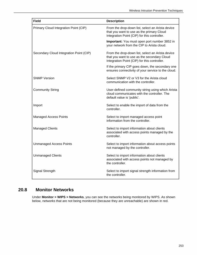
Wireless Intrusion Prevention Techniques
Field Description
Primary Cloud Integration Point (CIP) From the drop-down list, select an Arista devicethat you want to use as the primary CloudIntegration Point (CIP) for this controller.
Important: You must open port number 3852 inyour network from the CIP to Arista cloud.
Secondary Cloud Integration Point (CIP) From the drop-down list, select an Arista devicethat you want to use as the secondary CloudIntegration Point (CIP) for this controller.
If the primary CIP goes down, the secondary oneensures connectivity of your service to the cloud.
SNMP Version Select SNMP V2 or V3 for the Arista cloudcommunication with the controller.
Community String User-defined community string using which Aristacloud communicates with the controller. Thedefault value is 'public'.
Import Select to enable the import of data from thecontroller.
Managed Access Points Select to import managed access pointinformation from the controller.
Managed Clients Select to import information about clientsassociated with access points managed by thecontroller.
Unmanaged Access Points Select to import information about access pointsnot managed by the controller.
Unmanaged Clients Select to import information about clientsassociated with access points not managed bythe controller.
Signal Strength Select to import signal strength information fromthe controller.
20.8 Monitor Networks
Under Monitor > WIPS > Networks, you can see the networks being monitored by WIPS. As shownbelow, networks that are not being monitored (because they are unreachable) are shown in red.
253

Card Dataholder Environment (CDE) networks are networks that store, process, or transmit paymentcard transactions and sensitive cardholder data. CDE networks are in the scope of PCI DSScompliance. You can right-click on a network and change its type from CDE to Non-CDE or vice versa.
20.9 Auto-Deletion SettingsUsing auto-deletion settings, you can specify parameters to automatically rogues access points (APs)and clients.
You can automatically delete the following items:
• APs• Clients• Network• Alerts• Inactive Authorized APs
You must have superuser, administrator, or operator privileges to use auto-deletion settings.
20.9.1 Auto-Delete Access Points, Clients, and Network
You can specify the duration of inactivity after which rogue access points (APs) or clients areautomatically deleted. For networks, you can define the duration for which the networks are retainedon the server. After the specified retention duration, the networks are automatically deleted from theserver. If you want to retain manually classified APs or clients, you can specify that in the auto-deletionparameters.
You can also delete authorized but inactive APs from the current location. Click Delete InactiveAuthorized Access Points at the bottom of the Access Points tab.
Follow these steps to auto-delete APs, clients, and network:
1. Got to MONITOR > WIPS > Access Points.2. Click Auto Deletion.3. From the right pane, define the parameters to delete access points, clients, and network.
254

Wireless Intrusion Prevention Techniques
4. Save the settings.
20.10 WIPS Advanced Settings
Under Configure > WIPS > Authorized WiFi Policy, you can define Advanced Settings that allow youto pre-classify access points (APs) and define No-Wi-Fi networks.
Access Point Pre-Classification
Pre-classification of access points helps WIPS identify potential authorized and rogue APs. As shownin the figure below, by default, access points connected to a monitored subnet are pre-classified aspotentially authorized or rogue. These APs then show up with the appropriate classification on theMonitor > WIPS tab. This helps if, for instance, an unclassified AP is connected to the network. TheAP appears on the Monitor > WIPS tab. You can then re-classify it appropriately as either rogue orauthorized and—for rogue APs—take appropriate action.
255

You can also have WIPS pre-classify APs based on the signal strength with which they are visible. Asshown in the figure below, if you enable signal strength based pre-classification, CV-CUE allows you todefine a signal strength threshold. APs with signal strength greater than the threshold are automaticallyclassified as potentially authorized or rogue.
Relying on signal strength based classification alone, however, is not advisable, especially if you planto enable automatic intrusion prevention. First, if a legitimate AP from a neighboring facility is visiblewith a signal strength higher than the threshold, then classifying it as rogue could disrupt legitimate Wi-Fi connections to the AP. Therefore, use this classification only if you are sure that no unauthorizedWi-Fi operates in the vicinity of your location. Second, signal strength based classification will notdetect rogue APs that operate with a signal strength weaker than the threshold (smartphones runningWi-Fi hotspots, for example).
Define No-Wi-Fi Networks
Security-sensitive environments might need to ensure that no Wi-Fi network operates at certainlocations. As shown in the figure below, you can define "No-Wi-Fi" networks for a location, i.e., specifysubnets where no Wi-Fi is allowed. If you define such networks, an AP detected on the network at thatlocation is automatically classified as a rogue AP, even if it conforms to the authorized policy.
256

Wireless Intrusion Prevention Techniques
257

258

Chapter 21
Troubleshooting Wi-Fi
The TROUBLESHOOT view in CV-CUE provides tools that help the network administratorstroubleshoot issues in the Wi-Fi network.
The troubleshooting tools provided by CV-CUE include:
• Packet Trace• Client Connectivity Test
21.1 Capture Packet Trace for a Client
You can perform the Capture Packet Trace action on a client to intercept a data packet that iscrossing or moving over a specific network. The captured packet is stored temporarily for analysis. Thepacket is inspected to help diagnose and solve network problems
To capture a packet in CV-CUE:
1. Go to MONITOR > Clients.
A list of APs seeing the client is displayed.2. Right-click on the name of the AP or select the menu icon (three vertical dots) to view the available
actions and select Capture Packet Trace.
The Capture Packet Trace dialog box opens.3. On the Capture tab, enter the following details and click Start Packet Capture.
Option Description
Timeout It is the time in minutes that specify the timeinterval for the packet trace capture. The rangeis from 1 min to 720 min.
Streaming Option It specifies the type of packet capture to beused:
• Upload to server: It creates a file to capturethe packet trace which can be viewed onlyafter the entire packet capture process iscomplete.
• Wireshark on local machine: The packettrace can be opened during an ongoingcapturing process.
Filename Prefix It is mandatory field to specify theprefix for a filename. For example,Packet_wireless_143438.pcap, where:
• Packet: is the prefix of the file name.• _wireless_143438: is the name of the file.• .pcap: is the file extension which is
compatible with Wireshark.
259

Option Description
Wireless Settings Select this option to edit advanced wirelesssettings.
Traffic Selection It is the type of traffic that you prefer whiletroubleshooting.
• All packets on the channel: To captureall packets from all clients visible to thetroubleshooting AP sensor.
• Only packets for the selected Client<MAC address>: To view only packets fromthe selected AP.
Packet Types select the type of packets that you want tocapture.
Protocol and Channel Selection Select the protocols and channel for whichyou want to troubleshoot. If you want to selecta single channel, select the Select Channeloption and specify the channel number andWidth (channel offset). By default, the protocoland channels are displayed based on thedevice template applied to the troubleshootingsensor. You can select a different protocol and/or channel, if required. Alternatively, you canselect the Rotate on all Channels option, totroubleshoot on all available channels.
A dialog displaying the ongoing progress for the capture packet trace is displayed. Click Stop toforcefully stop the packet capture.
4. After the successful completion of the packet trace, click Download to view the file in Wireshark.
21.2 View Packet Trace History for a ClientYou can view the Packet Trace History for a selected client. The packet traces captured only duringthe last 30 minutes are displayed in the history.
To view the packet trace history, perform the following steps:
The Packet Trace History displays packet traces captured in the last 30 minutes.
1. Right-click the client or select the menu icon (three vertical dots) to view the available actions.2. Select Packet Trace History.3. Select the History tab in the Capture Packet Trace window to view the packet capture history.4. Select any Packet Trace to view the following detailed information:
Field Description
Filename Filename specifies the name of the capturedpacket trace.
MAC Address MAC Address of the device for which packettrace is captured.
Capturing Device MAC Address MAC Address of the device that has capturedthe packet trace.
260

Troubleshooting Wi-Fi
Field Description
Start Start time of packet capture.
End End time of packet capture.
Troubleshooting Mode Mode of troubleshooting.
Status Status specifies if the trace is completed or inprogress.
5. Click on the three vertical dots for a packet capture file to view the available actions:
6. Choose one of the following actions:
• Download - to download the trace file• Delete - to delete the trace file• Open - to open the trace file. You need to access Arista Packets in order to open the trace file. If
Arista Packets is not accessible, the Open option is disabled.
21.3 Capture Packet Trace for an APYou can troubleshoot Arista devices operating in AP or AP/Sensor mode. The packet is captured andinspected to help diagnose and solve network problems.
1. Go to MONITOR > Access Points.
A list of APs that are being monitored is displayed.2. Right-click on the name of the AP for which you want to capture the packet trace and select
Capture Packet Trace.
The Capture Packet Trace dialog box opens.3. On the Capture tab, enter the following details and click Start Packet Capture.
261

Option Description
Timeout It is the time in minutes that specify the timeinterval for the packet trace capture. The rangeis from 1 min to 720 min.
Streaming Option It specifies the type of packet capture to beused:
• Upload to server: It creates a file to capturethe packet trace which can be viewed onlyafter the entire packet capture process iscomplete.
• Wireshark on local machine: The packettrace can be opened during an ongoingcapturing process.
Filename Prefix It is mandatory field to specify theprefix for a filename. For example,Packet_wireless_143438.pcap, where:
• Packet: is the prefix of the file name.• _wireless_143438: is the name of the file.• .pcap: is the file extension which is
compatible with Wireshark.
Wireless Settings Select this option to edit advanced wirelesssettings.
Traffic Selection It is the type of traffic that you prefer whiletroubleshooting.
• Packets of all BSSIDs on this accesspoint: Captures all the packets for allBSSIDs broadcasted by the selected AP.
• Packets of a single BSSID: Captures thepackets for a single BSSID broadcasetd bythe selected AP. Select your BSSID from thegiven drop-down list.
• All packets on the configured channels inFrequency Band and Channel Selectionsection: Captures all the packets for all thechannels defined in the Frequency Band andChannel Selection section.
Protocol and Channel Selection Select the protocols and channel for whichyou want to troubleshoot. If you want to selecta single channel, select the Select Channeloption and specify the channel number andWidth (channel offset). By default, the protocoland channels are displayed based on thedevice template applied to the troubleshootingsensor. You can select a different protocol and/or channel, if required. Alternatively, you canselect the Rotate on all Channels option, totroubleshoot on all available channels.
Wired Settings Select this option to capture packets from wireddevices.
262

Troubleshooting Wi-Fi
Option Description
Interface Select from the available ethernet ports from thelist. The default value is eth0.
VLAN ID Enter the VLAN Id.
ICMP, UDP, DHCP, MDNS, LLMNR, DNS,RADIUS, ARP, TCP
Select required protocols from the list.
A dialog displaying the ongoing progress for the capture packet trace is displayed. Click Stop toforcefully stop the packet capture.
4. After the successful completion of the packet trace, click Download to view the file in Wireshark.
21.4 View Packet Trace History for an APYou can view the Packet Trace History for a selected AP. The packet traces captured only during thelast 30 minutes are displayed in the history.
To view the packet trace history, perform the following steps:
The Packet Trace History displays packet traces captured in the last 30 minutes.
1. Right-click the AP or select the menu icon (three vertical dots) to view the available actions.2. Select Troubleshoot > Packet Trace History.3. Select the History tab in the Capture Packet Trace window to view the packet capture history.4. Select any Packet Trace to view the following detailed information:
Field Description
Filename Filename specifies the name of the capturedpacket trace.
MAC Address MAC Address of the device for which packettrace is captured.
Capturing Device MAC Address MAC Address of the device that has capturedthe packet trace.
Start Start time of packet capture.
End End time of packet capture.
Troubleshooting Mode Mode of troubleshooting.
Status Status specifies if the trace is completed or inprogress.
5. Click on the three vertical dots for a packet capture file to view the available actions:
263

6. Choose one of the following actions:
• Download - to download the trace file.• Delete - to delete the trace file.• Open - to open the trace file. You need to access Arista Packets in order to open the trace file. If
Arista Packets is not accessible, the Open option is disabled.
21.5 Live Client DebuggingThe Live Client Debugging feature enables you to troubleshoot client activities. You can view live thelogs of a client connection.
The Live Client Debugging can be used by an user with Operator role and above. A Viewer role cannotperform the live client debugging nor access the logs.
You can perform the following tasks with the Live Client Debugging feature:
• Start Live Debugging• Stop Live Debugging• Archive the Debugging Log• Download the Debugging Log• Delete the Debugging Log• View Live Client Debugging
21.5.1 Start Live DebuggingYou can start the live debugging for one client at a time. However, you can parallelly debug maximum10 clients on CV-CUE.
To start live client debugging, perform the following tasks:
1. Navigate to MONITOR > Clients.
264

Troubleshooting Wi-Fi
The page displays the list of clients on the selected folder in the Navigator that are monitored byCV-CUE.
2. Right-click on the client that you want to debug and select Start Client Live Debugging.
The Live Client Debugging page is displayed.3. On the Live Client Debugging page, from the Select Time Durationdrop-down list select the time
duration for which the client debugging must be performed.4. (Optional) Select Change Location.
Use this option only when you want to track the logs of a client, for a locatiion other than its defaultlocation. This is useful when the client is roaming across locations.
5. Select Archive Logs or Discard Logs to save or discard the client logs.
If you select Archive, the logs are saved on the server after the time-out duration or if you stop theLive Client Debugging session. If you select Discard, the log is discarded, 30 minutes after the livedebugging is stopped.
6. Click Start to start the live client debugging.
You are redirected to the Live Client Debugging page, where the client logs are displayed live. .
Note: On the Clients page, the name of the client in bold and italics indicates that the LiveClient Debugging is in progress.
The logs can be accessed as a text file. The logs contain the following information:
• Client MAC address• SSID• BSSID• Name of the AP• Channel• Timestamp of when the log started• Time diff in milliseconds between 2 consecutive events• Event
A sample of the log files is as follows:
Note:
• You can also start Live Client Debugging from the TROUBLESHOOT > Live ClientDebugging. Search the required client and click Start Live Client Debugging hyperlinklocated at the top-right corner of the page.
265

• To access the archived client logs, navigate to TROUBLESHOOT > Live ClientDebugging. The name of the log in highlighted in bold italics indicates that the debugging isin progress.
21.5.2 Stop Live DebuggingYou can stop a Live Client Debugging, while the debugging is in progress.
To stop the debugging session, perform the following tasks:
1. Navigate to the TROUBLESHOOT > Live Client Debugging.
The logs that are in progress are highlighted in bold italics.2. Right-click on any such log, and select Stop Live Debugging.
Note: Alternatively, you can stop the debugging, by navigating to MONITOR > Clients. Onthe Clients page, the clients with live debugging are indicated in bold italics. Right-click therequired client (in bold italics) and select Stop Client Debugging. A message is displayedthat confirms that the debugging has stopped
21.5.3 View Live Client DebuggingYou can view the logs live on the Live Client Debugging page. You can view the live debugging onlyfor those events of the client that are in progress and have not ended.
To view the live client debugging, perform the following tasks:
1. Navigate to the TROUBLESHOOT > Live Client Debugging.
A list of logs is displayed. The logs that are still in progress are in bold and italics.2. Right-click any such .log file and select View Client Debugging.
You will be redirected to the Live Client Debugging page.
Note: To view the Live Client Debugging, you can also navigate to MONITOR > Clients.The clients in bold and italics are the clients where live client debugging is in progress.Right-click any such client for which you want to view the live debugging logs and selectLive Client Debugging. The events after opening the .log file are seen in the live debuggingsession. The events that occur while the Live Client Debugging is running in the backgroundare recorded and can be downloaded. To know more about downloading a log file, referDownload Live Client Debugging Logs.
21.5.4 Delete Live Client Debugging LogsYou can delete the Live Client Debugging log files for completed sessions. You cannot delete a log filethat is still in progress.
To delete the logs, perform the following tasks:
1. Navigate to the TROUBLESHOOT > Live Client Debugging.
A list of logs is displayed.2. Right-click on the log that you want to delete and select Delete Live Client Debugging .3. If you want to delete multiple logs, select the logs, right-click and select Delete Live Client
Debugging.
A message is displayed that confirms that the logs are deleted.
21.5.5 Download Live Client Debugging LogsYou can download the logs of a Live Client Debugging session.
To download the logs, perform the following tasks:
1. Navigate to the TROUBLESHOOT > Live Client Debugging.
266

Troubleshooting Wi-Fi
A list of logs is displayed.2. Click the log name to download the file in ZIP format. Alternately, right-click the log that you want to
download and select Download Live Client Debugging.
If you want to download multiple logs, select the logs, right click and select Download Live ClientDebugging.
The log is downloaded as a .zip file. A customer can archive maximum 500 log files on the server. Ifthe size of the log file reaches 2MB, the live debugging will stop after 1 minute.
21.5.6 Blinking LEDsSuppose that for troubleshooting purposes you want to physically access an AP that is deployed on alarge floor with many APs. To locate this AP, you can use the UI to make the AP LEDs blink.
To make AP LEDs blink, perform the following steps:
1. Go to Monitor > WiFi > Access Points (or Monitor > WIPS > Access Points)2. Select the AP you want to locate.3. Click the three-dot menu.4. Select Troubleshooting > Start LED Blinking and the time interval for which you want the AP
LEDs to continue blinking (while you physically locate it). When you click Start LED Blinking, thepower, radio, and LAN LEDs of the AP blink one after another (like a moving spot of light on theAP), allowing you to easily locate the AP on the floor.
You can also follow the steps above to stop LED blinking on an AP for which you started LED blinkingby selecting Troubleshooting > Stop LED Blinking in step 4 above.
You can also start (or stop) LED blinking from a floor plan. To make AP LEDs blink from a floor plan,perform the following steps:
1. Go to the Locations tab and navigate to the floor plan where the AP is placed.2. Select the AP you want to locate.3. Select Troubleshooting > Start LED Blinking and the time interval for which you want the AP
LEDs to continue blinking.
21.6 Audit Logs
Audit logs are logs of various user actions such as logging into CV-CUE or logging out of CV-CUE,
changes in location hierarchy, etc. Logs help in tracking user actions, which can be used for useraccountability.
Only a Superuser can download audit logs or configure the audit logs retention settings.
21.6.1 Audit Log Types
Log Type Description
All Includes all log types
User Access Logs user action related to user access suchas password changes, RADIUS authenticationchanges, and others
Devices Logs user action related to the AP such as APname changes, AP reboot, AP firmware upgrade,and others
Alerts Logs user action related to alerts such as deletingan alert
267

Global Settings Logs user action related to global settings suchas changes to Google integration, Syslog server,and SNMP settings, and so on
Location Based Settings Logs user action related to location basedsettings such as SSID settings, which includesfirewall, role-based access control, network, andothers
Location Hierarchy Logs user action related to the location hierarchysuch as adding or deleting a folder or group, floormap related changes, and others
Reports Logs user action related to the location hierarchysuch as adding or deleting a folder or group, floormap related changes, and others
Start/Stop Functions Logs user action related to system services suchas database, web server, and so on
System Logs user action related to system relatedoperations such as adding or deleting a network,changes in the service module, time zone relatedchanges, and so on
Third Party and Others Includes changes related to third party serversand custom files
21.6.2 Download Audit Logs
1. Click System > Logs to open the Audit Logs page.2. Select the log type and specify the duration for which you want to download the logs.3. Specify the Sort By value to sort your downloaded logs.4. Click Download to download the logs in the tsv format
21.6.3 Configure Audit Logs Retention Settings
You can define a custom retention period from 7 days to 365 days (both inclusive) for audit logs. Youcan also restore the previously set duration and reset to the system default log retention period as well.The default retention period is 10 days.
To configure the audit logs retention policy:
1. Click System > Logs to open the Audit Logs page.2. Click Audit Logs Retention Policy.3. In the right panel, specify the number of days in the Maintain User Action Logs for last field.4. Save your settings.
268

Chapter 22
Floor Plans
You can add floor plans to a location in CV-CUE.
You can then drag and drop APs onto the floor plan, and perform some operations on the AP from thefloor plan. This helps when you want to perform some operations on an AP somewhere on the floor —for example, you might want to view the packet trace history of an AP near a user who has problemsconnecting to the network. You can then right-click the AP on the floor plan to view its packet tracehistory.
Note: At any location in CV-CUE, you can see a card view of only the floor plans of thatlocation and those of its immediate child locations. You will not see floor plans of locations thatare further down in the location hierarchy. For example, suppose that "Town" is a child locationof "West Region", which is in turn a child location of "HQ". Then, when you go to Floor Planson HQ, you will see a card view of only the HQ and West Region floor plans, and not those ofTown.
You can import an image or a ".spm" file as a floor plan. A ".spm" file is an Arista Planner file. AristaPlanner is a tool that allows you to model obstacles and generate heat maps for coverage, link speed,etc. The ".spm" file contains a model of the obstacles on the floor — for example walls, glass partitions,and doors. This gives you a better picture of the floor. Future releases of CV-CUE will allow you toview heat maps as well.
22.1 Add A Floor PlanYou can add floor plans to a location in CV-CUE.
To add a floor plan to a location:
1. In the CV-CUE location hierarchy, go to the location where you want to add the floor plan.2. Go to Floor Plans and click Add New Floor Plan.
An Add New Floor Plan dialog appears.3. Enter the name you want to give to the floor plan.4. ClickUpload Image or Upload SPM.
269

The file selection window appears. Select the file you want to upload and click Open.5. Set the dimensions of the floor plan.6. Click Save to save the floor plan.
22.2 Perform Operations on an AP from Floor PlanYou can perform various operations on an AP from a floor plan.
To perform operations on the AP from a floor plan:
1. In the CV-CUE location hierarchy, go to the location of the floor plan.2. Click and open the floor plan.3. Drag and drop APs from the right panel to wherever you want to place them on the floor plan.4. Right-click the AP you want to perform the operations for and select the operation you want to
perform.
270

Chapter 23
Heat Maps
Heat Maps are used to help the user to visualize the coverage, link speed and channels of placeddevices on the floor plan.
User can select different view for the floor plan to visualize the device placements, AP Coverage, APLink Speed and AP Channel Coverage of the floor plan.
Different views for the floor plans are:
• Default View• AP Coverage View• AP Link Speed View• AP Channel Coverage View
23.1 Default ViewDefault View shows the floor plan and placed devices on the floor.
1. Select FLOOR PLANS tab from the left panel.2. Select the existing floor plan for which you wish to see the Default View.3. Choose RF Heatmaps option from the right hand side panel.4. Select Default View.
It shows Default View of the floor plan.
271
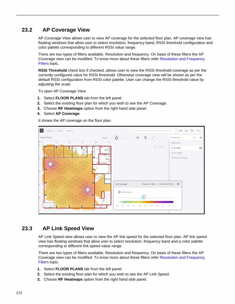
23.2 AP Coverage ViewAP Coverage View allows user to view AP coverage for the selected floor plan. AP coverage view hasfloating windows that allow user to select resolution, frequency band, RSSI threshold configuration andcolor palette corresponding to different RSSI value range.
There are two types of filters available, Resolution and frequency. On basis of these filters the APCoverage view can be modified. To know more about these filters refer Resolution and FrequencyFilters topic.
RSSI Threshold check box if checked, allows user to view the RSSI threshold coverage as per thecurrently configured value for RSSI threshold. Otherwise coverage view will be shown as per thedefault RSSI configuration from RSSI color palette. User can change the RSSI threshold value byadjusting the scale.
To open AP Coverage View
1. Select FLOOR PLANS tab from the left panel.2. Select the existing floor plan for which you wish to see the AP Coverage.3. Choose RF Heatmaps option from the right hand side panel.4. Select AP Coverage.
It shows the AP coverage on the floor plan.
23.3 AP Link Speed ViewAP Link Speed view allows user to view the AP link speed for the selected floor plan. AP link speedview has floating windows that allow user to select resolution, frequency band and a color palettecorresponding to different link speed value range.
There are two types of filters available, Resolution and frequency. On basis of these filters the APCoverage view can be modified. To know more about these filters refer Resolution and FrequencyFilters topic.
1. Select FLOOR PLANS tab from the left panel.2. Select the existing floor plan for which you wish to see the AP Link Speed.3. Choose RF Heatmaps option from the right hand side panel.
272

Heat Maps
4. Select AP Link Speed.
It shows AP link speed for the floor plan.
23.4 AP Channel Coverage ViewAP Channel Coverage View allows user to view the AP channel coverage for the selected floor plan.AP channel coverage has floating windows that allow user to select resolution, frequency band and acolor palette corresponding to different channels.
There are two types of filters available, Resolution and frequency. On basis of these filters the ChannelCoverage View can be modified. To know more about these filters refer Resolution and FrequencyFilters topic.
1. Select FLOOR PLANS tab from the left panel.2. Select the existing floor plan for which you wish to see the AP Channel Coverage.3. Choose RF Heatmaps option from the right hand side panel.4. Select AP Channel Coverage.
It shows AP channel coverage for the floor plan.
273

23.5 Resolution and Frequency FiltersResolution and Frequency are the two filters available for heat maps. These filters are available for allthe views except Default View.
Resolution Filter
Resolution filter is used to set the resolution settings for the floor plan. There are three types ofresolution settings:
• Low: Accuracy of calculation and visualization will be low but it will take less time to show theresult.
• Medium: Accuracy of calculation and visualization will be moderate and will take moderate time toshow the result.
• High: Accuracy of calculation and visualization will be highest but it will take maximum time to showthe output.
Frequency Filter
Frequency Filter is used to filter data based on the frequency on which AP is working. The data isfiltered based on the following criteria:
• 2.4 GHz: Data for only 2.4 GHz AP radios will be shown.• 5 GHz: Data for only 5 GHz AP radios will be shown.• 6 GHz: Data for only 5 GHz AP radios will be shown.• All bands: Data for 2.4, 5, and 6 GHz AP radios will be shown.
274

Chapter 24
Locate Access Points and Clients
You can locate a specific access point (AP) or client that is added to a floor plan from the UI. You canuse this feature to locate a rogue AP or client in your floor plan. However, you can’t locate multipledevices or clients. APs or clients are located based on the triangulation method.
You can locate a device from the following places in CV-CUE:
• FLOOR PLANS• MONITOR > WiFi > Clients• MONITOR > WiFi > Access Points• MONITOR > WIPS > Managed WiFi Devices• MONITOR > WIPS > Access Points• MONITOR > WIPS > Clients• Alert Drilldown
24.1 Locationing Criteria
The server runs the locationing algorithm and, based on it, APs report another AP or client’s RSSI.Whether APs can detect another AP or client depends on three criteria:
• The AP or client must be active.
• Clients must actively transmit data packets for locationing to work.• Unplaced, managed devices that operate in WIPS-only mode can’t be located.
• The device must be visible to at least three APs. At least three APs must report the device and theAPs must be placed on the floor. For example, if there are only two APs on a floor, then you can’tlocate the device on the floor plan. Instead, you see a Proximity view.
• The three placed APs must operate in the same frequency band. For example, if there are threeAPs on a floor, where two APs are operating on 2.4 GHz and one AP is operating on 5 GHz, thenyou can’t use locationing to track an AP or client. All three APs must operate in the same frequencyband.
You must understand the difference between managed and unmanaged devices to understandlocationing. The following points briefly describe what each of these terms mean:
• Managed devices are Arista APs that are configured either in AP mode or in WIPS mode. You canplace Managed devices on the floor plan.
• Unmanaged devices are Wi-Fi devices such as mobile phones, APs that are in the vicinity andvisible to the managed devices. You cannot place them on a floor plan but you can locate themprovided there is some data traffic from or to those devices. They can fall into any of the followingcategories: Authorized, Rouge, Guest, or External.
• Placed devices are managed devices (APs) that are placed on a floor plan.
If CV-CUE can’t locate a device because there is no placed AP or because fewer than three APs areplaced on the floor, then it displays the Proximity view for the device. The Proximity page shows anapproximate distance of the device with respect to other APs.
275

24.2 Locate an AP or a Client in a Floor Plan
You can locate managed clients and devices using the Connected Clients and Failed Clientscheckboxes. Use the Search option from the right panel to locate unmanaged and unplaced devicesand clients, especially WIPS clients and devices. You can also use Search to see the Proximity viewsof clients that could not be located on the floor plan.
1. Click Floor Plans and expand the Navigator.2. Select the location from the Location tree.3. Click Locate Devices from the drop-down menu in the right panel.4. Select the Connected Client checkbox to see the list of managed devices and clients in the floor
plan.
276

Locate Access Points and Clients
24.3 Drill Down from a Device
You can drill down to the details page of an AP or client from a floor plan. Right-click an AP in a floorplan and then click View Access Point Details to see the details page of the device.
277
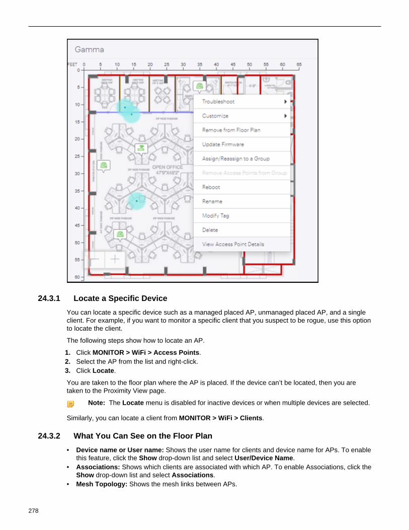
24.3.1 Locate a Specific Device
You can locate a specific device such as a managed placed AP, unmanaged placed AP, and a singleclient. For example, if you want to monitor a specific client that you suspect to be rogue, use this optionto locate the client.
The following steps show how to locate an AP.
1. Click MONITOR > WiFi > Access Points.2. Select the AP from the list and right-click.3. Click Locate.
You are taken to the floor plan where the AP is placed. If the device can’t be located, then you aretaken to the Proximity View page.
Note: The Locate menu is disabled for inactive devices or when multiple devices are selected.
Similarly, you can locate a client from MONITOR > WiFi > Clients.
24.3.2 What You Can See on the Floor Plan
• Device name or User name: Shows the user name for clients and device name for APs. To enablethis feature, click the Show drop-down list and select User/Device Name.
• Associations: Shows which clients are associated with which AP. To enable Associations, click theShow drop-down list and select Associations.
• Mesh Topology: Shows the mesh links between APs.
278

Locate Access Points and Clients
• Connected clients and their connection health such as Low RSSI, Low Data Rate, and others.• Failed clients and the reason of failure
279

280

Chapter 25
Reports in CV-CUE
CV-CUE currently supports the following types of reports.
Wireless Intrusion PreventionSystem (WIPS)
Compliance Inventory
Reports about the Wi-Fi securityposture.
Reports to meet federal orindustry-based regulatorycompliance for Wi-Fi security.
Details of AP, clients, tunnelsand networks for both Wi-Fi andWIPS.
• Airspace Risk Assessment• Wireless Vulnerability
Assessment• Security Scorecard• Intrusion Prevention
Summary• WIPS Alerts• AP Classification• Client Classification
• DoD Directive 8100.2Compliance.
• HIPAA Wireless Compliance• PCI DSS Wireless
Compliance• SOX Wireless Compliance
• Wi-Fi Access Points• Wi-Fi Tunnels• WIPS - Managed Wi-Fi
Devices• WIPS - Networks• Managed Wi-Fi Device
Inventory• Wi-Fi Clients• WIPS - Clients• WIPS - Access Points
The reports can be accessed via the Reports tab on the left menu. You can view the definition andsections in each report, generate a report on-demand, or schedule one-time or recurring generation ofa report.
25.1 Scheduling ReportsReport generation can be scheduled on a one-time or recurring basis. Users with Admin or Operatorroles can schedule reports, while users with a viewer role can only view scheduled reports.
281

Clicking on the Schedule Report icon opens a panel on the right-hand side of the screen, with a set ofuser-configurable parameters, as shown in the figure below.
The email that delivers the scheduled report contains the URL of the report and its JSON bundle.By default, the report URL is available for a limited period; once it expires, you can upload the JSONbundle to the report rendering application to view the report.
282

Reports in CV-CUE
If the archival setting is set to Never Delete, then the URL sent in the email will always be valid until thereport is manually deleted from the REPORTS > Archived page.
Once the report is successfully scheduled, it can be seen under REPORTS > Scheduled.
25.2 On-Demand Generation of Reports
Clicking on the Generate Report icon opens a panel on the right-hand side of a screen with a set ofparameters to be configured as shown in the image below.
283

Sample HTML Report
284

Reports in CV-CUE
25.3 Archive a ReportReports can be archived so that they can be viewed at a later time. When the report archival quota ofa user is consumed, no more reports can be archived unless older reports are deleted. You can definethe date when an archived report should be deleted or you can also disable the auto-deletion for areport.
Archived reports can be viewed under REPORTS > Archived tab in CV-CUE. Visibility of an archivedreport is not location-specific; it is based on a user's role. An archived report is always visible to a userwho has previously generated the report. Role-based access is as follows:
• Superusers - can view all archived reports.• Administrators - can view reports archived by them and for them.• Operators - can view reports archived by them and for them.• Viewers - cannot archive or view an archived report.
285

286

Chapter 26
Third-Party Servers
Integration of third-party servers with CV-CUE is a system-level operation; it applies to the entirenetwork.
Third-party servers supported are:
• Google• ArcSight• SMTP• SNMP• Syslog
26.1 Google IntegrationYou can integrate Google for Work with your network using CV-CUE.
To configure Google integration:
1. Go to System > Google Integration.2. Click Upload JSON Key File and .
The file selection window opens.3. Select the JSON key file you have downloaded from Google and click Open.
The JSON file name shows up on the CV-CUE screen.4. Enter the Admin Email Address.
This is the email address associated with the service account JSON key created in Google.5. Click Sync Client List to sync the list of clients with the Google server.
This updates the client list with the latest changes if any.
26.2 ArcSight Integration
Integration with ArcSight’s Enterprise Security Management (ESM) enables CV-CUE to send eventsto the designated ArcSight server. The ArcSight server is configured to accept messages containingdetailed event information in ArcSight’s Common Event Format (CEF). CV-CUE needs the IP Addressor the hostname and the port on which the ArcSight server receives events. Apart from events, youcan also send audit logs from CV-CUE to an ArcSight server.
To add an ArcSight server, perform the following steps:
1. Go to System > Third-Party Servers > ArcSight Integration.2. Select Enable ArcSight Servers.3. Click Add in the ArcSight Servers table to add an ArcSight server.4. Enter the IP address or hostname of the Arcsight server.5. Enter the port number to be used for communication between CV-CUE and ArcSight.6. Click Select next to the Primary Cloud Integration Point (CIP) and select the access point (AP)
you want to designate as the primary CIP.
Note: Only CIP-enabled APs appear in the list. Make sure that you enable CIP mode on theAPs you want to use as CIPs.
287

7. If you want to add a secondary CIP, click Select next to the Secondary Cloud Integration Point(CIP) and select the AP you want to designate as the secondary CIP.
8. Enable Forward Events and Forward Audit Logs to forward events and audit logs respectivelyfrom CV-CUE to ArcSight servers.
9. Click Done.10. Save the settings by clicking Save on the ArcSight Integration tab.
You can monitor the status of the ArcSight service from the ArcSight Integration tab. As shown inthe following figure, the current status shows “Running” when the service is running, and “Stopped”when the service has stopped.
You can also enable and disable individual ArcSight servers using the three-dot menu in the table.
26.3 SMTPThe SMTP settings will be generic for the system and will be used for any email functionality. Althoughcurrently it is used for alerts, it will not be restricted for this use only. We must state that the SMTPsettings will be used by CV-CUE to notify users through email, for example notification of alerts.
Note: Only on-premises CV-CUE deployments need an SMTP server to be set up. For clouddeployments, email notifications are sent by the Arista cloud services.
To configure SMTP, perform the following steps:
1. Go to System >Third Party Server.2. Click the SMTP tab.3. Configure the following parameters:
Option Description
SMTP Server IP Address/Hostname IP Address or the host name of the SMTPserver used by the system for sending e-mails.
Default : 127.0.0.1
Port Port number of the SMTP server.
288

Third-Party Servers
Option Description
Default : 25
"From" Email Address The source address from which e-mails aresent.
Default : [email protected]
4. Select Enforce use of StartTLS (TLSv1) to enforce the use of STARTTLS to send e-mails in anencrypted format.
STARTTLS is an extension to plain text communication protocols like SMTP that offers a wayto upgrade a plain text connection to an encrypted (TLS or SSL) connection instead of using aseparate port for encrypted communication.
5. Select Verify SMTP Server's Certificate to verify the certificate of SMTP server against a defaultbuilt-in self signed CA certificate located on WM server or an uploaded CA certificate. If selected,and no certificate is uploaded then the certificate of SMTP server is verified against the built incertificate.
a. ClickSet Certificate.b. Browse and select the required certificate file, and click Open.
If the certificate is imported successfully, the certificate file name and certificate details can beseen on the page.
A Set Certificate option occurs.
Note: If Verify SMTP Server's Certificate is selected, e-mails are sent only if the uploadedcertificate matches with that on the SMTP server.
6. To authenticate with the SMTP sever, select Authentication Required, and enter the Usernameand Password.
7. Click Save.
26.4 SNMP
You can configure CV-CUE to send information via SNMP traps to one or more SNMP servers.Depending on whether your network uses a cloud-based Arista Wi-Fi server or an on-premises one,the following information can be sent to SNMP servers:
• For a cloud-based Wi-Fi deployment, CV-CUE can send alerts to your SNMP servers.• For an on-premises Wi-Fi server, CV-CUE can send alerts and system health metrics to your
SNMP servers.
26.4.1 SNMP - Alerts
To add an SNMP server for alerts, go to System > Third Party Servers > SNMP-Alerts and click Addon the Destination SNMP Servers table. The SNMP server settings panel opens up.
The settings are described in the table below.
Setting Description
Enabled Select to enable communication between CV-CUE and this SNMP server.
289

Setting Description
SNMP Trap Destination Server IP/Hostname Enter the IP address or hostname of the SNMPserver.
Note: For a cloud-based Arista Wi-Fi deployment,if the SNMP server uses a private IP address, youneed to select a Cloud Integration Point.
Port Number The port number for the SNMP server-CV-CUEcommunication.
Primary Cloud Integration Point (CIP) Note: This field does not appear for an on-premises Arista Wi-Fi server because it is neededonly to integrate a cloud-based Wi-Fi server.
From the drop-down list, select an Arista devicethat you want to use as the primary CloudIntegration Point (CIP) for the SNMP server.
Important: You must open port number 3852 inyour network from the CIP to Arista cloud.
Secondary Cloud Integration Point (CIP) From the drop-down list, select an Arista devicethat you want to use as the secondary CloudIntegration Point (CIP) for the SNMP server.
If the primary CIP goes down, the secondary oneensures connectivity of your service to the cloud.
SNMP Version Select SNMP V2 or V3 for the Arista servercommunication with the controller.
Community String For SNMP v2, define a custom community stringto authenticate with the SNMP server. The defaultvalue is "public". Ensure that you change thiscommunity string.
Username For SNMP V3, an auto-generated username forCV-CUE to log in to the SNMP server.
Authentication Password The password to authenticate with the SNMP v3server.
Authentication Protocol The authentication protocol used for SNMP v3.The options are MD5 (default) and SHA.
Privacy Password The private key used to encrypt SNMP v3-basedtraps.
Privacy Protocol The method used to encrypt SNMP v3-basedtraps. The options are DES (default) and AES.
Note: Make sure that the "Send Alerts using SNMP" checkbox is enabled. Even if all theindividual SNMP servers are "Enabled", CV-CUE will not send alerts unless the "Send Alertsusing SNMP" checkbox is selected.
290

Third-Party Servers
26.4.2 SNMP - Server Health
For an on-premises Arista Wi-Fi server, CV-CUE can send system health information to SNMPservers. To configure SNMP for system health, go to System > Third Party Servers > SNMP-Healthand configure the settings shown in the figure below.
An SNMP Management Information Base (MIB) is a collection of definitions that define the propertiesof a managed object in a managed device. For example, the Arista Wi-Fi server is a managed device,its disk memory is a managed object, and the Host Resource MIB contains information about the diskmemory of the Wi-Fi server.
The table below shows the SNMP Management Information Bases (MIBs) used for different systemhealth metrics.
291

MIB Description
IF MIB Select to send information about networkinterfaces such as eth0 and eth1.
AirTight MIB Select to send information about the Wi-Fimanagement specific processes running on theserver.
Host Resource MIB Select to send host resource information such asmemory and CPU.
MIB-II Select to send operational information such asSystem name, contact, and location. On theSNMP server, these fields are used to verify if the"SNMP GETs" option works.
To add SNMP servers, click Add on the Destination SNMP Servers table. As shown in the figurebelow, the SNMP server settings panel opens up.
292

Third-Party Servers
The settings are described in the table below.
Setting Description
Enabled Select to enable communication between CV-CUE and this SNMP server.
SNMP Trap Destination Server IP/Hostname Enter the IP address or hostname of the SNMPserver.
Port Number The port number for the SNMP server-CV-CUEcommunication.
SNMP Version Select one of the two options: a) SNMP V1,V2 orb) SNMP V3 for the the SNMP server-CV-CUEcommunication.
Username For SNMP V3, an auto-generated username forCV-CUE to log in to the SNMP server.
Authentication Password The password to authenticate with the SNMP v3server.
Authentication Protocol The authentication protocol used for SNMP v3.The options are MD5 (default) and SHA.
Privacy Password The private key used to encrypt SNMP v3-basedtraps.
Privacy Protocol The method used to encrypt SNMP v3-basedtraps. The options are DES (default) and AES.
Note: Make sure that the "Monitor System heath using SNMP" checkbox is enabled. Even ifall the individual SNMP servers are "Enabled", CV-CUE will not send system health informationunless the "Monitor System heath using SNMP" checkbox is selected.
26.5 SyslogYou can configure a Syslog server from CV-CUE to enable the underlying Wireless Manager service tosend messages to be logged in the syslog server.
To configure a Syslog server, perform the following steps:
1. Go to System > Syslog.2. The Syslog Integration Status indicates the status of the Syslog server.
293

The Current Status displays the current status of the SNMP server. The applicable values areRunning, Stopped and Error.
3. Select Enable Syslog Servers to enable integration of CV-CUE with Syslog server.
A Syslog Server table appears.4. Click Add
AnAdd Syslog Servers window appears on the right pane.5. UnderAdd Syslog Servers window, enter the following details:
Option Description
Syslog Server IP/Hostname Specifies the IP address or the hostname of theSyslog server.
Port Number Specify the port number of the Syslog server towhich the system sends alerts.
Default : 514
Primary Cloud Integration Point (CIP) Note: This field does not appear for an on-premises Arista Wi-Fi server because it isneeded only to integrate a cloud-based Wi-Fiserver.
Select a primary CIP to enable the integration ofArista Cloud with Syslog.
The syslog server on which a CIP device isselected is termed as CIP destination and islisted as a CIP destination for the CIP enabledArista device.
Secondary Cloud Integration Point (CIP) From the drop-down list, select an Arista devicethat you want to use as the secondary CloudIntegration Point (CIP) for the Syslog server.
If the primary CIP goes down, the secondaryone ensures connectivity of your service to thecloud.
Message Format Specify the format in which an alert is sent.Available options are:
• PLAIN• Intrusion Detection Message Exchange
Format (IDMEF).
Enabled Sends the alerts to the Syslog server.
Append BOM Header Appends the byte order mark to the syslogserver entry. This is relevant in case of plain textfiles.
Forward Events Forwards the main events to the Syslog server.
Forward Sub-events Forwards the sub-events along with the mainevents.
Forward Audit Logs Sends audit logs to the Syslog server. You canforward audit logs in plain text format only
6. Click Save.
294

Chapter 27
Advanced System Settings
Advanced system settings are system-level operations typically performed from the SYSTEM tab inCV-CUE. The settings apply to the entire network.
You can perform the following advanced system-level settings in CV-CUE:
• License settings for on-premises users• Language settings
27.1 License Settings for On-Premises Users
You can apply licenses from CV-CUE for on-premises users. After you upload the license file, youneed to log out and then log in again for the license to be effective.
Follow these steps to apply the license:
1. Got to SYSTEM > Advanced Settings > License.2. (Optional) Click Download License to download the existing license details in a text file format.3. Click Select License File and select the license file from your local or shared drive. Licences must
be in the json file format.4. Apply the license.5. When prompted, log out and then log in again to successfully activate the license.
27.2 Language Settings
You can define the system language that is used by CV-CUE as a mode of communication. CV-CUEuses the system language to send default messages from the application. For example, alerts andnotifications are communicated using the system language. The default system language is English.
Follow these steps to configure the system language:
1. Got to SYSTEM > Advanced Settings > Language.2. Select the system language and the SSID encoding language.3. Save the changes.
27.3 High Availability Status
If you have enabled the High Availability (HA) service, you can see the HA status and configurationdetails of the servers. For example, you can see whether the HA service is running or stopped ordisabled. If you have not configured the HA service, you will see the status as Disabled. This is a read-only page; you can’t configure anything on this page. Configure the HA service using the CLI.
To see the HA status from CV-CUE, go to System > Advanced Settings > High Availability Status.
295

27.4 System Status
You can see the status of the Wi-Fi server and other system-related information from System >Advanced Settings > System Status. You can also start and stop system services from the SystemStatus page.
The following system-related information is displayed on this page:
• Server ID• Server Access URL• Managed Device Communication Port• Maximum Managed Devices Allowed (Physical Devices)• Allowed Mode of Operation — Indicates whether Wi-Fi or WIPS or both services are enabled on the
server.• Software Version — Indicates the software version of CV-CUE• Software Build — Indicates the software build version of CV-CUE• Operating System• Appliance Model• IPv4 — Indicates the IPv4 address, if available• IPv6 — Indicates the IPv4 address, if available
27.5 Cluster Configurations
A server cluster or a cluster is a group of Wireless Manager (WM) servers. A cluster comprises aparent WM server and one or more child WM servers. A cluster is created to manage multiple serversusing a single server. This managing server is called the parent server and the servers that aremanaged from the parent server are called the child servers. A server can be part of only one cluster atany given time. A child server cannot be a parent of any other server in the cluster. Creating a clusterhelps in managing multiple servers together. For example, you can create a policy and implement itacross different servers using a cluster.
You can create clusters using the server command line console. For more information on creatingclusters and managing servers in a cluster, refer to the following chapters in your respective serverinstallation guide.
• Setup and Manage Server Cluster - For details on setting up server clusters• Server Config Shell Commands- For details on server cluster commands.
After you have assigned a parent server to a cluster and have added child servers to the servercluster, login into CV-CUE to view cluster data and manage cluster configuration.
Note: You must be a superuser to view cluster data and manage cluster configurations.
View Cluster Configurations
To view the cluster data:
1. Go to System > Advanced Settings.2. Click the Cluster Configuration tile. All the existing servers in a cluster are displayed.
296

Advanced System Settings
The table displays the following data:
Table 8: Cluster Configuration Details
Field Description
Status The status of the server. The icons mean thefollowing:
Table 9:
Icon Description
Connected Server
Disconnected server
Expired license ormismatched version
Server Name Name of the server
Mount Point Mount location of the server
Server IP Address IP Address of the server
Version Software Version number of the server
You can perform the following actions on a cluster server:
297

• Mount or Unmount the server• Change mount location• Copy Policies• Fix version mismatch• Fix License
Note: You can perform the actions only a connected server.
Mount or Unmount the Child Server
To view the server cluster data or to copy the parent server’s policy, you need to mount the individualchild servers on the parent server location tree. Before you mount the child server, ensure that youhave applied a valid license to it and it has the same build version as the parent server.
To mount the child server:
1. Select the child server. Click Mount from the three-dot menu next to it.2. Select the mount location and click Save.
The child server is mounted on the selected location.
Note: When you mount a child server, the parent server policies are not inherited by the child serverautomatically. The child server continues to use its existing policies. You need to explicitly apply theparent server’s policy.
Similarly, you can umnount the child server from the parent server by clicking Unmount from thethree-dot menu next to it.
Change the Mount Point of the Child Server
You can change the mount point of a child server and mount it to another location. Before you changethe mount point of a server, ensure that a valid license is applied to it.
To change the mount location of the child server:
1. Select the child server. Click Change Mount from the three-dot menu next to it. The Change MountPoint pane appears.
2. Select the new mount point and click Save.
Copy Policies
Policies are configuration settings that you define for a server. If you want to keep the sameconfigurations or settings across servers in a cluster setup, you need to create only one policy andcopy the policy to all other servers. This helps in maintaining consistency in your settings, providesease of replication, and reduces human errors. You can copy policy settings from a child server toanother child server, a parent server to a child server, or a child server to a parent server. You cancopy the following policies:
• Account Suspension• Password Policy• Language Setting• Audit Logs• Auto Deletion• SMTP Configuration• Radius Configuration• Server Upgrade• Certificate• LDAP Configuration• AP Server Key (Device Communication Key)
298

Advanced System Settings
• ArcSight Integration• Banned APs• Banned Clients• License• Reports Look and Feel• SysLog Integration• SNMP
You can copy a single policy or copy multiple policies at once.
To copy policies in a cluster server,
1. Navigate to System > Advanced Settings.2. Click the Cluster Configuration tile. Alternatively, you can also navigate to the particular policy
setting that you want to copy.3. Click Copy Policies.4. The Copy Policy pane is displayed. Select your To and From Servers.
5. Select the policies to copy.6. Click Save. The Confirm Copy Policy dialog box appears.7. Click Confirm.
299

Once the policy settings are copied, you will get the Copy Policy Results pane displaying the successor failure of the copied policies.
Fix Mismatched Version of the Child Server
The parent server and the child servers in a cluster must have the same software versions. If there isa mismatch between the versions of the parent server and the child server, you need to upgrade yourchild server to match the version of the parent server.
To fix the child server version:
1. Click Fix Version Mismatch from the three-dot menu next to it. The fix version mismatch paneopens.
2. Upgrade your child server. For more information on upgrading your server, refer to Upgrade Server.
Fix Invalid License of the Child Server
The child servers in a cluster must have a valid license. In case of a missing license or an expiredlicense, you need to fix the license of the child server.
Note: This feature is available for on-premise setup only.
To fix the child server license:
1. Click Fix License from the three-dot menu next to it. The fix license pane opens.2. Select the appropriate license file from your local storage and click Apply License.
27.6 NTP Configuration
Network Time Protocol (NTP) is used to synchronize the time in servers and computers that are indifferent networks over the internet. You can add a maximum of three NTP servers.
1. Go to System > Advanced Settings > NTP Configuration.2. Click the Enable NTP check box.3. Add the NTP servers. You must add at least one NTP server.4. Click Check Drift to check the time drift between NTP servers.5. Sync and save the settings
27.7 Upgrade Server
You can check for available upgrades and upgrade your server to the latest version of CloudVisionCognitive Unified Edge (CV-CUE). Only a Superuser can initiate a server upgrade.
Note: This feature is available for on-premises deployments only.
Prerequisites for Upgrade
• TCP Port 8080 of the server is accessible from your computer.• Popups are not blocked.
Upgrading your Server
Before you start, ensure that you have downloaded the upgrade bundle to your computer. Also notethat you cannot abort or cancel the server upgrade process once the server upgrade is in progress.The upgrade process continues even if you close the browser window.
To upgrade your server:
300

Advanced System Settings
1. Go to System > Advanced Settings > Upgrade Server. The Upgrade Server screen displays thecurrent build details.
2. Click Check for Upgrade to check if upgrades are available. You can download the upgradebundle from Arista’s support website.
3. (Optional) Select the Check Server upgrade availability at each login checkbox to check foravailable upgrades on every login.
4. Click Select File and select the upgrade bundle from your local storage.5. Click Check Compatibility and verify that the upgrade bundle is compatible with the server.6. Click Upload and Upgrade. The Confirm Upgrade screen displays the current build and upgrade
build details.7. Click Confirm to initiate the server upgrade. Once the upload is complete, the server upgrade starts
automatically.8. Refresh your browser and log in to CV-CUE after the server is upgraded.
While the server upgrade is in progress, you cannot access the CV-CUE UI. After the server upgradeis successful, the server reboots automatically. Wait for a few minutes for the server to reboot. Afterthis, you can access the CV-CUE UI again.
Parent-Child or Multi Server Setup
If you have a Parent-Child or a Multiple Server setup and you are upgrading a child server, only thechild server is inaccessible while it is upgrading. You will be redirected to the dashboard of the parentserver and you can access the parent server.
If you are upgrading the parent server, wait for a few minutes for the server to reboot and log in againto access the server. While the parent server is upgrading, you can access the child server(s).
27.8 Base URLs for APIs
Since the Wireless Manager (WM) UI is deprecated, you canot access the WM directly. However, youcan view the WM host URL in CV-CUE and use the URL to test APIs offered by CV-CUE or createyour own applications. Similarly, if you use the Guest Manager sevices, you can also view the URL forguest analytics (Guest Manager) from CV-CUE.
To view the base URLs, navigate to SYSTEM > Advanced Settings > Base URLs for APIs.
The URLs for both guest analytics, and configuration and management are static links. For moreinformation on availale APIs, see the API Help Portal. The URL for specific end point is available in theAPI Help Portal. The base URL is available in CV-CUE. For example, if the API endpoint is client, thenthe URL is <wm_base_url>/wifi/api/clients.
301

302

Chapter 28
Client Connectivity Test Using a Tri-radio AP
With a tri-radio Arista access point (AP), you can turn its third radio into a client that can connect toanother AP you want to test. This gives you the ability to proactively validate network assurance,the reachability of network services, and the quality of experience for critical applications such asVoIP. The AP being tested is called the Target AP. Acting as a client, the third radio of the tri-radio APconnects to the target AP and runs tests to assess network health and identify problems if any. In CV-CUE, you can select the applications you want to test and set up a recurring schedule.
For example, you could test VoIP applications at important meeting locations.
The tests, listed below, range from basic Wi-Fi and Internet connectivity to application experience:
• Association• Authentication• DHCP• Gateway• DNS• WAN Latency• Application Test• VOIP Test• Throughput Test
Broadly, running tests using the third radio as a client consists of three steps: create a test profile,schedule a test or run it on demand using the profile, and analyze the test results.
28.1 Test Profile
A test profile comprises:
• The SSID being tested• The frequency band being tested and• The tests that you want to run on the SSID and that band.
A test profile allows you to test client experience based on the use case. For example, for a corporateSSID, you could define a test profile that includes VoIP test and productivity applications. For aGuest SSID, you could exclude VoIP from the test profile and include only some social and customapplications. If your VoIP Wi-Fi clients are expected to primarily use the 5 GHz frequency band, thenyou could specify that in the test profile for testing VoIP quality of experience. The figure below showsan example of a test profile for a corporate SSID. A single test run carries out all the tests included inthe test profile. Thus, for the corporate SSID test profile shown in the figure below, a single test runwould consist of the Basic Connectivity Test, application tests for the Productivity applications chosen,the VoIP test, and the Throughput test.
You can run tests manually or on demand by selecting the AP to be tested, as shown below.
Alternatively, you can schedule tests for a location (see the Schedule section below for details).
Important things to remember about test profiles are:
• You must create a test profile before you run a client connectivity test.
303

• When you create a test profile, you can save it and use it multiple times. If multiple APs broadcastthe same SSID, then a single test profile can be used to run tests on all the APs.
• To run a test on a target AP, make sure that the target AP is broadcasting the SSID that is in theselected test profile.
28.2 Schedule
Scheduling periodic tests can help you optimize network performance and proactively unearth anyissues on an ongoing basis, thereby avoiding reactive network troubleshooting fire drills. A schedulecan comprise a single test run or multiple test runs recurring every few days or weeks.
When you set up a schedule for client connectivity tests at a location, the schedule automaticallyapplies to all its child locations. Note that the parent location and one or more child locations could bein different time zones. In such cases, the time you select is interpreted by each location as its localtime.
Selecting APs for a Scheduled Test
When you schedule a test, a maximum of two target APs is tested for each folder. The selection of thetarget and tri-radio client APs is based on the considerations shown in the table below.
Target AP Tri-radio Client AP
Target APs are selected at random to avoidtesting the same AP repeatedly in a recurringschedule.
At least one tri-radio AP should be able to seethe target AP with good RSSI, e.g., -70dBm orgreater.
The SSID and frequency band of the target APmust match those in the selected test profile.
The third radio of the tri-radio AP must notbe busy in other activities such as intrusionprevention, troubleshooting, or another test.
The target AP must not be busy with another test. The tri-radio AP that sees the target AP with thebest RSSI is chosen to act as the client, providedits third radio is not busy.
If a tri-radio client AP and target AP meeting the above criteria are found, then the test run starts perthe schedule. Otherwise, the test run is not carried out and the appropriate reason is logged in theresults.
28.3 Results
The Result Status column on the Results page shows a Green, Red, Orange or Grey dot against eachtest run. Note that a test run consists of multiple tests. The colors indicate the following:
• Grey: The test run could not be completed.• Green: All tests in the test run succeeded.• Red: One or more tests in the test run completely failed.• Orange: Partial success (or failure) of a test. A partial success could mean, for example, that some
of the applications in the application test failed but others succeeded (see the Application TestResults section below for a detailed explanation).
304

Client Connectivity Test Using a Tri-radio AP
Application Test Results
Application Tests are grouped by the type of application - Productivity, Social, etc. The figure belowshows an application test result.
Application tests send an HTTP GET request to the application being tested. If the HTTP GET fails, aPing test is carried out to check connectivity to the application server. If the HTTP GET succeeds, theresult captures the following parameters:
• Page Size• HTTP Response Code (codes 100-399 represent a success)• Page Loading Time. You can hover on the Page Loading Time to see the breakdown in terms of:• • DNS Lookup Time
• Initial Connection Time• SSL Connection Time
The logic for Application Test results is as follows:
• Green: All application tests succeeded.• Red: All application tests fail.• Orange: Anything other than Red or Green for a completed test run.
Thus, if even one of the applications fails, the application test result is Orange—a partial success—because the conditions for Red (all applications fail) or Green (all applications succeed) do not hold.
305

Test Result Descriptions
Shown below are the descriptions of the fields in each test result.
Field Description
General information • Name of the target AP• Name of the tri-radio AP• Timestamp
• Start time - when the test started• Stop time - when the test completed
Access point acting as a client (tri-radio AP) • AP Name - Name of the tri-radio AP• Radio Mac - MAC address of the tri-radio AP• SSID - SSID being tested (as per the test
profile)• Frequency Band - Frequency band being
tested (as per the test profile)• Connectivity Test Profile - The name of the
test profile used to run the client connectivitytest.
Association • Successful (Green)• Failed (Red)
Authentication • The authentication status:
• Successful (Green)• Failed (Red)
• Security method: The security method used.
Note: The latency is shown if the securitymode is 802.1x.
DHCP • The DHCP status:
• Successful (Green)• Failed (Red)
• IP address: The IP address used by the DHCPserver if successful
• Latency: The DHCP latency in milliseconds ifsuccessful
• DNS Server Option• DHCP Gateway
Gateway • Reachable: The status of the gateway. Thevalues are:
• Successful (Green)• Failed (Red)
• Latency if successful
306

Client Connectivity Test Using a Tri-radio AP
Field Description
DNS • DNS Status: List of DNS servers with thestatus for each one:
• Successful (Green)• Failed (Red)• Partial (Orange)
• IP address and latency if successful.
Note: When any one of the DNS servershas a failed status, the overall status ofthe DNS server test is set to "Partial".If the overall the status of the DNS testis "Partial", the Client Connectivity testresult is set to "Failed".
WAN Latency • WAN Reachability:
• Successful (Green)• Failed) (Red)
• WAN URL: The URL used to test theconnectivity.
Note: The default URL is www.google.com which cannot beedited.
• Latency if reachable
Ping Test • Ping Test::
• Successful (Green)• Failed (Red)
• Host: The host URL• Latency if successful
HTTP GET If successful, it captures the following:
• Page Size• HTTP Response Code (codes 100-399
represent a success)• Page Loading Time. You can hover on the
Page Loading Time to see the breakdown interms of:
• • DNS Lookup Time• Initial Connection Time• SSL Connection Time
307

Field Description
VoIP Test • VoIP call status:
• Successful (Green)• Failed (Red)
• Mean Opinion Score (MOS) between 0 to 5,shown as 5 stars.
• When you hover the mouse over the MOSscore, you can see values for:
• Latency• Packet loss• Jitter
Throughput Test • Internet/Wi-Fi throughput test status:
• Successful (Green)• Failed (Red)
• Internet Throughput Test
• Upload and Download speeds.• Wi-Fi Throughput Test
• TCP Upload and Download speeds.• UDP Upload and Download speeds.
308

Chapter 29
Mesh Network
A mesh network is typically used when it’s difficult to run a wired Ethernet connection to every accesspoint (AP). In a mesh deployment, only some APs have a wired Ethernet connection—these APsare called “root nodes”. Other APs (called “non-root nodes”) form “mesh links” or “hops”—a chain ofwireless links leading ultimately to the root node.
Thus, in a mesh, root nodes are directly connected to a switch, whereas the other APs connect tothe wired network via one or more wireless hops to the root node. Each hop introduces a drop in thethroughput, so a mesh network deployment requires careful planning.
CV-CUE (CV-CUE) supports mesh configuration via mesh profiles. The following sections describe keycharacteristics of Arista mesh networks, and the prerequisites and steps to set up a mesh.
29.1 Key Characteristics of Arista Mesh
• CV-CUE supports mesh only for groups, and not for folders (locations). You cannot create a meshprofile in a folder.
• When setting up a mesh network for the first time, make sure that all participating APs areconnected to the Wireless Manager (WM) server. This is because an AP must be connected toWMfor a mesh profile to be enabled on it.
• A root node must be active and available at all times for a mesh network to work.
309

• APs in a mesh automatically find the path and connect to the best root node. So once the individualAPs are up, it takes some time for the mesh network to be up and running.
• A mesh AP periodically checks if its root node is reachable; if not, it automatically sets up a differentpath to a root node.
• We recommend that for mesh links you use the 5 GHz band because it has more non-overlappingchannels and for 802.11ac APs, the mesh can leverage 802.11ac capabilities on the 5 GHz band.
• Only one AP radio can be configured in mesh mode.
29.1.1 Prerequisites for Mesh Access Points
Before setting up a mesh network, you need to make sure that the APs participating in the mesh meetthe following prerequisites:
• Mesh APs must have Background Scanning turned off.
Note: Background scanning is automatically turned off when you enable a mesh profile for a group.To manually turn background scanning off, go to Configure > Device Settings in the group wherethe mesh profile is defined and set Background Scanning to Off.
• For APs in a mesh, Channel Selection must be set to Manual on the band to be used for mesh links(we recommend that you use the 5 GHz band for mesh links). Under Configure > WiFi > RadioSettings> Channel Settings, set the Channel Selection to Manual and select the channel that APswill use to set up mesh links.
• Mesh cannot operate on Dynamic Frequency Selection (DFS) channels. When selecting a 5 GHzchannel for mesh APs, make sure that it’s not a DFS channel.
• A mesh profile is basically a special kind of SSID—one that has a mesh configuration. To join amesh network, i.e., for a mesh profile to be enabled on it, an AP radio can run a maximum of sixother (non-mesh) SSIDs. Thus, if AP1 is to be part of a 5 GHz band mesh, it can run a maximum ofsix other (non-mesh) 5 GHz SSIDs.
• Only one mesh profile can be enabled per group.
29.2 Features Affected By Mesh Mode
Because the mesh link must be kept up at all times, the following features are not supported in meshmode:
• When you enable a mesh profile for a group, background scanning (including VoIP-awarescanning) is automatically turned off on the mesh radios of APs in that group.
• Automatic Channel Selection is not supported on the mesh radio of an AP; the other radios canselect channels automatically.
• Link Aggregation (LAG) is not supported in mesh mode.
Note that the multi-function radio of an AP continues to scan (for WIPS, etc.) even if one of the otherradios is a mesh radio.
29.3 Set Up Mesh Network
To set up a mesh network, you need to enable the mesh profile on all participating APs and definethe root nodes before deploying the APs. You can then deploy them at their respective locations andconnect the root nodes to the wired network.
The steps for the initial pre-deployment setup are as follows:
1. Connect all participating APs to the wired network and thereby to the Wireless Manager (WM)server.
310

Mesh Network
As mentioned in the Prerequisites section, for a mesh profile to be enabled on an AP, it mustbe connected to the WM. Keep all the mesh APs connected to the wired network until you haveenabled the mesh profile on them.
2. In the CV-CUE (CV-CUE) UI, go to System > Navigator > Groups and click on the “+” icon tocreate a group for the mesh network.
Note: CV-CUE supports mesh only for groups, and not for folders (locations). You cannotcreate a mesh profile in a folder. To create a mesh profile, you must first create a group, addthe mesh APs to that group, and then create a mesh profile.
3. Under Monitor > WiFi, select the APs you want to add to the mesh, right-click and select Assign/Re-assign to a Group, and add the mesh APs to the group you created.
4. Decide which APs you want to use as root nodes. Note down the MAC addresses of these APs.5. In the left-hand side navigator, go to the mesh group you created. Under Configure > WiFi >
Mesh, click Add Mesh Profile. The following figure shows a mesh profile in a mesh group.
6. Configure the fields shown in the following table.
Field Description
Mesh SSID Name The external name for the mesh link that APsuse when setting up mesh links.
Mesh Profile Name Internal to the system. It’s used to identify amesh profile.
Max Hop Counts The maximum number of wireless hopsbetween a non-root AP and its root node.
Note: The maximum allowed value is 8.
Max Downlink The maximum number of APs downlink of anAP, i.e., the maximum number of “child” APs anAP can have.
Note: The maximum allowed value is 5.
Min RSSI The minimum RSSI required for APs to formmesh links with each other.
7. Save the mesh profile.8. Go back to Configure > WiFi > Mesh. Click Enable on the mesh profile. The Enable Mesh wizard
opens up.
311

9. The Enable Mesh wizard takes you through the AP configuration steps needed to enable the meshnetwork. For example, it prompts you to select the frequency band and the channel to be used formesh links (5 GHz is the better one). The exact steps in the wizard depend on the prerequisites thatthe mesh APs meet.
10. In the final step of the wizard, click Enable Mesh. This activates the mesh mode for APs in thegroup. To verify this, go to Monitor > WiFi > Access Points and confirm that the Mesh Modecolumn shows “Enabled” for these APs.
Note: APs reboot when mesh is enabled on them. So it takes some time (could be a fewminutes) for the Mesh Mode column to show “Enabled”. Once you have verified that theAPs are in mesh mode, we recommend that you disconnect the non-root APs from the wirednetwork to avoid VLAN congestion (but keep the root nodes connected to the network).
11. The next step is to select root nodes from the Select Root Node right panel. Select APs that havea wired connection and Save them as root nodes.
Note: Do not disconnect the root node APs until you have saved them as root nodes.
The mesh APs are now ready to be deployed.
29.4 Deployment and Post-Deployment
If you have planned the mesh network properly (taking coverage and the number of mesh links perAP into account), the deployment process is straightforward. You can connect the root nodes to thewired network and place the non-root nodes within a Min RSSI radius from APs with which they aresupposed to form mesh links. Make sure that no AP ends up having more “child” APs than the maxdownlink value. Arista mesh is self-actuating and self-healing: non-root APs automatically find the bestpath to a root node, both initially and in the event of a link failure.
For any post-deployment changes to the mesh group configuration, Wireless Manager pushes theconfiguration to the root nodes. The root nodes then push it to the non-root nodes, which in turn push itto their “child” APs, and so on.
Note: You need to add your service SSIDs (the ones you want Wi-Fi clients to use) to the mesh groupso that they get pushed to all the APs in the mesh.
312

Chapter 30
User Accounts
For on-premises deployments, you can manage users from CV-CUE. You can create new users, andthen define LDAP and RADIUS configuration as applicable for the authentication of users. You canconfigure certificate-based authentication of users with the Superuser role. Similarly, you can set thepassword policy, and user account suspension criteria.
• Define and manage users from System > User Accounts > Users. You can specify the type ofusers such as local, LDAP, or RADIUS users.
• Configure the LDAP server parameters using System > User Accounts > LDAP.• Configure the RADIUS server parameters using System > User Accounts > RADIUS.• Configure the certificate-based authentication parameters using System > User Accounts >
Certificate.• Configure the password settings using System > User Accounts > Password Settings.• Configure the account suspension criteria using System > User Accounts > Account
Suspension.
The Users tab also serves as the dashboard where you see a snapshot of the user privileges. Fromthe Users dashboard, you can edit individual user accounts, change the password, lock or unlock theuser account, and delete the user. These actions are available for individual users; not for multipleusers.
30.1 User Roles and their PrivilegesCV-CUE supports four types of users — Superuser, Administrator, Operator and Viewer. You musthave the Superuser privileges to manage users in CV-CUE.
The following table details the role-wise privileges in CV-CUE.
Privileges Superuser Administrator Operator Viewer
User Account Management
Set or modifyidentification andauthenticationoption (Local,RADIUS, LDAP,and Certificate)
Yes No No No
Add and deleteusers
Yes No No No
View and modifyproperties of anyusers (in Userstab)
Yes No No No
313

Privileges Superuser Administrator Operator Viewer
Define passwordstrength, accountlocking policy,maximumconcurrentsessions for allusers
Yes No No No
View and modifypreferences inManage Account(email, password,languagepreferences, andtime zone)
Yes Yes Yes Yes
User actions audit
Download useractions audit log
Yes No No No
Modify useractions auditlifetime
Yes No No No
System and operation settings
Modify systemsettings andoperating policies
Yes Yes No No
Events, devices, and locations
View generatedevents
Yes Yes Yes Yes
Modify and deletegenerated events
Yes Yes Yes No
View devices Yes Yes Yes Yes
Add, delete, andmodify devices(APs, Clients,Sensors)
Yes Yes Yes No
View locations Yes Yes Yes Yes
Add, delete, andmodify locations
Yes Yes Yes No
Calibrate locationtracking
Yes Yes Yes No
Reports
314

User Accounts
Privileges Superuser Administrator Operator Viewer
Add, delete,modify — SharedReport
Yes Yes (only selfcreated)
Yes (only selfcreated)
No
Generate —Shared Report
Yes Yes Yes Yes
Schedule —Shared Report
Yes Yes Yes No
Add, delete,modify, generate,schedule — MyReport
Yes (only selfcreated)
Yes (only selfcreated)
Yes (only selfcreated)
No
30.2 Manage UsersThe Users tab serves as the dashboard where you see a snapshot of the user privileges. From theUsers dashboard, you can edit individual user accounts, change the password, lock or unlock the useraccount, and delete the user. If a user account is temporarily suspended due to multiple unsuccessfulpassword attempts, you can unlock such temporary suspensions from the Users dashboard. Theseactions are available for individual users; not for multiple users.
Add Users
To add a user, do the following.
1. Go to System > User Accounts > Users.2. Click Add User.3. The User Name page opens.4. Provide the user details on the User Name page and then save the page.
The following table describes some of the fields on the User Name page. Some of the fields are notapplicable for RADIUS and LDAP users.
Field Description
User Type Specifies the type of user. You can define a local,LDAP, or RADIUS user.
Login ID Specifies the login id of the user. For RADIUSand LDAP users, the login ID must be the sameas defined in LDAP and RADIUS settings.
First Name Specifies the first name of the user. Notapplicable for LDAP users.
Last Name Specifies the last name of the user. Notapplicable for LDAP users.
Email Specifies the e-mail id of the user. Not applicablefor LDAP users.
Language Preference Specifies the language in which the user wants toview the UI text. The default value is English.
315

Field Description
Time Zone Specifies the time zone in which the useroperates.
Authorization
Role Specifies the role assigned to the user. Choosefrom Viewer, Operator, Administrator and SuperUser. For more information on what individualroles
Allowed Locations Specifies the locations for which the user canoperate. Click Change hyperlink to modify thelist of allowed locations. A user can operate onone or more locations. For instance, a Superusercould have rights to multiple locations.
Wi-Fi Access Management Enables users to access the Wi-Fi managementsettings and functions on CV-CUE. Depending onthe role, users have restricted access to the Wi-Fimanagement operations.
WIPS Management Enables users to access the WIPS managementsettings and functions on CV-CUE. Dependingon the role, users have restricted access to theWIPS management operations.
Password (Not applicable for LDAP and RADIUS users)
Set Password Specifies the password for the user.
Confirm Password Repeat the password for confirmation.
Force user to change password Specifies that the user must change the passwordafter the first login.
Password Expiry — Never Expires Specifies that the password set by users afterthe first login never expires. Users can manuallychange the password any time but the systemnever forces users to change the password.
Password Expiry — Expires Specifies that users must change the passwordafter the specified duration. Configure theduration in the Expires After field, after which thepassword expires. The unit is calculated in days.The Warn Before field specifies that users will bewarned before the specified days of the expiryday.
For example, if you configure the Expires After as90 days and Warn Before as 15 days, then thepassword will expire after 90 days and the userwill be warned to change the password after 75days, which is 15 days before the expiry of thepassword. Note that if users don’t change thepassword when intimated, they will be locked outof the application and the Superuser needs toreset their password.
316

User Accounts
Field Description
Password Expiry — Expires After Specifies the duration in days from the time ofchange of the password after which the passwordexpires.
Password Expiry — Warn Before Specifies the time in days before the passwordexpiry to prompt the user to change thepassword.
Session Timeout
Session Timeout Specifies the idle time interval after which theuser's User Interface (UI) session should betimed out. Two options are available. SelectNever Expires, if you don't want the session totimeout. Select Expires After and specify the timein minutes (between 10 and 120 minutes) afterwhich the session should time out.
Additional User Fields (Not applicable for LDAP and RADIUS users)
Additional User Fields Specifies some predefined and custom user fieldsthat you can create for users. For example, youcan assign a department to each user and assignthem specific privileges. Use the Add/RemoveColumns button in the Users tab to enable andview any of the additional user fields in the table.
Edit a User
You can edit only one user details at a time. To edit a user, do the following.
1. Go to System > User Accounts > Users.2. Right-click the user and click Edit.3. Edit the user details and save the changes.
Note: You cannot edit the User Type and Login ID fields.
Change the Password of a User
While creating the user, if you haven’t assigned any password to the user, you can do so using theChange Password option. Also, you can also change any existing password of a user.
To change the password, follow these steps:
1. Go to System > User Accounts > Users.2. Right-click the user and click Change Password.3. In the Change Password right-panel, provide the new password.4. Save the changes.
30.3 LDAP Server-based Authentication
For on-premises deployments, you can configure your LDAP server and map it to CV-CUE toauthenticate CV-CUE users. After you have configured the LDAP server, users or groups defined inthe LDAP server can log in to CV-CUE. Based on the authentication and user role defined in CV-CUE,users get restricted access to Wi-Fi, WIPS, or both configuration pages.
You can configure the following attributes in LDAP:
317

• Connection Details: Connects CV-CUE with your primary and secondary LDAP servers.• LDAP Configuration Parameters: Allows access to the LDAP compliant directories.• Privileges for LDAP Users: Specifies the role and locations assigned to LDAP users. The specified
values apply to all users authenticated via LDAP.
You must have Superuser privileges to configure the LDAP server access parameters.
To configure LDAP server access parameters, do the following.
1. Go to System > User Accounts > LDAP.2. Click the LDAP Authentication check box.3. Configure the LDAP connection details as described in the Connection Details table.4. If you have selected Verify LDAP Server's Certificate, you must add a certificate. Click Add
Certificate to add trusted root CA Certificate(s) for the LDAP server. Choose the certificate fromyour local drive.
5. Specify the LDAP configuration details as described in the LDAP Configuration Details table.6. If the directory does not allow an anonymous search, you must configure user credentials to search
the LDAP compliant directory. Click the Authentication required to search LDAP check box.Configure the user credentials as described in the User Credentials table.
7. Click Start Test to test the authentication options.8. Configure user privileges as described in the Privileges for LDAP Users table.9. Save the changes.
Connection Details
Field Description
Primary Server IP Address/Hostname The IP address or hostname of the primary LDAPserver.
(Primary Server) Port The port number of the primary LDAP server. Thedefault port is 389.
Backup Server IP Address/Hostname The IP address or hostname of the backup LDAPserver.
(Backup Server) Port The port number of the backup LDAP server.
Enforce Use of SSL/TLS Enable this option to ensure only the SSL/TLSconnection to the LDAP server is allowed. If youdon’t select this option, even Open connection tothe LDAP server is allowed, besides SSL/TLS.
Verify LDAP Server’s Certificate Enable this option to ensure that the CV-CUEuser cannot connect to the LDAP server unlessthe certificate check passes. When this optionis not selected, the CV-CUE user can connectto the LDAP server without verifying the LDAPserver certificate.
LDAP Configuration Details
318

User Accounts
Field Description
Base Distinguished Name Specifies the base distinguished name (Base DN)of the directory to which you want to connect, forexample, o=democorp, c=au.
Distinguished Name is a unique identifier of anentry in the Directory Information Tree (DIT).The name is the concatenation of RelativeDistinguished Names (RDNs) from the top of theDIT down to the entry in question.
Filter String This is a mandatory argument. It is a stringspecifying the attributes (existing or new) that theLDAP server uses to filter users. For example,IsUser=A is a filter string. By specifying a filterstring, you can allow or deny login to a particularorganizational unit (OU) or a group of usersdefined in the active directory (AD).
You can specify a DN (Distinguish Name) ofany particular group to allow access to onlythose users who are members of that group. Forexample, memberOf=DC=GroupName,DC=com.
You can include members from multiple groupsby using an OR condition. For example, to allowaccess to users under Base DN who are memberof any of the two groups — Admins OR Reviewer,you must include the following filter string:
(|(memberOf=CN=Admins,DC=ITShop,DC=Com)OR(memberOf=CN=Reviewer,DC=ITShop,DC=Com))
Similarly, to allow access to users under Base DNwho are member of both Admins AND Reviewergroups, you must include the following filterstring:
(&(memberOf=CN=Admins,DC=ITShop,DC=Com)
AND(memberOf=CN=Reviewer,DC=ITShop,DC=Com))
You can have alternative configurations in theAD, such as, adding a new attribute namedATNWIFI to the users in AD that are grantedaccess and then setting the filter string to allowusers with that attribute only. For example, filterstring = ATNWIFI
You can also create a new group of users in theAD with access granted and include that group inthe filter string.
A common filter string that you can use is'objectClass=*'.You can use this string when youdo not want to filter out any LDAP entry.
319

Field Description
User ID Attribute Specifies the string defined in the LDAP schemathat the system uses to identify the user. (Default:cn)
User Credentials
Field Description
Admin User DN Specifies the DN of the administrator user that isused for authentication in the LDAP server.
Password Specifies the password for the administrator user.
Append Base DN Indicates that when selected the base DNspecified in the LDAP Configuration Detailssection is appended to the Admin User DN.
Privileges for LDAP Users
Feild Description
User Role Attribute Specifies the user role attribute string that thesystem uses to identify a user’s role, as defined inthe LDAP schema.
User Role Specifies the default role for the new LDAP users.You can select one of the following four options— Superuser, Administrator, Operator, andViewer.
User Location Attribute Specifies the user location attribute string that thesystem uses to identify the locations where theuser is allowed access, as defined in your LDAPschema.
Locations The location to which a new LDAP user hasaccess rights. You can select another location byclicking Change.
30.4 RADIUS-based Authentication
For on-premises deployments, you can use a RADIUS server to facilitate user authentication to accessCV-CUE. Configure the RADIUS server access parameters from the System > User Accounts >RADIUS tab.
You can configure the Authentication, Accounting, and Advanced Settings parameters for the RADIUSserver.
Follow these steps to configure the RADIUS server:
1. Go to System > User Accounts > RADIUS.2. Click the Authentication section.3. Specify the IP address or hostname, port number, and shared secret for the primary RADIUS
server. Configuring the secondary RADIUS server is optional.4. Click Test to test the connection to the RADIUS server.
320

User Accounts
5. In RADIUS users log in to the WiFi server using, click CLI if you want users to access CV-CUEusing the command line. Click UI if you want the users to access CV-CUE using the GUI.
6. Select vendor specific attributes as appropriate. The option you select here will be used whenvendor specific attributes are not defined for the RADIUS server.
7. Select the Role of RADIUS users and the location that users can access in CV-CUE. The user canaccess the selected location and all its child locations.
You have configured the RADIUS authentication.
The next steps are to configure the RADIUS accounting server and some advanced settings. If youdon’t want to configure the RADIUS accounting server, you can save the page.
Configure the RADIUS Accounting Server
RADIUS accounting server is an optional configuration. You can use the accounting service of theRADIUS server independent of the RADIUS authentication services. The RADIUS accounting serviceis used to monitor the network and collect statistical data of the connected client.
1. Click the Accounting section.2. Specify the IP address/ hostname, port number and shared secret for the primary and secondary
RADIUS accounting servers.3. Click the Advanced Settingssection.4. Enter the realm or domain for CLI users.5. Enter the realm or domain for GUI users.6. Select the Use Prefix Notation check box to use the realm or domain as prefix. If you don’t select
the check box, the realm or domain is used as a postfix notation.7. Save the changes.
30.5 Certificate-based Authentication
In on-premises deployments, you can authenticate users using digital certificates. Configure thesettings for user authentication from System > User Accounts > Certificate option.
There are three authentication criteria:
• Allow access with certificate only• Allow access without certificate• Users must provide password along certificate
Authentication Criteria
Allow access without certificate: The user authentication is performed using the password. Theuser has to enter the user name and the password at the login prompt. The password may be locallyverified by the system or may be verified using the external LDAP or RADIUS authentication service,as appropriate.
Allow access with certificate only: The user authentication is performed using the client certificate(such as smart card). The system verifies the client certificate and obtains user identity (user name)from the certificate. Other attributes for the user are retrieved either locally or from the externalauthentication services such as LDAP or RADIUS, as appropriate.
Users must provide certificate along with password: Both client certificate and password arerequired for the user authentication. The user provides the client certificate and the password atthe login prompt. The system verifies the password locally or using the external LDAP or RADIUSauthentication service, as appropriate.
Note: In order to use the certificate-based authentication, ensure that the UI host can accessthe server using TCP port 4433. If there is a firewall between the UI host and the server, youmust open the port 4433 from the host to the server.
321

Configure Certificate-based Authentication
To configure the certificate-based authentication, do the following:
1. Go to System > User Accounts > Certificate.2. Enable the Certificate-Based Authentication check box.3. Select one of the following values from the Use field in certificate as user identity drop down list:
• CN — Indicates the common name or fully qualified domain name of the web server receivingthe certificate.
• EMAIL — Indicates the email ID of the user.• SAN RFC22 Name — Indicates a user identifier name, which include IP address, email address,
URI, and other.• SAN Principal Name — Indicates the login ID of the user or server.
4. Specify your Authentication Criteria.5. Click Add Certificate and select the certificate from your local drive. After adding the certificate,
you can view the details of the certificate and even delete the certificate.6. Click the Certificate Revocation checkbox to define the certificate revocation criteria. Note that
you must select at least one option in the Certificate Revocation section.7. Click Use Online Certificate Status Protocol (OCSP) check box to verify the revocation status of
digital certificates.8. Click the Check against Certificate Revocation Lists check box to verify the certificates that are
revoked by the issuing certificate authority.9. Select Valid or Invalid in Treat certificate as when certificate status cannot be confirmed. The
default status is Valid.10. Save the settings.
30.6 User Password SettingsFor on-premises deployments, you can configure the minimum requirements for a password in thePassword Settings tab. The password settings apply to all user roles - Superuser, Administrator,Operator, and Viewer. If you change the password settings, older passwords are not affected. Onlythose passwords that are created after you change the settings are subject to the new passwordsettings. This setting applies only to local authentication and does not apply to LDAP and RADIUSauthentication.
To configure password settings, follow these steps:
1. Go to System > User Accounts > Password Settings.2. Specify the number of characters required for the password. Minimum number of characters is 4,
maximum number of characters is 15.3. Select the check boxes if you want numeric and special characters respectively in the password.4. Save the changes.
30.7 User Account SuspensionFor on-premises deployments, a Superuser can configure the account suspension criteria for otherusers. Account suspension protects the system from fake logins through dictionary attacks or frommultiple failed login attempts. There are four roles available in CV-CUE — Superuser, Administrator,Viewer, and Operator. You can configure different settings for each of these user roles.
Configure Account Suspension
To configure the Account Suspension settings for a user role, do the following:
1. Go to System > User Accounts > Account Suspension.
322

User Accounts
2. Expand each role and specify the number of failed login attempts and the duration for the accountsuspension to activate.
3. Specify a suspension time during which the consecutive failed login attempts happen. For example,Consecutive login failures are more than 4 [3 - 10] times in 5 [5 - 30] minutes. Suspension Time is30 minutes. This indicates that if a user tries to log in 4 times in a duration of 5 minutes, then thatuser account will be suspended for 30 minutes.
4. Save the changes.
323

324

Chapter 31
Introduction to Migration Tool-2
The Migration tool phase 1 was already in use for the migration of model-specific configurations ina device template to universal configurations. Phase 1 had a few limitations. It dealt only with themigration of single, model-specific configurations in a device template to universal configurations.
With phase-2 of the Migration tool, you will be able to migrate all device templates with model-specificconfigurations to universal configurations. You will see a link to launch the migration tool on folders thathave device templates that need migration . The migration link helps to migrate the device templatesat a folder even if the default device template is migrated. On selecting a folder, you will see all thetemplates in that folder.
31.1 How to Launch the Migration Tool
There are two ways you can launch the tool:
1. When you attempt to configure a folder in CV-CUE that is using an outdated template
2. Via the tool tip of the "bird" icon for folders that have outdated templates
31.2 Steps to use Migration ToolFixing a template means converting any model-specific configurations in the template to universalconfigurations. The main page shows templates in that folder that need fixing. The template cards alsoshow details such as the number of devices using the template, configurations in the template, SSIDsusing the template, etc.
Click a template to fix it. This opens up the template showing the configurations it contains. Discussedbelow are two scenarios for a template.
325

Scenario I - A Model-Specific Configuration is Default
• Consider two types of devices:• • Type A Devices : Devices that are using this configuration because it is applied as default at
their folder in the location tree.• Type B Devices: Devices to which this template is applied directly (not via their folder).
• When you fix a template:• • You can select "Make Default" for one configuration. This makes it the default configuration
for that folder (see first card from the left in the screenshot above, the C-60 Config). If this isa model-specific configuration, then fixing the template converts it to a Universal configurationwith settings of the original model-specific config (C-60 in the screenshot above). For thisconfiguration:
• • Type A devices using this configuration continue to use it as the default configuration for theirfolder in the location tree.
• Type B devices using this configuration form a Group in CV-CUE.
326

Introduction to Migration Tool-2
• Configurations that are not being used by any devices are discarded by default. If you uncheckthe Discard box, this will create an empty Group for each such configuration.
• For all other configurations in the template, devices using the configuration form Groupsregardless of whether they are of Type A or Type B.
Scenario II - A Universal Configuration is Default
• Shown above is the alternative scenario - when the second card from the left (Universal Config) ischosen as "Make Default"
• This card has 1 Type A device that continues to use this configuration as default at its location.• The 2 devices on the C-60 card now go on to form a Group.
Click "Preview" to see the effect of your choices - i.e. to see which devices form groups and whichones continue to use the configuration you have chosen as Default.
Click 'Fix This Template' to confirm.
31.3 How to Analyze Location TreeThe migration of device templates can be done effectively by analyzing the entire location tree.
The "Analyze" option in the UI helps to determine which device templates have been fixed by coloringthe folder icons with different colors. The "Analyze" option can be viewed in the left panel under thelocation tree.
1. Click the Auto Migrate option. The location tree will be displayed. You can see the Analyze button atthe bottom most part of the tree.
327

Once you click on Analyze, it starts analyzing the folders. During the analysis, you will not be ableto perform any other operations on the Migration Tool.
2. Once the Analysis is completed, you can see red, orange, or green folders depending on theirstatus.
a. Red - If the folder is colored Red, it means that none of the device templates under that folderhas been fixed.
b. Orange - If the folder is colored orange, it means that some templates have been fixed, whileothers still need to be fixed.
c. Green - If the location folder is colored green, it means that all the templates for that folder arefixed.
3. When you click on the folder, you can see all the device templates under that folder that need to befixed.
328

Introduction to Migration Tool-2
When you hover on a folder, it displays the status of the migration.4. You can see the templates that need to be fixed if the color of the location folder is either red or
orange. Click on the template and fix it. If the template was created at a parent folder, then it willthrow a message asking you to navigate to the parent folder to fix it.
You will then be navigated to the parent folder and you can fix the template from there.
329

330

Chapter 32
Appendix A: Configure AP Server Key
You can configure a key or passphrase for authentication and encryption between APs and the server.To configure this key or passphrase:
1. Go to System > AP-Server Key.2. Select Key or Passphrase and enter a 32-digit hex key or a passphrase between 10 and 27
characters.3. Save the settings.
331

332