Close-Packed Dye Molecules in Zeolite Channels Self-Assemble into Supramolecular Nanoladders
12
Close-Packed Dye Molecules in Zeolite Channels Self-Assemble into Supramolecular Nanoladders Lara Gigli, † Rossella Arletti, ‡,§ Gloria Tabacchi,* ,∥ Ettore Fois, ∥ Jenny G. Vitillo, §,∥ Gianmario Martra, §,⊥ Giovanni Agostini, §,⊥,○ Simona Quartieri, # and Giovanna Vezzalini † † Dipartimento di Scienze Chimiche e Geologiche, Universita ̀ degli Studi di Modena e Reggio Emilia, Via Giuseppe Campi 183, 41125-Modena, Italy ‡ Dipartimento di Scienze della Terra, Universita ̀ degli Studi di Torino, Via Valperga Caluso 35, 10125-Torino, Italy § Interdepartmental Centre “Nanostructure Interfaces and SurfacesNIS”, Via Pietro Giuria 7, 10125-Torino, Italy ∥ Dipartimento di Scienza ed Alta Tecnologia, Universita ̀ degli Studi dell’Insubria, Via Lucini 3, 22100-Como, Italy ⊥ Dipartimento di Chimica, Universita ̀ degli Studi di Torino, Via Pietro Giuria 7, 10125-Torino, Italy # Dipartimento di Fisica e Scienze della Terra, Universita ̀ degli Studi di Messina, Viale Ferdinando Stagno d’Alcontres 3, 98166-Messina S.Agata, Italy * S Supporting Information ABSTRACT: A tough challenge in nanomaterials chemistry is the determination of the structure of multicomponent nanosystems. Dye−zeolite L composites are building blocks of hierarchically organized multifunctional materials for technological applications. Supramolecular organization inside zeolite L nanochannels, which governs electronic properties, is barely understood. This is especially true for confined close-packed dye molecules, a regime not investigated in applications yet and that might have great potential for future development in this field. Here we realize for the first time composites of zeolite L with maximally packed fluorenone molecules and elucidate their structure by integrated multitechnique analyses. By IR spectroscopy, thermogravimetric analysis, and X-ray diffraction, we establish the maximum degree of dye loading obtained (1.5 molecules per unit cell), and by modeling we reveal that at these conditions fluorenone molecules form quasi 1-D supramolecular nanoladders running along the zeolite channels. Spatial and morphological control provided by the nanoporous matrix combined with a complex blend of strong dye−zeolite and weaker dye−dye van der Waals interactions lie at the origin of this unique architecture, which is also stabilized by the hydrogen bond network of coadsorbed water molecules surrounding the dye nanoladder and penetrating between its rungs. 1. INTRODUCTION Zeolites, beside their well-established use as catalysts and molecular sieves, are becoming increasingly popular in the cutting-edge field of design and fabrication of advanced functional materials. 1 The regular pore systems of nanometric openings exhibited by the framework make zeolites ideal host matrices for achieving supramolecular organization of photo- active species, leading to versatile building blocks for the realization of hierarchically organized multifunctional compo- site materials. 1−3 Microlasers, pigments, optical switches, or artificial antenna systems are only few of the possible applications of these fascinating systems. 4−10 To date, different zeolites with suitable channel dimensions, such as AlPO4-5, 11,12 zeolite Y, 13 and zeolite L, 14,15 as well as mesoporous materials, such as MCM-41, 16 have been successfully adopted as nanosized host matrices for the synthesis of these composites. In this rapidly evolving scenario, the inclusion of photoactive molecules into one-dimensional channel systems is of para- mount relevance for further progress in some of the most challenging fields of nanoscience and nanotechnology. Since the nanometric diameter channels of zeolites may induce an anisotropic arrangement of photoactive molecules, the resulting host−guest materials show outstanding energy transfer capabilities, mimicking the functionalities of the antenna systems of living plants. 17−21 This is a key requirement for the fabrication of increasingly sophisticated optical devices which might open novel pathways in areas such as solar energy harvesting, information processing, and nanodiagnostics. 22−24 Zeolite L (ZL) is a very appealing host matrix for the realization of one-dimensional photoactive domains. Due to the narrow openings (free diameter 7.8 Å) and maximum diameter (∼12 Å) of its channels, sufficiently bulky dye molecules are constrained to align to the channel axis and are prevented from passing each other. Moreover, ZL crystal growth is not affected by stacking fault problems that might occlude the parallel channel system. 25,26 By virtue of such a feature, it is indeed Received: April 4, 2014 Revised: July 1, 2014 Published: July 2, 2014 Article pubs.acs.org/JPCC © 2014 American Chemical Society 15732 dx.doi.org/10.1021/jp505600e | J. Phys. Chem. C 2014, 118, 15732−15743
-
Upload
independent -
Category
Documents
-
view
5 -
download
0
Transcript of Close-Packed Dye Molecules in Zeolite Channels Self-Assemble into Supramolecular Nanoladders

Close-Packed Dye Molecules in Zeolite Channels Self-Assemble intoSupramolecular NanoladdersLara Gigli,† Rossella Arletti,‡,§ Gloria Tabacchi,*,∥ Ettore Fois,∥ Jenny G. Vitillo,§,∥ Gianmario Martra,§,⊥
Giovanni Agostini,§,⊥,○ Simona Quartieri,# and Giovanna Vezzalini†
†Dipartimento di Scienze Chimiche e Geologiche, Universita degli Studi di Modena e Reggio Emilia, Via Giuseppe Campi 183,41125-Modena, Italy‡Dipartimento di Scienze della Terra, Universita degli Studi di Torino, Via Valperga Caluso 35, 10125-Torino, Italy§Interdepartmental Centre “Nanostructure Interfaces and SurfacesNIS”, Via Pietro Giuria 7, 10125-Torino, Italy∥Dipartimento di Scienza ed Alta Tecnologia, Universita degli Studi dell’Insubria, Via Lucini 3, 22100-Como, Italy⊥Dipartimento di Chimica, Universita degli Studi di Torino, Via Pietro Giuria 7, 10125-Torino, Italy#Dipartimento di Fisica e Scienze della Terra, Universita degli Studi di Messina, Viale Ferdinando Stagno d’Alcontres 3,98166-Messina S.Agata, Italy
*S Supporting Information
ABSTRACT: A tough challenge in nanomaterials chemistry is the determination of thestructure of multicomponent nanosystems. Dye−zeolite L composites are building blocksof hierarchically organized multifunctional materials for technological applications.Supramolecular organization inside zeolite L nanochannels, which governs electronicproperties, is barely understood. This is especially true for confined close-packed dyemolecules, a regime not investigated in applications yet and that might have great potentialfor future development in this field. Here we realize for the first time composites of zeoliteL with maximally packed fluorenone molecules and elucidate their structure by integratedmultitechnique analyses. By IR spectroscopy, thermogravimetric analysis, and X-raydiffraction, we establish the maximum degree of dye loading obtained (1.5 molecules perunit cell), and by modeling we reveal that at these conditions fluorenone molecules formquasi 1-D supramolecular nanoladders running along the zeolite channels. Spatial andmorphological control provided by the nanoporous matrix combined with a complex blendof strong dye−zeolite and weaker dye−dye van der Waals interactions lie at the origin ofthis unique architecture, which is also stabilized by the hydrogen bond network of coadsorbed water molecules surrounding thedye nanoladder and penetrating between its rungs.
1. INTRODUCTIONZeolites, beside their well-established use as catalysts andmolecular sieves, are becoming increasingly popular in thecutting-edge field of design and fabrication of advancedfunctional materials.1 The regular pore systems of nanometricopenings exhibited by the framework make zeolites ideal hostmatrices for achieving supramolecular organization of photo-active species, leading to versatile building blocks for therealization of hierarchically organized multifunctional compo-site materials.1−3 Microlasers, pigments, optical switches, orartificial antenna systems are only few of the possibleapplications of these fascinating systems.4−10 To date, differentzeolites with suitable channel dimensions, such as AlPO4-5,11,12
zeolite Y,13 and zeolite L,14,15 as well as mesoporous materials,such as MCM-41,16 have been successfully adopted asnanosized host matrices for the synthesis of these composites.In this rapidly evolving scenario, the inclusion of photoactivemolecules into one-dimensional channel systems is of para-mount relevance for further progress in some of the mostchallenging fields of nanoscience and nanotechnology. Since
the nanometric diameter channels of zeolites may induce ananisotropic arrangement of photoactive molecules, the resultinghost−guest materials show outstanding energy transfercapabilities, mimicking the functionalities of the antennasystems of living plants.17−21 This is a key requirement forthe fabrication of increasingly sophisticated optical deviceswhich might open novel pathways in areas such as solar energyharvesting, information processing, and nanodiagnostics.22−24
Zeolite L (ZL) is a very appealing host matrix for therealization of one-dimensional photoactive domains. Due to thenarrow openings (free diameter 7.8 Å) and maximum diameter(∼12 Å) of its channels, sufficiently bulky dye molecules areconstrained to align to the channel axis and are prevented frompassing each other. Moreover, ZL crystal growth is not affectedby stacking fault problems that might occlude the parallelchannel system.25,26 By virtue of such a feature, it is indeed
Received: April 4, 2014Revised: July 1, 2014Published: July 2, 2014
Article
pubs.acs.org/JPCC
© 2014 American Chemical Society 15732 dx.doi.org/10.1021/jp505600e | J. Phys. Chem. C 2014, 118, 15732−15743
possible to obtain high concentrations of well oriented dyemolecules, which are crucial for realizing, e.g., artificial antennasystems. An atomistic-detail knowledge of these organizedarrangements of dyes would be fundamental for the futuredevelopment of molecular-based optical devices.Supramolecular organization in ZL nanochannels largely
depends, at a microscopic level, on the orientation of themolecules with respect to the channel axis, which in turndepends on the size, shape, charge, and concentration of thephotoactive guests, as well as on the presence and nature of theadopted cosolvent medium.1 In addition, molecular packingplays a key role in modulating the dye orientation and,therefore, the properties of the composites, especially when dyemolecules significantly smaller than the ZL channel aperture areincluded.1,3 In this case, the molecules are no longerconstrained to align to the channel axis: due to the largerorientation freedom, their distribution is not uniform and theirorientation depends on the local concentration. In suchconditions, it becomes extremely difficult to predict thestructural details of the supramolecular arrangement insideZL simply on the basis of the geometrical parameters of theguest molecules.2,3
Experimental information might be gathered by structural X-ray diffraction studies. However, in the case of dye−ZL systems,
difficulties arise from the high symmetry of the zeolite, from thelow amount of the light atoms of the dye (which do not allowthe determination of a possible symmetry lowering), and fromthe noncoincidence of the point symmetry of ZL with that ofthe dye. In addition, because of the nonuniform concentration/orientation of the dye, disorder along the channel could also bepresent. Furthermore, due to the small size of available ZLcrystallites, single crystal X-ray diffraction is not affordable.27 Asa consequence, X-ray structural determinations on this kind ofmaterials are extremely challenging: as a matter of fact, only afew diffraction studies are available in the literature.28,29
Some insight can be provided by optical spectroscopy oforiented dye−ZL monolayers30,31 or by fluorescence micros-copy approaches.32−34 Since both techniques probe theorientation of the electronic transition dipole moment of themolecules with respect to the ZL channel axis, only indirectinformation on the actual geometrical features of supra-molecular organization can be obtained. Moreover, datainterpretation is not straightforward because even single crystalmicroscopy data are the result of averaging over a large numberof situations (e.g., a 600 nm diameter ZL crystal containsroughly 100 000 parallel channels)1 stemming from thenonuniform orientation of the molecules. In this context,modeling dye−ZL composites could be of great help for
Figure 1. (a) Projection along [001] of zeolite L structure. Light gray: water sites; dark gray: K sites. (b) Side view of the 12 MR channel runningalong the c axis. (c) SEM picture of as-synthesized zeolite L crystals.
The Journal of Physical Chemistry C Article
dx.doi.org/10.1021/jp505600e | J. Phys. Chem. C 2014, 118, 15732−1574315733
understanding the organization of molecules confined innanochannels. For example, theoretical investigations onxanthene dye−ZL composites unraveled the orientation ofthe dye and revealed that it was influenced by the watercosolvent.35 On the other hand, in the case of the dyefluorenone (FL), orientation was found to be governed by thestrong interaction between the ZL extraframework potassiumcations and the fluorenone carbonyl oxygen. Such aninteraction was responsible for the stability of the fluore-none−ZL composite as well as for its substantial anisotropy,independent of the water content inside the channels.36,37
All of these studies were performed by modeling a low dyeloading in order to mimic the dye concentrations generallyadopted in actual dye−ZL composites, which are normallybelow 0.5 molecules per unit cell.23 The structure, properties,and behavior of highly packed dye−ZL materials, i.e.,characterized by a high degree of dye loading, have neverbeen explored to date, neither by experiment nor by modeling.A deep understanding of this regime might provide novel ideasand alternative routes for advances in the fabrication of ZL-based devices, and this work represents the first contributiontoward this goal.By exploiting the full potential of a multitechnique integrated
experimental−computational approach, here we study for thefirst time high dye-loading ZL/FL materials and shed light onhow dye molecules are organized in closely packed ZL/FLsystems. In the following, the results of combined X-raydiffraction/IR/thermogravimetric analyses on ZL/FL systemscharacterized by different FL content are reported, discussed,and rationalized by theoretical modeling on the basis of acomplex balance of interactions among dye molecules, water,and ZL matrix.
2. EXPERIMENTAL SECTION2.1. Materials. Host. Potassium zeolite L (LTL-framework
type,26 Si/Al ratio 2.9) was purchased from Tosoh Corporation(Japan) (code HSZ-500). The LTL framework (space groupP6/mmm) is built of columns of cancrinite cages stacked withdouble six membered rings (D6R) along the c axis. Thesecolumns are connected to form large circular 12-ring (12MR)channels of size 7.4 × 7.8 Å and smaller elliptical 8-ring (8MR)ones of 1.9 × 5.6 Å, both running along the c axis. The mainchannels are connected to the parallel 8MR ones by nonplanarboat-shaped 8 membered rings (Figure 1a,b).The scanning electron microscopy (SEM) picture in Figure
1c shows the typical barrel shape of the crystals and a ratherhomogeneous size distribution of about 400 × 600 nm. Thechemical composition of the zeolite was determined by X-rayfluorescence and thermogravimetric analysis. The resultingchemical formula is K8.46(Al8.35Si27.53)O72·17.91H2O.The XRPD pattern of the as-synthesized ZL (Figure S1 in
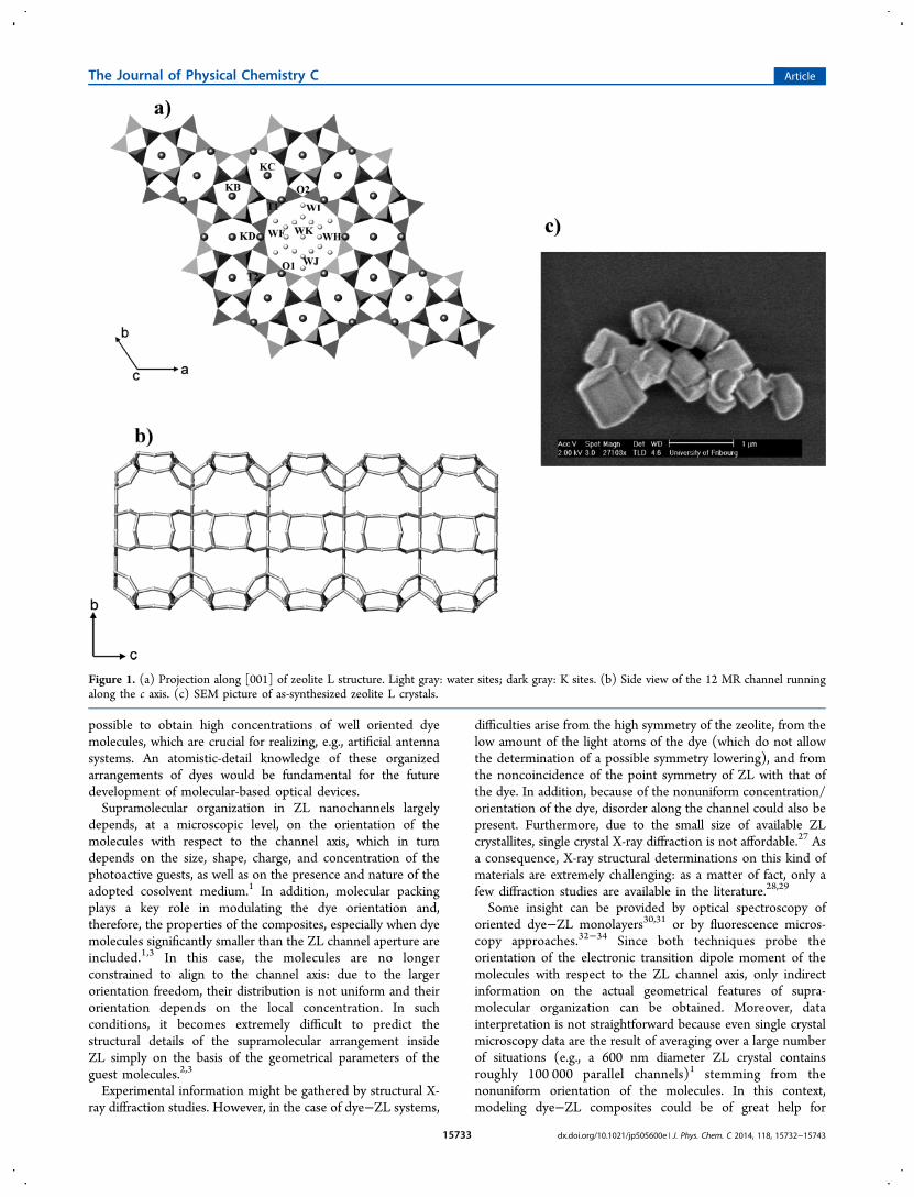
the Supporting Information, hereafter SI) confirms the goodcrystallinity of the material and the absence of impurities.Guest. 9-Fluorenone (C13H8O), purchased as an analytical
standard by Sigma-Aldrich with a purity of 98.0%, was usedwithout further purification. The dye is a neutral and flatorganic molecule, with a carbonyl as functional group.38 InFigure 2 the structure and the dimensions of the molecule areshown.Synthesis of ZL/FL Composites. FL was inserted into the
channels of ZL by using gas-phase adsorption. Four ZL/FLsamples were synthesized with nominal loadings of 0.5, 1.0, 1.5,and 2.25 molecules per unit cell, following the experimental set
up reported in ref 23. (the samples are hereafter reported asZL/0.5FL, ZL/1.0FL, ZL/1.5FL, and ZL/2.25FL). ZL was firstdehydrated at 200 °C for 4 h in vacuum (10−4 mbar), on thebasis of the results of the dehydration and rehydration studyreported by Gigli et al.39 Dehydrated ZL was mixed, in inertatmosphere (operating in a glow box fluxed with high-puritydry N2), with FL powderin ratios corresponding to thedesired loadingsand placed in a rotating oven. The mixtureswere kept at 120 °C for 24 h in order to ensure theencapsulation of the dye and its homogeneous distribution inthe zeolite channels. The composites were characterized bythermogravimetric analysis (TGA), ATR-IR spectroscopy, andXRPD.
2.2. Methods. TGA-MSEGA. The chemical and structuralcharacterizations of ZL/FL composites were carried out in airat room temperature (RT), i.e. in conditions of possiblerehydration.The thermal analyses (TGA coupled with Evolved Gas Mass
Spectrometry, (MSEGA)) of as-synthesized ZL, pure FL, andthe four ZL/FL composites were performed on a Seiko SSC5200 thermal analyzer equipped with a quadrupole massspectrometer (ESS, GeneSys Quadstar 422) using the followingexperimental conditions: 10 °C/min heating rate, from RT to900 °C, 100 μL/min of air flux. The gas emitted during thethermal reactions was monitored in order to allow theunambiguous identification of the species responsible for theweight loss observed in the TGA. Gas analyses were carried outin Multiple Ion Detection mode (MID), following the intensitychanges of 8 species (m/z = 16 (CH4), 18 (H2O), 28 (CO), 30(CH3CH3), 44, 45 (CO2), 78 (C6H6), and 180 (C13H8O)) vstemperature. Before starting MID analysis, backgroundsubtraction was applied to set the zero point conditions.
ATR-IR Spectroscopy. Infrared spectra (2 cm−1 resolution,average on 256 scans) were collected in Attenuated TotalReflection (ATR) mode on loose powder on a Bruker Vertex70instrument (DTGS detector), equipped with a Bruker OPTIKPlatinum ATR accessory (internal reflection element indiamond). Atmospheric carbon dioxide and moisture signalshave been subtracted from all the spectra by applying theAtmospheric Correction tools, as implemented in the Opus 6.5software.
X-ray Powder Diffraction. Preliminary XRPD tests on all thesynthesized composites have been performed using a PhilipsPW1729 diffractometer (θ/θ geometry, Cu Kα radiation). Thepowder was loaded on a zero background quartz sample holder.
Figure 2. Structure, bond lengths (Å), and bond angles (deg) of the 9-fluorenone molecule.23
The Journal of Physical Chemistry C Article
dx.doi.org/10.1021/jp505600e | J. Phys. Chem. C 2014, 118, 15732−1574315734
Data were collected in the 2θ range 3−120° with steps of 0.02and at 5.5 s per step speed.The structural refinements of selected samples (as-synthe-
sized ZL, ZL/0.5FL, ZL/1.0FL, and ZL/1.5FL) were based onhigh-resolution XRPD patterns collected at the SNBL (BM01a)beamline at ESRF (European Synchrotron Radiation Facility)in transmission geometry, with a fixed wavelength of 0.6825 Å.The powder samples were loaded and packed in a 0.3 mmboron capillary, mounted on a standard goniometric head, andspun during data collection. Bidimensional diffraction patternswere recorded on a PILATUS3M-Series detector (pixeldimension 172 μm) at a fixed distance of 193 mm from thesample. One-dimensional diffraction patterns were obtained inthe 2θ range 0−50° by integrating the two-dimensional imageswith the program FIT2D.40
Structural Refinements. Structural refinements were per-formed by full profile Rietveld analysis using the GSASpackage41 with the EXPGUI interface.42 Since no evidence ofsuperstructure and symmetry change in the ZL/FL compositeswas detected from the analysis of the powder patterns, therefinements were performed in the P6/mmm space group. Theframework and potassium atom coordinates reported in ref 39for the room temperature refinement were used as a startingmodel. For all tetrahedral atoms, the Si scattering factor wasused, neglecting the amount of Al atoms. The Bragg peakprofile was modeled using a pseudo-Voigt function with 0.01%cutoff peak intensity. The background was empirically fittedusing a Chebyschev polynomial with 20 variable coefficients.The scale factor, 2θ-zero shift, and unit-cell parameters wereaccurately refined. Table 1 reports the refinement parameters
for ZL and for three composites. The thermal displacementparameters were constrained in the following way: the samevalue for all the tetrahedral atoms, a second value for all theframework oxygen atoms, a third one for the oxygen atoms ofwater molecules, and a fourth one for the FL molecule atoms.The thermal parameters of the K sites were allowed to vary.Occupancy factors and isotropic thermal displacement factorswere refined in alternate refinement cycles. In the ZL/FLsamples, the water and FL molecules were located after theinspection of the Fourier difference maps. H atoms were notconsidered during the structure refinement due to their lowscattering factors. Soft constraints were imposed on tetrahedralbond lengths (Si−O = 1.63 Å) as well as on the C−C (in therange 1.39−1.48 Å) and C−O (1.22 Å) distances, withtolerance values of 0.03 Å. These latter constraints could not beremoved without unrealistic bond distances emerging in the
structure due to the high number of variables in the refinementand to the extremely low scattering power of the FL molecules;hence, the weight on the constraints was kept at a value of 1000in the last cycles of the refinements. The occupancy of FLcarbon sites was allowed to vary in the first refinement cyclesand successively was fixed to the average value.The final atomic positions and thermal parameters for the
four refinements are given in Table S1. The framework andextraframework interatomic distances for ZL and for thecomposites are reported in Tables S2 and S3. The finalobserved and calculated powder patterns of as-synthesized ZLand of the ZL/0.5FL, ZL/1.0FL, and ZL/1.5FL composites areshown in Figure S1.
Models and Calculations. Density functional theory (DFT)calculations were performed on a series of models for the ZL/1.0FL and ZL/1.5FL composites. The PBE approximation43
with periodic boundary conditions and Grimme corrections44
for the FL−FL interactions was applied throughout. For bothsystems the simulation cell was twice the experimental unit cell(u.c.) of the ZL host along c. Calculations on the ZL/0.5FLcomposite (simulation cell stoichiometry: K18[Al18Si54O144]·FL) with the PBE functional and periodic boundary conditionswere previously performed and thoroughly described in refs 36and 37.Electronic wave functions were expanded in planewaves up
to a kinetic energy cutoff of 25 Ry (200 Ry for the density).Electron−ionic core interactions were computed with ultrasoftVanderbilt pseudopotentials for H, C, and O and with normconserving pseudopotentials for Si, Al, and K (semicore in thecase of K).45−48 This electronic structure computationalscheme provided a proper description of the ZL/0.5FLcomposite,36,37 as well as of other large organic−inorganicsystems.49−54,35 All calculations were performed with theCPMD code,55 a particularly valuable approach in the studyof quasi one-dimensional supramolecular systems inside zeolitenanochannels.56−59
In order to try establishing which close-packing arrangementsof FL molecules could be possible inside ZL channels, dry ZL/FL models were first considered. Local energy minima for thedry ZL/1.0FL and ZL/1.5FL models, characterized by thesimulation cell stoichiometries K18[Al18Si54O144]·2FL andK18[Al18Si54O144]·3FL, respectively, were obtained by geometryoptimization of different guess configurations. The guessconfigurations for the ZL/1.0FL and ZL/1.5FL systems werebuilt by inserting two and three FL molecules per simulationcell, respectively (convergence criterion: 5. × 10−4 au for forceson atoms). In the ZL/1.5FL model, one ZL unit cell contained2 FL molecules and the adjacent one 1 FL molecule. In the caseof the ZL/1.0FL system, two different models were considered:model 1-1, characterized by an occupancy of 1 FL molecule perZL unit cell, and model 2-0, where one ZL unit cell contained 2FL molecules and the adjacent one 0 FL molecules. The guessgeometries of both the 1-1 and 2-0 models were built bypositioning the FL molecules so that their CO groups wereeither in a parallel (“sin”) or antiparallel (“anti”) configuration.In all cases, the stabilization energy of the composites withrespect to the isolated ZL and FL components was calculatedwith eq 1:
Δ · = · − − ×E n E n E n E(ZL FL) (ZL FL) (ZL) (FL) (1)
where E(ZL·nFL) is the energy of the optimized dry ZL/nFLmodel (n = 2, 3 for ZL/1.0FL and ZL/1.5FL, respectively) andE(ZL) is the energy of the empty ZL, while E(FL) is the energy
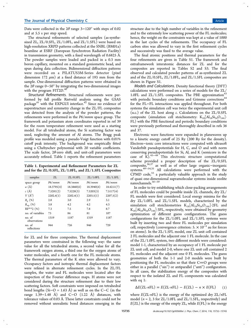
Table 1. Experimental and Refinement Parameters for ZLand for the ZL/0.5FL, ZL/1.0FL, and ZL/1.5FL Composites
samples ZL ZL/0.5FL ZL/1.0FL ZL/1.5FL
space group P6/mmm P6/mmm P6/mmm P6/mmma (Å) 18.3795(4) 18.3860(6) 18.3940(6) 18.4211(7)c (Å) 7.5281(2) 7.5228(3) 7.5203(3) 7.5117(4)V (Å3) 2202.4(1) 2202.4(1) 2203.5(1) 2207.5(2)Rp (%) 2.8 3.0 2.9 3.1Rwp (%) 3.8 4.2 4.2 4.3RF**2 (%) 7.3 7.5 7.8 8.7no. of variables 73 84 81 107no. ofobservations
1319 1187 1319 1187
no. ofreflections
944 726 946 729
The Journal of Physical Chemistry C Article
dx.doi.org/10.1021/jp505600e | J. Phys. Chem. C 2014, 118, 15732−1574315735

of an isolated FL molecule calculated in the same simulationcell.In the case of the low-FL-content system, i.e., the ZL/0.5FL
composite, an atomistic-level structural description wasobtained from both 0 K energy minimization and roomtemperature first-principles molecular dynamics trajectories, asdiscussed in ref 36, to which we refer for further details.Once the minimum energy structure of the dry ZL/1.5FL
system, corresponding to the maximum degree of FL loading,was obtained, several hydrated models characterized bystoichiometry K18[Al18Si54O144]·3FL·13H2O were built byadding 13 water molecules in the simulation cell. Nevertheless,ZL/1.5FL models containing 12 and 14 water molecules werealso considered. The stabilization energies of the hydrated ZL/1.5FL models with respect to the isolated components werecalculated with eq 2:
Δ · ·
= · · − − −
E x
E x E E xE
(ZL 3FL H O)
(ZL 3FL H O) (ZL) 3 (FL) (H O)2
2 2(2)
where E(ZL·3FL·xH2O) is the energy of the optimizedhydrated ZL/1.5FL model (x = 12, 13, 14) and E(ZL) is theenergy of the empty ZL, while E(FL) and E(H2O) arerespectively the energies of an isolated FL molecule and of anisolated water molecule calculated with the same simulation cellparameters. The relative stabilities of the systems with 12 and14 water molecules with respect to that containing 13 H2O’s,were calculated with eqs 3 and 4, respectively:
Δ = · · − · ·
−
E E E
E
(12/13) (ZL 3FL 12H O) [ (ZL 3FL 13H O)
(H O)]2 2
2 (3)
Δ = · · − · ·
+
E E E
E
(14/13) (ZL 3FL 14H O) [ (ZL 3FL 13H O)
(H O)]2 2
2 (4)
Stabilization energies and relative stabilities reported in thefollowing are given in kJ per mol of simulation cell.
3. RESULTS AND DISCUSSION3.1. TGA-MSEGA. Water and fluorenone contents in the
ZL/FL composites were determined by TGA-MSEGA. Figure3 shows the TG (a) and DTG curves (b) as a function oftemperature for the as-synthesized ZL, for pure crystalline FL,and for the ZL/FL composites.The as-synthesized ZL loses most of its water content
(11.9%) in the 30−120 °C temperature range, with a maximumin the DTG curve at 110 °C. However, the weight loss keeps onup to 250 °C, as shown by the slight slope of the TGA curve. Awater loss at such a low temperature is consistent with the ZLstructure; in fact, among the 18 extraframework watermolecules localized in the 12MR channel, only 5 arecoordinated to K cations, while the remaining are weaklybonded to each other.26,39
The thermal analysis of crystalline fluorenone (gray solid linein Figure 3) exhibits only one fast weight loss at 220 °C, andthe mass spectrometry reveals that FL does not decompose insubmoieties but is released in its molecular form.As shown in Figure 3 and Table 2, in the four composites the
water release occurs at about 100 °C and the weight losses are8.7%, 7.3%, 5.5%, and 5.4% (corresponding to 13.6, 11.5, 8.8,and 8.8H2O molecules per u.c.) in ZL/0.5FL, ZL/1.0FL, ZL/
1.5FL, and ZL/2.25FL, respectively. The water loss temper-ature slightly decreases when the water amount in thecomposite decreases, as a consequence of the FL penetration.The fluorenone release in the composites occurs again in onestep, but at higher temperature with respect to pure FL (in therange 300−500 °C). This indicates that FL is not simplyphysisorbed on the zeolite surface but is encapsulated inside thezeolite channels. It is worth noting that the release temperaturedecreases with increasing the FL loading, indicating aninfluence of loading on the host−guest FL−ZL interactions.The sample ZL/2.25FL shows a further weight loss at 170 °C,absent in the TG curve of all the other composites. This can beinterpreted as the result of the removal of a portion of FLpresent as crystalline phase, not confined in zeolite porosities.This fact is confirmed by the XRPD pattern collected on thatsample, showing reflections pertaining to the crystallinefluorenone phase (Figure 4).On the basis of the mass spectrometry results, we observed
that, when confined in the zeolite L, FL is released as CO2 andC6H6 as a consequence of the higher release temperature. Theweight losses corresponding to the encapsulated FL are 2.8%,5.6%, 8.7%, and 9.5% (corresponding to 0.43, 0.88, 1.43, and1.50 FL molecules) in the ZL/0.5FL, ZL/1.0FL, ZL/1.5FL, andZL/2.25FL composites, respectively (Table 2). These results,and in particular the presence of only 1.5 molecules in thesample ZL/2.25FL, indicate that the maximum possible loadingof the dye in zeolite L is 1.5 molecules per unit cell. Thecrystalline fluorenone detected in the case of the ZL/2.25FLcomposite corresponds to the exceeding dye on the zeolitesurface. Consequently, this sample was not further investigated.In all of the investigated composites, the amounts of water andFL are, as expected, inversely correlated, indicating that thefluorenone molecules entering the channels replace the watermolecules.
3.2. ATR-IR Spectroscopy. Figure 5 shows the IR spectraof FL in the solid state and in solution in cyclohexane (uppersection “FL”) compared with the spectra of bare ZL (dotted
Figure 3. TG (a) and DTG curves (b) vs temperature for ZL (blacksolid curve), for pure FL (gray solid curve), and for the ZL/0.5FL(dashed black line), ZL/1.0FL (dashed-double dot black line), ZL/1.5FL (dotted black line), and ZL/2.25FL (dashed-dot black line)composites.
The Journal of Physical Chemistry C Article
dx.doi.org/10.1021/jp505600e | J. Phys. Chem. C 2014, 118, 15732−1574315736
black line) and ZL mixed with FL before (middle section) andafter (lower section) thermal treatment.Among the IR signals, the stretching vibration of the
carbonyl group of FL (at 1711 cm−1 in solid and 1716 cm−1 incyclohexane solution) is expected to be particularly informativeon the nature of the chemical environment around the FLmolecule, being easily red-shifted if directly involved ininteractions with positive charges (as in the case of FL graftingon K+ ions). Conversely, the CC ring in plane stretchingmodes vibrating at 1610 and 1598 cm−1 are expected to beinsensitive to the interaction of FL with the environment. Theexposure of bare ZL to air for recording the IR spectrum
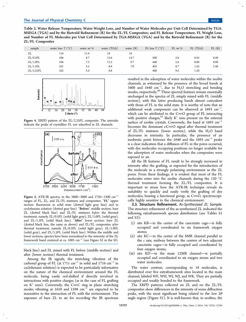
resulted in the adsorption of water molecules within the zeolitechannels, as witnessed by the presence of the broad bands at3400 and 1640 cm−1, due to H2O stretching and bendingmodes, respectively.60 These spectral features remain essentiallyunchanged in the spectra of ZL simply mixed with FL (middlesection), with this latter producing bands almost coincidentwith those of FL in the solid state. It is worthy of note that anadditional weak component can be observed at 1693 cm−1,which can be attributed to the CO group of FL interactingwith positive charges,61 likely K+ ions present on the externalsurface of zeolite crystals. Conversely, the band at 1693 cm−1
becomes the dominant νCO signal after thermal treatmentof ZL/FL mixtures (lower section), while the H2O banddecreases in intensity. In particular, the presence of anisosbestic point between the 1640 and the 1693 cm−1 peaksis a clear indication that a diffusion of FL in the pores occurred,with dye molecules occupying positions no longer available forthe adsorption of water molecules when the composites wereexposed to air.All the IR features of FL result to be strongly increased in
intensity after the grafting, as expected for the introduction ofthe molecule in a strongly polarizing environment as the ZLpores. From these findings, it is evident that most of the FLmolecules enter into the zeolite channels during the 120 °Cthermal treatment forming the ZL/FL composites. It isimportant to stress how the ATR-IR technique reveals itssuitability to quickly and easily verify the grafting of dyemolecules, bearing a functional group, as CO, spectroscopi-cally highly sensitive to the chemical environment.
3.3. Structure Refinement. As-Synthesized ZL Sample.The structure refinement of the as-synthesized ZL indicated thefollowing extraframework species distribution (see Tables S1and S3):
(i) site KBin the center of the cancrinite cageis fullyoccupied and coordinated to six framework oxygenatoms;
(ii) site KCin the center of the 8MR channel parallel tothe c axis, midway between the centers of two adjacentcancrinite cagesis fully occupied and coordinated byfour oxygen atoms;
(iii) site KDin the main 12MR channelis partiallyoccupied and coordinated to six oxygen atoms and twowater molecules.
The water content, corresponding to 18 molecules, isdistributed over five extraframework sites located in the mainchannel, labeled WF, WH, WI, WJ, and WK. They are partiallyoccupied and weakly bonded to the framework.The XRPD patterns collected on ZL and on the ZL/FL
composites show differences in the intensity of some diffractionpeaks, with the most significant being related to the low 2θangle region (Figure S1). It is well-known that, in zeolites, the
Table 2. Water Release Temperature, Water Weight Loss, and Number of Water Molecules per Unit Cell Determined by TGA-MSEGA (TGA) and by the Rietveld Refinement (R) for the ZL/FL Composites; and FL Release Temperature, FL Weight Loss,and Number of FL Molecules per Unit Cell Determined by TGA-MSEGA (TGA) and by the Rietveld Refinement (R) for theZL/FL Composites
sample water loss T (°C) water wt % water (TGA) water (R) FL loss T (°C) FL wt % FL (TGA) FL (R)
ZL 110 11.9 18 18ZL/0.5FL 106 8.7 13.6 14.7 500 2.8 0.43 0.49ZL/1.0FL 104 7.3 11.5 9.7 440 5.6 0.88 0.98ZL/1.5FL 101 5.5 8.8 7.0 403 8.7 1.43 1.48ZL/2.25FL 102 5.4 8.8 400 9.5 1.50
Figure 4. XRPD pattern of the ZL/2.25FL composite. The asterisksindicate the peaks of crystalline FL not adsorbed in ZL channels.
Figure 5. ATR-IR spectra, in the 3800−3000 and 1750−1500 cm−1
ranges of FL, ZL, and ZL/FL mixtures and composites. “FL” uppersection: fluorenone in solid state (dotted light gray line) and incyclohexane solution (dotted gray line). “Before” middle section: bareZL (dotted black line) and ZL/FL mixtures before the thermaltreatment, namely ZL/0.5FL (solid light gray), ZL/1.0FL (solid gray),and ZL/1.5FL (solid black line). “After” lower section: bare ZL(dotted black line, the same as above) and ZL/FL composites af terthermal treatment, namely ZL/0.5FL (solid light gray), ZL/1.0FL(solid gray), and ZL/1.5FL (solid black line). Within the middle andlower sections, spectra have been normalized to the intensity of the ZLframework band centered at ca. 1005 cm−1 (see Figure S2 in the SI).
The Journal of Physical Chemistry C Article
dx.doi.org/10.1021/jp505600e | J. Phys. Chem. C 2014, 118, 15732−1574315737
intensities of the low-angle peaks of the diffraction pattern arerelated to the extraframework species distribution. Thus, thesechanges are consistent with the FL penetration and inagreement with the TGA and ATR-IR results. Only smallchanges in the cell parameters occur; in particular, a slightincrease of a and a decrease of c parameters are observed in thecomposites with respect to the original material (Table 1).By comparing the results of the structural refinements of ZL
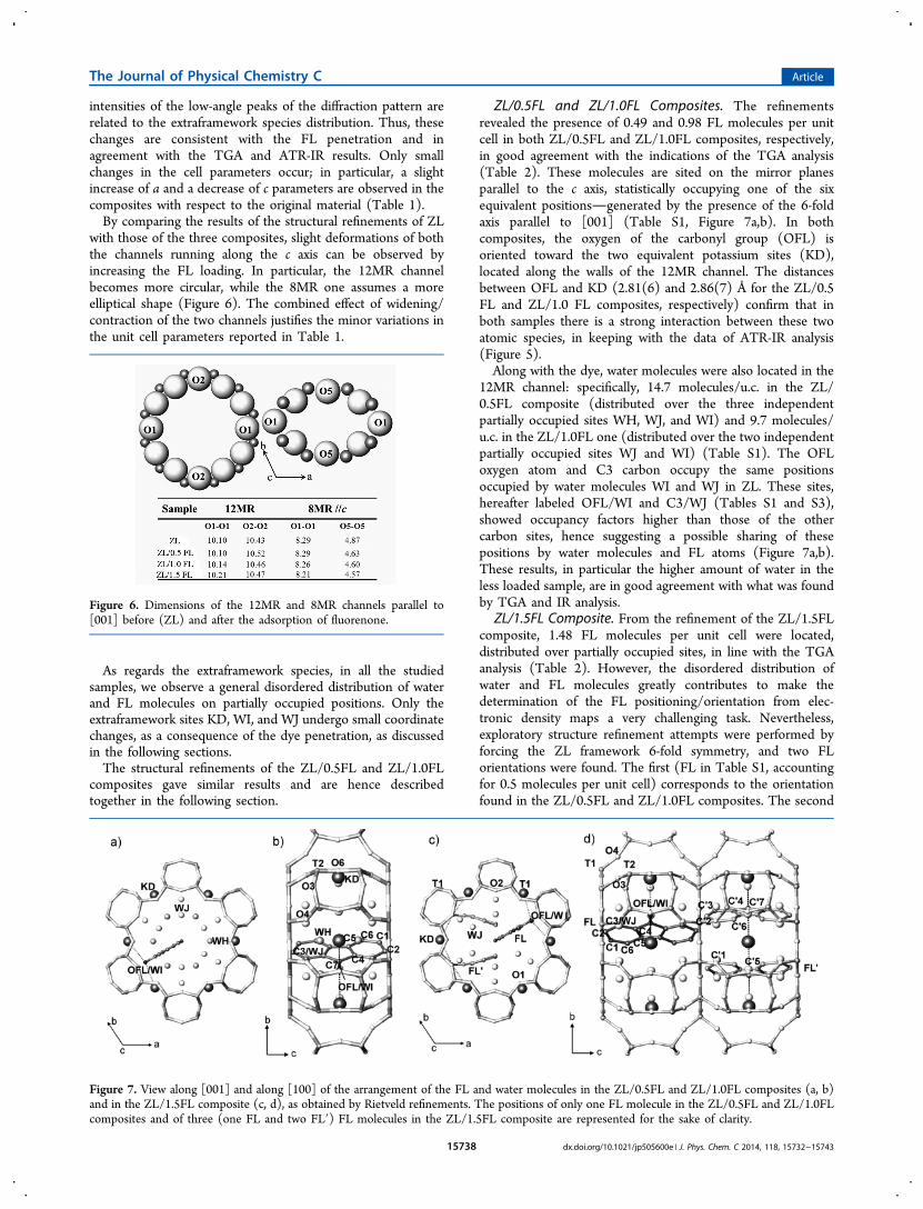
with those of the three composites, slight deformations of boththe channels running along the c axis can be observed byincreasing the FL loading. In particular, the 12MR channelbecomes more circular, while the 8MR one assumes a moreelliptical shape (Figure 6). The combined effect of widening/contraction of the two channels justifies the minor variations inthe unit cell parameters reported in Table 1.
As regards the extraframework species, in all the studiedsamples, we observe a general disordered distribution of waterand FL molecules on partially occupied positions. Only theextraframework sites KD, WI, and WJ undergo small coordinatechanges, as a consequence of the dye penetration, as discussedin the following sections.The structural refinements of the ZL/0.5FL and ZL/1.0FL
composites gave similar results and are hence describedtogether in the following section.
ZL/0.5FL and ZL/1.0FL Composites. The refinementsrevealed the presence of 0.49 and 0.98 FL molecules per unitcell in both ZL/0.5FL and ZL/1.0FL composites, respectively,in good agreement with the indications of the TGA analysis(Table 2). These molecules are sited on the mirror planesparallel to the c axis, statistically occupying one of the sixequivalent positionsgenerated by the presence of the 6-foldaxis parallel to [001] (Table S1, Figure 7a,b). In bothcomposites, the oxygen of the carbonyl group (OFL) isoriented toward the two equivalent potassium sites (KD),located along the walls of the 12MR channel. The distancesbetween OFL and KD (2.81(6) and 2.86(7) Å for the ZL/0.5FL and ZL/1.0 FL composites, respectively) confirm that inboth samples there is a strong interaction between these twoatomic species, in keeping with the data of ATR-IR analysis(Figure 5).Along with the dye, water molecules were also located in the
12MR channel: specifically, 14.7 molecules/u.c. in the ZL/0.5FL composite (distributed over the three independentpartially occupied sites WH, WJ, and WI) and 9.7 molecules/u.c. in the ZL/1.0FL one (distributed over the two independentpartially occupied sites WJ and WI) (Table S1). The OFLoxygen atom and C3 carbon occupy the same positionsoccupied by water molecules WI and WJ in ZL. These sites,hereafter labeled OFL/WI and C3/WJ (Tables S1 and S3),showed occupancy factors higher than those of the othercarbon sites, hence suggesting a possible sharing of thesepositions by water molecules and FL atoms (Figure 7a,b).These results, in particular the higher amount of water in theless loaded sample, are in good agreement with what was foundby TGA and IR analysis.
ZL/1.5FL Composite. From the refinement of the ZL/1.5FLcomposite, 1.48 FL molecules per unit cell were located,distributed over partially occupied sites, in line with the TGAanalysis (Table 2). However, the disordered distribution ofwater and FL molecules greatly contributes to make thedetermination of the FL positioning/orientation from elec-tronic density maps a very challenging task. Nevertheless,exploratory structure refinement attempts were performed byforcing the ZL framework 6-fold symmetry, and two FLorientations were found. The first (FL in Table S1, accountingfor 0.5 molecules per unit cell) corresponds to the orientationfound in the ZL/0.5FL and ZL/1.0FL composites. The second
Figure 6. Dimensions of the 12MR and 8MR channels parallel to[001] before (ZL) and after the adsorption of fluorenone.
Figure 7. View along [001] and along [100] of the arrangement of the FL and water molecules in the ZL/0.5FL and ZL/1.0FL composites (a, b)and in the ZL/1.5FL composite (c, d), as obtained by Rietveld refinements. The positions of only one FL molecule in the ZL/0.5FL and ZL/1.0FLcomposites and of three (one FL and two FL′) FL molecules in the ZL/1.5FL composite are represented for the sake of clarity.
The Journal of Physical Chemistry C Article
dx.doi.org/10.1021/jp505600e | J. Phys. Chem. C 2014, 118, 15732−1574315738

(FL′ in Table S1, accounting for 1.0 molecule per unit cell)features the FL molecular long axis parallel to the c axis, butwith some atoms outside the mirror plane parallel to [001]. Onthe basis of the size and geometry of FL molecules, andconsidering the bond distances among the dye moleculesobtained by the refinement, the only possible FL distribution isthat reported in Figure 7c,d. In particular, if we consider twoadjacent unit cells, one should be occupied by two equivalentnearly parallel FL′ molecules (among the 12 symmetricallyequivalent ones) while the other should contain one FLmolecule. Also in this model every oxygen atom of the guestmolecules is coordinated to two KD sites (Table S3).As already observed in the ZL/0.5FL and ZL/1.0FL
composites, the refinement located the water molecules inthe OFL/WI and C3/WJ sites (Tables S1 and S3). The FL′−water distances however showed values well below thoseexpected from the corresponding van der Waals radii; e.g., theOFL′ atom is at distances of 1.07 and 2.89 Å from WI and WJ,while C3′ is at distances of 2.87 and 1.31 Å from WI and WJ.These short distances are due to the partial occupancy of thesites and to the great variability of the positions of the watermolecules from unit cell to unit cell because of theirdependence on the location of FL. Therefore, even thoughthe R/F2 value for this refinement may be considered rathergood (8.7%) in view of the high number of variables, the 6-foldsymmetry constraint imposed in the refinement resulted in atoo short C−C distance (2.56 Å) between FL and FL′molecules present in two adjacent cells. To solve this structuralinconsistency and provide a realistic structural model of the FLpacking inside the composite, density functional calculationswere performed.3.4. Simulation Results. Modeling of Dry ZL/FL Adducts.
In order to try unraveling the structure of the FL organizationin ZL nanochannels, let us first recall that the fluorenonemolecular length, 8.9 Å along its longest axis, is greater than theZL cell dimension along the channel (7.52 Å). FL is, however,noticeably shorter than the maximum channel opening (∼12Å), indicating that this dye could have orientation freedominside the zeolite and should not necessarily align with the ZLchannel axis. Actually, by increasing the FL content, a modestshortening of the cell along the c axis is detected, suggestingthat, at high FL loading, an organization of the FL molecules insingle file should be rather improbable. As reported in refs 36and 37, at low loading (i.e., 0.5 FL per u.c.) the calculatedminimum energy structure for a dry ZL/0.5FL system ischaracterized by a FL molecule coordinated, via the carbonyloxygen, to a K+ cation and oriented with its long molecular axisforming an angle of about 30° with the c axis. The stabilizationenergy of this structure with respect to the isolated ZL and FLcomponents amounts to −80.8 kJ mol−1. Even though ageometry with the FL long axis aligned with the channeldirection is only 12.1 kJ mol−1 less stable than the minimumenergy structure, at room temperature the FL most probableorientation is that with the molecular long axis at 30° withrespect to the channel axis. Such an angle decreases to 20°upon hydration, indicating that in humid conditions not onlyFL keeps contact with K+ but also its average position andorientation inside the channel are not substantially influ-enced.36,37 Also, configurations with the FL long axisperpendicular to the channel axis, where the FL carbonyloxygen is far from the extraframework potassium cations, aremuch higher in energy than those aligned with the channel axis
and become unstable at room temperature conditions, asevidenced by first-principles molecular dynamics.37
Based on the above results and on host−guest structuralproperties, in the case of the ZL/1.0FL composite, the mostprobable supramolecular organization should feature the FLmolecules approximately aligned with the channel axis and withtheir carbonyl oxygen directed toward the channel walls, whereaccessible K+ ions are located. With this in mind, two kinds ofarrangements, described as (2,0) or (1,1), could be devised,corresponding to (i) two adjacent ZL unit cells approximatelyoccupied by two and 0 FL molecules (2,0); (ii) each ZL unitcell containing 1 FL molecule (1,1). Two different orientationsof the CO group of the two FL molecules were considered:(i) anti, characterized by an antiparallel arrangement of the CO groups; (ii) sin, where the CO groups are parallel.Geometry optimization of several ZL/1.0FL models exhibitingthese arrangements indicates that different optimized structureshave comparable energies, separated by less than 4 kJ mol−1
(see Figure 8). The most stable structure is an anti-(2,0)
configuration (Figure 8a) and has a stabilization energy of−141.4 kJ mol−1 with respect to the isolated components (seeeq 1). A sin-(2,0) arrangement (Figure 8b) is, however, nearlyisoenergetic, being less stable than the minimum energystructure by only 5.0 kJ mol−1. Also, an anti-(1,1) structure(Figure 8c) is of comparable energy, being only 3.8 kJ mol−1
less stable than the anti-(2,0) one. On the other hand, the moststable among the sin-(1,1) arrangements (Figure 8d) is 33.5 kJ
Figure 8. Graphical representation of minimum energy structurescalculated for the ZL/1.0FL models: (a) anti-(2,0) arrangement of theFL molecules; (b) sin-(2,0) arrangement; (c) anti-(1,1) arrangement;(d) sin-(1,1) arrangement. ZL framework atoms are represented assticks (brown: Si, green: Al, red: O), K+ as yellow spheres. FL atomsare in the van der Waals representation (cyan: C, red: O, white: H).
The Journal of Physical Chemistry C Article
dx.doi.org/10.1021/jp505600e | J. Phys. Chem. C 2014, 118, 15732−1574315739

mol−1 higher in energy than the anti-(2,0). Since all of thesestructures are characterized by distances between the FLcarbonyl oxygen and K+ in line with the correspondingexperimental values and compatible with a strong potassium−FL interaction, their different relative stabilities mainly derivefrom FL−FL interactions. Actually, the minimum energystructure for the ZL/1.0 FL system is just the one characterizedby the highest degree of FL close-packing, which maximizes thefavorable van der Waals interactions between the dyemolecules.Also, for the maximum loading of 1.5 FL per u.c., we
performed geometry optimization on different guess structures,all characterized by a (2,1) FL arrangement (see Figure 9a).The stabilization energy of the resulting minimum energystructure with respect to the isolated components (eq 1)amounts to −266.5 kJ mol−1. Here the supramolecularorganization consists of two FL molecules, FL1 and FL2 (ina sin configuration), located approximately inside one of the ZLunit cells with their long axes nearly parallel to each other andto the channel direction, while the third one, FL3, is positionedin the adjacent unit cell and oriented at about 45° with respectto the ZL channel axis. Indeed, the stronger intermolecularinteractions and the severe structural constraints implied byconfinement in nanochannels at high packing conditions forcethe FL molecules to organize just like a ladder with inclinedrungs running along the ZL channel, as clearly evidenced in
Figure 9. Indeed, the molecules are essentially planar and showonly slight distortions from the ideal gas-phase FL structure,indicating that this ladderlike supramolecular architecture isachieved without any significant perturbation of the FLmolecular geometry. Moreover, the FL nanoladder stillmaintains some resemblance to the structure of the FLcrystal,38 suggesting that, at high loading regimes, also guest−guest van der Waals interactions, and specifically π−π stacking,are pivotal in governing supramolecular organization. Theconfining environment provided by the ZL nanochannelsprevents the formation of the thermodynamically stable bulksolid FL and constrains the dye molecules to self-assemble intoa new, low-dimensionality solid phase: the FL nanoladder.Nevertheless, such a stunning example of spatio-morphologi-cally controlled crystallization owes its existence also tononcovalent though directional host−guest interactions,which drive the positioning and orientation of each individualdye molecule forming the nanoladder. In this respect, we noticethat each FL is in close contact with the ZL K+ cations via itscarbonyl oxygen, in line with the previously discussedexperimental evidence. More specifically, the distances of thethree carbonyl oxygens from the zeolite K+ cations amount to2.539, 2.570, and 2.676 Å, respectively, indicating that, like inthe case of lower FL-loading ZL/FL systems,36,37 also strongCO/K+ interactions play a key role in supramolecularorganization.
Figure 9. Graphical representation of the minimum energy structure calculated for the (a) dry ZL/1.5FL model; (b) hydrated ZL/1.5FL model(with 13H2O in the simulation cell). Atom color codes as in Figure 8.
The Journal of Physical Chemistry C Article
dx.doi.org/10.1021/jp505600e | J. Phys. Chem. C 2014, 118, 15732−1574315740

Hydrated System with 1.5 FL per u.c. Several hydratedmodels of the ZL/1.5FL system were considered, characterizedeither by a different number of water molecules in thesimulation cell (in the 12−14 range) or by a different startingarrangement of the FL and H2O molecules. The minimumenergy structure obtained by placing 13 water molecules in thesimulation cell is shown in Figure 9b. In this structure, 8 watermolecules are located in the unit cell containing FL3 and theremaining 5 in that occupied by the FL1 and FL2 molecules. Inline with results obtained on other dye−ZL composites,35,54 thewater molecules are mainly clustered in the ZL channel regioncharacterized by a lower local concentration of the dye and tryto adopt a quasi-tetrahedral organization mimicking that ofwater in the condensed phases, in order to maximize thenumber and strength of hydrogen bonds. Indeed, the high valueof the stabilization energy calculated for this structure, 752.7 kJmol−1 (eq 2), indicates that water actively contributes tostabilize close-packing of dye molecules inside zeolite nano-channels. As clearly evidenced in Figure 9, besides slightdeformations related to the water copresence, the arrangementof the FL molecules resembles quite closely the FL nanoladderfound in the dry ZL/1.5FL composite. It can therefore beconcluded that, at ambient temperature and pressureconditions, water molecules do not significantly perturbatethe FL supramolecular organization. This finding is nicely inline with the fact that FL molecules interact more strongly withthe zeolite than water does, as demonstrated in ref 36. Due tothe dominant FL−K+ interaction, water molecules cannotdisplace the dye from the zeolite, but they seamlesslyincorporate FL molecules into the hydrogen bond networkand finely tune FL positioning and orientation inside the ZLchannel through hydrogen bond interactions. Actually, thedistances of the three carbonyl oxygens from the zeolite K+
cations, amounting to 2.524, 2.590, and 2.848 Å respectively,are very close to those of the dry ZL/1.5FL system, confirmingthat the presence of water has only minor structural effects onthe FL arrangement. As far as the water content is concerned,by applying eqs 3 and 4, we calculated that the systemcontaining 13 H2O (namely, 6.5 H2O per crystallographic cell)is more stable than both the systems containing 12 or 14 watermolecules, by 149.4 and 38.5 kJ mol−1, respectively. The greaterenergy stability of the 13 H2O composite, with respect to the12 H2O one, can be easily rationalized on the basis of thehigher number of hydrogen bond interactions. Nevertheless,the minimum energy structure obtained at higher water content(14 H2O) is less stable than the 13 H2O one because, as a resultof the reduced available space inside the ZL channel, thegeometry of the FL molecules exhibits larger distortions fromthe ideal planar FL structure. Therefore, computational results,besides integrating experimental data on the high-FL-contentcomposite, shed light and rationalize several aspects ofsupramolecular organization inside ZL channels, thus enablingus, for the first time, to catch a fleeting glimpse of howpromisingly appealing it could be to explore close-packed dyemolecules self-assembled in 1-D confining environments.
4. CONCLUSIONSTo unravel the supramolecular organization of close-packedphotoactive molecules confined in one-dimensional nano-channels, zeolite L/fluorenone (ZL−FL) composites charac-terized by different dye loading have been synthesized. Resultsof thermogravimetric, IR, and X-ray structural refinementsestablished that the maximum degree of FL loading
corresponds to 1.5 FL molecules per ZL unit cell. A thoroughcharacterization of the structural properties and energetics ofthis dye−zeolite system has been accomplished by DFT-basedmodeling, which revealed the template-directed self-assembly ofplanar dye molecules into a noncovalent nanoladder.By increasing loading from 0 to 1.5 molecules per cell,
fluorenone gradually replaces water molecules in ZL in view ofits stronger interaction with the zeolite and fills the nano-channel by organizing into arrangements that concomitantlymaximize the π-stacking (intermolecular guest−guest inter-actions) and allow each FL carbonyl group to interact with a K+
(host−guest interactions). Such organized FL distributionsonly at maximum loading can be considered as a single,continuous nanostructure of dye molecules. This arrangement,formed by pairs of π-stacked molecules connected by a singleFL, holds some resemblance with the structure of solidfluorenone (the FL pairs); however, the confinement inside ZLchannels and the different dimensions of the FL molecule andZL unit cell prevent the connectivity of consecutive pairs ofmolecules like in crystalline fluorenone, thus resulting in theformation of a unique architecture. Interestingly, the pro-gressive filling of FL is accompanied by slight thoughappreciable deformations of the channel apertures, indicatingthat also zeolite framework flexibility contributes to achieve theoptimal FL organization (i.e., that characterized by the higheststability) at the maximum loading. Moreover, the watermolecules inside the channel after FL intrusion are arrangedin such a way to maximize hydrogen bond interaction, thusproviding further stabilization to the system without alteringthe FL distribution, which is governed by the stronger FL−FLand FL−ZL interactions.On the whole, all of the results presented in this study
highlight the key role of the ZL channels in providing spatial,directional, and morphological control over the realization ofsupramolecular nanoarchitectures of photoactive species andstress the relevance of extraframework K+ cations in stabilizingcarbonyl-functionalized species inside ZL and in fine-tuningtheir organization.Among the ZL/FL composites investigated in this study,
only the maximally loaded system features a continuous andorganized distribution of dye molecules inside ZL nano-channels. By virtue of this architecture, the ZL/1.5FLcomposite should be the most promising candidate fortechnological applications. Following this hypothesis, futurework specifically aimed at electronic and optical properties ofclose-packed ZL/FL composites will essentially focus on themaximally loaded system. Nevertheless, the identification of thefirst continuous and quasi 1-D dye nanostructure self-assembledinto a zeolite, accompanied by the understanding of theinterplay of host−guest/guest−guest interactions governingsupramolecular organization at the high packing conditionsgathered in this study, strongly suggests that high-loadingregimes are promising and deserve to be deeply investigated,giving thus further momentum to the design of dye−ZLcomposites for innovative optical devices.
■ ASSOCIATED CONTENT*S Supporting InformationObserved and calculated diffraction patterns and final differencecurve from Rietveld refinements of the pure ZL and of the ZL/0.5FL, ZL/1.0FL, ZL/1.5FL composites. ATR-IR spectra ofbare ZL and ZL/FL materials before and after the thermaltreatment. Atomic coordinates, occupancy factors, and thermal
The Journal of Physical Chemistry C Article
dx.doi.org/10.1021/jp505600e | J. Phys. Chem. C 2014, 118, 15732−1574315741
displacement parameters for the bare ZL, ZL/0.5FL, ZL/1.0FL,and ZL/1.5FL composites. Framework bond distances for theZL and ZL/0.5FL, ZL/1.0FL, and ZL/1.5FL composites.Extraframework bond distances for ZL, ZL/0.5FL, ZL/1.0FL,and ZL/1.5FL composites. This material is available free ofcharge via the Internet at http://pubs.acs.org.
■ AUTHOR INFORMATIONCorresponding Author*E-mail: [email protected] Address○(G.A.) European Synchrotron Radiation Facility (ESRF), B.P.220, 38043 Grenoble, France.NotesThe authors declare no competing financial interest.
■ ACKNOWLEDGMENTSThe BM01 beamline at the European Synchrotron RadiationFacility and Dr. Vladimir Dmitriev are acknowledged forallocation of experimental beamtime. Dr. Simona Bigi and Dr.Daniele Malferrrari are acknowledged for the help in TGA-MSEGA analyses. Professor Gion Calzaferri is acknowledgedfor useful discussions. Prof. Carlo Lamberti is acknowledged forthe hospitality at NIS laboratories. This work was supported bythe Italian MIUR, within the framework of the followingprojects: PRIN2009 “Struttura, microstruttura e proprieta deiminerali”; PRIN2010-11 “Dalle materie prime del sistema Terraalle applicazioni tecnologiche: studi cristallochimici e struttur-ali”; FIRB, Futuro in Ricerca “ImPACT” (RBFR12CLQD);INFOCHEM project PRIN 2010CX2TLM_006.
■ REFERENCES(1) Calzaferri, G. Nanochannels: Hosts for the SupramolecularOrganization of Molecules and Complexes. Langmuir 2012, 28, 6216−6231.(2) Calzaferri, G.; Lutkouskaya, K. Mimicking the Antenna System ofGreen Plants. Photochem. Photobiol. Sci. 2008, 7, 879−910.(3) Calzaferri, G.; Meallet-Renault, R.; Bruhwiler, D.; Pansu, R.;Dolamic, I.; Dienel, T.; Adler, P.; Li, H.; Kunzmann, A. DesigningDye-Nanochannel Antenna Hybrid Materials for Light Harvesting,Transport and Trapping. ChemPhysChem 2011, 12, 580−594.(4) Gruner, M.; Siozios, V.; Hagenhoff, B.; Breitenstein, D.; Strassert,C. A. Structural and Photosensitizing Features of PhthalocyanineZeolite Hybrid Nanomaterials. Photochem. Photobiol. 2013, 89, 1406−1412.(5) Tsotsalas, M. M.; Kopka, K.; Luppi, G.; Wagner, S.; Law, M. P.;Schafers, M.; De Cola, L. Encapsulating (111)In in Nanocontainers forScintigraphic Imaging: Synthesis, Characterization, and in VivoBiodistribution. ACS Nano 2010, 4, 342−348.(6) Li, Z.; Luppi, G.; Geiger, A.; Josel, H.-P.; De Cola, L.Bioconjugated Fluorescent Zeolite L Nanocrystals as Labels in ProteinMicroarrays. Small 2011, 7, 3193−3201.(7) El-Gindi, J.; Benson, K.; De Cola, L.; Galla, H.-J.; Kehr, N. S. CellAdhesion Behaviour on Enantiomerically Functionalized Zeolite LMonolayers. Angew. Chem., Int. Ed. 2012, 51, 3716−3720.(8) Wen, T.; Zhang, W.; Hu, X.; He, L.; Li, H. Insight into theLuminescence Behavior of Europium(III) β-Diketonate ComplexesEncapsulated in Zeolite L Crystals. ChemPlusChem 2013, 78, 438−442.(9) Szarpak-Jankowska, A.; Burgess, C.; De Cola, L.; Huskens, J.Cyclodextrin-Modified Zeolites: Host−Guest Surface Chemistry forthe Construction of Multifunctional Nanocontainers. Chem.Eur. J.2013, 44, 14925−14930.(10) Manzano, H.; Gartzia-Rivero, L.; Banuelos, J.; Lopez-Arbeloa, I.Ultraviolet-Visible Dual Absorption by a Single BODIPY Dye
Confined in LTL Zeolite Nanochannels. J. Phys. Chem. C 2013, 117,13331−13336.(11) Caro, J.; Marlow, F.; Wust, M. Chromophore−ZeoliteCompositesThe Organizing Role of Molecular-Sieves. Adv. Mater.1994, 6, 413−416.(12) Ihlein, G.; Schuth, F.; Kraus, O.; Vietze, U.; Laeri, F. Alignmentof a Laser Dye in the Channels of the AlPO4-5 Molecular Sieve. Adv.Mater. 1998, 10, 1117−1119.(13) Hoppe, R.; Schulz-Ekloff, G.; Wohrle, D.; Kirschhock, C.; Fuess,H.; Uytterhoeven, L.; Schoonheydt, R. Incorporation of MethyleneBlue in NaY Zeolite at Crystallographically Defined Positions. Adv.Mater. 1995, 7, 61−64.(14) Calzaferri, G.; Pauchard, M.; Maas, H.; Huber, S.; Khatyr, A.;Schaafsma, T. J. Photonic Antenna System for Light Harvesting,Transport and Trapping. Mater. Chem. 2002, 12, 1−13.(15) Mahato, R. N.; Lulf, H.; Siekman, M. H.; Kersten, S. P.;Bobbert, P. A.; de Jong, M. P.; De Cola, L.; van der Wiel, W. G.Ultrahigh Magnetoresistance at Room Temperature in MolecularWires. Science 2013, 341, 257−260.(16) Onida, B.; Bonelli, B.; Lucco-Borlera, M.; Flora, L.; OteroArean, C.; Garrone, E. Spectroscopic Properties of Dye-LoadedMesoporous Silicas of the Structural Type MCM-41. Stud. Surf. Sci.Catal. 2001, 135, 364−364.(17) Busby, M.; Blum, C.; Tibben, M.; Fibikar, S.; Calzaferri, G.;Subramaniam, V.; De Cola, L. Time, Space, and Spectrally ResolvedStudies on J-Aggregate Interactions in Zeolite L Nanochannels. J. Am.Chem. Soc. 2008, 130, 10970−10976.(18) Kim, H. S.; Pham, T. T.; Yoon, K. B. Aligned Inclusion ofDipolar Dyes into Zeolite Channels by Inclusion in the Excited State.J. Am. Chem. Soc. 2008, 130, 2134−2135.(19) Martínez-Martínez, V.; García, R.; Gomez-Hortiguela, L.; SolaLlano, R.; Perez-Pariente, J.; Lopez-Arbeloa, I. Highly Luminescentand Optically Switchable Hybrid Material by One Pot Encapsulationof Dyes into MgAPO-11 Unidirectional Nanopores. ACS Photonics2014, DOI: 10.1021/ph4000604.(20) Li, P.; Wang, Y.; Li, H.; Calzaferri, G. LuminescenceEnhancement after Adding Stoppers to Europium(III) Nano zeoliteL. Angew. Chem., Int. Ed. 2014, 53, 2904−2909.(21) Devaux, A.; Calzaferri, G.; Miletto, I.; Cao, P.; Belser, P.;Bruhwiler, D.; Khorev, O.; Haner, R.; Kunzmann, A. Self-Absorptionand Luminescence Quantum Yields of Dye−Zeolite L Composites. J.Phys. Chem. C 2013, 117, 23034−23047.(22) Calzaferri, G.; Huber, S.; Maas, H.; Minkowski, C. Host-GuestAntenna Materials. Angew. Chem., Int. Ed. 2003, 42, 3732−3758.(23) Devaux, A.; Minkowski, C.; Calzaferri, G. Electronic andVibrational Properties of Fluorenone in the Channels of Zeolite L.Chem.Eur. J. 2004, 10, 2391−2408.(24) Calzaferri, G.; Devaux, A. In Supramolecular Photochemistry;Ramamurthy, V., Inoue, Y., Eds.; Wiley&Sons: 2011.(25) Lupulescu, A. I.; Kumar, M.; Rimer, J. D. A Facile Strategy toDesign Zeolite L Crystals with Tunable Morphology and SurfaceArchitecture. J. Am. Chem. Soc. 2013, 135, 6608−6617.(26) Barrer, R. M.; Villiger, H. The Crystal Structure of the SyntheticZeolite L. Z. Kristallogr. 1969, 128, 352−370.(27) Lee, Y. J.; Lee, J. S.; Yoon, K. B. Synthesis of Long Zeolite-LCrystals with Flat Facets Original Research Article. MicroporousMesoporous Mater. 2005, 80, 237−246.(28) Hennessy, B.; Megelski, S.; Marcolli, C.; Shklover, V.; Barlocher,Ch.; Calzaferri, G. Characterization of Methyl Viologen in theChannels of Zeolite L. J. Phys. Chem. B 1999, 103, 3340−3351.(29) Simoncic, P.; Armbruster, T.; Pattison, P. Cationic Thionin Bluein the Channels of Zeolite Mordenite. J. Phys. Chem. B 2004, 108,17352−17360.(30) Calzaferri, G. Energy Transfer Processes in Nanochannels. IlNuovo Cimento 2008, 123 B, 1337−1367.(31) Huber, S.; Zabala Ruiz, A.; Li, H.; Patrinoiu, G.; Botta, C.;Calzaferri, G. Optical Spectroscopy of Inorganic-Organic Host-GuestNanocrystals Organized as Oriented Monolayers. Inorg. Chim. Acta2007, 360, 869−875.
The Journal of Physical Chemistry C Article
dx.doi.org/10.1021/jp505600e | J. Phys. Chem. C 2014, 118, 15732−1574315742
(32) Blum, C.; Cesa, Y.; Escalante, M.; Subramaniam, V. MultimodeMicroscopy: Spectral and Lifetime Imaging. J. R. Soc. Interface 2009, 6,S35−S43.(33) Megelski, S.; Lieb, A.; Pauchard, M.; Drechsler, A.; Glaus, S.;Debus, C.; Meixner, A. J.; Calzaferri, G. Orientation of FluorescentDyes in the Nano Channels of Zeolite L. J. Phys. Chem. B 2001, 105,25−35.(34) Gasecka, A.; Dieu, L.-Q.; Bruhwiler, D.; Brasselet, S. ProbingMolecular Order in Zeolite L Inclusion Compounds Using Two-Photon Fluorescence Polarimetry. J. Phys. Chem. B 2010, 114, 4192−4198.(35) Fois, E.; Tabacchi, G.; Calzaferri, G. Orientation and Order ofXanthene Dyes in the One-Dimensional Channels of Zeolite L:Bridging the Gap between Experimental Data and Molecular Behavior.J. Phys. Chem. C 2012, 116, 16784−16799.(36) Fois, E.; Tabacchi, G.; Calzaferri, G. Interactions, Behavior andStability of Fluorenone Inside Zeolite Nanochannels. J. Phys. Chem. C2010, 114, 10572−10579.(37) Zhou, X.; Wesolowski, T. A.; Tabacchi, G.; Fois, E.; Calzaferri,G.; Devaux, A. First-Principles Simulations of Absorption Bands ofFluorenone in Zeolite L. Phys. Chem. Chem. Phys. 2013, 15, 159−167.(38) Luss, H. R.; Smith, D. L. The Crystal and Molecular Structure of9-Fluorenone. Acta Crystallogr., B 1972, 28, 884−889.(39) Gigli, L.; Arletti, R.; Quartieri, S.; Di Renzo, F.; Vezzalini, G.The High Thermal Stability of the Synthetic Zeolite KL: DehydrationMechanism by in Situ SR-XRPD Experiments. Microporous MesoporousMater. 2013, 177, 8−16.(40) Hammersley, A. P.; Svensson, S. O.; Hanfland, M.; Fitch, A. N.;Hausermann, D. Two Dimensional Detector Software: From RealDetector to Idealized Image or Two Theta Scan. High Pressure Res.1996, 14, 235−248.(41) Larson, A. C.; Von Dreele, R. B. General Structure AnalysisSystem ″GSAS″; Los Alamos National Laboratory Report; Los Alamos,1994; LAUR 86-748.(42) Toby, B.H. J. EXPGUI, a Graphical User Interface for GSAS.Appl. Crystallogr. 2001, 34, 210−213.(43) Perdew, J. P.; Burke, K.; Ernzerhof, M. Generalized GradientApproximation Made Simple. Phys. Rev. Lett. 1996, 77, 3865−3868.(44) Grimme, S. Semiempirical GGA-Type density FunctionalConstructed with a Long-Range Dispersion Correction. J. Comput.Chem. 2006, 27, 1787−1799.(45) Vanderbilt, D. Soft self-Consistent Pseudopotentials in aGeneralized Eigenvalue Formalism. Phys. Rev. B 1990, 41, 7892−7895.(46) Kleinman, L.; Bylander, D. M. Efficacious Form for ModelPseudopotentials. Phys. Rev. Lett. 1982, 48, 1425−1428.(47) Hamman, D. R.; Schluter, M.; Chiang, C. Norm-ConservingPseudopotentials. Phys. Rev. Lett. 1979, 43, 1494−1497.(48) Troullier, N.; Martins, J. L. Efficient pseudopotentials for Plane-Wave Calculations. Phys. Rev. B 1991, 43, 1993−2006.(49) Gamba, A.; Tabacchi, G.; Fois, E. TS-1 from First Principles. J.Phys. Chem. A 2009, 113, 15006−15015.(50) Ceriani, C.; Fois, E.; Gamba, A.; Tabacchi, G.; Ferro, O.;Quartieri, S.; Vezzalini, G. Dehydration Dynamics of Bikitaite: Part II.Ab Initio Molecular Dynamics Study. Am. Mineral. 2004, 89, 102−109.(51) Spano, E.; Tabacchi, G.; Gamba, A.; Fois, E. On the Role of Ti(IV) as a Lewis Acid in the Chemistry of Titanium Zeolites:Formation, Structure, Reactivity, and Aging of Ti-Peroxo oxidizingIntermediates. A First Principles Study. J. Phys. Chem. B 2006, 110,21651−21661.(52) Fois, E.; Gamba, A.; Tabacchi, G. Bathochromic Effects inElectronic Excitation Spectra of Hydrated Ti Zeolites: A TheoreticalCharacterization. ChemPhysChem 2008, 9, 538−543.(53) Fois, E.; Tabacchi, G.; Barreca, D.; Gasparotto, A.; Tondello, E.“Hot” Surface Activation of Molecular Complexes: Insight fromModeling Studies. Angew. Chem., Int. Ed. 2010, 49, 1944−1948.(54) Fois, E.; Tabacchi, G.; Devaux, A.; Belser, P.; Bruhwiler, D.;Calzaferri, G. Host−Guest Interactions and Orientation of Dyes in theOne-Dimensional Channels of Zeolite L. Langmuir 2013, 29, 9188−9198.
(55) CPMD Code: MPI fur Festkorperforschung: Stuttgart,Germany; IBM Zurich Research Laboratory: Zurich, Switzerland,1990−2012.(56) Fois, E.; Tabacchi, G.; Quartieri, S.; Vezzalini, G. Dipolar Host/Guest Interactions and Geometrical Confinement at the Basis of theStability of One-Dimensional Ice in Zeolite Bikitaite. J. Chem. Phys.1999, 111, 355−359.(57) Fois, E.; Gamba, A.; Tabacchi, G.; Quartieri, S.; Vezzalini, G.Water Molecules in Single File: First-Principles Studies of One-Dimensional Water Chains in Zeolites. J. Phys. Chem. B 2001, 105,3012−3016.(58) Fois, E.; Gamba, A.; Tabacchi, G.; Quartieri, S.; Vezzalini, G. Onthe Collective Properties of Water Molecules in One-DimensionalZeolitic Channels. Phys. Chem. Chem. Phys. 2001, 3, 4158−4163.(59) Fois, E.; Gamba, A.; Medici, C.; Tabacchi, G. IntermolecularElectronic Excitation Transfer in a Confined Space: A First-PrinciplesStudy. ChemPhysChem 2005, 6, 1917−1922.(60) Paze, C.; Bordiga, S.; Lamberti, C.; Salvalaggio, M.; Zecchina,A.; Bellussi, G. Acidic Properties of H-β Zeolite As Probed by Baseswith Proton Affinity in the 118−204 kcal mol−1 Range: A FTIRInvestigation. J. Phys. Chem. B 1997, 101, 4740−4751.(61) Zecchina, A.; Scarano, D.; Bordiga, S.; Spoto, G.; Lamberti, C.Surface Structures of Oxides and Halides and Their Relationships toCatalytic Properties. Adv. Catal. 2002, 46, 265−397.
The Journal of Physical Chemistry C Article
dx.doi.org/10.1021/jp505600e | J. Phys. Chem. C 2014, 118, 15732−1574315743