Cisco Meeting Server 3.3, Single Split Server Deployment Guide
197
Cisco Meeting Server Cisco Meeting Server Release 3.3 Single Split Server Deployment Guide June 02, 2022 Cisco Systems, Inc. www.cisco.com
-
Upload
khangminh22 -
Category
Documents
-
view
0 -
download
0
Transcript of Cisco Meeting Server 3.3, Single Split Server Deployment Guide

Cisco Meeting Server Cisco Meeting Server Release 3.3Single Split Server Deployment Guide
June 02, 2022
Cisco Systems, Inc. www.cisco.com

Cisco Meeting Server Release 3.3 : Single Split Meeting Server Deployments 2
Contents
What's new 9
1 Introduction 101.1 Using the Cisco Expressway-E as the Edge device in Meeting Server deployments 131.2 Using the Cisco Expressway-C with the Meeting Server in the core network 15
1.2.1 Using the Cisco Expressway H.323 gateway component 151.3 Using Meeting Server as the Edge device in Meeting Server deployments 161.4 How to use this guide 17
1.4.1 Commands 191.5 Configuring the Meeting Server 19
1.5.1 MMP and API Interfaces 201.5.2 New tools to ease configuring Meeting Server 20
1.6 Meeting Server licensing 231.6.1 Licensed features 231.6.2 Smart Licensing 241.6.3 Smart Account and Virtual Account information 25
2 General concepts for deployment 272.1 Web Admin 302.2 Call Bridge 302.3 Database 302.4 Web Bridge 3 302.5 Turn Server 312.6 Meeting Server Edge 322.7 Recording meetings 33
2.7.1 License keys for recording 332.8 Streaming meetings 33
2.8.1 License keys for streaming 342.9 Hosting branding files locally 342.10 On screen messaging 342.11 SIP trunks and routing 352.12 Support for Lync and Skype for Business 35
2.12.1 Support for Lync and Skype for Business clients 352.12.2 Support for Dual Homed Conferencing 36
2.13 Web Scheduler (Beta support) 362.13.1 Scheduler in the web app UI 36

Cisco Meeting Server Release 3.3 : Single Split Meeting Server Deployments 3
2.14 MeetingApps (Beta support) 37
3 Prerequisites 393.1 Prerequisites for installing and configuring the Meeting Server 39
3.1.1 DNS configuration 393.1.2 Security certificates 393.1.3 Firewall configuration 393.1.4 Syslog server 393.1.5 Network Time Protocol server 403.1.6 Call Detail Record support 413.1.7 Host name 413.1.8 Other requirements 423.1.9 Specific prerequisites for a virtualized deployment 42
3.2 Meeting Server Edge hardware configuration 423.2.1 Edge server configurations 433.2.2 Deployment considerations 44
3.3 Network Planning for Meeting Server Edge 453.3.1 Technical description 453.3.2 Network planning 463.3.3 Deploying Meeting Server web edge 50
4 Configuring the MMP 524.1 Creating and managing MMP and Web Admin interface user accounts 524.2 Upgrading software 524.3 Configuring the Call Bridge listening interface 534.4 Configuring the Web Admin interface for HTTPS access 544.5 Stage Edge Server instances 554.6 Configuring Web Bridge 3 56
4.6.1 Useful information to help configure Web Bridge 3 574.6.2 Enabling the Web Bridge 3 Service 584.6.3 Configuring Call bridge C2W connections 604.6.4 Configure Call Bridge with Web Bridge Addresses 60
4.7 Configuring the TURN Server 624.7.1 Enable the TURN Service 624.7.2 Configure Call Bridge with TURN Addresses 64
4.8 Configuring MeetingApps (Beta support) 664.9 LDAP authentication for MMP users 67

Cisco Meeting Server Release 3.3 : Single Split Meeting Server Deployments 4
5 LDAP configuration 695.1 Why use LDAP? 695.2 Meeting Server settings 705.3 Example 735.4 Enforcing passcode protection for non-member access to all user spaces 74
6 Dial plan configuration — overview 766.1 Introduction 766.2 Web Admin Interface configuration pages that handle calls 77
6.2.1 Outbound calls page 776.2.2 Incoming call page: call matching 786.2.3 Call forwarding 79
6.3 Dial Transforms 80
7 Dial plan configuration — SIP endpoints 827.1 Introduction 827.2 SIP video endpoints dialing a meeting hosted on the Meeting Server 82
7.2.1 SIP call control configuration 827.2.2 Meeting Server configuration 83
7.3 Media encryption for SIP calls 857.4 Enabling TIP support 857.5 IVR configuration 867.6 Next steps 86
8 Dial plan configuration — integrating Lync/Skype for Business 878.1 Lync clients dialing into a call on the Meeting Server 87
8.1.1 Lync Front End (FE) server configuration 888.1.2 Adding a dial plan rule on the Meeting Server 89
8.2 Integrating SIP endpoints and Lync clients 908.3 Adding calls between Lync clients and SIP video endpoints 91
8.3.1 Lync Front End server configuration 918.3.2 VCS configuration 928.3.3 Meeting Server configuration 92
8.4 Integrating web app with SIP and Lync clients 948.5 Integrating Lync using Lync Edge service 95
8.5.1 Lync Edge call flow 958.5.2 Configuration on Meeting Server to use Lync Edge 96
8.6 Direct Lync federation 98

Cisco Meeting Server Release 3.3 : Single Split Meeting Server Deployments 5
8.7 Calling into scheduled Lync meetings directly and via IVR 998.8 Choosing Call Bridge mode to connect participants to Lync conferences 101
9 Office 365 Dual Homed Experience with OBTP Scheduling 1029.1 Overview 1029.2 Configuration 1029.3 In-conference experience 103
10 Settings for Web Bridge 3 10410.1 Web Bridge 3 connections 104
10.1.1 Web Bridge 3 call flow 10510.2 Web Bridge 3 settings 106
10.2.1 How to create and apply a web bridge profile example 106
11 Recording and Streaming meetings 11011.1 Feature benefits of the new internal SIP recorder and streamer 11011.2 Points to note when implementing the new internal SIP recorder and streamer 11011.3 Recording overview 111
11.3.1 Third-party external SIP recorder support 11211.3.2 Meeting Server internal SIP recorder component support 112
11.4 Example of deploying the new internal SIP recorder component on a VM server 11411.5 Configuring an external third-party SIP recorder 11711.6 Finding out recording status 11811.7 Recording indicator for dual homed conferences 11811.8 Recording with Vbrick 119
11.8.1 Prerequisites for the Meeting Server 11911.8.2 Configuring the Meeting Server to work with Vbrick 120
11.9 Streaming meetings 12211.10 Deploying the new SIP streamer component on a VM server 123
11.10.1 Known Limitations 126
12 Single Sign On (SSO) for Cisco Meeting Server web app 12712.1 Configuring SSO for use on Meeting Server web app 127
12.1.1 Example 1 config.json file 13112.1.2 Example 2 Simple service provider metadata file. 13212.1.3 Example 3 Comprehensive service provider metadata file. 132
13 Support for ActiveControl 13413.1 ActiveControl on the Meeting Server 134

Cisco Meeting Server Release 3.3 : Single Split Meeting Server Deployments 6
13.2 Limitations 13413.3 Overview on ActiveControl and the iX protocol 13413.4 Disabling UDT within SIP calls 13513.5 Enabling iX support in Cisco Unified Communications Manager 13513.6 Filtering iX in Cisco VCS 13613.7 iX troubleshooting 137
14 Scheduler - Deployment (Beta support) 13814.1 Deploying the Scheduler 139
15 Additional security considerations & QoS 14215.1 Common Access Card (CAC) integration 14215.2 Online Certificate Status Protocol (OCSP) 14215.3 FIPS 14215.4 TLS certificate verification 14315.5 User controls 14315.6 Firewall rules 14315.7 DSCP 14415.8 Verifying SSH fingerprints 144
16 Diagnostic tools to help Cisco Support troubleshoot issues 14616.1 SIP Tracing 14616.2 Log bundle 14616.3 Ability to generate a keyframe for a specific call leg 14816.4 Reporting registered media modules in syslog 148
17 Additional licensing information 14917.1 Licensing 149
17.1.1 How Smart licenses work in Meeting Server — overview 14917.1.2 Expired license feature enforcement actions 15117.1.3 How to retrieve licensing information (Smart Licensing) 15217.1.4 Smart Licensing registration process 15217.1.5 Multiparty licensing 15417.1.6 Assigning Personal Multiparty licenses to users 15517.1.7 How Cisco Multiparty licenses are assigned 15517.1.8 Determining Cisco Multiparty licensing usage 15617.1.9 Calculating SMP Plus license usage 15717.1.10 Retrieving license usage snapshots from a Meeting Server 157

Cisco Meeting Server Release 3.3 : Single Split Meeting Server Deployments 7
17.1.11 License reporting 15817.1.12 Legacy licensing file method 158
18 Obtaining information on hosted conferences 16018.1 Call Detail Records (CDRs) 16018.2 Events 160
Appendix A DNS records needed for the deployment 162
Appendix B Ports required for the deployment 164B.1 Configuring the Meeting Server 164B.2 Connecting services 165B.3 Using Meeting Server components 165B.4 Ports open on loopback 168
Appendix C Call capacities by Cisco Meeting Server platform 169C.1 Cisco Meeting Server web app call capacities 170
C.1.1 Cisco Meeting Server web app call capacities — external calling 170C.1.2 Cisco Meeting Server web app capacities — mixed (internal + external) call-
ing 171C.2 Number of users supported on Cisco Meeting Server 171
Appendix D Activation key for unencrypted SIP media 172D.1 Unencrypted SIP media mode 172D.2 Determining the Call Bridge media mode 173
Appendix E Dual Homed Conferencing 174E.1 Overview 174E.2 Consistent meeting experience in dual homed conferences 174
E.2.1 Summary of user experiences 175E.3 Mute/unmute meeting controls in dual homed conferences 176E.4 Configuring the Dual Homed Lync functionality 177
E.4.1 Troubleshooting 177
Appendix F More information on LDAP field mappings 179
Appendix G Using TURN servers behind NAT 181G.1 Identifying candidates 181
G.1.1 Host candidate 181G.1.2 Server Reflexive candidate 181

Cisco Meeting Server Release 3.3 : Single Split Meeting Server Deployments 8
G.1.3 Relay candidate 182G.2 Checking connectivity 184G.3 NAT in front of the TURN server 185
Appendix H Using a standby Meeting Server 188H.1 Backing up the currently used configuration 188H.2 Transferring a backup to the standby server 188
Appendix I Web Admin Interface — Configuration menu options 191I.1 General 191I.2 Active Directory 191I.3 Call settings 192I.4 Outbound calls and Incoming calls 193I.5 CDR settings 193I.6 Spaces 194I.7 API 194
Cisco Legal Information 196
Cisco Trademark 197

Cisco Meeting Server Release 3.3 : Single Split Meeting Server Deployments 9
What's newVersion Change
June 2, 2022 Updated information on Single NIC configuration for TURN Server. Refer NIC requirement
April 20, 2022 Updated for version 3.5
March 1, 2022 Updated the document for certificate name validation performed during Call Bridge cluster validation
December 15, 2021 Updated for version 3.4.
August 24, 2021 Updated for version 3.3.
August 25, 2021 Some sections in the guide have been restructured and rewritten to make them more comprehensive. This version includes several bug fixes.
June 02, 2021 Updated information on TURN Server ports and loopback interface.
May 19, 2021 Updated the document for web app call capacities and recommendations for Medium OVA Expressway.
April 21, 2021 Updated the TURN Server connections and Using Meeting Server components sections with port range details.
April 08, 2021 Updated for version 3.2.
Call capacities by Cisco Meeting Server platforms updated.
March 15, 2020 Updated the document for short term credentials on the Meeting Server being a fully supported feature.
December 02, 2020 Minor correction.
November 30, 2020 New version for 3.1. Including:
Cisco Meeting Server web edge information added.
Single Sign On information added.
October 07, 2020 Minor correction.
September 02, 2020 Minor edit to clarify VM minimum requirement to 4 vCPU cores for Record-er/Streamer.
August 17, 2020 New version for 3.0.
Removed deprecated components listed in 3.0 Release Notes.
What's new

Cisco Meeting Server Release 3.3 : Single Split Meeting Server Deployments 10
1 IntroductionThe Cisco Meeting Server software can be hosted on specific servers based on Cisco Unified Computing Server (UCS) technology or on a specification-based VM server. Cisco Meeting Server is referred to as the Meeting Server throughout this document.
Note: Cisco Meeting Server software version 3.0 onwards does not support X-Series servers.
This guide covers the Meeting Server deployed as a split server deployment, the deployment does not include scalability or resilience factors. The server comprises of a number of components, see Figure 1.
Note: Meeting Server 3.0 introduced a mandatory requirement to have Cisco Meeting Management 3.0 (or later). Meeting Management handles the product registration and interaction with your Smart Account (if set up) for Smart Licensing support. For more details on Smart Licensing, see the section Smart licensing.
A single combined Meeting Server deployment enables both SIP and web app participants to join meetings if participants have direct network access to the Call Bridge for signaling and media. This deployment works where all participants are within the same Intranet or network.
When support is needed for participants joining your meetings who maybe outside your network boundary, we require what is described as a split-server deployment because additional components are needed to overcome limitations imposed by NAT and firewall rules.
Meeting Server supports three general strategies to address this outside connectivity: The Cisco Expressway solution, 3rd party SIP firewall traversal solutions, and the Meeting Server Edge deployment model.
l The Cisco Expressway solution offers firewall traversal technology for SIP calling and web proxy with TURN Server functionality for web app participants. The Cisco Expressway offers a variety of deployment options for its Core and Edge instances and is purposely built for spanning security enclaves for calling and conferencing. The Cisco Expressway solution offers a converged Edge strategy for multiple Cisco collaboration technologies.
l 3rd party SIP firewall traversal solutions are available, that offer other technologies to traverse network boundaries for SIP calling such as session border controllers. These technologies are not covered specifically in this guide.
l The Meeting Server Edge deployment model uses multiple Meeting Server instances split into Core and Edge roles to enable connectivity for web app participants from outside your network. The value of the Meeting Server Edge deployment is to offer high-capacity connectivity for web app participants from outside your network in capacities greater than what is supported by Cisco Expressway. The Meeting Server Edge deployment model does not address SIP firewall traversal needs – traversal needs for SIP calling must be
1 Introduction

Cisco Meeting Server Release 3.3 : Single Split Meeting Server Deployments 11
addressed separately using Cisco Expressway or other SIP calling technologies. A typical Meeting Server Edge deployment would use Cisco Expressway for SIP calling and the Meeting Server Edge instances for web app participants.
Choosing a deployment model should be based on your organization’s needs. If you need SIP connectivity to external participants, we recommend deploying the Cisco Expressway solution for firewall traversal. For web app connectivity, Expressway (Large OVA or CE1200) is the recommended solution for deployments with medium web app scale requirements (i.e. 800 calls or less), Expressway (Medium OVA) is the recommended solution for deployments with small web app scale requirements (i.e. 200 calls or less). Beginning with version 3.1, for deployments that need larger web app scale, Meeting Server Edge is the recommended deployment model.
Note: Meeting Server Edge deployments require the use of Web Bridge 3 to support the capacities and functionalities described in this guide. Existing deployments using Web Bridge 2 must migrate to Web Bridge 3 to follow this guide.
These deployments are labeled split-server deployments as the roles are divided up over multiple servers, some inside your network and some outside. The Edge role lives in a public accessible portion of the network to support connections outside your organization, and Core roles operate on the internal network with no immediate access from the outside. Each role maybe further broken down into specialized tasks. For instance, the Meeting Server Recorder and Streamer roles are optional features that are deployed in the Core, but on separate servers from the main Meeting Server.
Figures 1 and 2 show the Cisco Expressway and Meeting Server Edge models.
l Figure 1 shows the Cisco Expressway providing both SIP and web app connectivity in the Edge, with Meeting Servers in the core to provide the Call Bridge, Web Bridge and other Meeting Server services.
l Figure 2 shows the TURN services and Web Bridge 3 functionalities provided by the Meeting Server in the DMZ as a Meeting Server Edge instance.
Note: Web Bridge 3 moves to the Edge server but can also still be operated in the Core for internal participants.
1 Introduction

Cisco Meeting Server Release 3.3 : Single Split Meeting Server Deployments 12
Figure 1: Split server deployment using Cisco Expressway
When used as an Edge server, the Meeting Server is configured only with the minimal necessary services to reduce its surface area and improve its security posture. The Edge instance runs only the services needed to be reachable to the Internet for web app users: Web Bridge, which provides the web interface for clients; and TURN, which provides the firewall traversal technology for media. The Edge provides these extensions to the Core while everything else is operated in the core network, away from public exposure.
1 Introduction

Cisco Meeting Server Release 3.3 : Single Split Meeting Server Deployments 13
Figure 2: Split Server Deployment using Meeting Server Edge
1.1 Using the Cisco Expressway-E as the Edge device in Meeting Server deploymentsExpressway (Large OVA or CE1200) is the recommended solution for deployments with medium web app scale requirements (i.e. 800 calls or less). Expressway (Medium OVA) is the recommended solution for deployments with small web app scale requirements (i.e. 200 calls
1 Introduction

Cisco Meeting Server Release 3.3 : Single Split Meeting Server Deployments 14
or less). However, for deployments that need larger web app scale, from version 3.1 we recommend Cisco Meeting Server web edge as the required solution.
Cisco Expressway software's Edge features have been developed to enable the Cisco Expressway-E to be used as the Edge device in Meeting Server deployments. The Cisco Expressway offers SIP firewall traversal, a reverse web proxy to support external participants joining Meeting Server conferences using the browser-based web app, and TURN Server capabilities to support media traversal for web app and remote Lync and Skype for Business clients.
In addition, the Cisco Expressway-E can be used as a SIP Registrar to register SIP endpoints or to proxy registrations to the internal call control platform (Cisco Unified Communications Manager or Cisco Expressway-C).
CAUTION: Important notes for Expressway users If you are deploying Web Bridge 3 and web app, you must use Expressway version X12.6 or later. Earlier versions of Expressway are not supported by Web Bridge 3.
Note: Cisco Expressway-E can not be used between on premises Microsoft infrastructure and the Meeting Server. In deployments with on-premises Microsoft infrastructure and the Meeting Server, the Meeting Server must use the Microsoft Edge server to traverse Microsoft calls into and out of the organization.
Note: If you are configuring dual homed conferencing between on-premises Meeting Server and on-premises Microsoft Skype for Business infrastructure, then the Meeting Server automatically uses the TURN services of the Skype for Business Edge.
Table 1 below indicates the configuration documentation that covers setting up Cisco Expressway-E to perform these functions. Table 2 below shows the introduction of the features by release.
Edge feature Configuration covered in this guide
Connect remote browser based Meeting Server web apps
Cisco Expressway Web Proxy for Cisco Meeting Server Deployment Guide
Connect remote Lync and Skype for Business clients Cisco Meeting Server with Cisco Expressway Deploy-ment Guide
SIP Registrar or to proxy registrations to the internal call control platform
Cisco Expressway-E and Expressway-C Basic Con-figuration (X12.6)
Table 1: Documentation covering Cisco Expressway as the edge device for the Meeting Server
1 Introduction

Cisco Meeting Server Release 3.3 : Single Split Meeting Server Deployments 15
Cisco Express-way-E version Edge feature
Meeting Server version
X12.6 Supports Cisco Meeting Server web app. See Cisco Expressway Web Proxy for Cisco Meeting Server (X12.6)
2.9 and later
Table 2: Expressway edge support for the Meeting Server
1.2 Using the Cisco Expressway-C with the Meeting Server in the core networkIn addition to deploying Cisco Expressway-E at the edge of the network, Cisco Expressway-C can be deployed in the core network with the Meeting Server. If deployed between the Meeting Server and an on-premises Microsoft Skype for Business infrastructure, the Cisco Expressway-C can provide IM&P and video integration. In addition the Cisco Expressway-C can provide the following functionality:
n a SIP Registrar,
n an H.323 Gatekeeper,
n Call control in Meeting Server deployments with Call Bridge groups configured to load balance conferences across Meeting Server nodes.
Feature Configuration covered in this guide
Call control device to load balance clustered Meeting Servers
Cisco Meeting Server Load Balancing Calls Across Cisco Meeting Servers
SIP Registrar Cisco Expressway-E and Expressway-C Basic Configuration (X12.6)
H.323 Gatekeeper Cisco Expressway-E and Expressway-C Basic Configuration (X12.6)
Table 3:Additional documentation covering Cisco Expressway-C and the Meeting Server
1.2.1 Using the Cisco Expressway H.323 gateway component
In line with Cisco’s goal of a single Edge solution across the Cisco Meeting Server and Cisco Expressway, Cisco has removed the H.323 Gateway component from version 3.0 of the Meeting Server software. Customers are encouraged to migrate to the more mature H.323 Gateway component in the Cisco Expressway.
Any H.323 endpoints registered to Expressway-E or Expressway-C will not consume Rich Media Session (RMS) licenses when calling into the Cisco Meeting Server from Expressway version X8.10 onwards.
1 Introduction

Cisco Meeting Server Release 3.3 : Single Split Meeting Server Deployments 16
1.3 Using Meeting Server as the Edge device in Meeting Server deploymentsThe Meeting Server Edge design requires you to deploy Edge instances of Meeting Server where they are reachable by external participants. This can be in your DMZ or public networks. Because this server is exposed to untrusted traffic, only essential services are enabled, and the recommended deployment is for the Edge instance to be deployed in the DMZ behind a NAT or firewall with selective rules allowing only required traffic. The Edge server in the DMZ must be reachable by the Call Bridge servers deployed in the core. We recommend the DMZ/Intranet boundary be access controlled with only required traffic being allowed.
Web app client connectivity is achieved by having the Call Bridge connect outbound to the Web Bridge C2W interface using TLS to establish a secure control channel between the Core and Edge for Web Bridge functions. External browser clients connect to the Web Bridge in the Edge using HTTPS.
Media traffic for external web app clients is handled using a TURN relay setup through the Meeting Server’s TURN server. After connecting to Web Bridge and being verified, web clients connect to the TURN server’s listening port and request a relay transport address be allocated for them on the TURN server’s interface. Using ICE, the client and Call Bridge validate they can send traffic through this relay to each other, and the resulting relay allows both parties to send and receive media across the network boundaries.
Using a TURN relay setup by the external client is the required deployment philosophy for the Edge server to achieve the published call capacities for Meeting Server Edge. Other combinations or scenarios may result in media connectivity being established but can result in reduced capacities and suboptimal media routing and therefore is not advised.
To reduce complexity, this guide only covers the scenario where the remote client establishes the relay.
Figure 3: Example of Meeting Server Edge TURN Server
1 Introduction

Cisco Meeting Server Release 3.3 : Single Split Meeting Server Deployments 17
CAUTION: The Edge Meeting Server must stay within the DMZ and should not be directly connected to networks of different trust levels or security enclaves. The TURN server only needs one interface to perform its relay role. While the Meeting Server supports multiple interfaces, it should not be directly connected to different levels of trusted networks (such as a DMZ and Intranet simultaneously), as the product does not provide hardware or process isolation and is not designed to protect against attacks trying to move from one enclave to the other.
1.4 How to use this guideThis deployment guide follows on from the appropriate Installation Guide for your server, and assumes that you have completed the installation instructions already. This guide should be read and used in conjunction with the appropriate Certificate Guidelines.
In addition to this deployment guide and the Certificate Guidelines, the reference material shown in the figure below can be found on the Cisco Meeting Server documentation page.
Note: Throughout this guide, the term coSpace is referred to as space.
1 Introduction

Cisco Meeting Server Release 3.3 : Single Split Meeting Server Deployments 18
Figure 4: Overview of guides covering the Meeting Server
1 Introduction

Cisco Meeting Server Release 3.3 : Single Split Meeting Server Deployments 19
Note: The address ranges we use in Cisco user documentation are those defined in RFC 5737 which are explicitly reserved for documentation purposes. IP addresses in Meeting Server user documentation should be replaced with correct IP addresses routable in your network, unless otherwise stated.
1.4.1 Commands
In this document, commands are shown in black and must be entered as given—replacing any parameters in <> brackets with your appropriate values. Examples are shown in blue and must be adapted to your deployment.
1.5 Configuring the Meeting ServerThere are two layers to the Cisco Meeting Server software: a Platform and an Application.
n The Platform is configured through the Mainboard Management Processor (MMP). The MMP is used for low level bootstrapping, and configuration via its command line interface. For example, the MMP is used to enable the Web Bridge, Database clustering, and for various other components.
n The Application runs on the MMP platform. Administration of the application level (call and media management) can be done via the Call Bridge's Web Admin interface or through the Application Programming Interface (API) if you prefer. The API uses HTTPS as a transport mechanism and is designed to be scalable in order to manage the potentially very large numbers of active calls and spaces available in a deployment.
From version 2.9, the application level administration can all be done via the Call Bridge’s Web Admin Interface both for single and clustered Meeting Servers.
1 Introduction

Cisco Meeting Server Release 3.3 : Single Split Meeting Server Deployments 20
1.5.1 MMP and API Interfaces
Table 4: Network interfaces configured for the MMP and API on the different Meeting Server platforms
Platform Access to MMP Access to Web Admin interface and API
Cisco Meeting Server 2000
Serial over LAN (SoL) connection on blade 1.
Note: Before accessing the MMP you need to configure the network settings for the Fabric Interconnect modules
Interface A created during the configuration of MMP. It is a virtual connection that is connected to the external network through uplinks configured on Port 1 of the Fabric Interconnect modules.
Note: Cisco Meeting Server 2000 platform does not support more than one interface (i.e. configuring 'ipv4 b| c | d' is not supported).
Cisco Meeting Server 1000 and other virtualized deployments
Virtual interface A One Ethernet interface (A) is created, but up to three more can be added (B, C and D). The Call Bridge Web Admin interface and the API can be configured to run on any one of the A-D Ethernet interfaces.
1.5.2 New tools to ease configuring Meeting Server
The following tools are available to help administrators configure and deploy Meeting Server:
n Installation Assistant Simplifies the creation of a simple Cisco Meeting Server installation for demonstrations, lab environments, or as the starting point for basic installations. From version 3.3 onwards, Installation Assistant is not longer a standalone tool. It is integrated with Meeting Management and can be used from the Meeting Management UI.
n Provisioning Cisco Meeting Server web app users through Cisco Meeting Management, available from version 2.9.
n API access through the Meeting Server web interface. From version 2.9, the Meeting Server API can be accessed via the Configuration tab of the Meeting Server Web Admin interface. Some examples in this guide have been changed from using API methods POST and PUT, to using API access through the web interface.
Installation Assistant tool
Use the Installation Assistant to simplify the creation of a single Cisco Meeting Server installation for demonstrations, lab environments, or as the starting point for basic installations. The tool configures Meeting Server based on the best practice deployment described in the Cisco Meeting Server Single Server Simplified Deployment guide. From version 3.3 onwards, it is integrated with Meeting Management to collect information about your setup and then pushes that configuration to the server without you needing to use utilities to access the API, SFTP or the Meeting Server's command line interface. The Installation Assistant can be run from the Meeting Management UI. Refer to the Meeting Management Installation Guide for the software requirements for the client computer, details on installing and running the software, and the steps to configuring a Meeting Server.
1 Introduction

Cisco Meeting Server Release 3.3 : Single Split Meeting Server Deployments 21
Installation Assistant configures Meeting Server to be a SIP MCU capable of making and receiving calls and optionally enables the Cisco Meeting Server web app.
Installation Assistant is intended to be used on an empty, non-configured Meeting Server. It is not a management tool for Meeting Server, nor is it for re-configuring existing Meeting Server installations. The tool is built for configuring Meeting Server virtual machines only. It is not for use with the Cisco Meeting Server 2000 platform.
Using Cisco Meeting Management to provision Cisco Meeting Server web app users
Cisco Meeting Management connected to a Meeting Server or Meeting Server cluster, provides the facility to provision LDAP authenticated Cisco Meeting Server web app users, rather than needing to use the Meeting Server API. The feature also allows admins to create space templates that can be used by web app users to create their own space.
Refer to the Cisco Meeting Management User Guide for Administrators for information on connecting LDAP servers to Meeting Server clusters, how to add one or more user imports, how to create a space template, reviewing and committing the changes and finally running the LDAP sync.
API access on the web interface
To simplify using the Call Bridge API without the need for third-party applications, version 2.9 introduced a user interface for the Call Bridge API that can be accessed via the Configuration tab of the Meeting Server web interface, as shown in Figure 5.
The Scheduler APIs introduced in version 3.3 are not supported via this interface. See Accessing Scheduler APIs.
Note: To access the API via the web interface you still need to do the initial Meeting Server configuration settings and authentication using the MMP as you would if you were using a third party application. See the MMP Command reference guide for details.
1 Introduction

Cisco Meeting Server Release 3.3 : Single Split Meeting Server Deployments 22
Figure 5: Accessing the Call Bridge API via the Meeting Server web interface
Note: If you wish to delete any configured API objects, select Allow delete on the right-hand side of the screen. By default, deletion is disallowed and Require delete confirmation is checked to help prevent unintentional deletions.
Using the API via the web interface offers a user-friendly way to work with the API as it gives a more visual approach to configuring your Meeting Server. For example, configuring callProfiles can be achieved using the check boxes and fields shown in Figure 6.
1 Introduction

Cisco Meeting Server Release 3.3 : Single Split Meeting Server Deployments 23
Figure 6: Configuring callProfiles using API access on the web interface
1.6 Meeting Server licensingYou will need licenses to complete a setup of the Cisco Meeting Server. From version 3.0 Meeting Server requires license management through the Cisco Meeting Management product and supports Cisco Smart Licensing. as well as the traditional file based method of licensing for existing users. The support for local license files (traditional licensing mode) has been deprecated and license reservation is introduced. From the 3.4 release onwards, Smart licensing is mandatory for Meeting Server. The support for traditional licensing has been deprecated from 3.4 and later releases. Customers are advised to move to Smart licensing.
Note: In an environment where you cannot use Meeting Management or connect to the internet due to security reasons, contact your Cisco Account team for alternate licensing options.
This chapter covers licensed features, Smart licensing, and information about Smart accounts and virtual accounts. You can find more information about licensing in this section.
1.6.1 Licensed features
The following Meeting Server features require a license:
n Call Bridge
n Call Bridge [No Encryption Support]
n Customizations (for custom layouts)
1 Introduction

Cisco Meeting Server Release 3.3 : Single Split Meeting Server Deployments 24
n Recording or Streaming
n Snapshot of participants in the meeting
In addition to feature licenses, user licenses also need to be purchased, there are 2 different types of user licenses:
n Personal Multiparty Plus (PMP Plus)
n Shared Multiparty Plus (SMP Plus)
See Multiparty licensing for more information.
Note: With Cisco Meeting Management, you can use Trial Mode for a 90 day full featured period without licenses.
1.6.2 Smart Licensing
Version 3.0 of Meeting Server introduced support for Smart Licensing on Cisco Meeting Server using Cisco Meeting Management version 3.0 (or later). This transition to the software licensing model, i.e. moving from traditional Product Activation Key (PAK) licenses to Smart Licensing, improves the user experience of license purchasing, registration and software administration. It also aligns Meeting Server with other Cisco products' approach to software licensing and utilizes Cisco Smart Account — a central repository where you can view, store, and manage licenses across your entire organization.
Note: Cisco Smart Licensing Cloud Certificates will be updated in February 2023. After the update, all communications directly with Smart Licensing cloud or through Cisco Smart Software manager (SSM) on-prem will be impacted. It is recommended to upgrade to Meeting Management 3.6 before Feb 2023. SLR/PLR customers should also upgrade to Meeting Management 3.6 for getting new licenses, performing manual sync or adding a new call bridge.
All new license purchases still receive a PAK code — retain for reference — as all licenses will be available in the Smart Account that Meeting Management will sync to.
For further information and to create a Smart Account, go to: https://software.cisco.com and choose Smart Licensing.
The Meeting Server licensing changes from versions prior to 3.0 are:
l Cisco Meeting Management version 3.0 (or later) is mandatory in version 3.0 — Meeting Management reads the Meeting Server license file, and can handle the product registration and interaction with your Smart Account (if set up).
l You can now license multiple clusters with one set of Meeting Server licenses in your Smart Account and you no longer need to load the license file onto each individual Meeting Server instance as was the case prior to 3.0.
1 Introduction

Cisco Meeting Server Release 3.3 : Single Split Meeting Server Deployments 25
l Meeting Management with Smart Licensing tracks how many Call Bridges per cluster, thereby eliminating the need for the R-CMS-K9 activation license.
l For a new deployment with no existing licenses:
l Newly purchased licenses may be Smart-enabled by default and require a Smart Account — once you have entered the license details into Meeting Management, it will validate the license details against those held in the Smart Account.
l For an existing deployment with a local license file on each Call Bridge:
l You can upgrade to 3.x without a Smart Account, and Meeting Management will read the existing license file(s) as per the traditional licensing method.
l You can move to a Smart Account using the Cisco Smart Software Manager (CSSM) portal and choose the option to convert your existing licenses to Smart.
l SMP Plus and PMP Plus license usage is combined to decide if a day is counted as overage (if either license is over, the whole day is regarded as usage higher than the entitlement). For other feature licenses (for example, recording or custom layout), they are assessed separately and enabled with entitlement via Meeting Management (assuming the license exists in your Smart account).
Note: The term "overage" is used to describe a situation where license usage is higher than the entitlement.
Note: As Meeting Management is required for all 3.0 deployments, for larger customer deployments, Meeting Management can be deployed in new licensing-only mode without active meeting management.
1.6.3 Smart Account and Virtual Account information
Smart Accounts can contain Virtual Accounts which allow you to organize your licenses by any designation of your choice, for example, by department. Here are some important points to note when using a Smart Virtual Account with Meeting Server and Meeting Management:
l Each Meeting Server cluster(s) to a single Meeting Management should be linked to a user-defined Smart Virtual Account.
l Each Virtual Account can only connect with a single Meeting Management server that is configured to handle Smart Licensing.
l Only configure a single Meeting Management to Smart — we recommend you do not configure a second redundant Meeting Management for Smart Licensing as double counting of license usage will occur.
1 Introduction

Cisco Meeting Server Release 3.3 : Single Split Meeting Server Deployments 26
l PMP Plus, SMP Plus, and Recording/Streaming licenses can be shared across multiple clusters with a single Meeting Management instance and Smart Licensing in a single Virtual Account.
l ACU licensing is not available with the Meeting Management licensing dashboard — ACUs are not supported in 3.0 and later.
For more information about licensing, see Additional licensing information.
1 Introduction

Cisco Meeting Server Release 3.3 : Single Split Meeting Server Deployments 27
2 General concepts for deploymentThis chapter provides an overview of the general concepts of Meeting Server and deploying in a split server deployment. Figure 7 illustrates a typical Meeting Server Edge deployment with the TURN server, MeetingApps and Web Bridge 3 components enabled on a virtual Meeting Server in the DMZ.
Note: Both the core and edge server must run the same version of software.
Expressway (Large OVA or CE1200) is the recommended solution for deployments with medium web app scale requirements (i.e. 800 calls or less). Expressway (Medium OVA) is the recommended solution for deployments with small web app scale requirements (i.e. 200 calls or less). However, for deployments that need larger web app scale, from version 3.1 we recommend Cisco Meeting Server web edge as the required solution.
With the greater demand for remote working driving the need for increased web app scale, Cisco Meeting Server version 3.1 has been developed and tested to provide edge support for this increased web app scale. Figure 7 shows an example of how you can deploy the Meeting Server web edge solution to optimize your deployment for larger web app scale.
2 General concepts for deployment

Cisco Meeting Server Release 3.3 : Single Split Meeting Server Deployments 28
Figure 7: Example of a Meeting Server deployment using the TURN server component in a split server deployment
2 General concepts for deployment

Cisco Meeting Server Release 3.3 : Single Split Meeting Server Deployments 29
Note: n The Meeting Server includes a Recording facility and a Streaming facility. Enable
the Recorder/Streamer on the same server as the Call Bridge only if you are evaluating the features, as this will result in a drop in the connection 15 minutes after the call is initiated. For normal deployment enable the Recorder/Streamer on a different server to the Call Bridge. If you intend to deploy the Recorder and
2 General concepts for deployment

Cisco Meeting Server Release 3.3 : Single Split Meeting Server Deployments 30
Streamer on the same Meeting Server, you will need to size the server appropriately for both uses. For more information on recording and streaming, see Section 11.
2.1 Web AdminThe Web Admin is a web based interface to configure the Meeting Server.
After configuring the Web Admin Interface for HTTPS access, as described in the Meeting Server installation guide, type the hostname or IP address of the server in a web browser to reach the login screen of the Web Admin Interface. See Web Admin Interface — Configuration menu options for details of the configuration accessible through the Web Admin Interface. From version 2.9, the API can be accessed via the Configuration tab of the Web Admin Interface.
In addition to providing an administrator web page for Meeting Server, Web Admin also provides the interface for the REST API for Meeting Server. The REST API can be accessed with any conventional REST tool such as Postman or Chrome Poster. Starting with version 2.9, the Web Admin interface includes an API Explorer interface that allows administrators to work with the Meeting Server API without additional tools/software. The API Reference Guide is available here.
2.2 Call BridgeThe Call Bridge is the component on the Meeting Server that bridges the conference connections, enabling multiple participants to join meetings hosted on the Meeting Server or Lync AVMCUs. The Call Bridge exchanges audio and video streams so that participants can see and hear each other. The Call Bridge does require licensing to operate.
2.3 DatabaseThe Call Bridge reads from and writes to the database storing the space information, for example, the members of spaces, and recent activity within a space. In a split deployment, the database is created and managed automatically by the Call Bridge running on the main core instance and does not require a license or configuration.
2.4 Web Bridge 3Web Bridge 3 is a Meeting Server component that enables participants to join meetings using the browser-based Cisco web app client. Web Bridge 3 provides the web server for Cisco Meeting Server web app participants and works in conjunction with the Call Bridge and TURN Server components to support clients. The original Web Bridge 2 component and Cisco Meeting App for WebRTC are removed as of version 3.0. Cisco Meeting App for desktop and iOS are also no longer supported and are replaced by Cisco Meeting Server web app.
2 General concepts for deployment

Cisco Meeting Server Release 3.3 : Single Split Meeting Server Deployments 31
Note: If you are not using the web app, you do not need to deploy Web Bridge 3.
If you are using the web app (i.e. you have deployed Web Bridge 3), see Cisco Meeting Server web app Important Information for details on when features are released and issues resolved for the web app. All information relevant to the web app is contained in this separate document and is not included in the Meeting Server release notes.
The Important Information guide describes the following:
n Any new or changed feature in the web app, and details of fixed issues and open issues associated with the web app with an indication of the version of Meeting Server where this feature/fix is available.
n Any upcoming changes in browsers affecting the web app, and the affected versions of the web app with recommended workarounds.
Note: There is no automatic upgrade migration from Web Bridge 2 to Web Bridge 3. If you have already deployed Web Bridge 3 in version 2.9, you should check your settings after upgrade because they will not be migrated across from the Web Admin or old settings in /webBridges/<webbridge id>.
2.5 Turn ServerThe TURN Server component in Meeting Server provides firewall traversal technology for Cisco web app users allowing the Meeting Server to be deployed behind a Firewall or NAT. The TURN Server provides a TURN relay allowing web app users to exchange media with the Call Bridge when they do not have a direct route between them due to firewalls or NAT technology. Using the TURN Server does not require a license.
The role of the TURN Server can be provided using Meeting Server in the Meeting Server Edge deployment scenario or could be provided by Cisco Expressway if using Expressway for its Web Bridge proxy. In Meeting Server deployments, the TURN Server is only used for web app clients. SIP calls with Call Bridge do not use TURN.
The TURN Server provides firewall traversal for calls that cannot directly send media end to end by providing a relay point that both parties in the call can reach. During the setup of a call, the web app client connects to the TURN Server on its listening port, authenticates, and requests a relay be allocated. The TURN Server assigns a relay transport address specific for this client by assigning a separate port number where the TURN Server listens for media that should be forwarded to this client. The relay address is passed to the remote party and is told to send any media intended for the client to be sent to this relay address. When the remote party connects to the relay address, the TURN Server learns the source address for the remote party where it can send media to reach that side of the call. This exchange establishes a point both parties can reach, and the TURN Server selectively forwards traffic in both directions based on the assigned relay.
2 General concepts for deployment

Cisco Meeting Server Release 3.3 : Single Split Meeting Server Deployments 32
The web app client connects to the TURN listening port and the remote party (Call Bridge) connects to the relay port. While it is possible to configure the Call Bridge to connect to TURN and request a relay (reversing the roles), it is not necessary as long as the network is properly configured to allow the UDP traffic between the Call Bridge and TURN Server.
Figure 8: TURN Server relay example
By default, the TURN Server listens on port 3478 for UDP. This is the industry standard for STUN traffic and is used by the client requesting a TURN Server relay be allocated. The TURN Server can also listen on a second port for TCP based connections to accommodate clients who are on networks that may block UDP STUN/TURN traffic. This TCP port is typically set to use port 443 to shadow allowed HTTPS traffic. When a client connects to TURN using TCP, the TURN Server internally interworks the traffic to UDP and forwards it as UDP to Call Bridge. The Call Bridge does not use TCP for media.
Although the Meeting Server configuration option for enabling TURN TCP is named "tls", TURN accepts UDP, TCP, and TLS on this additional port when TURN TLS mode is enabled. Note that even though TLS is enabled, TURN TLS is not used by Meeting Server or web app. Web app uses TCP or UDP and Call Bridge always uses UDP (Media is encrypted using SRTP).
The TURN Server should not be used as a device to span different trust levels or security enclaves. The TURN Server performs as a common meeting point for traffic, and not as a network bridge.
2.6 Meeting Server EdgeMeeting Server Edge or CMS Edge is the label used to describe a limited role Meeting Serverr instance deployed in the DMZ or external network to be the point of contact for external web app participants. One or more limited-service instances of Meeting Server are deployed in your DMZ or external network to be the 'Edge' role and work in conjunction with Meeting Server instances deployed in the internal network - the ‘Core’.The CMS Edge should only have Web Bridge 3 and TURN services enabled on it. This deployment scenario is a high-capacity alternative to using the Cisco Expressway as the proxy and TURN Server for external web app
2 General concepts for deployment

Cisco Meeting Server Release 3.3 : Single Split Meeting Server Deployments 33
participants. The Meeting Server Edge deployment model does not address SIP firewall traversal needs – traversal needs for SIP calling must be addressed separately using Cisco Expressway or other SIP calling technologies. A typical Meeting Server Edge deployment would use Cisco Expressway for SIP calling and the Meeting Server Edge functionality for Cisco web app participants.
2.7 Recording meetingsPrior to 3.0, Meeting Server's internal recorder and streamer components were dependent upon the Meeting Server's internal XMPP server component — in 3.0 this XMPP server is removed. Version 3.0 introduces a new internal recorder and streamer, both SIP-based.
The new internal recorder and streamer components and dialing out to third-party SIP recorders are all configured using SIP URIs, so when recording or streaming is started the administrator-configured SIP URI is called.
The internal SIP Recorder component (from version 3.0) on the Meeting Server adds the capability of recording meetings and saving the recordings to a document storage such as a network file system (NFS).
For more information on recording meetings, see Section 11.
2.7.1 License keys for recording
You will need one or more licenses for recording. One ‘recording’ license supports 1 concurrent streaming or 1 recording, existing recording licenses will allow streaming. Contact your Cisco sales representative or partner to discuss your licensing requirements.
2.8 Streaming meetingsThe internal SIP Streamer component (from version 3.0) adds the capability of streaming meetings held in a space to the RTMP URL configured on the space.
An external streaming server needs to be configured to be listening on this RTMP URL. The external streaming server can then offer live streaming to users, or it can record the live stream for later playback.
Note: The Streamer component supports the RTMP standard in order to work with third party streaming servers that also support the RTMP standard. Vbrick is the officially supported external streaming server, however, other servers have also been tested.
Version 3.1 extends the RTMP support in the internal SIP streamer application to RTMPS — essentially RTMP over a TLS connection. Previously all traffic between the streamer and RTMP server was unencrypted, 3.1 RTMPS support allows this traffic to be encrypted.
2 General concepts for deployment

Cisco Meeting Server Release 3.3 : Single Split Meeting Server Deployments 34
The existing tls MMP command is extended to optionally allow configuration of TLS trusts for RTMPS. This step is optional but recommended. If a TLS trust is not configured then the RTMPS connection will not be secure.
2.8.1 License keys for streaming
You will need one or more licenses for streaming. One ‘recording’ license supports 1 concurrent streaming or 1 recording, existing recording licences will allow streaming. Contact your Cisco sales representative or partner to discuss your licensing requirements.
2.9 Hosting branding files locallyOne set of branding files can be held locally on the Meeting Server. These locally hosted branding files are available to the Call Bridge and Web Bridge once the Meeting Server is operational, removing the risk of delays in applying customization due to problems with the web server. The images and audio prompts replace the equivalent files built into the Meeting Server software; during start up, these branding files are detected and used instead of the default files. Locally hosted branding files are overridden by any remote branding from a web server.
You can change these locally hosted files simply by uploading a newer version of the files and restarting the Call Bridge and Web Bridge. If you remove the locally hosted files, the Meeting Server will revert to using the built-in (US English) branding files after the Call Bridge and Web Bridge have been restarted, providing a web server has not been set up to provide the branding files.
Note: To use multiple sets of branding files, you still need to use an external web server.
For more information on hosting branding files locally, see the Cisco Meeting Server Customization Guidelines.
2.10 On screen messagingThe Meeting Server provides the ability to display an on-screen text message to participants in a meeting hosted on the Meeting Server; only one message can be shown at a time. Using the API, the duration that the message is displayed can be set, or made permanent until a new message is configured. Use the messageText, messagePosition and messageDuration parameters for API object /calls.
For users of SIP endpoints and Lync/Skype for Business clients, the on-screen text message is displayed in the video pane. The position of the message in the video pane can be selected from top, middle or bottom.
On screen messaging is also sent to other devices that are using ActiveControl in the deployment, for instance CE8.3 endpoints, and individual Meeting Servers not in a cluster but
2 General concepts for deployment

Cisco Meeting Server Release 3.3 : Single Split Meeting Server Deployments 35
with the in-call message feature enabled. Meeting Servers in a cluster also support on screen messaging through a proprietary mechanism.
2.11 SIP trunks and routingThe Meeting Server requires SIP trunks to be set up from one or more of the following: SIP Call Control, Voice Call Control and Lync Front End (FE) server. Changes to the call routing configuration on these devices are required to route calls to the Meeting Server that require the Web Bridge service for interoperability.
2.12 Support for Lync and Skype for Business
2.12.1 Support for Lync and Skype for Business clients
You can use Skype for Business clients, and Lync 2010 and Lync 2013 clients connected to a Skype for Business server, Lync 2010 or 2013 server . From version 2.6, the Meeting Server supports Skype for Business 2019.
The Meeting Server uses:
n the RTV codec transcoding up to 1080p with the 2010 Lync Windows client and 2011 Lync Mac clients,
n the H.264 codec with the 2013 Lync Windows client and Skype for Business client.
The Meeting Server will provide both RTV and H.264 streams when a mixture of clients versions are connected.
Lync 2010 and 2013 clients and Skype for Business clients can share content. The Meeting Server transcodes the content from native Lync RDP into the video format used by other participants in the meeting and sends it as a separate stream. Lync and Skype for Business clients also receive content over a RDP stream and can display it separately from the main video.
The Lync FE Server will need a Trusted SIP Trunk configured to route calls originating from Lync endpoints through to the SIP video endpoints i.e. to route calls with destination in the SIP video endpoint domain through to the Call Bridge.
The SIP Call Control will require configuration changes to route calls destined to the Lync/Skype for Business client domain to the Call Bridge so that SIP video endpoints can call Lync/Skype for Business clients.
The dial plan routes Lync/Skype for Business calls between these two domains in both directions.
The Meeting Server includes support for Lync Edge to enable Lync/Skype for Business clients outside of your firewall to join spaces.
2 General concepts for deployment

Cisco Meeting Server Release 3.3 : Single Split Meeting Server Deployments 36
Dual homed conferencing functionality improves how the Meeting Server communicates with the Lync AVMCU, resulting in a richer meeting experience for both Lync/Skype for Business and Cisco Meeting Server web app users. Appendix E describes the dual homed conference experience.
2.12.2 Support for Dual Homed Conferencing
Dual homed conferencing requires the Lync Edge settings to be configured on the Lync Edge server settings on the Meeting Server for conference lookup. If you already have an on-prem Lync deployment or Lync Federation deployment working with the Meeting Server deployment, then no additional configuration is required on the Meeting Server. If this is a new deployment, then you need to setup the Meeting Server to use the Lync Edge server, see Chapter 8.
For information on the features which improves the experience of participants in Lync/Skype for Business meetings, see:
n FAQ on the improvements in meeting experience for Lync participants,
n FAQ on RDP support,
n FAQ on multiple video encoder support.
2.13 Web Scheduler (Beta support)The Scheduler is a Meeting Server component that allows end users to schedule meetings via the web app. It is supported on Meeting Server 1000 ,Meeting Server 2000 and Meeting Server on VM deployments. For Meeting Server on specification-based VM platforms, an additional 4 GB of RAM is required for running the scheduler component. There is no additional RAM requirement for Meeting Server 1000 and Meeting Server 2000. Scheduler supports sending email notifications via configuration of an SMTP email server. For more information on email server configuration, see Cisco Meeting Server Installation Guides.
One scheduler supports 150,000 meetings; two or three schedulers can be added to provide resiliency but the capacity remains at 150K scheduled meetings. Scheduled meeting data is stored in the Meeting Server database and both clustered and single box database deployments are supported.
For more information, see Scheduler - Deployment.
2.13.1 Scheduler in the web app UI
l The user interface for scheduling meetings will be displayed to web app users, provided at least one scheduler has established a connection to the Web Bridge. If no schedulers are enabled then the web app user will not see the user interface for scheduling meetings.
l When the administrator adds, removes, or changes Web Bridges via the Call Bridge /Web Bridges API, the scheduler does not automatically become aware of those changes.
2 General concepts for deployment

Cisco Meeting Server Release 3.3 : Single Split Meeting Server Deployments 37
Therefore, the schedulers must be restarted. Similarly, when a scheduler is disabled, the Web Bridges are not aware that the scheduler is purposely disabled rather than just down for some unexpected reason. If the scheduler is intentionally disabled by the administrator, a restart of the Web Bridges is recommended so that the scheduling user interface is not displayed.
l When a scheduler is down due to being disabled or some other issue, the Web Bridge uses a different scheduler if available. Otherwise, an error is displayed to the web app users.
2.14 MeetingApps (Beta support)A new service called MeetingApps has been implemented to support file sharing. The MeetingApps must be configured on a stand alone Meeting Server node without any other services. Depending on whether the participants are joining from an external or an internal network, MeetingApps can be configured on DMZ network or on internal network accordingly.
We recommend you to configure MeetingApps on a stand alone Meeting Server in a split-server deployment.
Note: Cisco does not guarantee that a beta feature will become a fully supported feature in the future. Beta features are subject to change based on feedback, and functionality may change or be removed in the future.
To enable file sharing in meetings where you have web app participants joining from internal and external network, the MeetingApps must be deployed on DMZ network. The MeetingApps must be assigned a publicly accessible IP address and the firewall ports must opened on DMZ for public access.
If file sharing is restricted only for participants joining a web app meeting internally, the MeetingApps can be deployed anywhere in the data center.
The MeetingApps can be configured on a Meeting Server 1000 or Meeting Server on VM deployments using the MMP command meetingapps.
Note: MeetingApps services cannot be configured on a Meeting Server 2000. However, you can use Meeting server 2000 as a Call Bridge or Web Bridge along with MeetingApps on Meeting Server 1000 or Meeting Server on VM deployments.
File store capacity on MeetingApps is approximately 20 GB at a given point of time. Participants in the meeting will not be able to share the files if the file store capacity is exhausted within a period of 12 hours from the time the first file was shared. The file are deleted by an internal task that runs every 12 hours.
2 General concepts for deployment

Cisco Meeting Server Release 3.3 : Single Split Meeting Server Deployments 38
Web Bridges in your environment must be configured to talk to MeetingApps in order to upload or download the files shared in the meeting.
While configuring the MeetingApps, a secret key is generated to ensure secure communication between MeetingApps and Web Bridge. The MeetingApps host name, port number and the secret key generated must be provided to configure the web bridge using the MMP command webbridge3 meetingapps add. Everytime a web app user logs in, Web Bridge sends a request to MeetingApps to authenticate the user.
Refer to Configuiring MeetingApps for more information.
2 General concepts for deployment

Cisco Meeting Server Release 3.3 : Single Split Meeting Server Deployments 39
3 Prerequisites
3.1 Prerequisites for installing and configuring the Meeting ServerThis chapter describes the changes to your network configuration that you need to consider before installing and configuring the Meeting Server; some of these items can be configured beforehand.
3.1.1 DNS configuration
The Meeting Server needs a number of DNS SRV and A records. See Appendix A for a full list, but specific records are also mentioned elsewhere.
3.1.2 Security certificates
You will need to generate and install X.509 certificates and keys for services which use TLS; for example, Call Bridge, Web Admin Interface (the Call Bridge’s interface), Web Bridge 3, TURN server, and the Network Load Balancer (if used).
The Certificates Guidelines for split deployments contains both background information on certificates and instructions, including how to generate self-signed certificates using the Meeting Server’s MMP commands. These certificates are useful for testing your configuration in the lab. However, in a production environment we strongly recommend using certificates signed by a Certificate Authority (CA).
Instructions that were previously in this guide concerning certificates have been removed and replaced by a single step referencing the Certificate Guidelines.
Note: If you self-sign a certificate, and use it, you may see a warning message that the service is untrusted. To avoid these messages re-issue the certificate and have it signed by a trusted CA: this can be an internal CA unless you want public access to this component.
3.1.3 Firewall configuration
See Appendix B for the list of ports which need to be opened on your firewall, and Section 15.6 for advice on creating Firewall rules.
3.1.4 Syslog server
The Meeting Server creates Syslog records which are stored locally and can also be sent to a remote location. These records are useful when troubleshooting because they contain more detailed logging than is available on a Meeting Server’s own internal log page. Internal syslog messages can be downloaded over SFTP, however Cisco recommends that the host servers
3 Prerequisites

Cisco Meeting Server Release 3.3 : Single Split Meeting Server Deployments 40
(Edge and Core) are configured to send debug information to a remote Syslog server. Both Meeting Servers must use the same Syslog server; when using a Syslog server for troubleshooting, remember to look in the logs for both Meeting Servers.
Note: The Syslog server must use TCP, not UDP. Check that your Syslog server is configured to use TCP.
Follow the instructions below on each Meeting Server to define a Syslog server.
1. SSH into the MMP and log in.
2. Enter the following command, syslog server add <server address> [port]
Examples:
syslog server add syslog01.example.com 514 syslog server add 192.168.3.4 514
3. Enable the Syslog server by entering:
syslog enable
4. Optionally, if you want to send the audit log to a Syslog server follow these steps.
(The audit log facility records configuration changes and significant low-level events. For example, changes made to the dial plan or configuration of a space via the Web Admin Interface or the API, are tracked in this log file, and tagged with the name of the user that made the changealong with the respective source IP address and SSH port. This enables identifying the source of events, especially in concurrent sessions . The file is also available via SFTP.)
a. Create a user with the audit role.
user add <username> (admin|crypto|audit|appadmin)user add audituser audit
b. Log out of the MMP and log back in with the newly created user account.
c. Enter the command (this command can only be run by a user with the audit role): syslog audit add <servername>syslog audit add audit-server.example.org
Note: Normally local Syslog files are overwritten in time, but you can permanently store system and audit log files using the syslog rotate <filename> and syslog audit rotate <filename> commands. These files can also be downloaded over SFTP. See the MMP Command Reference.
3.1.5 Network Time Protocol server
Configure one or more Network Time Protocol (NTP) servers to synchronize time between the Meeting Server components.
3 Prerequisites

Cisco Meeting Server Release 3.3 : Single Split Meeting Server Deployments 41
Note: Sharing a common view of time is important for multiple reasons, it is necessary when checking for certificate validity and to prevent replay attacks. It also ensures that timings in the logs are consistent.
On each Meeting Server:
1. If necessary, SSH into the MMP and log in.
2. To set up an NTP server, type:
ntp server add <domain name or IP address of NTP server>
To find the status of configured NTP servers, type ntp status
See the MMP Command Reference for a full list of ntp commands.
3.1.6 Call Detail Record support
The Meeting Server generates Call Detail Records (CDRs) internally for key call-related events, such as a new SIP connection arriving at the server, or a call being activated or deactivated. It can be configured to send these CDRs to a remote system to be collected and analyzed. There is no provision for records to be stored on a long-term basis on the Meeting Server, nor any way to browse CDRs on the Meeting Server.
The core server in a single split server deployment supports up to four CDR receivers, enabling you to deploy different management tools such as Meeting Management, or more than one instance of Meeting Management for resiliency.
For more information on setting up Meeting Management as a CDR receiver, see the Cisco Meeting Management Admin Guide.
You can use either the Web Admin Interface or the API to configure the core Meeting Server with the URI of the CDR receivers. If you are using the Web Admin interface go to Configuration > CDR settings and enter the URI of the CDR receivers. Refer to the Call Detail Records Guide or the API Reference guide for details on using the API to configure the Core Meeting Server with the URIs of the CDR receivers.
3.1.7 Host name
Cisco recommends that each Meeting Server is given its own hostname.
1. If necessary, SSH into the MMP and log in.
2. Type:hostname <name>hostname london1hostname mybox.example.com
3. Type:reboot
3 Prerequisites

Cisco Meeting Server Release 3.3 : Single Split Meeting Server Deployments 42
Note: A reboot is required after issuing this command.
3.1.8 Other requirements
n Access to an LDAP server to import users. This can be a Microsoft Active Directory (AD) server or an OpenLDAP server.
If you plan for users to utilise the web apps to connect to the Meeting Server, then you must have an LDAP server. User accounts are imported from the LDAP server. You can create user names by importing fields from LDAP as described in LDAP configuration. The passwords are not cached on the Meeting Server, they are managed centrally and securely on the LDAP server. When a web app authenticates, a call is made to the LDAP server.
n Decision on a dial plan to use to reach calls hosted on the Call Bridge. The dial plan will depend on your environment; that is whether you are making one or more of the following types of call: Lync, SIP (including voice) or web app calls. Instructions for deploying this dial plan are given in Chapter .
n Access to one or more of the following to test the solution: Lync clients, SIP endpoints, SIP phones and/or web apps as appropriate.
n Access to a SIP Call Control platform if you intend to make SIP calls. Chapter 7 and Chapter explain how to set up a SIP trunk to the Cisco VCS and summarizes the required dial plan configuration changes. Information on setting up the SIP Trunk to a Cisco Unified Communications Manager (CUCM), the Avaya CM and Polycom DMA is provided in the Cisco Meeting Server Deployments with Call Control guide; you can use other call control devices not listed in the guide.
n If you intend to integrate the Meeting Server with an audio deployment, the Meeting Server must connect to a Voice Call Control device attached to a PBX; it is not possible to connect a Meeting Server directly to a PBX.
n If deploying in a Lync environment, access to the Lync Front End (FE) server to make dial plan configuration changes there. The changes required are given in this document.
3.1.9 Specific prerequisites for a virtualized deployment
n A host server that complies with the resources specified in the Installation Guide for Cisco Meeting Server Virtualized Deployments.
3.2 Meeting Server Edge hardware configurationThe Meeting Server Edge role can be deployed as a single server or as multiple servers. The choice is driven by the concurrent call capacity needed for external web app participants. If a high percentage of your participants are expected to be external web app participants, Cisco recommends deploying Edge servers so their capacity matches or exceeds the Call Bridge
3 Prerequisites

Cisco Meeting Server Release 3.3 : Single Split Meeting Server Deployments 43
capacity in the core. Note that excess Edge capacity will not enable more participants to connect than what the core Call Bridge deployment supports. Edge provides the Web Bridge and TURN capacity for a participant; the core must still provide the Call Bridge capacity for the web app participant.
3.2.1 Edge server configurations
Two virtual machine hardware configurations are supported for the Edge server role. These configurations define the supported minimum hardware requirements and capacities they support.
"Small" Edge Server
1 x Cisco Meeting Server VM with the following specification for supported Cisco hardware
l 4 GB RAM
l 4 vCPUs
l 1Gbps network interface
"Large" Edge Server
1 x Cisco Meeting Server VM with the following specification for supported Cisco hardware
l 8 GB RAM
l 16 vCPUs
l 10Gbps network interface
Recommended processor specifications:
We recommend processor specification such as Intel Xeon E5 2600 running at 2.5GHz or higher. We recommend 1 vCPU to 1 physical CPU.
NIC requirement:
Cisco has tested and validated Split-server deployment using single NIC configuration for the TURN Servers. Hence, from version 3.0, we recommend you configure listening ports for a TURN Server only on one interface.
Co-residency support:
The Edge server can be co-resident with other VMs. However, each 4 vCPU VM has a 1 Gbps NIC requirement and each 16 vCPU has a 10Gbps NIC requirement. The VM host will need sufficient NIC capacity for all applications.
Note:
n Meeting Server 1000 M4 hardware supports 1Gbps NIC. Meeting Server M5 onwards hardware supports 10Gbps NIC.
3 Prerequisites

Cisco Meeting Server Release 3.3 : Single Split Meeting Server Deployments 44
n The CMS 2000 is not suitable as a Meeting Server Edge instance.
Table 5: Edge Server web app call capacities
Type of calls Small Edge VM Call Capacity Large Edge VM Call Capacity
Full HD calls 1080p30 video
100 350
HD calls 720p30 video
175 700
SD calls 448p30 video
250 1000
Audio calls (G.711) 850 3000
The two Edge server configurations provide capacities that simplify matching Edge capacity to Core Call Bridge capacity when using Cisco Meeting Server appliances for Call Bridge.
Determine the number of Edge servers needed by reviewing the Call Bridge call capacity the core Call Bridge supports, and the Edge server hardware configuration being used.
3.2.2 Deployment considerations
l We recommend that all edge servers serving the same Call Bridge or Call Bridge Group be the same capacity, i.e. all 4 vCPUs or all 16 vCPUs, not a mix of both.
l For scalable or resilient deployments, we recommend that you configure Call Bridge groups. This allows you to assign a unique group of TURN servers to each Call Bridge group which is useful for helping with load balancing and keeping TURN servers sensibly
3 Prerequisites

Cisco Meeting Server Release 3.3 : Single Split Meeting Server Deployments 45
geolocated with Call Bridges.
l For web app to match SIP scale (up to 24 Call Bridges per cluster), we support multiple edge servers. However, Call Bridge groups only support up to 10 Edge servers per group. For scalable or resilient deployments needing more than 10 Edge servers, more than one Call Bridge group will be necessary.
l To support the Meeting Server Edge solution, a new MMP command turn highcapacity-mode (enable|disable) is introduced that enables TURN scalability mode. This setting is enabled by default.
3.3 Network Planning for Meeting Server Edge
3.3.1 Technical description
The Meeting Server Edge design requires you deploy Edge instances where they are reachable by external participants. This can be in your DMZ or public networks. The recommended deployment is for an Edge instance to be deployed in the DMZ behind a NAT or firewall with selective rules allowing only required traffic. The Edge server in the DMZ must be reachable by the Call Bridge servers deployed in the core. We recommend the DMZ/Intranet boundary be access controlled with only required traffic being allowed.
Web app client connectivity is achieved by having the Call Bridge connect outbound to the Web Bridge C2W interface using TLS to establish a control channel between the core and edge for Web Bridge functions. External clients connect to the Web Bridge listening port using HTTPS.
Media traffic for external web app clients is handled using the TURN Server as a relay. Authenticated web clients connect to the TURN Server’s listening port and request a relay transport address be allocated for them on the TURN Server’s interface.Using ICE, the client and Call Bridge validate they can send traffic through this relay to each other and if it is their best route. The Call Bridge can send media outbound to the allocated relay address, which is sent onward (or ‘relayed’) to the external client by the TURN Server. Traffic from the client is sent to the TURN Server listening address and relayed using the relay transport address as its source, back to the Call Bridge. The UDP based media can reach the Call Bridge in the core by the firewall allowing symmetric UDP traffic back to the originating connection.
Note: From version 3.0, we recommend you configure the listening ports for a TURN Server on a single interface.
Using a TURN relay setup by the external client is the required deployment model for the Edge server to achieve the published call capacities. Other combinations or scenarios may result in media connectivity being established but can result in reduced capacities and suboptimal media routing and therefore are not advised.
The recommended deployment for Meeting Server Edge enables external web app participants to connect to the Edge instance using TURN over UDP and the Call Bridge connecting to the
3 Prerequisites

Cisco Meeting Server Release 3.3 : Single Split Meeting Server Deployments 46
TURN relay via UDP. This configuration is optimal for balancing security and performance. To improve compatibility with restrictive client networks, an optional scenario to add a second DMZ interface to move TURN to its own interface to support TURN over TCP 443 is also covered. While other combinations of network paths and service configurations are technically feasible, they are not documented by Cisco as they may incur other security risks, capacity impacts, or are simply excluded from this guide to reduce variations.
Figure 9: Sample Diagram of TURN using UDP
3.3.2 Network planning
This section outlines the network requirements to operate Meeting Server Edge instances in a DMZ network. The nomenclature used assumes there are three security levels of network. The Internet, a DMZ, and an Intranet. The scenarios outlined include multiple meeting server instances and TCP fallback. Destinations are labeled based on their role and may map to multiple addresses in your environment.
3.3.2.1 DMZ to Internet boundary
The DMZ by default should only accept incoming connections from the Internet for approved traffic and services. Because we do not know where participants may connect from, connections to these services must be accepted from all source IPs.
Note: The DMZ network maybe NAT’d or directly routable from the public internet. The examples here assume the DMZ is NAT’d.
To support web app, the firewall must accept incoming TCP connections from the Internet to port 443 for the Meeting Server Edge servers hosting the Web Bridge 3 service. Optionally you can enable TCP port 80 if you wish to enable HTTP redirect so users who attempt a HTTP
3 Prerequisites

Cisco Meeting Server Release 3.3 : Single Split Meeting Server Deployments 47
connection will automatically redirect to HTTPS. Participants are not allowed to use HTTP for calls; the port only supports redirecting to HTTPS.
Media is best sent over UDP but call participants on the internet may find themselves behind firewalls which could block UDP traffic, so an optional TCP fallback is offered. For media traffic, the firewall should accept incoming connections to the Edge Server on TURN listening port UDP 3478. When enabling TURN using TCP, TURN server listens also listens on TCP 3478 and the designated port. If enabling TURN using TCP 443, a second DMZ IP interface is needed on the server with TURN and Web Bridge 3 each listening on different interfaces.
Note: If the DMZ is NAT’d and you are using multiple Edge Servers, separate IPs are needed in the NAT configuration for each Edge server because each must be directly addressable from the Intranet for UDP traffic.
3.3.2.2 DMZ to Internet traffic rules
Description Direction Source IP Source Protocol: Port Target IP Target Protocol: Port
Client Browser HTTPS
INCOMING Any TCP {unreserved} {WB3} TCP 443
Client Browser (Optional)
INCOMING Any TCP {unreserved} {WB3} TCP 80
Client STUN/TURN
INCOMING Any UDP {unreserved} {TURN} UDP 3478
Client STUN/TURN TCP
INCOMING Any TCP {unreserved} {TURN} TCP 3478
Client STUN/TURN TCP 443 (Optional)
INCOMING Any TCP {unreserved} {TURN} TCP 443
Symmetric return TURN traffic (usually automatic)
OUTGOING {TURN} UDP {3478} Any UDP {unreserved}
Note:
n {WB3} = IP list of Web Bridge 3 server listening interfaces
n {TURN} = IP list of TURN server listening interfaces
n TURN TCP 443 is an optional deployment. If you want to enable TURN TCP on 443 and you are already using TCP port 443 for Web Bridge 3, regardless of whether they are on separate
3 Prerequisites

Cisco Meeting Server Release 3.3 : Single Split Meeting Server Deployments 48
interfaces, you must deploy a new Meeting Server Edge server.
n Firewall must allow symmetric or return UDP traffic to the Internet for media from TURN Server relay
n Each TURN Server must be independently addressable from the Internet when using multiple TURN servers
3.3.2.3 Intranet to DMZ boundary
By default, the firewall should not permit any TCP connections to be made from the Meeting Server Edge server instance towards the intranet to protect the intranet. It must also not allow any UDP packets to be sent from the Meeting Server Edge server into the intranet, unless a UDP packet has already (and recently) been sent from the intranet to the edge box on the same address/port pairing i.e. a UDP packet from <DMZ IP>:50342 to <Intranet IP>:50131 should be blocked unless there was previously a packet from <Intranet IP>:50131 to <DMZ IP>:50342.
The firewall must allow incoming TCP connections to the Meeting Server Edge server on the C2W listening port from the Call Bridges operating in the core. It should also permit inbound UDP packets from the call bridges operating in the core (i.e. source <any core callbridge IP>:< 32,768 to 65,535 > to destination <Edge CMS IP>:< 50,000 to 62,000 >). The firewall must allow the return UDP traffic for these connections.
Having the core Call Bridges directly routable with the Meeting Server Edge nodes is preferred, but the core Meeting Servers can behind a NAT relative to the DMZ services and still use the TURN relay allocated by external clients. The core Meeting Servers do not need to connect to the TURN listening ports as the relay setup by the external client is sufficient for both parties. If using NAT, traffic to the call bridge will be seen as a peer-reflexive candidate in the ICE connection testing.
Description DirectionSource IP Source Protocol: Port Target IP Target Protocol: Port
Meeting Server C2W Interface
OUTGOING {Call Bridge IPs}
TCP {unreserved} {WB3} Web Bridge 3 C2W listening port. Eg., webbridge3 c2w listen a:9999 would use TCP 9999
Call Bridge Media Traffic
OUTGOING {Call Bridge IPs}
UDP {32,768 to 65,535} {TURN} UDP {50,000 to 62,000}
Symmetric return TURN traffic (usu-ally auto-matic)
INCOMING {TURN} UDP {50,000 to 62,000} {Call Bridge IPs}
UDP {32,768 to 65,535}
3 Prerequisites

Cisco Meeting Server Release 3.3 : Single Split Meeting Server Deployments 49
Note:
n {WB3} = IP list of Web Bridge 3 servers
n {TURN} = IP list of TURN servers
n Call Bridge = IP list of the Call Bridge servers in the core
n Firewall must allow symmetric/return UDP traffic to the Internet for media from TURN Server relay
n When using multiple interfaces in the Edge server, the TURN server may allocate a relay on an interface other than where TURN is listening, so ensure Call Bridge Media Traffic, and return traffic, is allowed to reach both Edge server interfaces.
n You must configure the listening ports for a TURN Server on a single interface.
Figure 10: web app using TURN 3478 UDP or 3478 TCP
3.3.2.4 Management and Platform Traffic
For clarity purposes, the prior network requirement sections excluded discussing requirements for management services and platform needs. Management and Platform requirements are covered separately in this section. Because infrastructure services and administrative
3 Prerequisites

Cisco Meeting Server Release 3.3 : Single Split Meeting Server Deployments 50
management policies for DMZ networks will vary between organizations, these topics will be described in terms relative to the Edge Meeting Server instance, rather than describing which network boundary they cross. Apply these concepts to the specifics of your environment.
For the Meeting Server to handle TLS and certificates properly the Edge server must be able to access NTP and DNS services. Administrators will also need to use SFTP and SSH to configure and update the Meeting Server software. Syslog for centralized logging is optional, but strongly recommended. These services should be configured to be accessible from the Edge’s DMZ network interface while adhering to common security practices such as restricting traffic to known sources. Note that when using multiple interfaces, packets will egress the Edge server based on IP routing logic, not necessarily a pinned interface. Ensure source-based firewall rules account for the multiple interfaces if in use.
3.3.2.5 Management Traffic for Meeting Server Edge
Description Direction Source IPSource Pro-to:Port Target IP Target Proto:Port
NTP OUTGOING {WB3} or {TURN} UDP 123 {NTP Server}
UDP 123
DNS OUTGOING {WB3} or {TURN} UDP {unre-served}
{DNS Server}
UDP 53
Syslog INCOMING {WB3} or {TURN} TCP {unre-served}
{Syslog Server}
TCP 514*
App Management (SSH, SFTP)
INCOMING {Intranet/Admin IPs}
TCP {unre-served}
{WB3} or {TURN}
TCP 22
Note:
n {WB3} = IP list of Web Bridge 3 servers
n {TURN} = IP list of TURN servers
n Syslog destination port is configurable
n Verification of certificates may require outbound connections to OSCP or CRL destinations as defined by the certificates in use
n Not documented here are other server management technologies that maybe used to manage the server hardware or hypervisor used to host the Meeting Server virtual machine (ESXi, Cisco CIMC interface, etc).
3.3.3 Deploying Meeting Server web edge
The following steps give a high level view of how to deploy Meeting Server web edge:
3 Prerequisites

Cisco Meeting Server Release 3.3 : Single Split Meeting Server Deployments 51
1. Configure the TURN server on the Meeting Server edge via the MMP.
2. Configure Web Bridge 3 on the Meeting Server edge via the MMP.
3. Link the Web Bridge 3 to the Call Bridge, (i.e. add the callBridge parameter via the Web Admin user interface under Configuration > API to /api/v1/turnServers and /api/v1/webBridges, and check Web Bridge 3 certificate requirements).
4. Check that connections are functioning correctly — to do this, you can test manually by logging in via the web app address, or check on the Web Admin interface under Status > General and look at the Fault conditions, and Recent errors and warnings. (Note that Web Bridge 3/TURN connection failure messages aren't shown.)
5. Add the firewall settings as follows:
a. Call Bridge must be able to connect to the TCP connection Web Bridge 3 c2w connection ports (as specified on the "c2w://address:port" in the API; i.e. in the url field on /api/v1/webBridges.)
b. TURN relay ports on the Meeting Server edge are 50000 to 62000, so Call Bridge must be able to contact those on UDP to send media.
c. External web app clients must be able to reach the TURN Server on UDP 3478. A fallback to TCP is possible, the port depends on the 'turn tls <port>' configuration so that port would also need to be opened on that occassion.
3 Prerequisites

Cisco Meeting Server Release 3.3 : Single Split Meeting Server Deployments 52
4 Configuring the MMPThe Meeting Server components are configured using the MMP. Each Meeting Server instance will need configuration.
4.1 Creating and managing MMP and Web Admin interface user accountsYou should have created an MMP administrator user account on each Meeting Server by following the Cisco Meeting Server Installation Guide ; if so, go on to the next section. The same account is used to access the Web Admin Interface.
(If you do not have these MMP administrator user accounts, you will have to use the emergency admin recovery procedure detailed in the Installation Guide appropriate to your deployment.)
Note: See the MMP Command Reference Guide for the full range of MMP commands, including setting up additional administrator user accounts and user accounts with other roles.
4.2 Upgrading softwareThe Cisco Meeting Server 2000, and Cisco Meeting Server 1000 ship with the latest software release available at the time of shipment, but may not be up-to-date. Equally, if you downloaded the software some days ago, we advise you to check on the Cisco website in case a later version is available, and if so, upgrade to the latest version.
The following instructions apply to all types of deployment:
1. To find out which software version is running on the Meeting Server, SSH into the MMP of the server, log in and type:version
2. Before upgrading your Meeting Servers:
a. take a backup of the current configuration on each server. Save the backup safely to a local server. See the MMP Command Reference guide for full details. Do NOT use the automatic backup file that is created during the upgrade process.
b. save the cms.lic and certificate files to the local server.
c. using the Web Admin interface, check that all calls (SIP and clients) are working and no fault conditions are listed.
d. If your deployment has clustered database, uncluster the nodes using the database cluster remove command.
4 Configuring the MMP

Cisco Meeting Server Release 3.3 : Single Split Meeting Server Deployments 53
3. To upgrade, first download the appropriate software file from the Cisco website. Click on this link, then click on the appropriate Meeting Server type listed in the right hand column of the web page and follow any instructions displayed with the download link.
4. Use an SFTP client to upload the new software image to the MMP of the Meeting Server. For example:
sftp [email protected]
put upgrade.img
where 10.1.x.y is an IP address or domain name.
5. Upgrade the Core server, connect via SSH to the MMP and type:upgrade
wait approximately 10 to 12 minutes for the server to restart, and for the Web Admin interface to be available.
6. To verify that the upgrade was successful, SSH into the MMP of each server, log in and type the following command:version
7. Upgrade the Edge server and verify that the upgrade was successful.
This completes the upgrading of the Meeting Server deployment. Now verify that:
n dial plans are intact,
n and no fault conditions are reported on the Web Admin interface and log files.
If you unclustered the nodes before upgrading, make sure you cluster them back using the MMP command.
Check that you are able to connect using SIP and web app (as well as Web Bridge 3 if that is supported).
Note on rollback procedure: If anything unexpected happens after you upgrade the servers and you decide to downgrade, simply upload the software release for the previous version, and type upgrade. Then use the MMP command factory_reset app on each server. Once the server has rebooted from a factory reset, use the backup rollback <name> command to restore the backup configuration files on each server. Providing you restore the backup file that was created from the server, the license file and certificate files will match the server.
4.3 Configuring the Call Bridge listening interfaceThe Call Bridge service should run on the main Meeting Server instance in your internal network. The Call Bridge needs a key and certificate pair that is used to establish TLS connections with SIP Proxies, peers like the Skype Front End (FE) server and for C2W connections for Web Bridge. If your peer SIP Proxy requires TLS (Example: Skype for Business) the certificate must be trusted by the peer.
4 Configuring the MMP

Cisco Meeting Server Release 3.3 : Single Split Meeting Server Deployments 54
Note: SIP and Skype calls can traverse local firewalls using the Cisco Expressway, you will need to configure trust between the Call Bridge and the Cisco Expressway. Cisco Expressway must be running X8.9 or later. For more information, see Cisco Expressway Options with Cisco Meeting Server and/or Microsoft Infrastructure (Expressway X8.9.2) or if running X8.10 see Cisco Expressway Web Proxy for Cisco Meeting Server (X8.10) and Cisco Expressway Session Classification Deployment Guide (X8.10).
The command callbridge listen <interface> allows you to configure a listening interface. The default recommendation is to enable Call Bridge to listen on the first interface ‘a’
1. Create and upload the Call Bridge certificate and keys as described in the Certificate Guidelines.
2. Sign into the MMP and configure the Call Bridge to listen on interface a.
callbridge listen a
Note: The Call Bridge must not have a NAT between it and SIP participants or SIP Proxies it needs to directly communicate with. Call Bridge can be paired with firewall traversal solutions like Cisco Expressway to address Firewall Traversal or NAT issues, but must not traversal a NAT between it and the SIP Proxy.
3. Configure the certificates Call Bridge will use with the command:
callbridge certs <key file> <certificate file> <ca bundle>
Example:
callbridge certs callbridge.key callbridge.crt ca-bundle.crt
More information regarding certificates and using a certificate bundle as provided by your CA, is described in the Certificate Guidelines.
4. Restart the Call Bridge interface to apply the changes.
callbridge restart
4.4 Configuring the Web Admin interface for HTTPS accessThe Web Admin interface is needed on your Meeting Server instance where Call Bridge is running but is not required for the Meeting Server instances in the Edge. For reduced attack surface, the recommendation is to not run Web Admin on Edge instances.
The Web Admin Interface is the Call Bridge’s user interface. You should have set up the certificate for the Web Admin Interface (by following one of the Installation Guides). If you have not, do so now.
1. The installation automatically set up the Web Admin Interface to use port 443 on interface A. However, the Web Bridge also uses TCP port 443. If both the Web Admin Interface and the
4 Configuring the MMP

Cisco Meeting Server Release 3.3 : Single Split Meeting Server Deployments 55
Web Bridge use the same interface, then you need to change the port for the Web Admin Interface to a non-standard port such as 445, use the MMP command webadmin listen <interface> <port>. For example:webadmin listen a 445
2. To test that you can access the Web Admin Interface, type your equivalent into your web browser: https://meetingserver.example.com:445
If it works, proceed to the next section.
3. If you cannot reach the Web Admin Interface:
a. Sign into the MMP, type the following and look at the output:
webadmin
The last line of the output should say "webadmin running".
b. If it does not there is a configuration problem with your Web Admin Interface. Check that you have enabled it by typing:
webadmin enable
c. The output of the webadmin command should also tell you the names of the certificates you have installed, e.g. webadmin.key and webadmin.crt.
Note: They should be the same names of the certificates you uploaded previously.
Assuming these are the names then type:
pki match webadmin.key webadmin.crt
This will check that the key and certificate match.
d. If you are still experiencing issues, troubleshoot the problem as explained in the Certificates Guidelines.
4.5 Stage Edge Server instancesComplete this section if you will be using Meeting Server as the Edge for external web app participants. If you are not supporting web app clients that cannot directly access the Call Bridge, you do not need Meeting Server Edge and may skip this section.
Meeting Server Edge instances should only be configured with the minimum services necessary to keep its security exposure as minimal as possible. To perform their role, Edge Server instances only need the Web Bridge 3 Service and TURN Services enabled. The server will also need NTP and DNS clients configured so it can do lookups and maintain accurate time required for TLS operations. While optional, configuring syslog to send logs to a central server is recommended. The deployment steps will cover both the standard TURN UDP configuration, and the optional TURN configuration using TCP 443.
4 Configuring the MMP

Cisco Meeting Server Release 3.3 : Single Split Meeting Server Deployments 56
Before configuring Web Bridge and TURN, any Meeting Server instances in the Edge should be deployed per the Installation Guide relevant to your platform and have completed:
l Setup access to the server MMP interface (console or SSH)
l Configuring the IP information for the network interface(s)
l Configured the DNS client on the server
l Configured the NTP client on the server
l Configured Syslog if desired
For help with any of these tasks, please refer to the Installation Guides and MMP Command reference.
4.6 Configuring Web Bridge 3Web Bridge 3 is used to enable the use of the browser based Cisco Meeting Server web app. If you are not enabling use of the web app in your deployment, you do not need the Web Bridge Service and can skip this section.
l If you need to support web app clients from your internal network, you should configure Web Bridge on your main Meeting Server instance in the Core and complete the steps in this section.
l If you are using Cisco Expressway as your proxy and TURN Server for web app, Web Bridge needs to be configured on your main Meeting Server instance in the Core and you should complete the steps in this section.
l If you are using the Edge Meeting Server model, you have the option of running Web Bridge just in the Edge or running it both in the Edge and the main Internal Meeting Server instance. Enabling Web Bridge on the internal server allows clients to use web app without making connections to the Web Bridge in the DMZ. The recommendation for deployments using the Edge Meeting Server model is to run Web Bridge in both the DMZ and internal server instances. Complete the steps in this section and configure Web Bridge on the Edge instances and the main Meeting Server instance in the Core.
Note: Running Web Bridge in both the Core and Edge requires clients resolve the same Web Bridge hostname to either the internal or Edge instance as appropriate for them - this is normally referred to as 'Split-DNS' where the DNS Server resolves names to addresses based on where the client is located.
CAUTION: Important notes for Expressway users If you are deploying Web Bridge 3 and web app you must use Expressway version X12.6 or later, earlier Expressway versions are not supported by Web Bridge 3.
4 Configuring the MMP

Cisco Meeting Server Release 3.3 : Single Split Meeting Server Deployments 57
Note: For more information on the web app, see Cisco Meeting Server web app Important Information.
4.6.1 Useful information to help configure Web Bridge 3
The following is useful information to help you configure Web Bridge 3 so that you can use web app:
l "Call Bridge to Web Bridge" protocol (C2W) is the link between the callbridge and webbridge3. It is an outgoing connection from the Call Bridge to the Web Bridge to establish a control channel between them. Certificates are used to authenticate and secure the C2W connection. C2W is exclusive to Call Bridge - Web Bridge traffic and is not used by users or other services.
l A C2W listening port is defined on the Web Bridge server (using webbridge3 c2w listen) to allow the Call Bridge to connect to the Web Bridge using an HTTPS connection. There is no set default value for the port number to use, but this guide uses 9999 as the example. This connection must be secured with certificates.
l We recommend you protect the C2W port from external access — it only needs to be reachable from Call Bridges.
l A Call Bridge must be able to uniquely reach the C2W interface of each Web Bridge it is configured to work with (C2W connections must use unique hostname or IP per Web Bridge 3 instance).
l Web app clients will have a single address to reach the Web Bridge so when multiple Web Bridges are used, DNS or Load Balancer solutions should be used to direct a shared name to an available Web Bridge instance. The client to Web Bridge connection is stateless for non-call activity and a session does not need to stay with a single Web Bridge.
l When establishing the TLS connection, both sides must present a certificate to verify. The Call Bridge uses the certificate set using the callbridge certs command and the Web Bridge uses the certificate set using the webbridge3 c2w certs command.
l The Web Bridge will trust certificates of Call Bridges and Schedulers that are in the Web Bridge’s C2W trust store or have been signed by a certificate in the trust store, set by webbridge3 c2w trust. It is recommended to use a bundle containing the Call Bridge certificates that will connect to this Web Bridge so that only specific certificate matches will be allowed (certificate-pinning).
l The Call Bridgewill trust certificates of Web Bridges that are in the Call Bridge’s C2W trust store or have been signed by a certificate in the trust store, set by callbridge trust c2w. It’s recommended to use a bundle containing the Web Bridge certificates that this Call Bridge will connect so that only specific certificate matches will be allowed (certificate-pinning).
4 Configuring the MMP

Cisco Meeting Server Release 3.3 : Single Split Meeting Server Deployments 58
l The Scheduler trusts certificates of Web Bridges that are in the Scheduler’s C2W trust store or have been signed by a certificate in the trust store, set by the command scheduler c2w certs <key-file> <crt-fullchain-file>.
l If the certificates used for C2W or Call Bridge have extended key usages defined, they must have the usages enabled to allow a Mutual TLS authentication exchange between Call Bridge and Web Bridge. If extended key usages are defined in a certificate, the Web Bridge 3 C2W certificate must include the "server authentication" extended key usage, and the Call Bridge certificate must include "client authentication" extended key usage. If no extended key usages are defined in a certificate, all usages are assumed valid.
l As the C2W connection is only between internal services, you do not explicitly need to use a certificate signed by a public authority. You can use self-signed certificates created within the MMP.
l l l The SAN/CN in the Web Bridge C2W certificate must match the FQDN or IP address that is used in the c2w:// url used to register the Web Bridge 3 in the Call Bridge API. If this does not match, the Call Bridge will fail the TLS negotiation, rejecting the certificate presented by the Web Bridge, and will fail to connect with the Web Bridge.
Note: If you want a certificate signed by a Public CA you will need to use the FQDN. (Certificates containing an IP address cannot be signed by a Public CA.) If you want to use an IP address in the C2W address you can create your own certificates as the C2W connection is not a public connection, therefore using Public CAs is not necessary.
l The certificate used for the Web Bridge listening interface should be signed by a certificate authority the clients will trust to avoid certificate warnings when clients connect. The FQDN the clients use to reach Web Bridge should be in the certificate CN or SAN list to avoid certificate warnings when clients connect.
l For general certificate information, see the Certificate Guidelines appropriate for your deployment.
4.6.2 Enabling the Web Bridge 3 Service
The Web Bridge service should be enabled on the Core Meeting Server instance if using the Cisco Expressway proxy or supporting web app clients who can reach the Call Bridge directly. When using the Meeting Server Edge deployment, Web Bridge 3 should run on all Edge instances and can optionally be ran on the Core Meeting Server instance where Call Bridge is running.
Complete these steps on each Meeting Server instance where Web Bridge 3 will run.
1. SSH into the MMP and log in.
2. Configure the interface and port web bridge will use for the web server with the command webbridge3 https listen <interface>:<port>.
4 Configuring the MMP

Cisco Meeting Server Release 3.3 : Single Split Meeting Server Deployments 59
Using the first interface and port 443 is recommended. Example:
webbridge3 https listen a:443
3. Set the HTTPS certificate and key pair Web Bridge will use for its web server with the command webbridge3 https certs <key file> <full certificate chain file>.
This command requires the certificate be defined as the full certificate chain - meaning a certificate bundle that starts with the end entity certificate, includes all the intermediate signing certificate authorities, and ends with the root certificate. Example:
webbridge3 https certs wb3-https.key wb3-https-fullchain.crt
4. Configure the interface and port for the C2W connection with the command
webbridge3 c2w listen <interface>:<port> .
Using the first interface and the default example port 9999 is recommended. Example:
webbridge3 c2w listen a:9999
5. Configure the C2W connection certificates with the command webbridge3 c2w certs <key file> <full certificate chain file>.
Example:
webbridge3 c2w certs wb3-c2w.key wb3-c2w-fullchain.crt
Note: This certificate must include the FQDN or IP address of the C2W interface in the CN or SAN list of the certificate. Additional information is also available in this FAQ - How do I configure connection certificates for use with Web Bridge 3?
6. The Web Bridge 3 C2W trust store must be configured to control which Call Bridge will be allowed to connect to this Web Bridge. The trust bundle should include the Call Bridge certificate of all Call Bridges that will connect to this Web Bridge, or the certificate of the CA that signed the Call Bridge certificates. For the most control, it is recommended to use the individual Call Bridge certificates in the bundle (certificate-pinning) rather than the certificate of the signing authority. Configure the web bridge's c2w trust bundle with the command webbridge3 c2w trust <certificate bundle> Example:
webbridge3 c2w trust wb3-c2w-trust-bundle.crt
7. Enable the http redirect. This is optional, but recommended for end-user ease of use
webbridge3 http-redirect enable
8. Enable the web bridge service
webbridge3 enable
Repeat the above steps for each Meeting Server instance where Web Bridge will be running and ensure the certificate or key pairs used are correct for each instance.
4 Configuring the MMP

Cisco Meeting Server Release 3.3 : Single Split Meeting Server Deployments 60
4.6.3 Configuring Call bridge C2W connections
C2W is the control interface between the Call Bridge and Web Bridge instances and must be configured in the Call Bridge if Web Bridge is deployed. The Call Bridge’s C2W trust bundle should include the Web Bridge C2W certificates of all Web Bridge that this Call Bridge will connect to, or the certificate that signed the Web Bridge C2W certificates. For the most control, it is recommended to use the individual Web Bridge C2W certificates in the bundle (certificate-pinning) rather than the certificate of the signing authority.
1. Connect to the MMP interface of the Internal Meeting Server running Call Bridge.
2. The Call Bridge should already be configured with a certificate from the steps performed in Configuring the Call Bridge listening interface. Confirm by running the command callbridge and checking that the Key File and Certificate file settings are configured. If not, repeat the steps in Configuring the Call Bridge listening interface before proceeding. The Call Bridge must be configured with certificates for C2W functionality.
3. Use the command callbridge trust c2w <certificate bundle file> to configure the Call Bridge's C2W trust store with a certificate bundle that includes the C2W certificates of the Web Bridge instances. Example:
callbridge trust c2w c2w-callbrige-trust-store.crt
Note: Unless limited by scopes, the Call Bridge will attempt to connect to all Web Bridge that are defined in the Meeting Server API.
4. Restart the Call Bridgecallbridge restart
4.6.4 Configure Call Bridge with Web Bridge Addresses
The Call Bridge must be told the C2W address of each Web Bridge it will connect to (including a co-resident Web Bridge) by creating a Web Bridge entry in the Meeting Server API. This guide will use API explorer in the Web Admin interface of Meeting Server to illustrate how to complete this task.
4 Configuring the MMP

Cisco Meeting Server Release 3.3 : Single Split Meeting Server Deployments 61
1. Log in to the Meeting Server Web Admin interface and select Configuration > API.
2. Using the Filter input box, type webBridges to filter the list view, as shown here:
3. Locate the /api/v1/webBridges row from the resulting list and click the ► icon to expand it.
4. Click Create new to create a new Web Bridge object and the following parameter fields display as shown here:
5. Fill in the url field using the format c2w://<Web Bridge FQDN>:<c2w port> with the FQDN address of the C2W interface for Web Bridge being added. Example:
c2w://cmsedge1.company.com:9999
4 Configuring the MMP

Cisco Meeting Server Release 3.3 : Single Split Meeting Server Deployments 62
Note: The FQDN entered here must be the CN or in the list of SAN names of the certificate assigned to the C2W interface of Web Bridge 3 and must resolve to the IP of the C2W interface for the Web Bridge. IP Addresses can only be used if the C2W certificate has the IP address in the certificate’s SAN or CN.
6. Click Create to save the new Web Bridge entry.
If you have multiple Web Bridges, repeat the above steps creating one Web Bridge object for each Web Bridge instance.
4.7 Configuring the TURN ServerThe TURN Server is used to provide media traversal services for web app users who cannot directly reach the Call Bridge.
l If you are not using the web app client in your deployment, you can skip this section.
l If you are using Cisco Expressway as your web proxy and TURN provider, please use the Cisco Expressway Web Proxy for Cisco Meeting Server (X12.6) for instructions on configuring the TURN Server and Call Bridge settings instead of this section.
l If you are using a Meeting Server Edge deployment, the TURN Server should be configured on each of your Edge instances. Complete the steps in this section to configure the TURN services.
Complete the following sections to configure a TURN Server and add it to Call Bridge.
4.7.1 Enable the TURN Service
1. SSH into the MMP and log in.
2. Enable the short term credential mode for TURN Server. Introduced in version 3.1, short term credentials offer a significant increase in security over the previously used static TURN Server credentials. The TURN credentials are used to control who can request a relay on the TURN Server and are automatically given to web app clients during call setup to allow use of the TURN Server. It is recommended that all deployments usingMeeting Server Edge enable the short term credential mode. Enter the following command to enable short term credential mode:
turn short_term_credentials_mode enable
3. Set the shared secret and realm for the TURN Server's short term credential feature using the command:
turn short_term_credentials <shared secret> <realm>
4 Configuring the MMP

Cisco Meeting Server Release 3.3 : Single Split Meeting Server Deployments 63
These two values can be any string and should be treated like passwords. These values will also be needed when defining the TURN Server in the Call Bridge Settings. Example:
turn short_term_credentials mysharedsecret example.com
CAUTION: Your TURN Server password and credentials must be unique. Do not reuse your admin username or password.
4. If the TURN Server’s listening interface is located behind a NAT relative to the Internet/external network, tell the TURN Server the public IP Address that maps to the TURN Server using the command:
turn public-ip <ip address>.
If your TURN Server uses a public routable IP address, skip this step. Example:
turn public-ip 5.10.20.99.
5. Configure the TURN Server to listen on a specific interface using the command turn listen <interface allowed list>. You should configure TURN to listen on the first interface ‘a’ along with Web Bridge. Example:
turn listen a
6. If enabling TURN TCP on 3478, configure the TCP port the TURN Server should use with the turn tls <port|none> command.
Example:
turn tls 3478
The example assumes you are using the TCP 3478 port. If you are not enabling TURN TCP, skip this step.
7. If enabling TURN TCP, the TURN Server must be configured with a certificate and key pair to use. The certificate should be signed by the same CA that signed the Web Bridge's certificate. If you are not enabling TURN TCP, you may skip this step. Configure the TURN Server's certificate with the command turn certs <key file> <certificate file> <ca cert>. Example:
turn certs turnCert.key turnCert.crt CAbundle.crt
Note: The certificate used for TURN Server can be an existing certificate such as Web Bridge 3 certificate.
8. Enable the TURN Server
turn enable
If multiple Edge Server instances are to be used, repeat the above TURN configuration steps for each Edge Meeting Server instance ensuring the certificate/ key pairs used are correct for each instance.
4 Configuring the MMP

Cisco Meeting Server Release 3.3 : Single Split Meeting Server Deployments 64
4.7.2 Configure Call Bridge with TURN Addresses
The Call Bridge must be configured with the details of the available TURN Servers to use. These TURN configurations are only used for web app participants and Skype for Business call flows. See section Dial plan configuration-integrating Lync/Skype for Business for details on configuring Skype for Business support.
The Call Bridge must be told the TURN Server it can use by creating a turnServers entry for each TURN Server in the Meeting Server API. This guide will use API explorer in the Web Admin interface of Meeting Server to illustrate how to complete this task.
1. Log in to the Meeting Server Web Admin interface and select Configuration > API:
2. Using the Filter input box, type turn to filter the list view, as shown here:
3. Locate the /api/v1/turnServers row from the resulting list and click the ► icon to expand it
4. Click Create new to create a new turnServer object and the following parameter fields will be shown:
4 Configuring the MMP

Cisco Meeting Server Release 3.3 : Single Split Meeting Server Deployments 65
5. Fill in the following fields for the TURN Server being added:
serverAddress - Fill in the IP address or the DNS name of the TURN Server only if the Call Bridge has to connect TURN Server's listening port else provide a dummy address so the Call Bridge will not attempt to contact the TURN Server - Example: nothing.local
clientAddress - Fill in with the IP address or DNS name that external clients will use to reach the TURN Server
Note: If TURN is NAT'd, enter the public NAT address). For example: 128.8.5.2
useShortTermCredentials - Set to true if you configured the TURN Server to use short term credentials in the prior section (recommended).
sharedSecret - Enter the sharedSecret string used when the TURN Server was configured in Step 3 of the previous section.
type - If this parameter is unset, it defaults to "standard", and tells the clients to use UDP 3478 and fallback on TCP 443 to connect to the TURN server. When deploying Meeting Server web edge, this parameter should be set to "cms".
tcpPortNumberOverride – If you configured TURN TCP on a port other than 443, enter the port number configured with the turn tls command.
Note: Using this configuration can generate a status that the Call Bridge cannot connect to the TURN Server due to the dummy address in the serverAddress field. This is a known issue but does not impact the deployment.
4 Configuring the MMP

Cisco Meeting Server Release 3.3 : Single Split Meeting Server Deployments 66
6. Click Create to save the new TURN Server entry.
If you have multiple TURN Servers, repeat the above steps creating a TURN Server object for each TURN Server instance.
4.8 Configuring MeetingApps (Beta support)Meeting server admin should configure MeetingApps before they can start sharing the files in a meeting. Only a signed-in web app user can share and download the files in the meeting. It is recommended to configure MeetingApps service on a stand alone Meeting Server.
Follow these steps to configure:
1. SSH into the MMP and log in.
2. Configure the interface and port MeetingApps will use to communicate using the command
meetingapps https listen <interface> <port>
Note: l The ports configured must be reachable at both internal and external networks
depending on where you deploy the MeetingApps.
l For troubleshooting the reachability of the MeetingApps, you can use the API https://hostname/IP address:port/api/ping.
3. Configure the certificate key pair for the MeetingApps using the command
meetingapps https certs <key-file> <crt-fullchain-file>
Note: It is recommended to use publicly signed browser trusted CA certificates. If you plan to use internal CA signed certificates, refer to Cisco Meeting Server Release Certificate Guidelines for information on generating CSR and validating the certificates.
4. Generate the secret key using the command:
meetingapps gensecret
Copy the generated key to later configure the Web Bridge. Everytime the command is executed, a new secret key is generated and Web Bridge must be configured with the new key.
5. Enable the MeetingApps service using the command
meetingapps enable
6. Before configuring the Web Bridge to connect to MeetingApps, all the Web Bridges must be disabled using the command
4 Configuring the MMP

Cisco Meeting Server Release 3.3 : Single Split Meeting Server Deployments 67
webbridge3 disable
7. All the Web Bridges in your setup will need to communicate with the MeetingApps to upload or download files shared in the meeting. Configure the Web Bridge to connect to the MeetingApps using the command
webbridge3 meetingapps add <hostname> <port> <secretkey>
Meeting Server admin has to provide the hostname of the MeetingApps and the secret key generated earlier using the meetingapps gensecret command.
8. Enable all the Web Bridges using the command
webbridge3 enable
4.9 LDAP authentication for MMP usersThe new ldap option is added to the user add MMP command enables you to configure details of an LDAP server, directory search parameters, TLS settings, and enable or disable LDAP authentication. During Meeting Server deployment, administrators and web app users with LDAP user accounts can log in to Web Admin Interface, SSH, SFTP, and serial console using LDAP authentication. User login will be rejected in case of failure in LDAP authentication.
Note: For Common access card (CAC) deployments, CAC authentication takes precedence over both, LDAP authentication and local authentication.
This feature does not support importing MMP users via LDAP, or converting existing local users to LDAP authenticated users. Administrator has to manually pre-configure the LDAP users by adding each user with the MMP command user add. Ensure that the login names are unique for local and LDAP users. To add LDAP users, a new option [ldap] is added to the command:
user add <username> (admin|crypto|audit|appadmin|api) [ldap]
Note: Meeting Server API does not support access to users with LDAP authentication.
The authentication of the users added using the ldap option is done by the LDAP server. No look up for local password is done in this case. In case of local users, authentication is done using a local password lookup only. LDAP authentication does not support password changes.
Note: In case the LDAP server becomes unavailable or Meeting Server is unable to reach the LDAP server, then LDAP users will be unable to log in. As a backup, it is a good practice to always keep at least one local admin user configured on the MMP.
Meeting Server supports configuration of a Microsoft AD LDAP server or an Open LDAP server, with either one of hostname/IPv4/IPV6, along with port, using the new ldap option. This LDAP server can be the same as the one used for web app user authentication. Make sure the LDAP
4 Configuring the MMP

Cisco Meeting Server Release 3.3 : Single Split Meeting Server Deployments 68
server being used is a supported server type and it has to be configured separately for Meeting Server.
See the MMP Command reference guide for details.
4 Configuring the MMP

Cisco Meeting Server Release 3.3 : Single Split Meeting Server Deployments 69
5 LDAP configurationIf you plan for users to utilize the web apps to connect to the Meeting Server, then you must have an LDAP server (currently Microsoft Active Directory, OpenLDAP or Oracle Internet Directory LDAP3, see note below). The Meeting Server imports the User accounts from the LDAP server.
You can create user names by importing fields from LDAP, as described in this section. The passwords are not cached on the Meeting Server, a call is made to the LDAP server when a web app authenticates, and therefore passwords are managed centrally and securely on the LDAP server.
Note: When configuring the Meeting Server for LDAP/AD sync, the fields which accept LDAP/AD attributes require that attributes are entered in their case-sensitive format. For example, if the username mapping uses the attribute userPrincipalName then $userPrincipalName$ can result in successful sync but $UserPrincipalName$ will result in sync failure. You are advised to check that each LDAP attribute is entered in the correct case.
Note: From version 2.1, the Meeting Server supports Oracle Internet Directory (LDAP version 3). This must be configured through the API, not the Web Admin interface. To configure the Meeting Server to support Oracle Internet Directory, the Meeting Server should not use the LDAP paged results control in search operations during LDAP sync. POST to /ldapServers or PUT to /ldapServers/<ldap server id> the request parameter usePagedResults set to false.
5.1 Why use LDAP?Using LDAP to configure the Meeting Server is a powerful and scalable way to set up your environment: defining your organization’s calling requirements within the LDAP structure minimizes the amount of configuration required on the Meeting Server.
The server uses the concept of filters, rules and templates, which allow you to separate users into groups, for example:
n Everyone in the HR department
n Staff at grade 11 and above
n Job title = 'director'
n People whose surname starts with 'B'
5 LDAP configuration

Cisco Meeting Server Release 3.3 : Single Split Meeting Server Deployments 70
5.2 Meeting Server settingsThe examples in this section explain how to configure a single LDAP server (in this case Active Directory), using the Web Admin interface on the Meeting Server. However, the Meeting Server supports multiple LDAP servers which can be configured via the API, see the LDAP Methods section in the API Reference guide.
When configuring a cluster of Call Bridges, the simplest method is to use the API. If configuring multiple Call Bridges via the Web Admin interface, each must have identical configuration.
Note: The Web Admin Interface only allows you to configure one LDAP server.
To set up the Meeting Server to work with Active Directory, follow these steps:
1. Sign in to the Web Admin Interface and go to Configuration > Active Directory.
2. Configure the connection to the LDAP server in the first section with the following:
l Address = this is the hostname or IP address of your LDAP server
l Port = usually 636
l Username = the Distinguished Name (DN) of a registered user. You may want to create a user specifically for this purpose.
l Password = the password for the user name you are using
l Secure Connection = tick this box for a secure connection
For example:Address: ldap.example.com Port: 636 Username: cn=Fred Bloggs,cn=Users,OU=Sales,dc=YourCompany,dc=com Password: password
Note: For further details of the permissions required by the user name and password credentials, see Appendix F.
Note: The Meeting Server supports secure LDAP. By default the LDAP server runs on port 636 for secure communications and port 389 for insecure communications. The Meeting Server supports both, but we recommend using 636. Note that you must select Secure Connection (see above) for communications to be secure: using port 636 alone is not enough.
Note: When LDAP servers are configured with secure connection, connections are not fully secure until TLS certificate verification has been configured using the tls ldap command on the MMP.
5 LDAP configuration

Cisco Meeting Server Release 3.3 : Single Split Meeting Server Deployments 71
3. Type the Import Settings which will be used to control which users will be imported.
l Base Distinguished Name = the node in the LDAP tree from which to import users.The following is a sensible choice for base DN to import users
cn=Users,dc=sales,dc=YourCompany,dc=com
l Filter = a filter expression that must be satisfied by the attribute values in a user's LDAP record. The syntax for the Filter field is described in rfc4515.
A rule for importing people into the main database might reasonably be 'import anyone with an email address', and this is expressed by the following filter:mail=*
For testing purposes you may want to import a named user (e.g. fred.bloggs)and a group of test users whose mail address starts with “test”; for example:(|(mail=fred.bloggs*)(mail=test*))
If you wanted to import everyone apart from one named user (e..g. fred.bloggs), use this format:(!(mail=fred.bloggs*))
To import users that belong to a specific group, you can filter on the memberOf attribute. For example:memberOf=cn=apac,cn=Users,dc=Example,dc=com
This imports both groups and people that are members of the APAC group.
To restrict to people (and omit groups), use:(&(memberOf=cn=apac,cn=Users,dc=Example,dc=com)(objectClass=person))
Using an extensible matching rule (LDAP_MATCHING_RULE_IN_CHAIN / 1.2.840.113556.1.4.1941), it is possible to filter on membership of any group in a membership hierarchy (below the specified group); for example:(&(memberOf:1.2.840.113556.1.4.1941:=cn=apac,cn=Users,dc=Example,dc=com)(objectClass=person))
Other good examples which you can adapt to your LDAP setup include:
Filter that adds all Person and User except the ones defined with a !(&(objectCategory=person)(objectClass=user)(!(cn=Administrator))(!(cn=Guest))(!(cn=krbtgt)))
Filter that adds same as above (minus krbtgt user) and only adds if they have a sAMAccountName
5 LDAP configuration

Cisco Meeting Server Release 3.3 : Single Split Meeting Server Deployments 72
(&(objectCategory=person)(objectClass=user)(!(cn=Administrator))(!(cn=Guest))(sAMAccountName=*))
Filter that adds same as above (Including krbtgt user) and only adds if they have a sAMAccountName(&(objectCategory=person)(objectClass=user)(!(cn=Administrator))(!(cn=Guest))(!(cn=krbtgt))(sAMAccountName=*))
This filter only imports specified users within (|( tree(&(objectCategory=person)(objectClass=user)(|(cn=accountname)(cn=anotheraccountname)))
Global Catalog query to import only members of specified security group (signified with =cn=xxxxx(&(memberOf:1.2.840.113556.1.4.1941:=cn=groupname,cn=Users,dc=example,dc=com)(objectClass=person))
4. Set up the Field Mapping Expressions
The field mapping expressions control how the field values in the Meeting Server’s user records are constructed from those in the corresponding LDAP records. Currently, the following fields are populated in this way:
l Display Name
l User name
l space Name
l space URI user part (i.e. the URI minus the domain name)
l space Secondary URI user part (optional alternate URI for space)
l space call id (unique ID for space for use by WebRTC client guest calls)
Field mapping expressions can contain a mixture of literal text and LDAP field values, as fol-lows:
$<LDAP field name>$
As an example, the expression
Generates:
For more information see More Information on LDAP Field Mappings.
5 LDAP configuration

Cisco Meeting Server Release 3.3 : Single Split Meeting Server Deployments 73
Note: Each imported user must have a unique user ID (JID), constructed using the JID field in the Field Mapping Expressions section of the Configuration > Active Directory. In order to construct a valid JID, any LDAP attribute used in the JID field mapping expression must be present in each LDAP record that is to be imported. To ensure that only records that have these attributes present are imported, we recommend that you include presence filters (i.e. those of the form (<attribute name>=*)) using a ‘&’ (AND) in the Filter field under Import Settings for each attribute used in the JID field mapping expression. For example, suppose your JID field mapping expression is [email protected], and you wish to import users who are members of the group cn=Sales,cn=Users,dc=company,dc=com, an appropriate import filter would be:
(&(memberOf=cn=Sales,cn=Users,dc=company,dc=com)(sAMAccountName=*))
5. To synchronize with Active Directory, select Sync now or activate the synchronization by using the appropriate API call (see the Cisco Meeting Server API Reference Guide).
Note: that you must manually resynchronize whenever entries in the LDAP server change.
6. View the result of the synchronization by going to Status > Users.
It is possible to choose whether to use OU separation when importing from the LDAP server. In the Web Admin Interface, go to Configuration > Active Directory and in the Corporate Directory Settings section select Restrict Search to Searcher OU to enable the search only within the OU of the user account.
5.3 ExampleThis example assigns a space to a particular group of users and a Call ID for this space using an 88 prefix in front of the regular telephone number.
1. Create the group in the LDAP structure called “space” and assign the required members to that group.
2. Use the following filter which uses the extensible matching rule (LDAP_MATCHING_RULE_IN_CHAIN / 1.2.840.113556.1.4.1941) to find all the users that are a member of the “space” group:
(&(memberOf:1.2.840.113556.1.4.1941:=cn=space,cn=Users,dc=lync, dc=example,dc=com)(objectClass=person))
5 LDAP configuration

Cisco Meeting Server Release 3.3 : Single Split Meeting Server Deployments 74
3. Then synchronizing a particular user in the directory called:
cn = Fred BlogsTelePhoneNumber = 7655sAMAccountName = fred.blogs
creates the following space which can be viewed on the Status > Users page.
Name Username
Fred Blogs [email protected]
And the following space that can be viewed on the Configuration > space page.
Name URI user part
fred.blogs fred.blogs.space
5.4 Enforcing passcode protection for non-member access to all user spacesWhen spaces are auto-generated via an LDAP sync, they are all created without a passcode. By default nonMemberAccess is set to true so that the existing behavior remains unchanged, no passcode is required to access the space and non-members are able to access the created spaces.
Setting nonMemberAccess to false allows a company to enforce passcode protection for non-member access to all user spaces.
5 LDAP configuration

Cisco Meeting Server Release 3.3 : Single Split Meeting Server Deployments 75
To ensure the member must configure non-member access and set a passcode as part of the LDAP sync:
n Either POST to /ldapSources or PUT to /ldapSources/<ldap source id> the request parameter nonMemberAccess set to false.
n To retrieve the nonMemberAccess setting, use GET on /ldapSources/<ldap source id>.
Note: Spaces created before version 2.4 (when this parameter was introduced) are unaffected by any LDAP syncs.
5 LDAP configuration

Cisco Meeting Server Release 3.3 : Single Split Meeting Server Deployments 76
6 Dial plan configuration — overview
6.1 IntroductionFor the Meeting Server to be integrated in a SIP, Lync and voice environment, connections need to be set up from the SIP Call Control, Lync FE Server and Voice Call Control to the Meeting Server. Changes to the call routing configuration on these devices is required in order to correctly route the calls that require the Meeting Server.
Figure 11 assumes a company deployment which has a mix of SIP video endpoints, Lync clients and IP phones: the Meeting Server enables connectivity between Lync clients and SIP video endpoints, and between Lync clients and IP phones.
The SIP video endpoints are configured on a domain called vc.example.com and the Lync clients on example.com. You will need to adapt the example, as appropriate.
Figure 11: Example deployment for dial plan configuration
As shown in the figure above, the Lync FE server needs a trusted SIP Trunk to the Meeting Server, configured to route calls originating from Lync clients through to Meeting Server spaces, Cisco Meeting Server web app users and also SIP video endpoints. The subdomains vc.example.com (for SIP video endpoints) and meetingserver.example.com (for spaces) should be routed through this trunk from the Lync FE server to the Meeting Server.
6 Dial plan configuration — overview

Cisco Meeting Server Release 3.3 : Single Split Meeting Server Deployments 77
Note: Connections to Office 365 or on-premise Lync deployments in another organization, should route to a Cisco Expressway. See the Expressway deployment guides for more information.
The SIP Call Control platform needs a SIP trunk set up to route calls to the example.com domain (for Lync Clients) and meetingserver.example.com (for spaces and web apps) to the Meeting Server.
The Meeting Server requires a dial plan to route calls with domain example.com to the Lync FE server and subdomain vc.example.com to the SIP Call Control platform.
The next section discusses the two configuration pages in the Web Admin interface of the Meeting Server that determine how the Meeting Server handles incoming calls and outbound calls.
Following this chapter, Chapter 7 and Chapter 8 provide step-by-step instructions on configuring the total solution.
6.2 Web Admin Interface configuration pages that handle callsThis section explains the configuration pages in the Web Admin interface that the Meeting Server uses to determine how to handle each call.
Two configuration pages in the Web Admin Interface control how the Meeting Server behaves for incoming and outgoing calls: Outbound calls and Incoming calls. The Outbound Calls page controls how outbound calls are handled; the Incoming calls page determines whether incoming calls are rejected. If they are not rejected, but matched and forwarded, then information about how to forward them is required and the Incoming Calls page has two tables – one to configure matching/rejection and the other to configure the forwarding behavior.
6.2.1 Outbound calls page
The Outbound Calls page allows you to configure appropriate dial plans comprising a number of dial plan rules. A dial transform can be applied to Outbound calls to control the routing of the outbound calls, see Dial Transforms.
Domain: the domain to match in order to apply the dial plan rule; either a complete value (e.g. "example.com") or a “wildcarded” one (e.g. "*.com").
6 Dial plan configuration — overview

Cisco Meeting Server Release 3.3 : Single Split Meeting Server Deployments 78
SIP proxy to use: each entry/rule in a dial plan matches on the Domain of the outgoing call (see below) and determines which SIP proxy to use (or whether it is a direct call).
Local contact domain: is the domain that will be used for the contact URI for calls using this dial plan rule.
CAUTION: If you are using Lync, we suggest that you use the Local contact domain. If you are not using Lync we recommend that the Local contact domain field is left blank to avoid unexpected issues with the SIP call flow.
CAUTION: For each Lync domain you need to create an outbound rule — follow the procedures described in this section. If you have many Lync domains you can consider creating an outbound rule with a wildcard domain.
Local from domain: is the domain the call uses as its originator ID/Caller ID.
Trunk type: usually, you set up rules to route calls out to third party SIP control devices such as CiscoExpressway, Avaya Manager or Lync servers. Therefore, there are currently three types of SIP trunks you can configure: Standard SIP, Avaya and Lync.
Note: A common use of the Meeting Server is with an Avaya PBX; these calls will be audio-only. However, the Meeting Server does not impose this restriction on interoperability with Avaya products (some of which support video also): therefore a call of type of ‘avaya’ does not imply that the call is audio-only.
Behavior and Priority: Dial plan rules are tried in the order of the Priority values. If a rule is matched, but the call cannot be made, then other lower priority rules may be tried. If a rule has a behavior of STOP, then no further rules are used.
Encryption: select from Auto, Encrypted, Unencrypted.
CAUTION: The default Encryption behavior mode is Auto. Ensure all "Lync" outbound dialing rules are explicitly set to Encrypted mode to prevent the Call Bridge attempting to use unencrypted TCP for these connections in the event of the TLS connection attempt failing.
6.2.2 Incoming call page: call matching
The top table in the Incoming Call page is the Call Matching table. The rules defined in the Call Matching table govern how the Meeting Server handles incoming SIP calls. Any call routed to the Meeting Server on any domain can be tested for a match for IVRs, web app users or for preconfigured spaces on that server.
The example Call matching rule below seeks to match all calls coming in on the meetingserver.example.com domain to both web app users and spaces.
6 Dial plan configuration — overview

Cisco Meeting Server Release 3.3 : Single Split Meeting Server Deployments 79
For example, if the incoming call was to [email protected] and there was a configured space called name.space the call would be routed to the space with that name.
It is recommended that rules are created for every domain expected for incoming calls. With some call control solutions the domain may be the IP address or hostname of the server. In these cases the highest priority domain is expected to be the main domain, with IP address and hostname rules having lower priority.
Rules with a higher priority value are matched first. In cases where multiple rules have the same priority then matching occurs based on alphabetical order of the domain.
After a rule is executed rules further down the list are ignored for the call.
If all Call Matching rules fail, the next table (Call Forwarding) is used as described in the next section.
Points to note:
n Matching for space and/or users is only done on the part of the URI before the @.
n The highest priority rule that matches a space is used to form the URI in the invitation text. It is expected that the highest priority rules are for the deployment as a whole rather than for individual IP addesses or hostnames.
n Do not leave the Domain field blank in a rule, otherwise the Call Bridge will refuse the call.
n No rules in the Call matching table will result in all domains being matched.
6.2.3 Call forwarding
If an incoming call fails to match any of the rules in the Call Matching table, the call will be handled according to the Call Forwarding table. In this table you can have rules to decide whether to reject the call outright or to forward the call in bridge mode, for example resolving to a Lync conference. By defining rules, you decide whether to forward the call or not. It might be appropriate to “catch” certain calls and reject them.
Rules can overlap, and the Domain matching pattern can include wildcards, for example: exa*.com; but do not use “*” as a match all, otherwise you will create call loops. Order rules using the Priority value; higher numbered rules are tried first.
For calls that will be forwarded, you can rewrite the destination domain using the Forwarding domain. A new call is created to the specified domain. The Caller ID setting allows the forwarded call to either preserve the original calling party’s ID or to generate a new one. Select
6 Dial plan configuration — overview

Cisco Meeting Server Release 3.3 : Single Split Meeting Server Deployments 80
pass through to preserve the calling party’s ID or use dial plan to generate a new calling party ID according to your call routing configuration.
The example Call Forwarding rule below forwards calls for the domain lync.example.com and the routing is determined by the call routing rules.
An incoming call is terminated if does not match any of the rules in the Call Matching table and does not match any of the Domain matching patterns in the Call Forwarding table.
6.3 Dial TransformsDial Transforms are applied to outgoing calls prior to the Outbound rules taking effect. When dial transforms are applied, the outbound dial plan rules are applied to the transformed number. Dial Transforms only affect Outbound calls, they do NOT affect gateway calls.
There are three stages to the transform:
n A “type” is applied, which defines the type of preprocessing to apply to the transform.
l Raw: produces one component - $1
l Strip: removes dots, dashes, spaces and produces one component - $1
l Phone: use to transform to an international phone number - produces two components $1county code and $2number
Note: A phone URI is recognized as a purely numeric string (optionally prefixed by a ‘+’) when it begins with a valid international dial code (e.g. 44 for UK or 1 for US) followed by the correct number of digits for a phone number for that region.
n The components are matched using regular expressions to see if the rule is valid
n An output string is created from the components according to the defined transform
6 Dial plan configuration — overview

Cisco Meeting Server Release 3.3 : Single Split Meeting Server Deployments 81
Examples
Example Type Match Transform
For US numbers, use 'vcs1' directly Phone ($1/01/) $2@vcs1
For UK numbers, add a prefix and use 'vcs2'
Phone ($1/44/) 90044$2@vcs2
For UK numbers starting with a 7, add '90044' as a prefix, add '123@mobilevcs' as a suffix
Phone ($1/44/)($2/^7/) 90044$2{}123@mobilevcs
For unrecognized all-digit strings, use '@vcs3' as a suffix
Strip ($1/(\d){6,}/) $1@vcs3
Replace + with 00 Strip ($1/\+(\d)+/) $1{/\+/00/}
Replace an alphanumeric regex e.g. (.*)@example.com and replace with \[email protected]
Raw ($1/(.*)@example.com/)
$1{/@example.com$/ [email protected]/}
For a single Meeting Server, use the Configuration > Outbound Calls page in the Web Admin Interface to control how dialed numbers are transformed. If a match expression is provided, the regular expression determines whether the specified transform expression is applied
For example, the dial plan in the screen shot below ensures that outbound "+1" (US) calls use one Call Bridge and +44 (UK) calls use another.
6 Dial plan configuration — overview

Cisco Meeting Server Release 3.3 : Single Split Meeting Server Deployments 82
7 Dial plan configuration — SIP endpoints
7.1 IntroductionThis chapter describes the configuration to enable SIP video endpoints to dial into a meeting hosted on the Meeting Server. Work through the steps in the order provided, adapting the example as appropriate.
7.2 SIP video endpoints dialing a meeting hosted on the Meeting ServerThis first step considers the configuration required on the call control device and on the Meeting Server to direct SIP video endpoints to meetings hosted on the Meeting Server.
Figure 12: Example of SIP video endpoints calling into Meeting Server hosted calls
7.2.1 SIP call control configuration
This example assumes the SIP Call Control is a Cisco VCS, but similar steps are required on other call control devices, for example using the Cisco Unified Communications Manager, see the Cisco Meeting Server with Cisco Unified Communications Manager Deployment Guide.
7 Dial plan configuration — SIP endpoints

Cisco Meeting Server Release 3.3 : Single Split Meeting Server Deployments 83
1. Sign in to the VCS as an administrator.
2. Set up a zone to route calls to the Meeting Server
a. Go to VCS Configuration > Zones > New.
b. Create the zone with the following:
l H.323 Mode = Off.
l SIP Mode = On
l SIP Port = 5060 (5061 if using TLS)
l SIP Transport = TCP or TLS, as appropriate
l SIP Accept Proxied Registrations = Allow
l Authentication Policy = Treat as authenticated
l SIP Authentication Trust Mode = Off
l Peer 1 Address = the IP address of the Call Bridge
3. Add a search rule to route calls to the Meeting Server. For example to route any calls on SIP endpoints to a meeting on the Meeting Server using the domain meetingserver.example.com.
a. Go to VCS Configuration > Dial Plan > Search rules
b. Give the rule a suitable name, e.g. Route EPs to Meeting Server.
c. Set the following:
l Source = Any
l Request Must Be Authenticated = No
l Mode = Alias pattern match
l Pattern Type = Regex
l Pattern String = .*@meetingserver.example.com
l Pattern Behavior = Leave
l On Successful Match = Stop
l Target = the zone you created for the Meeting Server.
7.2.2 Meeting Server configuration
1. Sign in to the Web Admin Interface on the Meeting Server.
2. Either create a space on the Meeting Server for endpoints to dial into:
a. Go to Configuration >space
b. Add a space with:
7 Dial plan configuration — SIP endpoints

Cisco Meeting Server Release 3.3 : Single Split Meeting Server Deployments 84
l Name =<string>, for example. Call 001
l URI =<user part of the URI>, for example. 88001
or use an already existing space.
Note: spaces can also be created or modified from the API. See the API Reference guide.
3. Add an inbound dial plan rule for incoming calls to the Meeting Server.
a. Go to Configuration > Inbound Calls and add a dial plan rule with the following details:
l Domain name = <FQDN of the Meeting Server>, for example meetingserver.example.com
l Targets spaces = yes
l Targets IVRs = yes
l optional Targets users = yes
l Targets Lync = yes Note: this is required later in Section 8.1.2
Note: See Section for more information on the Inbound calls page of the Web Admin interface.
4. Add an outbound dial plan rule for outbound calls to SIP endpoints via the VCS.
a. Go to Configuration > Outbound Calls and add a dial plan rule with the following details:
l Domain =<domain to match> such as example.com or *.com
l SIP Proxy to use = <the IP address or FQDN of your VCS>
l Local Contact Domain =
Note: The local contact domain field should be left blank unless setting up a trunk to Lync (as in Section 8.1.2).
l Local From Domain = <FQDN of the Meeting Server>
l Trunk type=Standard SIP.
Note: See Section for more information on the Outbound calls page of the Web Admin interface.
SIP video endpoints can now dial into a call 88001 hosted on the Meeting Server by dialing [email protected], and the Meeting Server can call out to SIP endpoints.
Before moving onto creating dial plans for Lync in Chapter 8, consider whether to:
7 Dial plan configuration — SIP endpoints

Cisco Meeting Server Release 3.3 : Single Split Meeting Server Deployments 85
n configure the media encryption setting, see Section 7.3,
n enable TIP support for Cisco CTS endpoints, see Section 7.4,
n configure an Interactive Voice Response (IVR), see Section 7.5.
7.3 Media encryption for SIP callsThe Meeting Server supports media encryption for SIP connections, including Lync calls, made to or from the Meeting Server. This is configured in the Configuration > Call settings page in the Web Admin Interface.
1. Sign in to the Web Admin Interface and go to Configuration > Call settings
2. Select the appropriate SIP media encryption setting (allowed, required or disabled).
3. Change the bandwidth settings for SIP, CMA (web app) or Server reflexive.
4. To select applying these changes to SIP calls already in progress, click the Apply to Active Calls button at the end of the page, or to select applying these changes to future SIP calls click the Submit button.
Note: The SIP Encryption field in the Web Admin Interface Configuration > Outbound Calls page allows you to set the SIP control encryption behavior for each Outbound Calls rule. This separates the control and media encryption behavior, allowing a TLS control connection to be used in the absence of media encryption; you can also set the bahavior via the API.
7.4 Enabling TIP supportIf you use endpoints such as the Cisco CTS range, you need to select TIP protocol support. Enable it as follows:
1. In the Web Admin Interface go to Configuration > Call settings and in the SIP Settings section, set TIP (Telepresence Interoperability Protocol) to enabled.
7 Dial plan configuration — SIP endpoints

Cisco Meeting Server Release 3.3 : Single Split Meeting Server Deployments 86
2. Set both SIP Bandwidth Settings to at least 4000000.
3. Click Submit.
7.5 IVR configurationYou can configure an Interactive Voice Response (IVR) to manually route to pre-configured calls. Incoming calls can be routed to the IVR where callers are greeted by a prerecorded voice message inviting them to enter the ID number of the call or space that they want to join. Video participants will see a welcome splash screen. After entering the ID, users are routed to the appropriate call or space, or prompted to enter a PIN if the call or space has one. (Callers are disconnected after the third incorrect call ID.)
If you intend to use an IVR follow these instructions:
1. Sign into the Web Admin Interface and go to Configuration > General.
2. In the IVR section, configure the following:
l IVR numeric ID = <numeric call ID that users call to reach the IVR>
l Joining scheduled Lync conferences by ID= “not allowed” or “allowed” depending on your policy.
3. On Configuration > Incoming Calls set Target IVRs = "yes" to match incoming calls to the IVR.
4. Configure the appropriate routing on your SIP Call Control to ensure that calls to the numbers set in the previous step are routed to the Meeting Server.
7.6 Next stepsNow follow the steps in Chapter 8 to configure dial plans to integrate Meeting Server with Lync deployments.
7 Dial plan configuration — SIP endpoints

Cisco Meeting Server Release 3.3 : Single Split Meeting Server Deployments 87
8 Dial plan configuration — integrating Lync/Skype for BusinessThroughout this chapter, references to Microsoft Lync also mean Microsoft Skype for Business.
Note: For Call Bridge integration with Lync Edge, the Call Bridge needs its own login account. For each Lync call to or from the Call Bridge, the server requests TURN resources from the Lync Edge using that account. Until that call is disconnected, that resource is considered "Used" from a Lync point of view. Lync will only allow up to 12 TURN allocations per user account; therefore, with 1 registration, only 12 calls are possible.
8.1 Lync clients dialing into a call on the Meeting ServerThis section details the configuration required to enable Lync endpoints to join a meeting hosted on the Meeting Server. It uses the same call number/URI as used in Section 7.2; adapt the example as appropriate.
Figure 13: Example Lync clients calling into Meeting Server hosted meetings
8 Dial plan configuration — integrating Lync/Skype for Business

Cisco Meeting Server Release 3.3 : Single Split Meeting Server Deployments 88
8.1.1 Lync Front End (FE) server configuration
CAUTION: This section provides an example for configuring a static route between a Lync FE server and the Meeting Server, it is only a guideline and is not meant to be an explicit set of instructions for you to follow. Cisco strongly advises you to seek the advice of your local Lync server administrator on the best way to implement the equivalent on your server’s configuration.
Note: Before configuring a static route from the Lync FE server, ensure that you have installed certificates on the Meeting Server which will be trusted by the Lync FE server – as described in the Certificate Guidelines.
To route calls originating from Lync clients to the Meeting Server, add a Lync static route pointing to the Meeting Server. This involves setting the Meeting Server as a trusted application for the Lync FE server and adding the static route.
1. Open the Lync Server Management Shell.
2. Create a new application pool that will contain the Meeting Server as a trusted application.New-CsTrustedApplicationPool -Identity fqdn.meetingserver.com -ComputerFqdn fqdn.meetingserver.com -Registrar fqdn.lyncserver.com -site 1 -RequiresReplication $false -ThrottleAsServer $true -TreatAsAuthenticated $true
Replacing
l fqdn.meetingserver.com with the FQDN of the Meeting Server, the identity MUST be the CN specified in the Call Bridge’s certificate.
l fqdn.lyncserver.com with your Lync FE Server or FE Pool FQDN
3. Add the Meeting Server as a trusted application to the application pool.
New-CsTrustedApplication -ApplicationId meetingserver-application -TrustedApplicationPoolFqdn fqdn.meetingserver.com -Port 5061
Replacing
l meetingserver-application with name of your choice
l fqdn.meetingserver.com with the FQDN of the Meeting Server
4. Create the static route between the Meeting Server and the Lync FE server.$x=New-CsStaticRoute -TLSRoute -Destination "fqdn.meetingserver.com" -MatchUri "meetingserver.example.com" -Port 5061 -UseDefaultCertificate $true
Replacing
l fqdn.meetingserver.com with your FQDN of the Meeting Server
l meetingserver.example.com with the URI matching the domain used for all of your Meeting Server calls.
8 Dial plan configuration — integrating Lync/Skype for Business

Cisco Meeting Server Release 3.3 : Single Split Meeting Server Deployments 89
5. Add the new static route to the existing collection of static routes Set-CsStaticRoutingConfiguration -Identity global -Route @{Add=$x}
6. Optional. Before enabling the static route, consider changing the default screen resolution for Lync calls from the default of VGA to HD720p. To enable HD720p on Lync:Set-CsMediaConfiguration -MaxVideoRateAllowed Hd720p15M
7. Enable the new static route.Enable-CsTopology
Note: Users may have to logout and login again to update to the new HD720p setting, all other settings are automatic and should work within a few minutes.
8.1.2 Adding a dial plan rule on the Meeting Server
1. Sign in to the Web Admin Interface of the Meeting Server, go to Configuration > Outbound Calls
2. At the bottom of the Outbound calls table, create a new dial plan rule
a. In the Domain field, enter the Lync domain that will be matched for calls that need to be sent to Lync. For example, example.com
b. SIP Proxy to Use field, enter the address (IP address or FQDN) of the proxy device through which to make the call.
l Either leave this field blank and the server will perform a DNS SRV lookup for the called domain using _sipinternaltls._tcp.<yourlyncdomain>.com
l or enter the IP address or FQDN of the Front End Pool (or Lync sip domain) and the server will first perform a DNS SRV lookup for that defined domain using _sipinternaltls._tcp.<Server address>.com and then perform a DNS A record lookup for the Host entered if the SRV lookup fails to resolve
l or enter the IP address or FQDN of your Lync FE server
c. Local Contact Domain field, enter the FQDN of your Meeting Server. For example: meetingserver.example.com
Note: The only case in which this field should be set is when setting up a trunk to Lync; otherwise it should be left blank.
d. Local From Domain field, enter the domain that you want the call to be seen as coming from (the Caller ID) e.g. meetingserver.example.com
Note: If you leave Local From Domain blank, the domain used for the Caller ID defaults to that entered as the Local Contact Domain.
8 Dial plan configuration — integrating Lync/Skype for Business

Cisco Meeting Server Release 3.3 : Single Split Meeting Server Deployments 90
e. Trunk Type field, select Lync
f. In the Behavior field, select stop or continue depending on whether the next outbound dial plan rule is tried if this rule fails to result in a connected call.
g. Priority field, assign a Priority level to determine the order in which dial plan rules will be applied. Rules with higer prioity vales are applied first.
h. Encryption field, select Auto, Encrypted or Unencrypted according to whether encrypted SIP control traffic on calls made via this rule, is enforced.
i. Select Add New.
Note: Tenant and Call Bridge scope can only be set through the API.
After completion you should be able to call from the Lync environment to the Meeting Server and from the Meeting Server to Lync.
In the example, the Lync clients can now dial into a call 88001 hosted on the Meeting Server by dialing [email protected].
8.2 Integrating SIP endpoints and Lync clientsTo allow SIP endpoints to dial a Meeting Server space, implement the steps in Section 7.2; to allow Lync clients to dial a Meeting Server space, implement Section 8.1.
Then both SIP video endpoint users and Lync client users can enter the same call by dialing <call_id>@meetingserver.example.com
Figure 14: Example of SIP video endpoints and Lync clients calling into Meeting Server hosted meetings
8 Dial plan configuration — integrating Lync/Skype for Business

Cisco Meeting Server Release 3.3 : Single Split Meeting Server Deployments 91
8.3 Adding calls between Lync clients and SIP video endpointsThis section assumes the completion of the configuration described in the two dial plan configuration sections (Section 7.2 and Section 8.1). It expands the example to allow Lync and SIP video endpoints to call each other in a call using the Meeting Server as a gateway to transcode the video and audio (see the figure below).
Note: The Outbound Calls page was used previously to set up a SIP trunk from the Meeting Server to the Cisco VCS. In order to configure the Meeting Server to act as a “point-to-point bridge” between Lync and SIP environments, you need to configure call forwarding as described in this section and also set up a SIP trunk from the Meeting Server to other SIP call control devices you are using such as the Lync FE server, Cisco VCS, CUCM, Avaya CM or Polycom DMA.
Figure 15: Example of SIP video endpoints and Lync clients in calls
In this example:
n A Lync user can dial <name>@vc.example.com to set up a call with a SIP video endpoint, for example [email protected].
n A SIP video endpoint can dial <name>@example.com to set up a call with a Lync endpoint, for example [email protected].
Adapt the example as appropriate.
8.3.1 Lync Front End server configuration
To allow Lync clients to call SIP video endpoints:
8 Dial plan configuration — integrating Lync/Skype for Business

Cisco Meeting Server Release 3.3 : Single Split Meeting Server Deployments 92
n Add a Lync static route pointing to the Meeting Server that will redirect calls for @vc.example.com. Follow the steps on creating a Lync static route given in Section 8.1
this will route Lync client calls to SIP video endpoints.
8.3.2 VCS configuration
To allow SIP video endpoint to call Lync clients:
n Add a search rule on the VCS (SIP call control device) to route calls with the suffix @example.com to the Meeting Server.
this will route SIP video endpoint calls to Lync clients.
8.3.3 Meeting Server configuration
Create two forwarding rules on the Meeting Server, one to forward calls to SIP endpoints, and the other to forward calls to Lync clients. Then create two outbound dial plan rules one to route outbound calls to SIP endpoints, and the other to route outbound calls to Lync clients.
1. Sign in to the Web Admin Interface and go to Configuration > Incoming Calls.
2. In the Call forwarding section, create two new rules:
a. Create a call forwarding rule for calls to vc.example.com
l Domain matching pattern = vc.exa*.comWildcards are permitted in any part of a domain matching pattern, but do not use “*” as a match all, otherwise you will create call loops.
l Priority = <number> any value is acceptable, including 0 if there are no other forwarding rules configured. To ensure a rule is always used, set its priority as the highest of any rules configured.
(Rules are checked in order of priority; highest priority first. If two Domain Matching Patterns match a destination domain, the rule with the higher priority is used.)
l Forward = forward
(If you select “reject”, calls that matched the Domain Matching Pattern are not forwarded but terminate.)
l Caller ID = use dial plan this will use the domain from the outbound dial plan.
l Rewrite Domain = noThe call will be forwarded using the domain that was called.
(If you select yes here, you must then complete the Forwarding domain field. The original domain will be replaced with the one you enter in Forwarding domain before the call is forwarded.)
l Click Add new
8 Dial plan configuration — integrating Lync/Skype for Business

Cisco Meeting Server Release 3.3 : Single Split Meeting Server Deployments 93
b. Create a call forwarding rule for calls to example.com
l Domain matching pattern = exa*.com
l Priority: <number>
l Forward = forward
l Caller ID = use dial plan
l Rewrite Domain = no
l Click Add new.
3. Go to Configuration>Outbound calls page, create two new rules:
a. Create a dial plan for calls to domain vc.example.com for SIP endpoints, this is a repeat of step 4 in Section 7.2.2.
l In the Domain field, enter the SIP domain that will be matched for calls that need to be sent to SIP endpoints. For example, vc.example.com
l SIP Proxy to use= <the IP address or FQDN of your VCS>
l l Local Contact Domain =
Note: The local contact domain field should be left blank.
l Local From Domain = <FQDN of the Meeting Server>
l Trunk type=Standard SIP.
l Select Add New.
b. Create a dial plan rule for calls to domain example.com for Lync clients, this is a repeat of Section 8.1.2.
l In the Domain field, enter the Lync domain that will be matched for calls that need to be sent to Lync. For example, example.com
l SIP Proxy to Use field, enter the address (IP address or FQDN) of the proxy device through which to make the call.
l Either leave this field blank and the server will perform a DNS SRV lookup for the called domain using _sipinternaltls._tcp.<yourlyncdomain>.com
l or enter the IP address or FQDN of the Front End Pool (or Lync sip domain) and the server will first perform a DNS SRV lookup for that defined domain using _sipinternaltls._tcp.<yourlyncdomain>.com and then perform a DNS A record lookup for the Host entered if the SRV lookup fails to resolve
l or enter the IP address or FQDN of your Lync FE server
l Local Contact Domain field, enter the FQDN of your Meeting Server. For example: meetingserver.example.com
8 Dial plan configuration — integrating Lync/Skype for Business

Cisco Meeting Server Release 3.3 : Single Split Meeting Server Deployments 94
Note: The only case in which this field should be set is when setting up a trunk to Lync; otherwise it should be left blank.
l Local From Domain field, enter the domain that you want the call to be seen as coming from (the Caller ID), this will be the FQDN of the Call Bridge, e.g. meetingserver.example.com
Note: If you leave Local From Domain blank, the domain used for the Caller ID defaults to that entered as the Local Contact Domain.
l Trunk Type field, select Lync
l In the Behavior field, select stop or continue depending on whether the next outbound dial plan rule is tried if this rule fails to result in a connected call.
l Priority field, assign a Priority level to determine the order in which dial plan rules will be applied. Rules with higer prioity vales are applied first.
l Encryption field, select Auto, Encrypted or Unencrypted according to whether encrypted SIP control traffic on calls made via this rule, is enforced.
l Select Add New.
SIP video endpoints can now call Lync clients by dialing <name>@example.com , and Lync clients can call SIP video endpoints by dialing <endpoint>@vc.example.com .
8.4 Integrating web app with SIP and Lync clients
Note: web app users are not permitted to call out to Lync meetings.
Refer to the sections on LDAP Configuration for instructions on configuring your Meeting Server to use the web app.
If you are using the same LDAP configuration to create both Lync accounts and web app accounts, and using the Meeting Server as a Lync gateway, then problems can occur with users calling web app clients rather than the intended Lync client. To prevent this happening set up rules for Call matching and Call forwarding, this is explained below.
For example, assume there is an account [email protected] on the Meeting Server and a [email protected] account on the Lync FE server. If a call arrives at the Meeting Server and no Call matching rules are configured, the Meeting Server will ignore the domain and the call will go to the Meeting Server’s [email protected] account. The Meeting Server check’s whether there is a user “fred” locally, ignoring the xxxx in fred@xxxx.
The solution is to configure a Call matching rule on the Incoming Calls page to match the domain for local web app users and a Call forwarding rule to forward calls to Lync clients. For the Call matching rule, set the Domain name field to something distinct from the domain that the
8 Dial plan configuration — integrating Lync/Skype for Business

Cisco Meeting Server Release 3.3 : Single Split Meeting Server Deployments 95
Lync FE server uses, for example example.com. In the Call forwarding section create a rule specifying the Lync domain in the Domain matching pattern field, for example lync.example.com. A call to [email protected] will reach the web app user but a call to [email protected] will be forwarded to Fred’s Lync client.
8.5 Integrating Lync using Lync Edge serviceFor NAT traversal using the Lync Edge server, follow the configuration steps in this section to configure Lync Edge settings on the Meeting Server. This is required to support Dual Homed Conferencing or if the Lync Edge performs the TURN/ICE role for Lync calls, rather than the Meeting Server.
8.5.1 Lync Edge call flow
To establish a call from the Meeting Server to the Lync Edge server (see Figure 16 below):
1. The Call Bridge makes a “register” SIP call to the Lync FE server.
2. The “register” is acknowledged.
3. The Call Bridge sends a “service” to the Lync FE server.
4. The FE server returns the URI of the media relay authentication server (MRAS). (The Lync Edge Server acts as a MRAS.)
5. The Lync client initiates an incoming call.
6. The Call Bridge sends “service” messages to the Lync FE server to request MRAS credentials to use the Lync Edge MRAS service
7. The Lync FE server returns the credentials for the Call Bridge to use, as well as the UDP and TCP ports, and the MRAS URI once again
8. The Call Bridge resolves this MRAS URI using DNS and starts sending STUN messages directly to the Lync Edge server
9. The call media then flows directly between the Call Bridge and Lync Edge’s TURN server on UDP port 3478 and returns from the Lync Edge server to the Call Bridge on a port in the ephemeral range above.
Therefore the following ports need to be opened in the firewall for the media between Call Bridge and the Lync Edge server: UDP 3478 outgoing and 32768-65535 incoming.
8 Dial plan configuration — integrating Lync/Skype for Business

Cisco Meeting Server Release 3.3 : Single Split Meeting Server Deployments 96
Figure 16: Call Bridge to Lync Edge server call flow
8.5.2 Configuration on Meeting Server to use Lync Edge
To use a Lync Edge server, log into the Web Admin Interface of the Meeting Server, go to Configuration > General and configure the Lync Edge Settings. (When a Lync Edge server is configured, it takes the TURN / ICE role for Lync calls, and so at some level is an alternative to the TURN server settings above).
8 Dial plan configuration — integrating Lync/Skype for Business

Cisco Meeting Server Release 3.3 : Single Split Meeting Server Deployments 97
You also need to create a Lync user client account to set up the Meeting Server- Lync Server Edge configuration.
Follow these steps to set up the Meeting Server to use the Lync Edge server:
1. Ensure that you have the appropriate DNS records in place; see Appendix 1 for a list of DNS records needed for the split server type deployment.
2. Create a new user in your LDAP directory, just as you would any other user in your directory, for example, firstname=”edge”, second name = “user”.
3. Log into the user manager on your Lync FE Server and create a Lync Client user from the user you created in the previous step. Do this in the same way as you would any other user to enable them to use Lync. Using the example name above creates a Lync client user called [email protected]
4. Sign in to the Web Admin Interface of the Meeting Server, and go to Configuration > General. Configure the Lync Edge Settings by entering the Lync FE Server Address (or a host name that resolves to this). For Username enter the Lync client user name created in the previous step.
5. Complete the Number of Registrations field, if necessary.
This field overcomes a feature of the Lync Edge server that limits the number of simultaneous calls that it will run for one registered device. By entering a number greater than 1, the Call Bridge will make that number of registrations, thereby increasing the number of simultaneous calls that the Meeting Server can make out through the Lync Edge Server.
Entering a number greater than 1 adds a number to the end of your Lync Edge username and registers with the resulting username. For example, if you configured Username as [email protected] and set Number of Registrations to 3, you will need to create the following users in your Lync environment so that they can be used with the Edge server:[email protected] [email protected] [email protected]
We recognize that this requires some administrative overhead; however it is due to a limitation of the Lync Edge server as explained above.
Leave the Number of Registrations blank to only make a single registration as [email protected].
Note: There is no need to enter the password for the Lync users because the Lync FE server trusts the Call Bridge.
8 Dial plan configuration — integrating Lync/Skype for Business

Cisco Meeting Server Release 3.3 : Single Split Meeting Server Deployments 98
Points to note about configuring the Lync Edge:
n The Meeting Server supports Lync content (presentations contributed over RDP) from external Lync clients whose media arrives via the Lync Edge server. In addition, space (URIs) now report back as busy or available based on how many participants are currently in the space so that Lync clients that have spaces in their favorites can see the space status.
n If you are using a Lync AVMCU, you need to configure the Lync edge settings in order to register with the Lync FE server.
n web apps continue to use the Meeting Server TURN server even if a Lync Edge server is configured.
n If you have a Lync Edge server configured, all Lync calls will use that server for ICE candidate gathering and external media connectivity. If you do not have a Lync Edge server configured, but have configured a Cisco Expressway in your deployment, then the Lync calls will be handled by the configured TURN server in the Expressway.
n In a typical Lync Edge deployment, the internal interface of the Lync Edge server will not have a default gateway defined; only the external interface has a default gateway defined. If the Call Bridge interface is not on the same local subnet as the internal interface of the Lync Edge server, then you must define a static and persistent network route to the Lync Edge server so it can route packets to the Meeting Server correctly, using the internal interface. To add a static and persistent network route to the Lync Edge Server, open CMD and issue the command below , replacing the example data with your own IP information.
Example Command:
route add –p 10.255.200.0 mask 255.255.255.0 10.255.106.1
In this example a network route is added that allows the entire subnet of 10.255.200.0 to route through the gateway of 10.255.106.1; 10.255.106.1 is the gateway of the subnet for the internal interface on the Lync Edge server.
Failure to add this route will result in all STUN packets sent by the Meeting Server to the Lync Edge server to go unanswered, which can result in call failures.
8.6 Direct Lync federationThe Meeting Server supports direct federation with Microsoft Lync, by putting the Call Bridge on a public IP address with no involvement from NAT. This allows calls to be made from the Meeting Server direct to any Lync domain and vice versa.
To allow inbound calls you must:
1. Create the DNS SRV record _sipfederationtls._tcp.domain.com that points to the FQDN of the Meeting Server. This step is required as Call Bridge will need to have a public IP, and NAT is not supported in this scenario.
8 Dial plan configuration — integrating Lync/Skype for Business

Cisco Meeting Server Release 3.3 : Single Split Meeting Server Deployments 99
2. Add a DNS A record that resolves the FQDN of the Meeting Server to a public IP address.
3. Upload a certificate and certificate bundle to the Meeting Server that complies with the following:
a. The certificate must have the FQDN as the CN, or if using a certificate with a SAN list then ensure that the FQDN is also in the SAN list. Note: if the certificate contains a SAN list, then Lync will ignore the CN field and only use the SAN list.
b. The certificate must be signed by a public CA.
Note: you are advised to use the same Certificate Authority (CA) that is trusted by Lync FE servers. Contact your Lync adviser for details of the CA and for support on the Meeting Server-Lync integration.
c. The certificate bundle must contain the Root CA’s certificate and all intermediate certificates in the chain in sequence, so that a chain of trust can be established.
Note: for more information on certificates refer to the Introduction in the Cisco Meeting Server Certificate Guidelines.
d. Open the appropriate Firewall ports as stated in Appendix B for example: TCP 5061, UDP 3478, UDP 32768-65535, TCP 32768-65535
For outbound calls from the Meeting Server:
1. Create an outbound dial rule, leave the Domain and SIP proxy fields blank, and set Trunk type as Lync. Also set the appropriate Local contact domain and the Local from domain fields.
If specifying individual domains in outbound dial plan rules, ensure that all domains configured on the Lync side have been added. The domains in use can be read from the Lync Server Topology Builder. Note that if additional domains are later added to Lync, then these should also be added to the outbound dial plan rules.
8.7 Calling into scheduled Lync meetings directly and via IVRPre-requisite on Lync deployment: This feature requires a working Lync deployment with telephone dial-in capabilities already enabled. The Lync deployment requires one or more on-prem Lync FE servers to be configured.
Note: The on-prem Lync FE servers need to be configured even if your Lync deployment does not support external Lync or Skype for Business clients.
8 Dial plan configuration — integrating Lync/Skype for Business

Cisco Meeting Server Release 3.3 : Single Split Meeting Server Deployments 100
The Meeting Server supports calling into a scheduled Lync meeting from WebRTC or SIP endpoint, using the Lync call ID to join the call; Cisco Meeting App users can only be added to a Lync meeting by a Lync client. This feature requires one or more Lync FE servers to be configured on the Meeting Server for conference lookup. You can configure one via the Web Admin interface under the Lync Edge settings from Configuration > General, and one or more via the API (create them as TURN servers with type "lyncEdge"). Refer to Configuration on Meeting Server to use Lync Edge for instructions on how to do this. If there are multiple FE servers in a Pool, use the Pool FQDN as the Server Address.
Note: For Lync meeting resolution, the Meeting Server uses the Lync meeting ID and DNS lookup of _sipinternaltls._tcp.lync-domain, rather than outbound rules. Set DNS SRV record _sipinternaltls._tcp.lync-domain on your DNS server or if you do not want to use a DNS SRV record then setup a record on the Meeting Server with the command dns app add rr <DNS RR>. For more information on using the dns app command see the MMP Command Line Reference; for a list of DNS records needed for the split type deployment see Appendix.
Configure the Lync FE servers, then follow the task sequence in Table 6 below:
Table 6: Task sequence to configure Lync FE servers
Sequence Task On the Web Admin Interface Via the API
1 Configure the Call Bridge IVR(s) to allow entry of Lync conference IDs
If you have set up an IVR via the Web Admin Interface:
Go to Configuration > General in the IVR section, set Joining scheduled Lync conferences by ID to allowed
If you have set up IVRs through the API:
Set resolveLync ConferenceIds to true for the configured IVR
2 Allow direct dialing to Lync con-ference IDs from standard SIP sys-tems. Note: you may choose to extend an existing configured domain to allow Lync conference access, or to create a new one for this purpose.
Go to Configuration > Incoming calls, and for one or more con-figured call matching domains, set Targets Lync to yes
Set resolveToLync Conferences t to true on the incom-ing dial plan rule
3 Allow Lync conference ID entry via the Web Bridge call join interface
If you have set up the Web Bridge via the Web Admin Inteface:
Go to Configuration > General in the Web bridge settings section ensure that Joining scheduled Lync conferences by ID is set to allowed
If you have set up Web Bridges through the API:
Set resolveLync ConferenceIds to true on the Web Bridge
If a call is being matched against Lync conference IDs, the Call Bridge first checks that the call ID does not apply to a space, if it does not then the Call Bridge identifies a Lync FE server that it has
8 Dial plan configuration — integrating Lync/Skype for Business

Cisco Meeting Server Release 3.3 : Single Split Meeting Server Deployments 101
been configured with, that has advertised itself as having the capability to resolve IDs. The Call Bridge queries the Lync FE server to determine whether the call ID in question corresponds to a Lync conference - if it does, the look up is deemed to have been successful and the call is joined to the Lync call. If the call ID is not recognized as corresponding to a Lync conference then no further Lync FE servers will be queried.
Note: You may get unexpected results if you add the settings of multiple Lync FE servers that are in different Lync deployments. For instance, if multiple Lync conferences in different Lync deployments use the same call ID, then more than one Lync FE server may respond positively to the lookup, in which case the "first" successful Lync resolution is used.
Note: Each participant connecting through a Meeting Server to a Lync meeting is required to have a unique "from:" SIP address to avoid participant conflicts in the Lync AVMCU. Telephone participants connecting through a PSTN gateway are at a high risk of encountering participant conflicts due to the generic outgoing callerID information. It is recommended that all telephone participants connect to Lync meetings through the Lync PSTN Conferencing/Mediation Server rather than through the Meeting Server Dual Home gateway.
The text in the invitations sent for scheduled Lync meetings can be customized to include the necessary details to allow users to join via the Meeting Server. These details should be placed in the custom footer section. For example ‘For SIP/H.323 endpoints, join by calling [email protected] and entering the conference ID above. For WebRTC go to join.example.com and enter the conference ID above.’ The URIs in this must match those configured above. Please see the Microsoft documentation https://technet.microsoft.com/en-us/library/gg398638.aspx for more details.
8.8 Choosing Call Bridge mode to connect participants to Lync conferencesYou can choose the behavior of the Call Bridge when connecting participants to Lync conferences, using the Meeting Server API. A request parameter lyncConferenceMode has been added when POSTing to /callProfiles or PUTing to /callProfile/<call profile id>.
Set to dualHomeCallBridge if you want the calls on the same Call Bridge to be combined into one conference. This will result in a single conference on the Call Bridge, the Call Bridge will call out to the AVMCU meeting.
Set to gateway if you do not want the calls to be combined into one conference. Each SIP participant will be in their own conference with an associated call out to the AVMCU meeting.
Note: Set lyncConferenceMode to gateway to disable dual home conferencing.
8 Dial plan configuration — integrating Lync/Skype for Business

Cisco Meeting Server Release 3.3 : Single Split Meeting Server Deployments 102
9 Office 365 Dual Homed Experience with OBTP Scheduling
9.1 Overview“Office 365 Dual Homed Experience with OBTP (One Button To Push) Scheduling” allows participants to join Office 365 meetings using Cisco endpoints that support OBTP.
The host schedules a meeting using Microsoft Outlook with Skype for Business plugin, and adds participants and conference rooms (including OBTP-enabled endpoints) and a location to meet in.
To join the meeting, participants using a OBTP-enabled endpoint simply push the OBTP button on the endpoint or touchscreen. Skype for Business clients click a link to join the meeting as normal.
Note: If using Office 365, only invited OBTP-enabled endpoints or Skype for Business clients with Office 365 can join the Lync meeting; Cisco endpoints cannot join the meeting manually, via the Meeting Server IVR. This is a key difference to an on-premise Lync deployment,which allows any Cisco endpoint to join manually via the Meeting Server IVR.
Note: “Office 365 Dual Homed Experience with OBTP (One Button To Push) Scheduling” is supported from Version 2.2, and requires Cisco TMS 15.5, and Cisco TMS XE 5.5 or later.
9.2 Configuration
Note: This feature requires the Call Bridge to connect to the public internet in order to contact Office 365. You will need to open TCP port 443 on your firewall for outgoing traffic.
To set up this method of joining Office 365 meetings, sign into the Web Admin interface of the Meeting Server, navigate to Configuration>Incoming calls and configure a Call matching rule for incoming calls with the Targets Lync Simplejoin field set to true . This tells the Meeting Server how to resolve the Lync Simple Meet URL sent in the Office 365 invite.
To have the ability to call participants as well as meetings, use an existing outbound dial plan rule to route the outbound calls, or create a new outbound dial plan rule.
9 Office 365 Dual Homed Experience with OBTP Scheduling

Cisco Meeting Server Release 3.3 : Single Split Meeting Server Deployments 103
9.3 In-conference experience "Office 365 Dual Homed Experience with OBTP Scheduling” provides the “dual homed experience” with 2-way audio, video and content sharing. Office 365 clients have the familiar in-conference experience determined by the Lync AVMCU, and participants using OBTP enabled endpoints have a video conferencing experience determined by the Meeting Server. All see the combined participants lists.
Note: Controls on clients do not work conference wide, and can give rise to some strange behavior. For example, if a Skype for Business client mutes an endpoint connected to the Meeting Server then the endpoint will mute, but no notification is sent to the endpoint to say it has been muted; the endpoint cannot unmute itself. If a Skype for Business client mutes all endpoints connected to the Meeting Server and then unmutes them, all the endpoints will remain muted.
Note: ActiveControl functionality such as muting and dropping participants only affect participants on the local Call Bridge and not on the Lync AVMCU.
9 Office 365 Dual Homed Experience with OBTP Scheduling

Cisco Meeting Server Release 3.3 : Single Split Meeting Server Deployments 104
10 Settings for Web Bridge 3This section explains how to configure the settings through which the Call Bridge communicates with Web Bridge 3. This allows you to use web app video calls and meetings.
If you are testing the web app, follow the instructions in Section 10.2 in the order provided at any time after the initial Meeting Server configuration has been completed. If you are not using web app, skip this chapter.
Note: If your deployment requires the Cisco Expressway Web Proxy to connect to the Web Bridge, then ensure the SAN field of the Web Bridge certificate includes the A record used by the Expressway-C that will connect to the Web Bridge, otherwise the connection will fail. For example, if the Expressway is configured to connect to the Web Bridge on join.example.com, an A record must exist for this FQDN, and the SAN field of the Web Bridge certificate must include join.example.com.
10.1 Web Bridge 3 connectionsTable 7 show the ports used for web app connections. Section 10.1.1 describes the call flow between the web app and components in the Meeting Server.
Figure 17: web app port usage
10 Settings for Web Bridge 3

Cisco Meeting Server Release 3.3 : Single Split Meeting Server Deployments 105
Table 7: Ports required for web app connections
Component Connecting toDestination port to open Traffic type
Traffic dir-ection with respect to component
Additional information
Web Bridge 3 web app 443 (Note 1) TCP (HTTPS)
Incoming
Web Bridge 3 web app 80 TCP (HTTP) Incoming
Call Bridge Web Bridge 3 Destination port to open: configurable by the user; traffic type: TCP (C2W); direction: outgoing
Note 1: Destination port should be what is configured for Web Bridge 3 https listening port.
10.1.1 Web Bridge 3 call flow
This section describes the call flow between the web app and components in the Meeting Server.
1. The web browser opens an HTTPS connection.
2. User is prompted to Join meeting (see step 3) or Sign in (see step 4)
3. If Join meeting is selected, user is prompted to enter the Call ID/URI and passcode and set their name.
a. Call details are sent over HTTPS to Web bridge 3; Web Bridge 3 queries the Call Bridge over the C2W connection to validate call details.
b. If successful, the user is asked to pick media settings.
c. After choosing media settings, the call details and desired name are sent over HTTPS to the Web Bridge 3; forwarded over C2W to the Call Bridge. Call Bridge will respond with a call access token which is returned to the browser and details theTURN servers to be used by the browser.
d. Call Bridge requests allocations from its configured TURN server.
e. Web app requests allocations from the provided TURN server.
f. The browser opens a websocket connection to the Web Bridge 3, which is forwarded over C2W connection to the Call Bridge. The call access token is sent over this websocket.
g. The browser and Call Bridge exchange SDP over websocket containing local media IP address/ports as well as media relay address/ports.
10 Settings for Web Bridge 3

Cisco Meeting Server Release 3.3 : Single Split Meeting Server Deployments 106
h. ICE negotiation sends UDP packets between all browser media IP address/port combinations and all Call Bridge address/port combinations; attempts TCP connections to TCP media relay address/ports.
i. Shortest successful media path is used for transmitting media between the browser and Call Bridge, either directly, through a TURN UDP relay, or through a TURN TCP relay (with the TURN server translating media packets between TCP stream and UDP)
4. If Sign in is selected, user is prompted to enter Username and Password.
a. Sent over HTTPS to web bridge, which is forwarded to call bridge to obtain an portal access token if successful.
b. Enters user portal, all requests are made over HTTPS sending portal access token as header.
c. If a join call request is made, the flow is the same as above from step 3c onwards, except instead of sending call details and desired name to obtain a call access token, the browser instead sends call details and portal access token.
Useful information: call access tokens and portal access tokens are different, although similar. The portal access token is valid for 24 hours and allows a user to access the user portal. The call access token is only valid for the duration of a user's participation in the call, and is used only to join a call. The only way to obtain a portal access token is by signing in with a user name and password. A call access token can be obtained either by doing a guest join, or by using the portal access token along with the details of the meeting the user wants to join
10.2 Web Bridge 3 settingsVersion 3.0 onwards allows you to configure Web Bridge configuration options in a common place rather than solely on a per Web Bridge basis — you can apply the same settings for all, or a specified group of Web Bridges.
The /webBridgeProfiles API object contains the various Web Bridge configuration options. A newly defined Web Bridge profile can be assigned to the individual webBridge objects, or to the top level (global) profile or tenants.
See the section on Web Bridge and Web Bridge Profile Methods in the API Reference Guide for further details on configuring the Web Bridge 3.
10.2.1 How to create and apply a web bridge profile example
Note: In a single split deployment the Web Bridge 3 configuration must point to the Edge server.
Before you begin, ensure that you have installed the Web Bridge 3 certificate and configured the Web Bridge 3 as detailed in Section 4.6. Then follow these steps:
10 Settings for Web Bridge 3

Cisco Meeting Server Release 3.3 : Single Split Meeting Server Deployments 107
1. To create a webBridgeProfile using the Meeting Server Web Admin interface:
a. Log in to the Meeting Server Web Admin interface and select Configuration > API:
b. From the list of API objects, tap the ► after /api/v1/webBridgeProfiles
c. Click Create new.
d. Set the name field to the name you wish to call this web bridge profile.
e. Set the resourceArchive field to the address of any customization archive file that the Meeting Server should use for web bridges using this web bridge profile.
f. Set the allowPasscodes field to either true or false. This field determines whether or not web bridges using this web bridge profile should allow users to lookup coSpaces (and coSpace access methods) with passcodes in combination with an numeric ID/URI. If this parameter is not supplied, it defaults to true.
g. Set the allowSecrets field to either true or false. This field determines whether or not web bridges using this web bridge profile should allow users to access coSpaces (and coSpace access methods) through a meeting join link with a numeric ID and secret. If this parameter is not supplied, it defaults to true.
h. Set the userPortalEnabled field to either true or false. This field determines whether or not web bridges using this web bridge profile should display the sign-in tab on the index page. If this parameter is not supplied, it defaults to true.
i. Set the allowUnauthenticatedGuests field to either true or false. If set to true, guest access is allowed from the landing screen on web bridges using this web bridge profile. If set to false, visitor access is only allowed once users have logged into the User Portal. If this parameter is not supplied, it defaults to true.
j. Set the resolveCoSpaceCallIds field to either true or false. This field determines whether or not web bridges using this web bridge profile should accept coSpace and coSpace access method call IDs for the purpose of allowing visitors to join cospace meetings. If this parameter is not supplied, it defaults to true.
k. Set the resolveCoSpaceUris field to either off, domainSuggestionDisabled or domainSuggestionEnabled. This field determines whether or not this web bridge should accept coSpace and coSpace access method SIP URIs for the purpose of allowing visitors to join cospace meetings. When set to off, join by URI is disabled; when set to domainSuggestionDisabled, join by URI is enabled but the domain of the URI won't be auto-completed or verified on this web bridge; when set to domainSuggestionEnabled join by URI is enabled and the domain of the URI can be auto-completed and verified on this web bridge. If this parameter is not supplied, it defaults to off.
l. Click Create.
10 Settings for Web Bridge 3

Cisco Meeting Server Release 3.3 : Single Split Meeting Server Deployments 108
2. Once you've created the profile, you can then add addresses — this is the Web Bridge URI used to generate meeting invites and the cross launch URL for the web app.
Note: From version 3.1 you can also now specify multiple IVR numbers and Web Bridge addresses — up to 32 IVR numbers and up to 32 Web Bridge addresses per Web Bridge profile. These are used when displaying join information, and for generating email invitations.
In this example a Web Bridge URI and IVR telephone number are applied to a webBridgeProfile as follows:
a. From the list of API objects tap the ► after /api/v1/webBridgeProfiles
b. Click View or edit
c. From the resulting "webBridgeProfile object selector window", click Select for the object id of the webBridgeProfile that you have created in Step 1 that you wish to assign a Web Bridge URI and IVR number to. Enter the label and URL address for the Web Bridge, and enter the label and number for the IVR as required.
d. Click Create.
3. Assign the ID of the newly created webBridgeProfile to any or all of the following, as required:
l Top level (global) profile (/api/v1/system/profiles)
l Tenants (/api/v1/tenants/<id>)
10 Settings for Web Bridge 3

Cisco Meeting Server Release 3.3 : Single Split Meeting Server Deployments 109
l WebBridges (/api/v1/webBridges/<id>)
In this example an updated webBridgeProfile is assigned to the top level (global) profile as follows:
a. From the list of API objects tap the ► after /api/v1/system/profiles
b. Click View or edit
c. Scroll down the parameters to webBridgeProfile and click Choose.
d. From the resulting "webBridgeProfile object selector window", click Select for the object id of the webBridgeProfile that you have created in Step 1 that you wish to assign to the top level global profile.
e. Click Modify.
f. The newly assigned webBridgeProfile object id should now be listed under Object configuration.
Note: For more information on the web app, see Cisco Meeting Server web app Important Information.
10 Settings for Web Bridge 3

Cisco Meeting Server Release 3.3 : Single Split Meeting Server Deployments 110
11 Recording and Streaming meetingsPrior to 3.0, Meeting Server's internal recorder and streamer components were dependent upon the Meeting Server's internal XMPP server component — in 3.0 this XMPP server is removed. Version 3.0 introduces a new internal recorder and streamer, both SIP-based.
The new internal recorder and streamer components and dialing out to third-party SIP recorders are all configured using SIP URIs, so when recording or streaming is started the administrator-configured SIP URI is called.
11.1 Feature benefits of the new internal SIP recorder and streamer l The new recorder and streamer support changing layouts. The recorder/streamer get its
layout in a similar way to other SIP calls, i.e. from the defaultLayout parameter on the callLegProfile hierarchy or coSpace object. You can also change the layout parameter in the callLeg.
l Custom layouts can be set using the layoutTemplate parameter (you will need a customizations license to implement custom layouts).
l You can control the maximum resolution on a per callLeg basis using the qualityMain parameter in callLegProfiles and callLegs.
l Previously the XMPP streamer only supported 720p resolution, however the new streamer supports up to 1080p resolution and 3.0 allows you to select the streamer resolution using the MMP comand streamer sip resolution.
l You can choose whether the streamer/recorder receives presentation by changing the presentationViewingAllowed parameter setting in the callLegProfile.
l Improved scalability with the introduction of the new MMP command recorder limit and streamer limit.
11.2 Points to note when implementing the new internal SIP recorder and streamer
Note: The new internal SIP recorder and streamer service cannot be used as an External recording or streaming service as the services rely on specific SIP header parameters passed by the Meeting Server Call Bridge. When calls from any other source that is not Meeting Server Call Bridge connect, the recorder/streamer will reject the call as it won't locate the specific SIP headers expected.
11 Recording and Streaming meetings

Cisco Meeting Server Release 3.3 : Single Split Meeting Server Deployments 111
The recommended deployment for production usage of the recorder is to run it on a dedicated VM with a minimum of 4 vCPU cores and 4GB of RAM. The following table provides an idea of performance and resource usage for each of the recording types.
Table 8: Internal SIP recorder performance and resource usage
Recording Set-ting
Recordings per vCPU
RAM required per recording
Disk budget per hour
Maximum concurrent recording
720p 2 0.5GB 1GB 40
1080p 1 1GB 2GB 20
audio 16 100MB 150MB 100
Key point to note (applies to new internal recorder component only):
l Performance scales linearly adding vCPUs up to the number of host physical cores.
The recommended deployment for production usage of the streamer is to run it on a dedicated VM with a minimum of 4 vCPU cores and 4GB of RAM. The following table gives an idea of 3 recommended minimum specifications and the number of streams they can handle.
Table 9: Internal SIP streamer recommended specifications
Number of vCPUs RAM
Number of 720p streams
Number of 1080p streams
Number of audio-only streams
4 4GB 50 37 100
4 8GB 100 75 200
8 8GB 200 150 200
Key points to note (applies to new internal streamer component only):
l Number of vCPUs should not oversubscribe the number of physical cores.
l Maximum number of 720p streams supported is 200 regardless of adding more vCPUs.
l Maximum number of 1080p streams supported is 150 regardless of adding more vCPUs.
l Maximum number of audio-only streams supported is 200 regardless of adding more vCPUs.
11.3 Recording overviewThere are two methods of recording meetings when using Meeting Server:
l Third-party external SIP recorder
l Meeting Server internal SIP recorder component
11 Recording and Streaming meetings

Cisco Meeting Server Release 3.3 : Single Split Meeting Server Deployments 112
11.3.1 Third-party external SIP recorder support
Meeting Server allows configuration of a third-party external SIP recorder so that when recording is started an administrator-configured SIP URI is called in the same way as the new Meeting Server internal SIP recorder component.
Note: Support for an external third-party SIP recorder still requires Meeting Server recording licenses.
The third-party external SIP recorder feature:
l allows recorders to negotiate BFCP in order to receive separate video and content streams. This gives more flexible options for how recordings are formatted.
l supports the same resolutions as we do for standard SIP calls
l supports the same audio and video codecs as standard SIP calls
l as with the existing Meeting Server internal recorder, any media content sent by the SIP recorder is discarded.
Note: The SIP recorder feature does not support TIP or Active Control.
11.3.2 Meeting Server internal SIP recorder component support
The internal SIP Recorder component (from version 3.0) on the Meeting Server adds the capability of recording meetings and saving the recordings to a document storage such as a network file system (NFS).
The Recorder should be enabled on a different Meeting Server to the server hosting the conferences, see Figure 18. Only locate the Recorder on the same Meeting Server as the Call Bridge which is hosting the conferences (local) for the purposes of testing the deployment.
Where possible it is recommended that the Recorder is deployed in the same physical locality as the target file system to ensure low latency and high network bandwidth. It is expected that the NFS is located within a secure network.
11 Recording and Streaming meetings

Cisco Meeting Server Release 3.3 : Single Split Meeting Server Deployments 113
Note: Depending on the mechanism you use to store the recordings you may need to open external firewall ports so that the recorder, uploader and storage system can communicate. For example: NFS running version 2 or 3 of the port mapper protocol uses TCP or UDP ports 2049 and 111.
Note: Do not use the Firewall component on the Meeting Server if using either the Recorder or Uploader.
Note: At the end of recording a meeting, the recording is automatically converted to MP4. The converted file is suitable for placing within a document storage/distribution system, for example, in a network file system (NFS) they are stored in the NFS folder spaces/<space ID; tenant spaces are stored in tenants/<tenant ID>/spaces/<space ID>.
The following figures show the various permitted recording deployments.
Figure 18: Permitted deployment for recording: remote mode
11 Recording and Streaming meetings

Cisco Meeting Server Release 3.3 : Single Split Meeting Server Deployments 114
Figure 19: Permitted deployment for testing purposes only: local mode
11.4 Example of deploying the new internal SIP recorder component on a VM server
Note: If you plan to save the recordings on a NFS server running Windows 2008 R2 SP1, there is a windows hotfix required to fix permission issues: https://support.microsoft.com/en-us/kb/2485529. Consult your Microsoft Windows Administrator before applying this fix.
This is a two stage process:
l Configuring a Meeting Server recorder via the MMP
l Configuring the recorder URI via the API
Task 1: Configuring a Meeting Server recorder via the MMP
1. Upgrade to version 3.0.
2. SSH into the MMP and login to configure the recorder (enter the MMP command, recorder to see a list of all available commands).
3. Enter recorder nfs <hostname/IP>:<directory> to configure the NFS location.
4. Enter recorder resolution <audio|720p|1080p> to configure the desired resolution (or to only record the audio of calls).
11 Recording and Streaming meetings

Cisco Meeting Server Release 3.3 : Single Split Meeting Server Deployments 115
5. Configure the listening interface of the recorder and the SIP TCP and TLS ports to listen on using the MMP command recorder sip listen <interface> <tcp-port|none> <tls-port|none>. Set the respective port to none to disable the service:
a. For example, if you want to only listen on the TLS port and not the TCP port, enter recorder sip listen a none 6000
b. Make a note of the ports you've configured if they're not the default TCP/TLS ports (5060/5061) as they will be needed later.
Note: If you want to listen on the default SIP TCP/TLS ports (5060/5061) you MUST ensure that the Call Bridge is not listening on the same interface, otherwise the ports will clash. You must disable the Call Bridge by removing the corresponding interface, by entering the MMP command callbridge listen none.
6. Optionally, if TLS is configured, configure the SIP TLS certificates you would like to use:
a. Enter the MMP command recorder sip certs <key-file> <crt-file> [<crt-bundle>]
Note: Note that if SIP TLS certificates are not configured with this option, the SIP TLS service will fail to start.
7. Optionally, if TLS is configured, you can perform TLS verification for SIP on the recorder as follows:
a. Enter the MMP command tls sip trust [<crt-bundle>]
b. Enter the MMP command tls sip verify enable
Note: For the TLS connection to be secure we recommend enabling TLS verification.
8. Check the configuration is correct — enter the MMP command recorder to view the configuration.
9. Enter the MMP command recorder enable to enable the recorder service.
Task 2: Configuring the recorder URI via the API
Once the new SIP recorder is enabled, it can be configured and used in the Call Bridge in the same way as a third-party SIP recorder, using the sipRecorderUri API parameter specified in the API call profile object.
If you wish, you can also configure a custom URI that maps to an outboundDialPlan rule (the domain can be anything of your choice, e.g. "recording.com"). You will need to configure an outboundDialPlan rule which tells Meeting Server how to route the domain used in sipRecorderUri to the recorder. This will allow you to control priority values, encryption, etc. For more information on configuring outboundDialPlan rules, see the "Dial plan configuration — overview" chapter.
11 Recording and Streaming meetings

Cisco Meeting Server Release 3.3 : Single Split Meeting Server Deployments 116
Note: The user part of the configured URI (i.e. the part before the '@' symbol) has no special meaning, and for the new internal SIP recorder component, although required, it can usually be anything, e.g. "[email protected]". However, this may not be the case for third-party SIP recorders which may use the user part of the URI for user credentials, for example. The important part of the URI is the domain part.
To configure the sipRecorderUri parameter using the Meeting Server Web Admin interface:
1. Log in to the Meeting Server Web Admin interface and select Configuration > API:
2. From the list of API objects, tap the ► after /api/v1/callProfiles
3. To configure or modify an existing call profile, select the object id of the required callProfile and fill in the sipRecorderUri field with your chosen URI.
Note: When using the new SIP recorder you only need to use one SIP URI, e.g [email protected], you don't need to have different SIP URIs on different profiles (it makes no difference).
4. If you haven't done so already, set the recordingMode field to either, manual or automatic (depending on how you want meetings to be recorded).
5. Click Modify.
The updated callProfile can then be assigned to coSpaces, tenants or the top level (global) profile, as required. In this example an updated callProfile is assigned at the global level as follows:
1. Using the Web Admin interface, select Configuration > API:
a. From the list of API objects tap the ► after /api/v1/system/profiles
b. Click View or edit
c. Scroll down the parameters to callProfile and click Choose.
d. From the resulting "callProfile object selector window", click Select for the object id of the callProfile you wish to assign to the top level global profile.
e. Click Modify.
f. The newly assigned callProfile object id should now be listed under Object configuration.
11.4.0.1 callProfile configuration example (if using a matching outbound dial plan rule):
In this example, recordingMode is set to automatic and sipRecorderUri to [email protected] using the steps above.
11 Recording and Streaming meetings

Cisco Meeting Server Release 3.3 : Single Split Meeting Server Deployments 117
From the Meeting Server Web Admin interface select Configuration > Outbound calls to see the matching outbound dial plan rule:
If you configured the recorder in the MMP to use SIP TCP/TLS ports which are different from the default standard ports (5060/5061), you MUST specify the listening port in the sipRecorderUri field or in the matching outbound dial plan rule if you are using one, as shown below:
If using an outbound dial plan rule, make sure the service of the port specified matches the encryption type, for example, if using the SIP TLS port, set the Encryption mode to Encrypted.
11.5 Configuring an external third-party SIP recorder n Specify the SIP recorder — use the sipRecorderUri API parameter for /callProfile objects. If
set, this URI is used to dial out to when recording is enabled. If unset, the Meeting Server recorder component (if configured in /recorders) is used.
a. Use the Web Admin interface of the Meeting Server, select Configuration>API
b. From the list of API objects, tap the ► after /callProfiles
c. Either click on the object id of an existing call profile or create a new one
d. Set the sipRecorderUri parameter
n Use the recordingMode parameter on the API object /callProfiles or /callProfiles/<call profile id> to select whether a meeting can be recorded or not. Options for this are:
l automatic — recording occurs without any user intervention, if recording cannot occur the meeting still occurs.
l manual — users can manually start and stop the recording using DTMF.
l disabled — no users can record.
n Control which users have permission to start and stop recording by setting the recordingControlAllowed parameter on callLegProfiles.
11 Recording and Streaming meetings

Cisco Meeting Server Release 3.3 : Single Split Meeting Server Deployments 118
n Use the startRecording and stopRecording parameters for /dtmfProfiles and /dtmfProfiles/<dtmf profile id> to map the DTMF tones for starting and stopping recording.
Note: The additional API objects are given in the Cisco Meeting Server API Reference guide.
11.6 Finding out recording statusTo find out the recording status:
n Use the Web Admin interface of the Meeting Server, select Configuration > API
n From the list of API objects, tap the ► after /callLegs
n Click on the object id of an existing call leg
Perform a GET on callLegs/<call leg id> — the recording value in the status output found here indicates whether this callLeg is recording (true) or not (false).
11.7 Recording indicator for dual homed conferencesFor dual homed conferences, recording should be done using the Microsoft recording method on the Lync/Skype endpoint. We do not recommend using Cisco Meeting Server to record dual homed conferences.
A recording icon indicates to SIP participants connected to the Meeting Server that a Lync/Skype endpoint is recording the conference on the Lync/Skype side.
Meeting Server adds a recording icon to the video pane composed for non-ActiveControl endpoints. Table 10 below shows the icons that Meeting Server will display to indicate that a dual homed conference is being recorded.
Table 10: Recording indicators
Icon displayed Description
Meeting is being recorded via the Meeting Server.
Meeting is being recorded by a Lync/Skype endpoint
Meeting is being recorded via the Meeting Server and by a Lync/Skype endpoint.
The meeting is not being recorded (no icon displayed).
11 Recording and Streaming meetings

Cisco Meeting Server Release 3.3 : Single Split Meeting Server Deployments 119
Note: web app shows the recording state using its own icons, they do not distinguish between local and remote recording. Meeting Server icons are not overlaid on the web app video pane.
11.8 Recording with Vbrick
Note: This section only applies to the Meeting Server internal Recorder component.
The Uploader component simplifies the work flow for uploading Meeting Server recordings to the video content manager, Vbrick, from a configured NFS connected to a Meeting Server. No manual importing of recordings is required.
Once the Uploader component is configured and enabled, recordings are pushed from the NFS to Vbrick, and an owner is assigned to the recording. The Rev portal applies security configured by your administrator to your video content, only allowing a user to access the content that they are permitted to access. Vbrick emails the owner when the recording is available in the owner’s Rev portal. Owners of a recording access the video content through their Rev portal, and can edit and distribute as necessary.
Note: If a file is added to the NFS share within a space directory, the file will be uploaded to Vbrick as though it were a valid recording. Take care to apply permissions to your NFS share so that only the Recorder can write to it.
Note: Depending on the mechanism you use to store the recordings you may need to open external firewall ports so that the recorder, uploader and storage system can communicate. For example: NFS running version 2 or 3 of the port mapper protocol uses TCP or UDP ports 2049 and 111.
Note: Do not use the Firewall component on the Meeting Server if using either the Recorder or Uploader.
11.8.1 Prerequisites for the Meeting Server
Uploader installation. The Uploader component can be installed on the same server as the Recorder component, or on a separate server. If installed on the same server as the Recorder, then add a couple of vCPUs for it to use. If run on a different server, then use the same server specification as for the Recorder: dedicated VM with a minimum of 4 physical cores and 4GB of RAM.
CAUTION: The Uploader must run on a different Meeting Server to the Call Bridge hosting the conferences.
11 Recording and Streaming meetings

Cisco Meeting Server Release 3.3 : Single Split Meeting Server Deployments 120
Read and Write access to the NFS share. The Meeting Server running the Uploader will require Read and Write permissions for the NFS. Write permission is required to allow the Uploader to re-write the name of the mp4 file when upload is completed.
Note: If the NFS is set or becomes Read Only, then the Uploader component will continuously upload the same video recording to Vbrick. This is a result of the Uploader being unable to mark the file as upload complete. To avoid this, ensure that the NFS provides read/write access.
API Access to Vbrick Rev. Configure API access for a user on Vbrick Rev.
API Access to Call Bridge. Configure API access for a user on the Meeting Server running the Call Bridge.
Trust Store Store the certificate chains from the Vbrick Rev server, and the Meeting Server running the Web Admin interface for the Call Bridge. The Uploader needs to trust both the Vbrick Rev and the Call Bridge.
Decide who has access to the video recordings. Access to uploaded video recordings can be set to: All Users, Private, and for only space owners and members.
Default state of video recordings. Decide whether the video recordings are immediately available after upload (Active), or that the owner of the video recording needs to publish it to make the recording available (Inactive).
Table 11: Port Requirements
Component Connecting to Destination port to open
Call Bridge NFS (version 3) 2049
Uploader Web Admin of Call Bridge 443 or port specified in Uploader configuration
Uploader Vbrick Rev server 443 for video uploads and API access to Vbrick Rev server
11.8.2 Configuring the Meeting Server to work with Vbrick
These steps assume that you have already setup the NFS to store recordings.
1. Establish an SSH connection to the MMP of the Meeting Server where you want to run the Uploader. Log in.
2. For new Vbrick installations, ignore this step. If you are reconfiguring a Vbrick installation then first disable Vbrick access to the Meeting Server. uploader disable
3. Specify the NFS that the Uploader will monitor.uploader nfs <hostname/IP>:<directory>
4. Specify the Meeting Server that the Uploader will query for recording information, for example the name of the Meeting Server hosting the space associated with the recording.uploader cms host <hostname>
11 Recording and Streaming meetings

Cisco Meeting Server Release 3.3 : Single Split Meeting Server Deployments 121
5. Specify the Web Admin port on the Meeting Server running the Call Bridge. If a port is not specified, it defaults to port 443. uploader cms port <port>
6. Specify the user with API access on the Meeting Server running the Call Bridge. The password is entered separately.uploader cms user <username>
7. Set the password for the user specified in step 6. Typeuploader cms passwordyou will be prompted for the password.
8. Create a certificate bundle (crt-bundle) holding a copy of the Root CA’s certificate and all intermediate certificates in the chain for the Web Admin on the Meeting Server running the Call Bridge.
9. Add the certificate bundle created in step 8 to the Meeting Server trust store.uploader cms trust <crt-bundle>
10. Configure the Vbrick host and the port to which the Uploader will connect.uploader rev host <hostname>uploader rev port <port>
Note: The port defaults to 443 unless otherwise specified.
11. Add a Vbrick Rev user who has API permission to upload video recordings. uploader rev user <username>
12. Set the password for the user specified in step 11. Typeuploader rev passwordyou will be prompted for the password.
13. Create a certificate bundle (crt-bundle) holding a copy of the Root CA’s certificate and all intermediate certificates in the chain for the Vbrick Rev server.
14. Add the certificate bundle created in step 13 to the Vbrick Rev trust store.uploader rev trust <crt-bundle>
15. Set access to the video recording.uploader access <Private|Public|AllUsers>
16. Give members of the space the ability to view or edit the recordings.uploader cospace_member_access <view|edit|none>
Note: This step requires the listed members to have valid email addresses which are associated with accounts on Vbrick. For example [email protected]
17. Decide whether the owner of the space is the single owner of the video recordings.uploader recording_owned_by_cospace_owner <true|false>
11 Recording and Streaming meetings

Cisco Meeting Server Release 3.3 : Single Split Meeting Server Deployments 122
Note: This step also requires the owner of the video recordings to have a valid email address which is associated with an account on Vbrick.
18. If the owner of the space is not listed in Vbrick Rev, then set the username of the fallback owner. If the fallback owner is not specified, then owner will default to the user configured on the MMP.uploader fallback_owner <vbrick-user>
19. Enable comments to the video recordings.uploader comments enable
20. Enable ratings for the video recordings.uploader ratings enable
21. Set the download permission for the video recordings.uploader downloads enable
22. Set the default state of the video recording when first uploaded to Vbrick Rev.uploader initial_state <active|inactive>
23. Decide whether to delete the video recording from the NFS after upload is completeuploader delete_after_upload <true|false>
24. Enable the Uploader to access the Meeting Server uploader enable
Note: Set messageBoardEnabled to true to see the messages being posted in the space indicating that the recording is available.
11.9 Streaming meetingsThe internal SIP Streamer component (from version 3.0) adds the capability of streaming meetings held in a space to the RTMP URL configured on the space.
An external streaming server needs to be configured to be listening on this RTMP URL. The external streaming server can then offer live streaming to users, or it can record the live stream for later playback.
Note: The Streamer component supports the RTMP standard in order to work with third party streaming servers that also support the RTMP standard. Vbrick is the officially supported external streaming server, however, other servers have also been tested.
Note: The Streamer component supports the RTMP standard in order to work with third party streaming servers that also support the RTMP standard. Vbrick is the officially supported external streaming server, however, other servers have also been tested.
11 Recording and Streaming meetings

Cisco Meeting Server Release 3.3 : Single Split Meeting Server Deployments 123
Note: You may need to open firewall ports if the streaming destination RTMP URLs are on the external side of a firewall.
Version 3.1 extends the RTMP support in the internal SIP streamer application to RTMPS — essentially RTMP over a TLS connection. Previously all traffic between the streamer and RTMP server was unencrypted, 3.1 RTMPS support allows this traffic to be encrypted.
The existing tls MMP command is extended to optionally allow configuration of TLS trusts for RTMPS. This step is optional but recommended. If a TLS trust is not configured then the RTMPS connection will not be secure.
The following figure shows the permitted streamer deployment.
Figure 20: Permitted deployment for streaming: remote mode
For testing purposes only, the Streamer can be co-located on the same server as the Call Bridge. This may support between 1 to 2 simultaneous streamings.
11.10 Deploying the new SIP streamer component on a VM serverThis is a two stage process:
l Configuring a Meeting Server streamer via the MMP
l Configuring the streamer URI via the API
Task 1: Configuring a Meeting Server streamer via the MMP
11 Recording and Streaming meetings

Cisco Meeting Server Release 3.3 : Single Split Meeting Server Deployments 124
1. Upgrade to version 3.0.
2. SSH into the MMP and login to configure the recorder (enter the MMP command, streamer help to see a list of all available commands).
3. Configure the listening interface of the streamer and the SIP TCP and TLS ports to listen on using the MMP command streamer sip listen <interface> <tcp-port|none> <tls-port|none>. Set the respective port to none to disable the service:
a. For example, if you want to only listen on the TLS port and not the TCP port, enter streamer sip listen a none 6000
b. Make a note of the ports you've configured if they're not the default TCP/TLS ports (5060/5061), as they will be needed later.
4. Optionally, you can set the maximum resolution that you want the streamer to do (or to only stream the audio of calls) using the MMP command streamer sip resolution <audio|720p|1080p>, if not specified, the default is 720p.
a. For example, if you want to set it to 1080p, enter streamer sip resolution 1080p
Note: If you want to use 1080p we recommend that you increase your transmit SIP call bandwidth to 3,500,000 bits per second to optimize the video quality. To do this, on the Web Admin UI go to Configuration > Call settings > Bandwidth settings (SIP) and set as required.
5. Optionally, if TLS is configured, configure the SIP TLS certificates you would like to use:
a. Enter the MMP command streamer sip certs <key-file> <crt-file> [<crt-bundle>]
Note: Note that if SIP TLS certificates are not configured with this option, the SIP TLS service will fail to start.
6. Optionally, if TLS is configured, you can perform TLS verification for SIP (or LDAP or RTMPS) on the streamer as follows, for example:
a. Enter the MMP command tls sip trust [<crt-bundle>]
b. Enter the MMP command tls sip verify enable
Note: For the TLS connection to be secure we recommend enabling TLS verification.
7. Check the configuration is correct — enter the MMP command streamer to view the configuration.
8. Enter the MMP command streamer enable to enable the streamer service.
Task 2: Configuring the streamer URI via the API
11 Recording and Streaming meetings

Cisco Meeting Server Release 3.3 : Single Split Meeting Server Deployments 125
Once the new SIP streamer is enabled, it can be configured and used in the Call Bridge using the sipStreamerUri API parameter specified in the API call profile object.
If you wish, you can also configure a custom URI that maps to an outboundDialPlan rule (the domain can be anything of your choice, e.g. "streaming.com"). You will need to configure an outboundDialPlan rule which tells Meeting Server how to route the domain used in sipStreamerUri to the streamer. This will allow you to control priority values, encryption, etc. For more information on configuring /outboundDialPlanRules, see the "Dial plan configuration - overview" chapter of your deployment guide.
Note: The user part of the configured URI (i.e. the part before the '@' symbol) has no special meaning, and for the new internal SIP streamer component, although required, it can usually be anything, e.g. "[email protected]". The important part of the URI is the domain part.
To configure the sipStreamerUri parameter using the Meeting Server Web Admin interface:
1. Log in to the Meeting Server Web Admin interface and select Configuration > API:
2. From the list of API objects, tap the ► after /api/v1/callProfiles
3. To configure or modify an existing call profile, select the object id of the required callProfile and fill in the sipStreamerUri field with your chosen URI.
Note: When using the new SIP streamer you only need to use one SIP URI, e.g [email protected], you don't need to have different SIP URIs on different profiles.
4. If you haven't done so already, set the streamingMode parameter to either, manual or automatic (depending on how you want meetings to be streamed).
5. Click Modify.
The updated callProfile can then be assigned to coSpaces, tenants or the top level (global) profile, as required. In this example an updated callProfile is assigned at the global level as follows:
1. Using the Web Admin interface, select Configuration > API:
a. From the list of API objects tap the ► after /api/v1/system/profiles
b. Click View or edit
c. Scroll down the parameters to callProfile and click Choose.
d. From the resulting "callProfile object selector window", click Select for the object id of the callProfile you wish to assign to the top level global profile.
e. Click Modify.
f. The newly assigned callProfile object id should now be listed under Object configuration.
11 Recording and Streaming meetings

Cisco Meeting Server Release 3.3 : Single Split Meeting Server Deployments 126
For each coSpace in the API that you wish to enable streaming for, you must configure the streamUrl coSpace API field with the RTMPS stream URL to stream to (e.g. "rtmps://mystream.com/live/app"). To configure this:
1. Log in to the Meeting Server Web Admin interface and select Configuration > API:
2. From the list of API objects, tap the ► after /api/v1/coSpaces
3. To configure or modify an existing coSpace, select the object id of the required coSpace and fill in the streamUrl field with the RTMPS stream URL to stream to.
4. Click Modify.
11.10.1 Known Limitations
CAUTION: Be warned that the stream URL is sent via SIP headers, so any RTMP stream URLs containing login credentials could potentially be exposed to call control providers which may log them.
11 Recording and Streaming meetings

Cisco Meeting Server Release 3.3 : Single Split Meeting Server Deployments 127
12 Single Sign On (SSO) for Cisco Meeting Server web appThis feature allows a web app user to login using an SSO provider to verify their identity.
SSO means the web app user doesn't need to enter their password every time they sign in as they can now have a single session with an identity provider (the entity responsible for authenticating users at a single place and maintaining a single session for each, for example, OAuth, gmail).
It allows the web app user to login with different SSO providers on the same Web Bridge.
This SSO mechanism uses SAML (Security Assertion Markup Language) 2.0 which is an open standard and a widely used industry standard protocol.
Note: Currently Meeting Server supports only HTTP-POST bindings in the SAML 2.0 protocol. This means it will only accept messages on its HTTP-POST AssertionConsumerService and it will reject Identity Providers with no HTTP-POST bindings available
Note: If you enable SSO login, you can no longer use LDAP login.
12.1 Configuring SSO for use on Meeting Server web appTo use SSO requires some configuration for the identity provider and on the Meeting Server (regarded as the Service Provider in the SAML 2.0 exchange) as detailed below.
Task 1: Mapping between Identity provider and Meeting Server users
So that Meeting Server can correctly map users on your Identity provider to its own users you will need to setup an authenticationId for every user authenticated via SSO. This can be done as part of the standard ldap sync process. The contents of this field will be verified against a custom parameter passed from the Identity provider with successful responses (see Task 2).
We recommend that you choose a unique identifier for each user (e.g. $sAMAccountName$). Empty values for the authenticationIds are not accepted.
To setup the authenticationId as part of an ldapSync you can create a new ldapSync or modify an existing one.
You then need to create/modify an ldapMapping and populate the authenticationIdMapping parameter with an appropriate value (e.g. $sAMAccountName$).
12 Single Sign On (SSO) for Cisco Meeting Server web app

Cisco Meeting Server Release 3.3 : Single Split Meeting Server Deployments 128
Using the Meeting Server Web Admin interface:
a. Log in to the Meeting Server Web Admin interface and select Configuration > API:
b. From the list of API objects, tap the ► after /api/v1/ldapMappings
c. Click Create new or select the ID for an existing ldap mapping to modify.
d. Populate the authenticationIdMapping parameter with an appropriate value (e.g. $sAMAccountName$ ) and click Create or Modify, as appropriate.
e. For the changes to take effect on the Meeting Server you now need to trigger an ldapSync. From the list of API objects, tap the ► after /api/v1/ldapSyncs and select the object ID or Create new, as appropriate. Once the ldapSync has finished you can verify that the process has succeeded by examining one of your Meeting Server users.
f. Firstly, from the list of API objects, tap the ► after /api/v1/users, to display a list of users as seen in this example:
12 Single Sign On (SSO) for Cisco Meeting Server web app

Cisco Meeting Server Release 3.3 : Single Split Meeting Server Deployments 129
g. Select one of the users that should now have authenticationId set up (you may need to use the Filter field). The user entry should now include an authenticationId field with the correct value from the ldapSync as shown in this example:
Task 2: Identity Provider configuration
1. All identity providers let you upload a metadata xml file representing the Service Provider being registered with them (i.e. the Meeting Server in this instance). Some identity providers simplify the process by allowing you to configure the most important pieces of information. Metadata xml file examples can be found here.
The values to include in the metadata xml file to be uploaded to the identity provider are:
a. entityID — this is the Web Bridge 3 address (i.e. https://<domain>:port). This address must be a valid Web Bridge 3 address reachable from the browsers of web app users.
Note: If there are multiple Web Bridge 3s in a deployment this should be a load-balanced address.
b. An HTTP-POST AssertionConsumerService for the Web Bridge address defined as the entityId following the format "https://<domain>:<port>/api/auth/sso/idpResponse".
c. Optional. A public key for signing with which the identity provider will verify AuthnRequest signatures.
d. Optional. A public key for encryption with which the identity provider will encrypt information sent back to one of the Web Bridge 3s routable through the address provided above.
12 Single Sign On (SSO) for Cisco Meeting Server web app

Cisco Meeting Server Release 3.3 : Single Split Meeting Server Deployments 130
Note: Meeting Server requires that messages sent to it are signed by the identity provider on the Response and/or Assertion level. Unsigned communication will be discarded.
2. You need to configure a custom parameter passed from your identity provider with a successful response. For each user its contents should match the value already configured as authenticationId for that Meeting Server user (e.g. $sAMAccountName$). Usually identity providers will have a special form or dialog for that as part of creating the Service Provider entry. This parameter can be any name of your choosing, although we recommend you choose something easy to remember, such as "uid" (you will need the name in Task 3).
Task 3: Creating SSO archive zip file
1. To configure the Meeting Server, you need to create an archive zip file named sso_<name>.zip for each SSO you want to configure for the Web Bridge 3 on that Meeting Server. The file name must start with "sso_" followed by a meaningful name of your choice.
Create a zip archive file containing these files:
a. idp_config.xml — This is a file that the administrator will receive from the identity provider.
b. config.json — includes:
l supportedDomains (array of strings) — a list of all domains for Meeting Server users which will be authenticated against this identity provider. I.e. using the examples from Task 1, supportedDomains would contain the single entry of "example.com".
l authenticationIdMapping (string) — name of the parameter from the identity provider responses configured as part of Task 2 (e.g. "uid") that matches to the authenticationIds in the Meeting Server. Web app users for SSO must have authenticationIds setup for them(see Task 1.)
l ssoServiceProviderAddress (string) — the address on which the identity providers will send the responses, this will match the Web Bridge 3 specified in the entityID in Task 2.
c. Optional. sso_sign.key — private key for the public signing key configured on the identity provider side. It will be used to sign outgoing AuthnRequests from Meeting Server which can then be verified using the public key on the identity provider's side.
d. Optional. sso_encrypt.key — private key for the public encryption key configured on the identity provider side. It will be used to decrypt on the Meeting Server messages encrypted with the public key on the identity provider's side.
12 Single Sign On (SSO) for Cisco Meeting Server web app

Cisco Meeting Server Release 3.3 : Single Split Meeting Server Deployments 131
Note: You will need different named zip files for different identity providers.
2. Create an archive (zip) file containing the SSO files.
Note: When you zip the files, do not zip the folder containing the SSO files. If this is done, this will create an extra layer of folder (zipped file > folder > SSO files). Instead, highlight the SSO files and right-click to zip them (or open a zip application and zip the files together). This will create a zipped file with the SSO files without creating an extra layer of folder (e.g. zipped file > SSO files).
Task 4: Uploading the SSO archive zip
The SSO archive zip now needs to be uploaded and hosted on the local Web Bridge 3.
Note: The commands in the following steps are for console/terminal environments (i.e. command prompt or terminal) and not for SFTP clients such as WinSCP.
1. For each Meeting Server with an enabled Web Bridge 3 which will locally host this zip archive:
2. a. Connect your SFTP client to the IP address of the MMP.
b. Log in using the credentials of the MMP admin user.
c. Upload the zip file sso_<name>.zip. For example: PUT sso_<name>.zip
d. Connect your SSH client to the IP address of the MMP.
e. Log in using the credentials of the MMP admin user.
f. Restart the Web Bridge 3webbridge3 restart
3. The new SSO archive file will be picked up after the restart.
Note: Once a web app user is logged in they will have a separate session on the web app application from the one with the identity provider. This means that if they logout/sign out from the web app application but not from the identity provider once they enter the same username they will automatically be allowed into the web app application again. However, if they sign out from the identity provider it doesn't sign them out from the web app application and they will have to also sign out from the web app application. To ensure that you cannot log in for this browser session again you must sign out from both the web app application and the identity provider.
12.1.1 Example 1 config.json file
This is an example config.json file:
12 Single Sign On (SSO) for Cisco Meeting Server web app

Cisco Meeting Server Release 3.3 : Single Split Meeting Server Deployments 132
{ "authenticationIdMapping" : "<parameter_from_task_2>", "ssoServiceProviderAddress" : "https://<domain>:<port>", "supportedDomains" : ["<domain1>","<domain2>"] }
12.1.2 Example 2 Simple service provider metadata file.
This is an example simple service provider metadata file — note that administrators will have to modify <domain> and <port> with their relevant values.<md:EntityDescriptor xmlns:md="urn:oasis:names:tc:SAML:2.0:metadata" ID="https://<domain>:<port>" entityID="https://<domain>:<port>"> <md:SPSSODescriptor AuthnRequestsSigned="false" WantAssertionsSigned="true" protocolSupportEnumeration="urn:oasis:names:tc:SAML:2.0:protocol"> <md:NameIDFormat>urn:oasis:names:tc:SAML:2.0:nameid-format:transient</md:NameIDFormat> <md:AssertionConsumerService Binding="urn:oasis:names:tc:SAML:2.0:bindings:HTTP-POST" Location="https://<domain>:<port>/api/auth/sso/idpResponse" index="0"/> </md:SPSSODescriptor> </md:EntityDescriptor>
12.1.3 Example 3 Comprehensive service provider metadata file.
This is a comprehensive metadata file example which includes an xml for the signing and encryption keys.
Note: The keys should be placed in the X509Certificate sub-elements of their corresponding KeyDescriptor elements according to the use parameter ("encryption" or "signing"). You must substitute "..." with the text contents of the key (e.g. ds:X509CertificateMIID**<omitted_key_text>**+gb</ds:X509Certificate> )
Note: If you include a signing certificate, the value AuthnRequestsSigned is set to "true" (it is set to "false" in the simpler metadata file in example 2).
<md:EntityDescriptor xmlns:md="urn:oasis:names:tc:SAML:2.0:metadata" ID="https://<domain>:<port>" entityID="https://<domain>:<port>"> <md:SPSSODescriptor AuthnRequestsSigned="true" WantAssertionsSigned="true" protocolSupportEnumeration="urn:oasis:names:tc:SAML:2.0:protocol"> <md:KeyDescriptor use="signing"> <ds:KeyInfo xmlns:ds="http://www.w3.org/2000/09/xmldsig#"> <ds:X509Data> <ds:X509Certificate>...</ds:X509Certificate> </ds:X509Data> </ds:KeyInfo> </md:KeyDescriptor> <md:KeyDescriptor use="encryption"> <ds:KeyInfo xmlns:ds="http://www.w3.org/2000/09/xmldsig#"> <ds:X509Data>
12 Single Sign On (SSO) for Cisco Meeting Server web app

Cisco Meeting Server Release 3.3 : Single Split Meeting Server Deployments 133
<ds:X509Certificate>...</ds:X509Certificate> </ds:X509Data> </ds:KeyInfo> </md:KeyDescriptor> <md:NameIDFormat>urn:oasis:names:tc:SAML:2.0:nameid-format:transient</md:NameIDFormat> <md:AssertionConsumerService Binding="urn:oasis:names:tc:SAML:2.0:bindings:HTTP-POST" Location="https://<domain>:<port>/api/auth/sso/idpResponse" index="0"/> </md:SPSSODescriptor> </md:EntityDescriptor>
12 Single Sign On (SSO) for Cisco Meeting Server web app

Cisco Meeting Server Release 3.3 : Single Split Meeting Server Deployments 134
13 Support for ActiveControlThe Meeting Server supports ActiveControl for hosted calls. For participants using a Cisco SX, MX or DX endpoint with CE 8.3+ software installed, ActiveControl allows the meeting participant to receive details of the meeting and perform a few administrative tasks during the meeting, using the endpoint interface.
13.1 ActiveControl on the Meeting ServerThe Meeting Server supports sending the following meeting information to ActiveControl enabled endpoints:
n Participant list (also known as the roster list) so that you can see the names of the other people in the call and the total number of participants,
n indicator of audio activity for the currently speaking participant,
n indicator of which participant is currently presenting,
n Indicators telling whether the meeting is being recorded or streamed, and if there are any non-secure endpoints in the call,
n on screen message which will be displayed to all participants,
and supports these administrative tasks on ActiveControl enabled endpoints:
n select the layout to be used for the endpoint,
n disconnect other participants in the meeting.
13.2 Limitations n If an ActiveControl enabled call traverses a Unified CM trunk with a Unified CM version lower
than 9.1(2), the call may fail. ActiveControl should not be enabled on older Unified CM trunks (Unified CM 8.x or earlier).
n ActiveControl is a SIP only feature. H.323 interworking scenarios are not supported.
13.3 Overview on ActiveControl and the iX protocolActiveControl uses the iX protocol, which is advertised as an application line in the SIP Session Description Protocol (SDP). The Meeting Server automatically supports ActiveControl, but the feature can be disabled, see section Section 13.4 . In situations where the far end network is not known or is known to have devices that do not support the iX protocol, it may be safest to disable iX on SIP trunks between the Meeting Server and the other Call control or Video Conferencing devices. For instance:
13 Support for ActiveControl

Cisco Meeting Server Release 3.3 : Single Split Meeting Server Deployments 135
n for connections to Unified CM 8.x or earlier systems the older Unified CM systems will reject calls from ActiveControl-enabled devices. To avoid these calls failing, leave iX disabled on any trunk towards the Unified CM 8.x device in the network. In cases where the 8.x device is reached via a SIP proxy, ensure that iX is disabled on the trunk towards that proxy.
n for connections to third-party networks. In these cases there is no way to know how the third-party network will handle calls from ActiveControl-enabled devices, the handling mechanism may reject them. To avoid such calls failing, leave iX disabled on all trunks to third-party networks.
n for Cisco VCS-centric deployments which connect to external networks or connect internally to older Unified CM versions. From Cisco VCS X8.1, you can turn on a zone filter to disable iX for INVITE requests sent to external networks or older Unified CM systems. (By default, the filter is off.)
13.4 Disabling UDT within SIP callsActiveControl uses the UDT transport protocol for certain features, for example sending roster lists to endpoints, allowing users to disconnect other participants while in a call, and inter-deployment participation lists. UDT is enabled by default. You can disable UDT for diagnostic purposes, for example if your call control does not use UDT, and you believe this is the reason the call control does not receive calls from the Meeting Server.
Using the Web Admin interface of the Meeting Server, select Configuration>API:
1. From the list of API objects, tap the ► after /compatibilityProfiles
2. Either click on the object id of an existing compatibility profile or create a new one
3. Set parameter sipUDT = false. Click Modify.
4. From the list of API objects, tap the ► after /system/profiles
5. Click the View or edit button
6. Click Choose to the right of parameter compatiilityProfile. Select the object id of the compatibilityProfile created in step 3 above
7. Click Modify.
13.5 Enabling iX support in Cisco Unified Communications ManagerSupport for the iX protocol is disabled by default on the Cisco Unified Communications Manager for some SIP profiles. To enable iX support in Unified CM, you must first configure support in the SIP profile and then apply that SIP profile to the SIP trunk.
13 Support for ActiveControl

Cisco Meeting Server Release 3.3 : Single Split Meeting Server Deployments 136
Configuring iX support in a SIP profile
1. Choose Device > Device Settings > SIP Profile. The Find and List SIP Profiles window displays.
2. Do one of the following:
a. To add a new SIP profile, click Add New.
b. To modify an existing SIP profile, enter the search criteria and click Find. Click the name of the SIP profile that you want to update.
The SIP Profile Configuration window displays.
3. Check the check box for Allow iX Application Media
4. Make any additional configuration changes.
5. Click Save
Applying the SIP profile to a SIP trunk
1. Choose Device > Trunk.
The Find and List Trunks window displays.
2. Do one of the following:
a. To add a new trunk, click Add New.
b. To modify a trunk, enter the search criteria and click Find. Click the name of the trunk that you want to update.
The Trunk Configuration window displays.
3. From the SIP Profile drop-down list, choose the appropriate SIP profile.
4. Click Save.
5. To update an existing trunk, click Apply Config to apply the new settings.
13.6 Filtering iX in Cisco VCSTo configure the Cisco VCS to filter out the iX application line for a neighbor zone that does not support the protocol, the zone must be configured with a custom zone profile that has the SIP UDP/IX filter mode advanced configuration option set to On.
To update advanced zone profile option settings:
1. Create a new neighbor zone or select an existing zone (Configuration > Zones > Zones).
2. In the Advanced parameters section, for Zone profile, choose Custom if it is not already selected. The zone profile advanced configuration options display.
13 Support for ActiveControl

Cisco Meeting Server Release 3.3 : Single Split Meeting Server Deployments 137
3. From the SIP UDP/IX filter mode drop-down list, choose On.
4. Click Save.
13.7 iX troubleshooting
Table 12: Call handling summary for calls that contain an iX header
Scenario Outcome
Unified CM 8.x or earlier Calls fail
Unified CM 9.x earlier than 9.1(2) Calls handled normally but no ActiveControl
Unified CM 9.1(2) Calls handled normally plus ActiveControl
Endpoint - no support for iX and no SDP implementation Endpoint may reboot or calls may fail
13 Support for ActiveControl

Cisco Meeting Server Release 3.3 : Single Split Meeting Server Deployments 138
14 Scheduler - Deployment (Beta support)The scheduler is deployed as a new component using the Meeting Server MMP. When the scheduler is enabled, it makes API requests to the Call Bridge over the loopback interface. It is therefore a requirement that the scheduler is deployed on a Meeting Server which is also hosting a Call Bridge. It is not possible to configure the scheduler to use a remote Call Bridge.
The list of configured Web Bridges is retrieved by the scheduler using the Call Bridge APIs. Persistent C2W connections are established to each Web Bridge similar to how the Call Bridge also establishes a C2W connection to each Web Bridge. No explicit configuration is required to enable connection between the scheduler and Call Bridge, because this happens automatically over the loopback interface. Similarly, the C2W connections are all automatic but it is necessary to configure a trust bundle between the scheduler and Web Bridges.
Note: The scheduler will need to be able to establish a C2W connection to all Web Bridges in a cluster.
It is not necessary to deploy a scheduler alongside every Call Bridge. One scheduler supports 150,000 meetingsA scheduler on a Meeting Server 1000 and Meeting Server on VM deployments supports 150, 000 meetings and a scheduler on Meeting server 2000 supports 200,000 meetings. Two or three schedulers can be added to provide resiliency but the capacity remains at 150K scheduled meetings. Scheduled meeting data is stored in the Meeting Server database and both clustered and single box database deployments are supported.
The Call Bridge may log API requests from the scheduler as user "scheduler". This is for logging purposes only and not a real account. There is no built in account and the scheduler user does
14 Scheduler - Deployment (Beta support)

Cisco Meeting Server Release 3.3 : Single Split Meeting Server Deployments 139
not need to explicitly create an account. The scheduler uses the Call Bridge API over the loopback interface and is automatically a trusted source to issue API commands.
14.1 Deploying the SchedulerTo enable connection between the scheduler and Call Bridge, no explicit configuration is needed. This happens automatically over the loopback interface. Similarly, the C2W connections are all automatic, but it is necessary for a trust bundle to be configured between the scheduler and Web Bridges.
1. Configure C2W Trust.
C2W is a TLS-based WebSocket connection established from the scheduler to each Web Bridge. Each scheduler needs to be able to connect to each Web Bridge in a cluster. The scheduler requires configuration of a client certificate and key to be used for this connection. To do this, create a certificate and upload it to the Meeting Server via SFTP or use the pki MMP commands to create a certificate.
Configure the scheduler to use the certificate:
scheduler c2w certs <key-file> <crt-fullchain-file>
For example:
scheduler c2w certs scheduler_c2w.key scheduler.cer
It is necessary for the scheduler to be able to trust each Web Bridge it connects to. Upload a trust bundle which contains each Web Bridge certificate, via SFTP.
Configure the scheduler using the command:
scheduler c2w trust webbridge_bundle.cer
It is also necessary for the Web Bridge to be able to trust the scheduler. So it is important to include the scheduler certificate in the bundle configured using the command:
webbridge3 c2w trust <crt-bundle>
All the necessary certs for both schedulers and Call Bridges should be included in the <crt-bundle>.
2. (Optional) Configure scheduler's HTTPS interface.
The scheduler has its own HTTPS interface which if enabled, can be used to configure scheduler meetings using the scheduler APIs. The Web Bridge however, does not communicate with the scheduler using the management API. Though it is not mandatory to enable the HTTPS server, it is recommended that you do so because it provides some diagnostic and troubleshooting functionality.
Configure the HTTPS server listen interface using the command:
scheduler https listen <interface> <port>
14 Scheduler - Deployment (Beta support)

Cisco Meeting Server Release 3.3 : Single Split Meeting Server Deployments 140
For example:
scheduler https listen a 8443
Configure a certificate key pair for the server using the command:
scheduler https certs <key-file> <crt-fullchain-file>
For example:
scheduler https certs scheduler_https.key scheduler_https.cer
3. (Optional) Configure the email server.
For more information about configuration of the email server and types of email configuration, see Installation Guide.
The configuration of the server address and port, enabling email protocol, and configuring a username for authentication are specified via the following scheduler MMP commands:
scheduler email server <hostname|address> <port>
scheduler email server none
scheduler email username <smtp username>
scheduler email protocol <smtp|smtps>
scheduler email auth <enable|disable>
scheduler email starttls <enable|disable>
Email will not be configured on a scheduler if no server address is configured on it. At least one email server must be configured for the scheduler to send email invites. Emails can be sent from any scheduler and not necessarily from the scheduler which was used to schedule the meeting. If an email server is down, then a different scheduler sends the email.
4. After configuring the email server, enable the scheduler using the command:
scheduler enable
5. Check the configuration and status of the service using the command:
scheduler status
Sample output of a successful configuration:
1 cms> scheduler status2 Status: enabled3 Running4 Database responsive at start5 HTTPS configured6 C2W configured7 Email server configured8
14 Scheduler - Deployment (Beta support)

Cisco Meeting Server Release 3.3 : Single Split Meeting Server Deployments 141
9 Scheduler application status:10 {11 "status": "UP",12 "components": {13 "c2w": {14 "status": "UP",15 "details": {16 "guid": "dc06c10f-a220-42d8-b4eb-f9be3d07faf4",17 "webbridges": "webbridge1.mycompany.com:4443:CONNECTED,
webbridge1.mycompany.com:8443:CONNECTED, webbridge3.mycompany.com:8443:CONNECTED"
18 }19 },20 "db": {21 "status": "UP"22 },23 "mail": {24 "status": "UP",25 "details": {26 "location": "smtp.mycompany.com:25"27 }28 },29 "ping": {30 "status": "UP"31 }32 }33 }
14 Scheduler - Deployment (Beta support)

Cisco Meeting Server Release 3.3 : Single Split Meeting Server Deployments 142
15 Additional security considerations & QoSThis chapter discusses other security features available on the Meeting Server that are in addition to authentication provided through X.509 certificates and public keys.
Note: The commands listed in this chapter are also listed in the MMP Command Reference guide.
15.1 Common Access Card (CAC) integration The Common Access Card (CAC) is used as an authentication token to access computer facilities. The CAC contains a private key which cannot be extracted but can be used by on-card cryptographic hardware to prove the identity of the card holder.
The Meeting Server supports administrative logins to the SSH and Web Admin Interface using CAC. Use the MMP commands in Table 13 below to configure CAC for your deployment.
Table 13: MMP commands to configure CAC logins
MMP commands Description
cac enable|disable [strict] Enables/disables CAC mode with optional strict mode removing all password-based logins
cac issuer <ca cert-bundle> Identifies trusted certificate bundle to verify CAC certificates
cac ocsp certs <keyfile> <cer-tificatefile>
Identifies certificate and private key for TLS communications with OCSP server, if used
cac ocsp responder <URL> Identifies URL of OCSP server
cac ocsp enable|disable Enables/disables CAC OCSP verification
15.2 Online Certificate Status Protocol (OCSP)OCSP is a mechanism for checking the validity and revocation status of certificates. The MMP can use OCSP to work out whether the CAC used for a login is valid and, in particular, has not been revoked.
15.3 FIPSYou can enable a FIPS 140-2 level 1 certified software cryptographic module, then cryptographic operations are carried out using this module and cryptographic operations are restricted to the FIPS approved cryptographic algorithms.
15 Additional security considerations & QoS

Cisco Meeting Server Release 3.3 : Single Split Meeting Server Deployments 143
Table 14: MMP commands to configure FIPS
MMP commands Description
fips enable|dis-able
Enables/disables the FIPS-140-2 mode cryptography for all cryptographic operations for network traffic. After enabling or disabling FIPS mode, a reboot is required
fips Displays whether FIPS mode is enabled
fips test Runs the built-in FIPS test
15.4 TLS certificate verificationYou can enable Mutual Authentication for SIP and LDAP in order to validate that the remote certificate is trusted. When enabled, the Call Bridge will always ask for the remote certificate (irrespective of which side initiated the connection) and compare the presented certificate to a trust store that has been uploaded and defined on the server.
Table 15: MMP commands to configure TLS
MMP commands Description
tls <sip|ldap> trust <crt bundle>
Defines Certificate Authorities to be trusted
tls <sip|ldap> verify enable|disable|ocsp
Enables/disables certificate verification or whether OCSP is to be used for verification
tls <sip|ldap> displays current configuration
15.5 User controlsMMP admin users can:
n Reset another admin user’s password
n Set the maximum number of characters that can be repeated in a user’s password – and there are a number of other user password rule additions
n Limit MMP access by IP address
n Disable MMP accounts after configurable idle period
15.6 Firewall rulesThe MMP supports the creation of simple firewall rules for both the media and admin interfaces. Note that this is not intended to be a substitute for a full standalone firewall solution and therefore is not detailed here.
15 Additional security considerations & QoS

Cisco Meeting Server Release 3.3 : Single Split Meeting Server Deployments 144
Firewall rules must be specified separately for each interface. After setting up a firewall rule on an interface, remember to enable the firewall on that interface. See the MMP Command Reference for full details and examples.
CAUTION: We recommend using the serial console to configure the firewall, because using SSH means that an error in the rules would make the SSH port inaccessible. If you must use SSH then ensure that an allow ssh rule is created for the ADMIN interface before enabling the firewall.
15.7 DSCPYou can enable DSCP tagging for the different traffic types on the Meeting Server (see the MMP Command Reference).
1. Sign in to the MMP.
2. Use dscp (4|6) <traffic type> (<DSCP value>|none) to set the DSCP values as required. For example: dscp 4 oa&m 0x22 which sets operations, administration and management for IPv4.
3. Alternatively, use the dscp assured (true|false) command to force the use of the assured or non-assured DSCP values for the "voice" and "multimedia" traffic types. For example: dscp assured true
Note: DSCP tagging is for all packets being sent from the Meeting Server only. For PC Client DSCP tagging, Group Policy must be used to define desired DSCP values because Windows controls this, and normal user accounts have no permissions to set DSCP.
15.8 Verifying SSH fingerprintsAdministrators connecting to theMeeting Server for the first time via SSH or SFTP, can verify the keys prompted by the Meeting Server by retrieving the fingerprints of the keys installed on the meeting server before logging in.
15 Additional security considerations & QoS

Cisco Meeting Server Release 3.3 : Single Split Meeting Server Deployments 145
Table 16: MMP command to retrieve the keys
MMP Command Description
ssh server_key list The output displays a list of keys along with the size, type, and fingerprints for all existing keys in the Meeting Server host, among the following keys:
l ssh_host_dsa_key.pub
l ssh_host_ecdsa_key.pub
l ssh_host_ed25519_key.pub
l ssh_host_key.pub
l ssh_host_rsa_key.pub
15 Additional security considerations & QoS

Cisco Meeting Server Release 3.3 : Single Split Meeting Server Deployments 146
16 Diagnostic tools to help Cisco Support troubleshoot issuesIn addition to using Syslog records (see Section 3.1.4) to help diagnose deployment issues, the following features are available on the Meeting Server:
l SIP tracing
l log bundle
l generate keyframe for specific call leg
l regular reporting of registered media modules
16.1 SIP TracingYou can enable additional SIP tracing using the Logs > Detailed tracing page in the Web Admin Interface. These logs may be useful when investigating call setup failure issues for SIP endpoints and should be disabled at all other times. To prevent the verbose logging being enabled for longer than necessary, it automatically shuts off after a choice of 1 minute, 10 minutes, 30 minutes or 24 hours. Refer to the Meeting Server Support FAQs on the Cisco website for more troubleshooting information.
Diagnostics for failed login attempts include:
n the IP address of the far end included in event log messages relating to logins
n audit messages generated for unsuccessful logins (minus the user name) and log in session timeouts. They are also generated for successful logins.
16.2 Log bundleFrom version 2.2, the Meeting Server can produce a log bundle containing the configuration and state of various components in the Meeting Server. This log bundle includes the syslog and live.json files, the files will aid Cisco Support speed up their analysis of your issue.
If you need to contact Cisco support with an issue, follow these steps to download the log bundle from the Meeting Server.
1. Connect your SFTP client to the IP address of the MMP.
2. Log in using the credentials of an MMP admin user.
3. Copy the file logbundle.tar.gz to a local folder.
4. Rename the file, changing the logbundle part of the filename to identify which server
16 Diagnostic tools to help Cisco Support troubleshoot issues

Cisco Meeting Server Release 3.3 : Single Split Meeting Server Deployments 147
produced the file. This is important in a multi-server deployment.
5. Send the renamed file to your Cisco Support contact for analysis.
Meeting Server can produce a log bundle containing the configuration and state of various components in the Meeting Server. This log bundle includes the syslog and live.json files. If you need to contact Cisco support with an issue, these files will aid them to speed up their analysis.
The Meeting Server log bundle is generated in the following ways:
l Meeting Server admin can initiate the log bundle download process by connecting the SFTP client to the MMP IP address using the MMP admin user credentials. The system generates and downloads a log bundle with file name logbundle.tar.gz.
l Alternatively, the admin can generate the log bundle before initiating the download process using the generate_logbundle command. A log bundle with file name generatedlogbundle.tar.gz is generated.
Command/Examples Description/Notes
generate_logbundle Generates the log bundle with the file name generatedlogbundle.tar.gz on the respective meeting server.
Note: Each time this command is executed the latest log bundle replaces the log bundle that was generated earlier.
Download the log bundle using the steps mentioned below:
1. Connect your SFTP client to the IP address of the MMP.
2. Log in using the credentials of an MMP admin user.
3. Run one of these commands in the location where the log bundle must be downloaded:
a. sftp get logbundle.tar.gz
b. sftp get generatedlogbundle.tar.gz
4. Copy the file logbundle.tar.gz/generatedlogbundle.tar.gz to a local folder.
5. Rename the file, changing the logbundle part of the filename to identify which server produced the file. This is important in a multi-server deployment.
6. Send the renamed file to your Cisco Support contact for analysis.
Initial file size of the log bundle.tar.gz is 1 Kb, after transfer via SFTP the size will increase depending on the number of files and their size.
Note: In the event that you are not able to download the logbundle due to a slow network connection between a computer and the Meeting Server, you can download the log and live.json files to send to Cisco Support.
16 Diagnostic tools to help Cisco Support troubleshoot issues

Cisco Meeting Server Release 3.3 : Single Split Meeting Server Deployments 148
16.3 Ability to generate a keyframe for a specific call legA generateKeyframe object has been added to /callLegs/<call leg id>. This is a debug facility, and Cisco Support may ask you to use the feature when diagnosing an issue.
Using the Web Admin interface, select Configuration > API, then
1. From the list of API objects, tap the ► after /callLegs
2. Click on the object id of the call leg
3. From the list of Related objects at the top of the page, click /callLegs/<call leg id>/generateKeyframe
4. Click Create
This will trigger the generation of a new keyframe in the outgoing video streams for the call leg in question
16.4 Reporting registered media modules in syslogsyslog can print a message every 15 minutes to allow people to monitor whether all media modules are alive and well.
An example from a Meeting Server 2000:
2020-08-06T13:21:39.316Z user.info cms2kapp host:server INFO : media module status 1111111 (1111111/1111111) 7/7 (full media capacity)
16 Diagnostic tools to help Cisco Support troubleshoot issues

Cisco Meeting Server Release 3.3 : Single Split Meeting Server Deployments 149
17 Additional licensing informationMeeting Management is mandatory with Meeting Server 3.0 or later for licensing purposes. If you are using Smart Licensing, then you must connect to the Cisco Smart Software Manager. The support for local license files (traditional licensing mode) has been deprecated and license reservation is introduced.
Note: In an environment where you cannot use Meeting Management or connect to the internet due to security reasons, contact your Cisco Account team for alternate options.
17.1 LicensingYou can find the following information in this chapter:
l How Smart licences work in Meeting Server
l Expired license feature enforcement actions
l How to retrieve licensing information (Smart licensing)
l Smart licensing registration process
l Obtaining Cisco user licenses using the traditional licensing method
l Assigning Personal Multiparty licenses to users
l How Cisco Multiparty licenses are assigned
l Determining Cisco Multiparty licensing usage
l Calculating SMP Plus license usage
l Retrieving license usage snapshots from a Meeting Server
l License reporting
17.1.1 How Smart licenses work in Meeting Server — overview
Meeting Management is mandatory for licensing to work on Meeting Server 3.0 and later. A trust and interaction between Meeting Server and Meeting Management is introduced to support the new licensing using Smart or for existing customers use of installed licensing files — it's this trusted link that enables Meeting Management to license Meeting Server.
Note: For full details on using Cisco Meeting Management to administer Smart Licensing, see the Meeting Management 3.0 Administrator Guide.
A high level work flow for implementing Smart Licensing is as follows:
17 Additional licensing information

Cisco Meeting Server Release 3.3 : Single Split Meeting Server Deployments 150
1. Register your Meeting Management to Smart Licensing Virtual Account.
2. When a Meeting Server first starts up it will have no license status values defined.
Note: You can use Trial Mode for a 90 day full featured period without licenses.
3. When Meeting Server first connects to a Meeting Management instance set up to administer Smart Licensing, it checks to see if the Meeting Server has previously had a license applied. If not, it will set the license expiry date to 90 days in the future.
The expiry date for a license is shown in Meeting Management and also returned in the clusterLicensing API, as shown in Section .
Note: The expiry date for any feature license will only ever be up to a maximum of 90 days in the future.
4. Meeting Management collates Meeting Server licensing usage for the cluster and reports to your Smart Account on a daily basis to check that it has the licenses required to ensure the Meeting Server is in compliance. The Smart Account responds to Meeting Management to indicate if the Meeting Server is compliant or not. Meeting Management then sets the expiry dates as appropriate as follows:
a. If the Meeting Management identifies that a license exists and is below entitlement for a particular feature, the expiry date will be extended to 90 days in the future.
Note: If Meeting Server doesn't connect to Meeting Management and send usage data for a period of 90 days then the Meeting Server's license won't get refreshed and will therefore expire. For information on the enforcement actions when a license expires, see Section 17.1.2.
If a license usage is higher than the entitlement, or a license is not found, then enforcement occurs as follows.
b. If Meeting Management identifies that less than 15 out of the last 90 days are non-compliant, it will allow this and reset the Meeting Server expiry date to 90 days in the future from that point. The admin will get a visual warning to notify "Insufficient licenses".
c. If Meeting Management identifies that more than 15 of the last 90 days are non-compliant, the first level of enforcement (Alarm 1) will occur, i.e. out of compliance notifications on the Meeting Management interface.
d. If overage continues, Meeting Management does not reset the 90 day clock, it gives you a countdown in xx days in which to add new licenses otherwise Alarm levels 2 and 3 will be enabled for all participants joining a meeting as shown in Figure 21.
17 Additional licensing information

Cisco Meeting Server Release 3.3 : Single Split Meeting Server Deployments 151
Figure 21 shows the enforcement flow from initial start up in trial mode on the left-hand side through to overage enforcement as shown on the right-hand side.
Figure 21: Cisco Meeting Server and Cisco Meeting Management Smart Licensing enforcement flow
17.1.2 Expired license feature enforcement actions
Previously, Meeting Server would evaluate its license file on restart only. From 3.0 the current status of whether a feature is licensed or not can change dynamically, for example, because a feature license expires (previously this would not have been evident until a restart), or there has been an API change. Meeting Management will calculate enforcement actions with Smart Licensing or traditional license file mode.
Note: You can use the Smart Licensing portal to enable email notifications for "insufficient licenses".
When a license feature has expired the actions described in Table 17 will occur.
17 Additional licensing information

Cisco Meeting Server Release 3.3 : Single Split Meeting Server Deployments 152
Table 17: Expired license enforcement actions
Feature Action
callBridge When expired: a visual text message displays on screen lasting 30 seconds and an audio prompt plays on joining a meeting for all participants/all meetings. (Alarm level 2)
When expired more than 90 days ago or no license present: the same as before but the visual message is permanent. The audio prompt plays "Your deployment is out of licensing compliance, please contact your administrator". (Alarm level 3) . However, encrypted calls are not processed in the unlicensed state.
Note: you only need callBridge or callBridgeNoEncryption to prevent the above action.
callBridgeNoEncryption
PMP/SMP
customizations When expired or not present, customization features will not be active during a meeting.
recording When expired or not present you will not be able to start a new recording (regardless of whether it is a 3rd party recorder or not).
This license represents recording and streaming so the same restrictions also apply to streaming.
To turn off Alarms 2 and 3, simply add more licenses to your Smart Account.
17.1.3 How to retrieve licensing information (Smart Licensing)
To retrieve licensing information for a cluster using the Meeting Server Web Admin interface:
1. Log in to the Meeting Server Web Admin interface and select Configuration > API:
2. From the list of API objects, tap the ► after /api/v1/clusterLicensing
3. The current license status for the cluster is displayed as shown in this example:
Figure 22: clusterLicensing API — license status
17.1.4 Smart Licensing registration process
To enable Smart Licensing:
17 Additional licensing information

Cisco Meeting Server Release 3.3 : Single Split Meeting Server Deployments 153
1. Sign in to Cisco Smart Software Manager (CSSM) portal and choose Virtual Account with Meeting Server Licenses.
2. Generate a registration token.
3. Copy the token to your clipboard.
4. Open the instance of Meeting Management that you want to use for license reporting.
5. Go to the Settings page, Licensing tab.
6. Click Change.
7. Choose Smart Licensing and Save.
8. Click Register.
9. Paste the registration token (this allows Meeting Management to connect to the Smart Licensing portal).
10. Click Register.
11. When you have registered, check how many licenses you have in your Virtual Account.
12. In Meeting Management, go to the Licenses page.
13. Enter the license information for the licenses you have in your Virtual Account.
If any licenses are not shown in your Virtual Account, use the Convert Licenses tab, search by PAK to find them, then choose Convert Licenses as shown in Figure 23. (If you can't find a license(s), open a case by sending an email to [email protected].)
Figure 23: License conversion for Smart Licensing
This section assumes that you have already purchased the licenses that will be required for your Meeting Server from your Cisco Partner and you have received your PAK code(s).
Follow these steps to register the PAK code with the MAC address of your Meeting Server using the Cisco License Registration Portal.
17 Additional licensing information

Cisco Meeting Server Release 3.3 : Single Split Meeting Server Deployments 154
1. Obtain the MAC address of your Meeting Server by logging in to the MMP of your server, and enter the MMP command: iface a
Note: This is the MAC address of your VM, not the MAC address of the server platform that the VM is installed on.
2. Open the Cisco License Registration Portal and register the PAK code(s) and the MAC address of your Meeting Server.
3. If your PAK does not have an R-CMS-K9 activation license, you will need this PAK in addition to your feature licenses.
4. The license portal will email a zipped copy of the license file. Extract the zip file and rename the resulting xxxxx.lic file to cms.lic.
5. Using your SFTP client, log into Meeting Server and copy the cms.lic file to the Meeting Server file system.
6. Restart the Call Bridge using the MMP command callbridge restart
7. After restarting the Call Bridge, check the license status by entering the MMP command license
The activated features and expirations will be displayed.
17.1.5 Multiparty licensing
17.1.5.1 Personal Multiparty plus licensing
Personal Multiparty Plus (PMP Plus) provides a named host license assigned to each specific user who frequently hosts video meetings. This can be purchased through Cisco UWL Meeting or Flex Meetings (which includes PMP Plus). Personal Multiparty Plus is an all-in-one licensing offer for video conferencing. It allows users to host conferences of any size (within the limits of the Cisco Meeting Server hardware deployed). Anyone can join a meeting from any endpoint, and the license supports up to full HD 1080p60 quality video, audio, and content sharing.
Note: Using Unified Communications Manager, the initiator of an Ad Hoc conference can be identified and if they have been assigned a PMP Plus license then that is used for the conference.
Note: To determine the number of active calls using the PMP Plus licence of an individual, use the parameter callsActive on API object /system/multipartyLicensing/activePersonalLicenses. We generally allow 2 calls to be active allowing for one starting and other finishing. If the call is on a cluster of Call Bridges then use the parameter weightedCallsActive on API object /system/multipartyLicensing/activePersonalLicenses for each Call Bridge in the cluster. The sum of weightedCallsActive across the cluster matches the number of distinct calls on
17 Additional licensing information

Cisco Meeting Server Release 3.3 : Single Split Meeting Server Deployments 155
the cluster using the individual’s PMP Plus license. If a PMP Plus licence is exceeded, then SMP Plus licences are assigned, see Section 17.1.7.
17.1.5.2 Shared Multiparty plus licensing
Shared Multiparty Plus (SMP Plus) provides a concurrent license that is shared by multiple users who host video meetings infrequently. Shared Multiparty Plus enables all employees who do not have PMP Plus host license to access video conferencing. It is ideal for customers that have room systems deployed that are shared among many employees. All users with PMP Plus or using SMP Plus licenses have the same great experience, they can host a meeting with their space, initiate an ad-hoc meeting or schedule a future one. Each shared host license supports one concurrent video meeting of any size (within the limits of the hardware deployed).
Note: To determine the number of SMP Plus licences required, use the parameter callsWithoutPersonalLicense on API object /system/multipartyLicensing. If the calls are on a cluster of Call Bridges then use the parameter weightedCallsWithoutPersonalLicense on API object /system/multipartyLicensing for each Call Bridge in the cluster. The sum of weightedCallsWithoutPersonalLicense across the cluster matches the number of distinct calls on the cluster which require an SMP Plus license.
17.1.6 Assigning Personal Multiparty licenses to users
This process requires that users are imported from a single LDAP source. See the "Provisioning — Import users" chapter in the Meeting Management 3.0 Administrator Guide for full details.
17.1.6.1 To determine whether a specific user has a license:
1. From the list of API objects, tap the ► after /users
a. Select the object id of the specific user
b. Identify the object id of the userProfile associated with this user
2. From the list of API objects, tap the ► /userProfiles
a. Select the object id of the specific userProfile
b. Find the setting for parameter hasLicence. If set to true then the user identified in step 1 is associated with a Cisco Multiparty user license. If set to false the user is NOT associated with a Cisco Multiparty user license.
Note: If the userProfile is deleted, then the userProfile is unset for the ldapSource and the imported users.
17.1.7 How Cisco Multiparty licenses are assigned
When a meeting starts in a space, a Cisco license is assigned to the space. Which license is assigned by the Cisco Meeting Server is determined by the following rules:
17 Additional licensing information

Cisco Meeting Server Release 3.3 : Single Split Meeting Server Deployments 156
n if the space owner is defined and corresponds to a Meeting Server imported LDAP user with an assigned Cisco PMP Plus license, the license of that owner is assigned irrespective of whether the person is active in the conference, if not, then
n if the meeting was created via ad hoc escalation from Cisco Unified Communications Manager, then Cisco Unified Communications Manager provides the GUID of the user escalating the meeting. If that GUID corresponds to a Meeting Server imported LDAP user with an assigned Cisco PMP Plus license, the license of that user is assigned, if not, then
n if the meeting was scheduled via Cisco TMS version 15.6 or newer, then TMS will provide the owner of the meeting. If that user corresponds to a Meeting Server imported LDAP user by user ID/email address with an assigned Cisco PMP Plus license, the license of that user is assigned to the meeting, if not then,
n a Cisco SMP Plus license is assigned.
17.1.8 Determining Cisco Multiparty licensing usage
We recommend you use Meeting Management to view your Multiparty licensing usage. However, the API can be used.
Table 18 below lists the API objects and parameters that can be used to determine the consumption of Multiparty licenses.
Table 18: Objects and parameters related to Multiparty license usage
API object Parameter (s) Use to ......
/system/licensing personal,shared
determine whether components of the Cisco Meeting Server have a Multiparty license and are activated. Values are: noLicense, activated, grace, expired.
Also provides date of expiry and number limit.
/system/multipartyLicensing personalLicenseLimit,sharedLicenseLimit,personalLicenses,callsWithoutPersonalLicense,weightedCallsWithoutPersonalLicense
indicates the number of licenses available and in use
/system/multipartyLicensing/ activePersonalLicenses
callsActive,weightedCallsActive
indicates the number of active calls that are using a Personal Mul-tiparty Plus user license,
/userProfiles hasLicense indicates whether or not a user is associated with a Cisco Multiparty user license
17 Additional licensing information

Cisco Meeting Server Release 3.3 : Single Split Meeting Server Deployments 157
For more information on these additional object and fields to support Cisco Multiparty licensing, refer to the Cisco Meeting Server API Reference Guide.
17.1.9 Calculating SMP Plus license usage
For the following specific scenarios, the SMP Plus license consumed for a meeting is reduced to 1/6th of a full SMP Plus license:
n an audio-only conference where no attendees are using video,
n a Lync gateway call unless the Meeting Server is recording or streaming, at which point it is considered a full conference and a full SMP Plus license is consumed,
n a point to point call involving a web app and a SIP endpoint, or two web apps, unless the Meeting Server is recording or streaming, at which point it is considered a full conference and a full SMP Plus license is consumed.
A full SMP Plus license is consumed for any audio-video conference instantiated from a space with the owner property undefined, owned by an imported LDAP user without a PMP Plus license, or owned by an imported LDAP user whose PMP Plus license has already been consumed, this is irrespective of the number of participants.
Note: A point to point call is defined as: n having no permanent space on the Meeting Server, n two or less participants, including the recorder or streamer n no participants hosted on the Lync AVMCU,
This includes Lync Gateway calls as well as other types of calls: point-to-point web app to web app, web app to SIP and SIP to SIP.
17.1.10 Retrieving license usage snapshots from a Meeting Server
An administrator can retrieve license usage from the Meeting Server. These cannot be accessed though the Web Admin Interface, instead use an API tool such as POSTMAN:
Use GET on /system/MPLicenseUsage/knownHosts to retrieve host ids of the Meeting Servers in the deployment. Supply an offset and limit if required to retrieve host ids other than those on the first page of the list.
Use GET on /system/MPLicenseUsage to retrieve license usage from the Call Bridge of the Meeting Server with the specified host id. Supply a start and end time for the snapshot. Provides information on number of personal licenses in use, number of shared licenses in use which are audio only, point to point, or neither audio or point to point, number of calls being recorded and number of streamed calls.
17 Additional licensing information

Cisco Meeting Server Release 3.3 : Single Split Meeting Server Deployments 158
Note: Note: personal and shared licenses are normalized over the number of Call Bridges that the call spans.
17.1.11 License reporting
Meeting Management has license reporting/usage information for the last 90 days, and Cisco Smart Software Manager also contains license reporting information. The usage of recording licenses indicates the number of conferences recording concurrently, similarly the streaming license usage indicates the number of conferences streaming concurrently.
17.1.12 Legacy licensing file method
This section only applies if you are using the traditional licensing method. From version 3.4, the support for traditional licensing has been deprecated. The existing local licenses will still be supported until the license expires.
17.1.12.1 Obtaining Cisco user licenses using the traditional licensing method
This section assumes that you have already purchased the licenses that will be required for your Meeting Server from your Cisco Partner and you have received your PAK code(s).
Follow these steps to register the PAK code with the MAC address of your Meeting Server using the Cisco License Registration Portal.
1. Obtain the MAC address of your Meeting Server by logging in to the MMP of your server, and enter the MMP command: iface a
Note: This is the MAC address of your VM, not the MAC address of the server platform that the VM is installed on.
2. Open the Cisco License Registration Portal and register the PAK code(s) and the MAC address of your Meeting Server.
3. If your PAK does not have an R-CMS-K9 activation license, you will need this PAK in addition to your feature licenses.
4. The license portal will email a zipped copy of the license file. Extract the zip file and rename the resulting xxxxx.lic file to cms.lic.
5. Using your SFTP client, log into Meeting Server and copy the cms.lic file to the Meeting Server file system.
6. Restart the Call Bridge using the MMP command callbridge restart
7. After restarting the Call Bridge, check the license status by entering the MMP command license
The activated features and expirations will be displayed.
17 Additional licensing information

Cisco Meeting Server Release 3.3 : Single Split Meeting Server Deployments 159
17 Additional licensing information

Cisco Meeting Server Release 3.3 : Single Split Meeting Server Deployments 160
18 Obtaining information on hosted conferencesThere are two mechanisms for obtaining information on conferences hosted on the Meeting Server which remove the need to constantly poll the API: Call Detail Records and Events.
Note: You can configure Cisco Meeting Management as a CDR (Call Detail Record) receiver and events client on each Call Bridge to get information about active meetings via API requests, CDRs, and Meeting Server events. For more information, see the Meeting Management User Guide for Administrators.
18.1 Call Detail Records (CDRs)The Meeting Server generates Call Detail Records (CDRs) internally for key call-related events, such as a new SIP connection arriving at the server, or a call being activated or deactivated.
The server can be configured to send these records to a remote system to be collected and analyzed. There is no provision for records to be stored on a long-term basis on the Meeting Server, nor any way to browse CDRs on the Meeting Server itself.
The CDR system can be used in conjunction with the Meeting Server API, with the call ID and call leg IDs values being consistent between the two systems to allow cross referencing of events and diagnostics.
The Meeting Server supports up to four CDR receivers, enabling you to deploy different management tools or multiple instances of the same management tool, such as Cisco Meeting Management. For more information, see the Cisco Meeting Server Call Detail Records Guide.
18.2 EventsMeeting Server can notify an "events client" in real-time of changes that are occurring on the Meeting Server. The Meeting Server acts as a server for the events, and the events client could be for example, a web-based management application. Cisco Meeting Management acts as an events client.
Note: You can construct your own events client, which is similar to constructing an API client. The events client needs to support HTTP and WebSocket libraries, both are available in common scripting languages like Python. The events port on the Meeting Server is the same port as you configured for the Web Admin, typically TCP port 443 on interface A.
Rather than continually poll an API resource on the Meeting Server, an events client can subscribe to an event resource to receive updates. For example, after establishing a WebSocket connection between the events client and the Meeting Server, the events client can subscribe to the event resource callRoster and receive updates on the participant list of an active
18 Obtaining information on hosted conferences

Cisco Meeting Server Release 3.3 : Single Split Meeting Server Deployments 161
conference to find out when a new participant joins, or an existing participant changes layout etc.
For more information, see the Cisco Meeting Server Events Guide.
18 Obtaining information on hosted conferences

Cisco Meeting Server Release 3.3 : Single Split Meeting Server Deployments 162
Appendix A DNS records needed for the deployment
Note: You can configure the DNS resolver(s) to return values which are not configured in external DNS servers or which need to be overridden; custom Resource Records (RRs) can be configured which will be returned instead of querying external DNS servers. (The RR is not available to clients.) See the MMP Command Reference for details.
Note: Verify that no A or SRV records already exist for any Meeting Servers before defining the records below.
Table 19: DNS records required for deployment
Type Example and Description
A / AAAA join.example.com
Resolves to:IP address of Web Bridge.
Description:This record is not used by the Meeting Server directly; however, it is common practice to provide an end user with an FQDN to type into the browser which resolves to the Web Bridge. There is no restriction or requirement on the format of this record.
A / AAAA ukcore1.example.com
Resolves to:IP address of the Call Bridge.
Description:Used by the Lync FE server to contact the Call Bridge.
A / AAAA ukcoreadmin.example.com
ukedgeadmin.example.com
Resolves to:IP address of the MMP Interface
Description:This record is used purely for admin purposes; when system administrators prefer a FQDN to remember for each MMP interface.
Appendix A DNS records needed for the deployment

Cisco Meeting Server Release 3.3 : Single Split Meeting Server Deployments 163
Type Example and Description
SRV(*) _sipinternaltls._tcp.<yourLyncdomain>
Resolves to:The A record of the Lync FE server or FE Pool.
Description:If you have an FE pool, you can have multiple FE records pointing to individual FE servers within the pool. You also need this record if you want Meeting Server to resolve Lync meetings by Lync meeting IDs.
A / AAAA fe.<yourLyncdomain>
Resolves to:IP address of the Lync FE server.
Description:You will need one record for each individual FE server.
SRV(*) _sipfederationtls._tcp.<yourSIPdomain>
Resolves to:The FQDN of the Call Bridge.
Description:This record is required for Lync federation.
A callbridge.example.com
Resolves to: IP address of the Call Bridge.
Description:Required for Lync federation as the Call Bridge will need to have a public IP address, and NAT is not supported in this scenario.
(*) SRV records do not resolve directly to IP addresses. You need to create associated A or AAAA name records in order to satisfy the SRV requirements.
Appendix A DNS records needed for the deployment

Cisco Meeting Server Release 3.3 : Single Split Meeting Server Deployments 164
Appendix B Ports required for the deploymentThe following diagram shows the connections to the Meeting Server and location of the firewall in a split server deployment. Use the tables below the diagram to identify which ports to open.
Figure 24: Ports that must be open in a split server deployment using the TURN server and Web Bridge 3 components in the DMZ
B.1 Configuring the Meeting ServerTable 20 lists the ports to use to configure the Meeting Server.
Table 20: Ports for administration of the Meeting Server
Code Connect toDestination port to open Method
Traffic type
Traffic dir-ection with respect to Meeting Server Additional information
E MMP 22 SSH TCP Incoming Secure login to MMP
F API or Web Admin
80 HTTP TCP Incoming Port enabled/disabled through MMP
G API or Web Admin
443 HTTPS TCP Incoming Port configurable through MMP
Appendix B Ports required for the deployment

Cisco Meeting Server Release 3.3 : Single Split Meeting Server Deployments 165
B.2 Connecting servicesUse Table 21 to identify which ports are used to connect different services to the web app.
Table 21: Ports to open to connect services
Code ComponentConnecting to
Destination port to open
Traffic type
Traffic dir-ection with respect to component Additional information
A MMP NTP server 123 TCP or UDP
Outgoing
B MMP Syslog server 514 TCP Outgoing Default port, different port configurable through MMP
C1 MMP SNMP server 161 UDP Incoming
C2 MMP SNMP TRAP 162 TCP or UDP
Outgoing
D MMP/Call Bridge/Web Bridge
DNS server 53 TCP or UDP
Outgoing
Call Bridge CDR recipient device
TCP Outgoing set URI of CDR recipient in Web Admin interface, or API using API object /system/cdrReceivers/
B.3 Using Meeting Server componentsUse Table 22 to identify which ports are used to connect to the components in the Meeting Servers and the ports that need to be open through the firewall.
Table 22: Ports to open to use Meeting Server components
Code ComponentConnecting to
Destination port to open Traffic type
Traffic dir-ection with respect to component Additional information
H Call Bridge3rd partySIP recorder
5060 TCP (SIP)
Outgoing
5060 UDP (SIP)
5061 TLS (SIP)
Appendix B Ports required for the deployment

Cisco Meeting Server Release 3.3 : Single Split Meeting Server Deployments 166
Code ComponentConnecting to
Destination port to open Traffic type
Traffic dir-ection with respect to component Additional information
H1 Call Bridge 3rd partySIP recorder
Media Outgoing ports determined by 3rd party SIP recorder
32768-65535
UDP (STUN, RTP, BFCP)
Incoming
I Call BridgeRecorder/ Streamer
5060 TCP (SIP)
Outgoing
Ports configurable through MMP. For a local recorder use the loop-back interface, e.g. lo:8443
5061 TLS (SIP)
5060 TCP (SIP) Incoming
5061 TLS (SIP)
I1 Call BridgeRecorder/ Streamer
32768-65535
Media Outgoing
32768-65535
UDP (STUN, RTP, BFCP)
Incoming
I2 Recorder Network File Server (NFS)
Use the MMP command recorder nfs <host-name/IP<directory> to specify where to store the recordings on the NFS
I3 Streamer Streamer cli-ent
1935 RTMP Outgoing
J Call Bridge LDAP/LDAPS (Active Dir-ectory)
389/636 (Note 1)
TCP/TCP (SIP TLS)
Outgoing Port configurable through Web Admin inter-face
K Call Bridge
Internal registered SIP endpoint or voice call con-trol
5060UDP (SIP), TCP (SIP) Incoming
and outgoing
5061 TCP (SIP TLS)
Appendix B Ports required for the deployment

Cisco Meeting Server Release 3.3 : Single Split Meeting Server Deployments 167
Code ComponentConnecting to
Destination port to open Traffic type
Traffic dir-ection with respect to component Additional information
K1 Call Bridge Internal registered SIP endpoint or voice call con-trol
32768-65535
UDP (STUN, RTP, BFCP)
Incoming
L Call Bridge Lync FE server/ AVMCU
5061 TCP (SIP TLS)
Incoming and outgoing
L1 Call Bridge
Lync client, Lync FE server / AVMCU
1024-65535 (Note 2)
UDP (STUN, RTP)
Outgoing
32768-65535
UDP (STUN, RTP)
Incoming
1024-65535 (Note 2)
TCP (RDP) Outgoing
32768-65535
TCP (RDP) Incoming
M Call Bridge Lync Edge server
3478 UDP Outgoing
443 TCP Outgoing
M1 Call Bridge Lync Edge server
32768-65535
UDP (STUN, RTP)
Incoming
N1 Call Bridge Web Bridge 3 9999 TCP (C2W) bidirectional data flow
Note: C2W listening port is admin defined
N2 Call Bridge TURN Server 50000-62000 (Note 4)
UDP (RTP, STUN)
Outgoing Firewall must allow return UDP traffic
P2 Web Bridge 3
Cisco Meet-ing Server web app
443 TCP (HTTPS)
Incoming and outgoing
Port 80 optional for HTTP > HTTPS redirect
P3 TURN server Cisco Meet-ing Server web app
3478
(Note 3)
(Note 4)
UDP (RTP, STUN)
Incoming Firewall must allow return UDP traffic
Appendix B Ports required for the deployment

Cisco Meeting Server Release 3.3 : Single Split Meeting Server Deployments 168
Code ComponentConnecting to
Destination port to open Traffic type
Traffic dir-ection with respect to component Additional information
Q Call Bridge Database Internal to Meeting Server, does not require open ports on the fire-wall
Note:
Note 1: Port 636 (secure) and 389 (non-secure) are commonly used for this function but the port is configurable through the Web Admin interface. The same applies to 3268 and 3269 (non-secure and secure) global catalog LDAP requests.Note 2: Exact range depends on configuration of Lync server.Note 3: Admin may optionally enable 3478 TCP or another customer TCP port for TURN.Note 4: TURN and Media ranges assume web app allocates TURN relay and Call Bridge does not create TURN relays as documented in this guide.
B.4 Ports open on loopbackThe ports listed in Table 23 are open on the loopback interface.
Table 23: Ports on loopback
Port Usage Notes
53 DNS
123 NTP
1234 HTTP Not applicable to Cisco Meeting Server 2000
2829, 2830 Server to media internal connection
3521 configd
5432 postgres
5060 SIP always open
5061 encrypted SIP only if certificates applied to Call Bridge
5070 BFCP only on IPv6
8080 HTTP always open
8081 HTTP if webadmin enabled
3478 STUN
Appendix B Ports required for the deployment

Cisco Meeting Server Release 3.3 : Single Split Meeting Server Deployments 169
Appendix C Call capacities by Cisco Meeting Server platformTable 24 below details maximum call capacities on Meeting Servers by upgrading to later software versions. Note that there are different capacities for a single or cluster of Meeting Servers compared to load balancing calls within a Call Bridge Group.
Software version 2.9 3.0, 3.1, and 3.2 3.2
Cisco Meeting Server platform
1000 M4
1000 M5 2000
1000 M4
1000 M5 2000
1000 M5v2
2000 M5v2
Meeting Servers - Individual or in a cluster (notes 1,2 3 and 4)
and Meeting Servers in a Call Bridge group
1080p30720p30SDAudio
48961921700
48961922200
350 700 10003000
48961921700
48961922200
350 700 10003000
601202402200
43787512503000
HD par-ticipants per con-ference per server
96 96 450 96 96 450 120 450
web app call capacities (internal calling from 3.0 & external calling on CMS web edge from 3.1):
Full HDHDSDAudio calls
4896192500
4896192500
350 700 10001000
60120240500
43787512501250
Meeting Servers in a Call Bridge Group
Call type supported
Inbound SIPOutbound SIP
Cisco Meeting App
Load limit 96,000 96,000 700,000(note 5)
96,000 96,000 700,000 120,000 875,000
Table 24:Evolution in Meeting Server call capacity
Note 1: Maximum of 24 Call Bridge nodes per cluster; cluster designs of 8 or more nodes need to be approved by Cisco, contact Cisco Support for more information.
Note 2: Clustered Cisco Meeting Server 2000's without Call Bridge Groups configured, support integer multiples of maximum calls, for example integer multiples of 700 HD calls.
Appendix C Call capacities by Cisco Meeting Server platform

Cisco Meeting Server Release 3.3 : Single Split Meeting Server Deployments 170
Note 3: Up to 16,800 HD concurrent calls per cluster (24 nodes x 700 HD calls) applies to SIP or web app calls.
Note 4: A maximum of 2600 participants per conference per cluster depending on the Meeting Servers platforms within the cluster.
Note 5: From version 3.2, Meeting Server supports increased call capacities on Meeting Server 1000 M5v2 and Meeting Server 2000 M5v2 hardware variants.
l The load limit for Meeting Server 1000 M5v2 has increased from 96,000 to 120,000. The Meeting Server 1000 call capacity for 720p video calls has increased from a maximum of 96 to 120 on the new platform.
l The load limit for Meeting Server 2000 M5v2 has increased from 700,000 to 875,000. The Meeting Server 2000 call capacity for 720p video calls has increased from 700 to 875 on the new platform.
Note 6: Table 24 assumes call rates up to 2.5 Mbps-720p5 content for video calls and G.711 for audio calls. Other codecs and higher content resolution/framerate will reduce capacity. When meetings span multiple call bridges, distribution links are automatically created and also count against a server's call count and capacity. Load limit numbers are for H.264 only.
Note 7: The call setup rate supported for the cluster is up to 40 calls per second for SIP calls and 20 calls per second for Cisco Meeting Server web app calls.
C.1 Cisco Meeting Server web app call capacitiesThis section details call capacities for deployments using Web Bridge 3 and web app for external and mixed calling. (For internal calling capacities, see Table 24.)
C.1.1 Cisco Meeting Server web app call capacities — external calling
Expressway (Large OVA or CE1200) is the recommended solution for deployments with medium web app scale requirements (i.e. 800 calls or less). Expressway (Medium OVA) is the recommended solution for deployments with small web app scale requirements (i.e. 200 calls or less). However, for deployments that need larger web app scale, from version 3.1 we recommend Cisco Meeting Server web edge as the required solution which will scale up to SIP capacity (see Table 24).
External calling is when clients use Cisco Expressway as a reverse proxy and TURN server to reach the Web Bridge and Call Bridge.
When using Expressway to proxy web app calls, the Expressway will impose maximum calls restrictions to your calls as shown in Table 25.
Note: If you are deploying Web Bridge 3 and web app you must use Expressway version X12.6 or later, earlier Expressway versions are not supported by Web Bridge 3.
Appendix C Call capacities by Cisco Meeting Server platform

Cisco Meeting Server Release 3.3 : Single Split Meeting Server Deployments 171
Table 25: Cisco Meeting Server web app call capacities — external calling
Setup Call TypeCE1200 Platform
Large OVA Expressway
Medium OVA Expressway
Per Cisco Expressway (X12.6 or later) Full HD 150 150 50
Other 200 200 50
The Expressway capacity can be increased by clustering the Expressway pairs. Expressway pairs clustering is possible up to 6 nodes (where 4 are used for scaling and 2 for redundancy), resulting in a total call capacity of four times the single pair capacity.
Note: The call setup rate for the Expressway cluster should not exceed 6 calls per second for Cisco Meeting Server web app calls.
C.1.2 Cisco Meeting Server web app capacities — mixed (internal + external) calling
Both standalone and clustered deployments can support combined internal and external call usage. When supporting a mix of internal and external participants the total web app capacity will follow Appendix C for Internal Calls, but the number of participants within the total that can connect from external is still bound by the limits in Table 25.
For example, a single standalone Meeting Server 2000 with a single Large OVA Expressway pair supports a mix of 1000 audio-only web app calls but the number of participants that are external is limited to a maximum of 200 of the 1000 total.
C.2 Number of users supported on Cisco Meeting Server From version 3.3, a Cisco Meeting Server cluster can support up to 300,000 users depending on the servers where the databases are located. All databases in the cluster must be on the same specification server.
Table 26: Number of users supported on Cisco Meeting Server
Cisco Meeting Server Maximum number of users
Meeting Server 2000 M5v2 300,000
Meeting Server 2000 M5v1 200,000
Meeting Server 2000 M4, Meeting Server 1000 M4, M5v1, M5v2, and Specification based servers
75,000
Note: LDAP sync for a large number of users can cause an increase in call join times. We advise adding new users/coSpaces onto the Meeting Server during a maintenance window or during off peak hours.
Appendix C Call capacities by Cisco Meeting Server platform

Cisco Meeting Server Release 3.3 : Single Split Meeting Server Deployments 172
Appendix D Activation key for unencrypted SIP mediaYou have the choice of purchasing an activation key with SIP media encryption enabled or SIP media encryption disabled (unencrypted SIP media) for the Cisco Meeting Server 1000, Cisco Meeting Server 2000 and the VM software image. Choose either encrypted or unencrypted options under the software pids R-CMS-K9 and R-CMS-2K-K9. Media includes audio, video, content video and ActiveControl data.
Note: Current Call Bridge activations are unaffected, unless an activation key is uploaded with SIP media encryption disabled.
D.1 Unencrypted SIP media modeIf the activation key for "SIP media encryption disabled" is uploaded to the Meeting Server, then the following occurs:
n media sent between the Meeting Server and SIP devices is unencrypted,
n media sent over distribution links between clustered Call Bridges is unencrypted,
n call signalling remains encrypted,
n media in calls between the Meeting Server and web app, on any platform, remains encrypted,
n an error message is returned if the sipMediaEncryption parameter is set to anything other than prohibited on the following API objects:/calls/<call id>/participants
/calls/<call id>/callLegs
/callLegs/<call leg id>
/callLegProfiles and /callLegProfiles/<call leg profile id>
/callLegs/<call leg id>/callLegProfileTrace
n an error message is displayed if the SIP media encryption field on the the Configuration>Call settings web page of the Web Admin interface is set to anything other than disabled.
Note: If SIP media encryption is disabled, call signaling can still be encrypted on outbound calls, if required, by setting the sipControlEncryption parameter on /outboundDialPlanRules.
Appendix D Activation key for unencrypted SIP media
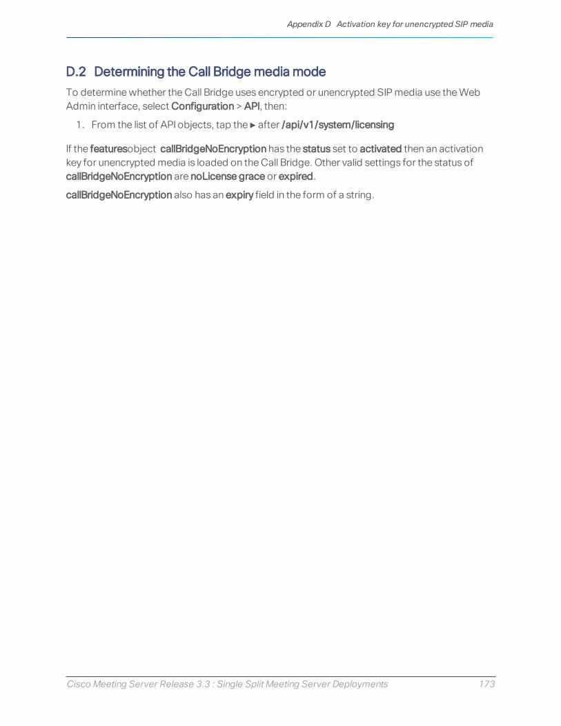
Cisco Meeting Server Release 3.3 : Single Split Meeting Server Deployments 173
D.2 Determining the Call Bridge media modeTo determine whether the Call Bridge uses encrypted or unencrypted SIP media use the Web Admin interface, select Configuration > API, then:
1. From the list of API objects, tap the ► after /api/v1/system/licensing
If the featuresobject callBridgeNoEncryption has the status set to activated then an activation key for unencrypted media is loaded on the Call Bridge. Other valid settings for the status of callBridgeNoEncryption are noLicense grace or expired.
callBridgeNoEncryption also has an expiry field in the form of a string.
Appendix D Activation key for unencrypted SIP media

Cisco Meeting Server Release 3.3 : Single Split Meeting Server Deployments 174
Appendix E Dual Homed Conferencing
E.1 OverviewDual homed conferencing also improves the user experience for both Lync client users and web app users in Lync scheduled meetings and in Lync drag and drop style meetings (also known as ad hoc calls). Lync participants can use drag and drop to add web app users to a Lync meeting, and can use conference controls to mute web app users or disconnect them. For web app users joining a Lync scheduled conference, they will see the video from up to five Lync participants, as well as video from the web app users. Lync users see video in a gallery format from all of the web app users, as well as the Lync users in the meeting. Both Lync users and web app users receive a full combined list of participants in the meeting.
Note: The "Add Participant" button on the Lync/Skype for Business client does not work in ad hoc dual homed conferences. Do not use the "Meet Now" button as a workaround, as this will this will leave an active call between the Meeting Server and the AVMCU.
Lync participants can also directly dial into a Meeting Server space or use drag and drop to add a Meeting Server space to a Lync meeting. These are useful if a large meeting is being held in a Cisco Meeting Server space which the Lync user wants to join. In the first case they will receive a composed layout of multiple participants. When adding a complete space to a Lync meeting, the Lync user will receive only one video stream from the space (the main speaker) and will not receive a full combined participant list. They can continue to add additional Lync participants as normal.
Note: Dual-homed conferences with a Meeting Server cluster are not currently supported with Expressway X8.11 as the edge for the Meeting Server, unless at least some of the Microsoft traffic flows directly between one of the Meeting Servers in the cluster and the Microsoft infrastructure (and not through Expressway). Dual-homing is supported with Expressway X8.11 as the edge for standalone Meeting Servers.
E.2 Consistent meeting experience in dual homed conferencesThe Meeting Server sends two H.264 video streams stream per video participant to the AVMCU, a high resolution video stream and a low resolution video stream, see Figure 25. Lync, Skype for Business and O365 clients that support the high resolution, subscribe to and receive the high quality video stream. Clients that select a lower quality, because of bandwidth restrictions, window size, layout, CPU power or being on a mobile device, subscribe to and receive the lower quality streams, and do not reduce the video quality nor degrade the video experience for other participants.
Appendix E Dual Homed Conferencing

Cisco Meeting Server Release 3.3 : Single Split Meeting Server Deployments 175
Note: Ensure that the bandwidth of the SIP trunk is set sufficiently high to accommodate the two video streams. We recommend 8MB for LANs and 2.5MB for WANs.
Figure 25: Dual media streams to AVMCU
Note: Any devices using Microsoft RTVideo will not benefit from this feature.
E.2.1 Summary of user experiences
Dual homed conferencing combined with support for RDP and multiple video encoders, results in a richer meeting experience for both Lync and web app users.
n Both Lync client users and web app users see familiar screen layouts.
n Both Lync client users and web app users receive a full combined list of all participants in the meeting, regardless of where they are connected.
n Lync client users see a non-square aspect ratio for video from SIP endpoints and web apps.
n Lync client users see content in a separate area of their screen rather than in the main video area.
n The Meeting Server sends video using the best quality codec supported by each participant in Lync meetings. This optimizes the experience for all Lync client users in a meeting, when a mixture of Lync client versions are used by participants.
Appendix E Dual Homed Conferencing

Cisco Meeting Server Release 3.3 : Single Split Meeting Server Deployments 176
n The Meeting Server sends two H.264 video streams stream per video participant to the AVMCU, a high resolution video stream and a low resolution video stream, to preserve the high resolution experience for clients that support it, when clients that can only support low resolution join the meeting.
n Chat works in Lync AVMCU conferences with web app users in spaces. and in direct calls between a web app user and a Lync client.
Note: For the best user experience during meetings, use Lync 2013, Skype for Business 2015 or later, which allow multiple video streams to be transmitted to the Meeting Server. This enables an endpoint or web app user connecting to the Meeting Server to view multiple Lync participants. Lync 2010 only provides a single loudest speaker stream, if the loudest speaker is on the Meeting Server side of the conference already, then web app users and SIP endpoint users will not view the Lync participants.
For more information on RDP and multiple video encoder support, see these FAQs:
n RDP support,
n multiple video encoder support.
E.3 Mute/unmute meeting controls in dual homed conferencesVersion 2.4 of the Meeting Server software introduced improved mute/unmute meeting controls in dual homed conferences for:
n on-premise and Office 365 Lync/Skype for Business clients,
n end point users,
n web app users.
Note: This section assumes that muting and unmuting is enabled using the API of the Meeting Server.
Muting/unmuting:
n Lync clients can mute and unmute anyone in the dual homed conference, this means themselves and others, and they can mute and unmute the audience too.
n All endpoint users can now mute Lync clients,
n Endpoint users on the Lync side of the AVMCU can now mute and unmute themselves (self) and other endpoints (either on the Lync clients/endpoints connected to the AVMCU or on the Meeting Server side). Prior to version 2.4, only endpoint users on the Meeting Server side of the AVMCU could mute and unmute themselves (self) and others.
Appendix E Dual Homed Conferencing

Cisco Meeting Server Release 3.3 : Single Split Meeting Server Deployments 177
n For non-ActiveControl endpoints, the Meeting Server sends DTMF key sequences for each mute and unmute, and overlays an icon on the media stream to the endpoint to indicate whether the endpoint is muted or unmuted.
n For ActiveControl endpoints running CE 9.2.1or later software, the endpoint handles the icons and messages (the Meeting Server does not overlay icons).
n Once an ActiveControl endpoint is muted it has to be unmuted locally so as to ensure the privacy of any local conversation. For example, when a remote participant mutes an ActiveControl endpoint and then tries to unmute it, the ActiveControl endpoint will mute itself again until it is locally unmuted.
n When a remote participant tries to unmute a non-ActiveControl endpoint, the non-ActiveControl endpoint will be unmuted.
n web app users and Cisco Meeting Management users can mute and unmute Lync clients. They also see the correct mute state of all participants in the meeting.
Muting/unmuting web app users:
n Information on local muting and unmuting of a web app user is not passed to Lync clients in dual homed conferences. However, if a Lync client remotely mutes a web app user and the web app unmutes itself, the Meeting Server tells the Lync clients about the unmuting.
n When a remote participant tries to unmute a web app user, the web app user will remain locally muted. Note: other participants will still see them as unmuted, although they are actually muted.
n The web app shows the mute/unmute state using its own icons. Meeting Server icons are not overlaid on the web app video pane.
E.4 Configuring the Dual Homed Lync functionalityIf you already have an on-prem Lync deployment or Lync Federation deployment working with the Meeting Server deployment, then no additional configuration is required on the Meeting server.
If this is a new deployment, then make sure that you configure the Lync Edge settings on the Meeting Server, see Section 8.5.
E.4.1 Troubleshooting
If users are unable to join a Lync conference via the IVR or using a dial plan rule that resolves to “Lync”, the first thing to do is to verify that the “Lync Edge” settings have been set up - the same mechanism is used to resolve Lync conferences as is used to find the Edge server. The Meeting Server must query the Lync FE server to find both of these.
If this fails, a message will be logged in the event log to say that the conference ID cannot be found:
Appendix E Dual Homed Conferencing

Cisco Meeting Server Release 3.3 : Single Split Meeting Server Deployments 178
lync conference resolution: conference “1234” not found
This may mean that the conference does not exist, but there are also other possible causes.
If SIP traffic tracing is enabled, there should be a ‘SERVICE’ message sent to the Lync FE server just before the above message is logged, which should be replied to with a 200 OK. Check that this message is sent to the correct IP, which should be that of a Lync FE server.
If this message is not sent (it does not show up in the logs), then it is possible that the Call Bridge is unable to find the Lync server using a DNS SRV lookup for the _sipinternaltls._tcp.lyncdomain record, and so does not know where to send it. Enabling DNS tracing and retrying should confirm this. However this can also happen if the Lync Edge settings have not been configured on the Meeting Server.
If the Service message is sent but the Lync server replies with “403 unauthorized”, then the most likely cause of this is that the local contact domain in the outbound dial plan rule for this Lync domain is not set correctly. It should be set to the FQDN of the Meeting Server, which should be the same as the FQDN supplied in the CN of the Call Bridge’s certificate.
Appendix E Dual Homed Conferencing

Cisco Meeting Server Release 3.3 : Single Split Meeting Server Deployments 179
Appendix F More information on LDAP field mappingsThis section provides additional information for LDAP field mappings that you set up for the Meeting Server.
Parts of an LDAP field value can be substituted by means of a sed-like construction, as follows:
$<LDAP field name>|'/<regex>/<replacement format>/<option>'$
where:
<option> can be g, to replace every match of <regex> with <replacement format>, or blank to match only the first
parts of <regex> can be tagged for use in <replacement format> by enclosing them in round brackets
tagged matches can be referenced in <replacement format> as \x where x is a digit from 0 to 9. Match 0 corresponds to the entire match, and matches 1-9 the 1st to 9th tagged sub-expressions
single quotes inside the substitution expression must be escaped with a backslash, as must backslash characters themselves
any character other than a single quote, a backslash, or the digits 0-9 can be used in place of the forward slash that separates the components of the substitution expression
if the separating character is to be used as a literal within the expression, it must be escaped with a backslash.
As an example, the following would convert addresses in the format:[email protected]
into the format:[email protected] JIDs$mail|'/@test/@xmpp/'$
and the following would remove every lower case 'a' from the user's full name:$cn|'/a//g'$
A sensible set of expressions for use might be:Full name: $cn$JID: $mail|'/@test/'$space URI: $mail|'/@.*//'$.spacespace dial-in number: $ipPhone$
Appendix F More information on LDAP field mappings

Cisco Meeting Server Release 3.3 : Single Split Meeting Server Deployments 180
Note: The LDAP server credentials are used to read the following fields (for security reasons you may want to restrict the fields and permissions available using those credentials):
l mail
l objectGUID
l entryUUID
l nsuniqueid
l telephoneNumber
l mobile
l sn
l givenName
Appendix F More information on LDAP field mappings

Cisco Meeting Server Release 3.3 : Single Split Meeting Server Deployments 181
Appendix G Using TURN servers behind NATThe TURN server can be deployed behind a NAT, and the NAT address specified using the MMP command turn public-ip. However, due to how Interactive Connectivity Establishment (ICE) works, careful configuration of the NAT is required to ensure connectivity always works.
This appendix provides an overview of how ICE works. It explains:
n how candidates are identified,
n how connectivity is checked,
n the effect of NAT in front of the TURN server,
n how NAT affects external web app users.
Note: Issues can arise when the only available path includes both relay candidates. This requires the firewall to be correctly configured, so that all clients are able to send and receive video and audio.
G.1 Identifying candidatesICE works by gathering a list of candidate addresses and ports, and then finding which pairs of these candidates allow media to be exchanged. When multiple candidate pairs are available then a priority scheme is used to determine which pair is used.
Typically, three candidates might exist:
1. Host candidate
2. Server Reflexive candidate
3. Relay candidate
G.1.1 Host candidate
The most simple candidate is the host candidate. This is the address used by the host interface. This is often on a local network and not routable.
G.1.2 Server Reflexive candidate
The server reflexive candidate is the address that the TURN server sees incoming packets coming from. To determine this, the host sends packets to a defined port on the TURN server (normally port 3478) and the TURN server replies with information about where the packets came from.
Appendix G Using TURN servers behind NAT

Cisco Meeting Server Release 3.3 : Single Split Meeting Server Deployments 182
Figure 26: Server Reflexive candidate
In cases where the host is behind a firewall carrying out NAT, then this is different to the host candidate. In many cases, packets sent to this port and address will be forwarded back to the host.
Figure 27: Effect of a host behind a firewall carrying out NAT
G.1.3 Relay candidate
The final candidate is the relay candidate. This candidate is created by the TURN server in response to requests from the host. The relay address of this candidate is the TURN server interface address, when NAT is used the relay address is changed to an address from NAT.
Appendix G Using TURN servers behind NAT

Cisco Meeting Server Release 3.3 : Single Split Meeting Server Deployments 183
Figure 28: Relay candidate
Data sent to this relay address is then sent back to the host via the TURN server.
Figure 29: TURN server returns relay address to host
This relay candidate has a second use. It can also be used by the host to send packets to the far end. This occurs when there is no other path possible. Note that these packets come from the TURN server itself, so will only get their NAT address when rewritten by the firewall.
Appendix G Using TURN servers behind NAT

Cisco Meeting Server Release 3.3 : Single Split Meeting Server Deployments 184
Figure 30: Host sending packets to the far end
G.2 Checking connectivityOnce candidates are known then connectivity checks are undertaken. Each host tries to contact the far end host, server reflexive and relay addresses directly. It then also uses its relay to attempt connections to the same far end candidates.
Table 27: Candidates for two hosts (using same TURN server)
Host Type Address:port
1 Host 192.168.1.1:50010
1 Server Reflexive 192.0.2.1:50020
1 Relay 203.0.113.1:50110
2 Host 172.16.1.1:50100
2 Server Reflexive 198.51.100.1:50040
2 Relay 203.0.113.1:50510
Table 28: Candidate pairs formed by host 1
Source Destination Type Destination address
Host (192.168.1.1:50010) Host 172.16.1.1:50100
Host (192.168.1.1:50010) Server Reflexive 198.51.100.1:50040
Host (192.168.1.1:50010) Relay 203.0.113.1:50510
Relay (10.0.1.1:50110) Host 172.16.1.1:50100
Appendix G Using TURN servers behind NAT

Cisco Meeting Server Release 3.3 : Single Split Meeting Server Deployments 185
Source Destination Type Destination address
Relay (10.0.1.1:50110) Server Reflexive 198.51.100.1:50040
Relay (10.0.1.1:50110) Relay 203.0.113.1:50510
Typically, the relay addresses are only required when the hosts have limited network access. For example, a user in a coffee shop or hotel may not be able to access any higher numbered ports.
When both hosts have restricted access then a path that involves both relay candidates can be formed. In this case, the traffic flows out of one relay candidate and into the other before being forwarded on to the far end.
Figure 31: Host to host media path using relay to relay path (no NAT)
G.3 NAT in front of the TURN serverWhen NAT is present in front of the TURN server, the flow becomes more complicated. The relay candidates are expecting to receive traffic from one of the other hosts candidates. If the packets are sent from the TURN server’s interface, and are not rewritten by the firewall, then they will appear to be coming from an unknown address. This prevents a succesful connectivity check and in cases where the other paths are not available, there are no routes for media to take.
Appendix G Using TURN servers behind NAT

Cisco Meeting Server Release 3.3 : Single Split Meeting Server Deployments 186
Figure 32: Host to host media path using relay to relay path (with NAT)
Table 29: Host to host media path using relay to relay path (with NAT)
Source address (in packets) Destination Action at destination
192.168.1.1:50010 203.0.113.1:3478 via Firewall
Firewall 1 rewrites source address
192.0.2.1:50020 203.0.113.1:3478 Firewall 3 rewrites destination address and forwards to the TURN server
192.0.2.1:50020 10.0.1.1:3478 TURN serevr internally maps this to the relay address for this source, and sends to far end’s relay.
10.0.1.1:50110 203.0.113.1:50510 via Firewall
Firewall 3 rewrites destination address
10.0.1.1:50110 10.0.1.1:50510 TURN server sees unexpected source address and drops traffic.
The solution for this is known as hairpin NAT, loopback NAT or NAT reflection. In this the source address of the traffic is rewritten as well as the destination. The source address is then the address of the firewall, which means it matches one of the candidates.
Table 30: Host to host media path using relay to relay path (with hairpin NAT)
Source address (in packets) Destination Action at destination
192.168.1.1:50010 203.0.113.1:3478 via Firewall Firewall 1 rewrites source address
192.0.2.1:50020 203.0.113.1:3478 Firewall 3 rewrites destination address and forwards to the TURN server.
Appendix G Using TURN servers behind NAT

Cisco Meeting Server Release 3.3 : Single Split Meeting Server Deployments 187
Source address (in packets) Destination Action at destination
192.0.2.1:50020 10.0.1.1:3478 TURN server internally maps this to the relay address for this source, and sends to far end’s relay.
10.0.1.1:50110 203.0.113.1:50510 via Firewall Firewall 3 rewrites both source and destination addresses.
203.0.113.1:50110 10.0.1.1:50510 TURN server internally maps traffic from relay to assigned host.
10.0.1.1:3478 198.51.100.1:50040 via Firewall Firewall 3 rewrites source address.
203.0.113.1:3478 198.51.100.1:50040 Firewall 2 rewrites destination address.
203.0.113.1:3478 172.16.1.1:50100 Arrives at final destination.
For details on how to enable this functionality, refer to your firewall documentation.
Appendix G Using TURN servers behind NAT

Cisco Meeting Server Release 3.3 : Single Split Meeting Server Deployments 188
Appendix H Using a standby Meeting ServerThe instructions in this appendix apply to virtualized deployments, including the Cisco Meeting Server 1000.
H.1 Backing up the currently used configuration 1. Establish an SSH connection to the currently used Meeting Server using an SSH utility such
as OpenSSH or PuTTY.
2. Issue the command:
backup snapshot <name>
This backup includes IP addresses, passwords and certificates into a file called <name>.bak. We recommend using a name in the format servername_date (for example, test_server_2014_09_04).
A successful backup creation returns:
cms> backup snapshot test_server_2014_09_04.bak ready for download
3. Download the backup file using an SFTP client (e.g. WinSCP).
Note: We recommend backing up your Meeting Servers regularly, e.g. once a day and that you store copies of the backup externally to the Meeting Server and the standby server.
H.2 Transferring a backup to the standby serverWe recommend that you keep the standby sever running at all times.
1. Copy all the certificates and the cms.lic file from the standby server in case they differ from the original server that the backup was created on. Store them somewhere safe.
2. Establish an SFTP connection with the standby server.
3. Upload the previously saved backup file on to the standby server.
4. Issue the MMP backup list command to confirm that the backup file was successfully uploaded. This should return something similar to:
cms> backup list test_server_2014_09_
5. Enter the following command and confirm to restore from the backup file:
backup rollback <name>
This overwrites the existing configuration and reboots the Meeting Server. Therefore a warning message is displayed. The confirmation is case sensitive and you must press upper case Y, otherwise the operation will be aborted.
Appendix H Using a standby Meeting Server

Cisco Meeting Server Release 3.3 : Single Split Meeting Server Deployments 189
Note: It is not possible to create a backup from one type of deployment and roll it back on the other type, for example, from a virtualized Meeting Server 1000 to a Meeting Server 2000, and vice versa.
A successful operation returns:
Relevant only to "traditional" licensing mode on Meeting Management: When you restore from the backup, everything is overwritten including the IP address, certificates and the cms.lic file. Therefore if you are restoring onto a different server from the one that the backup was made on, you must manually copy the original cms.lic file and any certificates that are not valid on the new server. Note that the cms.lic file is tied to the MAC address of the server; therefore after the backup has been restored to the new server, the license from one server will be invalid on another one. You will therefore need to issue a new license if you are restoring from a new VM. Once you have a valid license, Meeting Management will then consider it licensed and the system will work again as expected.
Relevant only to Smart Licensing users: When you restore from the backup, everything is overwritten including the IP address and certificates. Therefore if you are restoring onto a different server from the one that the backup was made on, you must manually copy any certificates that are not valid on the new server.
1. Establish an SFTP connection with the standby server
2. Relevant only to "traditional" licensing mode on Meeting Management: Upload the previously saved original cms.lic file back on to this server.
3. If necessary:
a. Put back any certificates and private keys (if the restored versions are not valid on the standby server).
b. Assign these certificates to their corresponding services using the following commands:
callbridge certs nameofkey nameofcertificatewebbridge3 https certs nameofkey nameofcertificate
Appendix H Using a standby Meeting Server

Cisco Meeting Server Release 3.3 : Single Split Meeting Server Deployments 190
webbridge3 c2w certs nameofkey nameofcertificatewebadmin certs nameofkey nameofcertificatewebbridge trust nameofcallbridgecertificate
c. Restart any service for which you changed the certificatecallbridge restartwebbridge3 restartwebadmin restart
After the new server has fully booted up, it will be fully operational, and will take over the services of the original server.
Appendix H Using a standby Meeting Server

Cisco Meeting Server Release 3.3 : Single Split Meeting Server Deployments 191
Appendix I Web Admin Interface — Configuration menu optionsThe Configuration tab on the Call Bridge's Web Admin interface allows you to configure the following options:
l General
l Active Directory
l Call settings
l Outbound calls and Incoming calls
l CDR settings
l Spaces
l API
I.1 GeneralUse the Configuration > General page to set up and configure:
l TURN server settings. Use these settings to allow the Call Bridge and external clients to access the TURN server. See Web Admin interface settings for the TURN server. Use MMP commands to configure the TURN server itself. See Configuring the MMP.
l Lync Edge settings. Use these settings if you are integrating your Call Bridge with Lync Edge. See Configuration on Meeting Server to use Lync Edge.
l IVR. Use these settings if you are using an Interactive Voice Response (IVR) to manually route to pre-configured calls, so callers are greeted by a prerecorded voice message inviting them to enter the ID number of the call or space that they want to join. See IVR configuration.
I.2 Active DirectoryIf you want users to use web apps to connect to the Meeting Server, then you must have an LDAP server. The Meeting Server imports the User accounts from the LDAP server.
Note: You can use OpenLDAP and Oracle Internet Directory (LDAP version 3), however, this needs to be configured via the API—it cannot be configured through the Web Admin interface.
Use the Configuration > Active Directory page to set up the Meeting Server to work with Active Directory. See LDAP configuration.
Appendix I Web Admin Interface — Configuration menu options

Cisco Meeting Server Release 3.3 : Single Split Meeting Server Deployments 192
I.3 Call settingsUse the Configuration > Call settings page to:
l Allow media encryption for SIP calls (including Lync).
l Specify whether participant label overlays are shown on SIP calls.
l Specify the preferred size (in milliseconds) for outgoing audio packets; 10ms, 20ms, or 40ms.
l Enable TIP support. (You need to enable TIP support if you use endpoints such as the Cisco CTS range.)
l Allow presentation video channel operations—if this is set to prohibited then no content channel video or BFCP capability will be advertised to the far end.
l If presentation video channel operations are allowed for SIP calls, this setting determines the Call Bridge's BFCP behavior, one of:
l server role only—this is the normal option for a conferencing device, and is intended for use with BFCP client mode devices (for instance, SIP endpoints).or
l server and client role—this option allows the Call Bridge to operate in either BFCP client or BFCP server mode in calls with remote devices.
This setting allows improved presentation video sharing with a remote conference-hosting device.
l Set the value for the Resource-Priority header field in outgoing SIP calls. This setting tells the Meeting Server how much priority you will allow the bandwidth to allocate for presenting. This depends on the bandwidth capability of the network environment and other factors such as if there are any immersive systems that push HD, for example.
l Enable and disable UDP signaling for SIP. Set to one of:
l disabled|enabled: disable if you use SIP over TCP, or require that all of your network traffic is encrypted.
l enabled, single address mode corresponds to the SIP over UDP behavior in versions prior to 2.2 and is the default.
l enabled, multi address if the Call Bridge is configured to listen on more than one interface.
l Enable Lync presence support. This setting determines whether or not this Call Bridge should supply information on destination URIs it serves to Lync presence subscribers.
l Leave the Lync packet pacing mode set to default. Do not change the setting to delay unless instructed to do so by Cisco Support.
Appendix I Web Admin Interface — Configuration menu options

Cisco Meeting Server Release 3.3 : Single Split Meeting Server Deployments 193
Note: For more information on each field, you can use the hover-over text that displays for each individual field, or see Dial plan configuration — SIP endpoints.
The Call settings page also allows you to change the bandwidth settings for SIP, Cisco Meeting Server (web app), Server reflexive, Relay, VPN, and Lync content. The settings are measured in bits-per-second, for example, 2000000 is 2Mbps. We dedicate at least 64kbps for audio, and recommend 2Mbps for a 720p30 call, or around 3.5Mbps for a 1080p30 call. More bandwidth would be required for 60fps.
You may need to change some of the bandwidth settings if you allow SIP media encryption, or enable TIP support, for example. In the case of 3 screen TIP calls, the bandwidth numbers seen on the Call settings page get automatically tripled, so you do not need to manually set them to 6Mbps for example. However, we would normally recommend (3x) 4Mbps for most CTS calls.
I.4 Outbound calls and Incoming callsUse the Configuration > Outbound calls / Incoming calls pages to determine how the Meeting Server handles each call.
The Outbound calls page controls how outbound calls are handled; the Incoming calls page determines whether incoming calls are rejected, or matched and forwarded. If they are matched and forwarded, then information about how to forward them is required. The Incoming calls page has two tables—one to configure matching/rejection and the other to configure forwarding behavior.
For more information on completing these fields, see Web Admin Interface configuration pages that handle calls.
I.5 CDR settingsUse the Configuration > CDR settings page to enter the URI of the CDR receivers.
The Meeting Server generates Call Detail Records (CDRs) internally for key call-related events, such as a new SIP connection arriving at the server, or a call being activated or deactivated. It can be configured to send these CDRs to a remote system to be collected and analyzed. You can not store records on a long-term basis on the Meeting Server, or browse CDRs on the Meeting Server.
For more information on completing these fields, see Call Detail Record support and the Call Details Record Guide.
You can also use the API to configure the Meeting Server with the URI of the CDR receivers. See the API Reference guide.
Appendix I Web Admin Interface — Configuration menu options
Cisco Meeting Server Release 3.3 : Single Split Meeting Server Deployments 194
I.6 SpacesUse the Configuration > Spaces page to create a space on the Meeting Server to dial into. This allows, for example, endpoints and web app to dial in.
Add a space with:
l Name for example. Call 001
l URI for example. 88001
On this page you can also optionally specify Secondary URI user part, Call ID, Passcode, and Default Layout.
You can also use the API to create spaces. See the API Reference guide.
Note: The Call ID parameter supports only a numeric value, therefore should be configured with a number.
I.7 APIFrom version 2.9, the API can be accessed using the Meeting Server Web Admin Interface rather than using API Methods and third-party applications. After logging in to the Web Admin interface, navigate to the Configuration tab and select API from the pull-down list. See Figure 33.
Figure 33: Accessing the API via the Meeting Server web admin interface
Appendix I Web Admin Interface — Configuration menu options

Cisco Meeting Server Release 3.3 : Single Split Meeting Server Deployments 195
Note: To access the API via the web interface you still need to do the initial Meeting Server configuration settings and authentication using the MMP as you would if you were using a third party application.
Appendix I Web Admin Interface — Configuration menu options

Cisco Meeting Server Release 3.3 : Single Split Meeting Server Deployments 196
Cisco Legal InformationTHE SPECIFICATIONS AND INFORMATION REGARDING THE PRODUCTS IN THIS MANUAL ARE SUBJECT TO CHANGE WITHOUT NOTICE. ALL STATEMENTS, INFORMATION, AND RECOMMENDATIONS IN THIS MANUAL ARE BELIEVED TO BE ACCURATE BUT ARE PRESENTED WITHOUT WARRANTY OF ANY KIND, EXPRESS OR IMPLIED. USERS MUST TAKE FULL RESPONSIBILITY FOR THEIR APPLICATION OF ANY PRODUCTS.
THE SOFTWARE LICENSE AND LIMITED WARRANTY FOR THE ACCOMPANYING PRODUCT ARE SET FORTH IN THE INFORMATION PACKET THAT SHIPPED WITH THE PRODUCT AND ARE INCORPORATED HEREIN BY THIS REFERENCE. IF YOU ARE UNABLE TO LOCATE THE SOFTWARE LICENSE OR LIMITED WARRANTY, CONTACT YOUR CISCO REPRESENTATIVE FOR A COPY.
The Cisco implementation of TCP header compression is an adaptation of a program developed by the University of California, Berkeley (UCB) as part of UCB’s public domain version of the UNIX operating system. All rights reserved. Copyright © 1981, Regents of the University of California.
NOTWITHSTANDING ANY OTHER WARRANTY HEREIN, ALL DOCUMENT FILES AND SOFTWARE OF THESE SUPPLIERS ARE PROVIDED “AS IS” WITH ALL FAULTS. CISCO AND THE ABOVE-NAMED SUPPLIERS DISCLAIM ALL WARRANTIES, EXPRESSED OR IMPLIED, INCLUDING, WITHOUT LIMITATION, THOSE OF MERCHANTABILITY, FITNESS FOR A PARTICULAR PURPOSE AND NONINFRINGEMENT OR ARISING FROM A COURSE OF DEALING, USAGE, OR TRADE PRACTICE.
IN NO EVENT SHALL CISCO OR ITS SUPPLIERS BE LIABLE FOR ANY INDIRECT, SPECIAL, CONSEQUENTIAL, OR INCIDENTAL DAMAGES, INCLUDING, WITHOUT LIMITATION, LOST PROFITS OR LOSS OR DAMAGE TO DATA ARISING OUT OF THE USE OR INABILITY TO USE THIS MANUAL, EVEN IF CISCO OR ITS SUPPLIERS HAVE BEEN ADVISED OF THE POSSIBILITY OF SUCH DAMAGES.
Any Internet Protocol (IP) addresses and phone numbers used in this document are not intended to be actual addresses and phone numbers. Any examples, command display output, network topology diagrams, and other figures included in the document are shown for illustrative purposes only. Any use of actual IP addresses or phone numbers in illustrative content is unintentional and coincidental.
All printed copies and duplicate soft copies of this document are considered uncontrolled. See the current online version for the latest version.
Cisco has more than 200 offices worldwide. Addresses and phone numbers are listed on the Cisco website at www.cisco.com/go/offices.
© 2021 Cisco Systems, Inc. All rights reserved.
Cisco Legal Information

Cisco Meeting Server Release 3.3 : Single Split Meeting Server Deployments 197
Cisco TrademarkCisco and the Cisco logo are trademarks or registered trademarks of Cisco and/or its affiliates in the U.S. and other countries. To view a list of Cisco trademarks, go to this URL: www.cisco.com/go/trademarks. Third-party trademarks mentioned are the property of their respective owners. The use of the word partner does not imply a partnership relationship between Cisco and any other company. (1721R)
Cisco Trademark