
AOS-W Instant 6.2.1.0-3.3 - Alcadis Support
296
AOS-W Instant 6.2.1.0-3.3 User Guide
-
Upload
khangminh22 -
Category
Documents
-
view
3 -
download
0
Transcript of AOS-W Instant 6.2.1.0-3.3 - Alcadis Support

AOS-W Instant6.2.1.0-3.3
UserG
uide

Copyright
© 2013 Alcatel-Lucent. All rights reserved.
Specifications in this manual are subject to change without notice.
Originated in the USA.
AOS-W, Alcatel 4302, Alcatel 4304, Alcatel 4306, Alcatel 4308, Alcatel 4324, Alcatel 4504, Alcatel 4604, Alcatel 4704, Alcatel 6000,OAWAP41, OAW-AP68, OAW-AP60/61/65, OAW-AP70, OAW-AP80, OAW-AP92/93, OAW-AP105, OAW-AP120/121, OAW-AP124/125, OAW-AP175, OAW-IAP92/93/105, OAW-RAP2, OAW-RAP5, andOmnivista 3600 Air Manager are trademarks ofAlcatel-Lucent in the United States and certain other countries.
Any other trademarks appearing in this manual are the property of their respective companies. Includes software from LitechSystems Design. The IF-MAP client library copyright 2011 Infoblox, Inc. All rights reserved. This product includes softwaredeveloped by Lars Fenneberg et al.
Legal Notice
The use of Alcatel-Lucent switching platforms and software, by all individuals or corporations, to terminate Cisco or Nortel VPNclient devices constitutes complete acceptance of liability by that individual or corporation for this action and indemnifies, in full,Alcatel-Lucent from any and all legal actions that might be taken against it with respect to infringement of copyright on behalf ofCisco Systems or Nortel Networks.

AOS-W Instant 6.2.1.0-3.3|User Guide Contents | 3
Contents
Contents 3
About this Guide 21
Intended Audience 21
Related Documents 21
Conventions 21
Contacting Support 22
About AOS-W Instant 23
AOS-W Instant Overview 23
Supported Devices 23
AOS-W Instant UI 24
AOS-W Instant CLI 24
What is New in AOS-W Instant 6.2.1.0-3.3 24
Initial Configuration 27
Setting up Instant Network 27
Connecting anOAW-IAP 27
Assigning an IP address to the OAW-IAP 27
Assigning a Static IP 28
Connecting to a ProvisioningWi-Fi Network 28
OAW-IAP Cluster 28
Disabling the ProvisioningWi-Fi Network 29
Logging in to the AOS-W Instant UI 29
Specifying Country Code 30
Accessing the Instant CLI 30
Connecting to a CLI Session 30
Applying Configuration Changes 31
Example: 31
Using Sequence Sensitive Commands 31

44 | Contents Dell PowerConnect W-Series Aruba Instant 6.2.1.0-3.3 | User Guide
AOS-W Instant User Interface 33
Banner 33
Search 33
Tabs 33
Networks Tab 34
Access Points Tab 34
Clients Tab 35
Links 35
New Version Available 35
System 36
RF 37
Security 38
Maintenance 39
Help 40
More 40
VPN 40
IDS 41
Wired 42
Services 42
DHCPServer 43
Support 44
Logout 44
Monitoring 44
Info 45
RF Dashboard 46
RF Trends 47
Usage Trends 48
Mobility Trail 52
Spectrum 53
Alerts 53
IDS 56
Configuration 57
AirGroup 57

Language 58
OmniVista 3600 Setup 58
Pause/Resume 58
Views 58
Basic Configuration Procedures 61
Updating IP Address of an OAW-IAP 61
In the Instant UI 61
In the CLI 62
Modifying the OAW-IAP Name 62
In the Instant UI 62
In the CLI 63
Updating Location Details of an OAW-IAP 63
In the Instant UI 63
In the CLI 63
Configuring External Antenna 63
EIRP and AntennaGain 63
Configuring AntennaGain 64
In the Instant UI 64
In the CLI 64
Upgrading anOAW-IAP 64
Upgrading anOAW-IAP Using OmniVista 3600 and Image Server 64
ImageManagement Using OmniVista 3600 64
ImageManagement Using Cloud Server 65
Upgrading anOAW-IAP Using Automatic Image Check 65
Upgrading to a New VersionManually 65
Upgrading an Image Using CLI 66
Enabling Terminal Access 67
In the Instant UI 67
In the CLI 67
Enabling Auto JoinMode 67
Disabling Auto JoinMode 67
Adding anOAW-IAP to the Network 67
AOS-W Instant 6.2.1.0-3.3|User Guide Contents | 5

66 | Contents Dell PowerConnect W-Series Aruba Instant 6.2.1.0-3.3 | User Guide
Removing anOAW-IAP from the Network 68
Configuring a Preferred Band 68
In the Instant UI 68
In the CLI 68
Configuring Radio Profiles for an OAW-IAP 68
Configuring ARM Assigned Radio Profiles for an OAW-IAP 68
Configuring Radio Profiles Manually for an OAW-IAP 69
In the CLI 69
Configuring Inter-user Bridging and Local Routing 69
In the Instant UI 69
In the CLI 69
Configuring Uplink for an OAW-IAP 70
In the Instant UI 70
In the CLI 70
Configuring an NTP Server 70
In the Instant UI 70
In the CLI 71
Virtual Controller Configuration 73
Virtual Controller Overview 73
Master Election Protocol 73
Preference to anOAW-IAP with 3G/4GCard 73
Preference to anOAW-IAP with Non-Default IP 73
Virtual Controller IP Address Configuration 74
Configuring Name and IP Address for Virtual Controller 74
In the Instant UI 74
In the CLI 74
Mesh OAW-IAP Configuration 75
MeshNetwork Overview 75
MeshOAW-IAPs 75
Mesh Portals 75
Mesh Points 76
Setting up Instant Mesh Network 76

Wireless Network Profiles 79
UnderstandingWireless Network Profiles 79
Network Types 79
ConfiguringWLAN Settings for an SSID Profile 80
In the Instant UI 80
In the CLI 82
Configuring VLAN Settings for aWLAN SSID Profile 83
VLAN Pooling 83
Configuring VLAN Settings for an SSID Profile 83
In the Instant UI 83
In the CLI 84
Configuring Security Settings for aWLAN SSID Profile 84
Configuring Security Settings for an Employee or Voice Network 85
In the Instant UI 85
Configuring Enterprise Security Level 85
Configuring PersonalSecurity Level 87
Configuring Open Security Level 88
In the CLI 89
Configuring Security Settings for Guest Network 90
In the Instant UI 90
In the CLI 90
Configuring Access Rules for aWLAN SSID Profile 91
In the Instant UI 91
In the CLI 92
Editing Status of aWLAN SSID Profile 92
In the Instant UI 92
In the CLI 93
Configuring Additional WLAN SSIDs 93
Enabling the Extended SSID 93
In the Instant UI 93
In the CLI 93
Editing aWLAN SSID Profile 94
AOS-W Instant 6.2.1.0-3.3|User Guide Contents | 7

88 | Contents Dell PowerConnect W-Series Aruba Instant 6.2.1.0-3.3 | User Guide
Deleting aWLAN SSID Profile 94
Uplink Configuration 95
Understanding Uplink Interfaces 95
Ethernet Uplink 96
3G/4GUplink 97
Types of Modems 97
Wi-Fi Uplink 99
Configuring Uplinks 99
Configuring Cellular Uplink Profiles 100
In the Instant UI 100
In the CLI 100
Configuring aWi-Fi Uplink Profile 102
Configuring PPPoE Uplink Profile 103
In the Instant UI 103
In the CLI 103
Configuring Uplink Preferences and Switching 104
Enforcing Uplinks 104
In the Instant UI 104
In the CLI 104
Setting an Uplink Priority 104
In the Instant UI 104
In the CLI 105
Enabling Uplink Preemption 105
In the Instant UI 105
In the CLI 105
Switching Uplinks Based on VPN and Internet Availability 105
Switching UplinksBased on VPN Status 105
Switching UplinksBased on Internet Availability 106
In the Instant UI 106
In the CLI 106
Viewing Uplink Status and Configuration 106
Wired Profiles 109
Configuring aWired Profile 109

ConfiguringWired Settings 109
In the Instant UI 109
In the CLI 110
Configuring VLAN for aWired Profile 110
In the Instant UI 110
In the CLI 111
Configuring Security Settings for aWired Profile 111
Configuring Security Settings for aWired Employee Network 111
In the Instant UI 112
In the CLI 112
Configuring Security Settings for aWired Guest Network 112
In the Instant UI 112
In the CLI 113
Configuring Access Rules for aWired Profile 113
In the Instant UI 113
In the CLI 114
Understanding Hierarchical Deployment 114
ConfiguringWired Bridging on Ethernet 0 115
In the Instant UI 115
In the CLI 116
Assigning a Profile to Ethernet Ports 116
In the Instant UI 116
In the CLI 116
Deleting aWired Profile 116
Editing aWired Profile 116
Authentication 117
Understanding AuthenticationMethods 117
Supported Authentication Servers 119
External RADIUS Server 119
RADIUS Server Authentication with VSA 119
Internal RADIUS Server 119
Authentication Termination onOAW-IAP 120
AOS-W Instant 6.2.1.0-3.3|User Guide Contents | 9

1010 | Contents Dell PowerConnect W-Series Aruba Instant 6.2.1.0-3.3 | User Guide
Understanding Encryption Types 120
WPA andWPA2 120
Recommended Authentication and Encryption Combinations 121
Understanding Authentication Survivability 121
Configuring Authentication Servers 124
Configuring an External Server for Authentication 124
In the Instant UI 124
In the CLI 126
Enabling RADIUS Server Support 127
In the Instant UI 127
In the CLI 127
Configuring Authentication Parameters for Virtual Controller Management Interface 127
In the Instant UI 127
In the CLI 128
Configuring Users 129
In the Instant UI 129
In the CLI 130
Configuring 802.1X Authentication for a Network Profile 130
Configuring 802.1X authentication for aWireless Network Profile 131
In the Instant UI 131
In the CLI 131
Configuring 802.1X authentication forWired Profiles 131
In the Instant UI 131
In the CLI 132
ConfiguringMAC Authentication for a Network Profile 132
ConfiguringMAC Authentication forWireless Network Profiles 132
In the Instant UI 132
In the CLI 133
ConfiguringMAC Authentication forWired Profiles 133
In the Instant UI 133
In the CLI 133
ConfiguringMAC Authentication with 802.1X Authentication 133

ConfiguringMAC and 802.1X Authentication for aWireless Network Profile 133
In the Instant UI 134
In the CLI 134
ConfiguringMAC and 802.1X Authentication forWired Profiles 134
In the Instant UI 134
In the CLI 134
Configuring Captive Portal Authentication 135
Configuring Internal Captive Portal for Guest Network 135
Configuring Internal Captive Portal Authentication forWireless Network Profile 135
In the Instant UI 135
In the CLI 136
Configuring Internal Captive Portal Authentication for aWired Profile 137
In the Instant UI 137
In the CLI 137
Customizing a Splash Page Design 138
In the Instant UI 138
In the CLI 138
Configuring External Captive Portal for a Guest Network 138
Configuring External Captive Portal Authentication for a Network Profile 139
In the Instant UI 139
In the CLI 140
Disabling Captive Portal Authentication 141
Configuring External Captive Portal Authentication Using ClearPass Guest 141
Creating aWeb Login page in the ClearPass Guest 141
Configuring the RADIUS Server in Instant 141
Configuring Captive Portal Roles for an SSID with 802.1x authentication 142
In the Instant UI 142
In the CLI 144
ConfiguringMAC Authentication with Captive Portal Authentication 144
ConfiguringMAC Authentication with Captive Portal Authentication 145
In the Instant UI 145
In the CLI 145
ConfiguringWalled Garden Access 146
AOS-W Instant 6.2.1.0-3.3|User Guide Contents | 11
1212 | Contents Dell PowerConnect W-Series Aruba Instant 6.2.1.0-3.3 | User Guide
In the Instant UI 146
In the CLI 146
ConfiguringWISPr Authentication 146
In the Instant UI 147
In the CLI 148
Blacklisting Clients 148
Blacklisting Users Dynamically 148
Authentication Failure Blacklisting 148
Session Firewall Based Blacklisting 148
Configuring Blacklist Duration 148
In the Instant UI 148
In the CLI 149
Blacklisting Clients Manually 149
Adding a Client to the Blacklist 149
In the Instant UI 149
In the CLI 149
Uploading Certificates 150
Loading Certificates using Instant UI 150
Loading Certificates using OmniVista 3600 151
Roles and Policies 155
Instant Firewall Policies and Access Rules 155
Understanding Service Options 155
Understanding Destination Options 157
Extended Voice and Video Functionality 157
QoS for Microsoft Office OCS and Apple Facetime 158
Microsoft OCS 158
Apple Facetime 158
Configuring Access Rules 158
In the Instant UI 158
In the CLI 159
Configuring Source NAT 159
Enabling Source NAT 160

Configuring Source-Based Routing 160
Examples for Access Rules 160
Allow POP3 Service to a Particular Server 160
Allow TCP Service to a Particular Network 161
Deny FTP Service except to a Particular Server 161
Deny bootp Service except to a Particular Network 161
Configuring ALGProtocols 162
In the Instant UI 162
In the CLI 163
Configuring Firewall Settings for Protection from ARP Attacks 163
In the Instant UI 163
In the CLI 164
Configuring User Roles 165
Creating a User Role 165
In the Instant UI 165
In the CLI 165
ConfiguringMachine and User Authentication Roles 166
In the Instant UI 166
In the CLI 166
Configuring Role Assignment Rules 166
Understanding Role Assignment Rules 167
MAC-Address Attribute 167
DHCP Option and DHCP Fingerprinting 167
802.1X-Authentication-Type 167
Creating Role Assignment Rules 167
In the Instant UI 167
In the CLI 168
Configuring VLAN Assignment Rules 168
Understanding VLAN Assignment 168
Vendor Specific Attributes (VSA) 169
Supported VSAs 170
VLAN Derivation Rule 173
AOS-W Instant 6.2.1.0-3.3|User Guide Contents | 13

1414 | Contents Dell PowerConnect W-Series Aruba Instant 6.2.1.0-3.3 | User Guide
User Role 173
VLANs Created for an SSID 174
Configuring VLAN Derivation Rules 174
In the Instant UI 174
In the CLI 175
Configuring a User Role for VLAN Derivation 175
Creating a User VLAN Role 175
In the Instant UI 175
In the CLI 176
Assigning User VLAN Roles to a Network Profile 176
In the Instant UI 176
In the CLI 177
Mobility and Client Management 179
Layer-3Mobility Overview 179
Configuring L3-Mobility 180
HomeAgent Load Balancing 180
Configuring aMobility Domain for Instant 180
In the Instant UI 180
In the CLI 181
Spectrum Monitor 183
Understanding Spectrum Data 183
Device List 183
NonWi-Fi Interferers 184
Channel Details 186
Channel Metrics 187
Spectrum Alerts 188
Configuring SpectrumMonitors and Hybrid OAW-IAP to Hybrid OAW-IAPs 188
Converting an OAW-IAP to Hybrid OAW-IAP 188
In the Instant UI 188
In the CLI 188
Converting an OAW-IAP to a SpectrumMonitor 189
In the Instant UI 189

In the CLI 190
Adaptive Radio Management 191
ARMOverview 191
Channel or Power Assignment 191
Voice Aware Scanning 191
Load Aware Scanning 191
Band SteeringMode 191
Spectrum Load Balancing 191
Airtime Fairness Mode 192
Access Point Control 192
Monitoring the Network with ARM 192
ARMMetrics 193
Configuring ARM Features on anOAW-IAP 193
In the Instant UI 193
In the CLI 195
Configuring Radio Settings for an OAW-IAP 197
In the Instant UI 197
In the CLI 198
Intrusion Detection 201
Detecting and Classifying Rogue APs 201
OS Fingerprinting 201
ConfiguringWireless Intrusion Protection and Detection Levels 202
Containment Methods 206
Configuring IDS Using CLI 206
Content Filtering 209
Content Filtering 209
Enabling Content Filtering 209
Enabling Content Filtering for aWireless Profile 209
In the Instant UI 209
In the CLI 209
Enabling Content Filtering for aWired Profile 210
In the Instant UI 210
AOS-W Instant 6.2.1.0-3.3|User Guide Contents | 15

1616 | Contents Dell PowerConnect W-Series Aruba Instant 6.2.1.0-3.3 | User Guide
In the CLI 210
Configuring Enterprise Domains 210
In the Instant UI 210
In the CLI 210
Configuring OpenDNS Credentials 210
In the Instant UI 211
In the CLI 211
DHCP Configuration 213
Understanding DHCP Assignment Modes 213
Configuring DHCP Scopes 214
Configuring Distributed DHCP Scopes 214
In the Instant UI 214
In the CLI 216
Configuring Local, Local,L3, and Centralized,L2 DHCP Scopes 217
In the Instant UI 217
In the CLI 219
Configuring DHCP Server for Client IP Assignment 219
In the Instant UI 219
In the CLI 220
VPN Configuration 221
Understanding VPN Features 221
Configuring a Tunnel from Virtual Controller to Alcatel-Lucent Mobility Switch 221
In the Instant UI 221
In the CLI 222
Configuring Routing Profiles 223
In the Instant UI 223
In the CLI 224
IAP-VPN Configuration 225
Overview 225
Termination of IPSec andGRE VPN Tunnels 225
L2/L3 ForwardingModes 225
OSPF Configuration 226

VPN Configuration 226
Whitelist Database Configuration 226
SwitchWhitelist Database 226
External Whitelist Database 226
VPN Local Pool Configuration 227
Role Assignment for the Authenticated OAW-IAPs 227
VPN Profile Configuration 227
Viewing Branch Status 227
Example 227
OmniVista 3600 Integration and Management 229
OmniVista 3600 Features 229
ImageManagement 229
IAP and Client Monitoring 229
Template-based Configuration 229
Trending Reports 230
Intrusion Detection System 230
Wireless Intrusion Detection System (WIDS) Event Reporting to OmniVista 3600 230
RF Visualization Support for AOS-W Instant 230
Configuring OmniVista 3600 231
Configuring for OmniVista 3600 Discovery through DHCP 231
Standard DHCP option 60 and 43 onWindows Server 2008 231
AlternateMethod for Defining Vendor-Specific DHCP Options 235
Configuring Organization String 237
Shared Key 238
Configuring OmniVista 3600 Information 238
In the Instant UI 238
In the CLI 239
AirGroup Configuration 241
AirGroupOverview 241
AirGroup with Instant 242
AirGroup Solution 243
AirGroup Features 244
AOS-W Instant 6.2.1.0-3.3|User Guide Contents | 17

1818 | Contents Dell PowerConnect W-Series Aruba Instant 6.2.1.0-3.3 | User Guide
CPPM andClearPass Guest Features 245
AirGroup Components 245
Configuring AirGroup for AOS-W Instant 245
Enabling or Disabling AirGroup 245
In the Instant UI 245
In the CLI 246
Configuring AirGroup and CPPM interface in AOS-W Instant 247
Creating a RADIUS Server 248
Assign a Server to AirGroup 248
Configure CPPM to Enforce Registration 248
Change of Authorization (CoA) 248
Real Time Location Server Configuration 249
Configuring RTLS 249
In the Instant UI 249
In the CLI 249
Hotspot Profiles 251
Understanding Hotspot Profiles 251
Generic Advertisement Service (GAS) 251
Access Network Query Protocol (ANQP) 252
Hotspot 2.0 Query Protocol (H2QP) 252
Information Elements (IEs) andManagement Frames 252
Access Network Types 252
NAI Realm List 253
Venue types 253
Advertisement Profiles for a Hotspot 254
Configuring an NAI Realm Profile 255
Configuring a Venue NameProfile 256
Configuring a Network Authentication Profile 257
Configuring a Roaming Consortium Profile 257
Configuring an IP Address Availability Profile 258
Configuring a 3GPP Profile 258
Configuring a Domain Profile 258

Configuring H2QP Profiles 258
Configuring anOperator-friendly Profile 258
Configuring a Connection Capability Profile 259
Configuring anOperating Class Profile 259
Configuring aWAN Metrics Profile 259
Configuring a Hotspot Profile 260
Creating a Hotspot Profile 260
Associating a Hotspot Profile with an Advertisement Profile 262
Enabling a Hotspot Profile on aWLAN SSID 262
OAW-IAP Management 263
Configuring LED Display 263
In the Instant UI 263
In the CLI 263
Backing up and Restoring OAW-IAP Configuration Data 263
Viewing Current Configuration 263
Backing up Configuration Data 263
Restoring Configuration 264
Converting anOAW-IAP to a Remote AP and Campus AP 264
Converting anOAW-IAP to Remote AP 264
Converting anOAW-IAP using CLI 266
Converting anOAW-IAP to Campus AP 267
Converting anOAW-IAP to StandaloneMode 267
Converting anOAW-IAP using CLI 268
Resetting a Remote AP or Campus AP to anOAW-IAP 268
Rebooting the OAW-IAP 268
Monitoring Devices and Logs 271
Configuring SNMP 271
SNMP Parameters for OAW-IAP 271
Configuring SNMP 272
Creating community strings for SNMPv1 and SNMPv2Using Instant UI 272
Creating community strings for SNMPv3 Using Instant UI 272
Configuring SNMP Community Strings in the CLI 273
AOS-W Instant 6.2.1.0-3.3|User Guide Contents | 19

2020 | Contents Dell PowerConnect W-Series Aruba Instant 6.2.1.0-3.3 | User Guide
Configuring SNMP Traps 274
In the Instant UI 274
In the CLI 274
Configuring TFTP DumpServer 274
In the Instant UI 274
In the CLI 274
Configuring a Syslog Server 275
In the Instant UI 275
In the CLI 276
Viewing Logs 276
Support Commands 277
Regulatory Domain 281
Country Codes List 281
ClearPass Guest Setup 286
Testing 290
Troubleshooting 290
Terminology 291
Acronyms and Abbreviations 291
Glossary 293

AOS-W Instant 6.2.1.0-3.3|User Guide About thisGuide | 21
About this Guide
This User Guide describes the features supported by AOS-W Instant and provides detailed instructions for setting upand configuring Instant network.
Intended AudienceThis guide is intended for customers who configure and use AOS-W Instant.
Related DocumentsThe AOS-W Instant product documentation includes the following:
l AOS-W Instant 6.2.1.0-3.3 Quick Start Guide
l AOS-W Instant 6.2.1.0-3.3 User Guide
l AOS-W Instant 6.2.1.0-3.3MIB ReferenceGuide
l AOS-W Instant 6.2.1.0-3.3 Release Notes
ConventionsThe following conventions are used throughout this manual to emphasize important concepts:
Type Style Description
Italics This style is used to emphasize important terms and to mark the titles of books.
System items This fixed-width font depicts the following:l Sample screen outputl System promptsl Filenames, software devices, and specific commands when mentioned in the text
Commands In the command examples, this style depicts the keywords that must be typed exactly asshown.
<Arguments> In the command examples, italicized text within angle brackets represents items that youshould replace with information appropriate to your specific situation. For example:# send <text message>In this example, you would type “send” at the system prompt exactly as shown, followed bythe text of the message you wish to send. Do not type the angle brackets.
[Optional] Command examples enclosed in brackets are optional. Do not type the brackets.
{Item A |
Item B}
In the command examples, items within curled braces and separated by a vertical barrepresent the available choices. Enter only one choice. Do not type the braces or bars.
Table 1: Typographical Conventions
The following informational icons are used throughout this guide:
Indicates helpful suggestions, pertinent information, and important things to remember.

2222 | About thisGuide Dell PowerConnect W-Series Aruba Instant 6.2.1.0-3.3 | User Guide
Indicates a risk of damage to your hardware or loss of data.
Indicates a risk of personal injury or death.
Contacting Support
Contact Center Online
l Main Site http://www.alcatel-lucent.com/enterprise
l Support Site https://service.esd.alcatel-lucent.com
l Email [email protected]
Service & Support Contact Center Telephone
l North America 1-800-995-2696
l Latin America 1-877-919-9526
l Europe +33 (0) 38 855 6929
l Asia Pacific +65 6240 8484
l Worldwide 1-818-878-4507
AOS-W Instant 6.2.1.0-3.3|User Guide About AOS-W Instant | 23
Chapter 4About AOS-W Instant
This chapter provides the following information:
l AOS-W Instant Overview
l What is New in AOS-W Instant 6.2.1.0-3.3
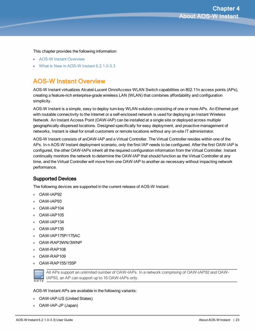
AOS-W Instant OverviewAOS-W Instant virtualizes Alcatel-Lucent OmniAccess WLAN Switch capabilities on 802.11n access points (APs),creating a feature-rich enterprise-grade wireless LAN (WLAN) that combines affordability and configurationsimplicity.
AOS-W Instant is a simple, easy to deploy turn-key WLAN solution consisting of one or more APs. An Ethernet portwith routable connectivity to the Internet or a self-enclosed network is used for deploying an Instant WirelessNetwork. An Instant Access Point (OAW-IAP) can be installed at a single site or deployed across multiplegeographically-dispersed locations. Designed specifically for easy deployment, and proactivemanagement ofnetworks, Instant is ideal for small customers or remote locations without any on-site IT administrator.
AOS-W Instant consists of anOAW-IAP and a Virtual Controller. The Virtual Controller resides within one of theAPs. In n AOS-W Instant deployment scenario, only the first IAP needs to be configured. After the first OAW-IAP isconfigured, the other OAW-IAPs inherit all the required configuration information from the Virtual Controller. Instantcontinually monitors the network to determine the OAW-IAP that should function as the Virtual Controller at anytime, and the Virtual Controller will move from oneOAW-IAP to another as necessary without impacting networkperformance.
Supported Devices
The following devices are supported in the current release of AOS-W Instant:
l OAW-IAP92
l OAW-IAP93
l OAW-IAP104
l OAW-IAP105
l OAW-IAP134
l OAW-IAP135
l OAW-IAP175P/175AC
l OAW-RAP3WN/3WNP
l OAW-RAP108
l OAW-RAP109
l OAW-RAP155/155P
All APs support an unlimited number of OAW-IAPs. In a network comprising of OAW-IAP92 andOAW-IAP93, an AP can support up to 16OAW-IAPs only.
AOS-W Instant APs are available in the following variants:
l OAW-IAP-US (United States)
l OAW-IAP-JP (Japan)

2424 | About AOS-W Instant Dell PowerConnect W-Series Aruba Instant 6.2.1.0-3.3 | User Guide
l OAW-IAP-IL (Israel)
l OAW-IAP-ROW (Rest of World)
For information on the complete list of the countries supported by the OAW-IAP-ROW type, see Regulatory Domainon page 281.
AOS-W Instant UI
The AOS-W Instant User Interface (UI) provides a standard web based interface that allows you to configure andmonitor aWi-Fi network. Instant UI is accessible through a standard web browser from a remotemanagementconsole or workstation and can be launched using the following browsers:
l Internet Explorer 8 or later
l Safari 6.0 or later
l Google Chrome 23.0.1271.95m or later
l Mozilla Firefox 17.0 or later
To view the Instant UI, ensure that the JavaScript is enabled on the web browser. For more information on Instant UIfeatures, see AOS-W Instant User Interface on page 33.
The Instant UI logs out automatically if the window is inactive for fifteenminutes.
AOS-W Instant CLI
The AOS-W Instant Command Line Interface (CLI) is a text-based interface accessible through a Secure Shell(SSH) session.
SSH access requires that you configure an IP address and a default gateway on theOAW-IAP and connect theOAW-IAP to your network. This is typically performed when the Instant network on anOAW-IAP is set up.
What is New in AOS-W Instant 6.2.1.0-3.3The following features are added in the AOS-W Instant 6.2.1.0-3.3 release:
Feature Description
Support for configurationthrough the Instant CLI
This feature supports scripting through Instant CLI for configuring Virtual Controller andOAW-IAPs.
Enhancements to theInstant User Interface (UI)
In the current release, the Instant UI is enhanced, and some menu options andconfiguration windows are reorganized.
Enhancements to theOAW-IAP Upgrade Pro-cedure
This feature allows the users to defer rebooting of the OAW-IAP after a software upgrade.
Enhancements to instantSSID Broadcasting
This feature allows the instant SSID to be broadcast only when Alcatel-Lucent OmniVista3600 and Activate are not available and if the automatic provisioning of an OAW-IAP fails.
Table 2: New Features in 6.2.1.0-3.3

Feature Description
Distributed DHCP for IAP-VPN
This feature allows you to configure the DHCP address assignment for the branchesconnected to the corporate network through VPN. You can configure the range of DHCPaddresses used in the branches and the number of client addresses allowed per branch.You can also specify the IP addresses that must be excluded from those assigned toclients, so that they are assigned statically.
The Instant UI has been enhanced to provide an easy and flexible workflow for DHCPconfiguration.
Support for the Local,L3DHCP modes
This feature allows you to configure Local,L3 (NAT and L3 switching) DHCP scope.
Support for vendor-spe-cific DHCP options
This feature allows you to configure vendor-specific DHCP options for DHCP scopes.
VLAN Derivation basedon DHCP option
This feature allows you to configure user VLAN derivation based on a DHCP option.
Spectrum Load Balancing This feature helps optimize network resources by balancing client load across channelsand by dividing APs in a cluster into several logical AP RF neighborhood domains.
WMM Traffic Management The Wi-Fi Multimedia (WMM) is a Wi-Fi Alliance specification based on the IEEE 802.11ewireless Quality of Service (QoS) standard. You can allocate WMM traffic share for thevoice, video, best effort, and background access categories when configuring an SSIDprofile.
Enhancements toVLAN assignment forwired clients
This feature supports Virtual Controller assigned VLANs, such as Guest VLAN, on a wiredprofile.
Role Derivation for wiredClients
Instant now supports role derivation for wired profiles. The administrators can configurerules for a wired profile and assign user roles that determine network privileges for thewired clients.
VLAN derivation for wiredclients
This feature supports VLAN assignment for wired clients based on the user rolesconfigured for a wired profile.
Configurable VLAN forthe Virtual Controller IP
This feature allows you to configure the VLAN for the Virtual Controller IP address.
Support for Dual EthernetUplinks and enhance-ments to Uplink Switching
This feature allows you to configure an alternate Ethernet uplink. When the uplink on anexisting Ethernet port fails, the OAW-IAP switches over to the uplink available on analternate physical port.
Internet access to theguest users when theExternal Captive portalserver is not available
This feature allows the guest users to access the Internet when the external CaptivePortal is not available. When the external Captive portal is not available, the guest usersare redirected to the URL specified in the SSID profile.
DHCP-based role der-ivation with Captive Portalauthentication
This feature allows you to configure role derivation rules for Captive portal authentication.
Table 2: New Features in 6.2.1.0-3.3
AOS-W Instant 6.2.1.0-3.3|User Guide About AOS-W Instant | 25

2626 | About AOS-W Instant Dell PowerConnect W-Series Aruba Instant 6.2.1.0-3.3 | User Guide
Feature Description
Configurable accountingmodes for guest users
This feature allows you to configure the accounting mode for guest users to determinewhen to start and stop accounting for a Captive portal SSID.
Disable Captive PortalAuthentication based onthe current uplink type
This feature allows you to disable redirection to the Captive portal based on the type ofcurrent uplink.
8021X authentication withCaptive portal role
This feature allows you to configure Captive portal role for the clients using an SSID with802.1X authentication.
Support for enabling anddisabling SSID
This feature allows the administrator to disable a WLAN SSID and enable it whenrequired.
Firewall Settings for ARPattacks
This feature allows you to enable firewall settings to protect the network against wiredattacks, such as ARP attacks or malformed DHCP packets, and notify the administratorwhen these attacks are detected.
Support for 512 userentries in the local userdatabase of OAW-IAPs
This feature adds support for up to 512 users in the local database of the OAW-IAPs.
Support for configuringhotspot profiles
This feature supports the configuration of hotspot profiles for a WLAN SSID.
Support for policy basedcorporate access andsource based routing
This feature allows you to configure a policy based corporate access for client traffic. Forexample, all traffic on an SSID can be sent to the corporate network, while another SSIDcan have direct access to the Internet for some services, protocols, or destinations.
You can also configure source based routing for client traffic by allowing traffic on oneSSID to reach the Internet through a corporate network and another SSID to use analternate uplink.
AirGroup enhancements Instant now supports the discovery of AirGroup devices across IAP clusters. With thisfeature enabled, clients can discover devices when they roam to a new cluster.In the current release, the users can also configure Bonjour Services in the guest VLAN.
Table 2: New Features in 6.2.1.0-3.3
IAP Platform Description
RAP155/155P AOS-W Instant supports OAW-RAP155 /155P devices. The OAW-RAP155 and OAW-RAP155P aredual-radio, dual-band wireless APs that offer wired and wireless network access, zero-touchprovisioning, identity-based access control, policy based forwarding, air monitoring, and wirelessintrusion protection across the 2.4 GHz and 5 GHz (802.11a/b/g and 802.11n) bands. For moreinformation about this product, go to .
Table 3: New Hardware Platforms introduced in this release

AOS-W Instant 6.2.1.0-3.3|User Guide InitialConfiguration | 27
Chapter 5Initial Configuration
This chapter describes the following procedures:
l Setting up Instant Network on page 27
l Logging in to the AOS-W Instant UI on page 29
l Accessing the Instant CLI on page 30
Setting up Instant NetworkBefore installing anOAW-IAP:
l Ensure that you have an Ethernet cable of the required length to connect an OAW-IAP to the home router.
l Ensure that you have one of the following power sources:
n IEEE 802.3af/at-compliant Power over Ethernet (PoE) source. The PoE source can be any power sourceequipment (PSE) switch or amidspan PSE device.
n AOS-W Instant power adapter kit.
Perform the following procedures to set up the AOS-W Instant network:
1. Connecting anOAW-IAP on page 27
2. Assigning an IP address to the OAW-IAP on page 27
3. Connecting to a ProvisioningWi-Fi Network on page 28
Connecting an OAW-IAP
Based on the type of the power source used, perform one of the following steps to connect an OAW-IAP to the powersource:
l PoE switch— Connect the ENET 0 port of the OAW-IAP to the appropriate port on the PoE switch.
l PoE midspan— Connect the ENET 0 port of the OAW-IAP to the appropriate port on the PoE midspan.
l AC to DC power adapter— Connect the 12V DC power jack socket to the AC to DC power adapter.
OAW-RAP155P supports PSE for 802.3at powered device (class 0-4) on one port (E1 or E2), or 802.3afpowered DC IN (Power Socket) on two ports (E1 and E2).
Assigning an IP address to the OAW-IAP
TheOAW-IAP needs an IP address for network connectivity. When you connect an OAW-IAP to a network, itreceives an IP address from aDHCP server.
To obtain an IP address for an OAW-IAP:
1. Ensure that the DHCP service is enabled on the network.
2. Connect the ENET 0 port of OAW-IAP to a switch or router using an Ethernet cable.
3. Connect the OAW-IAP to a power source. TheOAW-IAP receives an IP address provided by the switch orrouter.
If there is no DHCP service on the network, the OAW-IAP can be assigned a static IP address. If a staticIP is not assigned, the OAW-IAP obtains an IP automatically within the 169.254 subnet.

2828 | InitialConfiguration Dell PowerConnect W-Series Aruba Instant 6.2.1.0-3.3 | User Guide
Assigning a Static IP
To assign a static IP to anOAW-IAP:
1. Connect a terminal, PC, or workstation running a terminal emulation program to the Console port on the OAW-IAP.
2. Power on the OAW-IAP. An autoboot countdown prompt that allows you to interrupt the normal startup processand access apboot is displayed.
3. Click Enter before the timer expires. TheOAW-IAP goes into the apboot mode.
4. In the apboot mode, use the following commands to assign a static IP to the OAW-IAP.Hit <Enter> to stop autoboot: 0
apboot>
apboot> setenv ipaddr 192.0.2.0
apboot> setenv netmask 255.255.255.0
apboot> setenv gatewayip 192.0.2.2
apboot> save
Saving Environment to Flash...
Un-Protected 1 sectors
.done
Erased 1 sectors
Writing
5. Use the printenv command to view the configuration.apboot> printenv
Connecting to a Provisioning Wi-Fi Network
TheOAW-IAPs boot with factory default configuration and try to provision automatically. If the automaticprovisioning is successful, the instant SSID will not be available. If OmniVista 3600 and Activate are not reachableand the automatic provisioning fails, the instant SSID becomes available and the users can connect to aprovisioning network by using the instant SSID.
To connect to a provisioningWi-Fi network:
1. Ensure that the client is not connected to any wired network.
2. Connect a wireless enabled client to a provisioningWi-Fi network: for example, instant.
3. If theWindows OS system is used:
a. Click the wireless network connection icon in the system tray. TheWireless Network Connection windowappears.
b. Click on the instant network and then click Connect.
4. If theMac OS system is used:
a. Click the AirPort icon. A list of availableWi-Fi networks is displayed.
b. Click on the instant network.
The instant SSIDs are broadcast in 2.4 GHz only.
OAW-IAP Cluster
OAW-IAPs in the same VLAN automatically find each other and form a single functioning network managed by aVirtual Controller.
Moving anOAW-IAP from one cluster to another requires a factory reset of the OAW-IAP.

Disabling the Provisioning Wi-Fi Network
The provisioning network is enabled by default. AOS-W Instant provides the option to disable the provisioningnetwork through the console port. Use this option only when you do not want the default SSID instant to bebroadcast in your network.
To disable the provisioning network:
1. Connect a terminal or PC/workstation running a terminal emulation program to the Console port on the OAW-IAP.
2. Configure the terminal or terminal emulation program to use the following communication settings:
Baud Rate Data Bits Parity Stop Bits Flow Control
9600 8 None 1 None
Table 4: Terminal Communication Settings
3. Power on the OAW-IAP. An autoboot countdown prompt that allows you to interrupt the normal startup processand access apboot is displayed.
4. Click Enter before the timer expires. TheOAW-IAP goes into the apboot mode through console.
5. In the apboot mode, use the following commands to disable the provisioning network:n apboot> factory_reset
n apboot> setenv disable_prov_ssid 1
n apboot> saveenv
n apboot> reset
Logging in to the AOS-W Instant UILaunch a web browser and enter http://instant.Alcatel-Lucentnetworks.com. In the login screen, enter the followingcredentials:
l Username— admin
l Password— admin
The following figure shows the Login screen:
Figure 1 Login Screen
AOS-W Instant 6.2.1.0-3.3|User Guide InitialConfiguration | 29

3030 | InitialConfiguration Dell PowerConnect W-Series Aruba Instant 6.2.1.0-3.3 | User Guide
When you use a provisioningWi-Fi network to connect to the Internet, all browser requests are directed to the InstantUI. For example, if you enter www.example.com in the address field, you are directed to the Instant UI. You canchange the default login credentials after the first login.
Specifying Country Code
This procedure is applicable to the OAW-IAP-ROW (Rest of World) variants only. Skip this step if you areinstalling OAW-IAP in the United States, Japan, or Israel.
The Country Code window is displayed for the OAW-IAP-ROW (Rest of World) variants when you log in to theInstant UI for the first time. You can specify a country code by selecting an appropriate option from the PleaseSpecify the Country Code drop-down list.
Figure 2 Specifying a Country Code
.For the complete list of the country codes supported by the OAW-IAP-ROW variant type, see Regulatory Domain onpage 281.
Accessing the Instant CLIIn the current release, AOS-W Instant supports the use of Command Line Interface (CLI) for scripting purposes.When youmake configuration changes on amaster OAW-IAP in the CLI, all associated OAW-IAPs in the clusterinherit these changes and subsequently update their configurations. You can access the Instant CLI through aSecure Shell (SSH).
To enable the SSH access to the OAW-IAP CLI:
1. From the Instant UI, navigate to System > Show advanced options.
2. Select Enabled from the Terminal access drop-down list.
3. Click OK.
Connecting to a CLI Session
On connecting to a CLI session, the system displays its host name followed by the login prompt. Use theadministrator credentials to start a CLI session. For example:
(Instant Access Point)
User: admin
Password: *****
If the login is successful, the privileged commandmode is enabled and a command prompt is displayed. Forexample:
(Instant Access Point)#
The privilegedmode provides access to show, clear, ping, traceroute, and commit commands. The configurationcommands are available in configmode. Tomove from privilegedmode to the configurationmode, enter thefollowing command at the command prompt:
(Instant Access Point)# configure terminal

The configure terminal command allows you to enter the basic configurationmode and the command prompt isdisplayed as follows:
(Instant Access Point)(config)#
The Instant CLI allows CLI scripting in several other sub-commandmodes to allow the users to configure individualinterfaces, SSIDs, access rules, and security settings.
You can use the questionmark (?) to view the commands available in a privilegedmode, configurationmode, or sub-mode.
Although automatic completion is supported for some commands such as configure terminal, thecomplete exit and end commands must be entered at command prompt.
Applying Configuration Changes
Each command processed by the Virtual Controller is applied on all the slaves in a cluster. The changes configuredin a CLI session are saved in the CLI context. The CLI does not support the configuration data exceeding the 4Kbuffer size in a CLI session; therefore, Alcatel-Lucent recommends that you configure fewer changes at a time andapply the changes at regular intervals.
To apply changes at regular intervals, use the following command in the privilegedmode:
(Instant Access Point)# commit apply
To view the changes that are yet to be applied, use the following command in the privilegedmode:
(Instant Access Point)# show uncommitted-config
To revert to the earlier configuration, use the following command in the privilegedmode.
(Instant Access Point)# commit revert
Example:
(Instant Access Point)(config)# rf dot11a-radio-profile
(Instant Access Point)(RF dot11a Radio Profile)# beacon-interval 200
(Instant Access Point)(RF dot11a Radio Profile)# no legacy-mode
(Instant Access Point)(RF dot11a Radio Profile)# dot11h
(Instant Access Point)(RF dot11a Radio Profile)# interference-immunity 3
(Instant Access Point)(RF dot11a Radio Profile)# csa-count 2
(Instant Access Point)(RF dot11a Radio Profile)# spectrum-monitor
(Instant Access Point)(RF dot11a Radio Profile)# end
(Instant Access Point)# show uncommitted-config
rf dot11a-radio-profile
no legacy-mode
beacon-interval 200
no dot11h
interference-immunity 3
csa-count 1
no spectrum-monitor
Instant Access Point# commit apply
Using Sequence Sensitive Commands
The Instant CLI does not support positioning or precedence of sequence-sensitive commands. Therefore, Alcatel-Lucentrecommends that you remove the existing configuration before adding or modifying the configuration detailsfor sequence-sensitive commands. You can either delete an existing profile or remove a specific configuration byusing the no… commands.
The following table lists the sequence-sensitive commands and the corresponding no command to remove theconfiguration.
AOS-W Instant 6.2.1.0-3.3|User Guide InitialConfiguration | 31

3232 | InitialConfiguration Dell PowerConnect W-Series Aruba Instant 6.2.1.0-3.3 | User Guide
Sequence-Sensitive Command Corresponding no command
opendns <username <password> no opendns
rule <dest> <mask> <match> <protocol> <start-port>
<end-port> {permit |deny | src-nat | dst-nat {<IP-
address> <port>| <port>}}[<option1....option9>]
no rule <dest> <:mask> <match>
<protocol> <start-port> <end-port>
{permit | deny | src-nat | dst-nat}
mgmt-auth-server <auth-profile-name> no mgmt-auth-server <auth-profile-
name>
set-role <attribute>{{equals| not-equals| starts-
with| ends-with| contains} <operator> <role>| value-
of}
no set-role <attribute>{{equals|
not-equals| starts-with| ends-with|
contains} <operator>| value-of}
no set-role
set-vlan <attribute>{{equals| not-equals| starts-
with| ends-with| contains} <operator> <VLAN-ID>|
value-of}
no set-vlan <attribute>{{equals|
not-equals| starts-with| ends-with|
contains} <operator>| value-of}
no set-vlan
auth-server <name> no auth-server <name>
Table 5: Sequence-Sensitive Commands

AOS-W Instant 6.2.1.0-3.3|User Guide AOS-W Instant User Interface | 33
Chapter 6AOS-W Instant User Interface
The AOS-W Instant main window consists of the following elements:
l Banner
l Search
l Tabs
l Links
l Views
The following figure shows the AOS-W Instant main window:
Figure 3 AOS-W Instant MainWindow
Banner
The banner is a horizontal rectangle that appears at the top left corner of the AOS-W Instant main window. It displaysthe company name, logo, and Virtual Controller's name.
Search
Administrators can search for an OAW-IAP, client, or a network in the Search text box. When you type a searchtext, the search function suggests matching keywords and allows you to automatically complete the search textentry.
Tabs
The AOS-W Instant main window consists of the following tabs:
n Networks Tab— Provides information about the network profiles configured in the Instant network.
n Access Points Tab— Provides information about the OAW-IAPs configured in the Instant network.
n Clients Tab— Provides information about the clients in the Instant network.
Each tab appears in a compressed view by default. The number of networks, OAW-IAPs, or clients in the networkprecedes the tab names. The individual tabs can be expanded or collapsed by clicking on the tabs. The list items ineach tab can be sorted by clicking the triangle icon next to the heading labels.

3434 | AOS-W Instant User Interface Dell PowerConnect W-Series Aruba Instant 6.2.1.0-3.3 | User Guide
Networks Tab
This tab displays a list of Wi-Fi networks that are configured in the Instant network. The network names appear aslinks.
The expanded view displays the following information about eachWi-Fi network:
l Name (SSID) — Name of the network.
l Clients — Number of clients that are connected to the network.
l Type — Type of network type such as Employee, Guest, or Voice.
l Band — Band in which the network is broadcast: 2.4 GHz band, 5 GHz band, or both.
l Authentication Method — Authenticationmethod required to connect to the network.
l Key Management — Authentication key type.
l IP Assignment— Source of IP address for the client.
To add aWi-Fi network, click the New link in the Networks tab. An edit link appears on clicking the network name inthe Networks tab. To delete a network, click on the link x next to the edit link.
For more information on the procedure to add or modify a wireless network, seeWireless Network Profiles on page79.
Access Points Tab
If the Auto JoinMode feature is enabled, a list of enabled and active OAW-IAPs in the Instant network is displayed inthe Access Points tab. TheOAW-IAP names are displayed as links.
If the Auto JoinMode feature is disabled, a New link appears. Click this link to add a new OAW-IAP to the network.If an OAW-IAP is configured and not active, its MAC Address is displayed in red.
The expanded view of the Access Points tab displays the following information about eachOAW-IAP:
l Name — Name of the OAW-IAP.
l IP Address — IP address of the OAW-IAP.
l Mode — Mode of the OAW-IAP.
n Access — In this mode, the AP serves clients and scans the home channel for spectrum analysis whilemonitoring channels for rogue APs in the background.
n Monitor — In this mode, the AP acts as a dedicated Air Monitor (AM), scanning all channels for rogue APs andclients.
l Spectrum— When enabled, the AP functions as a dedicated full-spectrum RFmonitor, scanning all channels todetect interference from neighboring APs or non-Wi-Fi devices such as microwaves and cordless phones. WhenSpectrum is enabled, the AP does not provide access services to clients.
l Clients — Number of clients that are connected to the OAW-IAP.
l Type — Model number of the OAW-IAP.
l Mesh Role — Role of themesh portal or mesh point.
l Channel — Channel on which the OAW-IAP is currently broadcast.
l Power (dB) — Maximum transmission EIRP of the radio.
l Utilization (%) — Percentage of time that the channel is utilized.
l Noise (dBm) — Noise floor of the channel.
An edit link appears on clicking the OAW-IAP name. For details about editing OAW-IAP settings see BasicConfiguration Procedures on page 61.

Clients Tab
This tab displays a list of clients that are connected to the Instant network. The client names appear as links. Theexpanded view displays the following information about each client:
l Name — User name of the client or guest users if available.
l IP Address — IP address of the client.
l MAC Address — MAC address of the client.
l OS — Operating system that runs on the client.
l Network — The network to which the client is connected.
l Access Point — OAW-IAP to which the client is connected.
l Channel — The client operating channel.
l Type — Type of theWi-Fi client: A, G, AN, or GN.
l Role — Role assigned to the client.
l Signal — Current signal strength of the client, as detected by the AP.
l Speed (mbps) — Current speed at which data is transmitted. When the client is associated with an AP, itconstantly negotiates the speed of data transfer. A value of 0means that the AP has not heard from the client forsome time.
Links
The following links allow you to configure various features for the Instant network:
n New Version Available
n System
n RF
n Security
n Maintenance
n More
n Help
n Logout
n Monitoring
n Spectrum
n Alerts
n IDS
n Configuration
n AirGroup
n Language
n OmniVista 3600 Setup
n Pause/Resume
Each of these links is explained in the subsequent sections.
New Version Available
This link appears in the top right corner of Instant main window only if a new image version is available on the imageserver andOmniVista 3600 is not configured. For more information about the New version available link and itsfunctions, see Upgrading anOAW-IAP on page 64.
AOS-W Instant 6.2.1.0-3.3|User Guide AOS-W Instant User Interface | 35

3636 | AOS-W Instant User Interface Dell PowerConnect W-Series Aruba Instant 6.2.1.0-3.3 | User Guide
System
This link displays the System window. The System window consists of the following tabs:
Use the Show/Hide Advanced option at the bottom of the System window to view or hide the advancedoptions.
l General— Allows you to configure, view or edit the Name, IP address, NTP Server, and other OAW-IAP settingsfor the Virtual Controller.
n For information about Virtual Controller configuration, see Virtual Controller Configuration on page 73.
n For information about NTP Server configuration, see Configuring an NTP Server on page 70.
n For information about Auto join mode, Terminal Access, LED display, TFTP DumpServer, and Deny interuser bridging, seeOAW-IAP Management on page 263.
l Admin — Allows you to configure administrator credentials for access to the Virtual Controller Management UserInterface. You can also configure OmniVista 3600 in this tab. For more information onmanagement interface andOmniVista 3600 configuration, see Configuring Authentication Parameters for Virtual Controller ManagementInterface on page 127 and Configuring OmniVista 3600 on page 231 respectively.
l DHCP — Allows you to configure DHCP server settings of the Virtual Controller.
l Uplink — Allows you to view or configure uplink settings. See Uplink Configuration on page 95 for moreinformation.
l L3 Mobility — Allows you to view or configure the Layer-3mobility settings. See Configuring L3-Mobility on page180 for more information.
l Enterprise Domains — Allows you to view or configure the DNS domain names that are valid in the enterprisenetwork.
l Monitoring — Allows you to view or configure the following details:
n Syslog — Allows you to view or configure Syslog Server details for sending syslogmessages to the externalservers. See Configuring a Syslog Server on page 275 for more information.
n TFTP Dump — Allows you to view or configure a TFTP dump server for core dump files. See ConfiguringTFTP DumpServer on page 274 for more information.
n SNMP — Allows you to view or configure SNMP agent settings. See Configuring SNMP on page 271 for moreinformation.
l WISPr — Allows you to view or configure theWISPr settings. See ConfiguringWISPr Authentication on page 146for more information.
The following figure shows the default view of the System window.

Figure 4 SystemWindow - Default View
RF
The RF link displays a window for configuring Adaptive RadioManagement (ARM) and Radio features.
l ARM — Allows you to view or configure channel and power settings for all the OAW-IAPs in the network. Forinformation about ARM configuration, see ARMOverview on page 191.
l Radio — Allows you to view or configure radio settings for 2.4 GHz and the 5GHz radio profiles. For informationabout Radio, see Configuring Radio Settings for an OAW-IAP on page 197.
The following figure shows the default view of the RF window:
AOS-W Instant 6.2.1.0-3.3|User Guide AOS-W Instant User Interface | 37

3838 | AOS-W Instant User Interface Dell PowerConnect W-Series Aruba Instant 6.2.1.0-3.3 | User Guide
Figure 5 RFWindow - Default View
Security
The Security link displays a window with the following tabs:
l Authentication Servers— Use this window to configure an external RADIUS server for a wireless network. SeeConfiguring an External Server for Authentication on page 124 for more information.
l Users for Internal Server— Use this window to populate the system’s internal authentication server with users.This list is used by networks for which per-user authorization is specified using the Virtual Controller’s internalauthentication server. For more information about users, see Configuring Users on page 129.
l Roles— Use this window to view the roles defined for all the Networks. The Access Rules part allows you toconfigure permissions for each role. For more information, see Configuring User Roles on page 165.
l Blacklisting— Use this window to blacklist clients. For more information, see Blacklisting Clients on page 148.
l Firewall Settings— Use this window to enable or disable Application Layer Gateway (ALG) supporting addressand port translation for various protocols. For more information, see Roles and Policies on page 155.
l Walled Garden—Use this window to allow or prevent access to a selected list of Websites. For moreinformation, see ConfiguringWalled Garden Access on page 146.
The following figure shows the default view of the Security window:

Figure 6 Security Window - Default View
Maintenance
TheMaintenance link displays a window that allows you tomaintain theWi-Fi network. TheMaintenance windowconsists of the following tabs:
l About—Displays the Build Time, OAW-IAP model name, the AOS-W Instant version, Website address ofAlcatel-Lucent, and Copyright information.
l Configuration— Displays the following details:
n Current Configuration — Displays the current configuration details.
n Clear Configuration —Allows you to clear the current configuration details of the network.
n Factory Reset —Allows you to reset an OAW-IAP to the default factory configuration settings.
n Backup Configuration — Allows you to back up local configuration details. The backed up configuration datais saved in the file named instant.cfg.
n Restore Configuration — Allows you to restore the backed up configuration. TheOAW-IAP must be rebootedafter restoring the configuration for the changes to affect.
l Certificates — Displays information about the certificates installed in the Instant network. You can also uploadnew certificates and set a passphrase for the certificates. For more information, see Uploading Certificates onpage 150.
l Firmware — Displays the current firmware version and provides various options to upgrade to a new firmwareversion. For more information, see Upgrading anOAW-IAP on page 64.
l Reboot — Displays the OAW-IAPs in the network and provides an option to reboot the required access point or allaccess points. For more information, see Upgrading anOAW-IAP on page 64.
l Convert — Provides an option to convert an OAW-IAP to amobility switchmanaged Remote AP or Campus AP,or a standalone AP. For more information, see Converting anOAW-IAP to a Remote AP and Campus AP onpage 264.
The following figure shows the default view of theMaintenance window:
AOS-W Instant 6.2.1.0-3.3|User Guide AOS-W Instant User Interface | 39

4040 | AOS-W Instant User Interface Dell PowerConnect W-Series Aruba Instant 6.2.1.0-3.3 | User Guide
Figure 7 MaintenanceWindow - Default View
Help
The Help link allows you to view a short description or definition of selected terms and fields in the UI windows ordialogs.
To activate the context-sensitive help:
1. Click the Help link at the top right corner of Instant main window.
2. Click any text or term displayed in green italics to view its description or definition.
3. To disable the helpmode, click Done.
More
TheMore link allows you to select the following options:
l VPN
l IDS
l Wired
l Services
l DHCP Server
l Support
VPN
The VPN window allows you to define communication settings with a remote Switch. See VPN Configuration onpage 221 for more information. The following figure shows the default view of the VPN window:

Figure 8 VPN - Default View
IDS
The IDS window allows you to configure wireless intrusion detection and protection levels. The following figuresshow the IDS window:
Figure 9 IDS Window: Intrusion Detection
AOS-W Instant 6.2.1.0-3.3|User Guide AOS-W Instant User Interface | 41

4242 | AOS-W Instant User Interface Dell PowerConnect W-Series Aruba Instant 6.2.1.0-3.3 | User Guide
Figure 10 IDS Window: Intrusion Protection
Formore information on wireless intrusion detection and protection, see Detecting and Classifying Rogue APs onpage 201.
Wired
TheWired window allows you to configure a wired network profile. SeeWired Profiles on page 109 for moreinformation. The following figure shows theWired window:
Figure 11 WiredWindow
Services
The Services window allows you to configure services such as AirGroup, RTLS, andOpenDNS. The Serviceswindow consists of the following tabs:
l AirGroup — Allows you to configure the AirGroup and AirGroup services. For more information, see AirGroupConfiguration on page 241.

l RTLS — Allows you to integrate OmniVista 3600Management platform, Ekahau Real-Time Location Server andNearbuy Real Time Location Server with AOS-W Instant. For more information, see Real Time Location ServerConfiguration on page 249.
l OpenDNS— Allows you to configure support for OpenDNS business solutions, which require anOpenDNS(www.opendns.com) account. TheOpenDNS credentials are used by AOS-W Instant andOmniVista 3600 tofilter content at the enterprise level. For more information, see Configuring OpenDNS Credentials on page 210.
The following figure shows the default view of the Services window:
Figure 12 Services Window: Default View
DHCP Server
The DHCP Servers window allows you to configure various DHCP modes. The following figure shows the contentsof the DHCP Servers window:
Figure 13 DHCP Servers Window
Formore information, see DHCP Configuration on page 213.
AOS-W Instant 6.2.1.0-3.3|User Guide AOS-W Instant User Interface | 43

4444 | AOS-W Instant User Interface Dell PowerConnect W-Series Aruba Instant 6.2.1.0-3.3 | User Guide
Support
The Support consists of the following fields:
l Command— Allows you to select a support command for execution.
l Target—Displays a list of OAW-IAPs in the network.
l Run— Allows you to execute the selected command for a specific OAW-IAP or all OAW-IAPs and view logs.
l Auto Run— Allows you to configure a schedule for automatic execution of a support command for a specificOAW-IAP or all OAW-IAPs.
l Filter—Allows you to filter the contents of a command output.
l Clear—Clears the command output displayed after a command is executed.
l Save Results— Allows you to save the support command logs as an HTML or text file.
For more information on support commands, see Viewing Logs on page 276. The following figure shows the Supportwindow:
Figure 14 Support Window
Logout
The Logout link allows you to log out of the Instant UI.
Monitoring
TheMonitoring link displays theMonitoring pane for the Instant network. Use the down arrow located to theright side of these links to compress or expand themonitoring pane.
Themonitoring pane consists of the following sections:
l Info
l RF Dashboard
l RF Trends
l Usage Trends
l Mobility Trail

Info
The Info section displays the configuration information of the Virtual Controller by default. On selecting the NetworkView tab, themonitoring pane displays configuration information of the selected network. Similarly in the AccessPoint or the Client view, this section displays the configuration information of the selected OAW-IAP or the client.
Name Description
Info section in VirtualController view
The Info section in the Virtual Controller view displays the following information:l Name— Displays the Virtual Controller name.l System Location—Displays the system location.l Country Code— Displays the Country in which the Virtual Controller is operating.l Virtual Controller IP address— Displays the IP address of the Virtual Controller.l OmniVista 3600 IP — Displays the IP address of the OmniVista 3600 server.l Band— Displays the band in which the Virtual Controller is operating — 2.4 GHz
band, 5 GHz band, or both.l Master— Displays the IP address of the Access Point acting as Virtual Controller.l OpenDNS Status— Displays the OpenDNS status. If the OpenDNS status indicates
as Not Connected, ensure that the network connection is up and appropriatecredentials are configured for OpenDNS.
l MAS integration— Displays the status of the MAS integration feature.l Uplink type — Displays the type of uplink configured on the OAW-IAP: for example,
Ethernet or 3G.l Uplink status — Indicates the uplink status.l Blacklisted clients — Displays the number of blacklisted clients.
Info section in Client view The Info section in the Client view displays the following information:l Name— Displays the name of the client.l IP Address— Displays IP address of the client.l MAC Address— Displays MAC Address of the client.l OS— Displays the Operating System that is running on the client.l Network— Indicates the network to which the client is connected.l Access Point— Indicates the OAW-IAP to which the client is connected.l Channel— Indicates the channel that is currently used by the client.l Type— Displays the channel type on which client is broadcasting.
Info section in Network view The Info section in the Network view displays the following information:l Name — Displays Name of the network.l Status — Displays the status of network.l Band — Displays the band in which the network is broadcast: For example, 2.4 GHz
band, 5 GHz band, or both.l Type — Displays the type of network: For example, Employee, Guest, or Voice.l IP Assignment— Displays the source of IP address for the client.l Access— Indicates the level of access control configured for the network.l ACL Captive Portal—Displays the status of Captive portal ACL configuration.l Security level— Indicates the type of user authentication and data encryption
configured for the network.
Info section in Access Pointview
The Info section in the Access Point view displays the following information :l Name — Displays the name of the selected OAW-IAP.l IP Address — Displays the IP address of the OAW-IAP.l Mode — Displays the mode in which the AP is configured to operate:
l In Access mode, the OAW-IAP serves clients, while also monitoringfor rogue APs in the background.
l In Monitor mode, the OAW-IAP acts as a dedicated monitor,scanning all channels for rogue APs and clients.
l Spectrum — Displays the status of the spectrum monitor.
Table 6: Contents of the Info Section in the Instant MainWindow
AOS-W Instant 6.2.1.0-3.3|User Guide AOS-W Instant User Interface | 45

4646 | AOS-W Instant User Interface Dell PowerConnect W-Series Aruba Instant 6.2.1.0-3.3 | User Guide
Name Description
l Clients — Number of clients associated with the OAW-IAP.l Type — Displays the model number of the OAW-IAP.l CPU Utilization — Displays the CPU utilization in percentage.l Memory Free — Displays the memory availability of the OAW-IAP in MB.l Serial number — Displays the serial number of the OAW-IAP.l From Port— Displays the port from where the slave OAW-IAP is learned in hierarchy
mode.
Table 6: Contents of the Info Section in the Instant MainWindow
RF Dashboard
The RF Dashboard section lists the OAW-IAPs that exceed the utilization, noise, or error threshold. It also showsthe clients with low speed or signal strength in the network and the RF information for the OAW-IAP to which theclient is connected.
TheOAW-IAP names appear as links. When anOAW-IAP is clicked, the OAW-IAP configuration information isdisplayed in the Info section and the RF Dashboard section is displayed at the bottom left corner of the Instant mainwindow.
The following figure shows an example of the RF dashboard with Utilization, Band frames, Noise Floor, and Errorsdetails:
Figure 15 RF Dashboard in theMonitoring Pane
The following table describes the icons available on the RF Dashboard pane:
Table 7: RF Dashboard Icons
Icon Name Description
1 SignalIcon
Displays the signal strength of the client. Depending on the signal strength of the client, the colorof the lines on the Signal bar changes from Green > Orange > Red.l Green— Signal strength is more than 20 decibels.l Orange— Signal strength is between 15-20 decibels.l Red— Signal strength is less than 15 decibels.To view the signal graph for a client, click on the signal icon next to the client in the Signalcolumn.
2 Speedicon
Displays the data transfer speed of the client. Depending on the data transfer speed of the client,the color of the Signal bar changes from Green > Orange > Red.l Green— Data transfer speed is more than 50 percent of the maximum speed supported by
the client.l Orange— Data transfer speed is between 25-50 percent of the maximum speed supported by
the client.l Red— Data transfer speed is less than 25 percent of the maximum speed supported by the
client.To view the data transfer speed graph of a client, click on the speed icon against the client in theSpeed column.

Icon Name Description
3 Utilizationicon
Displays the radio utilization rate of the OAW-IAPs. Depending on the percentage of utilization,the color of the lines on the Utilization icon changes from Green > Orange > Red.l Green— Utilization is less than 50 percent.l Orange— Utilization is between 50-75 percent.l Red— Utilization is more than 75 percent.To view the utilization graph of an OAW-IAP, click the Utilization icon next to the OAW-IAP in theUtilization column.
4 Noise icon Displays the noise floor details for the OAW-IAPs. Noise is measured in decibels/meter.Depending on the noise floor, the color of the lines on the Noise icon changes from Green >Orange > Red.l Green— Noise floor is more than 87 dBm.l Orange— Noise floor is between 80 dBm-87 dBm.l Red— Noise floor is less than 80 dBm.To view the noise floor graph of an OAW-IAP, click the noise icon next to the OAW-IAP in theNoise column.
5 Errorsicon
Displays the errors for the OAW-IAPs. Depending on the errors, color of the lines on the Errorsicon changes from Green > Yellow > Red.l Green— Errors are less than 5000 frames per second.l Orange— Errors are between 5000-10000 frames per second.l Red— Errors are more than 10000 frames per second.To view the errors graph of an OAW-IAP, click the Errors icon next to the OAW-IAP in the Errorscolumn.
RF Trends
The RF Trends section displays the following graphs for the selected client:
Figure 16 Signal Graph
AOS-W Instant 6.2.1.0-3.3|User Guide AOS-W Instant User Interface | 47

4848 | AOS-W Instant User Interface Dell PowerConnect W-Series Aruba Instant 6.2.1.0-3.3 | User Guide
Figure 17 Frames Graph
Figure 18 SpeedGraph
Figure 19 Throughput Graph
Usage Trends
The Usage Trends displays the following graphs:
l Clients — In the default view, the Clients graph displays the number of clients that were associated with theVirtual Controller in the last 15minutes. In Network or Instant Access Points view, this graph displays thenumber of clients that were associated with the selected network or OAW-IAP in the last 15minutes.
l Throughput— In the default view, the Throughput graph displays the incoming and outgoing throughput traffic forthe Virtual Controller in the last 15minutes. In the Network or Instant Access Points view, this graph displays theincoming and outgoing throughput traffic for the selected network or OAW-IAP in the last 15minutes.

Figure 20 Usage Trends Section in theMonitoring Pane
The following table describes the graphs displayed in the Network view:
Graph Name Description Monitoring Procedure
Clients The Clients graph shows the number of clientsassociated with the network for the last 15minutes.To see an enlarged view, click the graph.l The enlarged view provides Last, Minimum,
Maximum, and Average statistics for thenumber of clients associated with the VirtualController for the last 15 minutes.
l To see the exact number of clients in theAlcatel-Lucent AOS-W Instant network at aparticular time, hover the cursor over the graphline.
To check the number of clients associatedwith the network for the last 15 minutes,1. Log in to the Instant UI. The Virtual
Controller view appears. This is thedefault view.
2. In the Networks tab, click the network forwhich you want to check the clientassociation. The Network view appears.
3. Study the Clients graph in the UsageTrends pane. For example, the graphshows that one client is associated withthe selected network at 12:00 hours.
Throughput The Throughput graph shows the throughput ofthe selected network for the last 15 minutes.l Outgoing traffic — Throughput for outgoing
traffic is displayed in green. Outgoing traffic isshown above the median line.
l Incoming traffic — Throughput for incomingtraffic is displayed in blue. Incoming traffic isshown below the median line.
To see an enlarged view, click the graph.l The enlarged view provides Last, Minimum,
Maximum, and Average statistics for theincoming and outgoing traffic throughput of thenetwork for the last 15 minutes.
To see the exact throughput of the selectednetwork at a particular time, hover the cursor overthe graph line.
To check the throughput of the selectednetwork for the last 15 minutes,1. Log in to the Instant UI. The Virtual
Controller view appears. This is thedefault view.
2. In the Networks tab, click the network forwhich you want to check the clientassociation. The Network view appears.
3. Study the Throughput graph in theUsage Trends pane. For example, thegraph shows 22.0 Kbps incoming trafficthroughput for the selected network at12:03 hours.
Table 8: Network View — Graphs andMonitoring Procedures
The following table describes the graphs displayed in the Access Point view:
AOS-W Instant 6.2.1.0-3.3|User Guide AOS-W Instant User Interface | 49

5050 | AOS-W Instant User Interface Dell PowerConnect W-Series Aruba Instant 6.2.1.0-3.3 | User Guide
GraphName
Description Monitoring Procedure
NeighboringAPs
The Neighboring APs graph shows thenumber of APs heard by the selectedOAW-IAP:l Valid APs: An AP that is part of the
enterprise providing WLAN service.l Interfering APs: An AP that is seen in
the RF environment but is notconnected to the network.
l Rogue APs: An unauthorized AP that isplugged into the wired side of thenetwork.
To see the number of different types ofneighboring APs for the last 15 minutes,hover the cursor over the respective graphlines.
To check the neighboring APs detected by the OAW-IAP for the last 15 minutes,1. Log in to the Instant UI. The Virtual Controller view
appears. This is the default view.2. In the Access Points tab, click the OAW-IAP for
which you want to monitor the client association.The OAW-IAP view appears.
3. Study the Neighboring APs graph in the Overviewsection. For example, the graph shows that 148interfering APs are detected by the OAW-IAP at12:04 hours.
CPUUtilization
The CPU Utilization graph displays theutilization of CPU for the selected IAP.To see the CPU utilization of the OAW-IAP,hover the cursor over the graph line.
To check the CPU utilization of the OAW-IAP for thelast 15 minutes,1. Log in to the Instant UI. The Virtual Controller view
appears. This is the default view.2. In the Access Points tab, click the OAW-IAP for
which you want to monitor the client association.The OAW-IAP view appears.
3. Study the CPU Utilization graph in the Overviewpane. For example, the graph shows that the CPUutilization of the OAW-IAP is 30% at 12:09 hours.
NeighboringClients
The Neighboring Clients graph shows thenumber of clients not connected to theselected AP, but heard by it.l Any client that successfully
authenticates with a valid AP andpasses encrypted traffic is classified asa valid client.
l Interfering: A client associated to anyAP and is not valid is classified as aninterfering client.
To see the number of different types ofneighboring clients for the last 15 minutes,hover the cursor over the respective graphlines.
To check the neighboring clients detected by the OAW-IAP for the last 15 minutes,1. Log in to the Instant UI. The Virtual Controller view
appears. This is the default view.2. In the Access Points tab, click the OAW-IAP for
which you want to monitor the client association.The OAW-IAP view appears.
3. Study the Neighboring Clients graph in theOverview pane. For example, the graph showsthat 20 interfering clients were detected by theOAW-IAP at 12:15 hours.
Memory free(MB)
The memory free graph displays thememory availability of the OAW-IAP in MB.To see the free memory of the OAW-IAP,hover the cursor over the graph line.
To check the free memory of the OAW-IAP for the last15 minutes,1. Log in to the Instant UI. The Virtual Controller view
appears. This is the default view.2. In the Access Points tab, click the OAW-IAP for
which you want to monitor the client association.The OAW-IAP view appears.
3. Study the Memory free graph in the Overviewpane. For example, the graph shows that the freememory of the OAW-IAP is 64 MB at 12:13 hours.
Clients The Clients graph shows the number ofclients associated with the selected OAW-IAP for the last 15 minutes.
To check the number of clients associated with theOAW-IAP for the last 15 minutes,1. Log in to the Instant UI. The Virtual Controller view
Table 9: Access Point View — Usage Trends andMonitoring Procedures

GraphName
Description Monitoring Procedure
To see an enlarged view, click the graph.The enlarged view provides Last,Minimum, Maximum, and Averagestatistics for the number of clientsassociated with the OAW-IAP for the last15 minutes.To see the exact number of clientsassociated with the selected OAW-IAP at aparticular time, hover the cursor over thegraph line.
appears. This is the default view.2. In the Access Points tab, click the OAW-IAP for
which you want to monitor the client association.The OAW-IAP view appears.
3. Study the Clients graph. For example, the graphshows that six clients are associated with the OAW-IAP at 12:11 hours.
Throughput The Throughput graph shows thethroughput for the selected OAW-IAP forthe last 15 minutes.l Outgoing traffic — Throughput for
outgoing traffic is displayed in green.Outgoing traffic is shown about themedian line.
l Incoming traffic — Throughput forincoming traffic is displayed in blue.Incoming traffic is shown below themedian line.
To see an enlarged view, click the graph.l The enlarged view provides Last,
Minimum, Maximum, and Averagestatistics for the incoming and outgoingtraffic throughput of the OAW-IAP forthe last 15 minutes.
To see the exact throughput of the selectedOAW-IAP at a particular time, hover thecursor over the graph line.
To check the throughput of the selected OAW-IAP forthe last 15 minutes,1. Log in to the Instant UI. The Virtual Controller view
appears. This is the default view.2. In the Access Points tab, click the OAW-IAP for
which you want to monitor the throughput. TheOAW-IAP view appears.
3. Study the Throughput graph. For example, thegraph shows 44.03 Kbps incoming trafficthroughput at 12:08 hours.
Table 9: Access Point View — Usage Trends andMonitoring Procedures
The following table describes the RF trends graphs available in the client view:
GraphName
Description Monitoring Procedure
Signal The Signal graph shows the signalstrength of the client for the last 15 minutes.It is measured in decibels.To see an enlarged view, click the graph.The enlarged view provides Last,Minimum, Maximum, and Average signalstatistics of the client for the last 15minutes.To see the exact signal strength at aparticular time, move the cursor over thegraph line.
To monitor the signal strength of the selected client forthe last 15 minutes,1. Log in to the Instant UI. The Virtual Controller view
appears. This is the default view.2. In the Clients tab, click the IP address of the client
for which you want to monitor the signal strength.The client view appears.
3. Study the Signal graph in the RF Trends pane. Forexample, the graph shows that signal strength forthe client is 54.0 dB at 12:23 hours.
Frames The Frames Graph shows the In and Outframe rate per second of the client for thelast 15 minutes. It also shows data for theRetry In and Retry Out frames.l Outgoing frames — Outgoing frame
To monitor the In and Out frame rate per second andretry frames for the In and Out traffic, for the last 15minutes,1. Log in to the Instant UI. The Virtual Controller view
appears. This is the default view.
Table 10: Client View — RF Trends Graphs andMonitoring Procedures
AOS-W Instant 6.2.1.0-3.3|User Guide AOS-W Instant User Interface | 51

5252 | AOS-W Instant User Interface Dell PowerConnect W-Series Aruba Instant 6.2.1.0-3.3 | User Guide
GraphName
Description Monitoring Procedure
traffic is displayed in green. It is shownabove the median line.
l Incoming frames — Incoming frametraffic is displayed in blue. It is shownbelow the median line.
l Retry Out — Retries for the outgoingframes are displayed above the medianline in black .
l Retry In — Retries for the incomingframes are displayed below the medianline in red.
To see an enlarged view, click the graph.The enlarged view provides Last,Minimum, Maximum, and Average statisticsfor the In, Out, Retries In, and Retries Outframes.To see the exact frames at a particular timemove the cursor over the graph line.
2. In the Clients tab, click the IP address of the clientfor which you want to monitor the frames. The clientview appears.
3. Study the Frames graph in the RF Trends pane. Forexample, the graph shows 4.0 frames per secondfor the client at 12:27 hours.
Speed The Speed graph shows the data transferspeed for the client. Data transfer ismeasured in Mbps.To see an enlarged view, click the graph.The enlarged view shows Last, Minimum,Maximum, and Average statistics of theclient for the last 15 minutes.To see the exact speed at a particular time,move the cursor over the graph line.
To monitor the speed for the client for the last 15minutes,1. Log in to the Instant UI. The Virtual Controller view
appears. This is the default view.2. In the Clients tab, click the IP address of the client
for which you want to monitor the speed. The clientview appears.
3. Study the Speed graph in the RF Trends pane. Forexample, the graph shows that the data transferspeed at 12:26 hours is 240 Mbps.
Throughput The Throughput Graph shows thethroughput of the selected client for the last15 minutes.l Outgoing traffic — Throughput for
outgoing traffic is displayed in green.Outgoing traffic is shown above themedian line.
l Incoming traffic — Throughput forincoming traffic is displayed in blue.Incoming traffic is shown below themedian line.
To see an enlarged view, click the graph.The enlarged view shows Last, Minimum,Maximum, and Average statistics for theincoming and outgoing traffic throughput ofthe client for the last 15 minutes.To see the exact throughput at a particulartime, move the cursor over the graph line.
To monitor the errors for the client for the last 15minutes,1. Log in to the Instant UI. The Virtual Controller view
appears. This is the default view.2. In the Clients tab, click the IP address of the client
for which you want to monitor the throughput. Theclient view appears.
3. Study the Throughput graph in the RF Trends pane.For example, the graph shows 1.0 Kbps outgoingtraffic throughput for the client at 12:30 hours.
Table 10: Client View — RF Trends Graphs andMonitoring Procedures
Mobility Trail
TheMobility Trail section displays the followingmobility trail information for the selected client:
l Association Time— The time at which the selected client was associated with a particular OAW-IAP.The Instant UI shows the client-OAW-IAP association over the last 15minutes.
l Access Point— TheOAW-IAP namewith which the client was associated.

Mobility information about the client is reset each time it roams from oneOAW-IAP to another.
Spectrum
The spectrum link (in the Access Point view) displays the spectrum data that is collected by a hybrid AP or by anOAW-IAP that has enabled spectrummonitor. The spectrum data is not reported to the Virtual Controller.
The spectrum link displays the following:
l Device list - The device list display consists of a device summary table and channel information for active nonWi-Fi devices currently seen by a spectrummonitor or hybrid AP radio.
l Channel Utilization and Monitoring - This chart provides an overview of channel quality across the spectrum. Itshows channel utilization information such as channel quality, availability, and utilizationmetrics as seen by aspectrummonitor for the 2.4 GHz and 5GHz radio bands. The first bar for each channel represents thepercentage of air time used by nonWi-Fi interferers andWi-Fi devices. The second bar indicates the channelquality. A higher percentage value indicates better quality.
l Channel Details -When youmove your mouse over a channel, the channel details or the summary of the 5GHzand 2.4 GHz channels as detected by a spectrummonitor are displayed. You can view the aggregate data foreach channel seen by the spectrummonitor radio, including themaximum AP power, interference and the Signal-to-Noise and Interference Ratio (SNIR). Spectrummonitors display spectrum analysis data seen on all channelsin the selected band, and hybrid OAW-IAPs display data from the one channel they aremonitoring.
For more information on spectrummonitoring, see SpectrumMonitor on page 183.
Alerts
Alerts are generated when a user encounters problems while accessing or connecting to theWi-Fi network. Thealerts that are generated on AOS-W Instant can be categorized as follows:
l 802.11 related association and authentication failure alerts
l 802.1X relatedmode and key mismatch, server, and client time-out failure alerts
l IP address related failures - Static IP address or DHCP related alerts.
The following figure shows the contents of details displayed on clicking the Alerts link:
Figure 21 Alerts Link
The Alerts link displays the following types of alerts:
l Client Alerts
l Active Faults
AOS-W Instant 6.2.1.0-3.3|User Guide AOS-W Instant User Interface | 53

5454 | AOS-W Instant User Interface Dell PowerConnect W-Series Aruba Instant 6.2.1.0-3.3 | User Guide
l Fault History
Type of Alert Description Information Displayed
Client Alerts The Client alerts occur whenclients are connected to theInstant network.
A client alert displays the following fields:l Timestamp— Displays the time at which the client alert was
recorded.l MAC address— Displays the MAC address of the client which
caused the alert.l Description— Provides a short description of the alert.l Access Points— Displays the IP address of the OAW-IAP to
which the client is connected.l Details— Provides complete details of the alert.
Active Faults The Active Faults occur in theevent of a system fault.
An Active Faults consists of the following fields:l Time— Displays the system time when an event occurs.l Number— Indicates the number of sequence.l Description— Displays the event details.
Fault History The Fault History alerts occur inthe event of a system fault.
The Fault History displays the following information:l Time— Displays the system time when an event occurs.l Number— Indicates the number of sequence.l Cleared by— Displays the module which cleared this fault.l Description— Displays the event details.
Table 11: Types of Alerts
The following figures show the client alerts, fault history, and active faults:
Figure 22 Client Alerts

Figure 23 Fault History
Figure 24 Active Faults
The following table displays a list of alerts that are generated on the Alcatel-Lucent AOS-W Instant network:
TypeCode
Description Details Corrective Actions
10010-1
Internal error The OAW-IAP hasencountered an internalerror for this client.
Contact the Alcatel-Lucent customer supportteam.
10010-2
Unknown SSID inassociation request
The OAW-IAP cannot allowthis client to associate,because the associationrequest received containsan unknown SSID.
Identify the client and check its Wi-Fi driver andmanager software.
10010-3
Mismatchedauthentication/encryptionsetting
The OAW-IAP cannot allowthis client to associate,because its authenticationor encryption settings do notmatch OAW-IAP'sconfiguration.
Ascertain the correct authentication orencryption settings and try to associate again.
10010-4
Unsupported 802.11 rate The OAW-IAP cannot allowthis client to associatebecause it does not supportthe 802.11 rate requestedby this client.
Check the configuration on the OAW-IAP to seeif the desired rate can be supported; if not,consider replacing the OAW-IAP with anothermodel that can support the rate.
Table 12: Alerts List
AOS-W Instant 6.2.1.0-3.3|User Guide AOS-W Instant User Interface | 55

5656 | AOS-W Instant User Interface Dell PowerConnect W-Series Aruba Instant 6.2.1.0-3.3 | User Guide
TypeCode
Description Details Corrective Actions
10010-5
Maximum capacityreached on OAW-IAP
The OAW-IAP has reachedmaximum capacity andcannot accommodate anymore clients.
Consider expanding capacity by installingadditional OAW-IAPs or balance load byrelocating OAW-IAPs.
10020-6
Invalid MAC Address The OAW-IAP cannotauthenticate this clientbecause the client's MACaddress is not valid.
This condition may be indicative of amisbehaving client. Try to locate the clientdevice and check its hardware and software.
10030-7
Client blocked due torepeated authenticationfailures
The OAW-IAP is temporarilyblocking the 802.1Xauthentication request fromthis client, because thecredentials provided arerejected by the RADIUSserver too many times.
Identify the client and check its 802.1Xcredentials.
10030-8
RADIUS serverconnection failure
The OAW-IAP cannotauthenticate this clientusing 802.1X, because theRADIUS server did notrespond to theauthentication request.
If the OAW-IAP is using the internal RADIUSserver, recommend checking the relatedconfiguration as well as the installed certificateand passphrase.
If the OAW-IAP is using an external RADIUSserver, check if there are any issues with theRADIUS server and try connecting again.
10030-9
RADIUS serverauthentication failure
The OAW-IAP cannotauthenticate this clientusing 802.1X , because theRADIUS server rejected theauthentication credentials(password and so on)provided by the client.
Ascertain the correct authentication credentialsand log in again.
10041-0
Integrity check failure inencrypted message
The OAW-IAP cannotreceive data from this client, because the integritycheck of the receivedmessage (MIC) has failed.
Check the encryption setting on the client andon the OAW-IAP.
10051-1
DHCP request timed out This client did not receive aresponse to its DHCPrequest in time.
Check the status of the DHCP server in thenetwork.
Table 12: Alerts List
IDS
The IDS link displays a list of foreign APs and foreign clients that are detected in the network. It consists of thefollowing sections:
l Foreign Access Points Detected— Lists the APs that are not controlled by the Virtual Controller. The followinginformation is displayed for each foreign AP:
n MAC address— Displays theMAC address of the foreign AP.
n Network— Displays the name of the network to which the foreign AP is connected.
n Classification— Displays the classification of the foreign AP, for example, Interfering OAW-IAP or RogueOAW-IAP.

n Channel— Displays the channel in which the foreign AP is operating.
n Type— Displays theWi-Fi type of the foreign AP.
n Last seen— Displays the time when the foreign AP was last detected in the network.
n Where— Provides information about the OAW-IAP that detected the foreign AP. Click the pushpin icon to viewthe information.
l Foreign Clients Detected— Lists the clients that are not controlled by the Virtual Controller. The followinginformation is displayed for each foreign client:
n MAC address— Displays theMAC address of the foreign client.
n Network— Displays the name of the network to which the foreign client is connected.
n Classification— Displays the classification of the foreign client: Interfering client.
n Channel— Displays the channel in which the foreign client is operating.
n Type— Displays theWi-Fi type of the foreign client.
n Last seen— Displays the time when the foreign client was last detected in the network.
n Where— Provides information about the OAW-IAP that detected the foreign client. Click the pushpin icon toview the information.
The following figure shows an example for the intrusion detection log.
Figure 25 Intrusion Detection
Formore information on the intrusion detection feature, see Intrusion Detection on page 201.
Configuration
The Configuration link provides an overall view of your Virtual Controller configuration.
The following figure shows the Virtual Controller configuration details displayed on clicking the Configuration link.
Figure 26 Configuration Link
AirGroup
This AirGroup link provides an overall view of your AirGroup configuration. Click each field to view or edit thesettings.
l MAC — Displays theMAC address of the AirGroup servers.
AOS-W Instant 6.2.1.0-3.3|User Guide AOS-W Instant User Interface | 57

5858 | AOS-W Instant User Interface Dell PowerConnect W-Series Aruba Instant 6.2.1.0-3.3 | User Guide
l IP — Displays the IP address of the AirGroup servers.
l Host Name — Displays themachine name or hostname of the AirGroup servers.
l Service— Displays the type of the services such as AirPlay or AirPrint.
l VLAN— Displays VLAN details of the AirGroup servers.
l Wired/Wireless — Displays if the AirGroup server is connected via wired or wireless interface.
l Username —Displays the username if the server is connected through 802.1X authentication. If the server isconnected through PSK or open authentication, this field is blank.
l AP-MAC— Displays theMAC address of the OAW-IAP to which the server is connected.
l Update no/hash— This is used for debugging issues. Use this to identify the internal database of AirGroup.
l CPPM— By clicking on this, you get details of the registered rules in ClearPass Policy Manager (CPPM) for thisserver.
l MDNS Cache— By clicking on this, you receiveMDNS record details of a particular server.
The following figure shows the AirGroup server details available on clicking the AirGroup link:
Figure 27 AirGroup Link
Language
The Language link provides a list of languages in the login screen to allow users to select their preferred languagebefore logging in to the Instant UI. In addition, this link is also located at the bottom left corner of the Instant UI. Adefault language is selected based on the language preferences in the client desktop operating system or browser. IfInstant cannot detect the language, then English (En) is used as the default language.
OmniVista 3600 Setup
OmniVista is a solution for managing rapidly changing wireless networks. When enabled, OmniVista 3600 allowsyou tomanage the Instant network. For more information onOmniVista 3600, seeOmniVista 3600 Integration andManagement on page 229. TheOmniVista 3600 status is displayed at the bottom of the Instant main window. If theOmniVista 3600 status is Not Set Up, click the Set Up Now link to configure OmniVista 3600. The System windowappears with Admin tab selected. For information to configure OmniVista 3600, see Configuring OmniVista 3600 onpage 231.
Pause/Resume
The Pause/Resume link is located at the bottom right corner of the Instant main window.
Click the Pause link to pause the automatic refreshing of the Instant UI is automatically refreshed after every 15seconds by default. The Instant UI is automatically refreshed after every 15 seconds by default. When the automaticrefreshing is paused, the Pause link changes to Resume. Click the Resume link to resume automatic refreshing.
Automatic refreshing allows you to get the latest information about the network and network elements. You can usethe Pause link when you want to analyze or monitor the network or a network element, and therefore do not want theuser interface to refresh.
Views
Depending on the link or tab that is clicked, the AOS-W Instant displays information about the Virtual Controller, Wi-Fi networks, OAW-IAPs, or the clients in the Info section. The views on the Instant main window are classified asfollows:

l Virtual Controller view— The Virtual Controller view is the default view. This view allows you tomonitor theInstant network. This view allows you tomonitor the AOS-W Instant network.
l The following Instant UI elements are available in this view:
n Tabs— Networks, Access Points, and Clients. For detailed information about the tabs, see Tabs on page 33.
n Links— Monitoring, Client Alerts, and IDS. The Spectrum link is visible if you have configured the OAW-IAPas a spectrummonitor. These links allow you tomonitor the AOS-W Instant network. For more informationabout these links, seeMonitoring on page 44, IDS on page 56, Alerts on page 53, and SpectrumMonitor onpage 183.
l Network view— The Network view provides information that is necessary tomonitor a selected wireless network.All Wi-Fi networks in the Instant network are listed in the Networks tab. Click the name of the network that youwant to monitor. Network view for the selected network appears.
l Instant Access Point view— The Instant Access Point view provides information that is necessary tomonitor aselected OAW-IAP. All OAW-IAPs in the Instant network are listed in the Access Points tab. Click the name ofthe OAW-IAP that you want to monitor. Access Point view for that OAW-IAP is displayed.
l Client view— The Client view provides information that is necessary tomonitor a selected client. In the Clientview, all the clients in the Instant network are listed in the Clients tab. Click the IP address of the client that youwant to monitor. Client view for that client appears.
For more information on the graphs and the views, seeMonitoring on page 44.
AOS-W Instant 6.2.1.0-3.3|User Guide AOS-W Instant User Interface | 59

0511361-01 | April 2013 60

AOS-W Instant 6.2.1.0-3.3|User Guide BasicConfiguration Procedures | 61
Chapter 7Basic Configuration Procedures
This chapter describes the following basic OAW-IAP deployment methods and configuration tasks:
l Updating IP Address of an OAW-IAP on page 61
l Modifying the OAW-IAP Name on page 62
l Updating Location Details of an OAW-IAP on page 63
l Configuring External Antenna on page 63
l Upgrading anOAW-IAP on page 64
l Adding anOAW-IAP to the Network on page 67
l Removing anOAW-IAP from the Network on page 68
l Enabling Terminal Access on page 67
l Enabling Auto JoinMode on page 67
l Configuring a Preferred Band on page 68
l Configuring Radio Profiles for an OAW-IAP on page 68
l Configuring Inter-user Bridging and Local Routing on page 69
l Configuring Uplink for an OAW-IAP on page 70
l Configuring an NTP Server on page 70
Updating IP Address of an OAW-IAPYou can configure IP address of an OAW-IAP by using Instant UI or CLI.
In the Instant UI
To change the IP address of OAW-IAP:
1. In the Access Points tab, click the OAW-IAP tomodify. The edit link is displayed.
2. Click the edit link. The edit window for modifying OAW-IAP details is displayed.

6262 | BasicConfiguration Procedures Dell PowerConnect W-Series Aruba Instant 6.2.1.0-3.3 | User Guide
Figure 28 Configuring OAW-IAP Settings
3. Select either the Get IP address from DHCP server or Specify statically option. If you have selected theSpecify statically option, perform the following steps:
a. Enter the new IP address for the OAW-IAP in the IP address text box.
b. Enter the subnet mask of the network in the Netmask text box.
c. Enter the IP address of the default gateway in the Default gateway text box.
d. Enter the IP address of the DNS server in the DNS server text box.
e. Enter the domain name in the Domain name text box.
4. Click OK and reboot the OAW-IAP.
In the CLI
To configure IP address:
(Instant Access Point)# ip-address <IP-address> <Subnet-mask> <NextHop-IP-address> <DNS-IP-
address> <domain-name>
Modifying the OAW-IAP NameYou can change the name of anOAW-IAP by using the Instant UI or CLI.
In the Instant UI
1. In the Access Points tab, click the OAW-IAP you want to rename. The edit link is displayed.
2. Click the edit link. The edit window for modifying OAW-IAP details is displayed.
3. Edit the OAW-IAP name in the Name text box.
4. Click OK.

In the CLI
To change the name:
(Instant Access Point)# hostname <system-name>
Updating Location Details of an OAW-IAPYou can update the physical location details of an OAW-IAP by using the Instant UI or CLI. The system locationdetails are used for retrieving information through the SNMP sysLocationMIB object.
In the Instant UI
To update location details:
1. In the Instant main window, click the System link. The System window appears.
2. In the General tab of System window, specify the location of the OAW-IAP in the System location text box.
3. Click OK.
In the CLI
To update location details of an OAW-IAP:
(Instant Access Point)(config)# syslocation <location-name>
(Instant Access Point)(config)# end
(Instant Access Point)# commit apply
Configuring External AntennaIf your OAW-IAP has external antenna connectors, you need to configure the transmit power of the system. Theconfigurationmust ensure that the system’s Equivalent Isotropically Radiated Power (EIRP) is in compliance withthe limit specified by the regulatory authority of the country in which the OAW-IAP is deployed. You can alsomeasure or calculate additional attenuation between the device and antenna before configuring the antenna gain. Toknow if your AP device supports external antenna connectors, see the Install Guide that is shipped along with the APdevice.
EIRP and Antenna Gain
The following formula can be used to calculate the EIRP limit related RF power based on selected antennas(antenna gain) and feeder (Coaxial Cable loss):
EIRP = Tx RF Power (dBm)+GA (dB) - FL (dB)
The following table describes this formula:
Formula Element Description
EIRP Limit specific for each country of deployment
Tx RF Power RF power measured at RF connector of the unit
GA Antenna gain
FL Feeder loss
Table 13: Formula Variable Definitions
AOS-W Instant 6.2.1.0-3.3|User Guide BasicConfiguration Procedures | 63

6464 | BasicConfiguration Procedures Dell PowerConnect W-Series Aruba Instant 6.2.1.0-3.3 | User Guide
The following table lists gain values supported by each type of antenna:
Frequency Band Type Gain (dBi)
2.4 GHz Dipole/Omni 6
Panel 12
Sector 12
5 GHz Dipole/Omni 6
Panel 14
Sector 14
Table 14: Antenna Types andMaximum AntennaGains
For information on antenna gain recommended by themanufacturer, see .
Configuring Antenna Gain
You can configure antenna gain for APs with external connectors using Instant UI or CLI.
In the Instant UI
1. Navigate to the Access Point tab, select the access point to configure and then click edit.
2. In the Edit Access Point window, select External Antenna to configure the antenna gain value. This option isavailable only for access points that support external antennas, for example OAW-IAP134 or OAW-IAP92.
3. Enter the antenna gain values in dBm for 2.4GHz and 5GHz bands.
4. Click OK.
In the CLI
To configure external antenna for 5 GHz frequency:
(Instant Access Point)# a-external-antenna <dBi>
To configure external antenna for 2,4 GHz frequency:
(Instant Access Point)# g-external-antenna <dBi>
Upgrading an OAW-IAPWhile upgrading anOAW-IAP, you can use the image check feature to allow theOAW-IAP to find new softwareimage versions available on a cloud-based image server hosted andmaintained by Alcatel-Lucent. The location ofthe image server is fixed and cannot be changed by the user. The image server is loaded with latest versions ofAOS-W Instant software.
Upgrading an OAW-IAP Using OmniVista 3600 and Image Server
AOS-W Instant supports mixed AP-class instant deployment with all APs as part of the same Virtual Controllercluster.
Image Management Using OmniVista 3600
If themulti-class OAW-IAP network is managed by OmniVista 3600, image upgrades can only be done through theOmniVista 3600 UI. TheOAW-IAP images for different classes must be uploaded on the AMP server. When new

OAW-IAPs joining the network need to synchronize their software with the version running on the Virtual Controller,and if the new OAW-IAP belongs to a different class, the image file for the new OAW-IAP is provided by OmniVista3600. If OmniVista 3600 does not have the appropriate image file, the new AP will not be able to join the network.
The Virtual Controller communicates with the OmniVista 3600 server if OmniVista 3600 is configured. IfOmniVista 3600 is not configured on theOAW-IAP, the image is requested from the Image server.
Image Management Using Cloud Server
If themulti-class AOS-W Instant software network is not managed by OmniVista 3600, image upgrades can be donethrough the cloud-based image check feature. When a new OAW-IAP joining the network needs to synchronize itssoftware version with the version on the Virtual Controller and if the new OAW-IAP belongs to a different class, theimage file for the new OAW-IAP is provided by the cloud server.
Upgrading anOAW-IAP Using Automatic Image Check
You can upgrade anOAW-IAP by using the automatic image check feature. The Automatic image checks areperformed once after the AP boots up and every week thereafter.
If the image check locates a new version of the AOS-W Instant software on the image server, a New versionavailable link appears at the top right corner of the Instant UI.
If OmniVista 3600 is configured, the automatic image check is disabled.
To check for a new version on the image server in the cloud:
1. Go toMaintenance>Automatic>Check for New Version. After the image check is completed, one of thefollowingmessages appears:
n No new version available — If there is no new version available.
n Image server timed out — Connection or session between the image server and theOAW-IAP is timed out.
n Image server failure — If the image server does not respond.
n A new image version found — If a new image version is found.
2. If a new version is found, the Upgrade Now button becomes available and the version number is displayed.
3. Click Upgrade Now.
TheOAW-IAP downloads the image from the server, saves it to flash and reboots. Depending on the progressand success of the upgrade, one of the followingmessages is displayed:
n Upgrading — While image upgrading is in progress.
n Upgrade successful — When the upgrading is successful.
n Upgrade failed — When the upgrading fails.
If the upgrade fails and an error message is displayed, retry upgrading the OAW-IAP.
Upgrading to a New Version Manually
If the automatic image check feature is disabled, you can use obtain an image file from a local file system or from aTFTP or HTTP URL. Tomanually check for a new firmware image version and obtain an image file:
1. Navigate toMaintenance>Firmware. The Firmware window is displayed.
AOS-W Instant 6.2.1.0-3.3|User Guide BasicConfiguration Procedures | 65

6666 | BasicConfiguration Procedures Dell PowerConnect W-Series Aruba Instant 6.2.1.0-3.3 | User Guide
Figure 29 Firmware UpgradeWindow
2. Under Manual section, perform the following steps:
l Select the Image file option. This method is only available for single-class OAW-IAPs.
The following examples describe the image file format for different OAW-IAP models:
n For IAP-135/134 — AlcatelInstant_Cassiopeia_6.2.1.0-3.3.0.0_xxxx
n For RAP-108/109 — AlcatelInstant_Pegasus_6.2.1.0-3.3.0.0_xxxx
n For OAW-RAP155/155P — AlcatelInstant_Aries_6.2.1.0-3.3.0.0_xxxx
n For all other OAW-IAPs — AlcatelInstant_Orion_6.2.1.0-3.3.0.0_xxxx
l Select the Image URL option. Select this option to obtain an image file from a TFTP, FTP, or HTTP URL.
n HTTP - http://<IP-address>/<image-file>. For example, http://<IP-address>/AlcatelInstant_Orion_6.2.1.0-3.3.0.0_xxxx
n TFTP - tftp://<IP-address>/<image-file>. For example, tftp://<IP-address>/AlcatelInstant_Orion_6.2.1.0-3.3.0.0_xxxx
n FTP - ftp://<IP-address>/<image-file>. For example, ftp://<IP-address>/AlcatelInstant_Orion_6.2.1.0-3.3.0.0_xxxx
3. Clear the Reboot all APs after upgrade check box if required. The Reboot all APs after upgrade check box isselected by default to allow theOAW-IAPs to reboot automatically after a successful upgrade. To reboot theOAW-IAP at a later time, clear the Reboot all APs after upgrade check box.
4. Click Upgrade Now to upgrade theOAW-IAP to the newer version.
Upgrading an Image Using CLI
To upgrade an image using a HTTP, TFTP, or FTP URL:
(Instant Access Point)# upgrade-image <ftp/tftp/http-URL>
To upgrade an image without rebooting the OAW-IAP:
(Instant Access Point)# upgrade-image2-no-reboot <ftp/tftp/http-URL>
To view the upgrade information:
(Instant Access Point)# show upgrade info

Image Upgrade Progress
----------------------
Mac IP Address AP Class Status Image Info Error Detail
--- --------- -------- ------ ---------- ------------
d8:c7:c8:c4:42:98 10.17.101.1 Orion image-ok image file none
Auto reboot :enable
Use external URL :disable
Enabling Terminal AccessYou can enable terminal access to anOAW-IAP by using the Instant UI or CLI.
In the Instant UI
1. In the Instant main window, click the System link. The System window appears.
2. In the General tab of System window, click Show advanced options to display the advanced options.
3. Select Enabled from the Terminal access drop-down list.
4. Click OK.
Telnet access to Instant CLI is not supported.
In the CLI
To enable terminal access:
(Instant Access Point)(config)# terminal-access
(Instant Access Point)(config)# end
(Instant Access Point)# commit apply
Enabling Auto Join ModeThe Auto JoinMode feature allows OAW-IAPs to automatically discover the Virtual Controller and join the network.
The Auto Join Mode feature is enabled by default. If the Auto JoinMode feature is disabled, a New link appears inthe Access Points tab. Click this link to addOAW-IAPs to the network. If this feature is disabled, the inactive OAW-IAPs appear in red.
Disabling Auto Join Mode
To disable Auto JoinMode:
1. In the Instant main window, click the System link. The System window appears.
2. In the General tab of System window, click Show advanced options.
3. Select Disabled from the Auto join mode drop-down list.
4. Click OK.
Adding an OAW-IAP to the NetworkTo add anOAW-IAP to the Instant network, assign an IP address. For more information, see Assigning an IPaddress to the OAW-IAP on page 27.
After an OAW-IAP is connected to the network, if the Auto JoinMode feature is enabled, the OAW-IAP inherits theconfiguration from the Virtual Controller and is listed in the Access Points tab.
If the Auto JoinMode is disabled, perform the following steps to add anOAW-IAP to the network:
AOS-W Instant 6.2.1.0-3.3|User Guide BasicConfiguration Procedures | 67

6868 | BasicConfiguration Procedures Dell PowerConnect W-Series Aruba Instant 6.2.1.0-3.3 | User Guide
1. In the Access Points tab, click the New link. The New Access Point window is displayed.
2. In the New Access Point window, enter theMAC address for the new OAW-IAP.
3. Click OK.
Removing an OAW-IAP from the NetworkYou can remove anOAW-IAP from the network only if the Auto JoinMode feature is disabled. To remove anOAW-IAP from the network:
1. In the Access Points tab, click the OAW-IAP to delete. An x appears against the OAW-IAP.
2. Click x to confirm the deletion.
The deleted OAW-IAPs cannot join the Instant network anymore and no longer appear in the Instant UI.However, themaster OAW-IAP details cannot be deleted from the Virtual Controller database.
Configuring a Preferred BandYou can configure a preferred band for anOAW-IAP by using the Instant UI or the CLI.
In the Instant UI
1. In the Instant main window, click the System link. The System window appears.
2. In the General tab of System window, select 2.4 GHz, 5 GHz or All from the Preferred band drop-down list forsingle-radio access points.
3. Click OK.
Reboot the OAW-IAP after configuring the radio profile for the changes to affect.
In the CLI
To configure a preferred band:
(Instant Access Point)(config)# rf-band <band>
(Instant Access Point)(config)# end
(Instant Access Point)# commit apply
Configuring Radio Profiles for an OAW-IAPYou can configure a radio profile on anOAW-IAP either manually or by using the Adaptive RadioManagement(ARM) feature.
Adaptive RadioManagement (ARM) is enabled on Alcatel-Lucent AOS-W Instant by default. It automaticallyassigns appropriate channel and power settings for the OAW-IAPs. For more information on ARM, see AdaptiveRadioManagement on page 191.
Configuring ARM Assigned Radio Profiles for an OAW-IAP
To enable ARM assigned radio profiles:
1. In the Access Points tab, click the OAW-IAP tomodify. The edit link is displayed.
2. Click the edit link. The edit window for modifying OAW-IAP details is displayed.
3. Click the Radio tab. The Radio tab details are displayed.
4. Ensure that an appropriate mode is selected.

5. Select the Adaptive radio management assigned option under the bands that are applicable to the OAW-IAPconfiguration.
6. Click OK.
Configuring Radio Profiles Manually for an OAW-IAP
Tomanually configure radio settings:
1. In the Access Points tab, click the AP for which you want to enable ARM. The edit link appears.
2. Click the edit link. The Edit Access Point window appears.
3. Click the Radio tab.
4. Ensure that an appropriate mode is selected.
In theMonitor and SpectrumMonitor modes, the APs do not provide access services to clients.
By default the channel and power for an AP are optimized dynamically using Adaptive RadioManagement(ARM). You can override ARM on the 2.4 GHz and 5GHz bands and set the channel and powermanually ifdesired. The following table describes various modes of for an AP.
5. Select Administrator assigned in 2.4 GHz and 5 GHz band sections.
6. Select appropriate channel number from the Channel drop-down list for both 2.4 GHz and 5 GHz band sections.
7. Enter appropriate transmit power value in the Transmit power text box in 2.4 GHz and 5 GHz band sections.
8. Click OK.
In the CLI
To configure a radio profile:
(Instant Access Point)# wifi0-mode {<access>|<monitor>|<spectrum-monitor>}
(Instant Access Point)# wifi1-mode {<access>|<monitor>|<spectrum-monitor>}
(Instant Access Point)# a-channel <channel> <tx-power>
(Instant Access Point)# g-channel <channel> <tx-power>
Configuring Inter-user Bridging and Local RoutingYou can configure inter-user bridging and local routing by using the Instant UI or CLI.
In the Instant UI
To prevent inter-user bridging and local routing:
1. In the Instant main window, click the System link. The System window appears.
2. In the General tab of System window, click Show advanced options to display the advanced options.
l From the Deny inter user bridging drop-downmenu, select Enabled to prevent traffic between two clientsconnected to the sameOAW-IAP.
l From the Deny local routing drop-downmenu, select Enabled to prevent local routing traffic between twoclients connected to the sameOAW-IAP.
In the CLI
To configure inter-user bridging and local routing:
(Instant Access Point)(config)# deny-inter-user-bridging
(Instant Access Point)(config)# deny-local-routing
(Instant Access Point)(config)# end
(Instant Access Point)# commit apply
AOS-W Instant 6.2.1.0-3.3|User Guide BasicConfiguration Procedures | 69

7070 | BasicConfiguration Procedures Dell PowerConnect W-Series Aruba Instant 6.2.1.0-3.3 | User Guide
Configuring Uplink for an OAW-IAPInstant supports amanagement VLAN for the uplink traffic on anOAW-IAP. After an OAW-IAP is provisioned withthe uplink management VLAN, all management traffic sent from theOAW-IAP is tagged with themanagementVLAN.
You can configure the uplink management VLAN on anOAW-IAP by using the Instant UI or CLI.
In the Instant UI
To configure uplink management VLAN:
1. In the Access Points tab, click the OAW-IAP tomodify. The edit link is displayed.
2. Click the edit link. The edit window for modifying OAW-IAP details is displayed.
3. Click the Uplink tab.
4. Specify the VLAN in the Uplink Management VLAN field.
5. Click OK.
In the CLI
To configure uplink VLAN:
(Instant Access Point)# uplink-vlan <VLAN-ID>
To view the uplink VLAN status:
(Instant Access Point)# show uplink-vlan
Uplink Vlan Current :0
Uplink Vlan Provisioned :1
Configuring an NTP ServerTo facilitate communication between various elements in a network, time synchronization between the elements andacross the network is critical. Time synchronization allows you to:
l Trace and track security gaps, network usage, and troubleshoot network issues.
l Map event on one network element to a corresponding event on another.
l Maintain accurate time for billing services and similar.
The Network Time Protocol (NTP) helps obtain the precise time from a server and regulate the local time in eachnetwork element. If NTP server is not configured in the Instant network, an OAW-IAP reboot may lead to variation intime data.
The NTP server is set to pool.ntp.org by default.
You can configure an NTP server by using the Instant UI or the CLI.
In the Instant UI
To configure an NTP server:
1. Click System link at the top right corner of the Instant UI. The System window appears.
2. In the General tab of System window, enter the IP address or the URL (domain name) of the NTP server in theNTP Server text box.

3. Select a time zone from the Timezone drop-down list. The time zone indicates the time returned by the NTPserver.
You can enable daylight saving time (DST) onOAW-IAPs if the time zone you selected supports thedaylight saving time. If the Time Zone selected does not support DST, the Daylight Saving Timeoption does not appear. When enabled, the Daylight saving time ensures that the OAW-IAPs reflect theseasonal time changes in the region they serve.
4. To enable daylight saving time, select the Daylight Saving Time check box.
5. Click OK.
In the CLI
To configure an NTP server:
(Instant Access Point)(config)# ntp-server <name>
(Instant Access Point)(config)# end
(Instant Access Point)# commit apply
To configure timezone:
(Instant Access Point)(config)# clock timezone <name> <hour-offset> <minute-offset>
(Instant Access Point)(config)# clock summer-time <timezone> recurring <start-week> <start-
day> <start-month> <start-hour> <end-week> <end-day> <end-month> <end-hour>
(Instant Access Point)(config)# end
(Instant Access Point)# commit apply
AOS-W Instant 6.2.1.0-3.3|User Guide BasicConfiguration Procedures | 71

0511361-01 | April 2013 72

AOS-W Instant 6.2.1.0-3.3|User Guide VirtualController Configuration | 73
Chapter 8Virtual Controller Configuration
This chapter provides the following information:
l Virtual Controller Overview
l Virtual Controller IP Address Configuration
Virtual Controller OverviewAOS-W Instant does not require an external Switch to regulate andmanage theWi-Fi network. Instead, oneOAW-IAP in every network assumes the role of Virtual Controller. It coordinates, stores, and distributes the settingsrequired to provide a centralized functionality to regulate andmanage theWi-Fi network. The Virtual Controller is thesingle point of configuration and firmwaremanagement. When configured, the Virtual Controller sets up andmanages the VPN tunnel to a OmniAccess WLAN Switch in the data center.
The Virtual Controller also functions like any other AP with full RF scalability. It also acts as a node, coordinatingDHCP address allocation for network address translated clients ensuringmobility of the clients when they roambetween different OAW-IAPs.
Master Election Protocol
TheMaster Election Protocol enables the Instant network to dynamically elect an OAW-IAP to take on a VirtualController role and allow graceful failover to a new Virtual Controller when the existing Virtual Controller is notavailable. This protocol ensures stability of the network during initial startup or when the Virtual Controller goes downby allowing only oneOAW-IAP to self-elect as a Virtual Controller.
Preference to an OAW-IAP with 3G/4G Card
TheMaster Election Protocol prefers the OAW-IAP with a 3G/4G card, when electing a Virtual Controller for theInstant network during the initial setup. The Virtual Controller is selected based on the following criteria:
l If there is more than oneOAW-IAP with 3G/4G cards, one of theseOAW-IAPs is dynamically elected as theVirtual Controller.
l When anOAW-IAP without 3G/4G card is elected as the Virtual Controller but is up for less than 5minutes,another OAW-IAP with 3G/4G card in the network is elected as the Virtual Controller to replace it and theprevious Virtual Controller reboots.
l When anOAW-IAP without 3G/4G card is already elected as the Virtual Controller and is up for more than 5minutes, the Virtual Controller will not be replaced until it goes down.
OAW-IAP135 is preferred over OAW-IAP105 when a Virtual Controller is elected.
Preference to an OAW-IAP with Non-Default IP
TheMaster Election Protocol prefers anOAW-IAP with non-default IP, when electing a Virtual Controller for theInstant network during initial startup. If there aremore than oneOAW-IAP with non-default IPs in the network, allOAW-IAPs with default IP will automatically reboot and the DHCP process is used to assign new IP addresses.
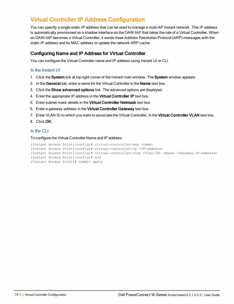
7474 | VirtualController Configuration Dell PowerConnect W-Series Aruba Instant 6.2.1.0-3.3 | User Guide
Virtual Controller IP Address ConfigurationYou can specify a single static IP address that can be used tomanage amulti-AP Instant network. This IP addressis automatically provisioned on a shadow interface on theOAW-IAP that takes the role of a Virtual Controller. WhenanOAW-IAP becomes a Virtual Controller, it sends three Address Resolution Protocol (ARP)messages with thestatic IP address and its MAC address to update the network ARP cache.
Configuring Name and IP Address for Virtual Controller
You can configure the Virtual Controller name and IP address using Instant UI or CLI.
In the Instant UI
1. Click the System link at top right corner of the Instant main window. The System window appears.
2. In the General tab, enter a name for the Virtual Controller in the Name text box.
3. Click the Show advanced options link. The advanced options are displayed.
4. Enter the appropriate IP address in the Virtual Controller IP text box.
5. Enter subnet mask details in the Virtual Controller Netmask text box.
6. Enter a gateway address in the Virtual Controller Gateway text box.
7. Enter VLAN ID to which you want to associate the Virtual Controller, in the Virtual Controller VLAN text box.
8. Click OK.
In the CLI
To configure the Virtual Controller Name and IP address:
(Instant Access Point)(config)# virtual-controller-key <name>
(Instant Access Point)(config)# virtual-controller-ip <IP-address>
(Instant Access Point)(config)# virtual-controller-vlan <Vlan-ID> <Mask> <Gateway-IP-address>
(Instant Access Point)(config)# end
(Instant Access Point)# commit apply

AOS-W Instant 6.2.1.0-3.3|User Guide MeshOAW-IAPConfiguration | 75
Chapter 9Mesh OAW-IAP Configuration
This chapter provides the following information:
l MeshNetwork Overview on page 75
l Setting up Instant Mesh Network on page 76
Mesh Network OverviewThe AOS-W Instant secure enterprisemesh solution is an effective way to expand network coverage for outdoor andindoor enterprise environments without any wires. As traffic traverses across meshOAW-IAPs, themesh networkautomatically reconfigures around broken or blocked paths. This self-healing feature provides increased reliabilityand redundancy and allows the network to continue operation even when anOAW-IAP stops functioning or if aconnection fails.
Mesh OAW-IAPs
Mesh network requires at least one valid uplink (wired or 3G) connection. Any provisionedOAW-IAP that has a validuplink (wired or 3G) functions as amesh portal, and the OAW-IAP without an Ethernet link functions as ameshpoint. Themesh portal can also act as a Virtual Controller. A Mesh portal (MPP) uses its uplink connection to reachthe switch, amesh point, or establishes an all wireless path to themesh portal. Mesh portals andmesh points arealso known as mesh nodes, a generic term used to describe OAW-IAPs configured for mesh.
If twoOAW-IAPs have valid uplink connections, there is redundancy in themesh network, andmost mesh points tryto mesh directly with one of the two portals. However, depending on the actual deployment and RF environment,somemesh points may mesh through other intermediate mesh points.
In an Instant mesh network, themaximum hop count is two nodes (point >point >portal) and themaximum number ofmesh points per mesh portal is eight.
MeshOAW-IAPs detect the environment when they boot up, locate and associate with their nearest neighbor, todetermine the best path to themesh portal.
Instant mesh functionality is supported only on dual radio OAW-IAPs only. On dual-radio OAW-IAPs, the 5GHzradio is always used for bothmesh-backhaul and client traffic, while the 2.4 GHz radio is always used for clienttraffic.
Mesh service is automatically enabled on 802.11a band for dual-radio OAW-IAP only, and this is notconfigurable.
Themesh network must be provisioned for the first time by plugging into the wired network. After that, mesh worksonOAW-IAP-ROWs like any other regulatory domain.
Mesh Portals
A mesh portal (MPP) is a gateway between the wireless mesh network and the enterprise wired LAN. Themeshroles are automatically assigned based on theOAW-IAP configuration. A mesh network could havemultiple meshportals to support redundant mesh paths (mesh links between neighboringmesh points that establish the best pathto themesh portal) from the wireless mesh network to the wired LAN.
Themesh portal broadcasts amesh services set identifier (MSSID/ mesh cluster name) to advertise themeshnetwork service to other mesh points in that Instant network. This is not configurable and is transparent to the user.

7676 | MeshOAW-IAPConfiguration Dell PowerConnect W-Series Aruba Instant 6.2.1.0-3.3 | User Guide
Themesh points authenticate to themesh portal and establish a link that is secured using Advanced EncryptionStandard (AES) encryption.
Themesh portal reboots after 5minutes when it loses its uplink connectivity to a wired network.
Mesh Points
Themesh point establishes an all-wireless path to themesh portal. Themesh point provides traditional WLANservices such as client connectivity, intrusion detection system (IDS) capabilities, user role association, andQualityof Service (QoS) for LAN-to-mesh communication to clients and performs mesh backhaul/network connectivity.
Mesh point also supports LAN bridging. You can connect any wired device to the downlink port of themesh point. In the case of single Ethernet port platforms such as AP-93 and AP-105, you can convert theEth0 uplink port to a downlink port by enabling Eth0 Bridging. For additional information, see ConfiguringWired Bridging on Ethernet 0 on page 115.
Setting up Instant Mesh NetworkInstant mesh can be provisioned in two ways:
l Over-the-air provisioning
l Over-the-wire provisioning
Over-the-air provisioning is available when only oneOAW-IAP mesh network is being advertised. TheOAW-IAP-ROW must have a the country code set to transmit or receive; therefore, over-the-air provisioning is not supported bythe OAW-IAP-ROW variants.
To set up amesh network:
1. Connect all the OAW-IAPs to a DHCP server, so that the OAW-IAPs get their IP addresses in the same subnet.
2. For over-the-air provisioning — Connect oneOAW-IAP to the switch to form themesh portal. Ensure that only oneVirtual Controller (one subnet) is available over-the-air and all the OAW-IAPs are connected to a DHCP serverand get their IP addresses in the same subnet.
TheOAW-IAP mesh point gets an IP address from the sameDHCP pool as the portal, and the DHCPrequest goes through the portal.
3. Ensure that an open SSID, instant is listed. Connect a laptop to the default ( instant) SSID.
4. Type http://instant.Alcatel-Lucentnetworks.com in a browser.
5. Click I understand the risks and Add exception to ignore the certificate warnings.
6. In the login window, enter the following credentials:
l Username— admin
l Password— admin
7. Create a new SSID and wpa-2 personal keys with unrestricted or network based access rules. Select anypermit for basic connectivity.
8. Connect a client to the new SSID and disconnect from the instant SSID. All the OAW-IAPs show up on theVirtual Controller.
Disconnect the OAW-IAPs that you want to deploy as Mesh Points from the switch and place the OAW-IAPs at thedesired location. TheOAW-IAPs with valid uplink connections function as themesh portal.

TheOAW-IAPs in US, JP, or IL regulatory domain which are in factory default state scan for severalminutes after booting. AnOAW-IAP mesh point in factory default state automatically joins the portal onlyif a single Instant mesh network is found. You can also enable the auto-join feature in the existingnetwork to allow mesh points to automatically join the network.
AOS-W Instant 6.2.1.0-3.3|User Guide MeshOAW-IAPConfiguration | 77

0511361-01 | April 2013 78

AOS-W Instant 6.2.1.0-3.3|User Guide WirelessNetworkProfiles | 79
Chapter 10Wireless Network Profiles
This chapter provides the following information:
l UnderstandingWireless Network Profiles on page 79
l ConfiguringWLAN Settings for an SSID Profile on page 80
l Configuring VLAN Settings for aWLAN SSID Profile on page 83
l Configuring Security Settings for aWLAN SSID Profile on page 84
l Configuring Access Rules for aWLAN SSID Profile on page 91
l Editing Status of aWLAN SSID Profile on page 92
l Configuring Additional WLAN SSIDs on page 93
l Editing aWLAN SSID Profile on page 94
l Deleting aWLAN SSID Profile on page 94
Understanding Wireless Network ProfilesDuring start up, a wireless client searches for radio signals or beacon frames that originate from the nearest OAW-IAP. After locating the OAW-IAP, the following transactions take place between the client and the OAW-IAP:
1. Authentication — TheOAW-IAP communicates with a RADIUS server to validate or authenticate the client.
2. Connection — After successful authentication, the client establishes a connection with the OAW-IAP.
Network Types
Instant wireless networks are categorized as:
l Employee network — An Employee network is a classic Wi-Fi network. This network type is used by theemployees in an organization and it supports passphrase-based or 802.1X based authenticationmethods.Employees can access the protected data of an enterprise through the employee network after successfulauthentication. The employee network is selected by default during a network profile configuration.
l Voice network —This Voice network type allows you to configure a network profile for devices that provide onlyvoice services such as handsets or applications that require voice traffic prioritization.
l Guest network —TheGuest wireless network is created for guests, visitors, contractors, and any non-employeeusers who use the enterpriseWi-Fi network. The Virtual Controller assigns the IP address for the guest clients.Captive portal or passphrase based authenticationmethods can be set for this wireless network. Typically, aguest network is an un-encrypted network. However, you can specify the encryption settings when configuring aguest network.
When a client is associated to the Voice network, all data traffic is marked and placed into the highpriority queue in QoS (Quality of Service).
To configure a new wireless network profile, complete the following procedures:
1. ConfiguringWLAN Settings
2. Configuring VLAN Settings
3. Configuring Security Settings
4. Configuring Access Rules for a Network

8080 | WirelessNetworkProfiles Dell PowerConnect W-Series Aruba Instant 6.2.1.0-3.3 | User Guide
Configuring WLAN Settings for an SSID ProfileYou can configureWLAN settings using Instant UI or CLI.
In the Instant UI
To configureWLAN settings:
1. In the Networks tab of the Instant main window, click the New link. The New WLAN window appears. Thefollowing figure shows the contents of WLAN Settings tab:
Figure 30 WLAN Settings Tab
2. Enter a name that uniquely identifies a wireless network in the Name (SSID) text box.
3. Based on the type of network profile, select any of the following options under Primary usage:
l Employee
l Voice
l Guest
4. Click the Show advanced options link. The advanced options for configuration are displayed.
a. Under Broadcast/Multicast, perform the following steps:
l Select any of the following values for Broadcast filtering:
n All—When set to All, the OAW-IAP drops all broadcast andmulticast frames except DHCPand ARP.
n ARP—When set to ARP, the OAW-IAP converts ARP requests to unicast and send framesdirectly to the associated client.
n Disabled— When set to Disabled, all broadcast andmulticast traffic is forwarded.

l Specify the DTIM interval. The DTIM interval indicates the delivery traffic indicationmessage (DTIM)period in beacons, which can be configured for every WLAN SSID profile. The DTIM interval determineshow often the OAW-IAP should deliver the buffered broadcast andmulticast frames to associated clientsin the powersavemode.The default value is 1, whichmeans the client checks for buffered data on theOAW-IAP at every beacon. You can also configure a higher DTIM value for power saving.
l Select Enabled for Multicast transmission optimization if you want the OAW-IAP to select the optimalrate for sending broadcast andmulticast frames based on the lowest of unicast rates across all associatedclients. When this option is enabled, multicast traffic can be sent at up to 24Mbps. The default rate forsending frames for 2.4 GHz is 1Mbps and 5.0 GHz is 6Mbps. This option is disabled by default.
l Select Enabled for Dynamic multicast optimization to allow OAW-IAP to convert multicast streams intounicast streams over the wireless link. Enabling Dynamic Multicast Optimization (DMO) enhances thequality and reliability of streaming video, while preserving the bandwidth available to the non-video clients.
When you enable DMO onmulticast SSID profiles, ensure that the DMO feature is enabled on all SSIDsconfigured in the same VLAN.
l Specify a value for DMO channel utilization threshold to set a threshold for DMO channel utilization.With DMO, the OAW-IAP converts multicast streams into unicast streams as long as the channelutilization does not exceed this threshold. The default value is 90% and themaximum threshold value is100%. When the threshold is reached or exceeds themaximum value, the OAW-IAP sends multicasttraffic over the wireless link.
b. Under Transmit Rates, specify the following parameters:
l 2.4 GHz—If the 2.4 GHz band is configured on theOAW-IAP, specify theminimum andmaximumtransmission rate. The default value for minimum transmission rate is 1Mbps andmaximum transmissionrate is 54Mbps.
l 5 GHz—If the 5GHz band is configured on theOAW-IAP, specify theminimum andmaximumtransmission rate. The default value for minimum transmission rate is 6Mbps andmaximum transmissionrate is 54Mbps.
c. Select any of the following check boxes to specify the bandwidth limit under Bandwidth Limits.
l Airtime—Select this check box to specify an aggregate amount of airtime that all clients in this network canuse for sending and receiving data. Specify the airtime percentage.
l Each user— Select this check box to specify a throughput for any single user in this network. Specify thethroughput value in Kbps.
The bandwidth contracts are applied per user for an SSID and are not based on user roles.
l Each radio— Select this check box to specify an aggregate amount of throughput that each radio isallowed to provide for the connected clients.
d. Configure the following options forWi-Fi Multimedia (WMM) traffic management. WMM supports voice,video, best effort, and background access categories. You can allocate a higher bandwidth for voice and videotraffic than other types of traffic based on the network profile. Specify a percentage value for the followingparameters:
l Background WMM share — Allocates bandwidth for background traffic such as file downloads or printjobs.
l Best effort WMM share —Allocates bandwidth or best effort traffic such as traffic from legacy devices ortraffic from applications or devices that do not support QoS.
l Video WMM share — Allocates bandwidth for video traffic generated from video streaming.
AOS-W Instant 6.2.1.0-3.3|User Guide WirelessNetworkProfiles | 81

8282 | WirelessNetworkProfiles Dell PowerConnect W-Series Aruba Instant 6.2.1.0-3.3 | User Guide
l Voice WMM share — Allocates bandwidth for voice traffic generated from the incoming and outgoing voicecommunication.
In a non-WMM or hybrid environment, where some clients are not WMM-capable, you can allocate highervalues for Best effort WMM share and Voice WMM share to allocate a higher bandwidth to clientstransmitting best effort and voice traffic.
e. Under Miscellaneous, specify the following parameters:
l Set Content filtering to Enabled to route all DNS requests for the non-corporate domains to OpenDNS onthis network.
l Select a value for Band to specify the band at which the network transmits radio signals. You can set theband to 2.4 GHz, 5 GHz, or All. The All option is selected by default.
l Specify the time for Inactivity timeout. If a client session is inactive for the specified duration, the sessionexpires and the users are required to log in again. Theminimum value is set to 60 seconds and the defaultvalue is 1000 seconds.
l Select the Hide SSID check box if you do not want the SSID (network name) to be visible to users.
l Select Disable SSID to disable the SSID. On selecting this check box, the SSID is disabled, but notremoved from the network. By default, all SSIDs are enabled.
l Select the Can be used without Uplink if you do not want to SSID profile to use uplink.
l Specify themaximum number of clients that can be configured for each BSSID on aWLAN in theMaxclients threshold text box. You can specify a value within the range of 0 to 255. The default value is 64.
l Specify a threshold value in the Local probe request threshold text box to limit the number of incomingprobe requests. When a client sends a broadcast probe request frame to search for all available SSIDs,this option controls system response for this network profile and ignores probe requests if required. Youcan specify a Received signal strength indication (RSSI) value within range of 0 to 100 dB.
5. Click Next to configure VLAN settings. For more information, see Configuring VLAN Settings for aWLAN SSIDProfile on page 83.
In the CLI
To configureWLAN settings for an SSID profile:
(Instant Access Point)(config)# wlan ssid-profile <SSID-Name>
(Instant Access Point)(SSID Profile<name>)# essid <ESSID-name>
(Instant Access Point)(SSID Profile<name>)# type {<Employee> | <Voice>| <Guest>}
(Instant Access Point)(SSID Profile<name>)# broadcast-filter <type>
(Instant Access Point)(SSID Profile<name>)# dtim-period <number-of-beacons>
(Instant Access Point)(SSID Profile<name>)# multicast-rate-optimization
(Instant Access Point)(SSID Profile<name>)# dynamic-multicast-optimization
(Instant Access Point)(SSID Profile<name>)# dmo-channel-utilization-threshold
(Instant Access Point)(SSID Profile<name>)# a-max-tx-rate <rate>
(Instant Access Point)(SSID Profile<name>)# a-min-tx-rate <rate>
(Instant Access Point)(SSID Profile<name>)# g-max-tx-rate <rate>
(Instant Access Point)(SSID Profile<name>)# g-min-tx-rate <rate>
(Instant Access Point)(SSID Profile<name>)# bandwidth-limit <limit>
(Instant Access Point)(SSID Profile<name>)# per-user-bandwidth-limit <limit>
(Instant Access Point)(SSID Profile<name>)# air-time-limit <limit>
(Instant Access Point)(SSID Profile<name>)# wmm-background-share <percentage-of-traffic_share>
(Instant Access Point)(SSID Profile<name>)# wmm-best-effort-share<percentage-of-traffic-share>
(Instant Access Point)(SSID Profile<name>)# wmm-video-share <percentage-of-traffic_share>
(Instant Access Point)(SSID Profile<name>)# wmm-voice-share <percentage-of-traffic_share>
(Instant Access Point)(SSID Profile<name>)# rf-band {<2.4>|<5.0>|<all>}
(Instant Access Point)(SSID Profile<name>)# content-filtering
(Instant Access Point)(SSID Profile<name>)# hide-ssid
(Instant Access Point)(SSID Profile<name>)# inactivity-timeout <interval>
(Instant Access Point)(SSID Profile<name>)# work-without-uplink
(Instant Access Point)(SSID Profile<name>)# local-probe-req-thresh <threshold>

(Instant Access Point)(SSID Profile<name>)# max-clients-threshold <number-of-clients>
(Instant Access Point)(SSID Profile<name>)# end
(Instant Access Point)(SSID Profile<name>)# commit apply
Configuring VLAN Settings for a WLAN SSID ProfileVLAN configuration is required for networks with more devices and broadcast traffic on aWLAN. Based on thenetwork type and its requirements, you can configure the VLAN settings.
VLAN Pooling
In a single OAW-IAP cluster, a large number of clients can be assigned to the same VLAN. Using the same VLANfor multiple clients can lead to a high level of broadcasts in the same subnet. Tomanage the broadcast traffic, youcan partition the network into different subnets and use L3-mobility between those subnets when clients roam.However, if a large number of clients need to be in the same subnet, you can configure VLAN pooling, in which eachclient is randomly assigned a VLAN from a pool of VLANs on the same SSID. Thus, VLAN pooling allows automaticpartitioning of a single broadcast domain of clients into multiple VLANs.
Configuring VLAN Settings for an SSID Profile
If you are creating a new SSID profile, complete theWLAN Settings procedure before configuring VLAN.For more information, see ConfiguringWLAN Settings for an SSID Profile on page 80.
You can configure VLAN settings for an SSID profile using the Instant UI or CLI.
In the Instant UI
To configure VLAN settings for an SSID:
1. In the VLAN tab of New WLAN window. The VLAN tab contents are displayed.
Figure 31 VLAN Tab
AOS-W Instant 6.2.1.0-3.3|User Guide WirelessNetworkProfiles | 83

8484 | WirelessNetworkProfiles Dell PowerConnect W-Series Aruba Instant 6.2.1.0-3.3 | User Guide
2. Select any for the following options for Client IP assignment:
l Virtual Controller assigned—On selecting this option, the client obtains the IP address from the VirtualController. The Virtual Controller creates a private subnet and VLAN on theOAW-IAP for the wireless clients.The network address translation for all client traffic that goes out of this interface is carried out at the source.This setup eliminates the need for complex VLAN and IP address management for amulti-site wirelessnetwork. For more information on DHCP scopes and server configuration, see DHCP Configuration on page213.
l Network assigned—Select this option to obtain the IP address from the network.
3. If the Network assigned is selected, specify any of the following options for the Client VLAN assignment.
l Default— On selecting this option, the client obtains the IP address in the same subnet as the OAW-IAPs. Bydefault, the client VLAN is assigned to the native VLAN on the wired network.
l Static— On selecting this option, you need to specify a single VLAN, a comma separated list of VLANS, or arange of VLANs for all clients on this network. Select this option for configuring VLAN pooling.
l Dynamic— On selecting this option, you can assign the VLANs dynamically from aDynamic HostConfiguration Protocol (DHCP) server. To create VLAN assignment rules:
a. Click New to assign the user to a VLAN. The New VLAN Assignment Rule window appears.
b. Enter the following information:
l Attribute— Select an attribute returned by the RADIUS server during authentication.
l Operator— Select an operator for matching the string.
l String— Enter the string tomatch.
l VLAN— Enter the VLAN to be assigned.
4. Click Next to configure security settings for the employee network. For more information, see ConfiguringSecurity Settings for aWLAN SSID Profile on page 84.
In the CLI
Tomanually assign VLANs forWLAN SSID users:
(Instant Access Point)(config)# wlan ssid-profile <SSID-Name>
(Instant Access Point)(SSID Profile<name>)# vlan <vlan-ID>
(Instant Access Point)(SSID Profile<name>)# end
(Instant Access Point)(SSID Profile<name>)# commit apply
To enforce DHCP-based VLAN assignment:
(Instant Access Point)(config)# wlan ssid-profile <SSID-Name>
(Instant Access Point)(SSID Profile<name>)# enforce-dhcp
(Instant Access Point)(SSID Profile<name>)# end
(Instant Access Point)(SSID Profile<name>)# commit apply
To create a new VLAN assignment rule:
(Instant Access Point)(config)# wlan ssid-profile <SSID-Name>
(Instant Access Point)(SSID Profile <name>)# set-vlan <attribute>{equals|not-equals| starts-
with| ends-with| contains} <operator> <VLAN-ID>| value-of}
(Instant Access Point)(SSID Profile <name>)# end
(Instant Access Point)# commit apply
Configuring Security Settings for a WLAN SSID ProfileThis section describes the following procedures:
l Configuring Security Settings for an Employee or Voice Network

l Configuring Security Settings for Guest Network
If you are creating a new SSID profile, configure theWLAN and VLAN settings before defining securitysettings. For more information, see ConfiguringWLAN Settings for an SSID Profile on page 80 andConfiguring VLAN Settings for aWLAN SSID Profile on page 83.
Configuring Security Settings for an Employee or Voice Network
You can configure security settings for an employee or voice network by using the Instant UI or CLI.
In the Instant UI
To configure security settings for an employee or voice network:
1. In the Security tab, specify any of the following types of security levels by moving the slider to a desired level:
l Enterprise
l Personal
l Open
The default security setting for a network profile is Personal.
2. Based on the security level specified, complete the following procedures:
l Configuring Enterprise Security Level
l Configuring Personal Security Level
l Configuring Open Security Level
Configuring Enterprise Security Level
On selecting enterprise security level, the authentication options applicable to the enterprise network are displayed:
Figure 32 Security Tab: Enterprise
To configure settings for the enterprise security level:
1. Select the required key option from the Key management drop-down list. The following options are available:
l WPA-2 Enterprise
l WPA Enterprise
l Both (WPA-2 & WPA)
AOS-W Instant 6.2.1.0-3.3|User Guide WirelessNetworkProfiles | 85

8686 | WirelessNetworkProfiles Dell PowerConnect W-Series Aruba Instant 6.2.1.0-3.3 | User Guide
l Dynamic WEP with 802.1X
2. If you do not want to use a session key from the RADIUS Server to derive pair wise unicast keys, set SessionKey for LEAP to Enabled. This is required for old printers that use dynamic WEP through Lightweight ExtensibleAuthentication Protocol (LEAP) authentication. The Session Key for LEAP feature is Disabled by default.
3. To terminate the EAP portion of 802.1X authentication on theOAW-IAP instead of the RADIUS server, setTermination to Enabled.
Enabling Termination can reduce network traffic to the external RADIUS server by terminating the authorizationprotocol on the OAW-IAP. By default, for 802.1X authorization, the client conducts an EAP exchange with theRADIUS server, and the OAW-IAP acts as a relay for this exchange. When Termination is enabled, the OAW-IAP by itself acts as an authentication server and terminates the outer layers of the EAP protocol, only relayingthe innermost layer to the external RADIUS server.
If you are using LDAP for authentication, ensure that AP termination is configured to support EAP.
4. Configure an authentication server by using the Authentication server 1 drop-down list:
l Select an authentication server from the list if an external servers are already configured.
l Select New to configure any of the following servers as an external RADIUS server:
n RADIUS Server
n LDAP Server
n CPPM Server for AirGroup CoA
For information on configuring external servers, see Configuring an External Server for Authenticationon page 124.
l To use an internal server, select Internal server and add the clients that are required to authenticate with theinternal RADIUS server. Click the Users link to add the users. For information on adding a user, seeConfiguring Users on page 129.
5. Specify a value for Reauth interval. When set to a value greater than zero, APs periodically reauthenticate allassociated and authenticated clients.
6. To enable blacklisting of the clients with a specific number of authentication failures, select Enabled from theBlacklisting drop-down list and specify a value for Max authentication failures. The users who fail toauthenticate the number of times specified in Max authentication failures field are dynamically blacklisted.
7. To enable accounting, select Enabled from the Accounting drop-down list. On setting this option to Enabled,APs post accounting information to the Radius server at the specified Accounting interval.
8. To enable authentication survivability, set Authentication survivability to Enabled. Specify a value in hours forCache timeout (global) to set the duration after which the authenticated credentials in the cachemust expire.When the cache expires, the clients are required to authenticate again. You can specify a value within range of 1to 99 hours and the default value is 24 hours.
The authentication survivability feature requires ClearPass Policy Manager 6.0.2 or later, and is availableonly when the New server option is selected authentication. On setting this parameter to Enabled, AOS-W Instant authenticates the previously connected clients using EAP-PEAP authentication even whenconnectivity to ClearPass Policy Manager is temporarily lost. The Authentication survivability feature isnot applicable when a RADIUS server is configured as an internal server.
9. Specify the following parameters to configure theMAC address based authentication under MACauthentication.

l Perform MAC authentication before 802.1X — Select this check box to use 802.1X authentication onlywhen theMAC authentication is successful.
l MAC authentication fail-thru — On selecting this check box, the 802.1X authentication is attempted whentheMAC authentication fails.
10. Click Upload Certificate and browse to upload a certificate file for the internal server. For more information oncertificates, see Uploading Certificates on page 150.
11. Click Next to configure access rules. For more information, see Configuring Access Rules for aWLAN SSIDProfile on page 91.
Configuring Personal Security Level
On selecting personal security level, the authentication options applicable to the personalized network are displayed.
Figure 33 Security Tab: Personal
To configure settings for the personal security level:
1. Ensure that security level set to Personal.
2. Select an encryption key from the Key management drop-down list.
l ForWPA-2 Personal, WPA Personal, and Both (WPA-2&WPA) keys, specify the following parameters:
a. Passphrase format: Select a passphrase format from the Passphrase format drop-down list.The following options are available are:
l 8-63 alphanumeric chars
l 64 hexadecimal chars
b. Enter a passphrase in the Passphrase text box and reconfirm.
l For Static WEP, specify the following parameters:
a. Select an appropriate value forWEP key size from theWEP key size drop-down list. You canspecify 64-bit or 128-bit .
b. Select an appropriate value for Tx key from the Tx Key drop-down list. You can specify 1, 2, 3,or 4.
c. Enter an appropriateWEP key and reconfirm.
AOS-W Instant 6.2.1.0-3.3|User Guide WirelessNetworkProfiles | 87

8888 | WirelessNetworkProfiles Dell PowerConnect W-Series Aruba Instant 6.2.1.0-3.3 | User Guide
3. To configureMAC authentication, set MAC authentication to Enabled. When Enabled, configure at least oneRADIUS server for authentication server.
4. Configure an authentication server by using the Authentication server 1 drop-down list:
l Select an authentication server from the list if an external servers are already configured.
l Select New to configure any of the following servers as an external RADIUS server:
n RADIUS Server
n LDAP Server
n CPPM Server for AirGroup CoA
For information on configuring external servers, see Configuring an External Server for Authenticationon page 124.
l To use an internal server, select Internal server and add the clients that are required to authenticate with theinternal RADIUS server. Click the Users link to add the users. For information on adding a user, seeConfiguring Users on page 129.
5. Specify a value for Reauth interval. When set to a value greater than zero, APs periodically reauthenticate allassociated and authenticated clients.
6. To enable blacklisting of the clients with a specific number of authentication failures, select Enabled from theBlacklisting drop-down list and specify a value for Max authentication failures. The users who fail toauthenticate the number of times specified in Max authentication failures field are dynamically blacklisted.
7. To enable accounting, select Enabled from the Accounting drop-down list. On setting this option to Enabled,APs post accounting information to the Radius server at the specified Accounting interval.
8. Click Upload Certificate and browse to upload a certificate file for the internal server. See Uploading Certificateson page 150 for more information.
9. Click Next to configure access rules. For more information, see Configuring Access Rules for aWLAN SSIDProfile on page 91.
Configuring Open Security Level
On selecting Open security level, the authentication options applicable to an open network are displayed:

Figure 34 Security Tab: Open
To configure settings for the open security level:
1. To enableMAC authentication, select Enabled from theMAC authentication drop-down list. When Enabled,configure at least one RADIUS server for authentication server.
a. Select a required type of authentication server option from the Authentication server 1 drop-down list.
l New— If you select this option, an external RADIUS server has to be configured to authenticate the users.For information on configuring an external RADIUS server, see Authentication on page 117.
l Internal server— To use an internal server, select Internal server and add the clients that are required toauthenticate with the internal RADIUS server. Click the Users link to add the users. For information onadding a user, see Configuring Users on page 129.
b. Reauth interval— When set to a value greater than zero, APs periodically reauthenticate all associated andauthenticated clients.
c. Accounting — When enabled, APs posts accounting information to the RADIUS server at the specifiedAccounting interval.
d. Blacklisting— To enable blacklisting of the clients with a specific number of authentication failures, select theEnabled option. Specify the number of times after which users who fail to authenticate must be dynamicallyblacklisted in theMax authentication failures text box. Themaximum value for this entry is 10.
2. Click Upload Certificate and browse to upload a certificate file for the internal server. See Uploading Certificateson page 150 for more information.
3. Click Next to configure access rules. For more information, see Configuring Access Rules for aWLAN SSIDProfile on page 91.
In the CLI
To configure security settings for the employee and voice users of aWLAN SSID profile:
(Instant Access Point)(config)# wlan ssid-profile <SSID-Name>
AOS-W Instant 6.2.1.0-3.3|User Guide WirelessNetworkProfiles | 89

9090 | WirelessNetworkProfiles Dell PowerConnect W-Series Aruba Instant 6.2.1.0-3.3 | User Guide
(Instant Access Point)(SSID Profile<name>)# opmode {<opensystem>|<wpa2-ae>|<wpa2-psk-
aes>|<wpa-tkip>|<wpa-psk-tkip>|<wpa-tkip>|<wpa2-aes>|<wpa-psk-tkip>|<wpa2-psk-aesstatic-
wep>|<dynamic-wep>}
(Instant Access Point)(SSID Profile<name>)# leap-use-session-key
(Instant Access Point)(SSID Profile<name>)# blacklist
(Instant Access Point)(SSID Profile<name>)# mac-authentication
(Instant Access Point)(SSID Profile<name>)# l2-auth-failthrough
(Instant Access Point)(SSID Profile<name>)# external-server
(Instant Access Point)(SSID Profile<name>)# termination
(Instant Access Point)(SSID Profile<name>)# auth-server <server-name>
(Instant Access Point)(SSID Profile<name>)# auth-survivability
(Instant Access Point)(SSID Profile<name>)# auth-survivability cache-time-out <hours>
(Instant Access Point)(SSID Profile<name>)# server-load-balancing
(Instant Access Point)(SSID Profile<name>)# radius-accounting
(Instant Access Point)(SSID Profile<name>)# radius-accounting-mode {user-authentication| user-
association}
(Instant Access Point)(SSID Profile<name>)# radius-interim-accounting-interval <minutes>
(Instant Access Point)(SSID Profile<name>)# radius-reauth-interval <minutes>
(Instant Access Point)(SSID Profile<name>)# max-authentication-failures <number>
(Instant Access Point)(SSID Profile<name>)# end
(Instant Access Point)(SSID Profile<name>)# commit apply
Configuring Security Settings for Guest Network
You can configure the captive portal page and encryption parameters for a guest network by using the Instant UI orCLI.
In the Instant UI
To configure the captive portal page and encryption parameters for a guest network:
1. Select any of the following options for the Splash Page Type drop-down:
l Internal - Authenticated
l Internal - Acknowledged
l External-RADIUS
l External - Authentication Text
l None
The guest users are required to accept the terms and conditions and enter a username and password on thecaptive portal page. If you are configuring a splash page, ensure that the users who are required to use thecaptive portal authentication are added to the user database. For information about adding a user and configuringcaptive portal authentication, see Configuring Users on page 129 and Configuring Captive Portal Authenticationon page 135 respectively.
2. Configure the authentication parameters based on the Splash Page Type selected. For more information, seeConfiguring Captive Portal Authentication on page 135.
3. Click Next to configure access rules. For more information, see Configuring Access Rules for aWLAN SSIDProfile on page 91.
In the CLI
To configure security settings for guest users of aWLAN SSID profile:
(Instant Access Point)(config)# wlan ssid-profile <SSID-Name>
(Instant Access Point)(SSID Profile<name>)# essid <ESSID-name>
(Instant Access Point)(SSID Profile<name>)# type <Guest>
(Instant Access Point)(SSID Profile<name>)# captive-portal <type> exclude-uplink <type>
(Instant Access Point)(SSID Profile<name>)# blacklist
(Instant Access Point)(SSID Profile<name>)# mac-authentication
(Instant Access Point)(SSID Profile<name>)# max-authentication-failures <number>
(Instant Access Point)(SSID Profile<name>)# auth-server <server-name>

(Instant Access Point)(SSID Profile<name>)# wpa-passphrase <WPA_key>
(Instant Access Point)(SSID Profile<name>)# radius-accounting
(Instant Access Point)(SSID Profile<name>)# radius-interim-accounting-interval
(Instant Access Point)(SSID Profile<name>)# radius-accounting-mode {user-association|user-
authentication}
(Instant Access Point)(SSID Profile<name>)# end
(Instant Access Point)(SSID Profile<name>)# commit apply
To configure external captive portal page for a guest user:
(Instant Access Point)(config)# wlan external-captive-portal
(Instant Access Point)(External Captive Portal)# auth-text <text>
(Instant Access Point)(External Captive Portal)# port <port>
(Instant Access Point)(External Captive Portal)# redirect-url <url>
(Instant Access Point)(External Captive Portal)# server <server>
(Instant Access Point)(External Captive Portal)# server-fail-through
(Instant Access Point)(External Captive Portal)# url <url>
(Instant Access Point)(External Captive Portal)# end
(Instant Access Point)(External Captive Portal)# commit apply
To configure internal captive portal splash page for a guest user:
(Instant Access Point)(config)# wlan captive-portal
(Instant Access Point)(Captive Portal)# authenticated
(Instant Access Point)(Captive Portal)# background-color <color-indicator>
(Instant Access Point)(Captive Portal)# banner-color <color-indicator>
(Instant Access Point)(Captive Portal)# banner-text <text>
(Instant Access Point)(Captive Portal)# decoded-texts <text>
(Instant Access Point)(Captive Portal)# redirect-url <url>
(Instant Access Point)(Captive Portal)# terms-of-use <text>
(Instant Access Point)(Captive Portal)# use-policy <text>
(Instant Access Point)(Captive Portal)# end
(Instant Access Point)(Captive Portal)# commit apply
Configuring Access Rules for a WLAN SSID ProfileIf you are creating a new SSID profile, complete theWLAN Settings and configure VLAN and securityparameters, before defining access rules. For more information, see ConfiguringWLAN Settings for anSSID Profile on page 80, Configuring VLAN Settings for aWLAN SSID Profile on page 83, andConfiguring Security Settings for aWLAN SSID Profile on page 84.
You can configure up to 64 access rules for an employee, voice, or guest network using the Instant UI or CLI.
In the Instant UI
To configure access rules for an employee, voice or guest network:
1. In the Access Rules tab, set slider to any of the following types of access control:
l Unrestricted— Select this to set unrestricted access to the network.
l Network-based— Set the slider to Network-based to set common rules for all users in a network. The Allowany to all destinations access rule is enabled by default. This rule allows traffic to all destinations. To definean access rule:
a. Click New.
b. Select appropriate options in the New Rule window.
c. Click OK.
l Role-based— Select Role-based to enable access based on user roles. For role-based access control:
n Create a user role if required. For more information, see Configuring User Roles.
AOS-W Instant 6.2.1.0-3.3|User Guide WirelessNetworkProfiles | 91

9292 | WirelessNetworkProfiles Dell PowerConnect W-Series Aruba Instant 6.2.1.0-3.3 | User Guide
n Create access rules for a specific user role. For more information, see Configuring Access Rules on page158. You can also configure an access rule to enforce Captive portal authentication for an SSID that isconfigured to use 802.1X authenticationmethod. For more information, see Configuring Captive PortalRoles for an SSID with 802.1x authentication on page 142.
n Create a role assignment rule. For more information, see Configuring Role Assignment Rules on page 166.
2. Click Finish.
In the CLI
To configure access control rules for aWLAN SSID:
(Instant Access Point)(config)# wlan access-rule <access-rule-name>
(Instant Access Point)(Access Rule <Name>)# rule <dest> <mask> <match> <protocol> <start-port>
<end-port> {permit |deny | src-nat | dst-nat {<IP-address> <port> | <port>}}
[<option1....option9>]
(Instant Access Point)(Access Rule <Name>)# end
(Instant Access Point)# commit apply
To configure access control based on the SSID:
(Instant Access Point)(config)# wlan ssid-profile <SSID-Name>
(Instant Access Point)(SSID Profile<name>)# set-role-by-ssid
(Instant Access Point)(SSID Profile<name>)# end
(Instant Access Point)(SSID Profile<name>)# commit apply
To configure role assignment rules:
(Instant Access Point)(config)# wlan ssid-profile <SSID-Name>
(Instant Access Point)(SSID Profile<name>)# set-role <attribute>{{equals|not-equals|starts-
with|ends-with|contains}<operator><role>|value-of}
(Instant Access Point)(SSID Profile<name>)# end
(Instant Access Point)(SSID Profile<name>)# commit apply
To configure a pre-authentication role:
(Instant Access Point)(config)# wlan ssid-profile <SSID-Name>
(Instant Access Point)(SSID Profile<name>)# set-role-pre-auth <pre-authentication-role>
(Instant Access Point)(SSID Profile<name>)# end
(Instant Access Point)(SSID Profile<name>)# commit apply
To configuremachine and user authentication roles
(Instant Access Point)(config)# wlan ssid-profile <SSID-Name>
(Instant Access Point)(SSID Profile<name>)# set-role-machine-auth <machine-authentication-
only> <user-authentication-only>
(Instant Access Point)(SSID Profile<name>)# end
(Instant Access Point)(SSID Profile<name>)# commit apply
To configure unrestricted access:
(Instant Access Point)(config)# wlan ssid-profile <SSID-Name>
(Instant Access Point)(SSID Profile<name>)# set-role-unrestricted
(Instant Access Point)(SSID Profile<name>)# end
(Instant Access Point)(SSID Profile<name>)# commit apply
Editing Status of a WLAN SSID ProfileYou can enable or disable an SSID profile in the Instant UI or CLI.
In the Instant UI
Tomodify the status of aWLAN SSID profile:
1. In the Networks tab, select the network that you want to edit. The edit link appears.
2. Click the edit link. The Edit network window appears.

3. Select or clear the Disable SSID check box to disable or enable the SSID. The SSID is enabled by default.
4. Click Next or the tab name tomove to the next tab.
5. Click Finish to save themodifications.
In the CLI
To disable an SSID(Instant Access Point)(config)# wlan ssid-profile <SSID-Name>
(Instant Access Point)(SSID Profile<name>)# disable
(Instant Access Point)(SSID Profile<name>)# end
(Instant Access Point)# commit apply
To enable an SSID:(Instant Access Point)(config)# wlan ssid-profile <SSID-Name>
(Instant Access Point)(SSID Profile<name>)# enable
(Instant Access Point)(SSID Profile<name>)# end
(Instant Access Point)# commit apply
Configuring Additional WLAN SSIDsBy default, you can create up to six WLAN SSIDs. With the Extended SSID option enabled, you can create up to 16WLANs. TheOAW-IAPs that support 16WLANs are as follows:
l OAW-RAP3WN/3WNP
l OAW-IAP92
l OAW-IAP93
l OAW-IAP134
l OAW-IAP135
The number of SSIDs that become active on eachOAW-IAP depends on theOAW-IAP platform.
Enabling the Extended SSID
Enabling the Extended SSID option disables mesh.
You can configure additional SSIDs by using the Instant UI or CLI.
In the Instant UI
1. Click the System link at top right corner of the Instant main window.
2. Click the Show advanced options link.
3. In the General tab, select Enabled from the Extended SSID drop-down list.
4. Click OK.
5. Reboot the OAW-IAP for the changes to take effect. After you enable the option and reboot the OAW-IAP, theWi-Fi andmesh links are disabled automatically.
In the CLI
To enable the extended SSIDs:
(Instant Access Point)(config)# extended-ssid
(Instant Access Point)(config)# end
(Instant Access Point)# commit apply
AOS-W Instant 6.2.1.0-3.3|User Guide WirelessNetworkProfiles | 93

9494 | WirelessNetworkProfiles Dell PowerConnect W-Series Aruba Instant 6.2.1.0-3.3 | User Guide
Editing a WLAN SSID ProfileTo edit aWLAN SSID profile:
1. In the Networks tab, select the network that you want to edit. The edit link appears.
2. Click the edit link. The Edit network window appears.
3. Modify the required settings. Click Next to move to the next tab.
4. Click Finish to save themodifications.
Deleting a WLAN SSID ProfileTo delete aWLAN SSID profile:
1. In the Networks tab, click the network which you want to delete. A x link appears against the network to bedeleted.
2. Click x. A delete confirmation window appears.
3. Click Delete Now.

AOS-W Instant 6.2.1.0-3.3|User Guide UplinkConfiguration | 95
Chapter 11Uplink Configuration
This chapter provides the following information:
l Understanding Uplink Interfaces on page 95
l Configuring Uplinks on page 99
Understanding Uplink InterfacesAOS-W Instant network supports Ethernet, 3G and 4GUSB modems, and theWi-Fi uplink to provide access to thecorporate Instant network. The 3G/4GUSB modems and theWi-Fi uplink can be used to extend the connectivity toplaces where an Ethernet uplink cannot be configured. It also provides a reliable backup link for the Ethernet basedInstant network.
The following figure illustrates a scenario in which the OAW-IAPs join the Virtual Controller as slave OAW-IAPsthrough a wired or meshWi-Fi uplink:
Figure 35 Uplink Types
The following types of uplinks are supported on AOS-W Instant:
l Ethernet Uplink
l 3G/4GUplink
l Wi-Fi Uplink
The following figure shows the window for configuring uplinks in the Instant UI:

9696 | UplinkConfiguration Dell PowerConnect W-Series Aruba Instant 6.2.1.0-3.3 | User Guide
Formore information on uplink configuration procedures, see Configuring Uplinks on page 99.
Ethernet Uplink
The Ethernet 0 port on an OAW-IAP is enabled as an uplink port by default. You can view the type of uplink and thestatus of the uplink in the Instant UI in the Info tab.
Figure 36 Uplink Status
Ethernet uplink supports the following types of configuration:
n PPPoE
n DHCP
n Static IP

You can use PPPoE for your uplink connectivity in both OAW-IAP and IAP-VPN deployments. PPPoE is supportedonly in a single AP deployment.
Uplink redundancy with the PPPoE link is not supported.
When the Ethernet link is up, it is used as a PPPoE or DHCP uplink. Once the PPPoE settings are configured,PPPoE has the highest priority for the uplink. TheOAW-IAP can establish a PPPoE session with a PPPoE server atthe ISP and get authenticated using Password Authentication Protocol (PAP) or the Challenge HandshakeAuthentication Protocol (CHAP). Depending upon the request from the PPPoE server, either the PAP or the CHAPcredentials are used for authentication. After you configure PPPoE, reboot the OAW-IAP for the configuration toaffect. The PPPoE connection is dialed after the AP comes up. The PPPoE configuration is checked during OAW-IAP boot and if the configuration is not incorrect, Ethernet is used for the uplink connection.
When PPPoE is used, do not configure Dynamic RADIUS Proxy and IP address of the Virtual Controller.An SSID created with default VLAN is not supported with PPPoE uplink.
You can also configure an alternate Ethernet uplink to enable uplink failover when an Ethernet port fails.
3G/4G Uplink
AOS-W Instant supports the use of 3G/4GUSB modems to provide the Internet backhaul to an AOS-W Instantnetwork. The 3G/4GUSB modems can be used to extend client connectivity to places where an Ethernet uplinkcannot be configured. This enables the RAPs to automatically choose the available network in a specific region.
The 3G and 4G LTE USB modems can be provisioned onOAW-RAP3WN/3WNP, OAW-RAP108, andOAW-RAP155/155P.
Types of Modems
AOS-W Instant supports the following three types of 3Gmodems:
l True Auto Detect— Modems of this type can be used only in one country and for a specific ISP. The parametersare configured automatically and hence no configuration is necessary.
l Auto-detect + ISP/country— Modems of this type require the user to specify the Country and ISP. The samemodem is used for different ISPs with different parameters configured for each of them.
l No Auto-detect— Modems of this type are used only if they share the sameDevice-ID, Country, and ISP details.You need to configure different parameters for each of them. Thesemodems work with AOS-W Instant when theappropriate parameters are configured. All the new auto-detectedmodems falls under this category as theparameters necessary to automatically configure them are unknown.
The following table lists the types of supported 3Gmodems:
Modem Type Supported 3G Modems
True Auto Detect l USBConnect 881 (Sierra 881U)l Quicksilver (Globetrotter ICON 322)l UM100C (UTstarcom)l Icon 452l Aircard 250U (Sierra)l USB 598 (Sierra)l U300 (Franklin wireless)
Table 15: List of Supported 3GModems
AOS-W Instant 6.2.1.0-3.3|User Guide UplinkConfiguration | 97

9898 | UplinkConfiguration Dell PowerConnect W-Series Aruba Instant 6.2.1.0-3.3 | User Guide
Modem Type Supported 3G Modems
l U301 (Franklin wireless)l USB U760 for Virgin (Novatel)l USB U720 (Novatel/Qualcomm)l UM175 (Pantech)l UM150 (Pantech)l UMW190(Pantech)l SXC-1080 (Qualcomm)l Globetrotter ICON 225l UMG181l NTT DoCoMo L-05A (LG FOMA L05A)l NTT DoCoMo L-02Al ZTE WCDMA Technologies MSM (MF668?)l Fivespot (ZTE)l c-motech CNU-600l ZTE AC2736l SEC-8089 (EpiValley)l Nokia CS-10l NTT DoCoMo L-08C (LG)l NTT DoCoMo L-02C (LG)l Novatel MC545l Huawei E220 for Movistar in Spainl Huawei E180 for Movistar in Spainl ZTE-MF820l Huawei E173s-1l Sierra 320l Longcheer WM72l U600 (3G mode)
Auto-detect + ISP/country l Sierra USB-306 (HK CLS/1010 (HK))l Sierra 306/308 (Telstra (Aus))l Sierra 503 PCIe (Telstra (Aus))l Sierra 312 (Telstra (Aus))l Aircard USB 308 (AT&T's Shockwave)l Compass 597(Sierra) (Sprint)l U597 (Sierra) (Verizon)l Tstick C597(Sierra) (Telecom(NZ))l Ovation U727 (Novatel) (Sprint)l USB U727 (Novatel) (Verizon)l USB U760 (Novatel) (Sprint)l USB U760 (Novatel) (Verizon)l Novatel MiFi 2200 (Verizon Mifi 2200)l Huawei E272, E170, E220 (ATT)l Huawei E169, E180,E220,E272 (Vodafone/SmarTone (HK))l Huawei E160 (O2(UK))l Huawei E160 (SFR (France))l Huawei E220 (NZ and JP)l Huawei E176G (Telstra (Aus))l Huawei E1553, E176 (3/HUTCH (Aus))l Huawei K4505 (Vodafone/SmarTone (HK))l Huawei K4505 (Vodafone (UK))l ZTE MF656 (Netcom (norway))l ZTE MF636 (HK CSL/1010)l ZTE MF633/MF636 (Telstra (Aus))l ZTE MF637 (Orange in Israel)l Huawei E180, E1692,E1762 (Optus (Aus))
Table 15: List of Supported 3GModems

Modem Type Supported 3G Modems
l Huawei E1731 (Airtel-3G (India))l Huawei E3765 (Vodafone (Aus))l Huawei E3765 (T-Mobile (Germany)l Huawei E1552 (SingTel)l Huawei E1750 (T-Mobile (Germany))l UGM 1831 (TMobile)l Huawei D33HW (EMOBILE(Japan))l Huawei GD01 (EMOBILE(Japan))l Huawei EC150 (Reliance NetConnect+ (India))l KDDI DATA07(Huawei) (KDDI (Japan))l Huawei E353 (China Unicom)l Huawei EC167 (China Telecom)l Huawei E367 (Vodafone (UK))l Huawei E352s-5 (T-Mobile (Germany))
No auto-detect l Huawei D41HWl ZTE AC2726
Table 15: List of Supported 3GModems
Modem Type Supported 4G Modem
4G Pantech UML290
Table 16: 4GSupportedModem
WhenUML290 runs in auto detect mode, themodem can switch from 4G network to 3G network or vice-versa based on the signal strength. To configure the UML290 for the 3G network only, manually set theUSB type to pantech-3g. To configure the UML290 for the 4G network only, manually set the 4GUSBtype to pantech-lte.
Wi-Fi Uplink
TheWi-Fi uplink is supported for all the OAW-IAP models, but only themaster OAW-IAP uses this uplink. TheWi-Fiallows uplink to open, PSK-CCMP, and PSK-TKIP SSIDs.
l For single radio OAW-IAPs, the radio serves wireless clients and theWi-Fi uplink.
l For dual radio OAW-IAPs, both radios can be used to serve clients but only one of them can be used for theWi-Fiuplink.
When theWi-Fi uplink is in use, the client IP is assigned by the internal DHCP server.
Configuring UplinksThis section describes the following procedures:
l Configuring Cellular Uplink Profiles on page 100
l Configuring aWi-Fi Uplink Profile on page 102
l Configuring PPPoE Uplink Profile on page 103
AOS-W Instant 6.2.1.0-3.3|User Guide UplinkConfiguration | 99

100100 | UplinkConfiguration Dell PowerConnect W-Series Aruba Instant 6.2.1.0-3.3 | User Guide
l Configuring Uplink Preferences and Switching on page 104
Configuring Cellular Uplink Profiles
You can configure 3G or 4G uplinks using the Instant UI or CLI.
In the Instant UI
1. Click the System link at the upper right corner of the AOS-W Instant main window. The System window isdisplayed.
2. In the System window, click the show advanced settings link. The advanced options are displayed.
3. Click the Uplink tab and perform any of the following steps:
l To configure a 3G or 4G uplink automatically, select the Country and ISP. The parameters are automaticallypopulated.
l To configure a 3G or 4G uplink manually, perform the following steps:
a. Obtain themodem configuration parameters from the local IT administrator or themodemmanufacturer.
b. Enter the type of the 3G/4Gmodem driver type:
l For 3G — Enter the type of 3Gmodem in the USB type text box.
l For 4G — Enter the type of 4Gmodem in the 4G USB type text box.
c. Enter the device ID of modem in the USB dev text box.
d. Enter the TTY port of themodem in the USB tty text box.
e. Enter the parameter to initialize themodem in the USB init text box.
f. Enter the parameter to dial the cell tower in the USB dial text box.
g. Enter the username used to dial the ISP in the USB user text box.
h. Enter the password used to dial the ISP in the USB password text box.
i. Enter the parameter used to switch amodem from the storagemode tomodemmode in theUSB mode switch text box.
4. To configure 3G/4G switch network, provide the driver type for the 3Gmodem in the USB type text box and thedriver type for 4Gmodem in the 4G USB type text box.
5. Click OK.
6. Reboot the OAW-IAP for changes to affect.
In the Instant UI, you can view the list of country, ISP in the country, and the ISP drop-down list. You caneither use the country or ISP to configure themodem, or configure the individual modem parametersmanually. If you cannot view the list of country or ISP from the drop-down list, then configure themodemparameters manually. Contact your IT administrator or themanufacturer of your modem to obtain theparameter details.
In the CLI
To configure a 3G cellular uplink profile:
(Instant Access Point)(config) # cellular-uplink-profile
(Instant Access Point)(cellular-uplink-profile)# usb-type <3G-usb-type>
(Instant Access Point)(cellular-uplink-profile)# modem-country <country>
(Instant Access Point)(cellular-uplink-profile)# modem-isp <service-provider-name>
(Instant Access Point)(cellular-uplink-profile)# usb-user <username>
(Instant Access Point)(cellular-uplink-profile)# usb-passwd <password>
(Instant Access Point)(cellular-uplink-profile)# usb-dev <device-ID>

(Instant Access Point)(cellular-uplink-profile)# usb-tty <tty-port>
(Instant Access Point)(cellular-uplink-profile)# usb-init <Initialization-parameter>
(Instant Access Point)(cellular-uplink-profile)# usb-dial <dial-parameter>
(Instant Access Point)(cellular-uplink-profile)# modem-country <country>
(Instant Access Point)(cellular-uplink-profile)# end
(Instant Access Point)# commit apply
To configure a 4G cellular uplink profile:
(Instant Access Point)(config) # cellular-uplink-profile
(Instant Access Point)(cellular-uplink-profile)# 4g-usb-type <4g-usb>
(Instant Access Point)(cellular-uplink-profile)# modem-country <country>
(Instant Access Point)(cellular-uplink-profile)# modem-isp <service-provider-name>
(Instant Access Point)(cellular-uplink-profile)# usb-user <username>
(Instant Access Point)(cellular-uplink-profile)# usb-passwd <password>
(Instant Access Point)(cellular-uplink-profile)# usb-dev <device-ID>
(Instant Access Point)(cellular-uplink-profile)# usb-tty <tty-port>
(Instant Access Point)(cellular-uplink-profile)# usb-init <Initialization-parameter>
(Instant Access Point)(cellular-uplink-profile)# usb-dial <dial-parameter>
(Instant Access Point)(cellular-uplink-profile)# modem-country <country>
(Instant Access Point)(cellular-uplink-profile)# end
(Instant Access Point)# commit apply
To switch amodem from the storagemode tomodemmode:
(Instant Access Point)(config)# cellular-uplink-profile
(Instant Access Point)(cellular-uplink-profile)# usb-modeswitch <usb-modem>
To configure 3G/4G switch network
(Instant Access Point)(config) # cellular-uplink-profile
(Instant Access Point)(cellular-uplink-profile)# usb-type <3G-usb-type>
(Instant Access Point)(cellular-uplink-profile)# 4g-usb-type <4g-usb>
(Instant Access Point)(cellular-uplink-profile)# modem-country <country>
(Instant Access Point)(cellular-uplink-profile)# modem-isp <service-provider-name>
(Instant Access Point)(cellular-uplink-profile)# usb-user <username>
(Instant Access Point)(cellular-uplink-profile)# usb-passwd <password>
(Instant Access Point)(cellular-uplink-profile)# usb-dev <device-ID>
(Instant Access Point)(cellular-uplink-profile)# usb-tty <tty-port>
(Instant Access Point)(cellular-uplink-profile)# usb-init <Initialization-parameter>
(Instant Access Point)(cellular-uplink-profile)# usb-dial <dial-parameter>
(Instant Access Point)(cellular-uplink-profile)# modem-country <country>
(Instant Access Point)(cellular-uplink-profile)# end
(Instant Access Point)# commit apply
To view the cellular configuration:
(Instant Access Point)# show cellular config
USB Plugged in: Vendor_ID=0 Product_ID=0
cellular configure
------------------
Type Value
---- -----
4g-usb-type pantech-lte
usb-type
usb-dev test
usb-tty
usb-init
usb-user
usb-passwd
usb-dial usb-init
usb-modeswitch
modem-isp verison
modem-country India
AOS-W Instant 6.2.1.0-3.3|User Guide UplinkConfiguration | 101
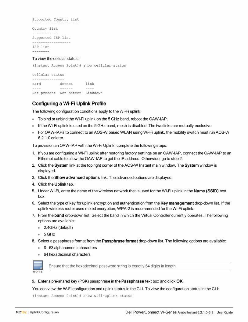
102102 | UplinkConfiguration Dell PowerConnect W-Series Aruba Instant 6.2.1.0-3.3 | User Guide
Supported Country list
----------------------
Country list
------------
Supported ISP list
------------------
ISP list
--------
To view the cellular status:
(Instant Access Point)# show cellular status
cellular status
---------------
card detect link
---- ------ ----
Not-present Not-detect Linkdown
Configuring a Wi-Fi Uplink Profile
The following configuration conditions apply to theWi-Fi uplink:
l To bind or unbind theWi-Fi uplink on the 5GHz band, reboot the OAW-IAP.
l If theWi-Fi uplink is used on the 5GHz band, mesh is disabled. The two links aremutually exclusive.
l For OAW-IAPs to connect to an AOS-W basedWLAN usingWi-Fi uplink, themobility switchmust run AOS-W6.2.1.0 or later.
To provision anOAW-IAP with theWi-Fi Uplink, complete the following steps:
1. If you are configuring aWi-Fi uplink after restoring factory settings on anOAW-IAP, connect the OAW-IAP to anEthernet cable to allow theOAW-IAP to get the IP address. Otherwise, go to step 2.
2. Click the System link at the top right corner of the AOS-W Instant main window. The System window isdisplayed.
3. Click the Show advanced options link. The advanced options are displayed.
4. Click the Uplink tab.
5. UnderWi-Fi, enter the name of the wireless network that is used for theWi-Fi uplink in the Name (SSID) textbox.
6. Select the type of key for uplink encryption and authentication from the Key management drop-down list. If theuplink wireless router uses mixed encryption, WPA-2 is recommended for theWi-Fi uplink.
7. From the band drop-down list. Select the band in which the Virtual Controller currently operates. The followingoptions are available:
l 2.4GHz (default)
l 5GHz
8. Select a passphrase format from the Passphrase format drop-down list. The following options are available:
l 8 - 63 alphanumeric characters
l 64 hexadecimal characters
Ensure that the hexadecimal password string is exactly 64 digits in length.
9. Enter a pre-shared key (PSK) passphrase in the Passphrase text box and click OK.
You can view theW-Fi configuration and uplink status in the CLI. To view the configuration status in the CLI:
(Instant Access Point)# show wifi-uplink status

configured :NO
(Instant Access Point)# show wifi-uplink config
ESSID :
Cipher Suite :
Passphrase :
Band :
(Instant Access Point)# show wifi-uplink auth log
----------------------------------------------------------------------
wifi uplink auth configuration:
----------------------------------------------------------------------
----------------------------------------------------------------------
wifi uplink auth log:
----------------------------------------------------------------------
[1116]2000-01-01 00:00:45.625: Global control interface '/tmp/supp_gbl'
Configuring PPPoE Uplink Profile
You can configure PPPOE settings from the Instant UI or CLI.
In the Instant UI
1. Click the System link at the top right corner of the AOS-W Instant main window. The System window isdisplayed.
2. Click the Show advanced options link. The advanced options are displayed.
3. In the Uplink tab, perform the following steps in the PPPoE section:
a. Enter the PPPoE service name provided by your service provider in the Service name field.
b. In the CHAP secret and Retype fields, enter the secret key used for Challenge Handshake AuthenticationProtocol (CHAP) authentication. You can use amaximum of 34 characters for the CHAP secret key.
c. Enter the user name for the PPPoE connection in the User field.
d. In the Password and Retype fields, enter a password for the PPPoE connection and confirm it.
4. Click OK.
5. Reboot the OAW-IAP for the configuration to affect.
In the CLI
To configure a PPPoE uplink connection:
(Instant Access Point)(config) # pppoe-uplink-profile
(Instant Access Point)(pppoe-uplink-profile)# pppoe-svcname <service-name>
(Instant Access Point)(pppoe-uplink-profile)# pppoe-username <username>
(Instant Access Point)(pppoe-uplink-profile)# pppoe-passwd <password>
(Instant Access Point)(pppoe-uplink-profile)# pppoe-chapsecret <password>
(Instant Access Point)(pppoe-uplink-profile)# end
(Instant Access Point)# commit apply
To view the PPPoE configuration:
(Instant Access Point)# show pppoe config
PPPoE Configuration
-------------------
Type Value
---- -----
User testUser
Password 3c28ec1b82d3eef0e65371da2f39c4d49803e5b2bc88be0c
Service name internet03
AOS-W Instant 6.2.1.0-3.3|User Guide UplinkConfiguration | 103

104104 | UplinkConfiguration Dell PowerConnect W-Series Aruba Instant 6.2.1.0-3.3 | User Guide
CHAP secret 8e87644deda9364100719e017f88ebce
To view the PPPoE status:
(Instant Access Point)# show pppoe status
pppoe uplink state:Suppressed.
Configuring Uplink Preferences and Switching
This topic describes the following procedures:
l Enforcing Uplinks on page 104
l Setting an Uplink Priority on page 104
l Enabling Uplink Preemption on page 105
l Switching Uplinks Based on VPN and Internet Availability on page 105
l Viewing Uplink Status and Configuration on page 106
Enforcing Uplinks
The following configuration conditions apply to the uplink enforcement:
l When an uplink is enforced, the OAW-IAP uses the specified uplink regardless of uplink preemption configurationand the current uplink status.
l When an uplink is enforced andmultiple Ethernet ports are configured and uplink is enabled on the wired profiles,the OAW-IAP tries to find an alternate Ethernet link based on the priority configured.
l When no uplink is enforced and preemption is not enabled, and if the current uplink fails, the OAW-IAP tries tofind an available uplink based on the priority configured.
l When no uplink is enforced and preemption is enabled, and if the current uplink fails, the OAW-IAP tries to find anavailable uplink based on in the priority configured. If current uplink is active, the OAW-IAP periodically tries touse a higher priority uplink and switches to the higher priority uplink even if the current uplink is active.
You can enforce a specific uplink on anOAW-IAP by using the Instant UI or CLI.
In the Instant UI
To enforce an uplink:
1. Click the System > show advanced settings > Uplink. The Uplink tab contents are displayed.
2. Under Uplink Management, select the type of uplink from the Enforce Uplink drop-down list. If Ethernet uplinkis selected, the Port field is displayed.
3. Specify the Ethernet interface port number.
4. Click OK. The selected uplink is enforced on theOAW-IAP.
In the CLI
To enforce an uplink:
(Instant Access Point)(config)# uplink
(Instant Access Point)(uplink)# enforce {cellular|ethernet|wifi|none}
(Instant Access Point)(uplink)# end
(Instant Access Point)# commit apply
Setting an Uplink Priority
You can set an uplink priority by using the Instant UI or CLI.
In the Instant UI
1. Click the System > show advanced settings > Uplink. The Uplink tab contents are displayed.

2. Under Uplink Priority List, select the uplink, and click the icons at the bottom of the Uplink Priority List section,to increase or decrease the priority. By default, the Eth0 uplink is set as a high priority uplink.
3. Click OK. The selected uplink is prioritized over other uplinks.
In the CLI
To set an uplink priority:
(Instant Access Point)(config)# uplink
(Instant Access Point)(uplink)# uplink-priority {cellular <priority> | ethernet <priority>|
[port <Interface-number> <priority>]|wifi <priority>}
(Instant Access Point)(uplink)# end
(Instant Access Point)# commit apply
For example, to set a priority for Ethernet uplink:(Instant Access Point)(uplink)# uplink-priority ethernet port 0 1
(Instant Access Point)(uplink)# end
(Instant Access Point)# commit apply
Enabling Uplink Preemption
The following configuration conditions apply to uplink preemption:
l Preemption can be enabled only when no uplink is enforced.
l When preemption is disabled and the current uplink goes down, the OAW-IAP tries to find an available uplinkbased on the uplink priority configuration.
l When preemption is enabled and if the current uplink is active, the OAW-IAP periodically tries to use a higherpriority uplink, and switches to a higher priority uplink even if the current uplink is active.
You can enable uplink preemption using Instant UI or CLI.
In the Instant UI
1. Click the System > show advanced settings > Uplink. The Uplink tab contents are displayed.
2. Under Uplink Management, ensure that the Enforce Uplink is set to none.
3. Select Enabled from the Pre-emption drop-down list.
4. Click OK.
In the CLI
To enable uplink preemption:
(Instant Access Point)(config)# uplink
(Instant Access Point)(uplink)# preemption
(Instant Access Point)(uplink)# end
(Instant Access Point)# commit apply
Switching Uplinks Based on VPN and Internet Availability
The default priority for uplink switchover is Ethernet and then 3G/4G. TheOAW-IAP can switch to the lower priorityuplink if the current uplink is down.
Switching Uplinks Based on VPN Status
AOS-W Instant supports switching uplinks based on the VPN status when deployingmultiple uplinks (Ethernet,3G/4G, andWi-Fi). When VPN is used with multiple backhaul options, the OAW-IAP switches to an uplinkconnection based on the VPN connection status, instead of only using the Ethernet or the physical backhaul link.
The following configuration conditions apply to uplink switching:
AOS-W Instant 6.2.1.0-3.3|User Guide UplinkConfiguration | 105

106106 | UplinkConfiguration Dell PowerConnect W-Series Aruba Instant 6.2.1.0-3.3 | User Guide
l If the current uplink is Ethernet and the VPN connection is down, the OAW-IAP tries to reconnect to VPN. Theretry time depends on the fast failover configuration and the primary or backup VPN tunnel. If this fails, the OAW-IAP waits for the VPN failover timeout and selects a different uplink such as 3G/4G orWi-Fi.
l If the current uplink is 3G orWi-Fi, and Ethernet has a physical link, the OAW-IAP periodically suspends usertraffic to try and connect to the VPN on the Ethernet. If the OAW-IAP succeeds, the OAW-IAP switches toEthernet. If the OAW-IAP does not succeed, it restores the VPN connection to the current uplink.
This feature is automatically enabled when VPN is configured on theOAW-IAP. OAW-IAP monitors theVPN status and when the VPN connection is not available for 3minutes, the uplink switches to anotheravailable connection (if a low priority uplink is detected and the uplink preference is set to none).
Switching Uplinks Based on Internet Availability
You can configure AOS-W Instant to switch uplinks based on Internet availability.
When the uplink switchover based on Internet availability is enabled, the OAW-IAP continuously sends ICMPpackets to somewell-known Internet servers. If the request is timed out due to a bad uplink connection or uplinkinterface failure, and the public Internet is not reachable from the current uplink, the OAW-IAP switches to a differentconnection.
You can set preferences for uplink switching using Instant UI and CLI.
In the Instant UI
To configure uplink switching:
1. Click the System > show advanced settings > Uplink. The Uplink tab contents are displayed.
2. Under Uplink Management, configure the following parameters:
l VPN failover timeout — To configure uplink switching based on VPN status, specify the duration to wait foran uplink switch. The default duration is set to 180 seconds.
l Internet failover — To configure uplink switching based on Internet availability, perform the following steps:
a. Select Enabled from the Internet failover drop-down list.
b. Specify the required values for Failover detection Count and Failover detection frequence.
c. Click OK.
When Internet failover is enabled, the OAW-IAP ignores the VPN status, although uplinkswitching based on VPN status is enabled.
In the CLI
To enable uplink switching based on VPN status:
(Instant Access Point)(config)# uplink
(Instant Access Point)(uplink)# failover-vpn-timeout <seconds>
(Instant Access Point)(uplink)# end
(Instant Access Point)# commit apply
To enable uplink switching based on Internet availability:
(Instant Access Point)(config)# uplink
(Instant Access Point)(uplink)# failover-internet
(Instant Access Point)(uplink)# failover-internet-pkt-lost-cnt <count>
(Instant Access Point)(uplink)# failover-internet-pkt-send-freq <frequency>
(Instant Access Point)(uplink)# end
(Instant Access Point)# commit apply
Viewing Uplink Status and Configuration
To view the uplink status and configuration in the CLI:

Instant Access Point# show uplink status
Uplink preemption :enable
Uplink enforce :none
Ethernet uplink bond0 :DHCP
Uplink Table
------------
Type State Priority In Use
---- ----- -------- ------
eth0 UP 0 Yes
Wifi-sta LOAD 6 No
3G/4G INIT 7 No
Internet failover :disable
Max allowed test packet loss:10
Secs between test packets :30
VPN failover timeout (secs) :180
ICMP pkt sent :0
ICMP pkt lost :0
Continuous pkt lost :0
VPN down time :0
Instant Access Point# show uplink config
Uplink preemption :enable
Uplink enforce :none
Ethernet uplink bond0 :DHCP
Internet failover :disable
Max allowed test packet loss:10
Secs between test packets :30
VPN failover timeout (secs) :180
AOS-W Instant 6.2.1.0-3.3|User Guide UplinkConfiguration | 107

0511361-01 | April 2013 108

AOS-W Instant 6.2.1.0-3.3|User Guide Wired Profiles | 109
Chapter 12Wired Profiles
This chapter describes the following procedures:
l Configuring aWired Profile on page 109
l Assigning a Profile to Ethernet Ports on page 116
l Understanding Hierarchical Deployment on page 114
l ConfiguringWired Bridging on Ethernet 0 on page 115
l Editing aWired Profile on page 116
l Deleting aWired Profile on page 116
Configuring a Wired ProfileTo configure a wired profile using Instant UI, complete the following procedures:
1. ConfiguringWired Settings on page 109
2. Configuring VLAN for aWired Profile on page 110
3. Configuring Security Settings for aWired Profile on page 111
4. Configuring Access Rules for aWired Profile on page 113
Configuring Wired Settings
You can configure wired settings for a wired profile by using the Instant UI or CLI.
In the Instant UI
1. Click theWired link under More at the top right corner of the AOS-W Instant main window. TheWired window isdisplayed.
2. Click New underWired Networks. The New Wired Network window appears. The following figure shows thecontents of Wired Settings tab:
Figure 37 New Wired Network Window: Wired Settings Window
3. Click theWired Settings tab and enter the following information:
a. Name— Specify a name for the profile.

110110 | Wired Profiles Dell PowerConnect W-Series Aruba Instant 6.2.1.0-3.3 | User Guide
b. Primary Usage — Select Employee or Guest.
c. Speed/Duplex — Ensure that appropriate values are selected for Speed/Duplex. Contact your networkadministrator if you need to assign speed and duplex parameters.
d. POE — Set POE to Enabled to enable Power over Ethernet.
The E2 port on RAP-3WNP supports Power Sourcing Equipment (PSE) to supply power to any compliant802.3af powered (class 0-4) device. OAW-RAP155Psupports PSE for 802.3af powered device (class 0-4)on one port (E1 or E2), or 802.3at powered DC IN (Power Socket) on two ports (E1 and E2).
e. Admin Status — Ensure that an appropriate value is selected. The Admin Status indicates if the port is up ordown.
f. Content Filtering— To ensure that all DNS requests to non-corporate domains on this wired network are sentto OpenDNS, select Enabled for Content Filtering.
g. Uplink — Select Enabled to configure uplink on this wired profile. If Uplink is set to Enabled and this networkprofile is assigned to a specific port, the port will be enabled as Uplink port. For more information on assigninga wired network profile to a port, see Assigning a Profile to Ethernet Ports on page 116.
4. Click Next. The VLAN tab details are displayed.
5. Configure VLAN for the wired profile. For more information, see Configuring VLAN for aWired Profile on page110.
In the CLI
To configure wired settings for:
(Instant Access Point)(config)# wired-port-profile <profile-name>
(Instant Access Point)(wired ap profile<name>)# type {<employee> |<guest>}
(Instant Access Point)(wired ap profile<name>)# speed {10 |100 |1000 |auto}
(Instant Access Point)(wired ap profile<name>)# duplex {<half>|<full>|<auto>}
(Instant Access Point)(wired ap profile<name>)# no shutdown
(Instant Access Point)(wired ap profile<name>)# poe
(Instant Access Point)(wired ap profile<name>)# uplink-enable
(Instant Access Point)(wired ap profile<name>)# content-filtering
(Instant Access Point)(wired ap profile<name>)# end
(Instant Access Point)(wired ap profile<name>)# commit apply
Configuring VLAN for a Wired Profile
If you are creating a new wired profile, complete theWired Settings procedure before configuring VLAN.For more information, see ConfiguringWired Settings on page 109.
You can configure VLAN using Instant UI or CLI.
In the Instant UI
To configure VLAN:
1. In the VLAN tab, enter the following information.
a. Mode — You can specify any of the followingmodes:
l Access — Select this mode to allow the port to carry a single VLAN specified as the native VLAN.
l Trunk — Select this mode to allow the port to carry packets for multiple VLANs specified as allowedVLANs.
b. Specify any of the following values for Client IP Assignment:

l Virtual Controller Assigned: Select this option to allow the Virtual Controller to assign IP addresses tothe wired clients. When the Virtual Controller assignment is used, the source IP address is translated forall client traffic that goes through this interface. The Virtual Controller can also assign a guest VLAN to awired client.
l Network Assigned: Select this option to allow the clients to receive an IP address from the network towhich the Virtual Controller is connected. On selecting this option, the New button to create a VLAN isdisplayed. Create a new VLAN if required.
c. If the Trunk mode is selected:
l Specify the Allowed VLAN, enter a list of comma separated digits or ranges 1,2,5 or 1-4, or all. TheAllowed VLAN refers to the VLANs carried by the port in Access mode.
l If Client IP Assignment is set the Network Assigned, specify a value for Native VLAN. A VLAN thatdoes not have a VLAN ID tag in the frames is referred to as Native VLAN. You can specify a value withinthe range of 1-4093.
d. If the Access mode is selected:
l If the Client IP Assignment is set to Virtual Controller Assigned, proceed to step 2.
l If the Client IP Assignment is set the Network Assigned, specify a value for Access VLAN to indicatethe VLAN carried by the port in the Access mode.
2. Click Next. The Security tab details are displayed.
3. Configure security settings for the wired profile. For more information, see Configuring Security Settings for aWired Profile on page 111.
In the CLI
To configure VLAN settings for a wired profile:
(Instant Access Point)(config)# wired-port-profile <profile-name>
(Instant Access Point)(wired ap profile<name>)# switchport-mode {<trunk> | <access>}
(Instant Access Point)(wired ap profile<name>)# allowed-vlan <vlan>
(Instant Access Point)(wired ap profile<name>)# native-vlan {<guest|1…4095>}
(Instant Access Point)(wired ap profile<name>)# end
(Instant Access Point)(wired ap profile<name>)# commit apply
To configure a new VLAN assignment rule:
(Instant Access Point)(config)# wired-port-profile <profile-name>
(Instant Access Point)(wired ap profile <profile-name>)# set-vlan <attribute>{equals| not-
equals| starts-with| ends-with| contains} <operator> <VLAN-ID>| value-of}
(Instant Access Point)(wired ap profile <profile-name>)# end
(Instant Access Point)# commit apply
Configuring Security Settings for a Wired Profile
This section describes the following procedures:
l Configuring Security Settings for aWired Employee Network on page 111
l Configuring Security Settings for aWired Guest Network on page 112
If you are creating a new wired profile, complete theWired Settings and VLAN procedures beforespecifying security settings. For more information, see ConfiguringWired Settings on page 109 andConfiguring VLAN Settings for aWLAN SSID Profile on page 83.
Configuring Security Settings for a Wired Employee Network
You can configure security parameters for an employee network by using the Instant UI or CLI.
AOS-W Instant 6.2.1.0-3.3|User Guide Wired Profiles | 111

112112 | Wired Profiles Dell PowerConnect W-Series Aruba Instant 6.2.1.0-3.3 | User Guide
In the Instant UI
To configure security parameters for an employee network:
1. Configure the following parameters in the Security tab.
l MAC authentication — To enableMAC authentication, select Enabled. TheMAC authentication is disabledby default.
l 802.1X authentication — To enable 802.1X authentication, select Enabled.
l MAC authentication fail-thru — To enable authentication fail-thru, select Enabled. When this feature isenabled, 802.1X authentication is attempted whenMAC authentication fails. TheMAC authentication fail-thru check box is displayed only when bothMAC authentication and 802.1X authentication are Enabled.
l Select any of the following options for Authentication server 1:
n New — On selecting this option, an external RADIUS server must be configured to authenticate the users.For information on configuring an external server, see Configuring an External Server for Authentication onpage 124.Authentication on page 117
n Internal server— If an internal server is selected, add the clients that are required to authenticate with theinternal RADIUS server. Click the Users link to add the users. For information on adding a user, seeConfiguring Users on page 129.
n Reauth interval — Specify the interval at which all associated and authenticated clients must bereauthenticated.
n Load balancing— Set this to Enabled if you are using two RADIUS authentication servers, so that theload across the two RADIUS servers is balanced.
2. Click Next. The Access tab details are displayed.
In the CLI
To configure security settings for an employee network:
(Instant Access Point)(config)# wired-port-profile <profile-name>
(Instant Access Point)(wired ap profile<name>)# mac-authentication
(Instant Access Point)(wired ap profile<name>)# dot1x
(Instant Access Point)(wired ap profile<name>)# l2-auth-failthrough
(Instant Access Point)(wired ap profile<name>)# auth-server <name>
(Instant Access Point)(wired ap profile<name>)# server-load-balancing
(Instant Access Point)(wired ap profile<name>)# radius-reauth-interval <Minutes>
(Instant Access Point)(wired ap profile<name>)# end
(Instant Access Point)(wired ap profile<name>)# commit apply
Configuring Security Settings for a Wired Guest Network
You can configure parameters for the guest network by using the Instant UI or CLI.
In the Instant UI
To configure the following parameters for a guest network:
1. In the Security tab, select any of the following options for the Splash Page Type drop-down:
l Internal - Authenticated
l Internal - Acknowledged
l External-RADIUS
l External - Authentication Text
l None
Guest users are required to accept the terms and conditions and enter a username and password on the captiveportal page. If you are configuring a splash page, ensure that the users who are required to use the captive portal

authentication are added to the user database. For information about adding a user and customizing a splashpage, see Configuring Users on page 129 and Configuring Internal Captive Portal for Guest Network on page 135.
2. Configure the authentication parameters based on the Splash Page Type selected. For more information, seeConfiguring Captive Portal Authentication on page 135.
3. Click Next to configure access rules. For more information, see Configuring Access Rules for aWired Profile onpage 113
In the CLI
To configure security settings for a guest user of the wired profile:
(Instant Access Point)(config)# wired-port-profile <profile-name>
(Instant Access Point)(wired ap profile<name>)# captive-portal <type>
(Instant Access Point)(wired ap profile<name>)# captive-portal <type> exclude-uplink {<3G>|
<4G>| <Wifi> | Ethernet}
(Instant Access Point)(wired ap profile<name>)# end
(Instant Access Point)(wired ap profile<name>)# commit apply
Configuring Access Rules for a Wired Profile
The Ethernet ports allow third-party devices such as VoIP phones or printers (which support only wired connections)to connect to the wireless network. You can also configure an Access Control List (ACL) for additional security onthe Ethernet downlink.
If you are creating a new wired profile, complete theWired Settings and configure VLAN and securityparameters, before defining access rules. For more information, see ConfiguringWired Settings on page109, Configuring VLAN for aWired Profile on page 110, and Configuring Security Settings for aWiredProfile on page 111.
You can configure access rules by using the Instant UI or CLI.
In the Instant UI
To configure access rules:
1. In the Access tab, configure the following access rule parameters.
a. Select any of the following types of access control:
l Role-based— Allows the users to obtain access based on the roles assigned to them.
l Unrestricted— Allows the users to obtain unrestricted access on the port.
l Network-based— Allows the users to be authenticated based on access rules specified for a network.
b. If the Role-based access control is selected, perform the following steps:
l Under Roles, select an existing role for which you want apply the access rules, or click New and add therequired role. The list of roles defined for all networks is displayed under Roles.
The default role with the same name as the network, is automatically defined for each network. Thedefault roles cannot bemodified or deleted.
l Select the access rule associated with a specific role andmodify if required. To add a new access rule,click New in the Access Rules window. You can configure up to 64 access rules. For more information onconfiguring access rules, see Configuring Access Rules on page 158.
l Configure rules to assign roles for an authenticated client. You can also configure rules to derive VLANsfor the wired network profile. For more information on role assignment rules and VLAN derivation rules, seeConfiguring Role Assignment Rules on page 166 and Configuring VLAN Derivation Rules on page 174.
AOS-W Instant 6.2.1.0-3.3|User Guide Wired Profiles | 113

114114 | Wired Profiles Dell PowerConnect W-Series Aruba Instant 6.2.1.0-3.3 | User Guide
l Select the Assign pre-authentication role check box to add a pre-authentication role that allows someaccess to the users before the client authentication.
l Select the Enforce Machine Authentication check box, to configure access rights to clients based onwhether the client device supports machine authentication. Select theMachine auth only and User authonly rules. Machine Authentication is only supported onWindows devices and devices such as iPads.
If Enforce Machine Authentication is enabled, both the device and the user must be authenticated forthe role assignment rule to apply.
2. Click Finish.
In the CLI
To configure access rules for a wired profile:
(Instant Access Point)(config)# wired-port-profile <profile-name>
(Instant Access Point)(wired ap profile<name>)# access-rule-name
(Instant Access Point)(wired ap profile<name>)# end
(Instant Access Point)(wired ap profile<name>)# commit apply
To configure role assignment rules:
(Instant Access Point)(config)# wired-port-profile <profile-name>
(Instant Access Point)(wired ap profile<name>)# set-role <attribute>{{equals| not-equal|
starts-with| ends-with| contains}<operator> <role>| value-of}
(Instant Access Point)(wired ap profile<name>)# end
(Instant Access Point)(wired ap profile<name>)# commit apply
To configure a pre-authentication role:
(Instant Access Point)(config)# wired-port-profile <profile-name>
(Instant Access Point)(wired ap profile<name>)# set-role-pre-auth <pre-authentication-role>
(Instant Access Point)(wired ap profile<name>)# end
(Instant Access Point)(wired ap profile<name>)# commit apply
To configuremachine and user authentication roles:
(Instant Access Point)(config)# wired-port-profile <profile-name>
(Instant Access Point)(wired ap profile<name>)# set-role-machine-auth <machine-authentication-
only> <user-authentication-only>
(Instant Access Point)(wired ap profile<name>)# end
(Instant Access Point)(wired ap profile<name>)# commit apply
To configure unrestricted access:
(Instant Access Point)(config)# wired-port-profile <profile-name>
(Instant Access Point)(wired ap profile<name>)# set-role-unrestricted
(Instant Access Point)(wired ap profile<name>)# end
(Instant Access Point)(wired ap profile<name>)# commit apply
Understanding Hierarchical DeploymentAn OAW-IAP-130 series or RAP-3WN AP (with more than one wired port) can be connected to the downlink wiredport of another OAW-IAP (ethX). An OAW-IAP with a single Ethernet port (like OAW-IAP-90 or OAW-IAP-100 seriesdevices) can be provisioned to use Ethernet bridging, so that Ethernet 0 port is converted to a downlink wired port.
You can also form an OAW-IAP network by connecting the downlink port of an AP to other APs. Only one AP in thenetwork uses its downlink port to connect to the other APs. This AP (called the root AP) acts as the wired device forthe network, provides DHCP service and an L3 connection to the ISP uplink with NAT. The root AP is always themaster of the Instant network. In a single Ethernet port platform deployment, the root AP must be configured to usethe 3G uplink.
A typical hierarchical deployment consists of the following:

l A direct wired ISP connection or a wireless uplink.
l One ormore DHCP pools for private VLANs.
l One downlink port configured on a private VLAN without authentication for connecting to slave APs. Ensure thatthe downlink port configured in a private VLAN is not used for any wired client connection. Other downlink portscan be used for connecting to the wired clients.
The following figure illustrates a hierarchical deployment scenario:
Figure 38 Hierarchical Deployment
Configuring Wired Bridging on Ethernet 0Instant supports wired bridging on the Ethernet 0 port of an OAW-IAP.
Enabling wired bridging on this port of an OAW-IAP makes the port available as a downlink wired bridgeand allows client access through the port. You can also use the port to connect a wired device when a 3Guplink is used.
You can configure support for wired bridging on the Ethernet 0 port of an OAW-IAP using Instant UI or CLI.
In the Instant UI
To configure Ethernet bridging:
1. In the Access Points tab, click the OAW-IAP tomodify. The edit link is displayed.
2. Click the edit link. The edit window for modifying OAW-IAP details is displayed.
3. Click the Uplink tab.
4. Select Enable from the Eth0 Bridging drop-downmenu.
5. Click OK.
6. Reboot the OAW-IAP.
AOS-W Instant 6.2.1.0-3.3|User Guide Wired Profiles | 115
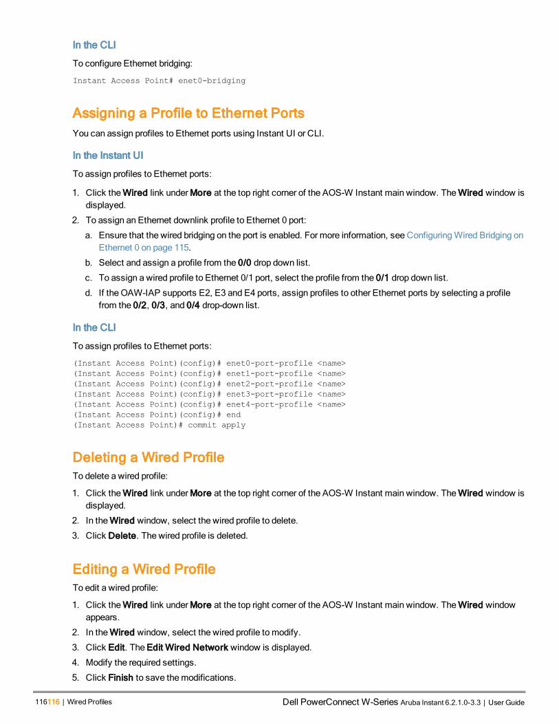
116116 | Wired Profiles Dell PowerConnect W-Series Aruba Instant 6.2.1.0-3.3 | User Guide
In the CLI
To configure Ethernet bridging:
Instant Access Point# enet0-bridging
Assigning a Profile to Ethernet PortsYou can assign profiles to Ethernet ports using Instant UI or CLI.
In the Instant UI
To assign profiles to Ethernet ports:
1. Click theWired link under More at the top right corner of the AOS-W Instant main window. TheWired window isdisplayed.
2. To assign an Ethernet downlink profile to Ethernet 0 port:
a. Ensure that the wired bridging on the port is enabled. For more information, see ConfiguringWired Bridging onEthernet 0 on page 115.
b. Select and assign a profile from the 0/0 drop down list.
c. To assign a wired profile to Ethernet 0/1 port, select the profile from the 0/1 drop down list.
d. If the OAW-IAP supports E2, E3 and E4 ports, assign profiles to other Ethernet ports by selecting a profilefrom the 0/2, 0/3, and 0/4 drop-down list.
In the CLI
To assign profiles to Ethernet ports:
(Instant Access Point)(config)# enet0-port-profile <name>
(Instant Access Point)(config)# enet1-port-profile <name>
(Instant Access Point)(config)# enet2-port-profile <name>
(Instant Access Point)(config)# enet3-port-profile <name>
(Instant Access Point)(config)# enet4-port-profile <name>
(Instant Access Point)(config)# end
(Instant Access Point)# commit apply
Deleting a Wired ProfileTo delete a wired profile:
1. Click theWired link under More at the top right corner of the AOS-W Instant main window. TheWired window isdisplayed.
2. In theWired window, select the wired profile to delete.
3. Click Delete. The wired profile is deleted.
Editing a Wired ProfileTo edit a wired profile:
1. Click theWired link under More at the top right corner of the AOS-W Instant main window. TheWired windowappears.
2. In theWired window, select the wired profile to modify.
3. Click Edit. The Edit Wired Network window is displayed.
4. Modify the required settings.
5. Click Finish to save themodifications.

AOS-W Instant 6.2.1.0-3.3|User Guide Authentication | 117
Chapter 13Authentication
This chapter provides the following information:
l Understanding AuthenticationMethods on page 117
l Supported Authentication Servers on page 119
l Understanding Encryption Types on page 120
l Understanding Authentication Survivability on page 121
l Configuring Authentication Servers on page 124
l Configuring Authentication Parameters for Virtual Controller Management Interface on page 127
l Configuring Users on page 129
l Configuring 802.1X Authentication for a Network Profile on page 130
l ConfiguringMAC Authentication for a Network Profile on page 132
l ConfiguringMAC Authentication with 802.1X Authentication on page 133
l Configuring Captive Portal Authentication on page 135
l ConfiguringMAC Authentication with Captive Portal Authentication on page 144
l Configuring Captive Portal Roles for an SSID with 802.1x authentication on page 142
l ConfiguringWalled Garden Access on page 146
l ConfiguringWISPr Authentication on page 146
l Blacklisting Clients on page 148
l Uploading Certificates on page 150
Understanding Authentication MethodsAuthentication is a process of identifying a user by through a valid username and password. Clients can also beauthenticated based on their MAC addresses.
The following authenticationmethods are supported in AOS-W Instant:
l 802.1X authentication — 802.1X is amethod for authenticating the identity of a user before providing networkaccess to the user. Remote Authentication Dial In User Service (RADIUS) is a protocol that provides centralizedauthentication, authorization, and accountingmanagement. For authentication purpose, the wireless client canassociate to a network access server (NAS) or RADIUS client such as a wireless OAW-IAP. The wireless clientcan pass data traffic only after successful 802.1X authentication. For more information on configuring anOAW-IAP to use 802.1X authentication, see Configuring 802.1X Authentication for a Network Profile on page 130.
l MAC authentication — Media Access Control (MAC) authentication is used for authenticating devices based ontheir physical MAC addresses. MAC authentication requires that theMAC address of amachinematches amanually defined list of addresses. This authenticationmethod is not recommended for scalable networks andthe networks that require stringent security settings. For more information on configuring anOAW-IAP to useMAC authentication, see ConfiguringMAC Authentication for a Network Profile on page 132.
l MAC authentication with 802.1X authentication —This authenticationmethod has the following features:
n MAC authentication precedes 802.1X authentication - The administrators can enableMAC authentication for802.1X authentication. MAC authentication shares all the authentication server configurations with 802.1Xauthentication. If a wireless or wired client connects to the network, MAC authentication is performed first. IfMAC authentication fails, 802.1X authentication does not trigger. If MAC authentication is successful, 802.1X

118118 | Authentication Dell PowerConnect W-Series Aruba Instant 6.2.1.0-3.3 | User Guide
authentication is attempted. If 802.1X authentication is successful, the client is assigned an 802.1Xauthentication role. If 802.1X authentication fails, the client is assigned a deny-all role or mac-auth-only role.
n MAC authentication only role - Allows you to create amac-auth-only role to allow role-based access ruleswhenMAC authentication is enabled for 802.1X authentication. Themac-auth-only role is assigned to aclient when theMAC authentication is successful and 802.1X authentication fails. If 802.1X authentication issuccessful, themac-auth-only role is overwritten by the final role. Themac-auth-only role is primarily usedfor wired clients.
n L2 authentication fall-through - Allows you to enable the l2-authentication-fallthrough mode. When thisoption is enabled, the 802.1X authentication is allowed even if theMAC authentication fails. If this option isdisabled, 802.1X authentication is not allowed. The l2-authentication-fallthrough mode is disabled bydefault.
For more information on configuring anOAW-IAP to useMAC + 802.1X Authentication, see ConfiguringMACAuthentication with 802.1X Authentication on page 133.
l Captive Portal — Captive portal authentication is used for authenticating guest users. For more information onCaptive Portal authentication, see Configuring Captive Portal Authentication on page 135.
l MAC authentication with Captive Portal authentication—This authenticationmethod has the followingfeatures:
n If the captive portal splash page type is Internal-Authenticated or External-RADIUS Server, MACauthentication reuses the server configurations.
n If the captive portal splash page type is Internal-Acknowledged or External-Authentication Text andMACauthentication is enabled, a server configuration page is displayed.
n If the captive portal splash page type is none, MAC authentication is disabled.
n You can configure themac-auth-only role whenMAC authentication is enabled with captive portalauthentication.
For more information configuring anOAW-IAP to useMAC and Captive Portal authentication, see ConfiguringMAC Authentication with Captive Portal Authentication on page 144.
l 802.1X authentication with Captive Portal authentication — This authenticationmechanism allows you toconfigure different Captive portal settings for clients on the same SSID. For example, you can configure an802.1x SSID and create a role with for captive portal access, so that some of the clients using the SSID derivethe Captive portal role. You can configure rules to indicate access to external or internal Captive portal, or none.For more information on configuring Captive portal roles for an SSID with 802.1x authentication, see ConfiguringCaptive Portal Roles for an SSID with 802.1x authentication on page 142.
l WISPr authentication—Wireless Internet Service Provider roaming (WISPr) authentication allows a smart clientto authenticate on the network when they roam between wireless Internet service providers, even if the wirelesshotspot uses an Internet Service Provider (ISP) with whom the client may not have an account.
If a hotspot is configured to useWISPr authentication in a specific ISP and a client attempts to access theInternet at that hotspot, theWISPr AAA server configured for the ISP authenticates the client directly and allowsthe client to access the network. If the client only has an account with a partner ISP, theWISPr AAA serverforwards the client’s credentials to the partner ISP’s WISPr AAA server for authentication. When the client isauthenticated on the partner ISP, it is also authenticated on your hotspot’s own ISP as per their serviceagreements. TheOAW-IAP assigns the default WISPr user role to the client when your ISP sends anauthenticationmessage to the OAW-IAP. For more information onWISPr authentication, see ConfiguringWISPrAuthentication on page 146.

Supported Authentication ServersBased on the security requirements, you can configure internal or external RADIUS servers. This section describesthe following types of authentication servers and authentication termination, which can be configured for a networkprofile:
l External RADIUS Server on page 119
l Internal RADIUS Server on page 119
l Authentication Termination onOAW-IAP on page 120
External RADIUS Server
In the external RADIUS server, the IP address of the Virtual Controller is configured as the NAS IP address. InstantRADIUS is implemented on the Virtual Controller, and this eliminates the need to configuremultiple NAS clients forevery OAW-IAP on the RADIUS server for client authentication. Instant RADIUS dynamically forwards all theauthentication requests from aNAS to a remote RADIUS server. The RADIUS server responds to theauthentication request with an Access-Accept or Access-Reject message, and users are allowed or denied accessto the network depending on the response from the RADIUS server.
When you enable an external RADIUS server for the network, the client on the OAW-IAP sends a RADIUS packetto the local IP address. The external RADIUS server then responds to the RADIUS packet.
Instant supports the following external authentication servers:
l RADIUS (Remote Authentication Dial-In User Service)
l LDAP (Lightweight Directory Access Protocol)
l CPPM Server for AirGroup CoA
To use an LDAP server for user authentication, configure the LDAP server on the Virtual Controller, and configureuser IDs and passwords.
To use a RADIUS server for user authentication, configure the RADIUS server on the Virtual Controller.
RADIUS Server Authentication with VSA
An external RADIUS server authenticates network users and returns to the OAW-IAP the vendor-specific attribute(VSA) that contains the name of the network role for the user. The authenticated user is placed into themanagementrole specified by the VSA.
For a complete list of VSAs supported by Instant, see Supported VSAs on page 170.
Internal RADIUS Server
EachOAW-IAP has an instance of free RADIUS server operating locally. When you enable the Internal RADIUSserver option for the network, the client on the OAW-IAP sends a RADIUS packet to the local IP address. TheInternal RADIUS server listens and replies to the RADIUS packet.
The following authenticationmethods are supported in AOS-W Instant network:
l EAP-TLS— The Extensible Authentication Protocol-Transport Layer Security (EAP-TLS)method supports thetermination of EAP-TLS security using the internal RADIUS server. The EAP-TLS requires both server andcertification authority (CA) certificates installed on theOAW-IAP. The client certificate is verified on the VirtualController (the client certificate must be signed by a knownCA), before the username is verified on theauthentication server.
l EAP-TTLS (MSCHAPv2)— The Extensible Authentication Protocol-Tunneled Transport Layer Security (EAP-TTLS)method uses server-side certificates to set up authentication between clients and servers. However, theactual authentication is performed using passwords.
AOS-W Instant 6.2.1.0-3.3|User Guide Authentication | 119

120120 | Authentication Dell PowerConnect W-Series Aruba Instant 6.2.1.0-3.3 | User Guide
l EAP-PEAP (MSCHAPv2)— EAP-PEAP is an 802.1X authenticationmethod that uses server-side public keycertificates to authenticate clients with server. The PEAP authentication creates an encrypted SSL / TLS tunnelbetween the client and the authentication server. Exchange of information is encrypted and stored in the tunnelensuring the user credentials are kept secure.
l LEAP— Lightweight Extensible Authentication Protocol (LEAP) uses dynamic WEP keys for authenticationbetween the client and authentication server.
To useOAW-IAP’s internal database for user authentication, add the names and passwords of the users to beauthenticated.
Alcatel-Lucent does not recommend the use of LEAP authenticationmethod, because it does not provideany resistance to network attacks.
Authentication Termination on OAW-IAP
AOS-W Instant allows Extensible Authentication Protocol (EAP) termination for Protected Extensible AuthenticationProtocol (PEAP)-Generic Token Card (PEAP-GTC) and Protected Extensible Authentication Protocol-MicrosoftChallenge Authentication Protocol version 2 (PEAP-MSCHAV2). PEAP-GTC termination allows authorizationagainst an Lightweight Directory Access Protocol (LDAP) server and external RADIUS server while PEAP-MSCHAV2 allows authorization against an external RADIUS server.
This allows the users to run PEAP-GTC termination with their username and password to a local Microsoft ActiveDirectory server with LDAP authentication.
l EAP-Generic Token Card (GTC)— This EAP method permits the transfer of unencrypted usernames andpasswords from client to server. Themain uses for EAP-GTC are one-time token cards such as SecureID andthe use of LDAP or RADIUS as the user authentication server. You can also enable caching of user credentialson the OAW-IAP to an external authentication server for user data backup.
l EAP-Microsoft Challenge Authentication Protocol version 2 (MS-CHAPv2)— This EAP method is widelysupported by Microsoft clients. A RADIUS server must be used as the back-end authentication server.
Understanding Encryption TypesEncryption is the process of converting data into a cryptic format or code when it is transmitted on a network.Encryption prevents unauthorized use of the data.
Instant supports the following types of encryption:
l WEP —Wired Equivalent Privacy (WEP) is an authenticationmethod where all users share the same key. WEPis not secure as other encryption types such as TKIP.
l TKIP —Temporal Key Integrity Protocol (TKIP) uses the same encryption algorithm as WEP. However, TKIP ismore secure and has an additional message integrity check (MIC).
l AES — The Advanced Encryption Standard (AES) encryption algorithm awidely supported encryption type for allwireless networks that contain any confidential data. AES inWi-Fi leverages 802.1X or PSKs to generate perstation keys for all devices. AES provides a high level of security like IP Security (IPsec) clients.
WEP and TKIP are limited toWLAN connection speed of 54Mbps. The 802.11n connection supportsonly AES encryption. Alcatel-Lucent recommends AES encryption. Ensure that all devices that do notsupport AES are upgraded or replaced with the devices that support AES encryption.
WPA and WPA2
WPA is created based on a draft of 802.11i, which allowed users to createmore secureWLANs. WPA2encompasses the full implementation of the 802.11i standard. WPA2 is a superset that encompasses the full WPA

feature set.
The following table summarizes the differences between the two certifications:
Certification Authentication Encryption
WPA l PSKl IEEE 802.1X with
ExtensibleAuthenticationProtocol (EAP)
TKIP with message integrity check (MIC)
WPA2 l PSKl IEEE 802.1X with
EAP
AES -- Counter Mode with Cipher Block ChainingMessage Authentication Code (AESCCMP)
Table 17:WPA andWPA2 Features
WPA andWPA2 can be further classified as follows:
l Personal — Personal is also called Pre-Shared Key (PSK). In this type, a unique key is shared with each client inthe network. Users have to use this key to securely log in to the network. The key remains the same until it ischanged by authorized personnel. You can also configure key change intervals .
l Enterprise — Enterprise is more secure thanWPA Personal. In this type, every client automatically receives aunique encryption key after securely logging on to the network. This key is automatically updated at regularintervals. WPA uses TKIP andWPA2 uses the AES algorithm.
Recommended Authentication and Encryption Combinations
The following table summarizes the recommendations for authentication and encryption combinations for theWi-Finetworks.
Network Type Authentication Encryption
Employee 802.1X AES
Guest Network Captive Portal None
Voice Network or Handhelddevices
802.1X or PSK assupported by the device
AES if possible, TKIP or WEP ifnecessary (combine with securitysettings assigned for a user role).
Table 18: Recommended Authentication and Encryption Combinations
Understanding Authentication SurvivabilityThe authentication survivability feature supports authorization survivability against remote link failure for MobilityControllers when working with ClearPass Policy Manager (CPPM).
When enabled, this feature allows Instant to authenticate the previously connected clients using EAP-PEAPauthentication even when connectivity to ClearPass Policy Manager is temporarily lost.
The following figure illustrates the scenario where the OAW-IAP offloads EAP method authentication to ClearPassover a remote link connection. After authenticating the user against Active Directory and deriving enforcementattributes for the user, the ClearPass Policy Manager returns additional information in the RADIUS Access-Acceptmessage, which the OAW-IAP caches to support authentication survivability.
AOS-W Instant 6.2.1.0-3.3|User Guide Authentication | 121

122122 | Authentication Dell PowerConnect W-Series Aruba Instant 6.2.1.0-3.3 | User Guide
As shown in the following figure, the information sent by the CPPM varies depending on the authenticationmethodused.
Figure 39 802.1X Authentication when CPPM is reachable
The following figure illustrates a scenario where when the remote link is not available and the IAP is no longer able toreach the CPPM. Here, the OAW-IAP terminates and completes the EAP authentication using the cachedcredentials.
If both the OAW-IAP to which the client was associated and the CPPM are not available, the client will benot be able to reauthenticate until the CPPM server is available again.

Figure 40 802.1X Authentication using cached credentials
The following figure illustrates a scenario where the CPPM link is available again. TheOAW-IAP sends theRADIUS-Request message to the CPPM server directly for client authentication.
Figure 41 802.1X Authentication when CPPM is reachable again
AOS-W Instant 6.2.1.0-3.3|User Guide Authentication | 123

124124 | Authentication Dell PowerConnect W-Series Aruba Instant 6.2.1.0-3.3 | User Guide
You can enable authentication survivability for a wireless network profile when configuring enterprise securityparameters. For more information, see Configuring Security Settings for aWLAN SSID Profile on page 84.
Configuring Authentication ServersThis section describes the following procedures:
l Configuring an External Server for Authentication on page 124
l Enabling RADIUS Server Support on page 127
Configuring an External Server for Authentication
You can add an external RADIUS server using the Instant UI or CLI.
In the Instant UI
To configure an authentication server:
1. Click the Security link at the top right corner of the Instant main window. The Security window is displayed.
2. To create a new server, click New. A window for specifying details for the new server is displayed. The followingfigure shows the parameters to configure for a new authentication server configuration:
Figure 42 New Authentication ServerWindow
3. Configure any of the following types of server:
l RADIUS Server — To configure a RADIUS server, specify the attributes described in the following table:
Parameter Description
Name Enter the name of the new external RADIUS server.
IP address Enter the IP address of the external RADIUS server.
Table 19: RADIUS Server Configuration Parameters

Parameter Description
Auth port Enter the authorization port number of the external RADIUS server. The default portnumber is 1812.
Accounting port Enter the accounting port number. This port is used for sending accounting recordsto the RADIUS server. The default port number is 1813.
Shared key Enter a shared key for communicating with the external RADIUS server.
Retype key Re-enter the shared key.
Timeout Specify a timeout value in seconds. The value determines the timeout for oneRADIUS request. The OAW-IAP retries to send the request several times (asconfigured in the Retry count), before the user gets disconnected. For example, ifthe Timeout is 5 seconds, Retry counter is 3, user is disconnected after 20seconds. The default value is 5 seconds.
Retry count Specify a number between 1 and 5. Indicates the maximum number ofauthentication requests that are sent to the server group, and the default value is 3requests.
RFC 3576 Select Enabled to allow the APs to process RFC 3576-compliant Change ofAuthorization (CoA) and disconnect messages from the RADIUS server.Disconnect messages cause a user session to be terminated immediately,whereas the CoA messages modify session authorization attributes such as datafilters.
NAS IP address Enter the Virtual Controller IP address. The NAS IP address is the Virtual ControllerIP address that is sent in data packets.
NOTE: If you do not enter the IP address, the Virtual Controller IP address is usedby default when Dynamic RADIUS Proxy is enabled.
NAS identifier Use this to configure strings for RADIUS attribute 32, NAS Identifier, to be sent withRADIUS requests to the RADIUS server.
l LDAP Server —To configure an LDAP server, specify the attributes described in the following table:
Parameter Description
Name Enter the name of the LDAP server.
IP address Enter the IP address of the LDAP server.
Auth port Enter the authorization port number of the LDAP server. The default port number is389.
Admin-DN Enter a distinguished name for the admin user with read/search privileges acrossall the entries in the LDAP database (the user need not have write privileges, butthe user must be able to search the database, and read attributes of other users inthe database).
Admin password Enter a password for administrator.
Base-DN Enter a distinguished name for the node which contains the entire user database.
Table 20: LDAP Server Configuration Parameters
AOS-W Instant 6.2.1.0-3.3|User Guide Authentication | 125

126126 | Authentication Dell PowerConnect W-Series Aruba Instant 6.2.1.0-3.3 | User Guide
Parameter Description
Filter Specify the filter to apply when searching for a user in the LDAP database. Thedefault filter string is (objectclass=*).
Key Attribute Specify the attribute to use as a key while searching for the LDAP server. For ActiveDirectory, the value is sAMAccountName
Timeout Enter a value between 1 and 30 seconds. The default value is 5.
Retry count Enter a value between 1 and 5. The default value is 3.
l CPPM Server for AirGroup CoA — To configure a CPPM server used for AirGroup CoA (Change ofAuthorization), select the CoA only check box. The RADIUS server is automatically selected.
Parameter Description
Name Enter the name of the server.
IP address Enter the IP address of the server.
Air Group CoA port Enter a port number for sending AirGroup CoA on a different port than on thestandard CoA port. The default value is 5999.
Shared key Enter a shared key for communicating with the external RADIUS server.
Retype key Re-enter the shared key.
Table 21: CPPM Server Configuration Parameters for AirGroupCoA
4. Click OK.
The CPPM server acts as a RADIUS server and asynchronously provides the Ai Group parameters forthe client device including shared user, role, and location.
5. To assign the RADIUS authentication server to a network profile, select the newly added server when configuringsecurity settings for a wireless or wired network profile.
You can also add an external RADIUS server by selecting New for Authentication Server whenconfiguring aWLAN or wired profile. For more information, see Configuring Security Settings for aWLANSSID Profile on page 84 and Configuring Security Settings for aWired Profile on page 111.
In the CLI
To configure a RADIUS server:
(Instant Access Point)(config)# wlan auth-server <profile-name>
(Instant Access Point)(Auth Server <profile-name>)# ip <IP-address>
(Instant Access Point)(Auth Server <profile-name>)# key <key>
(Instant Access Point)(Auth Server <profile-name>)# port <port>
(Instant Access Point)(Auth Server <profile-name>)# acctport <port>
(Instant Access Point)(Auth Server <profile-name>)# nas-id <NAS-ID>
(Instant Access Point)(Auth Server <profile-name>)# nas-ip <NAS-IP-address>
(Instant Access Point)(Auth Server <profile-name>)# timeout <seconds>
(Instant Access Point)(Auth Server <profile-name>)# retry-count <number>
(Instant Access Point)(Auth Server <profile-name>)# rfc3576
(Instant Access Point)(Auth Server <profile-name>)# end
(Instant Access Point)# commit apply

To configure an LDAP server:
(Instant Access Point)(config)# wlan ldap-server <profile-name>
(Instant Access Point)(LDAP Server <profile-name>)# ip <IP-address>
(Instant Access Point)(LDAP Server <profile-name>)# port <port>
(Instant Access Point)(LDAP Server <profile-name>)# admin-dn <name>
(Instant Access Point)(LDAP Server <profile-name>)# admin-password <password>
(Instant Access Point)(LDAP Server <profile-name>)# base-dn <name>
(Instant Access Point)(LDAP Server <profile-name>)# filter <filter>
(Instant Access Point)(LDAP Server <profile-name>)# key-attribute <key>
(Instant Access Point)(LDAP Server <profile-name>)# timeout <seconds>
(Instant Access Point)(LDAP Server <profile-name>)# retry-count <number>
(Instant Access Point)(LDAP Server <profile-name>)# end
(Instant Access Point)# commit apply
To configure a CPPM server used for AirGroup CoA (Change of Authorization):
(Instant Access Point)(config)# wlan auth-server <profile-name>
(Instant Access Point)(Auth Server <profile-name>)# ip <IP-address>
(Instant Access Point)(Auth Server <profile-name>)# key <key>
(Instant Access Point)(Auth Server <profile-name> # cppm-rfc3576-port <port>
(Instant Access Point)(Auth Server <profile-name>)# cppm-rfc3576-only
(Instant Access Point)(Auth Server <profile-name>)# end
(Instant Access Point)# commit apply
Enabling RADIUS Server Support
You can enable RADIUS Server Support using Instant UI or CLI.
In the Instant UI
To enable RADIUS server support:
1. In the Instant main window, click the System link. The System window appears.
2. In the General tab of System window, select Enabled from the Dynamic RADIUS Proxy drop-down list.
3. Click OK.
When Dynamic RADIUS Proxy enabled, the Virtual Controller network uses the IP Address of theVirtual Controller for communication with external RADIUS servers. Ensure that the Virtual Controller IPAddress is set as a NAS IP when configuring RADIUS server attributes with Dynamic RADIUS proxyenabled. For more information on configuring RADIUS server attributes, see Configuring an ExternalServer for Authentication on page 124.
In the CLI
To enable the dynamic RADIUS proxy feature:
(Instant Access Point)(config)# dynamic-radius-proxy
(Instant Access Point)(config)# end
(Instant Access Point)# commit apply
Configuring Authentication Parameters for Virtual ControllerManagement InterfaceYou can configure authentication settings to access to the Virtual Controller management user interface in theInstant UI or CLI.
In the Instant UI
1. Click the System link at top right corner of the Instant main window. The System window appears.
AOS-W Instant 6.2.1.0-3.3|User Guide Authentication | 127

128128 | Authentication Dell PowerConnect W-Series Aruba Instant 6.2.1.0-3.3 | User Guide
2. Select the Admin tab. The Admin tab details are displayed. The following figure shows the contents of the Admintab:
Figure 43 Admin Tab: Management Authentication Parameters
3. Under Local, select any of the following options from the Authentication drop-down list:
l Internal— Select this option to specify a single set of user credentials. Enter the Username and Password foraccessing the Virtual Controller Management User Interface.
l RADIUS Server— Specify one or two RADIUS servers to authenticate clients. If two servers are configured,users can use them in primary or backupmode or load balancingmode. To enable load balancing, selectEnabled from the Load balancing drop-down list.
l RADIUS server w/ fallback to internal— Select this option to use both internal and external servers. Whenenabled, the authentication switches to Internal if there is no response from the RADIUS server (RADIUSserver timeout). To complete this configuration, perform the following steps:
a. To enable load balancing, select Enabled from the Load balancing drop-down list.
b. Specify a Username and Password.
c. Retype the password to confirm.
4. Click OK.
In the CLI
To configuremanagement authentication settings:
(Instant Access Point) (config)# mgmt-auth-server <server1>
(Instant Access Point) (config)# mgmt-auth-server <server2>
(Instant Access Point) (config)# mgmt-auth-server-load-balancing

(Instant Access Point) (config)# mgmt-auth-server-local-backup
(Instant Access Point) (config)# end
(Instant Access Point) (config)# commit apply
Configuring UsersThe AOS-W Instant user database consists of a list of guest and employee users. Addition of a user involvesspecifying a login credentials for a user. The login credentials for these users are provided outside the AOS-WInstant system.
A guest user can be a visitor who is temporarily using the enterprise network to access the Internet. However, if youdo not want to allow access to the internal network and the Intranet, you can segregate the guest traffic from theenterprise traffic by creating a guest WLAN and specifying the required authentication, encryption, and access rules.
An employee user is the employee who is using the enterprise network for official tasks. You can create EmployeeWLANs, specify the required authentication, encryption and access rules and allow the employees to use theenterprise network.
The user database is also used when anOAW-IAP is configured as an internal RADIUS server.
The local user database of APs can support up to 512 user entries except OAW-IAP93. OAW-IAP93supports only 256 user entries. If there are already 512 users, OAW-IAP93 will not be able to join thecluster.
You can add a user by using the Instant UI or CLI.
In the Instant UI
To configure users:
1. Click the Security at the top right corner of Instant main window.
2. Click Users for Internal Server. The following figure shows the contents of the Users for Internal Server tab.
Figure 44 Adding a User
AOS-W Instant 6.2.1.0-3.3|User Guide Authentication | 129

130130 | Authentication Dell PowerConnect W-Series Aruba Instant 6.2.1.0-3.3 | User Guide
3. Enter the username in the Username text box.
4. Enter the password in the Password text box and reconfirm.
5. Select a type of network from the Type drop-down list.
6. Click Add and click OK. The users are listed in the Users list.
7. To edit user settings:
a. Select the user to modify under Users
b. Click Edit to modify user settings.
c. Click OK.
8. To delete a user:
a. In the Users section, select the username to delete
b. Click Delete.
c. Click OK.
9. To delete all or multiple users at a time:
a. Select the usernames that you want to delete
b. Click Delete All.
c. Click OK.
Deleting a user only removes the user record from the user database, and will not disconnect the onlineuser associated with the username.
In the CLI
To configure an employee user:(Instant Access Point)(config)# user <username> <password> radius
(Instant Access Point)(config)# end
(Instant Access Point)# commit apply
To configure a guest user:(Instant Access Point)(config)# user <username> <password> portal
(Instant Access Point)(config)# end
(Instant Access Point)# commit apply
Configuring 802.1X Authentication for a Network ProfileThe AOS-W Instant network supports internal RADIUS server and external RADIUS server for 802.1Xauthentication.
The steps involved in 802.1X authentication are as follows:
1. The NAS requests authentication credentials from awireless client.
2. The wireless client sends authentication credentials to the NAS.
3. The NAS sends these credentials to a RADIUS server.
4. The RADIUS server checks the user identity and authenticates the client if the user details are available in itsdatabase. The RADIUS server sends an Access-Accept message to the NAS. If the RADIUS server cannotidentify the user, it stops the authentication process and sends an Access-Reject message to the NAS. TheNAS forwards this message to the client and the client must re-authenticate with appropriate credentials.
5. After the client is authenticated, the RADIUS server forwards the encryption key to the NAS. The encryption keyis used for encrypting or decrypting traffic sent to and from the client.
The NAS acts as a gateway to guard access to a protected resource. A client connecting to the wirelessnetwork first connects to the NAS.

Configuring 802.1X authentication for a Wireless Network Profile
You can configure 802.1X authentication for a wireless network profile in the Instant UI or CLI.
In the Instant UI
To enable 802.1X authentication for a wireless network:
1. In the Network tab, click New to create a new network profile or select an existing profile for which you want toenable 802.1X authentication and click edit.
2. In the Edit <profile-name> or New WLAN window, ensure that all requiredWLAN and VLAN attributes aredefined, and then click Next.
3. In the Security tab, specify the following parameters for the Enterprise security level:
a. Select any of the following options from the Key management drop-down list.
l WPA-2 Enterprise
l WPA Enterprise
l Both (WPA-2 & WPA)
l Dynamic WEP with 802.1X
4. If you do not want to use a session key from the RADIUS Server to derive pair wise unicast keys, set SessionKey for LEAP to Enabled.
5. To terminate the EAP portion of 802.1X authentication on theOAW-IAP instead of the RADIUS server, setTermination to Enabled.
By default, for 802.1X authorization, the client conducts an EAP exchange with the RADIUS server, and the APacts as a relay for this exchange. When Termination is enabled, the OAW-IAP by itself acts as an authenticationserver and terminates the outer layers of the EAP protocol, only relaying the innermost layer to the externalRADIUS server.
6. Specify the type of authentication server to use and configure other required parameters. For more information onconfiguration parameters, see Configuring Security Settings for aWLAN SSID Profile on page 84
7. Click Next to define access rules, and then click Finish to apply the changes.
In the CLI
To configure 802.1X authentication for a wireless network:
(Instant Access Point) (config)# wlan ssid-profile <SSID-Name>
(Instant Access Point) (SSID Profile <"profile-name>")# type {<Employee>|<Voice>}
(Instant Access Point) (SSID Profile <"profile-name>")# opmode {<opensystem> |<wpa2-ae>|<wpa2-
psk-aes>|<wpa-tkip>|<wpa-psk-tkip>|<wpa-tkip>|<wpa2-aes>|<wpa-psk-tkip>|<wpa2-psk-aesstatic-
wep>|<dynamic-wep>}
(Instant Access Point) (SSID Profile <"profile-name>")# leap-use-session-key
(Instant Access Point) (SSID Profile <"profile-name>")# termination
(Instant Access Point) (SSID Profile <"profile-name>")# external-server
(Instant Access Point) (SSID Profile <"profile-name>")# auth-server <server-name>
(Instant Access Point) (SSID Profile <"profile-name>")# auth-survivability
(Instant Access Point) (SSID Profile <"profile-name>")# auth-survivability cache-time-out
<hours>
(Instant Access Point) (SSID Profile <"profile-name>")# radius-reauth-interval <minutes>
(Instant Access Point) (SSID Profile <"profile-name>")# end
(Instant Access Point)# commit apply
Configuring 802.1X authentication for Wired Profiles
You can configure 802.1X authentication for a wired profile in the Instant UI or CLI.
In the Instant UI
To enable 802.1X authentication for a wired profile:
AOS-W Instant 6.2.1.0-3.3|User Guide Authentication | 131

132132 | Authentication Dell PowerConnect W-Series Aruba Instant 6.2.1.0-3.3 | User Guide
1. Click theWired link under More at the top right corner of the AOS-W Instant main window. TheWired window isdisplayed.
2. Click New underWired Networks to create a new network or select an existing profile for which you want toenable 802.1X authentication and then click Edit.
3. In the New Wired Network or the Edit Wired Network window, ensure that all the requiredWired and VLANattributes are defined, and then click Next.
4. In the Security tab, select Enabled from the 802.1X authentication drop-down list.
5. Specify the type of authentication server to use and configure other required parameters. For more information onconfiguration parameters, see Configuring Security Settings for aWired Profile on page 111
6. Click Next to define access rules, and then click Finish to apply the changes.
7. Assign the profile to an Ethernet port. For more information, see Assigning a Profile to Ethernet Ports on page116.
In the CLI
To enable 802.1X authentication for a wired profile:
(Instant Access Point) (config)# wired-port-profile <profile-name>
(Instant Access Point) (wired ap profile <profile-name>)# type {<employee> |<guest>}
(Instant Access Point) (wired ap profile <profile-name>)# dot1x
(Instant Access Point) (wired ap profile <profile-name>)# auth-server <server1>
(Instant Access Point) (wired ap profile <profile-name>)# auth-server <server1>
(Instant Access Point) (wired ap profile <profile-name>)# server-load-balancing
(Instant Access Point) (wired ap profile <profile-name>)# radius-reauth-interval <Minutes>
(Instant Access Point) (wired ap profile <profile-name>)# end
(Instant Access Point)# commit apply
Configuring MAC Authentication for a Network ProfileMAC authentication can be used alone or it can be combined with other forms of authentication such as WEPauthentication. However, it is recommended that you do not use theMAC-based authentication.
This section describes the following procedures:
l ConfiguringMAC Authentication forWireless Network Profiles on page 132
l ConfiguringMAC Authentication forWireless Network Profiles on page 132
Configuring MAC Authentication for Wireless Network Profiles
You can configureMAC authentication for a wired profile in the Instant UI or CLI.
In the Instant UI
To enableMAC Authentication for a wireless network:
1. In the Network tab, click New to create a new network profile or select an existing profile for which you want toenableMAC authentication and click edit.
2. In the Edit <profile-name> or New WLAN window, ensure that all requiredWLAN and VLAN attributes aredefined, and then click Next.
3. In the Security tab, select Enabled from theMAC authentication drop-down list, for Personal or Opensecurity level.
4. Specify the type of authentication server to use and configure other required parameters. For more information onconfiguration parameters, see Configuring Security Settings for aWLAN SSID Profile on page 84
5. Click Next to define access rules, and then click Finish to apply the changes.

In the CLI
To configure aWLAN SSID profile in the CLI:
(Instant Access Point)(config)# wlan ssid-profile <SSID-Name>
(Instant Access Point)(SSID Profile <name>)# type {<Employee> | <Voice>| <Guest>}
(Instant Access Point)(SSID Profile <name>)# mac-authentication
(Instant Access Point)(SSID Profile <name>)# external-server
(Instant Access Point)(SSID Profile <name>)# auth-server <server-name1>
(Instant Access Point)(SSID Profile <name>)# auth-server <server-name2>
(Instant Access Point)(SSID Profile <name>)# server-load-balancing
(Instant Access Point)(SSID Profile <name>)# radius-reauth-interval <minutes>
(Instant Access Point)(SSID Profile <name>)# end
(Instant Access Point)# commit apply
Configuring MAC Authentication for Wired Profiles
You can configureMAC authentication for a wired profile in the Instant UI or CLI.
In the Instant UI
To enableMAC authentication for a wired profile:
1. Click theWired link under More at the top right corner of the AOS-W Instant main window. TheWired window isdisplayed.
2. Click New underWired Networks to create a new network or select an existing profile for which for which youwant to enableMAC authentication and then click Edit.
3. In the New Wired Network or the Edit Wired Network window, ensure that all the requiredWired and VLANattributes are defined, and then click Next.
4. In the Security tab, select Enabled from theMAC authentication drop-down list.
5. Specify the type of authentication server to use and configure other required parameters. For more information onconfiguration parameters, see Configuring Security Settings for aWired Profile on page 111
6. Click Next to define access rules, and then click Finish to apply the changes.
In the CLI
To enableMAC authentication for a wired profile:
(Instant Access Point)(config)# wired-port-profile <profile-name>
(Instant Access Point)(wired ap profile <name>)# type {<employee> |<guest>}
(Instant Access Point)(wired ap profile <name>)# mac-authentication
(Instant Access Point)(wired ap profile <name>)# auth-server <server-1>
(Instant Access Point)(wired ap profile <name>)# auth-server <server-2>
(Instant Access Point)(wired ap profile <name>)# server-load-balancing
(Instant Access Point)(wired ap profile <name>)# radius-reauth-interval <Minutes>
(Instant Access Point)(wired ap profile <name>)# end
(Instant Access Point)# commit apply
Configuring MAC Authentication with 802.1X AuthenticationThis section describes the following procedures:
l ConfiguringMAC and 802.1X Authentication for aWireless Network Profile on page 133
l ConfiguringMAC and 802.1X Authentication forWired Profiles on page 134
Configuring MAC and 802.1X Authentication for a Wireless Network Profile
You can configureMAC authentication with 802.1X authentication for wireless network profile using Instant UI orCLI.
AOS-W Instant 6.2.1.0-3.3|User Guide Authentication | 133

134134 | Authentication Dell PowerConnect W-Series Aruba Instant 6.2.1.0-3.3 | User Guide
In the Instant UI
To configure bothMAC and 802.1X authentication for a wireless network:
1. In the Network tab, click New to create a new network profile or select an existing profile for which you want toenableMAC and 802.1X authentication and click edit.
2. In the Edit <profile-name> or New WLAN window, ensure that all requiredWLAN and VLAN attributes aredefined, and then click Next.
3. In the Security tab, ensure that the required parameters for MAC authentication and 802.1X authentication areconfigured.
4. Select the Perform MAC authentication before 802.1X check box to use 802.1X authentication only when theMAC authentication is successful.
5. Select the check box MAC authentication fail-thru to use 802.1X authentication even when theMACauthentication fails.
6. Click Next and then click Finish to apply the changes.
In the CLI
To configure bothMAC and 802.1X authentication for a wireless network:
(Instant Access Point)(config)# wlan ssid-profile <SSID-Name>
(Instant Access Point)(SSID Profile <Name>)# type {<Employee> | <Voice>| <Guest>}
(Instant Access Point)(SSID Profile <Name>)# mac-authentication
(Instant Access Point)(SSID Profile <Name>)# l2-auth-failthrough
(Instant Access Point)(SSID Profile <Name>)# auth-server <server-name1>
(Instant Access Point)(SSID Profile <Name>)# auth-survivability
(Instant Access Point)(SSID Profile <Name>)# auth-survivability cache-time-out <hours>
(Instant Access Point)(SSID Profile <Name>)# radius-reauth-interval <minutes>
(Instant Access Point)(SSID Profile <Name>)# end
(Instant Access Point)# commit apply
Configuring MAC and 802.1X Authentication for Wired Profiles
You can configureMAC and 802.1X authentication for a wired profile in the Instant UI or CLI.
In the Instant UI
To enableMAC and 802.1X authentication for a wired profile:
1. Click theWired link under More at the top right corner of the AOS-W Instant main window. TheWired window isdisplayed.
2. Click New underWired Networks to create a new network or select an existing profile for which for which youwant to enableMAC authentication and then click Edit.
3. In the New Wired Network or the Edit Wired Network window, ensure that all the requiredWired and VLANattributes are defined, and then click Next.
4. In the Security tab, enable the following options:
l Select Enabled from theMAC authentication drop-down list.
l Select Enabled from the 802.1X authentication drop-down list.
l Select Enabled from theMAC authentication fail-thru drop-down list.
5. Specify the type of authentication server to use and configure other required parameters. For more information onconfiguration parameters, see Configuring Security Settings for aWired Profile on page 111
6. Click Next to define access rules, and then click Finish to apply the changes.
In the CLI
To enableMAC and 802.1X authentication for a wired profile:

(Instant Access Point)(config)# wired-port-profile <profile-name>
(Instant Access Point)(wired ap profile <profile-name>)# type {<employee> |<guest>}
(Instant Access Point)(wired ap profile <profile-name>)# mac-authentication
(Instant Access Point)(wired ap profile <profile-name>)# dot1x
(Instant Access Point)(wired ap profile <profile-name>)# l2-auth-failthrough
(Instant Access Point)(wired ap profile <profile-name>)# auth-server <name>
(Instant Access Point)(wired ap profile <profile-name>)# server-load-balancing
(Instant Access Point)(wired ap profile <profile-name>)# radius-reauth-interval <Minutes>
(Instant Access Point)(wired ap profile <profile-name>)# end
(Instant Access Point)# commit apply
Configuring Captive Portal Authentication AOS-W Instant network supports captive portal authenticationmethod for a Guest network type. In this method, aweb page is displayed to a guest user who tries to access the Internet. The user has to authenticate or acceptcompany's network usage policy in the web page.
Instant supports both internal and external captive portal authentication.
This section describes the following procedures:
l Configuring Internal Captive Portal for Guest Network on page 135
l Customizing a Splash Page Design on page 138
l Configuring External Captive Portal for a Guest Network on page 138
l Configuring External Captive Portal Authentication Using ClearPass Guest on page 141
l Disabling Captive Portal Authentication on page 141
Configuring Internal Captive Portal for Guest Network
In the Internal Captive Portal type, an internal server is used for hosting the captive portal service.
Instant supports the following types of internal captive portal authentication:
l Internal Authenticated— When Internal Authenticated is enabled, a guest user must authenticate in thecaptive portal page to access the wireless network. The guest users who are required to authenticate must beadded to the user database.
l Internal Acknowledged— When Internal Acknowledged is enabled, a guest user must accept the terms andconditions to access the wireless network.
This section describes the following procedures:
l Configuring Internal Captive Portal Authentication forWireless Network Profile on page 135
l Configuring Internal Captive Portal Authentication forWireless Network Profile on page 135
Configuring Internal Captive Portal Authentication for Wireless Network Profile
You can configure internal captive portal authentication when adding or editing a guest network created for wirelessor wired profile. You can use Instant UI or CLI to configure captive portal authentication.
In the Instant UI
To configure internal captive portal authentication for a wireless network profile:
1. In the Network tab, click New to create a new network profile or select an existing profile for which you want toenable internal captive portal authentication and click edit.
2. In the Edit <profile-name> or New WLAN window, ensure that all requiredWLAN and VLAN attributes aredefined, and then click Next.
3. In the Security tab:
AOS-W Instant 6.2.1.0-3.3|User Guide Authentication | 135

136136 | Authentication Dell PowerConnect W-Series Aruba Instant 6.2.1.0-3.3 | User Guide
a. Select any of the following from the Splash page type drop-down list.
l Internal - Authenticated
l Internal - Acknowledged
b. Select Enabled from theWISPr drop-down list to enable theWISPr authentication for InternalAuthenticated splash page. For more information onWISPr authentication, see ConfiguringWISPrAuthentication on page 146.
c. Select Enabled from theMAC authentication drop-down list to enable theMAC authentication. Forinformation onMAC authentication, see ConfiguringMAC Authentication for a Network Profile on page 132.
d. Select any of the following from the Auth server 1drop-down list:
l Select a server from the list of servers if the server is already configured.
l Select Internal Server to authenticate user credentials at run time.
l Select New for configuring an new external RADIUS server for authentication. For more information onconfiguring external radius server, see Configuring an External Server for Authentication on page 124.
e. Select a value for Reauth interval to allow APs to periodically reauthenticate all associated andauthenticated clients.
f. Select an accountingmode from Accounting mode for posting accounting information at the specifiedAccounting interval. You can select either Authentication or Association mode. When the accountingmode is set to Authentication, the accounting starts only after client authentication is successful and stopswhen the client logs out of the network. If the Accountingmode is set to Association, the accounting startswhen the client associates to the network successfully and stops when the client is disconnected.
g. Select Enabled from Blacklisting drop-down list to enable blacklisting of the clients with a specific number ofauthentication failures. Specify a value for Max authentication failures to indicate themaximum number ofauthentication failures dynamic blacklisting of users who fail to authenticate the number of times specified.
h. If Internal Server is selected as an authentication server, under Internal server, click the User link to addusers for internal authentication. For more information about adding a user, see Configuring Users on page129.
i. To exclude uplink, select an uplink type under Disable if uplink type is.
4. Configure the required encryption parameters.
5. Click Next to configure access rules, and then click Finish to apply the changes.
In the CLI
To configure internal captive portal withWISPr authentication enabled:
(Instant Access Point)(config)# wlan ssid-profile <profile-name>
(Instant Access Point)(SSID Profile <name>)# essid <ESSID-name>
(Instant Access Point)(SSID Profile <name>)# type <Guest>
(Instant Access Point)(SSID Profile <name>)# captive-portal <internal-authenticated> exclude-
uplink {3G|4G|Wifi|Ethernet}
(Instant Access Point)(SSID Profile <name>)# wispr
(Instant Access Point)(SSID Profile <name>)# blacklist
(Instant Access Point)(SSID Profile <name>)# max-authentication-failures <number>
(Instant Access Point)(SSID Profile <name>)# auth-server <server-name>
(Instant Access Point)(SSID Profile <name>)# wpa-passphrase <WPA_key>
(Instant Access Point)(SSID Profile <name>)# radius-accounting
(Instant Access Point)(SSID Profile <name>)# radius-interim-accounting-interval
(Instant Access Point)(SSID Profile <name>)# radius-accounting-mode {user-association|user-
authentication}
(Instant Access Point)(SSID Profile <name>)# end
(Instant Access Point)(SSID Profile <name>)# commit apply

Configuring Internal Captive Portal Authentication for a Wired Profile
You can configure internal captive portal authentication when adding or editing a guest network created a wiredprofile. You can use Instant UI or CLI to configure captive portal authentication.
In the Instant UI
To configure internal captive portal authentication for a wired profile:
1. Click theWired link under More at the top right corner of the AOS-W Instant main window. TheWired window isdisplayed.
2. Click New underWired Networks to create a new network or select an existing profile for which you want toenable 802.1X authentication and then click Edit.
3. In the New Wired Network or the Edit Wired Network window, ensure that all the requiredWired and VLANattributes are defined, and then click Next
4. In the Security tab:
a. Select any of the following from the Splash page type drop-down list.
l Internal - Authenticated
l Internal - Acknowledged
b. Select Enabled from theMAC authentication drop-down list to enable theMAC authentication. Forinformation onMAC authentication, see ConfiguringMAC Authentication for a Network Profile on page 132.
c. Select any of the following from the Auth server 1drop-down list:
l Select a server from the list of servers if the server is already configured.
l Select Internal Server to authenticate user credentials at run time.
l Select New for configuring an new external RADIUS server for authentication. For more information onconfiguring external radius server, see Configuring an External Server for Authentication on page 124.
d. Select a value for Reauth interval to allow APs to periodically reauthenticate all associated andauthenticated clients.
e. If Internal Server is selected as an authentication server, under Internal server, click the User link to addusers for internal authentication. For more information about adding a user, see Configuring Users on page129.
f. To exclude an uplink, select the uplink type for Disable if uplink type is.
5. Configure the required encryption parameters.
6. Click Next to configure access rules, and then click Finish to apply the changes.
7. Assign the profile to an Ethernet port. For more information, see Assigning a Profile to Ethernet Ports on page 116
In the CLI
To configure internal captive portal for a wired profile:
(Instant Access Point) (config)# wired-port-profile <profile-name>
(Instant Access Point) (wired ap profile <profile-name>)# type <guest>
(Instant Access Point) (wired ap profile <profile-name>)# captive-portal {<internal-
authenticated>| <internal-acknowledged>}
(Instant Access Point) (wired ap profile <profile-name>)# captive-portal {<internal-
authenticated>| <internal-acknowledged>} exclude-uplink {3G|4G|Wifi|Ethernet}
(Instant Access Point) (wired ap profile <profile-name>)# mac-authentication
(Instant Access Point) (wired ap profile <profile-name>)# auth-server <server1>
(Instant Access Point) (wired ap profile <profile-name>)# radius-reauth-interval <Minutes>
(Instant Access Point) (wired ap profile <profile-name>)# end
(Instant Access Point)# commit apply
AOS-W Instant 6.2.1.0-3.3|User Guide Authentication | 137

138138 | Authentication Dell PowerConnect W-Series Aruba Instant 6.2.1.0-3.3 | User Guide
Customizing a Splash Page Design
A splash page is a web page that is displayed to the guest users when they are trying to access the Internet. You cancustomize the appearance of a splash page.
The customized splash page design applies to all SSID splash pages.
You can customize a splash page for internal captive portal using Instant UI or CLI.
In the Instant UI
1. Select an existing wireless or wired profile. Depending on the network profile selected, the Edit <WLAN-Profile>or Edit Wired Network window is displayed.
You can also customize splash page design in the Security tab of New WLAN and New Wired Networkwindows when configuring a new profile.
2. Navigate to the Security tab.
3. Under Splash Page Visuals, use the editor to specify text and colors for the initial page that will be displayed tothe users connecting to the network. The initial page asks for user credentials or email, depending on the splashpage type (Internal - Authenticated or Internal -Acknowledged) for which you are customizing the splash pagedesign.
a. To change the color of the splash page, click the Splash page rectangle and select the required color from theBackground Color palette.
b. To change the welcome text, click the first square box in the splash page, type the required text in theWelcome text box, and click OK. Ensure that the welcome text does not exceed 127 characters.
c. To change the policy text, click the second square in the splash page, type the required text in the Policy textbox, and click OK. Ensure that the policy text does not exceed 255 characters.
4. Click Next and then click Finish.
You can customize the captive portal page using double-byte characters. Traditional Chinese, SimplifiedChinese, and Korean are a few languages that use double-byte characters. Click on the banner, term, orpolicy in the Splash Page Visuals to modify the text in the red box. These fields accept double-bytecharacters or a combination of English and double-byte characters.
In the CLI
To customize internal captive portal splash page:
(Instant Access Point)(config)# wlan captive-portal
(Instant Access Point)(Captive Portal)# authenticated
(Instant Access Point)(Captive Portal)# background-color <color-indicator>
(Instant Access Point)(Captive Portal)# banner-color <color-indicator>
(Instant Access Point)(Captive Portal)# banner-text <text>
(Instant Access Point)(Captive Portal)# decoded-texts <text>
(Instant Access Point)(Captive Portal)# redirect-url <url>
(Instant Access Point)(Captive Portal)# terms-of-use <text>
(Instant Access Point)(Captive Portal)# use-policy <text>
(Instant Access Point)(Captive Portal)# end
(Instant Access Point)# commit apply
Configuring External Captive Portal for a Guest Network
AOS-W Instant supports external captive portal authentication. The external portal can be on the cloud or on aserver outside the enterprise network.

Configuring External Captive Portal Authentication for a Network Profile
You can configure external captive portal authentication for a network profile when adding or editing a guest networkusing Instant UI or CLI.
In the Instant UI
1. Select an existing wireless or wired profile. Depending on the network profile selected, the Edit <WLAN-Profile>or Edit Wired Network window is displayed.
You can also configure External Captive portal in the Security tab of New WLAN and New WiredNetwork windows when configuring a new wireless or wired profile.
2. In the Security tab, select any of the following options from the Splash page type drop-down:
l External - Authentication Text
l External - RADIUS Server
3. Configure the following parameters based on type of splash page you selected.
Parameter Description
WISPr Select Enabled if you want to enable WISPr authentication. For more information on WISPrauthentication, see Configuring WISPr Authentication on page 146.
NOTE: The WISPr authentication is applicable only for the External - RADIUS Server andInternal-Authenticated splash pages and is not applicable for wired profiles.
MAC authentication Select Enabled if you want to enable MAC authentication. For information on MACauthentication, see Configuring MAC Authentication for a Network Profile on page 132.
Authenticationserver
To configure Authentication server, select any of the following options:l If the server is already configured, select the server from the list.l To create new external RADIUS server, select New. For more information, see Configuring
an External Server for Authentication on page 124.
Reauth intervalSpecify a value for reauthentication interval at which the APs periodically reauthenticate allassociated and authenticated clients.
Accounting mode Select an accounting mode from Accounting mode for posting accounting information at thespecified Accounting interval. When the accounting mode is set to Authentication, the account-ing starts only after client authentication is successful and stops when the client logs out of thenetwork. If the accounting mode is set to Association, the accounting starts when the clientassociates to the network successfully and stops when the client is disconnected.
Blacklisting If you are configuring a wireless network profile, select Enabled to enable blacklisting of theclients with a specific number of authentication failures.
Max authenticationfailures
If you are configuring a wireless network profile and the Blacklisting is enabled, specify amaximum number of authentication failures after which users who fail to authenticate must bedynamically blacklisted.
Walled gardenClick the link to open the Walled Garden window. The walled garden configuration determinesaccess to the Websites. For more information, see Configuring Walled Garden Access on page146.
Table 22: External Captive Portal Configuration Parameters
AOS-W Instant 6.2.1.0-3.3|User Guide Authentication | 139

140140 | Authentication Dell PowerConnect W-Series Aruba Instant 6.2.1.0-3.3 | User Guide
Parameter Description
Disable if uplink typeis
Select the type of the uplink to exclude.
External SplashPage
Specify the following parameters:l IP or hostname— Enter the IP address or the hostname of the external splash page server.l URL— Enter the URL for the external splash page server.l Port—Enter the number of the port to use for communicating with the external splash page
serverl Redirect URL—Specify a redirect URL if you want to redirect the users to another URL.l Captive Portal failure—This field allows you to configure Internet access for the guest
clients when the external captive portal server is not available. Select Deny Internet toprevent clients from using the network, or Allow Internet to allow the guest clients to accessInternet when the external Captive portal server is not available.
l Automatic URL Whitelisting— Select Enabled or Disabled to enable or disable automaticwhitelisting of URLs. On selecting the check box for the external Captive portalauthentication, the URLs that are allowed for the unauthenticated users to access areautomatically whitelisted. In the current release, the automatic URL whitelisting is disabledby default.
l This option is enabled by default.l Auth Text—If the External Authentication splash page is selected, specify the authentication
text that must be returned by the external server after successful authentication.
Table 22: External Captive Portal Configuration Parameters
4. Click Next to continue and then click Finish to apply the changes.
In the CLI
To configure security settings for guest users of theWLAN SSID profile:
(Instant Access Point)(config)# wlan ssid-profile <SSID-Name>
(Instant Access Point)(SSID Profile <name>)# essid <ESSID-name>
(Instant Access Point)(SSID Profile <name>)# type <Guest>
(Instant Access Point)(SSID Profile <name>)# captive-portal <type> exclude-uplink
{3G|4G|Wifi|Ethernet}
(Instant Access Point)(SSID Profile <name>)# blacklist
(Instant Access Point)(SSID Profile <name>)# mac-authentication
(Instant Access Point)(SSID Profile <name>)# max-authentication-failures <number>
(Instant Access Point)(SSID Profile <name>)# auth-server <server-name>
(Instant Access Point (SSID Profile <name>)# radius-accounting
(Instant Access Point (SSID Profile <name>)# radius-interim-accounting-interval
(Instant Access Point (SSID Profile <name>)# radius-accounting-mode {user-association|user-
authentication}
(Instant Access Point)(SSID Profile <name>)# wpa-passphrase <WPA_key>
(Instant Access Point)(SSID Profile <name>)# wep-key <WEP-key> <WEP-index>
(Instant Access Point)(SSID Profile <name>)# end
(Instant Access Point)# commit apply
To configure external Captive Portal splash page:
(Instant Access Point)(config)# wlan external-captive-portal
(Instant Access Point)(External Captive Portal)# auth-text <text>
(Instant Access Point)(External Captive Portal)# port <port>
(Instant Access Point)(External Captive Portal)# redirect-url <url>
(Instant Access Point)(External Captive Portal)# server <server>
(Instant Access Point)(External Captive Portal)# url <url>
(Instant Access Point)(External Captive Portal)# end
(Instant Access Point)# commit apply
To allow Internet access to users when external Captive Portal is unavailable:
(Instant Access Point)(config)# wlan external-captive-portal

(Instant Access Point)(External Captive Portal)# server-fail-through
(Instant Access Point)(External Captive Portal)# end
(Instant Access Point)# commit apply
To enable automatic whitelisting of URLs:
(Instant Access Point)(config)# wlan external-captive-portal
(Instant Access Point)(External Captive Portal)# no auto-whitelist-disable
(Instant Access Point)(External Captive Portal)# end
(Instant Access Point)# commit apply
Disabling Captive Portal Authentication
To disable captive portal authentication, perform the following steps:
1. Select an existing wireless or wired profile. Depending on the network profile selected, the Edit <WLAN-Profile>or Edit Wired Network window is displayed.
You can also customize splash page design in the Security tab of New WLAN and New Wired Networkwindows when configuring a new profile.
2. Navigate to the Security tab.
3. Select None from the Splash page type drop-down list.
4. Click Next and then click Finish to apply the changes.
Configuring External Captive Portal Authentication Using ClearPass Guest
You can configure Instant to point to ClearPass Guest as an external Captive Portal server. With this configuration,the user authentication is performed by matching a string in the server response and RADIUS server (eitherClearPass Guest or a different RADIUS server).
Creating a Web Login page in the ClearPass Guest
The ClearPass Guest Visitor Management Appliance provides a simple and personalized user interface throughwhich operational staff can quickly and securely manage visitor network access. With ClearPass Guest, your non-technical staff have controlled access to a dedicated visitor management user database. Through a customizableweb portal, your staff can easily create an account, reset a password or set an expiry time for visitors. Visitors canbe registered at reception and provisioned with an individual guest account that defines their visitor profile and theduration of their visit. By defining a web login page on the ClearPass Guest Visitor Management Appliance, you areable to provide a customized graphical login page for visitors accessing the network.
For information on setting up the RADIUSWeb Login feature, see the RADIUS Services section in the ClearPassGuest Deployment Guide.
Configuring the RADIUS Server in Instant
To configure Instant to point to ClearPass Guest as an external Captive Portal server, perform the following steps:
1. Select an existing wireless network profile, the Edit <WLAN-Profile> window is displayed.
You can also configure RADIUS server in the Security tab of the New WLAN window when configuring anew profile.
2. In the Security tab, select External- RADIUS Server and update the following fields:
a. Enter the IP address of the ClearPass Guest server in the IP or hostname field. Obtain the ClearPass GuestIP address from your system administrator.
AOS-W Instant 6.2.1.0-3.3|User Guide Authentication | 141

142142 | Authentication Dell PowerConnect W-Series Aruba Instant 6.2.1.0-3.3 | User Guide
b. Enter /page_name.php in the URL field. This URLmust correspond to the Page Name configured in theClearPass Guest RADIUSWeb Login page. For example, if the Page Name is Alcatel-Lucent, the URLshould be /Alcatel-Lucent.php in the Instant UI.
c. Enter the Port number (generally should be 80). The ClearPass Guest server uses this port for HTTPservices.
d. To create an external RADIUS server, select New from the Authentication server 1 drop-down list. Forinformation on the new RADIUS server configuration parameters, see Configuring an External Server forAuthentication on page 124.
3. The new network appears in the Networks tab. Click the wireless network icon on your desktop and select thenew network.
4. Open any browser and type any URL. Instant redirects the URL to ClearPass Guest login page.
5. Log in to the network with the username and password specified used while configuring the RADIUS server.
Configuring Captive Portal Roles for an SSID with 802.1xauthenticationYou can configure an access rule to enforce Captive portal authentication for SSIDs with 802.1X authenticationenabled. You can configure rules to provide access to external Captive portal, internal Captive portal, or none, sothat some of the clients using this SSID can derive the Captive portal role.
The following conditions apply to the 802.1X and Captive portal authentication configuration:
l If a user role does not have Captive Portal settings configured, the Captive portal settings configured for an SSIDare applied to the client's profile.
l If the SSID does not have Captive Portal settings configured, the Captive portal settings configured for a userrole are applied to the client's profile.
l If Captive portal settings are configured for both SSID and user role, the Captive portal settings configured for auser role are applied to the client's profile.
You can create a Captive portal role for both Internal-acknowledged and External Authentication Text splashpage types.
To enforce Captive Portal role, use the Instant UI or CLI.
In the Instant UI
To create a Captive portal role:
1. Select an SSID profile. The Edit <WLAN-Profile> window is displayed.
You can also define access rules in the Access tab of the New WLAN window when configuring a newprofile.
2. In the Access tab, slide to Role-based access control using the scroll bar to specify access rules for guestusers.
3. Select a role or create a new if required.
4. Click New to add a new rule. The New Rule window is displayed.
5. In the New Rule window, specify the following parameters. The following figures show the parameters forCaptive Portal role configuration:

Figure 45 Captive Portal Rule for Internal Acknowledged Splash Page
Figure 46 Captive Portal Rule for External Authentication Text Splash Page
Field Description
Rule type Select Captive Portal from the drop-down list.
Splash PageType
Select any of following attributes:l Select Internal to configure a rule for internal captive portal authentication.l Select External to configure a rule for external captive portal authentication.
Internal If Internal is selected as splash page type, perform the following steps:l Under Splash Page Visuals, use the editor to specify text and colors for the initial
page that would be displayed to users connecting to the network. The initial page
Table 23: New Access Rule Configuration Parameters
AOS-W Instant 6.2.1.0-3.3|User Guide Authentication | 143

144144 | Authentication Dell PowerConnect W-Series Aruba Instant 6.2.1.0-3.3 | User Guide
Field Description
asks for user credentials or email, depending on the splash page type configuredl To change the color of the splash page, click the Splash page rectangle and select
the required color from the Background Color palette.l To change the welcome text, click the first square box in the splash page, type the
required text in the Welcome text box, and click OK. Ensure that the welcome textdoes not exceed 127 characters.
l To change the policy text, click the second square in the splash page, type therequired text in the Policy text box, and click OK. Ensure that the policy text doesnot exceed 255 characters.
l Specify the URL, to which you want redirect the guest users.l Click Preview to preview the Captive Portal page.
External If External is selected as splash page type, perform the following steps:l IP or hostname— Enter the IP address or the hostname of the external splash page
server.l URL— Enter the URL for the external splash page server.l Port—Enter the number of the port to use for communicating with the external
splash page serverl Redirect URL—Specify a redirect URL if you want to redirect the users to another
URL.l Captive Portal failure—This field allows you to configure Internet access for the
guest clients when the external captive portal server is not available. Select DenyInternet to prevent clients from using the network, or Allow Internet to allow theguest clients to access Internet when the external Captive portal server is notavailable.
l Automatic URL Whitelisting— Select Enabled or Disabled to enable or disableautomatic whitelisting of URLs. On selecting the check box for the external Captiveportal authentication, the URLs allowed for the unauthenticated users to access areautomatically whitelisted. In the current release, the automatic URL whitelisting isdisabled by default.
l Auth Text—If the External Authentication splash page is selected, specify theauthentication text that must be returned by the external server after successfulauthentication.
6. Click OK. The enforce captive portal rule is created and listed as an access rule.
7. Create a role assignment rule based on the user role, to which the Captive portal access rule is assigned.
8. Click Finish.
The client can connect to this SSID after authenticating with username and password. On successful login, theCaptive portal role is assigned to the client.
In the CLI
To create a Captive portal role:
(Instant Access Point)(config)# wlan access-rule <Name>
(Instant Access Point)(Access Rule <Name>)# captive-portal {external|internal}
(Instant Access Point)(Access Rule <Name>)# end
(Instant Access Point)# commit apply
Configuring MAC Authentication with Captive Portal AuthenticationThis authenticationmethod has the following features:
l If the captive portal splash page type is Internal-Authenticated or External-RADIUS Server, MACauthentication reuses the server configurations.

l If the captive portal splash page type is Internal-Acknowledged or External-Authentication Text andMACauthentication is enabled, a server configuration page is displayed.
l If the captive portal splash page type is none, MAC authentication is disabled.
l MAC authentication only role— You can use theWLAN wizard to configure themac-auth-only role in the role-based access rule configuration section whenMAC authentication is enabled with captive portal authentication.
Configuring MAC Authentication with Captive Portal Authentication
You can configure theMAC authentication with Captive Portal authentication for a network profile using the InstantUI or CLI.
In the Instant UI
1. Select an existing wireless or wired profile for which you want to enableMAC with Captive Portal authentication.Depending on the network profile selected, the Edit <WLAN-Profile> or Edit Wired Network window isdisplayed.
You can configureMAC authentication with Captive Portal authentication, in the Access tab of the NewWLAN and New Wired Network windows when configuring a new profile.
2. In the Access tab, specify the following parameters for a network with Role-Based rules:
a. Select the Enforce Machine Authentication check box whenMAC authentication is enabled for CaptivePortal. If theMAC authentication fails, the Captive Portal authentication role is assigned to the client.
b. For wireless network profile, select Enforce MAC Auth Only Role check box whenMAC authentication isenabled for Captive Portal. After successful MAC authentication, MAC auth only role is assigned to the client.
3. Click Next and then click Finish to apply the changes.
In the CLI
To configureMAC authentication with Captive Portal authentication for a wireless profile:
(Instant Access Point)(config)# wlan ssid-profile <SSID-Name>
(Instant Access Point)(SSID Profile <name>)# type <Guest>
(Instant Access Point)(SSID Profile <name>)# mac-authentication
(Instant Access Point)(SSID Profile <name>)# captive-portal <type> exclude-uplink <type>
(Instant Access Point)(SSID Profile <name>)# set-role-machine-auth <machine-authentication>
<user-authentication>
(Instant Access Point)(SSID Profile <name>)# set-role-mac-auth <MAC-authentication-only>
(Instant Access Point)(SSID Profile <name>)# end
(Instant Access Point)# commit apply
To configureMAC authentication with Captive Portal authentication for a wired profile:
(Instant Access Point)(config)# wired-port-profile <profile-name>
(Instant Access Point)(wired ap profile <name>)# type <guest>
(Instant Access Point)(wired ap profile <name>)# mac-authentication
(Instant Access Point)(wired ap profile <name>)# captive-portal <type>
(Instant Access Point)(wired ap profile <name>)# captive-portal <type> exclude-uplink {<3G>|
<4G>| <Wifi> | Ethernet}
(Instant Access Point)(wired ap profile <name>)# set-role-machine-auth <machine-only> <user-
only>
(Instant Access Point)(wired ap profile <name>)# set-role-mac-auth <mac-only>
(Instant Access Point)(wired ap profile <name>)# end
(Instant Access Point)# commit apply
AOS-W Instant 6.2.1.0-3.3|User Guide Authentication | 145

146146 | Authentication Dell PowerConnect W-Series Aruba Instant 6.2.1.0-3.3 | User Guide
Configuring Walled Garden AccessOn the Internet, a walled garden typically controls access to web content and services. TheWalled garden access isrequired when an external captive portal is used. For example, a hotel environment where the unauthenticated usersare allowed to navigate to a designated login page (for example, a hotel website) and all its contents.
The users who do not sign up for the Internet service can view the “allowed”Websites (typically hotel propertyWebsites). TheWebsite names must be DNS-based and support the option to define wildcards. This works for clientdevices with or without HTTP proxy settings.
When a user attempts to navigate to otherWebsites, which are not in the whitelist of the walled garden profile, theuser is redirected to the login page. In addition, a blacklisted walled garden profile can also be configured to explicitlyblock the unauthenticated users from accessing someWebsites.
You can create a walled garden access in Instant UI or CLI.
In the Instant UI
To create aWalled Garden access:
1. Click the Security link at the top right corner of the Instant main window and click Walled Garden. TheWalledGarden tab contents are displayed.
2. To allow users to access a specific domain, click New and enter the domain name or URL in theWhitelistsection of the window. This allows access to a domain while the user remains unauthenticated. Specify a POSIXregular expression (regex(7)). For example:
l yahoo.commatches various domains such as news.yahoo.com, travel.yahoo.com and finance.yahoo.com
l www.apple.com/library/test is a subset of www.apple.com site corresponding to path /library/test/*
l favicon.ico allows access to /favicon.ico from all domains.
3. To deny users access to a domain, click New and enter the domain name or URL in the Blacklist section of thewindow. This prevents the unauthenticated users from viewing specific Websites. When a URL specified in theblacklist is accessed by an unauthenticated user, OAW-IAP sends an HTTP 403 response to the client with asimple error message.
If the requested URL neither appears on the blacklist or whitelist list, the request is redirected to the externalCaptive portal.
4. Select the domain name/URL and click Edit to modify or Delete to remove the entry from the list.
5. Click OK to apply the changes.
In the CLI
To create aWalled Garden access:
(Instant Access Point)(config)# wlan walled-garden
(Instant Access Point)(Walled Garden)# white-list <domain>
(Instant Access Point)(Walled Garden)# black-list <domain>
(Instant Access Point)(Walled Garden)# end
(Instant Access Point)# commit apply
Configuring WISPr AuthenticationInstant supports the following smart clients:
n iPass
n Boingo

These smart clients enable client authentication and roaming between hotspots by embedding iPass GenericInterface Specification (GIS) redirect, authentication, and logoff messages within HTMLmessages that are sent tothe OAW-IAP.
WISPr authentication is supported only for the Internal – Authenticated and External - RADIUS Servercaptive portal authentication:Select the Internal – Authenticated or the External - RADIUS Server option from the Splash pagetype drop-downmenu to configureWISPr authentication for a wireless network profile.
You can configureWISPr authentication using Instant UI or CLI
In the Instant UI
1. Click the System link at the top-right corner of the Instant main window. The System window is displayed.
2. Click Show advanced options.
3. Click WISPr tab. TheWISPr tab contents are displayed. The following figure shows theWISPr tab contents:
Figure 47 ConfiguringWISPr Authentication
4. Enter the ISOCountry Code for theWISPr Location ID in the ISO Country Code text box.
5. Enter the E.164 Area Code for theWISPr Location ID in the E.164 Area Code text box.
6. Enter the operator name of the Hotspot in the Operator Name text box.
7. Enter the E.164 Country Code for theWISPr Location ID in the E.164 Country Code text box.
8. Enter the SSID/Zone section for theWISPr Location ID in the SSID/Zone text box.
AOS-W Instant 6.2.1.0-3.3|User Guide Authentication | 147

148148 | Authentication Dell PowerConnect W-Series Aruba Instant 6.2.1.0-3.3 | User Guide
9. Enter the name of the Hotspot location in the Location Name text box. If no name is defined, the name of theOAW-IAP to which the user is associated is used.
10. Click OK to apply the changes.
TheWISPr RADIUS attributes and configuration parameters are specific to the RADIUS server used by your ISP fortheWISPr authentication. Contact your ISP to determine these values. You can find a list of ISO and ITU countryand area codes at the ISO and ITU Websites (www.iso.org and http://www.itu.int).
A Boingo smart client uses a NAS identifier in the format <CarrierID>_<VenueID> for locationidentification. To support Boingo clients, ensure that you configure the NAS identifier parameter in theRadius server profile for theWISPr server.
In the CLI(Instant Access Point)(config)# wlan wispr-profile
(Instant Access Point)(WISPr)# wispr-location-id-ac
(Instant Access Point)(WISPr)# wispr-location-id-cc
(Instant Access Point)(WISPr)# wispr-location-id-isocc
(Instant Access Point)(WISPr)# wispr-location-id-network
(Instant Access Point)(WISPr)# wispr-location-name-location
(Instant Access Point)(WISPr)# wispr-location-name-operator-name
(Instant Access Point)(WISPr)# end
(Instant Access Point)# commit apply
Blacklisting ClientsThe client blacklisting denies connection to the blacklisted clients. When a client is blacklisted, it is not allowed toassociate with anOAW-IAP in the network. If a client is connected to the network when it is blacklisted, adeauthenticationmessage is sent to force client disconnection.
This section describes the following procedures:
l Blacklisting Clients Manually on page 149
l Blacklisting Users Dynamically on page 148
Blacklisting Users Dynamically
The clients can be blacklisted dynamically when they exceed the authentication failure threshold or when ablacklisting rule is triggered as part of the authentication process.
Authentication Failure Blacklisting
When a client takes time to authenticate and exceeds the configured failure threshold, it is automatically blacklistedby an OAW-IAP.
Session Firewall Based Blacklisting
In session firewall based blacklisting, an ACL rule is used to enable the option for automation blacklisting. when theACL rule is triggered, it sends out blacklist information and the client is blacklisted.
Configuring Blacklist Duration
You can set the blacklist duration using Instant UI or CLI.
In the Instant UI
To set a blacklist duration:
1. Click the Security link from the top right corner of the Instant main window.
2. Click the Blacklisting tab.

3. Under Dynamic Blacklisting:
4. For Auth failure blacklist time, duration in seconds after which the clients that exceed the authentication failurethresholdmust be blacklisted.
5. For PEF rule blacklisted time, enter the duration in seconds after which the clients can be blacklisted due to anACL rule trigger.
You can configure amaximum number of authentication failures by the clients, after which a client mustbe blacklisted. For more information on configuringmaximum authentication failure attempts, seeConfiguring Security Settings for aWLAN SSID Profile on page 84
To enable session firewall based blacklisting, click New and navigate toWLAN Settings > VLAN >Security > Access window, and enable the Blacklist option of the corresponding ACL rule.
In the CLI
To dynamically blacklist clients:(Instant Access Point)(config)# auth-failure-blacklist-time <seconds>
(Instant Access Point)(config)# blacklist-time <seconds>
(Instant Access Point)(config)# end
(Instant Access Point)# commit apply
To view the blacklisted clients:(Instant Access Point)# show blacklist-client config
Blacklist Time :60
Auth Failure Blacklist Time :60
Manually Blacklisted Clients
----------------------------
MAC Time
--- ----
Dynamically Blacklisted Clients
-------------------------------
MAC Reason Timestamp Remaining time(sec) AP IP
--- ------ --------- ------------------- -----
Dyn Blacklist Count :0
Blacklisting Clients Manually
Manual blacklisting adds theMAC address of a client to the blacklist. These clients are added into a permanentblacklist. These clients are not allowed to connect to the network unless they are removed from the blacklist.
Adding a Client to the Blacklist
You can add a client to the blacklist manually using Instant UI or CLI.
In the Instant UI
1. Click the Security link from the top right corner of the Instant main window.
2. Click the Blacklisting tab.
3. Under theManual Blacklisting, click New .
4. Enter theMAC address of the client to be blacklisted in theMAC address to add text box.
5. Click OK. The Blacklisted Since tab displays the time at which the current blacklisting has started for the client.
6. To delete a client from themanual blacklist, select theMAC Address of the client under theManual Blacklisting,and then click Delete.
In the CLI
To blacklist a client:
AOS-W Instant 6.2.1.0-3.3|User Guide Authentication | 149

150150 | Authentication Dell PowerConnect W-Series Aruba Instant 6.2.1.0-3.3 | User Guide
(Instant Access Point)(config)# blacklist-client <MAC-Address>
(Instant Access Point)(config)# end
(Instant Access Point)# commit apply
To view the blacklisted clients:(Instant Access Point)# show blacklist-client
Blacklisted Clients
-------------------
MAC Reason Timestamp Remaining time(sec) AP name
--- ------ --------- ------------------- -------
00:1c:b3:09:85:15 user-defined 17:21:29 Permanent -
Uploading CertificatesA certificate is a digital file that certifies the identity of the organization or products of the organization. It is also usedto establish your credentials for any web transactions. It contains the organization name, a serial number, expirationdate, a copy of the certificate-holder's public key, and the digital signature of the certificate-issuing authority so that arecipient can ensure that the certificate is real.
AOS-W Instant supports the following certificate files:
l Server certificate: PEM or PKCS#12 format with passphrase (PSK)
l CA certificate: PEM or DER format
This section describes the following procedures:
l Loading Certificates using Instant UI on page 150
l Loading Certificates using OmniVista 3600 on page 151
Loading Certificates using Instant UI
To load a certificate in the Instant UI:
1. Click theMaintenance link at the top right corner of the Instant main window.
2. Click the Certificates tab. The Certificates tab contents are displayed. The following figure shows theCertificates window:

Figure 48 MaintenanceWindow: Certificates Tab
3. To upload a certificate, click Upload New Certificate. The New Certificate window appears.
4. Select the Certificate type— CA certificate and Server certificate from the drop-down list. The CA certificate isrequired to validate the client’s certificate and the server certificate verifies the server's identity to the client.
5. Select the certificate format from the Certificate format drop-down list.
6. If you have selected Server certificate type, enter a passphrase in Passphrase and reconfirm. The defaultpassword is whatever.
7. Click Browse and select the appropriate certificate file, and click Upload Certificate. The CertificateSuccessfully Installed message is displayed.
Loading Certificates using OmniVista 3600
You canmanage certificates using the OmniVista 3600. The AMP directly provisions the certificates and performsbasic certificate verification (such as certificate type, format, version, serial number and so on), before accepting thecertificate and uploading to an OAW-IAP network. The AMP packages the text of the certificate into an HTTPSmessage and sends it to the Virtual Controller. After the VC receives this message, it draws the certificate contentfrom themessage, converts it to the right format and saves it on the RADIUS server.
To load a certificate in OmniVista 3600:
1. Navigate to Device Setup > Certificate and then click Add to add a new certificate. The Certificate windowappears.
2. Enter the certificate Name, and click Choose File to browse and upload the certificate.
AOS-W Instant 6.2.1.0-3.3|User Guide Authentication | 151

152152 | Authentication Dell PowerConnect W-Series Aruba Instant 6.2.1.0-3.3 | User Guide
Figure 49 Loading Certificate via OmniVista 3600
3. Select the appropriate Format that matches the certificate file name. Select Server Cert certificate Type, andprovide the passphrase if you want to upload a Server certificate. Select either Intermediate CA or Trusted CAcertificate Type, if you want to upload a CA certificate.
Figure 50 Server Certificate
4. After you upload the certificate, navigate to Groups, click the Instant Group and then select Basic. TheGroupname appears only if you have entered the Organization name in the Instant UI. For more information, seeConfiguring Organization String on page 237 for further information.
Figure 51 Selecting the Group

The Virtual Controller Certificate section displays the certificates (CA cert and Server).
5. Click Save to apply the changes only to OmniVista 3600. Click Save and Apply to apply the changes to theOAW-IAP.
6. To clear the certificate options, click Revert.
AOS-W Instant 6.2.1.0-3.3|User Guide Authentication | 153

0511361-01 | April 2013 154
AOS-W Instant 6.2.1.0-3.3|User Guide Rolesand Policies | 155
Chapter 14Roles and Policies
This chapter describes the procedures for configuring user roles, role assignment, and firewall policies.
l Instant Firewall Policies and Access Rules on page 155
l Configuring User Roles on page 165
l Configuring Role Assignment Rules on page 166
l Configuring VLAN Assignment Rules on page 168
Instant Firewall Policies and Access RulesTheOAW-IAP clients are associated with user roles, which determine the client’s network privileges and thefrequency at which clients re-authenticate. You can configure rules and apply those to client or user role.
AOS-W Instant supports a firewall feature that uses a simplified firewall policy language. An administrator can definethe firewall policies on an SSID or wired profile. At the end of the authentication process, these policies are uniformlyapplied to users connected to that network. The AOS-W Instant Firewall allows you to limit packets or bandwidthavailable to a particular class of users. AOS-W Instant firewall manages packets according to the first rule thatmatches packet.
The firewall logs on the AOS-W Instant APs are generated as syslogmessages.
AOS-W Instant firewall also supports the Application Layer Gateway (ALG) functions such as SIP, Vocera, AlcatelNOE, and Cisco Skinny protocols.
You can configure of up to 64 access control rules for a firewall policy.
This section provides the following information:
l Understanding Service Options on page 155
l Understanding Destination Options on page 157
l Configuring Access Rules on page 158
l Configuring Source NAT on page 159
l Examples for Access Rules on page 160
l Configuring ALGProtocols on page 162
l Configuring Firewall Settings for Protection from ARP Attacks on page 163
Understanding Service Options
The following table lists the set of service options available in the Instant UI. You can allow or deny access to any orall of these services depending on your requirements.
Service Description
any Access is allowed or denied to all services.
Table 24: Network Service Options

156156 | Rolesand Policies Dell PowerConnect W-Series Aruba Instant 6.2.1.0-3.3 | User Guide
Service Description
custom Available options are TCP, UDP, and Other. If you select the TCP or UDP options, enterappropriate port numbers. If you select the Other option, enter the appropriate ID.
adp Application Distribution Protocol
bootp Bootstrap Protocol
dhcp Dynamic Host Configuration Protocol
dns Domain Name Server
esp Encapsulating Security Payload
ftp File Transfer Protocol
gre Generic Routing Encapsulation
h323-tcp H.323-Transmission Control Protocol
h323-udp H.323-User Datagram Protocol
http-proxy2 Hypertext Transfer Protocol-proxy2
http-proxy3 Hypertext Transfer Protocol-proxy3
http Hypertext Transfer Protocol
https Hypertext Transfer Protocol Secure
icmp Internet Control Message Protocol
ike Internet Key Exchange
kerberos Computer network authentication protocol
l2tp Layer 2 Tunneling Protocol
lpd-tcp Line Printer Daemon protocol-Transmission Control Protocol
lpd-udp Line Printer Daemon protocol-User Datagram Protocol
msrpc-tcp Microsoft Remote Procedure Call-Transmission Control Protocol
msrpc-udp Microsoft Remote Procedure Call-User Datagram Protocol
netbios-dgm Network Basic Input/Output System-Datagram Service
netbios-ns Network Basic Input/Output System-Name Service
netbios-ssn Network Basic Input/Output System-Session Service
ntp Network Time Protocol
papi Point of Access for Providers of Information
pop3 Post Office Protocol 3

Service Description
pptp Point-to-Point Tunneling Protocol
rtsp Real Time Streaming Protocol
sccp Skinny Call Control Protocol
sip Session Initiation Protocol
sip-tcp Session Initiation Protocol-Transmission Control Protocol
sip-udp Session Initiation Protocol-User Datagram Protocol
smb-tcp Server Message Block-Transmission Control Protocol
smb-udp Server Message Block-User Datagram Protocol
smtp Simple mail transfer protocol
snmp Simple network management protocol
snmp-trap Simple network management protocol-trap
svp Software Validation Protocol
tftp Trivial file transfer protocol
Understanding Destination Options
The following table lists the destination options available in the Instant UI. You can allow or deny access to any or allof these destinations depending on your requirements.
Destination Description
To all destinations Access is allowed or denied to all destinations.
To a particular server Access is allowed or denied to a particular server. You have to specifythe IP address of the server.
Except to a particular server Access is allowed or denied to servers other than the specified server.You have to specify the IP address of the server.
To a network Access is allowed or denied to a network. You have to specify the IPaddress and netmask for the network.
Except to a network Access is allowed or denied to networks other than the specified network.You have to specify the IP address and netmask for the network.
Table 25: Destination Options
Extended Voice and Video Functionality
AOS-W Instant has the added ability to identify and prioritize voice and video traffic from applications such asMicrosoft Office Communications Server (OCS) and Apple Facetime.
AOS-W Instant 6.2.1.0-3.3|User Guide Rolesand Policies | 157

158158 | Rolesand Policies Dell PowerConnect W-Series Aruba Instant 6.2.1.0-3.3 | User Guide
QoS for Microsoft Office OCS and Apple Facetime
Voice and video devices use a signaling protocol to establish, control, and terminate voice and video calls. Thesecontrol or signaling sessions are usually permitted using pre-defined ACLs. If the control signaling packets areencrypted, the OAW-IAP cannot determine the dynamic ports are used for voice or video traffic. In these cases, theOAW-IAP has to use an ACLwith the classify-media option enabled to identify the voice or video flow based on adeep packet inspection and analysis of the actual traffic.
Microsoft OCS
Microsoft Office Communications Server (OCS) uses Session Initiation Protocol (SIP) over TLS to establish,control, and terminate voice and video calls.
Apple Facetime
When an Apple device starts a Facetime video call, it initiates a TCP session to the Apple Facetime server over port5223, then sends SIP signalingmessages over a non-default port. Whenmedia traffic starts flowing, audio and videodata are sent through that same port using RTP. (The audio and video packets are interleaved in the air, thoughindividual the sessions can be uniquely identified using their payload type and sequence numbers.) The RTP headerand payload also get encapsulated under the TURN ChannelDataMessages. The Facetime call is terminated with aSIP BYE message that can be sent by either party.
The following table lists the ports used by Apple Facetime. Facetime users need to be assigned a role where traffic isallowed on these ports.
Port Packet Type
53 TCP/UDP
443 TCP
3478-3497 UDP
5223 TCP
16384-16387 UDP
16393-16402 UDP
Table 26: Ports Used by the Apple Facetime Application
Configuring Access Rules
You can configure access rules using Instant UI or CLI.
In the Instant UI
1. Select an existing wireless or wired profile. Depending on the network profile selected, the Edit <WLAN-Profile>or Edit Wired Network window is displayed.
You can also configure access rules in the Access tab of the New WLAN and New Wired Networkwindows when configuring a new profile.
2. In the Access tab, slide to Network-based using the scroll bar to specify access rules for the network.
3. Click New to add a new rule. The New Rule window is displayed.
4. In the New Rule window, specify the following parameters:

Field Description
Rule type Select a rule type, for example Access control from the drop-down list.
Action Select any of following attributes:l Select Allow to allow access users based on the access rule.l Select Deny to deny access to users based on the access rule.l Select Destination-NAT to allow changes to destination IP address.l Select Source-NAT to allow changes to the source IP address.
Service Select a service from the list of available services.
Destination Specify the destination.
Log Select this check box if you want a log entry to be created when this rule is triggered.Instant firewall supports firewall based logging function. Firewall logs on the OAW-IAPsare generated as syslog messages.
Blacklist Select the Blacklist check box to blacklist the client when this rule is triggered. Theblacklisting lasts for the duration specified as Auth failure blacklist time on theBlacklisting tab of the Security window. For more information, see Blacklisting Clientson page 148.
Classifymedia
Select the Classify media check box to prioritize video and voice traffic. When enabled,a packet inspection is performed on all non-NAT traffic and the traffic is marked asfollows:l Video: Priority 5 (Critical)l Voice: Priority 6 (Internetwork Control)
Disable scan-ning
Select Disable scanning check box to disable ARM scanning when this rule istriggered.The selection of the Disable scanning applies only if ARM scanning is enabled, Formore information, see Configuring Radio Settings for an OAW-IAP on page 197.
DSCP tag Select the DSCP tag check box to specify a DSCP value to prioritize traffic when thisrule is triggered. Specify a value within the range of 0 to 63. To assign a higher priority,specify a higher value.
802.1p prior-ity
Select the 802.1p priority check box to specify an 802.1p priority. Specify a valuebetween 0 and 7. To assign a higher priority, specify a higher value.
Table 27: Access Rule Configuration Parameters
In the CLI
To configure access rules:
(Instant Access Point)(config)# wlan access-rule <access-rule-name>
(Instant Access Point)(Access Rule <Name>)# rule <dest> <mask> <match> <protocol> <start-port>
<end-port> {permit |deny | src-nat | dst-nat {<IP-address> <port> | <port>}}
[<option1....option9>]
(Instant Access Point)(Access Rule <Name>)# end
(Instant Access Point)# commit apply
Configuring Source NAT
The source NAT action in access rules allows the user to override the routing profile entries. For example, when arouting profile is configured to use 0.0.0.0/0 , the client traffic on an SSID in L3mode access to the corporatenetwork is sent to the tunnel. When an access rule is configured with Source NAT action, the users can specify theservice, protocol, or destination to which the source NAT is applied.
AOS-W Instant 6.2.1.0-3.3|User Guide Rolesand Policies | 159

160160 | Rolesand Policies Dell PowerConnect W-Series Aruba Instant 6.2.1.0-3.3 | User Guide
You can also configure source based routing to allow client traffic on one SSID to reach the Internet through thecorporate network, while the other SSID can be used as an alternate uplink.
Enabling Source NAT
To enable source NAT:
1. Select an existing wireless or wired profile. Depending on the network profile selected, the Edit <WLAN-Profile>or Edit Wired Network window is displayed.
You can also configure access rules in the Access tab of the New WLAN and New Wired Networkwindows when configuring a new profile.
2. In the Access tab, slide to Network-based using the scroll bar to specify access rules for the network.
3. Click New to add a new rule. The New Rule window is displayed.
4. In the New Rule window, select Access control from the drop-down list.
5. Select Source-NAT to allow changes to the source IP address.
6. Select a service from the list of available services.
7. Specify the destination.
8. If required, enable other parameters such as Log, Blacklist, Classify media, Disable scanning, DSCP tag, and802.1p priority.
9. Click OK.
Configuring Source-Based Routing
To configure source-based routing:
1. Ensure that an L3 subnet with the netmask, gateway, VLAN, and IP address is configured, For more informationon configuring L3 subnet, see Configuring L3-Mobility on page 180.
2. Ensure that the source IP address is associated with the IP address configured for the L3 subnet.
3. Create an access rule for the SSID profile with Source NAT action as described in Enabling Source NAT on page160. The source NAT pool is configured and source based routing entry is created.
Examples for Access Rules
This section provides procedures to create the following access rules.
l Allow POP3 Service to a Particular Server on page 160
l Allow TCP Service to a Particular Network on page 161
l Deny FTP Service except to a Particular Server on page 161
l Deny bootp Service except to a Particular Network on page 161
Allow POP3 Service to a Particular Server
To configure POP3 service to a particular server:
1. Select an existing wireless or wired profile. Depending on the network profile selected, the Edit <WLAN-Profile>or Edit Wired Network window is displayed.
You can also configure access rules in the Access tab of the New WLAN and New Wired Networkwindows when configuring a new profile.
2. In the Access tab, slide to Network-based using the scroll bar to specify access rules for the network.
3. Click New to add a new rule. The New Rule window is displayed.

a. Select Allow from the Action drop-down list.
b. Select pop3 from the Service drop-down list.
c. Select to a particular server from the Destination drop-down list and enter appropriate IP address in the IPtext box.
d. Click OK.
4. Click Finish.
Allow TCP Service to a Particular Network
To allow TCP service to a particular server:
1. Select an existing wireless or wired profile. Depending on the network profile selected, the Edit <WLAN-Profile>or Edit Wired Network window is displayed.
You can also configure access rules in the Access tab of the New WLAN and New Wired Networkwindows when configuring a new profile.
2. In the Access tab, slide to Network-based using the scroll bar to specify access rules for the network.
3. Click New to add a new rule. The New Rule window is displayed.
a. Select Allow from the Action drop-down list.
b. Select Custom from the Service drop-down list.
n Select TCP from the Protocol drop-down list.
n Enter appropriate port number in the Ports text box.
c. Select to a network from the Destination drop-down list.
n Enter appropriate IP address in the IP text box.
n Enter appropriate netmask in the Netmask text box.
d. Click OK.
4. Click Finish.
Deny FTP Service except to a Particular Server
To define deny FTP service access rule except to a particular server:
1. Select an existing wireless or wired profile. Depending on the network profile selected, the Edit <WLAN-Profile>or Edit Wired Network window is displayed.
You can also configure access rules in the Access tab of the New WLAN and New Wired Networkwindows when configuring a new profile.
2. In the Access tab, slide to Network-based using the scroll bar to specify access rules for the network.
3. Click New to add a new rule. The New Rule window is displayed.
a. Select Deny from the Action drop-down list.
b. Select ftp from the Service drop-down list.
c. Select except to a particular server from the Destination drop-down list and enter appropriate IP address inthe IP text box.
d. Click OK.
4. Click Finish.
Deny bootp Service except to a Particular Network
To define deny bootp service access rule except to a network:
AOS-W Instant 6.2.1.0-3.3|User Guide Rolesand Policies | 161

162162 | Rolesand Policies Dell PowerConnect W-Series Aruba Instant 6.2.1.0-3.3 | User Guide
1. Select an existing wireless or wired profile. Depending on the network profile selected, the Edit <WLAN-Profile>or Edit Wired Network window is displayed.
You can also configure access rules in the Access tab of the New WLAN and New Wired Networkwindows when configuring a new profile.
2. In the Access tab, slide to Network-based using the scroll bar to specify access rules for the network.
3. Click New to add a new rule. The New Rule window is displayed.
a. Select Deny from the Action drop-down list.
b. Select bootp from the Service drop-down list.
c. Select except to a network from the Destination drop-down list.
l Enter the appropriate IP address in the IP text box.
l Enter the appropriate netmask in the Netmask text box.
d. Click OK.
4. Click Finish.
Configuring ALG Protocols
You can enable or disable protocols for Application Layer Gateway (ALG) in AOS-W Instant using Instant UI or CLI.
In the Instant UI
To configure protocols for ALG:
1. Click the Security link at the top right corner of Instant main window.
2. Click the Firewall Settings tab. The Firewall Setting tab contents are displayed. The following figure shows thecontents of the Firewall Settings tab:
3. Select Enabled from the corresponding drop-down lists to enable SIP, VOCERA, Alcatel NOE, and Ciscoskinny protocols.
4. Click OK.

When the protocols for ALG are Disabled the changes do not take effect affect until the existing usersessions are expired. Reboot the OAW-IAP and the client, or wait for few minutes for changes to affect.
In the CLI
To configure protocols for ALG:(Instant Access Point)(config)# alg
(Instant Access Point)(ALG)# sccp-disable
(Instant Access Point)(ALG)# no sip-disable
(Instant Access Point)(ALG)# no ua-disable
(Instant Access Point)(ALG)# no vocera-disable
(Instant Access Point)(ALG)# end
(Instant Access Point)# commit apply
To view the ALG configuration:(Instant Access Point)# show alg
Current ALG
-----------
ALG Status
--- ------
sccp Disabled
sip Enabled
ua Enabled
vocera Enabled
Configuring Firewall Settings for Protection from ARP Attacks
You can configure firewall settings to protect the network against attacks using AOS-W Instant using Instant UI orCLI.
In the Instant UI
To configure firewall settings:
1. Click the Security link at the top right corner of Instant main window.
2. Click the Firewall Settings tab. The Firewall Setting tab contents are displayed.
AOS-W Instant 6.2.1.0-3.3|User Guide Rolesand Policies | 163

164164 | Rolesand Policies Dell PowerConnect W-Series Aruba Instant 6.2.1.0-3.3 | User Guide
3. To configure protection against security attacks, select the following check boxes:
l Select Drop bad ARP to enable the OAW-IAP to drop the fake ARP packets.
l Select Fix malformed DHCP to the OAW-IAP to fix themalformed DHCP packets.
l Select ARP poison check to enable the OAW-IAP to trigger an alert notifying the user about the ARPpoisoning that may have been caused by the rogue APs.
4. Click OK.
In the CLI
To configure firewall settings to prevent attacks(Instant Access Point)(config)# attack
(Instant Access Point)(ATTACK)# drop-bad-arp-enable
(Instant Access Point)(ATTACK)# fix-dhcp-enable
(Instant Access Point)(ATTACK)# poison-check-enable
(Instant Access Point)(ATTACK)# end
(Instant Access Point)# commit apply
To view the configuration status:(Instant Access Point)# show attack config
Current Attack
--------------
Attack Status
------ ------
drop-bad-arp Enabled
fix-dhcp Enabled
poison-check Enabled
To view the attack statistics(Instant Access Point)# show attack stats
attack counters
--------------------------------------
Counter Value
------- -------

arp packet counter 0
drop bad arp packet counter 0
dhcp response packet counter 0
fixed bad dhcp packet counter 0
send arp attack alert counter 0
send dhcp attack alert counter 0
arp poison check counter 0
garp send check counter 0
Configuring User RolesEvery client in the AOS-W Instant network is associated with a user role, which determines the client’s networkprivileges, the frequency of reauthentication, and the applicable bandwidth contracts.
Instant supports role derivation based on DHCP option for Captive Portal authentication. When the Captive Portalauthentication is successful, a new user role is assigned to guest users based on DHCP option configured for theSSID profile, instead of the pre-authenticated role.
Instant now supports role derivation based on DHCP option for Captive Portal authentication. When theCaptive Portal authentication is successful, a new user role is assigned to the guest users based onDHCP option configured for the SSID profile, instead of the pre-authenticated role.
This section describes the following procedures:
l Creating a User Role on page 165
l Configuring User Roles on page 165
l ConfiguringMachine and User Authentication Roles on page 166
Creating a User Role
You can create a user role by using Instant UI or CLI.
In the Instant UI
To create a user role:
1. Click the Security at the top right corner of Instant main window.
2. Click Roles tab. The Roles tab contents are displayed.
3. Under Roles, click New.
4. Enter a name for the new role and click OK.
You can also create a user role when configuring wireless or wired network profiles. For more information,see Configuring Access Rules for aWLAN SSID Profile on page 91 and Configuring Access Rules for aWired Profile on page 113
In the CLI
To configure user roles and access rules:
(Instant Access Point)(config)# wlan access-rule <access-rule-name>
(Instant Access Point)(Access Rule <Name>)# rule <dest> <mask> <match> <protocol> <start-port>
<end-port> {permit |deny | src-nat | dst-nat {<IP-address> <port> | <port>}}
[<option1....option9>]
AOS-W Instant 6.2.1.0-3.3|User Guide Rolesand Policies | 165

166166 | Rolesand Policies Dell PowerConnect W-Series Aruba Instant 6.2.1.0-3.3 | User Guide
Configuring Machine and User Authentication Roles
You can assign different rights to clients based on whether their hardware device supports machine authentication.Machine Authentication is only supported onWindows devices, so this can be used to distinguish betweenWindowsdevices and other devices such as iPads.
You can create any of the following types of rules:
l Machine Auth only role - This indicates aWindows machine with no user logged in. The device supports machineauthentication and has a valid RADIUS account, but a user has not yet logged in and authenticated.
l User Auth only role - This indicates a known user or a non-Windows device. The device does not supportmachine auth or does not have a RADIUS account, but the user is logged in and authenticated.
When a device does bothmachine and user authentication, the user obtains the default role or the derived role basedon the RADIUS attribute.
You can configuremachine authentication with role-based access control using Instant UI or CLI.
In the Instant UI
To configuremachine authentication with role-based access control, perform the following steps:
1. In the Access tab of theWLAN (New WLAN or Edit <WLAN-profile>) orWired Network configuration (NewWired Network or Edit Wired Network) window, under Roles, createMachine auth only and User authonly roles.
2. Configure access rules for these roles by selecting the role, and applying the rule. For more information onconfiguring access rules, see Configuring Access Rules on page 158.
3. Select Enforce Machine Authentication and select theMachine auth only and User auth only roles.
4. Click Finish to apply these changes.
In the CLI
To configuremachine and user authentication roles for aWLAN SSID:
(Instant Access Point)(config)# wlan ssid-profile <SSID-Name>
(Instant Access Point)(SSID Profile<name>)# set-role-machine-auth <machine-authentication-
only> <user-authentication-only>
(Instant Access Point)(SSID Profile<name>)# end
(Instant Access Point)(SSID Profile<name>)# commit apply
To configuremachine and user authentication roles for wired profile:
(Instant Access Point)(config)# wired-port-profile <profile-name>
(Instant Access Point)(wired ap profile<name>)# set-role-machine-auth <machine-authentication-
only> <user-authentication-only>
(Instant Access Point)(wired ap profile<name>)# end
(Instant Access Point)(wired ap profile<name>)# commit apply
Configuring Role Assignment RulesThis section describes the following procedures:
l Understanding Role Assignment Rules on page 167
l Extended Voice and Video Functionality on page 157
l Creating Role Assignment Rules on page 167

Understanding Role Assignment Rules
MAC-Address Attribute
The first three octets in aMAC address are known as Organizationally Unique Identifier (OUI), and are purchasedfrom the Institute of Electrical and Electronics Engineers, Incorporated (IEEE) Registration Authority. This identifieruniquely identifies a vendor, manufacturer, or other organization (referred to by the IEEE as the “assignee”) globallyand effectively reserves a block of each possible type of derivative identifier (such as MAC addresses) for theexclusive use of the assignee. OAW-IAPs use theOUI part of a MAC address to identify the devicemanufacturerand assign a desired role for users who have completed 802.1X authentication andMAC authentication.
DHCP Option and DHCP Fingerprinting
The DHCP fingerprinting allows you to identify the operating system of a device by looking at the options in theDHCP frame. Based on the operating system type, a role can be assigned to the device.
For example, to create a role assignment rule with DHCP option, select equals from theOperator drop-down listand enter 370103060F77FC in the String text box. Since 370103060F77FC is the fingerprint for Apple iOS devicessuch as iPad and iPhone, OAW-IAP assigns Apple iOS devices to the role that you choose.
Device DHCP Option DHCP Fingerprint
Apple iOS Option 55 370103060F77FC
Android Option 60 3C64686370636420342E302E3135
Blackberry Option 60 3C426C61636B4265727279
Windows 7/Vista Desktop Option 55 37010f03062c2e2f1f2179f92b
Windows XP(SP3, Home,Professional)
Option 55 37010f03062c2e2f1f21f92b
Windows Mobile Option 60 3c4d6963726f736f66742057696e646f777320434500
Windows 7 Phone Option 55 370103060f2c2e2f
Apple Mac OSX Option 55 370103060f775ffc2c2e2f
Table 28: Validated DHCP Fingerprint
802.1X-Authentication-Type
You can also to use client 802.1X authentication to assign a desired role for users who have completed 802.1Xauthentication.
Creating Role Assignment Rules
You can configure rules for determining the role that is assigned for each authenticated client.
When creatingmore than one role assignment rule based on RADIUS attributes, a DHCP option, and802.1X-authentication-type, the first matching rule in the rule list is applied.
You can create a role assignment rules by using the Instant UI or CLI.
In the Instant UI
1. In theWLAN (Network>New>New WLAN or Network>edit>Edit <WLAN-profile>) window orWired Networkconfiguration (Wired>New>New Wired Network or Wired>Edit>Edit Wired Network) window, click the
AOS-W Instant 6.2.1.0-3.3|User Guide Rolesand Policies | 167

168168 | Rolesand Policies Dell PowerConnect W-Series Aruba Instant 6.2.1.0-3.3 | User Guide
Access tab.
2. Under Role Assignment Rules, click New.
3. Select the attribute from the Attribute drop-down list that the rule it matches against. The list of supportedattributes includes RADIUS attributes, DHCP-Option, 802.1X-Authentication-Type, andMAC-Address. Forinformation on a list of RADIUS attributes, see RADIUS Server Authentication with VSA on page 119.
4. Select the operator from theOperator drop-down list. The following types of operators are supported:
l contains— To check if the attribute contains the operand value.
l Is the role— To check if the role is same as the operand value.
l equals— To check if the attribute is equal to the operand value.
l not-equals— To check if the attribute is not equal to the operand value.
l starts-with— To check if the attribute the starts with the operand value.
l ends-with— To check if the attribute ends with the operand value.
5. Enter the string tomatch in the String text box.
6. Select the appropriate role from the Role drop-down list.
7. Click OK.
When EnforceMachine Authentication is enabled, both the device and the user must be authenticated forthe role assignment rule to apply.
In the CLI
To configure role assignment rules for aWLAN SSID:
(Instant Access Point)(config)# wlan ssid-profile <SSID-Name>
(Instant Access Point)(SSID Profile<name>)# set-role <attribute>{{equals|not-equals|starts-
with|ends-with|contains}<operator><role>|value-of}
(Instant Access Point)(SSID Profile<name>)# end
(Instant Access Point)(SSID Profile<name>)# commit apply
To configure role assignment rules for a wired profile:
(Instant Access Point)(config)# wired-port-profile <profile-name>
(Instant Access Point)(wired ap profile<name>)# set-role <attribute>{{equals|not-equal|starts-
with|ends-with|contains}<operator> <role>| value-of}
(Instant Access Point)(wired ap profile<name>)# end
(Instant Access Point)(wired ap profile<name>)# commit apply
Configuring VLAN Assignment RulesThis section describes the following procedures:
l Understanding VLAN Assignment on page 168
l Configuring VLAN Derivation Rules on page 174
l Configuring a User Role for VLAN Derivation on page 175
Understanding VLAN Assignment
You can assign VLANs to a client based on the following configuration conditions:
l The default VLAN configured for theWLAN can be assigned to a client.
l If VLANs are configured for aWLAN SSID or an Ethernet port profile, the VLAN for client can be derived beforethe authentication, from the rules configured for these profiles.
l If a rule derives a specific VLAN, it is prioritized over the user roles that may have a VLAN configured.

l The user VLANs can be derived from the default roles configured for 802.1X authentication or MACauthentication.
l After client authentication, the VLAN can be derived from Vendor Specific Attributes (VSA) for RADIUS serverauthentication.
l The DHCP-based VLANs can be derived for Captive Portal authentication.
Instant supports role derivation based on DHCP option for Captive Portal authentication. When theCaptive Portal authentication is successful, the role derivation based on DHCP option assigns a new userrole to the guest users, instead of the pre-authenticated role.
Vendor Specific Attributes (VSA)
When an external RADIUS server is used, the user VLAN can be derived from the Alcatel-Lucent-User-Vlan VSA.The VSA is then carried in an Access-Accept packet from the RADIUS server. TheOAW-IAP can analyze the returnmessage and derive the value of the VLAN which it assigns to the user.
Figure 52 RADIUS Access-Accept packets with VSA
Figure 53 Configure VSA on a RADIUS Server
AOS-W Instant 6.2.1.0-3.3|User Guide Rolesand Policies | 169

170170 | Rolesand Policies Dell PowerConnect W-Series Aruba Instant 6.2.1.0-3.3 | User Guide
Supported VSAs
Instant supports the following VSAs:
l AP-Group
l AP-Name
l ARAP-Features
l ARAP-Security
l ARAP-Security-Data
l ARAP-Zone-Access
l Acct-Authentic
l Acct-Delay-Time
l Acct-Input-Gigawords
l Acct-Input-Octets
l Acct-Input-Packets
l Acct-Link-Count
l Acct-Multi-Session-Id
l Acct-Output-Gigawords
l Acct-Output-Octets
l Acct-Output-Packets
l Acct-Session-Id
l Acct-Session-Time
l Acct-Status-Type
l Acct-Terminate-Cause
l Acct-Tunnel-Packets-Lost
l Add-Port-To-IP-Address
l Alcatel-Lucent-AP-Group
l Alcatel-Lucent-Admin-Role
l Alcatel-Lucent-AS-User-Name
l Alcatel-Lucent-AS-Credential-Hash
l Alcatel-Lucent-AirGroup-Device-Type
l Alcatel-Lucent-AirGroup-Shared-Role
l Alcatel-Lucent-AirGroup-Shared-User
l Alcatel-Lucent-AirGroup-User-Name
l Alcatel-Lucent-AS-User-Name
l Alcatel-Lucent-AS-Credential-Hash
l Alcatel-Lucent-Auth-Survivability
l Alcatel-Lucent-CPPM-Role
l Alcatel-Lucent-Essid-Name
l Alcatel-Lucent-Framed-IPV6-Address
l Alcatel-Lucent-Location-Id
l Alcatel-Lucent-Mdps-Device-Iccid
l Alcatel-Lucent-Mdps-Device-Imei
l Alcatel-Lucent-Mdps-Device-Name

l Alcatel-Lucent-Mdps-Device-Product
l Alcatel-Lucent-Mdps-Device-Serial
l Alcatel-Lucent-Mdps-Device-Udid
l Alcatel-Lucent-Mdps-Device-Version
l Alcatel-Lucent-Mdps-Max-Devices
l Alcatel-Lucent-Named-User-Vlan
l Alcatel-Lucent-No-DHCP-Fingerprint
l Alcatel-Lucent-Port-Id
l Alcatel-Lucent-Priv-Admin-User
l Alcatel-Lucent-Template-User
l Alcatel-Lucent-User-Role
l Alcatel-Lucent-User-Vlan
l CHAP-Challenge
l Callback-Id
l Callback-Number
l Class
l Connect-Info
l Connect-Rate
l Crypt-Password
l DB-Entry-State
l Digest-Response
l Domain-Name
l EAP-Message
l Error-Cause
l Event-Timestamp
l Exec-Program
l Exec-Program-Wait
l Expiration
l Fall-Through
l Filter-Id
l Framed-AppleTalk-Link
l Framed-AppleTalk-Network
l Framed-AppleTalk-Zone
l Framed-Compression
l Framed-IP-Address
l Framed-IP-Netmask
l Framed-IPX-Network
l Framed-IPv6-Pool
l Framed-IPv6-Prefix
l Framed-IPv6-Route
l Framed-Interface-ID
l Framed-MTU
l Framed-Protocol
AOS-W Instant 6.2.1.0-3.3|User Guide Rolesand Policies | 171

172172 | Rolesand Policies Dell PowerConnect W-Series Aruba Instant 6.2.1.0-3.3 | User Guide
l Framed-Route
l Framed-Routing
l Full-Name
l Group
l Group-Name
l Hint
l Huntgroup-Name
l Idle-Timeout
l Login-IP-Host
l Login-IPv6-Host
l Login-LAT-Node
l Login-LAT-Port
l Login-LAT-Service
l Login-Service
l Login-TCP-Port
l Menu
l Message-Auth
l NAS-IPv6-Address
l NAS-Port-Type
l Password
l Password-Retry
l Port-Limit
l Prefix
l Prompt
l Rad-Authenticator
l Rad-Code
l Rad-Id
l Rad-Length
l Reply-Message
l Revoke-Text
l Server-Group
l Server-Name
l Service-Type
l Session-Timeout
l Simultaneous-Use
l State
l Strip-User-Name
l Suffix
l Termination-Action
l Termination-Menu
l Tunnel-Assignment-Id
l Tunnel-Client-Auth-Id
l Tunnel-Client-Endpoint
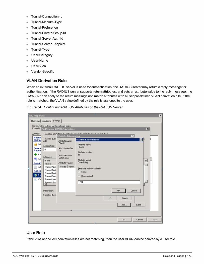
l Tunnel-Connection-Id
l Tunnel-Medium-Type
l Tunnel-Preference
l Tunnel-Private-Group-Id
l Tunnel-Server-Auth-Id
l Tunnel-Server-Endpoint
l Tunnel-Type
l User-Category
l User-Name
l User-Vlan
l Vendor-Specific
VLAN Derivation Rule
When an external RADIUS server is used for authentication, the RADIUS server may return a reply message forauthentication. If the RADIUS server supports return attributes, and sets an attribute value to the reply message, theOAW-IAP can analyze the returnmessage andmatch attributes with a user pre-defined VLAN derivation rule. If therule is matched, the VLAN value defined by the rule is assigned to the user.
Figure 54 Configuring RADIUS Attributes on the RADIUS Server
User Role
If the VSA and VLAN derivation rules are not matching, then the user VLAN can be derived by a user role.
AOS-W Instant 6.2.1.0-3.3|User Guide Rolesand Policies | 173

174174 | Rolesand Policies Dell PowerConnect W-Series Aruba Instant 6.2.1.0-3.3 | User Guide
VLANs Created for an SSID
If the VSA and VLAN derivation rules are not matching, and the User Role does not contain a VLAN, the user VLANcan be derived by VLANs configured for an SSID or Ethernet port profile.
Configuring VLAN Derivation Rules
The rule assigns the user to a VLAN based on the attributes returned by the RADIUS server when the user isauthenticated and theMAC address of the user.
You can configure VLAN derivation rules for an SSID profile by using the Instant UI or CLI.
In the Instant UI
1. Perform the following steps:
l To configure VLAN derivation rule for aWLAN SSID profile, Click Network>New>New WLAN>VLAN orNetwork>edit>Edit <WLAN-profile>>VLAN. Select the Dynamic option under the Client VLANassignment.
l To configure VLAN derivation rule for a wired network profile, click Wired>New>New WiredNetwork>VLAN orWired>Edit>Edit Wired Network>VLAN.
2. Click New to create a VLAN assignment rule. The New VLAN Assignment Rule window appears.
Figure 55 VLAN Assignment RuleWindow
3. Specify the following parameters:
l Attribute— Select the attribute returned by the RADIUS server during authentication. For a complete list ofVSAs supported by Instant, see Supported VSAs on page 170.
Instant now allows you to configure a VLAN derivation rule based on a DHCP option. The following figureshows an example for selecting dhcp-option to create a VLAN derivation rule.

Figure 56 VLAN Assignment Rule Based on DHCP Option
l Operator— Select an operator for matching the string.
l String— Enter the string tomatch.
l VLAN— Enter the VLAN to be assigned.
4. Click OK.
5. Ensure that all other required parameters are configured.
6. Click Finish to apply the changes.
In the CLI
To create a VLAN assignment rule forWLAN SSID:
(Instant Access Point)(config)# wlan ssid-profile <SSID-Name>
(Instant Access Point)(SSID Profile <name>)# set-vlan <attribute>{equals|not-equals|starts-
with|ends-with|contains}<operator><VLAN-ID>|value-of}
(Instant Access Point)(SSID Profile <name>)# end
(Instant Access Point)# commit apply
To configure a VLAN assignment rule for a wired profile:(Instant Access Point)(config)# wired-port-profile <profile-name>
(Instant Access Point)(wired ap profile <profile-name>)# set-vlan <attribute>{equals|not-
equals|starts-with|ends-with|contains}<operator><VLAN-ID>|value-of}
(Instant Access Point)(wired ap profile <profile-name>)# end
(Instant Access Point)# commit apply
Configuring a User Role for VLAN Derivation
This section describes the following procedures:
l Creating a User VLAN Role on page 175
l Assigning User VLAN Roles to a Network Profile on page 176
Creating a User VLAN Role
You can create a user role for VLAN derivation using the Instant UI or CLI
In the Instant UI
To configure a user role for VLAN derivation:
1. Click the Security at the top right corner of Instant main window.
2. Click Roles tab. The Roles tab contents are displayed.
3. Under Roles, click New.
4. Enter a name for the new role and click OK.
AOS-W Instant 6.2.1.0-3.3|User Guide Rolesand Policies | 175

176176 | Rolesand Policies Dell PowerConnect W-Series Aruba Instant 6.2.1.0-3.3 | User Guide
5. Under the Access rules, click New.
6. Select the Rule type as VLAN assignment.
7. Enter the ID of the VLAN in the VLAN ID text box. The following figure shows an example of a user VLAN role:
Figure 57 Configuring User Role for VLAN Derivation
8. Click OK.
In the CLI
To create a VLAN role:
(Instant Access Point)(config)# wlan access-rule <rule-name>
(Instant Access Point)(Access Rule <rule-name>)# vlan 200
(Instant Access Point)(Access Rule <rule-name>)# end
(Instant Access Point)# commit apply
Assigning User VLAN Roles to a Network Profile
You can configure user VLAN roles for a network profile using Instant UI or CLI.
In the Instant UI
To assign a user VLAN role:
1. Click Network>New>New WLAN>Access or Network>edit>Edit <WLAN-profile>>Access.
2. Ensure that the slider is at the Role-based option.
3. Click New under the New Role Assignment and configure the following parameters:
a. Select the attribute from the Attribute drop-down list.
b. Select the operator to match from theOperator drop-down list.
c. Enter the string tomatch in the String text box.
d. Select the role to be assigned from the Role text box. The following figure shows an example for the VLANrole assignment:

Figure 58 User VLAN Role Assignment
4. Click OK.
In the CLI
To assign VLAN role to aWLAN profile:
(Instant Access Point)(config)# wlan ssid-profile <SSID-Name>
(Instant Access Point)(SSID Profile <name>)# set-role <attribute>{{equals <operator> <role>|
not-equals <operator> <role> | starts-with <operator> <role> | ends-with <operator> <role>
|contains <operator> <role>}|value-of}
(Instant Access Point)(SSID Profile <name>)# end
(Instant Access Point)# commit apply
AOS-W Instant 6.2.1.0-3.3|User Guide Rolesand Policies | 177

0511361-01 | April 2013 178

AOS-W Instant 6.2.1.0-3.3|User Guide Mobility and Client Management | 179
Chapter 15Mobility and Client Management
This chapter provides the following information:
l Layer-3Mobility Overview on page 179
l Configuring L3-Mobility on page 180
Layer-3 Mobility OverviewOAW-IAPs form a single Instant network when they are in the same Layer-2 (L2) domain. As the number of clientsincrease, multiple subnets are required to avoid broadcast overhead. In such a scenario, a client must be allowed toroam away from the Instant network to which it first connected (home network) to another network supporting thesameWLAN access parameters (foreign network) and continue its existing sessions.
Layer-3 (L3) mobility allows a client to roam without losing its IP address and sessions. If WLAN access parametersare same across these networks, clients connected to OAW-IAPs in a given Instant network can roam to APs in aforeign Instant network and continue their existing sessions. Clients roaming across these networks are able tocontinue using their IP addresses after roaming. You can configure a list of Virtual Controller IP addresses acrosswhich L3mobility is supported.
AOS-W Instant Layer-3mobility solution defines aMobility Domain as a set of Instant networks, with sameWLANaccess parameters, across which client roaming is supported. The Instant network to which the client first connectsis called its home network. When the client roams to a foreign network, an AP in the home network (home AP)anchors all traffic to or from this client. The AP to which the client is connected in the foreign network (foreign AP)tunnels all client traffic to or from the home AP through aGRE tunnel.
Figure 59 Routing of traffic when the client is away from its home network
When a client first connects to an Instant network, amessage is sent to all configured Virtual Controller IPaddresses to see if this is an L3 roamed client. On receiving an acknowledgement from any of the configured Virtual

180180 | Mobility and Client Management Dell PowerConnect W-Series Aruba Instant 6.2.1.0-3.3 | User Guide
Controller IP addresses, the client is identified as an L3 roamed client. If the AP has noGRE tunnel to this homenetwork, a new tunnel is formed to an AP (home AP) from the client's home network.
Each foreign AP has only one home AP per Instant network to avoid duplication of broadcast traffic. Separate GREtunnels are created for each foreign AP / home AP pair. If a peer AP is a foreign AP for one client and a home AP foranother, two separate GRE tunnels are used to handle L3 roaming traffic between these APs.
If client subnet discovery fails on association due to some reason, the foreign AP identifies its subnet when it sendsout the first L3 packet. If the subnet is not a local subnet and belongs to another Instant network, the client is treatedas an L3 roamed client and all its traffic is forwarded to the home network through aGRE tunnel.
Configuring L3-MobilityTo configure amobility domain, you have to specify the list of all Instant networks that form themobility domain. Toallow clients to roam seamlessly among all the APs, specify the Virtual Controller IP for each foreign subnet. Youmay include the local Instant or Virtual Controller IP address, so that the same configuration can be used across allInstant networks in themobility domain.
It is recommended that you configure all client subnets in themobility domain. When client subnets are configured:
l If a client is from a local subnet, it is identified as a local client. When a local client starts using the IP address,the L3 roaming is terminated.
l If the client is from a foreign subnet, it is identified as a foreign client. When a foreign client starts using the IPaddress, the L3 roaming is set up.
Home Agent Load Balancing
HomeAgent Load Balancing is required in large networks wheremultiple tunnels might terminate on a single borderor lobby AP and overload it. When load balancing is enabled, the Virtual Controller assigns the home AP for roamedclients by using a round robin policy. With this policy, the load for the APs acting as HomeAgents for roamed clientsis uniformly distributed across the OAW-IAP cluster.
Configuring a Mobility Domain for Instant
You can configure L3mobility domain by using Instant UI or CLI.
In the Instant UI
To configure amobility domain, perform the following steps:
1. Click the System link at top right corner of the Instant main window. The System window appears.
2. Click the Show advanced options link. The advanced options are displayed.
3. Click L3 Mobility. The L3Mobility window is displayed.

Figure 60 L3Mobility Window
1. Select Enabled from the Home agent load balancing drop-down list. By default, home agent load balancing isdisabled.
2. Click New in the Virtual Controller IP Addresses section, add the IP address of a Virtual Controller that is partof themobility domain, and click OK.
3. Repeat Step 2 to add the IP addresses of all Virtual Controllers that form the L3mobility domain.
4. Click New in the Subnets section and specify the following:
a. Enter the client subnet in the IP address text box.
b. Enter themask in the Subnet mask text box.
c. Enter the VLAN ID in the home network in the VLAN ID text box.
d. Enter the home VC IP address for this subnet in the Virtual Controller IP text box.
5. Click OK.
In the CLI
To configure amobility domain:
(Instant Access Point)(config)# l3-mobility
(Instant Access Point)(L3-mobility)# home-agent-load-balancing
(Instant Access Point)(L3-mobility)# virtual-controller <IP-address>
(Instant Access Point)(L3-mobility)# subnet <IP-address> <subnet-mask> <VLAN-ID> <virtual-
controller-IP-address>
(Instant Access Point)(L3-mobility)# end
(Instant Access Point)(L3-mobility)# commit apply
AOS-W Instant 6.2.1.0-3.3|User Guide Mobility and Client Management | 181

0511361-01 | April 2013 182

AOS-W Instant 6.2.1.0-3.3|User Guide SpectrumMonitor | 183
Chapter 16Spectrum Monitor
This chapter provides the following information:
l Understanding Spectrum Data on page 183
l Configuring SpectrumMonitors and Hybrid OAW-IAP to Hybrid OAW-IAPs on page 188
Understanding Spectrum DataWireless networks operate in environments with electrical and radio frequency devices that can interfere withnetwork communications. Microwave ovens, cordless phones, and even adjacent Wi-Fi networks are all potentialsources of continuous or intermittent interference. The spectrummonitor softwaremodules onOAW-IAPs thatsupport this feature are able to examine the radio frequency (RF) environment in which theWi-Fi network isoperating, identify interference and classify its sources. An analysis of the results can then be used to quickly isolateissues with packet transmission, channel quality, and traffic congestion caused by contention with other devicesoperating in the same band or channel.
Spectrummonitors (SMs) are OAW-IAP radios that gather spectrum data but do not service clients. Each SM scansand analyzes the spectrum band used by the SM's radio (2.4 GHz or 5 GHz). An AP radio in hybrid AP modecontinues to serve clients as an access point while it analyzes spectrum analysis data for the channel the radio usesto serve clients. You can record data for both types of spectrummonitor devices. However, the recorded spectrum isnot reported to the Virtual Controller. A spectrum alert is sent to the VC when a nonWi-Fi interference device isdetected.
The spectrummonitor is supported onOAW-IAP104, OAW-IAP105, OAW-IAP134 andOAW-IAP135 radios.
The spectrum data is collected by eachOAW-IAP spectrummonitor and hybrid AP. The spectrum data is notreported to the VC. The Spectrum link is visible in the Instant UI (Access Point view) only if you have enabled thespectrummonitoring feature. You can view the following spectrum data in the Instant UI:
l Device List
l NonWi-Fi Interferers
l Channel Metrics
l Channel Details
l Spectrum Alerts
Device List
The device list consists of a device summary table and channel information for active nonWi-Fi devices currentlyseen by a spectrummonitor or hybrid AP radio. To view the device list, click Spectrum in the dashboard.
To view the device list, click Spectrum in the dashboard. The following figure shows an example of the device listdetails.

184184 | SpectrumMonitor Dell PowerConnect W-Series Aruba Instant 6.2.1.0-3.3 | User Guide
Figure 61 Device List
Device Summary and Channel Information shows the details of the information that is displayed:
Column Description
Type Device type. This parameter can be any of the following:l audio FF (fixed frequency)l bluetoothl cordless base FH (frequency hopper)l cordless phone FF (fixed frequency)l cordless network FH (frequency hopper)l generic FF (fixed frequency)l generic FH (frequency hopper)l generic interfererl microwavel microwave inverterl videol xboxNOTE: For additional details about non Wi-Fi device types shown in this table,see Non Wi-Fi Interferer Types.
ID ID number assigned to the device by the spectrum monitor or hybrid AP radio.Spectrum monitors and hybrid APs assign a unique spectrum ID per devicetype.
Cfreq Center frequency of the signal sent from the device.
Bandwidth Channel bandwidth used by the device.
Channels-affected Radio channels affected by the wireless device.
Signal-strength Strength of the signal sent from the device, in dBm.
Duty-cycle Device duty cycle. This value represents the percent of time the devicebroadcasts a signal.
Add-time Time at which the device was first detected.
Update-time Time at which the device’s status was updated.
Table 29: Device Summary and Channel Information
Non Wi-Fi Interferers
The following table describes each type of nonWi-Fi interferer detected by the spectrummonitor feature.

Non Wi-FiInterferer
Description
Bluetooth Any device that uses the Bluetooth protocol to communicate in the 2.4 GHz band is classifiedas a Bluetooth device. Bluetooth uses a frequency hopping protocol.
FixedFrequency(Audio)
Some audio devices such as wireless speakers and microphones also use fixed frequencyto continuously transmit audio. These devices are classified as Fixed Frequency (Audio).
FixedFrequency(CordlessPhones)
Some cordless phones use a fixed frequency to transmit data (much like the fixed frequencyvideo devices). These devices are classified as Fixed Frequency (Cordless Phones).
FixedFrequency(Video)
Video transmitters that continuously transmit video on a single frequency are classified asFixed Frequency (Video). These devices typically have close to a 100% duty cycle. Thesetypes of devices may be used for video surveillance, TV or other video distribution, andsimilar applications.
FixedFrequency(Other)
All other fixed frequency devices that do not fall into one of the above categories areclassified as Fixed Frequency (Other)).
Note that the RF signatures of the fixed frequency audio, video and cordless phone devicesare very similar and that some of these devices may be occasionally classified as FixedFrequency (Other).
FrequencyHopper(Cordless Base)
Frequency hopping cordless phone base units transmit periodic beacon-like frames at alltimes. When the handsets are not transmitting (i.e., no active phone calls), the cordless baseis classified as Frequency Hopper (Cordless Bas).
FrequencyHopper(CordlessNetwork)
When there is an active phone call and one or more handsets are part of the phoneconversation, the device is classified as Frequency Hopper (Cordless Network). Cordlessphones may operate in 2.4 GHz or 5 GHz bands. Some phones use both 2.4 GHz and 5 GHzbands (for example, 5 GHz for Base-to-handset and 2.4 GHz for Handset-to-base). Thesephones may be classified as unique Frequency Hopper devices on both bands.
FrequencyHopper (Xbox)
The Microsoft Xbox device uses a frequency hopping protocol in the 2.4 GHz band. Thesedevices are classified as Frequency Hopper (Xbox).
FrequencyHopper (Other)
When the classifier detects a frequency hopper that does not fall into one of the abovecategories, it is classified as Frequency Hopper (Other). Some examples include IEEE802.11 FHSS devices, game consoles and cordless/hands-free devices that do not use oneof the known cordless phone protocols.
Microwave Common residential microwave ovens with a single magnetron are classified as aMicrowave. These types of microwave ovens may be used in cafeterias, break rooms,dormitories and similar environments. Some industrial, healthcare or manufacturingenvironments may also have other equipment that behave like a microwave and may alsobe classified as a Microwave device.
Microwave(Inverter)
Some newer-model microwave ovens have the inverter technology to control the poweroutput and these microwave ovens may have a duty cycle close to 100%. These microwaveovens are classified as Microwave (Inverter). Dual-magnetron industrial microwave ovenswith higher duty cycle may also be classified as Microwave (Inverter). There may be otherequipment that behaves like inverter microwaves in some industrial, healthcare ormanufacturing environments. Those devices may also be classified as Microwave (Inverter).
Table 30: NonWi-Fi Interferer Types
AOS-W Instant 6.2.1.0-3.3|User Guide SpectrumMonitor | 185

186186 | SpectrumMonitor Dell PowerConnect W-Series Aruba Instant 6.2.1.0-3.3 | User Guide
Non Wi-FiInterferer
Description
GenericInterferer
Any non-frequency hopping device that does not fall into one of the other categoriesdescribed in this table is classified as a Generic Interferer. For example a Microwave-likedevice that does not operate in the known operating frequencies used by the Microwaveovens may be classified as a Generic Interferer. Similarly wide-band interfering devices maybe classified as Generic Interferers.
Channel Details
When youmove your mouse over a channel, the channel details or the summary of the 5GHz and 2.4 GHz channelsas detected by a spectrummonitor are displayed. You can view the aggregate data for each channel seen by thespectrummonitor radio, including themaximum AP power, interference and the signal-to-noise-and-interferenceRatio (SNIR). SNIR is the ratio of signal strength to the combined levels of interference and noise on that channel.Spectrummonitors display spectrum data seen on all channels in the selected band, and hybrid APs display datafrom the one channel they aremonitoring.
Figure 62 Channel Details
Channel Details Information shows the information that you can view in the channel details graph.
Table 31: Channel Details Information
Column Description
Channel An 802.11a or 802.11g radio channel.
Quality(%) Current relative quality of the channel.
Utilization(%) The percentage of the channel being used.
Wi-Fi (%) The percentage of the channel currently being used by Wi-Fi devices.
Type Device type.
Total nonwifi (%) The percentage of the channel currently being used by non Wi-Fi devices.
Known APs Number of valid APs identified on the radio channel.
UnKnown APs Number of invalid or rogue APs identified on the radio channel.
Channel Util (%) Percentage of the channel currently in use.
Max AP Signal (dBm) Signal strength of the AP that has the maximum signal strength on a channel.

Column Description
Max Interference(dBm)
Signal strength of the non Wi-Fi device that has the highest signal strength.
SNIR (db) The ratio of signal strength to the combined levels of interference and noise on thatchannel. This value is calculated by determining the maximum noise-floor andinterference-signal levels, and then calculating how strong the desired signal is abovethis maximum.
Channel Metrics
The channel metrics graph displays channel quality, availability and utilizationmetrics as seen by a spectrummonitor or hybrid AP. You can view the channel utilization data for the percentage of each channel that is currentlybeing used by Wi-Fi devices, and the percentage of each channel being used by nonWi-Fi devices and 802.11adjacent channel interference (ACI). This chart shows the channel availability, the percentage of each channel thatis available for use, or the current relative quality of selected channels in the 2.4 GHz or 5 GHz radio bands. Whilespectrummonitors can display data for all channels in their selected band, hybrid APs display data for their onemonitored channel only.
To view this graph, click 2.4 GHz in the Spectrum section of the dashboard.
Figure 63 Channel Metrics for the 2.4 GHz Radio Channel
To view this graph, click 5 GHz in the Spectrum section of the dashboard.
Figure 64 Channel Metrics for the 5GHz Radio Channel
Channel Metrics shows the information displayed in the channel metrics graph.
Column Description
Channel A 2.4 GHz or 5 GHz radio channel.
Table 32: Channel Metrics
AOS-W Instant 6.2.1.0-3.3|User Guide SpectrumMonitor | 187
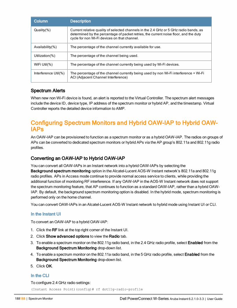
188188 | SpectrumMonitor Dell PowerConnect W-Series Aruba Instant 6.2.1.0-3.3 | User Guide
Column Description
Quality(%) Current relative quality of selected channels in the 2.4 GHz or 5 GHz radio bands, asdetermined by the percentage of packet retries, the current noise floor, and the dutycycle for non Wi-Fi devices on that channel.
Availability(%) The percentage of the channel currently available for use.
Utilization(%) The percentage of the channel being used.
WiFi Util(%) The percentage of the channel currently being used by Wi-Fi devices.
Interference Util(%) The percentage of the channel currently being used by non Wi-Fi interference + Wi-FiACI (Adjacent Channel Interference)
Spectrum Alerts
When new nonWi-Fi device is found, an alert is reported to the Virtual Controller. The spectrum alert messagesinclude the device ID, device type, IP address of the spectrummonitor or hybrid AP, and the timestamp. VirtualController reports the detailed device information to AMP.
Configuring Spectrum Monitors and Hybrid OAW-IAP to Hybrid OAW-IAPsAn OAW-IAP can be provisioned to function as a spectrummonitor or as a hybrid OAW-IAP. The radios on groups ofAPs can be converted to dedicated spectrummonitors or hybrid APs via the AP group’s 802.11a and 802.11g radioprofiles.
Converting an OAW-IAP to Hybrid OAW-IAP
You can convert all OAW-IAPs in an Instant network into a hybrid OAW-IAPs by selecting theBackground spectrummonitoring option in the Alcatel-Lucent AOS-W Instant network’s 802.11a and 802.11gradio profiles. APs in Access mode continue to provide normal access service to clients, while providing theadditional function of monitoring RF interference. If any OAW-IAP in the AOS-W Instant network does not supportthe spectrummonitoring feature, that AP continues to function as a standard OAW-IAP, rather than a hybrid OAW-IAP. By default, the background spectrummonitoring option is disabled. In the hybrid mode, spectrummonitoring isperformed only on the home channel.
You can convert OAW-IAPs in an Alcatel-Lucent AOS-W Instant network to hybrid mode using Instant UI or CLI.
In the Instant UI
To convert an OAW-IAP to a hybrid OAW-IAP:
1. Click the RF link at the top right corner of the Instant UI.
2. Click Show advanced options to view the Radio tab.
3. To enable a spectrummonitor on the 802.11g radio band, in the 2.4 GHz radio profile, select Enabled from theBackground SpectrumMonitoring drop-down list.
4. To enable a spectrummonitor on the 802.11a radio band, in the 5GHz radio profile, select Enabled from theBackground SpectrumMonitoring drop-down list.
5. Click OK.
In the CLI
To configure 2.4 GHz radio settings:
(Instant Access Point)(config)# rf dot11g-radio-profile

Instant Access Point (RF dot11 g Radio Profile)# spectrum-monitor
To configure 5GHz radio settings:
(Instant Access Point)(config)# rf dot11a-radio-profile
Instant Access Point (RF dot11a Radio Profile)# spectrum-band <type>
To view the radio configuration:
Instant Access Point# show radio config
2.4 GHz:
Legacy Mode:disable
Beacon Interval:100
802.11d/802.11h:disable
Interference Immunity Level:2
Channel Switch Announcement Count:0
Channel Reuse Type:disable
Channel Reuse Threshold:0
Background Spectrum Monitor:enable
5.0 GHz:
Legacy Mode:disable
Beacon Interval:100
802.11d/802.11h:disable
Interference Immunity Level:2
Channel Switch Announcement Count:0
Channel Reuse Type:disable
Channel Reuse Threshold:0
Background Spectrum Monitor:enable
Standalone Spectrum Band:5ghz-upper
Converting an OAW-IAP to a Spectrum Monitor
In spectrummode, spectrummonitoring is performed on entire bands. However for the 5GHz radio, spectrummonitoring is performed on only one of the three bands:
l 5GHz - lower
l 5GHz -middle
l 5GHz - higher
By default, spectrummonitoring is performed on a higher band of the 5GHz radio.
You can configure an OAW-IAP to function as a standalone spectrummonitor using Instant UI or CLI.
In the Instant UI
To convert an OAW-IAP to a spectrummonitor:
1. In the Access Points tab, click the AP that you want to convert to a spectrummonitor. The edit link appears.
2. Click the edit link. The Edit Access Point window appears.
3. Click the Radio tab.
4. From the Access Mode drop-down list, select SpectrumMonitor.
5. Click OK.
6. Reboot the OAW-IAP for the changes to affect.
7. To enable spectrummonitoring for any other band for the 5GHz radio:
a. Click the RF link at the upper right corner of the Instant UI.
b. Click Show advanced options to view the Radio tab.
c. For the 5GHz radio, specify the spectrum band you want that radio tomonitor by selecting Lower, Middle, orHigher from the Standalone spectrum band drop-down list.
AOS-W Instant 6.2.1.0-3.3|User Guide SpectrumMonitor | 189

190190 | SpectrumMonitor Dell PowerConnect W-Series Aruba Instant 6.2.1.0-3.3 | User Guide
d. Click OK.
In the CLI
To convert an OAW-IAP to a spectrummonitor:
(Instant Access Point)# wifi0-mode {<access>|<monitor>|<spectrum-monitor>}
(Instant Access Point)# wifi1-mode {<access>|<monitor>|<spectrum-monitor>}
To enable spectrummonitoring for any other band for the 5GHz radio:(Instant Access Point)(config)# rf dot11a-radio-profile
Instant Access Point (RF dot11a Radio Profile)# spectrum-band <type>
To view the radio configuration:
Instant Access Point# show radio config
2.4 GHz:
Legacy Mode:disable
Beacon Interval:100
802.11d/802.11h:disable
Interference Immunity Level:2
Channel Switch Announcement Count:0
Channel Reuse Type:disable
Channel Reuse Threshold:0
Background Spectrum Monitor:disable
5.0 GHz:
Legacy Mode:disable
Beacon Interval:100
802.11d/802.11h:disable
Interference Immunity Level:2
Channel Switch Announcement Count:0
Channel Reuse Type:disable
Channel Reuse Threshold:0
Background Spectrum Monitor:disable
Standalone Spectrum Band:5ghz-upper

AOS-W Instant 6.2.1.0-3.3|User Guide Adaptive RadioManagement | 191
Chapter 17Adaptive Radio Management
This chapter provides the following information:
l ARMOverview on page 191
l Configuring ARM Features on anOAW-IAP on page 193
l Configuring Radio Settings for an OAW-IAP on page 197
ARM OverviewAdaptive RadioManagement (ARM) is a radio frequency management technology that optimizes WLANperformance even in the networks with highest traffic by dynamically and intelligently choosing the best 802.11channel and transmitting power for eachOAW-IAP in its current RF environment. ARM works with all standardclients, across all operating systems, while remaining in compliance with the IEEE 802.11 standards. It does notrequire any proprietary client software to achieve its performance goals. ARM ensures low-latency roaming,consistently high performance, andmaximum client compatibility in amulti-channel environment. By ensuring thefair distribution of availableWi-Fi bandwidth tomobile devices, ARM ensures that data, voice, and video applicationshave sufficient network resources at all times. ARM allows mixed 802.11a, b, g, and n client types to inter operate atthe highest performance levels.
Channel or Power Assignment
The channel or power assignment feature automatically assigns channel and power settings for all the OAW-IAPs inthe network according to changes in the RF environment. This feature automates many setup tasks during networkinstallation and the ongoing operations when RF conditions change.
Voice Aware Scanning
The Voice Aware scanning feature prevents anOAW-IAP supporting an active voice call from scanning for otherchannels in the RF spectrum and allows nOAW-IAP to resume scanning when there are no active voice calls. Thissignificantly improves the voice quality when a call is in progress and simultaneously delivers the automated RFmanagement functions. By default, this feature is enabled.
Load Aware Scanning
The Load Aware Scanning feature dynamically adjusts scanning behavior to maintain uninterrupted data transfer onresource intensive systems when the network traffic exceeds a predefined threshold. TheOAW-IAPs resumecompletemonitoring scans when the traffic drops to the normal levels. By default, this feature is enabled.
Band Steering Mode
The Band Steering feature assigns the dual-band capable clients to the 5GHz band on dual-bandOAW-IAPs. Thisfeature reduces co-channel interference and increases available bandwidth for dual-band clients, because there aremore channels on the 5GHz band than on the 2.4 GHz band. For more information, Configuring ARM Features on anOAW-IAP on page 193.
Spectrum Load Balancing
The spectrum load balancing feature allows the APs in a cluster to be divided into several logical AP RFneighborhood called domains, which share the same clients. When the Spectrum load balancing feature is enabled,

192192 | Adaptive RadioManagement Dell PowerConnect W-Series Aruba Instant 6.2.1.0-3.3 | User Guide
the Virtual Controller determines the distribution of clients and balances client load across channels, regardless ofwhether the AP is responding to the wireless clients' probe requests.
With this feature, the client load for an AP is determined based on the value specified for the SLB threshold. Whenthe client load on an AP reaches or exceeds the SLB threshold in comparison to its neighbors, or if a neighboring APon another channel does not have any clients, load balancing is enabled on that AP, to allow clients to connect to anavailable or less loaded channel. When the client count reaches the threshold, the APs with load balancing enabledwill not send probe response or authentication response to the new client requests.
Airtime Fairness Mode
The Airtime Fairness feature provides equal access to all clients on the wireless medium, regardless of client type,capability, or operating system, thus delivering uniform performance to all clients. This feature prevents the clientsfrommonopolizing resources.
Access Point Control
The following access point control features are supported:
l Customize Valid Channels — You can customize Valid 5 GHz channels and Valid 2.4 GHz channels for20MHz and 40MHz channels in the OAW-IAP. The administrators can configure the ARM channels in thechannel width window. The valid channels automatically show in the static channel assignment window.
l Minimum Transmit Power — This indicates theminimum Effective Isotropic Radiated Power (EIRP) from 3 to 33dBm in 3 dBm increments. Youmay also specify a special value of 127 dBm for regulatory maximum to disablepower adjustments for environments such as outdoor mesh links. A higher power level settingmay beconstrained by the local regulatory requirements and AP capabilities. If theminimum transmission EIRP settingconfigured on an AP is not supported by the AP model, this value is reduced to the highest supported powersetting. The default value is for minimum transmit power is 18 dBm.
l Maximum Transmit Power — This indicates themaximum Effective Isotropic Radiated Power (EIRP) from 3 to33 dBm in 3 dBm increments. Higher power level settings may be constrained by local regulatory requirementsand AP capabilities. If themaximum transmission EIRP configured on an AP is not supported by the AP model,the value is reduced to the highest supported power setting. The default value for maximum transmit power is 127dBm.
l Client Aware — When Enabled, ARM does not change channels for the APs with active clients, except for highpriority events such as radar or excessive noise. This featuremust be enabled inmost deployments for a stableWLAN. If the Client Awaremode is Disabled, the OAW-IAP may change to amore optimal channel, whichchangemay disrupt current client traffic for a while. The Client Aware option is Enabled by default.
When the Client Aware ARM is disabled, channels can be changed even when the clients are active on aBSSID.
l Scanning — When ARM is enabled, the OAW-IAP dynamically scans all 802.11 channels within its 802.11regulatory domain at regular intervals and reports to the OAW-IAP. This scanning report includes WLANcoverage, interference, and intrusion detection data.
l Wide Channel Bands — This feature allows administrators to configure 40MHz channels in the 2.4 GHz and 5.0GHz bands. 40MHz channels are essentially two 20MHz adjacent channels that are bonded together. 40MHzchannel effectively doubles the frequency bandwidth available for data transmission.
Monitoring the Network with ARM
When ARM is enabled, an OAW-IAP dynamically scans all 802.11 channels within its 802.11 regulatory domain atregular intervals and sends reports to a Virtual Controller on network (WLAN) coverage, interference, and intrusiondetection.

ARM Metrics
ARM computes coverage and interferencemetrics for each valid channel and chooses the best performing channeland transmit power settings for eachOAW-IAP RF environment. EachOAW-IAP gathers other metrics on its ARM-assigned channel to provide a snapshot of the current RF health state.
Configuring ARM Features on an OAW-IAPYou can configure ARM features such as band steering, spectrum load balancing, and airtime fairness mode eitherusing Instant UI or CLI.
In the Instant UI
To configure ARM:
1. Click the RF link at the top right corner of the Instant main window.
2. Click Show advanced options. The ARM tab details are displayed.
Figure 65 RFWindow - ARM Tab
3. Configure the following parameters for Band steering mode:
AOS-W Instant 6.2.1.0-3.3|User Guide Adaptive RadioManagement | 193

194194 | Adaptive RadioManagement Dell PowerConnect W-Series Aruba Instant 6.2.1.0-3.3 | User Guide
Parameter Description
Prefer 5 GHz Select this option to use band steering in 5 GHz mode. On selecting this, the OAW-IAP steers the client to 5 GHz band (if the client is 5 GHz capable), but allows theclient connection on the 2.4 GHz band if the client persistently attempts for 2.4 GHzassociation.
Force 5 GHz Select this option to enforce 5 GHz band steering mode on the OAW-IAPs.
Balance Bands Select this option is selected, the OAW-IAP tries to balance the clients across thetwo radios to best utilize the available 2.4 GHz bandwidth. This feature takes intoaccount the fact that the 5 GHz band has more channels than the 2.4 GHz band,and that the 5 GHz channels operate in 40MHz while the 2.5 GHz band operates in20MHz.
Disabled Select this option if you want to allow the clients to select the band to use.
Table 33: Band SteeringMode - Configuration Parameters
4. For Airtime fairness mode, specify any of the following values:
Parameter Description
Default Access Select this option to provide access based on client requests. When Air TimeFairness is set to default access, per user and per SSID bandwidth limits are notenforced.
Fair Access Select this option to allocate Airtime evenly across all the clients.
Preferred Access Select this option to set a preference where 11n clients are assigned more airtimethan 11a/11g. The 11a/11g clients get more airtime than 11b. The ratio is 16:4:1.
Table 34: Airtime Fairness Mode - Configuration Parameters
5. For Spectrum load balancing, specify the following parameters:
Parameter Description
Spectrum loadbalancing
Select Enabled to enable Spectrum load balancing on APs so that clients areassigned to less loaded channels. When enabled, the Virtual Controller compareswhether an AP has more clients than its neighboring APs on other channels. Whenthe client load for an AP reaches or exceeds the threshold specified for SLBthreshold, load balancing is enabled on the AP. For more information, see SpectrumLoad Balancing on page 191.
SLB calculatinginterval
The value specified for SLB calculating interval determines how often spectrum loadbalancing must be calculated. The interval is specified in seconds and the defaultvalue is 30 seconds. You can specify a value within the range of 10-600.
SLB neighbormatching %
The value specified for SLB neighbor matching % indicates the percentage forcomparing client density of AP neighbors to determine the client load on a specificAP channel. You can specify a percentage value within the range of 20-100. Thedefault value is 75%.
SLB threshold The value specified for SLB threshold indicates the number of clients on a channel.When the client load for an AP reaches or exceeds the specified threshold, loadbalancing is enabled on the AP. You can specify a value within range of 1-20. Thedefault value is 2.
Table 35: Spectrum Load Balancing - Configuration Parameters

6. For Access Point Control, specify the following parameters:
Parameter Description
Customize ValidChannels
Select this check box to customize valid channels for 2,4 GHz and 5 GHz. By default,the AP uses valid channels as defined by the Country Code (regulatory domain). Onselecting the Customize Valid Channels check box, a list of valid channels for both2.4.GHz and 5 GHz are displayed. The valid channel customization feature isdisabled by default.
Minimum Trans-mit Power
Specify the minimum transmission power. The value specified for Minimum TransmitPower indicates the minimum Effective Isotropic Radiated Power (EIRP) from 3 to 33dBm in 3 dBm increments. If the minimum transmission EIRP setting configured onan AP is not supported by the AP model, this value is reduced to the highestsupported power setting. The default value is for minimum transmit power is 18 dBm.
Maximum Trans-mit Power
Specify the maximum transmission power. The value specified for MaximumTransmit Power indicates the maximum Effective Isotropic Radiated Power (EIRP)from 3 to 33 dBm in 3 dBm increments. If the maximum transmission EIRP configuredon an AP is not supported by the AP model, the value is reduced to the highestsupported power setting. The default value for maximum transmit power is 127 dBm.
Client aware Select Enabled to allow ARM to control channel assignments for the APs with activeclients. When the Client aware mode is set to Disabled, the OAW-IAP may change toa more optimal channel, which change may disrupt current client traffic. The Clientaware option is Enabled by default.
Scanning Select Enabled so that the OAW-IAP dynamically scans all 802.11 channels within its802.11 regulatory domain at regular intervals and reports to the OAW-IAP. This scan-ning report includes WLAN coverage, interference, and intrusion detection data.
Wide ChannelBands
Select a band to allow to place APs in 40Mhz (wide band) channels. The Widechannel band allows administrators to configure 40 MHz channels in the 2.4 GHzand 5.0 GHz bands. 40 MHz channels are two 20 MHz adjacent channels that arebonded together. 40 MHz channel effectively doubles the frequency bandwidthavailable for data transmission.
For high performance, you can select 5GHz. If the AP density is low, enable in the2.4GHz band.
Table 36: Access Point Control - Configuration Parameters
7. Reboot the OAW-IAP.
8. Click OK.
In the CLI
To configure ARM features:
(Instant Access Point)(config)# arm
(Instant Access Point)(ARM)# a-channels <5GHz-channels>
(Instant Access Point)(ARM)# g-channels <2.4GHz-channels>
(Instant Access Point)(ARM)# min-tx-power <power>
(Instant Access Point)(ARM)# max-tx-power <power>
(Instant Access Point)(ARM)# band-steering-mode {<Prefer 5 GHz>| <Force 5 GHz>|<Balance
Bands>|<Disabled>}
(Instant Access Point)(ARM)# air-time-fairness-mode {<Default Access>| <Fair Access> |
<Preferred Access>}
(Instant Access Point)(ARM)# client-aware
(Instant Access Point)(ARM)# wide-bands {<5GHz>|<2GHz>|<All>|<None>}
(Instant Access Point)(ARM)# scanning
(Instant Access Point)(ARM)# spectrum-load-balancing
AOS-W Instant 6.2.1.0-3.3|User Guide Adaptive RadioManagement | 195

196196 | Adaptive RadioManagement Dell PowerConnect W-Series Aruba Instant 6.2.1.0-3.3 | User Guide
(Instant Access Point)(ARM)# spectrum-load-balancing calc-interval <Seconds>
(Instant Access Point)(ARM)# spectrum-load-balancing nb-matching <Percentage>
(Instant Access Point)(ARM)# spectrum-load-balancing calc-threshold <threshold>
(Instant Access Point)(ARM)# end
(Instant Access Point)# commit apply
To view ARM configuration:
(Instant Access Point)# show arm config
Minimum Transmit Power :18
Maximum Transmit Power :127
Band Steering Mode :prefer-5ghz
Client Aware :disable
Scanning :disable
Wide Channel Bands :5ghz
Air Time Fairness Mode :fair-access
Spectrum Load Balancing :disable
SLB NB Matching Percent :75
SLB Calculating Interval :30
SLB Threshold :2
Custom Channels :No
2.4 GHz Channels
----------------
Channel Status
------- ------
1 enable
2 disable
3 disable
4 disable
5 disable
6 enable
7 disable
8 disable
9 disable
10 disable
11 enable
12 disable
13 disable
1+ enable
2+ disable
3+ disable
4+ disable
5+ disable
6+ disable
7+ enable
5.0 GHz Channels
----------------
Channel Status
------- ------
36 enable
40 enable
44 enable
48 enable
52 enable
56 enable
60 enable
64 enable
149 enable
153 enable
157 enable
161 enable
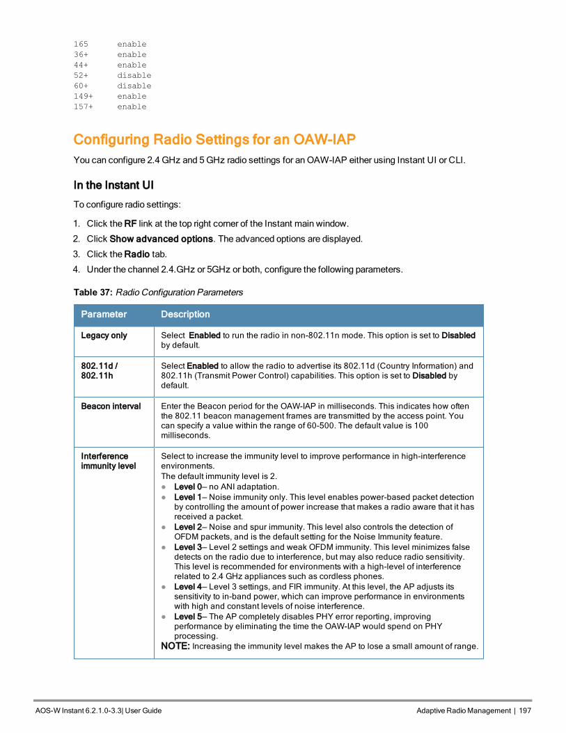
165 enable
36+ enable
44+ enable
52+ disable
60+ disable
149+ enable
157+ enable
Configuring Radio Settings for an OAW-IAPYou can configure 2.4 GHz and 5GHz radio settings for an OAW-IAP either using Instant UI or CLI.
In the Instant UI
To configure radio settings:
1. Click the RF link at the top right corner of the Instant main window.
2. Click Show advanced options. The advanced options are displayed.
3. Click the Radio tab.
4. Under the channel 2.4.GHz or 5GHz or both, configure the following parameters.
Parameter Description
Legacy only Select Enabled to run the radio in non-802.11n mode. This option is set to Disabledby default.
802.11d /802.11h
Select Enabled to allow the radio to advertise its 802.11d (Country Information) and802.11h (Transmit Power Control) capabilities. This option is set to Disabled bydefault.
Beacon interval Enter the Beacon period for the OAW-IAP in milliseconds. This indicates how oftenthe 802.11 beacon management frames are transmitted by the access point. Youcan specify a value within the range of 60-500. The default value is 100milliseconds.
Interferenceimmunity level
Select to increase the immunity level to improve performance in high-interferenceenvironments.The default immunity level is 2.l Level 0— no ANI adaptation.l Level 1— Noise immunity only. This level enables power-based packet detection
by controlling the amount of power increase that makes a radio aware that it hasreceived a packet.
l Level 2— Noise and spur immunity. This level also controls the detection ofOFDM packets, and is the default setting for the Noise Immunity feature.
l Level 3— Level 2 settings and weak OFDM immunity. This level minimizes falsedetects on the radio due to interference, but may also reduce radio sensitivity.This level is recommended for environments with a high-level of interferencerelated to 2.4 GHz appliances such as cordless phones.
l Level 4— Level 3 settings, and FIR immunity. At this level, the AP adjusts itssensitivity to in-band power, which can improve performance in environmentswith high and constant levels of noise interference.
l Level 5— The AP completely disables PHY error reporting, improvingperformance by eliminating the time the OAW-IAP would spend on PHYprocessing.
NOTE: Increasing the immunity level makes the AP to lose a small amount of range.
Table 37: Radio Configuration Parameters
AOS-W Instant 6.2.1.0-3.3|User Guide Adaptive RadioManagement | 197

198198 | Adaptive RadioManagement Dell PowerConnect W-Series Aruba Instant 6.2.1.0-3.3 | User Guide
Parameter Description
Channel switchannouncementcount
Specify the count to indicate the number of channel switching announcements thatmust be sent before switching to a new channel. This allows associated clients torecover gracefully from a channel change.
Backgroundspectrummonitoring
Select Enabled to allow the APs in access mode to continue with normal accessservice to clients, while performing additional function of monitoring RF interference(from both neighboring APs and non Wi-Fi sources such as, microwaves andcordless phones) on the channel they are currently serving clients.
5. Reboot the OAW-IAP after configuring the radio profile settings.
In the CLI
To configure 2.4 GHz radio settings:
(Instant Access Point) (config)# rf dot11g-radio-profile
(Instant Access Point) (RF dot11 g Radio Profile)# beacon-interval <milliseconds>
(Instant Access Point) (RF dot11 g Radio Profile)# legacy-mode
(Instant Access Point) (RF dot11 g Radio Profile)# spectrum-monitor
(Instant Access Point) (RF dot11 g Radio Profile)# dot11h
(Instant Access Point) (RF dot11 g Radio Profile)# interference-immunity <level>
(Instant Access Point) (RF dot11 g Radio Profile)# csa-count <count>
(Instant Access Point) (RF dot11 g Radio Profile)# end
(Instant Access Point)# commit apply
To configure 5GHz radio settings:
(Instant Access Point) (config)# rf dot11a-radio-profile
(Instant Access Point) (RF dot11a Radio Profile)# beacon-interval <milliseconds>
(Instant Access Point) (RF dot11a Radio Profile)# legacy-mode
(Instant Access Point) (RF dot11a Radio Profile)# spectrum-monitor
(Instant Access Point) (RF dot11a Radio Profile)# spectrum-band <type>
(Instant Access Point) (RF dot11a Radio Profile)# dot11h
(Instant Access Point) (RF dot11a Radio Profile)# interference-immunity <level>
(Instant Access Point) (RF dot11a Radio Profile)# csa-count <count>
(Instant Access Point) (RF dot11 g Radio Profile)# end
(Instant Access Point)# commit apply
To view the radio configuration:
(Instant Access Point)# show radio config
2.4 GHz:
Legacy Mode:disable
Beacon Interval:100
802.11d/802.11h:disable
Interference Immunity Level:2
Channel Switch Announcement Count:0
Channel Reuse Type:disable
Channel Reuse Threshold:0
Background Spectrum Monitor:disable
5.0 GHz:
Legacy Mode:disable
Beacon Interval:100
802.11d/802.11h:disable
Interference Immunity Level:2
Channel Switch Announcement Count:0
Channel Reuse Type:disable
Channel Reuse Threshold:0

Background Spectrum Monitor:disable
Standalone Spectrum Band:5ghz-upper
AOS-W Instant 6.2.1.0-3.3|User Guide Adaptive RadioManagement | 199

0511361-01 | April 2013 200

AOS-W Instant 6.2.1.0-3.3|User Guide Intrusion Detection | 201
Chapter 18Intrusion Detection
The Intrusion Detection System (IDS) is a feature that monitors the network for the presence of unauthorized OAW-IAPs and clients. It also logs information about the unauthorized OAW-IAPs and clients, and generates reportsbased on the logged information.
The IDS feature in the AOS-W Instant network enables you to detect rogue APs, interfering APs, and other devicesthat can potentially disrupt network operations.
This chapter describes the following procedures:
l Detecting and Classifying Rogue APs on page 201
l OS Fingerprinting on page 201
l ConfiguringWireless Intrusion Protection and Detection Levels on page 202
l Configuring IDS Using CLI on page 206
Detecting and Classifying Rogue APsA rogue AP is an unauthorized AP plugged into the wired side of the network.
An interfering AP is an AP seen in the RF environment but is not connected to the wired network. While theinterfering AP can potentially cause RF interference, it is not considered a direct security threat, because it is notconnected to the wired network. However, an interfering AP may be reclassified as a rogue AP.
To detect the rogue APs, click the IDS link in the Instant main window. The built-in IDS scans for access points thatare not controlled by the Virtual Controller. These are listed and classified as either Interfering or Rogue, dependingon whether they are on a foreign network or your network.
Figure 66 Intrusion Detection
OS FingerprintingTheOS Fingerprinting feature gathers information about the client that is connected to the Alcatel-Lucent AOS-WInstant network to find the operating system that the client is running on. The following is a list of advantages of thisfeature:
l Identifying rogue clients— Helps to identify clients that are running on forbidden operating systems.
l Identifying outdated operating systems— Helps to locate outdated and unexpected OS in the company network.
l Locating and patching vulnerable operating systems— Assists in locating and patching specific operating systemversions on the network that have known vulnerabilities, thereby securing the company network.
OS Fingerprinting is enabled in the AOS-W Instant network by default. The following operating systems areidentified by AOS-W Instant:
l Windows 7

202202 | Intrusion Detection Dell PowerConnect W-Series Aruba Instant 6.2.1.0-3.3 | User Guide
l Windows Vista
l Windows Server
l Windows XP
l Windows ME
l OS-X
l iPhone
l iOS
l Android
l Blackberry
l Linux
Configuring Wireless Intrusion Protection and Detection LevelsWIP offers a wide selection of intrusion detection and protection features to protect the network against wirelessthreats.
Likemost other security-related features of the Alcatel-Lucent network, theWIP can be configured on theOAW-IAP.
You can configure the following options:
l Infrastructure Detection Policies— Specifies the policy for detecting wireless attacks on access points
l Client Detection Policies— Specifies the policy for detecting wireless attacks on clients
l Infrastructure Protection Policies— Specifies the policy for protecting access points from wireless attacks.
l Client Protection Policies— Specifies the policy for protecting clients from wireless attacks.
l Containment Methods— Prevents unauthorized stations from connecting to your AOS-W Instant network.
Each of these options contains several default levels that enable different sets of policies. An administrator cancustomize enable or disable these options accordingly.
The detection levels can be configured using the IDS window. To view the IDS window, click More>IDS link at thetop right corner of the Instant main window. The following levels of detection can be configured in theWIP Detectionpage:
l Off
l Low
l Medium
l High
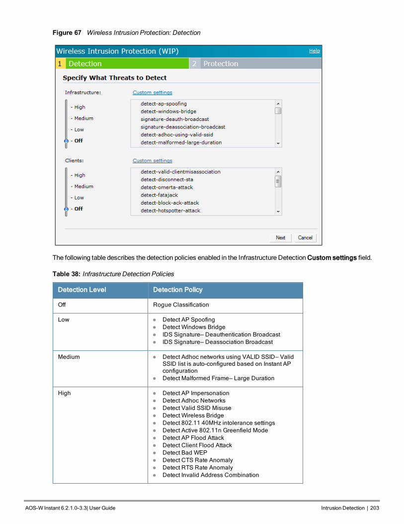
Figure 67 Wireless Intrusion Protection: Detection
The following table describes the detection policies enabled in the Infrastructure Detection Custom settings field.
Detection Level Detection Policy
Off Rogue Classification
Low l Detect AP Spoofingl Detect Windows Bridgel IDS Signature— Deauthentication Broadcastl IDS Signature— Deassociation Broadcast
Medium l Detect Adhoc networks using VALID SSID— ValidSSID list is auto-configured based on Instant APconfiguration
l Detect Malformed Frame— Large Duration
High l Detect AP Impersonationl Detect Adhoc Networksl Detect Valid SSID Misusel Detect Wireless Bridgel Detect 802.11 40MHz intolerance settingsl Detect Active 802.11n Greenfield Model Detect AP Flood Attackl Detect Client Flood Attackl Detect Bad WEPl Detect CTS Rate Anomalyl Detect RTS Rate Anomalyl Detect Invalid Address Combination
Table 38: Infrastructure Detection Policies
AOS-W Instant 6.2.1.0-3.3|User Guide Intrusion Detection | 203

204204 | Intrusion Detection Dell PowerConnect W-Series Aruba Instant 6.2.1.0-3.3 | User Guide
Detection Level Detection Policy
l Detect Malformed Frame— HT IEl Detect Malformed Frame— Association Requestl Detect Malformed Frame— Authl Detect Overflow IEl Detect Overflow EAPOL Keyl Detect Beacon Wrong Channell Detect devices with invalid MAC OUI
Table 38: Infrastructure Detection Policies
The following table describes the detection policies enabled in the Client Detection Custom settings field.
Detection Level Detection Policy
Off All detection policies are disabled.
Low l Detect Valid Station Misassociation
Medium l Detect Disconnect Station Attackl Detect Omerta Attackl Detect FATA-Jack Attackl Detect Block ACK DOSl Detect Hotspotter Attackl Detect unencrypted Valid Clientl Detect Power Save DOS Attack
High l Detect EAP Rate Anomalyl Detect Rate Anomalyl Detect Chop Chop Attackl Detect TKIP Replay Attackl IDS Signature— Air Jackl IDS Signature— ASLEAP
Table 39: Client Detection Policies
The following levels of detection can be configured in theWIP Protection page:
l Off
l Low
l High

Figure 68 Wireless Intrusion Protection: Detection
The following table describes the detection policies that are enabled in the Infrastructure Protection Customsettings field.
Detection Level Detection Policy
Off All detection policies are disabled
Low l Protect SSID – Valid SSID list should be autoderived from Instant configuration
l Rogue Containment
High l Protect from Adhoc Networksl Protect AP Impersonation
Table 40: Infrastructure Protection Policies
The following table describes the detection policies that are enabled in the Client Protection Custom settings field.
Detection Level Detection Policy
Off All detection policies are disabled
Low l Protect Valid Station
High l Protect Windows Bridge
Table 41: Client Protection Policies
AOS-W Instant 6.2.1.0-3.3|User Guide Intrusion Detection | 205

206206 | Intrusion Detection Dell PowerConnect W-Series Aruba Instant 6.2.1.0-3.3 | User Guide
Containment Methods
You can enable wired and wireless containments to prevent unauthorized stations from connecting to your AOS-WInstant network.
AOS-W Instant supports the following types of containment mechanisms:
l Wired containment— When enabled, Alcatel-Lucent Access Points generate ARP packets on the wired networkto contain wireless attacks.
l Wireless containment— When enabled, the system attempts to disconnect all clients that are connected orattempting to connect to the identified Access Point.
n None— Disables all the containment mechanisms.
n Deauthenticate only— With deauthentication containment, the Access Point or client is contained bydisrupting the client association on the wireless interface.
n Tarpit containment— With Tarpit containment, the Access Point is contained by luring clients that areattempting to associate with it to a tarpit. The tarpit can be on the same channel or a different channel as theAccess Point being contained.
Figure 69 Containment Methods
Configuring IDS Using CLITo configure IDS using CLI:
(Instant Access Point)(config)# ids
(Instant Access Point)(IDS)# infrastructure-detection-level <type>
(Instant Access Point)(IDS)# client-detection-level <type>
(Instant Access Point)(IDS)# infrastructure-protection-level <type>
(Instant Access Point)(IDS)# client-protection-level <type>

(Instant Access Point)(IDS)# wireless-containment <type>
(Instant Access Point)(IDS)# wired-containment
(Instant Access Point)(IDS)# detect-ap-spoofing
(Instant Access Point)(IDS)# detect-windows-bridge
(Instant Access Point)(IDS)# signature-deauth-broadcast
(Instant Access Point)(IDS)# signature-deassociation-broadcast
(Instant Access Point)(IDS)# detect-adhoc-using-valid-ssid
(Instant Access Point)(IDS)# detect-malformed-large-duration
(Instant Access Point)(IDS)# detect-ap-impersonation
(Instant Access Point)(IDS)# detect-adhoc-network
(Instant Access Point)(IDS)# detect-valid-ssid-misuse
(Instant Access Point)(IDS)# detect-wireless-bridge
(Instant Access Point)(IDS)# detect-ht-40mhz-intolerance
(Instant Access Point)(IDS)# detect-ht-greenfield
(Instant Access Point)(IDS)# detect-ap-flood
(Instant Access Point)(IDS)# detect-client-flood
(Instant Access Point)(IDS)# detect-bad-wep
(Instant Access Point)(IDS)# detect-cts-rate-anomaly
(Instant Access Point)(IDS)# detect-rts-rate-anomaly
(Instant Access Point)(IDS)# detect-invalid-addresscombination
(Instant Access Point)(IDS)# detect-malformed-htie
(Instant Access Point)(IDS)# detect-malformed-assoc-req
(Instant Access Point)(IDS)# detect-malformed-frame-auth
(Instant Access Point)(IDS)# detect-overflow-ie
(Instant Access Point)(IDS)# detect-overflow-eapol-key
(Instant Access Point)(IDS)# detect-beacon-wrong-channel
(Instant Access Point)(IDS)# detect-invalid-mac-oui
(Instant Access Point)(IDS)# detect-valid-clientmisassociation
(Instant Access Point)(IDS)# detect-disconnect-sta
(Instant Access Point)(IDS)# detect-omerta-attack
(Instant Access Point)(IDS)# detect-fatajack
(Instant Access Point)(IDS)# detect-block-ack-attack
(Instant Access Point)(IDS)# detect-hotspotter-attack
(Instant Access Point)(IDS)# detect-unencrypted-valid
(Instant Access Point)(IDS)# detect-power-save-dos-attack
(Instant Access Point)(IDS)# detect-eap-rate-anomaly
(Instant Access Point)(IDS)# detect-rate-anomalies
(Instant Access Point)(IDS)# detect-chopchop-attack
(Instant Access Point)(IDS)# detect-tkip-replay-attack
(Instant Access Point)(IDS)# signature-airjack
(Instant Access Point)(IDS)# signature-asleap
(Instant Access Point)(IDS)# protect-ssid
(Instant Access Point)(IDS)# rogue-containment
(Instant Access Point)(IDS)# protect-adhoc-network
(Instant Access Point)(IDS)# protect-ap-impersonation
(Instant Access Point)(IDS)# protect-valid-sta
(Instant Access Point)(IDS)# protect-windows-bridge
(Instant Access Point)(IDS)# end
(Instant Access Point)# commit apply
AOS-W Instant 6.2.1.0-3.3|User Guide Intrusion Detection | 207

0511361-01 | April 2013 208

AOS-W Instant 6.2.1.0-3.3|User Guide Content Filtering | 209
Chapter 19Content Filtering
This chapter provides the following information:
l Content Filtering on page 209
l Enabling Content Filtering on page 209
l Configuring Enterprise Domains on page 210
l Configuring OpenDNS Credentials on page 210
Content FilteringThe Content Filtering feature allows you to create Internet access policies that allow or deny user access toWebsites based onWebsite categories and security ratings. With this feature, you can:
l Prevent knownmalware hosts from accessing your wireless network.
l Improve employee productivity by limiting access to certain websites.
l Reduce bandwidth consumption significantly.
Content Filtering can be configured on an SSID and up to four enterprise domain names can be configuredmanually.When enabled, all DNS requests to non-corporate domains on this wireless network are sent to the open DNSserver.
Regardless of whether content filtering is disabled or enabled, the DNS requests to http://instant.Alcatel-Lucentnetworks.com are always resolved internally on AOS-W Instant.
Enabling Content FilteringThe content filtering configuration applies to all OAW-IAPs in the network and the service is enabled or disabledglobally across the wireless or wired network profiles.
You can enable content filtering for an SSID when configuring or modifying a wireless or wired network using InstantUI or CLI.
Enabling Content Filtering for a Wireless Profile
To enable content filtering for a wireless SSID, perform the following steps:
In the Instant UI
1. Select a wireless profile in the Networks tab and then click the edit link. The window for editing theWLAN SSIDprofile is displayed.
2. Click Show advanced options.
3. Select Enabled from the Content Filtering drop-down list and click Next to continue.
You can also enable content filtering while adding a new wireless profile. For more information, see ConfiguringWLAN Settings for an SSID Profile on page 80.
In the CLI
To enable content filtering on aWLAN SSID:
(Instant Access Point)(config)# wlan ssid-profile <SSID-Name>

210210 | Content Filtering Dell PowerConnect W-Series Aruba Instant 6.2.1.0-3.3 | User Guide
(Instant Access Point)(SSID Profile <name>)# content-filtering
(Instant Access Point)(SSID Profile <name>)# end
(Instant Access Point)# commit apply
Enabling Content Filtering for a Wired Profile
To enable content filtering for a wired profile, perform the following steps:
In the Instant UI
1. Click theWired link under More at the top right corner of the AOS-W Instant main window. TheWired windowappears.
2. In theWired window, select the wired profile to modify.
3. Click Edit. The Edit Wired Network window is displayed.
4. In theWired Settings tab, select Enabled from the Content Filtering drop-down list and click Next to continue.
In the CLI
To enable content filtering for a wired profile in the CLI:
(Instant Access Point)(config)# wired-port-profile test
(Instant Access Point)(wired ap profile <name>)# content-filtering
(Instant Access Point)(wired ap profile <name>)# end
(Instant Access Point)# commit apply
Configuring Enterprise DomainsThe enterprise domain names list displays all the DNS domain names that are valid on the enterprise network. Thislist is used to determine how client DNS requests should be routed. When Content Filtering is enabled, the DNSrequest of the clients is verified and the domain names that do not match the names in the list are sent to the openDNS server.
You can configure an enterprise domain using Instant UI or CLI.
In the Instant UI
Tomanually add a domain:
1. Navigate to System> General, click Show advanced options >Enterprise Domains. The EnterpriseDomain tab contents are displayed.
2. Click New and enter a New Domain Name
3. Click OK to apply the changes.
To delete a domain, select the domain and click Delete to remove the domain name from the list.
In the CLI
To configure an enterprise domain:
(Instant Access Point)(config)# internal-domains
(Instant Access Point)(domain)# domain-name <name>
(Instant Access Point)(domain)# end
(Instant Access Point)# commit apply
Configuring OpenDNS CredentialsWhen configured, the OpenDNS credentials are used by Instant to access OpenDNS to provide enterprise-levelcontent filtering. You can configure OpenDNS credentials using Instant UI or CLI.

In the Instant UI
To configure OpenDNS credentials:
1. Click More> Services>OpenDNS. TheOpenDNS tab contents are displayed.
2. Enter the Username and Password to enable access to OpenDNS.
3. Click OK to apply the changes.
In the CLI
To configure OpenDNS credentials:
(Instant Access Point)(config)# opendns <username <password>
(Instant Access Point)(config)# end
(Instant Access Point)# commit apply
AOS-W Instant 6.2.1.0-3.3|User Guide Content Filtering | 211

0511361-01 | April 2013 212

AOS-W Instant 6.2.1.0-3.3|User Guide DHCPConfiguration | 213
Chapter 20DHCP Configuration
This chapter provides the following information:
l Understanding DHCP Assignment Modes on page 213
l Configuring DHCP Scopes on page 214
l Configuring DHCP Server for Client IP Assignment on page 219
Understanding DHCP Assignment ModesThe Virtual Controller supports different modes of DHCP address assignment. With each DHCP addressassignment mode, various client traffic forwardingmodes are associated. For more information client trafficforwardingmodes for IAP-VPN, see L2/L3 ForwardingModes on page 225.
Instant supports the following DHCP assignment modes:
l Distributed DHCP Modes:
n Distributed, L2 — In this mode, the Virtual Controller acts as the DHCP server, but the default gateway is inthe data center. Based on the number of clients specified for each branch, the range of IP addresses isdivided. Based on the IP address range and client count configuration, the DHCP server in the VirtualController controls a scope that is a subset of the complete IP Address range for the subnet distributed acrossall the branches. This DHCP Assignment mode is used with the L2 forwardingmode.
n Distributed, L3 — In this mode, the Virtual Controller acts as the DHCP server and the default gateway.Based on the number of clients specified for each branch, the range of IP addresses is divided. Based on theIP address range and client count configuration, the DHCP server in the Virtual Controller is configured with aunique subnet and a corresponding scope.
l Other DHCP Modes:
n Local — In this mode, the Virtual Controller acts as both the DHCP Server and the default gateway. Theconfigured subnet and the corresponding DHCP scope are independent of subnets configured in other OAW-IAP clusters. The Virtual Controller assigns an IP address from a local subnet and forwards traffic to bothcorporate and non-corporate destinations. The network address is translated appropriately and the packetis forwarded through the IPSec tunnel or through the uplink. This DHCP assignment mode is used for the NATforwardingmode.
n Local, L3— In this mode, the Virtual Controller acts as a DHCP server and the gateway and assigns an IPaddresses from the local subnet. TheOAW-IAP routes the packets sent by clients on its uplink. This modedoes not provide corporate access through the IPsec tunnel. This DHCP assignment mode is used with theL3 forwardingmode.
n Centralized, L2— In this mode, the Virtual Controller does not assign an IP address to the client. However,the Virtual Controller acts as DHCP Relay that forwards the DHCP traffic to the switch over the VPN tunnel.The IP address is obtained from either the switch, or a DHCP server behind the controller serving the VLAN ofthe client. This DHCP assignment mode also allows you to add the DHCP option 82 to the DHCP trafficforwarded to the controller.

214214 | DHCPConfiguration Dell PowerConnect W-Series Aruba Instant 6.2.1.0-3.3 | User Guide
Configuring DHCP ScopesYou can configure Distributed,L2, Distributed,L3, Local or NAT DHCP, Local,L3, and Centralized L2 DHCP scopesusing the Instant UI or CLI.
This section describes the following procedures:
l Configuring Distributed DHCP Scopes on page 214
l Configuring Local, Local,L3, and Centralized,L2 DHCP Scopes on page 217
Configuring Distributed DHCP Scopes
Instant allows you to configure the DHCP address assignment for the branches connected to the corporate networkthrough VPN. You can configure the range of DHCP IP addresses used in the branches and the number of clientaddresses allowed per branch. You can also specify the IP addresses that must be excluded from those assigned toclients, so that they are assigned statically.
You can configure distributed DHCP scopes such as Distributed, L2 or Distributed,L3 by using the Instant UI or CLI.
In the Instant UI
To configure distributed DHCP scopes such as Distributed,L2 or Distributed,L3:
1. Click More>DHCP Server at the top right corner of the Instant Main window. The DHCP Server window isdisplayed. The following figure shows the contents of the DHCP Server window.
Figure 70 DHCP Server
2. To configure a distributed DHCP mode, click New under Distributed DHCP Scopes. The New DHCP Scopewindow is displayed. The following figure shows the contents of the New DHCP Scope window.

Figure 71 New DHCP Scope: Distributed DHCP Mode
3. Based on type of distributed DHCP scope, configure the following parameters:
Name Description
Name Enter a name for the DHCP scope.
Type Select any of the following options:l Distributed, L2— On selecting Distributed, L2, the Virtual Controller acts as the
DHCP Server but the default gateway is in the data center. Traffic is bridged intoVPN tunnel.
l Distributed, L3— On selecting Distributed, L3, the Virtual Controller acts as bothDHCP Server and default gateway. Traffic is routed into the VPN tunnel.
VLAN Specify a VLAN ID. To use this subnet, ensure that the VLAN ID specified here isassigned to an SSID profile. For more information on SSID profile configuration, seeConfiguring VLAN Settings for a WLAN SSID Profile on page 83 and ConfiguringVLAN for a Wired Profile on page 110
Netmask If Distributed, L2 is selected for type of DHCP scope, specify the subnet mask. The sub-net mask and the network determine the size of subnet.
Default router If Distributed, L2 is selected for type of DHCP scope, specify the IP address of thedefault router.
DNS Server If required, specify the IP address of a DNS server.
Domain Name If required, specify the domain name.
Lease Time Specify a lease time for the client in minutes.
IP Address Range Specify a range of IP addresses to use. To add another range, click the + icon. You canspecify up to four different ranges of IP addresses.l For Distributed,L2 mode, ensure that all IP ranges are in the same subnet as the
default router. On specifying the IP address ranges, a subnet validation is
Table 42: Distributed DHCP Mode: Configuration Parameters
AOS-W Instant 6.2.1.0-3.3|User Guide DHCPConfiguration | 215

216216 | DHCPConfiguration Dell PowerConnect W-Series Aruba Instant 6.2.1.0-3.3 | User Guide
Name Description
performed to ensure that the specified ranges of IP address are in the same subnetas the default router and subnet mask. The configured IP range is divided intoblocks based on the configured client count.
l For Distributed,L3 mode, you can configure any discontiguous IP ranges. Theconfigured IP range is divided into multiple IP subnets that are sufficient toaccommodate the configured client count.
NOTE: You can allocate multiple branch IDs (BID) per subnet. The OAW-IAPgenerates a subnet name from the DHCP IP configuration, which the switch can use asa subnet identifier. If static subnets are configured in each branch, all of them areassigned the with BID 0, which is mapped directly to the configured static subnet.
Option Specify the type and a value for the DHCP option. You can configure the organization-specific DHCP options supported by the DHCP server. To add multiple DHCP options,click the + icon. You can add up to eight DHCP options.
Table 42: Distributed DHCP Mode: Configuration Parameters
4. Click Next.
5. Specify the number of clients to use per branch. The client count configured for a branch determines the use of IPaddresses from the IP address range defined for a DHCP scope. For example, if 20 IP addresses are available inan IP address range configured for a DHCP scope and a client count of 9 is configured, only a few IP addresses(in this example, 9) from this range will be used and allocated to a branch. TheOAW-IAP does not allow theadministrators to assign the remaining IP addresses to another branch, although a lower value is configured forthe client count.
6. Click Next. The Static IP tab is displayed. The number of first and last IP addresses reserved in the subnet isdisplayed.
7. Click Finish.
In the CLI
To configure Distributed,L2 DHCP scope:
(Instant Access Point)(config)# ip dhcp <profile-name>
(Instant Access Point)(DHCP Profile<profile-name>)# ip dhcp server-type <Distributed,L2>
(Instant Access Point)(DHCP Profile<profile-name>)# server-vlan <vlan-ID>
(Instant Access Point)(DHCP Profile<profile-name>)# subnet-mask <subnet-mask>
(Instant Access Point)(DHCP Profile<profile-name>)# default-router <IP-address>
(Instant Access Point)(DHCP Profile<profile-name>)# client-count <number>
(Instant Access Point)(DHCP Profile<profile-name>)# dns-server <name>
(Instant Access Point)(DHCP Profile<profile-name>)# domain-name <domain-name>
(Instant Access Point)(DHCP Profile<profile-name>)# lease-time <minutes>
(Instant Access Point)(DHCP Profile<profile-name>)# ip-range <start-IP> <end-IP>
(Instant Access Point)(DHCP Profile<profile-name>)# reserve {first|last} <count>
(Instant Access Point)(DHCP Profile<profile-name>)# option <type> <value>
(Instant Access Point)(DHCP Profile<profile-name>)# end
(Instant Access Point))# commit apply
To configure Distributed,L3 DHCP scope:
(Instant Access Point)(config)# ip dhcp <profile-name>
(Instant Access Point)(DHCP Profile<profile-name>)# ip dhcp server-type <Distributed,L3>
(Instant Access Point)(DHCP Profile<profile-name>)# server-vlan <vlan-ID>
(Instant Access Point)(DHCP Profile<profile-name>)# client-count <number>
(Instant Access Point)(DHCP Profile<profile-name>)# dns-server <name>
(Instant Access Point)(DHCP Profile<profile-name>)# domain-name <domain-name>
(Instant Access Point)(DHCP Profile<profile-name>)# lease-time <minutes>
(Instant Access Point)(DHCP Profile<profile-name>)# ip-range <start-IP> <end-IP>
(Instant Access Point)(DHCP Profile<profile-name>)# reserve {first | last} <count>

(Instant Access Point)(DHCP Profile<profile-name>)# option <type> <value>
(Instant Access Point)(DHCP Profile<profile-name>)# end
(Instant Access Point))# commit apply
Configuring Local, Local,L3, and Centralized,L2 DHCP Scopes
You can configure Local, Local,L3, and Centralized,L2 DHCP scopes by using the Instant UI or CLI.
In the Instant UI
To configure Local, Local,L3, and Centralized,L2 DHCP scopes:
1. Click More>DHCP Server at the top right corner of the Instant Main window. The DHCP Server window isdisplayed.
2. To configure a Local, Local,L3, or Centralized,L2 DHCP scopes, click New under Other DHCP Scopes. TheNew DHCP Scope window is displayed. The following figure shows the contents of the New DHCP Scopewindow.
Figure 72 New DHCP Scope: Other DHCP scopes
3. Based on type of DHCP scope, configure the following parameters:
Name Description
Name Enter a name for the DHCP scope.
Type Select any of the following options:l Local— On selecting Local, the DHCP server for local branch network is used for
keeping the scope of the subnet local to the OAW-IAP. In the NAT mode, the trafficis forwarded through the IPSec tunnel or the uplink.
l Local, L3—On selecting Local, L3, the Virtual Controller acts as a DHCP server andgateway. In this mode, the an OAW-IAP routes the packets sent by clients and alsoadds a route on the switch, after the VPN tunnel is set up during the registration ofthe subnet.
l Centralized, L2— On selecting Centralized, L2, the Virtual Controller does notassign an IP address to the client and the DHCP traffic is directly forwarded to theswitch over the IPSec tunnel. The client IP address is obtained from either thecontroller or a DHCP server behind the controller serving the VLAN of the client.
VLAN ID Specify a VLAN ID. To use this subnet, ensure that the VLAN ID specified here isassigned to an SSID profile. For more information on SSID profile configuration, seeConfiguring VLAN Settings for a WLAN SSID Profile on page 83 and ConfiguringVLAN for a Wired Profile on page 110
Table 43: DHCP Mode: Configuration Parameters
AOS-W Instant 6.2.1.0-3.3|User Guide DHCPConfiguration | 217

218218 | DHCPConfiguration Dell PowerConnect W-Series Aruba Instant 6.2.1.0-3.3 | User Guide
Name Description
Network Specify the network to use.
Net Mask If Local or Local,L3 is selected, specify the subnet mask. The subnet mask and the net-work determine the size of subnet.
Excluded address If Local,L3 is selected, specify the IP address to exclude, The value entered in the fielddetermines the exclusion range of the subnet. Based on the size of the subnet, the IPaddresses that come before or after the IP address value specified in this field areexcluded.
DNS Server If required, specify the IP address of a DNS server for the Local and Local,L3 scopes.
Domain Name If required, specify the domain name for the Local and Local,L3 scopes.
Lease Time Specify a lease time for the client in minutes.
Option Specify the type and a value for the DHCP option. You can configure the organization-specific DHCP options supported by the DHCP server. To add multiple DHCP options,click the + icon.
DHCP relay Select Enabled to allow the OAW-IAPs to intercept the broadcast packets and relayDHCP requests directly to corporate network, instead of broadcasting packets to thecorporate network. When enabled, this feature helps reduce network traffic caused bythe broadcasting of DHCP requests to the corporate network.
DHCP server Specify the IP address of the DHCP relay server.
Option82 This option is available only if Centralized, L2 is selected. Select Alcatel to enableDHCP Option 82 to allow clients to send DHCP packets with the Option 82 string.
The Option 82 string is available only in the Alcatel (ALU) format. The ALU format forthe Option 82 string consists of the following:l Remote Circuit ID; X AP-MAC; SSID; SSID-Typel Remote Agent; X IDUE-MAC
Table 43: DHCP Mode: Configuration Parameters
4. Click OK.
TheOption 82 is specific to Alcatel and is not configurable in this version of AOS-W Instant.
The following table describes the behavior of DHCP Relay Agent andOption 82 in the OAW-IAP.
DHCP Relay Option 82 Behavior
Enabled Enabled DHCP packet relayed with the ALU-specific Option 82 string
Enabled Disabled DHCP packet relayed without the ALU-specific Option 82 string
Disabled Enabled DHCP packet not relayed, but broadcast with the ALU-specific Option 82 string
Disabled Disabled DHCP packet not relayed, but broadcast without the ALU-specific Option 82string
Table 44: DHCP Relay andOption 82

In the CLI
To configure Local DHCP scope:
(Instant Access Point)(config)# ip dhcp <profile-name>
(Instant Access Point)(DHCP Profile<profile-name>)# server-type <Local>
(Instant Access Point)(DHCP Profile<profile-name>)# server-vlan <vlan-ID>
(Instant Access Point)(DHCP Profile<profile-name>)# subnet <IP-address>
(Instant Access Point)(DHCP Profile<profile-name>)# subnet-mask <subnet-mask>
(Instant Access Point)(DHCP Profile<profile-name>)# dns-server <name>
(Instant Access Point)(DHCP Profile<profile-name>)# domain-name <domain-name>
(Instant Access Point)(DHCP Profile<profile-name>)# lease-time <minutes>
(Instant Access Point)(DHCP Profile<profile-name>)# option <type> <value>
(Instant Access Point)(DHCP Profile<profile-name>)# end
(Instant Access Point))# commit apply
To configure Local,L3 DHCP scope:
(Instant Access Point)(config)# ip dhcp <profile-name>
(Instant Access Point)(DHCP Profile<profile-name>)# server-type <Local,L3>
(Instant Access Point)(DHCP Profile<profile-name>)# server-vlan <vlan-ID>
(Instant Access Point)(DHCP Profile<profile-name>)# subnet <IP-address>
(Instant Access Point)(DHCP Profile<profile-name>)# subnet-mask <subnet-mask>
(Instant Access Point)(DHCP Profile<profile-name>)# exclude-address <IP-address>
(Instant Access Point)(DHCP Profile<profile-name>)# dns-server <name>
(Instant Access Point)(DHCP Profile<profile-name>)# domain-name <domain-name>
(Instant Access Point)(DHCP Profile<profile-name>)# lease-time <minutes>
(Instant Access Point)(DHCP Profile<profile-name>)# option <type> <value>
(Instant Access Point)(DHCP Profile<profile-name>)# end
(Instant Access Point))# commit apply
To configure Centralized,L2 DHCP scope:
(Instant Access Point)(config)# ip dhcp <profile-name>
(Instant Access Point)(DHCP Profile<profile-name>)# server-type <Centralized,L2>
(Instant Access Point)(DHCP Profile<profile-name>)# server-vlan <vlan-ID>
(Instant Access Point)(DHCP Profile<profile-name>)# dhcp-relay
(Instant Access Point)(DHCP Profile<profile-name>)# dhcp-server <DHCP-relay-server>
(Instant Access Point)(DHCP Profile<profile-name>)# option82 alu
(Instant Access Point)(DHCP Profile<profile-name>)# end
(Instant Access Point))# commit apply
Configuring DHCP Server for Client IP AssignmentThe DHCP server is a built-in server, used for networks in which clients are assigned IP address by the VirtualController. You can customize the DHCP pool subnet and address range to provide simultaneous access tomorenumber of clients. The largest address pool supported is 2048. The default size of the IP address pool is 512.
When the DHCP server is configured and if the Client IP assignment parameter for an SSID profile is set to VirtualController Assigned, the Virtual Controller assigns the IP addresses toWLAN or wired clients.
You can configure a domain name, DNS server and DHCP server for client IP assignment using Instant UI or CLI.
In the Instant UI
1. Click the System link at top right corner of the Instant main window. The System window appears.
2. In the DHCP tab, enter the domain name of the client in the Domain name text box.
3. Enter the IP addresses of the DNS servers separated by comma(,) in the DNS server text box.
4. Enter the duration of the DHCP lease in the Lease time text box.
5. Select Minutes, Hours, or Days for the lease time from the drop-down list next to Lease time. The default leasetime is 0.
6. Enter the network in the Network text box.
AOS-W Instant 6.2.1.0-3.3|User Guide DHCPConfiguration | 219
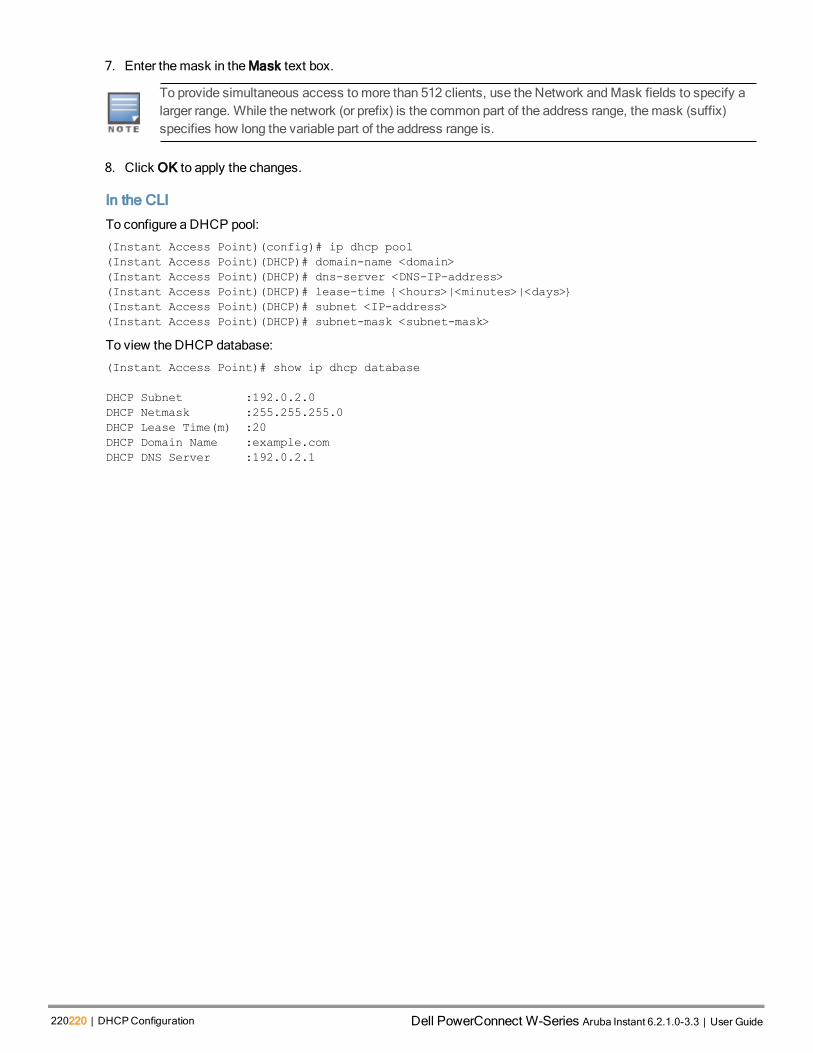
220220 | DHCPConfiguration Dell PowerConnect W-Series Aruba Instant 6.2.1.0-3.3 | User Guide
7. Enter themask in theMask text box.
To provide simultaneous access tomore than 512 clients, use the Network andMask fields to specify alarger range. While the network (or prefix) is the common part of the address range, themask (suffix)specifies how long the variable part of the address range is.
8. Click OK to apply the changes.
In the CLI
To configure a DHCP pool:
(Instant Access Point)(config)# ip dhcp pool
(Instant Access Point)(DHCP)# domain-name <domain>
(Instant Access Point)(DHCP)# dns-server <DNS-IP-address>
(Instant Access Point)(DHCP)# lease-time {<hours>|<minutes>|<days>}
(Instant Access Point)(DHCP)# subnet <IP-address>
(Instant Access Point)(DHCP)# subnet-mask <subnet-mask>
To view the DHCP database:
(Instant Access Point)# show ip dhcp database
DHCP Subnet :192.0.2.0
DHCP Netmask :255.255.255.0
DHCP Lease Time(m) :20
DHCP Domain Name :example.com
DHCP DNS Server :192.0.2.1

AOS-W Instant 6.2.1.0-3.3|User Guide VPN Configuration | 221
Chapter 21VPN Configuration
This chapter describes the following VPN configuration procedures:
l Understanding VPN Features on page 221
l Configuring a Tunnel from Virtual Controller to Alcatel-Lucent Mobility Switch on page 221
l Configuring Routing Profiles on page 223
Understanding VPN FeaturesThe Virtual Private Networks (VPN) feature enables the OAW-IAP, acting as the Virtual Controller, to create a VPNtunnel to an Alcatel-Lucent Mobility Switch in your corporate office. The switch acts as a VPN end-point and doesnot supply the AOS-W Instant AP with any configuration.
The VPN features are recommended for:
l Enterprises with many branches that do not have a dedicated VPN connection to the corporate office.
l Branch offices that require multiple APs.
l Individuals working from home, connecting to the VPN.
The survivability feature of OAW-IAPs with the VPN connectivity of RAPs allows you to provide corporateconnectivity to non-corporate networks.
Configuring a Tunnel from Virtual Controller to Alcatel-Lucent MobilitySwitchYou can configure a tunnel from the Virtual Controller to theMobility Controller using Instant UI or CLI.
In the Instant UI
To configure a tunnel:
1. Click theMore>VPN link at the top right corner of the Instant UI. The Tunneling window is displayed.
Figure 73 Tunneling Controller
2. Select any of the following:
l IPSec
l GRE

222222 | VPN Configuration Dell PowerConnect W-Series Aruba Instant 6.2.1.0-3.3 | User Guide
3. If you select GRE from the Protocol drop-down list, then the packets are sent and received without encryption.
a. Host— Enter the IP address or the fully qualified domain name (FQDN) for themain VPN/GRE endpoint.
a. GRE type — Enter the value for GRE type parameter.
b. Per-AP tunnel — Select Enabled or Disabled from the Per-AP tunnel drop-down list. The administrator canenable this option to create a GRE tunnel from eachOAW-IAP to the VPN/GRE Endpoint rather than thetunnels created just from the Virtual Controller. When enabled, the traffic to the corporate network is sentthrough a Layer-2 GRE tunnel from theOAW-IAP itself and need not be forwarded through the VirtualController.
By default, the Per-AP tunnel option is disabled.
4. If you select IPSec from the Protocol drop-down list, the packets are sent and received with encryption.
a. Enter the IP address or fully qualified domain name for themain VPN/IPSec endpoint in the Primary hostfield.
b. Enter the IP address or fully qualified domain name for the backup VPN/IPSec endpoint in the Backup hostfield. This entry is optional.
c. Select Enabled from the Preemption drop-down list to allow the VPN tunnel to switch back to the primaryhost when it becomes available again. This step is optional.
d. Specify a value in seconds for Hold time. When preemption is enabled and the primary host comes up, theVPN tunnel switches to the primary host after the specified hold-time. The default value for Hold time is 600seconds.
e. Select Enabled or Disabled from the Fast failover drop-down list. Enabling the fast failover feature allowsthe OAW-IAP to create a backup VPN tunnel to the switch along with the primary tunnel, andmaintain boththe primary and backup tunnels separately. If the primary tunnel fails, the OAW-IAP can switch the datastream to the backup tunnel. This reduces the total failover time to less than oneminute.
f. Specify a value in seconds for Secs between test packets. Based on the configured frequency, the OAW-IAP can verify if an active VPN connection is available. The default value is 5 seconds, whichmeans that theOAW-IAP will send one packet to the controller at every 5 seconds.
g. Enter a value for Max allowed test packet loss, to define a number for lost packets, after which the IAP candetermine that the VPN connection is unavailable. The default value is 2.
5. Click Next to continue.
In the CLI
To configure aGRE VPN tunnel:
(Instant Access Point)(config)# gre primary <name>
(Instant Access Point)(config)# gre type <type>
(Instant Access Point)(config)# gre per-ap-tunnel
(Instant Access Point)(config)# end
(Instant Access Point)# commit apply
To configure an IPSec VPN tunnel:
(Instant Access Point)(config)# vpn primary <name>
(Instant Access Point)(config)# vpn backup <name>
(Instant Access Point)(config)# fast-failover
(Instant Access Point)(config)# hold-time <seconds>
(Instant Access Point)(config)# preemption
(Instant Access Point)(config)# vpn monitor-pkt-send-freq <frequency>
(Instant Access Point)(config)# vpn monitor-pkt-lost-cnt <count>
(Instant Access Point)(config)# end
(Instant Access Point)# commit apply

To view VPN status:Instant Access Point# show vpn status
profile name:default
--------------------------------------------------
current using tunnel :unselected tunnel
ipsec is preempt status :disable
ipsec is fast failover status :disable
ipsec hold on period :600
ipsec tunnel monitor frequency (seconds/packet):10
ipsec tunnel monitor timeout by lost packet cnt :2
ipsec primary tunnel crypto type :Cert
ipsec primary tunnel peer address :N/A
ipsec primary tunnel peer tunnel ip :N/A
ipsec primary tunnel ap tunnel ip :N/A
ipsec primary tunnel current sm status :Init
ipsec primary tunnel tunnel status :Down
ipsec primary tunnel tunnel retry times :0
ipsec primary tunnel tunnel uptime :0
ipsec backup tunnel crypto type :Cert
ipsec backup tunnel peer address :N/A
ipsec backup tunnel peer tunnel ip :N/A
ipsec backup tunnel ap tunnel ip :N/A
ipsec backup tunnel current sm status :Init
ipsec backup tunnel tunnel status :Down
ipsec backup tunnel tunnel retry times :0
ipsec backup tunnel tunnel uptime :0
Configuring Routing ProfilesAOS-W Instant can terminate a single VPN connection on an Alcatel-Lucent Mobility Switch. The Routing profiledefines the corporate subnets which need to be tunneled through IPSec.
You can configure routing profiles to specify a policy based on routing into the VPN tunnel using Instant UI or CLI.
In the Instant UI
To configure a routing profile:
1. Click Routing in the Tunneling window. The routing details are displayed.
2. Click New. The route parameters to configure are displayed.
AOS-W Instant 6.2.1.0-3.3|User Guide VPN Configuration | 223

224224 | VPN Configuration Dell PowerConnect W-Series Aruba Instant 6.2.1.0-3.3 | User Guide
Figure 74 Tunneling—Routing
3. Update the following parameters:
l Destination— Specify the destination network that is reachable through the VPN tunnel.
l Netmask— Specify the subnet mask of network that is reachable through the VPN tunnel.
l Gateway— Specify the gateway to which traffic must be routed. This IP address must be the switch IPaddress on which the VPN connection is terminated.
4. Click OK.
5. Click Finish.
In the CLI(Instant Access Point)(config)# routing-profile
(Instant Access Point)(Routing-profile)# route <destination> <mask> <gateway>
(Instant Access Point)(Routing-profile)# end
(Instant Access Point)# commit apply

AOS-W Instant 6.2.1.0-3.3|User Guide IAP-VPN Configuration | 225
Chapter 22IAP-VPN Configuration
Alcatel-Lucent switches provide an ability to terminate the IPSec andGRE VPN tunnels from theOAW-IAP andprovide corporate connectivity to the branch network.
This section describes the following topics:
l Overview on page 225
l VPN Configuration on page 226
l Viewing Branch Status on page 227
OverviewThis section provides a brief summary of the features supported by the switches to allow VPN termination from anOAW-IAP.
Termination of IPSec and GRE VPN Tunnels
OAW-IAPs can terminate VPN tunnels on Switch. The IAP cluster creates an IPSec or GRE VPN tunnel from theVirtual Controller to aMobility Switch in your corporate office. The switch only acts an IPSec or GRE VPN end-pointand it does not configure the OAW-IAP. For more information on how to create an IPSec or GRE VPN tunnel, seeVPN Configuration on page 221.
L2/L3 Forwarding Modes
The Virtual Controller enables different DHCP pools (various assignment modes) in addition to allocating IP subnetsfor each branch. The Virtual Controller allows different modes of forwarding of traffic from the clients on a VLAN witha VPN tunnel. The forwardingmodes are associated with various modes of DHCP address assignment modes. Formore information on DHCP assignment modes and configuring DHCP scope for IAP-VPN, see UnderstandingDHCP Assignment Modes on page 213.
The following DHCP modes are supported:
l NATMode: In this mode, the source IP for all client traffic is translated. The traffic destined for the corporatenetwork is translated using the VPN tunnel IP address of the OAW-IAP and is forwarded through the IPsec VPNtunnel. The traffic destined for the non-corporate network is translated using the IP address of the IAP and isforwarded through the uplink.
When the NATmode is used for forwarding client traffic, hosts on the corporate network cannot establishconnections to the clients on the OAW-IAP, because the source address of the clients is translated.
l L2 Switching Mode: In this mode, the traffic destined for the corporate network is bridged through the VPNtunnel to the switch and the destined for the non-corporate network is translated using the IP address of theOAW-IAP and is forwarded through the uplink.
When anOAW-IAP registers with the switch, and is configured to use the L2 DHCP address assignment mode,the switch automatically adds the VPN tunnel associated to this OAW-IAP into the VLAN multicast table. Thisallows the clients connecting to the L2mode VLAN to be part of the same L2 broadcast domain on the switch.
l L3 Routing Mode: In this mode, the traffic destined for the corporate network is routed through the VPN tunnel tothe switch and the traffic destined for the non corporate network is translated using the IP address of the OAW-IAP and is forwarded through the uplink.

226226 | IAP-VPN Configuration Dell PowerConnect W-Series Aruba Instant 6.2.1.0-3.3 | User Guide
When anOAW-IAP registers with the switch and is configured to use the L3 DHCP address assignment mode,theMobility Switch adds a route on the switch, enabling routing of traffic from the corporate network to clients onthis subnet in the branch.
OSPF Configuration
OSPF (Open Shortest Path First) is a dynamic Interior Gateway routing Protocol (IGP) based on IETF RFC 2328.The premise of OSPF is that the shortest or fastest routing path is used. The implementation of OSPFv2 allowsAlcatel-Lucent Switches to deploy effectively in a Layer 3 topology. The Switches can act as default gateway for allclients and forward user packets to the upstream router.
In the current release of AOS-W, each IAP-VPN can be defined a separate subnet derived from corporate intranetpool to allow IAP-VPN devices to work independently. For more information on configuring OSPF for IAP-VPN, seeAOS-WUser Guide.
VPN ConfigurationThe following VPN configuration steps on the switch, enable OAW-IAPs to terminate their VPN connection on theswitch:
Whitelist Database Configuration
The whitelist database is a list of theMAC addresses of the OAW-IAPs that are allowed to establish VPNconnections with theMobility Switch. This list can be either stored in theMobility Switch or on an external server.
Switch Whitelist Database
You can use the following CLI command to configure the whitelist database entry if the switch is acting as thewhitelist database:
(host) #local-userdb-ap add mac-address 00:11:22:33:44:55 ap-group test
The ap-group parameter is not used for any configuration, but needs to be configured. The parameter can be anyvalid string.
External Whitelist Database
If an external server is being used as the location for the whitelist database, add theMAC addresses of the validOAW-IAPs in the external database or external directory server and then configure a RADIUS server to authenticatethe IAPs using the entries in the external database or external directory server.
If you are usingWindows 2003 server, perform the following steps to configure the external whitelist database on it.There are equivalent steps available forWindows Server 2008 and other RADIUS servers.
1. Add theMAC addresses for all the OAW-IAPs in the Active Directory of the RADIUS server:
a. Open the Active Directory and Computers window, add a new user and specify theMAC address (withoutthe colon delimiter) of the OAW-IAP for the user name and password.
b. Right-click the user that you have just created and click Properties.
c. In the Dial-in tab, select Allow access in the Remote Access Permission section and click OK.
d. Repeat Step a through Step b for all OAW-IAPs.
2. Define the remote access policy in the Internet Authentication Service:
a. In the Internet Authentication Service window, select Remote Access Policies.
b. Launch the wizard to configure a new remote access policy.
c. Define filters and select grant remote access permission in the Permissions window.
d. Right-click the policy that you have just created and select Properties.

e. In the Settings tab, select the policy condition, and Edit Profile....
f. In the Advanced tab, select Vendor Specific, and click Add to add new vendor specific attributes.
g. Add new vendor specific attributes and click OK.
h. In the IP tab, provide the IP address of the OAW-IAP and click OK.
VPN Local Pool Configuration
The VPN local pool is used to assign an IP Address to the OAW-IAP after successful XAUTH VPN.
(host) # ip local pool "rapngpool" <startip> <endip>
Role Assignment for the Authenticated OAW-IAPs
Define a role that includes a src-nat rule to allow connections to the RADIUS server and for the Dynamic RadiusProxy in the IAP to work. This role is assigned to IAPs after successful authentication.
(host) (config) #ip access-list session iaprole
(host) (config-sess-iaprole)#any host <radius-server-ip> any src-nat
(host) (config-sess-iaprole)#any any any permit
(host) (config-sess-iaprole)#!
(host) (config) #user-role iaprole
(host) (config-role) #session-acl iaprole
(host) (config-role) #!
VPN Profile Configuration
The VPN profile configuration defines the server used to authenticate the IAP (internal or an external server) and therole assigned to the IAP after successful authentication.
(host) (config) #aaa authentication vpn default-iap
(host) (VPN Authentication Profile "default-iap") #server-group default
(host) (VPN Authentication Profile "default-iap") #default-role iaprole
For information about the VPN profile configuration on theOAW-IAP, see VPN Configuration on page 221.
Viewing Branch StatusTo view the details of the branches connected to the switch, execute the show iap table command.
Example
This example shows the details of the branches connected to the switch:
(host) (config) #show iap table
IAP Table
---------
Branch KeyStatu-
s
Branch
NameInner IP VC MAC Address Bid(Subnet Name) Branch subnet
---------------
------- -------- ----------- ---------------------- ------------
bc91f01b57a7ba010302932-
d
6e5cf08b139ecac601a2024
UP Instant
C0:42:2C192.0.2.3
d8:c7:c8:c0:01:6-
c
0(22.22.22.0-22.22.22.20,
16)
3(83.83.83.084.84.84.255
400)
22.22.22.0/28
The output of this command includes the following parameters:
AOS-W Instant 6.2.1.0-3.3|User Guide IAP-VPN Configuration | 227

228228 | IAP-VPN Configuration Dell PowerConnect W-Series Aruba Instant 6.2.1.0-3.3 | User Guide
Parameter Description
Branch Key Key for the branch, which is unique to each branch.
Status Current status of the branch (UP/DOWN).
Branch Name Name of the branch.
Inner IP Internal VPN IP of the branch.
MAC Address MAC address of the Virtual Controller.
Bid(Subnet Name) Brach ID of the subnet.
Branch Subnet The subnet to which the branch is allocated.
Table 45: IAP Table Parameters

AOS-W Instant 6.2.1.0-3.3|User Guide OmniVista 3600 Integration andManagement | 229
Chapter 23OmniVista 3600 Integration and Management
This chapter provides the following information:
l OmniVista 3600 Features on page 229
l Configuring OmniVista 3600 on page 231
OmniVista 3600 FeaturesOmniVista 3600 is a powerful tool and easy-to-use network operations system that manages Alcatel-Lucentwireless, wired, and remote access networks, as well as wired and wireless infrastructures from awide range ofthird-party manufacturers. With its easy-to-use interface, OmniVista 3600 provides real-timemonitoring, proactivealerts, historical reporting, and fast, efficient troubleshooting. It also offers tools that manage RF coverage,strengthen wireless security, and demonstrate regulatory compliance.
Alcatel-Lucent OAW-IAPs communicate with OmniVista 3600 using the using the HTTPS protocol. This allows anOmniVista 3600 server to be deployed in the cloud across a NAT device, such as a router. This OmniVista 3600features available in the AOS-W Instant network are described in the following sections.
Image Management
OmniVista 3600 allows you tomanage firmware updates onWLAN devices by defining aminimum acceptablefirmware version for eachmake andmodel of a device. It remotely distributes the firmware image to theWLANdevices that require updates, and it schedules the firmware updates such that updating is completed withoutrequiring you tomanually monitor the devices.
The followingmodels can be used to upgrade the firmware:
l Automatic— In this model, the Virtual Controller periodically checks for newer updates from a configured URL andautomatically initiates upgrade of the network.
l Manual— In this model, the user canmanually start a firmware upgrade for each Virtual Controller or set thedesired firmware preference per group of devices.
IAP and Client Monitoring
OmniVista 3600 allows you to find any OAW-IAP or client on the wireless network and to see real-timemonitoringviews. Thesemonitoring views can be used to aggregate critical information and high-endmonitoring information.
In the OmniVista 3600 User Interface (UI), you can select either Manage Read/Write or Monitor-only+Firmware Upgrades as management modes. When theManagement level is set to ManageRead/Write, the Instant UI is in read-only mode. If AirwaveManagement Level is set to Monitor-only+Firmware Upgrades mode, the Instant UI changes to the read-write mode.
Template-based Configuration
OmniVista 3600 automatically creates a configuration template based on any of the existing OAW-IAPs, and itapplies that template across the network as shown in the following figure. It audits every device on an ongoing basisto ensure that configurations never vary from the enterprise policies. It alerts you whenever a violation is detectedand automatically repairs the incorrectly configured devices.

230230 | OmniVista 3600 Integration andMan-agement Dell PowerConnect W-Series Aruba Instant 6.2.1.0-3.3 | User Guide
Figure 75 Template-based Configuration
Trending Reports
OmniVista 3600 saves up to 14months of actionable information, including network performance data and userroaming patterns, so you can analyze how network usage and performance trends have changed over time. It alsoprovides detailed capacity reports with which you can plan the capacity and appropriate strategies for yourorganization.
Intrusion Detection System
OmniVista 3600 provides advanced, rules-based rogue classification. It automatically detects rogue APsirrespective of their location in the network and prevents authorized OAW-IAPs from being detected as rogueOAW-IAPs. It tracks and correlates the IDS events to provide a complete picture of network security.
Wireless Intrusion Detection System (WIDS) Event Reporting to OmniVista 3600
OmniVista 3600 supports Wireless Intrusion Detection System (WIDS) Event Reporting, which is provided byAlcatel-Lucent AOS-W Instant. This includes WIDS classification integration with the RAPIDS (Rogue AccessPoint Detection Software) module. RAPIDS is a powerful and easy-to-use tool for automatic detection ofunauthorized wireless devices. It supports multiple methods of rogue detection and uses authorized wireless APs toreport other devices within range.
TheWIDS report cites the number of IDS events for devices that have experienced themost instances in the prior24 hours and provides links to support additional analysis or configuration in response.
RF Visualization Support for AOS-W Instant
OmniVista 3600 supports RF visualization for Alcatel-Lucent AOS-W Instant. The VisualRF module provides a real-time picture of the actual radio environment of your wireless network and the ability to plan the wireless coverage ofnew sites. VisualRF uses sophisticated RF fingerprinting to accurately display coverage patterns and calculate thelocation of every Instant device in range. VisualRF provides graphical access to floor plans, client location, and RFvisualization for floors, buildings, and campuses that host your network.

Figure 76 Adding an OAW-IAP in VisualRF
Configuring OmniVista 3600Before configuring the OmniVista 3600, ensure that you have the following information:
l IP address of the OmniVista 3600 server.
l Shared key for service authorization, assigned by the OmniVista 3600 administrator.
This section describes the following procedures:
l Configuring Organization String on page 237
l Configuring for OmniVista 3600 Discovery through DHCP on page 231
l AlternateMethod for Defining Vendor-Specific DHCP Options on page 235
Configuring for OmniVista 3600 Discovery through DHCP
TheOmniVista 3600 can be discovered through DHCP server. You can configure this only if OmniVista 3600 wasnot configured earlier or if you have deleted the precedent configuration.
On the DHCP server, the format for option 60 is " InstantAP", and the format for option 43 is “ams-ip,ams-key”.
Standard DHCP option 60 and 43 on Windows Server 2008
In networks that are not using DHCP option 60 and 43, it is easy to use the standard DHCP options 60 and 43 for anAP or OAW-IAP. For Alcatel-Lucent APs, these options can be used to indicate themaster controller or the localcontroller. For OAW-IAPs, these options can be used to define the OmniVista 3600 IP, group, and password.
1. From a server runningWindows Server 2008 navigate to Server Manager> Roles> DHCPsever >domain DHCP Server > IPv4.
2. Right-click IPv4 and select Set Predefined Options.
AOS-W Instant 6.2.1.0-3.3|User Guide OmniVista 3600 Integration andManagement | 231

232232 | OmniVista 3600 Integration andMan-agement Dell PowerConnect W-Series Aruba Instant 6.2.1.0-3.3 | User Guide
Figure 77 Instant and DHCP options for OmniVista 3600: Set PredefinedOptions
3. Select DHCP Standard Options in the Option class drop-down list and then click Add.
4. Enter the following information:
n Name— Alcatel-Lucent AOS-W Instant
n Data Type— String
n Code— 60
n Description— Alcatel-Lucent AOS-W Instant AP

Figure 78 AOS-W Instant and DHCP options for OmniVista 3600: PredefinedOptions and Values
5. Navigate to Server Manager and select Server Options in the IPv4 window. (This sets the value globally. Useoptions on a per-scope basis to override the global options.)
6. Right-click Server Options and select the configuration options.
AOS-W Instant 6.2.1.0-3.3|User Guide OmniVista 3600 Integration andManagement | 233

234234 | OmniVista 3600 Integration andMan-agement Dell PowerConnect W-Series Aruba Instant 6.2.1.0-3.3 | User Guide
Figure 79 AOS-W Instant and DHCP options for OmniVista 3600: Server Options
7. Select 060 Alcatel-Lucent AOS-W Instant AP in the Server Options window and enter Alcatel-LucentInstantAP in the String Value.
Figure 80 AOS-W Instant and DHCP options for OmniVista 3600—060 OAW-IAP in Server Options
8. Select 043 Vendor Specific Info and enter a value for airwave-orgn, airwave-ip, airwave-key in the ASCIIfield (for example: tme-instant-store1,<IP-address>, Alcatel-Lucent123).

Figure 81 AOS-W Instant and DHCP options for OmniVista 3600— 043 Vendor Specific Info
This creates a DHCP option 60 and 43 on a global basis. You can do the same on a per-scope basis. The per-scopeoption overrides the global option.
Figure 82 AOS-W Instant and DHCP options for OmniVista 3600: ScopeOptions
Alternate Method for Defining Vendor-Specific DHCP Options
This section describes how to add vendor-specific DHCP options for AOS-W Instant APs in a network that alreadyuses DHCP options 60 and 43 for other services. Some networks use DHCP standard options 60 and 43 to provide
AOS-W Instant 6.2.1.0-3.3|User Guide OmniVista 3600 Integration andManagement | 235

236236 | OmniVista 3600 Integration andMan-agement Dell PowerConnect W-Series Aruba Instant 6.2.1.0-3.3 | User Guide
the DHCP clients information about certain services such as PXE. In such an environment, the standard DHCPoptions 60 and 43 cannot be used for Alcatel-Lucent APs.
This method describes how to set up a DHCP server to send option 43 with OmniVista 3600 information to Alcatel-Lucent AOS-W Instant OAW-IAP. This section assumes that option 43 is sent per scope, because option 60 is beingshared by other devices as well.
The DHCP scopemust be specific to Instant, and the PXE devices that use options 60 and 43must notconnect to the subnet defined by this scope. This is because you can specify only one option 43 for ascope, and if other devices that use option 43 connect to this subnet, they are presented with Instant-specific information.
1. In server 2008, navigate to Server Manager > Roles > DHCP Server > Domain DHCP Server > IPv4.
2. Select a scope (subnet). Scope (10.169.145.0)145 is selected in the example shown in the figure below.
3. Right-click and select Advanced, and then specify the following options:
n Vendor class— DHCP Standard Options
n User class— Default User Class
n Available options— Select 043 Vendor-Specific Info
n String Value— Alcatel-LucentInstantAP, tme-store4, 10.169.240.8, Alcatel-Lucent123 (which is the APdescription, organization string, OmniVista 3600 IP address, Pre-shared key for OmniVista 3600)
Figure 83 Vendor Specific DHCP options
Upon completion, the OAW-IAP shows up as a new device in OmniVista 3600, and a new group called tme-store4is created. Navigate to APs/Devices > New > Group to view this group.

Figure 84 OmniVista 3600—New Group
Figure 85 OmniVista 3600—Monitor
Configuring Organization String
TheOrganization string is a set of colon-separated strings created by the OmniVista 3600 administrator to accuratelyrepresent the deployment of each Alcatel-Lucent AOS-W Instant system. This string is defined by the installationpersonnel on the site.
You can use any of the following strings:
l AMP Role— "Org Admin" (initially disabled)
AOS-W Instant 6.2.1.0-3.3|User Guide OmniVista 3600 Integration andManagement | 237

238238 | OmniVista 3600 Integration andMan-agement Dell PowerConnect W-Series Aruba Instant 6.2.1.0-3.3 | User Guide
l AMP User— "Org Admin" (assigned to the role "Org Admin")
l Folder— "Org" (under the Top folder in AMP)
l Configuration Group— "Org"
You can also assign additional strings to create a hierarchy of sub folders under the folder named "Org". Forexample:
n subfolder1 for a folder under the "Org" folder
n subfolder2 for a folder under subfolder1
Shared Key
The Shared Secret key is used by the administrator to manually authorize the first Virtual Controller for anorganization. Any string is acceptable.
Configuring OmniVista 3600 Information
You can configure OmniVista 3600 information using Instant UI or CLI.
In the Instant UI
1. Click the OmniVista 3600 Set Up Now link in the bottom-middle region of the Instant UI window. The Systemwindow is displayed with the OmniVista 3600 parameters in the Admin tab.
Figure 86 Configuring OmniVista 3600
2. Enter the name of your organization in the Organization name text box. The name defined for organization will bedisplayed under the Groups tab in the OmniVista 3600 user interface.
3. Enter the IP address of the OmniVista 3600 server in the AirWave IP text box.
4. Enter the IP address of a backupOmniVista 3600 server in the AirWave backup IP text box. The backup serverprovides connectivity when the primary server is down. If the OAW-IAP cannot send data to the primary server,the Virtual Controller switches to the backup server automatically.

5. Enter the shared key in the Shared key text box and reconfirm. This shared key is used for configuring the firstAP in the Alcatel-Lucent AOS-W Instant network.
6. Click OK.
In the CLI
To configure OmniVista 3600 information in Instant:
(Instant Access Point)(config)# organization <name>
(Instant Access Point)(config)# ams-ip <IP-address>
(Instant Access Point)(config)# ams-backup-ip <IP-address>
(Instant Access Point)(config)# ams-key <key>
(Instant Access Point)(config)# end
(Instant Access Point)# commit apply
AOS-W Instant 6.2.1.0-3.3|User Guide OmniVista 3600 Integration andManagement | 239

0511361-01 | April 2013 240

AOS-W Instant 6.2.1.0-3.3|User Guide AirGroup Configuration | 241
Chapter 24AirGroup Configuration
This chapter provides the following information:
l AirGroupOverview on page 241
l AirGroup with Instant on page 242
l Configuring AirGroup for AOS-W Instant on page 245
l Configuring AirGroup and CPPM interface in AOS-W Instant on page 247
AirGroup OverviewAirGroup is a unique enterprise-class capability that leverages zero configuration networking to enable Bonjour®services such as Apple® AirPrint and AirPlay frommobile devices in an efficient manner. Apple AirPlay and AirPrintservices are based on the Bonjour protocol are essential services in campus Wi-Fi networks.
Zero configuration networking enables service discovery, address assignment, and name resolution for desktopcomputers, mobile devices, and network services. It is designed for flat, single-subnet IP networks such as wirelessnetworking at home. Bonjour is the trade name for the zero configuration implementation introduced by Apple. It issupported by most of the Apple product lines, including theMac OS X operating system, iPhone, iPod Touch, iPad,Apple TV, and AirPort Express.
Bonjour can be installed on computers runningMicrosoft Windows® and is supported by the new network-capableprinters. Bonjour is also included with popular software programs such as Apple iTunes, Safari, and iPhoto. Bonjouruses multicast DNS (mDNS) to locate devices and the services offered by these devices. The AirGroup solutionsupports both wired and wireless devices. Wired devices, which support the Bonjour services aremade part of theAirGroup when the VLANs of the devices are terminated on the Virtual Controller.
AirGroup also supports Alcatel-Lucent ClearPass Policy Manager. With CPPM:
l Users can register their personal devices and define a group of users who can to share the registered devices.
l Administrators can register andmanage an organization's shared devices such as printers and conference roomApple TVs. An administrator can grant global access to each device, or restrict access according to theusername, role, or user location.
The distributed AirGroup architecture allows eachOAW-IAP to handle Bonjour queries and responses individuallyinstead of overloading a Virtual Controller with these tasks. This results in a scalable AirGroup solution.
As shown in the following figure, the OAW-IAP1 discovers Air Printer (P1) andOAW-IAP3 discovers Apple TV(TV1). OAW-IAP1 advertises information about its connected P1 device to the other OAW-IAPs that is OAW-IAP2andOAW-IAP3. Similarly, OAW-IAP3 advertises TV1 device to OAW-IAP1 andOAW-IAP2. This type of distributedarchitecture allows any OAW-IAP to respond to its connected devices locally. In this example, the iPad connectedto OAW-IAP2 obtains direct response from the sameOAW-IAP about the other Bonjour-enabled services in thenetwork.

242242 | AirGroup Configuration Dell PowerConnect W-Series Aruba Instant 6.2.1.0-3.3 | User Guide
Figure 87 - AirGroup Architecture
AirGroup is not supported on a 3G uplink.
AirGroup with InstantAirGroup™ capabilities are available as a feature in Alcatel-Lucent WLANs whereWi-Fi data is distributed amongAOS-W Instant APs. When an Alcatel-Lucent WLAN is powered by an AOS-W Instant and CPPM, AirGroup beginsfunctioning.
An AirGroup device can be registered by an administrator or a guest user.
1. The AirGroup administrator gives an end user the AirGroup operator role which authorizes the user to register theusers' device—such as an Apple TV on the CPPM platform.
2. AOS-W Instant maintains information for all mDNS services. AOS-W Instant queries CPPM tomap eachdevice’s access privileges to available services.
3. AOS-W Instant responds back to the query made by a device based on contextual data such as user role,username, and location.

Figure 88 AirGroup Enables Personal Device Sharing
AirGroup Solution
In large universities and enterprise networks, it is common for Bonjour-capable devices to connect to the networkacross VLANs. As a result, user devices such as an iPad on a specific VLAN cannot discover an Apple TV thatresides on another VLAN. As the addresses used by the protocol are link-scopemulticast addresses, each query oradvertisement can only be forwarded on its respective VLAN, but not across different VLANs.
Broadcast andmulticast traffic are usually filtered out from awireless LAN network to preserve the airtime andbattery life. This inhibits the performance of Bonjour services as they rely onmulticast traffic. Alcatel-Lucentaddresses this multicast DNS (mDNS) challenge with AirGroup technology.
AirGroup leverages key elements of Alcatel-Lucent’s solution portfolio including operating system software for AOS-W Instant, CPPM , and the VLAN-based or role-based filtering options offered by Bonjour services. AirGroupmaintains seamless connectivity between clients and services across VLANs and SSIDs. ThemDNS packet trafficis minimized thereby preserving valuable wired network bandwidth andWLAN airtime.
The following table summarizes the filtering options:
Features Alcatel-Lucent AOS-W Instant Deployment Models
Integrated Integrated with CPPM
Allow mDNS to propagate across subnets/VLANs Yes Yes
Limit multicast mDNS traffic on the network Yes Yes
VLAN based mDNS service policy enforcement Yes Yes
User-role based mDNS service policyenforcement
Yes Yes
Portal to self register personal leaves No Yes
Table 46: AirGroup Filtering Options
AOS-W Instant 6.2.1.0-3.3|User Guide AirGroup Configuration | 243

244244 | AirGroup Configuration Dell PowerConnect W-Series Aruba Instant 6.2.1.0-3.3 | User Guide
Features Alcatel-Lucent AOS-W Instant Deployment Models
Device owner based policy enforcement No Yes
Location based policy enforcement No Yes
Shared user list based policy enforcement No Yes
Shared role list based policy enforcement No Yes
Table 46: AirGroup Filtering Options
AirGroup also enables context awareness for services across the network:
l AirGroup is aware of personal devices. For example, an Apple TV in a dorm room can be associated with thestudent who owns it.
l AirGroup is aware of shared resources. This might be an Apple TV in ameeting room or a printer in a supply roomthat is available to certain users, such as themarketing department. Or, in a classroom, teachers can use AirPlayto wirelessly project a laptop screen onto an HDTV monitor using an Apple TV.
l AirGroup is aware of the location of services when CPPM support is enabled. For example, depending onproximity, an iPad would be presented with the closest printer instead of all the printers in the building.
l When configured with Instant, AirGroup enables a client to perform a location-based discovery. For example,when a client roams from one Instant cluster to another, it can discover devices available in the new cluster towhich the client is currently connected.
The following figure shows a higher-education environment with shared, local, and personal services available tomobile devices. With AirGroup, the context-based policies determine the Bonjour services that can be accessed byan end-user’s mobile device.
Figure 89 - AirGroup in a Higher-Education Environment
AirGroup Features
AirGroup supports the following features:
l AirGroup sends unicast responses tomDNS queries and reduces mDNS traffic footprint.
l Ensure cross-VLAN visibility and availability of mDNS devices and services.
l Allow or block mDNS services for all users.

l Allow or block mDNS services based on user roles.
l Allow or block mDNS services based on VLANs.
l Match users’ devices, such as iPads, to their closest Bonjour devices, such as printers. This requires CPPMsupport.
CPPM and ClearPass Guest Features
CPPM andClearPass Guest support the following features:
l Registration portal forWLAN users to register their personal devices such as Apple TVs and printers.
l Registration portal forWLAN administrators to register shared devices, such as conference room Apple TVs andprinters.
l Operator-defined personal AirGroup to specify a list of other users who can share devices with the operator.
l Administrator defined username, user role, and location attributes for shared devices.
AirGroup Components
The components that make up the AirGroup Solution include the AOS-W Instant, CPPM, and ClearPass Guest. Theversion requirements are described in the following table:
Component Minimum Version
Alcatel-Lucent AOS-W Instant 6.2.1.0-3.3
ClearPass Guest software 3.9.7
AirGroup Services plugin 0.8.7
ClearPass Policy Manager software 5.2
Table 47: AOS-W Instant, CPPM, and ClearPass Guest Requirements
Starting from ClearPass version 6.0, the ClearPass Guest and the AirGroup Services plug-in areintegrated into a single platform.
Configuring AirGroup for AOS-W InstantTo configure AirGroup and its service, enable AirGroup and AirGorup services such as AirPlay and AirPrint.
Enabling or Disabling AirGroup
You can configure AirGroup services, using Instant UI or CLI.
In the Instant UI
To enable AirGroup and its services:
1. Click theMore>Services link at the top right corner of the Instant main window.
2. Click Air Group tab. The Air Group tab details are displayed.
AOS-W Instant 6.2.1.0-3.3|User Guide AirGroup Configuration | 245

246246 | AirGroup Configuration Dell PowerConnect W-Series Aruba Instant 6.2.1.0-3.3 | User Guide
Figure 90 AirGroup Configuration
3. Select the Enable Air Group check box. The AirGroup configuration parameters are displayed.
4. Select Enable Guest Bonjour multicast to allow the users to use Bonjour services enabled in a guest VLAN.When this check box is enabled, the Bonjour devices are visible only in the guest VLAN and AirGroup will notdiscover or enforce policies in guest VLAN.
5. Select the Enable Air Group across mobility domains check box to enable Inter cluster. AOS-W Instantsupports two types assignment modes:
l Intra Cluster - In the Intra Cluster model, the OAW-IAP does not share themDNS database information withthe other clusters.
l Inter Cluster - In the Inter Cluster model, the OAW-IAP shares themDNS database information with the otherclusters. The DNS records in the Virtual Controller can be shared with the all the Virtual Controllers configuredfor L3Mobility.
By default, this feature is disabled. To define clusters, L3 Mobility tab of Settings to define a set of clusters.
6. Select the Enable Air Print check box. The following two options are displayed:
l Air Print disallowed roles— Click Edit and select the user roles for which you want to restrict access toAirPrint devices. By default, an AirGroup service is accessible by all user roles configured in your OAW-IAPcluster. The disallow role option prevents the specified user roles from accessing AirPrint services.
l Air Print disallowed VLANs —Click Edit and select the VLANs which will be excluded by AirPrint servers. Bydefault, an AirGroup service is accessible by users or devices in all VLANs configured in your OAW-IAPcluster. You can enable or disable learning of AirGroup services in a specific VLAN.
7. Select the Enable Air Play check box. The following two options are displayed:
l Air Play disallowed roles—Click Edit and select the user roles that must be restricted from accessing AirPlaydevices.
l Air Play disallowed VLANs —Click Edit and select the VLANs that must be excluded by the AirPlay servers.
8. Clear Pass Settings— Use this section to configure the CPPM server, CoA server, and enforce Clear Passregistering.
l CPPM server 1— Indicates the ClearPass Policy Manager server information for AirGroup policy.
l Enforce Clear Pass registering— When enabled, only devices registered with CPPMwill be discovered byBonjour devices, based on the CPPM policy.
In the CLI
To configure AirGroup:
(Instant Access Point)(config)# airgroup

(Instant Access Point)(airgroup)# cppm enforce-registration
(Instant Access Point)(airgroup)# cppm-server <server>
(Instant Access Point)(airgroup)# cppm-server-dead-time <interval>
(Instant Access Point)(airgroup)# cppm-query-interval <interval>
(Instant Access Point)(airgroup)# disallow-vlan <vlan-ID>
(Instant Access Point)(airgroup)# enable-guest-multicast
(Instant Access Point)(airgroup)# multi-swarm
(Instant Access Point)(airgroup)# end
(Instant Access Point)# commit apply
To configure AirGroup Service
(Instant Access Point)(config)# airgroupservice <airgroup-service>
(Instant Access Point)(airgroup-service)# id <airgroupservice-ID>
(Instant Access Point)(airgroup-service)# description <text>
(Instant Access Point)(airgroup-service)# disallow-role <role>
(Instant Access Point)(airgroup-service)# disallow-vlan <vlan-ID>
(Instant Access Point)(airgroup-service)# end
(Instant Access Point)# commit apply
To view AirGroup configuration status:
Instant Access Point# show airgroup status
AirGroup Feature
----------------
Status
------
Enabled
AirGroup Multi Swarm
--------------------
Status
------
Enabled
AirGroup Guest Multicast
------------------------
Status
------
Enabled
CPPM Parameters
---------------
Parameter Value
--------- -----
CPPM Server test
CPPM Server test1
CPPM Enforce Registration Enabled
CPPM Server query interval 0 Seconds
CPPM Server dead time 100 Seconds
AirGroup Service Information
----------------------------
Service Status
------- ------
airplay Enabled
airprint Enabled
test Enabled
test-profile Enabled
Configuring AirGroup and CPPM interface in AOS-W InstantConfigure the AirGroup and CPPM interface to allow an AirGroup OAW-IAP and CPPM to exchange informationregarding device sharing, and location. The configuration options define the RADIUS server that is used by theAirGroup RADIUS client.
AOS-W Instant 6.2.1.0-3.3|User Guide AirGroup Configuration | 247

248248 | AirGroup Configuration Dell PowerConnect W-Series Aruba Instant 6.2.1.0-3.3 | User Guide
The AirGroup configuration with CPPM involves the following steps:
1. Create a RADIUS service
2. Assign a Server to AirGroup
3. Configure CPPM to Enforce Registration
Creating a RADIUS Server
You can configure an external RADIUS Security window. For more information on the configuring CPPM server, seeConfiguring an External Server for Authentication on page 124. You can also create a RADIUS server in the AirGroup window. Navigate to Services> AirGroup > Clear Pass Settings > CPPM server 1> and select New fromthe drop-downmenu.
Assign a Server to AirGroup
To associate CPPM server with AirGroup, select the CPPM server from the CPPM Server 1 drop-down.
If two CPPM servers are configured, the CPPM server 1 acts as a primary server and the CPPM server 2acts as a backup server.
After configuration is complete, this particular server will appear in the CoA server option. To view this server go toServices> AirGroup >ClearPass Settings > CoA server.
Configure CPPM to Enforce Registration
WhenCPPM registration is enforced, the devices registered with CPPMwill be discovered by Bonjour devices,based on the CPPM policy.
Change of Authorization (CoA)
When aRADIUS server is configured with Change of Authorization (CoA) with ClearPass Guest server, the guestusers are allowed to register their devices. For more information on configuring RADIUS server with CoA , seeConfiguring an External Server for Authentication on page 124.
You can also create a CoA only server in the Services> AirGroup > Clear Pass Settings > CoAserver window.

AOS-W Instant 6.2.1.0-3.3|User Guide RealTime Location Server Configuration | 249
Chapter 25Real Time Location Server Configuration
This chapter describes the procedure for configuring Real Time Location Server (RTLS).
Configuring RTLSAOS-W Instant supports the real-time tracking of devices when integrated with OmniVista 3600 , Ekahau Real TimeLocation Server, Nearbuy Real Time Location Server or Aeroscout Real Time Location Server. With the help of theRTLS, the devices can bemonitored in real-time or through history.
You can configure RTLS using Instant UI or CLI.
In the Instant UI
To configure RTLS:
1. Click theMore>Services link at the top right corner of the Instant main window. The Services window isdisplayed.
2. Click the RTLS tab. The following figure shows the contents of the RTLS tab.
Figure 91 RTLSWindow
3. Select the Aruba RTLS check box to integrate Instant with OmniVista 3600 , Ekahau Real Time LocationServer, and Nearbuy Real Time Location Server.
4. Specify the IP address and port to which the location reports must be sent.
5. Specify the shared secret key in the Passphrase text box.
6. Specify the frequency at which packets are sent to the server. The default value is 5 seconds.
7. Select the Aeroscout check box to send the RFID tag information to an AeroScout RTLS. Specify the IPaddress and port number of the AeroScout server, to which location reports must be sent.
8. Select the Include unassociated stations check boxes to sendmobile unit reports to the Aeroscout and theAruba RTLS servers on the client stations not associated to any OAW-IAP (unassociated stations).
In the CLI
To configure AirWave RTLS:

250250 | RealTime Location Server Con-figuration Dell PowerConnect W-Series Aruba Instant 6.2.1.0-3.3 | User Guide
(Instant Access Point)(config)# airwave-rtls <IP-address> <port> <passphrase> <seconds>
include-unassoc-sta
(Instant Access Point)(config)# end
(Instant Access Point)# commit apply
To configure Aeroscout RTLS
(Instant Access Point)(config)# aeroscout-rtls <IP-address> <port> include-unassoc-sta
(Instant Access Point)(config)# end
(Instant Access Point)# commit apply

AOS-W Instant 6.2.1.0-3.3|User Guide Hotspot Profiles | 251
Chapter 26Hotspot Profiles
This chapter describes the following procedures:
l Understanding Hotspot Profiles on page 251
l Advertisement Profiles for a Hotspot on page 254
l Configuring an NAI Realm Profile on page 255
l Configuring a Venue NameProfile on page 256
l Configuring a Network Authentication Profile on page 257
l Configuring a Roaming Consortium Profile on page 257
l Configuring a 3GPP Profile on page 258
l Configuring an IP Address Availability Profile on page 258
l Configuring a Domain Profile on page 258
l Configuring H2QP Profiles on page 258
l Configuring a Hotspot Profile on page 260
In the current release, Instant supports the hotspot profile configuration only through the CLI.
Understanding Hotspot ProfilesHotspot 2.0 is aWi-Fi Alliance specification based on the 802.11u protocol, which allows wireless clients to discoverhotspots usingmanagement frames (such as beacon, association request and association response), connect tonetworks, and roam between networks without additional authentication.
The Hotspot 2.0 provides the following services:
l Network discovery and selection— Allows the clients to discover suitable and available networks by advertisingthe access network type, roaming consortium, and venue information through themanagement frames. Fornetwork discovery and selection, Generic Advertisement Service (GAS) and Access Network Query Protocol(ANQP) are used.
l QOS Mapping— Provides amapping between the network-layer QoS packet marking and over- the-air QoS framemarking based on user priority.
When a hotspot is configured in a network:
l The clients search for available hotspots using the beaconmanagement frame.
l When a hotspot is found, client sends queries to obtain information about the type of network authentication andIP address, and IP address availability using the Generic Advertisement Service (GAS) action frames.
l Based on the response of the advertisement Server (response to the GAS Action Frames), the relevant hotspot isselected and the client attempts to associate with it.
l Based on the authenticationmode used for mobility clients, the client authenticates to access the network.
Generic Advertisement Service (GAS)
GAS is a request-response protocol, which provides L2 transport mechanism between a wireless client and a serverin the network prior to authentication. It helps in determining an 802.11 infrastructure before associating clients andallows clients to send queries tomultiple 802.11 networks in parallel.

252252 | Hotspot Profiles Dell PowerConnect W-Series Aruba Instant 6.2.1.0-3.3 | User Guide
An AP can include its service provider Organization Identifier (OI) indicating the service provider identity in beaconsand probe responses to clients. When a client recognizes anOAW-IAP's OI, it attempts to associate to that OAW-IAP using the security credentials corresponding to that service provider. If the client does not recognize the AP’sOI, the client sends aGeneric Advertisement Service (GAS) query to the OAW-IAP to request more informationabout the network before associating. A client transmits a GAS Query using aGAS Initial Request frame and theOAW-IAP provides the query response or information on how to receive the query response in a GAS InitialResponse frame. To transmit a GAS query for any advertisement protocol, the advertisement protocol ID mustinclude the advertisement protocol information element with information about the advertisement protocol and itscorresponding advertisement control.
Access Network Query Protocol (ANQP)
ANQP provides a range of information, such as IP address type and availability, roaming partners accessiblethrough a hotspot, and the Extensible Authentication Protocol (EAP)method supported for authentication, for a queryand response protocol. The ANQP Information Elements (IEs) provide additional data that can be sent from anOAW-IAP to the client to identify the OAW-IAP's network and service provider. If a client requests this informationthrough aGAS query, the hotspot AP sends the ANQP capability list in the GAS Initial Response frame indicatingsupport for the following IEs:
l Venue Name
l Domain Name
l Network Authentication Type
l Roaming Consortium List
l Network Access Identifier Realm
l 3GPP Cellular Network Data
Hotspot 2.0 Query Protocol (H2QP)
The H2QP profiles provide a range of information on hotspot 2.0 elements such as hotspot protocol and port,operating class, operator names, WAN status, and uplink and downlink metrics.
Information Elements (IEs) and Management Frames
The hotspot 2.0 configuration supports the following IEs:
l Interworking IE—Provides information about the Interworking service capabilities such as the Internet availabilityin a specific service provider network.
l Advertisement Protocol IE—Provides information about the advertisement protocol that a client can use forcommunication with the advertisement servers in a network.
l Roaming Consortium IE—Provides information about the service provider network for roaming clients, which canbe used to authenticate with the AP.
The IEs are included in the followingManagement Frames when 802.11u is enabled:
l Beacon Frame
l Probe Request Frame
l Probe response frame
l Association Request
l Re-Association request
Access Network Types
The following types of 802.11u network types are supported:

l Chargeable Public network—This network provides access to the Internet based on payment. For example, asubscription-based Internet access in a coffee shop or a hotel offering chargeable in-room Internet accessservice.
l Free public network —This network is accessible to all without any charges applied. For example, a hotspot inairport or other public places that provide Internet access with no additional cost.
l Emergency Services Only Network —This network is limited to accessing emergency services only.
l Personal device network —This network is accessible for personal devices. For example, a laptop or cameraconfigured with a printer for the purpose of printing.
l Private Network—This network is accessible for authorized users only. For example, home networks or enterprisenetworks that require user authentication.
l Private network with guest access— This network is accessible to guest users based on guest authenticationmethods. For example, enterprise networks that allow guest users with captive portal authentication.
l Test network— This network is used for test purposes only.
l Wildcard Network—This network indicates a wildcard network.
NAI Realm List
AnNAI Realm profile identifies and describes a NAI realm to which the clients can connect. The NAI realm settingson anOAW-IAP as an advertisement profile to determine the NAI realm elements that must be included as part of aGAS Response frame.
Venue types
The venue types provides information on the venue names associated with a Base Service Set (BSS), to which theclients can associate. You can configure the following venue types for a hotspot profile:
l assembly-amphitheatre
l assembly-amusement-park
l assembly-arena
l assembly-bar
l assembly-coffee-shop
l assembly-convention-center
l assembly-emer-coord-center
l assembly-library
l assembly-musuem
l assembly-passenger-terminal
l assembly-restaurant
l assembly-stadium
l assembly-theater
l assembly-worship-place
l assembly-zoo
l business-attorney
l business-bank
l business-doctor
l business-fire-station
l business-police-station
l business-post-office
AOS-W Instant 6.2.1.0-3.3|User Guide Hotspot Profiles | 253

254254 | Hotspot Profiles Dell PowerConnect W-Series Aruba Instant 6.2.1.0-3.3 | User Guide
l business-professional-office
l business-research-and-development
l educational-primary-school
l educational-secondary-school
l educational-university
l industrial-factory
l institutional-alcohol-or-drug-rehab
l institutional-group-home
l institutional-hospital
l institutional-prison
l institutional-terminal-care
l mercantile-automotive-service-station
l mercantile-gas-station
l mercantile-grocery
l mercantile-retail
l mercantile-shopping-mall
l outdoor-bus-stop
l outdoor-city-park
l outdoor-kiosk
l outdoor-muni-mesh-nwk
l outdoor-rest-area
l outdoor-traffic-control
l residential-boarding-house
l residential-dormitory
l residential-hotel
l residential-private-residence
l unspecified
l vehicular-airplane
l vehicular-automobile
l vehicular-bus
l vehicular-ferry
l vehicular-motor-bike
l vehicular-ship
l vehicular-train
Advertisement Profiles for a HotspotA hotspot profile contains one or several advertisement profiles. The following advertisement profiles can beconfigured through the Instant CLI:
l NAI Realm profile
l Venue NameProfile
l Network Auth Profile
l Roaming Consortium Profile

l 3GPP Profile
l IP Address availability Profile
l Domain Name Profile
l Operator Friendly Name Profile
l Connection Capability Profile
l Operating Class Profile
l WAN-Metrics Profile
Configuring an NAI Realm Profile
You configure an NAI Realm profile to define the NAI realm information that can be send as an ANQP IE in a GASquery response.
To configure a NAI profile, enter the following commands at the command prompt:
(Instant Access Point)(config)# hotspot anqp-nai-realm-profile <name>
(Instant Access Point)(nai-realm <name>)# nai-realm-name <name>
(Instant Access Point)(nai-realm <name>)# nai-realm-encoding <UTF8-encode>
(Instant Access Point)(nai-realm <name>)# nai-realm-eap-method <eap-method>
(Instant Access Point)(nai-realm <name>)# nai-realm-auth-id-1 <authentication-ID>
(Instant Access Point)(nai-realm <name>)# nai-realm-auth-id-2 <authentication-ID>
(Instant Access Point)(nai-realm <name>)# nai-realm-auth-value-1 <authentication-value>
(Instant Access Point)(nai-realm <name>)# nai-home-realm
(Instant Access Point)(nai-realm <name>)# enable
(Instant Access Point)(nai-realm <name>)# end
(Instant Access Point)# commit apply
You can specify any of the following EAP methods for the nai-realm-eap-method <eap-method> command:
l crypto-card—To use crypto card authentication
l eap-aka—To use EAP for UMTS Authentication and Key Agreement
l eap-sim—To use EAP for GSM Subscriber Identity Modules
l eap-tls —To use EAP-Transport Layer Security (EAP-TLS)
l eap-ttls—To use EAP-Tunneled Transport Layer Security (EAP-TTLS)
l generic-token-card—To use EAP Generic Token Card (EAP-GTC)
l identity—To use EAP Identity type
l notification—To use the hotspot realm uses EAP Notificationmessages for authentication.
l one-time-password—To use authentication with a single-use password
l peap—To use protected Extensible Authentication Protocol (PEAP)
l peap-mschapv2—To use PEAP with Microsoft Challenge Handshake Authentication Protocol (PEAP-MSCHAP)version 2.
You can specify any of the following authenticationmethods as an authentication ID for the nai-realm-auth-id-1<authentication-ID> command:
l credential-type—To use credential-based authentication
l expanded-eap — To use EAP authenticationmethod.
l expanded-inner-eap—To use the expanded inner EAP authenticationmethod.
l inner-auth-eap —To use inner EAP authentication type.
l non-eap-inner-auth—To use non-EAP inner authentication type
l tunneled-eap-credential-type—To use the tunneled EAP credential typeS
AOS-W Instant 6.2.1.0-3.3|User Guide Hotspot Profiles | 255

256256 | Hotspot Profiles Dell PowerConnect W-Series Aruba Instant 6.2.1.0-3.3 | User Guide
You can specify any of the authentication values for the nai-realm-auth-value-1 <authentication-value>command based on the authenticationmethod specified for nai-realm-auth-id-1 <authentication-ID>:
l cred-cert
l cred-hw-token
l cred-nfc
l cred-none
l cred-rsvd
l cred-sim
l cred-soft-token
l cred-user-pass
l cred-usim
l cred-vendor-spec
l eap-crypto-card—EAP Method
l eap-generic-token-card
l eap-identity
l eap-method-aka
l eap-method-sim
l eap-method-tls
l eap-method-ttls
l eap-notification
l eap-one-time-password
l eap-peap
l eap-peap-mschapv2
l non-eap-chap
l non-eap-mschap
l non-eap-mschapv2
l non-eap-pap
l non-eap-rsvd
l reserved
Configuring a Venue Name Profile
You configure venue name profile to send venue information as an ANQP IE in a GAS query response. To configurea venue name profile, enter the following commands at the command prompt:
(Instant Access Point)(config)# hotspot anqp-venue-name-profile <name>
(Instant Access Point)(venue-name <name>)# venue-name <name>
(Instant Access Point)(venue-name <name>)# venue-group <group-name>
(Instant Access Point)(venue-name <name>)# venue-type <type>
(Instant Access Point)(venue-name <name>)# venue-lang-code <language>
(Instant Access Point)(venue-name <name>)# enable
(Instant Access Point)(venue-name <name>)# end
(Instant Access Point)# commit apply
You can specify any of the following venue groups for the venue-group <group-name> command:
l assembly
l business
l educational

l factory-or-industrial
l institutional
l mercantile
l outdoor
l reserved
l residential
l storage
l unspecified
l Utility-Misc
l Vehicular
You can specify any of the types of venue listed in the Venue types on page 253 for the venue-type <type>command.
Configuring a Network Authentication Profile
You can configure a network authentication profile to define the authentication type used by the hotspot network. Toconfigure a network authentication profile, enter the following commands at the command prompt:
(Instant Access Point)(config)# hotspot anqp-nwk-auth-profile <name>
(Instant Access Point)(network-auth <name>)# nwk-auth-type <type>
(Instant Access Point)(network-auth <name>)# url <URL>
(Instant Access Point)(network-auth <name>)# enable
(Instant Access Point)(network-auth <name>)# end
(Instant Access Point)# commit apply
You can specify any of the following network authentication type for the nwk-auth-type <type> command:
l acceptance —To allow the user to accept terms and conditions before accessing a hotspot network.
l dns-redirection—To allow DNS redirection.
l http-https-redirection—To allow HTTP/HTTPS redirection.
l online-enroll—To allow online enrollment.
Configuring a Roaming Consortium Profile
You can configure a roaming consortium profile to send the roaming consortium information as an ANQP IE in a GASquery response. To configure a roaming consortium profile, enter the following commands at the command prompt:
(Instant Access Point)(config)# hotspot anqp-roam-cons-profile <name>
(Instant Access Point)(roaming-consortium <name>)# roam-cons-oi <roam-cons-oi>
(Instant Access Point)(roaming-consortium <name>)# roam-cons-oi-len <roam-cons-oi-len>
(Instant Access Point)(roaming-consortium <name>)# enable
(Instant Access Point)(roaming-consortium <name>)# end
(Instant Access Point)# commit apply
Specify a hexadecimal string of 3 to 5 octets for roam-cons-oi <roam-cons-oi>.
Based on theOI specified, you can specify the following parameters for the length of OI in roam-cons-oi-len<roam-cons-oi-len>.
l For 0: 0 Octets in the OI (Null)
l For 3: OI length is 24-bit (3 Octets)
l For 5: OI length is 36-bit (5 Octets)
AOS-W Instant 6.2.1.0-3.3|User Guide Hotspot Profiles | 257

258258 | Hotspot Profiles Dell PowerConnect W-Series Aruba Instant 6.2.1.0-3.3 | User Guide
Configuring an IP Address Availability Profile
You can configure the available IP address types to send information on IP address availability as an ANQP IE in aGAS query response. To configure an IP address availability profile, enter the following commands at the commandprompt:
(Instant Access Point)(config)# hotspot anqp-ip-addr-avail-profile <name>
(Instant Access Point)(IP-addr-avail <name>)# ipv4-addr-avail
(Instant Access Point)(IP-addr-avail <name>)# ipv6-addr-avail
(Instant Access Point)(IP-addr-avail <name>)# enable
(Instant Access Point)(IP-addr-avail <name>)# end
(Instant Access Point)# commit apply
Configuring a 3GPP Profile
You can configure a 3rd Generation Partnership Project (3GPP) profile to define information for the 3GCellularNetwork for hotspots.
To configure a 3GPP profile, enter the following commands at the command prompt:
(Instant Access Point)(config)# hotspot anqp-3gpp-profile <name>
(Instant Access Point)(3gpp <name>)# 3gpp-plmn1
(Instant Access Point)(3gpp <name>)# enable
(Instant Access Point)(3gpp <name>)# end
(Instant Access Point)# commit apply
The Public LandMobile Network (PLMN) ID is a combination of themobile country code and network code. You canspecify up to 6 PLMN IDs for a 3GPP profile.
Configuring a Domain Profile
You can configure a domain profile to send the domain names as an ANQP IE in a GAS query response. Toconfigure a domain name profile, enter the following commands at the command prompt:
(Instant Access Point)(config)# hotspot anqp-domain-name-profile <name>
(Instant Access Point)(domain-name <name>)# domain-name <domain-name>
(Instant Access Point)(domain-name <name>)# enable
(Instant Access Point)(domain-name <name>)# end
(Instant Access Point)# commit apply
Configuring H2QP Profiles
You can configure the following H2QP profiles to send information in a GAS query response:
l Operator-friendly Name
l Connection Capability Profile
l Operating Class Profile
l WAN Metrics Profile
Configuring an Operator-friendly Profile
You can configure the operator-friendly name profile to define the identify the operator. To configure an H2QPoperator-friendly name profile:
(Instant Access Point)(config)# hotspot h2qp-oper-name-profile <name>
(Instant Access Point)(operator-friendly-name <name>)# op-fr-name <op-fr-name>
(Instant Access Point)(operator-friendly-name <name>)# op-lang-code <op-lang-code>
(Instant Access Point)(operator-friendly-name <name>)# enable
(Instant Access Point)(operator-friendly-name <name>)# end
(Instant Access Point)# commit apply

Configuring a Connection Capability Profile
You can configure a Connection Capability profile to define information such as the hotspot IP protocols andassociated port numbers that are available for communication. To configure an H2QP connection capability profile:
(Instant Access Point)(config) # hotspot h2qp-conn-cap-profile
(Instant Access Point)(connection-capabilities <name>)# esp-port
(Instant Access Point)(connection-capabilities <name>)# icmp
(Instant Access Point)(connection-capabilities <name>)# tcp-ftp
(Instant Access Point)(connection-capabilities <name>)# tcp-http
(Instant Access Point)(connection-capabilities <name>)# tcp-pptp-vpn
(Instant Access Point)(connection-capabilities <name>)# tcp-ssh
(Instant Access Point)(connection-capabilities <name>)# tcp-tls-vpn
(Instant Access Point)(connection-capabilities <name>)# tcp-voip
(Instant Access Point)(connection-capabilities <name>)# udp-ike2
(Instant Access Point)(connection-capabilities <name>)# udp-ipsec-vpn
(Instant Access Point)(connection-capabilities <name>)# udp-voip
(Instant Access Point)(connection-capabilities <name>)# enable
(Instant Access Point)(connection-capabilities <name>)# end
(Instant Access Point)# commit apply
Configuring an Operating Class Profile
You can configure an operating class profile, to list the channels on which the hotspot is capable of operating. Toconfigure an H2QP operating class profile:
(Instant Access Point)(config) # hotspot h2qp-oper-class-profile <name>
(Instant Access Point)(operator-class <name>)# op-cl <class-ID>
(Instant Access Point)(operator-class <name>)# enable
(Instant Access Point)(operator-class <name>)# end
(Instant Access Point)# commit apply
Configuring a WAN Metrics Profile
You can configure aWAN metrics profile to define information about access network characteristics such as linkstatus andmetrics. To configure aWAN metrics profile:
(Instant Access Point)(config)# hotspot h2qp-wan-metrics-profile <name>
(Instant Access Point)(WAN-metrics <name>)# at-capacity ?
(Instant Access Point)(WAN-metrics <name>)# downlink-load <load>
(Instant Access Point)(WAN-metrics <name>)# downlink-speed <speed>
(Instant Access Point)(WAN-metrics <name>)# load-duration <duration>
(Instant Access Point)(WAN-metrics <name>)# symm-link
(Instant Access Point)(WAN-metrics <name>)# uplink-load <load>
(Instant Access Point)(WAN-metrics <name>)# uplink-speed <speed>
(Instant Access Point)(WAN-metrics <name>)# wan-metrics-link-status <status>
(Instant Access Point)(WAN-metrics <name>)# end
(Instant Access Point)# commit apply
You can specify the followingWAN downlink and uplink parameters:
l Downlink load— Indicates the percentage of theWAN downlink currently utilized. The default value of 0indicates that the downlink speed is unknown or unspecified.
l Downlink speed —Indicates theWAN downlink speed in Kbps.
l Uplink load—Indicates the percentage of theWAN uplink currently utilized. The default value of 0 to indicatesthat the downlink speed is unknown or unspecified.
l Uplink speed—Indicates theWAN uplink speed in Kbps.
l Load duration—Indicates the duration in seconds during which the downlink utilization is measured.
l Symmetric links—Indicates if the uplink and downlink have the same speed.
l WAN Link Status— Indicates if theWAN is down (link_down), up (link_up), in test state (link_test), or reserved.
AOS-W Instant 6.2.1.0-3.3|User Guide Hotspot Profiles | 259

260260 | Hotspot Profiles Dell PowerConnect W-Series Aruba Instant 6.2.1.0-3.3 | User Guide
Configuring a Hotspot ProfileYou can configure a hotspot profile and associate the advertisement profiles to use for a hotspot network connectionor setup. The hotspot profile can be enabled on one or more SSID profile by creating a reference in theWLAN SSIDprofile.
This topic describes the following procedures:
l Creating a Hotspot Profile on page 260
l Associating a Hotspot Profile with an Advertisement Profile on page 262
l Enabling a Hotspot Profile on aWLAN SSID on page 262
Creating a Hotspot Profile
To create a hotspot profile:
(Instant Access Point)(config)# hotspot hs-profile <name>
(Instant Access Point)(Hotspot2.0 <name>)# asra
(Instant Access Point)(Hotspot2.0 <name>)# access-network-type <type>
(Instant Access Point)(Hotspot2.0 <name>)# addtl-roam-cons-ois <roam-consortium-OIs>
(Instant Access Point)(Hotspot2.0 <name>)# comeback-mode
(Instant Access Point)(Hotspot2.0 <name>)# gas-comeback-<delay-interval>
(Instant Access Point)(Hotspot2.0 <name>)# group-frame-block
(Instant Access Point)(Hotspot2.0 <name>)# hessid <hotspot-essid>
(Instant Access Point)(Hotspot2.0 <name>)# internet
(Instant Access Point)(Hotspot2.0 <name>)# p2p-cross-connect
(Instant Access Point)(Hotspot2.0 <name>)# p2p-dev-mgmt
(Instant Access Point)(Hotspot2.0 <name>)# pame-bi
(Instant Access Point)(Hotspot2.0 <name>)# query-response-length-limit <integer>
(Instant Access Point)(Hotspot2.0 <name>)# roam-cons-len-1 <integer>
(Instant Access Point)(Hotspot2.0 <name>)# roam-cons-len-2 <integer>
(Instant Access Point)(Hotspot2.0 <name>)# roam-cons-len-3 <integer>
(Instant Access Point)(Hotspot2.0 <name>)# roam-cons-oi-1 <integer>
(Instant Access Point)(Hotspot2.0 <name>)# roam-cons-oi-2 <integer>
(Instant Access Point)(Hotspot2.0 <name>)# roam-cons-oi-3 <integer>
(Instant Access Point)(Hotspot2.0 <name>)# venue-group <group>
(Instant Access Point)(Hotspot2.0 <name>)# venue-type <type>
(Instant Access Point)(Hotspot2.0 <name>)# enable
(Instant Access Point)(Hotspot2.0 <name>)# end
(Instant Access Point)#commit apply
The hotspot profile configuration parameters are described in the following table:
Parameter Description
access-network-type
Specify any of the following 802.11u network types.l emergency-servicesl personal-devicel privatel private-guestl publicl public-freel testl wildcardFor more information on access network type, see Access Network Types on page 252.
addtl-roam-cons-ois
Specify the number of additional roaming consortium Organization Identifiers (OIs) advertised bythe AP. You can specify up to three additional OIs.
Table 48: Hotspot Configuration Parameters

Parameter Description
asra Enable the Additional Steps Required for Access (asra) to indicate if additional steps arerequired for authentication. When enabled, the following information is sent to the client inresponse to an ANQP query. For ASRA, ensure that the network authentication type isassociated.
comeback-mode Enable this parameter to allow the client to obtain a GAS Request and Response as aComeback-Request and Comeback-Response.
gas-comeback-delay
Specify a GAS come back delay interval in milliseconds to allow the client to retrieve the queryresponse using a comeback request action frame when the GAS response is delayed. You canspecify a value within the range of 100-2000 milliseconds and the default value is 500milliseconds.
grp-frame-block Enable this parameter if you want to stop the AP from sending forward downstream group-addressed frames.
hessid Specify a Homogenous Extended Service Set Identifier (HESSID) in a hexadecimal formatseparated by colons.
internet Specify this parameter to allow the IAP to send an Information Element (IE) indicating that thenetwork allows Internet access.
p2p-cross-connect Specify this parameter to advertise support for P2P Cross Connections.
p2p-dev-mgmt Specify this parameter to advertise support for P2P device management.
pame-bi Specify this parameter to enable Pre-Association Message Exchange BSSID Independent(PAME-BI) bit, with which the IAP can indicate that the Advertisement Server can return a queryresponse independent of the BSSID used in the GAS Frame exchange.
query-response-length-limit
Specify this parameter to set the maximum length of the GAS query response, in octets. You canspecify a value within the range of 1-255 octets.
roam-cons-len-1roam-cons-len-2roam-cons-len-3
Specify the length of the organization identifier. The value of the roam-cons-len-1, roam-cons-len-2, or roam-cons-len-3. The roaming consortium OI is based on the following parameters:l 0: Zero Octets in the OI (Null)l 3: OI length is 24-bit (3 Octets)l 5: OI length is 36-bit (5 Octets)
venue-group Specify one of the following venue groupsl assemblyl businessl educationall factory-or-industriall institutionall mercantilel outdoorl reservedl residentiall storagel unspecifiedl Utility-Miscl Vehicular
venue-type Specify a venue type to be advertised in the ANQP IEs from IAPs associated with this hotspotprofile.
Table 48: Hotspot Configuration Parameters
AOS-W Instant 6.2.1.0-3.3|User Guide Hotspot Profiles | 261

262262 | Hotspot Profiles Dell PowerConnect W-Series Aruba Instant 6.2.1.0-3.3 | User Guide
Associating a Hotspot Profile with an Advertisement Profile
To associate a hotspot profile with an advertisement profile:
(Instant Access Point)(config)# hotspot hs-profile <name>
(Instant Access Point)(Hotspot2.0 <name>)# advertisement-protocol <protocol>
(Instant Access Point)(Hotspot2.0 <name>)# advertisement-profile anqp-3gpp <name>
(Instant Access Point)(Hotspot2.0 <name>)# advertisement-profile anqp-domain-name <name>
(Instant Access Point)(Hotspot2.0 <name>)# advertisement-profile anqp-ip-addr-avail <name>
(Instant Access Point)(Hotspot2.0 <name>)# advertisement-profile anqp-nai-realm <name>
(Instant Access Point)(Hotspot2.0 <name>)# advertisement-profile anqp-nwk-auth <name>
(Instant Access Point)(Hotspot2.0 <name>)# advertisement-profile anqp-roam-cons <name>
(Instant Access Point)(Hotspot2.0 <name>)# advertisement-profile anqp-venue-name <name>
(Instant Access Point)(Hotspot2.0 <name>)# advertisement-profile h2qp-conn-cap <name>
(Instant Access Point)(Hotspot2.0 <name>)# advertisement-profile h2qp-oper-class <name>
(Instant Access Point)(Hotspot2.0 <name>)# advertisement-profile h2qp-oper-name <name>
(Instant Access Point)(Hotspot2.0 <name>)# advertisement-profile h2qp-wan-metrics <name>
(Instant Access Point)(Hotspot2.0 <name>)# end
(Instant Access Point)# commit apply
The configuration parameters for associating an advertisement profile with a hotspot profile are described in thefollowing table:
Parameter Description
advertisement-profile Specify the advertisement profile to associate with this hotspot profile. For information onadvertisement profiles, see Advertisement Profiles for a Hotspot on page 254.
advertisement-protocol Specify any of the following advertisement protocol types:l Access Network Query Protocol (ANQP) as anqpl Emergency Alert System( EAS) as emergencyl Media Independent Handover (MIH) Command and Event Services Capability Discovery
as mih-cmd-eventl Media Independent Handover (MIH) Information Service as mih-info
You can also specify reserved to indicate future use.
Table 49: Advertisement Association Parameters
Enabling a Hotspot Profile on a WLAN SSID
To enable a hotspot profile on aWLAN SSID:
(Instant Access Point)(config)# wlan ssid-profile <name>
(Instant Access Point)(SSID Profile <name>)# hotspot-profile <name>
(Instant Access Point)(SSID Profile <name>)# end
(Instant Access Point)# commit apply

AOS-W Instant 6.2.1.0-3.3|User Guide OAW-IAPManagement | 263
Chapter 27OAW-IAP Management
This section provides information on the following procedures:
l Configuring LED Display on page 263
l Backing up and Restoring OAW-IAP Configuration Data on page 263
l Converting anOAW-IAP to a Remote AP and Campus AP on page 264
l Resetting a Remote AP or Campus AP to anOAW-IAP on page 268
l Rebooting the OAW-IAP on page 268
Configuring LED Display
The LED display is always in the Enabled mode during the anOAW-IAP reboot.
You can enable or disable LED Display for an OAW-IAP using either Instant UI or CLI.
In the Instant UI
To enable or disable LED display for all OAW-IAPs in an Instant network, perform the following steps:
1. In the Instant main window, click the System link. The System window appears.
2. In the General tab of System window, click Show advanced options to display the advanced options.
3. From the LED Display drop-downmenu, select Enabled to enable LED display or Disabled to turn off the LEDdisplay.
4. Click OK.
In the CLI
To enable or disable LED display:
(Instant Access Point)(config)# led-off
(Instant Access Point)(config)# no led-off
(Instant Access Point)(config)# end
(Instant Access Point)# commit apply
Backing up and Restoring OAW-IAP Configuration DataYou can back up theOAW-IAP configuration data and restore the configuration when required.
Viewing Current Configuration
To view the current configuration on theOAW-IAP:
l In the Instant UI, navigate toMaintenance>Configuration>Current Configuration.
l In the CLI, enter the following command at the command prompt:(Instant Access Point)# show running-config
Backing up Configuration Data
To back up theOAW-IAP configuration data:

264264 | OAW-IAPManagement Dell PowerConnect W-Series Aruba Instant 6.2.1.0-3.3 | User Guide
1. Navigate to theMaintenance > Configuration> page.
2. Click Backup Configuration.
3. Click Continue to confirm the backup. The instant.cfg containing the OAW-IAP configuration data is saved inyour local file system.
4. To view the configuration that is backed up by the OAW-IAP, enter the following command at the commandprompt:
(Instant Access Point)# show backup-config
Restoring Configuration
To restore configuration:
1. Navigate to theMaintenance > Configuration>page.
2. Click Restore Configuration. Click Browse to browse your local system and select the configuration file .
3. Click Restore Now.
4. Click Restore Configuration to confirm restoration. The configuration is restored and theOAW-IAP reboots toload the new configuration.
Converting an OAW-IAP to a Remote AP and Campus APYou can provision anOAW-IAP as a Campus AP or Remote AP in a switch-based network. Before converting anOAW-IAP, ensure that both the OAW-IAP and switch are configured to operate in the same regulatory domain.
This section describes the following procedures:
l Converting anOAW-IAP to Remote AP on page 264
l Converting anOAW-IAP to Campus AP on page 267
l Converting anOAW-IAP to StandaloneMode on page 267
l Converting anOAW-IAP using CLI on page 268
Converting an OAW-IAP to Remote AP
For Remote AP conversion, the Virtual Controller sends the Remote AP convert command to all the other OAW-IAPs. The Virtual Controller along with the other slave OAW-IAPs set up a VPN tunnel to the remote switch, anddownload the firmware through FTP. The Virtual Controller uses IPsec to communicate to theMobility Switch overthe Internet.
l If the OAW-IAP obtains OmniVista 3600 information through DHCP (Option 43 andOption 60), it establishes anHTTPS connection to the AirWave server and downloads the configuration and operates in the OAW-IAP mode.
l If the OAW-IAP does not get AirWave information through DHCP provisioning, it tries provisioning through afirmware image server in the cloud by sending a serial numberMAC address. If an entry for the OAW-IAP ispresent in the firmware image cloud server and is provisioned as anOAW-IAP > Remote AP, the firmware imagecloud server responds with mobility switch IP address, AP group, and AP type. TheOAW-IAP then contacts theswitch, establishes certificate-based secure communication, and obtains configuration and image from theswitch. TheOAW-IAP reboots and comes up as a Remote AP. TheOAW-IAP then establishes an IPSECconnection with the switch and begins operating in the Remote AP mode.
l If an OAW-IAP entry for the AP is present in the firmware image cloud server, the OAW-IAP obtains AirWaveserver information from the cloud server and downloads configuration from OmniVista 3600 to operate in theOAW-IAP mode.
l If there is no response from the cloud server or AirGroup is received, the OAW-IAP comes up in Instant mode.
l Formore information on firmware image cloud server, see Upgrading anOAW-IAP on page 64.

A mesh point cannot be converted to Remote AP, becausemesh access points do not support VPNconnection.
AnOAW-IAP can be converted to a Campus AP and Remote AP only if the switch is running AOS-W 6.1.4 or later.
The following table describes the supported OAW-IAP platforms andminimal AOS-W version required for theCampus AP or Remote AP conversion.
Table 50: OAW-IAP Platforms andMinimal AOS-W Versions for OAW-IAP to Remote AP Conversion
OAW-IAP Platform AOS-W Version AOS-W Instant Version
OAW-IAP-92 6.1.4 or later 1.0 or later
OAW-IAP-93 6.1.4 or later 1.0 or later
OAW-IAP-104 6.1.4 or later 3.0 or later
OAW-IAP-105 6.1.4 or later 1.0 or later
OAW-IAP-134 6.1.4 or later 2.0 or later
OAW-IAP-135 6.1.4 or later 2.0 or later
OAW-IAP-175AC 6.1.4 or later 3.0 or later
OAW-IAP-175P 6.1.4 or later 3.0 or later
OAW-RAP3WN 6.1.4 or later 3.0 or later
OAW-RAP3WNP 6.1.4 or later 3.0 or later
OAW-RAP108 6.2.0.0 or later 3.2 or later
OAW-RAP109 6.2.0.0 or later 3.2 or later
OAW-RAP155 6.2.0.0 or later 3.3 or later
OAW-RAP155P 6.2.0.0 or later 3.3 or later
To convert an OAW-IAP to RAP, perform the following steps:
1. Click theMaintenance link in the Instant main window.
2. Click the Convert tab. The Convert tab is displayed.
AOS-W Instant 6.2.1.0-3.3|User Guide OAW-IAPManagement | 265

266266 | OAW-IAPManagement Dell PowerConnect W-Series Aruba Instant 6.2.1.0-3.3 | User Guide
Figure 92 - Maintenance—Convert Tab
Figure 93 - Convert options
3. Select Remote APs managed by a Mobility Controller from the drop-down list.
4. Enter the hostname (fully qualified domain name) or the IP address of the switch in the Hostname or IP Addressof Mobility Controller text box. Contact your local network administrator to obtain the IP address.
Ensure that themobility switch IP Address is reachable by the OAW-IAPs.
5. Click Convert Now to complete the conversion. TheOAW-IAP reboots and begins operating in the Remote APmode.
6. After conversion, the OAW-IAP is managed by themobility switch.
For OAW-IAPs to function as Remote APs, configure the OAW-IAP in the Remote AP white-list andenable the FTP service on the switch.
If the VPN setup fails and an error message is displayed, click OK, copy the error logs, and share themwith your local administrator.
Converting an OAW-IAP using CLI
To an convert an OAW-IAP:
Instant Access Point# convert-aos-ap <mode> <controller-IP-address>

Converting an OAW-IAP to Campus AP
To convert an OAW-IAP to Campus AP, do the following:
1. Click theMaintenance link in the Instant main window.
2. Click the Convert tab. The Convert tab is displayed.
Figure 94 - Converting anOAW-IAP to Campus AP
3. Select Campus APs managed by a Mobility Controller from the drop-down list.
4. Enter the hostname, Fully Qualified Domain Name (FQDN), or the IP address of the switch in the Hostname orIP Address of Mobility Controller text box. Contact your local administrator to obtain these details.
5. Ensure that the OAW-IAPs access themobility switch IP Address.
6. Click Convert Now to complete the conversion.
Converting an OAW-IAP to Standalone Mode
This feature allows you to deploy anOAW-IAP as an autonomous AP which is a separate entity from the existingVirtual Controller cluster in the Layer 2 domain.
To convert an OAW-IAP to a standalone AP:
1. Click theMaintenance link in the Instant main window.
2. Click the Convert tab. The Convert tab is displayed.
Figure 95 - Standalone AP Conversion
AOS-W Instant 6.2.1.0-3.3|User Guide OAW-IAPManagement | 267

268268 | OAW-IAPManagement Dell PowerConnect W-Series Aruba Instant 6.2.1.0-3.3 | User Guide
3. Select Standalone AP from the drop-down list.
4. Select the Access Point from the drop-down list.
5. Click Convert Now to complete the conversion. TheOAW-IAP now operates in the standalonemode.
Converting an OAW-IAP using CLI
To an convert an OAW-IAP:
(Instant Access Point)# convert-aos-ap <mode> <controller-IP-address>
Resetting a Remote AP or Campus AP to an OAW-IAPThe reset button located on the rear of an OAW-IAP can be used to reset the OAW-IAP to factory default settings.
To reset an OAW-IAP, perform the following steps:
1. Power off the OAW-IAP.
2. Press and hold the reset button using a small and narrow object such as a paperclip.
3. Power on the OAW-IAP without releasing the reset button. The power LED flashes within 5 seconds indicatingthat the reset is completed.
4. Release the reset button. TheOAW-IAP reboots with the factory default settings.
All APs have a reset button, except OAW-IAP175P/175AC. Contact Alcatel-Lucent support for resettingtheseOAW-IAPs.
Rebooting the OAW-IAPIf you encounter any problem with the OAW-IAPs, you can reboot all OAW-IAPs or a selected OAW-IAPs in anetwork using the Instant UI. To reboot anOAW-IAP:
1. Click theMaintenance link. TheMaintenance window appears.
2. Click the Reboot tab.

Figure 96 - Rebooting the OAW-IAP
3. In the OAW-IAP list, select the OAW-IAP that you want to reboot and click Reboot selected Access Point. Toreboot all the OAW-IAPs in the network, click Reboot All.
4. The Confirm Reboot for OAW-IAP is displayed. Click Reboot Now to proceed. The Reboot in Progressmessage appears indicating that the reboot is in progress. The Reboot Successful message is displayed afterthe process is complete. If the system fails to boot, the Unable to contact Access Points after reboot wasinitiated message is displayed.
5. Click OK.
AOS-W Instant 6.2.1.0-3.3|User Guide OAW-IAPManagement | 269

0511361-01 | April 2013 270

AOS-W Instant 6.2.1.0-3.3|User Guide Monitoring Devicesand Logs | 271
Chapter 28Monitoring Devices and Logs
This chapter provides the following information:
l Configuring SNMP on page 271
l Configuring a Syslog Server on page 275
l Configuring TFTP DumpServer on page 274
l Viewing Logs on page 276
Configuring SNMPThis section provides the following information:
l SNMP Parameters for OAW-IAP on page 271
l Configuring SNMP on page 272
l Configuring SNMP Traps on page 274
SNMP Parameters for OAW-IAP
AOS-W Instant supports SNMPv1, SNMPv2c, and SNMPv3 for reporting purposes only. AnOAW-IAP cannot useSNMP to set values in an Alcatel-Lucent system.
You can configure the following parameters for OAW-IAP.
Field Description
Community Strings for SNMPV1and SNMPV2
An SNMP Community string is a text string that acts as a password,and is used to authenticate messages sent between the VirtualController and the SNMP agent.
If you are using SNMPv3 to obtain values from the Alcatel-Lucent AOS-W Instant, you can configure thefollowing parameters:
Name A string representing the name of the user.
Authentication Protocol An indication of whether messages sent on behalf of this user canbe authenticated, and if so, the type of authentication protocol used.This can take one of the two values:l MD5— HMAC-MD5-96 Digest Authentication Protocoll SHA: HMAC-SHA-96 Digest Authentication Protocol
Authentication protocolpassword
If messages sent on behalf of this user can be authenticated, the(private) authentication key for use with the authentication protocol.This is a string password for MD5 or SHA depending on the choiceabove.
Privacy protocol An indication of whether messages sent on behalf of this user canbe protected from disclosure, and if so, the type of privacy protocolwhich is used. This takes the value DES (CBC-DES SymmetricEncryption).
Privacy protocol password If messages sent on behalf of this user can be encrypted/decryptedwith DES, the (private) privacy key for use with the privacy protocol.
Table 51: SNMP Parameters for OAW-IAP

272272 | Monitoring Devicesand Logs Dell PowerConnect W-Series Aruba Instant 6.2.1.0-3.3 | User Guide
Configuring SNMP
This section describes the procedure for configuring SNMPv1, SNMPv2, and SNMPv3 community strings usingInstant UI or CLI.
Creating community strings for SNMPv1 and SNMPv2 Using Instant UI
To create community strings for SNMPv1 and SNMPv2:
1. Click System link at the top right corner of the Instant main window. The system window is displayed.
2. Click theMonitoring tab. The following figure shows the SNMP configuration parameters displayed in theMonitoring tab.
Figure 97 Monitoring Tab: SNMP Configuration Parameters
3. Click New in the Community Strings for SNMPV1 and SNMPV2 box.
4. Enter the string in the New Community String text box.
5. Click OK.
6. To delete a community string, select the string, and click Delete.
Creating community strings for SNMPv3 Using Instant UI
To create community strings for SNMPv3:
1. Click System link at the top right corner of the Instant main window. The system window is displayed.
2. Click theMonitoring tab. The SNMP configuration parameters displayed in theMonitoring tab.
3. Click New in the Users for SNMPV3 box. A window for specifying SNMPv3 user information is displayed.
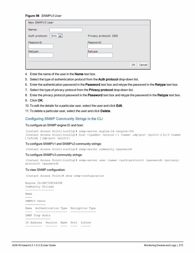
Figure 98 SNMPv3User
4. Enter the name of the user in the Name text box.
5. Select the type of authentication protocol from the Auth protocol drop-down list.
6. Enter the authentication password in the Password text box and retype the password in the Retype text box.
7. Select the type of privacy protocol from the Privacy protocol drop-down list.
8. Enter the privacy protocol password in the Password text box and retype the password in the Retype text box.
9. Click OK.
10. To edit the details for a particular user, select the user and click Edit.
11. To delete a particular user, select the user and click Delete.
Configuring SNMP Community Strings in the CLI
To configure an SNMP engine ID and host:
(Instant Access Point)(config)# snmp-server engine-id <engine-ID>
(Instant Access Point)(config)# host <ipaddr> version {1 <name> udp-port <port>}|{2c|3 <name>
[inform] [udp-port <port>]}
To configure SNMPv1 and SNMPv2 community strings:
(Instant Access Point)(config)# snmp-server community <password>
To configure SNMPv3 community strings:
(Instant Access Point)(config)# snmp-server user <name> <auth-protocol> <password> <privacy-
protocol> <password>
To view SNMP configuration:
(Instant Access Point)# show snmp-configuration
Engine ID:D8C7C8C44298
Community Strings
-----------------
Name
----
SNMPv3 Users
------------
Name Authentication Type Encryption Type
---- ------------------- ---------------
SNMP Trap Hosts
---------------
IP Address Version Name Port Inform
---------- ------- ---- ---- ------
AOS-W Instant 6.2.1.0-3.3|User Guide Monitoring Devicesand Logs | 273

274274 | Monitoring Devicesand Logs Dell PowerConnect W-Series Aruba Instant 6.2.1.0-3.3 | User Guide
Configuring SNMP Traps
AOS-W Instant supports the configuration of external trap receivers. Only the OAW-IAP acting as the VirtualController generates traps. TheOID of the traps is 1.3.6.1.4.1.14823.2.3.3.1.200.2.X.
You can configure SNMP traps using Instant UI or CLI.
In the Instant UI
To configure an SNMP trap receiver:
1. Navigate to System>Show advanced options> Monitoring. TheMonitoring window is displayed.
1. Under SNMP Traps, enter a name in the SNMP Engine ID text box. It indicates the name of the SNMP agent onthe access point. The SNMPV3 agent has an engine ID that uniquely identifies the agent in the device and isunique to that internal network.
2. Click New and update the following fields:
l IP Address— Enter the IP Address of the new SNMP Trap receiver.
l Version —Select the SNMP version— v1, v2c, v3 from the drop-down list. The version specifies the format oftraps generated by the access point.
l Community/Username— Specify the community string for SNMPv1 and SNMPv2c traps and a username forSNMPv3 traps.
l Port— Enter the port to which the traps are sent. The default value is 162.
l Inform— When enabled, traps are sent as SNMP INFORMmessages. It is applicable to SNMPV3 only. Thedefault value is Yes.
3. Click OK to view the trap receiver information in the SNMP Trap Receivers window.
In the CLI
To configure SNMP traps:
(Instant Access Point)(config)# snmp-server host <IP-address> {version 1 | version 2 | version
3} <name> udp-port <port> inform
(Instant Access Point)(config)# end
(Instant Access Point)# commit apply
The current release of Instant supports SNMP management Information bases (MIBs) along with Alcatel-Lucent-MIBs. For information about Alcatel-Lucent MIBs, SNMP MIBs and SNMP traps, see the AOS-WInstant 6.2.1.0-3.3 MIB ReferenceGuide.
Configuring TFTP Dump Server
You can configure a TFTP server for storing core dump files by using the Instant UI or CLI.
In the Instant UI
1. In the Instant main window, click the System link. The System window appears.
2. Click Show advanced options to display the advanced options.
3. Click theMonitoring tab. TheMonitoring tab details are displayed.
4. Enter the IP address of the TFTP server in the TFTP Dump Server text box.
5. Click OK.
In the CLI
To configure a TFTP server:
(Instant Access Point)(config)# tftp-dump-server <IP-address>
(Instant Access Point)(config)# end

(Instant Access Point)# commit apply
Configuring a Syslog ServerYou can specify a syslog server for sending syslogmessages to the external servers either by using Instant UI orCLI.
In the Instant UI
1. In the Instant main window, click the System link. The System window appears.
2. Click Show advanced options to display the advanced options.
3. Click theMonitoring tab. TheMonitoring tab details are displayed.
Figure 99 Syslog Server
4. In the Syslog server text box, enter the IP address of the server to which you want to send system logs.
5. Select the required values to configure syslog facility levels. Syslog Facility is an information field associatedwith a syslogmessage. It is an application or operating system component that generates a logmessage. Thefollowing seven facilities are supported by Syslog:
l AP-Debug— Detailed log about the AP device.
l Network— Log about change of network, for example, when a new OAW-IAP is added to a network.
l Security— Log about network security, for example, when a client connects using wrong password.
l System— Log about configuration and system status.
l User— Important logs about client.
l User-Debug— Detailed log about client.
l Wireless— Log about radio.
AOS-W Instant 6.2.1.0-3.3|User Guide Monitoring Devicesand Logs | 275

276276 | Monitoring Devicesand Logs Dell PowerConnect W-Series Aruba Instant 6.2.1.0-3.3 | User Guide
The following table describes the logging levels in order of severity, from themost to the least severe.
Logging Level Description
Emergency Panic conditions that occur when the system becomes unusable.
Alert Any condition requiring immediate attention and correction.
Critical Any critical conditions such as a hard drive error.
Errors Error conditions.
Warning Warning messages.
Notice Significant events of a non-critical and normal nature. The default value forall Syslog facilities.
Informational Messages of general interest to system users.
Debug Messages containing information useful for debugging.
Table 52: Logging Levels
6. Click OK.
In the CLI
To configure a syslog server:
(Instant Access Point)(config)# syslog-server <IP-address>
To configure syslog facility levels:
(Instant Access Point)(config)# syslog-level <logging-level> [ap-debug | network | security |
system | user | user-debug | wireless]
(Instant Access Point)(config)# end
(Instant Access Point)# commit apply
To view syslog logging levels:
Instant Access Point# show syslog-level
Logging Level
-------------
Facility Level
-------- -----
ap-debug warn
network warn
security warn
system warn
user warn
user-debug warn
wireless error
Viewing LogsTo view the log information for OAW-IAPs:
1. Navigate toMore>Support at the top right corner of the Instant main window. The Support window is displayed.
2. Select the required option from the Command drop-down list.
3. Select All Access Points or Instant Access Point(VC) from the Target drop-down list.

4. Click Run.
Support Commands
You can view the following information for each access point in the Alcatel-Lucent AOS-W Instant network using thesupport window:
l AP 3G/4G Status—Displays the cellular status of the OAW-IAP.
l AP 802.1X Statistics— Displays the 802.1X statistics of the OAW-IAP.
l AP Access Rule Table— Displays the list of ACL rules configured on theOAW-IAP.
l AP Active— Displays the list of active APs in Instant network.
l AP Airgroup Cache— Displays the Bonjour Multicast DNS (mDNS) records for the OAW-IAP.
l AP Airgroup CPPM Entries —Displays the AirGroup CPPM policies of the registered devices.
l AP Airgroup CPPM Servers— Displays the AirGroup CPPM server information.
l AP Airgroup Debug Statistics— Displays the debug statistics for the OAW-IAP.
l AP Airgroup Servers— Displays information about the Bonjour devices which supports AirPrint and AirPlayservices for the OAW-IAP.
l AP Airgroup User— Displays the IP/MAC address, device name, VLAN, type of connection of the Bonjourdevices for the OAW-IAP.
l AP Allowed Channels— Displays information of the allowed channels for the OAW-IAP.
l AP All Supported Timezones— Displays all the supported time zones of Instant.
l AP ARM Bandwidth Management— Displays bandwidthmanagement information for the OAW-IAP.
l AP ARMChannels— Displays ARM channel details for the OAW-IAP.
l AP ARMConfiguration— Displays ARM configuration details for the OAW-IAP.
l AP ARMHistory— Displays the channel history and power changes due to Adaptive RadioManagement (ARM)for the OAW-IAP.
l AP ARMNeighbors— Displays the ARM neighbors of the OAW-IAP.
l AP ARMRF Summary— Displays the status and statistics for all channels monitored by the OAW-IAP.
l AP ARM Scan Times— Displays channel scanning information for the OAW-IAP.
l AP ARP Table— Displays the ARP table of the OAW-IAP.
l AP Association Table— Displays information about the OAW-IAP association.
l AP Authentication Frames— Displays the authentication trace buffer information of the OAW-IAP.
l AP BSSID Table— Displays the Basic Service Set (BSS) table of the OAW-IAP.
l AP Country Codes— Displays country code details for the OAW-IAP.
l AP CPU Utilization— Displays utilization of CPU for the OAW-IAP.
l AP Crash Info— Displays crash log information (if it exists) for the OAW-IAP. The stored information is clearedfrom the flash after the AP reboots.
l AP Current Time— Displays the current time configured on theOAW-IAP.
l AP Current Timezone— Displays the current time zone configured on the OAW-IAP.
l AP Datapath ACL Table Allocation— Displays ACL table allocation details for the OAW-IAP.
l AP Datapath ACL Tables— Displays the list of ACL rules configured for the SSID and Ethernet port profiles.
l AP Datapath Bridge Table— Displays bridge table entry statistics includingMAC address, VLAN, assignedVLAN, Destination and flag information for the OAW-IAP.
l AP Datapath DMO Session— Displays details of a DMO session.
l AP Datapath Multicast Table—Displays multicast table statistics for the OAW-IAP.
l AP Datapath Route Table— Displays route table statistics for the OAW-IAP.
AOS-W Instant 6.2.1.0-3.3|User Guide Monitoring Devicesand Logs | 277

278278 | Monitoring Devicesand Logs Dell PowerConnect W-Series Aruba Instant 6.2.1.0-3.3 | User Guide
l AP Datapath Session Table— Displays the datapath session table statistics for the OAW-IAP.
l AP Datapath Statistics— Displays the hardware packet statistics for the OAW-IAP.
l AP Datapath User Table— Displays datapath user statistics such as current entries, pending deletes, highwater mark, maximum entries, total entries, allocation failures, invalid users, andmaximum link length for theOAW-IAP.
l AP Datapath VLAN Table— Displays the VLAN table information such as VLAN memberships inside thedatapath including L2 tunnels for the OAW-IAP.
l AP Daylight Saving Time—Displays the Daylight Saving Time configured on theOAW-IAP.
l AP Driver Configuration— Displays driver configuration details of the OAW-IAP.
l AP Election Statistics—Displays master election statistics.
l AP ESSID Table— Displays the SSID profiles configured on theOAW-IAP.
l AP Flash Configuration— Displays statistics of the OAW-IAP configuration stored in flashmemory.
l AP IGMP Group Table—Displays IGMP group information.
l AP Interface Counters— Displays information about the Ethernet interface packet counters for the OAW-IAP.
l AP Interface Status— Displays the Ethernet port status for the OAW-IAP.
l AP Internal DHCP Status—Displays details on DHCP allocation.
l AP IP Interface—Displays a summary of all IP-related information for Ethernet interfaces configured on theOAW-IAP.
l AP IP Route Table— Displays information about IP routes for the OAW-IAP.
l AP L3 Mobility Datapath—Display L3mobility details.
l AP L3 Mobility Events Log—Displays a log with L3 client roaming details.
l AP L3 Mobility Status—Displays the status of L3 roaming clients.
l AP Log All— Displays all logs for the OAW-IAP.
l AP Log AP-Debug— Displays logs with debugging information for the OAW-IAP.
l AP Log Conversion—Displays image conversion details for the OAW-IAP.
l AP Log Driver—Displays the status of drivers configured on theOAW-IAP.
l AP Log Network— Displays network logs for the OAW-IAP.
l AP Log PPPd—Displays the Point-to-Point Protocol daemon (PPPd) network connection details.
l AP Log Rapper—Displays rapper information.
l AP Log Sapd— Displays SAPd logs.
l AP Log Security— Displays security logs of the OAW-IAP.
l AP Log System— Displays system logs of the OAW-IAP.
l AP Log Tunnel Status Management—Displays tunnel status.
l AP Log Upgrade—Displays image download and upgrade details for the OAW-IAP.
l AP Log User-Debug— Displays user-debug logs of the OAW-IAP.
l AP Log User— Displays user logs of the OAW-IAP.
l AP Log VPN Tunnel Log— Displays VPN tunnel status for the OAW-IAP.
l AP Log Wireless— Displays wireless logs of the OAW-IAP.
l AP Management Frames— Displays the traced 802.11management frames for the OAW-IAP.
l AP Memory Allocation State Dumps — Displays thememory allocation details for the OAW-IAP.
l AP Memory Utilization— Displays memory utilization of the OAW-IAP.
l AP Mesh Counters— Displays themesh counters of the OAW-IAP.
l AP Mesh Link— Displays themesh link of the OAW-IAP.

l AP Mesh Neighbors— Displays themesh link neighbors of the OAW-IAP.
l AP Monitor Active Laser Beams—Displays the active laser beam sources for the OAW-IAP.
l AP Monitor AP Table— Displays the list of APs monitored by the OAW-IAP.
l AP Monitor ARP Cache—Displays ARP cache details for the OAW-IAP.
l AP Monitor Client Table— Displays the list of clients monitored by the OAW-IAP.
l AP Monitor Containment Information— Displays containment details for the OAW-IAP.
l AP Monitor Potential AP Table— Displays the list of potential APs for the OAW-IAP.
l AP Monitor Potential Client Table— Displays the list of potential clients for the OAW-IAP.
l AP Monitor Router—Displays information about the potential wireless devices.
l AP Monitor Scan Information—Displays scanned information for the OAW-IAP
l AP Monitor Status— Displays the configuration and status of monitor information of the OAW-IAP.
l AP Persistent Clients— Displays the list persistent clients for the OAW-IAP.
l AP PPPoE uplink debug—Displays PPPoE debug logs.
l AP PPPoE uplink status— Displays PPPoE uplink status.
l AP Processes— Displays the processes running on theOAW-IAP.
l AP Radio 0 Stats— Displays aggregate debug statistics of the OAW-IAP Radio 0.
l AP Radio 1 Stats— Displays aggregate debug statistics of the OAW-IAP Radio 1.
l AP RADIUS Statistics— Displays the RADIUS server statistics for the OAW-IAP.
l AP Shaping Table— Displays shaping information for clients associated with the OAW-IAP.
l AP Sockets— Displays information sockets of the OAW-IAP.
l AP STMConfiguration— Displays STM configuration details for each SSID profile configured on theOAW-IAP.
l AP System Status— Displays detailed system status information for the OAW-IAP.
l AP System Summary— Displays the OAW-IAP configuration.
l AP Tech Support Dump— Displays the logs with complete OAW-IAP configuration information required fortechnical support.
l AP Uplink Status—Displays uplink status for the OAW-IAP.
l AP User Table—Displays the list of clients for the OAW-IAP.
l AP Valid Channels— Displays valid channels of the OAW-IAP.
l AP Version— Displays the version number of the OAW-IAP.
l AP VPN Status—Displays VPN status for the OAW-IAP.
l APWired Port Settings— Displays wired port configuration details for the OAW-IAP.
l APWired User Table—Displays the list of clients associated with the wired network profile configured on theOAW-IAP.
l VC 802.1x Certificate— Displays the CA certificate and server certificate for the Virtual Controller.
l VC About— Displays information such as AP type, build time of image, and image version for the VirtualController.
l VC Active Configuration— Displays the active configuration of Virtual Controller.
l VC Airgroup Service— Displays the Bonjour services supported by the Virtual Controller.
l VC Airgroup Status— Displays the status of the AirGroup and CPPM server details configured on the VirtualController.
l VC Allowed AP Table— Displays the list of allowed APs.
l VC AMP Current State Data—Displays the current status of OmniVista 3600.
l VC AMP Current Stats Data—Displays the current OmniVista 3600 configuration details.
AOS-W Instant 6.2.1.0-3.3|User Guide Monitoring Devicesand Logs | 279

280280 | Monitoring Devicesand Logs Dell PowerConnect W-Series Aruba Instant 6.2.1.0-3.3 | User Guide
l VC AMP Data Sent—Displays information about the data exchange betweenOmniVista 3600 Server and theVirtual Controller.
l VC AMP Events Pending—Displays information about the pending events on the OmniVista 3600 server.
l VC AMP Last Configuration Received—Displays the last configuration details received from OmniVista 3600.
l VC AMP Single Sign-on Key—Displays single sign-on key details for OmniVista 3600.
l VC Application Services— Displays the details of application services, which includes protocol number, portnumber.
l VC Auth-Survivability cache— Displays the list of 802.1X cached user's information.
l VC DHCP Option 43 Received— Displays information about the current activities for the DHCP scope withOption 43.
l VC Global Alerts— Displays the list of alerts for all OAW-IAPs managed by the Virtual Controller.
l VC Global Statistics— Displays the flow information and signal strength of the Virtual Controller.
l VC IDS AP List— Displays the list of OAW-IAPs monitored by the Virtual Controller.
l VC IDS Client List— Displays the list of clients detected by IDS for the Virtual Controller.
l VC Internal DHCP Server Configuration— Displays the configuration details of the internal DHCP server.
l VC Local User Database— Displays the list of users configured for the OAW-IAP.
l VC OpenDNS Configuration and Status— Displays configuration details and status of the OpenDNS server.
l VC Radius Attributes— Displays information about the RADIUS attributes.
l VC Radius Servers— Displays the list of RADIUS servers configured on theOAW-IAP.
l VC Saved Configuration— Displays the configuration details of the Virtual Controller.
l VC Scanning Statistics—Displays the scanned information for the OAW-IAP.
l VC SNMP Configuration— Displays the SNMP configuration details of the OAW-IAP.
l VC Uplink 3G/4G Configuration—Displays the 3G/4G cellular configuration information for the OAW-IAPsmanaged by the Virtual Controller.
l VC Uplink Management Configuration—Displays uplink configuration details for the Virtual Controller.
l VC WISPr Configuration — Displays theWISPr configuration details.
Use the support commands under the supervision of Alcatel-Lucent technical support.

AOS-W Instant 6.2.1.0-3.3|User Guide RegulatoryDomain | 281
Chapter 29Regulatory Domain
The IEEE 802.11/b/g/nWi-Fi networks operate in the 2.4 GHz spectrum and IEEE 802.11a/n operate in the 5.0 GHzspectrum. These spectrums are divided into channels. The 2.4 GHz spectrum is divided into 14 overlapping,staggered 20MHz wireless carrier channels. These channels are spaced 5MHz apart. The 5GHz spectrum isdivided intomore channels. The channels that can be used in a particular country differ based on the regulations ofthat country.
The initial Wi-Fi setup requires you to specify the country code for the country in which the Alcatel-Lucent AOS-WInstant operates. This configuration sets the regulatory domain for the radio frequencies that the OAW-IAPs use.Within the regulated transmission spectrum, a high-throughput 802.11a, 802.11b/g, or 802.11n radio setting can beconfigured. The available 20MHz and 40MHz channels are dependent on the specified country code.
You cannot change the country code for the OAW-IAPs designated for US and Japan and Israel. Improper countrycode assignment can disrupt wireless transmissions. Most countries impose penalties and sanctions on operators ofwireless networks with devices set to improper country codes. Country Codes List on page 281 shows the list ofcountry codes.
Figure 100 - Specifying a Country Code
Country Codes List
Code Country Name
US United States
CA Canada
JP3 Japan
DE Germany
NL Netherlands
IT Italy
PT Portugal
Table 53: Country Codes List

282282 | RegulatoryDomain Dell PowerConnect W-Series Aruba Instant 6.2.1.0-3.3 | User Guide
Code Country Name
LU Luxembourg
NO Norway
FI Finland
DK Denmark
CH Switzerland
CZ Czech Republic
ES Spain
GB United Kingdom
KR Republic of Korea (SouthKorea)
CN China
FR France
HK Hong Kong
SG Singapore
TW Taiwan
BR Brazil
IL Israel
SA Saudi Arabia
LB Lebanon
AE United Arab Emirates
ZA South Africa
AR Argentina
AU Australia
AT Austria
BO Bolivia
CL Chile
GR Greece
IS Iceland
IN India

Code Country Name
IE Ireland
KW Kuwait
LI Liechtenstein
LT Lithuania
MX Mexico
MA Morocco
NZ New Zealand
PL Poland
PR Puerto Rico
SK Slovak Republic
SI Slovenia
TH Thailand
UY Uruguay
PA Panama
RU Russia
KW Kuwait
LI Liechtenstein
LT Lithuania
MX Mexico
MA Morocco
NZ New Zealand
PL Poland
PR Puerto Rico
SK Slovak Republic
SI Slovenia
TH Thailand
UY Uruguay
PA Panama
AOS-W Instant 6.2.1.0-3.3|User Guide RegulatoryDomain | 283

284284 | RegulatoryDomain Dell PowerConnect W-Series Aruba Instant 6.2.1.0-3.3 | User Guide
Code Country Name
RU Russia
EG Egypt
TT Trinidad and Tobago
TR Turkey
CR Costa Rica
EC Ecuador
HN Honduras
KE Kenya
UA Ukraine
VN Vietnam
BG Bulgaria
CY Cyprus
EE Estonia
MU Mauritius
RO Romania
CS Serbia and Montenegro
ID Indonesia
PE Peru
VE Venezuela
JM Jamaica
BH Bahrain
OM Oman
JO Jordan
BM Bermuda
CO Colombia
DO Dominican Republic
GT Guatemala
PH Philippines

Code Country Name
LK Sri Lanka
SV El Salvador
TN Tunisia
PK Islamic Republic of Pakistan
QA Qatar
DZ Algeria
AOS-W Instant 6.2.1.0-3.3|User Guide RegulatoryDomain | 285

AOS-W Instant 6.2.1.0-3.3|User Guide ClearPassGuest Setup | 286
ClearPass Guest Setup
To configure ClearPass Guest:
1. On ClearPass Guest, navigate to Administration > AirGroup Services.
2. Click Configure AirGroup Services.
Figure 101 Configure AirGroup Services
3. Click Add a new controller.
Figure 102 Add a New Controller for AirGroup Services
4. Update the fields with the appropriate information.
Ensure that the port configuredmatches the CoA port (RFC 3576) set on the OAW-IAP configuration.

287287 | ClearPassGuest Setup Dell PowerConnect W-Series Aruba Instant 6.2.1.0-3.3 | User Guide
Figure 103 Configure AirGroup Services Controller Settings
5. Click Save Configuration.
In order to demonstrate AirGroup, either an AirGroup Administrator or an AirGroupOperator account must be created.
1. Navigate to the ClearPass Policy Manager UI, and navigate to Configuration > Identity > Local Users.
Figure 104 Configuration > Identity > Local Users Selection
2. Click Add User.
3. Create an AirGroup Administrator.

Figure 105 Create an AirGroup Administrator
4. In this example, the password used is test123. Click Add.
5. Now click Add User, and create an AirGroup Operator.
Figure 106 Create an AirGroupOperator
6. Click Add to save the user with an AirGroup Operator role. The AirGroup Administrator and AirGroupOperator IDs will be displayed in the Local Users UI screen.
AOS-W Instant 6.2.1.0-3.3|User Guide ClearPassGuest Setup | 288

289289 | ClearPassGuest Setup Dell PowerConnect W-Series Aruba Instant 6.2.1.0-3.3 | User Guide
Figure 107 Local Users UI Screen
7. Navigate to the ClearPass Guest UI and click Logout. The ClearPass Guest Login page appears. Use theAirGroup admin credentials to log in.
8. After logging in, click Create Device.
Figure 108 Create a Device
The following page is displayed.
Figure 109 - Register Shared Device
For this test, add your AppleTV device name andMAC address but leave all other fields empty.

9. Click Register Shared Device.
Testing
To verify the setup:
1. Disconnect your AppleTV andOSX Mountain Lion/iOS 6 devices if they were previously connected to thewireless network. Remove their entries from the controller’s user table using these commands:
n Find theMAC address— show user table
n Delete the address from the table— aaa user delete mac 00:aa:22:bb:33:cc
2. Reconnect both devices. To limit access to the AppleTV, access the ClearPass Guest UI using either theAirGroup admin or the AirGroup operator credentials. Next, navigate to List Devices > Test Apple TV > Edit.Add a username that is not used to log in to the Apple devices in the Shared With field.
3. Disconnect and remove theOSX Mountain Lion/iOS 6 device from the controller’s user table. Reconnect thedevice by not using the username that you added to the Shared With field. The AppleTV should not be availableto this device.
4. Disconnect the OSX Mountain Lion/iOS 6 device and delete it from the controller’s user table. Reconnect usingthe username that was added to the Shared With field. TheOSX Mountain Lion/iOS 6 device should once againhave access to the AppleTV.
Troubleshooting
Table 54: Troubleshooting
Problem Solution
Limiting devices has no effect. Ensure IPv6 is disabled.
Apple Macintosh running Mountain Lion can useAirPlay but iOS devices cannot.
Ensure IPv6 is disabled.
AOS-W Instant 6.2.1.0-3.3|User Guide ClearPassGuest Setup | 290

AOS-W Instant 6.2.1.0-3.3|User Guide Terminology | 291
Terminology
Acronyms and AbbreviationsThe following table lists the abbreviations used in this user guide.
Abbreviation Expansion
ARM Adaptive Radio Management
ARP Address Resolution Protocol
BSS Basic Server Set
BSSID Basic Server Set Identifier
CA Certification Authority
CLI Command Line Interface
DHCP Dynamic Host Configuration Protocol
DMZ Demilitarized Zone
DNS Domain Name System
EAP-TLS Extensible Authentication Protocol- Transport Layer Security
EAP-TTLS Extensible Authentication Protocol-Tunneled TransportLayer Security
OAW-IAP Instant Access Point
IDS Intrusion Detection System
IEEE Institute of Electrical and Electronics Engineers
ISP Internet Service Provider
Instant UI Instant User Interface
LEAP Lightweight Extensible Authentication Protocol
MX Mail Exchanger
MAC Media Access Control
NAS Network Access Server
NAT Network Address Translation
Table 55: List of abbreviations

292292 | Terminology Dell PowerConnect W-Series Aruba Instant 6.2.1.0-3.3 | User Guide
Abbreviation Expansion
NS Name Server
NTP Network Time Protocol
PEAP Protected Extensible Authentication Protocol
PEM Privacy Enhanced Mail
PoE Power over Ethernet
RADIUS Remote Authentication Dial In User Service
VC Virtual Controller
VSA Vendor-Specific Attributes
WLAN Wireless Local Area Network
Table 55: List of abbreviations

0511296-01 | April 2013 293
GlossaryThe following table lists the terms and their definitions used in this guide.
Term Definition
802.11 An evolving family of specifications for wireless LANs developed by aworking group of the Institute of Electrical and Electronics Engineers(IEEE). 802.11 standards use the Ethernet protocol and CSMA/CA (carriersense multiple access with collision avoidance) for path sharing.
802.11a Provides specifications for wireless systems. Networks using 802.11aoperate at radio frequencies in the 5GHz band. The specification uses amodulation scheme known as orthogonal frequency-division multiplexing(OFDM) that is especially well suited to use in office settings. Themaximum data transfer rate is 54 Mbps.
802.11b WLAN standard often called Wi-Fi; backward compatible with 802.11.Instead of the phase-shift keying (PSK) modulation method historicallyused in 802.11 standards, 802.11b uses complementary code keying(CCK), which allows higher data speeds and is less susceptible tomultipath-propagation interference. 802.11b operates in the 2.4 GHz bandand the maximum data transfer rate is 11 Mbps.
802.11g Offers transmission over relatively short distances at up to 54 Mbps,compared with the 11 Mbps theoretical maximum of 802.11b. 802.11goperates in the 2.4 GHz band and employs orthogonal frequency divisionmultiplexing (OFDM), the modulation scheme used in 802.11a, to obtainhigher data speed. Computers or terminals set up for 802.11g can fallback to speeds of 11 Mbps, so that 802.11b and 802.11g devices can becompatible within a single network.
802.11n Wireless networking standard to improve network throughput over the twoprevious standards 802.11a and 802.11g with a significant increase in themaximum raw data rate from 54 Mbps to 600 Mbps with the use of fourspatial streams at a channel width of 40 MHz. 802.11n operates in the 2.4and 5.0 bands.
access point (AP) An access point connects users to other users within the network and alsocan serve as the point of interconnection between the WLAN and a fixedwire network. The number of access points a WLAN needs is determinedby the number of users and the size of the network.
access point mapping The act of locating and possibly exploiting connections to WLANs whiledriving around a city or elsewhere. To do war driving, you need a vehicle,a computer (which can be a laptop), a wireless Ethernet card set to work inpromiscuous mode, and some kind of an antenna which can be mountedon top of or positioned inside the car. Because a WLAN may have a rangethat extends beyond an office building, an outside user may be able tointrude into the network, obtain a free Internet connection, and possiblygain access to company records and other resources.
ad-hoc network A LAN or other small network, especially one with wireless or temporaryplug-in connections, in which some of the network devices are part of thenetwork only for the duration of a communications session or, in the caseof mobile or portable devices, while in some close proximity to the rest ofthe network.
Table 56: List of Terms

0511296-01 | April 2013 294
Term Definition
band A specified range of frequencies of electromagnetic radiation.
Daylight Saving Time Daylight saving time (DST), also known as summer time, is the practice ofadvancing clocks, so that evenings have more daylight and morningshave less. Typically clocks are adjusted forward one hour near the start ofspring and are adjusted backward in autumn.
DHCP The Dynamic Host Configuration Protocol (DHCP) is an auto-configurationprotocol used on IP networks. Computers or any network peripherals thatare connected to IP networks must be configured, before they cancommunicate with other computers on the network. DHCP allows acomputer to be configured automatically, eliminating the need for anetwork administrator. DHCP also provides a central database to keep atrack of computers connected to the network. This database helps inpreventing any two computers from being configured with the same IPaddress.
DNS Server A DNS server functions as a phonebook for the Internet and Internet users.It converts human readable computer hostnames into IP addresses andvice-versa.A DNS server stores several records for a domain name such as anaddress 'A' record, name server (NS), and mail exchanger (MX) records.The Address 'A' record is the most important record that is stored in a DNSserver, because it provides the required IP address for a networkperipheral or element.
Extensible AuthenticationProtocol (EAP)
Authentication protocol for wireless networks that expands on methodsused by the point-to-point protocol (PPP), a protocol often used whenconnecting a computer to the Internet. EAP can support multipleauthentication mechanisms, such as token cards, smart cards, certificates,one-time passwords, and public key encryption authentication.
fixed wireless Wireless devices or systems in fixed locations such as homes and offices.Fixed wireless devices usually derive their electrical power from the utilitymains, unlike mobile wireless or portable wireless which tend to bebattery-powered. Although mobile and portable systems can be used infixed locations, efficiency and bandwidth are compromised compared withfixed systems.
frequency allocation Use of radio frequency spectrum regulated by governments.
frequency spectrum Part of the electromagnetic spectrum.
hotspot A WLAN node that provides Internet connection and virtual privatenetwork (VPN) access from a given location. A business traveller, forexample, with a laptop equipped for Wi-Fi can look up a local hot spot,contact it, and get connected through its network to reach the Internet andtheir own company remotely with a secure connection. Increasingly, publicplaces, such as airports, hotels, and coffee shops are providing freewireless access for customers.
IEEE 802.11 standards The IEEE 802.11 is a set of standards that are categorized based on theradio wave frequency and the data transfer rate.
POE PoE is a method of delivering power on the same physical Ethernet wireused for data communication. Power for devices is provided in one of thefollowing two ways:l Endspan— The switch that an AP is connected for power supply.
Table 56: List of Terms

0511296-01 | April 2013 295
Term Definition
l Midspan— A device can sit between the switch and APsThe choice of endspan or midspan depends on the capabilities of theswitch to which the OAW-IAP is connected. Typically if a switch is in placeand does not support PoE, midspan power injectors are used.
PPPoE Point-to-Point Protocol over Ethernet (PPPoE) is a method of connectingto the Internet typically used with DSL services where the client connectsto the DSL modem.
QoS Quality of Service—refers to the capability of a network to provide betterservice to a specific network traffic over various technologies.
Radio Frequency (RF) Portion of electromagnetic spectrum in which electromagnetic waves aregenerated by feeding alternating current to an antenna.
virtual private network (VPN) A network that uses a public telecommunication infrastructure, such as theInternet, to provide remote offices or individual users with secure access totheir organization's network. A VPN ensures privacy through securityprocedures and tunneling protocols such as the Layer Two TunnelingProtocol ( L2TP ). Data is encrypted at the sending end and decrypted atthe receiving end.
wideband code-divisionmultiple access (W-CDMA)
Officially known as IMT-2000 direct spread; ITU standard derived fromCode-Division Multiple Access (CDMA). W-CDMA is a third-generation(3G) mobile wireless technology that promises much higher data speedsto mobile and portable wireless devices than commonly offered in today'smarket.
Wi-Fi A term for certain types of WLANs. Wi-Fi can apply to products that useany 802.11 standard. Wi-Fi has gained acceptance in many businesses,agencies, schools, and homes as an alternative to a wired LAN. Manyairports, hotels, and fast-food facilities offer public access to Wi-Finetworks.
Wired equivalent privacy (WEP) A security protocol specified in 802.11b, designed to provide a WLAN witha level of security and privacy comparable to what is usually expected of awired LAN. Data encryption protects the vulnerable wireless link betweenclients and access points; once this measure has been taken, other typicalLAN security mechanisms such as password protection, end-to-endencryption, virtual private networks (VPNs), and authentication can be putin place to ensure privacy.
wireless Describes telecommunications in which electromagnetic waves (ratherthan some form of wire) carry the signal over part or all of thecommunication path.
wireless network In a Wireless LAN (WLAN), laptops, desktops, PDAs, and other computerperipherals are connected to each other without any network cables.These network elements or clients use radio signals to communicate witheach other. Wireless networks are set up based on the IEEE 802.11standards.
wireless ISP (WISP) An internet service provider (ISP) that allows subscribers to connect to aserver at designated hot spots (access points) using a wireless connectionsuch as Wi-Fi. This type of ISP offers broadband service and allowssubscriber computers, called stations, to access the Internet and the Webfrom anywhere within the zone of coverage provided by the serverantenna, usually a region with a radius of several kilometers.
Table 56: List of Terms

0511296-01 | April 2013 296
Term Definition
wireless service provider A company that offers transmission services to users of wireless devicesthrough radio frequency (RF) signals rather than through end-to-end wirecommunication.
wireless local area network(WLAN)
A local area network (LAN) that the users access through a wirelessconnection. 802.11 standards specify WLAN technologies. WLANs arefrequently some portion of a wired LAN.
Table 56: List of Terms