CHAPTER II SELECTING AND ACCOMMODATING INFLOW DESIGN FLOODS FOR DAMS
57
October 1993 CHAPTER II SELECTING AND ACCOMMODATING INFLOW DESIGN FLOODS FOR DAMS
Transcript of CHAPTER II SELECTING AND ACCOMMODATING INFLOW DESIGN FLOODS FOR DAMS

October 1993
CHAPTER II
SELECTING AND ACCOMMODATING INFLOWDESIGN FLOODS FOR DAMS

2-i October 1993
Chapter II
Selecting and Accommodating InflowDesign Floods for Dams
2-0 Contents
Title Page
2-1 Purpose and Scope . . . . . . . . . . . . . . . . . . . . . . . . . . . . . . . . . . . . . . . . . . 2-1
2-2 Definition of Terms . . . . . . . . . . . . . . . . . . . . . . . . . . . . . . . . . . . . . . . . . . 2-1
2-3 Determination of the Inflow Design Flood . . . . . . . . . . . . . . . . . . . . . . . . 2-3
2-3.1 Hazard Evaluation . . . . . . . . . . . . . . . . . . . . . . . . . . . . . . . . . . . . 2-42-3.1.1 General . . . . . . . . . . . . . . . . . . . . . . . . . . . . . . . . . . . . . . . . . . . . 2-42-3.1.2 Defining the Hazard Potential . . . . . . . . . . . . . . . . . . . . . . . . . . . 2-42-3.1.3 Evaluating the Consequences of Dam Failure . . . . . . . . . . . . . . . . 2-52-3.1.4 Studies to Define the Consequences of Dam Failure . . . . . . . . . . 2-62-3.1.5 Incremental Hazard Evaluation for Inflow
Design Flood Determination . . . . . . . . . . . . . . . . . . . . . . . . . . . 2-92-3.1.6 Criteria for Selecting the Inflow Design Flood . . . . . . . . . . . . . . . 2-10
2-3.2 Probable Maximum Floods for Dam Safety . . . . . . . . . . . . . . . . . 2-122-3.2.1 General . . . . . . . . . . . . . . . . . . . . . . . . . . . . . . . . . . . . . . . . . . . . 2-122-3.2.2 Probable Maximum Precipitation . . . . . . . . . . . . . . . . . . . . . . . . . 2-12
2-3.3 Floods to Protect Against Loss of Benefits During the Life of the Project - Applicable Only to Low Hazard Dams . . . . . . . . 2-14

2-ii October 1993
2-0 Contents (Cont.)
Title Page
2-4 Accommodating Inflow Design Floods . . . . . . . . . . . . . . . . . . . . . . . . . . . 2-14
2-4.1 Flood Routing Guidelines . . . . . . . . . . . . . . . . . . . . . . . . . . . . . . . 2-142-4.1.1 General . . . . . . . . . . . . . . . . . . . . . . . . . . . . . . . . . . . . . . . . . . . . . 2-142-4.1.2 Guidelines for Initial Elevation Based on Storage Allocation . . . . 2-142-4.1.3 Reservoir Constraints . . . . . . . . . . . . . . . . . . . . . . . . . . . . . . . . . . 2-142-4.1.4 Reservoir Regulation Requirements . . . . . . . . . . . . . . . . . . . . . . . 2-152-4.1.5 Evaluation of Domino-like Failure . . . . . . . . . . . . . . . . . . . . . . . . 2-16
2-4.2 Spillway and Flood Outlet Selection and Design . . . . . . . . . . . . . . 2-172-4.2.1 General . . . . . . . . . . . . . . . . . . . . . . . . . . . . . . . . . . . . . . . . . . . . . 2-172-4.2.2 Gated or Ungated Spillways . . . . . . . . . . . . . . . . . . . . . . . . . . . . . 2-172-4.2.3 Design Considerations . . . . . . . . . . . . . . . . . . . . . . . . . . . . . . . . . . 2-18
2-4.3 Freeboard Allowances . . . . . . . . . . . . . . . . . . . . . . . . . . . . . . . . . . 2-202-4.3.1 General . . . . . . . . . . . . . . . . . . . . . . . . . . . . . . . . . . . . . . . . . . . . . 2-202-4.3.2 Freeboard Guidelines . . . . . . . . . . . . . . . . . . . . . . . . . . . . . . . . . . 2-20
2-5 References . . . . . . . . . . . . . . . . . . . . . . . . . . . . . . . . . . . . . . . . . . . . . . . . . 2-23
2-6 Appendices . . . . . . . . . . . . . . . . . . . . . . . . . . . . . . . . . . . . . . . . . . . . . . . . 2-25
Appendix II-A Dambreak StudiesAppendix II-B Hydrometeorological Report (HMR)
Nos. 51 and 52 vs. HMR No. 33Appendix II-C Inflow Design Flood Selection Procedures

2-1 October 1993
Chapter II
Selecting and AccommodatingInflow Design Floods for Dams
2-1 Purpose and Scope
The purpose of this chapter of the Guidelines is to provide technical guidance fordetermining the appropriate Inflow Design Flood (IDF) to be used in the review of spillwayand appurtenant structure designs and to conform to the provisions of the Federal Guidelinesfor Dam Safety.
This chapter is not intended to provide a complete manual of all procedures used forestimating inflow design floods for spillways, because the selection of procedures isdependent upon available hydrologic data and individual watershed characteristics. Allstudies submitted to the Commission should be performed by a competent engineerexperienced in hydrology and hydraulics, and should contain a summary of the designassumptions, design analyses, and methodologies used to evaluate the inflow design flood.
2-2 Definition of Terms
This section contains definitions of some specialized technical terms used in this chapter:
Flood Routing - A process of determining progressively over time the amplitude of a floodwave as it moves past a dam and continues downstream to successive points along a river orstream.
Freeboard - Vertical distance between a specified stillwater reservoir surface elevation andthe top of the dam, without camber.
Hazard - A situation which creates the potential for adverse consequences such as loss oflife, property damage, or other adverse impacts. Impacts in the area downstream of a damdefined by the flood waters released through spillways and outlet works of the dam or watersreleased by partial or complete failure of the dam. There may also be impacts upstream ofthe dam due to backwater flooding or landslides around the reservoir perimeter.
Hydrograph - A graphical representation of the streamflow stage or discharge as a functionof time at a particular point on a watercourse.

2-2 October 1993
Inflow Design Flood (IDF) - The floodflow above which the incremental increase in watersurface elevation due to failure of a dam or other water impounding structure is no longerconsidered to present an unacceptable threat to downstream life or property. The IDF of adam or other water impounding structure flood hydrograph is used in the design of a dam andits appurtenant works particularly for sizing the spillway and outlet works, and fordetermining maximum height of a dam, freeboard, and temporary storage requirements.
Maximum Wind - The most severe wind for generating waves that is reasonably possibleat a particular reservoir. The determination will generally include results of meteorologicstudies which combine wind velocity, duration, direction, and seasonable distributioncharacteristics in a realistic manner.
One Percent Chance Flood - A flood that has 1 chance in 100 of being equaled or exceededin a specified time period, usually 1 year.
Outlet Works - A dam appurtenance that provides release of water (generally controlled)from a reservoir.
Probable Maximum Flood (PMF) - The flood that may be expected from the most severecombination of critical meteorologic and hydrologic conditions that are reasonably possiblein the drainage basin under study. This is the upper limit for determining the IDF.
Probable Maximum Precipitation (PMP) - Theoretically, the greatest depth of precipitationfor a given duration that is physically possible over a given size storm area at a particulargeographical location during a certain time of the year.
Reservoir Regulation Procedure (Rule Curve) - Compilation of operating procedures thatgovern reservoir storage and releases.
Spillway - A gated or ungated hydraulic structure used to discharge water from a reservoir.Definition of specific types of spillways follow:
• Service Spillway. A spillway that is designed to provide continuous or frequentregulated or unregulated releases from a reservoir without significant damage to eitherthe dam or its appurtenant structures.
• Auxiliary Spillway. Any secondary spillway which is designed to be operatedvery infrequently; possibly, in anticipation of some degree of structuraldamage or erosion to the spillway would occur during operation.

2-3 October 1993
• Emergency Spillway. A spillway that is designed to provide additionalprotection against overtopping of dams and is intended for use under extremeflood conditions or mis-operation or malfunction of the service spillway.
• Spillway Capacity - The maximum outflow flood which a dam can safely pass.
Stillwater Level - The elevation that a water surface would assume if all wave action wereabsent.
Wave Runup - Vertical height above the stillwater level to which water from a specific wavewill run up the face of a structure or embankment.
Wind Setup - The vertical rise of the stillwater level at the face of a structure or embankmentcaused by wind stresses on the surface of the water.
2-3 Determination of the Inflow Design Flood
The Commission's Order No. 122, issued January 21, 1981, states that the adequacy of aspillway must be evaluated by considering the hazard potential which would result fromfailure of the project works during flood flows. (See Section 1-2.2 of Chapter I of theseGuidelines for definition of hazard potential.) If failure of the project works would presenta threat to human life or would cause significant property damage, the project works mustbe designed to either withstand overtopping or the loading condition that would occur duringa flood up to the probable maximum flood, or to the point where a failure would no longerconstitute a hazard to downstream life or property. In the alternative, the capacity of thespillway must be adequate to prevent the reservoir from rising to an elevation that wouldendanger the safety of the project works.
The Inflow Design Flood (IDF) is the flood flow above which the incremental increase inwater surface elevation due to failure of a dam or other water impounding structure is nolonger considered to present an unacceptable threat to downstream life and property.
The procedures used to determine whether or not the failure of a project would constitute athreat to human life or could cause significant property damage vary with the physicalcharacteristics and location of the project.
Analyses of dam failures are complex with many historical dam failures not completelyunderstood. The principal uncertainties in determining outflow from a dam failure involvethe mode and degree of failure. These uncertainties can be circumvented in situations whereit can be shown that the complete and sudden removal of the dam would not endanger human

2-4 October 1993
life or cause extensive property damage. Otherwise, reasonable failure postulations andsensitivity analyses such as those suggested in Appendix II-A should be used. Although astudy using the breach parameters suggested in Appendix II-A of this chapter may indicatethat a hazard does not exist, a hazard could exist for a more extensive mode of failure. If itis judged that a more extensive mode of failure is possible, then an analyses should be doneto determine whether a need for remedial action is required. The possibility of moreextensive modes of failure should particularly be considered when failure is due toovertopping.
2-3.1 Hazard Evaluation
A properly designed, constructed, and operated dam can be expected to improve the safetyof downstream developments during floods. However, the impoundment of water by a damcan create a potential hazard to downstream developments greater than that which wouldexist without the dam because of the potential for dam failure. There are several potentialcauses of dam failure, including hydrologic, geologic, seismic, and structural. This chapterof the Guidelines is limited to the selection of the IDF for the hydrologic design of a dam toreduce the likelihood of failure from a flood occurrence to an acceptable level.
2-3.1.1 General
Once a dam is constructed, the downstream hydrologic regime may change, particularlyduring flood events. The change in hydrologic regime could alter land use patterns toencroach on a flood plain that would otherwise not be developed without the dam.Consequently, evaluation of the consequences of dam failure must be based on the dambeing in place, and must compare the impacts of with-failure and without-failureconditions on existing development and known and prospective future development.Comparisons between existing downstream conditions with and without the dam are notrelevant.
2-3.1.2 Defining the Hazard Potential
The hazard potential of a dam pertains to the potential for loss of human life or propertydamage in the area downstream of the dam in the event of failure or incorrect operation ofa dam. Hazard potential does not refer to the structural integrity of the dam itself, but ratherthe effects if a failure should occur.
The hazard potential classification assigned to a dam (see Section 1-2.2, Chapter I, ofthese Guidelines) should be based on the worst-case failure condition. That is, theclassification is based on failure consequences resulting from the failure condition that
2-5 October 1993
will result in the greatest potential for loss of life and property damage. For example, afailure during normal operating conditions may result in the released water being confinedto the river channel, indicating a low hazard potential. However, if the dam were to failduring a floodflow condition, and the result would be a potential loss of life or seriousdamage to property, the dam would have high hazard potential classification.
In many cases, the hazard potential classification can be determined by field investigationsand a review of available data, including topographic maps. However, when the hazardpotential classification is not apparent from a field reconnaissance, detailed studies, includingdambreak analyses, are required for various floodflow conditions to evaluate the incrementaleffects of a failure of a dam in order to identify the flood level above which the consequencesof failure become acceptable--that is, the floodflow condition above which the additionalincremental increase in elevation due to failure of a dam is no longer considered to presentan unacceptable threat to downstream life and property.
The selection of the appropriate IDF for a dam is related to the hazard classification for thedam. The IDF for a dam having a low hazard potential is selected primarily to protectagainst loss of the dam and its benefits should a failure occur. The IDF for high andsignificant hazard potential dams is the maximum flood above which there are no significantincremental impacts on downstream life and property.
2-3.1.3 Evaluating the Consequences of Dam Failure
The possible consequences resulting from a dam failure include loss of human life;economic, social, and environmental impacts; damage to national security installations; andpolitical and legal ramifications. Estimates of the potential for loss of human life and theeconomic impacts of damage resulting from dam failure are the usual bases for defininghazard potential. Social and environmental impacts, damage to national securityinstallations, and political and legal ramifications are not easily evaluated, and are moresusceptible to subjective or qualitative evaluation. Therefore, these other considerations donot usually affect decisions on hazard potential. Because their actual impacts cannot beclearly defined, particularly in economic terms, their consideration as factors fordetermining the hazard potential rating must be on a case-by-case basis, as determined bythe Regional Director in consultation with the Director or Deputy Director, D2SI.
The following factors should be evaluated regarding potential for loss of human life whenestimating the potential for fatalities resulting from dam failure:
• The number and location of habitable structures within the potentialarea inundated by dam failure. The presence of public facilities within

2-6 October 1993
the potential area inundated by dam failure that would attract people ona temporary basis (e.g., improved campgrounds, organized orunorganized recreation areas, State or national parks, etc.) requiresspecial consideration.
• Type of flow conditions based on water depths, temperatures and velocities,rate of rise of the flood wave, duration of floodflow, and special hazardousconditions such as the presence of surface waves, debris flow or terrainconditions which may increase potential for loss of lives.
The evaluation of the economic impacts of failure should consider damages to residences;commercial property; industrial property; public utilities and facilities including transmissionlines and substations; transportation systems; agricultural buildings, lands, and equipment;dams; and loss of production and other benefits from project operation.
In summary, in most situations the investigation of the impacts of failure on downstreamlife and property is sufficient in itself to determine the appropriate hazard potentialrating and to select the appropriate IDF for a project. However, in determining theappropriate IDF for a project, there could be circumstances beyond loss of life and propertydamage, particularly when a failure would have minimal or no impact on downstream lifeand property, that would dictate using a more conservative hazard potential rating and IDF.For example, the reservoir of a dam that would normally be considered to have a low hazardpotential based on insignificant incremental increases (in elevation) due to a failure may beknown to contain extensive toxic sediments. If released, those toxic sediments would bedetrimental to the eco-system. Therefore, a low hazard potential rating would not beappropriate. Instead, a higher standard should be used for selecting the hazard potentialrating and IDF.
2-3.1.4 Studies to Define the Consequences of Dam Failure
The degree of study required to sufficiently define the impacts of dam failure for selectingan appropriate IDF will vary with the extent of existing and potential downstreamdevelopment, the size of reservoir (depth and storage volume), and type of dam. Evaluationof the river reach and areas impacted by a dam failure should proceed only until sufficientinformation is generated to reach a sound decision or there is a good understanding of theconsequences of failure. In some cases, it may be apparent, from a field inspection or areview of aerial photographs, Flood Insurance Rating Maps, and recent topographic maps,that loss of life and extensive economic impacts attributable to dam failure would occur andbe unacceptable. In other cases, detailed studies including dambreak analyses will berequired. It may also be necessary to perform field surveys to determine the basement and

2-7 October 1993
first floor elevations of potentially affected habitable structures (residential, commercial,etc.).
When conducting dambreak studies, the consequences of the incremental increase due tofailure under both normal (full reservoir with normal streamflow conditions prevailing) andfloodflow conditions up to the point where a dam failure would no longer significantlyincrease the threat to life or property should be considered. For each flood condition, watersurface elevations with and without dam failure, flood wave travel times, and rates of riseshould be determined. This evaluation is known as an incremental hazard evaluation. Sincedambreak analyses and flood routing studies do not provide precise results, evaluation of theconsequences of failure should be reasonably conservative.
The upper limit of flood magnitude to be considered in an IDF evaluation is the ProbableMaximum Flood (PMF) (see Chapter VIII of these Guidelines).
The type of dam and the mechanism that could cause failure require careful considerationif a realistic breach is to be assumed. Special consideration should be given to the followingfactors:
• Size and shape of the breach,• Time of breach formation,• Hydraulic head, and• Storage in the reservoir.• Reservoir inflow
In addition, special cases where a dam failure could cause domino-like failure of downstreamdams resulting in a cumulative flood wave large enough to cause a threat should beconsidered.
The area affected by dam failure is the additional area inundated by the incremental increasein flood levels over that which would occur by natural flooding with the dam in place. Thearea affected by a flood wave resulting from a theoretical dam breach is a function of theheight of the flood wave and the length and width of the river at a particular location. Anassociated and important factor is the flood wave travel time. These elements are primarilya function of the rate and extent of dam failure, but also are functions of channel andfloodplain geometry and roughness and channel slope.
The flood wave should be routed downstream to the point where the incremental effect ofa failure will no longer constitute a threat to life or property. When routing a dambreak floodthrough the downstream reaches, appropriate local inflows should be considered in the

2-8 October 1993
computations. Downstream concurrent inflows can be determined using one of the followingapproaches:
• Concurrent inflows can be based on historical records, if these records indicate thatthe tributaries contributing to the reservoir volume are characteristically in flood stageat the same time that flood inflows to the reservoir occur. Concurrent inflows basedon historical records should be adjusted so they are compatible with the magnitudeof the flood inflow computed for the dam under study.
• Concurrent inflows can be developed from flood studies for downstream reacheswhen they are available. However, if these concurrent floods represent inflows to adownstream reservoir, suitable adjustments must be made to properly distribute flowsamong the tributaries.
• Concurrent inflows may be assumed equal to the mean annual flood (approximatelybankfull capacity) for the channel and tributaries downstream from the dam. Themean annual flood can be determined from flood flow frequency studies. As thedistance downstream from the dam increases, engineering judgment may be requiredto adjust the concurrent inflows selected.
In general, the study should be terminated when the potential for loss of life and significantproperty damage caused by routing floodflows appears limited. This point could occurwhen:
• There are no habitable structures, and anticipated future development in thefloodplain is limited,
• Floodflows are contained within a large downstream reservoir,• Floodflows are confined within the downstream channel, or• Floodflows enter a bay or ocean. The failure of a dam during a particular flood may increase the area flooded and also alterthe flow velocity and depth of flow as well as the rate of rise of flood flows. These changesin flood flows could also affect the amount of damage. To fully evaluate the hazard createdby a dam, a range of flood magnitudes needs to be examined. Water surface profiles, floodwave travel times, and rates of rise should be determined for each condition.
The results of the downstream routing should be clearly shown on inundation maps with thebreach wave travel time indicated at critical downstream locations. The inundation mapsshould be developed at a scale sufficient to identify downstream habitable structures withinthe impacted area. Guidance on inundation map requirement appears in Section 6-2.3 of

2-9 October 1993
Chapter VI of these Guidelines and in the Commission's Revised Emergency Action PlanGuidelines issued February 22, 1988, located in Appendix VI-C of Chapter VI.
Dambreak studies should be performed in accordance with one or more of the techniquespresented in Appendix II-A and Section 6-2 of Chapter VI of these Guidelines.
The most widely used and recommended method for dambreak analysis is the unsteadyflow and dynamic routing method used in the National Weather Service Dambreakmodel. In fact, the Corps of Engineers Hydrologic Engineering Center (HEC) HEC-IManual defers to the NWS DAMBRK model when studies require higher levels of accuracy.The NWS FLOODWAV model, released in 1993, combines the NWS DAMBRK model withthe NWS DWOPER model. FLOODWAV is also recommended as a preferred model fordambreak analysis.
Most of the methods used for estimating dambreak hydrographs, including the widely usedNWS Dambreak Model, require selecting the size, shape, and time of formation of the dambreach as input parameters for the computations. Therefore, sensitivity analyses areconsidered necessary. Sensitivity analyses, based on varying flood inflow conditions andbreach parameters, should be performed only to the extent necessary to make a decision.
2-3.1.5 Incremental Hazard Evaluation for Inflow Design Flood Determination
The IDF is determined through an iterative process known as an incremental hazardevaluation. In other words, to evaluate the incremental increase in consequences due to damfailure, you would begin with the normal inflow condition and the reservoir at normal fullreservoir level with normal streamflow conditions prevailing. That condition should berouted through the dam and downstream areas, with the assumption that the dam remains inplace. The same flow should then be routed through the dam with the assumption that thedam fails.
The incremental increase in downstream water surface elevation between the with-failure andwithout-failure conditions should then be determined (in other words, how much higherwould the water downstream be if the dam failed than if the dam did not fail?). The amountof damage that could result should then be identified. If the incremental rise in flood waterdownstream indicates an additional threat to downstream life and/or property, assess the needfor remedial action.
If the study under normal flow conditions indicates no adverse consequences, the sameanalyses should be done for several larger flood levels to determine the greatest unacceptablethreat to downstream life and/or property. Under each incrementally larger inflow condition

2-10 October 1993
identify the consequences of failure. For each larger assumed flood inflow condition (whichcan be percentages of the PMF):
• assume the dam remains in place during the non-failure conditions, and • assume the dam fails when the peak reservoir elevation is attained for the assumed
inflow condition.
It is not appropriate to assume that a dam fails on the rising limb of the inflowhydrograph. For example, current methods available cannot accurately determine the extentof overtopping that an earth dam can withstand or how rapidly the dam will erode andultimately breach from overtopping. Therefore, until such methodologies are available andproven, a conservative approach should be followed that assumes that failure occurs at thepeak of the flood hydrograph. The assumption should also be made that the dam has beentheoretically modified to contain or safely pass all lower inflow floods. This is anappropriate assumption since this procedure requires that the dambreak analyses start at thenormal operating condition, with incremental increases in the flood inflow condition for eachsubsequent failure scenario up to the point where a failure no longer constitutes a threat todownstream life and property. In summary, before one selects larger floods for analysis, youshould determine that failure at a lower flood constituted a threat to downstream life andproperty.
The above procedure should be repeated until the flood inflow condition is identified suchthat a failure at that flow or larger flows (up to the PMF) will no longer result in anadditional hazard to downstream life and property. The resultant flood flow is the IDF forthe project. The maximum IDF is always the PMF, but in many cases the IDF will besubstantially less than the PMF.
It is important to investigate the full range of flood flow conditions to verify that a failureunder flood flows larger than the selected IDF up through the PMF will not result in anyadditional hazard. In addition, once the design for remedial repairs is selected, the IDFshould be verified for that design.
Appendix II-C provides specific guidance and procedures, including a comprehensiveflowchart, for conducting an incremental hazard evaluation to select the appropriateIDF for a dam and determine the need for remedial measures.
2-3.1.6 Criteria for Selecting the Inflow Design Flood
The selection of the appropriate IDF for a dam is related to the hazard potential classificationand is the result of the incremental hazard evaluation.
2-11 October 1993
There is not a separate IDF for each different section of a dam. A dam is assigned only oneIDF, and it is determined based on the consequences of failure of the section of the dam thatcreates the worst hazard potential downstream. This should not, however, be confused withthe design criteria for different sections of a dam which may be based on the effect of theirfailure on downstream areas.
The criteria for selecting an IDF for the design of a dam requires consideration of theconsequences of dam failure under both normal and flood flow conditions.
The PMF should be adopted as the IDF in those situations where consequences attributableto dam failure for flood conditions less than the PMF are unacceptable. The determinationof unacceptability clearly exists when the area affected is evaluated and indicates there is apotential for loss of human life and extensive property damage.
A flood less than the PMF may be adopted as the IDF in those situations where theconsequences of dam failure at flood flows larger than the selected IDF are acceptable. Inother words, where detailed studies conclude that the risk is only to the dam owners' facilitiesand no increased damage to downstream areas is created by failure, a risk-based approachis acceptable. Generally, acceptable consequences exist when evaluation of the area affectedindicates:
• There are no permanent human habitations, or known national security installations,commercial or industrial development, nor are such habitations, or commercial orindustrial developments projected to occur within the potential hazard area in theforeseeable future.
• There are permanent human habitations within the potential hazard area that wouldbe affected by failure of the dam, but there would be no significant incrementalincrease in the hazard to life or property resulting from the occurrence of afailure during floods larger than the proposed IDF. For example, if animpoundment has a small storage volume and failure would not add appreciably tothe volume of the outflow flood hydrograph, it is likely that downstream inundationwould be essentially the same with or without failure of the dam.
The consequences of dam failure may not be acceptable if the hazard potential to thesehabitations is increased appreciably by the failure flood wave or level of inundation. Whena dambreak analysis shows downstream incremental effects of approximately two feetor more, engineering judgment and further analysis will be necessary to finally evaluatethe need for modification to the dam. In general, the consequences of failure areconsidered acceptable when the incremental effects of failure on downstream structures
2-12 October 1993
are approximately two feet or less. However, the two-foot increment is not an absolutedecision-making point. Sensitivity analyses and engineering judgment are the tools usedin making final decisions. For example, if it is determined that a trailer sitting on blocks canbe moved and displaced by as little as six inches of water, then the acceptable incrementalimpact would be much less than two feet. As a second example, if a sensitivity analysisdemonstrates that the largest breach width recommended by this chapter is the only conditionthat results in an incremental rise of two feet, then engineering judgment becomes necessaryto determine whether a smaller breach having acceptable consequences of failure is morerealistic for the given conditions (e.g. flow conditions, characteristics of dam, velocity invicinity of structures, location and type of structures).
In addition, selection of the appropriate magnitude of the IDF may include consideration ofwhether a dam provides vital community services such as municipal water supply or energy.Therefore, a higher degree of protection may be required against failure to ensure thoseservices are continued during and following extreme flood conditions when alternate servicesare unavailable. If the economic risk of losing such services is acceptable, the IDF can beless conservative. However, loss of water supply for domestic purposes may not be anacceptable public health risk.
2-3.2 Probable Maximum Floods for Dam Safety
The PMF is the upper limit of floods to be considered when selecting the appropriate IDFfor a dam.
2-3.2.1 General
A deterministic approach should be used to determine the PMF. In the deterministicapproach, a flood hydrograph is generated by modeling the physical atmospheric anddrainage basin hydrologic and hydraulic processes. The approach attempts to represent themost severe combination of meteorologic and hydrologic conditions considered reasonablypossible for a given drainage basin. The PMF represents an estimate of the upper limit ofrun-off that is capable of being produced on the watershed. Chapter VIII of theseGuidelines provides criteria for determining the PMF.
2-3.2.2 Probable Maximum Precipitation (PMP)
The concept that the PMP represents an upper limit to the level of precipitation theatmosphere can produce has been stated in many hydrometeorological documents. Thecommonly used approach in deterministic PMP development for non-orographic regions isto determine the limiting surface dew point temperature (used to obtain the moisture

2-13 October 1993
maximization factor) and collect a "sufficient" sample of extreme storms. The latter is donethrough a method known as storm transposition, i.e., the adjustment of moisture observed ina storm at its actual site of occurrence to the corresponding moisture level at the site fromwhich the PMP is to be determined. Storm transposition is based on the concept that allstorms within a meteorologically homogeneous region could occur at any other locationwithin that region with appropriate adjustments for effects of elevation and moisture supply.The maximized transposed storm values are then enveloped both depth-durationally anddepth-areally to obtain PMP estimates for a specific basin. Several durations of PMP shouldbe considered to ensure the most appropriate duration is selected.
In orographic regions, where local influences affect the delineation of meteorologicalhomogeneity, transposition is generally not permitted. Alternative procedures are offeredfor these regions that are less reliant on the adequacy of the storm sample. Most of theseprocedures involve development of both non-orographic and orographic components(sometimes an orographic intensification factor is used) of PMP. Orographic andnon-orographic PMP's are then combined to obtain total PMP estimates for an orographicbasin.
To date, no single orographic procedure has been developed that offers universalapplicability. These techniques have been discussed at length in various National WeatherService (NWS) reports and in the Manual for Estimation of PMP (WMO, 1986). Currently,PMP estimates are available for the entire conterminous United States, as well as Alaska,Hawaii, and Puerto Rico.
As our understanding and the availability of data increases, the "particular" PMP estimatesthat appear in NWS Hydrometeorological Reports may require adjustment in order to betterdefine the conceptual PMP for a specific site. Therefore, it is appropriate to refine PMPestimates with site specific or regional studies performed by a qualifiedhydrometeorologist with experience in determining PMP. The results of availableresearch such as that developed by the Electric Power Research Institute for the Wisconsinand Michigan areas should be considered in performing site specific studies. Since thesestudies can become very time consuming and costly, the benefit of a site specific study mustbe carefully considered.
See Appendix IIB for guidelines adopted by FERC staff on the use of HydrometeorologicalReport (HMR) Nos. 51 and 52 vs. HMR No. 33.

2-14 October 1993
2-3.3 Floods to Protect Against Loss of Benefits During the Life of the Project - Applicable Only to Low Hazard Dams
Dams identified as having a low hazard potential should be designed to at least meet aminimum standard to protect against the risk of loss of benefits during the life of the project;to hold 0&M costs to a reasonable level; to maintain public confidence in owners andagencies responsible for dam safety; and to be in compliance with local, State, or otherregulations applicable to the facility. Flood frequency and risk base analyses may be usedfor this analysis. Generally, it would not be an appropriate risk to design a dam having a lowhazard potential for a flood frequency of less than 100 years. (See Section 3-3.3 of ChapterIII of these Guidelines.)
2-4 Accommodating Inflow Design Floods
2-4.1 Flood Routing Guidelines
2-4.1.1 General
Site-specific considerations should be used to establish flood routing criteria for each damand reservoir. The criteria for routing the IDF should be consistent with the reservoirregulation procedure that is to be followed in actual operation. General guidelines to be usedin establishing criteria follow.
2-4.1.2 Guidelines for Initial Elevations
Specific guidance for establishing the initial reservoir elevation during the PMF is providedin Section 8-3.1 of Chapter VIII of these Guidelines. This criteria should also be applied torouting the IDF when the IDF is less than the PMF. In general, if there is no allocated orplanned flood control storage (e.g. run-of-river), the flood routing usually begins with thereservoir at the normal maximum pool elevation. If regulation studies show that pool levelswould be lower than the normal maximum pool elevation during the critical IDF season, thenthe results of those specific regulation studies would be analyzed to determine theappropriate initial pool level for routing the IDF.
2-4.1.3 Reservoir Constraints
Flood routing criteria should recognize constraints that may exist on the maximum desirablewater surface elevation. A limit or maximum water surface reached during a routing of theIDF can be achieved by providing spillways and outlet works with adequate dischargecapacity. Backwater effects of floodflow into the reservoir must specifically be considered
2-15 October 1993
when constraints on water surface elevation are evaluated. Reservoir constraints may includethe following:
• Topographic limitations on reservoir stage which exceed the economic limits of dikeconstruction.
• Public works around the reservoir rim which are not to be relocated, such as watersupply facilities and sewage treatment plants.
• Dwellings, factories, and other developments around the reservoir rim which are notto be relocated.
• If there is a loss of storage capacity caused by sediment accumulation in portions ofthe reservoir, then this factor should be accounted for in routing the IDF. Sedimentdeposits in reservoir headwater areas may build up a delta which can increaseflooding in that area, as well as reduce flood storage capacity, thereby having aneffect on routings.
• Geologic features that may become unstable when inundated, and result in landslideswhich would threaten the safety of the dam, domestic and/or other developments, ordisplace needed storage capacity.
• Flood plain management plans and objectives established under Federal or Stateregulations and/or authorities.
2-4.1.4 Reservoir Regulation Requirements
Considerations to be evaluated when establishing flood routing criteria for a project include:
(1) regulation requirements to meet project purposes; (2) the need to impose a maximum regulated release rate to prevent flooding
or erosion of downstream areas and control rate of drawdown; (3) the need to provide a minimum regulated release capacity to recover flood
control storage for use in regulating subsequent floods; and (4) the practicability of evacuating the reservoir for emergencies and for
performing inspection, maintenance, and repair.
Spillways, outlet works, and penstocks for powerplants are sized to satisfy projectrequirements and must be operated in accordance with specific instructions if these projectworks are relied upon to make flood releases, subject to the following limitations:

2-16 October 1993
• Only those release facilities which can be expected to operate reliably under theassumed flood condition should be assumed to be operational for flood routing.Reliability depends upon structural competence and availability for use. Availabilityand reliability of generating units for flood release during major floods should bejustified. Availability of a source of auxiliary power for gate operation, effects ofreservoir debris on operability and discharge capacity of gates and other facilities,accessibility of controls, design limits on operating head, reliability of access roads,and availability of operating personnel at the site during flood events are other factorsto be considered in determining whether to assume release facilities are operational.
• A positive way of making releases to the natural watercourse by use of a bypass orwasteway must be available if canal outlets are to be considered available for makingflood releases.
• Bypass outlets for generating units may be used if they are or can be isolated from theturbines by gates or valves.
• In flood routing, assumed releases are generally limited to maximum valuesdetermined from project uses, by availability of outlet works, tailwater conditionsincluding effects of downstream tributary inflows and wind tides, and downstreamnondamaging discharge capacities until allocated storage elevations are exceeded.When a reservoir's capacity in regulating flows is exceeded, then other factors,particularly dam safety, will govern releases.
• During normal flood routing, the rate of outflow from the reservoir should not exceedthe rate of inflow until the outflow begins to exceed the maximum project flooddischarge capacity at normal pool elevation, nor should the maximum rate of increaseof outflow exceed the maximum rate of increase of inflow. This is to prevent outflowconditions from being more severe than pre-dam conditions. An exception to thepreceding would be the case where streamflow forecasts are available and pre-floodreleases could reduce reservoir levels to provide storage for flood flows.
2-4.1.5 Evaluation of Domino-like Failure
If one or more dams are located downstream of the site under review, the failure wave shouldbe routed downstream to determine if any of the downstream dams would breach in adomino-like action. The flood routing of flows entering the most upstream of a series ofsuch dams may be either dynamic or level pool. The routing through all subsequentdownstream reservoirs should be dynamic. Tailwater elevations should consider the effectof backwater from downstream constrictions.
2-17 October 1993
2-4.2 Spillway and Flood Outlet Selection and Design
2-4.2.1 General
Spillways and flood outlets should be designed to safely convey major floods to thewatercourse downstream from the dam and to prevent overtopping of the dam. They areselected for a specific dam and reservoir on the basis of release requirements, topography,geology, dam safety, and project economics.
2-4.2.2 Gated or Ungated Spillways
An ungated spillway releases water whenever the reservoir elevation exceeds the spillwaycrest level. A gated spillway can regulate releases over a broad range of water levels.
Ungated spillways are more reliable than gated spillways. Gated spillways provide greateroperational flexibility and large discharge capacity per unit length. Operation of gatedspillways and/or their regulating procedures should generally ensure that the peak floodoutflow does not exceed the natural downstream flow that would occur without the dam.
The selection of a gated or ungated type of spillway for a specific dam depends upon siteconditions, project purposes, economic factors, costs of operation and maintenance, andother considerations.
The following paragraphs focus on considerations that influence the choice between gatedand ungated spillways:
(1) Discharge capacity - For a given spillway crest length and maximum allowable watersurface elevation, a gated spillway can be designed to release higher discharges thanan ungated spillway because the crest elevation may be lower than the normalreservoir storage level. This is a consideration when there are limitations on spillwaycrest length or maximum water surface elevation.
(2) Project objectives and flexibility - Gated spillways permit a wide range of releasesand have capability for pre-flood drawdown.
(3) Operation and maintenance - Gated spillways may experience more operationalproblems and are more expensive to construct and maintain than ungated spillways.Constant attendance or several inspections per day by an operator during high waterlevels is highly desirable for reservoirs with gated spillways, even when automatic orremote controls are provided. During periods of major flood inflows where automatic
2-18 October 1993
or remote controls are not provided, the spillway should be constantly manned. Gatedspillways are more subject to clogging from debris and jamming from ice, whereas,properly designed ungated spillways are basically free from these problems. Gatedspillways require regular maintenance, and, as a minimum, an annual operation testfor safety purposes. However, ungated spillways can have flashboards, trip gates,stop log sections, etc. which can have operational problems during floods and mayrequire constant attendance or several inspections per day during high water levels.
(4) Reliability - The nature of ungated spillways reduces dam failure potential associatedwith improper operation and maintenance. Where forecasting capability is unreliable,or where time from the beginning of runoff to peak inflow is only a few hours,ungated spillways are more reliable, particularly for high hazard structures.Consequences of failure of operation equipment or errors in operation are more severefor gated spillways.
(5) Data and control requirements - Gated spillways require reliable real time hydrologicand meteorologic data to make proper regulation possible.
(6) Emergency evacuation - Unless ungated spillways have removable sections such asflashboards, trip gates, or stop log sections, they cannot be used to evacuate areservoir during emergencies. The capability of gated spillways to draw down poolsfrom the top of the gates to the spillway crest can be an advantage when emergencyevacuation to reduce head on the dam is a concern.
(7) Economics and selection - Designs to be evaluated should be technically adequatealternatives. Economic considerations often indicate whether gated or ungatedspillways are selected. The possibility of selecting a combination of more than onetype of spillway is also a consideration. Final selection of the type of crest controlshould be based on a comprehensive analysis of all pertinent factors, includingadvantages, disadvantages, limitations, and feasibility of options.
2-4.2.3 Design Considerations
Dams and their appurtenant structures should be designed to give satisfactory performanceand to practically eliminate the probability of failure. These guidelines identify threespecific classifications of spillways (service, auxiliary, and emergency) and outlet works thatare used to pass floodwaters, each serving a particular function. The following paragraphsdiscuss functional requirements.

2-19 October 1993
Service spillways should be designed for frequent use and should safely convey releasesfrom a reservoir to the natural watercourse downstream from the dam. Considerations mustbe given to waterway freeboard, length of stilling basins, if needed, and amount ofturbulence and other performance characteristics. It is acceptable for the crest structure,discharge channel (e.g., chute, conduit, tunnel), and energy dissipator to exhibit marginallysafe performance characteristics for the IDF. However, they should exhibit excellentperformance characteristics for frequent and sustained flows such as up to the 1 percentchance flood event. Other physical limitations may also exist which have an effect onspillway sizing.
Auxiliary spillways are usually designed for infrequent use and it is acceptable to sustainlimited damage during passage of the IDF. The design of auxiliary spillways should bebased on economic considerations and be subject to the following requirements:
• The auxiliary spillway should discharge into a watercourse sufficiently separatedfrom the abutment to preclude abutment damage and should discharge into the mainstream a sufficient distance downstream from the toe of the dam so that flows will notendanger the dam's structural integrity or usefulness of the service spillway.
• The auxiliary spillway channel should either be founded in competent rock or anadequate length of protective surfacing should be provided to prevent the spillwaycrest control from degrading to the extent that it results in an unacceptable loss ofconservation storage or a large uncontrolled discharge which exceeds peak inflow.
Emergency spillways may be used to obtain a high degree of hydrologic safety with minimaladditional cost. Because of their infrequent use it is acceptable for them to sustainsignificant damage when used and they may be designed with lower structural standards thanthose used for auxiliary spillways.
An emergency spillway may be advisable to accommodate flows resulting from mis-operation or malfunction of other spillways and outlet works. Generally, they are sized toaccommodate a flood smaller than the IDF. The crest of an emergency spillway should beset above the normal maximum water surface (attained when accommodating the IDF) so itwill not overflow as a result of reservoir setup and wave action. The design of an emergencyspillway should be subject to the following limitations:
• The structural integrity of the dam should not be jeopardized by spillway operation.
• Large conservation storage volumes should not be lost as a result of degradation ofthe crest during operation.

2-20 October 1993
• The effects of a downstream flood resulting from uncontrolled release of reservoirstorage should not be greater than the flood caused by the IDF without the dam.
Outlet works used in passing floods and evacuating reservoir storage space should bedesigned for frequent use and should be highly reliable. Reliability is dependent onfoundation conditions which influence settlement and displacement of waterways, onstructural competence, on susceptibility of the intake and conduit to plugging, on hydrauliceffects of spillway discharge, and on operating reliability.
2-4.3 Freeboard Allowances
2-4.3.1 General
Freeboard provides a margin of safety against overtopping failure of dams. It is generallynot necessary to prevent splashing or occasional overtopping of a dam by waves underextreme conditions. However, the number and duration of such occurrences should notthreaten the structural integrity of the dam, interfere with project operation, or create hazardsto personnel. Freeboard provided for concrete dams can be less conservative than forembankment dams because of their resistance to wave damage or erosion. If studiesdemonstrate that concrete dams can withstand the PMF while overtopped without significanterosion of foundation or abutment material, then no freeboard should be required for thePMF condition. Special consideration may be required in cases where a powerplant islocated near the toe of the dam. The U.S. Bureau of Reclamation has developed guidelines(Ref. 12) that provide criteria for freeboard computations.
Normal freeboard is defined as the difference in elevation between the top of the dam andthe normal maximum pool elevation. Minimum freeboard is defined as the difference in poolelevation between the top of the dam and the maximum reservoir water surface that wouldresult from routing the IDF through the reservoir. Intermediate freeboard is defined as thedifference between intermediate storage level and the top of the dam. Intermediate freeboardmay be applicable when there is exclusive flood control storage.
2-4.3.2 Freeboard Guidelines
Following are guidelines for determining appropriate freeboard allowances:
• Freeboard allowances should be based on site-specific conditions and the type of dam(concrete or embankment).
2-21 October 1993
• Both normal and minimum freeboard requirements should be evaluated indetermining the elevation of the top of the dam. The resulting higher top of damelevation should be adopted for design.
• Freeboard allowances for wind-wave action should be based upon the most reliablewind data available that are applicable to the site. The significant wave should be theminimum used in determining wave runup; and the sum of wind setup and waverunup should be used for determining requirements for this component of freeboard.
• Computations of wind-generated wave height, setup, and runup should incorporateselection of a reasonable combined occurrence of pool level, wind velocity, winddirection, and wind durations based on site-specific studies.
• It is highly unlikely that maximum winds will occur when the reservoir water surfaceis at its maximum elevation resulting from routing the IDF, because the maximumlevel generally persists only for a relatively short period of time (a few hours).Consequently, winds selected for computing wave heights should be appropriate forthe short period the pool would reside at or near maximum levels.
• Normal pool levels persist for long periods of time. Consequently, maximum windsshould be used to compute wave heights.
• Freeboard allowance for settlement should be applied to account for consolidation offoundation and embankment materials when uncertainties exists in computationalmethods or data used yield unreliable values for camber design. Freeboard allowancefor settlement should not be applied where an accurate determination of settlementcan be made and is included in the camber.
• Freeboard allowance for embankment dams for estimated earthquake-generatedmovement, resulting seiches, and permanent embankment displacements ordeformations should be considered if a dam is located in an area with potential forintense seismic activity.
• Reduction of freeboard allowances on embankment dams may be appropriate forsmall fetches, obstructions that impede wave generation, special slope and crestprotection, and other factors.
• Freeboard allowance for wave and volume displacement due to potential landslideswhich cannot be economically removed or stabilized should be considered if areservoir is located in a topographic setting where the wave or higher water resulting

2-22 October 1993
from displacement may be destructive to the dam or may cause serious downstreamdamage.
• Total freeboard allowances should include only those components of freeboard whichcan reasonably occur simultaneously for a particular water surface elevation.Components of freeboard and combinations of those components which have areasonable probability of simultaneous occurrence are listed in the followingparagraphs for estimating minimum, normal, and intermediate freeboards. The topof the dam should be established to accommodate the most critical combination ofwater surface and freeboard components from the following combinations.
For minimum freeboard combinations the following components, when they can reasonablyoccur simultaneously, should be added to determine the total minimum freeboardrequirement:
(1) Wind-generated wave runup and setup for a wind appropriate for maximum reservoirstage for the IDF.
(2) Effects of possible malfunction of spillway and/or outlet works during routing of theIDF.
(3) Settlement of embankment and foundation not included in crest camber.
(4) Landslide-generated waves and/or displacement of reservoir volume (only caseswhere landslides are triggered by the occurrence of higher water elevations andintense precipitation associated with the occurrence of the IDF).
For normal freeboard combinations, the most critical of the following two combinations ofcomponents should be used for determining normal freeboard requirements:
(1) Combination 1
(a) Wind-generated wave runup and setup for maximum wind, and
(b) Settlement of embankment and foundation not included in camber.
(2) Combination 2
(a) Landslide-generated waves and/or displacement of reservoirvolume;
2-23 October 1993
(b) Settlement of embankment and foundation not included in camber;and
(c) Settlement of embankment and foundation or seiches as a result ofthe occurrence of the maximum credible earthquake.
For intermediate freeboard combinations, in special cases, a combination of intermediatewinds and water surface between normal and maximum levels should be evaluated todetermine whether this condition is critical. This may apply where there are exclusive floodcontrol storage allocations.
2-5. References
1. American Nuclear Society (1981). Determining Design Basis Flooding at PowerReactor Sites. ANSI/ANS-2.8 1981.
2. Committee on Safety Criteria for Dams (1985). Safety of Dams - Flood andEarthquake Criteria. Prepared under the Auspices of Water Science and TechnologyBoard, Commission on Engineering and Technical Systems, National ResearchCouncil, Washington, D.C.: National Academy Press, 374 pp.
3. Federal Emergency Management Agency (1984). Federal Guidelines for Selectingand Accommodating Inflow Design Floods for Dams. Prepared by Working Groupon Inflow Design Flood Subcommittee 1 of Interagency Committee on Dam Safety.
4. Federal Energy Regulatory Commission (1993). Operating Manual for Inspection ofProjects and Supervision of Licenses for Water Power Projects.
5. Hydrology Subcommittee, (1981). Estimating Peak Flow Frequencies for NaturalUngaged Watersheds: A Proposed Nationwide Test. U.S. Water Resources Council,346 pp.
6. Hydrology Subcommittee, (1982). Guidelines for Determining Flood FlowFrequency. Hydrology Subcommittee Bulletin 17B, with editorial corrections.Interagency Advisory Committee on Water Data, U.S. Geological Survey, 28 pp.
7. Interagency Committee on Water Data (1985 Draft). Feasibility of Assigning aProbability to the Probable Maximum Flood. Prepared by Working Group ofHydrology Committee.

2-24 October 1993
8. International Symposium on Flood Frequency and Risk Analyses at Louisiana StateUniversity, Baton Rouge, La. (May 14-17, 1986). Proceedings to be published late1986.
9. Lane, W. L., (1985). Rare Flood Frequency Estimation - A Case Study of the PecosRiver, (Abstract). EOS Transactions of AGU, 66(18), 267.
10. Myers, V.A., (1969). The Estimation of Extreme Precipitation as the Basis forDesign Floods - Resume of Practice in the United States. Proceedings of theLeningrad Symposium on Floods and Their Computation, August 1967, Vol. 1,International Association of Scientific Hydrology, Gentbrugge, Belgium, 84-101.
11. Naef, F., (1981). Can We Model the Rainfall-Runoff Process Today? HydrologicalSciences Bulletin, 26.
12. U.S. Bureau of Reclamation, (1981). Freeboard Criteria and Guidelines forComputing Freeboard Allowances for Storage Dams. ACER Technical MemorandumNo. 2.

2-25 October 1993
2.6 APPENDICES

October 1993
Appendix II-A
DAMBREAK STUDIES
October 19932-A-1
APPENDIX II-A
Dambreak Studies
The evaluation of the downstream consequences in the event of a dam failure is a mainelement in determining hazard potential and formulating emergency action plans forhydroelectric projects. The solution requires knowledge of the lateral and longitudinalgeometry of the stream, its frictional resistance, a discharge-elevation relationship at oneboundary, and the time-varying flow or elevation at the opposite boundary.
The current state-of-the-art is to use transient flow or hydraulic methods to predict dambreakwave formation and downstream progression. The transient flow methods solve andtherefore account for the essential momentum forces involved in the rapidly changing flowcaused by a dambreak. Another technique, referred to as storage routing or the hydrologicmethod, solves one-dimensional equations of steady flow ignoring the pressure andacceleration contributions to the total momentum force. For the same outflow hydrograph,the storage routing procedures will always yield lower water surface elevations thanhydraulic or transient flow routing.
When routing a dambreak flood through the downstream reaches appropriate local inflowsshould be included in the routing which are consistent with the assumed storm centering.
The mode and degree of dam failure involves considerable uncertainty and cannot bepredicted with acceptable engineering accuracy; therefore, conservative failure postulationsare necessary. Uncertainties can be circumvented in situations where it can be shown thatthe complete and sudden removal of a dam (or dams) will not endanger human life or causesignificant property damage.
The following provides references on dambreak analyses and criteria which may prove usefulas indicators of reasonableness of the breach parameters, peak discharge, depth of flow, andtravel time determined by the licensee. In addition, Section 6-2 and Appendix VI-C ofChapter VI of these Guidelines provides additional criteria on analytical requirementsfor dambreak analyses.
I. REFERENCES
Suggested acceptable references regarding dam failure studies include the following: A. Fread, D. L. "DAMBRK - The NWS Dam-Break Flood Forecasting Model,"
National Weather Service, Silver Spring, Maryland, 1988 Version. This (or

October 19932-A-2
the most recent version) is the preferred method for performing dambreakstudies.
B. Fread, D. L. "NWS FLDWAV Model: The Replacement of DAMBRK for Dam-Break Flood Prediction", Proceedings, Association of State Dam Safety Officials,10th Annual Conference, Kansas City, Missouri, September 26-29, 1993. Since thismodel combines the NWS DAMBRK model and the NWS DWOPER model, it isalso considered the preferred method.
C. Westmore, Jonathan N. and Fread, Danny L., "The NWS Simplified Dam-Break Flood Forecasting Model," National Weather Service, Silver Spring,Maryland, 1981. (Copy previously furnished to each Regional Office with adetailed example).
D. Fread, D. L., 1977: The development and testing of a dam-break floodforecasting model, "Proceedings, Dam-Break Flood Modeling Workshop,"U.S. Water Resources Council, Washington, D.C., 1977, pp. 164-197.
E. Hydrologic Engineering Center, "Flood Hydrograph Package (HEC-1) UsersManual for Dam Safety Investigations," September, 1990.
F. Gandlach, D. L. and Thomas, W. A., "Guidelines for Calculating and Routinga Dam-Break Flood," Research Note No. 5, U.S. Army Corps of Engineers,Hydrologic Engineering Center, 1977.
G. Cecilio, C. B. and Strassburger, A. G., "Downstream Hydrograph from DamFailure," Engineering Foundation Conference on Evaluation of Dam Safety,1976.
H. Soil Conservation Service, "Simplified Dam-Breach Routing Procedure,"March 1979. (To be used only for flood routing technique, not dambreakdischarge).
I. Chow, V. T., Open Channel Hydraulics, McGraw-Hill Book Company, Inc.,New York, 1959, Chapter 20.
J. Henderson, F. M., Open Channel Flow, McMillan Company, New York,1966, Chapters 8 and 9.

October 19932-A-3
C'23.4A
s
BR
K. Hydrologic Engineering Center, "Flood Emergency Plans, Guidelines forCorps Dam," June 1980. (Forwarded to all Regional Engineers bymemorandum dated February 11, 1981).
L. Hydrologic Engineering Center, "UNET, One-Dimensional Unsteady Flow Througha Full Network of Open Channels", September 1992.
II. CRITERIA
The following criteria may prove useful as an indicator of the reasonableness of a dambreakstudy:
A. If the dambreak analysis has been performed by an acceptable method (References Aand B are the preferred methods), then generally only the breach parameters, peakdischarge, and flood wave travel time should be verified as an indicator of the licensee'scorrect application of the method selected. Downstream routing parameters (i.e., Manning's"n") should be reviewed for acceptability and inundation maps should be reviewed for clarityand completeness of information (i.e., travel times). The following criteria are consideredto be adequate and appropriate for verifying the selected breach parameters and peakdischarge:
1. Breach Parameters - Most serious dam failures result in a situation resembling weirconditions. Breach width selection is judgmental and should be made based on the channelor valley width with failure occurring at the deepest section. The bottom of the breachshould generally be assumed to be at the foundation elevation of the dam. Pages 2-A-8through 2-A-11 of this appendix contain suggested breach parameters and should be usedwhen verifying the selected breach parameters. For worst case scenarios, the breach widthshould be in the upper range while the time of failure should be in the lower range. Howevera sensitivity analysis is recommended to determine the reasonableness of the assumptions.
2. Peak Discharge - The peak discharge may be verified by use of equations (11) and (13)of Reference No. 1. Although the equations assume a rectangular-shaped breach, atrapezoidal breach may be analyzed by specifying a rectangular breach width that is equalto the average width of the trapezoidal breach.
Equation 11:

October 19932-A-4
Qbmax
'3.1BR(C
(tf%C
H))3
Qbmax
'Qo%3.1BR(
C
(tf%C
H))3
Where: C = constantAs = reservoir surface area, in acres
BR = average breach width, in feet
Equation 13:
Where: Qbmax = maximum breach outflow, in cfstf = time of failure, in hoursH = maximum head over the weir, in feet
This equation for Qbmax has been found to give results within +5% of the Qpeak from the fullDAMBRK model.
In a rare case where a dam impounding a small storage volume has a large time of failure,the equations above will predict a much higher flow than actually occurs.
At a National Weather Service Dam-Break Model Symposium held in Tulsa, Oklahoma, June27-30, 1983, Dr. Danny Fread presented an update to his simplified method. Equation 13has been modified as follows to include additional outflow not attributed to breach outflow:
Where: Qo = Additional (non-breach) outflow (cfs) at time tf (i.e.,
spillway flow and/or crest overflow) (optional data value,may be set to 0).

October 19932-A-5
d'(Qn
1.46B(S)0.5)0.6
V'1.49(S)0.5(d)0.67
n
C'53V(0.68)
This equation has also been modified to address instantaneous failure, because in somesituations where a dam fails very rapidly, the negative wave that forms in the reservoir maysignificantly affect the outflow from the dam.
3. Flood Wave Travel Time - Reasonableness of the flood wave travel time may bedetermined by use of the following "rule-of-thumb" approximation for average wave speed:
(a) Assume an equivalent rectangular channel section for the selected irregularchannel section.
(b) Assume a constant average channel slope.
(c) Compute depth of flow from the following adjusted Manning's equation.
Where: d = depth of flow for assumed rectangular section, ft.Q = peak discharge, cfsB = average width (rectangular), ft.S = average slope, ft./ft.n = Manning's roughness coefficient
(d) Compute average velocity from Manning's Equation:
Where: V = average velocity, fps
(e) Compute wave speed, C (Kinematic velocity):

October 19932-A-6
TT'XC
C'2(S)0.5
Where: C = wave speed (mph)
Note: 1 fps = 0.68 mph
(f) Determination travel time, TT
Where: TT = travel time, hr.X = distance from dam, mi.
Note: If the slope is flat, the following "rule-of-thumb" provides avery rough estimate of the wave speed:
Where: C = wave speed, mphS = average slope, ft./mi.
In addition, as a "rule-of-thumb", the dynamic routing (NWS) method should be usedwhenever severe backwater conditions at downstream areas occur and/or the slope isless than 20 ft/mi. When these restrictions are not present normal hydrologic routing(HEC-1) may provide reasonable results. It is recommended that HEC-2 be used todetermine the resulting water surface elevations when HEC-1 is used for the dambreakstudy.
The HEC-I Manual (Reference E) states that when "a higher order of accuracy isneeded, then an unsteady flow model, such as the National Weather Service's DAMBRKshould be used." Experience demonstrates that the higher order of accuracy is usuallyrequired. Therefore, the NWS DAMBRK model and the more recent NWSFLOODWAV model are the preferred methods and recommended for all situationsrequiring dambreak studies.
B. If a dambreak analysis has been performed by a method other than one of thesuggested acceptable methods, the selected breach parameters, peak discharge, depth of flowand travel time of the flood wave shall be verified by one of the two methods:

October 19932-A-7
1. Unsteady Flow - Dynamic Routing Method (Recommended)
The NWS "DAMBRK" Model (Reference A) and the NWS "FLOODWAV" Model(Reference B) are the recommended methods. Each FERC Regional Office has receivedthe software using the NWS DAMBRK program and should use this program, as necessary,to verify dambreak studies. As the flood wave travels downstream, the peak discharge andwave velocity generally, but not always, decrease. This attenuation in the flood wave isprimarily due to energy dissipation when it is near the dam and to valley storage as itprogresses in an unsteady flow downstream. It is important that the NWS model becalibrated to historical floods, if at all possible.
2. Steady Flow Method (Provides a rough estimate)
If this method is selected, the breach parameters and peak discharge shall be verified as inpart "A" above. The method described below should be utilized only for preliminaryassessments and the obtained values may be far from the actually expected results. Soundjudgement and extensive numerical experience is necessary when evaluating the results.
For a rough estimate of the travel time and flood wave, it is recommended that one of thefollowing two steady state methods be used for verification of the licensee's values:
a. When steam gage data are available, the depth of flow and travel time canbe estimated as follows (This method will indirectly take valley storage intoconsideration):
(1) Identify existing stream gages located downstream of the dam.
(2) Obtain the stage-discharge curve for each gage.
(3) Assuming Qpeak remains constant, extrapolate the curves to theQpeak value of the flood wave and determine the correspondingwater surface elevation.
(4) Using the continuity equation to determine the velocity, estimate thetravel time between each cross-section.
b. When stream gage data is not available, the depth of flow and travel timecan be estimated based on the following steady-state method:

October 19932-A-8
(1) Assume the area downstream of the dam is a channel. This willneglect valley storage.
(2) Identify on topographic maps all abrupt changes in channel widthand/or slope. Using this as a basis, select and plot channel cross-sections.
(3) Assume Qbmax remains constant throughout the entire stream lengthunder consideration.
(4) Selecting a fairly rough Manning's n value, determine the depth offlow by applying Manning's equation to each cross-section.Assume the energy slope is equal to the slope of the channel.
(5) Using the continuity equation to determine the velocity, estimate thetravel time between each cross-section.
C. The above criteria for breach parameters, peak discharge, depth of flow, and travel timeshould provide the necessary "ballpark figures" needed for comparison with licensee'sestimates. When large discrepancies in compared values exist, or questions arise aboutassumptions to be made, or it appears that an extensive review will be necessary, theRegional Director should contact the Washington Office, D2SI for guidance. Themethodology used by the licensee should be a part of the study and should be requested ifnot included.
October 19932-A-9
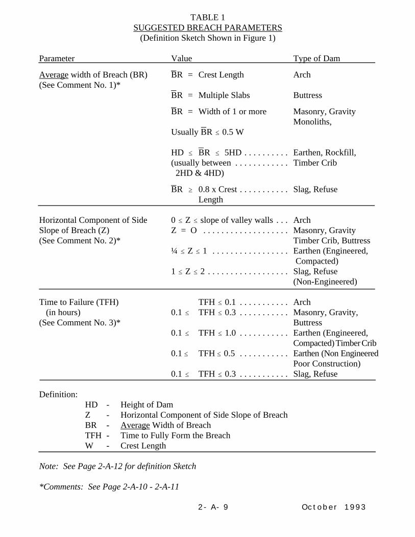
TABLE 1SUGGESTED BREACH PARAMETERS
(Definition Sketch Shown in Figure 1)
Parameter Value Type of Dam
Average width of Breach (BR) BR = Crest Length Arch(See Comment No. 1)*
BR = Multiple Slabs Buttress
BR = Width of 1 or more Masonry, Gravity Monoliths,
Usually BR # 0.5 W
HD # BR # 5HD . . . . . . . . . . Earthen, Rockfill,(usually between . . . . . . . . . . . . Timber Crib 2HD & 4HD)
BR $ 0.8 x Crest . . . . . . . . . . . Slag, RefuseLength
Horizontal Component of Side 0 # Z # slope of valley walls . . . ArchSlope of Breach (Z) Z = O . . . . . . . . . . . . . . . . . . . Masonry, Gravity(See Comment No. 2)* Timber Crib, Buttress
¼ # Z # 1 . . . . . . . . . . . . . . . . . Earthen (Engineered, Compacted)
1 # Z # 2 . . . . . . . . . . . . . . . . . . Slag, Refuse(Non-Engineered)
Time to Failure (TFH) TFH # 0.1 . . . . . . . . . . . Arch (in hours) 0.1 # TFH # 0.3 . . . . . . . . . . . Masonry, Gravity,(See Comment No. 3)* Buttress
0.1 # TFH # 1.0 . . . . . . . . . . . Earthen (Engineered,Compacted) Timber Crib
0.1 # TFH # 0.5 . . . . . . . . . . . Earthen (Non EngineeredPoor Construction)
0.1 # TFH # 0.3 . . . . . . . . . . . Slag, Refuse
Definition:HD - Height of DamZ - Horizontal Component of Side Slope of BreachBR - Average Width of BreachTFH - Time to Fully Form the BreachW - Crest Length
Note: See Page 2-A-12 for definition Sketch
*Comments: See Page 2-A-10 - 2-A-11

October 19932-A-10
Comments:
1. BR is the average breach width, which is not necessarily the bottom width. BR is thebottom width for a rectangle, but BR is not the bottom width for a trapezoid.
2. Whether the shape is rectangular, trapezoidal, or triangular is not generally criticalif the average breach width for each shape is the same. What is critical is theassumed average width of the breach.
3. Time to failure is a function of height of dam and location of breach. Therefore, thelonger the time to failure, the wider the breach should be. Also, the greater the heightof the dam and the storage volume, the greater the time to failure and average breachwidth will probably be. Time to failure is the time from the start of the breachformation until the complete breach is formed. It does not include the time leadingup to the start of the breach formation. For example, the time to erode away thedownstream slope of an earth dam is not included. In this situation, the time to failurecommences after sufficient erosion of the downstream slope has occurred and actualformation of the breach (the lowering of the crest) has begun.
4. The bottom of the breach should be at the foundation elevation.
5. Breach width assumptions should be based on the type of dam, the height of dam, thevolume of the reservoir, and the type of failure (e.g. piping, sustained overtopping,etc.). Slab and buttress dams require sensitivity analyses that vary the number ofslabs assumed to fail.
6. For a worst-case scenario, the average breach width should be in the upper portion ofthe recommended range, the time to failure should be in the lower portion of therange, and the Manning's "n" value should be in the upper portion of therecommended range. In order to fully evaluate the impacts of a failure ondownstream areas, a sensitivity analysis is required to estimate the confidence andrelative differences resulting from varying assumptions.
a. To compare relative differences in peak elevation based on variations in breachwidths, the sensitivity analysis should be based on the following assumptions:
1. Assume a probable (reasonable) maximum breach width, a probableminimum time to failure, and a probable maximum Manning's "n" value.Manning's "n" values for sections immediately below the dam and up toseveral thousand feet or more downstream of the dam should be assumedto be larger than the maximum value suggested by field investigations in

October 19932-A-11
order to account for uncertainties of high energy losses, velocities,turbulence, etc., resulting from the initial failure.
2. Assume a probable minimum breach width, a probable maximumtime to failure, and a probable minimum Manning's "n" value.
Plot the resulting water surface elevation at selected locations downstream fromthe dam for each run on the same graph. Compare the differences in elevationwith respect to distance downstream from the dam for the two cases.
b. To compare differences in travel time of the flood wave, the sensitivity analysisshould be based on the following assumptions:
1. Use criteria in a. 1.
2. Assume a probable maximum breach width, a probable minimum timeto failure, and a probable minimum Manning's "n" value.
Plot the results (elevation-distance downstream) of both runs on the same graphto compare the changes in travel time with respect to distance downstream fromthe dam.
c. To compare differences in elevation between natural flood conditions andnatural flood conditions plus dambreak, the sensitivity analysis should be basedon the following assumptions:
1. Route natural flood without dambreak assuming maximum probableManning's "n" value.
2. Use criteria in a. 1.
Plot the results (elevation-distance downstream) of both runs on the same graphto compare the changes in elevation with respect to distance downstream fromthe dam.
7. When dams are assumed to fail from overtopping, wider breach widths than thosesuggested in Table 1 should be considered if overtopping is sustained for a longperiod of time.

October 19932-A-12
October 1993
APPENDIX II-B
HYDROMETEOROLOGICAL REPORT (HMR)
Nos. 51 and 52 vs HMR No. 33

October 19932-B-1
APPENDIX IIB
Hydrometeorological Report (HMR) Nos. 51 and 52 vs HMR No. 33
In accordance with Section 12.35(b)(1) of the Commission's Regulations, if structural failureof project works (water impounding structures) would present a hazard to human life orcause significant property damage, licensed or exempted project works subject to Part 12 ofthe Commission's Regulations must be analyzed to evaluate their capability to withstand theloading conditions and/or overtopping which may occur from a flood up to the probablemaximum flood (PMF) or the capacity of spillways to prevent the reservoir from rising toan elevation that would endanger downstream life and property.
As a result of the recent publications of Hydrometeorological Reports Nos. 51 and 52 (HMRNos. 51 and 52), the FERC Staff has adopted the following guidelines for evaluating thespillway adequacy of all licensed and exempted projects located east of the 105th meridian:
(1) For existing structures where a reasonable determination of the ProbableMaximum Precipitation (PMP) has not previously been made using suitablemethods and data such as contained in HMR No. 33 or derived from specificmeteorologic studies, or the PMF has not been properly determined, the abilityof the project structures to withstand the loading or overtopping which mayoccur from the PMF must be re-evaluated using HMR Nos. 51 and 52.
(2) For existing structures where a reasonable determination of the PMP haspreviously been made, a PMF has been properly determined, and the projectstructures can withstand the loading or overtopping imposed by that PMF, a re-evaluation of the adequacy of the spillway using HMR Nos. 51 and 52 is notrequired. Generally, no PMF studies will be repeated solely because of thepublication of HMR Nos. 51 and 52. However, there is no objection to usingthe two reports for necessary PMF studies for any water retaining structure,should you so desire.
(3) For all unconstructed projects and for those projects where any proposed orrequired modification will significantly affect the stability of water impoundingproject structures, the adequacy of the project spillway must be evaluatedusing:
(a) HMR Nos. 51 and 52, or
(b) Specific basin studies where the project lies in the stippled areas onFigures 18 through 47 of HMR No. 51.

PROCEDURE FOR SELECTING APPROPRIATE INFLOW DESIGN FLOOD (IDF)AND DETERMINING NEED FOR REMEDIAL ACTION
INTRODUCTION
The purpose of this appendix is to describe the procedures used to select the appropriate inflow design flood (IDF) for a dam, and to determine the need for remedial action. Theseprocedures are presented in two flowcharts. The first flowchart describes the steps neededto determine. . .
• If the probable maximum flood (PMF) was used in the original design of the dam,
• If the PMF or some lesser flood is the appropriate IDF, and,
• Whether remedial action at the dam is needed to enable it to safely accommodate the appropriate PMF and/or IDF.
In order to determine whether the PMF or some lesser flood is the appropriate IDF, it maybe necessary to conduct an incremental hazard evaluation. This process is presented in thesecond flowchart.
Following each flowchart is a breakdown of the procedures. Each block is presentedindividually, and includes an explanation of the steps taken.
PROCEDURES FOR DETERMINING THE APPROPRIATE IDFAND THE NEED FOR REMEDIAL ACTION
Flowchart 1 in Figure 1 presents a logical, step-by-step approach for evaluating thehydrologic design of an existing dam, and determining the appropriate IDF for the dam andwhether remedial action is needed in order for the dam to safely accommodate the IDF.
Flowchart 1 is on the next page.
2-C-1 October, 1993

FIGURE 1. FLOWCHART 1 -- PROCEDURES FOR DETERMININGTHE APPROPRIATE INFLOW DESIGN FLOOD (IDF)
AND THE NEED FOR REMEDIAL ACTION
Is the damsafe for thePMF?
4
Is thePMF theappropriateIDF?
6
Is the damsafe for thenew PMF?
10
STOPNo furtheraction isrequired
11
13
STOPNo furtheraction isrequired
14 12 Remedialaction isrequired forthe dam tosafely thenew PMF.
15
Remedial actionis required for thedam to safelyaccommodate theappropriate IDF
3 Is the
original PMFMethodologyacceptable (includingflood routing)?
9Conduct a
new PMF studyand flood routingbased on currentcriteria, asnecessary
8Based on the
incrementalhazard evaluationis the PMF theappropriate IDF?
incrementalhazard evaluation determine theappropriate IDF(see Flowchart 2)
7Conduct
incrementalhazard evaluationto determine theappropriate IDF(see Flowchart 2)
STOPNo furtheraction isrequired
52
Was the PMFused for theoriginaldesign?
1
Review the floodused for theoriginal design
yes yes yes
yes yes
yes
no
no
no
no or
notapparent
Is the damsafe for theappropriateIDF?
2-C-2

EXPLANATION OF FLOWCHART 1
An explanation of the IDF flowchart is presented below.
1
Review the floodused for theoriginal design
Block 1
The initial step in selecting the appropriate IDF anddetermining the need for dam safety modification isto review the basis for the original hydrologic designof an existing dam. This information will providevaluable insight regarding whether the flood originallyused for design purposes satisfies current criteria orwhether detailed investigations and analyses will berequired to determine the appropriate IDF for the dam.
In those situations where the original design informationhas been lost, detailed investigations and analyses willnormally be required.
Block 2
2
Was the PMFused by theoriginal design?
Block1
yes
Block 3
no
Block7
Once you have identified the basis for the originalhydrologic design, the next step is to determine if theflood used for the original design is the probable maximum flood (PMF). This question is important,since the upper limit of the IDF is the PMF.
If your answer is YES, continue to Block 3.
If your answer is NO, go to Block 7. In Block 7 youwill perform an incremental hazard evaluation to determine the appropriate IDF.
To ensure the reliability of the original PMF studyor the assumptions made on the various parametersaffecting the study, it is necessary to determine ifthe PMF methodology originally used is still acceptable under current criteria.
If your answer is YES, continue to Block 4.
If your answer is NO, go to Block 6. In Block 6, youwill answer the question: Is the PMF the appropriateIDF?
Block2
3 Is the
original PMFMethodologyacceptable (includingflood routing)?
yes yes
Block4
no
Block6
Block 3
Continued . . .2-C-3
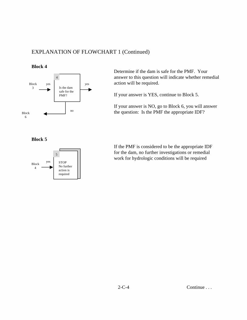
EXPLANATION OF FLOWCHART 1 (Continued)
Block 4
Is the damsafe for thePMF?
4
yes yes
no
Block3
Block6
Determine if the dam is safe for the PMF. Youranswer to this question will indicate whether remedialaction will be required.
If your answer is YES, continue to Block 5.
If your answer is NO, go to Block 6, you will answerthe question: Is the PMF the appropriate IDF?
STOPNo furtheraction isrequired
5
yes
Block 5
Block4
If the PMF is considered to be the appropriate IDFfor the dam, no further investigations or remedialwork for hydrologic conditions will be required
Continue . . .2-C-4

Is thePMF theappropriateIDF?
6
no
no or
notapparent
Block3
Block4
Block4
Block9
Block 6
EXPLANATION OF FLOWCHART 1 (Continued)
IF . . .
In Block 3 you determined that the original PMFmethodology is NOT acceptable,
OR . . .
In Block 4 you determined that the dam is NOTsafe for the PMF,
THEN . . .
You need to determine if the PMF is the appropriateIDF.
In some cases, such as when the dam is totallysubmerged during the PMF, it may be obvious thatthe appropriate IDF is something less than the PMF.In other cases, it will not be apparent whether the IDF should be the PMF or something less. In thesetwo cases, it will be necessary to perform an incremental hazard evaluation to determine the appropriate IDF for the dam. Continue to Block 7.
Sometimes, based on the size and volume of the dam and reservoir, the proximity of the dam to downstream communities, or even because ofpolitical decisions, it will be obvious that the IDFshould be the PMF. If this is the case, a new PMFstudy will be required. Go to Block 9.
Continued2-C-5

EXPLANATION OF FLOWCHART 1 (Continued)
Block 7
incrementalhazard evaluation determine theappropriate IDF(see Flowchart 2)
7Conduct
incrementalhazard evaluationto determine theappropriate IDF(see Flowchart 2)
no or
notapparent
Block2
Block6
Block9
IF . . .
In Block 2 you determined that the flood used in theoriginal design is NOT the PMF,
OR . . .
In Block 6 you determined that it is obvious that theIDF should be less than the PMF or it is not apparentif the IDF should be the PMF or something less,
THEN . . .
You need to perform an incremental hazard evaluationto determine the appropriate IDF. Performing theincremental hazard evaluation involves:
• Conducting dambreak sensitivity studies,
• Reviewing incremental rises between with- failure and without-failure conditions for a range of flood inflows (see Flowchart 2).
• Selecting the appropriate IDF on the basis of the dambreak studies and incremental impacts on downstream areas.
A procedural flowchart for performing a hazardevaluation appears in Flowchart 2 (Figure 2),followed by an explanation of the procedure.
Continued . . .2-C-6

EXPLANATION OF FLOWCHART 1 (Continued)
8Based on the
incrementalhazard evaluationis the PMF theappropriate IDF?
yes
Block 8Block
7
Block9
Block13
9Conduct a
new PMF studyand flood routingbased on currentcriteria, asnecessary
yes
yes
Block 9
Block6
Block8 Block
10
You should use the results of the incremental hazardevaluation and dambreak studies conducted in Block 7to determine if the PMF is the appropriate IDF.
The IDF should be the PMF when the incremental consequences of failure are unacceptable, regardlessof how large the assumed flood inflow becomes.
If your answer is YES, continue to Block 9.
If your answer is NO, go to Block 13. In Block 13 you will answer the question: Is the dam safe forthe appropriate IDF?
IF . . .
In Block 6 you determined that the PMF is obviouslythe appropriate IDF,
OR . . .
If, based on the incremental hazard evaluationconducted in Block 8, the PMF is the appropriate IDF,
THEN . . .
You should conduct a new PMF study and flood routing based on current criteria, unless it wasdetermined in Block 3 that the original PMF isacceptable under current criteria.
Continued...2-C-7

EXPLANATION OF FLOWCHART 1 (Continued)
Once the new PMF is calculated, you shoulddetermine if the dam is safe for the new PMF.
If the dam is SAFE for the new PMF, no furtherinvestigations or remedial actions for hydrologicconditions are required.
If the dam is NOT SAFE for the new PMF, remedial action is required for the dam to safelyaccommodate the PMF.
IF….
In Block 8 you determined that the PMF is NOTthe appropriate IDF,
THEN…..
You need to determine if the dam is safe for the appropriate IDF.
If the dam is SAFE for the appropriate IDF, no further investigations or remedial action for hydro-logic conditions are required.
If the dam is NOT SAFE for the appropriate IDF,remedial action is required for the dam to safetyaccommodate the appropriate IDF.
Depending on the type of remedial actionconsidered, it may be necessary to reevaluate the IDF to ensure that the appropriate IDF has beenselected for the design of any modification.
Blocks 10, 11 and 12
Is the damsafe for thenew PMF?
10
STOPNo furtheraction isrequired
11
12
Remedial actionis required for thedam to safelyaccommodate thenew PMF.
yes
no
Block 9
Blocks 13, 14 and 15
Is the damsafe for theappropriateIDF?
10
STOPNo furtheraction isrequired
11
12
Remedial actionis required for thedam to safelyaccommodate theappropriate IDF.
yes
no
Block 8
no
2-C-8 October 1993

INTRODUCTION
As stated prviously, if the PMF was not used for the original design of a dam, or if the PMFis not the appropriate IDF, an incremental hazard evlauation must be performed todetermine the appropriate IDF.
PROCEDURES FOR CONDUCTING AN INCREMENTAL HAZARD EVALUATION
Flowchart 2 in Figure 2 shows the procedures for performing an incremental hazardevaluation. This flowchart is an expansion of Block 7 in Flowchart 1, Figure 1.
Flowchart 1 is on the next page.
2-C-9
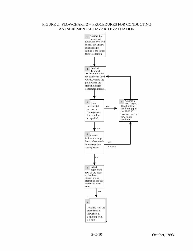
FIGURE 2. FLOWCHART 2 -- PROCEDURES FOR CONDUCTINGAN INCREMENTAL HAZARD EVALUATION
6
7
Continue with theprocedures in Flowchart 1. Beginning withBlock 8.
5 Could aFailure at a largerflood inflow resultin unacceptableconsequences
incrementalhazard evaluation determine theappropriate IDF(see Flowchart 2)
3 Is theIncremental increase inconsequencesdue to failureacceptable?
2
1 Assume thatthe normal
yes
no
IDF on the basisof dambreakstudies and in-cremental impactson downstreamareas
Reservoir level withnormal streamflowconditions pre-vailing is the initialfailure condition
Analysis and routethe dambreak flooddownstream to thepoint where theflood no longerconstitutes a threat
Conduct dambreak
Selectappropriate
incrementalhazard evaluation determine theappropriate IDF(see Flowchart 2)
3Assume anew (larger)
Flood inflowcondition (up tothe PMF, ifnecessary) as thenew failurecondition
no
yes
not sure
no
2-C-10 October, 1993

EXPLANATION OF FLOWCHART 2
Block 1
1 Assume thatthe normal
Reservoir level with normal streamflowconditions pre-vailing is the initialfailure condition.
Block2
Block 2
Assume that the normal reservoir level with normalstreamflow conditions prevailing is the initial failurecondition. Starting at this point will ensure that thefull range of flood inflow conditions will beinvestigated and will include the “sunny day” failurecondition. It will also assist in verifying the initialhazard rating assigned to the dam. Using the normal maximum water surface level as the initial conditionis particularly important if the initial hazard ratingwas low.
Next, conduct dambreak sensitivity studies (of variousbreach parameters) and route the dambreak flood to the point downstream where it no longer constitutes a threatto downstream life and property.
It is important to remember that the incremental increases should address the differences between the nonfailurecondition with the dam remaining in place and thefailure condition. Also, the dam should not be assumedto fail until the peak reservoir water surface elevation isattained for the assumed flood inflow condition beinganalyzed. Dams should be assumed to fail as described in Chapter II of these Engineering Guidelines.
Continued...
2-C-11
An explanation of the Hazard Evaluation Flowchart is presented below.
2 Conductdambreak
Analysis and routethe dambreak flooddownstream to thepoint where theflood no longerconstitutes a threat
Block1
Block4
Block3

EXPLANATION OF FLOWCHART 2 (Continued)
Block 3
3
Is the incrementalincrease inconsequences dueto failureacceptable?.
Block5
Block 4
Now, determine if the additional increase inconsequences due to failure is acceptable. Answeringthis question is critical in the incremental hazardevaluation and doing so involves an estimate of lossof life and property with and without dam failure.
If the consequences of failure under the assumedfloodflow conditions are NOT ACCEPTABLE, go toBlock 4.
If the consequences of failure ARE ACCEPTABLE,continue to Block 5..
IF …
In Block 3 it was determined that the consequences of failure under the assumed floodflow conditions areNOT ACCEPTABLE,
THEN …
Assume a new (larger flood inflow condition (e.g.,some percentage of the PMF) and perform a new dambreak analysis (see Block 2). This procedureshould be repeated until an acceptable level offlooding is identified, or the full PMF has been reached.
Continued...
2-C-12
4 Assume a new(larger) flood
Inflow condition(up to the PMF, ifnecessary) as the new failurecondition.
Block2
Block5
Block3
October, 1993
Block2
no Block4
yes
no
yes
not sure

EXPLANATION OF FLOWCHART 2 (Continued)
IF ...
In Block 3 you determined that the consequences of failureunder the assumed floodlfow conditions are ACCEPTABLE,i.e., failure of the dam under “sunny day” conditoins wasinsignificant,
THEN ...
Determine if failure at a larger flood inflow condition will result in unacceptable consequences. This question is veryimportant. For example, situations exist where a failureduring normal water surface conditions results in the floodwave being contained completely within the banks of a riverand obviously would not cause a threat to life and propertydownstream. However, under some floodflow conditions,the natural river flows may go out-of-bank, and a failure ontop of that flood condition will result in an additional threatto downstream life and property.
If failure at another flood level will result in UNACCEPTABLEconsequences, or if you are NOT SURE, return to Block 4.Assume larger flood inflow conditions and perform newdambreak studies. This procedure should be repeated to determine the acceptable level of flooding.
If failure at another flood level will NOT result in unacceptableconsequences, continue to Block 6.
You should now select the appropriate IDF based on theresults of dambreak studies and incremental impacts ondownstream areas.
Continued...2-C-13
Block 6
Block 5
5
Could a failure ata larger floodinflow result inunacceptableconsequences?
Block6
Block3
no
Block4
yes
yes
not sure
no
6
Select appropriateIDF on the basis ofdambreak studiesand incrementalimpacts ondownstream areas.
Block5
Block7
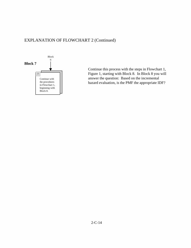
EXPLANATION OF FLOWCHART 2 (Continued)
Continue withthe proceduresin Flowchart 1,beginning withBlock 8.
7
Block 7
Block6
Continue this process with the steps in Flowchart 1,Figure 1, starting with Block 8. In Block 8 you willanswer the question: Based on the incrementalhazard evaluation, is the PMF the appropriate IDF?
2-C-14