CHAPTER 3: OPEN CHANNEL - NET
79
January 1, 2022 Drainage Design Guide Chapter 3: Open Channel Chapter 3: Open Channel 3-i CHAPTER 3: OPEN CHANNEL 3. OPEN CHANNEL ................................................................................................. 3-1 3.1 Open Channel Flow Theory ............................................................................ 3-1 3.1.1 Mass, Energy, and Momentum................................................................... 3-1 3.1.1.1 Mass ....................................................................................................... 3-1 3.1.1.2 Energy .................................................................................................... 3-1 3.1.1.3 Momentum .............................................................................................. 3-4 3.1.2 Uniform Flow .............................................................................................. 3-5 3.1.2.1 Manning’s Equation ................................................................................ 3-5 3.1.3 Critical Flow .............................................................................................. 3-10 3.1.3.1 Specific Energy and Critical Depth ....................................................... 3-10 3.1.3.2 Critical Velocity ..................................................................................... 3-14 3.1.3.3 Super-Critical Flow ............................................................................... 3-14 3.1.3.4 Sub-Critical Flow................................................................................... 3-14 3.1.3.5 Theoretical Considerations ................................................................... 3-15 3.1.4 Non-Uniform Flow .................................................................................... 3-15 3.1.4.1 Gradually Varied Flow........................................................................... 3-17 3.1.4.2 Gradually Varied Flow Profile Computation .......................................... 3-17 3.1.4.3 Rapidly Varied Flow .............................................................................. 3-24 3.1.5 Channel Bends ......................................................................................... 3-27 3.2 Open Channel Design ................................................................................... 3-29 3.2.1 Types of Open Channels for Highways .................................................... 3-29 3.2.2 Roadside Ditches ..................................................................................... 3-31 3.2.3 Median Ditches......................................................................................... 3-35 3.2.4 Interceptor Ditches ................................................................................... 3-36 3.2.5 Outfall Ditches .......................................................................................... 3-37 3.2.6 Hydrology ................................................................................................. 3-37 3.2.6.1 Frequency ............................................................................................. 3-38 3.2.6.2 Time of Concentration........................................................................... 3-38 3.2.7 Tailwater and Backwater .......................................................................... 3-38 3.2.8 Side Drains ............................................................................................... 3-47 3.2.8.1 Design Analysis Requirements for Side Drains .................................... 3-47 3.2.8.2 Material Requirements .......................................................................... 3-48 3.2.8.3 End Treatment ...................................................................................... 3-48 3.3 Channel Linings............................................................................................. 3-51 3.3.1 Flexible Linings......................................................................................... 3-51 3.3.1.1 Vegetation............................................................................................. 3-51 3.3.1.2 Other Flexible Linings ........................................................................... 3-52 3.3.2 Rigid Linings ............................................................................................. 3-54 3.3.2.1 Cast-in-Place Concrete ......................................................................... 3-55 3.3.2.2 Fabric Formed Revetment .................................................................... 3-55
-
Upload
khangminh22 -
Category
Documents
-
view
2 -
download
0
Transcript of CHAPTER 3: OPEN CHANNEL - NET
January 1, 2022 Drainage Design Guide Chapter 3: Open Channel
Chapter 3: Open Channel 3-i
CHAPTER 3: OPEN CHANNEL
3. OPEN CHANNEL ................................................................................................. 3-1
3.1 Open Channel Flow Theory ............................................................................ 3-13.1.1 Mass, Energy, and Momentum ................................................................... 3-1
3.1.1.1 Mass ....................................................................................................... 3-13.1.1.2 Energy .................................................................................................... 3-13.1.1.3 Momentum .............................................................................................. 3-4
3.1.2 Uniform Flow .............................................................................................. 3-53.1.2.1 Manning’s Equation ................................................................................ 3-5
3.1.3 Critical Flow .............................................................................................. 3-103.1.3.1 Specific Energy and Critical Depth ....................................................... 3-103.1.3.2 Critical Velocity ..................................................................................... 3-143.1.3.3 Super-Critical Flow ............................................................................... 3-143.1.3.4 Sub-Critical Flow ................................................................................... 3-143.1.3.5 Theoretical Considerations ................................................................... 3-15
3.1.4 Non-Uniform Flow .................................................................................... 3-153.1.4.1 Gradually Varied Flow........................................................................... 3-173.1.4.2 Gradually Varied Flow Profile Computation .......................................... 3-173.1.4.3 Rapidly Varied Flow .............................................................................. 3-24
3.1.5 Channel Bends ......................................................................................... 3-27
3.2 Open Channel Design ................................................................................... 3-293.2.1 Types of Open Channels for Highways .................................................... 3-293.2.2 Roadside Ditches ..................................................................................... 3-313.2.3 Median Ditches ......................................................................................... 3-353.2.4 Interceptor Ditches ................................................................................... 3-363.2.5 Outfall Ditches .......................................................................................... 3-373.2.6 Hydrology ................................................................................................. 3-37
3.2.6.1 Frequency ............................................................................................. 3-383.2.6.2 Time of Concentration........................................................................... 3-38
3.2.7 Tailwater and Backwater .......................................................................... 3-383.2.8 Side Drains ............................................................................................... 3-47
3.2.8.1 Design Analysis Requirements for Side Drains .................................... 3-473.2.8.2 Material Requirements .......................................................................... 3-483.2.8.3 End Treatment ...................................................................................... 3-48
3.3 Channel Linings ............................................................................................. 3-513.3.1 Flexible Linings ......................................................................................... 3-51
3.3.1.1 Vegetation ............................................................................................. 3-513.3.1.2 Other Flexible Linings ........................................................................... 3-52
3.3.2 Rigid Linings ............................................................................................. 3-543.3.2.1 Cast-in-Place Concrete ......................................................................... 3-553.3.2.2 Fabric Formed Revetment .................................................................... 3-55
January 1, 2022 Drainage Design Guide Chapter 3: Open Channel
Chapter 3: Open Channel 3-ii
3.3.3 Velocity and Shear Stress Limitations ...................................................... 3-553.3.4 Application Guidance for Some Common Channel Linings ...................... 3-58
3.3.4.1 Rubble Riprap ....................................................................................... 3-583.3.4.2 Fabric Formed Revetments .................................................................. 3-593.3.4.3 Gabions ................................................................................................ 3-613.3.4.4 Soil Stabilizers ...................................................................................... 3-65
3.4 Drainage Connection Permitting and Maintenance Concerns .................. 3-673.4.1 Drainage Connection Permitting ............................................................... 3-67
3.4.1.1 Roadside Ditch Impacts ........................................................................ 3-673.4.1.2 Median Ditch Impacts ........................................................................... 3-693.4.1.3 Outfall Ditch Impacts ............................................................................. 3-71
3.4.2 Maintenance Concerns............................................................................. 3-713.4.2.1 Ditch Closures ...................................................................................... 3-713.4.2.2 Acquisition of Ditches from Local Ownership ........................................ 3-773.4.2.3 Addition of Sidewalks to Roadway Projects .......................................... 3-77
January 1, 2022 Drainage Design Guide Chapter 3: Open Channel
Chapter 3: Open Channel 3-1
3. OPEN CHANNEL
3.1 OPEN CHANNEL FLOW THEORY
3.1.1 Mass, Energy, and Momentum
The three basic principles that generally apply to flow analysis, including open channel flow evaluations, are:
Conservation of mass Conservation of energy Conservation of linear momentum
3.1.1.1 Mass
You can mathematically express the conservation of mass for continuous steady flow in the Continuity Equation as:
AvQ (3.1-1)
where:
Q = Discharge, in cubic feet per second A = Cross-sectional area, in square feet v = Average channel velocity, in feet per second
For continuous unsteady flow, the Continuity Equation must include time as a variable. You can find additional information on unsteady flow from Chow (1959) or Henderson (1966).
3.1.1.2 Energy
The total energy head at a point in an open channel is the sum of the potential and kinetic energy of the flowing water. The potential energy is represented by the elevation of the water surface. The water surface elevation is the depth of flow, d, defined in Section 1.4, added to the elevation of the channel bottom, z. The water surface elevation is a measure of the potential work that the flow can do as it transitions to a lower elevation. The kinetic energy is the energy of motion as measured by the velocity, v.
If you insert a straight tube down into the flow, the water level in the tube will rise to the water surface elevation in the channel. If you insert a tube with a 90-degree elbow into the flow with the open end pointing into the flow, then the water level will rise to a level higher than the water surface elevation in the channel—this distance is a measure of the ability of the water velocity to do work. Using Newton’s Laws of Motion, this distance is
January 1, 2022 Drainage Design Guide Chapter 3: Open Channel
Chapter 3: Open Channel 3-2
v2/2g, where g is the acceleration due to gravity. Therefore, the total energy head at a point in an open channel is: d + z + v2/2g.
As water flows down a channel, the flow loses energy because of friction and turbulence. You can set the total energy head between two points in a channel reach equal to one another if the losses between the sections are added to the downstream total energy head. This equality is commonly known as the Energy Equation, which is expressed as:
losshzg
vdz
g
vd 2
2
221
2
11
22(3.1-2)
where:
d1, d2 = Depth of open channel flow at channel sections 1 and 2, respectively, in feet
v1, v2 = Average channel velocities at channel sections 1 and 2, respectively, in feet per second
z1, z2 = Channel elevations above an arbitrary datum at channel sections 1 and 2, respectively, in feet
hloss = Head or energy loss between channel sections 1 and 2, in feet g = Acceleration due to gravity, 32.174 ft/sec2
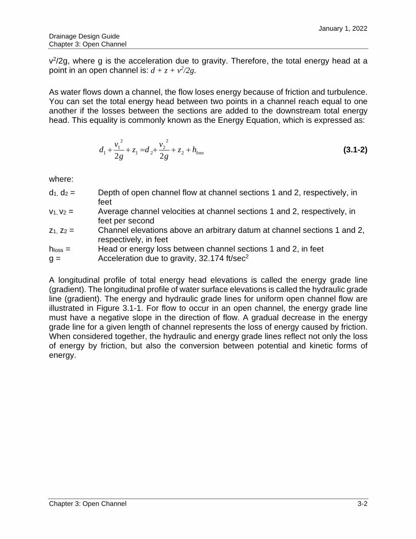
A longitudinal profile of total energy head elevations is called the energy grade line (gradient). The longitudinal profile of water surface elevations is called the hydraulic grade line (gradient). The energy and hydraulic grade lines for uniform open channel flow are illustrated in Figure 3.1-1. For flow to occur in an open channel, the energy grade line must have a negative slope in the direction of flow. A gradual decrease in the energy grade line for a given length of channel represents the loss of energy caused by friction. When considered together, the hydraulic and energy grade lines reflect not only the loss of energy by friction, but also the conversion between potential and kinetic forms of energy.
January 1, 2022 Drainage Design Guide Chapter 3: Open Channel
Chapter 3: Open Channel 3-3
Figure 3.1-1: Characteristics of Uniform Open Channel Flow
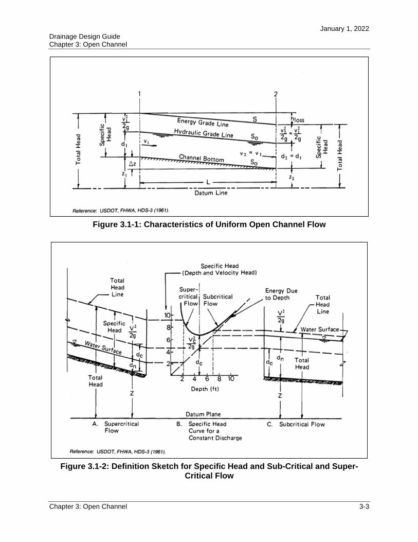
Figure 3.1-2: Definition Sketch for Specific Head and Sub-Critical and Super-Critical Flow
January 1, 2022 Drainage Design Guide Chapter 3: Open Channel
Chapter 3: Open Channel 3-4
For uniform flow conditions, the energy grade line is parallel to the hydraulic grade line, which is parallel to the channel bottom (see Figure 3.1-1). Thus, for uniform flow, the slope of the channel bottom becomes an adequate basis for the determination of friction losses. During uniform flow, no conversions occur between kinetic and potential forms of energy. If the flow is accelerating, the hydraulic grade line would be steeper than the energy grade line, while decelerating flow would produce an energy grade line steeper than the hydraulic grade line.
The Energy Equation presented in Equation 3.1-2 ignores the effect of a non-uniform velocity distribution on the computed velocity head. The actual distribution of velocities over a channel section are non-uniform (i.e., slow along the bottom and faster in the middle). The velocity head for actual flow conditions generally is greater than the value computed using the average channel velocity. Find guidance on kinetic energy coefficients that account for non-uniform velocity conditions in Chapter 5 (Bridge Hydraulics).
For typical prismatic channels with a fairly straight alignment, the effect of disregarding the existence of a non-uniform velocity distribution is negligible, especially when compared to other uncertainties involved in such calculations. Therefore, Equation 3.1-2 is appropriate for most open channel problems. However, if you know or suspect that velocity distributions are non-typical, you should obtain additional information related to velocity coefficients, as presented by Chow (1959) or Henderson (1966).
Equation 3.1-2 also assumes that the hydrostatic law of pressure distribution is applicable. This law states that the distribution of pressure over the channel cross section is the same as the distribution of hydrostatic pressure; that is, that the distribution is linear with depth. The assumption of a hydrostatic pressure distribution for flowing water is valid only if the flow is not accelerating or decelerating in the plane of the cross section. Thus, restrict the use of Equation 3.1-2 to conditions of uniform or gradually varied non-uniform flow. If you know that the flow will be varying rapidly, obtain additional information, as presented by Chow (1959) or Henderson (1966).
3.1.1.3 Momentum
According to Newton's Second Law of Motion, the change of momentum per unit of time is equal to all the resultant external forces applied to the moving body. Applying this principle to open channel flow produces a relationship that is virtually the same as the Energy Equation expressed in Equation 3.1-2. Theoretically, these principles of energy and momentum are unique, primarily because energy is a scalar quantity (magnitude only), while momentum is a vector quantity (magnitude and direction). In addition, the head loss determined by the Energy Equation measures the internal energy dissipated in a particular channel reach, while the Momentum Equation measures the losses due to external forces exerted on the water by the walls of the channel. However, for uniform flow, since the losses due to external forces and internal energy dissipation are equal, the Momentum and Energy Equations give the same results.
January 1, 2022 Drainage Design Guide Chapter 3: Open Channel
Chapter 3: Open Channel 3-5
Applying the momentum principle has certain advantages for problems involving substantial changes of internal energy, such as a hydraulic jump. Thus, you should use the momentum principle for evaluating rapidly varied non-uniform flow conditions. Theoretical details of the momentum principle applied to open channel flow are presented by Chow (1959) and Henderson (1966). Section 3.1.4.3 provides a brief presentation of hydraulic jump fundamentals.
3.1.2 Uniform Flow
Although steady uniform flow is rare in drainage facilities, it is practical in many cases to assume that steady uniform flow occurs in appropriate segments of an open channel system. The results obtained from calculations based on this assumption will be approximate and general, but still can provide satisfactory solutions for many practical problems.
3.1.2.1 Manning’s Equation
Determine the hydraulic capacity of an open channel by applying Manning's Equation, which determines the average velocity when given the depth of flow in a uniform channel cross section. Given the velocity, calculate the capacity (Q) as the product of velocity and cross-sectional area (see Equation 3.1-1).
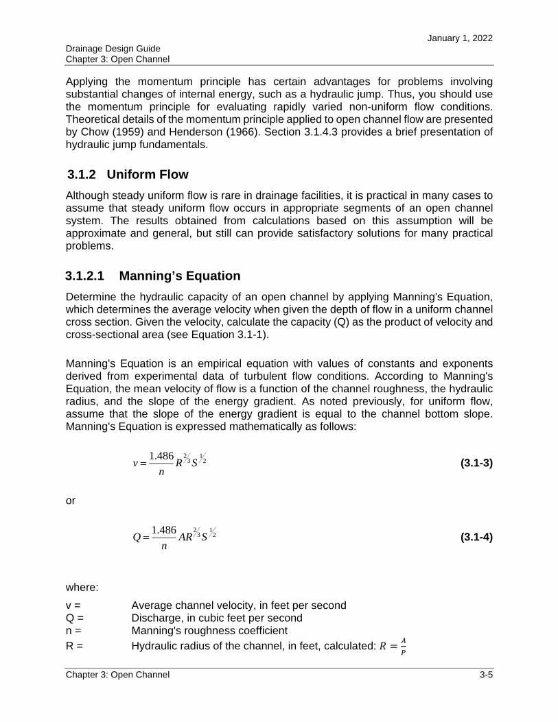
Manning's Equation is an empirical equation with values of constants and exponents derived from experimental data of turbulent flow conditions. According to Manning's Equation, the mean velocity of flow is a function of the channel roughness, the hydraulic radius, and the slope of the energy gradient. As noted previously, for uniform flow, assume that the slope of the energy gradient is equal to the channel bottom slope. Manning's Equation is expressed mathematically as follows:
21
32486.1
SRn
v (3.1-3)
or
21
32486.1
SARn
Q (3.1-4)
where:
v = Average channel velocity, in feet per second Q = Discharge, in cubic feet per second n = Manning's roughness coefficient
R = Hydraulic radius of the channel, in feet, calculated: 𝑅 =𝐴
𝑃
January 1, 2022 Drainage Design Guide Chapter 3: Open Channel
Chapter 3: Open Channel 3-6
P = Wetted perimeter of channel, in feet S = Slope of the energy gradient, in feet per feet A = Cross-sectional area of the open channel, in square feet
You can find design values for Manning’s roughness coefficient for artificial channels (i.e., roadside, median, interceptor, and outfall ditches) in Chapter 2 (Section 2.7) of the Drainage Manual. You can find guidance on methods for estimate Manning’s roughness coefficient for natural channels in Chapter 5 (Bridge Hydraulics).
Example 3.1-1—Discharge given Normal Depth
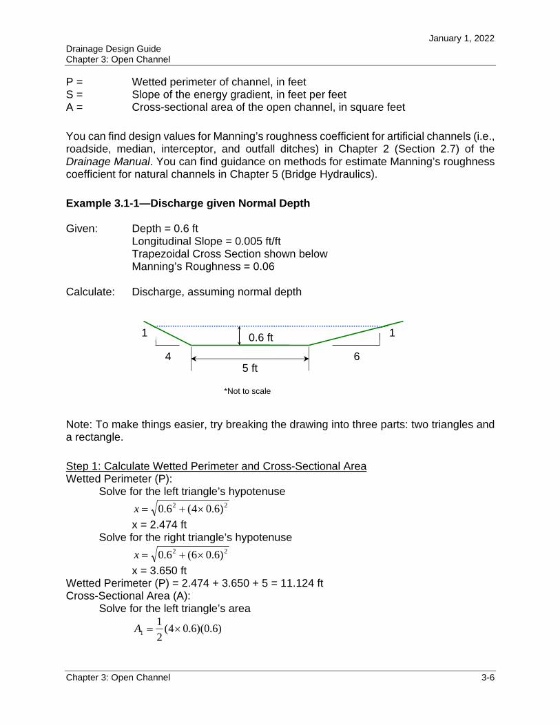
Given: Depth = 0.6 ft Longitudinal Slope = 0.005 ft/ft Trapezoidal Cross Section shown below Manning’s Roughness = 0.06
Calculate: Discharge, assuming normal depth
*Not to scale
Note: To make things easier, try breaking the drawing into three parts: two triangles and a rectangle.
Step 1: Calculate Wetted Perimeter and Cross-Sectional Area Wetted Perimeter (P):
Solve for the left triangle’s hypotenuse 22 )6.04(6.0 x
x = 2.474 ft Solve for the right triangle’s hypotenuse
22 )6.06(6.0 x
x = 3.650 ft Wetted Perimeter (P) = 2.474 + 3.650 + 5 = 11.124 ft Cross-Sectional Area (A):
Solve for the left triangle’s area
)6.0)(6.04(2
11 A
5 ft 4
1
6
1 0.6 ft
January 1, 2022 Drainage Design Guide Chapter 3: Open Channel
Chapter 3: Open Channel 3-7
72.01 A ft2
Solve for the right triangle’s area
)6.0)(6.06(2
12 A
08.12 A ft2
Solve for the rectangle’s area 6.053 A
33 A ft 2
Cross-Sectional Area (A) = 8.4308.172.0 ft2
Step 2: Calculate Hydraulic Radius
Hydraulic Radius (R) =P
A
Hydraulic Radius (R) = 4315.0124.11
8.4 ft
Step 3: Calculate Average Velocity
Average Velocity (v) = 21
32
)()(486.1
SRn
Average Velocity (v) = 00.1)005.0()4315.0(06.0
486.12
13
2
ft/sec
Step 4: Calculate the Discharge Discharge (Q) = Av
Discharge (Q) = 00.1 ft/sec 8.4 ft 80.42 ft 3/sec
As an alternative approach, Example C.1 of Appendix C solves this example problem using equations from Figure C-4.
Example 3.1-1 has a direct solution because the depth is known. The next problem will be more difficult to solve because the discharge will be given and the normal depth must be calculated. The equations cannot be solved directly for depth, so an iterative process is used to solve for normal depth. You also can solve Example 3.1-1 using the charts in Appendix C.
January 1, 2022 Drainage Design Guide Chapter 3: Open Channel
Chapter 3: Open Channel 3-8
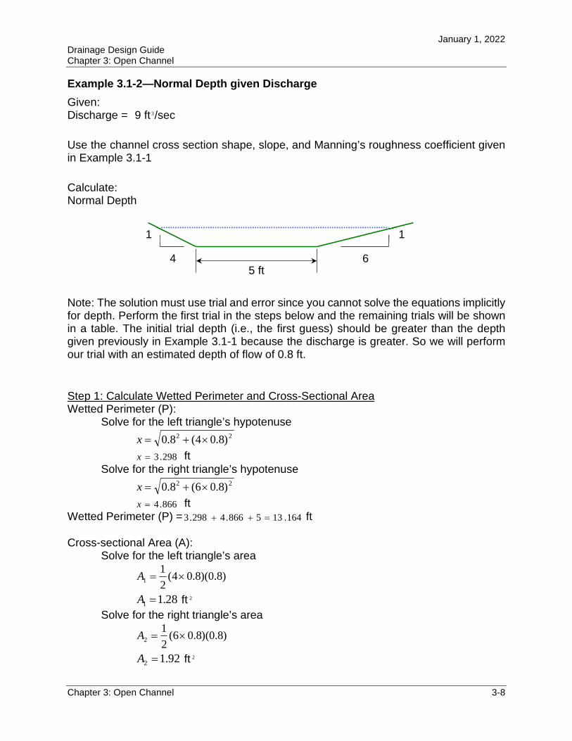
Example 3.1-2—Normal Depth given Discharge
Given: Discharge = 9 ft 3/sec
Use the channel cross section shape, slope, and Manning’s roughness coefficient given in Example 3.1-1
Calculate: Normal Depth
Note: The solution must use trial and error since you cannot solve the equations implicitly for depth. Perform the first trial in the steps below and the remaining trials will be shown in a table. The initial trial depth (i.e., the first guess) should be greater than the depth given previously in Example 3.1-1 because the discharge is greater. So we will perform our trial with an estimated depth of flow of 0.8 ft.
Step 1: Calculate Wetted Perimeter and Cross-Sectional Area Wetted Perimeter (P):
Solve for the left triangle’s hypotenuse 22 )8.04(8.0 x
298.3x ft Solve for the right triangle’s hypotenuse
22 )8.06(8.0 x
866.4x ft Wetted Perimeter (P) = 164.135866.4298.3 ft
Cross-sectional Area (A): Solve for the left triangle’s area
)8.0)(8.04(2
11 A
28.11 A ft 2
Solve for the right triangle’s area
)8.0)(8.06(2
12 A
92.12 A ft 2
5 ft 4
1
6
1
January 1, 2022 Drainage Design Guide Chapter 3: Open Channel
Chapter 3: Open Channel 3-9
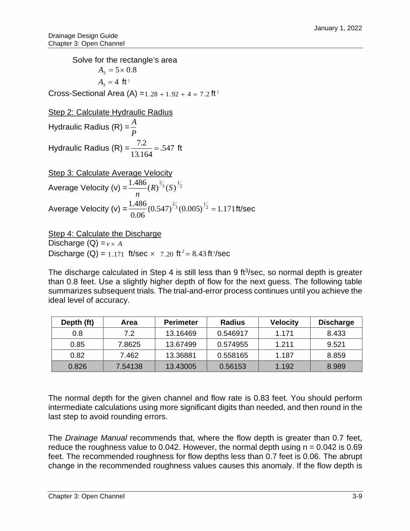
Solve for the rectangle’s area 8.053 A
43 A ft 2
Cross-Sectional Area (A) = 2.7492.128.1 ft 2
Step 2: Calculate Hydraulic Radius
Hydraulic Radius (R) =P
A
Hydraulic Radius (R) = 547.164.13
2.7 ft
Step 3: Calculate Average Velocity
Average Velocity (v) = 21
32
)()(486.1
SRn
Average Velocity (v) = 171.1)005.0()547.0(06.0
486.12
13
2
ft/sec
Step 4: Calculate the Discharge Discharge (Q) = Av
Discharge (Q) = 171.1 ft/sec 20.7 ft 43.82 ft 3/sec
The discharge calculated in Step 4 is still less than 9 ft3/sec, so normal depth is greater than 0.8 feet. Use a slightly higher depth of flow for the next guess. The following table summarizes subsequent trials. The trial-and-error process continues until you achieve the ideal level of accuracy.
Depth (ft) Area Perimeter Radius Velocity Discharge
0.8 7.2 13.16469 0.546917 1.171 8.433
0.85 7.8625 13.67499 0.574955 1.211 9.521
0.82 7.462 13.36881 0.558165 1.187 8.859
0.826 7.54138 13.43005 0.56153 1.192 8.989
The normal depth for the given channel and flow rate is 0.83 feet. You should perform intermediate calculations using more significant digits than needed, and then round in the last step to avoid rounding errors.
The Drainage Manual recommends that, where the flow depth is greater than 0.7 feet, reduce the roughness value to 0.042. However, the normal depth using n = 0.042 is 0.69 feet. The recommended roughness for flow depths less than 0.7 feet is 0.06. The abrupt change in the recommended roughness values causes this anomaly. If the flow depth is
January 1, 2022 Drainage Design Guide Chapter 3: Open Channel
Chapter 3: Open Channel 3-10
the primary concern, then using n = 0.06 will give a conservative answer. However, if the velocity is the primary concern, then using n = 0.042 is conservative.
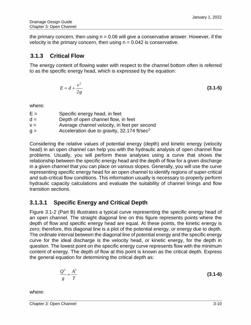
3.1.3 Critical Flow
The energy content of flowing water with respect to the channel bottom often is referred to as the specific energy head, which is expressed by the equation:
g
vdE
2
2
(3.1-5)
where:
E = Specific energy head, in feet d = Depth of open channel flow, in feet v = Average channel velocity, in feet per second g = Acceleration due to gravity, 32.174 ft/sec2
Considering the relative values of potential energy (depth) and kinetic energy (velocity head) in an open channel can help you with the hydraulic analysis of open channel flow problems. Usually, you will perform these analyses using a curve that shows the relationship between the specific energy head and the depth of flow for a given discharge in a given channel that you can place on various slopes. Generally, you will use the curve representing specific energy head for an open channel to identify regions of super-critical and sub-critical flow conditions. This information usually is necessary to properly perform hydraulic capacity calculations and evaluate the suitability of channel linings and flow transition sections.
3.1.3.1 Specific Energy and Critical Depth
Figure 3.1-2 (Part B) illustrates a typical curve representing the specific energy head of an open channel. The straight diagonal line on this figure represents points where the depth of flow and specific energy head are equal. At these points, the kinetic energy is zero; therefore, this diagonal line is a plot of the potential energy, or energy due to depth. The ordinate interval between the diagonal line of potential energy and the specific energy curve for the ideal discharge is the velocity head, or kinetic energy, for the depth in question. The lowest point on the specific energy curve represents flow with the minimum content of energy. The depth of flow at this point is known as the critical depth. Express the general equation for determining the critical depth as:
T
A
g
Q 32
(3.1-6)
where:
January 1, 2022 Drainage Design Guide Chapter 3: Open Channel
Chapter 3: Open Channel 3-11
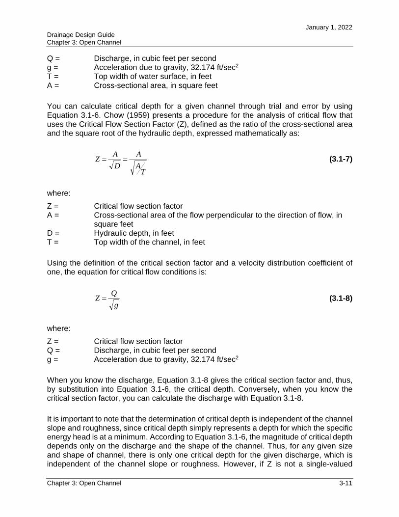
Q = Discharge, in cubic feet per second g = Acceleration due to gravity, 32.174 ft/sec2
T = Top width of water surface, in feet A = Cross-sectional area, in square feet
You can calculate critical depth for a given channel through trial and error by using Equation 3.1-6. Chow (1959) presents a procedure for the analysis of critical flow that uses the Critical Flow Section Factor (Z), defined as the ratio of the cross-sectional area and the square root of the hydraulic depth, expressed mathematically as:
TA
A
D
AZ (3.1-7)
where:
Z = Critical flow section factor A = Cross-sectional area of the flow perpendicular to the direction of flow, in
square feet D = Hydraulic depth, in feet T = Top width of the channel, in feet
Using the definition of the critical section factor and a velocity distribution coefficient of one, the equation for critical flow conditions is:
g
QZ (3.1-8)
where:
Z = Critical flow section factor Q = Discharge, in cubic feet per second g = Acceleration due to gravity, 32.174 ft/sec2
When you know the discharge, Equation 3.1-8 gives the critical section factor and, thus, by substitution into Equation 3.1-6, the critical depth. Conversely, when you know the critical section factor, you can calculate the discharge with Equation 3.1-8.
It is important to note that the determination of critical depth is independent of the channel slope and roughness, since critical depth simply represents a depth for which the specific energy head is at a minimum. According to Equation 3.1-6, the magnitude of critical depth depends only on the discharge and the shape of the channel. Thus, for any given size and shape of channel, there is only one critical depth for the given discharge, which is independent of the channel slope or roughness. However, if Z is not a single-valued
January 1, 2022 Drainage Design Guide Chapter 3: Open Channel
Chapter 3: Open Channel 3-12
function of depth, it is possible to have more than one critical depth. For a given value of specific energy, the critical depth results in the greatest discharge, or conversely, for a given discharge, the specific energy is a minimum for the critical depth.
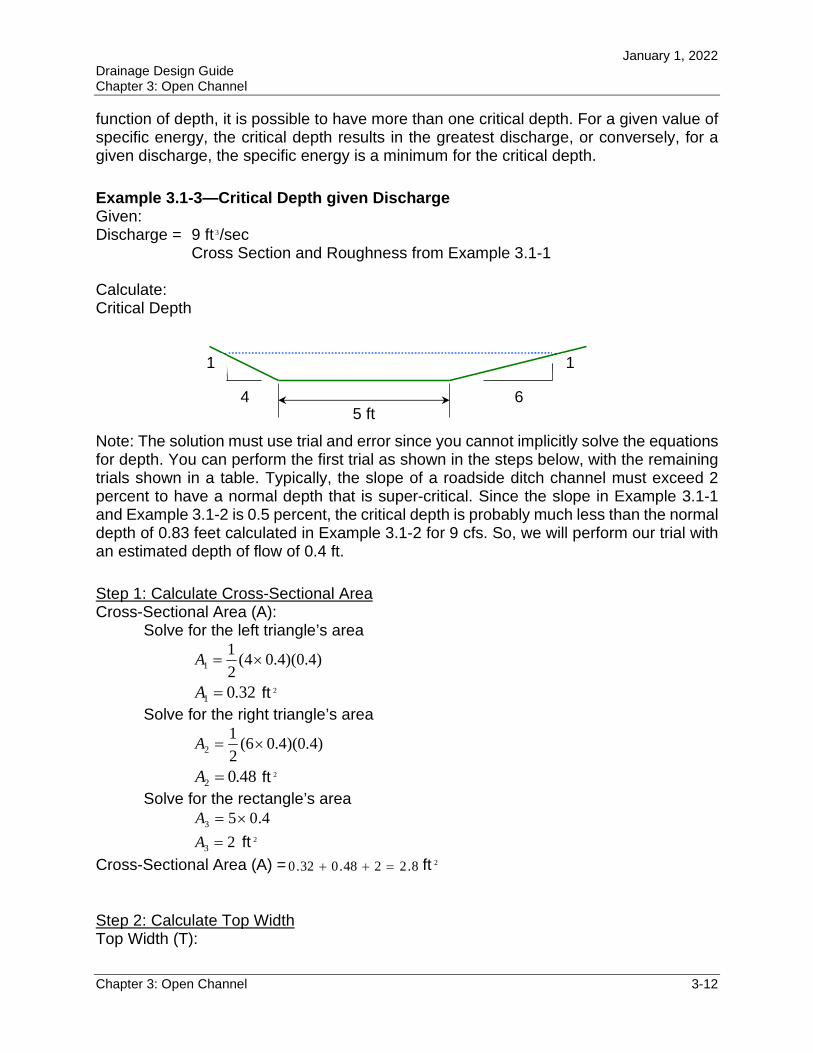
Example 3.1-3—Critical Depth given Discharge Given: Discharge = 9 ft 3/sec
Cross Section and Roughness from Example 3.1-1
Calculate: Critical Depth
Note: The solution must use trial and error since you cannot implicitly solve the equations for depth. You can perform the first trial as shown in the steps below, with the remaining trials shown in a table. Typically, the slope of a roadside ditch channel must exceed 2 percent to have a normal depth that is super-critical. Since the slope in Example 3.1-1 and Example 3.1-2 is 0.5 percent, the critical depth is probably much less than the normal depth of 0.83 feet calculated in Example 3.1-2 for 9 cfs. So, we will perform our trial with an estimated depth of flow of 0.4 ft.
Step 1: Calculate Cross-Sectional Area Cross-Sectional Area (A):
Solve for the left triangle’s area
)4.0)(4.04(2
11 A
32.01 A ft 2
Solve for the right triangle’s area
)4.0)(4.06(2
12 A
48.02 A ft 2
Solve for the rectangle’s area 4.053 A
23 A ft 2
Cross-Sectional Area (A) = 8.2248.032.0 ft 2
Step 2: Calculate Top Width Top Width (T):
5 ft 4
1
6
1
January 1, 2022 Drainage Design Guide Chapter 3: Open Channel
Chapter 3: Open Channel 3-13
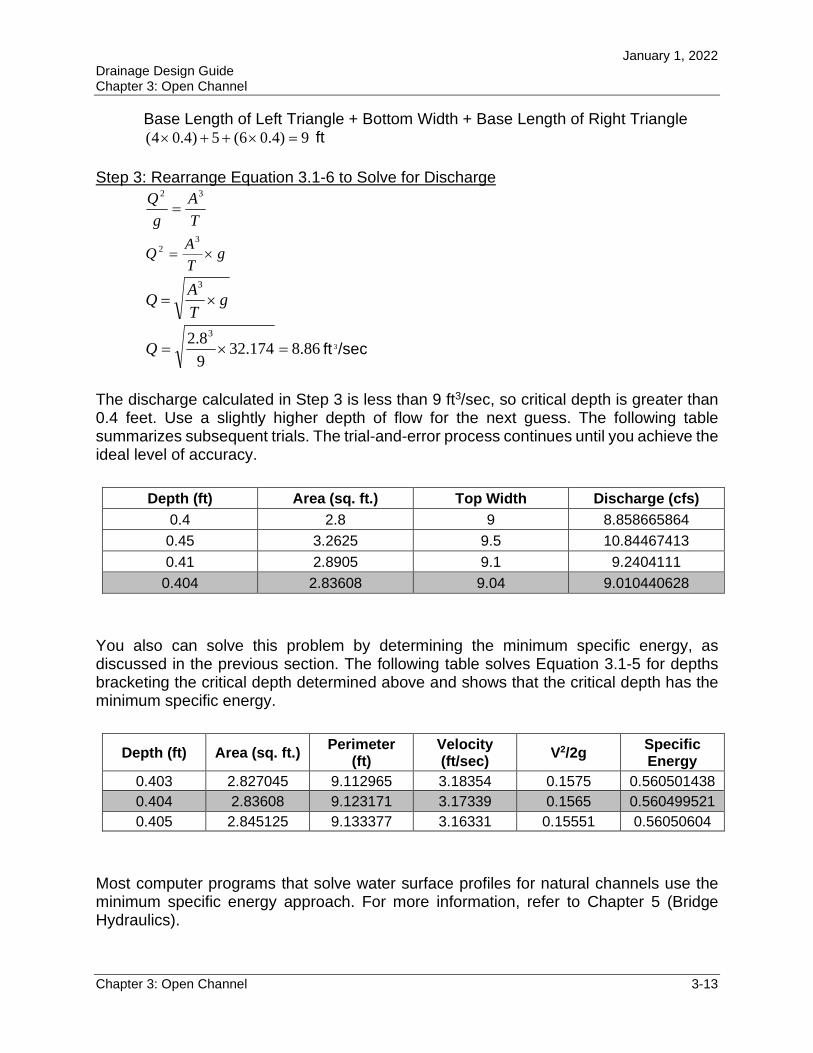
Base Length of Left Triangle + Bottom Width + Base Length of Right Triangle 9)4.06(5)4.04( ft
Step 3: Rearrange Equation 3.1-6 to Solve for Discharge
T
A
g
Q 32
gT
AQ
32
gT
AQ
3
86.8174.329
8.2 3
Q ft 3/sec
The discharge calculated in Step 3 is less than 9 ft3/sec, so critical depth is greater than 0.4 feet. Use a slightly higher depth of flow for the next guess. The following table summarizes subsequent trials. The trial-and-error process continues until you achieve the ideal level of accuracy.
Depth (ft) Area (sq. ft.) Top Width Discharge (cfs)
0.4 2.8 9 8.858665864
0.45 3.2625 9.5 10.84467413
0.41 2.8905 9.1 9.2404111
0.404 2.83608 9.04 9.010440628
You also can solve this problem by determining the minimum specific energy, as discussed in the previous section. The following table solves Equation 3.1-5 for depths bracketing the critical depth determined above and shows that the critical depth has the minimum specific energy.
Depth (ft) Area (sq. ft.) Perimeter
(ft) Velocity (ft/sec)
V2/2g Specific Energy
0.403 2.827045 9.112965 3.18354 0.1575 0.560501438
0.404 2.83608 9.123171 3.17339 0.1565 0.560499521
0.405 2.845125 9.133377 3.16331 0.15551 0.56050604
Most computer programs that solve water surface profiles for natural channels use the minimum specific energy approach. For more information, refer to Chapter 5 (Bridge Hydraulics).
January 1, 2022 Drainage Design Guide Chapter 3: Open Channel
Chapter 3: Open Channel 3-14
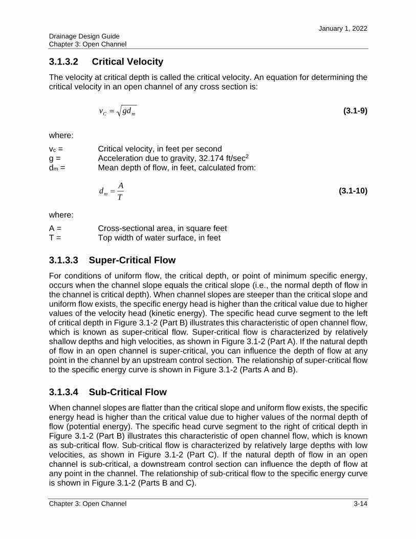
3.1.3.2 Critical Velocity
The velocity at critical depth is called the critical velocity. An equation for determining the critical velocity in an open channel of any cross section is:
mC gdv (3.1-9)
where:
vc = Critical velocity, in feet per second g = Acceleration due to gravity, 32.174 ft/sec2
dm = Mean depth of flow, in feet, calculated from:
T
Adm (3.1-10)
where:
A = Cross-sectional area, in square feet T = Top width of water surface, in feet
3.1.3.3 Super-Critical Flow
For conditions of uniform flow, the critical depth, or point of minimum specific energy, occurs when the channel slope equals the critical slope (i.e., the normal depth of flow in the channel is critical depth). When channel slopes are steeper than the critical slope and uniform flow exists, the specific energy head is higher than the critical value due to higher values of the velocity head (kinetic energy). The specific head curve segment to the left of critical depth in Figure 3.1-2 (Part B) illustrates this characteristic of open channel flow, which is known as super-critical flow. Super-critical flow is characterized by relatively shallow depths and high velocities, as shown in Figure 3.1-2 (Part A). If the natural depth of flow in an open channel is super-critical, you can influence the depth of flow at any point in the channel by an upstream control section. The relationship of super-critical flow to the specific energy curve is shown in Figure 3.1-2 (Parts A and B).
3.1.3.4 Sub-Critical Flow
When channel slopes are flatter than the critical slope and uniform flow exists, the specific energy head is higher than the critical value due to higher values of the normal depth of flow (potential energy). The specific head curve segment to the right of critical depth in Figure 3.1-2 (Part B) illustrates this characteristic of open channel flow, which is known as sub-critical flow. Sub-critical flow is characterized by relatively large depths with low velocities, as shown in Figure 3.1-2 (Part C). If the natural depth of flow in an open channel is sub-critical, a downstream control section can influence the depth of flow at any point in the channel. The relationship of sub-critical flow to the specific energy curve is shown in Figure 3.1-2 (Parts B and C).
January 1, 2022 Drainage Design Guide Chapter 3: Open Channel
Chapter 3: Open Channel 3-15
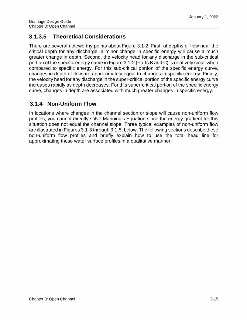
3.1.3.5 Theoretical Considerations
There are several noteworthy points about Figure 3.1-2. First, at depths of flow near the critical depth for any discharge, a minor change in specific energy will cause a much greater change in depth. Second, the velocity head for any discharge in the sub-critical portion of the specific energy curve in Figure 3.1-2 (Parts B and C) is relatively small when compared to specific energy. For this sub-critical portion of the specific energy curve, changes in depth of flow are approximately equal to changes in specific energy. Finally, the velocity head for any discharge in the super-critical portion of the specific energy curve increases rapidly as depth decreases. For this super-critical portion of the specific energy curve, changes in depth are associated with much greater changes in specific energy.
3.1.4 Non-Uniform Flow
In locations where changes in the channel section or slope will cause non-uniform flow profiles, you cannot directly solve Manning's Equation since the energy gradient for this situation does not equal the channel slope. Three typical examples of non-uniform flow are illustrated in Figures 3.1-3 through 3.1-5, below. The following sections describe these non-uniform flow profiles and briefly explain how to use the total head line for approximating these water surface profiles in a qualitative manner.
January 1, 2022 Drainage Design Guide Chapter 3: Open Channel
Chapter 3: Open Channel 3-16
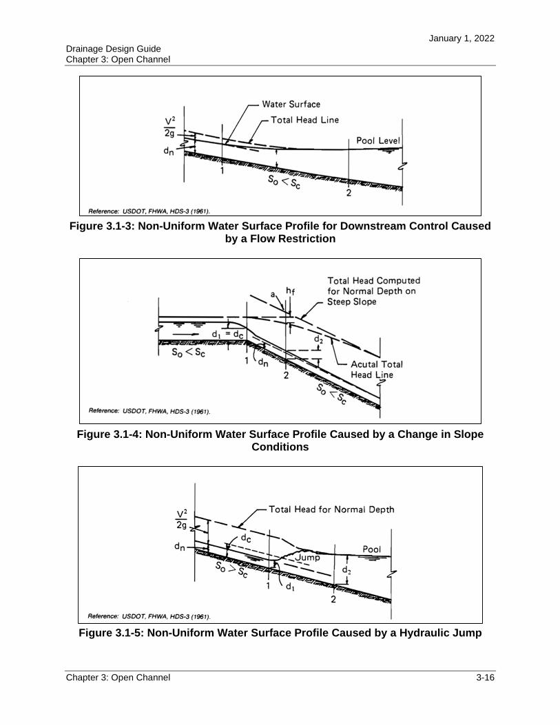
Figure 3.1-3: Non-Uniform Water Surface Profile for Downstream Control Caused by a Flow Restriction
Figure 3.1-4: Non-Uniform Water Surface Profile Caused by a Change in Slope Conditions
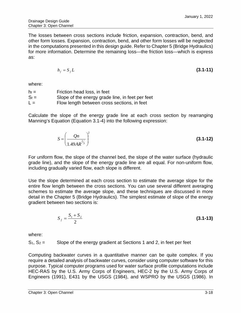
Figure 3.1-5: Non-Uniform Water Surface Profile Caused by a Hydraulic Jump
January 1, 2022 Drainage Design Guide Chapter 3: Open Channel
Chapter 3: Open Channel 3-17
3.1.4.1 Gradually Varied Flow
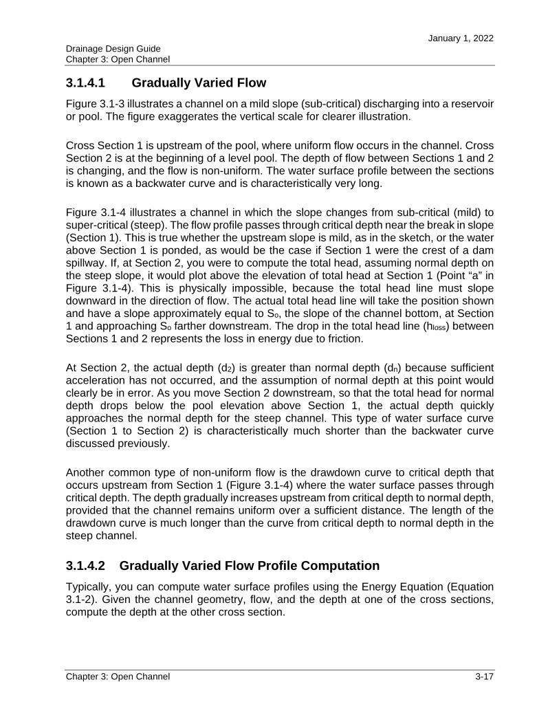
Figure 3.1-3 illustrates a channel on a mild slope (sub-critical) discharging into a reservoir or pool. The figure exaggerates the vertical scale for clearer illustration.
Cross Section 1 is upstream of the pool, where uniform flow occurs in the channel. Cross Section 2 is at the beginning of a level pool. The depth of flow between Sections 1 and 2 is changing, and the flow is non-uniform. The water surface profile between the sections is known as a backwater curve and is characteristically very long.
Figure 3.1-4 illustrates a channel in which the slope changes from sub-critical (mild) to super-critical (steep). The flow profile passes through critical depth near the break in slope (Section 1). This is true whether the upstream slope is mild, as in the sketch, or the water above Section 1 is ponded, as would be the case if Section 1 were the crest of a dam spillway. If, at Section 2, you were to compute the total head, assuming normal depth on the steep slope, it would plot above the elevation of total head at Section 1 (Point “a” in Figure 3.1-4). This is physically impossible, because the total head line must slope downward in the direction of flow. The actual total head line will take the position shown and have a slope approximately equal to So, the slope of the channel bottom, at Section 1 and approaching So farther downstream. The drop in the total head line (hloss) between Sections 1 and 2 represents the loss in energy due to friction.
At Section 2, the actual depth (d2) is greater than normal depth (dn) because sufficient acceleration has not occurred, and the assumption of normal depth at this point would clearly be in error. As you move Section 2 downstream, so that the total head for normal depth drops below the pool elevation above Section 1, the actual depth quickly approaches the normal depth for the steep channel. This type of water surface curve (Section 1 to Section 2) is characteristically much shorter than the backwater curve discussed previously.
Another common type of non-uniform flow is the drawdown curve to critical depth that occurs upstream from Section 1 (Figure 3.1-4) where the water surface passes through critical depth. The depth gradually increases upstream from critical depth to normal depth, provided that the channel remains uniform over a sufficient distance. The length of the drawdown curve is much longer than the curve from critical depth to normal depth in the steep channel.
3.1.4.2 Gradually Varied Flow Profile Computation
Typically, you can compute water surface profiles using the Energy Equation (Equation 3.1-2). Given the channel geometry, flow, and the depth at one of the cross sections, compute the depth at the other cross section.
January 1, 2022 Drainage Design Guide Chapter 3: Open Channel
Chapter 3: Open Channel 3-18
The losses between cross sections include friction, expansion, contraction, bend, and other form losses. Expansion, contraction, bend, and other form losses will be neglected in the computations presented in this design guide. Refer to Chapter 5 (Bridge Hydraulics) for more information. Determine the remaining loss—the friction loss—which is express as:
LSh ff (3.1-11)
where:
hf = Friction head loss, in feet Sf = Slope of the energy grade line, in feet per feet L = Flow length between cross sections, in feet
Calculate the slope of the energy grade line at each cross section by rearranging Manning’s Equation (Equation 3.1-4) into the following expression:
2
32
49.1
AR
QnS (3.1-12)
For uniform flow, the slope of the channel bed, the slope of the water surface (hydraulic grade line), and the slope of the energy grade line are all equal. For non-uniform flow, including gradually varied flow, each slope is different.
Use the slope determined at each cross section to estimate the average slope for the entire flow length between the cross sections. You can use several different averaging schemes to estimate the average slope, and these techniques are discussed in more detail in the Chapter 5 (Bridge Hydraulics). The simplest estimate of slope of the energy gradient between two sections is:
221 SS
S f
(3.1-13)
where:
S1, S2 = Slope of the energy gradient at Sections 1 and 2, in feet per feet
Computing backwater curves in a quantitative manner can be quite complex. If you require a detailed analysis of backwater curves, consider using computer software for this purpose. Typical computer programs used for water surface profile computations include HEC-RAS by the U.S. Army Corps of Engineers, HEC-2 by the U.S. Army Corps of Engineers (1991), E431 by the USGS (1984), and WSPRO by the USGS (1986). In
January 1, 2022 Drainage Design Guide Chapter 3: Open Channel
Chapter 3: Open Channel 3-19
addition, textbooks by Chow (1959), Henderson (1966), or Streeter (1971), and publications by the USGS (1976b), Brater and King (1976), or the USDA, SCS (NEH-5, 2008) may be useful.
Example 3.1.4—Gradually Varied Flow Example
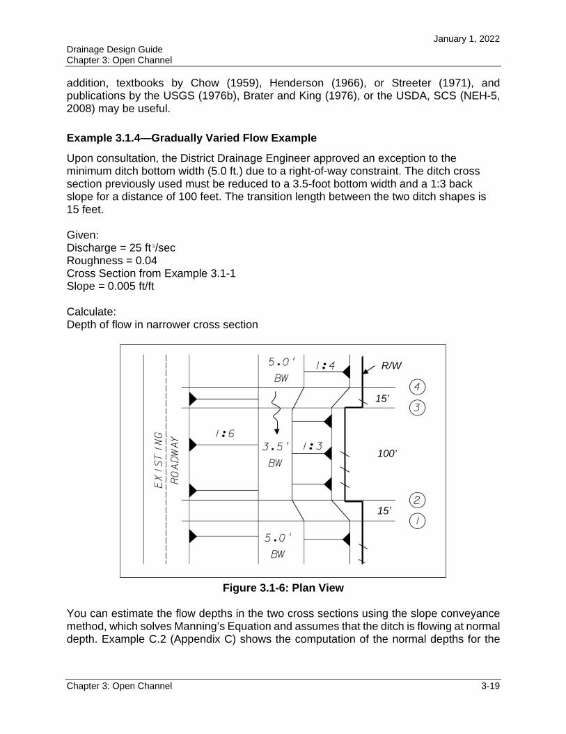
Upon consultation, the District Drainage Engineer approved an exception to the minimum ditch bottom width (5.0 ft.) due to a right-of-way constraint. The ditch cross section previously used must be reduced to a 3.5-foot bottom width and a 1:3 back slope for a distance of 100 feet. The transition length between the two ditch shapes is 15 feet.
Given: Discharge = 25 ft 3/sec Roughness = 0.04 Cross Section from Example 3.1-1 Slope = 0.005 ft/ft
Calculate: Depth of flow in narrower cross section
Figure 3.1-6: Plan View
You can estimate the flow depths in the two cross sections using the slope conveyance method, which solves Manning’s Equation and assumes that the ditch is flowing at normal depth. Example C.2 (Appendix C) shows the computation of the normal depths for the
100’
15’
15’
R/W
January 1, 2022 Drainage Design Guide Chapter 3: Open Channel
Chapter 3: Open Channel 3-20
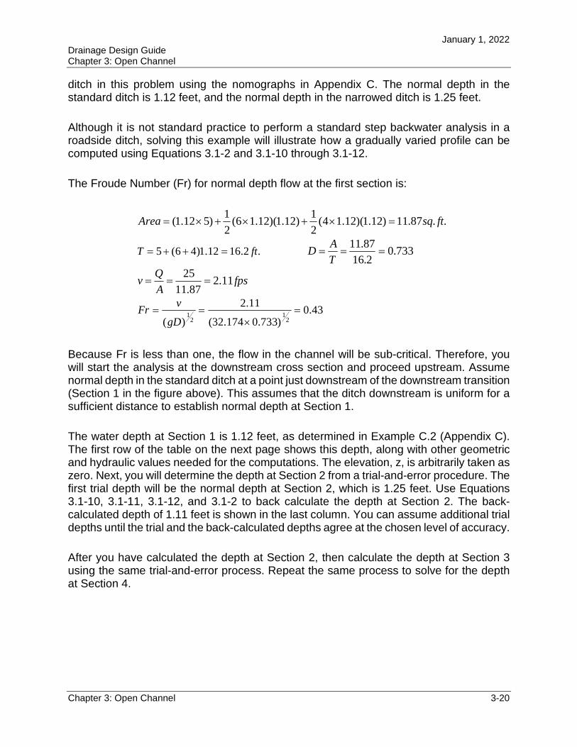
ditch in this problem using the nomographs in Appendix C. The normal depth in the standard ditch is 1.12 feet, and the normal depth in the narrowed ditch is 1.25 feet.
Although it is not standard practice to perform a standard step backwater analysis in a roadside ditch, solving this example will illustrate how a gradually varied profile can be computed using Equations 3.1-2 and 3.1-10 through 3.1-12.
The Froude Number (Fr) for normal depth flow at the first section is:
..87.11)12.1)(12.14(2
1)12.1)(12.16(
2
1)512.1( ftsqArea
.2.1612.1)46(5 ftT 733.02.16
87.11
T
AD
fpsA
Qv 11.2
87.11
25
43.0)733.0174.32(
11.2
)( 21
21
gD
vFr
Because Fr is less than one, the flow in the channel will be sub-critical. Therefore, you will start the analysis at the downstream cross section and proceed upstream. Assume normal depth in the standard ditch at a point just downstream of the downstream transition (Section 1 in the figure above). This assumes that the ditch downstream is uniform for a sufficient distance to establish normal depth at Section 1.
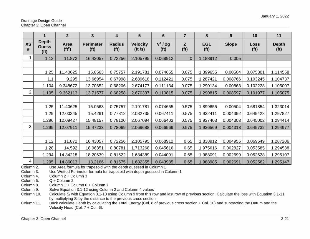
The water depth at Section 1 is 1.12 feet, as determined in Example C.2 (Appendix C). The first row of the table on the next page shows this depth, along with other geometric and hydraulic values needed for the computations. The elevation, z, is arbitrarily taken as zero. Next, you will determine the depth at Section 2 from a trial-and-error procedure. The first trial depth will be the normal depth at Section 2, which is 1.25 feet. Use Equations 3.1-10, 3.1-11, 3.1-12, and 3.1-2 to back calculate the depth at Section 2. The back-calculated depth of 1.11 feet is shown in the last column. You can assume additional trial depths until the trial and the back-calculated depths agree at the chosen level of accuracy.
After you have calculated the depth at Section 2, then calculate the depth at Section 3 using the same trial-and-error process. Repeat the same process to solve for the depth at Section 4.
January 1, 2022 Drainage Design Guide Chapter 3: Open Channel
Chapter 3: Open Channel 3-21
1 2 3 4 5 6 7 8 9 10 11
XS #
Depth Guess
(ft)
Area (ft2)
Perimeter (ft)
Radius (ft)
Velocity (ft /s)
V2 / 2g (ft)
Z (ft)
EGL (ft)
Slope Loss (ft)
Depth (ft)
1 1.12 11.872 16.43057 0.72256 2.105795 0.068912 0 1.188912 0.005
1.25 11.40625 15.0563 0.75757 2.191781 0.074655 0.075 1.399655 0.00504 0.075301 1.114558
1.1 9.295 13.66954 0.67998 2.689618 0.112421 0.075 1.287421 0.008766 0.103245 1.104737
1.104 9.348672 13.70652 0.68206 2.674177 0.111134 0.075 1.290134 0.00863 0.102228 1.105007
2 1.105 9.362113 13.71577 0.68258 2.670337 0.110815 0.075 1.290815 0.008597 0.101977 1.105075
1.25 11.40625 15.0563 0.75757 2.191781 0.074655 0.575 1.899655 0.00504 0.681854 1.323014
1.29 12.00345 15.4261 0.77812 2.082735 0.067411 0.575 1.932411 0.004392 0.649423 1.297827
1.296 12.09427 15.48157 0.78120 2.067094 0.066403 0.575 1.937403 0.004303 0.645002 1.294414
3 1.295 12.07911 15.47233 0.78069 2.069688 0.066569 0.575 1.936569 0.004318 0.645732 1.294977
1.12 11.872 16.43057 0.72256 2.105795 0.068912 0.65 1.838912 0.004955 0.069549 1.287206
1.28 14.592 18.06351 0.80781 1.713268 0.045616 0.65 1.975616 0.002827 0.053585 1.294538
1.294 14.84218 18.20639 0.81522 1.684389 0.044091 0.65 1.988091 0.002699 0.052628 1.295107
4 1.295 14.86013 18.2166 0.81575 1.682355 0.043985 0.65 1.988985 0.002691 0.052562 1.295147Column 2. Use Area formula for trapezoid with the depth guessed in Column 1 Column 3. Use Wetted Perimeter formula for trapezoid with depth guessed in Column 1 Column 4. Column 2 ÷ Column 3 Column 5. Q ÷ Column 2 Column 8. Column 1 + Column 6 + Column 7 Column 9. Solve Equation 3.1-12 using Column 2 and Column 4 values Column 10. Calculate Sf with Equation 3.1-13 using Column 9 from this row and last row of previous section. Calculate the loss with Equation 3.1-11
by multiplying Sf by the distance to the previous cross section. Column 11. Back calculate Depth by calculating the Total Energy (Col. 8 of previous cross section + Col. 10) and subtracting the Datum and the
Velocity Head (Col. 7 + Col. 6).
January 1, 2022 Drainage Design Guide Chapter 3: Open Channel
Chapter 3: Open Channel 3-22
Looking at the results of the profile analysis on the previous page, there are several things you might not expect. First, the flow depth at Section 2 (1.105 feet) is less than the flow depth at Section 1 (1.12 feet), which might be unexpected because the normal depth of Section 2 is greater than Section 1. However, this is not an unusual occurrence in contracted sections. The reason that the flow depth decreases is because the velocity, and, therefore, the velocity head, increases. The increase in the velocity head is greater than the losses between the sections; therefore, the depth must decrease to balance the energy equation. The opposite can occur in an expanding reach, resulting in an unexpected rise in the flow depth even though the normal depth decreases.
The next unusual result is that the flow depth at Section 3 is greater than the normal depth in the narrow section. Since the flow depth is less than normal depth at Section 2, the water surface profile should approach normal depth from below as the calculations proceed upstream. Therefore, the flow depth at Section 3 should be less than the normal depth. The reason that the profile jumps over the normal depth line is because of numerical errors introduced by Equation 3.1-13. When the change in the energy gradient between two cross sections is too large, Equation 3.1-13 does not accurately estimate the average energy gradient between the sections. Cross sections must be added between these cross sections to reduce the numerical errors to an acceptable amount.
This example was solved using HEC-RAS with the extra cross sections added. The details are described below, but the results indicate that the flow depth essentially converges to normal depth within the 100-foot distance between Sections 2 and 3. The normal depth is 1.25 feet compared to the 1.24 feet computed by HEC-RAS at Section 3. This Illustrates one of the primary reasons that water surface profiles are not necessary in the typical roadside ditch design. The water depth does not significantly vary from normal depth at any location. So, assuming that the design includes some freeboard, the ditch will operate adequately when designed by assuming normal depth.
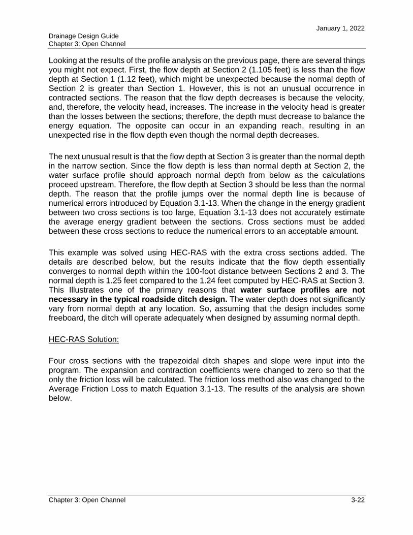
HEC-RAS Solution:
Four cross sections with the trapezoidal ditch shapes and slope were input into the program. The expansion and contraction coefficients were changed to zero so that the only the friction loss will be calculated. The friction loss method also was changed to the Average Friction Loss to match Equation 3.1-13. The results of the analysis are shown below.
January 1, 2022 Drainage Design Guide Chapter 3: Open Channel
Chapter 3: Open Channel 3-23
To compare the results with the spreadsheet solution, the depth of flow must be calculated from the water surface elevation.
Section River Station Water Surface Z Flow Depth
(Ft.)
1 0 1.12 0 1.12
2 15 1.18 0.075 1.11
3 115 1.87 0.575 1.30
4 130 1.94 0.65 1.29
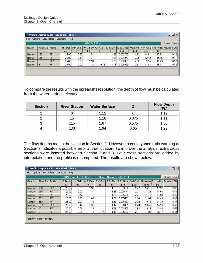
The flow depths match the solution in Section 2. However, a conveyance ratio warning at Section 3 indicates a possible error at that location. To improve the analysis, extra cross sections were inserted between Section 2 and 3. Four cross sections are added by interpolation and the profile is recomputed. The results are shown below:
January 1, 2022 Drainage Design Guide Chapter 3: Open Channel
Chapter 3: Open Channel 3-24
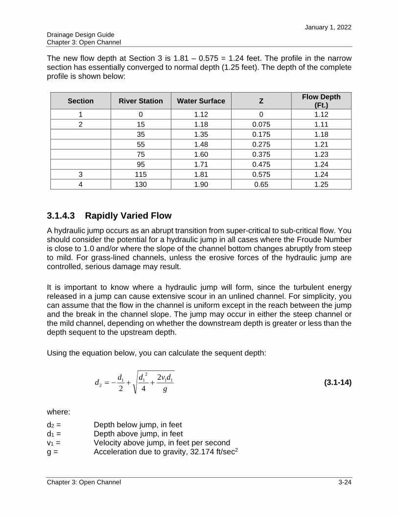
The new flow depth at Section 3 is 1.81 – 0.575 = 1.24 feet. The profile in the narrow section has essentially converged to normal depth (1.25 feet). The depth of the complete profile is shown below:
Section River Station Water Surface Z Flow Depth
(Ft.)
1 0 1.12 0 1.12
2 15 1.18 0.075 1.11
35 1.35 0.175 1.18
55 1.48 0.275 1.21
75 1.60 0.375 1.23
95 1.71 0.475 1.24
3 115 1.81 0.575 1.24
4 130 1.90 0.65 1.25
3.1.4.3 Rapidly Varied Flow
A hydraulic jump occurs as an abrupt transition from super-critical to sub-critical flow. You should consider the potential for a hydraulic jump in all cases where the Froude Number is close to 1.0 and/or where the slope of the channel bottom changes abruptly from steep to mild. For grass-lined channels, unless the erosive forces of the hydraulic jump are controlled, serious damage may result.
It is important to know where a hydraulic jump will form, since the turbulent energy released in a jump can cause extensive scour in an unlined channel. For simplicity, you can assume that the flow in the channel is uniform except in the reach between the jump and the break in the channel slope. The jump may occur in either the steep channel or the mild channel, depending on whether the downstream depth is greater or less than the depth sequent to the upstream depth.
Using the equation below, you can calculate the sequent depth:
g
dvddd 11
2
112
2
42 (3.1-14)
where:
d2 = Depth below jump, in feet d1 = Depth above jump, in feet v1 = Velocity above jump, in feet per second g = Acceleration due to gravity, 32.174 ft/sec2
January 1, 2022 Drainage Design Guide Chapter 3: Open Channel
Chapter 3: Open Channel 3-25
If the downstream depth is greater than the sequent depth, the jump will occur in the steep region. If the downstream depth is lower than the sequent depth, the jump will move into the mild channel (Chow). For more discussion on the location of hydraulic jumps, refer to Open-Channel Hydraulics, by V.T. Chow, PhD.
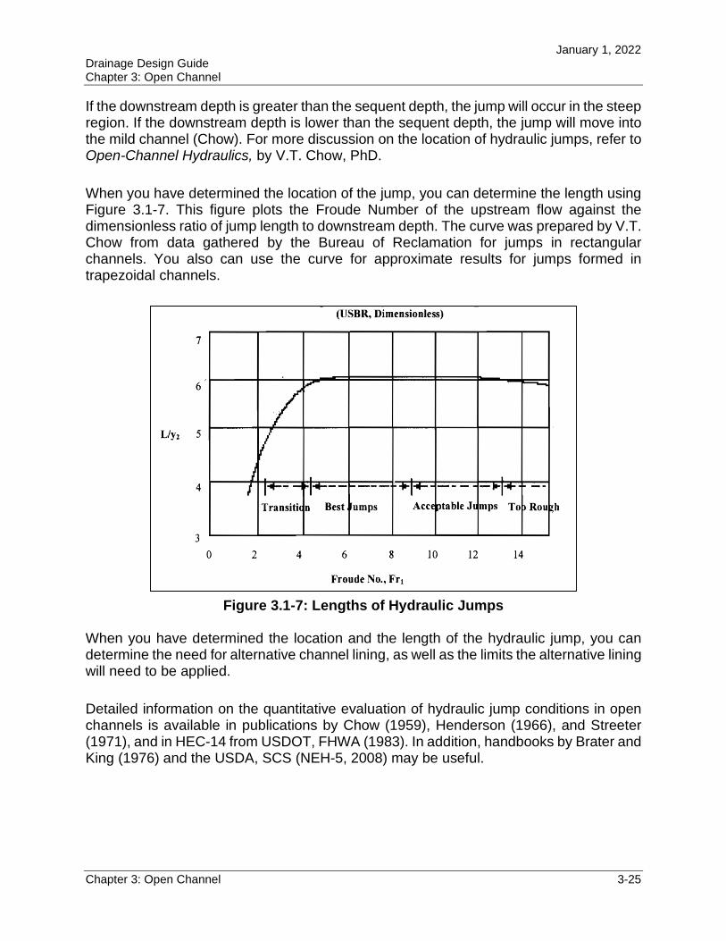
When you have determined the location of the jump, you can determine the length using Figure 3.1-7. This figure plots the Froude Number of the upstream flow against the dimensionless ratio of jump length to downstream depth. The curve was prepared by V.T. Chow from data gathered by the Bureau of Reclamation for jumps in rectangular channels. You also can use the curve for approximate results for jumps formed in trapezoidal channels.
Figure 3.1-7: Lengths of Hydraulic Jumps
When you have determined the location and the length of the hydraulic jump, you can determine the need for alternative channel lining, as well as the limits the alternative lining will need to be applied.
Detailed information on the quantitative evaluation of hydraulic jump conditions in open channels is available in publications by Chow (1959), Henderson (1966), and Streeter (1971), and in HEC-14 from USDOT, FHWA (1983). In addition, handbooks by Brater and King (1976) and the USDA, SCS (NEH-5, 2008) may be useful.
January 1, 2022 Drainage Design Guide Chapter 3: Open Channel
Chapter 3: Open Channel 3-26
Example 3.1-5—Hydraulic Jump Example
Given: Q = 60.23 cfs V1 = 13.81 fps g = 32.2 ft/s2
d1 = 0.33 ft d2 = 6.74 ft
You calculated the depths above using Manning’s Equation. The ditch has a 12.5-foot bottom width with 1:2 side slopes. The longitudinal slopes are 10 percent and 0.001 percent, respectively. The roughness value for the proposed rubble riprap is 0.035.
Calculate: Hydraulic Jump and the extent of rubble needed.
Step 1: Calculate Froude Number and the Length of the Hydraulic Jump Froude Number, F1:
1
11
gd
VF
)33.0)(2.32(
81.131 F
24.41 F
Length of the Hydraulic Jump, L: From Figure 3.1-7,
85.52
d
L
Therefore, )74.6)(85.5(85.5 2 dL
ftftL 404.39
Step 2: Calculate the Upstream Sequent Depth Upstream Sequent Depth, d1’:
4
2
2
211
211'
1
d
g
dVdd
4
)33.0(
2.32
)33.0()81.13(2
2
33.0 22'1 d
ftd 81.1'1
January 1, 2022 Drainage Design Guide Chapter 3: Open Channel
Chapter 3: Open Channel 3-27
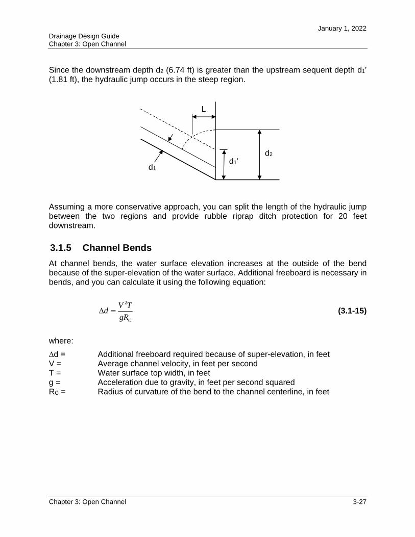
Since the downstream depth d2 (6.74 ft) is greater than the upstream sequent depth d1’ (1.81 ft), the hydraulic jump occurs in the steep region.
Assuming a more conservative approach, you can split the length of the hydraulic jump between the two regions and provide rubble riprap ditch protection for 20 feet downstream.
3.1.5 Channel Bends
At channel bends, the water surface elevation increases at the outside of the bend because of the super-elevation of the water surface. Additional freeboard is necessary in bends, and you can calculate it using the following equation:
CgR
TVd
2
(3.1-15)
where:
∆d = Additional freeboard required because of super-elevation, in feet V = Average channel velocity, in feet per second T = Water surface top width, in feet g = Acceleration due to gravity, in feet per second squared RC = Radius of curvature of the bend to the channel centerline, in feet
d2
d1’ d1
L
January 1, 2022 Drainage Design Guide Chapter 3: Open Channel
Chapter 3: Open Channel 3-28
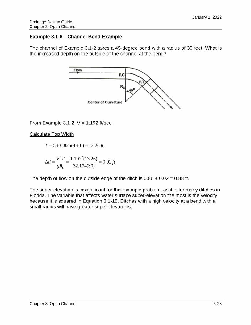
Example 3.1-6—Channel Bend Example
The channel of Example 3.1-2 takes a 45-degree bend with a radius of 30 feet. What is the increased depth on the outside of the channel at the bend?
From Example 3.1-2, V = 1.192 ft/sec
Calculate Top Width
.26.13)64(826.05 ftT
ftgR
TVd
C
02.0)30(174.32
)26.13(192.1 22
The depth of flow on the outside edge of the ditch is 0.86 + 0.02 = 0.88 ft.
The super-elevation is insignificant for this example problem, as it is for many ditches in Florida. The variable that affects water surface super-elevation the most is the velocity because it is squared in Equation 3.1-15. Ditches with a high velocity at a bend with a small radius will have greater super-elevations.
January 1, 2022 Drainage Design Guide Chapter 3: Open Channel
Chapter 3: Open Channel 3-29
3.2 OPEN CHANNEL DESIGN
You were given the channel shape, slope, and roughness in the previous example problems. From these example problems, you determined the flow depths and velocities using the analysis methods described in this chapter. If a project incorporates existing channels, then you can apply the analysis methods to those channels just as you applied them to the example problems. However, many projects will require you to design new channels. This section discusses how you select the channel geometry and channel linings for FDOT projects.
3.2.1 Types of Open Channels for Highways
You can classify open channels generally as those that occur naturally and those that are manmade, including improved natural channels. The latter, called artificial channels, are used on most roadway projects. The types of channels commonly used on FDOT projects are listed in Chapter 2 of the Drainage Manual:
Roadside Ditch Median Ditch Interceptor Ditch Outfall Ditch Canals
Section 2.2 of the Drainage Manual recommends design frequencies for each of these channel types.
The roadside ditch receives runoff from the roadway pavement and shoulders as directed by the cross slope and shoulder slopes. The roadside ditch also may receive flow from offsite drainage areas on adjacent properties. The roadside ditch also may intercept ground water to protect the base of the roadway. The roadside ditch conveys the flow to an outfall point, although the ditch may flow into other ditches or components of the stormwater management system before reaching the ultimate outfall point from FDOT right of way. Depressed medians will collect runoff and a median ditch will be needed to convey runoff to an outfall point. In general, roadside and median ditches are relatively shallow trapezoidal channels, while swales are shallow, triangular, zero-bottom-width channels.
Interceptor ditches have various purposes. They provide a method for intercepting offsite flow above cut slopes, thereby controlling slope erosion. They can also collect offsite flow and keep it separate from the project stormwater. This flow can bypass the stormwater treatment facilities, reducing their size and cost.
Design outfall ditches, in most cases, to receive runoff from numerous secondary drainage facilities, such as roadside ditches or storm drains. The delineation between a
January 1, 2022 Drainage Design Guide Chapter 3: Open Channel
Chapter 3: Open Channel 3-30
roadside ditch and an outfall ditch can become blurred. If the discharge from a stormwater management facility is brought back to the roadside ditch to convey the flow to another point on the project for ultimate discharge, then consider the roadside ditch to be an outfall ditch for the purpose of selecting the design frequency. If you combine considerable flows from offsite areas and onsite project flows together in the roadside ditch to become a significant discharge, then consider the roadside ditch to be an outfall ditch for the purpose of selecting the design frequency. It is unwise to use a roadside ditch as an outfall ditch, since its probable depth and size could create a potential hazard.
Canals, like outfalls, also are large artificial channels that accept flows from other drainage components. The added connotation of a canal is that there is always water in the channel, unlike many outfalls that only flow immediately after a rainfall event. If the canal, which always has water, is close to the road, then it can be a potential hazard. For the purpose of identifying a hazard, the FDM defines a canal as an open ditch parallel to the roadway for a minimum distance of 1,000 feet, and with a seasonal water depth in excess of three feet for extended periods of time (24 hours or more). Water Management Districts and local agencies may have a different definition for canals when determining regulatory jurisdiction.
Other FDOT publications mention other types of ditches. Right-of-way ditches are mentioned in the Standard Specifications and a detail is given on Standard Plans, Index 524-001. The right-of-way ditch often functions as a type of relief ditch, handling drainage needs other than those for the roadway and thus freeing roadside ditches from carrying anything except roadway runoff. You usually can consider right-of-way ditches as interceptor ditches when selecting the design frequency.
The term “lateral ditch” is used in the FDM and the Standard Specifications. The term is used to determine:
How the ditch excavation will be paid for How the ditch is shown in the plans
A lateral ditch generally is perpendicular to the roadway and can flow either toward or away from the road. However, a lateral ditch also can run parallel to the road right of way if the ditch or channel is separate from the roadway template. Refer to the FDM for guidance on selecting the excavation pay item. Consider the purpose of the lateral ditch and associate it with one of the ditch types listed above to select the design frequency.
Several FDOT publications use the term roadway ditch rather than roadside ditch. These two terms are interchangeable. Other FDOT publications or engineers performing work for the Department also may use many other terms to refer to open channels. The definitions of most of these terms are self-explanatory because of their descriptive names. Some examples are:
January 1, 2022 Drainage Design Guide Chapter 3: Open Channel
Chapter 3: Open Channel 3-31
Drainage ditch Stormwater ditch Bypass ditch Diversion ditch Conveyance channel Agricultural ditch
A swale is a special kind of artificial ditch that has become important in Florida. The following legal definition of a swale as it relates to the regulation and treatment of stormwater discharge is from section 403.803(11), Florida Statutes:
"Swale" means a manmade trench which: a) has a top width-to-depth ratio of the cross section equal to or greater than 6:1, or
side slopes equal to or greater than 3 feet horizontal to one-foot vertical; and b) contains contiguous areas of standing or flowing water only following a rainfall
event; and c) is planted with or has stabilized vegetation suitable for soil stabilization,
stormwater treatment, and nutrient uptake; and d) is designed to take into account the soil erodibility, soil percolation, slope, slope
length, and drainage area so as to prevent erosion and reduce pollutant concentration of any discharge.
3.2.2 Roadside Ditches
You can design roadside ditches using the following steps:
Step 1—Establish a Preliminary Drainage Plan. Roadside ditches will be components of an overall drainage system. Since the roadside ditch generally will follow the grade of the road, the high points in the roadway grade will be initial drainage boundaries. However, you can adjust these boundaries by using special ditch grades so that the ditch flows in a different direction than the roadway grade. You also can adjust the boundaries significantly for projects in flat terrain. It is, however, best to keep existing drainage patterns if possible. You also can adjust low points with special ditch grades if the ideal discharge point is not at the low point of the roadway grade.
Most projects will have stormwater management facilities, so the roadside ditches will connect with the conveyance components to the various facilities. Not all portions of the roadside ditch can physically be directed to a stormwater management facility, so short segments may need to discharge to other points, such as streams or ditches near cross drains and bridges, or other points along the roadway.
When determining initial ditch grades, provide a ditch slope with sufficient grade to minimize ponding and sediment accumulation. The Drainage Manual requires a minimum physical slope of 0.0005 feet/feet for ditches where positive flow is required. These flat
January 1, 2022 Drainage Design Guide Chapter 3: Open Channel
Chapter 3: Open Channel 3-32
slopes are difficult to grade during construction and clumps of grass left behind by mowers easily impede the flow.
Existing utilities also may control the grade of the ditch to maintain minimum cover over the utility.
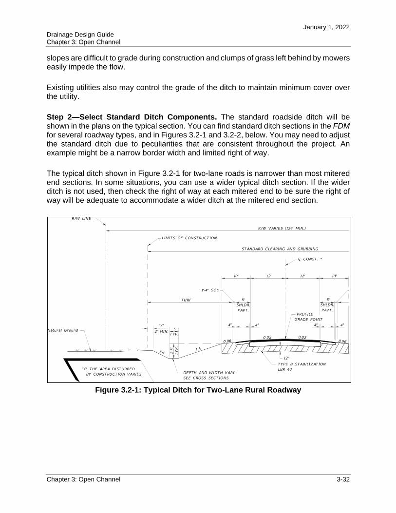
Step 2—Select Standard Ditch Components. The standard roadside ditch will be shown in the plans on the typical section. You can find standard ditch sections in the FDMfor several roadway types, and in Figures 3.2-1 and 3.2-2, below. You may need to adjust the standard ditch due to peculiarities that are consistent throughout the project. An example might be a narrow border width and limited right of way.
The typical ditch shown in Figure 3.2-1 for two-lane roads is narrower than most mitered end sections. In some situations, you can use a wider typical ditch section. If the wider ditch is not used, then check the right of way at each mitered end to be sure the right of way will be adequate to accommodate a wider ditch at the mitered end section.
Figure 3.2-1: Typical Ditch for Two-Lane Rural Roadway
January 1, 2022 Drainage Design Guide Chapter 3: Open Channel
Chapter 3: Open Channel 3-33
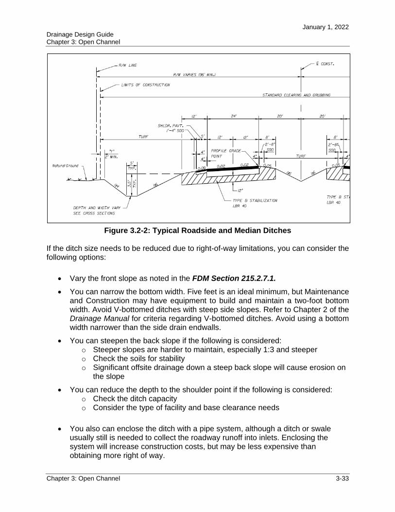
Figure 3.2-2: Typical Roadside and Median Ditches
If the ditch size needs to be reduced due to right-of-way limitations, you can consider the following options:
Vary the front slope as noted in the FDM Section 215.2.7.1.
You can narrow the bottom width. Five feet is an ideal minimum, but Maintenance and Construction may have equipment to build and maintain a two-foot bottom width. Avoid V-bottomed ditches with steep side slopes. Refer to Chapter 2 of the Drainage Manual for criteria regarding V-bottomed ditches. Avoid using a bottom width narrower than the side drain endwalls.
You can steepen the back slope if the following is considered: o Steeper slopes are harder to maintain, especially 1:3 and steeper o Check the soils for stability o Significant offsite drainage down a steep back slope will cause erosion on
the slope
You can reduce the depth to the shoulder point if the following is considered: o Check the ditch capacity o Consider the type of facility and base clearance needs
You also can enclose the ditch with a pipe system, although a ditch or swale usually still is needed to collect the roadway runoff into inlets. Enclosing the system will increase construction costs, but may be less expensive than obtaining more right of way.

January 1, 2022 Drainage Design Guide Chapter 3: Open Channel
Chapter 3: Open Channel 3-34
Step 3—Check for locations where the standard ditch will not work. A good way to check is to plot the standard ditch on the cross sections. Look for places where the ditch extends beyond the right of way or conflicts with utilities and other obstructions. Also look in the Plan View to check for obstructions between the cross sections.
You can adjust the size of the ditch while also considering the same issues identified in the previous step. If the grade of the ditch must be adjusted, then you must develop a special ditch profile and plot it in the plans. Some locations where the ditch grade may need to be adjusted include:
Outfall locations—The grade of the standard ditch will follow the grade of the road. If the outfall location is not at the lowest point in the roadway profile, then you need to develop a special ditch profile.
Locations of high water table—These areas may require feedback to the roadway designer to raise the roadway grade.
Cross drains, median drains, and side drains—These structures may need to be at a lower elevation than the standard ditch elevation. If the entrance end of the culvert is depressed below the stream bed, more head is exerted on the inlet for the same headwater elevation. Usually, the sump is paved, but for small depressions, an unpaved excavation may be adequate.
Locations where the top of the back slope creates a ditch that is too shallow—Sometimes, you can use a berm to contain the ditch instead of changing the grade. Be careful that offsite drainage is not blocked. If you use a berm, provide an adequate top width and side slopes for ease of maintenance. A suggested minimum top width is three feet, but five feet is ideal.
You will need to develop special ditch profiles if the profile grade is less than the minimum ditch slope. Refer to the Drainage Manual for minimum ditch slope criteria. At vertical curve crests, the ditch grade will be less than the minimum ditch grade criteria given in the Drainage Manual. (In fact, the ditch grade will go to zero at the high point.) A special ditch grade is not necessary at a vertical curve crest.
Step 4—Compute the Flow Depths and Velocities. Although some designers check the ditch at regular intervals, it is not necessary. Checking at critical locations is adequate. Check the ditch at the outfall point. The discharge will be greatest at this location, so it may represent the worst-case conditions for the entire ditch. Other critical locations to check are:
Changes in slope, specifically steeper slopes Changes in shape, specifically narrower sections Shallowest ditch depths Changes in lining (roughness) Changes in flow
January 1, 2022 Drainage Design Guide Chapter 3: Open Channel
Chapter 3: Open Channel 3-35
Determine the maximum allowable depth of the ditch at these sections, including freeboard. Section 2.4.5 of the Drainage Manual provides freeboard requirements. If the actual depth exceeds the maximum allowable depth in the ditch, then the ditch does not have enough capacity. Possible ways to increase the ditch capacity include:
Increase bottom width Make ditch side slopes flatter Make longitudinal ditch slope steeper Provide a smoother ditch lining Install drop inlets and a storm drain pipe beneath the ditch Berm up the back slope of the ditch
Step 5—Check Lining Requirements. When the ditch geometry components are set and the depth of flow is determined to be adequate, then the ditch needs to be checked to determine if you need a ditch lining. Check the maximum velocity in the ditch against the allowable velocities for bare earth shown in Table 2.4 of the Drainage Manual. If these velocities are met, then you can use the standard treatment of grassing and mulching.
If the maximum ditch velocity exceeds the allowable velocity for bare earth, then you should provide sodding, ditch paving, or other forms of ditch lining. See Section 3.3 for more discussion of ditch linings.
3.2.3 Median Ditches
The design steps for median ditches are similar to those for roadside ditches.
Step 1—Establish a Preliminary Drainage Plan. As with roadside ditches, median ditches also will be components of an overall drainage system. The grade of the median ditch generally will follow the grade of the road. Generally, curbs are not provided on the edge of the pavement and the median ditch drains part or all of the shoulder area in addition to the median itself. Even where curbs are provided, it is preferable to slope medians wider than 15 feet to a ditch. This keeps water in the median off the pavement. Medians less than 15 feet wide generally are crowned for drainage, and, if they are less than six feet in width, they usually are paved. Permitting agencies may request that the median ditch be depressed.
When the width of the median ditch is established, locate outfall points from the median. If the travel lanes slope to the outside and the median is impervious, then the median runoff may not need to be conveyed to a stormwater treatment facility. The median may be able to discharge directly into cross drains via inlets.
Median cross overs, bridge piers, or other structures often interrupt continuous flow in medians. Decide whether to convey around the obstruction or to one side of the roadway.
January 1, 2022 Drainage Design Guide Chapter 3: Open Channel
Chapter 3: Open Channel 3-36
Consider the flow depth in the median, feasible means to convey the flow around the obstruction, the size of pipe to convey the flow to the outside, the cover available, and the elevation of the roadside ditch to which the flow will be conveyed. Also consider the actual low point of the median ditch, which is usually at the low point of the roadway grade. This may be affected by guardrail, turn lanes, etc. Turn lanes and other non-typical roadway configurations also may create a depressed gore area. You will need to analyze these areas with methods similar to those used for roadside ditches.
Considerations to determine which side of the roadside to discharge to include:
Maintenance of traffic phasing and construction sequencing Which side the outfall or stormwater facility is located on Commingling with offsite runoff
Step 2—Select Standard Ditch Components. The standard median ditch will be shown in the Plans on the Typical Section. Standard ditch sections are given in the FDM for several roadway types, and one is shown in Figure 3.2-2.
Step 3—Compute the Flow Depths and Velocities. Determine critical locations to check depth of flow and velocities, as outlined above. In addition to the critical areas for the roadside ditch, you also should evaluate the median ditch in gore areas caused by turn lanes or additional pavement. If the actual depth exceeds the maximum allowable depth, then you will need to increase the capacity of the ditch. Use methods similar to those for increasing the capacity of a roadside ditch. Be mindful of the additional clear zone requirements for median ditches.
Step 4—Check Lining Requirements. After you establish the section of the ditch, check the maximum velocities against the allowable velocities for bare soil. If those velocities are exceeded, then you need to research further to determine the appropriate lining for the ditch. See Section 3.3 of this design guide for further discussion.
3.2.4 Interceptor Ditches
Interceptor ditches run along the natural ground near the top edge of a cut slope or along the edge of the right of way to intercept the runoff before it reaches the roadway. Interceptor ditches along the edge of the right of way are commonly referred to as right-of-way ditches.
The interceptor ditch generally will follow the grade of the natural ground adjacent to the project, not the profile grade of the road. If possible, locate the high points in an interceptor ditch at the drainage divides of the adjacent property to maintain existing drainage patterns. Low points also typically follow the adjacent terrain, allowing the interceptor ditch to discharge to points such as streams near cross drains and bridges.
January 1, 2022 Drainage Design Guide Chapter 3: Open Channel
Chapter 3: Open Channel 3-37
Most projects will have stormwater management facilities. These facilities often are set off from the project area, so it is important to consider conflicts that may arise where the outfall ditch intersects the interceptor ditch.
The design steps for interceptor ditches are the same as those for the roadside ditch. See Section 3.2.2 for the design procedure.
3.2.5 Outfall Ditches
Since outfall ditches receive runoff from numerous secondary drainage facilities, including stormwater management facilities, design the standard ditch section for a larger capacity. You should evaluate the standard ditch section against the clear zone criteria for the project. Even though outfall ditches have a larger design event and carry larger flows, the design steps are the same as those for the roadside ditch. See Section 3.2.2 for the design procedure.
The design also should include consideration of the following:
The drainage area that flows into the outfall ditch by overland flow. Designers often forget to include this area in the total drainage area when determining the design flow rates for the outfall ditch. Another concern is erosion down the side slope from the sheet flow from these areas. You can use spoil from the ditch construction to create berms to block and collect the flow in inlets to prevent this erosion.
Check for existing outfall easements. Some easements may require a specific type of conveyance, such as a ditch or a pipe system.
3.2.6 Hydrology
As stated in Section 2.3 of the Drainage Manual, hydrologic data used for the design of open channels will be based on one of the following methods, as appropriate for the particular site:
Use a frequency analysis of observed (gage) data when available Use the regional or local regression equation developed by the USGS Use the Rational Equation for drainage areas up to 600 acres Use the method applied for the design of the stormwater management facility in
the design of the outfall from this facility Request hydrologic data from the controlling entity for regulated or controlled
canals
For a more detailed discussion on procedure selection and method for calculating runoff rates, refer to Chapter 2 (Hydrology).
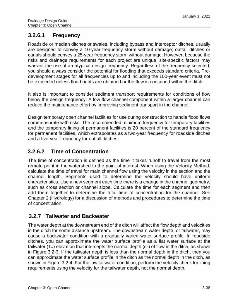
January 1, 2022 Drainage Design Guide Chapter 3: Open Channel
Chapter 3: Open Channel 3-38
3.2.6.1 Frequency
Roadside or median ditches or swales, including bypass and interceptor ditches, usually are designed to convey a 10-year frequency storm without damage; outfall ditches or canals should convey a 25-year frequency storm without damage. However, because the risks and drainage requirements for each project are unique, site-specific factors may warrant the use of an atypical design frequency. Regardless of the frequency selected, you should always consider the potential for flooding that exceeds standard criteria. Pre-development stages for all frequencies up to and including the 100-year event must not be exceeded unless flood rights are obtained or the flow is contained within the ditch.
It also is important to consider sediment transport requirements for conditions of flow below the design frequency. A low flow channel component within a larger channel can reduce the maintenance effort by improving sediment transport in the channel.
Design temporary open channel facilities for use during construction to handle flood flows commensurate with risks. The recommended minimum frequency for temporary facilities and the temporary lining of permanent facilities is 20 percent of the standard frequency for permanent facilities, which extrapolates as a two-year frequency for roadside ditches and a five-year frequency for outfall ditches.
3.2.6.2 Time of Concentration
The time of concentration is defined as the time it takes runoff to travel from the most remote point in the watershed to the point of interest. When using the Velocity Method, calculate the time of travel for main channel flow using the velocity in the section and the channel length. Segments used to determine the velocity should have uniform characteristics. Use a new segment each time there is a change in the channel geometry, such as cross section or channel slope. Calculate the time for each segment and then add them together to determine the total time of concentration for the channel. See Chapter 2 (Hydrology) for a discussion of methods and procedures to determine the time of concentration.
3.2.7 Tailwater and Backwater
The water depth at the downstream end of the ditch will affect the flow depth and velocities in the ditch for some distance upstream. The downstream water depth, or tailwater, may cause a backwater condition with a gradually varied water surface profile. In roadside ditches, you can approximate the water surface profile as a flat water surface at the tailwater (Tw) elevation that intercepts the normal depth (dn) of flow in the ditch, as shown in Figure 3.2-3. If the tailwater depth is less than the normal depth in the ditch, then you can approximate the water surface profile in the ditch as the normal depth in the ditch, as shown in Figure 3.2-4. For the low tailwater condition, perform the velocity check for lining requirements using the velocity for the tailwater depth, not the normal depth.
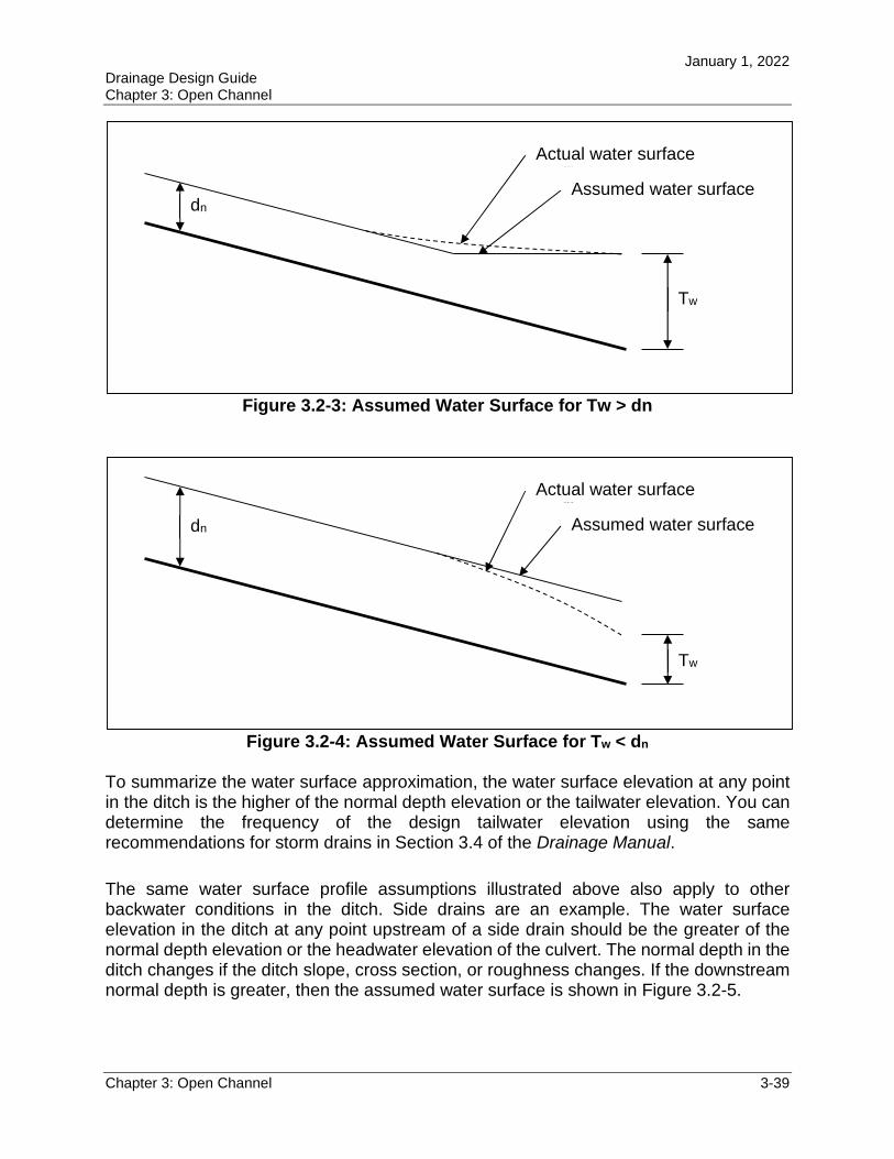
January 1, 2022 Drainage Design Guide Chapter 3: Open Channel
Chapter 3: Open Channel 3-39
Figure 3.2-3: Assumed Water Surface for Tw > dn
Figure 3.2-4: Assumed Water Surface for Tw < dn
To summarize the water surface approximation, the water surface elevation at any point in the ditch is the higher of the normal depth elevation or the tailwater elevation. You can determine the frequency of the design tailwater elevation using the same recommendations for storm drains in Section 3.4 of the Drainage Manual.
The same water surface profile assumptions illustrated above also apply to other backwater conditions in the ditch. Side drains are an example. The water surface elevation in the ditch at any point upstream of a side drain should be the greater of the normal depth elevation or the headwater elevation of the culvert. The normal depth in the ditch changes if the ditch slope, cross section, or roughness changes. If the downstream normal depth is greater, then the assumed water surface is shown in Figure 3.2-5.
dn
Actual water surface profile
Assumed water surface
Tw
dn
Actual water surface profile
Assumed water surface
Tw
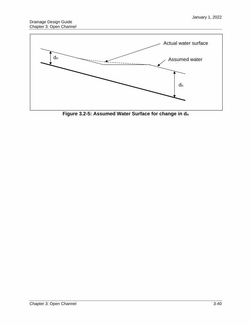
January 1, 2022 Drainage Design Guide Chapter 3: Open Channel
Chapter 3: Open Channel 3-40
Figure 3.2-5: Assumed Water Surface for change in dn
dn
Actual water surface profile
Assumed water surface
dn
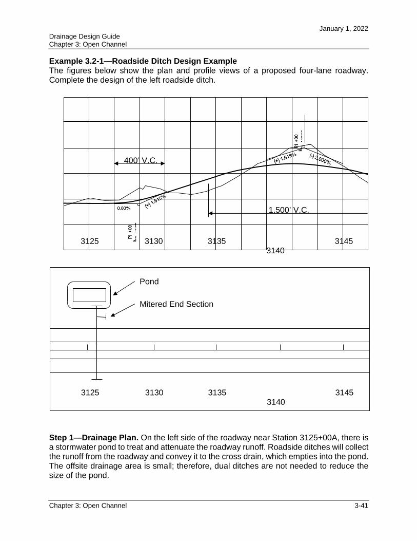
January 1, 2022 Drainage Design Guide Chapter 3: Open Channel
Chapter 3: Open Channel 3-41
Example 3.2-1—Roadside Ditch Design Example The figures below show the plan and profile views of a proposed four-lane roadway. Complete the design of the left roadside ditch.
Step 1—Drainage Plan. On the left side of the roadway near Station 3125+00A, there is a stormwater pond to treat and attenuate the roadway runoff. Roadside ditches will collect the runoff from the roadway and convey it to the cross drain, which empties into the pond. The offsite drainage area is small; therefore, dual ditches are not needed to reduce the size of the pond.
3125 3130 31353140
3145
Pond
Mitered End Section
3125 3130 31353140
3145
400’ V.C.
1,500’ V.C.
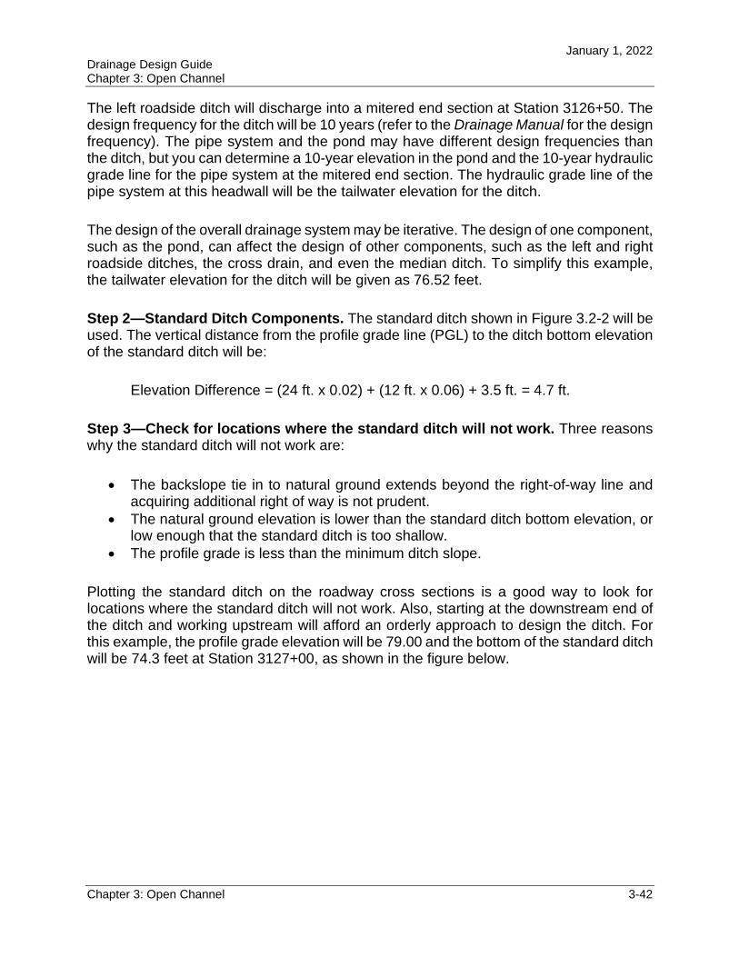
January 1, 2022 Drainage Design Guide Chapter 3: Open Channel
Chapter 3: Open Channel 3-42
The left roadside ditch will discharge into a mitered end section at Station 3126+50. The design frequency for the ditch will be 10 years (refer to the Drainage Manual for the design frequency). The pipe system and the pond may have different design frequencies than the ditch, but you can determine a 10-year elevation in the pond and the 10-year hydraulic grade line for the pipe system at the mitered end section. The hydraulic grade line of the pipe system at this headwall will be the tailwater elevation for the ditch.
The design of the overall drainage system may be iterative. The design of one component, such as the pond, can affect the design of other components, such as the left and right roadside ditches, the cross drain, and even the median ditch. To simplify this example, the tailwater elevation for the ditch will be given as 76.52 feet.
Step 2—Standard Ditch Components. The standard ditch shown in Figure 3.2-2 will be used. The vertical distance from the profile grade line (PGL) to the ditch bottom elevation of the standard ditch will be:
Elevation Difference = (24 ft. x 0.02) + (12 ft. x 0.06) + 3.5 ft. = 4.7 ft.
Step 3—Check for locations where the standard ditch will not work. Three reasons why the standard ditch will not work are:
The backslope tie in to natural ground extends beyond the right-of-way line and acquiring additional right of way is not prudent.
The natural ground elevation is lower than the standard ditch bottom elevation, or low enough that the standard ditch is too shallow.
The profile grade is less than the minimum ditch slope.
Plotting the standard ditch on the roadway cross sections is a good way to look for locations where the standard ditch will not work. Also, starting at the downstream end of the ditch and working upstream will afford an orderly approach to design the ditch. For this example, the profile grade elevation will be 79.00 and the bottom of the standard ditch will be 74.3 feet at Station 3127+00, as shown in the figure below.
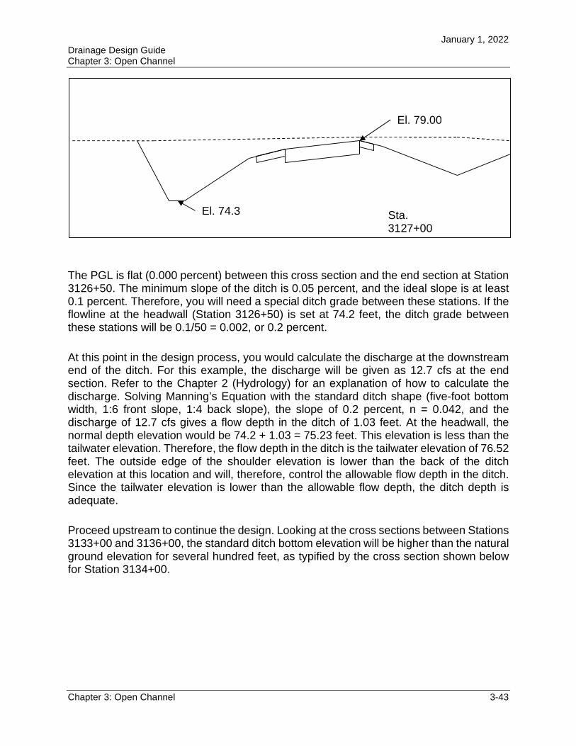
January 1, 2022 Drainage Design Guide Chapter 3: Open Channel
Chapter 3: Open Channel 3-43
The PGL is flat (0.000 percent) between this cross section and the end section at Station 3126+50. The minimum slope of the ditch is 0.05 percent, and the ideal slope is at least 0.1 percent. Therefore, you will need a special ditch grade between these stations. If the flowline at the headwall (Station 3126+50) is set at 74.2 feet, the ditch grade between these stations will be 0.1/50 = 0.002, or 0.2 percent.
At this point in the design process, you would calculate the discharge at the downstream end of the ditch. For this example, the discharge will be given as 12.7 cfs at the end section. Refer to the Chapter 2 (Hydrology) for an explanation of how to calculate the discharge. Solving Manning’s Equation with the standard ditch shape (five-foot bottom width, 1:6 front slope, 1:4 back slope), the slope of 0.2 percent, n = 0.042, and the discharge of 12.7 cfs gives a flow depth in the ditch of 1.03 feet. At the headwall, the normal depth elevation would be 74.2 + 1.03 = 75.23 feet. This elevation is less than the tailwater elevation. Therefore, the flow depth in the ditch is the tailwater elevation of 76.52 feet. The outside edge of the shoulder elevation is lower than the back of the ditch elevation at this location and will, therefore, control the allowable flow depth in the ditch. Since the tailwater elevation is lower than the allowable flow depth, the ditch depth is adequate.
Proceed upstream to continue the design. Looking at the cross sections between Stations 3133+00 and 3136+00, the standard ditch bottom elevation will be higher than the natural ground elevation for several hundred feet, as typified by the cross section shown below for Station 3134+00.
El. 74.3
El. 79.00
Sta. 3127+00
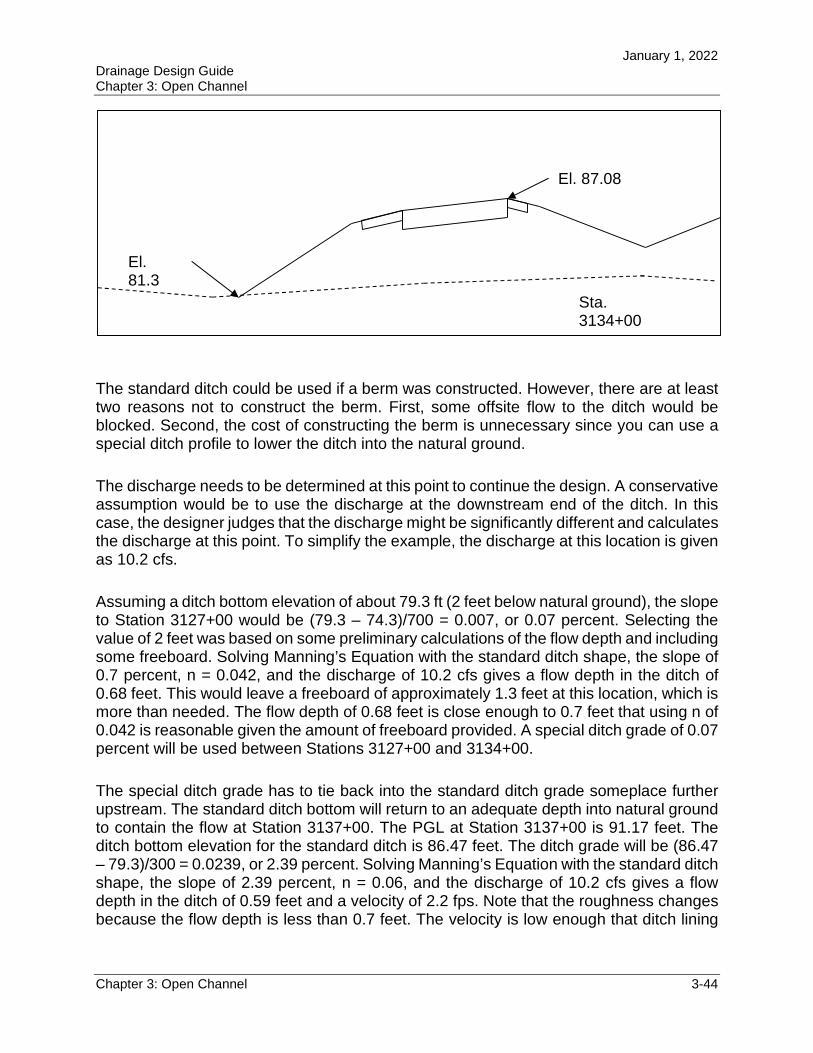
January 1, 2022 Drainage Design Guide Chapter 3: Open Channel
Chapter 3: Open Channel 3-44
The standard ditch could be used if a berm was constructed. However, there are at least two reasons not to construct the berm. First, some offsite flow to the ditch would be blocked. Second, the cost of constructing the berm is unnecessary since you can use a special ditch profile to lower the ditch into the natural ground.
The discharge needs to be determined at this point to continue the design. A conservative assumption would be to use the discharge at the downstream end of the ditch. In this case, the designer judges that the discharge might be significantly different and calculates the discharge at this point. To simplify the example, the discharge at this location is given as 10.2 cfs.
Assuming a ditch bottom elevation of about 79.3 ft (2 feet below natural ground), the slope to Station 3127+00 would be (79.3 – 74.3)/700 = 0.007, or 0.07 percent. Selecting the value of 2 feet was based on some preliminary calculations of the flow depth and including some freeboard. Solving Manning’s Equation with the standard ditch shape, the slope of 0.7 percent, n = 0.042, and the discharge of 10.2 cfs gives a flow depth in the ditch of 0.68 feet. This would leave a freeboard of approximately 1.3 feet at this location, which is more than needed. The flow depth of 0.68 feet is close enough to 0.7 feet that using n of 0.042 is reasonable given the amount of freeboard provided. A special ditch grade of 0.07 percent will be used between Stations 3127+00 and 3134+00.
The special ditch grade has to tie back into the standard ditch grade someplace further upstream. The standard ditch bottom will return to an adequate depth into natural ground to contain the flow at Station 3137+00. The PGL at Station 3137+00 is 91.17 feet. The ditch bottom elevation for the standard ditch is 86.47 feet. The ditch grade will be (86.47 – 79.3)/300 = 0.0239, or 2.39 percent. Solving Manning’s Equation with the standard ditch shape, the slope of 2.39 percent, n = 0.06, and the discharge of 10.2 cfs gives a flow depth in the ditch of 0.59 feet and a velocity of 2.2 fps. Note that the roughness changes because the flow depth is less than 0.7 feet. The velocity is low enough that ditch lining
Sta. 3134+00
El. 87.08
El. 81.3
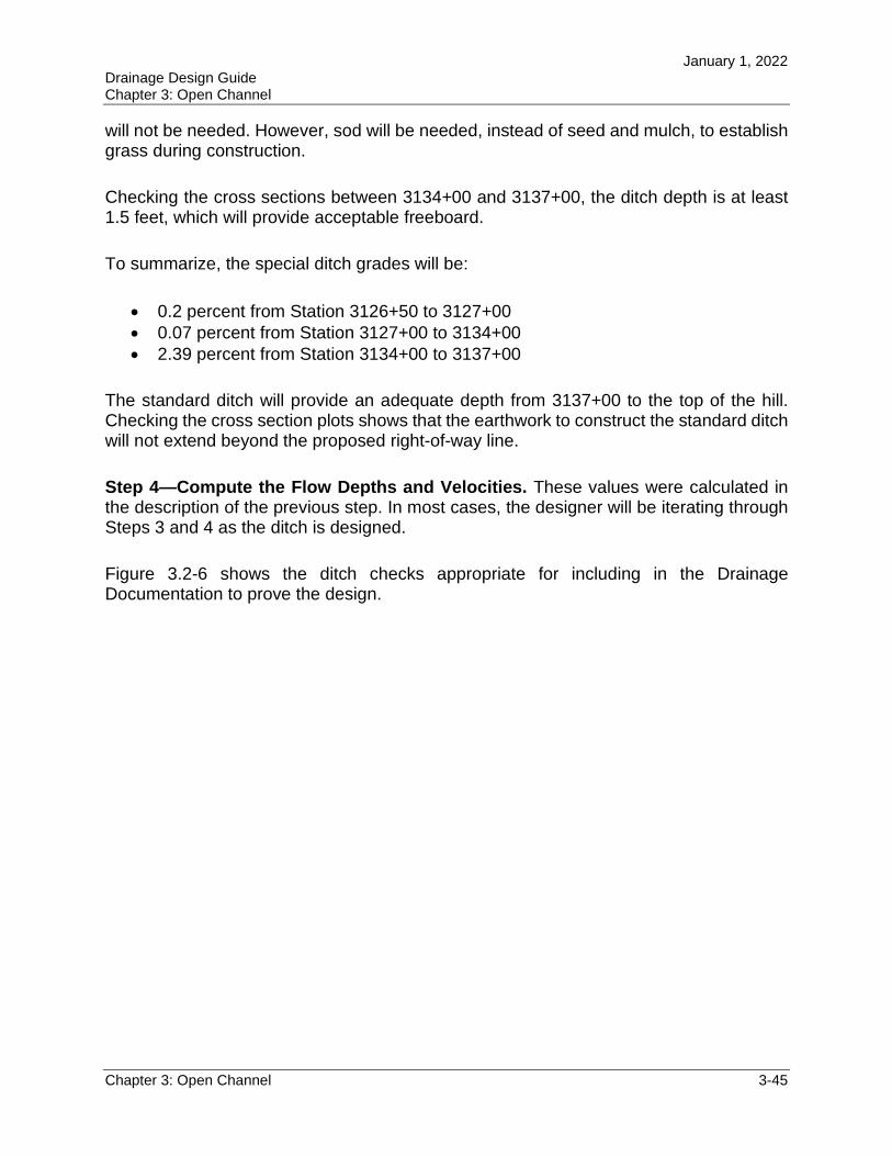
January 1, 2022 Drainage Design Guide Chapter 3: Open Channel
Chapter 3: Open Channel 3-45
will not be needed. However, sod will be needed, instead of seed and mulch, to establish grass during construction.
Checking the cross sections between 3134+00 and 3137+00, the ditch depth is at least 1.5 feet, which will provide acceptable freeboard.
To summarize, the special ditch grades will be:
0.2 percent from Station 3126+50 to 3127+00 0.07 percent from Station 3127+00 to 3134+00 2.39 percent from Station 3134+00 to 3137+00
The standard ditch will provide an adequate depth from 3137+00 to the top of the hill. Checking the cross section plots shows that the earthwork to construct the standard ditch will not extend beyond the proposed right-of-way line.
Step 4—Compute the Flow Depths and Velocities. These values were calculated in the description of the previous step. In most cases, the designer will be iterating through Steps 3 and 4 as the ditch is designed.
Figure 3.2-6 shows the ditch checks appropriate for including in the Drainage Documentation to prove the design.
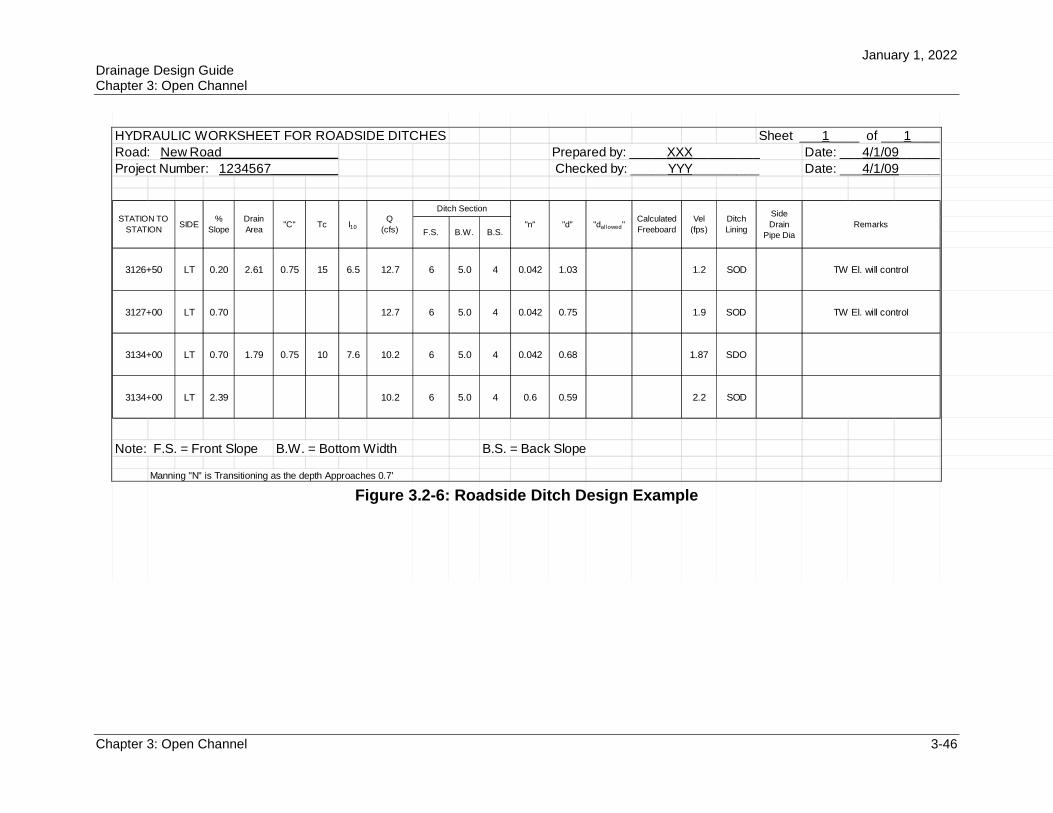
January 1, 2022 Drainage Design Guide Chapter 3: Open Channel
Chapter 3: Open Channel 3-46
HYDRAULIC WORKSHEET FOR ROADSIDE DITCHES
LT 0.20 2.61 0.75 15 6.5 12.7 6 5.0 4 0.042 1.03 1.2 SOD
LT 0.70 12.7 6 5.0 4 0.042 0.75 1.9 SOD
LT 0.70 1.79 0.75 10 7.6 10.2 6 5.0 4 0.042 0.68 1.87 SDO
LT 2.39 10.2 6 5.0 4 0.6 0.59 2.2 SOD
Note: F.S. = Front Slope B.W. = Bottom Width B.S. = Back Slope
Manning "N" is Transitioning as the depth Approaches 0.7'
Project Number: 1234567____________________
STATION TO
STATIONSIDE
%
Slope
Drain
Area"C" Tc
Q
(cfs)
Ditch Section
F.S. B.W.
Sheet ___1____ of ___1_______
Prepared by: _____XXX_________ Date: ___4/1/09_______
Checked by: _____YYY_________ Date: ___4/1/09_______
"dallowed"Calculated
FreeboardB.S.
3134+00
3134+00
Road: New Road__________________________________________
3126+50 TW El. will control
3127+00 TW El. will control
Remarks"n" "d"Vel
(fps)
Ditch
Lining
Side
Drain
Pipe Dia
I10
Figure 3.2-6: Roadside Ditch Design Example

January 1, 2022 Drainage Design Guide Chapter 3: Open Channel
Chapter 3: Open Channel 3-47
3.2.8 Side Drains
Continuous flow in a roadside ditch can be interrupted by side street/road connections and/or driveway connections to the project roadway. Even a limited access roadway, such as an interstate highway, may have an occasional access driveway that will impede roadside ditch flow, especially at or near adjacent stormwater pond locations. You can maintain ditch flow continuity through such obstructions via roadside ditch culverts or side drains.
A side drain is a class of culvert pipe that can transport flow through fill placed in a roadside ditch. A side drain is normally aligned parallel or nearly parallel to the project roadway and along the flowline of the ditch. Side drains located under public roads connecting to the project roadway, are identified and hydraulically sized as a cross drains (see Chapter 4, Culverts). Side drains and cross drains are similar in many ways, but there are some differences in design analysis requirements, materials, and end treatment. Cross drains have to meet more rigorous criteria for some parameters.
3.2.8.1 Design Analysis Requirements for Side Drains
You size a side drain for the storm frequency required to design the roadside ditch that contains the side drain (usually the 10-year frequency, as mentioned in Section 3.2.6.1). You can determine the side drain design flow by applying the same hydrologic method used to compute the corresponding ditch design flows (usually the Rational Equation, described in Section 2.2.3). Then, you can determine the side drain pipe dimensions via the inlet-control/outlet-control procedure described in Section 4.5. (Note: The FHWA HY-8 computer software is one of several computer programs capable of applying this procedure to the side drain design data.)
You will normally develop the design flow for a side drain in the design calculations spreadsheet or worksheet for the roadside ditch that contains the side drain. (Figure 2-1 of the Drainage Manual depicts such a ditch design worksheet.) The design flow and surface water depth for the ditch section at the upstream end of the side drain are determined in the ditch calculations, and this ditch flow is the side drain design inflow as well. This flow typically is also the design flow for the ditch section at the downstream end of the side drain, and must be accounted for in the calculations for the remainder of the downstream ditch length. Of course, if additional flow enters the side drain between its upstream and downstream ends, this additional flow also must be appropriately accounted for in both the side drain hydraulic design and in the downstream ditch design calculations.
Determine the tailwater elevation at the culvert outlet. Since the culvert usually is placed through fill in the roadside ditch, the ditch calculations downstream of the culvert are used to determine the tailwater. The culvert tailwater will be the normal depth in the
January 1, 2022 Drainage Design Guide Chapter 3: Open Channel
Chapter 3: Open Channel 3-48
downstream ditch unless the tailwater for the ditch controls the water surface elevation at the side drain outlet. Refer to Section 3.2.7 for more discussion on tailwater.
Then you can generate the hydraulic calculations for a side drain, using the procedure described above to determine the pipe dimensions needed to safely pass the design flow to the downstream ditch segment. Include these side drain calculations in the Drainage Documentation Report as either a separate section or as part of the Ditch Calculations section.
Note that the surface water depth computed for culvert flow at the upstream end of a side drain generally will be larger than the depth computed for ditch flow at that location. If the difference in this flow depth is not significant, evaluate the ditch flow depths upstream from the side drain and adjust (if appropriate) for the “flat pool” that will be established in the ditch by the higher of the two water surface elevations. If the difference in surface water flow depth at the side drain is substantial and the ditch design is sensitive to actual flow depths, a backwater analysis may be needed rather than the “flat pool” approximation in determining the actual flow depth estimates.
3.2.8.2 Material Requirements
In general, side drains are not considered to be as critical as cross drains. Therefore, material service life requirements for side drains are less stringent than for cross drains. Consult Chapter 6 of the Drainage Manual, the FDOT Standard Specifications, Chapter 8 (Optional Pipe Materials) in this handbook, and the appropriate District Drainage Engineer for any clarification needed on pipe materials acceptable for use as side drains. Culvert and ditch calculations may show the need for two allowable pipe sizes, depending on the Manning’s roughness coefficients of the optional pipe materials for the side drain.
3.2.8.3 End Treatment
The only allowable side drain end treatment is the mitered end section (Standard Plans, Index 430-022). Due to the normal side drain alignment and close proximity to the project roadway (usually within the clear zone), Standard Plans, Index 430-022 specifies that grates be installed for the larger pipe sizes. The grates are intended to provide a measure of safety for errant vehicles that encounter the end treatment. The grates, however, will potentially collect debris and will increase the entrance loss coefficient, Ke, from 0.7 to 1.0 for the mitered end section. When a grate is likely to be used, consider the following items:
Recognize that the specification of a grate could increase the required side drain size (due to the increase in Ke).
In critical hydraulic locations, evaluate the potential debris transport prior to using grates. Vegetated ditch grades in excess of 3 percent, pipe with less than 1.5 feet of cover, or paved ditch grades in excess of 1 percent will require such an evaluation.
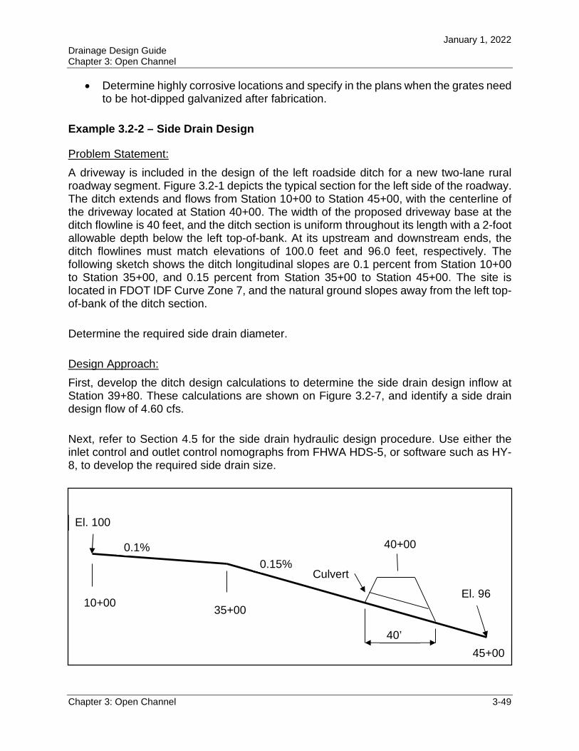
January 1, 2022 Drainage Design Guide Chapter 3: Open Channel
Chapter 3: Open Channel 3-49
Determine highly corrosive locations and specify in the plans when the grates need to be hot-dipped galvanized after fabrication.
Example 3.2-2 – Side Drain Design
Problem Statement:
A driveway is included in the design of the left roadside ditch for a new two-lane rural roadway segment. Figure 3.2-1 depicts the typical section for the left side of the roadway. The ditch extends and flows from Station 10+00 to Station 45+00, with the centerline of the driveway located at Station 40+00. The width of the proposed driveway base at the ditch flowline is 40 feet, and the ditch section is uniform throughout its length with a 2-foot allowable depth below the left top-of-bank. At its upstream and downstream ends, the ditch flowlines must match elevations of 100.0 feet and 96.0 feet, respectively. The following sketch shows the ditch longitudinal slopes are 0.1 percent from Station 10+00 to Station 35+00, and 0.15 percent from Station 35+00 to Station 45+00. The site is located in FDOT IDF Curve Zone 7, and the natural ground slopes away from the left top-of-bank of the ditch section.
Determine the required side drain diameter.
Design Approach:
First, develop the ditch design calculations to determine the side drain design inflow at Station 39+80. These calculations are shown on Figure 3.2-7, and identify a side drain design flow of 4.60 cfs.
Next, refer to Section 4.5 for the side drain hydraulic design procedure. Use either the inlet control and outlet control nomographs from FHWA HDS-5, or software such as HY-8, to develop the required side drain size.
Culvert
0.1%
0.15%
10+00 35+00
45+00
40+00
40’
El. 100
El. 96
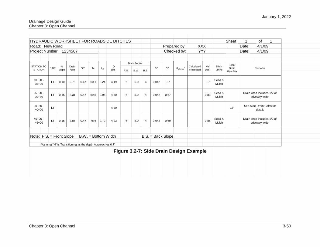
January 1, 2022 Drainage Design Guide Chapter 3: Open Channel
Chapter 3: Open Channel 3-50
HYDRAULIC WORKSHEET FOR ROADSIDE DITCHES
LT 0.10 2.75 0.47 60.1 3.24 4.19 6 5.0 4 0.042 0.7 0.7Seed &
Mulch
LT 0.15 3.31 0.47 69.5 2.96 4.60 6 5.0 4 0.042 0.67 0.83Seed &
Mulch
LT 4.60 18"
LT 0.15 3.86 0.47 78.6 2.72 4.93 6 5.0 4 0.042 0.69 0.85Seed &
Mulch
Note: F.S. = Front Slope B.W. = Bottom Width B.S. = Back Slope
Manning "N" is Transitioning as the depth Approaches 0.7'
39+80 -
40+20
See Side Drain Calcs for
details
40+20 -
45+00
Drain Area includes 1/2 of
driveway width
Road: New Road__________________________________________
10+00 -
35+00
35+00 -
39+80
Drain Area includes 1/2 of
driveway width
Remarks"n" "d"Vel
(fps)
Ditch
Lining
Side
Drain
Pipe Dia
I10
Q
(cfs)
Ditch Section
F.S. B.W.
Sheet ___1____ of ___1_______
Prepared by: _____XXX_________ Date: ___4/1/09_______
Checked by: _____YYY_________ Date: ___4/1/09_______
"dallowed"Calculated
FreeboardB.S.
Project Number: 1234567____________________
STATION TO
STATIONSIDE
%
Slope
Drain
Area"C" Tc
Figure 3.2-7: Side Drain Design Example
January 1, 2022 Drainage Design Guide Chapter 3: Open Channel
Chapter 3: Open Channel 3-51
3.3 CHANNEL LININGS
As stated in Section 2.4.3 of the Drainage Manual, when designing open channels, you need to consider channel linings. Erosion and sloughing cause most maintenance problems in channels. Channel linings often solve these problems. The Standard Plans,and the Standard Specifications identify standard lining types. The two main classifications of open channel linings are flexible and rigid. Flexible linings include vegetative linings such as grass, rubble riprap, and geotextile or interlocking concrete grids. Rigid linings include concrete, asphalt, and soil-cement. From an erosion control standpoint, the primary difference between rigid and flexible channel linings is their response to changes in channel shape (i.e., width, depth, and alignment). For most artificial channels, the ideal lining is natural, emerging vegetation, with grass used to provide initial and long-term erosion resistance.
The following are examples of lining materials in each classification.
1. Flexible Linings: a. Grasses or natural vegetation b. Rubble riprap c. Wire-enclosed riprap (gabions) d. Turf reinforcement (non-biodegradable)
2. Rigid Linings: a. Cast-in-place concrete or asphaltic concrete b. Soil cement and roller-compacted concrete c. Fabric formed revetment d. Partially grouted riprap e. Articulated concrete blocks
3.3.1 Flexible Linings
Flexible linings have several advantages compared to rigid linings. They generally are less expensive, permit infiltration and exfiltration, and can be vegetated to have a natural appearance. Flow in channels with flexible linings is similar to that found in natural small channels. Natural conditions offer better habitat opportunities for local flora and fauna. In many cases, flexible linings are designed to provide only transitional protection against erosion while vegetation establishes and becomes the permanent lining of the channel; flexible channel linings are best suited to conditions of moderate shear stresses. Channel reaches with accelerating or decelerating flow (expansions, contractions, drops, and backwater) and waves (transitions, flows near critical depth, and shorelines) will require special analysis and may not be suitable for flexible channel linings.
3.3.1.1 Vegetation
Vegetative linings consist of seeded or sodded grasses placed in and along the channel, as well as naturally occurring vegetation. Vegetation is one of the most common and most
January 1, 2022 Drainage Design Guide Chapter 3: Open Channel
Chapter 3: Open Channel 3-52
ideal channel linings for an artificial channel. It stabilizes the body of the channel, consolidates the soil mass of the bed, checks erosion on the channel surface, and controls the movement of soil particles along the channel bottom. Vegetative channel lining also is recognized as a best management practice for stormwater quality design in highway drainage systems. The slower flow of a vegetated channel helps the uptake of highway runoff contaminants (particularly suspended sediments) before they leave the highway right of way and enter streams.
There are conditions for which vegetation may not be acceptable, so you will need to consider other linings. These conditions include, but are not limited to:
Standing or continuous flowing water Areas which do not receive the regular maintenance necessary to prevent
domination by taller vegetation Lack of nutrients and excessive soil drainage Areas where sod will be excessively shaded
The Department operates on the premise that, with proper seeding and mulching during construction, maintenance of most ditches on normal sections and grades can be handled economically until a growth of grass becomes established. The use of temporary erosion control measures in ditches with low velocities will provide time for grassing and mulching to establish a vegetative ditch. When velocities exceed those for bare soils, seeding and mulching should not be used.
Sodding is recommended when the design velocity exceeds the value permitted for the bare base soil conditions, but is less than 4 feet per second. Lapped or shingle sod is recommended when the design velocity exceeds that for sod (4 feet per second), and is suitable with velocities up to 5.5 feet per second.
3.3.1.2 Other Flexible Linings
Flexible linings usually are less expensive than rigid linings, provide a safer roadside, and have self-healing qualities that reduce maintenance. They also allow the infiltration and exfiltration of water.
(A) Rubble Riprap
After grass, rubble riprap is the most common type of flexible lining. It presents a rough surface that can dissipate energy and mitigate velocity increases. There are two standard types of rubble riprap. Use ditch lining rubble riprap in standard or typical ditches or channels. It consists of smaller stone sizes, which reduces construction costs over bank and shore rubble. Limit bank and shore rubble riprap to uses such as revetments and linings along stream banks and shorelines where extreme flows or wave action occurs.
January 1, 2022 Drainage Design Guide Chapter 3: Open Channel
Chapter 3: Open Channel 3-53
Limited right of way and availability of material may restrict the use of this type of flexible lining. Place rubble riprap on a filter blanket and prepared slope to form a well-graded mass with a minimum of voids. Riprap and gabion linings can perform in the initial range of hydraulic conditions where you would use rigid linings. Stones used for riprap and gabion installations preferably have an angular shape that allow them to interlock. These linings usually require a filter material between the stone and the underlying soil to prevent soil washout and migration of fine grained soils. Sometimes you will need a bedding stone layer to protect the filter fabric from larger stone.
(B) Gabion Mats
Gabions are made of riprap enclosed in a wire container or closed structure that binds units of the riprap lining together. The wire enclosure normally consists of a rectangular container made of steel wire woven in a uniform pattern and reinforced on corners and edges with heavier wire. The containers are filled with stone, connected together, and anchored to the channel side slope. The forms of wire-enclosed riprap vary from thin mattresses to boxlike gabions. Use gabions typically when rubble riprap is either not available or not large enough to be stable. Although flexible, wire mesh restricts gabion movement. The wire mesh must provide an adequate service life. If the wire mesh fails, the individual stones will migrate.
(C) Articulating Concrete Block (ACB) Revetment Systems
ACB systems consist of a precast block matrix connected together by cables. The articulating properties of the matrix allow the system to accommodate changes in the ground surface that may occur due to settling. The block configuration varies with the manufacturer. The systems typically are manufactured in units of multiple precast blocks that can be lifted easily and placed with construction equipment. HEC-23 and the National Concrete Masonry Association’s Design Manual for Articulating Concrete Block Revetment Systems provide guidance for the design of these systems.
(D) Turf Reinforcement
Depending on the application, materials, and method of installation, turf reinforcement may serve a transitional or long-term function. The concept of turf reinforcement is to provide a structure to the soil/vegetation matrix that will both assist in the establishment of vegetation and provide support to mature vegetation. Two types of turf reinforcement commonly are available: soil/gravel methods and turf reinforcement mats (TRMs).
To create soil/gravel turf reinforcement, you mix gravel mulch into on-site soils and seed the soil-gravel layer. The rock products industry provides a variety of uniformly graded gravels for use as mulch and soil stabilization. A gravel/soil mixture provides a non-degradable lining that is created as part of the soil preparation and is followed by seeding.
January 1, 2022 Drainage Design Guide Chapter 3: Open Channel
Chapter 3: Open Channel 3-54
A TRM is a non-degradable rolled erosion control product (RECP) composed of UV-stabilized synthetic fibers, filaments, netting, and/or wire mesh processed into a three-dimensional matrix. TRMs provide sufficient thickness, strength, and void space to permit soil filling and establishment of grass roots within the matrix. One limitation to the use of TRMs is in areas where siltation is a problem. When the ditch is cleaned by maintenance, it is likely that the geofabric will be snagged and pulled out by the equipment.
3.3.2 Rigid Linings
Rigid linings generally are constructed of concrete, asphalt, or soil-cement pavement whose smoothness offers a higher capacity for a given cross-sectional area. Higher velocities, however, create the potential for scour at channel lining transitions from the rigid lining back to the grass lining. A rigid lining can be destroyed by flow undercutting the lining, channel headcutting, or the buildup of hydrostatic pressure behind the rigid surfaces. When properly designed, rigid linings may be appropriate where the channel width is restricted. Rigid linings are useful in flow zones where high shear stress or rapidly varied or turbulent flow conditions exist, such as at transitions in channel shape or at an energy dissipation structure.
Rigid linings are particularly vulnerable to a seasonal rise in the water table that can cause a static uplift pressure on the lining. If you need a rigid lining in such conditions, incorporate a reliable system of under drains and weep holes as a part of the channel design. Evaluate the migration of fine grained soils into filter layers to ensure that the ground water is being discharged without filter clogging or collapse of the underlying soil. A related case is the buildup of soil pore pressure behind the lining when the flow depth in the channel drops quickly. Using watertight joints and backflow preventers on weep holes can help to reduce the buildup of water behind the lining.
Section 2.4.3.1.2 of the Drainage Manual states that you should consider the potential for buoyancy due to the uplift water pressure when concrete linings are to be used where soils may become saturated. The total upward force is equal to the weight of the water displaced by the channel. The total weight of the lining helps to resist the uplift pressure. When the weight of the lining is less than the uplift pressure, the channel is unstable.
Acceptable countermeasures include:
Increasing the thickness of the lining to add additional weight For sub-critical flow conditions, specifying weep holes at appropriate intervals in
the channel bottom to relieve the upward pressure on the channel For super-critical flow conditions, using sub-drains in lieu of weep holes
January 1, 2022 Drainage Design Guide Chapter 3: Open Channel
Chapter 3: Open Channel 3-55
3.3.2.1 Cast-in-Place Concrete
Refer to Standard Plans, Index 524-001 for typical ditch pavement details. Asphalt linings have limited use since routine maintenance activities often damage or destroy them. Use filter fabric to prevent soil loss through pavement cracks.
Despite the non-erodible nature of concrete linings, they are susceptible to failure from foundation instability. The major cause of failure is undermining that can occur in a number of ways. Inadequate erosion protection at the outfall, at the channel edges, and on bends can initiate undermining by allowing water to carry away the foundation material and leaving the channel to break apart. Concrete linings also may break up and deteriorate due to conditions such as a high water table or swelling soils that exert an uplift pressure on the lining. When a rigid lining breaks and displaces upward, the lining continues to move due to dynamic uplift and drag forces. The broken lining typically forms large, flat slabs that are particularly susceptible to these forces.
3.3.2.2 Fabric Formed Revetment
Fabric formed revetments, also known as grout-filled mattresses, are the result of pumping a concrete mix into fabric envelopes or cases. The advantage of using fabric formed revetments is that they reduce construction time by eliminating the need for wooden forms and expensive lifting machines and also allow the concrete to be pumped and cured below the water line.
Filter point fabric formed revetments consist of a dual wall fabric that is injected with concrete. This type of fabric formed revetment is characterized by a deeply cobbled surface. The filter points woven into the fabric provide a means for groundwater to escape and to provide release for the hydrostatic pressure. Filter point fabrics provide a higher coefficient of friction to promote energy dissipation.
As of June 2020, FDOT has Developmental Specification 531 for fabric formed revetment systems available.
3.3.3 Velocity and Shear Stress Limitations
HEC-15 provides a detailed presentation of stable channel design concepts for roadside and median channels. This section provides a brief summary of significant concepts.
Stable channel design concepts provide a means of evaluating and defining channel configurations that will perform within acceptable limits of stability. Most highway drainage channels cannot tolerate bank instability and lateral migration. When the material forming the channel boundary effectively resists the erosive forces of the flow, then you have achieved stability. You can apply principles of rigid boundary hydraulics to evaluate this type of system.
January 1, 2022 Drainage Design Guide Chapter 3: Open Channel
Chapter 3: Open Channel 3-56
Apply both velocity and tractive force methods to help determine channel stability. Permissible velocity procedures are empirical in nature, so they have been used to design numerous channels in Florida and throughout the world. However, tractive force methods consider actual physical processes occurring at the channel boundary and represent a more realistic model of the detachment and erosion processes.
The hydrodynamic force that water flowing in a channel creates causes a shear stress on the channel bottom. The bed material, in turn, resists this shear stress by developing a tractive force. Tractive force theory states that the flow-induced shear stress should not produce a force greater than the tractive resisting force of the bed material. This tractive resisting force of the bed material creates the permissible or critical shear stress of the bed material. In a uniform flow, the shear stress is equal to the effective component of the gravitational force acting on the body of water parallel to the channel bottom. The average shear stress is equal to:
= R S (3.3-1)
where:
= Average shear stress, in pounds per square feet = Unit weight of water,62.4 lb/ft3
R = Hydraulic radius, in feet S = Average bed slope or energy slope, in feet per feet
The maximum shear stress for a straight channel occurs on the channel bed and is less than or equal to the shear stress at maximum depth. Compute the maximum shear stress as follows:
d = d S (3.3-2)
where:
d = Maximum shear stress, in pounds per square feet d = Maximum depth of flow, in feet S = Channel bottom slope, in feet per feet
Velocity limitations for artificial open channels should be consistent with stability requirements for the selected channel lining. As indicated above, use seed and mulch only when the design velocity does not exceed the allowable velocity for bare soil. Table 2.3 of the Drainage Manual presents maximum shear stress values and allowable velocities for different soils. When design velocities exceed those acceptable for bare soil, sod, or lapped sod, consider flexible or rigid linings. Table 2.4 of the Drainage Manualsummarizes maximum velocities for these lining types.
January 1, 2022 Drainage Design Guide Chapter 3: Open Channel
Chapter 3: Open Channel 3-57
Side Slope Stability The shear stress on the channel sides generally is less than the maximum shear stress calculated on the channel bottom, but you should consider this issue when determining the height of a channel lining along the side slope of the channel. The maximum shear stress on the side of a channel is given by:
s= d (3.3-3)
where:
s = Side shear stress on the channel, in pounds per square feet
= Ratio of channel side to bottom shear stress
d = Shear stress in channel at maximum depth, in pounds per square feet
The value K1 depends on the size and shape of the channel. For parabolic channels, the shear stress at any point on the side slope is related to the depth at that point and you can calculate it using Equation 3.3-2. For trapezoidal and triangular channels, K1 is based on the horizontal dimension 1: Z (V: H) of the side slopes.
K1 = 0.77 Z ≤ 1.5 K1 = 0.066Z + 0.67 1.5 < Z < 5 K1 = 1.0 5 ≤ Z
Avoid using side slopes steeper than 1:3 for flexible linings other than riprap or gabions because of the potential for erosion at the side slopes. Steep side slopes are allowable within a channel if cohesive soil conditions exist.
Maintenance Considerations Also consider maintenance of the channel when choosing a channel lining. The channel will need to be accessible by mowers and trucks.
Mowing
Side slopes of vegetated channels will need to be traversable for mowing equipment and crews. The maximum traversable slope for this equipment is 1:4.
Access Across Channel
If there is rubble riprap lining the channel and a vegetated buffer on the backside of the channel along the right of way, the irregularity of the riprap typically prevents access. In this situation, it may become impractical to maintain the vegetation.
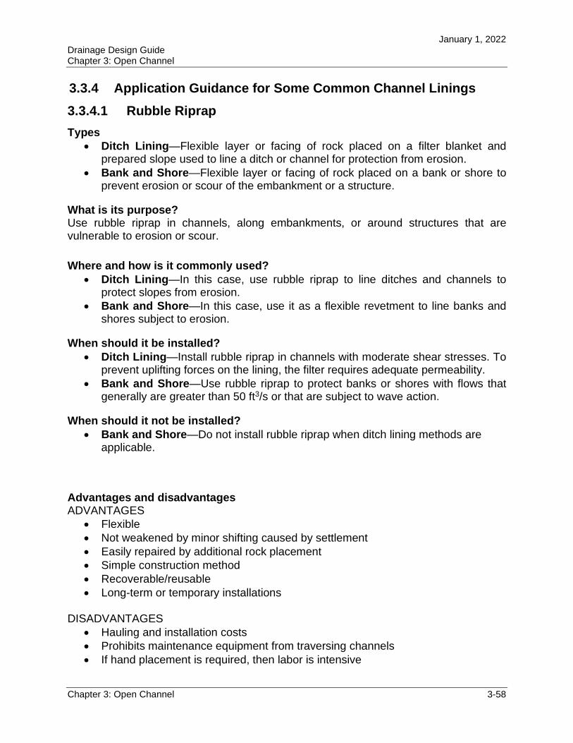
January 1, 2022 Drainage Design Guide Chapter 3: Open Channel
Chapter 3: Open Channel 3-58
3.3.4 Application Guidance for Some Common Channel Linings
3.3.4.1 Rubble Riprap
Types Ditch Lining—Flexible layer or facing of rock placed on a filter blanket and
prepared slope used to line a ditch or channel for protection from erosion. Bank and Shore—Flexible layer or facing of rock placed on a bank or shore to
prevent erosion or scour of the embankment or a structure.
What is its purpose? Use rubble riprap in channels, along embankments, or around structures that are vulnerable to erosion or scour.
Where and how is it commonly used? Ditch Lining—In this case, use rubble riprap to line ditches and channels to
protect slopes from erosion. Bank and Shore—In this case, use it as a flexible revetment to line banks and
shores subject to erosion.
When should it be installed? Ditch Lining—Install rubble riprap in channels with moderate shear stresses. To
prevent uplifting forces on the lining, the filter requires adequate permeability. Bank and Shore—Use rubble riprap to protect banks or shores with flows that
generally are greater than 50 ft3/s or that are subject to wave action.
When should it not be installed? Bank and Shore—Do not install rubble riprap when ditch lining methods are
applicable.
Advantages and disadvantagesADVANTAGES
Flexible Not weakened by minor shifting caused by settlement Easily repaired by additional rock placement Simple construction method Recoverable/reusable Long-term or temporary installations
DISADVANTAGES Hauling and installation costs Prohibits maintenance equipment from traversing channels If hand placement is required, then labor is intensive
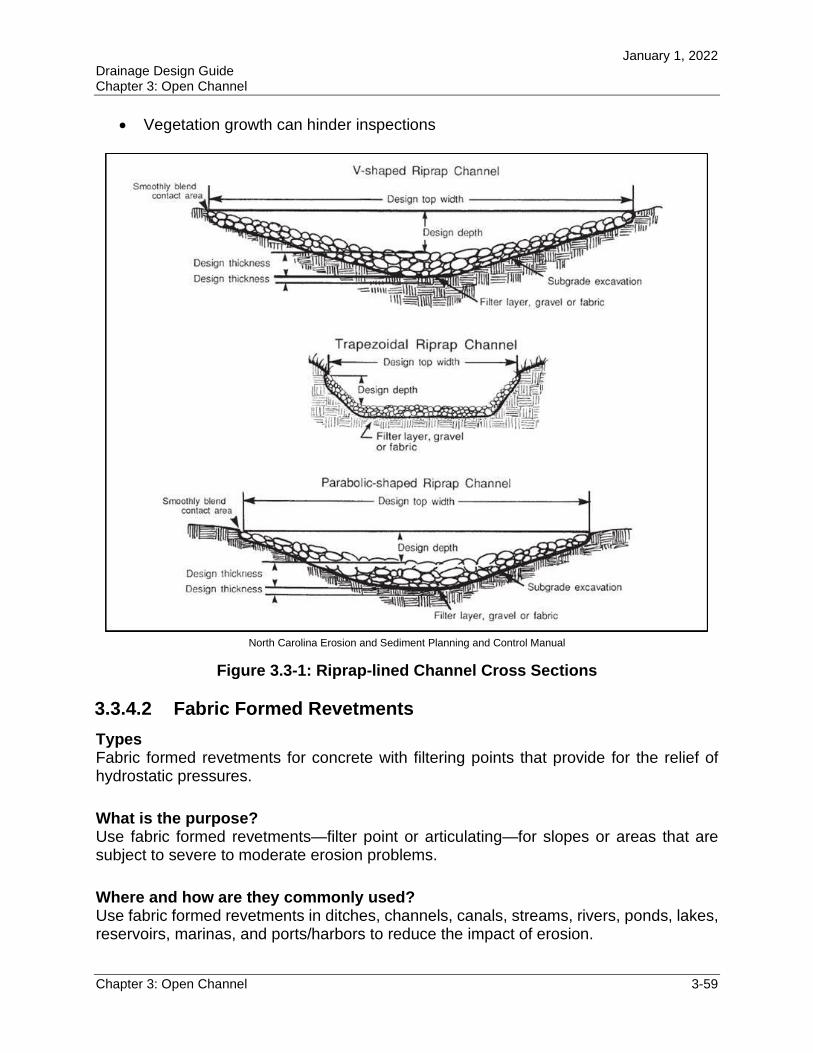
January 1, 2022 Drainage Design Guide Chapter 3: Open Channel
Chapter 3: Open Channel 3-59
Vegetation growth can hinder inspections
North Carolina Erosion and Sediment Planning and Control Manual
Figure 3.3-1: Riprap-lined Channel Cross Sections
3.3.4.2 Fabric Formed Revetments
Types Fabric formed revetments for concrete with filtering points that provide for the relief of hydrostatic pressures.
What is the purpose? Use fabric formed revetments—filter point or articulating—for slopes or areas that are subject to severe to moderate erosion problems.
Where and how are they commonly used? Use fabric formed revetments in ditches, channels, canals, streams, rivers, ponds, lakes, reservoirs, marinas, and ports/harbors to reduce the impact of erosion.
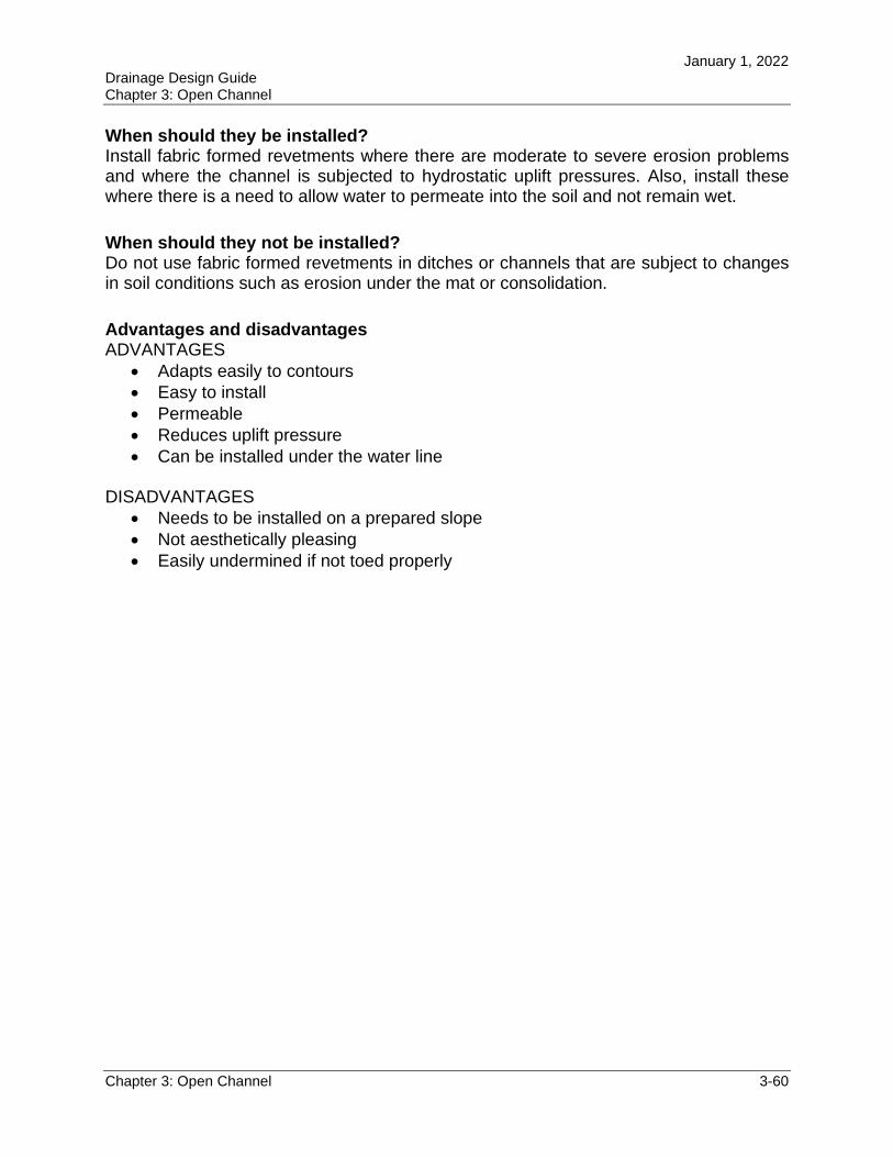
January 1, 2022 Drainage Design Guide Chapter 3: Open Channel
Chapter 3: Open Channel 3-60
When should they be installed? Install fabric formed revetments where there are moderate to severe erosion problems and where the channel is subjected to hydrostatic uplift pressures. Also, install these where there is a need to allow water to permeate into the soil and not remain wet.
When should they not be installed? Do not use fabric formed revetments in ditches or channels that are subject to changes in soil conditions such as erosion under the mat or consolidation.
Advantages and disadvantages ADVANTAGES
Adapts easily to contours Easy to install Permeable Reduces uplift pressure Can be installed under the water line
DISADVANTAGES Needs to be installed on a prepared slope Not aesthetically pleasing Easily undermined if not toed properly
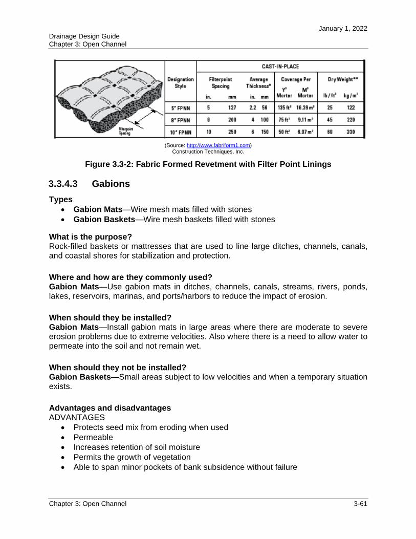
January 1, 2022 Drainage Design Guide Chapter 3: Open Channel
Chapter 3: Open Channel 3-61
(Source: http://www.fabriform1.com) Construction Techniques, Inc.
Figure 3.3-2: Fabric Formed Revetment with Filter Point Linings
3.3.4.3 Gabions
Types Gabion Mats—Wire mesh mats filled with stones Gabion Baskets—Wire mesh baskets filled with stones
What is the purpose? Rock-filled baskets or mattresses that are used to line large ditches, channels, canals, and coastal shores for stabilization and protection.
Where and how are they commonly used? Gabion Mats—Use gabion mats in ditches, channels, canals, streams, rivers, ponds, lakes, reservoirs, marinas, and ports/harbors to reduce the impact of erosion.
When should they be installed? Gabion Mats—Install gabion mats in large areas where there are moderate to severe erosion problems due to extreme velocities. Also where there is a need to allow water to permeate into the soil and not remain wet.
When should they not be installed? Gabion Baskets—Small areas subject to low velocities and when a temporary situation exists.
Advantages and disadvantages ADVANTAGES
Protects seed mix from eroding when used Permeable Increases retention of soil moisture Permits the growth of vegetation Able to span minor pockets of bank subsidence without failure
January 1, 2022 Drainage Design Guide Chapter 3: Open Channel
Chapter 3: Open Channel 3-62
DISADVANTAGES Cost of installation Susceptibility of the wire baskets to corrosion and abrasion damage More difficult and expensive to repair Less flexible than standard riprap
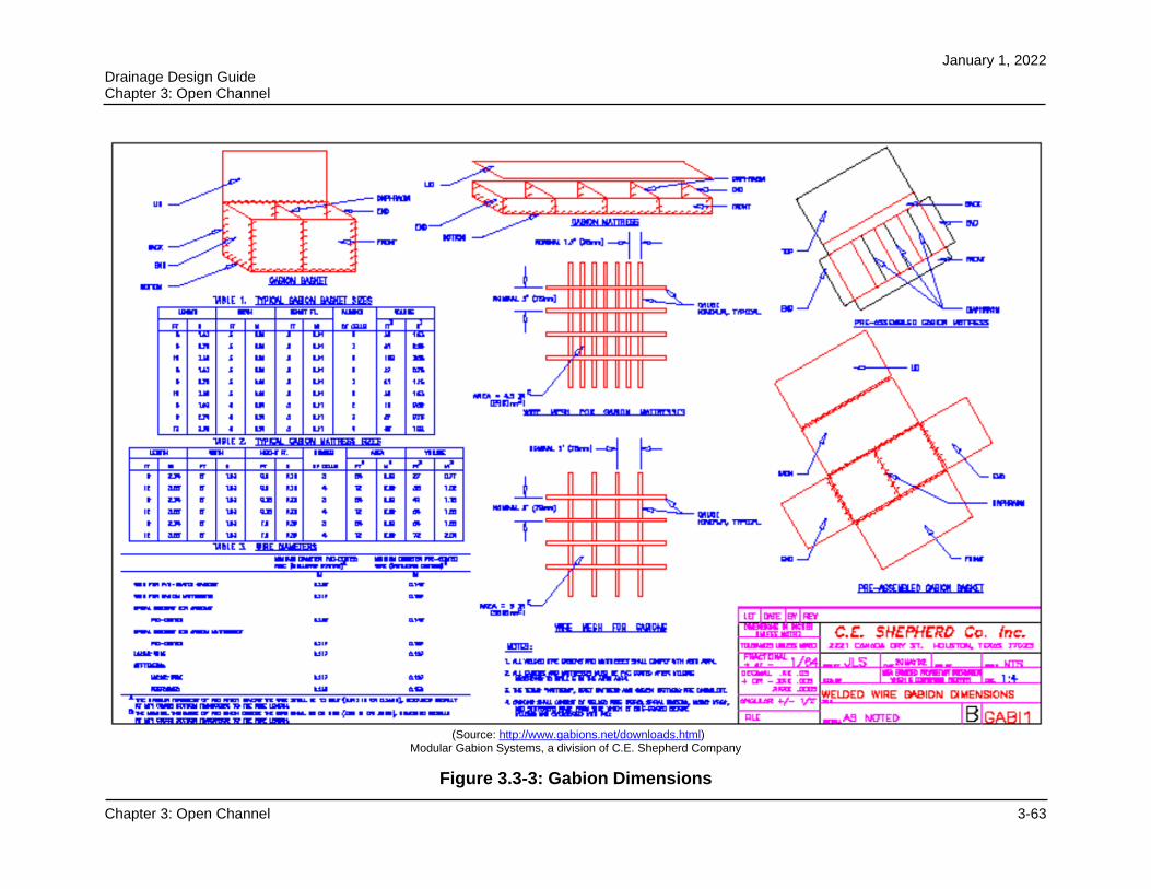
January 1, 2022 Drainage Design Guide Chapter 3: Open Channel
Chapter 3: Open Channel 3-63
(Source: http://www.gabions.net/downloads.html) Modular Gabion Systems, a division of C.E. Shepherd Company
Figure 3.3-3: Gabion Dimensions
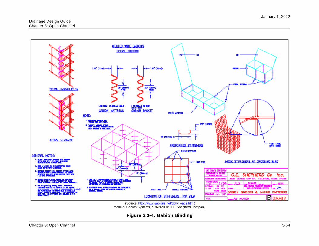
January 1, 2022 Drainage Design Guide Chapter 3: Open Channel
Chapter 3: Open Channel 3-64
(Source: http://www.gabions.net/downloads.html) Modular Gabion Systems, a division of C.E. Shepherd Company
Figure 3.3-4: Gabion Binding
January 1, 2022 Drainage Design Guide Chapter 3: Open Channel
Chapter 3: Open Channel 3-65
3.3.4.4 Soil Stabilizers
Types Turf Reinforcement Mats—A long-term non-degradable mat composed of UV
stabilized synthetic fibers, nettings, and/or filaments. Erosion Control Blankets—A temporary degradable mat composed of
processed natural or polymer fibers mechanically, structurally, or chemically bound together to form a continuous matrix.
What is the purpose? To protect disturbed slopes and channels from wind and water erosion. The blanket materials are natural materials, such as straw, wood excelsior, coconut, or are geotextile synthetic woven materials, such as polypropylene.
Where and how are they commonly used? Turf Reinforcement Mats—Use them on ditch slopes and fill slopes to reduce the
impact of erosion for long periods of construction. Erosion Control Blankets—Use them on ditch slopes and fill slopes to reduce
the impact of erosion during short periods of construction.
When should they be installed? Turf Reinforcement Mats—Where there are low velocities of flow Erosion Control Blankets—Where there are low velocities of flow and where
there are sensitive environmental areas
When should they not be installed? Turf Reinforcement Mats—Do not install for permanent situations and where
there are high velocities of flow. Erosion Control Blankets—Do not install for permanent situations and where
there are high velocities of flow.
Advantages and disadvantages ADVANTAGES
Adapts easily to contours Easy to install Permeable Reduced uplift pressure
DISADVANTAGES Cost Maintenance equipment can damage or pull out
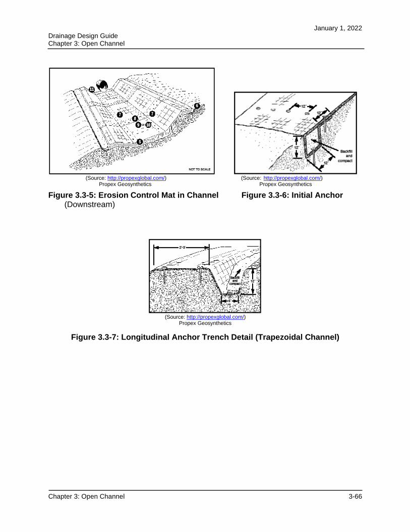
January 1, 2022 Drainage Design Guide Chapter 3: Open Channel
Chapter 3: Open Channel 3-66
(Source: http://propexglobal.com/) (Source: http://propexglobal.com/) Propex Geosynthetics Propex Geosynthetics
Figure 3.3-5: Erosion Control Mat in Channel Figure 3.3-6: Initial Anchor(Downstream)
(Source: http://propexglobal.com/) Propex Geosynthetics
Figure 3.3-7: Longitudinal Anchor Trench Detail (Trapezoidal Channel)
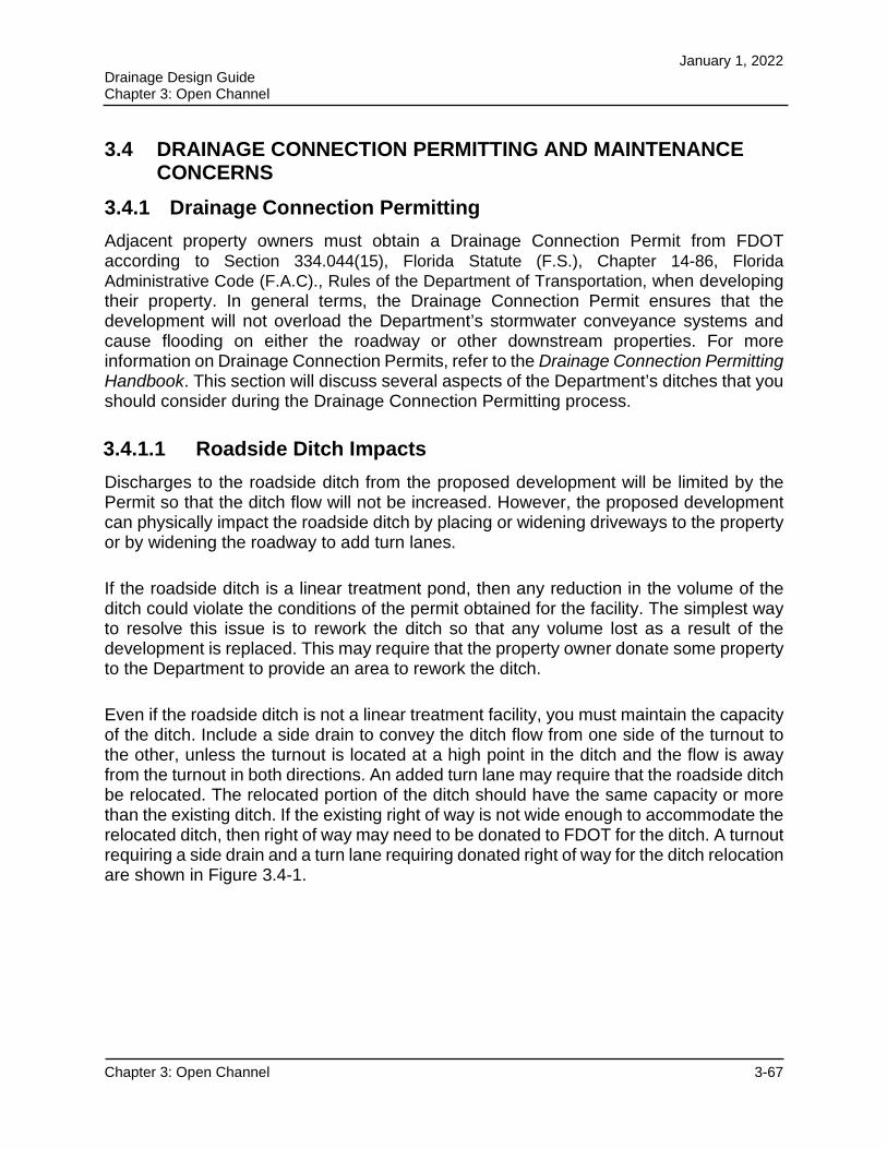
January 1, 2022 Drainage Design Guide Chapter 3: Open Channel
Chapter 3: Open Channel 3-67
3.4 DRAINAGE CONNECTION PERMITTING AND MAINTENANCE CONCERNS
3.4.1 Drainage Connection Permitting
Adjacent property owners must obtain a Drainage Connection Permit from FDOT according to Section 334.044(15), Florida Statute (F.S.), Chapter 14-86, Florida Administrative Code (F.A.C)., Rules of the Department of Transportation, when developing their property. In general terms, the Drainage Connection Permit ensures that the development will not overload the Department’s stormwater conveyance systems and cause flooding on either the roadway or other downstream properties. For more information on Drainage Connection Permits, refer to the Drainage Connection Permitting Handbook. This section will discuss several aspects of the Department’s ditches that you should consider during the Drainage Connection Permitting process.
3.4.1.1 Roadside Ditch Impacts
Discharges to the roadside ditch from the proposed development will be limited by the Permit so that the ditch flow will not be increased. However, the proposed development can physically impact the roadside ditch by placing or widening driveways to the property or by widening the roadway to add turn lanes.
If the roadside ditch is a linear treatment pond, then any reduction in the volume of the ditch could violate the conditions of the permit obtained for the facility. The simplest way to resolve this issue is to rework the ditch so that any volume lost as a result of the development is replaced. This may require that the property owner donate some property to the Department to provide an area to rework the ditch.
Even if the roadside ditch is not a linear treatment facility, you must maintain the capacity of the ditch. Include a side drain to convey the ditch flow from one side of the turnout to the other, unless the turnout is located at a high point in the ditch and the flow is away from the turnout in both directions. An added turn lane may require that the roadside ditch be relocated. The relocated portion of the ditch should have the same capacity or more than the existing ditch. If the existing right of way is not wide enough to accommodate the relocated ditch, then right of way may need to be donated to FDOT for the ditch. A turnout requiring a side drain and a turn lane requiring donated right of way for the ditch relocation are shown in Figure 3.4-1.
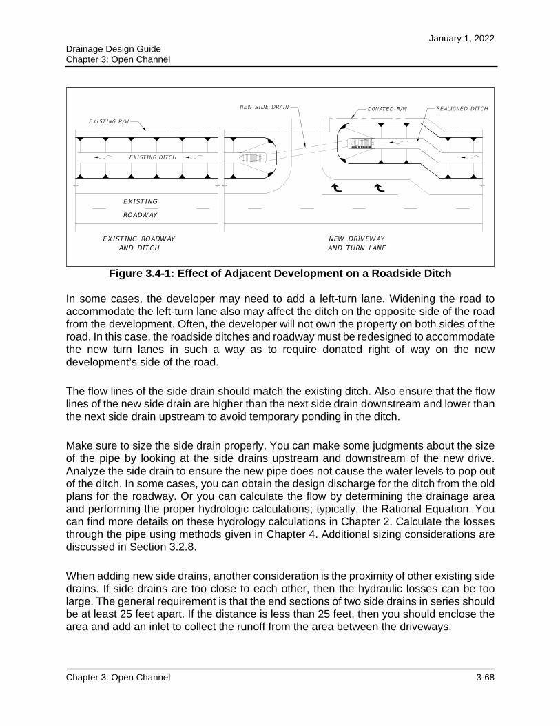
January 1, 2022 Drainage Design Guide Chapter 3: Open Channel
Chapter 3: Open Channel 3-68
Figure 3.4-1: Effect of Adjacent Development on a Roadside Ditch
In some cases, the developer may need to add a left-turn lane. Widening the road to accommodate the left-turn lane also may affect the ditch on the opposite side of the road from the development. Often, the developer will not own the property on both sides of the road. In this case, the roadside ditches and roadway must be redesigned to accommodate the new turn lanes in such a way as to require donated right of way on the new development’s side of the road.
The flow lines of the side drain should match the existing ditch. Also ensure that the flow lines of the new side drain are higher than the next side drain downstream and lower than the next side drain upstream to avoid temporary ponding in the ditch.
Make sure to size the side drain properly. You can make some judgments about the size of the pipe by looking at the side drains upstream and downstream of the new drive. Analyze the side drain to ensure the new pipe does not cause the water levels to pop out of the ditch. In some cases, you can obtain the design discharge for the ditch from the old plans for the roadway. Or you can calculate the flow by determining the drainage area and performing the proper hydrologic calculations; typically, the Rational Equation. You can find more details on these hydrology calculations in Chapter 2. Calculate the losses through the pipe using methods given in Chapter 4. Additional sizing considerations are discussed in Section 3.2.8.
When adding new side drains, another consideration is the proximity of other existing side drains. If side drains are too close to each other, then the hydraulic losses can be too large. The general requirement is that the end sections of two side drains in series should be at least 25 feet apart. If the distance is less than 25 feet, then you should enclose the area and add an inlet to collect the runoff from the area between the driveways.
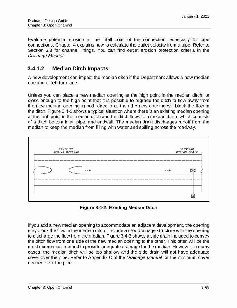
January 1, 2022 Drainage Design Guide Chapter 3: Open Channel
Chapter 3: Open Channel 3-69
Evaluate potential erosion at the infall point of the connection, especially for pipe connections. Chapter 4 explains how to calculate the outlet velocity from a pipe. Refer to Section 3.3 for channel linings. You can find outlet erosion protection criteria in the Drainage Manual.
3.4.1.2 Median Ditch Impacts
A new development can impact the median ditch if the Department allows a new median opening or left-turn lane.
Unless you can place a new median opening at the high point in the median ditch, or close enough to the high point that it is possible to regrade the ditch to flow away from the new median opening in both directions, then the new opening will block the flow in the ditch. Figure 3.4-2 shows a typical situation where there is an existing median opening at the high point in the median ditch and the ditch flows to a median drain, which consists of a ditch bottom inlet, pipe, and endwall. The median drain discharges runoff from the median to keep the median from filling with water and spilling across the roadway.
Figure 3.4-2: Existing Median Ditch
If you add a new median opening to accommodate an adjacent development, the opening may block the flow in the median ditch. Include a new drainage structure with the opening to discharge the flow from the median. Figure 3.4-3 shows a side drain included to convey the ditch flow from one side of the new median opening to the other. This often will be the most economical method to provide adequate drainage for the median. However, in many cases, the median ditch will be too shallow and the side drain will not have adequate cover over the pipe. Refer to Appendix C of the Drainage Manual for the minimum cover needed over the pipe.
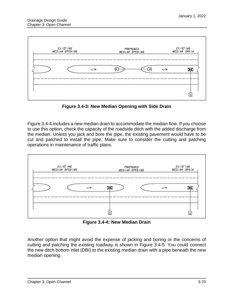
January 1, 2022 Drainage Design Guide Chapter 3: Open Channel
Chapter 3: Open Channel 3-70
Figure 3.4-3: New Median Opening with Side Drain
Figure 3.4-4 includes a new median drain to accommodate the median flow. If you choose to use this option, check the capacity of the roadside ditch with the added discharge from the median. Unless you jack and bore the pipe, the existing pavement would have to be cut and patched to install the pipe. Make sure to consider the cutting and patching operations in maintenance of traffic plans.
Figure 3.4-4: New Median Drain
Another option that might avoid the expense of jacking and boring or the concerns of cutting and patching the existing roadway is shown in Figure 3.4-5. You could connect the new ditch bottom inlet (DBI) to the existing median drain with a pipe beneath the new median opening.
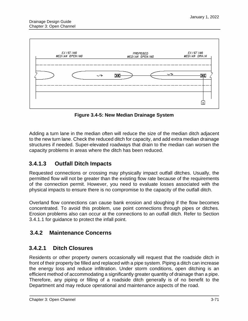
January 1, 2022 Drainage Design Guide Chapter 3: Open Channel
Chapter 3: Open Channel 3-71
Figure 3.4-5: New Median Drainage System
Adding a turn lane in the median often will reduce the size of the median ditch adjacent to the new turn lane. Check the reduced ditch for capacity, and add extra median drainage structures if needed. Super-elevated roadways that drain to the median can worsen the capacity problems in areas where the ditch has been reduced.
3.4.1.3 Outfall Ditch Impacts
Requested connections or crossing may physically impact outfall ditches. Usually, the permitted flow will not be greater than the existing flow rate because of the requirements of the connection permit. However, you need to evaluate losses associated with the physical impacts to ensure there is no compromise to the capacity of the outfall ditch.
Overland flow connections can cause bank erosion and sloughing if the flow becomes concentrated. To avoid this problem, use point connections through pipes or ditches. Erosion problems also can occur at the connections to an outfall ditch. Refer to Section 3.4.1.1 for guidance to protect the infall point.
3.4.2 Maintenance Concerns
3.4.2.1 Ditch Closures
Residents or other property owners occasionally will request that the roadside ditch in front of their property be filled and replaced with a pipe system. Piping a ditch can increase the energy loss and reduce infiltration. Under storm conditions, open ditching is an efficient method of accommodating a significantly greater quantity of drainage than a pipe. Therefore, any piping or filling of a roadside ditch generally is of no benefit to the Department and may reduce operational and maintenance aspects of the road.
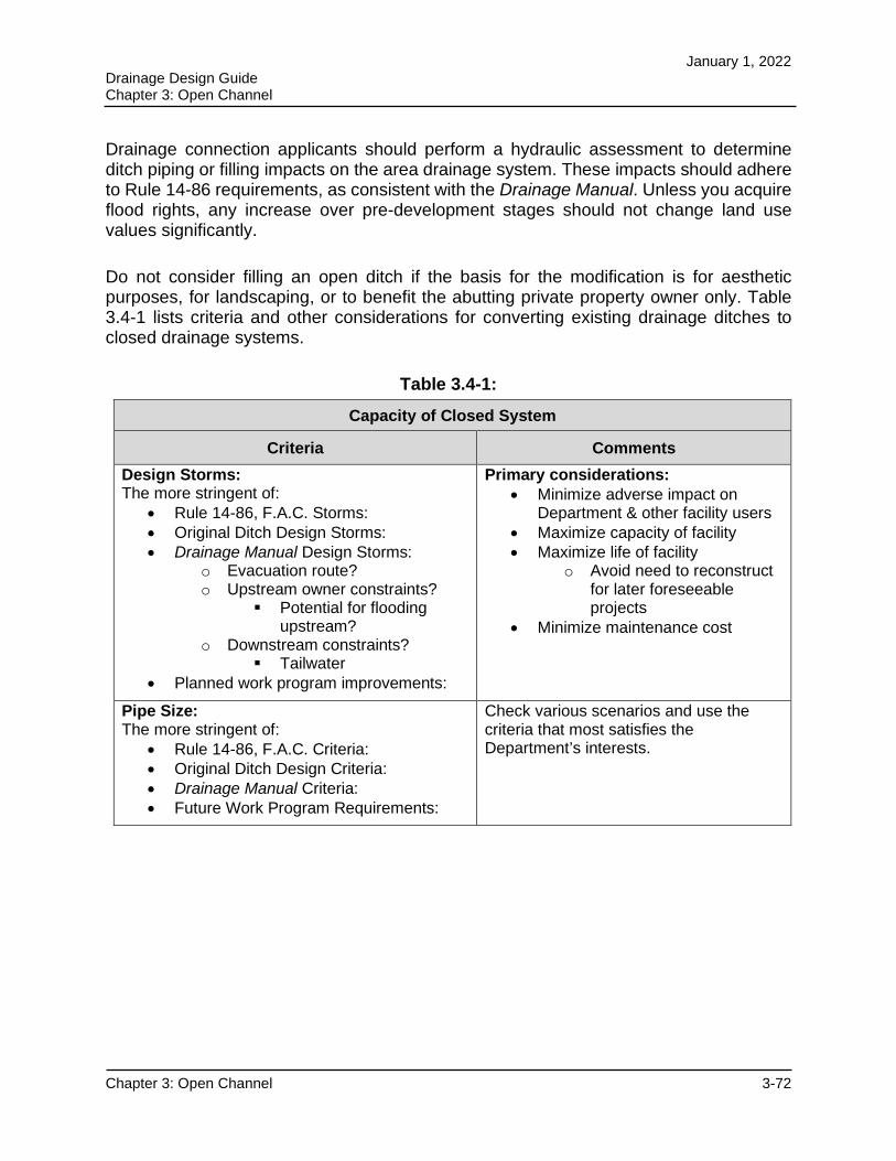
January 1, 2022 Drainage Design Guide Chapter 3: Open Channel
Chapter 3: Open Channel 3-72
Drainage connection applicants should perform a hydraulic assessment to determine ditch piping or filling impacts on the area drainage system. These impacts should adhere to Rule 14-86 requirements, as consistent with the Drainage Manual. Unless you acquire flood rights, any increase over pre-development stages should not change land use values significantly.
Do not consider filling an open ditch if the basis for the modification is for aesthetic purposes, for landscaping, or to benefit the abutting private property owner only. Table 3.4-1 lists criteria and other considerations for converting existing drainage ditches to closed drainage systems.
Table 3.4-1:
Capacity of Closed System
Criteria Comments
Design Storms: The more stringent of:
Rule 14-86, F.A.C. Storms: Original Ditch Design Storms: Drainage Manual Design Storms:
o Evacuation route? o Upstream owner constraints?
Potential for flooding upstream?
o Downstream constraints? Tailwater
Planned work program improvements:
Primary considerations: Minimize adverse impact on
Department & other facility users Maximize capacity of facility Maximize life of facility
o Avoid need to reconstruct for later foreseeable projects
Minimize maintenance cost
Pipe Size: The more stringent of:
Rule 14-86, F.A.C. Criteria: Original Ditch Design Criteria: Drainage Manual Criteria: Future Work Program Requirements:
Check various scenarios and use the criteria that most satisfies the Department’s interests.
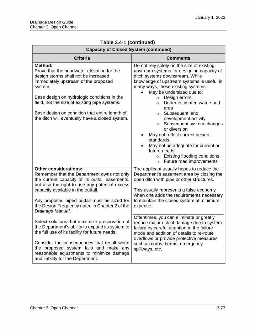
January 1, 2022 Drainage Design Guide Chapter 3: Open Channel
Chapter 3: Open Channel 3-73
Table 3.4-1 (continued)
Capacity of Closed System (continued)
Criteria Comments
Method: Prove that the headwater elevation for the design storms shall not be increased immediately upstream of the proposed system.
Base design on hydrologic conditions in the field, not the size of existing pipe systems.
Base design on condition that entire length of the ditch will eventually have a closed system.
Do not rely solely on the size of existing upstream systems for designing capacity of ditch systems downstream. While knowledge of upstream systems is useful in many ways, these existing systems:
May be undersized due to: o Design errors o Under estimated watershed
area o Subsequent land
development activity o Subsequent system changes
or diversion May not reflect current design
standards May not be adequate for current or
future needs o Existing flooding conditions o Future road improvements
Other considerations: Remember that the Department owns not only the current capacity of its outfall easements, but also the right to use any potential excess capacity available in the outfall.
Any proposed piped outfall must be sized for the Design Frequency noted in Chapter 2 of the Drainage Manual.
Select solutions that maximize preservation of the Department’s ability to expand its system to the full use of its facility for future needs.
Consider the consequences that result when the proposed system fails and make any reasonable adjustments to minimize damage and liability for the Department.
The applicant usually hopes to reduce the Department’s easement area by closing the open ditch with pipe or other structures.
This usually represents a false economy when one adds the requirements necessary to maintain the closed system at minimum expense.
Oftentimes, you can eliminate or greatly reduce major risk of damage due to system failure by careful attention to the failure mode and addition of details to re-route overflows or provide protective measures such as curbs, berms, emergency spillways, etc.
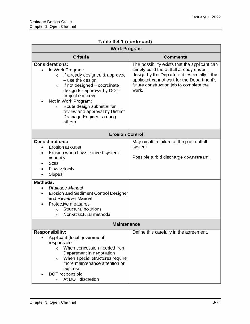
January 1, 2022 Drainage Design Guide Chapter 3: Open Channel
Chapter 3: Open Channel 3-74
Table 3.4-1 (continued)
Work Program
Criteria Comments
Considerations: In Work Program:
o If already designed & approved – use the design
o If not designed – coordinate design for approval by DOT project engineer
Not in Work Program: o Route design submittal for
review and approval by District Drainage Engineer among others
The possibility exists that the applicant can simply build the outfall already under design by the Department, especially if the applicant cannot wait for the Department’s future construction job to complete the work.
Erosion Control
Considerations: Erosion at outlet Erosion when flows exceed system
capacity Soils Flow velocity Slopes
May result in failure of the pipe outfall system.
Possible turbid discharge downstream.
Methods: Drainage Manual Erosion and Sediment Control Designer
and Reviewer Manual Protective measures
o Structural solutions o Non-structural methods
Maintenance
Responsibility: Applicant (local government)
responsible o When concession needed from
Department in negotiation o When special structures require
more maintenance attention or expense
DOT responsible o At DOT discretion
Define this carefully in the agreement.
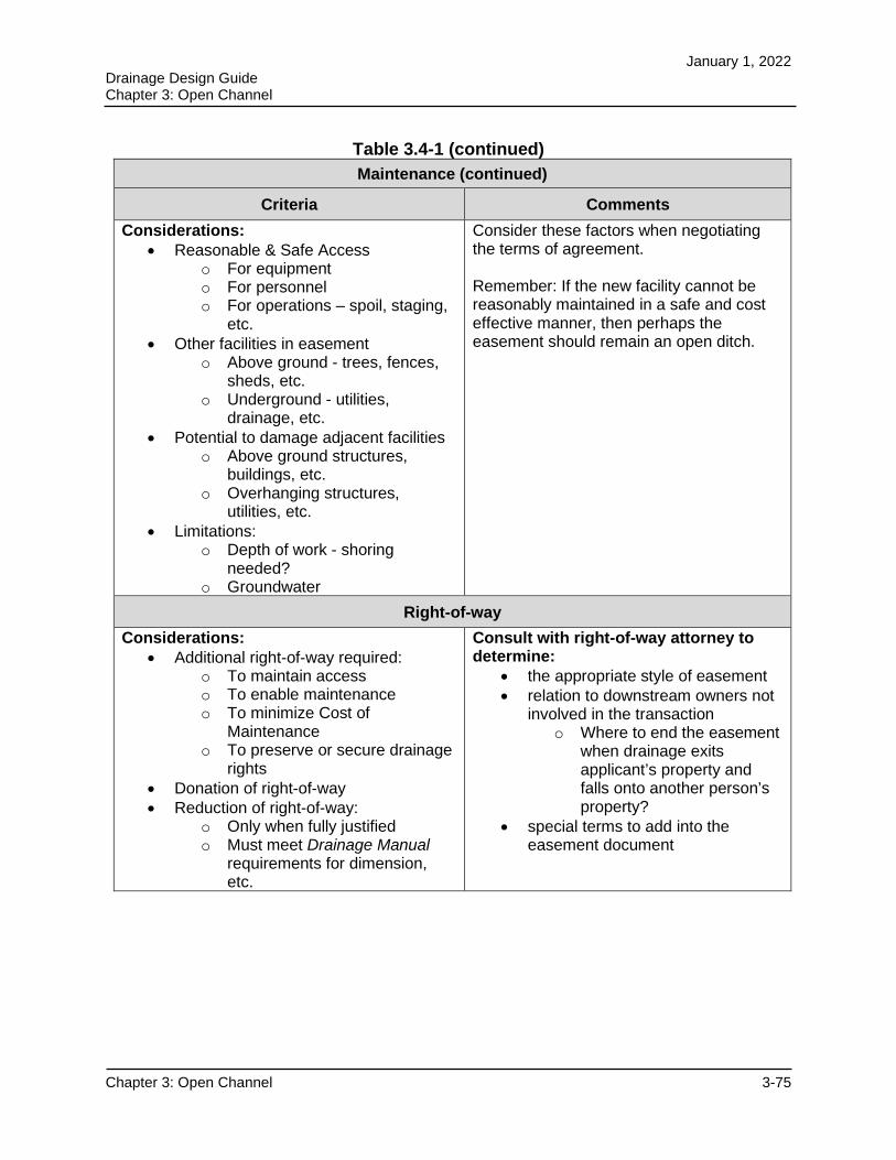
January 1, 2022 Drainage Design Guide Chapter 3: Open Channel
Chapter 3: Open Channel 3-75
Table 3.4-1 (continued)
Maintenance (continued)
Criteria Comments
Considerations: Reasonable & Safe Access
o For equipment o For personnel o For operations – spoil, staging,
etc. Other facilities in easement
o Above ground - trees, fences, sheds, etc.
o Underground - utilities, drainage, etc.
Potential to damage adjacent facilities o Above ground structures,
buildings, etc. o Overhanging structures,
utilities, etc. Limitations:
o Depth of work - shoring needed?
o Groundwater
Consider these factors when negotiating the terms of agreement.
Remember: If the new facility cannot be reasonably maintained in a safe and cost effective manner, then perhaps the easement should remain an open ditch.
Right-of-way
Considerations: Additional right-of-way required:
o To maintain access o To enable maintenance o To minimize Cost of
Maintenance o To preserve or secure drainage
rights Donation of right-of-way Reduction of right-of-way:
o Only when fully justified o Must meet Drainage Manual
requirements for dimension, etc.
Consult with right-of-way attorney to determine:
the appropriate style of easement relation to downstream owners not
involved in the transaction o Where to end the easement
when drainage exits applicant’s property and falls onto another person’s property?
special terms to add into the easement document
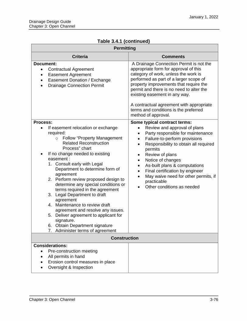
January 1, 2022 Drainage Design Guide Chapter 3: Open Channel
Chapter 3: Open Channel 3-76
Table 3.4.1 (continued)
Permitting
Criteria Comments
Document: Contractual Agreement Easement Agreement Easement Donation / Exchange Drainage Connection Permit
A Drainage Connection Permit is not the appropriate form for approval of this category of work, unless the work is performed as part of a larger scope of property improvements that require the permit and there is no need to alter the existing easement in any way.
A contractual agreement with appropriate terms and conditions is the preferred method of approval.
Process: If easement relocation or exchange
required: o Follow “Property Management
Related Reconstruction Process” chart
If no change needed to existing easement : 1. Consult early with Legal
Department to determine form of agreement
2. Perform review proposed design to determine any special conditions or terms required in the agreement
3. Legal Department to draft agreement
4. Maintenance to review draft agreement and resolve any issues.
5. Deliver agreement to applicant for signature.
6. Obtain Department signature 7. Administer terms of agreement
Some typical contract terms: Review and approval of plans Party responsible for maintenance Failure-to-perform provisions Responsibility to obtain all required
permits Review of plans Notice of changes As-built plans & computations Final certification by engineer May waive need for other permits, if
practicable Other conditions as needed
Construction
Considerations: Pre-construction meeting All permits in hand Erosion control measures in place Oversight & Inspection
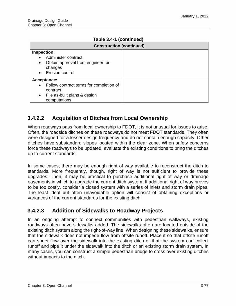
January 1, 2022 Drainage Design Guide Chapter 3: Open Channel
Chapter 3: Open Channel 3-77
Table 3.4-1 (continued)
Construction (continued)
Inspection: Administer contract Obtain approval from engineer for
changes Erosion control
Acceptance: Follow contract terms for completion of
contract File as-built plans & design
computations
3.4.2.2 Acquisition of Ditches from Local Ownership
When roadways pass from local ownership to FDOT, it is not unusual for issues to arise. Often, the roadside ditches on these roadways do not meet FDOT standards. They often were designed for a lesser design frequency and do not contain enough capacity. Other ditches have substandard slopes located within the clear zone. When safety concerns force these roadways to be updated, evaluate the existing conditions to bring the ditches up to current standards.
In some cases, there may be enough right of way available to reconstruct the ditch to standards. More frequently, though, right of way is not sufficient to provide these upgrades. Then, it may be practical to purchase additional right of way or drainage easements in which to upgrade the current ditch system. If additional right of way proves to be too costly, consider a closed system with a series of inlets and storm drain pipes. The least ideal but often unavoidable option will consist of obtaining exceptions or variances of the current standards for the existing ditch.
3.4.2.3 Addition of Sidewalks to Roadway Projects
In an ongoing attempt to connect communities with pedestrian walkways, existing roadways often have sidewalks added. The sidewalks often are located outside of the existing ditch system along the right-of-way line. When designing these sidewalks, ensure that the sidewalk does not impede flow from offsite runoff. Place it so that offsite runoff can sheet flow over the sidewalk into the existing ditch or that the system can collect runoff and pipe it under the sidewalk into the ditch or an existing storm drain system. In many cases, you can construct a simple pedestrian bridge to cross over existing ditches without impacts to the ditch.