Chapter 23 Magnetic Flux and Faraday's Law of induction
10
Chapter 23 Magnetic Flux and Faraday’s Law of induction Outline 23-1 Induced Electromotive Force (emf) 23-2 Magnetic Flux 23-3 Faraday’s Law of Induction 23-4 Lens’s Law 23-5 Mechanical Work 23-6 Generators and Motors 23-10 Transformers 23 10 Transformers
-
Upload
khangminh22 -
Category
Documents
-
view
1 -
download
0
Transcript of Chapter 23 Magnetic Flux and Faraday's Law of induction

Chapter 23 Magnetic Flux and Faraday’s Law of induction
Outline
23-1 Induced Electromotive Force (emf)
23-2 Magnetic Flux23-3 Faraday’s Law of Induction
23-4 Lens’s Law
23-5 Mechanical Work
23-6 Generators and Motors
23-10 Transformers23 10 Transformers

23-1 Induced Electromotive Force (emf)
Michael Faraday’s Experimentation: Magnetic induction
When the switch is closed on:
1) Magnetic field increase/rise.
2) The ammeter deflects.
3) As long as the current (primary circuit) is constant, the ammeter is zero.
When the switch is open:
Figure 23-1M i I d i
When the switch is open:
1) The ammeter deflects in opposite direction.
Magnetic InductionHow magnetic field create emf.
2) Then return to zero.

Summary:
• The current in the secondary circuit is zero if the current in the primary circuit is constant.
• When the magnetic field in the second coil increases, a current is observed in the secondary circuit;
• when the magnetic field in the second circuit decreases, a current is observed but in the opposite direction.
The secondary current is called induced current, since there is no direct contaction between the two circuits.
We also say the changing of magnetic field creates an induced emf(electromotive force) in the secondary circuit.
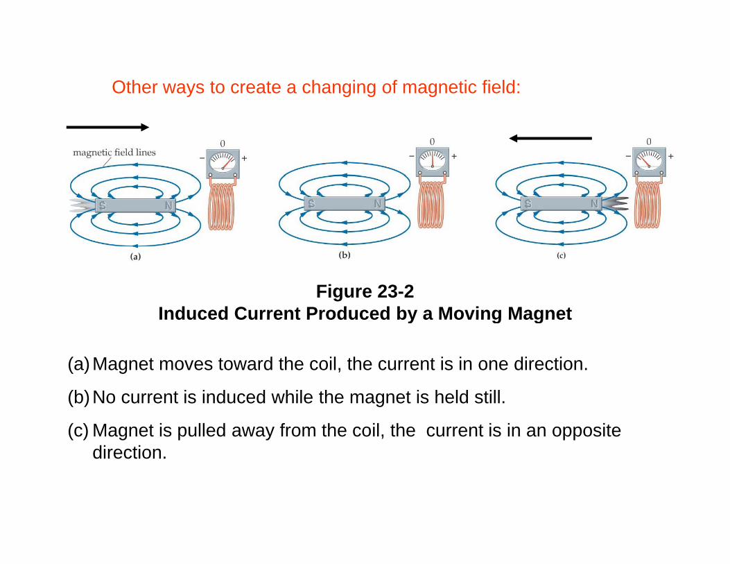
Other ways to create a changing of magnetic field:
Figure 23-2Induced Current Produced by a Moving MagnetInduced Current Produced by a Moving Magnet
(a)Magnet moves toward the coil, the current is in one direction.
(b)No current is induced while the magnet is held still.
(c) Magnet is pulled away from the coil, the current is in an opposite direction.
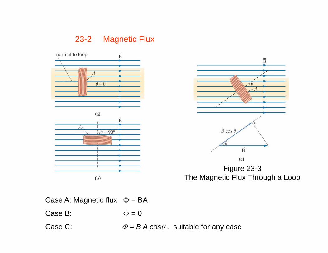
23-2 Magnetic Flux
Figure 23-3The Magnetic Flux Through a Loop
Case A: Magnetic flux Φ = BA
Case B: Φ = 0
Case C: Φ = B A cosθ , suitable for any case

Definition of Magnetic Flux, Φ
Φ = B A cosθ (23-1)
SI unit: 1 T·m2 = 1 weber = 1 WbSI unit: 1 T·m2 = 1 weber = 1 Wb

Example 23-1 A system in Flux
Consider a circular loop with a 2.50-cm radius in a constant magnetic field of 0.625 T. Find the magnetic flux through this loop when its normal makes an angle of (a) 0˚, (b) 30.0˚, (c) 60.0˚, and (d) 90˚.
Picture the problemExample 23-1Example 23-1
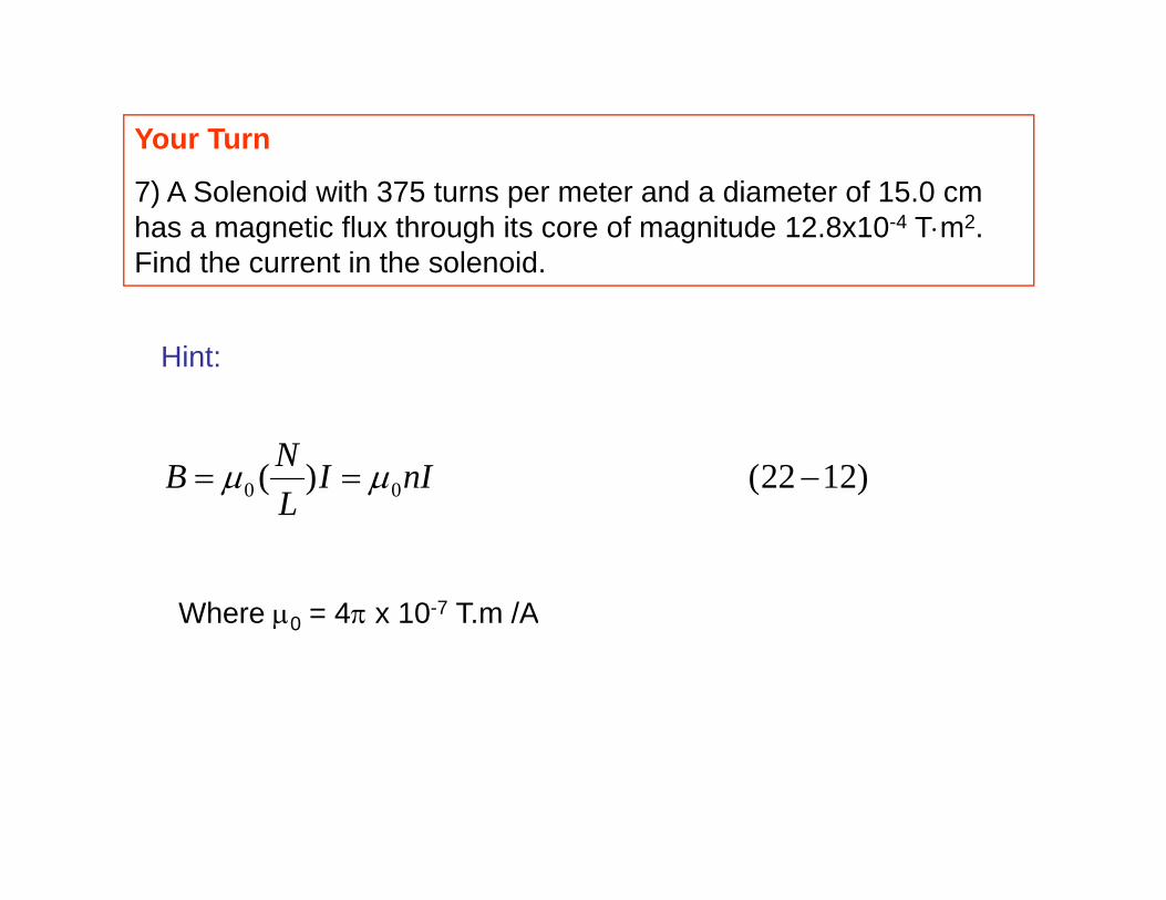
Your Turn
7) A Solenoid with 375 turns per meter and a diameter of 15.0 cm has a magnetic flux through its core of magnitude 12.8x10⁻⁴ T⋅m2. Find the current in the solenoid.
Hint:
)1222()( 00 −== nIILNB μμL
Where μ0 = 4π x 10-7 T.m /AWhere μ0 4π x 10 T.m /A
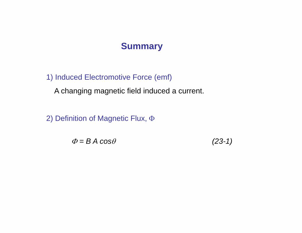
SSummary
1) Induced Electromotive Force (emf)
A changing magnetic field induced a current.
2) Definition of Magnetic Flux, Φ
Φ = B A cosθ (23-1)
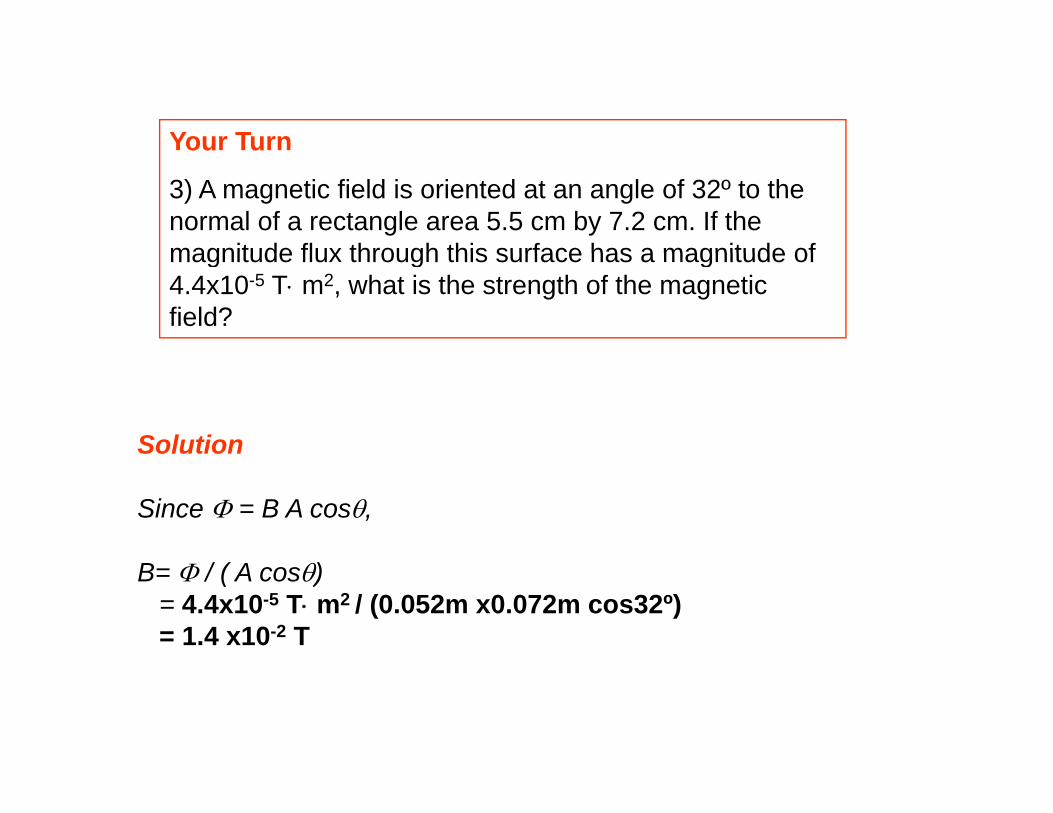
Your Turnou u
3) A magnetic field is oriented at an angle of 32º to the normal of a rectangle area 5.5 cm by 7.2 cm. If the magnitude flux through this surface has a magnitude ofmagnitude flux through this surface has a magnitude of 4.4x10⁻⁵ T⋅ m2, what is the strength of the magnetic field?
Solution
Since Φ = B A cosθ,
B= Φ / ( A cosθ)= 4.4x10⁻⁵ T⋅ m2 / (0.052m x0.072m cos32º)= 1.4 x10⁻² T