CHAPTER 15: Wave Motion Responses to Questions
511
© 2008 Pearson Education, Inc., Upper Saddle River, NJ. All rights reserved. This material is protected under all copyright laws as they currently exist. No portion of this material may be reproduced, in any form or by any means, without permission in writing from the publisher. 475 CHAPTER 15: Wave Motion Responses to Questions 1. Yes. A simple periodic wave travels through a medium, which must be in contact with or connected to the source for the wave to be generated. If the medium changes, the wave speed and wavelength can change but the frequency remains constant. 2. The speed of the transverse wave is the speed at which the wave disturbance propagates down the cord. The individual tiny pieces of cord will move perpendicular to the cord with an average speed of four times the amplitude divided by the period. The average velocity of the individual pieces of cord is zero, but the average speed is not the same as the wave speed. 3. The maximum climb distance (4.3 m) occurs when the tall boat is at a crest and the short boat is in a trough. If we define the height difference of the boats on level seas as Δh and the wave amplitude as A, then Δh + 2A = 4.3 m. The minimum climb distance (2.5 m) occurs when the tall boat is in a trough and the short boat is at a crest. Then Δh – 2A = 2.5 m. Solving these two equations for A gives a wave amplitude of 0.45 m. 4. (a) Striking the rod vertically from above will displace particles in a direction perpendicular to the rod and will set up primarily transverse waves. (b) Striking the rod horizontally parallel to its length will give the particles an initial displacement parallel to the rod and will set up primarily longitudinal waves. 5. The speed of sound in air obeys the equation . v B ρ = If the bulk modulus is approximately constant and the density of air decreases with temperature, then the speed of sound in air should increase with increasing temperature. 6. First, estimate the number of wave crests that pass a given point per second. This is the frequency of the wave. Then, estimate the distance between two successive crests, which is the wavelength. The product of the frequency and the wavelength is the speed of the wave. 7. The speed of sound is defined as v B ρ = , where B is the bulk modulus and ρ is the density of the material. The bulk modulus of most solids is at least 10 6 times as great as the bulk modulus of air. This difference overcomes the larger density of most solids, and accounts for the greater speed of sound in most solids than in air. 8. One reason is that the wave energy is spread out over a larger area as the wave travels farther from the source, as can be seen by the increasing diameter of the circular wave. The wave does not gain energy as it travels, so if the energy is spread over a larger area, the amplitude of the wave must be smaller. Secondly, the energy of the wave dissipates due to damping, and the amplitude decreases. 9. If two waves have the same speed but one has half the wavelength of the other, the wave with the shorter wavelength must have twice the frequency of the other. The energy transmitted by a wave depends on the wave speed and the square of the frequency. The wave with the shorter wavelength will transmit four times the energy transmitted by the other wave. 10. Yes. Any function of (x - vt) will represent wave motion because it will satisfy the wave equation, Eq. 15-16.
-
Upload
khangminh22 -
Category
Documents
-
view
46 -
download
0
Transcript of CHAPTER 15: Wave Motion Responses to Questions

© 2008 Pearson Education, Inc., Upper Saddle River, NJ. All rights reserved. This material is protected under all copyright laws as they currently exist. No portion of this material may be reproduced, in any form or by any means, without permission in writing from the publisher.
475
CHAPTER 15: Wave Motion Responses to Questions 1. Yes. A simple periodic wave travels through a medium, which must be in contact with or connected
to the source for the wave to be generated. If the medium changes, the wave speed and wavelength can change but the frequency remains constant.
2. The speed of the transverse wave is the speed at which the wave disturbance propagates down the
cord. The individual tiny pieces of cord will move perpendicular to the cord with an average speed of four times the amplitude divided by the period. The average velocity of the individual pieces of cord is zero, but the average speed is not the same as the wave speed.
3. The maximum climb distance (4.3 m) occurs when the tall boat is at a crest and the short boat is in a
trough. If we define the height difference of the boats on level seas as Δh and the wave amplitude as A, then Δh + 2A = 4.3 m. The minimum climb distance (2.5 m) occurs when the tall boat is in a trough and the short boat is at a crest. Then Δh – 2A = 2.5 m. Solving these two equations for A gives a wave amplitude of 0.45 m.
4. (a) Striking the rod vertically from above will displace particles in a direction perpendicular to the
rod and will set up primarily transverse waves. (b) Striking the rod horizontally parallel to its length will give the particles an initial displacement
parallel to the rod and will set up primarily longitudinal waves. 5. The speed of sound in air obeys the equation .v B ρ= If the bulk modulus is approximately
constant and the density of air decreases with temperature, then the speed of sound in air should increase with increasing temperature.
6. First, estimate the number of wave crests that pass a given point per second. This is the frequency of
the wave. Then, estimate the distance between two successive crests, which is the wavelength. The product of the frequency and the wavelength is the speed of the wave.
7. The speed of sound is defined as v B ρ= , where B is the bulk modulus and ρ is the density of the
material. The bulk modulus of most solids is at least 106 times as great as the bulk modulus of air. This difference overcomes the larger density of most solids, and accounts for the greater speed of sound in most solids than in air.
8. One reason is that the wave energy is spread out over a larger area as the wave travels farther from
the source, as can be seen by the increasing diameter of the circular wave. The wave does not gain energy as it travels, so if the energy is spread over a larger area, the amplitude of the wave must be smaller. Secondly, the energy of the wave dissipates due to damping, and the amplitude decreases.
9. If two waves have the same speed but one has half the wavelength of the other, the wave with the
shorter wavelength must have twice the frequency of the other. The energy transmitted by a wave depends on the wave speed and the square of the frequency. The wave with the shorter wavelength will transmit four times the energy transmitted by the other wave.
10. Yes. Any function of (x - vt) will represent wave motion because it will satisfy the wave equation,
Eq. 15-16.

Physics for Scientists & Engineers with Modern Physics, 4th Edition Instructor Solutions Manual
© 2008 Pearson Education, Inc., Upper Saddle River, NJ. All rights reserved. This material is protected under all copyright laws as they currently exist. No portion of this material may be reproduced, in any form or by any means, without permission in writing from the publisher.
476
11. The frequency does not change at the boundary because the two sections of cord are tied to each other and they must oscillate together. The wavelength and wave speed can be different, but the frequency must remain constant across the boundary.
12. The transmitted wave has a shorter wavelength. If the wave is inverted upon reflection at the
boundary between the two sections of rope, then the second section of rope must be heavier. Therefore, the transmitted wave (traveling in the heavier rope) will have a lower velocity than the incident wave or the reflected wave. The frequency does not change at the boundary, so the wavelength of the transmitted wave must also be smaller.
13. Yes, total energy is always conserved. The particles in the medium, which are set into motion by the
wave, have both kinetic and potential energy. At the instant in which two waves interfere destructively, the displacement of the medium may be zero, but the particles of the medium will have velocity, and therefore kinetic energy.
14. Yes. If you touch the string at any node you will not disturb the motion. There will be nodes at each
end as well as at the points one-third and two-thirds of the distance along the length of the string. 15. No. The energy of the incident and reflected wave is distributed around the antinodes, which exhibit
large oscillations. The energy is a property of the wave as a whole, not of one particular point on the wave.
16. Yes. A standing wave is an example of a resonance phenomenon, caused by constructive
interference between a traveling wave and its reflection. The wave energy is distributed around the antinodes, which exhibit large amplitude oscillations, even when the generating oscillations from the hand are small.
17. When a hand or mechanical oscillator vibrates a string, the motion of the hand or oscillator is not
exactly the same for each vibration. This variation in the generation of the wave leads to nodes which are not quite “true” nodes. In addition, real cords have damping forces which tend to reduce the energy of the wave. The reflected wave will have a smaller amplitude than the incident wave, so the two waves will not completely cancel, and the node will not be a true node.
18. AM radio waves have a much longer wavelength than FM radio waves. How much waves bend, or
diffract, around obstacles depends on the wavelength of the wave in comparison to the size of the obstacle. A hill is much larger than the wavelength of FM waves, and so there will be a “shadow” region behind the hill. However, the hill is not large compared to the wavelength of AM signals, so the AM radio waves will bend around the hill.
19. Waves exhibit diffraction. If a barrier is placed between the energy source and the energy receiver,
and energy is still received, it is a good indication that the energy is being carried by waves. If placement of the barrier stops the energy transfer, it may be because the energy is being transferred by particles or that the energy is being transferred by waves with wavelengths smaller than the barrier.
Solutions to Problems 1. The wave speed is given by v fλ= . The period is 3.0 seconds, and the wavelength is 8.0 m.
( ) ( )8.0m 3.0s 2.7m sv f Tλ λ= = = =

Chapter 15 Wave Motion
© 2008 Pearson Education, Inc., Upper Saddle River, NJ. All rights reserved. This material is protected under all copyright laws as they currently exist. No portion of this material may be reproduced, in any form or by any means, without permission in writing from the publisher.
477
2. The distance between wave crests is the wavelength of the wave. 343m s 262 Hz 1.31 mv fλ = = = 3. The elastic and bulk moduli are taken from Table 12-1. The densities are taken from Table 13-1.
(a) For water: 9 2
3 3
2.0 10 N m1400m s
1.00 10 kg mv B ρ ×= = =
×
(b) For granite: 9 2
3 3
45 10 N m4100m s
2.7 10 kg mv E ρ ×= = =
×
(c) For steel: 9 2
3 3
200 10 N m5100m s
7.8 10 kg mv E ρ ×= = =
×
4. To find the wavelength, use v fλ = .
AM: 8 8
1 23 31 2
3.00 10 m s 3.00 10 m s545 m 188 m AM: 190 m to 550 m
550 10 Hz 1600 10 Hzv vf f
λ λ× ×= = = = = =
× ×
FM: 8 8
1 26 61 2
3.00 10 m s 3.00 10 m s3.41m 2.78m FM: 2.8m to 3.4m
88 10 Hz 108 10 Hzv vf f
λ λ× ×= = = = = =
× ×
5. The speed of the longitudinal wave is given by Eq. 15-3, v E ρ= . The speed and the frequency
are used to find the wavelength. The bulk modulus is found in Table 12-1, and the density is found in Table 13-1.
9 2
3 3
100 10 N m7.8 10 kg m
0.62m5800Hz
Evf f
ρλ
××
= = = =
6. To find the time for a pulse to travel from one end of the cord to the other, the velocity of the pulse
on the cord must be known. For a cord under tension, we have Eq. 15-2, .Tv F μ=
( ) ( )
8.0m 0.19s
140 N0.65kg 8.0m
T
T
x F xv t
t Fμμ
Δ Δ= = → Δ = = =Δ
7. For a cord under tension, we have from Eq. 15-2 that .Tv F μ= The speed is also the
displacement divided by the elapsed time, vxt
=ΔΔ
. The displacement is the length of the cord.
( ) ( ) ( )
( ) ( )( )
2 2
2 2 2 2
0.40kg 7.8m 4.3N
0.85sT
T
F x m mv F
t t t tμ
μΔ
= = → = = = = =Δ Δ Δ Δ
l l l
l
8. The speed of the water wave is given by v B ρ= , where B is the bulk modulus of water, from
Table 12-1, and ρ is the density of sea water, from Table 13-1. The wave travels twice the depth of the ocean during the elapsed time.

Physics for Scientists & Engineers with Modern Physics, 4th Edition Instructor Solutions Manual
© 2008 Pearson Education, Inc., Upper Saddle River, NJ. All rights reserved. This material is protected under all copyright laws as they currently exist. No portion of this material may be reproduced, in any form or by any means, without permission in writing from the publisher.
478
9 2
33 3
2 2.8s 2.0 10 N m 2.0 10 m
2 2 2 1.025 10 kg mvt t B
vt ρ
×= → = = = = ×
×l
l
9. (a) The speed of the pulse is given by
( )2 660m
77.65m s 78m s17s
xv
tΔ
= = = ≈Δ
(b) The tension is related to the speed of the pulse by T .v F μ= The mass per unit length of the cable can be found from its volume and density.
( )
( )
2
22 23 3
2
1.5 10 m7.8 10 kg m 1.378kg m
2 2
m mV d
m d
ρπ
μ πρ π−
= = →
×= = = × =
⎛ ⎞⎛ ⎞⎜ ⎟ ⎜ ⎟⎝ ⎠ ⎝ ⎠
l
l
( ) ( )22T T 77.65m s 1.378kg m 8300Nv F F vμ μ= → = = =
10. (a) Both waves travel the same distance, so 1 1 2 2x v t v tΔ = = . We let the smaller speed be 1v , and
the larger speed be 2v . The slower wave will take longer to arrive, and so 1t is more than 2t .
( )
( ) ( )
( ) ( )
1 2 2 1 2 2 2
12
2 1
2 2
1.7min 102s 102s
5.5km s102s 102s 187s
8.5km s 5.5km s
8.5km s 187s 1600km
t t t v t v t
vt
v v
x v t
= + = + → + = →
= = =− −
Δ = = =
(b) This is not enough information to determine the epicenter. All that is known is the distance of the epicenter from the seismic station. The direction is not known, so the epicenter lies on a circle of radius 31.9 10 km× from the seismic station. Readings from at least two other seismic stations are needed to determine the epicenter’s position.
11. (a) The shape will not change. The wave will move 1.10 meters to the right in 1.00 seconds. See
the graph. The parts of the string that are moving up or down are indicated.
-2
-1
0
1
2
0 1 2 3 4meters
cent
imet
ers
EarlierLater
down up down up down

Chapter 15 Wave Motion
© 2008 Pearson Education, Inc., Upper Saddle River, NJ. All rights reserved. This material is protected under all copyright laws as they currently exist. No portion of this material may be reproduced, in any form or by any means, without permission in writing from the publisher.
479
(b) At the instant shown, the string at point A will be moving down. As the wave moves to the right, the string at point A will move down by 1 cm in the time it takes the “valley” between 1 m and 2 m to move to the right by about 0.25 m.
1cm
4cm s0.25m 1.10m s
yv
tΔ −
= = ≈ −Δ
This answer will vary depending on the values read from the graph. 12. We assume that the wave will be transverse. The speed is given by Eq. 15-2. The tension in the
wire is equal to the weight of the hanging mass. The linear mass density is the volume mass density times the cross-sectional area of the wire. The volume mass density is found in Table 13-1.
( ) ( )
( ) ( )2
ball ball23 3
5.0kg 9.80m s89 m s
7800kg m 0.50 10 mTF m g m g
vV Aρμ πρ
−= = = = =
×l
l l
13. The speed of the waves on the cord can be found from Eq. 15-2, T .v F μ= The distance between
the children is the wave speed times the elapsed time.
( ) ( )2 2T T 35N 0.50s 18m
0.50kgF F
x v t t x tm x m
Δ = Δ = Δ → Δ = Δ = =Δ
14. (a) We are told that the speed of the waves only depends on the acceleration due to gravity and the
wavelength.
[ ]2 : 1 2 1 2
L Lv kg L T
T T
αγα γλ α α= → = − = − → =⎡ ⎤ ⎡ ⎤
⎢ ⎥ ⎢ ⎥⎣ ⎦ ⎣ ⎦
: 1 1 1 2 L v k gα γ γ α λ= + → = − = =
(b) Here the speed of the waves depends only on the acceleration due to gravity and the depth of the water.
[ ]2 : 1 2 1 2L Lv kg h L TT T
αβα β α α⎡ ⎤ ⎡ ⎤= → = − = − → =⎢ ⎥ ⎢ ⎥⎣ ⎦ ⎣ ⎦
: 1 1 1 2 L v k ghα β β α= + → = − = =
15. From Eq. 15-7, if the speed, medium density, and frequency of the two waves are the same, then the
intensity is proportional to the square of the amplitude. 2 2
2 1 2 1 2 1 2 13 3 1.73I I E E A A A A= = = → = = The more energetic wave has the larger amplitude. 16. (a) Assume that the earthquake waves spread out spherically from the source. Under those
conditions, Eq. (15-8ab) applies, stating that intensity is inversely proportional to the square of the distance from the source of the wave.
( ) ( )2 245km 15km 15km 45km 0.11I I = =

Physics for Scientists & Engineers with Modern Physics, 4th Edition Instructor Solutions Manual
© 2008 Pearson Education, Inc., Upper Saddle River, NJ. All rights reserved. This material is protected under all copyright laws as they currently exist. No portion of this material may be reproduced, in any form or by any means, without permission in writing from the publisher.
480
(b) The intensity is proportional to the square of the amplitude, and so the amplitude is inversely proportional to the distance from the source of the wave.
45km 15km 15km 45km 0.33A A = = 17. We assume that all of the wave motion is outward along the surface of the water – no waves are
propagated downwards. Consider two concentric circles on the surface of the water, centered on the place where the circular waves are generated. If there is no damping, then the power (energy per unit time) being transferred across the boundary of each of those circles must be the same. Or, the power associated with the wave must be the same at each circular boundary. The intensity depends on the amplitude squared, so for the power we have this.
( ) 2 2 constant 12 2 constant
2P I r kA r A A
rk rπ π
π= = = → = → ∝
18. (a) Assuming spherically symmetric waves, the intensity will be inversely proportional to the
square of the distance from the source. Thus 2Ir will be constant.
( ) ( )( )
2 2near near far far
226 2 9 2 9 2far
near far 22near
48km3.0 10 W m 6.912 10 W m 6.9 10 W m
1.0km
I r I r
rI I
r
= →
= = × = × ≈ ×
(b) The power passing through an area is the intensity times the area.
( ) ( )9 2 2 106.912 10 W m 2.0m 1.4 10 WP IA= = × = ×
19. (a) The power transmitted by the wave is assumed to be the same as the output of the oscillator.
That power is given by Eq. 15-6. The wave speed is given by Eq. 15-2. Note that the mass per unit length can be expressed as the volume mass density times the cross sectional area.
( ) ( ) ( ) ( ) ( )
2 2 2 2 2 2 2 2 2 2 2 2T TT
22 22 3 3
2 2 2 2
2 60.0Hz 0.0050m 5.0 10 m 7800kg m 7.5N 0.38W
F FP Svf A S f A S f A f A S F
Sπ ρ π ρ π ρ π ρ
μ ρ
π π −
= = = =
= × =
(b) The frequency and amplitude are both squared in the equation. Thus is the power is constant, and the frequency doubles, the amplitude must be halved, and so be 0.25cm .
20. Consider a wave traveling through an area S with speed v, much like Figure 15-11. Start with Eq.
15-7, and use Eq. 15-6.
energyvolume
P E E EI v
S St S t S t= = = = = ×
l l
l l
21. (a) We start with Eq. 15-6. The linear mass density is the mass of a given volume of the cord
divided by the cross-sectional area of the cord.
2 2 2 2 2 22 ; 2m V S
P Svf A S P vf Aρ ρπ ρ μ ρ π μ= = = = = → =
l
l l l
(b) The speed of the wave is found from the given tension and mass density, according to Eq. 15-2.
( ) ( ) ( ) ( )
2 2 2 2 2 2 2 2 2T T
2 22
2 2 2
2 120Hz 0.020m 0.10kg m 135N 420W
P vf A f A F f A Fπ μ π μ μ π μ
π
= = =
= =

Chapter 15 Wave Motion
© 2008 Pearson Education, Inc., Upper Saddle River, NJ. All rights reserved. This material is protected under all copyright laws as they currently exist. No portion of this material may be reproduced, in any form or by any means, without permission in writing from the publisher.
481
22. (a) The only difference is the direction of motion. ( ) ( ), 0.015sin 25 1200D x t x t= +
(b) The speed is found from the wave number and the angular frequency, Eq. 15-12.
1200rad s
48m s25rad m
vkω
= = =
23. To represent a wave traveling to the left, we replace x by .x vt+ The resulting expression can be
given in various forms.
( )[ ]
( )
sin 2 sin 2 sin 2
sin
x vt x tD A x vt A A
TA kx t
π λ φ π φ π φλ λ λ
ω φ
= + + = + + = + +
= + +
⎡ ⎤ ⎡ ⎤⎛ ⎞ ⎛ ⎞⎜ ⎟ ⎜ ⎟⎢ ⎥ ⎢ ⎥⎝ ⎠ ⎝ ⎠⎣ ⎦ ⎣ ⎦
24. The traveling wave is given by ( )0.22sin 5.6 34 .D x t= +
(a) The wavelength is found from the coefficient of x.
11
2 25.6m 1.122 m 1.1m
5.6mπ πλλ
−−
= → = = ≈
(b) The frequency is found from the coefficient of t.
1
1 34s34 2 5.411Hz 5.4 Hz
2s f fπ
π
−− = → = = ≈
(c) The velocity is the ratio of the coefficients of t and x.
1
1
2 34s6.071m s 6.1m s
5.6m 2v f
πλπ
−
−= = = ≈
Because both coefficients are positive, the velocity is in the negative x direction. (d) The amplitude is the coefficient of the sine function, and so is 0.22m .
(e) The particles on the cord move in simple harmonic motion with the same frequency as the wave. From Chapter 14, max 2 .v D fDω π= =
( )1
max
34s2 2 0.22m 7.5m s
2v fDπ π
π
−
= = =⎛ ⎞⎜ ⎟⎝ ⎠
The minimum speed is when a particle is at a turning point of its motion, at which time the speed is 0.
min 0v = 25. The traveling wave is given by ( ) ( ) ( ) ( )1 1, 0.026m sin 45m 1570s 0.66 .D x t x t− −= ⎡ ⎤− +⎣ ⎦
(a) ( ) ( ) ( ) ( ) ( )1 1 1,1570s 0.026m cos 45m 1570s 0.66 x
D x tv x t
t− − −∂
= = − − + →∂
⎡ ⎤⎣ ⎦
( ) ( ) ( )1max
1570s 0.026m 41m sxv −= =
(b) ( ) ( ) ( ) ( ) ( )2
21 1 12
,1570s 0.026m sin 45m 1570s 0.66 x
D x ta x t
t− − −∂
= = − − + →∂
⎡ ⎤⎣ ⎦
( ) ( ) ( )21 4 2max
1570s 0.026m 6.4 10 m sxa −= = ×

Physics for Scientists & Engineers with Modern Physics, 4th Edition Instructor Solutions Manual
© 2008 Pearson Education, Inc., Upper Saddle River, NJ. All rights reserved. This material is protected under all copyright laws as they currently exist. No portion of this material may be reproduced, in any form or by any means, without permission in writing from the publisher.
482
(c) ( ) ( ) ( ) ( ) ( ) ( ) ( )1 1 11.00m,2.50s 1570s 0.026m cos 45m 1.00m 1570s 2.50s 0.66xv − − −= − − +⎡ ⎤⎣ ⎦
35m s=
( ) ( ) ( ) ( ) ( ) ( ) ( )1 1 121.00m,2.50s 1570s 0.026m 45m 1.00m 1570s 2.50s 0.66sinxa − − −= − − +⎡ ⎤⎣ ⎦
24 3.2 10 m s= ×
26. The displacement of a point on the cord is given by the wave, ( ) ( ), 0.12sin 3.0 15.0 .D x t x t= − The
velocity of a point on the cord is given by .Dt
∂∂
( ) ( ) ( ) ( ) ( ) ( )1 10.60m,0.20s 0.12m sin 3.0m 0.60m 15.0s 0.20s 0.11mD − −= − = −⎡ ⎤⎣ ⎦
( ) ( ) ( )
( ) ( ) ( ) ( ) ( ) ( ) ( )
1
1 1 1
0.12m 15.0s cos 3.0 15.0
0.60m,0.20s 0.12m 15.0s cos 3.0m 0.60m 15.0s 0.20s 0.65m s
Dx t
tDt
−
− − −
∂= − −
∂∂
= − − = −∂
⎡ ⎤⎣ ⎦
27. (a) The spreadsheet used for
this problem can be found on the Media Manager, with filename “PSE4_ISM_CH15.XLS,” on tab “Problem 15.27a.”
(b) For motion to the right, replace x by .x vt− ( ) ( ) ( )[ ], 0.45m cos 2.6 2.0 1.2D x t x t= − +
(c) See the graph above. (d) For motion to the left, replace x by .x vt+ Also see the graph above. ( ) ( ) ( )[ ], 0.45m cos 2.6 2.0 1.2D x t x t= + +
28. (a) The wavelength is the speed divided by the frequency.
345m s
0.658m524 Hz
vf
λ = = =
(b) In general, the phase change in degrees due to a time difference is given by .360
tT
φΔ Δ=
°
41 1 90 4.77 10 s
360 360 524 Hz 360t
f t tT f
φ φ −Δ Δ Δ °= = Δ → Δ = = = ×
° ° °⎛ ⎞⎜ ⎟⎝ ⎠
-0.50
-0.25
0.00
0.25
0.50
0.0 0.5 1.0 1.5 2.0 2.5 3.0x (m)
D (m
)
t = 0
t = 1 s, right
t = 1 s, left

Chapter 15 Wave Motion
© 2008 Pearson Education, Inc., Upper Saddle River, NJ. All rights reserved. This material is protected under all copyright laws as they currently exist. No portion of this material may be reproduced, in any form or by any means, without permission in writing from the publisher.
483
(c) In general, the phase change in degrees due to a position difference is given by .360
xφλ
Δ Δ=
°
( ) ( )0.044m 360 360 24.1
360 0.658mx xφ φλ λ
Δ Δ Δ= → Δ = ° = ° = °
°
29. The amplitude is 0.020 cm, the wavelength is 0.658 m, and the frequency is 524 Hz. The
displacement is at its most negative value at x = 0, t = 0, and so the wave can be represented by a cosine that is phase shifted by half of a cycle.
( ) ( )( ) ( )
( ) ( ) ( ) ( )
1
1
, cos
2 524 Hz2 20.020cm ; 9.54m ; 2 2 524 Hz 3290rad s
345m s
, 0.020cm cos 9.54m 3290rad s , in m, in s
D x t A kx t
fA k f
v
D x t x t x t
ω φ
ππ π ω π πλ
π
−
−
= − +
= = = = = = = =
= − +⎡ ⎤⎣ ⎦
Other equivalent expressions include the following.
( ) ( ) ( ) ( )( ) ( ) ( ) ( )
1
1 32
, 0.020cm cos 9.54m 3290rad s
, 0.020cm sin 9.54m 3290rad s
D x t x t
D x t x t π
−
−
= − −
= − +
⎡ ⎤⎣ ⎦⎡ ⎤⎣ ⎦
30. (a) For the particle of string at x = 0,
the displacement is not at the full amplitude at t = 0. The particle is moving upwards, and so a maximum is approaching from the right. The general form of the wave is given by ( ) ( ), sinD x t A kx tω φ= + + . At
x = 0 and t = 0, ( )0,0 sinD A φ= and so we can find the phase angle. ( ) ( ) ( )10,0 sin 0.80cm 1.00cm sin sin 0.80 0.93D A φ φ φ −= → = → = =
So we have ( ) 2,0 sin 0.93 , in cm.
3.0D x A x x
π= +⎛ ⎞
⎜ ⎟⎝ ⎠
See the graph. It matches the description
given earlier. The spreadsheet used for this problem can be found on the Media Manager, with filename “PSE4_ISM_CH15.XLS,” on tab “Problem 15.30a.”
(b) We use the given data to write the wave function. Note that the wave is moving to the right, and that the phase angle has already been determined.
( ) ( )
( )
( ) ( ) ( ) ( )
1
1
, sin
21.00cm ; 2.09cm ; 2 2 245Hz 1540rad s
3.00cm
, 1.00cm sin 2.09cm 1540rad s 0.93 , in cm, in s
D x t A kx t
A k f
D x t x t x t
ω φπ ω π π−
−
= + +
= = = = = =
= + +⎡ ⎤⎣ ⎦
-1.2
-0.8
-0.4
0
0.4
0.8
1.2
0.0 0.5 1.0 1.5 2.0 2.5 3.0 3.5 4.0
x (cm)
D (c
m)

Physics for Scientists & Engineers with Modern Physics, 4th Edition Instructor Solutions Manual
© 2008 Pearson Education, Inc., Upper Saddle River, NJ. All rights reserved. This material is protected under all copyright laws as they currently exist. No portion of this material may be reproduced, in any form or by any means, without permission in writing from the publisher.
484
31. To be a solution of the wave equation, the function must satisfy Eq. 15-16, 2 2
2 2 2
1.
D Dx v t
∂ ∂=
∂ ∂
2
22
22
2
sin cos
cos cos ; sin cos
sin sin ; sin cos
D A kx t
D DkA kx t k A kx t
x xD D
A kx t A kx tt t
ω
ω ω
ω ω ω ω
=
∂ ∂= = −
∂ ∂∂ ∂
= − = −∂ ∂
This gives 2 2 2
2 2 2 ,D k D
x tω∂ ∂
=∂ ∂
and since vkω
= from Eq. 15-12, we have 2 2
2 2 2
1.
D Dx v t
∂ ∂=
∂ ∂
Yes, the function is a solution.
32. To be a solution of the wave equation, the function must satisfy Eq. 15-16, 2 2
2 2 2
1.
D Dx v t
∂ ∂=
∂ ∂
(a) ( )lnD A x vt= +
( ) ( )2 2
2 2
2
2 2 ; ; ; D D D Av Dx x t t
A A Avx vt x vtx vt x vt
∂ ∂ ∂ ∂= = − = = −
∂ ∂ ∂ ∂+ ++ +
This gives 2 2
2 2 2
1 ,D Dx v t
∂ ∂=
∂ ∂ and so yes, the function is a solution.
(b) ( )4D x vt= −
( ) ( ) ( ) ( )2 2
2 2
3 2 3 224 ; 12 4 ; 12 ; D D D Dv v
x x t tx vt x vt x vt x vt∂ ∂ ∂ ∂
= = = − =∂ ∂ ∂ ∂
− − − −
This gives 2 2
2 2 2
1 ,D Dx v t
∂ ∂=
∂ ∂ and so yes, the function is a solution.
33. We find the various derivatives for the function from Eq. 15-13c.
( ) ( ) ( ) ( )
( ) ( )
22
2
22
2
, sin ; cos ; sin ;
cos ; sin
D DD x t A kx t Ak kx t Ak kx t
x xD D
A kx t A kx tt t
ω ω ω
ω ω ω ω
∂ ∂= + = + = − +
∂ ∂∂ ∂
= + = − +∂ ∂
To satisfy the wave equation, we must have 2 2
2 2 2
1 .D Dx v t
∂ ∂=
∂ ∂
( ) ( )( )2 2 2
2 2 22 2 2 2 2
1sin sin
1 D DAk kx t A kx t k
x v t v vωω ω ω∂ ∂
= − + − +∂ ∂
→ = → =
Since ,v kω= the wave equation is satisfied. We find the various derivatives for the function from Eq. 15-15. Make the substitution that
,u x vt= + and then use the chain rule.

Chapter 15 Wave Motion
© 2008 Pearson Education, Inc., Upper Saddle River, NJ. All rights reserved. This material is protected under all copyright laws as they currently exist. No portion of this material may be reproduced, in any form or by any means, without permission in writing from the publisher.
485
( ) ( ) ( )
2 2
2 2
2 2 22
2 2 2
, ; ;
;
D dD u dD D dD d dD u d DD x t D x vt D u
x du x du x x du dx du x du
D dD u dD D dD dD d dD u d D d Dv v v v v v v
t du t du t t du t du du du t du du
∂ ∂ ∂ ∂ ∂= + = = = = = =
∂ ∂ ∂ ∂ ∂
∂ ∂ ∂ ∂ ∂ ∂= = = = = = =
∂ ∂ ∂ ∂ ∂ ∂
⎛ ⎞⎜ ⎟⎝ ⎠
⎛ ⎞ ⎛ ⎞⎜ ⎟ ⎜ ⎟⎝ ⎠ ⎝ ⎠
To satisfy the wave equation, we must have 2 2
2 2 2
1 .D Dx v t
∂ ∂=
∂ ∂
2 2 2 2 2
22 2 2 2 2 22
1 1 D D d D d D d Dv
x v t du du duv∂ ∂
=∂ ∂
→ = =
Since we have an identity, the wave equation is satisfied. 34. Find the various derivatives for the linear combination.
( ) ( ) ( )1 1 2 2 1 1 2 2
2 2 21 2 1 2
1 2 1 22 2 2
2 2 21 2 1 2
1 2 1 22 2 2
, , ,
;
;
D x t C D C D C f x t C f x t
D f f D f fC C C C
x x x x x xD f f D f f
C C C Ct t t t t t
= + = +
∂ ∂ ∂ ∂ ∂ ∂= + = +
∂ ∂ ∂ ∂ ∂ ∂∂ ∂ ∂ ∂ ∂ ∂
= + = +∂ ∂ ∂ ∂ ∂ ∂
To satisfy the wave equation, we must have 2 2
2 2 2
1 .D Dx v t
∂ ∂=
∂ ∂ Use the fact that both 1f and 2f satisfy
the wave equation.
2 2 2 2 2 2 2 2
1 2 1 2 1 21 2 1 2 1 22 2 2 2 2 2 2 2 2 2 2 2
1 1 1 1D f f f f f f DC C C C C C
x x x v t v t v t t v t∂ ∂ ∂ ∂ ∂ ∂ ∂ ∂
= + = + = + =∂ ∂ ∂ ∂ ∂ ∂ ∂ ∂
⎡ ⎤ ⎡ ⎤ ⎡ ⎤⎢ ⎥ ⎢ ⎥ ⎢ ⎥⎣ ⎦ ⎣ ⎦ ⎣ ⎦
Thus we see that 2 2
2 2 2
1 ,D Dx v t
∂ ∂=
∂ ∂ and so D satisfies the wave equation.
35. To be a solution of the wave equation, the function must satisfy Eq. 15-16, 2 2
2 2 2
1.
D Dx v t
∂ ∂=
∂ ∂
( ) ( ) ( )
( ) ( ) ( ) ( ) ( ) ( ) ( )
( ) ( )
2 2
2 2 2
2
222 2
2
2
2 2 2 2 2 1
2
; kx t kx t
kx t kx t kx t
kx t
DD e k kx t e
xD
k kx t k kx t e k e k kx t exD
kx t et
ω ω
ω ω ω
ω
ω
ω ω ω
ω ω
− − − −
− − − − − −
− −
∂= = − −
∂∂
= − − − − + − = − −∂∂
= −∂
⎡ ⎤ ⎡ ⎤⎣ ⎦⎣ ⎦
( ) ( ) ( ) ( ) ( ) ( ) ( )
( ) ( ) ( ) ( )
2 2 2
2 2
222 2
2
2 22 22 2
2 2 2 2
22
2
2 2 2 2 2 1
1 1 2 2 1 2 2 1
kx t kx t kx t
kx t kx t
Dkx t kx t e e kx t e
tD D
k kx t e kx t ex v t v
kv
ω ω ω
ω ω
ω ω ω ω ω ω ω
ω ω ω
ω
− − − − − −
− − − −
∂= − − + − = − −
∂∂ ∂
= → − − = − − →∂ ∂
=
⎡ ⎤ ⎡ ⎤⎣ ⎦⎣ ⎦
⎡ ⎤ ⎡ ⎤⎣ ⎦ ⎣ ⎦
Since ,vkω
= we have an identity. Yes, the function is a solution.

Physics for Scientists & Engineers with Modern Physics, 4th Edition Instructor Solutions Manual
© 2008 Pearson Education, Inc., Upper Saddle River, NJ. All rights reserved. This material is protected under all copyright laws as they currently exist. No portion of this material may be reproduced, in any form or by any means, without permission in writing from the publisher.
486
36. We assume that A λ for the wave given by ( )sin .D A kx tω= −
( ) ( ) max
maxmax wave max wave
max
sin cos
22 100 0.06350
DD A kx t v A kx t v A
tv
A v v v v
fv A fAv v v f
ω ω ω ω
λ λ ωλω
λπω π πλ
∂′ ′= − → = = − − → =∂
′′ ′→ → = →
′= = = = ≈
37. (a) For the wave in the lighter cord, ( ) ( ) ( ) ( )-1 1, 0.050m sin 7.5m 12.0s .D x t x t−= −⎡ ⎤⎣ ⎦
( )1
2 20.84m
7.5mkπ πλ
−= = =
(b) The tension is found from the velocity, using Eq. 15-2.
( ) ( )( )
2122T
T 22 1
12.0s 0.10kg m 0.26 N
7.5m
Fv F v
kωμ μ
μ
−
−= → = = = =
(c) The tension and the frequency do not change from one section to the other.
( )2 21 2 1 1
T1 T2 1 2 2 12 2 11 2 2 1 2
2 2 0.5 0.59m
7.5mF F
k k kω ω μ π μ πμ μ λ λ
μ μ −= → = = → = = = =
38. (a) The speed of the wave in a stretched cord is given by Eq. 15-2, T .v F μ= The tensions must
be the same in both parts of the cord. If they were not the same, then the net longitudinal force on the joint between the two parts would not be zero, and the joint would have to accelerate along the length of the cord.
T HH LT
L HT L
Fv
v Fv F
μ μμμμ
= → = =
(b) The frequency must be the same in both sections. If it were not, then the joint between the two sections would not be able to keep the two sections together. The ends could not stay in phase with each other if the frequencies were different.
H L H H L
H L L L H
v v v v
fv
λ μλ λ λ λ μ
= → = → = =
(c) The ratio under the square root sign is less than 1, and so the lighter cord has the greater wavelength.
39. (a) The distance traveled by the reflected sound wave is found from the Pythagorean theorem.
( ) ( )2 22 21 12 2
22 d D x vt t D x
v= + = → = +
(b) Solve for 2t .
( )2
22 2 2122 2 2
4 4xt D D
v v vx= + = +⎡ ⎤⎣ ⎦

Chapter 15 Wave Motion
© 2008 Pearson Education, Inc., Upper Saddle River, NJ. All rights reserved. This material is protected under all copyright laws as they currently exist. No portion of this material may be reproduced, in any form or by any means, without permission in writing from the publisher.
487
A plot of 2 2vst x would have a slope of 21 v , which can be used to determine the value of v.
The y intercept of that plot is 22
4D
v. Knowing the y intercept and the value of v, the value of D
can be determined. 40. The tension and the frequency do not change from one side of the knot to the other.
(a) We force the cord to be continuous at 0x = for all times. This is done by setting the initial wave plus the reflected wave (the displacement of a point infinitesimally to the LEFT of 0x = ) equal to the transmitted wave (the displacement of a point infinitesimally to the RIGHT of
0x = ) for all times. We also use the facts that ( )sin sinθ θ− = − and 1 1 2 2.k v k v=
( ) ( ) ( ) ( ) ( ) ( )( ) ( ) ( ) ( )
R T 1 1 R 1 1 T 2 2
1 1 R 1 1 T 2 2 T 1 1
R T T R
0, 0, 0, sin sin sin
sin sin sin sin
D t D t D t A k v t A k v t A k v t
A k v t A k v t A k v t A k v t
A A A A A A
+ = → − + = − →
− + = − = − →
− + = − → = +
(b) To make the slopes match for all times, we must have ( ) ( )[ ] ( )[ ]R T, , ,D x t D x t D x tx x
+ =∂ ∂∂ ∂
when evaluated at the origin. We also use the result of the above derivation, and the facts that ( )cos cosθ θ− = and 1 1 2 2.k v k v=
( ) ( )[ ] ( )[ ]
( ) ( ) ( )( ) ( ) ( )
( )
R T0 0
1 1 1 1 R 1 1 2 T 2 2
1 1 1 1 R 1 1 2 T 2 2
2 11 1 R 2 T 2 R R
2 1
, , ,
cos cos cos
cos cos cos
x x
D x t D x t D x tx x
k A k v t k A k v t k A k v t
k A k v t k A k v t k A k v t
k kk A k A k A k A A A A
k k
= =
∂ ∂+ = →
∂ ∂− + = − →
+ = →
−+ = = − → =
+⎛ ⎞⎜ ⎟⎝ ⎠
Use 12 1
2
.vk kv
=
1 1 1 21 1
2 1 1 1 22 2 2 2R
1 1 1 22 1 1 1 21 1
2 2 2 2
1
1
v v v vk k
k k k v vv v v vA A A A A A
v v v vk k k v vk kv v v v
− − −− −
= = = = =+ ++ + +
⎛ ⎞ ⎛ ⎞ ⎛ ⎞⎜ ⎟ ⎜ ⎟ ⎜ ⎟⎛ ⎞ ⎛ ⎞⎜ ⎟ ⎜ ⎟ ⎜ ⎟⎜ ⎟ ⎜ ⎟
⎝ ⎠ ⎝ ⎠⎜ ⎟ ⎜ ⎟ ⎜ ⎟⎜ ⎟ ⎜ ⎟ ⎜ ⎟⎝ ⎠ ⎝ ⎠ ⎝ ⎠
(c) Combine the results from the previous two parts.
2 1 2 1 2 1 2 1 1T R
2 1 2 1 2 1 2 1 2 1
1 2
1 1 21 1
2
21
2 2
k k k k k k k k kA A A A A A A A
k k k k k k k k k k
k vA A
v v vk kv
− − + −= − = − = − = − =
+ + + + +
= =++
⎡ ⎤ ⎡ ⎤⎛ ⎞ ⎛ ⎞ ⎛ ⎞ ⎛ ⎞ ⎛ ⎞⎜ ⎟ ⎜ ⎟ ⎜ ⎟ ⎜ ⎟ ⎜ ⎟⎢ ⎥ ⎢ ⎥⎝ ⎠ ⎝ ⎠ ⎝ ⎠ ⎝ ⎠ ⎝ ⎠⎣ ⎦ ⎣ ⎦
⎛ ⎞⎜ ⎟ ⎛ ⎞⎜ ⎟ ⎜ ⎟
⎝ ⎠⎜ ⎟⎜ ⎟⎝ ⎠

Physics for Scientists & Engineers with Modern Physics, 4th Edition Instructor Solutions Manual
© 2008 Pearson Education, Inc., Upper Saddle River, NJ. All rights reserved. This material is protected under all copyright laws as they currently exist. No portion of this material may be reproduced, in any form or by any means, without permission in writing from the publisher.
488
41. (a) (b)
(c) The energy is all kinetic energy at the moment when the string has no displacement. There is no elastic potential energy at that moment. Each piece of the string has speed but no displacement.
42. (a) The resultant wave is the algebraic sum of the two component waves.
( ) ( ) ( ) ( )[ ]( ) ( )[ ] ( ) ( )[ ]
( ) ( )
1 2
1 12 2
1 12 2
sin sin sin sin
2sin cos
2 sin 2 2 cos 2 cos sin2 2
D D D A kx t A kx t A kx t A kx t
A kx t kx t kx t kx t
A kx t A kx t
ω ω φ ω ω φ
ω ω φ ω ω φ
φ φω φ φ ω
= + = − + − + = − + − +
= − + − + − − − +
= − + = − +⎛ ⎞ ⎛ ⎞⎜ ⎟ ⎜ ⎟⎝ ⎠ ⎝ ⎠
(b) The amplitude is the absolute value of the coefficient of the sine function, 2 cos2
.Aφ
The
wave is purely sinusoidal because the dependence on x and t is sin2
.kx tφω− +⎛ ⎞
⎜ ⎟⎝ ⎠
(c) If 0,2 , 4 , , 2nφ π π π= , then the amplitude is ( )22 cos 2 cos 2 cos 2 1
2 2n
A A A n Aφ π
π= = = ±
2A= , which is constructive interference. If ( ),3 ,5 , , 2 1nφ π π π π= + , then the amplitude
is ( ) ( )1
22 cos 2 cos 2 cos 02 2
2 1A A A
nn
πφ π= = =+
⎡ ⎤+⎣ ⎦ , which is destructive interference.
(d) If 2πφ = , then the resultant wave is as follows.
2 cos sin 2 cos sin 2 sin2 2 4 4 4
D A kx t A kx t A kx tφ φ π π πω ω ω= − + = − + = − +⎛ ⎞ ⎛ ⎞ ⎛ ⎞ ⎛ ⎞ ⎛ ⎞
⎜ ⎟ ⎜ ⎟ ⎜ ⎟ ⎜ ⎟ ⎜ ⎟⎝ ⎠ ⎝ ⎠ ⎝ ⎠ ⎝ ⎠ ⎝ ⎠
This wave has an amplitude of 2A , is traveling in the positive x direction, and is shifted to the left by an eighth of a cycle. This is “halfway” between the two original waves. The displacement is 1
2 A at the origin at t = 0.
43. The fundamental frequency of the full string is given by unfingered 441Hz2v
f = =l
. If the length is
reduced to 2/3 of its current value, and the velocity of waves on the string is not changed, then the new frequency will be as follows.
( ) ( )fingered unfingered2
3
3 3 3441Hz 662 Hz
2 2 2 2 2v v
f f= = = = =⎛ ⎞ ⎛ ⎞⎜ ⎟ ⎜ ⎟⎝ ⎠ ⎝ ⎠l l

Chapter 15 Wave Motion
© 2008 Pearson Education, Inc., Upper Saddle River, NJ. All rights reserved. This material is protected under all copyright laws as they currently exist. No portion of this material may be reproduced, in any form or by any means, without permission in writing from the publisher.
489
44. The frequencies of the harmonics of a string that is fixed at both ends are given by 1nf nf= , and so
the first four harmonics are 1 2 3 4294 Hz , 588Hz , 882 Hz , 1176Hzf f f f= = = = .
45. The oscillation corresponds to the fundamental. The frequency of that oscillation is
1
1 1 2Hz.
1.5s 3f
T= = = The bridge, with both ends fixed, is similar to a vibrating string, and so
1
2Hz, 1,2,3 .
3n
nf nf n= = = … The periods are the reciprocals of the frequency, and so
1.5s, 1,2,3 .nT n
n= = …
46. Four loops is the standing wave pattern for the 4th harmonic, with a frequency given by
4 14 280 Hzf f= = . Thus 1 2 3 570 Hz , 140 Hz , 210 Hz, and 350 Hzf f f f= = = = are all other
resonant frequencies. 47. Each half of the cord has a single node, at the center of the cord. Thus each half of the cord is a half
of a wavelength, assuming that the ends of the cord are also nodes. The tension is the same in both halves of the cord, and the wavelengths are the same based on the location of the node. Let subscript 1 represent the lighter density, and subscript 2 represent the heavier density.
T1 T21 1 1 2 2 2 1 2 T1 T2
1 2
T1
1 11 2
2 1T2
2 2
; = ; ;
1
21
F Fv f v f F F
Fff F
λ λ λ λμ μ
λ μ μμ
λ μ
= = = = =
= = =
The frequency is higher on the lighter portion. 48. Adjacent nodes are separated by a half-wavelength, as examination of Figure 15-26 will show.
( )
1node 2
96m s 0.11m
2 2 445Hzv v
xf f
λ λ= → Δ = = = =
49. Since 1nf nf= , two successive overtones differ by the fundamental frequency, as shown below.
( )1 1 1 11 320Hz 240 Hz 80Hzn nf f f n f nf f+Δ = − = + − = = − =
50. The speed of waves on the string is given by Eq. 15-2, T .v F μ= The resonant frequencies of a
string with both ends fixed are given by Eq. 15-17b, vib2n
nvf =
l, where vibl is the length of the
portion that is actually vibrating. Combining these relationships allows the frequencies to be calculated.

Physics for Scientists & Engineers with Modern Physics, 4th Edition Instructor Solutions Manual
© 2008 Pearson Education, Inc., Upper Saddle River, NJ. All rights reserved. This material is protected under all copyright laws as they currently exist. No portion of this material may be reproduced, in any form or by any means, without permission in writing from the publisher.
490
( ) ( ) ( )T
1 3vib
2 1 3 1
1 520 N 320.7 Hz
2 2 0.600m 3.16 10 kg 0.900m
2 641.4 Hz 3 962.1Hz
n
n Ff f
f f f f
μ −= = =
×
= = = =
l
So the three frequencies are 320Hz , 640Hz , 960Hz , to 2 significant figures.
51. The speed of the wave is given by Eq. 15-2, T .v F μ= The wavelength of the fundamental is
1 .2λ = l Thus the frequency of the fundamental is T1
1
1 .2
vf
Fλ μ
==l
Each harmonic is present in
a vibrating string, and so T1 2
, 1,2,3,n
n Ff nf n
μ= = = …
l.
52. The string must vibrate in a standing wave pattern to have a certain number of loops. The frequency
of the standing waves will all be 120 Hz, the same as the vibrator. That frequency is also expressed
by Eq. 15-17b, 2n
nvf =
l. The speed of waves on the string is given by Eq. 15-2, T .v F μ= The
tension in the string will be the same as the weight of the masses hung from the end of the string, TF mg= , ignoring the mass of the string itself. Combining these relationships gives an expression
for the masses hung from the end of the string.
(a) 2 2
T2
4
2 2 2n
n
nv n F n mg ff m
n gμ
μ μ= = = → =
l
l l l
( ) ( ) ( )( )
2 2 4
1 2 2
4 1.50m 120Hz 6.6 10 kg m8.728kg 8.7kg
1 9.80m sm
−×= = ≈
(b) 12 2
8.728kg2.2 kg
2 4m
m = = =
(c) 15 2
8.728kg0.35kg
5 25m
m = = =
53. The tension in the string is the weight of the hanging mass, TF mg= . The speed of waves on the
string can be found by T ,F mgv
μ μ= = and the frequency is given as 120 Hzf = . The wavelength
of waves created on the string will thus be given by
( ) ( )( )
2
4
0.070kg 9.80m s1 10.2687 m
120 Hz 6.6 10 kg mv mgf f
λμ −
= = = =×
.
The length of the string must be an integer multiple of half of the wavelength for there to be nodes at both ends and thus form a standing wave. Thus 2, , 3 2, 2.nλ λ λ λ=l The number of standing wave patterns is given by the number of integers that satisfy 0.10 m 2 1.5m.nλ< <
( ) ( )2 0.10 m 2 0.10 m
0.10 m 2 0.740.2687 m
n nλλ
< → > = =

Chapter 15 Wave Motion
© 2008 Pearson Education, Inc., Upper Saddle River, NJ. All rights reserved. This material is protected under all copyright laws as they currently exist. No portion of this material may be reproduced, in any form or by any means, without permission in writing from the publisher.
491
( ) ( )2 1.5m 2 1.5m
2 1.5m 11.10.2687 m
n nλλ
< → < = =
Thus we see that we must have n from 1 to 11, and so there are 11 standing wave patterns that may be achieved.
54. The standing wave is given by ( ) ( ) ( )2.4cm sin 0.60 cos 42 .D x t= (a) The distance between nodes is half of a wavelength.
1 12 2 1
25.236cm 5.2 cm
0.60cmd
kπ πλ
−= = = = ≈
(b) The component waves travel in opposite directions. Each has the same frequency and speed, and each has half the amplitude of the standing wave.
( )
( ) ( ) ( )
112
node
42s2.4 cm 1.2 cm ; 6.685Hz 6.7 Hz ;
2 22 2 5.236cm 6.685Hz 70.01cm s 70cm s 2 sig. fig.
A f
v f d f
ωπ π
λ
−
= = = = = ≈
= = = = ≈
(c) The speed of a particle is given by .Dt
∂∂
( ) ( ) ( )[ ] ( ) ( ) ( ) ( )
( ) ( ) ( ) ( ) ( ) ( ) ( )[ ]1
2.4cm sin 0.60 cos 42 42rad s 2.4cm sin 0.60 sin 42
3.20cm, 2.5s 42 rad s 2.4cm sin 0.60cm 3.20cm sin 42rad s 2.5s
92cm s
Dx t x t
t tDt
−
∂ ∂= = −
∂ ∂∂
= −∂
=
⎡ ⎤⎣ ⎦
55. (a) The given wave is ( )1 4.2sin 0.84 47 2.1D x t= − + . To produce a standing wave, we simply need
to add a wave of the same characteristics but traveling in the opposite direction. This is the appropriate wave.
( )2 4.2sin 0.84 47 2.1D x t= + +
(b) The standing wave is the sum of the two component waves. We use the trigonometric identity that ( ) ( )1 1
1 2 1 2 1 22 2sin sin 2sin cosθ θ θ θ θ θ+ = + − .
( ) ( )( ) ( ) ( )[ ]
( ) ( )[ ] ( ) ( ) ( ) ( )
1 2
12
12
4.2sin 0.84 47 2.1 4.2sin 0.84 47 2.1
4.2 2 sin 0.84 47 2.1 0.84 47 2.1
cos 0.84 47 2.1 0.84 47 2.1
8.4sin 0.84 2.1 cos 47 8.4sin 0.84 2.1 cos 47
D D D x t x t
x t x t
x t x t
x t x t
= + = − + + + +
= − + + + +
− + − + +
= + − = +
We note that the origin is NOT a node. 56. From the description of the water’s behavior, there is an antinode at each end of the tub, and a node
in the middle. Thus one wavelength is twice the tub length. ( ) ( ) ( )tub2 2 0.45m 0.85 Hz 0.77m sv f fλ= = = =l

Physics for Scientists & Engineers with Modern Physics, 4th Edition Instructor Solutions Manual
© 2008 Pearson Education, Inc., Upper Saddle River, NJ. All rights reserved. This material is protected under all copyright laws as they currently exist. No portion of this material may be reproduced, in any form or by any means, without permission in writing from the publisher.
492
57. The frequency is given by 1 .fv Fλ λ μ
= = The wavelength and the mass density do not change
when the string is tightened.
( )2
2 2 22 1
1 1 11
11
294 Hz 1.15 315Hz1
Fv F f F F
f f ff F FF
λ μλ λ μ
λ μ
= = → = = → = = =
58. (a) Plotting one full wavelength
means from 0x = to
1
2 21.795m
3.5mx
kπ πλ
−= = = =
1.8m.≈ The functions to be plotted are given below. The spreadsheet used for this problem can be found on the Media Manager, with filename “PSE4_ISM_CH15.XLS,” on tab “Problem 15.58.”
( ) ( )11 0.15m sin 3.5m 1.8D x−= −⎡ ⎤⎣ ⎦ and ( ) ( )1
2 0.15m sin 3.5m 1.8D x−= +⎡ ⎤⎣ ⎦
(b) The sum 1 2D D+ is plotted, and the nodes and antinodes are indicated. The analytic result is given below. The spreadsheet used for this problem can be found on the Media Manager, with filename “PSE4_ISM_CH15.XLS,” on tab “Problem 15.58.”
( ) ( ) ( ) ( )( ) ( ) ( )
1 11 2
1
0.15m sin 3.5m 1.8 0.15m sin 3.5m 1.8
0.30 m sin 3.5m cos 1.8
D D x x
x
− −
−
+ = − + −
=
⎡ ⎤ ⎡ ⎤⎣ ⎦ ⎣ ⎦
This expression should have nodes and antinodes at positions given by the following.
( ) ( )
1node
1antinode
121
2
3.5m , 0,1,2 0, 0.90 m, 1.80 m3.5
3.5m , 0,1,2 0.45m, 1.35 m3.5
nx n n x
x n n xn
ππ
ππ
−
−
= = → = =
= + = → = =+
…
…
The graph agrees with the calculations.
-0.15
-0.10
-0.05
0.00
0.05
0.10
0.15
0 0.3 0.6 0.9 1.2 1.5 1.8x (m)
D1,
D2 (
m)
D1D2
-0.15
-0.10
-0.05
0.00
0.05
0.10
0.15
0 0.3 0.6 0.9 1.2 1.5 1.8x (m)
D1 +
D2 (
m)
node
antinode
antinode

Chapter 15 Wave Motion
© 2008 Pearson Education, Inc., Upper Saddle River, NJ. All rights reserved. This material is protected under all copyright laws as they currently exist. No portion of this material may be reproduced, in any form or by any means, without permission in writing from the publisher.
493
59. The standing wave formed from the two individual waves is given below. The period is given by 12 2 1.8s 3.5s.T π ω π −= = =
( ) ( ) ( ) ( ) ( ) ( )1 1 1 11 2 0.15m sin 3.5m 1.8s 0.15m sin 3.5m 1.8sD D x t x t− − − −+ = − + −⎡ ⎤ ⎡ ⎤⎣ ⎦ ⎣ ⎦
( ) ( ) ( )1 1 0.30 m sin 3.5m cos 1.8sx t− −=
(a) For the point x = 0, we see that the sum of the two waves is identically 0. This means that the point x = 0 is a node of the standing wave. The spreadsheet used for this problem can be found on the Media Manager, with filename “PSE4_ISM_CH15.XLS,” on tab “Problem 15.59.”
(b) For the point 4,x λ= we see
that the ampli-tude of that point is twice the amplitude of either wave. Thus this point is an antinode of the standing wave. The spreadsheet used for this problem can be found on the Media Manager, with filename “PSE4_ISM_CH15.XLS,” on tab “Problem 15.59.”
60. (a) The maximum swing is twice the amplitude of the standing wave. Three loops is 1.5
wavelengths, and the frequency is given.
( ) ( )
( ) ( ) ( ) ( ) ( )[ ]
12
132
1
8.00cm 4.00cm ; 2 2 120 Hz 750 rad s ;
2 2 ; 1.64 m 1.09 m ; 5.75m
1.09 m
sin cos 4.00cm sin 5.75m cos 750 rad s
A f
k k
D A kx t x t
ω π ππ πλ λλ
ω
−
−
= = = = =
= → = → = = =
= = ⎡ ⎤⎣ ⎦
(b) Each component wave has the same wavelength, the same frequency, and half the amplitude of the standing wave.
( ) ( ) ( )( ) ( ) ( )
1
1
1
2
2.00cm sin 5.75m 750 rad s
2.00cm sin 5.75m 750 rad s
D x t
D x t
−
−
= −
= +
⎡ ⎤⎣ ⎦⎡ ⎤⎣ ⎦
-0.3
-0.2
-0.1
0
0.1
0.2
0.3
0 0.5 1 1.5 2 2.5 3 3.5t (s)
D (m
)
D1D2D1+D2
-0.3
-0.2
-0.1
0
0.1
0.2
0.3
0 0.5 1 1.5 2 2.5 3 3.5t (s)
D (m
)
D1D2D1+D2

Physics for Scientists & Engineers with Modern Physics, 4th Edition Instructor Solutions Manual
© 2008 Pearson Education, Inc., Upper Saddle River, NJ. All rights reserved. This material is protected under all copyright laws as they currently exist. No portion of this material may be reproduced, in any form or by any means, without permission in writing from the publisher.
494
61. Any harmonic with a node directly above the pickup will NOT be “picked up” by the pickup. The pickup location is exactly 1/4 of the string length from the end of the string, so a standing wave with a frequency corresponding to 4 (or 8 or 12 etc.) loops will not excite the pickup. So n = 4, 8, and 12 will not excite the pickup.
62. The gap between resonant frequencies is the fundamental frequency (which is thus 300 Hz for this
problem), and the wavelength of the fundamental is twice the string length. ( ) ( ) ( ) ( )12 2 0.65m 300 Hz 390 m sn nv f f fλ += = − = =l
63. The standing wave is the sum of the two individual standing waves. We use the trigonometric
identities for the cosine of a difference and a sum. ( )1 2 1 2 1 2cos cos cos sin sinθ θ θ θ θ θ− = + ; ( )1 2 1 2 1 2cos cos cos sin sinθ θ θ θ θ θ+ = −
( ) ( ) ( ) ( )[ ]
[ ]1 2 cos cos cos cos
cos cos sin sin cos cos sin sin
2 cos cos
D D D A kx t A kx t A kx t kx t
A kx t kx t kx t kx t
A kx t
ω ω ω ω
ω ω ω ωω
= + = − + + = − + +
= + + −
=
Thus the standing wave is 2 cos cos .D A kx tω= The nodes occur where the position term forces
2 cos cos 0D A kx tω= = for all time. Thus ( )cos 0 2 1 , 0,1,2,2
kx kx n nπ
= → = ± + = . Thus,
since 12.0 mk −= , we have ( )12 m, 0,1,2,
2x n n
π= ± + = .
64. The frequency for each string must be the same, to ensure continuity of the string at its junction.
Each string will obey these relationships: T 2, , .
Ff v v
nλ λ
μ= = =
l Combine these to find the
nodes. Note that n is the number of “loops” in the string segment, and that n loops requires 1n + nodes.
T T T2 2 , ,
2F F n F
f v v f fn n
λ λμ μ μ
= = = → = → =l l
l
Al T Fe T Al Al Al
Al Al Fe Fe Fe Fe Fe
0.600 m 2.70g m 2 0.400
2 2 0.882 m 7.80g m 5n F n F n
nμ
μ μ μ= → = = = =
l
l l l
Thus there are 3 nodes on the aluminum, since Al 2,n = and 6 nodes on the steel, since Fe 5,n = but one node is shared so there are 8 total nodes. Use the formula derived above to find the lower frequency.
( )
Al Al3
Al Al
2 135 N 373Hz
2 2 0.600 m 2.70 10 kg mn F
fμ −
= = =×l
65. The speed in the second medium can be found from the law of refraction, Eq. 15-19.
( )2 2 22 1
1 1 1
sin sin sin31 8.0km s 5.2km s
sin sin sin52v
v vv
θ θθ θ
°= → = = =
°⎛ ⎞⎜ ⎟⎝ ⎠
66. The angle of refraction can be found from the law of refraction, Eq. 15-19.
12 2 22 1 2
1 1 1
sin 2.5m s sin sin sin35 0.512 sin 0.419 31
sin 2.8m sv vv v
θ θ θ θθ
−= → = = = → = = °°

Chapter 15 Wave Motion
© 2008 Pearson Education, Inc., Upper Saddle River, NJ. All rights reserved. This material is protected under all copyright laws as they currently exist. No portion of this material may be reproduced, in any form or by any means, without permission in writing from the publisher.
495
67. The angle of refraction can be found from the law of refraction, Eq. 15-19. The relative velocities can be found from the relationship given in the problem.
( )( )
( )
2 2 22
1 1 1
12
331 0.60 15sin 331 0.60 322 sin sin33 sin33 0.5069
sin 331 0.60 331 0.60 25 346
sin 0.5069 30 2 sig. fig.
v Tv T
θ θθ
θ −
+ −+= = → = ° = ° =
+ +
= = °
68. (a) Eq. 15-19 gives the relationship between the angles and the speed of sound in the two media.
For total internal reflection (for no sound to enter the water), water 90θ = ° or watersin 1θ = . The air is the “incident” media. Thus the incident angle is given by the following.
1 1 1air air air air iair i water iM
water water water water r
sin ; sin sin sin sin
sinv v v v
v v v vθ θ θ θ θθ
− − −= = = → = =⎡ ⎤ ⎡ ⎤ ⎡ ⎤⎢ ⎥ ⎢ ⎥ ⎢ ⎥
⎣ ⎦⎣ ⎦ ⎣ ⎦
(b) From the angle of incidence, the distance is found. See the diagram.
( )
1 1airair M
water
air M
343m ssin sin 13.8
1440 m s
tan 1.8m tan13.8 0.44 m1.8m
vv
xx
θ
θ
− −= = = °
= → = ° =
69. The angle of refraction can be found from the law of refraction, Eq. 15-19. The relative velocities
can be found from Eq. 15-3.
22 2 1 1 water 1
1 1 2 2 water 21
112 1 2
2
sinsin
3.6sin sin sin38 0.70 sin 0.70 44
2.8
Ev SG SGv SG SGE
SGSG
ρθ ρ ρθ ρ ρρ
θ θ θ −
= = = = =
= = ° = → = = °
70. The error of 2o is allowed due to diffraction of the waves. If the waves are incident at the “edge” of
the dish, they can still diffract into the dish if the relationship θ λ≈ l is satisfied.
( ) o 2 2o
rad 0.5 m 2 1.745 10 m 2 10 m
180λ πθ λ θ − −≈ → = = × = × ≈ ×⎛ ⎞
⎜ ⎟⎝ ⎠
ll
If the wavelength is longer than that, there will not be much diffraction, but “shadowing” instead. 71. The frequency is 880 Hz and the phase velocity is 440 m/s, so the wavelength is
440 m s0.50 m.
880 Hzvf
λ = = =
(a) Use the ratio of distance to wavelength to define the phase difference.
6 0.50 m
0.042 m2 12 12
xx
π λλ π= → = = =
(b) Use the ratio of time to period to define the phase difference.
( ) ( )42 2 2 1.0 10 s 880 Hz 0.55rad
2t t
tfT T
φ πφ π ππ
−= → = = = × =
1.8m
x
air Mθ

Physics for Scientists & Engineers with Modern Physics, 4th Edition Instructor Solutions Manual
© 2008 Pearson Education, Inc., Upper Saddle River, NJ. All rights reserved. This material is protected under all copyright laws as they currently exist. No portion of this material may be reproduced, in any form or by any means, without permission in writing from the publisher.
496
72. The frequency at which the water is being shaken is about 1 Hz. The sloshing coffee is in a standing wave mode, with antinodes at each edge of the cup. The cup diameter is thus a half-wavelength, or
16 cm.λ = The wave speed can be calculated from the frequency and the wavelength. ( ) ( )16 cm 1 Hz 16 cm sv fλ= = =
73. The speed of a longitudinal wave in a solid is given by Eq. 15-3, .v E ρ= Let the density of the
less dense material be 1ρ , and the density of the more dense material be 2ρ . The less dense material will have the higher speed, since the speed is inversely proportional to the square root of the density.
11 2
2 12
2.5 1.6Ev
v E
ρ ρρρ
= = = ≈
74. From Eq. 15-7, if the speed, medium density, and frequency of the two waves are the same, then the
intensity is proportional to the square of the amplitude. 2 2
2 1 2 1 2 1 2 12.5 2.5 1.6I I P P A A A A= = = → = = The more energetic wave has the larger amplitude. 75. (a) The amplitude is half the peak-to-peak distance, so 0.05m .
(b) The maximum kinetic energy of a particle in simple harmonic motion is the total energy, which is given by 21
total 2E kA= . Compare the two kinetic energy maxima.
2 221
22 max 2 221
21 max 1 1
0.075m2.25
0.05mK kA AK kA A
= = = =⎛ ⎞ ⎛ ⎞⎜ ⎟ ⎜ ⎟
⎝ ⎠⎝ ⎠
76. From Eq. 15-17b, 2
,n
nvf
L= we see that the frequency is proportional to the wave speed on the
stretched string. From Eq. 15-2, T ,v F μ= we see that the wave speed is proportional to the square root of the tension. Thus the frequency is proportional to the square root of the tension.
2 2
T 2 2 2T 2 T 1 T 1 T 1
T 1 1 1
247 Hz 0.938
255HzF f f
F F F FF f f
= → = = =⎛ ⎞ ⎛ ⎞⎜ ⎟ ⎜ ⎟
⎝ ⎠⎝ ⎠
Thus the tension should be decreased by 6.2% . 77. We assume that the earthquake wave is moving the ground vertically, since it is a transverse wave.
An object sitting on the ground will then be moving with SHM, due to the two forces on it – the normal force upwards from the ground and the weight downwards due to gravity. If the object loses contact with the ground, then the normal force will be zero, and the only force on the object will be its weight. If the only force is the weight, then the object will have an acceleration of g downwards. Thus the limiting condition for beginning to lose contact with the ground is when the maximum acceleration caused by the wave is greater than g. Any larger downward acceleration and the ground would “fall” quicker than the object. The maximum acceleration is related to the amplitude and the frequency as follows.
( )
22
max 22 2 2 2
9.80m s 0.69m
4 4 0.60Hzg g
a A g Af
ωω π π
= > → > = = =

Chapter 15 Wave Motion
© 2008 Pearson Education, Inc., Upper Saddle River, NJ. All rights reserved. This material is protected under all copyright laws as they currently exist. No portion of this material may be reproduced, in any form or by any means, without permission in writing from the publisher.
497
78. (a) The speed of the wave at a point h above the lower end depends on the tension at that point and the linear mass density of the cord. The tension must equal the mass of the lower segment if the lower segment is in equilibrium. Use Eq. 15-2 for the wave speed.
TT segment ;
hmgh F
F m g mg v hgmμ
= = = = =l
l
l
(b) We treat h as a variable, measured from the bottom of the cord. The wave speed at that point is given above as .v hg= The distance a wave would travel up the cord during a time dt is then
.dh vdt hg dt= = To find the total time for a wave to travel up the cord, integrate over the length of the cord.
total
0 0
total0 0
2 2
t L
LL
dh dhdh vdt hgdt dt dt
hg hg
dh h Lt
g ghg
= = → = → = →
= = =
∫ ∫
∫
79. (a) The spreadsheet used for this
problem can be found on the Media Manager, with filename “PSE4_ISM_CH15.XLS,” on tab “Problem 15.79.”
(b) The wave function is found by replacing x in the pulse by .x vt−
( )( )[ ]
3
2 2
4.0m
2.4m s 2.0m,D
x tx t =
− +
(c) The spreadsheet used for this problem can be found on the Media Manager, with filename “PSE4_ISM_CH15.XLS,” on tab “Problem 15.79.”
t = 0 sec
0.0
0.5
1.0
1.5
2.0
-10 -5 0 5 10x (m)
D (m
)
t = 1.0 sec, moving right
0.0
0.5
1.0
1.5
2.0
-10 -5 0 5 10x (m)
D (m
)

Physics for Scientists & Engineers with Modern Physics, 4th Edition Instructor Solutions Manual
© 2008 Pearson Education, Inc., Upper Saddle River, NJ. All rights reserved. This material is protected under all copyright laws as they currently exist. No portion of this material may be reproduced, in any form or by any means, without permission in writing from the publisher.
498
(d) The wave function is found by replacing x in the pulse by
.x vt+ The spreadsheet used for this problem can be found on the Media Manager, with filename “PSE4_ISM_CH15.XLS,” on tab “Problem 15.79.”
( )[ ]3
2 2
4.0m
2.4m s 2.0mD
x t=
+ +
80. (a) The frequency is related to the tension by Eqs. 15-1 and 15-2.
T T
T T T T
T12
T T T
1 1 1 1 1
2 2 2
2
v F df F ff
dF F F F
f f Ff f
F F F
λ λ μ λ μ λ μ= = → = = =
Δ Δ≈ → Δ ≈
Δ⎛ ⎞⎜ ⎟⎝ ⎠
(b) T
T T T
6 2 2 0.0275 3%
2 436f f F fF F F fΔ Δ Δ
≈ → ≈ = = =Δ
⎛ ⎞⎜ ⎟⎝ ⎠
(c) The only change in the expression T1 Fλ μ
as the overtone changes is the wavelength, and the
wavelength does not influence the final result. So yes, the formula still applies. 81. (a) The overtones are given by 1, 2,3, 4nf nf n= = …
( ) ( )( ) ( )
2 3
2 3
G : 2 392 Hz 784 Hz 3 392 Hz 1176 Hz 1180 Hz
B : 2 494 Hz 988 Hz 3 440 Hz 1482 Hz 1480 Hz
f f
f f
= = = = ≈
= = = = ≈
(b) If the two strings have the same length, they have the same wavelength. The frequency difference is then due to a difference in wave speed caused by different masses for the strings.
T2 2
GG G G A G A
A A A G A GT
A
494 1.59
392
Fmf v v m m f
f v v m m fFm
λλ
= = = = → = = =⎛ ⎞ ⎛ ⎞
⎜ ⎟⎜ ⎟ ⎝ ⎠⎝ ⎠
l
l
(c) If the two strings have the same mass per unit length and the same tension, then the wave speed on both strings is the same. The frequency difference is then due to a difference in wavelength. For the fundamental, the wavelength is twice the length of the string.
G B B G BG
B G G B GB
2 494 1.26
2 392vf f
f v fλ λλ λ
= = = → = = =l l
l l
(d) If the two strings have the same length, they have the same wavelength. The frequency difference is then due to a difference in wave speed caused by different tensions for the strings.
t = 1.0 sec, moving left
0.0
0.5
1.0
1.5
2.0
-10 -5 0 5 10x (m)
D (m
)

Chapter 15 Wave Motion
© 2008 Pearson Education, Inc., Upper Saddle River, NJ. All rights reserved. This material is protected under all copyright laws as they currently exist. No portion of this material may be reproduced, in any form or by any means, without permission in writing from the publisher.
499
TB2 2
B B B TB TB B
A A A TA TA ATA
392 0.630
494
Fm Lf v v F F f
f v v F F fFm L
λλ
= = = = → = = =⎛ ⎞ ⎛ ⎞
⎜ ⎟⎜ ⎟ ⎝ ⎠⎝ ⎠
82. Relative to the fixed needle position, the ripples are moving with a linear velocity given by
( )2 0.108 mrev 1min33 0.3732 m s
min 60 s 1 revv
π= =⎛ ⎞⎛ ⎞ ⎛ ⎞⎜ ⎟ ⎜ ⎟ ⎜ ⎟⎝ ⎠ ⎝ ⎠ ⎝ ⎠
This speed is the speed of the ripple waves moving past the needle. The frequency of the waves is
3
0.3732 m s240.77 Hz 240 Hz
1.55 10 mv
fλ −
= = = ≈×
83. The speed of the pulses is found from the tension and mass per unit length of the wire.
T 255 N129.52 m s
0.152 kg 10.0 mF
vμ
= = =
The total distance traveled by the two pulses will be the length of the wire. The second pulse has a shorter time of travel than the first pulse, by 20.0 ms.
( )( ) ( )
( )( ) ( )
21 2 1 2 1 1
222
1
21 1
2.00 10
10.0m 2.00 10 129.52m s2.00 104.8604 10 s
2 2 129.52 m s
129.52m s 4.8604 10 s 6.30m
d d vt vt vt v t
vt
v
d vt
−
−−−
−
= + = + = + − ×
+ ×+ ×= = = ×
= = × =
l
l
The two pulses meet 6.30m from the end where the first pulse originated.
84. We take the wave function to be ( ) ( ), sinD x t A kx tω= − . The wave speed is given by ,vk fω λ
= =
while the speed of particles on the cord is given by .Dt
∂∂
( )max
cos
1 10.0cm 1.59cm
2 2
D DA kx t A
t t
A v Ak k
ω ω ω
ω λωπ π
∂ ∂= − − → =
∂ ∂
= = → = = = =
⎛ ⎞⎜ ⎟⎝ ⎠
85. For a resonant
condition, the free end of the string will be an antinode, and the fixed end of the string will be a node. The minimum distance from a node to an antinode is 4λ . Other wave patterns that fit the boundary conditions of a node at
-1
0
1
0 1n = 5 n = 3
n = 1

Physics for Scientists & Engineers with Modern Physics, 4th Edition Instructor Solutions Manual
© 2008 Pearson Education, Inc., Upper Saddle River, NJ. All rights reserved. This material is protected under all copyright laws as they currently exist. No portion of this material may be reproduced, in any form or by any means, without permission in writing from the publisher.
500
one end and an antinode at the other end include 3 4 , 5 4 , λ λ … . See the diagrams. The general relationship is ( )2 1 4 , 1,2,3,n nλ= − =l . Solving for the wavelength gives
4 , 1,2,3,
2 1n
nλ = =
−l
.
86. The addition of the support will force the bridge to have its lowest mode of oscillation to have a node
at the center of the span, which would be the first overtone of the fundamental frequency. If the wave speed in the bridge material remains constant, then the resonant frequency will double, to 6.0 Hz. Since earthquakes don’t do significant shaking at that frequency, the modifications would be effective at keeping the bridge from having large oscillations during an earthquake.
87. From the figure, we can see that the amplitude is 3.5 cm, and the wavelength is 20 cm. The
maximum of the wave at x = 0 has moved to x = 12 cm at t = 0.80 s, which is used to find the velocity. The wave is moving to the right. Finally, since the displacement is a maximum at x = 0 and t = 0, we can use a cosine function without a phase angle.
( ) ( ) ( ) ( )
1 12cm3.5cm; 20cm 0.10 cm ; 15cm s; 1.5 rad s
0.80s
, cos 3.5cm cos 0.10 1.5 , in cm, in s
A k v vk
D x t A kx t x t x t
πλ π ω πλ
ω π π
−2= = → = = = = = =
= − = −
88. From the given data, 0.50 mA = and 2.5m 4.0s 0.625m s.v = = We use Eq. 15-6 for the average
power, with the density of sea water from Table 13-1. We estimate the area of the chest as ( )20.30m . Answers may vary according to the approximation used for the area of the chest.
( ) ( ) ( ) ( ) ( )2 2 22 2 2 2 32 2 1025kg m 0.30m 0.625m s 0.25Hz 0.50m
18W
P Svf Aπ ρ π= =
=
89. The unusual decrease of water corresponds to a trough in Figure 15-4. The crest or peak of the wave
is then one-half wavelength from the shore. The peak is 107.5 km away, traveling at 550 km/hr.
( )1
2 215km 60 min 11.7 min 12 min
550 km hr 1hrx
x vt tvΔ
Δ = → = = = ≈⎛ ⎞⎜ ⎟⎝ ⎠
90. At t = 1.0 s, the leading edge of
each wave is 1.0 cm from the other wave. They have not yet interfered. The leading edge of the wider wave is at 22 cm, and the leading edge of the narrower wave is at 23 cm.
t = 1.0 s
0 5 10 15 20 25 30 35 40
x (cm)

Chapter 15 Wave Motion
© 2008 Pearson Education, Inc., Upper Saddle River, NJ. All rights reserved. This material is protected under all copyright laws as they currently exist. No portion of this material may be reproduced, in any form or by any means, without permission in writing from the publisher.
501
At t = 2.0 s, the waves are overlapping. The diagram uses dashed lines to show the parts of the original waves that are undergoing interference.
At t = 3.0 s, the waves have “passed through” each other, and are no longer interfering.
91. Because the radiation is uniform, the same energy must pass through every spherical surface, which
has the surface area 24 .rπ Thus the intensity must decrease as 21 .r Since the intensity is proportional to the square of the amplitude, the amplitude will decrease as 1 .r The radial motion
will be sinusoidal, and so we have ( )sin .A
D kr tr
ω= −⎛ ⎞⎜ ⎟⎝ ⎠
92. The wavelength is to be 1.0 m. Use Eq. 15-1.
344m s 340Hz
1.0mv
v f fλλ
= → = = =
There will be significant diffraction only for wavelengths larger than the width of the window, and so waves with frequencies lower than 340 Hz would diffract when passing through this window.
93. The value of k was taken to be 11.0m− for this problem. The peak of the wave moves to the right by
0.50 m during each second that elapses. This can be seen qualitatively from the graph, and quantitatively from the spreadsheet data. Thus the wave speed is given by the constant c, 0.50m s .
The direction of motion is in the positive x direction. The wavelength is seen to be m .λ π= Note
that this doesn’t agree with the relationship 2
.kπλ = The period of the function 2sin θ is π , not 2π
as is the case for sinθ . In a similar fashion the period of this function is 2 s .T π= Note that this
t = 2.0 s
0 5 10 15 20 25 30 35 40
x (cm)
t = 3.0 s
0 5 10 15 20 25 30 35 40
x (cm)

Physics for Scientists & Engineers with Modern Physics, 4th Edition Instructor Solutions Manual
© 2008 Pearson Education, Inc., Upper Saddle River, NJ. All rights reserved. This material is protected under all copyright laws as they currently exist. No portion of this material may be reproduced, in any form or by any means, without permission in writing from the publisher.
502
doesn’t agree with the relationship 2 ,kvTπω= = again because of the
behavior of the 2sin θ function. But
the relationship vTλ= is still true for
this wave function. The spreadsheet used for this problem can be found on the Media Manager, with filename “PSE4_ISM_CH15.XLS,” on tab “Problem 15.93.”
Further insight is gained by re-writing the function using the trigonometric identity
2 1 12 2sin cos2 ,θ θ= − because function cos2θ has a period of .π
94. (a) The graph shows the wave moving
3.0 m to the right each second, which is the expected amount since the speed of the wave is 3.0 m/s and the form of the wave function says the wave is moving to the right. The spreadsheet used for this problem can be found on the Media Manager, with filename “PSE4_ISM_CH15.XLS,” on tab “Problem 15.94a.”
(b) The graph shows the wave moving
3.0 m to the left each second, which is the expected amount since the speed of the wave is 3.0 m/s and the form of the wave function says the wave is moving to the left. The spreadsheet used for this problem can be found on the Media Manager, with filename “PSE4_ISM_CH15.XLS,” on tab “Problem 15.94b.”
0
1
2
3
4
5
-6 -5 -4 -3 -2 -1 0 1 2 3 4 5x (m)
D (m
)
0t =
1.0st =
2.0st =
0
2
4
6
8
10
-8 -6 -4 -2 0 2 4 6 8 10x (m)
D(x
, t) (
m)
t = 0t = 1.0t = 2.0
0
2
4
6
8
10
-10 -8 -6 -4 -2 0 2 4 6 8x (m)
D(x
, t) (
m)
t = 0t = 1.0t = 2.0

© 2008 Pearson Education, Inc., Upper Saddle River, NJ. All rights reserved. This material is protected under all copyright laws as they currently exist. No portion of this material may be reproduced, in any form or by any means, without permission in writing from the publisher.
503
CHAPTER 16: Sound Responses to Questions 1. Sound exhibits diffraction, refraction, and interference effects that are characteristic of waves. Sound
also requires a medium, a characteristic of mechanical waves. 2. Sound can cause objects to vibrate, which is evidence that sound is a form of energy. In extreme
cases, sound waves can even break objects. (See Figure 14-24 showing a goblet shattering from the sound of a trumpet.)
3. Sound waves generated in the first cup cause the bottom of the cup to vibrate. These vibrations
excite vibrations in the stretched string which are transmitted down the string to the second cup, where they cause the bottom of the second cup to vibrate, generating sound waves which are heard by the second child.
4. The wavelength will change. The frequency cannot change at the boundary since the media on both
sides of the boundary are oscillating together. If the frequency were to somehow change, there would be a “pile-up” of wave crests on one side of the boundary.
5. If the speed of sound in air depended significantly on frequency, then the sounds that we hear would
be separated in time according to frequency. For example, if a chord were played by an orchestra, we would hear the high notes at one time, the middle notes at another, and the lower notes at still another. This effect is not heard for a large range of distances, indicating that the speed of sound in air does not depend significantly on frequency.
6. Helium is much less dense than air, so the speed of sound in the helium is higher than in air. The
wavelength of the sound produced does not change, because it is determined by the length of the vocal cords and other properties of the resonating cavity. The frequency therefore increases, increasing the pitch of the voice.
7. The speed of sound in a medium is equal to ,v B ρ= where B is the bulk modulus and ρ is the
density of the medium. The bulk moduli of air and hydrogen are very nearly the same. The density of hydrogen is less than the density of air. The reduced density is the main reason why sound travels faster in hydrogen than in air.
8. The intensity of a sound wave is proportional to the square of the frequency, so the higher-frequency
tuning fork will produce more intense sound. 9. Variations in temperature will cause changes in the speed of sound and in the length of the pipes. As
the temperature rises, the speed of sound in air increases, increasing the resonance frequency of the pipes, and raising the pitch of the sound. But the pipes get slightly longer, increasing the resonance wavelength and decreasing the resonance frequency of the pipes and lowering the pitch. As the temperature decreases, the speed of sound decreases, decreasing the resonance frequency of the pipes, and lowering the pitch of the sound. But the pipes contract, decreasing the resonance wavelength and increasing the resonance frequency of the pipes and raising the pitch. These effects compete, but the effect of temperature change on the speed of sound dominates.
10. A tube will have certain resonance frequencies associated with it, depending on the length of the
tube and the temperature of the air in the tube. Sounds at frequencies far from the resonance

Physics for Scientists & Engineers with Modern Physics, 4th Edition Instructor Solutions Manual
© 2008 Pearson Education, Inc., Upper Saddle River, NJ. All rights reserved. This material is protected under all copyright laws as they currently exist. No portion of this material may be reproduced, in any form or by any means, without permission in writing from the publisher.
504
frequencies will not undergo resonance and will not persist. By choosing a length for the tube that isn’t resonant for specific frequencies you can reduce the amplitude of those frequencies.
11. As you press on frets closer to the bridge, you are generating higher frequency (and shorter
wavelength) sounds. The difference in the wavelength of the resonant standing waves decreases as the wavelengths decrease, so the frets must be closer together as you move toward the bridge.
12. Sound waves can diffract around obstacles such as buildings if the wavelength of the wave is large
enough in comparison to the size of the obstacle. Higher frequency corresponds to shorter wavelength. When the truck is behind the building, the lower frequency (longer wavelength) waves bend around the building and reach you, but the higher frequency (shorter wavelength) waves do not. Once the truck has emerged from behind the building, all the different frequencies can reach you.
13. Standing waves are generated by a wave and its reflection. The two waves have a constant phase
relationship with each other. The interference depends only on where you are along the string, on your position in space. Beats are generated by two waves whose frequencies are close but not equal. The two waves have a varying phase relationship, and the interference varies with time rather than position.
14. The points would move farther apart. A lower frequency corresponds to a longer wavelength, so the
distance between points where destructive and constructive interference occur would increase. 15. According to the principle of superposition, adding a wave and its inverse produces zero
displacement of the medium. Adding a sound wave and its inverse effectively cancels out the sound wave and substantially reduces the sound level heard by the worker.
16. (a) The closer the two component frequencies are to each other, the longer the wavelength of the
beat. If the two frequencies are very close together, then the waves very nearly overlap, and the distance between a point where the waves interfere constructively and a point where they interfere destructively will be very large.
17. No. The Doppler shift is caused by relative motion between the source and observer. 18. No. The Doppler shift is caused by relative motion between the source and observer. If the wind is
blowing, both the wavelength and the velocity of the sound will change, but the frequency of the sound will not.
19. The child will hear the highest frequency at position C, where her speed toward the whistle is the
greatest. 20. The human ear can detect frequencies from about 20 Hz to about 20,000 Hz. One octave corresponds
to a doubling of frequency. Beginning with 20 Hz, it takes about 10 doublings to reach 20,000 Hz. So, there are approximately 10 octaves in the human audible range.
21. If the frequency of the sound is halved, then the ratio of the frequency of the sound as the car recedes
to the frequency of the sound as the car approaches is equal to ½. Substituting the appropriate Doppler shift equations in for the frequencies yields a speed for the car of 1/3 the speed of sound.

Chapter 16 Sound
© 2008 Pearson Education, Inc., Upper Saddle River, NJ. All rights reserved. This material is protected under all copyright laws as they currently exist. No portion of this material may be reproduced, in any form or by any means, without permission in writing from the publisher.
505
Solutions to Problems In these solutions, we usually treat frequencies as if they are significant to the whole number of units. For example, 20 Hz is taken as to the nearest Hz, and 20 kHz is taken as to the nearest kHz. We also treat all decibel values as good to whole number of decibels. So 120 dB is good to the nearest decibel. 1. The round trip time for sound is 2.0 seconds, so the time for sound to travel the length of the lake is
1.0 seconds. Use the time and the speed of sound to determine the length of the lake. ( ) ( )343m s 1.0 s 343 m 340md vt= = = ≈
2. The round trip time for sound is 2.5 seconds, so the time for sound to travel the length of the lake is
1.25 seconds. Use the time and the speed of sound in water to determine the depth of the lake.
( )( ) 31560m s 1.25 s 1950 m 2.0 10 md vt= = = = ×
3. (a) 220 Hz 20 kHz 4
343m s 343m s17 m 1.7 10 m
20 Hz 2.0 10 Hzv vf f
λ λ −= = = = = = ××
So the range is from 1.7 cm to 17 m.
(b) 56
343m s2.3 10 m
15 10 Hzvf
λ −= = = ××
4. The distance that the sounds travels is the same on both days. That distance is equal to the speed of
sound times the elapsed time. Use the temperature-dependent relationships for the speed of sound in air.
( )( )[ ]( ) ( )( )[ ]( )1 1 2 2 2
2
331 0.6 27 m s 4.70s 331 0.6 m s 5.20s
29 C
d v t v t T
T
= = → + = + →
= − °
5. (a) The ultrasonic pulse travels at the speed of sound, and the round trip distance is twice the
distance d to the object. ( ) ( )31 1
min min min min2 22 343m s 1.0 10 s 0.17 md vt d vt −= → = = × =
(b) The measurement must take no longer than 1/15 s. Again, the round trip distance is twice the distance to the object.
( ) ( )1 1 1max max max max2 2 152 343m s s 11md vt d vt= → = = =
(c) The distance is proportional to the speed of sound. So the percentage error in distance is the same as the percentage error in the speed of sound. We assume the device is calibrated to work at 20 C.°
( )[ ]23 C 20 C
20 C
331 0.60 23 m s 343m s0.005248 0.5%
343m sd v v v
d v v° °
°
+ −Δ Δ −= = = = ≈
6. (a) For the fish, the speed of sound in seawater must be used.
1350m
0.865s1560m s
dd vt t
v= → = = =
(b) For the fishermen, the speed of sound in air must be used.
1350m
3.94s343m s
dd vt t
v= → = = =

Physics for Scientists & Engineers with Modern Physics, 4th Edition Instructor Solutions Manual
© 2008 Pearson Education, Inc., Upper Saddle River, NJ. All rights reserved. This material is protected under all copyright laws as they currently exist. No portion of this material may be reproduced, in any form or by any means, without permission in writing from the publisher.
506
7. The total time T is the time for the stone to fall ( )downt plus the time for the sound to come back to
the top of the cliff ( )upt : up downT t t= + . Use constant acceleration relationships for an object
dropped from rest that falls a distance h in order to find downt , with down as the positive direction.
Use the constant speed of sound to find upt for the sound to travel a distance h.
( )
2 21 10 0 down down down snd up up2 2
snd
222 2 2 2snd1 1 1
down up snd snd2 2 2snd
down: up:
2 0
hy y v t at h gt h v t t
v
vhh gt g T t g T h v T h T v
v g
= + + → = = → =
= = − = − → − + + =⎛ ⎞ ⎛ ⎞⎜ ⎟ ⎜ ⎟
⎝ ⎠⎝ ⎠
This is a quadratic equation for the height. This can be solved with the quadratic formula, but be sure to keep several significant digits in the calculations.
( ) ( ) ( )
( )
2 222
2 6 2
343m s2 343m s 3.0s 3.0s 343m s 0
9.80 m s
26068 m 1.0588 10 m 0 26028 m , 41m
h h
h h h
− + + = →
− + × = → =
⎛ ⎞⎜ ⎟⎝ ⎠
The larger root is impossible since it takes more than 3.0 sec for the rock to fall that distance, so the correct result is 41mh = .
8. The two sound waves travel the same distance. The sound will travel faster in the concrete, and thus
take a shorter time.
( ) concreteair air concrete concrete concrete air air
concrete air
concreteair air air
concrete air
0.75s 0.75s
0.75s
vd v t v t v t t
v v
vd v t v
v v
= = = − → =−
= =−
⎛ ⎞⎜ ⎟⎝ ⎠
The speed of sound in concrete is obtained from Table 16-1 as 3000 m/s.
( ) ( )3000m s343m s 0.75s 290m
3000m s 343m sd = =
−⎛ ⎞⎜ ⎟⎝ ⎠
9. The “5 second rule” says that for every 5 seconds between seeing a lightning strike and hearing the
associated sound, the lightning is 1 mile distant. We assume that there are 5 seconds between seeing the lightning and hearing the sound. (a) At 30oC, the speed of sound is ( )[ ]331 0.60 30 m s 349m s+ = . The actual distance to the
lightning is therefore ( )( )349 m s 5s 1745 md vt= = = . A mile is 1610 m.
( )1745 1610% error 100 8%
1745−
= ≈
(b) At 10oC, the speed of sound is ( )[ ]331 0.60 10 m s 337 m s+ = . The actual distance to the
lightning is therefore ( )( )337 m s 5s 1685 md vt= = = . A mile is 1610 m.
( )1685 1610% error 100 4%
1685−
= ≈

Chapter 16 Sound
© 2008 Pearson Education, Inc., Upper Saddle River, NJ. All rights reserved. This material is protected under all copyright laws as they currently exist. No portion of this material may be reproduced, in any form or by any means, without permission in writing from the publisher.
507
10. The relationship between the pressure and displacement amplitudes is given by Eq. 16-5.
(a) ( ) ( ) ( )3
9MM 3
3.0 10 Pa2 7.5 10 m
2 2 1.29 kg m 331m s 150 HzP
P vAf Avf
πρπρ π
−−Δ ×
Δ = → = = = ×
(b) ( ) ( ) ( )3
11M3 3
3.0 10 Pa7.5 10 m
2 2 1.29 kg m 331m s 15 10 HzP
Avfπρ π
−−Δ ×
= = ××
=
11. The pressure amplitude is found from Eq. 16-5. The density of air is 31.29 kg m .
(a) ( ) ( ) ( ) ( )3 10 5M 2 2 1.29 kg m 331m s 3.0 10 m 55Hz 4.4 10 PaP vAfπρ π − −Δ = = × = ×
(b) ( ) ( ) ( ) ( )3 10 3M 2 2 1.29 kg m 331m s 3.0 10 m 5500 Hz 4.4 10 PaP vAfπρ π − −Δ = = × = ×
12. The pressure wave can be written as Eq. 16-4. (a) ( )M cosP P kx tωΔ = −Δ −
( )
( ) ( ) ( )
5 1M
5 1
110 rad s4.4 10 Pa ; 2 2 55Hz 110 rad s ; 0.33 m
331m s
4.4 10 Pa cos 0.33 m 110 rad s
P f kv
P x t
ω πω π π π π
π π
− −
− −
Δ = × = = = = = =
Δ = − × −⎡ ⎤⎣ ⎦
(b) All is the same except for the amplitude and ( ) 42 2 5500 Hz 1.1 10 rad s.fω π π π= = = ×
( ) ( ) ( )3 1 44.4 10 Pa cos 0.33 m 1.1 10 rad sP x tπ π− −Δ = − × − ×⎡ ⎤⎣ ⎦
13. The pressure wave is ( ) ( ) ( )1 10.0035Pa sin 0.38 m 1350 s .P x tπ π− −Δ = ⎡ ⎤−⎣ ⎦
(a) 1
2 25.3m
0.38 mkπ πλ
π −= = =
(b) 11350 s
675Hz2 2
fω ππ π
−
= = =
(c) 1
11350 s3553 3600 m s
0.38 mm sv
kω π
π −
−
= = = ≈
(d) Use Eq. 16-5 to find the displacement amplitude.
( )( ) ( ) ( )
M
13M3
2
0.0035Pa1.0 10 m
2 2 2300 kg m 3553m s 675Hz
P vAf
PA
vf
πρ
πρ π−
Δ = →
Δ= = = ×
14. ( )12 12 12 2 2120120 0
0
120 dB 10log 10 10 1.0 10 W m 1.0 W mI
I II
−= → = = × =
( )2 2 12 2 10 22020 0
0
20 dB 10log 10 10 1.0 10 W m 1.0 10 W mI
I II
− −= → = = × = ×
The pain level is 1010 times more intense than the whisper.

Physics for Scientists & Engineers with Modern Physics, 4th Edition Instructor Solutions Manual
© 2008 Pearson Education, Inc., Upper Saddle River, NJ. All rights reserved. This material is protected under all copyright laws as they currently exist. No portion of this material may be reproduced, in any form or by any means, without permission in writing from the publisher.
508
15. 6 2
12 20
2.0 10 W m10log 10log 63 dB
1.0 10 W mII
β−
−
×= = =
×
16. From Figure 16-6, at 40 dB the low frequency threshold of hearing is about 70 80 Hz− . There is
no intersection of the threshold of hearing with the 40 dB level on the high frequency side of the chart, and so a 40 dB signal can be heard all the way up to the highest frequency that a human can hear, 20, 000 Hz .
17. (a) From Figure 16-6, at 100 Hz, the threshold of hearing (the lowest detectable intensity by the
ear) is approximately 9 25 10 W m−× . The threshold of pain is about 25 W m . The ratio of
highest to lowest intensity is thus 2
99 2
5 W m10
5 10 W m−=
×.
(b) At 5000 Hz, the threshold of hearing is about 13 210 W m− , and the threshold of pain is about
1 210 W m− . The ratio of highest to lowest intensity is 1 2
1213 2
10 W m10
10 W m
−
−= .
Answers may vary due to estimation in the reading of the graph. 18. Compare the two power output ratings using the definition of decibels.
150
100
150 W10log 10log 1.8dB
100 WPP
β = = =
This would barely be perceptible. 19. The intensity can be found from the decibel value.
( )/10 12 12 2 20
0
10 log 10 10 10 W m 1.0 W mI
I II
ββ −= → = = =
Consider a square perpendicular to the direction of travel of the sound wave. The intensity is the energy transported by the wave across a unit area perpendicular to the direction of travel, per unit
time. So IE
S t=ΔΔ
, where S is the area of the square. Since the energy is “moving” with the wave,
the “speed” of the energy is v, the wave speed. In a time tΔ , a volume equal to V Sv tΔ = Δ would contain all of the energy that had been transported across the area S. Combine these relationships to find the energy in the volume.
( ) ( )32
91.0 W m 0.010 m
2.9 10 J343m s
E I VI E IS t
S t v−Δ Δ
= → Δ = Δ = = = ×Δ
20. From Example 12-4, we see that a sound level decrease of 3 dB corresponds to a halving of intensity.
Thus the sound level for one firecracker will be 95 dB 3 dB 92 dB− = . 21. From Example 16-4, we see that a sound level decrease of 3 dB corresponds to a halving of intensity.
Thus, if two engines are shut down, the intensity will be cut in half, and the sound level will be 127 dB. Then, if one more engine is shut down, the intensity will be cut in half again, and the sound level will drop by 3 more dB, to a final value of 124 dB .

Chapter 16 Sound
© 2008 Pearson Education, Inc., Upper Saddle River, NJ. All rights reserved. This material is protected under all copyright laws as they currently exist. No portion of this material may be reproduced, in any form or by any means, without permission in writing from the publisher.
509
22. ( ) ( ) 6.2 6Signal Noise Signal Noisetape tape
62dB 10log 10 1.6 10I I I I= → = = ×
( ) ( ) 9.8 9Signal Noise Signal Noisetape tape
98dB 10log 10 6.3 10I I I I= → = = ×
23. (a) According to Table 16-2, the intensity in normal conversation, when about 50 cm from the
speaker, is about 6 23 10 W m−× . The intensity is the power output per unit area, and so the power output can be found. The area is that of a sphere.
( ) ( ) ( )22 6 2 6 6 4 3 10 W m 4 0.50 m 9.425 10 W 9.4 10 WP
I P IA I rA
π π− − −= → = = = × = × ≈ ×
(b) 6 66
1 person75W 7.96 10 8.0 10 people
9.425 10 W−= × ≈ ×
×⎛ ⎞⎜ ⎟⎝ ⎠
24. (a) The energy absorbed per second is the power of the wave, which is the intensity times the area.
( )
( )( )
5 5 12 2 7 20
0
7 2 5 2 12
50 dB 10log 10 10 1.0 10 W m 1.0 10 W m
1.0 10 W m 5.0 10 m 5.0 10 W
II I
I
P IA
− −
− − −
= → = = × = ×
= = × × = ×
(b) 312 7
1 s 1 yr1 J 6.3 10 yr
5.0 10 J 3.16 10 s−= ×
× ×⎛ ⎞⎛ ⎞⎜ ⎟⎜ ⎟⎝ ⎠⎝ ⎠
25. The intensity of the sound is defined to be the power per unit area. We assume that the sound
spreads out spherically from the loudspeaker.
(a) ( )
22 250
250 2502 12 20
250W 1.624 W m1.624 W m 10log 10log 122dB
1.0 10 W m4 3.5mI
II
βπ −
= = = = =×
( )
22 45
45 452 12 20
45W 0.2923W m0.2923W m 10log 10log 115dB
1.0 10 W m4 3.5mI
II
βπ −
= = = = =×
(b) According to the textbook, for a sound to be perceived as twice as loud as another means that the intensities need to differ by a factor of 10. That is not the case here – they differ only by a
factor of 1.624
60.2598
≈ . The expensive amp will not sound twice as loud as the cheaper one.
26. (a) Find the intensity from the 130 dB value, and then find the power output corresponding to that
intensity at that distance from the speaker.
( )13 13 12 2 22.8m2.8m 0
0
130 dB 10log 10 10 1.0 10 W m 10W mI
I II
β −= = → = = × =
( ) ( )22 24 4 2.2 m 10W m 608W 610WP IA r Iπ π= = = = ≈
(b) Find the intensity from the 85 dB value, and then from the power output, find the distance corresponding to that intensity.
( )
( )
8.5 8.5 12 2 4 20
0
24 2
85dB 10log 10 10 1.0 10 W m 3.16 10 W m
608W4 390m
4 4 3.16 10 W m
II I
I
PP r I r
I
β
ππ π
− −
−
= = → = = × = ×
= → = = =×

Physics for Scientists & Engineers with Modern Physics, 4th Edition Instructor Solutions Manual
© 2008 Pearson Education, Inc., Upper Saddle River, NJ. All rights reserved. This material is protected under all copyright laws as they currently exist. No portion of this material may be reproduced, in any form or by any means, without permission in writing from the publisher.
510
27. The first person is a distance of 1 100mr = from the explosion, while the second person is a distance
( )2 5 100mr = from the explosion. The intensity detected away from the explosion is inversely proportional to the square of the distance from the explosion.
( )
22
1 2 12
2 1 2
5 100m5 ; 10log 10log5 7.0dB
100mI r II r I
β= = = = = =⎡ ⎤⎢ ⎥⎣ ⎦
28. (a) The intensity is proportional to the square of the amplitude, so if the amplitude is 2.5 times
greater, the intensity will increase by a factor of 6.25 6.3≈ .
(b) 010log 10log6.25 8dBI Iβ = = =
29. (a) The pressure amplitude is seen in Eq. 16-5 to be proportional to the displacement amplitude and
to the frequency. Thus the higher frequency wave has the larger pressure amplitude, by a factor of 2.6.
(b) The intensity is proportional to the square of the frequency. Thus the ratio of the intensities is the square of the frequency ratio.
( )22.6
2
2.66.76 6.8f
f
I fI f
= = ≈
30. The intensity is given by Eq. 15-7, 2 2 22 ,I v f Aπ ρ= using the density of air and the speed of sound
in air.
( ) ( ) ( ) ( )222 2 2 3 2 4 2
2
12 20
2 2 1.29 kg m 343m s 380 Hz 1.3 10 m 21.31W m
21.31W m10log 10log 133dB 130dB
1.0 10 W m
I v f A
II
ρ π π
β
−
−
= = × =
= = = ≈×
Note that this is above the threshold of pain. 31. (a) We find the intensity of the sound from the decibel value, and then calculate the displacement
amplitude from Eq. 15-7.
( )
( ) ( ) ( )
/10 12 12 2 20
0
2 2 2
25
3
10 log 10 10 10 W m 1.0 W m
2
1 1 1.0 W m3.2 10 m
2 330 Hz 2 1.29 kg m 343m s
II I
I
I v f A
IA
f v
ββ
π ρ
π ρ π
−
−
= → = = =
= →
= = = ×
(b) The pressure amplitude can be found from Eq. 16-7.
( )
( ) ( ) ( ) ( )
2M
3 2M
2
2 2 343m s 1.29 kg m 1.0 W m 30 Pa 2 sig. fig.
PI
v
P v I
ρ
ρ
Δ= →
Δ = = =
32. (a) We assume that there has been no appreciable absorption in this 25 meter distance. The
intensity is the power divide by the area of a sphere of radius 25 meters. We express the sound level in dB.

Chapter 16 Sound
© 2008 Pearson Education, Inc., Upper Saddle River, NJ. All rights reserved. This material is protected under all copyright laws as they currently exist. No portion of this material may be reproduced, in any form or by any means, without permission in writing from the publisher.
511
( )
( ) ( )5
22 2 12 20 0
5.0 10 W ; 10 log 10log 10log 138dB
4 4 4 25m 10 W mP I P
Ir I r I
βπ π π −
×= = = = =
(b) We find the intensity level at the new distance, and subtract due to absorption.
( )( ) ( )
( ) ( )
5
22 12 20
withabsorption
5.0 10 W10log 10log 106dB
4 4 1000 m 10 W m
106dB 1.00 km 7.0dB km 99 dB
Pr I
βπ π
β
−
×= = =
= − =
(c) We find the intensity level at the new distance, and subtract due to absorption.
( )( ) ( )
( ) ( )
5
22 12 20
withabsorption
5.0 10 W10log 10log 88.5dB
4 4 7500 m 10 W m
88.5dB 7.50 km 7.0dB km 36dB
Pr I
βπ π
β
−
×= = =
= − =
33. For a closed tube, Figure 16-12 indicates that 1 4.v
f =l
We assume the bass clarinet is at room
temperature.
( )1
1
343m s 1.24 m
4 4 4 69.3Hzv v
ff
= → = = =ll
34. For a vibrating string, the frequency of the fundamental mode is given by T12 2
Fvf
L L m L= = .
( )( ) ( )22 4TT
1 =4 4 0.32 m 440 Hz 3.5 10 kg 87 N
2F
f F Lf mL m L
−= → = × =
35. (a) If the pipe is closed at one end, only the odd harmonic frequencies are present, and are given by
1, 1,3,54n
nvf nf n
L= = = .
( )1
343m s69.2 Hz
4 4 1.24 mv
fL
= = =
3 1 5 1 7 13 207 Hz 5 346 Hz 7 484 Hzf f f f f f= = = = = =
(b) If the pipe is open at both ends, all the harmonic frequencies are present, and are given by
12n
nvf nf= =
l.
( )1
343m s138.3Hz 138 Hz
2 2 1.24 mv
f = = = ≈l
2 1 3 1 4 1
3 22 277 Hz 3 415Hz 4 553Hz
2v v v
f f f f f f= = = = = = = = =l l l
36. (a) The length of the tube is one-fourth of a wavelength for this (one end closed) tube, and so the
wavelength is four times the length of the tube.

Physics for Scientists & Engineers with Modern Physics, 4th Edition Instructor Solutions Manual
© 2008 Pearson Education, Inc., Upper Saddle River, NJ. All rights reserved. This material is protected under all copyright laws as they currently exist. No portion of this material may be reproduced, in any form or by any means, without permission in writing from the publisher.
512
( )343m s
410 Hz4 0.21m
vf
λ= = =
(b) If the bottle is one-third full, then the effective length of the air column is reduced to 14 cm.
( )343m s
610 Hz4 0.14 m
vf
λ= = =
37. For a pipe open at both ends, the fundamental frequency is given by 1 2v
f =l
, and so the length for a
given fundamental frequency is 12
vf
=l .
( ) ( )
320 Hz 20 kHz
343m s 343m s8.6 m 8.6 10 m
2 20 Hz 2 20,000 Hz−= = = = ×l l
38. We approximate the shell as a closed tube of length 20 cm, and calculate the fundamental frequency.
( )343m s
429 Hz 430 Hz4 4 0.20 mv
f = = = ≈l
39. (a) We assume that the speed of waves on the guitar string does not change when the string is
fretted. The fundamental frequency is given by 2v
f =l
, and so the frequency is inversely
proportional to the length.
1
constantf f∝ → =l
l
( )EE E A A A E
A
330 Hz 0.73 m 0.5475 m
440 Hzf
f ff
= → = = =⎛ ⎞⎜ ⎟⎝ ⎠
l l l l
The string should be fretted a distance 0.73 m 0.5475 m 0.1825 m 0.18 m− = ≈ from the nut of the guitar.
(b) The string is fixed at both ends and is vibrating in its fundamental mode. Thus the wavelength is twice the length of the string (see Fig. 16-7).
( )2 2 0.5475 m 1.095m 1.1 mλ = = = ≈l
(c) The frequency of the sound will be the same as that of the string, 440 Hz . The wavelength is given by the following.
343m s
0.78 m440 Hz
vf
λ = = =
40. (a) At o15 CT = , the speed of sound is given by ( )( )331 0.60 15 m s 340 m sv = + = (with 3
significant figures). For an open pipe, the fundamental frequency is given by 2v
f =l
.
( )340 m s
0.649 m2 2 2 262 Hzv v
ff
= → = = =l
l
(b) The frequency of the standing wave in the tube is 262 Hz . The wavelength is twice the
length of the pipe, 1.30 m .

Chapter 16 Sound
© 2008 Pearson Education, Inc., Upper Saddle River, NJ. All rights reserved. This material is protected under all copyright laws as they currently exist. No portion of this material may be reproduced, in any form or by any means, without permission in writing from the publisher.
513
(c) The wavelength and frequency are the same in the air, because it is air that is resonating in the organ pipe. The frequency is 262 Hz and the wavelength is 1.30 m .
41. The speed of sound will change as the temperature changes, and that will change the frequency of
the organ. Assume that the length of the pipe (and thus the resonant wavelength) does not change.
( )( )
22 5.0 5.0 2222 5.0 5.0 22
5.0 22
25.0
22 22
331 0.60 5.01 1 2.96 10 3.0%
331 0.60 22
v v v vf f f f f
v vf v
vf v
λ λ λ
λ
λ
−
−= = Δ = − =
−+Δ
= = − = − = − × = −+
42. A flute is a tube that is open at both ends, and so the fundamental frequency is given by 2v
f =l
,
where l is the distance from the mouthpiece (antinode) to the first open side hole in the flute tube (antinode).
( )343m s
0.491m2 2 2 349 Hzv v
ff
= → = = =l
l
43. For a tube open at both ends, all harmonics are allowed, with 1nf nf= . Thus consecutive harmonics
differ by the fundamental frequency. The four consecutive harmonics give the following values for the fundamental frequency.
1 523Hz 392 Hz 131Hz, 659 Hz 523Hz 136 Hz, 784 Hz 659 Hz 125Hzf = − = − = − = The average of these is ( )1
1 3 131Hz 136 Hz 125Hz 131Hz.f = + + ≈ We use that for the fundamental frequency.
(a) ( )1
1
343m s 1.31m
2 2 2 131Hzv v
ff
= → = = =ll
Note that the bugle is coiled like a trumpet so that the full length fits in a smaller distance.
(b) G4 C51 G4 C5
1 1
392 Hz 523Hz 2.99 ; 3.99 ;
131Hz 131Hznf f
f nf n nf f
= → = = = = = =
E5 G5E5 G5
1 1
659 Hz 784 Hz5.03 ; 5.98
131Hz 131Hzf f
n nf f
= = = = = =
The harmonics are 3, 4, 5, and 6 .
44. (a) The difference between successive overtones for this pipe is 176 Hz. The difference between
successive overtones for an open pipe is the fundamental frequency, and each overtone is an integer multiple of the fundamental. Since 264 Hz is not a multiple of 176 Hz, 176 Hz cannot be the fundamental, and so the pipe cannot be open. Thus it must be a closed pipe.
(b) For a closed pipe, the successive overtones differ by twice the fundamental frequency. Thus 176 Hz must be twice the fundamental, so the fundamental is 88 Hz . This is verified since
264 Hz is 3 times the fundamental, 440 Hz is 5 times the fundamental, and 616 Hz is 7 times the fundamental.

Physics for Scientists & Engineers with Modern Physics, 4th Edition Instructor Solutions Manual
© 2008 Pearson Education, Inc., Upper Saddle River, NJ. All rights reserved. This material is protected under all copyright laws as they currently exist. No portion of this material may be reproduced, in any form or by any means, without permission in writing from the publisher.
514
45. The tension and mass density of the string do not change, so the wave speed is constant. The
frequency ratio for two adjacent notes is to be 1/122 . The frequency is given by 2
.vf =
l
1st 1stfret fret unfingered1/12
1st 1/12 1/12fretunfingered
unfingered
1stfret unfingered unfingered
2nd nth nth unfinge1/12 2 /12 /12fret fret fret
265.0cm
2 61.35cm2 2 2
2
; 2 2 2n
vf
vf
vf
x
= → = = → = = =
= = → = =
ll
ll
l
ll l
l l l ( )( ) ( ) ( ) ( )( ) ( ) ( ) ( )( ) ( ) ( ) ( )
/12red nth unfingered
fret
1/12 2 /121 2
3/12 4 /123 4
5 /12 6 /125 6
1 2
65.0cm 1 2 3.6cm ; 65.0cm 1 2 7.1cm
65.0cm 1 2 10.3cm ; 65.0cm 1 2 13.4cm
65.0cm 1 2 16.3cm ; 65.0cm 1 2 19.0cm
n
x x
x x
x x
−
− −
− −
− −
− = −
= − = = − =
= − = = − =
= − = = − =
l l
46. (a) The difference between successive overtones for an open pipe is the fundamental frequency.
1 330 Hz 275Hz 55 Hzf = − =
(b) The fundamental frequency is given by 1 2v
f =l
. Solve this for the speed of sound.
( ) ( ) 212 2 1.80 m 55 Hz 198m s 2.0 10 m sv f= = = ≈ ×l
47. The difference in frequency for two successive harmonics is 40 Hz. For an open pipe, two
successive harmonics differ by the fundamental, so the fundamental could be 40 Hz, with 240 Hz being the 6th harmonic and 280 Hz being the 7th harmonic. For a closed pipe, two successive harmonics differ by twice the fundamental, so the fundamental could be 20 Hz. But the overtones of a closed pipe are odd multiples of the fundamental, and both overtones are even multiples of 30 Hz. So the pipe must be an open pipe .
( )[ ]
( )331 0.60 23.0 m s
4.3m2 2 2 40 Hzv v
ff
+= → = = =l
l
48. (a) The harmonics for the open pipe are 2n
nvf =
l. To be audible, they must be below 20 kHz.
( ) ( )4
42 2.48m 2 10 Hz
2 10 Hz 289.22 343m snv
n×
< × → < =l
Since there are 289 harmonics, there are 288 overtones .
(b) The harmonics for the closed pipe are 4n
nvf =
l, n odd. Again, they must be below 20 kHz.
( ) ( )4
44 2.48m 2 10 Hz
2 10 Hz 578.44 343m snv
n×
< × → < =l
The values of n must be odd, so n = 1, 3, 5, …, 577. There are 289 harmonics, and so there are 288 overtones .

Chapter 16 Sound
© 2008 Pearson Education, Inc., Upper Saddle River, NJ. All rights reserved. This material is protected under all copyright laws as they currently exist. No portion of this material may be reproduced, in any form or by any means, without permission in writing from the publisher.
515
49. A tube closed at both ends will have standing waves with displacement nodes at each end, and so has the same harmonic structure as a string that is fastened at both ends. Thus the wavelength of the fundamental frequency is twice the length of the hallway, 1 2 16.0 m.λ = =l
11
2 1343m s
21.4 Hz 42.8 Hz16.0 m
= ; 2vf f f
λ= = = =
50. To operate with the first harmonic, we see from the figure that the thickness must be half of a
wavelength, so the wavelength is twice the thickness. The speed of sound in the quartz is given by ,v G ρ= analogous to Eqs. 15-3 and 15-4.
( ) ( )10 2 2
41 1 1 12 2 2 2 6
2.95 10 N m 2650 kg m= 1.39 10 m
12.0 10 HzGv
tf f
ρλ −
×= = = = ×
×
51. The ear canal can be modeled as a closed pipe of length 2.5 cm. The resonant frequencies are given
by , odd4n
nvf n=
l. The first several frequencies are calculated here.
( )( ) ( )2
1 3 5
343m s3430 Hz , odd
4 4 2.5 10 m
3430 Hz 10,300 Hz 17,200 Hz
n
nnvf n n
f f f
−= = =
×
= = =
l
In the graph, the most sensitive frequency is between 3000 and 4000 Hz. This corresponds to the fundamental resonant frequency of the ear canal. The sensitivity decrease above 4000 Hz, but is seen to “flatten out” around 10,000 Hz again, indicating higher sensitivity near 10,000 Hz than at surrounding frequencies. This 10,000 Hz relatively sensitive region corresponds to the first overtone resonant frequency of the ear canal.
52. From Eq. 15-7, the intensity is proportional to the square of the amplitude and the square of the
frequency. From Fig. 16-14, the relative amplitudes are 2
1
0.4AA
≈ and 3
1
0.15.AA
≈
( )
( )
2 22 2 2 2 222 2 2 22 2 2 2 2 2 2
2 2 2 2 21 1 1 1 1 1 1
2 2223 3 3
1 1 1
2 32 1 3 1
1 1
22 2 0.4 0.64
2
3 0.15 0.20
10log 10log 0.64 2dB 10log 10log 0.24 7 dB ;
I v f A f A f AI v f A
I v f A f A f A
I f AI f A
I II I
π ρπ ρπ ρ
β β− −
= → = = = = =
= = =
= = = − = = = −
⎛ ⎞ ⎛ ⎞⎜ ⎟ ⎜ ⎟⎝ ⎠ ⎝ ⎠
⎛ ⎞ ⎛ ⎞⎜ ⎟ ⎜ ⎟⎝ ⎠ ⎝ ⎠
53. The beat period is 2.0 seconds, so the beat frequency is the reciprocal of that, 0.50 Hz. Thus the
other string is off in frequency by 0.50 Hz± . The beating does not tell the tuner whether the second string is too high or too low.
54. The beat frequency is the difference in the two frequencies, or 277 Hz 262 Hz 15 Hz− = . If the
frequencies are both reduced by a factor of 4, then the difference between the two frequencies will also be reduced by a factor of 4, and so the beat frequency will be ( )1
4 15 Hz 3.75Hz 3.8 Hz= ≈ .

Physics for Scientists & Engineers with Modern Physics, 4th Edition Instructor Solutions Manual
© 2008 Pearson Education, Inc., Upper Saddle River, NJ. All rights reserved. This material is protected under all copyright laws as they currently exist. No portion of this material may be reproduced, in any form or by any means, without permission in writing from the publisher.
516
55. Since there are 4 beats/s when sounded with the 350 Hz tuning fork, the guitar string must have a frequency of either 346 Hz or 354 Hz. Since there are 9 beats/s when sounded with the 355 Hz tuning fork, the guitar string must have a frequency of either 346 Hz or 364 Hz. The common value is 346 Hz .
56. (a) Since the sounds are initially 180° out of phase,
another 180° of phase must be added by a path length difference. Thus the difference of the distances from the speakers to the point of constructive interference must be half of a wavelength. See the diagram.
( ) ( )1 1 1
min2 2 2
343m s 2 0.583m
2 2 294 Hzv
d x x d x df
λ λ λ− − = → = + → = = = =
This minimum distance occurs when the observer is right at one of the speakers. If the speakers are separated by more than 0.583 m, the location of constructive interference will be moved away from the speakers, along the line between the speakers.
(b) Since the sounds are already 180° out of phase, as long as the listener is equidistant from the speakers, there will be completely destructive interference. So even if the speakers have a tiny separation, the point midway between them will be a point of completely destructive interference. The minimum separation between the speakers is 0.
57. Beats will be heard because the difference in the speed of sound for the two flutes will result in two
different frequencies.
( )[ ]
( )1
1
331 0.60 28 m s263.4 Hz
2 2 0.66 mv
f+
= = =l
( )[ ]
( )2
2
331 0.60 5.0 m s253.0 Hz 263.4 Hz 253.0 Hz 10 beats sec
2 2 0.66 mv
f f+
= = = Δ = − =l
58. (a) The microphone must be moved to the right until the difference
in distances from the two sources is half a wavelength. See the diagram. We square the expression, collect terms, isolate the remaining square root, and square again.
( ) ( )
( ) ( )
12 1 2
2 22 21 1 12 2 2
2 22 21 1 12 2 2
S S
D x D x
D x D x
λ
λ
λ
− = →
+ + − − + = →
+ + = + − + →
l l
l l
( ) ( ) ( ) ( )
( ) ( ) ( )
( )( )
2 2 22 2 2 21 1 1 1 12 4 2 2 2
2 22 2 2 2 2 4 2 21 1 1 1 14 2 4 16 2
2 21 14 162 2 2 4 2 2 2 2 2 21 1
16 4 2 2
2
2 4 2 2
4 4
D x D x D x
Dx D x D x Dx D x
DD x Dx D Dx x x
D
λ λ
λ λ λ λ λ
λλ λ λ λ λ λ λ
λ
22
+ + = + − + + − + →
− = − + → − + = − +
+ −− + = − + + → =
−
⎡ ⎤⎣ ⎦
l l l
l l
ll
The values are 3.00m, 3.20m,D = =l and ( ) ( )343m s 494 Hz 0.694m.v fλ = = =
( ) ( ) ( ) ( )( ) ( )
2 21 14 16
2 2
3.00 m 3.20 m 0.694 m0.694 m 0.411m
4 3.00 m 0.694 mx
2 + −= =
−
A Bx d x−
D
l
x
S 2 S 1

Chapter 16 Sound
© 2008 Pearson Education, Inc., Upper Saddle River, NJ. All rights reserved. This material is protected under all copyright laws as they currently exist. No portion of this material may be reproduced, in any form or by any means, without permission in writing from the publisher.
517
(b) When the speakers are exactly out of phase, the maxima and minima will be interchanged. The intensity maxima are 0.411 m to the left or right of the midpoint, and the intensity minimum is at the midpoint.
59. The beat frequency is 3 beats per 2 seconds, or 1.5 Hz. We assume the strings are the same length
and the same mass density. (a) The other string must be either 220.0 Hz 1.5 Hz 218.5 Hz− = or 220.0 Hz 1.5 Hz+
221.5 Hz= .
(b) Since T12 2
,v Ff
μ= =l l
we have 2
T T
T T
T f f f
f F F FfF F
′ ′′∝ → = → =
′⎛ ⎞⎜ ⎟⎝ ⎠
.
To change 218.5 Hz to 220.0 Hz: 2
T
220.01.014, 1.4% increase .
218.5F F′ = =⎛ ⎞
⎜ ⎟⎝ ⎠
To change 221.5 Hz to 220.0 Hz: 2
T
220.00.9865, 1.3% decrease
221.5.F F′ = =⎛ ⎞
⎜ ⎟⎝ ⎠
60. (a) To find the beat frequency, calculate the frequency of each sound, and then subtract the two
frequencies.
( )beat 1 21 2
1 1 343m s 3.821Hz 4 Hz
2.64 m 2.72 mv v
f f fλ λ
= − = − = − = ≈
(b) The speed of sound is 343 m/s, and the beat frequency is 3.821 Hz. The regions of maximum intensity are one “beat wavelength” apart.
( )343m s89.79 m 90 m 2 sig. fig.
3.821Hzvf
λ = = = ≈
61. (a) Observer moving towards stationary source.
( )obs
snd
30.0 m s 1 1 1350 Hz 1470 Hz
343m sv
f fv
′ = + = + =⎛ ⎞ ⎛ ⎞⎜ ⎟ ⎜ ⎟
⎝ ⎠⎝ ⎠
(b) Observer moving away from stationary source.
( )obs
snd
30.0 m s 1 1 1350 Hz 1230 Hz
343m sv
f fv
′ = − = − =⎛ ⎞ ⎛ ⎞⎜ ⎟ ⎜ ⎟
⎝ ⎠⎝ ⎠
62. The moving object can be treated as a moving “observer” for calculating the frequency it receives
and reflects. The bat (the source) is stationary.
objectobject bat
snd
1v
f fv
′ = −⎛ ⎞⎜ ⎟⎝ ⎠
Then the object can be treated as a moving source emitting the frequency object f ′ , and the bat as a stationary observer.
( )( )
object
snd objectobject sndbat bat bat
object object snd object
snd snd
1
1 1
vv vf v
f f fv v v vv v
−′ −
′′ = = =+
+ +
⎛ ⎞⎜ ⎟⎝ ⎠
⎛ ⎞ ⎛ ⎞⎜ ⎟ ⎜ ⎟⎝ ⎠ ⎝ ⎠

Physics for Scientists & Engineers with Modern Physics, 4th Edition Instructor Solutions Manual
© 2008 Pearson Education, Inc., Upper Saddle River, NJ. All rights reserved. This material is protected under all copyright laws as they currently exist. No portion of this material may be reproduced, in any form or by any means, without permission in writing from the publisher.
518
( )4 4343m s 30.0 m s 5.00 10 Hz 4.20 10 Hz
343m s 30.0 m s−
= × = ×+
63. (a) For the 18 m/s relative velocity:
( )
( )
sourcemoving src
snd
srcobservermoving snd
1 1 2300 Hz 2427 Hz 2430 Hz
18m s11
343m s
18 m s 1 2300 Hz 1 2421Hz 2420 Hz
343m s
f fvv
vf f
v
′ = = = ≈−−
′ = + = + = ≈
⎛ ⎞ ⎛ ⎞⎜ ⎟ ⎜ ⎟
⎝ ⎠⎝ ⎠⎛ ⎞ ⎛ ⎞⎜ ⎟ ⎜ ⎟
⎝ ⎠⎝ ⎠
The frequency shifts are slightly different, with source observermoving moving
f f′ ′> . The two frequencies are
close, but they are not identical. As a means of comparison, calculate the spread in frequencies divided by the original frequency.
source observermoving moving
source
2427 Hz 2421Hz 0.0026 0.26%
2300 Hz
f f
f
′ ′−−
= = =
(b) For the 160 m/s relative velocity:
( )
( )
sourcemoving src
snd
srcobservermoving snd
1 1 2300 Hz 4311Hz 4310 Hz
160 m s11
343m s
160 m s 1 2300 Hz 1 3372 Hz 3370 Hz
343m s
f fvv
vf f
v
′ = = = ≈−−
′ = + = + = ≈
⎛ ⎞ ⎛ ⎞⎜ ⎟ ⎜ ⎟
⎝ ⎠⎝ ⎠⎛ ⎞ ⎛ ⎞⎜ ⎟ ⎜ ⎟
⎝ ⎠⎝ ⎠
The difference in the frequency shifts is much larger this time, still with source observermoving moving
f f′ ′> .
source observermoving moving
source
4311Hz 3372 Hz 0.4083 41%
2300 Hz
f f
f
′ ′−−
= = =
(c) For the 320 m/s relative velocity:
( )sourcemoving src
snd
1 1 2300 Hz 34,300 Hz
320 m s11
343m s
f fvv
′ = = =−−
⎛ ⎞ ⎛ ⎞⎜ ⎟ ⎜ ⎟
⎝ ⎠⎝ ⎠
( )srcobservermoving snd
320 m s 1 2300 Hz 1 4446 Hz 4450 Hz
343m sv
f fv
′ = + = + = ≈⎛ ⎞ ⎛ ⎞⎜ ⎟ ⎜ ⎟
⎝ ⎠⎝ ⎠
The difference in the frequency shifts is quite large, still with source observermoving moving
f f′ ′> .
source observermoving moving
source
34,300 Hz 4446 Hz 12.98 1300%
2300 Hz
f f
f
′ ′−−
= = =
(d) The Doppler formulas are asymmetric, with a larger shift for the moving source than for the moving observer, when the two are getting closer to each other. In the following derivation, assume src snd ,v v and use the binomial expansion.

Chapter 16 Sound
© 2008 Pearson Education, Inc., Upper Saddle River, NJ. All rights reserved. This material is protected under all copyright laws as they currently exist. No portion of this material may be reproduced, in any form or by any means, without permission in writing from the publisher.
519
1
src srcsource observermoving movingsnd sndsrc
snd
1 1 1
1
v vf f f f f
v vvv
−
′ ′= = − ≈ + =−
⎛ ⎞ ⎛ ⎞⎜ ⎟ ⎜ ⎟⎛ ⎞ ⎝ ⎠ ⎝ ⎠
⎜ ⎟⎝ ⎠
64. The frequency received by the stationary car is higher than the frequency emitted by the stationary
car, by 4.5 HzfΔ = .
( )
sourceobs source
source
snd
sndsource
source
1
343m s1 4.5 Hz 1 98 Hz
15m s
ff f f
vv
vf f
v
= + Δ = →−
= Δ − = − =
⎛ ⎞⎜ ⎟⎝ ⎠
⎛ ⎞ ⎛ ⎞⎜ ⎟ ⎜ ⎟
⎝ ⎠⎝ ⎠
65. (a) The observer is stationary, and the source is moving. First the source is approaching, then the
source is receding.
( )
( )
sourcemoving srctowards
snd
sourcemoving srcaway
snd
1m s 120.0 km h 33.33m s
3.6 km h
1 1 1280 Hz 1420 Hz
33.33m s11
343m s
1 11280 Hz 1170 Hz
33.33m s11
343m s
f fvv
f fvv
=
′ = = =−−
′ = = =++
⎛ ⎞⎜ ⎟⎝ ⎠
⎛ ⎞ ⎛ ⎞⎜ ⎟ ⎜ ⎟
⎝ ⎠⎝ ⎠
⎛ ⎞ ⎛ ⎞⎜ ⎟ ⎜ ⎟
⎝ ⎠⎝ ⎠
(b) Both the observer and the source are moving, and so use Eq. 16-11.
1m s
90.0 km h 25m s3.6 km h
=⎛ ⎞⎜ ⎟⎝ ⎠
( )( ) ( ) ( )
( )( )( ) ( ) ( )
( )
snd obsapproaching
snd src
snd obsreceding
snd src
343m s 25m s 1280 Hz 1520 Hz
343m s 33.33m s
343m s 25m s1280 Hz 1080 Hz
343m s 33.33m s
v vf f
v v
v vf f
v v
+ +′ = = =− −
− −′ = = =+ +
(c) Both the observer and the source are moving, and so again use Eq. 16-11.
( )( ) ( ) ( )
( )
( )( ) ( ) ( )
( )
snd obspolicecar snd srcapproaching
snd obspolicecar snd srcreceding
1m s 80.0 km h 22.22 m s
3.6 km h
343m s 22.22 m s 1280 Hz 1330 Hz
343m s 33.33m s
343m s 22.22 m s1280 Hz 1240 Hz
343m s 33.33m s
v vf f
v v
v vf f
v v
=
− −′ = = =− −
+ +′ = = =+ +
⎛ ⎞⎜ ⎟⎝ ⎠

Physics for Scientists & Engineers with Modern Physics, 4th Edition Instructor Solutions Manual
© 2008 Pearson Education, Inc., Upper Saddle River, NJ. All rights reserved. This material is protected under all copyright laws as they currently exist. No portion of this material may be reproduced, in any form or by any means, without permission in writing from the publisher.
520
66. The wall can be treated as a stationary “observer” for calculating the frequency it receives. The bat is flying toward the wall.
wall bat
bat
snd
1
1f f
vv
′ =−
⎛ ⎞⎜ ⎟⎝ ⎠
Then the wall can be treated as a stationary source emitting the frequency wallf ′ , and the bat as a moving observer, flying toward the wall.
( )( )
( )
snd batbat batbat wall bat bat
snd snd snd batbat
snd
4 4
1 1 1
1
343m s 7.0 m s 3.00 10 Hz 3.13 10 Hz
343m s 7.0 m s
v vv vf f f f
v v v vvv
+′′ ′= + = + =−
−
+= × = ×
−
⎛ ⎞ ⎛ ⎞⎜ ⎟ ⎜ ⎟⎛ ⎞⎝ ⎠ ⎝ ⎠
⎜ ⎟⎝ ⎠
67. We assume that the comparison is to be made from the frame of reference of the stationary tuba.
The stationary observers would observe a frequency from the moving tuba of
sourceobs beat
source
snd
75 Hz 78 Hz 78 Hz 75Hz 3Hz
12.0 m s11
343m s
ff f
vv
= = = = − =−−
⎛ ⎞ ⎛ ⎞⎜ ⎟ ⎜ ⎟
⎝ ⎠⎝ ⎠
.
68. For the sound to be shifted up by one note, we must have ( )1/12
sourcemoving
2 .f f′ =
( )1/12sourcemoving src
snd
1 2
1f f f
vv
′ = = →−
⎛ ⎞⎜ ⎟⎝ ⎠
( )src snd1/12 1/12
1 1 3.6 km h 1 1 343m s 19.25m s 69.3km h
2 2 m sv v= − = − = =
⎛ ⎞⎛ ⎞ ⎛ ⎞⎜ ⎟ ⎜ ⎟ ⎜ ⎟⎝ ⎠ ⎝ ⎠ ⎝ ⎠
69. The ocean wave has 44 mλ = and 18 m sv = relative to the ocean floor. The frequency of the
ocean wave is then 18 m s
0.409 Hz. 44 m
vf
λ= = =
(a) For the boat traveling west, the boat will encounter a Doppler shifted frequency, for an observer moving towards a stationary source. The speed 18 m sv = represents the speed of the waves in the stationary medium, and so corresponds to the speed of sound in the Doppler formula. The time between encountering waves is the period of the Doppler shifted frequency.
( )obs
observermoving snd
15m s 1 1 0.409 Hz 0.750 Hz
18m s
1 11.3s
0.750 Hz
vf f
v
Tf
′ = + = + = →
= = =
⎛ ⎞ ⎛ ⎞⎜ ⎟ ⎜ ⎟
⎝ ⎠⎝ ⎠
(b) For the boat traveling east, the boat will encounter a Doppler shifted frequency, for an observer moving away from a stationary source.

Chapter 16 Sound
© 2008 Pearson Education, Inc., Upper Saddle River, NJ. All rights reserved. This material is protected under all copyright laws as they currently exist. No portion of this material may be reproduced, in any form or by any means, without permission in writing from the publisher.
521
( )obs
observermoving snd
15m s 1 1 0.409 Hz 0.0682 Hz
18m s
1 115s
0.0682 Hz
vf f
v
Tf
′ = − = − = →
= = =
⎛ ⎞ ⎛ ⎞⎜ ⎟ ⎜ ⎟
⎝ ⎠⎝ ⎠
70. The Doppler effect occurs only when there is relative motion of the source and the observer along
the line connecting them. In the first four parts of this problem, the whistle and the observer are not moving relative to each other and so there is no Doppler shift. The wind speed increases (or decreases) the velocity of the waves in the direction of the wind, as if the speed of sound were different, but the frequency of the waves doesn’t change. We do a detailed analysis of this claim in part (a).
(a) The wind velocity is a movement of the medium, and so adds or subtracts from the speed of sound in the medium. Because the wind is blowing away from the observer, the effective speed of sound is snd wind.v v− The wavelength of the waves traveling towards the observer is
( )snd wind 0 ,a v v fλ = − where 0f is the frequency emitted by the factory whistle. This wavelength approaches the observer at a relative speed of snd wind .v v− Thus the observer hears the frequency calculated here.
snd wind snd wind0
snd wind
0
720 Hzaa
v v v vf f
v vf
λ− −
= = = =−
(b) Because the wind is blowing towards the observer, the effective speed of sound is snd wind .v v+
The same kind of analysis as applied in part (a) gives that 720 Hz .bf =
(c) Because the wind is blowing perpendicular to the line towards the observer, the effective speed of sound along that line is snd .v Since there is no relative motion of the whistle and observer,
there will be no change in frequency, and so 720 Hz .cf =
(d) This is just like part (c), and so 720 Hz .df =
(e) Because the wind is blowing toward the cyclist, the effective speed of sound is snd wind.v v+ The wavelength traveling toward the cyclist is ( )snd wind 0 .e v v fλ = + This wavelength approaches the cyclist at a relative speed of snd wind cycle .v v v+ + The cyclist will hear the following frequency.
( ) ( )( )
( )( ) ( )snd wind cycle snd wind cycle
0snd wind
343 15.0 12.0 m s720 Hz
343 15.0
744 Hz
ee
v v v v v vf f
v vλ+ + + + + +
= = =+ +
=
(f) Since the wind is not changing the speed of the sound waves moving towards the cyclist, the speed of sound is 343 m/s. The observer is moving towards a stationary source with a speed of 12.0 m/s.
( )obs
sns
12.0 m s1 720 Hz 1 745Hz
343m sv
f fv
′ = + = + =⎛ ⎞ ⎛ ⎞⎜ ⎟ ⎜ ⎟
⎝ ⎠⎝ ⎠

Physics for Scientists & Engineers with Modern Physics, 4th Edition Instructor Solutions Manual
© 2008 Pearson Education, Inc., Upper Saddle River, NJ. All rights reserved. This material is protected under all copyright laws as they currently exist. No portion of this material may be reproduced, in any form or by any means, without permission in writing from the publisher.
522
71. The maximum Doppler shift occurs when the heart has its maximum velocity. Assume that the heart is moving away from the original source of sound. The beats arise from the combining of the original 2.25 MHz frequency with the reflected signal which has been Doppler shifted. There are two Doppler shifts – one for the heart receiving the original signal (observer moving away from stationary source) and one for the detector receiving the reflected signal (source moving away from stationary observer).
( )( )
heart
snd heartsndheart heartheart original detector original original
snd snd heartheart heart
snd snd
original detector original origin
1 1
1 1
vv vvv f
f f f f fv v vv v
v v
f f f f f
−′ −′ ′′= − = = =
++ +
′′Δ = − = −
⎛ ⎞⎜ ⎟⎛ ⎞ ⎝ ⎠
⎜ ⎟ ⎛ ⎞ ⎛ ⎞⎝ ⎠⎜ ⎟ ⎜ ⎟⎝ ⎠ ⎝ ⎠( )( ) ( )
snd blood bloodal original
snd blood snd blood
2
v v vf
v v v v−
= →+ +
( ) ( )3
blood snd 6original
2260 Hz1.54 10 m s 8.9 10 m s
2 2 2.25 10 Hz 260 Hzf
v vf f
−Δ= = × = ×
− Δ × −
If instead we had assumed that the heart was moving towards the original source of sound, we would
get blood sndoriginal2
fv v
f fΔ
=+ Δ
. Since the beat frequency is much smaller than the original frequency,
the fΔ term in the denominator does not significantly affect the answer. 72. (a) The angle of the shock wave front relative to the direction of motion is given by Eq. 16-12.
1 osnd snd
obj snd
1 1sin sin 30
2.0 2.0 2.0v vv v
θ θ −= = = → = = (2 sig. fig.)
(b) The displacement of the plane ( )objv t from the time it
passes overhead to the time the shock wave reaches the observer is shown, along with the shock wave front. From the displacement and height of the plane, the time is found.
( ) ( )
obj obj
o
tan tan
6500 m18s
2.0 310 m s tan 30
h ht
v t vθ
θ= → =
= =
73. (a) The Mach number is the ratio of the object’s speed to the speed of sound.
( )4
obs
sound
1m s1.5 10 km hr
3.6 km hr92.59 93
45m sv
Mv
×= = = ≈
⎛ ⎞⎜ ⎟⎝ ⎠
(b) Use Eq. 16-125 to find the angle.
1 1 1snd
obj
1 1sin sin sin 0.62
92.59vv M
θ − − −= = = = °
objv t
h
θ

Chapter 16 Sound
© 2008 Pearson Education, Inc., Upper Saddle River, NJ. All rights reserved. This material is protected under all copyright laws as they currently exist. No portion of this material may be reproduced, in any form or by any means, without permission in writing from the publisher.
523
74. From Eq. 16-12, snd
obj
sinvv
θ = .
(a) 1 1 osnd
obj
343m ssin sin 2.2
8800 m svv
θ − −= = =
(b) 1 1 osnd
obj
1560 m ssin sin 10
8800 m svv
θ − −= = = (2 sig. fig.)
75. Consider one particular wave as shown in the diagram, created at the
location of the black dot. After a time t has elapsed from the creation of that wave, the supersonic source has moved a distance objv t , and the
wave front has moved a distance sndv t . The line from the position of the source at time t is tangent to all of the wave fronts, showing the location of the shock wave. A tangent to a circle at a point is perpendicular to the radius connecting that point to the center, and so a right angle is formed. From the right triangle, the angle θ can be defined.
snd snd
obj obj
sinv t vv t v
θ = =
76. (a) The displacement of the plane from the time it passes
overhead to the time the shock wave reaches the listener is shown, along with the shock wave front. From the displacement and height of the plane, the angle of the shock wave front relative to the direction of motion can be found. Then use Eq. 16-12.
1 o1.25 km 1.25tan tan 32
2.0 km 2.0θ θ −= → = =
(b) objo
snd
1 11.9
sin sin 32v
Mv θ
= = = =
77. Find the angle of the shock wave, and then find the distance the
plane has traveled when the shock wave reaches the observer. Use Eq. 16-12.
1 1 1snd snd
obj snd
1sin sin sin 27
2.2 2.2
9500 m 9500 mtan 18616 m 19 km
tan 27
v vv v
DD
θ
θ
− − −= = = = °
= → = = =°
78. The minimum time between pulses would be the time for a pulse to travel from the boat to the
maximum distance and back again. The total distance traveled by the pulse will be 150 m, at the speed of sound in fresh water, 1440 m/s.
150 m
0.10s1440 m s
dd v t t
v= → = = =
objv tθ
sndv t
2.0 km
1.25 km
θ
D
9500m
θ

Physics for Scientists & Engineers with Modern Physics, 4th Edition Instructor Solutions Manual
© 2008 Pearson Education, Inc., Upper Saddle River, NJ. All rights reserved. This material is protected under all copyright laws as they currently exist. No portion of this material may be reproduced, in any form or by any means, without permission in writing from the publisher.
524
79. Assume that only the fundamental frequency is heard. The fundamental frequency of an open pipe is
given by 2v
fL
= .
(a) ( ) ( )3.0 2.5
343m s 343m s57 Hz 69 Hz
2 2 3.0 m 2 2 2.5 mv v
f fL L
= = = = = =
( ) ( )
( )
2.0 1.5
1.0
343m s 343m s86 Hz 114.3Hz 110 Hz
2 2 2.0 m 2 2 1.5 m
343m s171.5 Hz 170 Hz
2 2 1.0 m
v vf f
L L
vf
L
= = = = = = ≈
= = = ≈
(b) On a noisy day, there are a large number of component frequencies to the sounds that are being made – more people walking, more people talking, etc. Thus it is more likely that the frequencies listed above will be a component of the overall sound, and then the resonance will be more prominent to the hearer. If the day is quiet, there might be very little sound at the desired frequencies, and then the tubes will not have any standing waves in them to detect.
80. The single mosquito creates a sound intensity of 12 2
0 1 10 W mI −= × . Thus 100 mosquitoes will create a sound intensity of 100 times that of a single mosquito.
00
0
100100 10log 10log100 20dB
II I
Iβ= = = = .
81. The two sound level values must be converted to intensities, then the intensities added, and then
converted back to sound level. 8.2 882
82 82 0 00
: 82dB 10log 10 1.585 10I
I I I II
= → = = ×
( )( )
8.9 88789 89 0 0
0
8total 82 89 0
880
total0
: 89dB 10log 10 7.943 10
9.528 10
9.528 1010log 10log 6.597 10 89.8dB 90dB 2 sig. fig.
II I I I
I
I I I I
II
β
= → = = ×
= + = × →
×= = × = ≈
82. The power output is found from the intensity, which is the power radiated per unit area.
( )11.5 11.5 12 2 1 20
0
115 dB 10log 10 10 1.0 10 W m 3.162 10 W mI
I II
− −= → = = × = ×
( ) ( )22 1 22
4 4 9.00 m 3.162 10 W m 322 W4
P PI P r I
A rπ π
π−= = → = = × =
83. Relative to the 1000 Hz output, the 15 kHz output is –12 dB.
15 kHz 15 kHz 15 kHz15 kHz
1.212 dB 10log 1.2 log 10 11W175W 175 W 175WP P P
P−− = → − = → = → =

Chapter 16 Sound
© 2008 Pearson Education, Inc., Upper Saddle River, NJ. All rights reserved. This material is protected under all copyright laws as they currently exist. No portion of this material may be reproduced, in any form or by any means, without permission in writing from the publisher.
525
84. The 130 dB level is used to find the intensity, and the intensity is used to find the power. It is assumed that the jet airplane engine radiates equally in all directions.
( )
( ) ( )
13 13 12 2 1 20
0
22 1 2 2
130dB 10log 10 10 1.0 10 W m 1.0 10 W m
1.0 10 W m 2.0 10 0.013W
II I
I
P IA I r
β
π π
−
−
= = → = = × = ×
= = = × × =
85. The gain is given by out3
in
125 W10log 10log 51dB
1.0 10 WPP
β−
= = =×
.
86. It is desired that the sound from the speaker arrives at a listener 30 ms after the sound from the singer
arrives. The fact that the speakers are 3.0 m behind the singer adds in a delay of 3.0 m
343m s=
38.7 10 s,−× or about 9 ms. Thus there must be 21 ms of delay added into the electronic circuitry. 87. The strings are both tuned to the same frequency, and both have the same length. The mass per unit
length is the density times the cross sectional area. The frequency is related to the tension by Eqs. 15-1 and 15-2.
2 2 2T T TT2
2 2 22 2 2 12T high high high high
2 2 2 12T low low low low
1 1 ; 4
2 2 2
4 0.724 mm1.07
4 0.699 mm
v F F Ff v f F f r
r
F f r r dF f r r d
ρ πμ μ ρπ
ρ πρ π
= = → = = → = →
= = = = =⎛ ⎞ ⎛ ⎞ ⎛ ⎞⎜ ⎟ ⎜ ⎟ ⎜ ⎟
⎝ ⎠⎝ ⎠ ⎝ ⎠
ll l l
l
l
88. The strings are both tuned to the same frequency, and both have the same length. The mass per unit
length is the density times the cross sectional area. The frequency is related to the tension by Eqs. 15-1 and 15-2.
2 2 2T T TT2
2 2 2 2T acoustic acoustic acoustic acoustic acoustic acoustic acoust
2 2 2 2T electric electric electric electric electric electric
1 1 ; 4
2 2 2
44
v F F Ff v f F f r
r
F f r r dF f r r
ρ πμ μ ρπ
ρ π ρ ρρ π ρ ρ
= = → = = → = →
= = =⎛ ⎞⎜ ⎟⎝ ⎠
ll l l
l
l
2
ic
electric
23
3
7760 kg m 0.33m 1.7
7990 kg m 0.25m
d
= =
⎛ ⎞⎜ ⎟⎝ ⎠
⎛ ⎞⎛ ⎞⎜ ⎟⎜ ⎟⎝ ⎠⎝ ⎠
89. (a) The wave speed on the string can be found from the length and the fundamental frequency.
( ) ( ) 2 2 0.32 m 440 Hz 281.6 280 m s2
m svf v f= → = = = ≈l
l
The tension is found from the wave speed and the mass per unit length.
( ) ( )22 4TT 7.21 10 kg m 281.6 m s 57 N
Fv F vμ
μ−= → = = × =
(b) The length of the pipe can be found from the fundamental frequency and the speed of sound.
( )343m s
0.1949 m 0.19 m4 4 4 440 Hzv v
ff
= → = = = ≈ll

Physics for Scientists & Engineers with Modern Physics, 4th Edition Instructor Solutions Manual
© 2008 Pearson Education, Inc., Upper Saddle River, NJ. All rights reserved. This material is protected under all copyright laws as they currently exist. No portion of this material may be reproduced, in any form or by any means, without permission in writing from the publisher.
526
(c) The first overtone for the string is twice the fundamental. 880 Hz
The first overtone for the open pipe is 3 times the fundamental. 1320 Hz 90. The apparatus is a closed tube. The water level is the closed end, and so is a node of air
displacement. As the water level lowers, the distance from one resonance level to the next corresponds to the distance between adjacent nodes, which is one-half wavelength.
( )12 2 2 0.395m 0.125m 0.540 m
343m s635 Hz
0.540 mv
f
λ λ
λ
Δ = → = Δ = − =
= = =
l l
91. The fundamental frequency of a tube closed at one end is given by 1 .4
fv=l
The change in air
temperature will change the speed of sound, resulting in two different frequencies.
( ) ( )( )
30.0 C
30.0 C 30.0 C 30.0 C30.0 C 25.0 C
25.0 C25.0 C 25.0 C 25.0 C
30.0 C30.0 C 25.0 C 25.0 C
25.0 C
4
4331 0.60 30.0
1 349 Hz 1 3Hz331 0.60 25.0
vf v v
f fvf v v
vf f f f
v
°
° ° °° °
°° ° °
°° ° °
°
= = → =
+Δ = − = − = − =
+
⎛ ⎞⎜ ⎟⎝ ⎠
⎛ ⎞⎛ ⎞⎜ ⎟⎜ ⎟
⎝ ⎠ ⎝ ⎠
l
l
92. Call the frequencies of four strings of the violin A B C D, , , f f f f with Af the lowest pitch. The mass
per unit length will be named μ . All strings are the same length and have the same tension. For a
string with both ends fixed, the fundamental frequency is given by T1
12 2v F
fμ
= =l l
.
( )
T T AB A B A2
B A
1 11.5 1.5 0.44
2 2 1.5F F
f fμμ μ
μ μ= → = → = =
l l
( ) ( )( )
( ) ( )( )
2 2T T AC B A C A4
C A
3 3T T AD C A D A6
D A
1 11.5 1.5 1.5 0.20
2 2 1.5
1 11.5 1.5 1.5 0.088
2 2 1.5
F Ff f f
F Ff f f
μμ μμ μ
μμ μμ μ
= = → = → = =
= = → = → = =
l l
l l
93. The effective length of the tube is ( )1 1
3 3eff. 0.60 m 0.030 m 0.61m.D+ = + ==l l
Uncorrected frequencies: ( )2 1
, 1,2,3 4n
n vf n
−= = →…
l
( ) ( )1 4
343m s2 1 143Hz, 429 Hz, 715Hz, 1000 Hz
4 0.60 mf n− = − =
Corrected frequencies: ( )
eff
2 1, 1,2,3
4n
n vf n
−= = →…
l
( ) ( )1 4
343m s2 1 141Hz, 422 Hz, 703Hz, 984 Hz
4 0.61mf n− = − =

Chapter 16 Sound
© 2008 Pearson Education, Inc., Upper Saddle River, NJ. All rights reserved. This material is protected under all copyright laws as they currently exist. No portion of this material may be reproduced, in any form or by any means, without permission in writing from the publisher.
527
94. Since the sound is loudest at points equidistant from the two sources, the two sources must be in phase. The difference in distance from the two sources must be an odd number of half-wavelengths for destructive interference.
0.28m 2 0.56m 343m s 0.56 m 610 Hzf vλ λ λ= → = = = =
( )0.28 m 3 2 0.187 m 343m s 0.187 m 1840 Hz out of rangef vλ λ λ= → = = = =
95. As the train approaches, the observed frequency is given by approachtrain
snd
1fv
fv
′ = −⎛ ⎞⎜ ⎟⎝ ⎠
. As the train
recedes, the observed frequency is given by trainrecede
snd
1v
f fv
′ = +⎛ ⎞⎜ ⎟⎝ ⎠
. Solve each expression for f ,
equate them, and then solve for trainv .
( )( ) ( ) ( )
( )
train trainapproach recede
snd snd
approach recedetrain snd
approach recede
1 1
552 Hz 486 Hz343m s 22 m s
552 Hz 486 Hz
v vf f
v v
f fv v
f f
′ ′− = + →
′ ′− −= = =
′ ′+ +
⎛ ⎞ ⎛ ⎞⎜ ⎟ ⎜ ⎟⎝ ⎠ ⎝ ⎠
96. The Doppler shift is 3.5 Hz, and the emitted frequency from both trains is 516 Hz. Thus the
frequency received by the conductor on the stationary train is 519.5 Hz. Use this to find the moving train’s speed.
( ) ( )snd
source sndsnd source
516 Hz 1 1 343m s 2.31m s
519.5 Hzv f
f f v vv v f
′ = → = − = − =′−
⎛ ⎞ ⎛ ⎞⎜ ⎟⎜ ⎟ ⎝ ⎠⎝ ⎠
97. (a) Since both speakers are moving towards the observer at the same speed, both frequencies have
the same Doppler shift, and the observer hears no beats . (b) The observer will detect an increased frequency from the speaker moving towards him and a
decreased frequency from the speaker moving away. The difference in those two frequencies will be the beat frequency that is heard.
( ) ( )
( ) ( )
towards awaytrain train
snd snd
snd sndtowards away
snd train snd traintrain train
snd snd
1 1
1 1
1 1
1 1
343m s 343m s348 Hz
343m s 10.0 m s 343m s
f f f fv vv v
v vf f f f f
v v v vv vv v
′ ′= =− +
′ ′− = − = −− +
− +
−−
⎛ ⎞ ⎛ ⎞⎜ ⎟ ⎜ ⎟⎝ ⎠ ⎝ ⎠
⎡ ⎤⎢ ⎥⎛ ⎞ ⎛ ⎞ ⎣ ⎦
⎜ ⎟ ⎜ ⎟⎝ ⎠ ⎝ ⎠
( ) ( )20 Hz 2 sig. fig.10.0 m s
=+
⎡ ⎤⎢ ⎥⎣ ⎦
(c) Since both speakers are moving away from the observer at the same speed, both frequencies have the same Doppler shift, and the observer hears no beats .

Physics for Scientists & Engineers with Modern Physics, 4th Edition Instructor Solutions Manual
© 2008 Pearson Education, Inc., Upper Saddle River, NJ. All rights reserved. This material is protected under all copyright laws as they currently exist. No portion of this material may be reproduced, in any form or by any means, without permission in writing from the publisher.
528
98. For each pipe, the fundamental frequency is given by 2v
f =l
. Find the frequency of the shortest
pipe.
( )343m s
71.46 Hz2 2 2.40 mv
f = = =l
The longer pipe has a lower frequency. Since the beat frequency is 8.0 Hz, the frequency of the longer pipe must be 63.46 Hz. Use that frequency to find the length of the longer pipe.
( )343m s
2.70 m2 2 2 63.46 Hzv v
ff
= → = = =l
l
99. Use Eq. 16-11, which applies when both source and observer are in motion. There will be two
Doppler shifts in this problem – first for the emitted sound with the bat as the source and the moth as the observer, and then the reflected sound with the moth as the source and the bat as the observer.
( )( )
( )( )
( )( )
( )( )
snd moth snd bat snd moth snd batmoth bat bat moth bat
snd bat snd moth snd bat snd moth
v v v v v v v v
f f f f fv v v v v v v v
+ + + +′ ′′ ′= = =− − − −
( ) ( )( )
( )( )
343 5.0 343 7.5 51.35kHz 55.23kHz
343 7.5 343 5.0+ +
= =− −
100. The beats arise from the combining of the original 3.80 MHz frequency with the reflected signal
which has been Doppler shifted. There are two Doppler shifts – one for the blood cells receiving the original frequency (observer moving away from stationary source) and one for the detector receiving the reflected frequency (source moving away from stationary observer).
( )( )
blood
snd bloodsndblood bloodblood original detector original original
snd snd bloodblood blood
snd snd
1 1
1 1
vv vvv f
f f f f fv v vv v
v v
−′ −′ ′′= − = = =
++ +
⎛ ⎞⎜ ⎟⎛ ⎞ ⎝ ⎠
⎜ ⎟ ⎛ ⎞ ⎛ ⎞⎝ ⎠⎜ ⎟ ⎜ ⎟⎝ ⎠ ⎝ ⎠
( )( ) ( )
( ) ( )( )
snd blood bloodoriginal detector original original original
snd blood snd blood
63
2
2 0.32 m s 3.80 10 Hz 1600 Hz
1.54 10 m s 0.32 m s
v v vf f f f f f
v v v v−′′Δ = − = − =+ +
= × =× +
101. It is 70.0 ms from the start of one chirp to the start of the next. Since the chirp itself is 3.0 ms long, it
is 67.0 ms from the end of a chirp to the start of the next. Thus the time for the pulse to travel to the moth and back again is 67.0 ms. The distance to the moth is half the distance that the sound can travel in 67.0 ms, since the sound must reach the moth and return during the 67.0 ms.
( ) ( )31snd 2 343m s 67.0 10 s 11.5 md v t −= = × =
102. (a) We assume that src snd ,v v and use the binomial expansion.
1
src srcsource observermoving movingsnd sndsrc
snd
1 1 1
1
v vf f f f f
v vvv
−
′ ′= = − ≈ + =−
⎛ ⎞ ⎛ ⎞⎜ ⎟ ⎜ ⎟⎛ ⎞ ⎝ ⎠ ⎝ ⎠
⎜ ⎟⎝ ⎠

Chapter 16 Sound
© 2008 Pearson Education, Inc., Upper Saddle River, NJ. All rights reserved. This material is protected under all copyright laws as they currently exist. No portion of this material may be reproduced, in any form or by any means, without permission in writing from the publisher.
529
(b) We calculate the percent error in general, and then substitute in the given relative velocity.
src
snd src
snd
src
snd
11
1approx. exact
% error 100 1001exact
1
vf f
v vv
fvv
+ −−
−= =
−
⎛ ⎞⎛ ⎞⎜ ⎟⎜ ⎟ ⎛ ⎞⎝ ⎠⎜ ⎟⎜ ⎟⎜ ⎟⎛ ⎞ ⎝ ⎠
⎜ ⎟ ⎜ ⎟⎝ ⎠ ⎜ ⎟⎛ ⎞⎜ ⎟⎜ ⎟⎜ ⎟⎝ ⎠⎝ ⎠
2 2
src src src
snd snd snd
18.0 m s 100 1 1 1 100 100 0.28%
343m sv v vv v v
= + − − = − = − = −⎡ ⎤⎛ ⎞⎛ ⎞ ⎛ ⎞ ⎛ ⎞⎜ ⎟⎜ ⎟ ⎜ ⎟⎢ ⎥ ⎜ ⎟
⎝ ⎠⎝ ⎠⎝ ⎠ ⎝ ⎠⎣ ⎦
The negative sign indicates that the approximate value is less than the exact value.
103. The person will hear a frequency walktowards
snd
1v
f fv
′ = +⎛ ⎞⎜ ⎟⎝ ⎠
from the speaker that they walk towards.
The person will hear a frequency walkaway
snd
1v
f fv
′ = −⎛ ⎞⎜ ⎟⎝ ⎠
from the speaker that they walk away from.
The beat frequency is the difference in those two frequencies.
( )walk walk walktowards away
snd snd snd
1.4 m s1 1 2 2 282 Hz 2.3Hz
343m sv v v
f f f f fv v v
′ ′− = + − − = = =⎛ ⎞ ⎛ ⎞⎜ ⎟ ⎜ ⎟⎝ ⎠ ⎝ ⎠
104. There will be two Doppler shifts in this problem – first for a stationary source with a moving
“observer” (the blood cells), and then for a moving source (the blood cells) and a stationary “observer” (the receiver). Note that the velocity component of the blood parallel to the sound transmission is 1
blood blood2cos 45 .v v° = It is that component that causes the Doppler shift.
( )( )
( )
1blood2
blood originalsnd
1blood2
1snd blood2sndblood
detector original original1 1 1blood blood2 2 snd blood2
snd snd
original detectorblood
1
1
1 1
2
vf f
v
vv vvf
f f fv v v v
v v
f fv
′ = −
−−′
′′ = = = →+
+ +
′′−=
′′
⎛ ⎞⎜ ⎟⎝ ⎠
⎛ ⎞⎜ ⎟⎝ ⎠
⎛ ⎞ ⎛ ⎞⎜ ⎟ ⎜ ⎟⎝ ⎠ ⎝ ⎠
( ) snddetector original
vf f+
Since the cells are moving away from the transmitter / receiver combination, the final frequency received is less than the original frequency, by 780 Hz. Thus detector original 780 Hz.f f′′ = −
( )( )
( )( )
( )( ) ( )
original detectorblood snd snd
detector original original
6
780 Hz2 2
2 780 Hz
780 Hz2 1540m s 0.17 m s
2 5.0 10 Hz 780 Hz
f fv v v
f f f
′′−= =
′′ + −
= =× −⎡ ⎤⎣ ⎦

Physics for Scientists & Engineers with Modern Physics, 4th Edition Instructor Solutions Manual
© 2008 Pearson Education, Inc., Upper Saddle River, NJ. All rights reserved. This material is protected under all copyright laws as they currently exist. No portion of this material may be reproduced, in any form or by any means, without permission in writing from the publisher.
530
105. The apex angle is 15o, so the shock wave angle is 7.5o. The angle of the shock wave is also given by wave objectsin v vθ = .
owave object object wavesin sin 2.2 km h sin 7.5 17 km hv v v vθ θ= → = = =
106. First, find the path difference in the original configuration. Then move the obstacle to the right by
dΔ so that the path difference increases by 12 .λ Note that the path difference change must be on the
same order as the wavelength, and so ,d dΔ l since , .dλ l
( ) ( ) ( ) ( ) ( )
( ) ( ) ( ) ( )( ) ( )( )( ) ( ) ( )
2 2 22 1 12 2initial final
2 2 221 1 12 2 2final initial
2 2 221 1 12 2 2
2 ; 2
2 2
2 2
D d D d d
D D d d d
d d d
λ
λ
Δ = + − Δ = + Δ + −
Δ − Δ = = + Δ + − − + − →
+ Δ + = + +
l l l l
l l l l
l l
Square the last equation above.
( ) ( ) ( ) ( ) ( )2 2 2 22 2 2 21 1 1 1 12 4 2 2 24 2 2 2 4d d d d d dλ λ+ Δ + Δ + = + + + +⎡ ⎤ ⎡ ⎤⎣ ⎦ ⎣ ⎦l l l
We delete terms that are second order in the small quantities dΔ and .λ
( ) ( )2 22 21 12 28 2
4d d d d d
dλλΔ = + → Δ = +l l
107. (a) The “singing” rod is manifesting standing waves. By holding the rod at its midpoint, it has a
node at its midpoint, and antinodes at its ends. Thus the length of the rod is a half wavelength. The speed of sound in aluminum is found in Table 16-1.
5100 m s
3400 Hz2 1.50 m
v vf
Lλ= = = =
(b) The wavelength of sound in the rod is twice the length of the rod, 1.50 m .
(c) The wavelength of the sound in air is determined by the frequency and the speed of sound in air.
343m s
0.10 m3400 Hz
vf
λ = = =
108. The displacement amplitude is related to the intensity by Eq. 15-7. The intensity can be calculated
from the decibel value. The medium is air.
( ) ( )10 10.5 12 2 20
0
10 log 10 10 10 W m 0.0316 W mI
I II
ββ −= → = = =
(a) 2 2 22 I v f Aπ ρ= →
( ) ( ) ( )2
73 3
1 1 0.0316 W m2.4 10 m
2 8.0 10 Hz 2 343m s 1.29 kg mI
Af vπ ρ π
−= = = ××
(b) ( ) ( ) ( )
25
3
1 1 0.0316 W m5.4 10 m
2 35 Hz 2 343m s 1.29 kg mI
Af vπ ρ π
−= = = ×

Chapter 16 Sound
© 2008 Pearson Education, Inc., Upper Saddle River, NJ. All rights reserved. This material is protected under all copyright laws as they currently exist. No portion of this material may be reproduced, in any form or by any means, without permission in writing from the publisher.
531
109. (a) The spreadsheet used for this problem can be found on the Media Manager, with filename “PSE4_ISM_CH16.XLS,” on tab “Problem 16.109a.”
(b) The spreadsheet used for this problem can be found on the Media Manager, with filename \ “PSE4_ISM_CH16.XLS,” on tab “Problem 16.109b.”
0.0
0.2
0.4
0.6
0.8
1.0
1.2
0 0.1 0.2 0.3 0.4 0.5x (m)
D(x
)
0.0
0.2
0.4
0.6
0.8
1.0
1.2
0 0.1 0.2 0.3 0.4 0.5x (m)
D(x
)

© 2009 Pearson Education, Inc., Upper Saddle River, NJ. All rights reserved. This material is protected under all copyright laws as they currently exist. No portion of this material may be reproduced, in any form or by any means, without permission in writing from the publisher.
1
CHAPTER 21: Electric Charges and Electric Field Responses to Questions 1. Rub a glass rod with silk and use it to charge an electroscope. The electroscope will end up with a
net positive charge. Bring the pocket comb close to the electroscope. If the electroscope leaves move farther apart, then the charge on the comb is positive, the same as the charge on the electroscope. If the leaves move together, then the charge on the comb is negative, opposite the charge on the electroscope.
2. The shirt or blouse becomes charged as a result of being tossed about in the dryer and rubbing
against the dryer sides and other clothes. When you put on the charged object (shirt), it causes charge separation within the molecules of your skin (see Figure 21-9), which results in attraction between the shirt and your skin.
3. Fog or rain droplets tend to form around ions because water is a polar molecule, with a positive
region and a negative region. The charge centers on the water molecule will be attracted to the ions (positive to negative).
4. See also Figure 21-9 in the text. The negatively
charged electrons in the paper are attracted to the positively charged rod and move towards it within their molecules. The attraction occurs because the negative charges in the paper are closer to the positive rod than are the positive charges in the paper, and therefore the attraction between the unlike charges is greater than the repulsion between the like charges.
5. A plastic ruler that has been rubbed with a cloth is charged. When brought near small pieces of
paper, it will cause separation of charge in the bits of paper, which will cause the paper to be attracted to the ruler. On a humid day, polar water molecules will be attracted to the ruler and to the separated charge on the bits of paper, neutralizing the charges and thus eliminating the attraction.
6. The net charge on a conductor is the difference between the total positive charge and the total
negative charge in the conductor. The “free charges” in a conductor are the electrons that can move about freely within the material because they are only loosely bound to their atoms. The “free electrons” are also referred to as “conduction electrons.” A conductor may have a zero net charge but still have substantial free charges.
7. Most of the electrons are strongly bound to nuclei in the metal ions. Only a few electrons per atom
(usually one or two) are free to move about throughout the metal. These are called the “conduction electrons.” The rest are bound more tightly to the nucleus and are not free to move. Furthermore, in the cases shown in Figures 21-7 and 21-8, not all of the conduction electrons will move. In Figure 21-7, electrons will move until the attractive force on the remaining conduction electrons due to the incoming charged rod is balanced by the repulsive force from electrons that have already gathered at the left end of the neutral rod. In Figure 21-8, conduction electrons will be repelled by the incoming rod and will leave the stationary rod through the ground connection until the repulsive force on the remaining conduction electrons due to the incoming charged rod is balanced by the attractive force from the net positive charge on the stationary rod.
+ + + + + + +
- +
- +
- +
- +

Physics for Scientists & Engineers with Modern Physics, 4th Edition Instructor Solutions Manual
© 2009 Pearson Education, Inc., Upper Saddle River, NJ. All rights reserved. This material is protected under all copyright laws as they currently exist. No portion of this material may be reproduced, in any form or by any means, without permission in writing from the publisher.
2
8. The electroscope leaves are connected together at the top. The horizontal component of this tension force balances the electric force of repulsion. (Note: The vertical component of the tension force balances the weight of the leaves.)
9. Coulomb’s law and Newton’s law are very similar in form. The electrostatic force can be either
attractive or repulsive; the gravitational force can only be attractive. The electrostatic force constant is also much larger than the gravitational force constant. Both the electric charge and the gravitational mass are properties of the material. Charge can be positive or negative, but the gravitational mass only has one form.
10. The gravitational force between everyday objects on the surface of the Earth is extremely small.
(Recall the value of G: 6.67 x 10⁻¹¹ Nm2/kg2.) Consider two objects sitting on the floor near each other. They are attracted to each other, but the force of static fiction for each is much greater than the gravitational force each experiences from the other. Even in an absolutely frictionless environment, the acceleration resulting from the gravitational force would be so small that it would not be noticeable in a short time frame. We are aware of the gravitational force between objects if at least one of them is very massive, as in the case of the Earth and satellites or the Earth and you.
The electric force between two objects is typically zero or close to zero because ordinary objects are typically neutral or close to neutral. We are aware of electric forces between objects when the objects are charged. An example is the electrostatic force (static cling) between pieces of clothing when you pull the clothes out of the dryer.
11. Yes, the electric force is a conservative force. Energy is conserved when a particle moves under the
influence of the electric force, and the work done by the electric force in moving an object between two points in space is independent of the path taken.
12. Coulomb observed experimentally that the force between two charged objects is directly
proportional to the charge on each one. For example, if the charge on either object is tripled, then the force is tripled. This is not in agreement with a force that is proportional to the sum of the charges instead of to the product of the charges. Also, a charged object is not attracted to or repelled from a neutral object, which would be the case if the numerator in Coulomb’s law were proportional to the sum of the charges.
13. When a charged ruler attracts small pieces of paper, the charge on the ruler causes a separation of
charge in the paper. For example, if the ruler is negatively charged, it will force the electrons in the paper to the edge of the paper farthest from the ruler, leaving the near edge positively charged. If the paper touches the ruler, electrons will be transferred from the ruler to the paper, neutralizing the positive charge. This action leaves the paper with a net negative charge, which will cause it to be repelled by the negatively charged ruler.
14. The test charges used to measure electric fields are small in order to minimize their contribution to
the field. Large test charges would substantially change the field being investigated. 15. When determining an electric field, it is best, but not required, to use a positive test charge. A
negative test charge would be fine for determining the magnitude of the field. But the direction of the electrostatic force on a negative test charge will be opposite to the direction of the electric field. The electrostatic force on a positive test charge will be in the same direction as the electric field. In order to avoid confusion, it is better to use a positive test charge.

Chapter 21 Electric Charges and Electric Field
© 2009 Pearson Education, Inc., Upper Saddle River, NJ. All rights reserved. This material is protected under all copyright laws as they currently exist. No portion of this material may be reproduced, in any form or by any means, without permission in writing from the publisher.
3
16. See Figure 21-34b. A diagram of the electric field lines around two negative charges would be just like this diagram except that the arrows on the field lines would point towards the charges instead of away from them. The distance between the charges is l.
17. The electric field will be strongest to the right of the positive charge (between the two charges) and
weakest to the left of the positive charge. To the right of the positive charge, the contributions to the field from the two charges point in the same direction, and therefore add. To the left of the positive charge, the contributions to the field from the two charges point in opposite directions, and therefore subtract. Note that this is confirmed by the density of field lines in Figure 21-34a.
18. At point C, the positive test charge would experience zero net force. At points A and B, the direction of the force on the positive test charge would be the same as the direction of the field. This direction is indicated by the arrows on the field lines. The strongest field is at point A, followed (in order of decreasing field strength) by B and then C.
19. Electric field lines can never cross because they give the direction of the electrostatic force on a
positive test charge. If they were to cross, then the force on a test charge at a given location would be in more than one direction. This is not possible.
20. The field lines must be directed radially toward or away from the point charge (see rule 1). The
spacing of the lines indicates the strength of the field (see rule 2). Since the magnitude of the field due to the point charge depends only on the distance from the point charge, the lines must be distributed symmetrically.
21. The two charges are located along a line as shown in the
diagram. (a) If the signs of the charges are opposite then the point on
the line where E = 0 will lie to the left of Q. In that region the electric fields from the two charges will point in opposite directions, and the point will be closer to the smaller charge.
(b) If the two charges have the same sign, then the point on the line where E = 0 will lie between the two charges, closer to the smaller charge. In this region, the electric fields from the two charges will point in opposite directions.
22. The electric field at point P would point in the negative x-direction. The magnitude of the field
would be the same as that calculated for a positive distribution of charge on the ring:
3/ 22 2
1
4 o
QxE
x a
23. The velocity of the test charge will depend on its initial velocity. The field line gives the direction of
the change in velocity, not the direction of the velocity. The acceleration of the test charge will be along the electric field line.
24. The value measured will be slightly less than the electric field value at that point before the test
charge was introduced. The test charge will repel charges on the surface of the conductor and these charges will move along the surface to increase their distances from the test charge. Since they will then be at greater distances from the point being tested, they will contribute a smaller amount to the field.
ℓ
Q 2Q

Physics for Scientists & Engineers with Modern Physics, 4th Edition Instructor Solutions Manual
© 2009 Pearson Education, Inc., Upper Saddle River, NJ. All rights reserved. This material is protected under all copyright laws as they currently exist. No portion of this material may be reproduced, in any form or by any means, without permission in writing from the publisher.
4
25. The motion of the electron in Example 21-16 is projectile motion. In the case of the gravitational force, the acceleration of the projectile is in the same direction as the field and has a value of g; in the case of an electron in an electric field, the direction of the acceleration of the electron and the field direction are opposite, and the value of the acceleration varies.
26. Initially, the dipole will spin clockwise. It will “overshoot” the equilibrium position (parallel to the
field lines), come momentarily to rest and then spin counterclockwise. The dipole will continue to oscillate back and forth if no damping forces are present. If there are damping forces, the amplitude will decrease with each oscillation until the dipole comes to rest aligned with the field.
27. If an electric dipole is placed in a nonuniform electric field, the charges of the dipole will experience
forces of different magnitudes whose directions also may not be exactly opposite. The addition of these forces will leave a net force on the dipole.
Solutions to Problems 1. Use Coulomb’s law to calculate the magnitude of the force.
19 19
9 2 2 31 2
22 12
1.602 10 C 26 1.602 10 C8.988 10 N m C 2.7 10 N
1.5 10 m
Q QF k
r
2. Use the charge per electron to find the number of electrons.
6 14
19
1 electron38.0 10 C 2.37 10 electrons
1.602 10 C
3. Use Coulomb’s law to calculate the magnitude of the force.
6 3
9 2 21 222
25 10 C 2.5 10 C8.988 10 N m C 7200 N
0.28m
Q QF k
r
4. Use Coulomb’s law to calculate the magnitude of the force.
219
9 2 21 222 15
1.602 10 C8.988 10 N m C 14 N
4.0 10 m
Q QF k
r
5. The charge on the plastic comb is negative, so the comb has gained electrons.
31
6
1916 14
1e 9.109 10 kg3.0 10 C
1.602 10 C 1e4.9 10 4.9 10 %
0.035kg
m
m
6. Since the magnitude of the force is inversely proportional to the square of the separation distance,
2
1F
r , if the distance is multiplied by a factor of 1/8, the force will be multiplied by a factor of 64.
2
064 64 3.2 10 N 2.0 NF F

Chapter 21 Electric Charges and Electric Field
© 2009 Pearson Education, Inc., Upper Saddle River, NJ. All rights reserved. This material is protected under all copyright laws as they currently exist. No portion of this material may be reproduced, in any form or by any means, without permission in writing from the publisher.
5
7. Since the magnitude of the force is inversely proportional to the square of the separation distance,
2
1F
r , if the force is tripled, the distance has been reduced by a factor of 3 .
0 8.45 cm4.88 cm
3 3
rr
8. Use the charge per electron and the mass per electron.
6 14 14
19
3114 16
1 electron46 10 C 2.871 10 2.9 10 electrons
1.602 10 C
9.109 10 kg2.871 10 e 2.6 10 kg
1 e
9. To find the number of electrons, convert the mass to moles, the moles to atoms, and then multiply by
the number of electrons in an atom to find the total electrons. Then convert to charge.
23 19
8
1mole Al 6.022 10 atoms 79electrons 1.602 10 C15kg Au 15kg Au
0.197 kg 1 mole 1molecule electron
5.8 10 C
The net charge of the bar is 0C , since there are equal numbers of protons and electrons.
10. Take the ratio of the electric force divided by the gravitational force.
1 2 29 2 2 192
39E 1 2
11 2 2 31 271 2G 1 2
2
8.988 10 N m C 1.602 10 C2.3 10
6.67 10 N m kg 9.11 10 kg 1.67 10 kg
Q QkF kQ Qr
m mF Gm mGr
The electric force is about 392.3 10 times stronger than the gravitational force for the given scenario. 11. (a) Let one of the charges be q , and then the other charge is T .Q q The force between the
charges is 2T
E T2 2.
q Q q kF k qQ q
r r
To find the maximum and minimum force, set the
first derivative equal to 0. Use the second derivative test as well.
2 E
E T2
E
E
1T T22
2
1T22 2 max
; 2 0
20 gives
k FF qQ q
r
FF
d kQ q q Q
dq r
d kq Q
dq r
So 11 2 T2q q Q gives the maximum force.
(b) If one of the charges has all of the charge, and the other has no charge, then the force between
them will be 0, which is the minimum possible force. So 1 2 T0, q q Q gives the minimum
force.

Physics for Scientists & Engineers with Modern Physics, 4th Edition Instructor Solutions Manual
© 2009 Pearson Education, Inc., Upper Saddle River, NJ. All rights reserved. This material is protected under all copyright laws as they currently exist. No portion of this material may be reproduced, in any form or by any means, without permission in writing from the publisher.
6
12. Let the right be the positive direction on the line of charges. Use the fact that like charges repel and unlike charges attract to determine the direction of the forces. In the following expressions,
9 2 28.988 10 N m Ck .
75 2 2
48 2 2
85 2 2
75 C 48 C 75 C 85 C ˆ147.2 N 150 N0.35m 0.70m
75 C 48 C 48 C 85 Cˆ ˆ ˆ ˆ563.5N 560 N0.35m 0.35m
85 C 75 C 85 C 48 C ˆ416.3N 420 N0.70m 0.35m
ˆ ˆ ˆ
ˆ ˆ ˆ
k k
k k
k k
F i
F i i i i
F i
i i i
i i i
13. The forces on each charge lie along a line connecting the charges. Let the
variable d represent the length of a side of the triangle. Since the triangle is equilateral, each angle is 60o. First calculate the magnitude of each individual force.
6 6
9 2 21 212 22
6 6
9 2 21 313 22
7.0 10 C 8.0 10 C8.988 10 N m C
1.20m
0.3495N
7.0 10 C 6.0 10 C8.988 10 N m C
1.20m
0.2622 N
Q QF k
d
Q QF k
d
6 6
9 2 22 323 3222
8.0 10 C 6.0 10 C8.988 10 N m C 0.2996 N
1.20m
Q QF k F
d
Now calculate the net force on each charge and the direction of that net force, using components.
o o 2
1 12 13
o o 1
1 12 13
112 2 1 1
1 1 1 1 2
1
0.3495N cos60 0.2622 N cos60 4.365 10 N
0.3495N sin 60 0.2622 N sin 60 5.297 10 N
5.297 10 N0.53N tan tan 265
4.365 10 N
x x x
y y y
y
x y
x
F F F
F F F
FF F F
F
o 1
2 21 23
o 1
2 21 23
122 2 1 1
2 2 2 2 1
2
0.3495N cos60 0.2996 N 1.249 10 N
0.3495N sin 60 0 3.027 10 N
3.027 10 N0.33N tan tan 112
1.249 10 N
x x x
y y y
y
x y
x
F F F
F F F
FF F F
F
o 1
3 31 32
o 1
3 31 32
132 2 1 1
3 3 3 3 1
3
0.2622 N cos60 0.2996 N 1.685 10 N
0.2622 N sin 60 2.271 10 N
2.271 10 N0.26 N tan tan 53
1.685 10 N
0
x x x
y y y
y
x y
x
F F F
F F F
FF F F
F
1Q
2Q 3Q
12F
d
13F
d
d32F
31F
21F
23F

Chapter 21 Electric Charges and Electric Field
© 2009 Pearson Education, Inc., Upper Saddle River, NJ. All rights reserved. This material is protected under all copyright laws as they currently exist. No portion of this material may be reproduced, in any form or by any means, without permission in writing from the publisher.
7
14. (a) If the force is repulsive, both charges must be positive since the total charge is positive. Call the total charge Q.
221 11 2
1 2 1 12 2
2 22 2
1
226 61
2 9 2 2
0
4 4
2 2
12.0N 1.16 m 90.0 10 C 90.0 10 C 4
8.988 10 N m C
kQ Q QkQ Q FdQ Q Q F Q QQ
d d k
Fd FdQ Q Q Q
k kQ
6 660.1 10 C , 29.9 10 C
(b) If the force is attractive, then the charges are of opposite sign. The value used for F must then be negative. Other than that, the solution method is the same as for part (a).
221 11 2
1 2 1 12 2
2 22 2
1
226 61
2 9 2 2
6 6
0
4 4
2 2
12.0N 1.16 m 90.0 10 C 90.0 10 C 4
8.988 10 N m C
106.8 10 C , 16.8 10 C
kQ Q QkQ Q FdQ Q Q F Q QQ
d d k
Fd FdQ Q Q Q
k kQ
15. Determine the force on the upper right charge, and then use the
symmetry of the configuration to determine the force on the other three charges. The force at the upper right corner of the square is the vector sum of the forces due to the other three charges. Let the variable d represent the 0.100 m length of a side of the square, and let the variable Q represent the 4.15 mC charge at each corner.
2 2
41 41 412 2
2 2 2 2o
42 42 422 2 2 2
2 2
43 43 432 2
, 0
2 2 cos45 ,
2 2 4 4
0 ,
x y
x y
x y
Q QF k F k F
d d
Q Q Q QF k F k k F k
d d d d
Q QF k F F k
d d
Add the x and y components together to find the total force, noting that 4 4x yF F .
2 2 2
4 41 42 43 42 2 2
2 20 1
4 4x x x x y
Q Q QF F F F k k k F
d d d
2 22 2
4 4 4 2 2
2 11 2 2
4 2x y
Q QF F F k k
d d
41F1Q
2Q 3Q
d
4Q
43F
42F

Physics for Scientists & Engineers with Modern Physics, 4th Edition Instructor Solutions Manual
© 2009 Pearson Education, Inc., Upper Saddle River, NJ. All rights reserved. This material is protected under all copyright laws as they currently exist. No portion of this material may be reproduced, in any form or by any means, without permission in writing from the publisher.
8
23
9 2 2 7
2
4.15 10 C 1 8.988 10 N m C 2 2.96 10 N
20.100m
41 o
4
tan 45y
x
F
F above the x-direction.
For each charge, the net force will be the magnitude determined above, and will lie along the line from the center of the square out towards the charge.
16. Determine the force on the upper right charge, and then use the symmetry of the configuration to
determine the force on the other charges.
The force at the upper right corner of the square is the vector sum of the forces due to the other three charges. Let the variable d represent the 0.100 m length of a side of the square, and let the variable Q represent the 4.15 mC charge at each corner.
2 2
41 41 412 2
2 2 2 2o
42 42 422 2 2 2
2 2
43 43 432 2
, 0
2 2 cos45 ,
2 2 4 4
0 ,
x y
x y
x y
Q QF k F k F
d d
Q Q Q QF k F k k F k
d d d d
Q QF k F F k
d d
Add the x and y components together to find the total force, noting that 4 4x yF F .
2 2 2 2
4 41 42 43 42 2 2 2
2 20 1 0.64645
4 4x x x x y
Q Q Q QF F F F k k k k F
d d d d
2 2
2 2
4 4 4 2 20.64645 2 0.9142x y
Q QF F F k k
d d
23
9 2 2 7
2
4.15 10 C 8.988 10 N m C 0.9142 1.42 10 N
0.100m
41 o
4
tan 225y
x
F
F from the x-direction, or exactly towards the center of the square.
For each charge, there are two forces that point towards the adjacent corners, and one force that points away from the center of the square. Thus for each charge, the net force will be the magnitude
of 71.42 10 N and will lie along the line from the charge inwards towards the center of the square. 17. The spheres can be treated as point charges since they are spherical, and so Coulomb’s law may be
used to relate the amount of charge to the force of attraction. Each sphere will have a magnitude Q of charge, since that amount was removed from one sphere and added to the other, being initially uncharged.
2 2
1 2
2 2 9 2 2
7 12
19
1.7 10 N 0.12 m
8.988 10 N m C
1 electron 1.650 10 C 1.0 10 electrons
1.602 10 C
Q Q Q FF k k Q r
r r k
41F
1Q
2Q 3Q
d
4Q
43F
42F

Chapter 21 Electric Charges and Electric Field
© 2009 Pearson Education, Inc., Upper Saddle River, NJ. All rights reserved. This material is protected under all copyright laws as they currently exist. No portion of this material may be reproduced, in any form or by any means, without permission in writing from the publisher.
9
x
0Q Q04Q
l
l – x
Q Qq
d xd x
18. The negative charges will repel each other, and so the third charge must put an opposite force on each of the original charges. Consideration of the various possible configurations leads to the conclusion that the third charge must be positive and must be between the other two charges. See the diagram for the definition of variables. For each negative charge, equate the magnitudes of the two forces on the charge. Also note that 0 .x l
2 2
0 0 0 022 2 2
0 0 1322
2 2
0 0 40 0 0922 2 2
4 4 4left: right:
4
4 4 4
3
Q Q Q Q Q Qk k k k
x x
Q Q Q Qk k x
x x
Q Q Q xk k Q Q Q Q
x
l ll
ll
l l
Thus the charge should be of magnitude 409 Q , and a distance 1
0 03 from towards 4Q Q l .
19. (a) The charge will experience a force that is always pointing
towards the origin. In the diagram, there is a greater force of
2
04
d x to the left, and a lesser force of
2
04
d x to
the right. So the net force is towards the origin. The same would be true if the mass were to the left of the origin. Calculate the net force.
2 2
net 2 2 2 2
2 2 2 2
0 0 0
0 0
4
4 4 4
4
Qq Qq QqF d x d x
d x d x d x d x
Qqd Qqdx x
d x d x d x d x
We assume that .x d
net 2 2 3
00
Qqd QqF x x
dd x d x
This has the form of a simple harmonic oscillator, where the “spring constant” is elastic 3
0
kd
The spring constant can be used to find the period. See Eq. 14-7b.
3
0
elastic3
0
2 2 2m m m d
TQqk Qq
d
(b) Sodium has an atomic mass of 23.
327 12 2 2 103
0219
1213
29 1.66 10 kg 8.85 10 C N m 3 10 m2 2
1.60 10 C
10 ps2.4 10 s 0.24 ps 0.2 ps
1s
m dT

Physics for Scientists & Engineers with Modern Physics, 4th Edition Instructor Solutions Manual
© 2009 Pearson Education, Inc., Upper Saddle River, NJ. All rights reserved. This material is protected under all copyright laws as they currently exist. No portion of this material may be reproduced, in any form or by any means, without permission in writing from the publisher.
10
20. If all of the angles to the vertical (in both cases) are assumed to be small, then the spheres only have horizontal displacement, and so the electric force of repulsion is always horizontal. Likewise, the small angle condition leads to tan sin for all small angles. See the free-body diagram for each sphere, showing the three forces of gravity, tension, and the electrostatic force. Take to the right to be the positive horizontal direction, and up to be the positive vertical direction. Since the spheres are in equilibrium, the net force in each direction is zero.
(a) 1 T1 1 E1 E1 T1 1sin 0 sinxF F F F F
1 11 T1 1 1 T1 E1 1 1 1 1 1
1 1
cos sin tancos cos
y
m g m gF F m g F F m g m g
A completely parallel analysis would give E2 2 2F m g . Since the electric forces are a
Newton’s third law pair, they can be set equal to each other in magnitude.
E1 E2 1 1 2 2 1 2 2 1 1F F m g m g m m
(b) The same analysis can be done for this case.
E1 E2 1 1 2 2 1 2 1 1 2F F m g m g m m
(c) The horizontal distance from one sphere to the other is s by the small angle approximation. See the diagram. Use the relationship derived above that EF mg to solve for the distance.
Case 1: 1 2 1 12 2
dd l l
l
1/ 32
1 1 E1 2
2 4
2
kQ Q d kQm g F mg d
d mg
l
l
Case 2: 1 2 1 1
3 2
2 3
dd l l
l
1/ 32
1 1 E1 2
2 2 3
3
kQ Q d kQm g F mg d
d mg
l
l
21. Use Eq. 21–3 to calculate the force. Take east to be the positive x direction.
19 16 16ˆ ˆ 1.602 10 C 1920 N C 3.08 10 N 3.08 10 N westqq
F
E F E i i
22. Use Eq. 21–3 to calculate the electric field. Take north to be the positive y direction.
14
5 5
19
ˆ2.18 10 N ˆ1.36 10 N C 1.36 10 N C south1.602 10 Cq
F j
E j
23. Use Eq. 21–4a to calculate the electric field due to a point charge.
69 2 2 7
22
33.0 10 C8.988 10 N m C 1.10 10 N C up
0.164 m
QE k
r
Note that the electric field points away from the positive charge.
1m g
E1F
T1F
1
2m g
E2F
T2F
2
1sinl
l1 2 l
2sinl

Chapter 21 Electric Charges and Electric Field
© 2009 Pearson Education, Inc., Upper Saddle River, NJ. All rights reserved. This material is protected under all copyright laws as they currently exist. No portion of this material may be reproduced, in any form or by any means, without permission in writing from the publisher.
11
24. Use Eq. 21–3 to calculate the electric field.
5
6
8.4 Ndown9.5 10 N C up
8.8 10 Cq
FE
25. Use the definition of the electric field, Eq. 21-3.
4
6
ˆ7.22 10 Nˆ172 N C
4.20 10 Cq
jFE j
26. Use the definition of the electric field, Eq. 21-3.
3
6
ˆ ˆ3.0 3.9 10 Nˆ ˆ2400 3100 N C
1.25 10 Cq
i jFE i j
27. Assuming the electric force is the only force on the electron, then Newton’s second law may be used
to find the acceleration.
19
14 2
net 31
1.602 10 C 576 N C 1.01 10 m s
9.109 10 kg
qm q a E
m
F a E
Since the charge is negative, the direction of the acceleration is opposite to the field .
28. The electric field due to the negative charge will point
toward the negative charge, and the electric field due to the positive charge will point away from the positive charge. Thus both fields point in the same direction, towards the negative charge, and so can be added.
1 2 1 21 2 1 22 22 2 2
1 2
9 2 2
6 6 7
2
4
/ 2 / 2
4 8.988 10 N m C 8.0 10 C 5.8 10 C 7.8 10 N C
0.080m
Q Q Q Q kE E E k k k k Q Q
r r
ll l
The direction is towards the negative charge .
29. 30. Assuming the electric force is the only force on the electron, then Newton’s second law may be used
to find the electric field strength.
27 6 2
19
1.673 10 kg 1.8 10 9.80m s 0.18N C
1.602 10 Cnet
maF ma qE E
q
1 0Q 2 0Q
1E
2l 2E

Physics for Scientists & Engineers with Modern Physics, 4th Edition Instructor Solutions Manual
© 2009 Pearson Education, Inc., Upper Saddle River, NJ. All rights reserved. This material is protected under all copyright laws as they currently exist. No portion of this material may be reproduced, in any form or by any means, without permission in writing from the publisher.
12
31. The field at the point in question is the vector sum of the two fields shown in Figure 21-56. Use the results of Example 21-11 to find the field of the long line of charge.
thread 2
0 0
2 2
0 0 0
2 22 2 1
2
0
1 1ˆ ˆ ˆ ; cos sin 2 4
1 1 1ˆ ˆcos sin4 2 4
12.0cm0.070m 0.120m 0.0193m ; 0.070m ; tan 59.7
7.0cm
1cos 8.988 10
4
Q
x
Q
y d
Q Q
d y d
d y
QE
d
E j E i j
E i j
9 2 2 11
2
2 2
0 0 0
9 2 2 11
2
11 11
2 2
2.0CN m C cos59.7 4.699 10 N C
0.0193m
1 1 1 2sin sin
2 4 4
2 2.5C m 2.0C 8.988 10 N m C sin59.7 1.622 10 N C
0.070cm 0.0193m
ˆ ˆ4.7 10 N C 1.6 10 N C
y
x y
Q QE
y d y d
E E E
E i j
2 211 11 11
11
1
11
4.699 10 N C 1.622 10 N C 5.0 10 N C
1.622 10 N Ctan 199
4.699 10 N CE
32. The field due to the negative charge will point towards
the negative charge, and the field due to the positive charge will point towards the negative charge. Thus the magnitudes of the two fields can be added together to find the charges.
2210
net 2 2 9 2 2
586 N C 0.160m82 2 2.09 10 C
8 8 8.988 10 N m C/ 2Q
Q kQ EE E k Q
k
l
ll
33. The field at the upper right corner of the square is the vector sum of
the fields due to the other three charges. Let the variable l represent the 1.0 m length of a side of the square, and let the variable Q represent the charge at each of the three occupied corners.
1 1 12 2
o
2 2 22 2 2 2
3 3 12 2
, 0
2 2 cos45 ,
2 2 4 4
0 ,
x y
x y
x y
Q QE k E k E
Q Q Q QE k E k k E k
Q QE k E E k
l l
l l l l
l l
Add the x and y components together to find the total electric field, noting that x yE E .
QE
Q
2lQE
Q
1E
3E
2E
1Q
2Q 3Q
l

Chapter 21 Electric Charges and Electric Field
© 2009 Pearson Education, Inc., Upper Saddle River, NJ. All rights reserved. This material is protected under all copyright laws as they currently exist. No portion of this material may be reproduced, in any form or by any means, without permission in writing from the publisher.
13
1 2 3 2 2 2
2 20 1
4 4x x x x y
Q Q QE E E E k k k E
l l l
2 2
2 2
2 11 2 2
4 2x y
Q QE E E k k
l l
6
9 2 2 4
2
2.25 10 C 1 8.988 10 N m C 2 2.60 10 N C
21.22m
1tan 45.0y
x
E
E from the x-direction.
34. The field at the center due to the two 27.0 C negative charges
on opposite corners (lower right and upper left in the diagram) will cancel each other, and so only the other two charges need to be considered. The field due to each of the other charges will point directly toward the charge. Accordingly, the two fields are in opposite directions and can be combined algebraically.
1 2 1 21 2 2 2 22 2 2
Q Q Q QE E E k k k
l l l
69 2 2
2
6
38.6 27.0 10 C 8.988 10 N m C
0.525m 2
7.57 10 N C, towards the 38.6 C charge
35. Choose the rightward direction to be positive. Then the field due to +Q will be positive, and the
field due to –Q will be negative.
2 2 2 2 22 2
1 1 4Q Q kQxaE k k kQ
x a x a x a x a x a
The negative sign means the field points to the left .
36. For the net field to be zero at point P, the magnitudes of the fields created by 1Q and 2Q must be
equal. Also, the distance x will be taken as positive to the left of 1Q . That is the only region where
the total field due to the two charges can be zero. Let the variable l represent the 12 cm distance, and note that 1
1 22Q Q .
1 21 2 22
1
2 1
25 C12cm 35cm
45 C 25 C
Q Qk k
x x
Qx
Q Q
E El
l
2Q
1 38.6 CQ
l
2Q
1E
2E
2 27.0 CQ

Physics for Scientists & Engineers with Modern Physics, 4th Edition Instructor Solutions Manual
© 2009 Pearson Education, Inc., Upper Saddle River, NJ. All rights reserved. This material is protected under all copyright laws as they currently exist. No portion of this material may be reproduced, in any form or by any means, without permission in writing from the publisher.
14
AE
Q
l
l
l
Q
BE
A
B
37. Make use of Example 21-11. From that, we see that the electric field due to the line charge along the
y axis is 1
0
1 ˆ.2 x
E i
In particular, the field due to that line of charge has no y dependence. In a
similar fashion, the electric field due to the line charge along the x axis is 2
0
1 ˆ.2 y
E j
Then the
total field at ,x y is the vector sum of the two fields.
1 2
0 0 0
2 2 1 1 10
2 2
0 0
0
1 1 1 1ˆ ˆ ˆ ˆ2 2 2
1
1 1 2 ; tan tan tan
12 22
y
x
x y x y
E xyE x y
x y xy E yx
E E E i j i j
38. (a) The field due to the charge at A will point straight downward, and
the field due to the charge at B will point along the line from A to the origin, 30o below the negative x axis.
A A A2 2
o
B B2 2 2
o
B 2 2
A B A B2 2
2 2 2 2 2 22 2
4 4 4 2
0 ,
3 cos30 ,
2
sin 302
3 3
2 2
3 9 12 3
4 4 4
t
x x
x
y
x x x y y y
x y
Q QE k E E k
Q Q QE k E k k
Q QE k k
Q QE E E k E E E k
k Q k Q k Q kQE E E
l l
l l l
l l
l l
l l l l
21 1 1 1 o
2
332an tan tan tan 3 240
3 3
2
y
x
QkE
E Qk
l
l
(b) Now reverse the direction of AE
A A A2 2
o o
B B B2 2 2 2 2
A B A B2 2
0 ,
3 cos30 , sin 30
2 2
3
2 2
x x
x y
x x x y y y
Q QE k E E k
Q Q Q Q QE k E k k E k k
Q QE E E k E E E k
l l
l l l l l
l l
2 2 2 2 2 22 2
4 4 4 2
3 4
4 4 4x y
k Q k Q k Q kQE E E
l l l l

Chapter 21 Electric Charges and Electric Field
© 2009 Pearson Education, Inc., Upper Saddle River, NJ. All rights reserved. This material is protected under all copyright laws as they currently exist. No portion of this material may be reproduced, in any form or by any means, without permission in writing from the publisher.
15
21 1 1 o
2
12tan tan tan 3303 3
2
y
x
QkE
E Qk
l
l
39. Near the plate, the lines should come from it almost vertically,
because it is almost like an infinite line of charge when the observation point is close. When the observation point is far away, it will look like a point charge.
40. Consider Example 21-9. We use the result from this example, but
shift the center of the ring to be at 12x l for the ring on the right,
and at 12x l for the ring on the left. The fact that the original
expression has a factor of x results in the interpretation that the sign of the field expression will give the direction of the field. No special consideration needs to be given to the location of the point at which the field is to be calculated.
right left
1 12 2
/ 2 / 22 22 21 10 02 2
1 12 2
/ 2 / 22 22 21 102 2
1 1ˆ ˆ 4 4
ˆ 4
Q x Q x
x R x R
x xQ
x R x R
E E E
i i
i
l l
l l
l l
l l
41. Both charges must be of the same sign so that the electric fields created by the two charges oppose
each other, and so can add to zero. The magnitudes of the two electric fields must be equal.
1 2 2 11 2 12 2
2
9 1 9
4 43 2 3
Q Q Q QE E k k Q
Q
l l
42. In each case, find the vector sum of the field caused by the charge on the left leftE
and the field
caused by the charge on the right rightE
Point A: From the symmetry of the geometry, in calculating the electric field at point A only the vertical components of the fields need to be considered. The horizontal components will cancel each other.
1
2 2
5.0tan 26.6
10.0
5.0cm 10.0cm 0.1118md
d
leftE
Q Q
leftE
rightE
d
A
+ + + + +
R R
O 12 l
12 l
x
y

Physics for Scientists & Engineers with Modern Physics, 4th Edition Instructor Solutions Manual
© 2009 Pearson Education, Inc., Upper Saddle River, NJ. All rights reserved. This material is protected under all copyright laws as they currently exist. No portion of this material may be reproduced, in any form or by any means, without permission in writing from the publisher.
16
69 2 2 6
A A22
5.7 10 C2 sin 2 8.988 10 N m C sin 26.6 3.7 10 N C 90
0.1118m
kQE
d
Point B: Now the point is not symmetrically placed, and so horizontal and vertical components of each individual field need to be calculated to find the resultant electric field.
1 1
left right
2 2
left
2 2
right
5.0 5.0tan 45 tan 18.4
5.0 15.0
5.0cm 5.0cm 0.0707 m
5.0cm 15.0cm 0.1581m
d
d
left right left right2 2
left right
9 2 2 6 6
2 2
left right left right2 2
left right
cos cos
cos45 cos18.4 8.988 10 N m C 5.7 10 C 5.30 10 N C
0.0707 m 0.1581m
sin sin
8.988 10
x x x
y y y
Q QE k k
d d
Q QE k k
d d
E E
E E
9 2 2 6 6
2 2
2 2 6 1
B
sin45 sin18.4N m C 5.7 10 C 7.89 10 N C
0.0707 m 0.1581m
9.5 10 N C tan 56y
x y B
x
EE E E
E
The results are consistent with Figure 21-34b. In the figure, the field at Point A points straight up, matching the calculations. The field at Point B should be to the right and vertical, matching the calculations. Finally, the field lines are closer together at Point B than at Point A, indicating that the field is stronger there, matching the calculations.
43. (a) See the diagram. From the symmetry of the charges, we see that
the net electric field points along the y axis.
3/ 22 2 2 20 0
ˆ ˆ2 sin4 2
Q Qy
y y
E j j
l l
(b) To find the position where the magnitude is a maximum, set the first derivative with respect to y equal to 0, and solve for the y value.
3/ 22 2
0
2
QyE
y
l
323/ 2 5/ 22 2 2 2
0 0
22 21
23/ 2 5/ 22 2 2 2
2 0 2 2
1 3 2
dE Q Qyy
dy y y
yy y
y y
l l
l l
l l
r
E
+ xQ+
y
Q
y
¬ ¬
E1 E2
rightE leftE
leftd
QQ left right
rightd

Chapter 21 Electric Charges and Electric Field
© 2009 Pearson Education, Inc., Upper Saddle River, NJ. All rights reserved. This material is protected under all copyright laws as they currently exist. No portion of this material may be reproduced, in any form or by any means, without permission in writing from the publisher.
17
This has to be a maximum, because the magnitude is positive, the field is 0 midway between the charges, and 0E as .y
44. From Example 21-9, the electric field along the x-axis is
322 2
0
1
4
QxE
x a
. To find the position
where the magnitude is a maximum, we differentiate and set the first derivative equal to zero.
3 12 2
52
52
2 2 2 232 2 2 2
32 2 2 20
0
2 2
2 2
0
23
4 4
2 0 24
M
x a x x a xdE Q Qx a x
dx x a x a
Q aa x x
x a
Note that 0E at 0x and x , and that 0E for 0 x . Thus the value of the magnitude
of E at Mx x must be a maximum. We could also show that the value is a maximum by using the
second derivative test. 45. Because the distance from the wire is much smaller than the length of the wire, we can approximate
the electric field by the field of an infinite wire, which is derived in Example 21-11.
6
629
2 2
0 0
4.75 10 C2
1.8 10 N C,2.0m1 1 2 N m8.988 10
2 4 C 2.4 10 m away from the wireE
x x
46. This is essentially Example 21-11 again, but with different limits of
integration. From the diagram here, we see that the maximum
angle is given by 22
2sin .
2x
l
l
We evaluate the results at
that angle.
22
22
2sin
2
20 sin2
sin4
x
x
Ex
l
l
l
l
1/ 22 2 2 2 22 2 2
0 00
2 2
4 2 42 2 4 2x x xx x x x
l l l l
ll l l
47. If we consider just one wire, then from the answer to problem 46, we
would have the following. Note that the distance from the wire to the
point in question is 22 2 .x z l
wire 1/ 22 22 2 2
02 2 4 2E
z z
l
l l l
But the total field is not simply four times the above expression, because the fields due to the four wires are not parallel to each other.
z
2l2l
22 2z l
rightwire
E leftwire
E
xx
r
P
l
dqdy
dE
y
y

Physics for Scientists & Engineers with Modern Physics, 4th Edition Instructor Solutions Manual
© 2009 Pearson Education, Inc., Upper Saddle River, NJ. All rights reserved. This material is protected under all copyright laws as they currently exist. No portion of this material may be reproduced, in any form or by any means, without permission in writing from the publisher.
18
Consider a side view of the problem. The two dots represent two parallel wires, on opposite sides of the square. Note that only the vertical component of the field due to each wire will actually contribute to the total field. The horizontal components will cancel.
wire wire wire 224 cos 4
2
zE E E
z
l
wire 1/ 2 22 2 22 2 20
1/ 22 2 2 2
0
42 22 4 2
8
4 4 2
zE
zz z
z
z z
l
ll l l
l
l l
The direction is vertical, perpendicular to the loop. 48. From the diagram, we see that the x components of the two fields will cancel each other at the point
P. Thus the net electric field will be in the negative y-direction, and will be twice the y-component of either electric field vector.
net 2 2
1/ 22 2 2 2
3 / 22 2
2 sin 2 sin
2
2 in the negative direction
kQE E
x a
kQ a
x a x a
kQay
x a
49. Select a differential element of the arc which makes an
angle of with the x axis. The length of this element is ,Rd and the charge on that element is .dq Rd The magnitude of the field produced by that element is
2
0
1.
4
RddE
R
From the diagram, considering
pieces of the arc that are symmetric with respect to the x axis, we see that the total field will only have an x component. The vertical components of the field due to symmetric portions of the arc will cancel each other. So we have the following.
horizontal 2
0
1cos
4
RddE
R
0 0
0 0
0horizontal 0 02
0 0 0 0
1 2 sincos cos sin sin
4 4 4 4
RdE d
R R R R
The field points in the negative x direction, so 0
0
2 sin
4ˆE
R
i
x
QE
Q
Q
a
aQE
x
topdE
bottomdE
RdR
0

Chapter 21 Electric Charges and Electric Field
© 2009 Pearson Education, Inc., Upper Saddle River, NJ. All rights reserved. This material is protected under all copyright laws as they currently exist. No portion of this material may be reproduced, in any form or by any means, without permission in writing from the publisher.
19
50. (a) Select a differential element of the arc which makes an angle of with the x axis. The length of this element is ,Rd and the charge on that element is .dq Rd The magnitude of the field produced by that element is
2
0
1.
4
RddE
R
From the diagram, considering
pieces of the arc that are symmetric with respect to the x axis, we see that the total field will only have a y component, because the magnitudes of the fields due to those two pieces are the same. From the diagram we see that the field will point down. The horizontal components of the field cancel.
20vertical 2
0 0
/ 2 / 2/ 22 20 0 0 1 1
vertical 2 4 / 2
0 0 0/ 2 / 2
0 0 012
0 0 0
1sin sin
4 4
sin sin sin 24 4 4
ˆ 4 8 8
RddE d
R R
E d dR R R
R R R
E j
(b) The force on the electron is given by Eq. 21-3. The acceleration is found from the force.
0
0
19 6
0 0
31 12 2 2
0 0
17 2
ˆ 8
1.60 10 C 1.0 10 C mˆ ˆ ˆ
8 8 8 9.11 10 kg 8.85 10 C N m 0.010 m
ˆ 2.5 10 m s
qm q
R
q e
m R m R
F a E j
a j j j
j
51. (a) If we follow the first steps of Example 21-11, and refer to Figure 21-29, then the differential
electric field due to the segment of wire is still 2 2
0
1.
4
dydE
x y
But now there is no
symmetry, and so we calculate both components of the field.
3 / 22 2 2 20 0
3 / 22 2 2 20 0
1 1cos cos
4 4
1 1sin sin
4 4
x
y
dy x dydE dE
x y x y
dy y dydE dE
x y x y
The anti-derivatives needed are in Appendix B4.
3 / 2 3 / 2 2 2 22 2 2 2
0 0 00 0 0
2 2
0
1
4 4 4
4
x
x dy x dy x yE
x x yx y x y
x x
l
l l
l
l
d E
d E
dQ Rd

Physics for Scientists & Engineers with Modern Physics, 4th Edition Instructor Solutions Manual
© 2009 Pearson Education, Inc., Upper Saddle River, NJ. All rights reserved. This material is protected under all copyright laws as they currently exist. No portion of this material may be reproduced, in any form or by any means, without permission in writing from the publisher.
20
3 / 2 3 / 2 2 22 2 2 20 0 00 0 0
2 2
2 2 2 20 0
1 1
4 4 4
1 1
4 4
y
y dy y dyE
x yx y x y
x xxx x x
l
l l
l
l l
Note that 0,yE and so the electric field points to the right and down.
(b) The angle that the electric field makes with the x axis is given as follows.
2 2
2 2 22 2
0
2
2 2
0
4tan 1
4
y
x
x xE x x x xx x
E
x x
l
ll
l l l l
l
As , l the expression becomes tan 1 , and so the field makes an angle of
45 below the axis .x
52. Please note: the first printing of the textbook gave the length of the charged wire as 6.00 m, but it should have been 6.50 m. That error has been corrected in later printings, and the following solution uses a length of 6.50 m. (a) If we follow the first steps of Example 21-11, and refer to Figure 21-29, then the differential
electric field due to the segment of wire is still 2 2
0
1.
4
dydE
x y
But now there is no
symmetry, and so we calculate both components of the field.
3 / 22 2 2 20 0
3 / 22 2 2 20 0
1 1cos cos
4 4
1 1cos sin
4 4
x
y
dy x dydE dE
x y x y
dy y dydE dE
x y x y
The anti-derivatives needed are in Appendix B4.
maxmax max
min minmin
3 / 2 3 / 2 2 2 22 2 2 20 0 0
max min
2 2 2 20 max min
629
2
1
4 4 4
4
3.15 10 C 6.50 mN m 8.99 10
C 0.250 m
2.50 m
0.25
yy y
x
y y y
x dy x dy x yE
x x yx y x y
y y
x x y x y
2 2 2 2
4 4
4.00 m
0 m 2.50 m 0.250 m 4.00 m
3.473 10 N C 3.5 10 N C

Chapter 21 Electric Charges and Electric Field
© 2009 Pearson Education, Inc., Upper Saddle River, NJ. All rights reserved. This material is protected under all copyright laws as they currently exist. No portion of this material may be reproduced, in any form or by any means, without permission in writing from the publisher.
21
maxmax max
min minmin
3 / 2 3 / 2 2 22 2 2 20 0 0
2 2 2 20 max min
629
2
2 2
1 1
4 4 4
1 1
4
3.15 10 CN m 8.99 10
C 6.50 m
1 1
0.250 m 2.50 m 0.25
yy y
y
y y y
y dy y dyE
x yx y x y
x y x y
2 20 m 4.00 m
647 N C 650 N C
(b) We calculate the infinite line of charge result, and calculate the errors.
629 4
2
0 0
4 4
4
4
3.15 10 C2 N m2 8.99 10 3.485 10 N m
2 4 C 6.50 m 0.250 m
3.473 10 N C 3.485 10 N m0.0034
3.485 10 N m
647 N C0.019
3.485 10 N m
x
y
Ex x
E E
E
E
E
And so we see that xE is only about 0.3% away from the value obtained from the infinite line of
charge, and yE is only about 2% of the value obtained from the infinite line of charge. The
field of an infinite line of charge result would be a good approximation for the field due to this wire segment.
53. Choose a differential element of the rod dx a
distance x from the origin, as shown in the diagram. The charge on that differential element is
.Q
dq dxl
The variable x is treated as positive,
so that the field due to this differential element is 2 2
0 0
1.
4 4
dq Q dxdE
x x x x
l Integrate
along the rod to find the total field.
2 200 0 0 00 0
0
1 1 1
4 4 4 4
4
Q dx Q dx Q QE dE
x x x xx x x x
Q
x x
l l
l l l l l
l
l
x
y
xO dE
dx
dq
x

Physics for Scientists & Engineers with Modern Physics, 4th Edition Instructor Solutions Manual
© 2009 Pearson Education, Inc., Upper Saddle River, NJ. All rights reserved. This material is protected under all copyright laws as they currently exist. No portion of this material may be reproduced, in any form or by any means, without permission in writing from the publisher.
22
54. As suggested, we divide the plane into long narrow strips of width dy and length l. The charge on the strip is the area of the strip times the charge per unit area: .dq dy l The charge per unit length
on the strip is .dq
dy l
From Example 21-11, the field due to that narrow strip is
2 2 2 2
0 0
.2 2
dydE
y z y z
From Figure 21-68 in the textbook, we see that this field
does not point vertically. From the symmetry of the plate, there is another long narrow strip a distance y on the other side of the origin, which would create the same magnitude electric field. The horizontal components of those two fields would cancel each other, and so we only need calculate the vertical component of the field. Then we integrate along the y direction to find the total field.
2 22 200
1
2 2 2 2
0 0 0
1 1
0 0 0
; cos22
1tan
2 2 2
tan tan2 2 2 2 2
z
z
dy zdydE dE dE
y zy z
zdy z dy z yE E
y z y z z z
55. Take Figure 21-28 and add the angle , measured from the –z axis,
as indicated in the diagram. Consider an infinitesimal length of the ring .ad The charge on that infinitesimal length is dq ad
.Q Q
ad da
The charge creates an infinitesimal electric
field, ,d E
with magnitude 2
1
4
dqdE
r
2 2
1.
4
Qd
x a
From the
symmetry of the figure, we see that the z component of d E
will be cancelled by the z component due to the piece of the ring that is on the opposite side of the y axis. The trigonometric relationships give cosxdE dE and sin sin .ydE dE The factor of sin can be justified by noting that
0ydE when 0, and sinydE dE when 2.
3/ 22 2 2 22 2 2 2
3/ 2 3/ 22 2 2 2 20
3/ 22 2 2 2 2 2 2 2
3/ 2 3/ 22 2 2 2 2 20
cos4 4
4 4
sin sin sin sin4 4
sin cos4 4
x
x
y
y
Q d x Qx ddE dE
x a x a x a
Qx QxE d
x a x a
Q d a QadE dE d
x a x a x a
Qa QaE d
x a x a
cos0
x
y
a
z
r P
ad
dE
x

Chapter 21 Electric Charges and Electric Field
© 2009 Pearson Education, Inc., Upper Saddle River, NJ. All rights reserved. This material is protected under all copyright laws as they currently exist. No portion of this material may be reproduced, in any form or by any means, without permission in writing from the publisher.
23
3/ 22 2 2
2
4
Qa
x a
We can write the electric field in vector notation.
3/ 2 3/ 2 3/ 22 2 2 2 2 2 2
0
2 2ˆ ˆ ˆ ˆ4 4 4
Qx Qa Q ax
x a x a x a
E i j i j
56. (a) Since the field is uniform, the electron will experience a constant force in the direction opposite
to its velocity, so the acceleration is constant and negative. Use constant acceleration relationships with a final velocity of 0.
2 2
0
231 62 2 2
0 0 0
19 3
; 2 0
9.11 10 kg 27.5 10 m s0.189m
2 2 2 1.60 10 C 11.4 10 N C2
eEF ma qE eE a v v a x
m
v v mvx
eEa eEm
(b) Find the elapsed time from constant acceleration relationships. Upon returning to the original position, the final velocity will be the opposite of the initial velocity.
0
31 6
80 0 0
19 3
2 9.11 10 kg 27.5 10 m s2 22.75 10 s
1.60 10 C 11.4 10 N C
v v at
v v v mvt
eEa eEm
57. (a) The acceleration is produced by the electric force.
net
19
4 15 16 2
31
15 2 16 2
1.60 10 Cˆ ˆ ˆ ˆ2.0 8.0 10 N C 3.513 10 1.405 10 m s
9.11 10 kg
ˆ ˆ3.5 10 m s 1.4 10 m s
m q e
e
m
F a E E
a E i j i j
i j
(b) The direction is found from the components of the velocity.
4 15 16 2 9
6 7
71 1
6
ˆ ˆ ˆ8.0 10 m s 3.513 10 1.405 10 m s 1.0 10 s
ˆ ˆ 3.513 10 1.397 10 m s
1.397 10 m stan tan 256 or 104
3.513 10 m sy
x
t
v
v
v v a j i j
i j
This is the direction relative to the x axis. The direction of motion relative to the initial direction is measured from the y axis, and so is 166 counter-clockwise from the initial direction.
58. (a) The electron will experience a force in the opposite direction to the electric field. Since the
electron is to be brought to rest, the electric field must be in the same direction as the initial velocity of the electron, and so is to the right .
(b) Since the field is uniform, the electron will experience a constant force, and therefore have a constant acceleration. Use constant acceleration relationships to find the field strength.

Physics for Scientists & Engineers with Modern Physics, 4th Edition Instructor Solutions Manual
© 2009 Pearson Education, Inc., Upper Saddle River, NJ. All rights reserved. This material is protected under all copyright laws as they currently exist. No portion of this material may be reproduced, in any form or by any means, without permission in writing from the publisher.
24
2 2 2
0 0 2 2 qE qE
F qE ma a v v a x v xm m
22 2 31 520 0
19
9.109 10 kg 7.5 10 m s40 N C 2 sig. fig.
2 2 2 1.602 10 C 0.040m
m v v mvE
q x q x
59. The angle is determined by the velocity. The x component of the velocity is constant. The time to
pass through the plates can be found from the x motion. Then the y velocity can be found using constant acceleration relationships.
0 0
0 0
19 3
022 31 7
0 0
1
;
1.60 10 C 5.0 10 N C 0.049 mtan .4303
9.11 10 kg 1.00 10 m s
tan 0.4303 23
y y y
y
x
x eE xx v t t v v a t
v m v
eE x
v eExm v
v v mv
60. Since the field is constant, the force on the electron is constant, and so the acceleration is constant.
Thus constant acceleration relationships can be used. The initial conditions are 0 0,x 0 0,y
0 1.90m s,xv and 0 0.yv
2 210 0 02
19 112
31
19 11
2 210 0 2
; ,
2
1.60 10 C 2.00 10 N C1.90m s 2.0s 2.0s 3.2 m
2 9.11 10 kg
1.60 10 C 1.20 10 N C
2 2 9.11 1
x x y y
xx x x
y
y y
q e e em q a E a E
m m m m
eEx x v t a t v t t
m
eEy y v t a t t
m
F a E a E E
2
312.0s 4.2 m
0 kg
61. (a) The field along the axis of the ring is given in Example 21-9, with the opposite sign because this
ring is negatively charged. The force on the charge is the field times the charge q. Note that if x is positive, the force is to the left, and if x is negative, the force is to the right. Assume that
.x R
3/ 2 3/ 22 2 2 20 0 0
3
1
4 4 4
Q xq qQx qQxF qE
x R x R R
This has the form of a simple harmonic oscillator, where the “spring constant” is
elastic 3
0
.4
Qqk
R
(b) The spring constant can be used to find the period. See Eq. 14-7b.
3 3
0 0
elastic3
0
42 2 2 4
4
m m m R m RT
Qqk Qq QqR

Chapter 21 Electric Charges and Electric Field
© 2009 Pearson Education, Inc., Upper Saddle River, NJ. All rights reserved. This material is protected under all copyright laws as they currently exist. No portion of this material may be reproduced, in any form or by any means, without permission in writing from the publisher.
25
62. (a) The dipole moment is given by the product of the positive charge and the separation distance.
19 9 28 281.60 10 C 0.68 10 m 1.088 10 C m 1.1 10 C mp Q l
(b) The torque on the dipole is given by Eq. 21-9a.
28 4 24sin 1.088 10 C m 2.2 10 N C sin 90 2.4 10 C mpE
(c) 28 4 24sin 1.088 10 C m 2.2 10 N C sin 45 1.7 10 N mpE
(d) The work done by an external force is the change in potential energy. Use Eq. 21-10.
final initial initial final
28 4 24
cos cos cos cos
1.088 10 C m 2.2 10 N C 1 1 4.8 10 J
W U pE pE pE
63. (a) The dipole moment is the effective charge of each atom times the separation distance.
30
20
10
3.4 10 C m 3.4 10 C
1.0 10 m
pp Q Q
ll
(b) 20
19
3.4 10 C0.21
1.60 10 C
Q
e
No, the net charge on each atom is not an integer multiple of e. This
is an indication that the H and Cl atoms are not ionized – they haven’t fully gained or lost an electron. But rather, the electrons spend more time near the Cl atom than the H atom, giving the molecule a net dipole moment. The electrons are not distributed symmetrically about the two nuclei.
(c) The torque is given by Eq. 21-9a.
30 4 26
maxsin 3.4 10 C m 2.5 10 N C 8.5 10 N m pE pE
(d) The energy needed from an external force is the change in potential energy. Use Eq. 21-10.
final initial initial final
30 4 26
cos cos cos cos
3.4 10 C m 2.5 10 N C 1 cos45 2.5 10 J
W U pE pE pE
64. (a) From the symmetry in the diagram, we see that the resultant field
will be in the y direction. The vertical components of the two fields add together, while the horizontal components cancel.
1/ 22 2 2 20
3/ 2 3 22 20 00
net 2 sin 24
2 2 2
4 44
Q rE E
r r
Qr Qr Q
r rr
l l
l
(b) Both charges are the same sign. A long distance away from the
charges, they will look like a single charge of magnitude 2 ,Q and so 2 2
0
2.
4
q QE k
r r
65. (a) There will be a torque on the dipole, in a direction to decrease . That torque will give the
dipole an angular acceleration, in the opposite direction of .
2
2sin sin
d pEpE I
dt I
x+ +
r
Q Q
¬ ¬
y
E
E

Physics for Scientists & Engineers with Modern Physics, 4th Edition Instructor Solutions Manual
© 2009 Pearson Education, Inc., Upper Saddle River, NJ. All rights reserved. This material is protected under all copyright laws as they currently exist. No portion of this material may be reproduced, in any form or by any means, without permission in writing from the publisher.
26
If is small, so that sin , then the equation is in the same form as Eq. 14-3, the equation of motion for the simple harmonic oscillator.
2 2
2 2sin 0
d pE pE d pE
dt I I dt I
(b) The frequency can be found from the coefficient of in the equation of motion.
2 1
2
pE pEf
I I
66. If the dipole is of very small extent, then the potential energy is a function of position, and so Eq. 21-
10 gives .U x x p E Since the potential energy is known, we can use Eq. 8-7.
x
dU d dF x
dx dx dx
Ep E p
Since the field does not depend on the y or z coordinates, all other components of the force will be 0.
Thus ˆ ˆ .x
dF
dx
EF i p i
67. (a) Along the x axis the fields from the two charges are
parallel so the magnitude is found as follows.
net 2 21 12 20 0
2 21 12 2
2 21 12 20
4 4
4
Q Q
QQE E E
r r
Q r r
r r
l l
l l
l l
2 2 4 3 31 1
0 0 02 20
2 2 2 1 2
4 4 44
Q r Q r Q p
r r rr r
l l l
l l
The same result is obtained if the point is to the left of .Q
(b) The electric field points in the same direction as the dipole moment vector. 68. Set the magnitude of the electric force equal to the magnitude of the force of gravity and solve for
the distance.
2
E G 2
9 2 2
19
31 2
8.988 10 N m C1.602 10 C 5.08m
9.11 10 kg 9.80m s
eF F k mg
r
kr e
mg
69. Water has an atomic mass of 18, so 1 mole of water molecules has a mass of 18 grams. Each water
molecule contains 10 protons.
23 19
926.02 10 H O molecules 10protons 1.60 10 C65kg 3.5 10 C
0.018kg 1 molecule proton
– + r – Q + Q
y
¬
rE

Chapter 21 Electric Charges and Electric Field
© 2009 Pearson Education, Inc., Upper Saddle River, NJ. All rights reserved. This material is protected under all copyright laws as they currently exist. No portion of this material may be reproduced, in any form or by any means, without permission in writing from the publisher.
27
70. Calculate the total charge on all electrons in 3.0 g of copper, and compare 38 C to that value.
23 19
51mole 6.02 10 atoms 29e 1.602 10 CTotal electron charge 3.0g 1.32 10 C
63.5g mole atoms 1 e
6
10
5
38 10 CFraction lost 2.9 10
1.32 10 C
71. Use Eq. 21-4a to calculate the magnitude of the electric charge on the Earth.
262
5
2 9 2 2
150 N C 6.38 10 m 6.8 10 C
8.988 10 N m C
Q ErE k Q
r k
Since the electric field is pointing towards the Earth’s center, the charge must be negative . 72. (a) From problem 71, we know that the electric field is pointed towards the Earth’s center. Thus an
electron in such a field would experience an upwards force of magnitude EF eE . The force
of gravity on the electron will be negligible compared to the electric force.
E
19
13 2 13 2
31
1.602 10 C 150 N C2.638 10 m s 2.6 10 m s , up
9.11 10 kg
F eE ma
eEa
m
(b) A proton in the field would experience a downwards force of magnitude EF eE . The force of
gravity on the proton will be negligible compared to the electric force.
E
19
10 2 10 2
27
1.602 10 C 150 N C1.439 10 m s 1.4 10 m s , down
1.67 10 kg
F eE ma
eEa
m
(c) Electron: 13 2
12
2
2.638 10 m s2.7 10
9.80m s;
a
g
Proton:
10 29
2
1.439 10 m s1.5 10
9.80m s
a
g
73. For the droplet to remain stationary, the magnitude of the electric force on the droplet must be the
same as the weight of the droplet. The mass of the droplet is found from its volume times the density of water. Let n be the number of excess electrons on the water droplet.
34E 3
35 3 3 236 7
19
4 1.8 10 m 1.00 10 kg m 9.80m s49.96 10 1.0 10 electrons
3 3 1.602 10 C 150 N C
F q E mg neE r g
r gn
eE
74. There are four forces to calculate. Call the rightward direction the positive direction. The value of k
is 9 2 28.988 10 N m C and the value of e is 191.602 10 C .
net CH CN OH ON 2 2 2 2 29
0.40 0.20 1 1 1 1
0.30 0.40 0.18 0.281 10 m
k e eF F F F F
10 10 2.445 10 N 2.4 10 N

Physics for Scientists & Engineers with Modern Physics, 4th Edition Instructor Solutions Manual
© 2009 Pearson Education, Inc., Upper Saddle River, NJ. All rights reserved. This material is protected under all copyright laws as they currently exist. No portion of this material may be reproduced, in any form or by any means, without permission in writing from the publisher.
28
75. Set the Coulomb electrical force equal to the Newtonian gravitational force on one of the bodies (the Moon).
2
Moon EarthE G 2 2
orbit orbit
11 2 2 22 24
13Moon Earth
9 2 2
6.67 10 N m kg 7.35 10 kg 5.98 10 kg5.71 10 C
8.988 10 N m C
M MQF F k G
r r
GM MQ
k
76. The electric force must be a radial force in order for the electron to move in a circular orbit.
2 2
E radial 2
orbit orbit
21929 2 2 11
orbit 22 31 6
1.602 10 C8.988 10 N m C 5.2 10 m
9.109 10 kg 2.2 10 m s
Q mvF F k
r r
Qr k
mv
77. Because of the inverse square nature of the electric field,
any location where the field is zero must be closer to the weaker charge 2Q . Also, in between the two charges,
the fields due to the two charges are parallel to each other and cannot cancel. Thus the only places where the field can be zero are closer to the weaker charge, but not between them. In the diagram, this means that l must be positive.
2 22 1
2 1220
Q QE k k Q d Q
d
l
l ll
6
22
5 611 2
1.6m from ,5.0 10 C2.0m
3.6m from 2.5 10 C 5.0 10 C
QQd
QQ Q
l
78. We consider that the sock is only acted on by two forces – the force of gravity, acting downward,
and the electrostatic force, acting upwards. If charge Q is on the sweater, then it will create an
electric field of 0 0
,2 2
Q AE
where A is the surface area of one side of the sweater. The same
magnitude of charge will be on the sock, and so the attractive force between the sweater and sock is 2
0
.2
E
QF QE
A This must be equal to the weight of the sweater. We estimate the sweater area as
0.10 m2, which is roughly a square foot.
2
0
12 2 2 2 2 7
0
2
2 2 8.85 10 C N m 0.10m 0.040kg 9.80m s 8 10 C
E
QF QE mg
A
Q Amg
79. The sphere will oscillate sinusoidally about the equilibrium point, with an amplitude of 5.0 cm. The
angular frequency of the sphere is given by 126 N m 0.650kg 13.92rad sk m . The
distance of the sphere from the table is given by 0.150 0.0500cos 13.92 mr t . Use this distance
1Q2Q
d l

Chapter 21 Electric Charges and Electric Field
© 2009 Pearson Education, Inc., Upper Saddle River, NJ. All rights reserved. This material is protected under all copyright laws as they currently exist. No portion of this material may be reproduced, in any form or by any means, without permission in writing from the publisher.
29
and the charge to give the electric field value at the tabletop. That electric field will point upwards at all times, towards the negative sphere.
9 2 2 6 4
2 22 2
7
2
8.988 10 N m C 3.00 10 C 2.70 10N C
0.150 0.0500cos 13.92 m 0.150 0.0500cos 13.92
1.08 10 N C, upwards
3.00 cos 13.9
QE k
r t t
t
80. The wires form two sides of an isosceles triangle, and so the two charges are
separated by a distance 2 78cm sin 26 68.4 cm l and are directly horizontal
from each other. Thus the electric force on each charge is horizontal. From the free-body diagram for one of the spheres, write the net force in both the horizontal and vertical directions and solve for the electric force. Then write the electric force by Coulomb’s law, and equate the two expressions for the electric force to find the charge.
T T
T E E T
2
E 2
3 2
6 6
9 2 2
cos 0 cos
sin 0 sin sin tancos
2 tantan 2
24 10 kg 9.80m s tan262 0.684m 4.887 10 C 4.9 10 C
8.988 10 N m C
y
x
mgF F mg F
mgF F F F F mg
Q mgF k mg Q
k
ll
81. The electric field at the surface of the pea is given by Eq. 21-4a. Solve that equation for the
charge.
26 32
9
2 9 2 2
3 10 N C 3.75 10 m 5 10 C
8.988 10 N m C
Q ErE k Q
r k
This corresponds to about 3 billion electrons.
82. There will be a rightward force on 1Q due to 2Q , given by Coulomb’s law. There will be a leftward
force on 1Q due to the electric field created by the parallel plates. Let right be the positive direction.
1 212
Q QF k Q E
x
6 6
9 2 2 6 4
2
6.7 10 C 1.8 10 C 8.988 10 N m C 6.7 10 C 7.3 10 N C
0.34m
0.45 N, right
mg
EF
TF

Physics for Scientists & Engineers with Modern Physics, 4th Edition Instructor Solutions Manual
© 2009 Pearson Education, Inc., Upper Saddle River, NJ. All rights reserved. This material is protected under all copyright laws as they currently exist. No portion of this material may be reproduced, in any form or by any means, without permission in writing from the publisher.
30
83. The weight of the sphere is the density times the volume. The electric force is given by Eq. 21-1, with both spheres having the same charge, and the separation distance equal to their diameter.
2 234
32 2
53 2 259
9 2 2
2
16 35kg m 9.80m s 1.0 10 m168.0 10 C
3 3 8.99 10 N m C
Q kQmg k r g
d r
grQ
k
84. From the symmetry, we see that the resultant field will be in the y
direction. So we take the vertical component of each field.
net 1/ 22 2 22 20 0
3/ 2 22 20
3/ 23 2 2
3/ 22 2 2
0
3/ 223
2
3/ 225
0 2
22 sin 2
4 4
2 1
4
2
4
2 1 1
4 1
Q r QE E E
r rr
Q r
rr
Qr r
r r
Qrr
rr
l l
l
l
l
l
l
Use the binomial expansion, assuming .r l
3/ 22 2 23 3 33 3
2 2 22 2 2
net 3 / 2 5 4225 0 035
20 20 2
2 1 1 2 1 1 23
4 1 44 14 1
Qr Qr Qrr r r Q
Er r
rrrr
l l l
l
ll
Notice that the field points toward the negative charges. 85. This is a constant acceleration situation, similar to projectile motion in a uniform gravitational field.
Let the width of the plates be l, the vertical gap between the plates be h, and the initial velocity be
0.v Notice that the vertical motion has a maximum displacement of h/2. Let upwards be the positive
vertical direction. We calculate the vertical acceleration produced by the electric field and the time t for the electron to cross the region of the field. We then use constant acceleration equations to solve for the angle.
0 0
0 0
210 top 0 0 02
top 0 0 0 0
; cos cos
0 sin cos 2 sin cos
y y y
y y y
eEF ma qE eE a v t t
m v
eE eEv v a t v v
m v m
l
l l
l
x
y
+ +
r
Q
¬ ¬ –
E
E
E
Q -2Q

Chapter 21 Electric Charges and Electric Field
© 2009 Pearson Education, Inc., Upper Saddle River, NJ. All rights reserved. This material is protected under all copyright laws as they currently exist. No portion of this material may be reproduced, in any form or by any means, without permission in writing from the publisher.
31
2
21 1 1 1 1top 0 0 top 0 02 2 2 2 2
0 0 0 0
22 2
10 0 0 022 2 2
0 0 0
0 0
1 1102
sin cos cos
1 1tan tan tan tan
4 cos 4 cos
2 sin cos
2 1.02tan tan tan
y y
eEy y v t a t h v
v m v
eE eEh
m v m eE
m
hh
l l
l ll l l l
l
ll
cm18
6.0cm
86. (a) The electric field from the long wire is derived in Example 21-11.
0
1,
2E
r
radially away from the wire
(b) The force on the electron will point radially in, producing a centripetal acceleration.
2
0
19 6
9 2 2
31
0
7
2
1.60 10 C 0.14 10 C m12 2 8.99 10 N m C
4 9.11 10 kg
2.1 10 m s
e mvF qE
r r
ev
m
Note that this speed is independent of r. 87. We treat each of the plates as if it were infinite, and
then use Eq. 21-7. The fields due to the first and third plates point towards their respective plates, and the fields due to the second plate point away from it. See the diagram. The directions of the fields are given by the arrows, so we calculate the magnitude of the fields from Eq. 21-7. Let the positive direction be to the right.
1 12A 1 2 3
0 0 02 2 2E E E E
6 2
4
12 2 2
0.50 0.25 0.35 10 C m 3.4 10 N C, to the right
2 8.85 10 C N m
1 12B 1 2 3
0 0 0
6 24 4
12 2 2
2 2 2
0.50 0.25 0.35 10 C m 2.3 10 N C 2.3 10 N C to the left
2 8.85 10 C N m
E E E E
1 12C 1 2 3
0 0 0
6 23
12 2 2
2 2 2
0.50 0.25 0.35 10 C m 5.6 10 N C to the right
2 8.85 10 C N m
E E E E
++++++
1
––––––
––––––
2 3
A B C D
1E
1E
1E
1E
2E
2E
2E
2E
3E
3E
3E
3E

Physics for Scientists & Engineers with Modern Physics, 4th Edition Instructor Solutions Manual
© 2009 Pearson Education, Inc., Upper Saddle River, NJ. All rights reserved. This material is protected under all copyright laws as they currently exist. No portion of this material may be reproduced, in any form or by any means, without permission in writing from the publisher.
32
1 12D 1 2 3
0 0 0
6 24 3
12 2 2
2 2 2
0.50 0.25 0.35 10 C m 3.4 10 N C 3.4 10 N C to the left
2 8.85 10 C N m
E E E E
88. Since the electric field exerts a force on the charge in the
same direction as the electric field, the charge is positive. Use the free-body diagram to write the equilibrium equations for both the horizontal and vertical directions, and use those equations to find the magnitude of the charge.
1 o
E T E T
T T
3 2 o
7
4
43cmcos 38.6
55cm
sin 0 sin
cos 0 tancos
1.0 10 kg 9.80 m s tan 38.6tan5.2 10 C
1.5 10 N C
x
y
F F F F F QE
mgF F mg F QE mg
mgQ
E
89. A negative charge must be placed at the center of the square. Let
8.0 CQ be the charge at each corner, let q be the magnitude of
negative charge in the center, and let 9.2cmd be the side length of the square. By the symmetry of the problem, if we make the net force on one of the corner charges be zero, the net force on each other corner charge will also be zero.
2 2
41 41 412 2
2 2 2 2o
42 42 422 2 2 2
2 2
43 43 432 2
o
4 4 42 2 2
, 0
2 2 cos45 ,
2 2 4 4
0 ,
2 2 cos 45
2
x y
x y
x y
q qx qy
Q QF k F k F
d d
Q Q Q QF k F k k F k
d d d d
Q QF k F F k
d d
qQ qQ qQF k F k k F
d d d
The net force in each direction should be zero.
2 2
2 2 2
6 6
2 20 0
4
1 1 1 18.0 10 C 7.66 10 C
4 42 2
x
Q Q qQF k k k
d d d
q Q
So the charge to be placed is 67.7 10 Cq .
55cmL
EF
TF
mg
43cm
41F1Q
d
2Q 3Q
q
4qF 4Q
43F
42F

Chapter 21 Electric Charges and Electric Field
© 2009 Pearson Education, Inc., Upper Saddle River, NJ. All rights reserved. This material is protected under all copyright laws as they currently exist. No portion of this material may be reproduced, in any form or by any means, without permission in writing from the publisher.
33
This is an unstable equilibrium . If the center charge were slightly displaced, say towards the right, then it would be closer to the right charges than the left, and would be attracted more to the right. Likewise the positive charges on the right side of the square would be closer to it and would be attracted more to it, moving from their corner positions. The system would not have a tendency to return to the symmetric shape, but rather would have a tendency to move away from it if disturbed.
90. (a) The force of sphere B on sphere A is given by Coulomb’s law.
2
AB 2, away from B
kQF
R
(b) The result of touching sphere B to uncharged sphere C is that the charge on B is shared between the two spheres, and so the charge on B is reduced to 2Q . Again use Coulomb’s law.
2
AB 2 2
2, away from B
2
QQ kQF k
R R
(c) The result of touching sphere A to sphere C is that the charge on the two spheres is shared, and so the charge on A is reduced to 3 4Q . Again use Coulomb’s law.
2
AB 2 2
3 4 2 3, away from B
8
Q Q kQF k
R R
91. (a) The weight of the mass is only about 2 N. Since the tension in the string is more
than that, there must be a downward electric force on the positive charge, which means that the electric field must be pointed down . Use the free-body diagram to write an expression for the magnitude of the electric field.
T E E T
2
6T
7
0
5.18N 0.210kg 9.80m s9.18 10 N C
3.40 10 C
F F mg F F QE F mg
F mgE
Q
(b) Use Eq. 21-7.
6 12 4 2
0
0
2 2 9.18 10 N C 8.854 10 1.63 10 C m2
E E
92. (a) The force will be attractive. Each successive charge is another distance d farther than the
previous charge. The magnitude of the charge on the electron is e.
2 2 2 2 2 2 2 2 2
2
2 2 2 21 0 0
1 1 1 1
1 2 3 42 3 4
1 1
4 6 24
n
eQ eQ eQ eQ eQF k k k k k
dd d d d
eQ eQ eQk
d n d d
(b) Now the closest Q is a distance of 3d from the electron.
2 2 2 2 2 2 2 2 2
2 2
2 2 2 2 2 2 2 23 1 0
1 1 1 1
3 4 5 63 4 5 6
1 1 1 1 5 5
1 2 6 4 4 6 4n n
eQ eQ eQ eQ eQF k k k k k
dd d d d
eQ eQ eQ eQk k k
d n d n d d
mg
EF
TF

Physics for Scientists & Engineers with Modern Physics, 4th Edition Instructor Solutions Manual
© 2009 Pearson Education, Inc., Upper Saddle River, NJ. All rights reserved. This material is protected under all copyright laws as they currently exist. No portion of this material may be reproduced, in any form or by any means, without permission in writing from the publisher.
34
93. (a) Take ,dE
dx set it equal to 0, and solve for the location of the maximum.
3/ 22 2
3/ 2 1/ 22 2 2 2 2 232 2 2
3 5/ 22 2 2 2
1
4
2 20 2 0
4 4
QxE
x a
x a x x a x a xdE Q Qa x
dx x a x a
10.0cm
7.07cm2 2
ax
(b) Yes, the maximum of the graph does coincide with the analytic maximum. The spreadsheet used for this problem can be found on the Media Manager, with filename “PSE4_ISM_CH21.XLS,” on tab “Problem 21.93b.”
(c) The field due to the ring is
ring 3/ 22 2
1.
4
QxE
x a
(d) The field due to the point charge is
ring 2
1.
4
QE
x Both are plotted
on the graph. The graph shows that the two fields converge at large distances from the origin. The spreadsheet used for this problem can be found on the Media Manager, with filename “PSE4_ISM_CH21.XLS,” on tab “Problem 21.93cd.”
(e) According to the spreadsheet, ring point0.9E E at about 37 cm. An analytic calculation gives the
same result.
ring point 3/ 2 22 2
3/ 223/ 23 2 2 3
2 2 / 3 2 / 3
1 10.9 0.9
4 4
10.0cm0.9 0.9 1 37.07cm
1 11 1
0.9 0.9
Qx QE E
xx a
a ax x a x x
x
0.0
0.5
1.0
1.5
2.0
2.5
0 2 4 6 8 10 12
x (cm)
Ele
ctri
c fi
eld
(106 N
/C)
0.0
1.5
3.0
4.5
6.0
0 10 20 30 40 50
x (cm)
Ele
ctri
c fi
eld
(106 N
/C)
Ring
Point

Chapter 21 Electric Charges and Electric Field
© 2009 Pearson Education, Inc., Upper Saddle River, NJ. All rights reserved. This material is protected under all copyright laws as they currently exist. No portion of this material may be reproduced, in any form or by any means, without permission in writing from the publisher.
35
94. (a) Let 1 8.00 C,q 2 2.00 C,q and
0.0500m.d The field directions due to the charges are shown in the diagram. We take care with the signs of the x coordinate used to calculate the magnitude of the field.
2 1 2 12 1 2 2 2 2
0 0 0 0
2 1 2 10 2 1 2 2 2 2
0 0 0 0
2 10 2 1 2 2
0 0
1 22 2 2
0 0
1
1 1 1 1
4 4 4 4
1 1 1 1
4 4 4 4
1 1
4 4
1 1
4 4
x d
d x
x d
d x
q q q qE E E
x d x dx d x d
q q q qE E E
d x x dx x d
q qE E E
q qE E E
d
d x d x
x d x d
-20
-15
-10
-5
0
5
10
15
20
-30 -20 -10 0 10 20 30x (cm)
E (
108 N
/C)
The spreadsheet used for this problem can be found on the Media Manager, with filename “PSE4_ISM_CH21.XLS,” on tab “Problem 21.94a.”
(b) Now for points on the y axis. See the diagram for this case.
1 2
1 2
2 2 2 2
0 0
1 2 1 2
2 2 2 2 2 20 0
1 2
3/ 22 20
cos cos
1 cos 1 cos
4 4
1 1 cos
4 4
1
4
xE E E
q q
d y d y
q q q q d
d y d y d y
q q d
d y
1 21 2 2 2 2 2
0 0
1 2 1 2 1 23/ 22 2 2 2 2 2 2 2
0 0 0
1 sin 1 sinsin sin
4 4
1 1 1 sin
4 4 4
y
q qE E E
d y d y
q q q q q q yy
d y d y d y d y
2q 1q
d d
1E
1E
1E
2E
2E
2E
O
2q 1q
d d
1E
2E
y

Physics for Scientists & Engineers with Modern Physics, 4th Edition Instructor Solutions Manual
© 2009 Pearson Education, Inc., Upper Saddle River, NJ. All rights reserved. This material is protected under all copyright laws as they currently exist. No portion of this material may be reproduced, in any form or by any means, without permission in writing from the publisher.
36
-4.0
-3.0
-2.0
-1.0
0.0
1.0
-30 -20 -10 0 10 20 30y (cm)
E (
107 N
/C)
Ex
Ey
The spreadsheet used for this problem can be found on the Media Manager, with filename “PSE4_ISM_CH21.XLS,” on tab “Problem 21.94b.”

© 2009 Pearson Education, Inc., Upper Saddle River, NJ. All rights reserved. This material is protected under all copyright laws as they currently exist. No portion of this material may be reproduced, in any form or by any means, without permission in writing from the publisher.
37
CHAPTER 22: Gauss’s Law Responses to Questions 1. No. If the net electric flux through a surface is zero, then the net charge contained in the surface is
zero. However, there may be charges both inside and outside the surface that affect the electric field at the surface. The electric field could point outward from the surface at some points and inward at others. Yes. If the electric field is zero for all points on the surface, then the net flux through the surface must be zero and no net charge is contained within the surface.
2. No. The electric field in the expression for Gauss’s law refers to the total electric field, not just the
electric field due to any enclosed charge. Notice, though, that if the electric field is due to a charge outside the Gaussian surface, then the net flux through the surface due to this charge will be zero.
3. The electric flux will be the same. The flux is equal to the net charge enclosed by the surface divided
by ε0. If the same charge is enclosed, then the flux is the same, regardless of the shape of the surface. 4. The net flux will be zero. An electric dipole consists of two charges that are equal in magnitude but
opposite in sign, so the net charge of an electric dipole is zero. If the closed surface encloses a zero net charge, than the net flux through it will be zero.
5. Yes. If the electric field is zero for all points on the surface, then the integral of dE A
over the surface will be zero, the flux through the surface will be zero, and no net charge will be contained in the surface. No. If a surface encloses no net charge, then the net electric flux through the surface will be zero, but the electric field is not necessarily zero for all points on the surface. The integral of
dE A
over the surface must be zero, but the electric field itself is not required to be zero. There may be charges outside the surface that will affect the values of the electric field at the surface.
6. The electric flux through a surface is the scalar (dot) product of the electric field vector and the area
vector of the surface. Thus, in magnitude, E cosEA . By analogy, the gravitational flux
through a surface would be the product of the gravitational field (or force per unit mass) and the area, or g cosgA . Any mass, such as a planet, would be a “sink” for gravitational field. Since
there is not “anti-gravity” there would be no sources. 7. No. Gauss’s law is most useful in cases of high symmetry, where a surface can be defined over
which the electric field has a constant value and a constant relationship to the direction of the outward normal to the surface. Such a surface cannot be defined for an electric dipole.
8. When the ball is inflated and charge is distributed uniformly over its surface, the field inside is zero.
When the ball is collapsed, there is no symmetry to the charge distribution, and the calculation of the electric field strength and direction inside the ball is difficult (and will most likely give a non-zero result).
9. For an infinitely long wire, the electric field is radially outward from the wire, resulting from
contributions from all parts of the wire. This allows us to set up a Gaussian surface that is cylindrical, with the cylinder axis parallel to the wire. This surface will have zero flux through the top and bottom of the cylinder, since the net electric field and the outward surface normal are perpendicular at all points over the top and bottom. In the case of a short wire, the electric field is not radially outward from the wire near the ends; it curves and points directly outward along the axis of

Physics for Scientists & Engineers with Modern Physics, 4th Edition Instructor Solutions Manual
© 2009 Pearson Education, Inc., Upper Saddle River, NJ. All rights reserved. This material is protected under all copyright laws as they currently exist. No portion of this material may be reproduced, in any form or by any means, without permission in writing from the publisher.
38
the wire at both ends. We cannot define a useful Gaussian surface for this case, and the electric field must be computed directly.
10. In Example 22-6, there is no flux through the flat ends of the cylindrical Gaussian surface because
the field is directed radially outward from the wire. If instead the wire extended only a short distance past the ends of the cylinder, there would be a component of the field through the ends of the cylinder. The result of the example would be altered because the value of the field at a given point would now depend not only on the radial distance from the wire but also on the distance from the ends.
11. The electric flux through the sphere remains the same, since the same charge is enclosed. The
electric field at the surface of the sphere is changed, because different parts of the sphere are now at different distances from the charge. The electric field will not have the same magnitude for all parts of the sphere, and the direction of the electric field will not be parallel to the outward normal for all points on the surface of the sphere. The electric field will be stronger on the side closer to the charge and weaker on the side further from the charge.
12. (a) A charge of (Q – q) will be on the outer surface of the conductor. The total charge Q is placed
on the conductor but since +q will reside on the inner surface, the leftover, (Q – q), will reside on the outer surface.
(b) A charge of +q will reside on the inner surface of the conductor since that amount is attracted by the charge –q in the cavity. (Note that E must be zero inside the conductor.)
13. Yes. The charge q will induce a charge –q on the inside surface of the thin metal shell, leaving the
outside surface with a charge +q. The charge Q outside the sphere will feel the same electric force as it would if the metal shell were not present.
14. The total flux through the balloon’s surface will not change because the enclosed charge does not
change. The flux per unit surface area will decrease, since the surface area increases while the total flux does not change.
Solutions to Problems 1. The electric flux of a uniform field is given by Eq. 22-1b.
(a) 2 2
E cos 580 N C 0.13m 31N m Ccos0EA E A
(b) 2 2
E cos 580N C 0.13m cos45 22 N m CEA E A
(c) 2
E cos 580 N C 0.13m cos90 0EA E A
2. Use Eq. 22-1b for the electric flux of a uniform field. Note that the surface area vector points
radially outward, and the electric field vector points radially inward. Thus the angle between the two is 180 .
E
2
22 6E
16
cos 150 N C 4 150 N C
7.7 10 N m C
4 cos180 6.38 10 m
EA R
E A

Chapter 22 Gauss’s Law
© 2009 Pearson Education, Inc., Upper Saddle River, NJ. All rights reserved. This material is protected under all copyright laws as they currently exist. No portion of this material may be reproduced, in any form or by any means, without permission in writing from the publisher.
39
3. (a) Since the field is uniform, no lines originate or terminate inside the cube, and so the net flux is
net 0 .
(b) There are two opposite faces with field lines perpendicular to the faces. The other four faces have field lines parallel to those faces. For the faces parallel to the field lines, no field lines
enter or exit the faces. Thus parallel 0 .
Of the two faces that are perpendicular to the field lines, one will have field lines entering the cube, and so the angle between the field lines and the face area vector is 180 . The other will have field lines exiting the cube, and so the angle between the field lines and the face area
vector is 0 . Thus we have 2
entering 0 0cos180E A E A E l and
2
leaving 0 0cos0 .E A E A E l
4. (a) From the diagram in the textbook, we see that the flux outward through the hemispherical
surface is the same as the flux inward through the circular surface base of the hemisphere. On that surface all of the flux is perpendicular to the surface. Or, we say that on the circular base,
.E A Thus 2
E .r E E A
(b) E
is perpendicular to the axis, then every field line would both enter through the hemispherical
surface and leave through the hemispherical surface, and so E 0 . 5. Use Gauss’s law to determine the enclosed charge.
2 12 2 2 8enclE encl E 1840N m C 8.85 10 C N m 1.63 10 Co
o
6. The net flux through each closed surface is determined by the net charge inside. Refer to the picture
in the textbook.
1 0 0 2 0
3 0 0 4 5 0
3 2 ; 2 3 0 ;
2 3 ; 0 ; 2
Q Q Q Q Q Q
Q Q Q Q
7. (a) Use Gauss’s law to determine the electric flux.
6
5 2enclE 12 2 2
1.0 10 C1.1 10 N m C
8.85 10 C N mo
Q
(b) Since there is no charge enclosed by surface A2, E 0 .
8. The net flux is only dependent on the charge enclosed by the surface. Since both surfaces enclose
the same amount of charge, the flux through both surfaces is the same. Thus the ratio is 1:1 . 9. The only contributions to the flux are from the faces perpendicular to the electric field. Over each of
these two surfaces, the magnitude of the field is constant, so the flux is just E A on each of these
two surfaces.
2 2 enclE right leftright left
0
Q
E E
E A E A l l

Physics for Scientists & Engineers with Modern Physics, 4th Edition Instructor Solutions Manual
© 2009 Pearson Education, Inc., Upper Saddle River, NJ. All rights reserved. This material is protected under all copyright laws as they currently exist. No portion of this material may be reproduced, in any form or by any means, without permission in writing from the publisher.
40
22 12 2 2 7
encl right left 0 410 N C 560 N C 25m 8.85 10 C N m 8.3 10 CQ E E l
10. Because of the symmetry of the problem one sixth of the total flux will pass through each face.
encl encl1 1face total6 6
0 06
Q Q
Notice that the side length of the cube did not enter into the calculation. 11. The charge density can be found from Eq. 22-4, Gauss’s law. The charge is the charge density times
the length of the rod.
5 2 12 2 2
5encl 0
0 0
7.3 10 N m C 8.85 10 C N m 4.3 10 C m
0.15m
Q
l
l
12. 13. The electric field can be calculated by Eq. 21-4a, and that can be solved for the magnitude of the
charge.
22 22
11
2 9 2 2
6.25 10 N C 3.50 10 m 8.52 10 C
8.988 10 N m C
Q ErE k Q
r k
This corresponds to about 85 10 electrons. Since the field points toward the ball, the charge must
be negative. Thus 118.52 10 CQ . 14. The charge on the spherical conductor is uniformly distributed over the surface area of the sphere, so
24.
Q
R
The field at the surface of the sphere is evaluated at r = R.
2
2 2
0 0 0
1 1 4
4 4
Q RE r R
R R
15. The electric field due to a long thin wire is given in Example 22-6 as 0
1.
2E
R
(a)
6
9 2 2 4
0 0
2 7.2 10 C m1 1 28.988 10 N m C 2.6 10 N C
2 4 5.0mE
R R
The negative sign indicates the electric field is pointed towards the wire.

Chapter 22 Gauss’s Law
© 2009 Pearson Education, Inc., Upper Saddle River, NJ. All rights reserved. This material is protected under all copyright laws as they currently exist. No portion of this material may be reproduced, in any form or by any means, without permission in writing from the publisher.
41
(b)
6
9 2 2 4
0 0
2 7.2 10 C m1 1 28.988 10 N m C 8.6 10 N C
2 4 1.5mE
R R
The negative sign indicates the electric field is pointed towards the wire. 16. Because the globe is a conductor, the net charge of -1.50 mC will
be arranged symmetrically around the sphere. 17. Due to the spherical symmetry of the problem, the electric field can be evaluated using Gauss’s law
and the charge enclosed by a spherical Gaussian surface of radius r.
2
2
0 0
encl encl14
4
Q Qd E r E
r
E A
Since the charge densities are constant, the charge enclosed is found by multiplying the appropriate charge density times the volume of charge enclosed by the Gaussian sphere. Let 1 6.0cmr and
2 12.0cm.r
(a) Negative charge is enclosed for 1.r r
3 343encl
2 2 12 2 2
0 0 0
11
5.0C m1 1
4 4 3 3 8.85 10 C N m
1.9 10 N C m
r rrQE
r r
r
(b) In the region 1 2 ,r r r all of the negative charge and part of the positive charge is
enclosed.
3 3 3 34 43 31 1 1encl
2 2 2
0 0 0 0
33 3 3
12 2 2 2 12 2 2
8 2
11
2
1 1
4 4 3 3
5.0C m 8.0C m 0.060m 8.0C m
3 8.85 10 C N m 3 8.85 10 C N m
1.1 10 N m C3.0 10 N C m
r r r r rQE
r r r
r
r
rr
(c) In the region 2 ,r r all of the charge is enclosed.
3 3 3 3 34 43 31 2 1 1 2encl
2 2 2
0 0 0
3 33 3 3 8 2
12 2 2 2 2
1 1
4 4 3
5.0C m 8.0C m 0.060m 8.0C m 0.120m 4.1 10 N m C
3 8.85 10 C N m
r r r r rQE
r r r
r r

Physics for Scientists & Engineers with Modern Physics, 4th Edition Instructor Solutions Manual
© 2009 Pearson Education, Inc., Upper Saddle River, NJ. All rights reserved. This material is protected under all copyright laws as they currently exist. No portion of this material may be reproduced, in any form or by any means, without permission in writing from the publisher.
42
(d) See the adjacent plot. The field is continuous at the edges of the layers. The spreadsheet used for this problem can be found on the Media Manager, with filename “PSE4_ISM_CH22.XLS,” on tab “Problem 22.17d.”
18. See Example 22-3 for a detailed discussion related to this problem.
(a) Inside a solid metal sphere the electric field is 0 . (b) Inside a solid metal sphere the electric field is 0 . (c) Outside a solid metal sphere the electric field is the same as if all the charge were concentrated
at the center as a point charge.
6
9 2 2
22
0
5.50 10 C18.988 10 N m C 5140N C
4 3.10m
QE
r
The field would point towards the center of the sphere. (d) Same reasoning as in part (c).
6
9 2 2
22
0
5.50 10 C8.988 10 N m C 772 N C
8.00m
1
4
QE
r
The field would point towards the center of the sphere. (e) The answers would be no different for a thin metal shell. (f) The solid sphere of charge is dealt with in Example 22-4. We see from that Example that the
field inside the sphere is given by 3
0 0
1.
4
QE r
r Outside the sphere the field is no different.
So we have these results for the solid sphere.
6
9 2 2
3
5.50 10 C0.250m 8.988 10 N m C 0.250m 458N C
3.00mE r
6
9 2 2
3
5.50 10 C2.90m 8.988 10 N m C 2.90m 5310N C
3.00mE r
69 2 2
2
5.50 10 C3.10m 8.988 10 N m C 5140N C
3.10mE r
69 2 2
2
5.50 10 C8.00m 8.988 10 N m C 772 N C
3.10mE r
All point towards the center of the sphere.
-2.0
-1.0
0.0
1.0
2.0
3.0
0 10 20 30 40 50
r (cm)
Ele
ctri
c fi
eld
(1010
N/C
)

Chapter 22 Gauss’s Law
© 2009 Pearson Education, Inc., Upper Saddle River, NJ. All rights reserved. This material is protected under all copyright laws as they currently exist. No portion of this material may be reproduced, in any form or by any means, without permission in writing from the publisher.
43
19. For points inside the nonconducting spheres, the electric field will be determined by the charge inside the spherical surface of radius r.
3343
encl 343 0 0
r rQ Q Q
r r
The electric field for 0r r can be
calculated from Gauss’s law.
encl0 2
0
( )4
QE r r
r
3
2 3
0 0 0 0
1
4 4
r QQ r
r r r
The electric field outside the sphere is calculated from Gauss’s law with encl .Q Q
encl0 2 2
0 04 4
Q QE r r
r r
The spreadsheet used for this problem can be found on the Media Manager, with filename “PSE4_ISM_CH22.XLS,” on tab “Problem 22.19.”
20. (a) When close to the sheet, we approximate it as an infinite sheet, and use the result of Example
22-7. We assume the charge is over both surfaces of the aluminum.
9
2
5
12 2 2
275 10 C
0.25m2.5 10 N C, away from the sheet
2 2 8.85 10 C N mo
E
(b) When far from the sheet, we approximate it as a point charge.
99 2 2
22
0
1 275 10 C8.988 10 N m C 11N C, away from the sheet
4 15m
QE
r
21. (a) Consider a spherical gaussian surface at a radius of 3.00 cm. It encloses all of the charge.
2
0
69 2 2 7
22 20
4
1 5.50 10 C8.988 10 N m C 5.49 10 N C, radially outward
4 3.00 10 m
Qd E r
QE
r
E A
(b) A radius of 6.00 cm is inside the conducting material, and so the field must be 0. Note that
there must be an induced charge of 65.50 10 C on the surface at r = 4.50 cm, and then an
induced charge of 65.50 10 C on the outer surface of the sphere. (c) Consider a spherical gaussian surface at a radius of 3.00 cm. It encloses all of the charge.
2
0
69 2 2 5
22 20
4
1 5.50 10 C8.988 10 N m C 5.49 10 N C, radially outward
4 30.0 10 m
Qd E r
QE
r
E A
0.0
1.0
2.0
3.0
4.0
0 5 10 15 20 25 30r (cm)
Ele
ctri
c fi
eld
(106 N
/C)

Physics for Scientists & Engineers with Modern Physics, 4th Edition Instructor Solutions Manual
© 2009 Pearson Education, Inc., Upper Saddle River, NJ. All rights reserved. This material is protected under all copyright laws as they currently exist. No portion of this material may be reproduced, in any form or by any means, without permission in writing from the publisher.
44
22. (a) Inside the shell, the field is that of the point charge, 2
0
1
4.
QE
r
(b) There is no field inside the conducting material: 0 .E
(c) Outside the shell, the field is that of the point charge, 2
0
1
4.
QE
r
(d) The shell does not affect the field due to Q alone, except in the shell material, where the field is 0. The charge Q does affect the shell – it polarizes it. There will be an induced charge of –Q uniformly distributed over the inside surface of the shell, and an induced charge of +Q uniformly distributed over the outside surface of the shell.
23. (a) There can be no field inside the conductor, and so there must be an induced charge of
8.00 C on the surface of the spherical cavity.
(b) Any charge on the conducting material must reside on its boundaries. If the net charge of the cube is 6.10 C, and there is a charge of 8.00 C on its inner surface, there must be a charge
of 1.90 C on the outer surface.
24. Since the charges are of opposite sign, and since the charges are free to move since they are on
conductors, the charges will attract each other and move to the inside or facing edges of the plates. There will be no charge on the outside edges of the plates. And there cannot be charge in the plates themselves, since they are conductors. All of the charge must reside on surfaces. Due to the symmetry of the problem, all field lines must be perpendicular to the plates, as discussed in Example 22-7. (a) To find the field between the plates, we choose a gaussian cylinder,
perpendicular to the plates, with area A for the ends of the cylinder. We place one end inside the left plate (where the field must be zero), and the other end between the plates. No flux passes through the curved surface of the cylinder.
encl
0ends side rightend
between between
0 0
Qd d d d
AE A E
E A E A E A E A
The field lines between the plates leave the inside surface of the left plate, and terminate on the inside surface of the right plate. A similar derivation could have been done with the right end of the cylinder inside of the right plate, and the left end of the cylinder in the space between the plates.
(b) If we now put the cylinder from above so that the right end is inside the conducting material, and the left end is to the left of the left plate, the only possible location for flux is through the left end of the cylinder. Note that there is NO charge enclosed by the Gaussian cylinder.
encl
0ends side leftend
Q
d d d d
E A E A E A E A
+
+
+
+
–
–
–
–
betweenE
+
+
+
+
–
–
–
–
outsideE

Chapter 22 Gauss’s Law
© 2009 Pearson Education, Inc., Upper Saddle River, NJ. All rights reserved. This material is protected under all copyright laws as they currently exist. No portion of this material may be reproduced, in any form or by any means, without permission in writing from the publisher.
45
outside outside
0 0
0 0 E A E
(c) If the two plates were nonconductors, the results would not change. The charge would be distributed over the two plates in a different fashion, and the field inside of the plates would not be zero, but the charge in the empty regions of space would be the same as when the plates are conductors.
25. Example 22-7 gives the electric field from a positively charged
plate as 0/ 2E with the field pointing away from the plate.
The fields from the two plates will add, as shown in the figure. (a) Between the plates the fields are equal in magnitude, but
point in opposite directions.
between
0 0
02 2
E
(b) Outside the two plates the fields are equal in magnitude and point in the same direction.
outside
0 0 02 2E
(c) When the plates are conducting the charge lies on the surface of the plates. For nonconducting plates the same charge will be spread across the plate. This will not affect the electric field between or outside the two plates. It will, however, allow for a non-zero field inside each plate.
26. Because 3.0 cm << 1.0 m, we can consider the plates to be infinite in size, and ignore any edge
effects. We use the result from Problem 24(a).
2 12 2 2 9
0
0 0
160 N C 1.0 m 8.85 10 C N m 1.4 10 CQ A
E Q EA
27. (a) In the region 10 ,r r a gaussian surface would enclose no charge. Thus, due to the spherical
symmetry, we have the following.
2 encl
0
4 0 0Q
d E r E
E A
(b) In the region 21 ,r r r only the charge on the inner shell will be enclosed.
2 2
2 encl 1 1 1 1
2
0 0 0
44
Q r rd E r E
r
E A
(c) In the region 2 ,r r the charge on both shells will be enclosed.
2 2 2 2
2 encl 1 1 2 2 1 1 2 2
2
0 0 0
4 44
Q r r r rd E r E
r
E A
(d) To make 0E for 2 ,r r we must have 2 2
1 1 2 2 0 .r r This implies that the shells are of
opposite charge.
(e) To make 0E for 21 ,r r r we must have 1 0 . Or, if a charge 2
1 14Q r were placed
at the center of the shells, that would also make 0.E

Physics for Scientists & Engineers with Modern Physics, 4th Edition Instructor Solutions Manual
© 2009 Pearson Education, Inc., Upper Saddle River, NJ. All rights reserved. This material is protected under all copyright laws as they currently exist. No portion of this material may be reproduced, in any form or by any means, without permission in writing from the publisher.
46
28. If the radius is to increase from 0r to 02r linearly during an elapsed time of T, then the rate of
increase must be 0 .r T The radius as a function of time is then 00 0 1 .
r tr r t r
T T
Since the
balloon is spherical, the field outside the balloon will have the same form as the field due to a point charge. (a) Here is the field just outside the balloon surface.
22
20 0
0
1 1
4 41
Q QE
r tr
T
(b) Since the balloon radius is always smaller than 03.2 ,r the total charge enclosed in a gaussian
surface at 03.2r r does not change in time.
22
0 0 0
1 1
4 4 3.2
Q QE
r r
29. Due to the spherical symmetry of the problem, Gauss’s law using a sphere of radius r leads to the
following.
2 encl encl
2
0 0
4 4
Q Qd E r E
r
E A
(a) For the region 10 ,r r the enclosed charge is 0.
encl
2
0
04
QE
r
(b) For the region 01 ,r r r the enclosed charge is the product of the volume charge density times
the volume of charged material enclosed. The charge density is given by 3 34 4
3 30 1
Q
r r
3 3
0 1
3.
4
Q
r r
3 34 43 3 13 3 3 3 3 34 4
3 3 1 0 1 1encl encl
2 2 2 2 2 3 3
0 0 0 0 0 0 1
3
4
4 4 4 4 4
Qr r
r r r r r rQ V QE
r r r r r r r
(c) For the region 0,r r the enclosed charge is the total charge, Q.
2
04
QE
r
30. By the superposition principle for electric fields (Section 21-6), we find the field for this problem by
adding the field due to the point charge at the center to the field found in Problem 29. At any
location 0,r the field due to the point charge is 2
04.
qE
r

Chapter 22 Gauss’s Law
© 2009 Pearson Education, Inc., Upper Saddle River, NJ. All rights reserved. This material is protected under all copyright laws as they currently exist. No portion of this material may be reproduced, in any form or by any means, without permission in writing from the publisher.
47
(a) 2 2
0 0
04 4
q Q
q qE E
r rE
(b)
3 3 3 3
1 1
2 2 3 3 2 3 3
0 0 0 1 0 0 1
1
4 4 4q Q
r r r rq QE E E q Q
r r r r r r r
(c) 2 2 2
0 0 04 4 4q Q
q Q q QE E E
r r r
31. (a) Create a gaussian surface that just encloses the inner surface of the spherical shell. Since the
electric field inside a conductor must be zero, Gauss’s law requires that the enclosed charge be zero. The enclosed charge is the sum of the charge at the center and charge on the inner surface of the conductor.
enc inner 0Q q Q
Therefore inner .Q q
(b) The total charge on the conductor is the sum of the charges on the inner and outer surfaces.
outer inner outer inner Q Q Q Q Q Q Q q
(c) A gaussian surface of radius 1r r only encloses the center charge, q. The electric field will
therefore be the field of the single charge.
1 2
0
( )4
qE r r
r
(d) A gaussian surface of radius 1 0r r r is inside the conductor so 0 .E
(e) A gaussian surface of radius 0r r encloses the total charge q Q . The electric field will then
be the field from the sum of the two charges.
0 2
0
( )4
q QE r r
r
32. (a) For points inside the shell, the field will be due to the point charge only.
0 2
04
qE r r
r
(b) For points outside the shell, the field will be that of a point charge, equal to the total charge.
0 2
04
q QE r r
r
(c) If ,q Q we have 0 2
04
QE r r
r and 0 2
0
2
4.
QE r r
r
(d) If ,q Q we have 0 2
04
QE r r
r
and 0 0 .E r r

Physics for Scientists & Engineers with Modern Physics, 4th Edition Instructor Solutions Manual
© 2009 Pearson Education, Inc., Upper Saddle River, NJ. All rights reserved. This material is protected under all copyright laws as they currently exist. No portion of this material may be reproduced, in any form or by any means, without permission in writing from the publisher.
48
33. We follow the development of Example 22-6. Because of the symmetry, we expect the field to be directed radially outward (no fringing effects near the ends of the cylinder) and to depend only on the perpendicular distance, R, from the symmetry axis of the shell. Because of the cylindrical symmetry, the field will be the same at all points on a gaussian surface that is a cylinder whose axis coincides with the axis of the shell. The gaussian surface is of radius r and
length l. E
is perpendicular to this surface at all points. In order to apply Gauss’s law, we need a
closed surface, so we include the flat ends of the cylinder. Since E
is parallel to the flat ends, there is no flux through the ends. There is only flux through the curved wall of the gaussian cylinder.
encl encl encl
0 0 0
22
Q A A
d E R ER
E A l
l
(a) For 0,R R the enclosed surface area of the shell is encl 02 .A R l
encl 0 0
0 0 0
2, radially outward
2 2
A R RE
R R R
l
l l
(b) For 0,R R the enclosed surface area of the shell is encl 0,A and so 0 .E
(c) The field for 0R R due to the shell is the same as the field due to the long line of charge, if we
substitute 02 .R
34. The geometry of this problem is similar to Problem 33, and so
we use the same development, following Example 22-6. See the solution of Problem 33 for details.
encl E encl E encl
0 0 0
2 2
Q V Vd E R E
R
E A l
l
(a) For 0,R R the enclosed volume of the shell is 2
encl 0 .V R l
2
E encl E 0
0 0
, radially outward2 2
V RE
R R
l
(b) For 0,R R the enclosed volume of the shell is 2
encl .V R l
E encl E
0 0
, radially outward2 2
V RE
R
l
35. The geometry of this problem is similar to Problem 33, and so we use the same development,
following Example 22-6. See the solution of Problem 33 for details. We choose the gaussian cylinder to be the same length as the cylindrical shells.
encl encl
0 0
22
Q Q
d E R ER
E Al
l
(a) For 10 ,R R no charge is enclosed, and so encl
0
02
.Q
ER
l
R 0
¬ R
R0
¬
R

Chapter 22 Gauss’s Law
© 2009 Pearson Education, Inc., Upper Saddle River, NJ. All rights reserved. This material is protected under all copyright laws as they currently exist. No portion of this material may be reproduced, in any form or by any means, without permission in writing from the publisher.
49
(b) For 21 ,R R R charge Q is enclosed, and so 0
, radially outward .2
QE
R
l
(c) For 2 ,R R both charges of Q and Q are enclosed, and so encl
0
02
.Q
ER
l
(d) The force on an electron between the cylinders points in the direction opposite to the electric field, and so the force is inward. The electric force produces the centripetal acceleration for the electron to move in the circular orbit.
221
centrip 2
0 0
2 4
eQ v eQF eE m K mv
R R
l l
Note that this is independent of the actual value of the radius, as long as 21 .R R R
36. The geometry of this problem is similar to Problem 33, and so we use the same development,
following Example 22-6. See the solution of Problem 33 for details. We choose the gaussian cylinder to be the same length as the cylindrical shells.
encl encl
0 0
22
Q Q
d E R ER
E A ll
(a) At a distance of 3.0cm,R no charge is enclosed, and so encl
0
02
.Q
ER
l
(b) At a distance of 7.0cm,R the charge on the inner cylinder is enclosed.
6
9 2 2 4encl encl
0 0
0.88 10 C22 8.988 10 N m C 4.5 10 N C
2 4 0.070m 5.0m
Q QE
R R
l l
The negative sign indicates that the field points radially inward. (c) At a distance of 12.0cm,R the charge on both cylinders is enclosed.
69 2 2 4encl encl
0 0
1.56 0.88 10 C22 8.988 10 N m C 2.0 10 N C
2 4 0.120m 5.0m
Q QE
R R
l l
The field points radially outward. 37. (a) The final speed can be calculated from the work-energy theorem, where the work is the integral
of the force on the electron between the two shells.
2 21 102 2W F dr mv mv
Setting the force equal to the electric field times the charge on the electron, and inserting the electric field from Problem 36 gives the work done on the electron.
2
1
2
0 0 1
19
16
12 2 2
ln2 2
1.60 10 C 0.88 C 9.0cmln 1.65 10 J
2 8.85 10 C /Nm 5.0 m 6.5cm
R
R
qQ qQ RW dR
R R
l l
Solve for the velocity from the work-energy theorem.
16
7
31
2 1.65 10 J21.9 10 m/s
9.1 10 kg
Wv
m

Physics for Scientists & Engineers with Modern Physics, 4th Edition Instructor Solutions Manual
© 2009 Pearson Education, Inc., Upper Saddle River, NJ. All rights reserved. This material is protected under all copyright laws as they currently exist. No portion of this material may be reproduced, in any form or by any means, without permission in writing from the publisher.
50
(b) The electric force on the proton provides its centripetal acceleration.
2
02c
qQmvF qE
R R
l
The velocity can be solved for from the centripetal acceleration.
19
5
12 2 2 27
1.60 10 C 0.88 C5.5 10 m/s
2 8.85 10 C /Nm 1.67 10 kg 5.0 mv
Note that as long as the proton is between the two cylinders, the velocity is independent of the radius.
38. The geometry of this problem is similar to Problem 33, and
so we use the same development, following Example 22-6. See the solution of Problem 33 for details.
encl encl
0 0
2 2
Q Qd E R E
R
E A l
l
(a) For 10 ,R R the enclosed charge is the volume of
charge enclosed, times the charge density.
2
encl E E
0 0 02 2 2
Q R RE
R R
l
l l
(b) For 1 2 ,R R R the enclosed charge is all of the charge on the inner cylinder.
2 2
encl E 1 E 1
0 0 02 2 2
Q R RE
R R R
l
l l
(c) For 2 3,R R R the enclosed charge is all of the charge on the inner cylinder, and the part of
the charge on the shell that is enclosed by the gaussian cylinder.
2 2 2 2 2 2
E 1 E 2 E 1 2encl
0 0 02 2 2
R R R R R RQE
R R R
l l l
l l
(d) For 3,R R the enclosed charge is all of the charge on both the inner cylinder and the shell.
2 2 2 2 2 2
E 1 E 3 2 E 1 3 2encl
0 0 02 2 2
R R R R R RQE
R R R
l l l
l l
(e) See the graph. The spreadsheet used for this problem can be found on the Media Manager, with filename “PSE4_ISM_CH22.XLS,” on tab “Problem 22.38e.”
0.0
2.0
4.0
6.0
8.0
10.0
0.0 2.5 5.0 7.5 10.0 12.5 15.0 17.5 20.0
R (cm)
E (
104 N
/C)
R
¬ R 2
R 1 E
R 3
E

Chapter 22 Gauss’s Law
© 2009 Pearson Education, Inc., Upper Saddle River, NJ. All rights reserved. This material is protected under all copyright laws as they currently exist. No portion of this material may be reproduced, in any form or by any means, without permission in writing from the publisher.
51
39. Due to the spherical symmetry of the geometry, we have the following to find the electric field at any radius r. The field will point either radially out or radially in.
2 encl encl
2
0 0
4 4
Q Qd E r E
r
E A
(a) For 00 ,r r the enclosed charge is due to the part of the charged sphere that has a radius
smaller than r.
34
3Eencl E
2 2
0 0 04 4 3
rQ rE
r r
(b) For 0 1,r r r the enclosed charge is due to the entire charged sphere of radius 0.r
34 3
3E 0encl E 0
2 2 2
0 0 04 4 3
rQ rE
r r r
(c) For 1 2 ,r r r r is in the interior of the conducting spherical shell, and so 0 .E This implies
that encl 0,Q and so there must be an induced charge of magnitude 34E 03 r on the inner
surface of the conducting shell, at 1.r
(d) For 2 ,r r the enclosed charge is the total charge of both the sphere and the shell.
34 3
3E 0encl E 0
2 2 2
0 0 0 0
1
4 4 4 3
Q rQ Q rE
r r r
40. The conducting outer tube is uncharged, and the electric field is 0 everywhere within the conducting
material. Because there will be no electric field inside the conducting material of the outer cylinder tube, the charge on the inner nonconducting cylinder will induce an oppositely signed, equal magnitude charge on the inner surface of the conducting tube. This charge will NOT be uniformly distributed, because the inner cylinder is not in the center of the tube. Since the conducting tube has no net charge, there will be an induced charge on the OUTER surface of the conducting tube, equal in magnitude to the charge on the inner cylinder, and of the same sign. This charge will be uniformly distributed. Since there is no electric field in the conducting material of the tube, there is no way for the charges in the region interior to the tube to influence the charge distribution on the outer surface. Thus the field outside the tube is due to a cylindrically symmetric distribution of charge. Application of Gauss’s law as in Example 22-6, for a Gaussian cylinder with a radius larger
than the conducting tube, and a length l leads to encl
0
2 .Q
E R
l The enclosed charge is the
amount of charge on the inner cylinder.
22 encl E 1
encl E 1
0 0
2 2
Q RQ R E
R R
l
l
41. We treat the source charge as a disk of positive charge of radius concentric with a disk of negative
charge of radius 0.R In order for the net charge of the inner space to be 0, the charge per unit area of
the source disks must both have the same magnitude but opposite sign. The field due to the annulus is then the sum of the fields due to both the positive and negative rings.

Physics for Scientists & Engineers with Modern Physics, 4th Edition Instructor Solutions Manual
© 2009 Pearson Education, Inc., Upper Saddle River, NJ. All rights reserved. This material is protected under all copyright laws as they currently exist. No portion of this material may be reproduced, in any form or by any means, without permission in writing from the publisher.
52
(a) At a distance of 00.25R from the center of the ring, we can approximate both of the disks as
infinite planes, each producing a uniform field. Since those two uniform fields will be of the same magnitude and opposite sign, the net field is 0.
(b) At a distance of 075R from the center of the ring, it appears to be approximately a point charge,
and so the field will approximate that of a point charge, 2
0 0
1
4 75
QE
R
42. The conducting sphere is uncharged, and the electric field is 0 everywhere within its interior, except
for in the cavities. When charge 1Q is placed in the first cavity, a charge 1Q will be drawn from the
conducting material to the inner surface of the cavity, and the electric field will remain 0 in the conductor. That charge 1Q will NOT be distributed symmetrically on the cavity surface. Since the
conductor is neutral, a compensating charge 1Q will appear on the outer surface of the conductor
(charge can only be on the surfaces of conductors in electrostatics). Likewise, when charge 2Q is
placed in the second cavity, a charge 2Q will be drawn from the conducting material, and a
compensating charge 2Q will appear on the outer surface. Since there is no electric field in the
conducting material, there is no way for the charges in the cavities to influence the charge distribution on the outer surface. So the distribution of charge on the outer surface is uniform, just as it would be if there were no inner charges, and instead a charge 1 2Q Q were simply placed on the
conductor. Thus the field outside the conductor is due to a spherically symmetric distribution of
1 2Q Q . Application of Gauss’s law leads to 1 2
2
0
1
4.
Q QE
r
If 1 2 0,Q Q the field will point
radially outward. If 1 2 0,Q Q the field will point radially inward.
43. (a) Choose a cylindrical gaussian surface with the flat ends parallel to and equidistant from the
slab. By symmetry the electric field must point perpendicularly away from the slab, resulting in no flux passing through the curved part of the gaussian cylinder. By symmetry the flux through each end of the cylinder must be equal with the electric field constant across the
surface. 2E dA EA
The charge enclosed by the surface is the charge density of the slab multiplied by the volume of the slab enclosed by the surface.
enc Eq Ad
Gauss’s law can then be solved for the electric field.
0 0
2 2
E EAd dE dA EA E
Note that this electric field is independent of the distance from the slab. (b) When the coordinate system of this problem is changed to axes parallel z and perpendicular
r to the slab, it can easily be seen that the particle will hit the slab if the initial perpendicular
velocity is sufficient for the particle to reach the slab before the acceleration decreases its velocity to zero. In the new coordinate system the axes are rotated by 45.
0 00 0 0
ˆ ˆˆ ˆcos 45 sin 452 2
y yr y y r z r z

Chapter 22 Gauss’s Law
© 2009 Pearson Education, Inc., Upper Saddle River, NJ. All rights reserved. This material is protected under all copyright laws as they currently exist. No portion of this material may be reproduced, in any form or by any means, without permission in writing from the publisher.
53
0 00 0 0
ˆ ˆˆ ˆsin 45 cos 452 2
v vv v v r z r z
ˆ/a qE m r
The perpendicular components are then inserted into Eq. 2-12c, with the final velocity equal to zero.
2
2 0 00 0
0
0 2 ( ) 2 02 2 2
Er
v q d yv a r r
m
Solving for the velocity gives the minimum speed that the particle can have to reach the slab.
00
0
2 Eq dyv
m
44. Due to the spherical symmetry of the problem, Gauss’s law using a sphere of radius r leads to the
following.
2 encl encl
2
0 0
4 4
Q Qd E r E
r
E A
(a) For the region 10 ,r r the enclosed charge is 0.
encl
2
0
04
QE
r
(b) For the region 01 ,r r r the enclosed charge is the product of the volume charge density times
the volume of charged material enclosed. The charge density is given by 10 .
r
r We must
integrate to find the total charge. We follow the procedure given in Example 22-5. We divide the sphere up into concentric thin shells of thickness dr, as shown in Fig. 22-14. We then integrate to find the charge.
1 1
2 21encl E 0 1 0 1 0 1
2 2 2 2
1 0 1 0 1 1encl
2 2 2
0 0 0
4 4 2
2
4 4 2
r r
r r
rQ dV r dr r r dr r r r
r
r r r r r rQE
r r r
(c) For the region 0,r r the enclosed charge is the total charge, found by integration in a similar
fashion to part (b).
0 0
1 1
2 21encl E 0 1 0 1 0 0 1
2 2 2 2
1 0 0 1 0 1 0 1encl
2 2 2
0 0 0
4 4 2
2
4 4 2
r r
r r
rQ dV r dr r r dr r r r
r
r r r r r rQE
r r r

Physics for Scientists & Engineers with Modern Physics, 4th Edition Instructor Solutions Manual
© 2009 Pearson Education, Inc., Upper Saddle River, NJ. All rights reserved. This material is protected under all copyright laws as they currently exist. No portion of this material may be reproduced, in any form or by any means, without permission in writing from the publisher.
54
(d) See the attached graph. We have chosen 1
1 02 .r r Let
2 2
0 1 0 1
0 0 2
0 0
.2
r r rE E r r
r
The spreadsheet used for this problem can be found on the Media Manager, with filename “PSE4_ISM_CH22.XLS,” on tab “Problem 22.44d.”
45. (a) The force felt by one plate will be the charge on that plate multiplied by the electric field caused
by the other plate. The field due to one plate is found in Example 22-7. Let the positive plate be on the left, and the negative plate on the right. We find the force on the negative plate due to the positive plate.
aon on due to b b a b bplate plate plate 0"b" "b" "a"
6 2 2 6 2
12 2 2
2
15 10 C m 1.0 m 15 10 C m12.71N
2 8.85 10 C /Nm
13N, towards the other plate
F q E A E A
(b) Since the field due to either plate is constant, the force on the other plate is constant, and then the work is just the force times the distance. Since the plates are oppositely charged, they will attract, and so a force equal to and opposite the force above will be required to separate them. The force will be in the same direction as the displacement of the plates.
312.71N cos0 5.0 10 m 0.064 JW F x
46. Because the slab is very large, and we are considering only distances from the slab much less than its
height or breadth, the symmetry of the slab results in the field being perpendicular to the slab, with a constant magnitude for a constant distance from the center. We assume that E 0 and so the
electric field points away from the center of the slab. (a) To determine the field inside the slab, choose a cylindrical
gaussian surface, of length 2x d and cross-sectional area A. Place it so that it is centered in the slab. There will be no flux through the curved wall of the cylinder. The electric field is parallel to the surface area vector on both ends, and is the same magnitude on both ends. Apply Gauss’s law to find the electric field at a distance 1
2x d from the center of the slab.
See the first diagram.
encl
0 0ends side ends
20 2
xAQd d d d EA
E A E A E A E A
1inside 2
0
; x
E x d
0.00
0.25
0.50
0.75
1.00
0.0 0.5 1.0 1.5 2.0
r /r 0
E/E
0
12 d1
2 d
xx
E
E

Chapter 22 Gauss’s Law
© 2009 Pearson Education, Inc., Upper Saddle River, NJ. All rights reserved. This material is protected under all copyright laws as they currently exist. No portion of this material may be reproduced, in any form or by any means, without permission in writing from the publisher.
55
(b) Use a similar arrangement to determine the field outside the slab. Now let 2 .x d See the second diagram.
encl
0ends
Q
d d
E A E A
1
outside 2
0 0
2 ; 2
dA dEA E x d
Notice that electric field is continuous at the boundary of the slab. 47. (a) In Problem 46, it is shown that the field outside a flat slab of nonconducting material with a
uniform charge density is given by 02.
dE
If the charge density is positive, the field points
away from the slab, and if the charge density is negative, the field points towards the slab. So for this problem’s configuration, the field outside of both half-slabs is the vector sum of the fields from each half-slab. Since those fields are equal in magnitude and opposite in direction, the field outside the slab is 0.
(b) To find the field in the positively charged half-slab, we use a cylindrical gaussian surface of cross sectional area A. Place it so that its left end is in the positively charged half-slab, a distance x > 0 from the center of the slab. Its right end is external to the slab. Due to the symmetry of the configuration, there will be no flux through the curved wall of the cylinder. The electric field is parallel to the surface area vector on the left end, and is 0 on the right end. We assume that the electric field is pointing to the left. Apply Gauss’s law to find the electric field a distance 0 x d from the center of the slab. See the diagram.
encl
0ends side leftend
0 00
0 0
0
x
Qd d d d
d x A d xEA E
E A E A E A E A
Since the field is pointing to the left, we can express this as 0
0
0
ˆ .x
d xE
i
(c) To find the field in the negatively charged half-slab, we use a cylindrical gaussian surface of cross sectional area A. Place it so that its right end is in the negatively charged half-slab, a distance x < 0 from the center of the slab. Its left end is external to the slab. Due to the symmetry of the configuration, there will be no flux through the curved wall of the cylinder. The electric field is parallel to the surface area vector on the left end, and is 0 on the right end. We assume that the electric field is pointing to the right. Apply Gauss’s law to find the electric field at a distance
0d x from the center of the slab. See the diagram.
encl
0ends side rightend
0 Q
d d d d
E A E A E A E A
12 d1
2 d
xx
E
E
d
x0E
E
0
d
x0E
E
0
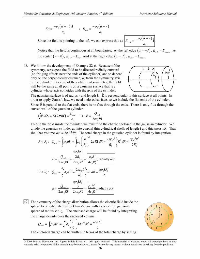
Physics for Scientists & Engineers with Modern Physics, 4th Edition Instructor Solutions Manual
© 2009 Pearson Education, Inc., Upper Saddle River, NJ. All rights reserved. This material is protected under all copyright laws as they currently exist. No portion of this material may be reproduced, in any form or by any means, without permission in writing from the publisher.
56
0 0
0
0 0
x
d x A d xEA E
Since the field is pointing to the left, we can express this as 0
0
0
ˆ .x
d xE
i
Notice that the field is continuous at all boundaries. At the left edge ,x d 0 outside .xE E At
the center 0 ,x 0 >0.xE E And at the right edge ,x d 0 outside .xE E
48. We follow the development of Example 22-6. Because of the
symmetry, we expect the field to be directed radially outward (no fringing effects near the ends of the cylinder) and to depend only on the perpendicular distance, R, from the symmetry axis of the cylinder. Because of the cylindrical symmetry, the field will be the same at all points on a gaussian surface that is a cylinder whose axis coincides with the axis of the cylinder.
The gaussian surface is of radius r and length l. E
is perpendicular to this surface at all points. In order to apply Gauss’s law, we need a closed surface, so we include the flat ends of the cylinder.
Since E
is parallel to the flat ends, there is no flux through the ends. There is only flux through the curved wall of the gaussian cylinder.
encl encl
0 0
22
Q Q
d E R ER
E A ll
To find the field inside the cylinder, we must find the charge enclosed in the gaussian cylinder. We divide the gaussian cylinder up into coaxial thin cylindrical shells of length l and thickness dR. That shell has volume 2 .dV R dR l The total charge in the gaussian cylinder is found by integration.
2 430 0
0 encl E 0 2 2
0 0 00 0 0
4
032
encl 00
2
0 0 0 0
2: 2
2
2 , radially out
2 2 4
R R RR RR R Q dV R dR R dR
R R R
R
Q RRE
R R R
l l
l
l
l l
0 0 230 0 0
0 encl E 2
00 0
2
0 02
encl 0 0
0 0 0
2:
2
2 , radially out2 2 4
R RR
R R Q dV R dRR
RQ R
ER R R
l l
l
l l
49. The symmetry of the charge distribution allows the electric field inside the
sphere to be calculated using Gauss’s law with a concentric gaussian sphere of radius 0.r r The enclosed charge will be found by integrating
the charge density over the enclosed volume.
4
2 0encl E 00
0 0
4r r r
Q dV r drr r
The enclosed charge can be written in terms of the total charge by setting
R0
¬
R

Chapter 22 Gauss’s Law
© 2009 Pearson Education, Inc., Upper Saddle River, NJ. All rights reserved. This material is protected under all copyright laws as they currently exist. No portion of this material may be reproduced, in any form or by any means, without permission in writing from the publisher.
57
0r r and solving for the charge density in terms of the total charge.
44 430 0 0
0 0 0 encl3
0 0 0 0
( )r Q r r
Q r Q r Qr r r r
The electric field is then found from Gauss’s law
4 2
2encl
4
0 0 0 0 0
44
Q Q r Q r
d E r Er r
E A
The electric field points radially outward since the charge distribution is positive. 50. By Gauss’s law, the total flux through the cylinder is 0.Q We find
the flux through the ends of the cylinder, and then subtract that from the total flux to find the flux through the curved sides. The electric field is that of a point charge. On the ends of the cylinder, that field will vary in both magnitude and direction. Thus we must do a detailed integration to find the flux through the ends of the cylinder. Divide the ends into a series of concentric circular rings, of radius R and thickness dR. Each ring will have an area of 2 .RdR The angle
between E
and dA
is , where 0tan .R R See the diagram of the
left half of the cylinder.
0
left 2end 00
1cos 2
4
RQ
d R dRr
E A
The flux integral has three variables: r, R, and . We express r and in terms of R in order to integrate. The anti-derivative is found in Appendix B-4.
00 0
2 2 0 00 2 2
0
0 0 0left 3 / 22 2 2 2 2 22 2end 0 0 0 00 00 00 0
both leftends end0 0
total sides both
0
; cos
1 2 12
4 4 2
1 1 1 ; 2 1
2 2 2
RR R
R Rr R R
r R R
Q R QR RdR QRR dR
R R R R R RR R
Q Q
Q
sides bothends ends0 0 0 0
1 1
2 2
Q Q Q Q
51. The gravitational field a distance r from a point mass M is given by Eq. 6-8, 2
ˆ,GM
r g r
where r
is a unit vector pointing radially outward from mass M. Compare this to the electric field of a point
charge, 2
0
1ˆ.
4
Q
rE r
To change the electric field to the gravitational field, we would make these
changes: 0 ; 4 .Q GM E g
Make these substitutions in Gauss’s law.
encl
0
encl4 Q
d d GM
E A g A
rdA
E
R
dR
0R
0R
Q

Physics for Scientists & Engineers with Modern Physics, 4th Edition Instructor Solutions Manual
© 2009 Pearson Education, Inc., Upper Saddle River, NJ. All rights reserved. This material is protected under all copyright laws as they currently exist. No portion of this material may be reproduced, in any form or by any means, without permission in writing from the publisher.
58
52. (a) We use Gauss’s law for a spherically symmetric charge distribution, and assume that all the charge is on the surface of the Earth. Note that the field is pointing radially inward, and so the dot product introduces a negative sign.
2
encl 0
26
2 5 5
encl 0 Earth 9 2 2
4
150 N C 6.38 10 m4 6.793 10 C 6.8 10 C
8.988 10 N m C
d E r Q
Q ER
E A
(b) Find the surface density of electrons. Let n be the total number of electrons.
12 2 22
0 Earth 0
2 19
Earth
9 2
8.85 10 C N m 150 N C4
4 1.60 10 C
8.3 10 electrons m
Q ne
A A
n Q ER E
A eA e R e
53. The electric field is strictly in the y direction. So, referencing the diagram, there is no
flux through the top, bottom, front, or back faces of the cube. Only the “left” and “right” faces will have flux through them. And since the flux is only dependent on the y coordinate, the flux through each of those two faces is particularly simple. Calculate the flux and use Gauss’s law to find the enclosed charge.
left rightface face
2 3 2
left rightface face
3 3
encl 0 encl 0
ˆ ˆ ˆ ˆ
d d d
b dA a b dA b a b
a Q Q a
E A E A E A
j j j jl l l l
l l
54. (a) Find the value of b by integrating the charge density over the entire sphere. Follow the
development given in Example 22-5.
0 2 41E 04 40
0
4 4 r Q
Q dV br r dr b r br
(b) To find the electric field inside the sphere, we apply Gauss’s law to an imaginary sphere of radius r, calculating the charge enclosed by that sphere. The spherical symmetry allows us to evaluate the flux integral simply.
4
2enclE 4 40
0 0 0
2
04
0 0
; 4
1,
4
rQ Q Qrd Q dV r r dr
r r
QrE r r
r
E A
(c) As discussed in Example 22-4, the field outside a spherically symmetric distribution of charge is the same as that for a point charge of the same magnitude located at the center of the sphere.
02
0
1,
4
QE r r
r
z
x
y
¬
¬
¬
E

Chapter 22 Gauss’s Law
© 2009 Pearson Education, Inc., Upper Saddle River, NJ. All rights reserved. This material is protected under all copyright laws as they currently exist. No portion of this material may be reproduced, in any form or by any means, without permission in writing from the publisher.
59
55. The flux through a gaussian surface depends only on the charge enclosed by the surface. For both of these spheres the two point charges are enclosed within the sphere. Therefore the flux is the same for both spheres.
9 9
2encl
12 2 2
0
9.20 10 C 5.00 10 C475 N m /C
8.85 10 C N m
Q
56. (a) The flux through any closed surface containing the total charge must be the same, so the flux
through the larger sphere is the same as the flux through the smaller sphere, 2235 N m /C .
(b) Use Gauss’s law to determine the enclosed charge.
12 2 2 2 9enclencl 0
0
8.85 10 C N m 235 N m /C 2.08 10 CQ
Q
57. (a) There is no charge enclosed within the sphere, and so no flux lines can
originate or terminate inside the sphere. All field lines enter and leave the sphere. Thus the net flux is 0.
(b) The maximum electric field will be at the point on the sphere closest to Q, which is the top of the sphere. The minimum electric field will be at the point on the sphere farthest from Q, which is the bottom of the sphere.
max 22 210 closest 0 0 002
min 22 250 farthest 0 0 002
1 1 1
4 4
1 1 1
4 4 25
Q Q QE
r rr
Q Q QE
r rr
Thus the range of values is sphere2 2surface0 0 0 0
1 1
25.
Q QE
r r
(c) E
is not perpendicular at all points. It is only perpendicular at the two points already discussed: the point on the sphere closest to the point charge, and the point on the sphere farthest from the point charge.
(d) The electric field is not perpendicular or constant over the surface of the sphere. Therefore Gauss’s law is not useful for obtaining E at the surface of the sphere because a gaussian surface cannot be chosen that simplifies the flux integral.
58. The force on a sheet is the charge on the sheet times the average
electric field due to the other sheets: But the fields due to the “other” sheets is uniform, so the field is the same over the entire sheet. The force per unit area is then the charge per unit area, times the field due to the other sheets.
on on other on othersheet sheet sheets sheet sheets
other on otheron on sheets sheet sheetssheet sheet
F q E q E
F qE E
A A
E
E E
102 r
0r
Q
III
II IIIE
IIE
IE
IIE

Physics for Scientists & Engineers with Modern Physics, 4th Edition Instructor Solutions Manual
© 2009 Pearson Education, Inc., Upper Saddle River, NJ. All rights reserved. This material is protected under all copyright laws as they currently exist. No portion of this material may be reproduced, in any form or by any means, without permission in writing from the publisher.
60
The uniform fields from each of the three sheets are indicated on the diagram. Take the positive direction as upwards. We take the direction from the diagram, and so use the absolute value of each charge density. The electric field magnitude due to each sheet is given by 02 .E
9 29 2I
I III II III II 12 2 2I 0
6 2
6.5 10 C m5.0 2.0 10 C m
2 2 8.85 10 C N m
1.1 10 N m up
FE E
A
9 29 2II
II III I III I 12 2 2II 0
7 2
2.0 10 C m5.0 6.5 10 C m
2 2 8.85 10 C N m
1.7 10 N m up
FE E
A
9 29 2III
III III I II I 12 2 2III 0
6 2
5.0 10 C m2.0 6.5 10 C m
2 2 8.85 10 C N m
1.3 10 N m down
FE E
A
59. (a) The net charge inside a sphere of radius 0a will be made of two parts – the positive point charge
at the center of the sphere, and some fraction of the total negative charge, since the negative charge is distributed over all space, as described by the charge density. To evaluate the portion of the negative charge inside the sphere, we must determine the coefficient A. We do that by integrating the charge density over all space, in the manner of Example 22-5. Use an integral from Appendix B-5.
0 02 22 2 3
03
0 0 0
3
0
2!4 4 4
2
r a r a
Ee dV Ae r dr A e r dr A Aaa
eA
a
Now we find the negative charge inside the sphere of radius 0 ,a using an integral from
Appendix B-4. We are indicating the elementary charge by ,e so as to not confuse it with the
base of the natural logarithms.
0 0
0 0
00
2 22 2
neg 3
00 0
22 2 2
0 033
0 0 0
2 2 19 2 19
net neg pos
19
44
42 2 2 2 5 1
2
5 1 5 1.6 10 C 5 1.083 10 C
1.1 10 C
a a
r a r a
ar a
eQ Ae r dr e r dr
a
e ea r a r e e
a a
Q Q Q e e e e e e
(b) The field at a distance 0r a is that of a point charge of magnitude netQ at the origin, because of
the spherical symmetry and Gauss’s law.
19
9 2 2 11encl net22 2 10
0 0 0
1.083 10 C1 18.988 10 N m C 3.5 10 N C
4 4 0.53 10 m
Q QE
r a

Chapter 22 Gauss’s Law
© 2009 Pearson Education, Inc., Upper Saddle River, NJ. All rights reserved. This material is protected under all copyright laws as they currently exist. No portion of this material may be reproduced, in any form or by any means, without permission in writing from the publisher.
61
60. The field due to the plane is plane
0
,2
E
as discussed in Example 22-7. Because the slab is very
large, and we assume that we are considering only distances from the slab much less than its height or breadth, the symmetry of the slab results in its field being perpendicular to the slab, with a constant magnitude for a constant distance from its center. We also assume that E 0 and so the
electric field of the slab points away from the center of the slab. (a) To determine the field to the left of the plane, we
choose a cylindrical gaussian surface, of length x d and cross-sectional area A. Place it so that the plane is centered inside the cylinder. See the diagram. There will be no flux through the curved wall of the cylinder. From the symmetry, the electric field is parallel to the surface area vector on both ends. We already know that the field due to the plane is the same on both ends, and by the symmetry of the problem, the field due to the slab must also be the same on both ends. Thus the total field is the same magnitude on both ends.
encl Eoutside
0 0ends side ends
Eoutside left
of plane 0
0 2
2
Q A dAd d d d E A
dE E
E A E A E A E A
(b) As argued above, the field is symmetric on the outside of the charged matter.
Erightof plane 02
dE
(c) To determine the field inside the slab, we choose a cylindrical gaussian surface of cross-sectional area A with one face to the left of the plane, and the other face inside the slab, a distance x from the plane. Due to symmetry, the field again is parallel to the surface area vector on both ends, has a constant value on each end, and no flux pierces the curved walls. Apply Gauss’s law.
encloutside inside
0left right sideend end
E Eencl E inside
0 0
Einside
0
0
2
2, 0
2
Qd d d d E A E A
d A xAQ A xA A E A
x dE x d
E A E A E A E A
Notice that the field is continuous from “inside” to “outside” at the right edge of the slab, but not at the left edge of the slab. That discontinuity is due to the surface charge density.
d
x
E
E
x
insideE
outsideE

Physics for Scientists & Engineers with Modern Physics, 4th Edition Instructor Solutions Manual
© 2009 Pearson Education, Inc., Upper Saddle River, NJ. All rights reserved. This material is protected under all copyright laws as they currently exist. No portion of this material may be reproduced, in any form or by any means, without permission in writing from the publisher.
62
61. Consider this sphere as a combination of two spheres. Sphere 1 is a solid sphere of radius 0r and
charge density E centered at A and sphere 2 is a second sphere of radius 0 / 2r and density E
centered at C. (a) The electric field at A will have zero contribution from sphere 1 due to its symmetry about point
A. The electric field is then calculated by creating a gaussian surface centered at point C with radius 0 / 2.r
34 12 3 2E 0enc E 01
02
0 0 0
4 6
rq rd E r E
E A
Since the electric field points into the gaussian surface (negative) the electric field at point A points to the right.
(b) At point B the electric field will be the sum of the electric fields from each sphere. The electric field from sphere 1 is calculated using a gaussian surface of radius 0r centered at A.
342 3 0 Eenc E 0
1 1 0 1
0 0 0
4 3
rq rd E r E
E A
At point B the field from sphere 1 points toward the left. The electric field from sphere 2 is calculated using a gaussian surface centered at C of radius 03 / 2.r
34 12 3 2E 0enc E 03
2 2 0 22
0 0 0
4 54
rq rd E r E
E A
At point B, the electric field from sphere 2 points toward the right. The net electric field is the sum of these two fields. The net field points to the left.
E 0 E 0 E 01 2
0 0 0
17
3 54 54
r r rE E E
.
62. We assume the charge is uniformly distributed, and so the field of the pea is that of a point charge.
2
0
22 6 12 2 2 9
0
1
4
4 3 10 N C 4 8.85 10 C N m 0.00375m 5 10 C
QE r R
R
Q E R
63. (a) In an electrostatic situation, there is no electric field inside a
conductor. Thus 0E inside the conductor. (b) The positive sheet produces an electric field, external to
itself, directed away from the plate with a magnitude as
given in Example 22-7, of 11
0
.2
E
The negative sheet
produces an electric field, external to itself, directed towards
the plate with a magnitude of 22
0
.2
E
Between the left
and middle sheets, those two fields are parallel and so add to each other.
6 2
51 2left 1 2 12 2 2middle 0
2 5.00 10 C m5.65 10 N C , to the right
2 2 8.85 10 C N mE E E
+
+
+
+
–
–
–
–
+
+
+
+
–
–
–
–
1 net 0Q 3
1E
3E
1E
3E

Chapter 22 Gauss’s Law
© 2009 Pearson Education, Inc., Upper Saddle River, NJ. All rights reserved. This material is protected under all copyright laws as they currently exist. No portion of this material may be reproduced, in any form or by any means, without permission in writing from the publisher.
63
(c) The same field is between the middle and right sheets. See the diagram.
5
middleright
5.65 10 N C , to the rightE
(d) To find the charge density on the surface of the left side of the middle sheet, choose a gaussian cylinder with ends of area A. Let one end be inside the conducting sheet, where there is no electric field, and the other end be in the area between the left and middle sheets. Apply Gauss’s law in the manner of Example 22-16. Note that there is no flux through the curved sides of the cylinder, and there is no flux through the right end since it is in conducting material. Also note that the field through the left end is in the opposite direction as the area vector of the left end.
encl leftleftmiddle 0 0left right side
end end
6 21 2left 0 left 0
middle 0
0 0
5.00 10 C m2
Q Ad d d d E A
E
E A E A E A E A
(e) Because the middle conducting sheet has no net charge, the charge density on the right side must be the opposite of the charge density on the left side.
6 2
right left 5.00 10 C m
Alternatively, we could have applied Gauss’s law on the right side in the same manner that we did on the left side. The same answer would result.
64. Because the electric field has only x and y components, there will be no flux
through the top or bottom surfaces. For the other faces, we choose a horizontal strip of height dz and width a for a differential element and integrate to find the flux. The total flux is used to determine the enclosed charge.
front 0 0
0
223
0 0 02
0 0
ˆ ˆ ˆ1
12
a
x a
aa
z zd E E adz
a a
z zE a dz E a z E a
a a
E A i j i
23back 0 0 02
0 0
ˆ ˆ ˆ1a
x
z zE E adz E a
a a
i j i
2
21right 0 0 0 0 02
0 0 0
ˆ ˆ ˆ12
aa a
y a
z z z zE E adz E a dz E a E a
a a a a
i j j
21
left 0 0 02
0
2 2 2 23 3 1 1total front back right left top bottom 0 0 0 02 2 2 2
enclencl
0
ˆ ˆ ˆ1
0 0
0 0
a
y a
z zE E adz E a
a a
E a E a E a E a
i j j
x
y
aa
a
dz
z
E

Physics for Scientists & Engineers with Modern Physics, 4th Edition Instructor Solutions Manual
© 2009 Pearson Education, Inc., Upper Saddle River, NJ. All rights reserved. This material is protected under all copyright laws as they currently exist. No portion of this material may be reproduced, in any form or by any means, without permission in writing from the publisher.
64
65. (a) Because the shell is a conductor, there is no electric field in the conducting material, and all charge must reside on its surfaces. All of the field lines that originate from the point charge at the center must terminate on the inner surface of the shell. Therefore the inner surface must have an equal but opposite charge to the point charge at the center. Since the conductor has the same magnitude of charge as the point charge at the center, all of the charge on the conductor is on the inner surface of the shell, in a spherically symmetric distribution.
(b) By Gauss’s law and the spherical symmetry of the problem, the electric field can be calculated
by 2
0
encl1
4
QE
r .
9 2 2 6 4 2
encl
2 2 2
0
8.988 10 N m C 3.0 10 C1 2.7 10 N m C0.10 m:
4
0.15m: 0
Qr E
r r r
r E
And since there is no electric field in the shell, we could express the second answer as
0.10 m: 0 .r E
66. (a) At a strip such as is marked in the textbook diagram, dA
is perpendicular to the surface, and E
is inclined at an angle relative to dA
.
/ 22
hemisphere
0
/ 2/ 22 2 2 21
2 00
cos 2 sin
2 cos sin 2 sin
d E R d
R E d R E R E
E A
(b) Choose a closed gaussian surface consisting of the hemisphere and the circle of radius R at the base of the hemisphere. There is no charge inside that closed gaussian surface, and so the total flux through the two surfaces (hemisphere and base) must be zero. The field lines are all perpendicular to the circle, and all of the same magnitude, and so that flux is very easy to calculate.
2
circle
2 2
total circle hemisphere hemisphere hemisphere
cos180
0
d E d EA E R
E R R E
E A A
67. The flux is the sum of six integrals, each of the form .dE A
Because
the electric field has only x and y components, there will be no flux through the top or bottom surfaces. For the other faces, we choose a vertical strip of height a and width dy (for the front and back faces) or dx (for the left and right faces). See the diagram for an illustration of a strip on the front face. The total flux is then calculated, and used to determine the enclosed charge.
2 2 2
front 0 0 0
0 0
ˆ ˆ ˆx y x y a ya a
a a ax y x
x a
E e E e ady aE e dy
i j i
This integral does not have an analytic anti-derivative, and so must be integrated numerically. We
approximate the integral by a sum:
22
10
.ia ya ya n
aa
i
e dy e y
The region of integration is divided
xy
aa
a
dy
z

Chapter 22 Gauss’s Law
© 2009 Pearson Education, Inc., Upper Saddle River, NJ. All rights reserved. This material is protected under all copyright laws as they currently exist. No portion of this material may be reproduced, in any form or by any means, without permission in writing from the publisher.
65
into n elements, and so 0a
yn
and .iy i y We initially evaluate the sum for n = 10. Then we
evaluate it for n = 20. If the two sums differ by no more than 2%, we take that as the value of the integral. If they differ by more than 2%, we choose a larger n, compute the sum, and compare that to the result for n = 20. We continue until a difference of 2% or less is reached. This integral, for n = 100 and a = 1.0 m, is 0.1335 m. So we have this intermediate result.
2
2
front 01
1.0 m 50 N C 0.1335m 6.675 N m Cia yn
ax
x a i
aE e y
Now do the integral over the back face.
2 2 2
back 0 0 00 0 0
ˆ ˆ ˆx y x y ya a
a a ax y x
x
E e E e a dy aE e dy
i j i
We again get an integral that cannot be evaluated analytically. A similar process to that used for the
front face is applied again, and so we make this approximation:
22
0 010
.iyya n
aax x
i
aE e dy aE e y
The numeric integration gives a value of 0.7405 m.
2
2
back 00 1
1.0 m 50 N C 0.7405m 37.025 N m C.iyn
ax
x i
aE e y
Now consider the right side.
22 2
right 0
0
0 0
0
ˆ ˆ ˆx aa
ay
y a
x y x yaa a
x y aE e dxE e E e a dx
i j j
Notice that the same integral needs to be evaluated as for the front side. All that has changed is the variable name. Thus we have the following.
2
2
right 0
0
1.0 m 25 N C 0.1335m 3.3375 N m Cx aa
ay
y a
aE e dx
Finally, do the left side, following the same process. The same integral arises as for the back face.
2 2 2
left 0 0 00 0 0
2
ˆ ˆ ˆ
1.0 m 25 N C 0.7405m 18.5125 N m C
x y x y xa a
a a ax y y
y
E e E e a dx aE e dx
i j j
Sum to find the total flux, and multiply by 0 to find the enclosed charge.
total front back right left top bottom
2 2 2
12 2 2 2 10
encl 0 total
6.675 37.025 3.3375 18.5125 N m C 45.525 N m C 46 N m C
8.85 10 C N m 45.525 N m C 4.0 10 CQ
The spreadsheet used for this problem can be found on the Media Manager, with filename “PSE4_ISM_CH22.XLS,” on tab “Problem 22.67.”

© 2009 Pearson Education, Inc., Upper Saddle River, NJ. All rights reserved. This material is protected under all copyright laws as they currently exist. No portion of this material may be reproduced, in any form or by any means, without permission in writing from the publisher.
66
CHAPTER 23: Electric Potential Responses to Questions 1. Not necessarily. If two points are at the same potential, then no net work is done in moving a charge
from one point to the other, but work (both positive and negative) could be done at different parts of the path. No. It is possible that positive work was done over one part of the path, and negative work done over another part of the path, so that these two contributions to the net work sum to zero. In this case, a non-zero force would have to be exerted over both parts of the path.
2. The negative charge will move toward a region of higher potential and the positive charge will move
toward a region of lower potential. In both cases, the potential energy of the charge will decrease. 3. (a) The electric potential is the electric potential energy per unit charge. The electric potential is a
scalar. The electric field is the electric force per unit charge, and is a vector. (b) Electric potential is the electric potential energy per unit charge.
4. Assuming the electron starts from rest in both cases, the final speed will be twice as great. If the
electron is accelerated through a potential difference that is four times as great, then its increase in kinetic energy will also be greater by a factor of four. Kinetic energy is proportional to the square of the speed, so the final speed will be greater by a factor of two.
5. Yes. If the charge on the particle is negative and it moves from a region of low electric potential to a
region of high electric potential, its electric potential energy will decrease. 6. No. Electric potential is the potential energy per unit charge at a point in space and electric field is
the electric force per unit charge at a point in space. If one of these quantities is zero, the other is not necessarily zero. For example, the point exactly between two charges with equal magnitudes and opposite signs will have a zero electric potential because the contributions from the two charges will be equal in magnitude and opposite in sign. (Net electric potential is a scalar sum.) This point will not have a zero electric field, however, because the electric field contributions will be in the same direction (towards the negative and away from the positive) and so will add. (Net electric field is a vector sum.) As another example, consider the point exactly between two equal positive point charges. The electric potential will be positive since it is the sum of two positive numbers, but the electric field will be zero since the field contributions from the two charges will be equal in magnitude but opposite in direction.
7. (a) V at other points would be lower by 10 V. E would be unaffected, since E is the negative
gradient of V, and a change in V by a constant value will not change the value of the gradient. (b) If V represents an absolute potential, then yes, the fact that the Earth carries a net charge would
affect the value of V at the surface. If V represents a potential difference, then no, the net charge on the Earth would not affect the choice of V.
8. No. An equipotential line is a line connecting points of equal electric potential. If two equipotential
lines crossed, it would indicate that their intersection point has two different values of electric potential simultaneously, which is impossible. As an analogy, imagine contour lines on a topographic map. They also never cross because one point on the surface of the Earth cannot have two different values for elevation above sea level.

Chapter 23 Electric Potential
© 2009 Pearson Education, Inc., Upper Saddle River, NJ. All rights reserved. This material is protected under all copyright laws as they currently exist. No portion of this material may be reproduced, in any form or by any means, without permission in writing from the publisher.
67
9. The equipotential lines (in black) are perpendicular to the electric field lines (in red). 10. The electric field is zero in a region of space where the electric potential is constant. The electric
field is the gradient of the potential; if the potential is constant, the gradient is zero. 11. The Earth’s gravitational equipotential lines are roughly circular, so the orbit of the satellite would
have to be roughly circular. 12. The potential at point P would be unchanged. Each bit of positive charge will contribute an amount
to the potential based on its charge and its distance from point P. Moving charges to different locations on the ring does not change their distance from P, and hence does not change their contributions to the potential at P.
The value of the electric field will change. The electric field is the vector sum of all the contributions to the field from the individual charges. When the charge Q is distributed uniformly about the ring, the y-components of the field contributions cancel, leaving a net field in the x-direction. When the charge is not distributed uniformly, the y-components will not cancel, and the net field will have both x- and y-components, and will be larger than for the case of the uniform charge distribution. There is no discrepancy here, because electric potential is a scalar and electric field is a vector.
13. The charge density and the electric field strength will be greatest at the pointed ends of the football
because the surface there has a smaller radius of curvature than the middle. 14. No. You cannot calculate electric potential knowing only electric field at a point and you cannot
calculate electric field knowing only electric potential at a point. As an example, consider the uniform field between two charged, conducting plates. If the potential difference between the plates is known, then the distance between the plates must also be known in order to calculate the field. If the field between the plates is known, then the distance to a point of interest between the plates must also be known in order to calculate the potential there. In general, to find V, you must know E and be able to integrate it. To find E, you must know V and be able to take its derivative. Thus you need E or V in the region around the point, not just at the point, in order to be able to find the other variable.
15. (a) Once the two spheres are placed in contact with each other, they effectively become one larger
conductor. They will have the same potential because the potential everywhere on a conducting surface is constant.
(b) Because the spheres are identical in size, an amount of charge Q/2 will flow from the initially charged sphere to the initially neutral sphere so that they will have equal charges.
(c) Even if the spheres do not have the same radius, they will still be at the same potential once they are brought into contact because they still create one larger conductor. However, the amount of charge that flows will not be exactly equal to half the total charge. The larger sphere will end up with the larger charge.

Physics for Scientists & Engineers with Modern Physics, 4th Edition Instructor Solutions Manual
© 2009 Pearson Education, Inc., Upper Saddle River, NJ. All rights reserved. This material is protected under all copyright laws as they currently exist. No portion of this material may be reproduced, in any form or by any means, without permission in writing from the publisher.
68
16. If the electric field points due north, the change in the potential will be (a) greatest in the direction opposite the field, south; (b) least in the direction of the field, north; and (c) zero in a direction perpendicular to the field, east and west.
17. Yes. In regions of space where the equipotential lines are closely spaced, the electric field is stronger
than in regions of space where the equipotential lines are farther apart. 18. If the electric field in a region of space is uniform, then you can infer that the electric potential is
increasing or decreasing uniformly in that region. For example, if the electric field is 10 V/m in a region of space then you can infer that the potential difference between two points 1 meter apart (measured parallel to the direction of the field) is 10 V. If the electric potential in a region of space is uniform, then you can infer that the electric field there is zero.
19. The electric potential energy of two unlike charges is negative. The electric potential energy of two
like charges is positive. In the case of unlike charges, work must be done to separate the charges. In the case of like charges, work must be done to move the charges together.
Solutions to Problems 1. Energy is conserved, so the change in potential energy is the opposite of the change in kinetic
energy. The change in potential energy is related to the change in potential.
231 52
initial final
19
9.11 10 kg 5.0 10 m s0.71V
2 2 1.60 10 C
U q V K
K K K mvV
q q q
The final potential should be lower than the initial potential in order to stop the electron. 2. The work done by the electric field can be found from Eq. 23-2b.
19 17baba ba ba 1.60 10 C 55V 185V 3.84 10 J
WV W qV
q
3. The kinetic energy gained by the electron is the work done by the electric force. Use Eq. 23-2b to
calculate the potential difference.
16
baba 19
5.25 10 J3280V
1.60 10 C
WV
q
The electron moves from low potential to high potential, so plate B is at the higher potential. 4. By the work energy theorem, the total work done, by the external force and the electric field
together, is the change in kinetic energy. The work done by the electric field is given by Eq. 23-2b.
external electric final initial external b a final
4 4
external finalb a 6
KE KE KE
KE 7.00 10 J 2.10 10 J53.8V
9.10 10 C
W W W q V V
WV V
q
Since the potential difference is negative, we see that a bV V .

Chapter 23 Electric Potential
© 2009 Pearson Education, Inc., Upper Saddle River, NJ. All rights reserved. This material is protected under all copyright laws as they currently exist. No portion of this material may be reproduced, in any form or by any means, without permission in writing from the publisher.
69
5. As an estimate, the length of the bolt would be the voltage difference of the bolt divided by the breakdown electric field of air.
8
6
1 1033m 30m
3 10 V m
V
6. The distance between the plates is found from Eq. 23-4b, using the magnitude of the electric field.
2ba ba 45V 3.5 10 m
1300V m
V VE d
d E
7. The maximum charge will produce an electric field that causes breakdown in the air. We use the
same approach as in Examples 23-4 and 23-5.
surface 0 breakdown surface
0 0
22 6 6
0 0 breakdown 9 2 2
1 and
4
14 0.065m 3 10 V m 1.4 10 C
8.99 10 N m C
QV r E V
r
Q r E
8. We assume that the electric field is uniform, and so use Eq. 23-4b, using the magnitude of the
electric field.
4ba
3
110V2.8 10 V m
4.0 10 m
VE
d
9. To find the limiting value, we assume that the E-field at the radius of the sphere is the minimum
value that will produce breakdown in air. We use the same approach as in Examples 23-4 and 23-5.
surfacesurface 0 breakdown 0 6
breakdown
surface 0 surface 0 9 2 2
0 0
8
35,000V 0.0117 m 0.012 m
3 10 V m
1 1 4 35,000V 0.0117 m
4 8.99 10 N m C
4.6 10 C
VV r E r
E
QV Q V r
r
10. If we assume the electric field is uniform, then we can use Eq. 23-4b to estimate the magnitude of the
electric field. From Problem 22-24 we have an expression for the electric field due to a pair of oppositely charged planes. We approximate the area of a shoe as 30 cm x 8 cm.
0 0
12 2 2 2 3
60
3
8.85 10 C / Nm 0.024m 5.0 10 V1.1 10 C
1.0 10 m
V QE
d A
AVQ
d
11. Since the field is uniform, we may apply Eq. 23-4b. Note that the electric field always points from
high potential to low potential.
(a) BA 0 .V The distance between the two points is exactly perpendicular to the field lines.
(b) CB C B 4.20 N C 7.00m 29.4 VV V V
(c) CA C A C B B A CB BA 29.4 V 0 29.4 VV V V V V V V V V

Physics for Scientists & Engineers with Modern Physics, 4th Edition Instructor Solutions Manual
© 2009 Pearson Education, Inc., Upper Saddle River, NJ. All rights reserved. This material is protected under all copyright laws as they currently exist. No portion of this material may be reproduced, in any form or by any means, without permission in writing from the publisher.
70
12. From Example 22-7, the electric field produced by a large plate is uniform with magnitude 0
.2
E
The field points away from the plate, assuming that the charge is positive. Apply Eq. 23-41.
0 0
0 0 00 0
ˆ ˆ0 2 2 2
x x x xV x V V x V d dx V x V
E i i
l
13. (a) The electric field at the surface of the Earth is the same as that of a point charge, 2
0 0
.4
QE
r
The electric potential at the surface, relative to ( ) 0V is given by Eq. 23-5. Writing this in terms of the electric field and radius of the earth gives the electric potential.
6
0
0 0
150 V m 6.38 10 m = 0.96 GV4
QV Er
r
(b) Part (a) demonstrated that the potential at the surface of the earth is 0.96 GV lower than the potential at infinity. Therefore if the potential at the surface of the Earth is taken to be zero, the
potential at infinity must be ( ) 0.96 GV .V If the charge of the ionosphere is included in the calculation, the electric field outside the ionosphere is basically zero. The electric field between the earth and the ionosphere would remain the same. The electric potential, which would be the integral of the electric field from infinity to the surface of the earth, would reduce to the integral of the electric field from the ionosphere to the earth. This would result in a negative potential, but of a smaller magnitude.
14. (a) The potential at the surface of a charged sphere is derived in Example 23-4.
0 0 0 0
0 0
12 2 2
8 20 0 0 0 0
2 2
0 0 0
8 2
4 4
680 V 8.85 10 C /Nm43.761 10 C m
Area 4 4 0.16 m
3.8 10 C m
QV Q rV
r
Q Q rV V
r r r
(b) The potential away from the surface of a charged sphere is also derived in Example 23-4.
0 0 0 0 0 0 0
0 0
0.16 m 680 V4 4.352 m 4.4 m
4 4 25V
Q rV rV rVV r
r r r V
15. (a) After the connection, the two spheres are at the same potential. If they were at different
potentials, then there would be a flow of charge in the wire until the potentials were equalized. (b) We assume the spheres are so far apart that the charge on one sphere does not influence the
charge on the other sphere. Another way to express this would be to say that the potential due to either of the spheres is zero at the location of the other sphere. The charge splits between the spheres so that their potentials (due to the charge on them only) are equal. The initial charge on sphere 1 is Q, and the final charge on sphere 1 is Q1.
1 1 1 1 1
1 2 1 2 1
0 1 0 2 0 1 0 2 1 2
; ; 4 4 4 4
Q Q Q Q Q Q rV V V V Q Q
r r r r r r
Charge transferred
1 21
1 2 1 2
r rQ Q Q Q Q
r r r r

Chapter 23 Electric Potential
© 2009 Pearson Education, Inc., Upper Saddle River, NJ. All rights reserved. This material is protected under all copyright laws as they currently exist. No portion of this material may be reproduced, in any form or by any means, without permission in writing from the publisher.
71
16. From Example 22-6, the electric field due to a long wire is radial relative to the wire, and is of
magnitude 0
1.
2E
R
If the charge density is positive, the field lines point radially away from the
wire. Use Eq. 23-41 to find the potential difference, integrating along a line that is radially outward from the wire.
b b
a a
ab a b a
0 0 0 b
1ln ln
2 2 2 R
R R
R R
RV V d dR R R
R
E
l
17. (a) The width of the end of a finger is about 1 cm, and so consider the fingertip to be a part of a
sphere of diameter 1 cm. We assume that the electric field at the radius of the sphere is the minimum value that will produce breakdown in air. We use the same approach as in Examples 23-4 and 23-5.
6
surface 0 breakdown 0.005m 3 10 V m 15,000VV r E
Since this is just an estimate, we might expect anywhere from 10,000 V to 20,000 V.
(b) 2
0surface
0 0 0 0
1 1 4
4 4
Q rV
r r
12 2 2
5 20surface
0
8.85 10 C /N m15,000V 2.7 10 C m
0.005mV
r
Since this is an estimate, we might say the charge density is on the order of 230 C m . 18. We assume the field is uniform, and so Eq. 23-4b applies.
7
9
0.10 V1 10 V m
10 10 m
VE
d
19. (a) The electric field outside a charged, spherically symmetric volume is the same as that for a
point charge of the same magnitude of charge. Integrating the electric field from infinity to the radius of interest will give the potential at that radius.
0 02 2
0 0 0 0
; 4 4 4 4
rrQ Q Q QE r r V r r dr
r r r r
(b) Inside the sphere the electric field is obtained from Gauss’s Law using the charge enclosed by a sphere of radius r.
34
2 303 34
30 0 0 0
4 4
Q r Qrr E E r r
r r
Integrating the electric field from the surface to 0r r gives the electric potential inside the
sphere.
0 0
2 2
0 0 3 3 2
0 0 0 0 0 0 0 0 0
34 4 8 8
rr
r r
Qr Q Qr Q rV r r V r dr
r r r r r
(c) To plot, we first calculate 0 0
0 04
QV V r r
r and 0 0 2
0 04.
QE E r r
r Then we plot
0V V and 0E E as functions of 0 .r r

Physics for Scientists & Engineers with Modern Physics, 4th Edition Instructor Solutions Manual
© 2009 Pearson Education, Inc., Upper Saddle River, NJ. All rights reserved. This material is protected under all copyright laws as they currently exist. No portion of this material may be reproduced, in any form or by any means, without permission in writing from the publisher.
72
For 0 :r r
2
2 2 30 0 0 0 01
0 02 2
0 02
0 0 0 0
38 4
3 ;
4 4
Q r Qr
r r r rrV V E E
Q Qr rr r
For 0 :r r 22
1 20 00 00 0 0 02
2
0 0 0 0
4 4 ;
4 4
Q Q
r rr rV V r r E E r r
Q Qr rr r
The spreadsheet used for this problem can be found on the Media Manager, with filename “PSE4_ISM_CH23.XLS,” on tab “Problem 23.19c.”
20. We assume the total charge is still Q, and let 2
E .kr We evaluate the constant k by calculating
the total charge, in the manner of Example 22-5.
0
2 2 54E 05 5
00
54
4
rQ
Q dV kr r dr k r kr
(a) The electric field outside a charged, spherically symmetric volume is the same as that for a point charge of the same magnitude of charge. Integrating the electric field from infinity to the radius of interest gives the potential at that radius.
0 02 2
0 0 0 0
; 4 4 4 4
rrQ Q Q QE r r V r r dr
r r r r
(b) Inside the sphere the electric field is obtained from Gauss’s Law using the charge enclosed by a sphere of radius r.
5
2 2 2 5encl 4encl E 55 5 5
0 0 0 00
5 54 ; 4
4 4
rQ Q Q Qrr E Q dV r r dr r
r r r
0.00
0.25
0.50
0.75
1.00
1.25
1.50
0.0 0.5 1.0 1.5 2.0 2.5 3.0r/r 0
V/V
(r0 )
0.0
0.2
0.4
0.6
0.8
1.0
0.0 0.5 1.0 1.5 2.0 2.5 3.0r/r 0
E/E
(r0 )

Chapter 23 Electric Potential
© 2009 Pearson Education, Inc., Upper Saddle River, NJ. All rights reserved. This material is protected under all copyright laws as they currently exist. No portion of this material may be reproduced, in any form or by any means, without permission in writing from the publisher.
73
3
encl0 2 5
0 0 04 4
Q QrE r r
r r
Integrating the electric field from the surface to 0r r gives the electric potential inside the
sphere.
0 0
3 4 4
0 0 5 5 4
0 0 0 0 0 0 0 0 0
54 4 16 16
rr
r r
Qr Q Qr Q rV r r V r dr
r r r r r
(c) To plot, we first calculate 0 0
0 04
QV V r r
r and 0 0 2
0 04.
QE E r r
r Then we plot
0V V and 0E E as functions of 0 .r r
For 0 :r r
4 3
4 4 350 0 0 0 01
0 04 4 3
0 02
0 0 0 0
516 4
5 ;
4 4
Q r Qr
r r r rrV V E E
Q Qr rr r
For 0 :r r 22
1 20 00 00 0 0 02
2
0 0 0 0
4 4 ;
4 4
Q Q
r rr rV V r r E E r r
Q Qr rr r
The spreadsheet used for this problem can be found on the Media Manager, with filename “PSE4_ISM_CH23.XLS,” on tab “Problem 23.20c.”
0.00
0.25
0.50
0.75
1.00
1.25
1.50
0 0.5 1 1.5 2 2.5 3r /r 0
V/V
0
0.0
0.2
0.4
0.6
0.8
1.0
0 0.5 1 1.5 2 2.5 3r /r 0
E/E
0

Physics for Scientists & Engineers with Modern Physics, 4th Edition Instructor Solutions Manual
© 2009 Pearson Education, Inc., Upper Saddle River, NJ. All rights reserved. This material is protected under all copyright laws as they currently exist. No portion of this material may be reproduced, in any form or by any means, without permission in writing from the publisher.
74
21. We first need to find the electric field. Since the charge distribution is spherically symmetric, Gauss’s law tells us the electric field everywhere.
2
2
0 0
encl encl14
4
Q Qd E r E
r
E A
If 0,r r calculate the charge enclosed in the manner of Example 22-5. 2 4 3 5
2 2
encl E 0 0 02 2 2
0 0 00 0
1 4 4 43 5
r rr r r rQ dV r dr r dr
r r r
The total charge in the sphere is the above expression evaluated at 0.r r 3 5 3
0 0 0 0total 0 2
0
84
3 5 15
r r rQ
r
Outside the sphere, we may treat it as a point charge, and so the potential at the surface of the sphere is given by Eq. 23-5, evaluated at the surface of the sphere.
3
0 02
total 0 00
0 0 0 0 0
81 1 215
4 4 15
rQ r
V r rr r
The potential inside is found from Eq. 23-4a. We need the field inside the sphere to use Eq. 23-4a.
The field is radial, so we integrate along a radial line so that .d EdrE
l
3 5
0 2 30encl 0
0 2 2 2
0 0 0 0
43 51 1
4 4 3 5
r r
rQ r rE r r
r r r
0
0 0 0 0
0
0
3 2 4
0 0
2 2
0 0 0 0
2 4 2 2 4 2 4
0 0 0 0 0 0
2 2 2
0 0 0 0 0 0
2 2 4
0 0
2
0 0
3 5 6 20
2
6 20 15 6 20 6 20
4 6 20
rr r r
r r
r r r r
r
r r
r
r r r rV V d E dr dr
r r
r r r r r r rV V
r r r
r r r
r
E
l
22. Because of the spherical symmetry of the problem, the electric field in each region is the same as that
of a point charge equal to the net enclosed charge.
(a) For 32encl
2 2 2 2
0 0 0
1 1 3:
4 4 8
Q Q Qr r E
r r r
For 21 : 0 ,r r r E because the electric field is 0 inside of conducting material.
For 12encl
1 2 2 2
0 0 0
1 1 10 :
4 4 8
Q Q Qr r E
r r r
(b) For 2r r , the potential is that of a point charge at the center of the sphere.
32
2
0 0 0
1 1 3
4 4 8,
Q Q QV r r
r r r

Chapter 23 Electric Potential
© 2009 Pearson Education, Inc., Upper Saddle River, NJ. All rights reserved. This material is protected under all copyright laws as they currently exist. No portion of this material may be reproduced, in any form or by any means, without permission in writing from the publisher.
75
(c) For 21r r r , the potential is constant and equal to its value on the outer shell, because there is
no electric field inside the conducting material.
2 1 2
0 2
3
8,
QV V r r r r r
r
(d) For 10 r r , we use Eq. 23-4a. The field is radial, so we integrate along a radial line so that
.d EdrE
l
1
1 1 1
1
2
0 0 1
1
0 1 0 1 0 2
1 1 1
8 8
1 1 1 1 1 10
8 8 2 8,
r r r
r r
r r r
r r
Q QV V d E dr dr
r r r
Q Q QV V r r
r r r r r r
E
l
(e) To plot, we first calculate 0 2
0 2
3
8
QV V r r
r and 0 2 2
0 2
3
8.
QE E r r
r Then we plot
0V V and 0E E as functions of 2 .r r
For 10 r r : 22
1 20 2 201 1 12 23 3 32
0 02
0 2 0 2
1 1 1
8 81 ;
3 3
8 8
Q Q
r rV E rrr r r r
Q QV E rr r
For 21r r r : 0 2
0 02
0 2 0 2
3
81 ; 0
3 3
8 8
0Q
V ErQ QV E
r r
For 2r r : 22
1 22 20 02 22
0 02
0 2 0 2
3 3
8 8 ;
3 3
8 8
Q Q
V r E rr rr r r r
Q QV r E rr r
The spreadsheet used for this problem can be found on the Media Manager, with filename “PSE4_ISM_CH23.XLS,” on tab “Problem 23.22e.”
0.0
1.0
2.0
3.0
4.0
5.0
0.00 0.25 0.50 0.75 1.00 1.25 1.50 1.75 2.00
r /r 2
V/V
0

Physics for Scientists & Engineers with Modern Physics, 4th Edition Instructor Solutions Manual
© 2009 Pearson Education, Inc., Upper Saddle River, NJ. All rights reserved. This material is protected under all copyright laws as they currently exist. No portion of this material may be reproduced, in any form or by any means, without permission in writing from the publisher.
76
0.0
1.0
2.0
3.0
4.0
5.0
0.00 0.25 0.50 0.75 1.00 1.25 1.50 1.75 2.00
r /r 2
E/E
0
23. The field is found in Problem 22-33. The field inside the cylinder is 0, and the field outside the
cylinder is 0
0
.R
R
(a) Use Eq. 23-4a to find the potential. Integrate along a radial line, so that .d EdRE
l
0
0 0 0
0 0
0 0 0
00 0
0 0
ln
ln ,
R R R
R R
R R R
R
R R RV V d E dR dR
R R
R RV V R R
R
E
l
(b) The electric field inside the cylinder is 0, so the potential inside is constant and equal to the
potential on the surface, 0 .V
(c) No, we are not able to assume that 0V at .R 0V because there would be charge at infinity for an infinite cylinder. And from the formula derived in (a), if ,R .RV
24. Use Eq. 23-5 to find the charge.
9
0 9 2 2
0
1 1 4 0.15 m 185V 3.1 10 C
4 8.99 10 N m C
QV Q rV
r
25. (a) The electric potential is given by Eq. 23-5.
19
9 2 2
10
0
1 1.60 10 C8.99 10 N m C 28.77 V 29V
4 0.50 10 m
QV
r
(b) The potential energy of the electron is the charge of the electron times the electric potential due to the proton.
19 181.60 10 C 28.77V 4.6 10 JU QV
26. (a) Because of the inverse square nature of the electric
field, any location where the field is zero must be closer to the weaker charge 2q . Also, in between the
two charges, the fields due to the two charges are parallel to each other (both to the left) and cannot cancel. Thus the only places where the field can be zero are closer to the weaker charge,
dx
1 0q 2 0q

Chapter 23 Electric Potential
© 2009 Pearson Education, Inc., Upper Saddle River, NJ. All rights reserved. This material is protected under all copyright laws as they currently exist. No portion of this material may be reproduced, in any form or by any means, without permission in writing from the publisher.
77
but not between them. In the diagram, this is the point to the left of 2.q Take rightward as the
positive direction.
2 22 12 122
0 0
62
26 61 2
1 10
4 4
2.0 10 C5.0cm 16cm left of
3.4 10 C 2.0 10 C
q qE q d x q x
x d x
qx d q
q q
(b) The potential due to the positive charge is positive everywhere, and the potential due to the negative charge is negative everywhere. Since the negative charge is smaller in magnitude than the positive charge, any point where the potential is zero must be closer to the negative charge. So consider locations between the charges (position 1x ) and to the left of the negative charge (position 2x )
as shown in the diagram.
6
1 2 2location 1 1 6
0 1 1 2 1
1 2location 2
0 2 2
6
22 6
1 2
2.0 10 C 5.0cm10 1.852cm
4 5.4 10 C
10
4
2.0 10 C 5.0cm7.143cm
1.4 10 C
q q q dV x
d x x q q
q qV
d x x
q dx
q q
So the two locations where the potential is zero are 1.9 cm from the negative charge towards the positive charge, and 7.1 cm from the negative charge away from the positive charge.
27. The work required is the difference in the potential energy of the charges, calculated with the test
charge at the two different locations. The potential energy of a pair of charges is given in Eq. 23-10
as 0
1
4
qQU
r . So to find the work, calculate the difference in potential energy with the test
charge at the two locations. Let Q represent the 25 C charge, let q represent the 0.18 C test charge, D represent the 6.0 cm distance, and let d represent the 1.0 cm distance. Since the potential energy of the two 25 C charges doesn’t change, we don’t include it in the calculation.
initial final
0 0 0 0
1 1 1 1
4 2 4 2 4 2 4 2
Qq Qq Qq QqU U
D D D d D d
external final initialforce 0 0 0
0
9 2 2 6 6
1 1 1Work 2
4 2 4 2 4 2
2 1 1 1
4 2 2 2
1 1 12 8.99 10 N m C 25 10 C 0.18 10 C
0.040m 0.080m 0.030m
0.34J
Qq Qq QqU U
D d D d D
D d D d D
An external force needs to do positive work to move the charge.
d1x2x
1 0q 2 0q

Physics for Scientists & Engineers with Modern Physics, 4th Edition Instructor Solutions Manual
© 2009 Pearson Education, Inc., Upper Saddle River, NJ. All rights reserved. This material is protected under all copyright laws as they currently exist. No portion of this material may be reproduced, in any form or by any means, without permission in writing from the publisher.
78
28. (a) The potential due to a point charge is given by Eq. 23-5.
ba b a
0 b 0 a 0 b a
9 2 2 6 4
1 1 1 1
4 4 4
1 1 8.99 10 N m C 3.8 10 C 3.6 10 V
0.36m 0.26m
q q qV V V
r r r r
(b) The magnitude of the electric field due to a point charge is given by Eq. 21-4a. The direction of the electric field due to a negative charge is towards the charge, so the field at point a will point downward, and the field at point b will point to the right. See the vector diagram.
9 2 2 6
5
b 22
0 b
9 2 2 6
5
a 22
0 a
5 5
b a
2 25 5
b a
8.99 10 N m C 3.8 10 C1 ˆ ˆ ˆ2.636 10 V m4 0.36m
8.99 10 N m C 3.8 10 C1 ˆ ˆ ˆ5.054 10 V m4 0.26m
ˆ ˆ2.636 10 V m 5.054 10 V m
2.636 10 V m 5.054 10 V m 5.7 10
q
r
q
r
E i i i
E j j j
E E i j
E E
5 V m
51a
5
b
5.054 10tan tan 62
2.636 10
E
E
29. We assume that all of the energy the proton gains in being accelerated by the
voltage is changed to potential energy just as the proton’s outer edge reaches the outer radius of the silicon nucleus.
initial final initial
0
141
4
e eU U eV
r
19
9 2 2 6
initial 15
0
14 1.60 10 C1 148.99 10 N m C 4.2 10 V
4 1.2 3.6 10 m
eV
r
30. By energy conservation, all of the initial potential energy of the charges will change to kinetic energy
when the charges are very far away from each other. By momentum conservation, since the initial momentum is zero and the charges have identical masses, the charges will have equal speeds in opposite directions from each other as they move. Thus each charge will have the same kinetic energy.
2
21initial final initial final 2
0
1 2
4
QE E U K mv
r
29 2 2 623
6
0
8.99 10 N m C 5.5 10 C12.0 10 m s
4 1.0 10 kg 0.065m
Qv
mr
bE
aE
aE
bE
b aE E
r

Chapter 23 Electric Potential
© 2009 Pearson Education, Inc., Upper Saddle River, NJ. All rights reserved. This material is protected under all copyright laws as they currently exist. No portion of this material may be reproduced, in any form or by any means, without permission in writing from the publisher.
79
31. By energy conservation, all of the initial potential energy will change to kinetic energy of the electron when the electron is far away. The other charge is fixed, and so has no kinetic energy. When the electron is far away, there is no potential energy.
21initial final initial final 2
0
9 2 2 19 10
31
0
5
4
2 8.99 10 N m C 1.60 10 C 1.25 10 C2
4 9.11 10 kg 0.425m
9.64 10 m s
e QE E U K mv
r
e Qv
mr
32. Use Eq. 23-2b and Eq. 23-5.
BA B A
0 0 0 0
0 0 0
1 1 1 1
4 4 4 4
2 21 1 1 1 1 1 12
4 4 4
q qq qV V V
d b b b d b
q b dqq
d b b b d b d b b b d b
33. (a) For every element dq as labeled in Figure
23-14 on the top half of the ring, there will be a diametrically opposite element of charge –dq. The potential due to those two infinitesimal elements will cancel each other, and so the potential due to the entire ring is 0.
(b) We follow Example 21-9 from the textbook. But because the upper and lower halves of the ring are oppositely charged, the parallel components of the fields from diametrically opposite infinitesimal segments of the ring will cancel each other, and
the perpendicular components add, in the negative y direction. We know then that 0 .xE
1/ 2 3 / 22 22 2 2 2 2 20 0 0
2 2
3 / 2 3 / 22 2 2 2 20 00 0
3 / 22 20
1 1 2sin sin4 4 8
1
8 4
ˆ4
y
R R
y y
Qddq R Q dRdE dE
r x R x R x R
Q Q RE dE d
x R x R
Q R
x R
E j
ll
l
Note that for ,x R this reduces to 3
0
ˆ,4
Q R
x E j
which has the typical distance dependence
for the field of a dipole, along the axis of the dipole.
dq
dq
topdE
bottomdE
x

Physics for Scientists & Engineers with Modern Physics, 4th Edition Instructor Solutions Manual
© 2009 Pearson Education, Inc., Upper Saddle River, NJ. All rights reserved. This material is protected under all copyright laws as they currently exist. No portion of this material may be reproduced, in any form or by any means, without permission in writing from the publisher.
80
34. The potential at the corner is the sum of the potentials due to each of the charges, using Eq. 23-5.
0 0 0 0 0
3 21 1 1 1 1 1 21 2 1
4 4 4 4 4 22 2
Q QQ Q QV
l l l ll
35. We follow the development of Example 23-9, with Figure 23-15. The charge on a thin ring of radius
R and thickness dR is 2 .dq dA RdR Use Eq. 23-6b to find the potential of a continuous
charge distribution.
2 22
11 1
1/ 22 2
2 2 2 20 0 0 0
2 2 2 2
2 1
0
21 1
4 4 2 2
2
R R R
RR R
RdRdq RV dR x R
r x R x R
x R x R
36. All of the charge is the same distance from the center of the semicircle – the radius of the semicircle.
Use Eq 23-6b to calculate the potential.
0 0
0 0 0 00
1 1 ;
4 4 44
dq Q Qr r V dq
r r
l
ll l
37. The electric potential energy is the product of the point charge and the electric potential at the
location of the charge. Since all points on the ring are equidistant from any point on the axis, the electric potential integral is simple.
2 2 2 2 2 2
0 0 04 4 4
dq q qQU qV q dq
r x r x r x
Energy conservation is used to obtain a relationship between the potential and kinetic energies at the center of the loop and at a point 2.0 m along the axis from the center.
0 0
2
2 2 2
0 0
120
4 4
K U K U
qQ qQmv
r r x
This is equation is solved to obtain the velocity at x = 2.0 m.
2 20
2 2 3 2 212
1 1
2
3.0 C 15.0 C 1 1
2 8.85 10 C / Nm 7.5 10 kg 0.12 m 0.12 m 2.0 m
29 m/s
qQv
m r r x

Chapter 23 Electric Potential
© 2009 Pearson Education, Inc., Upper Saddle River, NJ. All rights reserved. This material is protected under all copyright laws as they currently exist. No portion of this material may be reproduced, in any form or by any means, without permission in writing from the publisher.
81
38. Use Eq. 23-6b to find the potential of a continuous charge distribution. Choose a differential element of length dx at position
x along the rod. The charge on the element is ,2
Qdq dx
land the
element is a distance 2 2r x y from a point on the y axis. Use
an indefinite integral from Appendix B-4, page A-7.
axis 2 20 0
1 1 24 4
y
Qdxdq
Vr x y
l
l
l
2 2
2 2
2 20 0
1 ln ln
4 2 8
yQ Qx y x
y
l
l
l l
l l l l
39. Use Eq. 23-6b to find the potential of a continuous charge
distribution. Choose a differential element of length dx at position x along the rod. The charge on the element is
,2
Qdq dx
land the element is a distance x x from a point
outside the rod on the x axis.
0 0 0 0
1 1 12 ln ln , 4 4 4 2 8
Qdxdq Q Q x
V x x xr x x x
l
l
l
l
ll ll l l
40. For both parts of the problem, use Eq. 23-6b to find the potential of a continuous charge distribution.
Choose a differential element of length dx at position x along the rod. The charge on the element is .dq dx ax dx
(a) The element is a distance 2 2r x y from a point on the y
axis.
2 2
0 0
1 10
4 4
dq ax dxV
r x y
l
l
The integral is equal to 0 because the region of integration is “even” with respect to the origin, while the integrand is “odd.” Alternatively, the antiderivative can be found, and the integral can be shown to be 0. This is to be expected since the potential from points symmetric about the origin would cancel on the y axis.
(b) The element is a distance x x from a point outside
the rod on the x axis.
0 0 0
1 1
4 4 4
dq dx a x dxV
r x x x x
ax
l l
l l
A substitution of z x x can be used to do the integration.
r
l l
x dxx
y
x dxx
ll
r
l l
x dxx
y
x dxx
ll
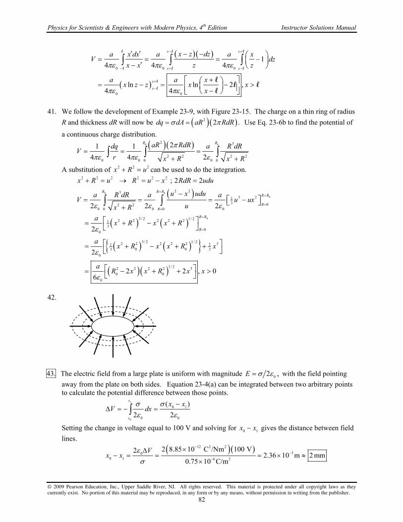
Physics for Scientists & Engineers with Modern Physics, 4th Edition Instructor Solutions Manual
© 2009 Pearson Education, Inc., Upper Saddle River, NJ. All rights reserved. This material is protected under all copyright laws as they currently exist. No portion of this material may be reproduced, in any form or by any means, without permission in writing from the publisher.
82
0 0 0
0 0
14 4 4
ln ln 2 , 4 4
x x
x x
x
x
x z dza x dx a a xV dz
x x z z
a a xx z z x x
x
l l l
l l l
l
l
ll l
l
41. We follow the development of Example 23-9, with Figure 23-15. The charge on a thin ring of radius
R and thickness dR will now be 2 2 .dq dA aR RdR Use Eq. 23-6b to find the potential of
a continuous charge distribution.
0 0
2 3
2 2 2 20 0 00 0
21 1
4 4 2
R RaR RdRdq a R dRV
r x R x R
A substitution of 2 2 2x R u can be used to do the integration.
0 0
0
0
2 2 2 2 2 2
2 233 21
3 02 20 0 00 0
3/ 2 1/ 22 2 2 2 213
00
3 / 2 1/ 22 2 2 2 2 31 20 03 3
0
12 2 2 2
0 0
0
; 2 2
2 2 2
2
2
26
R R RR R
RR
R R
R
x R u R u x RdR udu
u x udua R dR a aV u ux
ux R
ax R x x R
ax R x x R x
aR x x R
/ 2 32 , 0x x
42. 43. The electric field from a large plate is uniform with magnitude 02 ,E with the field pointing
away from the plate on both sides. Equation 23-4(a) can be integrated between two arbitrary points to calculate the potential difference between those points.
1
0
0 1
0 0
( )
2 2
x
x
x xV dx
Setting the change in voltage equal to 100 V and solving for 0 1x x gives the distance between field
lines.
12 2 2
300 1 6 2
2 8.85 10 C /Nm 100 V22.36 10 m 2 mm
0.75 10 C/m
Vx x

Chapter 23 Electric Potential
© 2009 Pearson Education, Inc., Upper Saddle River, NJ. All rights reserved. This material is protected under all copyright laws as they currently exist. No portion of this material may be reproduced, in any form or by any means, without permission in writing from the publisher.
83
44. The potential at the surface of the sphere is 0
0 0
1.
4
QV
r The potential outside the sphere is
00
0
1,
4
Q rV V
r r and decreases as you move away from the surface. The difference in potential
between a given location and the surface is to be a multiple of 100 V.
69 2 2
0
0 0
0 00 0 0 0
0
1 0.50 10 C8.99 10 N m C 10,216 V
4 0.44 m
100 V 100 V
QV
r
r VV V V V n r r
r V n
(a) 0
1 0
0
10,216 V0.44 m 0.444 m
100 V 1 10,116 V
Vr r
V
Note that to within the appropriate number of significant figures, this location is at the surface of the sphere. That can be interpreted that we don’t know the voltage well enough to be working with a 100-V difference.
(b) 0
10 0
0
10,216 V0.44 m 0.49 m
100 V 10 9, 216 V
Vr r
V
(c) 0
100 0
0
10, 216 V0.44 m 21m
100 V 100 216 V
Vr r
V
45. The potential due to the dipole is given by Eq. 23-7.
(a)
9 2 2 30
22 90
8.99 10 N m C 4.8 10 C m cos01 cos
4 4.1 10 m
pV
r
3 2.6 10 V
(b)
9 2 2 30 o
22 90
8.99 10 N m C 4.8 10 C m cos 451 cos
4 4.1 10 m
pV
r
3 1.8 10 V
(c)
9 2 2 30 o
22 90
8.99 10 N m C 4.8 10 C m cos1351 cos
4 1.1 10 m
pV
r
3 1.8 10 V 46. (a) We assume that 1p
and 2p
are equal in magnitude, and that each makes a 52 angle with p
.
The magnitude of 1p
is also given by 1p qd , where q is the net charge on the hydrogen
atom, and d is the distance between the H and the O.
1 1
3020
10
2 cos52 2 cos52
6.1 10 C m5.2 10 C
2 cos52 2 0.96 10 m cos52
pp p p qd
pq
d
This is about 0.32 times the charge on an electron.
r
r
r

Physics for Scientists & Engineers with Modern Physics, 4th Edition Instructor Solutions Manual
© 2009 Pearson Education, Inc., Upper Saddle River, NJ. All rights reserved. This material is protected under all copyright laws as they currently exist. No portion of this material may be reproduced, in any form or by any means, without permission in writing from the publisher.
84
(b) Since we are considering the potential far from the dipoles, we will take the potential of each dipole to be given by Eq. 23-7. See the diagram for the angles
involved. From part (a), 1 2 .2cos52
pp p
1 2
1 2
0 0
cos 52 cos 521 1
4 4
p pV V V
p p
r r
0
0
0 0
1 cos 52 cos 52
4 2 cos52
1 cos52 cos sin 52 cos cos52 cos sin 52 cos
4 2 cos52
1 1 cos 2cos52 cos
4 2 cos52 4
p
r
p
r
p p
r r
47. 2 2
0 0 0 0
1 1 1 1
4 4 4 4
dV d q q d q qE
dr dr r dr r r r
48. The potential gradient is the negative of the electric field. Outside of a spherically symmetric charge
distribution, the field is that of a point charge at the center of the distribution.
19
9 2 2 21
22 150
92 1.60 10 C18.99 10 N m C 2.4 10 V m
4 7.5 10 m
dV qE
dr r
49. The electric field between the plates is obtained from the negative derivative of the potential.
(8.0 V/m) 5.0 V 8.0 V/mdV d
E xdx dx
The charge density on the plates (assumed to be conductors) is then calculated from the electric field between two large plates, 0/ .E
12 2 2 11 2
0 8.0 V/m 8.85 10 C /Nm 7.1 10 C/mE
The plate at the origin has the charge 11 27.1 10 C/m and the other plate, at a positive x, has charge 11 27.1 10 C/m so that the electric field points in the negative direction.
50. We use Eq. 23-9 to find the components of the electric field.
2 2 2 2
2 22 2 2 2 2 2
0 ; 0
2
x z
y
V VE E
x z
a y b by y y a bV byE
y y a y a y a y
2 2
22 2
ˆy a b
a y
E j
52
52 r
1p
2p

Chapter 23 Electric Potential
© 2009 Pearson Education, Inc., Upper Saddle River, NJ. All rights reserved. This material is protected under all copyright laws as they currently exist. No portion of this material may be reproduced, in any form or by any means, without permission in writing from the publisher.
85
51. We use Eq. 23-9 to find the components of the electric field.
2.5 3.5 ; 2 2.5 3.5 ; 3.5
ˆ ˆ ˆ2.5 3.5 2 2.5 3.5 3.5
x y z
V V VE y yz E y x xz E xy
x y z
y yz y x xz xy
E i j k
52. We use the potential to find the electric field, the electric field to find the force, and the force to find
the acceleration.
6
22 3 2
5
; ;
2.0 10 C2.0 m 2 2.0 V m 2.0 m 3 3.0 V m 2.0 m 1.1m s
5.0 10 kg
x xx x x x
x
V F qE q V q VE F qE a
x m m m x m x
a x
53. (a) The potential along the y axis was derived in Problem 38.
2 22 2 2 2
axis 2 20 0
1/ 2 1/ 22 2 2 21 12 2
2 2 2 2 2 20 0
ln ln ln8 8
2 2
8 4
y
y
yQ QV y y
y
y y y yV Q QE
y y y y y
l ll l l l
l ll l
l l
l l l l l l
From the symmetry of the problem, this field will point along the y axis.
2 2
0
1 ˆ4
Q
y y
E j
l
Note that for ,y l this reduces to the field of a point charge at the origin. (b) The potential along the x axis was derived in Problem 39.
axis
0 0
2 2
0 0
ln ln ln8 8
1 1 1
8 4
x
x
Q x QV x x
x
V Q QE
x x x x
ll l
l l l
l l l l
From the symmetry of the problem, this field will point along the x axis.
2 2
0
1 ˆ4
Q
x
E il
Note that for ,x l this reduces to the field of a point charge at the origin. 54. Let the side length of the equilateral triangle be L. Imagine bringing the
electrons in from infinity one at a time. It takes no work to bring the first electron to its final location, because there are no other charges present. Thus 1 0W . The work done in bringing in the second electron to its
final location is equal to the charge on the electron times the potential (due to the first electron) at the final location of the second electron.
Thus 2
2
0 0
1 1
4 4
e eW e
L
l
. The work done in bringing the third electron to its final
l
e e
e
l
l

Physics for Scientists & Engineers with Modern Physics, 4th Edition Instructor Solutions Manual
© 2009 Pearson Education, Inc., Upper Saddle River, NJ. All rights reserved. This material is protected under all copyright laws as they currently exist. No portion of this material may be reproduced, in any form or by any means, without permission in writing from the publisher.
86
location is equal to the charge on the electron times the potential (due to the first two electrons).
Thus 2
3
0 0 0
1 1 1 2
4 4 4
e e eW e
l l l
. The total work done is the sum 1 2 3W W W .
29 2 2 192 2 2
1 2 3 10
0 0 0
18 18
19
3 8.99 10 N m C 1.60 10 C1 1 2 1 30
4 4 4 1.0 10 m
1eV 6.9 10 J 6.9 10 J 43eV
1.60 10 J
e e eW W W W
l l l
55. The gain of kinetic energy comes from a loss of potential energy due to conservation of energy, and
the magnitude of the potential difference is the energy per unit charge. The helium nucleus has a charge of 2e.
3125 10 eV
62.5kV2
U KV
q q e
The negative sign indicates that the helium nucleus had to go from a higher potential to a lower potential.
56. The kinetic energy of the particle is given in each case. Use the kinetic energy to find the speed.
(a) 19
2 712 31
2 1500eV 1.60 10 J eV2 2.3 10 m s
9.11 10 kg
Kmv K v
m
(b) 19
2 512 27
2 1500eV 1.60 10 J eV2 5.4 10 m s
1.67 10 kg
Kmv K v
m
57. The potential energy of the two-charge configuration (assuming they are both point charges) is given
by Eq. 23-10.
2
1 2
0 0
2
final initial
0 initial final
29 2 2 19
9 9 19
1 1
4 4
1 1
4
1 1 1eV8.99 10 N m C 1.60 10 C
0.110 10 m 0.100 10 m 1.60 10 J
1.31eV
Q Q eU
r r
eU U U
r r
Thus 1.3 eV of potential energy was lost. 58. The kinetic energy of the alpha particle is given. Use the kinetic energy to find the speed.
6 19
2 712 27
2 5.53 10 eV 1.60 10 J eV2 1.63 10 m s
6.64 10 kg
Kmv K v
m

Chapter 23 Electric Potential
© 2009 Pearson Education, Inc., Upper Saddle River, NJ. All rights reserved. This material is protected under all copyright laws as they currently exist. No portion of this material may be reproduced, in any form or by any means, without permission in writing from the publisher.
87
59. Following the same method as presented in Section 23-8, we get the following results. (a) 1 charge: No work is required to move a single charge into a position, so 1 0.U
2 charges: This represents the interaction between 1Q and 2.Q
1 2
0 12
2
1
4
Q QU
r
3 charges: This now adds the interactions between 1 3&Q Q and 2 3& .Q Q
1 2 1 3 2 3
0 12 13 23
3
1
4
Q Q Q Q Q QU
r r r
4 charges: This now adds the interaction between 1 4& ,Q Q 2 4& ,Q Q and 3 4& .Q Q
1 2 1 3 1 4 2 3 2 4 3 4
0 12 13 14 23 24 34
4
1
4
Q Q Q Q Q Q Q Q Q Q Q QU
r r r r r r
(b) 5 charges: This now adds the interaction between 1 5& ,Q Q 2 5& ,Q Q 3 5& ,Q Q and 4 5& .Q Q
1 2 1 3 1 4 1 5 2 3 2 4 2 5 3 4 3 5 4 5
0 12 13 14 15 23 24 25 34 35 45
5
1
4
Q Q Q Q Q Q Q Q Q Q Q Q Q Q Q Q Q Q Q QU
r r r r r r r r r r
60. (a) The potential energy of the four-charge configuration was derived in Problem 59. Number the
charges clockwise, starting in the upper right hand corner of the square.
1 2 1 3 1 4 2 3 2 4 3 44
0 12 13 14 23 24 34
2 2
0 0
1
4
1 1 1 1 1 14 2
4 42 2
Q Q Q Q Q Q Q Q Q Q Q QU
r r r r r r
Q Q
b b b b bb b
1Q
2Q4Q
3Q5Q
12r24r
34r 23r
13r14r
45r
35r
15r
25r
1Q
2Q4Q
3Q
12r24r
34r 23r
13r14r

Physics for Scientists & Engineers with Modern Physics, 4th Edition Instructor Solutions Manual
© 2009 Pearson Education, Inc., Upper Saddle River, NJ. All rights reserved. This material is protected under all copyright laws as they currently exist. No portion of this material may be reproduced, in any form or by any means, without permission in writing from the publisher.
88
(b) The potential energy of the fifth charge is due to the interaction between the fifth charge and each of the other four charges. Each of those interaction terms is of the same magnitude since the fifth charge is the same distance from each of the other four charges.
2
5thcharge 0
4 24
QU
b
(c) If the center charge were moved away from the center, it would be moving closer to 1 or 2 of the other charges. Since the charges are all of the same sign, by moving closer, the center charge would be repelled back towards its original position. Thus it is in a place of stable equilibrium.
(d) If the center charge were moved away from the center, it would be moving closer to 1 or 2 of the other charges. Since the corner charges are of the opposite sign as the center charge, the center charge would be attracted towards those closer charges, making the center charge move even farther from the center. So it is in a place of unstable equilibrium.
61. (a) The electron was accelerated through a potential difference of 1.33 kV (moving from low
potential to high potential) in gaining 1.33 keV of kinetic energy. The proton is accelerated through the opposite potential difference as the electron, and has the exact opposite charge. Thus the proton gains the same kinetic energy, 1.33 keV .
(b) Both the proton and the electron have the same KE. Use that to find the ratio of the speeds.
27
p2 2 e1 1p p e e2 2 31
p
1.67 10 kg 42.8
9.11 10 kge
mvm v m v
v m
The lighter electron is moving about 43 times faster than the heavier proton. 62. We find the energy by bringing in a small amount of charge at a time, similar to the method given
in Section 23-8. Consider the sphere partially charged, with charge q < Q. The potential at the
surface of the sphere is 0 0
1,
4
qV
r and the work to add a charge dq to that sphere will increase the
potential energy by .dU Vdq Integrate over the entire charge to find the total potential energy.
2
0 0 0 00
1 1
4 8
Q q QU dU dq
r r
63. The two fragments can be treated as point charges for purposes of calculating their potential energy.
Use Eq. 23-10 to calculate the potential energy. Using energy conservation, the potential energy is all converted to kinetic energy as the two fragments separate to a large distance.
1 2initial final initial final
0
219
9 2 2 6
15 15 19
1
4
38 54 1.60 10 C 1eV 8.99 10 N m C 250 10 eV
5.5 10 m 6.2 10 m 1.60 10 J
250 MeV
q qE E U K V
r
This is about 25% greater than the observed kinetic energy of 200 MeV.

Chapter 23 Electric Potential
© 2009 Pearson Education, Inc., Upper Saddle River, NJ. All rights reserved. This material is protected under all copyright laws as they currently exist. No portion of this material may be reproduced, in any form or by any means, without permission in writing from the publisher.
89
64. We find the energy by bringing in a small amount of spherically symmetric charge at a time, similar to the method given in Section 23-8. Consider that the sphere has been partially constructed, and so has a charge q < Q, contained in a radius 0.r r Since the sphere is made of uniformly charged
material, the charge density of the sphere must be E 343 0
.Q
r
Thus the partially constructed sphere
also satisfies E 43
3,
q
r
and so
3
3 3 34 43 3 0 0
.q Q Qr
qr r r
The potential at the surface of that
sphere can now found.
3
23
0
3
0 0 0 0
1 1 1
4 4 4
Qr
q QrrV
r r r
We now add another infinitesimally thin shell to the partially constructed sphere. The charge of that
shell is 2
E 4 .dq r dr The work to add charge dq to the sphere will increase the potential energy
by .dU Vdq Integrate over the entire sphere to find the total potential energy.
0 02 2
2 4EE3 3
0 0 0 0 0 00 0
1 34
4 20
r rQr Q Q
U dU Vdq r dr r drr r r
65. The ideal gas model, from Eq. 18-4, says that 2 31rms2 2 .K mv kT
23
2 531rms rms2 2 31
273 K
23
5
rms 312700 K
3 1.38 10 J K 273K3 1.11 10 m s
9.11 10 kg
3 1.38 10 J K 2700 K33.5 10 m s
9.11 10 kg
kTK mv kT v
m
kTv
m
66. If there were no deflecting field, the electrons would hit the
center of the screen. If an electric field of a certain direction moves the electrons towards one extreme of the screen, then the opposite field will move the electrons to the opposite extreme of the screen. So we solve for the field to move the electrons to one extreme of the screen. Consider three parts to the
electron’s motion, and see the diagram, which is a top view. First, during the horizontal acceleration phase, energy will be conserved and so the horizontal speed of the electron xv can
be found from the accelerating potential V . Secondly, during the deflection phase, a vertical force will be applied by the uniform electric field which gives the electron a leftward velocity, yv . We
assume that there is very little leftward displacement during this time. Finally, after the electron leaves the region of electric field, it travels in a straight line to the left edge of the screen.
Acceleration:
21initial final 2
2 x x
eVU K eV mv v
m
E
field 2.6 cmx
xv
screen 14cmy
screen 34cmx

Physics for Scientists & Engineers with Modern Physics, 4th Edition Instructor Solutions Manual
© 2009 Pearson Education, Inc., Upper Saddle River, NJ. All rights reserved. This material is protected under all copyright laws as they currently exist. No portion of this material may be reproduced, in any form or by any means, without permission in writing from the publisher.
90
Deflection:
fieldfield field field
field0 field
time in field:
0
x
x
y y y y y
x
xx v t t
v
eE xeEF eE ma a v v a t
m mv
Screen:
screen screenscreen screen screen screen screen x y y
x x
x xx v t t y v t v
v v
field
screen field
2
screen
y x
x x x
eE x
vy mv eE x
x v v mv
32 screenscreen screen
screen field screen field screen field
5 5
22 6.0 10 V 0.14 m2
0.34 m 0.026 m
1.90 10 V m 1.9 10 V m
x
eVy my mv V ymE
x e x x e x x x
As a check on our assumptions, we calculate the upward distance that the electron would move while in the electric field.
2 2 2
2 field fieldfield1 10 field field2 2
25
3
02 42
1.90 10 V m 0.026 m 5.4 10 m
4 6000 V
y
x
eE x E xeE xy v t a t
eVm v Vmm
This is about 4% of the total 15 cm vertical deflection, and so for an estimation, our approximation is
acceptable. And so the field must vary from 5 51.9 10 V m to 1.9 10 V m
67. Consider three parts to the electron’s motion. First, during the
horizontal acceleration phase, energy will be conserved and so the horizontal speed of the electron xv can be found from the
accelerating potential, V . Secondly, during the deflection phase, a vertical force will be applied by the uniform
electric field which gives the electron an upward velocity, yv .
We assume that there is very little upward displacement during this time. Finally, after the electron leaves the region of electric field, it travels in a straight line to the top of the screen.
Acceleration:
21initial final 2
2 x x
eVU K eV mv v
m
E
fieldx
xv
11cm
22cm
screenx

Chapter 23 Electric Potential
© 2009 Pearson Education, Inc., Upper Saddle River, NJ. All rights reserved. This material is protected under all copyright laws as they currently exist. No portion of this material may be reproduced, in any form or by any means, without permission in writing from the publisher.
91
Deflection:
fieldfield field field
field0 field
time in field:
0
x
x
y y y y y
x
xx v t t
v
eE xeEF eE ma a v v a t
m mv
Screen:
screen screenscreen screen screen screen screen x y y
x x
x xx v t t y v t v
v v
field
screen field
2
screen
y x
x x x
eE x
vy mv eE x
x v v mv
2 screenscreen screen
screen field screen field screen field
5 5
22 7200 V 0.11m2
0.22 m 0.028m
2.57 10 V m 2.6 10 V m
x
eVy my mv V ymE
x e x x e x x x
As a check on our assumptions, we calculate the upward distance that the electron would move while in the electric field.
2 2 2
2 field fieldfield1 10 field field2 2
25
3
02 42
2.97 10 V m 0.028m 8.1 10 m
4 7200 V
y
x
eE x E xeE xy v t a t
eVm v Vmm
This is about 7% of the total 11 cm vertical deflection, and so for an estimation, our approximation is acceptable.
68. The potential of the earth will increase because the “neutral” Earth will now be charged by the
removing of the electrons. The excess charge will be the elementary charge times the number of electrons removed. We approximate this change in potential by using a spherical Earth with all the excess charge at the surface.
19 2334
33
2
9 2 2 6
6
0 Earth
1.602 10 C 10 6.02 10 molecules 1000 kg0.00175m
H O molecule 0.018 kg m
1203C
1 1203C8.99 10 N m C 1.7 10 V
4 6.38 10 m
eQ
e
QV
R
69. The potential at the surface of a charged sphere is that of a point charge of the same magnitude,
located at the center of the sphere.
8
9 2 2
0
1 10 C18.99 10 N m C 599.3V 600 V
4 0.15m
qV
r

Physics for Scientists & Engineers with Modern Physics, 4th Edition Instructor Solutions Manual
© 2009 Pearson Education, Inc., Upper Saddle River, NJ. All rights reserved. This material is protected under all copyright laws as they currently exist. No portion of this material may be reproduced, in any form or by any means, without permission in writing from the publisher.
92
70. 71. Let 1d represent the distance from the left charge to point b, and let 2d represent the distance from
the right charge to point b. Let Q represent the positive charges, and let q represent the negative charge that moves. The change in potential energy is given by Eq. 23-2b.
2 2 2 2
1 2
b a b a
0
0
12 14 cm 18.44 cm 14 24 cm 27.78 cm
1
4 0.1844 m 0.2778m 0.12 m 0.24 m
1 1 1 1 1
4 0.1844 m 0.2778m 0.12 m 0.24 m
d d
Q Q Q QU U q V V q
9 2 2 6 6 1 8.99 10 N m C 1.5 10 C 33 10 C 3.477 m 1.547 J 1.5J
72. (a) All eight charges are the same distance from the center of the cube. Use Eq. 23-5 for the
potential of a point charge.
center
0 0 0
1 16 1 18 9.24
4 4 43 3
2
Q Q QV
l ll
(b) For the seven charges that produce the potential at a corner, three are a distance l away from
that corner, three are a distance 2l away from that corner, and one is a distance 3l away from that corner.
corner
0 0 0 0 0
1 1 1 3 1 1 13 3 3 5.70
4 4 4 4 42 3 2 3
Q Q Q Q QV
l l ll l
(c) The total potential energy of the system is half the energy found by multiplying each charge times the potential at a corner. The factor of half comes from the fact that if you took each charge times the potential at a corner, you would be counting each pair of charges twice.
2 2
1corner2
0 0
3 1 1 18 4 3 22.8
4 42 3
Q QU QV
l l
+ +

Chapter 23 Electric Potential
© 2009 Pearson Education, Inc., Upper Saddle River, NJ. All rights reserved. This material is protected under all copyright laws as they currently exist. No portion of this material may be reproduced, in any form or by any means, without permission in writing from the publisher.
93
73. The electric force on the electron must be the same magnitude as the weight of the electron. The magnitude of the electric force is the charge on the electron times the magnitude of the electric field. The electric field is the potential difference per meter: E V d .
E E
31 2
12
19
;
9.11 10 kg 9.80 m s 0.035m2.0 10 V
1.60 10 C
F mg F q E eV d eV d mg
mgdV
e
Since it takes such a tiny voltage to balance gravity, the thousands of volts in a television set are more than enough (by many orders of magnitude) to move electrons upward against the force of gravity.
74. From Problem 59, the potential energy of a configuration of four
charges is 1 2 1 3 1 4 2 3 2 4 3 4
0 12 13 14 23 24 34
1
4.
Q Q Q Q Q Q Q Q Q Q Q QU
r r r r r r
Let a side of the square be l, and number the charges clockwise starting with the upper left corner.
1 2 1 3 1 4 2 3 2 4 3 4
0 12 13 14 23 24 34
1
4
Q Q Q Q Q Q Q Q Q Q Q QU
r r r r r r
0
2629 2 2
0
2 3 2 2 3 2 2 3 21
4 2 2
3.1 10 C1 1 8 8.99 10 N m C 8 7.9J
4 0.080m2 2
Q Q Q Q Q Q Q Q Q Q Q Q
Q
l l l ll l
l
75. The kinetic energy of the electrons (provided by the UV light) is converted completely to potential
energy at the plate since they are stopped. Use energy conservation to find the emitted speed, taking the 0 of PE to be at the surface of the barium.
21initial final 2
19
6
31
KE PE
2 1.60 10 C 3.02 V21.03 10 m s
9.11 10 kg
mv qV
qVv
m
76. To find the angle, the horizontal and vertical components of the velocity are needed. The horizontal
component can be found using conservation of energy for the initial acceleration of the electron. That component is not changed as the electron passes through the plates. The vertical component can be found using the vertical acceleration due to the potential difference of the plates, and the time the electron spends between the plates.
Horizontal:
21inital final 2
PE KE x
x
xqV mv t
v
Vertical:
0
E y y y y
y y
x
v v qE t qE xF qE ma m v
t m mv
+
Q 2Q
-3Q2Q –
l+ +
l
l l

Physics for Scientists & Engineers with Modern Physics, 4th Edition Instructor Solutions Manual
© 2009 Pearson Education, Inc., Upper Saddle River, NJ. All rights reserved. This material is protected under all copyright laws as they currently exist. No portion of this material may be reproduced, in any form or by any means, without permission in writing from the publisher.
94
Combined:
2
1
250 V0.065m
0.013mtan 0.1136
2 2 2 5500 V
tan 0.1136 6.5
y
y y y yx
x x x
qE x
v qE x qE x E xmv
v v mv qV V
77. Use Eq. 23-5 to find the potential due to each charge. Since the triangle is
equilateral, the 30-60-90 triangle relationship says that the distance from a
corner to the midpoint of the opposite side is 3 2l .
A
0 0 0 0
0
B
0 0 0 0 0
31 1 1 1 2 14
4 2 4 2 4 43 2 3
32
6
31 1 1 1 6 3
4 2 4 2 4 4 23 2 3
Q Q Q QV
Q
Q Q Q Q QV
l l ll
l
l l ll l
C
0 0 0 0 0
31 1 1 1 2 1 32 1
4 2 4 2 4 4 63 2 3
Q Q Q Q QV
l l l ll
78. Since the E-field points downward, the surface of the Earth is a lower potential than points above the
surface. Call the surface of the Earth 0 volts. Then a height of 2.00 m has a potential of 300 V. We also call the surface of the Earth the 0 location for gravitational PE. Write conservation of energy relating the charged spheres at 2.00 m (where their speed is 0) and at ground level (where their electrical and gravitational potential energies are 0).
21initial final 2
4
2
2
4.5 10 C 300 V2 9.80 m s 2.00 m 6.3241m s
0.340 kg
qVE E mgh qV mv v gh
m
v
4
24.5 10 C 300 V
2 9.80 m s 2.00 m 6.1972 m s0.340 kg
6.3241m s 6.1972 m s 0.13m s
v
v v
79. (a) The energy is related to the charge and the potential difference by Eq. 23-3.
6
64.8 10 J 1.2 10 V
4.0C
UU q V V
q
(b) The energy (as heat energy) is used to raise the temperature of the water and boil it. Assume that room temperature is 20oC.
f Q mc T mL
A
B
C
Q Q
3Q

Chapter 23 Electric Potential
© 2009 Pearson Education, Inc., Upper Saddle River, NJ. All rights reserved. This material is protected under all copyright laws as they currently exist. No portion of this material may be reproduced, in any form or by any means, without permission in writing from the publisher.
95
6
5f
4.8 10 J1.8kg
J J4186 80C 22.6 10
kg C kg
Qm
c T L
80. Use Eq. 23-7 for the dipole potential, and use Eq. 23-9 to determine the electric field.
1/ 22 2
3 / 22 2 2 2 20 0 0
3 / 2 1/ 22 2 2 23 2 22
3 5 / 22 2 2 20 0
2 2
3
0
5 / 22 232 2
0 0
1 cos
4 4 4
2 2
4 4
2cos sin
4
32
4 4
x
y
x
x yp p p xV
r x y x y
x y x x y xV p p x yE
x x y x y
p
r
V px p xyE x y y
y x
5 / 2 32
0
3cos sin
4
p
ry
Notice the 3
1
rdependence in both components, which is indicative of a dipole field.
81. (a) Since the reference level is given as V = 0 at ,r the potential outside the shell is that of a
point charge with the same total charge.
3 3 3 34 4
E 2 1 2 13 3 E2
0 0 0
1 1,
4 4 3
r r r rQV r r
r r r
Note that the potential at the surface of the shell is 2
32E 1
2
0 2
.3
r
rV r
r
(b) To find the potential in the region 1 2 ,r r r we need the electric field in that region. Since the
charge distribution is spherically symmetric, Gauss’s law may be used to find the electric field.
3 3 3 34 43 3E 1 12 encl encl E
2 2 2
0 0 0 0
1 14
4 4 3
r r r rQ Qd E r E
r r r
E A
The potential in that region is found from Eq. 23-4a. The electric field is radial, so we integrate
along a radial line so that .d EdrE
l
2
2 2 2 2 2
2
2
3 3 3 31 2E E 1 E 11
22 2
0 0 0
3 3 32 2 2 2 2E 1 E 1 E 131 1 1 1 1
2 2 12 2 2 2 6 3
0 0 0
3 3 3
, 3 3
rr r r r
r r
r r r r r
r
r r
r
r r r rV V d E dr dr r dr r
r r r
r r rV V r r r r r r r
r r r
E
l
2r

Physics for Scientists & Engineers with Modern Physics, 4th Edition Instructor Solutions Manual
© 2009 Pearson Education, Inc., Upper Saddle River, NJ. All rights reserved. This material is protected under all copyright laws as they currently exist. No portion of this material may be reproduced, in any form or by any means, without permission in writing from the publisher.
96
(c) Inside the cavity there is no electric field, so the potential is constant and has the value that it has on the cavity boundary.
1
32 2 2 2E 1 E1 1 1
2 1 2 1 12 6 3
0 1 0
, 2
r
rV r r r r r r
r
The potential is continuous at both boundaries. 82. We follow the development of Example 23-9, with Figure 23-15. The charge density of the ring is
2 22 1020 0
4.
3
Q Q
RR R
The charge on a thin ring of radius R and thickness dR is
dq dA 2
0
42 .
3
QRdR
R
Use Eq. 23-6b to find the potential of a continuous charge
distribution.
0 00
11 1 02
0 02 2
21/ 22 20
2 22 2 2 20 0 0 0 0 0
2 2 2 210 042
0 0
42
1 1 2 23
4 4 3 3
2
3
R R R
RR R
QRdR
dq Q R QRV dR x R
r R Rx R x R
Qx R x R
R
83. From Example 22-6, the electric field due to a long wire is radial relative to the wire, and is of
magnitude 0
1.
2E
R
If the charge density is positive, the field lines point radially away from the
wire. Use Eq. 23-41 to find the potential difference, integrating along a line that is radially outward from the wire.
a a
b b
ba b a b
0 0 0 a
1ln ln
2 2 2 R
R R
R R
RV V d dR R R
R
E
l
84. (a) We may treat the sphere as a point charge located at the center of the field. Then the electric
field at the surface is surface 2
0 0
1,
4
QE
r and the potential at the surface is surface
0 0
1.
4
QV
r
6 5
surface surface 0 breakdown 0
0 0
13 10 V m 0.20 m 6 10 V
4
QV E r E r
r
(b)
5
5 5
surface 0 0 surface 9 2 2
0 0
0.20 m 6 10 V1 4 1.33 10 C 1 10 C
4 8.99 10 N m C
QV Q rV
r
85. (a) The voltage at 0.20 mx is obtained by inserting the given data directly into the voltage equation.
4
2 22 2 2 2
150 V m0.20 m 23 kV
0.20 m 0.20 m
BV
x R

Chapter 23 Electric Potential
© 2009 Pearson Education, Inc., Upper Saddle River, NJ. All rights reserved. This material is protected under all copyright laws as they currently exist. No portion of this material may be reproduced, in any form or by any means, without permission in writing from the publisher.
97
(b) The electric field is the negative derivative of the potential.
2 32 2 2 2
ˆ4ˆ d B Bx
dx x R x Rx
iE i
Since the voltage only depends on x the electric field points in the positive x direction. (c) Inserting the given values in the equation of part (b) gives the electric field at 0.20 mx
4
5
32 2
ˆ4 150 V m 0.20 mˆ(0.20 m) 2.3 10 V m
0.20 m 0.20 m
iE i
86. Use energy conservation, equating the energy of charge 1q at its initial position to its final position
at infinity. Take the speed at infinity to be 0, and take the potential of the point charges to be 0 at infinity.
2 21 1initial final initial initial final final 0 1 initial final 1 final2 2
point point
2 2 1 210 1 02 2 2 2 2
0 0
1 2 10 0
4
E E K U K U mv q V mv q V
q q qmv q v
ma b a b
87. (a) From the diagram, the potential at x is the potential of two
point charges.
0 0
exact
1 1
4 4
q qV
x d x d
9
2 2
0
1 2 1.0 10 C, 0.010 m
4 ,
qdq d
x d
(b) The approximate potential is given by Eq. 23-7, with 0, 2 ,p qd and .r x
approx 2
0
1 2
4
qdV
x
To make the difference at small distances more apparent, we have plotted from 2.0 cm to 8.0 cm. The spreadsheet used for this problem can be found on the Media Manager, with filename “PSE4_ISM_CH23.XLS,” on tab “Problem 23.87.”
q q
d dx
0
100
200
300
400
500
600
2.0 3.0 4.0 5.0 6.0 7.0 8.0
x (cm)
V (
Vol
ts)
Actual
Approx

Physics for Scientists & Engineers with Modern Physics, 4th Edition Instructor Solutions Manual
© 2009 Pearson Education, Inc., Upper Saddle River, NJ. All rights reserved. This material is protected under all copyright laws as they currently exist. No portion of this material may be reproduced, in any form or by any means, without permission in writing from the publisher.
98
88. The electric field can be determined from the potential by using Eq. 23-8, differentiating with respect to x.
1/ 2 1/ 22 2 2 210 022 2
0 0 0 0
2 12 2
dV x d Q QE x x R x x R x
dx dx R R
1/ 22 2 20 0 0
12
Q x
R x R
Express V and E in terms of 0 .x R Let 0 .X x R
1/ 22 2 2
02
0 0 0 0
6
9 2 2 2 5 2
21
2 4
2 5.0 10 C8.99 10 N m C 1 8.99 10 V 1
0.10 m
Q QV x x R x X X
R R
X X X X
1/ 22 2 22 20 0 0 00
6
9 2 2
2 2
6
2
21 1
2 4 1
2 5.0 10 C8.99 10 N m C 1
0.10 m 1
8.99 10 V m 11
Q x Q XE x
R R Xx R
X
X
X
X
The spreadsheet used for this problem can be found on the Media Manager, with filename “PSE4_ISM_CH23.XLS,” on tab “Problem 23.88.”
0.0
2.0
4.0
6.0
8.0
10.0
0.0 0.5 1.0 1.5 2.0 2.5 3.0 3.5 4.0
x /R 0
V (
105 V
olts
)
0.0
2.0
4.0
6.0
8.0
10.0
0.0 0.5 1.0 1.5 2.0 2.5 3.0 3.5 4.0
x /R 0
E (
106 V
/m)

Chapter 23 Electric Potential
© 2009 Pearson Education, Inc., Upper Saddle River, NJ. All rights reserved. This material is protected under all copyright laws as they currently exist. No portion of this material may be reproduced, in any form or by any means, without permission in writing from the publisher.
99
89. (a) If the field is caused by a point charge, the potential will have a graph that has the appearance of 1/r behavior, which means that the potential change per unit of distance will decrease as potential is measured farther from the charge. If the field is caused by a sheet of charge, the potential will have a linear decrease with distance. The graph indicates that the field is caused by a point charge. The spreadsheet used for this problem can be found on the Media Manager, with filename “PSE4_ISM_CH23.XLS,” on tab “Problem 23.89a.”
(b) Assuming the field is caused by a point charge, we assume the charge is at x d , and then the
potential is given by 0
1.
4
QV
x d
This can be rearranged to the following.
0
0
1
4
1
4
QV
x d
Qx d
V
If we plot x vs. 1
V, the slope is
0
,4
Q
which can be used to
determine the charge.
0
11
0 9 2 2
slope 0.1392 m V 4
0.1392 m V4 0.1392 m V 1.5 10 C
8.99 10 N m C
Q
Q
The spreadsheet used for this problem can be found on the Media Manager, with filename “PSE4_ISM_CH23.XLS,” on tab “Problem 23.89b.”
(c) From the above equation, the y intercept of the graph is the location of the charge, d. So the
charge is located at 0.0373m 3.7cm from the first measured position .x d
x = 0.1392 (1/V ) - 0.0373
0.000
0.020
0.040
0.060
0.080
0.100
0.000 0.200 0.400 0.600 0.800 1.000
1/V (V-1)
x (
m)
0.0
1.0
2.0
3.0
4.0
0.0 1.0 2.0 3.0 4.0 5.0 6.0 7.0 8.0 9.0
V(Volts)
x (cm)

© 2009 Pearson Education, Inc., Upper Saddle River, NJ. All rights reserved. This material is protected under all copyright laws as they currently exist. No portion of this material may be reproduced, in any form or by any means, without permission in writing from the publisher.
100
CHAPTER 24: Capacitance, Dielectrics, Electric Energy Storage Responses to Questions 1. Yes. If the conductors have different shapes, then even if they have the same charge, they will have
different charge densities and therefore different electric fields near the surface. There can be a potential difference between them. The definition of capacitance C = Q/V cannot be used here because it is defined for the case where the charges on the two conductors of the capacitor are equal and opposite.
2. Underestimate. If the separation between the plates is not very small compared to the plate size, then
fringing cannot be ignored and the electric field (for a given charge) will actually be smaller. The capacitance is inversely proportional to potential and, for parallel plates, also inversely proportional to the field, so the capacitance will actually be larger than that given by the formula.
3. Ignoring fringing field effects, the capacitance would decrease by a factor of 2, since the area of
overlap decreases by a factor of 2. (Fringing effects might actually be noticeable in this configuration.)
4. When a capacitor is first connected to a battery, charge flows to one plate. Because the plates are
separated by an insulating material, charge cannot cross the gap. An equal amount of charge is therefore repelled from the opposite plate, leaving it with a charge that is equal and opposite to the charge on the first plate. The two conductors of a capacitor will have equal and opposite charges even if they have different sizes or shapes.
5. Charge a parallel-plate capacitor using a battery with a known voltage V. Let the capacitor discharge
through a resistor with a known resistance R and measure the time constant. This will allow calculation of the capacitance C. Then use C = ε0A/d and solve for ε0.
6. Parallel. The equivalent capacitance of the three capacitors in parallel will be greater than that of the
same three capacitors in series, and therefore they will store more energy when connected to a given potential difference if they are in parallel.
7. If a large copper sheet of thickness l is inserted between the plates of a parallel-plate capacitor, the
charge on the capacitor will appear on the large flat surfaces of the copper sheet, with the negative side of the copper facing the positive side of the capacitor. This arrangement can be considered to be two capacitors in series, each with a thickness of 1
2 .d l The new net capacitance will be
0 ,C A d l so the capacitance of the capacitor will be reduced.
8. A force is required to increase the separation of the plates of an isolated capacitor because you are
pulling a positive plate away from a negative plate. The work done in increasing the separation goes into increasing the electric potential energy stored between the plates. The capacitance decreases, and the potential between the plates increases since the charge has to remain the same.
9. (a) The energy stored quadruples since the potential difference across the plates doubles and the
capacitance doesn’t change: 212U CV .
(b) The energy stored quadruples since the charge doubles and the capacitance doesn’t change: 2
12
QU
C .

Chapter 24 Capacitance, Dielectrics, Electric Energy Storage
© 2009 Pearson Education, Inc., Upper Saddle River, NJ. All rights reserved. This material is protected under all copyright laws as they currently exist. No portion of this material may be reproduced, in any form or by any means, without permission in writing from the publisher.
101
(c) If the separation between the plates doubles, the capacitance is halved. The potential difference across the plates doesn’t change if the capacitor remains connected to the battery, so
the energy stored is also halved: 212U CV .
10. (c) If the voltage across a capacitor is doubled, the amount of energy it can store is quadrupled:
212U CV .
11. The dielectric will be pulled into the capacitor by the electrostatic attractive forces between the
charges on the capacitor plates and the polarized charges on the dielectric’s surface. (Note that the addition of the dielectric decreases the energy of the system.)
12. If the battery remains connected to the capacitor, the energy stored in the electric field of the
capacitor will increase as the dielectric is inserted. Since the energy of the system increases, work must be done and the dielectric will have to be pushed into the area between the plates. If it is released, it will be ejected.
13. (a) If the capacitor is isolated, Q remains constant, and 2
12
QU
C becomes
2
12'
QU
KC and the
stored energy decreases.
(b) If the capacitor remains connected to a battery so V does not change, 212U CV becomes
212'U KCV , and the stored energy increases.
14. For dielectrics consisting of polar molecules, one would expect the dielectric constant to decrease
with temperature. As the thermal energy increases, the molecular vibrations will increase in amplitude, and the polar molecules will be less likely to line up with the electric field.
15. When the dielectric is removed, the capacitance decreases. The potential difference across the plates
remains the same because the capacitor is still connected to the battery. If the potential difference remains the same and the capacitance decreases, the charge on the plates and the energy stored in the capacitor must also decrease. (Charges return to the battery.) The electric field between the plates will stay the same because the potential difference across the plates and the distance between the plates remain constant.
16. For a given configuration of conductors and dielectrics, C is the proportionality constant between the
voltage between the plates and the charge on the plates. 17. The dielectric constant is the ratio of the capacitance of a capacitor with the dielectric between the
plates to the capacitance without the dielectric. If a conductor were inserted between the plates of a capacitor such that it filled the gap and touched both plates, the capacitance would drop to zero since charge would flow from one plate to the other. So, the dielectric constant of a good conductor would be zero.
Solutions to Problems 1. The capacitance is found from Eq. 24-1.
3
62.8 10 C 3.0 10 F 3.0 F
930 V
QQ CV C
V

Physics for Scientists & Engineers with Modern Physics, 4th Edition Instructor Solutions Manual
© 2009 Pearson Education, Inc., Upper Saddle River, NJ. All rights reserved. This material is protected under all copyright laws as they currently exist. No portion of this material may be reproduced, in any form or by any means, without permission in writing from the publisher.
102
2. We assume the capacitor is fully charged, according to Eq. 24-1.
6 412.6 10 F 12.0 V 1.51 10 CQ CV
3. The capacitance is found from Eq. 24-1.
12
1275 10 C 3.1 10 F 3.1pF
24.0 V
QQ CV C
V
4. Let 1Q and 1V be the initial charge and voltage on the capacitor, and let 2Q and 2V be the final
charge and voltage on the capacitor. Use Eq. 24-1 to relate the charges and voltages to the capacitance.
1 1 2 2 2 1 2 1 2 1
672 1
2 1
26 10 C5.2 10 F 0.52 F
50 V
Q CV Q CV Q Q CV CV C V V
Q QC
V V
5. After the first capacitor is disconnected from the battery, the total charge must remain constant. The
voltage across each capacitor must be the same when they are connected together, since each capacitor plate is connected to a corresponding plate on the other capacitor by a constant-potential connecting wire. Use the total charge and the final potential difference to find the value of the second capacitor.
Total 1 1 1 1 final 2 2 finalinitial final final
Total 1 2 1 2 final 1 1 1 2 finalfinal final initial
1initial 6 5
2 1
final
125V1 7.7 10 F 1 5.6 10 F 56 F
15V
Q C V Q C V Q C V
Q Q Q C C V C V C C V
V
C CV
6. The total charge will be conserved, and the final potential difference across the capacitors will be the
same.
1 2 0 1 10 1 2 1 2 1 0
1 2 2 1 2
1 22 0 1 0 0 2 0
1 2 1 2
10
1 01 21 2
1 1 1 2
; Q Q Q Q C
Q Q Q V V Q QC C C C C
C CQ Q Q Q Q Q Q
C C C C
CQ
Q QC CV V V
C C C C
7. The work to move the charge between the capacitor plates is ,W qV where V is the voltage
difference between the plates, assuming that q Q so that the charge on the capacitor does not change appreciably. The charge is then found from Eq. 24-1. The assumption that q Q is justified.
15μF 15J
1.1C0.20 mC
Q CW
W qV q QC q

Chapter 24 Capacitance, Dielectrics, Electric Energy Storage
© 2009 Pearson Education, Inc., Upper Saddle River, NJ. All rights reserved. This material is protected under all copyright laws as they currently exist. No portion of this material may be reproduced, in any form or by any means, without permission in writing from the publisher.
103
8. (a) The total charge on the combination of capacitors is the sum of the charges on the two individual capacitors, since there is no battery connected to them to supply additional charge, and there is no neutralization of charge by combining positive and negative charges. The voltage across each capacitor must be the same after they are connected, since each capacitor plate is connected to a corresponding plate on the other capacitor by a constant-potential connecting wire. Use the total charge and the fact of equal potentials to find the charge on each capacitor and the common potential difference.
1 1 1 2 2 2 1 1 final 2 2 finalinitial initial initial initial final final
Total 1 2 1 2 1 1 2 2 1 final 2 finalinitial initial final final initial initial
1 1 2 2initial i
final
Q C V Q C V Q C V Q C V
Q Q Q Q Q C V C V C V C V
C V C V
V
6 6
nitial
61 2
1 2
6 3
1 1 finalfinal
6 3
2 2 finalfinal
2.70 10 F 475V 4.00 10 F 525V
6.70 10 F
504.85V 505V
2.70 10 F 504.85V 1.36 10 C
4.00 10 F 504.85V 2.02 10 C
C C
V V
Q C V
Q C V
(b) By connecting plates of opposite charge, the total charge will be the difference of the charges on the two individual capacitors. Once the charges have equalized, the two capacitors will again be at the same potential.
1 1 1 2 2 2 1 1 final 2 2 finalinitial initial initial initial final final
Total 1 2 1 2 1 1 2 2 1 final 2 finalinitial initial final final initial initial
1 1initial
final
Q C V Q C V Q C V Q C V
Q Q Q Q Q C V C V C V C V
C V C
V
6 62 2initial
6
1 2
1 2
6 4
1 1 finalfinal
6 4
2 2 finalfinal
2.70 10 F 475V 4.00 10 F 525V
6.70 10 F
122.01V 120 V
2.70 10 F 122.01V 3.3 10 C
4.00 10 F 122.01V 4.9 10 C
V
C C
V V
Q C V
Q C V
9. Use Eq. 24-1.
6
3
1200 F 6.0 V 1d ; 7.2 10 s 83d
1.0 10 C s 86,400s
Q C VQ C V t
Q t Q t
10. (a) The absolute value of the charge on each plate is given by Eq. 24-1. The plate with electrons
has a net negative charge. Q CV N e CV

Physics for Scientists & Engineers with Modern Physics, 4th Edition Instructor Solutions Manual
© 2009 Pearson Education, Inc., Upper Saddle River, NJ. All rights reserved. This material is protected under all copyright laws as they currently exist. No portion of this material may be reproduced, in any form or by any means, without permission in writing from the publisher.
104
15
5 5
19
35 10 F 1.5V3.281 10 3.3 10 electrons
1.60 10 C
CVN
e
(b) Since the charge is directly proportional to the potential difference, a 1.0% decrease in potential difference corresponds to a 1.0% decrease in charge.
15
15
0.01 ;
0.01 35 10 F 1.5V0.01 0.011.75s 1.8s
0.30 10 C s
Q Q
Q Q CVt
Q t Q t Q t
11. Use Eq. 24-2.
6 3
2 2
0 12 2 2
0
0.40 10 F 2.8 10 m 126.6 m 130 m
8.85 10 C N m
A CdC A
d
If the capacitor plates were square, they would be about 11.2 m on a side. 12. The capacitance per unit length of a coaxial cable is derived in Example 24-2
12 2 2
110
outside inside
2 8.85 10 C N m23.5 10 F m
ln ln 5.0 mm 1.0 mm
C
R R
l
13. Inserting the potential at the surface of a spherical conductor into Eq. 24.1 gives the capacitance of a
conducting sphere. Then inserting the radius of the Earth yields the Earth’s capacitance.
12 6 4
0
0
4 4 8.85 10 F/m 6.38 10 m 7.10 10 F4
Q QC r
V Q r
14. From the symmetry of the charge distribution, any electric field
must be radial, away from the cylinder axis, and its magnitude must be independent of the location around the axis (for a given radial location). We assume the cylinders have charge of magnitude Q in a length l. Choose a Gaussian cylinder of length d and radius R, centered on the capacitor’s axis, with d l and the Gaussian cylinder far away from both ends of
the capacitor. On the ends of this cylinder, dE A
and so there is no flux through the ends. On the curved side of the
cylinder, the field has a constant magnitude and dE A
. Thus .d EdAE A
Write Gauss’s law.
enclcurved curvedwalls walls 0
2Q
d E A E Rd
E A
For b ,R R encl 00 2 0 0.Q E Rd E
For a ,R R encl 0QQ Q
d d
l l
, and so encl 00 2 0 0.Q E Rd E
15. We assume there is a uniform electric field between the capacitor plates, so that ,V Ed and then
use Eqs. 24-1 and 24-2.
12 4 2 6
max max 0 max 0 max
8
8.85 10 F/m 6.8 10 m 3.0 10 V m
1.8 10 C
AQ CV E d AE
d
d Ra
Rb
+ Q
– Q
Gaussian cylinder of radius R

Chapter 24 Capacitance, Dielectrics, Electric Energy Storage
© 2009 Pearson Education, Inc., Upper Saddle River, NJ. All rights reserved. This material is protected under all copyright laws as they currently exist. No portion of this material may be reproduced, in any form or by any means, without permission in writing from the publisher.
105
16. We assume there is a uniform electric field between the capacitor plates, so that ,V Ed and then use Eqs. 24-1 and 24-2.
12 4 2 5
0 0
9
8.85 10 F/m 21.0 10 m 4.80 10 V m
8.92 10 C
AQ CV Ed AE
d
17. We assume there is a uniform electric field between the capacitor plates, so that ,V Ed and then
use Eqs. 24-1 and 24-2.
6
4
6 3
92 10 C 5.8 10 V m
0.80 10 F 2.0 10 m
QQ CV CEd E
Cd
18. (a) The uncharged plate will polarize so that negative
charge will be drawn towards the positive capacitor plate, and positive charge will be drawn towards the negative capacitor plate. The same charge will be on each face of the plate as on the original capacitor plates. The same electric field will be in the gaps as before the plate was inserted. Use that electric field to determine the potential difference between the two original plates, and the new capacitance. Let x be the distance from one original plate to the nearest face of the sheet, and so d x l is the distance from the other original plate to the other face of the sheet.
1 2
0 0 0 0
1 2 0
0 0 0
; ;
Q d xQ QxE V Ex V E d x
A A A
Q d x Q dQx Q AV V V C
A A A C d
ll
l l
l
(b)
0
finalinitial 0 final 0
initial0
1 ; ; 1.7
0.40 0.60
A
dA A C d dC C
Ad d C d d dd
l
l l
19. (a) The distance between plates is obtained from Eq. 24-2.
0 0 A A
C xx C
Inserting the maximum capacitance gives the minimum plate separation and the minimum capacitance gives the maximum plate separation.
6 2
0min 12
max
8.85pF/m 25 10 m0.22 m
1000.0 10 F
Ax
C
6 2
omax
min
8.85pF/m 25 10 m0.22 mm 220 m
1.0 pF
Ax
C
So 0.22 m 220 m .x
d
x
d x lE
Epositive plate
negative plate

Physics for Scientists & Engineers with Modern Physics, 4th Edition Instructor Solutions Manual
© 2009 Pearson Education, Inc., Upper Saddle River, NJ. All rights reserved. This material is protected under all copyright laws as they currently exist. No portion of this material may be reproduced, in any form or by any means, without permission in writing from the publisher.
106
(b) Differentiating the distance equation gives the approximate uncertainty in distance.
0 0
2
dx d A Ax C C C
dC dC C C
.
The minus sign indicates that the capacitance increases as the plate separation decreases. Since only the magnitude is desired, the minus sign can be dropped. The uncertainty is finally written in terms of the plate separation using Eq. 24-2.
2
02
00
A x Cx C
AA
x
(c) The percent uncertainty in distance is obtained by dividing the uncertainty by the separation distance.
min min
2
min o
0.22 m 0.1pF 100%100% 100% 0.01%
8.85pF/m 25mm
x x C
x A
max max
2
max o
0.22 mm 0.1pF 100%100% 100% 10%
8.85pF/m 25mm
x x C
x A
20. The goal is to have an electric field of strength SE at a radial distance of 5.0 bR from the center of the
cylinder. Knowing the electric field at a specific distance allows us to calculate the linear charge density on the inner cylinder. From the linear charge density and the capacitance we can find the potential difference needed to create the field. From the cylindrically symmetric geometry and
Gauss’s law, the field in between the cylinders is given by 0
1.
2E
R
The capacitance of a
cylindrical capacitor is given in Example 24-2.
b S 0 b S
0 b
a b a b0 b S
a b
4 6
b S a b 4
15.0 2 5.0
2 5.0
ln ln 2 5.0
2 2 2ln
0.100 m 5.0 ln 5.0 1.0 10 m 2.7 10 N C ln 9300 V
1.0 10 m
QE R R E R E
R
R R R RQ Q QQ CV V R E
CR R
R E R R
l
l l
21. To reduce the net capacitance, another capacitor must be added in series.
1 eq
eq 1 2 2 eq 1 1 eq
1 1 1 1 1 1
C C
C C C C C C C C
9 9
1 eq 9
2 9 9
1 eq
2.9 10 F 1.6 10 F3.57 10 F 3600pF
2.9 10 F 1.6 10 F
C CC
C C
Yes, an existing connection needs to be broken in the process. One of the connections of the original capacitor to the circuit must be disconnected in order to connect the additional capacitor in series.
22. (a) Capacitors in parallel add according to Eq. 24-3.
6 5
eq 1 2 3 4 5 6 6 3.8 10 F 2.28 10 F 22.8 FC C C C C C C

Chapter 24 Capacitance, Dielectrics, Electric Energy Storage
© 2009 Pearson Education, Inc., Upper Saddle River, NJ. All rights reserved. This material is protected under all copyright laws as they currently exist. No portion of this material may be reproduced, in any form or by any means, without permission in writing from the publisher.
107
(b) Capacitors in series add according to Eq. 24-4.
1 1 67
eq 6
1 2 3 4 5 6
1 1 1 1 1 1 6 3.8 10 F6.3 10 F
3.8 10 F 6
0.63 F
CC C C C C C
23. We want a small voltage drop across C1. Since ,V Q C if we put
the smallest capacitor in series with the battery, there will be a large voltage drop across it. Then put the two larger capacitors in parallel, so that their equivalent capacitance is large and therefore will have a small voltage drop across them. So put C1 and C3 in parallel with each other, and then put that combination in series with C2. See the diagram. To calculate the voltage across C1, find the equivalent capacitance and the net charge. That charge is used to find the voltage drop across C2, and then that voltage is subtracted from the battery voltage to find the voltage across the parallel combination.
eq2 1 31 2 3 2eq eq eq 0 2
eq 2 1 3 2 1 3 1 2 3 2 2
2 1 30
eq eq 0 21 2 31 0 2 0 0 0 0
2 2 2 1 2 3
1 1 1 ; ; ;
1.5 F12 V
6.5 F
2.8V
QC C CC C C QC Q C V V
C C C C C C C C C C C C
C C CV
Q C V CC C CV V V V V V V
C C C C C C
24. The capacitors are in parallel, and so the potential is the same for each capacitor, and the total charge
on the capacitors is the sum of the individual charges. We use Eqs. 24-1 and 24-2.
1 2 31 1 0 2 2 0 3 3 0
1 2 3
1 2 3 1 2 3total 1 2 3 0 0 0 0 0 0
1 2 3 1 2 3
1 2 30 0 0
1 2 3total 1 2 3net 0 0 0 1 2 3
1 2 3
; ; A A A
Q CV V Q C V V Q C V Vd d d
A A A A A AQ Q Q Q V V V V
d d d d d d
A A AV
d d dQ A A AC C C C
V V d d d
25. Capacitors in parallel add linearly, and so adding a capacitor in parallel will increase the net
capacitance without removing the 5.0 F capacitor.
5.0 F 16 F 11 F connected in parallelC C
26. (a) The two capacitors are in parallel . Both capacitors have their high voltage plates at the same
potential (the middle plate), and both capacitors have their low voltage plates at the same potential (the outer plates, which are connected).
(b) The capacitance of two capacitors in parallel is the sum of the individual capacitances.
0 01 2 0
1 2 1 2
1 20
1 2
1 1A AC C C A
d d d d
d dA
d d
3C
2C
1C
0V

Physics for Scientists & Engineers with Modern Physics, 4th Edition Instructor Solutions Manual
© 2009 Pearson Education, Inc., Upper Saddle River, NJ. All rights reserved. This material is protected under all copyright laws as they currently exist. No portion of this material may be reproduced, in any form or by any means, without permission in writing from the publisher.
108
(c) Let 1 2 constant.d d l Then
0 0
1 2 1 1
.A A
Cd d d d
l l
l We see that C as 1 0d or
1d l (which is 2 0d ). Of course, a real capacitor would break down as the plates got too
close to each other. To find the minimum capacitance, set 1
0dC
d d and solve for 1.d
11 2
10 10 1 2222 2
1 1 1 1 1 1
1 2min 0 0 0 01 1
2 21 2 1 2
0min max
1 2
20
4 4
4 ;
d
ddC d AA d d
d d d d d d d d
d dC A A A A
d d d d
AC C
d d
l
lll l
l l
l
l l l
27. The maximum capacitance is found by connecting the capacitors in parallel.
9 9 8 8
max 1 2 3 3.6 10 F 5.8 10 F 1.00 10 F 1.94 10 F in parallelC C C C
The minimum capacitance is found by connecting the capacitors in series.
1 1
9
min 9 9 8
1 2 3
1 1 1 1 1 11.82 10 F in series
3.6 10 F 5.8 10 F 1.00 10 FC
C C C
28. When the capacitors are connected in series, they each have the same charge as the net capacitance.
(a) 1 1
1 2 eq eq 6 6
1 2
1 1 1 19.0V
0.50 10 F 0.80 10 FQ Q Q C V V
C C
6
6 6
1 21 26 6
1 2
2.769 10 C
2.769 10 C 2.769 10 C5.538V 5.5V 3.461V 3.5V
0.50 10 F 0.80 10 F
Q QV V
C C
(b) 6 6
1 2 eq 2.769 10 C 2.8 10 CQ Q Q
When the capacitors are connected in parallel, they each have the full potential difference.
(c) 6 6
1 2 1 1 19.0 V 9.0V 0.50 10 F 9.0V 4.5 10 CV V Q CV
6 6
2 2 2 0.80 10 F 9.0V 7.2 10 CQ C V
29. (a) From the diagram, we see that C1 and C2 are in series. That combination is in parallel with C3,
and then that combination is in series with C4. Use those combinations to find the equivalent capacitance. We use subscripts to indicate which capacitors have been combined.
31 112 123 12 32 2 2
12
31234 5
1234 123 4
1 1 1 ; ;
1 1 1 2 1 5
3 3
C C C C C C C CC C C
C CC C C C C C

Chapter 24 Capacitance, Dielectrics, Electric Energy Storage
© 2009 Pearson Education, Inc., Upper Saddle River, NJ. All rights reserved. This material is protected under all copyright laws as they currently exist. No portion of this material may be reproduced, in any form or by any means, without permission in writing from the publisher.
109
(b) The charge on the equivalent capacitor 1234C is given by 31234 1234 5 .Q C V CV This is the
charge on both of the series components of 1234.C
3 3 2
123 123 123 123 1235 2 5
3 34 4 4 45 5
Q CV C V CV V V
Q CV C V V V
The voltage across the equivalent capacitor 123C is the voltage across both of its parallel
components. Note that the sum of the charges across the two parallel components of 123C is the
same as the total charge on the two components, 35 .CV
2 1 2 1123 12 12 12 125 2 5 5
2 2 2123 3 3 3 35 5 5
;
;
V V V Q C V C V CV
V V V Q C V C V CV
Finally, the charge on the equivalent capacitor 12C is the charge on both of the series
components of 12.C
1 1 1 112 1 1 1 1 12 2 1 2 25 5 5 5 ; Q CV Q CV V V Q CV Q CV V V
Here are all the results, gathered together.
31 2
1 2 3 45 5 5
31 21 2 3 45 5 5
; ;
; ;
Q Q CV Q CV Q CV
V V V V V V V
30. C1 and C2 are in series, so they both have the same charge. We then use that charge to find the
voltage across each of C1 and C2. Then their combined voltage is the voltage across C3. The voltage across C3 is used to find the charge on C3.
1 21 2 1 2
1 2
3 1 2 3 3 3
12.4 C 12.4 C12.4 C ; 0.775V ; 0.775V
16.0 F 16.0 F
1.55V ; 16.0 F 1.55V 24.8 C
Q QQ Q V V
C C
V V V Q C V
From the diagram, C4 must have the same charge as the sum of the charges on C1 and C3. Then the voltage across the entire combination is the sum of the voltages across C4 and C3.
4
4 1 3 4
4
ab 4 3
37.2 C12.4 C 24.8 C 37.2 C ; 1.31V
28.5 F
1.31V 1.55V 2.86V
QQ Q Q V
C
V V V
Here is a summary of all results.
1 2 3 4
1 2 3 4 ab
12.4 C ; 24.8 C ; 37.2 C
0.775V ; 1.55V ; 1.31V ; 2.86V
Q Q Q Q
V V V V V
31. When the switch is down the initial charge on C2 is calculated from Eq. 24-1.
2 2 0Q C V
When the switch is moved up, charge will flow from C2 to C1 until the voltage across the two capacitors is equal.
2 1 22 1
2 1 1
Q Q CV Q Q
C C C
The sum of the charges on the two capacitors is equal to the initial charge on C2.
C2
C1
V0
S

Physics for Scientists & Engineers with Modern Physics, 4th Edition Instructor Solutions Manual
© 2009 Pearson Education, Inc., Upper Saddle River, NJ. All rights reserved. This material is protected under all copyright laws as they currently exist. No portion of this material may be reproduced, in any form or by any means, without permission in writing from the publisher.
110
2 2 12 2 1 1 1 1
1 1
C C CQ Q Q Q Q Q
C C
Inserting the initial charge in terms of the initial voltage gives the final charges. 2
2 1 1 2 2 21 2 0 1 0 2 1 0
1 2 1 1 2
; C C C C C C
Q C V Q V Q Q VC C C C C C
32. (a) From the diagram, we see that C1 and C2 are in parallel, and
C3 and C4 are in parallel. Those two combinations are then in series with each other. Use those combinations to find the equivalent capacitance. We use subscripts to indicate which capacitors have been combined.
12 1 2 34 3 4
1234 12 34 1 2 3 4
1 2 3 41234
1 2 3 4
; ;
1 1 1 1 1
C C C C C C
C C C C C C C
C C C CC
C C C C
(b) The charge on the equivalent capacitor 1234C is given by 1234 1234 .Q C V This is the charge on
both of the series components of 1234.C Note that 12 34 .V V V
1 2 3 4
1 2 3 4 3 4123412 1234 12 12 12
12 1 2 1 2 3 4
1 2 3 4
1 2 3 4 1 2123434 1234 34 34 34
34 3 4 1 2 3 4
C C C C
C C C C C CCQ C V C V V V V V
C C C C C C C
C C C C
C C C C C CCQ C V C V V V V V
C C C C C C C
The voltage across the equivalent capacitor 12C is the voltage across both of its parallel
components, and the voltage across the equivalent 34C is the voltage across both its parallel
components.
3 412 1 2
1 2 3 4
1 3 4 2 3 41 1 1 2 2 2
1 2 3 4 1 2 3 4
;
;
C CV V V V
C C C C
C C C C C CCV Q V C V Q V
C C C C C C C C
1 234 3 2
1 2 3 4
3 1 2 4 1 23 3 3 4 4 4
1 2 3 4 1 2 3 4
;
;
C CV V V V
C C C C
C C C C C CC V Q V C V Q V
C C C C C C C C
b
C1
C2a
C 3
C 4
a
C1234
b
c
c ba
C34 C12

Chapter 24 Capacitance, Dielectrics, Electric Energy Storage
© 2009 Pearson Education, Inc., Upper Saddle River, NJ. All rights reserved. This material is protected under all copyright laws as they currently exist. No portion of this material may be reproduced, in any form or by any means, without permission in writing from the publisher.
111
33. (a) The voltage across C3 and C4 must be the same, since they are in parallel.
3 4 43 4 4 3
3 4 3
16 F 23 C 46 C
8 F
Q Q CV V Q Q
C C C
The parallel combination of C3 and C4 is in series with the parallel combination of C1 and C2, and so 3 4 1 2.Q Q Q Q That total charge then divides between C1 and C2 in such a way that
1 2.V V
1 4 11 2 3 4 1 2
1 4 4
11 2
4 1
69 C69 C ;
8.0 F69 C 69 C 23 C ; 69 C 23 C 46 C
24.0 F
Q Q QQ Q Q Q V V
C C C
CQ Q
C C
Notice the symmetry in the capacitances and the charges. (b) Use Eq. 24-1.
11 2 1
1
33 4 3
3
23 C2.875V 2.9 V ; 2.9 V
8.0 F
23 C2.875V 2.9 V ; 2.9 V
8.0 F
QV V V
C
QV V V
C
(c) ba 1 3 2.875V 2.875V 5.75V 5.8VV V V
34. We have P 1 2C C C and S 1 2
1 1 1.
C C C Solve for 1C and 2C in terms of PC and S.C
P 1 1 P
S 1 2 1 P 1 1 P 1 1 P 1
2P1 P 1 P S
S 1 P 1
22
P P P S
1
2 P 1
1 1 1 1 1
1 0
35.0 F 35.0 F 4 35.0 F 5.5 F4
2 228.2 F, 6.8 F
35.0 F 28.2 F 6.8 F or 35.0 F 6.8 F 28.2 F
C C C C
C C C C C C C C C C C C
CC C C C C
C C C C
C C C CC
C C C
So the two values are 28.2 F and 6.8 F .
35. Since there is no voltage between points a and b, we can imagine there
being a connecting wire between points a and b. Then capacitors C1 and C2 are in parallel, and so have the same voltage. Also capacitors C3 and Cx are in parallel, and so have the same voltage.
1 2 31 2 3
1 2 3
; xx
x
Q Q Q QV V V V
C C C C
Since no charge flows through the voltmeter, we could also remove it from the circuit and have no change in the circuit. In that case, capacitors C1 and Cx are in series and so have the same charge. Likewise capacitors C2 and C3 are in series, and so have the same charge.
V0
c
C1
C2 C3
Cx
b
a
Vd

Physics for Scientists & Engineers with Modern Physics, 4th Edition Instructor Solutions Manual
© 2009 Pearson Education, Inc., Upper Saddle River, NJ. All rights reserved. This material is protected under all copyright laws as they currently exist. No portion of this material may be reproduced, in any form or by any means, without permission in writing from the publisher.
112
1 2 3 ; xQ Q Q Q
Solve this system of equations for Cx.
3 1 13 3 3
3 3 2 2
8.9 F 4.8 F 2.4 F
18.0 Fx x
x
x
Q Q Q Q CC C C C
C C Q Q C
36. The initial equivalent capacitance is the series combination of the two individual capacitances. Each
individual capacitor will have the same charge as the equivalent capacitance. The sum of the two initial charges will be the sum of the two final charges, because charge is conserved. The final potential of both capacitors will be equal.
eq 1 2
1 2 1 2eq eq eq 0 0
1 2 1 2
1 2 eq 1final final final
1 2 eq 1 2final final final final 1 2 2
11 eqfinal 1 2
1 1 1
3200pF 1800pF ; 12.0V 13,824 pC
5000pF
2
2 ;
3200pF2 2
5000
C C C
C C C CC Q C V V
C C C C
Q Q Q Q
Q Q Q V VC C C
CQ Q
C C
8
8
2 eq 1final final
13,824 pC 17,695pC 1.8 10 CpF
2 2 13,824 pC 17,695pC 9953pC 1.0 10 CQ Q Q
37. (a) The series capacitors add reciprocally, and then the parallel combination is found by adding
linearly.
1 1 1
3 2 3 2 32eq 1 1 1 1
2 3 2 3 2 3 2 3 2 3
1 1 C C C C CCC C C C C
C C C C C C C C C C
(b) For each capacitor, the charge is found by multiplying the capacitance times the voltage. For
1C , the full 35.0 V is across the capacitance, so 6
1 1 24.0 10 F 35.0VQ CV
48.40 10 C . The equivalent capacitance of the series combination of 2C and 3C has the full
35.0 V across it, and the charge on the series combination is the same as the charge on each of the individual capacitors.
1
6 41eq eq eq 2 33
1 1 24.0 10 F 35.0V 2.80 10 C
2 3
CC Q C V Q Q
C C
38. From the circuit diagram, we see that 1C is in parallel with the voltage, and so 1 24V .V
Capacitors 2C and 3C both have the same charge, so their voltages are inversely proportional to their
capacitance, and their voltages must total to 24.0 V.
2 3 2 2 3 3 2 3
2 32 2 2
3 2 3
3 2
;
4.00 F 24.0V 13.7V
7.00 F
24.0V 13.7V 10.3V
Q Q C V C V V V V
C CV V V V V
C C C
V V V

Chapter 24 Capacitance, Dielectrics, Electric Energy Storage
© 2009 Pearson Education, Inc., Upper Saddle River, NJ. All rights reserved. This material is protected under all copyright laws as they currently exist. No portion of this material may be reproduced, in any form or by any means, without permission in writing from the publisher.
113
39. For an infinitesimal area element of the capacitance a distance y up from the small end, the distance between the plates is tan .d x d y d y
Since the capacitor plates are square, they are of dimension ,A A and the
area of the infinitesimal strip is .A dydA The infinitesimal capacitance dC of the strip is calculated, and then the total capacitance is found by adding together all of the infinitesimal capacitances, in parallel with each other.
0 0 0
00
0 0
ln
AA
A dA A dyC dC
d d y d y
A dy AC dC d y
d y
0 0 0 ln ln ln ln 1A A d A A A
d A dd d
We use the approximation from page A-1 that 212ln 1 .x x x
2
0 0 012ln 1 1
2
A A A A A A AC
d d d d d
40. No two capacitors are in series or in parallel in the diagram, and so we may not simplify by that
method. Instead use the hint as given in the problem. We consider point a as the higher voltage. The equivalent capacitance must satisfy tot eq .Q C V
(a) The potential between a and b can be written in three ways. Alternate but equivalent expressions are shown in parentheses.
2 1 2 3 4 5 4 2 3 5 3 4 1 ; ; ; V V V V V V V V V V V V V V V V
There are also three independent charge relationships. Alternate but equivalent expressions are shown in parentheses. Convert the charge expressions to voltage – capacitance expression.
tot 2 5 tot 4 1 2 1 3 4 3 5
eq 2 2 5 5 eq 4 4 1 1 2 2 1 1 3 3
; ;
; ;
Q Q Q Q Q Q Q Q Q Q Q Q
C V C V C V C V C V CV C V CV C V
We have a set of six equations: 2 1 2 3 4 5 41 ; 2 ; 3V V V V V V V V V V
eq 2 2 5 5 eq 4 4 1 1 2 2 1 1 3 34 ; 5 ; 6C V C V C V C V C V CV C V CV C V
Solve for eqC as follows.
(i) From Eq. (1), 21 .V V V Rewrite equations (5) and (6). V1 has been eliminated.
eq 4 4 1 1 2 2 2 1 1 2 3 35 ; 6C V C V CV CV C V CV CV C V
(ii) From Eq. (3), 45 .V V V Rewrite equation (4). V5 has been eliminated.
eq 2 2 5 5 4 4C V C V C V C V
(iii) From Eq. (2), 3 2 4.V V V V Rewrite equation (6). V3 has been eliminated.
2 2 1 1 2 3 3 2 3 4
1 2 3 2 3 4 1 3
6
6
C V CV CV C V C V C V
C C C V C V C C V
d y
y
d

Physics for Scientists & Engineers with Modern Physics, 4th Edition Instructor Solutions Manual
© 2009 Pearson Education, Inc., Upper Saddle River, NJ. All rights reserved. This material is protected under all copyright laws as they currently exist. No portion of this material may be reproduced, in any form or by any means, without permission in writing from the publisher.
114
Here is the current set of equations.
eq 2 2 5 5 4
eq 4 4 1 1 2
1 2 3 2 3 4 1 3
4
5
6
C V C V C V C V
C V C V CV CV
C C C V C V C C V
(iv) From Eq. (4), 4 2 2 5 eq
5
1.V C V C V C V
C Rewrite equations (5) and (6).
5 eq 4 2 2 5 eq 5 1 5 1 2
5 1 2 3 2 3 2 2 5 eq 5 1 3
5
6
C C V C C V C V C V C CV C CV
C C C C V C C V C V C V C C C V
(v) Group all terms by common voltage.
5 eq 4 eq 4 5 5 1 4 2 5 1 2
5 1 3 3 eq 3 5 5 1 2 3 3 2 2
5
6
C C C C C C C C V C C C C V
C C C C C C C V C C C C C C V
(vi) Divide the two equations to eliminate the voltages, and solve for the equivalent capacitance.
5 eq 4 eq 4 5 5 1 4 2 5 1
5 1 2 3 3 25 1 3 3 eq 3 5
1 2 3 1 2 4 1 2 5 1 3 5 1 4 5 2 3 4 2 4 5 3 4 5eq
1 3 1 4 1 5 2 3 2 4 2 5 3 4 3 5
C C C C C C C C C C C C
C C C C C CC C C C C C C
C C C C C C C C C C C C C C C C C C C C C C C CC
C C C C C C C C C C C C C C C C
(b) Evaluate with the given data. Since all capacitances are in F, and the expression involves
capacitance cubed terms divided by capacitance squared terms, the result will be in F.
1 2 3 1 2 4 1 2 5 1 3 5 1 4 5 2 3 4 2 4 5 3 4 5eq
1 3 1 4 1 5 2 3 2 4 2 5 3 4 3 5
1 2 3 4 5 5 3 4 4 2 3 2 5 3 5
1 3 4 5 2 3 4 5 3 4 5
4.5 8.0 17.0 4.5 12.5 8.0 8.0 4.5 8.0 4.
C C C C C C C C C C C C C C C C C C C C C C C CC
C C C C C C C C C C C C C C C C
C C C C C C C C C C C C C C C
C C C C C C C C C C C
5 4.5 4.5F
4.5 17.0 8.0 17.0 4.5 12.5
6.0 F
41. The stored energy is given by Eq. 24-5.
22 9 31 12 2 2.8 10 F 2200V 6.8 10 JU CV
42. The energy density is given by Eq. 24-6.
22 12 2 2 7 31 102 2 8.85 10 C N m 150V m 1.0 10 J mu E
43. The energy stored is obtained from Eq. 24-5, with the capacitance of Eq. 24-2.
242 23
212 2 20
4.2 10 C 0.0013m2.0 10 J
2 2 2 8.85 10 C N m 0.080 m
Q Q dU
C A

Chapter 24 Capacitance, Dielectrics, Electric Energy Storage
© 2009 Pearson Education, Inc., Upper Saddle River, NJ. All rights reserved. This material is protected under all copyright laws as they currently exist. No portion of this material may be reproduced, in any form or by any means, without permission in writing from the publisher.
115
44. (a) The charge is constant, and the tripling of separation reduces the capacitance by a factor of 3.
2
0122
2
1 20
1
23
32
Q ACCU d
AQU CdC
(b) The work done is the change in energy stored in the capacitor.
2 2 2
2 1 1 1 1
1 00
3 2 22
Q Q Q dU U U U U
AC Ad
45. The equivalent capacitance is formed by C1 in parallel with the series combination of C2 and C3.
Then use Eq. 24-5 to find the energy stored.
2
2 3 3net 1 2
2 3
22 2 6 33 31net2 4 4
2
22.6 10 F 10.0V 1.70 10 J
C C CC C C C
C C C
U C V CV
46. (a) Use Eqs. 24-3 and 24-5.
22 2 6 4 41 1 1parallel eq 1 22 2 2 0.65 10 F 28V 2.548 10 J 2.5 10 JU C V C C V
(b) Use Eqs. 24-4 and 24-5.
6 6
22 21 21 1 1series eq2 2 2 6
1 2
5 5
0.45 10 F 0.20 10 F28V
0.65 10 F
5.428 10 J 5.4 10 J
C CU C V V
C C
(c) The charge can be found from Eq. 24-5.
4
51parallel2
5
6
series
2 2.548 10 J2 1.8 10 C
28V
2 5.428 10 J3.9 10 C
28V
UU QV Q Q
V
Q
47. The capacitance of a cylindrical capacitor is given in Example 24-2 as
0
a b
2.
lnC
R R
l
(a) If the charge is constant, the energy can be calculated by 2
12 .
QU
C
201
2
a b a b2 122
01 2 a b12
a b1
2
ln ln 31
2 lnln 3
Q
R R R RU CC
QU C R RR RC
l
l
The energy comes from the work required to separate the capacitor components.

Physics for Scientists & Engineers with Modern Physics, 4th Edition Instructor Solutions Manual
© 2009 Pearson Education, Inc., Upper Saddle River, NJ. All rights reserved. This material is protected under all copyright laws as they currently exist. No portion of this material may be reproduced, in any form or by any means, without permission in writing from the publisher.
116
(b) If the voltage is constant, the energy can be calculated by 212 .U CV
0
21a b a b22 2 2
21021 1 1 a b
a b
2
ln 3 ln1
2 ln 3ln
R R R RU C V C
U CV C R RR R
l
l
Since the voltage remained constant, and the capacitance decreased, the amount of charge on the capacitor components decreased. Charge flowed back into the battery that was maintaining the constant voltage.
48. (a) Before the capacitors are connected, the only stored energy is in the initially-charged capacitor.
Use Eq. 24-5.
22 6 4 41 11 1 02 2 2.20 10 F 12.0V 1.584 10 J 1.58 10 JU CV
(b) The total charge available is the charge on the initial capacitor. The capacitance changes to the equivalent capacitance of the two capacitors in parallel.
2 262 2 2
1 01 1 11 1 0 eq 1 2 2 2 2 2 6
eq 1 2
5 5
2.20 10 F 12.0V ; ;
5.70 10 F
6.114 10 J 6.11 10 J
Q C VQ Q CV C C C U
C C C
(c) 5 4 5
2 1 6.114 10 J 1.584 10 J 9.73 10 JU U U
49. (a) With the plate inserted, the capacitance is that of two series capacitors of plate separations
1d x and 2 .d d x l 1
0
0 0
i
x d x AC
A A d
l
l
With the plate removed the capacitance is obtained directly from Eq. 24-2.
0f
AC
d
Since the voltage remains constant the energy of the capacitor will be given by Eq. 24-5 written in terms of voltage and capacitance. The work will be the change in energy as the plate is removed.
212
220 0 01
2 2
f i f iW U U C C V
A A A VV
d d d d
l
l l
The net work done is negative. Although the person pulling the plate out must do work, charge is returned to the battery, resulting in a net negative work done.
(b) Since the charge now remains constant, the energy of the capacitor will be given by Eq. 24-5
written in terms of capacitance and charge. 2 2 2
0 0 0
1 1
2 2 2f i
Q Q d d QW
C C A A A
l l

Chapter 24 Capacitance, Dielectrics, Electric Energy Storage
© 2009 Pearson Education, Inc., Upper Saddle River, NJ. All rights reserved. This material is protected under all copyright laws as they currently exist. No portion of this material may be reproduced, in any form or by any means, without permission in writing from the publisher.
117
The original charge is 00 0
AQ CV V
d
l and so
2
020
0 02
0
.2 2
AV
AVdWA d
lll
l
50. (a) The charge remains constant, so we express the stored energy as 2 2
1 12 2
0
,Q Q x
UC A
where x
is the separation of the plates. The work required to increase the separation by dx is ,dW Fdx where F is the force on one plate exerted by the other plate. That work results in an
increase in potential energy, .dU
2 2
12
0 0
1
2
Q dx QdW Fdx dU F
A A
(b) We cannot use 2
0 0 0
Q QF QE Q Q
A A
because the electric field is due to both plates,
and charge cannot put a force on itself by the field it creates. By the symmetry of the geometry, the electric field at one plate, due to just the other plate, is 1
2 .E See Example 24-10.
51. (a) The electric field outside the spherical conductor is that of an equivalent point charge at the
center of the sphere, so 2
0
1, .
4
QE r R
r Consider a differential volume of radius dr, and
volume 24 ,dV r dr as used in Example 22-5. The energy in that volume is .dU udV Integrate over the region outside the conductor.
2 2 22 21 1
0 02 2 2 2
0 0 0
2
0
1 1 14
4 8 8
8
RR R
Q Q QU dU udV E dV r dr dr
r r r
Q
R
(b) Use Eq. 24-5 with the capacitance of an isolated sphere, from the text immediately after Example 24-3.
2 2 2
1 12 2
0 04 8
Q Q QU
C R R
(c) When there is a charge q < Q on the sphere, the potential of the sphere is 0
1.
4
qV
R The
work required to add a charge dq to the sphere is then 0
1.
4
qdW Vdq dq
R That work
increase the potential energy by the same amount, so 0
1.
4
qdU dW Vdq dq
R Build up
the entire charge from 0 to Q, calculating the energy as the charge increases.
2
0 0 00 0
1 1
4 4 8
Q Qq QU dU dW Vdq dq qdq
R R R

Physics for Scientists & Engineers with Modern Physics, 4th Edition Instructor Solutions Manual
© 2009 Pearson Education, Inc., Upper Saddle River, NJ. All rights reserved. This material is protected under all copyright laws as they currently exist. No portion of this material may be reproduced, in any form or by any means, without permission in writing from the publisher.
118
52. In both configurations, the voltage across the combination of capacitors is the same. So use 12 .U CV
2 21 21 1 1 1P P 1 2 S S2 2 2 2
1 2
22 21 21 1P S 1 2 1 2 1 22 2
1 2
2 2
2 2 2 2 2
1 1 2 2 1 2
1
2
;
5 5 5
3 9 4 3 53 0
2 2
3 5 3 5, 2.62,0.382
2 2
C CU C V C C V U C V V
C C
C CU U C C V V C C C C
C C
C C CC C C C C C
C
C
53. First find the ratio of energy requirements for a logical operation in the past to the current energy
requirements for a logical operation.
221 22past past past past
212present present presentpresent
20 5.0220
1 1.5
N CVE C V
E N CV C V
So past operations would have required 220 times more energy. Since 5 batteries in the past were required to hold the same energy as a present battery, it would have taken 1100 times as many batteries in the past. And if it takes 2 batteries for a modern PDA, it would take 2200 batteries to power the PDA in the past. It would not fit in a pocket or purse. The volume of a present-day
battery is 22 30.5cm 4 cm 3cm .V r l The volume of 2200 of them would be 36600cm ,
which would require a cube about 20 cm in side length. 54. Use Eq. 24-8 to calculate the capacitance with a dielectric.
22
12 2 2 11
0 3
4.2 10 m2.2 8.85 10 C N m 1.9 10 F
1.8 10 m
AC K
d
55. The change in energy of the capacitor is obtained from Eq. 24-5 in terms of the constant voltage and
the capacitance.
2 2 21 1 1f i 0 0 02 2 2 1U U U C V KC V K C V
The work done by the battery in maintaining a constant voltage is equal to the voltage multiplied by the change in charge, with the charge given by Eq. 24-1.
2
battery f i 0 0 01W V Q Q V C V KC V K C V
The work done in pulling the dielectric out of the capacitor is equal to the difference between the change in energy of the capacitor and the energy done by the battery.
2 21battery 0 02
22 9 4102
1 1
1 3.4 1 8.8 10 F 100 V 1.1 10 J
W U W K C V K C V
K C V

Chapter 24 Capacitance, Dielectrics, Electric Energy Storage
© 2009 Pearson Education, Inc., Upper Saddle River, NJ. All rights reserved. This material is protected under all copyright laws as they currently exist. No portion of this material may be reproduced, in any form or by any means, without permission in writing from the publisher.
119
56. We assume the charge and dimensions are the same as in Problem 43. Use Eq. 24-5 with charge and capacitance.
262 2 2
1 1 1 12 2 2 2 12 2 2 4 2
0 0
420 10 C 0.0013m289.2 J 290J
7 8.85 10 C N m 64 10 m
Q Q Q dU
C KC K A
57. From Problem 10, we have 1535 10 F.C Use Eq. 24-8 to calculate the area.
215 9 613 2
0 12 2 2
0
2 2
35 10 F 2.0 10 m 10 m 3.164 10 m
25 8.85 10 C N m 1m
0.3164 m 0.32 m
A CdC K A
d K
Half of the area of the cell is used for capacitance, so 21.5cm is available for capacitance. Each capacitor is one “bit.”
262 7
2 2
10 m 1bit 1byte1.5cm 5.86 10 bytes 59 Mbytes
10 cm 0.32 m 8bits
58. The initial charge on the capacitor is initial initialQ C V . When the mica is inserted, the capacitance
changes to final initialC KC , and the voltage is unchanged since the capacitor is connected to the same
battery. The final charge on the capacitor is final finalQ C V .
9
final initial final initial initial
7
1 7 1 3.5 10 F 32 V
6.7 10 C
Q Q Q C V C V K C V
59. The potential difference is the same on each half of the capacitor,
so it can be treated as two capacitors in parallel. Each parallel capacitor has half of the total area of the original capacitor.
1 12 2 1
1 2 1 0 2 0 1 2 02
A A AC C C K K K K
d d d
60. The intermediate potential at the boundary of the two dielectrics can
be treated as the “low” potential plate of one half and the “high” potential plate of the other half, so we treat it as two capacitors in series. Each series capacitor has half of the inter-plate distance of the original capacitor.
1 1
1 2 0 1 22 2
1 2 1 0 2 0 0 1 2 1 2
1 1 1 2
2
d d d K K A K KC
C C C K A K A A K K d K K
61. The capacitor can be treated as two series capacitors with the same
areas, but different plate separations and dielectrics. Substituting Eq. 24-8 into Eq. 24-4 gives the effective capacitance.
11
1 2 0 1 2
1 2 1 0 2 0 1 2 2 1
1 1 d d A K KC
C C K A K A d K d K
d K1 K2
dK1
K2
d1 K1
K2d2

Physics for Scientists & Engineers with Modern Physics, 4th Edition Instructor Solutions Manual
© 2009 Pearson Education, Inc., Upper Saddle River, NJ. All rights reserved. This material is protected under all copyright laws as they currently exist. No portion of this material may be reproduced, in any form or by any means, without permission in writing from the publisher.
120
62. (a) Since the capacitors each have the same charge and the same voltage in the initial situation,
each has the same capacitance of 0
0
.Q
CV
When the dielectric is inserted, the total charge of
02Q will not change, but the charge will no longer be divided equally between the two
capacitors. Some charge will move from the capacitor without the dielectric 1C to the
capacitor with the dielectric 2C . Since the capacitors are in parallel, their voltages will be the
same.
1 2 1 0 11 2
1 2
1 0 0 0 2 0
2
2 20.48 ; 1.52
1 4.2
Q Q Q Q QV V
C C C KC
Q Q Q Q Q QK
(b) 1 0 2 01 2 0
1 0 0 2 0 0
0.48 1.520.48
3.2
Q Q Q QV V V
C Q V C Q V
63. (a) We treat this system as two capacitors, one with a dielectric,
and one without a dielectric. Both capacitors have their high voltage plates in contact and their low voltage plates in contact, so they are in parallel. Use Eq. 24-2 and 24-8 for the capacitance. Note that x is measured from the right edge of the capacitor, and is positive to the left in the diagram.
2
1 2 0 0 0 1 1x x x
C C C K Kd d d
l l l l
l
(b) Both “capacitors” have the same potential difference, so use 212 .U CV
2
2 211 2 0 0 02 1 1
2
xU C C V K V
d
l
l
(c) We must be careful here. When the voltage across a capacitor is constant and a dielectric is inserted, charge flows from the battery to the capacitor. So the battery will lose energy and the capacitor gain energy as the dielectric is inserted. As in Example 24-10, we assume that work is
done by an external agent ncW in such a way that the dielectric has no kinetic energy. Then
the work-energy principle (Chapter 8) can be expressed as ncW U or nc .dW dU This is
analogous to moving an object vertically at constant speed. To increase (decrease) the gravitational potential energy, positive (negative) work must be done by an outside, non-gravitational source.
In this problem, the potential energy of the voltage source and the potential energy of the capacitor both change as x changes. Also note that the change in charge stored on the capacitor is the opposite of the change in charge stored in the voltage supply.
21nc cap battery nc 0 battery 02
battery cap2 2 2 2 21 1 1 1nc 0 0 0 0 0 0 02 2 2 2
2 22 0 01
0 02
11
2
dW dU dU dU F dx d CV d Q V
dQ dQdC dC dC dC dCF V V V V V V V
dx dx dx dx dx dx dx
K VV K
d d
l l
l
d K
x + x
¬

Chapter 24 Capacitance, Dielectrics, Electric Energy Storage
© 2009 Pearson Education, Inc., Upper Saddle River, NJ. All rights reserved. This material is protected under all copyright laws as they currently exist. No portion of this material may be reproduced, in any form or by any means, without permission in writing from the publisher.
121
Note that this force is in the opposite direction of dx, and so is to the right. Since this force is being applied to keep the dielectric from accelerating, there must be a force of equal magnitude to the left pulling on the dielectric. This force is due to the attraction of the charged plates and the induced charge on the dielectric. The magnitude and direction of this attractive force are
2
0 0 1 , left .2
VK
d
l
64. (a) We consider the cylinder as two cylindrical capacitors in parallel. The two “negative plates” are
the (connected) halves of the inner cylinder (half of which is in contact with liquid, and half of which is in contact with vapor). The two “positive plates” are the (connected) halves of the outer cylinder (half of which is in contact with liquid, and half of which is in contact with vapor). Schematically, it is like Figure 24-30 in Problem 59. The capacitance of a cylindrical capacitor is given in Example 24-2.
0 liq 0 V 0liq V liq V V
a b a b a b
a bV
liq V 0
2 2 2
ln ln ln
ln1
2
K h K h hC C C K K K C
R R R R R R
C R RhK
K K
l l
l
l l
(b) For the full tank, 1,h
l and for the empty tank, 0.
h
l
Full:
0 liq0liq V V
a b a b
22
ln ln
KhC K K K
R R R R
ll
l
12 2 2
92 8.85 10 C N m 2.0 m 1.4
1.5 10 Fln 5.0 mm 4.5mm
Empty:
0 0 Vliq V V
a b a b
2 2
ln ln
h KC K K K
R R R R
l l
l
12 2 2
92 8.85 10 C N m 2.0 m 1.0
1.1 10 Fln 5.0 mm 4.5mm
65. Consider the dielectric as having a layer of equal and opposite charges at each side of the dielectric.
Then the geometry is like three capacitors in series. One air gap is taken to be 1,d and then the other
air gap is 1 .d d l
1 1
1 2 3 0 0 0 0
12 2 2 2 2
100
33
1 1 1 1 1
8.85 10 C N m 2.50 10 m1.72 10 F
1.00 10 m1.00 10 m
3.50
d d dd
C C C C A K A A A K
AC
dK
l l ll
ll

Physics for Scientists & Engineers with Modern Physics, 4th Edition Instructor Solutions Manual
© 2009 Pearson Education, Inc., Upper Saddle River, NJ. All rights reserved. This material is protected under all copyright laws as they currently exist. No portion of this material may be reproduced, in any form or by any means, without permission in writing from the publisher.
122
66. By leaving the battery connected, the voltage will not change when the dielectric is inserted, but the amount of charge will change. That will also change the electric field.
(a) Use Eq. 24-2 to find the capacitance.
2 2
12 2 2 10 10
0 0 3
2.50 10 m8.85 10 C N m 1.106 10 F 1.11 10 F
2.00 10 m
AC
d
(b) Use Eq. 24-1 to find the initial charge on each plate.
10 8 8
0 0 1.106 10 F 150 V 1.659 10 C 1.66 10 CQ C V
In Example 24-12, the charge was constant, so it was simple to calculate the induced charge and then the electric fields from those charges. But now the voltage is constant, and so we calculate the fields first, and then calculate the charges. So we are solving the problem parts in a different order.
(d) We follow the same process as in part (f) of Example 24-12.
00 D 0
5
0 3
3 3
5
150 V1.167 10 V m
1.00 10 m2.00 10 m 1.00 10 m
3.50
1.17 10 V m
EV E d E E d
K
VE
dK
l l l l
ll
(e) 5
4 40D
1.167 10 V m3.333 10 V m 3.33 10 V m
3.50
EE
K
(h) 0
0 0
Q
EA
5 2 12 2 2 8
0
8
1.167 10 V m 0.0250 m 8.85 10 C N m 2.582 10 C
2.58 10 C
Q EA
(c) 8 8
ind
1 11 2.582 10 C 1 1.84 10 C
3.50Q Q
K
(f) Because the battery voltage does not change, the potential difference between the plates is
unchanged when the dielectric is inserted, and so is 150 V .V
(g) 8
102.582 10 C1.72 10 pF
150 V
QC
V
Notice that the capacitance is the same as in Example 24-12. Since the capacitance is a constant (function of geometry and material, not charge and voltage), it should be the same value.
67. The capacitance will be given by /C Q V . When a charge Q is placed on one plate and a
charge –Q is placed on the other plate, an electric field will be set up between the two plates. The electric field in the air-filled region is just the electric field between two charged plates,
0
0 0
QE
A
. The electric field in the dielectric is equal to the electric field in the air,

Chapter 24 Capacitance, Dielectrics, Electric Energy Storage
© 2009 Pearson Education, Inc., Upper Saddle River, NJ. All rights reserved. This material is protected under all copyright laws as they currently exist. No portion of this material may be reproduced, in any form or by any means, without permission in writing from the publisher.
123
divided by the dielectric constant: 0
0
D
E QE
K KA .
The voltage drop between the two plates is obtained by integrating the electric field between the two plates. One plate is set at the origin with the dielectric touching this plate. The dielectric ends at x l . The rest of the distance to x d is then air filled.
0 0 00 0
d dQdx Qdx QV d d
KA A A K
E x
l
l
ll
The capacitance is the ratio of the voltage to the charge.
0
0
Q Q AC
QV ddKA K
llll
68. Find the energy in each region from the energy density and the volume. The energy density in the
“gap” is given by 21gap 0 gap2 ,u E and the energy density in the dielectric is given by 21
D D2 Du E 2 2
gap gap1 10 02 2 ,
E EK
K K
where Eq. 24-10 is used.
2
gap12 0
D D D D2
2 gaptotal gap D gap gap D D 1 12 20 gap 0
Vol
Vol Vol
1.00 mm0.222
1.00 mm 3.50 1.00 mm
EAU U u K
EU U U u uE A d A
K
Kd Kd
K
l
l l
l
l
l l ll
69. There are two uniform electric fields – one in the air, and one in the gap. They are related by Eq. 24-
10. In each region, the potential difference is the field times the distance in the direction of the field over which the field exists.
airair air glass glass air air glass
glass
glass
air
air glass glass
3 3
4
5.8090.0 V
3.00 10 m 5.80 2.00 10 m
2.69 10 V m
EV E d E d E d d
K
KE V
d K d
4
3airglass
glass
2.69 10 V m4.64 10 V m
5.80
EE
K
The charge on the plates can be calculated from the field at the plate, using Eq. 22-5. Use Eq. 24-11b to calculate the charge on the dielectric.

Physics for Scientists & Engineers with Modern Physics, 4th Edition Instructor Solutions Manual
© 2009 Pearson Education, Inc., Upper Saddle River, NJ. All rights reserved. This material is protected under all copyright laws as they currently exist. No portion of this material may be reproduced, in any form or by any means, without permission in writing from the publisher.
124
plate plate
air
0 0
4 12 2 2 2 7
plate air 0
7 7
ind
2.69 10 V m 8.85 10 C N m 1.45m 3.45 10 C
1 11 3.45 10 C 1 2.86 10 C
5.80
QE
A
Q E A
Q QK
70. (a) The capacitance of a single isolated conducting sphere is given after example 24-3.
0
1212 2 2 10
4
F 1m 10 pF4 8.85 10 C N m 1.11 10 1.11pF cm
m 100cm 1F
C r
C
r
And so 1.11pF cm pF cm .C r C r
(b) We assume that the human body is a sphere of radius 100 cm. Thus the rule pF cmC r
says that the capacitance of the human body is about 100 pF .
(c) A 0.5-cm spark would require a potential difference of about 15,000 V. Use Eq. 24-1.
100 pF 15,000 V 1.5 CQ CV
71. Use Eq. 24-5 to find the capacitance.
2 51
2 22
2 1200J2 4.3 10 F
7500 V
UU CV C
V
72. (a) We approximate the configuration as a parallel-plate capacitor, and so use Eq. 24-2 to calculate
the capacitance.
22
12 2 2 12
0 0
12
4.5in 0.0254 m in8.85 10 C N m 7.265 10 F
0.050 m
7 10 F
A rC
d d
(b) Use Eq. 24-1.
12 11 117.265 10 F 9 V 6.539 10 C 7 10 CQ CV
(c) The electric field is uniform, and is the voltage divided by the plate separation.
9 V
180 V m 200 V m0.050 m
VE
d
(d) The work done by the battery to charge the plates is equal to the energy stored by the capacitor. Use Eq. 24-5.
22 12 10 101 12 2 7.265 10 F 9 V 2.942 10 J 3 10 JU CV
(e) The electric field will stay the same, because the voltage will stay the same (since the capacitor is still connected to the battery) and the plate separation will stay the same. The capacitance changes, and so the charge changes (by Eq. 24-1), and so the work done by the battery changes (by Eq. 24-5).

Chapter 24 Capacitance, Dielectrics, Electric Energy Storage
© 2009 Pearson Education, Inc., Upper Saddle River, NJ. All rights reserved. This material is protected under all copyright laws as they currently exist. No portion of this material may be reproduced, in any form or by any means, without permission in writing from the publisher.
125
73. Since the capacitor is disconnected from the battery, the charge on it cannot change. The capacitance of the capacitor is increased by a factor of K, the dielectric constant.
initial initialinitial initial final final final initial initial
final initial
1 34.0 V 15V
2.2
C CQ C V C V V V V
C KC
74. The energy is given by Eq. 24-5. Calculate the energy difference for the two different amounts of
charge, and then solve for the difference.
22 22 21 1 1
2 2 2
6
3 31 12 23
1 2
2 2
17.0 10 F 18.5J13.0 10 C 17.7 10 C 17.7 mC
13.0 10 C
Q QQ Q QU U Q Q Q Q Q
C C C C C
C UQ Q
Q
75. The energy in the capacitor, given by Eq. 24-5, is the heat energy absorbed by the water, given by
Eq. 19-2.
21heat 2
J2 3.5kg 4186 95 C 22 C
2 kg C844 V 840 V
3.0 F
U Q CV mc T
mc TV
C
76. (a) The capacitance per unit length of a cylindrical capacitor with no dielectric is derived in
Example 24-2, as
0
outside inside
2
ln.
C
R R
l The addition of a dielectric increases the capacitance
by a factor of K.
0
outside inside
2
ln
C K
R R
l
(b)
12 2 2
100
outside inside
2 8.85 10 C N m 2.621.1 10 F m
ln ln 9.0 mm 2.5mm
C K
R R
l
77. The potential can be found from the field and the plate separation. Then the capacitance is found
from Eq. 24-1, and the area from Eq. 24-8.
6
9 9
4 3
9 3
2
0 12 2 2
0
;
0.675 10 C3.758 10 F 3.76 10 F
9.21 10 V m 1.95 10 m
3.758 10 F 1.95 10 m 0.221m
3.75 8.85 10 C N m
VE Q CV CEd
d
QC
Ed
A CdC K A
d K
78. (a) If N electrons flow onto the plate, the charge on the top plate is ,Ne and the positive charge
associated with the capacitor is .Q Ne Since ,Q CV we have ,Ne CV V Ne C
showing that V is proportional to N.

Physics for Scientists & Engineers with Modern Physics, 4th Edition Instructor Solutions Manual
© 2009 Pearson Education, Inc., Upper Saddle River, NJ. All rights reserved. This material is protected under all copyright laws as they currently exist. No portion of this material may be reproduced, in any form or by any means, without permission in writing from the publisher.
126
(b) Given 1mVV and we want 1,N solve for the capacitance.
19 16 16
3
11.60 10 C 1.60 10 F 2 10 F
1 10 V
Ne e NV V
C C
NC e
V
(c) Use Eq. 24-8.
2
0 0
16 9 67
12 2 2
0
1.60 10 F 100 10 m 10 m7.76 10 m 0.8 m
8.85 10 C N m 3 1m
AC K K
d d
Cd
K
l
l
79. The relative change in energy can be obtained by inserting Eq. 24-8 into Eq. 24-5.
2
0
02
00120
122
2
Q AU CC d
KAQU C KdC
The dielectric is attracted to the capacitor. As such, the dielectric will gain kinetic energy as it enters the capacitor. An external force is necessary to stop the dielectric. The negative work done by this force results in the decrease in energy within the capacitor.
Since the charge remains constant, and the magnitude of the electric field depends on the charge, and not the separation distance, the electric field will not be affected by the change in distance between the plates. The electric field between the plates will be reduced by the dielectric constant, as given in Eq. 24-10.
0
0 0
/ 1E E K
E E K
80. (a) Use Eq. 24-2.
12 2 2 6 2
7 708.85 10 C N m 120 10 m
7.08 10 F 7.1 10 F1500 m
AC
d
(b) Use Eq. 24-1.
7 77.08 10 F 3.5 10 V 24.78C 25CQ CV
(c) Use Eq. 24-5.
7 8 81 12 2 24.78C 3.5 10 V 4.337 10 J 4.3 10 JU QV
81. We treat this as N capacitors in parallel, so that the total capacitance is N times the capacitance of a
single capacitor. The maximum voltage and dielectric strength are used to find the plate separation of a single capacitor.
36
6 6
S
eq 0
100 V 6.0 10 m3.33 10 m ; 1800
30 10 V m 3.33 10 m
Vd N
E d
AC NC N K
d
l

Chapter 24 Capacitance, Dielectrics, Electric Energy Storage
© 2009 Pearson Education, Inc., Upper Saddle River, NJ. All rights reserved. This material is protected under all copyright laws as they currently exist. No portion of this material may be reproduced, in any form or by any means, without permission in writing from the publisher.
127
6 6
eq
12 2 2 3 3
0
1.0 10 F 3.33 10 m1.244 1.2
1800 8.85 10 C N m 12.0 10 m 14.0 10 m
C dK
N A
82. The total charge doesn’t change when the second capacitor is connected, since the two-capacitor
combination is not connected to a source of charge. The final voltage across the two capacitors must be the same. Use Eq. 24-1.
0 1 0 1 2 1 1 2 2 1 1 2 1
0 12 1
1
12.4 V 5.9 V3.5 F 3.856 F 3.9 F
5.9 V
Q C V Q Q C V C V C V C V
V VC C
V
83. (a) Use Eq. 24-5 to calculate the stored energy.
22 8 41 12 2 8.0 10 F 2.5 10 V 25JU CV
(b) The power is the energy converted per unit time.
5
6
0.15 25JEnergy9.38 10 W 940 kW
time 4.0 10 sP
84. The pressure is the force per unit area on a face of the dielectric. The force is related to the potential
energy stored in the capacitor by Eq. 8-7, ,dU
Fdx
where x is the separation of the capacitor
plates.
2 22 2 0 01 1
02 2 2 2
242
12 2 2
0
; 2 2
2 1.0 10 m 40.0 Pa2170 V
3.1 8.85 10 C N m
A dU K AV F K VU CV K V F P
x dx x A x
x PV
K
85. (a) From the diagram, we see that one group of 4 plates is connected together, and the other group
of 4 plates is connected together. This common grouping shows that the capacitors are connected in parallel .
(b) Since they are connected in parallel, the equivalent capacitance is the sum of the individual capacitances. The variable area will change the equivalent capacitance.
eq 0
4 2
12 2 2 12minmin 0 3
7 7
2.0 10 m7 7 8.85 10 C N m 7.7 10 F
1.6 10 m
AC C
d
AC
d
4 2
12 2 2 11maxmax 0 3
9.0 10 m7 7 8.85 10 C N m 3.5 10 F
1.6 10 m
AC
d
And so the range is from 7.7 pF to 35pF .

Physics for Scientists & Engineers with Modern Physics, 4th Edition Instructor Solutions Manual
© 2009 Pearson Education, Inc., Upper Saddle River, NJ. All rights reserved. This material is protected under all copyright laws as they currently exist. No portion of this material may be reproduced, in any form or by any means, without permission in writing from the publisher.
128
86. (a) Since the capacitor is charged and then disconnected from the power supply, the charge is constant. Use Eq. 24-1 to find the new voltage.
411 1 2 2 2 1
2
8.0pFconstant 7500V 6.0 10 V
1.0pF
CQ CV CV C V V V
C
(b) In using this as a high voltage power supply, once it discharges, the voltage drops, and it needs to be recharged. So it is not a constant source of high voltage. You would also have to be sure it was designed to not have breakdown of the capacitor material when the voltage gets so high.
Another disadvantage is that it has only a small amount of energy stored: 212U CV
212 4 312 1.0 10 C 6.0 10 V 1.8 10 J , and so could actually only supply a small amount
of power unless the discharge time was extremely short. 87. Since the two capacitors are in series, they will both have the same charge on them.
1 2 series
series series 1 2
12 12
12series 12 12 12
1 series
1 1 1 ;
125 10 C 175 10 F5.15 10 F
175 10 F 25.0V 125 10 C
VQ Q Q
C Q C C
Q CC
CV Q
88. (a) The charge can be determined from Eqs. 24-1 and 24-2.
4 2
12 2 2 11
0 4
11
2.0 10 m8.85 10 C N m 12 V 4.248 10 C
5.0 10 m
4.2 10 C
AQ CV V
d
(b) Since the battery is disconnected, no charge can flow to or from the plates. Thus the charge is constant.
114.2 10 CQ (c) The capacitance has changed and the charge has stayed constant, and so the voltage has
changed.
1 1 0 0 0 1 0 0
1 0
11 0
0
constant
0.75mm12 V 18V
0.50mm
A AQ CV CV C V V V
d d
dV V
d
(d) The work is the change in stored energy.
11 101 1 1 11 0 1 02 2 2 2 4.248 10 C 6.0V 1.3 10 JW U QV QV Q V V
89. The first capacitor is charged, and so has a certain amount of charge on its plates. Then, when the
switch is moved, the capacitors are not connected to a source of charge, and so the final charge is equal to the initial charge. Initially treat capacitors 2C and 3C as their equivalent capacitance,
2 323
2 3
2.0 F 2.4 F1.091 F.
4.4 F
C CC
C C
The final voltage across 1C and 23C must be the
same. The charge on 2C and 3C must be the same. Use Eq. 24-1.
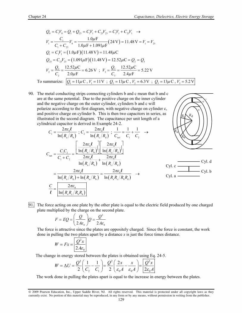
Chapter 24 Capacitance, Dielectrics, Electric Energy Storage
© 2009 Pearson Education, Inc., Upper Saddle River, NJ. All rights reserved. This material is protected under all copyright laws as they currently exist. No portion of this material may be reproduced, in any form or by any means, without permission in writing from the publisher.
129
0 1 0 1 23 1 1 23 23 1 1 23 1
11 0 1 23
1 23
1.0 F24 V 11.48V
1.0 F 1.091 F
Q C V Q Q C V C V C V C V
CV V V V
C C
1 1 1
23 23 23 2 3
2 32 3
2 3
1.0 F 11.48V 11.48 C
1.091 F 11.48 V 12.52 C
12.52 C 12.52 C6.26 V ; 5.22 V
2.0 F 2.4 F
Q C V
Q C V Q Q
Q QV V
C C
To summarize: 1 1 2 2 3 311 C , 11V ; 13 C , 6.3V ; 13 C , 5.2 VQ V Q V Q V
90. The metal conducting strips connecting cylinders b and c mean that b and c
are at the same potential. Due to the positive charge on the inner cylinder and the negative charge on the outer cylinder, cylinders b and c will polarize according to the first diagram, with negative charge on cylinder c, and positive charge on cylinder b. This is then two capacitors in series, as illustrated in the second diagram. The capacitance per unit length of a cylindrical capacitor is derived in Example 24-2.
0 01 2
a b c d net 1 2
0 0
a b c d1 2net
0 01 2
a b c d
0 0
c d a b a c b d
0
a c b d
2 2 1 1 1 ; ;
ln ln
2 2
ln ln
2 2
ln ln
2 2
ln ln ln
2
ln
C CR R R R C C C
R R R RC CC
C CR R R R
R R R R R R R R
C
R R R R
l l
l l
l l
l l
l
91. The force acting on one plate by the other plate is equal to the electric field produced by one charged
plate multiplied by the charge on the second plate. 2
0 02 2
Q QF EQ Q
A A
The force is attractive since the plates are oppositely charged. Since the force is constant, the work done in pulling the two plates apart by a distance x is just the force times distance.
2
02
Q xW Fx
A
The change in energy stored between the plates is obtained using Eq. 24-5. 2 2 2
2 1 0 0 0
1 1 2
2 2 2
Q Q x x Q xW U
C C A A A
The work done in pulling the plates apart is equal to the increase in energy between the plates.
R a Rb
Rc R d +
–+
–
Cyl. dCyl. c
Cyl. bCyl. a

Physics for Scientists & Engineers with Modern Physics, 4th Edition Instructor Solutions Manual
© 2009 Pearson Education, Inc., Upper Saddle River, NJ. All rights reserved. This material is protected under all copyright laws as they currently exist. No portion of this material may be reproduced, in any form or by any means, without permission in writing from the publisher.
130
92. Since the other values in this problem manifestly have 2 significant figures, we assume that the capacitance also has 2 significant figures. (a) The number of electrons is found from the charge on the capacitor.
15
5
19
30 10 F 1.5V 2.8 10 's
1.60 10 C
CVQ CV Ne N e
e
(b) The thickness is determined from the dielectric strength.
9
max min 9
min max
1.5V 1.5 10 m
1.0 10 V m
V VE d
d E
(c) The area is found from Eq. 24-8.
15 9
13
0 12 2 2
0
30 10 F 1.5 10 m 2.0 10 m
25 8.85 10 C N m
A CdC K A
d K
93. Use Eq. 24-2 for the capacitance.
12 2 2 4 2
160 08.85 10 C N m 1.0 10 m
9 10 m1F
A AC d
d C
No , this is not practically achievable. The gap would have to be smaller than the radius of a proton. 94. See the schematic diagram for the arrangement. The two
“capacitors” are in series, and so have the same charge. Thus their voltages, which must total 25kV, will be inversely proportional to their capacitances. Let C1 be the glass-filled capacitor, and C2 be the vinyl capacitor. The area of the foot is approximately twice the area of the hand, and since there are two feet on the floor and only one hand on the screen, the area
ratio is foot
hand
4.
1
A
A
21 1 2 2 1 2
1
0 glass hand 0 vinyl foot
1 2
glass vinyl
;
CQ C V C V V V
C
K A K AC C
d d
0 vinyl foot
vinyl vinyl foot glass2
0 glass hand1 glass hand vinyl
glass
21 2 2 2 2 2
1
3 4 0.631.5
5 1 1.0
2.5 25,000 V 10,000 V
K A
d K A dCK AC K A d
d
CV V V V V V V
C
95. (a) Use Eq. 24-2 to calculate the capacitance.
12 2 2 2
900 3
8.85 10 C N m 2.0 m5.9 10 F
3.0 10 m
AC
d
Use Eq. 24-1 to calculate the charge.
25kV
6.3mm glass
1cm vinyl
hand
feet
floor

Chapter 24 Capacitance, Dielectrics, Electric Energy Storage
© 2009 Pearson Education, Inc., Upper Saddle River, NJ. All rights reserved. This material is protected under all copyright laws as they currently exist. No portion of this material may be reproduced, in any form or by any means, without permission in writing from the publisher.
131
9 7 7
0 0 0 5.9 10 F 45V 2.655 10 C 2.7 10 CQ C V
The electric field is the potential difference divided by the plate separation.
00 3
45V15000 V m
3.0 10 m
VE
d
Use Eq. 24-5 to calculate the energy stored.
22 9 61 10 0 02 2 5.9 10 F 45V 6.0 10 JU C V
(b) Now include the dielectric. The capacitance is multiplied by the dielectric constant.
9 8 8
0 3.2 5.9 10 F 1.888 10 F 1.9 10 FC KC
The voltage doesn’t change. Use Eq. 24-1 to calculate the charge.
9 7 7
0 3.2 5.9 10 F 45V 8.496 10 C 8.5 10 CQ CV KC V
Since the battery is still connected, the voltage is the same as before, and so the electric field doesn’t change.
0 15000 V mE E
Use Eq. 24-5 to calculate the energy stored.
22 2 9 51 1 102 2 2 3.2 5.9 10 F 45V 1.9 10 JU CV KC V
96. (a) For a plane conducting surface, the electric field is given by Eq. 22-5.
6 12 2 2 4 2
max S 0
0 0
7 7
3 10 N C 8.85 10 C N m 150 10 m
3.98 10 C 4 10 C
QE Q E A
A
(b) The capacitance of an isolated sphere is derived in the text, right after Example 24-3.
12 2 2 10 10
04 4 8.85 10 C N m 1m 1.11 10 F 1 10 FC r
(c) Use Eq. 24-1, with the maximum charge from part (a) and the capacitance from part (b).
7
10
3.98 10 C 3586 V 4000 V
1.11 10 F
QQ CV V
C
97. (a) The initial capacitance is obtained directly from Eq. 24-8.
00 3
3.7 8.85 pF/m 0.21m 0.14 m32 nF
0.030 10 m
K AC
d
(b) Maximum charge will occur when the electric field between the plates is equal to the dielectric strength. The charge will be equal to the capacitance multiplied by the maximum voltage, where the maximum voltage is the electric field times the separation distance of the plates.
6 3
max 0 0 32 nF 15 10 V/m 0.030 10 m
14 C
Q C V C Ed
(c) The sheets of foil would be separated by sheets of paper with alternating sheets connected together on each side. This capacitor would consist of 100 sheets of paper with 101 sheets of foil.
Al paper101 100 101 0.040 mm 100 0.030 mm
7.0 mm
t d d

Physics for Scientists & Engineers with Modern Physics, 4th Edition Instructor Solutions Manual
© 2009 Pearson Education, Inc., Upper Saddle River, NJ. All rights reserved. This material is protected under all copyright laws as they currently exist. No portion of this material may be reproduced, in any form or by any means, without permission in writing from the publisher.
132
(d) Since the capacitors are in parallel, each capacitor has the same voltage which is equal to the
total voltage. Therefore breakdown will occur when the voltage across a single capacitor provides an electric field across that capacitor equal to the dielectric strength.
6 3
max max 15 10 V/m 0.030 10 m 450 VV E d
98. From Eq. 24-2, 0 .C Ad
So if
we plot C vs. A, we should get a
straight line with a slope of 0 .d
0
0
12 2 2
12 2
3
slope
slope
8.85 10 C N m
8606 10 F m
1.03 10 m 1.0 mm
d
d
The spreadsheet used for this problem can be found on the Media Manager, with filename “PSE4_ISM_CH24.XLS,” on tab “Problem 24.98.”
C = 8606 A
R2 = 0.99
0
200
400
600
800
1000
1200
0.00 0.02 0.04 0.06 0.08 0.10 0.12
A (m2)
C (
pF)

© 2009 Pearson Education, Inc., Upper Saddle River, NJ. All rights reserved. This material is protected under all copyright laws as they currently exist. No portion of this material may be reproduced, in any form or by any means, without permission in writing from the publisher.
133
CHAPTER 25: Electric Currents and Resistance Responses to Questions 1. A battery rating in ampere-hours gives the total amount of charge available in the battery. 2. The chemical reactions within the cell cause electrons to pile up on the negative electrode. If the
terminals of the battery are connected in a circuit, then electrons flow from the negative terminal because it has an excess of electrons. Once the electrons return to the cell, the electrolyte again causes them to move to the negative terminal.
3. When a flashlight is operated, the battery energy is being used up. 4. The terminal of the car battery connected to “ground” is actually connected to the metal frame of the
car. This provides a large “sink” or “source” for charge. The metal frame serves as the common ground for all electrical devices in the car, and all voltages are measured with respect to the car’s frame.
5. Generally, water is already in the faucet spout, but it will not come out until the faucet valve is
opened. Opening the valve provides the pressure difference needed to force water out of the spout. The same thing is essentially true when you connect a wire to the terminals of a battery. Electrons already exist in the wires. The battery provides the potential that causes them to move, producing a current.
6. Yes. They might have the same resistance if the aluminum wire is thicker. If the lengths of the wires
are the same, then the ratios of resistivity to cross-sectional area must also be the same for the resistances to be the same. Aluminum has a higher resistivity than copper, so if the cross-sectional area of the aluminum is also larger by the same proportion, the two wires will have the same resistance.
7. If the emf in a circuit remains constant and the resistance in the circuit is increased, less current will
flow, and the power dissipated in the circuit will decrease. Both power equations support this result. If the current in a circuit remains constant and the resistance is increased, then the emf must increase and the power dissipated in the circuit will increase. Both equations also support this result. There is no contradiction, because the voltage, current, and resistance are related to each other by V = IR.
8. When a lightbulb burns out, the filament breaks, creating a gap in the circuit so that no current flows. 9. If the resistance of a small immersion heater were increased, it would slow down the heating
process. The emf in the circuit made up of the heater and the wires that connect it to the wall socket is maintained at a constant rms value. If the resistance in the circuit is increased, less current will flow, and the power dissipated in the circuit will decrease, slowing the heating process.
10. Resistance is proportional to length and inversely proportional to cross-sectional area.
(a) For the least resistance, you want to connect the wires to maximize area and minimize length. Therefore, connect them opposite to each other on the faces that are 2a by 3a.
(b) For the greatest resistance, you want to minimize area and maximize length. Therefore, connect the wires to the faces that are 1a by 2a.

Physics for Scientists & Engineers with Modern Physics, 4th Edition Instructor Solutions Manual
© 2009 Pearson Education, Inc., Upper Saddle River, NJ. All rights reserved. This material is protected under all copyright laws as they currently exist. No portion of this material may be reproduced, in any form or by any means, without permission in writing from the publisher.
134
11. When a light is turned on, the filament is cool, and has a lower resistance than when it is hot. The current through the filament will be larger, due to the lower resistance. This momentary high current will heat the wire rapidly, possibly causing the filament to break due to thermal stress or vaporize. After the light has been on for some time, the filament is at a constant high temperature, with a higher resistance and a lower current. Since the temperature is constant, there is less thermal stress on the filament than when the light is first turned on.
12. When connected to the same potential difference, the 100-W bulb will draw more current (P = IV).
The 75-W bulb has the higher resistance (V = IR or P = V²/R). 13. The electric power transferred by the lines is P = IV. If the voltage across the transmission lines is
large, then the current in the lines will be small. The power lost in the transmission lines is P = I²R. The power dissipated in the lines will be small, because I is small.
14. If the circuit has a 15-A fuse, then it is rated to carry current of no more than 15 A. Replacing the 15-
A fuse with a 25-A fuse will allow the current to increase to a level that is dangerously high for the wiring, which might result in overheating and possibly a fire.
15. The human eye and brain cannot distinguish the on-off cycle of lights when they are operated at the
normal 60 Hz frequency. At much lower frequencies, such as 5 Hz, the eye and brain are able to process the on-off cycle of the lights, and they will appear to flicker.
16. The electrons are not “used up” as they pass through the lamp. Their energy is dissipated as light and
heat, but with each cycle of the alternating voltage, their potential energy is raised again. As long as the electrons keep moving (converting potential energy into kinetic energy, light, and heat) the lamp will stay lit.
17. Immediately after the toaster is turned on, the Nichrome wire heats up and its resistance increases.
Since the (rms) potential across the element remains constant, the current in the heating element must decrease.
18. No. Energy is dissipated in a resistor but current, the rate of flow of charge, is not “used up.” 19. In the two wires described, the drift velocities of the electrons will be about the same, but the current
density, and therefore the current, in the wire with twice as many free electrons per atom will be twice as large as in the other wire.
20. (a) If the length of the wire doubles, its resistance also doubles, and so the current in the wire will
be reduced by a factor of two. Drift velocity is proportional to current, so the drift velocity will be halved.
(b) If the wire’s radius is doubled, the drift velocity remains the same. (Although, since there are more charge carriers, the current will quadruple.)
(c) If the potential difference doubles while the resistance remains constant, the drift velocity and current will also double.
21. If you turn on an electric appliance when you are outside with bare feet, and the appliance shorts out
through you, the current has a direct path to ground through your feet, and you will receive a severe shock. If you are inside wearing socks and shoes with thick soles, and the appliance shorts out, the current will not have an easy path to ground through you, and will most likely find an alternate path. You might receive a mild shock, but not a severe one.

Chapter 25 Electric Currents and Resistance
© 2009 Pearson Education, Inc., Upper Saddle River, NJ. All rights reserved. This material is protected under all copyright laws as they currently exist. No portion of this material may be reproduced, in any form or by any means, without permission in writing from the publisher.
135
Solutions to Problems 1. Use the definition of current, Eq. 25-1a.
18
19
1.30C 1 electron 1.30A 8.13 10 electrons s
s 1.60 10 C
QI
t
2. Use the definition of current, Eq. 25-1a.
5 6.7 A 5.0h 3600s h 1.2 10 CQ
I Q I tt
3. Use the definition of current, Eq. 25-1a.
19
11
6
1200 ions 1.60 10 C ion5.5 10 A
3.5 10 s
QI
t
4. Solve Eq. 25-2a for resistance.
120V
294.2A
VR
I
5. (a) Use Eq. 25-2b to find the current.
240V
27.91A 28A8.6
VV IR I
R
(b) Use the definition of current, Eq. 25-1a.
4 27.91A 50min 60s min 8.4 10 CQ
I Q I tt
6. (a) Solve Eq. 25-2a for resistance.
120V
12.63 139.5A
VR
I
(b) Use the definition of average current, Eq. 25-1a.
9.5A 15min 60s min 8600CQ
I Q I tt
7. Use Ohm’s Law, Eq. 25-2a, to find the current. Then use the definition of current, Eq. 25-1a, to
calculate the number of electrons per minute.
21
19
4.5V 2.8C 1 electron 60s electrons1.1 10
1.6 s 1.60 10 C 1min minute
V QI
R t
8. Find the potential difference from the resistance and the current.
5 2 6
6 3
2.5 10 m 4.0 10 m 1.0 10
3100A 1.0 10 3.1 10 V
R
V IR

Physics for Scientists & Engineers with Modern Physics, 4th Edition Instructor Solutions Manual
© 2009 Pearson Education, Inc., Upper Saddle River, NJ. All rights reserved. This material is protected under all copyright laws as they currently exist. No portion of this material may be reproduced, in any form or by any means, without permission in writing from the publisher.
136
9. (a) Use Eq. 25-2b to find the resistance.
12V
200.60A
VR
I (2 sig. fig.)
(b) An amount of charge Q loses a potential energy of Q V as it passes through the resistor.
The amount of charge is found from Eq. 25-1a.
0.60A 60s 12 V 430JU Q V I t V
10. (a) If the voltage drops by 15%, and the resistance stays the same, then by Eq. 25-2b, V IR , the
current will also drop by 15%.
final initial0.85 0.85 6.50A 5.525A 5.5AI I
(b) If the resistance drops by 15% (the same as being multiplied by 0.85), and the voltage stays the same, then by Eq. 25-2b, the current must be divided by 0.85.
initialfinal
6.50A7.647 A 7.6A
0.85 0.85
II
11. Use Eq. 25-3 to find the diameter, with the area as 2 2 4A r d .
8
4
2
4 1.00m 5.6 10 m4 4 4.7 10 m
0.32R d
A d R
l l l
12. Use Eq. 25-3 to calculate the resistance, with the area as 2 2 4A r d .
8 2
22 3
4 4.5m41.68 10 m 4.3 10
1.5 10 mR
A d
l l
13. Use Eq. 25-3 to calculate the resistances, with the area as 2 2 4.A r d
2
4R
A d
l l.
Al28Al 22
Al Al Al CuAl22 8
CuCu Cu Cu AlCu 2
Cu
42.65 10 m 10.0m 1.8mm
0.644 1.68 10 m 20.0m 2.0mm
R dd
R dd
l
l
l l
14. Use Eq. 25-3 to express the resistances, with the area as 2 2 4A r d , and so 2
4.R
A d
l l
W Cu W Cu2 2
W Cu
8
WW Cu 8
Cu
4 4
5.6 10 m2.2 mm 4.0mm
1.68 10 m
R Rd d
d d
l l
The diameter of the tungsten should be 4.0 mm.

Chapter 25 Electric Currents and Resistance
© 2009 Pearson Education, Inc., Upper Saddle River, NJ. All rights reserved. This material is protected under all copyright laws as they currently exist. No portion of this material may be reproduced, in any form or by any means, without permission in writing from the publisher.
137
15. (a) If the wire obeys Ohm’s law, then V IR or 1
,I VR
showing a linear relationship between I
and V. A graph of I vs. V should give a straight line with a slope of 1
R and a y-intercept of 0.
(b) From the graph and the calculated linear fit, we see that the wire obeys Ohm’s law.
1slope
1A V
0.720
1.39
R
R
The spreadsheet used for this problem can be found on the Media Manager, with filename “PSE4_ISM_CH25.XLS,” on tab “Problem 25.15b.”
(c) Use Eq. 25-3 to find the resistivity.
2426
3.2 10 m 1.39 1.0 10 m
4 4 0.11m
AR d RR
A
l
l l
From Table 25-1, the material is nichrome. 16. Use Eq. 25-5 multiplied by Al so that it expresses resistance instead of resistivity.
0 0 0 0
0 1
1 1.15 1 1.15
0.15 0.1522C
.0068 C
R R T T R T T
T T
So raise the temperature by 22 C to a final temperature of 42 C . 17. Since the resistance is directly proportional to the length, the length of the long piece must be 4.0
times the length of the short piece. short long short short short short long4.0 5.0 0.20 , 0.80 l l l l l l l l l l
Make the cut at 20% of the length of the wire .
short long short long0.20 , 0.80 0.2 2.0 , 0.8 8.0R R R R l l l l
18. Use Eq. 25-5 for the resistivity.
T Al 0 Al Al 0 0 W
8
0 W0 1 8
Al 0 Al
1
1 1 5.6 10 m1 20 C 1 279.49 C 280 C
2.65 10 m0.00429 C
T T
T T
19. Use Eq. 25-5 multiplied by Al so that it expresses resistances instead of resistivity.
0 01 R R T T
0 1
0
1 1 1401 20 C 1 2390 C 2400 C
120.0045 C
RT T
R
I = 0.720 V
0
0.1
0.2
0.3
0.4
0 0.1 0.2 0.3 0.4 0.5 0.6V (V)
I (A
)

Physics for Scientists & Engineers with Modern Physics, 4th Edition Instructor Solutions Manual
© 2009 Pearson Education, Inc., Upper Saddle River, NJ. All rights reserved. This material is protected under all copyright laws as they currently exist. No portion of this material may be reproduced, in any form or by any means, without permission in writing from the publisher.
138
20. Calculate the voltage drop by combining Ohm’s Law (Eq. 25-2b) with the expression for resistance, Eq. 25-3.
8
22 3
4 1.68 10 m 26m412A 2.5V
1.628 10 mV IR I I
A d
l l
21. The wires have the same resistance and the same resistivity.
2
long longshortshort shortlong short 2
1 2 short shortlong
4 2 4 2
dR R
A A d dd
l ll l
22. In each case calculate the resistance by using Eq. 25-3 for resistance.
(a)
5 2
4 4
2 2
3.0 10 m 1.0 10 m3.75 10 3.8 10
2.0 10 m 4.0 10 mx
x
yz
RA
l
(b)
5 2
3
2 2
3.0 10 m 2.0 10 m1.5 10
1.0 10 m 4.0 10 my
y
xz
RA
l
(c)
5 2
3
2 2
3.0 10 m 4.0 10 m6.0 10
1.0 10 m 2.0 10 mz
z
xy
RA
l
23. The original resistance is 0 0R V I , and the high temperature resistance is R V I , where the two
voltages are the same. The two resistances are related by Eq. 25-5, multiplied by Al so that it expresses resistance instead of resistivity.
00 0 0 0 0
0 0
1
1 1 11 1 1 1
1 0.4212A 20.0 C 1 44.1 C
0.3818A0.00429 C
R V I IR R T T T T T T
R V I I
24. For the cylindrical wire, its (constant) volume is given by 0 0 ,V A A l l and so .V
A l
Combine
this relationship with Eq. 25-3. We assume that 0.l l
2 2
0 00
0 0 0 0
0 0 1222
0
0
; ; 2
2 2 2
2
dRR R
A V A V d V
dR V R V R R RR
d V R
V
l l l l l
l
l ll l l
ll l l l
This is true for any initial conditions, and so 12
0 0
R
R
l
l

Chapter 25 Electric Currents and Resistance
© 2009 Pearson Education, Inc., Upper Saddle River, NJ. All rights reserved. This material is protected under all copyright laws as they currently exist. No portion of this material may be reproduced, in any form or by any means, without permission in writing from the publisher.
139
25. The resistance depends on the length and area as .R A l Cutting the wire and running the wires side by side will halve the length and double the area.
12 1 1
2 14 42R R
A A
l l
26. The total resistance is to be 3700 ohms totalR at all temperatures. Write each resistance in terms of
Eq.25-5 (with o
0 0 CT ), multiplied by Al to express resistance instead of resistivity.
total 0C C 0N N 0C 0C C 0N 0N N
0C 0N 0C C 0N N
1 1
R R T R T R R T R R T
R R R R T
For the above to be true, the terms with a temperature dependence must cancel, and the terms without a temperature dependence must add to totalR . Thus we have two equations in two unknowns.
0C C0C C 0N N 0N
N
0C N C0C Ctotal 0C 0N 0C
N N
0
RR R T R
RRR R R R
1o
N0C total 1 1o o
N C
0N total 0C
0.0004 C3700 1644 1600
0.0004 C 0.0005 C
3700 1644 2056 2100
R R
R R R
27. We choose a spherical shell of radius r and thickness dr as a differential element. The area of this
element is 24 .r Use Eq. 25-3, but for an infinitesimal resistance. Then integrate over the radius of the sphere.
22
11
2 2
1 2
1 1 1 1 1
4 4 4 4
rr
rr
d dr drR dR R dR
A A r r r r r
l l
28. (a) Let the values at the lower temperature be indicated by a subscript “0”. Thus 00 0
0
RA
l
00 2
0
4.
d
l
The change in temperature results in new values for the resistivity, the length, and
the diameter. Let represent the temperature coefficient for the resistivity, and T represent
the thermal coefficient of expansion, which will affect the length and diameter.
0 T 0 000 0 022 2
0 T 00 T 0
00 T 0 0 0
T 0
4 1 14 41
11
1 1 1
1
T T T TR T T
A d d T Td T T
T TR R T T R T T
T T
ll l l

Physics for Scientists & Engineers with Modern Physics, 4th Edition Instructor Solutions Manual
© 2009 Pearson Education, Inc., Upper Saddle River, NJ. All rights reserved. This material is protected under all copyright laws as they currently exist. No portion of this material may be reproduced, in any form or by any means, without permission in writing from the publisher.
140
00 1 6 1
0 T
140 1220 C
12 0.0045C 140 5.5 10 C
20 C 2405 C 2425 C 2400 C
R RT T
R R
(b) The net effect of thermal expansion is that both the length and diameter increase, which lowers the resistance.
2 20 20 T 00 0
2200 0 0 T 00 T 0
0 2
0
6 1
0
0 0
41 1
4 11
1 0.9869
1 5.5 10 C 2405 C
% change 100 1 100 1.31 1.3%
T TR d ddR d T Td T T
d
R R R
R R
l
ll
l l l
The net effect of resistivity change is that the resistance increases.
02
10 000
00 0 00 2
0
0
0 0
4
11 1 0.0045C 2405 C
4
11.82
% change 100 1 100 1082 1100%
T TR dT T
Rd
R R R
R R
l
l
29. (a) Calculate each resistance separately using Eq. 25-3, and then add the resistances together to find
the total resistance.
8
Cu CuCu 22 3
8
Al AlAl 22 3
total Cu Al
4 1.68 10 m 5.0m40.054567
1.4 10 m
4 2.65 10 m 5.0m40.086074
1.4 10 m
0.054567 0.086074 0.140641 0.14
RA d
RA d
R R R
l l
l l
(b) The current through the wire is the voltage divided by the total resistance.
3
total
85 10 V0.60438A 0.60A
0.140641
VI
R
(c) For each segment of wire, Ohm’s law is true. Both wires have the current found in (b) above.
Cu Cu
Al Al
0.60438A 0.054567 0.033V
0.60438A 0.086074 0.052V
V IR
V IR
Notice that the total voltage is 85 mV.

Chapter 25 Electric Currents and Resistance
© 2009 Pearson Education, Inc., Upper Saddle River, NJ. All rights reserved. This material is protected under all copyright laws as they currently exist. No portion of this material may be reproduced, in any form or by any means, without permission in writing from the publisher.
141
30. (a) Divide the cylinder up into concentric cylindrical shells of radius r, thickness dr, and length l. See the diagram. The resistance of one of those shells, from Eq. 25-3, is found. Note that the “length” in Eq. 25-3 is in the direction of the current flow, so we must substitute in dr for the “length” in Eq. 25-3. The area is the surface area of the thin cylindrical shell. Then integrate over the range of radii to find the total resistance.
2
1
2
1
" " ;
2
ln2 2
r
r
drR dR
A r
dr rR dR
r r
l
l
l l
(b) Use the data given to calculate the resistance from the above formula.
542
1
15 10 m 1.8mmln ln 5.8 10
2 2 0.024m 1.0mm
rR
r
l
(c) For resistance along the axis, we again use Eq. 25-3, but the current is flowing in the direction of length l. The area is the cross-sectional area of the face of the hollow cylinder.
5
2 2 2 23 32 1
15 10 m 0.024m0.51
1.8 10 m 1.0 10 mR
A r r
l l
31. Use Eq. 25-6 to find the power from the voltage and the current.
0.27 A 3.0V 0.81WP IV
32. Use Eq. 25-7b to find the resistance from the voltage and the power.
22 2 240V
173300 W
V VP R
R P
33. Use Eq. 25-7b to find the voltage from the power and the resistance.
2
3300 0.25W 29VV
P V RPR
34. Use Eq. 25-7b to find the resistance, and Eq. 25-6 to find the current.
(a) 22 2 110V
161.3 16075W
V VP R
R P
75W
0.6818A 0.68A110V
PP IV I
V
(b) 22 2 110V
27.5 28440W
V VP R
R P
440W
4.0A110V
PP IV I
V
r1
r
dr
r2

Physics for Scientists & Engineers with Modern Physics, 4th Edition Instructor Solutions Manual
© 2009 Pearson Education, Inc., Upper Saddle River, NJ. All rights reserved. This material is protected under all copyright laws as they currently exist. No portion of this material may be reproduced, in any form or by any means, without permission in writing from the publisher.
142
35. (a) From Eq. 25-6, if power P is delivered to the transmission line at voltage V, there must be a current .I P V As this current is carried by the transmission line, there will be power losses
of 2I R due to the resistance of the wire. This power loss can be expressed as 2P I R 2 2 .P R V Equivalently, there is a voltage drop across the transmission lines of .V IR
Thus the voltage available to the users is ,V V and so the power available to the users is
2 2 .P V V I VI V I VI I R P I R The power loss is 2P P P P P I R
2 2 2 .I R P R V
(b) Since 2
1,P
V V should be as large as possible to minimize .P
36. (a) Since 2 2
V V
P RR P
says that the resistance is inversely proportional to the power for a
constant voltage, we predict that the 850 W setting has the higher resistance.
(b) 22 120V
17850 W
VR
P
(c) 22 120V
121250 W
VR
P
37. (a) Use Eq. 25-6 to find the current.
95W
0.83A115V
PP IV I
V
(b) Use Eq. 25-7b to find the resistance.
22 2 115V
14095W
V VP R
R P
38. The power (and thus the brightness) of the bulb is proportional to the square of the voltage,
according to Eq. 25-7b, 2V
PR
. Since the resistance is assumed to be constant, if the voltage is cut
in half from 240 V to 120V, the power will be reduced by a factor of 4. Thus the bulb will appear only about 1/4 as bright in the United States as in Europe.
39. To find the kWh of energy, multiply the kilowatts of power consumption by the number of hours in
operation.
1kW 1hEnergy in kW in h 550W 6.0min 0.055kWh
1000W 60minP t
To find the cost of the energy used in a month, multiply times 4 days per week of usage, times 4 weeks per month, times the cost per kWh.
kWh 4d 4 week 9.0cents
Cost 0.055 7.9cents monthd 1week 1month kWh

Chapter 25 Electric Currents and Resistance
© 2009 Pearson Education, Inc., Upper Saddle River, NJ. All rights reserved. This material is protected under all copyright laws as they currently exist. No portion of this material may be reproduced, in any form or by any means, without permission in writing from the publisher.
143
40. To find the cost of the energy, multiply the kilowatts of power consumption by the number of hours in operation times the cost per kWh.
1kW 24h $0.095Cost 25W 365day $21
1000 W 1day kWh
41. The A h rating is the amount of charge that the battery can deliver. The potential energy of the
charge is the charge times the voltage.
63600s75A h 12V 3.2 10 J 0.90kWh
1hU QV
42. (a) Calculate the resistance from Eq. 25-2b and the power from Eq. 25-6.
3.0V7.895 7.9 0.38A 3.0V 1.14 W 1.1W
0.38A
VR P IV
I
(b) If four D-cells are used, the voltage will be doubled to 6.0 V. Assuming that the resistance of the bulb stays the same (by ignoring heating effects in the filament), the power that the bulb
would need to dissipate is given by Eq. 25-7b, 2V
PR
. A doubling of the voltage means the
power is increased by a factor of 4 . This should not be tried because the bulb is probably not rated for such a high wattage. The filament in the bulb would probably burn out, and the glass bulb might even explode if the filament burns violently.
43. Each bulb will draw an amount of current found from Eq. 25-6.
bulb P
P IV IV
The number of bulbs to draw 15 A is the total current divided by the current per bulb.
total
total bulb
120 V 15 A 24 bulbs
75 W
VIPI nI n n
V P
44. Find the power dissipated in the cord by Eq. 25-7a, using Eq. 25-3 for the resistance.
22 2 2 2 8
22 2 2
4 5.4 m415.0 A 1.68 10 m
4 0.129 10 m
15.62 W 16 W
P I R I I IA d d
l l l
45. Find the current used to deliver the power in each case, and then find the power dissipated in the
resistance at the given current.
22
dissipated 2
25
dissipated 2412,000 V
=
7.5 10 W3.0 11719 W
1.2 10 V
P PP IV I P I R R
V V
P
25
4
dissipated 2450,000 V
7.5 10 W3.0 675W difference 11719 W 675W 1.1 10 W
5 10 VP

Physics for Scientists & Engineers with Modern Physics, 4th Edition Instructor Solutions Manual
© 2009 Pearson Education, Inc., Upper Saddle River, NJ. All rights reserved. This material is protected under all copyright laws as they currently exist. No portion of this material may be reproduced, in any form or by any means, without permission in writing from the publisher.
144
46. (a) By conservation of energy and the efficiency claim, 75% of the electrical power dissipated by the heater must be the rate at which energy is absorbed by the water.
heat wateremitted by absorbedelectromagnet by water
0.75 0.75 Q mc T
P IVt t
0.120 kg 4186J kg 95 C 25 C
8.139 A 8.1A0.75 0.75 12 V 480s
mc TI
Vt
(b) Use Ohm’s law to find the resistance of the heater.
12 V
1.58.139 A
VV IR R
I
47. The water temperature rises by absorbing the heat energy that the electromagnet dissipates. Express
both energies in terms of power, which is energy per unit time.
heat waterelectric to heat
water
17.5A 240 V0.154 kg s 0.15kg s
4186J kg C 6.50C
Q mc TP P IV
t t
m IV
t c T
This is 154 mL s. 48. For the wire to stay a constant temperature, the power generated in the resistor is to be dissipated by
radiation. Use Eq. 25-7a and 19-18, both expressions of power (energy per unit time). We assume that the dimensions requested and dimensions given are those at the higher temperature, and do not take any thermal expansion effects into account. We also use Eq. 25-3 for resistance.
2 4 4 2 4 4
high low high low2
1/ 31/ 3 2 82
2 4 4 4 42 8 2 4high low
5
4
4 15.0 A 5.6 10 m4
1.0 5.67 10 W m K 3100 K 293K
9.92 10 m 0.099 mm
I R A T T I d T Td
Id
T T
ll
49. Use Ohm’s law and the relationship between peak and rms values.
rmspeak rms
220V2 2 2 0.12 A
2700
VI I
R
50. Find the peak current from Ohm’s law, and then find the rms current from Eq. 25-9a.
peak
peak rms peak
180 V0.47368A 0.47 A 2 0.47368A 2 0.33A
380
VI I I
R
51. (a) When everything electrical is turned off, no current will be flowing into the house, even though
a voltage is being supplied. Since for a given voltage, the more resistance, the lower the current, a zero current corresponds to an infinite resistance.
(b) Use Eq. 25-7a to calculate the resistance.
22 2 120 V = 96
2 75W
V VP R
R P

Chapter 25 Electric Currents and Resistance
© 2009 Pearson Education, Inc., Upper Saddle River, NJ. All rights reserved. This material is protected under all copyright laws as they currently exist. No portion of this material may be reproduced, in any form or by any means, without permission in writing from the publisher.
145
52. The power and current can be used to find the peak voltage, and then the rms voltage can be found from the peak voltage.
peak
rms rms rms rms
peak
2 1500 W2 390 V
5.4 A2
I PP I V V V
I
53. Use the average power and rms voltage to calculate the peak voltage and peak current.
(a) peak rms2 2 660 V 933.4 V 930 VV V
(b) peak
rms rms rms peak
rms
2 1800 W2 3.9 A
660 V2
I PP I V V I
V
54. (a) We assume that the 2.5 hp is the average power, so the maximum power is twice that, or 5.0 hp,
as seen in Figure 25-22.
746W
5.0hp 3730W 3700W1hp
(b) Use the average power and the rms voltage to find the peak current.
1
peak 2rms rms rms peak
rms
2 3730 W2 11A
240 V2
I PP I V V I
V
55. (a) The average power used can be found from the resistance and the rms voltage by Eq. 25-10c.
22
rms240 V
1309 W 1300 W44
VP
R
(b) The maximum power is twice the average power, and the minimum power is 0.
max min2 2 1309 W 2600 W 0 WP P P
56. (a) Find rms.V Use an integral from Appendix B-4, page A-7.
1/ 2
1/ 2 1/ 22 2 2
0 0 0rms 0
0
0
4sin
1 2sin
82 2 2
T
T
tt V t V VTV V dt
T T TT
(b) Find rms.V
1/ 2 1/ 2 1/ 2/ 2 2
22 2 0 0rms 0
0 0 / 2
1 1 10 0
2 2
T T T
T
V T VV V dt V dt dt
T T T T
57. (a) We follow the derivation in Example 25-14. Start with Eq. 25-14, in absolute value.
d d 22 D1
2D
6 3
10
d 223 3 3 19 3
4
1 mole
1 mole
4 2.3 10 A 63.5 10 kg5.1 10 m s
6.02 10 8.9 10 kg m 1.60 10 C 0.65 10 m
j I I I mj nev v
ne neA N e dNe d
m
v

Physics for Scientists & Engineers with Modern Physics, 4th Edition Instructor Solutions Manual
© 2009 Pearson Education, Inc., Upper Saddle River, NJ. All rights reserved. This material is protected under all copyright laws as they currently exist. No portion of this material may be reproduced, in any form or by any means, without permission in writing from the publisher.
146
(b) Calculate the current density from Eq. 25-11.
6
2 2
22 2 4
4 2.3 10 A46.931A m 6.9 A m
6.5 10 m
I I Ij
A r d
(c) The electric field is calculated from Eq. 25-17.
8 2 71 1.68 10 m 6.931A m 1.2 10 V mj E E j
58. (a) Use Ohm’s law to find the resistance.
0.0220 V
0.02933 0.0290.75A
VV IR R
I
(b) Find the resistivity from Eq. 25-3.
2328 8
0.02933 1.0 10 m1.589 10 m 1.6 10 m
5.80 m
RA
RA R r
l
l l
(c) Use Eq. 25-11 to find the current density.
5 2 5 2
22
0.752.387 10 A m 2.4 10 A m
0.0010 m
I Ij
A r
(d) Use Eq. 25-17 to find the electric field.
8 5 2 3 3
1
1.589 10 m 2.387 10 A m 3.793 10 V m 3.8 10 V m
j E
E j
(e) Find the number of electrons per unit volume from the absolute value of Eq. 25-14.
5 2
28 3
d 5 19
d
2.387 10 A m 8.8 10 e m
1.7 10 m s 1.60 10 C
jj nev n
v e
59. We are given a charge density and a speed (like the drift speed) for both types of ions. From that we
can use Eq. 25-13 (without the negative sign) to determine the current per unit area. Both currents are in the same direction in terms of conventional current – positive charge moving north has the same effect as negative charge moving south – and so they can be added.
d
12 3 19 6
d dHe O
11 3 19 6
2 2
2.8 10 ions m 2 1.60 10 C ion 2.0 10 m s
7.0 10 ions m 1.60 10 C ion 6.2 10 m s
2.486 A m 2.5A m , North
I neAv
Inev nev
A
60. The magnitude of the electric field is the voltage change per unit meter.
3
6
8
70 10 V7.0 10 V m
1.0 10 m
VE
x

Chapter 25 Electric Currents and Resistance
© 2009 Pearson Education, Inc., Upper Saddle River, NJ. All rights reserved. This material is protected under all copyright laws as they currently exist. No portion of this material may be reproduced, in any form or by any means, without permission in writing from the publisher.
147
61. The speed is the change in position per unit time.
2 27.20 10 m 3.40 10 m
35 m s0.0063s 0.0052s
xv
t
Two measurements are needed because there may be a time delay from the stimulation of the nerve to the generation of the action potential.
62. The power is the work done per unit time. The work done to move a charge through a potential
difference is the charge times the potential difference. The charge density must be multiplied by the surface area of the cell (the surface area of an open tube, length times circumference) to find the actual charge moved.
7 23 19 6
2
9
mol ions C 3 10 6.02 10 1.6 10 0.10 m 20 10 m 0.030 V
m s mol ion
5.4 10 W
W QV QP V
t t t
63. The energy supplied by the battery is the energy consumed by the lights.
supplied consumed
85A h 3600s h 12V 1h39913s 11.09 h 11h
92 W 3600s
E E Q V Pt
Q Vt
P
64. The ampere-hour is a unit of charge.
1C s 3600s1.00A h 3600 C
1A 1 h
65. Use Eqs. 25-3 and 25-7b.
2 2
2 2
2
242 2
8
2
4 ;
4
1.5V 5.0 10 m1.753m 1.8m
4 4 1.68 10 m 15W
V VR P
A r d Rd
V d
P
l l l
l
l
If the voltage increases by a factor of 6 without the resistance changing, the power will increase by a factor of 36. The blanket would theoretically be able to deliver 540 W of power, which might make the material catch on fire or burn the occupant.
66. Use Eq. 25-6 to calculate the current.
746 W
6.22 A120 V
PP IV I
V
67. From Eq. 25-2b, if R V I , then G I V
0.48A
0.16S3.0 V
IG
V

Physics for Scientists & Engineers with Modern Physics, 4th Edition Instructor Solutions Manual
© 2009 Pearson Education, Inc., Upper Saddle River, NJ. All rights reserved. This material is protected under all copyright laws as they currently exist. No portion of this material may be reproduced, in any form or by any means, without permission in writing from the publisher.
148
68. Use Eq. 25-7b to express the resistance in terms of the power, and Eq. 25-3 to express the resistance in terms of the wire geometry.
2 2
2 2
824
22 2
4
4 9.71 10 m 3.5m 1500 W44 2.3 10 m
110 V
V VP R R
R P A r d
V Pd
d P V
l l l
l l
69. (a) Calculate the total kWh used per day, and then multiply by the number of days and the cost per
kWh.
1.8kW 2.0 h d 4 0.1kW 6.0 h d 3.0 kW 1.0 h d 2.0 kWh d
11.0 kWh d
$0.105Cost 11.0 kWh d 30d $34.65 $35 per month
kWh
(b) The energy required by the household is 35% of the energy that needs to be supplied by the power plant.
Household Energy 0.35 coal mass coal energy per mass
1000 W 3600s11.0 kWh d 365d
kW 1hHousehold Energycoal mass
0.35 coal energy per mass kcal 4186J0.35 7500
kg 1kcal
1315kg
1300 kg of coal
70. To deliver 15 MW of power at 120 V requires a current of 6
515 10 W1.25 10 A
120 V
PI
V
.
Calculate the power dissipated in the resistors using the current and the resistance.
22 2 2 2 8
22 2 3
7
7
5 2 1.0 m4 4 1.25 10 A 1.68 10 m
5.0 10 m
2.674 10 W
1kW $0.090Cost Power time rate per kWh 2.674 10 W 1h
1000 W kWh
$2407 $2,400 per hour per meter
L L LP I R I I I
A r d
71. (a) Use Eq. 25-7b to relate the power to the voltage for a constant resistance.
2 22
105
2 2
117
105 V 105 V 0.805 or a 19.5% decrease
117 V 117 V
RPVP
R P R
(b) The lower power output means that the resistor is generating less heat, and so the resistor’s temperature would be lower. The lower temperature results in a lower value of the resistance, which would increase the power output at the lower voltages. Thus the decrease would be smaller than the value given in the first part of the problem.

Chapter 25 Electric Currents and Resistance
© 2009 Pearson Education, Inc., Upper Saddle River, NJ. All rights reserved. This material is protected under all copyright laws as they currently exist. No portion of this material may be reproduced, in any form or by any means, without permission in writing from the publisher.
149
72. Assume that we have a meter of wire, carrying 35 A of current, and dissipating 1.5 W of heat. The
power dissipated is 2
RP I R , and the resistance is RA
l.
2 2 2 2
2 2
8
2 3
4
1.68 10 m 1.0 m42 2 35A 4.2 10 m
1.5W
R
R R
P I R I I IA r d
d I IP P
l l l
l l
73. (a) The resistance at the operating temperature can be calculated directly from Eq. 25-7.
22 2 120 V190
75W
V VP R
R P
(b) The resistance at room temperature is found by converting Eq. 25-5 into an equation for resistances and solving for 0.R
0 0
0 10
1
19215
1 1 0.0045K 3000 K 293K
R R T T
RR
T T
74. (a) The angular frequency is 210 rad s .
210 rad s
33.42 Hz 33Hz2 2
f
(b) The maximum current is 1.80 A.
maxrms
1.80 A1.27 A
2 2
II
(c) For a resistor, V IR .
1.80 A sin 210 24.0 43.2sin 210 VV IR t t
75. (a) The power delivered to the interior is 65% of the power drawn from the source.
interiorinterior source source
950 W0.65 1462 W 1500 W
0.65 0.65
PP P P
(b) The current drawn is current from the source, and so the source power is used to calculate the current.
sourcesource source
source
1462 W 12.18A 12 A
120 V
PP IV I
V
76. The volume of wire is unchanged by the stretching. The volume is equal to the length of the wire
times its cross-sectional area, and since the length was increased by a factor of 1.20, the area was decreased by a factor of 1.20. Use Eq. 25-3.
20 0 0 00 0 0
00 0
1.20 1.20 1.20 1.44 1.44
1.201.20
AR A R R
AA A A l l l l
l l

Physics for Scientists & Engineers with Modern Physics, 4th Edition Instructor Solutions Manual
© 2009 Pearson Education, Inc., Upper Saddle River, NJ. All rights reserved. This material is protected under all copyright laws as they currently exist. No portion of this material may be reproduced, in any form or by any means, without permission in writing from the publisher.
150
77. The long, thick conductor is labeled as conductor number 1, and the short, thin conductor is labeled
as number 2. The power transformed by a resistor is given by Eq. 25-7b, 2P V R , and both have the same voltage applied.
1 21 2 1 2 1 2 1 2
1 2
2
1 1 1 2 2 2 2 11 22
2 2 2 1 1 1 1 2
2 4 diameter 2diameter
14 2 : 2 :1
2
R R A AA A
P V R R A AP P
P V R R A A
l ll l
l l
l l
78. The heater must heat 3108m of air per hour from o5 C to o20 C , and also replace the heat being lost at a rate of 850 kcal/h. Use Eq. 19-2 to calculate the energy needed to heat the air. The density of air is found in Table 13-1.
3
3
m kg kcal kcal 108 1.29 0.17 15C 355
h m kg C h
kcal kcal kcal 4186J 1hPower required 355 850 1205 1401W 1400 W
h h h kcal 3600s
Q mQ mc T c T
t t
79. (a) Use Eq. 25-7b.
22 2 240 V
20.57 212800 W
V VP R
R P
(b) Only 75% of the heat from the oven is used to heat the water. Use Eq. 19-2.
oven
oven
0.75 Heat absorbed by water
1kg0.120 L 4186J kg C 85C
1L20.33s 20s 2 sig. fig.
0.75 0.75 2800 W
P t mc T
mc Tt
P
(c) 11cents 1h2.8 kW 20.33s 0.17 cents
kWh 3600s
80. (a) The horsepower required is the power dissipated by the frictional force, since we are neglecting
the energy used for acceleration.
1m s 1hp240 N 45 km hr 3000W 4.0 hp
3.6 km hr 746 WP Fv
(b) The charge available by each battery is 595A h 95C s 3600s 3.42 10 CQ , and so the total charge available is 24 times that. The potential energy of that charge is the charge times the voltage. That energy must be delivered (batteries discharged) in a certain amount of time to produce the 3000 W necessary. The speed of the car times the discharge time is the range of the car between recharges.
U QV QV d
P tt t P v
524 3.42 10 C 12 V
410 km240 N
QV QV QVd vt v v
P Fv F

Chapter 25 Electric Currents and Resistance
© 2009 Pearson Education, Inc., Upper Saddle River, NJ. All rights reserved. This material is protected under all copyright laws as they currently exist. No portion of this material may be reproduced, in any form or by any means, without permission in writing from the publisher.
151
81. The mass of the wire is the density of copper times the volume of the wire, and the resistance of the
wire is given by Eq. 25-3. We represent the mass density by m and the resistivity by .
m m
3 3 8
m
82 41
2
0.0155kg 12.535.997 m 36.0 m
8.9 10 kg m 1.68 10 m
4 1.68 10 m 35.997 m4 2.48 10 m
12.5
R A m AA R R
mR
A d dR R
l l l
l
l l
l l
82. The resistance can be calculated from the power and voltage, and then the diameter of the wire can
be calculated from the resistance.
2 2 2
2 21 12 2
8
4 4
22
4 100 10 m 3.8 m 95W41.787 10 m 1.8 10 m
120 V
V V L L V LP R R
R P A Pd d
LPd
V
83. Use Eq. 25-7b.
(a) 22 120 V
1200 W12
VP
R
(b) 22 120 V
103 W 100 W140
VP
R
(2 sig. fig.)
84. Use Eq. 25-7b for the power in each case, assuming the resistance is constant.
22
13.8V 13.8V
22
12.0 V 12.0 V
13.81.3225 32% increase
12.0
V RP
P V R
85. Model the protons as moving in a continuous beam of cross-sectional area A. Then by Eq. 25-13,
dI neAv , where we only consider the absolute value of the current. The variable n is the number
of protons per unit volume, so N
nA
l
, where N is the number of protons in the beam and is the
circumference of the ring. The “drift” velocity in this case is the speed of light.
d d d N N
I neAv eAv evA
l l
3
12
19 8
d
11 10 6300 m1.4 10 protons
1.60 10 C 3.00 10 m s
IN
ev
l
86. (a) The current can be found from Eq. 25-6.
40W 120 V 0.33A 40W 12 V 3.3AA A A B B BI P V I P V I P V

Physics for Scientists & Engineers with Modern Physics, 4th Edition Instructor Solutions Manual
© 2009 Pearson Education, Inc., Upper Saddle River, NJ. All rights reserved. This material is protected under all copyright laws as they currently exist. No portion of this material may be reproduced, in any form or by any means, without permission in writing from the publisher.
152
(b) The resistance can be found from Eq. 25-7b.
2 22 22 120 V 12 V
360 3.640 W 40 W
A BA B
A B
V VVR R R
P P P
(c) The charge is the current times the time.
0.33A 3600s 1200 C
3.3A 3600s 12,000C
A A
B B
Q It Q I t
Q I t
(d) The energy is the power times the time, and the power is the same for both bulbs.
5 40 W 3600s 1.4 10 JA BE Pt E E
(e) Bulb B requires a larger current, and so should have larger diameter connecting wires to avoid overheating the connecting wires.
87. (a) The power is given by P IV .
14 A 220 V 3080W 3100 WP IV
(b) The power dissipated is given by 2
RP I R , and the resistance is RA
l.
822 2 2 2
22 2 3
4 1.68 10 m 15m414 A 23.73W
1.628 10 m
24 W
RP I R I I IA r d
l l l
(c)
822
22 3
4 1.68 10 m 15m414 A 14.92 W 15W
2.053 10 mR
LP I
d
(d) The savings is due to the power difference.
1kW 12 h $0.12
Savings 23.73W 14.92 W 30d1000 W 1d 1kWh
$0.3806 / month 38cents per month
88. The wasted power is due to losses in the wire. The current in the wire can be found by I P V .
(a) 2 2 2 2
2
2 2 2 2 2 2
4R
P P L P L P LP I R R
V V A V r V d
82
2 23
4 1.68 10 m 25.0 m1750 W 16.954 W 17.0 W
120 V 2.59 10 m
(b)
822
2 22 2 3
4 1.68 10 m 25.0 m1750 W46.70 W
120 V 4.12 10 mR
P LP
V d
89. (a) The D-cell provides 25 mA at 1.5 V for 820 h, at a cost of $1.70.
1kWEnergy 1.5V 0.025A 820 h 0.03075kWh
1000 WPt VIt

Chapter 25 Electric Currents and Resistance
© 2009 Pearson Education, Inc., Upper Saddle River, NJ. All rights reserved. This material is protected under all copyright laws as they currently exist. No portion of this material may be reproduced, in any form or by any means, without permission in writing from the publisher.
153
$1.70
Cost kWh $55.28 kWh $55 kWh0.03075kWh
(b) The AA-cell provides 25 mA at 1.5 V for 120 h, at a cost of $1.25.
1kWEnergy 1.5V 0.025A 120 h 0.0045kWh
1000 W
$1.25Cost kWh $277.78 kWh $280 kWh
0.0045kWh
Pt VIt
The D-cell is $55.28 kWh
550 as costly$0.10 kWh
. The AA-cell is $277.78 kWh
2800 ascostly$0.10 kWh
.
90. The electrons are assumed to be moving with simple harmonic motion. During one cycle, an object
in simple harmonic motion will move a distance equal to the amplitude from its equilibrium point. From Eq. 14-9a, we know that max ,v A where is the angular frequency of oscillation. From
Eq. 25-13 in absolute value, we see that max max .I neAv Finally, the maximum current can be
related to the power by Eqs. 25-9 and 25-10. The charge carrier density, n, is calculated in Example 25-14.
1rms rms max rms2
max max2
rms
7
228 3 19 3
2
4
4 2 550 W5.6 10 m
2 60 Hz 8.4 10 m 1.60 10 C 1.7 10 m 120 V
P I V I V
v I PA
dneAne V
The electron will move this distance in both directions from its equilibrium point. 91. Eq. 25-3 can be used. The area to be used is the cross-sectional area of the pipe.
outside inside
8
4
2 22 2 2 2
1.68 10 m 10.0 m1.34 10
2.50 10 m 1.50 10 mR
A r r
l l
92. We assume that all of the current that enters at a leaves at b, so that the current is the same at each
end. The current density is given by Eq. 25-11.
5 2
a 2 22 31a 2
5 2
b 2 22 31b 2
4 2.0 A44.1 10 A m
2.5 10 m
4 2.0 A41.6 10 A m
4.0 10 m
I I Ij
A aa
I I Ij
A bb

Physics for Scientists & Engineers with Modern Physics, 4th Edition Instructor Solutions Manual
© 2009 Pearson Education, Inc., Upper Saddle River, NJ. All rights reserved. This material is protected under all copyright laws as they currently exist. No portion of this material may be reproduced, in any form or by any means, without permission in writing from the publisher.
154
93. Using Eq. 25-3, we find the infinitesimal resistance first of a thin vertical slice at a horizontal distance x from the center of the left side towards the center of the right side. Let the thickness of that slice be dx. That thickness corresponds to the variable l in Eq. 25-3. The diameter of this slice is
.xa b a
l Then integrate over all the slices to
find the total resistance.
2
14
2
0 14
0
4 1 4
dxR dR
A xa b a
dxR dR
xb a abx a b aa b a
l
l
l
l
l l
ll
94. The resistance of the filament when the flashlight is on is 3.2 V
160.20 A
VR
I . That can be used
with a combination of Eqs. 25-3 and 25-5 to find the temperature.
0 0
o o o
0 1o0
1
1 1 161 20 C 1 2168 C 2200 C
1.50.0045 C
R R T T
RT T
R
95. When the tank is empty, the entire length of the wire is in a non-superconducting state, and so has a
non-zero resistivity, which we call . Then the resistance of the wire when the tank is empty is
given by 00 .
VR
A I
l When a length x of the wire is superconducting, that portion of the wire
has 0 resistance. Then the resistance of the wire is only due to the length ,xl and so
0 .x x x
R RA A
l l l l
l l This resistance, combined with the constant current, gives
.V IR
00 0 0
0 0
1 1 1V x x V
V IR R V V f fR V
l
l l
Thus a measurement of the voltage can give the fraction of the tank that is filled with liquid helium.
0
x
dx

Chapter 25 Electric Currents and Resistance
© 2009 Pearson Education, Inc., Upper Saddle River, NJ. All rights reserved. This material is protected under all copyright laws as they currently exist. No portion of this material may be reproduced, in any form or by any means, without permission in writing from the publisher.
155
96. We plot resistance vs. temperature. The graph is shown as follows, with no curve fitted to it. It is apparent that a linear fit will not be a good fit to this data. Both quadratic and exponential equations fit the data well, according to the R-squared coefficient as given by Excel. The equations and the predictions are given below.
4 0.0442
exp 30.1 10 TR e
4 2 4
quad 7.39 10 8200 25.9 10R T T
Solving these expressions for 57,641R (using the spreadsheet) gives exp 37.402 CT and
quad 37.021 CT . So the temperature is probably in the range between those two values:
37.021 C 37.402 C .T The average of those two values is 37.21 C .T The spreadsheet used for this problem can be found on the Media Manager, with filename “PSE4_ISM_CH25.XLS,” on tab “Problem 25.96.”
As an extra comment, how might you choose between the exponential and quadratic fits? While they both give almost identical predictions for this intermediate temperature, they differ significantly at temperatures near 0 C. The exponential fit would give a resistance of about 301,000 at 0 C, while the quadratic fit would give a resistance of about 259,000 at 0 C. So a measurement of resistance near 0 C might be very useful.
0
2
4
6
8
10
12
14
20 25 30 35 40 45 50T (oC)
R (
104
)

© 2009 Pearson Education, Inc., Upper Saddle River, NJ. All rights reserved. This material is protected under all copyright laws as they currently exist. No portion of this material may be reproduced, in any form or by any means, without permission in writing from the publisher.
156
CHAPTER 26: DC Circuits Responses to Questions 1. Even though the bird’s feet are at high potential with respect to the ground, there is very little
potential difference between them, because they are close together on the wire. The resistance of the bird is much greater than the resistance of the wire between the bird’s feet. These two resistances are in parallel, so very little current will pass through the bird as it perches on the wire. When you put a metal ladder up against a power line, you provide a direct connection between the high potential line and ground. The ladder will have a large potential difference between its top and bottom. A person standing on the ladder will also have a large potential difference between his or her hands and feet. Even if the person’s resistance is large, the potential difference will be great enough to produce a current through the person’s body large enough to cause substantial damage or death.
2. Series: The main disadvantage of Christmas tree lights connected in series is that when one bulb
burns out, a gap is created in the circuit and none of the bulbs remains lit. Finding the burned-out bulb requires replacing each individual bulb one at a time until the string of bulbs comes back on. As an advantage, the bulbs are slightly easier to wire in series.
Parallel: The main advantage of connecting the bulbs in parallel is that one burned-out bulb does not affect the rest of the strand, and is easy to identify and replace. As a disadvantage, wiring the bulbs in parallel is slightly more difficult.
3. Yes. You can put 20 of the 6-V lights in series, or you can put several of the 6-V lights in series with
a large resistance. 4. When the bulbs are connected in series, they have the same current through them. R2, the bulb with
the greater resistance, will be brighter in this case, since P = I²R. When the bulbs are connected in parallel, they will have the same voltage across them. In this case, R1, the bulb with the lower resistance, will have a larger current flowing through it and will be brighter: P = V²/R.
5. Double outlets are connected in parallel, since each has 120 V across its terminals and they can be
used independently. 6. Arrange the two batteries in series with each other and the two bulbs in parallel across the combined
voltage of the batteries. This configuration maximizes the voltage gain and minimizes the equivalent resistance, yielding the maximum power.
7. The battery has to supply less power when the two resistors are connected in series than it has to
supply when only one resistor is connected. R
VIVP
2
, so if V is constant and R increases, the
power decreases. 8. The overall resistance decreases and more current is drawn from the source. A bulb rated at 60-W
and 120-V has a resistance of 240 Ω. A bulb rated at 100-W and 120-V has a resistance of 144 Ω. When only the 60-W bulb is on, the total resistance is 240 Ω. When both bulbs are lit, the total resistance is the combination of the two resistances in parallel, which is only 90 Ω.
9. No. The sign of the battery’s emf does not depend on the direction of the current through the battery.
Yes, the terminal voltage of the battery does depend on the direction of the current through the

Chapter 26 DC Circuits
© 2009 Pearson Education, Inc., Upper Saddle River, NJ. All rights reserved. This material is protected under all copyright laws as they currently exist. No portion of this material may be reproduced, in any form or by any means, without permission in writing from the publisher.
157
battery. Note that the sign of the battery’s emf in the loop equation does depend on the direction the loop is traversed (+ in the direction of the battery’s potential, – in the opposite direction), and the terminal voltage sign and magnitude depend on whether the loop is traversed with or against the current.
10. When resistors are connected in series, the equivalent resistance is the sum of the individual
resistances, Req,series = R1 + R2 + …. The current has to go through each additional resistance if the resistors are in series and therefore the equivalent resistance is greater than any individual resistance. In contrast, when capacitors are in parallel the equivalent capacitance is equal to the sum of the individual capacitors, Ceq,parallel = C1 + C2 + …. Charge drawn from the battery can go down any one of the different branches and land on any one of the capacitors, so the overall capacitance is greater than that of each individual capacitor.
When resistors are connected in parallel, the current from the battery or other source divides into the different branches and so the equivalent resistance is less than any individual resistor in the circuit. The corresponding expression is 1/Req,parallel = 1/R1 + 1/R2 + …. The formula for the equivalent capacitance of capacitors in series follows this same form, 1/Ceq,series = 1/C1 + 1/C2 + …. When capacitors are in series, the overall capacitance is less than the capacitance of any individual capacitor. Charge leaving the first capacitor lands on the second rather than going straight to the battery.
Compare the expressions defining resistance (R = V/I) and capacitance (C = Q/V). Resistance is proportional to voltage, whereas capacitance is inversely proportional to voltage.
11. When batteries are connected in series, their emfs add together, producing a larger potential. The
batteries do not need to be identical in this case. When batteries are connected in parallel, the currents they can generate add together, producing a larger current over a longer time period. Batteries in this case need to be nearly identical, or the battery with the larger emf will end up charging the battery with the smaller emf.
12. Yes. When a battery is being charged, current is forced through it “backwards” and then Vterminal =
emf + Ir, so Vterminal > emf. 13. Put the battery in a circuit in series with a very large resistor and measure the terminal voltage. With
a large resistance, the current in the circuit will be small, and the potential across the battery will be mainly due to the emf. Next put the battery in parallel with the large resistor (or in series with a small resistor) and measure the terminal voltage and the current in the circuit. You will have enough information to use the equation Vterminal = emf – Ir to determine the internal resistance r.
14. No. As current passes through the resistor in the RC circuit, energy is dissipated in the resistor.
Therefore, the total energy supplied by the battery during the charging is the combination of the energy dissipated in the resistor and the energy stored in the capacitor.
15. (a) Stays the same; (b) Increases; (c) Decreases; (d) Increases; (e) Increases;
(f) Decreases; (g) Decreases; (h) Increases; (i) Remains the same. 16. The capacitance of a parallel plate capacitor is inversely proportional to the distance between the
plates: (C = ε0A/d). As the diaphragm moves in and out, the distance between the plates changes and therefore the capacitance changes with the same frequency. This changes the amount of charge that can be stored on the capacitor, creating a current as the capacitor charges or discharges. The current oscillates with the same frequency as the diaphragm, which is the same frequency as the incident sound wave, and produces an oscillating Voutput.

Physics for Scientists & Engineers with Modern Physics, 4th Edition Instructor Solutions Manual
© 2009 Pearson Education, Inc., Upper Saddle River, NJ. All rights reserved. This material is protected under all copyright laws as they currently exist. No portion of this material may be reproduced, in any form or by any means, without permission in writing from the publisher.
158
17. See the adjacent figure. If both switches are connected to the same wire, the circuit is complete and the light is on. If they are connected to opposite wires, the light will remain off.
18. In an analog ammeter, the internal resistor, or shunt resistor, has a small value and is in parallel with
the galvanometer, so that the overall resistance of the ammeter is very small. In an analog voltmeter, the internal resistor has a large value and is in series with the galvanometer, and the overall resistance of the voltmeter is very large.
19. If you use an ammeter where you need to use a voltmeter, you will short the branch of the circuit. Too much current will pass through the ammeter and you will either blow the fuse on the ammeter or burn out its coil.
20. An ammeter is placed in series with a given circuit element in order to measure the current through
that element. If the ammeter did not have very low (ideally, zero) resistance, its presence in the circuit would change the current it is attempting to measure by adding more resistance in series. An ideal ammeter has zero resistance and thus does not change the current it is measuring.
A voltmeter is placed in parallel with a circuit element in order to measure the voltage difference across that element. If the voltmeter does not have a very high resistance, than its presence in parallel will lower the overall resistance and affect the circuit. An ideal voltmeter has infinite resistance so that when placed in parallel with circuit elements it will not change the value of the voltage it is reading.
21. When a voltmeter is connected across a resistor, the voltmeter is in parallel with the resistor. Even if
the resistance of the voltmeter is large, the parallel combination of the resistor and the voltmeter will be slightly smaller than the resistor alone. If Req decreases, then the overall current will increase, so that the potential drop across the rest of the circuit will increase. Thus the potential drop across the parallel combination will be less than the original voltage drop across the resistor.
22. A voltmeter has a very high resistance. When it is connected to the battery very little current will
flow. A small current results in a small voltage drop due to the internal resistance of the battery, and the emf and terminal voltage (measured by the voltmeter) will be very close to the same value. However, when the battery is connected to the lower-resistance flashlight bulb, the current will be higher and the voltage drop due to the internal resistance of the battery will also be higher. As a battery is used, its internal resistance increases. Therefore, the terminal voltage will be significantly lower than the emf: Vterminal = emf – Ir. A lower terminal voltage will result in a dimmer bulb, and usually indicates a “used-up” battery.
23. (a) With the batteries in series, a greater voltage is delivered to the lamp, and the lamp will burn brighter. (b) With the batteries in parallel, the voltage across the lamp is the same as for either battery alone.
Each battery supplies only half of the current going through the lamp, so the batteries will last twice as long.

Chapter 26 DC Circuits
© 2009 Pearson Education, Inc., Upper Saddle River, NJ. All rights reserved. This material is protected under all copyright laws as they currently exist. No portion of this material may be reproduced, in any form or by any means, without permission in writing from the publisher.
159
Solutions to Problems 1. See Figure 26-2 for a circuit diagram for this problem. Using the same analysis as in Example 26-1,
the current in the circuit is IR r
e
. Use Eq. 26-1 to calculate the terminal voltage.
(a)
ab
81.06.00V 5.93V
81.0 0.900
R r r RV Ir r
R r R r R r
e eee e e
(b) ab
8106.00V 5.99 V
810 0.900
RV
R r
e
2. See the circuit diagram below. The current in the circuit is I. The voltage abV is given by Ohm’s law
to be abV IR . That same voltage is the terminal voltage of the series EMF.
ab ab
1144
4 and
1.5V 0.45A 124 0.333 0.3
0.45A
V Ir Ir Ir Ir Ir V IR
IRIr IR r
I
e e e e e
ee
3. We take the low-resistance ammeter to have no resistance. The
circuit is shown. The terminal voltage will be 0 volts.
ab
1.5V0 0.060
25AV Ir r
I
ee
4. See Figure 26-2 for a circuit diagram for this problem. Use Eq. 26-1.
abab
abab
12.0V 8.4 V 0.038
95A
8.4 V 0.088
95A
VV Ir r
I
VV IR R
I
ee
5. The equivalent resistance is the sum of the two resistances:
eq 1 2R R R . The current in the circuit is then the voltage
divided by the equivalent resistance: eq 1 2
IR R R
e e. The
voltage across the 2200- resistor is given by Ohm’s law.
22200 2 2
1 2 1 2
220012.0V 9.3V
650 2200
RV IR R
R R R R
e
e
Ie e e e
R
r rrrab
A
ab
Ier
Ie
1R2R

Physics for Scientists & Engineers with Modern Physics, 4th Edition Instructor Solutions Manual
© 2009 Pearson Education, Inc., Upper Saddle River, NJ. All rights reserved. This material is protected under all copyright laws as they currently exist. No portion of this material may be reproduced, in any form or by any means, without permission in writing from the publisher.
160
6. (a) For the resistors in series, use Eq. 26-3, which says the resistances add linearly.
eq 3 45 3 65 330R
(b) For the resistors in parallel, use Eq. 26-4, which says the resistances add reciprocally.
eq
eq
3 65 3 451 1 1 1 1 1 1 3 3
45 45 45 65 65 65 45 65 65 45
65 458.9
3 65 3 45
R
R
7. (a) The maximum resistance is made by combining the resistors in series.
eq 1 2 3 680 720 1200 2.60 kR R R R
(b) The minimum resistance is made by combining the resistors in parallel.
eq 1 2 3
1 1
eq
1 2 3
1 1 1 1
1 1 1 1 1 1270
680 720 1200
R R R R
RR R R
8. The equivalent resistance of five 100- resistors in parallel is found, and then that resistance is
divided by 10 to find the number of 10- resistors needed.
1 1
eq
1 2 3 4 5
1 1 1 1 1 5 2020 10 2
100 10R n n
R R R R R
9. Connecting nine of the resistors in series will enable you to make
a voltage divider with a 4.0 V output. To get the desired output, measure the voltage across four consecutive series resistors.
eq
eq
ab
9 1.0 9.0
9.0V4.0 4.0 4.0 4.0V
9.0 9.0
R IR
V I
e e
e
10. The resistors can all be connected in series.
eq 3 1.70k 5.10kR R R R
The resistors can all be connected in parallel.
1
eq
eq
1 1 1 1 3 1.70k 567
3 3
RR
R R R R R
Two resistors in series can be placed in parallel with the third.
eq
eq
2 1.70k1 1 1 1 1 3 2 1.13k
2 2 3 3
RR
R R R R R R R
Two resistors in parallel can be placed in series with the third.
1
eq
1 1 31.70k 2.55k
2 2
RR R R
R R
Ie
4.05.0
ab

Chapter 26 DC Circuits
© 2009 Pearson Education, Inc., Upper Saddle River, NJ. All rights reserved. This material is protected under all copyright laws as they currently exist. No portion of this material may be reproduced, in any form or by any means, without permission in writing from the publisher.
161
11. The resistance of each bulb can be found from its power rating.
22 2 12.0V
364.0W
V VP R
R P
Find the equivalent resistance of the two bulbs in parallel.
eq
eq
1 1 1 2 36 18
2 2
RR
R R R R
The terminal voltage is the voltage across this equivalent resistance. Use that to find the current drawn from the battery.
ab ab abab eq
eq
2
2
V V VV IR I
R R R
Finally, use the terminal voltage and the current to find the internal resistance, as in Eq. 26-1.
ab ab abab
ab ab
12.0V 11.8V 36 0.305 0.3
2 2 2 11.8V
V V VV Ir r R
VI VR
e ee
E
12. (a) Each bulb should get one-eighth of the total voltage, but let us prove that instead of assuming it.
Since the bulbs are identical, the net resistance is eq 8R R . The current flowing through the
bulbs is then tot tottot eq
eq
8
V VV IR I
R R . The voltage across one bulb is found from Ohm’s
law.
tot tot 110V13.75V 14V
8 8 8
V VV IR R
R
(b)
tot tot 110V 32.74 33
8 8 8 0.42 A
V VI R
R I
22 0.42 A 32.74 5.775W 5.8WP I R
13. We model the resistance of the long leads as a single resistor r. Since the bulbs are in parallel, the
total current is the sum of the current in each bulb, and so 8 RI I . The voltage drop across the long
leads is leads 8 8 0.24 A 1.4 2.688VRV Ir I r . Thus the voltage across each of the parallel
resistors is tot leads 110V 2.688V 107.3VRV V V . Since we have the current through each
resistor, and the voltage across each resistor, we calculate the resistance using Ohm’s law. 107.3V
447.1 4500.24A
RR R
R
VV I R R
I
The total power delivered is totP V I , and the “wasted” power is 2I r . The fraction wasted is the
ratio of those powers.
2
tot tot
8 0.24A 1.4fraction wasted 0.024
110V
I r Ir
IV V
So about 2.5% of the power is wasted. 14. The power delivered to the starter is equal to the square of the current in the circuit multiplied by the
resistance of the starter. Since the resistors in each circuit are in series we calculate the currents as the battery emf divided by the sum of the resistances.
rI
R
R
e

Physics for Scientists & Engineers with Modern Physics, 4th Edition Instructor Solutions Manual
© 2009 Pearson Education, Inc., Upper Saddle River, NJ. All rights reserved. This material is protected under all copyright laws as they currently exist. No portion of this material may be reproduced, in any form or by any means, without permission in writing from the publisher.
162
2 22 22eq 0eqS S
20 0 S 0 0eq eq S C
20.02 0.15
0.400.02 0.15 0.10
R RP I R I r R
P I R I R R r R R
e
e
15. To fix this circuit, connect another resistor in parallel with the 480- resistor so that the equivalent
resistance is the desired 370 .
1 1
2
eq 1 2 eq 1
1 1 1 1 1 1 1 1615 1600
370 480R
R R R R R
So solder a 1600- resistor in parallel with the 480- resistor. 16. (a) The equivalent resistance is found by combining the 820 and 680 resistors in parallel, and
then adding the 960 resistor in series with that parallel combination.
1
eq
1 1960 372 960 1332 1330
820 680R
(b) The current delivered by the battery is 3
eq
12.0V9.009 10 A
1332
VI
R
. This is the
current in the 960 resistor. The voltage across that resistor can be found by Ohm’s law.
3
470 9.009 10 A 960 8.649 V 8.6VV IR
Thus the voltage across the parallel combination must be 12.0V 8.6V 3.4 V . This is the
voltage across both the 820 and 680 resistors, since parallel resistors have the same voltage across them. Note that this voltage value could also be found as follows.
3
parallel parallel 9.009 10 A 372 3.351V 3.4 VV IR
17. The resistance of each bulb can be found by using Eq. 25-7b, 2P V R . The two individual resistances are combined in parallel. We label the bulbs by their wattage.
2
2
11
eq 2 2
75 40
1
1 1 75W 25W121 120
110V 110V
PP V R
R V
RR R
18. (a) The three resistors on the far right are in series, so their equivalent
resistance is 3R. That combination is in parallel with the next resistor to the left, as shown in the dashed box in the second figure. The equivalent resistance of the dashed box is found as follows.
1
3eq1 4
1 1
3R R
R R
This equivalent resistance of 34 R is in series with the next two
resistors, as shown in the dashed box in the third figure (on the next page). The equivalent resistance of that dashed box is 3 11
eq2 4 42 .R R R R This 114 R is in

Chapter 26 DC Circuits
© 2009 Pearson Education, Inc., Upper Saddle River, NJ. All rights reserved. This material is protected under all copyright laws as they currently exist. No portion of this material may be reproduced, in any form or by any means, without permission in writing from the publisher.
163
parallel with the next resistor to the left, as shown in the fourth figure. The equivalent resistance of that dashed box is found as follows.
1
11eq2 15
1 4.
11R R
R R
This is in series with the last two resistors, the ones connected directly to A and B. The final equivalent resistance is given below.
11 41 41eq 15 15 152 125 341.67 342R R R R
(b) The current flowing from the battery is found from Ohm’s law.
total
eq
50.0V0.1463A 0.146A
341.67
VI
R
This is the current in the top and bottom resistors. There will be less current in the next resistor because the current splits, with some current passing through the resistor in question, and the rest of the current passing through the equivalent resistance of 11
4 R , as shown in the last figure.
The voltage across R and across 114 R must be the same, since they are in parallel. Use this to
find the desired current.
11 114 4
11 11total4 4
11 11total total15 15
0.1463A 0.107A
R R RR R
R
V V I R I R I I R
I I I
19. The resistors have been numbered in the accompanying diagram to help in
the analysis. 1R and 2R are in series with an equivalent resistance of
12 2R R R R . This combination is in parallel with 3R , with an
equivalent resistance of 1
2123 3
1 1
2R R
R R
. This combination is in
series with 4R , with an equivalent resistance of 521234 3 3
R R R R . This
combination is in parallel with 5R , with an equivalent resistance of 1
512345 8
1 3
5R R
R R
. Finally, this combination is in series with 6R ,
and we calculate the final equivalent resistance. 5 13
eq 8 8R R R R
20. We reduce the circuit to a single loop by combining series
and parallel combinations. We label a combined resistance with the subscripts of the resistors used in the combination. See the successive diagrams.
1R and 2R are in series.
12 1 2 2R R R R R R
12R and 3R are in parallel.
1 1
2123 3
12 3
1 1 1 1
2R R
R R R R
6R
1R
2R
3R4R
5R
6R
1R2R
3R
5R
4R
e
A
B
C
6R
12R
3R
5R
4R
e
A
B
C

Physics for Scientists & Engineers with Modern Physics, 4th Edition Instructor Solutions Manual
© 2009 Pearson Education, Inc., Upper Saddle River, NJ. All rights reserved. This material is protected under all copyright laws as they currently exist. No portion of this material may be reproduced, in any form or by any means, without permission in writing from the publisher.
164
123R and 4R are in series.
521234 123 4 3 3R R R R R R
1234R and 5R are in parallel.
1 1
512345 85
31234 5
1 1 1 1R R
R R R R
12345R and 6R are in series, producing the equivalent
resistance. 5 13
eq 12345 6 8 8R R R R R R
Now work “backwards” from the simplified circuit. Resistors in series have the same current as their equivalent resistance, and resistors in parallel have the same voltage as their equivalent resistance. To avoid rounding errors, we do not use numeric values until the end of the problem.
eq 6 1234513
8eq
8
13I I I
R R R e e e
51355 5
5 1234 12345 12345 12345 5 58 13
5
5131234 2 2
1234 4 123 123 123 123 12 33 13531234
2133 12
3 3 12
3 12
8 5 ;
13 13
3 3 ;
13 13
2 ;
13 2 13
VV V V I R R I I
R R R R
VI I I V I R R V V
R R R R
V VI I I
R R R R
e e ee
e e ee
e e e1 2I I
R
Now substitute in numeric values.
1 2 3 4
25 6 AB 3 13
12.0 V 2 30.77 mA ; 1.54 mA ; 2.31mA ;
13 13 1.20 k 13 13
5 83.85mA ; 6.15mA ; 1.85V
13 13
I I I IR R R
I I V VR R
e e e
e ee
21. The resistors r and R are in series, so the equivalent resistance of the circuit is R r and the current
in the resistors is .IR r
e
The power delivered to load resistor is found from Eq. 25-7a. To find
the value of R that maximizes this delivered power, set 0dP
dR and solve for R.
222 2
2 4
2 2 2 2
2 ; 0
0 02 2 2 2
R r R R rR dPP I R R
R r dRR r R r
R r R R r R Rr r R Rr R r
e ee
22. It is given that the power used when the resistors are in series is one-fourth the power used when the
resistors are in parallel. The voltage is the same in both cases. Use Eq. 25-7b, along with the definitions of series and parallel equivalent resistance.
6R
123R
5R
4R
e
A
B
C
6R5R
e
A C
1234R
6R12345R
e
A CeqR
e

Chapter 26 DC Circuits
© 2009 Pearson Education, Inc., Upper Saddle River, NJ. All rights reserved. This material is protected under all copyright laws as they currently exist. No portion of this material may be reproduced, in any form or by any means, without permission in writing from the publisher.
165
2 2
1 21 1series parallel series parallel 1 24 4
series parallel 1 2
2 22 2
1 2 1 2 1 1 2 2 1 2 1 2 1 2
4 4
4 2 4 0
V V R RP P R R R R
R R R R
R R R R R R R R R R R R R R
Thus the two resistors must be the same, and so the “other” resistor is 3.8k .
23. We label identical resistors from left to right as leftR , middleR , and
rightR . When the switch is opened,
the equivalent resistance of the circuit increases from 32
R r to 2R r . Thus the current delivered
by the battery decreases, from 32 R re
to 2R re
. Note that this is LESS than a 50% decrease.
(a) Because the current from the battery has decreased, the voltage drop across leftR will decrease,
since it will have less current than before. The voltage drop across rightR decreases to 0, since no
current is flowing in it. The voltage drop across middleR will increase, because even though the
total current has decreased, the current flowing through middleR has increased since before the
switch was opened, only half the total current was flowing through middleR .
left middle right decreases ; increases ; goes to 0V V V .
(b) By Ohm’s law, the current is proportional to the voltage for a fixed resistance.
left middle right decreases ; increases ; goes to 0I I I
(c) Since the current from the battery has decreased, the voltage drop across r will decrease, and thus the terminal voltage increases.
(d) With the switch closed, the equivalent resistance is 32
R r . Thus the current in the circuit is
closed 32
IR r
e
, and the terminal voltage is given by Eq. 26-1.
terminal closed 3 3 3closed 2 2 2
0.501 9.0V 1
5.50 0.50
8.486V 8.5V
rV I r r
R r R r
ee e e
(e) With the switch open, the equivalent resistance is 2R r . Thus the current in the circuit is
closed2
IR r
e, and again the terminal voltage is given by Eq. 26-1.
terminal closedclosed
0.501 9.0V 1
2 2 2 5.50 0.50
8.609V 8.6V
rV I r r
R r R r
ee e e
24. Find the maximum current and resulting voltage for each resistor under the power restriction.
22
3
1800 18003
,
0.5W0.0167 A 0.5W 1.8 10 30.0V
1.8 10
V PP I R I V RP
R R
I V

Physics for Scientists & Engineers with Modern Physics, 4th Edition Instructor Solutions Manual
© 2009 Pearson Education, Inc., Upper Saddle River, NJ. All rights reserved. This material is protected under all copyright laws as they currently exist. No portion of this material may be reproduced, in any form or by any means, without permission in writing from the publisher.
166
3
2800 28003
3
3700 37003
0.5W0.0134 A 0.5W 2.8 10 37.4 V
2.8 10
0.5W0.0116A 0.5W 3.7 10 43.0V
3.7 10
I V
I V
The parallel resistors have to have the same voltage, and so the voltage across that combination is limited to 37.4 V. That would require a current given by Ohm’s law and the parallel combination of the two resistors.
parallel
parallel parallel
parallel 2800 2100
1 1 1 137.4V 0.0235A
2800 3700
VI V
R R R
This is more than the maximum current that can be in 1800R . Thus the maximum current that 1800R
can carry, 0.0167 A , is the maximum current for the circuit. The maximum voltage that can be applied across the combination is the maximum current times the equivalent resistance. The equivalent resistance is the parallel combination of 2800R and 3700R added to 1800R .
1 1
max max eq max 1800
2800 3700
1 1 1 10.0167 A 1800
2800 3700
56.68V 57V
V I R I RR R
25. (a) Note that adding resistors in series always results in a larger resistance, and adding resistors in
parallel always results in a smaller resistance. Closing the switch adds another resistor in parallel with 3R and 4R , which lowers the net resistance of the parallel portion of the circuit,
and thus lowers the equivalent resistance of the circuit. That means that more current will be delivered by the battery. Since 1R is in series with the battery, its voltage will increase.
Because of that increase, the voltage across 3R and 4R must decrease so that the total voltage
drops around the loop are equal to the battery voltage. Since there was no voltage across 2R
until the switch was closed, its voltage will increase. To summarize:
1 2 3 4 and increase ; and decreaseV V V V
(b) By Ohm’s law, the current is proportional to the voltage for a fixed resistance. Thus
1 2 3 4 and increase ; and decreaseI I I I
(c) Since the battery voltage does not change and the current delivered by the battery increases, the power delivered by the battery, found by multiplying the voltage of the battery by the current
delivered, increases .
(d) Before the switch is closed, the equivalent resistance is 3R and 4R in parallel, combined with
1R in series.
1 1
eq 1
3 4
1 1 2125 187.5
125R R
R R
The current delivered by the battery is the same as the current through 1R .
battery
total 1
eq
22.0V0.1173A
187.5
VI I
R

Chapter 26 DC Circuits
© 2009 Pearson Education, Inc., Upper Saddle River, NJ. All rights reserved. This material is protected under all copyright laws as they currently exist. No portion of this material may be reproduced, in any form or by any means, without permission in writing from the publisher.
167
The voltage across 1R is found by Ohm’s law.
1 1 0.1173A 125 14.66VV IR
The voltage across the parallel resistors is the battery voltage less the voltage across 1R .
p battery 1 22.0V 14.66V 7.34VV V V
The current through each of the parallel resistors is found from Ohm’s law.
p
3 4
2
7.34V0.0587A
125
VI I
R
Notice that the current through each of the parallel resistors is half of the total current, within the limits of significant figures. The currents before closing the switch are as follows.
1 3 40.117 A 0.059AI I I
After the switch is closed, the equivalent resistance is 2R , 3R , and 4R in parallel, combined with
1R in series. Do a similar analysis.
1 1
eq 1
2 3 4
battery
total 1 1 1
eq
p
p battery 1 2 3 4
2
1 1 1 3125 166.7
125
22.0V0.1320A 0.1320A 125 16.5V
166.7
5.5V22.0V 16.5V 5.5V 0.044A
125
R RR R R
VI I V IR
R
VV V V I I I
R
Notice that the current through each of the parallel resistors is one third of the total current, within the limits of significant figures. The currents after closing the switch are as follows.
1 2 3 40.132A 0.044AI I I I
Yes, the predictions made in part (b) are all confirmed.
26. The goal is to determine r so that 0
0.R
R R
dP
dR
This ensures that R produce very little change in ,RP
since .RR
dPP R
dR The power delivered to the heater can be found by 2
heater heater ,P V R and so we
need to determine the voltage across the heater. We do this by calculating the current drawn from the voltage source, and then subtracting the voltage drop across r from the source voltage.
0
2
eq total
eq
2 2
heaterheater total heater 2
222 0 0 0heater
0 04
0
22 ;
2 2
; 2 2 2 2
2 2 2 20 2
2R R
r R r R rRr Rr rR r I
r R rR r R r R r R r R r
R r
R r R r R V RV I r r P
r R r R r R r R R r
R r R R rdPR r R
dR R r
ee e
e e e ee e e
e 0
2 2 2 2 2
0 0 0 0 0 0
2 2 2 0
4 4 8 4 0 4 2
R r
R R r r R R r r R r R

Physics for Scientists & Engineers with Modern Physics, 4th Edition Instructor Solutions Manual
© 2009 Pearson Education, Inc., Upper Saddle River, NJ. All rights reserved. This material is protected under all copyright laws as they currently exist. No portion of this material may be reproduced, in any form or by any means, without permission in writing from the publisher.
168
27. All of the resistors are in series, so the equivalent resistance is just the sum of the resistors. Use Ohm’s law then to find the current, and show all voltage changes starting at the negative pole of the battery and going counterclockwise.
eq
9.0V0.383A 0.38A
9.5 12.0 2.0
voltages 9.0V 9.5 0.383A 12.0 0.383A 2.0 0.383A
9.0V 3.638V 4.596V 0.766V 0.00V
IR
E
28. Apply Kirchhoff’s loop rule to the circuit starting at the upper left corner of the circuit diagram, in
order to calculate the current. Assume that the current is flowing clockwise.
6V2.0 18V 6.6 12V 1.0 0 0.625A
9.6I I I I
The terminal voltage for each battery is found by summing the potential differences across the internal resistance and EMF from left to right. Note that for the 12 V battery, there is a voltage gain going across the internal resistance from left to right.
terminal
terminal
18V battery: 2.0 18V 0.625A 2.0 18V 16.75V 17V
12V battery: 1.0 12V 0.625A 1.0 12V 12.625V 13V
V I
V I
29. To find the potential difference between points a and b, the current must be found from Kirchhoff’s
loop law. Start at point a and go counterclockwise around the entire circuit, taking the current to be counterclockwise.
ab a b
0 2
2 2 0V2
IR IR IR IR IR
V V V IR IR IR RR
e
e
e e
e e e
30. (a) We label each of the currents as shown in the accompanying
figure. Using Kirchhoff’s junction rule and the first three junctions (a-c) we write equations relating the entering and exiting currents.
1 2
2 3 4
1 4 5
[1]
[2]
[3]
I I I
I I I
I I I
We use Kirchhoff’s loop rule to write equations for loops abca, abcda, and bdcb.
2 4 1
2 3
3 5 4
0 [4]
0 [5]
0 [6]
I R I R I R
I R I R
I R I R I R
e
We have six unknown currents and six equations. We solve these equations by substitution. First, insert Eq. [3] into [6] to eliminate current I5. Next insert Eq. [2] into Eqs. [1], [4], and [5] to eliminate I2.

Chapter 26 DC Circuits
© 2009 Pearson Education, Inc., Upper Saddle River, NJ. All rights reserved. This material is protected under all copyright laws as they currently exist. No portion of this material may be reproduced, in any form or by any means, without permission in writing from the publisher.
169
3 1 4 4 3 1 4
1 3 4
3 4 4 1 3 4 1
3 4 3 4 3
0 0 2 [6*]
[1*]
0 0 2 R [4*]
0 0 2
I R I I R I R I R I R I R
I I I I
I I R I R I R I R I I R
I I R I R I R I R
e [5*] e
Next we solve Eq. [4*] for I4 and insert the result into Eqs. [1*], [5*], and [6*].
1 13 4 1 4 1 32 2
31 1 11 3 1 3 1 32 2 2 2
1 13 1 1 3 3 1 1 32 2
112
0 2
- [1**]
0 2 - 2 2 [6**]
0
I R I R I R I I I
I I I I I I I I
I R I R I I R I R I R I I
I
31 13 3 1 32 2 22 0 [5**]I R I R I R I R e e
Finally we substitute Eq. [6**] into Eq [5**] and solve for I1. We insert this result into Eq. [1**] to write an equation for the current through the battery in terms of the battery emf and resistance.
3 31 11 1 1 1 1 12 2 2 20 ; 2
2I R I R I I I I I I
R R
e ee
(b) We divide the battery emf by the current to determine the effective resistance.
eqR RI R
e e
e
31. This circuit is identical to Example 26-9 and Figure 26-13 except for the numeric values. So we may
copy the same equations as developed in that Example, but using the current values. Eq. (a): 3 1 2I I I ; Eq. (b): 1 334 45 48 0I I
Eq. (c): 1 234 19 75 0I I Eq. (d): 12 1
75 343.95 1.79
19
II I
Eq. (e): 13 1
45 340.938 0.708
48
II I
3 1 2 1 1 1 1
2 1 3 1
0.938 0.708 3.95 1.79 0.861A
3.95 1.79 2.41A ; 0.938 0.708 1.55A
I I I I I I I
I I I I
(a) To find the potential difference between points a and d, start at point a and add each individual potential difference until reaching point d. The simplest way to do this is along the top branch.
ad d a 1 34 0.861A 34 29.27 V 29 VV V V I
Slight differences will be obtained in the final answer depending on the branch used, due to rounding. For example, using the bottom branch, we get the following.
ad d a 1 2 19 75V 2.41A 19 29.21V 29 VV V V I e
(b) For the 75-V battery, the terminal voltage is the potential difference from point g to point e. For the 45-V battery, the terminal voltage is the potential difference from point d to point b.
terminal 1 2
terminal 2 3
75V battery: 75V 2.41A 1.0 73V
45V battery: 45V 1.55A 1.0 43V
V I r
V I r
e
e

Physics for Scientists & Engineers with Modern Physics, 4th Edition Instructor Solutions Manual
© 2009 Pearson Education, Inc., Upper Saddle River, NJ. All rights reserved. This material is protected under all copyright laws as they currently exist. No portion of this material may be reproduced, in any form or by any means, without permission in writing from the publisher.
170
32. There are three currents involved, and so there must be three independent equations to determine those three currents. One comes from Kirchhoff’s junction rule applied to the junction of the three branches at the top center of the circuit.
1 2 3I I I
Another equation comes from Kirchhoff’s loop rule applied to the left loop, starting at the negative terminal of the battery and progressing counterclockwise.
1 1 2 1 258V 120 82 64 0 58 202 64I I I I I
The final equation comes from Kirchhoff’s loop rule applied to the right loop, starting at the negative terminal of the battery and progressing counterclockwise.
3 2 3 2 33.0V 25 64 110 0 3 64 135I I I I I
Substitute 1 2 3I I I into the left loop equation, so that there are two equations with two unknowns.
2 3 2 2 358 202 64 266 202I I I I I
Solve the right loop equation for 2I and substitute into the left loop equation, resulting in an
equation with only one unknown, which can be solved.
3 32 3 2 2 3 3
33 2 1 2 3
135 3 135 33 64 135 ; 58 266 202 266 202
64 64
135 30.09235A ; 0.1479 A ; 0.24025A
64
I II I I I I I
II I I I I
The current in each resistor is as follows:
120 : 0.24 A 82 : 0.24A 64 : 0.15A 25 : 0.092A 110 : 0.092 A
33. Because there are no resistors in the bottom branch, it is possible to write Kirchhoff loop equations
that only have one current term, making them easier to solve. To find the current through 1R , go
around the outer loop counterclockwise, starting at the lower left corner.
3 13 1 1 1 1
1
6.0V 9.0V0 0.68A, left
22
V VV I R V I
R
To find the current through 2R , go around the lower loop counterclockwise, starting at the lower left
corner.
33 2 2 2
2
6.0V0 0.33A, left
18
VV I R I
R
34. (a) There are three currents involved, and so there must be three
independent equations to determine those three currents. One comes from Kirchhoff’s junction rule applied to the junction of the three branches on the right of the circuit.
2 1 3 1 2 3 I I I I I I
Another equation comes from Kirchhoff’s loop rule applied to the top loop, starting at the negative terminal of the battery and progressing clockwise.
1 1 1 2 2 1 20 9 25 48I R I R I I e
The final equation comes from Kirchhoff’s loop rule applied to the bottom loop, starting at the negative terminal of the battery and
1e
2e
2R
3R
2I
3I
1R1I
1I 3I
2I3.0V58V
120
8264 110
25

Chapter 26 DC Circuits
© 2009 Pearson Education, Inc., Upper Saddle River, NJ. All rights reserved. This material is protected under all copyright laws as they currently exist. No portion of this material may be reproduced, in any form or by any means, without permission in writing from the publisher.
171
progressing counterclockwise. 2 3 3 2 2 3 20 12 35 48I R I R I I e
Substitute 1 2 3I I I into the top loop equation, so that there are two equations with two
unknowns. 1 2 2 3 2 2 3 3 29 25 48 25 48 73 25 ; 12 35 48I I I I I I I I I
Solve the bottom loop equation for 2I and substitute into the top loop equation, resulting in an
equation with only one unknown, which can be solved.
33 2 2
32 3 3 3 3
33 2
1 2 3
12 3512 35 48
48
12 359 73 25 73 25 432 876 2555 1200
48
444 12 350.1182 A 0.12 A , up ; 0.1638A 0.16A , left
3755 48
0.0456A 0.046A , right
II I I
II I I I I
II I
I I I
(b) We can include the internal resistances simply by adding 1.0 to 1R and 3.R So let 1 26R
and let 3 36 .R Now re-work the problem exactly as in part (a).
2 1 3 1 2 3 I I I I I I
1 1 1 2 2 1 20 9 26 48I R I R I I e
2 3 3 2 2 3 20 12 36 48I R I R I I e
1 2 2 3 2 2 3 3 29 26 48 26 48 74 26 ; 12 36 48I I I I I I I I I
3 33 2 2
32 3 3 3 3
33 2
1 2 3
12 36 1 312 36 48
48 4
1 39 74 26 74 26 36 74 222 104
4
38 1 30.1166A 0.12A , up ; 0.1626A 0.16A, left
326 4
0.046A , right
I II I I
II I I I I
II I
I I I
The currents are unchanged to 2 significant figures by the inclusion of the internal resistances. 35. We are to find the ratio of the power used when the resistors are in series, to the power used when
the resistors are in parallel. The voltage is the same in both cases. Use Eq. 25-7b, along with the definitions of series and parallel equivalent resistance.
1 1
series 1 2 parallel
1 2 n
2parallelseries series
2 2
parallel parallel series
1 1 1 ;
1
n
n RR R R R nR R
R R R R n
RP V R R n
P V R R nR n

Physics for Scientists & Engineers with Modern Physics, 4th Edition Instructor Solutions Manual
© 2009 Pearson Education, Inc., Upper Saddle River, NJ. All rights reserved. This material is protected under all copyright laws as they currently exist. No portion of this material may be reproduced, in any form or by any means, without permission in writing from the publisher.
172
36. (a) Since there are three currents to determine, there must be three independent equations to determine those three currents. One comes from Kirchhoff’s junction rule applied to the junction near the negative terminal of the middle battery.
1 2 3I I I
Another equation comes from Kirchhoff’s loop rule applied to the top loop, starting at the negative terminal of the middle battery, and progressing counterclockwise. We add series resistances.
2 1 1 212.0V 12 12.0V 35 0 24 35 12I I I I
The final equation comes from Kirchhoff’s loop rule applied to the bottom loop, starting at the negative terminal of the middle battery, and progressing clockwise.
2 3 2 312.0V 12 6.0V 34 0 6 12 34I I I I
Substitute 1 2 3I I I into the top loop equation, so that there are two equations with two
unknowns. 1 2 2 3 2 2 324 35 12 35 12 47 35I I I I I I I
Solve the bottom loop equation for 2I and substitute into the top loop equation, resulting in an
equation with only one unknown, which can be solved for 3I .
3 32 3 2 2 3 3
33 2 1 2 3
6 34 6 346 12 34 ; 24 47 35 47 35
12 12
6 342.97mA ; 0.508A ; 0.511A
12
I II I I I I I
II I I I I
(b) The terminal voltage of the 6.0-V battery is 3
36.0V 6.0V 2.97 10 A 1.0I r
5.997V 6.0V .
37. This problem is the same as Problem 36, except the total resistance in the top branch is now 23
instead of 35 . We simply reproduce the adjusted equations here without the prose.
1 2 3I I I
2 1 1 212.0V 12 12.0V 23 0 24 23 12I I I I
2 3 2 312.0V 12 6.0V 34 0 6 12 34I I I I
1 2 2 3 2 2 324 23 12 23 12 35 23I I I I I I I
3 32 3 2 2 3 3
33 2 1 2 3
6 34 6 346 12 34 ; 24 35 23 35 23
12 12
6 340.0532A ; 0.6508A ; 0.704 A 0.70A
12
I II I I I I I
II I I I I

Chapter 26 DC Circuits
© 2009 Pearson Education, Inc., Upper Saddle River, NJ. All rights reserved. This material is protected under all copyright laws as they currently exist. No portion of this material may be reproduced, in any form or by any means, without permission in writing from the publisher.
173
38. The circuit diagram has been labeled with six different currents. We apply the junction rule to junctions a, b, and c. We apply the loop rule to the three loops labeled in the diagram.
1 2 1 3 5 3 4
1 1 5 5 2 2 3 3 4 4 5 5
2 2 4 4
1 ; 2 ; 3
4 0 ; 5 0
6 0
I I I I I I I I I
I R I R I R I R I R I R
I R I R
e
Eliminate I using equations 1) and 3).
3 4 1 2 1 3 5
1 1 5 5 2 2 3 3 4 4 5 5
2 2 4 4
1 ; 2
4 0 ; 5 0
6 0
I I I I I I I
I R I R I R I R I R I R
I R I R
e
Eliminate 1I using equation 2.
3 4 3 5 2 4 5 21 I I I I I I I I
3 5 1 5 5 2 2 3 1 5 1 5 2 2
3 3 4 4 5 5
2 2 4 4
4 0 0
5 0
6 0
I I R I R I R I R I R R I R
I R I R I R
I R I R
e
Eliminate 4I using equation 1.
3 1 5 1 5 2 2
3 3 5 2 4 5 5 3 3 5 4 5 2 4
2 2 5 2 4 2 2 4 5 4
4 0
5 0 0
6 0 0
I R I R R I R
I R I I R I R I R I R R I R
I R I I R I R R I R
e e
Eliminate 2I using equation 4: 2 3 1 5 1 5
2
1.I I R I R R
R
3 3 5 4 5 3 1 5 1 5 4
2
3 1 4 2 3 5 2 4 2 5 1 4 5 4
3 1 5 1 5 2 4 5 4
2
2 3 1 2 4 5 1 2 1 4 5 2 5 4 2 4
15 0
0
16 0
0
I R I R R I R I R R RR
I R R R R I R R R R R R R R
I R I R R R R I RR
R I R R R I R R R R R R R R R R
e
e
Eliminate 3I using equation 5:
2 4 2 5 1 4 5 4
3 5
1 4 2 3
R R R R R R R RI I
R R R R
2 4 2 5 1 4 5 42 5 1 2 4 5 1 2 1 4 5 2 5 4 2 4
1 4 2 3
2 4 2 5 1 4 5 451 2 4 1 2 1 4 5 2 5 4 2 4
2 1 4 2 3
5
0
25 14 25 15 22 14 15 14
22 14 25 25
R R R R R R R RR I R R R I R R R R R R R R R R
R R R R
R R R R R R R RIR R R R R R R R R R R R R
R R R R R
I
e
e
22 25 1412
22 25 22 14 15 25 15 14 25 14
+ –
å
a
b
1 2
I1
I2
I3c
d
R1
3
I4
I5
I
R3
R4R2
R5

Physics for Scientists & Engineers with Modern Physics, 4th Edition Instructor Solutions Manual
© 2009 Pearson Education, Inc., Upper Saddle River, NJ. All rights reserved. This material is protected under all copyright laws as they currently exist. No portion of this material may be reproduced, in any form or by any means, without permission in writing from the publisher.
174
5 5
6.0V 5261 1.140mA upwards
5261I I
2 4 2 5 1 4 5 43 5
1 4 2 3
25 14 25 15 22 14 15 14 1.140mA 0.1771A
22 14 25 12
R R R R R R R RI I
R R R R
2 3 1 5 1 5
2
1 10.1771A 22 0.00114 A 37 0.1542 A
25I I R I R R
R
4 5 2
1 3 5
0.00114 A 0.1542 A 0.1531A
0.1771A 0.00114 A 0.1760A
I I I
I I I
We keep an extra significant figure to show the slight difference in the currents.
22 25 12 14 150.176A 0.154 A 0.177 A 0.153A 0.001A, upwardsI I I I I
39. The circuit diagram from Problem 38 is reproduced, with 2 0.R This
circuit can now be simplified significantly. Resistors 1R and 5R are in
parallel. Call that combination 15.R That combination is in series with
3.R Call that combination 153.R That combination is in parallel with 4.R
See the second diagram. We calculate the equivalent resistance 153,R use
that to find the current through the top branch in the second diagram, and then use that current to find the current through 5.R
1 1
153 3
1 5
1 1 1 112 20.92
22 15R R
R R
Use the loop rule for the outside loop to find the current in the top branch.
153 153 153
153
6.0V0 0.2868A
20.92I R I
R
e
e
This current is the sum of the currents in 1R and 5.R Since those two
resistors are in parallel, the voltage across them must be the same.
1 5 1 1 5 5 153 5 1 5 5
15 153
5 1
220.2868A 0.17 A
37
V V I R I R I I R I R
RI I
R R
40. (a) As shown in the diagram, we use symmetry to reduce the
number of independent currents to six. Using Kirchhoff’s junction rule, we write equations for junctions a, c, and d. We then use Kirchhoff’s loop rule to write the loop equations for loops afgba, hedch, and aba (through the voltage source).
1 2 3 4 1 5 42 [1] ; [2] ; 2 [3]I I I I I I I I
1 3 2 4 5 3
2
0 2 [4] ; 0 2 [5]
0 [6]
I R I R I R I R I R I R
I R
e
+ –å
R1 R3
R5
R1
+ –
å
R3
R5
I1 I2
I3
Ia b
e
h
g
d
c
f
I1
I1I1
I3
I4
I4 I4
I4I5
I

Chapter 26 DC Circuits
© 2009 Pearson Education, Inc., Upper Saddle River, NJ. All rights reserved. This material is protected under all copyright laws as they currently exist. No portion of this material may be reproduced, in any form or by any means, without permission in writing from the publisher.
175
We have six equations with six unknown currents. We use the method of substitution to reduce the equations to a single equation relating the emf from the power source to the current through the power source. This resulting ratio is the effective resistance between points a and b. We insert Eqs. [2], [3], and [6] into the other three equations to eliminate I1, I2, and I5.
3 4 3 4
3 4 3 4 3
4 4 3 4 3
2 =2 2 [1*]
0 2 = 2 3 [4*]
0 2 2 4 [5*]
I I I I IR R
I I R I R R I R I RR
I R I R I R I R I R
e e
ee
We solve Eq. [5*] for I3 and insert that into Eq. [4*]. We then insert the two results into Eq. [1*] and solve for the effective resistance.
3 4 4 4 4
74 4 4 eq 12
4 ; 0 2 3 414
10 24 122 4 2 10
14 14 7
I I I R I R IR
I I I I R RR R R R R R I
ee
e e e e e e e
(b) As shown in the diagram, we use symmetry to reduce the number of currents to four. We use Kirchhoff’s junction rule at junctions a and d and the loop rule around loops abca (through the voltage source) and afgdcha. This results in four equations with four unknowns. We solve these equations for the ratio of the voltage source to current I, to obtain the effective resistance.
1 2 3 2
2 2 3 1
2 [1] ; 2 [2]
0 2 [3] ; 0 2 2 2 [4]
I I I I I
I R I R I R I R
e
We solve Eq. [3] for I2 and Eq. [2] for I3. These results are inserted into Eq. [4] to determine I1. Using these results and Eq. [1] we solve for the effective resistance.
22 3 1 2 3
11 2 eq 2
3 ; ;
2 2 4 2 4 43 2
2 2 ; = = 4 2
II I I I I
R R R R R
I I I R RR R R I
e e e e e
e e e e
(c) As shown in the diagram, we again use symmetry to reduce the number of currents to three. We use Kirchhoff’s junction rule at points a and b and the loop rule around the loop abgda (through the power source) to write three equations for the three unknown currents. We solve these equations for the ratio of the emf to the current through the emf (I) to calculate the effective resistance.
1 1 2
1 2
3 [1] ; 2 [2]
0 2 [3]
I I I I
I R I R
e
We insert Eq. [2] into Eq. [3] and solve for I1. Inserting I1
into Eq. [1] enables us to solve for the effective resistance.
511 1 1 1 eq2 6
2 60 2 ; 3
5 5I R I R I I I R R
R R I
e e ee
I1
I2I
a b
e
h
g
d
c
f
I1
I1
I=0
I3
I1
I2
I3 I3I3
I=0
I
I1
I2
Ia b
e
h
g
d
c
f
I1I1I1
I2
I1
I1
I2
I2
I2
I2
I

Physics for Scientists & Engineers with Modern Physics, 4th Edition Instructor Solutions Manual
© 2009 Pearson Education, Inc., Upper Saddle River, NJ. All rights reserved. This material is protected under all copyright laws as they currently exist. No portion of this material may be reproduced, in any form or by any means, without permission in writing from the publisher.
176
41. (a) To find the equivalent resistance between points a and c, apply a voltage between points a and c, find the current that flows from the voltage source, and then calculate eq .R I e
There is no symmetry to exploit.
3
1 5 2
2 6 3
5 6 4
1 2 3
Bottom Loop 1) 0
a - d - b 2) 0
a - b - c 3) 0
d - b - c 4) 0
junction a 5)
junction d 6)
RI
RI RI RI
RI RI RI
RI RI R I
I I I I
e
1 4 5
2 5 6
junction b 7)
I I I
I I I
From Eq. 1, substitute 3 .I R e
1 5 2 1 5 2
2 6 2 6
5 6 4 5 6 4
1 2 1 4 5 2 5 6
2) 0
3) 0
4) 0
5) 6) 7) ; ;
RI RI RI I I I
RI RI R I IR R
RI RI R I R I I R I
I I I I I I I I IR
e e
e
From Eq. 7, substitute 6 2 5I I I
1 5 2 2 2 5 2 5
5 2 4 1 2 1 4 5
2) 3) 2
4) 2 5) 6)
;
; ;
I I I I I I I IR R
R I I R I I I I I I IR
e e
e
From Eq. 6, substitute 1 4 5 5 1 4 I I I I I I
1 4 2 2 1 4
1 4 2 4 1 2
2) 2 3) 2
4) 2 2 5)
;
;
I I I I I IR
R I I I R I I I IR
e
e
From Eq. 2, substitute 1 4 2 4 1 22 2I I I I I I
2 1 1 2 2 1
1 1 2 2 1 2 2 1 1 2
1 2
3) 2 2 3
4) 2 2 2 2 3 2 2
5)
I I I I I IR R
R I I I I R I I R I I R I I
I I IR
e e
e
From Eq. 3, substitute 2 1 1 23 3I I I IR R
e e
2 2 2 2 2 24) 3 2 3 2 3 3 2 5 2R I I R I I R I R IR R R R
e e e e
1I
6I
4I
3I
2I
5I
II
R
R
RR
RR
a
b
d
c
e

Chapter 26 DC Circuits
© 2009 Pearson Education, Inc., Upper Saddle River, NJ. All rights reserved. This material is protected under all copyright laws as they currently exist. No portion of this material may be reproduced, in any form or by any means, without permission in writing from the publisher.
177
2 2 25) 3 4I I I I IR R
e e
From Eq. 5, substitute 214I I
1 1eq4 4
5 34) 3 2 5 2
8
R R RR I R I R
R R I R R
e e e
(b) In this case, apply a voltage between points a and b. Now there is symmetry. In this case no current would flow through resistor ,R and so that branch can be eliminated from the circuit. See the adjusted diagram. Now the upper left two resistors (from a to d to b) are in series, and the lower right two resistors (from a to c to b) are in series. These two combinations are in parallel with each other, and with the resistor between a and b. The equivalent resistance is now relatively simple to calculate.
1 1
1eq 2
1 1 1 4
2 2 2R R
R R R R
42. Define 1I to be the current to the right through the 2.00 V
battery 1 ,e and 2I to be the current to the right through the
3.00 V battery 2 .e At the junction, they combine to give
current 1 2I I I to the left through the top branch. Apply
Kirchhoff’s loop rule first to the upper loop, and then to the outer loop, and solve for the currents.
1 1 1 2 1 1 2
2 2 1 2 2 1 2
0 0
0 0
I r I I R R r I RI
I r I I R RI R r I
e e
e e
Solve the first equation for 2I and substitute into the second equation to solve for 1.I
1 1 11 1 2 2 1
2 1 2 1 1
1 2 1
2.00 4.4500 0.500 1.1125
4.00
3.00V 4.00 4.45 0.500 1.1125 0
0.815A ; 0.500 1.1125 1.407A
R r I IR r I RI I I
R
RI R r I I I
I I I
ee
e
The voltage across R is its resistance times 1 2I I I .
1 2 4.00 0.815A 1.407A 2.368V 2.37VRV R I I
Note that the top battery is being charged – the current is flowing through it from positive to negative.
43. We estimate the time between cycles of the wipers to be from 1 second to 15 seconds. We take these
times as the time constant of the RC combination.
6 6
1s 1s6 6
1s 15s 10 ; 15 10
1 10 F 1 10 FRC R R
C C
So we estimate the range of resistance to be 1M 15M .
R
R
RR
R
a
b
d
c
R
r
1I
2I
1 2I I
1e
2e
r

Physics for Scientists & Engineers with Modern Physics, 4th Edition Instructor Solutions Manual
© 2009 Pearson Education, Inc., Upper Saddle River, NJ. All rights reserved. This material is protected under all copyright laws as they currently exist. No portion of this material may be reproduced, in any form or by any means, without permission in writing from the publisher.
178
44. (a) From Eq. 26-7 the product RC is equal to the time constant.
6
9
3
24.0 10 s 1.60 10 F
15.0 10RC C
R
(b) Since the battery has an EMF of 24.0 V, if the voltage across the resistor is 16.0 V, the voltage across the capacitor will be 8.0 V as it charges. Use the expression for the voltage across a charging capacitor.
/ /
6 6
1 1 ln 1
8.0 Vln 1 24.0 10 s ln 1 9.73 10 s
24.0 V
t t C CC
C
V t VV e e
Vt
e e
e
e
45. The current for a capacitor-charging circuit is given by Eq. 26-8, with R
the equivalent series resistance and C the equivalent series capacitance.
eq eq
eq
t
R CI e
R
e
eq 1 21 2eq eq 1 2
1 2
ln lnIR I R RC C
t R C R RC C
e e
26 3
3
6
3.8 10 F 1.50 10 A 4400 4400 ln 5.0 10 s
7.6 10 F 12.0V
46. Express the stored energy in terms of the charge on the capacitor, using Eq. 24-5. The charge on the
capacitor is given by Eq. 26-6a.
22
2 221 1 1max2 2 2
2 2
max max max
11 1 ;
0.75 1 0.75 1 0.75
ln 1 0.75 2.01
t
t t
t t
C eQU C e U e
C C
U U U e U e
t
ee
47. The capacitance is given by Eq. 24-8 and the resistance by Eq. 25-3. The capacitor plate separation
d is the same as the resistor length l. Calculate the time constant.
12 12 2 2
0 0 1.0 10 m 5.0 8.85 10 C N m 44sd A
RC K KA d
48. The voltage of the discharging capacitor is given by C 0
t RCV V e . The capacitor voltage is to be
00.0010V .
C 0 0 0
6
0.0010 0.0010 ln 0.010
ln 0.010 8.7 10 3.0 10 F ln 0.0010 0.18s
t RC t RC t RC tV V e V V e e
RC
t RC
+– +–
+–
1R1C2C2R
S e
I

Chapter 26 DC Circuits
© 2009 Pearson Education, Inc., Upper Saddle River, NJ. All rights reserved. This material is protected under all copyright laws as they currently exist. No portion of this material may be reproduced, in any form or by any means, without permission in writing from the publisher.
179
49. (a) At t = 0, the capacitor is uncharged and so there is no voltage difference across it. The capacitor is a “short,” and so a simpler circuit can be drawn just by eliminating the capacitor. In this simpler circuit, the two resistors on the right are in parallel with each other, and then in series with the resistor by the switch. The current through the resistor by the switch splits equally when it reaches the junction of the parallel resistors.
1
3 1eq 1 2 3 12 23
2eq
1 1 2 ;
3 3R R R I I I I
R R R R R R
e e e e
(b) At ,t the capacitor will be fully charged and there will be no current in the branch containing the capacitor, and so a simpler circuit can be drawn by eliminating that branch. In this simpler circuit, the two resistors are in series, and they both have the same current.
eq 1 2 3
eq
2 ; 02
R R R R I I IR R
e e
(c) At ,t since there is no current through the branch containing the capacitor, there is no potential drop across that resistor. Therefore the voltage difference across the capacitor equals the voltage difference across the resistor through which 2I flows.
2
12 2
2C RV V I R R
R
e
e
50. (a) With the currents and junctions labeled as in the diagram, we use
point a for the junction rule and the right and left loops for the loop rule. We set current I3 equal to the derivative of the charge on the capacitor and combine the equations to obtain a single differential equation in terms of the capacitor charge. Solving this equation yields the charging time constant.
1 2 3 1 1 2 2 2 2 [1] ; 0 [2] ; 0 [3]Q
I I I I R I R I RC
e
We use Eq. [1] to eliminate I1 in Eq. [2]. Then we use Eq. [3] to eliminate I2 from Eq. [2].
2 3 1 2 2 2 1 2 3 1 1 2 3 12
0 ; 0 ; 0Q
I I R I R I R R I R R R I RR C
e e e
We set I3 as the derivative of the charge on the capacitor and solve the differential equation by separation of variables.
1 21 2 1 0 0
2 1 22
1 2
2
1 2 1 21 22
1 2 1 2 1 2200
1 2
2
1
0=
ln ln
Q t
Q t
R RQ dQ dQR R R dt
R C dt R R CR CQ
R R
R CQ
R R R RR RR CQ t t
R R R R C R R CR CR R
R CQ
R
ee
e
e
e
e 1 2
1 2
2
1R R
tR R Ce
R
From the exponential term we obtain the time constant, 1 2
1 2
.R R C
R R

Physics for Scientists & Engineers with Modern Physics, 4th Edition Instructor Solutions Manual
© 2009 Pearson Education, Inc., Upper Saddle River, NJ. All rights reserved. This material is protected under all copyright laws as they currently exist. No portion of this material may be reproduced, in any form or by any means, without permission in writing from the publisher.
180
(b) We obtain the maximum charge on the capacitor by taking the limit as time goes to infinity. 1 2
1 22 2max
1 2 1 2
1 lim
R Rt
R R C
t
R C R CQ e
R R R R
e e
51. (a) With the switch open, the resistors are in series with each other, and so have the same current.
Apply the loop rule clockwise around the left loop, starting at the negative terminal of the source, to find the current.
1 2
1 2
24V0 1.818A
8.8 4.4
VV IR IR I
R R
The voltage at point a is the voltage across the 4.4 -resistor.
2 1.818A 4.4 8.0VaV IR
(b) With the switch open, the capacitors are in series with each other. Find the equivalent capacitance. The charge stored on the equivalent capacitance is the same value as the charge stored on each capacitor in series.
1 2eq
eq 1 2 1 2
eq eq 1 2
0.48 F 0.36 F1 1 1 0.2057 F
0.48 F 0.36 F
24.0V 0.2057 F 4.937 C
C CC
C C C C C
Q VC Q Q
The voltage at point b is the voltage across the 0.24 F -capacitor.
2
2
4.937 C13.7 V 14 V
0.36 Fb
QV
C
(c) The switch is now closed. After equilibrium has been reached a long time, there is no current flowing in the capacitors, and so the resistors are again in series, and the voltage of point a must be 8.0 V. Point b is connected by a conductor to point a, and so point b must be at the same
potential as point a, 8.0V . This also means that the voltage across 2C is 8.0 V, and the
voltage across 1C is 16 V.
(d) Find the charge on each of the capacitors, which are no longer in series.
1 1 1
2 2 2
16V 0.48 F 7.68 C
8.0V 0.36 F 2.88 C
Q V C
Q V C
When the switch was open, point b had a net charge of 0, because the charge on the negative plate of 1C had the same magnitude as the charge on the positive plate of 2C . With the switch
closed, these charges are not equal. The net charge at point b is the sum of the charge on the negative plate of 1C and the charge on the positive plate of 2C .
b 1 2 7.68 C 2.88 C 4.80 C 4.8 CQ Q Q
Thus 4.8 C of charge has passed through the switch, from right to left.

Chapter 26 DC Circuits
© 2009 Pearson Education, Inc., Upper Saddle River, NJ. All rights reserved. This material is protected under all copyright laws as they currently exist. No portion of this material may be reproduced, in any form or by any means, without permission in writing from the publisher.
181
52. Because there are no simple series or parallel connections in this circuit, we use Kirchhoff’s rules to write equations for the currents, as labeled in our diagram. We write junction equations for the junctions c and d. We then write loop equations for each of the three loops. We set the current through the capacitor equal to the derivative of the charge on the capacitor.
1 21 3 2 4
1 2
1 23 3 4 4
1 2
[1] ; [2] ; 0 [3]
0 [4] ; 0 [5]
Q QI I I I I I
C C
Q QI R I R
C C
e
We differentiate Eq. [3] with respect to time and set the derivative of the charge equal to the current.
1 2 1 2 22 1
1 2 1 2 1
1 10 0 =
dQ dQ I I CdI I
dt dt C dt C C C C e
We then substitute Eq. [1] into Eq. [2] to eliminate I. Then using Eqs. [4] and [5] we eliminate I3 and I4 from the resulting equation. We eliminate I2 using the derivative equation above.
1 2 21 3 2 4 1 1
3 1 1 4 2
; Q C Q
I I I I I IR C C R C
Finally, we eliminate Q2 using Eq.[3].
1 2 1 1 2 4 31 1 1 4 1
3 1 1 4 1 1 3 1
1 1 2 31 4 1
1 4 3
1
where and
Q C Q C C R RI I I R Q
R C C R C C R C
Q C C RI R R R C C
C C R R
e e
e
This final equation represents a simple RC circuit, with time constant .RC
4 3 1 21 2 34 1
1 4 3 4 3
8.8 4.4 0.48 F 0.36 F2.5 s
8.8 4.4
R R C CC C RRC R C
C R R R R
53. The full-scale current is the reciprocal of the sensitivity.
5
full-scale
12.9 10 A
35,000 VI
or 29 A
54. The resistance is the full-scale voltage multiplied by the sensitivity.
6 6
full-scale
sensitivity 250V 35,000 V 8.75 10 8.8 10R V
55. (a) The current for full-scale deflection of the galvanometer is
5
G
1 12.222 10 A
sensitivity 45,000 VI
To make an ammeter, a shunt resistor must be placed in parallel with the galvanometer. The voltage across the shunt resistor must be the voltage across the galvanometer. The total current is to be 2.0 A. See Figure 26-28 for a circuit diagram.

Physics for Scientists & Engineers with Modern Physics, 4th Edition Instructor Solutions Manual
© 2009 Pearson Education, Inc., Upper Saddle River, NJ. All rights reserved. This material is protected under all copyright laws as they currently exist. No portion of this material may be reproduced, in any form or by any means, without permission in writing from the publisher.
182
5
G GG G s s s G G 5
s full G
4 4
2.222 10 A 20.0
2.0A 2.222 10 A
2.222 10 2.2 10 in parallel
I II r I R R r r
I I I
(b) To make a voltmeter, a resistor must be placed in series with the galvanometer, so that the desired full scale voltage corresponds to the full scale current of the galvanometer. See Figure 26-29 for a circuit diagram. The total current must be the full-scale deflection current.
full G G
fullG 5
G
1.00V20.0 44985 45k in series
2.222 10 A
V I r R
VR r
I
56. (a) To make an ammeter, a shunt resistor must be placed in parallel with the galvanometer. The
voltage across the shunt resistor must be the voltage across the galvanometer. See Figure 26-28 for a circuit diagram.
shunt G full G shunt G G
6
5G Gshunt 6
full G
55 10 A 327.0 10
25A 55 10 A
V V I I R I R
I RR
I I
(b) To make a voltmeter, a resistor must be placed in series with the galvanometer, so that the desired full-scale voltage corresponds to the full scale current of the galvanometer. See Figure 26-29 for a circuit diagram.
6full scalefull scale G ser G ser G 6
G
250V 30 4.5 10
55 10 A
VV I R R R R
I
57. We divide the full-scale voltage of the electronic module by the module’s internal resistance to
determine the current through the module that will give full-scale deflection. Since the module and R2 are in parallel they will have the same voltage drop across them (400 mV) and their currents will add to equal the current through R1. We set the voltage drop across R1 and R2 equal to the 40 volts and solve the resulting equation for R2.
meter meter metermeter 2 1 2 meter meter
2 2
meter1 1 meter meter meter 1
2
6
1 meter2
meter meter 1
400 mV4.00 nA ; ;
100 M
10 10 0.400 V
40 V 0.400 V 4.00 1
V V VI I I I I I
r R R
VV I R V V V I R
R
RVR
V V I R
9 6100 k
0 A 10 10
58. To make a voltmeter, a resistor serR must be placed in
series with the existing meter so that the desired full scale voltage corresponds to the full scale current of the galvanometer. We know that 25 mA produces full scale deflection of the galvanometer, so the voltage drop across the total meter must be 25 V when the current through the meter is 25 mA.
GGR
shuntRserR
fullscale
V
fullscale
I

Chapter 26 DC Circuits
© 2009 Pearson Education, Inc., Upper Saddle River, NJ. All rights reserved. This material is protected under all copyright laws as they currently exist. No portion of this material may be reproduced, in any form or by any means, without permission in writing from the publisher.
183
1
full full eq full serscale scale scale G shunt
1 1fullscale
ser 3
full G shuntscale
1 1
1 1 25V 1 1999.8 1000
25 10 A 33 0.20
V I R I RR R
V
RI R R
The sensitivity is 1000
40 V25V
59. If the voltmeter were ideal, then the only resistance in the circuit would be the series combination of
the two resistors. The current can be found from the battery and the equivalent resistance, and then the voltage across each resistor can be found.
4
tot 1 2 3
tot
4 3
44 1
4 3
27 2
45V44 k 27 k 71k ; 6.338 10 A
71 10
6.338 10 A 44 10 27.89 V
6.338 10 A 27 10 17.11V
VR R R I
R
V IR
V IR
Now put the voltmeter in parallel with the 44 k resistor. Find its equivalent resistance, and then follow the same analysis as above.
1
eq
4
tot eq 2 3
tot
4 3
44 eq eq
1 130.07 k
44 k 95k
45V30.07 k 27k 57.07 k 7.885 10 A
57.07 10
7.885 10 A 30.07 10 23.71V 24 V
23.71V 27.89V% error 100 15% reading too low
27.89 V
R
VR R R I
R
V V IR
And now put the voltmeter in parallel with the 27k resistor, and repeat the process.
1
eq
4
tot eq 1 3
tot
4 3
27 eq eq
1 121.02 k
27 k 95k
45V21.02 k 44 k 65.02 k 6.921 10 A
65.02 10
6.921 10 A 21.02 10 14.55V 15V
14.55V 17.11V% error 100 15% reading too low
17.11V
R
VR R R I
R
V V IR
60. The total resistance with the ammeter present is eq 650 480 53 1183 .R The voltage
supplied by the battery is found from Ohm’s law to be 3
battery eq 5.25 10 A 1183V IR
6.211V. When the ammeter is removed, we assume that the battery voltage does not change. The
equivalent resistance changes to eq 1130R , and the new current is again found from Ohm’s law.

Physics for Scientists & Engineers with Modern Physics, 4th Edition Instructor Solutions Manual
© 2009 Pearson Education, Inc., Upper Saddle River, NJ. All rights reserved. This material is protected under all copyright laws as they currently exist. No portion of this material may be reproduced, in any form or by any means, without permission in writing from the publisher.
184
A
V
er0.50
7.5k 7.5k
15k
battery 3
eq
6.211V5.50 10 A
1130
VI
R
61. Find the equivalent resistance for the entire circuit, and then
find the current drawn from the source. That current will be the ammeter reading. The ammeter and voltmeter symbols in the diagram below are each assumed to have resistance.
eq
4
source
eq
7500 150001.0 0.50 7500
7500 15000
12.0V12501.5 12500 ; 9.60 10 A
12500
R
IR
e
The voltmeter reading will be the source current times the equivalent resistance of the resistor–voltmeter combination.
4
meter source eq
7500 150009.60 10 A 4.8V
7500 15000V I R
62. From the first diagram, write the sum of the currents at junction
a, and then substitute in for those currents as shown.
1 1
1
1 1
1 1A 1V
1V1 2 1 1 1
2 1 V
1V
2 1 V
0 ; ; R R
R A V
R R
I I I
V V VV I R I I I
R R R
V V V
R R R
ee
e
Then do a similar procedure for the second diagram.
2 2
2
2 2
2 2A 2V
2V2 1 2 2 2
1 2 V
2V
1 2 V
0 ; ; R R
R A V
R R
I I I
V V VI R V I I I
R R R
V V V
R R R
ee
e
Now there are two equations in the two unknowns of 1R and 2.R Solve for the reciprocal values and
then find the resistances. Assume that all resistances are measured in kilohms.
1 1
2 2
1V
2 1 V 2 1 2 1
2V
1 2 V 1 2 1 2
1 2 2 1
2 1
12.0 5.5 5.5 5.5 6.5 5.5 0.30556
18.0
12.0 4.0 4.0 4.0 8.0 4.0 0.22222
18.0
8.0 4.0 1 20.22222 0.05556
6.5 5.50.3
R R
R R
V V V
R R R R R R R
V V V
R R R R R R R
R R R R
R R
e
e
1 1 1
2 5.5 1 0.666670556 6.5 0.05556 0.30556
7.5R R R
RV+
–
R1
R2
I1
a
b
c
+
–
R1
R2
I2
d
e
f
V
RV
V
I1A I1V
I2AI2V
å
å

Chapter 26 DC Circuits
© 2009 Pearson Education, Inc., Upper Saddle River, NJ. All rights reserved. This material is protected under all copyright laws as they currently exist. No portion of this material may be reproduced, in any form or by any means, without permission in writing from the publisher.
185
1 2
2 1
1 211.25k ; 0.05556 8.18kR R
R R
So the final results are 1 211k ; 8.2kR R
63. The sensitivity of the voltmeter is 1000 ohms per volt on the 3.0
volt scale, so it has a resistance of 3000 ohms. The circuit is shown in the diagram. Find the equivalent resistance of the meter–resistor parallel combination and the entire circuit.
1
Vp
V V
eq p
3000 94001 12274
3000 9400
2274 9400 11674
R RR
R R R R
R R R
Using the meter reading of 2.3 volts, calculate the current into the parallel combination, which is the current delivered by the battery. Use that current to find the EMF of the battery.
3
p
3
eq
2.3V1.011 10 A
2274
1.011 10 A 11674 11.80V 12 V
VI
R
IR
e
64. By calling the voltmeter “high resistance,” we can assume it has no current passing through it. Write
Kirchhoff’s loop rule for the circuit for both cases, starting with the negative pole of the battery and proceeding counterclockwise.
1meter 1 1 1 1 1 1 1 1 1
1
2meter 2 2 2 2 2 2 2 2 2
2
Case 1: 0
Case 2: 0
VV V I R I r I R I r R r R
R
VV V I R I r I R I r R r R
R
e e
e e
Solve these two equations for the two unknowns of e and r .
1 21 2
1 2
2 11 2
1 2 2 1
11
1
8.1V 9.7 V35 14.0 5.308 5.3
9.7 V 14.0 8.1V 35
9.7 V5.308 35 11.17 V 11V
35
V Vr R r R
R R
V Vr R R
V R V R
Vr R
R
e
e
65. We connect the battery in series with the body and a resistor. The current through this series circuit
is the voltage supplied by the battery divided by the sum of the resistances. The voltage drop across the body is equal to the current multiplied by the body’s resistance. We set the voltage drop across the body equal to 0.25 V and solve for the necessary resistance.
1.5 V 1 1 1800 9000 9.0 k
0.25 V
B
BB B
B
IR R
RV IR R R
R R V
e
e e
V
e
R R
VR

Physics for Scientists & Engineers with Modern Physics, 4th Edition Instructor Solutions Manual
© 2009 Pearson Education, Inc., Upper Saddle River, NJ. All rights reserved. This material is protected under all copyright laws as they currently exist. No portion of this material may be reproduced, in any form or by any means, without permission in writing from the publisher.
186
66. (a) Since 2P V R and the voltage is the same for each combination, the power and resistance are
inversely related to each other. So for the 50 W output, use the higher-resistance filament . For the 100 W output, use the lower-resistance filament . For the 150 W output, use the filaments in parallel .
(b) 2 P V R
2 22
50 W 100 W
120V 120V 288 290 144 140
50W 100W
VR R R
P
As a check, the parallel combination of the resistors gives the following.
22
1 2p
1 2
288 144 120 V96 150 W
288 144 96
R R VR P
R R R
.
67. The voltage drop across the two wires is the 3.0 A current times their total resistance.
wires wires p3.0A 0.0065 m 130m 2.535V 2.5VV IR R
Thus the voltage applied to the apparatus is source wires 120V 2.535V 117.465V 117VV V V .
68. The charge on the capacitor and the current in the resistor both decrease exponentially, with a time
constant of .RC The energy stored in the capacitor is given by 2
12 ,
QU
C and the power
dissipated in the resistor is given by 2 .P I R
/ / / /0 00 0
22 2 2 1 220 0 01 1 1 1 1
decrease 0 2 2 2 2 2
0
/ 2 /0
2 22 0
dissipated 20 0 0
;
1
t RC t RC t RC t RC
t t
t t
t RC t RC
V QQ Q e I I e e e
R RC
Q Q Q Q e QU U U U e
C C C C C
Qe e
RC
QU Pdt I Rdt Rdt dt
RC
2 /
22 201
2
20
2 0
201
2 1
2
1
t RCe
Qe e
C
Q RC
RC
Q
C
And so we see that decrease dissipated .U U
69. The capacitor will charge up to 75% of its maximum value, and then discharge. The charging time is
the time for one heartbeat.
beat beat
beat
beat0 0 0
4beat
6
1min 60s0.8333s
72beats 1min
1 0.75 1 0.25 ln 0.25
0.8333s9.2 10
ln 0.25 6.5 10 F 1.3863
t tt
RC RC RC
t
tV V e V V e e
RC
tR
C

Chapter 26 DC Circuits
© 2009 Pearson Education, Inc., Upper Saddle River, NJ. All rights reserved. This material is protected under all copyright laws as they currently exist. No portion of this material may be reproduced, in any form or by any means, without permission in writing from the publisher.
187
70. (a) Apply Ohm’s law to find the current.
body
body
110V0.116A 0.12A
950
VI
R
(b) The description of “alternative path to ground” is a statement that the 35 path is in parallel with the body. Thus the full 110 V is still applied across the body, and so the current is the
same: 0.12A .
(c) If the current is limited to a total of 1.5 A, then that current will get divided between the person and the parallel path. The voltage across the body and the parallel path will be the same, since they are in parallel.
body alternate body body alternate alternate total body alternate
alternatebody total
body alternate
351.5A 0.0533A 53mA
950 35
V V I R I R I I R
RI I
R R
This is still a very dangerous current. 71. (a) If the ammeter shows no current with the closing of the switch, then points B and D must be at
the same potential, because the ammeter has some small resistance. Any potential difference between points B and D would cause current to flow through the ammeter. Thus the potential drop from A to B must be the same as the drop from A to D. Since points B and D are at the same potential, the potential drop from B to C must be the same as the drop from D to C. Use these two potential relationships to find the unknown resistance.
3 1BA DA 3 3 1 1
1 3
1CB CD 3 1 2 2
3
2 3 1
x x
R IV V I R I R
R I
IV V I R I R R R
IR R R
(b) 32
1
78.6972 121
630x
RR R
R
72. From the solution to problem 71, the unknown resistance is given by 2 3 1 .xR R R R We use that
with Eq. 25-3 to find the length of the wire.
32 2 2
1
232
2 3
8
1
4
2
29.2 3.48 1.22 10 m29.5m
4 4 38.0 10.6 10 m
x
R L L LR R
R A dd
R R dL
R
73. Divide the power by the required voltage to determine the current drawn by the hearing aid.
2.5 W0.625 A
4.0 V
PI
V
Use Eq. 26-1 to calculate the terminal voltage across the three batteries for mercury and dry cells.
Hg
D
3 3 1.35 V 0.625 A 0.030 3.99 V
3 3 1.50 V 0.625 A 0.35 3.84 V
V Ir
V Ir
e
e
The terminal voltage of the mercury cell batteries is closer to the required 4.0 V than the voltage from the dry cell.

Physics for Scientists & Engineers with Modern Physics, 4th Edition Instructor Solutions Manual
© 2009 Pearson Education, Inc., Upper Saddle River, NJ. All rights reserved. This material is protected under all copyright laws as they currently exist. No portion of this material may be reproduced, in any form or by any means, without permission in writing from the publisher.
188
74. One way is to connect N resistors in series. If each resistor can dissipate 0.5 W, then it will take 7 resistors in series to dissipate 3.5 W. Since the resistors are in series, each resistor will be 1/7 of the total resistance.
eq 3200457 460
7 7
RR
So connect 7 resistors of 460 each, rated at ½ W, in series.
Or, the resistors could be connected in parallel. Again, if each resistor watt can dissipate 0.5 W, then it will take 7 resistors in parallel to dissipate 3.5 W. Since the resistors are in parallel, the equivalent resistance will be 1/7 of each individual resistance.
eq
eq
1 17 7 7 3200 22.4 kR R
R R
So connect 7 resistors of 22.4 k each, rated at ½ W, in parallel.
75. To build up a high voltage, the cells will have to be put in series. 120 V is needed from a series of
0.80 V cells. Thus 120V
150 cells0.80V cell
are needed to provide the desired voltage. Since these
cells are all in series, their current will all be the same at 350 mA. To achieve the higher current desired, banks made of 150 cells each can be connected in parallel. Then their voltage will still be at
120 V, but the currents would add making a total of 3
1.3A3.71 banks 4 banks
350 10 A bank
. So
the total number of cells is 600 cells . The panel area is 4 2 2600 cells 9.0 10 m cell 0.54m .
The cells should be wired in 4 banks of 150 cells in series per bank, with the banks in parallel . This will produce 1.4 A at 120 V. To optimize the output, always have the panel pointed directly at the sun .
76. (a) If the terminal voltage is to be 3.0 V, then the voltage across 1R will be 9.0 V. This can be used
to find the current, which then can be used to find the value of 2R .
11 1 2 2
1
2 22 1
1
3.0 V14.5 4.833 4.8
9.0 V
VV IR I V IR
R
V VR R
I V
(b) If the load has a resistance of 7.0 , then the parallel combination of 2R and the load must be
used to analyze the circuit. The equivalent resistance of the circuit can be found and used to calculate the current in the circuit. Then the terminal voltage can be found from Ohm’s law, using the parallel combination resistance.
2 load2+load
2 load
T 2+load
eq
4.833 7.02.859 2.859 14.5 17.359
11.833
12.0V0.6913A 0.6913A 2.859 1.976V 2.0V
17.359
eq
R RR R
R R
VI V IR
R
The presence of the load has affected the terminal voltage significantly.

Chapter 26 DC Circuits
© 2009 Pearson Education, Inc., Upper Saddle River, NJ. All rights reserved. This material is protected under all copyright laws as they currently exist. No portion of this material may be reproduced, in any form or by any means, without permission in writing from the publisher.
189
77. There are two answers because it is not known which direction the given current is flowing through the 4.0 k resistor. Assume the current is to the right. The voltage across the 4.0 k resistor is
given by Ohm’s law as 33.10 10 A 4000 12.4 V.V IR The voltage drop across the
8.0 k must be the same, and the current through it is 312.4 V1.55 10 A.
8000
VI
R
The total
current in the circuit is the sum of the two currents, and so 3
tot 4.65 10 A.I That current can be
used to find the terminal voltage of the battery. Write a loop equation, starting at the negative terminal of the unknown battery and going clockwise.
ab tot tot
3
ab
5000 12.4 V 12.0 V 1.0
24.4V 5001 4.65 10 A 47.65V 48V
V
V
I I
If the current is to the left, then the voltage drop across the parallel combination of resistors is still 12.4 V, but with the opposite orientation. Again write a loop equation, starting at the negative terminal of the unknown battery and going clockwise. The current is now to the left.
ab tot tot
3
ab
5000 12.4 V 12.0 V+ 1.0
0.4V 5001 4.65 10 A 23.65V 24 V
V
V
I I
78. The terminal voltage and current are given for two situations. Apply Eq. 26-1 to both of these
situations, and solve the resulting two equations for the two unknowns.
1 1 2 2 1 1 2 2
2 1
1 2
1 1
;
47.3V 40.8V1.413 1.4
7.40A 2.80A
40.8V 7.40A 1.413 51.3V
V I r V I r V I r V I r
V Vr
I I
V I r
e e e
e
79. The current in the circuit can be found from the resistance and the power dissipated. Then the
product of that current and the equivalent resistance is equal to the battery voltage.
2 33
33
1
eq eq
0.80W 0.1557 A
33
1 133 68.66 0.1557 A 68.66 10.69 V 11V
68 75
PP I R I
R
R V IR
80. If the switches are both open, then the circuit is a simple series circuit. Use Kirchhoff’s loop rule to
find the current in that case. 6.0V 50 20 10 0 6.0V 80 0.075AI I
If the switches are both closed, the 20- resistor is in parallel with R. Apply Kirchhoff’s loop rule to the outer loop of the circuit, with the 20- resistor having the current found previously.
6.0V 0.075A 206.0V 50 0.075A 20 0 0.090A
50I I
This is the current in the parallel combination. Since 0.075 A is in the 20- resistor, 0.015 A must be in R. The voltage drops across R and the 20- resistor are the same since they are in parallel.
2020 20 20 20
0.075A 20 100
0.015AR R
R
IV V I R I R R R
I

Physics for Scientists & Engineers with Modern Physics, 4th Edition Instructor Solutions Manual
© 2009 Pearson Education, Inc., Upper Saddle River, NJ. All rights reserved. This material is protected under all copyright laws as they currently exist. No portion of this material may be reproduced, in any form or by any means, without permission in writing from the publisher.
190
81. (a) We assume that the ammeter is ideal and so has 0 resistance, but that the voltmeter has resistance VR . Then apply Ohm’s law, using the equivalent resistance. We also assume the
voltmeter is accurate, and so it is reading the voltage across the battery.
eq
V V V
V
1 1 1 1 1 1 1
1 1
I IV IR I V I
R R R R V R V RR R
(b) We now assume the voltmeter is ideal, and so has an infinite resistance, but that the ammeter has resistance AR . We also assume that the voltmeter is accurate and so is reading the voltage
across the battery.
eq A A A V V
V IR I R R R R R RI I
82. (a) The 12- and the 25- resistors are in parallel, with a net resistance 1-2R as follows.
1
1-2
1 18.108
12 25R
1-2R is in series with the 4.5- resistor, for a net resistance 1-2-3R as follows.
1-2-3 4.5 8.108 12.608R
That net resistance is in parallel with the 18- resistor, for a final equivalent resistance as follows.
1
eq
1 17.415 7.4
12.608 18R
(b) Find the current in the 18- resistor by using Kirchhoff’s loop rule for the loop containing the battery and the 18- resistor.
18 18 18
18
6.0V0 0.33A
18I R I
R
e
e
(c) Find the current in 1-2R and the 4.5- resistor by using Kirchhoff’s loop rule for the outer loop
containing the battery and the resistors 1-2R and the 4.5- resistor.
1-2 1-2 1-2 4.5 1-2
1-2 4.5
6.0V0 0.4759 A
12.608I R I R I
R R
E
e
This current divides to go through the 12- and 25- resistors in such a way that the voltage drop across each of them is the same. Use that to find the current in the 12- resistor.
12 25
1-2 12 25 25 1-2 12
12 12 25 25 1-2 12 25
2512 1-2
12 25
250.4759 A 0.32 A
37
R R
I I I I I I
V V I R I R I I R
RI I
R R
(d) The current in the 4.5- resistor was found above to be 1-2 0.4759AI . Find the power
accordingly.
22
4.5 1-2 4.5 0.4759 A 4.5 1.019 W 1.0WP I R

Chapter 26 DC Circuits
© 2009 Pearson Education, Inc., Upper Saddle River, NJ. All rights reserved. This material is protected under all copyright laws as they currently exist. No portion of this material may be reproduced, in any form or by any means, without permission in writing from the publisher.
191
83. Write Kirchhoff’s loop rule for the circuit, and substitute for the current and the bulb resistance based on the bulb ratings.
2 2
bulb bulb bulbbulb bulb bulb bulb bulb bulb
bulb bulb bulb
bulb bulb bulb
2
bulb bulbbulb bulb
bulb bulb bulb bulb bulb
0
3.0V9.0V 3.0V 9.0
2.0W
V V PP R P I V I
R P V
I R I R
V VR R V
I P V P P
e
e ee
84. The equivalent resistance of the circuit is the parallel combination of the bulb and the lower portion
of the potentiometer, in series with the upper portion of the potentiometer. With the slide at position x, the resistance of the lower portion is var ,xR and the resistance of the upper portion is var1 .x R
From that equivalent resistance, we find the current in the loop, the voltage across the bulb, and then the power expended in the bulb.
1
lower bulb var bulbparallel
lower bulb lower bulb var bulb
2
bulbeq var parallel loop bulb loop parallel bulb
eq bulb
1 1
1 ; ; ;
R R xR RR
R R R R xR R
VR x R R I V I R P
R R
e
(a) Consider the case in which 1.00.x In this case, the full battery potential is across the bulb,
and so it is obvious that bulb 120V.V Thus 22
bulbbulb
bulb
120V60W .
240
VP
R
(b) Consider the case in which 0.65.x
var bulbparallel
var bulb
eq var parallel
loop bulb
eq
2
bulb
0.65 150 24069.33
0.65 150 240
1 0.35 150 69.33 121.83
120V0.9850A ; 0.9850A 69.33 68.29 V
121.83
68.29 V19.43W 19 W
240
xR RR
xR R
R x R R
I VR
P
e
(c) Consider the case in which 0.35.x
var bulbparallel
var bulb
eq var parallel
loop bulb
eq
2
bulb
0.35 150 24043.08
0.35 150 240
1 0.65 150 69.33 140.58
120V0.8536A ; 0.8536A 43.08 36.77 V
140.58
36.77 V5.63W 5.6W
240
xR RR
xR R
R x R R
I VR
P
e

Physics for Scientists & Engineers with Modern Physics, 4th Edition Instructor Solutions Manual
© 2009 Pearson Education, Inc., Upper Saddle River, NJ. All rights reserved. This material is protected under all copyright laws as they currently exist. No portion of this material may be reproduced, in any form or by any means, without permission in writing from the publisher.
192
85. (a) When the galvanometer gives a null reading, no current is passing through the galvanometer or the emf that is being measured. All of the current is flowing through the slide wire resistance. Application of the loop rule to the lower loop gives 0,IR e since there is no current through the emf to cause voltage drop across any internal resistance. The amount of current flowing through the slide wire resistor will be the same no matter what emf is used since no current is flowing through the lower loop. Apply this relationship to the two emf’s.
ss s s
s s
0 ; 0 ; x xx x x
x
RIR IR I
R R R
e ee e e e
(b) Use the equation derived above. We use the fact that the resistance is proportional to the length of the wire, by Eq. 25-3, .R A l
s s sss s
45.8cm1.0182 V 1.39 V
33.6cm
x
x xx
R AR
A
l
l
l le e e e
(c) If there is current in the galvanometer, then the voltage between points A and C is uncertainty
by the voltage drop across the galvanometer, which is 3
G G G 0.012 10 A 35V I R
44.2 10 V . The uncertainty might of course be more than this, due to uncertainties compounding from having to measure distance for both the standard emf and the unknown emf. Measuring the distances also has some uncertainty associated with it.
(d) Using this null method means that the (unknown) internal resistance of the unknown emf does not enter into the calculation. No current passes through the unknown emf, and so there is no voltage drop across that internal resistance.
86. (a) In normal operation, the capacitor is fully charged by the power supply, and so the capacitor
voltage is the same as the power supply voltage, and there will be no current through the resistor. If there is an interruption, the capacitor voltage will decrease exponentially – it will discharge. We want the voltage across the capacitor to be at 75% of the full voltage after 0.20 s. Use Eq. 26-9b for the discharging capacitor.
0.20s / 0.20s //
0 0 0
6
; 0.75 0.75
0.20s 0.20s81790 82 k
ln 0.75 8.5 10 F ln 0.75
RC RCt RCV V e V V e e
RC
(b) When the power supply is functioning normally, there is no voltage across the resistor, so the device should NOT be connected between terminals a and b. If the power supply is not functioning normally, there will be a larger voltage across the capacitor than across the capacitor–resistor combination, since some current might be present. This current would result in a voltage drop across the resistor. To have the highest voltage in case of a power supply failure, the device should be connected between terminals b and c .
87. Note that, based on the significant figures of the resistors, that the 1.0- resistor will not change the
equivalent resistance of the circuit as determined by the resistors in the switch bank.
Case 1: n = 0 switch closed. The effective resistance of the circuit is 16.0k . The current in the
circuit is 16V
1.0mA.16.0k
I
The voltage across the 1.0- resistor is V IR
1.0mA 1.0 1.0mV .

Chapter 26 DC Circuits
© 2009 Pearson Education, Inc., Upper Saddle River, NJ. All rights reserved. This material is protected under all copyright laws as they currently exist. No portion of this material may be reproduced, in any form or by any means, without permission in writing from the publisher.
193
Case 2: n = 1 switch closed. The effective resistance of the circuit is 8.0k . The current in the
circuit is 16V
2.0mA.8.0k
I
The voltage across the 1.0- resistor is V IR
2.0mA 1.0 2.0mV .
Case 3: n = 2 switch closed. The effective resistance of the circuit is 4.0k . The current in the
circuit is 16V
4.0mA.4.0k
I
The voltage across the 1.0- resistor is V IR
4.0mA 1.0 4.0mV .
Case 4: n = 3 and n = 1 switches closed. The effective resistance of the circuit is found by the parallel combination of the 2.0-k and 8.0-k resistors.
1
eq
1 11.6k
2.0k 8.0kR
The current in the circuit is 16V
10mA.1.6k
I
The voltage across the 1.0- resistor is
10mA 1.0 10mV .V IR
So in each case, the voltage across the 1.0- resistor, if taken in mV, is the expected analog value corresponding to the digital number set by the switches.
88. We have labeled the resistors and the currents through the
resistors with the value of the specific resistance, and the emf’s with the appropriate voltage value. We apply the junction rule to points a and b, and then apply the loop rule to loops 1, 2, and 3. This enables us to solve for all of the currents.
5 6 top top 6.8 12 5 6 12 6.8
5 6.8 12 6
5 10 5 5 6 6
4 8 12 12 6.8 6.8
12 12 6 6
;
[1]
0 [2] loop 1
0 [3] loop 2
0
I I I I I I I I I I
I I I I
I R I R
I R I R
I R I R
e e
e e
[4] loop 3
Use Eq. 4 to substitute 6 6 12 12I R I R and 126 12 12
6
2 .R
I I IR
Also combine the emf’s by adding the
voltages. 5 6.8 12 15 5 5 12 12 12 12 12 6.8 6.83 [1] ; 0 [2] ; 0 [3]I I I I R I R I R I R e e
Use Eq. 1 to eliminate 6.8I by 6.8 12 53 .I I I
15 5 5 12 12
12 12 12 12 5 6.8 12 12 12 6.8 5 6.8
0 [2]
3 0 3 0 [3]
I R I R
I R I I R I R R I R
e
e e
Use Eq. 2 to eliminate 5I by 15 12 125
5
,I R
IR
e
and then solve for 12.I
15 12 1212 12 12 6.8 6.8
5
3 0 I R
I R R RR
ee
I12
12
3 10e
5e
4e
8e5R
12R6R
6.8R5I
6I
6.8I
topIa b

Physics for Scientists & Engineers with Modern Physics, 4th Edition Instructor Solutions Manual
© 2009 Pearson Education, Inc., Upper Saddle River, NJ. All rights reserved. This material is protected under all copyright laws as they currently exist. No portion of this material may be reproduced, in any form or by any means, without permission in writing from the publisher.
194
12 5 15 6.812
12 5 6.8 5 12 6.8
12
15 12 125 5
5
6.8 12 5
12.00V 5.00 15.00V 6.800
3 12.00 5.00 3 6.800 5.00 12.00 6.800
0.66502A 0.665A
15.00V 0.66502A 12.001.40395A 1.40A
5.00
3 3 0.
R RI
R R R R R R
I
I RI I
R
I I I
e e
e
6.8
6 12 6
66502A 1.40395A 0.59111A 0.591A
2 2 0.66502 A 1.33A
I
I I I
89. (a) After the capacitor is fully charged, there is no current
through it, and so it behaves like an “open” in the circuit. In the circuit diagram, this means that I5 = 0, I1 = I3, and I2 = I4. Write loop equations for the leftmost loop and the outer loop in order to solve for the currents.
2 2 4 2
2 4
1 1 3 1
1 3
12.0V 1.20A
10.0
12.0V 0.800A
15.0
0
0
I R R IR R
I R R IR R
ee
ee
Use these currents to find the voltage at points c and d, which will give the voltage across the capacitor.
c 2 2
d 1 1
cd
12.0V 1.20A 1.0 10.8V
12.0V 0.800A 10.0 4.00V
10.8V 4.00V 6.8V ; 2.2 F 6.8V 14.96 C 15 C
V I R
V I R
V Q CV
e
e
(b) When the switch is opened, the emf is taken out of the circuit. Then we have the capacitor discharging through an equivalent resistance. That equivalent resistance is the series combination of R1 and R2, in parallel with the series combination of R3 and R4. Use the expression for discharging a capacitor, Eq. 26-9a.
eq
1 1
eq
1 2 3 4
/
0 0
6 5
eq
1 1 1 16.16
11.0 14.0
0.030
ln 0.030 6.16 2.2 10 F ln 0.030 4.8 10 s
t R C
RR R R R
Q Q e Q
t R C
90. (a) The time constant of the RC circuit is given by Eq. 26-7. 33.0 k 4.00 F 132 msRC
During the charging cycle, the charge and the voltage on the capacitor increases exponentially as in Eq. 26-6b. We solve this equation for the time it takes the circuit to reach 90.0 V.
/ 90.0 V1 ln 1 132 ms ln 1 304 ms
100.0 Vt V
V e t
ee
(b) When the neon bulb starts conducting, the voltage on the capacitor drops quickly to 65.0 V and then starts charging. We can find the recharging time by first finding the time for the capacitor to reach 65.0 V, and then subtract that time from the time required to reach 90.0 V.
C+–
R2
b
R1
R3R4
a
c d
I1
I3I4
I2I I5
å
S

Chapter 26 DC Circuits
© 2009 Pearson Education, Inc., Upper Saddle River, NJ. All rights reserved. This material is protected under all copyright laws as they currently exist. No portion of this material may be reproduced, in any form or by any means, without permission in writing from the publisher.
195
2
65.0 Vln 1 132 ms ln 1 139 ms
100.0 V
304 ms 139 ms 165 ms ; 304ms 165ms 469ms
Vt
t t
e
(c) The spreadsheet used for this problem can be found on the Media Manager, with filename “PSE4_ISM_CH26.XLS,” on tab “Problem 26.90c.”
91. We represent the 10.00-M resistor by 10 ,R and the resistance of the voltmeter as V.R In the first
configuration, we find the equivalent resistance eqA ,R the current in the circuit A ,I and the voltage
drop across .R
10 VeqA R A A A
10 V eqA eqA
; ; A
R R RR R I V I R V V
R R R R
e
e e e
In the second configuration, we find the equivalent resistance eqB,R the current in the circuit B,I and
the voltage drop across 10.R
10
V 10eqB 10 R B 10 B B
V eqB eqB
; ; B
RR RR R I V I R V V
R R R R
e
e e e
We now have two equations in the two unknowns of R and V.R We solve the second equation for
VR and substitute that into the first equation. We are leaving out much of the algebra in this solution.
A10 VeqA
10 V
10 10 B 10B V
VeqB B 10 B10
V
A10 V B 10
1010 V B 10 B
B 1010
B 10 B
;
R RV
R RR RR R
R R V R RV R
RRR R V R V RRR R
R RV
R R V R RR RR R R V R V RR
V R RR
R V R V R
e e e
e e ee
e e e
e
e
B10
A
7.317V10.00M 199.92 M 200M 3 sig. fig.
0.366V
VR R
V
0
10
20
30
40
50
60
70
80
90
100
0 0.1 0.2 0.3 0.4 0.5 0.6 0.7
time (sec)
Vol
tage
(V
)

Physics for Scientists & Engineers with Modern Physics, 4th Edition Instructor Solutions Manual
© 2009 Pearson Education, Inc., Upper Saddle River, NJ. All rights reserved. This material is protected under all copyright laws as they currently exist. No portion of this material may be reproduced, in any form or by any means, without permission in writing from the publisher.
196
92. Let the internal resistance of the voltmeter be indicated by V ,R and let the 15-M resistance be
indicated by 15.R We calculate the current through the probe and voltmeter as the voltage across the probe divided by the equivalent resistance of the problem and the voltmeter. We then set the voltage drop across the voltmeter equal to the product of the current and the parallel combination of VR and
15.R This can be solved for the unknown resistance.
15 V 15 V 15 VV
15 V 15 V15 V 15 V 15 V 15 V
15 V 15 V
15 V 15 V15 VV
15 V 15 V V
;
15M 10M 50,000V1 1
25M 50V
5994 M 6000M 6G
V R R V R R VR RI V I
R R R RR R R R R R R R RR RR R R R
VR R R R
R R VVR
R R R R V
93. The charge and current are given by Eq. 26-6a and Eq. 26-8, respectively.
/ / 4 7 3
7 6final
4initial 4
1 ; ; 1.5 10 3.0 10 F 4.5 10 s
0.63 0.63 0.63 3.0 10 F 9.0V 1.70 10 C
9.0V0.37 0.37 0.37 2.22 10 A
1.5 10
t RC t RCQ C e I e RCR
Q C
IR
ee
e
e
The graphs are shown. The times for the requested values are about 4.4 or 4.5 ms, about one time constant, within the accuracy of estimation on the graphs. The spreadsheet used for this problem can be found on the Media Manager, with filename “PSE4_ISM_CH26.XLS,” on tab “Problem 26.93.”
0.0
0.5
1.0
1.5
2.0
2.5
0 1 2 3 4 5 6 7 8 9 10time (ms)
char
ge (
C)
0.0
0.1
0.2
0.3
0.4
0.5
0.6
0 1 2 3 4 5 6 7 8 9 10time (ms)
curr
ent (
mA
)

© 2009 Pearson Education, Inc., Upper Saddle River, NJ. All rights reserved. This material is protected under all copyright laws as they currently exist. No portion of this material may be reproduced, in any form or by any means, without permission in writing from the publisher.
197
CHAPTER 27: Magnetism Responses to Questions 1. The compass needle aligns itself with the local magnetic field of the Earth, and the Earth’s magnetic
field lines are not always parallel to the surface of the Earth. 2. The magnetic field lines are concentric circles around the wire.
With the current running to the left, the field is directed counterclockwise when looking from the left end. So, the field goes into the page above the wire and comes out of the page below the wire.
3. The force is downward. The field lines point from the north pole to the south pole, or left to right.
Use the right hand rule. Your fingers point in the direction of the current (away from you). Curl them in the direction of the field (to the right). Your thumb points in the direction of the force (downward).
4. F
is always perpendicular to both B
and
. B
and
can be at any angle with respect to each other. 5. Alternating currents will have little effect on the compass needle, due to the rapid change of the
direction of the current and of the magnetic field surrounding it. Direct currents will deflect a compass needle. The deflection depends on the magnitude and direction of the current and the distance from the current to the compass. The effect on the compass decreases with increasing distance from the wire.
6. The kinetic energy of the particle will stay the same. The magnetic force on the particle will be
perpendicular to the particle’s velocity vector and so will do no work on the particle. The force will change the direction of the particle’s velocity but not the speed.
7. Positive particle in the upper left: force is downward toward the wire. Negative particle in the upper
right: force is to the left. Positive particle in the lower right: force is to the left. Negative particle in the lower left: force is upward toward the wire.
8. In the areas where the particle’s path is curving up towards the top
of the page, the magnetic field is directed into the page. Where the particle’s path curves downward towards the bottom of the page, the magnetic field is directed out of the page. Where the particle is moving in a straight line, the magnetic field direction is parallel or anti-parallel to the particle’s velocity. The strength of the magnetic field is greatest where the radius of curvature of the path is the smallest.
9. (a) Near one pole of a very long bar magnet, the magnetic field is proportional to 21 .r
(b) Far from the magnet as a whole, the magnetic field is proportional to 31 .r 10. The picture is created when moving charged particles hit the back of the screen. A strong magnet
held near the screen can deflect the particles from their intended paths, and thus distort the picture. If the magnet is strong enough, it is possible to deflect the particles so much that they do not even reach the screen, and the picture “goes black.”
I

Physics for Scientists & Engineers with Modern Physics, 4th Edition Instructor Solutions Manual
© 2009 Pearson Education, Inc., Upper Saddle River, NJ. All rights reserved. This material is protected under all copyright laws as they currently exist. No portion of this material may be reproduced, in any form or by any means, without permission in writing from the publisher.
198
11. The negative particle will curve down (toward the negative plate) if v > E/B because the magnetic force (down) will be greater than the electric force (up). If v < E/B the negative particle will curve up toward the positive plate because the electric force will be greater than the magnetic force. The motion of a positive particle would be exactly opposite that of a negative particle.
12. No, you cannot set a resting electron into motion with a static magnetic field. In order for a charged
particle to experience a magnetic force, it must already have a velocity with a component perpendicular to the magnetic field: F = qvBsinθ. If v = 0, F = 0. Yes, you can set an electron into motion with an electric field. The electric force on a charged particle does not depend on velocity:
F = qE. 13. The particle will move in an elongating helical path in the direction of the electric field (for a
positive charge). The radius of the helix will remain constant. 14. Consider a positive ion. It will experience a force downward due to the applied electric field. Once it
begins moving downward, it will then experience a force out (in the direction of the red arrow) because of its motion in the magnetic field. A negative ion will experience a force up due to the electric field and then, because it is a negative particle moving up in the magnetic field directed to the right, it will experience a force out. The positive and negative ions therefore each feel a force in the same direction.
15. The beam is deflected to the right. The current in the wire creates a magnetic field into the page
surrounding the beam of electrons. This results in a magnetic force on the negative particles that is to the right.
16. Yes. One possible situation is that the magnetic field is parallel or anti-parallel to the velocity of the
charged particle. In this case, the magnetic force would be zero, and the particle would continue moving in a straight line. Another possible situation is that there is an electric field with a magnitude and direction (perpendicular to the magnetic field) such that the electric and magnetic forces on the particle cancel each other out. The net force would be zero and the particle would continue moving in a straight line.
17. No. A charged particle may be deflected sideways by an electric field if a component of its velocity
is perpendicular to the field. 18. If the direction of the velocity of the electrons is changing but their speed is not, then they are being
deflected by a magnetic field only, and their path will be circular or helical. If the speed of the electrons is changing but the direction is not, then they are being accelerated by an electric field only. If both speed and direction are changing, the particles are possibly being deflected by both magnetic and electric fields, or they are being deflected by an electric field that is not parallel to the initial velocity of the particles. In the latter case, the component of the electron velocity antiparallel to the field direction will continue to increase, and the component of the electron velocity perpendicular to the field direction will remain constant. Therefore, the electron will asymptotically approach a straight path in the direction opposite the field direction. If the particles continue with a circular component to their path, there must be a magnetic field present.
19. Use a small current-carrying coil or solenoid for the compass needle.

Chapter 27 Magnetism
© 2009 Pearson Education, Inc., Upper Saddle River, NJ. All rights reserved. This material is protected under all copyright laws as they currently exist. No portion of this material may be reproduced, in any form or by any means, without permission in writing from the publisher.
199
20. Suspend the magnet in a known magnetic field so that it is aligned with the field and free to rotate. Measure the torque necessary to rotate the magnet so that it is perpendicular to the field lines. The
magnetic moment will be the torque divided by the magnetic field strength. τ μ B
so
B when the magnetic moment and the field are perpendicular.
21. (a) If the plane of the current loop is perpendicular to the field such that the direction of A
is parallel to the field lines, the loop will be in stable equilibrium. Small displacements from this
position will result in a torque that tends to return the loop to this position.
(b) If the plane of the current loop is perpendicular to the field such that the direction of A
is anti-parallel to the field lines, the loop will be in unstable equilibrium.
22. The charge carriers are positive. Positive particles moving to the right in the figure will experience a
magnetic force into the page, or toward point a. Therefore, the positive charge carriers will tend to move toward the side containing a; this side will be at a higher potential than the side with point b.
23. The distance 2r to the singly charged ions will be twice the distance to the doubly charged ions.
Solutions to Problems 1. (a) Use Eq. 27-1 to calculate the force with an angle of 90 and a length of 1 meter.
sin sin 9.40A 0.90T sin90 8.5N mF
F I B IB ll
(b) sin 9.40A 0.90T sin35.0 4.9 N mF
IB l
2. Use Eq. 27-1 to calculate the force.
5sin 150A 240m 5.0 10 T sin68 1.7 NF I B l
3. The dip angle is the angle between the Earth’s magnetic field and the current in the wire. Use Eq.
27-1 to calculate the force.
5 4sin 4.5A 1.6m 5.5 10 T sin 41 2.6 10 NF I B l
4. To have the maximum force, the current must be perpendicular to the magnetic field,
as shown in the first diagram. Use max0.25F F
l l to find the angle between the wire
and the magnetic field, illustrated in the second diagram.
1max0.25 sin 0.25 sin 0.25 14F F
IB IB l l
5. (a) By the right hand rule, the magnetic field must be pointing up, and so the top pole face must be
a South pole . (b) Use Eq. 27-2 to relate the maximum force to the current. The length of wire in the magnetic
field is equal to the diameter of the pole faces.
B
wire
B
wire

Physics for Scientists & Engineers with Modern Physics, 4th Edition Instructor Solutions Manual
© 2009 Pearson Education, Inc., Upper Saddle River, NJ. All rights reserved. This material is protected under all copyright laws as they currently exist. No portion of this material may be reproduced, in any form or by any means, without permission in writing from the publisher.
200
2
maxmax
7.50 10 N 3.4091A 3.41A
0.100m 0.220T
FF I B I
B
ll
(c) Multiply the maximum force by the sine of the angle between the wire and the magnetic field.
2 2
max sin 7.50 10 N sin80.0 7.39 10 NF F
6. The magnetic force must be equal in magnitude to the force of gravity on the wire. The maximum
magnetic force is applicable since the wire is perpendicular to the magnetic field. The mass of the wire is the density of copper times the volume of the wire.
21B 2
23 3 3 22
5
8.9 10 kg m 1.00 10 m 9.80m s1400A
4 4 5.0 10 T
F mg I B d g
d gI
B
l l
This answer does not seem feasible. The current is very large, and the resistive heating in the thin copper wire would probably melt it.
7. We find the force using Eq. 27-3, where the vector length is broken down into two parts: the portion
along the z-axis and the portion along the line y=2x.
1 2
ˆ ˆ2ˆ0.250m 0.250m5
i jkL L
1 2
ˆ ˆ2 ˆˆ20.0A 0.250m 0.318 T5
2ˆ ˆ ˆ ˆˆ ˆ1.59 N 1.59 +1.42 N5
I I
i jF B B k i
k i j i j k
L L L
2 2
1
1.59 1.42 N 2.13 N
1.42 Ntan 41.8 below the negative y-axis
1.59 N
F
F
8. We find the force per unit length from Eq. 27-3. Note that while the length is not known, the
direction is given, and so ˆ. ill
B
B
3
ˆ
ˆ ˆ ˆ1mˆ ˆ ˆ3.0A 1 0 0 0.75 1.08 N m
100cm0.20T 0.36T 0.25T
ˆ ˆ7.5 11 10 N cm
I I
I
F B i B
i j kF
i B j k
j k
l
l
l
9. We find the net force on the loop by integrating the infinitesimal force on each infinitesimal portion
of the loop within the magnetic field. The infinitesimal force is found using Eq. 27-4 with the
current in an infinitesimal portion of the loop given by ˆ ˆcos sinId I rd i jL
.
0 0
0 0
2 2
0 0ˆ ˆ ˆ ˆˆcos sin cos sinId B I rd B IB r d
F i j k j iL

Chapter 27 Magnetism
© 2009 Pearson Education, Inc., Upper Saddle River, NJ. All rights reserved. This material is protected under all copyright laws as they currently exist. No portion of this material may be reproduced, in any form or by any means, without permission in writing from the publisher.
201
0
0
2
0 0 0 0 0 0
0 0
ˆ ˆ ˆ ˆ ˆ ˆ sin cos sin 2 sin cos 2 cos
ˆ2 sin
IB r IB r
IB r
j i j j i i
j
The trigonometric identities sin 2 sin and cos 2 cos are used to simplify the
solution.
10. We apply Eq. 27-3 to each circumstance, and solve for the magnetic field. Let ˆ ˆ ˆ .x y zB B B B i j k
For the first circumstance, ˆ. ill
B
ˆ ˆ ˆ
ˆ ˆˆ8.2 A 2.0m 0 0 16.4A m 16.4A m 2.5 N
2.5N0 ; 16.4A m 2.5N 0.1524T ; unknown
16.4A m
z y
x y z
y z z x
I B B
B B B
B B B B
i j k
F B j k j
l
For the second circumstance, ˆ. jll
B
ˆ ˆ ˆ
ˆˆ ˆ8.2A 0 2.0m 0 2.5N 16.4A m 2.5 5.0 N
0 0.1524T
5.0 N16.4A m 5.0 N 0.3049T
16.4A m
ˆx
x
x x
I B
B
B B
i j k
F B k i ki
l
Thus ˆ ˆ0.30 0.15 T . B i k
11. We find the force along the wire by integrating the infinitesimal force from each path element (given
by Eq. 27-4) along an arbitrary path between the points a and b.
0 0 0ˆ ˆ ˆ ˆ ˆ ˆˆ
b b b
a a a
Id I dx dy B IB dx dy IB x y F B i j k j i j iL
The resultant magnetic force on the wire depends on the displacement between the points a and b, and not on the path taken by the wire. Therefore, the resultant force must be the same for the curved path, as for the straight line path between the points.
12. The net force on the current loop is the sum of the
infinitesimal forces obtained from each current element. From the figure, we see that at each current segment, the magnetic field is perpendicular to the current. This results in a force with only radial and vertical components. By symmetry, we find that the radial force components from segments on opposite sides of the loop cancel. The net force then is purely vertical. Symmetry also shows us that each current element contributes the same magnitude of force.
2
2 2ˆ ˆ ˆsin 2 2r
rId B IB d I B r IB
r d
F k k kL l
z
I
r B
dF
dl
B
dF
dl

Physics for Scientists & Engineers with Modern Physics, 4th Edition Instructor Solutions Manual
© 2009 Pearson Education, Inc., Upper Saddle River, NJ. All rights reserved. This material is protected under all copyright laws as they currently exist. No portion of this material may be reproduced, in any form or by any means, without permission in writing from the publisher.
202
13. The maximum magnetic force as given in Eq. 27-5b can be used since the velocity is perpendicular to the magnetic field.
19 5 14
max 1.60 10 C 8.75 10 m s 0.45T 6.3 10 NF qvB
By the right hand rule, the force must be directed to the North . 14. The magnetic force will cause centripetal motion, and the electron will move in a clockwise circular
path if viewed in the direction of the magnetic field. The radius of the motion can be determined.
31 625
max 19
9.11 10 kg 1.70 10 m s 2.02 10 m
1.60 10 C 0.480T
v mvF qvB m r
r qB
15. In this scenario, the magnetic force is causing centripetal motion, and so must have the form of a
centripetal force. The magnetic force is perpendicular to the velocity at all times for circular motion.
27 72
max 19
6.6 10 kg 1.6 10 m s 1.8T
2 1.60 10 C 0.18m
v mvF qvB m B
r qr
16. Since the charge is negative, the answer is the OPPOSITE of the result given from the right hand rule
applied to the velocity and magnetic field. (a) left (b) left (c) upward (d) inward into the paper (e) no force (f) downward
17. The right hand rule applied to the velocity and magnetic field would give the direction of the force.
Use this to determine the direction of the magnetic field given the velocity and the force. (a) downward (b) inward into the paper (c) right
18. The force on the electron due to the electric force must be the same magnitude as the force on the
electron due to the magnetic force.
3
6 6
E B 3
8.8 10 V m 1.173 10 m s 1.2 10 m s
7.5 10 T
EF F qE qvB v
B
If the electric field is turned off, the magnetic force will cause circular motion.
31 624
B 19 3
9.11 10 kg 1.173 10 m s 8.9 10 m
1.60 10 C 7.5 10 T
v mvF qvB m r
r qB
19. (a) The velocity of the ion can be found using energy conservation. The electrical potential energy
of the ion becomes kinetic energy as it is accelerated. Then, since the ion is moving perpendicular to the magnetic field, the magnetic force will be a maximum. That force will cause the ion to move in a circular path.
21initial final 2
2
qVE E qV mv v
m

Chapter 27 Magnetism
© 2009 Pearson Education, Inc., Upper Saddle River, NJ. All rights reserved. This material is protected under all copyright laws as they currently exist. No portion of this material may be reproduced, in any form or by any means, without permission in writing from the publisher.
203
2
max
27
2
19
22 6.6 10 kg 2700V1 2 1
3.1 10 m0.340T 2 1.60 10 C
vF qvB m
r
qVm
mv mVmrqB qB B q
(b) The period can be found from the speed and the radius. Use the expressions for the radius and the speed from above.
27
7
19
1 22
2 6.6 10 kg2 2 2 3.8 10 s
2 1.60 10 C 0.340T2
mV
B qr r mv T
T v qBqV
m
20. The velocity of each charged particle can be found using energy conservation. The electrical
potential energy of the particle becomes kinetic energy as it is accelerated. Then, since the particle is moving perpendicularly to the magnetic field, the magnetic force will be a maximum. That force will cause the ion to move in a circular path, and the radius can be determined in terms of the mass and charge of the particle.
21initial final 2
2
max
2
21 2
qVE E qV mv v
m
qVm
v mv mVmF qvB m rr qB qB B q
dd
pddd p
p p d
pp
p
p
p p
pp
1 2
22 2
2 11
1 2
42 2
2 21
mm V
mB qrr r
r m V q
qB q
mm V
mB qrr r
r m V q
qB q
21. (a) From Example 27-7, we have that mv
rqB
, and so rqB
vm
. The kinetic energy is given by
2 2 2 221 1
2 2 2
rqB r q BK mv m
m m
and so we see that 2 .K r
(b) The angular momentum of a particle moving in a circular path is given by L mvr . From
Example 27-7, we have that mv
rqB
, and so rqB
vm
. Combining these relationships gives
2 .rqB
L mvr m r qBrm

Physics for Scientists & Engineers with Modern Physics, 4th Edition Instructor Solutions Manual
© 2009 Pearson Education, Inc., Upper Saddle River, NJ. All rights reserved. This material is protected under all copyright laws as they currently exist. No portion of this material may be reproduced, in any form or by any means, without permission in writing from the publisher.
204
22. The force on the electron is given by Eq. 27-5a.
4 4 4
B
19 4 16 15
ˆ ˆ ˆ
ˆ7.0 10 m s 6.0 10 m s 0 4.2 4.8 10 T m s
0.80T 0.60T 0
ˆ ˆ ˆ 1.60 10 C 0.6 10 T m s 9.6 10 N 1 10 N
q e e
i j k
F v B k
k k k
23. The kinetic energy of the proton can be used to find its velocity. The magnetic force produces
centripetal acceleration, and from this the radius can be determined.
221
2
6 19 27
19
2
22 6.0 10 eV 1.60 10 J eV 1.67 10 kg2
1.8m1.60 10 C 0.20T
K mvK mv v qvB r
m r
Km
K mmv mrqB qB qB
mv
qB
24. The magnetic field can be found from Eq. 27-5b, and the direction is found from the right hand rule.
Remember that the charge is negative.
13
maxmax 19 6
8.2 10 N 1.8T
1.60 10 C 2.8 10 m s
FF qvB B
qv
The direction would have to be East for the right hand rule, applied to the velocity and the magnetic field, to give the proper direction of force.
25. The total force on the proton is given by the Lorentz equation, Eq. 27-7.
3 3 3 3
B
19 3
19 3
ˆ ˆ ˆ
ˆ ˆ3.0 4.2 10 V m 6.0 10 m s 3.0 10 m s 5.0 10 m s
0.45T 0.38T 0
ˆ ˆ ˆ ˆ ˆ 1.60 10 C 3.0 4.2 1.9 2.25 0.93 10 N C
ˆ ˆ ˆ 1.60 10 C 4.9 6.45 0.93 10 N C
7.84 10
q e
i j k
F E v B i j
i j i j k
i j k
16 15 16
15
ˆ ˆ ˆ1.03 10 1.49 10 N C
ˆ ˆ ˆ 0.78 1.0 0.15 10 N
i j k
i j k
26. The force on the electron is given by Eq. 27-5a. Set the force expression components equal and
solve for the velocity components.
B
136
19
ˆ ˆ ˆ
ˆ ˆ ˆ ˆ
0 0
3.8 10 N 2.8 10 m s
1.60 10 C 0.85T
x y x y z y z x z
z
xx y z y
z
q F F e v v v ev B e v B
B
FF ev B v
eB
i j k
F v B i j i j

Chapter 27 Magnetism
© 2009 Pearson Education, Inc., Upper Saddle River, NJ. All rights reserved. This material is protected under all copyright laws as they currently exist. No portion of this material may be reproduced, in any form or by any means, without permission in writing from the publisher.
205
136
19
6
2.7 10 N 2.0 10 m s
1.60 10 C 0.85T
ˆ ˆ2.0 2.8 10 m s
y
y x z x
z
FF ev B v
eB
v i j
Notice that we have not been able to determine the z component of the electron’s velocity. 27. The kinetic energy of the particle can be used to find its velocity. The magnetic force produces
centripetal acceleration, and from this the radius can be determined. Inserting the radius and velocity into the equation for angular momentum gives the angular momentum in terms of the kinetic energy and magnetic field.
221
2
2
22 2
K mv mvK mv v qvB r
m r qB
Km
K mKmL mvr mm qB qB
From the equation for the angular momentum, we see that doubling the magnetic field while keeping the kinetic energy constant will cut the angular momentum in half.
1final initial2L L
28. The centripetal force is caused by the magnetic field, and is given by Eq. 27-5b.
2
31 6 o
5 5
19
sin
9.11 10 kg 3.0 10 m s sin 454.314 10 m 4.3 10 m
1.60 10 C 0.28T
vF qvB qv B m
r
mvr
qB
The component of the velocity that is parallel to the magnetic field is unchanged, and so the pitch is that velocity component times the period of the circular motion.
31
o 6 o 4
19
22 2
2 9.11 10 kg2cos45 3.0 10 m s cos45 2.7 10 m
1.60 10 C 0.28T
mv
r mqBT
v v qB
mp v T v
qB
29. (a) For the particle to move upward the magnetic force
must point upward, by the right hand rule we see that the force on a positively charged particle would be downward. Therefore, the charge on the particle must be negative.
(b) In the figure we have created a right triangle to relate the horizontal distance l, the displacement d, and the radius of curvature, r. Using the Pythagorean theorem we can write an expression for the radius in terms of the other two distances.

Physics for Scientists & Engineers with Modern Physics, 4th Edition Instructor Solutions Manual
© 2009 Pearson Education, Inc., Upper Saddle River, NJ. All rights reserved. This material is protected under all copyright laws as they currently exist. No portion of this material may be reproduced, in any form or by any means, without permission in writing from the publisher.
206
2 2
22 2 2
r rd
r dd
l
l
Since the momentum is perpendicular to the magnetic field, we can solve for the momentum by relating the maximum force (Eq. 27-5b) to the centripetal force on the particle.
2 22
max
00 0
2
qB dmvF qvB p mv qB r
r d
l
30. In order for the path to be bent by 90 within a distance d, the radius of curvature must be less than
or equal to d. The kinetic energy of the protons can be used to find their velocity. The magnetic force produces centripetal acceleration, and from this, the magnetic field can be determined.
221
2
1/ 2
2 2
2
22
K mv mvK mv v qvB B
m r qr
Km
mv KmmBed ed e d
31. The magnetic force will produce centripetal acceleration. Use that relationship to calculate the
speed. The radius of the Earth is 66.38 10 km , and the altitude is added to that.
19 6 42
8
B 27
1.60 10 C 6.385 10 m 0.50 10 T 1.3 10 m s
238 1.66 10 kg
v qrBF qvB m v
r m
Compare the size of the magnetic force to the force of gravity on the ion.
19 8 4
8B
27 2
g
1.60 10 C 1.3 10 m s 0.50 10 T2.3 10
238 1.66 10 kg 9.80m s
F qvB
F mg
Yes, we may ignore gravity. The magnetic force is more than 200 million times larger than gravity. 32. The magnetic force produces an acceleration that is perpendicular to the original motion. If that
perpendicular acceleration is small, it will produce a small deflection, and the original velocity can be assumed to always be perpendicular to the magnetic field. This leads to a constant perpendicular acceleration. The time that this (approximately) constant acceleration acts can be found from the original velocity v and the distance traveled l. The starting speed in the perpendicular direction will be zero.
qvB
F ma qvB am
29 5 32 221 1
0 2 2 3
7
18.5 10 C 5.00 10 T 1.00 10 m
2 2 3.40 10 kg 155m s
8.8 10 m
qvB qBd v t a t
m v mv
l l
This small distance justifies the assumption of constant acceleration.

Chapter 27 Magnetism
© 2009 Pearson Education, Inc., Upper Saddle River, NJ. All rights reserved. This material is protected under all copyright laws as they currently exist. No portion of this material may be reproduced, in any form or by any means, without permission in writing from the publisher.
207
33. (a) In the magnetic field, the proton will move along an arc of a circle. The distance x in the diagram is a chord of that circle, and so the center of the circular path lies on the perpendicular bisector of the chord. That perpendicular bisector bisects the central angle of the circle which subtends the chord. Also recall that a radius is perpendicular to a tangent. In the diagram,
1 2 because they are vertical angles. Then 2 4 , because
they are both complements of 3 , so 1 4 . We have 4 5
since the central angle is bisected by the perpendicular bisector of the chord. 5 7 because they are both complements of 6 ,
and 7 8 because they are vertical angles. Thus
1 2 4 5 7 8 , and so in the textbook diagram, the angle at which the proton leaves
is o45 .
(b) The radius of curvature is given by mv
rqB
, and the distance x is twice the value of cosr .
27 5
o 3
19
1.67 10 kg 1.3 10 m s2 cos 2 cos 2 cos45 2.3 10 m
1.60 10 C 0.850T
mvx r
qB
34. (a) Since the velocity is perpendicular to the magnetic field,
the particle will follow a circular trajectory in the x-y plane of radius r. The radius is found using the centripetal acceleration.
2
mv
qvB rr
mv
qB
From the figure we see that the distance is the chord distance, which is twice the distance cos .r Since the velocity is perpendicular to the radial vector, the initial direction and the angle are complementary angles. The angles and are also complementary angles, so 30 .
0 0
0 0
22 cos cos30 3
mv mvr
qB qB
(b) From the diagram, we see that the particle travels a circular path, that is 2 short of a complete circle. Since the angles and are complementary angles, so 60 . The trajectory distance is equal to the circumference of the circular path times the fraction of the complete circle. Dividing the distance by the particle speed gives t.
0
0 0 0 0 0
360 2 602 2 2 4360 3 3
mvr mt
v v v qB qB
l
35. The work required by an external agent is equal to the change in potential energy. The potential
energy is given by Eq. 27-12, .U μ B
(a) initial finalfinal initial initial finalcos cosW U NIAB μ B μ B μ B μ B
cos0 cos180 2NIAB NIAB
(b) initial finalcos cos cos90 cos 90 0W NIAB NIAB
1
234
8
765
r

Physics for Scientists & Engineers with Modern Physics, 4th Edition Instructor Solutions Manual
© 2009 Pearson Education, Inc., Upper Saddle River, NJ. All rights reserved. This material is protected under all copyright laws as they currently exist. No portion of this material may be reproduced, in any form or by any means, without permission in writing from the publisher.
208
36. With the plane of the loop parallel to the magnetic field, the torque will be a maximum. We use Eq. 27-9.
2
0.185m Nsin 3.32T
sin 1 4.20A 0.0650m sin 90NIAB B
NIAB
37. (a) The torque is given by Eq. 27-9. The angle is the angle between the B-field and the
perpendicular to the coil face.
2
5 50.180msin 12 7.10A 5.50 10 T sin 24 4.85 10 m N
2NIAB
(b) In Example 27-11 it is stated that if the coil is free to turn, it will rotate toward the orientation so that the angle is 0. In this case, that means the north edge of the coil will rise, so that a perpendicular to its face will be parallel with the Earth’s magnetic field.
38. The magnetic dipole moment is defined in Eq. 27-10 as NIA . The number of turns, N , is 1.
The current is the charge per unit time passing a given point, which on the average is the charge on the electron divided by the period of the circular motion, I e T . If we assume the electron is
moving in a circular orbit of radius r, then the area is 2r . The period of the motion is the circumference of the orbit divided by the speed, 2T r v . Finally, the angular momentum of an
object moving in a circle is given by L mrv . Combine these relationships to find the magnetic moment.
2
2 2
2 2 2 2 2 2
e e e r v erv emrv e eNIA r r mrv L
T r v r m m m
39. (a) The magnetic moment of the coil is given by Eq. 27-10. Since the current flows in the
clockwise direction, the right hand rule shows that the magnetic moment is down, or in the negative z-direction.
2
2 20.22m ˆ ˆ ˆ15 7.6A 4.334 A m 4.3 A m2
NI
μ A k k k
(b) We use Eq. 27-11 to find the torque on the coil.
2 ˆ ˆ ˆ ˆˆ ˆ4.334 A m 0.55 0.60 0.65 T 2.6 2.4 m N μ B k i j k i j
(c) We use Eq. 27-12 to find the potential energy of the coil.
2 2
ˆ ˆˆ ˆ4.334 A m 0.55 0.60 0.65 T 4.334A m 0.65 T
2.8 J
U
μ B k i j k
40. To find the total magnetic moment, we divide the rod into infinitesimal pieces of
thickness dy. As the rod rotates on its axis the charge in each piece, ,Q d dy
creates a current loop around the axis of rotation. The magnitude of the current is the charge times the frequency of rotation, 2 . By integrating the infinitesimal magnetic moments from each piece, we find the total magnetic moment.
2
2 2
0 02 2 6
d dQ Q Q dd dI y dy y dy
d d
μ μ A
.
+
+
+
+
+
+
+
+
dy
y

Chapter 27 Magnetism
© 2009 Pearson Education, Inc., Upper Saddle River, NJ. All rights reserved. This material is protected under all copyright laws as they currently exist. No portion of this material may be reproduced, in any form or by any means, without permission in writing from the publisher.
209
41. From Section 27-5, we see that the torque is proportional to the current, so if the current drops by 12%, the output torque will also drop by 12%. Thus the final torque is 0.88 times the initial torque.
42. In Section 27-6, it is shown that the deflection of the galvanometer needle is proportional to the
product of the current and the magnetic field. Thus if the magnetic field is decreased to 0.860 times its original value, the current must be increased by dividing the original value by 0.860 to obtain the same deflection.
initialinitial initialfinalinitial final
final initial
63.0 A 78.8 A
0.800
BI BIB IB I
B B
43. From the galvanometer discussion in Section 27-6, the amount of deflection is proportional to the
ratio of the current and the spring constant: I
k . Thus if the spring constant decreases by 15%,
the current can decrease by 15% to produce the same deflection. The new current will be 85% of the original current.
final initial0.85 0.85 46 A 39 AI I
44. Use Eq. 27-13.
522
260V m1.5 10 C kg
0.46T 0.0080m
q E
m B r
45. The force from the electric field must be equal to the weight.
15 2
19
3.3 10 kg 9.80m s 0.010m 5.94 6 electrons
1.60 10 340V
V mgdqE ne mg n
d eV
46. (a) Eq. 27-14 shows that the Hall emf is proportional to the magnetic field perpendicular to the
conductor’s surface. We can use this proportionality to determine the unknown resistance. Since the new magnetic field is oriented 90 to the surface, the full magnetic field will be used to create the Hall potential.
63mV0.10T 0.53T
12mVH H
H H
BB B
B
e e
e e
(b) When the field is oriented at 60 to the surface, the magnetic field, sin 60 ,B is used to create the Hall potential.
sin
0.10T63 mV60 0.61T
12 mV sin60H
H
B B B
e
e
47. (a) We use Eq. 27-14 for the Hall Potential and Eq. 25-13 to write the current in terms of the drift velocity.
1dH
Hd
v BdK
IB enten td v B e
(b) We set the magnetic sensitivities equal and solve for the metal thickness.
22 3
3 1129 3
1 1 3 10 m0.15 10 m 5 10 m
1 10 ms
m ss s m m m
nt t
en t en t n
This is less than one sixth the size of a typical metal atom.

Physics for Scientists & Engineers with Modern Physics, 4th Edition Instructor Solutions Manual
© 2009 Pearson Education, Inc., Upper Saddle River, NJ. All rights reserved. This material is protected under all copyright laws as they currently exist. No portion of this material may be reproduced, in any form or by any means, without permission in writing from the publisher.
210
(c) Use the magnetic sensitivity to calculate the Hall potential.
19 22 3 3
100 mA 0.1T14mV 10mV
1.6 10 C 3 10 m 0.15 10 mH H
IBK IB
ent
e
48. (a) We find the Hall field by dividing the Hall emf by the width of the metal.
4 46.5 V2.167 10 V/m 2.2 10 V/m
0.03 mH
HEd
e
(b) Since the forces from the electric and magnetic fields are balanced, we can use Eq. 27-14 to calculate the drift velocity.
44 42.167 10 V/m
2.709 10 m s 2.7 10 m/s0.80T
Hd
Ev
B
(c) We now find the density using Eq. 25-13.
19 4 4
28 3
42A
1.6 10 C 6.80 10 m 0.03m 2.709 10 m/s
4.7 10 electrons/m
d
In
eAv
49. We find the magnetic field using Eq. 27-14, with the drift velocity given by Eq. 25-13. To
determine the electron density we divide the density of sodium by its atomic weight. This gives the number of moles of sodium per cubic meter. Multiplying the result by Avogadro’s number gives the number of sodium atoms per cubic meter. Since there is one free electron per atom, this is also the density of free electrons.
6 19 3 3 23
( )
1.86 10 V 1.60 10 C 1.30 10 m 0.971 1000 kg/m 6.022 10 e/mole
12.0 A 0.02299 kg/mole0.820T
H H H H A
Ad
Nnet etB
v d I I mId
ne td
e e e e
50. (a) The sign of the ions will not change the magnitude of the Hall emf, but will
determine the polarity of the emf . (b) The flow velocity corresponds to the drift velocity in Eq. 27-14.
3
HH
0.13 10 V 0.56m s
0.070T 0.0033mvBd v
Bd
EE
51. The magnetic force on the ions causes them to move in a circular path, so the magnetic force is a
centripetal force. This results in the ion mass being proportional to the path’s radius of curvature.
2
21.0 21.621.0 21.6
21.9 22.221.9
constant 76 u 22.8cm
76 u 76 u 70 u 72 u
21.0cm 22.8cm 21.6cm 22.8cm
76 u 76 u 73u
21.9 cm 22.8cm 22.2cm 22.8cm
qvB m v r m qBr v m r qB v
m mm m
m mm
22.2 74 um
The other masses are 70 u, 72 u, 73 u, and 74 u .

Chapter 27 Magnetism
© 2009 Pearson Education, Inc., Upper Saddle River, NJ. All rights reserved. This material is protected under all copyright laws as they currently exist. No portion of this material may be reproduced, in any form or by any means, without permission in writing from the publisher.
211
52. The velocity of the ions is found using energy conservation. The electrical potential energy of the ions becomes kinetic energy as they are accelerated. Then, since the ions move perpendicularly to the magnetic field, the magnetic force will be a maximum. That force will cause the ions to move in a circular path.
22 2 2 2 2 2
21 12 2
2 2
mv qBR qBR q B R qR BqvB v qV mv m m
R m m m V
53. The location of each line on the film is twice the radius of curvature of the ion. The radius of
curvature can be found from the expression given in Section 27-9.
27 4
2
12 219
2 2
13 14
2 2
2 12 1.67 10 kg 2.48 10 V m2 1.8467 10 m
1.60 10 C 0.58T
2 2.0006 10 m 2 2.1545 10 m
qBB r mE mEm r r
E qBB qBB
r
r r
The distances between the lines are 2 2 3 3
13 12
2 2 3 3
14 13
2 2 2.0006 10 m 1.8467 10 m 1.539 10 m 1.5 10 m
2 2 2.1545 10 m 2.0006 10 m 1.539 10 m 1.5 10 m
r r
r r
If the ions are doubly charged, the value of q in the denominator of the expression would double, and so the actual distances on the film would be halved. Thus the distances between the lines would also be halved.
2 3 4 4
13 12
2 2 4 4
14 13
2 2 1.0003 10 m 9.2335 10 m 7.695 10 m 7.7 10 m
2 2 1.07725 10 m 1.0003 10 m 7.695 10 m 7.7 10 m
r r
r r
54. The particles in the mass spectrometer follow a semicircular path as shown in Fig. 27-33. A particle
has a displacement of 2r from the point of entering the semicircular region to where it strikes the film. So if the separation of the two molecules on the film is 0.65 mm, the difference in radii of the two molecules is 0.325 mm. The mass to radius ratio is the same for the two molecules.
2
2
4CO N
constant
28.0106 u 28.0134 u 3.251m 3.3m
3.25 10 m
qvB m v r m qBr v m r
m mr
r r r r
55. Since the particle is undeflected in the crossed fields, its speed is given by Eq. 27-8. Without the
electric field, the particle will travel in a circle due to the magnetic force. Using the centripetal acceleration, we can calculate the mass of the particle. Also, the charge must be an integer multiple of the fundamental charge.
2
219227
3
1.60 10 C 0.034T 0.027m3.3 10 kg 2.0u
/ 1.5 10 V/m
mvqvB
rnqBr qBr neB r
m n nv E B E
The particle has an atomic mass of a multiple of 2.0 u. The simplest two cases are that it could be a
hydrogen-2 nucleus (called a deuteron), or a helium-4 nucleus (called an alpha particle): 2 41 2H, He .

Physics for Scientists & Engineers with Modern Physics, 4th Edition Instructor Solutions Manual
© 2009 Pearson Education, Inc., Upper Saddle River, NJ. All rights reserved. This material is protected under all copyright laws as they currently exist. No portion of this material may be reproduced, in any form or by any means, without permission in writing from the publisher.
212
56. The radius and magnetic field values can be used to find the speed of the protons. The electric field is then found from the fact that the magnetic force must be the same magnitude as the electric force for the protons to have straight paths.
2
E B
219 2
2 6
27
1.60 10 C 0.625T 5.10 10 m1.91 10 V m
1.67 10 kg
qvB mv r v qBr m F F qE qvB
E vB qB r m
The direction of the electric field must be perpendicular to both the velocity and the magnetic field, and must be in the opposite direction to the magnetic force on the protons.
57. The magnetic force produces centripetal acceleration.
162
19 3
3.8 10 kg m s 2.4T
1.60 10 C 1.0 10 m
pqvB mv r mv p qBr B
qr
The magnetic field must point upward to cause an inward-pointing (centripetal) force that steers the protons clockwise.
58. The kinetic energy is used to determine the speed of the particles, and then the speed can be used to
determine the radius of the circular path, since the magnetic force is causing centripetal acceleration.
221
2
27p
31
e
222
2
1.67 10 kg42.8
9.11 10 kg2
p
p
ee
Km
m KK mv mv mK mv v qvB rm r qB qB qB
m K
r mqB
r mm K
qB
59. (a) There will be one force on the rod, due to the magnetic force on the charge carriers in the rod.
That force is of magnitude BF IdB , and by Newton’s second law is equal to the mass of the
rod times its acceleration. That force is constant, so the acceleration will be constant, and constant acceleration kinematics can be used.
0net B
IdB v v v IdBF F IdB ma a v t
m t t m
(b) Now the net force is the vector sum of the magnetic force and the force of kinetic friction.
net B fr k N k
0k k
F F F IdB F IdB mg ma
IdB v v v IdBa g v g t
m t t m
(c) Using the right hand rule, we find that the force on the rod is to the east, and the rod moves east. 60. Assume that the magnetic field makes an angle with respect to the
vertical. The rod will begin to slide when the horizontal magnetic force cosIB l is equal to the maximum static friction .s NF Find the
normal force by setting the sum of the vertical forces equal to zero. See the free body diagram.
sin 0 sin sinB N N BF F mg F mg F mg I B l mg
NF
frF
BF
B

Chapter 27 Magnetism
© 2009 Pearson Education, Inc., Upper Saddle River, NJ. All rights reserved. This material is protected under all copyright laws as they currently exist. No portion of this material may be reproduced, in any form or by any means, without permission in writing from the publisher.
213
cos = sin
sin coss
s sNs
mgIB F mg I B B
I
l l
l
We find the angle for the minimum magnetic field by setting the derivative of the magnetic field with respect to the angle equal to zero and solving for the angle.
-1 -12
cos sin0 tan tan 0.5 26.6
sin coss s
s
s
mgdBd I
l
20.5 0.40kg 9.80m/s 0.22T
sin cos 36A 0.22m 0.5sin 26.6 cos26.6s
s
mgB
I
l
The minimum magnetic field that will cause the rod to move is 0.22 T at 27 from the vertical. 61. The magnetic force must be equal in magnitude to the weight of the electron.
31 2
6
19 4
9.11 10 kg 9.80 m s 1.1 10 m s
1.60 10 C 0.50 10 T
mgmg qvB v
qB
The magnetic force must point upwards, and so by the right hand rule and the negative charge of the electron, the electron must be moving west .
62. The airplane is a charge moving in a magnetic field. Since it is flying perpendicular to the magnetic
field, Eq. 27-5b applies.
6 5 5
max 1850 10 C 120m s 5.0 10 T 1.1 10 NF qvB
63. The maximum torque is found using Eq. 27-9 with sin 1 . Set the current equal to the voltage
divided by resistance and the area as the square of the side length.
22 49.0V20 0.050m 0.020T 3.8 10 m N
24 V
NIAB N BR
l
64. The speed of the electrons is found by assuming the energy supplied
by the accelerating voltage becomes kinetic energy of the electrons. We assume that those electrons are initially directed horizontally, and that the television set is oriented so that the electron velocity is perpendicular to the Earth’s magnetic field, resulting in the largest possible force. Finally, we assume that the magnetic force on the electrons is small enough that the electron velocity is essentially perpendicular to the Earth’s field for the entire trajectory. This results in a constant acceleration for the electrons. (a) Acceleration:
21initial final 2
2 x x
eVU K eV mv v
m
Deflection:
fieldfield field field
3EarthEarth
Earth Earth3
time in field:
22
x
x
xy x y y
xx v t t
v
eVe B
qv B e VmF qv B ma a Bm m m
xv yx

Physics for Scientists & Engineers with Modern Physics, 4th Edition Instructor Solutions Manual
© 2009 Pearson Education, Inc., Upper Saddle River, NJ. All rights reserved. This material is protected under all copyright laws as they currently exist. No portion of this material may be reproduced, in any form or by any means, without permission in writing from the publisher.
214
23 322 field1 1 1
Earth Earth2 2 23 3
192 25
Earth 31 3
3
2 2
2
1.60 10 C 5.0 10 T 0.18m
8 8 9.11 10 kg 2.0 10 V
5.37 10 m 5.4 mm
y
x
e V x e V my a t B B x
m v m eV
eB x
mV
(b) 19
2 25
Earth 31
1.60 10 C5.0 10 T 0.18 m
8 8 9.11 10 kg 28,000 V
ey B x
mV
3 1.4 10 m Note that the deflection is significantly smaller than the horizontal distance traveled, and so the
assumptions made above are verified. 65. From Fig. 27-22 we see that when the angle is positive, the torque is negative. The magnitude of
the torque is given by Eq. 27-9. For small angles we use the approximation sin . Using Eq. 10-14, we can write the torque in terms of the angular acceleration, showing that it is a harmonic oscillator.
2sin MM
IabBNIAB IabB I
I
We obtain the period of motion from the angular frequency, using 2T . First we determine the moment of inertia of the loop, as two wires rotating about their centers of mass and two wires rotating about an axis parallel to their lengths.
2 22
2
312 2
12 2 2 2 2 2 12
3 322 2
12 3
M
M
a b mbb a bI m b m
a b a b a b
mb a b mb a bIT
NIabB a b NIabB a b NIaB
66. (a) The frequency of the voltage must match the frequency of circular motion of the particles, so
that the electric field is synchronized with the circular motion. The radius of each circular orbit
is given in Example 27-7 as rmv
qB . For an object moving in circular motion, the period is
given by 2
Tr
v
, and the frequency is the reciprocal of the period.
2
2 22
Tr v v Bq
fmvv r mqB
In particular we note that this frequency is independent of the radius, and so the same frequency can be used throughout the acceleration.
(b) For a small gap, the electric field across the gap will be approximately constant and uniform as the particles cross the gap. If the motion and the voltage are synchronized so that the maximum voltage occurs when the particles are at the gap, the particles receive an energy increase of

Chapter 27 Magnetism
© 2009 Pearson Education, Inc., Upper Saddle River, NJ. All rights reserved. This material is protected under all copyright laws as they currently exist. No portion of this material may be reproduced, in any form or by any means, without permission in writing from the publisher.
215
0K qV as they pass each gap. The energy gain from one revolution will include the passing
of 2 gaps, so the total kinetic energy increase is 02qV .
(c) The maximum kinetic energy will occur at the outside of the cyclotron.
22 2192 2 2 2
2 max max1 1 1 1max max2 2 2 2 27
0.50m 1.60 10 C 0.60T
1.67 10 kg
r qB r q BK mv m
m m
13
19 6
1eV 1MeV 6.898 10 J 4.3MeV
1.60 10 J 10 eV
67. The protons will follow a circular path as they move through the
region of magnetic field, with a radius of curvature given in Example
27-7 as mv
rqB
. Fast-moving protons will have a radius of curvature
that is too large and so they will exit above the second tube. Likewise, slow-moving protons will have a radius of curvature that is too small and so they will exit below the second tube. Since the exit velocity is perpendicular to the radius line from the center of curvature, the bending angle can be calculated.
2 19
1 1 1 1
27 7
sin
5.0 10 m 1.60 10 C 0.38Tsin sin sin sin 0.214 12
1.67 10 kg 0.85 10 m s
r
qB
r mv
l
l l
68. (a) The force on each of the vertical wires in the loop is
perpendicular to the magnetic field and is given by Eq. 27-1, with 90 . When the face of the loop is parallel to the magnetic field, the forces point radially away from the axis. This provides a tension in the two horizontal sides. When the face of the loop is perpendicular to the magnetic field, the force on opposite vertical wires creates a shear force in the horizontal wires. From Table 12-2, we see that the tensile and shear strengths of aluminum are the same, so either can be used to determine the minimum strength. We set tensile strength multiplied by the cross-sectional area of the two wires equal the tensile strength multiplied by the safety factor and solve for the wire diameter.
2
6 2
4
10 10 15.0 A 0.200 m 1.35 T10 2 2
2 200 10 N/m
5.0777 10 m 0.508 mm
I BF dI B d
A F A
ll
(b) The resistance is found from the resistivity using Eq. 25-3.
82-4
4 0.200m2.65 10 m 0.105
5.0777 10m
2
RA
l
r r
l

Physics for Scientists & Engineers with Modern Physics, 4th Edition Instructor Solutions Manual
© 2009 Pearson Education, Inc., Upper Saddle River, NJ. All rights reserved. This material is protected under all copyright laws as they currently exist. No portion of this material may be reproduced, in any form or by any means, without permission in writing from the publisher.
216
69. The accelerating force on the bar is due to the magnetic force on the current. If the current is constant, the magnetic force will be constant, and so constant acceleration kinematics can be used.
2 2
2 2
0
02
2 2
v vv v a x a
x x
2
232
net
1.5 10 kg 25m s2 1.1A
2 2 1.0m 0.24 m 1.8T
vm
xma mvF ma IdB I
dB dB xdB
Using the right hand rule, for the force on the bar to be in the direction of the acceleration shown in Fig. 27-53, the magnetic field must be down .
70. (a) For the beam of electrons to be undeflected, the magnitude of the magnetic force must equal the
magnitude of the electric force. We assume that the magnetic field will be perpendicular to the velocity of the electrons so that the maximum magnetic force is obtained.
3 3
B E 6
8400V m 1.75 10 T 1.8 10 T
4.8 10 m s
EF F qvB qE B
v
(b) Since the electric field is pointing up, the electric force is down. Thus the magnetic force must be up. Using the right hand rule with the negative electrons, the magnetic field must be out of the plane of the plane formed by the electron velocity and the electric field.
(c) If the electric field is turned off, then the magnetic field will cause a centripetal force, moving the electrons in a circular path. The frequency is the reciprocal of the period of the motion.
2
19
7
31 6
1.60 10 C 8400V m1 4.9 10 Hz
2 2 2 2 2 9.11 10 kg 4.8 10 m s
mv qBrqvB v
r m
qBrv qB qEmf
T r r m mv
71. We find the speed of the electron using conservation
of energy. The accelerating potential energy becomes the kinetic energy of the electron.
212
2
eVeV mv v
m
Upon entering the magnetic field the electron is traveling horizontally. The magnetic field will cause the path of the electron to rotate an angle from the horizontal. While in the field, the electron will travel a horizontal distance d and a vertical distance h0. Using the Pythagorean theorem, and trigonometric relations, we can write three equations which relate the unknown parameters, r, h0, and .
22 2 2 200 0tan = sin
h h dr d r h h r r d
d r
l
These three equations can be directly solved, for the radius of curvature. However, doing so requires solving a 3rd order polynomial. Instead, we can guess at a value for h0, such as 1.0 cm. Then we use the tangent equation to calculate an approximate value for . Then insert the approximate value into the sine equation to solve for r. Finally, inserting the value of r into the third equation we solve for h0. We then use the new value of h0 as our guess and reiterated the process a couple of times until the value of h0 does not significantly change.

Chapter 27 Magnetism
© 2009 Pearson Education, Inc., Upper Saddle River, NJ. All rights reserved. This material is protected under all copyright laws as they currently exist. No portion of this material may be reproduced, in any form or by any means, without permission in writing from the publisher.
217
1
2 2
0
11cm 1.0cm 3.5cmtan 28.39 7.36cm
22cm 3.5cm sin 28.39
7.36cm 7.36cm 3.5cm 0.885cm
r
h
1
2 2
0
11 cm 0.885 cm 3.5 cmtan 28.67 7.30 cm
22 cm 3.5 cm sin 28.67
7.30 cm 7.30 cm 3.5 cm 0.894 cm
r
h
1
2 2
0
11 cm 0.894 cm 3.5 cmtan 28.65 7.30cm
22 cm 3.5 cm sin 28.67
7.30cm 7.30cm 3.5cm 0.894cm
r
h
The magnetic field can be determined from the trajectory’s radius, as done in Example 27-7.
31 3
2 219
2 9.11 10 kg 25 10 V2 2 7.3mT
1.60 10 C 0.0730m
mv mv m eV mVr B
eB er er m er
72. (a) As the electron orbits the nucleus in the absence of the magnetic field, its
centripetal acceleration is caused solely by the electrical attraction between the electron and the nucleus. Writing the velocity of the electron as the circumference of its orbit times its frequency, enables us to obtain an equation for the frequency of the electron’s orbit.
22 2 20 2
02 2 3
2
4
rfke v kem m f
r r r mr
When the magnetic field is added, the magnetic force adds or subtracts from the centripetal acceleration (depending on the direction of the field) resulting in the change in frequency.
222 2
02
22 0
2
rfke qBq rf B m f f f
r r m
We can solve for the frequency shift by setting 0f f f , and only keeping the lowest order
terms, since 0.f f
2 20 0 0
20
02qB
f f f f fm
f
202 f f f 02 2
qB qBf f
m m 2
0f 0 4qB
fm
(b) The “” indicates whether the magnetic force adds to or subtracts from the centripetal acceleration. If the magnetic force adds to the centripetal acceleration, the frequency increases. If the magnetic force is opposite in direction to the acceleration, the frequency decreases.
73. The speed of the proton can be calculated based on the radius of curvature of the (almost) circular
motion. From that the kinetic energy can be calculated.
22 2 2 2
21 12 2
2
mv qBr qBr q B rqvB v K mv m
r m m m
2 2192 2
2 22 2 3 3
2 1 27
20
1.60 10 C 0.018T8.5 10 m 10.0 10 m
2 2 1.67 10 kg
6.9 10 J or 0.43eV
q BK r r
m

Physics for Scientists & Engineers with Modern Physics, 4th Edition Instructor Solutions Manual
© 2009 Pearson Education, Inc., Upper Saddle River, NJ. All rights reserved. This material is protected under all copyright laws as they currently exist. No portion of this material may be reproduced, in any form or by any means, without permission in writing from the publisher.
218
74. The forces on each of the two horizontal sides of the loop have the same magnitude, but opposite directions, so these forces sum to zero. The left side of the loop is located at x = b, where the magnetic field is zero, and therefore the force is zero. The net force is the force acting on the right side of the loop. By the right hand rule, with the current directed toward the top of the page and the magnetic field into the page, the force will point in the negative x direction with magnitude given by Eq. 27-2.
2
00
ˆ ˆ ˆ1Ia Bb a
I B IaBb b
F i i il
75. We assume that the horizontal component of the Earth’s magnetic field is
pointing due north. The Earth’s magnetic field also has the dip angle of 22o. The angle between the magnetic field and the eastward current is 90o. Use Eq. 27-1 to calculate the magnitude of the force.
5 osin 330A 5.0m 5.0 10 T sin90
0.083N
F I B
l
Using the right hand rule with the eastward current and the Earth’s magnetic field, the force on the wire is northerly and 68o above the horizontal .
76. Since the magnetic and gravitational force along the entire rod is
uniform, we consider the two forces acting at the center of mass of the rod. To be balanced, the net torque about the fulcrum must be zero. Using the usual sign convention for torques and Eq. 10-10a, we solve for the magnetic force on the rod.
1 1 14 4 40 M MMg d mg d F d F M m g
We solve for the current using Eq. 27-2. 8.0 7.0M m g m m gF mg
IB dB dB dB
l
The right hand rule indicates that the current must flow toward the left since the magnetic field is into the page and the magnetic force is downward.
77. (a) For the rod to be in equilibrium, the gravitational torque and the magnetic torque must be equal and opposite. Since the rod is uniform,
the two torques can be considered to act at the same location (the center of mass). Therefore, components of the two forces perpendicular to the rod must be equal and opposite. Since the gravitational force points downward, its perpendicular component will point down and to the right. The magnetic force is perpendicular to the rod and must point towards the left to oppose the perpendicular component of the gravitational force. By the right hand rule, with a magnetic field pointing out of the page, the current must flow downward from the pivot to produce this force.
(b) We set the magnitude of the magnetic force, using Eq. 27-2, equal to the magnitude of the perpendicular component of the gravitational force, sinF mg , and solve for the magnetic field.
EarthB
E
N
BF
o22
o68

Chapter 27 Magnetism
© 2009 Pearson Education, Inc., Upper Saddle River, NJ. All rights reserved. This material is protected under all copyright laws as they currently exist. No portion of this material may be reproduced, in any form or by any means, without permission in writing from the publisher.
219
20.150kg 9.80m/s sin13sinsin 0.028T
12 A 1.0mmg
I B mg BI
ll
(c) The largest magnetic field that could be measured is when .90
2
max
0.150kg 9.80m/s sin90sin900.12T
12A 1.0mmg
BI
l

© 2009 Pearson Education, Inc., Upper Saddle River, NJ. All rights reserved. This material is protected under all copyright laws as they currently exist. No portion of this material may be reproduced, in any form or by any means, without permission in writing from the publisher.
220
CHAPTER 28: Sources of Magnetic Field Responses to Questions 1. Alternating currents will have little effect on the compass needle, due to the rapid change of the
direction of the current and of the magnetic field surrounding it. Direct currents will deflect a compass needle. The deflection depends on the magnitude and direction of the current and the distance from the current to the compass. The effect on the compass decreases with increasing distance from the wire.
2. The magnetic field due to a long straight current is proportional to the current strength. The electric
field due to a long straight line of electric charge at rest is proportional to the charge per unit length. Both fields are inversely proportional to the distance from the wire or line of charge. The magnetic field lines form concentric circles around the wire; the electric field lines are directed radially outward if the line of charge is positive and radially inward if the line of charge is negative.
3. The magnetic forces exerted on one wire by the other try to align the wires. The net force on either
wire is zero, but the net torque is not zero. 4. Yes. Assume the upper wire is fixed in position. Since the currents in the wires are in the same
direction, the wires will attract each other. The lower wire will be held in equilibrium if this force of attraction (upward) is equal in magnitude to the weight of the wire (downward).
5. (a) The current in the lower wire is opposite in direction to the current in the upper wire.
(b) The upper wire can be held in equilibrium due to the balance between the magnetic force from the lower wire and the gravitational force. The equilibrium will be stable for small vertical displacements, but not for horizontal displacements.
6. (a) Let 2 1.I I 0 encl 0 1 2 0 12d I I I I B l
(b) Let 2 1.I I 0 encl 0 1 2 0d I I I B l
7. Inside the cavity 0B
since the geometry is cylindrical and no current is enclosed.
8. Construct a closed path similar to that shown in part (a) of the figure, such that sides ab and cd are
perpendicular to the field lines and sides bc and da lie along the field lines. Unlike part (a), the path will not form a rectangle; the sides ab and cd will flare outward so that side bc is longer than side da. Since the field is stronger in the region of da than it is in the region of bc, but da is shorter than bc,
the contributions to the integral in Ampère’s law may cancel. Thus, 0 encl 0I d B is possible
and the field is consistent with Ampère’s law. The lines could not curve upward instead of downward, because then bc would be shorter than da and it would not be possible for the contributions to sum to zero.
9. The equation for the magnetic field strength inside a solenoid is given by 0 .B In
(a) The magnetic field strength is not affected if the diameter of the loops doubles. (b) If the spacing between the loops doubles, the number of loops per unit length decreases by a
factor of 2, and the magnetic field strength then also decreases by a factor of 2.

Chapter 28 Sources of Magnetic Field
© 2009 Pearson Education, Inc., Upper Saddle River, NJ. All rights reserved. This material is protected under all copyright laws as they currently exist. No portion of this material may be reproduced, in any form or by any means, without permission in writing from the publisher.
221
iron rod on pivot
solenoid
(c) If the solenoid’s length is doubled along with the doubling of the total number of loops, then the number of loops per unit length remains the same, and the magnetic field strength is not affected.
10. The Biot-Savart law states that the net field at a point in space is the vector sum of the field
contributions due to each infinitesimal current element. As shown in Example 28-12, the magnetic field along the axis of a current loop is parallel to the axis because the perpendicular field contributions cancel. However, for points off the axis, the perpendicular contributions will not cancel. The net field for a point off the axis will be dominated by the current elements closest to it. For example, in Figure 28-21, the field lines inside the loop but below the axis curve downward, because these points in space are closer to the lower segment of the loop (where the current goes into the page) than they are to the upper segment (where the current comes out of the page).
11. No. The magnetic field varies in strength and direction for points in the plane of the loop. The
magnetic field is strongest at the center of the loop. 12. The lead-in wires to electrical devices have currents running in opposite directions. The magnetic
fields due to these currents are therefore also opposite in direction. If the wires are twisted together, then the distance from a point outside the wires to each of the individual wires is about the same, and the field contributions from the two wires will cancel. If the wires were not twisted and were separate from each other, then a point outside the wires would be a different distance from one of the wires than from the other, and there would be a net field due to the currents in the wires.
13. The Biot-Savart law and Coulomb’s law are both inverse-square in the radius and both contain a
proportionality constant. Coulomb’s law describes a central force; the Biot-Savart law involves a cross product of vectors and so cannot describe a central force.
14. (a) The force between two identical electric charges is given by Coulomb’s law: 2
2.
kqF
r
Magnetic pole strength of a bar magnet could be defined using an analogous expression for the
magnetic force between the poles of two identical magnets: 2
24.
mF
r
Then, magnetic pole
strength, m, would be given by 24
.Fr
m
To determine m, place two identical magnets
with their poles facing each other a distance r apart and measure the force between them. (b) The magnetic pole strength of a current loop could be defined the same way by using two
identical current loops instead of two bar magnets.
15. Determine the magnetic field of the Earth at one of the magnetic poles (north or south), and use Equation 28-7b to calculate the magnetic moment. In this equation, x will be (approximately) the radius of the Earth.
16. To design a relay, place an iron rod inside a solenoid, with the
solenoid oriented such that one end of it is facing a second iron rod on a pivot. The second iron rod functions as a switch for the large-current circuit and is normally held open by a spring. When current flows through the solenoid, the iron rod inside it becomes magnetized and attracts the second iron rod, closing the switch and allowing current to flow.

Physics for Scientists & Engineers with Modern Physics, 4th Edition Instructor Solutions Manual
© 2009 Pearson Education, Inc., Upper Saddle River, NJ. All rights reserved. This material is protected under all copyright laws as they currently exist. No portion of this material may be reproduced, in any form or by any means, without permission in writing from the publisher.
222
17. (a) The source of the kinetic energy is the attractive force produced by the magnetic field from the magnet acting on the magnetic moments of the atoms in the iron.
(b) When the block strikes the magnet, some of the kinetic energy from the block is converted into kinetic energy in the iron atoms in the magnet, randomizing their magnetic moments and decreasing the overall field produced by the magnet. Some of the kinetic energy of the block as a whole is also converted into the kinetic energy of the individual atoms in the block, resulting in an increase in thermal energy.
18. No, a magnet with a steady field will only attract objects made of ferromagnetic materials.
Aluminum is not ferromagnetic, so the magnetic field of the magnet will not cause the aluminum to become a temporary magnet and therefore there will be no attractive force. Iron is ferromagnetic, so in the presence of a magnet, the domains in a piece of iron will align such that it will be attracted to the magnet.
19. An unmagnetized nail has randomly oriented domains and will not generate an external magnetic field. Therefore, it will not attract an unmagnitized paper clip, which also has randomly oriented domains. When one end of the nail is in contact with a magnet, some of the domains in the nail align, producing an external magnetic field and turning the nail into a magnet. The magnetic nail will cause some of the domains in the paper clip to align, and it will be attracted to the nail.
20. Yes, an iron rod can attract a magnet and a magnet can attract an iron rod. Consider Newton’s third
law. If object A attracts object B then object B attracts object A. 21. Domains in ferromagnetic materials in molten form were aligned by the Earth’s magnetic field and
then fixed in place as the material cooled. 22. Yes. When a magnet is brought near an unmagnetized piece of iron, the magnet’s field causes a
temporary alignment of the domains of the iron. If the magnet’s north pole is brought near the iron, then the domains align such that the temporary south pole of the iron is facing the magnet, and if the magnet’s south pole is closest to the iron, then the alignment will be the opposite. In either case, the magnet and the iron will attract each other.
23. The two rods that have ends that repel each other will be the magnets. The unmagnetized rod will be
attracted to both ends of the magnetized rods. 24. No. If they were both magnets, then they would repel one another when they were placed with like
poles facing each other. However, if one is a magnet and the other isn’t, they will attract each other no matter which ends are placed together. The magnet will cause an alignment of the domains of the non-magnet, causing an attraction.
25. (a) The magnetization curve for a paramagnetic substance is a straight line with slope slightly
greater than 1. It passes through the origin; there is no hysteresis. (b) The magnetization curve for a diamagnetic substance is a straight line with slope slightly less
than 1. It passes through the origin; there is no hysteresis. The magnetization curve for a ferromagnetic substance is a hysteresis curve (see Figure 28-29). 26. (a) Yes. Diamagnetism is present in all materials but in materials that are also paramagnetic or ferromagnetic, its effects will not be noticeable. (b) No. Paramagnetic materials are nonferromagnetic materials with a relative permeability greater than one. (c) No. Ferromagnetic materials are those that can be magnetized by alignment of their domains.

Chapter 28 Sources of Magnetic Field
© 2009 Pearson Education, Inc., Upper Saddle River, NJ. All rights reserved. This material is protected under all copyright laws as they currently exist. No portion of this material may be reproduced, in any form or by any means, without permission in writing from the publisher.
223
Solutions to Problems 1. We assume the jumper cable is a long straight wire, and use Eq. 28-1.
7
4 40cable
4 10 T m A 65A3.714 10 T 3.7 10 T
2 2 0.035m
IB
r
Compare this to the Earth’s field of 40.5 10 T .
4
cable Earth 5
3.714 10 T7.43
5.0 10 TB B
, so the field of the cable is over 7 times that of the Earth.
2. We assume that the wire is long and straight, and use Eq. 28-1.
4
0 wirewire 7
0
2 0.15m 0.50 10 T2 37.5A 38A
2 4 10 T m A
I rBB I
r
3. Since the currents are parallel, the force on each wire will be attractive, toward the other wire. Use
Eq. 28-2 to calculate the magnitude of the force.
7 2
0 1 22 2
4 10 T m A 35A25m 0.15N, attractive
2 2 0.040m
I IF
d
l
4. Since the force is attractive, the currents must be in the same direction, so the current in the second
wire must also be upward. Use Eq. 28-2 to calculate the magnitude of the second current.
0 1 22 2
422 7
0 2 1
2
2 2 0.070m7.8 10 N m 9.75A 9.8A upward
4 10 T m A 28A
I IF
d
F dI
I
l
l
5. To find the direction, draw a radius line from the wire to the field point.
Then at the field point, draw a perpendicular to the radius line, directed so that the perpendicular line would be part of a counterclockwise circle.
6. For the experiment to be accurate to 2.0% , the magnetic field due to the current in the cable must
be less than or equal to 2.0% of the Earth’s magnetic field. Use Eq. 28-1 to calculate the magnetic field due to the current in the cable.
4
Earth0cable Earth 7
0
2 1.00m 0.020 0.5 10 T2 0.0200.020 5.0A
2 4 10 T m A
r BIB B I
r
Thus the maximum allowable current is 5.0A .
I
E
DC

Physics for Scientists & Engineers with Modern Physics, 4th Edition Instructor Solutions Manual
© 2009 Pearson Education, Inc., Upper Saddle River, NJ. All rights reserved. This material is protected under all copyright laws as they currently exist. No portion of this material may be reproduced, in any form or by any means, without permission in writing from the publisher.
224
7. Since the magnetic field from a current carrying wire circles the wire, the individual field at point P from each wire is perpendicular to the radial line from that wire to point P. We define 1B
as the
field from the top wire, and 2B
as the field from the bottom wire. We use Eq. 28-1 to calculate the magnitude of each individual field.
7
401
1
7
502
2
4 10 T m A 35A1.17 10 T
2 2 0.060 m
4 10 T m A 35A7.00 10 T
2 2 0.100m
IB
r
IB
r
We use the law of cosines to determine the angle that the radial line from each wire to point P makes with the vertical. Since the field is perpendicular to the radial line, this is the same angle that the magnetic fields make with the horizontal.
2 2 2
11
2 2 2
12
0.060 m 0.130 m 0.100 mcos 47.7
2 0.060 m 0.130 m
0.100 m 0.130 m 0.060 mcos 26.3
2 0.100 m 0.130 m
Using the magnitudes and angles of each magnetic field we calculate the horizontal and vertical components, add the vectors, and calculate the resultant magnetic field and angle.
4 o 5 o 5
net 1 1 2 2cos cos 1.174 10 T cos 47.7 7.00 10 T cos 26.3 1.626 10 TxB B B
4 o 5 o 4
net 1 1 2 1sin sin 1.17 10 T sin 47.7 7.00 10 T sin 26.3 1.18 10 TyB B B
2 22 2 5 4 4, ,
4,1 1
5,
4 4
1.626 10 T 1.18 10 T 1.19 10 T
1.18 10 T=tan tan 82.2
1.626 10 T
1.19 10 T @ 82.2 1.2 10 T @ 82
net x net y
net y
net y
B B B
B
B
B
8. At the location of the compass, the magnetic field caused by the wire will point to
the west, and the Earth’s magnetic field points due North. The compass needle will point in the direction of the NET magnetic field.
7
50wire
51 1Earth
5
wire
4 10 T m A 43A4.78 10 T
2 2 0.18m
4.5 10 Ttan tan 43 N of W
4.78 10 T
IB
r
B
B
9. The magnetic field due to the long horizontal wire points straight up at the
point in question, and its magnitude is given by Eq. 28-1. The two fields are oriented as shown in the diagram. The net field is the vector sum of the two fields.
7
50wire
4 10 T m A 24.0A2.40 10 T
2 2 0.200m
IB
r
wireB
EarthBnetB
netB
wireB
EarthB

Chapter 28 Sources of Magnetic Field
© 2009 Pearson Education, Inc., Upper Saddle River, NJ. All rights reserved. This material is protected under all copyright laws as they currently exist. No portion of this material may be reproduced, in any form or by any means, without permission in writing from the publisher.
225
5
Earth 5.0 10 TB
o 5 o 5
net Earth net wire Earth
2 22 2 5 5 5
net net net
5net 1 1
5
net
cos44 3.60 10 T sin 44 1.07 10 T
3.60 10 T 1.07 10 T 3.8 10 T
1.07 10 Ttan tan 17 below the horizont
3.60 10 T
x y
x y
y
x
B B B B B
B B B
B
B
al
10. The stream of protons constitutes a current, whose magnitude is found by multiplying the proton rate
times the charge of a proton. Then use Eq. 28-1 to calculate the magnetic field.
7 9 19
170stream
4 10 T m A 2.5 10 protons s 1.60 10 C proton4.0 10 T
2 2 2.0m
IB
r
11. (a) If the currents are in the same direction, the magnetic fields at the midpoint between the two
currents will oppose each other, and so their magnitudes should be subtracted.
7
50 1 0 2net
1 2
4 10 T m A25A 2.0 10 T A 25A
2 2 2 0.010m
I IB I I
r r
(b) If the currents are in the opposite direction, the magnetic fields at the midpoint between the two currents will reinforce each other, and so their magnitudes should be added.
7
50 1 0 2net
1 2
4 10 T m A25A 2.0 10 T A 25A
2 2 2 0.010m
I IB I I
r r
12. Using the right-hand-rule we see that if the currents flow in the same direction, the magnetic fields
will oppose each other between the wires, and therefore can equal zero at a given point. Set the sum of the magnetic fields from the two wires equal to zero at the point 2.2 cm from the first wire and use Eq. 28-1 to solve for the unknown current.
0 1 0 2 22 1
1 2 1
6.0cm 2.2cm0 2.0A 3.5A
2 2 2.2cmnet
I I rB I I
r r r
13. Use the right hand rule to determine the direction of the magnetic field
from each wire. Remembering that the magnetic field is inversely proportional to the distance from the wire, qualitatively add the magnetic field vectors. The magnetic field at point #2 is zero.
14. The fields created by the two wires will oppose each other, so the net field is the difference of the
magnitudes of the two fields. The positive direction for the fields is taken to be into the paper, and so the closer wire creates a field in the positive direction, and the farther wire creates a field in the negative direction. Let d be the separation distance of the wires.
0 0 0 0net 1 1
2 2closer farther closer farther
1 1 1 1
2 2 2 2
I I I IB
r r r r r d r d

Physics for Scientists & Engineers with Modern Physics, 4th Edition Instructor Solutions Manual
© 2009 Pearson Education, Inc., Upper Saddle River, NJ. All rights reserved. This material is protected under all copyright laws as they currently exist. No portion of this material may be reproduced, in any form or by any means, without permission in writing from the publisher.
226
0
1 12 2
7
6 6
2
4 10 T m A 28.0A 0.0028m
2 0.10m 0.0014m 0.10m 0.0014 m
1.568 10 T 1.6 10 T
I d
r d r d
Compare this to the Earth’s field of 40.5 10 T .
6
net Earth 4
1.568 10 T0.031
0.5 10 TB B
The field of the wires is about 3% that of the Earth. 15. The center of the third wire is 5.6 mm from the left wire, and 2.8 mm from the right wire. The force
on the near (right) wire will attract the near wire, since the currents are in the same direction. The force on the far (left) wire will repel the far wire, since the currents oppose each other. Use Eq. 28-2 to calculate the force per unit length.
0 1 2near near
near
7
near 0 1 2
3
near near
2
25.0A 28.0A4 10 T m A0.050 N m, attractive
2 2 2.8 10 m
I IF
d
F I I
d
l
l
0 1 2far far
far
7
far 0 1 2
3
far far
2
25.0A 28.0A4 10 T m A0.025N m, repelling
2 2 5.6 10 m
I IF
d
F I I
d
l
l
16. (a) We assume that the power line is long and straight, and use Eq. 28-1.
7
6 60line
4 10 T m A 95A2.235 10 T 2.2 10 T
2 2 8.5m
IB
r
The direction at the ground, from the right hand rule, is south. Compare this to the Earth’s field
of 40.5 10 T , which points approximately north.
6
line Earth 4
2.235 10 T0.0447
0.5 10 TB B
The field of the cable is about 4% that of the Earth. (b) We solve for the distance where line Earth .B B
7
0 0line Earth 4
Earth
4 10 T m A 95A 0.38m 0.4m
2 2 2 0.5 10 T
I IB B r
r B
So about 0.4 m below the wire, the net B-field would be 0, assuming the Earth’s field points straight north at this location.

Chapter 28 Sources of Magnetic Field
© 2009 Pearson Education, Inc., Upper Saddle River, NJ. All rights reserved. This material is protected under all copyright laws as they currently exist. No portion of this material may be reproduced, in any form or by any means, without permission in writing from the publisher.
227
17. The Earth’s magnetic field is present at both locations in the problem, and we assume it is the same at both locations. The field east of a vertical wire must be pointing either due north or due south. The compass shows the direction of the net magnetic field, and it changes from 28o E of N to 55o E of N when taken inside. That is a “southerly” change (rather than a “northerly” change), and so the field due to the wire must be pointing due south. See the diagram. For the angles,
28 , 55 , and 180 and so 27 and o125 . Use
the law of sines to find the magnitude of wireB
, and then use Eq. 28-1 to find the
magnitude of the current.
wire Earth 0wire Earth
o5
Earth o 7
0
sin
sin sin sin 2
sin 2 sin 27 25.0 10 T 0.120m 17A
sin sin125 4 10 T m A
B B IB B
r
I B r
Since the field due to the wire is due south, the current in the wire must be down . 18. The magnetic field at the loop due to the long wire is into the page, and can be calculated by Eq. 28-
1. The force on the segment of the loop closest to the wire is towards the wire, since the currents are in the same direction. The force on the segment of the loop farthest from the wire is away from the wire, since the currents are in the opposite direction.
Because the magnetic field varies with distance, it is more difficult to calculate the total force on the left and right segments of the loop. Using the right hand rule, the force on each small piece of the left segment of wire is to the left, and the force on each small piece of the right segment of wire is to the right. If left and right small pieces are chosen that are equidistant from the long wire, the net force on those two small pieces is zero. Thus the total force on the left and right segments of wire is zero, and so only the parallel segments need to be considered in the calculation. Use Eq. 28-2.
0 1 2 0 1 2 0net near far near far 1 2
near far near far
72 6
1 1
2 2 2
4 10 T m A 1 1 3.5A 0.100m 5.1 10 N, towards wire
2 0.030m 0.080m
I I I IF F F I I
d d d d
l l l
19. The left wire will cause a field on the x axis that points in the y direction, and the right wire will
cause a field on the x axis that points in the negative y direction. The distance from the left wire to a point on the x axis is x, and the distance from the right wire is d x .
0 0 0 0net
1 1 2ˆ ˆ ˆ ˆ2 2 2 2
I I I I d x
x d x x d x x d x
B j j j j
20. The left wire will cause a field on the x axis that points in the negative y direction, and the right wire
will also cause a field on the x axis that points in the negative y direction. The distance from the left wire to a point on the x axis is x, and the distance from the right wire is d x .
0 0 0
net
2 2 1ˆ ˆ ˆ2 2 2
I I I
x d x x d x
B j j j
EarthB
wireB
netB

Physics for Scientists & Engineers with Modern Physics, 4th Edition Instructor Solutions Manual
© 2009 Pearson Education, Inc., Upper Saddle River, NJ. All rights reserved. This material is protected under all copyright laws as they currently exist. No portion of this material may be reproduced, in any form or by any means, without permission in writing from the publisher.
228
21. The magnetic fields created by the individual currents will be at right angles to each other. The field due to the top wire will be to the right, and the field due to the bottom wire will be out of the page. Since they are at right angles, the net field is the hypotenuse of the two individual fields.
2 2 72 20 top 2 20 bottom 0
net top bottom
top bottom
5
4 10 T m A20.0A 12.0A
2 2 2 2 0.100m
4.66 10 T
I IB I I
r r r
22. The net magnetic field is the vector sum of the magnetic fields
produced by each current carrying wire. Since the individual magnetic fields encircle the wire producing it, the field is perpendicular to the radial line from the wire to point P. We let
1B
be the field from the left wire, and 2B
designate the field from the right wire. The magnitude of the magnetic field vectors is calculated from Eq. 28-1.
7
501
1
7
502
2
4 10 T m A 16.5A2.7500 10 T
2 2 0.12 m
4 10 T m A 16.5A2.5385 10 T
2 2 0.13m
IB
r
IB
r
We use the law of cosines to determine the angle that the radial line from each wire to point P makes with the horizontal. Since the magnetic fields are perpendicular to the radial lines, these angles are the same as the angles the magnetic fields make with the vertical.
2 2 2
11
2 2 2
12
0.12 m 0.082 m 0.13 mcos 77.606
2 0.12 m 0.082 m
0.13 m 0.082 m 0.12 mcos 64.364
2 0.13 m 0.082 m
Using the magnitudes and angles of each magnetic field we calculate the horizontal and vertical components, add the vectors, and calculate the resultant magnetic field and angle.
5 5net 1 1 2 2
6
sin sin 2.7500 10 T sin77.606 2.5385 10 T sin64.364
49.75 10 T
xB B B
5 5
net 1 1 2 1
6
cos cos 2.7500 10 T cos77.606 2.5385 10 T cos64.364
5.080 10 T
yB B B
2 22 2 6 6 5, ,
6,1 1
6,
5
49.75 10 T 5.080 10 T 5.00 10 T
5.08 10 T=tan tan 5.83
49.75 10 T
5.00 10 T @ 5.83 below the negative -axis
net x net y
net y
net y
B B B
B
B
x
B

Chapter 28 Sources of Magnetic Field
© 2009 Pearson Education, Inc., Upper Saddle River, NJ. All rights reserved. This material is protected under all copyright laws as they currently exist. No portion of this material may be reproduced, in any form or by any means, without permission in writing from the publisher.
229
23. (a) The net magnetic field a point y above the center of the strip can be found by dividing the strip into infinitely thin wires and integrating the field contribution from each wire. Since the point is directly above the center of the strip, we see that the vertical contributions to the magnetic field from symmetric points on either side of the center cancel out. Therefore, we only need to integrate the horizontal component of the magnetic field. We use Eq. 28-1 for the magnitude of the magnetic field, with the current given by
.I
dI dxd
1 1
2 2
1 1
2 2
0 0 0
2 22 2 2 2
/ 2
1 10 0
/ 2
sin
2 2 2
1tan tan
2 2
d d
x
d d
d
d
I dx y Iy dxB dI
r d d x yx y x y
Iy x I d
d y y d y
(b) In the limit of large y, 1tan / 2 / 2 .d y d y
10 0 0tan2 2 2x
I I Id dB
d y d y y
This is the same as the magnetic field for a long wire. 24. We break the current loop into the three branches of the triangle and add the forces from each of the
three branches. The current in the parallel branch flows in the same direction as the long straight wire, so the force is attractive with magnitude given by Eq. 28-2.
01 2
IIF a
d
By symmetry the magnetic force for the other two segments will be equal. These two wires can be broken down into infinitesimal segments, each with horizontal length dx. The net force is found by integrating Eq. 28-2 over the side of the triangle. We set x=0 at the left end of the left leg. The
distance of a line segment to the wire is then given by 3r d x . Since the current in these segments flows opposite the direction of the current in the long wire, the force will be repulsive.
/ 2/ 20 0 0
2 0 0
3ln 3 ln 1
22 3 2 32 3
aa II II II aF dx d x
dd x
We calculate the net force by summing the forces from the three segments.
0 0 01 2
3 3 32 2 ln 1 ln 1
2 2 2 3 22 3
II II IIa a aF F F a
d d d d
25. Use Eq. 28-4 for the field inside a solenoid.
3
0
7
0
0.385 10 T 0.400m 0.160A
4 10 T m A 765
IN BB I
N
l
l

Physics for Scientists & Engineers with Modern Physics, 4th Edition Instructor Solutions Manual
© 2009 Pearson Education, Inc., Upper Saddle River, NJ. All rights reserved. This material is protected under all copyright laws as they currently exist. No portion of this material may be reproduced, in any form or by any means, without permission in writing from the publisher.
230
26. The field inside a solenoid is given by Eq. 28-4.
40
7
0
0.30T 0.32m 1.7 10 turns
4 10 T m A 4.5A
IN BB N
I
l
l
27. (a) We use Eq. 28-1, with r equal to the radius of the wire.
7
0
3
4 10 T m/A 33 A5.3 mT
2 2 1.25 10 m
IB
r
(b) We use the results of Example 28-6, for points inside the wire. Note that 1.25 0.50 mmr
0.75mm.
7 3
022 3
4 10 T m/A 33A 0.75 10 m3.2mT
2 2 1.25 10 m
IrB
R
(c) We use Eq. 28-1, with r equal to the distance from the center of the wire.
7
0
3 3
4 10 T m/A 33 A1.8 mT
2 2 1.25 10 m 2.5 10 m
IB
r
28. We use the results of Example 28-10 to find the maximum and minimum fields.
7
0min
max
7
0max
min
4 10 T m/A 687 25.0 A12.7 mT
2 2 0.270 m
4 10 T m/A 687 25.0 A13.7 mT
2 2 0.250 m
12.7 mT 13.7 mT
NIB
r
NIB
r
B
29. (a) The copper wire is being wound about an average
diameter that is approximately equal to the outside diameter of the solenoid minus the diameter of the wire, or
.D d See the (not to scale) end-view diagram. The length of each wrapping is .D d We divide the
length of the wire L by the length of a single winding to determine the number of loops. The length of the solenoid is the number of loops multiplied by the outer diameter of the wire, d.
3
2 3
20.0m2.00 10 m 0.554m
2.50 10 m 2.00 10 m
Ld
D d
l
(b) The field inside the solenoid is found using Eq. 28-4. Since the coils are wound closely together, the number of turns per unit length is equal to the reciprocal of the wire diameter.
7
00 3
# turns 1
4 10 T m/A 16.7A10.5mT
2.00 10 m
LD d d
nd
IB nI
d
l
l l l
d
DD d

Chapter 28 Sources of Magnetic Field
© 2009 Pearson Education, Inc., Upper Saddle River, NJ. All rights reserved. This material is protected under all copyright laws as they currently exist. No portion of this material may be reproduced, in any form or by any means, without permission in writing from the publisher.
231
30. (a) The magnitude of the magnetic field from each wire is found using Eq. 28-1. The direction of the magnetic field is perpendicular to the radial vector from the current to the point of interest. Since the currents are both coming out of the page, the magnetic fields will point counterclockwise from the radial line. The total magnetic field is the vector sum of the individual fields.
0 01 2 1 1 2 2
1 2
ˆ ˆ ˆ ˆsin cos sin cos2 2
I I
r r
B B B i j i j
0 1 1 1 2
1 2 1 2
sin sin cos cosˆ ˆ2
I
r r r r
i j
This equation for the magnetic field shows that the x-component of the magnetic field is symmetric and the y-component is anti-symmetric about = 90.
(b) See sketch. (c) The two diagrams are similar in shape, as
both form loops around the central axes. However, the magnetic field lines form a vector field, showing the direction, not necessarily the magnitude of the magnetic field. The equipotential lines are from a scalar field showing the points of constant magnitude. The equipotential lines do not have an associated direction.
31. Because of the cylindrical symmetry, the magnetic fields will be
circular. In each case, we can determine the magnetic field using Ampere’s law with concentric loops. The current densities in the wires are given by the total current divided by the cross-sectional area.
0 0
inner outer2 2 21 3 2
I IJ J
R R R
(a) Inside the inner wire the enclosed current is determined by the current density of the inner wire.
20 encl 0 inner
20 0 0
0 2 21 1
22
ds I J R
I R I RB R B
R R
B
(b) Between the wires the current enclosed is the current on the inner wire.
0 00 encl 0 0 2
2
Ids I B R I B
R
B
(c) Inside the outer wire the current enclosed is the current from the inner wire and a portion of the current from the outer wire.
2 20 encl 0 0 outer 2
2 2 2 22 30 0
0 0 0 2 2 2 23 2 3 2
22
ds I I J R R
R R R RIB r I I B
RR R R R
B
r
I0 (out)
I0 (in)
R1
R2
R3

Physics for Scientists & Engineers with Modern Physics, 4th Edition Instructor Solutions Manual
© 2009 Pearson Education, Inc., Upper Saddle River, NJ. All rights reserved. This material is protected under all copyright laws as they currently exist. No portion of this material may be reproduced, in any form or by any means, without permission in writing from the publisher.
232
(d) Outside the outer wire the net current enclosed is zero.
0 encl 0 2 0 0ds I B R B B
(e) See the adjacent graph. The
spreadsheet used for this problem can be found on the Media Manager, with filename “PSE4_ISM_CH28.XLS,” on tab “Problem 28.31e.”
32. We first find the constants C1 and C2 by integrating the currents over each cylinder and setting the
integral equal to the total current.
1 1
3
2
2 3 00 1 1 1 1 1 3
10 0
2 3 3 00 2 3 2 2 2 3 3
3 2
2 32 2
3 2
2 32
3 2
R R
R
R
II C R RdR C R dR R C C
R
II C R dR R R C C
R R
(a) Inside the inner wire the enclosed current is determined by integrating the current density inside the radius R.
3 300 encl 0 1 0 1 0 3
10
3 20 0 0
0 3 31 1
2 2 32
3 3 2
22
R Ids I C R R dR C R R
R
I R I RB R B
R R
B
(b) Between the wires the current enclosed is the current on the inner wire.
0 00 encl 0 0 2
2
Ids I B R I B
R
B
(c) Inside the outer wire the current enclosed is the current from the inner wire and a portion of the current from the outer wire.
2 20 encl 0 0 2 0 0 2
3 323 3
0 0 2 2 0 0 3 33 2
3 3 3 3 3 33 2 2 30 0
0 0 3 3 3 3 3 33 2 3 2 3 2
2 2
21
3
22
R R
R Rds I I C R RdR I C R RdR
R RI C R R I
R R
R R R R R RIB r I B
RR R R R R R
B
(d) Outside the outer wire the net current enclosed is zero.
0 encl 0 2 0 0ds I B R B B
0.0
0.5
1.0
1.5
2.0
2.5
3.0
0.0 0.5 1.0 1.5 2.0 2.5 3.0R (cm)
B (
10-5
T)

Chapter 28 Sources of Magnetic Field
© 2009 Pearson Education, Inc., Upper Saddle River, NJ. All rights reserved. This material is protected under all copyright laws as they currently exist. No portion of this material may be reproduced, in any form or by any means, without permission in writing from the publisher.
233
33. Use Eq. 28-7b to write a ratio of the magnetic fields at the surface of the earth and 13,000 km above the surface. Use the resulting ratio to determine the magnetic field above the surface.
0
33 3 334 62 1 12
2 13 3 301 2 2
31
6.38 10 km2 = = 1.0 10 T = 3.6 10 T
19.38 10 km2
B x xxB B
B x xx
34. Since the point C is along the line of the two straight segments of the current,
these segments do not contribute to the magnetic field at C. We calculate the magnetic field by integrating Eq. 28-5 along the two curved segments. Along each integration the line segment is perpendicular to the radial vector and the radial distance is constant.
1 1
2 2
0 00 0 0 0
2 2 2 21 2 1 20 0
ˆ ˆ ˆ ˆ4 4 4 4
R R
R R
I d r I d r I Ids ds
R R R R
B k k
l l
0 0 0 2 1
1 2 1 2
ˆ ˆ ˆ 4 4 4
I I I R R
R R R R
k k k
35. Since the current in the two straight segments flows radially toward and away from the center of the
loop, they do not contribute to the magnetic field at the center. We calculate the magnetic field by integrating Eq. 28-5 along the two curved segments. Along each integration segment, the current is perpendicular to the radial vector and the radial distance is constant. By the right-hand-rule the magnetic field from the upper portion will point into the page and the magnetic field from the lower portion will point out of the page.
00 1 0 2 0 01 22 2 2
upper lower
3ˆ ˆ ˆ ˆ 0.35 0.654 4 4 4 40
RI ds I ds II I I I
R R R R R
B k k k k
36. We assume that the inner loop is sufficiently small that the magnetic field from the
larger loop can be considered to be constant across the surface of the smaller loop. The field at the center of the larger loop is illustrated in Example 28-12. Use Eq. 27-10 to calculate the magnetic moment of the small loop, and Eq. 27-11 to calculate the torque.
202
2 22 0 0 22
2 27
7
ˆ ˆ 2
ˆ ˆ ˆ2 2
4 10 T m/A 7.0 A 0.018 mˆ ˆ1.3 10 m N
2 0.25 m
II I R
R
I I RI R
R R
B i μ A j
τ μ B j i k
k k
This torque would cause the inner loop to rotate into the same plane as the outer loop with the currents flowing in the same direction.
37. (a) The magnetic field at point C can be obtained using the Biot-
Savart law (Eq. 28-5, integrated over the current). First break the loop into four sections: 1) the upper semi-circle, 2) the lower semi-circle, 3) the right straight segment, and 4) the left straight segment. The two straight segments do not contribute to the magnetic field as the point C is in the same direction that the
C
I
IR 2
R1
CI
I
R2
R1
I1
R1
I2
1B
2μ

Physics for Scientists & Engineers with Modern Physics, 4th Edition Instructor Solutions Manual
© 2009 Pearson Education, Inc., Upper Saddle River, NJ. All rights reserved. This material is protected under all copyright laws as they currently exist. No portion of this material may be reproduced, in any form or by any means, without permission in writing from the publisher.
234
current is flowing. Therefore, along these segments r and ˆd are parallel and ˆ ˆ 0d r . For the upper segment, each infinitesimal line segment is perpendicular to the constant magnitude radial vector, so the magnetic field points downward with constant magnitude.
0 0 0upper 12 2
1 1
ˆˆ ˆ ˆ4 4 4
I d r I k IR k
r R R
B
.
Along the lower segment, each infinitesimal line segment is also perpendicular to the constant radial vector.
0 0 0lower 22 2
2 2
ˆˆ ˆ ˆ4 4 4
I d r I k IR k
r R R
B
Adding the two contributions yields the total magnetic field.
0 0 0upper lower
1 2 1 2
1 1ˆ ˆ ˆ4 4 4
I I Ik k k
R R R R
B B B
(b) The magnetic moment is the product of the area and the current. The area is the sum of the two half circles. By the right-hand-rule, curling your fingers in the direction of the current, the
thumb points into the page, so the magnetic moment is in the k direction.
2 2
2 21 21 2
ˆ ˆ2 2 2
R R IIk R R k
μ
38. Treat the moving point charge as a small current segment. We can write the
product of the charge and velocity as the product of a current and current segment. Inserting these into the Biot-Savart law gives us the magnetic field at point P.
0 0 02 2 3
ˆ ˆ
4 4 4
d dqq q d Id
dt dt
I d r q r q
r r r
v
v v rB
ll l
l
39. (a) The disk can be broken down into a series of infinitesimal thick rings.
As the charge in each of these rings rotates it produces a current of magnitude 2dI dq , where dq is the surface charge density
multiplied by the area of the ring. We use Eq. 27-10 to calculate the magnetic dipole moment of each current loop and integrate the dipole moments to obtain the total magnetic dipole moment.
2 32 2
23
20
ˆ22
ˆ ˆ4
R
Q Qd dI rdr r r dr
R R
Q Q Rr dr
R
μ A i
μ i i
(b) To find the magnetic field a distance x along the axis of the disk, we again consider the disk as a series of concentric currents. We use the results of Example 28-12 to determine the magnetic field from each current loop in the disk, and then integrate to obtain the total magnetic field.
3 32 2
2 20 0
22 2 2 22 2
r r Qd dI rdr
Rr x r x
B
P
v
r
q
x
d rr
R
Q

Chapter 28 Sources of Magnetic Field
© 2009 Pearson Education, Inc., Upper Saddle River, NJ. All rights reserved. This material is protected under all copyright laws as they currently exist. No portion of this material may be reproduced, in any form or by any means, without permission in writing from the publisher.
235
32
2 2 2 230 0 0
2 2 22 2 2 22 20
0
ˆ ˆ ˆ2 22
2 2 2
RR r x R xQ r Q Q
dr xR R Rr x R xr x
i i iB
(c) When we take the limit x R our equation reduces to Eq. 28-7b.
2 2 4 4
0 0 02 2 2 4 2 3 3
ˆ ˆ32 1 1 ... 2
2 2 2 8 2 4 2
Q R R R Q Rx x
R x x x R x x
i i μB
40. (a) Choose the y axis along the wire and the x axis passing from the
center of the wire through the point P. With this definition we calculate the magnetic field at P by integrating Eq. 28-5 over the length of the wire. The origin is at the center of the wire.
12
12
12
12
0 0 03/ 22 3 2 2
03/ 22 2
/ 2
0 01/ 2 1/ 22 2 2 2 2
/ 2
ˆ ˆ ˆˆ
4 4 4
ˆ4
ˆ ˆ4 2 4
d
d
d
d
d
d
dy R yI d r I d I
r r R y
IR dy
R y
IR y I d
RR R y R d
j i jrB
k
k k
l l
(b) If we take the limit as d , this equation reduces to Eq. 28-1.
0 0
1/ 22 2lim
2 24d
I IdB
R RR d
41. (a) The magnetic field at point Q can be obtained by integrating Eq. 28-5 over
the length of the wire. In this case, each infinitesimal current segment dl is parallel to the x axis, as is each radial vector. Since the magnetic field is proportional to the cross-product of the current segment and the radial vector, each segment contributes zero field. Thus the magnetic field at point Q is zero.
(b) The magnetic field at point P is found by integrating Eq. 28-5 over the length of the current segment.
0 00 0 0 0
3/ 2 3/ 22 3 2 2 2 2
0
0 01/ 2 1/ 22 2 2 2 2
ˆ ˆ ˆˆ ˆ4 4 4 4
ˆ ˆ4 4
d d
d
dx x yI d r I d I Iy dx
r r x y x y
Iy x I d
yy x y y d
i i jr
B k
k k
l l
42. We treat the loop as consisting of 5 segments, The first has length d,
is located a distance d to the left of point P, and has current flowing toward the right. The second has length d, is located a distance 2d to left of point P, and has current flowing upward. The third has length d, is located a distance d to the left of point P, and has current flowing downward. The fourth has length 2d, is located a distance d

Physics for Scientists & Engineers with Modern Physics, 4th Edition Instructor Solutions Manual
© 2009 Pearson Education, Inc., Upper Saddle River, NJ. All rights reserved. This material is protected under all copyright laws as they currently exist. No portion of this material may be reproduced, in any form or by any means, without permission in writing from the publisher.
236
below point P, and has current flowing toward the left. Note that the fourth segment is twice as long as the actual fourth current. We therefore add a fifth line segment of length d, located a distance d below point P with current flowing to the right. This fifth current segment cancels the added portion, but allows us to use the results of Problem 41 in solving this problem. Note that the first line points radially toward point P, and therefore by Problem 41(a) does not contribute to the net magnetic field. We add the contributions from the other four segments, with the contribution in the positive z-direction if the current in the segment appears to flows counterclockwise around the point P.
2 3 4 5
0 0 0 01/ 2 1/ 2 1/ 2 1/ 22 2 2 2 2 2 2 2
0
2ˆ ˆ ˆ ˆ4 2 4 4 44 4
5 ˆ24 2
I I I Id d d d
d d d dd d d d d d d d
I
d
B B B B B
k k k k
k
43. (a) The angle subtended by one side of a polygon, , from the
center point P is 2 divided by the number of sides, n. The length of the side L and the distance from the point to the center of the side, D, are obtained from trigonometric relations.
2 sin / 2 2 sin /
cos / 2 cos /
L R R n
D R R n
The magnetic field contribution from each side can be found using the result of Problem 40.
1 12 2
0 0
2 22 2
0
2 sin /
2 2 cos /4 2 sin / 4 cos /
tan /2
R nI ILB
D R nL D R n R n
In
R
The contributions from each segment add, so the total magnetic field is n times the field from one side.
0total tan /
2
InB n
R
(b) In the limit of large n, / n , becomes very small, so tan( / ) /n n .
0 0total 2 2
In IB
R n R
This is the magnetic field at the center of a circle. 44. The equation derived in Eq. 28-12 gives the magnetic field
a distance x from a single loop. We expand this single loop to the field of an infinite solenoid by multiplying the field from a single loop by n dx, the density of loops times the infinitesimal thickness, and integrating over all values of x. Use the table in Appendix B-4 to evaluate the integral.
3 3 1
22 2
2 2 20 0 0
02 2 22 2 2 22 22
IR ndx IR n dx IR n xB In
R R xR x R x
P
I0
R
D
L

Chapter 28 Sources of Magnetic Field
© 2009 Pearson Education, Inc., Upper Saddle River, NJ. All rights reserved. This material is protected under all copyright laws as they currently exist. No portion of this material may be reproduced, in any form or by any means, without permission in writing from the publisher.
237
45. To find the magnetic field at point (x,y) we break each current segment
into two segments and sum fields from each of the eight segments to determine the magnetic field at the center. We use the results of Problem 41(b) to calculate the magnetic field of each segment.
0 01/ 2 1/ 22 2 2 2
( )ˆ ˆ4 4 ( )
I x I b x
y yy x y b x
B k k
0 0
1/ 2 1/ 22 2 2 2
( )ˆ ˆ4 ( ) 4 ( )( ) ( ) ( )
I y I a y
b x b xb x y a y b x
k k
0 01/ 2 1/ 22 2 2 2
0 01/ 2 1/ 22 2 2 2
( ) )ˆ ˆ4 ( ) 4 ( )( ) ( ) ( )
( ) ˆ ˆ4 4( )
I b x I x
a y a ya y b x a y x
I a y I y
x xa y x y x
k k
k k
We simplify this equation by factoring out common constants and combining terms with similar roots.
2 2 2 2 2 2 2 20 ( ) ( ) ( ) ( ) ˆ
4 ( ) ( )( ) ( )
y x y b x a y b x a y xI
xy b x y a y b x x a y
B k
46. (a) By symmetry we see that on the x axis the magnetic field can only have an x component. To
justify this assertion, imagine that the magnetic field had a component off the axis. If the current loop were rotated by 90 about the x axis, the loop orientation would be identical to the original loop, but the off-axis magnetic field component would have changed. This is not possible, so the field only has an x component. The contribution to this field is the same for each loop segment, and so the total magnetic field is equal to 4 times the x component of the magnetic field from one segment. We integrate Eq. 28-5 to find this magnetic field.
1 12 2
1 12 2
12
12
120 0
3/ 2 3/ 22 22 2 2 21 12 2
20 0
1/ 2 1/ 22 2 2 22 22 2 21 12 2
ˆ ˆ ˆ4
4 2
ˆ ˆ2 2
2 4 2
d d
d d
d
d
dy dI Id dy
d x y d x y
Id y d I
d x d xd x d x y
j k i
B
i i
(b) Let x d to show that the magnetic field reduces to a dipole field of Eq. 28-7b.
2 2
0 01/ 2 32 2
ˆ ˆ2 2
24 2
d I d I
xx x
i i
B
Comparing our magnetic field to Eq. 28-7b we see that it is a dipole field with the magnetic
moment 2 ˆd Iμ i
47. (a) If the iron bar is completely magnetized, all of the dipoles are aligned. The total dipole moment is equal to the number of atoms times the dipole moment of a single atom.
1 1A
m
N VN
M

Physics for Scientists & Engineers with Modern Physics, 4th Edition Instructor Solutions Manual
© 2009 Pearson Education, Inc., Upper Saddle River, NJ. All rights reserved. This material is protected under all copyright laws as they currently exist. No portion of this material may be reproduced, in any form or by any means, without permission in writing from the publisher.
238
23 3 223
2 2
6.022 10 atoms/mole 7.80g/cm 9.0cm 1.2cm 1.0cm A m 1.8 10
55.845g/mole atom
16.35 A m 16 A m
(b) We use Eq. 27-9 to find the torque.
2sin 16.35 A m 0.80 T sin 90 13 m NB
48. The magnetic permeability is found
from the two fields.
0 0
0
0 0 0
; ;
B nI B nI
B B
B B
For the graph, we have not plotted the last three data points so that the structure for low fields is seen. The spreadsheet used for this problem can be found on the Media Manager, with filename “PSE4_ISM_CH28.XLS,” on tab “Problem 28.48.”
49. The magnetic field of a long, thin torus is the same as the field given by a long solenoid, as in Eq.
28-9.
7 -12200 4 10 Tm/A 285 m 3.0 A 2.4 TB nI
50. The field inside the solenoid is given by Eq. 28-4 with
0 replaced by the permeability of the iron.
5
0
2.2T 0.38 m 2.7 10 T m A 22
640 48A
NI BB
NI
l
l
51. Since the wires all carry the same current and are
equidistant from each other, the magnitude of the force per unit length between any two wires is the same and is given by Eq. 28-2.
2720
4
4 10 T m/A 8.00 A
2 2 0.035 m
3.657 10 N/m
IF
d
l
The direction of the force between two wires is along the radial line and attractive for currents traveling in the same direction and repulsive for currents traveling in opposite directions. The forces acting on wire M are radially away from the other two wires. By symmetry, the horizontal components of these forces cancel and the net force is the sum of the vertical components.
4 4
cos30 cos30
2 3.657 10 N/m cos30 6.3 10 N/m at 90
M MP MNF F F
0
10
20
30
40
50
60
70
0 2 4 6 8 10 12 14B 0(10-4 T)
(1
0-4 T
-m/A
)

Chapter 28 Sources of Magnetic Field
© 2009 Pearson Education, Inc., Upper Saddle River, NJ. All rights reserved. This material is protected under all copyright laws as they currently exist. No portion of this material may be reproduced, in any form or by any means, without permission in writing from the publisher.
239
The force on wire N is found by adding the components of the forces from the other two wires. By symmetry we see that this force is directed at an angle of 300. The force on wire P, will have the same magnitude but be directed at 240.
4 4 4,
4 4, y
2 24 4 4
4
cos60 3.657 10 N/m 3.657 10 N/m cos60 1.829 10 N/m
sin 60 3.657 10 N/m sin 60 3.167 10 N/m
1.829 10 N/m 3.167 10 N/m 3.7 10 N/m at 300
3.7 10 N/m at 240
N x NP NM
N NM
N
P
F F F
F F
F
F
52. The magnetic field at the midpoint between currents M and N is the
vector sum of the magnetic fields from each wire, given by Eq. 28-1. Each field points perpendicularly to the line connecting the wire to the midpoint.
net M N P
7
50M N
M
7
50P
P
4 10 T m A 8.00A9.143 10 T
2 2 0.0175m
4 10 T m A 8.00A5.279 10 T
2 2 3 0.0175m
IB B
r
IB
r
B B B B
22 2 4 5 4
net net net 1.849 10 T 4.571 10 T 4.93 10 Tx yB B B
5net 1 1
net 4
net
4.210 10 Ttan tan 14
1.702 10 Ty
y
B
B
The net field points slightly below the horizontal direction. 53. For the wire to be suspended the net magnetic force must equal the
gravitational force. Since the same current flows through the two lower wires, the net magnetic force is the sum of the vertical components of the force from each wire, given by Eq. 28-2. We solve for the unknown current by setting this force equal to the weight of the wire.
20 14
2 2
0
2 cos302
4 cos30
M NPM
MNP
I IF g d
r
g rdI
I
l l
23 2 2 3
7
8900kg m 9.80m s 0.035m 1.00 10 m170A
4 4 10 T m A 40.0A cos30
54. The centripetal force is caused by the magnetic field, and is given by Eq. 27-5b. From this force we
can calculate the radius of curvature.
2
sin v
F qvB qv B mr
31 7 o
4
19 2
9.11 10 kg 1.3 10 m s sin72.734 10 m 0.27 mm
1.60 10 C 3.3 10 T
mvr
qB
x
y
60°
I1
I2 I3
L
F
F
mg

Physics for Scientists & Engineers with Modern Physics, 4th Edition Instructor Solutions Manual
© 2009 Pearson Education, Inc., Upper Saddle River, NJ. All rights reserved. This material is protected under all copyright laws as they currently exist. No portion of this material may be reproduced, in any form or by any means, without permission in writing from the publisher.
240
The component of the velocity that is parallel to the magnetic field is unchanged, and so the pitch is that velocity component times the period of the circular motion.
31
7
19 2
22 2
2 9.11 10 kg2cos7 1.3 10 m s cos7 1.4 cm
1.60 10 C 3.3 10 T
mvr mqB
Tv v qB
mp v T v
qB
55. (a) Use Eq. 28-1 to calculate the field due to a long straight wire.
7
6 60 AA at B
A to B
4 10 T m A 2.0A2.667 10 T 2.7 10 T
2 2 0.15m
IB
r
(b)
7
6 60 BB at A
B to A
4 10 T m A 4.0A5.333 10 T 5.3 10 T
2 2 0.15m
IB
r
(c) The two fields are not equal and opposite. Each individual field is due to a single wire, and has no dependence on the other wire. The magnitude of current in the second wire has nothing to do with the value of the field caused by the first wire.
(d) Use Eq. 28-2 to calculate the force due to one wire on another. The forces are attractive since the currents are in the same direction.
7
on A due to B on B due to A 0 A B
A B A to B
5 5
4 10 T m A 2.0A 4.0A
2 2 0.15m
1.067 10 N m 1.1 10 N m
F F I I
d
l l
These two forces per unit length are equal and opposite because they are a Newton’s third law pair of forces.
56. (a) The magnetic field from the long straight wire will be out of the page
in the region of the wire loop with its magnitude given by Eq. 28-1. By symmetry, the forces from the two horizontal segments are equal and opposite, therefore they do not contribute to the net force. We use Eq. 28-2 to find the force on the two vertical segments of the loop and sum the results to determine the net force. Note that the segment with the current parallel to the straight wire will be attracted to the wire, while the segment with the current flowing in the opposite direction will be repelled from the wire.
0 1 2 0 1 2 0 1 22 4
2 1 1 2
7
5
1 1
2 2 2
4 10 T m A 2.0 A 10.0 A 0.26 m 1 1
2 0.05 m 0.12 m
1.2 10 N toward the wire
net
I I I I I IF F F
d d d d
ll l
(b) Since the forces on each segment lie in the same plane, the net torque on the loop is zero.

Chapter 28 Sources of Magnetic Field
© 2009 Pearson Education, Inc., Upper Saddle River, NJ. All rights reserved. This material is protected under all copyright laws as they currently exist. No portion of this material may be reproduced, in any form or by any means, without permission in writing from the publisher.
241
57. The sheet may be treated as an infinite number of parallel wires. The magnetic field at a location y above the wire will be the sum of the magnetic fields produced by each of the wires. If we consider the magnetic field from two wires placed symmetrically on either side of where we are measuring the magnetic field, we see that the vertical magnetic field components cancel each other out. Therefore, the field above the wire must be horizontal and to the left. By symmetry, the field a location y below the wire must have the same magnitude, but point in the opposite direction. We calculate the magnetic field using Ampere’s law with a rectangular loop that extends a distance y above and below the current sheet, as shown in the figure.
0 encl 0
sides top bottom
102
0 2
, to the left above the sheet
d d d d B D I jtD
B jt
B B B Bl l l l
58. (a) We set the magnetic force, using Eq. 28-2, equal to the weight of the wire and solve for the
necessary current. The current must flow in the same direction as the upper current, for the magnetic force to be upward.
20 1 2
23 2 2 32 2
2 70 1
2 4
8900kg m 9.80m s 0.050m 1.00 10 m360A, right
4 2 4 10 T m A 48.0A
M
I I dF g
r
g rdI
I
l
(b) The lower wire is in unstable equilibrium, since if it is raised slightly from equilibrium, the magnetic force would be increased, causing the wire to move further from equilibrium. (c) If the wire is suspended above the first wire at the same distance, the same current is needed,
but in the opposite direction, as the wire must be repelled from the lower wire to remain in equilibrium. Therefore the current must be 360 A to the left. This is a stable equilibrium for vertical displacement since if the wire is moved slightly off the equilibrium point the magnetic force will increase or decrease to push the wire back to the equilibrium height.
59. The magnetic field at the center of the square loop is four times the magnetic field from one of the
sides. It will be directed out of the page. We can use the result of Problem 40 for the magnitude of the field from one side, with 1
2 .R d If the current is flowing counterclockwise around the square
loop, the magnetic field due to each piece will point upwards.
0 0 0
one 1/ 2 1/ 21 22 2 2wire 122
0total one
wire
ˆ ˆˆ
2 2 24 4
2 2 ˆ4
I d I d I
R d dR d d d
I
d
k kB k
B B k
60. The magnetic field at the center of a circular loop was calculated in Example 28-12. To determine
the radius of the loop, we set the circumferences of the loops equal.
0 0 0circle square
2 2 22 4 ;
2 4
d I I IR d R B B
R d d
Therefore, changing the shape to a circular loop will decrease the magnetic field.
D
t
y
y
B
B
j

Physics for Scientists & Engineers with Modern Physics, 4th Edition Instructor Solutions Manual
© 2009 Pearson Education, Inc., Upper Saddle River, NJ. All rights reserved. This material is protected under all copyright laws as they currently exist. No portion of this material may be reproduced, in any form or by any means, without permission in writing from the publisher.
242
61. (a) Choose x = 0 at the center of one coil. The center of the other coil will then be at x = R. Since the currents flow in the same direction in both coils, the right-hand-rule shows that the magnetic fields from the two coils will point in the same direction along the axis. The magnetic field from a current loop was found in Example 28-12. Adding the two magnetic fields together yields the total field.
2 20 0
3/ 2 3/ 22 2 22( )
2 2
NIR NIRB x
R x R x R
(b) Evaluate the derivative of the magnetic field at 12 .x R
2 2 3 30 0 0 0
5/ 2 5 / 2 5 / 2 5 / 22 2 2 2 2 2 22
3 3 ( ) 3 30
2 4 / 4 4 / 42
dB NIR x NIR x R NIR NIR
dx R x R R R RR x R
Evaluate the second derivative of the magnetic field at 12 .x R
2 2 2 2 2 2 20 0 0 0
5/ 2 7 / 2 5 / 2 7 / 22 2 2 2 2 2 22 2
2 4 2 40 0 0 0
5 / 2 7 / 2 5 / 2 7 / 22 2 2 2
20
3 15 3 15 ( )
2 2 2 2
3 15 3 15
2 5 / 4 8 5 / 4 2 5 / 4 8 5 / 4
5
d B NIR NIR x NIR NIR x R
dx R x R x R x R R x R
NIR NIR NIR NIR
R R R R
NIR
5 / 22
3 15 4 3 15 40
2 8 5 2 8 5/ 4R
Therefore, at the midpoint 0dB
dx and
2
20.
d B
dx
(c) We insert the given data into the magnetic field equation to calculate the field at the midpoint.
2 2 20 0 01
2 3/ 2 3/ 2 3 / 22 2 22 2 21 1 12 2 2
27
3/ 22 2
2 2
4 10 T m A 250 2.0A 0.10m4.5mT
0.10m 0.05m
NIR NIR NIRB R
R R R R R R
62. The total field is the vector sum of the fields from the two currents. We
can therefore write the path integral as the sum of two such integrals.
1 2d d d B B B
l l l
To evaluate the integral for current 1, we use Eq. 28-1, with the magnetic field constant and parallel to the loop at each line segment.
20 1
1 0 1
02
Id rd I
r
B
l
To evaluate the integral for current 2, we consider a different angle d centered at I2 and crossing the path of the loop at two locations, as shown in the diagram. If we integrate clockwise around the path, the components of dl parallel to the field will be 1r d and 2 .r d Multiplying these components by the magnetic field at both locations gives the contribution to the integral from the sum of these segments.

Chapter 28 Sources of Magnetic Field
© 2009 Pearson Education, Inc., Upper Saddle River, NJ. All rights reserved. This material is protected under all copyright laws as they currently exist. No portion of this material may be reproduced, in any form or by any means, without permission in writing from the publisher.
243
0 2 0 21 1 2 2 1 2
1 2
02 2
I IB d B d r d r d
r r
l l
The total integral will be the sum of these pairs resulting in a zero net integral.
1 2 0 1 0 10d d d I I B B B
l l l
63. From Example 28-12, the magnetic field on the axis of a circular loop of wire of radius R carrying
current I is
0
2
3/ 22 22
IRB
R x
, where x is the distance along the axis from the center of the loop.
For the loop described in this problem, we have Earth.R x R
3/ 2 3/ 22 2 2 2 3/ 22Earth Earth Earth0
3/ 2 2 22 20 0 Earth 0
3/ 2 4 6
9
7
2 2 2 2
2
2 2 1 10 T 6.38 10 m3 10 A
4 10 T m A
B R x B R R BRIRB I
R RR x
64. The magnetic field from the wire at the location of the plane is perpendicular to the velocity of the
plane since the plane is flying parallel to the wire. We calculate the force on the plane, and thus the acceleration, using Eq. 27-5b, with the magnetic field of the wire given by Eq. 28-1.
0
3 7
0
5 2 6
2
18 10 C 2.8 m/s 4 10 T m/A 25 A
2 2 0.175 kg 0.086 m
1.67 10 m/s 1.7 10 '
IF qvB qv
r
IF qva
m m r
g s
65. (a) To find the length of wire that will give the coil sufficient resistance to run at maximum power,
we write the power equation (Eq. 25-7b) with the resistance given by Eq. 25-3. We divide the length by the circumference of one coil to determine the number of turns.
2 2 2 2
max 2max
22 32 2
8 3max
35 V 2.0 10 m46 turns
2.0 m 1.68 10 m 1.0 10 W
V V V dP
R Pd
V dN
D D P
ll
l
(b) We use the result of Example 28-12 to determine the magnetic field at the center of the coil, with the current obtained from Eq. 25-7b.
7 3
0 0 max4 10 T m/A 46 1.0 10 W
0.83 mT2.0 m 35 V
NI N PB
D D V
(c) Increasing the number of turns will proportionately increase the resistance and therefore decrease the current. The net result is no change in the magnetic field.

Physics for Scientists & Engineers with Modern Physics, 4th Edition Instructor Solutions Manual
© 2009 Pearson Education, Inc., Upper Saddle River, NJ. All rights reserved. This material is protected under all copyright laws as they currently exist. No portion of this material may be reproduced, in any form or by any means, without permission in writing from the publisher.
244
I1 I2
I3
I 4 I5
a
a a
P
66. The magnetic field at the center of the square is the vector sum of the magnetic field created by each current. Since the magnitudes of the currents are equal and the distance from each corner to the center is the same, the magnitude of the magnetic field from each wire is the same and is given by Eq. 28-1. The direction of the magnetic field is directed by the right-hand-rule and is shown in the diagram. By symmetry, we see that the vertical components of the magnetic field cancel and the horizontal components add.
01 2 3 4
0 0
ˆ4 cos452
2 2ˆ ˆ422
22
I
r
I I
dd
B B B B B i
i i
67. The wire can be broken down into five segments: the two
long wires, the left vertical segment, the right vertical segment, and the top horizontal segment. Since the current in the two long wires either flow radially toward or away from the point P, they will not contribute to the magnetic field. The magnetic field from the top horizontal segment points into the page and is obtained from the solution to Problem 40.
12
0 0
2 22 2 54top
I IaB
a aa a
The magnetic fields from the two vertical segments both point into the page with magnitudes obtained from the solution to Problem 41.
12
0 0
224 / 2 5/ 2vert
I IaB
a aa a
Summing the magnetic fields from all the segments yields the net field.
0 0 0 52 2 , into the page.
22 5 5top vert
I I IB B B
aa a
68. Use Eq. 28-4 for the field inside a solenoid.
7
304 10 T m A 2.0A 420
8.8 10 T0.12 m
INB
l
69. The field due to the solenoid is given by Eq. 28-4. Since the field due to the solenoid is
perpendicular to the current in the wire, Eq. 27-2 can be used to find the force on the wire segment.
7
0 solenoidwire wire solenoid wire wire
solenoid
4 10 T m A 33A 55022A 0.030m
0.15m
0.10 N to the south
I NF I B I
ll l

Chapter 28 Sources of Magnetic Field
© 2009 Pearson Education, Inc., Upper Saddle River, NJ. All rights reserved. This material is protected under all copyright laws as they currently exist. No portion of this material may be reproduced, in any form or by any means, without permission in writing from the publisher.
245
70. Since the mass of copper is fixed and the density is fixed, the volume is fixed, and we designate it as
Cu Cu Cu Cu CuV m A l . We call the fixed voltage 0V . The magnetic field in the solenoid is given by
Eq. 28-4.
0 0 0 0 0 Cu 0 0 Cu Cu0 0 2
Cusol Cu sol RCu RCu sol Cu RCu sol Cusol
Cu
0 0 Cu Cu
2
RCu sol Cu
IN N V N V N A V N mB V
RA
V m N
ll l l l l ll
l l
The number of turns of wire is the length of wire divided by the circumference of the solenoid.
Cu
Cu 0 0 Cu Cu 0 0 Cu Cu 0 0 Cu Cusol
2 2
sol RCu sol Cu RCu sol Cu RCu sol sol Cu
12
2 2
V m N V m V mrN B
r r
l
l
l l l l l l
The first factor in the expression for B is made of constants, so we have sol sol Cu
1B
r
l l. Thus we
want the wire to be short and fat . Also the radius of the solenoid should be small and the length of the solenoid small.
71. The magnetic field inside the smaller solenoid will equal the sum of the fields from both solenoids.
The field outside the inner solenoid will equal the field produced by the outer solenoid only. We set the sum of the two fields given by Eq. 28-4 equal to 1
2 times the field of the outer solenoid and
solve for the ratio of the turn density.
10 0 02
2
3b
a b ba
nI n In In
n
72. Take the origin of coordinates to be at the center of the semicircle.The magnetic field at the center of
the semicircle is the vector sum of the magnetic fields from each of the two long wires and from the semicircle. By the right-hand-rule each of these fields point into the page, so we can sum the magnitudes of the fields. The magnetic field for each of the long segments is obtained by integrating Eq. 28-5 over the straight segment.
0 00 0 0 0
straight 3 / 2 3 / 22 3 2 2 2 2
0
0 01/ 22 2 2
ˆ ˆ ˆˆˆ
4 4 4 4
ˆ ˆ4 4
dx x rI d R I d I Ir dx
R R x r x r
Ir x I
rr x r
i i jR
B k
k k
l l
The magnetic field for the curved segment is obtained by integrating Eq. 28-5 over the semicircle.
0 0 0curve 2 2
0 0
ˆ ˆ ˆ4 4 4
r rI d r I Ids
r r r
B k k
l
0 0 0straight curve
ˆ ˆ ˆ2 2 24 4 4
I I I
r r r
B B B k k k

Physics for Scientists & Engineers with Modern Physics, 4th Edition Instructor Solutions Manual
© 2009 Pearson Education, Inc., Upper Saddle River, NJ. All rights reserved. This material is protected under all copyright laws as they currently exist. No portion of this material may be reproduced, in any form or by any means, without permission in writing from the publisher.
246
73. (a) Set x = 0 at the midpoint on the axis between the two loops. Since the loops are a distance R
apart, the center of one loop will be at 12x R and the center of the other at 1
2 .x R The
currents in the loops flow in opposite directions, so by the right-hand-rule the magnetic fields from the two wires will subtract from each other. The magnitude of each field can be obtained from Example 28-12.
2 20 0
3/ 2 3/ 22 22 21 12 2
( )2 2
NIR NIRB x
R R x R R x
Factoring out 318 R from each of the denominators yields the desired equation.
0 0
3/ 2 3/ 22 2
3/ 2 3/ 22 2
0
4 4( )
4 1 2 / 4 1 2 /
4 2 24 1 4 1
NI NIB x
R x R R x R
NI x x
R R R
(b) For small values of x, we can use the approximation2
2 41 1
x x
R R
.
3/ 2 3/ 2
0
3/ 2 3/ 2
0
4 4 4( ) 4 1 4 1
4 4 41 1
5 55 5
NI x xB x
R R R
NI x x
R RR
Again we can use the expansion for small deviations 3/ 2
4 61 1
5 5
x x
R R
0 0
2
4 486 6( ) 1 1
5 55 5 25 5
NI NIxx xB x
R RR R
This magnetic field has the expected linear dependence on x with a coefficient of
2048 / 25 5C NI R .
(c) Set C equal to 0.15 T/m and solve for the current.
22
70
25 0.15 T/m 0.04 m 525 51.5 A
48 48 4 10 T m/A 150
CRI
N
74. We calculate the peak current using Eqs. 25-7 and 25-9. Then we use the peak current in Eq. 28-1 to
calculate the maximum magnetic field.
avg avg0 max 0max rms max
rms rms
7 6
3
22 2
2 2
2 4 10 T m/A 45 10 W71 T
2 12 m 15 10 V
P PII I B
V r r V

Chapter 28 Sources of Magnetic Field
© 2009 Pearson Education, Inc., Upper Saddle River, NJ. All rights reserved. This material is protected under all copyright laws as they currently exist. No portion of this material may be reproduced, in any form or by any means, without permission in writing from the publisher.
247
75. We use the results of Example 28-12 to calculate the magnetic field as a function of position. The spreadsheet used for this problem can be found on the Media Manager, with filename “PSE4_ISM_CH28.XLS,” on tab “Problem 28.75.”
272 6 30
3/ 2 3/ 2 3/ 22 2 2 22 2
250 4 10 T m/A 2.0A 0.15m 7.0686 10 T m
2 2 0.15m 0.15m
N IRB
R x x x
.
76. (a) Use the results of Problem 61(a) to write the magnetic field.
2 20 0
3/ 2 3/ 22 2 22( )
2 2
NIR NIRB x
R x R x R
(b) See the graph. The spreadsheet used for this problem can be found on the Media Manager, with filename “PSE4_ISM_CH28.XLS,” on tab “Problem 28.76b.”
(c) Use the values from the spreadsheet to find the % difference.
2
6.0cm 5.0cm 4.49537mT 4.49588mT%diff 100 100
5.0cm 4.49588mT
1.1 10 %
B x B x
B x
0.0
0.5
1.0
1.5
2.0
2.5
-40 -30 -20 -10 0 10 20 30 40
x (cm)
B (
10-3
T)
4.25
4.30
4.35
4.40
4.45
4.50
4.55
0 2 4 6 8 10
x (cm)
B (
10-3
T)

© 2009 Pearson Education, Inc., Upper Saddle River, NJ. All rights reserved. This material is protected under all copyright laws as they currently exist. No portion of this material may be reproduced, in any form or by any means, without permission in writing from the publisher.
248
CHAPTER 29: Electromagnetic Induction and Faraday’s Law Responses to Questions 1. Using coils with many (N) turns increases the values of the quantities to be experimentally
measured, because the induced emf and therefore the induced current are proportional to N. 2. Magnetic flux is a quantitative measure of the number of magnetic field lines passing through a
given area. It depends not only on the field itself, but also on the area and on the angle between the field and the area.
3. Yes, the current is induced clockwise. No, there is no induced current if the magnet is steady,
because there is no changing flux through the ring. Yes, the current is induced counterclockwise. 4. There is no induced current in the loop that is moving parallel to the wire because there is no change
of magnetic flux through the loop. The induced current in the loop moving away from the wire is clockwise. The magnetic field through the loop due to the current is directed into the page, and the loop is moving such that its distance from the wire is increasing, resulting in a decrease in magnetic field strength and therefore a decrease in magnetic flux through the loop. By Lenz’s law, a decreasing magnetic flux into the page results in a clockwise induced current.
5. Yes. The force is attractive. The induced clockwise current in the right loop will induce a
counterclockwise current in the left loop which will slow the relative motion of the loops. 6. (a) Yes.
(b) The current starts as soon as the battery is connected and current begins to flow in the first loop. (c) The induced current stops as soon as the current in the first loop has reached its steady value. (d) The induced current in the second loop will be counterclockwise, in order to oppose the
change. (e) While there is an induced current, there will be a force between the two loops. (f) The force will be repulsive, since the currents are in opposite directions.
7. Yes, a current will be induced in the second coil. It will start when the battery is disconnected from
the first coil and stop when the current falls to zero in the first coil. The current in the second loop will be clockwise.
8. Counterclockwise. If the area of the loop decreases, the flux through the loop (directed out of the
page) decreases. By Lenz’s law, the resulting induced current will be counterclockwise to oppose the change. Another way to approach this question is to use the right-hand rule. As the bar moves to the left, the negative electrons in the bar will experience a force down, which results in a counterclockwise current.
9. (a) The current through RA will be to the right. The field due to the current in coil B will be to the
left. As coil B is moved toward coil A, the flux through A will increase, so the induced field in coil A will be to the right, to oppose the change. This field corresponds to an induced current flowing from left to right in RA.
(b) The current through RA will be to the left. When coil B is moved away from coil A, the flux through coil A will decrease, so the induced field will be to the left, to oppose the change. This field corresponds to an induced current flowing from right to left in RA.
(c) If RB is increased, the current in the circuit will decrease, decreasing the flux through coil A, resulting in a current through RA to the left.

Chapter 29 Electromagnetic Induction and Faraday’s Law
© 2009 Pearson Education, Inc., Upper Saddle River, NJ. All rights reserved. This material is protected under all copyright laws as they currently exist. No portion of this material may be reproduced, in any form or by any means, without permission in writing from the publisher.
249
10. The shielding prevents external fields from inducing a current which would cause a false signal in the inner signal wire.
11. The currents in the two wires will be 180º out of phase. If they are very close together, or wrapped
around each other, then the magnetic fields created by the currents in the wires will very nearly cancel each other.
12. The straight wire will fall faster. Since the magnetic field is non-uniform, the flux through the loop
will change as the loop falls, inducing a current which will oppose the change and therefore resist the downward motion. Eddy currents will also be induced in the straight wire, but they will be much smaller since the straight wire does not form a closed loop.
13. (a) Yes. If a rapidly changing magnetic field exists outside, then currents will be induced in the
metal sheet. These currents will create magnetic fields which will partially cancel the external fields.
(b) Yes. Since the metal sheet is permeable, it will partially shield the interior from the exterior static magnetic field; some of the magnetic field lines will travel through the metal sheet.
(c) The superconducting sheet will shield the interior from magnetic fields. 14. Each of the devices mentioned has a different operating current and voltage, and each needs its own
transformer with its own ratio of primary to secondary turns designed to convert normal household current and voltage into the required current and voltage. If the devices were designed to operate with the same current and voltage, they could all run on identical transformers.
15. You could hook the transformer up to a known ac voltage source. The ratio of the output voltage to
the input voltage will give the ratio of turns on the two coils. If you pair up the leads incorrectly (one lead from each coil, rather than both leads from the same coil), there will be no output voltage. Alternatively, you could attach an ohmmeter to two of the leads. The resistance will be infinite if you have one lead from each pair, and nearly zero if you have both leads from the same pair.
16. Higher voltages are inherently more dangerous because of the increased risk of establishing large
currents and large electromagnetic fields. The large potential differences between the wires and the ground could cause arcing and short circuits, leading to accidental electrocutions. In addition, higher-voltage power lines will have higher electromagnetic fields associated with them than lower-voltage power lines. Biological effects of exposure to high electromagnetic fields are not well understood, but there is evidence of increased health risks to people who live close to high voltage power lines.
17. When the transformer is connected to the 120-V dc source no back emf is generated, as would
happen with an ac source. Therefore, the current in the transformer connected to the dc source will be very large. Because transformers generally are made with fine, low resistance wires, the large current could cause the wires to overheat, melt the insulation, and burn out.
18. A motor uses electric energy to create mechanical energy. When a large electric motor is running,
the current in the motor’s coil creates a back emf. When the motor is first turned on, the back emf is small, allowing the motor to draw maximum current. The back emf has a maximum value when the motor is running at full speed, reducing the amount of current required to run the motor. As the current flow in the motor’s coil stabilizes, the motor will operate at its lower, normal current. The lights will dim briefly when the refrigerator motor starts due to the increased current load on the house circuit. Electric heaters operate by sending a large current through a large resistance, generating heat. When an electric heater is turned on, the current will increase quickly to its

Physics for Scientists & Engineers with Modern Physics, 4th Edition Instructor Solutions Manual
© 2009 Pearson Education, Inc., Upper Saddle River, NJ. All rights reserved. This material is protected under all copyright laws as they currently exist. No portion of this material may be reproduced, in any form or by any means, without permission in writing from the publisher.
250
maximum value (no coil, so no back emf) and will stay at its maximum value as long as the heater is on. Therefore, the lights will stay dim as long as the heater is on.
19. At the moment shown in Figure 29-15, the armature is rotating clockwise and so the current in
length b of the wire loop on the armature is directed outward. (Use the right-hand rule: the field is north to south and the wire is moving with a component downward, therefore force on positive charge carriers is out.) This current is increasing, because as the wire moves down, the downward component of the velocity increases. As the current increases, the flux through the loop also increases, and therefore there is an induced emf to oppose this change. The induced emf opposes the current flowing in section b of the wire, and therefore creates a counter-torque.
20. Eddy currents exist in any conducting material, so eddy current brakes could work with wheels made
of copper or aluminum. 21. The nonferrous materials are not magnetic but they are conducting. As they pass by the permanent
magnets, eddy currents will be induced in them. The eddy currents provide a “braking” mechanism which will cause the metallic materials to slide more slowly down the incline than the nonmetallic materials. The nonmetallic materials will reach the bottom with larger speeds. The nonmetallic materials can therefore be separated from the metallic, nonferrous materials by placing bins at different distances from the bottom of the incline. The closest bin will catch the metallic materials, since their projectile velocities off the end of the incline will be small. The bin for the nonmetallic materials should be placed farther away to catch the higher-velocity projectiles.
22. The slots in the metal bar prevent the formation of large eddy currents, which would slow the bar’s
fall through the region of magnetic field. 23. As the aluminum sheet is moved through the magnetic field, eddy currents are created in the sheet.
The magnetic force on these induced currents opposes the motion. Thus it requires some force to pull the sheet out. (See Figure 29-21.)
24. As the bar magnet falls, it sets up eddy currents in the metal tube which will interact with the magnet
and slow its fall. The magnet will reach terminal velocity (due to the interactions with the magnetic dipoles set up by the eddy currents, not air resistance) when the weight of the magnet is balanced by the upward force from the eddy currents.
25. As the bar moves in the magnetic field, induced eddy currents are created in the bar. The magnetic
field exerts a force on these currents that opposes the motion of the bar. (See Figure 29-21.) 26. Although in principle you could use a loudspeaker in reverse as a microphone, it would probably not
work in actual practice. The membrane of the microphone is very lightweight and sensitive to the sound waves produced by your voice. The cardboard cone of a loudspeaker is much stiffer and would significantly dampen the vibrations so that the frequency of the impinging sound waves would not be translated into an induced emf with the same frequency.
Solutions to Problems 1. The average induced emf is given by Eq. 29-2b.
38 Wb 58Wb2 460 V
0.42sB Bd
N Ndt t
e

Chapter 29 Electromagnetic Induction and Faraday’s Law
© 2009 Pearson Education, Inc., Upper Saddle River, NJ. All rights reserved. This material is protected under all copyright laws as they currently exist. No portion of this material may be reproduced, in any form or by any means, without permission in writing from the publisher.
251
2. As the magnet is pushed into the coil, the magnetic flux increases to the right. To oppose this increase, flux produced by the induced current must be to the left, so the induced current in the resistor will be from right to left.
3. As the coil is pushed into the field, the magnetic flux through the coil increases into the page. To
oppose this increase, the flux produced by the induced current must be out of the page, so the induced current is counterclockwise.
4. The flux changes because the loop rotates. The angle between the field and the normal to the loop
changes from 0o to 90o. The average induced emf is given by the “difference” version of Eq. 29-2b.
2 o o
avg
2
0.110 m 1.5T cos90 cos0cos
0.20s
0.110 m 1.5T 0 10.29 V
0.20s
B AB
t t
e
5. Use Eq. 29-2a to calculate the emf. Setting the flux equal to the magnetic field multiplied by the
area of the loop, A r2 , and the emf equal to zero, we can solve for the rate of change in the coil radius.
2 2 2 0
0.12 m0.010 T/s 0.0012 m/s 1.2 mm/s
2 2 0.500 T
Bd d dB drB r r Br
dt dt dt dtdr dB r
dt dt B
e
6. We choose up as the positive direction. The average induced emf is given by the “difference”
version of Eq. 29-2a.
2
20.054 m 0.25T 0.68T5.3 10 V
0.16sB A B
t t
e
7. (a) When the plane of the loop is perpendicular to the field lines, the flux is given by the maximum
of Eq. 29-1a.
22 20.50T 0.080 m 1.0 10 WbB BA B r
(b) The angle is o55 (c) Use Eq. 29-1a.
22 o 3cos 0.50T 0.080 m cos55 5.8 10 WbB BA B r
8. (a) As the resistance is increased, the current in the outer loop will decrease. Thus the flux through
the inner loop, which is out of the page, will decrease. To oppose this decrease, the induced current in the inner loop will produce a flux out of the page, so the direction of the induced current will be counterclockwise.
(b) If the small loop is placed to the left, the flux through the small loop will be into the page and will decrease. To oppose this decrease, the induced current in the inner loop will produce a flux into the page, so the direction of the induced current will be clockwise.

Physics for Scientists & Engineers with Modern Physics, 4th Edition Instructor Solutions Manual
© 2009 Pearson Education, Inc., Upper Saddle River, NJ. All rights reserved. This material is protected under all copyright laws as they currently exist. No portion of this material may be reproduced, in any form or by any means, without permission in writing from the publisher.
252
9. As the solenoid is pulled away from the loop, the magnetic flux to the right through the loop decreases. To oppose this decrease, the flux produced by the induced current must be to the right, so the induced current is counterclockwise as viewed from the right end of the solenoid.
10. (a) The average induced emf is given by the “difference” version of Eq. 29-2b.
2
20.040 m 0.45T 0.52T2.7 10 V
0.18sB A B
t t
e
(b) The positive result for the induced emf means the induced field is away from the observer, so the induced current is clockwise.
11. (a) The magnetic flux through the loop is into the paper and decreasing, because the area is decreasing. To oppose this decrease, the induced current in the loop will produce a flux into the paper, so the direction of the induced current will be clockwise. (b) The average induced emf is given by the “difference” version of Eq. 29-2b.
2 2
2 2
avg
0.75T 0.100 m 0.030 m
0.50s
4.288 10 V 4.3 10 V
BB A
t t
e
(c) We find the average induced current from Ohm’s law.
2
24.288 10 V1.7 10 A
2.5I
R
e
12. As the loop is pulled from the field, the flux through the loop decreases, causing an induced EMF
whose magnitude is given by Eq. 29-3, .B v le Because the inward flux is decreasing, the induced flux will be into the page, so the induced current is clockwise, given by I R e . Because this current in the left-hand side of the loop is in a downward magnetic field, there will be a magnetic force to the left. To keep the rod moving, there must be an equal external force to the right, given by
.F I B l
2 22 2 0.650T 0.350 m 3.40 m s
0.628 N0.280
B v B vF I B B B
R R R
l ll l l
e
13. (a) Use Eq. 29-2a to calculate the emf induced in the ring, where the flux is the magnetic field
multiplied by the area of the ring. Then using Eq. 25-7, calculate the average power dissipated in the ring as it is moved away. The thermal energy is the average power times the time.
214
2221 2 42
4
2 423
6 3
16
0.80T 0.015m8.075 10 J 8.1mJ
16 55 10 45 10 s
BB dBA
t t t
B d B dtQ P t t
R t R R t
e
e
(b) The temperature change is calculated from the thermal energy using Eq. 19-2.
3
3
3
8.075 10 J4.2 10 C
15 10 kg 129J kg C
QT
mc

Chapter 29 Electromagnetic Induction and Faraday’s Law
© 2009 Pearson Education, Inc., Upper Saddle River, NJ. All rights reserved. This material is protected under all copyright laws as they currently exist. No portion of this material may be reproduced, in any form or by any means, without permission in writing from the publisher.
253
14. The average emf induced in the short coil is given by the “difference” version of Eq. 29-2b. N is the number of loops in the short coil, and the flux change is measured over the area of the short coil. The magnetic flux comes from the field created by the solenoid. The field in a solenoid is given by Eq. 28-4, 0 solenoid solenoidB IN l , and the changing current in the solenoid causes the field to change.
0 solenoidshort short
solenoidshort short 0 short solenoid short
solenoid
27
44 10 T m A 15 420 0.0125m 5.0 A
1.3 10 V0.25m 0.60s
INN A
N A B N N A I
t t t
l
l
e
15. (a) There is an emf induced in the coil since the flux through the coil changes. The current in the
coil is the induced emf divided by the resistance of the coil. The resistance of the coil is found from Eq. 25-3.
wire
coilcoil wire
wire
22 3 3
8
coil
28 0.110 m 1.3 10 m 8.65 10 T s 0.1504 A 0.15A
1.68 10 m 28 2 0.110 m
RA
dBNA NA AdtI
RA
dBNA
dt
dB
dt
l
l l
e
e
(b) The rate at which thermal energy is produced in the wire is the power dissipated in the wire.
822 2 3
23wire
1.68 10 m 28 2 0.110.1504 A 1.4 10 W
1.3 10 mP I R I
A
l
16. The sinusoidal varying current in the power line creates a sinusoidal varying magnetic field
encircling the power line, given by Eq. 28-1. Using Eq. 29-1b we integrate this field over the area of the rectangle to determine the flux through it. Differentiating the flux as in Eq. 29-2b gives the emf around the rectangle. Finally, by setting the maximum emf equal to 170 V we can solve for the necessary length of the rectangle.
0 0
7.0 m 7.0 m0 0 0 0 0 0
5.0 m 5.0 m
( ) cos 2 ;2
( ) cos 2 cos 2 ln 1.4 cos 22 2 2B
IB t ft
rI I dr I
t BdA ft dr ft ftr r
l l l
0 00 0
0 0 0
07
0 0
ln 1.4 cos 2 ln 1.4 sin 2 ;2
ln 1.4
170V12m
ln 1.4 10 4 10 T m A 55,000A 60Hz ln 1.4
Bd N I dN ft N I f ft
dt dt
N I f
N I f
l l
l
l
e
e
e
This is unethical because the current in the rectangle creates a back emf in the initial wire. This results in a power loss to the electric company, just as if the wire had been physically connected to the line.

Physics for Scientists & Engineers with Modern Physics, 4th Edition Instructor Solutions Manual
© 2009 Pearson Education, Inc., Upper Saddle River, NJ. All rights reserved. This material is protected under all copyright laws as they currently exist. No portion of this material may be reproduced, in any form or by any means, without permission in writing from the publisher.
254
17. The charge that passes a given point is the current times the elapsed time, Q I t . The current will
be the emf divided by the resistance, IR
e
. The resistance is given by Eq. 25-3, wire
RA
l, and the
emf is given by the “difference” version of Eq. 29-2a. Combine these equations to find the charge during the operation.
loop
loop loop wire
wire
wire
2 2 2
loop wire loop wire loop wire
loop
23
8
; ;
2 2
0.091m 1.175 10 m 0.750T 8.81C
2 1.68 10 m
B
A BA B A A BtR I
t t A R tA
A A B r r B r r BQ I t
r
l
l l
l
ee
18. (a) Use Eq. 29-2b to calculate the emf.
3 2 2 2
2
75 8.8 0.51 10 T m 6.6 1.1475 V
6.6 1.1 V
Bd dN t t t
dt dt
t
e
(b) Evaluate at the specific times.
2
2
1.0s 6.6 1.1475 1.0 V 5.5V
4.0s 6.6 1.1475 4.0 V 12 V
t
t
e
e
19. The energy dissipated in the process is the power dissipated by the resistor, times the elapsed time
that the current flows. The average induced emf is given by the “difference” version of Eq. 29-2a.
2
22 222 225
; ;
0.125m 0.40T2.1 10 J
150 0.12s
B
B
Pt R
A BtE P t t
R t R R t
ee
e
20. The induced emf is given by Eq. 29-2a. Since the field is uniform and is perpendicular to the area,
the flux is simply the field times the area.
2 20.28T 3.50 10 m s 9.8 mVBd dAB
dt dt
e
Since the area changes at a constant rate, and the area has not shrunk to 0 at t = 2.00 s, the emf is the same for both times.

Chapter 29 Electromagnetic Induction and Faraday’s Law
© 2009 Pearson Education, Inc., Upper Saddle River, NJ. All rights reserved. This material is protected under all copyright laws as they currently exist. No portion of this material may be reproduced, in any form or by any means, without permission in writing from the publisher.
255
21. The induced emf is given by Eq. 29-2a. Since the field is uniform and is perpendicular to the area, the flux is simply the field times the area of a circle. We calculate the initial radius from the initial area. To calculate the radius after one second we add the change in radius to the initial radius.
2
2 00 0 0
2
2
( ) 2
0.285m(0) 2 0.28T 0.043m s 23mV
0.285m(1.00s) 2 0.28T 0.043m s 1.00s 0.043m/s 26 mV
Bd rd dr A
t B Br A r rdt dt dt
e
e
e
22. The magnetic field inside the solenoid is given by Eq. 28-4, 0 .B nI Use Eq. 29-2a to calculate
the induced emf. The flux causing the emf is the flux through the small loop.
solenoid1 1 0 1 0 0 1 0 0sin sinBd dB dI
A A n A n I t A n I tdt dt dt
e
23. (a) If the magnetic field is parallel to the plane of the loop, no magnetic flux passes through the loop at any time. Therefore, the emf and the current in the loop are zero. (b) When the magnetic field is perpendicular to the plane of the loop, we differentiate Eq. 29-1a
with respect to time to obtain the emf in the loop. Then we divide the emf by the resistance to calculate the current in the loop.
0 0
2 2
1 12
0.60 T/s 0.50 m 2 0.70 m /s 2.0 s0.99 A
2.0
Bd dI t A t A t
R R dt R dt R
e
Since the magnetic field is pointing down into the page, the downward flux is increasing. The current then flows in a direction to create an upward flux. The resulting current is then 0.99 A in the counterclockwise direction.
24. The magnetic field across the primary coil is constant and is that of a solenoid (Eq. 28-4). We
multiply this magnetic field by the area of the secondary coil to calculate the flux through the secondary coil. Then using Eq. 29-2b we differentiate the flux to calculate the induced emf.
20 0
2 2 212 0 0 0 02
sin 2 4
4 sin 2 cos 2
B p
Bp p
BA n I ft d
d dN N n I d ft d fN n I ft
dt dt
e
25. (a) The magnetic field a distance r from the wire is perpendicular to the
wire and given by Eq. 28-1. Integrating this magnetic field over the area of the loop gives the flux through the loop.
0 0 ln 12 2
b a
B b
I Ia aBdA adr
r b
(b) Since the loop is being pulled away, .db
vdt
Differentiate the
magnetic flux with respect to time to calculate the emf in the loop.
a
b r
aI
dr
B

Physics for Scientists & Engineers with Modern Physics, 4th Edition Instructor Solutions Manual
© 2009 Pearson Education, Inc., Upper Saddle River, NJ. All rights reserved. This material is protected under all copyright laws as they currently exist. No portion of this material may be reproduced, in any form or by any means, without permission in writing from the publisher.
256
2
0 0 0ln 1 ln 12 2 2
Bd d Ia a Ia d a db Ia v
dt dt b db b dt b b a
e
Note that this is the emf at the instant the loop is a distance b from the wire. The value of b is changing with time.
(c) Since the magnetic field at the loop points into the page, and the flux is decreasing, the induced current will create a downward magnetic field inside the loop. The current in the loop then flows clockwise.
(d) The power dissipated in the loop as it is pulled away is related to the emf and resistance by Eq. 25-7b. This power is provided by the force pulling the loop away. We calculate this force from the power using Eq. 8-21. As in part (b), the value of b is changing with time.
2 2 2 40
22 24
P I a vF
v Rv Rb b a
e
26. From Problem 25, the flux through the loop is given by 0 ln 1 .2
B
Ia a
b
The emf is found
from Eq. 29-2a.
0 0
4
ln 1 ln 12 2
4 10 T m A 0.120 m 12.0ln 1 15.0 A 2500 rad s cos 2500
2 15.0
5.3 10 V cos 2500
Bd d Ia a a a dI
dt dt b b dt
t
t
e
27. The velocity is found from Eq. 29-3.
0.12 V
1.0 m s0.90T 0.132 m
B v vB
ll
ee
28. Because the velocity is perpendicular to the magnetic field and the rod, we find the induced emf
from Eq. 29-3.
20.800T 0.120 m 0.150 m s 1.44 10 VB v le
29. (a) Because the velocity is perpendicular to the magnetic field and the rod, we find the induced emf
from Eq. 29-3.
0.35T 0.250 m 1.3m s 0.1138 V 0.11VB v le
(b) Find the induced current from Ohm’s law, using the total resistance.
30.1138 V4.138 10 A 4.1mA
25.0 2.5I
R
e
(c) The induced current in the rod will be down. Because this current is in an upward magnetic field, there will be a magnetic force to the left. To keep the rod moving, there must be an equal external force to the right, given by Eq. 27-1.
3 44.138 10 A 0.250 m 0.35T 3.621 10 N 0.36 mNF I B l

Chapter 29 Electromagnetic Induction and Faraday’s Law
© 2009 Pearson Education, Inc., Upper Saddle River, NJ. All rights reserved. This material is protected under all copyright laws as they currently exist. No portion of this material may be reproduced, in any form or by any means, without permission in writing from the publisher.
257
30. The emf is given by Eq. 29-3 as .B v le The resistance of the conductor is given by Eq. 25-3. The length in Eq. 25-3 is the length of resistive material. Since the movable rod starts at the bottom of the U at time t = 0, in a time t it will have moved a distance vt.
2 2
B v B v B vAI
L vtR vtA A
l l l
l l
e
31. The rod will descend at its terminal velocity when the magnitudes of the
magnetic force (found in Example 29-8) and the gravitational force are equal. We set these two forces equal and solve for the terminal velocity.
2 2
3 2
2 22 2
3.6 10 kg 9.80 m/s 0.0013 0.39 m/s
0.060 T 0.18 m
t
t
B vmg
R
mgRv
B
l
l
32. Since the antenna is vertical, the maximum emf will occur when the car is traveling perpendicular to
the horizontal component of the Earth’s magnetic field. This occurs when the car is traveling in the east or west direction. We calculate the magnitude of the emf using Eq. 29-3, where B is the horizontal component of the Earth’s magnetic field.
5 45.0 10 Tcos45 0.750m 30.0m/s 8.0 10 V 0.80mVxB v le
33. (a) As the rod moves through the magnetic field an emf will be built up
across the rod, but no current can flow. Without the current, there is no force to oppose the motion of the rod, so yes, the rod travels at constant speed.
(b) We set the force on the moving rod, obtained in Example 29-8, equal to the mass times the acceleration of the rod. We then write the acceleration as the derivative of the velocity, and by separation of variables we integrate the velocity to obtain an equation for the velocity as a function of time.
2 2
0
2 2 2 2
2 2 2 2
000
ln ( )B
tv tmR
v
dv B dv BF ma m v dt
dt R v mR
dv B v Bdt t v t v e
v mR v mR
l
l l
l l
The magnetic force is proportional to the velocity of the rod and opposes the motion. This results in an exponentially decreasing velocity.
34. (a) For a constant current, of polarity shown in the figure, the
magnetic force will be constant, given by Eq. 27-2. Using Newton’s second law we can integrate the acceleration to calculate the velocity as a function of time.
0 0( )
v tdv I B I BF m I B dv dt v t t
dt m m
l ll
(b) For a constant emf, the current will vary with the speed of the rod, as motional emf opposes the motion of the rod. We again use Eq. 27-2 for the force on the rod, with the current given by Ohm’s law, and the induced motional emf given by Eq 29-3. The current produced by the induced emf opposes the current produced by the battery.
¬ B v

Physics for Scientists & Engineers with Modern Physics, 4th Edition Instructor Solutions Manual
© 2009 Pearson Education, Inc., Upper Saddle River, NJ. All rights reserved. This material is protected under all copyright laws as they currently exist. No portion of this material may be reproduced, in any form or by any means, without permission in writing from the publisher.
258
2 2
2 20
0 0
2 2 2 20 0
0 00 0
ln 1B
v t tmR
dv B v dv B dv BF m I B B dt dt
dt R B v mR v B mR
dv B v B Bdt t v t e
v B mR B mR B
l
l l ll l
l l
l l l
l l l
e
e e
e e
e e
(c) With constant current, the acceleration is constant and so the velocity does not reach a terminal velocity. However, with constant emf, the increasing motional emf decreases the applied force.
This results in a limiting, or terminal velocity of 0tv B le .
35. (a) The magnetic field is perpendicular to the rod, with the magnetic
field decreasing with distance from the rod, as in Eq. 28-1. The emf, de, across a short segment, dr, of the rod is given by the differential version of Eq. 29-3. Integrating this emf across the length of the wire gives the total emf.
0 0
ln2 2
b a
b
d Bvdr
I Iv b ad vdr
r b
e
e e
This emf points toward the wire, as positive charges are attracted toward the current. (b) The only change is the direction of the current, so the magnitude of the emf remains the same,
but points away from the wire, since positive charges are repelled from the current. 36. From Eq. 29-4, the induced voltage is proportional to the angular speed. Thus their quotient is a
constant.
1 2 22 1
1 2 1
1550 rpm 12.4 V 22.0 V
875rpm
e e
e e
37. We find the number of turns from Eq. 29-4. The factor multiplying the sine term is the peak output
voltage.
peak
peak 2
24.0 V 57.2 loops
0.420T 60 rev s 0.0515m2 rad revNB A N
B A
ee
38. From Eq. 29-4, the peak voltage is peak NB Ae . Solve this for the rotation speed.
peak
peak 2
120 V 9.39 rad s
480 0.550T 0.220 m
9.39 rad s1.49 rev s
2 2 rad rev
NB ANBA
f
ee
39. From Eq. 29-4, the peak voltage is peak NABe . The rms voltage is the peak voltage divided by
2 , and so rms peak 2 2V NAB= e .
40. Rms voltage is found from the peak induced emf. Peak induced emf is calculated from Eq. 29-4. peak NB A e

Chapter 29 Electromagnetic Induction and Faraday’s Law
© 2009 Pearson Education, Inc., Upper Saddle River, NJ. All rights reserved. This material is protected under all copyright laws as they currently exist. No portion of this material may be reproduced, in any form or by any means, without permission in writing from the publisher.
259
2
peak
rms
250 0.45T 2 rad rev 120 rev s 0.050m
2 2 2
471.1V 470 V
NB AV
e
To double the output voltage, you must double the rotation frequency to 240 rev/s. 41. From Eq. 29-4, the induced voltage (back emf) is proportional to the angular speed. Thus their
quotient is a constant.
1 2 22 1
1 2 1
2500 rpm 72 V 150 V
1200 rpm
e e
e e
42. When the motor is running at full speed, the back emf opposes the applied emf, to give the net across
the motor.
applied back back applied 120 V 7.20 A 3.05 98 VIR IR e e e e
43. The back emf is proportional to the rotation speed (Eq. 29-4). Thus if the motor is running at half
speed, the back emf is half the original value, or 54 V. Find the new current from writing a loop equation for the motor circuit, from Figure 29-20.
backback
120 V 54 V0 13A
5.0IR I
R
e e
e e
44. The magnitude of the back emf is proportional to both the rotation speed and the magnetic field,
from Eq. 29-4. Thus Be
is constant.
11 2 2 1 12 1
1 1 2 2 2 1
75V 1100 rpm 0.42
2300 rpm 85V
BBB B
B B
e e e
e
So reduce the magnetic field to 42% of its original value . 45. (a) The generator voltage rating is the generator emf less the back emf. The ratio of the generator
voltage rating to the generator emf is equal to the ratio of the effective resistance to the armature resistance. We solve this ratio for the generator emf, which is the same as the “no load” voltage.
load load loadnl load load
nl nl
250V 64A250V 2441V 2.4kV
0.40
R V IV V V
R R
e
(b) The generator voltage is proportional to the rotation frequency. From this proportionality we solve for the new generator voltage.
2 2 22 1
1 1 1
750rpm250V 190V
1000rpm
VV V
V
46. Because S PN N , this is a step-down transformer. Use Eq. 29-5 to find the voltage ratio, and Eq.
29-6 to find the current ratio.
S S S P
P P P S
85 turns 620 turns0.14 7.3
620 turns 85 turns
V N I N
V N I N

Physics for Scientists & Engineers with Modern Physics, 4th Edition Instructor Solutions Manual
© 2009 Pearson Education, Inc., Upper Saddle River, NJ. All rights reserved. This material is protected under all copyright laws as they currently exist. No portion of this material may be reproduced, in any form or by any means, without permission in writing from the publisher.
260
47. We find the ratio of the number of turns from Eq. 21-6.
S S
P P
12000 V50
240 V
N V
N V
If the transformer is connected backward, the role of the turns will be reversed:
S S SS
P P
1 1 240 V 4.8 V
50 240 V 50
N V VV
N V
48. (a) Use Eqs. 29-5 and 29-6 to relate the voltage and current ratios.
S S S SP P PS P
P P P S P S S
0.35 A ; 120 V 5.6 V
7.5 A
V N I VN I IV V
V N I N V I I
(b) Because S PV V , this is a step-down transformer.
49. (a) We assume 100% efficiency, and find the input voltage from P IV .
P P P
P
75W 3.409 V
22 A
PP I V V
I
Since P SV V , this is a step-up transformer.
(b) S
P
12 V3.5
3.409 V
V
V
50. (a) The current in the transmission lines can be found from Eq. 25-10a, and then the emf at the end
of the lines can be calculated from Kirchhoff’s loop rule.
6
towntown rms rms rms 3
rms
output
63town
output rms 3
rms
65 10 W 1444 A
45 10 V
0
65 10 W3.0 45 10 V 49333V 49 kV rms
45 10 V
PP V I I
V
IR V
PIR V R V
V
E
E
(b) The power loss in the lines is given by 2
loss rmsP I R .
22
loss loss rms22 6
total town loss town rms
1444A 3.0Fraction wasted
65 10 W 1444 A 3.0
0.088 8.8%
P P I R
P P P P I R
51. (a) If the resistor R is connected between the terminals, then it has a voltage V0 across it and current
I0 passing through it. Then by Ohm’s law the equivalent resistance is equal to the resistance of the resistor.
0eq
0
VR R
I
(b) We use Eqs. 29-5 and 29-6 to write the voltage drop and current through the resistor in terms of the source voltage and current to calculate the effective resistance.
S20
s 0 PPeq
Ps 0 S0
S
NV
V V NNR R R
NI I NIN

Chapter 29 Electromagnetic Induction and Faraday’s Law
© 2009 Pearson Education, Inc., Upper Saddle River, NJ. All rights reserved. This material is protected under all copyright laws as they currently exist. No portion of this material may be reproduced, in any form or by any means, without permission in writing from the publisher.
261
52. We set the power loss equal to 2% of the total power. Then using Eq. 25-7a we write the power loss in terms of the current (equal to the power divided by the voltage drop) and the resistance. Then, using Eq. 25-3, we calculate the cross-sectional area of each wire and the minimum wire diameter. We assume there are two lines to have a complete circuit.
2 22
loss 2
6 8 3
22 3
0.020 0.020 4
4 225 10 W 2.65 10 m 2 185 10 m40.01796m 1.8cm
0.020 0.020 660 10 V
P P dP P I R A
V A V
Pd
V
l l
l
The transmission lines must have a diameter greater than or equal to 1.8 cm. 53. Without the transformers, we find the delivered current, which is the current in the transmission
lines, from the delivered power, and the power lost in the transmission lines.
outout out line line
out
22
lost line line
85000 W 708.33A
120 V
708.33A 2 0.100 100346 W
PP V I I
V
P I R
Thus there must be 85000 W 100346W 185346W 185kW of power generated at the start of the process.
With the transformers, to deliver the same power at 120 V, the delivered current from the step-down transformer must still be 708.33 A. Using the step-down transformer efficiency, we calculate the current in the transmission lines, and the loss in the transmission lines.
out outout line out out line line line
end line
22
lost line line
120 V 708.33A0.99 0.99 71.548A
0.99 0.99 1200 V
71.548A 2 0.100 1024 W
V IP P V I V I I
V
P I R
The power to be delivered is 85000 W. The power that must be delivered to the step-down
transformer is 85000 W
85859 W0.99
. The power that must be present at the start of the transmission
must be 85859 W 1024 W 86883W to compensate for the transmission line loss. The power that must enter the transmission lines from the 99% efficient step-up transformer is 86883W
87761 88kW0.99
. So the power saved is 185346 W 87761W 97585W 98 kW .
54. We choose a circular path centered at the origin with radius 10 cm. By symmetry the electric field is
uniform along this path and is parallel to the path. We then use Eq. 29-8 to calculate the electric field at each point on this path. From the electric field we calculate the force on the charged particle.
2
6
2
0.10 m1.0 10 C 0.10 T/s 5.0 nN
2 2
Bd dBE d E r r
dt dtr dB
F QE Qdt
l
Since the magnetic field points into the page and is decreasing, Lenz’s law tells us that an induced circular current centered at the origin would flow in the clockwise direction. Therefore, the force on
a positive charge along the positive x-axis would be down, or in the ˆj direction.

Physics for Scientists & Engineers with Modern Physics, 4th Edition Instructor Solutions Manual
© 2009 Pearson Education, Inc., Upper Saddle River, NJ. All rights reserved. This material is protected under all copyright laws as they currently exist. No portion of this material may be reproduced, in any form or by any means, without permission in writing from the publisher.
262
55. (a) The increasing downward magnetic field creates a circular electric field along the electron path.
This field applies an electric force to the electron causing it to accelerate. (b) For the electrons to move in a circle, the magnetic force must provide a centripetal acceleration.
With the magnetic field pointing downward, the right-hand-rule requires the electrons travel in a clockwise direction for the force to point inward.
(c) For the electrons to accelerate, the electric field must point in the counterclockwise direction. A current in this field would create an upward magnetic flux. So by Lenz’s law, the downward magnetic field must be increasing.
(d) For the electrons to move in a circle and accelerate, the field must be pointing downward and increasing in magnitude. For a sinusoidal wave, the field is downward half of the time and upward the other half. For the half that it is downward its magnitude is decreasing half of the time and increasing the other half. Therefore, the magnetic field is pointing downward and increasing for only one fourth of every cycle.
56. In Example 29-14 we found the electric field along the electron’s path from Faraday’s law.
Multiplying this field by the electron charge gives the force on the electron, and from the force, we calculate the change in tangential velocity.
avg
2
dBdv F q q rE
dt m m m dt
We set the centripetal force on the electron equal to the magnetic force (using Eq. 27-5b) and solve for the velocity. Differentiating the velocity with respect to time (keeping the radius constant) yields a relation for the acceleration in terms of the changing magnetic field.
20
v qBr dv q dBqvB m v r
r m dt m dt
Equating these two equations for the electron acceleration, we see that the change in magnetic field at the electron must equal 1
2 of the average change in magnetic field. This relation is satisfied if at all
times 10 avg2 .B B
57. (a) The electric field is the change in potential across the rod (obtained from Ohm’s law) divided by
the length of the rod.
V IRE
l l
(b) Again the electric field is the change in potential across the rod divided by the length of the rod. The electric potential is the supplied potential less the motional emf found using Eq. 29-3 and the results of Problem 34(b).
2 2
2 20 0
0 0
1B
tmR
Bt
mR
B B eV B v
E e
l
ll l
l
l l l l
e ee e
58. (a) The clockwise current in the left-hand loop produces a magnetic field which is into the page within the loop and out of the page outside the loop. Thus the right-hand loop is in a magnetic
field that is directed out of the page. Before the current in the left-hand loop reaches its steady state, there will be an induced current in the right-hand loop that will produce a magnetic field into the page to oppose the increase of the field from the left-hand loop. Thus the induced current will be clockwise.
(b) After a long time, the current in the left-hand loop is constant, so there will be no induced current in the right-hand coil.

Chapter 29 Electromagnetic Induction and Faraday’s Law
© 2009 Pearson Education, Inc., Upper Saddle River, NJ. All rights reserved. This material is protected under all copyright laws as they currently exist. No portion of this material may be reproduced, in any form or by any means, without permission in writing from the publisher.
263
(c) If the second loop is pulled to the right, the magnetic field out of the page from the left-hand
loop through the second loop will decrease. During the motion, there will be an induced current in the right-hand loop that will produce a magnetic field out of the page to oppose the decrease of the field from the left-hand loop. Thus the induced current will be counterclockwise.
59. The electrical energy is dissipated because there is current flowing in a resistor. The power
dissipation by a resistor is given by 2P I R , and so the energy dissipated is 2E P t I R t . The current is created by the induced emf caused by the changing B-field. The average induced emf is given by the “difference” version of Eq. 29-2b.
2 222 22 22
22
2
0.270 m 0 0.755T
7.50 0.0400s
1.01 10 J
B A B A BI
t t R R t
A B A BE P t I R t R t
R tR t
ee
60. Because there are perfect transformers, the power loss is due to resistive heating in the transmission
lines. Since the town requires 65 MW, the power at the generating plant must be 65MW
0.985 65.99
MW. Thus the power lost in the transmission is 0.99 MW. This can be used to determine the current in the transmission lines.
62 0.99 10 W
241.3A2 85km 0.10 km
PP I R I
R
To produce 65.99 MW of power at 241.3 A requires the following voltage. 6
565.99 10 W2.73 10 V 270 kV
241.3A
PV
I
61. The charge on the capacitor can be written in terms of the voltage across the battery and the
capacitance using Eq. 24-1. When fully charged the voltage across the capacitor will equal the emf of the loop, which we calculate using Eq. 29-2b.
12 25.0 10 F 12 m 10 T/s 0.60 nCBd dBQ CV C CA
dt dt
62. (a) From the efficiency of the transformer, we have S P0.85P P . Use this to calculate the current
in the primary.
SS P P P P
P
75W0.85 0.85 0.8021A 0.80 A
0.85 0.85 110 V
PP P I V I
V
(b) The voltage in both the primary and secondary is proportional to the number of turns in the respective coil. The secondary voltage is calculated from the secondary power and resistance
since 2P V R .
P P P
S S S S
110V8.2
75W 2.4
N V V
N V P R

Physics for Scientists & Engineers with Modern Physics, 4th Edition Instructor Solutions Manual
© 2009 Pearson Education, Inc., Upper Saddle River, NJ. All rights reserved. This material is protected under all copyright laws as they currently exist. No portion of this material may be reproduced, in any form or by any means, without permission in writing from the publisher.
264
63. (a) The voltage drop across the lines is due to the resistance.
out in 42000 V 740 A 2 0.80 40816 V 41kVV V IR
(b) The power input is given by in inP IV .
7 7
in in 740A 42000V 3.108 10 W 3.1 10 WP IV
(c) The power loss in the lines is due to the current in the resistive wires.
22 5 5
loss 740A 1.60 8.76 10 W 8.8 10 WP I R
(d) The power output is given by out outP IV .
7 7
out out 740A 40816V 3.020 10 W 3.0 10 WP IV .
This could also be found by subtracting the power lost from the input power. 7 5 7 7
out in loss 3.108 10 W 8.76 10 W 3.020 10 W 3.0 10 WP P P
64. We find the current in the transmission lines from the power transmitted to the user, and then find the
power loss in the lines. 2 2
2T T T LT L L L L L L 2
P P P R
P I V I P I R RV V V
65. (a) Because S PV V , this is a step-down transformer.
(b) Assuming 100% efficiency, the power in both the primary and secondary is 35 W. Find the current in the secondary from the relationship P IV .
SS S S S
S
35W 2.9 A
12 V
PP I V I
V
(c) PP P P P
P
35W 0.29 A
120 V
PP I V I
V
(d) Find the resistance of the bulb from Ohm’s law. The bulb is in the secondary circuit.
SS S
S
12 V 4.1
2.9 A
VV I R R
I
66. A side view of the rail and bar is shown in the figure. From Section 21-3,
the emf in the bar is produced by the components of the magnetic field, the length of the bar, and the velocity of the bar, which are all mutually perpendicular. The magnetic field and the length of the bar are already perpendicular. The component of the velocity of the bar that is perpendicular to the magnetic field is cosv , and so the induced emf is given by the following.
cosB v le This produces a current in the wire, which can be found by Ohm’s law. That current is pointing into the page on the diagram.
cosB v
IR R
le
Because the current is perpendicular to the magnetic field, the force on the wire from the magnetic field can be calculated from Eq. 27-2, and will be horizontal, as shown in the diagram.
B
NF
mg
v
BF

Chapter 29 Electromagnetic Induction and Faraday’s Law
© 2009 Pearson Education, Inc., Upper Saddle River, NJ. All rights reserved. This material is protected under all copyright laws as they currently exist. No portion of this material may be reproduced, in any form or by any means, without permission in writing from the publisher.
265
2 2cos cos
B
B v B vF I B B
R R
l ll l
For the wire to slide down at a steady speed, the net force along the rail must be zero. Write Newton’s second law for forces along the rail, with up the rail being positive.
2 2 2
net
2 o
2 22 2 2 2 o
coscos sin 0 sin
0.60 0.040 kg 9.80 m s sin 6.0sin0.80 m s
cos 0.55T 0.32 m cos 6.0
B
B vF F mg mg
R
Rmgv
B
l
l
67. The induced current in the coil is the induced emf divided by the resistance. The induced emf is
found from the changing flux by Eq. 29-2a. The magnetic field of the solenoid, which causes the flux, is given by Eq. 28-4. For the area used in Eq. 29-2a, the cross-sectional area of the solenoid (not the coil) must be used, because all of the magnetic flux is inside the solenoid.
ind sol sol solind coil coil sol sol 0
sol
sol solcoil sol 0
coil sol 0 sol solsol
sol
2 7
2
=
150 turns 0.045m 4 10 T m A 230 turns 2.0 A 4.6 10 A
12 0.01m 0.10s
d dB N II N N A B
R dt dt
N dIN A
N A N dIdtI
R R dt
l
l
l
ee
As the current in the solenoid increases, a magnetic field from right to left is created in the solenoid and the loop. The induced current will flow in such a direction as to oppose that field, and so must flow from left to right through the resistor.
68. The average induced emf is given by the “difference” version of Eq. 29-2b. Because the coil
orientation changes by 180 , the change in flux is the opposite of twice the initial flux. The average current is the induced emf divided by the resistance, and the charge that flows in a given time is the current times the elapsed time.
avg
avg
2
22
2
B B NABN NA NA
t t t t
NABNAB RQt
Q I t t t BR R R NA
B B
e
e

Physics for Scientists & Engineers with Modern Physics, 4th Edition Instructor Solutions Manual
© 2009 Pearson Education, Inc., Upper Saddle River, NJ. All rights reserved. This material is protected under all copyright laws as they currently exist. No portion of this material may be reproduced, in any form or by any means, without permission in writing from the publisher.
266
69. Calculate the current in the ring from the magnitude of the emf (from Eq. 29-2a) divided by the resistance. Setting the current equal to the derivative of the charge, we integrate the charge and flux over the 90 rotation, with the flux given by Eq. 29-1a. This results in the total charge flowing past a given point in the ring. Note that the initial orientation of the ring area relative to the magnetic field is not given.
cos 90
cos
2
;
cos 90 cos1 1 1
0.23T 0.030mcos 90 cos 0.02601C cos 90 cos
0.025
B
BA
BA
d dQI dQ dt
dt R dt R
BAdQ dQ dt dt d d
R R dt R R R
e ee
e
To find the maximum charge, we set the derivative of the charge with respect to the starting angle, , equal to zero to find the extremes. Inserting the maximum angle into our equation, we find the maximum charge passing through the ring. Finally, we divide the maximum charge by the charge of a single electron to obtain the number of electrons passing the point in the ring.
max
17maxmax 19
0.02601 C sin 90 sin 0.02601 C cos sin 0 tan 1
45 or 225
0.02601 C cos 225 90 cos225 0.03678 C
0.03678 C2.3 10 electrons
1.60 10 C/e
dQ
d
Q
QN
q
70. The coil should have a diameter about equal to the diameter of a standard flashlight D-cell so that it
will be simple to hold and use. This would give the coil a radius of about 1.5 cm. As the magnet passes through the coil the field changes direction, so the change in flux for each pass is twice the maximum flux. Let us assume that the magnet is shaken with a frequency of about two shakes per second, so the magnet passes through the coil four times per second. We obtain the number of turns in the coil using Eq. 29-2b.
2
0
3.0V 0.25s11,000 turns
2 2 0.050T 0.015m
t tN
t B A
e e e
71. (a) Since the coils are directly connected to the wheels, the torque provided by the motor (Eq. 27-
9) balances the torque caused by the frictional force.
250 N 0.29 m
24.86 A 25 A270 0.12 m 0.15 m 0.60 T
FrNIAB Fr I
NAB
(b) To maintain this speed the power loss due to the friction (Eq. 8-21) must equal the net power provided by the coils. The power provided by the coils is the current through the coils multiplied by the back emf.
back back
250 N 35km h 1000m km97.76V 98V
24.86A 3600 s h
FvP Fv I
I
e e
(c) The power dissipated in the coils is the difference between the power produced by the coils and the net power provided to the wheels.
loss net back 24.86A 120V 97.76V 553W 600WP P P I I e e

Chapter 29 Electromagnetic Induction and Faraday’s Law
© 2009 Pearson Education, Inc., Upper Saddle River, NJ. All rights reserved. This material is protected under all copyright laws as they currently exist. No portion of this material may be reproduced, in any form or by any means, without permission in writing from the publisher.
267
(d) We divide the net power by the total power to determine the percent used to drive the car.
net back 97.76V0.8147 81%
120V
P I
P I
e
e
72. The energy is dissipated by the resistance. The power dissipated by the resistor is given by Eq. 25-
7b, and the energy is the integral of the power over time. The induced emf is given by Eq. 29-2a.
2 2 2 22 20 0
2
22 2 2 2 2 22 2 200 0
2 200
;
12 2
t tB
ttt t t
d dB NAB N A BN NA e P I R e
dt dt R R
NABN A B N A BE Pdt e dt e e
R R R
ee
22
2 0.10s 2018 0.100 m 0.50T
1 0.20J 12 2.0 0.10s
t te e
73. The total emf across the rod is the integral of the differential emf across
each small segment of the rod. For each differential segment, dr, the differential emf is given by the differential version of Eq. 29-3. The velocity is the angular speed multiplied by the radius. The figure is a top view of the spinning rod.
2120
d Bvd B rdr d B rdr B l
l le e e
74. (a) (b) At startup there is no back emf. We therefore treat the circuit as two parallel resistors, each
with the same voltage drop. The current through the battery is the sum of the currents through each resistor.
0 0field armature field armature
115 V 115 V41.5 A
36.0 3.00 I I I
R R
e e
(c) At full speed the back emf decreases the voltage drop across the armature resistor.
backfield armature
field armature
115V 115V 105V6.53A
36.0 3.00I I I
R R
e e e
+ –
fieldR
armatureR
0I
0field
I
0armature
I
estarting+ –
+ –
fieldR
armatureR
I
fieldI
armatureI
e
backe
full speed
B dr
r
v

Physics for Scientists & Engineers with Modern Physics, 4th Edition Instructor Solutions Manual
© 2009 Pearson Education, Inc., Upper Saddle River, NJ. All rights reserved. This material is protected under all copyright laws as they currently exist. No portion of this material may be reproduced, in any form or by any means, without permission in writing from the publisher.
268
75. Assume that the electric field does not fringe, but only has a horizontal component between the plates and zero field outside the plates. Apply Faraday’s law (Eq. 29-8) to this situation for a rectangular loop with one horizontal leg inside the plates and the second horizontal leg outside the plates. We integrate around this path in the counterclockwise direction. Since the field only has a horizontal component between the plates, only the horizontal leg will contribute to the electric field integral. Since the field is constant in this region, the integral is the electric field times the length of the leg.
0d Ed E E
l
l l l
For a static electric field, the magnetic flux is unchanging. Therefore 0.Bd
dt
Using Faraday’s law, we have 0,Bdd E
dt
E l l
which is not possible. Thus one of the
initial assumptions must be false. We conclude that the field must have some fringing at the edges. 76. The total emf across the disk is the integral of the differential emf
across each small segment of the radial line passing from the center of the disk to the edge. For each differential segment, dr, the emf is given by the differential version of Eq. 29-3. The velocity is the angular speed multiplied by the radius. Since the disk is rotating in the counterclockwise direction, and the field is out of the page, the emf is increasing with increasing radius. Therefore the rim is at the higher potential.
2120
R
d Bvd B rdr
d B rdr B R
le
e e
77. We set the electric field equal to the negative gradient of the electric potential (Eq. 23-8), with the
differential potential given by Eq. 29-3, as in Problem 76.
ˆ ˆ ˆd Br dr
Brdr dr
E r r r e
The electric field has magnitude Br and points radially inwards, toward the center of the disk. 78. The emf around the loop is equal to the time derivative of the flux, as in Eq. 29-2a. Since the area of
the coil is constant, the time derivative of the flux is equal to the derivative of the magnetic field multiplied by the area of the loop. To calculate the emf in the loop we add the voltage drop across the capacitor to the voltage drop across the resistor. The current in the loop is the derivative of the charge on the capacitor (Eq. 24-1).
/ / /0 00
/ / 20 00 0 2
1
1
t t t
t t BC
dQ dCV d CV VI CV e e e
dt dt dt R
V d dB dB dB VIR V e R V e V A r
R dt dt dt dt r
e
Since the charge is building up on the top plate of the capacitor, the induced current is flowing clockwise. By Lenz’s law this produces a downward flux, so the external downward magnetic field must be decreasing.
E
B
R

Chapter 29 Electromagnetic Induction and Faraday’s Law
© 2009 Pearson Education, Inc., Upper Saddle River, NJ. All rights reserved. This material is protected under all copyright laws as they currently exist. No portion of this material may be reproduced, in any form or by any means, without permission in writing from the publisher.
269
79. (a) As the loop falls out of the magnetic field, the flux through the loop decreases with time creating an induced emf in the loop. The current in the loop is equal to the emf divided by the resistance, which can be written in terms of the resistivity using Eq. 25-3.
2 2 2/ 4
4 16 16Bdd d dA d
I B B vR dt dt
el
l l l
This current induces a force on the three sides of the loop in the magnetic field. The forces on the two vertical sides are equal and opposite and therefore cancel.
2 2 2
16 16
d d B vF I B B v B
l
l l ll
By Lenz’s law this force is upward to slow the decrease in flux. (b) Terminal speed will occur when the gravitational force is equal to the magnetic force.
2 22
2
164
4 16mT
g m T
gd B vdF g v
B
ll
(c) We calculate the terminal velocity using the given magnetic field, the density of copper from Table 13-1, and the resistivity of copper from Table 25-1
3 3 8 2
2
16 8.9 10 kg/m 1.68 10 m 9.80 m/s3.7 cm/s
0.80 TTv
80. (a) See the graph, with best fit linear
trend line (with the y intercept forced to be 0).
(b) The theoretical slope is the induced voltage divided by the velocity. Take the difference between the experimental value found in part (a) and the theoretical value and divide the result by the theoretical value to obtain the percent difference.
exp theory exp
theory
0.3532 V s m% diff 100 1 100 1 100
0.126T 50 0.0561m
0.065%
m m m
m BN
l
(c) Use the theoretical equation to calculate the voltage at each experimental speed. Then calculate the percent difference at each speed.
Speed (m/s)
Induced Voltage (V)
Theoretical Induced
Voltage (V) % diff. 0.367 0.128 0.130 – 1.32%0.379 0.135 0.134 0.78%0.465 0.164 0.164 – 0.21%0.623 0.221 0.220 0.37%0.630 0.222 0.223 – 0.30%
The spreadsheet used for this problem can be found on the Media Manager, with filename “PSE4_ISM_CH29.XLS,” on tab “Problem 29.80.”
V = 0.3532 v
0.10
0.13
0.16
0.19
0.22
0.25
0.35 0.40 0.45 0.50 0.55 0.60 0.65
Speed, v (m/s)
Indu
ced
volt
age,
V (
V)

© 2009 Pearson Education, Inc., Upper Saddle River, NJ. All rights reserved. This material is protected under all copyright laws as they currently exist. No portion of this material may be reproduced, in any form or by any means, without permission in writing from the publisher.
270
CHAPTER 30: Inductance, Electromagnetic Oscillations, and AC Circuits Responses to Questions 1. (a) For the maximum value of the mutual inductance, place the coils close together, face to face, on
the same axis. (b) For the least possible mutual inductance, place the coils with their faces perpendicular to each
other. 2. The magnetic field near the end of the first solenoid is less than it is in the center. Therefore the flux
through the second coil would be less than that given by the formula, and the mutual inductance would be lower.
3. Yes. If two coils have mutual inductance, then they each have the capacity for self-inductance. Any
coil that experiences a changing current will have a self-inductance. 4. The energy density is greater near the center of a solenoid, where the magnetic field is greater. 5. To create the greatest self-inductance, bend the wire into as many loops as possible. To create the
least self-inductance, leave the wire as a straight piece of wire. 6. (a) No. The time needed for the LR circuit to reach a given fraction of its maximum possible
current depends on the time constant, τ = L/R, which is independent of the emf. (b) Yes. The emf determines the maximum value of the current (Imax = V0/R,) and therefore will
affect the time it takes to reach a particular value of current. 7. A circuit with a large inductive time constant is resistant to changes in the current. When a switch is
opened, the inductor continues to force the current to flow. A large charge can build up on the switch, and may be able to ionize a path for itself across a small air gap, creating a spark.
8. Although the current is zero at the instant the battery is connected, the rate at which the current is
changing is a maximum and therefore the rate of change of flux through the inductor is a maximum. Since, by Faraday’s law, the induced emf depends on the rate of change of flux and not the flux itself, the emf in the inductor is a maximum at this instant.
9. When the capacitor has discharged completely, energy is stored in the magnetic field of the inductor.
The inductor will resist a change in the current, so current will continue to flow and will charge the capacitor again, with the opposite polarity.
10. Yes. The instantaneous voltages across the different elements in the circuit will be different, but the
current through each element in the series circuit is the same. 11. The energy comes from the generator. (A generator is a device that converts mechanical energy to
electrical energy, so ultimately, the energy came from some mechanical source, such as falling water.) Some of the energy is dissipated in the resistor and some is stored in the fields of the capacitor and the inductor. An increase in R results in an increase in energy dissipated by the circuit. L, C, R, and the frequency determine the current flow in the circuit, which determines the power supplied by generator.

Chapter 30 Inductance, Electromagnetic Oscillations, and AC Circuits
© 2009 Pearson Education, Inc., Upper Saddle River, NJ. All rights reserved. This material is protected under all copyright laws as they currently exist. No portion of this material may be reproduced, in any form or by any means, without permission in writing from the publisher.
271
12. XL = XC at the resonant frequency. If the circuit is predominantly inductive, such that XL > XC, then the frequency is greater than the resonant frequency and the voltage leads the current. If the circuit is predominantly capacitive, such that XC > XL, then the frequency is lower than the resonant frequency and the current leads the voltage. Values of L and C cannot be meaningfully compared, since they are in different units. Describing the circuit as “inductive” or “capacitive” relates to the values of XL
and XC, which are both in ohms and which both depend on frequency. 13. Yes. When ω approaches zero, XL approaches zero, and XC becomes infinitely large. This is
consistent with what happens in an ac circuit connected to a dc power supply. For the dc case, ω is zero and XL will be zero because there is no changing current to cause an induced emf. XC will be infinitely large, because steady direct current cannot flow across a capacitor once it is charged.
14. The impedance in an LRC circuit will be a minimum at resonance, when XL = XC. At resonance, the
impedance equals the resistance, so the smallest R possible will give the smallest impedance. 15. Yes. The power output of the generator is P = IV. When either the instantaneous current or the
instantaneous voltage in the circuit is negative, and the other variable is positive, the instantaneous power output can be negative. At this time either the inductor or the capacitor is discharging power back to the generator.
16. Yes, the power factor depends on frequency because XL and XC, and therefore the phase angle,
depend on frequency. For example, at resonant frequency, XL = XC, the phase angle is 0º, and the power factor is one. The average power dissipated in an LRC circuit also depends on frequency, since it depends on the power factor: Pavg = Irms Vrms cosφ. Maximum power is dissipated at the resonant frequency. The value of the power factor decreases as the frequency gets farther from the resonant frequency.
17. (a) The impedance of a pure resistance is unaffected by the frequency of the source emf.
(b) The impedance of a pure capacitance decreases with increasing frequency. (c) The impedance of a pure inductance increases with increasing frequency. (d) In an LRC circuit near resonance, small changes in the frequency will cause large changes in the
impedance. (e) For frequencies far above the resonance frequency, the impedance of the LRC circuit is
dominated by the inductive reactance and will increase with increasing frequency. For frequencies far below the resonance frequency, the impedance of the LRC circuit is dominated by the capacitive reactance and will decrease with increasing frequency.
18. In all three cases, the energy dissipated decreases as R approaches zero. Energy oscillates between
being stored in the field of the capacitor and being stored in the field of the inductor. (a) The energy stored in the fields (and oscillating between them) is a maximum at resonant
frequency and approaches an infinite value as R approaches zero. (b) When the frequency is near resonance, a large amount of energy is stored in the fields but the
value is less than the maximum value. (c) Far from resonance, a much lower amount of energy is stored in the fields.
19. In an LRC circuit, the current and the voltage in the circuit both oscillate. The energy stored in the
circuit also oscillates and is alternately stored in the magnetic field of the inductor and the electric field of the capacitor.

Physics for Scientists & Engineers with Modern Physics, 4th Edition Instructor Solutions Manual
© 2009 Pearson Education, Inc., Upper Saddle River, NJ. All rights reserved. This material is protected under all copyright laws as they currently exist. No portion of this material may be reproduced, in any form or by any means, without permission in writing from the publisher.
272
20. In an LRC circuit, energy oscillates between being stored in the magnetic field of the inductor and being stored in the electric field of the capacitor. This is analogous to a mass on a spring, with energy alternating between kinetic energy of the mass and spring potential energy as the spring compresses and extends. The energy stored in the magnetic field is analogous to the kinetic energy of the moving mass, and L corresponds to the mass, m, on the spring. The energy stored in the electric field of the capacitor is analogous to the spring potential energy, and C corresponds to the reciprocal of the spring constant, 1/k.
Solutions to Problems 1. (a) The mutual inductance is found in Example 30-1.
27
21 21850 4 10 T m A 225 115 0.0200 m
3.10 10 H2.44 m
N N AM
l
(b) The emf induced in the second coil can be found from Eq. 30-3b.
21 12
12.0A3.10 10 H 3.79 V
0.0980 ms
dI IM M
dt t
e
2. If we assume the outer solenoid is carrying current 1,I then the magnetic field inside the outer
solenoid is 0 1 1.B n I The flux in each turn of the inner solenoid is 2 2
21 2 0 1 1 2 .B r n I r The
mutual inductance is given by Eq. 30-1. 2
22 21 2 0 1 1 20 1 2 2
1 1
N n n I r M
M n n rI I
l
l
3. We find the mutual inductance of the inner loop. If we assume the outer solenoid is carrying current
1,I then the magnetic field inside the outer solenoid is 10 1.
NB I
l The magnetic flux through each
loop of the small coil is the magnetic field times the area perpendicular to the field. The mutual inductance is given by Eq. 30-1.
1 12 0 2
1 1 2 21 0 1 2 221 2 0 2
1 1
sin sinsin sin ;
N IN AN I N N N A
BA A MI I
l
l l
4. We find the mutual inductance of the system using Eq. 30-1, with the flux equal to the integral of the
magnetic field of the wire (Eq. 28-1) over the area of the loop.
2
1
0 1 012 2
1 1 1
1ln
2 2
I wM wdr
I I r
l
l
l
l
5. Find the induced emf from Eq. 30-5.
10.0 A 25.0 A0.28 H 12 V
0.36s
dI IL L
dt t
e

Chapter 30 Inductance, Electromagnetic Oscillations, and AC Circuits
© 2009 Pearson Education, Inc., Upper Saddle River, NJ. All rights reserved. This material is protected under all copyright laws as they currently exist. No portion of this material may be reproduced, in any form or by any means, without permission in writing from the publisher.
273
6. Use the relationship for the inductance of a solenoid, as given in Example 30-3.
2
027
0
0.13H 0.300 m 4700 turns
4 10 T m A 0.021m
N A LL N
A
l
l
7. Because the current in increasing, the emf is negative. We find the self-inductance from Eq. 30-5.
0.0120s 2.50 V 0.566 H
0.0250 A 0.0280 A
dI I tL L L
dt t I
e e
8. (a) The number of turns can be found from the inductance of a solenoid, which is derived in
Example 30-3.
2 272
04 10 T m A 2800 0.0125m
0.02229 H 0.022 H0.217 m
N AL
l
(b) Apply the same equation again, solving for the number of turns.
2
027
0
0.02229 H 0.217 m 81turns
1200 4 10 T m A 0.0125m
N A LL N
A
l
l
9. We draw the coil as two elements in series, and pure resistance and
a pure inductance. There is a voltage drop due to the resistance of the coil, given by Ohm’s law, and an induced emf due to the inductance of the coil, given by Eq. 30-5. Since the current is increasing, the inductance will create a potential difference to oppose the increasing current, and so there is a drop in the potential due to the inductance. The potential difference across the coil is the sum of the two potential drops.
3.00 A 3.25 0.44 H 3.60 A s 11.3Vab
dIV IR L
dt
10. We use the result for inductance per unit length from Example 30-5.
9
97
0
2 55 10 H m2
55 10 H m4 10 T m A90 2
1 2
1
1
ln 55 10 H m 0.0030 m 0.00228 m2
0.0023m
L rr r e e
r
r
l
11. The self-inductance of an air-filled solenoid was determined in Example 30-3. We solve this
equation for the length of the tube, using the diameter of the wire as the length per turn.
22o o
0 2
232
2 270
1.0H 0.81 10 m46.16 m 46 m
4 10 T m/A 0.060 m
N A AL n A
d
Ld
r
ll
l
l
The length of the wire is equal to the number of turns (the length of the solenoid divided by the diameter of the wire) multiplied by the circumference of the turn.
3
46.16m0.12m 21,490m 21km
0.81 10 mL D
d
l
ab
increasingI
inducedE
R L

Physics for Scientists & Engineers with Modern Physics, 4th Edition Instructor Solutions Manual
© 2009 Pearson Education, Inc., Upper Saddle River, NJ. All rights reserved. This material is protected under all copyright laws as they currently exist. No portion of this material may be reproduced, in any form or by any means, without permission in writing from the publisher.
274
The resistance is calculated from the resistivity, area, and length of the wire.
8
23
1.68 10 m 21,490m0.70k
0.405 10 mR
A
l
12. The inductance of the solenoid is given by 2 2 2
0 0 .4
N A N dL
l l The (constant) length of the
wire is given by wire solN dl , and so since sol 2 sol 12.5d d , we also know that 1 22.5N N . The fact
that the wire is tightly wound gives sol wireNdl . Find the ratio of the two inductances.
2 2 2 22 20 2 2 wiresol 2 sol 2
2 sol 1 1 wire 1sol 2 sol 2 sol 22 2 2 2
2 20 1 1 wire1 sol 2 2 wire 2sol 1 sol 1
sol 1 sol 1 sol 1
42.5
4
N Nd d
L N d N
N NL N d Nd d
l
ll l l
l l
l l l
13. We use Eq. 30-4 to calculate the self-inductance, where
the flux is the integral of the magnetic field over a cross-section of the toroid. The magnetic field inside the toroid was calculated in Example 28-10.
2
1
20 0 2
1
ln2 2
r
B r
NI N h rN NL hdr
I I r r
14. (a) When connected in series the voltage drops across each inductor will add, while the currents in
each inductor are the same.
1 2 1 2 1 2 eq eq 1 2 dI dI dI dI
L L L L L L L Ldt dt dt dt
e e e
(b) When connected in parallel the currents in each inductor add to the equivalent current, while the voltage drop across each inductor is the same as the equivalent voltage drop.
1 2
eq 1 2 eq 1 2
1 1 1
dI dI dI
dt dt dt L L L L L L
e e e
Therefore, inductors in series and parallel add the same as resistors in series and parallel. 15. The magnetic energy in the field is derived from Eq. 30-7.
2
12
0
22 2221 1 1
2 2 2 7
0 0
Energy stored
Volume
0.600TEnergy Volume 0.0105m 0.380 m 18.9 J
4 10 T m A
Bu
B Br
l
16. (a) We use Eq. 24-6 to calculate the energy density in an electric field and Eq. 30-7 to calculate the
energy density in the magnetic field.
22 12 2 2 4 4 31 102 2 8.85 10 C /N m 1.0 10 N/C 4.4 10 J/mEu E
1r
2rr
dr
h

Chapter 30 Inductance, Electromagnetic Oscillations, and AC Circuits
© 2009 Pearson Education, Inc., Upper Saddle River, NJ. All rights reserved. This material is protected under all copyright laws as they currently exist. No portion of this material may be reproduced, in any form or by any means, without permission in writing from the publisher.
275
226 3 6 3
70
2.0 T1.592 10 J/m 1.6 10 J/m
2 2 4 10 T m/AB
Bu
(b) Use Eq. 24-6 to calculate the electric field from the energy density for the magnetic field given in part (a).
6 3
2 8102 12 2 2
0
2 1.592 10 J/m2 6.0 10 N/C
8.85 10 C /N mB
E B
uu E u E
17. We use Eq. 30-7 to calculate the energy density with the magnetic field calculated in Example 28-12.
2722 23 30 0
220 0
4 10 T m A 23.0A11.06 10 J m
2 2 2 8 8 0.280mB
B I Iu
R R
18. We use Eq. 30-7 to calculate the magnetic energy density, with the magnetic field calculated using
Eq. 28-1.
272 2230 0
22 2 2 30 0
4 10 T m/A 15 A11.6 J/m
2 2 2 8 8 1.5 10 mB
I IBu
R R
To calculate the electric energy density with Eq. 24-6, we must first calculate the electric field at the surface of the wire. The electric field will equal the voltage difference along the wire divided by the length of the wire. We can calculate the voltage drop using Ohm’s law and the resistance from the resistivity and diameter of the wire.
2 2
282
2 12 2 21 1 10 02 2 2 22 3
15 3
15A 1.68 10 m8.85 10 C /N m
1.5 10 m
5.6 10 J/m
E
V IR I IE
r r
Iu E
r
l
l l l
19. We use Eq. 30-7 to calculate the energy density in the toroid, with the magnetic field calculated in
Example 28-10. We integrate the energy density over the volume of the toroid to obtain the total energy stored in the toroid. Since the energy density is a function of radius only, we treat the toroid as cylindrical shells each with differential volume 2dV rhdr .
2 2
1 1
2 2 220 0
2 20 0
2 2 2 2 2 20 0 0 2
2 21
1
2 2 2 8
2 ln8 4 4
B
r r
B r r
NI N IBu
r r
N I N I h N I h rdrU u dV rhdr
r r r
20. The magnetic field between the cables is given in Example 30-5. Since the magnetic field only
depends on radius, we use Eq. 30-7 for the energy density in the differential volume 2dV r dr l and integrate over the radius between the two cables.
2 2
1 1
2 2 20 0 0 2
0 1
1 12 ln
2 2 4 4
r r
B r r
I I I rU dru dV rdr
r r r
l l

Physics for Scientists & Engineers with Modern Physics, 4th Edition Instructor Solutions Manual
© 2009 Pearson Education, Inc., Upper Saddle River, NJ. All rights reserved. This material is protected under all copyright laws as they currently exist. No portion of this material may be reproduced, in any form or by any means, without permission in writing from the publisher.
276
21. We create an Amperean loop of radius r to calculate the magnetic field within the wire using Eq. 28-3. Since the resulting magnetic field only depends on radius, we use Eq. 30-7 for the energy density in the differential volume 2dV r dr l and integrate from zero to the radius of the wire.
2 00 0 2 2
22enc
IrId I B r r B
R R
B
l
2 2 230 0 0
2 40 00
1 12
2 2 4 16
R R
B
Ir I IUu dV rdr r dr
R R
l l
22. For an LR circuit, we have max 1 tI I e . Solve for t .
max
max max
1 1 ln 1t t I II I e e t
I I
(a) max
max
0.95 ln 1 ln 1 0.95 3.0I
I I tI
(b) max
max
0.990 ln 1 ln 1 0.990 4.6 I
I I tI
(c) max
max
0.9990 ln 1 ln 1 0.9990 6.9 I
I I tI
23. We set the current in Eq. 30-11 equal to 0.03I0 and solve for the time.
/0 00.03 ln 0.03 3.5tI I I e t
24. (a) We set I equal to 75% of the maximum value in Eq. 30-9 and solve for the time constant.
/
0 0
2.56 ms0.75 1 1.847 ms 1.85 ms
ln 0.25 ln 0.25t t
I I I e
(b) The resistance can be calculated from the time constant using Eq. 30-10. 31.0 mH
16.8 1.847 ms
LR
25. (a) We use Eq. 30-6 to determine the energy stored in the inductor, with the current given by Eq.
Eq 30-9.
2
22 /012 2
12
tLVU LI e
R
(b) Set the energy from part (a) equal to 99.9% of its maximum value and solve for the time.
2 2
2/0 02 2
0.999 1 ln 1 0.999 7.62 2
tV VU e t
R R
26. (a) At the moment the switch is closed, no current will flow through the inductor. Therefore, the
resistors R1 and R2 can be treated as in series.
1 2 1 2 31 2
, 0I R R I I IR R
e
e
(b) A long time after the switch is closed, there is no voltage drop across the inductor so resistors R2 and R3 can be treated as parallel resistors in series with R1.

Chapter 30 Inductance, Electromagnetic Oscillations, and AC Circuits
© 2009 Pearson Education, Inc., Upper Saddle River, NJ. All rights reserved. This material is protected under all copyright laws as they currently exist. No portion of this material may be reproduced, in any form or by any means, without permission in writing from the publisher.
277
1 2 3 1 1 2 2 2 2 3 3
32 2 2 22 2
1 3 2 3 1 3 1 2
3 22 2 23 1 2 3
3 2 3 1 3 1 2 2 3 1 3 1 2
, = ,
I I I I R I R I R I R
RI R I RI I
R R R R R R R R
R RI R RI I I I
R R R R R R R R R R R R R
e
ee
ee
(c) Just after the switch is opened the current through the inductor continues with the same magnitude and direction. With the open switch, no current can flow through the branch with the switch. Therefore the current through R2 must be equal to the current through R3, but in the opposite direction.
2 23 2 1
2 3 1 3 1 2 2 3 1 3 1 2
, , 0R R
I I IR R R R R R R R R R R R
e e
(d) After a long time, with no voltage source, the energy in the inductor will dissipate and no current will flow through any of the branches.
1 2 3 0I I I 27. (a) We use Eq. 30-5 to determine the emf in the inductor as a function of time. Since the
exponential term decreases in time, the maximum emf occurs when t = 0.
/ / /00 0 max 0
tR L t tLI RdI dL L I e e V e V
dt dt L e e .
(b) The current is the same just before and just after the switch moves from A to B. We use Ohm’s law for a steady state current to determine I0 before the switch is thrown. After the switch is thrown, the same current flows through the inductor, and therefore that current will flow through the resistor R’. Using Kirchhoff’s loop rule we calculate the emf in the inductor. This will be a maximum at t = 0.
/0 00 max 0
55, 0 120V 6.6kVtV V R R
I IR R e VR R R R
e e e
28. The steady state current is the voltage divided by the resistance while the time constant is the
inductance divided by the resistance, Eq. 30-10. To cut the time constant in half, we must double the resistance. If the resistance is doubled, we must double the voltage to keep the steady state current constant.
0 02 2 2200 4400 2 2 240 V 480 VR R V V
29. We use Kirchhoff’s loop rule in the steady state (no voltage drop across the inductor) to determine
the current in the circuit just before the battery is removed. This will be the maximum current after the battery is removed. Again using Kirchhoff’s loop rule, with the current given by Eq. 30-11, we calculate the emf as a function of time.
5 -1
0 0
1.22 10 s2.2k / 18mH/ /0
0
0 e 12 V 12Vttt tR L
VV I R I
R
IR I Re V e e
e e
The emf across the inductor is greatest at t = 0 with a value of max 12Ve .

Physics for Scientists & Engineers with Modern Physics, 4th Edition Instructor Solutions Manual
© 2009 Pearson Education, Inc., Upper Saddle River, NJ. All rights reserved. This material is protected under all copyright laws as they currently exist. No portion of this material may be reproduced, in any form or by any means, without permission in writing from the publisher.
278
30. We use the inductance of a solenoid, as derived in Example 30-3: 2
0sol
N AL
l.
(a) Both solenoids have the same area and the same length. Because the wire in solenoid 1 is 1.5 times as thick as the wire in solenoid 2, solenoid 2 will have 1.5 times the number of turns as solenoid 1.
2
0 2 2222 2 2 2
2 20 11 1 1 1
1.5 2.25 2.25
N AL N N L
N AL N N L
l
l
(b) To find the ratio of the time constants, both the inductance and resistance ratios need to be known. Since solenoid 2 has 1.5 times the number of turns as solenoid 1, the length of wire used to make solenoid 2 is 1.5 times that used to make solenoid 1, or wire 2 wire 11.5 ,l l and the
diameter of the wire in solenoid 1 is 1.5 times that in solenoid 2, or wire 1 wire 21.5d d . Use this to
find their relative resistances, and then the ratio of time constants.
wire 1wire 1 wire 122 22
wire 11 wire 1 wire 2wire 1 wire 1
wire 2 wire 2 wire 22 wire 2 wire 12 2
wire 2 wire 2wire 2
1 1 1 1 1
2 2 2 2
3
3
2
2
1 1 1
1.5 1.5 1.5
1 ;
1.5
dR dA d
R dA dd
R L R L
R L R L
ll l
l
l l l l
2 1
2 1 2
3 1.5 =1.51
1.52.25
R
R
31. (a) The AM station received by the radio is the resonant frequency, given by Eq. 30-14. We divide
the resonant frequencies to create an equation relating the frequencies and capacitances. We then solve this equation for the new capacitance.
2 2
11 2 12 1
2 1 2
2
1 12 550kHz
1350pF 0.16nF1600kHz1 1
2
LCf C fC C
f C f
LC
(b) The inductance is obtained from Eq. 30-14.
22 2 2 3 12
1
1 1 1 162 H
2 4 4 550 10 Hz 1350 10 Ff L
LC f C
32. (a) To have maximum current and no charge at the initial time, we set t = 0 in Eqs. 30-13 and 30-15
to solve for the necessary phase factor .
0 0 0 0sin ( ) sin cos2 2
I I I t I t I t
0 0 00 cos 0 cos sin2 2
Q Q Q Q t Q t
Differentiating the charge with respect to time gives the negative of the current. We use this to write the charge in terms of the known maximum current.
0 00 0 0cos cos ( ) sin
dQ I II Q t I t Q Q t t
dt

Chapter 30 Inductance, Electromagnetic Oscillations, and AC Circuits
© 2009 Pearson Education, Inc., Upper Saddle River, NJ. All rights reserved. This material is protected under all copyright laws as they currently exist. No portion of this material may be reproduced, in any form or by any means, without permission in writing from the publisher.
279
(b) As in the figure, attach the inductor to a battery and resistor for an extended period so that a steady state current flows through the inductor. Then at time t = 0, flip the switch connecting the inductor in series to the capacitor.
33. (a) We write the oscillation frequency in terms of the capacitance using Eq. 30-14, with the parallel
plate capacitance given by Eq. 24-2. We then solve the resulting equation for the plate separation distance.
2 2
00
1 12 4
/f x A f L
LC L A x
(b) For small variations we can differentiate x and divide the result by x to determine the fractional change.
22 0
0 2 20
4 2 2 24 2 ;
4
A fdf Ldx df x fdx A fdf L
x A f L f x f
(c) Inserting the given data, we can calculate the fractional variation on x.
62 1 Hz2 10 0.0002%
1 MHz
x
x
34. (a) We calculate the resonant frequency using Eq. 30-14.
12
1 1 1 118,450 Hz 18.5 kHz
2 2 0.175 H 425 10 Ff
LC
(b) As shown in Eq. 30-15, we set the peak current equal to the maximum charge (from Eq. 24-1) multiplied by the angular frequency.
120
3
2 425 10 F 135 V 2 18,450 Hz
6.653 10 A 6.65 mA
I Q CV f
(c) We use Eq. 30-6 to calculate the maximum energy stored in the inductor.
22 31 12 2 0.175 H 6.653 10 A 3.87 JU LI
35. (a) When the energy is equally shared between the capacitor and inductor, the energy stored in the
capacitor will be one half of the initial energy in the capacitor. We use Eq. 24-5 to write the energy in terms of the charge on the capacitor and solve for the charge when the energy is equally shared.
220
0
1 2
2 2 2 2
QQQ Q
C C
(b) We insert the charge into Eq. 30-13 and solve for the time.
10 0
2 1 2cos cos
2 2 2 4 8
T TQ Q t t

Physics for Scientists & Engineers with Modern Physics, 4th Edition Instructor Solutions Manual
© 2009 Pearson Education, Inc., Upper Saddle River, NJ. All rights reserved. This material is protected under all copyright laws as they currently exist. No portion of this material may be reproduced, in any form or by any means, without permission in writing from the publisher.
280
36. Since the circuit loses 3.5% of its energy per cycle, it is an underdamped oscillation. We use Eq. 24-5 for the energy with the charge as a function of time given by Eq. 30-19. Setting the change in energy equal to 3.5% and using Eq. 30-18 to determine the period, we solve for the resistance.
2 2 2 20 0
2 20
2
22 2 2
2
26 2
cos 2 cos 0
2 2 1 0.035 ln(1 0.035) 0.03563cos 0
2
4 0.035632 20.03563
1 4 16 0.03563
4 0.065H 0.035631.4457 1.
1.00 10 F 16 0.03563
RL
RL
T
T
Q e QE RTC C e
QE L
C
LR RR
L L LC R L C
R
4
37. As in the derivation of 30-16, we set the total energy equal to the sum of the magnetic and electric
energies, with the charge given by Eq. 30-19. We then solve for the time that the energy is 75% of the initial energy.
2 2 22 22 20 0 0
2 20 0
cos sin2 2 2 2 2
0.75 ln 0.75 ln 0.75 0.292 2
R R RL L L
RL
t t tE B
t
Q Q QQ LIU U U e t e t e
C C C C
Q Q L L Le t
C C R R R
38. As shown by Eq. 30-18, adding resistance will decrease the oscillation frequency. We use Eq. 30-
14 for the pure LC circuit frequency and Eq. 30-18 for the frequency with added resistance to solve for the resistance.
2
2
2 2
9
1 1(1 .0025) 0.9975
4
4 0.350H41 0.9975 1 0.9975 2.0k
1.800 10 F
R
LC L LC
LR
C
39. We find the frequency from Eq. 30-23b for the reactance of an inductor.
660
2 3283Hz 3300 Hz2 2 0.0320 H
LL
XX fL f
L
40. The reactance of a capacitor is given by Eq. 30-25b, 1
2CX
fC .
(a) 6
1 1290
2 2 60.0 Hz 9.2 10 FCX
fC
(b) 2
6 6
1 11.7 10
2 2 1.00 10 Hz 9.2 10 FCX
fC

Chapter 30 Inductance, Electromagnetic Oscillations, and AC Circuits
© 2009 Pearson Education, Inc., Upper Saddle River, NJ. All rights reserved. This material is protected under all copyright laws as they currently exist. No portion of this material may be reproduced, in any form or by any means, without permission in writing from the publisher.
281
41. The impedance is 1
2CX
fC . The
extreme values are as follows.
max 6
min 6
1
2 10 Hz 1.0 10 F
16,000
1
2 1000 Hz 1.0 10 F
160
X
X
The spreadsheet used for this problem can be found on the Media Manager, with filename “PSE4_ISM_CH30.XLS,” on tab “Problem 30.41.”
42. We find the reactance from Eq. 30-23b, and the current from Ohm’s law.
3
2
2 2 33.3 10 Hz 0.0360 H 7532 7530
250 V 0.03319 A 3.3 10 A
7532
L
L
L
X fL
VV IX I
X
43. (a) At 0, the impedance of the capacitor is infinite. Therefore the parallel combination of the
resistor R and capacitor C behaves as the resistor only, and so is R. Thus the impedance of the entire circuit is equal to the resistance of the two series resistors.
Z R R (b) At , , the impedance of the capacitor is zero. Therefore the parallel combination of the
resistor R and capacitor C is equal to zero. Thus the impedance of the entire circuit is equal to the resistance of the series resistor only.
Z R 44. We use Eq. 30-22a to solve for the impedance.
rms
rms rmsrms
110V94mH
3.1A 2 60Hz
VV I L L
I
45. (a) We find the reactance from Eq. 30-25b.
8
1 12804 2800
2 2 660 Hz 8.6 10 FCX
fC
(b) We find the peak value of the current from Ohm’s law.
rmspeak rms
22,000 V2 2 2 11A at 660 Hz
2804C
VI I
X
46. (a) Since the resistor and capacitor are in parallel, they will have the same voltage drop across
them. We use Ohm’s law to determine the current through the resistor and Eq. 30-25 to determine the current across the capacitor. The total current is the sum of the currents across each element.
0
4
8
12
16
0 200 400 600 800 1000
Frequency (Hz)
Rea
ctan
ce (
k )

Physics for Scientists & Engineers with Modern Physics, 4th Edition Instructor Solutions Manual
© 2009 Pearson Education, Inc., Upper Saddle River, NJ. All rights reserved. This material is protected under all copyright laws as they currently exist. No portion of this material may be reproduced, in any form or by any means, without permission in writing from the publisher.
282
6
6
; 2
490 2 60 Hz 0.35 10 F2 2
2 2 1 490 2 60 Hz 0.35 10 F 1
0.0607 6.1%
R CC
C
R C
V VI I V fC
R X
V fC R fCI
I I V fC V R R fC
(b) We repeat part (a) with a frequency of 60,000 Hz.
6
6
490 2 60,000 Hz 0.35 10 F0.9847 98%
490 2 60,000 Hz 0.35 10 F 1C
R C
I
I I
47. The power is only dissipated in the resistor, so we use the power dissipation equation obtained in
section 25-7.
221 1avg 02 2 1.80A 1350 2187W 2.19kWP I R
48. The impedance of the circuit is given by Eq. 30-28a without a capacitive reactance. The reactance of
the inductor is given by Eq. 30-23b.
(a) 2 2 22 2 2 2 2 2 3 24 10.0 10 4 55.0 Hz 0.0260 HLZ R X R f L
41.00 10
(b) 2 2 22 2 2 2 2 2 3 2 44 10.0 10 4 5.5 10 Hz 0.0260 HLZ R X R f L
4 1.34 10 49. The impedance of the circuit is given by Eq. 30-28a without an inductive reactance. The reactance
of the capacitor is given by Eq. 30-25b.
(a)
22 2 2
22 2 2 22 6
1 175 397
4 4 60 Hz 6.8 10 FCZ R X R
f C
400 2 sig. fig.
(b)
22 2 2
22 2 2 22 6
1 175 75
4 4 60000 Hz 6.8 10 FCZ R X R
f C
50. We find the impedance from Eq. 30-27.
rms
3
rms
120 V1700
70 10 A
VZ
I
51. The impedance is given by Eq. 30-28a with no capacitive reactance.
22 2 2 2LZ R X R fL
22 2 2 2 2 2 2
60
2 22 2 2 2 2 2 2 2 2 2
2 4 2 4 60 Hz
4 4 4 60 Hz 4 16 60 Hz
fZ Z R f L R L
R f L R L R L

Chapter 30 Inductance, Electromagnetic Oscillations, and AC Circuits
© 2009 Pearson Education, Inc., Upper Saddle River, NJ. All rights reserved. This material is protected under all copyright laws as they currently exist. No portion of this material may be reproduced, in any form or by any means, without permission in writing from the publisher.
283
2 22 2 2 2
2 2
22 2 2 2 2
3 16 60 Hz 3 250034 60 Hz 4 60 Hz
4 4 4 0.42 H
1645Hz 1.6 kHz
R L Rf
L L
52. (a) The rms current is the rmv voltage divided by the impedance. The impedance is given by Eq.
30-28a with no inductive reactance,
2 2 2
2
1
2CZ R X R
fC .
rms rmsrms
22
22 2 2 22 6
2 2
120 V
1 13800
4 4 60.0 Hz 0.80 10 F
120 V2.379 10 A 2.4 10 A
5043
V VI
ZR
f L
(b) The phase angle is given by Eq. 30-29a with no inductive reactance.
6
1 1 1
112 60.0 Hz 0.80 10 F2
tan tan tan 413800
CX fC
R R
The current is leading the source voltage.
(c) The power dissipated is given by 22 3
rms 0.02379A 6.0 10 2.2 WP I R
(d) The rms voltage reading is the rms current times the resistance or reactance of the element.
2
rms rms
2
rmsrms rms 6
2.379 10 A 3800 90.4 V 90 V
2.379 10 A78.88V 79 V
2 2 60.0 Hz 0.80 10 F
2 sig. fig.R
CC
V I R
IV I X
fC
Note that, because the maximum voltages occur at different times, the two readings do not add to the applied voltage of 120 V. 53. We use the rms voltage across the resistor to determine the rms current through the circuit. Then,
using the rms current and the rms voltage across the capacitor in Eq. 30-25 we determine the frequency.
, rms rmsrms , rms
, rmsrms6
, rms , rms
2
3.0 V240 Hz
2 2 2 1.0 10 C 750 2.7 V
RC
R
C C
V II V
R fC
VIf
CV CRV
Since the voltages in the resistor and capacitor are not in phase, the rms voltage across the power source will not be the sum of their rms voltages.

Physics for Scientists & Engineers with Modern Physics, 4th Edition Instructor Solutions Manual
© 2009 Pearson Education, Inc., Upper Saddle River, NJ. All rights reserved. This material is protected under all copyright laws as they currently exist. No portion of this material may be reproduced, in any form or by any means, without permission in writing from the publisher.
284
54. The total impedance is given by Eq. 30-28a.
2
22 2 12
2L CZ R X X R fL
fC
2
23 4 2
4 9
1 8.70 10 2 1.00 10 Hz 3.20 10 H
2 1.00 10 Hz 6.25 10 F
8716.5 8.72 k
The phase angle is given by Eq. 30-29a.
1 1
4 2
4 9
1
1
3
12
2tan tan
12 1.00 10 Hz 3.20 10 H
2 1.00 10 Hz 6.25 10 F tan
535.9 tan 3.52
8.70 10
L C
fLX X fC
R R
R
The voltage is lagging the current, or the current is leading the voltage. The rms current is given by Eq. 30-27.
2rmsrms
725V8.32 10 A
Z 8716.5
VI
55. (a) The rms current is the rms voltage divided by the impedance. The impedance is given by Eq.
30-28a with no capacitive reactance.
22 2 2 2LZ R X R fL .
rms rmsrms 2 2 2 2 2 2 22
120 V
4 965 4 60.0 Hz 0.225H
120 V 0.124 A
968.7
V VI
Z R f L
(b) The phase angle is given by Eq. 30-29a with no capacitive reactance.
1 1 1 2 60.0 Hz 0.225H2
tan tan tan 5.02965
LX fL
R R
The current is lagging the source voltage.
(c) The power dissipated is given by 22
rms 0.124 A 965 14.8 WP I R
(d) The rms voltage reading is the rms current times the resistance or reactance of the element.
rms rms
rms rms rms
0.124 A 965 119.7 V 120 V
2 0.124 A 2 60.0 Hz 0.25H 10.5V
R
LL
V I R
V I X I fL
Note that, because the maximum voltages occur at different times, the two readings do not add to the applied voltage of 120 V.

Chapter 30 Inductance, Electromagnetic Oscillations, and AC Circuits
© 2009 Pearson Education, Inc., Upper Saddle River, NJ. All rights reserved. This material is protected under all copyright laws as they currently exist. No portion of this material may be reproduced, in any form or by any means, without permission in writing from the publisher.
285
56. (a) The current is found from the voltage and impedance. The impedance is given by Eq. 30-28a.
2
22 2 12
2L CZ R X X R fL
fC
2
2
6
rmsrms
1 2.0 2 60 Hz 0.035H 88.85
2 60 Hz 26 10 F
45V0.5065A 0.51A
88.85
VI
Z
(b) Use Eq. 30-29a to find the phase angle.
1 1
6
1 1
12
2tan tan
12 60 Hz 0.035H
2 60 Hz 26 10 F 88.83 tan tan 88
2.0 2.0
L C
fLX X fC
R R
(c) The power dissipated is given by 22
rms 0.5065A 2.0 0.51WP I R
57. For the current and voltage to be in phase, the reactances of the capacitor and inductor must be equal.
Setting the two reactances equal enables us to solve for the capacitance.
2 2 22
1 1 12 7.8 F
2 4 4 360Hz 0.025HL CX fL X C
fC f L
58. The light bulb acts like a resistor in series with the inductor. Using the desired rms voltage across
the resistor and the power dissipated by the light bulb we calculate the rms current in the circuit and the resistance. Then using this current and the rms voltage of the circuit we calculate the impedance of the circuit (Eq. 30-27) and the required inductance (Eq. 30-28b).
,rmsrms
,rms rms
75W 120V0.625A 192
120V 0.625AR
R
VPI R
V I
22rms
rms
2 222rms
rms
2
1 1 240 V192 0.88 H
2 2 60 Hz 0.625 A
VZ R fL
I
VL R
f I
59. We multiply the instantaneous current by the instantaneous voltage to calculate the instantaneous
power. Then using the trigonometric identity for the summation of sine arguments (inside back cover of text) we can simplify the result. We integrate the power over a full period and divide the result by the period to calculate the average power.
0 0 0 0
20 0
sin sin sin sin cos sin cos
sin cos sin cos sin
P IV I t V t I V t t t
I V t t t

Physics for Scientists & Engineers with Modern Physics, 4th Edition Instructor Solutions Manual
© 2009 Pearson Education, Inc., Upper Saddle River, NJ. All rights reserved. This material is protected under all copyright laws as they currently exist. No portion of this material may be reproduced, in any form or by any means, without permission in writing from the publisher.
286
22
0 00 0
2 22
0 0 0 00 0
1sin cos sin cos sin
2
cos sin sin sin cos 2 2
TP PdT I V t t t dt
T
I V t dt I V t t dt
2
2 10 0 0 0 0 020
1 2 1 cos sin sin cos
2 2 2I V I V t I V
60. Given the resistance, inductance, capacitance, and frequency, we calculate the impedance of the
circuit using Eq. 30-28b.
6
2 2 22
2 2 660 Hz 0.025 H 103.67
1 1120.57
2 2 660 Hz 2.0 10 F
150 103.67 120.57 150.95
L
C
L C
X fL
XfC
Z R X X
(a) From the impedance and the peak voltage we calculate the peak current, using Eq. 30-27.
00
340 V2.252 A 2.3 A
150.95
VI
Z
(b) We calculate the phase angle of the current from the source voltage using Eq. 30-29a.
1 1 103.67 120.57 tan tan 6.4
150 L CX X
R
(c) We multiply the peak current times the resistance to obtain the peak voltage across the resistor. The voltage across the resistor is in phase with the current, so the phase angle is the same as in part (b).
0, 0 2.252 A 150 340 V ; 6.4RV I R
(d) We multiply the peak current times the inductive reactance to calculate the peak voltage across the inductor. The voltage in the inductor is 90º ahead of the current. Subtracting the phase difference between the current and source from the 90º between the current and inductor peak voltage gives the phase angle between the source voltage and the inductive peak voltage.
0, 0 2.252 A 103.67 230 V
90.0 90.0 6.4 96.4
L L
L
V I X
(e) We multiply the peak current times the capacitive reactance to calculate the peak voltage across the capacitor. Subtracting the phase difference between the current and source from the -90º between the current and capacitor peak voltage gives the phase angle between the source voltage and the capacitor peak voltage.
0, 0 2.252 A 120.57 270 V
90.0 90.0 6.4 83.6
C C
C
V I X
61. Using Eq. 30-23b we calculate the impedance of the inductor. Then we set the phase shift in Eq. 30-
29a equal to 25º and solve for the resistance. We calculate the output voltage by multiplying the current through the circuit, from Eq. 30-27, by the inductive reactance (Eq. 30-23b).
2 2 175 Hz 0.055 H 60.48
60.48 tan 129.7 130
tan tan 25
L
L L
X fL
X XR
R

Chapter 30 Inductance, Electromagnetic Oscillations, and AC Circuits
© 2009 Pearson Education, Inc., Upper Saddle River, NJ. All rights reserved. This material is protected under all copyright laws as they currently exist. No portion of this material may be reproduced, in any form or by any means, without permission in writing from the publisher.
287
output
2 20 0
129.700.91
129.70 60.48
RV V IR R
V V IZ Z
62. The resonant frequency is found from Eq. 30-32. The resistance does not influence the resonant
frequency.
5
0 6 12
1 1 1 15.1 10 Hz
2 2 26.0 10 H 3800 10 Ff
LC
63. We calculate the resonant frequency using Eq. 30-32 with the inductance and capacitance given in
the example. We use Eq. 30-30 to calculate the power dissipation, with the impedance equal to the resistance.
06
1 1265 Hz
2 2 0.0300 H 12.0 10 Ff
LC
22rms rms
rms rms rms
90.0Vcos 324W
25.0
V R VP I V V
R R R
64. (a) We find the capacitance from the resonant frequency, Eq. 30-32.
9
0 22 2 2 30
3
1 1 1 1 5.60 10 F
2 4 4 4.15 10 H 33.0 10 Hzf C
LC Lf
(b) At resonance the impedance is the resistance, so the current is given by Ohm’s law.
peak
peak
136 V35.8 mA
3800
VI
R
65. (a) The peak voltage across the capacitor is the peak current multiplied by the capacitive reactance.
We calculate the current in the circuit by dividing the source voltage by the impedance, where at resonance the impedance is equal to the resistance.
0 0 0
0 0 00 0
1 1
2 2 2C C
V V VV X I T
f C R RC f
(b) We set the amplification equal to 125 and solve for the resistance.
09
0 0
1 1 1130
2 2 2 2 5000Hz 125 2.0 10 F
TR
f RC f C
66. (a) We calculate the resonance frequency from the inductance and capacitance using Eq.30-32.
09
1 121460 Hz 21 kHz
2 2 0.055 H 1.0 10 Ff
LC
(b) We use the result of Problem 65 to calculate the voltage across the capacitor.
0
0 90
1 2.0 V420 V
2 2 35 1.0 10 F 21460 HzC
VV
RC f
(c) We divide the voltage across the capacitor by the voltage source.
0
0
420 V210
2.0 VCV
V

Physics for Scientists & Engineers with Modern Physics, 4th Edition Instructor Solutions Manual
© 2009 Pearson Education, Inc., Upper Saddle River, NJ. All rights reserved. This material is protected under all copyright laws as they currently exist. No portion of this material may be reproduced, in any form or by any means, without permission in writing from the publisher.
288
67. (a) We write the average power using Eq. 30-30, with the current in terms of the impedance (Eq. 30-27) and the power factor in terms of the resistance and impedance (Eq. 30-29b). Finally we write the impedance using Eq. 30-28b.
2 2rms rms 0
rms rms rms 2 22cos
2 1
V R V R V RP I V V
Z Z Z R L C
(b) The power dissipation will be a maximum when the inductive reactance is equal to the capacitive reactance, which is the resonant frequency.
1
2f
LC
(c) We set the power dissipation equal to ½ of the maximum power dissipation and solve for the angular frequencies.
2 20 0
max 222
2 22
1 11
2 2 22 1
4 0 1
2
V R V RP P L C R
RR L C
RC R C LCLC RC
LC
We require the angular frequencies to be positive and for a sharp peak, 2 2 4R C LC . The angular width will then be the difference between the two positive frequencies.
2 1 1 1
2 2 2 2
LC RC R R R R
LC L L L LLC LC LC
68. (a) We write the charge on the capacitor using Eq. 24-1, where the voltage drop across the
capacitor is the inductive capacitance multiplied by the circuit current (Eq. 30-25a) and the circuit current is found using the source voltage and circuit impedance (Eqs. 30-27 and 30-28b).
0 0 0
0 0 0 2 22 2 2 21 1C C C
V CV VQ CV CI X C X
Z C R L C R L C
(b) We set the derivative of the charge with respect to the frequency equal to zero to calculate the frequency at which the charge is a maximum.
32
2 3 200 0
2 22 2 2 2 2 2
2
2
2 4 4 /0
1 1
1
2
V R L L CdQ Vd
d dR L C R L C
R
LC L
(c) The amplitude in a forced damped harmonic oscillation is given by Eq. 14-23. This is equivalent to the LRC circuit with 0 0 , 1 / , , and .F V k C m L b R
69. Since the circuit is in resonance, we use Eq. 30-32 for the resonant frequency to determine the
necessary inductance. We set this inductance equal to the solenoid inductance calculated in Example 30-3, with the area equal to the area of a circle of radius r, the number of turns equal to the length of the wire divided by the circumference of a turn, and the length of the solenoid equal to the diameter of the wire multiplied by the number of turns. We solve the resulting equation for the number of turns.

Chapter 30 Inductance, Electromagnetic Oscillations, and AC Circuits
© 2009 Pearson Education, Inc., Upper Saddle River, NJ. All rights reserved. This material is protected under all copyright laws as they currently exist. No portion of this material may be reproduced, in any form or by any means, without permission in writing from the publisher.
289
22
2 00
0 2 2
1 1 2
42
wire
o
rN A r
f LNdf CLC
l
l
2 23 7 72 2
03
18.0 10 Hz 2.20 10 F 4 10 T m A 12.0m37 loops
1.1 10 mo wiref C
Nd
l
70. The power on each side of the transformer must be equal. We replace the currents in the power
equation with the number of turns in the two coils using Eq. 29-6. Then we solve for the turn ratio. 2 2
2 2
345 10 75
8.0
p psp p p s s s
s p s
p p
s s
Z NIP I Z P I Z
Z I N
N Z
N Z
71. (a) We calculate the inductance from the resonance frequency.
0
2 2 22 3 9
1
21 1
0.03982 H 0.040H4 4 17 10 Hz 2.2 10 Fo
fLC
Lf C
(b) We set the initial energy in the electric field, using Eq. 24-5, equal to the maximum energy in the magnetic field, Eq. 30-6, and solve for the maximum current.
2922 2 01 1
0 max max2 2
2.2 10 F 120V 0.028A
0.03984 H
CVCV LI I
L
(c) The maximum energy in the inductor is equal to the initial energy in the capacitor.
22 91 1,max 02 2 2.2 10 F 120V 16 JLU CV
72. We use Eq. 30-6 to calculate the initial energy stored in the inductor.
22 51 10 02 2 0.0600H 0.0500A 7.50 10 JU LI
We set the energy in the inductor equal to five times the initial energy and solve for the current. We set the current equal to the initial current plus the rate of increase multiplied by time and solve for the time.
5
212
00
2 5.0 7.50 10 J2 111.8mA
0.0600H
111.8mA 50.0mA 0.79s
78.0mA/s
UU LI I
L
I II I t t
73. When the currents have acquired their steady-state
values, the capacitor will be fully charged, and so no current will flow through the capacitor. At this time, the voltage drop across the inductor will be zero, as the current flowing through the inductor is constant. Therefore, the current through R1 is zero, and the resistors R2 and R3 can be treated as in series.

Physics for Scientists & Engineers with Modern Physics, 4th Edition Instructor Solutions Manual
© 2009 Pearson Education, Inc., Upper Saddle River, NJ. All rights reserved. This material is protected under all copyright laws as they currently exist. No portion of this material may be reproduced, in any form or by any means, without permission in writing from the publisher.
290
01 3 2
1 3
12V2.4mA ; 0
5.0k
VI I I
R R
74. (a) The self inductance is written in terms of the magnetic flux in the toroid using Eq. 30-4. We set
the flux equal to the magnetic field of a toroid, from Example 28-10. The field is dependent upon the radius of the solenoid, but if the diameter of the solenoid loops is small compared with the radius of the solenoid, it can be treated as approximately constant.
2 2 2
0 0 0
0
4 2
8B
N d NI rN N dL
I I r
This is consistent with the inductance of a solenoid for which the length is 02 .rl (b) We calculate the value of the inductance from the given data, with r0 equal to half of the
diameter.
2 272 20
0
4 10 T m/A 550 0.020 m58 H
8 8 0.33 m
N dL
r
75. We use Eq. 30-4 to calculate the self inductance between the two wires. We calculate the flux by
integrating the magnetic field from the two wires, using Eq. 28-1, over the region between the two wires. Dividing the inductance by the length of the wire gives the inductance per unit length.
0 0 0
0 0 0
1 1 1
2 2 2
ln ln ln ln ln2 2
r rB
r r
r
r
I I hL hdr dr
I I r r r r
L r r rr r
h r r r
l l
l
l l
l ll
l
76. The magnetic energy is the energy density (Eq. 30-7) multiplied by the volume of the spherical shell
enveloping the earth.
242 22 6 3 15
70
0.50 10 T4 4 6.38 10 m 5.0 10 m 2.5 10 J
2 2 4 10 T m AB
BU u V r h
77. (a) For underdamped oscillation, the charge on the capacitor is given by Eq. 30-19, with 0.
Differentiating the current with respect to time gives the current in the circuit.
2 20 0( ) cos ; ( ) cos sin
2
R RL Lt tdQ R
Q t Q e t I t Q e t tdt L
The total energy is the sum of the energies stored in the capacitor (Eq. 24-5) and the energy stored in the inductor (Eq. 30-6). Since the oscillation is underdamped ( / 2R L ), the cosine term in the current is much smaller than the sine term and can be ignored. The frequency of oscillation is approximately equal to the undamped frequency of Eq. 30-14.
2 2
0 0
2 2 22 2 0 0
2 22 2 2
cos sin
2 2 2 2
cos sin2 2
R RL L
R RL L
t t
C L
t t
Q e t L Q e tQ LIU U U
C C
Q e Q et LC t
C C

Chapter 30 Inductance, Electromagnetic Oscillations, and AC Circuits
© 2009 Pearson Education, Inc., Upper Saddle River, NJ. All rights reserved. This material is protected under all copyright laws as they currently exist. No portion of this material may be reproduced, in any form or by any means, without permission in writing from the publisher.
291
(b) We differentiate the energy with respect to time to show the average power dissipation. We then set the power loss per cycle equal to the resistance multiplied by the square of the current. For a lightly damped oscillation, the exponential term does not change much in one cycle, while the sine squared term averages to ½ .
0 0
0
0 0
2 2
22 2 2 2 2
2 2
1 1sin
2 2
R RL L
RL
R RL L
t t
tt t
Q e RQ edU d
dt dt C LC
RQ eP I R Q e t Q e
LC LC
The change in power in the circuit is equal to the power dissipated by the resistor. 78. Putting an inductor in series with the device will protect it from sudden surges in current. The
growth of current in an LR circuit is given is Eq. 30-9.
max1 1tR L tR LVI e I e
R
The maximum current is 33 mA, and the current is to have a value of 7.5 mA after a time of 75 microseconds. Use this data to solve for the inductance.
max
max
6
2
max
1 1
75 10 sec 1504.4 10 H
7.5mAln 1ln 1
33mA
tR L tR L II I e e
I
tRL
I
I
Put an inductor of value 24.4 10 H in series with the device. 79. We use Kirchhoff’s loop rule to equate the input voltage to the voltage drops across the inductor and
resistor. We then multiply both sides of the equation by the integrating factor RtLe and integrate the
right-hand side of the equation using a u substitution with and Rt Rt RtL L Lu IRe du dIRe Ie dt L
Rt Rt Rt RtL L L L
in
in out
dIV L IR
dtdI L L L
V e dt L IR e dt du IR e V edt R R R
For /L R t , 1.RtLe Setting the exponential term equal to
unity on both sides of the equation gives the desired results.
in out
LV dt V
R
80. (a) Since the capacitor and resistor are in series, the impedance of the circuit is given by Eq. 30-
28a. Divide the source voltage by the impedance to determine the current in the circuit. Finally, multiply the current by the resistance to determine the voltage drop across the resistor.
22 1 2
in inR
V V RV IR R
Z R fC

Physics for Scientists & Engineers with Modern Physics, 4th Edition Instructor Solutions Manual
© 2009 Pearson Education, Inc., Upper Saddle River, NJ. All rights reserved. This material is protected under all copyright laws as they currently exist. No portion of this material may be reproduced, in any form or by any means, without permission in writing from the publisher.
292
22 6
130 mV 550 31 mV
550 1 2 60 Hz 1.2 10 F
(b) Repeat the calculation with a frequency of 6.0 kHz.
22 6
130 mV 550 130 mV
550 1 2 6000 Hz 1.2 10 FRV
Thus the capacitor allows the higher frequency to pass, but attenuates the lower frequency. 81. (a) We integrate the power directly from the current and voltage over one cycle.
2 2
0 0 0 00 0 0
22
20 00 0
0
1sin sin 90 sin cos
2 2
sinsin
2 2 4
TP IVdt I t V t dt I t V t dt
T
t I VI V
2
2sin 0 0
(b) We apply Eq. 30-30, with 90 .
rms rms cos90 0P I V As expected the average power is the same for both methods of calculation.
82. Since the current lags the voltage one of the circuit elements must be an inductor. Since the angle is
less than 90º, the other element must be a resistor. We use 30-29a to write the resistance in terms of the impedance. Then using Eq. 30-27 to determine the impedance from the voltage and current and Eq. 30-28b, we solve for the unknown inductance and resistance.
2 2 22 2rms
rms
rms
2 2rms
2tan 2 cot
2 2 cot 2 2 1 cot
120V = 51.5mH 52mH
2 1 cot 2 60Hz 5.6A 1 cot 65
2 cot 2 60Hz 51.5mH cot 65 9.1
fLR fL
RV
Z R fL fL fL fLI
VL
f I
R f L
83. We use Eq. 30-28b to calculate the impedance at 60 Hz. Then we double that result and solve for the
required frequency.
22 220 0
2 22 22 02
0
2 3500 2 60Hz 0.44 H 3504
4 3504 350042 2 2.2kHz
2 2 0.44 H
Z R f L
Z RZ R fL f
L
84. (a) We calculate capacitive reactance using Eq. 30-25b. Then using the resistance and capacitive
reactance we calculate the impedance. Finally, we use Eq. 30-27 to calculate the rms current.
6
2 22 2
1 11474
2 2 60.0Hz 1.80 10 F
5700 1474 5887
C
C
XfC
Z R X

Chapter 30 Inductance, Electromagnetic Oscillations, and AC Circuits
© 2009 Pearson Education, Inc., Upper Saddle River, NJ. All rights reserved. This material is protected under all copyright laws as they currently exist. No portion of this material may be reproduced, in any form or by any means, without permission in writing from the publisher.
293
rmsrms
120V20.38mA 20.4mA
5887
VI
Z
(b) We calculate the phase angle using Eq. 30-29a.
1 1 1474tan tan 14.5
5700CX
R
(c) The average power is calculated using Eq. 30-30.
rms rms cos 0.0204A 120V cos 14.5 2.37WP I V
(d) The voltmeter will read the rms voltage across each element. We calculate the rms voltage by multiplying the rms current through the element by the resistance or capacitive reactance.
rms
rms
20.38mA 5.70k 116V
20.38mA 1474 30.0V
R
C C
V I R
V I X
Note that since the voltages are out of phase they do not sum to the applied voltage. However, since they are 90º out of phase their squares sum to the square of the input voltage.
85. We find the resistance using Ohm’s law with the dc voltage and current. When then calculate the
impedance from the ac voltage and current, and using Eq. 30-28b.
rms
rms
2 22 222
45V 120V18 ; 31.58
2.5A 3.8A
31.58 182 69mH
2 2 60Hz
V VR Z
I I
Z RR fL L
f
86. (a) From the text of the problem, the Q factor is the ratio of the voltage across the capacitor or
inductor to the voltage across the resistor, at resonance. The resonant frequency is given by Eq. 30-32.
res 0
res
1 12
2 12L L
R
LV I X f L LLCQV I R R R R C
(b) Find the inductance from the resonant frequency, and the resistance from the Q factor.
0
6 6
22 2 2 8 60
62
8
1 1
2
1 12.533 10 H 2.5 10 H
4 4 1.0 10 F 1.0 10 Hz
1 1 1 2.533 10 H 4.5 10
350 1.0 10 F
fLC
LCf
L LQ R
R C Q C
87. We calculate the period of oscillation as 2 divided by the angular frequency. Then set the total
energy of the system at the beginning of each cycle equal to the charge on the capacitor as given by
Eq. 24-5, with the charge given by Eq. 30-19, with cos cos 1t t T . We take
the difference in energies at the beginning and end of a cycle, divided by the initial energy. For small damping, the argument of the resulting exponential term is small and we replace it with the first two terms of the Taylor series expansion.

Physics for Scientists & Engineers with Modern Physics, 4th Edition Instructor Solutions Manual
© 2009 Pearson Education, Inc., Upper Saddle River, NJ. All rights reserved. This material is protected under all copyright laws as they currently exist. No portion of this material may be reproduced, in any form or by any means, without permission in writing from the publisher.
294
2 2 20 0
max
cos2 2
2 2
R RL L
t tQ e t Q eT U
C C
222 2
0 0
20
2 2 21 1 1
RR LL
RL
tRt
Lt
U Q e Q e R Re
U L L QQ e
88. We set the power factor equal to the resistance divided by the impedance (Eq. 30-28a) with the
impedance written in terms of the angular frequency (Eq. 30-28b). We rearrange the resulting equation to form a quadratic equation in terms of the angular frequency. We divide the positive angular frequencies by 2 to determine the desired frequencies.
2 2222
22 9 92
9 2 4
4 45
9
1cos 1 1 0
cos1
10.033H 55 10 F 55 10 F 1500 1 1 0
0.17
1.815 10 F H 4.782 10 F 1 0
4.78225 10 Ω F 4.85756 10 Ω F2.65 10 rad s, 2.
3.63 10 F H
R RLC C R
Z R L C
3
5 3
07 10 rad s
2.65 10 rad s 2.07 10 rad s42kHz and 330Hz
2 2 2f
89. (a) We set 0 sinV V t and assume the inductive reactance
is greater than the capacitive reactance. The current will lag the voltage by an angle . The voltage across the resistor is in phase with the current and the voltage across the inductor is 90º ahead of the current. The voltage across the capacitor is smaller than the voltage in the inductor, and antiparallel to it.
(b) From the diagram, the current is the projection of the maximum current onto the y axis, with the current lagging the voltage by the angle . This is the same angle obtained in Eq. 30-29a. The magnitude of the maximum current is the voltage divided by the impedance, Eq. 30-28b.
100 22
1( ) sin sin ; tan
1
V L CI t I t t
RR L C
90. (a) We use Eq. 30-28b to calculate the impedance and Eq. 30-29a to calculate the phase angle.
6
22 22 3
1 13
754 rad s 0.0220H 16.59
1 1 754rad s 0.42 10 F 3158
23.2 10 16.59 3158 23.4k
16.59 3158tan tan 7.71
23.2 10
L
C
L C
L C
X L
X C
Z R X X
X X
R

Chapter 30 Inductance, Electromagnetic Oscillations, and AC Circuits
© 2009 Pearson Education, Inc., Upper Saddle River, NJ. All rights reserved. This material is protected under all copyright laws as they currently exist. No portion of this material may be reproduced, in any form or by any means, without permission in writing from the publisher.
295
(b) We use Eq. 30-30 to obtain the average power. We obtain the rms voltage by dividing the
maximum voltage by 2 . The rms current is the rms voltage divided by the impedance.
22 2rms 0
rms rms 3
0.95Vcos cos cos cos 7.71 19 W
2 2 23.4 10
V VP I V
Z Z
(c) The rms current is the peak voltage, divided by 2 , and then divided by the impedance.
50rms 3
2 0.95V 22.871 10 A 29 A
23.4 10
VI
Z
The rms voltage across each element is the rms current times the resistance or reactance of the element.
5 3rms
5rms
5 4rms
2.871 10 A 23.2 10 0.67V
2.871 10 A 3158 0.091V
2.871 10 A 16.59 4.8 10 V
R
C C
L L
V I R
V I X
V I X
91. (a) The impedance of the circuit is given by Eq. 30-28b with L CX X and 0R . We divide the
magnitude of the ac voltage by the impedance to get the magnitude of the ac current in the circuit. Since L CX X , the voltage will lead the current by 2. No dc current will flow through the capacitor.
22 20 200
20
1 1 1
sin 21
V VZ R L C L C I
Z L C
VI t t
L C
(b) The voltage across the capacitor at any instant is equal to the charge on the capacitor divided by the capacitance. This voltage is the sum of the ac voltage and dc voltage. There is no dc voltage drop across the inductor so the dc voltage drop across the capacitor is equal to the input dc voltage.
out,ac out 1 1
QV V V V
C
We treat the emf as a superposition of the ac and dc components. At any instant of time the sum of the voltage across the inductor and capacitor will equal the input voltage. We use Eq. 30-5 to calculate the voltage drop across the inductor. Subtracting the voltage drop across the inductor from the input voltage gives the output voltage. Finally, we subtract off the dc voltage to obtain the ac output voltage.
20 20
20
20out in 1 20
1 20 1 20
sin 2 cos 21 1
sin1
sin sin1
11 sin sin
1 1
L
L
dI d V V LV L L t t
dt dt L C L C
V Lt
L C
V LV V V V V t t
L C
L CV V t V V t
L C L C

Physics for Scientists & Engineers with Modern Physics, 4th Edition Instructor Solutions Manual
© 2009 Pearson Education, Inc., Upper Saddle River, NJ. All rights reserved. This material is protected under all copyright laws as they currently exist. No portion of this material may be reproduced, in any form or by any means, without permission in writing from the publisher.
296
20out,ac out 1 20 2
1sin sin
1 1
C VV V V V t t
L C LC
(c) The attenuation of the ac voltage is greatest when the denominator is large.
2 11 L CLC L X X
C
We divide the output ac voltage by the input ac voltage to obtain the attenuation.
202
2,out2 2
2,in 20
1 111
VV LCV V LC LC
(d) The dc output is equal to the dc input, since there is no dc voltage drop across the inductor.
1,out 1V V
92. Since no dc current flows through the capacitor, there will be no dc current through the resistor.
Therefore the dc voltage passes through the circuit with little attenuation. The ac current in the circuit is found by dividing the input ac voltage by the impedance (Eq. 30-28b) We obtain the output ac voltage by multiplying the ac current by the capacitive reactance. Dividing the result by the input ac voltage gives the attenuation.
2,out202,out 2 2 2 2 2
20
1 1
1
CC
C
VV XV IX
V R CR X R C
93. (a) Since the three elements are connected in parallel, at any given instant in time they will all three
have the same voltage drop across them. That is the voltages across each element will be in phase with the source. The current in the resistor is in phase with the voltage source with magnitude given by Ohm’s law.
0( ) sinR
VI t t
R
(b) The current through the inductor will lag behind the voltage by /2, with magnitude equal to the voltage source divided by the inductive reactance.
0( ) sin2L
L
VI t t
X
(c) The current through the capacitor leads the voltage by /2, with magnitude equal to the voltage source divided by the capacitive reactance.
0( ) sin2C
C
VI t t
X
(d) The total current is the sum of the currents through each element. We use a phasor diagram to add the currents, as was used in Section 30-8 to add the voltages with different phases. The net current is found by subtracting the current through the inductor from the current through the capacitor. Then using the Pythagorean theorem to add the current through the resistor. We use the tangent function to find the phase angle between the current and voltage source.
22 2
22 0 0 0 00 0 0 0
11R C L
C L
V V V VI I I I R C
R X X R R L

Chapter 30 Inductance, Electromagnetic Oscillations, and AC Circuits
© 2009 Pearson Education, Inc., Upper Saddle River, NJ. All rights reserved. This material is protected under all copyright laws as they currently exist. No portion of this material may be reproduced, in any form or by any means, without permission in writing from the publisher.
297
2
0( ) 1 sinV R
I t R C tR L
0 0
1 1
0
tan tan tanC L
C L
V VR R RX X
R CV X X LR
(e) We divide the magnitude of the voltage source by the magnitude of the current to find the impedance.
0 0
2 20
0 1 1
V V RZ
I V R RR C R C
R L L
(f) The power factor is the ratio of the power dissipated in the circuit divided by the product of the rms voltage and current.
20
2 2,rms
2 2rms rms 0 0
00
1
1 1
R R
VR
I R I R RV I V I V R R
V R C R CR L L
94. We find the equivalent values for each type of element in series. From the equivalent values we
calculate the impedance using Eq. 30-28b.
eq 1 2 eq 1 2eq 1 2
2 222
eq eq 1 2 1 2eq 1 2
1 1 1
1 1 1
R R R L L LC C C
Z R L R R L LC C C
95. If there is no current in the secondary, there will be no induced emf from the mutual inductance.
Therefore, we set the ratio of the voltage to current equal to the inductive reactance and solve for the inductance.
rms rms
rms rms
220 V2 0.14 H
2 2 60 Hz 4.3 AL
V VX fL L
I f I
96. (a) We use Eq. 24-2 to calculate the capacitance, assuming a parallel plate capacitor.
–12 2 2 –4 2
–12o–3
5.0 8.85 10 C N m 1.0 10 m2.213 10 F 2.2pF
2.0 10 m
K AC
d
(b) We use Eq. 30-25b to calculate the capacitive reactance.
6
–12
1 15.995 10 6.0M
2 2 12000Hz 2.2 10 FCX
fC
(c) Assuming that the resistance in the plasma and in the person is negligible compared with the capacitive reactance, calculate the current by dividing the voltage by the capacitive reactance.
–4oo 6
2500 V4.17 10 A 0.42mA
5.995 10C
VI
X
This is not a dangerous current level.

Physics for Scientists & Engineers with Modern Physics, 4th Edition Instructor Solutions Manual
© 2009 Pearson Education, Inc., Upper Saddle River, NJ. All rights reserved. This material is protected under all copyright laws as they currently exist. No portion of this material may be reproduced, in any form or by any means, without permission in writing from the publisher.
298
(d) We replace the frequency with 1.0 MHz and recalculate the current.
6 –1200 02 2 1.0 10 Hz 2.2 10 F 2500V 35mA
C
VI fCV
X
This current level is dangerous. 97. We calculate the resistance from the power dissipated and the current. Then setting the ratio of the
voltage to current equal to the impedance, we solve for the inductance.
2rms 2 2
rms
22rms
rms
2 2 22rms rms
350W21.88 22
4.0A
2
120V 4.0A 21.8854mH
2 2 60Hz
PP I R R
I
VZ R fL
I
V I RL
f
98. We insert the proposed current into the differential equation and solve for the unknown peak current
and phase.
0 0 0
0 0
0 0
0 0 0 0
sin sin sin
cos sin
cos cos sin sin sin cos cos sin
cos sin cos sin cos sin
dV t L I t RI t
dtL I t RI t
L I t t RI t t
L I RI t L I RI t
For the given equation to be a solution for all time, the coefficients of the sine and cosine terms must independently be equal.
10 0
0 0 0
0 0 00 2 2 2
2 2 2 2 2 2
For the cos term:
0 cos sin tan tan
For the sin term:
sin cos
= = sin cos
t
L LL I RI
R R
t
V L I RI
V V VI
L RL R R LL RR L R L
99. The peak voltage across either element is the current through the element multiplied by the
reactance. We set the voltage across the inductor equal to six times the voltage across the capacitor and solve for the frequency in terms of the resonant frequency, Eq. 30-14.
00 0
6 1 62 6 6
2 2L C
IV I fC V f f
fC LC

Chapter 30 Inductance, Electromagnetic Oscillations, and AC Circuits
© 2009 Pearson Education, Inc., Upper Saddle River, NJ. All rights reserved. This material is protected under all copyright laws as they currently exist. No portion of this material may be reproduced, in any form or by any means, without permission in writing from the publisher.
299
100. We use Kirchhoff’s junction rule to write an equation relating the currents in each branch, and the loop rule to write two equations relating the voltage drops around each loop. We write the voltage drops across the capacitor and inductor in terms of the charge and derivative of the current.
0 0sin 0 ; sin 0
R L C
C LR R
I I I
Q dIV t I R V t I R L
C dt
We combine these equations to eliminate the charge in the capacitor and the current in the inductor to write a single differential equation in terms of the current through the resistor.
0
2 222
0 02 2 2
220
0 2
sin
sin sin
sin sin
L R
C C RR
CR L R R
VdI I Rt
dt L L
dI d Q dIdCV t I RC CV t RC
dt dt dt dt
dI VdI dI I R dIt CV t RC
dt dt dt L L dt
We set the current in the resistor, 0 0sin sin cos cos sinRI I t I t t , equal to the
current provided by the voltage source and take the necessary derivatives.
20 00 0
2
0 2
0 00 0
sin cos cos sin sin sin cos cos sin sin
sin cos cos sin
cos cos sin sin sin s
V I RdI t t t t t CV t
dt L L
dRCI t t
dtV I R
I t I t tL L
200
2 20 0
in cos cos sin sin
sin cos cos sin
I Rt t CV t
L
RCI t RCI t
Setting the coefficients of the time dependent sine and cosine terms separately equal to zero enables us to solve for the magnitude and phase of the current through the voltage source. We also use Eq. 30-23b and Eq. 30-25b to write the inductance and capacitance in terms of their respective reactances.
10 00
0 0 0 00
00
0
From the cos( ) term:
cos sin sin tan tan
From the sin( ) term:
sin cos cos
sin cos
L C L C
L C L C L C
L L C C
C L
C L C L
C L
C
t
I R I R X X X XI
X X R X X R X X
t
V I R V RII
X X X X
V X XI
X X R X X
V X X
X X
2 2 2 22 2
0
2 22
C LC LL C L
C L C L C L C L
C L
C L C L
R X XX XR X X
X X R X X X X R X X
V X X
X X R X X
C L
R
I IC IL
V = V0 sin t

Physics for Scientists & Engineers with Modern Physics, 4th Edition Instructor Solutions Manual
© 2009 Pearson Education, Inc., Upper Saddle River, NJ. All rights reserved. This material is protected under all copyright laws as they currently exist. No portion of this material may be reproduced, in any form or by any means, without permission in writing from the publisher.
300
This gives us the current through the power source and resistor. We insert these values back into the junction and loop equations to determine the current in each element as a function of time. We calculate the impedance of the circuit by dividing the peak voltage by the peak current through the voltage source.
2 2210 0
0
; tan ; sinC L C L L C
RC L L C
X X R X XV X X VZ I t
I X X R X X Z
0 0
0
0 0
0 0
sin cos
cos cos
sin cos cos
sin cos cos
C RC R
C
L R CC
C C
dQ d dII CV t I RC CV t RC
dt dt dt
V Rt t
X Z
V V RI I I t t t
Z X Z
V R Vt t t
Z X X
101. (a) The resonant frequency is given by Eq. 30-32. At resonance, the impedance is equal to the
resistance, so the rms voltage of the circuit is equal to the rms voltage across the resistor.
6
rmsrms
1 17118Hz 7.1kHz
2 2 0.0050H 0.10 10 F
R
fLC
V V
(b) We set the inductance equal to 90% of the initial inductance and use Eq. 30-28b to calculate the new impedance. Dividing the rms voltage by the impedance gives the rms current. We multiply the rms current by the resistance to determine the voltage drop across the resistor.
6
2 2 22
rms rms rmsrms
1 1223.6
2 2 7118Hz 0.10 10 F
2 2 7118Hz 0.90 0.0050H 201.3
45 201.3 223.6 50.24
450.90
50.24
C
L
L C
R
XfC
X fL
Z R X X
RV V V V
Z
102. With the given applied voltage, calculate the rms current through each branch as the rms voltage
divided by the impedance in that branch.
rms rms,rms ,rms2 2 2 2
1 2
C L
C L
V VI I
R X R X
Calculate the potential difference between points a and b in two ways. First pass through the capacitor and then through R2. Then pass through R1 and the inductor.
rms rms 2ab 2 2 2 2 2
1 2
CC C L
C L
V X V RV I X I R
R X R X

Chapter 30 Inductance, Electromagnetic Oscillations, and AC Circuits
© 2009 Pearson Education, Inc., Upper Saddle River, NJ. All rights reserved. This material is protected under all copyright laws as they currently exist. No portion of this material may be reproduced, in any form or by any means, without permission in writing from the publisher.
301
rms 1 rmsab 1 2 2 2 2
1 2
LC L L
C L
V R V XV I R X I
R X R X
Set these voltage differences equal to zero, and rearrange the equations. 2 2 2 2rms rms 22 2 12 2 2 2
1 2
2 2 2 2rms 1 rms1 2 12 2 2 2
1 2
0
0
CC L C
C L
LL L C
C L
V X V RX R X R R X
R X R X
V R V XR R X X R X
R X R X
Divide the resulting equations and solve for the product of the resistances. Write the reactances in
terms of the capacitance and inductance to show that the result is frequency independent.
2 22 2
2 121 2 1 22 2 2 2
1 2 1
CC LL C
L L C
R R XX R X L LR R X X R R
C CR R X X R X
103. (a) The output voltage is the voltage across the capacitor, which is the current through the circuit
multiplied by the capacitive reactance. We calculate the current by dividing the input voltage by the impedance. Finally, we divide the output voltage by the input voltage to calculate the gain.
in in inout 2 2 2 2
out
2 2 2 2in
1 2 1
1
4 1
CC
C C
V X V VV IX
R X R X fCR
VA
V f C R
(b) As the frequency goes to zero, the gain becomes one. In this instance the capacitor becomes fully charged, so no current flows across the resistor. Therefore the output voltage is equal to the input voltage. As the frequency becomes very large, the capacitive reactance becomes very small, allowing a large current. In this case, most of the voltage drop is across the resistor, and the gain goes to zero.
(c) See the graph of the log of the gain as a function of the log of the frequency. Note that for frequencies less than about 100 Hz the gain is ~ 1. For higher frequencies the gain drops off proportionately to the frequency. The spreadsheet used for this problem can be found on the Media Manager, with filename “PSE4_ISM_CH30.XLS,” on tab “Problem 30.103c.”
104. (a) The output voltage is the voltage across the resistor, which is the current through the circuit
multiplied by the resistance. We calculate the current by dividing the input voltage by the impedance. Finally, we divide the output voltage by the input voltage to calculate the gain.
in in inout 2 2 2 2
2
2
2 112
C
V R V R fCRVV IR
R X fCRR
fC
-4
-3
-2
-1
0
-1 0 1 2 3 4 5 6log f
log
A

Physics for Scientists & Engineers with Modern Physics, 4th Edition Instructor Solutions Manual
© 2009 Pearson Education, Inc., Upper Saddle River, NJ. All rights reserved. This material is protected under all copyright laws as they currently exist. No portion of this material may be reproduced, in any form or by any means, without permission in writing from the publisher.
302
out
2 2 2 2in
2
4 1
V fCRA
V f C R
(b) As the frequency goes to zero, the gain drops to zero. In this instance the capacitor becomes fully charged, so no current flows across the resistor. Therefore the output voltage drops to zero. As the frequency becomes very large, the capacitive reactance becomes very small, allowing a large current. In this case, most of the voltage drop is across the resistor, and the gain is equal to unity.
(c) See the graph of the log of the gain as
a function of the log of the frequency. Note that for frequencies greater than about 1000 Hz the gain is ~ 1. For lower frequencies the gain drops off proportionately to the inverse of the frequency. The spreadsheet used for this problem can be found on the Media Manager, with filename “PSE4_ISM_CH30.XLS,” on tab “Problem 30.104c.”
105. We calculate the resonant frequency using Eq. 30-32.
0
6 6
1 120,000rad s
50 10 H 50 10 FLC
Using a spreadsheet, we calculate the impedance as a function of frequency using Eq. 30-28b. We divide the rms voltage by the impedance to plot the rms current as a function of frequency. The spreadsheet used for this problem can be found on the Media Manager, with filename “PSE4_ISM_CH30.XLS,” on tab “Problem 30.105.”
0
0.2
0.4
0.6
0.8
1
0 0.5 1 1.5 2 2.5 3/0
Irm
s (A
)
R = 0.1 ohms
R = 1 ohm
-4
-3
-2
-1
0
-1 0 1 2 3 4 5 6log f
log
A

© 2009 Pearson Education, Inc., Upper Saddle River, NJ. All rights reserved. This material is protected under all copyright laws as they currently exist. No portion of this material may be reproduced, in any form or by any means, without permission in writing from the publisher.
303
CHAPTER 31: Maxwell’s Equations and Electromagnetic Waves Responses to Questions 1. The magnetic field will be clockwise in both cases. In the first case, the electric field is away from
you and is increasing. The direction of the displacement current (proportional to Ed
dt
) is therefore
away from you and the corresponding magnetic field is clockwise. In the second case, the electric field is directed towards you and is decreasing; the displacement current is still away from you, and the magnetic field is still clockwise.
2. The displacement current is to the right. 3. The displacement current is spread out over a larger area than the conduction current. Thus, the
displacement current produces a less intense field at any given point.
4. One possible reason the term 0Ed
dt
can be called a “current” is because it has units of amperes.
5. The magnetic field vector will oscillate up and down, perpendicular to the direction of propagation
and to the electric field vector. 6. No. Sound is a longitudinal mechanical wave. It requires the presence of a medium; electromagnetic
waves do not require a medium. 7. EM waves are self-propagating and can travel through a perfect vacuum. Sound waves are
mechanical waves which require a medium, and therefore cannot travel through a perfect vacuum. 8. No. Electromagnetic waves travel at a very large but finite speed. When you flip on a light switch, it
takes a very small amount of time for the electrical signal to travel along the wires. 9. The wavelengths of radio and television signals are longer than those of visible light. 10. The wavelength of the current is 5000 km; the house is only 200 km away. The phase of the current
at the position of the house is 2/25 radians different from the phase at the source due to the position of the house.
11. The signals travel through the wires at close to the speed of light, so the length of the wires in a
normal room will have an insignificant effect. 12. 103 km: radio wave; 1 km: radio wave; 1 m: microwave; 1 cm: microwave; 1 mm: microwave or
infrared; 1 μm: infrared. 13. Yes, although the wavelengths for radio waves will be much longer than for sound waves, since the
radio waves travel at the speed of light.

Physics for Scientists & Engineers with Modern Physics, 4th Edition Instructor Solutions Manual
© 2009 Pearson Education, Inc., Upper Saddle River, NJ. All rights reserved. This material is protected under all copyright laws as they currently exist. No portion of this material may be reproduced, in any form or by any means, without permission in writing from the publisher.
304
14. Both cordless phones and cellular phones are radio receivers and transmitters. When you speak, the phone converts the sound waves into electrical signals which are amplified, modulated, and transmitted. The receiver picks up the EM waves and converts them back into sound. Cordless phones and cell phones use different frequency ranges and different intensities.
15. Yes. If one signal is sent by amplitude modulation and the other signal is sent by frequency
modulation, both could be carried over the same carrier frequency. There are other ways two signals can be sent on the same carrier frequency which are more complex.
16. The receiver’s antenna should also be vertical for the best reception. 17. Diffraction is significant when the order of magnitude of the wavelength of the waves is the same as
the size of the obstacles. AM waves have longer wavelengths than FM waves and will be more likely to diffract around hills and other landscape barriers.
18. It is amplitude modulated, or AM. The person flashing the light on and off is changing the amplitude
of the light (“on” is maximum amplitude and “off” is zero). The frequency of the carrier wave is just the frequency of the visible light, approximately 1014 to 1015 Hz.
Solutions to Problems
1. The electric field between the plates is given by ,V
Ed
where d is the distance between the plates.
51 V m 120 V s 1.1 10
0.0011m s
V dE dVE
d dt d dt
2. The displacement current is shown in section 31-1 to be D 0 .dE
I Adt
212 2 2 6 8
D 0
V8.85 10 C N m 0.058 m 2.0 10 6.0 10 A
m s
dEI A
dt
3. The current in the wires must also be the displacement current in the capacitor. Use the
displacement current to find the rate at which the electric field is changing.
15D
0 212 2 20
2.8A V 1.2 10
m s8.85 10 C N m 0.0160mD
dE dEI A
dt dt A
I
4. The current in the wires is the rate at which charge is accumulating on the plates and also is the
displacement current in the capacitor. Because the location in question is outside the capacitor, use the expression for the magnetic field of a long wire.
7 3
80 010 T m A 2 38.0 10 A2
7.60 10 T2 4 0.100m
I IB
R R
After the capacitor is fully charged, all currents will be zero, so the magnetic field will be zero.

Chapter 31 Maxwell’s Equations and Electromagnetic Waves
© 2009 Pearson Education, Inc., Upper Saddle River, NJ. All rights reserved. This material is protected under all copyright laws as they currently exist. No portion of this material may be reproduced, in any form or by any means, without permission in writing from the publisher.
305
5. The electric field between the plates is given by ,V
Ed
where d is the distance between the plates.
The displacement current is shown in section 31-1 to be D 0 .dE
I Adt
0D 0 0
1dE dV A dV dVI A A C
dt d dt d dt dt
6. (a) The footnote on page 816 indicates that Kirchhoff’s junction rule is valid at a capacitor plate,
and so the conduction current is the same value as the displacement current. Thus the
maximum conduction current is 35 A .
(b) The charge on the pages is given by 0 cos .Q CV C t e The current is the derivative of this.
0 max 0
6 3
max max0 212 2 2
0
sin ;
35 10 A 1.6 10 m
C 2 2 76.0 Hz 8.85 10 C N m 0.025m
6749 V 6700 V
dQI C t I C
dt
I I d
f A
e e
e
(c) From Eq. 31-3, D 0 .EdI
dt
6
6D maxD 0 12 2 2
max 0
35 10 A 4.0 10 V m s
8.85 10 C N mE E
Id dI
dt dt
7. (a) We follow the development and geometry given in Example 31-1, using R for the radial
distance. The electric field between the plates is given by ,V
Ed
where d is the distance
between the plates.
0 0 0 0
2flux
path 2Ed R Ed
d B Rdt dt
B
l
The subscripts are used on the radial variable because there might not be electric field flux through the entire area bounded by the amperian path. The electric field between the plates is
given by 0 sin 2
,V ftV
Ed d
where d is the distance between the plates.
2
flux
path 0 0
2 2 2
0 0 flux 0 0 flux 0 0 0 flux 0
path path path
2
2cos 2 cos 2
2 2
d R EB R
dt
d ER R fV R fVB ft ft
R dt R d R d
We see that the functional form of the magnetic field is 0 cos 2 .B B R ft

Physics for Scientists & Engineers with Modern Physics, 4th Edition Instructor Solutions Manual
© 2009 Pearson Education, Inc., Upper Saddle River, NJ. All rights reserved. This material is protected under all copyright laws as they currently exist. No portion of this material may be reproduced, in any form or by any means, without permission in writing from the publisher.
306
(b) If 0,R R then there is electric flux throughout the area bounded by the amperian loop, and so
path flux .R R R
2
0 0 flux 0 00 0 0 0 28 3
path
11 11
60 Hz 150 V
3.00 10 m s 5.0 10 m
6.283 10 T m 6.3 10 T m
R fV fVB R R R R
R d d
R R
If 0,R R then there is electric flux only out a radial distance of 0.R Thus pathR R and
flux 0.R R
22 2
0 0 flux 0 0 00 0 0 0 28 3
path
14 14
60 Hz 150 V 0.030 m1 1
3.00 10 m s 5.0 10 m
1 1 5.655 10 T m 5.7 10 T m
R fV fV RB R R
R d d R R
R R
(c) See the adjacent graph. Note that the magnetic field is continuous at the transition from “inside” to “outside” the capacitor radius. The spreadsheet used for this problem can be found on the Media Manager, with filename “PSE4_ISM_CH31.XLS,” on tab “Problem 31.7c.”
8. Use Eq. 31-11 with .v c
4
130 00 8
0
0.57 10 V m 1.9 10 T
3.00 10 m s
E Ec B
B c
9. Use Eq. 31-11 with .v c
9 800 0
0
12.5 10 T 3.00 10 m s 3.75V mE
c E B cB
10. The frequency of the two fields must be the same: 80.0 kHz . The rms strength of the electric field
can be found from Eq. 31-11 with .v c
8 9rms rms 3.00 10 m s 7.75 10 T 2.33V mE cB
The electric field is perpendicular to both the direction of travel and the magnetic field, so the electric field oscillates along the horizontal north-south line.
11. (a) If we write the argument of the cosine function as kz + t = k(z + ct), we see that the wave is
traveling in the – z direction, or ˆ .k
0.0
0.5
1.0
1.5
2.0
0.0 2.0 4.0 6.0 8.0 10.0r (cm)
B (
pT)

Chapter 31 Maxwell’s Equations and Electromagnetic Waves
© 2009 Pearson Education, Inc., Upper Saddle River, NJ. All rights reserved. This material is protected under all copyright laws as they currently exist. No portion of this material may be reproduced, in any form or by any means, without permission in writing from the publisher.
307
(b) E
and B
are perpendicular to each other and to the direction of propagation. At the origin, the electric field is pointing in the positive x direction. Since E B
must point in the negative z
direction, B
must point in the the – y direction, or ˆ .j The magnitude of the magnetic field is
found from Eq. 31-11 as 0 0 .B E c
12. The wave equation to be considered is 2 2
22 2
.E E
vx t
(a) Given 2, .x vtE x t Ae
2
2 2 22
2 2
2
2
2 2 2 1 2
x vt
x vt x vt x vt
EAe x vt
x
EAe Ae x vt Ae x vt
x
2 2
2 2 22
2 22 22
2 2
2 2 2 1 2
x vt x vt
x vt x vt x vt
EAe x vt v Ae v x vt
t
EAe v Ae v x vt v Ae x vt
t
We see that 2 2
22 2
,E E
vx t
and so the wave equation is satisfied.
(b) Given 2
, .x vt
E x t Ae
2
2 2 2
2 2
22 2
2
22
2
2
2 2 2 1 2
;
x vt
x vt x vt x vt
x vt x vt
EAe x
x
EAe Ae x Ae x
x
E EAve Av e
t t
This does NOT satisfy 2 2
22 2
,E E
vx t
since 2 2
2 2 22 1 2x vt x vt
v Ae x Av e in
general. 13. Use Eq. 31-14 to find the frequency of the microwave.
8
10
2
3.00 10 m s 2.00 10 Hz
1.50 10 m
cc f f
14. Use Eq. 31-14 to find the wavelength and frequency.
(a)
8
2
9
3.000 10 m s 1.165 10 m
25.75 10 Hz
cc f
f
(b)
8
18
9
3.00 10 m s 2.5 10 Hz
0.12 10 m
cc f f

Physics for Scientists & Engineers with Modern Physics, 4th Edition Instructor Solutions Manual
© 2009 Pearson Education, Inc., Upper Saddle River, NJ. All rights reserved. This material is protected under all copyright laws as they currently exist. No portion of this material may be reproduced, in any form or by any means, without permission in writing from the publisher.
308
15. Use the relationship that d vt to find the time.
11
2
8
1.50 10 m 5.00 10 s 8.33min
3.00 10 m s
dd vt t
v
16. Use Eq. 31-14 to find the wavelength.
8
7
14
3.00 10 m s 3.50 10 m 311nm
8.56 10 Hz
cc f
f
This wavelength is just outside the violet end of the visible region, so it is ultraviolet. 17. (a) Use Eq. 31-14 to find the wavelength.
8
5
3
3.00 10 m s 3.00 10 m
1.00 10 Hz
cc f
f
(b) Again use Eq. 31-14, with the speed of sound in place of the speed of light.
3
341m s 0.341m
1.00 10 Hz
vv f
f
(c) No, you cannot hear a 1000-Hz EM wave. It takes a pressure wave to excite the auditory system. However, if you applied the 1000-Hz EM wave to a speaker, you could hear the 1000-Hz pressure wave.
18. The length of the pulse is .d c t Use this to find the number of wavelengths in a pulse.
8 12
9
3.00 10 m s 38 10 s10734 11,000 wavelengths
1062 10 m
c tN
If the pulse is to be only one wavelength long, then its time duration is the period of the wave, which is the reciprocal of the wavelength.
9
15
8
1062 10 m13.54 10 s
3.00 10 m sT
f c
19. (a) The radio waves travel at the speed of light, and so .d v t The distance is found from the
radii of the orbits. For Mars when nearest the Earth, the radii should be subtracted.
9 9
8
227.9 10 m 149.6 10 m261s
3.000 10 m s
dt
c
(b) For Mars when farthest from Earth, the radii should be subtracted.
9 9
8
227.9 10 m 149.6 10 m1260s
3.000 10 m s
dt
c
20. (a) The general form of a plane wave is given in Eq. 31-7. For this wave, 0 sin .xE E kz t
1
76
2 281.60m 82m
0.077m
2.3 10 rad s3.661 10 Hz 3.7 MHz
2 2
k
f
Note that 6 881.60m 3.661 10 Hz 2.987 10 m s .f c

Chapter 31 Maxwell’s Equations and Electromagnetic Waves
© 2009 Pearson Education, Inc., Upper Saddle River, NJ. All rights reserved. This material is protected under all copyright laws as they currently exist. No portion of this material may be reproduced, in any form or by any means, without permission in writing from the publisher.
309
(b) The magnitude of the magnetic field is given by 0 0 .B E c The wave is traveling in the
k direction, and so the magnetic field must be in the j direction, since the direction of travel is
given by the direction of .E B
700 8
7 1 7
225V m7.50 10 T
3.00 10 m s
ˆ 7.50 10 T sin 0.077m 2.3 10 rad s
EB
c
z t
B j
21. The eight-sided mirror would have to rotate 1/8 of a revolution for the succeeding mirror to be in
position to reflect the light in the proper direction. During this time the light must travel to the opposite mirror and back.
8148
3
rad 3.00 10 m s2 rad rad3400 rad s 3.2 10 rev min
2 8 8 35 10 m
c
t x c x
22. The average energy transferred across unit area per unit time is the average magnitude of the
Poynting vector, and is given by Eq. 31-19a.
2 12 2 2 8 7 21 10 02 2 8.85 10 C N m 3.00 10 m s 0.0265V m 9.32 10 W mS cE
23. The energy per unit area per unit time is given by the magnitude of the Poynting vector. Let U
represent the energy that crosses area A in a time .T
2
rms
0
7
20
22 4 2 8 9rms
7
4 10 T m A 335J0.194 W m
1.00 10 m 3.00 10 m s 22.5 10 T
2.77 10 s 321 days
cB US
A t
Ut
AcB
24. The energy per unit area per unit time is given by the magnitude of the Poynting vector. Let U
represent the energy that crosses area A in a time .t
20 rms
20 rms
28 12 2 2 4 2
6
3.00 10 m s 8.85 10 C N m 0.0328V m 1.00 10 m 3600s h
1.03 10 J h
US c E
A tU
c E At
25. The intensity is the power per unit area, and also is the time averaged value of the Poynting vector.
The area is the surface area of a sphere, since the wave is spreading spherically.
2 2
2
22
0 rms rms 8 12 2 20
1500W4.775W m 4.8W m
4 5.0m
4.775W m 42V m
3.00 10 m s 8.85 10 C N m
PS
A
SS c E E
c

Physics for Scientists & Engineers with Modern Physics, 4th Edition Instructor Solutions Manual
© 2009 Pearson Education, Inc., Upper Saddle River, NJ. All rights reserved. This material is protected under all copyright laws as they currently exist. No portion of this material may be reproduced, in any form or by any means, without permission in writing from the publisher.
310
26. (a) We find E using Eq. 31-11 with .v c
8 73.00 10 m s 2.5 10 T 75V mE cB
(b) The average power per unit area is given by the Poynting vector, from Eq. 31-19a.
7
20 0
7 2 20
75V m 2.5 10 T7.5W m
2 2 4 10 N s C
E BI
27. From Eq. 31-16b, the instantaneous energy density is 2
0 .u E From Eq. 31-17, we see that this
instantaneous energy density is also given by .S c The time-averaged value is therefore .S c Multiply that times the volume to get the energy.
2
3 68
1350W m1.00m 4.50 10 J
3.00 10 m s
SU uV V
c
28. The power output per unit area is the intensity, and also is the magnitude of the Poynting vector. Use
Eq. 31-19a with rms values.
20 rms
rms 23 8 12 2 20
6rmsrms 8
0.0158W
1.00 10 m 3.00 10 m s 8.85 10 C N m
1376.3V m 1380V m
1376.3V m4.59 10 T
3.00 10 m s
PS c E
A
PE
Ac
EB
c
29. The radiation from the Sun has the same intensity in all directions, so the rate at which it reaches the
Earth is the rate at which it passes through a sphere centered at the Sun with a radius equal to the Earth’s orbit radius. The 21350W m is the intensity, or the magnitude of the Poynting vector.
22 11 2 26 4 4 1.496 10 m 1350W m 3.80 10 WP
S P SA R SA
30. (a) The energy emitted in each pulse is the power output of the laser times the time duration of the
pulse.
11 9 1.8 10 W 1.0 10 s 180JW
P W P tt
(b) We find the rms electric field from the intensity, which is the power per unit area. That is also the magnitude of the Poynting vector. Use Eq. 31-19a with rms values.
20 rms
11
rms 23 8 12 2 20
9
1.8 10 W
2.2 10 m 3.00 10 m s 8.85 10 C N m
2.1 10 V m
PS c E
A
PE
Ac

Chapter 31 Maxwell’s Equations and Electromagnetic Waves
© 2009 Pearson Education, Inc., Upper Saddle River, NJ. All rights reserved. This material is protected under all copyright laws as they currently exist. No portion of this material may be reproduced, in any form or by any means, without permission in writing from the publisher.
311
31. In each case, the required area is the power requirement of the device divided by 10% of the intensity of the sunlight.
(a) 3
4 2 22
50 10 W5 10 m 5cm
100W m
PA
I
A typical calculator is about 17 cm x 8 cm, which is about 2140cm . So yes, the solar panel can be mounted directly on the calculator.
(b) 2 22
1500W15m 20m to one sig. fig.
100W m
PA
I
A house of floor area 21000ft would have on the order of 2100m of roof area. So yes, a solar panel on the roof should be able to power the hair dryer.
(c) 2 2
2
20hp 746W hp149m 100m to one sig. fig.
100W m
PA
I
This would require a square panel of side length about 12 m. So no, this panel could not be mounted on a car and used for real-time power.
32. (a) Example 31-1 refers back to Example 21-13 and
Figure 21-31. In that figure, and the figure included here, the electric field between the plates is to the right. The magnetic field is shown as counterclockwise circles. Take any point between the capacitor plates, and find the direction of .E B
For instance, at the
top of the circle shown in Figure 31-4, E
is toward the viewer, and B
is to the left. The cross product E B
points down, directly to the line connecting the center of the plates. Or take the rightmost point on the circle. E
is again toward the viewer, and B
is upwards. The cross product E B
points to the left, again directly to the line connecting the center of the plates. In cylindrical coordinates,
ˆEE k
and ˆ .BB φ
The cross product ˆ ˆ ˆ. k φ r (b) We evaluate the Poynting vector, and then integrate it over the curved cylindrical surface
between the capacitor plates. The magnetic field (from Example 31-1) is 10 0 02 ,
dEB r
dt
evaluated at 0.r r E
and B
are perpendicular to each other, so 10 02
0
1,
dEr E
dt
S E B
inward. In calculating dS A for energy flow into the capacitor volume, note that both S
and
dA
point inward, and that S is constant over the curved surface of the cylindrical volume.
210 0 0 0 0 022 2
dE dEd SdA S dA SA S r d r E r d d r E
dt dt S A
The amount of energy stored in the capacitor is the energy density times the volume of the capacitor. The energy density is given by Eq. 24-6, 21
02 ,u E and the energy stored is the
energy density times the volume of the capacitor. Take the derivative of the energy stored with respect to time.
2 2 210 0 0 02Volume
dU dEU u E r d E r d
dt dt
We see that .dU
ddt
S A
d
r0
IIEB

Physics for Scientists & Engineers with Modern Physics, 4th Edition Instructor Solutions Manual
© 2009 Pearson Education, Inc., Upper Saddle River, NJ. All rights reserved. This material is protected under all copyright laws as they currently exist. No portion of this material may be reproduced, in any form or by any means, without permission in writing from the publisher.
312
33. (a) The intensity from a point source is inversely proportional to the distance from the source.
2
Star- 2Earth 11Sun Sun
Star- Sun-2 23 2 15Earth EarthStar Sun- Star
Earth
8 8
1350W m 1ly 1.496 10 m
1 10 W m 9.46 10 m
1.84 10 ly 2 10 ly
rI I
r rI r I
(b) Compare this distance to the galactic size.
Star- 8Earth
5
1.84 10 ly1840 2000
galactic size 1 10 ly
r
The distance to the star is about 2000 times the size of our galaxy. 34. We assume the light energy is all absorbed, and so use Eq. 31-21a.
22
6 2 6 2
8
75W
4 8.0 10 m3.108 10 N m 3.1 10 N m .
3.00 10 m s
SP
c
The force is pressure times area. We approximate the area of a fingertip to be 1.0 cm2.
6 2 4 2 103.108 10 N m 1.0 10 m 3.1 10 NF PA
35. The acceleration of the cylindrical particle will be the force on it (due to radiation pressure) divided
by its mass. The light is delivering electromagnetic energy to an area A at a rate of
1.0W.dU
dt That power is related to the average magnitude of the Poynting vector by .
dUdtSA
From Eq. 31-21a, that causes a pressure on the particle of ,S
Pc
and the force due to that pressure
is laser .F PA Combine these relationships with Newton’s second law to calculate the acceleration. The mass of the particle is its volume times the density of water.
2
2
2laser H O
6 233 8 2 7
H O
1
1.0W8 10 m s
3.00 10 m s 1000kg m 5 10 m
S dUF PA A ma r ra
c c dt
dU dta
c r
36. (a) The light is delivering electromagnetic energy to an area A of the suit at a rate of 3.0W.dU
dt
That power is related to the average magnitude of the Poynting vector by .dU dt
SA
From
Eq. 31-21b, that causes a pressure on the suit of 2
,S
Pc
and the force due to that pressure is
laser .F PA Combine these relationships to calculate the force.
8laser 8
2 3.0W2 22.0 10 N
3.00 10 m s
S dUF PA A
c c dt

Chapter 31 Maxwell’s Equations and Electromagnetic Waves
© 2009 Pearson Education, Inc., Upper Saddle River, NJ. All rights reserved. This material is protected under all copyright laws as they currently exist. No portion of this material may be reproduced, in any form or by any means, without permission in writing from the publisher.
313
(b) Use Newton’s law of universal gravitation, Eq. 6-1, to estimate the gravitational force. We take the 20 m distance as having 2 significant figures.
11 2 2
5
shuttle astronautgrav 22
6 6
6.67 10 N m kg1.03 10 kg 120kg
20m
2.061 10 N 2.1 10 N
m mF G
r
(c) The gravity force is larger, by a factor of approximately 100. 37. The intensity from a point source is inversely proportional to the distance from the source.
2 211Sun-JupiterEarth
22 11Jupiter Sun-
Earth
7.78 10 m27.0
1.496 10 m
rI
I r
So it would take an area of 227m at Jupiter to collect the same radiation as a 21.0-m solar panel at the Earth.
38. Use Eq. 31-14. Note that the higher frequencies have the shorter wavelengths.
(a) For FM radio we have the following.
8
8
3.00 10 m s2.78m
1.08 10 Hz
c
f
to
8
7
3.00 10 m s3.41m
8.8 10 Hz
c
f
(b) For AM radio we have the following.
8
6
3.00 10 m s180m
1.7 10 Hz
c
f
to
8
5
3.00 10 m s561m
5.35 10 Hz
c
f
39. Use Eq. 31-14.
8
9
3.00 10 m s0.16m
1.9 10 Hz
c
f
40. The resonant frequency of an LC circuit is given by 2 2
.fLC
We assume the inductance is
constant, and form the ratio of the two frequencies.
2 2
11 2 12 1
2 1 2
2
2
550kHz 2200pF 260pF
2 1610kHz
LCf C fC C
f C fLC
41. The resonant frequency of an LC circuit is given by 1
.2 2
fLC
Solve for the inductance.
2 2
91 22 2 2 6 12
1
1 1
42
1 15.3 10 H
4 4 88 10 Hz 620 10 F
f Lf CLC
Lf C

Physics for Scientists & Engineers with Modern Physics, 4th Edition Instructor Solutions Manual
© 2009 Pearson Education, Inc., Upper Saddle River, NJ. All rights reserved. This material is protected under all copyright laws as they currently exist. No portion of this material may be reproduced, in any form or by any means, without permission in writing from the publisher.
314
92 22 2 2 6 12
2
1 13.5 10 H
4 4 108 10 Hz 620 10 FL
f C
The range of inductances is 9 93.5 10 H 5.3 10 HL 42. The rms electric field strength of the beam can be found from the Poynting vector.
20 rms
4
rms 2 8 12 2 20
1.2 10 W1.6V m
750m 3.00 10 m s 8.85 10 C N m
PS c E
A
PE
Ac
43. The electric field is found from the desired voltage and the length of the antenna. Then use that
electric field to calculate the magnitude of the Poynting vector.
34rms
rms
2322 8 12 2 2rms
0 rms 0 22
9 2
1.00 10 V6.25 10 V m
1.60m
1.00 10 V3.00 10 m s 8.85 10 C N m
1.60m
1.04 10 W m
VE
d
VS c E c
d
44. We ignore the time for the sound to travel to the microphone. Find the difference between the time
for sound to travel to the balcony and for a radio wave to travel 3000 km.
6
radio soundradio sound 8
sound
3 10 m 50m0.14s,
3.00 10 m s 343m s
d dt t t
c v
so the person at the radio hears the voice 0.14 s sooner. 45. The length is found from the speed of light and the duration of the burst.
8 83.00 10 m s 10 s 3md ct
46. The time travel delay is the distance divided by the speed of radio waves (which is the speed of
light). 6
8
3 10 m0.01s
3.00 10 m s
dt
c
47. The time consists of the time for the radio signal to travel to Earth and the time for the sound to
travel from the loudspeaker. We use 343 m/s for the speed of sound.
8
radio soundradio sound 8
sound
3.84 10 m 25m1.35s
3.00 10 m s 343m s
d dt t t
c v
Note that about 5% of the time is for the sound wave. 48. (a) The rms value of the associated electric field is found from Eq. 24-6.
14 3
2 210 0 rms rms2 12 2 2
0
4 10 J m 0.0672V m 0.07V m
8.85 10 C N m
uu E E E

Chapter 31 Maxwell’s Equations and Electromagnetic Waves
© 2009 Pearson Education, Inc., Upper Saddle River, NJ. All rights reserved. This material is protected under all copyright laws as they currently exist. No portion of this material may be reproduced, in any form or by any means, without permission in writing from the publisher.
315
(b) A comparable value can be found using the magnitude of the Poynting vector.
20 rms 2
12 2 2 8rms 0
4
1 1 7500W
4 0.0672V m 4 8.85 10 C n m 3.00 10 m s
7055m 7km
PS cE
r
Pr
E c
49. The light has the same intensity in all directions, so use a spherical geometry centered on the source
to find the value of the Poynting vector. Then use Eq. 31-19a to find the magnitude of the electric field, and Eq. 31-11 with v c to find the magnitude of the magnetic field.
20 0 10 022
00 22 8 12 2 2
0
700 8
4
75W33.53V m
2 2 2.00m 3.00 10 m s 8.85 10 C n m
34V m
33.53V m1.1 10 T
3.00 10 m s
P PS c E
A r
PE
r c
EB
c
50. The radiation from the Sun has the same intensity in all directions, so the rate at which energy passes
through a sphere centered at the Sun is 24 .P S R This rate must be the same at any distance from the Sun. Use this fact to calculate the magnitude of the Poynting vector at Mars, and then use the Poynting vector to calculate the rms magnitude of the electric field at Mars.
22 2 2Earth
Mars Mars Earth Earth Mars Earth 0 rms2MarsMars
2Earth Earth
rms 8 12 2 2Mars 0 Mars
4 4
1350W m 1469V m
1.523.00 10 m s 8.85 10 C n m
RS R S R S S c E
R
S RE
c R
51. The direction of the wave velocity is the direction of the cross product .E B
“South” crossed into
“west” gives the direction downward. The electric field is found from the Poynting vector, Eq. 31-19a, and then the magnetic field is found from Eq. 31-11 with .v c
210 02
2
0 8 12 2 20
600 8
2 560W m2649V m 650V m
3.00 10 m s 8.85 10 C n m
649V m2.2 10 T
3.00 10 m s
S c E
SE
c
EB
c
52. From the hint, we use Eq. 29-4, which says 0 sin sin .t NBA t e e The intensity is given, and
this can be used to find the magnitude of the magnetic field.
2
rms rms rms 0rms 0
0 0
; sin sin E B cB S
S B t NBA tc
e e

Physics for Scientists & Engineers with Modern Physics, 4th Edition Instructor Solutions Manual
© 2009 Pearson Education, Inc., Upper Saddle River, NJ. All rights reserved. This material is protected under all copyright laws as they currently exist. No portion of this material may be reproduced, in any form or by any means, without permission in writing from the publisher.
316
0rms rms
7 2 2 4 22 3
8
4
4 10 N s C 1.0 10 W m 320 0.011m 2 810 10 Hz
3.00 10 m s
4.0 10 V
SNA B NA
c
e
53. (a) Since intensity is energy per unit time per unit area, the energy is found by multiplying the
intensity times the area of the antenna times the elapsed time.
2
13 2 100.33m1.0 10 W m 6.0h 3600s h 1.8 10 J
2U IAt
(b) The electric field amplitude can be found from the intensity, which is the magnitude of the Poynting vector. The magnitude of the magnetic field is then found from Eq. 31-11 with .v c
210 02
13 2
60 12 2 2 8
0
6
6140
0 8
2 1.0 10 W m28.679 10 V m
8.85 10 C N m 3.00 10 m s
8.7 10 V m
8.679 10 V m2.9 10 T
3.00 10 m s
I cE
IE
c
EB
c
54. Use the relationship between average intensity (the magnitude of the Poynting vector) and electric
field strength, as given by Eq. 31-19a. Also use the fact that intensity is power per unit area. We assume that the power is spherically symmetric about source.
210 02 2
22 12 2 2 80 0
4
25,000W61,200m
2 2 8.85 10 C N m 3.00 10 m s 0.020V m
61km
P PS cE
A r
Pr
cE
Thus, to receive the transmission one should be within 61 km of the station. 55. The light has the same intensity in all directions. Use a spherical geometry centered at the source
with the definition of the Poynting vector.
20 0 0 0 01 1 10 0 0 0 02 2 22 2 2 2 2
0 0
1 1
4 4 2
P P P cPS c E c E c E E
A r c c r r
56. (a) The radio waves have the same intensity in all directions. The power crossing a given area is
the intensity times the area. The intensity is the total power through the area of a sphere centered at the source.
2 3023
total
35,000W1.0m 2.785 10 W 2.8mW
4 1.0 10 m
PP IA A
A

Chapter 31 Maxwell’s Equations and Electromagnetic Waves
© 2009 Pearson Education, Inc., Upper Saddle River, NJ. All rights reserved. This material is protected under all copyright laws as they currently exist. No portion of this material may be reproduced, in any form or by any means, without permission in writing from the publisher.
317
(b) We find the rms value of the electric field from the intensity, which is the magnitude of the Poynting vector.
2 00 rms 2
0rms 22 3 8 12 2 2
0
4
35,000W
4 4 1.0 10 m 3.00 10 m s 8.85 10 C N m
1.024V m 1.0V m
PS c E
r
PE
r c
(c) The voltage over the length of the antenna is the electric field times the length of the antenna.
rms rms 1.024V m 1.0m 1.0VV E d
(d) We calculate the electric field at the new distance, and then calculate the voltage.
0rms 22 4 8 12 2 2
0
2 2 2rms rms
35,000W
4 4 5.0 10 m 3.00 10 m s 8.85 10 C N m
2.048 10 V m ; 2.048 10 V m 1.0m 2.0 10 V
PE
r c
V E d
57. The power output of the antenna would be the intensity at a given distance from the antenna, times
the area of a sphere surrounding the antenna. The intensity is the magnitude of the Poynting vector.
210 02
222 8 12 2 2 60 0
10
4 2 2 0.50m 3.00 10 m s 8.85 10 C N m 3 10 V m
4 10 W
S c E
P r S r c E
This is many orders of magnitude higher than the power output of commercial radio stations, which are no higher than the 10’s of kilowatts.
58. We calculate the speed of light in water according to the relationship given.
8 8water
0 0 0 0
water
1 1 1 1 13.00 10 m s 2.25 10 m s
1.77
11
0.752 75.2%
v cK K K
cv K
c c K
59. A standing wave has a node every half-wavelength, including the endpoints. For this wave, the
nodes would occur at the spacing calculated here.
8
1 1 12 2 2 9
3.00 10 m s0.0612m
2.45 10 Hz
c
f
Thus there would be nodes at the following distances from a wall: 0, 6.12 cm, 12.2 cm, 18.4 cm, 24.5 cm, 30.6 cm, and 36.7 cm (approximately the other wall).
So there are 5 nodes, not counting the ones at (or near) the walls. 60. (a) Assume that the wire is of length l and cross-sectional area A. There must be a voltage across
the ends of the wire to make the current flow ,V IR and there must be an electric field
associated with that voltage .E V l Use these relationships with the definition of
displacement current, Eq. 31-3.

Physics for Scientists & Engineers with Modern Physics, 4th Edition Instructor Solutions Manual
© 2009 Pearson Education, Inc., Upper Saddle River, NJ. All rights reserved. This material is protected under all copyright laws as they currently exist. No portion of this material may be reproduced, in any form or by any means, without permission in writing from the publisher.
318
D 0 0 0 0 0 0
0 0
1
Ed EA d V d IRd dE A dV A
I A Adt dt dt dt dt dt
dI dIR
R dt dt
l
l l
(b) Calculate the displacement current found in part (a).
12 2 2 8
D 0 3
16 16
1.0A8.85 10 C N m 1.68 10 m
1.0 10 s
1.4868 10 A 1.5 10 A
dII
dt
(c) From example 28-6, Ampere’s law gives the magnetic field created by a cylinder of current as
0
2
IB
r
at a distance of r from the axis of the cylindrical wire. This is true whether the current
is displacement current or steady current.
7 2 2 16
20 200 DD 3
0 D16
16 16D D
0 steadysteady steady
4 10 N s C 1.486 10 A2.97 10 T 3.0 10 T
2 2 1.0 10 m
1.486 10 A2 1.486 10 1.5 101.0A
2
IB
r
IB Ir
IB Ir
61. (a) We note that 22 2 2 2x t xt x t and so 2
22
0 0 .x t
x tyE E e E e
Since
the wave is of the form f x vt , with ,v the wave is moving in the +x direction.
(b) The speed of the wave is ,v c and so .c
(c) The electric field is in the y direction, and the wave is moving in the x direction. Since E B
must be in the direction of motion, the magnetic field must be in the z direction. The
magnitudes are related by .cB E
20 x tz
EB e
c
62. (a) Use the sin sin 2sin cos2 2
A B A BA B
from page A-4 in Appendix A.
0
0 0
0
sin sin
2 sin cos 2 sin cos2 2
2 sin cos
yE E kx t kx t
kx t kx t kx t kx tE E kx t
E kx t
0
0 0
0
sin sin
2 sin cos 2 sin cos2 2
2 cos sin
zB B kx t kx t
kx t kx t kx t kx tB B t kx
B kx t

Chapter 31 Maxwell’s Equations and Electromagnetic Waves
© 2009 Pearson Education, Inc., Upper Saddle River, NJ. All rights reserved. This material is protected under all copyright laws as they currently exist. No portion of this material may be reproduced, in any form or by any means, without permission in writing from the publisher.
319
(b) The Poynting vector is given by 0
1.
S E B
00 0
0
0 0 0 00 0
ˆ ˆ ˆ1 1
0 2 sin cos 0
0 0 2 cos sin
1 1ˆ ˆ4 sin cos sin cos sin 2 sin 2
E kx t
B kx t
E B kx kx t t E B kx t
i j k
S E B
i i
This is 0 for all times at positions where sin 2 0.kx
sin 2 0 2 , 0, 1, 2,2
nkx kx n x n
k
63. (a) To show that E
and B
are perpendicular, calculate their dot product.
0 0 0 0
0 0 0 0
ˆ ˆˆ ˆsin cos cos sin
sin cos cos sin 0
E kx t E kx t B kx t B kx t
E kx t B kx t E kx t B kx t
E B j k j k
Since 0,E B E
and B
are perpendicular to each other at all times.
(b) The wave moves in the direction of the Poynting vector, which is given by 0
1.
S E B
0 00 0
0 0
2 20 0 0 0 0 0
0 0
ˆ ˆ ˆ1 1
0 sin cos
0 cos sin
1 1ˆ ˆ ˆˆsin cos 0 0
E kx t E kx t
B kx t B kx t
E B kx t E B kx t E B
i j k
S E B
i j k i
We see that the Poynting vector points in the negative x direction, and so the wave moves in the negative x direction, which is perpendicular to both E
and B
.
(c) We find the magnitude of the electric field vector and the magnetic field vector.
1/ 22 2
0 0
1/ 22 2 2 20 0 0
sin cos
sin cos
E E kx t E kx t
E kx t E kx t E
E
1/ 22 2
0 0
1/ 22 2 2 20 0 0
cos sin
cos sin
B B kx t B kx t
B kx t B kx t B
B
(d) At x = 0 and t = 0, 0ˆEE k
and 0
ˆ.BB j
See the figure. The x axis is coming out of the page toward the reader. As time increases, the component of the electric field in the z direction electric field begins to get smaller and the component in the negative y direction begins to get larger. At the same time, the component of the magnetic field in the y direction begins to get smaller, and the component in the z direction begins to get larger. The net effect is that both vectors rotate counterclockwise.

© 2009 Pearson Education, Inc., Upper Saddle River, NJ. All rights reserved. This material is protected under all copyright laws as they currently exist. No portion of this material may be reproduced, in any form or by any means, without permission in writing from the publisher.
320
CHAPTER 32: Light: Reflection and Refraction Responses to Questions 1. (a) The Moon would look just like it does now, since the surface is rough. Reflected sunlight is
scattered by the surface of the Moon in many directions, making the surface appear white. (b) With a polished, mirror-like surface, the Moon would reflect an image of the Sun, the stars, and
the Earth. The appearance of the Moon would be different as seen from different locations on the Earth.
2. Yes, it would have been possible, although certainly difficult. Several attempts have been made to
reenact the event in order to test its feasibility. Two of the successful attempts include a 1975 experiment directed by Greek scientist Dr. Ioannis Sakkas and a 2005 experiment performed by a group of engineering students at MIT. (See www.mit.edu for links to both these and other similar experiments.) In both these cases, several individual mirrors operating together simulated a large spherical mirror and were used to ignite a wooden boat. If in fact the story is true, Archimedes would have needed good weather and an enemy fleet that cooperated by staying relatively still while the focused sunlight heated the wood.
3. The focal length of a plane mirror is infinite. The magnification of a plane mirror is 1. 4. The image is real and inverted, because the magnification is negative. The mirror is concave,
because convex mirrors can only form virtual images. The image is on the same side of the mirror as the object; real images are formed by converging light rays and light rays cannot actually pass through a mirror.
5. Ray 2 is directed as if it were going through the focal
point and is reflected from the convex mirror parallel to the principal axis.
6. Yes. For a plane mirror, o i ,d d since the object and image are equidistant from the mirror and the
image is virtual, or behind the mirror. The focal length of a plane mirror is infinite, so the result of
the mirror equation, Eq. 32-2, is o i
1 10
d d , or o i ,d d as expected.
7. Yes. When a concave mirror produces a real image of a real object, both do and di are positive. The
magnification equation, i
o
,d
md
results in a negative magnification, which indicates that the
image is inverted.
2

Chapter 32 Light: Reflection and Refraction
© 2009 Pearson Education, Inc., Upper Saddle River, NJ. All rights reserved. This material is protected under all copyright laws as they currently exist. No portion of this material may be reproduced, in any form or by any means, without permission in writing from the publisher.
321
air
eye
Apparent depth
air water
8. A light ray entering the solid rectangular object will exit the other side following a path that is parallel to its original path but displaced slightly from it. The angle of refraction in the glass can be determined geometrically from this displacement and the thickness of the object. The index of refraction can then be determined using Snell’s Law with this angle of refraction and the original angle of incidence. The speed of light in the material follows from the definition of the index of refraction:
.n c v 9. This effect is similar to diffuse reflection off of a rough surface. A ripply sea has multiple surfaces
which are at an angle to reflect the image of the Moon into your eyes. This makes the image of the Moon appear elongated.
10. A negative object distance corresponds to a virtual object. This could occur if converging rays from
another mirror or lens were intercepted by the mirror before actually forming an image. This image would be the object for the mirror.
11. The angle of refraction and the angle of incidence are both zero in this case. 12. Underestimate. The light rays leaving the bottom of
the pool bend away from the normal as they enter the air, so their source appears to be more shallow than it actually is. The greater the viewing angle, the more the bending of the light and therefore the less the apparent depth.
13. Your brain interprets the refracted rays as if the part of
the stick that is under water is closer to the surface than it actually is, so the stick appears bent.
14. Because the broad beam hits the surface of the water at an
angle, it illuminates an area of the surface that is wider than the beam width. Light from the beam bends towards the normal. The refracted beam is wider than the incident beam because one edge of the beam strikes the surface first, while the other edge travels farther in the air. (See the adjacent diagram.)
15. The light rays from the fish are bent away from the normal as they
leave the tank. The fish will appear closer to the side of the tank than it really is.
fish
air
n

Physics for Scientists & Engineers with Modern Physics, 4th Edition Instructor Solutions Manual
© 2009 Pearson Education, Inc., Upper Saddle River, NJ. All rights reserved. This material is protected under all copyright laws as they currently exist. No portion of this material may be reproduced, in any form or by any means, without permission in writing from the publisher.
322
16. The water drop acts like a lens, and refracts light as the light passes through it. Also, some of the light incident on the air/water boundary is reflected at the surface, so the drop can be seen in reflected light.
17. When the light ray passes from the blue material to the green material, the ray bends toward the
normal. This indicates that the index of refraction of the blue material is less than that of the green material. When the light ray passes from the green material to the yellow material, the ray bends away from the normal, but not far enough to make the ray parallel to the initial ray, indicating that the index of refraction of the yellow material is less than that of the green material but larger than the index of refraction of the blue material. The ranking of the indices of refraction is, least to greatest, blue, yellow, and green.
18. No. Total internal reflection can only occur when light travels from a medium of higher index of
refraction to a medium of lower index of refraction. 19. No. The refraction of light as it enters the pool will make the object look smaller. See Figure 32-32
and Conceptual Example 32-11. 20. The mirror is concave, and the person is standing inside the focal point so that a virtual, upright
image is formed. (A convex mirror would also form a virtual, upright image but the image would be smaller than the object.) In addition, an image is also present at the far right edge of the mirror, which is only possible if the mirror is concave.
21. (a) Since the light is coming from a vacuum into the atmosphere, which has a larger index of
refraction, the light rays should bend toward the normal (toward the vertical direction). (b) The stars are closer to the horizon than they appear to be from the surface of the Earth.
Solutions to Problems 1. Because the angle of incidence must equal the angle of reflection, we see from the ray diagrams that the ray that reflects to your eye must be as far below the horizontal line to the reflection point on the mirror as the top is above the line, regardless of your position. 2. For a flat mirror the image is as far behind the mirror as the object is in front, so the distance from
object to image is twice the distance from the object to the mirror, or 5.6m .
3. The law of reflection can be applied twice. At the first reflection,
the angle is , and at the second reflection, the angle is . Consider the triangle formed by the mirrors and the first reflected ray.
180 38 135 180 7

Chapter 32 Light: Reflection and Refraction
© 2009 Pearson Education, Inc., Upper Saddle River, NJ. All rights reserved. This material is protected under all copyright laws as they currently exist. No portion of this material may be reproduced, in any form or by any means, without permission in writing from the publisher.
323
4. The angle of incidence is the angle of reflection. See the diagram for the appropriate lengths.
( )tan
1.64m 0.38m (0.38m) 0.69m
2.30m
H h h
x
xx
l
5. The incoming ray is represented by line segment DA. For the
first reflection at A the angles of incidence and reflection are 1. For the second reflection at B the angles of incidence and reflection are 2. We relate 1 and 2 to the angle at which the
mirrors meet, , by using the sum of the angles of the triangle ABC.
1 2 1 290 90 180
Do the same for triangle ABD. 1 2 1 22 2 180 180 2 180 2
At point D we see that the deflection is as follows.
180 180 180 2 2
6. The rays entering your eye are diverging from the virtual
image position behind the mirror. Thus the diameter of the area on the mirror and the diameter of your pupil must subtend the same angle from the image.
pupilmirror i 1mirror pupil pupil2
i o i o i
22 2 31 1 1mirror mirror pupil4 4 4
6 2
4.5 10 m16
4.0 10 m
DD dD D D
d d d d d
A D D
7. See the “top view” ray diagram. 8. (a) The velocity of the incoming light wave is in the direction of the initial light wave. We can
write this velocity in component form, where the three axes of our coordinate system are chosen to be perpendicular to the plane of each of the three mirrors. As the light reflects off any of the three mirrors, the component of the velocity perpendicular to that mirror reverses direction. The other two velocity components will remain unchanged. After the light has reflected off of each of the three mirrors, each of the three velocity components will be reversed and the light will be traveling directly back from where it came.
(b) If the mirrors are assumed to be large enough, the light can only reflect off two of the mirrors if the velocity component perpendicular to the third mirror is zero. Therefore, in this case the light is still reflected back directly to where it came.
Mirror
H
hx
l
A
B
C
D
od id

Physics for Scientists & Engineers with Modern Physics, 4th Edition Instructor Solutions Manual
© 2009 Pearson Education, Inc., Upper Saddle River, NJ. All rights reserved. This material is protected under all copyright laws as they currently exist. No portion of this material may be reproduced, in any form or by any means, without permission in writing from the publisher.
324
9. The rays from the Sun will be parallel, so the image will be at the focal point, which is half the radius of curvature.
2 2(18.8cm) 37.6cmr f
10. To produce an image at infinity, the object must be at the focal point, which is half the radius of
curvature.
1 1o 2 2 24.0cm 12.0cmd f r
11. The image flips at the focal point, which is half the radius of curvature. Thus the radius is 1.0 m.
12. (a) The focal length is half the radius of curvature, so 1 12 2 24cm 12cm .f r
(b) Use Eq. 32-2. o
io i o
35cm 24cm1 1 1 76cm
35cm 24cm
d fd
d d f d f
(c) The image is inverted, since the magnification is negative. 13. The ball is a convex mirror with a focal length 1 1
2 2 4.6cm 2.3cm.f r Use Eq. 32-3 to
locate the image.
o
io i o
25.0cm 2.3cm1 1 1 2.106cm 2.1cm
25.0cm 2.3cm
d fd
d d f d f
The image is 2.1 cm behind the surface of the ball, virtual, and upright. Note that the magnification
is
i
o
2.106cm0.084.
25.0cm
dm
d
14. The image distance can be found from the object distance of 1.7 m and the magnification of +3.
With the image distance and object distance, the focal length and radius of curvature can be found.
ii o
o
o oo i o
o i o i o o
3 1.7m1 1 1 2.55m
1 3 1
2 2 2.55m 5.1m
dm d md
d
d mdd d mdf
d d f d d d md m
r f
15. The object distance of 2.00 cm and the magnification of +4.0 are used to find the image distance.
The focal length and radius of curvature can then be found.
ii o
o
o oo i o
o i o i o o
4 2.00cm1 1 1 2.677cm
1 4 1
2 2 2.667cm 5.3cm
dm d md
d
d mdd d mdf
d d f d d d md m
r f
Because the focal length is positive, the mirror is concave .

Chapter 32 Light: Reflection and Refraction
© 2009 Pearson Education, Inc., Upper Saddle River, NJ. All rights reserved. This material is protected under all copyright laws as they currently exist. No portion of this material may be reproduced, in any form or by any means, without permission in writing from the publisher.
325
16. The mirror must be convex. Only convex mirrors produce images that are upright and smaller than the object. The object distance of 18.0 m and the magnification of +0.33 are used to find the image distance. The focal length and radius of curvature can then be found.
ii o
o
o oo i o
o i o i o o
0.33 18.0m1 1 1 8.866m
1 0.33 1
2 2 8.866m 17.7m
dm d md
d
d mdd d mdf
d d f d d d md m
r f
17. The object distance of 3.0 m and the magnification of +0.5 are used to find the image distance. The
focal length and radius of curvature can then be found.
ii o
o
o oo i o
o i o i o o
0.5 3.0m1 1 1 3.0m
1 0.5 1
2 2 3.0m 6.0m
dm d md
d
d mdd d mdf
d d f d d d md m
r f
18. (a) From the ray diagram it is seen that the image is virtual. We estimate the
image distance as 6cm.
(b) Use a focal length of 9.0cm with
the object distance of 18.0cm.
o i
oi
o
1 1 1
18.0cm 9.0cm6.0cm
18.0cm 9.0cm
d d f
d fd
d f
(c) We find the image size from the magnification:
i i ii o
o o o
6.0cm 3.0mm 1.0mm
18.0cm
h d dm h h
h d d
19. Take the object distance to be ∞, and use Eq. 32-3. Note that the image distance is negative since the
image is behind the mirror.
io i i
1 1 1 1 1 1 16.0cm 2 32.0cmf d r f
d d f d f
Because the focal length is negative, the mirror is convex. 20. (a) i o o ; 1 ; h h m d r i o o ; 1 ; h h m d r

Physics for Scientists & Engineers with Modern Physics, 4th Edition Instructor Solutions Manual
© 2009 Pearson Education, Inc., Upper Saddle River, NJ. All rights reserved. This material is protected under all copyright laws as they currently exist. No portion of this material may be reproduced, in any form or by any means, without permission in writing from the publisher.
326
(b) Apply Eq. 32-3 and Eq. 32-4.
o ii
o i o o o
1 1 1 2 ;
2 2
rd d rd m
d d f r d r d d r
If o ,d r then o2 ,d r r so o
1.2
r rm
d r r
If o ,d r then o2 ,d r r so o
1.2
r rm
d r r
21. Consider the ray that reflects from the center of
the mirror, and note that i 0.d
o i i i
o i o o
i i
o o
tan h h d h
d d d h
h dm
h d
22. From the ray diagram, we see that with a
negative image distance, we have the following.
o i
o i
tanh h
d d
o i
o i
tanh h
d r r d
When we divide the two equations, we get
o i
o i o i o i o i
1 1 2 1 1 2
d r r d r r r r
d d d d d d d d r
If we define 2
rf and consider the radius of curvature and focal length to be negative, then we
have Eq. 32-2, o i
1 1 1.
d d f .
23. Use Eq. 32-2 and 32-3.
ii o
o
o oo i o
o i o i o o
0.55 3.2m1 1 1 3.9 m
1 0.55 1
dm d md
d
d mdd d mdf
d d f d d d md m
24. (a) We are given that i o.d d Use Eq. 32-3.
oo i o
1 1 1 2 1 2d f r
d d f d f
The object should be placed at the center of curvature. (b) Because the image is in front of the mirror, i 0,d it is real.

Chapter 32 Light: Reflection and Refraction
© 2009 Pearson Education, Inc., Upper Saddle River, NJ. All rights reserved. This material is protected under all copyright laws as they currently exist. No portion of this material may be reproduced, in any form or by any means, without permission in writing from the publisher.
327
(c) The magnification is oi
o o
1.dd
md d
Because the magnification is negative, the image is
inverted.
(d) As found in part (c), 1.m
25. (a) To produce a smaller image located behind the surface of the mirror requires a convex mirror. (b) Find the image distance from the magnification.
i i o i
io o o
26cm 3.5cm 20.2cm 20cm
4.5cm
h d d hm d
h d h
(2 sig. fig.)
As expected, i 0.d The image is located 20 cm behind the surface. (c) Find the focal length from Eq. 32.3.
o i
o i o i
26cm 20.2cm1 1 1 90.55cm 91cm
26cm 20.2cm
d df
d d f d d
(d) The radius of curvature is twice the focal length.
2 2 90.55cm 181.1cm 180cmr f
26. (a) To produce a larger upright image requires a concave mirror. (b) The image will be upright and virtual. (c) We find the image distance from the magnification:
i ii o
o o
o oo i o
o i o i o o
o
1 1 1
1
2 1.35 20.0cm22 154cm
1 1.35 1
h dm d md
h d
d mdd d mdf
d d f d d d md m
mdr f
m
27. (a) We use the magnification equation, Eq. 32-3, to write the image distance in terms of the
magnification and object distance. We then replace the image distance in the mirror equation, Eq. 32-2, and solve for the magnification in terms of the object distance and the focal length.
i o i o m d d d md
o i
o o
o
1 1 1
1 1 1
f d d
f d md
fm
f d
(b) We set 0.45 mf and draw a graph of the magnification as a function of the object distance. The spreadsheet used for this problem can be found on the Media Manager, with filename “PSE4_ISM_CH32.XLS,” on tab “Problem 32.27b.”
-10
-8
-6
-4
-2
0
0.4 0.5 0.6 0.7 0.8 0.9 1.0 1.1 1.2 1.3 1.4
d o (m)
m

Physics for Scientists & Engineers with Modern Physics, 4th Edition Instructor Solutions Manual
© 2009 Pearson Education, Inc., Upper Saddle River, NJ. All rights reserved. This material is protected under all copyright laws as they currently exist. No portion of this material may be reproduced, in any form or by any means, without permission in writing from the publisher.
328
(c) The image and object will have the same lateral size when the magnification is equal to negative one. Setting the magnification equal to negative one, we solve the equation found in part (a) for the object distance.
oo
1 2 0.90mf
m d ff d
(d) From the graph we see that for the image to be much larger than the object, the object should be placed at a point just beyond the focal point.
28. We use the magnification equation, Eq. 32-3, to write the image distance in terms of the
magnification and object distance. We then replace the image distance in the mirror equation, Eq. 32-2, and solve for the magnification in terms of the object distance and the focal length, with the focal length given as f f .
ii o
o o i o o
1 1 1 1 1 1
o
fdm d md m
d f d d f d md f d
From this relation, the closer the object is to the mirror (i.e., smaller object distance) the greater the magnification. Since a person’s nose is closer to the mirror than the rest of the face, its image appears larger.
29. (a) We use the magnification equation, Eq. 32-3, to write the image distance in terms of the
magnification and object distance. We then replace the image distance in the mirror equation, Eq. 32-2, and solve for the object distance in terms of the magnification and the focal length.
ii o
o
oo i o o o
1 1 1 1 1 1 1 1 11 1
dm d md
d
d ff d d f d md d m m
(b) We set the object distance equal to the range of all positive numbers. Since the focal length of a convex lens is negative, the term in parentheses in the above equation must be the range of all negative numbers for the object distance to include the range of all positive numbers. We solve the resulting equation for all possible values of the magnification.
1 11 0 1 0 1m
m m
30. The distance between the mirror and the wall is equal to
the image distance, which we can calculate using Eq. 32-2. The object is located a distance r from the wall, so the object distance will be r less than the image distance. The focal length is given by Eq. 32-1. For the object distance to be real, the image distance must be greater than r.
2 2i i
o i i i
2 2
i
1 1 1 2 1 12 4 0
4 16 8 21 0.292 or 1.71
4 2
d d r rf d d r d r d
r r rd r r r
Use Eq. 32-3 to calculate the magnification: i
o
1.712.41
1.71
d rm
d r r
od
id

Chapter 32 Light: Reflection and Refraction
© 2009 Pearson Education, Inc., Upper Saddle River, NJ. All rights reserved. This material is protected under all copyright laws as they currently exist. No portion of this material may be reproduced, in any form or by any means, without permission in writing from the publisher.
329
31. The lateral magnification of an image equals the height of the image divided by the height of the object. This can be written in terms of the image distance and focal length with Eqs. 32-2 and 32-3.
oi
i o o
i
o o
1 1 1
fdd
f d d d f
d fm
d d f
The longitudinal magnification will be the difference in image distances of the two ends of the object divided by the length of the image. Call the far tip of the wire object 1 with object distance o.d The
close end of the wire will be object 2 with object distance o .d l Using Eq. 32-2 we can find the image distances for both ends.
oo
i1 i2o i1 o o i2 o
1 1 1 1 1 1 ;
d fd fd d
f d d d f f d d d f
l
l l
Taking the difference in image distances and dividing by the object length gives the longitudinal magnification.
o o o o oi1 i2 o
o o o o
2
o o
1 d f d f d f d f d fd d d fm
d f d f d f d f
f
d f d f
l l l
l l l l
l
Set o ,dl so that the l drops out of the second factor of the denominator. Then rewrite the equation in terms of the lateral magnification, using the expression derived at the beginning of the problem.
22
22
oo
f fm m
d fd f
The negative sign indicates that the image is reversed front to back, as shown in the diagram. 32. We find the index of refraction from Eq. 32-1.
8
8
3.00 10 m s1.31
2.29 10 m s
cn
v
33. In each case, the speed is found from Eq. 32-1 and the index of refraction.
(a) Ethyl alcohol: 8
83.00 10 m s2.21 10 m s
1.36
cv
n
(b) Lucite: 8
83.00 10 m s1.99 10 m s
1.51
cv
n
(c) Crown glass: 8
83.00 10 m s1.97 10 m s
1.52
cv
n
34. Find the distance traveled by light in 4.2 years.
8 7 163.00 10 m s 4.2 yr 3.16 10 s yr 4.0 10 md c t
do di1
¬ ¬

Physics for Scientists & Engineers with Modern Physics, 4th Edition Instructor Solutions Manual
© 2009 Pearson Education, Inc., Upper Saddle River, NJ. All rights reserved. This material is protected under all copyright laws as they currently exist. No portion of this material may be reproduced, in any form or by any means, without permission in writing from the publisher.
330
35. The time for light to travel from the Sun to the Earth is found from the distance between them and the speed of light.
11
28
1.50 10 m5.00 10 s 8.33min
3.00 10 m s
dt
c
36. We find the index of refraction from Eq. 32-1.
water
water
water
1.331.51
0.88 0.88 0.880.88
c c c nn
v v cn
37. The length in space of a burst is the speed of light times the elapsed time.
8 83.00 10 m s 10 s 3md ct
38. Find the angle of refraction from Snell’s law.
1 111 1 2 2 2
2
1.33sin sin sin sin sin sin38.5 55.9
1.00
nn n
n
39. Find the angle of refraction from Snell’s law.
1 111 1 2 2 2
2
1.00sin sin sin sin sin sin63 35
1.56
nn n
n
40. We find the incident angle in the air (relative to the normal) from Snell’s law.
1 121 1 2 2 1 2
1
1.33sin sin sin sin sin sin33.0 46.4
1.00
nn n
n
Since this is the angle relative to the horizontal, the angle as measured from the horizon is
90.0 46.4 43.6 . 41. We find the incident angle in the water from Snell’s law.
1 121 1 2 2 1 2
1
1.00sin sin sin sin sin sin56.0 38.6
1.33
nn n
n
42. The angle of reflection is equal to the angle of incidence: ref1 1 22 . Use Snell’s law
air 1 glass 2 2 2
2 2 2 2 2 2
1 2
sin sin 1.00 sin2 1.56 sin
sin 2 2sin cos 1.56 sin cos 0.780 38.74
2 77.5
n n
43. The beam forms the hypotenuse of two right triangles as it passes
through the plastic and then the glass. The upper angle of the triangle is the angle of refraction in that medium. Note that the sum of the opposite sides is equal to the displacement D. First, we calculate the angles of refraction in each medium using Snell’s Law (Eq. 32-5).
D

Chapter 32 Light: Reflection and Refraction
© 2009 Pearson Education, Inc., Upper Saddle River, NJ. All rights reserved. This material is protected under all copyright laws as they currently exist. No portion of this material may be reproduced, in any form or by any means, without permission in writing from the publisher.
331
1 1 2 2
1 11
1
1 12
2
sin 45 sin sin
sin 45 sin 45sin sin 25.88
1.62
sin 45 sin 45sin sin 28.75
1.47
n n
n
n
We then use the trigonometric identity for tangent to calculate the two opposite sides, and sum to get the displacement.
1 2 1 1 1 1tan tan 2.0cm tan25.88 3.0cm tan 28.75 2.6cmD D D h h
44. (a) We use Eq. 32-5 to calculate the refracted angle as the light enters the glass (n=1.56) from the
air (n=1.00).
1 111 1 2 2 2 1
2
1.00sin sin sin sin sin sin 43.5 26.18 26.2
1.56
nn n
n
(b) We again use Eq. 32-5 using the refracted angle in the glass and the indices of refraction of the glass and water.
1 123 2
3
1.56sin sin sin sin 26.18 31.17 31.2
1.33
n
n
(c) We repeat the same calculation as in part (a), but using the index of refraction of water.
1 113 1
3
1.00sin sin sin sin 43.5 31.17 31.2
1.33
n
n
As expected the refracted angle in the water is the same whether the light beam first passes through the glass, or passes directly into the water.
45. We find the angle of incidence from the distances.
11 1
1
2.5mtan 1.9231 62.526
1.3mh l
For the refraction from air into water, we have air 1 water 2sin sin ;n n
2 21.00 sin62.526 sin 41.842
We find the horizontal distance from the edge of the pool from
1 2 1 2 2tan
2.5m 2.1m tan 41.842 m .4m
h
l l l l
46. Since the light ray travels parallel to the base when it exits the
glass, and the back edge of the glass makes a 45 angle to the horizontal, the exiting angle of refraction is 45. We use Snell’s law, Eq. 32-5, to calculate the incident angle at the back pane.
1 143 4
3
1.0sin sin sin sin 45 28.13
1.5
n
n
We calculate the refracted angle at the front edge of the glass by noting that the angles 2 and 3 in the figure form two angles of a triangle. The third angle, as determined by the perpendiculars to the surface, is 135.
1
2 nwater
nairh1
h2 l 1
l 2

Physics for Scientists & Engineers with Modern Physics, 4th Edition Instructor Solutions Manual
© 2009 Pearson Education, Inc., Upper Saddle River, NJ. All rights reserved. This material is protected under all copyright laws as they currently exist. No portion of this material may be reproduced, in any form or by any means, without permission in writing from the publisher.
332
2 3 2 3135 180 45 45 28.13 16.87 Finally, we use Snell’s law at the front face of the glass to calculate the incident angle.
1 121 2
1
1.5sin sin sin sin 16.87 25.81 26
1.0
n
n
47. As the light ray passes from air into glass with an angle of incidence of 25, the beam will refract. Determine the angle of refraction by applying Snell’s law.
1 1 2 2
1 112 1
2
sin sin
1.00sin sin sin sin 25 16.36
1.5
n n
n
n
We now consider the two right triangles created by the diameters of the incident and refracted beams with the air–glass interface, as shown in the figure. The diameters form right angles with the ray direction and using complementary angles we see that the angle between the diameter and the interface is equal to the incident and refracted angles. Since the air–glass interface creates the hypotenuse for both triangles we use the definition of the cosine to solve for this length in each triangle and set the lengths equal. The resulting equation is solved for the diameter of the refracted ray.
1 2 22 1
1 2 1
cos cos16.36 3.0mm 3.2mm
cos cos cos cos25
d dD d d
48. Find the angle 2 for the refraction at the first surface.
air 1 2
2 2
sin sin
1.00 sin45.0 sin 27.33
n n
Find the angle of incidence at the second surface from the triangle formed by the two sides of the prism and the light path.
2 390 90 180 A
3 2 60 27.33 32.67A
Use refraction at the second surface to find 4.
3 air 4 4 4sin sin 1.54 sin32.67 sin 56.2 from the normaln n
49. Since the angle of incidence at the base of the prism is o0 ,
the rays are undeflected there. The angle of incidence at the upper face of the prism is o30 . Use Snell’s law to calculate the angle of refraction as the light exits the prism.
11 1 r rsin sin sin 1.52sin30 49.46n
From the diagram, note that a normal to either top surface makes a 30 angle from the vertical. Subtracting 30 from the refracted angle will give the angle of the beam with respect to the vertical. By symmetry, the angle is twice the angle of the refracted beam from the vertical.
r2 30 2 49.46 30 38.9
1
2 3 4
n
A

Chapter 32 Light: Reflection and Refraction
© 2009 Pearson Education, Inc., Upper Saddle River, NJ. All rights reserved. This material is protected under all copyright laws as they currently exist. No portion of this material may be reproduced, in any form or by any means, without permission in writing from the publisher.
333
50. Because the surfaces are parallel, the angle of refraction from the first surface is the angle of incidence at the second. Thus for the two refractions, we have the following.
1 1 2 2 2 2 1 3sin sin ; sin sinn n n n Substitute the second equation into the first.
1 1 1 3 3 1sin sin n n
Because the ray emerges in the same index of refraction, it is undeviated. 51. Because the glass surfaces are parallel, the exit beam will be traveling in the same direction as the original beam. Find the angle inside the glass from Snell’s law,
air sin sin .n n Since the angles are small, cos 1 and
sin , where is in radians.
1.00 nn
Find the distance along the ray in the glass from
,cos
tL t
and then find the perpendicular displacement
from the original direction.
1sin
t nd L t t
n n
52. We find the speed of light from the speed of light in a vacuum divided by the index of refraction.
Examining the graph we estimate that the index of refraction of 450 nm light in silicate flint glass is 1.643 and of 680 nm light is 1.613. There will be some variation in the answers due to estimation from the graph.
red blue 680 450
red 680
1 1.613 1 1.6430.01826 1.8%
1 1.613
v v c n c n
v c n
53. We find the angles of refraction in the glass from Snell’s law, Eq. 32-5. 2,blue 2,blue1.00 sin60.00 1.4831 sin 35.727
2,red 2,red1.00 sin60.00 1.4754 sin 35.943 which gives 2,700 35.943 .
Thus the angle between the refracted beams is
2,red 2,blue 35.943 35.727 0.216 0.22 .
54. The indices of refraction are estimated from Figure 32-28 as
1.642 for 465 nm and 1.619 for 652 nm. Consider the refraction at the first surface.
air a b
b1 b1
sin sin
1.00 sin45 1.642 sin 25.51
n n
b2 b21.00 sin 45 1.619 sin 25.90
We find the angle of incidence at the second surface from the upper triangle.
b c90 90 180 A
1
22
3
n1 n2 n1
n
t
d
nair = 1.00
L
–
nair = 1.00
a
n
A
b c

Physics for Scientists & Engineers with Modern Physics, 4th Edition Instructor Solutions Manual
© 2009 Pearson Education, Inc., Upper Saddle River, NJ. All rights reserved. This material is protected under all copyright laws as they currently exist. No portion of this material may be reproduced, in any form or by any means, without permission in writing from the publisher.
334
c1 b1 c2 b260.00 25.51 34.49 ; 60.00 25.90 34.10A A Apply Snell’s law at the second surface. c air dsin sinn n
d1 d11.642 sin34.49 1.00 sin 68.4 from the normal
d2 d21.619 sin34.10 1.00 sin 65.2 from the normal
55. At the first surface, the angle of incidence o
1 60
from air 1 1.000n and the angle of refraction 2 into
water 2n n is found using Snell’s law.
1 1 2 2
2
12
sin sin
1.000 sin60 sin
sin60sin
n n
n
n
Note that at this surface the ray has been deflected from its initial direction by angle 1 260 . From the figure we see that the triangle that is interior to the drop is an isosceles triangle, so the angle of incidence from water 2n n at the second surface is 2 and angle of refraction is 3 into
air 3 1.000n . This relationship is identical to the relationship at the first surface, showing that the
refracted angle as the light exits the drop is again 60.
2 2 3 3 2 3 3 2
oo o
3 3
sin sin sin 1.000 sin sin sin
sin60sin sin60 60
n n n n
nn
Note that at this surface the ray has been deflected from its initial direction by the angle o
2 3 2 260 . The total deflection of the ray is equal to the sum of the deflections at each surface.
o
o o o o 11 2 2 2 2
sin 6060 60 120 2 120 2sin
n
Inserting the indices of refraction for the two colors and subtracting the angles gives the difference in total deflection.
o oo –1 o –1
violet redviolet red
o o o o–1 –1 –1 –1
red violet
sin60 sin60120 2sin 120 2sin
sin60 sin60 sin60 sin602 sin sin 2 sin sin
1.330 1.341
n n
n n
0.80
56. (a) We solve Snell’s law for the refracted angle. Then, since the index varies by only about 1%, we
differentiate the angle with respect to the index of refraction to determine the spread in angle.
1 11 2 2
2 2 1 122 2 2
2 1 12
sinsin sin sin
sin sin
sin sin1
nn
d n
n dn n nn
n
60o
R R
2
1 2 2 3

Chapter 32 Light: Reflection and Refraction
© 2009 Pearson Education, Inc., Upper Saddle River, NJ. All rights reserved. This material is protected under all copyright laws as they currently exist. No portion of this material may be reproduced, in any form or by any means, without permission in writing from the publisher.
335
(b) We set 1.5n and 1 0 0rad and solve for the spread in refracted angle.
12 2 2 2 2
1
sin sin 00.01 0
sin 1.5 sin 0
n
n n
(c) We set 1.5n and 1 90 and solve for the spread in refracted angle. We must convert the spread from radians back to degrees.
2 2 2
sin 90 1800.01 0.0089 rad 0.5
rad1.5 sin 90
57. When the light in the material with a higher index is incident at the critical angle, the refracted angle is 90°. Use Snell’s law.
1 1waterdiamond 1 water 2 1
diamond
1.33sin sin sin sin 33.3
2.42
nn n
n
Because diamond has the higher index, the light must start in diamond. 58. When the light in the liquid is incident at the critical angle, the refracted angle is 90°. Use Snell’s
law.
2liquid 1 air 2 liquid air
1
sin 1sin sin 1.00 1.31
sin sin 49.6n n n n
59. We find the critical angle for light leaving the water:
water 1 air 2
1 1air1
water
sin sin
1.00sin sin 48.75
1.33
n n
n
n
If the light is incident at a greater angle than this, it will totally reflect. Find R from the diagram.
1tan 72.0cm tan 48.75 82.1cmR H
60. The ray reflects at the same angle, so each segment makes
a 14.5° angle with the side. We find the distance l between reflections from the definition of the tangent function.
441.40 10 m
tan 5.41 10 mtan tan 14.5
d d
ll
61. We find the angle of incidence from the distances.
1 1
7.6cmtan 0.95 43.53
8.0cmh
l
The relationship for the maximum incident angle for refraction from liquid into air gives this.
liquid 1 air 2 liquid 1max 1maxliquid
1sin sin sin 1.00 sin90 sinn n n
n
Thus we have the following.
1
n1H
R air

Physics for Scientists & Engineers with Modern Physics, 4th Edition Instructor Solutions Manual
© 2009 Pearson Education, Inc., Upper Saddle River, NJ. All rights reserved. This material is protected under all copyright laws as they currently exist. No portion of this material may be reproduced, in any form or by any means, without permission in writing from the publisher.
336
1 1max liquidliquid liquid
1 1sin sin sin 43.53 0.6887 1.5n
n n
62. For the device to work properly, the light should experience total internal reflection at the top surface of the prism when it is a prism to air interface, but not total internal reflection when the top surface is a prism to water interface. Since the incident ray is perpendicular to the lower surface of the prism, light does not experience refraction at that surface. As shown in the diagram, the incident angle for the upper surface will be 45. We then use Eq. 32-7 to determine the minimum index of refraction for total internal reflection with an air interface, and the maximum index of refraction for a water interface. The usable indices of refraction will lie between these two values.
2 air waterc 1,min 1,max
1 c c
1.00 1.33sin 1.41 1.88
sin sin 45 sin sin 45
n n nn n
n
The index of refraction must fall within the range 1.41 1.88.n A Lucite prism will work. 63. (a) We calculate the critical angle using Eq. 32-7. We calculate the time for each ray to pass
through the fiber by dividing the length the ray travels by the speed of the ray in the fiber. The length for ray A is the horizontal length of the fiber. The length for ray B is equal to the length of the fiber divided by the critical angle, since ray B is always traveling along a diagonal line at the critical angle relative to the horizontal. The speed of light in the fiber is the speed of light in a vacuum divided by the index of refraction in the fiber.
2 B A A A A 1c B A
1 c 1 2
6
5
sin ; 1sin
1.0km 1.465 1.465 1 2.3 10 s
1.0003.00 10 km/s
n nt t t
n v v v v c n n
l l l l l
(b) We now replace the index of refraction of air (n = 1.000) with the index of refraction of the glass “cladding” (n = 1.460).
8A 1 15
2
1.0km 1.465 1.4651 1 1.7 10 s
3.00 10 km/s 1.460
n nt
c n
l
64. (a) The ray enters normal to the first surface, so there is no deviation there. The angle of incidence
is 45° at the second surface. When there is air outside the surface, we have the following. 1 1 2 2 1 2sin sin sin 45 sinn n n
For total internal reflection to occur, 2sin 1, and so 1
11.41.
sin 45n
(b) When there is water outside the surface, we have the following. 1 1 2 2 2 2sin sin 1.58 sin 45 1.33 sin sin 0.84n n
Because 2sin 1, the prism will not be totally reflecting. (c) For total reflection when there is water outside the surface, we have the following. 1 1 2 2 1 2sin sin sin 45 sinn n n
1 2sin 45 sin .n
For total internal reflection to occur, 2sin 1.
1
1.331.88
sin 45n

Chapter 32 Light: Reflection and Refraction
© 2009 Pearson Education, Inc., Upper Saddle River, NJ. All rights reserved. This material is protected under all copyright laws as they currently exist. No portion of this material may be reproduced, in any form or by any means, without permission in writing from the publisher.
337
65. For the refraction at the first surface, we have the following.
air 1 2 1 2
12
sin sin 1.00 sin sin
sin sin .
n n n
n
Find the angle of incidence at the second surface.
2 3
3 2 2
90 90 180
60.0
A
A
For the refraction at the second surface, we have this. 3 air 4 4sin sin 1.00 sinn n
The maximum value of 4 before internal reflection takes place at the second surface is 90°. For internal reflection to occur, we have the following.
3 2 2 2sin sin 1 sin cos cos sin 1n n A n A A
Use the result from the first surface to eliminate n.
1 2 21
2 2
1
2
2 2
sin sin cos cos sin sinsin 1
sin tan cos
1 1cos cos60.0sin sin 45.01
2.210 tan sin sin60.0
tan 0.452 24.3
A A A
A
A
A
or
Use the result from the first surface.
1min
2 max
sin sin 45.01.715 1.72
sin sin 24.3n n
66. For the refraction at the side of the rod, we have 2 1sin sin .n n
The minimum angle for total reflection min occurs when 90
2 min min2
1sin 1.00 1 1 sinn
n
Find the maximum angle of refraction at the end of the rod. max min90
Because the sine function increases with angle, for the refraction at the end of the rod, we have the following.
1 max 2 max max 2 min 2 minsin sin 1.00 sin sin 90 cosn n n n
If we want total internal reflection to occur for any incident angle at the end of the fiber, the maximum value of is 90°, so 2 mincos 1.n When we divide this by the result for the refraction
at the side, we get min mintan 1 45 . Thus we have the following.
2min
1 11.414
sin sin 45n
1
2 3 4
n
A
n 1
n 2
90°

Physics for Scientists & Engineers with Modern Physics, 4th Edition Instructor Solutions Manual
© 2009 Pearson Education, Inc., Upper Saddle River, NJ. All rights reserved. This material is protected under all copyright laws as they currently exist. No portion of this material may be reproduced, in any form or by any means, without permission in writing from the publisher.
338
67. We find the location of the image of a point on the bottom from the
refraction from water to glass, using Eq. 32-8, with R .
1 2 2 1
o i
2 oi
1
0
1.58 12.0cm14.26cm
1.33
n n n n
d d R
n dd
n
Using this image distance from the top surface as the object for the refraction from glass to air gives the final image location, which is the apparent depth of the water.
2 3 3 2 3 o2
i2o2 i2 2
1.00 13.0cm 14.26cm0 17.25cm
1.58
n n n n n dd
d d R n
Thus the bottom appears to be 17.3 cm below the surface of the glass. In reality it is 25 cm. 68. (a) We use Eq. 32-8 to calculate the location of the image of the fish. We
assume that the observer is outside the circle in the diagram, to the right of the diagram. The fish is located at the center of the sphere so the object distance is 28.0 cm. Since the glass is thin we use the index of refraction of the water and of the air. Index 1 refers to the water, and index 2 refers to the air. The radius of curvature of the right side of the bowl is negative.
1 2 2 1
o i
1 1
2 1 1i 2
o
1.00 1.33 1.331.00 28.0cm
28.0cm 28.0cm
n n n n
d d R
n n nd n
R d
The image is also at the center of the bowl. When the fish is at the center of the bowl, all small-angle light rays traveling outward from the fish are approximately perpendicular to the surface of the bowl, and therefore do not refract at the surface. This causes the image of the fish to also be located at the center of the bowl.
(b) We repeat the same calculation as above with the object distance 20.0 from the right side of the bowl, so o 20.0cm.d
1 1
2 1 1i 2
o
1.00 1.33 1.331.00 18.3cm
28.0cm 20.0cm
n n nd n
R d
The fish appears closer to the center of the bowl than it actually is. 69. (a) The accompanying figure shows a
light ray originating at point O and entering the convex spherical surface at point P. In this case 2 1n n . The ray bends away from the normal and creates a virtual image at point I. From the image and supplementary angles we obtain the relationships between the angles.
1 2
h1
I1
h2
I2 n1
n2
n
O

Chapter 32 Light: Reflection and Refraction
© 2009 Pearson Education, Inc., Upper Saddle River, NJ. All rights reserved. This material is protected under all copyright laws as they currently exist. No portion of this material may be reproduced, in any form or by any means, without permission in writing from the publisher.
339
We then use Snell’s law to relate the incident and refracted angle. For this derivation we assume these are small angles.
1 1 2 2 1 1 2 2sin sin n n n n
From the diagram we can create three right triangles, each with height h and lengths o ,d i ,d and R. Again, using the small angle approximation we obtain a relationship between the angles and lengths. Combining these definitions to eliminate the angles we obtain Eq. 32-8, noting that by our definition id is a negative value.
o i
; ; h h h
d R d
1 1 2 2 1 2 1 1 2 2
1 2 2 11 1 2 2
o i o i
n n n n n n n n
h h h h n n n nn n n n
d R d R d d R
(b) This image shows a concave surface with
2 1n n . Again, we use the approximation of small angles and sign convention that
0R and i 0.d We write relationships between the angles using supplementary angles, Snell’s law, and right triangles. Combining these equations to eliminate the angles we arrive at Eq. 32-8.
1 2o i
1 1 2 2 1 2 1 1 2 2
1 2 2 11 1 2 2
o i 0
; ; ; ;
i
h h h
d d R
n n n n n n n n
h h h h n n n nn n n n
R d R d d d R
(c) This image shows a concave surface with
2 1n n . Again, we use the approximation of small angles and sign convention that
0R and i 0.d We write relationships between the angles using supplementary angles, Snell’s law, and right triangles. Combining these equations to eliminate the angles we arrive at Eq. 32-8.
1 2i o
1 1 2 2 1 2 1 1 2 2
1 2 2 11 1 2 2
o i o i
; ; ; ;
h h h
d d R
n n n n n n n n
h h h h n n n nn n n n
R d R d d d R

Physics for Scientists & Engineers with Modern Physics, 4th Edition Instructor Solutions Manual
© 2009 Pearson Education, Inc., Upper Saddle River, NJ. All rights reserved. This material is protected under all copyright laws as they currently exist. No portion of this material may be reproduced, in any form or by any means, without permission in writing from the publisher.
340
70. We consider two rays leaving the coin. These rays refract
upon leaving the surface and reach the observer’s eye with angles of refraction all very near 45 . Let the origin of coordinates be at the actual location of the coin. We will write straight-line equations for each of two refracted rays, one with a refraction angle of and the other with a refraction angle of d , and extrapolate them back to where they intersect to find the location of the image. We
utilize the relationship .df
f x dx f x dxdx
First, apply Snell’s law to both rays. Ray # 1, leaving the coin at angle . sin sinn Ray # 2, leaving the coin at angle .d
sin sinn d d
Note the following relationship involving the differential angles.
sinsin sin sin cos ; sin sin cos
dd d d d d
d
So for Ray # 2, we would have the following Snell’s law relationship.
sin cos sin cos sin cos sin cos
coscos cos
cos
n d d n n d d
n d d d dn
This relationship between d and d will be useful later in the solution.
Ray # 1 leaves the water at coordinates 1 1tan ,x h y h and has a slope after it leaves the water of
1 tan 90 cot .m Thus a straight-line equation describing ray # 1 after it leaves the water is
as follows. 1 1 1 tan coty y x x m y h x h
Ray # 2 leaves the water at the following coordinates.
22 2
tantan tan tan sec ,
dx h d h d h d y h
d
Ray # 2 has the following slope after it leaves the water.
22
cottan 90 cot cot cot csc
dm d d d d
d
Thus a straight-line equation describing ray # 2 after it leaves the water is as follows.
2 22 2 2 tan sec cot cscy y x x m y h x h d d
To find where these rays intersect, which is the image location, set the two expressions for y equal to each other.
2 2tan cot tan sec cot csc h x h h x h d d
Expanding the terms and subtracting common terms gives us the following. 2 2 2 2 2csc tan csc sec cot sec cscx d h d h d h d d
The first three terms each have a differential factor, but the last term has two differential factors.
d
d
ray1
ray 2
h

Chapter 32 Light: Reflection and Refraction
© 2009 Pearson Education, Inc., Upper Saddle River, NJ. All rights reserved. This material is protected under all copyright laws as they currently exist. No portion of this material may be reproduced, in any form or by any means, without permission in writing from the publisher.
341
That means the last term is much smaller than the other terms, and so can be ignored. So we delete the last term, and use the relationship between the differentials derived earlier.
2 2 2
2 2 2
22
2 3
coscsc tan csc sec cot ;
cos
coscsc tan csc sec cot
cos
cos cot cos sintan sec tan
cos csc cos
x d h d h d d dn
x d h d h dn
x h hn n
Now we may substitute in values. We know that 45 and 0.75m.h We use the original
relationship for ray # 1 to solve for . And once we solve for x, we use the straight-line equation for ray # 1 to solve for y.
1 1 sin 45sin sin sin sin 32.12
1.33n
n
2 2
3 3
cos sin cos 45sin 45tan 0.75 tan32.12 0.1427m
cos 1.33cos 32.12
tan cot 0.75 0.1427 0.75tan32.12 cot 45 0.4264m
x hn
y h x h
The image of the coin is located 0.14 m toward the viewer and 0.43 m above the actual coin. 71. Use Eq. 32-2 to determine the location of the image from
the right mirror, in terms of the focal length. Since this distance is measured from the right mirror, we subtract that distance from the separation distance between the two mirrors to obtain the object distance for the left mirror. We then insert this object distance back into Eq. 32-2, with the known image distance and combine terms to write a quadratic equation for the focal length.
1
o1i1
o1 i1 o1 o1
o1 o1 o1o2 i1
o1 o1
o1 i2 o1 i2 o1 o1
o2 i2 o1 o1 i2 i2 o1 o1
2 2i2 o1 o1 i2 o1 i2 o1
1 1 1 1 1
1 1 1 1
fdd
f d d f d d f
fd Dd fD fdd D d D
d f d f
d f d d fd Dd fD fd
f d d Dd fD fd d d Dd fD fd
d Dd fD fd d d f f d fDd f D
2o1
2i2 o1 i2 o1 o1 i2 o1 i22 0
f d
f d D d f d d Dd Dd Dd d
We insert the values for the initial object distance, final image distance, and mirror separation distance and then solve the quadratic equation.
2 22
2 2 3
22 2 3
0.50m 1.00m 0.50m 2 0.50m 2 1.00m 0.50m 1.00m 0.50m 0
2.00m 1.50m 0.25m 0
1.50m 1.50m 4 2.00m 0.25m0.25m or 0.50m
2 2.00m
f f
f f
f
If the focal length is 0.25 m, the right mirror creates an image at the location of the object. With the paper in place, this image would be blocked out. With a focal length of 0.50 m, the light from the

Physics for Scientists & Engineers with Modern Physics, 4th Edition Instructor Solutions Manual
© 2009 Pearson Education, Inc., Upper Saddle River, NJ. All rights reserved. This material is protected under all copyright laws as they currently exist. No portion of this material may be reproduced, in any form or by any means, without permission in writing from the publisher.
342
right mirror comes out as parallel light. No image is formed from the right mirror. When this parallel light enters the second mirror it is imaged at the focal point (0.50 m) of the second mirror.
72. (a) We use Snell’s law to calculate the refracted angle within the medium. Then using the right triangle formed by the ray within the medium, we can use the trigonometric identities to write equations for the horizontal displacement and path length.
11 2 2
sinsin sin sinn
n
2 2 2 22 2 1
2 2 2cos
2 cos 1 sin sin
D D D nD
n
l
l
1 12 2 2 2 2 2
1 1
2 2 sin 2 sinsin sin
2 sin sin
d nD Dd
nn n
ll
(b) Evaluate the above expressions for 1 0 .
122 2 2 2 2
1 1
2 2 2 2 sin2 ; sin 0
2sin sin
nD nD d DD d
n n n
ll
These are the expected values. 73. (a) The first image seen will be due to a single reflection off the front glass. This image will be
equally far behind the mirror as you are in front of the mirror.
1 2 1.5 m= 3.0 mD The second image seen will be the image reflected once off the front mirror and once off the back mirror. As seen in the diagram, this image will appear to be twice the distance between the mirrors.
2 1.5 m 2.2 m + (2.2 m 1.5 m)=2 2.2 m = 4.4 mD The third image seen will be the image reflected off the front mirror, the back mirror, and off the front mirror again. As seen in the diagram this image distance will be the sum of twice your distance to the mirror and twice the distance between the mirrors.
3 1.5 m 2.2 m + 2.2 m +1.5 m=2 1.5 m 2 2.2 m = 7.4 mD The actual person is to the far right in the diagram.
(b) We see from the diagram that the first image is facing toward you ; the second image is facing
away from you ; and the third image is facing toward you. 74. Find the angle of incidence for refraction from water into air.
water 1 air 2
1 1
sin sin
1.33 sin 1.00 sin 90.0 13.0 47.11
n n
11.33 sin 1.00 sin 90.0 13.0 ,
We find the depth of the pool from 1tan .x h
1
2
n w a t er
n a ir
h
x
D
1D
2D3D

Chapter 32 Light: Reflection and Refraction
© 2009 Pearson Education, Inc., Upper Saddle River, NJ. All rights reserved. This material is protected under all copyright laws as they currently exist. No portion of this material may be reproduced, in any form or by any means, without permission in writing from the publisher.
343
tan 47.11 5.50m 5.11mh h
75. The apparent height of the image is related to the angle
subtended by the image. For small angles, this angle is the height of the image divided by the distance between the image and viewer. Since both images are virtual, which gives a negative image distance, the image to viewer (object) distance will be the object distance minus the image distance. For the plane mirror the object and image heights are the same, and the image distance is the negative of the object distance.
i oi o i o plane
o i o
; ; 2
h hh h d d
d d d
We use Eq. 32-2 and 32-3 to write the angle of the image in the convex mirror in terms of the object size and distance.
2o o o
i o io i o o
i i o i oi
o o o o
i o o oconvex 2 2
o i o o o o o
1 1 1 2
2 2
d f d d fd d d
f d d d f d f
h d h d h fh
h d d d f
h h f d f h f
d d d f d d f d d f
We now set the angle in the convex mirror equal to ½ of the angle in the plane mirror and solve for the focal length.
2o o1 1convex plane o o o o2 22
o o o
4 2 2 4
h f hd f d d f f d
d d f d
We use Eq. 32-1 to calculate the radius of the mirror.
1o o22 2 3.80mr f d d
76. For the critical angle, the refracted angle is 90°. For the refraction from plastic to air, we have the
following. plastic plastic air air plastic plasticsin sin sin39.3 1.00 sin 90 1.5788n n n n
For the refraction from plastic to water, we have the following.
plastic plastic water water plastic plasticsin sin 1.5788 sin 1.33 sin90 57.4n n
77. The two students chose different signs for the magnification, i.e., one upright and one inverted.
The focal length of the concave mirror is 1 12 2 46cm 23cm.f R We relate the object and
image distances from the magnification.
i ii o
o o
3 3d d
m d dd d
Use this result in the mirror equation.
o
o i o o
1 1 1 1 1 1 2 4 , 15.3cm,30.7cm
3 3 3
f fd
d d f d d f
So the object distances are 15 cm (produces virtual image) , and +31 cm (produces real image).
O I2
doI1
h1
plane
h2
convex
O
h

Physics for Scientists & Engineers with Modern Physics, 4th Edition Instructor Solutions Manual
© 2009 Pearson Education, Inc., Upper Saddle River, NJ. All rights reserved. This material is protected under all copyright laws as they currently exist. No portion of this material may be reproduced, in any form or by any means, without permission in writing from the publisher.
344
78. The object “creates” the I1 images as reflections from the actual
mirrors. The I2 images can be considered as images of the I1 “objects,” formed by the original mirrors. A specific I2 image is the image of the I1 “object” that is diametrically opposite it. Then the I3 image can be considered as an image of the I2 “objects.” Each I2 “object” would make the I3 “image” at the same location. We can consider the extension of the actual mirrors, shown as dashed lines, to help understand the image formation.
79. The total deviation of the beam is the sum of the deviations at
each surface. The deviation at the first surface is the refracted angle 2 subtracted from the incident angle 1 . The deviation
at the second surface is the incident angle 3 subtracted from
the refracted angle 4 . This gives the total deviation.
1 2 1 2 4 3
We will express all of the angles in terms of 2 . To minimize the deviation, we will take the derivative of the deviation with respect to 2 , and then set that derivative equal to zero. Use Snell’s law at the first surface to write the incident angle in terms of the refracted angle.
11 2 1 2sin sin sin sinn n
The angle of incidence at the second surface is found using complementary angles, such that the sum of the refracted angle from the first surface and the incident angle at the second surface must equal the apex angle.
2 3 3 2 The refracted angle from the second surface is again found using Snell’s law with the deviation in angle equal to the difference between the incident and refracted angles at the second surface.
1 13 4 4 3 2sin sin sin sin sin sinn n n
Inserting each of the angles into the deviation and setting the derivative equal to zero allows us to solve for the angle at which the deviation is a minimum.
1 12 2 2 2
1 12 2
22 12 2 2 3 22 2 2 2
2 2 2
sin sin sin sin
sin sin sin sin
coscos0
1 sin 1 sin
n n
n n
nd n
d n n
In order for 2 3, the ray must pass through the prism horizontally, which is perpendicular to the
bisector of the apex angle . Set 12 2 in the deviation equation (for the minimum deviation, m )
and solve for the index of refraction.
1 12 2
1 1 11 1 12 2 2
12
12
sin sin sin sin
sin sin sin sin 2sin sin
sin
sin
m
m
n n
n n n
n
1
2 3 4
n

Chapter 32 Light: Reflection and Refraction
© 2009 Pearson Education, Inc., Upper Saddle River, NJ. All rights reserved. This material is protected under all copyright laws as they currently exist. No portion of this material may be reproduced, in any form or by any means, without permission in writing from the publisher.
345
80. For the refraction at the second surface, we have this. 3 air 4 3 4sin sin 1.58 sin 1.00 sinn n
The maximum value of 4 before internal reflection takes place at the second surface is 90°. Thus for internal reflection not to occur, we have
3 3 31.58 sin 1.00 sin 0.6329 39.27
We find the refraction angle at the second surface.
2 3
2 3 3
90 90 180
72
A
A
Thus 2 72 39.27 32.73 . For the refraction at the first surface, we have the following. air 1 2 1 2 1 2sin sin 1.00 sin 1.58 sin sin 1.50 sinn n
Now apply the limiting condition.
1 1sin 1.58 sin32.73 0.754 58.69
81. (a) Consider the light ray shown in the figure. A ray of light
starting at point A reflects off the surface at point P before arriving at point B, a horizontal distance l from point A. We calculate the length of each path and divide the length by the speed of light to determine the time required for the light to travel between the two points.
2 22 221
x hx ht
c c
l
To minimize the time we set the derivative of the time with respect to x equal to zero. We also use the definition of the sine as opposite side over hypotenuse to relate the lengths to the angles of incidence and reflection.
2 2 2 21 2
1 2 1 22 2 2 21 2
0
sin sin
xdt x
dx c x h c x h
xx
x h x h
l
l
l
l
(b) Now we consider a light ray traveling from point A to point B in media with different indices of refraction, as shown in the figure. The time to travel between the two points is the distance in each medium divided by the speed of light in that medium.
2 22 221
1 2
x hx ht
c n c n
l
To minimize the time we set the derivative of the time with respect to x equal to zero. We also use the definition of the sine as opposite side over hypotenuse to relate the lengths to the angles of incidence and reflection.
1
2 3 4
n
A
1h2h
x xl1 2
1n1h
1
2n2h
2
l
-xl

Physics for Scientists & Engineers with Modern Physics, 4th Edition Instructor Solutions Manual
© 2009 Pearson Education, Inc., Upper Saddle River, NJ. All rights reserved. This material is protected under all copyright laws as they currently exist. No portion of this material may be reproduced, in any form or by any means, without permission in writing from the publisher.
346
2 21 11 1 2 22 2 2 2 2 22 2
1 12 2
0 sin sinn x n xdt n x n x
n ndx c x h x hc x h x h
l l
l l
82. We use Eq. 32-8 to calculate the location of the image and Eq. 32-3 to calculate the height of the
image.
1 1
1 2 2 1 2 1 1i 2
o i o
i i ii o
o o o
1.53 1.33 1.331.53 36.3cm
2.00cm 23cm
36.3cm2.0mm 3.2mm
23cm
n n n n n n nd n
d d R R d
h d dh h
h d d
83. A ray of light initially on the inside of the beam will strike the far surface at the
smallest angle, as seen in the associated figure. The angle is found using the triangle shown in the figure, with side r and hypotenuse r+d. We set this angle equal to the critical angle, using Eq. 32-7, and solve for the minimum radius of curvature.
2C
1
1sin
1
r n dr
r d n n n
84. A relationship between the image and object distances can be obtained from the given information.
i 1i o2
o
1 7.5cm
2
dm d d
d
Now we find the focal length and the radius of curvature.
o i
1 1 1 1 1 1 5.0cm 10cm
15cm 7.5cmf r
d d f f
85. If total internal reflection fails at all, it fails for 90 . Assume
90 and use Snell’s law to determine the maximum .
12 1 1 1
2
sin sin sin90 sinn
n n n nn
Snell’s law can again be used to determine the angle for which light (if not totally internally reflected) would exit the top surface, using the relationship 90 since they form two angles of a right triangle.
21 2 2 2
1
sin sin sin 90 cos sin cosn
n n n nn
Using the trigonometric relationship 2cos 1 sin we can solve for the exiting angle in terms
of the indices of refraction. 2
22 2 1
1 1 2
sin 1 sin 1n n n
n n n
Insert the values for the indices ( 1 1.00n and 2 1.51n ) to determine the sine of the exit angle. 2
1.51 1.00sin 1 1.13
1.00 1.51
Since the sine function has a maximum value of 1, the light totally internally reflects at the glass–air interface for any incident angle of light.

Chapter 32 Light: Reflection and Refraction
© 2009 Pearson Education, Inc., Upper Saddle River, NJ. All rights reserved. This material is protected under all copyright laws as they currently exist. No portion of this material may be reproduced, in any form or by any means, without permission in writing from the publisher.
347
If the glass is immersed in water, then 1 1.33n and 2 1.51n . 2
11.51 1.33sin 1 0.538 sin 0.538 32.5
1.33 1.51
Light entering the glass from water at 90 can escape out the top at 32.5, therefore total internal
reflection only occurs for incident angles 32.5 . 86. The path of the ray in the sphere forms an isosceles triangle with
two radii. The two identical angles of the triangle are equal to the refracted angle. Since the incoming ray is horizontal, the third angle is the supplementary angle of the incident angle. We set the sum of these angles equal to 180 and solve for the ratio of the incident and refracted angles. Finally we use Snell’s law in the small angle approximation to calculate the index of refraction.
r r
1 2 r r r
2 180 180 2
sin sin 2 2n n n n
87. The first graph is a graph of n vs. . The second graph is a graph n vs. of 21 . By fitting a line of
the form 2 ,n A B we have 1.50A and 3 6 2 25.74 10 10 nm 5740nm .B
The spreadsheet used for this problem can be found on the Media Manager, with filename “PSE4_ISM_CH32.XLS,” on tab “Problem 32.87.”
88. (a) As the light ray enters the water drop, its path changes
by the difference between the incident and refracted angles. We use Snell’s law to calculate the refracted angle. The light ray then reflects off the back surface of the droplet. At this surface its path changes by r180 2 , as seen in the diagram. As the light exits the droplet it refracts again, changing its path by the difference between the incident and refracted angles. Summing these three angles gives the total path change.
1r r
sinsin sin sinn
n
1r r r r
sin180 2 180 2 4 180 2 4sin
n
1.50
1.51
1.52
1.53
1.54
1.55
1.56
0 250 500 750 1000 1250
(nm)
n
y = 5.74x10⁻³ x + 1.50
1.50
1.51
1.52
1.53
1.54
1.55
1.56
0.0 2.0 4.0 6.0 8.0 10.0 12.0
1/2 (10-6 nm-2)
n

Physics for Scientists & Engineers with Modern Physics, 4th Edition Instructor Solutions Manual
© 2009 Pearson Education, Inc., Upper Saddle River, NJ. All rights reserved. This material is protected under all copyright laws as they currently exist. No portion of this material may be reproduced, in any form or by any means, without permission in writing from the publisher.
348
(b) Here is the graph of vs . The spreadsheet used for this problem can be found on the Media Manager, with filename “PSE4_ISM_CH32.XLS,” on tab “Problem 32.88.”
(c) On the spreadsheet, the
incident angles that give scattering angles from 138 to 140 are approximately 48.5 54.5 and 64.5 69.5 . This is 11/90 of the possible incident angles, or about 12%.
135
140
145
150
155
160
165
170
175
180
0 15 30 45 60 75 90Incident angle,
Scat
teri
ng a
ngle
,

© 2009 Pearson Education, Inc., Upper Saddle River, NJ. All rights reserved. This material is protected under all copyright laws as they currently exist. No portion of this material may be reproduced, in any form or by any means, without permission in writing from the publisher.
349
real image
virtual image
CHAPTER 33: Lenses and Optical Instruments Responses to Questions 1. The film must be placed behind the lens at the focal length of the lens. 2. The lens moves farther away from the film. When the photographer moves closer to his subject, the
object distance decreases. The focal length of the lens does not change, so the image distance must
increase, by Eq. 33-2, o i
1 1 1.
f d d
3. Yes. Diverging lenses, by definition, cause light rays to diverge and will not bring rays from a real
object to a focal point as required to form a real image. However, if another optical element (for example, a converging lens) forms a virtual object for the diverging lens, it is possible for the diverging lens to form a real image.
4. A real image formed by a thin lens is
on the opposite side of the lens as the object, and will always be inverted as shown in the top diagram. A virtual image is formed on the same side of the lens as the real object, and will be upright, as shown in the bottom diagram.
5. Yes. In the thin-lens equation, the variables for object distance and image distance can be
interchanged and the formula remains the same. 6. Yes, real images can be projected on a screen. No, virtual images cannot, because they are formed by
diverging rays, which do not come to a focus on the screen. Both kinds of images can be photographed. The lenses in a camera are designed to focus either converging or diverging light rays down onto the film.
7. (a) Yes. The image moves farther from the lens.
(b) Yes. The image also gets larger. 8. The mirror equation and the lens equation are identical. According to the sign conventions, d > 0
indicates a real object or image and d < 0 indicates a virtual object or image, for both mirrors and lenses. But the positions of the objects and images are different for a mirror and a lens. For a mirror, a real object or image will be in front of the mirror and a virtual object or image will be behind the mirror. For a lens, a real image will be on the opposite side of the lens from a real object, and a virtual image will be on the same side of the lens as the real object.

Physics for Scientists & Engineers with Modern Physics, 4th Edition Instructor Solutions Manual
© 2009 Pearson Education, Inc., Upper Saddle River, NJ. All rights reserved. This material is protected under all copyright laws as they currently exist. No portion of this material may be reproduced, in any form or by any means, without permission in writing from the publisher.
350
9. No. The lens will be a diverging lens when placed in water because the index of refraction of the lens is less than the index of refraction of the medium surrounding it. Rays going from water to lens material will bend away from the normal instead of toward the normal, and rays going from the lens back to the water will bend towards the normal.
10. A virtual image created by a previous lens can serve as a virtual object for a second lens. If the
previous lens creates an image behind the position of the second lens, that image will also serve as a virtual object for the second lens.
11. Assuming that the lens remains fixed and the screen is moved, the dog’s head will have the greater
magnification. The object distance for the head is less than the object distance for the tail, because the dog is facing the mirror. The image distance for the head will therefore be greater than the image distance for the tail. Magnification is the ratio of the image distance to the object distance, so will be greater for the head.
12. If the cat’s nose is closer to the lens than the focal point and the tail is farther from the lens than the
focal point, the image of the nose will be virtual and the image of the tail will be real. The virtual image of the front part of the cat will be spread out from the image of the nose to infinity on the same side of the lens as the cat. The real image of the back part of the cat will be spread out from the image of the tail to infinity on the opposite side of the lens.
13. The technique for determining the focal length of the diverging lens in Example 33-6 requires the
combination of the two lenses together to project a real image of the sun onto a screen. The focal length of the lens combination can be measured. If the focal length of the converging lens is longer than the focal length of the diverging lens (the converging lens is weaker than the diverging lens), then the lens combination will be diverging, and will not form a real image of the sun. In this case the focal length of the combination of lenses cannot be measured, and the focal length of the diverging lens alone cannot be determined.
14. A double convex lens causes light rays to converge because the
light bends towards the normal as it enters the lens and away from the normal as it exits the lens. The result, due to the curvature of the sides of the lens, is that the light bends towards the principal axis at both surfaces. The more strongly the sides of the lens are curved, the greater the bending, and the shorter the focal length.
15. Yes. The relative values of the index of refraction of the fluid and the index of refraction of the lens
will determine the refraction of light as it passes from the fluid through the lens and back into the fluid. The amount of refraction of light determines the focal length of the lens, so the focal length will change if the lens is immersed in a fluid. No, the image formation of the spherical mirror is determined by reflection, not refraction, and is independent of the medium in which the mirror is immersed.

Chapter 33 Lenses and Optical Instruments
© 2009 Pearson Education, Inc., Upper Saddle River, NJ. All rights reserved. This material is protected under all copyright laws as they currently exist. No portion of this material may be reproduced, in any form or by any means, without permission in writing from the publisher.
351
16. The lens material is air and the medium in which the lens is placed is water. Air has a lower index of refraction than water, so the light rays will bend away from the normal when entering the lens and towards the normal when leaving the lens. (a) A converging lens can be made by a shape that is thinner in
the middle than it is at the edges. (b) A diverging lens will be thicker in the middle than it is at
the edges. 17. If the object of the second lens (the image from the first lens) is exactly at the focal point, then a
virtual image will be formed at infinity and can be viewed with a relaxed eye. 18. The corrective lenses will not work the same underwater as in
air, and so the nearsighted person will probably not be able to see clearly underwater. The difference in the index of refraction of water and glass is much smaller than the difference in the indices for air and glass, so the lenses will not cause the incoming rays to diverge sufficiently.
19. Nearsighted. Diverging lenses are used to correct nearsightedness and converging lenses are used to
correct farsightedness. If the person’s face appears narrower through the glasses, then the image of the face produced by the lenses is smaller than the face, virtual, and upright. Thus, the lenses must be diverging, and therefore the person is nearsighted.
20. All light entering the camera lens while the shutter is open contributes to a single picture. If the
camera is moved while the shutter is open, the position of the image on the film moves. The new image position overlaps the previous image position, causing a blurry final image. With the eye, new images are continuously being formed by the nervous system, so images do not “build up” on the retina and overlap with each other.
21. Squinting limits the off-axis rays that enter the eye and results in an image that is formed primarily
by the center part of the lens, reducing spherical aberration and spreading of the image. 22. The image formed on the retina is inverted. The human brain then processes the image so that we
interpret the world we see correctly. 23. Both reading glasses and magnifiers are converging lenses used to produce magnified images. A
magnifier, generally a short focal length lens, is typically used by adjusting the distance between the lens and the object so that the object is exactly at or just inside the focal point. An object exactly at the focal point results in an image that is at infinity and can be viewed with a relaxed eye. If the lens is adjusted so that it focuses the image at the eye’s near point, the magnification is slightly greater. The lenses in reading glasses typically are a fixed distance from the eye. These lenses cause the rays from a nearby object to converge somewhat before they reach the eye, allowing the eye to focus on an object that is inside the near point. The focal length of the lens needed for reading glasses will depend on the individual eye. The object does not have to be inside the focal point of the lens. For both reading glasses and magnifiers, the lenses allow the eye to focus on an object closer than the near point.
Diverging lens
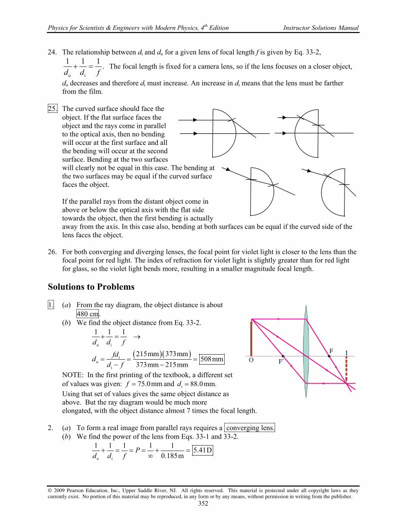
Physics for Scientists & Engineers with Modern Physics, 4th Edition Instructor Solutions Manual
© 2009 Pearson Education, Inc., Upper Saddle River, NJ. All rights reserved. This material is protected under all copyright laws as they currently exist. No portion of this material may be reproduced, in any form or by any means, without permission in writing from the publisher.
352
24. The relationship between di and do for a given lens of focal length f is given by Eq. 33-2,
o i
1 1 1.
d d f The focal length is fixed for a camera lens, so if the lens focuses on a closer object,
do decreases and therefore di must increase. An increase in di means that the lens must be farther from the film.
25. The curved surface should face the
object. If the flat surface faces the object and the rays come in parallel to the optical axis, then no bending will occur at the first surface and all the bending will occur at the second surface. Bending at the two surfaces will clearly not be equal in this case. The bending at the two surfaces may be equal if the curved surface faces the object.
If the parallel rays from the distant object come in above or below the optical axis with the flat side towards the object, then the first bending is actually away from the axis. In this case also, bending at both surfaces can be equal if the curved side of the lens faces the object.
26. For both converging and diverging lenses, the focal point for violet light is closer to the lens than the
focal point for red light. The index of refraction for violet light is slightly greater than for red light for glass, so the violet light bends more, resulting in a smaller magnitude focal length.
Solutions to Problems 1. (a) From the ray diagram, the object distance is about
480 cm. (b) We find the object distance from Eq. 33-2.
o i
io
i
1 1 1
215mm 373mm508mm
373mm 215mm
d d f
fdd
d f
NOTE: In the first printing of the textbook, a different set of values was given: 75.0mmf and i 88.0mm.d Using that set of values gives the same object distance as above. But the ray diagram would be much more elongated, with the object distance almost 7 times the focal length.
2. (a) To form a real image from parallel rays requires a converging lens. (b) We find the power of the lens from Eqs. 33-1 and 33-2.
o i
1 1 1 1 15.41D
0.185mP
d d f

Chapter 33 Lenses and Optical Instruments
© 2009 Pearson Education, Inc., Upper Saddle River, NJ. All rights reserved. This material is protected under all copyright laws as they currently exist. No portion of this material may be reproduced, in any form or by any means, without permission in writing from the publisher.
353
3. (a) The power of the lens is given by Eq. 33.1
1 1
4.26D0.235m
Pf
This lens is converging. (b) We find the focal length of the lens from Eq. 33.1
1 1 1
0.148m6.75D
P ff D
This lens is diverging. 4. To form a real image from a real object requires a converging lens. We find the focal length of the
lens from Eq. 33-2.
o i
o i o i
1.85m 0.483m1 1 1 0.383m
1.85m 0.483m
d df
d d f d d
Because i 0,d the image is real. 5. (a) We find the image distance from Eq. 33-2.
o
io i o
10.0m 0.105m1 1 1 0.106m 106mm
10.0m 0.105m
d fd
d d f d f
(b) Use the same general calculation.
o
io
3.0m 0.105m0.109m 109mm
3.0m 0.105m
d fd
d f
(c) Use the same general calculation.
o
io
1.0m 0.105m0.117m 117mm
1.0m 0.105m
d fd
d f
(d) We find the smallest object distance from the maximum image distance.
i
maxomino i i
min max max
132mm 105mm1 1 1 513mm 0.513m
132 mm 105mm
d fd
d d f d f
6. (a) We locate the image using Eq. 33-2.
o
io i o
18cm 28cm1 1 1 50.4cm 50cm
18cm 28cm
d fd
d d f d f
The negative sign means the image is 50 cm behind the lens (virtual). (b) We find the magnification from Eq. 33-3.
i
o
50.4cm2.8
18cm
dm
d
7. (a) The image should be upright for reading. The image
will be virtual, upright, and magnified. (b) To form a virtual, upright magnified image requires a
converging lens. (c) We find the image distance, then the focal length, and
then the power of the lens. The object distance is given.

Physics for Scientists & Engineers with Modern Physics, 4th Edition Instructor Solutions Manual
© 2009 Pearson Education, Inc., Upper Saddle River, NJ. All rights reserved. This material is protected under all copyright laws as they currently exist. No portion of this material may be reproduced, in any form or by any means, without permission in writing from the publisher.
354
ii o
o
d
m d mdd
i o o o
o i o i o o o
1 1 1 1 2.5 16.7 D
2.5 0.090m
d d md d mP
f d d d d d md md
8. Use Eqs. 33-1 and 33-2 to find the image distance, and Eq. 33-3 to find the image height.
o
io i o
0.125m1 1 1 0.0625m 6.25cm
1 8.00D 0.125m 1
dP d
d d f Pd
Since the image distance is negative, the image is virtual and behind the lens.
i i i
i oo o o
6.25cm 1.00mm 0.500mm upright
12.5cm
h d dm h h
h d d
9. First, find the original image distance from Eqs. 33-1 and 33-2.
oi
o i o
1.50m1 1 1 0.1364 m
1 8.00D 1.50m 1
dP d
d d f Pd
(a) With o 0.60m,d find the new image distance.
o
io i o
0.60m1 1 1 0.1579m
1 8.00D 0.60m 1
dP d
d d f Pd
Thus the image has moved 0.1579m 0.1364m 0.0215m 0.02m away from the lens.
(b) With o 2.40m,d find the new image distance.
o
io i o
2.40m1 1 1 0.1319m
1 8.00D 2.40m 1
dP d
d d f Pd
The image has moved 0.1319m 0.1364m 0.0045m 0.004m toward the lens.
10. (a) If the image is real, the focal length must be positive, the image distance must be positive, and
the magnification is negative. Thus i o2.50 .d d Use Eq. 33-2.
oo i o o
1 1 1 1 1 3.50 3.50 50.0mm 70.0mm
2.50 2.50 2.50d f
d d d d f
(b) If the image is magnified, the lens must have a positive focal length, because negative lenses always form reduced images. Since the image is virtual the magnification is positive. Thus
i o2.50 .d d Again use Eq. 33-2.
oo i o o
1 1 1 1 1 1.50 1.50 50.0mm 30.0mm
2.5 2.50 2.50d f
d d d d f
11. From Eq. 33-3, i oh h when i o .d d So find do from Eq. 33-2.
oo i o o
1 1 1 1 1 2 50cmd f
d d d d f
12. (a) Use Eqs. 33-2 and 33-3.
oi
o i o
1.30m 0.135m1 1 1 0.1506m 151mm
1.30m 0.135m
d fd
d d f d f

Chapter 33 Lenses and Optical Instruments
© 2009 Pearson Education, Inc., Upper Saddle River, NJ. All rights reserved. This material is protected under all copyright laws as they currently exist. No portion of this material may be reproduced, in any form or by any means, without permission in writing from the publisher.
355
i i ii o
o o o
0.1506m 2.80cm 0.324m
1.30m
h d dm h h
h d d
The image is behind the lens a distance of 151 mm, is real, and is inverted. (b) Again use Eqs. 33-2 and 33-3.
oi
o i o
i i ii o
o o o
1.30m 0.135m1 1 1 0.1223m 122 mm
1.30m 0.135m
0.1223m 2.80cm 0.263m
1.30m
d fd
d d f d f
h d dm h h
h d d
The image is in front of the lens a distance of 122 mm, is virtual, and is upright. 13. The sum of the object and image distances must be the distance between object and screen, which we
label as Td . We solve this relationship for the image distance, and use that expression in Eq. 33-2 in order to find the object distance.
2o i T i T o o T o T
o i o T o
22T T T
o
1 1 1 1 1 ; 0
86.0cm 86.0cm 4 16.0cm 86.0cm421.3cm, 64.7cm
2 2
d d d d d d d d d fdd d d d d f
d d fdd
Note that to have real values for od , we must in general have 2T T T4 0 4 .d fd d f
14. For a real image both the object distance and image distances are positive, and so the magnification is negative. Use Eqs. 33-2 and 33-3 to find the object and image distances. Since they are on opposite sides of the lens, the distance between them is their sum.
ii o o
o
oo i o o
i o
o i
2.95
1 1 1 1 1 3.95 3.95 85cm 113.8cm
2.95 2.95 2.95
2.95 2.95 113.8cm 335.7cm
113.8cm 335.7cm 449.5cm 450cm
dm d md d
d
d fd d d d f
d d
d d
15. (a) Use Eq. 33-2 to write an expression for the image distance in terms of the object distance and
focal length. We then use Eq. 33-3 to write an expression for the magnification.
o ii
o i o o o
1 1 1 ;
d f d fd m
d d f d f d d f

Physics for Scientists & Engineers with Modern Physics, 4th Edition Instructor Solutions Manual
© 2009 Pearson Education, Inc., Upper Saddle River, NJ. All rights reserved. This material is protected under all copyright laws as they currently exist. No portion of this material may be reproduced, in any form or by any means, without permission in writing from the publisher.
356
These expressions show that when od f , the image distance is positive, producing a real image, and the magnification is negative, which gives an inverted image.
(b) From the above equations, when od f , the image distance is negative, producing a virtual image, and the magnification is positive, which gives an upright image.
(c) We set od f and calculate the limiting image distance and magnification.
ii
o
1=
2 2
f f f d fd m
f f d f f
We also take the limit of large negative object distance.
i
io
= 0f d f
d f mf d f
From these limiting cases, we see that when od f , the image is real and upright with 1
i2 f d f and 120 m .
(d) We take the limiting condition o 0d , and determine the resulting image distance and magnification.
ii
o
0= 0 1
0 0
f d fd m
f d f
From this limit and that found in part (c), we see that when o0 d f , the image is real and
upright, with 1i 20 d f and 1
2 1.m
16. (a) We use the magnification equation, Eq. 33-3, to write the image distance in terms of the
magnification and object distance. We then replace the image distance in the mirror equation, Eq. 32-2, and solve for the magnification in terms of the object distance and the focal length.
i o i o m d d d md
o i
o o
o
1 1 1
1 1 1
f d d
f d md
fm
f d
(b) We set 0.45 mf and draw a graph of the magnification as a function of the object distance. The spreadsheet used for this problem can be found on the Media Manager, with filename “PSE4_ISM_CH33.XLS,” on tab “Problem 33.16b.”
(c) The image and object will have the same lateral size when the magnification is equal to negative one. Setting the magnification equal to negative one, we solve the equation found in part (a) for the object distance.
oo
1 2 0.90mf
m d ff d
(d) From the graph we see that for the image to be much larger than the object, the object should be placed at a point just beyond the focal point.
-10
-8
-6
-4
-2
0
0.4 0.5 0.6 0.7 0.8 0.9 1.0 1.1 1.2 1.3 1.4
d o (m)
m

Chapter 33 Lenses and Optical Instruments
© 2009 Pearson Education, Inc., Upper Saddle River, NJ. All rights reserved. This material is protected under all copyright laws as they currently exist. No portion of this material may be reproduced, in any form or by any means, without permission in writing from the publisher.
357
17. Find the object distance from Eq. 33-2.
i
oo i o i i
0.105m 6.50m1 1 1 1 1 1 0.107m
6.50m 0.105m
fdd
d d f d d f d f
Find the size of the image from Eq. 33-3.
i i ii o
o o o
6.50m 36mm 2187mm 2.2m
0.107m
h d dm h h
h d d
18. (a) Use Eq. 33-2 with o i T i T o .d d d d d d
22 T T To T o T o
o i o T o
41 1 1 1 1 0
2
d d fdd d d fd d
d d d d d f
There are only real solutions for od if 2T T T4 0 4 .d fd d f If that condition is met,
then there will be two locations for the lens, at distances 21o T T T2 4d d d fd from the
object, that will form sharp images on the screen. (b) If T 4 ,d f then Eq. 33-2 cannot be solved for real values of od or i .d
(c) If T 4 ,d f the lens locations relative to the object are given by 21o1 T T T2 4d d d fd and
21o2 T T T2 4 .d d d fd
2 2 21 1o1 o2 T T T T T T T T2 24 4 4d d d d d fd d d fd d fd
Find the ratio of image sizes using Eq. 33-3.
i2o
i2 i2 o1 T o2 o1o2
i1i1 o2 i1 o2 T o1o
o1
22 21 1 2T T T T T T T2 2
T T T
22 21 1T T TT T T T T T T2 2
4 4 4
44 4
dh
h d d d d dddh d d d d dhd
d d d fd d d fd d d fd
d d fdd d fd d d d fd
19. (a) With the definitions as given in the problem, o o x d f d x f and i x d f
i .d x f Use Eq. 33-2.
o i
2 2 2
1 1 1 1 1 1
2 2
x f x f
d d x f x f f x f x f f
f x x f x f x f f xf x f x x xf fx f f x x
(b) Use Eq. 33-2. o
io i o
48.0cm 38.0cm1 1 1 182cm
48.0cm 38.0cm
d fd
d d f d f
(c) Use the Newtonian form.
222
i
38.0cm 144.2cm
48.0cm 38.0cm
144.2cm 38.0cm 182cm
fxx f x
x
d x f

Physics for Scientists & Engineers with Modern Physics, 4th Edition Instructor Solutions Manual
© 2009 Pearson Education, Inc., Upper Saddle River, NJ. All rights reserved. This material is protected under all copyright laws as they currently exist. No portion of this material may be reproduced, in any form or by any means, without permission in writing from the publisher.
358
20. The first lens is the converging lens. An object at infinity will form an image at the focal point of the converging lens, by Eq. 33-2.
i1 1o1 i1 1 i1
1 1 1 1 1 20.0cmd f
d d f d
This image is the object for the second lens. Since this image is behind the second lens, the object distance for the second lens is negative, and so o2 6.0cm.d Again use Eq. 33-2.
o2 2i2
o2 i2 2 o2 2
6.0cm 33.5cm1 1 1 7.3cm
6.0cm 33.5cm
d fd
d d f d f
Thus the final image is real, 7.3 cm beyond the second lens. 21. Find the image formed by the first lens, using Eq. 33-2.
o1 1i1
o1 i1 1 o1 1
35.0cm 25.0cm1 1 1 87.5cm
35.0cm 25.0cm
d fd
d d f d f
This image is the object for the second lens. Because it is beyond the second lens, it has a negative object distance.
o2 16.5cm 87.5cm 71.0cmd Find the image formed by the second lens, again using Eq. 33-2.
o2 2i2
o2 i2 2 o2 2
71.0cm 25.0cm1 1 1 18.5cm
71.0cm 25.0cm
d fd
d d f d f
Thus the final image is real, 18.5 cm beyond second lens. The total magnification is the product of the magnifications for the two lenses:
i1 i2 i1 i21 2
o1 o2 o1 o2
d d d dm m m
d d d d
87.5cm 18.5cm
0.651 inverted35.0cm 71.0cm
22. From the ray diagram, the image from the first lens is a
virtual image at the focal point of the first lens. This is a real object for the second lens. Since the light is parallel after leaving the second lens, the object for the second lens must be at its focal point. Let the separation of the lenses be l. Note that the focal length of the diverging lens is negative.
1 2
1 2
1
34.0cm 24.0cm 10.0cm
10.0cm
f f
f f
f
l
l
23. (a) The first image is formed as in Example 33-5, and so iA 30.0cm.d This image becomes the
object for the lens B, at a distance oB 20.0cm 30.0cm 10.0cm.d This is a virtual object since it is behind lens N. Use Eq. 33-2 to find the image formed by lens B, which is the final image.
oB B
iBoB iB B oB B
10.0cm 25.0cm1 1 1 7.14cm
10.0cm 25.0cm
d fd
d d f d f
So the final image is 7.14 cm beyond lens B.
f1
f1 < 0 f2 > 0
f 2

Chapter 33 Lenses and Optical Instruments
© 2009 Pearson Education, Inc., Upper Saddle River, NJ. All rights reserved. This material is protected under all copyright laws as they currently exist. No portion of this material may be reproduced, in any form or by any means, without permission in writing from the publisher.
359
(b) The total magnification is the product of the magnifications for the two lenses:
iA iB iA iB1 2
oA oB oA oB
30.0cm 7.14cm0.357
60.0cm 10.0cm
d d d dm m m
d d d d
(c) See the ray diagram here. 24. (a) Find the image formed by the converging lens, using Eq. 33-2.
o1 1i1
o1 i1 1 o1 1
33cm 18cm1 1 1 39.6cm
33cm 18cm
d fd
d d f d f
This image is the object for the second lens. The image is to the right of the second lens, and so is virtual. Use that image to find the final image.
o2o2 i2 2
o2 2i2
o2 2
1 1 112cm 39.6cm 27.6cm ;
27.6cm 14cm28.4cm
27.6cm 14cm
dd d f
d fd
d f
So the final image is 28 cm to the left of the diverging lens, or 16 cm to the left of the converging lens.
(b) The initial image is unchanged. With the change in the distance between the lenses, the image distance for the second lens has changed.
o2o2 i2 2
o2 2i2
o2 2
1 1 138cm 39.6cm 1.6cm ;
1.6cm 14cm1.8cm
1.6cm 14cm
dd d f
d fd
d f
Now the final image is 1.8 cm to the right of the diverging lens. 25. (a) The first lens is the converging lens. Find the image formed by the first lens.
o1 1i1
o1 i1 1 o1 1
60.0cm 20.0cm1 1 1 30.0cm
60.0cm 20.0cm
d fd
d d f d f
This image is the object for the second lens. Since this image is behind the second lens, the object distance for the second lens is negative, and so o2 25.0cm 30.0cm 5.0cm.d Use Eq. 33-2.
o2 2i2
o2 i2 2 o2 2
5.0cm 10.0cm1 1 1 10cm
5.0cm 10.0cm
d fd
d d f d f
Thus the final image is real, 10 cm beyond the second lens. The distance has two significant figures.
(b) The total magnification is the product of the magnifications for the two lenses:
i1 i2 i1 i21 2
o1 o2 o1 o2
30.0cm 10.0cm1.0
60.0cm 5.0cm
d d d dm m m
d d d d

Physics for Scientists & Engineers with Modern Physics, 4th Edition Instructor Solutions Manual
© 2009 Pearson Education, Inc., Upper Saddle River, NJ. All rights reserved. This material is protected under all copyright laws as they currently exist. No portion of this material may be reproduced, in any form or by any means, without permission in writing from the publisher.
360
(c) See the diagram here. 26. We find the focal length of the combination by finding the image distance for an object very far
away. For the converging lens, we have the following from Eq. 33-2.
i1 Co1 i1 i1
1 1 1 1 1
C
d fd d f d
The first image is the object for the second lens. Since the first image is real, the second object distance is negative. We also assume that the lenses are thin, and so o2 i1 C.d d f
For the second diverging lens, we have the following from Eq. 33-2.
o2 i2 D C i2
1 1 1 1 1
d d f f d
Since the original object was at infinity, the second image must be at the focal point of the combination, and so i2 T.d f
D C i2 C T
1 1 1 1 1
f f d f f
27. (a) We see that the image is real and upright.
We estimate that it is 30 cm beyond the second lens, and that the final image height is half the original object height.
(b) Find the image formed by the first
lens, using Eq. 33-2.
o1 i1 1
1 1 1
d d f
o1 1i1
o1 1
36cm 13cm20.35cm
36cm 13cm
d fd
d f
This image is the object for the second lens. Because it is between the lenses, it has a positive object distance.
o2 56cm 20.35cm 35.65cmd Find the image formed by the second lens, again using Eq. 33-2.
o2 2i2
o2 i2 2 o2 2
35.65cm 16cm1 1 1 29.25cm
35.65cm 16cm
d fd
d d f d f
Thus the final image is real, 29 cm beyond the second lens. The total magnification is the product of the magnifications for the two lenses:
i1 i21 2
o1 o2
20.35cm 29.25cm0.46
36cm 35.65cm
d dm m m
d d

Chapter 33 Lenses and Optical Instruments
© 2009 Pearson Education, Inc., Upper Saddle River, NJ. All rights reserved. This material is protected under all copyright laws as they currently exist. No portion of this material may be reproduced, in any form or by any means, without permission in writing from the publisher.
361
28. Use Eq. 33-4, the lensmaker’s equation.
1 2
1 2
1 2
1 1 11
33.4cm 28.8cm1 126.66cm 27cm
1 1.58 1 33.4cm 28.8cm
nf R R
R Rf
n R R
29. Find the index from Eq. 33-4, the lensmaker’s equation.
1 2 12
1 2 1 2
1 1 1 1 11 1 1 31.4cm 1.54
28.9cm
R Rn n
f R R f R R
30. With the surfaces reversed, we have 1 46.2cmR and 2 22.4cm.R Use Eq. 33-4 to find the
focal length.
1 2
1 2
1 2
1 1 11
46.2cm 22.4cm1 187.0cm
1 1.50 1 46.2cm 22.4cm
nf R R
R Rf
n R R
31. The plane surface has an infinite radius of curvature. Let the plane surface be surface 2, so 2 .R
The index of refraction is found in Table 32-1.
1 2 1 1
1
11 1 1 1 1 11 1
1 1.46 1 18.7cm 8.6cm
nn n
f R R f R R
R n f
32. First we find the focal length from Eq. 33-3, the lensmaker’s equation. Then we use Eq. 33-2 to find
the image distance, and Eq. 33-3 to find the magnification.
1 2
1 2
1 2
1 1 11
22.0cm 18.5cm1 1223.6cm
1 1.52 1 22.0cm 18.5cm
nf R R
R Rf
n R R
oi
o i o
i
o
90.0cm 223.6m1 1 1 150.6cm 151cm
90.0cm 223.6cm
150.6cm1.67
90.0cm
d fd
d d f d f
dm
d
The image is virtual, in front of the lens, and upright. 33. Find the radius from the lensmaker’s equation, Eq. 33-4.:
1 2 1 2
1 1 1 1 11 1 n P n
f R R R R
1
21
1 1.56 1 0.300m0.34m
1 3.50D 0.300m 1.56 1
n RR
PR n

Physics for Scientists & Engineers with Modern Physics, 4th Edition Instructor Solutions Manual
© 2009 Pearson Education, Inc., Upper Saddle River, NJ. All rights reserved. This material is protected under all copyright laws as they currently exist. No portion of this material may be reproduced, in any form or by any means, without permission in writing from the publisher.
362
34. The exposure is proportional to the product of the lens opening area and the exposure time, with the square of the f-stop number inversely proportional to the lens opening area. Setting the exposures equal for both exposure times we solve for the needed f-stop number.
2 2 21 1 2 2 2 1
1
1 1000 s-stop -stop -stop -stop 16 5.54 or
1 120s 5.6
t ft f t f f f
t
35. We find the f-number from -stop .f f D
17cm
-stop6.0cm 2.8
f ff
D
36. We use similar triangles, created from the distances
between the centers of the two objects (H) and their ray traces to the hole (L1) and the distance between the centers of the two images (h) and the distance of the screen to the hole (L2) to determine the distance between the center of the two image circles. We then create similar triangles from the two ray traces for a single source with the base of one triangle equal to the diameter of the hole (d) , and the base of the second triangle equal to the diameter of the image circle (D). The heights for these two triangles are the distance from object to hole (L1) and the distance from object to image (L1 + L2).
2
1 2 1
7.0 cm 2.0 cm 0.14 cm 1.4 mm
100 cm
LH hh H
L L L
1 2
1 1 2 1
100cm 7.0cm 1.0mm 1.07mm
100cm
d D L LD d
L L L L
Since the separation distance of the two images is greater than their diameters, the two circles do not overlap.
37. We calculate the effective f-number for the pinhole camera by dividing the focal length by the
diameter of the pinhole. The focal length is equal to the image distance. Setting the exposures equal for both cameras, where the exposure is proportional to the product of the exposure time and the area of the lens opening (which is inversely proportional to the square of the f-stop number), we solve for the exposure time.
2
70mm-stop .
1.0mm 70
f ff
D
2 2
2 2 2 11 1 2 2 2 1 6
1
-stop 1 70-stop -stop 0.16 s s
-stop 250 s 11
ft f t f t t
f
38. Consider an object located a distance od from a
converging lens of focal length f and its real image
formed at distance id . If the distance od is much greater than the focal length, the lens equation tells us that the focal length and image distance are equal.
o oi
o i o o
1 1 1
fd fdd f
d d f d f d
od2020

Chapter 33 Lenses and Optical Instruments
© 2009 Pearson Education, Inc., Upper Saddle River, NJ. All rights reserved. This material is protected under all copyright laws as they currently exist. No portion of this material may be reproduced, in any form or by any means, without permission in writing from the publisher.
363
Thus, in a camera, the recording medium of spatial extent x is placed a distance equal to f behind the lens to form a focused image of a distant object. Assume the distant object subtends an angle of 40 at the position of the lens, so that the half-angle subtended is 20 , as shown in the figure. We then use the tangent of this angle to determine the relationship between the focal length and half the image height.
1
o 2o
tan 20 2 tan 20
x xf
f
(a) For a 35-mm camera, we set 36 mmx to calculate the focal length.
o
36 mm49 mm
2tan 20f
(b) For a digital camera, we set 1.0 cm 10 mmx .
o
10 mm14 mm
2tan 20f
39. The image distance is found from Eq. 33-3, and then the focal length from Eq. 33-2. The image is
inverted.
i i ii o
o o o
o i
o i o i
24mm 65m 41mm
38m
65m 0.041m1 1 1 0.041m 41mm
65m 0.041m
h d hm d d
h d h
d df
d d f d d
The object is essentially at infinity, so the image distance is equal to the focal length. 40. The length of the eyeball is the image distance for a far object, i.e., the focal length of the lens. We find the f-number from -stop .f f D
20mm-stop 2.5 or .
8.0mm 2.5
f ff
D
41. The actual near point of the person is 55 cm. With the lens, an object placed at the normal near
point, 25 cm, or 23 cm from the lens, is to produce a virtual image 55 cm from the eye, or 53 cm from the lens. We find the power of the lens from Eqs. 33-1 and 33-3.
o i
1 1 1 1 12.5D
0.23m 0.53mP
f d d
42. The screen placed 55 cm from the eye, or 53.2 cm from the lens, is to produce a virtual image 105
cm from the eye, or 103.2 cm from the lens. Find the power of the lens from Eqs. 33-1 and 33-2.
o i
1 1 1 1 10.91D
0.532m 1.032mP
f d d
43. With the contact lens, an object at infinity should form a virtual image at the far point of the eye, 17
cm from the contact lens. Use that with Eq. 33-2 to find the focal length of the contact lens. We find the power of the lens from
io i i
1 1 1 1 1 1 17cmf d
d d f d f
Find the new near point as the object location that forms a virtual image at the actual near point of 12 cm from the contact lens. Again use Eq. 33-2.

Physics for Scientists & Engineers with Modern Physics, 4th Edition Instructor Solutions Manual
© 2009 Pearson Education, Inc., Upper Saddle River, NJ. All rights reserved. This material is protected under all copyright laws as they currently exist. No portion of this material may be reproduced, in any form or by any means, without permission in writing from the publisher.
364
io
o i i
17cm 12cm1 1 1 41cm
12cm 17cm
fdd
d d f d f
So the person would have to hold the object 41 cm from their eye to see it clearly. With glasses, they only had to hold the object 32 cm from the eye. So glasses would be better.
44. (a) Since the lens power is negative, the lens is diverging, so it produces images closer than the
object. Thus the person is nearsighted. (b) We find the far point by finding the image distance for an object at infinity. Since the lens is
2.0 cm in front of the eye, the far point is 2.0 cm farther than the absolute value of the image distance.
i
o i i
1 1 1 1 1 1 4.50D 0.222 m 22.2 cm
4.50 D
FP 22.2 cm 2.0 cm 24.2 cm from eye
P dd d f d
45. (a) The lens should put the image of an object at infinity at the person’s far point of 78 cm. Note
that the image is still in front of the eye, so the image distance is negative. Use Eqs. 33-2 and 33-1.
o i
1 1 1 1 11.282 D 1.3D
0.78mP
f d d
(b) To find the near point with the lens in place, we find the object distance to form an image 25 cm in front of the eye.
i
oo i i
0.25m1 1 1 0.37m 37cm
1 1.282 D 0.25m 1
dP d
d d f Pd
46. The image of an object at infinity is to be formed 14 cm in front of the eye. So for glasses, the image
distance is to be i 12cm,d and for contact lenses, the image distance is to be i 14cm.d
o i i
glasses contacts
1 1 1 1 1 1 1
1 18.3D ; 7.1D
0.12m 0.14m
ii
f d Pd d f d f d
P P
47. Find the far point of the eye by finding the image distance FROM THE LENS for an object at
infinity, using Eq. 33-2.
i1 1o1 i1 1 i1 1
1 1 1 1 1 1 23.0cmd f
d d f d f
Since the image is 23.0 in front of the lens, the image is 24.8 cm in front of the eye. The contact lens must put the image of an object at infinity at this same location. Use Eq. 33-2 for the contact lens with an image distance of -24.8 cm and an object distance of infinity.
1 i2o2 i2 2 i2 1
1 1 1 1 1 1 24.8cmf d
d d f d f
48. (a) We find the focal length of the lens for an object at infinity and the image on the retina. The
image distance is thus 2.0 cm. Use Eq. 33-2.
o i
1 1 1 1 1 1 2.0cm
2.0cmf
d d f f

Chapter 33 Lenses and Optical Instruments
© 2009 Pearson Education, Inc., Upper Saddle River, NJ. All rights reserved. This material is protected under all copyright laws as they currently exist. No portion of this material may be reproduced, in any form or by any means, without permission in writing from the publisher.
365
(b) We find the focal length of the lens for an object distance of 38 cm and an image distance of 2.0 cm. Again use Eq. 33.2.
o i
o i o i
38cm 2.0cm1 1 1 1.9cm
38cm 2.0cm
d df
d d f d d
49. Find the object distance for the contact lens to form an image at the eye’s near point, using Eqs. 33-2
and 33-1.
io
o i i
1 1 1 0.106m 0.184m 18.4cm
1 4.00D 0.106m 1
dP d
d d f Pd
Likewise find the object distance for the contact lens to form an image at the eye’s far point.
io
i
0.200m1.00m 100cm
1 4.0D 0.200m 1
dd
Pd
(3 sig. fig.)
50. In the image we show the principal rays from
each of the two points as they pass directly through the cornea and onto the lens. These two rays and the distance between the two objects, l, and the distance between the two images (4 m) create similar triangles. We set the ratio of the bases and heights of these two triangles equal to solve for l.
4 m 4 m25 cm 50 m
25 cm 2.0 cm 2.0 cm
l
l
51. We find the focal length from Eq. 33-6
25cm
6.6cm3.8
N NM f
f M
52. Find the magnification from Eq. 33-6.
25cm
1.913cm
NM
f
53. (a) We find the focal length with the image at the near point from Eq. 33-6b.
25cm
1 12.5cm 13cm1 3.0 1
N NM f
f M
1
25cm3.0 1 ,
f which gives 1 12.5cm 13cm.f
(b) If the eye is relaxed, the image is at infinity, and so use Eq. 33-6a.
25cm
8.3cm3.0
N NM f
f M
54. Maximum magnification is obtained with the image at the near point (which is negative). We find
the object distance from Eq. 33-2, and the magnification from Eq. 33-6b.
io
o i i
25.0cm 8.80cm1 1 1 6.51cm
25.0cm 8.80cm
d fd
d d f d f
25cm 2.0cm
4 m

Physics for Scientists & Engineers with Modern Physics, 4th Edition Instructor Solutions Manual
© 2009 Pearson Education, Inc., Upper Saddle River, NJ. All rights reserved. This material is protected under all copyright laws as they currently exist. No portion of this material may be reproduced, in any form or by any means, without permission in writing from the publisher.
366
25.0cm
1 1 3.848.80cm
NM
f
55. (a) We find the image distance from Eq. 33-2.
oi
o i o
6.00cm 5.85cm1 1 1 234cm
5.85cm 6.00cm
fdd
d d f d f
(b) The angular magnification is given by Eq. 33-6a, since the eye will have to focus over 2 m away.
25.0cm
4.176.00cm
NM
f
56. (a) We use Eq. 33-6b to calculate the angular magnification.
25.0cm
1 1 3.609.60cm
NM
f
(b) Because the object without the lens and the image with the lens are at the near point, the angular magnification is also the ratio of widths. Using this relationship we calculate the image width.
io
o
3.60 3.40mm 12.3mmi
hM h Mh
h
(c) We use Eq. 33-2 to calculate the object distance, with the image distance at -25.0 cm.
i
oo i i
9.60cm 25.0cm1 1 1 6.94cm
25.0cm 9.60cm
fdd
d d f d f
57. (a) We find the image distance using Eq. 33-2.
o
io i o
9.5cm 8.3cm1 1 1 66cm
8.3cm 9.5cm
fdd
d d f d f
(b) The angular magnification is found using Eq. 33-5, with the angles given as defined in Figure 33-33.
o o
o o
25 cm3.0
8.3 cm
h d NM
h N d
58. First, find the focal length of the magnifying glass from Eq. 33-6a, for a relaxed eye (focused at
infinity).
25.0cm
8.33cm3.0
N NM f
f M
(a) Again use Eq. 33-6a for a different near point.
11
65cm7.8
8.33cm
NM
f
(b) Again use Eq. 33-6a for a different near point.
22
17cm2.0
8.33cm
NM
f
Without the lens, the closest an object can be placed is the near point. A farther near point means a smaller angle subtended by the object without the lens, and thus greater magnification.
O
ho
N
ho
hi
I
O

Chapter 33 Lenses and Optical Instruments
© 2009 Pearson Education, Inc., Upper Saddle River, NJ. All rights reserved. This material is protected under all copyright laws as they currently exist. No portion of this material may be reproduced, in any form or by any means, without permission in writing from the publisher.
367
59. The focal length is 10 cm. First, find the object distance for an image at infinity. Then, find the object distance for an image 25 cm in front of the eye.
Initial: oo i o
1 1 1 1 1 1 12cmd f
d d f d f
Final:
io
o i i
25cm 12cm1 1 1 8.1cm
25cm 12cm
d fd
d d f d f
The lens was moved 12cm 8.1cm 3.9cm 4 cm toward the fine print. 60. The magnification of the telescope is given by Eq. 33-7.
o
e
78cm28
2.8cm
fM
f
For both object and image far away, the separation of the lenses is the sum of the focal lengths.
o e 78cm 2.8cm 81cmf f 61. We find the focal length of the eyepiece from the magnification by Eq. 33-7.
o oe
e
88cm 2.5cm
35
f fM f
f M
For both object and image far away, the separation of the lenses is the sum of the focal lengths.
o e 88cm 2.5cm 91cmf f 62. We find the focal length of the objective from Eq. 33-7.
o e o e 7.0 3.0cm 21cmM f f f Mf
63. The magnification is given by Eq. 33-7.
o e o e 0.75m 35D 26M f f f P
64. For a distant object and a relaxed eye (which means the image is at infinity), the separation of the
eyepiece and objective lenses is the sum of their focal lengths. Use Eq. 33-7 to find the magnification.
o oo e
e o
75.5cm ; 30
78.0cm 75.5cm
f ff f M
f f
l
l
65. For a distant object and a relaxed eye (which means the image is at infinity), the separation of the
eyepiece and objective lenses is the sum of their focal lengths. Use Eq. 33-7 to find the magnification.
o oo e
e o
36.0cm ; 16
33.8cm 36.0cm
f ff f M
f f
l
l
66. The focal length of the objective is just half the radius of curvature. Use Eq. 33-7 for the
magnification.
1
o 2
e e
3.2m114 110
0.028m
f rM
f f

Physics for Scientists & Engineers with Modern Physics, 4th Edition Instructor Solutions Manual
© 2009 Pearson Education, Inc., Upper Saddle River, NJ. All rights reserved. This material is protected under all copyright laws as they currently exist. No portion of this material may be reproduced, in any form or by any means, without permission in writing from the publisher.
368
67. The focal length of the mirror is found from Eq. 33-7. The radius of curvature is twice the focal length.
oo e
e
120 0.031m 3.72m 3.7m ; 2 7.4mf
M f Mf r ff
68. The relaxed eye means that the image is at infinity, and so the distance between the two lenses is
1.25 m. Use that relationship with Eq. 33-7 to solve for the focal lengths. Note that the magnification for an astronomical telescope is negative.
o oo e o
e o
e o
120 1.25m ; 1.24m
1 120 1
1.25m 1.24m 0.01m 1 cm
f f Mf f M f
f f M
f f
ll
l
l
69. We use Eq. 33-6a and the magnification of the eyepiece to calculate the focal length of the eyepiece.
We set the sum of the focal lengths equal to the length of the telescope to calculate the focal length of the objective. Then using both focal lengths in Eq. 33-7 we calculate the maximum magnification.
e e o o e
o
e
25cm5cm ; 50cm 5cm 45cm
545cm
95cm
Nf f f f f
Mf
Mf
l l
70. Since the star is very far away, the image of the star from the objective mirror will be at the focal
length of the objective, which is equal to one-half its radius of curvature (Eq. 32-1). We subtract this distance from the separation distance to determine the object distance for the second mirror. Then, using Eq. 33-2, we calculate the final image distance, which is where the sensor should be placed.
oi1 o o2 i1
e o2i
o2 i2 e e o2 e
3.00m1.50m ; 0.90m 1.50m 0.60m
2 21.50m 0.60m1 1 1 2
3.0m2 2 0.60m 1.50m
Rd f d d
R dd
d d f R d R
l
71. We assume a prism binocular so the magnification
is positive, but simplify the diagram by ignoring the prisms. We find the focal length of the eyepiece using Eq. 33-7, with the design magnification.
oe
26cm3.47cm
7.5
ff
M
Using Eq. 33-2 and the objective focal length, we calculate the intermediate image distance. With the final image at infinity (relaxed eye), the secondary object distance is equal to the focal length of the eyepiece. We calculate the angular magnification using Eq. 33-5, with the angles shown in the diagram.
o o`i1
o1 i1 o o1 o
e i1
i1 e
26cm 400cm1 1 1 27.81cm
400cm 26cm
27.81cm8.0
3.47cm
f dd
d d f d f
h f dM
h d f

Chapter 33 Lenses and Optical Instruments
© 2009 Pearson Education, Inc., Upper Saddle River, NJ. All rights reserved. This material is protected under all copyright laws as they currently exist. No portion of this material may be reproduced, in any form or by any means, without permission in writing from the publisher.
369
72. The magnification of the microscope is given by Eq. 33-10b.
o e
25cm 17.5cm448.7 450
0.65cm 1.50cm
NM
f f
l
73. We find the focal length of the eyepiece from the magnification of the microscope, using the
approximate results of Eq. 33-10b. We already know that o .f l
e
o e o
25cm 17.5cm 1.6cm
680 0.40cm
N NM f
f f Mf
l l
Note that this also satisfies the assumption that e .f l 74. We use Eq. 33-10b.
e o
25cm 17cm607.1 610
2.5cm 0.28cm
NM
f f
l
75. (a) The total magnification is found from Eq. 33-10a.
o e 58.0 13.0 754M M M
(b) With the final image at infinity, we find the focal length of the eyepiece using Eq. 33-9.
e ee e
25.0cm 1.923cm 1.92cm
13.0
N NM f
f M
Since the image from the objective is at the focal point of the eyepiece, we set the image distance from the objective as the distance between the lenses less the focal length of the eyepiece. Using the image distance and magnification in Eq. 33-3, we calculate the initial object distance. Then using the image and object distance in Eq. 33-2 we calculate the objective focal length.
i e 20.0cm 1.92cm 18.08cmd f l
i io
o
o io
o o i o i
18.08cm0.312cm
58.0
0.312cm 18.08cm1 1 10.307cm
0.312cm 18.08cm
d dm d
d m
d df
f d d d d
(c) We found the object distance, in part (b), o 0.312cm .d
76. (a) The total magnification is the product of the magnification of each lens, with the magnification
of the eyepiece increased by one, as in Eq. 33-6b.
o e 1 58.0 13.0 1.0 812M M M
(b) We find the focal length of the eyepiece using Eq. 33-6b.
e ee e
25cm1 +1 1.92cm
13.0
N NM f
f M
Since the image from the eyepiece is at the near point, we use Eq. 33-2 to calculate the location of the object. This object distance is the location of the image from the objective. Subtracting this object distance from the distance between the lenses gives us the image distance from the objective. Using the image distance and magnification in Eq. 33-3, we calculate the initial object distance. Then using the image and object distance in Eq. 33-2 we calculate the objective focal length.

Physics for Scientists & Engineers with Modern Physics, 4th Edition Instructor Solutions Manual
© 2009 Pearson Education, Inc., Upper Saddle River, NJ. All rights reserved. This material is protected under all copyright laws as they currently exist. No portion of this material may be reproduced, in any form or by any means, without permission in writing from the publisher.
370
e i2o2
e 2 i2 i2 e
i1 o2
i io
o
o io
o o i o i
1.92cm 25.0cm1 1 1 1.78cm
25.0cm 1.92cm
20.0cm 1.78cm 18.22cm
18.22cm 0.314cm
58.0
0.314cm 18.22cm1 1 1 0.308
0.314cm 18.22cm
o
f dd
f d d d f
d d
d dm d
d m
d df
f d d d d
l
cm
(c) We found the object distance, in part (b), o 0.314cm .d
77. (a) Since the final image is at infinity (relaxed eye) the image from the objective is at the focal
point of the eyepiece. We subtract this distance from the distance between the lenses to calculate the objective image distance. Then using Eq. 33-2, we calculate the object distance.
i1 e
o i1o1
o o1 i1 i1 o
16.8cm 1.8cm 15.0cm
0.80cm 15.0cm1 1 1 0.85cm
15.0cm 0.80cm
d f
f dd
f d d d f
l
(b) With the final image at infinity, the magnification of the eyepiece is given by Eq. 33-10a.
e
e o
25.0cm 16.8cm 1.8cm247 250
1.8cm 0.85cm
N fM
f d
l
78. (a) We find the image distance from the objective using Eq. 33-2. For the final image to be at
infinity (viewed with a relaxed eye), the objective image distance must be at the focal distance of the eyepiece. We calculate the distance between the lenses as the sum of the objective image distance and the eyepiece focal length.
o o1
i1o1 i1 o o1 o
0.740cm 0.790cm1 1 1 11.7cm
0.790cm 0.740cm
f dd
d d f d f
i1 e 11.7cm 2.80cm 14.5cmd f l
(b) We use Eq. 33-10a to calculate the total magnification.
e
e o
25.0cm 14.5cm 2.80cm132
2.80cm 0.790cm
N fM
f d
l
79. For each objective lens we set the image distance equal to the sum of the focal length and 160 mm.
Then, using Eq. 33-2 we write a relation for the object distance in terms of the focal length. Using this relation in Eq. 33-3 we write an equation for the magnification in terms of the objective focal length. The total magnification is the product of the magnification of the objective and focal length.
o o
o i o o o i o o o
160 mm1 1 1 1 1 1 1 1 1
160 mm 160 mmo
f fd
d d f d f d d f f
i o
oo oo o
160mm 160 mm
160mm
160 mm
d fm
d ff f
Since the objective magnification is inversely proportional to the focal length, the objective with the smallest focal length o 3.9 mmf combined with the largest eyepiece magnification e 10M
yields the largest overall magnification. The objective with the largest focal length o 32 mmf

Chapter 33 Lenses and Optical Instruments
© 2009 Pearson Education, Inc., Upper Saddle River, NJ. All rights reserved. This material is protected under all copyright laws as they currently exist. No portion of this material may be reproduced, in any form or by any means, without permission in writing from the publisher.
371
coupled with the smallest eyepiece magnification e 5M yields the smallest overall
magnification.
largest smallest
160mm 160mm10 410 ; 5 25
3.9mm 32mmM M
80. (a) For this microscope both the objective and eyepiece have focal lengths of 12 cm. Since the
final image is at infinity (relaxed eye) the image from the objective must be at the focal length of the eyepiece. The objective image distance must therefore be equal to the distance between the lenses less the focal length of the objective. We calculate the object distance by inserting the objective focal length and image distance into Eq. 33-2.
i1 e
o i1o
o o i1 i1 o
55cm 12cm 43cm
12cm 43cm1 1 1 16.65cm 17cm
43cm 12cm
d f
f dd
f d d d f
l
(b) We calculate the magnification using Eq. 33-10a.
e
e o
25cm 55cm 12cm5.38 5.4
12cm 16.65cm
N fM
f d
l
(c) We calculate the magnification using Eq. 33-10b, and divide the result by the answer to part (b) to determine the percent difference.
approxapprox
e o
25cm 55cm 9.55 5.389.55 ; 0.775 78%
12cm 12cm 5.38
M MNM
f f M
l
81. We use Eq. 33-4 to find the focal length for each color, and then Eq. 33-2 to find the image distance.
For the plano-convex lens, 1 0R and 2 .R
red redred 1 2
1 1 1 1 11 1.5106 1 36.036cm
18.4cmn f
f R R
yellow orangeyellow 1 2
1 1 1 1 11 1.5226 1 35.209cm
18.4cmn f
f R R
We find the image distances from
o rediredo i red o red
red
66.0cm 36.036cm1 1 1 79.374cm 79.4cm
66.0cm 36.036cm
d fd
d d f d f
o yellowiyellowo i yellow o yellow
yellow
66.0cm 35.209cm1 1 1 75.469cm 75.5cm
66.0cm 35.209cm
d fd
d d f d f
The images are 3.9 cm apart, an example of chromatic aberration. 82. From Problem 26 we have a relationship between the individual focal lengths and the focal length of
the combination.
C DT
D C T T D C C D
25cm 28cm1 1 1 1 1 1 233cm
25cm 28cm
f ff
f f f f f f f f
(a) The combination is converging, since the focal length is positive. Also, the converging lens is “stronger” than the diverging lens since it has a smaller absolute focal length (or higher absolute power).
(b) From above, T 230cm .f

Physics for Scientists & Engineers with Modern Physics, 4th Edition Instructor Solutions Manual
© 2009 Pearson Education, Inc., Upper Saddle River, NJ. All rights reserved. This material is protected under all copyright laws as they currently exist. No portion of this material may be reproduced, in any form or by any means, without permission in writing from the publisher.
372
83. We calculate the range object distances from Eq. 33-2 using the given focal length and maximum
and minimum image distances.
i,maxo,min
o i i,max
200.0mm 206.4mm1 1 1 6450mm 6.45m
206.4mm 200.0mm
fdd
f d d d f
i,mino,max
i,min
200.0mm 200.0mm
200.0mm 200.0mm
fdd
d f
Thus the range of object distances is o6.45m .d
84. We calculate the maximum and minimum image distances from Eq. 33-2, using the given focal
length and maximum and minimum object distances. Subtracting these two distances gives the distance over which the lens must move relative to the plane of the sensor or film.
o,mini,max
o i o,min
o,maxi,min
o,max
i,max i,min
135mm 1.30m1 1 1 0.151m 151mm
1300mm 135mm
135mm135mm
135mm
151mm 135mm 16mm
fdd
f d d d f
fdd
d f
d d d
85. Since the object height is equal to the image height, the magnification is –1. We use Eq. 33-3 to
obtain the image distance in terms of the object distance. Then we use this relationship with Eq. 33-2 to solve for the object distance.
ii o
o
o i o o o
1
1 1 1 1 1 2 2 2 58mm 116mmo
dm d d
d
d ff d d d d d
The distance between the object and the film is the sum of the object and image distances.
o i o o o2 2 116 mm 232mmd d d d d d
86. When an object is very far away, the image will be at the focal point. We set the image distance in
Eq. 33-3 equal to the focal length to show that the magnification is proportional to the focal length.
i
o o o
1constant
d fm f f m f
d d d
87. We use Eq. 33-2 with the final image distance and focal length of the converging lens to determine
the location of the object for the second lens. Subtracting this distance from the separation distance between the lenses gives us the image distance from the first lens. Inserting this image distance and object distance into Eq. 33-2, we calculate the focal length of the diverging lens.
i2 2o2
o2 i2 2 i2 2
i1 o2
1 o11
o1 i1 1 i1 o1
17.0cm 12.0cm1 1 1 40.8cm
17.0cm 12.0cm
30.0cm 40.8cm 10.8cm
10.8cm 25.0cm1 1 1 19.0cm
10.8cm 25.0cmi
d fd
d d f d f
d d
d df
d d f d d
l

Chapter 33 Lenses and Optical Instruments
© 2009 Pearson Education, Inc., Upper Saddle River, NJ. All rights reserved. This material is protected under all copyright laws as they currently exist. No portion of this material may be reproduced, in any form or by any means, without permission in writing from the publisher.
373
88. The relationship between two lenses in contact was found in Problem 26. We use this resulting equation to solve for the combination focal length.
D CT
T D C D C
20.0cm 13.0cm1 1 1 37.1cm
20.0cm 13.0cm
f ff
f f f f f
Since the focal length is positive, the combination is a converging lens. 89. We use Eq. 33-7, which relates the magnification to the focal lengths, to write the focal length of the
objective lens in terms of the magnification and focal length of the eyepiece. Then setting the sum of the focal lengths equal to the length of the telescope we solve for the focal length of the eyepiece and the focal length of the objective.
o
o e e o e ee
o e
28cm ; 1 3.1cm
1 1 8.0
28cm 3.1cm 25cm
fM f Mf f f f M f
f M
f f
ll
l
90. (a) When two lenses are placed in contact, the negative of the image of the first lens is the object
distance of the second. Using Eq. 33-2, we solve for the image distance of the first lens. Inserting the negative of this image distance into the lens equation for the second lens we obtain a relationship between the initial object distance and final image distance. Again using the lens equation with this relationship, we obtain the focal length of the lens combination.
1 o1 i1 i1 1 o1 o2
2 o2 i2 o2 1 o1 2 1 o2 o1 T
1 2T
T 1 2 1 2
1 1 1 1 1 1 1
1 1 1 1 1 1 1 1 1 1 1
1 1 1
f d d d f d d
f d d d f d f f d d f
f ff
f f f f f
(b) Setting the power equal to the inverse of the focal length gives the relationship between powers of adjacent lenses.
T 1 2T 1 2
1 1 1P P P
f f f
91. (a) Because the Sun is very far away, the image will be at the focal point, or i .d f We find the
magnitude of the size of the image using Eq. 33-3, with the image distance equal to 28 mm.
6
i i o ii 8
o o o
1.4 10 km 28mm 0.26mm
1.5 10 km
h d h dh
h d d
(b) We repeat the same calculation with a 50 mm image distance.
6
i 8
1.4 10 km 50mm0.47mm
1.5 10 kmh
(c) Again, with a 135 mm image distance.
6
i 8
1.4 10 km 135mm1.3 mm
1.5 10 kmh
(d) The equations show that image height is directly proportional to focal length. Therefore the relative magnifications will be the ratio of focal lengths.
28mm0.56
50mm for the 28 mm lens ;
135mm2.7
50mm for the 135 mm lens.

Physics for Scientists & Engineers with Modern Physics, 4th Edition Instructor Solutions Manual
© 2009 Pearson Education, Inc., Upper Saddle River, NJ. All rights reserved. This material is protected under all copyright laws as they currently exist. No portion of this material may be reproduced, in any form or by any means, without permission in writing from the publisher.
374
92. We solve this problem by working through the lenses “backwards.” We use the image distances and focal lengths to calculate the object distances. Since the final image from the right lens is halfway between the lenses, we set the image distance of the second lens equal to the negative of half the distance between the lenses. Using Eq. 33-2, we solve for the object distance of this lens. By subtracting this object distance from the distance between the two lenses, we find the image distance from the first lens. Then using Eq. 33-2 again, we solve for the initial object distance.
1 1i2 2 2
i2 2o2
o2 i2 2 i2 2
i1 o2
i1 1o1
o1 i1 1 i1 1
30.0cm 15.0cm
15.0cm 20.0cm1 1 1 8.57cm
15.0cm 20.0cm
30.0 cm 8.57 cm 21.4 cm
21.4cm 15.0cm1 1 1 50.0cm
21.4cm 15.0cm
d
d fd
d d f d f
d d
d fd
d d f d f
l
l
93. We set di as the original image distance and i 10.0cmd as the new image distance. Then using Eq.
33-2 for both cases, we eliminate the focal length and solve for the image distance. We insert the real image distance into the initial lens equation and solve for the focal length.
o1 i o2 i o1 o2 i i i i
2 2i i
i i
i
1 1 1 1 1 1 1 1 1 10.0cm
10.0cm 10.0cm 10.0cm
1 1 10.0cm 10.0cm 1200cm 0
60.0cm 40.0cm 10.0cm
40.0cm or 30.0cm
d d f d d d d d d d d
d dd d
d
Only the positive image distance will produce the real image.
1
o1 i i 1
30.0cm 60.0cm1 1 120.0cm
30.0cm 60.0cmi o
o
d df
f d d d d
94. Since the distance to the sun is much larger than the
telescope’s focal length, the image distance is about equal to the focal length. Rays from the top and bottom edges of the sun pass through the lens unrefracted. These rays with the object and image heights form similar triangles. We calculate the focal length of the telescope by setting the ratio of height to base for each triangle equal.
8
6
1.5 10 km15 mm 1607 mm 1.6 m
1.4 10 km
o
i o
oi
o
f d
h h
df h
h
95. We use Eq. 33-3 to write the image distance in terms of the object distance, image height, and object
height. Then using Eq. 33-2 we solve for the object distance, which is the distance between the photographer and the subject.
i i o
o o i i o
o o
o i o i o i
1 1
1 1 1 1 1 11
o
h d hm
h d d h d
h h
f d d d h d h d
ih od oh

Chapter 33 Lenses and Optical Instruments
© 2009 Pearson Education, Inc., Upper Saddle River, NJ. All rights reserved. This material is protected under all copyright laws as they currently exist. No portion of this material may be reproduced, in any form or by any means, without permission in writing from the publisher.
375
oo
i
1750mm1 1 220mm 46,900mm 47 m
8.25mm
hd f
h
96. The exposure is proportional to the intensity of light, the area of the shutter, and the time. The area
of the shutter is proportional to the square of the diameter or inversely proportional to the square of the f-stop. Setting the two proportionalities equal, with constant time, we solve for the change in intensity.
2 2
1 2 2 22 2
1 11 2
-stop 16 8.2
-stop 5.6-stop -stop
I t I t I f
I ff f
97. The maximum magnification is achieved with the image at the near point, using Eq. 33-6b.
11
15.0cm1 1 2.8
8.5cm
NM
f
For an adult we set the near point equal to 25.0 cm.
22
25.0cm1 1 3.9
8.5cm
NM
f
The person with the normal eye (adult) sees more detail. 98. The actual far point of the person is 155cm. With the lens, an object far away is to produce a virtual
image 155cm from the eye, or 153cm from the lens. We calculate the power of the upper part of the bifocals using Eq. 33-2 with the power equal to the inverse of the focal length in meter.
1
1 o1 i1
1 1 1 1 10.65 D (upper part)
1.53 mP
f d d
The actual near point of the person is 45cm. With the lens, an object placed at the normal near point,
25 cm, or 23 cm from the lens, is to produce a virtual image 45cm from the eye, or 43cm from the lens. We again calculate the power using Eq. 33-2.
2
2 o2 i2
1 1 1 1 12.0 D (lower part)
0.23 m 0.43 mP
f d d
99. The magnification for a relaxed eye is given by Eq. 33-6a.
0.25m 4.0D 1.0 .M N f NP
100. (a) The magnification of the telescope is given by Eq. 33-7. The focal lengths are expressed in
terms of their powers.
o e
e o
4.5D2.25 2.3
2.0D
f PM
f P
(b) To get a magnification greater than 1, for the eyepiece we use the lens with the smaller focal length, or greater power: 4.5 D. 101. We calculate the man’s near point id using Eq. 33-2, with the initial object at 0.32 m with a 2.5 D
lens. To give him a normal near point, we set the final object distance as 0.25 m and calculate the power necessary to have the image at his actual near point.

Physics for Scientists & Engineers with Modern Physics, 4th Edition Instructor Solutions Manual
© 2009 Pearson Education, Inc., Upper Saddle River, NJ. All rights reserved. This material is protected under all copyright laws as they currently exist. No portion of this material may be reproduced, in any form or by any means, without permission in writing from the publisher.
376
o11 1 i
i o1 i o1 1 o1
2 1i o2 o1 o2
1 1 1 1 0.32m 1.6m
1 2.5D 0.32m 1
1 1 1 1 1 12.5 D 3.4 D
0.32 m 0.25 m
dP P d
d d d d Pd
P Pd d d d
102. (a) We solve Eq. 33-2 for the image distance. Then taking the time derivative of the image
distance gives the image velocity. If the velocity of the object is taken to be positive, then the
image distance is decreasing, and so o o
dv d
dt .
oi
i o o
o oo oi i o o o2 2
o o o o
2o
2
o
1 1 1
fdd
f d d d f
f d f fdd d fd f fdv d v v v
dt dt d f d f d f d f
f v
d f
(b) The velocity of the image is positive, which means the image is moving the same direction as the object. But since the image is on the opposite side of the lens as the object, the image must be moving away from the lens.
(c) We set the image and object velocities equal and solve for the image distance.
2
2 2oi o o o o o2
o
2f v
v v v d f f d f f d fd f
103. The focal length of the eyepiece is found using Eq. 33-1.
2e
e
1 14.3 10 m 4.3cm.
23 Df
P
For both object and image far away, we find the focal length of the objective from the separation of the lenses.
o e o e 85cm 4.3cm 80.7cmf f f f l l The magnification of the telescope is given by Eq. 33-7.
o
e
80.7cm19
4.3cm
fM
f
104. (a) The length of the telescope is the sum of the focal lengths. The magnification is the ratio of the
focal lengths (Eq. 33-7). For a magnification greater than one, the lens with the smaller focal length should be the eyepiece. Therefore the 4.0 cm lens should be the eyepiece.
o e 4.0cm 44cm 48cmf f l
o
e
44cm11
4.0cm
fM
f
(b) We use Eq. 33-10b to solve for the length, l, of the microscope.
e o
25 4.0 cm 44 cm 180 cm 1.8 m
25 cme oMf fN
Mf f N
ll
This is far too long to be practical.

Chapter 33 Lenses and Optical Instruments
© 2009 Pearson Education, Inc., Upper Saddle River, NJ. All rights reserved. This material is protected under all copyright laws as they currently exist. No portion of this material may be reproduced, in any form or by any means, without permission in writing from the publisher.
377
105. (a) The focal length of the lens is the inverse of the power.
1 1
0.286m 28.6cm.3.50D
fP
(b) The lens produces a virtual image at his near point. We set the object distance at 23 cm from the glass (25 cm from the eyes) and solve for the image distance. We add the two centimeters between the glass and eyes to determine the near point.
1 1
io i o
1 1 1 1 1 3.50D 1.18m
0.23m
0.02 m 1.18m 0.02m 1.20mi
P d Pf d d d
N d
(c) For Pam, find the object distance that has an image at her near point, –0.23 m from the lens.
1 1
oo i i
1 1 1 1 1 3.50 D 0.13m
0.23 mP d P
f d d d
Pam’s near point with the glasses is 13 cm from the glasses or 15 cm from her eyes. 106. As shown in the image, the parallel rays will pass through a single
point located at the focal distance from the lens. The ray passing through the edge of the lens (a distance D/2 from the principal axis) makes an angle with the principal axis. We set the tangent of this angle equal to the ratio of the opposite side (D/2) to the adjacent side (f) and solve for the focal length.
2 5.0 cmtan 41 cm
2tan 2 tan3.5
D Df
f
107. We use Eq. 33-6b to calculate the necessary focal length for a magnifying glass held at the near point
( 25 cmN ) to have a magnification of 3.0.M
25 cm1 12.5 cm
1 3.0 1
N NM f
f M
In the text, the lensmaker’s equation (Eq. 33-4) is derived assuming the lens is composed of material with index of refraction n and is surrounded by air, whose index of refraction is 1an . We now
modify this derivation, with the lens composed of air with index of refraction 1an surrounded by
water, whose index of refraction is w 1.33n . In the proof of the lensmaker’s equation, Snell’s law at small angles is first applied at both surfaces of the lens.
w 1 2 w 1 2 1 2w
3 w 4 3 w 4 3 4w
1sin sin
1sin sin
n n nn
n n nn
These equations are the same as those following Fig. 33-16, but with n replaced by 1/nw. The rest of the derivation is the same, so we can rewrite the lensmaker’s equation with this single modification. We assume the radii are equal, insert the necessary focal length, and solve for the radius of curvature
w 1 2 w w
w
1 1 1 1 1 1 1 1 21 1 1
1 12 1 2 12.5 cm 1 6.20cm 6.2cm
1.33
f n R R n R R n R
R fn
The lens is therefore a concave lens with radii of curvature –6.2 cm.

Physics for Scientists & Engineers with Modern Physics, 4th Edition Instructor Solutions Manual
© 2009 Pearson Education, Inc., Upper Saddle River, NJ. All rights reserved. This material is protected under all copyright laws as they currently exist. No portion of this material may be reproduced, in any form or by any means, without permission in writing from the publisher.
378
108. (a) We use Eq. 32-2 to calculate the image distance and then use the object and image distances in Eq. 32-3 to calculate the magnification. We finally make the approximation that the object distance is much larger than the focal length.
1
1 oi
o i 1 1 o o 1
i 1 o 1 11
o o o 1 o 1 o
1 1 1 1 1
1
f dd
d d f f d d f
d f d f fm
d d d f d f d
This real image, located near the focal distance from lens 1, becomes the object for the second lens. We subtract the focal length from the separation distance to determine the object distance for lens 2. Using Eq. 32-2, we calculate the second image distance and Eq. 32-3 to calculate the second magnification. Multiplying the two magnifications gives the total magnification.
2 o2i2
o2 i2 2 o2 2
112i2 2 o2 2
2 3 1o2 o2 o2 2 o2 2 1 1 14 2
1 11 2
o o
1 1 1
12
22
f dd
d d f d f
fd f d fm
d d d f d f f f f
f fm m
d d
(b) If the object is at infinity, the image from the first lens will form a focal length behind that lens. Subtracting this distance from the separation distance gives the object distance for the second lens. We use Eq. 32-2 to calculate the image distance from the second lens. Adding this distance to the separation distance between the lenses gives the distance the image is from the first lens.
311 1 12 42 o2 1
i2 123 1o2 i2 2 o2 2 1 1 14 2
3 51i2 1 1 14 2 4
1 1 1
f f ff dd f
d d f d f f f f
d d f f f
l
(c) We set the magnification equal to the total magnification found in part (a) and solve for the focal length.
11
o o
250mm 2 250mm125mm
2
fm f
d d
We use the results of part (b) to determine the distance of the lens to the film. We subtract this distance from 250 mm to determine how much closer the lens can be to the film in the two lens system.
5 514 4 125mm 156mm ; 250mm 156mm 94mmd f d
109. (a) We use Eqs. 33-2 and 33-3.
i i io
o o i i i
1 1 1 1 ; 1
d d m dm d m
d m d d f d d f
This is a straight line with slope = 1
f and y-intercept = 1.

Chapter 33 Lenses and Optical Instruments
© 2009 Pearson Education, Inc., Upper Saddle River, NJ. All rights reserved. This material is protected under all copyright laws as they currently exist. No portion of this material may be reproduced, in any form or by any means, without permission in writing from the publisher.
379
(b) A plot of i vs. m d is shown here.
1
1 1
slope .0726cm
13.8cm 14cm
f
The y-intercept is 1.028. Yes, it is close to the expected value of 1. The spreadsheet used for this problem can be found on the Media Manager, with filename “PSE4_ISM_CH33.XLS,” on tab “Problem 33.109b.”
(c) Use the relationship derived above.
i i i i1 1 1d d d
mf f f f
l l
A plot of i vs. m d would still have a slope of 1
f , so
1
slopef as before. The y-intercept
will have changed, to i1 .f
l
m = -0.0726 d i + 1.028
-2.00
-1.50
-1.00
-0.50
0.00
0 5 10 15 20 25 30 35 40d i (cm)
m

© 2009 Pearson Education, Inc., Upper Saddle River, NJ. All rights reserved. This material is protected under all copyright laws as they currently exist. No portion of this material may be reproduced, in any form or by any means, without permission in writing from the publisher.
380
CHAPTER 34: The Wave Nature of Light; Interference Responses to Questions 1. Yes, Huygens’ principle applies to all waves, including sound and water waves. 2. Light from the Sun can be focused by a converging lens on a piece of paper and burn a hole in the
paper. This provides evidence that light is energy. Also, you can feel the heat from the Sun beating down on you on a hot summer day. When you move into the shade you may still feel hot, but you don’t feel the Sun’s energy directly.
3. A ray shows the direction of propagation of a wave front. If this information is enough for the
situation under discussion, then light can be discussed as rays. Sometimes, however, the wave nature of light is essential to the discussion. For instance, the double slit interference pattern depends on the interference of the waves, and could not be explained by examining light as only rays.
4. The bending of waves around corners or obstacles is called diffraction. Diffraction is most prominent
when the size of the obstacle is on the order of the size of the wavelength. Sound waves have much longer wavelengths than do light waves. As a result, the diffraction of sound waves around a corner is noticeable and we can hear the sound in the “shadow region,” but the diffraction of light waves around a corner is not noticeable.
5. The wavelength of light cannot be determined from reflection measurements alone, because the law
of reflection is the same for all wavelengths. However, thin film interference, which involves interference of the rays reflecting from the front and back surfaces of the film, can be used to determine wavelength. Refraction can also be used to determine wavelength because the index of refraction for a given medium is different for different wavelengths.
6. For destructive interference, the path lengths must differ by an odd number of half wavelengths, such
as λ/2, 3λ/2, 5λ/2, 7λ/2, etc. In general, the path lengths must differ by λ(m + ½), where m is an integer.
7. Blue light has a shorter wavelength than red light. The angles to each of the bright fringes for the
blue light would be smaller than for the corresponding orders for the red light, so the bright fringes would be closer together for the blue light.
8. The fringes would be closer together because the wavelength of the light underwater is less than the
wavelength in air. 9. The two experiments are the same in principle. Each requires coherent sources and works best with a
single frequency source. Each produces a pattern of alternating high and low intensity. Sound waves have much longer wavelengths than light waves, so the appropriate source separation for the sound experiment would be larger. Also, sound waves are mechanical waves which require a medium through which to travel, so the sound experiment could not be done in a vacuum and the light experiment could.
10. The red light and the blue light coming from the two different slits will have different wavelengths
(and different frequencies) and will not have a constant phase relationship. In order for a double-slit pattern to be produced, the light coming from the slits must be coherent. No distinct double-slit interference pattern will appear. However, each slit will individually produce a “single-slit diffraction” pattern, as will be discussed in Chapter 35.

Chapter 34 The Wave Nature of Light; Interference
© 2009 Pearson Education, Inc., Upper Saddle River, NJ. All rights reserved. This material is protected under all copyright laws as they currently exist. No portion of this material may be reproduced, in any form or by any means, without permission in writing from the publisher.
381
11. Light from the two headlights would not be coherent, so would not maintain a consistent phase relationship and therefore no stable interference pattern would be produced.
12. As the thickness of the film increases, the number of different wavelengths in the visible range that
meet the constructive interference criteria increases. For a thick piece of glass, many different wavelengths will undergo constructive interference and these will all combine to produce white light.
13. Bright colored rings will occur when the path difference
between the two interfering rays is λ/2, 3λ/2, 5λ/2, and so forth. A given ring, therefore, has a path difference that is exactly one wavelength longer than the path difference of its neighboring ring to the inside and one wavelength shorter than the path difference of its neighboring ring to the outside. Newton’s rings are created by the thin film of air between a glass lens and the flat glass surface on which it is placed. Because the glass of the lens is curved, the thickness of this air film does not increase linearly. The farther a point is from the center, the less the horizontal distance that corresponds to an increase in vertical thickness of one wavelength. The horizontal distance between two neighboring rings therefore decreases with increasing distance from the center.
14. These lenses probably are designed to eliminate wavelengths at both the red and the blue ends of the
spectrum. The thickness of the coating is designed to cause destructive interference for reflected red and blue light. The reflected light then appears yellow-green.
15. The index of refraction of the oil must be less than the index of refraction of the water. If the oil film
appears bright at the edge, then the interference between the light reflected from the top of the oil film and from the bottom of the oil film at that point must be constructive. The light reflecting from the top surface (the air/oil interface) undergoes a 180º phase shift since the index of refraction of the oil is greater than that of air. The thickness of the oil film at the edge is negligible, so for there to be constructive interference, the light reflecting from the bottom of the oil film (the oil/water interface) must also undergo a 180º phase shift. This will occur only if the index of refraction of the oil is less than that of the water.
Solutions to Problems 1. Consider a wave front traveling at an angle 1 relative to a surface.
At time 0,t the wave front touches the surface at point A, as shown in the figure. After a time t, the wave front, moving at speed v, has moved forward such that the contact position has moved to point B. The distance between the two contact points is calculated using
simple geometry: 1
AB .sin
vt
By Huygens’ principle, at each point the wave front touches the surface, it creates a new wavelet. These wavelets expand out in all directions at speed v. The line passing through the surface of each of these wavelets is the reflected wave front. Using the radius of the wavelet created at 0,t the center of the wavelet created at time t, and the distance between the two contact points (AB) we create a right triangle. Dividing the radius of the wavelet centered at AB (vt) by distance between the contact points gives the sine of the angle between the contact surface and the reflected wave, 2 .

Physics for Scientists & Engineers with Modern Physics, 4th Edition Instructor Solutions Manual
© 2009 Pearson Education, Inc., Upper Saddle River, NJ. All rights reserved. This material is protected under all copyright laws as they currently exist. No portion of this material may be reproduced, in any form or by any means, without permission in writing from the publisher.
382
2 1 2 1
1
sin sin AB
sin
vt vtvt
Since these two angles are equal, their complementary angles (the incident and reflected angles) are also equal.
2. For constructive interference, the path difference is a multiple of the wavelength, as given by Eq. 34-
2a. Apply this to the fifth order.
5
71.8 10 m sin9.8sin
sin 6.1 10 m5
dd m
m
3. For constructive interference, the path difference is a multiple of the wavelength, as given by Eq. 34-
2a. Apply this to the third order.
9
63 610 10 m
sin 3.9 10 msin sin 28
md m d
4. For constructive interference, the path difference is a multiple of the wavelength, as given by Eq. 34-
2a. The location on the screen is given by tan ,x l as seen in Fig. 34-7(c). For small angles, we have sin tan .x l Adjacent fringes will have 1.m
11 2 2 1
5 87 14
7
sin
1 1 ;
4.8 10 m 0.085m 3.00 10 m s6.8 10 m ; 4.4 10 Hz
6.00m 6.8 10 m
x md m d m x
dm mm m
x x x x xd d d d d
d x cf
l
l
l ll l l
l
5. For constructive interference, the path difference is a multiple of the wavelength, as given by Eq. 34-
2a. The location on the screen is given by tan ,x l as seen in Fig. 34-7(c). For small angles, we have sin tan .x l Second order means m = 2.
1 21 2
9
42 12 1 4
sin ; ;
720 660 10 m 2 1.0m1.76 10 m 0.2mm
6.8 10 m
x m m md m d m x x x
d d d
mx x x
d
l l l
l
l
This justifies using the small angle approximation, since .x l 6. The slit spacing and the distance from the slits to the screen is the same in both cases. The distance
between bright fringes can be taken as the position of the first bright fringe (m = 1) relative to the central fringe. We indicate the lab laser with subscript 1, and the laser pointer with subscript 2. For constructive interference, the path difference is a multiple of the wavelength, as given by Eq. 34-2a. The location on the screen is given by tan ,x l as seen in Fig. 34-7(c). For small angles, we have sin tan .x l
1 21 2
12 2 2
1
sin ; ;
5.14mm632.8nm 650.52nm 651nm
5.00mm
x md m d m x x x
d d dd
x xx
l l l
l
l

Chapter 34 The Wave Nature of Light; Interference
© 2009 Pearson Education, Inc., Upper Saddle River, NJ. All rights reserved. This material is protected under all copyright laws as they currently exist. No portion of this material may be reproduced, in any form or by any means, without permission in writing from the publisher.
383
7. Using a ruler on Fig. 35-9a, the distance from the 0m fringe to the 10m fringe is found to be about 13.5 mm. For constructive interference, the path difference is a multiple of the wavelength, as given by Eq. 34-2a. The location on the screen is given by tan ,x l as seen in Fig. 34-7(c). For small angles, we have sin tan .x l
4
71.7 10 m 0.0135m
sin 6.6 10 m10 0.35m
x dx dxd m d m
m m
l l l
8. For constructive interference, the path difference is a multiple of the wavelength, as given by Eq. 34-
2a. The location on the screen is given by tan ,x l as seen in Fig. 34-7(c). For small angles, we have sin tan .x l
9
43
680 10 m 3 2.6msin 1.4 10 m
38 10 m
x md m d m d
x
l
l
9. For constructive interference, the path difference is a multiple of the wavelength, as given by Eq. 34-
2a. The location on the screen is given by tan ,x l as seen in Fig. 34-7(c). For small angles, we have sin tan .x l For adjacent fringes, 1.m
9
5
sin
633 10 m 3.8m1 0.035m 3.5cm
6.8 10 m
x md m d m x
d
x md
l
l
l
10. For constructive interference, the path difference is a multiple of the wavelength, as given by Eq. 34-
2a. The location on the screen is given by tan ,x l as seen in Fig. 34-7(c). For small angles, we have sin tan .x l
9
5633 10 m 1 5.0m
sin 1.3 10 m0.25m
x md m d m d
x
l
l
11. The 180° phase shift produced by the glass is equivalent to a path length of 1
2 . For constructive
interference on the screen, the total path difference is a multiple of the wavelength:
1 1max max2 2sin , 0, 1, 2, sin , 1, 2,d m m d m m
We could express the result as 1max 2sin , 0, 1, 2, .d m m
For destructive interference on the screen, the total path difference is 1 1
min min2 2sin , 0, 1, 2, sin , 0, 1, 2,d m m d m m
Thus the pattern is just the reverse of the usual double-slit pattern. There will be a dark central line. Every place there was a bright fringe will now have a dark line, and vice versa.
12. We equate the expression from Eq. 34-2a for the second order blue light to Eq. 34-2b, since the slit
separation and angle must be the same for the two conditions to be met at the same location.
12
12
sin 2 480nm 960nm ; sin , 0, 1, 2,
960nm 0 1920nm ; 1 640nm
2 384nm
bd m d m m
m m m
m
The only one visible is 640 nm . 384 nm is near the low-wavelength limit for visible light.

Physics for Scientists & Engineers with Modern Physics, 4th Edition Instructor Solutions Manual
© 2009 Pearson Education, Inc., Upper Saddle River, NJ. All rights reserved. This material is protected under all copyright laws as they currently exist. No portion of this material may be reproduced, in any form or by any means, without permission in writing from the publisher.
384
13. For constructive interference, the path difference is a multiple of the wavelength, as given by Eq. 34-2a. The location on the screen is given by tan ,x l as seen in Fig. 34-7(c). For small angles, we have sin tan .x l For adjacent fringes, 1.m
9
3
3
sin
544 10 m 5.0m1 2.7 10 m
1.0 10 m
x md m d m x
d
x md
l
l
l
14. An expression is derived for the slit separation from the data for the 500 nm light. That expression is
then used to find the location of the maxima for the 650 nm light. For constructive interference, the path difference is a multiple of the wavelength, as given by Eq. 34-2a. The location on the screen is given by tan ,x l as seen in Fig. 34-7(c). For small angles, we have sin tan .x l
1 1
1
2 2 2 22 1
1 1 1 1
1
sin
650nm 212mm 10.4mm 10mm 2 sig. fig.
500nm 3
x m m md m d m d x
x x d
m mx x
m mx
l l l
l
l
l
15. The presence of the water changes the wavelength according to Eq. 34-1, and so we must change
to .n n For constructive interference, the path difference is a multiple of the wavelength, as
given by Eq. 34-2a. The location on the screen is given by tan ,x l as seen in Fig. 34-7(c). For small angles, we have sin tan .x l Adjacent fringes will have 1.m
11 2
9
32 1 5
1sin ; ;
470 10 m 0.500m12.94 10 m
1.33 6.00 10 m
nn n
n n n
mx m md m d m x x x
d d d
m mx x x
d d d nd
ll l
l
l l l l
16. To change the center point from constructive interference to destructive interference, the phase shift
produced by the introduction of the plastic must be equivalent to half a wavelength. The wavelength of the light is shorter in the plastic than in the air, so the number of wavelengths in the plastic must be ½ greater than the number in the same thickness of air. The number of wavelengths in the distance equal to the thickness of the plate is the thickness of the plate divided by the appropriate wavelength.
plastic 1plastic air plastic 2
plastic
plastic
1
680nm570nm
2 1.60 12 1
tnt t t tN N n
tn
17. The intensity is proportional to the square of the amplitude. Let the amplitude at the center due to
one slit be 0.E The amplitude at the center with both slits uncovered is 02 .E 2
1 slit 0
2 slits 0
1
2 4
I E
I E
Thus the amplitude due to a single slit is one-fourth the amplitude when both slits are open.

Chapter 34 The Wave Nature of Light; Interference
© 2009 Pearson Education, Inc., Upper Saddle River, NJ. All rights reserved. This material is protected under all copyright laws as they currently exist. No portion of this material may be reproduced, in any form or by any means, without permission in writing from the publisher.
385
18. The intensity as a function of angle from the central maximum is given by Eq. 34-6.
2 21 10 02 2
sin sin sin 1cos cos cos
2
d d dI I I
1
12
sin 1 sin 1cos cos 45 90
4 22 2
2 sin
d dn n
d n
To only consider 0, we take just the plus sign.
122 sin , 0, 1, 2,d n n
19. The intensity of the pattern is given by Eq. 34-6. We find the angle where the intensity is half its
maximum value.
2 2 1/ 2 1/ 21 10 02 2
11/ 21/ 2
sin sin sin 1cos cos cos
2
sin 1cos sin
4 42
d d dI I I
d
d
If ,d then sin 14d
and so sin . This is the angle from the central maximum to the
location of half intensity. The angular displacement from the half-intensity position on one side of the central maximum to the half-intensity position on the other side would be twice this.
2 24 2d d
20. (a) The phase difference is given in Eq. 34-4. We are given the path length difference, sin .d
sin 1.25 2 2.50
2
d
(b) The intensity is given by Eq. 34-6.
2 20 0 0cos cos 1.25 0.500
2I I I I
21. A doubling of the intensity means that the electric field amplitude has increased by a factor of 2.
We set the amplitude of the electric field of one slit equal to 0E and of the other equal to 02E . We
use Eq. 34-3 to write each of the electric fields, where the phase difference, , is given by Eq. 34-4. Summing these two electric fields gives the total electric field.
0 0 0 0 0
0 0
sin 2 sin sin 2 sin cos 2 cos sin
1 2 cos sin 2 cos sin
E E t E t E t E t E t
E t E t
We square the total electric field intensity and integrate over the period to determine the average intensity.
22 2
0 0
0 0
2 22 2 20
0
1 11 2 cos sin 2 cos sin
1 2 cos sin 2cos sin 2 2 1 2 cos sin sin cos
T T
T
E E dt E t E t dtT T
Et t t t dt
T

Physics for Scientists & Engineers with Modern Physics, 4th Edition Instructor Solutions Manual
© 2009 Pearson Education, Inc., Upper Saddle River, NJ. All rights reserved. This material is protected under all copyright laws as they currently exist. No portion of this material may be reproduced, in any form or by any means, without permission in writing from the publisher.
386
2 22
20 0 1 2 cos 2sin 3 2 2 cos2 2
E E
Since the intensity is proportional to this average square of the electric field, and the intensity is maximum when 0, we obtain the relative intensity by dividing the square of the electric field by the maximum square of the electric field.
2
20 0
3 2 2 cos 2, with = sin
3 2 2
I Ed
I E
22. (a) If the sources have equal intensities, their electric fields will have
the same magnitudes. We show a phasor diagram with each of the electric fields shifted by an angle . As shown in the sketch, the three electric fields and their sum form a symmetric trapezoid. Since 20E and 0E are parallel, and 20E is rotated from 10E and 30E
by the angle , the magnitude of 0E is the sum of the components
of 10,E 20 ,E and 30E that are parallel to 20.E
0 10 20 30 10cos cos 1 2cosE E E E E
We set the intensity proportional to the square of the electric field magnitude and divide by the maximum intensity (at 0 ) to determine the relative intensity.
2 22
10022
0 0 10
1 2cos 1 2cos 2, sin
91 2cos0
EI Ed
I E E
(b) The intensity will be at its maximum when cos 1. In this case the three phasors are all in line.
max max max max
2cos 1 2 sin sin , 0, 1, 2,
mm d m
d
The intensity will be a minimum when 1 2cos 0. In this case the three phasors add to 0 and form an equilateral triangle as shown in the second diagram, for the case of k = 1, where k is defined below.
min
2 13 31 1
min 2 4 23 3
1 2cos 0
2 2cos , 0, 1, 2,
2 2
m mm
m m
This can be written as one expression with two parameters.
1min min3
1min 3
22 sin , 1, 2; 0, 1, 2,
sin , 1, 2; 0, 1, 2,
m k d k m
m k k md
23. From Example 34-7, we see that the thickness is related to the bright color wavelength by 4 .t n
4 4 4 1.32 120nm 634nmt n nt
24. Between the 25 dark lines there are 24 intervals. When we add the half-interval at the wire end, we
have 24.5 intervals over the length of the plates.
28.5cm
1.16cm24.5intervals
10E
20E
30E
0E

Chapter 34 The Wave Nature of Light; Interference
© 2009 Pearson Education, Inc., Upper Saddle River, NJ. All rights reserved. This material is protected under all copyright laws as they currently exist. No portion of this material may be reproduced, in any form or by any means, without permission in writing from the publisher.
387
25. (a) An incident wave that reflects from the outer surface of the bubble has a phase change of 1 . An incident wave
that reflects from the inner surface of the bubble has a phase change due to the additional path length, so
2film
22 .
t
For destructive interference with a
minimum non-zero thickness of bubble, the net phase change must be .
1net 2 1 film2
film
2 480nm2 180nm
2 2 1.33
tt
n
(b) For the next two larger thicknesses, the net phase change would be 3 and 5 .
net 2 1 filmfilm
3net 2 1 film 2
film
2 480nm2 3 361nm
1.33
2 480nm2 5 541nm
1.33
tt
n
tt
n
(c) If the thickness were much less than one wavelength, then there would be very little phase change introduced by additional path length, and so the two reflected waves would have a phase difference of about 1 . This would produce destructive interference.
26. An incident wave that reflects from the top surface of the
coating has a phase change of 1 . An incident wave that
reflects from the glass 1.5n at the bottom surface of the
coating has a phase change due to both the additional path length and a phase change of on reflection, so
2film
22 .
t
For constructive interference with a
minimum non-zero thickness of coating, the net phase change must be 2 .
1 1net 2 1 film2 2
film film
22 2
tt
n
.
The lens reflects the most for 570nm. The minimum non-zero thickness occurs for 1:m
min
film
570nm228nm
2 2 1.25t
n
Since the middle of the spectrum is being selectively reflected, the transmitted light will be stronger in the red and blue portions of the visible spectrum.
27. (a) When illuminated from above at A, a light ray reflected from the air-oil interface undergoes a
phase shift of 1 . A ray reflected at the oil-water interface undergoes no phase shift. If the
oil thickness at A is negligible compared to the wavelength of the light, then there is no significant shift in phase due to a path distance traveled by a ray in the oil. Thus the light reflected from the two surfaces will destructively interfere for all visible wavelengths, and the oil will appear black when viewed from above.
(b) From the discussion in part (a), the ray reflected from the air-oil interface undergoes a phase shift of 1 . A ray that reflects from the oil-water interface has no phase change due to
1
2 film2 2 0t
1
2 film2 2 t

Physics for Scientists & Engineers with Modern Physics, 4th Edition Instructor Solutions Manual
© 2009 Pearson Education, Inc., Upper Saddle River, NJ. All rights reserved. This material is protected under all copyright laws as they currently exist. No portion of this material may be reproduced, in any form or by any means, without permission in writing from the publisher.
388
reflection, but has a phase change due to the additional path length of 2oil
22 .
t
For
constructive interference, the net phase change must be a multiple of 2 .
1 1 1 1net 2 1 oil2 2 2 2
oil o
22 2
tm t m m
n
From the diagram, we see that point B is the second thickness that yields constructive interference for 580 nm, and so we use m = 1. (The first location that yields constructive interference would be for m = 0.)
1 1 1 12 2 2 2
o
580nm1 290nm
1.50t m
n
28. When illuminated from above, the light ray reflected from the air-oil interface undergoes a phase
shift of 1 . A ray reflected at the oil-water interface undergoes no phase shift due to reflection,
but has a phase change due to the additional path length of 2oil
22 .
t
For constructive
interference to occur, the net phase change must be a multiple of 2 .
1 1 1 1net 2 1 oil2 2 2 2
oil o
22 2
tm t m m
n
For 650nm, the possible thicknesses are as follows.
1 1650 2 2
650nm108nm, 325nm, 542nm,
1.50t m
For 390nm, the possible thicknesses are as follows.
1 1390 2 2
390nm65nm, 195nm, 325nm, 455nm,
1.50t m
The minimum thickness of the oil slick must be 325nm .
29. An incident wave that reflects from the convex surface of the
lens has no phase change, so 1 0. An incident wave that
reflects from the glass underneath the lens has a phase change due to both the additional path length and a phase change of
on reflection, so 2
22 .
t
For destructive
interference (dark rings), the net phase change must be an odd-integer multiple of , so
net 2 1 2 1 , 0, 1, 2, .m m Because 0m corresponds to the dark center, m
represents the number of the ring.
net 2 1
1 1air2 2
22 0 2 1 , 0, 1, 2,
31 560nm 8680nm 8.68 m
tm m
t m
The thickness of the lens is the thickness of the air at the edge of the lens:
1 0
2 2 2t

Chapter 34 The Wave Nature of Light; Interference
© 2009 Pearson Education, Inc., Upper Saddle River, NJ. All rights reserved. This material is protected under all copyright laws as they currently exist. No portion of this material may be reproduced, in any form or by any means, without permission in writing from the publisher.
389
30. An incident wave that reflects from the second surface of the upper piece of glass has no phase change, so 1 0. An incident wave that reflects
from the first surface of the second piece of glass has a phase change due to both the additional path length and a phase change of on reflection, so
2
22 .
t
For destructive interference (dark
lines), the net phase change must be an odd-integer multiple of , so
net 2 1 2 1 , 0, 1, 2, .m m Because 0m corresponds to the left edge of the diagram,
the 28th dark line corresponds to m = 27. The 28th dark line also has a gap thickness of d.
1net 2 1 2
12
22 0 2 1
27 670nm 9045nm 9.0 m
tm t m
d
31. With respect to the incident wave, the wave that reflects from
the air at the top surface of the air layer has a phase change of
1 0. With respect to the incident wave, the wave that reflects from the glass at the bottom surface of the air layer has a phase change due to both the additional path length and
reflection, so 2
22 .
t
For constructive interference,
the net phase change must be an even non-zero integer multiple of .
1 1net 2 1 2 2
22 0 2 , 1, 2,
tm t m m
.
The minimum thickness is with 1.m
1 1min 2 2450nm 1 113nmt
For destructive interference, the net phase change must be an odd-integer multiple of .
1net 2 1 2
22 0 2 1 , 0, 1, 2,
tm t m
The minimum non-zero thickness is 1min 2 450nm 1 225nm .t
32. With respect to the incident wave, the wave that reflects from the top surface of the alcohol has a phase change of
1 . With respect to the incident wave, the wave that reflects from the glass at the bottom surface of the alcohol has a phase change due to both the additional path length and a phase change of on reflection, so
2film
22 .
t
For constructive interference, the net
phase change must be an even non-zero integer multiple of .
11 1net 2 1 1 1film 1 1 12 2
1film film
22 2 , 1, 2, 3, ...
tm t m m m
n
.
glass
air
glass
1 0
2 2 2 t
1
2 film2 2 t

Physics for Scientists & Engineers with Modern Physics, 4th Edition Instructor Solutions Manual
© 2009 Pearson Education, Inc., Upper Saddle River, NJ. All rights reserved. This material is protected under all copyright laws as they currently exist. No portion of this material may be reproduced, in any form or by any means, without permission in writing from the publisher.
390
For destructive interference, the net phase change must be an odd-integer multiple .
21net 2 1 2 2 24
2film film
22 2 1 2 1 , 0, 1, 2, ...
tm t m m
n
.
Set the two expressions for the thickness equal to each other.
1 2 2 11 11 22 4
film film 1 2
635nm2 1 52 1 1.24 1.25
2 512nm 4
mm m
n n m
Thus we see that 1 2 2,m m and the thickness of the film is
11 112 2
film
635nm2 467nm
1.36t m
n
or 21 124 4
film
512nm2 1 5 471nm
1.36t m
n
With 2 sig.fig., the thickness is 470 nm. The range of answers is due to rounding 1 2 . 33. With respect to the incident wave, the wave that reflects from point B in the
first diagram will not undergo a phase change, and so B 0. With respect to the incident wave, the wave that reflects from point C in the first diagram has a phase change due to both the additional path length in air, and a phase
change of on reflection, and so we say that D
22 ,
y
where y is
the thickness of the air gap from B to C (or C to D). For dark rings, the net phase difference of the waves that recombine as they leave the glass moving upwards must be an odd-integer multiple of .
net D B
1dark 2
22 2 1
, 0, 1, 2,
ym
y m m
Because m = 0 corresponds to the dark center, m represents the number of the dark ring.
Let the air gap of y be located a horizontal distance r from the center of the lens, as seen in the second diagram. Consider the dashed right triangle in the second diagram.
22 2
2 2 2 2
2 2
2
2
R r R y
R r R Ry y
r Ry y
If we assume that ,y R then 2 2 .r Ry
2 2 1dark dark dark22 2 2 , 0, 1, 2,r Ry r Ry R m r m R m
34. From Problem 33, we have 1/ 2.r m R m R To find the distance between adjacent rings, we
assume 1 1 .m m m Since ,m m .dr
r mdm
1/ 2 1/ 212
1/ 22 21/ 21
2
;
14 4
drr m R m R R
dm
dr R Rr m m R R
dm m R m
R
y
r

Chapter 34 The Wave Nature of Light; Interference
© 2009 Pearson Education, Inc., Upper Saddle River, NJ. All rights reserved. This material is protected under all copyright laws as they currently exist. No portion of this material may be reproduced, in any form or by any means, without permission in writing from the publisher.
391
35. The radius of the m-th ring in terms of the wavelength of light and the radius of curvature is derived
in Problem 33 as .r m R Using this equation, with the wavelength of light in the liquid given by Eq. 34-1, we divide the two radii and solve for the index of refraction.
2 2
air air
liquid liquid
2.92 cm 1.32
2.54 cm/
r m R rn n
r rm n R
36. We use the equation derived in Problem 33, where r is the radius of the lens (1.7 cm) to solve for the
radius of curvature. Since the outer edge is the 44th bright ring, which would be halfway between the 44th and 45th dark fringes, we set m=44.5
22
9
0.017m 11.20m 11m
44.5 580 10 m
rr m R R
m
We calculate the focal length of the lens using Eq. 33-4 (the lensmaker’s equation) with the index of refraction of lucite taken from Table 32-1.
11
1 2
1 1 1 1 1 11 1.51 1 0.0455m 22m
11.2m 0.0455mn f
f R R
37. (a) Assume the indices of refraction for air, water, and
glass are 1.00, 1.33, and 1.50, respectively. When illuminated from above, a ray reflected from the air-water interface undergoes a phase shift of 1 , and a ray reflected at the water-glass interface also undergoes a phase shift of . Thus, the two rays are unshifted in phase relative to each other due to reflection. For constructive interference, the path difference 2t must equal an integer number of wavelengths in water.
waterwater
water
22 , 0, 1, 2,
n tt m m m
n m
(b) The above relation can be solved for the m-value associated with the reflected color. If this m- value is an integer the wavelength undergoes constructive interference upon reflection.
water water2 2
n t n tm
m
For a thickness 5200 m 2 10 nmt the m-values for the two wavelengths are calculated.
5
water700 nm
5
water400 nm
2 1.33 2 10 nm2760
700nm
2 1.33 2 10 nm21330
400nm
n tm
n tm
Since both wavelengths yield integers for ,m they are both reflected. (c) All m-values between m = 760 and m = 1330 will produce reflected visible colors. There are
1330 – (760 – 1) = 571 such values. (d) This mix of a large number of wavelengths from throughout the visible spectrum will give the
thick layer a white or grey appearance.
air
water
glass
1
2 film2 2 t

Physics for Scientists & Engineers with Modern Physics, 4th Edition Instructor Solutions Manual
© 2009 Pearson Education, Inc., Upper Saddle River, NJ. All rights reserved. This material is protected under all copyright laws as they currently exist. No portion of this material may be reproduced, in any form or by any means, without permission in writing from the publisher.
392
38. We assume 1 2 3n n n and that most of the incident light is transmitted. If the amplitude of an incident ray is taken to be 0 ,E then the amplitude of a reflected ray is 0 ,rE with
1.r The light reflected from the top surface of the film therefore has an amplitude of 0rE and is phase shifted by
1 from the incident wave, due to the higher index of refraction. The light transmitted at that top surface has an amplitude of 01 r E . That light is then reflected off the bottom surface of the film, and we
assume that it has the same reflection coefficient. Thus the amplitude of that second reflected ray is
20 0 01 ,r r E r r E rE the same amplitude as the first reflected ray. Due to traveling through
the film and reflecting from the glass, the second ray has a phase shift of 2 film 22 2 / 4 n l l , where l is the thickness of the film. Summing the two
reflected rays gives the net reflected wave.
0 0
0 2 2
cos cos 4 /
1 cos4 cos sin 4 sin
nE rE t rE t
rE n t n t
l
l l
As with the double slit experiment, we set the intensity proportional to the square of the wave amplitude and integrate over one period to calculate the average intensity.
220 2 20 0
2 2 2 22 22 20
02 2
2 22 2 20
2 2 0
1 11 cos4 cos sin 4 sin
1 cos4 cos sin 4 sin
2 1 cos4 sin 4 cos sin
1 cos4 sin 42
T T
T
I E dt rE n t n t dtT T
n t n tr Edt
T n n t t
r En n r E
l l
l l
l l
l l 221 cos4 n l
The reflected intensity without the film is proportional to the square of the intensity of the single reflected electric field.
2 2 2 2
22 20 00 no film 00 0 0
1 1cos cos
2
T T Tr E r EI E dt rE t dt t dt
T T T
Dividing the intensity with the film to that without the film gives the factor by which the intensity is reduced.
2 2
0 222 21
0 02
1 cos42 1 cos4
r E nIn
I r E
ll
To determine the thickness of the film, the phase difference between the two reflected waves with 550nm must be an odd integer multiple of so that there is destructive interference. The
minimum thickness will be for m = 0.
2 1 2
550nm4 2 1
4 4 4nn m
n n
l l
It is interesting to see that the same result is obtained if we set the reflected intensity equal to zero for a wavelength of 550 nm.
2 2 20
550nm2 1 cos4 0 cos4 1 4
4
In n n
I n l l l l
Finally, we insert the two given wavelengths (430 nm and 670 nm) into the intensity equation to determine the reduction in intensities.
t
1 =
2 = (2 t / film)2 + n1
n2
n3
2 film2 2 l
l
1
2 film2 2 l

Chapter 34 The Wave Nature of Light; Interference
© 2009 Pearson Education, Inc., Upper Saddle River, NJ. All rights reserved. This material is protected under all copyright laws as they currently exist. No portion of this material may be reproduced, in any form or by any means, without permission in writing from the publisher.
393
0
0
550 nm/4 550 nmFor 430 nm, 2 1 cos4 2 1 cos4 0.721 72%
430 nm / 4 430 nm
550 nmFor 670 nm, 2 1 cos4 0.308 31%
4 670 nm
I n
I n
I
I
39. From the discussion in section 34-6, we see that the path length change is twice the distance that the
mirror moves. One fringe shift corresponds to a change in path length of , and so corresponds to a mirror motion of 1
2 . Let N be the number of fringe shifts produced by a mirror movement of .x
9 41 12 21
2
650 589 10 m 1.91 10 mx
N x N
40. From the discussion in section 34-6, we see that the path length change is twice the distance that the
mirror moves. One fringe shift corresponds to a change in path length of , and so corresponds to a mirror motion of 1
2 . Let N be the number of fringe shifts produced by a mirror movement of .x
4
7
12
2 1.25 10 m2 6.51 10 m 651nm
384
x xN
N
41. From the discussion in section 34-6, we see that the path length change is twice the distance that the
mirror moves. One fringe shift corresponds to a change in path length of , and so corresponds to a mirror motion of 1
2 . Let N be the number of fringe shifts produced by a mirror movement of .x
The thickness of the foil is the distance that the mirror moves during the 272 fringe shifts.
9 51 12 21
2
272 589 10 m 8.01 10 mx
N x N
42. One fringe shift corresponds to an effective change in path length of . The actual distance has not
changed, but the number of wavelengths in the depth of the cavity has. If the cavity has a length d,
the number of wavelengths in vacuum is ,d
and the (greater) number with the gas present is
gas
gas
.n dd
Because the light passes through the cavity twice, the number of fringe shifts is twice
the difference in the number of wavelengths in the two media.
9gas
gas gas 2
176 632.8 10 m2 2 1 1 1 1.00482
2 2 1.155 10 m
n d d d NN n n
d
43. There are two interference patterns formed, one by each of the two wavelengths. The fringe patterns
overlap but do not interfere with each other. Accordingly, when the bright fringes of one pattern occurs at the same locations as the dark fringes of the other patterns, there will be no fringes seen, since there will be no dark bands to distinguish one fringe from the adjacent fringes.
To shift from one “no fringes” occurrence to the next, the mirror motion must produce an integer number of fringe shifts for each wavelength, and the number of shifts for the shorter wavelength must be one more than the number for the longer wavelength. From the discussion in section 34-6, we see that the path length change is twice the distance that the mirror moves. One fringe shift

Physics for Scientists & Engineers with Modern Physics, 4th Edition Instructor Solutions Manual
© 2009 Pearson Education, Inc., Upper Saddle River, NJ. All rights reserved. This material is protected under all copyright laws as they currently exist. No portion of this material may be reproduced, in any form or by any means, without permission in writing from the publisher.
394
corresponds to a change in path length of , and so corresponds to a mirror motion of 12 . Let N be
the number of fringe shifts produced by a mirror movement of .x
1 2 2 11 2 2 1
5 41 2
1 2
2 ; 2 ; 1 2 2 1
589.6nm 589.0nm2.89 10 nm 2.9 10 m
2 2 0.6nm
x x x xN N N N
x
44. We assume the luminous flux is uniform, and so is the same in all directions.
22 5 2 11 28 28
2827 27
4 10 lm m 4 1.496 10 m 2.81 10 lm 3 10 lm
2.81 10 lm2.24 10 cd 2 10 cd
4 sr 4 sr
F E A E r
FI
l l l
l
l
45. (a) The wattage of the bulb is the electric power input to the bulb.
1700lm
luminous efficiency 17lm W100W
F
P l
(b) The illuminance is the luminous flux incident on a surface, divided by the area of the surface. Let N represent the number of lamps, each contributing an identical amount of luminous flux.
12
2
luminous efficiency
2 250lm m 25m 30m2156lamps 160lamps
luminous efficiency 60lm W 40W
N PFE
A A
E AN
P
l
l
l
46. (a) For constructive interference, the path difference is a multiple of the wavelength, as given by
Eq. 34-2a. The location on the screen is given by tan ,x l as seen in Fig. 34-7(c). For small angles, we have sin tan .x l For adjacent fringes, 1.m
7
4
2
sin
5.0 10 m 4.0m 11.0 10 m
2.0 10 m
x md m d m x x m
d d
md
x
l l
l
l
(b) For minima, we use Eq. 34-2b. The fourth-order minimum corresponds to m = 3, and the fifth-order minimum corresponds to m = 4. The slit separation, screen distance, and location on the screen are the same for the two wavelengths.
1 1 1 1A A B B2 2 2 2
17 7A 2
B A 1B 2
sin
3.5= 5.0 10 m 3.9 10 m
4.5
xd m d m m m
m
m
l

Chapter 34 The Wave Nature of Light; Interference
© 2009 Pearson Education, Inc., Upper Saddle River, NJ. All rights reserved. This material is protected under all copyright laws as they currently exist. No portion of this material may be reproduced, in any form or by any means, without permission in writing from the publisher.
395
47. The wavelength of the signal is
8
6
3.00 10 m s4.00m.
75 10 Hz
v
f
(a) There is a phase difference between the direct and reflected signals
from both the path difference, 2 ,h
and the reflection, .
The total phase difference is the sum of the two.
122m
2 2 62 31 24.00m
h
Since the phase difference is an integer multiple of 2 , the interference is constructive. (b) When the plane is 22 m closer to the receiver, the phase difference is as follows.
122m 22m 512 2 51 2
4.00m 2
h y
Since the phase difference is an odd-half-integer multiple of 2 , the interference is destructive.
48. Because the measurements are made far from the antennas, we can use the analysis for the double
slit. Use Eq. 34-2a for constructive interference, and 34-2b for destructive interference. The
wavelength of the signal is
8
6
3.00 10 m s3.39m.
88.5 10 Hz
v
f
For constructive interference, the path difference is a multiple of the wavelength:
1
1 11 2max max
13max
sin , 0, 1, 2, 3, ... ; sin
1 3.39m 2 3.39msin 22 ; sin 49 ;
9.0m 9.0m
3 3.39 msin impossible
9.0m
md m m
d
For destructive interference, the path difference is an odd multiple of half a wavelength:
11 21
2
3121 12
0 1max max
5 72 21 1
2 3max max
sin , 0, 1, 2, 3, ... ; sin
3.39m3.39 msin 11 ; sin 34 ;
9.0m 9.0m
3.39 m 3.39msin 70 ; sin impossible
9.0m 9.0m
md m m
d
These angles are applicable both above and below the midline, and both to the left and the right of the antennas.
49. For constructive interference, the path difference is a multiple of the wavelength, as given by Eq. 34-
2a. The location on the screen is given by tan ,x l as seen in Fig. 34-7(c). For small angles, we have sin tan .x l Second order means m = 2.
1 21 2sin ; ;
x m m md m d m x x x
d d d
l l l
l

Physics for Scientists & Engineers with Modern Physics, 4th Edition Instructor Solutions Manual
© 2009 Pearson Education, Inc., Upper Saddle River, NJ. All rights reserved. This material is protected under all copyright laws as they currently exist. No portion of this material may be reproduced, in any form or by any means, without permission in writing from the publisher.
396
1 21 2
4 3
9 72 1
6.6 10 m 1.23 10 m690 10 m 4.36 10 m 440nm
2 1.60m
m mx x x
d d
d x
m
l l
l
50. PLEASE NOTE: In early versions of the textbook, in which the third line of this problem states that
“… light is a minimum only for …,” the resulting answer does not work out properly. It yields values of m = 6 and m = 4 for the integers in the interference relationship. Accordingly, the problem was changed to read “… light is a maximum only for … .” The solution here reflects that change. With respect to the incident wave, the wave that reflects at the top surface of the film has a phase change of 1 . With respect to the incident wave, the wave that reflects from the bottom surface of the film has a phase change due to the additional path length and no phase change due to reflection, so
2film
22 0.
t
For constructive interference, the net phase change must be an integer multiple
of 2 .
1 1 1 1net 2 1 film2 2 2 2
film film
22 2 , 0, 1, 2, ...
tm t m m m
n
.
Evaluate the thickness for the two wavelengths.
12 21 2 11 1 1 1
1 22 2 2 2 1film film 1 22
688.0nm 7 1.40
491.4nm 5
mt m m
n n m
Thus 2 3m and 1 2.m Evaluate the thickness with either value and the corresponding wavelength.
1 25 71 1 1 1 1 11 22 2 2 2 2 2 2 2
film film
688.0nm 491.4nm544 nm ; 544 nm
1.58 1.58t m t m
n n
51. From the discussion in section 34-6, we see that the path length change is twice the distance that the
mirror moves. The phase shift is 2 for every wavelength of path length change. The intensity as a function of phase shift is given by Eq. 34-6.
2 20 0
path change 2 4 2 ; cos cos
2 2
x x xI I I
52. To maximize reflection, the three rays shown in the figure should be
in phase. We first compare rays 2 and 3. Ray 2 reflects from
2 1,n n and so has a phase shift of 2 . Ray 3 will have a phase change due to the additional path length in material 2, and a phase shift of because of reflecting from 2.n n Thus
23
2
22 .
d
For constructive interference the net phase
change for rays 2 and 3 must be a non-zero integer multiple of 2 .
2 12 3 3 2 2 22
2
22 2 , 1, 2, 3
dm d m m
d1
n1 n2
d2
n1
123 n
1n 2n
1
2 film2 2t

Chapter 34 The Wave Nature of Light; Interference
© 2009 Pearson Education, Inc., Upper Saddle River, NJ. All rights reserved. This material is protected under all copyright laws as they currently exist. No portion of this material may be reproduced, in any form or by any means, without permission in writing from the publisher.
397
The minimum thickness is for m = 1, and so 12 22
2
.2
d mn
Now consider rays 1 and 2. The exact same analysis applies, because the same relationship exists
between the indices of refraction: 1n n and 2 1.n n Thus 11
.2
dn
53. With respect to the incident wave, the wave that reflects
from the top surface of the coating has a phase change of
1 . With respect to the incident wave, the wave that
reflects from the glass 1.5n at the bottom surface of the
coating has a phase change due to both the additional path
length and reflection, so 2film
22 .
t
For destructive
interference, the net phase change must be an odd-integer multiple of .
net 2 1film
1 1film4 4
film
22 2 1
2 1 2 1 , 0, 1, 2, ...
tm
t m m mn
The minimum thickness has m = 0, and so 1min 4
film
.tn
(a) For the blue light:
1min 4
450nm81.52nm 82nm .
1.38t
(b) For the red light:
1min 4
700nm126.8nm 130nm .
1.38t
54. The phase difference caused by the path difference back and forth through the coating must
correspond to half a wavelength in order to produce destructive interference.
1 1 12 4 42 2cm 0.5cmt t
55. We consider a figure similar to Figure 34-12, but with the
incoming rays at an angle of i to the normal. Ray s2 will travel
an extra distance 1 isind l before reaching the slits, and an
extra distance 2 sind l after leaving the slits. There will be a phase difference between the waves due to the path difference
1 2. l l When this total path difference is a multiple of the wavelength, constructive interference will occur.
1 2
i
sin sin
sin sin , 0, 1, 2,
id d mm
md
l l
Since the rays leave the slits at all angles in the forward direction, we could have drawn the leaving rays with a downward tilt instead of an upward tilt. This would make the ray s2 traveling a longer distance from the slits to the screen. In
2l
1l
d
i
i
1s 1s
2s
2s
1
2 film2 2 t

Physics for Scientists & Engineers with Modern Physics, 4th Edition Instructor Solutions Manual
© 2009 Pearson Education, Inc., Upper Saddle River, NJ. All rights reserved. This material is protected under all copyright laws as they currently exist. No portion of this material may be reproduced, in any form or by any means, without permission in writing from the publisher.
398
this case the path difference would be 2 1, l l and would result in the following expression.
2 1 i
1 2 i
sin sin sin sin , 0, 1, 2,
sin sin sin sin , 0, 1, 2,
i
i
md d m m
dm
d d m md
l l
l l
We combine the statements as follows.
isin sin , 0, 1, 2,m
md
Because of an arbitrary choice of taking 2 1, l l we could also have formulated the problem so
that the result would be expressed as isin sin , 0, 1, 2,m
md
.
56. The signals will be out of phase when the path difference equals an odd number of half-wavelengths.
Let the 175-m distance be represented by d.
2 2 2 21 12 2
22 2122 2 2 2 21 1
2 2 12
, 0, 1, 2, 3, ...
2 2
y d y m m y d y m
d my d y y m m y
m
We evaluate this for the first three values of m. The wavelength is 8
6
3.00 10 m s50m.
6.0 10 Hz
c
f
2 2 2 22 21 12 2
1 12 2
175m 50m600m, 167m, 60m, 0m
2 2 50m
d m my
m m
The first three points on the y axis where the signals are out of phase are at 0,60m, and 167 m .y
57. As explained in Example 34-6 the 1
2 - cycle phase change at the lower surface means that destructive
interference occurs when the thickness t is such that 2 , 0, 1, 2, ...t m m . Set 1m to find the smallest nonzero value of t.
1 12 2 680nm 340nmt
As also explained in Example 34-6, constructive interference will occur when 122 ,t m
0, 1, 2, ...m . We set 0m to find the smallest value of t:
1 14 4 680nm 170nmt
58. The reflected wave appears to be coming from the virtual image, so this corresponds to a double slit,
with the separation being d = 2S. The reflection from the mirror produces a phase shift, however, so the maxima and minima are interchanged, as described in Problem 11.
1max min2sin , 0, 1, 2, ; sin , 0, 1, 2,
2S 2Sm m m m
59. Since the two sources are 180 out of phase, destructive interference will occur when the path length
difference between the two sources and the receiver is 0, or an integer number of wavelengths. Since the antennae are separated by a distance of / 2d , the path length difference can never be greater than / 2 , so the only points of destructive interference occur when the receiver is equidistant from
each antenna, that is, at destructive 0 and 180 . Constructive interference occurs when the path
difference is a half integer wavelength. Again, since the separation distance between the two

Chapter 34 The Wave Nature of Light; Interference
© 2009 Pearson Education, Inc., Upper Saddle River, NJ. All rights reserved. This material is protected under all copyright laws as they currently exist. No portion of this material may be reproduced, in any form or by any means, without permission in writing from the publisher.
399
antennas is / 2d , the maximum path length difference is / 2 , which occurs along the line through the antennae, therefore the constructive interference only occurs at
constructive 90 and 270 . As expected, these angles are reversed from those in phase, found in
Example 34-5c. 60. If we consider the two rays shown in the diagram, we see that the
first ray passes through with no reflection, while the second ray has reflected twice. If film glass ,n n the first reflection from the glass
produces a phase shift equivalent to 1film2 , while the second
reflection from the air produces no shift. When we compare the two rays at the film-glass surface, we see that the second ray has a total shift in phase, due to its longer path length (2t) and reflection
1film2 . We set this path difference equal to an integer number of wavelengths for maximum
intensity and equal to a half-integer number of wavelengths for minimum intensity.
1 12 21
film film2film
121 1
film film2 2film
max: 2 , 1, 2, 3, ... , 1, 2, 3, ...
min: 2 , 0, 1, 2, 3, ... , 0, 1, 2, 3, ...
mt m m t m
n
mt m m t m
n
At 0t , or in the limit filmt n , the transmitted beam will be at a minimum. Each time the thickness increases by a quarter wavelength the intensity switches between a maximum and a minimum.
If film glass ,n n the first reflection from the glass produces no shift, while the second reflection from
the air also produces no shift. When we compare the two rays at the film-glass surface, we see that the second ray has a total shift due solely to the difference in path lengths, 2 .t
For maxima, we have
12
filmfilm
1 12 21
film2film
max: 2 , 0, 1, 2, 3, ... , 0, 1, 2, 3, ...
min: 2 , 1, 2, 3, ... , 1, 2, 3, ...
mt m m t m
n
mt m m t m
n
At 0t , or in the limit filmt n , the transmitted beam will be at a maximum. Each time the thickness increases by a quarter wavelength the intensity switches between a maximum and a minimum.
61. With respect to the incident wave, the wave that reflects
from the top surface of the film has a phase change of
1 . With respect to the incident wave, the wave that
reflects from the glass 1.52n at the bottom surface of
the film has a phase change due to both the additional path
length and reflection, so 2film
22 .
t
For
constructive interference, the net phase change must be an even non-zero integer multiple of .
0 1film20 or
1
2 film2 2 t

Physics for Scientists & Engineers with Modern Physics, 4th Edition Instructor Solutions Manual
© 2009 Pearson Education, Inc., Upper Saddle River, NJ. All rights reserved. This material is protected under all copyright laws as they currently exist. No portion of this material may be reproduced, in any form or by any means, without permission in writing from the publisher.
400
1 1net 2 1 film2 2
film film
22 2 , 1, 2, 3, ...
tm t m m m
n
.
The minimum non-zero thickness occurs for 1.m
min
film
643nm240nm
2 2 1.34t
n
62. The path difference to a point on the x axis from the two sources is 2 22 1 .d d d x d x For
the two signals to be out of phase, this path difference must be an odd number of half-wavelengths, so 1
2 , 0, 1, 2, .d m m Also, the maximum path difference is 3 .d Thus the path
difference must be 12 , 3
2 , or 52 for the signals to be out of phase (m = 0, 1, or 2). We solve for x
for the three path differences.
2 2 2 21 12 2
22 2 2 21 12 2
2 2 22 2 2 21 1 12 2 2
1 1 12 2 2
2 21 12 2
1 12 2
212
12
2
9 9
2 2 2
9 0 9 10 : 8.75 ; 1: 2.25
2 0 2 1
9 22 : 0.55
2 2
d x d x m x d x m
x d x x m m
d m m mx
m m m
m x m x
m x
63. For both configurations, we have sind m . The angles and the orders are to be the same. The
slit separations and wavelengths will be different. Use the fact that frequency and wavelength are related by .v f The speed of sound in room-temperature air is given in Chapter 16 as 343 m/s.
L S
L S
S14
4S S LSS L L L 8
LL L S
L
sinsin
343m s 4.6 10 Hz1.0 10 m 200m
3.00 10 m s 262 Hz
d mm d d d
vv ff
d d d dv v ff
The answer has 2 significant figures. 64. Light traveling from a region 12 from the vertical would have to
travel a slightly longer distance to reach the far antenna. Using trigonometry we calculate this distance, as was done in Young’s double slit experiment. Dividing this additional distance by the speed of light gives us the necessary time shift.
88
55 m sin12sin3.81 10 s 38.1 ns
3.00 10 m/s
dt
c c
l

Chapter 34 The Wave Nature of Light; Interference
© 2009 Pearson Education, Inc., Upper Saddle River, NJ. All rights reserved. This material is protected under all copyright laws as they currently exist. No portion of this material may be reproduced, in any form or by any means, without permission in writing from the publisher.
401
65. In order for the two reflected halves of the beam to be 180 out of phase with each other, the minimum path difference (2t) should be 1
2 in the plastic. Notice that there is no net phase
difference between the two halves of the beam due to reflection, because both halves reflect from the same material.
12
780nm2 126nm
4 4 1.55t t
n n
66. We determine n for each angle using a spreadsheet. The results are shown below.
25 50 75 100 125 150
degree 5.5 6.9 8.6 10.0 11.3 12.5
1.75 2.19 2.10 2.07 2.02 1.98
N
n
The average value is avg 2.02n . The spreadsheet used for this problem can be found on the Media
Manager, with filename “PSE4_ISM_CH34.XLS,” on tab “Problem 34.66.”

© 2009 Pearson Education, Inc., Upper Saddle River, NJ. All rights reserved. This material is protected under all copyright laws as they currently exist. No portion of this material may be reproduced, in any form or by any means, without permission in writing from the publisher.
402
CHAPTER 35: Diffraction and Polarization Responses to Questions 1. Radio waves have a much longer wavelength than visible light and will diffract around normal-sized
objects (like hills). The wavelengths of visible light are very small and will not diffract around normal-sized objects.
2. You see a pattern of dark and bright lines parallel to your fingertips in the narrow opening between
your fingers. 3. Light from all points of an extended source produces diffraction patterns, and these many different
diffraction patterns overlap and wash out each other so that no distinct pattern can be easily seen. When using white light, the diffraction patterns of the different wavelengths will overlap because the locations of the fringes depend on wavelength. Monochromatic light will produce a more distinct diffraction pattern.
4. (a) If the slit width is increased, the diffraction pattern will become more compact.
(b) If the wavelength of the light is increased, the diffraction pattern will spread out. 5. (a) A slit width of 50 nm would produce a central maximum so spread out that it would cover the
entire width of the screen. No minimum (and therefore no diffraction pattern) will be seen. The different wavelengths will all overlap, so the light on the screen will be white. It will also be dim, compared to the source, because it is spread out.
(b) For the 50,000 nm slit, the central maximum will be very narrow, about a degree in width for the blue end of the spectrum and about a degree and a half for the red. The diffraction pattern will not be distinct, because most of the intensity will be in the small central maximum and the fringes for the different wavelengths of white light will not coincide.
6. (a) If the apparatus is immersed in water, the wavelength of the light will decrease n
and
the diffraction pattern will become more compact. (b) If the apparatus is placed in a vacuum, the wavelength of the light will increase slightly, and the
diffraction pattern will spread out very slightly.
7. The intensity pattern is actually a function of the form 2
sin x
x
(see equations 35-7 and 35-8). The
maxima of this function do not coincide exactly with the maxima of sin2 x. You can think of the intensity pattern as the combination of a sin2 x function and a 1/x2 function, which forces the intensity function to zero and shifts the maxima slightly.
8. Similarities: Both have a regular pattern of light and dark fringes. The angular separation of the
fringes is proportional to the wavelength of the light, and inversely proportional to the slit size or slit separation. Differences: The single slit diffraction maxima decrease in brightness from the center. Maxima for the double slit interference pattern would be equally bright (ignoring single slit effects) and are equally spaced.
9. No. D represents the slit width and d the distance between the centers of the slits. It is possible for
the distance between the slit centers to be greater than the width of the slits; it is not possible for the distance between the slit centers to be less than the width of the slits.

Chapter 35 Diffraction and Polarization
© 2009 Pearson Education, Inc., Upper Saddle River, NJ. All rights reserved. This material is protected under all copyright laws as they currently exist. No portion of this material may be reproduced, in any form or by any means, without permission in writing from the publisher.
403
10. (a) Increasing the wavelength, λ, will spread out the diffraction pattern, since the locations of the minima are given by sin θ = mλ/D. The interference pattern will also spread out; the interference maxima are given by sin θ = mλ/d. The number of interference fringes in the central diffraction maximum will not change.
(b) Increasing the slit separation, d, will decrease the spacing between the interference fringes without changing the diffraction, so more interference maxima will fit in the central maximum of the diffraction envelope.
(c) Increasing the slit width, D, will decrease the angular width of the diffraction central maximum without changing the interference fringes, so fewer bright fringes will fit in the central maximum.
11. Yes. As stated in Section 35-5, “It is not possible to resolve detail of objects smaller than the
wavelength of the radiation being used.” 12. Yes. Diffraction effects will occur for both real and virtual images. 13. A large mirror has better resolution and gathers more light than a small mirror. 14. No. The resolving power of a lens is on the order of the wavelength of the light being used, so it is
not possible to resolve details smaller than the wavelength of the light. Atoms have diameters of about 10-8 cm and the wavelength of visible light is on the order of 10-5 cm.
15. Violet light would give the best resolution in a microscope, because the wavelengths are shortest. 16. Yes. (See the introduction to Section 35-7.) The analysis for a diffraction grating of many slits is
essentially the same as for Young’s double slit interference. However, the bright maxima of a multiple-slit grating are much sharper and narrower than those in a double-slit pattern.
17. The answer depends on the slit spacing of the grating being used. If the spacing is small enough,
only the first order will appear so there will not be any overlap. For wider slit spacing there can be overlap. If there is overlap, it will be the higher orders of the shorter wavelength light overlapping with lower orders of the longer wavelength light. See, for instance, Example 35-9, which shows the overlap of the third order blue light with the second order red light.
18. The bright lines will coincide, but those for the grating will be much narrower with wider dark
spaces in between. The grating will produce a much sharper pattern. 19. (a) Violet light will be at the top of the rainbow created by the diffraction grating. Principal
maxima for a diffraction grating are at positions given by sinm
d
. Violet light has a shorter
wavelength than red light and so will appear at a smaller angle away from the direction of the horizontal incident beam.
(b) Red light will appear at the top of the rainbow created by the prism. The index of refraction for violet light in a given medium is slightly greater than for red light in the same medium, and so the violet light will bend more and will appear farther from the direction of the horizontal incident beam.
20. The tiny peaks are produced when light from some but not all of the slits interferes constructively.
The peaks are tiny because light from only some of the slits interferes constructively.

Physics for Scientists & Engineers with Modern Physics, 4th Edition Instructor Solutions Manual
© 2009 Pearson Education, Inc., Upper Saddle River, NJ. All rights reserved. This material is protected under all copyright laws as they currently exist. No portion of this material may be reproduced, in any form or by any means, without permission in writing from the publisher.
404
21. Polarization demonstrates the transverse wave nature of light, and cannot be explained if light is considered only as particles.
22. Take the sunglasses outside and look up at the sky through them. Rotate the sunglasses (about an
axis perpendicular to the lens) through at least 180. If the sky seems to lighten and darken as you rotate the sunglasses, then they are polarizing. You could also look at a liquid crystal display or reflections from the floor while rotating the glasses, or put one pair of glasses on top of the other and rotate them. If what you see through the glasses changes as you rotate them, then the glasses are polarizing.
23. Black. If there were no atmosphere, there would be no scattering of the sunlight coming to Earth.
Solutions to Problems 1. We use Eq. 35-1 to calculate the angular distance from the middle of the central peak to the first
minimum. The width of the central peak is twice this angular distance.
91 1
1 1 3
1
680 10 msin sin sin 1.067
0.0365 10 m
2 2 1.067 2.13
D D
2. The angle from the central maximum to the first dark fringe is equal to half the width of the central
maximum. Using this angle and Eq. 35-1, we calculate the wavelength used.
1 11 2 2
3 41 1
32 16
sin sin 2.60 10 mm sin 16 7.17 10 mm 717 nmDD
3. The angle to the first maximum is about halfway between the angles to the first and second minima.
We use Eq. 35-2 to calculate the angular distance to the first and second minima. Then we average these to values to determine the approximate location of the first maximum. Finally, using trigonometry, we set the linear distance equal to the distance to the screen multiplied by the tangent of the angle.
1
9 91 1
1 26 6
1 2
1
sin sin
1 580 10 m 2 580 10 msin 8.678 sin 17.774
3.8 10 m 3.8 10 m
8.678 17.774 = 13.23
2 2
tan 10.0 m tan 13.23 2.35 m
m m
mD m
D
y
l
4. (a) We use Eq. 35-2, using m=1,2,3,… to calculate the possible diffraction minima, when the
wavelength is 0.50 cm.
1
1 11 2
sin sin
1 0.50 cm 2 0.50 cmsin 18.2 sin 38.7
1.6 cm 1.6 cm
m m
mD m
D

Chapter 35 Diffraction and Polarization
© 2009 Pearson Education, Inc., Upper Saddle River, NJ. All rights reserved. This material is protected under all copyright laws as they currently exist. No portion of this material may be reproduced, in any form or by any means, without permission in writing from the publisher.
405
1 13 4
3 0.50 cm 4 0.50 cmsin 69.6 sin no solution
1.6 cm 1.6 cm
There are three diffraction minima: 18, 39, and 70. (b) We repeat the process from part (a) using a wavelength of 1.0 cm.
1 11 2
1 1.0 cm 2 1.0 cmsin 38.7 sin =no real solution
1.6 cm 1.6 cm
The only diffraction minima is at 39 (c) We repeat the process from part (a) using a wavelength of 3.0 cm.
11
1 3.0 cmsin no real solution
1.6 cm
There are no diffraction minima. 5. The path-length difference between the top and bottom of the
slit for the incident wave is D sin i. The path-length difference between the top and bottom of the slit for the diffracted wave is D sin . When the net path-length difference is equal to a multiple of the wavelength, there will be an even number of segments of the wave having a path-length difference of /2. We set the path-length difference equal to m (an integer) times the wavelength and solve for the angle of the diffraction minimum.
sin sin
sin sin , 1, 2, ...
i
i
D D m
mm
D
From this equation we see that when = 23.0°, the minima will be symmetrically distributed around a central maximum at 23.0
6. The angle from the central maximum to the first bright maximum is half the angle between the first
bright maxima on either side of the central maximum. The angle to the first maximum is about halfway between the angles to the first and second minima. We use Eq. 35-2, setting 3 2m , to calculate the slit width, D.
1 11 2 2
1
35 17.5
3 2 633 nmsin 3157.6 nm 3.2 m
sin sin17.5m
mD m D
7. We use the distance to the screen and half the width of the diffraction maximum to calculate the
angular distance to the first minimum. Then using this angle and Eq. 35-1 we calculate the slit width. Then using the slit width and the new wavelength we calculate the angle to the first minimum and the width of the diffraction maximum.
1 1 11 11 12 2 2
1 1
1 11
1
0.06mtan tan tan 0.781
2.20m
580nmsin 42,537nm
sin sin0.781
y y
DD
l l
i
i
Slit, width aD

Physics for Scientists & Engineers with Modern Physics, 4th Edition Instructor Solutions Manual
© 2009 Pearson Education, Inc., Upper Saddle River, NJ. All rights reserved. This material is protected under all copyright laws as they currently exist. No portion of this material may be reproduced, in any form or by any means, without permission in writing from the publisher.
406
1 12 22 2
2 2
460nmsin sin sin 0.620
42,537nm
2 tan 2 2.20m tan 0.620 0.0476m 4.8cm
D D
y
l
8. (a) There will be no diffraction minima if the angle for the first minimum is greater than 90 . We
set the angle in Eq. 35-1 equal to 90 and solve for the slit width.
sinsin 90
DD
(b) For no visible light to exhibit a diffraction minimum, the slit width must be equal to the shortest visible wavelength.
min 400 nm .D 9. We set the angle to the first minimum equal to half of the separation angle between the dark bands.
We insert this angle into Eq. 35-1 to solve for the slit width.
1 1
2 2 55.0 27.5
440nmsin 953nm
sin sin 27.5D
D
10. We find the angle to the first minimum using Eq. 35-1. The distance on the screen from the central
maximum is found using the distance to the screen and the tangent of the angle. The width of the central maximum is twice the distance from the central maximum to the first minimum.
91 1
1 1 3
1 1
1
450 10 msin sin sin 0.02578
1.0 10 m
tan 5.0 m tan0.02578 0.00225 m
2 2 0.00225 m 0.0045 m 0.45 cm
D D
y
y y
l
11. (a) For vertical diffraction we use the height of the slit (1.5 m) as the slit width in Eq. 35-1 to
calculate the angle between the central maximum to the first minimum. The angular separation of the first minima is equal to twice this angle.
91 1
1 1 6
1
780 10 msin sin sin 31.3
1.5 10 m
2 2 31.3 63
D D
(b) To find the horizontal diffraction we use the width of the slit (3.0 m) in Eq. 35-1.
91 1
1 1 6
1
780 10 msin sin sin 15.07
3.0 10 m
2 2 15.07 30
D D
12. (a) If we consider the slit made up of N wavelets each of amplitude 0 ,E the total amplitude at the
central maximum, where they are all in phase, is 0.NE Doubling the size of the slit doubles the number of wavelets and thus the total amplitude of the electric field. Because the intensity is proportional to the square of the electric field amplitude, the intensity at the central maximum is increased by a factor of 4.
22 20 0 02 4 4I E E E I

Chapter 35 Diffraction and Polarization
© 2009 Pearson Education, Inc., Upper Saddle River, NJ. All rights reserved. This material is protected under all copyright laws as they currently exist. No portion of this material may be reproduced, in any form or by any means, without permission in writing from the publisher.
407
(b) From Eq. 35-1 we see that, for small angles, the width of the central maximum is inversely proportional to the slit width. Therefore doubling the slit width will cut the area of the central peak in half. Since the intensity is spread over only half the area, where the intensity is four times the initial intensity, the average intensity (or energy) over the central maximum has doubled. This is true for all fringes, so when the slit width is doubled, allowing twice the energy to pass through the slit, the average energy within each slit will also double, in accord with the conservation of energy.
13. We use Eq. 35-8 to calculate the intensity, where the angle is found from the displacement from
the central maximum (15 cm) and the distance to the screen.
–1
69
2 2
0
15cmtan tan 31.0
25cm
2 2sin 1.0 10 m sin 31.0 4.31rad
750 10 m
sin 4.31rad 2sin 20.1498 0.15
2 4.31rad 2
y
D
I
I
l
So the light intensity at 15 cm is about 15% of the maximum intensity. 14. (a) The secondary maxima do not occur precisely where sin / 2 is a maximum, that is at
12/ 2 ( ) where 1,2,3,...,m m because the diffraction intensity (Eq. 35-7) is the ratio of
the sine function and / 2 . Near the maximum of the sine function, the denominator of the intensity function causes the intensity to decrease more rapidly than the sine function causes it to increase. This results in the intensity reaching a maximum slightly before the sine function reaches its maximum.
(b) We set the derivative of Eq. 35-7 with respect to equal to zero to determine the intensity extrema.
2
2
sin 2 sin 2 cos 2 sin 20 2
2 2 2o o
dI dI I
d d
When the first term in brackets is zero, the intensity is a minimum, so the intensity is a maximum when the second term in brackets is zero.
2
cos 2 sin 20 2 tan 2
2
(c) The first and secondary maxima are found where these two curves intersect,
or 1 8.987 and
2 15.451. We
calculate the percent difference between these and the maxima of the sine curve, 1 3 and
2 5 .
0
2
4
6
8
10
0 2 4 6 8 10 12 14 16beta
y
y = beta/2
y = tan(beta/2)

Physics for Scientists & Engineers with Modern Physics, 4th Edition Instructor Solutions Manual
© 2009 Pearson Education, Inc., Upper Saddle River, NJ. All rights reserved. This material is protected under all copyright laws as they currently exist. No portion of this material may be reproduced, in any form or by any means, without permission in writing from the publisher.
408
1 1
11
2
8.987 30.0464 4.64%
3
15.451 50.0164 1.64%
5
The spreadsheet used for this problem can be found on the Media Manager, with filename “PSE4_ISM_CH35.XLS,” on tab “Problem 35.14.”
15. If the central diffraction peak contains nine fringes, there will be four fringes on each side of the
central peak. Thus the fifth maximum of the double slit must coincide with the first minimum of the diffraction pattern. We use Eq. 34-2a with m = 5 to find the angle of the fifth interference maximum and set that angle equal to the first diffraction minimum, given by Eq. 35-1, to solve for the ratio of the slit separation to slit width.
5 5
sin sin ; sin 5d m d Dd D d
16. (a) If the central diffraction peak is to contain seventeen fringes, there will be eight fringes on each
side of the central peak. Thus, the ninth minimum of the double slit must coincide with the first minimum of the diffraction pattern. We use Eq. 34-2b with m = 8 to find the angle of the ninth interference minimum and set that angle equal to the first diffraction minimum, given by Eq. 35-1, to solve for the ratio of the slit separation to slit width.
1
212
8 8.5sin sin
8.5sin 8.5
d md d
d DD d
Therefore, for the first diffraction minimum to be at the ninth interference minimum, the separation of slits should be 8.5 times the slit width.
(b) If the first diffraction minimum is to occur at the ninth interference maximum, we use Eq. 34-2a with m = 9 to find the angle of the ninth interference maximum and set that angle equal to the first diffraction minimum, given by Eq. 35-1, to solve for the ratio of the slit separation to slit width.
9 9 9
sin sin ; sin 9d m d Dd d D d
Therefore, for the first diffraction minimum to be at the ninth interference maximum, the separation of slits should be 9 times the slit width.
17. Given light with 605 nm passing through double slits with separation 0.120 mmd , we use Eq.
34-2a to find the highest integer m value for the interference fringe that occurs before the angle o90 .
–3
–9
0.120 10 m sin90sin 198
605 10 md m m
So, including the 0m fringe, and the symmetric pattern of interference fringes on each side of 0 , there are potentially a total of 198 198 1 397 fringes. However, since slits have width 0.040 mm,a the potential interference fringes that coincide with the slits’ diffraction minima will
be absent. Let the diffraction minima be indexed by 1, 2, 3, etc.m We then set the diffraction angles in Eq. 34-2a and Eq. 35-2 equal to solve for the m values of the absent fringes.

Chapter 35 Diffraction and Polarization
© 2009 Pearson Education, Inc., Upper Saddle River, NJ. All rights reserved. This material is protected under all copyright laws as they currently exist. No portion of this material may be reproduced, in any form or by any means, without permission in writing from the publisher.
409
0.120 mm
sin 3 30.040 mm
m m m dm m
D d m D
Using 1, 2, 3, etc.m , the 66 interference fringes on each side of 0 with ,1983, 6, 9, ...m will
be absent. Thus the number of fringes on the screen is 397 – 2 66 265 .
18. In a double-slit experiment, if the central diffraction peak contains 13 interference fringes, there is
the 0m fringe, along with fringes up to 6m on each side of 0 . Then, at angle , the 7m interference fringe coincides with the first diffraction minima. We set this angle in Eq. 34-2a and 35-2 equal to solve for the relationship between the slit width and separation.
1
7sin 7 7
1
m m d md D
D d D m
Now, we use these equations again to find the m value at the second diffraction minimum, 0.m
2
7sin 2 14
m m d Dm m
D d D D
Thus, the six fringes corresponding to 8m to 13m will occur within the first and second diffraction minima.
19. (a) The angle to each of the maxima of the double slit are given by Eq. 34-2a. The distance of a
fringe on the screen from the center of the pattern is equal to the distance between the slit and screen multiplied by the tangent of the angle. For small angles, we can set the tangent equal to the sine of the angle. The slit spacing is found by subtracting the distance between two adjacent fringes.
9
1 3
sin tan sin
1.0m 580 10 m10.019m 1.9cm
0.030 10 m
m m m m
m m
m my
d d
m my y y
d d d
l l l
ll l
(b) We use Eq. 35-1 to determine the angle between the center and the first minimum. Then by multiplying the distance to the screen by the tangent of the angle we find the distance from the center to the first minima. The distance between the two first order diffraction minima is twice the distance from the center to one of the minima.
91 1
1 1 3
1 1
1
580 10 msin sin sin 3.325
0.010 10 m tan 1.0m tan3.325 0.0581 m
2 2 0.0581m 0.116m 12cm
D Dy
y y
l
20. We set d D in Eqs. 34-4 and 35-6 to show . Replacing with in Eq. 35-9, and using the
double angle formula we show that Eq. 35-9 reduces to Eq. 35-7, with 2 . Finally using Eq.
35-6 again, we show that 2 implies that the new slit width D is simply double the initial slit width.
2 22 2 142
0 0 02 2
2 2sin sin
sin 2 2sin 2 cos 2sin 2cos 2
2 2 2
d D
I I I I

Physics for Scientists & Engineers with Modern Physics, 4th Edition Instructor Solutions Manual
© 2009 Pearson Education, Inc., Upper Saddle River, NJ. All rights reserved. This material is protected under all copyright laws as they currently exist. No portion of this material may be reproduced, in any form or by any means, without permission in writing from the publisher.
410
22
0 0 22
sin 2sin , where 2 .
2
2 2sin 2 sin 2
I I
D D D D
21. Using Eq. 34-2a we determine the angle at which the third-order interference maximum occurs.
Then we use Eq. 35-9 to determine the ratio of the intensity of the third-order maximum, where is given by Eq. 35-6 and is given by Eq. 34-4.
1 1 3sin sin sin 4.301
40.0
md m
d
40.0 52sin sin 4.301 1.885 rad
2 240.02
sin sin 4.301 9.424 rad2 2
D
d
2 22
2sin 2 sin 1.885 rad cos cos 9.424 0.255
2 2 1.885 rado o oI I I I
22. We use Eq. 34-2a to determine the order of the double slit maximum that corresponds to the same
angle as the first order single slit minimum, from Eq. 35-1. Since this double slit maximum is darkened, inside the central diffraction peak, there will be the zeroth order fringe and on either side of the central peak a number of maximum equal to one less than the double slit order. Therefore, there will be 2(m – 1)+1, or 2m – 1 fringes.
sinsin ; 2 1 2 1
d d d dd m m N m
D D D
(a) We first set the slit separation equal to twice the slit width, d = 2.00 D.
2.00
2 1 3D
ND
(b) Next we set d = 12.0 D. 12.00
2 1 23D
ND
(c) For the previous two parts, the ratio of slits had been an integer value. This corresponded to the single slit minimum overlapping the double slit maximum. Now that d = 4.50 D, the single slit minimum overlaps a double slit minimum. Therefore, the last order maximum, m = 4, is not darkened and N = 2m + 1.
2 1 2(4) 1 9N m (d) In this case the ratio of the slit separation to slit width is not an integer, nor a half-integer value.
The first order single-slit minimum falls between the seventh order maximum and the seventh order minimum. Therefore, the seventh order maximum will partially be seen as a fringe.
2 1 2(7) 1 15N m

Chapter 35 Diffraction and Polarization
© 2009 Pearson Education, Inc., Upper Saddle River, NJ. All rights reserved. This material is protected under all copyright laws as they currently exist. No portion of this material may be reproduced, in any form or by any means, without permission in writing from the publisher.
411
23. (a) If D , the central maximum of the diffraction pattern will be very wide. Thus we need consider only the interference between slits. We
construct a phasor diagram for the interference, with 2
sind
as
the phase difference between adjacent slits. The magnitude of the electric fields of the slits will have the same magnitude, 10 20E E
30 0.E E From the symmetry of the phasor diagram we see that
. Adding the three electric field vectors yields the net electric field.
0 10 20 30 0cos cos 1 2cosE E E E E
The central peak intensity occurs when = 0. We set the intensity proportional to the square of the electric field and calculate the ratio of the intensities.
2 22200
22 20 00 0
1 2cos 1 2cos
91 2cos0
EI E
I E E
(b) We find the locations of the maxima and minima by setting the first derivative of the intensity equal to zero.
20 021 2cos 1 2cos 2sin 0
9 9
dI I Id
d d
This equation is satisfied when either of the terms in parentheses is equal to zero. When 1 2cos 0, the intensity equals zero and is a minimum.
1 12
2 4 8 101 2cos 0 cos , , , ,...
3 3 3 3
Maxima occur for sin 0, which also says cos 1. 1sin 0 sin 0 0, ,2 ,3 ,...
When cos 1, the intensity is a principal maximum. When cos 1, the intensity is a secondary maximum.
2 2
0 0 0
22
00 0
2 2
0 0 0
1 2cos 1 2cos0(0)
9 9
1 2 11 2cos( )
9 9 9
1 2cos2 1 2(2 )
9 9
I I I I
II I I
I I I I
Thus we see that, since cos alternates between +1 and –1, there is only a single secondary maximum between each principal maximum.
24. The angular resolution is given by Eq. 35-10.
9
72
560 10 m 180 3600"1.22 1.22 2.69 10 rad 0.055"
254 10 m rad 1D
25. The angular resolution is given by Eq. 35-10. The distance between the stars is the angular
resolution times the distance to the stars from the Earth.
159
11
9.46 10 m16ly 550 10 m
1ly1.22 ; 1.22 1.22 1.5 10 m
0.66m
rr
D D
l
10E
20E
30E
0E

Physics for Scientists & Engineers with Modern Physics, 4th Edition Instructor Solutions Manual
© 2009 Pearson Education, Inc., Upper Saddle River, NJ. All rights reserved. This material is protected under all copyright laws as they currently exist. No portion of this material may be reproduced, in any form or by any means, without permission in writing from the publisher.
412
26. We find the angle subtended by the planet by dividing the orbital radius by the distance of the star to the earth. Then using Eq. 35-10 we calculate the minimum diameter aperture needed to resolve this angle.
9 15
11
1.22
1.22 550 10 m 4ly 9.461 10 m/ly1.220.17m 20cm
1AU 1.496 10 m/AU
r
d D
dD
r
27. We find the angular half-width of the flashlight beam using Eq. 35-10 with 5 cmD and
550 nm. We set the diameter of the beam equal to twice the radius, where the radius of the
beam is equal to the angular half-width multiplied by the distance traveled, 83.84 10 m.
–9
–5
8 –5 4
1.22 550 10 m1.221.3 10 rad
0.050 m
2 2 3.84 10 m 1.3 10 rad 1.0 10 m
D
d r
28. To find the focal length of the eyepiece we use Eq. 33-7, where the objective focal length is 2.00 m,
’ is the ratio of the minimum resolved distance and 25 cm, and is the ratio of the object on the moon and the distance to the moon. We ignore the inversion of the image.
7.5 km 384,000 km
2.0 m 0.098 m 9.8 cm0.10 mm 250 mm
ooe o o
e
dff f f
f d N
l
We use Eq. 35-10 to determine the resolution limit. 9
6560 10 m1.22 1.22 6.2 10 rad
0.11 mD
This corresponds to a minimum resolution distance, 6384,000km 6.2 10 rad 2.4kmr ,
which is smaller than the 7.5 km object we wish to observe. 29. We set the resolving power as the focal length of the lens multiplied by the angular resolution, as in
Eq. 35-11. The resolution is the inverse of the resolving power.
1
6
6
1 1.22 25 mm730 lines/mm
( / 2) 1.22 1.22 560 10 mm 50.0 mm
1 3.0 mm88 lines/mm
( /16) 1.22 560 10 mm 50.0 mm
f D
RP f D f
RP f
30. We use Eq. 35-13 to calculate the angle for the second order maximum.
9
1 15
2 480 10 msin sin sin 4.1
1.35 10 m
md m
d
31. We use Eq. 35-13 to calculate the wavelengths from the given angles. The slit separation, d, is the
inverse of the number of lines per cm, N. We assume that 12,000 is good to 3 significant figures. sin
sind mNm

Chapter 35 Diffraction and Polarization
© 2009 Pearson Education, Inc., Upper Saddle River, NJ. All rights reserved. This material is protected under all copyright laws as they currently exist. No portion of this material may be reproduced, in any form or by any means, without permission in writing from the publisher.
413
5 51 2
sin 28.8 sin36.74.01 10 cm 401 nm 4.98 10 cm 498 nm
12,000 /cm 12,000 /cm
5 53 4
sin38.6 sin 47.95.201 10 cm 520 nm 6.18 10 cm 618 nm
12,000 /cm 12,000 /cm
32. We use Eq. 35-13 to find the wavelength, where the number of lines, N, is the inverse of the slit
separation, or d=1/N.
5sin sin 26.0sin 4.17 10 cm 420nm
3 3500 /cmd m
mN
33. Because the angle increases with wavelength, to have a complete order we use the largest
wavelength. We set the maximum angle is 90° to determine the largest integer m in Eq. 35-13.
9
sin sin 90sin 2.1
700 10 m 6800 /cm 100 cm/md m m
N
Thus, two full spectral orders can be seen on each side of the central maximum, and a portion of the third order.
34. We find the slit separation from Eq. 35-13. Then set the number of lines per centimeter equal to the
inverse of the slit separation, N=1/d.
7
1 sin sin15.0sin 1300lines cm
3 650 10 cmd m N
d m
35. Since the same diffraction grating is being used for both wavelengths of light, the slit separation will
be the same. We solve Eq. 35-13 for the slit separation for both wavelengths and set the two equations equal. The resulting equation is then solved for the unknown wavelength.
1 1 2 2 1 22 1
1 2 2 1
sin 2 sin 20.6sin 632.8nm 556nm
sin sin sin 1 sin53.2
m m md m d
m
36. We find the first order angles for the maximum and minimum wavelengths using Eq. 35-13, where
the slit separation distance is the inverse of the number of lines per centimeter. Then we set the distance from the central maximum of the maximum and minimum wavelength equal to the distance to the screen multiplied by the tangent of the first order angle. The width of the spectrum is the difference in these distances.
1 1
1 71
1 72
2 1 2 1
sin sin sin
sin 410 10 cm 7800 lines/cm 18.65
sin 750 10 cm 7800 lines/cm 35.80
tan tan 2.80 m tan35.80 tan18.65 1.1m
md m m N
d
y y y
l
37. We find the second order angles for the maximum and minimum wavelengths using Eq. 35-13,
where the slit separation distance is the inverse of the number of lines per centimeter. Subtracting these two angles gives the angular width.
1 1sin sin sinm
d m m Nd

Physics for Scientists & Engineers with Modern Physics, 4th Edition Instructor Solutions Manual
© 2009 Pearson Education, Inc., Upper Saddle River, NJ. All rights reserved. This material is protected under all copyright laws as they currently exist. No portion of this material may be reproduced, in any form or by any means, without permission in writing from the publisher.
414
1 7 51 sin 2 4.5 10 m 6.0 10 /m 32.7
1 7 5
2
2 1
sin 2 7.0 10 m 6.0 10 /m 57.1
57.1 32.7 24
38. The 1m brightness maximum for the wavelength of 1200 nm occurs at angle . At this same
angle 2m , 3m , etc. brightness maximum will form for other wavelengths. To find these wavelengths, we use Eq. 35-13, where the right hand side of the equation remains constant, and solve for the wavelengths of higher order.
1 1 11 1
2 3 4
sin
1200 nm 1200 nm 1200 nm600 nm 400 nm 300 nm
2 3 4
m m
md m m
m m
Higher order maxima will have shorter wavelengths. Therefore in the range 360 nm to 2000 nm, the only wavelengths that have a maxima at the angle are 600 nm and 400 nm besides the 1200 nm.
39. Because the angle increases with wavelength, we compare the maximum angle for the second order
with the minimum angle for the third order, using Eq. 35-13, by calculating the ratio of the sines for each angle. Since this ratio is greater than one, the maximum angle for the second order is larger than the minimum angle for the first order and the spectra overlap.
2 2 2
3 3 3
2 700 nmsin 2 / 2sin sin ; 1.2
sin 3 / 3 3 400 nm
m dd m
d d
To determine which wavelengths overlap, we set this ratio of sines equal to one and solve for the second order wavelength that overlaps with the shortest wavelength of the third order. We then repeat this process to find the wavelength of the third order that overlaps with the longest wavelength of the second order.
2 2 23 2,max
3 3 3
2 3,min
sin 2 / 2 2 21 700 nm 467 nm
sin 3 / 3 3 3
3 3 400 nm 600 nm
2 2
d
d
Therefore, the wavelengths 600 nm – 700 nm of the second order overlap with the wavelengths 400 nm – 467 nm of the third order. Note that these wavelengths are independent of the slit spacing.
40. We set the diffraction angles as one half the difference between the angles on opposite sides of the
center. Then we solve Eq. 35-13 for the wavelength, with d equal to the inverse of the number of lines per centimeter.
1
51
2 22
52
26 38 26 1826 28 26 28/ 60 26.47
2 2sin sin 26.47
sin 4.618 10 cm 462 nm9650 line/cm
41 02 40 2740 44.5 40 44.5/ 60 40.742
2 2sin 40.742
6.763 10 cm9650 line/cm
r
r
dN
l
l
676 nm

Chapter 35 Diffraction and Polarization
© 2009 Pearson Education, Inc., Upper Saddle River, NJ. All rights reserved. This material is protected under all copyright laws as they currently exist. No portion of this material may be reproduced, in any form or by any means, without permission in writing from the publisher.
415
41. If the spectrometer were immersed in water, the wavelengths calculated in Problem 40 would be wavelengths in water. To change those wavelengths into wavelengths in air, we must multiply by the index of refraction.
5 51 2air air
4.618 10 cm 1.33 614nm ; 6.763 10 cm 1.33 899nm
Note that the second wavelength is not in the visible range. 42. We solve Eq. 35-13 for the slit separation width, d, using the given information. Then setting m=3,
we solve for the angle of the third order maximum.
1 13
1 589nmsin 2074nm 2.07 m
sin sin16.5
3 589nmsin sin 58.4
2074nm
m md
d
m
d
43. We find the angle for each “boundary” color from Eq. 35-13, and then use the fact that the
displacement on the screen is given by tan ,y
L where y is the displacement on the screen from the
central maximum, and L is the distance from the grating to the screen.
5 13
1 1msin ; 1 6.1 10 m ; tan tan sin
610lines mm 10 mm
m md y L L
d d
1 1red violet1
9 9
1 1
5 5
1 1red violet2
tan sin tan sin
1 700 10 m 1 400 10 m0.32m tan sin tan sin
1 6.1 10 m 1 6.1 10 m
0.0706m 7cm
tan sin tan sin
0.
m mL L
d d
m mL L
d d
l
l
9 9
1 1
5 5
2 700 10 m 2 400 10 m32m tan sin tan sin
1 6.1 10 m 1 6.1 10 m
0.3464m 35cm
The second order rainbow is dispersed over a larger distance. 44. (a) Missing orders occur when the angle to the interference maxima (Eq. 34-2a) is equal to the
angle of a diffraction minimum (Eq. 35-2). We set 2d D and show that the even interference orders are missing.
1 2 11 2
2
2sin 2 2
m m m d Dm m
d D m D D
Since 2 1,2,3,4, ...,m all even orders of m1 correspond to the diffraction minima and will be missing from the interference pattern.
(b) Setting the angle of interference maxima equal to the angle of diffraction minimum, with the orders equal to integers we determine the relationship between the slit size and separation that will produce missing orders.

Physics for Scientists & Engineers with Modern Physics, 4th Edition Instructor Solutions Manual
© 2009 Pearson Education, Inc., Upper Saddle River, NJ. All rights reserved. This material is protected under all copyright laws as they currently exist. No portion of this material may be reproduced, in any form or by any means, without permission in writing from the publisher.
416
1 2 1
2
sin m m d m
d D D m
(c) When d D , all interference maxima will overlap with diffraction minima so that no fringes will exist. This is expected because if the slit width and separation distance are the same, the slits will merge into one single opening.
45. (a) Diffraction maxima occur at angles for which the incident
light constructive interferes. That is, when the path length difference between two rays is equal to an integer number of wavelengths. Since the light is incident at an angle relative to the grating, each succeeding higher ray, as shown in the diagram, travels a distance 1 sind l farther to reach the grating. After passing through the grating the higher rays travel a distance to the screen that is again longer by 2 sind l . By setting the total path length difference equal to an integer number of wavelengths, we are able to determine the location of the bright fringes.
1 1 sin sin , 0,1,2,....d m m l l l
(b) The allows for the incident angle and the diffracted angle to have positive and negative values.
(c) We insert the given data, with m=1, to solve for the angles .
9
1 1 550 10 m sin sin sin sin15 0.93 and 32
0.01m 5000lines
m
d
46. Using Eq. 35-13 we calculate the maximum order possible for this diffraction grating, by setting the
angle equal to 90. Then we set the resolving power equal to the product of the number of grating lines and the order, where the resolving power is the wavelength divided by the minimum separation in wavelengths (Eq. 35-19) and solve for the separation.
9
0.01m 6500lines sin90sinsin 2.47 2
624 10 m
m dm
d
624 nm 0.015 nm
6500 lines/cm 3.18 cm 2Nm
Nm
The resolution is best for the second order, since it is more spread out than the first order. 47. (a) The resolving power is given by Eq. 35-19.
1 1R R 16,000 1 16,000 ; R 16,000 2 32,000Nm
(b) The wavelength resolution is also given by Eq. 35-19.
2 2
1 1
R
410nm 410nm2.6 10 nm 26pm ; 1.3 10 nm 13pm
16,000 1 32,000 1
NmNm

Chapter 35 Diffraction and Polarization
© 2009 Pearson Education, Inc., Upper Saddle River, NJ. All rights reserved. This material is protected under all copyright laws as they currently exist. No portion of this material may be reproduced, in any form or by any means, without permission in writing from the publisher.
417
48. (a) We use Eq. 35-13, with the angle equal to 90 to determine the maximum order.
1050nm sin90sin
sin 1.81580nm
m dm
d
Since the order must be an integer number there will only be one principal maximum on either side of the central maximum. Counting the central maximum and the two other principal maxima there will be a total of three principal maxima.
(b) We use Eq. 35-17 to calculate the peak width, where the full peak width is double the half-peak width and the angle to the peak is given by Eq. 35-13.
0
50 2
0 0
1 11
51 2
1
0
2 580nm22 6.4 10 rad 0.0037
cos cos 1.80 10 m cos0
1 580nmsin sin 33.5
1050nm
2 580nm27.7 10 rad 0.0044
cos 1.80 10 m cos 33.5
Nd
m
d
l
l
49. We use Eq. 35-20, with m = 1.
1 1 1 0.138nm2 sin sin sin 14.0
2 2 0.285nm
mm d
d
50. We use Eq. 35-20 for X-ray diffraction. (a) Apply Eq. 35-20 to both orders of diffraction.
1 11 1 22 1
2 2 1
sin 22 sin sin sin sin sin 26.8 64.4
sin 1
m mm d
m m
(b) Use the first order data.
2 0.24nm sin 26.82 sin
2 sin 0.22nm1
dm d
m
51. For each diffraction peak, we can measure the angle and count the order. Consider Eq. 35-20. 1 2 32 sin 2 sin ; 2 2 sin ; 3 2 sinm d d d d
From each equation, all we can find is the ratio 22 332sin sin sin
d
. No, we cannot
separately determine the wavelength or the spacing. 52. Use Eq. 35-21. Since the initial light is unpolarized, the intensity after the first polarizer will be half
the initial intensity. Let the initial intensity be 0.I
2
2 2 21 11 0 2 1 02 2
0
cos 65 ; cos cos 0.089
2
II I I I I
I
53. If 0I is the intensity passed by the first Polaroid, the intensity passed by the second will be 0I when
the two axes are parallel. To calculate a reduction to half intensity, we use Eq. 35-21. 2 21 1
0 02 2cos cos 45I I I

Physics for Scientists & Engineers with Modern Physics, 4th Edition Instructor Solutions Manual
© 2009 Pearson Education, Inc., Upper Saddle River, NJ. All rights reserved. This material is protected under all copyright laws as they currently exist. No portion of this material may be reproduced, in any form or by any means, without permission in writing from the publisher.
418
54. We assume that the light is coming from air to glass, and use Eq. 35-22b.
1p glass ptan 1.58 tan 1.58 57.7n
55. The light is traveling from water to diamond. We use Eq. 35-22a.
1diamondp p
water
2.42tan 1.82 tan 1.82 61.2
1.33
n
n
56. The critical angle exists when light passes from a material with a higher index of refraction 1n into
a material with a lower index of refraction 2 .n Use Eq. 32-7.
2C
1
sin sin55n
n
To find the Brewster angle, use Eq. 35-22a. If light is passing from high index to low index, we have the following.
12p p
1
tan sin55 tan sin55 39n
n
If light is passing from low index to high index, we have the following.
11p p
2
1 1tan tan 51
sin55 sin55
n
n
57. Let the initial intensity of the unpolarized light be 0.I The intensity after passing through the first
Polaroid will be 11 02 .I I Then use Eq. 35-21.
2 2 1 212 1 02
0
2cos cos cos
II I I
I
(a) 1 12
0
2 2cos cos 35.3
3
I
I
(b) 1 12
0
2 2cos cos 63.4
10
I
I
58. For the first transmission, the angle between the light and the polarizer is 18.0 . For the second
transmission, the angle between the light and the polarizer is 36.0 . Use Eq. 35-21 twice. 2 2 2 2
1 0 2 1 0 0cos 18.0 ; cos 36.0 cos 18.0 cos 36.0 0.592I I I I I I
Thus the transmitted intensity is 59.2% of the incoming intensity. 59. First case: the light is coming from water to air. Use Eq. 35-22a.
1 1air airp p
water water
1.00tan tan tan 36.9
1.33
n n
n n
Second case: for total internal reflection, the light must also be coming from water into air. Use Eq. 32-7.
1 1air airC p
water water
1.00sin sin sin 48.8
1.33
n n
n n
Third case: the light is coming from air to water. Use Eq. 35-22b.
1 1p water p watertan tan tan 1.33 53.1n n
Note that the two Brewster’s angles add to give 90.0 .

Chapter 35 Diffraction and Polarization
© 2009 Pearson Education, Inc., Upper Saddle River, NJ. All rights reserved. This material is protected under all copyright laws as they currently exist. No portion of this material may be reproduced, in any form or by any means, without permission in writing from the publisher.
419
60. When plane-polarized light passes through a sheet oriented at an angle , the intensity decreases
according to Eq. 35-21, 20 cos .I I For 45 , 2 1
2cos . Thus sheets 2 through 6 will each
reduce the intensity by a factor of 12 . The first sheet reduces the intensity of the unpolarized incident
light by 12 as well. Thus we have the following.
610 02 0.016I I I
61. We assume vertically polarized light of intensity 0I is incident upon the first polarizer. The angle
between the polarization direction and the polarizer is . After the light passes that first polarizer, the angle between that light and the next polarizer will be 90 . Apply Eq. 35-21.
2 2 2 2 2 21 0 1 0 0cos ; cos 90 cos cos 90 cos sinI I I I I I
We can also use the trigonometric identity 12sin cos sin 2 to write the final intensity as
2 2 210 04cos sin sin 2 .I I I
21 1 1
0 0 0 04 4 2
102
sin 2 2sin 2 cos2 2 sin 2 cos2 sin 4
sin 4 0 4 , 360 0,45 ,90
dI dI I I I
d dI
Substituting the three angles back into the intensity equation, we see that the angles 0 and 90 both give minimum intensity. The angle 45 gives the maximum intensity of 1
04 .I
62. We set the intensity of the beam as the sum of the maximum and minimum intensities. Using Eq.
35-21, we determine the intensity of the beam after it has passed through the polarizer. Since Imin is polarized perpendicular to Imax and the polarizer is rotated at an angle from the polarization of Imax, the polarizer is oriented at an angle of 90 from Imin.
0 max min
2 2 2 2 20 max min max mincos cos cos 90 cos sin
I I I
I I I I I I
We solve the percent polarization equation for Imin and insert the result into our intensity equation.
max minmin max
max min
1
1
I I pp I I
I I p
2 22 2
max max max
2 2 2 2
max max
1 cos 1 sin1cos sin
1 1
cos sin cos sin 1 cos2
1 1
p ppI I I I
p p
p pI I
p p
63. Because the width of the pattern is much smaller than the distance to the screen, the angles from the
diffraction pattern for this first order will be small. Thus we may make the approximation that sin tan . We find the angle to the first minimum from the distances, using half the width of the full first order pattern. Then we use Eq. 35-2 to find the slit width.
11min 1min2
4 5
8.20cmtan 0.01439 sin
285cm
1 415nmsin 2.88 10 nm 2.88 10 m
sin 0.01439
mD m D

Physics for Scientists & Engineers with Modern Physics, 4th Edition Instructor Solutions Manual
© 2009 Pearson Education, Inc., Upper Saddle River, NJ. All rights reserved. This material is protected under all copyright laws as they currently exist. No portion of this material may be reproduced, in any form or by any means, without permission in writing from the publisher.
420
64. If the original intensity is 0 ,I the first polarizers will reduce the intensity to one half the initial
intensity, or 11 02 .I I Each subsequent polarizer oriented at an angle to the preceding one will
reduce the intensity by 2cos , as given by Eq. 35-21. We set the final intensity equal to one quarter of the initial intensity, with 10 for each polarizer and solve for the minimum number of polarizers.
1 02102 2 2
ln 2 ln 2 0.25cos 1 1 23.6 24 polarizers
ln cos ln cos 10
n I II I n
We round the number of lenses up to the integer number of polarizers, so that the intensity will be less than 25% of the initial intensity.
65. The lines act like a grating. We assume that we see the first diffractive order, so m = 1. Use Eq. 35-
13.
1 480nm
sin 580nmsin sin56
md m d
66. We assume the sound is diffracted when it passes through the doorway, and find the angles of the
minima from Eq. 35-2.
1
1 1
1 1
1 1 1
; sin sin , 1, 2, 3, ...
1 340m s1: sin sin 27
0.88m 850Hz
2 340m s2 : sin sin 65
0.88m 850Hz
3 340m s3: sin sin sin 1.36 impossible
0.88m 850Hz
v mv mvD m m
f f Df
mvm
Df
mvm
Df
mvm
Df
Thus the whistle would not be heard clearly at angles of 27° and 65° on either side of the normal. 67. We find the angles for the first order from Eq. 35-13.
7
1 11
7
12
1 4.4 10 msin sin 19.5
0.01 m 7600
1 6.8 10 msin 31.1
0.01 m 7600
m
d
The distances from the central white line on the screen are found using the tangent of the angle and the distance to the screen.
1 1
2 2
tan 2.5m tan19.5 0.89m
tan 2.5m tan 31.1 1.51m
y L
y L
Subtracting these two distances gives the linear separation of the two lines.
2 1 1.51m 0.89m 0.6my y

Chapter 35 Diffraction and Polarization
© 2009 Pearson Education, Inc., Upper Saddle River, NJ. All rights reserved. This material is protected under all copyright laws as they currently exist. No portion of this material may be reproduced, in any form or by any means, without permission in writing from the publisher.
421
68. Because the angle increases with wavelength, to miss a complete order we use the smallest visible wavelength, 400 nm. The maximum angle is 90°. With these parameters we use Eq. 35-13 to find the slit separation, d. The inverse of the slit separation gives the number of lines per unit length.
7
2 400nmsin 800nm
sin sin901 1
12,500lines/cm800 10 cm
md m d
d
69. We find the angles for the two first-order peaks from the distance to the screen and the distances
along the screen to the maxima from the central peak.
1 11 11 1
1 12 22 2
3.32cmtan tan tan 2.88
66.0cm
3.71cmtan tan tan 3.22
66.0cm
y y
y y
l l
l l
Inserting the wavelength of yellow sodium light and the first order angle into Eq. 35-13, we calculate the separation of lines. Then, using the separation of lines and the second angle, we calculate the wavelength of the second source. Finally, we take the inverse of the line separation to determine the number of lines per centimeter on the grating.
11 1
1
12
7
1 589 nmsin 11,720nm
sin sin 2.88
sin11,720nm sin3.22 658nm
1 1 line853lines/cm
11,720 10 cm
md m d
d
m
d
70. We find the angles for the first order from Eq. 35-13, with m = 1. The slit spacing is the inverse of
the lines/cm of the grating.
15
9 91 1 1 11 2
5 5
1 1m 1m ; sin sin
8100lines cm 100cm 8.1 10
656 10 m 410 10 msin sin sin sin 13
1 1m m
8.1 10 8.1 10
md d m
d
d d
71. (a) This is very similar to Example 35-6. We use the same notation as in that Example, and solve
for the distance l.
3
4
9
6.0 10 m 2.0m1.22 1.8 10 m 18km
1.22 1.22 560 10 m
Dss
D
l l l
(b) We use the same data for the eye and the wavelength.
9
4
3
1.22 560 10 m1.22 180 36001.139 10 rad 23
rad 16.0 10 mD
Our answer is less than the real resolution, because of atmospheric effects and aberrations in the eye.

Physics for Scientists & Engineers with Modern Physics, 4th Edition Instructor Solutions Manual
© 2009 Pearson Education, Inc., Upper Saddle River, NJ. All rights reserved. This material is protected under all copyright laws as they currently exist. No portion of this material may be reproduced, in any form or by any means, without permission in writing from the publisher.
422
72. We first find the angular half-width for the first order, using Eq. 35-1, sin .D
Since this angle is
small, we may use the approximation that sin tan . The width from the central maximum to the first minimum is given by tan .y L That width is then doubled to find the width of the beam, from the first diffraction minimum on one side to the first diffraction minimum on the other side.
8 9
4
tan sin
2 3.8 10 m 633 10 m2 2 sin 2 4.8 10 m
0.010m
y L L
y y L LD
73. The distance between lines on the diffraction grating is found by solving Eq. 35-13 for d, the grating
spacing. The number of lines per meter is the reciprocal of d.
5
7
1 sin sin 21.5 5.79 10 lines m
sin 1 6.328 10 m
md
d m
74. (a) We calculate the wavelength of the mother’s sound by dividing the speed of sound by the
frequency of her voice. We use Eq. 34-2b to determine the double slit interference minima with 3.0 m.d
340 m s 400 Hz 0.85 mv f
1 1–1 –1 12 2 1
2
0.85 msin sin sin 0.2833 , 0,1,2,...
3.0 m
8.1 , 25 , 45 , and 83
m mm m
d
We use Eq. 35-2 to determine the angles for destructive interference from single slit diffraction, with 1.0 m.D
–1 –1 10.85 m
sin sin sin 0.85 , 1,2,...1.0 m
58
mmm m
D
(b) We use the depth and length of the room to determine the angle the sound would need to travel to reach the son.
1 8.0 mtan 58
5.0 m
This angle is close to the single slit diffraction minimum, so the son has a good explanation for not hearing her.
75. We use the Brewster angle, Eq. 35-22b, for light coming from air to water. 1 1
p ptan tan tan 1.33 53.1n n
This is the angle from the normal, as seen in Fig. 35-41, so the angle above the horizontal is the
complement of 90.0 53.1 36.9 . 76. (a) Let the initial unpolarized intensity be 0.I The intensity of the polarized light after passing the
first polarizer is 11 02 .I I Apply Eq. 35-21 to find the final intensity.
2 22 1 1cos cos 90 0 .I I I
(b) Now the third polarizer is inserted. The angle between the first and second polarizers is 66 , so the angle between the second and third polarizers is 24 . It is still true that 1
1 02 .I I

Chapter 35 Diffraction and Polarization
© 2009 Pearson Education, Inc., Upper Saddle River, NJ. All rights reserved. This material is protected under all copyright laws as they currently exist. No portion of this material may be reproduced, in any form or by any means, without permission in writing from the publisher.
423
2 2 2 2 21 12 1 0 3 2 02 2
3
1
cos 66 cos 66 ; cos 24 cos 66 cos 24 0.069
0.069
I I I I I I
I
I
(c) The two crossed polarizers, which are now numbers 2 and 3, will still not allow any light to pass
through them if they are consecutive to each other. Thus 3
1
0 .I
I
77. The reduction being investigated is that which occurs when the polarized light passes through the
second Polaroid. Let 1I be the intensity of the light that emerges from the first Polaroid, and 2I be the intensity of the light after it emerges from the second Polaroid. Use Eq. 35-21.
(a) 2 12 1 1cos 0.25 cos 0.25 60I I I
(b) 2 12 1 1cos 0.10 cos 0.10 72I I I
(c) 2 12 1 1cos 0.010 cos 0.010 84I I I
78. (a) We apply Eq. 35-21 through the successive polarizers. The initial light is unpolarized. Each
polarizer is then rotated 30 from the previous one.
2 2 2 2 21 1 1
1 0 2 1 2 0 2 3 2 3 0 2 32 2 2
2 2 2 2 2 2 21 14 3 4 0 2 3 4 0 02 2
; cos cos ; cos cos cos ;
cos cos cos cos cos 30 cos 30 cos 30 0.21
I I I I I I I I
I I I I I
(b) If we remove the second polarizer, then the angle between polarizers # 1 and # 3 is now 60
2 21 1
1 0 3 1 3 0 32 2
2 2 2 2 21 14 3 4 0 3 4 0 02 2
; cos cos ;
cos cos cos cos 60 cos 30 0.094
I I I I I
I I I I I
The same value would result by removing the third polarizer, because then the angle between polarizers # 2 and # 4 would be 60 Thus we can decrease the intensity by removing either the second or third polarizer.
(c) If we remove both the second and third polarizers, we will have two polarizers with their axes perpendicular, so no light will be transmitted. 79. For the minimum aperture the angle subtended at the lens by the smallest feature is the angular
resolution, given by Eq. 35-10. We let l represent the spatial separation, and r represent the altitude of the camera above the ground.
91.22 580 10 m 25000m1.22 1.22 0.3538m 0.4m
0.05m
rD
D r
l
l
80. Let 0I be the initial intensity. Use Eq. 35-21 for both transmissions of the light.
2 2 2 21 0 1 2 1 2 0 1 2 0
1 11
2
cos ; cos cos cos 0.25
0.25 0.25cos cos 42
cos cos48
I I I I I I
81. We find the spacing from Eq. 35-20.
11
102 9.73 10 m
2 sin 2.45 10 m2sin 2sin 23.4
mm d d

Physics for Scientists & Engineers with Modern Physics, 4th Edition Instructor Solutions Manual
© 2009 Pearson Education, Inc., Upper Saddle River, NJ. All rights reserved. This material is protected under all copyright laws as they currently exist. No portion of this material may be reproduced, in any form or by any means, without permission in writing from the publisher.
424
82. The angles for Bragg scattering are found from Eq. 35-20, for m = 1 and m = 2. If the distance from the crystal to the screen is l, the radius of the diffraction ring is given by tan 2 .r l
1
11
2 sin ; tan 2 tan 2sin2
tan 2sin2
md m r
d
mr
d
l l
l
9
1
9
1 0.10 10 m 0.12m tan 2sin 0.059m
2 0.22 10 m
9
1 12 9
2 0.10 10 mtan 2sin 0.12m tan 2sin 0.17m
2 2 0.22 10 m
mr
d
l
83. From Eq. 35-10 we calculate the minimum resolvable separation angle. We then multiply this angle
by the distance between the Earth and Moon to obtain the minimum distance between two objects on the Moon that the Hubble can resolve.
9
7
8 7
1.22 550 10 m1.222.796 10 rad
2.4m
3.84 10 m 2.796 10 rad 110m
D
s
l
84. From Eq. 35-10 we calculate the minimum resolvable separation angle. We then multiply this angle
by the distance between Mars and Earth to obtain the minimum distance between two objects that can be resolved by a person on Mars
9
4
10 4 7
1.22 550 10 m1.221.34 10 rad
0.005 m
8 10 m 1.34 10 rad 1.07 10 m
D
s
l
Since the minimum resolvable distance is much less than the Earth-Moon distance, a person standing on Mars could resolve the Earth and Moon as two separate objects without a telescope.
85. The distance x is twice the distance to the first minima. We can write x in terms of the slit width D
using Eq. 35-2, with m = 1. The ratio D
is small, so we may approximate sin tan .
; 2sin 2 2 tan 2D D
x y l l l
When the plate is heated up the slit width increases due to thermal expansion. Eq. 17-1b is used to determine the new slit width, with the coefficient of thermal expansion, , given in Table 17-1. Each slit width is used to determine a value for x. Subtracting the two values for x gives the change .x We use the binomial expansion to simplify the evaluation.
10
0 0 0 0
916
60 0
4
2 1 22 2 1 1 1
1 1
2 2.0m 650 10 m2 21 1 25 10 C 55C
22 10 m
1.7 10 m
x x x TD T D D T D
T TD D
l ll l
l l
X-rayCrystal
2
Screen
l

Chapter 35 Diffraction and Polarization
© 2009 Pearson Education, Inc., Upper Saddle River, NJ. All rights reserved. This material is protected under all copyright laws as they currently exist. No portion of this material may be reproduced, in any form or by any means, without permission in writing from the publisher.
425
86. The tangent of the angle for each order is the distance in the table divided by the distance to the screen. If we call the distance in the table y and the distance to the screen l, then we have this relationship.
1tan tany y l l
The relationship between the angle and the wavelength is given by Eq. 35-2, sin ,D m which can be
written as sin .mD
A plot of
sin vs. m should have a slope of
,D
and so the wavelength can be
determined from the slope and the slit width. The graph is shown, and the slope used to calculate the wavelength.
5slope slope 0.01471 4.000 10 m 588.4 nmDD
The spreadsheet used for this problem can be found on the Media Manager, with filename “PSE4_ISM_CH35.XLS,” on tab “Problem 35.86.”
87. We have N polarizers providing a rotation of 90 . Thus, each polarizer must rotate the light by an
angle of N 90 N . As the light passes through each polarizer, the intensity will be reduced by a
factor of 2Ncos . Let the original intensity be 0.I
2 2 4 2 61 0 N 2 1 N 0 N 3 2 N 0 N
2N2N
N 0 N 0
cos ; cos cos ; cos cos
cos 0.90 cos 90 N 0.90
I I I I I I I I
I I I
We evaluate 2Ncos 90 N for various values of N. A table for a few
values of N is shown here. We see that N = 24 satisfies the criteria, and so 90 24N 90 24N 3.75 .N So we need to put 24 polarizers in the
path of the original polarized light, each rotated 3.75 from the previous one. The spreadsheet used for this problem can be found on the Media Manager, with filename “PSE4_ISM_CH35.XLS,” on tab “Problem 35.87.”
88. (a) The intensity of the diffraction pattern is given by Eqs. 35-6 and 35-7. We want to find the
angle where 102 .I I Doubling this angle will give the desired .
12
2
10 02 or , with
sin 2 2 sin 2 sin
2 2 2I I I
This equation must be solved numerically. A spreadsheet was developed to find the non-zero
values of that satisfy 0sin2 . It is apparent from this expression that there will be no
solutions for 2. The only non-zero value is 1.392. Now use Eq. 35-6 to find .
1 1 1 1.3922
sin sin sin sin ;2 2
DD D D
1 1.392
2 2sinD
N [cos(90/N )]2N
21 0.889022 0.893823 0.898224 0.902225 0.9060
sin = 0.01471 m + 0.0001
R2 = 0.9999
0.00
0.02
0.04
0.06
0.08
0.10
0.12
0.14
0 2 4 6 8 10m
sin

Physics for Scientists & Engineers with Modern Physics, 4th Edition Instructor Solutions Manual
© 2009 Pearson Education, Inc., Upper Saddle River, NJ. All rights reserved. This material is protected under all copyright laws as they currently exist. No portion of this material may be reproduced, in any form or by any means, without permission in writing from the publisher.
426
(b) For :D 1 11.392 1.392
2sin 2sin 52.6D
For 100 :D 1 11.392 1.392
2sin 2sin 0.508100D
The spreadsheet used for this problem can be found on the Media Manager, with filename “PSE4_ISM_CH35.XLS,” on tab “Problem 35.88.”

© 2009 Pearson Education, Inc., Upper Saddle River, NJ. All rights reserved. This material is protected under all copyright laws as they currently exist. No portion of this material may be reproduced, in any form or by any means, without permission in writing from the publisher.
456
CHAPTER 37: Early Quantum Theory and Models of the Atom Responses to Questions 1. A reddish star is the coolest, followed by a whitish-yellow star. Bluish stars have the highest
temperatures. The temperature of the star is related to the frequency of the emitted light. Since red light has a lower frequency than blue light, red stars have a lower temperature than blue stars.
2. The energy radiated by an object may not be in the visible part of the electromagnetic spectrum. The
spectrum of a blackbody with a temperature of 1000 K peaks in the IR and the object appears red, since it includes some radiation at the red end of the visible spectrum. Cooler objects will radiate less overall energy and peak at even longer wavelengths. Objects that are cool enough will not radiate any energy at visible wavelengths.
3. The lightbulb will not produce light as white as the Sun, since the peak of its emitted light is in the
infrared. The lightbulb will appear more yellowish than the Sun, which has a spectrum that peaks in the visible range.
4. A bulb which appears red would emit very little radiant energy at higher visible frequencies and
therefore would not expose black and white photographic paper. This strategy would not work in a darkroom for developing color photographs since the photographic paper would be sensitive to light at all visible frequencies, including red.
5. If the threshold wavelength increases for the second metal, then it has a smaller work function than
the first metal. Longer wavelength corresponds to lower energy. It will take less energy for the electron to escape the surface of the second metal.
6. According to the wave theory, light of any frequency can cause electrons to be ejected as long as the
light is intense enough. A higher intensity corresponds to a greater electric field magnitude and more energy. Therefore, there should be no frequency below which the photoelectric effect does not occur. According to the particle theory, however, each photon carries an amount of energy which depends upon its frequency. Increasing the intensity of the light increases the number of photons but does not increase the energy of the individual photons. The cutoff frequency is that frequency at which the energy of the photon equals the work function. If the frequency of the incoming light is below the cutoff, the electrons will not be ejected because no individual photon has enough energy to impart to an electron.
7. Individual photons of ultraviolet light are more energetic than photons of visible light and will
deliver more energy to the skin, causing burns. UV photons also can penetrate farther into the skin, and, once at the deeper level, can deposit a large amount of energy that can cause damage to cells.
8. Cesium will give a higher maximum kinetic energy for the electrons. Cesium has a lower work
function, so more energy is available for the kinetic energy of the electrons. 9. (a) No. The energy of a beam of photons depends not only on the energy of each individual photon
but also on the total number of photons. If there are enough infrared photons, the infrared beam may have more energy than the ultraviolet beam.
(b) Yes. The energy of a single photon depends on its frequency: E = hf. Since infrared light has a lower frequency than ultraviolet light, a single IR photon will always have less energy than a single UV photon.

Chapter 37 Early Quantum Theory and Models of the Atom
© 2009 Pearson Education, Inc., Upper Saddle River, NJ. All rights reserved. This material is protected under all copyright laws as they currently exist. No portion of this material may be reproduced, in any form or by any means, without permission in writing from the publisher.
457
10. Fewer electrons are emitted from the surface struck by the 400 nm photons. Each 400 nm photon has a higher energy than each 450 nm photon, so it will take fewer 400 nm photons to produce the same intensity (energy per unit area per unit time) as the 450 nm photon beam. The maximum kinetic energy of the electrons emitted from the surface struck by the 400 nm photons will be greater than the maximum kinetic energy of the electrons emitted from the surface struck by the 450 nm photons, again because each 400 nm photon has a higher energy.
11. (a) In a burglar alarm, when the light beam is interrupted (by an intruder, or a door or window
opening), the current stops flowing in the circuit. An alarm could be set to go off when the current stops.
(b) In a smoke detector, when the light beam is obscured by smoke, the current in the circuit would decrease or stop. An alarm could be set to go off when the current decreased below a certain level.
(c) The amount of current in the circuit depends on the intensity of the light, as long as the frequency of the light is above the threshold frequency. The ammeter in the circuit could be calibrated to reflect the light intensity.
12. Yes, the wavelength increases. In the scattering process, some of the energy of the incident photon is
transferred to the electron, so the scattered photon has less energy, and therefore a lower frequency and longer wavelength, than the incident photon. (E = hf = hc/λ.)
13. In the photoelectric effect the photon energy is completely absorbed by the electron. In the Compton
effect, the photon is scattered from the electron and travels off at a lower energy. 14. According to both the wave theory and the particle theory the intensity of a point source of light
decreases as the inverse square of the distance from the source. In the wave theory, the intensity of the waves obeys the inverse square law. In the particle theory, the surface area of a sphere increases with the square of the radius, and therefore the density of particles decreases with distance, obeying the inverse square law. The variation of intensity with distance cannot be used to help distinguish between the two theories.
15. The proton will have the shorter wavelength, since it has a larger mass than the electron and
therefore a larger momentum .h p
16. Light demonstrates characteristics of both waves and particles. Diffraction and interference are wave
characteristics, and are demonstrated, for example, in Young’s double-slit experiment. The photoelectric effect and Compton scattering are examples of experiments in which light demonstrates particle characteristics. We can’t say that light IS a wave or a particle, but it has properties of each.
17. Electrons demonstrate characteristics of both waves and particles. Electrons act like waves in
electron diffraction and like particles in the Compton effect and other collisions. 18. Both a photon and an electron have properties of waves and properties of particles. They can both be
associated with a wavelength and they can both undergo scattering. An electron has a negative charge and a rest mass, obeys the Pauli exclusion principle, and travels at less than the speed of light. A photon is not charged, has no rest mass, does not obey the Pauli exclusion principle, and travels at the speed of light.
19. Opposite charges attract, so the attractive Coulomb force between the positive nucleus and the
negative electrons keeps the electrons from flying off into space.

Physics for Scientists & Engineers with Modern Physics, 4th Edition Instructor Solutions Manual
© 2009 Pearson Education, Inc., Upper Saddle River, NJ. All rights reserved. This material is protected under all copyright laws as they currently exist. No portion of this material may be reproduced, in any form or by any means, without permission in writing from the publisher.
458
20. Look at a solar absorption spectrum, measured above the Earth’s atmosphere. If there are dark (absorption) lines at the wavelengths corresponding to oxygen transitions, then there is oxygen near the surface of the Sun.
21. At room temperature, nearly all the atoms in hydrogen gas will be in the ground state. When light
passes through the gas, photons are absorbed, causing electrons to make transitions to higher states and creating absorption lines. These lines correspond to the Lyman series since that is the series of transitions involving the ground state or n = 1 level. Since there are virtually no atoms in higher energy states, photons corresponding to transitions from n > 2 to higher states will not be absorbed.
22. The closeness of the spacing between energy levels near the top of Figure 37-26 indicates that the
energy differences between these levels are small. Small energy differences correspond to small wavelength differences, leading to the closely spaced spectral lines in Figure 37-21.
23. There is no direct connection between the size of a particle and its de Broglie wavelength. It is
possible for the wavelength to be smaller or larger than the particle. 24. On average the electrons of helium are closer to the nucleus than the electrons of hydrogen. The
nucleus of helium contains two protons (positive charges), and so attracts each electron more strongly than the single proton in the nucleus of hydrogen. (There is some shielding of the nuclear charge by the second electron, but each electron still feels the attractive force of more than one proton’s worth of charge.)
25. The lines in the spectrum of hydrogen correspond to all the possible transitions that the electron can
make. The Balmer lines, for example, correspond to an electron moving from all higher energy levels to the n = 2 level. Although an individual hydrogen atom only contains one electron, a sample of hydrogen gas contains many atoms and all the different atoms will be undergoing different transitions.
26. The Balmer series spectral lines are in the visible light range and could be seen by early
experimenters without special detection equipment. 27. The photon carries momentum, so according to conservation of momentum, the hydrogen atom will
recoil as the photon is ejected. Some of the energy emitted in the transition of the atom to a lower energy state will be the kinetic energy of the recoiling atom, so the photon will have slightly less energy than predicted by the simple difference in energy levels.
28. No. At room temperature, virtually all the atoms in a sample of hydrogen gas will be in the ground
state. Thus, the absorption spectrum will contain primarily just the Lyman lines, as photons corresponding to transitions from the n = 1 level to higher levels are absorbed. Hydrogen at very high temperatures will have atoms in excited states. The electrons in the higher energy levels will fall to all lower energy levels, not just the n = 1 level. Therefore, emission lines corresponding to transitions to levels higher than n = 1 will be present as well as the Lyman lines. In general, you would expect to see only Lyman lines in the absorption spectrum of room temperature hydrogen, but you would find Lyman, Balmer, Paschen, and other lines in the emission spectrum of high-temperature hydrogen.

Chapter 37 Early Quantum Theory and Models of the Atom
© 2009 Pearson Education, Inc., Upper Saddle River, NJ. All rights reserved. This material is protected under all copyright laws as they currently exist. No portion of this material may be reproduced, in any form or by any means, without permission in writing from the publisher.
459
Solutions to Problems In several problems, the value of hc is needed. We often use the result of Problem 96, 1240eV nm.hc 1. We use Wien’s law, Eq. 37-1.
(a)
3 3
5P
2.90 10 m K 2.90 10 m K1.06 10 m 10.6 m
273KT
This wavelength is in the far infrared.
(b)
3 3
7P
2.90 10 m K 2.90 10 m K8.29 10 m 829nm
3500KT
This wavelength is in the infrared.
(c)
3 3
4P
2.90 10 m K 2.90 10 m K6.90 10 m 0.69 mm
4.2 KT
This wavelength is in the microwave region.
(d)
3 3
3P
2.90 10 m K 2.90 10 m K1.06 10 m 1.06mm
2.725KT
This wavelength is in the microwave region. 2. We use Wien’s law to find the temperature for a peak wavelength of 460 nm.
3 3
9P
2.90 10 m K 2.90 10 m K6300K
460 10 mT
3. Because the energy is quantized according to Eq. 37-2, the difference in energy between adjacent
levels is simply E = nhf.
34 13 206.63 10 J s 8.1 10 Hz 5.4 10 J 0.34eVE hf
4. We use Eq. 37-1 with a temperature of 98 F 37 C 310K.
3 3
6P
2.90 10 m K 2.90 10 m K9.4 10 m 9.4 m
310KT
5. (a) Wien’s displacement law says that PT constant. We must find the wavelength at which
,I T is a maximum for a given temperature. This can be found by setting 0.I
2 5 52
/ /
/ 6 5 /2
22/
2/ /
26 /
22
1 1
1 5 2
1
2 5 5 0 5 5
1
hc kT hc kT
hc kT hc kT
hc kT
hc kT hc kT
hc kT
I hchc
e e
hce e
kThce
hc hc hce e
kT kTe

Physics for Scientists & Engineers with Modern Physics, 4th Edition Instructor Solutions Manual
© 2009 Pearson Education, Inc., Upper Saddle River, NJ. All rights reserved. This material is protected under all copyright laws as they currently exist. No portion of this material may be reproduced, in any form or by any means, without permission in writing from the publisher.
460
P
5 5 ; x hce x x
kT
This transcendental equation will have some solution x = constant, and so P
hc
kT constant, and
so P constant .T The constant could be evaluated from solving the transcendental equation,
(b) To find the value of the constant, we solve 5 5,xe x or 5 5 .xx e This can be done
graphically, by graphing both 5y x and 5 xy e on the same set of axes and finding the
intersection point. Or, the quantity 5 5 xx e could be calculated, and find for what value of x that expression is 0. The answer is x = 4.966. We use this value to solve for h. The spreadsheet used for this problem can be found on the Media Manager, with filename “PSE4_ISM_CH37.XLS,” on tab “Problem 37.5.”
P
3 23
34P8
4.966
2.90 10 m K 1.38 10 J K4.966 4.966 6.62 10 J s
3.00 10 m s
hc
kT
Tkh
c
(c) We integrate Planck’s radiation formula over all wavelengths.
2 5
/ 20 0
52
02 5 4 4 3
/ 2 3 20 0 0
2, ; let ; ;
1
22 2
,1 1 1
hc kT
hc kT x x
hc hc hc hcI T d d x d dx
e kT xkT x kT
hchc
hc hc k T xxkTI T d d dx dxe e x kT h c e
4 34 4
3 20
2
1x
k xdx T T
h c e
Thus the total radiated power per unit area is proportional to 4.T Everything else in the expression is constant with respect to temperature.
6. We use Eq. 37-3.
34 6 266.626 10 J s 104.1 10 Hz 6.898 10 JE hf
7. We use Eq. 37-3 along with the fact that f c for light. The longest wavelength will have the
lowest energy.
34 8
191 1 199
1
6.63 10 J s 3.00 10 m /s 1eV4.85 10 J 3.03eV
1.60 10 J410 10 m
hcE hf
34 8
192 2 199
2
6.63 10 J s 3.00 10 m /s 1eV2.65 10 J 1.66eV
1.60 10 J750 10 m
hcE hf
Thus the range of energies is 19 192.7 10 J 4.9 10 JE or 1.7eV 3.0eV .E

Chapter 37 Early Quantum Theory and Models of the Atom
© 2009 Pearson Education, Inc., Upper Saddle River, NJ. All rights reserved. This material is protected under all copyright laws as they currently exist. No portion of this material may be reproduced, in any form or by any means, without permission in writing from the publisher.
461
8. We use Eq. 37-3 with the fact that f c for light.
34 8
12 3
19 3
6.63 10 J s 3.00 10 m/s3.27 10 m 3.3 10 nm
1.60 10 J/eV 380 10 eV
c hc
f E
Significant diffraction occurs when the opening is on the order of the wavelength. Thus there would be insignificant diffraction through the doorway.
9. We use Eq. 37-3 with the fact that f c for light.
19
13 13minmin min min 34
0.1eV 1.60 10 J eV 2.41 10 Hz 2 10 Hz
6.63 10 J s
EE hf f
h
8
5 5max 13
min
3.00 10 m s1.24 10 m 1 10 m
2.41 10 Hz
c
f
10. We use Eq. 37-5.
34
27
7
6.63 10 J s1.07 10 kg m s
6.20 10 m
hp
11. At the minimum frequency, the kinetic energy of the ejected electrons is 0. Use Eq. 37-4a.
19
140min 0 min 34
4.8 10 J0 7.2 10 Hz
6.63 10 J s
WK hf W f
h
12. The longest wavelength corresponds to the minimum frequency. That occurs when the kinetic
energy of the ejected electrons is 0. Use Eq. 37-4a.
0min 0 min
max
8 34
7max 19
0
0
3.00 10 m s 6.63 10 J s3.36 10 m 336nm
3.70eV 1.60 10 J eV
c WK hf W f
h
ch
W
13. The energy of the photon will equal the kinetic energy of the baseball. We use Eq. 37-3.
34 8
2 2712 22
2 6.63 10 J s 3.00 10 m s2 3.05 10 m
0.145kg 30.0m s
c hcK hf mv h
mv
14. We divide the minimum energy by the photon energy at 550 nm to find the number of photons.
18 9
min minmin 34 8
10 J 550 10 m 2.77 3 photons
6.63 10 J s 3.00 10 m s
E EE nhf E n
hf hc
15. The photon of visible light with the maximum energy has the least wavelength. We use 410 nm as
the lowest wavelength of visible light.
34 8
max 19 9min
6.63 10 J s 3.00 10 m/s3.03eV
1.60 10 J/eV 410 10 m
hchf
Electrons will not be emitted if this energy is less than the work function. The metals with work functions greater than 3.03 eV are copper and iron.

Physics for Scientists & Engineers with Modern Physics, 4th Edition Instructor Solutions Manual
© 2009 Pearson Education, Inc., Upper Saddle River, NJ. All rights reserved. This material is protected under all copyright laws as they currently exist. No portion of this material may be reproduced, in any form or by any means, without permission in writing from the publisher.
462
16. (a) At the threshold wavelength, the kinetic energy of the photoelectrons is zero, so the work function is equal to the energy of the photon.
0 max
1240eV nm2.4eV
520nm
hcW hf K hf
(b) The stopping voltage is the voltage that gives a potential energy change equal to the maximum kinetic energy. We use Eq. 37-4b to calculate the maximum kinetic energy.
max 0 0
max0
1240eV nm2.38eV 0.25eV
470nm
0.25eV0.25V
hcK hf W W
KV
e e
17. The photon of visible light with the maximum energy has the minimum wavelength. We use Eq. 37-
4b to calculate the maximum kinetic energy.
max 0 0
1240 eV nm2.48 eV 0.54 eV
410 nm
hcK hf W W
18. We use Eq. 37-4b to calculate the maximum kinetic energy. Since the kinetic energy is much less
than the rest energy, we use the classical definition of kinetic energy to calculate the speed.
max 0 0
1240eV nm2.48eV 0.92eV
365nm
hcK hf W W
19
2 5max1max 2 31
2 0.92eV 1.60 10 J eV2 5.7 10 m/s
9.11 10 kg
KK mv v
m
19. We use Eq. 37-4b to calculate the work function.
0 max max
1240 eV nm1.70 eV 2.65 eV
285 nm
hcW hf K K
20. Electrons emitted from photons at the threshold wavelength have no kinetic energy. We use Eq. 37-
4b with the threshold wavelength to determine the work function.
0 maxmax
1240 eV nm3.88 eV.
320 nm
hc hcW K
(a) We now use Eq. 36-4b with the work function determined above to calculate the kinetic energy of the photoelectrons emitted by 280 nm light.
max 0
1240 eV nm3.88 eV 0.55 eV
280 nm
hcK W
(b) Because the wavelength is greater than the threshold wavelength, the photon energy is less than the work function, so there will be no ejected electrons. 21. The stopping voltage is the voltage that gives a potential energy change equal to the maximum
kinetic energy of the photoelectrons. We use Eq. 37-4b to calculate the work function where the maximum kinetic energy is the product of the stopping voltage and electron charge.
0 max 0
1240 eV nm1.84 V 3.55 eV
230 nm
hc hcW K eV e

Chapter 37 Early Quantum Theory and Models of the Atom
© 2009 Pearson Education, Inc., Upper Saddle River, NJ. All rights reserved. This material is protected under all copyright laws as they currently exist. No portion of this material may be reproduced, in any form or by any means, without permission in writing from the publisher.
463
22. The energy required for the chemical reaction is provided by the photon. We use Eq. 37-3 for the energy of the photon, where / .f c
1240 eV nm
2.0 eV630 nm
hcE hf
Each reaction takes place in a molecule, so we use the appropriate conversions to convert eV/molecule to kcal/mol.
19 232.0 eV 1.60 10 J 6.02 10 molecules kcal
45 kcal/molemolecule eV mol 4186 J
E
23. (a) Since f c , the photon energy given by Eq. 37-3 can be written in terms of the wavelength
as .E hc This shows that the photon with the largest wavelength has the smallest energy. The 750-nm photon then delivers the minimum energy that will excite the retina.
–34 8
–19–9
6.63 10 J s 3.00 10 m s 1 eV1.66eV
1.60 10 J750 10 m
hcE
(b) The eye cannot see light with wavelengths less than 410 nm. Obviously, these wavelength photons have more energy than the minimum required to initiate vision, so they must not arrive at the retina. That is, wavelength less than 410 nm are absorbed near the front portion of the eye. The threshold photon energy is that of a 410-nm photon.
–34 8
–19–9
6.63 10 J s 3.00 10 m s 1 eV3.03eV
1.60 10 J410 10 m
hcE
24. We plot the maximum (kinetic) energy
of the emitted electrons vs. the frequency of the incident radiation. Eq. 37-4b says max 0.K hf W The best-fit straight line is determined by linear regression in Excel. The slope of the best-fit straight line to the data should give Planck’s constant, the x-intercept is the cutoff frequency, and the y-intercept is the opposite of the work function. The spreadsheet used for this problem can be found on the Media Manager, with filename “PSE4_ISM_CH37.XLS,” on tab “Problem 37.24.”
(a) 14 19 340.4157eV 10 Hz 1.60 10 J eV 6.7 10 J sh
(b) 140
cutoff 0 cutoff 14
2.3042eV 5.5 10 Hz
0.4157eV 10 Hz
Whf W f
h
(c) 0 2.3eVW
25. (a) Since f c , the photon energy is E hc and the largest wavelength has the smallest
energy. In order to eject electrons for all possible incident visible light, the metal’s work function must be less than or equal to the energy of a 750-nm photon. Thus the maximum value for the metal’s work function oW is found by setting the work function equal to the energy of the 750-nm photon.
E = 0.4157 f - 2.3042
R2 = 0.9999
0.0
0.5
1.0
1.5
2.0
2.5
3.0
6.0 7.0 8.0 9.0 10.0 11.0 12.0
Frequency (1014 Hz)
Ene
rgy
(eV
)

Physics for Scientists & Engineers with Modern Physics, 4th Edition Instructor Solutions Manual
© 2009 Pearson Education, Inc., Upper Saddle River, NJ. All rights reserved. This material is protected under all copyright laws as they currently exist. No portion of this material may be reproduced, in any form or by any means, without permission in writing from the publisher.
464
–34 8
o –19–9
6.63 10 J s 3.00 10 m s 1 eV1.66 eV
1.60 10 J750 10 m
hcW
(b) If the photomultiplier is to function only for incident wavelengths less than 410-nm, then we set the work function equal to the energy of the 410-nm photon.
–34 8
o –19–9
6.63 10 J s 3.00 10 m s 1 eV3.03 eV
1.60 10 J410 10 m
hcW
26. Since f c , the energy of each emitted photon is E hc . We multiply the energy of each
photon by 61.0 10 s to determine the average power output of each atom. At distance of
25 cmr , the light sensor measures an intensity of 21.6 nW 1.0 cmI . Since light energy emitted from atoms radiates equally in all directions, the intensity varies with distance as a spherical wave. Thus, from Section 15–3 in the text, the average power emitted is 24P r I . Dividing the total average power by the power from each atom gives the number of trapped atoms.
2 9 22
6 34 8 9atom
7
4 25cm 1.6 10 W/cm4
1.0 10 /s 6.63 10 J s 3.00 10 m/s / 780 10 m
4.9 10 atoms
P r IN
P nhc
27. We set the kinetic energy in Eq. 37-4b equal to the stopping voltage, 0eV , and write the frequency
of the incident light in terms of the wavelength, .f c We differentiate the resulting equation and solve for the fractional change in wavelength, and we take the absolute value of the final expression.
00 0 0 02
19 9
34 8
1.60 10 C 550 10 m0.01V 0.004
6.63 10 J s 3.00 10 m s
hc hc d edV eeV W edV d V
hc hc
28. We use Eq. 37-6b. Note that the answer is correct to two significant figures.
e
31 8 13
1 1e34
1 cos
9.11 10 kg 3.00 10 m s 1.5 10 mcos 1 cos 1 20
6.63 10 J s
h
m c
m c
h
29. The Compton wavelength for a particle of mass m is .h mc
(a)
34
12
31 8e
6.63 10 J s2.43 10 m
9.11 10 kg 3.00 10 m s
h
m c
(b)
34
15
27 8p
6.63 10 J s1.32 10 m
1.67 10 kg 3.00 10 m s
h
m c
(c) The energy of the photon is given by Eq. 37-3.
2photon rest energy
hc hcE hf mc
h mc

Chapter 37 Early Quantum Theory and Models of the Atom
© 2009 Pearson Education, Inc., Upper Saddle River, NJ. All rights reserved. This material is protected under all copyright laws as they currently exist. No portion of this material may be reproduced, in any form or by any means, without permission in writing from the publisher.
465
30. We find the Compton wavelength shift for a photon scattered from an electron, using Eq. 37-6b. The Compton wavelength of a free electron is given in the text right after Eq. 37-6b.
3C
e
1 cos 1 cos 2.43 10 nm 1 cosh
m c
(a) 3 32.43 10 nm 1 cos60 1.22 10 nma
(b) 3 32.43 10 nm 1 cos90 2.43 10 nmb
(c) 3 32.43 10 nm 1 cos180 4.86 10 nmc
31. (a) In the Compton effect, the maximum change in the photon’s wavelength is when scattering
angle o180 . We use Eq. 37-6b to determine the maximum change in wavelength. Dividing the maximum change by the initial wavelength gives the maximum fractional change.
e
–34
6
–31 8 9e
1– cos
6.63 10 J s 1 cos1801– cos 8.8 10
9.11 10 kg 3.00 10 m s 550 10 m
h
m c
h
m c
(b) We replace the initial wavelength with 0.10 nm.
–34
–31 8 9e
6.63 10 J s 1 cos1801– cos 0.049
9.11 10 kg 3.00 10 m s 0.10 10 m
h
m c
32. We find the change in wavelength for each scattering event using Eq. 37-6b, with a scattering angle
of o0.50 . To calculate the total change in wavelength, we subtract the initial wavelength, obtained from the initial energy, from the final wavelength. We divide the change in wavelength by the wavelength change from each event to determine the number of scattering events.
–34
o –17 8
–31 8e
6.63 10 J s 1 cos0.51– cos0.5 9.24 10 m 9.24 10 nm
9.11 10 kg 3.00 10 m s
h
m c
–34 8
–120 6 –19
0
6.63 10 J s 3.00 10 m s1.24 10 m 0.00124nm
1.0 10 eV 1.60 10 J eV
hc
E
.
90
–8
555 nm – 0.00124 nm 6 10 events
9.24 10 nmn
33. (a) We use conservation of momentum to set the initial momentum of the photon equal to the sum
of the final momentum of the photon and electron, where the momentum of the photon is given by Eq. 37-5 and the momentum of the electron is written in terms of the total energy (Eq. 36-13). We multiply this equation by the speed of light to simplify.
2 200 e
h h hc hcp E E
Using conservation of energy we set the initial energy of the photon and rest energy of the electron equal to the sum of the final energy of the photon and the total energy of the electron.
0
hc hcE E

Physics for Scientists & Engineers with Modern Physics, 4th Edition Instructor Solutions Manual
© 2009 Pearson Education, Inc., Upper Saddle River, NJ. All rights reserved. This material is protected under all copyright laws as they currently exist. No portion of this material may be reproduced, in any form or by any means, without permission in writing from the publisher.
466
By summing these two equations, we eliminate the final wavelength of the photon. We then solve the resulting equation for the kinetic energy of the electron, which is the total energy less the rest energy.
2
2 2 2 20 0 0 0
2
22 0 0
2 2 20 0 0
0
2
20 0
0
2 + 2
2
2 2 2
2 2
2
2 2
hc hcE E E E E E E E
hcE E
hc hcE E E E E E E
hcE
hcE E
K E Ehc
2
0 0
0 0 0
2
5
2 2 2
2 2 2
1240 eV nm2
0.160 nm 228eV1240 eV nm
2 5.11 10 eV0.160 nm
hc hcE E
hc hcE E E
(b) We solve the energy equation for the final wavelength.
0
11
0
1 1 228eV0.165nm
0.160nm 1240eV nm
hc hcE E
hc Khc hcE E
34. First we use conservation of energy, where the energy of the photon is written in terms of the
wavelength, to relate the initial and final energies. Solve this equation for the electron’s final energy.
2 2 hc hc hc hc
mc E E mc
Next, we define the x-direction as the direction of the initial motion of the photon. We write equations for the conservation of momentum in the horizontal and vertical directions, where is the angle the photon makes with the initial direction of the photon and is the angle the electron makes.
: cos cos : 0 sin sinx e y e
h h hp p p p
To eliminate the variable we solve the momentum equations for the electron’s momentum, square the resulting equations and add the two equations together using the identity 2 2cos sin 1.
2 22 2
2 22 2
2 222
cos cos sin sin
cos sin cos sin
2cos
e e
e e
e
h h hp p
h h hp p
h h hp

Chapter 37 Early Quantum Theory and Models of the Atom
© 2009 Pearson Education, Inc., Upper Saddle River, NJ. All rights reserved. This material is protected under all copyright laws as they currently exist. No portion of this material may be reproduced, in any form or by any means, without permission in writing from the publisher.
467
We now apply the relativistic invariant equation, Eq. 36-13, to write the electron momentum in terms of the electron energy. Then using the electron energy obtained from the conservation of energy equation, we eliminate the electron energy and solve for the change in wavelength.
22 22 2 2 42 2
2
2 2 22 2 2 2
2 2
2cos
1 1= 2
2 1 1cos 2
cos 1 cos
h h h E m c h hmc m c
c
h h hm c hmc m c
h hhmc
hh mc h
mc
35. The photon energy must be equal to the kinetic energy of the products plus the mass energy of the
products. The mass of the positron is equal to the mass of the electron.
2photon products products
2 2products photon products photon electron
2 2.67 MeV 2 0.511MeV 1.65MeV
E K m c
K E m c E m c
36. The photon with the longest wavelength has the minimum energy in order to create the masses with
no additional kinetic energy. Use Eq. 37-5.
34
16max 2 27 8
min
6.63 10 J s6.62 10 m
2 2 2 1.67 10 kg 3.00 10 m s
hc hc h
E mc mc
This must take place in the presence of some other object in order for momentum to be conserved. 37. The minimum energy necessary is equal to the rest energy of the two muons.
2min 2 2 207 0.511MeV 212 MeVE mc
The wavelength is given by Eq. 37-5.
34 8
15
19 6
6.63 10 J s 3.00 10 m s5.86 10 m
1.60 10 J eV 212 10 eV
hc
E
38. Since 0.001 ,v c the total energy of the particles is essentially equal to their rest energy. Both
particles have the same rest energy of 0.511 MeV. Since the total momentum is 0, each photon must have half the available energy and equal momenta.
photon2photon electron photon0.511MeV ; 0.511MeV
EE m c p c
c
39. The energy of the photon is equal to the total energy of the two particles produced. Both particles
have the same kinetic energy and the same mass.
2photon 2 2 0.375MeV 0.511MeV 1.772 MeVE K mc
The wavelength is found from Eq. 37-5.
34 8
13
19 6
6.63 10 J s 3.00 10 m s7.02 10 m
1.60 10 J eV 1.772 10 eV
hc
E

Physics for Scientists & Engineers with Modern Physics, 4th Edition Instructor Solutions Manual
© 2009 Pearson Education, Inc., Upper Saddle River, NJ. All rights reserved. This material is protected under all copyright laws as they currently exist. No portion of this material may be reproduced, in any form or by any means, without permission in writing from the publisher.
468
40. We find the wavelength from Eq. 37-7.
34
326.63 10 J s
2.9 10 m0.23kg 0.10m s
h h
p mv
41. The neutron is not relativistic, so we can use .p mv We also use Eq. 37-7.
34
12
27 4
6.63 10 J s4.7 10 m
1.67 10 kg 8.5 10 m s
h h
p mv
42. We assume the electron is non-relativistic, and check that with the final answer. We use Eq. 37-7.
34
6
31 9
6.63 10 J s 3.466 10 m s 0.01155
9.11 10 kg 0.21 10 m
h h hv c
p mv m
Our use of classical expressions is justified. The kinetic energy is equal to the potential energy change.
231 61221
2 19
9.11 10 kg 3.466 10 m s34.2eV
1.60 10 J eVeV K mv
Thus the required potential difference is 34 V. 43. The theoretical resolution limit is the wavelength of the electron. We find the wavelength from the
momentum, and find the momentum from the kinetic energy and rest energy. We use the result from Problem 94. The kinetic energy of the electron is 85 keV.
34 8
2 2 219 3 6 3
12
6.63 10 J s 3.00 10 m s
2 1.60 10 J eV 85 10 eV 2 0.511 10 eV 85 10 eV
4.1 10 m
hc
K mc K
44. We use the relativistic expression for momentum, Eq. 36-8.
2 2 2 2
2342 213
31 8
1 1
6.63 10 J s 1 0.9814.9 10 m
9.11 10 kg 0.98 3.00 10 m s
mv mv hp
v c v c
h v c
mv
45. Since the particles are not relativistic, we may use 2 2 .K p m We then form the ratio of the
kinetic energies, using Eq. 37-7.
2
2 2 272pe e
22 31p e
2p
1.67 10 kg2 ; 1840
2 2 9.11 10 kg2
hmp h m
Khm m m
m

Chapter 37 Early Quantum Theory and Models of the Atom
© 2009 Pearson Education, Inc., Upper Saddle River, NJ. All rights reserved. This material is protected under all copyright laws as they currently exist. No portion of this material may be reproduced, in any form or by any means, without permission in writing from the publisher.
469
46. We assume the neutron is not relativistic. If the resulting velocity is small, our assumption will be valid. We use Eq. 37-7.
34
27 9
6.63 10 J s 1300m s 1000m s
1.67 10 kg 0.3 10 m
h h hv
p mv m
This is not relativistic, so our assumption was valid. 47. (a) We find the momentum from Eq. 37-7.
34
2410
6.63 10 J s1.1 10 kg m s
6.0 10 m
hp
(b) We assume the speed is non-relativistic.
34
6
31 10
6.63 10 J s 1.2 10 m s
9.11 10 kg 6.0 10 m
h h hv
p mv m
Since 34.04 10 ,v c our assumption is valid. (c) We calculate the kinetic energy classically.
222 2 3 61 1 12 2 2 0.511MeV 4.04 10 4.17 10 MeV 4.17eVK mv mc v c
This is the energy gained by an electron if accelerated through a potential difference of 4.2 V. 48. Because all of the energies to be considered are much less than the rest energy of an electron, we can
use non-relativistic relationships. We use Eq. 37-7 to calculate the wavelength.
2
2 ; 2 2
p h hK p mK
m p mK
(a)
3410 10
31 19
6.63 10 J s2.7 10 m 3 10 m
2 2 9.11 10 kg 20eV 1.60 10 J eV
h
mK
(b)
3411 11
31 19
6.63 10 J s8.7 10 m 9 10 m
2 2 9.11 10 kg 200eV 1.60 10 J eV
h
mK
(c)
3411
31 3 19
6.63 10 J s2.7 10 m
2 2 9.11 10 kg 2.0 10 eV 1.60 10 J eV
h
mK
49. Since the particles are not relativistic, we may use 2 2 .K p m We then form the ratio of the
wavelengths, using Eq. 37-7.
pp e
e p
e
2 ; 1
22
h
m Kh h mhp mmKm K
Thus we see the proton has the shorter wavelength, since e p.m m
50. The final kinetic energy of the electron is equal to the negative change in potential energy of the
electron as it passes through the potential difference. We compare this energy to the rest energy of the electron to determine if the electron is relativistic.
3 31e 33 10 V 33 10 eVK q V
Because this is greater than 1% of the electron rest energy, the electron is relativistic. We use Eq. 36-13 to determine the electron momentum and then Eq. 37-5 to determine the wavelength.

Physics for Scientists & Engineers with Modern Physics, 4th Edition Instructor Solutions Manual
© 2009 Pearson Education, Inc., Upper Saddle River, NJ. All rights reserved. This material is protected under all copyright laws as they currently exist. No portion of this material may be reproduced, in any form or by any means, without permission in writing from the publisher.
470
2 222 2 2 2 2 4
2 2 23 3 3
2
1240eV nm0.0066nm
2 33 10 eV 2 33 10 eV 511 10 eV
K KmcE K mc p c m c p
ch hc
p K Kmc
Because « 5 cm, diffraction effects are negligible. 51. We will assume that the electrons are non-relativistic, and then examine the result in light of that
assumption. The wavelength of the electron can be found from Eq. 34-2a. The speed can then be found from Eq. 37-7.
orderorder
34
order31 6
sinsin ;
6.63 10 J s 2590m s
sin 9.11 10 kg 3.0 10 m sin55
e
e
d h hd m
m p m v
hmv
m d
This is far from being relativistic, so our original assumption was fine. 52. We relate the kinetic energy to the momentum with a classical relationship, since the electrons are
non-relativistic. We also use Eq. 37-7. We then assume that the kinetic energy was acquired by electrostatic potential energy.
2 2
2
2342
22 31 19 9
2 2
6.63 10 J s19V
2 2 9.11 10 kg 1.60 10 C 0.28 10 m
p hK eV
m m
hV
me
53. The kinetic energy is 3450 eV. That is small enough compared to the rest energy of the electron for
the electron to be non-relativistic. We use Eq. 37-7.
34 8
1/ 2 1/ 2 1/ 22 19 6
11
6.63 10 J s 3.00 10 m /s
2 2 1.60 10 J/eV 2 0.511 10 eV 3450 eV
2.09 10 m 20.9pm
h h hc
p mK mc K
54. The energy of a level is
2
13.6 eV.nE
n
(a) The transition from n = 1 to n' = 3 is an absorption, because the final state, n' = 3, has a higher energy. The photon energy is the difference between the energies of the two states.
2 2
1 113.6 eV 12.1 eV
3 1n nhf E E
(b) The transition from n = 6 to n' = 2 is an emission, because the initial state, n' = 2, has a higher energy. The photon energy is the difference between the energies of the two states.
2 2
1 113.6 eV 3.0 eV
2 6n nhf E E
(c) The transition from n = 4 to n' = 5 is an absorption, because the final state, n' = 5, has a higher energy. The photon energy is the difference between the energies of the two states.

Chapter 37 Early Quantum Theory and Models of the Atom
© 2009 Pearson Education, Inc., Upper Saddle River, NJ. All rights reserved. This material is protected under all copyright laws as they currently exist. No portion of this material may be reproduced, in any form or by any means, without permission in writing from the publisher.
471
2 2
1 113.6 eV 0.31 eV
5 4n nhf E E
The photon for the transition from n = 1 to n' = 3 has the largest energy. 55. To ionize the atom means removing the electron, or raising it to zero energy.
ionization 2 2
13.6eV 13.6eV0 0 1.51eV
3nE En
56. We use the equation that appears above Eq. 37-15 in the text.
(a) The second Balmer line is the transition from n = 4 to n = 2.
4 2
1240eV nm490nm
0.85eV 3.4eV
hc
E E
(b) The third Lyman line is the transition from n = 4 to n = 1.
4 1
1240eV nm97.3nm
0.85 eV 13.6 eV
hc
E E
(c) The first Balmer line is the transition from n = 3 to n = 2. For the jump from n = 5 to n = 2, we have
3 2
1240eV nm650nm
1.5 eV 3.4 eV
hc
E E
57. Doubly ionized lithium is similar to hydrogen, except that there are three positive charges (Z = 3) in
the nucleus. The square of the product of the positive and negative charges appears in the energy term for the energy levels. We can use the results for hydrogen, if we replace e2 by Ze2:
2 2
2 2 2
13.6eV 3 13.6eV 122eVn
ZE
n n n
ionization 1 2
122eV0 0 122eV
1E E
58. We evaluate the Rydberg constant using Eq. 37-8 and 37-15. We use hydrogen so Z = 1.
2 4
2 2 2 22 30
42 19 312 4
2 32 3 12 2 2 34 80
47 7 1
43 3
2 4
1 1 1 1 1
8
1 1.602176 10 C 9.109382 10 kg
8 8 8.854188 10 C N m 6.626069 10 J s 2.997925 10 m s
C kg1.0974 10 1.0974 10 m
CJ s m s
N m
Z e mR
h cn n n n
Z e mR
h c
59. The longest wavelength corresponds to the minimum energy, which is the ionization energy:
34 8
8
19ion
6.63 10 J s 3.00 10 m /s9.14 10 m 91.4nm
1.60 10 J/eV 13.6eV
hc
E

Physics for Scientists & Engineers with Modern Physics, 4th Edition Instructor Solutions Manual
© 2009 Pearson Education, Inc., Upper Saddle River, NJ. All rights reserved. This material is protected under all copyright laws as they currently exist. No portion of this material may be reproduced, in any form or by any means, without permission in writing from the publisher.
472
60. Singly ionized helium is like hydrogen, except that there are two positive charges (Z = 2) in the nucleus. The square of the product of the positive and negative charges appears in the energy term for the energy levels. We can use the results for hydrogen, if we replace e2 by Ze2.
2 2
2 2 2
13.6 eV 2 13.6 eV 54.4 eVn
ZE
n n n
We find the energy of the photon from the n = 5 to n = 2 transition in singly-ionized helium.
5 2 2 2
1 154.4 eV 11.4 eV
5 2E E E
Because this is NOT the energy difference between any two specific energy levels for hydrogen, the photon CANNOT be absorbed by hydrogen.
61. The energy of the photon is the sum of the ionization energy of 13.6 eV and the kinetic energy of
20.0eV. The wavelength is found from Eq. 37-3.
34 8
8total 19
total
6.63 10 J s 3.00 10 m /s 3.70 10 m 37.0nm
1.60 10 J/eV 33.6 eV
hc hchf E
E
62. A collision is elastic if the kinetic energy before the collision is equal to the kinetic energy after the
collision. If the hydrogen atom is in the ground state, then the smallest amount of energy it can absorb is the difference in the n = 1 and n = 2 levels. So as long as the kinetic energy of the incoming electron is less than that difference, the collision must be elastic.
2 1
13.6eV13.6eV 10.2eV
4K E E
63. Singly ionized helium is like hydrogen, except that there are two
positive charges (Z = 2) in the nucleus. The square of the product of the positive and negative charges appears in the energy term for the energy levels. We can use the results for hydrogen, if we replace e2 by Ze2:
2 2
2 2 2
1 2 3 4
13.6eV 2 13.6eV 54.4eV
54.5eV, 13.6eV, 6.0eV, 3.4eV
n
ZE
n n nE E E E
64. Doubly ionized lithium is like hydrogen, except that there are
three positive charges (Z = 3) in the nucleus. The square of the product of the positive and negative charges appears in the energy term for the energy levels. We can use the results for hydrogen, if we replace e2 by Ze2:
2 2
2 2 2
1 2 3
4
13.6eV 3 13.6eV 122.4eV
122eV, 30.6eV, 13.6eV,
7.65eV
n
ZE
n n nE E E
E
122
30.6
13.67.65

Chapter 37 Early Quantum Theory and Models of the Atom
© 2009 Pearson Education, Inc., Upper Saddle River, NJ. All rights reserved. This material is protected under all copyright laws as they currently exist. No portion of this material may be reproduced, in any form or by any means, without permission in writing from the publisher.
473
65. The potential energy for the ground state is given by the charge of the electron times the electric potential caused by the proton.
29 2 2 19 19
proton 100 1
9.00 10 N m C 1.60 10 C 1eV 1.60 10 J1
4 0.529 10 m
27.2eV
eU e V e
r
The kinetic energy is the total energy minus the potential energy.
1 13.6eV 27.2eV 13.6eVK E U
66. The value of n is found from 2
1,nr n r and then find the energy from Eq. 37-14b.
3122
1 101
52 2 2
0.10 10 m 972
0.529 10 m
13.6 eV 13.6 eV 13.6 eV1.4 10 eV
972 1375
nn
rr n r n
r
En
67. The velocity is found from Eq. 37-10 evaluated for n = 1.
34
6 3
10 311 e
2
6.63 10 J s2.190 10 m s 7.30 10
2 2 0.529 10 m 9.11 10 kg
n
nhmvr
hv c
rm
We see that ,v c and so yes, non-relativistic formulas are justified. The relativistic factor is as follows.
122 2 62
51 12 2 8
2.190 10 m s1 1 1 1 2.66 10 0.99997
3.00 10 m s
v v
c c
We see that 2 21 v c is essentially 1, and so again the answer is yes, non-relativistic formulas are
justified. 68. The angular momentum can be used to find the quantum number for the orbit, and then the energy
can be found from the quantum number. Use Eqs. 37-10 and 37-14b.
34 2
34
2
2
2 5.273 10 kg m s2 5.000 5
2 6.626 10 J s
13.6eV13.6eV 0.544eV
25n
h LL n n
h
ZE
n
69. Hydrogen atoms start in the 1n orbit (“ground state”). Using Eq. 37-9 and Eq. 37-14b, we
determine the orbit to which the atom is excited when it absorbs a photon of 12.75 Ev via collision with an electron. Then, using Eq. 37-15, we calculate all possible wavelengths that can be emitted as the electron cascades back to the ground state.
2
13.6 eV
13.6 eV 13.6 eV4
13.6 eV + 12.75 eV
U L U L
L
E E E E E En
nE E

Physics for Scientists & Engineers with Modern Physics, 4th Edition Instructor Solutions Manual
© 2009 Pearson Education, Inc., Upper Saddle River, NJ. All rights reserved. This material is protected under all copyright laws as they currently exist. No portion of this material may be reproduced, in any form or by any means, without permission in writing from the publisher.
474
Starting with the electron in the 4n orbit, the following transitions are possible: 4n to 3n ; 4n to 2n ; 4n to 1n ; 3n to 2n ; 3n to 1n ; 2n to 1n .
7 –1 5 –12 2
1 1 11.097 10 m – 5.333 10 m 1875 nm
3 4
7 –1 6 –12 2
1 1 11.097 10 m – 2.057 10 m 486.2 nm
2 4
7 –1 7 –12 2
1 1 11.097 10 m – 1.028 10 m 97.23 nm
1 4
7 –1 6 –12 2
1 1 11.097 10 m – 1.524 10 m 656.3 nm
2 3
7 –1 6 –12 2
1 1 11.097 10 m – 9.751 10 m 102.6 nm
1 3
7 –1 6 –12 2
1 1 11.097 10 m – 8.228 10 m 121.5 nm
1 2
70. When we compare the gravitational and electric forces we see that we can use the same expression
for the Bohr orbits, Eq. 37-11 and 37-14a, if we replace 204Ze with .e pGm m
2 20 0
1 2 2 2
2342
1 22 2 2 11 2 2 31 27
29
4
4
6.626 10 J s
4 4 6.67 10 N m / kg 9.11 10 kg 1.67 10 kg
1.20 10 m
e e
e p
h hr
m Ze m Ze
hr
Gm m
2 2 2 3 22 4 2 2
1 12 2 2 20 0
2 3 22 11 2 2 31 27
97234
22
8 4
2 6.67 10 N m kg 9.11 10 kg 1.67 10 kg4.22 10 J
6.626 10 J s
e pe eG m mZ e m Ze m
E Eh h h
71. We know that the radii of the orbits are given by 2
1.nr n r Find the difference in radius for adjacent orbits.
22 2 21 1 1 1 1 11 2 1 2 1n nr r r n r n r n r n n r n r
If 1,n we have 1 2
22 2 .n nr r
r nr nn n
In the classical limit, the separation of radii (and energies) should be very small. We see that letting n accomplishes this. If we substitute the expression for 1r from Eq. 37-11, we have this.
20
1 2
22
nhr nr
me
We see that 2 ,r h and so letting 0h is equivalent to considering .n

Chapter 37 Early Quantum Theory and Models of the Atom
© 2009 Pearson Education, Inc., Upper Saddle River, NJ. All rights reserved. This material is protected under all copyright laws as they currently exist. No portion of this material may be reproduced, in any form or by any means, without permission in writing from the publisher.
475
72. We calculate the energy from the light bulb that enters the eye by calculating the intensity of the light at a distance of 250 m by dividing the power in the visible spectrum by the area of a sphere of radius 250 m. We multiply the intensity of the light by the area of the pupil to determine the energy entering the eye per second. We divide this energy by the energy of a photon (Eq. 37-3) to calculate the number of photons entering the eye per second.
22
2
292 3
34 8
8
/ 44 16
0.030 75W 550 10 m 4.0 10 m
/ 16 250m16 6.626 10 J s 3.00 10 m s
1.0 10 photons/sec
e
e
P P DI P I D
P P Dn
hc hc
l l
l
73. To produce a photoelectron, the hydrogen atom must be ionized, so the minimum energy of the
photon is 13.6 eV. We find the minimum frequency of the photon from Eq. 37-3.
19
15minmin 34
13.6 eV 1.60 10 J eV 3.28 10 Hz
6.63 10 J s
E EE hf f f
h h
74. From Section 35-10, the spacing between planes, d, for the first-order peaks is given by Eq. 35-20,
2 sin .d The wavelength of the electrons can be found from their kinetic energy. The electrons are not relativistic at the energy given.
2 2
2
34
11
31 19
2 sin 2 2 2
6.63 10 J s8.9 10 m
2sin 2 2 sin38 2 9.11 10 kg 125eV 1.60 10 J/eV
p h hK d
m m mK
hd
mK
75. The power rating is the amount of energy produced per second. If this is divided by the energy per
photon, then the result is the number of photons produced per second.
2
26photon 34 8
photon
860W 12.2 10 m ; 5.3 10 photons s
6.63 10 J s 3.00 10 m s
hc P PE hf
E hc
76. The intensity is the amount of energy per second per unit area reaching the Earth. If that intensity is
divided by the energy per photon, the result will be the photons per second per unit area reaching the Earth. We use Eq. 37-3.
photon
2 9sunlight sunlight 21 2
photons 34 8photon
1350W m 550 10 m3.7 10 photons s m
6.63 10 J s 3.00 10 m/s
hcE hf
I II
E hc

Physics for Scientists & Engineers with Modern Physics, 4th Edition Instructor Solutions Manual
© 2009 Pearson Education, Inc., Upper Saddle River, NJ. All rights reserved. This material is protected under all copyright laws as they currently exist. No portion of this material may be reproduced, in any form or by any means, without permission in writing from the publisher.
476
77. The impulse on the wall is due to the change in momentum of the photons. Each photon is absorbed, and so its entire momentum is transferred to the wall.
on wall wall photons photon photon
9 9
18
34
0
6.5 10 N 633 10 m6.2 10 photons s
6.63 10 J s
nhF t p p np np
n F
t h
78. We find the peak wavelength from Wien’s law, Eq. 37-1.
3 3
3P
2.90 10 m K 2.90 10 m K1.1 10 m 1.1mm
2.7 KT
79. The total energy of the two photons must equal the total energy (kinetic energy plus mass energy) of
the two particles. The total momentum of the photons is 0, so the momentum of the particles must have been equal and opposite. Since both particles have the same mass and the same momentum, they each have the same kinetic energy.
2
photons particles e
21photons e2
2
0.755MeV 0.511MeV 0.244 MeV
E E m c K
K E m c
80. We calculate the required momentum from de Broglie’s relation, Eq. 37-7.
34
22
12
6.63 10 J s1.11 10 kg m/s
6.0 10 m
hp
(a) For the proton, we use the classical definition of momentum to determine the speed of the electron, and then the kinetic energy. We divide the kinetic energy by the charge of the proton to determine the required potential difference.
224
27
227 42
19
1.11 10 kg m/s6.65 10 m/s
1.67 10 kg
1.67 10 kg 6.65 10 m/s23V
2 2 1.60 10 C
pv c
m
K mvV
e e
(b) For the electron, if we divide the momentum by the electron mass we obtain a speed greater than 10% of the speed of light. Therefore, we must use the relativistic invariant equation to determine the energy of the electron. We then subtract the rest energy from the total energy to determine the kinetic energy of the electron. Finally, we divide the kinetic energy by the electron charge to calculate the potential difference.
122 22
0
12 2 2 4 222 8 31 8
14
22 14 31 8 150
15
19
1.11 10 kg m/s 3.00 10 m s 9.11 10 kg 3.00 10 m s
8.85 10 J
8.85 10 J 9.11 10 kg 3.00 10 m s 6.50 10 J
6.50 10 J41 kV
1.60 10 C
E pc m c
K E m c
KV
e

Chapter 37 Early Quantum Theory and Models of the Atom
© 2009 Pearson Education, Inc., Upper Saddle River, NJ. All rights reserved. This material is protected under all copyright laws as they currently exist. No portion of this material may be reproduced, in any form or by any means, without permission in writing from the publisher.
477
81. If we ignore the recoil motion, at the closest approach the kinetic energy of both particles is zero. The potential energy of the two charges must equal the initial kinetic energy of the particle:
Ag
0 min
29 2 2 19Ag 14
min 130
1
4
9.00 10 N m C 2 47 1.60 10 C12.8 10 m
4 4.8MeV 1.60 10 J MeV
Z e Z eK U
r
Z e Z er
K
82. The electrostatic potential energy is given by Eq. 23-5. The kinetic energy is given by the total
energy, Eq. 37-14a, minus the potential energy. The Bohr radius is given by Eq. 37-11.
2 2 2 2 4
2 2 2 2 20 0 0 0
2 4
2 4 2 4 2 4 2 4 2 2 22 2 200
2 42 2 2 2 2 2 2 2 2 2 2 2 2 40 0 0 0
2 2 20
1 1
4 4 4
84 ; 2
8 4 8 48
n
Ze Ze mZe Z e mU eV
r n h n h
Z e mUZ e m Z e m Z e m Z e m n hn h
K E UZ e mh n n h n h K n h Z e mn h
83. We calculate the ratio of the forces.
211 2 2 31 272gravitational
222 9 2 2 19electric
2
40
6.67 10 N m kg 9.11 10 kg 1.67 10 kg
9.00 10 N m C 1.60 10 C
4.4 10
e p
e p
Gm m
F Gm mr
F keker
Yes, the gravitational force may be safely ignored. 84. The potential difference gives the electrons a kinetic energy of 12.3 eV, so it is possible to provide
this much energy to the hydrogen atom through collisions. From the ground state, the maximum energy of the atom is 13.6 eV 12.3 eV 1.3 eV. From the energy level diagram, Figure 37-26, we see that this means the atom could be excited to the n = 3 state, so the possible transitions when the atom returns to the ground state are n = 3 to n = 2, n = 3 to n = 1, and n = 2 to n = 1. We calculate the wavelengths from the equation above Eq. 37-15.
3 2
3 2
1240eV nm650nm
1.5 eV 3.4 eV
hc
E E
3 1
3 1
1240eV nm102nm
1.5 eV 13.6 eV
hc
E E
2 1
2 1
1240eV nm122nm
3.4 eV 13.6 eV
hc
E E
85. The stopping potential is the voltage that gives a potential energy change equal to the maximum
kinetic energy. We use Eq. 37-4b to first find the work function, and then find the stopping potential for the higher wavelength.
max 0 0 0 00
hc hc
K eV W W eV

Physics for Scientists & Engineers with Modern Physics, 4th Edition Instructor Solutions Manual
© 2009 Pearson Education, Inc., Upper Saddle River, NJ. All rights reserved. This material is protected under all copyright laws as they currently exist. No portion of this material may be reproduced, in any form or by any means, without permission in writing from the publisher.
478
1 0 0 01 1 0 1 0
34 8
9 919
1 1
6.63 10 J s 3.00 10 m s 1 12.70eV 2.25eV
440 10 m 380 10 m1.60 10 J eV
hc hc hceV W eV hc eV
The potential difference needed to cancel an electron kinetic energy of 2.25 eV is 2.25 V. 86. (a) The electron has a charge e, so the potential difference produces a kinetic energy of eV. The
shortest wavelength photon is produced when all the kinetic energy is lost and a photon is emitted.
max 00
hc hc
hf eVeV
which gives 0 .hc
eV
(b) 0 3
1240eV nm0.038nm
33 10 eV
hc
eV
87. The average force on the sail is equal to the impulse on the sail divided by the time (Eq. 9-2). Since
the photons bounce off the mirror the impulse is equal to twice the incident momentum. We use Eq. 37-5 to write the momentum of the photon in terms of the photon energy. The total photon energy is the intensity of the sunlight multiplied by the area of the sail
22
8
2 1350 W/m 1000 m2 / 2 / 29.0 N
3.00 10 m/s
E c E tp IAF
t t c c
88. We first find the work function from the given data. A photon energy of 9.0 eV corresponds with a
stopping potential of 4.0 V. 0 0 0 0 9.0eV 4.0eV 5.0eVeV hf W W hf eV
If the photons’ wavelength is doubled, the energy is halved, from 9.0 eV to 4.5 eV. This is smaller than the work function, and so no current flows. Thus the maximum kinetic energy is 0. Likewise, if the photon’s wavelength is tripled, the energy is only 3.0 eV, which is still less than the work function, and so no current flows.
89. The electrons will be non-relativistic at that low energy. The maximum kinetic energy of the
photoelectrons is given by Eq. 37-4b. The kinetic energy determines the momentum, and the momentum determines the wavelength of the emitted electrons. The shortest electron wavelength corresponds to the maximum kinetic energy.
2 2
electron 0 electron2electron
0
34
9
31 19
2 2
2
6.63 10 J s1.2 10 m
1240eV nm2 9.11 10 kg 2.4eV 1.60 10 J eV
360nm
hc p h hK W
m m hcm W

Chapter 37 Early Quantum Theory and Models of the Atom
© 2009 Pearson Education, Inc., Upper Saddle River, NJ. All rights reserved. This material is protected under all copyright laws as they currently exist. No portion of this material may be reproduced, in any form or by any means, without permission in writing from the publisher.
479
90. The wavelength is found from Eq. 35-13. The velocity of electrons with the same wavelength (and thus the same diffraction pattern) is found from their momentum, assuming they are not relativistic. We use Eq. 37-7 to relate the wavelength and momentum.
34
31 3
sinsin
6.63 10 J s 1990m s
sin 9.11 10 kg 0.012 10 m sin3.5
d h hd n
n p mv
hnv
md
91. (a) See the adjacent figure. (b) Absorption of a 5.1 eV photon represents a transition
from the ground state to the state 5.1 eV above that, the third excited state. Possible photon emission energies are found by considering all the possible downward transitions that might occur as the electron makes its way back to the ground state.
6.4eV 6.8eV 0.4eV
6.4eV 9.0eV 2.6eV
6.4eV 11.5eV 5.1eV
6.8eV 9.0eV 2.2eV
6.8eV 11.5eV 4.7eV
9.0eV 11.5eV 2.5eV
92. (a) We use Eq. 37-4b to calculate the maximum kinetic energy of the electron and set this equal to
the product of the stopping voltage and the electron charge.
0 0max 0 0 0
0
/
1240eV nm 424nm 2.28eV0.65V
e
hf W hc WK hf W eV V
e e
V
(b) We calculate the speed from the non-relativistic kinetic energy equation and the maximum kinetic energy found in part (a).
19
2 5max1max max max2 31
2 0.65eV 1.60 10 J eV2 4.8 10 m/s
9.11 10 kg
KK mv v
m
(c) We use Eq. 37-7 to calculate the de Broglie wavelength.
34
9
31 5
6.63 10 J s1.52 10 m 1.5nm
9.11 10 kg 4.8 10 m s
h h
p mv
93. (a) We use Bohr’s analysis of the hydrogen atom, where we replace the proton mass with Earth’s
mass, the electron mass with the Moon’s mass, and the electrostatic force 2
2e
keF
r with the
gravitational force 2
.E Mg
Gm mF
r To account for the change in force, we replace 2ke with
.E MGm m With these replacements, we write expressions similar to Eq. 37-11 and Eq. 37-14a for the Bohr radius and energy.

Physics for Scientists & Engineers with Modern Physics, 4th Edition Instructor Solutions Manual
© 2009 Pearson Education, Inc., Upper Saddle River, NJ. All rights reserved. This material is protected under all copyright laws as they currently exist. No portion of this material may be reproduced, in any form or by any means, without permission in writing from the publisher.
480
2 2
2 2
2342 22
22 2 2 11 2 2 22 24
2 129
4
6.626 10 J s
4 4 6.67 10 N m / kg 7.35 10 kg 5.98 10 kg
5.16 10 m
n
nM E
h nr
mke
h nr n
Gm m
n
2 4 2
2 2
2 2 32 11 2 2 24 222 2 2 3
22 2 2 34
165
2
2
2 6.67 10 N m / kg 5.98 10 kg 7.35 10 kg2
6.626 10 J s
2.84 10 J
n
E Mn
e mkE
n h
G m mE
n h n
n
(b) We insert the known masses and Earth–Moon distance into the Bohr radius equation to determine the Bohr state.
2 2
2
22 11 2 2 22 24 8
234
68
4
4 6.67 10 Nm / kg 7.35 10 kg 5.98 10 kg 3.84 10 m
6.626 10 Js
2.73 10
M E nGm m rn
h
Since 6810 ,n a value of 1n is negligible compared to n. Hence the quantization of
energy and radius is not apparent. 94. We use Eqs. 36-13, 36-11, and 37-7 to derive the expression.
22 2 2 4 2 2 2 2 2 4 2 2 2 2 4
2 2 2 22 2 2 2 2
2 2 2 2 2
; 2
2 2 2
p c m c E E K mc p c m c K mc K mc K m c
h c h c hcK mc K p c
K mc K K mc K
95. As light leaves the flashlight it gains momentum. This change in momentum is given by Eq. 31-20.
Dividing the change in momentum by the elapsed time gives the force the flashlight must apply to the light to produce this momentum. This is equal to the reaction force that light applies to the flashlight.
88
3.0W1.0 10 N
3.00 10 m s
p U P
t c t c
96. (a) Since f c , the energy of each emitted photon is .E hc We insert the values for h and
c and convert the resulting units to eV nm.
–34 8 –19
–9
6.626 10 J s 2.998 10 m s 1eV 1.602 10 J 1240 eV nm
in nm10 m 1nm
hcE

Chapter 37 Early Quantum Theory and Models of the Atom
© 2009 Pearson Education, Inc., Upper Saddle River, NJ. All rights reserved. This material is protected under all copyright laws as they currently exist. No portion of this material may be reproduced, in any form or by any means, without permission in writing from the publisher.
481
(b) Insert 650 nm into the above equation.
1240 eV nm
1.9 eV650 nm
E
97. (a) We write the Planck time as P ,t G h c and the units of Pt must be .T
3 22 2
P 2
L ML Lt G h c T L M T
T TMT
There are no mass units in ,T and so , and 5 3.T L T There are no
length units in ,T and so 5 and 3 5 2.T T T Thus 1
2 and
52
.
1/ 2 1/ 2 5/ 2P 5
Ght G h c
c
(b)
11 2 2 34
43P 55 8
6.67 10 N m kg 6.63 10 J s1.35 10 s
3.00 10 m s
Ght
c
(c) We write the Planck length as P ,G h c and the units of P must be .L
3 22 2
P 2
L ML LG h c L L M T
T TMT
There are no mass units in ,L and so , and 5 3.L L T There are no
time units in ,L and so 3 and 5 3 2.L L L Thus 1
2 and
32
.
1/ 2 1/ 2 3/ 2P 3
Ght G h c
c
(d)
11 2 2 34
35P 53 8
6.67 10 N m kg 6.63 10 J s4.05 10 m
3.00 10 m s
Gh
c
98. For standing matter waves, there are nodes at the two walls. For the ground state (first harmonic),
the wavelength is twice the distance between the walls, or 12 l (see Figure 15-26b). We use Eq.
37-7 to find the velocity and then the kinetic energy.
22 2
12 2
1 2 ; ;
2 2 2 2 8
h h p h hp K
m m m
l ll l l
For the second harmonic, the distance between the walls is a full wavelength, and so .l
22 2
2
1 ;
2 2 2
h h p h hp K
m m m
ll l l

Physics for Scientists & Engineers with Modern Physics, 4th Edition Instructor Solutions Manual
© 2009 Pearson Education, Inc., Upper Saddle River, NJ. All rights reserved. This material is protected under all copyright laws as they currently exist. No portion of this material may be reproduced, in any form or by any means, without permission in writing from the publisher.
482
99. (a) Apply conservation of momentum before and after the emission of the photon to determine the recoil speed of the atom, where the momentum of the photon is given by Eq. 37-7.
–34
–3
–27 –9
6.63 10 J s0 6.0 10 m s
85 1.66 10 kg 780 10 m
h hmv v
m
(b) We solve Eq. 18-5 for the lowest achievable temperature, where the recoil speed is the rms speed of the rubidium gas.
2–27 –32–7
–23
85 1.66 10 kg 6.0 10 m s3 1.2 10 K 0.12 K
3 3 1.38 10 J K
kT mvv T
m k
100. Each time the rubidium atom absorbs a photon its momentum decreases by the momentum of the
photon. Dividing the initial momentum of the rubidium atom by the momentum of the photon, Eq. 37-7, gives the number of collisions necessary to stop the atom. Multiplying the number of collisions by the absorption time, 25 ns per absorption, provides the time to completely stop the atom.
27 9
34
8u 1.66 10 kg/u 290m s 780 10 m48,140
6.63 10 J s
48,140 25ns 1.2 ms
mv mvn
h h
T
101. (a) See the adjacent graphs. (b) To compare the intensities, the
two graphs are numerically integrated from 400 nm to 760 nm, which is approximately the range of wavelengths for visible light. The result of those integrations is that the higher temperature bulb is about 4.8 times more intense than the lower temperature bulb.
The spreadsheet used for this problem can be found on the Media Manager, with filename “PSE4_ISM_CH37.XLS,” on tab “Problem 37.101.”
102. Planck’s radiation formula I T was calculated for a temperature of 6000 K, for wavelengths
from 20 nm to 2000 nm. A plot of those calculations is in the spreadsheet for this problem. To estimate the % of emitted sunlight that is in the visible, this ratio was calculated by numeric integration. The details are in the spreadsheet.
700 nm
400nm2000 nm
20nm
,
% visible 0.42
,
I T d
I T d
So our estimate is that 42% of emitted sunlight is in the visible wavelengths. The spreadsheet used for this problem can be found on the Media Manager, with filename “PSE4_ISM_CH37.XLS,” on tab “Problem 37.102.”
0
1
2
3
4
5
6
0 400 800 1200 1600 2000 (nm)
I(,
T)
(1012
kg/
m/s
3 )
2700 K
3300 K

Chapter 37 Early Quantum Theory and Models of the Atom
© 2009 Pearson Education, Inc., Upper Saddle River, NJ. All rights reserved. This material is protected under all copyright laws as they currently exist. No portion of this material may be reproduced, in any form or by any means, without permission in writing from the publisher.
483
103. (a) For the photoelectric effect experiment, Eq. 37-4b can be expressed as max 0.K hf W The maximum kinetic energy is equal to the potential energy associated with the stopping voltage, so max 0.K eV We also have .f c Combine those relationships as follows.
0max 0 0 0 0
1
hc hc WK hf W eV W V
e e
A plot of 0V vs. 1
should yield a straight line with a slope of
hc
e and a y-intercept of 0 .
W
e
(b) The graph is shown, with a linear
regression fit as given by Excel.
(c) The slope is 1.24V m,hc
ae
and the y-intercept is 2.31V.b The spreadsheet used for this problem can be found on the Media Manager, with filename “PSE4_ISM_CH37.XLS,” on tab “Problem 37.103.”
(d) 002.31V 2.31eV
Wb W
e
(e) 19 6
348
1.60 10 C 1.24 10 V m6.61 10 J s
3.00 10 m s
eah
c
V 0 = 1.24(1/) - 2.31
R2 = 1.00
0.0
0.2
0.4
0.6
0.8
1.0
1.9 2.0 2.1 2.2 2.3 2.4 2.5 2.6
1/ (m-1)
V0
(Vol
ts)