Chapter 13: Constructing the Building
61
13-i COASTAL CONSTRUCTION MANUAL Table of Contents 13.1 Introduction .............................................................................. 13-1 13.2 Foundation Construction ........................................................... 13-2 13.2.1 Layout .......................................................................... 13-2 13.2.2 Soils ............................................................................. 13-6 13.2.3 Pile Foundation ............................................................ 13-9 13.2.4 Masonry Foundation Construction .............................. 13-15 13.2.5 Concrete Foundation Construction .............................. 13-17 13.2.6 Wood Foundation Construction ................................... 13-19 13.2.7 Foundation Material Durability ................................... 13-20 13.2.8 Field Preservative Treatment ....................................... 13-25 13.2.9 Substitutions ............................................................... 13-26 13.2.10 The Top Foundation Issues for Builders ...................... 13-26 13.2.11 Inspection Points ........................................................ 13-27 13.3 Structural Frame ..................................................................... 13-27 13.3.1 Floor Framing ............................................................ 13-31 13.3.2 Wall Framing ............................................................. 13-34 13.3.3 Roof Framing ............................................................. 13-38 13.3.4 The Top Structural Frame Issues for Builders .............. 13-40 13.4 Building Envelope .................................................................. 13-41 13.4.1 Substitution of Building Envelope Materials ............... 13-42 13.4.2 Building Envelope Inspection Points ........................... 13-42 13.4.3 The Top Building Envelope Issues for Builders ........... 13-43 13.5 Appurtenant Structures .......................................................... 13-44 Chapter 13: Constructing the Building Page
-
Upload
khangminh22 -
Category
Documents
-
view
2 -
download
0
Transcript of Chapter 13: Constructing the Building
13-iCOASTAL CONSTRUCTION MANUAL
TABLE OF CONTENTS
Table of Contents
13.1 Introduction .............................................................................. 13-1
13.2 Foundation Construction ........................................................... 13-2
13.2.1 Layout .......................................................................... 13-2
13.2.2 Soils ............................................................................. 13-6
13.2.3 Pile Foundation ............................................................ 13-9
13.2.4 Masonry Foundation Construction .............................. 13-15
13.2.5 Concrete Foundation Construction .............................. 13-17
13.2.6 Wood Foundation Construction................................... 13-19
13.2.7 Foundation Material Durability ................................... 13-20
13.2.8 Field Preservative Treatment ....................................... 13-25
13.2.9 Substitutions ............................................................... 13-26
13.2.10 The Top Foundation Issues for Builders ...................... 13-26
13.2.11 Inspection Points ........................................................ 13-27
13.3 Structural Frame ..................................................................... 13-27
13.3.1 Floor Framing ............................................................ 13-31
13.3.2 Wall Framing ............................................................. 13-34
13.3.3 Roof Framing ............................................................. 13-38
13.3.4 The Top Structural Frame Issues for Builders .............. 13-40
13.4 Building Envelope .................................................................. 13-41
13.4.1 Substitution of Building Envelope Materials ............... 13-42
13.4.2 Building Envelope Inspection Points ........................... 13-42
13.4.3 The Top Building Envelope Issues for Builders ........... 13-43
13.5 Appurtenant Structures .......................................................... 13-44
Chapter 13:Constructing the Building
Page
13-ii FEDERAL EMERGENCY MANAGEMENT AGENCY
TABLE OF CONTENTS
13.5.1 Decks ......................................................................... 13-44
13.5.2 Storage Buildings ....................................................... 13-46
13.5.3 Swimming Pools and Hot Tubs ................................... 13-46
13.5.4 Walkways and Sidewalks ............................................ 13-48
13.6 Utility/Mechanical Equipment ................................................ 13-49
13.6.1 Elevators .................................................................... 13-49
13.6.2 Heating, Ventilating, and Cooling (HVAC) Systems .... 13-50
13.6.3 Electrical Systems ...................................................... 13-53
13.6.4 Water and Wastewater Systems ................................... 13-53
13.6.5 Tanks.......................................................................... 13-54
13.7 References .............................................................................. 13-55
FiguresFigure 13-1 Site layout. ................................................................... 13-3
Figure 13-2 Typical pile notching process. ....................................... 13-4
Figure 13-3 Overnotched pile. ......................................................... 13-4
Figure 13-4 Properly notched pile. ................................................... 13-5
Figure 13-5 Plan view of foundation showing techniquesfor squaring a building. ................................................. 13-6
Figure 13-6 Damage caused by slope failure. ................................... 13-8
Figure 13-7 Typical wood-pile foundation........................................ 13-9
Figure 13-8 Diagonal wood bracing in a wood-pilefoundation. ................................................................. 13-12
Figure 13-9 Knee bracing in a wood-pile foundation. ..................... 13-13
Figure 13-10 Open masonry foundation. .......................................... 13-16
Figure 13-11 Concrete foundation. .................................................. 13-17
Figure 13-12 Concrete house. .......................................................... 13-18
Figure 13-13 Wood decay at the base of a post supportedby concrete. ................................................................ 13-21
Figure 13-14 Minimizing the least dimension of woodcontact surfaces. ......................................................... 13-22
13-iiiCOASTAL CONSTRUCTION MANUAL
TABLE OF CONTENTS
Figure 13-15 Drip cut minimizes horizontal water movementalong the bottom surface of a wood member. ............... 13-24
Figure 13-16 Exposure of end grain in stair stringer cuts. ................. 13-24
Figure 13-17 Deterioration in a notched stair stringer. ...................... 13-24
Figure 13-18 Alternative method of installing stair treads. ................ 13-25
Figure 13-19 Hurricane Iniki (1992), Hawaii. Connectorfailure caused by insufficient nailing.......................... 13-28
Figure 13-20 Reinforcement of overnotched piles. ......................... 13-29
Figure 13-21 Beam support at misaligned piles. ............................. 13-30
Figure 13-22 Proper pile notching for two-member andfour-member beams. ................................................... 13-30
Figure 13-23 Metal twist strap ties (circled). .................................... 13-31
Figure 13-24 Plywood web I-beams used as floor joistswith metal brace used to keep the bottomsof the joists from twisting. .......................................... 13-32
Figure 13-25 Acceptable locations for splices in multiple-member girders. .......................................................... 13-33
Figure 13-26 Using full-height sheathing improves transferof shear. ...................................................................... 13-35
Figure 13-27 Hurricane Andrew (1992), Florida. Roofsheathing found in debris. ........................................... 13-39
Figure 13-28 Sheathing nails (circled) missed roof rafterin new construction. .................................................... 13-39
Figure 13-29 Building damage from Hurricane Opal atPensacola Beach, Florida. ........................................... 13-45
Figure 13-30 Stair elevation system. ................................................ 13-46
Figure 13-31 Recommendations for orientation of in-groundpools. ......................................................................... 13-48
Figure 13-32 Cantilever floor framing for air-conditioning/heat pump compressor platform—plan view................ 13-51
Figure 13-33 Cantilever floor framing for air-conditioning/heat pump compressor platform – elevation view......... 13-51
Figure 13-34 Wood-brace-supported air-conditioning/heatpump compressor platform – plan view. ...................... 13-52
13-iv FEDERAL EMERGENCY MANAGEMENT AGENCY
TABLE OF CONTENTS
Figure 13-35 Wood-brace-supported air-conditioning/heatpump compressor platform – elevation view. ............... 13-52
Figure 13-36 Anchoring techniques for aboveground tanks. ............. 13-55
TablesTable 13.1 Soil Type Definitions Based on USDA
Unified Soil Classification System ................................ 13-7
Table 13.2 Engineering Properties of Soil TypesClassified by USDA ..................................................... 13-7
Table 13.3 Foundation Inspection Points ...................................... 13-27
Table 13.4 Floor Framing Inspection Points ................................. 13-34
Table 13.5 Wall Inspection Points ................................................ 13-37
Table 13.6 Roof Frame Inspection Points ..................................... 13-40
Table 13.7 Building Envelope Inspection Points ........................... 13-43
FormulasFormula 13.1 Pile Driving Resistance for Drop
Hammer Pile Drivers .................................................. 13-10
13-1COASTAL CONSTRUCTION MANUAL
CHAPTER 13CONSTRUCTING THE BUILDING
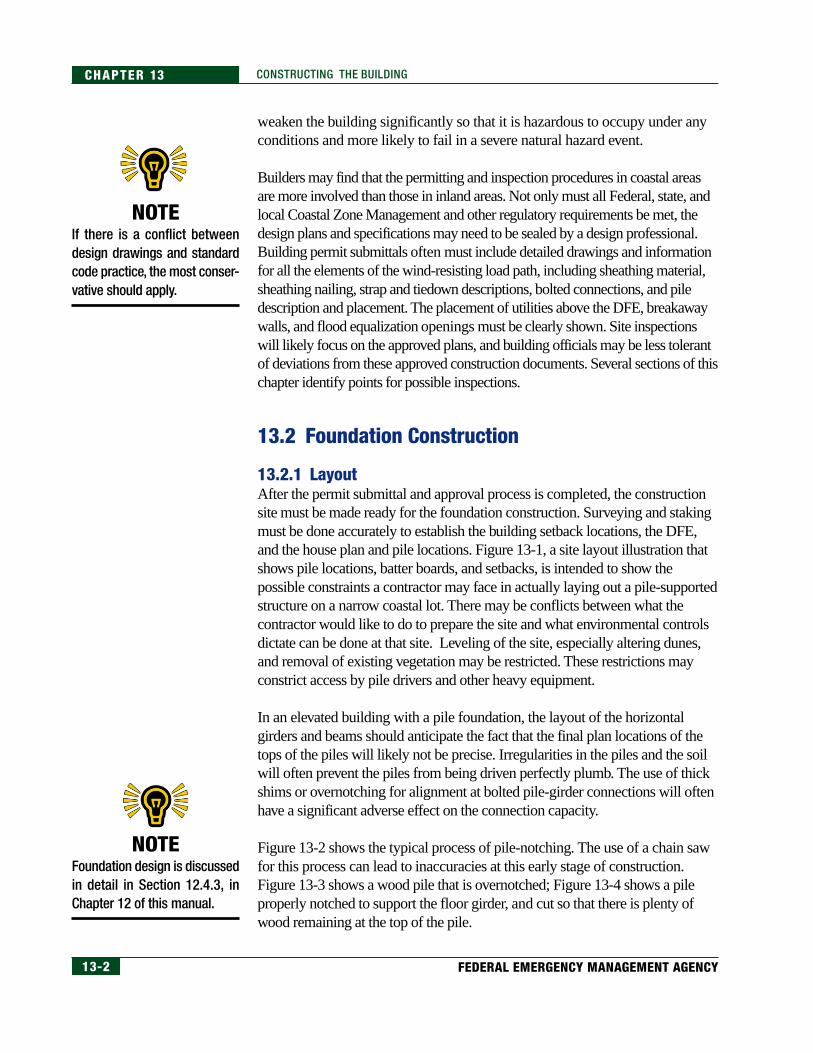
13.1 IntroductionConstruction of residential buildings in coastal zones presents challenges tothe builder not usually found in more inland locations. For all coastalresidential buildings, these challenges may include the following:
• connection details require additional inspections
• the need for careful surveying to place the building within property linesetbacks and above the Design Flood Elevation (DFE)
• the additional care required to ensure that all elements of the buildingwill withstand the large forces associated with high wind speeds andcoastal flooding
• the additional care that must be taken in constructing a buildingenvelope that will withstand the intrusion of air and moisture under theeffects of high wind speeds
• the difficulty of providing durable exterior construction in a moist,sometimes salt-laden, environment
• the requirement to protect and, usually, place utilities above the DFE
In constructing coastal residential buildings on elevated pile foundations,builders face additional challenges:
• the difficulty of constructing a driven pile foundation to acceptedconstruction plan tolerances
• the difficulty of building on an elevated post-and-beam foundation,compared to building on continuous wall foundations
This chapter discusses construction aspects of the above challenges, as well asother aspects of the coastal construction process. Individual sections coverconstruction items that will probably require the most care or attention on thepart of the builder in order for the design intent to be achieved.
While much of the discussion concerns constructing the building to meet thearchitect’s and engineer’s design intent for current and future conditions, it isalso important that the building elements be durable. Wood decay and termiteinfestation, metal corrosion, and concrete and masonry deterioration can
Constructing theBuilding
NOTEThe National Flood InsuranceProgram (NFIP) regulationsstate that for buildings in Vzones, “a registered profes-sional engineer or architectshall develop or review thestructural design, specificationsand plans for the construction,and shall certify that the designand methods of construction tobe used are in accordance withaccepted standards of practice”for meeting the provisions of theNFIP regulations regardingbuildings in V zones (see Chap-ter 6 of this manual).
NOTESections of this chapter refer tospecific requirements of the2000 International Building Code(referred to as the IBC 2000),prepared by the InternationalCode Council (ICC 2000a). TheICC also prepared the 2000 In-ternational Residential Code forOne- and Two-Family Dwellings(ICC 2000b), referred to as theIRC 2000. Designers should re-fer to pertinent sections of theIRC 2000, in addition to those ofthe IBC 2000 cited here.
13-2 FEDERAL EMERGENCY MANAGEMENT AGENCY
CHAPTER 13 CONSTRUCTING THE BUILDING
weaken the building significantly so that it is hazardous to occupy under anyconditions and more likely to fail in a severe natural hazard event.
Builders may find that the permitting and inspection procedures in coastal areasare more involved than those in inland areas. Not only must all Federal, state, andlocal Coastal Zone Management and other regulatory requirements be met, thedesign plans and specifications may need to be sealed by a design professional.Building permit submittals often must include detailed drawings and informationfor all the elements of the wind-resisting load path, including sheathing material,sheathing nailing, strap and tiedown descriptions, bolted connections, and piledescription and placement. The placement of utilities above the DFE, breakawaywalls, and flood equalization openings must be clearly shown. Site inspectionswill likely focus on the approved plans, and building officials may be less tolerantof deviations from these approved construction documents. Several sections of thischapter identify points for possible inspections.
13.2 Foundation Construction
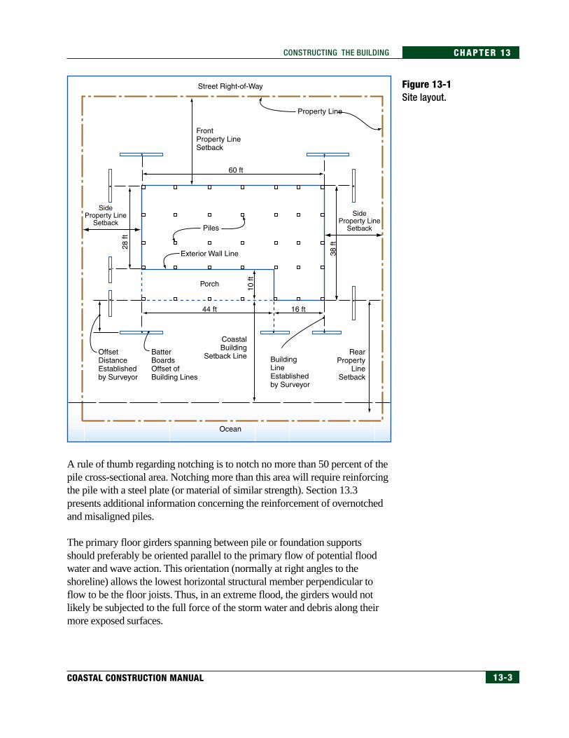
13.2.1 LayoutAfter the permit submittal and approval process is completed, the constructionsite must be made ready for the foundation construction. Surveying and stakingmust be done accurately to establish the building setback locations, the DFE,and the house plan and pile locations. Figure 13-1, a site layout illustration thatshows pile locations, batter boards, and setbacks, is intended to show thepossible constraints a contractor may face in actually laying out a pile-supportedstructure on a narrow coastal lot. There may be conflicts between what thecontractor would like to do to prepare the site and what environmental controlsdictate can be done at that site. Leveling of the site, especially altering dunes,and removal of existing vegetation may be restricted. These restrictions mayconstrict access by pile drivers and other heavy equipment.
In an elevated building with a pile foundation, the layout of the horizontalgirders and beams should anticipate the fact that the final plan locations of thetops of the piles will likely not be precise. Irregularities in the piles and the soilwill often prevent the piles from being driven perfectly plumb. The use of thickshims or overnotching for alignment at bolted pile-girder connections will oftenhave a significant adverse effect on the connection capacity.
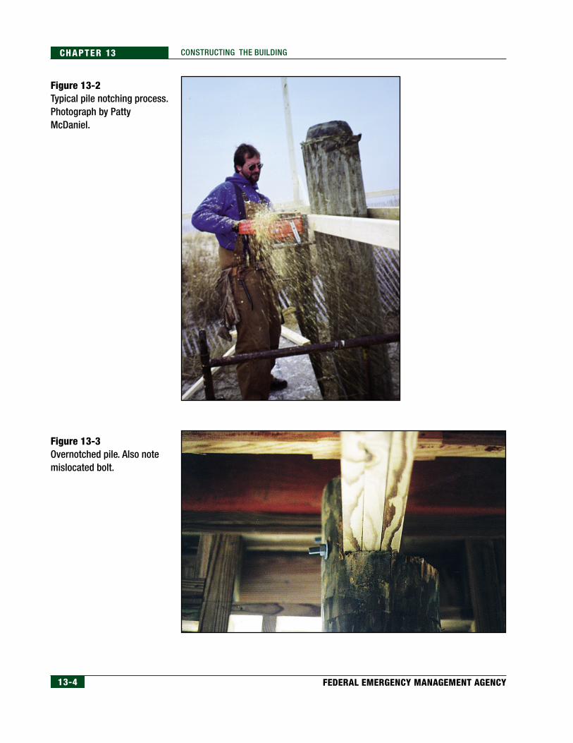
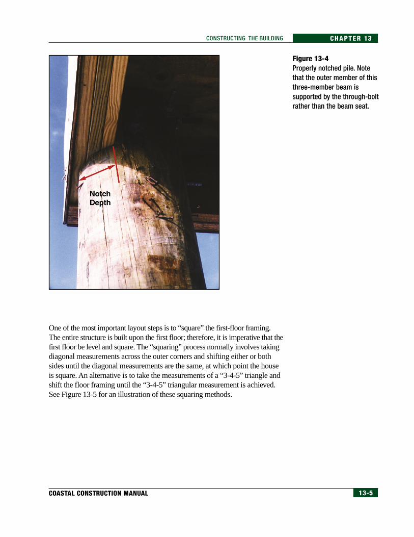
Figure 13-2 shows the typical process of pile-notching. The use of a chain sawfor this process can lead to inaccuracies at this early stage of construction.Figure 13-3 shows a wood pile that is overnotched; Figure 13-4 shows a pileproperly notched to support the floor girder, and cut so that there is plenty ofwood remaining at the top of the pile.
NOTEFoundation design is discussedin detail in Section 12.4.3, inChapter 12 of this manual.
NOTEIf there is a conflict betweendesign drawings and standardcode practice, the most conser-vative should apply.
13-3COASTAL CONSTRUCTION MANUAL
CHAPTER 13CONSTRUCTING THE BUILDING
Figure 13-1Site layout.
A rule of thumb regarding notching is to notch no more than 50 percent of thepile cross-sectional area. Notching more than this area will require reinforcingthe pile with a steel plate (or material of similar strength). Section 13.3presents additional information concerning the reinforcement of overnotchedand misaligned piles.
The primary floor girders spanning between pile or foundation supportsshould preferably be oriented parallel to the primary flow of potential floodwater and wave action. This orientation (normally at right angles to theshoreline) allows the lowest horizontal structural member perpendicular toflow to be the floor joists. Thus, in an extreme flood, the girders would notlikely be subjected to the full force of the storm water and debris along theirmore exposed surfaces.
13-4 FEDERAL EMERGENCY MANAGEMENT AGENCY
CHAPTER 13 CONSTRUCTING THE BUILDING
Figure 13-3Overnotched pile. Also notemislocated bolt.
Figure 13-2Typical pile notching process.Photograph by PattyMcDaniel.
13-5COASTAL CONSTRUCTION MANUAL
CHAPTER 13CONSTRUCTING THE BUILDING
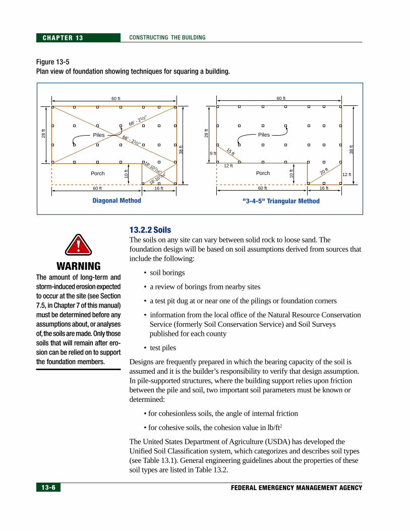
One of the most important layout steps is to “square” the first-floor framing.The entire structure is built upon the first floor; therefore, it is imperative that thefirst floor be level and square. The “squaring” process normally involves takingdiagonal measurements across the outer corners and shifting either or bothsides until the diagonal measurements are the same, at which point the houseis square. An alternative is to take the measurements of a “3-4-5” triangle andshift the floor framing until the “3-4-5” triangular measurement is achieved.See Figure 13-5 for an illustration of these squaring methods.
Figure 13-4Properly notched pile. Notethat the outer member of thisthree-member beam issupported by the through-boltrather than the beam seat.
13-6 FEDERAL EMERGENCY MANAGEMENT AGENCY
CHAPTER 13 CONSTRUCTING THE BUILDING
13.2.2 SoilsThe soils on any site can vary between solid rock to loose sand. Thefoundation design will be based on soil assumptions derived from sources thatinclude the following:
• soil borings
• a review of borings from nearby sites
• a test pit dug at or near one of the pilings or foundation corners
• information from the local office of the Natural Resource ConservationService (formerly Soil Conservation Service) and Soil Surveyspublished for each county
• test piles
Designs are frequently prepared in which the bearing capacity of the soil isassumed and it is the builder’s responsibility to verify that design assumption.In pile-supported structures, where the building support relies upon frictionbetween the pile and soil, two important soil parameters must be known ordetermined:
• for cohesionless soils, the angle of internal friction
• for cohesive soils, the cohesion value in lb/ft2
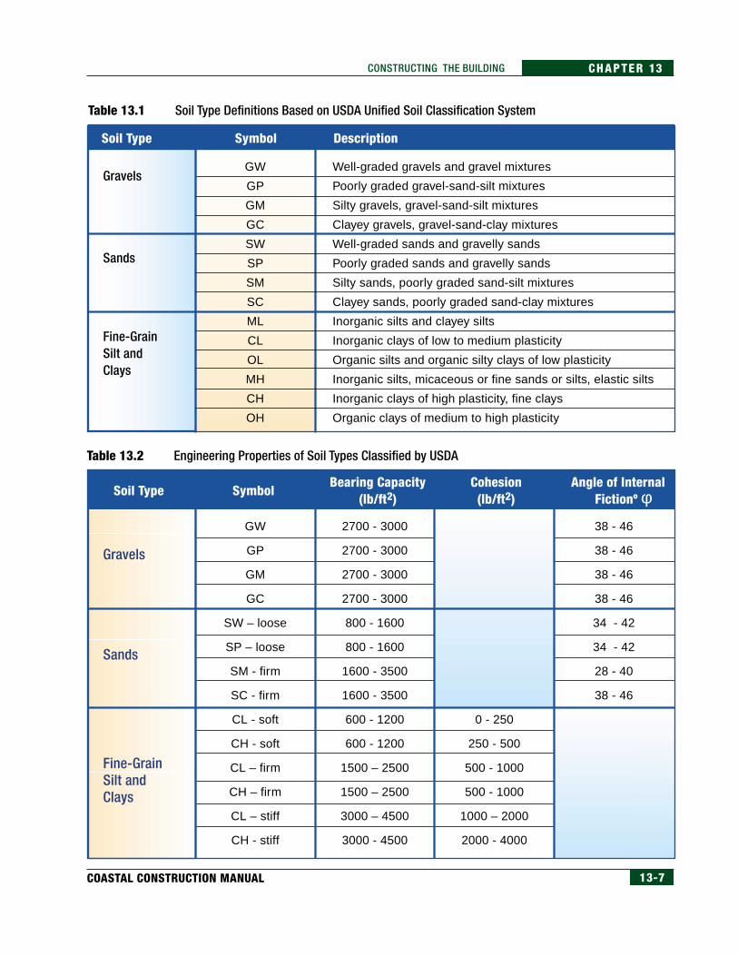
The United States Department of Agriculture (USDA) has developed theUnified Soil Classification system, which categorizes and describes soil types(see Table 13.1). General engineering guidelines about the properties of thesesoil types are listed in Table 13.2.
Figure 13-5Plan view of foundation showing techniques for squaring a building.
60 ft
66' - 21/2"
66' - 21/2"
18'-10 7/16"
18'-107 /16"
60 ft 16 ft
Porch
Diagonal Method
Piles28 ft
10 ft
38 ft
60 ft
60 ft
9 ft15 ft
12 ft
16 ft
12 ft20 ftPorch
"3-4-5" Triangular Method
Piles28 ft
10 ft
38 ft
WARNINGThe amount of long-term andstorm-induced erosion expectedto occur at the site (see Section7.5, in Chapter 7 of this manual)must be determined before anyassumptions about, or analysesof, the soils are made. Only thosesoils that will remain after ero-sion can be relied on to supportthe foundation members.
13-7COASTAL CONSTRUCTION MANUAL
CHAPTER 13CONSTRUCTING THE BUILDING
Table 13.1 Soil Type Definitions Based on USDA Unified Soil Classification System
Table 13.2 Engineering Properties of Soil Types Classified by USDA
GW
GP
GM
GC
SW
SP
SM
SC
ML
CL
OL
MH
CH
OH
Well-graded gravels and gravel mixtures
Poorly graded gravel-sand-silt mixtures
Silty gravels, gravel-sand-silt mixtures
Clayey gravels, gravel-sand-clay mixtures
Well-graded sands and gravelly sands
Poorly graded sands and gravelly sands
Silty sands, poorly graded sand-silt mixtures
Clayey sands, poorly graded sand-clay mixtures
Inorganic silts and clayey silts
Inorganic clays of low to medium plasticity
Organic silts and organic silty clays of low plasticity
Inorganic silts, micaceous or fine sands or silts, elastic silts
Inorganic clays of high plasticity, fine clays
Organic clays of medium to high plasticity
Gravels
Sands
Fine-Grain Silt and Clays
Soil Type Symbol Description
GW
GP
GM
GC
SW – loose
SP – loose
SM - firm
SC - firm
CL - soft
CH - soft
CL – firm
CH – firm
CL – stiff
CH - stiff
2700 - 3000
2700 - 3000
2700 - 3000
2700 - 3000
800 - 1600
800 - 1600
1600 - 3500
1600 - 3500
600 - 1200
600 - 1200
1500 – 2500
1500 – 2500
3000 – 4500
3000 - 4500
0 - 250
250 - 500
500 - 1000
500 - 1000
1000 – 2000
2000 - 4000
38 - 46
38 - 46
38 - 46
38 - 46
34 - 42
34 - 42
28 - 40
38 - 46
Gravels
Sands
Fine-Grain Silt and Clays
Soil Type SymbolBearing Capacity
(lb/ft2)Cohesion(lb/ft2)
Angle of InternalFictionº φ
13-8 FEDERAL EMERGENCY MANAGEMENT AGENCY
CHAPTER 13 CONSTRUCTING THE BUILDING
The soil bearing capacities listed in Table 13.2 are intended to provide asuggested range of values that can be used when other data are not available.However, soils can vary significantly in bearing capacity from one site to thenext. This manual recommends that a geotechnical engineer be consultedwhen any unusual or unknown soil condition is encountered.
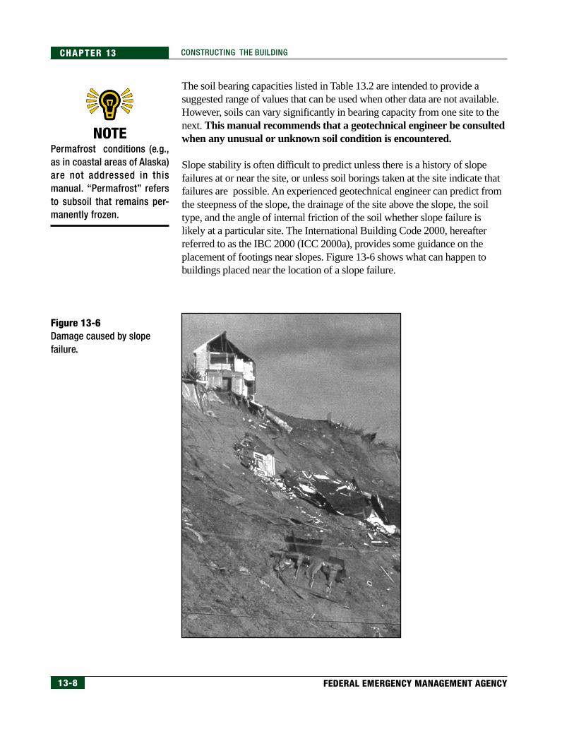
Slope stability is often difficult to predict unless there is a history of slopefailures at or near the site, or unless soil borings taken at the site indicate thatfailures are possible. An experienced geotechnical engineer can predict fromthe steepness of the slope, the drainage of the site above the slope, the soiltype, and the angle of internal friction of the soil whether slope failure islikely at a particular site. The International Building Code 2000, hereafterreferred to as the IBC 2000 (ICC 2000a), provides some guidance on theplacement of footings near slopes. Figure 13-6 shows what can happen tobuildings placed near the location of a slope failure.
Figure 13-6Damage caused by slopefailure.
NOTEPermafrost conditions (e.g.,as in coastal areas of Alaska)are not addressed in thismanual. “Permafrost” refersto subsoil that remains per-manently frozen.
13-9COASTAL CONSTRUCTION MANUAL
CHAPTER 13CONSTRUCTING THE BUILDING
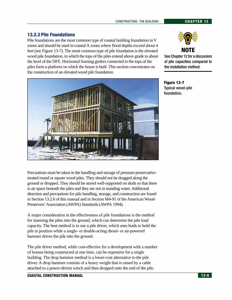
13.2.3 Pile FoundationsPile foundations are the most common type of coastal building foundation in Vzones and should be used in coastal A zones where flood depths exceed about 4feet (see Figure 13-7). The most common type of pile foundation is the elevatedwood pile foundation, in which the tops of the piles extend above grade to aboutthe level of the DFE. Horizontal framing girders connected to the tops of thepiles form a platform on which the house is built. This section concentrates onthe construction of an elevated wood pile foundation.
NOTESee Chapter 12 for a discussionof pile capacities compared tothe installation method.
Figure 13-7Typical wood-pilefoundation.
Precautions must be taken in the handling and storage of pressure-preservative-treated round or square wood piles. They should not be dragged along theground or dropped. They should be stored well-supported on skids so that thereis air space beneath the piles and they are not in standing water. Additionaldirection and precautions for pile handling, storage, and construction are foundin Section 13.2.6 of this manual and in Section M4-91 of the American Wood-Preservers’ Association (AWPA) Standards (AWPA 1994).
A major consideration in the effectiveness of pile foundations is the methodfor inserting the piles into the ground, which can determine the pile loadcapacity. The best method is to use a pile driver, which uses leads to hold thepile in position while a single- or double-acting diesel- or air-poweredhammer drives the pile into the ground.
The pile driver method, while cost-effective for a development with a numberof houses being constructed at one time, can be expensive for a singlebuilding. The drop hammer method is a lower-cost alternative to the piledriver. A drop hammer consists of a heavy weight that is raised by a cableattached to a power-driven winch and then dropped onto the end of the pile.
13-10 FEDERAL EMERGENCY MANAGEMENT AGENCY
CHAPTER 13 CONSTRUCTING THE BUILDING
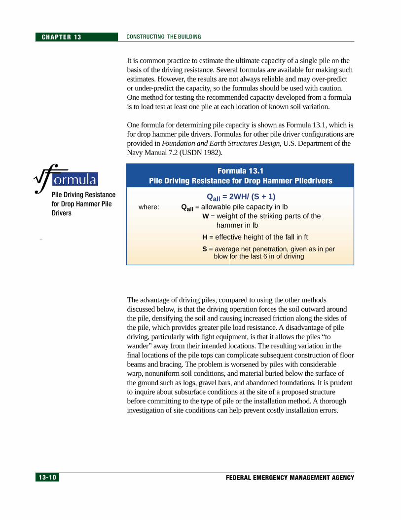
Formula 13.1Pile Driving Resistance for Drop Hammer Piledrivers
where: Qall = allowable pile capacity in lbW = weight of the striking parts of the hammer in lb
H = effective height of the fall in ft
S = average net penetration, given as in per blow for the last 6 in of driving
Qall = 2WH/ (S + 1)
It is common practice to estimate the ultimate capacity of a single pile on thebasis of the driving resistance. Several formulas are available for making suchestimates. However, the results are not always reliable and may over-predictor under-predict the capacity, so the formulas should be used with caution.One method for testing the recommended capacity developed from a formulais to load test at least one pile at each location of known soil variation.
One formula for determining pile capacity is shown as Formula 13.1, which isfor drop hammer pile drivers. Formulas for other pile driver configurations areprovided in Foundation and Earth Structures Design, U.S. Department of theNavy Manual 7.2 (USDN 1982).
Pile Driving Resistancefor Drop Hammer PileDrivers
The advantage of driving piles, compared to using the other methodsdiscussed below, is that the driving operation forces the soil outward aroundthe pile, densifying the soil and causing increased friction along the sides ofthe pile, which provides greater pile load resistance. A disadvantage of piledriving, particularly with light equipment, is that it allows the piles “towander” away from their intended locations. The resulting variation in thefinal locations of the pile tops can complicate subsequent construction of floorbeams and bracing. The problem is worsened by piles with considerablewarp, nonuniform soil conditions, and material buried below the surface ofthe ground such as logs, gravel bars, and abandoned foundations. It is prudentto inquire about subsurface conditions at the site of a proposed structurebefore committing to the type of pile or the installation method. A thoroughinvestigation of site conditions can help prevent costly installation errors.
13-11COASTAL CONSTRUCTION MANUAL
CHAPTER 13CONSTRUCTING THE BUILDING
The soils investigation should include determinations of the following:
• the type of foundations that have been installed in the area in the past
• the type of soil that might be expected, from past soil borings and soilsurveys
• whether the proposed site has been used for any other purpose, whichwould indicate whether there are any buried materials on the site
• how the site may have been used in the past, from a search of landrecords for past ownership
A less desirable but frequently used method of inserting piles into sandy soilis “jetting.” Jetting involves forcing a high-pressure stream of water through apipe advanced along the side of the pile. The water blows a hole in the sandinto which the pile is continuously pushed or dropped until the required depthis reached. Unfortunately, jetting loosens the soil around the pile and the soilbelow the tip, resulting in a lower load capacity.
Holes for piles may be excavated by an auger if the soil is sufficiently clayeyor silty. In addition, some sands may contain enough clay or silt to permitaugering. This method can be used by itself or in conjunction with piledriving. If the hole is full-sized, the pile is dropped in and the void backfilled.Alternatively, an undersized hole can be excavated and a pile driven into it.When the soil conditions are appropriate, the hole will stay open long enoughto drop or drive in a pile. In general, piles dropped or driven into augeredholes may not have as much capacity as those driven without augering.
If precast concrete piles or steel piles are used, only a regular pile driver withleads and a single- or double-acting hammer should be used. For any piledriving, the building jurisdiction or the engineer-of-record will probablyrequire that a driving log be kept for each pile. The log will show the numberof inches per blow as the driving progresses—a factor used in determining thepile capacity, as shown in Formula 13.1. As noted in Section 12.4.3, the twoprimary determinants of pile capacity are the depth of embedment in the soiland the soil properties.
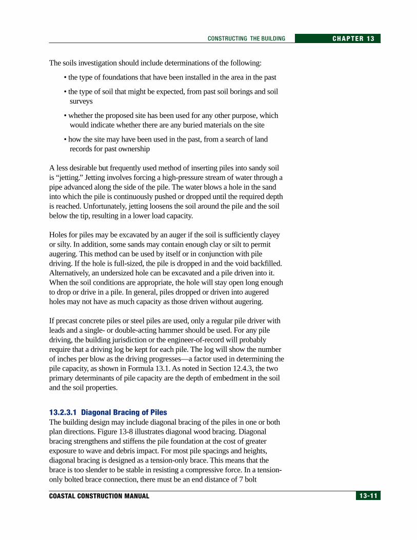
13.2.3.1 Diagonal Bracing of PilesThe building design may include diagonal bracing of the piles in one or bothplan directions. Figure 13-8 illustrates diagonal wood bracing. Diagonalbracing strengthens and stiffens the pile foundation at the cost of greaterexposure to wave and debris impact. For most pile spacings and heights,diagonal bracing is designed as a tension-only brace. This means that thebrace is too slender to be stable in resisting a compressive force. In a tension-only bolted brace connection, there must be an end distance of 7 bolt
13-12 FEDERAL EMERGENCY MANAGEMENT AGENCY
CHAPTER 13 CONSTRUCTING THE BUILDING
diameters in the brace (as illustrated in Figure 12-69, in Chapter 12) and aside distance of 4 bolt diameters in the pile. These clearances may be difficultto achieve if two adjacent braces end on the same side of a pile.
Figure 13-8Diagonal wood bracing in awood-pile foundation.
With tension-only braces, the design intent can be met only when all of thefollowing conditions are met:
• The horizontal floor beams or girders just above the diagonals mustserve as stiff, strong, and stable compression struts that span betweenthe pile tops. These members allow forces to the piles that are notdiagonally braced in the direction of the force to be transmitted to apile that is braced in that direction.
• Solid connections, usually achieved with bolts, must be provided thattransmit forces from the brace to the pile or floor system
• Bracing members must have sufficient strength to resist failure in tensionthroughout their life. This life will be shortened if the connections or thebracing members corrode, split, twist, bend, or otherwise change in sucha way that their structural integrity is compromised.
The placement of the lower bolted connection of the diagonal to the pilerequires some judgment. If the connection is placed too high above grade, thepile length below the connection is unbraced and the overall bracing is lessstrong and stiff. If the connection is placed too close to grade, the bolt hole ismore likely to be flooded or infested with termites. Because the bolt holepasses through the untreated part of the pile, flooding and subsequent decayor termite infestation will weaken the pile at a vulnerable location. The bolthole should be treated with preservative as discussed in Section 13.2.8 of thismanual and in Section M4-91 of the AWPA Standards (AWPA 1994).
13-13COASTAL CONSTRUCTION MANUAL
CHAPTER 13CONSTRUCTING THE BUILDING
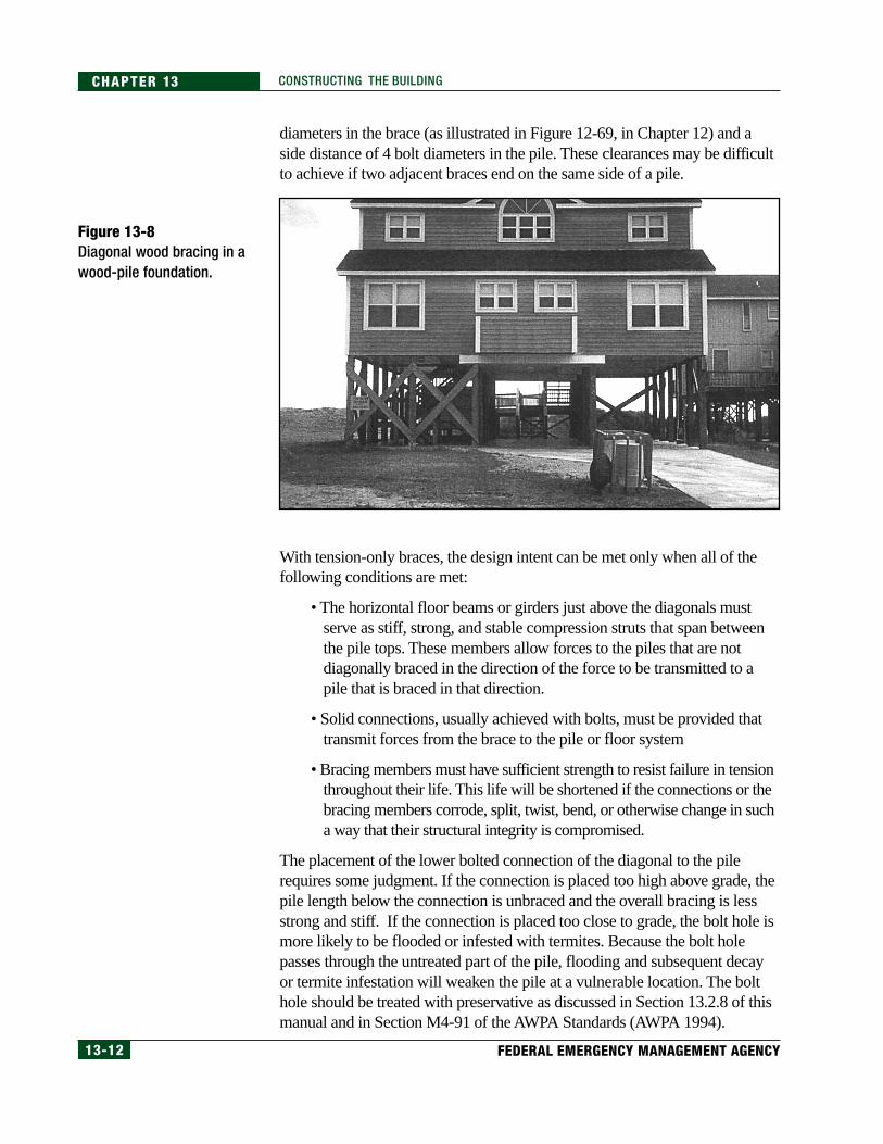
13.2.3.2 Knee Bracing of PilesKnee braces can be effective in supporting the pile against the lateral forces ofwind and water. Figure 13-9 illustrates knee bracing. Knee bracing increasesthe strength and stiffness of an elevated pile foundation by restraining rotationat the top of the pile and reducing the pile bending length. Knee bracing is notas stiff or as strong as diagonal bracing. Knee braces have an advantage overdiagonal braces in that they present less obstruction to waves and debris. Kneebraces are shorter than diagonal braces and are usually designed for bothtension and compression loads.
Figure 13-9Knee bracing in awood-pile foundation.
The entire load path into and through the knee brace must be designed withsufficient capacity. The girder or beam to which the knee brace is connectedmust have the bending strength to resist the axial force in the knee brace. Theconnections at each end of the knee brace must have sufficient capacity inboth tension and compression.
13-14 FEDERAL EMERGENCY MANAGEMENT AGENCY
CHAPTER 13 CONSTRUCTING THE BUILDING
13.2.3.3 Grade Beams in Pile FoundationsThe pile foundation design may or may not include grade beams. When used,grade beams tie the piles together, usually in both horizontal directions. Gradebeams are usually made of wood or reinforced concrete. Their exposure toground contact and possible wave forces requires highly durable construction.Wood grade beams must be of treated wood and be field treated where cutsand bores are made. For concrete grade beams, the concrete mix design, coverthickness, and curing must optimize durability. In addition, in areas subject toerosion or scour, grade beams must be designed to be self-supporting.Durability of concrete and wood construction is discussed in Section 13.2.7.
In V zones, grade beams must be used only for lateral support of the piles.If a floor is poured so that it is attached to or is monolithic with the gradebeams, the bottom of the grade beam becomes the bottom of lowesthorizontal structural member, which, as noted in Chapter 6, Section 6.4.3.3,must be at or above the Base Flood Elevation in order for the structure to bein compliance with the NFIP regulations.
If grade beams are used with wood piles, it is important that the connection ofthe grade beam to the pile does not encourage water retention. The maximumbending moment in the piles occurs at the grade beams. Decay caused bywater retention at that critical point in the piles would likely induce failureunder high-wind or wave forces.
13.2.3.4 Wood-Pile-to-Wood-Girder ConnectionsPiles are often notched to provide a bearing surface for a girder. The notchingshould not remove more than 50 percent of the pile cross section. Section12.5.9 describes the load calculation that must be performed at this connectionto resist failure in shear. The designer can state just how much bearing isneeded for sufficient bearing strength and acceptable eccentricity. The girdermust be truly bearing on the surface to be effective. If the bolts are not placedlow in the girder, it can shrink away from the bearing and the load will becarried in the bolts. Where the side and bottom of a girder are in contact witha notched pile, the wood of the pile at the notch is mostly untreated becausethe pressure preservative does not fully penetrate the wood. The surfaces ofthe pile exposed by notching should be treated with a field preservative.
The pile-to-girder connection may be subjected to large uplift forces in strongwinds. The bolted connection must withstand these forces. The bottom boltmust be at least 4 bolt diameters from the bottom of the girder. The top boltmust be at least 7 bolt diameters from the top of the pile. The bolts should notbe too widely spaced vertically across a sawn wood deep girder, as shrinkagewill cause the girder to split between the bolts. A glue-laminated or parallelstrand girder will be drier at installation and much less susceptible to this
13-15COASTAL CONSTRUCTION MANUAL
CHAPTER 13CONSTRUCTING THE BUILDING
problem. Bolted connections should always be installed with washers on boththe head and threaded ends of the bolt.
Vertical lag bolt, spike, or nail connections into the top of a wood pile shouldbe avoided. Such connections have no building-code-allowed capacity inwithdrawal and a reduced capacity in shear. In addition, the penetrationinvites water intrusion and subsequent decay that would further weaken theconnection. For connections made with spikes driven into the side grain of amember, the spikes should be driven into drilled guide holes so that the woodwill not be split.
Exposed wood should be assumed to have a moisture content greater than 19percent in coastal areas. There is evidence that fasteners embedded in treatedwood or naturally durable wood with a moisture content of more than 19percent are prone to corrosion, because of the treatment chemicals and thenatural wood extractive. The IBC 2000 (ICC 2000a) requires that fasteners forpressure-preservative-treated wood be of hot-dipped galvanized steel, stainlesssteel, silicon bronze, or copper. The California Redwood Associationrecommends the use of hot-dip galvanized nails in redwood.
13.2.4 Masonry Foundation ConstructionThe combination of high winds and moist (sometimes salt-laden) air can havea damaging effect on masonry construction by forcing moisture into thesmallest of cracks or openings in the masonry joints. The entry of moistureinto reinforced masonry construction can lead to corrosion of thereinforcement and subsequent cracking and spalling of the masonry. Moistureresistance is highly influenced by the quality of the materials and the qualityof the masonry construction at the site. Masonry material selection isdiscussed in Section 12.6, in Chapter 12 of this manual.
The quality of masonry construction depends on many considerations.Masonry units and packaged mortar and grout materials should be stored offthe ground and covered. Mortar and grouts must be carefully batched andmixed. As the masonry units are placed, head and bed joints must be wellmortared and tooled. Masonry work in progress must be well protected.Concave joints and V-joints provide the best moisture resistance.
Moisture penetration or retention must be carefully controlled where masonryconstruction adjoins other materials. As in any construction in the coastalbuilding envelope, flashing at masonry must be continuous, durable, and ofsufficient height and extent to impede the penetration of expected wind-drivenprecipitation. Because most residential buildings with masonry foundationshave other materials (e.g., wood, concrete, steel, vinyl) attached to thefoundation, allowance must be made for shrinkage of materials as they dry out
NOTEFor more information about pro-tecting metal connectors fromcorrosion, refer to FEMA NFIPTechnical Bulletin 8, CorrosionProtection for Metal Connectorsin Coastal Areas, in Appendix H.
WARNINGOpen masonry foundations Inearthquake hazard areas re-quire special reinforcementdetailing and pier proportionsto meet the requirement for in-creased ductility.
13-16 FEDERAL EMERGENCY MANAGEMENT AGENCY
CHAPTER 13 CONSTRUCTING THE BUILDING
and for differential movement between the materials. Expansion and contractionjoints must be placed so that the materials can easily move against each other.
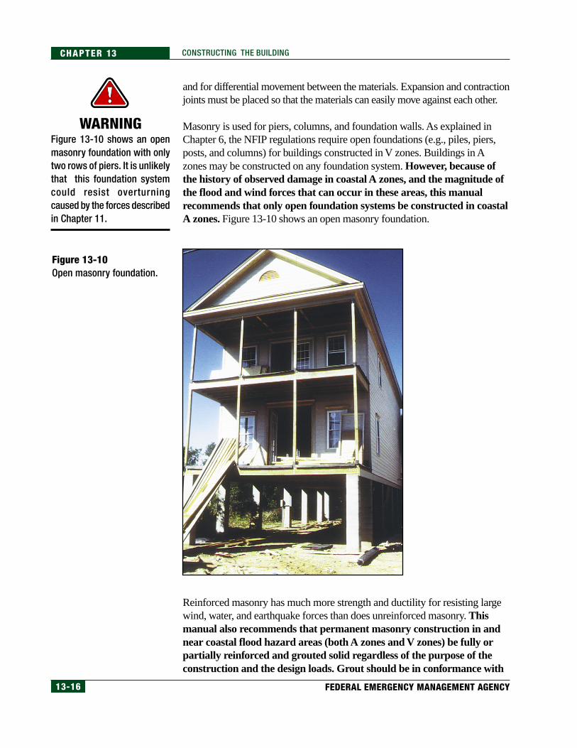
Masonry is used for piers, columns, and foundation walls. As explained inChapter 6, the NFIP regulations require open foundations (e.g., piles, piers,posts, and columns) for buildings constructed in V zones. Buildings in Azones may be constructed on any foundation system. However, because ofthe history of observed damage in coastal A zones, and the magnitude ofthe flood and wind forces that can occur in these areas, this manualrecommends that only open foundation systems be constructed in coastalA zones. Figure 13-10 shows an open masonry foundation.
WARNINGFigure 13-10 shows an openmasonry foundation with onlytwo rows of piers. It is unlikelythat this foundation systemcould resist overturningcaused by the forces describedin Chapter 11.
Figure 13-10Open masonry foundation.
Reinforced masonry has much more strength and ductility for resisting largewind, water, and earthquake forces than does unreinforced masonry. Thismanual also recommends that permanent masonry construction in andnear coastal flood hazard areas (both A zones and V zones) be fully orpartially reinforced and grouted solid regardless of the purpose of theconstruction and the design loads. Grout should be in conformance with
13-17COASTAL CONSTRUCTION MANUAL
CHAPTER 13CONSTRUCTING THE BUILDING
the requirements of the IBC 2000 (ICC 2000a). Knockouts should beplaced at the bottom of fully grouted cells to ensure that the grout completelyfills the cells from top to bottom.
For concrete masonry units, choosing Type I “moisture controlled” units andkeeping them dry in transit and on the job will minimize shrinkage cracking.Usually, for optimum crack control, Type S mortar should be used forbelowgrade applications and Type N mortar used for above-gradeapplications. The IBC 2000 specifies grout proportions by volume formasonry construction.
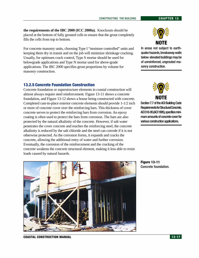
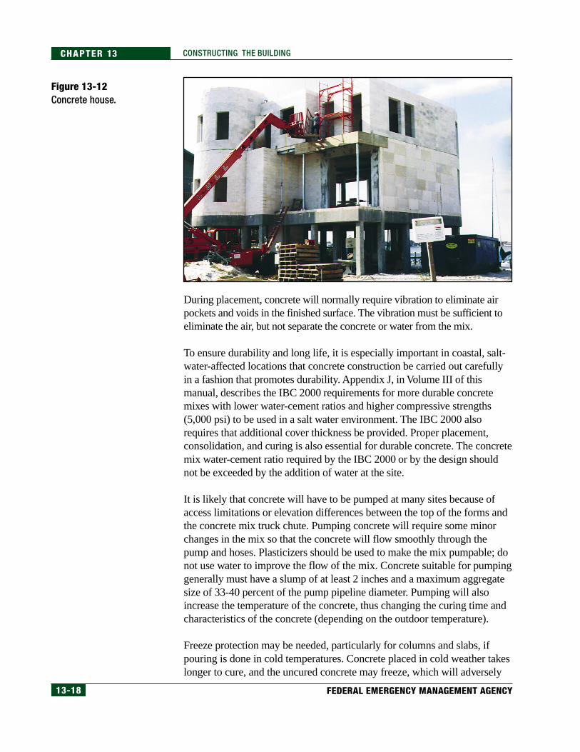
13.2.5 Concrete Foundation ConstructionConcrete foundation or superstructure elements in coastal construction willalmost always require steel reinforcement. Figure 13-11 shows a concretefoundation, and Figure 13-12 shows a house being constructed with concrete.Completed cast-in-place exterior concrete elements should provide 1-1/2 inchor more of concrete cover over the reinforcing bars. This thickness of coverconcrete serves to protect the reinforcing bars from corrosion. An epoxycoating is often used to protect the bars from corrosion. The bars are alsoprotected by the natural alkalinity of the concrete. However, if salt waterpenetrates the cover concrete and reaches the reinforcing steel, the concretealkalinity is reduced by the salt chloride and the steel can corrode if it is nototherwise protected. As the corrosion forms, it expands and cracks theconcrete, allowing the additional entry of water and further corrosion.Eventually, the corrosion of the reinforcement and the cracking of theconcrete weakens the concrete structural element, making it less able to resistloads caused by natural hazards.
NOTEIn areas not subject to earth-quake hazards, breakaway wallsbelow elevated buildings may beof unreinforced, ungrouted ma-sonry construction.
Figure 13-11Concrete foundation.
NOTESection 7.7 of the ACI Building CodeRequirements for Structural Concrete,ACI 318-95 (ACI 1995), specifies mini-mum amounts of concrete cover forvarious construction applications.
13-18 FEDERAL EMERGENCY MANAGEMENT AGENCY
CHAPTER 13 CONSTRUCTING THE BUILDING
During placement, concrete will normally require vibration to eliminate airpockets and voids in the finished surface. The vibration must be sufficient toeliminate the air, but not separate the concrete or water from the mix.
To ensure durability and long life, it is especially important in coastal, salt-water-affected locations that concrete construction be carried out carefullyin a fashion that promotes durability. Appendix J, in Volume III of thismanual, describes the IBC 2000 requirements for more durable concretemixes with lower water-cement ratios and higher compressive strengths(5,000 psi) to be used in a salt water environment. The IBC 2000 alsorequires that additional cover thickness be provided. Proper placement,consolidation, and curing is also essential for durable concrete. The concretemix water-cement ratio required by the IBC 2000 or by the design shouldnot be exceeded by the addition of water at the site.
It is likely that concrete will have to be pumped at many sites because ofaccess limitations or elevation differences between the top of the forms andthe concrete mix truck chute. Pumping concrete will require some minorchanges in the mix so that the concrete will flow smoothly through thepump and hoses. Plasticizers should be used to make the mix pumpable; donot use water to improve the flow of the mix. Concrete suitable for pumpinggenerally must have a slump of at least 2 inches and a maximum aggregatesize of 33-40 percent of the pump pipeline diameter. Pumping will alsoincrease the temperature of the concrete, thus changing the curing time andcharacteristics of the concrete (depending on the outdoor temperature).
Freeze protection may be needed, particularly for columns and slabs, ifpouring is done in cold temperatures. Concrete placed in cold weather takeslonger to cure, and the uncured concrete may freeze, which will adversely
Figure 13-12Concrete house.
13-19COASTAL CONSTRUCTION MANUAL
CHAPTER 13CONSTRUCTING THE BUILDING
affect its final strength. Methods of preventing concrete from freezing duringcuring include the following:
• heating adjacent soil before pouring on-grade concrete
• warming the mix ingredients before batching
• warming the concrete with heaters after pouring (avoid overheating)
• placing insulating blankets over and around the forms after pouring
• selecting a cement mix that will shorten curing time (e.g., hi-early)
Like masonry, concrete is used for piers, columns, and walls. However, therecommendation made in Section 13.2.4 of this manual regarding openfoundations in coastal A zones applies to concrete foundations as well. Inaddition, because the environmental impact of salt-laden air and moisturemake the damage potential significant for concrete, this manualrecommends that all concrete construction in and near coastal floodhazard areas (both V zones and A zones) be constructed with the moredurable 5,000-psi minimum compressive strength concrete regardlessof the purpose of the construction and the design loads.
13.2.6 Wood Foundation ConstructionAll of the wood used in the foundation piles, girders, beams, and braces mustbe pressure-preservative-treated wood or, when allowed, naturally decay-resistant wood. Section 12.6 (in Chapter 12) and Appendix J discuss theselection of materials for these wood elements. Piles must be treated withwaterborne arsenicals, creosote, or both. Girders and braces may be treatedwith waterborne arsenicals, pentachlorophenol, or creosote. Certainprecautions apply to working with any of these treated wood products, andadditional precautions apply for pentachlorophenol- and creosote-treatedwood. Additional information is available from Consumer Information Sheetswhere the products are sold.
When working with all treated wood, avoid frequent or prolongedinhalation of the sawdust. When sawing and boring, wear goggles and adust mask. Only treated wood that is visibly clean and free of surfaceresidue should be used for patios, decks, and walkways. Before eating ordrinking, wash all exposed skin areas thoroughly. If preservatives orsawdust accumulate on clothes, wash the clothes (separately from otherhousehold clothing) before wearing them again. Dispose of the cuttings byordinary trash collection or burial. The cuttings should not be burned inopen fires or in stoves, fireplaces, or residential boilers because toxicchemicals may be produced as part of the smoke and ashes. The cuttingsmay be burned only in commercial or industrial incinerators or boilers inaccordance with state and Federal regulations.
13-20 FEDERAL EMERGENCY MANAGEMENT AGENCY
CHAPTER 13 CONSTRUCTING THE BUILDING
Avoid frequent or prolonged skin contact with pentachlorophenol or creosote-treated wood; when handling it, wear long-sleeved shirts and long pants and usegloves impervious to the chemicals (e.g., vinyl-coated gloves).
Pentachlorophenol-pressure-treated wood should not be used in residentialinteriors except for laminated beams or for building components that are inground contact and are subject to decay or insect infestation and where twocoats of an appropriate sealer are applied. Sealers may be applied at theinstallation site. Urethane, shellac, latex epoxy enamel, and varnish areacceptable sealers.
Creosote-treated wood should not be used in residential interiors. Coal tarpitch and coal tar pitch emulsion are effective sealers for outdoor creosote-treated wood-block flooring. Urethane, epoxy, and shellac are acceptablesealers for all creosote-treated wood.
Wood foundations are being constructed in some parts of the country as part ofa basement or crawlspace. These foundation elements have walls constructedwith pressure-preservative-treated plywood and footings constructed with widepressure- preservative-treated wood boards such as 2x10’s or 2x12’s. Becausethe NFIP regulations allow continuous foundation walls (with the requiredopenings) in coastal A zones, continuous wood foundations might seem to beacceptable in these areas. However, because of the potential forces from wavesless than 3 feet high (as discussed in Chapters 11 and 12), a wood foundationsupported on a wood footing is not recommended in coastal A zones.
13.2.7 Foundation Material DurabilityIdeally, all of the pile-and-beam foundation framing of a coastal buildingwould be protected from rain by the overhead structure, even though all of theexposed materials should be resistant to decay and corrosion. In practice, theoverhead structure includes both enclosed spaces (such as the main house)and outside decks. The spaces between the floor boards on an outside deckallow water to pass through and fall on the framing below. A worst case forpotential rain and moisture penetration exists when less permeable deckscollect water and channel it to fall as a stream onto framing below. Inaddition, wind driven rain and ocean spray will penetrate into many smallspaces; protection of the wood in these spaces is important to long-termdurability of the structure.
The durability of the exposed wood frame will be improved if it is detailed toshed water during wetting and to dry readily afterward. Decay will occur inthose wetted locations where the moisture content of the exposed untreatedinterior core of treated wood elements remains above the fiber saturationpoint—about 30 percent. The moisture content of seasoned (S-DRY) 2x wood
13-21COASTAL CONSTRUCTION MANUAL
CHAPTER 13CONSTRUCTING THE BUILDING
when it arrives at the job site can be as high as 19 percent, but this moisturecontent is quickly reduced as the wood dries in the finished building. (Themoisture content of the large members (i.e., greater than 3x) will be muchmore than 19 percent when they arrive at the job site, and it will take monthsto drop below 19 percent.)
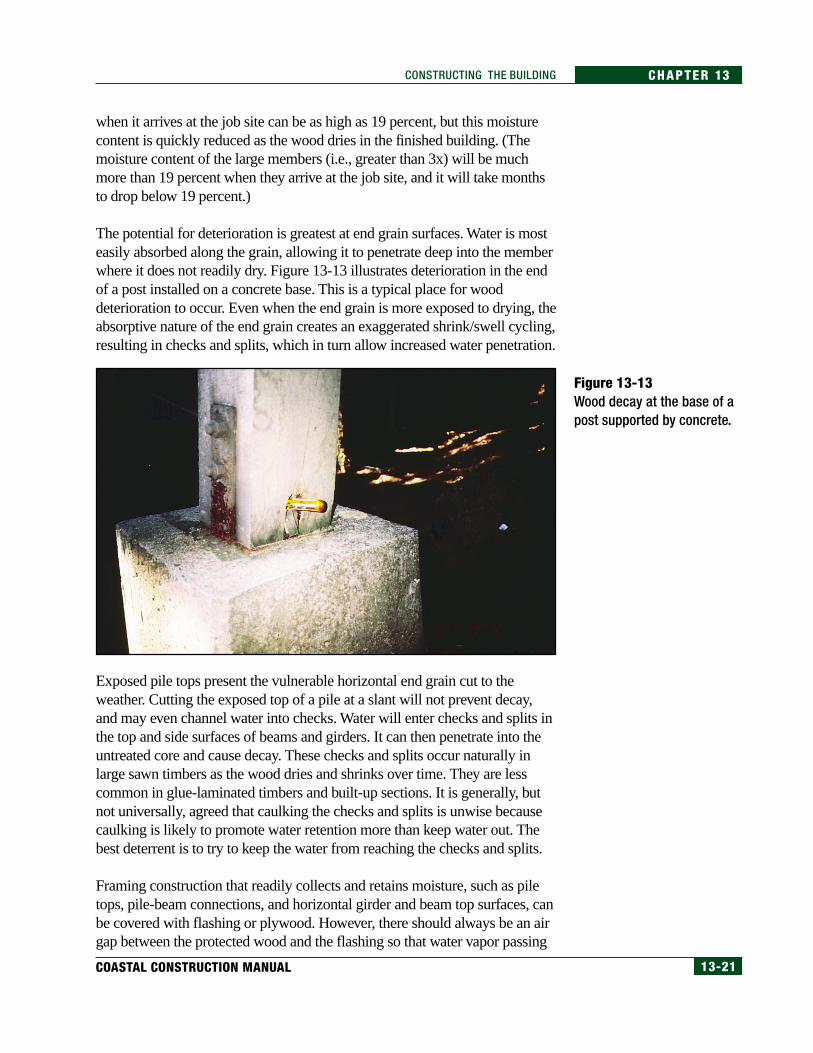
The potential for deterioration is greatest at end grain surfaces. Water is mosteasily absorbed along the grain, allowing it to penetrate deep into the memberwhere it does not readily dry. Figure 13-13 illustrates deterioration in the endof a post installed on a concrete base. This is a typical place for wooddeterioration to occur. Even when the end grain is more exposed to drying, theabsorptive nature of the end grain creates an exaggerated shrink/swell cycling,resulting in checks and splits, which in turn allow increased water penetration.
Figure 13-13Wood decay at the base of apost supported by concrete.
Exposed pile tops present the vulnerable horizontal end grain cut to theweather. Cutting the exposed top of a pile at a slant will not prevent decay,and may even channel water into checks. Water will enter checks and splits inthe top and side surfaces of beams and girders. It can then penetrate into theuntreated core and cause decay. These checks and splits occur naturally inlarge sawn timbers as the wood dries and shrinks over time. They are lesscommon in glue-laminated timbers and built-up sections. It is generally, butnot universally, agreed that caulking the checks and splits is unwise becausecaulking is likely to promote water retention more than keep water out. Thebest deterrent is to try to keep the water from reaching the checks and splits.
Framing construction that readily collects and retains moisture, such as piletops, pile-beam connections, and horizontal girder and beam top surfaces, canbe covered with flashing or plywood. However, there should always be an airgap between the protected wood and the flashing so that water vapor passing
13-22 FEDERAL EMERGENCY MANAGEMENT AGENCY
CHAPTER 13 CONSTRUCTING THE BUILDING
out of the wood is not condensed at the wood surface. For example, a close-fitting cap of sheet metal on a pile top can cause water vapor coming out ofthe pile top to condense and cause decay. The cap can also funnel water intothe end grain penetrations of the vertical fasteners.
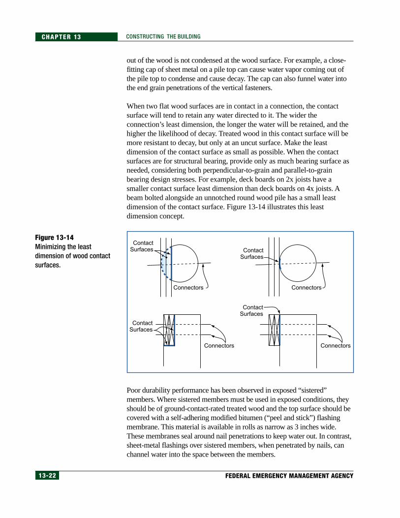
When two flat wood surfaces are in contact in a connection, the contactsurface will tend to retain any water directed to it. The wider theconnection’s least dimension, the longer the water will be retained, and thehigher the likelihood of decay. Treated wood in this contact surface will bemore resistant to decay, but only at an uncut surface. Make the leastdimension of the contact surface as small as possible. When the contactsurfaces are for structural bearing, provide only as much bearing surface asneeded, considering both perpendicular-to-grain and parallel-to-grainbearing design stresses. For example, deck boards on 2x joists have asmaller contact surface least dimension than deck boards on 4x joists. Abeam bolted alongside an unnotched round wood pile has a small leastdimension of the contact surface. Figure 13-14 illustrates this leastdimension concept.
Figure 13-14Minimizing the leastdimension of wood contactsurfaces.
Poor durability performance has been observed in exposed “sistered”members. Where sistered members must be used in exposed conditions, theyshould be of ground-contact-rated treated wood and the top surface should becovered with a self-adhering modified bitumen (“peel and stick”) flashingmembrane. This material is available in rolls as narrow as 3 inches wide.These membranes seal around nail penetrations to keep water out. In contrast,sheet-metal flashings over sistered members, when penetrated by nails, canchannel water into the space between the members.
Connectors Connectors
ContactSurfaces
Connectors Connectors
ContactSurfaces
ContactSurfaces
ContactSurfaces
13-23COASTAL CONSTRUCTION MANUAL
CHAPTER 13CONSTRUCTING THE BUILDING
Other methods of improving exposed structural frame durability includethe following:
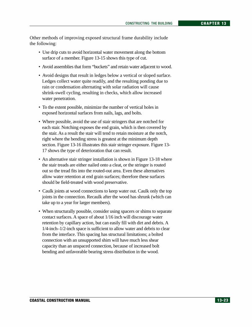
• Use drip cuts to avoid horizontal water movement along the bottomsurface of a member. Figure 13-15 shows this type of cut.
• Avoid assemblies that form “buckets” and retain water adjacent to wood.
• Avoid designs that result in ledges below a vertical or sloped surface.Ledges collect water quite readily, and the resulting ponding due torain or condensation alternating with solar radiation will causeshrink-swell cycling, resulting in checks, which allow increasedwater penetration.
• To the extent possible, minimize the number of vertical holes inexposed horizontal surfaces from nails, lags, and bolts.
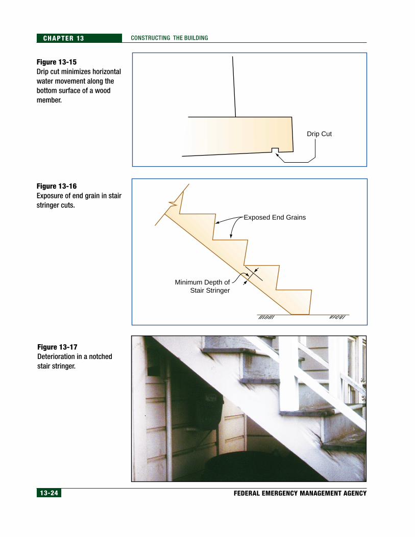
• Where possible, avoid the use of stair stringers that are notched foreach stair. Notching exposes the end grain, which is then covered bythe stair. As a result the stair will tend to retain moisture at the notch,right where the bending stress is greatest at the minimum depthsection. Figure 13-16 illustrates this stair stringer exposure. Figure 13-17 shows the type of deterioration that can result.
• An alternative stair stringer installation is shown in Figure 13-18 wherethe stair treads are either nailed onto a cleat, or the stringer is routedout so the tread fits into the routed-out area. Even these alternativesallow water retention at end grain surfaces; therefore these surfacesshould be field-treated with wood preservative.
• Caulk joints at wood connections to keep water out. Caulk only the topjoints in the connection. Recaulk after the wood has shrunk (which cantake up to a year for larger members).
• When structurally possible, consider using spacers or shims to separatecontact surfaces. A space of about 1/16 inch will discourage waterretention by capillary action, but can easily fill with dirt and debris. A1/4-inch–1/2-inch space is sufficient to allow water and debris to clearfrom the interface. This spacing has structural limitations; a boltedconnection with an unsupported shim will have much less shearcapacity than an unspaced connection, because of increased boltbending and unfavorable bearing stress distribution in the wood.
13-24 FEDERAL EMERGENCY MANAGEMENT AGENCY
CHAPTER 13 CONSTRUCTING THE BUILDING
Figure 13-15Drip cut minimizes horizontalwater movement along thebottom surface of a woodmember.
Figure 13-16Exposure of end grain in stairstringer cuts.
Figure 13-17Deterioration in a notchedstair stringer.
Drip Cut
Minimum Depth ofStair Stringer
Exposed End Grains

13-25COASTAL CONSTRUCTION MANUAL
CHAPTER 13CONSTRUCTING THE BUILDING
13.2.8 Field Preservative TreatmentField cuts and bores of pressure-preservative-treated piles, timbers, andlumber are inevitable in coastal construction. Unfortunately, these cuts exposethe inner untreated part of the wood member to possible decay and infestation.Although field preservative treatments are much less effective than pressure-preservative treatment, the decay and infestation potential can be minimizedwith treatment of the cuts and bolt holes with field-applied preservative. TheAWPA standard Care of Pressure-Treated Wood Products (AWPA 1991)describes field treatment procedures and field cutting restrictions for poles,piles, and sawn lumber.
Field application of preservatives should always be done in accordance withinstructions on the label. The most thorough application is by dip soaking forat least 3 minutes. When this is impractical, treatment may be done bythorough brushing or spraying. End grain is much more absorptive to field-applied preservatives than side grain. Bored holes should be poured full ofpreservative. If the hole passes through a check, then brushing of the hole willbe necessary, because the preservative would otherwise run into the checkinstead of remaining in and saturating the hole.
The preservatives commonly used in pressure treating wood (waterbornearsenicals, pentachlorophenol, and creosote) are not acceptable for fieldapplication. Copper napthenate is the most widely used field-appliedpreservative. Its deep green color may be objectionable, but wood treated withit can be painted with alkyd paints in dark colors after extended drying. Zincnapthenate is less effective than copper napthenate, especially in preventinginsect infestation. It is clear and therefore can be used where the color ofcopper napthenate is objectionable. It should not be painted with latex paints.
Figure 13-18Alternative method ofinstalling stair treads.
Wood StairTreads
StairStringer
StairStringer
Stair Tread
Stair TreadSupport RoutedOut of Stringer
StairStringer
Stair Tread
2x Cleat
13-26 FEDERAL EMERGENCY MANAGEMENT AGENCY
CHAPTER 13 CONSTRUCTING THE BUILDING
Tributyltin oxide (TBTO) is available, but should not be used in or nearmarine environments, because the leachates are toxic to aquatic organisms.Sodium borate is also available, but it does not readily penetrate dry wood,and it rapidly leaches out of wood when water is present; therefore, it is notrecommended.
13.2.9 SubstitutionsDuring construction, a contractor may find that materials called for in theconstruction plans or specifications are not available or that the delivery timefor those materials will be too long and will delay the completion of thebuilding. These conflicts will require that decisions be made aboutsubstituting one type of construction material for another. Because of the highnatural hazard forces imposed on a building near the coast, and the effects ofthe severe year-round environment in coastal areas, some substitutions mustbe made only after approval by a design professional and, if necessary, thelocal building official.
13.2.10 The Top Foundation Issues for Builders1. Piles, piers, or columns must be properly aligned.
2. The piles, piers, or columns must be driven or placed at the properelevation to resist failure and must extend below the expected depth ofscour and erosion.
3. Foundation materials must be flood damage-resistant (pressuretreated wood, masonry, concrete).
4. Provide adequate support at the top of the foundation element toproperly attach the floor framing system. Do not notch a woodfoundation element more than 50 percent of its cross-sectional area.
5. Breakaway walls are intended to fail; do not overnail these walls tothe foundations; do not install utilities or other obstructions behindthese walls; do not finish inside these walls.
6. Where foundation elements are masonry or concrete (except slabs-on-grade), place the proper size of reinforcing, the proper number ofsteel bars, and provide the proper concrete cover over the steel.
7. Exposed steel in the foundation will corrode; plan for it by installinghot-dipped galvanized or stainless steel.
8. Areas of pressure-treated wood that have been cut or drilled willretain water and will decay; treat these cut areas in the field.
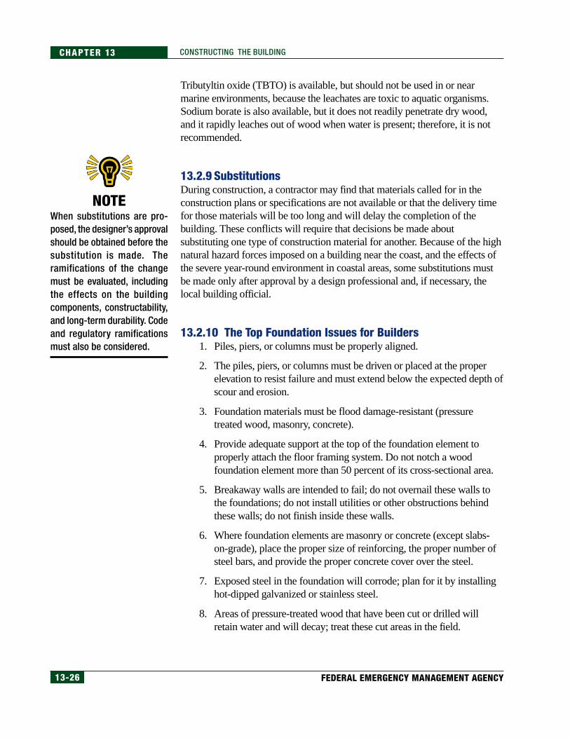
NOTEWhen substitutions are pro-posed, the designer’s approvalshould be obtained before thesubstitution is made. Theramifications of the changemust be evaluated, includingthe effects on the buildingcomponents, constructability,and long-term durability. Codeand regulatory ramificationsmust also be considered.
13-27COASTAL CONSTRUCTION MANUAL
CHAPTER 13CONSTRUCTING THE BUILDING
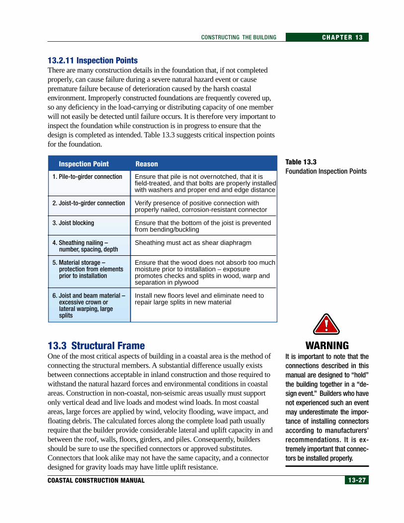
13.2.11 Inspection PointsThere are many construction details in the foundation that, if not completedproperly, can cause failure during a severe natural hazard event or causepremature failure because of deterioration caused by the harsh coastalenvironment. Improperly constructed foundations are frequently covered up,so any deficiency in the load-carrying or distributing capacity of one memberwill not easily be detected until failure occurs. It is therefore very important toinspect the foundation while construction is in progress to ensure that thedesign is completed as intended. Table 13.3 suggests critical inspection pointsfor the foundation.
Table 13.3Foundation Inspection Points
13.3 Structural FrameOne of the most critical aspects of building in a coastal area is the method ofconnecting the structural members. A substantial difference usually existsbetween connections acceptable in inland construction and those required towithstand the natural hazard forces and environmental conditions in coastalareas. Construction in non-coastal, non-seismic areas usually must supportonly vertical dead and live loads and modest wind loads. In most coastalareas, large forces are applied by wind, velocity flooding, wave impact, andfloating debris. The calculated forces along the complete load path usuallyrequire that the builder provide considerable lateral and uplift capacity in andbetween the roof, walls, floors, girders, and piles. Consequently, buildersshould be sure to use the specified connectors or approved substitutes.Connectors that look alike may not have the same capacity, and a connectordesigned for gravity loads may have little uplift resistance.
WARNINGIt is important to note that theconnections described in thismanual are designed to “hold”the building together in a “de-sign event.” Builders who havenot experienced such an eventmay underestimate the impor-tance of installing connectorsaccording to manufacturers’recommendations. It is ex-tremely important that connec-tors be installed properly.
1. Pile-to-girder connection
2. Joist-to-girder connection
3. Joist blocking
4. Sheathing nailing – number, spacing, depth
5. Material storage – protection from elements prior to installation
6. Joist and beam material – excessive crown or lateral warping, large splits
Ensure that pile is not overnotched, that it is field-treated, and that bolts are properly installed with washers and proper end and edge distance
Verify presence of positive connection with properly nailed, corrosion-resistant connector
Ensure that the bottom of the joist is prevented from bending/buckling
Sheathing must act as shear diaphragm
Ensure that the wood does not absorb too much moisture prior to installation – exposure promotes checks and splits in wood, warp and separation in plywood
Install new floors level and eliminate need to repair large splits in new material
Inspection Point Reason
13-28 FEDERAL EMERGENCY MANAGEMENT AGENCY
CHAPTER 13 CONSTRUCTING THE BUILDING
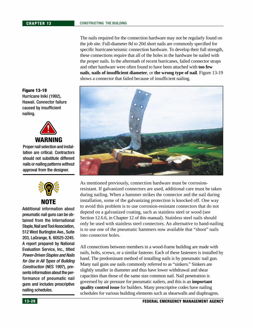
The nails required for the connection hardware may not be regularly found onthe job site. Full-diameter 8d to 20d short nails are commonly specified forspecific hurricane/seismic connection hardware. To develop their full strength,these connections require that all of the holes in the hardware be nailed withthe proper nails. In the aftermath of recent hurricanes, failed connector strapsand other hardware were often found to have been attached with too fewnails, nails of insufficient diameter, or the wrong type of nail. Figure 13-19shows a connector that failed because of insufficient nailing.
Figure 13-19Hurricane Iniki (1992),Hawaii. Connector failurecaused by insufficientnailing.
As mentioned previously, connection hardware must be corrosion-resistant. If galvanized connectors are used, additional care must be takenduring nailing. When a hammer strikes the connector and the nail duringinstallation, some of the galvanizing protection is knocked off. One wayto avoid this problem is to use corrosion-resistant connectors that do notdepend on a galvanized coating, such as stainless steel or wood (seeSection 12.6.6, in Chapter 12 of this manual). Stainless steel nails shouldonly be used with stainless steel connectors. An alternative to hand-nailingis to use one of the pneumatic hammers now available that “shoot” nailsinto connector holes.
All connections between members in a wood-frame building are made withnails, bolts, screws, or a similar fastener. Each of these fasteners is installed byhand. The predominant method of installing nails is by pneumatic nail gun.Many nail guns use nails commonly referred to as “sinkers.” Sinkers areslightly smaller in diameter and thus have lower withdrawal and shearcapacities than those of the same size common nail. Nail penetration isgoverned by air pressure for pneumatic nailers, and this is an importantquality control issue for builders. Many prescriptive codes have nailingschedules for various building elements such as shearwalls and diaphragms.
NOTEAdditional information aboutpneumatic nail guns can be ob-tained from the InternationalStaple, Nail and Tool Association,512 West Burlington Ave., Suite203, LaGrange, IL 60525-2245.A report prepared by NationalEvaluation Service, Inc., titledPower-Driven Staples and Nailsfor Use in All Types of BuildingConstruction (NES 1997), pre-sents information about the per-formance of pneumatic nailguns and includes prescriptivenailing schedules.
WARNINGProper nail selection and instal-lation are critical. Contractorsshould not substitute differentnails or nailing patterns withoutapproval from the designer.
13-29COASTAL CONSTRUCTION MANUAL
CHAPTER 13CONSTRUCTING THE BUILDING
Toenailing should not be used to make a structural connection. Toenailingreduces the withdrawal capacity of the nails and frequently splits the wood,reducing the capacity even further.
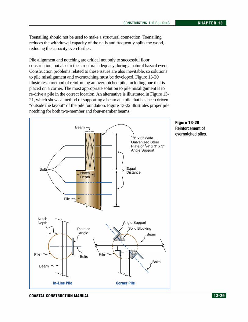
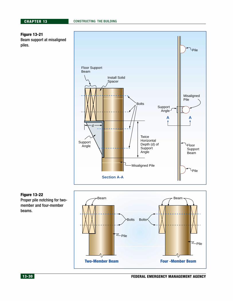
Pile alignment and notching are critical not only to successful floorconstruction, but also to the structural adequacy during a natural hazard event.Construction problems related to these issues are also inevitable, so solutionsto pile misalignment and overnotching must be developed. Figure 13-20illustrates a method of reinforcing an overnotched pile, including one that isplaced on a corner. The most appropriate solution to pile misalignment is tore-drive a pile in the correct location. An alternative is illustrated in Figure 13-21, which shows a method of supporting a beam at a pile that has been driven“outside the layout” of the pile foundation. Figure 13-22 illustrates proper pilenotching for both two-member and four-member beams.
Figure 13-20Reinforcement ofovernotched piles.
EqualDistance
1/4" x 6" WideGalvanized Steel Plate or 1/4" x 3" x 3" Angle Support
NotchDepth
NotchDepth
Beam
Pile
Pile Pile
Beam
Beam
Bolts
BoltsBolts
Plate orAngle
Angle Support
Solid Blocking
In-Line Pile Corner Pile
13-30 FEDERAL EMERGENCY MANAGEMENT AGENCY
CHAPTER 13 CONSTRUCTING THE BUILDING
Figure 13-21Beam support at misalignedpiles.
Figure 13-22Proper pile notching for two-member and four-memberbeams.
Pile
Pile
MisalignedPile
Floor SupportBeam
BoltsSupport
Angle
Misaligned Pile
d
TwiceHorizontalDepth (d) ofSupportAngle
SupportAngle
Floor SupportBeam
Install SolidSpacer
AA
Section A-A
Two-Member Beam
Beam Beam
Bolts
Pile
Four -Member Beam
Bolts
Pile
13-31COASTAL CONSTRUCTION MANUAL
CHAPTER 13CONSTRUCTING THE BUILDING
After the “square” foundation has been built, the primary layoutconcerns regarding how the building will perform under loads areconfined to other building elements being properly located so that loadtransfer paths are complete.
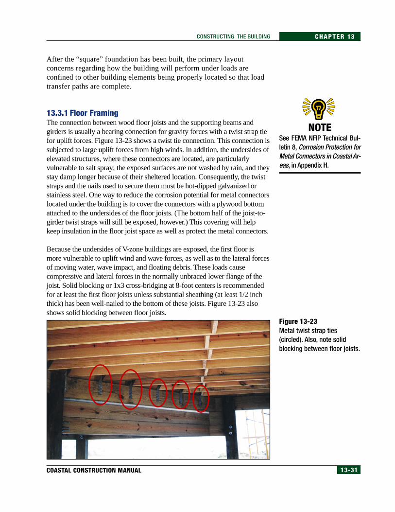
13.3.1 Floor FramingThe connection between wood floor joists and the supporting beams andgirders is usually a bearing connection for gravity forces with a twist strap tiefor uplift forces. Figure 13-23 shows a twist tie connection. This connection issubjected to large uplift forces from high winds. In addition, the undersides ofelevated structures, where these connectors are located, are particularlyvulnerable to salt spray; the exposed surfaces are not washed by rain, and theystay damp longer because of their sheltered location. Consequently, the twiststraps and the nails used to secure them must be hot-dipped galvanized orstainless steel. One way to reduce the corrosion potential for metal connectorslocated under the building is to cover the connectors with a plywood bottomattached to the undersides of the floor joists. (The bottom half of the joist-to-girder twist straps will still be exposed, however.) This covering will helpkeep insulation in the floor joist space as well as protect the metal connectors.
Because the undersides of V-zone buildings are exposed, the first floor ismore vulnerable to uplift wind and wave forces, as well as to the lateral forcesof moving water, wave impact, and floating debris. These loads causecompressive and lateral forces in the normally unbraced lower flange of thejoist. Solid blocking or 1x3 cross-bridging at 8-foot centers is recommendedfor at least the first floor joists unless substantial sheathing (at least 1/2 inchthick) has been well-nailed to the bottom of these joists. Figure 13-23 alsoshows solid blocking between floor joists.
Figure 13-23Metal twist strap ties(circled). Also, note solidblocking between floor joists.
NOTESee FEMA NFIP Technical Bul-letin 8, Corrosion Protection forMetal Connectors in Coastal Ar-eas, in Appendix H.
13-32 FEDERAL EMERGENCY MANAGEMENT AGENCY
CHAPTER 13 CONSTRUCTING THE BUILDING
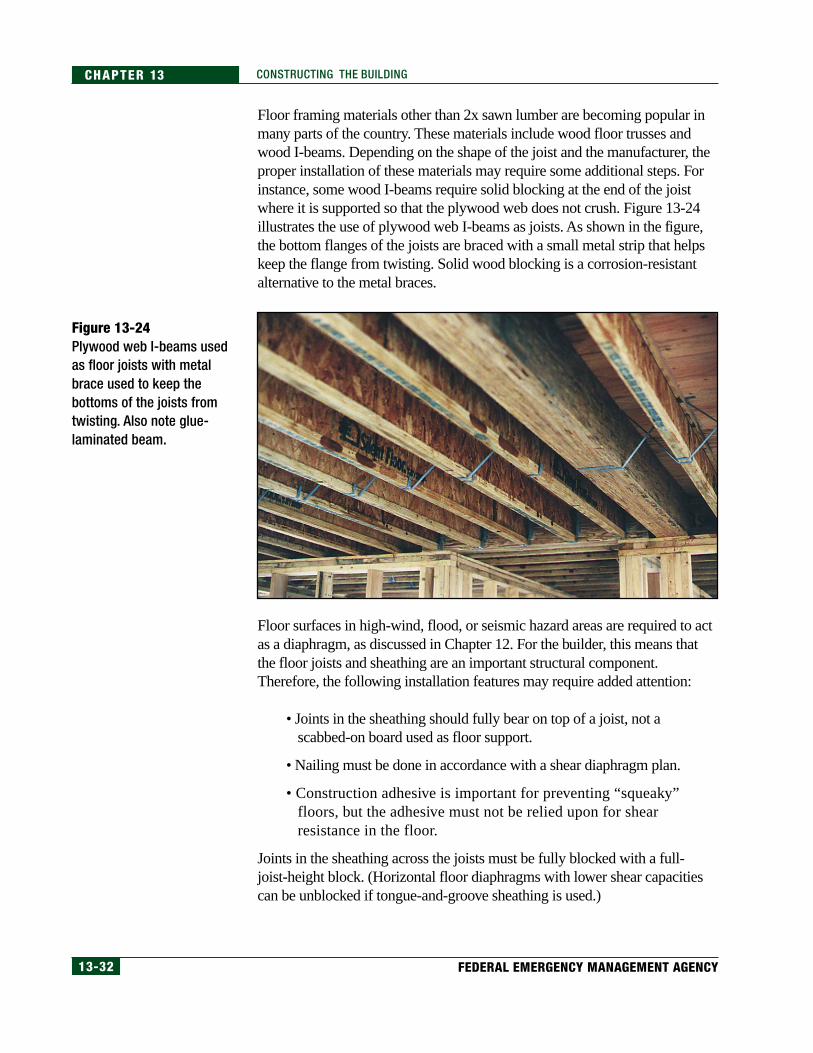
Floor framing materials other than 2x sawn lumber are becoming popular inmany parts of the country. These materials include wood floor trusses andwood I-beams. Depending on the shape of the joist and the manufacturer, theproper installation of these materials may require some additional steps. Forinstance, some wood I-beams require solid blocking at the end of the joistwhere it is supported so that the plywood web does not crush. Figure 13-24illustrates the use of plywood web I-beams as joists. As shown in the figure,the bottom flanges of the joists are braced with a small metal strip that helpskeep the flange from twisting. Solid wood blocking is a corrosion-resistantalternative to the metal braces.
Figure 13-24Plywood web I-beams usedas floor joists with metalbrace used to keep thebottoms of the joists fromtwisting. Also note glue-laminated beam.
Floor surfaces in high-wind, flood, or seismic hazard areas are required to actas a diaphragm, as discussed in Chapter 12. For the builder, this means thatthe floor joists and sheathing are an important structural component.Therefore, the following installation features may require added attention:
• Joints in the sheathing should fully bear on top of a joist, not ascabbed-on board used as floor support.
• Nailing must be done in accordance with a shear diaphragm plan.
• Construction adhesive is important for preventing “squeaky”floors, but the adhesive must not be relied upon for shearresistance in the floor.
Joints in the sheathing across the joists must be fully blocked with a full-joist-height block. (Horizontal floor diaphragms with lower shear capacitiescan be unblocked if tongue-and-groove sheathing is used.)
13-33COASTAL CONSTRUCTION MANUAL
CHAPTER 13CONSTRUCTING THE BUILDING
13.3.1.1 Horizontal Beams and GirdersAs discussed in Appendix J, girders and beams can be solid sawn timbers,glue-laminated timbers (see Figure 13-24), or built-up sections. The girdersspan between the piles and support the beams and joists. The piles are usuallynotched to receive the girders. To meet the design intent, girders, beams, andjoists must be square and level, girders must be secured to the piles, andbeams and joists must be secured to the girders.
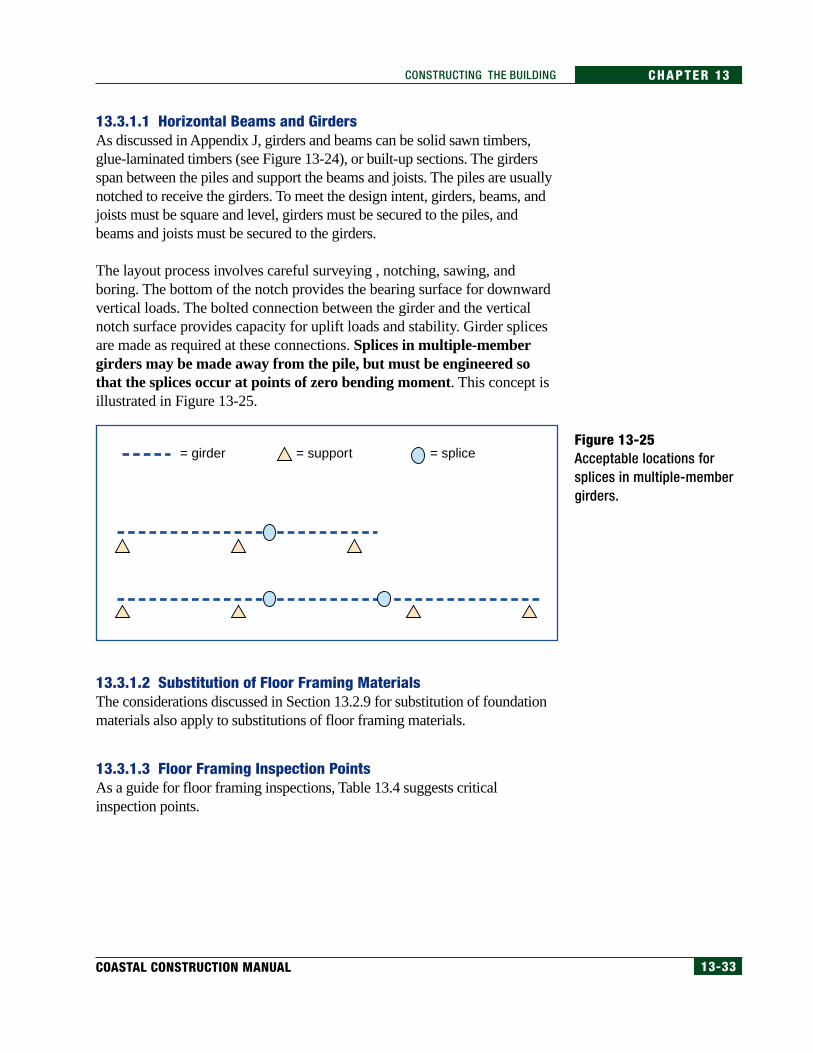
The layout process involves careful surveying , notching, sawing, andboring. The bottom of the notch provides the bearing surface for downwardvertical loads. The bolted connection between the girder and the verticalnotch surface provides capacity for uplift loads and stability. Girder splicesare made as required at these connections. Splices in multiple-membergirders may be made away from the pile, but must be engineered sothat the splices occur at points of zero bending moment. This concept isillustrated in Figure 13-25.
Figure 13-25Acceptable locations forsplices in multiple-membergirders.
13.3.1.2 Substitution of Floor Framing MaterialsThe considerations discussed in Section 13.2.9 for substitution of foundationmaterials also apply to substitutions of floor framing materials.
13.3.1.3 Floor Framing Inspection PointsAs a guide for floor framing inspections, Table 13.4 suggests criticalinspection points.
= girder = support = splice
13-34 FEDERAL EMERGENCY MANAGEMENT AGENCY
CHAPTER 13 CONSTRUCTING THE BUILDING
13.3.2 Wall FramingThe exterior walls and designated interior shear walls are an importantpart of the building’s vertical and lateral force-resisting system. Allexterior walls must withstand in-plane (i.e., parallel to the wall surface),gravity, and wind uplift tensile forces, and out-of-plane (i.e., normal orperpendicular to the wall surface) wind forces. Designated exterior andinterior shear walls must withstand shear and overturning forcestransferred through the walls to and from the adjacent roof and floordiaphragms and framing.
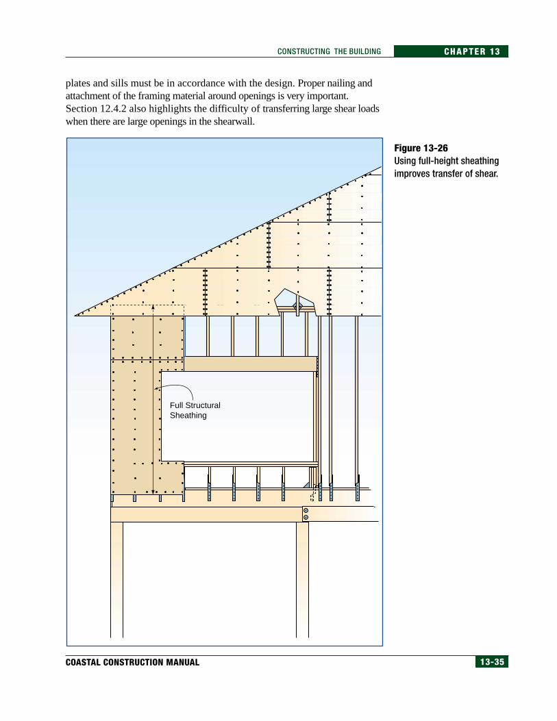
The framing of the walls must be of the specified material and must befastened in accordance with the design drawings and standard codepractice. Exterior wall and designated shear wall sheathing panels must beof the specified material and must be fastened with accurately placed nailswhose size, spacing, and durability are in accordance with the design.Horizontal sheathing joints in shear walls must be solidly blocked. Sheartransfer can be better accomplished if the sheathing extends the full heightfrom the bottom of the floor joist to the top plate (see Figure 13-26), butsheathing this long is frequently not available.
The design drawings may show tiedown connections between largeshearwall vertical posts and main girders. Especially in larger, tallerbuildings, these connections must resist thousands of pounds ofoverturning forces during high winds. See Section 12.4.2 for an exampleof the magnitude of these forces. The connections must be accomplishedwith careful layout, boring, and assembly. Shear transfer nailing at the top
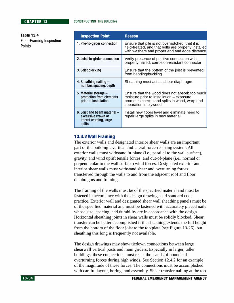
Table 13.4Floor Framing InspectionPoints
1. Pile-to-girder connection
2. Joist-to-girder connection
3. Joist blocking
4. Sheathing nailing – number, spacing, depth
5. Material storage – protection from elements prior to installation
6. Joist and beam material – excessive crown or lateral warping, large splits
Ensure that pile is not overnotched, that it is field-treated, and that bolts are properly installed with washers and proper end and edge distance
Verify presence of positive connection with properly nailed, corrosion-resistant connector
Ensure that the bottom of the joist is prevented from bending/buckling
Sheathing must act as shear diaphragm
Ensure that the wood does not absorb too much moisture prior to installation – exposure promotes checks and splits in wood, warp and separation in plywood
Install new floors level and eliminate need to repair large splits in new material
Inspection Point Reason
13-35COASTAL CONSTRUCTION MANUAL
CHAPTER 13CONSTRUCTING THE BUILDING
Figure 13-26Using full-height sheathingimproves transfer of shear.
plates and sills must be in accordance with the design. Proper nailing andattachment of the framing material around openings is very important.Section 12.4.2 also highlights the difficulty of transferring large shear loadswhen there are large openings in the shearwall.
Full StructuralSheathing
13-36 FEDERAL EMERGENCY MANAGEMENT AGENCY
CHAPTER 13 CONSTRUCTING THE BUILDING
It is very important that shearwall sheathing (e.g., plywood, OSB) with anexterior exposure be finished appropriately, with pigmented finishes such aspaint (which last longer than unpigmented finishes) or semitransparentpenetrating stains. It is also important that these finishes be properlymaintained. Salt crystal buildup in surface checks in siding can cause damageto the siding. This damage is typically worse in siding that is sheltered fromprecipitation, because the salt crystals are made larger from salt spray butnever washed off with fresh rainwater.
To meet the design intent, walls:
• must be plumb and square to each other and to the floor,
• must be lined up over solid support such as a beam, floor joists, or aperimeter band joist,
• must not have any more openings than designated by the plans,
• must not have openings located in places other than designated on theplans,
• must consist of material expected to resist corrosion and deterioration,and
• must be properly attached to the floors above and below the wall,including holddown brackets required to transfer overturning forces.
In addition, all portions of walls designed as shearwalls must be coveredwith sheathing nailed in accordance with either the plans or a specifiedprescriptive standard.
13.3.2.1 Interior Steel FramesIn coastal buildings with large openings or cathedral ceilings, the design mayinclude steel moment-resisting frames for wind and/or seismic lateral forces.These frames are necessary when even double-sheathed plywood walls haveinsufficient capacity. Figure 12-49, in Chapter 12, shows a steel momentframe installed in the wall of a coastal residential building.
The fabrication of steel moment frames will usually be done by a steelspecialty subcontractor, who will first prepare a set of shop drawings from thedesign drawings. The contractor and designer should both check the accuracyof the shop drawings. Most frames will have to be transported in sections andassembled on site with field bolting and/or welding. The building code ordesigner may require special inspection or shop certification for the shop andfield frame welding. If the frame is not exposed, a finish of shop primer willbe adequate. Exposed parts of the frame will require hot-dip galvanizing orsome other finish suitable for exterior exposure.
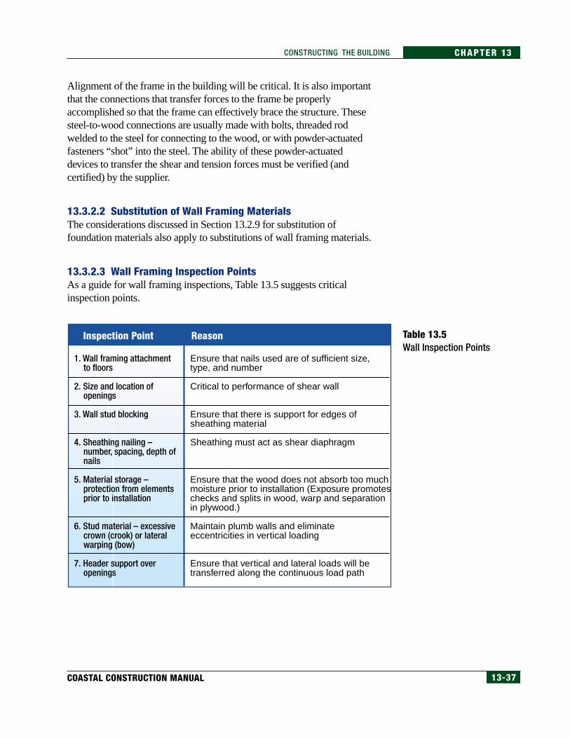
13-37COASTAL CONSTRUCTION MANUAL
CHAPTER 13CONSTRUCTING THE BUILDING
Alignment of the frame in the building will be critical. It is also importantthat the connections that transfer forces to the frame be properlyaccomplished so that the frame can effectively brace the structure. Thesesteel-to-wood connections are usually made with bolts, threaded rodwelded to the steel for connecting to the wood, or with powder-actuatedfasteners “shot” into the steel. The ability of these powder-actuateddevices to transfer the shear and tension forces must be verified (andcertified) by the supplier.
13.3.2.2 Substitution of Wall Framing MaterialsThe considerations discussed in Section 13.2.9 for substitution offoundation materials also apply to substitutions of wall framing materials.
13.3.2.3 Wall Framing Inspection PointsAs a guide for wall framing inspections, Table 13.5 suggests criticalinspection points.
Table 13.5Wall Inspection Points
1. Wall framing attachment to floors
2. Size and location of openings
3. Wall stud blocking
4. Sheathing nailing – number, spacing, depth of nails
5. Material storage – protection from elements prior to installation
6. Stud material – excessive crown (crook) or lateral warping (bow)
7. Header support over openings
Ensure that nails used are of sufficient size, type, and number
Critical to performance of shear wall
Ensure that there is support for edges of sheathing material
Sheathing must act as shear diaphragm
Ensure that the wood does not absorb too much moisture prior to installation (Exposure promotes checks and splits in wood, warp and separation in plywood.)
Maintain plumb walls and eliminate eccentricities in vertical loading
Ensure that vertical and lateral loads will be transferred along the continuous load path
Inspection Point Reason
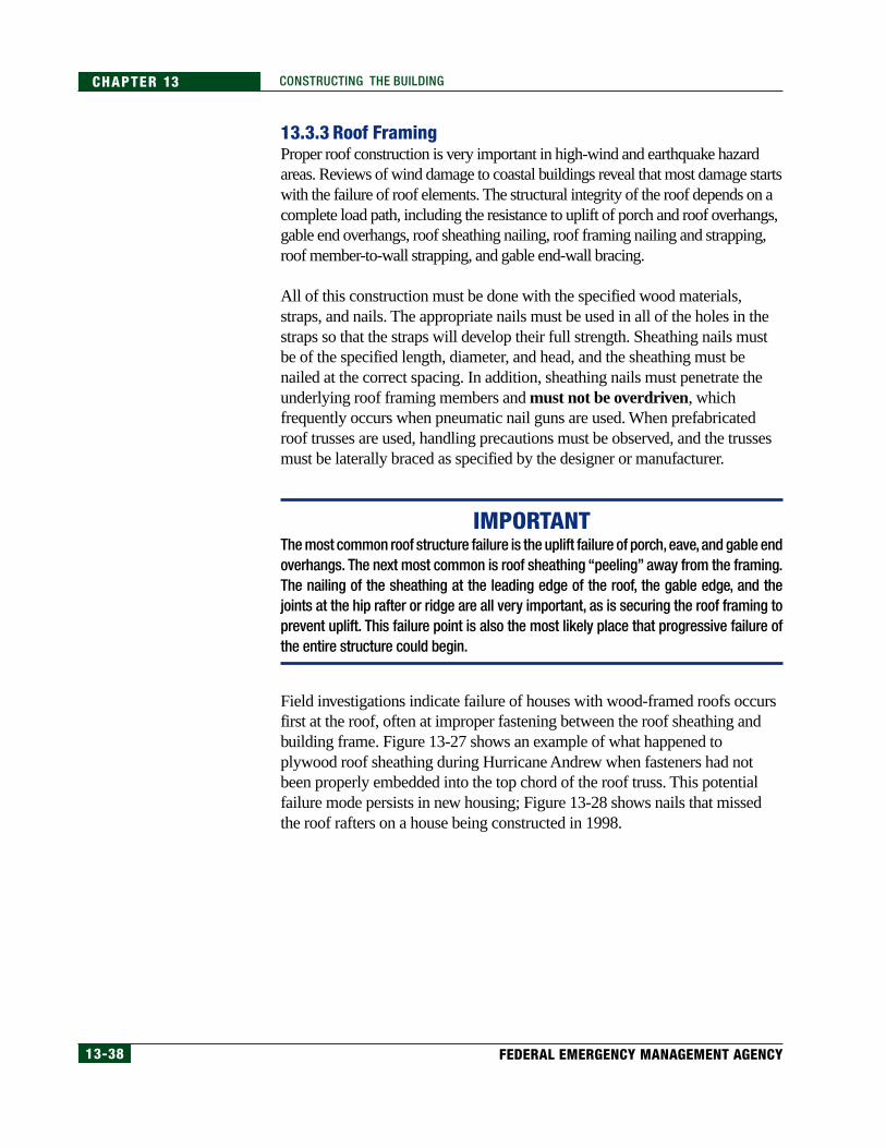
13-38 FEDERAL EMERGENCY MANAGEMENT AGENCY
CHAPTER 13 CONSTRUCTING THE BUILDING
13.3.3 Roof FramingProper roof construction is very important in high-wind and earthquake hazardareas. Reviews of wind damage to coastal buildings reveal that most damage startswith the failure of roof elements. The structural integrity of the roof depends on acomplete load path, including the resistance to uplift of porch and roof overhangs,gable end overhangs, roof sheathing nailing, roof framing nailing and strapping,roof member-to-wall strapping, and gable end-wall bracing.
All of this construction must be done with the specified wood materials,straps, and nails. The appropriate nails must be used in all of the holes in thestraps so that the straps will develop their full strength. Sheathing nails mustbe of the specified length, diameter, and head, and the sheathing must benailed at the correct spacing. In addition, sheathing nails must penetrate theunderlying roof framing members and must not be overdriven, whichfrequently occurs when pneumatic nail guns are used. When prefabricatedroof trusses are used, handling precautions must be observed, and the trussesmust be laterally braced as specified by the designer or manufacturer.
IMPORTANTThe most common roof structure failure is the uplift failure of porch, eave, and gable endoverhangs. The next most common is roof sheathing “peeling” away from the framing.The nailing of the sheathing at the leading edge of the roof, the gable edge, and thejoints at the hip rafter or ridge are all very important, as is securing the roof framing toprevent uplift. This failure point is also the most likely place that progressive failure ofthe entire structure could begin.
Field investigations indicate failure of houses with wood-framed roofs occursfirst at the roof, often at improper fastening between the roof sheathing andbuilding frame. Figure 13-27 shows an example of what happened toplywood roof sheathing during Hurricane Andrew when fasteners had notbeen properly embedded into the top chord of the roof truss. This potentialfailure mode persists in new housing; Figure 13-28 shows nails that missedthe roof rafters on a house being constructed in 1998.
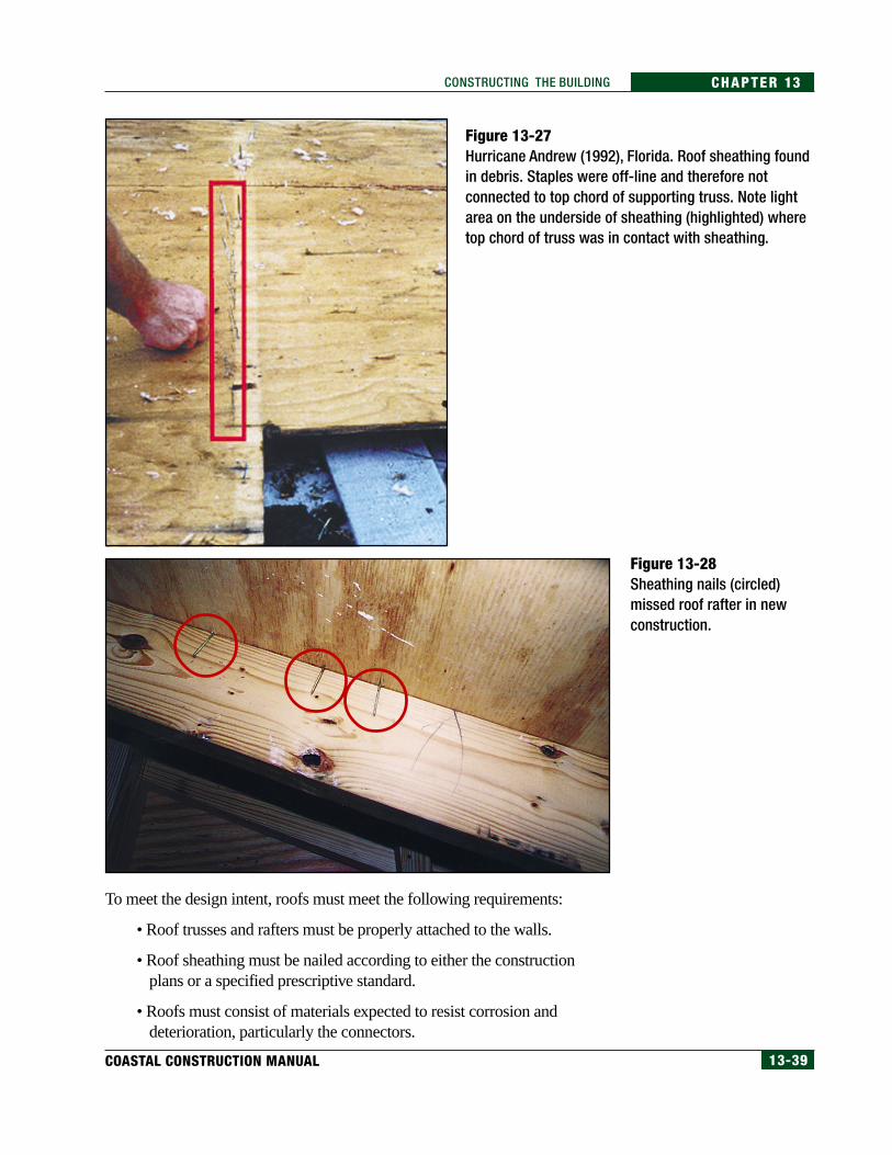
13-39COASTAL CONSTRUCTION MANUAL
CHAPTER 13CONSTRUCTING THE BUILDING
To meet the design intent, roofs must meet the following requirements:
• Roof trusses and rafters must be properly attached to the walls.
• Roof sheathing must be nailed according to either the constructionplans or a specified prescriptive standard.
• Roofs must consist of materials expected to resist corrosion anddeterioration, particularly the connectors.
Figure 13-27Hurricane Andrew (1992), Florida. Roof sheathing foundin debris. Staples were off-line and therefore notconnected to top chord of supporting truss. Note lightarea on the underside of sheathing (highlighted) wheretop chord of truss was in contact with sheathing.
Figure 13-28Sheathing nails (circled)missed roof rafter in newconstruction.
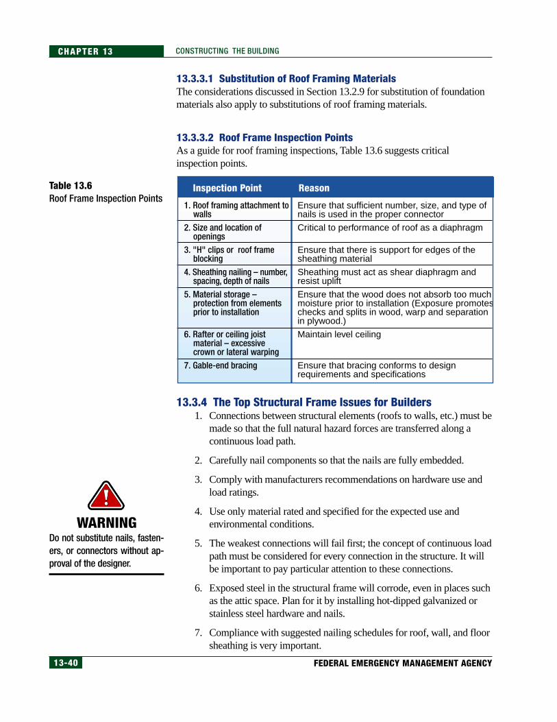
13-40 FEDERAL EMERGENCY MANAGEMENT AGENCY
CHAPTER 13 CONSTRUCTING THE BUILDING
13.3.3.1 Substitution of Roof Framing MaterialsThe considerations discussed in Section 13.2.9 for substitution of foundationmaterials also apply to substitutions of roof framing materials.
13.3.3.2 Roof Frame Inspection PointsAs a guide for roof framing inspections, Table 13.6 suggests criticalinspection points.
Table 13.6Roof Frame Inspection Points
13.3.4 The Top Structural Frame Issues for Builders1. Connections between structural elements (roofs to walls, etc.) must be
made so that the full natural hazard forces are transferred along acontinuous load path.
2. Carefully nail components so that the nails are fully embedded.
3. Comply with manufacturers recommendations on hardware use andload ratings.
4. Use only material rated and specified for the expected use andenvironmental conditions.
5. The weakest connections will fail first; the concept of continuous loadpath must be considered for every connection in the structure. It willbe important to pay particular attention to these connections.
6. Exposed steel in the structural frame will corrode, even in places suchas the attic space. Plan for it by installing hot-dipped galvanized orstainless steel hardware and nails.
7. Compliance with suggested nailing schedules for roof, wall, and floorsheathing is very important.
WARNINGDo not substitute nails, fasten-ers, or connectors without ap-proval of the designer.
1. Roof framing attachment to walls
2. Size and location of openings
3. "H" clips or roof frame blocking
4. Sheathing nailing – number, spacing, depth of nails
5. Material storage – protection from elements prior to installation
6. Rafter or ceiling joist material – excessive crown or lateral warping
7. Gable-end bracing
Ensure that sufficient number, size, and type of nails is used in the proper connector
Critical to performance of roof as a diaphragm
Ensure that there is support for edges of the sheathing material
Sheathing must act as shear diaphragm and resist uplift
Ensure that the wood does not absorb too much moisture prior to installation (Exposure promotes checks and splits in wood, warp and separation in plywood.)
Maintain level ceiling
Ensure that bracing conforms to design requirements and specifications
Inspection Point Reason
13-41COASTAL CONSTRUCTION MANUAL
CHAPTER 13CONSTRUCTING THE BUILDING
13.4 Building EnvelopeThe building envelope comprises the roof covering, exterior wall covering,and exterior doors and windows. The floor is also considered a part of theenvelope for buildings elevated on open foundations. The keys to successfulbuilding envelope construction include the following:
• A suitable design must be provided that is sufficiently specified anddetailed to allow the contractor to understand the design intent and togive the contractor adequate and clear guidance.
Lack of sufficient and clear design guidance regarding the buildingenvelope is common. In this situation, the contractor should seekadditional guidance from the designer or be responsible for providingdesign services in addition to constructing the building.
• The building must be constructed as intended by the designer (i.e., thecontractor must follow the drawings and specifications).
Examples include installing flashings, building paper, or air infiltrationbarriers so that water is shed at laps; using the specified type and sizeof fasteners and spacing them as specified; eliminating dissimilar metalcontact; using materials that are compatible with one another; installingcomponents in a manner that accommodates thermal movements sothat buckling or jacking out of fasteners is avoided; applying finishes toadequately cleaned, dried, and prepared substrates; installing backerrods or bond breaker tape at sealant joints; and tooling sealant joints.
• For products/systems specified by performance criteria, the contractormust exercise care in selecting those products/systems and inintegrating them into the building envelope.
For example, if the designer specifies a window by requiring that it becapable of resisting a specified wind pressure, the contractor shouldensure that the type of window that is being considered can resist thepressure when tested in accordance with the specified test (or a suitabletest if a test method is not specified). Furthermore, the contractor needsto ensure that the manufacturer, designer, or other qualified entityprovides guidance on how to attach the window frame to the wall sothat the frame will resist the design pressures.
• When the selection of accessory items is left to the discretion of thecontractor, without prescriptive or performance guidance, thecontractor must be aware of and consider special conditions at the site(e.g., termites, unusually severe corrosion, high earthquake or windloads) that should influence the selection of the accessory items.
For example, instead of using screws in plastic sleeves to anchorcomponents to a concrete or masonry wall, a contractor can use metal
13-42 FEDERAL EMERGENCY MANAGEMENT AGENCY
CHAPTER 13 CONSTRUCTING THE BUILDING
expansion sleeves or steel spikes intended for anchoring to concrete,which should provide a stronger and more reliable connection. Or,the use of plastic shims at metal doors may be appropriate to avoidtermite attack.
• Proposed substitutions of materials must be thoroughly evaluated andmust be approved by the designer (see Section 13.2.9).
The building envelope must be installed in a manner that will notcompromise the building’s structural integrity. For example, duringconstruction, if a window larger than originally intended is to beinstalled because of delivery problems or other reasons, thecontractor should obtain the designer’s approval prior to installation.The larger window may unacceptably reduce the shear capacity ofthe wall, or different header or framing connection details may benecessary. Likewise, if a door is to be located in a different position,the designer should evaluate the change to determine whether itadversely affects the structure.
• Adequate quality control (i.e., inspection by the contractor’s personnel)and adequate quality assurance (i.e., inspection by third parties such asthe building official, the designer, or a test lab) must be provided.
The amount of quality control/quality assurance will depend on themagnitude of the natural hazards being designed for, complexities ofthe building design, and the type of products/systems being used. Forexample, installation of windows that are very tall and wide andmake up the majority of a wall deserves more inspection thanisolated, relatively small windows. Inspection of roof coverings andwindows is generally more critical than inspection of most wallcoverings, because of the general susceptibility of roofing andglazing to wind and the resulting damage from water infiltration thatcommonly occurs when these elements fail.
13.4.1 Substitution of Building Envelope MaterialsThe considerations discussed in Section 13.2.9 for substitution of foundationmaterials also apply to substitutions of envelope materials.
13.4.2 Building Envelope Inspection PointsAs a guide for building envelope inspections, Table 13.7 suggests criticalinspection points.
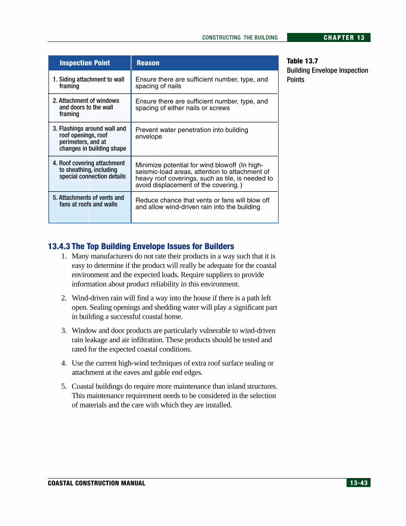
13-43COASTAL CONSTRUCTION MANUAL
CHAPTER 13CONSTRUCTING THE BUILDING
13.4.3 The Top Building Envelope Issues for Builders1. Many manufacturers do not rate their products in a way such that it is
easy to determine if the product will really be adequate for the coastalenvironment and the expected loads. Require suppliers to provideinformation about product reliability in this environment.
2. Wind-driven rain will find a way into the house if there is a path leftopen. Sealing openings and shedding water will play a significant partin building a successful coastal home.
3. Window and door products are particularly vulnerable to wind-drivenrain leakage and air infiltration. These products should be tested andrated for the expected coastal conditions.
4. Use the current high-wind techniques of extra roof surface sealing orattachment at the eaves and gable end edges.
5. Coastal buildings do require more maintenance than inland structures.This maintenance requirement needs to be considered in the selectionof materials and the care with which they are installed.
Table 13.7Building Envelope InspectionPoints
Inspection Point Reason
13-44 FEDERAL EMERGENCY MANAGEMENT AGENCY
CHAPTER 13 CONSTRUCTING THE BUILDING
13.5 Appurtenant Structures
13.5.1 DecksDecks often form a significant area of the elevated building platform. Theyare usually of 2x material, spaced to allow water drainage. The materialchoices, discussed in detail in Appendix J, include pressure-preservative-treated wood, naturally durable wood, and wood-plastic composites. Thedeck boards should be placed with a 1/8-inch–1/4-inch spacing to allow fordrainage and possible expansion when wetted. This gap is especially neededat the end grain. Many builders fasten deck boards with screws or ring-shank nails to minimize nail pops.
The question of whether to place flat-grained deck boards heart side up(rings concave up) or bark side up (rings concave down) has been a subjectof continued debate for years. Both orientations have advantages anddisadvantages. Wood will naturally shrink to be concave on the bark side.Treated southern pine lumber from small trees will tend to have moretreatment on the bark (sapwood) side. Shakes (cracks along the growthrings) tend to form on the heart side. So a deck board with the heart side upwill more likely dry with a convex top surface that sheds water, but it willbe prone to having shakes on the top surface. With the bark side up, theboard will more likely dry with a concave top surface that holds water, butthe exposed surface will be the treated sapwood that will resist the retainedwater. For minimum warp, select the more costly vertical-grained lumberover flat-grained lumber. Choose dried wood over green, or use green woodwith less tendency to warp. Green heart redwood and cedar are less prone towarp than green Douglas fir.
Wood railings around decks must be carefully designed for both strength anddurability. The IBC 2000 (ICC 2000a) requires that handrails resist a horizontaldistributed load of 20 lb/ft and a nonconcurrent point load of 200 lb. Thedesigner and builder must achieve this capacity in the wood railing constructionand the associated connections while considering stress reductions required bythe code for wet use and ripped lumber. The completed railing constructionshould not retain water in its connections that will lead to decay. Open railingsystems are preferable to solid railings because of the increased wind loadinduced on solid railings. Also, open railings below the DFE allow for improvedflow-through of flood waters. The local building code will specify themaximum allowable size of the openings between the railings.
Post-storm investigations of building damage have provided substantialevidence that decks and other exterior structures create a significant amountof debris when they break apart under the forces of wind and water. It isimportant that the construction methods and materials used in the installationof these exterior structures meet the same requirements as those established
WARNINGCantilever decks should not beplaced over bulkheads or retain-ing walls where wave runup onthe vertical structure could dam-age the deck.
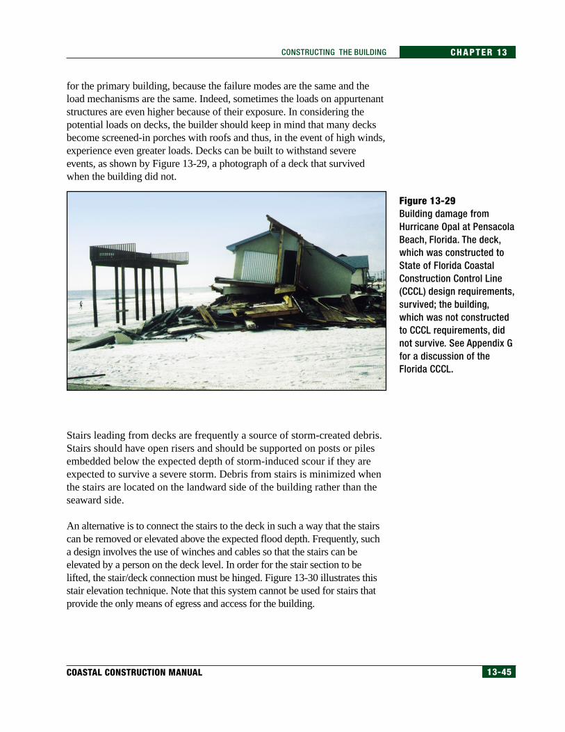
13-45COASTAL CONSTRUCTION MANUAL
CHAPTER 13CONSTRUCTING THE BUILDING
for the primary building, because the failure modes are the same and theload mechanisms are the same. Indeed, sometimes the loads on appurtenantstructures are even higher because of their exposure. In considering thepotential loads on decks, the builder should keep in mind that many decksbecome screened-in porches with roofs and thus, in the event of high winds,experience even greater loads. Decks can be built to withstand severeevents, as shown by Figure 13-29, a photograph of a deck that survivedwhen the building did not.
Figure 13-29Building damage fromHurricane Opal at PensacolaBeach, Florida. The deck,which was constructed toState of Florida CoastalConstruction Control Line(CCCL) design requirements,survived; the building,which was not constructedto CCCL requirements, didnot survive. See Appendix Gfor a discussion of theFlorida CCCL.
Stairs leading from decks are frequently a source of storm-created debris.Stairs should have open risers and should be supported on posts or pilesembedded below the expected depth of storm-induced scour if they areexpected to survive a severe storm. Debris from stairs is minimized whenthe stairs are located on the landward side of the building rather than theseaward side.
An alternative is to connect the stairs to the deck in such a way that the stairscan be removed or elevated above the expected flood depth. Frequently, sucha design involves the use of winches and cables so that the stairs can beelevated by a person on the deck level. In order for the stair section to belifted, the stair/deck connection must be hinged. Figure 13-30 illustrates thisstair elevation technique. Note that this system cannot be used for stairs thatprovide the only means of egress and access for the building.
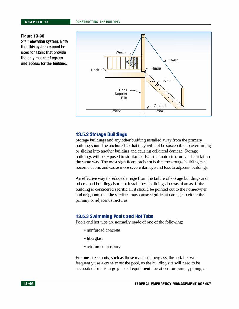
13-46 FEDERAL EMERGENCY MANAGEMENT AGENCY
CHAPTER 13 CONSTRUCTING THE BUILDING
13.5.2 Storage BuildingsStorage buildings and any other building installed away from the primarybuilding should be anchored so that they will not be susceptible to overturningor sliding into another building and causing collateral damage. Storagebuildings will be exposed to similar loads as the main structure and can fail inthe same way. The most significant problem is that the storage building canbecome debris and cause more severe damage and loss to adjacent buildings.
An effective way to reduce damage from the failure of storage buildings andother small buildings is to not install these buildings in coastal areas. If thebuilding is considered sacrificial, it should be pointed out to the homeownerand neighbors that the sacrifice may cause significant damage to either theprimary or adjacent structures.
13.5.3 Swimming Pools and Hot TubsPools and hot tubs are normally made of one of the following:
• reinforced concrete
• fiberglass
• reinforced masonry
For one-piece units, such as those made of fiberglass, the installer willfrequently use a crane to set the pool, so the building site will need to beaccessible for this large piece of equipment. Locations for pumps, piping, a
Figure 13-30Stair elevation system. Notethat this system cannot beused for stairs that providethe only means of egressand access for the building.
Cable
Hinge
Stairs
Ground
Winch
Deck
DeckSupport
Pile
13-47COASTAL CONSTRUCTION MANUAL
CHAPTER 13CONSTRUCTING THE BUILDING
heater (if there is one), fuel supply, and other associated equipment must befound so that the following requirements are met:
• The equipment must be located in the proper place to supply the poolwith water.
• The equipment must be elevated to or above the DFE so that thepotential for flood damage is minimized.
• The equipment must be set so that wind, or seismic, and water forces(including inundation by salt water or sediment) will not displace ordamage it. Unless specifically designed, most mechanical equipment isnot intended to be inundated with salt water. Equipment installed in thecorrosive coastal environment will normally require corrosion-resistantpiping (usually PVC), stainless steel pump impellers, cast iron pumpbodies, and totally enclosed electrical components.
The design considerations for one-piece pools are covered in Section 12.9.4 inChapter 12. The builder, however, must be able to execute the design intent,which includes the following:
• A one-piece pool must be able to resist flood forces with minimaldamage, whether the pool is full or empty. This means that an in-ground pool must resist failure from buoyancy as well as wall fracture.
• The pool equipment must be easily returned to service after a severe event.A flexible connection between the pump and piping may help achieve thisobjective so the equipment can move under forces from the severe event.This coupling will also reduce stress on the pipe from vibration.
• Pool accessories (e.g., cleaning nets, lane dividers) can becomeairborne debris and should have a secure storage location.
The design intent for concrete pools includes the following:
• Elevation of an in-ground pool should be such that scour will not permitthe pool to fail from either normal internal loads of the filled pool orfrom exterior loads imposed by the flood forces.
• The pool should be located as far landward as possible and should beoriented in such a way that flood forces are minimized. This includesplacing the pool with the narrowest dimension facing the direction offlow, orienting the pool so there is little to no angle of attack fromflood water, and installing a pool with rounded instead of squarecorners. All of these design choices will reduce the amount of scouraround the pool and thereby improve the chances the pool will survivethe storm. These concepts are illustrated in Figure 13-31.
NOTETwo articles concerning swim-ming pool design standards inV zones are included in Appen-dix L. The articles—Scour Im-pact of Coastal SwimmingPools on Beach Systems andConceptual Breakaway Swim-ming Pool Design for CoastalAreas—report the results ofstudies funded by FEMA.
CROSS-REFERENCE
See Section 12.9.4, in Chapter12, for design guidance andregulatory requirements re-garding swimming pools.
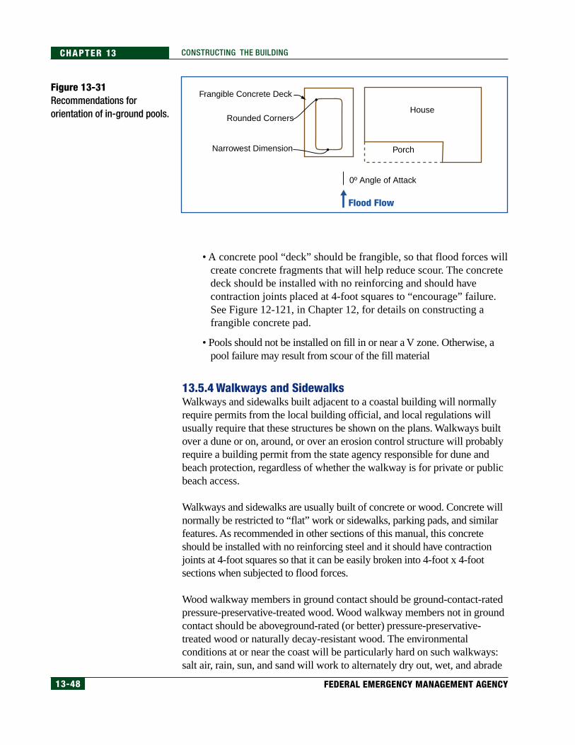
13-48 FEDERAL EMERGENCY MANAGEMENT AGENCY
CHAPTER 13 CONSTRUCTING THE BUILDING
• A concrete pool “deck” should be frangible, so that flood forces willcreate concrete fragments that will help reduce scour. The concretedeck should be installed with no reinforcing and should havecontraction joints placed at 4-foot squares to “encourage” failure.See Figure 12-121, in Chapter 12, for details on constructing afrangible concrete pad.
• Pools should not be installed on fill in or near a V zone. Otherwise, apool failure may result from scour of the fill material
13.5.4 Walkways and SidewalksWalkways and sidewalks built adjacent to a coastal building will normallyrequire permits from the local building official, and local regulations willusually require that these structures be shown on the plans. Walkways builtover a dune or on, around, or over an erosion control structure will probablyrequire a building permit from the state agency responsible for dune andbeach protection, regardless of whether the walkway is for private or publicbeach access.
Walkways and sidewalks are usually built of concrete or wood. Concrete willnormally be restricted to “flat” work or sidewalks, parking pads, and similarfeatures. As recommended in other sections of this manual, this concreteshould be installed with no reinforcing steel and it should have contractionjoints at 4-foot squares so that it can be easily broken into 4-foot x 4-footsections when subjected to flood forces.
Wood walkway members in ground contact should be ground-contact-ratedpressure-preservative-treated wood. Wood walkway members not in groundcontact should be aboveground-rated (or better) pressure-preservative-treated wood or naturally decay-resistant wood. The environmentalconditions at or near the coast will be particularly hard on such walkways:salt air, rain, sun, and sand will work to alternately dry out, wet, and abrade
Figure 13-31Recommendations fororientation of in-ground pools.
Frangible Concrete Deck
Rounded Corners
Narrowest Dimension
0º Angle of Attack
Flood Flow
House
Porch
13-49COASTAL CONSTRUCTION MANUAL
CHAPTER 13CONSTRUCTING THE BUILDING
the wood. Wood walkways at grade level should be anchored with postsburied several feet in the ground to prevent uplift from wind. During asevere flood event, scour may occur at the edges of the walkway and causean uplift failure, so the posts should be buried a minimum of 8 feet belowthe expected level of scour (see Appendix I).
There are several state-initiated guidance documents on walkway/walkoverconstruction. Appendix I includes a construction guidance document from theState of Florida, Bureau of Beaches and Coastal Systems, Beach/DuneWalkover Guidelines (January 1998) and a document from Florida Sea Granttitled Beach Dune Walkover Structures (December 1983).
13.6 Utility/Mechanical EquipmentThis section presents guidance concerning the installation of elevators,building utility systems (heating, ventilating, and cooling [HVAC], electrical,water, and wastewater), and storage tanks. For detailed information about thedesign and construction of utility systems for buildings in flood hazard areas,refer to Protecting Building Utilities From Flood Damage – Principles andPractices for the Design and Construction of Flood Resistant Building UtilitySystems, FEMA 348 (FEMA 1999).
13.6.1 ElevatorsElevators are becoming commonplace in many coastal homes. Normally,these elevators have only a one- to four-person capacity, and they almostalways require installation in an area that will at least be partially below theDFE. To minimize flood damage to the elevator and its parts, the buildershould look for locations above the DFE to mount elevator equipment (e.g.,electrical controls, hydraulic pumps).
Normally, for fire safety reasons, elevators are equipped with a default devicethat sends the cab to the lowest floor when there is a power outage (which willalways occur during a major storm). For the protection of the elevatorequipment and the occupants, this manual recommends that a float switch beinstalled that activates when inundated by flood water and sends the elevatorcab to a floor above the DFE. For additional information, see FEMA NFIPTechnical Bulletin 4, Elevator Installation for Buildings Located in SpecialFlood Hazard Areas, in Appendix H.
NOTEFor additional information aboutthe proper design and construc-tion of utility system compo-nents for buildings in flood haz-ard areas, refer to ProtectingBuilding Utilities From FloodDamage – Principles and Prac-tices for the Design and Con-struction of Flood ResistantBuilding Utility Systems, FEMA348 (FEMA 1999).
13-50 FEDERAL EMERGENCY MANAGEMENT AGENCY
CHAPTER 13 CONSTRUCTING THE BUILDING
13.6.2 Heating, Ventilating, and Cooling (HVAC) SystemsHVAC systems include a number of components that must be installed so thatthey are protected from damage during a severe wind, flood, or seismic event.These components include the following:
• outdoor condensers
• air-handling units
• ductwork for supply and return air
• electrical components for power to the air-handlers and controls
• fuel storage (if not electric)
If the HVAC components inside the building are all installed above the DFE,many potential losses will be avoided. The single most expensive componentoften lost during a severe event is the outdoor condenser. The reason is thatthe condenser is usually placed in a position that, while perhaps minimizingexpense for the HVAC system, leaves it exposed to the wind and water forcesthat accompany a severe storm.
To minimize damage to the outdoor condenser, do the following:
• Mount it on the side of the building that will be least affected by floodvelocity flow and waves.
• Mount it above the DFE.
• Secure it so that it cannot move, vibrate, or be blown off its support.
• Protect it from damage by airborne debris.
There are several ways to support an outdoor condenser with a connection tothe floor framing. These include the following:
• cantilever floor framing (see Figures 13-32 and 13-33; this methodrequires careful detailing to prevent water penetration into the buildingfloor and wall systems)
• pile-supported
• wood-brace-supported (see Figures 13-34 and 13-35)
• rooftop mount
COSTCONSIDERATION
HVAC equipment that is not el-evated above the DFE will prob-ably need to be repaired or re-placed after a flood.
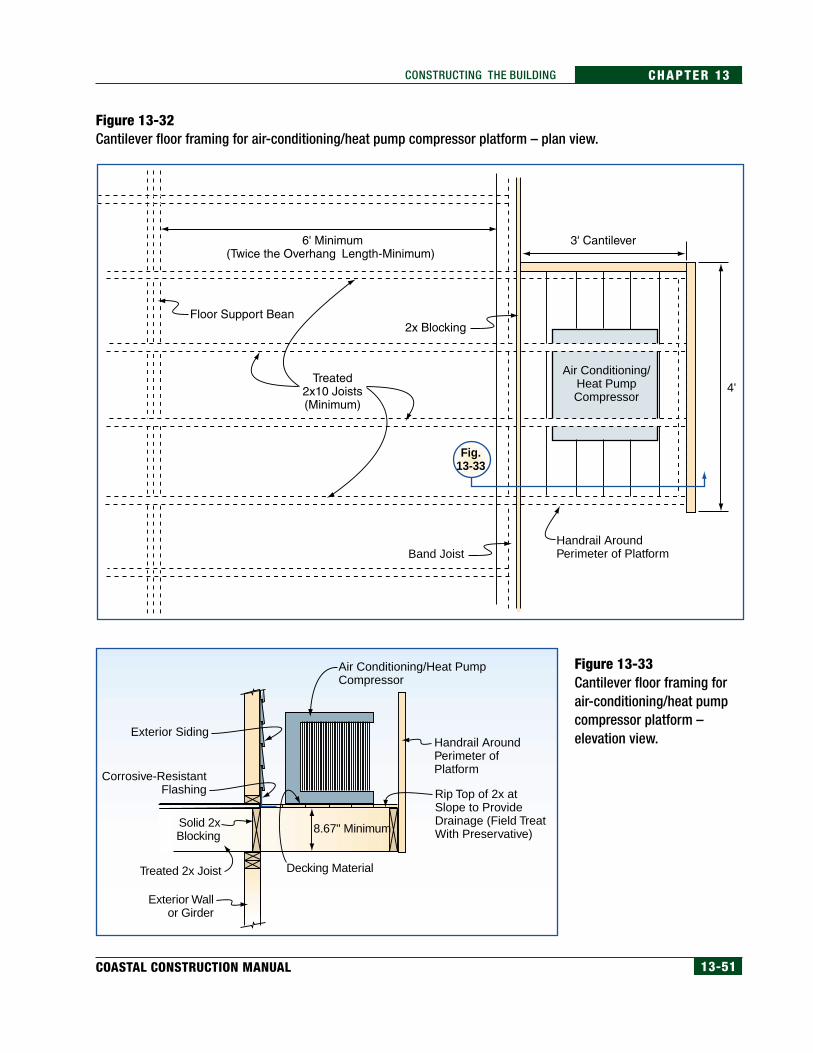
13-51COASTAL CONSTRUCTION MANUAL
CHAPTER 13CONSTRUCTING THE BUILDING
Figure 13-32Cantilever floor framing for air-conditioning/heat pump compressor platform – plan view.
Figure 13-33Cantilever floor framing forair-conditioning/heat pumpcompressor platform –elevation view.
Fig.13-33
Band Joist
4' Air Conditioning/
Heat PumpCompressor
Handrail AroundPerimeter of Platform
Exterior Siding
Air Conditioning/Heat PumpCompressor
Handrail AroundPerimeter of Platform
Rip Top of 2x atSlope to ProvideDrainage (Field TreatWith Preservative)
Corrosive-ResistantFlashing
Solid 2xBlocking
Treated 2x Joist
Exterior Wallor Girder
8.67" Minimum
Decking Material
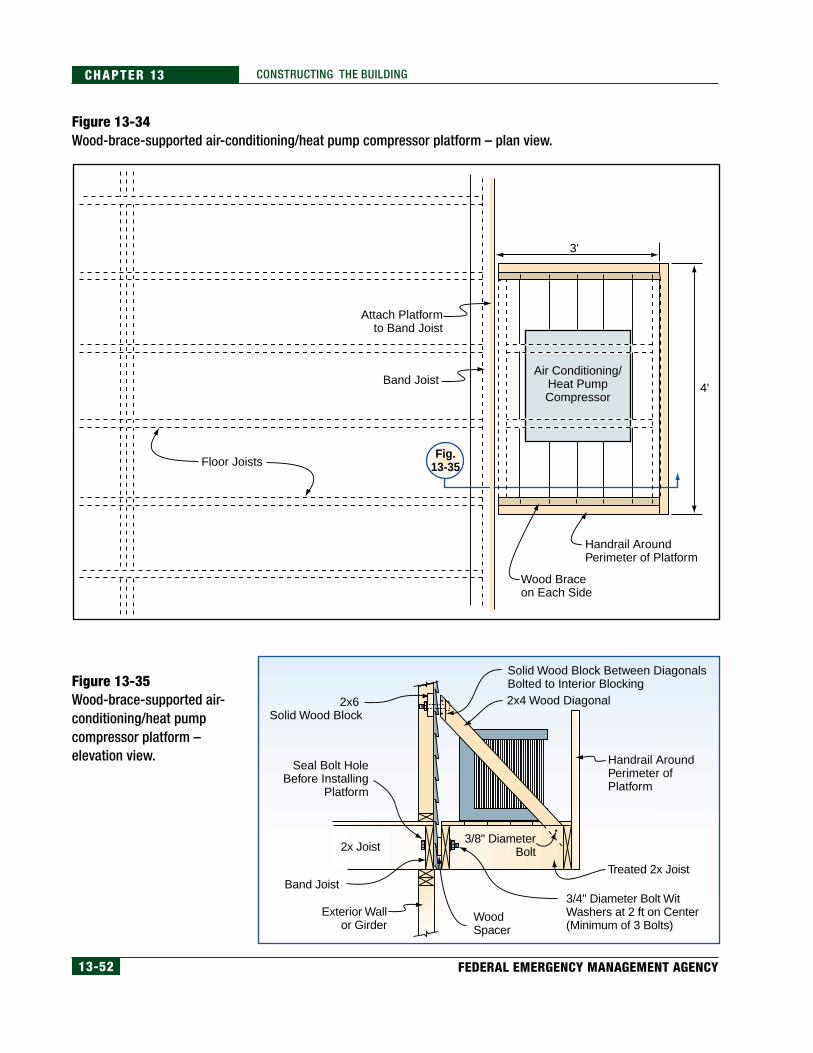
13-52 FEDERAL EMERGENCY MANAGEMENT AGENCY
CHAPTER 13 CONSTRUCTING THE BUILDING
Figure 13-34Wood-brace-supported air-conditioning/heat pump compressor platform – plan view.
Figure 13-35Wood-brace-supported air-conditioning/heat pumpcompressor platform –elevation view.
2x6 Solid Wood Block
Seal Bolt HoleBefore Installing
Platform
Solid Wood Block Between Diagonals Bolted to Interior Blocking
Handrail AroundPerimeter of Platform
2x4 Wood Diagonal
2x Joist
Treated 2x JoistBand Joist
Exterior Wallor Girder
3/8" DiameterBolt
3/4" Diameter Bolt WitWashers at 2 ft on Center(Minimum of 3 Bolts)
WoodSpacer
3'
4'
Floor Joists
Band Joist
Handrail AroundPerimeter of Platform
Wood Braceon Each Side
Air Conditioning/Heat PumpCompressor
Attach Platformto Band Joist
Fig.13-35
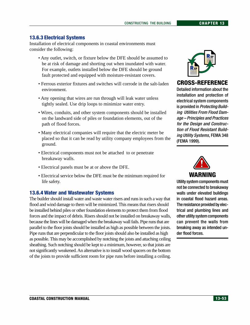
13-53COASTAL CONSTRUCTION MANUAL
CHAPTER 13CONSTRUCTING THE BUILDING
13.6.3 Electrical SystemsInstallation of electrical components in coastal environments mustconsider the following:
• Any outlet, switch, or fixture below the DFE should be assumed tobe at risk of damage and shorting out when inundated with water.For example, outlets installed below the DFE should be groundfault protected and equipped with moisture-resistant covers.
• Ferrous exterior fixtures and switches will corrode in the salt-ladenenvironment.
• Any opening that wires are run through will leak water unlesstightly sealed. Use drip loops to minimize water entry.
• Wires, conduits, and other system components should be installedon the landward side of piles or foundation elements, out of thepath of flood forces.
• Many electrical companies will require that the electric meter beplaced so that it can be read by utility company employees from theground.
• Electrical components must not be attached to or penetratebreakaway walls.
• Electrical panels must be at or above the DFE.
• Electrical service below the DFE must be the minimum required forlife safety.
13.6.4 Water and Wastewater SystemsThe builder should install water and waste water risers and runs in such a way thatflood and wind damage to them will be minimized. This means that risers shouldbe installed behind piles or other foundation elements to protect them from floodforces and the impact of debris. Risers should not be installed on breakaway walls,because the lines will be damaged when the breakaway wall fails. Pipe runs that areparallel to the floor joists should be installed as high as possible between the joists.Pipe runs that are perpendicular to the floor joists should also be installed as highas possible. This may be accomplished by notching the joists and attaching ceilingsheathing. Such notching should be kept to a minimum, however, so that joists arenot significantly weakened. An alternative is to install wood spacers on the bottomof the joists to provide sufficient room for pipe runs before installing a ceiling.
CROSS-REFERENCEDetailed information about theinstallation and protection ofelectrical system componentsis provided in Protecting Build-ing Utilities From Flood Dam-age – Principles and Practicesfor the Design and Construc-tion of Flood Resistant Build-ing Utility Systems, FEMA 348(FEMA 1999).
WARNINGUtility system components mustnot be connected to breakawaywalls under elevated buildingsin coastal flood hazard areas.The resistance provided by elec-trical and plumbing lines andother utility system componentscan prevent the walls frombreaking away as intended un-der flood forces.
13-54 FEDERAL EMERGENCY MANAGEMENT AGENCY
CHAPTER 13 CONSTRUCTING THE BUILDING
13.6.5 TanksSmall tanks used for fuel, such as propane tanks, should be elevated above theDFE; if a tank is detached from its location during a severe flood event, it canbecome a windborne or waterborne missile. In addition to being elevated,small tanks also need to be strapped or otherwise secured to the building sothat they will not be detached by high winds or a seismic event. Any strappingused should be corrosion-resistant. This technique can be altered toaccommodate an exterior location. Builders should keep in mind that thestrapping must resist forces from all four plan directions.
Larger tanks will normally be buried belowgrade or supported by and attachedto a foundation. In a Special Flood Hazard Area, erosion and scour can exposethe tank; the tank can fill with sediment/soil and salt water; or buoyancy forceson the tank can be sufficient to lift the tank out of the ground. Larger tanks maybe used for septic tanks or for the storage of propane or fuel oil.
This manual recommends the following for minimizing damage tobelowgrade tanks:
• Orient the tank so that scour is minimized. Do this by• orienting the tank with the narrowest dimension of the tank
perpendicular to the flood flow,
• orienting the tank so there is no angle of attack of the floodwater, and
• locating the tank so that flow diverted or channeled by nearbystructures is not directed toward the tank.
• Secure the tank so that buoyancy forces will not lift the tank out of theground. Do this by anchoring the tank to a concrete pad heavy enoughto keep the tank in the ground.
Aboveground tanks can be anchored in at least two ways (see Figure 13-36).In addition, the tank must be located such that scour does not undermine theslab foundation, and the openings of fill lines and overflows must be abovethe DFE so that flood water will not enter the tank.
WARNINGDo not anchor tanks to break-away walls under elevatedbuildings.
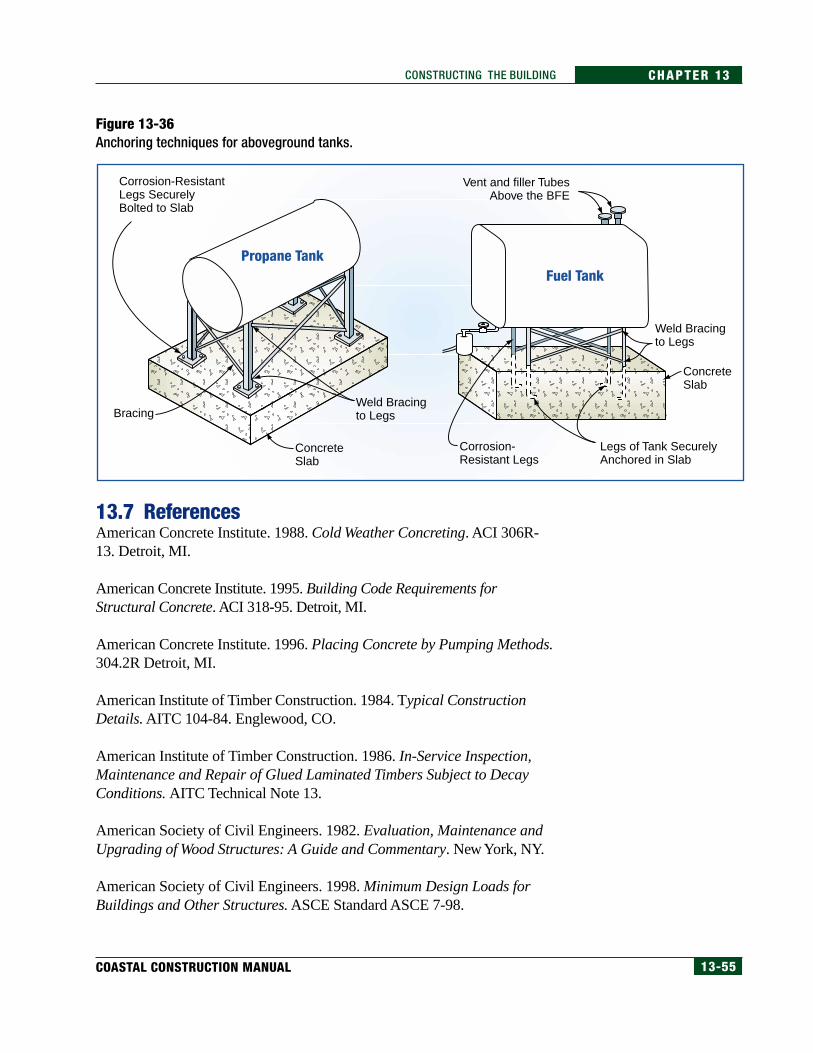
13-55COASTAL CONSTRUCTION MANUAL
CHAPTER 13CONSTRUCTING THE BUILDING
13.7 ReferencesAmerican Concrete Institute. 1988. Cold Weather Concreting. ACI 306R-13. Detroit, MI.
American Concrete Institute. 1995. Building Code Requirements forStructural Concrete. ACI 318-95. Detroit, MI.
American Concrete Institute. 1996. Placing Concrete by Pumping Methods.304.2R Detroit, MI.
American Institute of Timber Construction. 1984. Typical ConstructionDetails. AITC 104-84. Englewood, CO.
American Institute of Timber Construction. 1986. In-Service Inspection,Maintenance and Repair of Glued Laminated Timbers Subject to DecayConditions. AITC Technical Note 13.
American Society of Civil Engineers. 1982. Evaluation, Maintenance andUpgrading of Wood Structures: A Guide and Commentary. New York, NY.
American Society of Civil Engineers. 1998. Minimum Design Loads forBuildings and Other Structures. ASCE Standard ASCE 7-98.
Figure 13-36Anchoring techniques for aboveground tanks.
Propane TankFuel Tank
Corrosion-ResistantLegs SecurelyBolted to Slab
Vent and filler TubesAbove the BFE
Bracing
ConcreteSlab
ConcreteSlab
Weld Bracingto Legs
Weld Bracingto Legs
Legs of Tank SecurelyAnchored in Slab
Corrosion-Resistant Legs
13-56 FEDERAL EMERGENCY MANAGEMENT AGENCY
CHAPTER 13 CONSTRUCTING THE BUILDING
American Society for Testing and Materials. 1988. Standard RecommendedPractices for Increasing Durability of Building Constructions AgainstWater-Induced Damage. Standard E 241-77. Philadelphia, PA.
American Wood Preservers’ Association. 1991. Care of Pressure-TreatedWood Products. AWPA Standard M4-91. Woodstock, MD.
American Wood Preservers’ Association. 1994. Standards. Woodstock, MD.
Basham, K. 1995. “Cold Weather Concreting.” Journal of LightConstruction. January.
Bruce, Quarles, Shelly, et. al. 1997. Wood Performance in Service,Workshop Notes, Richmond, CA.
California Redwood Association. Redwood File. Novato, CA.
Chapdelaine, H. 1993. “Building Porches That Last.” Journal of LightConstruction. June.
Coastal Living Magazine. 1998. “Good Decisions: Decked Out.” January.
Dost, W. 1986. Performance of Wood Construction Materials, Kapalua BayVillas. WBRC report 35.04.20.
Dost, W. A. 1990. Wood: Detailing for Performance. Mill Valley, CA:GRDA Publications.
Federal Emergency Management Agency. 1999. Protecting Building UtilitiesFrom Flood Damage – Principles and Practices for the Design andConstruction of Flood Resistant Building Utility Systems. First Edition.FEMA 348. November.
Forest Products Research Society. 1988. Wood Protection Techniques and theUse of Treated Wood in Construction. Madison, WI.
Forest Products Society. 1996. Selection and Use of Preservative-TreatedWood. Madison, WI.
Graham and Womack. 1972. Wood-Metal Corrosion, An Annotated Survey.Research Bulletin 21. Oregon State University College of Forestry, ForestResearch Laboratory. Corvallis OR.
Hamilton, P. 1994. “On the Beach: Coastal Construction.” Journal of LightConstruction. April.
13-57COASTAL CONSTRUCTION MANUAL
CHAPTER 13CONSTRUCTING THE BUILDING
Hamilton, P. 1997. “Installing a Steel Moment Frame.” Journal of LightConstruction. March.
Highley, S. Controlling Decay in Waterfront Structures. Forest ProductsLaboratory. 1989.
International Code Council. 2000a. International Building Code. FinalDraft. Birmingham, AL. July.
International Code Council. 2000b. International Residential Code for One-and Two-Family Dwellings. Birmingham, AL.
McDonald, Falk, Williams and Winandy. 1996. Wood Decks, Materials,Construction and Finishing. Forest Products Society.
Meyer, R. W.; Kellogg, R. M. 1982. Structural Use of Wood in AdverseEnvironments. New York: Van Nostrand Reinhold.
Morrell, Helsing, Graham. Marine Wood Maintenance Manual. ResearchBulletin 48. Oregon State University College of Forestry, Forest ResearchLaboratory. Corvallis, OR.
National Evaluation Service, Inc. 1997. Power-Driven Staples and Nails forUse in All Types of Building Construction. National Evaluation Report NER-272. Reissued September 1.
Nnaji, Soronnadi, et al. 1996. “Scour Impact of Coastal Swimming Pools onBeach Systems.” Journal of Coastal Research. Winter. Ft. Lauderdale, FL.
Schein, E. 1968. The Influence of Design on Exposed Wood in Buildings inthe Puget Sound Area. USDA Pacific NW Forest and Range ExperimentStation. Portland, OR.
Simpson Strong-Tie Co., Inc. 1997. Simpson Wood Construction Connectors.
State of Florida, Bureau of Beaches and Coastal Systems. 1998. Beach/DuneWalkover Guidelines. January.
University of Florida Sea Grant Institute. 1983. Beach Dune WalkoverStructures. December.
U.S. Department of the Navy. 1982. Foundation and Earth Structures Design.Manual 7.2. Alexandria, VA. May.
Yazdani, Nur, et al. 1997. “Conceptual Breakaway Swimming Pool Designfor Coastal Areas.” Journal of Coastal Research. Winter. Ft. Lauderdale, FL.