Centricity™ RA600 Service Manual
278
GE Medical Systems Information Technologies Centricity™ RA600 Service Manual RadWorks Release 6.0 FP10516 Revision 2 Published—August 2002 Do not duplicate. © GE Medical Systems Information Technologies, 2002, All rights reserved
-
Upload
khangminh22 -
Category
Documents
-
view
1 -
download
0
Transcript of Centricity™ RA600 Service Manual

� GE Medical SystemsInformation Technologies
Centricity™ RA600 Service ManualRadWorks Release 6.0
FP10516Revision 2
Published—August 2002Do not duplicate.© GE Medical Systems Information Technologies, 2002, All rights reserved

Regulatory Requirements
This product complies with the regulatory requirements of the following:
uMedical Device Quality Systems Regulation, FDA (Food and Drug Administration, Department of Health and Human Services, USA).
nization, when
pment may cause ommunications. with emissions However, there is
ing the equipment roblem by one or
Page 2
uUnderwriters’ Laboratories, Inc. (UL), an independent testing laboratory.
uCanadian Standards Association (CSA).
u International Electrotechnical Commission (IEC), international standards orgaapplicable.
uGeneral Electric Medical Systems is ISO 9001 and EN 46001 certified.
uThe original document was written in English.
This equipment generates, uses, and can radiate radio frequency energy. The equiradio frequency interference to other medical and non-medical devices and radio cTo provide reasonable protection against such interference, this product complies limits for a Group 1, Class A Medical Devices Directive as stated in EN60601–1–2.no guarantee that interference will not occur in a particular installation.
If this equipment is found to cause interference (which may be determined by turnon and off), the user (or qualified service personnel) should attempt to correct the pmore of the following measure(s):
u reorient or relocate the affected device(s)

u increase the separation between the equipment and the affected device
upower the equipment from a source different from that of the affected device
uconsult the point of purchase or service representative for further suggestions
The manufacturer is not responsible for any interference caused by using other than recommended interconnect cables or by unauthorized changes or modifications to this equipment. Unauthorized changes or modifications could void the users’ authority to operate the equipment.
To comply with the regulations on electromagnetic interference for a Class A FCC Device, all interconnect cables to peripheral devices must be shielded and properly grounded. Use of cables not properly shielded and grounded may result in the equipment causing radio frequency interference in violation of the FCC regulations.Do not use devices which intentionally transmit RF Signals (Cellular Phones, Transceivers, or Radio Controlled Products) in the vicinity of this equipment as it may cause performance outside the published specifications. Keep the power to these type devices turned off when near this equipment.
atients, and other ent.
Page 3
The medical staff in charge of this equipment is required to instruct technicians, ppeople who may be around this equipment to fully comply with the above requirem

• This Service Manual is available in english only.• If a customer’s service provider requires a language other than English, it is the
customer’s responsibility to provide translation services.• Do not attempt to service the equipment unless this service manual has been con-
sulted and is understood.• Failure to heed this warning may result in injury to the service provider, operator or
patient from electric shock, mechanical or other hazards.
• Ce Manuel de maintenance n’est disponible qu’en anglais.• Si le technicien du client a besoin de ce manuel dans une autre langue que l’ang-
lais, c’est au client qu’il incombe de le faire traduire.• Ne pas tenter d’intervention sur les équipements tant que le manuel Service n’a pas
été consulté et compris.• Le non-respect de cet avertissement peut entraîner chez le technicien, l’opérateur
écaniques ou autres.
ache. ist es Aufgabe des
ndendienst-Hand-
n des Kundendienst-e Schläge, mecha-
ma que no sea el ducción.
ado y comprendido
l proveedor de servi- causas eléctricas,
WARNING
AVERTISSEMENT
Page 4
ou le patient des blessures dues à des dangers électriques, m
• Dieses Kundendienst-Handbuch existiert nur in englischer Spr• Falls ein fremder Kundendienst eine andere Sprache benötigt,
Kunden für eine entsprechende Übersetzung zu sorgen.• Versuchen Sie nicht, das Gerät zu reparieren, bevor dieses Ku
buch nicht zu Rate gezogen und verstanden wurde.• Wird diese warnung nicht beachtet, so kann es zu Verletzunge
technikers, des Bedieners oder des Patienten durch elektrischnische oder sonstige Gefahren kommen.
• Este Manual de Servicio sólo existe en inglés.• Si algún proveedor de servicios ajeno a GEMS solicita un idio
inglés, es responsabilidad del cliente ofrecer un servicio de tra• No se deberá dar servicio técnico al equipo, sin haber consult
este manual de servicio.• La no observancia del presente aviso puede dar lugar a que e
cios, el operador o el paciente sufran lesiones provocadas pormecánicas o de otra naturaleza.
WARNUNG
AVISO

• Este Manual de Assistência Técnica só se encontra disponível em Inglês.• Se qualquer outro serviço de assistência técnica, quE não a GEMS, solicitar estes
manuais noutro idioma, é da responsabilidade do cliente fornecer os serviços de tradução.
• Não tente reparar o equipamento sem ter consultado e compreendido este Manual de Assistência Técnica.
• O não cumprimento deste aviso pode por em perigo a segurança do técnico, oper-ador ou
• Il presente manuale di manutenzione è disponibile soltanto in inglese.• Se un addetto alla manutenzione esterno alla GEMS richiede il manuale in una lin-
gua diversa, il cliente è tenuto a provvedere direttamente alla traduzione.• Si proceda alla manutenzione dell’apparecchiatura solo dopo aver consultato il pre-
sente manuale ed averne compreso il contenuto.• Non tenere conto della presente avvertenza potrebbe far compiere operazioni da
cui derivino lesioni all’addetto alla manutenzione, all’utilizzatore ed al paziente per folgorazione elettrica, per urti meccanici od altri rischi.
ATENÇAO
AVVERTENZA
Page 5

Page 6
Revision History
Rev Date Author Reason For Change
0 3/2002 WB Initial release for Centricity RA600
1 4/2002 SA/WB Add work group server, streaming video, Europe’s dongle replacement procedure, revised initial powerup config., Flat panel display coverage & other miscellaneous minor fixes
2 8/2002 DB/SA/WB
Add RA600 Identification & Connectivity list to Chp. 1, revise monitor calibration CNF006, change streaming video SW013 and Static frame capture SW007 to point to kit doc, add software patch installation SW014.

Table of Contents
CHAPTER 1 INTRODUCTION . . . . . . . . . . . . . . . . . . . . . . . . . . . . . . . . . . . . . . . 11
CHAPTER 2 INSTALLATION STEERING GUIDE . . . . . . . . . . . . . . . . . . . . . . . 25
CHAPTER 3 HARDWARE INSTALLATION . . . . . . . . . . . . . . . . . . . . . . . . . . . . 28
Page 7
IST 001 (A+) 2048 x 2506 Portrait Monitor Interconnections . . . . . . . . . . . . . . . . .29
IST 002 (A) 1728 x 2304 Portrait Monitor Interconnections . . . . . . . . . . . . . . . . . .33
IST 003 (B) 1200 x 1600 Portrait Monitor Interconnections . . . . . . . . . . . . . . . . . .37
IST 004 (B+) 1536 x 2048 Flat Panel Portrait Monitor Connections . . . . . . . . . . . .41
IST 005 (C) 1280 x 1024 Landscape Monitor Interconnections . . . . . . . . . . . . . . .45
IST 006 Site Configuration Forms . . . . . . . . . . . . . . . . . . . . . . . . . . . . . . . . . . . . . .49
IST 007 Adaptec SCSI Card Installation . . . . . . . . . . . . . . . . . . . . . . . . . . . . . . . . .53
IST 008 Installing Frame Grabber Board . . . . . . . . . . . . . . . . . . . . . . . . . . . . . . . .55
IST 009 Optional Internal Hard Drive Connect & Configure . . . . . . . . . . . . . . . . . .57
IST 010 Installing Additional RAM Modules In CPU . . . . . . . . . . . . . . . . . . . . . . . .81
IST 011 Installing Global Modem . . . . . . . . . . . . . . . . . . . . . . . . . . . . . . . . . . . . . .86
IST 012 Installing Barco 3MP2FH Video Board . . . . . . . . . . . . . . . . . . . . . . . . . . .88
IST 013 Installing RAID Unit . . . . . . . . . . . . . . . . . . . . . . . . . . . . . . . . . . . . . . . . . .92

CHAPTER 4 SOFTWARE CONFIGURATION . . . . . . . . . . . . . . . . . . . . . . . . . . 95
CNF 001 Initial Power Up and Software Configuration . . . . . . . . . . . . . . . . . . . . . . .96
CNF 002 Configuring System IP Address, Subnet Mask or Default Route/Gateway 101
CNF 003 Changing Host/Computer Name . . . . . . . . . . . . . . . . . . . . . . . . . . . . . . .103
CNF 004 Adding/Configuring TCP/IP Printer . . . . . . . . . . . . . . . . . . . . . . . . . . . . .105
CNF 005 VNC Server Installation and Configuration . . . . . . . . . . . . . . . . . . . . . . .107
CNF 006 Monitor Calibration with Barco Tool (MediCal Pro) . . . . . . . . . . . . . . . . .109
CNF 007 Configuring Barco 3MP2FH Video Driver . . . . . . . . . . . . . . . . . . . . . . . .135
CNF 008 RAID System Recovery and Configuration . . . . . . . . . . . . . . . . . . . . . . .143
CNF 009 Configuring Workgroup Server & Client System . . . . . . . . . . . . . . . . . . .151
Page 8
CHAPTER 5 FUNCTIONAL CHECK . . . . . . . . . . . . . . . . . . . . . . . . . . . . . . . . . 161
VF 001 Functional Checks / Setup Completion . . . . . . . . . . . . . . . . . . . . . . . . . .162
VF 002 Saving/Restoring System and User Settings . . . . . . . . . . . . . . . . . . . . . .165
VF 003 Customer Turnover . . . . . . . . . . . . . . . . . . . . . . . . . . . . . . . . . . . . . . . . .173
CHAPTER 6 SOFTWARE PROCEDURES . . . . . . . . . . . . . . . . . . . . . . . . . . . . 175
SW 001 Restoring RA600 Original System Configuration . . . . . . . . . . . . . . . . . . .177
SW 002 Installing Centricity RA600 Software . . . . . . . . . . . . . . . . . . . . . . . . . . . .180
SW 003 (C, 2C) Matrox Video Board Driver Installation . . . . . . . . . . . . . . . . . . . .188
SW 004 (A+,A,B) Dome Video Board Driver Installation . . . . . . . . . . . . . . . . . . . .193
SW 005 Removing Applications Software . . . . . . . . . . . . . . . . . . . . . . . . . . . . . . .197
SW 006 Single Media Archive (SMA) Install, Configure & Test . . . . . . . . . . . . . .199

SW 007 Installing Foresight Static Frame Capture Software(Refer to Kit document FP10621) . . . . . . . . . . . . . . . . . . . . . . . . . . . . . .207
SW 008 Common Windows 2000 Procedures . . . . . . . . . . . . . . . . . . . . . . . . . . .208
SW 009 Changing DOME Display Font Size . . . . . . . . . . . . . . . . . . . . . . . . . . . . .223
SW 010 Installing Film Digitizer SCSI Software . . . . . . . . . . . . . . . . . . . . . . . . . .224
SW 011 Installing Work Group Server on RA600 . . . . . . . . . . . . . . . . . . . . . . . . .228
SW 012 Installing an RA600 Work Group Client . . . . . . . . . . . . . . . . . . . . . . . . . .230
SW 013 Install & Setup of Streaming Video Capture System (Refer to Kit document FP10621) . . . . . . . . . . . . . . . . . . . . . . . . . . . . . .232
SW 014 Installing Centricity RA600 Software Patch . . . . . . . . . . . . . . . . . . . . . . .233
Page 9
CHAPTER 7 TROUBLESHOOTING . . . . . . . . . . . . . . . . . . . . . . . . . . . . . . . . . 234
TSG 001 Telneting to a Workstation . . . . . . . . . . . . . . . . . . . . . . . . . . . . . . . . . . . .236
TSG 002 Workstation Directory Tree . . . . . . . . . . . . . . . . . . . . . . . . . . . . . . . . . . .238
TSG 003 Troubleshooting Network Problems . . . . . . . . . . . . . . . . . . . . . . . . . . . . .239
TSG 004 Using The VGA Service Monitor . . . . . . . . . . . . . . . . . . . . . . . . . . . . . . .241
TSG 005 Stop a Software Process . . . . . . . . . . . . . . . . . . . . . . . . . . . . . . . . . . . . .243
TSG 006 Display Windows 2000 System Logs . . . . . . . . . . . . . . . . . . . . . . . . . . . .244
TSG 007 Display Centricity RA600 Application Logs . . . . . . . . . . . . . . . . . . . . . . .245
TSG 008 Display IP/Netmask/Default Route Configuration Settings . . . . . . . . . . .246
TSG 009 Display Loaded Drivers . . . . . . . . . . . . . . . . . . . . . . . . . . . . . . . . . . . . . .247
TSG 010 Display System Services . . . . . . . . . . . . . . . . . . . . . . . . . . . . . . . . . . . . .248
TSG 011 Display System Hardware & Software Configuration . . . . . . . . . . . . . . .249
TSG 012 Display OS Version . . . . . . . . . . . . . . . . . . . . . . . . . . . . . . . . . . . . . . . . .250

TSG 013 Display Application Software Version . . . . . . . . . . . . . . . . . . . . . . . . . . .251
TSG 014 Workstation Application Problem Solving . . . . . . . . . . . . . . . . . . . . . . . .252
TSG 015 Connect Frame Grabber to Monitor that has no pass-through . . . . . . . .255
CHAPTER 8 DISASSEMBLY & REASSEMBLY PROCEDURES . . . . . . . . . . 257
DR 001 Video Board Switch Settings . . . . . . . . . . . . . . . . . . . . . . . . . . . . . . . . . .258
DR 002 PC Port Connection Diagram . . . . . . . . . . . . . . . . . . . . . . . . . . . . . . . . .260
DR 003 Replace-Configure PERC 3/DC RAID controller board . . . . . . . . . . . . . .262
DR 004 Replacement of 221S RAID Unit Components . . . . . . . . . . . . . . . . . . . .264
Page 10
CHAPTER 9 RENEWAL PARTS . . . . . . . . . . . . . . . . . . . . . . . . . . . . . . . . . . . . 265
CHAPTER 10 SUGGESTED MAINTENANCE . . . . . . . . . . . . . . . . . . . . . . . . . 275
MNT 001 Scheduled Maintenance . . . . . . . . . . . . . . . . . . . . . . . . . . . . . . . . . . . . .276

1 Introduction
Section 1: Introduction
Throughout this manual the common term Workstation is used to refer to the Centricity RA600 Workstation which represents the installed configuration of monitor(s) and computer.
chapter.
ut
.
he
Page 11
Section 2: Chapter Descriptions
Shown below is a summary of the chapters in this book and a description of each
Chapter 1 Introduction. This chapter contains information abothe workstation, a list of related manuals and a summary of what is in each chapter.
Chapter 2 Service/Installation Steering Guide. This chapterpresents an overview of what is required for a complete installation.
Chapter 3 System Installation. This chapter contains the jobcards needed to perform the installation, configure purchasable options, and post-installation activities
Chapter 4 Software Configuration. This chapter contains anintroduction and the job cards needed to configure tsoftware.
Chapter 5 Functional Check. This chapter contains job cardsfor verifying proper system function.

Introduction
Chapter 6 Software Procedures. This chapter contains job cards for performing common procedures, such as software loads, installs, and the day-to-day procedures needed for Windows NT operation and administration.
Chapter 7 Troubleshooting. This chapter includes a troubleshooting chart to help isolate problems and contains job cards for querying the system to display parameters and information about running processes, logs, software version, etc.
Chapter 8 Disassembly/Reassembly. This chapter contains job cards for disassembly and reassembly.
Chapter 9 Renewal Parts. Workstation replaceable parts list and part numbers.
Chapter 10 Suggested Maintenance. Suggested maintenance
anual
ing Guide
Page 12
Section 3: Related Documentation
Here is a list of documents related to the Centricity RA600 workstation.
Section 4: Centricity RA600 Workstation Standard Configuration
The standard Centricity RA600 Workstation configuration consists of:
procedures to be performed every six months.
Item GE Document Number Document Name
1 FP10515 Centricity RA600 Workstation Pre-Installation M
2 OI10091 Centricity RA600 / RadWorks 6.0 User’s Guide
3 DellTM Online Documentation - supplied on CD-ROM with Dell 1400 (Dell P/N 19FCD)
PowerEdge 1400 User’s GuidePowerEdge 1400 Installation and Troubleshoot

Introduction
l A computer, mouse, keyboard, and associated cabling.
l Either ofone or two or four portrait monitors (A+, A, or B models), or one or two landscape monitors (C models).
l A VGA service monitor for system maintenance tasks.
Illustration 1-1 shows a workstation configuration with two Barco CRT portrait monitors and the service monitor.
Barco Monitors Computer Unit
VGA ServiceMonitor
Page 13
Illustration 1-1: Centricity RA600 showing BARCO monitors & service monitor
KeyboardMouse

Introduction
4-1 Computer Configuration
Hardware Items
Item Description
Hard disk storage 36 GB SCSI disk drives
RAM 512 MB or 1 GB RAM with optional upgrade to 2 GB
Internal CD-ROM Speed: 20/48x (minimum)
Internal floppy disk 3.5"
Network Interface Connector
RJ45 connector
Video Board
MD5
MD4
MD2
Page 14
4-2 Monitor Configurations
These are the monitors used with the Centricity RA600.
Video board(s) One or two video boards depending upon the number of video monitors being used. (See appropriate job card in Chapter 3 for cabling and the location of video board in Computer Unit.)
Keyboard Standard 104 key
Mouse 2-button with scrolling wheel.
Model Type Type Resolution Refresh Rate
Barco A+ Model (Portrait) Monochrome CRT 2048 x 2560 71 Hz
Barco A Model (Portrait) Monochrome CRT 1728 x 2304 69 Hz
Barco B Model (Portrait) Monochrome CRT 1200 x 1600 75 Hz

Introduction
4-3 Service Monitor
The service monitor is used to run diagnostic tests on the A+, A, B and B+ model workstations.
Barco B+ Model (Portrait) Monochrome flat panel
1536 x 2048 59 Hz 3MP2FH
C Model (Landscape) Color CRT or flat panel
1280 x 1024 85 Hz(75 Hz for flat panel)
Matrox G450
Model Type Type Resolution Refresh Rate Video Board
oard GA
Model Type Type Resolution Refresh Rate
Video Board
Page 15
4-4 Software Items
VGA Service Monitor Color 640 x 480 default onbV
Software Items Installed
Item Description
Windows 2000 (with SP2) Operating System
Centricity RA600 Application Software

Introduction
Page 16
Illustration 1-2: Computer Unit, Front View

Introduction
Page 17
Illustration 1-3: Computer Unit, Rear View
Section 5: List of Abbreviations
The following abbreviations and terms are used throughout this manual.
Abbreviation/Term Definition
CPU Refers to the Computer Unit, (Central Processor Unit)
IP Internet Address, (Internet Protocol)

Introduction
usceptible to virus being used only
l be most secure Only trained GE ontent on the
NTFS The system hard drive, (New Technology File System)
SMPTE A test pattern displayed on a monitor, (Society of Motion Picture and Television Engineers)
Tech Support Technical Assistance offered by the GE Remote On-Line Center. Centricity RA600 Tech Support by the On-Line Center at 800-321-7937 or International at 414-896-5659.
LHS Left Hand Side
RHS Right Hand Side
the city from
the eration.
Abbreviation/Term Definition
Page 18
Section 6: Safety Precautions
Section 7: Centricity RA600 Workstation Virus Protection
Under normal usage conditions, the Centricity RA600 Workstation should not be sattacks. Normal usage conditions are defined as the Centricity RA600 Workstationto view/process DICOM images, not as an internet access point. The machine wilwhen set up with limited access and secure user account names and passwords. personnel and system administrators should add, modify, or delete pre-approved cworkstation computer, minimizing virus vulnerability.
Caution!When removing and replacing circuit boards, be sure to use recommended wrist-grounding strap to prevent static electridestroying components.
Caution!The maximum ambient magnetic field allowable for installingCentricity RA600 workstation is 1 gauss to ensure proper op

Introduction
If desired, anti-virus software can be installed on the workstation by customer designated system administrators as an additional precaution. GE Medical Systems has verified that the system can operate while anti-virus "live protection" software is running, but does not endorse any specific anti-virus software vendor. However, the anti-virus software MUST NOT be configured to periodically scan all drives, particularly partitions where the Centricity RA600 database and/or images are stored. If database or archive storage partitions are scanned for viruses, system performance will be severely degraded.
Section 8: Dell Service Strategies
8-1 Service Strategy for Dell Equipment
The local site FE (Field Engineer) will do the installation of all Centricity RA600 Workstation components (including Dell CPU/Server). When the customer calls into GE CARES, the ROC (Remote Online Center) will investigate the service call and determine if it’s related to the Dell
replacement part l CPU/Server). If
ill be dispatched.all the ROC for years of "Same re a limited
violated the billable rate.
the Global Parts al RAM modules,
defective CPU for
talling a piece of nty/Contract will
Page 19
equipment. If it is, the ROC will contact Dell and deploy the necessary Dell FE and(PLEASE NOTE—GEMS GPO will NOT be supporting spare parts for the Delthe ROC does not identify the root of the problem to be Dell-related, the local FE wWhile on site, if the local FE identifies the problem to be Dell-related, he/she will csupport. The ROC will then contact Dell for problem resolution. Dell will provide 3 Day, 4-Hour Response Service". This will include Parts & Global Service. There anumber of remote locations that Dell will not guarantee the 4 hour response time.If the Dell Service contract is no longer valid (after 3 years of purchase or if the FEcontract), the local FE and ROC will follow the same process of Dell Support at a
8-2 T3 Replacement for Dell CPU
If the Dell 1400 CPU requires replacement, the defective CPU must be returned toInventory. The FE is responsible for removing any physical upgrades (e.g. additionhard drives, SCSI boards, Barco video boards, frame grabber board, etc.) from theuse on the replacement CPU.
8-3 Dell Equipment Warranty/Contract Transfer
The FE must transfer the Warranty/Contract to Dell Europe or Asia if he/she is insU.S-purchased Dell hardware in one of those areas. If this is not done, the Warra

Introduction
not be valid outside the US. This transfer may take up to 3 weeks. If service needs to be done before the transfer, please contact the EMEA Program Manager at Dell for an immediate transfer.
EMEA Program ManagerGlobal SegmentTel: +44 (0) 1344 748931Fax: +44 (0) 1344 748953Mobile: +44 (0) 802 594845
The warranty transfer can be done on the internet by going to: http://www.dell.com/html/us/global/prem_page/tag_trans_form.htm which will display the Unit Location Transfer Form. The following information will be required to fill out the Transfer Form:Unit Information (all)
Unit Service Tag NumberCountry where system was originally purchased
Page 20
New Location Information (all)
Name (of contact person for Dell service)OrganizationStreet AddressCityState/ProvinceZip/Postal codeCountry where system will resideWork Phonee-mail
Current Service Level (choose one)
Parts OnlyReturn-to-BaseCollect and ReturnNext Business Day (NBD) On-Site

Introduction
Section 9: RA600 Site Identification and Remote Connectivity Information
GE CARES Information
Item Name Number
Facility Name
System Location (Bldg, Floor, etc.)
System ID [Too generic? What ID?]
Primary Field Engineer Name
Primary Field Engineer Phone
Customer Contact Name
Page 21
Hardware Information
Software Information
Customer Contact Phone
Item Name Number
CPU Type (Mfr., Model, Service Nol, etc.)
RAM amount
Hard Disk Size
RAID Unit (Mfr., Model, Size)
Item Name Number
Centricity RA600 Software Version No.
Centricity RA600 Dongle/License Serial No.

Introduction
Centricity RA600 Networking Information
Windows 2000 Registration ID No.
Item Name Number / Value
IP Address
MAC Address
Subnet Mask
Item Name Number
Page 22
RadWorks Installed Options
AE Title
Internet Connection Gateway Address
Remote Connectivity Software Installed(VNC, PC Anywhere, etc.)
VPN Connection Available for GE Service?(If yes, type and connection info)
Dial -In 56KB Modem Phone No.
Item Name Data / Value
Multi-monitor (Yes/No)
Type of Monitor(s)
Single Media Archive (SMA) Installed? Y/N

Introduction
sed: POTS, DSL,
Archive Module
Digitizer (Y/N)
Digitizer ID (Mfr, Model, S/N)
QC Module (Y/N)
Dicom print option (Y/N)
Dicom printer (Mfr, Model, S/N)
Integration module (Y/N)
Other
AE Title
Item Name Data / Value
Page 23
Modalities Connected to the RA600/RadWorks System(Indicate direct/remote connection & if remote, type of wide-area network (WAN) ucable, etc.)
Modality Type Description IP Address S.M. GW Port

Introduction
Modality Type Description IP Address S.M. GW Port AE Title
Page 24

2 Installation steering guide
Section 1: Introduction
This chapter provides directions on how to install and update software in the Centricity RA600 Workstation.
Centricity RA600
Workstation.
tall/
atically otup.
hapter
Page 25
Section 2: Steering Flowchart
Illustration 2-1 on page 27 is an overall process steering diagram for installing theWorkstation.
Section 3: Installing Options
Table 2-1 lists the procedures for installing optional items in the Centricity RA600
Optional Item Physical Installation
Software InsConfigure
Additional RAM Module(s) IST 010 N/A RAM is automrecognized at bo
Optional Hard Drive(s) IST 009 OS configure in C2, IST 009

Installation steering guide
Video Board N/A Driver for C monitor SW 003
Driver for A, A+, B, SW 004
Driver for B+CNF 007
Frame Grabber board(I-Color Static Frame Capture System)
IST 008 FP10621 (kit document)
Single Media Archive CD-R IST 007(SCSI board)
SW 006
009
009
ument)
Optional Item Physical Installation
Software Install/Configure
Page 26
Table 2-1: Optional Device Installation
Film Digitizer(Lumisys, Howtek, Vidar)
IST 007(SCSI board)
SW 010
Global Modem IST 011 N/A
Barco 3MP2FH Video Board N/A CNF 007
Barco’s MediCal Pro monitor calibration software
N/A CNF 008
RAID & Work Group Server IST 013 SW 011, CNF
Work Group Client N/A SW 012, CNF
I-Color Streaming Video Capture System
IST 008 FP10621 (kit doc

Installation steering guide
rm
Start
Site configurationforms completed
Complete siteconfiguration forms
IST 006
Installsite monitor
configuration
A MonitorPhysical
ConnectionIST 002
A+ MonitorPhysical
ConnectionIST 001
C MonitorPhysical
ConnectionIST 005
B MonitorPhysical
ConnectionIST 003
Y
N
B+ MonitorPhysical
ConnectionIST 004
Page 27
Illustration 2-1: Installation Flowchart with Ghost Load/ Load From Cold / Load From Wa
Software Installation(Not needed for new installation)SW001- Load from cold (Ghost)
SW002- Load from warm
Install & configure any peripheralsoftware. See Table 2-1
Functional Checks VF 001 andSave System & User Settings VF 002
Customer TurnoverVF 003
Stop
Calibrate Monitor(s) withBARCO Tool - MediCal Pro
Software CNF 006
Install any optional peripheraldevice(s). See Table 2-1
Configure Centricity RA600 systemto site CNF001
Install any software patch(es)included with the RA600 application
SW014

3 Hardware Installation
Section 1: Summary of Job CardS
Job Card No Hardware Installation Job Card Title
Page 28
IST 001 (A+) 2048 x 2506 Portrait Monitor Interconnections
IST 002 (A) 1728 x 2304 Portrait Monitor Interconnections
IST 003 (B) 1200 x 1600 Portrait Monitor Interconnections
IST 004 (B+) 1536 x 2048 Flat Panel Portrait Monitor Connections
IST 005 (C) 1280 x 1024 Landscape Monitor Interconnections
IST 006 Site Configuration Forms
IST 007 Adaptec SCSI Card Installation
IST 008 Installing Frame Grabber Board
IST 009 Optional Internal Hard Drive Connect & Configure
IST 010 Installing Additional RAM Modules In CPU
IST 011 Installing Global Modem
IST 012 Installing Barco 3MP2FH Video Board
IST 013 Installing RAID Unit

Hardware Installation IST 001 (A+) 2048 x 2506 Portrait Monitor Interconnections
� IST 001 (A+) 2048 x 2506 Portrait Monitor Interconnections
Section 1: INTRODUCTION
This job card contains the instructions for connecting the components comprising the Centricity RA600 Workstation. Monitor cabling diagrams are provided to show the connection of two or four Barco monitors to the appropriate video board slot positions at the rear of the computer housing.
y RA600
ter housing.
Caution!The maximum magnetic field allowable for installing the Centricity RA600 Workstation is 1 gauss to ensure proper operation.
Page 29
Section 2: Prerequisites
The site must be prepared for installation of the workstation. Refer to the CentricitWorkstation Pre-Installation Manual for detailed information.
uThe appropriate line voltage, line frequency, and power supply line cords.
uEthernet connection.
uAppropriate furniture for the Workstation (i.e. desk, chair, etc.).
Section 3: Cabling
Table 3-1 lists the part numbers of interconnecting cables used during installation.Refer to Illustration 1-3 to see where various connectors are located on the compu
3-1 Components Used During Installation

Hardware Installation IST 001 (A+) 2048 x 2506 Portrait Monitor Interconnections
settings. Also, the he person n configure the
eripherals.
n is installed. A
Cable Part No. From To Cable Detail
N/A CPU Keyboard Integrated Keyboard Cable
N/A CPU Network 10/100 BaseT Patch Cable
4363099 CPU - Video Board. Monitor Cable Monitor Cable to CPU
N/A CPU Mouse Integrated Mouse Cable
4363149 CPU Power Outlet Power Connection, USA
4363149 Monitor(s) Power Outlet Power Connection, USA
N/A CPU VGA port VGA Monitor Service Monitor Tool
Page 30
Table 3-1: Items used for installation of 2048 x 2506 workstation
The Centricity RA600 Workstation should already be configured as per the factory operating system software and applications software are installed at the factory. Tinstalling the workstation must physically interconnect workstation cables, and thesystem using site-specific information (i.e. IP address).
3-2 Line Voltage Selection
Line voltage selection is automatic for the workstation, monitors and most of the p
3-3 Power Connections
Power cables must be fitted with proper plugs for the country where the workstatiodistribution strip is supplied with the system.
3-4 Network Connection
The ethernet network connections are made via hubs or switches.

Hardware Installation IST 001 (A+) 2048 x 2506 Portrait Monitor Interconnections
3-5 Keyboard & Mouse Connections
Connect the mouse and keyboard to the computer housing.
3-6 Monitor Connections
Connect the monitors as shown in appropriate cabling illustration (two or four monitors).
Interface interconnectionsto two Barco “A” 2048 x 2560portrait monitors
Monitor cableconnector to
Video card connectors
Page 31
Illustration 3-1: Interconnecting two barco monitors to workstation
Slot 4
Slot 3
Blank
Blank
Blank
Video Card
White Black Green White Black Green
BarcoMonitor 1rear view
BarcoMonitor 2rear view
(primary monitor)
video interface
Calibrator connector
Slot 1
Slot 2
Slot 5
Slot 6
Blank
Blank
cable 2 cable 1

Hardware Installation IST 001 (A+) 2048 x 2506 Portrait Monitor Interconnections
Slot 4
Slot 3
Slot 2
Slot 1
Interface interconnectionsto four Barco “A” 2048 x 2560portrait monitors
Blank
Video Card
BarcoMonitor 1rear view
Monitor cableconnector tovideo interface
Calibrator connector
Video card connectors
able 1
ht Blk Grn
Vsync Hsync Video
Blank
Blank
Slot 5
Slot 6
Page 32
Illustration 3-2: interconnecting four barco monitors to workstation
Blank
Video Card
BarcoMonitor 2rear view
(primary monitor)
ccable 2
BarcoMonitor 3rear view
BarcoMonitor 4rear view
(primary monitor)
cable 1cable 2
Wht Blk Grn WWht Blk Grn Wht Blk Grn
Vsync Hsync VideoVsync Hsync VideoVsync Hsync Video

Hardware Installation IST 002 (A) 1728 x 2304 Portrait Monitor Interconnections
� IST 002 (A) 1728 x 2304 Portrait Monitor Interconnections
Section 1: INTRODUCTION
This job card contains the instructions for interconnecting the Workstation to other equipment and components as part of the installation. Monitor cabling diagrams are provided to show the interconnection of two or four Barco monitors to the appropriate video board slot positions at the rear of the computer housing.
y RA600
ter housing.
Caution!The maximum magnetic field allowable for installing the Centricity RA600 Workstation is 1 gauss to ensure proper operation.
Page 33
Section 2: Prerequisites
The site must be prepared for installation of the workstation. Refer to the CentricitWorkstation Pre-Installation Manual for detailed information.
uThe appropriate line voltage, line frequency, and power supply line cords.
uEthernet connection.
uAppropriate furniture for the Workstation (i.e. desk, chair, etc.)
Section 3: Cabling
Table 3-2 lists the part numbers of interconnecting cables used during installation.Refer to Illustration 1-3 to see where various connectors are located on the compu
3-1 Components Used During Installation

Hardware Installation IST 002 (A) 1728 x 2304 Portrait Monitor Interconnections
settings. Also, the he person n configure the
eripherals.
n is installed. A
Cable Part No. From To Cable Detail
N/A CPU Keyboard Integrated Keyboard Cable
N/A CPU Network 10/100 BaseT Patch Cable
4363102 CPU - Video Board Monitor Cable Monitor Cable to CPU
N/A CPU Mouse Integrated Mouse Cable
4363149 CPU Power Outlet Power Connection, USA
4363149 Monitor(s) Power Outlet Power Connection, USA
N/A CPU VGA port VGA Monitor Service Monitor Tool
Page 34
Table 3-2: Items used for installation of 1728 x 2304 workstation
The Centricity RA600 Workstation should already be configured as per the factory operating system software and applications software are installed at the factory. Tinstalling the workstation must physically interconnect workstation cables, and thesystem using site-specific information (i.e. IP address).
3-2 Line Voltage Selection
Line voltage selection is automatic for the workstation, monitors and most of the p
3-3 Power Connections
Power cables must be fitted with proper plugs for the country where the workstatiodistribution strip is supplied with the system.
3-4 Network Connection
The ethernet network connections are made via hubs or switches.

Hardware Installation IST 002 (A) 1728 x 2304 Portrait Monitor Interconnections
3-5 Keyboard & Mouse Connections
Connect the mouse and keyboard to the computer housing.
3-6 Monitor Connections
Connect the monitors as shown in appropriate cabling illustration (two or four monitors).
4
3
Interface interconnectionsto two Barco “A” 1728 x 2304portrait monitors
Black Green
arcoonitor 1ar view
Monitor cableconnector tovideo interface
Video card connectors
Slot 1
2
5
6
le 1
Page 35
Illustration 3-3: Connecting two barco 1728 by 2304 monitors to workstation
Slot
Slot
Blank
Blank
Blank
Video Card
White Black Green White
BMre
BarcoMonitor 2rear view
(primary monitor)
Calibrator connector
Slot
Slot
Slot
Blank
Blank
cable 2 cab

Hardware Installation IST 002 (A) 1728 x 2304 Portrait Monitor Interconnections
Slot 4
Slot 3
Slot 2
Slot 1
Interface interconnectionsto four Barco “A” 1728 x 2304portrait monitors
Blank
Video Card
BarcoMonitor 1rear view
Monitor cableconnector tovideo interface
Calibrator connector
Video card connectors
cable 1
Wht Blk Grn
Vsync Hsync Video
Blank
Blank
Slot 5
Slot 6
Page 36
Illustration 3-4: Connecting four barco 1728 by 2304 monitors to workstation
Blank
Video Card
BarcoMonitor 2rear view
(primary monitor)
cable 2
BarcoMonitor 3rear view
BarcoMonitor 4rear view
(primary monitor)
cable 1cable 2
Wht Blk Grn Wht Blk Grn Wht Blk Grn
Vsync Hsync VideoVsync Hsync VideoVsync Hsync Video

Hardware Installation IST 003 (B) 1200 x 1600 Portrait Monitor Interconnections
� IST 003 (B) 1200 x 1600 Portrait Monitor Interconnections
Section 1: INTRODUCTION
This job card contains the instructions for interconnecting the workstation to other equipment and components as part of the installation. Monitor cabling diagrams are provided to show the interconnection of two or four "B" monitors to the appropriate video board slot positions at the rear of the computer housing.
y RA600
ter housing.
Caution!The maximum magnetic field allowable for installing the GE Centricity RA600 Workstation is 1 gauss to ensure proper operation.
Page 37
Section 2: Prerequisites
The site must be prepared for installation of the workstation. Refer to the CentricitWorkstation Pre-Installation Manual for detailed information.
uThe appropriate line voltage, line frequency, and power supply line cords.
uEthernet connection.
uAppropriate furniture for the Workstation (i.e. desk, chair, etc.).
Section 3: Cabling
Table 3-3 lists the part numbers of interconnecting cables used during installation.Refer to Illustration 1-3 to see where various connectors are located on the compu
3-1 Components Used During Installation

Hardware Installation IST 003 (B) 1200 x 1600 Portrait Monitor Interconnections
I
settings. Also, the he person n configure the
eripherals.
n is installed. A
Cable Part No. From To Cable Detail
N/A CPU Keyboard Integrated Keyboard Cable
N/A CPU Network 10/100 BaseT Patch Cable
4363107 CPU - Video Board Monitor Cable Monitor Cable to CPU
N/A CPU Mouse Integrated Mouse Cable
4363149 CPU Power Outlet Power Connection, USA
4363149 Monitor(s) Power Outlet Power Connection, USA
N/A CPU VGA port VGA Monitor Service Monitor Tool
Page 38
Table 3-3: tems used for installation of 1200 x 1600 workstation
The Centricity RA600 Workstation should already be configured as per the factory operating system software and applications software are installed at the factory. Tinstalling the workstation must physically interconnect workstation cables, and thesystem using site-specific information (i.e. IP address).
3-2 Line Voltage Selection
Line voltage selection is automatic for the workstation, monitors and most of the p
3-3 Power Connections
Power cables must be fitted with proper plugs for the country where the workstatiodistribution strip is supplied with the system.
3-4 Network Connection
The ethernet network connections are made via hubs or switches.

Hardware Installation IST 003 (B) 1200 x 1600 Portrait Monitor Interconnections
3-5 Keyboard & Mouse Connections
Connect the mouse and keyboard to the computer housing.
3-6 Monitor Connections
Connect the monitors as shown in appropriate cabling illustration (two or four monitors).
Interface interconnectionsto two “B” 1200 x 1600portrait monitors
Video card connectors
Double-headed monitorcable connects to two
sync Video
nitor 1r view
Grn
Page 39
Illustration 3-5: connection of two "B" monitors to workstation
Slot 4
Slot 3
Slot 2
Slot 1
Blank
Blank
Blank
Video CardCalibratorconnector
Monitor 1 Monitor 2
interface connectors
Vsync Hsync Video Vsync H
BMorea
BMonitor 2rear view
(primary monitor)
cable 1cable 2
Wht Blk Grn Wht Blk
Note:Blue & Red leadson cable are not used.
Red Blue
Blank
Blank
Slot 6
Slot 5

Hardware Installation IST 003 (B) 1200 x 1600 Portrait Monitor Interconnections
Slot 4
Slot 3
Slot 2
Slot 1
Interface interconnectionsto four Barco “B” 1200 x 1600portrait monitors
Blank
Video Board
Blank
BMonitor 1rear view
cable 1
ht Blk Grn
Vsync Hsync Video
Calibrator
Video board connectors
connector
Monitor 2 Monitor 1
Double-headed monitorcable connects to twointerface connectors
Blank
Blank
Slot 5
Slot 6
Page 40
Illustration 3-6: connection of four "B" monitors to workstation
Video Board
BMonitor 2rear view
cable 2
BMonitor 3rear view
BMonitor 4rear view
cable 1cable 2
Wht Blk Grn WWht Blk Grn Wht Blk Grn
Vsync Hsync VideoVsync Hsync VideoVsync Hsync Video
Blue & Redleads not used
Blue & Redleads not used

Hardware Installation IST 004 (B+) 1536 x 2048 Flat Panel Portrait Monitor Connections
� IST 004 (B+) 1536 x 2048 Flat Panel Portrait Monitor
Connections
Section 1: INTRODUCTION
This job card contains the instructions for interconnecting the workstation to other equipment and components as part of the installation. Monitor cabling diagrams are provided to show the interconnection of two or four B+ monitors to the appropriate video board slot positions at the rear of the computer housing.
y RA600
ter housing.
peration.
Page 41
Section 2: Prerequisites
The site must be prepared for installation of the workstation. Refer to the CentricitWorkstation Pre-Installation Manual for detailed information.
uThe appropriate line voltage, line frequency, and power supply line cords.
uEthernet connection.
uAppropriate furniture for the Workstation (i.e. desk, chair, etc.).
Section 3: Cabling
Table 3-4 lists the part numbers of interconnecting cables used during installation.Refer to Illustration 1-3 to see where various connectors are located on the compu
Caution!The maximum magnetic field allowable for installing the GECentricity RA600 Workstation is 1 gauss to ensure proper o

Hardware Installation IST 004 (B+) 1536 x 2048 Flat Panel Portrait Monitor Connections
3-1 Components Used During Installation
settings. Also, the he person n configure the
eripherals.
st be fitted with supplied with the
Cable Part No. From To Cable Detail
N/A CPU Keyboard Integrated Keyboard Cable
N/A CPU Network 10/100 BaseT Patch Cable
N/A CPU - Video Board Monitor Provided with monitor
N/A CPU Mouse Integrated Mouse Cable
4363149 CPU Power Outlet Power Connection, USA
N/A Monitor(s) Power Outlet Provided with monitor
Page 42
Table 3-4: Items used for installation of B+ workstation
The Centricity RA600 Workstation should already be configured as per the factory operating system software and applications software are installed at the factory. Tinstalling the workstation must physically interconnect workstation cables, and thesystem using site-specific information (i.e. IP address).
3-2 Line Voltage Selection
Line voltage selection is automatic for the workstation, monitors and most of the p
3-3 Power Connections
Power connection is behind the top rear panel of the B+ monitor. Power cables muproper plugs for the country where the workstation is installed. A distribution strip issystem.
3-4 Network Connection
The ethernet network connections are made via hubs or switches.

Hardware Installation IST 004 (B+) 1536 x 2048 Flat Panel Portrait Monitor Connections
3-5 Keyboard & Mouse Connections
Connect the mouse and keyboard to the computer housing.
3-6 Monitor Connections
The monitor video connections are behind the top rear panel of the B+ monitor. A faring in the panel provides outlet for the video and power cables.Connect the monitors as shown in appropriate cabling illustration (two or four monitors).
Page 43
Illustration 3-7: connection of two "B+" monitors to workstation
(primary monitor)

Hardware Installation IST 004 (B+) 1536 x 2048 Flat Panel Portrait Monitor Connections
Page 44
Illustration 3-8: Connection of four "B+" monitors to workstation
(primary monitor)

Hardware Installation IST 005 (C) 1280 x 1024 Landscape Monitor Interconnections
� IST 005 (C) 1280 x 1024 Landscape Monitor Interconnections
Section 1: Introduction
This job card contains the instructions for interconnecting the Workstation to other equipment and components as part of the installation. Monitor cabling diagrams are provided to show the interconnection of one or two landscape monitors to the appropriate video board slot positions at the rear of the computer housing.
y RA600
ter housing. Refer
Caution!The maximum magnetic field allowable for installing the Centricity RA600 Workstation is 1 gauss to ensure proper operation.
Page 45
Section 2: Prerequisites
The site must be prepared for installation of the workstation. Refer to the CentricitWorkstation Technical Reference Manual for detailed information.
uThe appropriate line voltage, line frequency, and power supply line cords.
uEthernet connection.
uAppropriate furniture for the Workstation (i.e. desk, chair, etc.).
Section 3: Cabling
Table 3-5 lists the part numbers of interconnecting cables used during installation.Refer to Illustration 1-3 to see where various connectors are located on the computo included manufacturer’s documentation for access to flat panel connectors.

Hardware Installation IST 005 (C) 1280 x 1024 Landscape Monitor Interconnections
3-1 Components used During Installation
settings. Also, the he person n configure the
eripherals.
n is installed. A
Cable Part No. From To Cable Detail
N/A CPU Keyboard Integrated Keyboard Cable
N/A CPU Network 10/100 BaseT Patch Cable
436115 CPU - Video Board. Monitor Cable Monitor Cable to CPU
N/A CPU Mouse Integrated Mouse Cable
4363149 CPU Power Outlet Power Connection, USA
4363149 Monitor(s) Power Outlet Power Connection, USA
ool
Page 46
Table 3-5: Items used for installation of 1280 x 1024 workstation
The Centricity RA600 Workstation should already be configured as per the factory operating system software and applications software are installed at the factory. Tinstalling the workstation must physically interconnect workstation cables, and thesystem using site-specific information (i.e. IP address).
3-2 Line Voltage Selection
Line voltage selection is automatic for the workstation, monitors and most of the p
3-3 Power Connections
Power cables must be fitted with proper plugs for the country where the workstatiodistribution strip is supplied with the system.
3-4 Network Connection
The ethernet network connections are made via hubs or switches.
N/A CPU VGA port VGA Monitor Service Monitor T

Hardware Installation IST 005 (C) 1280 x 1024 Landscape Monitor Interconnections
3-5 Keyboard & Mouse Connections
Connect the mouse and keyboard to the appropriate receptacles on the computer housing.
3-6 Monitor Connections
Connect the monitors as shown in appropriate cabling illustration (one or two monitors). If the video card has two connectors, connect the primary monitor to connector 1. Make the monitor connections according to included manufacturer’s documentation.
Interface interconnectionsto one landscape monitor
Page 47
Illustration 3-9: connection of one landscape monitor
Slot 4
Slot 3
Blank
Blank
Blank
Video Card
LandscapeMonitor
Slot 1
Slot 2
Slot 5
Slot 6
Blank
Blank

Hardware Installation IST 005 (C) 1280 x 1024 Landscape Monitor Interconnections
instructions.
Slot 4
Slot 3
Interface interconnectionsto two landscape monitors
Video Card
Blank
Blank
Video Card
Slot 1
Slot 2
Slot 5
Slot 6
Blank
Blank
Page 48
Illustration 3-10:connection oF two landscape monitors
3-7 Video Board Driver Installation
Refer to job card SW 003 in chapter 6 for C monitor video board driver installation
LandscapeMonitor 1
LandscapeMonitor 2

Hardware Installation IST 006 Site Configuration Forms
� IST 006 Site Configuration Forms
Section 1: Introduction
This job card identifies what customer site specific data is necessary to configure the Centricity RA600 Workstation.
Section 2: Procedure
e Data Sheet, on each new option
site datasheet per
Page 49
2-1 Complete Data Sheet Information
Complete the Workstation Installation Worksheet on page 50 and the Example Sitpage 52 and leave it attached in the site’s service manual. Update these forms foror software release installation.
Note: Photocopy the forms for use on all workstations, as required.
Section 3: Required Data Definitions
A blank and an example site data sheet are at the end of this job card. Complete a the example site data sheet.
Required Information Answers To OS Configuration Questions
Hostname Operator configurableNormally supplied by the network administrator.

Hardware Installation IST 006 Site Configuration Forms
IP Address As suppliedNormally supplied by the network administrator.
Subnet mask(netmask)
As suppliedNormally supplied by the network administrator.
Default Gateway As suppliedNormally supplied by the network administrator.
Time zone Select as applicable.Double click on task bar clock to change settings.
Required Information Answers To OS Configuration Questions
Page 50
Table 3-6: Site Specific Data
Section 4: Workstation Installation Worksheet
Date and time Select as applicable.Double click on task bar clock to change settings.
Root Password As set by GEMS Field Service.
Workstation Installation Worksheet
Machine Type: Intel CPU
Serial Number:
System ID:
Internet Address:
Netmask: (subnet)

Hardware Installation IST 006 Site Configuration Forms
Root Password:
Hospital Name:
User’s Interface Language:
Application Support Telephone:
Miscellaneous:
Initial Software Revision:
Software Upgrade Revision:
Miscellaneous:
Workstation Installation Worksheet
Page 51
Software Upgrade Revision:
Miscellaneous:
Software Upgrade Revision:
Miscellaneous:
Software Upgrade Revision:
Miscellaneous:
Software Upgrade Revision:
Miscellaneous:
Software Upgrade Revision:
Miscellaneous:
Software Upgrade Revision:
Miscellaneous:

Hardware Installation IST 006 Site Configuration Forms
Section 5: Example Site Data Sheet
Software Upgrade Revision:
Miscellaneous:
Hospital Name: Phone: ___-___-____
F.D.O.:____-______
Your Name: Phone: ___-___-____
Ext.: ____ Aspen: _____
Hospital Network Administrator: Phone: ___-___-____
InSite Mdm Ph: ___-___-____
***Complete a separate sheet for each workstation on the FDO ***
Workstation Installation Worksheet
Page 52
Worktation configuration information:
Example Definition
Station location View Room 2106
Description/local identifier/room number for this system
Hostname SCD132 Hostname: (Maximum of 14 letters & number)
Workgroup Centricity RA600
IP Address 3.28.75.132 Internet (IP) address: Assigned unique number that identifies this station in a network.
Subnet Mask (Netmask)
255.255.255.252
Netmask: A number used by software to identify the subnet field of a network address.
Default Route 3.28.75.3 Default route: a route (IP address) that is used to communicate to an unknown subset.
This station Options. (Required on a multi-station FDO): Passwords
Display Type A+,A,B,C Administrator Password:
CANal1(if assigned)
Number Of Monitors
1,2,4 Centricity RA600 Password:
Radworks

Hardware Installation IST 007 Adaptec SCSI Card Installation
� IST 007 Adaptec SCSI Card Installation
Section 1: Introduction
This job card describes how to install an Adaptec SCSI controller card in the Centricity RA600 Workstation computer.
Section 2: Tools REquired
u5 mm cross-head screwdriver
cification.
Page 53
u5 mm flat-head screwdriver
uGrounding wristband
Section 3: Materials Required
uAdaptec AHA-2930U SCSI Card
u50-Pin SCSI Interface Cable
Section 4: Prerequisites
uCentricity RA600 Workstation with Windows 2000 Pro installed per GEMS spe
Section 5: Procedure

Hardware Installation IST 007 Adaptec SCSI Card Installation
Note: The components used in the workstation are static sensitive. Observe static precautions when performing this procedure.
1. Power off the system.
2. Remove the left-hand half of the workstation case.
l Slide the rear padlock hasp toward the chassis center and press the release button on the lower front of the bezel and remove the left side of the case.
l For detailed removal instructions, refer to the Dell Online Documentation, Dell PowerEdge System Documentation, Dell PowerEdge 1400, PowerEdge 1400 Installation and Troubleshooting Guide, Checking Inside the Compuuter.
3. Locate an available PCI slot for the Adaptec AHA-2930U SCSI card.
ctor at the rear of evice User’s
river selection for
install the
Page 54
Note: Be sure to observe proper ESD safety precautions when inserting the SCSI card.
4. Install the Adaptec AHA-2930U SCSI card into the PCI slot.
5. Replace the workstation case cover.
6. Connect one end of the 50-Pin SCSI Interface cable to the SCSI card connethe computer and the other end to the SCSI peripheral device. Refer to the dManual for detailed instructions.
7. Power-on the system.
8. The Windows 2000 operating system provides plug & play recognition and dthe Adaptec AHA-2930U SCSI Card.
Note: If the system does not recognize the card or otherwise indicates driver problems, driver supplied with the card per the installation instructions provided.

Hardware Installation IST 008 Installing Frame Grabber Board
� IST 008 Installing Frame Grabber Board
Section 1: Introduction
This job card describes how to install the a frame grabber board into the Centricity RA600 Workstation.
Section 2: Tools Required
u5 mm cross-head screwdriver
ase button on the
werEdge System Troubleshooting
be
Page 55
u5 mm flat-head screwdriver
uGrounding wristband
Section 3: Procedure
1. Power off the system.
2. Remove the left-hand half of the Dell 1400 computer case.
l Slide the rear padlock hasp toward the chassis center and press the relelower front of the bezel and remove the left side of the case.
l For detailed instructions, refer to the Dell Online Documentation, Dell PoDocumentation, Dell PowerEdge 1400, PowerEdge 1400 Installation and
Caution!The components inside the workstation computer case maydamaged by static electricity. Observe standard grounding precautions for handling static-sensitive components whenperforming this procedure.

Hardware Installation IST 008 Installing Frame Grabber Board
Guide, Checking Inside the Compuuter. The Dell Online Documentation CD is shipped with each Dell 1400 CPU.
Note: Be sure to observe proper ESD safety precautions when inserting the frame grabber board.
3. Insert the frame grabber board into an available PCI slot.
4. Replace the workstation case cover.
5. Power-on the system.
6. When Windows 2000 requests a driver for the frame grabber board, insert the Foresight Imaging CD and follow the instructions for installing the appropriate driver.
re (Refer to Kit
Page 56
7. Refer to job card SW 007 - Installing Foresight Static Frame Capture Softwadocument FP10621) on page 207 and install the frame grabber software.

Hardware Installation IST 009 Optional Internal Hard Drive Connect & Configure
� IST 009 Optional Internal Hard Drive Connect & Configure
Section 1: Introduction
This job describes how to connect an additional 36GB internal hard drive to a Centricity RA600 Workstation.
Section 2: Tools REquired
uPhilips head #2 screw driver
utions when
mputer chassis.
Page 57
uMedium slotted head screw driver
uGrounding wristband
Section 3: Materials Required
uOptional Hard Drive Installation Kit
Section 4: Procedure
Note: The components used in the workstation are static sensitive. Observe static precaperforming this procedure.
4-1 Physical Installation of Hard Drive
This procedure describes how to install the optional hard drive in the Dell 1400 co

Hardware Installation IST 009 Optional Internal Hard Drive Connect & Configure
1. 1. Unpack optional hard drive and mounting screws and retain packing material until installation is validated.
2. 2. Configure the hard drive as SCSI drive 2 by placing a jumper plug across pins 5 & 6 on the 28-pin connector at the front of the drive. Refer to Illustration 3-11, following.
Page 58
Illustration 3-11:Hard Drive Jumper configuration
3. Power down the processor and unplug the power cord.

Hardware Installation IST 009 Optional Internal Hard Drive Connect & Configure
4. Open CPU case by removing side access panel.
Release and remove the side access panel (use the release switch (padlock hasp) on lower rear panel and the push-button in front. Refer to Illustration 3-12 and on-line CPU documentation, as necessary.
Page 59
Illustration 3-12:Side Access Panel Release

Hardware Installation IST 009 Optional Internal Hard Drive Connect & Configure
5. Identify and disconnect ribbon data cable going to existing CPU hard drive.
6. Disconnect power connector from existing hard drives.
Page 60
Illustration 3-13:Hard Drive Connector

Hardware Installation IST 009 Optional Internal Hard Drive Connect & Configure
7. Remove Dell 1400 front panel by pressing down release button inside top of case and pulling front panel away and then up from chassis.
Page 61
Illustration 3-14:Front Panel Release

Hardware Installation IST 009 Optional Internal Hard Drive Connect & Configure
8. To access hard drive cage in CPU chassis,
l Pull out and down on the handle of the drive bay door on the front of the chassis until the cage front is about 1 inch out of the bay (Illustration 3-15),
Page 62
Illustration 3-15:Hard Drive Cage Access

Hardware Installation IST 009 Optional Internal Hard Drive Connect & Configure
l Then slide out the cage from the chassis to access the drive mounting screws on the top and bottom of the cage (Illustration 3-16).
Page 63
Illustration 3-16:Slide out hard drive cage

Hardware Installation IST 009 Optional Internal Hard Drive Connect & Configure
9. Fit the new drive into a vacant area of the hard drive cage, oriented the same as the existing drive, with the connectors facing inward toward the center of the case.
drive’s power
Page 64
Illustration 3-17:New Drive Installed In Cage
10. Mount the new drive to the drive cage with the four screws provided.
11. Slide the drive cage back into CPU chassis.
12. Pull up the drive bay door up and in to its locked position.
13. Connect the data ribbon cable to old and new drives.
14. Connect a power connector from the CPU power supply to each of the hard connectors.

Hardware Installation IST 009 Optional Internal Hard Drive Connect & Configure
15. If necessary, connect the system keyboard, mouse, and monitor to the appropriate connectors at the rear of the CPU chassis.
16. Power up the CPU and note that the operating system recognizes the new drive. If the new drive is not listed during the power up display sequence, power down the CPU, reseat the cable connections and try again. If the system won’t recognize the new hard drive when connected to any of the ribbon cable connectors, abort the installation and order a new hard drive from GPO.
17. When the operating system recognizes the new hard drive it can then be configured.
18. Replace the front and side covers on the CPU case when the new drive is shown to be operating as desired.
19. This completes the physical installation of the optional hard drive.
ve Tools >
strator recognizes t executed. Click
default. Click
drives
Page 65
4-2 Configuring the New Hard Drive in the System
Note: Volume Set cannot be created on a partition that contains systme files.
1. At the Windows 2000 desktop, navigate to Start > Programs > AdminstratiComputer Management and select Disk Management.
2. Note that the Write Signature and Upgrade Disk Wizard that the Disk Adminithat a new disk has been connected since the administrator program was lasNext.
3. In the Select Disk to Write Signature window, note that Disk 1 is selected byNext.
Caution!It is strongly advisable to back up any data on existing hardbefore proceeding to the next level.

Hardware Installation IST 009 Optional Internal Hard Drive Connect & Configure
Page 66
Illustration 3-18:Write signature to new disk

Hardware Installation IST 009 Optional Internal Hard Drive Connect & Configure
4. In the Completing the Write Signature... window, review the summary of your selections and click Finish.Note how the Computer Management window shows the new disk in the lower right pane.
e... from the pop-
hat in ing step.
Page 67
Illustration 3-19:New Disk 1 with written signature in Disk Management
5. Right-click on the Centricity RA600 D: drive area and select Extend Volumup menu; then click Next on the Extend Volume Wizard Welcome window.
Note: If, instead of the Extend Volume Wizard welcome, you get an error message like tIllustration 3-21, then click OK and skip to section 4-3; else continue with the follow

Hardware Installation IST 009 Optional Internal Hard Drive Connect & Configure
.
Page 68
Illustration 3-20:Starting Extend Volume wizard
Illustration 3-21:Can’t extend a volume originally created on basic (vis-a-vis dynamic) disk

Hardware Installation IST 009 Optional Internal Hard Drive Connect & Configure
6. Highlight Disk 1 in the All Available dynamic disks list and click Add>> to move this available space to the Selected dynamic disks list. Leave the default Sizes info set at Maximum and click Next.
isk areas are now
Page 69
Illustration 3-22:Using & finishing Extend Volume wizard
7. In the Completing the Extend Volume Wizard window, click Finish.Note, in the Disk Management display, that both the existing and extended ddesignated D:

Hardware Installation IST 009 Optional Internal Hard Drive Connect & Configure
4-3 Workaround for Extending a Volume Created on a Basic (non-dynamic) Disk.
Windows 2000 does not allow extending a volume that was created on a Basic disk. The workaround is to create a standalone new dynamic disk, transfer all existing data from the old to the new disk, delete the old disk, and then extend the new disk onto the old disk space.
Note: Perform steps 1 thru 5 of section 4-2, then continue with this procedure.
1. Right-click on the unallocated Disk 1 area and select Create Volume... from the popup menu. Click Next on the Welcome window of the Create Volume Wizard.
Page 70
Illustration 3-23:Create Volume Wizard
2. In the Select Volume Type window, click Next to accept the default.

Hardware Installation IST 009 Optional Internal Hard Drive Connect & Configure
Illustration 3-24:Select Disk & Assign Drive Letter for Volume
ks list and click the default values
adio button and
Page 71
3. In the Select Disks window, high-light Disk 1 in the All available dynamic disAdd>> to move it to the Selected dynamic disks list it for the volume. Leave in the Size selection and click Next.
4. In the Assign Drive Letter or Path window, select the Assign a drive letter rselect G: from the letter list; then click Next.

Hardware Installation IST 009 Optional Internal Hard Drive Connect & Configure
Illustration 3-25:Formatting & Finishing the Created Volume
button and select
use the Back
nt window.
Page 72
5. In the Format Volume window, select the Format this volume as follows radiothe following Formatting parameters:
a. File system to use: Select NTFS
b. Allocation unit size: Leave Default
c. Volume label: New Volume
d. Check the Perform a Quick Format check box.
e. Click Next.
6. In the Completing the Create Volume window, review the volume selections,button to make any necessary corrections and then click Finish.Note the appearance of the new Disk 1 volume in the Computer Manageme

Hardware Installation IST 009 Optional Internal Hard Drive Connect & Configure
u.
nu.
drive G: window.
in the next
Page 73
Illustration 3-26:Computer Management view of new Disk 1 volume
7. Copy the contents of the D: drive to the G: drive as follows:
a. Right-click on the D: area of Disk 0 and select Open from the popup men
b. Right-click on the G: area of Disk 1 and select Open from the popup me
c. Select the entire contents of D: in the D: drive window and copy it to the
Caution!Ensure that all of the D: drive data is copied or it will be lost steps.

Hardware Installation IST 009 Optional Internal Hard Drive Connect & Configure
d. Close both the D: and G: windows.
8. Right-click on the D: area of Disk 0 and select Delete Volume... from the popup menu.
p, click Yes.
es.s Unallocated
Page 74
Illustration 3-27: Deleting the D: volume
9. When the Are you sure... caution appears in the Delete simple volume popu
10. When the Disk Management popup asks Do you want to continue? click YNote that, following volume deletion, the former D: drive area now appears aspace.

Hardware Installation IST 009 Optional Internal Hard Drive Connect & Configure
Illustration 3-28:Clicking through warnings
11. Right-click on the G: drive area and select Extend Volume...
Page 75
Illustration 3-29:Extending the G: Drive

Hardware Installation IST 009 Optional Internal Hard Drive Connect & Configure
12. Click Next in the Welcome to the Extend Volume Wizard window.
ield and then click fault (maximum)
te the G:
Page 76
Illustration 3-30:Finish G: Volume Extension
13. In the Select Disks window, select Disk 0 In the All available dynamic disks fAdd>> to select this space for extension of G: . Leave the Size values at deand click Next.
14. In the Completing the Extend Volume Wizard window, click Finish to compleextension. Note that the former D: drive area now is labeled G:

Hardware Installation IST 009 Optional Internal Hard Drive Connect & Configure
e popup menu.
ity RA600 in the of the new volume.
Page 77
Illustration 3-31:Name the new extended volume.
15. Name the newly extended volume as follows:
a. Right-click on the Disk 1 New Volume area and select Properties from th
b. On the General tab of the New Volume Properties window, enter CentricLabel field and click OK. Note the new name now appears on both areasVerify that the total capacity of the extended drive is as expected.

Hardware Installation IST 009 Optional Internal Hard Drive Connect & Configure
Path... from the
t.
Page 78
Illustration 3-32:Changing the drive letter of the new volume
16. Change the drive letter of the new volume to D: as follows:
a. Right click on the new volume area and select Change Drive Letter andpopup menu.
b. In the Change Drive Letter... window, highlight the G: drive and click Edi

Hardware Installation IST 009 Optional Internal Hard Drive Connect & Configure
Illustration 3-33:Complete the drive letter change
c. In the Edit Drive Letter.. window, select the Assign a drive letter radio button and highlight D:, then click OK.
designated D:
Page 79
d. In the Confirm popup, click Yes.Note in the Disk Management console display, that the new drive is now
17. Close out of the Disk Management window.

Hardware Installation IST 009 Optional Internal Hard Drive Connect & Configure
nd its
Page 80
Illustration 3-34:The extended D: drive
18. Use the Windows 2000 Explore function to verify that the Database folder asubdirectories/files are present as before the installation.

Hardware Installation IST 010 Installing Additional RAM Modules In CPU
� IST 010 Installing Additional RAM Modules In CPU
Section 1: Introduction
This job card describes how to install additional RAM module(s) in the Dell 1400 in the following anticipated situations:
uAdding 1, 2, or 3 additional 512MB RAM module(s) to a Dell 1400 CPU that has 512MB RAM.
Minimum RAM for a Centricity RA600 CPU is 512MB.
000 Pro installed
ay be
Page 81
Section 2: Prerequisites:
uA properly installed and configured Dell PowerEdge 1400 CPU with Windows 2and running.
uThe RAM upgrade kit with the RAM modules to be added.
Section 3: Tools Required
uGrounding wristband
Section 4: Procedure
Caution!The RAM modules and other components in the Dell 1400 mdamaged by static electricity. Observe standard grounding precautions for handling static-sensitive components whenperforming this procedure.

Hardware Installation IST 010 Installing Additional RAM Modules In CPU
1. Unpack optional RAM module(s) and retain packing material until installation is validated.
2. Power down CPU and disconnect power cord from the receptacle on the rear of the Dell 1400.
3. Open CPU case by removing the side access panel.
4. Remove the left-hand half of the workstation case.
l Slide the rear padlock hasp toward the chassis center and press the release button on the lower front of the bezel and remove the left side of the case. Refer to Illustration 3-35
l For detailed removal instructions, refer to the Dell Online Documentation, Dell PowerEdge System Documentation, Dell PowerEdge 1400, PowerEdge 1400 Installation and Troubleshooting Guide, Checking Inside the Compuuter. The Dell Online Documentation CD is shipped with each Dell 1400 CPU
Page 82
Illustration 3-35:Side Access Panel Release.

Hardware Installation IST 010 Installing Additional RAM Modules In CPU
5. Identify the CPU power supply at the top rear of the chassis. Press the Release tab at the lower rear corner and rotate it up and away from the system board. The power supply mounting bracket has detents to hold it up while accessing the system board.
6. Identify RAM module locations (DIMM A thru DIMM D). See Illustration 3-36.
al memory and work .
ABCD
Page 83
Illustration 3-36:DIMM Module Location on System Board.
7. Mount the additional RAM module(s) into open memory locations. For optimoperation, start from location A (closest to the top edge of the system board)downwards to D, leaving no unoccupied locations between installed modules

Hardware Installation IST 010 Installing Additional RAM Modules In CPU
Note: There are no system requirements for the placement or the order of the RAM modules.
8. Rotate the power supply back down to its operating position and reconnect the CPU power cord.
9. Power up the CPU. The system will recognize the additional RAM, however no user intervention is required.
10. When reboot is complete, on the Windows desktop, right-click on the My Computer icon and select Manage.
11. In the Computer Management console window.
a. Click to expand the System Interface folder.
according to the odules ~ 1.2 GB
Page 84
b. Click on System Information.
c. Click on System Summary. Refer to Illustration 3-37.
d. Check to make sure that the value for Total Physical Memory is correctpost-upgrade number of RAM modules installed (e.g. Two 512MB RAM mRAM).
e. Close out of the Computer Management console window.

Hardware Installation IST 010 Installing Additional RAM Modules In CPU
the CPU case.
Page 85
Illustration 3-37:Checking System RAM Recognition.
12. If the system does not recognize the new RAM module(s),
a. Power down the CPU,
b. Disconnect the power cord
c. Release and raise the power supply
d. Reseat the RAM modules, and repeat steps 8 through 11.
13. When the new RAM is acknowledged by the CPU, replace the side cover on
This completes the installation and setup for the optional RAM module(s).

Hardware Installation IST 011 Installing Global Modem
� IST 011 Installing Global Modem
Section 1: Introduction
This job card describes how to install the GE global modem.
Section 2: Material Required
GE Global Modem Kit, including
property label, ips).
erefore, before
ou will use it.
w.MultiTech.com/
COM1 port.
Page 86
uDB24M-to-DB9F serial cable and
uModem kit (Includes modem, universal power supply, phone cables, customerphone company adapter kit, adhesive foot pads, and Velcro mounting tape str
Section 3: Prerequisites
Different countries have different requirements for how modems must function. Thyou use the modem in a given country,
u you must first verify that it is approved for use in that country and
uyou must configure the modem to match the defaults of the country in which y
To find these conditions, go to the modem supplier’s GEMS support web site at wwsupport/gems/
Note: The Global Modem driver is factory loaded and configured to operate through the
Section 4: Procedure

Hardware Installation IST 011 Installing Global Modem
1. Unpack the Global Modem Kit and retain packing material until installation is validated.
2. Power off the CPU.
3. Connect the serial cable from the COM1 port of the CPU to the modem.
4. Connect the power cord from the modem to the local power outlet.
5. Connect the telephone cable from the modem to the local communication outlet.
6. Set the modem power switch to ON.
7. Power up the CPU
8. Perform a functional check of the modem according to the application it is designed to be part be in place for full
uration according
Page 87
of. If the computer is in as-shipped condition, all necessary software should modem functionality.Only if necessary, perform the VNC (modem remote access software) configto job card CNF 005 on page 107.

Hardware Installation IST 012 Installing Barco 3MP2FH Video Board
� IST 012 Installing Barco 3MP2FH Video Board
Section 1: Introduction
This job card describes how to install the Barco 3MP2FH video controller board for the Barco 3M pixel flat panel monitor in the Dell 1400 computer.
Section 2: Material Required
uBarco 3MP2FH video controller board
.
f the
Page 88
uDell 1400 Computer
Section 3: Prerequisite
Section 4: Procedure
1. Unpack the 3MP2FH and retain packing material until installation is validated
2. Power off the CPU.
4-1 Hardware Setup
Caution!Wear a protective ESD strap during installation or handling oboard. Electrostatic charges can damage the board.

Hardware Installation IST 012 Installing Barco 3MP2FH Video Board
Note: Prior to installing your 3MP2FH board(s) in your PC please take a few minutes to familiarize yourself with both the board and the PCI slots in your computer.
s their locations
Page 89
Illustration 3-38:3MP2FH Switch Locations
There are four switches located at SW1 on the 3MP2FH. The following table showand briefly describes their functions and default states.
Table 3-7: Switch settings for BarcoMed 3MP2FH
Switch Function
VGA EN Enables VGA on the Primary Head (default is ON)
BIOS EN Allows the system BOIS to read the Video BIOS (default is ON)
NORMAL Controls Board State (default is ON)
INT CLK Internal Clock (default is ON)
The switches are in the ON position when the white slider switch is positions towards the top of the board

Hardware Installation IST 012 Installing Barco 3MP2FH Video Board
Prior to installing the BarcoMed 3MP2FH, check the setting of the VGA switches on the graphics board. By default, VGA should be enabled on the primary card. If installing 2 cards in the system, make sure that the VGA EN option on the 2nd card is set to OFF.
Page 90
Illustration 3-39:PCI Slots for video cards
Figure 2 illustrates the correct slots location for 3MP2FH cards.
4-2 Installing the BarcoMed 3MP2FH Graphics Controller
Install the 3MP2FH into your computer following these steps:

Hardware Installation IST 012 Installing Barco 3MP2FH Video Board
1. Turn off the power to your computer and disconnect the power cord.
2. Remove the chassis cover according to the manufacturer’s instructions. Be sure to observe safety warnings.
3. Install the first card in 3rd slot from bottom and the 2nd card in the bottom slot. Be sure that the board is seated firmly in the slot. See Illustration 3-39 for correct location.
4. Secure the card to the chassis with the PC’s I/O panel mounting screw, and replace the chassis cover.
5. Connect the primary display (left-most display in a linear configuration, top-most in a vertical configuration) to the uppermost connector on the 3MP2FH (the output farthest from the motherboard – “VID 1” in figure 3) using the provided DVI cable. Connect the secondary display to the other connector on the board in the same manner used for the primary display.
.
Page 91
Illustration 3-40:Video Outputs for 3MP2FH
6. Reconnect the power cord, turn on the power, and boot the system as usual

Hardware Installation IST 013 Installing RAID Unit
� IST 013 Installing RAID Unit
Section 1: Introduction
This job card outlines how to install the RAID storage unit (Dell PowerVault 221S) with Centricity RA600 (Dell 1400 platform) Work Group Server. The RAID unit is intended to be the primary short-term image storage repository for the RA600 with Workgroup Server option.For more detailed information on setting up the RAID unit, refe to the Dell Online Documentation provided on CD-ROM with the Dell PowerVault 221S RAID unit. This information is also available on the Dell website at www.support.dell.com/docs under Systems > PowerVault Storage > 220/221 S ~ Storage Systems > <language choice> > Installation & Service Guide > Service Information for Technicians.
cables.
this procedure.
Page 92
Section 2: Items Required
u Dell 1400 PowerEdge computer with Color monitor, keyboard and mouse
u Dell PowerVault 221S with two connecting SCSI cables
Section 3: Procedure
1. Unpack and identify the system components:
n Dell 1400 PowerEdge computer with keyboard, mouse and power cord
n Color monitor with power cord and monitor connector cable
n Dell PowerVault 221S RAID unit with two power cords and two SCSI-type
When making cable connections, refer to the Dell connector illustrations that follow
2. Connect the monitor cable between the monitor and the video controller.

Hardware Installation IST 013 Installing RAID Unit
3. Connect the two SCSI type cables between the RAID unit and the SCSI controller card (in one of the expansion slots in the computer):
n Connect one cable between SCSI connector A on the RAID unit and SCSI connector 0 on the PERC 3 SCSI controller board in the computer.
n Connect the other cable between SCSI connector B on the RAID unit and SCSI connector 1 on the PERC 3 SCSI controller board in the computer.
4. Set the Bus Configuration switch for split-bus configuration (middle position).
5. Connect the keyboard and mouse to the computer.
6. Connect the computer power cord from the computer to a compatible power outlet.
7. Connect the two RAID power cords from the RAID unit power supply modules to compatible
desktop and look
Page 93
power outlets.
8. Power up the RAID unit.
9. Power up the computer according to the Initial Power Up job card, CNF 001.
10. When Power up is complete, double-click on My Computer in the Dell 1400for the RAID unit represented as a hard disk [RA600_wgs(F:)].If the RAID unit does not appear, reboot the computer one more time.
11. Configure the RAID unit per job card CNF 008.

Hardware Installation IST 013 Installing RAID Unit
le pos.
Page 94
Illustration 3-41:Dell PowerEdge1400 unit rear view - connectors
Illustration 3-42:Dell PowerVault 221S RAID unit rear view
23 1
4
5
6
2
7 8 9
1 Bus config. switch - Set to midd2 Fan B fault3 Fan A fault4 Power supply status5 Power supply fault6 AC status7 AC connector8 Power supply on/off switch9 SCSI connector

4 Software Configuration
Section 1: SUMMARY OF job cardS
This section of the service manual covers common procedures for the workstation. Some procedures are duplicated here from other sections for ease of use.
Page 95
Job Card No. Software Configuration Job Cards
CNF 001 Initial Power Up and Software Configuration
CNF 002 Configuring System IP Address, Subnet Mask or Default Route/Gateway
CNF 003 Changing Host/Computer Name
CNF 004 Adding/Configuring TCP/IP Printer
CNF 005 VNC Server Installation and Configuration
CNF 006 Monitor Calibration with Barco Tool (MediCal Pro)
CNF 007 Configuring Barco 3MP2FH Video Driver
CNF 008 RAID System Recovery and Configuration
CNF 009 Configuring Workgroup Server & Client System

Software Configuration CNF 001 Initial Power Up and Software Configuration
� CNF 001 Initial Power Up and Software Configuration
Section 1: Introduction
This job card covers configuring the workstation OS software using customer site specific data. Refer to the forms in CNF 005 on page 107 for the customer information.
The workstation has the OS software and the application software installed at the time of manufacturing.
e recorded stallation .
Caution!On A+, A, and B systems, no boot information is displayed on screen until windows has booted to a point where the video drivers have started. Boot
tes. Resetting .
o the onboard
Page 96
Note: Important site-specific identification and connectivity values for the system must bin Chapter 1, Section 9 to facilitate ROC support of the site and to complete the inprocess. Filling in this data as it is collected will avoid lost time re-collecting it later
Section 2: Items Required
The following items are needed at the initial system power up:
uA VGA service monitor for A, A+, B, and B+ monitor configurationis
uWindows 2000 Registration ID Number
uRA600 License File
uSite-specific configuration information
time before the video is displayed, is approximately two minuthe system during boot time may cause future boot problemsIf you need to see boot information, connect a VGA monitor t(montherboard) VGA port.

Software Configuration CNF 001 Initial Power Up and Software Configuration
uSystem must be connected to a live network.The RA600 license file requires an active network communication. If the network is not available, you must disable MediaSense before installation. A registry key setting has been provided for disabling MediaSense. It is in c:\Service\DisableDHCPMediaSense.regDouble click on that file to disable MediaSense.
Section 3: Procedure
3-1 Power Up Workstation
1. Connect and power on the workstation system in the following order:
a. VGA monitor (if system is a A, A+, B or B+)
uring
s, click Next.
ext.
D cover and click
Page 97
b. System Monitor(s)
c. Computer
Note: The workstation has been configured with default information during the manufactprocess. The workstation will need to be configured for site specifics.
2. After reboot is complete, when the Windows 2000 Welcome window appear
3. Click Yes to the license agreement window.
4. Select regional settings on the next window and click Next.
5. On the following window, enter the owner and organization name and click N
6. In the following window, enter product key from the Recovery (Ghost image) CNext.

Software Configuration CNF 001 Initial Power Up and Software Configuration
7. Enter the computer name and click Next.
Note: The preceding name entry opportunity does not appear for a Workgroup Server. Refer to SW 011, on page 228.
8. Enter the current Date and Time information and click Next.The system proceeds with installation and then automatically reboots.
9. When the automatic reboot is complete, log in as administrator. The initial password for administrator is CANal1.
10. When the TCP/IP Configuration window pops up, choose
a. whether you want a specific or automatically supplied IP address: select the appropriate ateway addresses
t the appropriate if desired.
appropriate radio rs a password must
(for other
Page 98
radio button. If specific, enter the IP address, Subnet Mask, and Default Gin the fields provided
b. whether you want a specific or automatically supplied DNS server: selecradio button. If specific, enter the address of the server and an alternate,
c. If the compluter is to be a member of a domain or workgroup, select the button and enter the domain/workgroup server name. For domain membebe entered.
11. Click OK.
12. Only for A, A+, B and B+ monitor configurations, perform the following stepsconfigurations, skip to step 13):
a. Right click on the desktop and select Properties.
b. In the Display Properties window, select the Settings tab
c. Right click on the monitor 2 rectangle and select Primary.

Software Configuration CNF 001 Initial Power Up and Software Configuration
d. Right click on the monitor 1 rectangle and deselect Attached.
e. Click on the Apply button. The display switches to the primary monitor.
f. Click OK to close the Display Properties window.
13. For C monitors and 18” flat panel monitors perform the following steps (for demo units only, simply click OK & go to section 3-2):
a. Right click on the desktop and select Properties.
b. In the Display Properties window, select the Settings tab.
c. Click Advanced.
te to 85 Hz for a C y Properties
stallation drive).
ing License uct Type group e license diskette.
.
Page 99
d. In the Monitor Display Properties window set the Refresh Frequency ramonitor or to 75 Hz for an 18” flat panel, then click OK to close the Displawindow.
3-2 Install Centricity RA600 License File
1. Locate the Centricity RA600 Configuration floppy (license file diskette).
2. Copy the RA600 license file into the d:\AMI_60\bin\ folder (where d: is the in
3. Remove the blank license.dat file from the d:\AMI_60\bin folder, if present.
4. Rename the RA600 license file (e.g. 2x20020712007_.dat) to license .dat.
5. In the d:\AMI_60\bin folder, execute the RunLCfg.exe program. In the resultConfiguration popup window, check that the radio button seleted in the Prodmatches the item following Feature on the license file sheet provided with th(e.g. Standard, Diagnostic, etc.)
6. Click Test and note that the resulting message says that the test succeeded

Software Configuration CNF 001 Initial Power Up and Software Configuration
7. Close the License Configuration window.
3-3 Install Application Software Patch
Examine the installation package for any software update patch CD for the RA600 program. When any such patch is included, install the patch at this point per job card SW 014.
3-4 Initialize MediCal Pro Software
1. Launch MediCal Pro software by clicking Start > Programs > MediCal Pro > MediCal Pro.
2. Enter the license code when prompted.The license code can be found inside the MediCal Pro package, on the back of the CD case.
06 - Monitor
n be used to re available anually)
by selecting
Page 100
3. Set up and configure the MediCal Pro software according to job card CNF 0Calibration with Barco Tool (MediCal Pro).
Note: The MediCal Pro software is not intended for use with C monitors. The software cacheck C monitor calibration but since C monitor brightness and contrast controls aon the front of the monitor, no assurance is possible that the settings will remain (munchanged between calibrations
3-5 Initialize Centricity RA600 Software
Launch the RA600 software by double clicking the icon next to the Start button orStart > Programs > Centricity RA600 > Centricity RA600.

Software Configuration CNF 002 Configuring System IP Address, Subnet Mask or Default Route/Gateway
� CNF 002 Configuring System IP Address, Subnet Mask or
Default Route/Gateway
Section 1: Introduction
This job card explains how to change the title items or add a subnet mask or default route from the local workstation to a gateway device. The gateway may be required when the network changes and TCP/IP information is required to pass through a network routing device. A default route must be added to tell the workstation how to get to other devices on the other side of the routing device.
ns..
ct route entry tion that the
Page 101
Section 2: Prerequisites
The IP address of the default routing device.
Section 3: Procedure
3-1 Set IP Address & Subnet Mask
1. Select Start > Settings > Control Panel > Network and Dial-up Connectio
2. Right click on Local area connections and select Properties.
3. Select (TCP/IP) and click on Properties
Caution!Caution must be used when adding default routes. An incorrecould cause loss of network communications for the workstadefault route was added to.

Software Configuration CNF 002 Configuring System IP Address, Subnet Mask or Default Route/Gateway
4. In the popup window, choose
a. whether you want a specific or automatically supplied IP address. If specific, you must enter the IP address, Subnet Mask, and Default Gateway addresses in the fields provided
b. whether you want a specific or automatically supplied DNS server. If specific, enter the address of the servcer and an alternate, if desired.
5. Click OK twice and close the Network and Dial-up Connnections window.
6. Reboot the computer for the changes to take effect.
Page 102

Software Configuration CNF 003 Changing Host/Computer Name
� CNF 003 Changing Host/Computer Name
Section 1: Introduction
This job card provides instructions for properly changing the host / computer name.
Section 2: Prerequisites
n (if it is a ant it to
Caution!All computer names must be unique. Having two workstations with the same hostname can slow workstation response or cause workstations to be inoperable.
tead, refer to
Page 103
Note: Changing the computer name requires re-establishing its passwords in the domaimember of one) and also re-establishing its membership in any workgroups you wremain a member of. Be prepared to take care of these items.
Section 3: Procedure
3-1 Enter Computer Identification
1. Right click on My Computer and select Properties.
2. Select the Network Identification tab and click the Properties button.
Caution!Do not perform this procedure on Workgroup Server. InsSW 011, on page 228

Software Configuration CNF 003 Changing Host/Computer Name
3. In the Identification Changes popup window, enter the desired Computer name in the field provided.
Note: The computer name must be unique on the LAN.The preferred naming convention for the Centricity RA600 workstations is RWDxxx, where xxx is the last three numbers of the IP address. (RWD = RadWorks Display.
4. Click OK to close the Identification Changes window and OK to close the System Properties window.
Page 104

Software Configuration CNF 004 Adding/Configuring TCP/IP Printer
� CNF 004 Adding/Configuring TCP/IP Printer
Section 1: Introduction
This job card provides instructions for properly configuring the use of a TCP/IP printer for use with the application software. TCP/IP printers are paper based printers used for such things as printing reports and work lists.
Section 2: TOOLS REQUIRED
Windows 2000 CD-ROM.
sword has been
Page 105
Section 3: PREREQUISITES
uWorkstation integration completed.
uWorkstation operating system software installed and configured.
uWorkstation application software installed and configured.
uTCP/IP printers are on the network and pingable.
uPrinter network name and/or IP address or printer manufacturer and model.
Section 4: Procedure
1. Log in as administrator. There may be no password set at this time. If a passet it could be: (CANal1).

Software Configuration CNF 004 Adding/Configuring TCP/IP Printer
2. Click Start > Settings > Printers > Add PrinterThe Add Printer wizard initiates.
3. Click Next in the Welcome window and follow the wizard instructions to add the printer.
4. When prompted,
a. Enter the name and/or IP address of the printer
b. Select this printer as the default printer.
c. Designate whether the printer is to be shared
5. When the wizard installation completes, print a test page to check the connection and installation and click Finish on the wizard.
Page 106

Software Configuration CNF 005 VNC Server Installation and Configuration
� CNF 005 VNC Server Installation and Configuration
Section 1: Introduction
This job card Describes how to install and configure the VNC software to receive incoming support calls from the GEMS Remote Online Center.
Section 2: Prerequisites
uVNC is installed on the workstation or available on Centricity RA600/RadWorks 6.0 Utility/Driver
CForWindows.
Page 107
CD-ROM.
uWorkstation user login name and password.
Section 3: Procedure
3-1 VNC Server Installation and Configuration
1. Power up the CPU and log into the work station as administrator.
2. Place the Utility/Driver CD-ROM in the CD-ROM drive and access VNC>VN
3. Run setup.exe.
4. Click O.K. at the Install window.
5. Click Next at the Welcome window.
6. Click Yes at the Software License Agreement window.

Software Configuration CNF 005 VNC Server Installation and Configuration
7. Click Next to choose the default install location.
8. Click Next to select the default program folder.
9. Click Finish to complete the installation.
10. Select Start>Program>VNC>Administrative Tools>Install Default Registry Settings.
11. Select Start>Program>VNC>Administrative Tools>Install WinVNC Services.
12. Only if the workstation includes A and B monitors, ensure that the Palette Options is set for Dynamic Gray Palette as follows:
a. Select Start>Settings>Control Panel>Display.
tte.
Page 108
b. Select DOME tab.
c. From the Palette Options drop-down window, elect Dynamic Gray Pale
d. Select OK.
13. Restart the CPU.
14. At reboot, click O.K. on the WinVNC Error window.
15. Enter Password: 2getin and click OK. Leave other items at default settings.Now system is ready to get remotely connected.
16. Use the VNC Viewer to connect to the remote machine.

Software Configuration CNF 006 Monitor Calibration with Barco Tool (MediCal Pro)
� CNF 006 Monitor Calibration with Barco Tool (MediCal Pro)
Section 1: Introduction
This job card describes how to set up Barco’s MediCal Pro software and perform calibration on Barco and non-Barco monitors. The procedure here is an outline guide. For more detailed instructions, consult the Medical Pro User’s Guide provided with the software.
Note: A screen sensor (puck) is needed to perform calibration on most monitors (K2020JB for serial port connection, K2020JC for USB). The B+ flat panel has a built in sensor & does not need a puck.
n be used to re available anually)
2000 operating
Page 109
Note: The MediCal Pro software is not intended for use with C monitors. The software cacheck C monitor calibration but since C monitor brightness and contrast controls aon the front of the monitor, no assurance is possible that the settings will remain (munchanged between calibrations.
Section 2: Prerequisites
uRA600 system software is in factory-installed configuration, including Windowssystem and Medical Pro calibration software.
Section Medical Pro Procedures
2 System Setup Procedure
3 Individual Maintenance Tasks with MediCal Pro
4 Troubleshooting Unsatisfactory Calibration

Software Configuration CNF 006 Monitor Calibration with Barco Tool (MediCal Pro)
uRA600 video card(s) properly installed and configured.
uRA600 system monitors have been connected to the monitor controller card(s) per the applicable IST job card in Chapter 2.
Section 3: System Setup Procedure
1. Medical Pro software is pre-installed for your turnkey RA600 system. You may have to initialize it if you are using it for the first time. Refer to job card CNF 001, section 3-4.
2. Connect the Barco CRT displays to the PC box with serial data cables (this is not required for Barco flat panels). The left-most display in should be connected to the PC serial port and any other display(s) positioned to the right should be daisy chained from the left-most (“out” data connector of left monitor to “in” data connector of right monitor).
ct the screen ors, the puck itors, connect the
Pro > MediCal
ct Yes and enter
Page 110
3. Except for certain Barco monitors (those with built-in screen sensors), connesensor puck to the first monitor to be calibrated. On Barco A & B CRT monitconnection point may be under the center of the screen frame. For other monsensor according to the monitor manufacturer instructions.
4. Start the MediCal Pro application by selecting Start > Programs > MediCalPro. 2.01.
5. You are asked to go to advanced mode since you have no displays yet. Sele“advanced” in the User password field of the Log in pop-up. Select OK.

Software Configuration CNF 006 Monitor Calibration with Barco Tool (MediCal Pro)
6. A message box may appear, asking you for a connection to MediCal Administrator. This is a separate Barco network administration program for monitor calibration. Select No if you do not use this program. An additional message then appears, describing where to find this connection later; click OK.
7. The following initial conifiguration window appears (example shown is for a “dual head” card which controls one or two monitors). Click on Configuration Setup... to start the configuration wizard..
rco display the number of t, click Yes.
Page 111
8. Click Next twice to start the wizard searching, first for Barco monitors, i.e. Bacontroller card(s). The wizard reports its findings: If a Barco card is installed,displays connected is reported and wizard asks if this is correct. If it is correc

Software Configuration CNF 006 Monitor Calibration with Barco Tool (MediCal Pro)
9. If the number found does not match your configuration, click No and follow the troubleshooting plays are found.
ct. Click Yes twice rts findings and
structions.
Page 112
directions of the wizard (check cable connections, etc.) until all the Barco dis
10. If the display is not Barco, the wizard reports 0 found and asks if this is correto start the wizard searching for non-Barco display(s). The wizard again repoasks if this is correct. If not, click No & troubleshoot per the wizard screen in

Software Configuration CNF 006 Monitor Calibration with Barco Tool (MediCal Pro)
11. For the first non-Barco display found, the wizard terms it a “Remaining imaging board head” and asks if you want to control a display on this head. Click Yes and enter the requested information about the display connected, then click Next.
ted info entered.
match the display l is to select the
n the right bottom
Page 113
12. Follow the wizard’s direction until all displays have been found and all reques
13. When the Define Heads screen appears, follow the on-screen instructions towith the proper display controller. When the blinking display appears, the goaHead of the blinking display and the number of the head shown in a square oof every controller (head).

Software Configuration CNF 006 Monitor Calibration with Barco Tool (MediCal Pro)
14. When the Calibration screen appears, you can select to calibrate and do a Q/A check immediately. Select Next to continue.
15. When the following screen appears, you can select to calibrate and do a Q/A check
Page 114
immediately. Check both boxes and select Next to continue.Click Finish to finish the wizard and wait. The calibration should start..

Software Configuration CNF 006 Monitor Calibration with Barco Tool (MediCal Pro)
16. For a B+ flat panel monitor, the process is entirely automated because it has a built-in screen sensor.For other monitor types, follow the on-screen instructions to connect the screen sensor to the workstation computer. The first time the process uses the sensor you will receive the message to put the sensor on the table for a black calibration:
During calibration, you should use the ambient light shield of the sensor. At a subsequent step, you are asked to remove the sensor and then add it back
17. After each monitor calibration completes, click OK to the pop-up “calibration was successful” dialog box. After calibrating all displays, the Q/A Check is started; you should see the MediCal
B+ flat panel t calls. Other
Page 115
Pro/Maintenance Q/A Tasks dialog box:
18. Click Yes to start the Q/A Check and follow the steps on the screen. For the monitor, most steps will be automated except for the Visual Check judgemenmonitors will require use of the screen sensor.

Software Configuration CNF 006 Monitor Calibration with Barco Tool (MediCal Pro)
19. For measuring the uniformity of your display, you can remove the shield of your sensor, place it on the highlighted patch and press the enter key on the following message.
20. After finishing all Q/A tasks, you should see following message:
d screen is from a nd screen is for a
Page 116
21. Now your main view should look like one of the examples below. The left-handual B+ flat panel monitor test result with at least one test failed. The right-hadual monitor requiring the screen sensor that passed all tests.:

Software Configuration CNF 006 Monitor Calibration with Barco Tool (MediCal Pro)
22. Notice the graphic representation in the lower right-hand corner that shows the screen sensor used in the test. Close MediCal Pro now.
Note: - For 2 megapixel grayscale displays, the white is set to 65 fL, the black to 0.2 fL (DICOM as display function with Ambient Light Correction).- For 4 or 5 megapixel grayscale displays, white is set to 85 fL, black to 0.2 fL (DICOM as display function with Ambient Light Correction).- You can check these settings by right-clicking on a display and selecting Presets; there you will see the target definitions.- For non-Barco color displays, enter VALID data for the display brand name, type and serial number. The white and black is measured on the next calibration (same display function DICOM with Ambient Light Correction).
Section 4: Individual Maintenance Tasks with MediCal Pro
MediCal Pro.
he instructions for no tasks to be
ecting Q/A
Page 117
4-1 Q/A Check
1. To execute all due tasks for today, go to Start > Programs > MediCal Pro >2.01.
2. Select Q/A Check in the main window.
3. A message appears; select Yes to execute all due tasks for today and follow teach individual task. Select No to skip the execution of the tasks. If there areexecuted today, you are informed of this.
Note: You can see the total result in the main window or look up individual results by selSetup.

Software Configuration CNF 006 Monitor Calibration with Barco Tool (MediCal Pro)
4-2 Just do a Visual Check
1. If you want to execute a visual check (ignoring if it is due or not), go to Start > Programs > MediCal Pro > MediCal Q/A Visual Check.
2. Follow each step on the screen until the application closes.
4-3 Run an individual task
1. To run an individual task, start the MediCal Pro application by selecting Start > Programs > MediCal Pro > MediCal Pro. 2.01.
2. Select “Q/A Setup” to have an overview of the available Q/A Tasks. Select the task you would like to run by clicking on it. Right-click on the task and select “Run Now” in the popup menu to
the task ends.
Pro > MediCal
ch you would like ” to bring up the
Page 118
execute that particular task. Follow further instructions until the execution of
3. The result of the execution is displayed in the “Last Result” column of the Q/A setup view.
4-4 Look up histories of executed tasks
1. If you want to view the history of a task, select Start > Programs > MediCalPro. 2.01).
2. Select “Q/A Setup”. You now see the available tasks. Select the task for whito see the history. Right-click on it; a popup menu appears. Select “History…history of results for that task.

Software Configuration CNF 006 Monitor Calibration with Barco Tool (MediCal Pro)
3. You now see an overview of the total history of the selected task for all your displays. The results are sorted according to their execution time. The top result is the most recent. Select a particular result and click on “Details” for more information about the task result.
ch this task result e reached by the selected
Page 119
4. The following view shows the different displays in your display system to whiapplies. Further details (a graph or a number of measurement values) can bselecting a display and choosing “Details”. The information is applicable for display.
4-5 Look up detailed results of a Visual Check task

Software Configuration CNF 006 Monitor Calibration with Barco Tool (MediCal Pro)
1. Go to the history of the visual check task for a certain display as explained in the section “Look up histories of executed tasks”.
2. When the detailed information for a particular result on a display is chosen, the task history shows the following view. It contains an overview of the different questions of the visual check with the answers next to it in the “Result” column.
ained in the
e following lay on the
Page 120
4-6 Look up the values for the result of a Measure Uniformity task
1. Go to the history of the Measure Uniformity task for a certain display as explsection “Look up histories of executed tasks”.
2. When looking for details on the results of a display, the task history shows thMeasure Uniformity History. It contains with the results for the indicated dispMeasure Uniformity task.

Software Configuration CNF 006 Monitor Calibration with Barco Tool (MediCal Pro)
3. Click on the unnamed button below Measurements to see the measurement values for a particular result. A window shows up with the measured values of the uniformity task.
Measure Display n “Look up
Page 121
4-7 Look up detailed results of a measurement task
1. Go to the history of one of the measurement tasks (Measure Display White, Black, Measure Quality Level) for a certain display as explained in the sectiohistories of executed tasks”.

Software Configuration CNF 006 Monitor Calibration with Barco Tool (MediCal Pro)
2. Once you are in the task history details of that task for a certain display, you can view a graph of all the results of that task or you can view this information in a table format. See the illustrations below for a preview of what you can expect of these views.
Page 122
Section 5: Troubleshooting Unsatisfactory Calibration

Software Configuration CNF 006 Monitor Calibration with Barco Tool (MediCal Pro)
5-1 Measure Display White / Measure Display Black / Measure Quality Level is ‘WARNING’ or ‘NOT OK’.
In case one of the results of a measurement task has an insufficient result, it is recommended that you recalibrate the display for the task that had poor results. See the sections “Look up histories of executed tasks” and “Look up detailed results for a measurement task” for finding the display with the poor result. Follow the procedure described below.
1. You need to be logged in as an advanced user. If you are not yet in advanced mode (your configuration is not visible at the bottom of the main window), you need to log in again. Go to Tools > Options > User Login… in the menu. The login window appears.
K. The advanced
” in the popup alibration finishes,
f the display brate. This e display.
Page 123
2. Leave the user name as it is and type “advanced” as user password. Press Oview of MediCal Pro appears with the configuration of your displays.
3. To calibrate a display, right-click on the picture of a display. Select “Calibratemenu and follow the instructions for the calibration of the display. When the cyou can calibrate another display if necessary.
Note: Make sure the display you calibrate is the right one! Compare the serial number ofound in the task history with the serial number of the display you are about to caliserial number can be retrieved via the “Properties” option in the popup menu of th

Software Configuration CNF 006 Monitor Calibration with Barco Tool (MediCal Pro)
lts. (See section
display is causing ore information
ck if the LUC he instructions
Page 124
4. Finally, when the displays are calibrated again, retry the tasks with poor resu“Run an individual task” for more information about executing a single task.)
5-2 Measure Uniformity Task is ‘WARNING’ or ‘NOT OK’
1. In case a result of the Measure Uniformity task is unsatisfying, find out which the problem. See section “Look up histories of executed tasks” if you need mabout retrieving detailed information on task results.
2. Once you know which display is responsible for the problem, you should cheoption (Luminance Uniformity Correction) of that display is enabled. Follow tbelow to find the LUC setting.

Software Configuration CNF 006 Monitor Calibration with Barco Tool (MediCal Pro)
3. You need to be logged in as an advanced user. If you are not yet in advanced mode (your configuration is not visible at the bottom of the main window), you need to log in again. Go to Tools > Options > User Login … in the menu. The login window appears.
4. Leave the user name as it is and type “advanced” as user password. Press OK. The advanced view of MediCal Pro appears with the configuration of your displays.
play. Make sure nt of the option is
Select “Full the calibration.
er of the ipulating in option in the
Page 125
5. To check the setting of the LUC of a display, right click on the picture of a disthe option “Luminance Uniformity Correction…” is selected (The box in frochecked). If the LUC was already enabled, do a Full Screen Calibration on this display.Screen Calibration” in the same popup menu and follow the instructions of If the LUC was disabled, enable it now. Calibration is not necessary.
Note: Make sure the display you operate on is the correct one! Compare the serial numbdisplay found in the task history with the serial number of the display you are manthe configuration view. This serial number can be retrieved via the “Properties…” popup menu of the display.

Software Configuration CNF 006 Monitor Calibration with Barco Tool (MediCal Pro)
out which part of analysis of the go to the
Page 126
5-3 Visual check is ‘NOT OK’
When there is a problem with the visual check, the first thing you should do is findthe visual check is causing this problem. Follow the steps below to have a detailedproblem; if you already know which part of the visual check is problematic you canappropriate troubleshooting item.

Software Configuration CNF 006 Monitor Calibration with Barco Tool (MediCal Pro)
1. In the Q/A section, the visual check task will state its last result is “NOT OK”.
2. Go to the history of the Visual Check task. (See the section “Look up histories of executed tasks” if you need help on this).
3. You should see an overview of the results for the Visual Check task, where the last result (the top one) is “NOT OK”. Select this result and click “Details” to get detailed information.
in your display k, you should see
Page 127
4. The last result of the visual check task is visualized according to the displayssystem. If one or more displays had a negative result for the visual check tas

Software Configuration CNF 006 Monitor Calibration with Barco Tool (MediCal Pro)
it here. Select the display (you can only select one display at a time) where the result is “NOT OK” and click “Details”.
5. The different questions of the visual check task are displayed with the corresponding answer next to it. Here you will see what exactly caused the ‘NOT OK’ result of your visual check.
in the center of the block?”, then the item for
re is a problem with
e in the center of item for
Page 128
a. If ‘NOT OK’ is next to the question “Verify that the 5% block can be seen0% block and that the 95% block can be seen in the center of the 100% SMPTE test pattern was not displayed correctly. See the corresponding troubleshooting.
b. If ‘NOT OK’ is next to the question “Is the linearity acceptable?”, then thethe linearity. See the corresponding item for troubleshooting.
c. If ‘NOT OK’ is next to the question “Verify that there is a black pixel visibleach #?”, then there is a problem with the focus. See the corresponding troubleshooting.

Software Configuration CNF 006 Monitor Calibration with Barco Tool (MediCal Pro)
5-4 Visual check – SMPTE test pattern ‘squares not visible’ problem
1. In case the squares of the SMPTE test pattern are not visible on a certain display, you should recalibrate that display. Follow the procedure described below.
2. You need to be logged in as an advanced user. If you are not yet in advanced mode (your configuration is not visible at the bottom of the main window), you need to log in again. Go to Tools > Options > User Login… in the menu. The login window appears.
K. The advanced
” in the popup alibration finishes,
f the display brate. This e display.
Page 129
3. Leave the user name as it is and type “advanced” as user password. Press Oview of MediCal Pro appears with the configuration of your displays.
4. To calibrate a display, right-click on the picture of a display. Select “Calibratemenu and follow the instructions for the calibration of the display. When the cyou can calibrate another display if necessary.
Note: Make sure the display you calibrate is the right one! Compare the serial number ofound in the task history with the serial number of the display you are about to caliserial number can be retrieved via the “Properties” option in the popup menu of th

Software Configuration CNF 006 Monitor Calibration with Barco Tool (MediCal Pro)
at the squares of ” for more xecuting the task atterns shows up. yed on the pup
adjust your low.
Page 130
5. When the display is calibrated again, retry the visual check task and verify ththe SMPTE test pattern are visible now (See section “Run an individual taskinformation about executing a single task). You can also check this without eby choosing “Test Patterns” in the main view. A window with available test pSelect “SMPTE” from this list and click “Load”. The SMPTE pattern is displaselected display of your configuration. Right-click on the test pattern for a po
5-5 Visual check – linearity problem
1. In case the linearity of the display is problematic, it is recommended that youdisplay with the use of the alignment tool. Follow the procedure described be

Software Configuration CNF 006 Monitor Calibration with Barco Tool (MediCal Pro)
2. You need to be logged in as an advanced user. If you are not yet in advanced mode (your configuration is not visible at the bottom of the main window), you need to log in again. Go to Tools > Options > User Login… in the menu. The login window appears.
3. Leave the user name as it is and type “advanced” as user password. Press OK. The advanced view of MediCal Pro appears with the configuration of your displays.
y. Select
rial number e about to
Page 131
4. To start the alignment tool for a display, right-click on the picture of the displa“Alignment…” in the popup menu.
Note: Make sure the display where you do an alignment is the right one! Compare the seof the display found in the task history with the serial number of the display you aralign. This serial number can be retrieved via the “Properties” option.

Software Configuration CNF 006 Monitor Calibration with Barco Tool (MediCal Pro)
for horizontal and ure below). For for MediCal Pro.
Page 132
The display alignment tool shows on the display. Use the indicated tools vertical geometry settings to adjust the alignment of the display (see pictfurther information on using the alignment tool, refer to the user manual

Software Configuration CNF 006 Monitor Calibration with Barco Tool (MediCal Pro)
5. When the alignment of the display is adjusted, retry the visual check task and verify that the linearity has improved (See section “Run an individual task” for more information about executing a single task). You can also check this without executing the task. Choose “Test Patterns…” in the main view. A window with available test patterns shows up. Select “GEMS Linearity-Geometry” from this list and click “Load”. The linearity pattern is displayed on the selected display of your configuration. Right-click on the test pattern for a popup menu with further actions for this pattern.
. It is l Maintenance to
rify that the focus ut executing a st Patterns…” in Focus” from this f your
Page 133
5-6 Visual check – focus problem
1. The focus problem cannot be solved with the current version of MediCal Prorecommended that you consult a service technician with a version of MediCaadjust the focus of your display.
2. When the focus of the display is adjusted, retry the visual check task and vehas improved (See section “Run an individual task” for more information abosingle task). You can also check this without executing the task. Choose “Tethe main view. A window with available test patterns shows up. Select “GEMSlist and click “Load”. The focus pattern is displayed on the selected display o

Software Configuration CNF 006 Monitor Calibration with Barco Tool (MediCal Pro)
configuration. Right-click on the test pattern for a popup menu with further actions on this pattern.
Page 134

Software Configuration CNF 007 Configuring Barco 3MP2FH Video Driver
� CNF 007 Configuring Barco 3MP2FH Video Driver
Section 1: Introduction
This job card describes how to install and configure the Barco 3MP2FH video controller board driver for the Barco 3M pixel flat panel monitor.
Section 2: Material Required
uDell 1400 computer with 3MP2FH video board installed.
2.
board.
Page 135
uBarco Coronis 3 Mpixel flat panel display(s).
uPower and video connector cables for the flat panel displays
uCD containing video driver for the 3MP2FH video board
Section 3: Prerequisites
u 3MP2FH video board must be installed in the Dell 1400 computer per IST 001
uPower cable(s) connected to standard 110 Vac outlet(s)
uVideo cable(s) connected between the 3 Mpixel flat panel and the video driver
Section 4: Procedure

Software Configuration CNF 007 Configuring Barco 3MP2FH Video Driver
4-1 Reinstalling or Updating your BarcoMed Drivers
To reinstall your current BarcoMed Display Driver or install a new version of the BarcoMed Display Driver follow the steps below:
1. Right click on the desktop and select “Properties”. Select the “Settings” tab. Now select the rectangle that represents the BarcoMed 3MP2FH Imaging Board whose driver you wish to reinstall or update.
2. Click on the “Advanced” Button.
3. Select the “Adapter” tab and then click on the “Properties” button.
4. Select the “Driver” tab and then click on the “Update Date Driver” button. The “Upgrade Device Driver” Wizard will start. Click “Next” to continue.
ice so that I can
then click “Next”.
ur CORONIS
ext”.
ontinue the
click “Close” on ou are reinstalling .
Page 136
5. Select the radio button beside “Display a list of the known drivers for this devchoose a specific driver”. Click “Next”.
6. In the “Hardware Type” page of the wizard, highlight “Display Adapters” and
7. In the “Select a Device Driver” page of the wizard click “Have Disk”. Insert yoDriver Media or browse to the location of your driver and Click “OK”.
8. Select “BarcoMed 3MP2FH “ in the “Select a Device Driver” window. Click “N
9. The “Start Device Driver Installation” dialog box will appear. Click “Next”.
10. Windows will warn you that a digital signature was not found. Click “Yes” to cinstallation.
11. When the drivers are installed, click “Finish” on the update driver wizard andthe properties page for the device. Reboot your system when asked, even if yor updating the drivers for multiple BarcoMed 3MP2FH boards in yoursystem
12. Boot normally and log on using an account with administrator privileges.

Software Configuration CNF 007 Configuring Barco 3MP2FH Video Driver
4-2 Setting the Resolution of Your CORONIS Display Panel
1. To set the resolution for your CORONIS display panel(s), right click on the desktop and select “Properties”. Select the “Settings” tab. Now select the rectangle that represents the BarcoMed 3MP2FH Imaging Board you are working with. SPECIAL NOTE: If you are using the VGA capabilities of your BarcoMed 3MP2FH Imaging Board, the resolution for that board will still be set to a VGA resolution of “640 x 480” pixels. If the BarcoMed 3MP2FH Imaging Board is not running VGA, the device may not be enabled yet. To enable the device check the “Extend my Windows desktop onto this monitor” checkbox. Click the “Apply” button.
2. Click on the “Advanced” Button.
3. Select the “Adapter” tab and then click on the “List All Modes…” button. Select the resolution and refresh rate that your CORONIS display panel supports from the dialog box and click “OK”.
resolution of
play panels. olution as sing the
the bottom of the
box. Your high top.
to keep these
oards installed in
Page 137
Note: Note: The number of heads that the imaging board can support will multiply the X your mode.For example: The BarcoMed 3MP2FH Imaging Board supports two CORONIS disIf the resolution of each display is 2048 x 1536, Windows 2000 will display the res4096 x 1536. If necessary you can change the number of display panels later by uBarco Metheus Configuration Tab.
Click “OK” on the bottom of the Adapter Control Panel. If the “OK” button onAdapter Control Panel is not visible, press “CTRL”+“Enter” to select “OK”.
4. Click “OK” in the “Windows will now apply your new desktop settings” dialogresolution display(s) should now synchronize and display the Windows desk
5. Click “Yes” when asked, “Your desktop has been reconfigured. Do you wantsettings?”
Repeat steps 1 – 5 for each monitor/display panel on all the BarcoMed Imaging Byour system.

Software Configuration CNF 007 Configuring Barco 3MP2FH Video Driver
The system shown in the following screen capture has one BarcoMed 3MP2FH Imaging Boards installed and no 3 rd party VGA card. Your configuration may look different. This example shows Windows 2000 Display Properties Control Panel after the drivers have been installed and the resolution set.
for each monitor illustrates the 00. DualView is a s for the user to
Page 138
4-3 Installing DualView under Windows 2000
DualView allows a dual head graphics board to display two separate desktops, oneinstead of a single virtual desktop that spans across both monitors. Figure 6 belowdifference between running without and with DualView enabled under Windows 20feature that is supported by Windows XP. However, BARCO has provided a meanenable this functionality while running Windows 2000.

Software Configuration CNF 007 Configuring Barco 3MP2FH Video Driver
2FH Imaging ration may look
Page 139
In the system shown in the screen capture preceding, there is one BarcoMed 3MPBoard installed with Dual View disabled and no 3 rd party VGA card. Your configudifferent.

Software Configuration CNF 007 Configuring Barco 3MP2FH Video Driver
In the system shown in the preceding screen capture, there is one BarcoMed 3MP2FH Imaging Board installed with Dual View with Dual View enabled. Rectangles “1” and “2” represent the two CORONIS displays of a single board/dual head installation. Your configuration may look different.DualView can be installed with CORONIS on a BarcoMed 3MP2FH by following the steps listed below.
1. Follow the instructions in the section “Initial BarcoMed Display Driver Installation” to install the BarcoMed 3MP2FH driver for each 3MP2FH graphics board installed in the system.
2. Double-click the “Add/Remove Hardware” icon in the Microsoft Control Panel. The “Add/Remove Hardware Wizard” appears.
3. Click “Next”.
beside “Add/Plug and Play ardware device,
e “No, I want to
then click “Next”.
in the k “Next”.
ontinue the
Page 140
4. In the “Choose a Hardware Task” page of the wizard select the radio button Troubleshoot a device”, and click “Next”. Windows will now search for a new hardware device to install. When Windows fails to find a new Plug and Play hthe “Choose a Hardware Device” page of the wizard will appear.
5. Select “Add a new device”, and click “Next”.
6. In the “Find New Hardware” page of the wizard select the radio button besidselect the hardware from a list” and click “Next”.
7. In the “Hardware Type” page of the wizard, highlight “Display Adapters” and
8. In the “Select a Device Driver” page of the wizard select “BARCO Metheus”Manufacturers column and “BarcoMed 3MP2FH” in the Models column. Clic
9. The “Start Hardware Installation” dialog box appears. Click “Next”.
10. Windows will warn you that a digital signature was not found. Click “Yes” to cinstallation.

Software Configuration CNF 007 Configuring Barco 3MP2FH Video Driver
11. When the drivers have finished copying, click “Finish” on the “Completing Found New Hardware Wizard” page to complete the installation.
12. Windows may now prompt you to reboot your system. Click “Yes”. Boot normally and log on using an account with administrator privileges.
Repeat steps 1 – 12 above for each 3MP2FH board for which you want to have
the DualView feature enabled.
4-4 Setting the Resolution of Your CORONIS Panel with DualView enabled
Once you have completed the installation of the separate screens with DualView,you need to set the resolution for each display. Both screens of each imaging
board cannot be enabled at the same time unless their display properties match.
ht click on the r in this chapter). ard you are
e resolution Med o enable the e “Apply”
Click the “Apply”
temporarily
Page 141
1. To set the resolution for your CORONIS display panel(s) under DualView, rigdesktop and select “Properties”. Select the “Settings” tab (see figure 5 earlieNow select the rectangle that represents the BarcoMed 3MP2FH Imaging Boworking with.
Note: If you are using the VGA capabilities of your BarcoMed 3MP2FH Imaging Board, thfor that board will still be set to a VGA resolution of “640 x 480” pixels. If the Barco3MP2FH Imaging Board is not running VGA, the device may not be enabled yet. Tdevice check the “Extend my Windows desktop onto this monitor” checkbox. Click thbutton.
2. Detach one of the displays by right clicking on it and deselecting “Attached”.button.
Note: Since Windows 2000 will not let you detach the primary display, you may need to make another display the primary display.
3. For the display which is still attached click on the “Advanced” Button.

Software Configuration CNF 007 Configuring Barco 3MP2FH Video Driver
4. Select the “Adapter” tab and then click on the “List All Modes…” button. Select the resolution and refresh rate that your CORONIS display panel supports from the dialog box and click “OK”.
Note: In the Adapter box, the Adapter string shows if this display is the First View or the Second View on the Imaging Board. Please make a note of this, so that you can arrange the displays in the correct order later.
5. Drag the heads into the proper position in the window on the “Settings” tab, so that the arrangement in the window on the “Settings” tab matches the physical arrangement of your configuration.
6. Click “OK” on the bottom of the Adapter Control Panel. If the “OK” button on the bottom of the Adapter Control Panel is not visible, press “CTRL”+“Enter” to select “OK”.
box. Your high top.
to keep these y panel, bring up
electing
o displays on the
rify or
Page 142
7. Click “OK” in the “Windows will now apply your new desktop settings” dialogresolution display(s) should now synchronize and display the Windows desk
8. Click “Yes” when asked, “Your desktop has been reconfigured. Do you want settings?” To set the resolution of the Second View for you CORONIS displathe “Display Properties Control Panel” again and select the “Settings” tab.
9. Attach the display you detached in step 2 above, by right clicking on it and s“Attached”.
10. Now repeat steps 3 – 8 above for this display.
If you are using a Quad Head Configuration repeat all of the above steps for the twsecond imaging board.
Note: After installing DualView use the Barco Metheus Configuration Control Panel to vechange your system settings.

Software Configuration CNF 008 RAID System Recovery and Configuration
� CNF 008 RAID System Recovery and Configuration
Section 1: Introduction
This job card outlines how recover the RAID system and restore it to its original, factory-shipped configuration. Performing his procedure should normally be necessary only if the RAID system has been corrupted or a component has failed because the factory-built unit comes preloaded with the necessary software.
Section 2: Prerequisites
Page 143
uWindows 2000 Server registration ID number.
uVideo cable is properly connected between the computer and the monitor.
uCentricity RA600 Workgroup Server Recovery CD-ROM set is available
uCentricity RA600 license file diskette is available
Section 3: Procedure
3-1 Restoring Original System Configuration
Caution! All data and programs on the system disk will be erased.

Software Configuration CNF 008 RAID System Recovery and Configuration
1. Gather all necessary data before proceeding. Examine the computer to obtain its currently assigned IP Address and computer name. Write this information down so that it will be available during configuration.
2. Locate the computer name, if necessary, by right-clicking on the Network Neighborhood icon and selecting Properties. The Computer Name is shown on the Identification tab.
3. Place the Centricity RA600 Recovery CD-ROM disk 1 into the CD-ROM drive.
4. Restart the workstation.
5. The workstation will boot and the CD-ROM is auto-mounted.
6. Press the C key to continue.
o Yes.
.
reen.
rive
ddress, modality
Page 144
7. Press the Y key.
8. Press Yes to answer Partition size correct?
9. When screen asks whether to Proceed with disk load?, change the answer tThe disk load will take approximately 10 minutes
10. When prompted, insert Disk 2 of the set into the CD-ROM drive.
11. When prompted, remove CD from CD-ROM drive and reboot the computer.
After reboot is complete, perform the initial power up procedure, job card CNF 001
12. Delete the Ghost image rev icon that appears in the center of the monitor sc
13. Click on the My Computer icon and ensure that the RAID unit appears as dRA600 WGS(F:).
14. Reset all site-specific information for the workstation computer, such as IP ainterfacing, etc.

Software Configuration CNF 008 RAID System Recovery and Configuration
15. Check to see if AMI_60 folder is present on RA600 WGS(F:) drive. If not, copy it from c:\RW_Backup folder to (F:) drive and select to share the AMI_60 folder.
16. Copy RA600 license file to the Bin folder.
17. Start the Centricity RA600 application and check that it is working.
18. Use Windows Explorer to find and delete the following folder: c:\RW_BackUp.
3-2 Configuring the RAID Management System
1. Select Start > Programs > Dell OpenManage Applications > Array Manager > Array Manager Console.
rrays > PERC
Page 145
2. In left pane of Dell Open Manager window, navigate to <computer name> ASubsystem > Logical Array > Array Group 0.
3. In right-hand pane, highlight Array Disk 0:0

Software Configuration CNF 008 RAID System Recovery and Configuration
in the Type
Page 146
4. From the Task menu, select Assign Global Hotspare.
5. In right -hand pane, note that Array Disk 00 is now called Spare Array Disk column.

Software Configuration CNF 008 RAID System Recovery and Configuration
he Type pulldown
Page 147
6. High-light Logical Array > Array Group 0.
7. From the Task menu, select Create Virtual Disk...
8. In the resulting initial wizard window, click Next.
9. In the following wizard window, click Next to accept defaults.
10. In the following wizard window, leave all defaults except select RAID 5 from tmenu and then click Next.
11. In the following wizard window, click Next to accept default.
12. In the final wizard window, click on Finish.

Software Configuration CNF 008 RAID System Recovery and Configuration
3-3 Initializing the RAID
1. Select Programs > Dell OpenManage Applications > Array Manager > Array Manager Console.
Yes to confirm.
Page 148
2. Right click on Disk 1 in the left-hand pane, select Write Signature, and click
3. Right click on Disk 1 and select Create Volume...

Software Configuration CNF 008 RAID System Recovery and Configuration
Page 149
4. Click Next in the Welcome window of the Create Volume Wizard.
5. Select Disk 1, Select Free Space, and then click Next.

Software Configuration CNF 008 RAID System Recovery and Configuration
6. Select Primary Partition, accept the default value of Disk space to use (maximum), then click Next.
7. Select Assign a drive letter, select F, and click Next
Volume label of
creation.
Page 150
8. Check the Format this volume checkbox, select NTFS file system, enter a RA600 WGS, check the Perform Quick Format checkbox, then click Next.
9. Review the Volume Specifications and then click Finish to complete volumeThis completes volume creation.

Software Configuration CNF 009 Configuring Workgroup Server & Client System
� CNF 009 Configuring Workgroup Server & Client System
Section 1: Introduction
This job card outlines how to configure the RA600 Workgroup server and client installation after installation per job cards IST 013, SW 011 and SW 012.
Section 2: Prerequisites
uWindows 2000 Server OS is loaded on the computer.
.
11 and SW 012.
d if a user should
Page 151
uVideo cable(s) properly connected between the computer and the monitors(s)
uThe RA600 Workgroup server and client installed per job cards IST 013, SW 0
Section 3: Procedure
3-1 Disallow Empty Database Query
The following setting is meant to avoid hanging up the system for a long time periomistakenly query the database with no criteria when the database is very large.

Software Configuration CNF 009 Configuring Workgroup Server & Client System
1. Start the Centricity RA600 program and wait for the operator console to display.
n capture).
Page 152
2. Click on Data Selector tab in the Tooltab guide (see arrow in preceding scree
3. For each worklist name in the Worklist View pull-down list,
a. Select the worklist name.
b. Click the Properties button.

Software Configuration CNF 009 Configuring Workgroup Server & Client System
c. Uncheck the Allow Empty Query checkbox.
d. Click OK.
When the empty query option has been disallowed for all worklists, proceed to the next Configuration process.
Page 153

Software Configuration CNF 009 Configuring Workgroup Server & Client System
3-2 Initial settings for the Workgroup Server and for each Client Machine
1. In the Centricity RA600 console, select Configuration > Generic Properties > HIS-RIS
n.
Page 154
2. Highlight Default HIS/RIS Implementation... and click on the Config... butto
3. Select RadWorks Worklist tab.
4. Highlight Today and click on the Copy button.

Software Configuration CNF 009 Configuring Workgroup Server & Client System
Page 155
5. Select Today Copy and click on Modify.
6. Enter the new worklist name of Last 5 Days into the Description field.

Software Configuration CNF 009 Configuring Workgroup Server & Client System
olumn, modify the :
Page 156
7. On the Active studies tab, Query group, select StudyDate in the Description cfirst limit by appending minus five (- 5) at the end of the limit as shown below

Software Configuration CNF 009 Configuring Workgroup Server & Client System
.
Page 157
8. Close all open windows, then close and restart the Centricity RA600 program
9. Add a new worklist called "Last 5 Days" as follows:
a. From the Database menu, select the Add View.

Software Configuration CNF 009 Configuring Workgroup Server & Client System
b. In the Add View window, make the following entry in the Description field:
selected
Page 158
Last 5 Days [Do Not Delete]
c. In the List pull-down list, select Last 5 Days.
d. In the Copy Settings from field, ensure that the Local Studies... item is
e. Click OK.

Software Configuration CNF 009 Configuring Workgroup Server & Client System
10. At the Centricity RA600 Console, select Configuration > Generic Properties and then select the General tab.
11. In the Initial View window pulldown list, select the Last 5 Days [Do Not Delete] item and then click OK.
e initial worklist
Page 159
12. Close and restart the Centricity RA600 program.
13. In the Centricity RA600 console, ensure that the program has opened with thdisplay of Last 5 Days [Do Not Delete].

Software Configuration CNF 009 Configuring Workgroup Server & Client System
3-3 Workgroup Server and ASP
If this Workgroup server is to be used in an ASP (Application Service Provider) environment, configure Centricity RA600 Workgroup Server according to the ASP workflow environment.
et. This also rily change the IP
Page 160
3-4 Put Workgroup Server Machine Name in Client Hosts File
The clients require an entry for their server in the client machine hosts file (C:\WINNT\system32\drivers\etc\hosts)
This is mandatory if the client and the server are not on the same network or subnallows easier switching to a back-up server. The hosts file can be edited to temporaaddress for the server to the IP for the back-up server.

5 Functional Check
Section 1: Summary of Job Cards
Page 161
Job Card No. Functional Check Job Card Title
VF 001 Functional Checks / Setup Completion
VF 002 Saving/Restoring System and User Settings
VF 003 Customer Turnover

Functional Check VF 001 Functional Checks / Setup Completion
� VF 001 Functional Checks / Setup Completion
Section 1: Introduction
This job card finishes the required system configurations before turnover to the customer. This procedure will:
uTest to verify valid network connections.
uSet the administrator password.
al1).
Page 162
uLaunch the application program and check functionality
Section 2: Prerequisites
uWorkstation integration completed.
uWorkstation operating system software installed and configured.
uWorkstation application software installed and configured.
uMonitors calibrated.
Section 3: Procedure
1. Login as administrator. No password is set at this time. If a password has been set it could be: (CAN
2. Press the Enter key.

Functional Check VF 001 Functional Checks / Setup Completion
3-1 Verify Ethernet Connection
1. Click on Start > Programs > Accessories > Command Prompt.
2. Execute the ping command with the IP address of a workstation on the network.
Example:
n.
ping 3.28.75.100 [Return]
You should see a response from the ping if the Ethernet connection is good.
Pinging 3.28.75.100 with 32 bytes of data:
Page 163
The command should not time-out with no response indicated from the workstatio
3-2 Set Correct System Time
1. From Windows, right click on the clock located on the task bar.
2. Select the Adjust Date/Time menu option.
3. Click the Time Zone tab and set appropriately.
4. Click on Apply.
5. Select the Date & Time tab and set the time and date appropriately.
Reply from 3.28.75.100 : bytes=32 time<10ms TTL=255
Reply from 3.28.75.100 : bytes=32 time<10ms TTL=255
Reply from 3.28.75.100 : bytes=32 time<10ms TTL=255
Reply from 3.28.75.100 : bytes=32 time<10ms TTL=255

Functional Check VF 001 Functional Checks / Setup Completion
6. Click on OK to apply the changes.
3-3 Set The Administrator’s Password
1. Press the Ctrl - Alt - Delete keys.
2. Select Change Password.
3. Set the new password to CANal1 in the New Password field and Confirm Password fields. That is (Capital C, A, N, then lowercase letters: a, l, then the number 1).
4. Click OK when done, then Cancel.
5. Select Start > Shut Down
ntrol console.
02 procedure.
Page 164
6. Select Log off <User> and click OK.
7. Login as different user when the Windows login screen is displayed.
3-4 Application Software Checkout
1. Login to the system with the correct username and password.
2. Launch Centricity RA600 and note that the Data Selector comes up in the co
3. Select and double-click to display an image.
3-5 System and User Settings Backup Check (after final configuration)
1. Ensure both system and user’s settings are backed up according to the VF 0

Functional Check VF 002 Saving/Restoring System and User Settings
� VF 002 Saving/Restoring System and User Settings
Section 1: Introduction
This job card describes how to start and use the RadWorksSettings tool to manage the RA600 system settings and user profile settings. Only a system administrator may manage the system settings. Either an administrator or the user may manage the settings for a specific user.
Section 2: Items Required
wered on.
ure the
Page 165
uA formatted diskette (only if settings are to be stored offline)
Section 3: Prerequisites
uCentricity RA600 must be installed and running.OS is loaded.
uSystem monitor(s), keyboard and mouse must be functional and monitor(s) po
uAll system and user settings have been completed
Note: Only the correct drivers will successfully install with a particular video board. Be scorrect board installed before proceeding with the following procedure.
Section 4: Procedure
4-1 Start Settings Application

Functional Check VF 002 Saving/Restoring System and User Settings
1. Locate and launch the RadWorksSettings.exe program. The program should be located at D: > AMI_60 > bin > RadWorksSettingsTool.exe.
2. The Settings tool initial window appears.
ck the RadWorks
Page 166
4-2 Backing Up System Settings
1. Log on to the system as administrator, start the Settings application and cliSystem button.

Functional Check VF 002 Saving/Restoring System and User Settings
2. In the RadWorks System Settings window, click the Backup button.
3. In the Save As window, enter a name for the backup file and click Save to save the available system files to the default Backup folder, else first navigate to the preferred backup device and/or folder and then click Save.
4. Click OK to close the RadWorks System Settings window.
4-3 Restoring System Settings
1. Log on to the system as administrator, start the Settings application and click the RadWorks System button.
tore those system p device and/or
Page 167
2. In the RadWorks System Settings window, click the Restore button.
3. In the Open window, select the files you wish to restore and click Open to resfiles from the default Backup folder, else first navigate to the preferred backufolder, select the desired files there and then click Open.
4. Click OK to close the RadWorks System Settings window.

Functional Check VF 002 Saving/Restoring System and User Settings
4-4 Backing Up User Settings
1. Log on to the system under your user ID and password (or as administrator), start the Settings application and click the RadWorks User button
name and click s for saving.
ve the available ackup device and/
Page 168
2. In the RadWorks User Settings window, highlight your assigned user profile Save. An administrator may select any of the Available Settings profile name
3. In the Save As window, enter a name for the backup file and click Save to sasystem files to the default Backup folder, else first navigate to the preferred bor folder and then click Save.
4. Click OK to close the RadWorks System Settings window.
4-5 Backing Up User Settings

Functional Check VF 002 Saving/Restoring System and User Settings
1. Log on to the system under your user ID and password (or as administrator), start the Settings application and click the RadWorks User button
tore those system p device and/or
er profile to
Page 169
2. In the RadWorks System Settings window, click the Load button.
3. In the Open window, select the files you wish to restore and click Open to resfiles from the default Backup folder, else first navigate to the preferred backufolder, select the desired files there and then click Open.
4. For an administrator only, this Open window may be used to select a new Uschange an existing user profile. The system offers two options:
a. Replace the existing profile witht the new selection
b. Update the existing profile with tne settins of the new selection
Select the desired option and click OK.

Functional Check VF 002 Saving/Restoring System and User Settings
5. Click OK to close the RadWorks User Settings window.
4-6 Clear User Settings
1. Log on to the system under your user ID and password (or as administrator), start the Settings application and click the RadWorks User button
all settings for the s will be loaded
Page 170
2. In the RadWorks User Settings window, click the Clear button. This remove current user. The next time the current user logs into the system, no settingand the options for a new user will be presented (as in section 4-8).
3. Click OK to close the RadWorks System Settings window.
4-7 Delete User Settings Profiles

Functional Check VF 002 Saving/Restoring System and User Settings
1. Log on to the system under your user ID and password (or as administrator), start the Settings application and click the RadWorks User button
lick the Delete
es.
Page 171
2. In the RadWorks User Settings window, select the desired settings file and cbutton. This will remove only that settings file for the current user. Confirm the deletion in the popup confirmation dialog box.
3. Click OK to close the RadWorks System Settings window.
4-8 Choose User Profiles Running Centricity RA600
uPrerequisite: RA600 newly installed
1. User starts the RA600 application for the first time.
2. The initial use dialog box pops up to present the user with default user profil

Functional Check VF 002 Saving/Restoring System and User Settings
file) or
scratch (this loads
dialog when Shift will henceforth only
Page 172
3. The user may
a. select one of the listed profiles and click OK (this loads the selected pro
b. click Cancel to reject the defaults and build his own custom profile from the system defaults).
c. For either of the above choices, the user may also check the Only showkey is down check box. When this box is checked, this initial dialog box appear if the Shift key is held down when RA600 is started.
The RA600 console launches.

Functional Check VF 003 Customer Turnover
� VF 003 Customer Turnover
Section 1: Introduction
This procedure ensures that the installation of the workstation is complete and ready to turn over to the customer.
Section 2: Prerequisites
uWorkstation integration completed.
gured as
as appropriate
ction 9 of e data repository.
ion over to the
Page 173
uWorkstation operating system software installed (factory completed) and confiappropriate with site specific data.
uWorkstation application software installed (factory completed) and configured with site specific data.
uAll calibrations completed as appropriate.
uEnsure that the site-specific remote connectivity information is complete in SeChapter 1. Telephone the ROC to deposit this information in their installed bas
Section 3: Procedure
All tasks on the following checklist must be performed prior to turning the workstatcustomer.
Note: Photocopy this datasheet for use on all workstations, as required.

Functional Check VF 003 Customer Turnover
__________
Check off Task Completed
Ensure fans and other devices are clear of foreign bodies and functional.
Confirm images can be displayed on the graphical user interface.
Monitor(s) calibrated per procedure.
If applicable. default route information is added.
If applicable. verify that images sent to the printer(s) print correctly.
The workstation configuration data has been backed up to the 3.5” diskette and stored away.
d User
Page 174
Customer turnover completed by:___________________ Date Completed: ________
Ethernet pings performed.
Administrator password is set.
Save System & User settings & show customer where they are saved
Instruct customer in use of Settings Tool to save & restore System ansettings

6 Software Procedures
Section 1: SUMMARY OF job cardS
Below is a list of all job cards that need to be completed to perform one of the load or update tasks. The steering for installation is Illustration 2-1 on page 27 .
Page 175
Job Card No. Software Procedure Job Card
SW 001 Restoring RA600 Original System Configuration
SW 002 Installing Centricity RA600 Software
SW 003 (C, 2C) Matrox Video Board Driver Installation
SW 004 (A+,A,B) Dome Video Board Driver Installation
SW 005 Removing Applications Software
SW 006 Single Media Archive (SMA) Install, Configure & Test
SW 007 Installing Foresight Static Frame Capture Software (Refer to Kit document FP10621)
SW 008 Common Windows 2000 Procedures
SW 009 Changing DOME Display Font Size
SW 010 Installing Film Digitizer SCSI Software

Software Procedures
SW 011 Installing Work Group Server on RA600
SW 012 Installing an RA600 Work Group Client
SW 013 Install & Setup of Streaming Video Capture System (Refer to Kit document FP10621)
SW 014 Installing Centricity RA600 Software Patch
Job Card No. Software Procedure Job Card
Page 176

Software Procedures SW 001 Restoring RA600 Original System Configuration
� SW 001 Restoring RA600 Original System Configuration
Section 1: Introduction
This job card describes how to restore the RA600 system disc to its original, factory-shipped configuration.
Section 2: Items Required
uCentricity RA600 Recovery CD-ROM
for all sites at this tor.
first examine it to ame). Write this nfiguration Forms
Page 177
uWindows 2000 registration ID number
uCentricity RA600 license file diskette available
uMediCal Pro registration ID number
Section 3: Prerequisite
uA VGA service monitor (for any systems with A, A+ and B monitors) is requiredtime. Connect the service monitor to the computer motherboard Video connec
uGather all necessary data before proceeding. If baselining an existing system,obtain its currently assigned IP Address and Workstation Name (computer’s ninformation down so that it will be available during configuration. If the Site Co
Caution! All data and programs on the system disc will be erased.

Software Procedures SW 001 Restoring RA600 Original System Configuration
for an existing workstation are available, verify them against the workstation and then use them as a reference when configuring the workstation during the baselining process.
u If one exists, the configuration floppy may be used if the saved data is not suspect. Otherwise, simply note the workstation’s IP Address and Workstation Name, etc., for use when manually configuring the workstation.
u If the RadWorks Settings tool was used to save settings, locate the save location and retrieve the settings files. Refer to job card VF 002.
uNew workstations will require that an IP Address and Workstation Name be supplied by the hospital’s IS or Network personnel. If you are assigning the workstation name, use existing naming conventions, such as PLT001.
drive.
ervice
to Yes.
Page 178
Section 4: Procedure
1. Place the RA600 Workstation Recovery CD-ROM (1of 2) into the CD-ROM
2. Restart the workstation.
3. The workstation will boot and the CD-ROM is auto-mounted.
Note: For A, A+ and B-type systems, the boot information will appear only on the VGA smonitor that is required for this procedure.
4. Press the C key to continue.
5. Press the Y key.
6. Press Yes to answer Partition size correct?
7. When screen asks whether to Proceed with disk load?, switch the answer The disk load will take approximately 10 minutes

Software Procedures SW 001 Restoring RA600 Original System Configuration
8. Insert RA600 Workstation Recovery CD-ROM (2of 2), when prompted.
9. When the “Clone complete” message appears, remove (2of 2) CD from CD-ROM drive and reboot the computer.
10. After reboot is complete, when the Windows 2000 Welcome window appears, perform job card CNF 001, Initial Power Up and Software Configuration on page 96.
Page 179

Software Procedures SW 002 Installing Centricity RA600 Software
� SW 002 Installing Centricity RA600 Software
Section 1: Introduction
This job card describes how to install the RA600 software on a new workstation hardware platform. There are several options that may be installed with the RA600 software. Please refer to the pertinent job cards in this manual or to the RadWorks Technical Reference Manual (FP10123) for installation instructions.
Section 2: Items Required
d by a browser.
not available, you rovided for
is key.
Page 180
uCentricity RA600 CD-ROM.
uRA600 license file diskette
Section 3: Prerequisite
uSystem must be up and running under Windows 2000 OS.
u If used, the license file must be available on diskette or where it can be reache
uRA600 license file requires an active network communication. If the network ismust disable MediaSense before installation. A registry key setting has been pdisabling MediaSense. It is in c:\Service\DisableDHCPMediaSense.reg Refer to Section 4-2 for specific directions on defining the value assigned to th
Section 4: Procedure

Software Procedures SW 002 Installing Centricity RA600 Software
4-1 Typical Installation
1. Place the RA600 CD-ROM into the CD-ROM drive. When the CD-ROM self-loads and the Welcome to ... Setup screen appears, click Next.
ed, click Change.
I_60\ in the
Page 181
Illustration 6-1: Install to folder D:\ami_60\
2. When the Destination Folder screen appears with a C:\ drive location specifi
3. When the Change Current Destination Folder screen appears, type D:\AMFolder Name field, then click OK.

Software Procedures SW 002 Installing Centricity RA600 Software
4. Note that the Destination Folder screen now shows the just-entered folder name in the Install RadWorks to location.Click Next.
to the functions nal and whether or
rkgroup client -
alone.
Page 182
Illustration 6-2: Choose Installation Type and RadWorks Role
5. RadWorks - Choose the RadWorks type and role:
a. Click the proper radio button(s) to choose the installation type according purchased for this workstation: Diagnostic, Review,Standard, Educationot this workstation will be a Workgroup server
b. Click the proper radio button(s) to choose the workstation role:If the Workstation was designated a Workgroup server, then click the woThe workstation must also be a client of of it’s own workgroup. If the workstation was not designated a Workgroup server, click Stand
c. Click Next.

Software Procedures SW 002 Installing Centricity RA600 Software
6. RadWorks - Choose the licensing configuration and provide the licensing mechanism:
a. Click on the license file radio button.
b. For the license file choice only, type in the location of the license file in the field provided or click on Browse to navigate to the license file location.
c. Close the browse window, if used, ensure the license file field now shows the correct location (illustration example shows c:\license.dat), and click Next.
.
the expansion tree lick Next
t they are correct
Page 183
Illustration 6-3: Specify Optional Modules
7. Modules:
a. Highlight any optional program module(s) purchased for this workstation
b. Only if Acquisition is selected, select the type of acquisition modules fromand then the make-model of the device(s), where appropriate, and then c
8. When the Information window pops up with a list of your selections, check thaand click OK.

Software Procedures SW 002 Installing Centricity RA600 Software
9. If the devices are not correct click Back on the next screen to make corrections and then proceed. If the list shows the correct choices, continue to the Transmit screen.
cal network.
x.
Page 184
Illustration 6-4: Specify Transmit Parameters and Miscellaneous Install Items
10. Transmit: Enter the image/data transmission location data for this workstation in the lo
a. DICOM AE title:
b. Dicom port number:
c. teleradiology name:
d. teleradiology description:
e. If appropriate, check the Use modem for remote connections checkbo
f. Click Next
11. In the Miscellaneous screen:

Software Procedures SW 002 Installing Centricity RA600 Software
a. Check all the additional items you want to include with the installation on this workstation: Demo Data and/or Configure multimonitor.
b. Click Next
alling RadWorks
Page 185
Illustration 6-5: Choose Demo Data (or not) and Complete Installation
12. In the Ready to Install the Program screen, click Install. Note that the Instscreen appears and installation begins.
13. When the Installshield Wizard Completed screen appears, click Finish.

Software Procedures SW 002 Installing Centricity RA600 Software
Note: Only if the Single Media Archive (SMA) is included with this installation, the VOB software install wizard will appear. Follow the wizard’s instructions and use defaults to install this option.
14. Check for any RA600 software patch(es) included with the application. If any are present, install the patch(es) at this time according to the release notes included on the patch CD.
15. Double-click on the desk-top RadWorks icon to ensure that the program starts.
4-2 Disabling Media Sense
s" Help topic in nd "Edit Registry
ws NT or
eters
ay rantee be
Page 186
For information about how to edit the registry, view the "Changing Keys and ValueRegistry Editor (Regedit.exe) or the "Add and Delete Information in the Registry" aData" Help topics in Regedt32.exe.
Note: You should always back up the registry before you edit it. If you are running WindoWindows 2000, you should also update your Emergency Repair Disk (ERD).
To prevent your network adapter from detecting the link state:
1. Use Registry Editor (Regedt32.exe) to view the following key in the registry: HKEY_LOCAL_MACHINE\System\CurrentControlSet\Services\Tcpip\Param
2. If not already present, add the following registry value: Value Name: DisableDHCPMediaSense Data Type: REG_DWORD -Boolean Value Data Range: 0, 1 (False, True) Default: 0 (False)
Caution!Using Registry Editor incorrectly can cause serious problems that mrequire you to reinstall your operating system. Microsoft cannot guathat problems resulting from the incorrect use of Registry Editor cansolved. Use Registry Editor at your own risk.

Software Procedures SW 002 Installing Centricity RA600 Software
Description:This parameter controls DHCP Media Sense behavior. If you set this value data to 1, DHCP, and even non-DHCP, clients ignore Media Sense events from the interface. By default, Media Sense events trigger the DHCP client to take an action, such as attempting to obtain a lease (when a connect event occurs), or invalidating the interface and routes (when a disconnect event occurs).
3. Restart your computer.
Page 187

Software Procedures SW 003 (C, 2C) Matrox Video Board Driver Installation
� SW 003 (C, 2C) Matrox Video Board Driver Installation
Section 1: Introduction
This job card describes how to install the driver for the Matrox G450 video board for the C, 2C, or 18” flat panel (1x or 2x) monitor.
Section 2: Items Required
uCentricity RA600 Tools CD-ROM
should be
Page 188
uOne or two C monitor(s) or 18” flat panel .
Section 3: Prerequisites
uOS is loaded.
uVideo boards are properly installed in the workstation.
uVideo cables are properly connected.
uMonitors connected and powered on.
Section 4: Procedure
1. Locate and launch the Setup.exe program for the Matrox_G450. The programlocated at C: > Drivers > Matrox_G450 > Setup.exe.

Software Procedures SW 003 (C, 2C) Matrox Video Board Driver Installation
Note: The Setup.exe program is also available in a Win2K > Drivers folder on the Utility Tools CD-ROM (P/N 2309786).
2. In the first setup window, select the language desired for the installation instructions and click Next.
3. In the second setup window ensure that the devices supported by this driver include the G450 and click Next.
4. In the third setup window, check the Add extra “Dual Head Multi-Display” support checkbox and click Next.
e correct and click
w, click Next.
click Finish.
Page 189
Illustration 6-6: Initial Matrox Setup Windows
5. In the fourth setup window, ensure that the selections about to be installed arNext.
6. When the “Files have been copied” message appears in the fifth setup windo
7. In the sixth setup window, check the Restart my computer... checkbox and

Software Procedures SW 003 (C, 2C) Matrox Video Board Driver Installation
Illustration 6-7: Final Matrox Setup Windows
dows 2000 opup menu.
he Plug and Play tab.
ad Multi-display
window and make
sed.
button.
the monitor 2 button pears depressed.
Page 190
8. When the system reboots, a Matrox icon appears in the clock tray of the wintaskbar. Click on the Matrox icon and choose Display Properties from the p
9. On the Display Properties window, click the Advanced... button to bring up tMonitor and Matrox G400/450 Properties window and select the Dual Head
10. Expand the Features folder by clicking on the + box and highlight the DualHeitem.
11. Click on the Change Settings button to bring up the DualHead Multi-display the following selections:
a. Check the Use DualHead Multi-display checkbox if 2 monitors will be u
b. Select the Same resolution and color palette for both displays radio
c. Select the side-by-side relationship for the second monitor by clicking on to the right of the monitor 1 icon. The right-hand monitor 2 button now ap
d. Click the OK button to close the DualHead Multi-display window.

Software Procedures SW 003 (C, 2C) Matrox Video Board Driver Installation
Color (16 bit), 85
h Color (16 bit), 60
1024, High Color
Page 191
Illustration 6-8: Start Matrox properties selection.
12. Select the Adapter tab and make the following selections:
a. Click the List all modes button to bring up the List all modes window.
b. For a 1C, single color monitor configuration, highlight 1280 x 1024, HighHertz
c. For an 18” 1x flat panel monitor configuration, highlight 1280 x 1024, HigHertz
d. For a 2C, side-by-side, dual color monitor configuration, highlight 2560 x(16 bit), 85 Hertz

Software Procedures SW 003 (C, 2C) Matrox Video Board Driver Installation
e. For an 18” 2x flat panel monitor configuration, highlight 2560 x 1024, High Color (16 bit), 60 Hertz
f. Click OK to close the List all modes window.
.
Page 192
Illustration 6-9: Finish Monitor and Matrox properties selection
13. On the Plug and Play... window click the Apply button.
14. On the Windows will now apply your new desktop settings... popup, click OK
15. On the Monitor Settings popup, click Yes.
16. Click OK to close the Plug and Play... window.
17. Click OK to close the Display Properties window.

Software Procedures SW 004 (A+,A,B) Dome Video Board Driver Installation
� SW 004 (A+,A,B) Dome Video Board Driver Installation
Section 1: Introduction
This job card describes how to install the driver for the A+, A, and B monitor video board (Dome Md2, Md4, Md5).
Section 2: Items Required
uCentricity RA600 Tools CD-ROM
ure the
Page 193
uA VGA service monitor.
Section 3: Prerequisites
uOS is loaded.
uVideo board switch settings are set correctly.
uVideo boards are properly installed in the workstation.
uVideo cables are properly connected.
Note: Only the correct drivers will successfully install with a particular video board. Be scorrect board is installed before proceeding with the following procedure.
Section 4: Procedure

Software Procedures SW 004 (A+,A,B) Dome Video Board Driver Installation
1. If not already done, power on the workstation.
2. Log in as user: Administrator. There may be no password set at this time. If a password has been set it could be: (CANal1).
3. Navigate to C:\Drivers\ and choose the appropriate folder for your display(s). The MD4 and MD5 boards use the same folder.
4. Within the folder, double click on the Setup.exe program and follow the setup instructions provided to install the drivers.
5. When driver files have been installed, reboot when prompted.
6. Log into the system as Administrator. There may be no password set at this time. If a password has been set it could be: (CANal1).
indicated in the listed below for
Page 194
7. Click OK on the invalid display settings window and skip to step 11.
8. Click on Start > Settings > Control Panel.
9. Double click the Display icon in the Control Panel.
10. Select the Settings tab in the Display Panel.
11. Change the resolution and frequency settings for your video adaptor care aschart below. The DPI values are not needed at this point, however, they are reference.
.
Config Video Adaptor Resolution Refresh Rate DPI
A+ MD5 PCX 2048 x 2560See Note
71 Hz 168
A MD4 PCV 1728 x 2304See Note
68 Hz 144

Software Procedures SW 004 (A+,A,B) Dome Video Board Driver Installation
Table 6-1: RA600 Workstations Resolution and Frequency Settings
Note: You might have to execute the following test a second time if the monitor was blank initially.
12. Click the Test button and then click OK. Check that the Hi-Res monitors display the test
ections, and
orkstation.
Panel.
ettings table,
the Settings table,
B MD2 PCI 1200 x 1600See Note
75.5 Hz 103
NOTE: All settings need to be set individually for each monitor. In addition to this resolution setting, monitor 1 should be set as Primary Monitor and Extend Windows Desktop box should be checked, monitor 2 & 3 & 4 (if applicable) should be attached and Extend Windows Desktop box should be checked
Page 195
pattern.
Note: A test pattern should be displayed on monitor one. If not, check the settings, connpower. Repeat the test until a test pattern is displayed. Click on Yes.
13. Click OK to make the changes permanent and then click Yes to restart the w
14. Reboot the Workstation, re-login as Administrator and return to the Display
15. Select the DOME tab from the Display Panel.
16. Configure the Panel as listed below:
a. Select Dynamic Gray (from the palette option drop box).
b. Select the appropriate resolution that matches that as configured in the Sabove.
c. Select the correct monitor refresh rate that matches that as configured Inabove.

Software Procedures SW 004 (A+,A,B) Dome Video Board Driver Installation
d. Select the appropriate number of screens.
e. Select the correct monitor orientation (side by side or left/right). A set of icons will display showing the number of monitors and their respective orientation. The monitor layout is self explanatory. A 4A will have the 4x1 configuration depicted with 4 portrait monitors across by 1 monitor high.
f. Select (check on) Pedestal.
g. Ensure that Sync on Green and Composite Sync are NOT checked.
h. Ensure that Disabled Direct Draw and Disable Red & Blue are NOT checked.
i. Click OK to make the changes permanent.
elected
removed from the
Page 196
j. Click OK to test the new settings.
k. Click OK to accept the new settings or wait 15 seconds and OK will be sautomatically.
l. Click Yes to reboot the workstation.
17. The VGA service monitor is no longer required and may be powered off and workstation.

Software Procedures SW 005 Removing Applications Software
� SW 005 Removing Applications Software
Section 1: Introduction
This job card describes how to remove the Workstation applications.
Section 2: Prerequisites
uOS is loaded.
a password has
Page 197
uVideo board(s) switch settings are set correctly.
uVideo board(s) are properly Installed in the workstation.
uVideo cable(s) properly connected.
uVideo board driver installed.
Section 3: Procedure
1. Login as user: Administrator. There may be no password set at this time. Ifbeen set it could be: (CANal1).
2. Select Start > Settings > Control Panel > Add Remove Programs.
3. Click on the RadWorks Workstation (RA600) software package.
4. Click on Remove.

Software Procedures SW 005 Removing Applications Software
5. Confirm the deletion of the application.
6. Ignore any warnings about shared programs.
Page 198

Software Procedures SW 006 Single Media Archive (SMA) Install, Configure & Test
� SW 006 Single Media Archive (SMA) Install, Configure & Test
Section 1: Introduction
This job card describes how to install, configure, and use the Single Media Archive CD-RW drive.The integrated
VOB software enables the SMA function
Section 2: Items Required
e the same as job
o the drive
Page 199
uCentricity RA600 Application CD-ROM and any included software patch(es).
uApproved SMA Read-Write drive with power and signal cables.
uWritable CDs approved for use with the SMA drive.
Section 3: Prerequisites
Installation of SMA is part of the RA600 installation. The prerequisites are thereforcard SW 002. plus the following:
uSMA Read-Write drive must be connected to the RA600 computer according tmanufacturer’s directions.
Section 4: Procedure
1. Run the RA600 installation, enabling the SMA module in the process.

Software Procedures SW 006 Single Media Archive (SMA) Install, Configure & Test
2. Check for any RA600 software patch(es) included with the RA600 application. If any are present, install the patch(es) at this time according to the release notes included on the patch CD.
n heading to the .
Page 200
3. Start the RadWorks (RA600) application.
4. To add a new column to the data selector for the SMA, right click on the columright of where you want to insert the new column and select Insert column.

Software Procedures SW 006 Single Media Archive (SMA) Install, Configure & Test
5. In the Edit Column Properties dialog box make the new column properties 3109 102C - Selected for archiving and click OK.
oose Single
Page 201
6. Click the Configuration menu in the RadWorks (RA600) application and chMedia Archive.
7. In the Configure Single Media Archiving dialog box,

Software Procedures SW 006 Single Media Archive (SMA) Install, Configure & Test
a. For the Media Type, select Read Only from the drop down list.
b. For the Device selection, click the Browse button and navigate to the CD write device. Highlight the device and click OK.
c. For the Total Size field, enter the size of the CD capacity that will be used in the device, e.g. 650 or 700 MB.
d. If you want to add some fles (e.g. cdviewer) check the Copy files checkbox and browse to the folder where the files are located. Highlight the desired file(s) and click OK on the Browse dialog box.
e. For the Image directory field, browse the directory where images will be temporarily held while they are burned onto the CD, highlight that directory and click OK.
do verify the SMA
want to delete the itten to the SMA CD.
Page 202
f. Check the Verify burned contents checkbox if you want the system to CD write process.
g. Check the Delete marked studies after archiving checkbox only if you studies from the RadWorks (RA600) short-term storage after they are wr
Note: Additional configuration items are shown in the following graphic.

Software Procedures SW 006 Single Media Archive (SMA) Install, Configure & Test
elector for writing
Page 203
h. Click OK to complete the SMA configuration.
8. To test the SMA installation first select some studies in the RadWorks Data Sto the SMA. Either

Software Procedures SW 006 Single Media Archive (SMA) Install, Configure & Test
a. Select the studies by highlighting them in the Data Selector and then selecting Select for Archiving on the RadWorks Archiving menu. or
b. Right click on the desired study and select Archiving > Select for Archiving on the popup menu.
hiving column of
writable CD is in
own in the Est.
rmation on using
Page 204
Note that the selected studies become marked with Archive in the Select for Arcthe Data Selector.
9. When all the desired studies have been selected for archiving, first ensure athe drive. The approximate number of disks required to store the selected studies is shnumber of disks field on the Archive tab to the right of the Data Selctor.
Refer to the Centricity RA600 / RadWorks 6.0 User Guide, OI10091, for infothe Archive Index Tool.

Software Procedures SW 006 Single Media Archive (SMA) Install, Configure & Test
to the right of the
adWorks menu
Page 205
10. Start the write operation either- by clicking the Local Database > Create Volume button on the Archive tabRadWorks Data Selectoror- by selecting Archiving > Create Volume with marked studies from the Rbar.
Once the write process starts, the following popup windows describe the process:

Software Procedures SW 006 Single Media Archive (SMA) Install, Configure & Test
Page 206

Software Procedures SW 007 Installing Foresight Static Frame Capture Software (Refer to Kit document FP10621)
� SW 007 Installing Foresight Static Frame Capture Software
(Refer to Kit document FP10621)
As of Revision 2, this job card is a placeholder for the kit document to ensure instruction sync with the kit.The kit and kit document are updated independently of this manual by vendor Foresight Imaging.
Page 207

Software Procedures SW 008 Common Windows 2000 Procedures
� SW 008 Common Windows 2000 Procedures
Section 1: Introduction
This job card describes commonly used Windows 2000 Pro procedures.In the following sections, “local” means “physically in front of” the workstation console, while “remote” means electronically connected through the network to the workstation.
Section Topic
2-1 Booting Workstation from a Power Off Condition
Page 208
2-2 Shutdown Workstation Operating System
3-1 Changing to a Different Login Account
3-2 Log into OS using the Administrator Account
4-1 Reset System - when hard blocked
4-2 Shut Down System — from Command Prompt
4-3 Reboot System — from Command Prompt
5-1 Changing Date / Time
5-2 Remove Programs Using the Add / Remove Program Dialog
5-3 Auto Hiding the Windows Task Bar
5-4 Setting Screen Saver Password
5-5 Changing Background on Desktop

Software Procedures SW 008 Common Windows 2000 Procedures
5-6 Changing the Capacity of the Recycling Bin
5-7 Renaming Desktop Icons
5-8 Changing Mouse Sensitivity
5-9 Changing OS Passwords
5-10 Changing Mouse Properties Right Handed / Left Handed
7-1 Viewing Contents of a Floppy Disk
7-2 Viewing Contents of Internal Hard Disk
Section Topic
Page 209
7-3 Kill Workstation Application Locally — Workstation Application Blocked, Windowing System OK.
7-4 Workstation Information
7-5 Viewing Windows 2000 IP Configuration
7-6 Using Windows Help Files
7-7 Locating Files Using The Search Utility
7-8 Removing Shortcut From Desktop
7-9 Removing Items From The Recycle Bin
7-10 Removing The Entire Contents Of Recycle Bin
7-11 Displaying “Available Space” on Hard Drive
7-12 Displaying “Available Space” on Floppy Drive
7-13 Changing File Or Folder Properties

Software Procedures SW 008 Common Windows 2000 Procedures
Table 6-2: Common Windows 2000 Procedures List
Section 2: Startup / Shutdown
2-1 Booting Workstation from a Power Off Condition
e displayed
lower rear side of
the center right
e workstation will
8-1 Displaying Application Programs
8-2 Starting Application Programs
8-3 Changing Screen Saver Properties (wait value)
Section Topic
Page 210
Note: System will take about two minutes to boot, if using portrait monitors, no video will buntil the system has booted.
1. Verify the power is applied to the monitor (the on/off switch is located on thethe Barco monitor).
2. Verify that power is applied to the workstation (the on/off switch is located onfront of the CPU tower).
3. With the power applied to all the peripheral devices and to the workstation, thself boot the operating system (Windows 2000).
2-2 Shutdown Workstation Operating System
1. Click on Start.
2. Click on Shut Down.

Software Procedures SW 008 Common Windows 2000 Procedures
3. Select Shut Down from the list provided and click OK.
4. If the user needs to login with an alternate userid after rebooting the system, press CTRL + ALT + DEL to log onto the system.
Section 3: Login / Logout
3-1 Changing to a Different Login Account
1. Click on Start.
2. Select Shut Down.
Page 211
3. Select Log off <User> and click OK.
4. Login as different user when the Windows login screen is displayed.
3-2 Log into OS using the Administrator Account
1. At the Windows Workstation login screen press Ctrl - Alt - Del
2. Enter the user name of Administrator.
3. Type in the Administrator password CANal1.
Section 4: Shutdown and Reboot Workstation
4-1 Reset System - when hard blocked
Locally “hard blocked” and unable to login to system from a remote terminal.

Software Procedures SW 008 Common Windows 2000 Procedures
Note: Hard blocked refers to a system which is totally locked up. The only recourse is a reset.
1. Press the reset button located on the front of the CPU.
4-2 Shut Down System — from Command Prompt
1. Select Start > Programs > Accessories > Command Prompt, type shutdown /L hostname. (ex. shutdown /L SCD132)
2. Confirm the shutdown.
4-3 Reboot System — from Command Prompt
rocedure
Page 212
1. Select Start > Programs > Accessories > Command Prompt, type shutdown /L hostname /R (ex. shutdown /L SCD132 /R).
2. Confirm the reboot.
Section 5: OS - Config
5-1 Changing Date / Time
Note: This procedure only covers changing the date and time, not their format(s). This pcannot be performed as User IIS.
1. Right click the Task Bar (grey area next to the Start button)
2. Select Adjust Date/Time.
3. Check the Show Clock check box (if not done so already), and click OK.

Software Procedures SW 008 Common Windows 2000 Procedures
4. The clock appears in a popup dialog box.
5. Set the Date /Time and Time Zone accordingly and click OK.
5-2 Remove Programs Using the Add / Remove Program Dialog
Note: For instructions on removing applications software see SW 005 - Removing Applications Software.
1. Click on Start.
2. Select Settings.
/Remove determine
Page 213
3. Select Control Panel.
Note: Only programs that were designed for Windows can be removed by using the AddPrograms function. For all other programs, check the program’s documentation towhich files should be removed.
4. Double-click on Add / Remove Programs.
5. Select the program you wish to remove and click Remove.
5-3 Auto Hiding the Windows Task Bar
1. Select Start > Settings > Taskbar & Start Menu.
2. Uncheck Always on top.
3. Check Auto hide.

Software Procedures SW 008 Common Windows 2000 Procedures
4. Uncheck Show small icons in Start menu.
5. Check Show clock.
5-4 Setting Screen Saver Password
1. With the right mouse button, click on the desktop.
2. Select Properties.
3. Click on the Screen Saver tab.
4. Select a screen saver, if necessary and check the Password protected check box.
Page 214
5. Click OK (screen saver password = iis user password).
5-5 Changing Background on Desktop
1. Using the right mouse button, click on the desktop.
2. Select Properties.
3. Click on the Background tab.
4. Select the background.
5. Click OK.
5-6 Changing the Capacity of the Recycling Bin
1. Right click on the Recycling Bin icon on the desktop.
2. Select Properties.

Software Procedures SW 008 Common Windows 2000 Procedures
3. Click on the Global or [C:] tab.
4. Drag the slide bar to the appropriate level and click OK.
5-7 Renaming Desktop Icons
1. Right click the mouse button on the icon to be renamed.
2. Select Rename.
3. Enter a new name for the icon.
4. Press Enter.
Page 215
5-8 Changing Mouse Sensitivity
1. Select Start > Settings > Control Panel.
2. Double-click on the Mouse icon.
3. Select Motion tab.
4. Slide the motion bar to the desired speed for the mouse.
5. Click OK.
5-9 Changing OS Passwords
1. Select Start > Settings > Conrol Panel > Users & Passwords.
2. Select the desired user name from the list provided.
3. Click Set Password.

Software Procedures SW 008 Common Windows 2000 Procedures
4. Type the new password.
5. Type the new password in the confirm box
6. Click OK twice and close the control panel.
5-10 Changing Mouse Properties Right Handed / Left Handed
1. Select Start > Settings > Control Panel.
2. Double-click on the Mouse icon.
3. Select right handed or left handed radio button (as appropriate).
Page 216
4. Click OK.
Section 6: Remote Access
Section 7: Service Tools
7-1 Viewing Contents of a Floppy Disk
1. Insert the floppy diskette into floppy drive.
2. Double-click on the My Computer icon on the desktop.
3. Click on the 3.5” Floppy (A:) icon.
7-2 Viewing Contents of Internal Hard Disk

Software Procedures SW 008 Common Windows 2000 Procedures
1. Double-click on the My Computer icon on the desktop.
2. Double-click on the (C:) or (D:) icon.
7-3 Kill Workstation Application Locally — Workstation Application Blocked, Windowing System OK.
Application blocked refers to an application which is totally locked up. The only recourse is as follows:
1. Press Ctrl - Alt - Delete at the same time.
2. Click on Task Manager.
3. Select the process that is not responding.
ardware &
g System IP
mand
Page 217
4. Click on End Task.
7-4 Workstation Information
For displaying workstation site configuration, refer to TSG 011 - Display System HSoftware Configuration on page 249.For changing workstation site configuration settings, refer to CNF 002 - ConfigurinAddress, Subnet Mask or Default Route/Gateway on page 101.
7-5 Viewing Windows 2000 IP Configuration
Select Start > Programs > Accessories > Command Prompt, and type the com ipconfig /allExample response:
Windows 2000 IP Configuration
Host Name . . . . . . . . . . . . : RAD4A
Primary DNS Suffix . . . . . . . :

Software Procedures SW 008 Common Windows 2000 Procedures
Node Type . . . . . . . . . . . . : Hybrid
IP Routing Enabled. . . . . . . . : Yes
WINS Proxy Enabled. . . . . . . . : No
DNS Suffix Search List. . . . . . : iis.med.ge.com
Ethernet adapter Local Area Connection:
Connection-specific DNS Suffix . : iis.med.ge.com
Description . . . . . . . . . . . : Intel 8255x-based PCI Ethernet Adapter (10/100)
Physical Address. . . . . . . . . : 00-B0-D0-79-FD-EC
DHCP Enabled. . . . . . . . . . . : Yes
Autoconfiguration Enabled . . . . : Yes
IP Address. . . . . . . . . . . . : 3.28.77.180
Subnet Mask . . . . . . . . . . . : 255.255.252.0
Default Gateway . . . . . . . . . : 3.28.78.254
209
209
50
150
10
anuary 25, 2001
, February 01,
Page 218
DHCP Server . . . . . . . . . . . : 3.28.73.
DNS Servers . . . . . . . . . . . : 3.28.73.
3.20.66.
Primary WINS Server . . . . . . . : 3.28.73.
Secondary WINS Server . . . . . . : 3.20.68.
Lease Obtained. . . . . . . . . . : Thursday, J12:20:38 AM
Lease Expires . . . . . . . . . . : Thursday2001 12:20:38 AM
7-6 Using Windows Help Files
1. Select Start > Help.
2. Click on the Index tab, and enter the word / subject that you need help with.
3. Click on Display.
4. Click on the X when finished with the help.

Software Procedures SW 008 Common Windows 2000 Procedures
7-7 Locating Files Using The Search Utility
1. Select Start > Search.
2. Click on for Files or Folders.
3. In the “Search for files or folders named” field, in the name that needs to be located.
4. Click on Search Now.
7-8 Removing Shortcut From Desktop
1. Click on the desktop Shortcut icon to be removed.
ystem).
Page 219
2. Right click on the shortcut icon.
3. Select Delete.
4. Click Yes to send the shortcut to the recycling bin.
7-9 Removing Items From The Recycle Bin
1. Double-click on the Recycle Bin icon on the desktop.
2. Click on the item(s) to be removed (item will be permanently removed from s
3. Select File.
4. Select Delete.
5. Click Finish.
7-10 Removing The Entire Contents Of Recycle Bin

Software Procedures SW 008 Common Windows 2000 Procedures
1. Double-click on the Recycle Bin icon on the desktop
2. Select File.
3. Select Empty Recycle Bin (items will be permanently be remove from system).
4. Click Yes to removing the recycling bin contents
7-11 Displaying “Available Space” on Hard Drive
1. Double-click on the My Computer icon on the desktop.
2. Click on the C: icon. The approximate free space is shown.
Page 220
3. For more disk information, the File menu.
4. Click on Properties.
7-12 Displaying “Available Space” on Floppy Drive
1. Double-click on the My Computer icon on the desktop.
2. Click on the 3.5” Floppy (A:) icon.
3. Select File.
4. Click on Properties.
7-13 Changing File Or Folder Properties
1. Double-click on the My Computer icon on the desktop.
2. Right click on drive (A: or C:).

Software Procedures SW 008 Common Windows 2000 Procedures
3. Select the file or folder for which you want to change properties.
4. Select appropriate attributes.
5. Click OK.
Section 8: Applications
8-1 Displaying Application Programs
1. Click on Start.
2. Click on Programs.
l programs under
Page 221
8-2 Starting Application Programs
1. Click on Start.
2. Click on Programs.
3. Click on the appropriate program. Some programs listed may have additionathe programs listed.
8-3 Changing Screen Saver Properties (wait value)
1. Right click on the desktop.
2. Select Properties.
3. Click on the Screen Saver tab.

Software Procedures SW 008 Common Windows 2000 Procedures
4. Select a screen saver, if none is currently selected, and then use the up/down arrow in the Wait field to change the time. The screen saver will be activated when there is no keyboard activity for the time indicated in the Wait field.
Page 222

Software Procedures SW 009 Changing DOME Display Font Size
� SW 009 Changing DOME Display Font Size
Section 1: Introduction
This job card outlines how to change the size of the type font used with the DOME drivers supplied with some of the Centricity RA600 systems.
Section 2: Prerequisites
uLatest DOME Video Driver must be installed
roperties.
ed font size
dows is restarted.
or the change
rties window.
uestion.
Page 223
Section 3: Changing DOME Display Font Size
1. Right click on a blank screen area of the Dome display desktop and select P
2. Select the Settings tab and click the Advanced button.
3. On the General tab of the Dome...Properties popup window, select the desirchange; to Large, Small or Custom.
4. Click OK to close the news window that the change will take place after Win
5. Click Yes to the Are you sure... question popup.
6. Click Yes to the question popup about Use of existing files on the hard disk f(unless you’re sure of another source).
7. Save and close application programs and then click Close to close the prope
8. If you’re ready for the change, click Yes to the Do you want to reboot now... q

Software Procedures SW 010 Installing Film Digitizer SCSI Software
� SW 010 Installing Film Digitizer SCSI Software
Section 1: Introduction
This job card outlines installation and set-up of the software for a film digitizer as a SCSI device.
Section 2: Items Required
Centricity RA600 (RadWorks 6.0) CD
software talled as part of
sary. Refer to
in as the
Page 224
Section 3: Prerequisites
uEnsure that the RA600 workstation has been installed with both hardware andconfigured to GE specification. The RadWorks Acquisition module must be insthe RA600 (RadWorks 6.0) application.
uEnsure that proper SCSI ID has been set on the device interface card, if necesmanufacturer’s documentation for details.
Section 4: Procedure
1. Power up the RA600 workstation and, from the Windows 2000 desktop, log Administrator (need administrator privliges to load software).
2. Click Start > Settings> Control Panel > Add/Remove Software.
3. Select the RadWorks 6.0 program and click the Change button.
4. Click Next in the Welcome window of the RadWorks Setup wizard.

Software Procedures SW 010 Installing Film Digitizer SCSI Software
5. In the Program Modification window, select the Modifiy radio button.
6. In the Custom Setup window, double click the Acquisition module, select the desired digitizer (e.g., Lumiscan 75, HowteK, 450) and click Next.
7. In the Ready to Modify the Program window, click Install.
8. If an Infomation window appears with the name of the device(s) you selected, click OK.
9. The wizard then installs a modification to complete the task. In the Wizard completed window, click Finish.
ule and the new
Page 225
10. Click Finish to exit the wizard
11. Open the RA600 program and check for the presence of the acquisition moddigitizer device.

Software Procedures SW 010 Installing Film Digitizer SCSI Software
.
f the digitizer from
y D:\). For an SI-type scanner.
Page 226
12. When the setup sequence completes successfully, copy the driver software othe RA600 (RadWorks 6.0) CD (\3rdparty folder) into the manually created DataAcquisitionDrivers folder on the same root as the AMI software (ususallautomated install, specify a typical install to the above-named folder for a SC
13. Reboot the workstation.

Software Procedures SW 010 Installing Film Digitizer SCSI Software
14. Start the RA600 (RadWorks 6.0) application and click Acquire > Device on the menu bar to open the Device Management dialog box
ctivate.
complete. Test
Page 227
15. Select the digitizer device and click Load to load the device.
16. If you want to make this device a default device, select the device and click A
17. Click OK to close the Device Management window.The configuration of the RadWorks Acquisition Module for the digitizer is nowthe configuration by using RA600 (RadWorks) to scan films.

Software Procedures SW 011 Installing Work Group Server on RA600
� SW 011 Installing Work Group Server on RA600
Section 1: Introduction
This job card outlines how to install & configure the Centricity RA600 Workgroup Server on the Dell 1400 workstation. The Workgroup Server allows sharing of image files (and other files with clients in a work group relationship.
Section 2: Items Required
rds IST 013 &
Page 228
uDell 1400 PowerEdge computer
uPowerVault 201S RAID Unit
uCentricity RA600 CD-ROM
uCentricity RA600 Patch CD-ROM, if applicable
uCentricity RA600 Workgroup Server license
Section 3: Prerequisites
uWindows 2000 Server OS is loaded on the computer.
uVideo cable is properly connected between the computer and the monitor.
uDell Power Vault RAID is connected and configured with Dell 1400 (See job caCNF 008)

Software Procedures SW 011 Installing Work Group Server on RA600
Section 4: Procedure
Note: DO NOT CHANGE THE COMPUTER NAME OF THIS SYSTEM. By changing the Computer Name, Centricity RA600 Workgroup Server becomes un-operational.
In any event, if the Computer Name must be changed, the ROC should be notified and the Registry Keys need to be edited. It is strongly advised that a Windows 2000 server expert should edit these Registry Keys. If you are not familiar with the Registry Keys setting, please do not attempt this step otherwise this entire system may become un-operational.
uSearch the Registry Keys and replace all instances of \\RW_WGS\ with the new Computer Name.
nts.
erver and all
in as the
SW 002. When the Workgroup
card SW 012 and
Page 229
4-1 Installing Workgroup Server on Centricity RA600
Note: You must install the Workgroup Server before installing any of the Workgroup Clie
Note: During the install make sure you create the same default user on the Workgroup SClients.
1. Power up the RA600 workstation and, from the Windows 2000 desktop, log Administrator (need administrator privliges to load software).
2. Install (or reinstall, if applicable) the RA600 software as described in job cardthe install wizard asks you to “Choose the Radworks type” be sure to includeserver radio button.
3. When you complete the installation wizard, install at least one client per job then configure the Workgroup system per job card CNF009.

Software Procedures SW 012 Installing an RA600 Work Group Client
� SW 012 Installing an RA600 Work Group Client
Section 1: Introduction
This job card outlines how to install & configure the Centricity RA600 Workgroup client on the Dell 1400 workstation. The Workgroup Server allows sharing of image files (and other files with clients in a work group relationship.
Section 2: Items Required
nts.
Page 230
uDell 1400 PowerEdge computer
uCentricity RA600 CD-ROM
uCentricity RA600 Patch CD-ROM, if applicable
Section 3: Prerequisites
uWindows 2000 Server OS is loaded on the computer.
uVideo cable is properly connected between the computer and the monitor.
Section 4: Procedure
4-1 Installing Workgroup Client on Centricity RA600
Note: You must install the Workgroup Server before installing any of the Workgroup Clie

Software Procedures SW 012 Installing an RA600 Work Group Client
Note: During the install make sure you create the same default user on the Workgroup Server and all Clients.
1. Power up the Dell 1400 compute and, from the Windows 2000 desktop, log in as the Administrator (need administrator privliges to load software).
2. Connect to the Workgroup server via network and access the Centricity RA600 folder.
Note: To provide the optional capability of installing a client (via the network) from the server, do the following (if not already done): If a Centricity RA600 folder is not present on the Workgroup server’s “C:” drive, create one and copy all the contents from the root of the Centricity RA600 CD to this folder.After copying, make this folder Shared on the network.
SW 002. When he Workgroup
click on the Help
ppears, listing the
patch CD. If a
Page 231
3. Double click on D:\Centricity RA600\Release|Setup.exe
4. Install (or reinstall, if applicable) the RA600 software as described in job cardthe install wizard asks you to “Choose the Radworks role” be sure to select tclient radio button.
5. When you complete the installation wizard, open the RA600 application andmenu.
6. Click the Users option and note that an Active workgoup clients window acurrent active workgroup clients.
7. For a new installation, review the system software package for any software patch is present, install it at this point.
8. Configure each client according to job card CNF009.

Software Procedures SW 013 Install & Setup of Streaming Video Capture System (Refer to Kit document FP10621)
� SW 013 Install & Setup of Streaming Video Capture System
(Refer to Kit document FP10621)
As of Revision 2, this job card is a placeholder for the kit document to ensure instruction sync with the kit.The kit and kit document are updated independently of this manual by vendor Foresight Imaging.
Page 232

Software Procedures SW 014 Installing Centricity RA600 Software Patch
� SW 014 Installing Centricity RA600 Software Patch
Section 1: Introduction
This job card describes how to install a software patch to the RA600 application software.
Section 2: Prerequisites
uOS is loaded.
the workstation.
a password has
open it. Read the
Page 233
uVideo monitor(s), board(s) and driver(s) are properly Installed & configured in
uCentricity RA600 software application is installed and configured to the site.
uSoftware patch CD-ROM is at hand.
Section 3: Procedure
1. Login as user: Administrator. There may be no password set at this time. Ifbeen set it could be: CANal1.
2. Insert the patch CD-ROM into the CD-ROM drive.
3. Navigate to the release notes on the CD-ROM and double click on the file toentire file and follow the instructions to intall the patch.
4. Remove the patch CD-ROM from the CD-ROM drive.

7 Troubleshooting
Section 1: Introduction
The troubleshooting procedures are described in a series of job cards about the different steps, problems encountered with their corrective actions and useful procedures, when installing and using
d personnel
Page 234
the workstation.
Section 2: Summary of Job Cards
Caution!Corrective action should be made by authorized and qualifieonly.
Job Card No. Troubleshooting Job Card
TSG 001 Telneting to a Workstation
TSG 002 Workstation Directory Tree
TSG 003 Troubleshooting Network Problems
TSG 004 Using The VGA Service Monitor
TSG 005 Stop a Software Process
TSG 006 Display Windows 2000 System Logs

Troubleshooting
d PCI board ior to declaring a
escalation Center on ort line. The
TSG 007 Display Centricity RA600 Application Logs
TSG 008 Display IP/Netmask/Default Route Configuration Settings
TSG 009 Display Loaded Drivers
TSG 010 Display System Services
TSG 011 Display System Hardware & Software Configuration
TSG 012 Display OS Version
TSG 013 Display Application Software Version
TSG 014 Workstation Application Problem Solving
Job Card No. Troubleshooting Job Card
Page 235
For any troubleshooting procedures in this chapter, always insure that all cable anconnections are properly seated. This basic check should always be performed prpart bad and in need of replacement.
Note: If difficulties arise beyond the scope of site level repairs, please follow normal fieldprocedures. If necessary, contact RA600 (RadWorks) Tech Support at the On Line800-321-7937 or International on 414-896-2733. Drill down to the RadWorks suppdirect line has an added advantage that it eliminates several menu choice steps!
TSG 015 Connect Frame Grabber to Monitor that has no pass-through

Troubleshooting TSG 001 Telneting to a Workstation
� TSG 001 Telneting to a Workstation
Section 1: Introduction
This job card provides instructions to telenet into a workstation.
indow.
Caution!Be aware that it is possible to render a system inoperable through incorrect use of the telnet access software
e
Page 236
Section 2: Procedure
Note: Telneting in from a Sun system sometimes works best when done from an xterm w
> telnet 3.231.128.110 (for example, if this werthe IP address of a Workstation system)
This copy of the Ataman TCP Remote Logon Servicesis registered as licensed to: Avnet ComputerAccount Name: geservice (root)Password: 2charGE

Troubleshooting TSG 001 Telneting to a Workstation
d:
Microsoft(R) Windows NT(TM)(C) Copyright 1985-1996 Microsoft Corp. c:\>
Some “basic” keyboard functions (which may or may not be needed, de-pending on your terminal type):
^H - Delete the last character typed<ESC> - Erase the current line^Aa - The next character will be sent as an “Alt” character^Ac - The next character will be sent as a control character^As - The next character will be sent as a shift character^Au - Up Arrow^Ad - Down Arrow^Al - Left Arrow
Page 237
The workstation can be rebooted remotely if necessary with the following commanC:\shutdown /r
^Ar - Right Arrow

Troubleshooting TSG 002 Workstation Directory Tree
� TSG 002 Workstation Directory Tree
Section 1: System Files
This section shows an example directory structure for the RA600 (RadWorks) software.
c:\Ami_60+---Bin+---Connect
+---Receive+---Work
+---CDViewer+---CDViewer
+---Colortables
Page 238
Note: Database may be on drive d:\ if optional additional hard drive is present.
+---Database+---Archive
+---Archive001+---Archive002+---Archive002a+---Archive003+---Archive004+---Archive005
+---History+---Input+---Local
+---General+---Work
+---Log+---Print
+---Output+---Scripts+---Work
+---Registry+---Samples
+---Reports+---Template
+---User Profiles+---Utils+---Work
+---Common+---Viewing

Troubleshooting TSG 003 Troubleshooting Network Problems
� TSG 003 Troubleshooting Network Problems
Section 1: introduction
This job card is used to verify connectivity of the ethernet network connection.
Section 2: Monitoring Commands
Login as administrator to use the following commands:
iver.)
etwork.
--
Page 239
uPing: connection test
# ping 3.28.75.100 [Return] (IP address)3.28.75.100 is alive# ping 3.28.75.132 [Return] (one’s own address)3.28.75.132 is alive (Ethernet port test including transce
IP numbers in text are used for example ONLY. Use IP numbers for your specific n
uArp: get current IP-to-ethernet address translation of connected machines
unetstat -rn
# arp -a [Return] (Use arp -all for more information.)
Net to Media Table
Device IP AddressMask Flags Phys Addr
---- --------- --------------------------
le0 3.28.75.xxx 255.255.255.252 08:00:20:00:37:24
le0 3.28.75.xxx 255.255.255.252 08:00:20:1d:a4:27
...........

Troubleshooting TSG 003 Troubleshooting Network Problems
u ipconfig /all
uFor troubleshooting isolation steps, run new CAT 5 cable to eliminate possible cable problems.
Page 240

Troubleshooting TSG 004 Using The VGA Service Monitor
� TSG 004 Using The VGA Service Monitor
Section 1: Introduction
This job card explains using the VGA service monitor to troubleshoot video driver problems.It is useful when debugging boot problems or performing any low level diagnostics on portrait monitor systems where the Video Drivers have not started. By connecting the VGA monitor to the provided port on the CPU all video display will be directed to the VGA monitor.
However, when Windows NT has booted far enough (usually at the blue screen) the hi-res video drivers (if installed) will be enabled and video will be directed to the portrait monitors. In the event of display problems on the portrait monitors, video can be directed to the VGA display at Windows NT
) located on the
Page 241
boot by selecting the boot VGA mode from the boot menu.
Section 2: Procedure
Connect the VGA monitor cable to the 15 pin on-board VGA port (video connectorback of the CPU.
Caution!If booted into Windows via VGA mode caution should be used if adjusting video settings not to leave them permanently set in VGA mode.

Troubleshooting TSG 004 Using The VGA Service Monitor
Page 242
Illustration 7-1: Service Monitor Connection

Troubleshooting TSG 005 Stop a Software Process
� TSG 005 Stop a Software Process
Section 1: Introduction
This job card explains how to display and stop a software process. (If a particular process is thought to be problematic.)
Section 2: GUI Based Procedure
1. Right click the Taskbar and select Task Manager... to display the current running processes.
Page 243
2. Select the process to stop and click on the End Task button.

Troubleshooting TSG 006 Display Windows 2000 System Logs
� TSG 006 Display Windows 2000 System Logs
Section 1: Introduction
This job card explains how to display the Windows 2000 System logs. These logs are not stored in ASCII format and thus cannot be read directly from the file. The windows 2000 log files are:
uSystem—Drivers and OS level logs.
uSecurity—Security and Auditing logs.
orks) workstation Application Logs
nu item can also e used to filter the
Page 244
uApplication - application related logs, not to be confused with the RA600 (RadWapplications log file that is separate. See TSG 007 - Display Centricity RA600 on page 245.
Section 2: Procedure
1. Select Start > Programs > Administrative Tools > Event Viewer.
2. The appropriate log file can be selected from the Log menu option. This mebe used to clear or save log files to a ASCII file. The View menu option can blog files.

Troubleshooting TSG 007 Display Centricity RA600 Application Logs
� TSG 007 Display Centricity RA600 Application Logs
Section 1: Introduction
This job card explains how to display the RA600 (RadWorks) workstation application logs. The workstation application log file (radworks.log) is an ASCII based log file located in the c:\ami_60\log directory (assuming the RadWorks application is installed on the c:\ drive.
Section 2: GUI Based Procedure
OG are located in
such as notepad,
Page 245
1. The text log files: Connect.LOG, Database.LOG, Print.LOG and RadWorks.Lthe LOG subfolder of the AMI_60 folder. Navigate to this location using Windows explorer.
2. Any ASCII text view program in windows can be used to display the log file, wordpad, etc.

Troubleshooting TSG 008 Display IP/Netmask/Default Route Configuration Settings
� TSG 008 Display IP/Netmask/Default Route Configuration
Settings
Section 1: Introduction
This job card explains how to display current network configuration settings.
Section 2: Procedure
ns..
ay addresses
Page 246
1. Select Start > Settings > Control Panel > Network and Dial-up Connectio
2. Right click on Local area connections and select Properties.
3. Select (TCP/IP) and click on Properties
4. In the popup window, view the IP address, Subnet Mask, and Default Gatew

Troubleshooting TSG 009 Display Loaded Drivers
� TSG 009 Display Loaded Drivers
Section 1: Introduction
This job card explains how to display the drivers currently loaded by the Operating System.
Section 2: Procedure
1. Select Start > Settings > Control Panel > Administrative Tools > Computer Management > System Tools > Device Manager
Page 247

Troubleshooting TSG 010 Display System Services
� TSG 010 Display System Services
Section 1: Introduction
This job card explains how to display the system services being used by the Operating System.
Section 2: Procedure
1. Select Start > Settings > Control Panel > Administrative Tools > Services.
Page 248

Troubleshooting TSG 011 Display System Hardware & Software Configuration
� TSG 011 Display System Hardware & Software Configuration
Section 1: Introduction
This job card explains how to display the current hardware and software configuration of the workstation.
Section 2: GUI Based Procedure
1. Select Start > Programs > Administrative Tools > Computer Management
Page 249
2. .Select appropriate tools and services, as required.

Troubleshooting TSG 012 Display OS Version
� TSG 012 Display OS Version
Section 1: Introduction
This job card explains how to display the current OS version.
Section 2: GUI Based Procedure
1. Select Start > Settings > Control Panel > System.
ce packs installed.
Page 250
2. Select the General tab.The Main Screen will show the OS and its build version, along with any servi

Troubleshooting TSG 013 Display Application Software Version
� TSG 013 Display Application Software Version
Section 1: Introduction
This job card explains how to display the current software version running on the workstation.
Section 2: Procedure
1. Select Start > Programs > RadWorks 6.0 > RadWorks 6.0, or click on the Workstation icon on the desktop. The login prompt for the workstation will display the application title bar.
m.
Page 251
2. With RadWorks running, click on the Help menu and select About... Name and version are displayed for both RadWorks and the operating syste

Troubleshooting TSG 014 Workstation Application Problem Solving
� TSG 014 Workstation Application Problem Solving
Section 1: Introduction
This job card presents possible solutions to problems that may be encountered in the use of the Centricity RA600 application software.
Section 2: Problem Resolution
Page 252
Problem Possible Solution
1. Can’t send images Make sure you have added a destination.Select Connection>Destinations
2. Don’t see all images listed Make sure that you have not selected a filtered worklist.Worklist View = Local Patients or Local Studies
3. Can’t key images in cine mode Key images can only be identified in manual cine, not auto

Troubleshooting TSG 014 Workstation Application Problem Solving
4. My HPs (hanging protocols) aren’t listed in QC (quality control)
Hanging protocols must be established in both the Viewing and Quality Control tabs: Select Viewing>Manage Automated Hanging Protocol... or Quality Control>Manage Automatic Hanging Protocol...HP can be exported to disk from Viewing and imported into QC (or vice versa). Detailed steps for export from Viewing follow:1. Select Viewing>Manage Automated Hanging Protocols...2. In the Name window of the Automated Hanging Protocols Manager (Viewing) window, highlight the desired hanging protocol name and click Export.3. In the Export Hanging Protocol to XML file window, enter a name for the selected hanging protocol and click Browse.4. In the popup Save As window, navigate to the location where you want to save the selected hanging protocol and click Save.5. Click the Export... button to close the Export Hanging Protocol to XML
Protocols
Protocols...check the Use mport... button.on Browse to find
d then click
coming XML file, eded message
s in the list in the .
irect View box.
d that the digitizer
Problem Possible Solution
Page 253
file window and click OK to close the Automated HangingManager (Viewing) window.6. Check the location of the new XML file.Detailed steps for import to Quality Control follow:1. Select Quality Control>Manage Automated Hanging 2. In the Import Hanging Protocol XML file window, first Automated Hanging Protocol check box, then click on the I3. In the Import Hanging Protocol XML file window, click the XML file you want to import.4. Navigate to the file location and highlight the XML file anOpen.5. If desired, enter a new hanging protocol name for the inthen click the Import... button. Note that the Import succeappears.6. Check that the imported hanging protocol name appearAutomated Hanging Protocols Manager (QC) dialog box
5. Centricity RA600 won’t allow direct view
Check box must be selected for direct view.Select Configuration>Viewing>General and check the D
6. Cannot connect to film digitizer Ensure that you are licensed for the acquisition module ansoftware has been installed and configured.

Troubleshooting TSG 014 Workstation Application Problem Solving
7. Centricity RA600 did not save my worklist
Ensure that you have checked the Automatically save window settings check box.To find this check box select Configuration>Quality Control>General tab.
8. Can’t retrieve (import) from query (remote view)
Ensure that your workstation is set up as a destination on the system you are trying to query.
Problem Possible Solution
Page 254

Troubleshooting TSG 015 Connect Frame Grabber to Monitor that has no pass-through
� TSG 015 Connect Frame Grabber to Monitor that has no pass-
through
Section 1: Introduction
This job card provides a procedure to allow capture of frames from a video monitor that does not have both Video In and Video Out connectors.The Hi Def Accura frame grabber board has 8 channels (CA1 to CA4). To capture monochrome composite video, connect the video source to one of the CA channels. For most situations the video
es not have both ef Accura boaard
and the board
oard in "video
board:
ase button on the
werEdge System Troubleshooting D is shipped with
Page 255
source will come from a video monitor. If the monitor providing the video signal dovideo IN and video OUT connectors, you must use either a video splitter or the Hi Din "video pass-through" mode.You should never use a BNC T connector to split the video signal into the monitorbecause this will create ghosting.The following procedure explains how to set up the Hi Def Accura frame grabber bpass-through" mode.
Section 2: Procedure
1. Turn on the Centricity RA600 workstation power.
2. Remove the left-hand half of the Dell 1400 case to access the Hi Def Accura
l Slide the rear padlock hasp toward the chassis center and press the relelower front of the bezel and remove the left side of the case.
l For detailed instructions, refer to the Dell Online Documentation, Dell PoDocumentation, Dell PowerEdge 1400, PowerEdge 1400 Installation andGuide, Checking Inside the Compuuter. The Dell Online Documentation Ceach Dell 1400 CPU.

Troubleshooting TSG 015 Connect Frame Grabber to Monitor that has no pass-through
Note: Be sure to observe proper ESD safety precautions when inserting the frame grabber board.
3. Depending on which channel you will use to connect the video IN, set one of the following jumpers.
nect the
hannel. The s a valid video
Chapter 2. e ROC
Video IN Jumper No.
Jumper Setting Video OUT
CA1 J3 B CT1
CA2 J5 B CT2
CA3 J8 B CT3
CA4 J10 B CT4
Page 256
4. Replace the 1400 side cover and restart the Centricity RA600 system.
5. Connect the video source to the CA channel you have selected and then concorresponding CT channel to the monitor.
6. Follow job card SW 007 to install the Imagraph software and configure the cautosync function of the softwae will automatically detect the channel that hasignal.
Note: For more details on jumper settings refer to the Hi Def Accura card User Manual, This manual may be down loaded from http://www.foresightimaging.com or from thwebsite, Http://e.87.17.176, under Radworks > drivers > Frame Grabbers.

8 Disassembly & Reassembly Procedures
Section 1: Introduction
This chapter contains information on correct settings of the video boards inside the workstation computer and reference diagrams for rear panel connections to the workstation computer.
t are extremely al part. Wear a
entation, Dell mentation CD is
Page 257
The printed circuit boards and hard disk drives contain electronic components thasensitive to static electricity. Do not touch the components themselves or any metgrounding wrist strap when handling the drive assemblies or boards.For more detailed information on the Dell computer, refer to the Dell Online DocumPowerEdge System Documentation, Dell PowerEdge 1400. The Dell Online Docushipped with each Dell 1400 CPU.
Section 2: Summary of Job Cards
Job Card No. Disassembly/Reassembly Job Cards
DR 001 Video Board Switch Settings
DR 002 PC Port Connection Diagram
DR 003 Replace-Configure PERC 3/DC RAID controller board
DR 004 Replacement of 221S RAID Unit Components

Disassembly & Reassembly Procedures DR 001 Video Board Switch Settings
� DR 001 Video Board Switch Settings
Section 1: Introduction
This job card describes the various video board switch settings. These switches need to be set correctly or the system will not boot.
Page 258
Section 2: Tools Required
u5 mm cross-head screwdriver
u5 mm flat-head screwdriver
uGrounding wristband
uSmall Screwdriver for setting Dip switches
uSmall Needle Nose pliers for removing and installing jumpers

Disassembly & Reassembly Procedures DR 001 Video Board Switch Settings
Section 3: Procedure
Video boards should be installed in slots 4 & 6 (use slot 6 for the second board, if applicable)
The following switch settings are used to disable the VGA settings of the Dome (MDxxxx) and Barco (3MP2FH) video boards and must be set correctly for the system to boot. This does not apply to ‘C’ monitor systems.
Video BoardDip Switch 1 Settings
SW 1 SW 2 SW 3 SW 4
MD5PCX (A+ Dual Output) On Off On On
MD4PCV (A Resolution) On Off On On
MD2PCI (B Resolution) Using Jumper J4 place jumper
Page 259
Over Pins 2-3 (Pin 1 is top pin)
3MP2FH (1st Board)3MP2FH (2nd Board) if applicable
OnOff
OnOff
OnOn
OnOn

Disassembly & Reassembly Procedures DR 002 PC Port Connection Diagram
� DR 002 PC Port Connection Diagram
Section 1: Introduction
This job card identifies the onboard ports of the PC.
Section 2: Procedure
Reference Illustration 8-1 below for connections. For more information on how slot positions are assigned to different monitors, refer to Hardware Installation on page 28.
Page 260

Disassembly & Reassembly Procedures DR 002 PC Port Connection Diagram
Page 261
Illustration 8-1: PC Port Connections
123456

Disassembly & Reassembly Procedures DR 003 Replace-Configure PERC 3/DC RAID controller board
� DR 003 Replace-Configure PERC 3/DC RAID controller board
Section 1: Introduction
This job card describes the replacement and configuration of the PERC 3/DC RAID controller circuit board in the Dell 1400 computer.
Note: This procedure is necessary only when controller board is faulty.
Section 2: Items Required
3/DC Board
in the Dell 1400
rear of the unit
n for the e new board.
Page 262
uThe replacement FRU (Field Replaceable Unit) must be available: Dell PERC
uPhilips screwdrivers (Nos. 1 and 2)
uAnti-static guard grounding wrist strap
Section 3: Procedure
This procedure outlines the physical replacement of the PERC 3/DC circuit board computer and the configuration of the new board from the system hard disk.
1. Power down the Dell 1400 computer.
2. Power down the Dell RAID unit by turning off both the power switches at the
3. Disconnect the two SCSI cables at the rear of the computer.
4. Open the Dell computer unit (per instructions in the Dell online documentatioPowerEdge1400), remove the faulty PERC 3/DC board and replace it with th

Disassembly & Reassembly Procedures DR 003 Replace-Configure PERC 3/DC RAID controller board
5. Power up the computer. A mismatch error message will appear during system BIOS bootup.
6. When the mismatch error message appears on the monitor screen, press the <Ctrl>+<M> keys to run the Configuration Utility.
7. In the Management Menu box, use the arrow and Enter keys to select Configure > View/Add Configuration > View Disc Configuration.
8. Press F10 key to initiate autoconfiguration.
9. When the system asks whether to Save Configuration, answer Yes (with arrow & Enter keys).
10. Exit the Configuration Utility.
11. Reboot the system when prompted. The mismatch error message should not occur on this
unit.
unit represented
Page 263
boot.
12. Power down the computer and reconnect the two SCSI cables from the RAID
13. Power up the RAID unit (both power switches).
14. Power up the Dell 1400 computer.
15. Double-click on My Computer in the Dell 1400 desktop and look for the RAIDas a hard disk [RA600 wgs(F:)].
If the RAID unit does not appear, reboot the computer one more time.
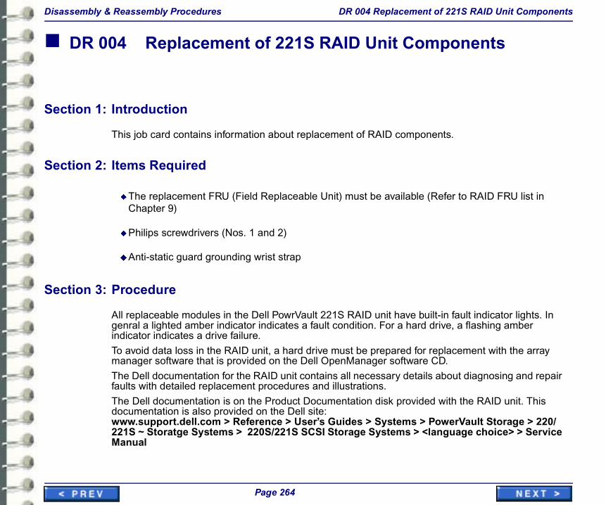
Disassembly & Reassembly Procedures DR 004 Replacement of 221S RAID Unit Components
� DR 004 Replacement of 221S RAID Unit Components
Section 1: Introduction
This job card contains information about replacement of RAID components.
Section 2: Items Required
uThe replacement FRU (Field Replaceable Unit) must be available (Refer to RAID FRU list in Chapter 9)
dicator lights. In hing amber
t with the array
nosing and repair
AID unit. This
Storage > 220/hoice> > Service
Page 264
uPhilips screwdrivers (Nos. 1 and 2)
uAnti-static guard grounding wrist strap
Section 3: Procedure
All replaceable modules in the Dell PowrVault 221S RAID unit have built-in fault ingenral a lighted amber indicator indicates a fault condition. For a hard drive, a flasindicator indicates a drive failure.
To avoid data loss in the RAID unit, a hard drive must be prepared for replacemenmanager software that is provided on the Dell OpenManager software CD.
The Dell documentation for the RAID unit contains all necessary details about diagfaults with detailed replacement procedures and illustrations.
The Dell documentation is on the Product Documentation disk provided with the Rdocumentation is also provided on the Dell site:www.support.dell.com > Reference > User’s Guides > Systems > PowerVault221S ~ Storatge Systems > 220S/221S SCSI Storage Systems > <language cManual

9 Renewal Parts
Section 1: INTRODUCTION
This chapter contains the renewal parts lists and procedure for license renewal/replacement.
g. RAM he new
Qty
1
1
Page 265
Section 2: Workstation FRU List
Note: If the Dell 1400 computer needs replacement, transfer all optional components (e.upgrade, Hard drive upgrade, Video & other optiona boards, etc.) from the old to tcomputer before returning the old computer for warranty purposes.
Part No. FRU Rep Description
2329008 1 Dell 1400 PIII 512MB - Unconfigured, no video board, no software
2291997 1 512 MB RAM DIMM 133 Mhz Upgrade
2293291 1 36GB Hard Drive Kit - Dell

Renewal Parts
workstation display(s)
4362604 1 Dome Video Board MD5-PCX 2
2295365 1 Dome Video Board MD4(PCI) 2
4356812 1 Dome Video Board MD2(PCL) 1
2328679 1 Barco Coronis 3MP Controller Board - Dual Head
2334569 1 Matrox Millenium G450 Controller for C/FP Mon. replaces 4362476
2306872 1 Flat Panel Monitor - NEC
2328218 1 Barco 3MP Flat Panel Monitor
4
2
2
2
2
2
5
5
Part No. FRU Rep Description Qty
Page 266
4362588 1 A+ Monitor - Portrait GS 2048X2506
2260812 1 B Monitor - Portrait GS 1200X1600
2260841 1 C Monitor - Landscape 1280X1024
2324060 1 Standard 19” Color Monitor
2333243 1 C Monitor - 21” with grey/black case (Sony P/N CPD-G520P)
Cables
4363107 1 MD5PCX - Video Board to Monitor cable
4363099 1 MD4 - Video Board to Monitor cable
4363115 1 Video Card to C Monitor cable
46-220383P1
2 BNC 75 Ohm cable terminator
4363149 2 110v Monitor/Computer power cord

Renewal Parts
Keyboards & mouse
2300612 1 104 Key, Keyboard (Dell P/N 310-4100) 1
2266207 1 French Keyboard
2266208 1 Spanish Keyboard
2266209 1 German Keyboard
2266210 1 Portugese Keyboard
2266212 1 Swedish Keyboard
2266215 1 European Power Cable
1
1
1
Part No. FRU Rep Description Qty
Page 267
2266211 1 Italian Keyboard
2266216 1 Italian Power Cable
2303424 1 Mechanical Serial wheel mouse (Dell P/N 310-3777)
Hi-Res service kit
2252691 N 3M Disposable ESD Wristband
4363073 2 VGA Monitor for Service Kit
Modem
2245794 1 Modem
Single Media Archive - Plextor
2266773 1 Adaptec 2930U SCSI Card
2274121 N 50 Pin SCSI 2 Interface Cable
2334029 1 SMA External Drive
HI*DEF Frame Grabber

Renewal Parts
2270474 1 Foresight Imaging HI*DEF Accura board 016030-200 1
2270476 1 Foresight Imaging 030063 8-channel video cable 1
iColor Frame Grabber
2308031 1 Frame Grabber Board - Single frame, color
2324574 1 Frame Grabber Board - Streaming, color (TIMS)
2335175 1 S-Video Y/C Adapter for FRMGRB
2335180 1 25DB to 6BNC Jack 7ft Cable-GRMGRB
Work Group Server
Part No. FRU Rep Description Qty
Page 268
Table 9-1: Workstation FRU Lis
2307368 1 PERC RAID Controller Bd
2184777-12 1 Standard 17” Monitor for WGS
2307370 1 1-meter SCSI Cable
2307365 1 36 gb Disk Drive
2342020 1 RAID Power Supply Module 460 kW
2342021 1 Cluster Card (SCSI Management Card)

Renewal Parts
t Process
oftware.
prise Archive and ss. Each dongle
included in the dongle can be r part number
Page 269
Illustration 9-1: Workstation
Section 3: Centricity RA600 Workstation License Renewal/Replacemen
This section outlines how to obtain a replacement dongle for RA600(RadWorks) s
3-1 Overview - Global
Centricity RA600, RadWorks, WebViewer, Centricity Web, Centricity DA210, EnterRadStore software utilize a dongle or a license file to control software feature acceor file is coded with the customer’s purchased modules and software version and software shipment. If the customer damages or loses this dongle, a replacement attained through GE Cares. The dongle is set up as a FRU 1 and is in stock unde2253361.

Renewal Parts
Dongles are coded specifically to a serial number based on the modules and options purchased. A replacement dongle needs to be coded so it gives the customer the same capabilities as their original dongle.
License files are used on some systems instead of a dongle. License files are coded to the MAC address of the primary network adapter in the computer and as such, can not be moved from machine to machine.To obtain a new code for a replacement dongle or a new license file, the FE should contact the ROC for their pole. In the case where the ROC cannot process the request the FE should contact the assigned service engineer for the product in their pole (see Paragraph 3-5).The FE must provide the customer name plus the following: either the MAC address for the primary NIC in the subject computer or the serial number of the replacement dongle and the serial number of the dongle that is being replaced, their email address and the FDO number for the system. Additional feature requests MUST be accompanied with an FDO number.The support engineer will then generate the appropriate code and email it to the FE.
ng normal
dos prompt:
8 3E 37 3F 3C 33
orkstation.
) to test the file or
Page 270
Note: The FE should expect up to a 1 day turn-around time for this code generation duribusiness hours in their pole, Monday-Friday.
3-2 Installation - Global
The FE attaches replacement dongle to PC and enters the following command at
<program installation path>\bin>upgrade "6B 55 22 56 4F 27 43 44 2B 40 40 03C 3C 37 38 3E BC"
Note: FE must use the provided upgrade code. The code above is an example
License files are installed by copying the file to the Applicare "BIN" folder on the w
In either case, the FE should then run the license configurator (bin\RUNLCFG.exedongle.
See the applicable product installation manual for instructions.

Renewal Parts
3-3 Global Procedure for the FE to request the ROC to provide a license file or a dongle code.
All requests must be handled by the ROC in the requesting pole.
3-3-1 Job to be performed by the FE during a new installation or an upgrade
uAt installation time, the FE records the either dongle serial number or the MAC address in the Service Manual,
uAt installation time, or for every new option or upgrade, the FE records the FDO number in the Service Manual
uThe FE attaches the shipping label in the service Manual
3-3-2 License file failed, or a temporary license file has been shipped (Turnkey system)
vious FDO
ile
contact identified
vious FDO
ode
Page 271
uThe FE provides the current FDO number to the ROC, and if applicable all prenumbers
uThe FE provides the MAC address to the ROC
uWithin 1 hour, the ROC sends a e-mail to the FE with the appropriate license f
u If the FE cannot contact anybody from the ROC, the FE sends an e-mail to thefor their pole (see below), with FDO information and MAC address
3-3-3 The dongle does not work (Software-Only system)
uThe FE provides the current FDO number to the ROC, and if applicable all prenumbers
uThe FE provides the dongle serial number to the ROC
uWithin 1 hour, the ROC sends a e-mail to the FE with the appropriate dongle c

Renewal Parts
u If the FE cannot contact anybody from the ROC, the FE sends an e-mail to the contact identified for their pole (see below), with FDO information and MAC address
u If the Dongle fails to work after a new code is supplied the FE must order a new Dongle (2253361) and then request a code for that dongle.
3-4 Europe-Only Dongle Replacement Procedures
3-4-1 WHERE DONGLES ARE USED / SHIPPED
uOn Radworks 5.1 Turnkey & Software Only systems
uOn RA 600 Software Only systems
5.1 or RA 600)
address and
pload it on the
Page 272
uWhen an new software module is sold for a Software Only system (Radworks
3-4-2 CASE IN WHICH A DONGLE CAN BE REPLACED BY A LICENSE FILE
uRadworks 5.1 Turnkey systems, damaged or lost dongle
3-4-3 CASE IN WHICH A DONGLE CANNOT BE REPLACED BY A LICENSE FILE
uRadworks 5.1 and Centricity RA 600, Software Only
3-4-4 PROCESS TO REPLACE A DONGLE BY A LICENSE FILE
Radworks 5.1 Turnkey, damaged dongle
1. GE FE contact the ROC with customer details (Name, Address, FDO), MACregistration information ( type of software and modules list)
2. ROC generates a temporary license file (1 month) and send it to the FE, or usystem (ROC decision)
3. GE FE sends the damaged dongle to the ROC

Renewal Parts
4. On reception of damaged dongle, ROC e-mail the permanent license file to FE or upload it on the system (ROC decision)
5. The update of the manufacturing database is done via an automatically generated and distributed e-mail
6. On a quarterly basis, ROC send damaged dongles to manufacturing at Mt Prospect
Radworks 5.1 Turnkey, lost / stolen dongle
1. GE FE contacts the ROC with customer details Name, Address, FDO), MAC address and registration information (type of software and modules list)
2. ROC generates a temporary license file (1 month) and sends it to the FE, or uploads it on the system (ROC decision)
e dongle and 2
nent license file to
rated and
Page 273
3. FE asks for a Service Quotation to from his ASM (equivalent to the cost of thvisits on site)
4. After approval by the customer of the service quote, ROC e-mails the permaFE or uploads it on the system (ROC decision)
5. The update of the manufacturing database is done via an automatically genedistributed e-mail
3-5 Current Service Engineering Contacts
3-5-1 Current Americas Contact
Saeed Alam
3-5-2 Current Europe Contacts
Jorge Aguirre orMaurice Robert

10 Suggested Maintenance
Section 1: Introductions
This chapter presents job cards related to suggested maintenance procedures for the Centricity RA600 Workstation.
aintenance.
Page 275
The Centricity RA600 Workstation does not require extensive routine hardware mReasonable care of its components will help ensure continuous operation.
Section 2: \Summary of Job Cards
Job Card No. Maintenance Job Card Title
MNT 001 Scheduled Maintenance

Suggested Maintenance MNT 001 Scheduled Maintenance
� MNT 001 Scheduled Maintenance
Section 1: INTRODUCTION
This job card contains the list of annual maintenance tasks to perform on the Centricity RA600 Workstation.
s, including the
cleaning kit to be
tems Vacuum
Caution!Pay special note to the electrostatic discharge precautions when working inside the Computer chassis. Use a static-discharge, wrist strap when necessary.
Page 276
uDo not use any type of abrasive pad, scouring powder, or solvents.
Section 2: Quarterly Tasks
uPerform the appropriate monitor calibration.
Section 3: Procedure
1. Verify the integrity of the external cable connections to the peripheral devicenetwork connections.
2. Clean the monitor and the keyboard. Use an appropriate Computer Systemssure not to scratch the monitor (part no. 46-194427P221).
3. Open the computer case.
4. Clean the inside of the computer housing. Use an appropriate Computer SysCleaner, such as 46-194427P392.

Suggested Maintenance MNT 001 Scheduled Maintenance
5. Carefully vacuum out the system, attending to heavy accumulation spots such as the processor area.
6. Before replacing the computer cover visually verify that the cooling fans are working properly.
Note: The use of compressed air is not recommended. Blowing dust out with a stream of air is not recommended because of the ESD (Electro-Static Discharge) hazards to components, and the dust hazard to the personnel in the area near the cleaning activity.
7. Proceed to the floppy disk drive head cleaning by means of a 3.5" cleaning diskette. (Local purchase, at computer supply store.) Can be done more often if the floppy disk drive is used regularly by customer.
8. Save the site parameters on a new configuration diskette. On a 6-month scheduled tte renewed twice data.
Page 277
maintenance, this allows you to have your back-up configuration floppy diskea year. The floppy is automatically formatted before saving the configuration

�GE Medical Systems – Information Technologies
GE Medical Systems – Information Technologies: Telex 37873718200 W. Tower Ave., Milwaukee, Wisconsin, 53201 U.S.A.
(Asia, Pacific, Latin America, North America)
GE Medical Systems – Information Technologies GmbHMunzinger Strasse 3, D-79111, Frieburg, Germany