CEMA 6v2 07 MASTER
228
2 nd Printing
-
Upload
khangminh22 -
Category
Documents
-
view
2 -
download
0
Transcript of CEMA 6v2 07 MASTER

2nd Printing

BELT CONVEYORSfor BULK MATERIALSSIXTH EDITION 2nd Printing
Printed by the Engineering Conference of theConveyor Equipment Manufacturers Association
Published by the Conveyor Equipment Manufacturers Association6724 Lone Oak Boulevard, Naples, Florida, USA 34109 239-514-3441 www.cemanet.org
焦作市钰欣机械有限公司 专业的带式输送机制造商
—————————————————————————————————————————————————— 地址:焦作市黄河大道(西段)118号 电话:0391-7755988 传真:0391-7755088 邮箱;[email protected]

Copyright © 2007 by the Conveyor Equipment Manufacturers AssociationAll rights reserved. This book may not be reproduced in any form without writtenpermission from the Conveyor Equipment Manufacturers Association.
Printed in the United States of America
Page layout and editing by K-Kom, Inc.
Printing (last digit): 9 8 7 6 5 4 3 2 1
Library of Congress Cataloging in Publication Data
Conveyor Equipment Manufacturers Association.Engineering ConferenceBelt conveyors for bulk materials.
Includes index.
1. Belt conveyors. 2. Bulk solids handling.
ISBN 1-89117-59-3
焦作市钰欣机械有限公司 专业的带式输送机制造商
—————————————————————————————————————————————————— 地址:焦作市黄河大道(西段)118号 电话:0391-7755988 传真:0391-7755088 邮箱;[email protected]

Chapter Index Title Page
PREFACE ......................................................................................................................IXACKNOWLEDGEMENTS ..................................................................................................XINTRODUCTION ............................................................................................................XI
ONE - BELT CONVEYOR GENERAL APPLICATIONS AND ECONOMICS ..............................1Introduction ........................................................................................2Conveying of a Variety of Materials ....................................................2Wide Range of Capacities ..................................................................2Adaptability to Path of Travel ..............................................................4Steep Angle Conveying ......................................................................5Loading, Discharging, and Stockpiling Capabilities ............................8Process Functions ..............................................................................9Reliability and Availability ................................................................10Environmental Advantages ................................................................11Safety ................................................................................................12Low Labor Costs ................................................................................12Low Power Costs ..............................................................................12Low Maintenance Costs ....................................................................12Long-Distance Transportation ..........................................................13Conveyor Economics ........................................................................13Feasibility Studies ............................................................................14Reduce After Purchase Costs ............................................................15Summary ..........................................................................................15
TWO - DESIGN CONSIDERATIONS ................................................................................17Introduction ......................................................................................19Conveyor Arrangements ..................................................................20Basic Flat and Troughed Belt Conveyor Paths ..................................20Belt Conveyor Loading and Discharge Arrangements ......................23Conveyor Structures ........................................................................24Types of Structures ..........................................................................25Connections ......................................................................................28Codes and Standards ........................................................................29Design ..............................................................................................30Loads ................................................................................................33Corrosion Protection ........................................................................36Maintenance ....................................................................................38Cross-Overs and Cross-Unders ........................................................42Considering the Long Term Effects of Design Decisions ....................43
THREE - CHARACTERISTICS AND CONVEYABILITY OF BULK MATERIALS ......................45Introduction ......................................................................................46Material Characteristics ....................................................................46Material Class Description ................................................................47Behavior of Materials on a Moving Belt ............................................49Effect of Inclines and Declines ..........................................................50
TABLE OF CONTENTS
V
T A B L E O F C O N T E N T S焦作市钰欣机械有限公司 专业的带式输送机制造商
—————————————————————————————————————————————————— 地址:焦作市黄河大道(西段)118号 电话:0391-7755988 传真:0391-7755088 邮箱;[email protected]

T A B L E O F C O N T E N T S
VI
Chapter Index Title Page
FOUR - CAPACITIES, BELT WIDTHS AND SPEEDS ..........................................................53Introduction ......................................................................................54Belt Widths ......................................................................................54Lump Size Considerations ................................................................54Belt Speeds ......................................................................................55Belt Conveyor Capacities ..................................................................57Belt Conveyor Capacity Tables and Their Use ..................................58Belt Load Cross Section Areas ..........................................................60
FIVE - BELT CONVEYOR IDLERS ....................................................................................65Introduction ......................................................................................66Idler Requirements ............................................................................66Idler Classifications ..........................................................................66General Types of Belt Conveyor Idlers ..............................................66Idler Spacing ....................................................................................73The Selection of Idlers ......................................................................74Idler Selection Procedure ................................................................75Preface to Selection Procedure, Figures and Tables ..........................78Example Idler Selection ....................................................................84Belt Alignment ..................................................................................89
SIX - BELT TENSION AND POWER ENGINEERING ..........................................................91Scope ................................................................................................95Introduction ......................................................................................95Definition of the Three Conveyor Cases ..........................................100 Belt Tension Calculations for Basic Conveyors: Basic Method ........102Belt Tension Calculations for Standard Conveyors: CEMA Historical Method ............................................................................103 Belt Tension Calculations for All Conveyors: Universal Method........104Tension Management ......................................................................129Component Tension Characteristics ................................................140Conveyor as a System ......................................................................155System Interactions ........................................................................157Transient Behaviors ........................................................................164Design Tools ....................................................................................166Example Conveyor Analysis..............................................................168
SEVEN - BELT SELECTION ............................................................................................185Introduction ....................................................................................187Determining Belt Specifications ......................................................187Factors in the Composition of Conveyor Belting ..............................187Conveyor Belt Cover Characteristics, Composition and Design ........188Loading Considerations....................................................................192The Belt Carcass ..............................................................................194Belt Splices ......................................................................................198Belt and System Considerations ......................................................201Belt Selection ..................................................................................206Belt Selection Tables ......................................................................208
EIGHT - PULLEYS AND SHAFTS ....................................................................................211Introduction ....................................................................................212Conveyor Pulleys..............................................................................212Pulley Lagging..................................................................................221Shafting ..........................................................................................223Terminology ....................................................................................228Special Pulleys ................................................................................229
焦作市钰欣机械有限公司 专业的带式输送机制造商
—————————————————————————————————————————————————— 地址:焦作市黄河大道(西段)118号 电话:0391-7755988 传真:0391-7755088 邮箱;[email protected]

T A B L E O F C O N T E N T S
VII
Chapter Index Title Page
NINE - CURVES ..........................................................................................................233Introduction ....................................................................................234Vertical Curves ................................................................................234Horizontal Curves ............................................................................243
TEN - STEEP ANGLE CONVEYING ................................................................................251Introduction ....................................................................................252Incline Limitations with Conventional Conveyors ............................252Molded Cleat Belts ..........................................................................253Pocket Belts ....................................................................................260Totally Enclosed Belts......................................................................267Pipe/Tube Conveyors ......................................................................272 Fold Belts ........................................................................................281Suspended Belts..............................................................................187Sandwich Belt Conveyors ................................................................293
ELEVEN - BELT CLEANERS AND ACCESSORIES............................................................307Introduction ....................................................................................308Conveyor Belt Cleaning Equipment ................................................308Access Doors ..................................................................................321Stops ..............................................................................................322Impact Beds ....................................................................................325Slider Beds ....................................................................................326Combination Impact, Slider and Roller Beds ..................................327Belt Training Devices ......................................................................328Belt Turnovers ................................................................................329Pulley Cleaners ..............................................................................330 Wing-type Pulleys ..........................................................................331Deck Plates ....................................................................................332Drip Pans ........................................................................................332Weather Protection ........................................................................333Magnetic Separators ......................................................................334Metal Detectors ..............................................................................336Conveyor Belt Scales ......................................................................336Sampling Devices ..........................................................................337Rip Detection Systems ....................................................................339Electrical Conveyor Accessories ......................................................339Accessory Horsepower Requirements ............................................342The Importance of Maintenance ....................................................342
TWELVE - TRANSFER POINTS ......................................................................................343Introduction ....................................................................................345System Design ................................................................................347Addressing Impact ..........................................................................350Control of Fugitive Material ............................................................353Skirtboards ....................................................................................371Wear Liners ....................................................................................375Other Discharge Chutes (into stockpiles, ships etc) ......................378Feeders ..........................................................................................381Trippers ..........................................................................................392Discharge Plows ............................................................................394Discharge Trajectories ....................................................................395
焦作市钰欣机械有限公司 专业的带式输送机制造商
—————————————————————————————————————————————————— 地址:焦作市黄河大道(西段)118号 电话:0391-7755988 传真:0391-7755088 邮箱;[email protected]

T A B L E O F C O N T E N T S
VIII
Chapter Index Title Page
THIRTEEN - CONVEYOR MOTOR DRIVES AND CONTROLS............................................419Introduction ....................................................................................422Conveyor Drive Evaluation Criteria ..................................................422Belt Drive Attributes ......................................................................427Conveyor Drive Systems Overview ................................................429Other Conveyor Drives ....................................................................446Speed Reducers ............................................................................446Belt Conveyor Drive Arrangement ..................................................449Backstops ......................................................................................452Brakes ............................................................................................455Brakes and Backstops in Combination ..........................................456Devices for Acceleration, Deceleration, and Torque Control ..........457Brake Heat Absorption Capacity ....................................................460Conveyor Belt Controls ....................................................................461Belt Protection Controls ..................................................................462Belt Control Apparatus ..................................................................465Conclusion ......................................................................................466
FOURTEEN - OPERATION, MAINTENANCE AND SAFETY ..............................................467Introduction ....................................................................................468Operation ......................................................................................468Maintenance ..................................................................................469Lubrication ......................................................................................470Safety ............................................................................................472Guidelines for Safe Operation and Maintenance ............................473Trouble Shooting Conveyor Problems ............................................475
FIFTEEN - BELT TAKEUPS ............................................................................................479Introduction ....................................................................................480Belt Takeups ..................................................................................480Belt Stretch or Elongation ..............................................................480Takeup Movement ..........................................................................480Manual Takeups ..............................................................................481Automatic Takeups ........................................................................483
SIXTEEN - EMERGING TECHNOLOGIES ........................................................................491Introduction ....................................................................................492Advanced Conveyor Design Methods ..............................................492Component Properties ....................................................................496Belt Construction ............................................................................497Transient System Analysis ..............................................................498Numerical Simulation of Transfer Chutes using Discrete Element Analysis ............................................................................505Air Supported Conveyors ................................................................507Example of Dynamic Analysis ..........................................................513
LIST OF EQUATIONS, FIGURES AND TABLES ..............................................................517
APPENDIX A SI Units ..........................................................................................531APPENDIX B Nomenclature ................................................................................535 APPENDIX C Kx and Ky ........................................................................................548APPENDIX D Conveyor Installation Standards For Belt Conveyors
Handling Bulk Materials ................................................................557APPENDIX E Belt Conveyor Idler Roll Ai' Test Procedure ..................................570APPENDIX F Belt Conveyor Idler Roll Kis' Test Procedure ..................................576
INDEX ........................................................................................................583
焦作市钰欣机械有限公司 专业的带式输送机制造商
—————————————————————————————————————————————————— 地址:焦作市黄河大道(西段)118号 电话:0391-7755988 传真:0391-7755088 邮箱;[email protected]

IX
P R E F A C E
PREFACEThe goal of this book is to be the definitive resource to experienced conveyor engineers on the design,installation, operation, and maintenance of belt conveyors for bulk materials. An experiencedconveyor engineer, by following the methods in this book, can be greatly assisted in the design a bulkmaterial conveyor that will be efficient and reliable at a level of quality that reflects a systemsapproach to design and operation and meets the user’s expectations.
Experienced conveyor engineers can use the information and engineering principals put forth todesign virtually any width, length, configuration and capacity of bulk materials handling belt conveyorand predict its performance within an acceptable range. Interested parties can also gain a basicunderstanding of the engineering, selection of components, related equipment and accessories andapplications for belt conveyors.
The information presented in this book is intended to cover the basic principles of belt conveyor designand to include such formulas, tables, charts and recommendations as are required to design most beltconveyors. The material is arranged in the order most convenient for the use of an experiencedconveyor engineer. As always, the responsibility for the ultimate safety, reliability, and functionality ofany conveyor system rests with those who design and build it.
While the formulas, recommendations and data are based on industry practice and are believed tobe reliable, CEMA does not, and can not, assume any role in, or responsibility for, the safety,reliability or functionality of any conveyor system or component which it did not design. Theformulas and principles in this book are guidelines only and are applicable to the design of a highpercentage of conveyors that are required to operate under reasonably normal conditions. However,conveyor design is as much art as it is science and some conveyors will operate under conditionsthat are beyond the scope of this book. These design challenges require broad experience for asatisfactory solution. A qualified designer or engineer from a CEMA member company should beconsulted in such cases, as well as in the design of conveyors critical to a process, very wide or fastconveyors and complex conveyor systems.
焦作市钰欣机械有限公司 专业的带式输送机制造商
—————————————————————————————————————————————————— 地址:焦作市黄河大道(西段)118号 电话:0391-7755988 传真:0391-7755088 邮箱;[email protected]

A C K N O W L E D G E M E N T S
X
ACKNOWLEDGEMENTSThe Conveyor Equipment Manufacturers Association is indebted to the members of The EngineeringConference, The General Bulk Material Handling Section, The Unit Handling Conveying Section, andthe many other individuals who contributed their time, effort and resources to the planning andcompilation of this book; to the member companies who made available the time and talent of theirengineers, draftspersons and marketing specialists; to the non-member companies, technicalassociations and professional societies for their assistance in making this book a reality.
CEMA and all of its members would like to express our appreciation to R. Todd Swinderman for hiswork in organizing, writing and producing this 6th Edition of the Belt Book. We are most grateful forhis extraordinary effort and dedication without which this book would never have been completed.
焦作市钰欣机械有限公司 专业的带式输送机制造商
—————————————————————————————————————————————————— 地址:焦作市黄河大道(西段)118号 电话:0391-7755988 传真:0391-7755088 邮箱;[email protected]

I N T R O D U C T I O N
INTRODUCTION
XI
The development of belt conveyors, capable of transporting virtually any bulk material at thousandsof tons per hour in a continuous and uniform stream, has been one of the most important innovationsfor modern industry. Its history dates back to 1830 when sawmills applied flat belts sliding in steeltroughs to move sawmill refuse and other materials away from milling operations. In the 1850’s, thegrain industry evolved the first conveyors designed to reduce the friction of rubber sliding in a steeltrough by replacing the trough with a series of pulleys, with end discs separated by bent bars, to forma cup for troughing a leather belt. These leather troughed belt conveyors were successfully applied inmany grain elevators during the 1860’s through 1880 as refinements in the bent bar pulley design ledto spooled wooden drums with shafts supported in bearings.
It wasn’t until 1891 that rubber belt conveyors were applied to handling heavy bulk materialspreviously considered transportable only by mobile equipment and gravity. Prior to this, oreprocessing plants were always built into the side of a hill, eliminating the need for horizontal transportby belt conveyor. In 1891, Thomas Edison experimented with flat belt conveyors similar to those usedin the grain handling industry to move heavy, abrasive ore at his iron mine and processing complex inOgdensburg, New Jersey. The belts were simply a cotton duck material. It soon became apparent thatthe cotton belts and wooden idlers were no match for the heavy and abrasive ore. Replacement of thebelt and idlers became necessary on a one to two month cycle.
In that same year, Thomas Robins Sr. approached Mr. Edison and convinced him to try a cotton duckbelt with a 1/8" rubber cover. Edison agreed and the new belt proved to be the wear solution. Aworking relationship began between the two inventors and Robins persuaded Edison to try a troughedbelt configuration using spool shaped idlers to form the trough. This proved to be a failure because theupper edge of the spool moved at a higher speed than the base of the trough, causing damage to theunderside of the belt from frictional resistance. The solution recommended by Robins was to break thespool into three independent cylindrical pulleys, each supported by a bearing at the ends of its shaft.These two innovations, the rubber belt covers and three roll idler, became the foundation for modernbelt conveyor design and the origin of the Hewitt-Robins Company, a founding member of CEMA, in1933.
In the ensuing years, the demand for higher capacities, longer runs, steeper conveying angles, andenergy efficiency has led to new innovations and technologies. Belt conveyors with capacities reaching20,000 tons per hour, lengths exceeding 30 miles, horizontal curves, and inclinations to vertical arecovered in this Sixth Edition. In addition, the costs per ton-mile to transport various materials areillustrated, based on proven experience at different operating sites. The technical informationcontained in this book is generally conservative in nature. Variations in specific applicationrequirements or extreme service requirements should always be addressed by member companyengineering personnel whose depth of experience exceeds that covered in this text.
In the first edition of this book, the Conveyor Equipment Manufacturers Association (CEMA) stated itsobjectives to make available the experience and technical knowledge of its members as a contributiontoward the design and construction of conveyors of superior performance, and also to provide basicdata and fundamentals of design for application to ordinary belt conveyor problems in order to achievesuccessful performance. Adhering to these same objectives, CEMA is pleased to offer this Sixth Editionof Belt Conveyors for Bulk Materials.
焦作市钰欣机械有限公司 专业的带式输送机制造商
—————————————————————————————————————————————————— 地址:焦作市黄河大道(西段)118号 电话:0391-7755988 传真:0391-7755088 邮箱;[email protected]

BE
LT
CO
NV
EY
OR
G
EN
ER
AL
AP
PL
IC
AT
IO
NS
AN
D E
CO
NO
MI
CS
Introduction
Conveying of a Variety of Materials
Wide Range of Capacities
Adaptability to Path of Travel
Steep Angle Conveying
Loading, Discharging, and Stockpiling Capabilities
Process Functions
Reliability and Availability
Environmental Advantages
Safety
Low Labor Costs
Low Power Costs
Low Maintenance Costs
Long-Distance Transportation
Conveyor Economics
Feasibility Studies
Reduce After Purchase Costs
Summary
BELT CONVEYORGENERAL APPLICATIONSAND ECONOMICS
1
C H A P T E R O N E焦作市钰欣机械有限公司 专业的带式输送机制造商
—————————————————————————————————————————————————— 地址:焦作市黄河大道(西段)118号 电话:0391-7755988 传真:0391-7755088 邮箱;[email protected]

BE
LT
CO
NV
EY
OR
GE
NE
RA
LA
PP
LI
CA
TI
ON
S A
ND
EC
ON
OM
IC
S
Introduction
The subject of belt conveyors is of primary interest to engineers, managers, and others who areresponsible for selecting equipment for handling bulk materials. This book is primarily a handbook, butChapter 1 is included to acquaint the reader with the many uses of belt conveyors and their advantagesunder widely varying conditions of operation.
Belt conveyors have attained a dominant position in transporting bulk materials due to such inherentadvantages as their economy and safety of operation, reliability, versatility, and practically unlimitedrange of capacities. In addition, they are suitable for performing numerous processing functions inconnection with their normal purpose of providing a continuous flow of material between operations.Recently, their conformity to environmental requirements has provided a further incentive for selectionof belt conveyors over other means of transportation.
Low labor and low energy requirements are fundamental with belt conveyors as compared with othermeans of transportation. Dramatic increases in operating costs continue to make conveyors anextremely favorable choice for applications that were not considered previously.
Belt conveyor manufacturers have consistently anticipated the needs of industry with improvements indesigns and with components that have exceeded all known requirements. Reliability and safety areoutstanding now that stronger and more durable belts are available, as well as greatly improvedcomponents and highly sophisticated electrical controls and safety devices.
Illustrated and described in this chapter are some of the advantages of belt conveyors, which areperforming a wide variety of intra-plant functions better and/or in a more innovative manner than ispossible with other means of transporting bulk materials. Also included are examples of relatively long-distance belt conveyor systems which are being used extensively because they combine such importantbenefits as reliability, safety, and low cost per ton of material transportation.
Conveying of a Variety of Materials
The size of materials that can be conveyed is limited by the width of the belt. Materials can range fromvery fine, dusty chemicals to large, lump ore, stone, coal, or pulpwood logs. Closely sized or friablematerials are carried with minimum degradation. Because rubber belts are highly resistant to corrosionand abrasion, maintenance costs are comparatively low when handling highly corrosive materials orthose that are extremely abrasive, such as alumina and sinter.
Materials that might cause sticking or packing if transported by other means are often handledsuccessfully on belt conveyors. Even such hot materials as foundry shakeout sand, coke, sinter, andiron ore pellets are conveyed successfully on heat resistant belts.
Wide Range of Capacities
Current available belt conveyors are capable of handling hourly capacities in excess of any practicalrequirement. Yet, they are also used economically in plants for transporting materials between processunits at a wide range of rates — sometimes as little as a mere dribble.
2
C H A P T E R O N E焦作市钰欣机械有限公司 专业的带式输送机制造商
—————————————————————————————————————————————————— 地址:焦作市黄河大道(西段)118号 电话:0391-7755988 传真:0391-7755088 邮箱;[email protected]

Wide Range of Capacities Cont.
Belt conveyors operate continuously — around the clock and around the calendar when required —without loss of time for loading and unloading or empty return trips. Scheduling and dispatching areunnecessary as the material is loaded to and unloaded from the belt conveyor automatically. Operatinglabor costs differ little, regardless of capacity ratings. Overall costs per ton decrease dramatically,however, as annual tonnage handled increases. Such economic considerations are illustrated later inthis chapter. For these reasons, belt conveyors are capable of handling tonnages of bulk materials thatwould be more costly and often impractical to transport by any other means.
BE
LT
CO
NV
EY
OR
G
EN
ER
AL
AP
PL
IC
AT
IO
NS
AN
D E
CO
NO
MI
CS
C H A P T E R O N E
3
Figure 1.1 Sulphur storage
Figure 1.2 Aggregate
焦作市钰欣机械有限公司 专业的带式输送机制造商
—————————————————————————————————————————————————— 地址:焦作市黄河大道(西段)118号 电话:0391-7755988 传真:0391-7755088 邮箱;[email protected]

焦作市钰欣机械有限公司 专业的带式输送机制造商
—————————————————————————————————————————————————— 地址:焦作市黄河大道(西段)118号 电话:0391-7755988 传真:0391-7755088 邮箱;[email protected]

BE
LT
CO
NV
EY
OR
GE
NE
RA
LA
PP
LI
CA
TI
ON
S A
ND
EC
ON
OM
IC
S
Adaptability to Path of Travel
Belt conveyor systems provide the means of transporting materials via the shortest distance betweenthe required loading and unloading points. They can follow existing terrain on grades of 30 to 35percent, compared to the 6 to 8 percent effective limits for truck haulage. They can also convey materialdownhill while generating electricity that can be utilized to drive other equipment in the plant. They canbe provided with structures which prevent the escape of dust to the surrounding atmosphere and areweather protected. Such structures are economical and are adaptable to special requirements. Beltconveyors provide a continuous flow of material while avoiding the confusion, delays, and safetyhazards of rail and motor traffic in plants and other congested areas. Many designs are available forsteep angle conveying up to 90 degrees.
Paths of travel can be quite flexible and the length of the routes can be extended repeatedly, asrequired. In some open-pit mining operations, conveyors thousands of feet long are shifted laterally onthe bench to follow the progress of excavation at the face.
Technology has advanced substantially in the design and application of horizontally curved beltconveyors. As a conveyor’s total length increases, so does the probability that transfer stations will berequired to avoid some obstacle in its straight line path. Horizontal curves eliminate the constraints ofthe straight line conveyor and reduce the installed and operating cost of the conveyor.
Horizontally curved conveyors use conventionally troughed conveyor belts and standard components.The loaded and empty belt passes through the carry and return runs of the horizontal curve inunconstrained equilibrium by super-elevating the idlers. Horizontal curves may also be combined withconvex and/or concave vertical curves to fit the conveyor to the most economical profile alignment.
Curved conveyors further enhance the reliability, availability and environmental advantages of the standardbelt conveyor by eliminating the infrastructure and dust control requirements at transfer stations.
4
C H A P T E R O N E
Figure 1.3 A fold belt carries oreout of a pit overdifficult terrain
Figure 1.4 Down hill conveying
焦作市钰欣机械有限公司 专业的带式输送机制造商
—————————————————————————————————————————————————— 地址:焦作市黄河大道(西段)118号 电话:0391-7755988 传真:0391-7755088 邮箱;[email protected]

BE
LT
CO
NV
EY
OR
G
EN
ER
AL
AP
PL
IC
AT
IO
NS
AN
D E
CO
NO
MI
CS
C H A P T E R O N E
5
Adaptability to Path of Travel Cont.
Steep Angle Conveying
Characteristics of bulk materials such as density, effective angle of internal friction, lump size andshape, are all factors which dictate the maximum incline angle which material can be conveyed by astandard belt conveyor without having it roll or slip backwards on the belt.
CEMA Standard 550 lists maximum incline limits that conventional trough conveyors can safely conveyvarious bulk materials. These maximum angles generally range from 10-30 degrees depending on thebulk material. Recent developments in steep angle conveying increase this incline angle therebyenhancing the flexible path that standard belt conveyors can now negotiate.
Simply making the belt cover irregular will increase its ability to carry materials up slightly greaterinclines with most belt manufacturers capable of molding patterns up to 1 inch high into the top cover.Molded patterns for some materials only increase the maximum incline recommendations by fivedegrees over a smooth belt cover. Larger cleats can either be hot or cold bonded or mechanicallyfastened onto the belts’ top cover after manufacture. These large cleats allow the conveying angle toincrease to approximately 45 degrees. The conveying capacity drops off rapidly as the angle increases.Cleats are available in various sizes, shapes, and configurations with most allowing the belt to run ineither a troughed or flat position. Cleated belts are usually restricted to short conveyors where few orno return idlers are needed and either the material does not stick to the surface or where the carrybackis acceptable.
Figure 1.5 Cable belt conveyorwith horizontalcurves along side anaccess road
焦作市钰欣机械有限公司 专业的带式输送机制造商
—————————————————————————————————————————————————— 地址:焦作市黄河大道(西段)118号 电话:0391-7755988 传真:0391-7755088 邮箱;[email protected]

焦作市钰欣机械有限公司 专业的带式输送机制造商
—————————————————————————————————————————————————— 地址:焦作市黄河大道(西段)118号 电话:0391-7755988 传真:0391-7755088 邮箱;[email protected]

BE
LT
CO
NV
EY
OR
GE
NE
RA
LA
PP
LI
CA
TI
ON
S A
ND
EC
ON
OM
IC
S
Steep Angle Conveying Cont.
To improve on the cleat approach, corrugated sidewalls can be added to the transverse cleated belt toform complete rectangular partitions. These sidewalls and a transverse rigid belt carcass allow it to runflat without troughing idlers. The sidewalls also increase the load carrying capacity over the "cleatonly" design and allow conveying up to 90 degree inclines.
One family of conveyors known as "pipe" or "tube" conveyors, "fold" belts, and "suspended" beltstotally encloses the material with the belt increasing the allowable angle of incline. In each case, theinternal area of the enclosed belt is fixed, and therefore is capable of transporting material up steeperinclines only if the internal area is completely loaded with material. At a steep angle these conveyorsare unable to completely unload the trailing end of a load when no additional material is coming alongto "push" the load up.
6
C H A P T E R O N E
Figure 1.6 Pocket belt
焦作市钰欣机械有限公司 专业的带式输送机制造商
—————————————————————————————————————————————————— 地址:焦作市黄河大道(西段)118号 电话:0391-7755988 传真:0391-7755088 邮箱;[email protected]

焦作市钰欣机械有限公司 专业的带式输送机制造商
—————————————————————————————————————————————————— 地址:焦作市黄河大道(西段)118号 电话:0391-7755988 传真:0391-7755088 邮箱;[email protected]

BE
LT
CO
NV
EY
OR
G
EN
ER
AL
AP
PL
IC
AT
IO
NS
AN
D E
CO
NO
MI
CS
C H A P T E R O N E
7
Steep Angle Conveying Cont.
Another family uses a sandwich belt principle and totally encloses the material and applies pressure tosecure it. The sandwich belt is a separate belt with drive mounted directly over the carrying belt. Itcompresses the material against the carrying belt allowing a steeper conveying angle to be achieved.This insures that neither sliding nor rollback will occur, even when conveying vertically. Systems areavailable that use only standard conveyor belts and components and therefore have high availabilityand low maintenance. These systems permit high belt speeds resulting in high capacity capabilities.Consult with the respective CEMA member manufacturers of steep angle belt conveyors for moreinformation and specific applications.
Figure 1.7 Tube conveyoradapts to plantlayout
Figure 1.8 Sandwich belt movesmaterial vertically
焦作市钰欣机械有限公司 专业的带式输送机制造商
—————————————————————————————————————————————————— 地址:焦作市黄河大道(西段)118号 电话:0391-7755988 传真:0391-7755088 邮箱;[email protected]

BE
LT
CO
NV
EY
OR
GE
NE
RA
LA
PP
LI
CA
TI
ON
S A
ND
EC
ON
OM
IC
S
Loading, Discharging, and Stockpiling Capacities
Belt conveyors are very flexible in their capabilities for receiving material from one or more locationsand for delivering it to points or areas, as required by plant flow sheets. They can provide the maintransportation artery while being loaded at several points or anywhere along their length by equipmentwhich provides a uniform feed to the belt. They are particularly useful in tunnels beneath stockpiles,from which they can reclaim and, where required, blend materials from various piles. Material cansimply be discharged over the head end of each conveyor or anywhere along its length by means ofplows or traveling trippers.
Belt conveyors, with their stackers and reclaimers, have become the only practical means for large-scale stockpiling and reclaiming of such bulk materials as coal, ore, woodchips, and taconite pellets.Stockpiles over a mile long are common at major bulk material handling facilities.
Self-unloading ships and lake vessels equipped with belt conveyors can be unloaded in all ports,including those which do not have dockside unloading equipment. Unloading capacities of suchsystems are usually greater than those of several grab bucket unloaders, requiring less turnaround timeand lower labor and other operating costs.
8
C H A P T E R O N E
Figure 1.9 Stockpile rake stylereclaimer andspreader conveyor
Figure 1.10 Ship loader withtelescopingdischarge chute
焦作市钰欣机械有限公司 专业的带式输送机制造商
—————————————————————————————————————————————————— 地址:焦作市黄河大道(西段)118号 电话:0391-7755988 传真:0391-7755088 邮箱;[email protected]

焦作市钰欣机械有限公司 专业的带式输送机制造商
—————————————————————————————————————————————————— 地址:焦作市黄河大道(西段)118号 电话:0391-7755988 传真:0391-7755088 邮箱;[email protected]

Loading, Discharging, and Stockpiling Capacities Cont.
New developments in chute designs have reduced the dust and spillage often associated withtransferring of bulk materials from belt to belt onto stockpiles and into bulk shipping conveyances.Telescoping chutes are used when the discharge height varies and curved chutes are frequently usedfor reducing dust and spillage at fixed transfer points.
In contrast with the above-mentioned high capacity unloading systems, certain materials, such asfoundry sand, can be plowed from the belts at specific locations in quantities controlled by therequirements of the application.
Process Functions
BE
LT
CO
NV
EY
OR
G
EN
ER
AL
AP
PL
IC
AT
IO
NS
AN
D E
CO
NO
MI
CS
C H A P T E R O N E
Figure 1.11 Curved loading chuteinstallation
Figure 1.12 Copper ore processingmill buildings containhundreds of specialpurpose process beltconveyors
9
焦作市钰欣机械有限公司 专业的带式输送机制造商
—————————————————————————————————————————————————— 地址:焦作市黄河大道(西段)118号 电话:0391-7755988 传真:0391-7755088 邮箱;[email protected]

焦作市钰欣机械有限公司 专业的带式输送机制造商
—————————————————————————————————————————————————— 地址:焦作市黄河大道(西段)118号 电话:0391-7755988 传真:0391-7755088 邮箱;[email protected]

BE
LT
CO
NV
EY
OR
GE
NE
RA
LA
PP
LI
CA
TI
ON
S A
ND
EC
ON
OM
IC
S
Process Functions Cont.
Although belt conveyors are generally used to transport and distribute materials, they are also usedwith auxiliary equipment for performing numerous functions during various stages of processing. Ahigh degree of blending is accomplished as materials are bedded into and reclaimed from stockpiles.Accurate samples of the material conveyed can be obtained by devices which cut through the stream ofmaterial as it flows from one conveyor to the next. Magnetic objects can be removed from the material.While being transported on the conveyor, materials can also be weighed accurately and continuouslyor they can be sorted, picked, or sprayed. In many cases, such operations are not only performed moreeffectively in connection with belt conveyors but are the only practical means.
Reliability and Availability
The reliability of belt conveyors has been proven over decades and in practically every industry.Individual conveyors can be managed and maintained to have less than 2% unplanned outages due tomechanical or electrical failures. Multiple complex conveyor systems routinely operate at 90%mechanical and electrical availability. Operators can have a dramatic effect on the availability ofconveyor systems so their training is critical to a successful low cost operation. Conveyors can operatecontinuously for long periods of time. They serve vital process units whose very success depends oncontinuous operation, such as handling coal in power plants and transporting raw bulk materials insteel plants, cement plants, paper mills, and to and from ships in ports, where downtime is very costly.Belt conveyors are often controlled by computer and remotely monitored. They can be housed so thatboth they and the material being transported are protected from elements that would otherwiseimpede the movement of trucks and certain other means of transportation.
10
C H A P T E R O N E
Figure 1.13 Mobile excavatorsand conveyors Areoften used In openpit mines
焦作市钰欣机械有限公司 专业的带式输送机制造商
—————————————————————————————————————————————————— 地址:焦作市黄河大道(西段)118号 电话:0391-7755988 传真:0391-7755088 邮箱;[email protected]

Reliability and Availability Cont.
Environmental Advantages
Belt conveyors can be more environmentally acceptable than other means of transporting bulkmaterials. They operate quietly, often in their own enclosures which can be elevated or subterranean toreduce safety and environmental concerns. At transfers, dust can be contained within transfer chutesor collected with suitable equipment, if necessary. Overland belt conveyor systems can be designed toblend into the landscape, resulting in an unscarred, quiet, and pollution-free operation.
Tubular galleries are becoming increasingly popular due to their long span capabilities, environmentalfeatures; aesthetics and the ability to shop assemble components to reduce field erection costs.
Air supported conveyors are used in many applications with sized material where controlling dust andnoise are a priority. Air supported conveyors are easily totally enclosed. They are well suited formultiple loading applications and have fewer components to maintain than conventional conveyors. Inaddition, air supported conveyors offer energy savings on long horizontal runs.
BE
LT
CO
NV
EY
OR
G
EN
ER
AL
AP
PL
IC
AT
IO
NS
AN
D E
CO
NO
MI
CS
C H A P T E R O N E
Figure 1.14 Emergency repair ofbelts can be donerapidly
Figure 1.15 Air supportedconveyor in a foundryapplication
11
焦作市钰欣机械有限公司 专业的带式输送机制造商
—————————————————————————————————————————————————— 地址:焦作市黄河大道(西段)118号 电话:0391-7755988 传真:0391-7755088 邮箱;[email protected]

BE
LT
CO
NV
EY
OR
GE
NE
RA
LA
PP
LI
CA
TI
ON
S A
ND
EC
ON
OM
IC
S
Safety
Belt conveyors operate with an extremely high degree of safety. Few personnel are required foroperation and they are exposed to fewer hazards than with other means of haulage. Electrical safetydevices such as pull cord switches, belt run-off switches, zero speed switches, and plugged chuteswitches are commonly required to be used on conveyors to provide maximum protection to bothpersonnel and equipment.
Low Labor Costs
Belt conveyors have low operating costs and provide a higher return on investment than competitivemethods. All functions of the system can be monitored from a central control panel or automaticallycontrolled by computer, allowing a minimum number of operating personnel to inspect the equipmentand report conditions that may require attention by the maintenance department.
The time required for maintenance personnel is also minimal. Most belts can be repaired or replaced inone shift. Many belts have conveyed well over 100 million tons before wearing out with only periodicplanned down time for maintenance. Eight hours a week is a typical planned maintenance outage forhigh capacity continuous operation conveyors systems. Major overhauls of conveyor systems canusually be done in less time than required for primary process equipment repairs.
Conveyors are particularly well suited to predictive and preventative maintenance programs. Computerprograms are available to assist in planning preventive maintenance based on manufacturers'recommended maintenance cycles. Automated monitoring systems can warn against pending failuresby sensing increases in heat and noise of various mechanical elements in the system allowingmaintenance personnel to make immediate corrections thus avoiding potential down-time. Automatedlubrication systems are easily adapted to conveyors to reduce manual lubrication labor.
Low Power Costs
The increasing cost of energy emphasizes the importance of power and its relation to the cost per tonfor transporting bulk materials. Because belt conveyors are operated by electric power, they are lessaffected by the prices, shortages, and other limitations of liquid fuel. They consume power only whenthey are being used. There is no need for empty return trips or idling in line for the next load. On longsystems the declined portion often assists in propelling an inclined or horizontal portion. Someconveyor systems are completely regenerative. The cost of power for belt conveyor systems has alwayscontributed to their extremely low operating costs and this advantage has increased substantially withthe rise in the cost of petroleum based fuels. Even though they are economical to operate, power is amajor portion of the cost of conveyor operation and careful selection of components can have adramatic effect on energy usage. Such substantial improvements have been made in belts andcomponents since the 5th edition of Belt Conveyors for Bulk Materials that one of the main goals of the6th edition is to provide a more accurate method of calculating power requirements.
Low Maintenance Costs
Maintenance costs for belt conveyors are extremely low compared with most other means oftransporting bulk materials. Extensive support systems, such as those commonly associated with truckhaulage, are not required. The skills needed for maintaining conveyors are universal and basic in natureso mechanics and electricians can do other maintenance tasks when not working on the conveyors.Because of the modular nature and standardization of belting and components, adequate inventoriesof spare parts can be maintained at a low cost and require relatively little storage space.
12
C H A P T E R O N E焦作市钰欣机械有限公司 专业的带式输送机制造商
—————————————————————————————————————————————————— 地址:焦作市黄河大道(西段)118号 电话:0391-7755988 传真:0391-7755088 邮箱;[email protected]

Long-Distance Transportation
The economic benefits of low operating costs for labor and energy, as well as some of the otheradvantages outlined above, have led to a widespread adoption of belt conveyor systems as a means oftransporting bulk materials over increasingly long distances. Not only were these systems the bestinvestments at the time they were installed, but continuing escalation in costs of both labor and liquidfuel have greatly enhanced their present value. Conveyors of 10 miles in length are in operation whileconveyors as long as 35 miles are being considered.
Conveyor Economics
It is difficult to establish a range for the cost per ton of material conveyed. There are a few "rules ofthumb" that give an indication of costs but each conveyor installation must be evaluated individually.A few widely quoted rules of thumb are:
1. An overland conveyor operation is more economical than truck haulage if the conveying distance exceeds .6 miles (1 km).
2. Beyond .6 miles (1 km) distance the ton-mile cost of transport by belt conveyor may be as low as one-tenth the cost by haul truck.
3. Estimated operating maintenance cost per year for a belt conveyor is 2% of the purchase cost of equipment plus 5% of the belt cost.
4. Belt replacement on average is every five years for hard rock applications and up to 15 years for non-abrasive applications.
5. Well maintained conveyor systems can reliably operate at 90% or higher availability.
An assessment of owning and operating costs is essential whenever conveyor systems are consideredin lieu of other means of bulk material transportation. Included is the capital cost of all comparativesystems, fuel or electrical costs, labor costs for maintenance and operations, parts inventoriesrequired, depreciation, and interest, taxes, and insurance.
In order to make a true cost comparison between two or more haulage systems, all costs chargeable toeach system must be considered, including ancillary facilities required for each system. For example,crushing facilities might be required to reduce lump size for handling on the belt conveyor but wouldnot be necessary for truck haulage. Conversely, a very large shop with extensive special equipment
BE
LT
CO
NV
EY
OR
G
EN
ER
AL
AP
PL
IC
AT
IO
NS
AN
D E
CO
NO
MI
CS
C H A P T E R O N E
Figure 1.16 Overland conveyormoves overburden Inan open pit coal mine
13
焦作市钰欣机械有限公司 专业的带式输送机制造商
—————————————————————————————————————————————————— 地址:焦作市黄河大道(西段)118号 电话:0391-7755988 传真:0391-7755088 邮箱;[email protected]

焦作市钰欣机械有限公司 专业的带式输送机制造商
—————————————————————————————————————————————————— 地址:焦作市黄河大道(西段)118号 电话:0391-7755988 传真:0391-7755088 邮箱;[email protected]

BE
LT
CO
NV
EY
OR
GE
NE
RA
LA
PP
LI
CA
TI
ON
S A
ND
EC
ON
OM
IC
S
Conveyor Economics Cont.
would be required for a fleet of trucks whereas only relatively inexpensive equipment is necessary forservicing the small components of a belt conveyor. Also, the effect of inflation and added investmentfor additional or replacement equipment and facilities must be considered.
Even though the owning and operating costs analysis may indicate an advantage of one system overanother, the more economical plan may require an initial investment which is higher than the alternateplan. The worth of this investment may be the determining factor in the investment decision.
Belt conveyors do not produce or alter a product but rather serve to facilitate production, marketing, ordisposal of various bulk materials. Their justification must have:
• Economic benefit
• Competitive price
• Reasonable after purchase costs
• Satisfy environmental, energy, and safety concerns
• Not result in litigation
If unplanned business interruption, accidents, injury, or death intercede this impacts the premise of theoriginal justification. Rather than being discouraged by these possibilities it is better to address themhead on.
Maximizing shareholder value normally drives choice. When a particular belt conveyor system isselected it is because there is hope that it will contribute more to profit than an alternative investment.When the decision to commit to a project is made the purchase price becomes the primary focus ofnegotiations. Price is paramount. Price is often the most obvious thing in a contract, whereas thequality of a product is rather more intangible. There are many disciplines that must be involved for thecompletion of a successful project. Each discipline sees the project differently and has particularinformation needs. The owner has to strike a balance between capital cost and operating costs. Theengineer has to consider numerous design decisions and their effect on meeting codes, safety, quality,and performance. The equipment manufacturers have to achieve a fine balance between cost andquality. Each will do a better job by understanding the whole picture and objectives need not be inconflict. By careful execution all interests are better served.
Converting systems from batch haulage (trucks, trains, and boats) to belt conveyors must take intoaccount both belt conveyor limitations and advantages. Belt conveyors demand sized material fed atan even rate for optimum utilization. Changes in process are frequently needed. These changes neednot be a disadvantage if a process requires continuous flow. What at first is a disadvantage can be builtinto an advantage. For example, large feed hoppers to accommodate batches can be re-sized to fit themore steady flow from smaller wheel loaders and belt conveyors.
Feasibility Studies
The purpose of a feasibility study is to predetermine profitability of a proposal. The cost of a typicalfeasibility study will be in a range from 0.5% to 1.5% of the total estimated project cost. While ownersare most interested in overall profitability within any plan there are always options. Where alternativesinvolve different ways of moving material, a haulage feasibility study should be considered. Normallysuch studies can be time consuming and a multi-month effort is not unusual.
Too often the real cost of belt conveyors has little to do with price or the results envisioned in afeasibility study. Significant costs that may come after the price is paid can outweigh by many timesthe original purchase price. After purchase costs can result from:
14
C H A P T E R O N E焦作市钰欣机械有限公司 专业的带式输送机制造商
—————————————————————————————————————————————————— 地址:焦作市黄河大道(西段)118号 电话:0391-7755988 传真:0391-7755088 邮箱;[email protected]

Feasibility Studies Cont.
• Mechanical failure
• Failure to perform contractually
• Poor design
• Poor operating practices
• Poor safety and housekeeping
• Environmental violations
• Poor maintenance
• Changes in the bulk material properties or throughput
Attempting to correct these types of problems later is sometimes virtually impossible and costs that aredesigned in that go on forever. Dealing with these issues is discussed throughout the book.
At constant quality any belt conveyor can be built in virtually millions of different design and componentcombinations. The cost of fabricated steel and the conveyor belt are most often the largest two costs ofa conveyor. Efficient design of the belt and conveyor structure is essential.
Determining the price of a belt conveyor system is essential to business or market planning. Price is notnecessarily a measure of quality and that frequently added quality can be obtained at a lower price. Afine balance must be reached between quality and price or commercial traffic would never occur.Finding least cost solution while meeting quality requirements is the proper objective.
Reduce After Purchase Costs
The mundane work of cleaning up spillage frequently incurs the biggest cost of belt conveyors. It is lesscostly to fix problems during the design stage than live with heavy maintenance costs for the life of theconveyor. Percent of belt sag is the one design criteria that has a specific bearing on spillage. It usedto be that 3% belt sag between idlers was an acceptable limit. Today designs approaching 0% sag inthe load zone are accepted practice achieved through the use of specially designed idlers or sliderbeds. Cleaning costs can be controlled by eliminating dust and minimizing carryback. Chapter 11 goesinto more detail on the accessories that can be added to a conveyor to reduce the costs of cleanup dueto dust, carryback and spillage.
Summary
Belt conveyors are a very economical, safe, and environmentally friendly haulage solution. The capitaland operating cost for each conveyor application is so dependent on the specific requirements andconstraints of the application that it is impossible to give even a range of costs expressed in dollars perton per mile hauled. Designing major belt conveyor installations for bulk material handling requires agreat deal of experience and engineering know how. CEMA members will be glad to aid the readerfurther by furnishing additional data, estimates, and proposals.
BE
LT
CO
NV
EY
OR
G
EN
ER
AL
AP
PL
IC
AT
IO
NS
AN
D E
CO
NO
MI
CS
C H A P T E R O N E
15
焦作市钰欣机械有限公司 专业的带式输送机制造商
—————————————————————————————————————————————————— 地址:焦作市黄河大道(西段)118号 电话:0391-7755988 传真:0391-7755088 邮箱;[email protected]

DE
SI
GN
CO
NS
ID
ER
AT
IO
NS
IntroductionConveyor ArrangementsBasic Flat and Troughed Belt Conveyor PathsBelt Conveyor Loading and Discharge ArrangementsConveyor Structures
Structure WidthsCarrying and Return Run StructureMain Pulley and Drive Components StructureOther Considerations for Structure Spacing
Types of Structures StringersTrussesTubular GalleriesPortalsTowers and BentsFrames and BasesFoundationsAnchor Bolts and Base Plates
ConnectionsBoltsWeldsPinsExpansion Joints
Codes & StandardsDesign
Allowable Stress DesignLoad and Resistance Factor DesignVibrationDeflectionBucklingMaterialsMiscellaneous
DESIGN CONSIDERATIONS
17
C H A P T E R T W O
Continued on following page...
焦作市钰欣机械有限公司 专业的带式输送机制造商
—————————————————————————————————————————————————— 地址:焦作市黄河大道(西段)118号 电话:0391-7755988 传真:0391-7755088 邮箱;[email protected]

18
DE
SI
GN
CO
NS
ID
ER
AT
IO
NS
C H A P T E R T W O
LoadsDead LoadsMaterial Live LoadsPiping and ConduitSpillage LoadsWalkway and Ladder Live LoadsPlugged Chute LoadsBelt Tension LoadsExpansion LoadsSnow and Ice LoadsWind LoadsSeismic LoadsDynamic LoadsLoad CombinationsFuture Allowable Loads
Stockpile Loads
Corrosion ProtectionPaintGalvanizingCorrosion Resistant Steels
Alternate Materials and Methods
MaintenanceAccess Requirements
Cross-Overs & Cross-UndersConsidering the long term effects of Design Decisions
UpgradingRedundancyCapital Vs Operating Costs
焦作市钰欣机械有限公司 专业的带式输送机制造商
—————————————————————————————————————————————————— 地址:焦作市黄河大道(西段)118号 电话:0391-7755988 传真:0391-7755088 邮箱;[email protected]

DE
SI
GN
CO
NS
ID
ER
AT
IO
NS
C H A P T E R T W O
19
Introduction
It the is goal of this chapter to introduce the common configurations and combinations of beltconveyors commonly chosen for use in bulk material handling and to discuss the related design consid-erations that affect the overall effectiveness of belt conveyor systems. In this chapter there arestructural, clearance and access design recommendations that, when properly incorporated, will resultin a conveyor system that is cost effective to operate and maintain. Designing a conveyor system isalways a trade off between various options and their effect on the total cost of ownership. Anexperienced CEMA member conveyor engineer should be consulted at the beginning of any project toassist in giving adequate consideration to the implications of decisions regarding conveyance path,structure, clearance and access.
Conveyor Arrangements
Belt conveyors can be arranged to follow an infinite number of profiles or paths of travel. Among these areconveyors which are horizontal, inclined or declined; with the inclusion of concave, convex or horizontalcurves in any combination. Horizontal curves are covered in more detail in Chapter 9. In addition, there aremany specialized adaptations of the basic belt conveyor such as pipe conveyors and steep angle conveyorswhich allow steeper conveying or tighter curves which are discussed in Chapters 10 and 16. Numerousarrangements are possible for loading to and discharging from the conveyor which are discussed onChapter 12.
The nomenclature of typical belt conveyor components is illustrated in Figure 2.1. Basic troughed beltarrangements are illustrated in figures 2.2 through 2.11. Almost all configurations and resulting calculationsoriginate from combinations of these basic arrangements. Belt conveyors can be connected to a mainlineconveyor to stockpile material several hundred feet on either or both sides, into piles of any practical length,or a stacker-reclaimer can be used to stockpile material or to reclaim and return it to the main beltconveyors.
Belt conveyors can be designed for practically any desired path of travel, limited only by the strength of thebelt, angle of incline or decline or available space. Some arrangements are more desirable than others. Forexample, transfers between conveyors should be avoided where possible due to additional wear on thebelts at the loading points, unnecessary additional fugitive material release, and possible plugging in thetransfer chutes.
Figure 2.1 Nomenclature of a Typical Troughed Belt Conveyor
焦作市钰欣机械有限公司 专业的带式输送机制造商
—————————————————————————————————————————————————— 地址:焦作市黄河大道(西段)118号 电话:0391-7755988 传真:0391-7755088 邮箱;[email protected]

DE
SI
GN
CO
NS
ID
ER
AT
IO
NS
C H A P T E R T W O
Basic Flat and Troughed Belt Conveyor Travel Paths
20
Figure 2.2 Basic horizontal path,unidirectional orbidirectional
Figure 2.3 Basic descendingpath
Figure 2.4 Basic ascending path
Figure 2.5 Basic concave verticalcurve path withtakeup
Figure 2.6 Basic convex verticalcurve path
焦作市钰欣机械有限公司 专业的带式输送机制造商
—————————————————————————————————————————————————— 地址:焦作市黄河大道(西段)118号 电话:0391-7755988 传真:0391-7755088 邮箱;[email protected]

焦作市钰欣机械有限公司 专业的带式输送机制造商
—————————————————————————————————————————————————— 地址:焦作市黄河大道(西段)118号 电话:0391-7755988 传真:0391-7755088 邮箱;[email protected]

焦作市钰欣机械有限公司 专业的带式输送机制造商
—————————————————————————————————————————————————— 地址:焦作市黄河大道(西段)118号 电话:0391-7755988 传真:0391-7755088 邮箱;[email protected]

Basic Flat and Troughed Belt Conveyor Travel Paths Cont.
DE
SI
GN
CO
NS
ID
ER
AT
IO
NS
C H A P T E R T W O
21
Figure 2.7 Horizontal curve path
Figure 2.8 Basic tripper orbooster drive path
Figure 2.9 Basic belt profilesplan view
焦作市钰欣机械有限公司 专业的带式输送机制造商
—————————————————————————————————————————————————— 地址:焦作市黄河大道(西段)118号 电话:0391-7755988 传真:0391-7755088 邮箱;[email protected]

DE
SI
GN
CO
NS
ID
ER
AT
IO
NS
C H A P T E R T W O
Basic Flat and Troughed Belt Conveyor Travel Paths Cont.
The basic paths, directions and profiles can be combined into an unlimited number of combinations ofstraight and curved flights to accommodate almost any requirement. Belts can carry cargo on both theupper and lower runs. The load carrying capacity of belt conveyors has an extremely large range from onepound an hour to tens of thousands of tons per hour. For those applications where basic belt conveyors arenot well suited there are a number of specialized designs.
22
Figure 2.10 Basic belt loadcarrying directionalcapabilities
Figure 2.11 Basic belt conveyorcross sectionalprofiles
焦作市钰欣机械有限公司 专业的带式输送机制造商
—————————————————————————————————————————————————— 地址:焦作市黄河大道(西段)118号 电话:0391-7755988 传真:0391-7755088 邮箱;[email protected]

Belt Conveyor Loading and Discharging Arrangements
It is recommended that the feed conveyor not be elevated more than the minimum height necessary for asatisfactory transfer. This translates into less power being needed to lift the material on the feed belt.Consequently any additional power absorbed due to excessive transfer height could be dissipated asimpact, abrasion, degradation, noise and dust generation, if careful design of the entire system is notcarried out. The amount of belt separation required is also dependent on the horizontal offset of theconveyors, when the orientation is not in-line. The further the horizontal distance between discharge pulleyand load zone, the greater the vertical separation needs to be.
DE
SI
GN
CO
NS
ID
ER
AT
IO
NS
C H A P T E R T W O
23
Figure 2.12 Movable inclinedtelescoping conveyorforming stockpile
Figure 2.13 Rock crushing andscreening plantutilizes several typesof basic conveyorprofiles
Figure 2.14 Pipe conveyor overdifficult terrain
焦作市钰欣机械有限公司 专业的带式输送机制造商
—————————————————————————————————————————————————— 地址:焦作市黄河大道(西段)118号 电话:0391-7755988 传真:0391-7755088 邮箱;[email protected]

焦作市钰欣机械有限公司 专业的带式输送机制造商
—————————————————————————————————————————————————— 地址:焦作市黄河大道(西段)118号 电话:0391-7755988 传真:0391-7755088 邮箱;[email protected]

DE
SI
GN
CO
NS
ID
ER
AT
IO
NS
C H A P T E R T W O
Belt Conveyor Loading and Discharging Arrangements Cont.
Chapter 12 details with troughed and flat belt transfers from belt to belt. Chapter 10 covers the loading anddischarge of specialized conveyors for steep angle conveying. The loading and discharge of a conveyor beltrequires close attention in the design phase to reduce the problems of releasing fugitive materials,excessive chute and belt wear and reduce d capacity due to build up and plugging.
Conveyor Structures
This section presents general guidelines for designing support structures and foundations for beltconveyors. These guidelines serve only as a basic introduction to familiarize project managers, engineers,and designers with important issues and common practices in use in the bulk material handling industry.These guidelines are not intended to be a substitute for any applicable codes or standards. In general, allsupporting structures should be designed to allow for proper operation of belt conveyors while addressingmany issues such as economy, fabrication, shipping, installation, alignment, deflection, loads, safety,access, clearances, clean-up, corrosion, routing of utilities, weather protection, and maintenance.
STRUCTURE WIDTHS
The spacing of the main support elements for conveyor components is divided into two general categories.The first category is the structure supporting the carrying and return run of the conveyor. The secondcategory is the structure supporting main pulleys and drive components.
CARRYING AND RETURN RUN STRUCTURE
For the carrying and return run structure the spacing of the structure is governed by the idler bolt holedimension, A, and the clearance dimension, C, given in CEMA Standard 502, latest edition. Thesedimensions vary by CEMA idler class, belt width and idler base. Within each CEMA idler class the rolldiameter does not affect dimension C, but belt width may. There are two idler base designations, standardand wide. The actual location of the support will be determined by the structural shape and the practicallocation for the idler mounting holes. The idler clearance dimension can be used as a guide for the outsidedimension for the support structure.
MAIN PULLEY AND DRIVE COMPONENTS STRUCTURE
The spacing of the structures in these areas of the conveyor is determined by the size and shape of thestructural elements based on design loads and the bolt hole patterns of the main bearings. The CEMAstandards B105.1 and 501.1 most current revisions give standard dimensions for many pulley applications.However, engineered pulleys of custom dimensions are often required for main pulleys. There is nostandard clearance dimension between the pulley edge and the chute wall although common practice is toallow a minimum of pulley face width plus 4 inches for the inside dimension of the chute.
OTHER CONSIDERATIONS FOR STRUCTURE SPACING
One of the most useful features of belt conveyors is their ability to be adapted to almost any type of designconstraint. Many other factors influence the spacing of conveyor structures. Many structures includeintegral walk ways for access. Structures are often designed to accommodate key process equipment andconveyor structures are secondary. Mobile and marine conveyors must be light weight and compact. Theoverall weight of the conveyor, structure and accumulated spillage is of prime importance on conveyorbooms used on stackers.
24
焦作市钰欣机械有限公司 专业的带式输送机制造商
—————————————————————————————————————————————————— 地址:焦作市黄河大道(西段)118号 电话:0391-7755988 传真:0391-7755088 邮箱;[email protected]

Types of Structures
This section presents an overview of various structure types that are typically used to support beltconveyor systems. Belt conveyor systems may be installed on portable equipment, on movablestructures, or on permanent structures. Regardless of the type of installation, the structural designmust properly support the conveyor, personnel and environmental loads. In addition, the structuralsupport must be "robust" enough to prevent undue movements or rotations of the belt system that willresult in belt alignment, wear, and spillage problems.
STRINGERS
Stringer supported conveyors are often found at or near grade, with short beam-supported sections ofconveyor supported by closely spaced foundations. Standard steel channel sections are often used asbeams. Figure 2.15 presents a typical stringer supported cross-section. If the belt profile is a shortdistance above grade, stringer supported sections often do not have attached maintenance walkways.
A stringer or beam supported belt conveyor system is not limited to short segments built at grade.Longer spans without intermediate supports can be achieved using steel wide flange sections. Whenshapes other than channel sections are used the spacing may vary from the standard spacing forchannel sections to accommodate bearing and idler bolt-hole patterns. Precast concrete members mayalso be used to construct longer spans. Sawn or glued-laminated timbers have also been used forstringer sections, and the use of timber may be advantageous when handling certain corrosive bulkmaterials such as salt.
The structural designer must be aware that the stringers and their foundations must support all of theforces acting on the conveyor system. Properly designed lateral and longitudinal bracing may benecessary to resist loads that act upon the stringer structure.
TRUSSES
For longer spans, steel trusses have long been employed to support belt conveyors. When comparedto a beam or stringer type of construction for long spans, a fabricated truss of steel members can beconsiderably lighter and less expensive. Various truss configurations have been employed, with the"Pratt" type of truss being historically the most popular. In a simple span "Pratt" truss, the verticalmembers are typically in compression, while the longer diagonal members are in tension. Long-span,cold-formed steel joists may also be appropriate for use as conveyor support trusses.
Steel trusses for the support of belt conveyors are typically of two types: a box or deck truss, as shownin Figure 2.16, or a gallery or walk-through truss, shown in Figure 2.17. Box trusses are typically usedfor intermediate length spans or for situations where the depth of the structure below the belt line isproblematic. Gallery trusses are often employed for longer spans, especially for situations where it isdesirable to enclose the belt and walkway.
The truss designer should be aware of the need for properly designed lateral force resisting systems.In-plane bracing is typically employed in the top and bottom chords of the truss, with box trusses oftenhaving diagonal bracing across the section of the truss. For both types of truss, the transfer of lateralforces at the conveyor support points will likely require that a stiffened portal section be employed, asnoted below.
Trusses are typically designed using the classic assumptions of pinned connections. In order to beconsistent with these assumptions, members at a panel point connection should be arranged so thatthe lines of action of the members, to the extent possible, intersect at a common point. In addition,eccentricity of individual truss members should be limited.
It is important that the support of a truss to a bent or tower occurs at a panel point. The truss typicallydoes not have the strength to transfer loads to the support except at the panel point intersection of thetruss members. This can be achieved by proper placement of the supports or by reinforcing the chordof the truss with a "strong back" adequate to span the distance between panel points.
DE
SI
GN
CO
NS
ID
ER
AT
IO
NS
C H A P T E R T W O
25
焦作市钰欣机械有限公司 专业的带式输送机制造商
—————————————————————————————————————————————————— 地址:焦作市黄河大道(西段)118号 电话:0391-7755988 传真:0391-7755088 邮箱;[email protected]

DE
SI
GN
CO
NS
ID
ER
AT
IO
NS
C H A P T E R T W O
Types of Structures Cont.
TUBULAR GALLERIES
Enclosed tubular gallery structures, as shown in Figure 2.18, may also be used to support and enclosea belt conveyor. Both custom designed and proprietary manufactured systems are available. The thinshell steel tube serves as both the supporting structure and the conveyor enclosure, creating a strongand attractive conveyor system.
The designer of an enclosed should consider the possibility that spillage or other materials may collectin the bottom of the tube, creating a large unintended weight that must be supported. Ventilation ofthe gallery may also be a design consideration.
Care must be taken in the support of the conveyor and walkway inside the tubular gallery. Supportscan create concentrated loads, which must be distributed into the thin shell tube without distortion oroverstress. In addition, the tube must be held round to properly transfer the stresses. Both of thesestructural issues are typically solved by stiffeners around the tube placed at an appropriate spacingalong the tube. These stiffeners can be plate, bar, rolled angles, or rolled tees.
PORTALS
Elevated conveyor structures, be they constructed using stringers, trusses, or enclosed galleries, maybe supported directly on foundations, or by bents and towers, as described below. The loads that areplaced on the stringers, trusses and galleries are transferred to the bents or towers, from where theloads are transferred the foundation level. This load transfer occurs for both vertical loads and fortransverse and longitudinal horizontal loads.
At the support locations over a tower or bent, the horizontal forces acting on the full height of a trussor gallery must be transferred to the bottom of the structure, from where they are transferred to thetower or bent. A stiffened structure section, commonly called a portal, is usually required at thislocation to prevent a truss from racking, or twisting out of alignment. With an enclosed tubular gallery,a stiffened ring or collar is usually provided at these locations for similar reasons.
TOWERS AND BENTS
The vertical structural elements that support an elevated belt conveyor are often classified as bents andtowers. Both can be constructed of structural steel or reinforced concrete. Hollow concrete tubes canbe used for conveyor supports, and are especially useful when piles of material are stacked beneaththe conveyor.
In general, a tower is structure that provides lateral support both transverse and longitudinal to theconveyor. Four-legged steel structures, sometimes called a four-legged bent, are commonly used.Towers often are placed at transfer points, belt takeup locations or conveyor drive platforms to takeadvantage of the both the strength and footprint of the tower.
A bent is a vertical member that supports the conveyor vertically and provides lateral load resistanceperpendicular to the belt, but is free to move or rotate in a direction parallel to the belt. A bent istypically a two-legged steel structure. Bents therefore depend upon the longitudinal stiffness of thetruss or gallery above to provide stability. The design and erection of bents must account for theinstability of the structure when the truss or gallery has not yet been erected.
26
焦作市钰欣机械有限公司 专业的带式输送机制造商
—————————————————————————————————————————————————— 地址:焦作市黄河大道(西段)118号 电话:0391-7755988 传真:0391-7755088 邮箱;[email protected]

Types of Structures Cont.
FRAMES AND BASES
The conveyor support structure must often support frames and bases for mechanical equipment, suchas the conveyor drive motor and reducer. The structural design of these sections must account for notonly the loads of the equipment, but also resist the movements and torques induced by moving parts.The structural designer should coordinate closely with the equipment supplier to insure theappropriate design and to coordinate anchor bolt placement, clearance requirements, and otherequipment related requirements.
FOUNDATIONS
The dead loads and external loads that are applied to conveyor systems, similar to other structures, areeventually supported by the ground. The internal forces, such as the belt tension, may be self-contained within the structure, or supported by the foundations, depending upon the structuralarrangement.
The conveyor designer must consider the stability of the structure and design adequate foundations toachieve that stability. Care must be taken to assure that the foundation system has capacity for anyuplift or overturning of the towers or bents. The conveyor must have a foundation at the ground or atie to a tower to resist longitudinal forces in the conveyor.
The foundations placed under a belt conveyor system will depend upon the nature of the soils found atthe site. It is recommended that an investigation by a qualified geotechnical engineer be performed inorder to determine the type of foundation most appropriate for the site and the applied conveyorloadings. Shallow concrete mat foundations or extended foundation utilizing piles or caissons may benecessary, depending upon the soil strata and applied loads.
The foundation and structure designer should be aware that foundation settlement, especiallydifferential foundation settlement, can be hazardous to the conveyor support structure. In addition,settlement can cause serious problems with belt alignment and wear.
ANCHOR BOLTS AND BASE PLATES
Steel anchor bolts are typically provided to attach conveyor structures to the concrete foundation. Asteel base plate is usually provided between the bottom of the structure or structural member and theconcrete surface in order to distribute to structural load over a larger area of concrete. A layer of groutis typically placed between the structure and pad to serve as a leveling course. Keyways, mated withsteel lugs and grout, are often provided to accommodate large shear forces.
Anchor bolts and base plates must be designed to accommodate the horizontal shears and uplift forcesthat the structure imparts to the foundation. The anchor bolts must be properly developed, oranchored, within the concrete foundation in order to be effective in resisting the design forces.
DE
SI
GN
CO
NS
ID
ER
AT
IO
NS
C H A P T E R T W O
27
焦作市钰欣机械有限公司 专业的带式输送机制造商
—————————————————————————————————————————————————— 地址:焦作市黄河大道(西段)118号 电话:0391-7755988 传真:0391-7755088 邮箱;[email protected]

DE
SI
GN
CO
NS
ID
ER
AT
IO
NS
C H A P T E R T W O
Types of Structures Cont.
Connections
Structures are typically fabricated from individual members that must be connected together to form thewhole. Connections can be classified as shop or field connections, depending upon the location where theconnection is made. The choice of shop and field connections and the types of connection to be employedmay be the responsibility of the structure designer, the fabricator, or other members of the design team. Ifthe design of the structural connections is delegated to the structural fabricator, the designer must be sureto indicate the magnitude of forces for which the connections are to be designed.
Historically, structural connections are often the "weak link" in a structural system. The structural designerand fabricator should be aware of the potential for inconsistencies in this area. In addition, designers anddetailers should be aware of the creation of inadvertent prying forces or moments on connections due toeccentricities of truss members and connections.
BOLTS
Structural bolts are used for many connections in steel structures. Bolted connections may be used inthe shop or in the field, but are especially common in field applications, with the appropriate bolt holesprovided in the steel members in the shop. Bolted connections should be designed, detailed andinstalled per the requirements of the American Institute of Steel Construction (AISC).
WELDS
Welded steel connections are also common in both the shop and field. It is very common to use weldedconnections for shop fabrication, where the welding can be performed in a closely monitoredenvironment, and to use field bolting to provide the final connection between shop-welded sections.Welded connections should be designed, detailed and placed per the requirements of the AmericanWelding Society (AWS).
28
Figure 2.15 Stringer styleconveyor
Figure 2.16 Box truss styleconveyor
Figure 2.17 Gallery truss styleconveyor
Figure 2.18 Tube style conveyorstructure
焦作市钰欣机械有限公司 专业的带式输送机制造商
—————————————————————————————————————————————————— 地址:焦作市黄河大道(西段)118号 电话:0391-7755988 传真:0391-7755088 邮箱;[email protected]

American Iron and Steel Institute (AISI)
American Concrete Institute (ACI)
American Galvanizers Association (AGA)
American Institute of Steel Construction (AISC)
American National Standards Institute (ANSI)
American Railway Engineering and Maintenance-of–Way Association (AREMA)
American Society for Nondestructive Testing (ASNT)
American Society of Civil Engineers (ASCE)
American Society of Testing Materials (ASTM)
American Welding Society (AWS)
Building Officials and Code Administrators (BOCA)
International Code Council (ICC)
International Conference of Building Officials (ICBO)
International Standards Organization (ISO)
Mining Safety and Health Administration (MSHA)
National Fire Protection Association (NFPA)
Occupational Safety and Health Administration (OSHA)
Society for Protective Coatings (SSPC)
Southern Building Code Congress International (SBCCI)
Wire Rope Technical Board (WRTB)
Connections Cont.
PINS
Pinned joints are used in situations where it is necessary for one structure or structural element torotate independently of another element to which it is connected. Pinned joints typically consist of around shaft, with the structural members free to rotate about the shaft. Structures on bodies of waterthat must rise and fall with changes in water level often employ pinned joints at support points.
AISC provides design provisions for pinned joints. Structural details at pinned joints should bearranged to allow for free movement of the structure throughout its intended range of rotation, and toprevent the collection of debris or spillage at the pin that could hinder its function.
EXPANSION JOINTS
Expansion joints may be required in some belt conveyor applications to accommodate thermalexpansion and contraction. Expansion joints may also be installed to provide for movement at specificpoints due to wind or other external forces on the structural system. Custom designed and proprietaryexpansion joints are available.
Structural details at expansion joints, similar to pinned joints, should be arranged to provide for freemovement of the structure throughout its intended range of motion. The structural details should alsoprevent the collection of debris or spillage at the joint that can hinder or prevent the joint fromfunctioning. Inadvertent forces and moments can be induced into a structure when expansion jointsare not free to provide the intended freedom of movement.
Codes & Standards
Table 2.19 lists several organizations which publish codes, standards, and recommendations affectingmany issues relating to the design of belt conveyor support systems.
Table 2.19 Organizations with publications relevant to conveyor design
DE
SI
GN
CO
NS
ID
ER
AT
IO
NS
C H A P T E R T W O
29
焦作市钰欣机械有限公司 专业的带式输送机制造商
—————————————————————————————————————————————————— 地址:焦作市黄河大道(西段)118号 电话:0391-7755988 传真:0391-7755088 邮箱;[email protected]

Organization & Publication Conveyor Support Related Issues
ACI 318, "Building Code Requirements for Foundation Design Requirements, Loads, Structural Concrete and Commentary" Strength, Reinforcement
AISC, "Detailing for Steel Construction" Shop Drawing Presentation, Connection Details, Framing details
SSPC, "Good Painting Practice – SSPC Painting Protective Coating Considerations, Surface PreparationManual, Volume 1"
IBC, "International Building Code" Structural & Foundation Design Requirements, Loads, Load Combinations
NFPA 101, "Life Safety Code" Fire Safety Issues, Required Egress
NFPA 5000, "Building Construction and Safety Code" Structural Design Requirements for Fire Safety
AREMA, "Manual For Rail Engineering" Required Rail Clearances
AISC, "Manual Of Steel Construction" (ASD or LRFD) Allowable Loads & Stresses, Connections, Structural Member Selections
ASCE 7, "Minimum Design Loads For Buildings Structural & Foundation Design Requirements, Loads, And Other Structures" Load Combinations
ISO 5049, "Mobile Equipment for Continuous Structural Design Considerations, Loads, Allowable Handling Of Bulk Materials" Stresses, Load, Overturning
NFPA 70, "National Electric Code" Required Power Line Clearances
AWS D1.1, "Structural Welding Code – Steel" Welded Connection Design Requirements, Weld Qualification, Fabrication, Inspection, Symbols
AGA, "The Design of Products to Be Hot-Dip Structural Design Considerations, Drainage, Galvanized After Fabrication" Venting, Distortion, Surface Repairs
OSHA, "Title 29 Code of Federal Regulations General Safety Issues, Stairs, Handrail, Walkways, Part 1910" Ladders, Guarding, Egress
MSHA, "Title 30 Code of Federal Regulations Safety Issues in Mining Applications Parts 1 to 199"
WRTB, "Wire Rope Users Manual" Rope Selection & Strength, Safety Factors, Minimum Sheave & Drum Diameters, Maximum Fleet Angles
DE
SI
GN
CO
NS
ID
ER
AT
IO
NS
C H A P T E R T W O
Codes & Standards Cont.
The following publications listed in Table 2.20 are examples of codes and standards published by theseorganizations. Project managers, engineers, and designers should determine which documents (and theirlatest editions) are required for each application. In many cases, state and local codes and standards mayalso apply.
Table 2.20 Examplepublications
Design
As a conveyor support system is defined, along with all applicable loads, the supports must be evaluatedto insure that the structure is both stable and economical. Typically, a layout of the structure is firstgenerated using estimated structural member sizes. This layout serves as the basis of determining theloads. It is very important to correctly identify all the loads acting on a structure under the guidelines of theapplicable codes and standards. One or two iterations of analysis and evaluation are typically required tofinalize the member selections. This procedure can be streamlined through the use of pre-engineeredstructures and through the use of standards and guidelines.
ALLOWABLE STRESS DESIGN
A traditional method for evaluating structural members under load is called "Allowable Stress Design"or ASD. With this method, loads acting on structural members are converted into stress values. Thesestresses are then compared with the allowable stresses. The allowable stresses are determined fromthe nominal strengths divided by a factor of safety. A member is said to "Pass" only if its actual stressesare lower than the allowable stresses when compared in the worse combination.
30
焦作市钰欣机械有限公司 专业的带式输送机制造商
—————————————————————————————————————————————————— 地址:焦作市黄河大道(西段)118号 电话:0391-7755988 传真:0391-7755088 邮箱;[email protected]

Simple Span Trusses 15:1 to 20:1
Continuous Span Trusses 20:1 to 25:1
Cantilever Trusses 10:1 to 12:1
Note – The span to depth ratios noted above are representative of those often used in practice, and are not intended to serve as recommendations. The depth to span ratio of a specific truss should be designed to limit member stresses and truss deflections to acceptable levels. Horizontal deflection on various truss structures in addition to vertical deflection must be considered. Since Codes are constantly being updated consult the most recent edition of the applicable code.
Design Cont.
LOAD AND RESISTANCE FACTOR DESIGN
An alternate method for evaluating structural members under load is called "Load & Resistance FactorDesign" or LRFD. Similarly, with this method, loads acting on the structural members are compared tothe predicted strength of the members. Separate factors are applied to each load and strength to reflectdegrees of uncertainty, load combinations, safety, and accuracy of predicted strengths. This methodprovides a uniform reliability not found in ASD.
VIBRATION
In addition to load and stress concerns, structural supports must be designed to prevent excessivevibration. Critical supporting structures should be analyzed to insure that the natural frequency of thestructure is greater than the applied frequency of any vibrating machinery or the belt. This is especiallyimportant for supports for screens, crushers, and feeders. Isolating vibrating equipment using sometype of damping device is recommended. Vibration of structural members due to wind, can be avoidedusing minimum values for slenderness ratios set by codes and standards. A member’s slenderness ratiois basically defined as the ratio of its effective length to its minimum radius of gyration (kl/r).
DEFLECTION
All structures under load will deflect. It is important to limit these deflections to avoid problems withbelt training, tripper or shuttle operation, or general structural interferences. Comfort and safety can beof concern in regard to allowable deflections along walkways. One method of minimizing deflectionproblems is to design camber into a beam or truss support. With this method, sufficient curvature isbuilt into the structure such that, under load, the structure deflects to a desired position. Note,however, that the total movement of a cambered beam or truss is the same as an un-cambered beamor truss. Deflection problems, as well as material costs, may be minimized by establishing guidelinesfor depth-to span ratios. Depth-to-span ratios are historically empirical and must be used in conjunctionwith sound judgment.
BUCKLING
The conveyor designer must be aware of limitations due to buckling. A member can buckle whensubjected to compressive loads or can buckle by twisting under bending loads. Refer to the structuralcode for the material being used for those limitations. These buckling limitations can significantlyreduce the carrying capacity of the member below normal stress limits. Care must be particularly usedwhen using high strength steels. The strength is increased but the buckling capacity (a function of themodulus of elasticity) is not increased for high strength steels. Adequate bracing for compressionmembers and for long bending members allow the member to support higher stresses.
MATERIALS
The steels used for conveyor support structures are designated by ASTM specifications. Table 2.22 listsseveral widely used steel products along with the most common ASTM specifications for each product.It is worth noting that many higher strength steels are now both equally available, at a comparable cost,as the lower strength steels. With W-sections, for example, ASTM A36 is being phased out by ASTMA992. Other ASTM specifications exist offering higher strengths and atmospheric corrosion resistance.The availability of these steels should be confirmed prior to their specification.
Table 2.21 Approximate span to depth ratios
DE
SI
GN
CO
NS
ID
ER
AT
IO
NS
C H A P T E R T W O
31
焦作市钰欣机械有限公司 专业的带式输送机制造商
—————————————————————————————————————————————————— 地址:焦作市黄河大道(西段)118号 电话:0391-7755988 传真:0391-7755088 邮箱;[email protected]

Min. Fy (ksi) Min. Fu (ksi)
W-shapes (note 1) ASTM A572 grade 50 50 65with special requirements per AISC Technical Bulletin #3,dated March 1997 (ASTMA992)
M-, S-, and HP-shapes A36 35 58A572 grade 50 50 65
Channels A36 36 58A572 grade 50 50 65
Angles A36 36 58
Steel pipe A53 grade B 35 60
Round HSS A500 grade B 42 58A500 grade C 46 62
Square & rectangular HSS A500 grade B 46 58A500 grade C 50 62
Structural plate A36 36 58
Structural bar A36 36 58
Raised-pattern floor plate A786 Note 2 Note 2
Other plate products Varies with application Varies VariesNotes:1. "ASTM A572 grade 50 with special requirements per AISC Technical Bulletin #3, dated March 1997" is also known as ASTM A992.2. If ordered as "commercial grade", no minimum strength is applicable. If ordered to a plate material specification such as "ASTM A36, A572 or
A588, Fy and Fu are as specified therein. "Commercial grade", per ASTM A786 Section 5.1.2, means "the product will be supplied 0.33 percent carbon and without specified mechanical properties."
3. Fy = 32 ksi for ASTM A36 material over 8" thick.
DE
SI
GN
CO
NS
ID
ER
AT
IO
NS
C H A P T E R T W O
Design Cont.
Table 2.22 Structural shapes & plate products and their usual ASTM specifications
MISCELLANEOUS
Supports should be designed (and installed) to provide parallel, straight, square, and level mountingsurfaces for conveyor components such as idlers, pulleys, drives and accessories such as scales andmagnets. The equipment manufacturer typically sets alignment tolerances. It is important in manycases to provide supports with some means of adjustment for squaring or leveling such as shims,jacking bolts, and slotted holes.
Supports should be designed with consideration for routing electrical conduits, cable trays, lighting, airand water piping, dust suppression systems, fire suppression systems, dust collection ducting,drainage pipes, and vacuum pipes. Placement of these systems should be such that access to orremoval of conveyor components is not hindered. Furthermore, conveyor support structures should bedesigned with adequate access to equipment for inspection, clean-up, and servicing.
In areas where build up of dust and spillage can create a hazard consideration should be give tostructures which tend to be self-cleaning. Round structural elements are often used on mobileconveyors to reduce build up. The orientation of structural elements such as angle sections can reducebuild up. Dust caps or 45-degree plates on key structural areas will reduce dust build up.
32
Figure 2.23 45-degree dust plates
焦作市钰欣机械有限公司 专业的带式输送机制造商
—————————————————————————————————————————————————— 地址:焦作市黄河大道(西段)118号 电话:0391-7755988 传真:0391-7755088 邮箱;[email protected]

Design Cont.
Special consideration should be given for the installation, splicing, and removal of conveyor belting.Other equipment such as pulleys, drives, and magnets may require the installation of service doors andmonorail beams with hoists. The distance between tower floors is usually affected when monorail/hoistsystems are needed.
All conveyor supports should be designed with some thought as to how the structure will be shippedand assembled. Trucks have limits for weight and size of shipments. Oversea shipments are oftenplaced in containers. Lifting lugs may be required for shipping and assembly.
Structures to be galvanized should be designed with consideration given to maximum galvanizingkettle size, possible distortion to the structure, proper venting and drainage of cleaning solutions andzinc, clearances between coated parts, and sealing of any overlapping surfaces.
Loads
This section presents a general description of the loads for which conveyor system support structures mustbe designed. This information is presented for educational purposes, and is not intended to be a substitutefor the applicable building code or other governing documents. The limiting conditions for conveyor are atstart up and at shut down in terms of design tensions, horsepower, and all of the related loads.
DEAD LOADS
The dead load of a structure is generally the self-weight of the elements from which the structure isconstructed. For a conveyor support structure, the structural members, the handrail, walkways, thebelts and idlers, electrical and utility conduits, and other permanently installed items are generallyclassified as dead loads. The dead load for design is typically reduced when it is accounted for theresistance of uplift loads. The dead load and anticipated lives loads must be combined to reach thetotal load on the structure.
MATERIAL LIVE LOADS
The material being conveyed on the belt is the material live load. Table 3.5 presents approximate unitweights for various bulk materials, while the typical belt conveyor capacities may be found in Chapter 4.CEMA Standard 550 has a comprehensive list of bulk material properties. It is recommended, however,that the designer consider a range of unit weights and material profiles when selecting a belt size, andsubsequently designing the support structure. For example, consider a 36" wide belt conveyor with 35°idlers, transporting a material with an estimated weight of 50 lbf/ft3 and a surcharge angle on the beltof 10°. This material will weigh approximately 41.3 lbf/ft. If the unit weight increases to 55 lbf/ft3, andthe surcharge angle increases to 15°, the material on the belt will weight approximately 49.7 lbf/ft – anincrease in material live load of 20%. Many times the design capacity of the belt is much less than thebelt can carry. An upset condition, such as a plugged chute, can cause a belt to fill temporarily. Theconveyor structure should be designed to structurally carry the full belt load unless there are fail safecontrols in place to assure that loading will not happen.
PIPING AND CONDUIT
Piping and conduit runs can collect significant amounts of materials. 150 lbf/ft is a generally acceptedlive load addition for the horizontal projection of piping and conduit runs.
DE
SI
GN
CO
NS
ID
ER
AT
IO
NS
C H A P T E R T W O
33
焦作市钰欣机械有限公司 专业的带式输送机制造商
—————————————————————————————————————————————————— 地址:焦作市黄河大道(西段)118号 电话:0391-7755988 传真:0391-7755088 邮箱;[email protected]
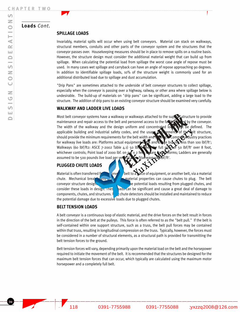
DE
SI
GN
CO
NS
ID
ER
AT
IO
NS
C H A P T E R T W O
Loads Cont.
SPILLAGE LOADS
Invariably, material spills will occur when using belt conveyors. Material can stack on walkways,structural members, conduits and other parts of the conveyor system and the structures that theconveyor passes over. Housekeeping measures should be in place to remove spills on a routine basis.However, the structure design must consider the additional material weight that can build up fromspillage. When calculating the potential load from spillage the worst case angle of repose must beused. In many cases wet spillage and carryback can have an angle of repose approaching 90 degrees.In addition to identifiable spillage loads, 10% of the structure weight is commonly used for anadditional distributed load due to spillage and dust accumulation.
"Drip Pans" are sometimes attached to the underside of belt conveyor structures to collect spillage,especially when the conveyor is passing over a highway, railway, or other area where spillage below isundesirable. The build-up of materials on "drip pans" can be significant, adding a large load to thestructure. The addition of drip pans to an existing conveyor structure should be examined very carefully.
WALKWAY AND LADDER LIVE LOADS
Most belt conveyor systems have a walkway or walkways attached to the support structure to providemaintenance and repair access to the belt and personnel access to the facility served by the conveyor.The width of the walkway and the design uniform and concentrated load must be defined. Theapplicable building and industrial safety codes, and the usage requirements of the belt structure,should provide the minimum requirements for the belt width and loadings. Common industry practicesfor walkway live loads are: Platforms actual equipment loads and usage but not less than 100 lbf/ft2;Walkways (60 lbf/ft2: ASCE 7-2002 Table 4.1) 50 lbf/ft over the full span or 50 lbf/ft2 over 8 foot,whichever controls; Point load of 2000 lbf. on a 2 x 2 feet square for platforms; Ladders are generallyassumed to be 500 pounds live load per vertical foot; Stairways 100 lbf/ft2.
PLUGGED CHUTE LOADS
Material is often transferred from a conveyor belt to a piece of equipment, or another belt, via a materialchute. Mechanical breakdowns or variable material properties can cause chutes to plug. The beltconveyor structure designer should determine the potential loads resulting from plugged chutes, andconsider these loads in design. These loads can be significant and cause a great deal of damage tocomponents, chutes, and structures. Plug chute detectors should be installed and maintained to reducethe potential damage due to excessive loads due to plugged chutes.
BELT TENSION LOADS
A belt conveyor is a continuous loop of elastic material, and the drive forces on the belt result in forcesin the direction of the belt at the pulleys. This force is often referred to as the "belt pull." If the belt isself-contained within one support structure, such as a truss, the belt pull forces may be containedwithin that truss, resulting in longitudinal compression on the truss. Typically, however, the forces mustbe considered in a number of structural elements, as a structural path is provided for transmitting thebelt tension forces to the ground.
Belt tension forces will vary, depending primarily upon the material load on the belt and the horsepowerrequired to initiate the movement of the belt. It is recommended that the structures be designed for themaximum belt tension forces that can occur, which typically are calculated using the maximum motorhorsepower and a completely full belt.
34
焦作市钰欣机械有限公司 专业的带式输送机制造商
—————————————————————————————————————————————————— 地址:焦作市黄河大道(西段)118号 电话:0391-7755988 传真:0391-7755088 邮箱;[email protected]

Loads Cont.
EXPANSION LOADS
Belt conveyors are typically supported on steel and/or concrete structures. Both steel and concreteexpand and contract with temperature at an approximate rate of 3/4 inch per 100 feet of structure per100° Fahrenheit. If the thermal movement of the structures is restrained, longitudinal forces occur inthe structural elements. In addition, rotation or movements of vertical support elements occur.Expansion joints may be provided in some structures to provide relief from the forces caused. However,the effect of thermal movements must be considered.
SNOW AND ICE LOADS
In colder climates, the accumulation of snow and ice on conveyor belt covers, structures, and walkwayscan add a significant load to the structure. The applicable local building code will typically provide theminimum local requirements for snow and ice build-up.
WIND LOADS
Wind blowing on a structure imparts a pressure on the structure that is proportional to the square ofthe velocity of the wind. The velocity of the wind, as well as many other factors that account for thelocation, shape and use of the structure are found in the applicable local building code. The windprovisions of most modern codes are taken from the publication ASCE-7. This publication providesmethods for determining the appropriate wind-created forces on open or semi-open structures, such asconveyor support trusses and towers.
Most designers recognize the effects of wind blowing tangential to a conveyor support structure.However, many designers ignore or discount the effects of wind blowing parallel to, or nearly parallel toa conveyor support structure. The pressures on the structures, and the subsequent structural forces,may be significantly different from those of a tangential wind, and cannot be ignored.
SEISMIC LOADS
Research into the effects of earthquakes on structures has resulted in significant changes to theseismic design provisions in modern building codes. Designers should be aware that seismic forcesmay have to be considered in situations where they have historically not been a design consideration.Seismic, or earthquake-movement induced loads, are determined using the provisions of the applicablelocal building code. Seismic forces are in part determined by the mass of the structure, and should becalculated with the belt full of material. The earthquake loads can occur in any direction. Theearthquake can produce longitudinal loads parallel to the conveyor which is much higher thanlongitudinal wind loads. These loads must be resisted by a foundation or tie to a tower.
DYNAMIC LOADS
The structural design of most belt conveyor systems is based upon a static loading model. However, abelt conveyor is a dynamic mechanical system, with the potential for movements, accelerations andvibrations to be imparted to the supporting structure. Items that may be of special concern are any typeof equipment that might impart a repeated dynamic loading, such as a vibratory feeder or a lumpbreaker. The design of the structure may in such cases have to consider the dynamic loadings andresonant properties of the structure.
LOAD COMBINATIONS
The applicable local building code provides definition of the appropriate combination of loads thatmust be considered in the design of structures. The designer of a belt conveyor structure must exercisegood judgment in applying the provisions of the applicable code to the design of an industrial structuresuch as a belt conveyor system. Designers should be aware that revised loading combinations arefound in modern building codes. Special care should be taken to insure that service level and strengthlevel loadings are not inappropriately combined.
DE
SI
GN
CO
NS
ID
ER
AT
IO
NS
C H A P T E R T W O
35
焦作市钰欣机械有限公司 专业的带式输送机制造商
—————————————————————————————————————————————————— 地址:焦作市黄河大道(西段)118号 电话:0391-7755988 传真:0391-7755088 邮箱;[email protected]

DE
SI
GN
CO
NS
ID
ER
AT
IO
NS
C H A P T E R T W O
Loads Cont.
FUTURE LOAD ALLOWANCES
Belt conveyors and other industrial structures are constructed and used in fluid and changeableenvironments. Changes in the material placed on the belt, to the belt idler slope, the motorhorsepower, and many other factors that influence the design of the structure are commonplace.
The designer cannot anticipate or predict what the future use or loadings of a conveyor system mightbe. However, it is not unusual for the end use of a conveyor system to have future plans or intentionsthat may allow the designer to accommodate future changes. For example, the user of a conveyorsystem may wish to add drip pans or siding to a conveyor system as a known future modification. Theseadditions significantly increase the structural loadings of the conveyor system, and should beconsidered as part of the original design. Modifying a conveyor structure to accommodate suchadditions in the future may be difficult and expensive. The addition of an agreed-to uniform load forfuture considerations, while adding to the initial conveyor cost, may provide a significant long-termbenefit to the end user or future users of the conveyor system.
STOCKPILE LOADS
Exterior stockpiles are often used to store bulk materials such as stone, coal, or other materials thatcan tolerate exposure to weather. Designers should be aware that exterior stockpiles exert significantforces and overturning moments on conveying system structures. This is especially true of conveyorsupport towers and bents which are directly impacted by either static stockpiles or flowing material.Soils theories outlined in soils manuals and texts or in NAVFAC can give assistance to the evaluation ofstockpile loads to buried conveyor supports.
Corrosion Protection
Belt conveyors are typically placed in industrial environments exposed to the weather, salt water,corrosives, ultra violet light and other elements that can deteriorate the conveyor. The conveyorstructure and components should be designed and constructed with the use and environment it will beused in. A number of methods can be used for corrosion protection.
In any corrosion protection system, care should be taken to avoid details that will promotedeterioration. Details that capture water or the conveyed product can promote corrosion. Theattachment of dissimilar metals can promote corrosion through galvanic action. Abrasion of movingcomponents on coated structures can remove the protection.
PAINT
The most common method of corrosion protection is to paint the conveyor structure. Paint processesvary from a wire brush and a single coat of paint, sand blast, acid etch and "high build" epoxy paintsystems. The level of paint depends on the expected life of the conveyor and the amount of corrosivesin the environment the conveyor is to be used in. The Steel Structures Painting Council (SSPC) manualsoffer information on the preparation and paint system appropriate for different operating conditions.
The advantage of paint is that it is a corrosion protection system that is available in most areas, tendsto be less costly than other corrosion protection, is easily field repaired and is available in many colors.The disadvantages of paint are the shorter life of paint corrosion protection; a scratch may allowdeterioration to develop under the paint and the inability to coat interior surfaces of pipes or tubes.
36
焦作市钰欣机械有限公司 专业的带式输送机制造商
—————————————————————————————————————————————————— 地址:焦作市黄河大道(西段)118号 电话:0391-7755988 传真:0391-7755088 邮箱;[email protected]

Corrosion Protection Cont.
GALVANIZING
Galvanizing is another form of surface corrosion protection in which the components are dipped inmolten zinc or zinc alloy to form a corrosion resistant coating. This coating will resist corrosion for alonger period than paint in most environments. Because the protection comes partially from thegalvanic action between the steel and the zinc, minor scratches will seal and still provide a level ofprotection for the steel.
Care must be taken in the detailing of steel to be hot dipped galvanized. If there are completelyenclosed air spaces, such as a pipe column with end plates, the heat from the hot dip process can causethe member to explode. Vent holes must be put in the steel to allow the escape of expanding gases.
Galvanizing can provide long term corrosion protection for many environments and can give protectionto interior areas not accessible to paint. Galvanized steel is difficult to repair in the field and the heatfrom the process can distort light members.
CORROSION RESISTANT STEELS
If a high level of corrosion resistance is required, the conveyor frame can be constructed from corrosionresistant metals such as stainless steels, weathering steels, or aluminum.
Stainless steel provides excellent corrosion protection in most environments. Because the steel iscorrosion resistant through the thickness of the steel, scratches do not affect the performance of thecorrosion resistance. Stainless steel construction is very expensive and therefore stainless steel shouldonly be used where the required corrosion resistance justifies the cost. Stainless steel is available inmany grades. The grade of stainless steel should be evaluated based on use, cost and availability.
Weathering steel rusts which creates a protective surface oxidation to protect the rest of the steel. Thissteel can be used for corrosion resistant conveyor members or enclosures. If the surface is scratched,the weathering steel will produce another corrosion resistant layer of oxidation and therefore "heals"itself. Be aware that this initial rust can stain surfaces below the weathering steel. Care must also betaken to use weld metal compatible with the weathering steel.
Aluminum is corrosion resistant in many environments. Aluminum is particularly useful for smaller andlighter conveyor members. While aluminum is lighter than steel, it is less strong and significantly lessstiff than steel. Many aluminum alloys are heat treated; therefore care must be given to properdetailing of welded connections to avoid the loss of strength in critical areas.
ALTERNATE MATERIALS AND METHODS
Most conveyor structures are constructed of steel. In some cases, because of the potential fordeterioration due to corrosion, alternate construction materials may appropriate. Concrete canproduce durable, low maintenance structures. Concrete can be used as cast in place (poured on site)or pre-cast components.
In other applications, wood or fiberglass may be the appropriate material to be most resistant tocorrosives. Care must be taken in the connection details to provide corrosion resistant connections tomatch the life of the wood structure.
Systems are available to provide cathodic protection for steel structures; however these systems arenot commonly used for conveyor structures.
DE
SI
GN
CO
NS
ID
ER
AT
IO
NS
C H A P T E R T W O
37
焦作市钰欣机械有限公司 专业的带式输送机制造商
—————————————————————————————————————————————————— 地址:焦作市黄河大道(西段)118号 电话:0391-7755988 传真:0391-7755088 邮箱;[email protected]

Clearance for: Minimum Values Dimension See Figure
Pulley Replacement BW+12 in., 30 in. min. A 2.26
Idler Replacement Primary side Belt Width, 30 in. min. B 2.27
Idler Replacement Secondary side 1/2 Belt Width, 24 in. min. C 2.26, 2.27
Clearance Under Conveyor for Cleaning 24 inches D 2.26, 2.27, 2.30
Belt Cleaner Service – Removal Belt Width E 2.29
Belt Cleaner Service – Inspection Height 24 in. min. or S + M, O or R F 2.29
Personnel Passage 30 inches G 2.28, 2.29, 2.30
Skirt Board Replacement Height Access 9 inches H 2.26
Skirt Board Adjustment 6 inches I 2.26
Personnel Access Opening Height 24 inches J 2.28, 2.29
Personnel Access Opening Width 24 inches K 2.28, 2.29
Overhead Clearance 48 inches L 2.26, 2.27, 2.29, 2.30, 2.31
Primary Belt Cleaner Location Consult Manufacturer M, N 2.28
Secondary Belt Cleaner Location Consult Manufacturer O, P 2.28
Tertiary Belt Cleaner Location Consult Manufacturer Q, R 2.28
Inspection Height Above Work Platform 24 inches S 2.28
Return Belt Cleaner (Plow) Consult Manufacturer T, U 2.30
Dribble Chute to Pulley clearance 12 inches V 2.28
Belt Repair Area 3X Belt Width, 10 ft. min. W 2.31
Conduit and Piping Run Free Zone See Figures 2.26 through 2.31
DE
SI
GN
CO
NS
ID
ER
AT
IO
NS
C H A P T E R T W O
Maintenance
Maintenance of the conveyor structure is critical to the safe and productive operation of a conveyorsystem. Conveyors are often located in areas where heavy equipment is operated and can be easilydamaged. Consideration should be given to protecting main structural elements from accidentaldamage from mobile equipment or maintenance operations through the use of barriers andguardrails. Damaged structures should be immediately repaired to prevent failure and to return theconveyor to its original path to prevent spillage and belt damage. Foundation settling can causesimilar problems with the belt path and must be compensated for or corrected. Process heat canaffect structures and provisions for shielding the structure must be maintained. Preplanning formaintenance by designing in lifting points or installing overhead cranes will eliminate using structuralelements as hoisting attachments and prevent structural damage.
When designing a conveyor belt system allowing adequate room for maintenance of components isessential. Lack of space for maintenance and inspection very quickly leads to a number of expensiveconditions including the avoidance of routine maintenance and inspection. Many times space islimited in the initial design to reduce capital costs or to fit more capacity into an existing space. To becompetitive engineering firms and contractors are forced into a low bid process that ignores the longterm costs of may design decisions. Design constraints that consider only capital costs or artificiallyunderestimate maintenance costs in order to fit a budget often increase operating and maintenancecosts and reduce the ability to safely operate the system. Many times the low bid savings are lost inthe first year of operation and the deficit grows every year thereafter.
ACCESS REQUIREMENTS
While the recommended clearances may seem to dramatically limit design options or increaseconstruction costs there are many conveyors designed in recent years that incorporate many of thesesuggestions. For example A-frame pulley support structures and larger pulley diameters are tworelatively easy ways to provide the needed clearance for cleaning devices.
The following minimum clearances and access requirements are required for cleaning, maintenanceand service of the common conveyor systems, components and accessories.
Table 2.24 Minimum recommended clearances and access requirements
38
焦作市钰欣机械有限公司 专业的带式输送机制造商
—————————————————————————————————————————————————— 地址:焦作市黄河大道(西段)118号 电话:0391-7755988 传真:0391-7755088 邮箱;[email protected]

Maintenance Cont.
DE
SI
GN
CO
NS
ID
ER
AT
IO
NS
C H A P T E R T W O
39
Figure 2.25 Views for recommended conveyor clearances
Figure 2.26 End view from tail pulley
焦作市钰欣机械有限公司 专业的带式输送机制造商
—————————————————————————————————————————————————— 地址:焦作市黄河大道(西段)118号 电话:0391-7755988 传真:0391-7755088 邮箱;[email protected]

DE
SI
GN
CO
NS
ID
ER
AT
IO
NS
C H A P T E R T W O
Maintenance Cont.
40
Figure 2.27 Section through skirtand load zone
Figure 2.28 Side view ofdischarge area
焦作市钰欣机械有限公司 专业的带式输送机制造商
—————————————————————————————————————————————————— 地址:焦作市黄河大道(西段)118号 电话:0391-7755988 传真:0391-7755088 邮箱;[email protected]

Maintenance Cont.
DE
SI
GN
CO
NS
ID
ER
AT
IO
NS
C H A P T E R T W O
41
Figure 2.29 End view ofdischarge area
Figure 2.30 Side view of tailsection and load zone
Figure 2.31 Side view of beltrepair area
焦作市钰欣机械有限公司 专业的带式输送机制造商
—————————————————————————————————————————————————— 地址:焦作市黄河大道(西段)118号 电话:0391-7755988 传真:0391-7755088 邮箱;[email protected]
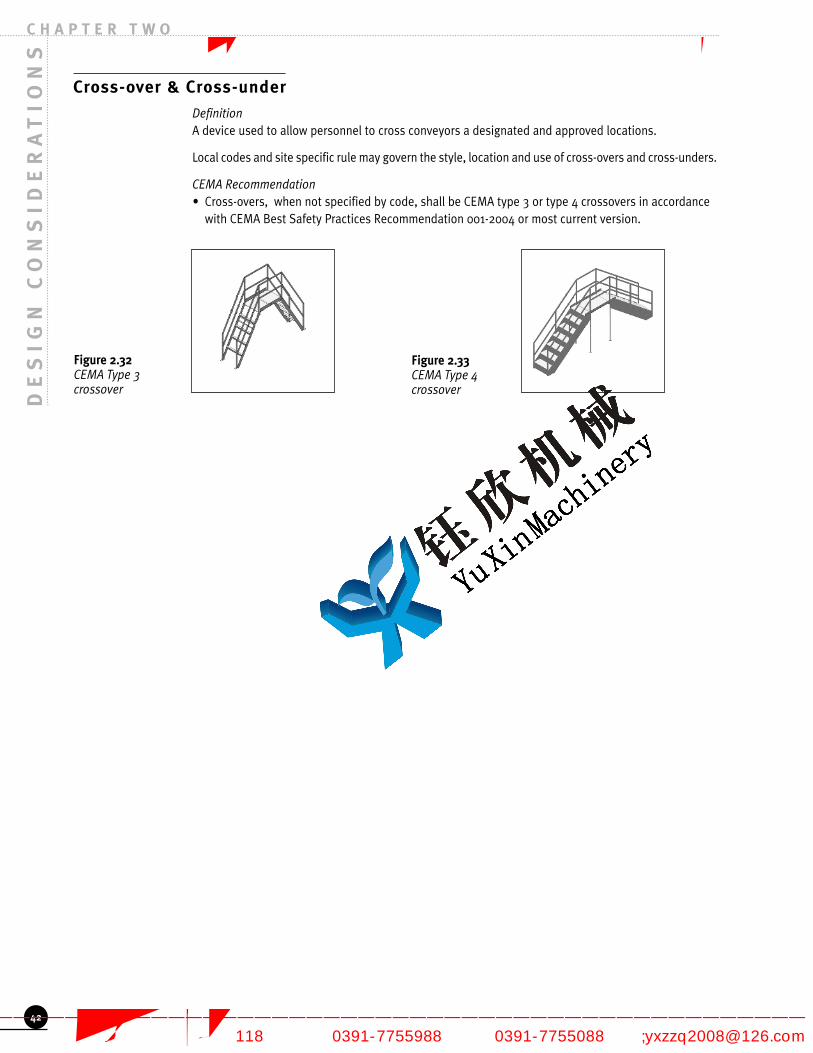
DE
SI
GN
CO
NS
ID
ER
AT
IO
NS
C H A P T E R T W O
Cross-over & Cross-under
DefinitionA device used to allow personnel to cross conveyors a designated and approved locations.
Local codes and site specific rule may govern the style, location and use of cross-overs and cross-unders.
CEMA Recommendation• Cross-overs, when not specified by code, shall be CEMA type 3 or type 4 crossovers in accordance
with CEMA Best Safety Practices Recommendation 001-2004 or most current version.
42
Figure 2.32 CEMA Type 3crossover
Figure 2.33 CEMA Type 4crossover
焦作市钰欣机械有限公司 专业的带式输送机制造商
—————————————————————————————————————————————————— 地址:焦作市黄河大道(西段)118号 电话:0391-7755988 传真:0391-7755088 邮箱;[email protected]

Considering the Long Term Effects of Design Decisions
The overall layout of a material handling system has a dramatic effect on the future cost of operatingand maintaining the system. Consideration should be given to paved access and clean up areas.Adequate space for mobile equipment should be allowed. Sumps should be designed when everpossible for drive in muck removal. The effects of wind, rain, snow and temperature should becarefully considered.
UPGRADING
If future plans may include increasing the capacity of the conveyor system careful consideration shouldbe given in the initial layout and design of the system. Increasing the speed of an existing conveyor toincrease capacity can create numerous problems with the flow of the material and the conveyorsstructures and enclosures. Changing the belt width or trough angle can not be done without seriousengineering investigation of the consequences.
REDUNDANCY
Redundant conveyor systems should be considered for any process which requires continuous feed ofmaterial, such as a boiler in a power plant. Different approaches can be taken to size the capacity ofredundant conveyors. It is often not necessary to duplicate 100% of the conveyor capacity if provisionsare made for storage, for example bunkers in a power plant. Common practice is to size redundantconveyors so that each one can convey 24 hours of material into storage in 8 to 16 hours. This allowssome margin of safety in the unlikely event that both conveyors are down at the same time. Spares andmaintenance capacity needs to be planned so that the storage capacity is enough time for repair orreplacement of any key component.
CAPITAL VS OPERATING COSTS
Deferring capital decisions to the operating budget to meet approved capital spending limits is one ofthe common practices that can have disastrous effects. While bulk material handling systems are oftenonly a small percentage of the initial cost they are often the main reason for delayed start up and undercapacity performance if not properly designed and maintained. Once production starts there is neverenough time or money to go back and redo or upgrade an under designed bulk material handlingsystem. All efforts are focused on cleanup, plugged chutes, overloads and just getting enoughmaterial into the process to keep it flowing. Critical components like the belt are often damaged andtheir life shortened.
DE
SI
GN
CO
NS
ID
ER
AT
IO
NS
C H A P T E R T W O
43
焦作市钰欣机械有限公司 专业的带式输送机制造商
—————————————————————————————————————————————————— 地址:焦作市黄河大道(西段)118号 电话:0391-7755988 传真:0391-7755088 邮箱;[email protected]

CH
AR
AC
TE
RI
ST
IC
S A
ND
CO
NV
EY
AB
LI
TY
OF
BU
LK
MA
TE
RI
AL
S
Introduction
Material Characteristics
Material Class Description
Behavior of Materials on a Moving Belt
Effect of Inclines and Declines
CHARACTERISTICS AND CONVEYABILITY OF BULK MATERIALS
45
C H A P T E R T H R E E焦作市钰欣机械有限公司 专业的带式输送机制造商
—————————————————————————————————————————————————— 地址:焦作市黄河大道(西段)118号 电话:0391-7755988 传真:0391-7755088 邮箱;[email protected]

CH
AR
AC
TE
RI
ST
IC
S A
ND
CO
NV
EY
AB
LI
TY
OF
BU
LK
MA
TE
RI
AL
S
Introduction
The successful design of a conveyor belt must begin with an accurate appraisal of the characteristics ofthe material to be transported. The behavior and state of bulk materials greatly depend on themoisture content and particle size distribution of the material. Wide variations in material behavior andbulk density with moisture and particle size can lead to unexpected tonnage or capacity issues,excessive spillage or material buildup, and equipment or system malfunction and failure.
Material Characteristics
A number of parameters are commonly used to describe material flow behavior, some of which areinternal and effective friction, cohesive and adhesive strength, flowability, boundary friction andadhesion, angle of repose, surcharge angle, particle size distribution, and bulk density. All of these areaffected by variations in moisture content and by the stress history of the material (loading andunloading conditions during transport).
A variety of test methods have been used to obtain these properties and behavioral parameters.Simplified test methods can be used to obtain some of the parameters such as angle of repose and bulkdensity, but the majority of the parameters must be obtained using more elaborate testingmethodology and equipment. Two such methods are outlined in ASTM D6128-00 and ASTM D6773-02.Other test methods are available as well.
Common practice involves the physical testing of the conveyed material at a number of moisturecontents, investigating the effects of time on material behavior. Depending on the actual process orsystem requirements, testing can also be performed at elevated temperatures and for various particlesize distributions.
Some of the more readily determinable material properties will be discussed in more detail here as theyare indicative of the behavior of the material on a conveyor belt, but it is important to realize that thetrue nature and behavior of the material is in no way fully described by these parameters.
The angle of repose of a material is the natural angle formed by gravity discharge of the material andmeasured from a horizontal base. The angle of surcharge of a material is the angle to the horizontalwhich the surface of the material assumes while the material is at rest on a moving conveyor belt. Thisangle is usually 5 degrees to 15 degrees less than the angle of repose, though in some materials it maybe as much as 20 degrees less.
Flowability can be qualitatively assessed by considering material characteristics such as size and shapeof fine particles and lumps, roughness or smoothness of the surface of the material particles,proportion of fines and lumps present, and moisture content of the material. Quantitative assessmentof Flowability requires the determination of many of the behavioral properties discussed above.
46
C H A P T E R T H R E E
Figure 3.1ASTM D6128-00 Tester
Figure 3.2 Close up of Shear Cell
焦作市钰欣机械有限公司 专业的带式输送机制造商
—————————————————————————————————————————————————— 地址:焦作市黄河大道(西段)118号 电话:0391-7755988 传真:0391-7755088 邮箱;[email protected]

Material Characteristics Cont.
Table 3.3Table of Flowability
Material Class Description
Consideration should also be given to the dustiness of the material, whether it is corrosive or explosive,temperature ranges, moisture content ranges, and any other process or environmental effects that mayaffect the flow behavior of the material. Some general information concerning these properties is givenin Table 3.4. Table 3.5 gives a list of materials with their physical characteristics and classification codedesignations. It must be understood that the data given in this table are for average conditions andaverage materials, and should be used as a guideline only. Each characteristic may vary in specificapplications and instances, and many important behavioral parameters are not listed.
CH
AR
AC
TE
RI
ST
IC
S A
ND
CO
NV
EY
AB
LI
TY
OF
BU
LK
MA
TE
RI
AL
SC H A P T E R T H R E E
47
FlowVery Free
Flowing 1*Free
Flowing 2*Average Flowing 3* Sluggish 4*
Equivalent Flow Function Ranges FF>10 >4 to <10 >2 to <4 <2
Angle of Surcharge (degrees)5 10 15 20 25 30
Angle of Repose (degrees)10 - 19 20 - 25 26 - 29 30 -34 35 -39 >40
Uniform size,very smallroundedparticles, eithervery wet or verydry, such as drysilica sand,cement, wetconcrete, etc.
Rounded, drypolishedparticles ofmedium weightsuch as wholegrain and beans
Regulargranularmaterials suchas fertilizer,sand andwashed gravel.
Irregular,granular orlumpymaterials ofmediumweight, suchas anthracitecoal, cottonseed meal,clay etc.
Typicalcommonmaterialssuch asbituminouscoal, stone,most ores,etc.
Irregular,stringy,fibrous,interlockingmaterial suchas wood chips,bagasse,temperedfoundry sand,etc.
* Numerical rating refers to Material Class Descriptions
焦作市钰欣机械有限公司 专业的带式输送机制造商
—————————————————————————————————————————————————— 地址:焦作市黄河大道(西段)118号 电话:0391-7755988 传真:0391-7755088 邮箱;[email protected]

CH
AR
AC
TE
RI
ST
IC
S A
ND
CO
NV
EY
AB
LI
TY
OF
BU
LK
MA
TE
RI
AL
S
Material Class Description Cont.
Table 3.4CEMA Material Classification Code System
Proper consideration must be given to those materials, the characteristics of which may vary undervarious conditions of handling, atmospheric humidity, age, or long storage. In many cases, accuracy indesign may require that carefully conducted tests be run to establish the material characteristics underthe required conditions. CEMA Standard 550-2003, or latest version, Classification and Definitions ofBulk Materials, gives detailed explanations and references used for establishing the CEMA materialclassification code. CEMA Standard 550-2003 classifies over 500 bulk materials. Materials or charac-teristics omitted from the latest version of CEMA Standard 550-2003 may be roughly appraised bycomparison with listed materials of the same general type. For design it is always recommended thatthe actual bulk solid be tested. Table 3.5 lists some common materials and their CEMA classifications.
48
C H A P T E R T H R E E
Material Characteristics CodeVery Fine – 100 Mesh and Under AFine – 1/8 inch and Under BGranular – Under 7 inch CLumpy – Containing Lumps Under 16 inch D
Size
Irregular – Stringy, Interlocking, Mats Together EVery Free Flowing – Angle of Repose < 19 deg. 1Free Flowing – Angle of Repose 20 to 29 deg. 2Average Flowing Angle of Repose 30 to 39 deg. 3
FlowabilityAngle of Repose
Sluggish – Angle of Repose > 40 deg. 4Nonabrasive 5Abrasive 6Very Abrasive 7
Abrasiveness
Very Sharp – Cuts or Gouges Belt Covers 8Very Dusty LAerates and Develops Fluid Characteristics MContains Explosive Dust NSticky – Adheres Easily OContaminable, Affecting Sale or Use PDegradable, Affecting Sale or Use QGives off Harmful Fumes or Dust RHighly Corrosive SMildly Corrosive THygroscopic UInterlocks or Mats VOils or Chemicals Present – May Affect Rubber WPacks under Pressure XVery Light and Fluffy – May be Wind Swept Y
MiscellaneousCharacteristics
(More than one may apply)
Elevated Temperature Z
焦作市钰欣机械有限公司 专业的带式输送机制造商
—————————————————————————————————————————————————— 地址:焦作市黄河大道(西段)118号 电话:0391-7755988 传真:0391-7755088 邮箱;[email protected]
CH
AR
AC
TE
RI
ST
IC
S A
ND
CO
NV
EY
AB
LI
TY
OF
BU
LK
MA
TE
RI
AL
SC H A P T E R T H R E E
49
Material Class Description Cont.
Table 3.5Excerpt of CEMA Standard 550: CLASSIFICATION & DEFINITIONS OF BULK MATERIALS
Behavior of Materials on a Moving Belt
Attention must be drawn to the fact that the normal characteristics of materials are considerablyinfluenced by the movement, slope, and speed of the conveyor belt that carries them. As the conveyorbelt passes successively over each carrying idler, the material on it is correspondingly agitated and theload profile of the material on the belt is changed. This change in profile is influenced by such factorsas vertical and horizontal curves in the belt direction, idler trough angle and configuration, beltinclination, belt sag, belt tension, belt velocity, and vibrations arising from the movement of the belt andsupport idlers.
Typically, the bulk solid is loaded onto the conveyor belt in a loose and unpacked state, with a loadprofile governed on the lower surface by the profile of the conveyor belt, and an upper profile governedby the material’s angle of repose. As the material is conveyed it will soon settle into its equilibrium, orpacked, condition as a result of the factors given above. The upper surface can then be approximated
MaterialDescription
LooseBulk
Density(lbf/ft3)
CEMA MaterialCode
Angle ofRepose
(degrees)
MaximumAllowableAngle ofConveyorInclination(degrees)
Alumina 55-66 58B627MY 22 12Bark, Wood, Refuse 10-20 15E45TVY 45 27Bentonite, 100 mesh 50-60 55A10025MXY 42 20Cement, Clinker 75-95 85D336 30-40 18-20Coal, Powder River Basin 40- 55 50D35LV 38 15Coal, Bituminous, Mined 45-55 50Dx35 38 15Coal, Lignite 37-45 41D335TN 38 15Coke, Petroleum, Shot 45-63 50C36LTWZ 35-40 14Coke, Petroleum, Sponge 45-63 50C36LTWZ 35-40 14Coke, Petroleum, Fluid 58-63 61B46LMTWYZ 25-35 *Copper, Ore 120-150 125Dx36 30-44 20Cullet, Fines 80-120 120C1/237 30-44 20Earth, Wet, Containing Clay 100-110 105D1646OV 45 23Gravel, Pebbles 90-100 95D327 30 12Kaolin, Clay, 3 in. & Under 63 63D325 35 19Lime, Hydrated 40 40B635LM 40 21Limestone, Crushed 85-90 88Dx36 38 18Phosphate, Rock, Pulverized 60 60B636 40 25Rice, Hulled 45-49 47C1/225P 19 8Sand, Foundry, Prepared 65-75 70B647X 30-44 24Taconite, Pellets 116-130 123D317Q 30-44 13-15* - Normally pneumatically conveyed
焦作市钰欣机械有限公司 专业的带式输送机制造商
—————————————————————————————————————————————————— 地址:焦作市黄河大道(西段)118号 电话:0391-7755988 传真:0391-7755088 邮箱;[email protected]

CH
AR
AC
TE
RI
ST
IC
S A
ND
CO
NV
EY
AB
LI
TY
OF
BU
LK
MA
TE
RI
AL
S
Behavior of Materials on a Moving Belt Cont.
using the angle of surcharge rather than the angle of repose. Segregation of the material will also occurwith the larger lump sizes migrating towards the upper surface of the load profile, and the finesmigrating towards the belt.
In general, the amount of settling that occurs during transport can be estimated to be in the range of10-15%. Using the load calculations given in chapter 4 (Figure 4.2) the load profile change can beestimated by assuming the upper surface is formed at the angle of repose in an unsettled or loose state,and at the angle of surcharge in a settled or packed state. This is depicted in Figure 3.6. Note that, inaddition to profile change, the bulk density of the conveyed material will change due to external forcesarising from the conditions described above. The density change due to conveying is also in the rangeof 10-15%. In effect, during conveying the load profile will decrease in area by ~10-15% and the bulkdensity will increase ~10-15%. For capacity and equipment calculations, it is important to know thevariation in bulk density in loose and packed states, the angle of repose and surcharge, and the particlesize distribution of the conveyed material. Once again, these factors are greatly influenced by themoisture content of the conveyed material.
Effect of Inclines and Declines
The nominal cross section of the material on a horizontal conveyor belt is measured in a plane normalto the belt. On an inclined or declined conveyor belt, gravity necessitates that the actual cross sectionof the load be considered in a vertical plane. To maintain the total width of the material load on the beltand to maintain unchanged surcharge angles, the cross section of the load possible on an inclined ordeclined belt must be less than that of a horizontal belt. Referring to the diagram used in the derivationof belt conveying capacity (Chapter 4, Figure 4.9) the trapezoidal area does not change although thearea represented by a segment of a circle formed by the surcharge does decrease as the cosine of theconveyor slope. The total effect is influenced by the surcharge angle at which the material will ride onthe conveyor belt. However, in most cases, the actual loss of capacity is less than 3 percent.
The following three precautions may well be observed: lumps are more likely to roll off the edges ofinclined conveyor belts than horizontal ones; for belts of constant slope, the spillage of material is morelikely to occur immediately beyond the loading point before the material is allowed to reach its packedstate and local accelerations/decelerations cause turbulence in the material; and, materials whichaerate excessively, such as very fine ground cements, or materials in which the proportion of water isso high that a slurry is created, must be carried on inclines such that the tendency of the material toslide back is fully offset.
50
C H A P T E R T H R E E
Figure 3.6Angle of Repose, Φr ,and Angle ofSurcharge, Φs
焦作市钰欣机械有限公司 专业的带式输送机制造商
—————————————————————————————————————————————————— 地址:焦作市黄河大道(西段)118号 电话:0391-7755988 传真:0391-7755088 邮箱;[email protected]

焦作市钰欣机械有限公司 专业的带式输送机制造商
—————————————————————————————————————————————————— 地址:焦作市黄河大道(西段)118号 电话:0391-7755988 传真:0391-7755088 邮箱;[email protected]

焦作市钰欣机械有限公司 专业的带式输送机制造商
—————————————————————————————————————————————————— 地址:焦作市黄河大道(西段)118号 电话:0391-7755988 传真:0391-7755088 邮箱;[email protected]

CH
AR
AC
TE
RI
ST
IC
S A
ND
CO
NV
EY
AB
LI
TY
OF
BU
LK
MA
TE
RI
AL
SC H A P T E R T H R E E
51
Effect of Inclines and Declines Cont.
Critical relationships between belt velocity, material conveyed, and conveyor setup must be maintainedto avoid spillage and slip-back of the material on inclined or declined belts. Simplified relationshipsfor the maximum belt velocities attainable before material slip or spillage occurs on inclined or declinedbelts are given by:
Where:
" # " #i 0slip-max = × belt belt
2es
S 1 !v 60 g cos " - sin " + (fpm)
2# ×Y $ %×h
$ %$ % &' &' &&' ' &&' ' & &' ( )( )
Equation 3.7Equation ForMaximum Belt SpeedBefore MaterialSlippage Occurs
" #i 0spill-max = × belt
2s
S !v 60 g×cos " + (fpm)
2# ×Y %×h
$ %&' &' &' &( )
Equation 3.8Equation forMaximum Belt SpeedBefore MaterialSpillage Occurs
�
�
�
�
� �
� � � � � � � �
��������������������� ����������������
��� ������������������� ������ ���� ��������������� ��������������
�
����� �������������������� ��������!��"�#$%$���
&' ������ ���' ���� ���
()*
�
�
�
���� ���+ ��������,+ ����� �#%-�.�#%)
/������ �����0 1��� ��"��������� 1��������
2 ��������������������,+ �!����������������������� 1���������������!�"������
3������ ���������� �!�� ��� �
� � � �
� �
� �
��������� 1���������������!�"������
�� 4�$�5�� 5��� �6��5�����7 � (������������������ � 5 ���6�4
8 ($
� ��������������%$�9�50:�;�(%*$��<�����������������������������������������
* + * +, - , -, - , -. /. /
�
�
�����������
������������������%#-(50:�4�%$��<�������������������������������������������������������
0:��������������0�������
6������������������������������������
7�������������� ��������������������� 1��������
焦作市钰欣机械有限公司 专业的带式输送机制造商
—————————————————————————————————————————————————— 地址:焦作市黄河大道(西段)118号 电话:0391-7755988 传真:0391-7755088 邮箱;[email protected]

CH
AR
AC
TE
RI
ST
IC
S A
ND
CO
NV
EY
AB
LI
TY
OF
BU
LK
MA
TE
RI
AL
S
Effect of Inclines and Declines Cont.
Note that these relationships hold for points well beyond the loading zone. To estimate critical beltvelocities in and immediately following the load zone, values for the above parameters must bedetermined in the load zone. For example, values for the load zone belt angle, idler spacing and beltsag in the load zone must be used. Material properties such as loose material density, material-beltinterface friction, and angle of repose rather than angle of surcharge must be used as well. Otherconsiderations in the load zone must also be considered to avoid spillage, such as impact effects, beltsupport, and the presence of sealing systems. In addition, some materials exhibit fluid-like behaviorand have a tendency to flow at much lower values of friction then one would expect at the material/beltinterface. As always, material and interface properties are greatly affected by moisture content andparticle size.
Graph 3.9 shows the effect of conveyor slope on the maximum attainable belt speeds before slip andspillage occur. Note that the sag ratio depends on the material load, idler spacing, and type andthickness of the conveyor belt used.
52
C H A P T E R T H R E E
Figure 3.9
0 5 10 15 20500
600
700
800
900
1000
belt inclination (degrees)
Maximum attainable belt speed before material slip/slide-back occurs
Maximum attainable belt speed before material spillage occurs
belt
sp
eed
(fpm
)
The values used in the example represent a specific Powder River Basin coal sample and a specific belt and do not representa typical value for design purposes. The values Si , Ys , θbelt , Φs and β must relate to the conveyor design parameters. Thevalues ρ, and σ0 for the bulk solid and the value µe for the belt and bulk material interface must be obtained through testingfor each bulk material and belt condition.
焦作市钰欣机械有限公司 专业的带式输送机制造商
—————————————————————————————————————————————————— 地址:焦作市黄河大道(西段)118号 电话:0391-7755988 传真:0391-7755088 邮箱;[email protected]

CA
PA
CI
TI
ES
, BE
LT
WI
DT
HS
AN
D S
PE
ED
S
IntroductionBelt WidthsLump Size ConsiderationsBelt Speeds
Power Generating Plants
Higher Belt SpeedsLower Belt Speeds
Belt Conveyor CapacitiesBelt Conveyor Capacity Tables and Their UseBelt Load Cross Section Areas
Troughed Belt Load Areas
Calculation of Material Cross Section AreaCalculation of Edge Distance with a Maximum Material Depth on BeltMaximum Material DepthMaterial Cross Section Area Between Skirtboards
CAPACITIES, BELT WIDTHSAND SPEEDS
53
C H A P T E R F O U R焦作市钰欣机械有限公司 专业的带式输送机制造商
—————————————————————————————————————————————————— 地址:焦作市黄河大道(西段)118号 电话:0391-7755988 传真:0391-7755088 邮箱;[email protected]

0
4
8
12
16
20
24
28
32
18 24 36 48 60 72 84 96 108 120
Lum
pS
ize
(in)
Belt Width (in)
10%
Lumps
, 90%
Fines
, 20 de
g.Surc
harge
All Lumps, 20 deg. Surch
arge
10% Lumps, 90% Fines, 30 deg. Surcharge
All Lumps, 30 deg. Surcharge
36
40
CA
PA
CI
TI
ES
, B
EL
TW
ID
TH
S A
ND
SP
EE
DS
IntroductionGenerally, for a given speed the belt width and conveyor capacity increase together. However the width ofnarrower belts may be governed by the size of lumps to be handled. Belts must be wide enough so that anycombination of prevailing lumps and finer material does not load the lumps too close to the edge of theconveyor belt. Also the inside dimensions of the loading chutes and the distance between skirtboards mustbe sufficient o pass various combinations of lumps without jamming. Consideration must be given to spillageand dust that can be created by misalignment, overloading and speeds too great for the design belt sag.
Belt Widths The width of conveyor belts is customarily expressed in inches. The belt widths treated in this manual andwhich are commonly available from conveyor belt manufacturers in the United States are as follows: 18, 24,30, 36, 42, 48, 54, 60, 72, 84, and 96 inches. Custom configurations using 108 and 120 inches and wider canalso be designed using similar concepts as those discussed in this chapter as well as throughout this book.
Generally, for a given speed, the belt width and the belt conveyor capacity increase together. However, thewidth of narrower belts may be governed by the size of lumps to be handled. Belts must be wide enough sothat any combination of prevailing lumps and finer material does not load the lumps too close to the edge ofthe conveyor belt. Also, the inside dimensions of loading chutes and the distance between skirtboards mustbe sufficient to pass various combinations of lumps without jamming. Consideration must be given to spillageand dust that can be created by misalignment, overloading and speeds too great for the design belt sag.
Lump Size ConsiderationsThe lump size influences the belt specifications and the choice of carrying idlers. There is also an empiricalrelationship between lump size and belt width. The recommended maximum lump size for various beltwidths is as follows: For a 20-degree surcharge, with 10 percent lumps and 90 percent fines, therecommended maximum lump size is one third of the belt width (b/3). With all lumps and no fines, therecommended maximum lump size is one-fifth of the belt width (b/5). For a 30-degree surcharge, with 10percent lumps and 90 percent fines, the recommended maximum lump size is one-sixth of the belt width(b/6). With all lumps and no fines, the recommended maximum lump size is one-tenth of the belt width(b/10). Another way to determine belt width for a specific lump size is illustrated in Figure 4.1. This simplechart shows the belt width necessary for a given size lump, for various proportions of lumps and fines, andfor various surcharge loadings. Fines size is no greater than 1/10 the maximum lump size.
Table 4.1 Belt width necessary for a given lump size
54
C H A P T E R F O U R焦作市钰欣机械有限公司 专业的带式输送机制造商
—————————————————————————————————————————————————— 地址:焦作市黄河大道(西段)118号 电话:0391-7755988 传真:0391-7755088 邮箱;[email protected]

Material Being Conveyed Belt Speeds (fpm) Belt Width (in)
Grain or other free flowing, 400 18nonabrasive material 600 24-30
800 36-421000 48-961200 108-120
Coal, damp clay, soft ores, overburden 600 18and earth, fine crushed stone 800 24-36
1000 42-601200 72-961400 108-120
Heavy , hard, sharp edged ore, coarse 400 18crushed stone 600 24-36
800 42-601000 72-961200 108-120
Foundry sand, prepared or damp; 350 Any Widthshake-out sand with small cores, with or without small castings (not hot enough to harm belting)
Prepared foundry sand and similar 200 Any Widthdamp (or dry abrasive) materials discharged from belt by rubber edged plows
Nonabrasive materials discharged 200 Any Widthfrom belt by means of plows Except for wood pulp where
300 to 400 is preferable
Feeder belts, flat or troughed, for 50 to 100 Any Widthfeeding fine , nonabrasive, or mildly abrasive materials from hoppers and bins
Coal (bituminous, sub-bituminous), 500 to 700 Any WidthPRB coal, lignite, petroleum coke, gob, for belt conveyorsculm and silt. 380 to 500 for silo
feed conveyors and tripper belt conveyors
Power Generating Plant applications 500 for belt conveyors Any Width380 for silo feed conveyorsand tripper belt conveyors
CA
PA
CI
TI
ES
, BE
LT
WI
DT
HS
AN
D S
PE
ED
SC H A P T E R F O U R
55
Belt Speeds
Suitable belt conveyor speed depends largely upon the characteristics of the material to be conveyed alongwith belt width, capacity, belt tensions and loading/unloading equipment. Each application must beevaluated on these technical issues as well as on capital cost, operating conditions and maintenanceconsiderations. General recommendations for maximum speeds of belt conveyors are shown in Table 4.2.
Table 4.2 Recommended maximum belt speeds
COAL FIRED POWER GENERATING PLANTS
Lower belt speeds and de-rated capacities are often used for handling coal in coal fired power generatingplants and handling other bulk materials subject to degradation and the hazards associated withspillage, leakage and dust generation. It is common practice not to load coal conveyors to their capacityin order to accommodate surge loads and to reduce spillage and leakage due to mistracking. A capacitydesign factor, DF, of 1.20 (83% of theoretical maximum capacity) is often used in handling coal in coalfired power plants. However, there are numerous factors to consider, including the properties of the bulkmaterial, the conveyor engineer’s experience in selecting an appropriate belt speed and the sizing ofother components which may affect the overall performance and cost of a system.
焦作市钰欣机械有限公司 专业的带式输送机制造商
—————————————————————————————————————————————————— 地址:焦作市黄河大道(西段)118号 电话:0391-7755988 传真:0391-7755088 邮箱;[email protected]

CA
PA
CI
TI
ES
, B
EL
TW
ID
TH
S A
ND
SP
EE
DS
Belt Speeds Cont.
HIGHER BELT SPEEDS
An increase in belt speed permits decreases in belt width and belt tension and will generally requirelower capital costs. Designers have been known to use speeds as much as 50% higher than thoseshown in Table 4.2. Higher belt speeds may be suitable when:
1. Conveying length is very long (> 5,000 ft).
2. Loading and unloading points are well designed and material is directed onto the belt near thesame speed as the belt and in the same direction.
3. The material has smaller lump sizes
4. The belt is suitably tensioned to limit sag levels below those described in Chapter 6. 5. Critical liftoff speeds over the idlers are much greater as discussed in Chapter 6.
However, the benefits must be weighed against the possible disadvantages of:
1. Increased belt wear.
2. Material degradation.
3. Wind losses.
4. Lump impact on carrying idlers.
5. Higher loading/unloading transfer maintenance.
6. Generally reduced life of all conveyor components.
Other design issues that must be considered when belt speeds exceed Table 4.2 are:
1. Idler dimensional tolerances.
2. Installation tolerances.
3. Belt transverse vibrations (Belt Flap).
4. Noise levels.
Consult a CEMA member company when considering operation at the highest ends of the speedrecommendations or beyond.
LOWER BELT SPEEDS
Consideration to using the lower end of the speed range should be applied for special materialconditions as follows;
1. Powder or fine materials should be conveyed at speeds low enough to minimize dusting, particularly at the loading and discharge points.
2. Fragile materials also limit belt speeds. Low speeds are necessary so that degradation of fragile materials will not occur at the loading and discharge points, as the conveyor belt and the material being carried move over the idlers.
3. Heavy, sharp-edged materials should be carried at moderate speeds. This is good practice because the sharp edges are likely to wear the belt cover unduly, particularly if the loading velocity of the material in the direction of belt travel is appreciably lower than the belt speed.
4. Hazards associated with material spillage, leakage and dust generation are of special concern suchas in coal fired power plant applications.
56
C H A P T E R F O U R焦作市钰欣机械有限公司 专业的带式输送机制造商
—————————————————————————————————————————————————— 地址:焦作市黄河大道(西段)118号 电话:0391-7755988 传真:0391-7755088 邮箱;[email protected]

BeltWidth 18 24 30 36 42 48 54 60 72 84 96 108 120(in)
StandardEdge 1.89 2.22 2.55 2.88 3.21 3.54 3.87 4.2 4.86 5.52 6.18 6.84 7.5Distance (in)
Belt Conveyor Capacities
Conveyors are typically not designed to be loaded to their maximum capacity in order to accommodatesurge loads and to reduce spillage and leakage due to mistracking. Typical capacity design factors, DF,range from 1.00 to 1.25 (100% to 80% of theoretical maximum capacity). However the conveyorhorsepower should always be calculated on 100% of theoretical capacity to accommodate startingunder surge or head loads.
For a given speed, belt conveyor capacities increase as the belt width increases. Also, the capacity of abelt conveyor depends on the surcharge angle and on the inclination of the side rolls of three-rolltroughing idlers. The nominal cross section of the material on a belt is measured in a plane normal tothe belt. On an inclined or declined conveyor, the material tends to conform to its surcharge angle asmeasured in a vertical plane. This decreases the area, Asc, as the cosine of the angle of conveyor slope.See Figure 4.9. However, in most cases, the actual loss of capacity is very small. Assuming a uniformfeed to the conveyor, the cross-sectional area of the load on the conveyor belt is the determinant of thebelt conveyor capacity.
CEMA Recommendation1. Select the belt width and speed based on a capacity design factor of 80% the theoretical maximum
tons per hour (reduction of capacity). This allows for surge loading and reduces spillage due to beltmistracking based on the material conveyed, the performance requirements and the experience of the conveyor designer.
2. Design conventional loading chute cross sections based on the loose material profile which is defined by the angle of repose, rather than the angle of surcharge, and the unconfined bulk density. This reduces the possibility of choking the flow as the material loads on the belt and begins to settle into a profile determined by the surcharge angle and bulk density.
In this manual, the cross-sectional area is based upon the following two conditions. First, the materialload on the troughed belt does not extend to the belt edges. The distance from the edges of thematerial load to the edges of the belt is set at "standard edge distance," which is defined as0.055BW + 0.9 inch, where BW is the width of the belt in inches.
Table 4.3 Standard edge distance
Throughout this manual, standard edge distance is presumed to be in effect unless otherwise specified.Second, the top of the load of the material is the arc of a circle tangent, at the edges of the load, to thesurcharge angle, unless otherwise specified.
CA
PA
CI
TI
ES
, BE
LT
WI
DT
HS
AN
D S
PE
ED
SC H A P T E R F O U R
57
焦作市钰欣机械有限公司 专业的带式输送机制造商
—————————————————————————————————————————————————— 地址:焦作市黄河大道(西段)118号 电话:0391-7755988 传真:0391-7755088 邮箱;[email protected]

Belt Asc Cross Sectional Area (ft2) Q 100 = Capacity (ft3/hr) at 100 fpmWidth Surcharge Angle (deg) Surcharge Angle (deg)(in) 0 5 10 15 20 25 30 0 5 10 15 20 25 30
18 0.090 0.109 0.128 0.148 0.168 0.188 0.209 538 653 769 886 1,006 1,128 1,25524 0.174 0.210 0.246 0.283 0.321 0.359 0.399 1,041 1,259 1,477 1,699 1,925 2,156 2,39430 0.285 0.343 0.402 0.462 0.523 0.585 0.650 1,708 2,060 2,414 2,773 3,138 3,512 3,89836 0.423 0.510 0.597 0.685 0.774 0.866 0.961 2,539 3,058 3,579 4,107 4,645 5,197 5,76542 0.589 0.708 0.829 0.951 1.075 1.202 1.333 3,533 4,251 4,973 5,703 6,447 7,210 7,99748 0.782 0.940 1.099 1.260 1.424 1.592 1.765 4,691 5,640 6,594 7,560 8,544 9,553 10,59354 1.002 1.204 1.407 1.613 1.823 2.037 2.259 6,013 7,225 8,444 9,678 10,935 12,224 13,55360 1.250 1.501 1.754 2.010 2.270 2.537 2.813 7,499 9,006 10,523 12,058 13,621 15,224 16,87772 1.827 2.193 2.561 2.933 3.313 3.702 4.103 10,961 13,156 15,364 17,600 19,876 22,210 24,61784 2.513 3.015 3.520 4.031 4.552 5.085 5.636 15,078 18,089 21,119 24,186 27,310 30,511 33,81496 3.099 3.717 4.339 4.969 5.610 6.267 6.945 18,596 22,304 26,035 29,811 33,658 37,601 41,667108 4.213 5.051 5.895 6.749 7.618 8.510 9.429 25,277 30,307 35,369 40,492 45,711 51,060 56,576120 5.226 6.265 7.311 8.369 9.446 10.551 11.690 31,359 37,592 43,863 50,212 56,679 63,306 70,142
CA
PA
CI
TI
ES
, B
EL
TW
ID
TH
S A
ND
SP
EE
DS
Belt Conveyor Capacity Tables and Their Use
Troughed and flat belt conveyor capacities are detailed in Tables 4.4 through 4.7. These tables are setup for 20 degrees, 35 degrees, and 45 degrees troughing idler shapes and flat belts; for variousdegrees of surcharge angles which correspond to the slumping characteristics of the materials to beconveyed; and for belt speeds of 100 fpm. To make the best use of these tables, the following eightsteps should be taken:
1. Referring to Tables 3.3 and 3.4 or CEMA Standard 550 determine the surcharge angle of the material. The surcharge angle, on the average, will be 5 degrees to 15 degrees less than the angle of repose.
2. Refer to Table 3.5 or CEMA Standard 550 to determine the density of the material in pounds per cubic foot (lbf/ft3).
3. Choose the idler shape suited to the material and to the conveying problem. Refer to Chapter 5.
4. Refer to Table 4.2, "Recommended Maximum Belt Speeds." Select a suitable conveyor belt speed.
5. Convert the desired tonnage per hour (tph) to be conveyed to the equivalent in cubic feet per hour (ft3/hr).DF=Capacity Design Factor is defined on page 55 to over rate the conveyor. For example, DF=1.2 is suggested for coal fired power plants.
ft3/hr = Q x 2000 x DFγ
6. Convert the desired capacity in cubic feet per hour to the equivalent capacity at a belt speed of 100 fpm.
Q100 = ft3/hr x 100 (fpm) actual belt speed (fpm)
7. Using the equivalent capacity so found, refer to Tables 4.4 through 4.7 and find the appropriate belt width.
8. If the material is lumpy, check the selected belt width against the curves in Figure 4.1. The lump size may determine the belt width, in which case the selected belt speed may require revision.
9. Convert the desired capacity in cubic feet per hour to the equivalent capacity at a belt speed of 100 fpm.
10.Using the equivalent capacity so found, refer to Tables 4.4 through 4.7 and find the appropriate belt width.
11.If the material is lumpy, check the selected belt width against the curves in Figure 4.1. The lump size may determine the belt width, in which case the selected belt speed may require revision.
Tables 4-4 through 4-7 are based on 100% capacity (Design Factor of 1.0) and zero degrees conveyor slope.
Table 4.4 20 degree troughed belt, three equal rolls, standard edge distance
58
C H A P T E R F O U R焦作市钰欣机械有限公司 专业的带式输送机制造商
—————————————————————————————————————————————————— 地址:焦作市黄河大道(西段)118号 电话:0391-7755988 传真:0391-7755088 邮箱;[email protected]

Belt Asc Cross Sectional Area (ft2) Capacity (ft3/hr) at 100 fpmWidth Surcharge Angle (deg) Surcharge Angle (deg)(in) 0 5 10 15 20 25 30 0 5 10 15 20 25 3018 NA 0.020 0.041 0.062 0.083 0.105 0.127 NA 123 246 371 498 629 76324 NA 0.039 0.078 0.117 0.157 0.198 0.241 NA 232 466 702 943 1,190 1,44430 NA 0.063 0.126 0.190 0.255 0.321 0.390 NA 376 755 1,138 1,528 1,928 2,34036 NA 0.092 0.185 0.280 0.376 0.474 0.575 NA 555 1,113 1,678 2,253 2,843 3,45242 NA 0.128 0.257 0.387 0.520 0.656 0.796 NA 768 1,541 2,323 3,119 3,936 4,77848 NA 0.169 0.340 0.512 0.688 0.868 1.053 NA 1,016 2,038 3,072 4,126 5,206 6,32054 NA 0.216 0.434 0.654 0.879 1.109 1.346 NA 1,298 2,604 3,927 5,273 6,654 8,07760 NA 0.269 0.540 0.814 1.093 1.380 1.675 NA 1,615 3,240 4,885 6,561 8,278 10,05072 NA 0.392 0.787 1.186 1.593 2.010 2.440 NA 2,353 4,720 7,117 9,558 12,060 14,64084 NA 0.538 1.080 1.628 2.186 2.758 3.349 NA 3,229 6,478 9,767 13,117 16,551 20,09296 NA 0.663 1.330 2.005 2.693 3.397 4.124 NA 3,977 7,979 12,029 16,155 20,384 24,746108 NA 0.899 1.804 2.721 3.654 4.610 5.596 NA 5,397 10,827 16,323 21,922 27,660 33,578120 NA 1.115 2.236 3.371 4.528 5.713 6.935 NA 6,688 13,417 20,229 27,167 34,278 41,613
Belt Asc Cross Sectional Area (ft2) Capacity (ft3/hr) at 100 fpmWidth Surcharge Angle (deg) Surcharge Angle (deg)(in) 0 5 10 15 20 25 30 0 5 10 15 20 25 3018 0.144 0.161 0.178 0.195 0.212 0.230 0.249 864 965 1,066 1,169 1,274 1,381 1,49224 0.278 0.310 0.341 0.374 0.406 0.440 0.475 1,668 1,858 2,049 2,242 2,438 2,640 2,84830 0.456 0.507 0.558 0.610 0.663 0.717 0.773 2,733 3,039 3,347 3,658 3,976 4,301 4,63636 0.676 0.751 0.827 0.903 0.981 1.061 1.143 4,059 4,508 4,961 5,419 5,886 6,364 6,85842 0.941 1.044 1.149 1.254 1.362 1.472 1.585 5,645 6,266 6,892 7,525 8,169 8,830 9,51248 1.249 1.385 1.523 1.662 1.804 1.950 2.100 7,491 8,312 9,138 9,974 10,826 11,699 12,59954 1.600 1.774 1.950 2.128 2.309 2.495 2.686 9,599 10,646 11,701 12,768 13,855 14,969 16,11960 1.994 2.211 2.430 2.651 2.876 3.107 3.345 11,966 13,269 14,580 15,906 17,258 18,643 20,07172 2.914 3.230 3.548 3.869 4.197 4.533 4.879 17,484 19,379 21,286 23,216 25,182 27,197 29,27584 4.007 4.440 4.876 5.317 5.766 6.227 6.702 24,043 26,642 29,256 31,902 34,598 37,361 40,21096 4.941 5.474 6.011 6.554 7.107 7.673 8.258 29,647 32,846 36,064 39,321 42,639 46,040 49,548108 6.715 7.438 8.165 8.901 9.651 10.420 11.212 40,290 44,627 48,990 53,408 57,907 62,518 67,274120 8.329 9.225 10.126 11.038 11.967 12.919 13.901 49,976 55,349 60,754 66,226 71,799 77,512 83,404
Belt Asc Cross Sectional Area (ft2) Capacity (ft3/hr) at 100 fpmWidth Surcharge Angle (deg) Surcharge Angle (deg)(in) 0 5 10 15 20 25 30 0 5 10 15 20 25 3018 0.170 0.185 0.200 0.215 0.230 0.246 0.262 1,021 1,110 1,199 1,289 1,381 1,475 1,57224 0.328 0.355 0.383 0.411 0.440 0.469 0.499 1,967 2,133 2,299 2,468 2,639 2,815 2,99630 0.536 0.581 0.625 0.671 0.717 0.764 0.812 3,219 3,485 3,752 4,023 4,299 4,582 4,87436 0.796 0.861 0.926 0.993 1.060 1.129 1.201 4,775 5,166 5,558 5,956 6,361 6,776 7,20442 1.106 1.196 1.286 1.378 1.471 1.566 1.665 6,637 7,176 7,717 8,266 8,825 9,397 9,98848 1.467 1.586 1.705 1.826 1.948 2.074 2.204 8,804 9,515 10,229 10,953 11,690 12,446 13,22554 1.879 2.030 2.182 2.336 2.493 2.654 2.819 11,276 12,183 13,094 14,017 14,958 15,921 16,91560 2.342 2.530 2.719 2.910 3.104 3.304 3.510 14,054 15,180 16,312 17,459 18,627 19,824 21,05972 3.421 3.693 3.968 4.246 4.529 4.818 5.118 20,525 22,161 23,807 25,474 27,171 28,911 30,70584 4.703 5.076 5.452 5.833 6.220 6.618 7.028 28,216 30,458 32,714 34,997 37,323 39,706 42,16596 5.798 6.257 6.720 7.188 7.665 8.154 8.658 34,786 37,545 40,320 43,130 45,991 48,924 51,950108 7.877 8.500 9.127 9.762 10.408 11.071 11.754 47,263 51,001 54,763 58,570 62,449 66,423 70,523120 9.770 10.541 11.317 12.103 12.904 13.724 14.570 58,617 63,247 67,905 72,620 77,423 82,345 87,422
Belt Conveyor Capacity Tables and Their Use Cont.
Table 4.5 35 degree troughed belt, three equal rolls, standard edge distance
Table 4.6 45 degree troughed belt, three equal rolls, standard edge distance
Table 4.7 Flat belt, standard edge distance
CA
PA
CI
TI
ES
, BE
LT
WI
DT
HS
AN
D S
PE
ED
SC H A P T E R F O U R
59
焦作市钰欣机械有限公司 专业的带式输送机制造商
—————————————————————————————————————————————————— 地址:焦作市黄河大道(西段)118号 电话:0391-7755988 传真:0391-7755088 邮箱;[email protected]

CA
PA
CI
TI
ES
, B
EL
TW
ID
TH
S A
ND
SP
EE
DS
Belt Load Cross Section Areas
TROUGHED BELT LOAD AREA
The belt theoretical load area tables are calculated using the standard edge distance, the geometry ofthe standard idler and a semicircular top surface cross section whose outer edge is tangent to the angleof surcharge. The equivalent center distance of the belt in contact with material is assumed to equal.371BW + .25 (in).
Referring to Figure 4.8 there are at least 2 cross section conditions that must be considered in theselection of a belt width and speed. During loading with conventional chutes there is often a turbulenttransition to a profile confined by the skirtboards and finally the steady state unconfined condition onthe belt governed by the surcharge angle.
Referring to Figure 4.9, the area of load cross section can be considered as two geometrical shapes.One is the trapezoidal area, the other is the circular segment area which is termed the surcharge area.The sum of these two areas equals Asc, which is the total cross-sectional area for the standard profilebased on the surcharge angle and standard edge distance.
60
C H A P T E R F O U R
Figure 4.8Cross sectionalarea profiles
Turb
ulen
ce
Skirt
edPr
ofile
Settl
edSu
rcha
rge
Prof
ile
A ss Asc
Figure 4.9 Area of standardsurcharge loadcross section, Asc
b x BW
b x BWwmc
we
b x BWc
b x BWw
r x BW
ßd x BWm
sch r x BWsch
Asc(0 degrees Slope)
s! s!
焦作市钰欣机械有限公司 专业的带式输送机制造商
—————————————————————————————————————————————————— 地址:焦作市黄河大道(西段)118号 电话:0391-7755988 传真:0391-7755088 邮箱;[email protected]

Belt Load Cross Section Areas Cont.
Tables 4.4 – 4.7 were generated using the equations: (derivations not shown)
Based on an analysis of the three-equal-roll troughing idlers of eight manufacturers, the lengthof the flat surface of the center roll averages 0.371 BW +.25, where BW is the belt width ininches. The 5th edition capacity calculation method is still valid. The calculation methodpresented in the 6th edition analysis of cross sectional areas produces similar results and ismore suitable for numerical analysis. The method is valid for flat and troughed belts. The crosssectional area of the belt radius at the juncture of the center rolls and wing rolls of troughedidler sets is ignored. Calculation of the cross sectional area is based on the geometry of thebelt’s upper surface.
Two situations are defined below. In the first case the cross sectional area, A, results from theconveyor specifications and the resulting edge clearance is calculated. In the second, the area,Asc, and the depth, dm, are calculated from the edge clearance. All b and r variables aredimensionless ratios of BW defined by the following:
CA
PA
CI
TI
ES
, BE
LT
WI
DT
HS
AN
D S
PE
ED
SC H A P T E R F O U R
61
,<$#',):,(-#,=$'>#?)%",
# $ # $bA = 0.371 × BW + 0.25 + 0.2595 × BW + 1.025 × cos" × 0.2595 × BW - 1.025 × sin"% & % &' ( ' (
,<$#',):,@%$695'$,A#8B#*(,
# $2
s ss
s
0.1855 × BW + 0.125 + 0.2595 × BW - 1.025 × cos(") # × ! sin(2! )A = × -
sin(! ) 180 2
) * ) *+, +,+, +,+ +,, +, - .- .,
,
=)('5,'$#', # $2 b ssc
A + AA ft =
144,
Continued on following page
焦作市钰欣机械有限公司 专业的带式输送机制造商
—————————————————————————————————————————————————— 地址:焦作市黄河大道(西段)118号 电话:0391-7755988 传真:0391-7755088 邮箱;[email protected]

CA
PA
CI
TI
ES
, B
EL
TW
ID
TH
S A
ND
SP
EE
DS
62
C H A P T E R F O U R
Belt Load Cross Section Areas Cont.
CALCULATION OF THE TOTAL MATERIAL CROSS SECTIONAL AREA, Asca, b, c and Φc are calculation variables:
This Asc equation is meant to be used to calculate Asc for particular center roll lengths and belt edgedistances including the CEMA standard belt edge of be = .055BW +0.9 (inches).
CALCULATION OF EDGE DISTANCE WITH A MAXIMUM MATERIAL DEPTH ON BELT
The unloaded edge distance bc x BW results when a particular cross section A is known from Q, V andthe bulk density and the center roll length is known.
Where a, b and c are calculation variables.
MAXIMUM MATERIAL DEPTH ON BELT
Assuming the circular cross section defined by the surcharge angle and the standard or calculated edgedistance, the maximum depth on the belt, dm = bd x BW, can be calculated as follows.
bd is a dimensionless ratio of the material depth to the belt width.
dm (in) = the maximum material depth
( ) ( )# $ # $
# $ # $# $ # $
� � �� �� �
� � � � � � � � � � �� � � � � ! � � � � $ � � ! � $&' � ( *, - � / � 2 3 � & � � � � $ 3 & �6 7 7 ' ' ' '% &) *" " % &" +,/ 0+ / 0, +/ 0, +, / 0- . ' (/ 0' (
bwe = bw - bwmc
bd = bwmc sin(") + [ )sin(
b
s
2c
! +)sin(
b)cos(
s
wmc
!! ](1-cos(!s))
# $# $
# $ # $# $ # $ # $
LM M ML
M
N O Q RT U W X Q Z [ W N O Q \ N O Q R W Q Z [ R
Q Z [ " " ""
# $# $# $
# $ # $# $_ _ ` ` `a`
b c d eg h g i d k l e m g i i o d k l i b c dd k l " " ""
# $# $ # $# $
p qr r rpp
r
st u u v w tx y { } v v ~ { � � � ~ v x � � ~
� � u � � � ~
bwmc = -b + (b2 - 4 x a x c).5
2 x a
焦作市钰欣机械有限公司 专业的带式输送机制造商
—————————————————————————————————————————————————— 地址:焦作市黄河大道(西段)118号 电话:0391-7755988 传真:0391-7755088 邮箱;[email protected]

Belt Width 18 24 30 36 42 48 54 60 72 84 96 108 120(in)
Standard Skirt 12 16 20 24 28 32 36 40 48 56 64 72 80Width (in)
CA
PA
CI
TI
ES
, BE
LT
WI
DT
HS
AN
D S
PE
ED
SC H A P T E R F O U R
63
Belt Load Cross Section Areas Cont.
MATERIAL CROSS SECTION AREA BETWEEN SKIRTBOARDS
The material constrained by skirtboards is analyzed by calculating the trapezoidal and surcharge areasper Asc above and adding a rectangular area contacting the skirting. The CEMA recommendedskirtboard width to belt width ratio is 0.67 BW.
Table 4.10 Standard skirtboard widths
Figure 4.11 Skirted profilecross sectionalarea, Ass
ß
Ws
Ass
d x BWms
b x BWc
(0 Degrees Slope)
焦作市钰欣机械有限公司 专业的带式输送机制造商
—————————————————————————————————————————————————— 地址:焦作市黄河大道(西段)118号 电话:0391-7755988 传真:0391-7755088 邮箱;[email protected]

BE
LT
CO
NV
EY
OR
ID
LE
RS
IntroductionIdler ClassificationsGeneral Types of Belt Conveyor Idlers
Carrying IdlersReturn IdlersTroughing Carrying IdlersImpact IdlersReturn Belt Training IdlersBelt Training Idlers, CarryingGarland, Catenary or Suspended IdlersReturn IdlersFlat Return IdlersSelf Cleaning Return IdlersReturn Belt Training Idlers, Two-Roll "Vee" Return IdlersBelt Scale Idlers
Idler SpacingReturn Idler SpacingCarrying Idler Spacing at Loading PointsTroughing Idler Spacing Adjacent to Terminal Pulleys
The Selection of IdlersRating and Idler Life
Idler Selection ProcedureType of Material HandledLump Size ConsiderationIdler LoadImpact ForcesEffect of Load on Predicted Bearing LifeBelt SpeedRoll DiameterEnvironmental, Maintenance and Other ConditionsSpecial Conditions
Preface to Selection Procedure, Figures and TablesExample Idler SelectionBelt Alignment
BELT CONVEYOR IDLERS
65
C H A P T E R F I V E焦作市钰欣机械有限公司 专业的带式输送机制造商
—————————————————————————————————————————————————— 地址:焦作市黄河大道(西段)118号 电话:0391-7755988 传真:0391-7755088 邮箱;[email protected]

Classification Roll Diameter (in) Belt Width (in)
B4 4 18 through 48
B5 5 18 through 48
C4 4 18 through 60
C5 5 18 through 60
C6 6 24 through 60
D5 5 24 through 72
D6 6 24 through 72
E6 6 36 through 96
E7 7 36 through 96
F6 6 60 through 96
F7 7 60 through 96
F8 8 60 through 96
BE
LT
CO
NV
EY
OR
ID
LE
RS
C H A P T E R F I V E
Introduction
Proper support and protection for the belt and proper support for the load being conveyed are importantrequirements for idlers.
Belt conveyor idlers for bulk materials are designed to incorporate rolls with various diameters. The rollsare fitted with antifriction bearings and seals, and are mounted on shafts.
Frictional resistance of the idler roll influences belt tension and, consequently, the horsepowerrequirement. Roll diameter, bearing design and seal requirements constitute the major componentsaffecting frictional resistance.
This manual does not discuss the relative merits of the various antifriction bearings used, or the meritsof the seals to protect these bearings from dirt and moisture and to retain the lubricant. Each beltconveyor manufacturer chooses a particular bearing and seal arrangement.
Idler Classifications
Selection of the proper roll diameter and size of bearing and shaft is based on the type of service,operating condition, load carried, and belt speed. For ease and accuracy of idler selection, the variousidler designs can be grouped into classifications as shown in Table 5.1. Refer to CEMA Standard 502latest revision for the latest detailed dimensional data and selection procedures. There are no currentCEMA standards for idlers on belts wider than 96 inches. These idlers are built to order based on theapplication. Contact a CEMA idler manufacturer for recommendations.
Table 5.1 CEMA idlerclassification
General Types of Belt Conveyor Idlers
There are two basic types of belt conveyor idlers: carrying idlers, which support the loaded run of theconveyor belt and; return idlers, which support the empty return run of the conveyor belt. See Figures5.2 through 5.4.
CARRYING IDLERS
Carrying idlers are of two general configurations. One is used for troughed belts and usually consistsof three rolls. The two outer rolls are inclined upward and the center roll is horizontal. The otherconfiguration is used for supporting flat belts. This idler generally consists of a single horizontal rollpositioned between brackets which attach directly to the conveyor frame.
66
焦作市钰欣机械有限公司 专业的带式输送机制造商
—————————————————————————————————————————————————— 地址:焦作市黄河大道(西段)118号 电话:0391-7755988 传真:0391-7755088 邮箱;[email protected]

BE
LT
CO
NV
EY
OR
ID
LE
RS
C H A P T E R F I V E
67
General Types of Belt Conveyor Idlers Cont.
RETURN IDLERS
Return idlers usually are horizontal rolls, positioned between brackets which normally are attached tothe underside of the support structure on which the carrying idlers are mounted. Two-roll "Vee" returnidlers are also used for better training and higher load ratings.
TROUGHING CARRYING IDLERS
Due to the increased cross sectional fill depth, troughed belts can carry far greater tonnages than flatbelts of the same width and speed. Troughing carrying idlers are sometimes referred to as "troughers"or "carriers", and are the most common type of belt conveyor idler used. Rolls are commonly fabricatedfrom steel tube with end disc (bearing housings) welded to the tube ends. Rolls made from highmolecular weight polyethylene are used where abrasion, material buildup, or corrosion create shortshell life with steel roll idlers.
Historically, 20-degree troughing idlers have longer application histories than either 35-degree or 45-degree troughing idlers. As conveyor belt design technology has advanced, allowing greater transverseflexibility, 35-degree troughing idlers have become the most widely used type of troughing idler.
Troughing idlers are made as either in-line or offset center roll design. Three roll, in-line, equal lengthroll troughing idlers are most commonly used and offer the best all-around shape to carry a maximumload cross section.
Figure 5.5 shows a 20-degree in-line troughing idler. An offset center roll (commonly known as a grainidler) idler is shown in Figure 5.6. This idler, utilizing the wing or side rolls located in an adjacent parallelplane to the center roll, is used in either the grain industry where thin belts are used or undergroundmining where height clearance is minimal. A picking and feeder (or picker) idler is shown in Figure 5.7.This design uses a long (extended) center roll and short side rolls inclined at 20 degrees to allowmaximum product dispersal for inspection or sorting. Unequal length roll troughing idlers are alsoavailable where the side rolls are inclined at 35 degrees or 45 degrees.
Figure 5.2 Carrying 35°troughing idler
Figure 5.3 Carrying flat belt idler
Figure 5.4 Return belt idler
焦作市钰欣机械有限公司 专业的带式输送机制造商
—————————————————————————————————————————————————— 地址:焦作市黄河大道(西段)118号 电话:0391-7755988 传真:0391-7755088 邮箱;[email protected]

焦作市钰欣机械有限公司 专业的带式输送机制造商
—————————————————————————————————————————————————— 地址:焦作市黄河大道(西段)118号 电话:0391-7755988 传真:0391-7755088 邮箱;[email protected]

BE
LT
CO
NV
EY
OR
ID
LE
RS
C H A P T E R F I V E
General Types of Belt Conveyor Idlers Cont.
IMPACT IDLERS
Impact troughing idlers, sometimes referred to as "cushion idlers," are used at loading points whereimpact resulting from lump size, material density, and height of material free fall could seriouslydamage the belt if the belt were rigidly supported.
Many types of impact troughing idler are available using pneumatic tires, semi-pneumatic tires, heavyrubber covers vulcanized to steel rolls, and individual narrow discs pressed onto a steel tube. This lattertype, as shown in Figure 5.8, is the most common type of construction. Each disc is made of a resilientmaterial such as a soft (40 to 50 durometer) natural rubber, grooved and relieved to allow the rubberto move under impact. The continuous (massed) row of discs gives better support to the belt than mostpneumatic or semi-pneumatic types. The resilient discs help absorb energy from impact loads, which couldsave the belt from impact damage. The discs are sacrificed in favor of reducing the risk of belt damage.
Impact troughing idlers with three equal length rolls have the same load rating as standard troughingidlers for a given CEMA class (series).
Flat belt impact rolls as shown in Figure 5.9 have the same load rating as a single roll return for a givenCEMA class. Flat belt type impact rolls are also available in a "live shaft" design supported by pillowblock style bearings. These are frequently used on heavy-duty belt feeders. They have a much higherload rating and are not covered by a CEMA standard, but are available from CEMA members on anapplication-by-application basis.
68
Figure 5.5 20° troughing idler
Figure 5.6 35° offsettroughing idler
Figure 5.7 20° picking belt idler
Figure 5.8 35° troughing rubber-cushion impact idler
焦作市钰欣机械有限公司 专业的带式输送机制造商
—————————————————————————————————————————————————— 地址:焦作市黄河大道(西段)118号 电话:0391-7755988 传真:0391-7755088 邮箱;[email protected]

焦作市钰欣机械有限公司 专业的带式输送机制造商
—————————————————————————————————————————————————— 地址:焦作市黄河大道(西段)118号 电话:0391-7755988 传真:0391-7755088 邮箱;[email protected]

General Types of Belt Conveyor Idlers Cont.
Even though an impact idler provides for some cushioning under the belt to help soften the force andreduce the possibility of damage, the impacting force has to be dissipated. The magnitude of theseimpact loads and their dissipation is not covered in CEMA load ratings.
Impact idlers with removable end stands, reinforced frames, and other special features to aidskirtboard and belt sealing systems are available from your CEMA idler manufacturer.
Using an impact style troughing idler as a transition idler is not recommended. Although not classifiedas idlers, there are numerous designs and configurations of fixed impact bars, impact saddles, impactcradles, and impact/slider beds available and described in CEMA Standard 575. These can solve somespecific impact or sealing system application problems, but are not a "cure all". These are availablefrom CEMA members on an application-by-application basis. Refer to Chapter 11.
BELT TRAINING IDLERS, CARRYING
Normal carrying idlers are the primary devices that control the belt alignment. No self-alignment idlersare needed under well designed, precisely assembled, and maintained belt conveyors. There aretransient conditions, however, that may cause conveyor belts to become misaligned despite all effortsto assure proper installation and maintenance. For this reason, conveyor manufacturers also furnishbelt training idlers to help control belt alignment in difficult situations.
The training idlers pivot about an axis vertically perpendicular to the centerline of the belt, and whenthe belt becomes off-center, they swing about so that the axes of the rolls themselves become cantedin a corrective direction. This swinging about the center pivot is accomplished in various ways usuallyassociated with the pressure of the off-center belt against a fixed arm attached to the idler frame. SeeFigure 5.10.
If the belt is to be reversed, the self-aligning idlers must be of a type that will swing about their pivot ina corrective direction regardless of belt direction. Those types that depend on friction of the off-centerbelt to shift the idler will work in both directions of belt movement. Even with properly designed self-aligning idlers, the training of a reversing belt requires very careful alignment of all idlers and pulleysas well as leveling and alignment of the conveyor structure itself.
If belt training idlers are required, they should be spaced from 100 to 150 feet apart, and at least onetraining idler should be used on conveyors less than 100 feet long. Belt training idlers should not beused in areas of belt transitions.
BE
LT
CO
NV
EY
OR
ID
LE
RS
C H A P T E R F I V E
69
Figure 5.9 Flat-belt rubber-cushion impact idlerwith fixed shaft
Figure 5.10 35° troughed belttraining idler
焦作市钰欣机械有限公司 专业的带式输送机制造商
—————————————————————————————————————————————————— 地址:焦作市黄河大道(西段)118号 电话:0391-7755988 传真:0391-7755088 邮箱;[email protected]

焦作市钰欣机械有限公司 专业的带式输送机制造商
—————————————————————————————————————————————————— 地址:焦作市黄河大道(西段)118号 电话:0391-7755988 传真:0391-7755088 邮箱;[email protected]

BE
LT
CO
NV
EY
OR
ID
LE
RS
C H A P T E R F I V E
General Types of Belt Conveyor Idlers Cont.
Fixed guide rolls placed perpendicular to the edge of the conveyor belt are not generally recommended,because continuous contact with the conveyor belt edge accelerates belt edge wear, appreciablyreducing belt life.
In general, the greater the belt tensions, the less effective the training idlers.
GARLAND IDLERS
Garland idlers, sometimes referred to as Catenary or Suspended idlers, usually consist of a three (3) rollconfiguration for carrying, two (2) roll configuration for returns and five (5) roll for impact idlers. Theflexibility of the Garland idler, in both longitudinal and transverse directions, gives this type of idler theability to adapt to load conditions. Garland carrying and impact idlers are usually a steel shellconstruction. Rubber covers or discs can be utilized on a three (3) roll unit to provide additionalcushioning but this will reduce the flexibility in centering the belt. Garland idlers usually consist of rollsconnected together by chain links and are suspended by means of various devices such as hooks,suspension plate or chains. Quick release suspensions can be furnished that allow the idler to belowered away from belt contact in the case of roll failure.
The suspended design aids in belt alignment and handles large, irregular lumps because of the flexibleconnections and available vertical move. The five (5) roll designs offer a deep trough configuration andgreater load capacities than conventional idlers. The suspension points outside and above the belt linemake them readily accessible and build-up is minimized, as there are no frames under the Garland idler.
Garland design idlers can be utilized on rigid frame or wire rope supported conveyors systems. Figure5.12 shows the available types and configuration under off-center loads.
70
Figure 5.11 Garland configuration
Figure 5.12 Garland formsand functions
焦作市钰欣机械有限公司 专业的带式输送机制造商
—————————————————————————————————————————————————— 地址:焦作市黄河大道(西段)118号 电话:0391-7755988 传真:0391-7755088 邮箱;[email protected]
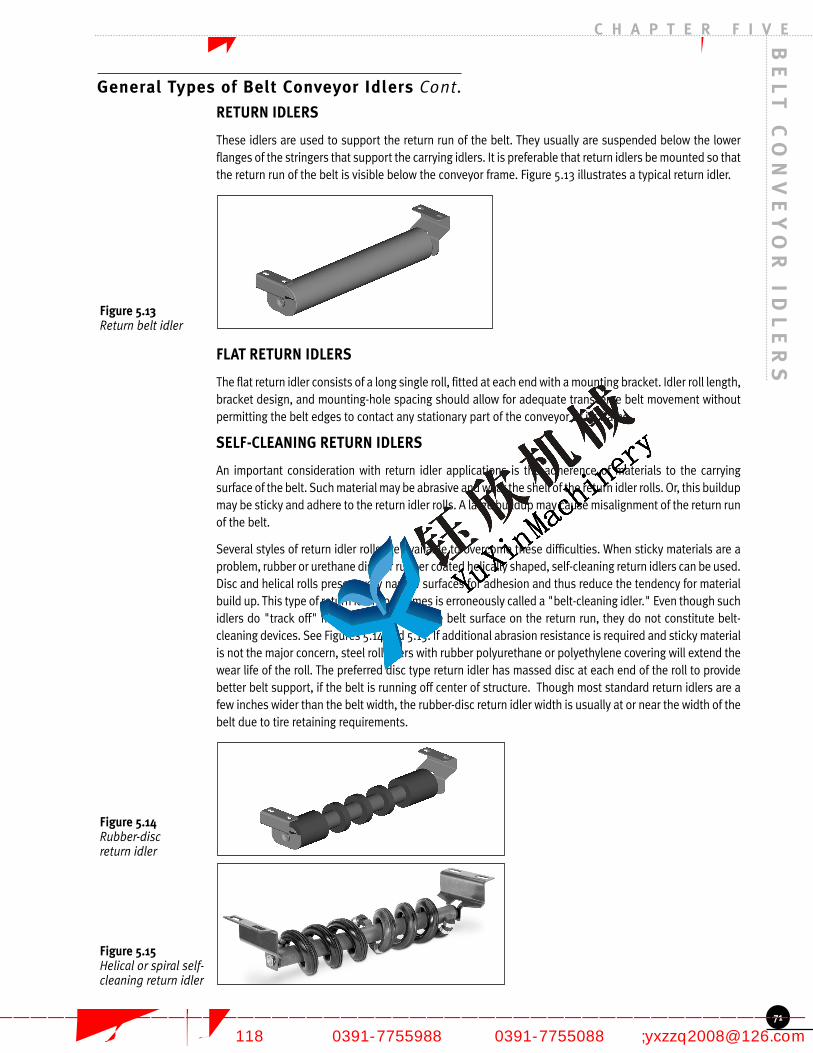
General Types of Belt Conveyor Idlers Cont.
RETURN IDLERS
These idlers are used to support the return run of the belt. They usually are suspended below the lowerflanges of the stringers that support the carrying idlers. It is preferable that return idlers be mounted so thatthe return run of the belt is visible below the conveyor frame. Figure 5.13 illustrates a typical return idler.
FLAT RETURN IDLERS
The flat return idler consists of a long single roll, fitted at each end with a mounting bracket. Idler roll length,bracket design, and mounting-hole spacing should allow for adequate transverse belt movement withoutpermitting the belt edges to contact any stationary part of the conveyor or its frame.
SELF-CLEANING RETURN IDLERS
An important consideration with return idler applications is the adherence of materials to the carryingsurface of the belt. Such material may be abrasive and wear the shell of the return idler rolls. Or, this buildupmay be sticky and adhere to the return idler rolls. A large buildup may cause misalignment of the return runof the belt.
Several styles of return idler rolls are available to overcome these difficulties. When sticky materials are aproblem, rubber or urethane disc, or rubber coated helically shaped, self-cleaning return idlers can be used.Disc and helical rolls present very narrow surfaces for adhesion and thus reduce the tendency for materialbuild up. This type of return idler sometimes is erroneously called a "belt-cleaning idler." Even though suchidlers do "track off" material adhering to the belt surface on the return run, they do not constitute belt-cleaning devices. See Figures 5.14 and 5.15. If additional abrasion resistance is required and sticky materialis not the major concern, steel roll idlers with rubber polyurethane or polyethylene covering will extend thewear life of the roll. The preferred disc type return idler has massed disc at each end of the roll to providebetter belt support, if the belt is running off center of structure. Though most standard return idlers are afew inches wider than the belt width, the rubber-disc return idler width is usually at or near the width of thebelt due to tire retaining requirements.
BE
LT
CO
NV
EY
OR
ID
LE
RS
C H A P T E R F I V E
71
Figure 5.13 Return belt idler
Figure 5.14 Rubber-disc return idler
Figure 5.15 Helical or spiral self-cleaning return idler
焦作市钰欣机械有限公司 专业的带式输送机制造商
—————————————————————————————————————————————————— 地址:焦作市黄河大道(西段)118号 电话:0391-7755988 传真:0391-7755088 邮箱;[email protected]

焦作市钰欣机械有限公司 专业的带式输送机制造商
—————————————————————————————————————————————————— 地址:焦作市黄河大道(西段)118号 电话:0391-7755988 传真:0391-7755088 邮箱;[email protected]

BE
LT
CO
NV
EY
OR
ID
LE
RS
C H A P T E R F I V E
General Types of Belt Conveyor Idlerss Cont.
On short conveyors, it may be necessary to equip the complete return run with self-cleaning idlers. Onlong return belt runs, it is necessary to use these idlers only to the point where the material on the beltsurface no longer will adhere to and build up on normal return idler rolls. Beyond this point, standardreturn idlers can be used.
RETURN BELT TRAINING IDLERS
Return belt idlers can be pivotally mounted to train or align the return belt in a manner similar to thetraining idlers previously described for the carrying run of the belt. See Figure 5.16. Training idlers forboth single direction or reversible belts are available. In general, a training idler designed for use on aone-way belt travel will not work on a reversible belt. Return belt training idlers are usually moreeffective than trough training idlers, due to lower belt tension on the return run.
TWO-ROLL "VEE" RETURN IDLERS
With the increased use of heavy, high-tension fabric and steel cable belts, the need for better supportand belt training has resulted in the development of "Vee" return idlers. A basic "Vee" return idlerconsists of two rolls, each tilted at a 5-, 10-, or 15-degree angle. These rolls are either of the garland(suspended) or rigid design. See Figures 5.17 and 5.18. The "Vee" return idler has some training effecton the belt, while allowing greater idler spacing because of its increased load rating. The trough shapeof the belt also tends to reduce or eliminate vibration along the conveyor.
"Vee" return idlers can be supplied with steel rolls, rolls coated with some type of polymer, or spaceddisc of rubber, urethane, or other material.
A decrease in wear life of the roll shell or spaced disc may occur with "Vee" return idlers. This is causedby most of the belt weight contacting the roll about one-fourth of the roll length from the centerline ofthe idler.
72
Figure 5.16 Return training idler
Figure 5.17 Two-roll "Vee" returnidler, rigid design
Figure 5.18 Two-roll suspended"Vee" return idler
焦作市钰欣机械有限公司 专业的带式输送机制造商
—————————————————————————————————————————————————— 地址:焦作市黄河大道(西段)118号 电话:0391-7755988 传真:0391-7755088 邮箱;[email protected]

Troughing Idler Spacing (Si)
Belt Width Weight of material Handled, lbf/ft3 Return(in) 30 50 75 100 150 200 Idlers
18 5.5 5.0 5.0 5.0 4.5 4.5 10.0
24 5.0 4.5 4.5 4.0 4.0 4.0 10.0
30 5.0 4.5 4.5 4.0 4.0 4.0 10.0
36 5.0 4.5 4.0 4.0 3.5 3.5 10.0
42 4.5 4.5 4.0 3.5 3.0 3.0 10.0
48 4.5 4.0 4.0 3.5 3.0 3.0 10.0
54 4.5 4.0 3.5 3.5 3.0 3.0 10.0
60 4.0 4.0 3.5 3.0 3.0 3.0 10.0
72 4.0 3.5 3.5 3.0 2.5 2.5 8.0
84 3.5 3.5 3.0 2.5 2.5 2.0 8.0
96 3.5 3.5 3.0 2.5 2.0 2.0 8.0
* Spacing indicated in feet. Spacing may be limited by load rating of idler. See idler load ratings in Tables 5.30 – 5.36.
General Types of Belt Conveyor Idlers Cont.
BELT SCALE IDLERS
Installations that include belt scales require idlers with more stringent tolerances in order to attainproper weighing accuracy. CEMA Standard No. 502 includes the scale idler requirements. Whenconsidering the installation and maintenance of a belt scale, the use of like idlers and rolls in the scalearea is important. Proper alignment of all components and the control of contaminants is essential.Belt conveyor scales from different manufacturers vary in characteristics, instructions, accuracy anddimensions. The basic application information and installation requirements relative to idler spacingand position must be obtained from the specific scale manufacturer.
Idler Spacing
Factors to consider when selecting idler spacing are belt weight, material weight, idler load rating, beltsag, idler life, belt rating, belt tension, and radius in vertical curves (see Chapter 9).
More complex issues (such as belt flap or vibration stability in wind, and power usage from beltindentation, material tramping, and rolling resistance) will be affected less by idler spacing.
If too much sag of a loaded troughed belt is permitted between the troughing idlers, the material mayspill over the edges of the belt. For the best design, especially on long-center troughed belt conveyors,the sag between idlers should be limited as described in Chapter 6. Table 5.19 lists conservativesuggested normal troughing idler spacing for use in general engineering practice, when the amount ofbelt sag is not specifically limited. Final idler selection should be determined based on informationobtained through detailed analysis by use of the CEMA idler selection method. These figures onspacing should be used in conjunction with the information on sag selection in Chapter 6. Spacing isnormally varied in 6-inch increments.
Some conveyor systems have been designed successfully utilizing extended idler spacing and/orgraduated idler spacing. Extended idler spacing is simply greater than normal spacing. This issometimes applied where belt tension, sag, belting strength, and idler rating permit. Advantages maybe lower idler cost (fewer used) and better belt training. Graduated idler spacing is greater than normalspacing at high tension portions of the belt. As the tension along the belt increases, the idler spacingis increased. Usually this type of spacing occurs toward and near the discharge end.
Extended and graduated spacing are not commonly used but if either is employed, care should be takennot to exceed idler load rating and sag limits during starting and stopping.
Table 5.19 Suggested normal spacing of belt idlers (Si ) *
BE
LT
CO
NV
EY
OR
ID
LE
RS
C H A P T E R F I V E
73
焦作市钰欣机械有限公司 专业的带式输送机制造商
—————————————————————————————————————————————————— 地址:焦作市黄河大道(西段)118号 电话:0391-7755988 传真:0391-7755088 邮箱;[email protected]

BE
LT
CO
NV
EY
OR
ID
LE
RS
C H A P T E R F I V E
Idler Spacing Cont.
RETURN IDLER SPACING
The suggested normal spacing of return idlers for general belt conveyor work is also given in Table 5.19.For conveyor belts with heavy carcasses, and with a width of 48 inches or more, it is recommended thatthe return idler spacing be determined by the use of the idler load ratings and belt sag considerations.(See Chapter 6.)
CARRYING IDLER SPACING AT LOADING POINTS
At loading points, the carrying idlers should be spaced to keep the belt steady and to hold the belt incontact with the rubber edging of the loading skirts along its entire length. Careful attention to thespacing of the carrying idlers at the loading points will minimize material leakage under the skirtboardsand, at the same time, will also minimize wear on the belt cover. Normally, carrying idlers in the loadingzone are spaced at half (or less) the normal spacing suggested in Table 5.19.
Caution: If impact idlers are used at loading zones, impact idler ratings are no higher than standardidler ratings.
Good practice dictates that the spacing of idler rolls under the loading area be such that the majordischarge portion of the load engages the belt between idlers. Rubber disc idlers are commonly usedbefore, between, and at the end of impact bars. Though this spacing is directed by bar length, idlerrating selection and elevation should be considered in these designs.
TROUGHING IDLER SPACING ADJACENT TO TERMINAL PULLEYS
In passing from the last troughing idler to the terminal pulley, the belt edges are stretched and tensionis increased at the outer edges. If the belt edge stress exceeds the elastic limit of the carcass, the beltedge will be stretched permanently and will cause belt-training difficulties. On the other hand, if thetroughing idlers are placed too far from the terminal pulleys, spillage of the load is likely.
Distance is important in the change (transition) from troughed to flat form. This is especially significantwhen deeply troughed idlers are used.
Depending on the transition distance, one, two, or more transition type troughing idlers can be used tosupport the belt between the last standard troughing idler and the terminal pulley. These idlers can bepositioned either at a fixed angle or at an adjustable concentrating angle.
The Selection of Idlers
Prior to October 1, 1996, CEMA ratings were based on 90,000 hours Bu (useful bearing life) at 500 rpm.Bu values were approximately 3 times L10. The Bu (useful bearing life) theory was technically correct.However, L10 bearing life is more commonly used and accepted for bearing life calculations and rating.Prior to CEMA publication 502-1996, the CEMA idler selection procedure used idler life (K) factors tocalculate an adjusted idler load. Some of these (K) factors were entirely independent of idler load andbearing L10 life. This procedure provided a conservative selection based on load but did not necessarilyprovide clear data relative to expected idler life.
RATING AND IDLER LIFE
Idler life is determined by a combination of many factors, such as seals, bearings, shell thickness, beltspeed, lump size/material density, maintenance, environment, temperature, and the proper CEMAseries of idler to handle the maximum calculated idler load. While bearing life is often used as anindicator of idler life, it must be recognized that the effect of other variables (e.g., seal effectiveness)may be more important in determining idler life than the bearings. Nevertheless, since bearing rating isthe only variable for which laboratory tests have provided standard values, CEMA uses bearing L10 life
74
焦作市钰欣机械有限公司 专业的带式输送机制造商
—————————————————————————————————————————————————— 地址:焦作市黄河大道(西段)118号 电话:0391-7755988 传真:0391-7755088 邮箱;[email protected]

The Selection of Idlers Cont.
as a guide for establishing idler ratings. The definition of L10 for belt conveyor idlers: The basic rated life(number of operating hours at 500 rpm) based on a 90 percent statistical model which is expressed asthe total number of revolutions 90 percent of the bearings in an apparently identical group of bearingssubjected to identical operating conditions will attain or exceed before a defined area of materialfatigue (flaking, spalling) occurs on one of its rings or rolling elements. The L10 life is also associatedwith 90 percent reliability for a single bearing under a certain load.
Tables 5.30 through 5.36 show load ratings for CEMA B, C, D, E and F idlers. These load ratings arebased on the following:
CEMA B load rating based on minimum L10 of 30,000 hours at 500 rpmCEMA C load rating based on minimum L10 of 30,000 hours at 500 rpmCEMA D load rating based on minimum L10 of 60,000 hours at 500 rpmCEMA E load rating based on minimum L10 of 60,000 hours at 500 rpmCEMA F load rating based on minimum L10 of 60,000 hours at 500 rpm
These loads and L10 life ratings are minimum ratings for CEMA rated idlers. Actual values for loadratings and L10 life for specific series and belt sizes supplied by CEMA manufacturers may be higher. Insome cases the idler frame design could be the limiting factor for load with L10 life being a higher value.
These loads and L10 life ratings are minimum ratings for CEMA rated idlers. Actual values for loadratings and L10 life for specific series and belt sizes supplied by CEMA manufacturers may be higher. Insome cases the idler frame design could be the limiting factor for load with L10 life being a higher value.
Idler Selection Procedure
There are many conditions that affect idler life. Those considered in this selection procedure are:
1. Type of material handled.
2. Idler load.
3. Effect of load on predicted bearing L10 life.
4. Belt speed.
5. Roll diameter.
6. Environmental, maintenance and other special conditions.
In addition to information provided in the Idler Selection Procedure, the above items are summarizedas follows:
TYPE OF MATERIAL HANDLED
The characteristics of the material handled have a direct bearing on the idler selection. The weight ofthe material governs the idler load and spacing, and lump size modifies the effect of weight byintroducing an impact factor. Table 5.23 combines the unit weight and the lump size into a group ofempirical factors referred to as K1. Note that in the table "lump size" means the largest lump whichmay occasionally be carried rather than the average lump.
LUMP SIZE CONSIDERATIONS
The lump size influences the belt specifications and the choice of carrying idlers. There is also anempirical relationship between lump size and belt width. The recommended maximum lump size forvarious belt widths is as follows:
For a 20 degree surcharge, with 10 percent lumps and 90 percent fines, the recommended maximum lumpis 1/3 the belt width (BW/3). With all lumps, the recommended maximum lump is 1/5 belt width (BW/5).
BE
LT
CO
NV
EY
OR
ID
LE
RS
C H A P T E R F I V E
75
焦作市钰欣机械有限公司 专业的带式输送机制造商
—————————————————————————————————————————————————— 地址:焦作市黄河大道(西段)118号 电话:0391-7755988 传真:0391-7755088 邮箱;[email protected]

BE
LT
CO
NV
EY
OR
ID
LE
RS
C H A P T E R F I V E
Idler Selection Procedure Cont.
For a 30 degree surcharge, with 10 percent lumps and 90 percent fines, the recommended maximumlump is 1/6 the belt width (BW/6). With all lumps, maximum lump is 1/10 the belt width (BW/10).
IDLER LOAD
To select the proper CEMA class (series) of idler, it is necessary to calculate the idler load. Thisprocedure is shown in "Idler Selection Procedure" (Step No. 1) for troughing idlers and (Step No. 2) forreturn idlers.
The idler load should be calculated for peak or maximum conditions. The belt conveyor designer shouldthoroughly investigate all conditions relative to calculating idler misalignment load (IML), in addition tostructure misalignment. The idler height deviation between standard fixed idlers and training idlers (orother special types of idlers) must be accounted for either by idler series selection or by conveyordesign and installation control.
IMPACT FORCES
Impact forces at conveyor loading points are yet another consideration of idler selection. Whether theconveyed material contains large lumps of is a continuous flow of homogeneous material with nolumps, the impact force should be studied. This process is demonstrated in Step No. 3.
When large lumps, greater than 2 inches, are present, the impact idler energy rating, WH, may becomea factor. Table 5.40 shows the minimum energy rating and the maximum lump size for each CEMA seriesimpact idler. The impact force, F, is then given by the following equation:
If the conveyed material does not contain lumps, but instead is a homogeneous stream of material, theimpact force is simply the function of the rate of flow and the height for fall. This impact force is givenby the following equation:
EFFECT OF LOAD ON PREDICTED BEARING L10 LIFE
When calculated idler load (CIL) is less than CEMA load rating of series idler selected, the bearing L10
life will increase. Figure 5.24 (Step No. 3) shows this relationship for either a tapered roller bearing ora ball bearing idler design. This chart can be used in conjunction with the type of service or lifeexpectancy of the conveyor system. If the specified design life of the conveyor system exceeds theCEMA L10 life rating at rated load, it may still meet specification based on percent of rated idler load vs.calculated idler load (CIL).
BELT SPEED
Bearing life (L10) is based on the number of revolutions of the bearing race. The faster the belt speed,the more revolutions per minute and consequently, a shorter life for a given number of revolutions. AllCEMA L10 life ratings are based on 500 rpm. Table 5.20 lists belt speed at 500 rpm for standard rolldiameters.
76
焦作市钰欣机械有限公司 专业的带式输送机制造商
—————————————————————————————————————————————————— 地址:焦作市黄河大道(西段)118号 电话:0391-7755988 传真:0391-7755088 邮箱;[email protected]

Roll Diameter (in) Belt Speed (fpm)
4 534
5 654
6 785
7 916
8 1047
Idler Selection Procedure Cont.
Table 5.20 Belt speeds at 500 rpm
Figure 5.25 (Step No. 4) shows the effect of belt speed on predicted bearing L10 life. However, suitablebelt conveyor speeds also depend upon the characteristics of the material to be conveyed, the capacitydesired, and the belt tensions employed. This subject is covered in more detail in Chapter 4.
ROLL DIAMETER
For a given belt speed, using larger diameter rolls will increase idler bearing L10. Figure 5.26 (Step No.5) shows this relationship. In addition, since larger diameter rolls will be contacting the belt less due toa slower rpm (at a given belt speed), the wear life of the shell will be increased.
ENVIRONMENTAL, MAINTENANCE AND OTHER CONDITIONS
Step No. 6 in the idler selection procedure identifies conditions that will affect potential idler life. All ofthese conditions do not have an exact mathematical basis and therefore can be very subjective. Themost important phase of this step is identifying the idler life condition for the application and thenarriving at solutions to obtain maximum idler life for that application. Since idler roll configuration, typeof bearing, and seal design can vary with each idler manufacturer, it is logical to state that idler life canalso vary for a given environmental and maintenance condition.
Figures 5.27, 5.28, and 5.29 show general conditions which will affect idler life. Those conditions areindependent of idler load but can cause idler failure before obtaining predicted L10 life rating. CEMArecommends contacting your CEMA idler manufacturer for assistance in establishing guidelines for"Potential Idler Life" for the various conditions shown or any unusual conditions not listed.
SPECIAL CONDITIONS
Idler roll shell material usually used throughout the industry is electric resistance welded steelmechanical tubing. For most belt conveyor applications, this material provides sufficient idler life mosteconomically. For severe abrasive or corrosive conditions, covered idler rolls are available in a variety ofmaterials. CEMA has not compiled a relative wear index or corrosion compatibility index for thesevarious materials. This information can be supplied by your CEMA idler manufacturer. However, theeconomic issue vs. increased life should be investigated thoroughly. Some of the generically availablematerials are listed below. There are numerous grades available in each of these materials which willaffect performance.
• Steel sleeves
• Rubber lagging
• Neoprene lagging
• Polyethylene sleeves/rolls
• Carboxylated nitrile
• Urethane• Ceramic
BE
LT
CO
NV
EY
OR
ID
LE
RS
C H A P T E R F I V E
77
焦作市钰欣机械有限公司 专业的带式输送机制造商
—————————————————————————————————————————————————— 地址:焦作市黄河大道(西段)118号 电话:0391-7755988 传真:0391-7755088 邮箱;[email protected]

BE
LT
CO
NV
EY
OR
ID
LE
RS
C H A P T E R F I V E
Idler Selection Procedure Cont.
Another consideration for increasing shell wear life is to use thicker metal shells. Some idlermanufacturers customarily supply larger diameter rolls with thicker metal shells and usually offeroptional shell thickness for all roll diameters. Idler shell wear life is more of a factor for the return idlerssince it normally contacts the "dirty" side of the belt resulting in abrasive wear of the shell. Theexception to this would be a conveyor system with a belt turnover system. With normal conveyorsystems, materials build up on the roll and increase its effective diameter. Because the buildup is neveruniform and usually is less at the belt edges, the clean sections of the return roll travel at a slowersurface speed than that of the belt. This results in relative slippage, thereby accelerating wear of boththe belt cover and the surface of the roll. Thus the life of the roll shell is usually shorter on return beltidlers than on carrying idlers. The material buildup can also aggravate belt training.
Impact forces at conveyor loading points are not covered by this selection procedure. This is due to themany variables and different designs utilized at loading points. Your CEMA idler manufacturer shouldbe consulted for impact idler recommendations.
Preface to Selection Procedure, Figures and Tables
INITIAL SELECTION, STEPS 1 AND 2:Select idler class by comparing calculated idler load with idler load ratings (CIL and CILR) from Tables5.30 through 5.36. CEMA idler manufacturers have standard designs meeting these load ratings anddimensional standards shown in tables listed in this publication.
BEARING L10 LIFE CORRECTION, STEPS 3, 4, AND 5:Factors K2 (Figure 5.24) and K3A (Figure 5.25) are multiplying factors used to adjust basic L10 life ratingof idler class selected. Factor K2 is based on percent of idler load and K3A is factor for actual roll speed(rpm). Factor K3B (Figure 5.26), step 5 is an optional step showing the advantage of using largerdiameter rolls. It can be used as a multiplier to save repeating step 4 if a larger diameter roll is used.
DETERMINE POTENTIAL IDLER LIFE, STEP 6:Factors K4A (Figure 5.27), K4B (Figure 5.28) and K4C (Figure 5.29) show conditions which will affectidler life and are independent of bearing L10 life, idler load and idler class. Use these figures to evaluatethe potential expected idler life. Contact your CEMA idler manufacturer for recommendations.
Step No. 1 Troughing Idler Series SelectionCalculated Idler Load (lbf ) = CIL = ((Wb + (Wm x K1)) x Si) + IML
Where:
Wb = Belt weight (lbf/ft) use actual or estimate from Table 5.22
Wm = Material weight (lbf/ft) = (Q x 2000) / (60 x V)
Q = Quantity of material conveyed (tons per hour)
V = Design belt speed (fpm)
Si = Spacing of idlers (ft)
K1 = Lump adjustment Factor (see Table 5.23)
NOTE: The actual weight of the lump should be compared with the Wm value. In certain situations itmay be necessary to use actual lump weight as Wm. Contact your CEMA idler manufacture if you havedoubts as to which value to use.
IML is the idler misalignment load (lbf ) due to idler height deviation and belt tension IML = (D x T) / (6 X Si) where:
D = Misalignment (in)T = Belt Tension (lbf )Si = Idler spacing (ft)
78
焦作市钰欣机械有限公司 专业的带式输送机制造商
—————————————————————————————————————————————————— 地址:焦作市黄河大道(西段)118号 电话:0391-7755988 传真:0391-7755088 邮箱;[email protected]

Material Lump Material Weight, lbf/ft3
Size (in) 50 75 100 125 150 175 200
4 1.0 1.0 1.0 1.0 1.1 1.1 1.1
6 1.0 1.0 1.0 1.1 1.1 1.1 1.1
8 1.0 1.0 1.1 1.1 1.2 1.2 1.2
10 1.0 1.1 1.1 1.1 1.2 1.2 1.2
12 1.0 1.1 1.1 1.2 1.2 1.2 1.3
14 1.1 1.1 1.1 1.2 1.2 1.3 1.3
16 1.1 1.1 1.2 1.2 1.3 1.3 1.4
18 1.1 1.1 1.2 1.2 1.3 1.3 1.4
Belt Width Material Carried, lbf/ft3
(in (BW)) 30-74 75-129 130-200
18 3.5 4.0 4.5
24 4.5 5.5 6.0
30 6.0 7.0 8.0
36 9.0 10.0 12.0
42 11.0 12.0 14.0
48 14.0 15.0 17.0
54 16.0 17.0 19.0
60 18.0 20.0 22.0
72 21.0 24.0 26.0
84 25.0 30.0 33.0
96 30.0 35.0 38.0
For steel cable belts increase the above values by 50%.
Preface to Selection Procedure, Figures and Tables Cont.
When an idler is higher than the adjacent idler, a component of belt tension will add load to that idler.The amount of height deviation can vary with the installation and type of idler. CEMA publication onconveyor installation standards (Appendix D, Belt Conveyors for Bulk Material, fifth edition or later) listsrecommendations on allowable structure misalignment).
Use CIL and select proper series of idler from tables 5.30 through 5.36.
CIL value should be equal to or less than idler rating.
This troughing idler selection procedure for calculated idler load does not include the following:
1. Impact force on idler at conveyor loading points.
2. Effect of belt transitions (head and tail pulley) on idler load.
See Step No. 3 for impact idler series selection. Contact your CEMA idler manufacturer for idler seriesselection for other loading conditions.
Table 5.22 Wb = Estimated Average Belt Weight,Multiple and Reduced Ply Belts (lbf/ft)
Actual belt weights vary with different constructions, manufacturers, cover gauges, etc. Use the abovevalues for estimating. Obtain actual values from the belt manufacturer whenever possible.
Table 5.23 K1 = Lump Adjustment Factor
BE
LT
CO
NV
EY
OR
ID
LE
RS
C H A P T E R F I V E
79
Figure 5.21 Idler heightmisalignment
焦作市钰欣机械有限公司 专业的带式输送机制造商
—————————————————————————————————————————————————— 地址:焦作市黄河大道(西段)118号 电话:0391-7755988 传真:0391-7755088 邮箱;[email protected]

BE
LT
CO
NV
EY
OR
ID
LE
RS
C H A P T E R F I V E
Preface to Selection Procedure, Figures and Tables Cont.
STEP NO. 2 RETURN IDLER SERIES SELECTIONCalculated Idler Load (lbf ) = CILR= (WB x SI) + IML
Use CILR and select proper series of idler from Tables 5.30 through 5.36. CILR should be equal to or lessthan return idler rating.
STEP NO. 3 K2 = EFFECT OF LOAD ON PREDICTED BEARING L10 LIFEWhen Calculated Idler Load (CIL) is less than the CEMA load rating of a series idler selected, the bearingL10 life will increase.
STEP NO. 4 K3A = EFFECT OF BELT SPEED ON PREDICTED BEARING L10 LIFECEMA L10 life ratings are based on 500 rpm. Slower speeds increase life and faster speeds decreaselife. Figure 5.25 shows this relationship.
STEP NO. 5 K3B = EFFECT OF ROLL DIAMETER ON PREDICTED BEARING L10 LIFEFor a given belt speed, using larger diameter rolls will increase idler L10 life. Figure 5.26 depicts L10 lifeadjustments for various roll diameters using 4 inch diameter as a value of 1.0. Percent life increase canbe calculated for each roll diameter increase.
80
Figure 5.24 K2 = Effect of load onpredicted bearing L10life
0.5 0.6 0.7 0.8 0.9 1.00.0
2.0
4.0
6.0
8.0
10.0
1.0
K2
Fact
or
CIL(Calculated Idler Load)ILR (Idler Load Rating)
� � � �
�� � � � � � � � � � � � ! # $ %
' ( *
* ( ,! "#$ #$ #$% &
- . / 1
23 4 5 6 7 7 5 9 6 : ; < = >
? @ A
A @ B! "#$ #$ #$% &
Figure 5.25 K3A = Effect of beltspeed on predictedbearing L10 life
焦作市钰欣机械有限公司 专业的带式输送机制造商
—————————————————————————————————————————————————— 地址:焦作市黄河大道(西段)118号 电话:0391-7755988 传真:0391-7755088 邮箱;[email protected]

Preface to Selection Procedure, Figures and Tables Cont.
NOTE: In addition to increased predicted bearing L10 life, larger diameter rolls can increase idler wear life.
STEP NO. 6 K4 = ENVIRONMENTAL, MAINTENANCE, AND OTHER SPECIAL CONDITIONSFigure 5.27 K4A = Effect of maintenance on potential idler life
Figure 5.28 K4B = Effect of environment on potential idler life
Figure 5.29 K4C = Effect of operating temperature on potential idler life
Based on collective application experience by CEMA idler manufacturers, these conditions are veryimportant in determining potential idler life. However, the exact mathematical basis is very subjective,so contact your CEMA idler manufacturer for assistance or for any unusual conditions not listed.
BE
LT
CO
NV
EY
OR
ID
LE
RS
C H A P T E R F I V E
81
Figure 5.26 K3B = Effect of rolldiameter on predictedbearing L10 life (basedon same belt speed)
Figure 5.27 K4A = Effect ofmaintenance onpotential idler life
Figure 5.28 K4B = Effect ofenvironmentalconditions onpotential idler life
焦作市钰欣机械有限公司 专业的带式输送机制造商
—————————————————————————————————————————————————— 地址:焦作市黄河大道(西段)118号 电话:0391-7755988 传真:0391-7755088 邮箱;[email protected]

Belt Width Trough Angle Single Two Roll(in) 20° 35° 45° Roll Return "Vee" Return
24 1200 1200 1200 600
30 1200 1200 1200 600
36 1200 1200 1200 600 850
42 1200 1200 1200 500 850
48 1200 1200 1200 425 850
54 1200 1116 1080 375 850
60 1150 1070 1035 280 850
72 1050 977 945 155 850
78 850
Ratings based on minimum L10 of 60,000 hours at 500 rpm.
Belt Width Trough Angle Single Two Roll(in) 20° 35° 45° Roll Return "Vee" Return
18 900 900 900 475
24 900 900 900 325 500
30 900 900 900 250 500
36 900 837 810 200 500
42 850 791 765 150 500
48 800 744 720 125 500
54 750 698 675 * 500
60 700 650 630 * 500
66 500
Ratings based on minimum L10 of 30,000 hours at 500 rpm. * Use CEMA D return idler.
Belt Width Trough Angle Single(in) 20° 35° 45° Roll Return
18 410 410 410 220
24 410 410 410 190
30 410 410 410 165
36 410 410 396 155
42 390 363 351 140
48 380 353 342 130
Ratings based on minimum L10 of 30,000 hours at 500 rpm.
BE
LT
CO
NV
EY
OR
ID
LE
RS
C H A P T E R F I V E
Preface to Selection Procedure, Figures and Tables Cont.
Table 5.30 5.30 load ratings for CEMA B idlers,lbf (rigid frame)
Table 5.31 Load ratings for CEMA C idlers, lbf (rigid frame)
Table 5.32 Load ratings for CEMA D idlers, lbf (rigid frame)
82
Figure 5.29 K4C = Effect ofoperationtemperature onpotential idler life
焦作市钰欣机械有限公司 专业的带式输送机制造商
—————————————————————————————————————————————————— 地址:焦作市黄河大道(西段)118号 电话:0391-7755988 传真:0391-7755088 邮箱;[email protected]

Belt Width (in) CEMA C CEMA D CEMA E
24 475 600
30 475 600
36 325 600 1260
42 250 600 1200
48 200 530 1000
54 150 440 1000
60 125 400 1000
72 280 925
84 775
96 625
Belt Width (in) CEMA C CEMA D CEMA E
18 1200
24 1200 1400 2100
30 1200 1400 2100
36 1200 1400 2100
42 1100 1400 2100
48 1000 1275 2100
54 875 1150 2100
60 780 1000 2100
72 850 2100
84 1825
96 1550
Belt Width Trough Angle Single Two Roll(in) 20° 35° 45° Roll Return "Vee" Return
60 3000 3000 3000 1500 **
72 3000 3000 3000 1200 **
84 3000 3000 3000 900 **
96 2800 2800 2800 600 **
Ratings based on Min. L10 of 60,000 hours at 500 rpm.** For "Vee" returns consider using CEMA E series.
Belt Width Trough Angle Single Two Roll(in) 20° 35° 45° Roll Return "Vee" Return
36 1800 1800 1800 1000 1300
42 1800 1800 1800 1000 1300
48 1800 1800 1800 1000 1300
54 1800 1800 1800 925 1300
60 1800 1800 1800 850 1300
72 1800 1800 1800 700 1300
84 1800 1674 1620 550 1300
96 1750 1628 1575 400 1300
102 1300
Ratings based on minimum L10 of 60,000 hours at 500 rpm.
Notes:1. Troughing idler load ratings (Tables 5.30 – 5.36) are for three equal length rolls.2. Load ratings also apply to impact rolls.3. Troughing idler load ratings are based on a load distribution of 70% on center roll and 15% on each
end roll for all trough angles. 4. Unequal length or picking idlers are not covered by this standard.
Preface to Selection Procedure, Figures and Tables Cont.
Table 5.33 Load ratings for CEMA E idlers, lbf, (rigid frame and garland where applicable)
Table 5.34 Load ratings for CEMA F idlers, lbf (rigid frame)
Table 5.35 Picking idler load ratings, lbf (rigid frame)
Table 5.36 Live shaft idler ratings, lbf
BE
LT
CO
NV
EY
OR
ID
LE
RS
C H A P T E R F I V E
83
焦作市钰欣机械有限公司 专业的带式输送机制造商
—————————————————————————————————————————————————— 地址:焦作市黄河大道(西段)118号 电话:0391-7755988 传真:0391-7755088 邮箱;[email protected]

BE
LT
CO
NV
EY
OR
ID
LE
RS
C H A P T E R F I V E
Example Idler Selection
CUSTOMER FURNISHED DATAPeak Load: 3,000 tph coal at 55/60 pcf minus 8 inch size
60 inch BW @ 650 fpm
T1 (Belt tension carrying side) ------------------------------ 37,000 lbf
T2 (Belt tension return side) --------------------------------- 12,000 lbf
Belt Weight ----------------------------------------------------------- 19 lbf/ft
D (Misalignment due to installation tolerances) --------------- 1/4 inch
Conveyor system components design life ------------------ 50,000 hours
Requested Information:Recommended Idler Series and Spacing:
Optional verification of customer data
Per Table 4.3 - 35° troughed belt cross section of load
60 inch BW @ 20° Surcharge = 2.876 ft2
Full belt load: 2.876 ft2 x 55 lbf/ft3 = 158 lbf/ft
Since this has been identified a Peak Load, the belt width, belt speed, and trough angle shown aregood selections.
Per Table 5.19: Suggested normal spacing of belt conveyor idlers (Si).
60 inch BW @ 50 lbf/ft3 = 4.0 ft
60 inch BW @ 75 lbf/ft3 = 3.5 ft
NOTE: Factors to be considered when selecting idler spacing are belt weight, material weight, idlerrating, idler life, belt rating, and belt tension. For general conveyor design and selection, limit belt sagto 2 percent of idler spacing at minimum tension conditions. Sag limits during conveyor starting andstopping should also be considered in overall selection.
IDLER SELECTIONStep No. 1: Carrying/troughing idler series selection based on Item B above. Use preliminary selectionof 4 ft.
K1 = 1.0 for 8-in lump
Per Table 5.32, D x 35° = 1070 lbf rating
Per Table 5.33, E x 35° = 1800 lbf rating
84
焦作市钰欣机械有限公司 专业的带式输送机制造商
—————————————————————————————————————————————————— 地址:焦作市黄河大道(西段)118号 电话:0391-7755988 传真:0391-7755088 邮箱;[email protected]

Example Idler Selection Cont.
NOTE: Although it is recommended that CIL be equal to or less than CEMA Idler Load Rating, there is acertain amount of judgment involved in final selection. In this example, an experienced belt designerwould know that the maximum IML load based on belt tension occurs at the head or discharge for alevel or incline conveyor. Since belt tension would be decreasing from this point towards the tail orloading end, the number of idlers that slightly exceeded the CEMA Idler Load Rating could bedetermined. D series x 35 degrees could be used and verification requested from CEMA idlermanufacturer.
Other choices are:
D series at less than 4 feet spacing
E series at greater than 4 feet spacing
Increase belt speed, which will decrease WM. This option would also decrease T1 belt tension, whichwould decrease IML.
Customer to maintain less than 1/4 inch height deviation due to installation tolerances.
Some of these choices would require recalculating belt tensions, etc., and then weighing theeconomics with the expected performance of each selection. For this example, we will select D seriesx 35 degree troughing idlers at 4 feet spacing, although optional choices C & D have great merit. Therated bearing L10 life is 60,000 hours.
Step No. 2: Return Idler Series Selection
Option: Table 5.19: suggested normal spacing of belt conveyor idler (Si)
Return idlers 60 inch BW = 10 ft
Based on the above option, use a preliminary selection of 10 ft spacing.
NOTE: Quite often it is desirable to have return idler spacing at a multiple of the troughing idler spacingto simplify stringer or truss design. However, this should not be the control for selection.
Per Table 5.32: D series single roll return = 280 lbf rating
Per Table 5.31: C series two roll "Vee" return = 500 lbf rating
If this conveyor has long centers, consideration should be given to using two roll "Vee" returns andincreasing spacing. With this choice it would not be necessary to use training idlers. For this example,select D series single roll returns at 12 feet 0 inches. The rated bearing L10 live is 60,000 hours.
Steps 1 and 2 have selected idlers based on load. Steps 3, 4, and 5 deal with predicted bearing L10 life,and Step 6 covers condition affecting potential idler life.
Step No. 3: Impact idler series selection
For homogeneous material without lumps:
Impact Force (lbf ) = F = 0.1389 x Q x H1/2
Where:
Q = Rate of flow (tph)
H = Height of fall (ft)
BE
LT
CO
NV
EY
OR
ID
LE
RS
C H A P T E R F I V E
85
焦作市钰欣机械有限公司 专业的带式输送机制造商
—————————————————————————————————————————————————— 地址:焦作市黄河大道(西段)118号 电话:0391-7755988 传真:0391-7755088 邮箱;[email protected]

BE
LT
CO
NV
EY
OR
ID
LE
RS
C H A P T E R F I V E
Example Idler Selection Cont.
The calculated impact force is then multiplied by an impact idler spacing factor, f, Table 5.39 todetermine the impact force on one idler.
Use this unit impact force, Fu, and select the proper series of impact idler from Tables 5.39 through 5.40.Fu should be equal to or less than the idler rating.
For material containing large lumps:
Where:
W = Weight of lump (lbf )
H = Height of fall (ft)
k = Spring constant for specific idler type (lbf/ft)(Consult idler manufacturer for k)
Use calculated energy rating, WH, and maximum lump size to select proper series of impact idler fromTable 5.40. Both WH and lump size should be equal to or less than the idler energy rating andmaximum lump size.
86
Figure 5.37 Impact from ahomogeneous stream
Figure 5.38 Impact from a single lump
焦作市钰欣机械有限公司 专业的带式输送机制造商
—————————————————————————————————————————————————— 地址:焦作市黄河大道(西段)118号 电话:0391-7755988 传真:0391-7755088 邮箱;[email protected]

3-Roll Rubber Impact Idlers
CEMA Series WH (lbf-ft) Maximum Lump Size (in)
B 40 4
C 160 6
D 240 8
E 460 12
F 870 18
Impact Idler Spacing, Si -impact(ft) Impact Idler Spacing Factor, f
1.0 0.5
1.5 0.7
2.0 0.9
> 2.0 1.0
Example Idler Selection Cont.
NOTE: Both cases, material without lumps and material containing lumps, should always be consideredand the heavier duty idler selected to insure adequate impact resistance capabilities.
Table 5.39 Impact idler spacing factor
Table 5.40 Minimum energy ratings for impact idlers
Step No. 4: K2 Effect of Load on Predicted Bearing L10 Life
K2 (from Figure 5.24, Tapered roller Bearing) = 1.0
Bearing L10 = (60,000 x 1.0) = 60,000 hours
K2 (from Figure 5.24, Tapered Roller Bearing) = 1.15
Bearing L10 = (60,0000 x 1.15) = 69,000 hours
Step No. 5: K3A Effect of Belt Speed on Predicted Bearing L10 Life
650 fpm belt speed specified.
Select minimum roll diameter for < 500 rpm at 650 fpm
From Table 5.20, 5 inch dia. = 654 fpm
K3A (from Figure 5.25) = 1.0
Bearing L10 life for D5 series idlers at 650 fpm
Troughing idler = (60,0000 x 1.0) = 60,000 hours
Return idler = (69,000 x 1.0) = 69,000 hours
Step No. 6: K3B Effect of Roll Diameter on Predicted Bearing Life
Compare bearing L10 life increase for 6 inch diameter roll.
= 1.20 or 20% increase in bearing L10 life
BE
LT
CO
NV
EY
OR
ID
LE
RS
C H A P T E R F I V E
87
焦作市钰欣机械有限公司 专业的带式输送机制造商
—————————————————————————————————————————————————— 地址:焦作市黄河大道(西段)118号 电话:0391-7755988 传真:0391-7755088 邮箱;[email protected]

BE
LT
CO
NV
EY
OR
ID
LE
RS
C H A P T E R F I V E
Example Idler Selection Cont.
K3B (Figure 5.26) =
Troughing idler = (60,000 x 1.2) = 72,000 hours
Return idler = (69,000 x 1.2) = 82,800 hours
NOTE: In addition, the 6 inch roll would have longer wear life, and roll resistance would be less, whichwould decrease belt tension and reduce IML.
D6 idlers are recommended; Idler selection is based on customer furnished data.
Troughing idlers D6 x 35° at 4 feet spacing with 72,000 hours predicted bearing L10 life.
Return idlers D6 at 12 ft spacing with 82,800 hours predicted bearing L10 life.
Step No. 7: K4 Effect of Environmental, Maintenance, and Temperature on Potential Idler Life.
For the purpose of example we will assume the following conditions:
K4A (Figure 5.27) Maintenance: ------------------------ Good to Fair
K4B (Figure 5.28) Environmental: ----------------------- Dirty
K4C (Figure 5.29) Temperature: ------------------------- <120° F
Hostile environmental conditions and the level of commitment to belt conveyor installation andmaintenance will affect idler life. With the above assumed conditions it is apparent that potential idlerlife will be less than the predicted bearing L10 life. These conditions should be discussed with yourCEMA idler manufacturer.
Expected or potential idler life may also be limited by shell wear. Shell wear can vary considerably witheach installation. In addition to conveyed material characteristics, environmental, and maintenancefactors, idler alignment and belt cleaning can have a significant effect on shell wear and idler life.
NOTE: Calculated idler loads should be repeated for training idlers (if used). Height deviation fortraining idlers must be included for IML calculation or controlled by shimming and maintaining closerinstallation tolerances at these areas of the conveyor.
Conclusion: There are numerous options available to the belt conveyor designer in regard to idlerselection. Through involving your CEMA idler manufacturer in this selection process these options canbe explored, resulting in a reliable, cost effective installation.
88
焦作市钰欣机械有限公司 专业的带式输送机制造商
—————————————————————————————————————————————————— 地址:焦作市黄河大道(西段)118号 电话:0391-7755988 传真:0391-7755088 邮箱;[email protected]

Belt Alignment
A belt conveyor must be designed, constructed and maintained so that the belt consistently runscentrally on its mechanical system of idlers and pulleys. To accomplish this, the following conditionsmust prevail:
1. Square the tail and head pulleys with the conveyor frame.
2. Square all idlers and returns with the conveyor frame; be sure they are in line and lie in the same horizontal plane; and tighten the attachment belts.
3. Level all frames to ensure a cross-section parallel to the ground plane. If one side of the conveyor frame is lower than the other, gravity will force the belt off-center.
4. The belt must be straight and the belt splice square. If side creep occurs only in the vicinity of the belt splice, the splice may not be square with the belt. In general, if the creep follows the belt, there is a problem with the belt. If it remains in one general area, there is a problem with the system.
5. The belt should have good contact with all troughing rolls.
6. Load material centrally on the belt.
Refer to Appendix D for information on CEMA Conveyor Installation Standards. There may be timeswhen the above procedure is not sufficient and the belt persistently runs to one side. The followingcorrective measures may be initiated to prevent side creep:
1. While running the belt at the lowest speed possible, find the point of maximum side creep. The idler preceding this point along the direction of belt travel can be adjusted to minimize side creep. Facing the conveyor from the tail end, the idler must be pivoted clockwise to correct side creep on the left and counterclockwise to correct side creep on the right. Once the belt is centered, change to a higher speed (if possible) and load the belt with material. Continue adjusting until normal operating conditions do not cause the belt to misalign.
2. If creep persists, insure that the head and tail pulleys are perfectly aligned. Steer the belt with the carrying or return idlers. See Figures 5.10 and 5.16.
3. Training idlers can be installed to replace troughing or return idlers. They should only be used in problem systems and should be at least 50 feet from any terminal or bend pulleys. Do not use a training idler in a vertical curve. Reversible belt training idlers are available for reversible belt conveyors. Free rotation of the training idler’s vertical bearing is essential for satisfactory tracking results.
4. If creep still persists, some or all of the troughing idlers may be tilted not more than 2 degrees from the vertical, in the direction of belt travel. See Figure 5.21.
5. If none of the above steps solve a belt misalignment condition, the conveyor should be laser aligned and corrective action taken based upon the survey data.
NOTE: Maximum tracking effect occurs when the distance between the corrective components and thefollowing components is maximized.
BE
LT
CO
NV
EY
OR
ID
LE
RS
C H A P T E R F I V E
89
焦作市钰欣机械有限公司 专业的带式输送机制造商
—————————————————————————————————————————————————— 地址:焦作市黄河大道(西段)118号 电话:0391-7755988 传真:0391-7755088 邮箱;[email protected]

BeltWidth CEMA Idler Class
(in) B4 B5 C4 C5 C6 D5 D6 E6 E7 F6 F7 F8
18 41 85 42 85 16524 50 106 51 106 210 106 21030 61 128 61 128 254 128 25436 72 152 72 152 312 152 312 419 75042 83 174 83 174 348 174 248 479 85748 94 196 94 196 385 196 385 539 96354 218 429 597 107060 234 473 659 1177 753 1171 176072 256 513 779 1391 884 1376 207184 933 1581 1014 1582 238296 1074 1737 1145 1790 2693
BeltWidth CEMA Idler Class
(in) B4 B5 C4 C5 C6 D5 D6 E6 E7 F6 F7 F8
18 43 90 45 90 17924 53 116 56 116 224 116 22430 65 140 67 140 269 140 26936 78 161 79 161 313 161 313 446 80142 90 185 91 185 358 185 358 502 87648 104 207 105 207 400 207 400 564 101754 223 447 223 447 628 112760 245 493 245 493 689 1234 838 1278 190172 266 538 811 1451 967 1481 220884 985 1598 1095 1695 253296 1114 1804 1224 1921 2870
BeltWidth CEMA Idler Class
(in) B4 B5 C4 C5 C6 D5 D6 E6 E7 F6 F7 F8
18 13.1 16.3 12.2 16.6 21.624 16.3 20.9 15.2 20.1 27.1 20.9 30.130 19.5 24.5 18.2 24.0 32.3 25.8 35.436 22.7 28.5 21.2 28.0 37.6 30.1 40.5 59.0 70.042 26.0 33.0 24.6 32.1 43.3 34.3 47.2 67.4 80.148 27.4 36.1 27.6 36.1 48.4 38.7 54.4 75.6 89.954 43.4 60.8 83.2 99.960 49.2 68.1 92.2 109.4 132.0 148.0 163.072 55.1 74.9 109.4 129.0 156.0 175.0 192.084 114.0 136.2 181.0 202.0 222.096 122.0 149.8 205.0 229.0 252.0
BeltWidth CEMA Idler Class
(in) B4 B5 C4 C5 C6 D5 D6 E6 E7 F6 F7 F8
18 15.0 19.2 14.5 19.1 26.724 18.3 24.2 17.5 23.2 32.6 23.2 32.630 21.8 28.3 20.5 26.8 38.0 26.8 38.036 25.3 33.0 23.5 31.3 43.6 31.3 43.6 64.8 81.842 30.8 38.1 26.5 35.2 49.2 35.2 49.2 73.3 91.748 32.9 41.6 29.5 39.3 54.8 39.3 54.8 81.9 101.354 45.9 62.3 45.9 62.3 93.6 121.860 50.1 68.3 50.1 68.3 102.2 132.7 143.0 162.0 180.072 57.9 77.8 119.4 154.5 169.0 191.0 211.084 132.0 164.0 195.0 219.0 243.096 145.3 173.0 221.0 248.0 274.0
BE
LT
CO
NV
EY
OR
ID
LE
RS
C H A P T E R F I V E
Belt Alignment Cont.
Table 5.41 Average weight (lbf)of troughing idler rotating parts – steel rolls
Table 5.42 Average weight (lbf) of return idler rotating parts – steel rolls
Table 5.43 WK2 (lbf-in2) averagefor three equal-roll troughing idlers
Table 5.44 WK2 (lbf-in2) average for single steel return idlers
90
焦作市钰欣机械有限公司 专业的带式输送机制造商
—————————————————————————————————————————————————— 地址:焦作市黄河大道(西段)118号 电话:0391-7755988 传真:0391-7755088 邮箱;[email protected]

BE
LT
TE
NS
IO
N A
ND
PO
WE
R E
NG
IN
EE
RI
NG
ScopeIntroduction
CEMA Conveyor Design EvolutionBelt Conveyor as a Basic Machine Tension Orientated Design Tension and Friction Terminology
Definition of the Three Conveyor Cases Basic ConveyorStandard ConveyorUniversal Conveyor
Belt Tension Calculations for Basic ConveyorsCase 1
Belt Tension Calculations for Standard Conveyors CEMA Standard Historical Method A Summary of the CEMA Standard Historical Method
Belt Tension Calculations for All Conveyors: Universal Method
Case 2Mass and Energy
Gravity Bulk Material AccelerationInertia
Main ResistancesLoad Independent Friction
Skirtboard Seal FrictionIdler Seal Drag
Load Dependent FrictionIdler Bearing Losses Belt Deformation Belt on Idler Alignment Friction
Garland IdlerSlider BedSkirtboard Friction
Load and Tension Dependent FrictionMaterial Trampling Loss Liftoff Loss
BELT TENSION AND POWERENGINEERING
91
C H A P T E R S I X
Continued on following page...
焦作市钰欣机械有限公司 专业的带式输送机制造商
—————————————————————————————————————————————————— 地址:焦作市黄河大道(西段)118号 电话:0391-7755988 传真:0391-7755088 邮箱;[email protected]

Point Sources of TensionPulleys as Passive Point Losses
Belt Cleaners Belt Discharge Plows
Active Tension ContributionsDriving the BeltBraking the Belt
Tension ManagementAnalysis Process
Steady State Running AnalysisMaximum Belt Tension
Operating Maximum Belt Tension Temporary Operating Maximum Belt Tension Starting and Stopping Maximum Tension Curves
Vertical Curves Horizontal Curves
Minimum Design TensionsMinimum T2 for Active PulleysBelt Sag between Idlers
Transient Tension Simplified ApproachCalculation of Average Acceleration and Deceleration Forces
Moving MassPassive Speed ChangeActive speed Change - Acceleration/Deceleration
Startup and ShutdownLoading
Component Tension Characteristics Belt
Energy Loss or ResistanceBelt Strength
Transient Load Safety FactorSplice
Modulus/Stiffness Longitudinal Stretch Speed of Tension ChangeCross Section Properties
Weight
BE
LT
TE
NS
IO
N A
ND
PO
WE
R E
NG
IN
EE
RI
NG
C H A P T E R S I X
92
Continued on following page...
焦作市钰欣机械有限公司 专业的带式输送机制造商
—————————————————————————————————————————————————— 地址:焦作市黄河大道(西段)118号 电话:0391-7755988 传真:0391-7755088 邮箱;[email protected]

BE
LT
TE
NS
IO
N A
ND
PO
WE
R E
NG
IN
EE
RI
NG
Idler Drag
Lifetime AffectsEnvironmental Seal Contamination
Spacing Alignment
Tracking Surface Friction
Roll Run OutInertia
Pulley Torque Transferal
Pulley DiameterLagging
Structural Implications -Running vs Transient LoadsPulley Inertia
Drive Components Torque and PowerDrive Inertia ConsiderationsDrivesBrakesBackstopsDrive System and Control
TakeupConstant Tension from Automatic Takeups
Takeup Tension DeadbandHysterisisTakeup Reaction Time
Constant Belt Length Fixed TakeupLoading Point
Material Entry GeometryReceiving Belt Equipment
AccessoriesConveyor as a System
OptimizationComponent Implications Maximum Belt Tension
Active Pulley LocationsMinimize T at Takeup Tension vs Energy Cost
Overall EfficiencyDIN fTransport Efficiency fe
93
C H A P T E R S I X
Continued on following page...
焦作市钰欣机械有限公司 专业的带式输送机制造商
—————————————————————————————————————————————————— 地址:焦作市黄河大道(西段)118号 电话:0391-7755988 传真:0391-7755088 邮箱;[email protected]

BE
LT
TE
NS
IO
N A
ND
PO
WE
R E
NG
IN
EE
RI
NG
C H A P T E R S I X
94
System InteractionsComponent Location
Active PulleysMultiple Pulley DrivesClustered DrivesBooster DrivesTail Drives
Takeup LocationBelt Stretch Influences
Local Belt StretchFixed Takeup or Constant Length BeltAutomatic Takeup Response
Reversing ConveyorReversing Conveyor Fixed TakeupReversing Conveyor Single Automatic TakeupReversing Conveyor Dual Drive
Transient BehaviorsHigh Dynamic TensionsFestooning from Low TensionsEffect on Material Carried Belt Stretch Potential Energy Drive or Brake SlipUnexpected FailuresBelt Flap
Design ToolsIterative Process Software Attributes
Example Conveyor Analysis
焦作市钰欣机械有限公司 专业的带式输送机制造商
—————————————————————————————————————————————————— 地址:焦作市黄河大道(西段)118号 电话:0391-7755988 传真:0391-7755088 邮箱;[email protected]

Scope
This chapter describes the calculation of the conveying forces and their interactions for use as primaryinputs to the sizing and operating requirements for components that make up a conveyor transportingbulk materials. The following methods represent the CEMA methods for the consistent design of beltconveyors for bulk materials based on the length and complexity of the design. There are three designmethods presented in this chapter, Basic, Standard and Universal, based on the complexity of theconveyor design and the desired level of accuracy. The Universal method is a new CEMA designprocedure that, when applied by an experienced conveyor engineer, should predict the power requiredto operate a conveyor for a wide range of applications with an accuracy of 110 ± 10% of the actual power.The Universal method allows the incorporation of specialized knowledge for an improved understandingof the various component forces and resistances of conveyor systems of any length or configuration.
Introduction
CEMA CONVEYOR DESIGN EVOLUTION
The earliest belt conveyor engineering methods as used in the first half of the 20th century weredependent upon empirical solutions that had been developed by various manufacturers andconsultants in this field. A second generation design method was developed by CEMA in the early1960s based on the design practices and experiences of its member companies. The belt conveyorengineering analysis, information, and formulas represented developments using observations andtests of actual belt conveyor operations and the best mathematical theory and analysis tools availableat the time. These methods included a breakdown of tension and power contributions from severalfriction mechanisms and various components in a manner that permitted the separate evaluation of theeffect of each factor. Within their range of applicability, they provided consistent and safe designs whileallowing design optimization and extrapolation for a commercially aggressive and maturing industry.
The formulas and methods described below are intended to continue that purpose recognizing theadvances in many elements of conveyor design and the ability of computers to analyze the changingstate of belt tension for alternate configurations of very long and complex conveyors. Those familiarwith the previous version of this chapter will see a familiar pattern which is to establish a discrete andsomewhat independent approach to the various design elements but with added functionalities ascompared to the previous system approach. This level of detail, while possible with manualcalculations, is primarily intended to provide a foundation for the use of computer programs incombining and managing the design concerns. This Chapter is also intended for instructional purposesto help assure that basic lessons and safe practices of conveyor design are understood and passed onto continuing generations of conveyor designers who might otherwise understand conveyor design asa simple numerical exercise.
BELT CONVEYOR AS A BASIC MACHINE
A belt conveyor is fundamentally a one dimensional machine and clearly follows physical laws. Anunderstanding of classical mechanics and Newton’s Laws of Motion provide a foundation for methodsdescribed in the balance of this chapter.
In summary, particularly relevant concepts from classical physics include:
1. Conservation of Energy: The amount of energy remains constant and energy is neither created nor destroyed. Energy can be converted from one form to another (potential energy can be converted to kinetic energy) but the total energy remains fixed.
2. Potential Energy: Potential energy is the stored energy by virtue of the position of an object. PE = M x g x H
3. Kinetic Energy: Kinetic energy is the energy of motion. KE = 1/2 x M x V2.
BE
LT
TE
NS
IO
N A
ND
PO
WE
R E
NG
IN
EE
RI
NG
C H A P T E R S I X
95
焦作市钰欣机械有限公司 专业的带式输送机制造商
—————————————————————————————————————————————————— 地址:焦作市黄河大道(西段)118号 电话:0391-7755988 传真:0391-7755088 邮箱;[email protected]

BE
LT
TE
NS
IO
N A
ND
PO
WE
R E
NG
IN
EE
RI
NG
C H A P T E R S I X
96
Introduction Cont.
4. The Concept of Work: Work is defined as a constant force applied over a distance. W = F x D
5. Newton’s First Law of Motion (Inertia): An object in motion tends to stay in motion until acted upon by another force.
6. Newton’s Second Law of Motion: The relationship between an object’s mass, its acceleration and the applied force is: F= M x A
7. Newton's Third Law of Motion (Conservation of Momentum): For every action there is an equal and opposite reaction. F1 = F2
Friction, a key component of the work of conveying, is used throughout the following as an empiricaland mathematical simplification of the energy loss from minute material fractures, molecularmovements and adhesive forces. The treatment of various frictions and their constitutive sourcesvaries with the relative importance and current understanding of their appropriate characterization. Inparticular, temperature and speed dependencies are important in the visco-elastic and viscousmaterials commonly used in conveyor component construction. Movements causing component andconveyed material degradation also consume energy and are treated as friction. Understandingfrictional energy loss is recognized as a primary need in accurate prediction of the operating statethroughout a conveyor.
Common terms used in this chapter in regard to the design, the bulk solid and the components of aparticular conveyor are active and passive. Passive is used to describe the inherent characteristics ofthe conveyor, the bulk solid and the conveyor components. The word active is used where the designerintentionally applies energy in a specific manner such as with a drive or brake.
TENSION ORIENTATED DESIGN
This chapter describes the prediction of belt force along the material conveyance path from the loadingpoint, or Tail, to the discharge, or Head, and back to the Tail. The calculation is principally oriented totension or the positive force in the belt. Tension has a direct influence on many design issues involvedwith conveyor design and the design process. That is:
1. The size or rating of many conveyor components, including the belt, are dictated by the belt tension applied to them.
2. The energy required to transport the material relates directly to the tension changes in the belt.
3. Drives and control components must be designed to provide changes in tension needed to cause and control motion.
4. Managing minimum and maximum belt tensions is necessary for reliable and efficient conveyor operation.
5. The magnitude of the belt tension affects the belt sag and therefore the material movement.
The calculations that follow apply to the total tension across any particular cross section of the belt.Belt tension varies across the width and, where important, these effects are addressed in other partsof this book.
In most conveyors it is useful to think of the conveyor as a series of discrete flights or sections. The tensionat any point such as the end of a flight or section is the algebraic sum of the tension at the end of theprevious flight and of the various tension changes along the current flight. With short flights, the averagetension can be approximated with the arithmetic average of the beginning and ending tension values.
The methods provided apply primarily to steady state or constant speed operation. However, they canalso be used to predict the changing friction as the belt speed changes uniformly during start up or shutdown. In this case, mass or inertia effects are included assuming all points along the belt are movingat the same speed as if the belt were rigid or non-stretching. This uniformly slow change in motion isreferred to as static analysis.
焦作市钰欣机械有限公司 专业的带式输送机制造商
—————————————————————————————————————————————————— 地址:焦作市黄河大道(西段)118号 电话:0391-7755988 传真:0391-7755088 邮箱;[email protected]

BE
LT
TE
NS
IO
N A
ND
PO
WE
R E
NG
IN
EE
RI
NG
C H A P T E R S I X
97
Introduction Cont.
Belt tensions may also vary in traveling waves during belt speed changes since all points andcomponents on the conveyor are not rigidly coupled. These transient belt tensions are commonlyignored safely due to successful experience using particular components or design practices but thedesigner should be aware that these transient tension conditions can cause severe and expensiveproblems in some cases. Dynamic analysis is used to predict these effects and include the frictionsdiscussed in this chapter. Dynamic analysis itself is outside the scope of this chapter and is discussedin Chapter 16.
The process of analyzing a particular conveyor consists of identifying the conveyance path, the materialloading conditions and the conveyor components. Belt motion leads to belt tension change along thecarrying run as well as on the return run of the belt. Quantitative tensions associated with materialenergy changes, running friction and component contributions are then accumulated from a particularpoint on the belt path progressing in the direction of belt movement. Figure 6.1 illustrates thesuperposition of resistances and accumulating tension in the direction of belt movement for a basicconveyor. The overall design process is most easily modeled as a summation of these discrete elementswhich can be incorporated into computerized methods.
Figure 6.1 Typical conveyingresistances andresulting belt tensiondiagram
焦作市钰欣机械有限公司 专业的带式输送机制造商
—————————————————————————————————————————————————— 地址:焦作市黄河大道(西段)118号 电话:0391-7755988 传真:0391-7755088 邮箱;[email protected]

BE
LT
TE
NS
IO
N A
ND
PO
WE
R E
NG
IN
EE
RI
NG
C H A P T E R S I X
Introduction Cont.
The conveyor path is also commonly analyzed as a summation of a sequence of segments orflights. The flight length should be kept small to minimize ‘averaging’ errors in the non linearportions of the calculation. Except for very simple designs, multiple iterations are needed toarrive at a practical and safe design due to the interdependencies between flight tensionsand resistances.
The intent of the following three approaches is to balance required of accuracy versus analysiseffort to gain accuracy by breaking the tension calculation into as many individual sources asneeded. This also provides a means for optimization and to fine tune or customize theprediction when specific performance data is available and appropriate. The Universal Methodis capable of predicting the total tension with an expected accuracy of 110% ± 10%. This impliesa 1.10 Safety Factor in addition to a ±10% factor for assumptions, variation in materialproperties, manufactured product tolerances, environmental conditions, aging andmaintenance effects. The Basic Method and Standard Method will predict the total tension forthose conveyors fitting the definitions within an acceptable but wider range of accuracy.
The design values and factors provided in this chapter are conservative estimates and thereforeshould result in over designed conveyors. Operational and safety critical components such asmotor and brake sizing should include an additional safety factor to account for thisconservative approach.
TENSION AND FRICTION TERMINOLOGY
In the equations that follow, tension and friction are key variables. Tension is indicated as a capital Twith a subscript "n" representing the flight or component location or direction. Exceptions are:
1. Unless specifically noted, tension, T is assumed to be Tx, tension in the direction of belt travel, and therefore the subscript "x" is customarily omitted.
2. T1, T2 and Te tensions which are adapted from previous editions and, with subscripts, relate to particular drive or brake pulleys. For drive pulleys Te is used interchangeably with ∆T described below (Subscripts of n = 1, 2.. separated by commas for multiple drives i.e. T1,1 etc)
Change in tension is a common theme in this chapter. Terminology convention uses ∆T lbf asthe net change in tension from a point source or total of continuous dT/dL loss for a particularflight or pulley (Te for drive or brake pulleys).
Positive (+) ∆T increases tension T and negative (-) ∆T reduces tension in the direction of beltmotion. The force units of pounds are expressed as lbf. If a clear distinction is appropriatebetween force and mass, the mass units will be expressed as lbm.
Friction variables provide for the calculation of individual sources of tension change, usually asa function of other operating variables. The calculations provided below often group severaldiscrete frictions into a subcategory with suitable accuracy for the range of conveyor addressedin this standard. Variable names and subscripts are used which imply the source of energy lossto aid in understanding the functional interactions. Units of friction vary with their use but willalways have lbf in numerator. The following terms are used in Chapter 6 and Chapter 16.
98
焦作市钰欣机械有限公司 专业的带式输送机制造商
—————————————————————————————————————————————————— 地址:焦作市黄河大道(西段)118号 电话:0391-7755988 传真:0391-7755088 邮箱;[email protected]

Introduction Cont.
Belt conveyors operate continuously — around the clock and around the calendar when required —without loss of time for loading and unloading or empty return trips. Scheduling and dispatching areunnecessary as the material is loaded to and unloaded from the belt conveyor automatically. Operatinglabor costs differ little, regardless of capacity ratings. Overall costs per ton decrease dramatically,however, as annual tonnage handled increases. Such economic considerations are illustrated later inthis chapter.
For these reasons, belt conveyors are capable of handling tonnages of bulk materials that would bemore costly and often impractical to transport by other means.
Friction Variables
• K = Internal energy loss. • C = Sliding friction between components.
Friction Subscripts
• b = Belt related losses.
• i = Idler related losses.
• m = Bulk material related losses.
Direction Subscripts
• x = + in direction of belt travel
• y = in the belt width direction referenced from 0 at belt centerline.
• z = in the belt thickness direction referenced from carrying side.
• Q (ton/hour or tph) = Bulk material loading rate in weight or force units.
• V (ft/min or fpm) = Belt speed.
• W (lb/ft) =Distributed external vertical loads.
• Wm (lb/ft) = Distributed gravity load of bulk material along length of belt.
• Wb (lb/ft) = Distributed gravity load of belt along length of belt.
• Ln (ft) = Length of a particular conveyor segment or flight n.
• L (ft) = Total conveyor path length, tail to head.
• Hn (ft) = Vertical lift (y) of flight n.
• BW (in) = Belt width.
• Sin (ft) = Spacing of idler sets along flight n.
• ∆Tn (lbf ) = Tension change in flight or pulley n.
• Tn (lbf ) = Average tension in flight or pulley n.
• T1,n (lbf ) = Tension in the belt approaching active pulley n.
• T2,n (lbf ) = Tension on the belt retreating from active pulley n.
• Ten (lbf ) = Tension change at an active pulley=T1n-T2n.
• F = External loads affecting ∆Tn, units as needed.
• n = The subscript n refers to one in a series of flights and pulleys making up an entire conveyor, typically referenced from the tail pulley progressing in the direction of belt movement.
BE
LT
TE
NS
IO
N A
ND
PO
WE
R E
NG
IN
EE
RI
NG
C H A P T E R S I X
99
焦作市钰欣机械有限公司 专业的带式输送机制造商
—————————————————————————————————————————————————— 地址:焦作市黄河大道(西段)118号 电话:0391-7755988 传真:0391-7755088 邮箱;[email protected]

Introduction Cont.
Definition of the Three Conveyor Cases
BASIC CONVEYOR
A basic conveyor is defined as:
• A single flight of less than 800 ft in length
• A single free flowing load point
• Inclined or horizontal but with out curves
• A belt with a fabric carcass
• Flat or equal roll troughing idlers
• A single drive
• Unidirectional or reversing up to 500 fpm
• A single gravity or fixed take up
• A maximum belt tension of 12,000 lbf
Any of the three design methods, Basic, Standard or Universal can be used to predict the tensionrequirements for a basic conveyor. A special case of the basic conveyor is the belt feeder which iscovered separately in Chapter 12.
BE
LT
TE
NS
IO
N A
ND
PO
WE
R E
NG
IN
EE
RI
NG
C H A P T E R S I X
100
Figure 6.2 Conveyor schematicand partial tensiondiagram illustratingtension terminology
焦作市钰欣机械有限公司 专业的带式输送机制造商
—————————————————————————————————————————————————— 地址:焦作市黄河大道(西段)118号 电话:0391-7755988 传真:0391-7755088 邮箱;[email protected]

Definition of the Three Conveyor Cases Cont.
STANDARD CONVEYOR
A standard conveyor is defined as:
• A single flight of less than 3000 ft in length
• Single or multiple free flowing load points
• Inclined, declined or horizontal with or without vertical curves
• A belt with a fabric carcass
• Flat or equal roll troughing idlers
• Unidirectional or reversing at any speed
• Single or multiple drives
• Gravity or automatic take ups
• A maximum belt tension of 16,000 lbf
The Standard or Universal design methods can be used to predict the tension requirements for anintermediate conveyor. The Standard method is the historical CEMA method described in the 5th editionof Belt Conveyors for Bulk Materials. There are additional design limitations for standard conveyorslisted in the examples of the 5th edition of Belt Conveyors for Bulk Materials.
UNIVERSAL CONVEYOR
A universal conveyor is defined as:
• A conveyor of any length
• Single or multiple freely flowing load points
• Inclined, declined and/or horizontal flights with horizontal or vertical curves
• A belt with a fabric carcass or steel cord belt
• Any belt profile
• Unidirectional or reversing
• Single or multiple drives
• Gravity or automatic take ups
The Universal design method must be used to accurately predict the tension requirements for auniversal conveyor. The Universal method is a new CEMA method described for the first time in the 6th
edition of Belt Conveyors for Bulk Materials.
BE
LT
TE
NS
IO
N A
ND
PO
WE
R E
NG
IN
EE
RI
NG
C H A P T E R S I X
101
焦作市钰欣机械有限公司 专业的带式输送机制造商
—————————————————————————————————————————————————— 地址:焦作市黄河大道(西段)118号 电话:0391-7755988 传真:0391-7755088 邮箱;[email protected]

BE
LT
TE
NS
IO
N A
ND
PO
WE
R E
NG
IN
EE
RI
NG
C H A P T E R S I X
Belt Tension Calculations for Basic Conveyors
The majority of conveyors used for moving and lifting materials can be analyzed simply and directlywith a few iterations and without concern for complicated interactions or loading variations. It isrecognized that the universal method described below is unnecessarily complex for the basicconveyors schematically shown in Figs 6.3 and 6.4.
Note that all calculations must satisfy the minimum tension concepts in this chapter to bea workable solution. In general, the total belt movement resistance will have an equivalentnormal friction factor, used for calculating the main resistances, less than 0.04. Thereforeas a rule of thumb over the full length of a basic conveyor:
102
Figure 6.3 Basic conveyor withinclined head drivewith fixed manualadjustment takeup
Figure 6.4Basic conveyor withinclined head drivewith fixed manualadjustment takeup
Figure 6.5 Basic methodequation
焦作市钰欣机械有限公司 专业的带式输送机制造商
—————————————————————————————————————————————————— 地址:焦作市黄河大道(西段)118号 电话:0391-7755988 传真:0391-7755088 邮箱;[email protected]

Belt Tension Calculations for Basic Conveyors Cont.
This conservative calculation for inclined conveyors similar to those shown in Fig 6.3 and 6.4 up to 800 ftlong, and at maximum loading, Wm, is suitable for drive sizing and component selection, though notoptimized. In particular, the lift tension for steep conveyors can be much more than this. For exampleat an incline of 10 degrees, tan (10°) = 0.176 >> 0.04, making accurate calculation of the main resistancerelatively unimportant. Point resistances for very short conveyors and load independent resistances forvery lightly loaded conveyors, both discussed below, should also be incorporated if this method is used.
CASE 1
The single flight conveyor shown in Fig 6.1 will be used to illustrate the basic calculations with theseinputs;
L = 400 ft
H = 70.5 ft
Q = 2500 ton/hour (tph)
V = 600 ft/min (fpm)
Wm = 139 lbf/ft
BW = 48 in
Wb = 11.4 lb/ft
Si = 4 ft on carry side; D6 35 degree idlers on carry side
Si = 12 ft on return side; single roll D5 return idlers
Ttu = 5500 lb, Tension at takeup
For the Case 1 example, Te is calculated to be 12,380 lb. That is, the drive must provide 12,380 lb of pullto maintain belt movement. On this 10° inclined conveyor, 79% of Te is used to lift the material.
Belt Tension Calculations for Standard Conveyors
CEMA STANDARD HISTORICAL METHOD
The 5th and prior editions of this book provided a calculation intermediate in complexity and accuracyto that described immediately above and the one that follows. Though not described in detail, it isaddressed here to establish its continued validity for the conveyors for which it was developed.
In particular, calculations are provided for the required power and the main resistance Te throughvariables called Ky, Kx (Appendix C) and Kt (Equation 6.18) provided is applicable for conveyors in which theaverage belt tension is 16,000 lbs or less and for conveyors up to 3,000 ft long with a single slope and a 3%maximum sag of the belt between the troughing and between the return idlers. The return idler spacing is 10ft nominal and loading of the belt is uniform and continuous. Data tables provide Ky for idler spacing between 3 ft and 5 ft. In addition, it should be noted that though Ky has been successfully extrapolated to a muchwider range of applications, the values provided were developed from testing on belts with fabric carcass inwidths 48 inches and less. Kx is somewhat dated but is considered satisfactory for use with this method.
In this range of applications, the results from this method and the more detailed universal method thatfollows will be similar when the applicable parameters in the latter are selected. Clearly, the methodsdo not use the same range of inputs so exact agreement cannot be expected. This method can beapplied to individual flights similar to that discussed below so that intermediate tensions can be foundfor use in calculating vertical curves.
BE
LT
TE
NS
IO
N A
ND
PO
WE
R E
NG
IN
EE
RI
NG
C H A P T E R S I X
103
焦作市钰欣机械有限公司 专业的带式输送机制造商
—————————————————————————————————————————————————— 地址:焦作市黄河大道(西段)118号 电话:0391-7755988 传真:0391-7755088 邮箱;[email protected]

BE
LT
TE
NS
IO
N A
ND
PO
WE
R E
NG
IN
EE
RI
NG
C H A P T E R S I X
Belt Tension Calculations for Standard Conveyors Cont.
A SUMMARY OF THE CEMA STANDARD HISTORICAL METHOD
A summary excerpt of the Standard CEMA method:
"To determine the effective tension, Te, it is necessary to identify and evaluate each of the individualforces acting on the conveyor belt and contributing to the tension required to drive the belt at thedriving pulley. Te is the final summarization of the belt tensions produced by forces such as:
1. The gravitational load to lift or lower the material being transported
2. The frictional resistance of the conveyor components, drive, and all accessories while operating atdesign capacity
3. The frictional resistance of the material as it is being conveyed
4. The force required to accelerate the material continuously as it is fed onto the conveyor by a chute or a feeder
The basic formula for calculating the effective tension, Te, is:
Where:
L, H, Wb, and Wm are as previously defined
Kx (lbf/ft)=Idler Resistance Factor
Ky = Belt Resistance Factor (dimensionless)
Kt = Temperature Correction Factor (dimensionless)
Tp (lbf ) = Tension due to the belt flexure around pulleys and pulley bearing resistance
Tam (lbf ) = Tension resulting from the force to accelerate the material as it is fed onto the belt
Tac (lbf ) = Tension from accessories
Tp , Tam , Tac are additional tension (lbf/ft) contributions as included in this edition
Note the implication of a single drive and unified source of tension loss. The details of this calculationmay be found in the 5th edition of Belt Conveyors for Bulk Materials and from CEMA member companies.This equation should not be mixed with the basic or universal methods. For the Case 1 example, Te iscalculated to be 11606 lbf. This is 94% of that calculated by the simplified method while the frictiononly, without the lift force, is 70% of the simpler method.
Belt Tension Calculations for All Conveyors: Universal Method
The remainder of this section describes general calculations applicable to all conveyors without limit asto length or profile. This Universal method is based on all understanding of the characteristics of themajor energy loss sources applied to standard components and constructions and with applicationparameters applicable to normal limits to speed and tension. Nonetheless, the Universal method hasbenefits due to a much broader scope than the Basic and Standard methods.
The forces seen in the belt can be categorized as follows;
• Work done on the belt from external sources.
• Internal forces associated with a change of velocity
• Uniform internal tension
The Universal method addresses the first of these which are calculated as operating at a steady speed.The calculations parallel the Basic and Standard historical CEMA calculation but with fewer constraintsfor their applicability. Therefore, most elements, except those relating to issues of the mainresistances, may be shared among all three methods. The second category of belt forces listed abovedevelop when the first is unbalanced. The third category is intentionally applied by the designer and is
104
Figure 6.6 Standard methodequation
焦作市钰欣机械有限公司 专业的带式输送机制造商
—————————————————————————————————————————————————— 地址:焦作市黄河大道(西段)118号 电话:0391-7755988 传真:0391-7755088 邮箱;[email protected]

Belt Tension Calculations for All Conveyors: Universal Method Cont.
distributed uniformly around the belt circuit as pre-stretch. The latter two categories are treated as tensionsthat are managed by the designer to assure overall operating success and discussed later in this chapter.
Nominal accuracy of this method is +/-10% but the default values provided in this section areconservative with the intent that so that the use of these equations by an inexperienced engineerproduces a conservative result. Certain operational and safety critical components such as brake sizingor with downhill flights should include additional safety factors described as Rr for each of the losscategories to account for this conservative approach. An experienced CEMA conveyor engineer utilizingvalues and design factors that are known to be representative of the application being designed can usethe Universal method to produce results that are within the 110% ± 10% target range.
The Universal method provides design parameters and empirically fit equations to quantify the energyloss categories and to simplify the calculation tension loss. The following list summarizes the range ofcomponents and constructions directly useable with the equations provided.
• CEMA Flat, 20, 35 and 45 degree equal length 3 roll idlers
• 1500 ft/min maximum belt speed
• Operating temperatures > -25°F – 120°F
• Common belt cover materials i.e. Natural, SBR etc.
• Multiple belt constructions with equal stiffness plies
• Maximum Belt width = 96 in
• Maximum Idler spacing = 10 ft
• Free flowing materials; Maximum Angle of Repose = 45 deg
Refer to the ‘Component Tension Characteristics’ section of this chapter, Chapter 16, Appendix F orcontact a CEMA member to extend or extrapolate beyond these limits.
This Universal calculation is similar to the historic method in that it sums various sources of loss for thetotal resistance to movement. It is different in that it focuses on addressing individual flights (refsubscript ‘n’) as needed for long complicated conveyors and in the detail and accuracy of calculation ofthe various constituent resistances. This section quantifies the tension changes at each flight while thediscussion of Tension Management below addresses how they all accumulate appropriately into a totalconveyor.
In summary, the calculation and the text that follows describe the tension added at each flight as follows:
Where:
Where all apply to the effect in flight or pulley n and;
∆Tn (lbf ) = Total change in belt tension to cause steady belt speed
∆THn (lbf ) = Change in belt tension to lift or lower the material and belt
∆Tamn (lbf ) = Tension added in loading to continuously accelerate material to belt speed
∆Tssn (lbf ) = Tension change due to the belt sliding on skirtboard seal
∆Tisn (lbf ) = Change in tension from idler seal friction
∆TiWn (lbf ) = Change in tension from idler load friction
BE
LT
TE
NS
IO
N A
ND
PO
WE
R E
NG
IN
EE
RI
NG
C H A P T E R S I X
105
Figure 6.7 Universal methodequation
焦作市钰欣机械有限公司 专业的带式输送机制造商
—————————————————————————————————————————————————— 地址:焦作市黄河大道(西段)118号 电话:0391-7755988 传真:0391-7755088 邮箱;[email protected]

BE
LT
TE
NS
IO
N A
ND
PO
WE
R E
NG
IN
EE
RI
NG
C H A P T E R S I X
106
Figure 6.8 Tension due to liftingthe belt and bulkmaterial
Belt Tension Calculations for All Conveyors: Universal Method Cont.
∆Tbin (lbf ) = Tension increase from visco-elastic deformation of belt
∆Tmn (lbf ) = Tension loss from idler misalignment
∆Tsbn (lbf ) = Drag due to Slider Beds
∆Tsn (lbf ) = Tension change due to bulk materials sliding on skirtboards
∆Tmn (lbf ) = Tension change due to bulk materials moving between the idlers
∆Tpxn (lbf ) = Tension change due to belt bending on the pulley
∆Tprn (lbf ) = Tension change due to pulley bearings
∆Tbcn (lbf ) = Tension added due to belt cleaners and plows
∆Tdpn (lbf ) = Tension added due to discharge plow
The various ∆T contributions are described individually below for a particular section or flight "n".When pulleys are considered as separate flights in series with the carrying and return flights, the othersources of resistance are set to zero for the pulley flights.
The relative importance of the various elements described below varies widely and none can beignored, though they may have very small contributions in particular conveyors.
The examples referred to as Case 2 use Figure 6.2 flights as follows with the same loading as used inCase 1 from the simple conveyor example.
CASE 2
L1= 15 ft; H1= 0 ft loading
L2= 500 ft; H2= 0 ft
L3= 500 ft; H3= 0 ft
L4= 300 ft; H4= 53 ft vertical curve
L5= 400 ft; H5=70.5 ft 10 degree incline
Ln and Hn are the same for the corresponding return flights
MASS AND ENERGY
Gravity A precise and often major source of belt tension is the work involved with inclined or declinedconveyance paths due to the Potential Energy change in the bulk material and belt for a height changeHn (Fig 6.2) The tension is sensitive to the direction of travel so that with uphill movement the tensionincreases and a downhill or negative slope angle causes reduction in this component of tension alongthe conveyance direction as gravity pulls the conveyor down the slope;
Where:
∆THn (lbf ) = Change in belt tension in flight n to cause steady belt speed.
Hn (ft) = Lift or drop (-H) over the length Ln of flight n.
θin (deg) = Uniform or average angle of incline(+) or decline (-) in direction of movement over the flight length Ln.
Gravity or Potential Energy is considered to have a continuous effect on tension along the length of anyslope from earth horizontal. It should be observed that the weight of the carry side belt and the returnside belt cancel each other out from the perspective of total conveyor Te but need to be included incircuit calculations to identify the local tension at any point. For flights including belt curves in a verticalplane (See Chapter 9) use H as described above, take an average slope or use trigonometry over thechange incline with the arc radius of the curve.
焦作市钰欣机械有限公司 专业的带式输送机制造商
—————————————————————————————————————————————————— 地址:焦作市黄河大道(西段)118号 电话:0391-7755988 传真:0391-7755088 邮箱;[email protected]

BE
LT
TE
NS
IO
N A
ND
PO
WE
R E
NG
IN
EE
RI
NG
C H A P T E R S I X
107
Belt Tension Calculations for All Conveyors: Universal Method Cont.
Bulk Material AccelerationWork or Kinetic Energy must be provided to the bulk material to accelerate it to match the speed of thebelt. The accelerating force is provided by the belt through an increase in tension at the loading point(s)in the direction of belt movement. Using the amount of Kinetic Energy added to the bulk material allowsthe calculation of belt tension effects without concern for the acceleration rate or the dynamics involvedwith impact, although these can be important issues for belt, chute and material degradation.
Where:
∆Tamn (lbf )= Tension added in loading flight n to continuously accelerate material to belt speed
g = 32.2 ft/sec2
Vo (fpm) = Initial Vo = initial velocity of material at point of impact with belt
θi (deg) = Angle of impact of material to the belt relative to belt direction. (See Figure 6.11)
Figure 6.9 Example, referenceflight 5 from Fig 6.2
Figure 6.11 Material velocitychange when loadingonto belt
Figure 6.10 Tension needed toaccelerate the bulkmaterial
! "! "÷ ø ù ú û
��� �� ����� ���� �
������
hd
焦作市钰欣机械有限公司 专业的带式输送机制造商
—————————————————————————————————————————————————— 地址:焦作市黄河大道(西段)118号 电话:0391-7755988 传真:0391-7755088 邮箱;[email protected]

BE
LT
TE
NS
IO
N A
ND
PO
WE
R E
NG
IN
EE
RI
NG
C H A P T E R S I X
Belt Tension Calculations for All Conveyors: Universal Method Cont.
This accelerating force must be added whenever the material leaves contact with the belt andreengages the belt at a trajectory different than the belt direction. For instance, this comes into playwith trippers along the belt path.
Common practice assumes θi =0 as worst case condition though a negative θi will require more tension.Tamn has minor impact on most conveyors of any significant length so this approximation is usuallyreasonable. See Chapter 12 for detail on calculation of V0.
For example, with material in free fall for 5 ft until it hits a chute wall inclined at 20 degrees to thehorizontal Flight 1 of Figure 6.11.
InertiaA belt conveyor, because of its long distributed mass, is considered a high inertia machine. This meansthat high forces or relatively long times are needed to cause change in velocity. This effect is importantto include when predicting the expected operation of the conveyor and the proper selection of itscomponents. The forces that create the changes in velocity are not considered steady state and are notpart of this section.
MAIN RESISTANCES
Continuous, bidirectional resistance to belt movement or quasi-frictional losses are often called themain resistances of conveyors. For long, flat conveyors where potential energy effects are non-existentand secondary point sources are relatively less important, the main resistances are the primaryresistance to belt and material movement. These losses, in general, will have the same magnitudeindependent of the direction of travel but always retard motion. They are described here as elementsof passive friction for calculation purpose though the energy loss mechanisms are not all classic slidingCoulomb friction. They are considered as continuous losses distributed along the conveyor orindividual flights and calculations are on a unit length basis though the losses may develop at eachidler or idler span.
The basic calculations described below provide conservative design values by using conservativematerial and component characteristics in the calculations though the actual resistance may besignificantly lower. When conveyors include significant downhill portions, safe design requiresassuring controlled speed and therefore must include the possibility of resistances at the lower levelsof the expected range. A multiplier ratio Rrxx is used with a friction calculation to obtain the low end ofthe expected range for each ∆Txx. These should not be used independently but simultaneously for allflights and all resistances as described as Tension Management in this chapter.
Load Independent FrictionThough energy loss and resistance to movement invariably involve applied forces, some of these are notassociated with the normal forces from the weight of the bulk material or the belt but from forces internalto the conveyor or component design. These losses contribute to conveyor main resistance simply frombelt movement.
108
Figure 6.12 Example horizontalflight 1 of Figure 6.11
焦作市钰欣机械有限公司 专业的带式输送机制造商
—————————————————————————————————————————————————— 地址:焦作市黄河大道(西段)118号 电话:0391-7755988 传真:0391-7755088 邮箱;[email protected]

Belt Tension Calculations for All Conveyors: Universal Method Cont.
Skirtboard Seal FrictionA skirt seal which rides on the belt is commonly used to contain dust and small particles. The calculationpredicts the resistance as the product of a friction factor and the unit normal force between the moving beltand the seal without influence from the material loading. The values are provided below apply to a genericrubber edge seal as shown in Fig 6.14, for flight "n" that is sealed along it’s full length on both sides;
Where:
∆Tssn (lbf ) = Tension change due to the belt sliding on skirtboard sealed flight. ‘n’
Css (lbf/ft) = Frictional resistance to the belt movement.
µss = Sliding friction coefficient between belt and seal rubber.
Fss (lbf ) = Effective normal force between belt and seal
Various specialty sealing products are available to perform this function with varying performance, life anddrag. Typical values are µss = 1.0 and Fss = 3.0 lbf/ft. of skirt seal for conventional slab rubber skirt boardseals shown in Fig 6.14. Css is calculated by multiplying by a factor of 2 because it is assumed that bothsides of the belt have a skirt seal. Therefore an estimate of 6.0 lbf/ft of conveyor is a typical value for ∆Tssn.These issues are discussed in more detail in Chapter 11 with values of Fss and µss for various materials andskirt seal configurations with a discussion on the merits and applications for specialty skirt seals
If the flight length is greater than the skirt length, this calculation should be used for a point source losscalculation substituting the skirted length for Ln.
Rrss = 0 for the case when the seal is completely worn, though this operating condition should rarely beused for calculations.
For example, with the above defaults for slab rubber skirtboard:
BE
LT
TE
NS
IO
N A
ND
PO
WE
R E
NG
IN
EE
RI
NG
C H A P T E R S I X
109
Figure 6.13 Calculation ofskirtboard seal drag
Figure 6.15 Skirtboard sealexample calculation
Figure 6.14 Skirtboard drag onthe belt
焦作市钰欣机械有限公司 专业的带式输送机制造商
—————————————————————————————————————————————————— 地址:焦作市黄河大道(西段)118号 电话:0391-7755988 传真:0391-7755088 邮箱;[email protected]

BE
LT
TE
NS
IO
N A
ND
PO
WE
R E
NG
IN
EE
RI
NG
C H A P T E R S I X
Belt Tension Calculations for All Conveyors: Universal Method Cont.
Idler Seal Drag The support idlers resist rotation and belt movement by a combination of mechanisms internal to the idlerroll and influenced by various elements of their design. The rotating resistance is a torsional moment whichis overcome at the belt line as tangential force acting on a moment arm equal to the roll radius. ReferenceFigure 6.16.
This section addresses the expected resistance that is not related to the applied load and is lumped intothe viscous and sliding drags associated with the roll seal and lubrication. Though some interaction existsbetween the seal and bearing drags, the two are treated as independent in addition to the bearing loadfunction in the following section.
The method provided below provides a simple estimate for the resistance provided by the idler seal. Theactual resistance varies widely so that the use of actual values is suggested for accurate predictions. Thefollowing equation is constructed to allow specific values to be incorporated.
Where:
∆Tisn (lbf ) = change in tension in flight ‘n’ from idler seal friction
KiV (in x lbf/rpm) = torsional speed effect-see Table 6.19
Kis (in x lbf ) = seal torsional resistance per roll at 500 rpm-see Table 6.19
KiT =Temperature correction factor per Equation 6.18
nr =number of rolls per idler set
Dr (in) =roll diameter
TF (°F) =Ambient operating temperature
Consult a CEMA member for KiT values to be used for designing long horizontal conveyors operating at low temperatures.
110
Figure 6.16 Idler belt line reaction
Figure 6.17 Idler seal frictioncalculation
Figure 6.18 Temperaturecorrection factorequation
焦作市钰欣机械有限公司 专业的带式输送机制造商
—————————————————————————————————————————————————— 地址:焦作市黄河大道(西段)118号 电话:0391-7755988 传真:0391-7755088 邮箱;[email protected]

Idler Kis KiVSeries (in x lbf) (in x lbf/rpm)
B 3.00 0.004
C 3.25 0.004
D 4.00 0.004
E 7.25 0.003
Belt Tension Calculations for All Conveyors: Universal Method Cont.
Table 6.19 Maximum expected individual idler roll seal torques for various CEMA idler series. (Use with Rris and RriV
discussed below)
The values in Table 6.19 are provided in terms of torque in order to ease the application of actualoperating performance for use in equation 6.16. If possible, the torsional resistance at the actualrotational speed should be obtained in this case and substituted directly as Kis with Kiv set to 0.0.Likewise, test values at expected operating temperature should be used so that KiT can also be set to 1.0.
When seal drag is found to be an important element of belt tension as in overland or downhillconveyors, the actual performance values are much preferred over the defaults provided in Table 6.19since these values represent the maximum expected drag from product produced by CEMA idlermanufacturers including varying seal designs and grease fills which have strong influences from speedand temperature. The idler rotating resistance varies over it’s lifetime from high torque during break-inwhen it is new to easy rolling during it’s prime operation to high resistance if the bearing or seal beginsto fail. This is discussed further later in this chapter. Separate from long term changes are breakawayresistance and a warm up time where the roll resistance drops off to a value after several minutes ofrunning from the stopped, cold state. The above formulas apply to the running state but the breakawaycondition may be estimated by use of a temperature 40°F less than ambient in the KiT formula. Theinevitability of manufacturing variability within and between production lots should be incorporatedinto any test regime used to obtain ‘typical’ values appropriate for design.
Rris = 0.20 with RriV = 0 should be applied where appropriate if the default values of Kis and Kiv fromTable 6.19 are used. Alternatively, since idler designs vary widely, actual manufacturer data should beused if available, including the actual Rri, calculated from the expected range of Kis and break in effects.
In Case 2, Flight 5, CEMA D5 3 Roll Troughing Idlers D6 3 roll troughing idlers are used on 4ft Spacing.For operation at 0°F:
BE
LT
TE
NS
IO
N A
ND
PO
WE
R E
NG
IN
EE
RI
NG
C H A P T E R S I X
111
Figure 6.20 Example idler sealfriction calculation
*Kis can be measured as described in Appendix F. By testing at three different
belt speeds a value for KiV can be determined for a specific idler.
焦作市钰欣机械有限公司 专业的带式输送机制造商
—————————————————————————————————————————————————— 地址:焦作市黄河大道(西段)118号 电话:0391-7755988 传真:0391-7755088 邮箱;[email protected]

Idler Series Taper Roller Deep Groove Ball
B 0.00155 0.00125
C 0.0017 0.00145
D 0.0017 0.00185
E 0.0029 0.00255
BE
LT
TE
NS
IO
N A
ND
PO
WE
R E
NG
IN
EE
RI
NG
C H A P T E R S I X
Belt Tension Calculations for All Conveyors: Universal Method Cont.
Load Dependent FrictionLoad dependent friction losses vary with the material and belt weight and, in some cases, from belttension components where idler forces are required to control curved belt paths. A prime purpose ofidlers is to support the gravity loading from the belt and material from mid span to mid span of theadjacent idlers. While doing so, belt tension losses are seen as reaction forces parallel to the beltmovement at each idler. This section describes the interaction between those loads perpendicular and,those loads parallel to belt movement. Both load components are transmitted to the idler by anaccumulating effect in the belt carcass or tension supporting element of the belt. In the following, Wm=0when the belt is empty. When belt tension components cause additional normal loading on the idlers,these should be added to (Wm + Wb) used throughout this section.
Idler Bearing LossesIn addition to load independent seal resistance, the idler resistance to rotation also varies with load as aCoulomb friction. This is due to internal sliding in the bearing and varies with the bearing used.
Table 6.21 Idler rotating resistance load factor CiW (in-lbf/ lbf)
Where:
∆TiWn (lbf ) = Change in tension in flight ‘n’ from idler load friction.
CiW (in x lbf/lbf ) = Torsional load effect, Table 6.21
Dr (in) = Idler roll diameter.
For Flight 5 of Case 2:
Use RriW = 0.67. Since idler and bearing designs vary widely, data for critical applications, includingbreak in time, should be obtained from a CEMA member idler manufacturer.
Belt Deformation The belt rubber is squeezed between the idler roll and the tensioning elements of the belt carcass as ittransfers the material and belt weight to the idler roll. As the belt contacts the leading edge of the idler roll,movement is hindered as the rubber deforms under this squeezing pressure. Conversely, belt movement isaided on the back side of the roll from the restoring reaction as the indentation deformation decreases.Since the rubber, as a viscoelastic material, does not react instantaneously, a portion of the work ofdeformation is not returned. The resulting deformation energy loss is absorbed by the belt as heat and seenas a net resistance to movement in the direction of belt movement through the moment that develops dueto the offset between the center of the roll and the center of the vertical reaction as shown in Figure 6.24.
112
Figure 6.23 Idler load frictioncalculation
Figure 6.22 Idler load frictioneffect
焦作市钰欣机械有限公司 专业的带式输送机制造商
—————————————————————————————————————————————————— 地址:焦作市黄河大道(西段)118号 电话:0391-7755988 传真:0391-7755088 邮箱;[email protected]

BE
LT
TE
NS
IO
N A
ND
PO
WE
R E
NG
IN
EE
RI
NG
C H A P T E R S I X
113
Belt Tension Calculations for All Conveyors: Universal Method Cont.
Rubber indentation energy loss varies primarily with the belt covers’ rubber thickness and stiffness, theidler roll radius and the perpendicular loading. Just as important is the degree to which the rubber reactselastically to return the energy of deformation to the system. This is affected by the rubber composition,the rubber temperature and to a lesser degree, the belt speed. Though the rubber itself can be a designvariable, a composite performance characteristic is provided which is suitable for design withcommercially available cover compounds. The general calculation of resistance to movement due to beltrubber indentation proceeds follows:
Figure 6.24 Belt deformation overidler roll
Figure 6.25 Rubber indentationdeformationresistance calculation
焦作市钰欣机械有限公司 专业的带式输送机制造商
—————————————————————————————————————————————————— 地址:焦作市黄河大道(西段)118号 电话:0391-7755988 传真:0391-7755088 邮箱;[email protected]

FABRIC BELTS STEEL CABLE BELTS
n an bn an bn
0 -2.56E-02 0.072 -2.56E-02 0.140
1 -5.74E-02 0.029 -5.74E-02 0.029
2 1.06E-04 -1.750 1.06E-04 -1.750
3 -2.61E-06 1.000 -2.61E-06 1.000
4 3.20E-08 3.20E-08
5 -1.03E-10 -1.03E-10
BELT AND MATERIAL
Troughing Angle 20 deg. 35 deg. 45 deg. Flat 10 deg. V Return
wi 1.28 1.36 1.39 1.14 NA
BELT ONLY
wi 1.265 1.406 1.465 1.00 1.45
BE
LT
TE
NS
IO
N A
ND
PO
WE
R E
NG
IN
EE
RI
NG
C H A P T E R S I X
114
Figure 6.27 Calculation of the beltcover viso-elasticrubber constant
Belt Tension Calculations for All Conveyors: Universal Method Cont.
Where:
∆Tbin (lbf ) = Tension increase from viscoelastic deformation of the belt cover
TF (° °F) = Operating ambient temperature
KbiR = Viscoelastic characteristic of belt cover rubber -Equation 6.29
Pjn = Cover indentation parameter (dimensionless)
E0 (psi) = Rubber stiffness property, Table 6.28
Dr (in) = Roll diameter
hb (in) = Belt cover thickness
wi = Load distribution factor, Table 6.26
The load on the idler affects the amount of energy loss. Since the gravity load supported by the idler is notuniform along the width of a carrying idler, the resistance is also not uniform across the belt width.Parameter wi is provided for the load distribution on various troughing angles. See Chapter 16 for furtherdiscussion of this calculation.
Table 6.26 Load distributionfactor table
Where:
TF (°F) = Operating temperature.
V (ft/min) = Belt Speed.
an and bn = Constant coefficients used in rubber characterization equations per 6.28
Table 6.28 Constants for equation 6.27,KbiR with E0 = 1,644 psi
The accuracy of the above calculation varies widely with cover compound and belt construction andcondition so that Rrbi = 0.67.
焦作市钰欣机械有限公司 专业的带式输送机制造商
—————————————————————————————————————————————————— 地址:焦作市黄河大道(西段)118号 电话:0391-7755988 传真:0391-7755088 邮箱;[email protected]

Belt Tension Calculations for All Conveyors: Universal Method Cont.
Example: With a belt pulley cover of 0.125 in and at 0° F, Flight 5 of Case 2 predicts as follows:
Belt on Idler Alignment Friction Idlers axes are considered perpendicular to the direction of belt travel. However, unless speciallymanufactured and installed very precisely, a small misalignment angle inevitably exists that causes a smalltransverse slip between the idler and the belt. This angle is referenced in plan or top view between the rollcenterline and a perpendicular to the belt centerline or direction of movement. See Fig 6.30. The transverseforce components average themselves out in both transverse directions so that the belt tracks satisfacto-rily, often from intentional correction during commissioning or with training idlers.
BE
LT
TE
NS
IO
N A
ND
PO
WE
R E
NG
IN
EE
RI
NG
C H A P T E R S I X
115
Figure 6.29 Example with a beltpulley cover of 0.375in. and at 0°F, Flight 5of Case 2
Figure 6.30 Idler misalignment
焦作市钰欣机械有限公司 专业的带式输送机制造商
—————————————————————————————————————————————————— 地址:焦作市黄河大道(西段)118号 电话:0391-7755988 传真:0391-7755088 邮箱;[email protected]

BE
LT
TE
NS
IO
N A
ND
PO
WE
R E
NG
IN
EE
RI
NG
C H A P T E R S I X
Belt Tension Calculations for All Conveyors: Universal Method Cont.
This transverse sliding causes a retarding force seen as tension loss that is significant for conveyordesign per the following equations:
Where:
∆Tmn (lbf ) = Tension loss in flight "n" from idler misalignment
Cim = Design factor for frictional resistance due to idler misalignment
Cbi = Friction factor for sliding between belt cover and idler material
eim (in/in) = Average misalignment of idler axis to belt longitudinal axis
∆Ae (in) = Effective total deviation from perpendicular to belt travel
∆Aei (in) = Expected average installation deviation referenced from center roll to perpendicular to belt travel
∆Aem (in) = Effective misalignment due to manufacturing variation
∆Aet (in) = Effective misalignment due to intentional inclination of idler frame δit, Equation 6.32
δit (in/in) = Intentional inclination of idler frame or wing roll to aid in belt tracking
As (in) = Distance between idler support points in the direction of belt widthRefer to CEMA Standard 502, most current edition
β (deg) = Idler troughing angle
Bw (in) = Wing roll length
Default values for design are as follows;
Cbi (in) = 0.5 sliding friction factor for steel roll on rubber belt cover
Cbi (in) = 0.75 sliding friction factor for rubber roll on rubber belt cover
∆Aei (in) = 0.375 for permanent rigid structure with deliberate angular alignment procedures
= 0.5 when installed without alignment measurement
= 0.75 in. when mounted on independent, imprecise footings
= 1.5 for movable or unstable footing, roof hung and other difficult installation conditions
∆Aem (in) = 0.1 in for variation from parallel of wing rolls to the center roll on a common idler set See idler discussion later in this chapter.
δit (in/in) = 0 (tangent of inclination angle in degrees)
Where ASC is per Chapter 4 Fig 4.9 and;
With;
116
Figure 6.31 Idler misalignmentforce calculation
Figure 6.32 The equation ofeffective idlermisalignment due toidler inclination forfixed frame idlers.
! "WCet it s
SC
A!A = 2 × × " × tan # × AA
! " ! " ! " ! "2 2 2c ccwc sch wmc
sin $ × cos $ 2×sin # × cos #$A = BW × r × - + b ×
2 2 2
# $% &'() *'( ') *( '(+ ,) *- .
cc
sch
b$ = arcsin2 × r
% &'( '( '( '(+ ,
焦作市钰欣机械有限公司 专业的带式输送机制造商
—————————————————————————————————————————————————— 地址:焦作市黄河大道(西段)118号 电话:0391-7755988 传真:0391-7755088 邮箱;[email protected]

Belt Tension Calculations for All Conveyors: Universal Method Cont.
For equal roll idlers a default value may be used;
It should be noted that the tension required to overcome idler tilt varies strongly with the load on thewing roll and the actual load should be calculated and used for precise prediction of tension changes.For critical conveyors and high sag conveyors an additional wing roll loading, a factor of up to 2.3 maybe applied to Awc due to dynamic forces which develop as the material cross section reforms betweeneach idler pair.
These values will vary and should be altered if specific information on actual practice is available. SeeFigure 6.30 for terminology with the idler discussion later in this chapter. In particular, ∆Aei can andshould be less than the default values provided. Refer to Appendix D. It should be noted that verticaland horizontal alignment is integral to sound, well aligned structure but do not have the major impacton resistance to movement that angular alignment does. Measurement of typical installations,especially as affected by belt width, and precise installations specifications including quality controlmay be warranted to obtain a reliable prediction of this loss category.
Rrim = 0.67. Data for critical applications should be obtained from a CEMA member idler manufacturerand the installer
Considering steel rolls in standard CEMA constructed idlers to be installed with a tape measure onpoured concrete footings, Flight 5 of Case 2 becomes;
Garland IdlerA similar phenomenon to that which causes ∆Aet occurs with garland or suspended idler sets. Note thatthese idlers are hung from the conveyor framework and are free to swing in the direction of belt movement.In this case, the total resistance to belt movement at the idler causes a similar δit misalignment, though itis self induced and the idler tilts in the opposite direction. The calculation of resistance, ∆Tgmn, due to theswinging action of the garland frame is similar to that for ∆Timn but must be done after all of the other mainresistances from this section are calculated. This procedure must be iterative since ∆Tgmn affects, and isaffected by, ∆Tsn , described on the next page. The basic calculation proceeds as follows:
BE
LT
TE
NS
IO
N A
ND
PO
WE
R E
NG
IN
EE
RI
NG
C H A P T E R S I X
117
Figure 6.33 Example of steel rollsin standard CEMAconstructed idlers,installed with a tapemeasure on pouredconcrete footings,Flight 5 of Case 2
WC
sc
A 1=
A 6
焦作市钰欣机械有限公司 专业的带式输送机制造商
—————————————————————————————————————————————————— 地址:焦作市黄河大道(西段)118号 电话:0391-7755988 传真:0391-7755088 邮箱;[email protected]

Slider Material Csb
Steel 0.64 to 0.84
Polyethylene 0.56
Urethane 0.60 to 0.67
BE
LT
TE
NS
IO
N A
ND
PO
WE
R E
NG
IN
EE
RI
NG
C H A P T E R S I X
Belt Tension Calculations for All Conveyors: Universal Method Cont.
Where:
∆Tmgn (lbf ) = Tension loss in flight n from self misalignment of garland idler
Cmg = Design frictional resistance from idler self alignment
Cbi = Sliding friction factor for roll on belt cover
Wi (lbf ) = Swinging weight of idler
∆Tni (lbf ) = Total tension loss from ‘main resistances’ in flight ‘n’ per idler
As a lower limit, ∆Aei should not be less than 0.5 in for garland idlers in the basic misalignmentcalculation, including its effect on inducing ∆Aet.
Slider BedOccasionally fixed sliding surfaces or slider beds are used to support the belt and load. The slidingresistance varies widely with moisture, material and belt cover but the following design method shouldprovide safe results for conveyor flights supported by sliding friction.
Where:
∆Tsbn (lbf ) = Tension loss from the slider beds in flight n.
Csb = Sliding Friction Factor, Table 6.36.
Table 6.36 Sliding friction factor on rubber covered belt, reference Table 11.73
When slider bed friction is used, all of the other main resistances for a particular flight of slider beds arezero. As with skirt seals, if the slider bed is less than the full conveyor length then the above calculationcan be used as a point resistance in combination with the other main resistances.
Values of 150% of the above should be used for breakaway conditions or startup conditions. Lower limitresistance values of Rrsb = 0.60. Since slider bed designs and materials vary widely, data for criticalapplications should be obtained from a CEMA member company.
Skirtboard FrictionWhen the bulk material is constrained within skirtboards, the force required to overcome skirtboard frictionis normally larger per foot of skirtboarded conveyor than the force to move the loaded belt over the idlers.When the total conveyor length is many times that portion of the length provided with the skirtboards, theadditional power requirements for the skirtboards is relatively small. However, if a large portion of theconveyor is equipped with skirtboards, the additional belt pull required may be a major factor in theeffective tension required to operate the conveyor.
118
Figure 6.35 Calculation of SliderBed Resistance.
Figure 6.34 Calculation of themisalignmentresistance fromgarland idlers
#! "
! " ! "
! "
gmn mg n m b
wcmg bi g
sc
nig
m b i i
nni
n
i
!T = C ×L × W +W
AC = 2 × ×C × " ×tan #
A
!T" =W +W ×S +W
!T!T =L
S
# $- .#
焦作市钰欣机械有限公司 专业的带式输送机制造商
—————————————————————————————————————————————————— 地址:焦作市黄河大道(西段)118号 电话:0391-7755988 传真:0391-7755088 邮箱;[email protected]

Belt Tension Calculations for All Conveyors: Universal Method Cont.
The skirtboard resistance is calculated as sliding Coulomb friction of the bulk material on the skirting. It iscalculated by determining the total pressure of the material against the skirtboard, then multiplying thisvalue by the appropriate coefficient of friction of the material handled. The total normal force against theskirtboard varies with the depth of material, the material weight and its internal friction angle
The pressure of the material against the skirtboard can be calculated with the wedge of material containedbetween a vertical skirtboard and the angle of surcharge of the material supported by both the skirt-boardand the belt.
Where:
∆Tsn (lbf ) = Tension change due to material sliding on skirtboarded flight n
Cs (lbf/ft/in2) = Consolidated skirt friction and material property, Table 6.40
dms (in) = Contact depth of material on skirting, Figure 6.41
Where:
Am is the material cross section area in ft2.
and;
γm (lbf/ft3) = Density of the bulk material.
ϕs = Material surcharge angle. (degrees when used with a trig function and in radians when used alone.)
β (deg) = Idler trough angle.
Bc (in) = Idler center roll length. Figure 6.39
Ws (in) = Skirtboard spacing. Figure 6.39
dms (in) = Depth of material sliding on the skirtboard. skirtboard per Figure 6.39
Where dms is calculated to be less than zero, the material does not drag on the skirting and no forcesdevelop and ∆Tsn =0.
BE
LT
TE
NS
IO
N A
ND
PO
WE
R E
NG
IN
EE
RI
NG
C H A P T E R S I X
119
Figure 6.37 Tension due tomaterial on theskirtboards
Figure 6.38 Contact depth onskirtboards
! " ! "! "
! "2 2 2 sm s c s s2
sms
s
$A × 144 - .25 W - B × tan # - .25W - cot $
sin $d
W
# $) *) *) *- ./
mm
Q × 2000A =
V × % × 60 #
Figure 6.39 Depth of material onskirtboards
SurchargeAngle
dms
Ws
TroughAngle #
Bc
s$
Am
焦作市钰欣机械有限公司 专业的带式输送机制造商
—————————————————————————————————————————————————— 地址:焦作市黄河大道(西段)118号 电话:0391-7755988 传真:0391-7755088 邮箱;[email protected]
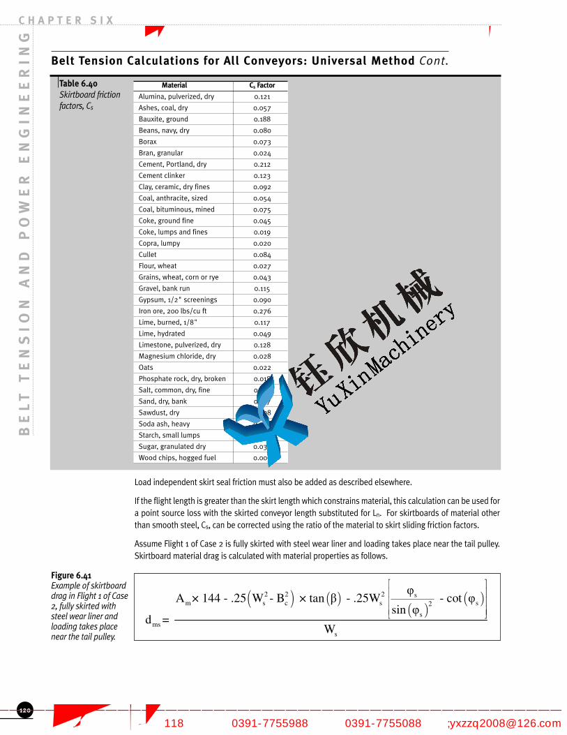
Material Cs Factor
Alumina, pulverized, dry 0.121
Ashes, coal, dry 0.057
Bauxite, ground 0.188
Beans, navy, dry 0.080
Borax 0.073
Bran, granular 0.024
Cement, Portland, dry 0.212
Cement clinker 0.123
Clay, ceramic, dry fines 0.092
Coal, anthracite, sized 0.054
Coal, bituminous, mined 0.075
Coke, ground fine 0.045
Coke, lumps and fines 0.019
Copra, lumpy 0.020
Cullet 0.084
Flour, wheat 0.027
Grains, wheat, corn or rye 0.043
Gravel, bank run 0.115
Gypsum, 1/2" screenings 0.090
Iron ore, 200 lbs/cu ft 0.276
Lime, burned, 1/8" 0.117
Lime, hydrated 0.049
Limestone, pulverized, dry 0.128
Magnesium chloride, dry 0.028
Oats 0.022
Phosphate rock, dry, broken 0.018
Salt, common, dry, fine 0.081
Sand, dry, bank 0.137
Sawdust, dry 0.008
Soda ash, heavy 0.070
Starch, small lumps 0.062
Sugar, granulated dry 0.034
Wood chips, hogged fuel 0.009
BE
LT
TE
NS
IO
N A
ND
PO
WE
R E
NG
IN
EE
RI
NG
C H A P T E R S I X
Belt Tension Calculations for All Conveyors: Universal Method Cont.
Table 6.40 Skirtboard friction factors, Cs
Load independent skirt seal friction must also be added as described elsewhere.
If the flight length is greater than the skirt length which constrains material, this calculation can be used fora point source loss with the skirted conveyor length substituted for Ln. For skirtboards of material otherthan smooth steel, Cs, can be corrected using the ratio of the material to skirt sliding friction factors.
Assume Flight 1 of Case 2 is fully skirted with steel wear liner and loading takes place near the tail pulley.Skirtboard material drag is calculated with material properties as follows.
120
Figure 6.41 Example of skirtboarddrag in Flight 1 of Case2, fully skirted withsteel wear liner andloading takes placenear the tail pulley.
#
! " ! "! "
! "2 2 2 sm s c s s2
sms
s
$A × 144 - .25 W - B × tan # - .25W - cot $
sin $d =
W
# $) *) *) *- .
#
焦作市钰欣机械有限公司 专业的带式输送机制造商
—————————————————————————————————————————————————— 地址:焦作市黄河大道(西段)118号 电话:0391-7755988 传真:0391-7755088 邮箱;[email protected]

Belt Tension Calculations for All Conveyors: Universal Method Cont.
Load and Tension Dependent FrictionThe belt sags in the span between adjacent idlers due to the belt and material load being supportedsimilar to a catenary. See Fig 6.42. The sag causes material deformation and energy loss. The sag of thebelt and the path of the bulk material is affected by the particular belt tension at the point in question.Therefore, the tension and tension loss are interrelated so that predicting the sag and tension changebecomes an iterative process as discussed later as tension management. The calculation is consideredfor a particular known tension, Tn, at the point in question.
BE
LT
TE
NS
IO
N A
ND
PO
WE
R E
NG
IN
EE
RI
NG
C H A P T E R S I X
121
Figure 6.42 Material deformationcaused by belt sag
2%+*+-#J2##K###I=;L#M0/N#>+("#F0)"%#O#####K###:LL#M1E?N#>+("#$E++)#P#####K###AQLL#M"E%N#"&/$#E+*#%&'*#@&/G+R+)#%?####K###6L#M(>1S1"<N#>'(T#)+/$0"R#0######K###<Q#M)+4;N#"*&'4%0/4#,/4(+#$$#####K####;<I65#$'*@%,*4+#,/4(+#0/#*,)0,/$#U&*#AL#M)+4;N#F%+/#'$+)#F0"%#,#"*04#1'/@"0&/V#2$###K####<A;L#M0/N#F0)"%#>+"F++/#$T0*"$#J@#####K####>@#W#J2#K#;<X5#W#J2#Y;AQ##K#5=;L:#M0/N#@+/"+*#*&((#>+("#@&/",@"#)0$",/@+#UH+1;#89',"0&/#<;=V##C%+/-#.?#K#5;QI#M1"
AN#)?$#K#5;A<#M0/N##
C%+/-#.?#K#5;QI#M1"
AN#)?$#K#5;A<#M0/N##
Cs = 12 xL1 = 15 (ft)∆Ts1 = Cs x dm2 x L1∆Ts1 = 3 (lbf)
lbfin2 ft
焦作市钰欣机械有限公司 专业的带式输送机制造商
—————————————————————————————————————————————————— 地址:焦作市黄河大道(西段)118号 电话:0391-7755988 传真:0391-7755088 邮箱;[email protected]

BE
LT
TE
NS
IO
N A
ND
PO
WE
R E
NG
IN
EE
RI
NG
C H A P T E R S I X
Belt Tension Calculations for All Conveyors: Universal Method Cont.
Material Trampling Loss The belt sag causes the individual particles of bulk material to repeatedly move against each other as theyprogress from one idler to the next, with consequent energy loss due to internal friction. Energy must beadded through the material depth to overcome the internal friction forces as the material closes on itselfbetween an idler and the point of maximum sag at the center of the idler spacing. A portion of this energyis recovered as the bed depth opens up again in the section from mid span to the idler. Note that there isno net elevation change and therefore no potential energy change between idlers.
Therefore, the energy loss is influenced by bed depth, the belt sag, and the material strength. In theequations that follow bed depth is calculated as the maximum depth on the center roll per the load crosssection geometry described in Chapter 4. The chart below provides a material friction parameter, Cmz, forthe different material Flowability categories described in Chapter 3.
The amount and shape of the belt sag is primarily influenced by the material weight, the belt tension andthe idler spacing, as in the catenary calculation, but also by the resistance to vertical deflection as thetroughed belt supports the load similar to a beam with cross sectional stiffness. The calculation is furthercomplicated since the belt does not act purely as a classic beam but also as a set of flat plates that areformed with the center roll and wing rolls. In the tension equations, the primary influences areincorporated in a basic calculation of the net work done on the material or energy loss. The uniqueinfluences of belt modulus and construction on the undulations in the vertical direction, z, along (x) andacross (y) the belt for are incorporated with a correction ratio, Rmz.
In contrast to the previous ‘friction’ calculations with material loading where work is the result of afriction force acting through a distance, the following develops the work or energy loss directly sincethe load dependency is not simple.
Where:
∆Tmzn (lbf ) = Tension loss in flight n from internal movements in the bulk material
Wmzn (ft-lbf ) = Belt work required to cause material movement from one idler to the next
dm (in) = Maximum material depth at center of belt, Reference Chapter 4
Tn (lbf ) = Belt tension in flight n
γm (lbf/ft3) = Density of bulk material, Reference Chapter 3
Cmz = Net material friction loss factor per Table 6.45
Rmz = Correction between actual sag and catenary sag per Equation. 6.44
122
Figure 6.43 Tension to overcomeinternal movement ofthe bulk material
! " ! "
mzn nmzn 2
in
3 in inmzn m m mz b m b m mz4
n n
W ×L!T =S
S S1 -1W = ×d ×% ×C ×BW× exp W +W × -1 ×exp × W +W × ×R
12 T 2 T
# $# $ # $) *) * ) *) *) * ) *) *- . - .- .
#
Figure 6.44 Equations for Rmz
! "
1.50.5sn
in
.5-2 -1.0
snin
BW4.181-1.572× -1.0827!y
S ×12
mz
BW4.966-4.071× - 1.062×10 !y
S ×12
mz
1R = e For Troughed Fabric Carcass Belts
12
1R = e For Troughed St
12
# $% &) *'( '() *'( ''() *+ ,- .
# $% &) *'( '() *'( ''() *+ ,- .
mz
eel Cable Belts
1R = For all Flat Belt Conveying
12
#
焦作市钰欣机械有限公司 专业的带式输送机制造商
—————————————————————————————————————————————————— 地址:焦作市黄河大道(西段)118号 电话:0391-7755988 传真:0391-7755088 邮箱;[email protected]

Flowability (Ref. Table 3.3) Angle of Repose (deg) Cmz
Very Free Flowing 0 to 19 1.5
Average Flowing 20 to 25 2.1
Average Flowing 26 to 29 2.5
Average Flowing 30 to 34 3.3
Average Flowing 35 to 39 4.2
Sluggish 40 to 45 5.7
Belt Tension Calculations for All Conveyors: Universal Method Cont.
Where:
∆ysn (%) = Average catenary belt sag for flight n as a percentage of the idler spacing:
The formulae for Rmz above applies for belt widths (BW) up to 96 inches and Idler Spacing (Sin) up to 10ft.
Table 6.45 Material friction loss factor
Rrmz = 0.67 due to variability of the material and belt properties,
With T5 = 19,500 lbf, the fabric carcass belt used in Case 2 yields the following example results:
Liftoff Loss Under conditions of high sag and high belt speed the bulk material can be launched slightly into the airlanding back on the belt a slightly different angle than the sagged belt path. The effect is a small impact ofthe full material stream with consequent energy loss equal to this angular difference times the KineticEnergy of the bulk material. In addition to energy loss, operation under this condition causes loss of controlof the material as it splashes back onto the belt, additional idler loading from this lifting action, wear of thebelt and material degradation. Various degrees of these effects can be expected at conditions nearing liftoffas the load redistributes in a reduced gravity field. In particular, dust can often be seen being exhaustedfrom the expanding and collapsing material bed.
BE
LT
TE
NS
IO
N A
ND
PO
WE
R E
NG
IN
EE
RI
NG
C H A P T E R S I X
123
Figure 6.46 Example correctionfactor calculation forbelt sag
Figure 6.47 Example calculation forthe tension loss frommaterial tramplingusing dm formulae fromChapter 4
焦作市钰欣机械有限公司 专业的带式输送机制造商
—————————————————————————————————————————————————— 地址:焦作市黄河大道(西段)118号 电话:0391-7755988 传真:0391-7755088 邮箱;[email protected]

0.5
cn 1n in 3nln 1n in 3n
5V = × c -2+S ×12×c ×g×12
-2×c +c ×S ×12×c
Belt Tension Calculations for All Conveyors: Universal Method Cont.
A loss coefficient for this phenomena, Kmz, can be calculated by plotting the belt path and materialtrajectory. Since operating under this condition is not considered good standard practice, the followingcalculation instead provides the maximum belt speed that liftoff will not incur and are therefore the beltspeeds which are within the scope of this chapter:
Where:
Vc (ft/min) = The critical maximum belt speed without causing material liftoff
c1n, c1in, and c3n = Functions in Equation 6.49
g = 32.2 ft/sec2
Where:
dm (in) = Maximum material depth at center of belt
Tmn (lbf ) = Minimum tension in flight ‘n’
Eb (lbf/in) = Longitudinal Belt Modulus
BE
LT
TE
NS
IO
N A
ND
PO
WE
R E
NG
IN
EE
RI
NG
C H A P T E R S I X
124
Figure 6.50 c1in Equation
� �� � �
�
� ����� ���
����� ����� ��� �
Figure 6.51 Equations for c1n andc3n for fabric belts
1n
21in
in
0.5
3n b 1.5
b
1C =
0.255 64.3745233.67+ +
c BW
S ×12
558.3C = 1.8123-0.004476 E -
E
Figure 6.52 Equations for c1n andc3n for steel cable belts
Figure 6.48 Material trajectorywhen V > Vc
Figure 6.49 Critical belt speed forapplicability of ∆Tcalculations
焦作市钰欣机械有限公司 专业的带式输送机制造商
—————————————————————————————————————————————————— 地址:焦作市黄河大道(西段)118号 电话:0391-7755988 传真:0391-7755088 邮箱;[email protected]

Belt Tension Calculations for All Conveyors: Universal Method Cont.
Belt speeds slightly higher than those calculated for Vcn have only minor penalties of power andabrasion. When dusting is a concern, speeds lower than those calculated allow the material stream toopen up and expel fines as it collapses downstream of each idler. The situation will dictate the desiredlimit to operating belt speed but, in general, it should be within +/- 10% of Vcn.
Case 2 results in the following for Flight 2. Note that, with close idler spacing in Flight 1 and equal spacingalong the rest of the conveyor, it is clear that Vc2 will be the lowest since its tension is the lowest.
Since V = 600 ft/min < Vc liftoff is not expected and therefore no additional power loss is expected dueto liftoff.
POINT SOURCES OF TENSION
Like acceleration contributions discussed above, the following tension contributions to the belt can belooked at a step changes in tension even though the actual tension is changed over a small finite length.This category of tension effects is primarily associated with various mechanical components both astension losses and tension adders. The latter, passive energy consumers similar to those addressedimmediately above, are discussed first for the sake of continuity, though active tension contributions aremore important in the general scope of conveyor design.
Pulleys are primary sources of point changes in tension and are often considered as separate flights inseries with the conveyance and return flights. When used so, the other sources of resistance for thisflight are set to zero. The remaining resistances described below are added to the other energy and mainresistances calculations.
Pulleys as Passive Point LossesPulleys have a passive loss element that should be added independently of their role as sources of activetension change. These are due to belt slip and bending as well as from pulley bearing rotatingresistance. The resistance of the belt to flexure over the pulleys is a function of the pulley diameter andthe belt stiffness. The belt stiffness depends upon the ambient temperature and the belt constructionbut is appropriately simplified below. The resistance of the pulley to rotate is a function of pillow blockbearing friction, lubricant, and seal friction. The pillow-block bearing friction depends upon the load onthe bearings, but the lubricant and seal frictions generally are independent of load. Since the drive pulleybearing friction does not affect belt tension, it’s contribution should not add to belt tension but shouldbe included when determining the active torques required of the motors, brakes etc; Detailed equationsare as follows;
BE
LT
TE
NS
IO
N A
ND
PO
WE
R E
NG
IN
EE
RI
NG
C H A P T E R S I X
m
b
m2
b
-4m b1i2
m
-412
21in
in
32
W = 138.9 lbf/ft
W = 11.4 lbf/ft
T = 15,000 lbf
E = 62,000 lbf/in
W + Wc = = 2.8×10
8 × T × 0.371 × 12
1c = = 8.3×10
0.255 64.3745233.67 + +
c BW
S × 12
c = 1.8123 -0.5
b 1.5
b
0.5
cn 1n in 3nln 1 in 3n
558.30.004476 E - = 0.698
E
5V = × c -2 + S × 12 × c × g × 12 = 607 ft/min
-2 × c + c × S × 12 × c
Figure 6.53 Example calculationfor minimum lift offbelt velocity
125
焦作市钰欣机械有限公司 专业的带式输送机制造商
—————————————————————————————————————————————————— 地址:焦作市黄河大道(西段)118号 电话:0391-7755988 传真:0391-7755088 邮箱;[email protected]

BE
LT
TE
NS
IO
N A
ND
PO
WE
R E
NG
IN
EE
RI
NG
C H A P T E R S I X
Belt Tension Calculations for All Conveyors: Universal Method Cont.
Where:
∆Tpn (lbf ) =Tension added by pulley n
∆Tpxn (lbf ) = Tension added to belt from belt to flex over pulley n
x = Subscript in ∆Tpxn;
‘f’ for Fabric Carcass belt
‘s’ for Steel Cable belt construction
∆Tprn (lbf ) = Resistance of pulley ’n’ bearings, lubricant, and seals
tb (in) = Conveyor belt thickness
Dpn (in) = Pulley ‘n’ diameter
dsn (in) = Pulley n shaft diameter
Rpn (lbf ) = Resultant radial load (vector sum of belt tensions and pulley weight) of pulley ‘n’
Tn (lbf ) = Belt tension at the pulley ‘n’
Rrp = Pulley drag, can vary up to Rrp = 0.67
Using the head pulley for Case 2 as an example;
Note, since this is a drive pulley ∆Tp6 does not contribute to the belt tension under normal operation.
126
Figure 6.54 Calculation ofresistance at pulleysfrom belt flex andbearing torque
Figure 6.55 Example pulleyresistance calculation
焦作市钰欣机械有限公司 专业的带式输送机制造商
—————————————————————————————————————————————————— 地址:焦作市黄河大道(西段)118号 电话:0391-7755988 传真:0391-7755088 邮箱;[email protected]

Belt Tension Calculations for All Conveyors: Universal Method Cont.
Belt Cleaners Many belt cleaning devices add directly to the belt pull as they scrape on the belt. The additional belt pullrequired for belt cleaning devices can vary widely due to diversity in design and consequent differencesin cleaning force and friction factor.
The following provides a basic calculation of individual cleaner resistances the summation for variousmultiple cleaners. The values provided should be used in lieu of data on specific cleaning systembeing used.
Where:
∆Tbcn (lbf ) = Tension change due to the ‘m’ belt cleaners sliding on flight n
m = Number of belt cleaners in flight n
Cbcm (lbf/in) = Frictional resistance from belt movement under cleaner pressure
µbcm = Sliding friction factor between belt and the cleaner blade = 1.0 for default use
Fbcm (lbf/in) = Effective normal force between belt and cleaner
Chapter 11 provides alternate values of µbc for specific cleaner types. The value Fbc varies considerablybased on cleaner design. The historical CEMA value of Cbc = 5.0 lbf/in of belt width may beconsidered as a nominal value for ∆Tbcn per belt cleaner but may not be sufficient. Accurate values ofµbc, Fbc or Cbc are most important for short conveyors as they can be a significant percentage of thetotal ∆T. Consult your CEMA belt cleaner manufacturer for specific performance expectations.
Return belt plow, commonly used to protect the belt from fugitive material being forced under a pulleyon the return belt strand, are cleaning devices and act similar to those described above. In this casea value of Fbc=2 lbf/in is recommended as a default value.
Rotary brushes and similar rotating cleaning devices do not impose appreciable belt pull ifindependently driven and properly adjusted. If such devices are driven from the conveyor drive shaft,suitable additional power should be incorporated in the appropriate pulley to operate them.
Since belt cleaners often not serviced, wear out or are disabled, their possible low level resistanceshould be considered zero, therefore use Rmbc = 0.
Belt Discharge Plows The use of a plow to discharge material off the side of the belt will require additional belt tension toovercome both the change in Kinetic Energy of the discharged material and frictional resistances in theplowed material and to the belt. Though the result of this calculation varies widely with material and plowdesign 8.0 lbf/in of belt width can be used to approximate the amount of additional belt pull that normallywill be required by well-adjusted, rubber-shod plows for applications suited to this discharge method.
While a flat belt conveyor may be fitted with a number of plows to discharge material at desired locations,seldom is more than one plow in use at one time on one run of the belt conveyor. However, whenproportioning plows are used, with each plow taking a fraction of the load from the belt, two or even threeseparate plows may be simultaneously in contact with the carrying run of the belt. In this case each maybe considered to require 60% of the above calculation.
BE
LT
TE
NS
IO
N A
ND
PO
WE
R E
NG
IN
EE
RI
NG
C H A P T E R S I X
127
Figure 6.56 Belt cleaner dragequations
Figure 6.57 Discharge plow forceon belt where ∆Tdpn
(lbf ) is the estimateddischarge plow drag
焦作市钰欣机械有限公司 专业的带式输送机制造商
—————————————————————————————————————————————————— 地址:焦作市黄河大道(西段)118号 电话:0391-7755988 传真:0391-7755088 邮箱;[email protected]

BE
LT
TE
NS
IO
N A
ND
PO
WE
R E
NG
IN
EE
RI
NG
C H A P T E R S I X
Belt Tension Calculations for All Conveyors: Universal Method Cont.
Active Tension ContributionsConventional belt conveyors must have tension added and/or removed to cause and control belt motion.This is accomplished by a frictional coupling between a pulley and the belt wrapped around it. In turn,the pulley is coupled to a source of torque proportional to the tension change caused in the belt and thepulley radius.
Where:
Tqn (ft-lbf ) = The active torque provided to the pulley
Dn (in) = Pulley diameter
∆Ten will vary widely per the characteristics of the conveyor, drive and control especially during changesof conveyor load and speed. Therefore, Tqn should not be confused with the maximum capacity of thesedevices.
The frictional coupling between the active pulley and belt provides an upper limit the for Te based on themagnitude of T2. This is discussed later in this chapter with the other influences on the maximum tensionchange transmittable by a pulley. The sign of tension change is also directly indicated by the torquedirection. If power is transmitted from the pulley to the belt, the approaching portion of the belt will havethe larger tension, (T1>T2). If power is transmitted from the belt to the pulley, requiring a regenerativedrive motor or brake, the reverse is true (T1<T2). The calculation of ∆Ten is not inherent to the conveyoras are the other elements of ∆T but, as part of the drive design, depend on the particular componentsselected and the desired motion.
Driving the BeltA drive is defined here as a device that removes or is capable of removing tension (-Tn) from the belt.Several key concepts that are involved with the execution of the mathematical concept of active orintentional tension management by the conveyor designer are introduced here and discussed laterThough tension is higher where a drive is operating, this change occurs in the direction opposite tomovement. The convention used here and discussed under ‘Tension Management’, accumulates tensionchanges in the direction of belt movement so the effect of the drive is opposite to intuition. Again,negative (-) tension change from a drive is necessary to propel an empty belt, but it should be recognized,in a general sense, that a drive may act differently when loaded under the wide range of applications forwhich conveyors are used in and for the particular conditions a particular conveyor may see.
A complete drive system is defined as all of the components which cause and control steady operation aswell as startup and stopping (normal and emergency) of a conveyor. A drive system, therefore, may bothadd and remove energy, with negative (-) and positive (+) tension changes respectively, depending on theoperating circumstances. Tension is transferred to all of the moving components of the conveyor systemthrough the belt.
When decline portions exist on a conveyor, energy absorption may have to be done on continuous orsteady state conditions. This will often require the use of regenerative motor and controls for the drive.That is, a drive may propel as well as retard movement. Brakes are components which only retardmovement, or add (+) tension in the direction of belt movement. These same components and a widerange of other devices and practices are available for use by the designer to maintain control of the beltand its load under transient conditions involving speed and load changes. Proper control, as used here,is the portion of the conveyor design that assures safe tensions for all components and desirablemovement of the bulk solid being carried. Active tension and control imply that tensions are added asneeded to develop the desired movement.
128
Figure 6.58 Active pulley torqueconversion to belttension
焦作市钰欣机械有限公司 专业的带式输送机制造商
—————————————————————————————————————————————————— 地址:焦作市黄河大道(西段)118号 电话:0391-7755988 传真:0391-7755088 邮箱;[email protected]

Belt Tension Calculations for All Conveyors: Universal Method Cont.
Braking the BeltThough braking, or energy removal, is often an integral part of the drive, this function is oftenaccomplished trough a separate brake, often on its own pulley. For the purposes of the tensionmathematics of the conveyor design, the brake will be treated similar to a drive except that it can only havea positive (+) value. Various conditions dictate the decision to use a brake or to integrate this function intothe drive but these will be discussed later in this chapter.
Likewise, a backstop can be used to remove tension from a stopped belt and thereby prevent rollback.The mathematics are the same as above.
Tension Management
The following generalized approach uses the findings of tension changes described above for "AllConveyors". For the simplest conveyors the design decisions are fewer and more straightforward sothat the tensions at specific locations are more intuitive so that the steps described in the "AnalysisProcess" may not be necessary. The "Minimum Design Tensions" section, however, must be followedfor proper operation.
ANALYSIS PROCESS
The process of analyzing a particular conveyor starts with identifying the conveyance path, materialloading and, often, the idlers per the previous chapters of this book. Belt conveyor analysis involvespredicting tensions around the belt circuit by summing the contributions described above.
The conveyance path is broken into a series of flights for which the ∆T components are tension arecalculated. The number and length of flights should be identified based on the variations in the conveyorslope, and the existence of curves, loading and discharge points and any accessory equipment as well asneed for accuracy of the analysis. Each pulley is considered a flight so that their individual contributionand loading can be incorporated
Initially, it will be necessary to assume or estimate the approximate size of various components and thetension at a particular point on the conveyor. The tensions are then accumulated from this pointprogressing in the direction of belt movement adding (or subtracting) the various friction and gravityeffects until back to the starting point. Several iterations cycles are needed from this point to develop anacceptable design.
The necessary tension required (to be added or subtracted) by active components such as drives, brakesand backstops are adjusted by the difference between the estimated tension and the summation at thesame point until they match. The result is a possible operating condition with a consistent tensiondistribution though it may not be a successful or desirable design.
Several iterations cycles are needed from this point to develop an acceptable design. The design isupdated, as needed, to:
• Assure that minimum tensions requirements described below are met
• Assure that all components are specified for appropriate reliability with implications of their design integrated into the tension summation
• Assure that acceptable operation is predicted under varying movement and loading conditions
With automatic takeups, used almost universally on long complicated conveyors, the takeup is usuallythe summation comparison point since it provides a point of stable or ‘constant’ tension. The updatingor iterative corrections must be done differently for conveyors with a fixed stretch. The interaction ofbelt stretch and tension is described later in this chapter.
When the total net conveyor tension ‘added’ is negative, that is when active energy dissipation isneeded, as with decline flights or under transient speed conditions, the possibility of friction overesti-mation is treated by evaluating the design with the low limit multipliers Rrxx describe above under
BE
LT
TE
NS
IO
N A
ND
PO
WE
R E
NG
IN
EE
RI
NG
C H A P T E R S I X
129
焦作市钰欣机械有限公司 专业的带式输送机制造商
—————————————————————————————————————————————————— 地址:焦作市黄河大道(西段)118号 电话:0391-7755988 传真:0391-7755088 邮箱;[email protected]
BE
LT
TE
NS
IO
N A
ND
PO
WE
R E
NG
IN
EE
RI
NG
C H A P T E R S I X
Tension Management Cont.
‘Main Resistances’. When used, all of the corrections should be applied around the full conveyor pathsince they address a range of expected performance. The tension summation analysis is repeated andthe design is again updated as indicated until all requirements are met.
Steady State Running AnalysisIn many cases, the design process is simplified by initially focusing the analysis on the operating conditionsthat develop when operating fully loaded at full speed. This high tension condition is useful for evaluationand comparison of major decisions of the design. Some of the steps or criterion described below are ofteneliminated for the sake of simplicity or time saving if experience or history so indicates. These practices,again with simple and predictable layouts, are often successful due to thermal forgiveness in drives and theinfrequency of high transient forces on the various components versus the more severe fatigue loading oflower steady state forces at many more cycles. Nonetheless, thorough design does not stop with steadystate analysis but tests and upgrades, as necessary, the design with various transient running conditions.
Automated computerized design tools allow the above iterations over the widest range of operatingconditions to take place without effort. Intuition and experience of the conveyor engineer are still essentialfor good conveyor design but can be applied to the optimizing and reliability judgments with more value.
MAXIMUM BELT TENSION
A key design parameter indicating the total cost of the conveyor is the maximum tension seen in the belt.This therefore is a major focus of the design process. A distinction needs to be made regarding thefrequency and magnitude effect of the tensions predicted under various operating conditions. Fatiguelimitations often dictate sizing but design rules vary by component based on the component’s load cyclesand relative importance.
Operating Maximum Belt TensionThe operating maximum belt tension is defined as the maximum belt tensions occurring when the belt isconveying the design load from the loading point continuously to the point of discharge. This is the steadystate condition. Operating maximum tension often occurs at the discharge point on horizontal or inclinedconveyors and at the loading point on regenerative declined conveyors. On compound conveyors withflights of varying slope, the operating maximum belt tension frequently occurs elsewhere.
Because the operating maximum belt tension must be known to select a belt, its location and magnitudemust be determined. The sizing of structure and other components will vary by location so the maximumtension occurring at each location needs to be understood as well.
Temporary Operating Maximum Belt Tension A temporary operating maximum belt tension is that maximum tension which occurs only for short periods.For example, a conveyor with a profile that contains an incline, a decline, and then another incline, maygenerate a higher operating tension when only the inclines are loaded and the decline is empty. Thepossibility of these temporary operating maximum belt tensions should be considered in the selection ofthe belt and the conveyor machinery.
Economy of design dictates the selection of a belt having a carcass strength at or near the normal operatingtensions. Consequently, the additional forces resulting from acceleration or deceleration may overstress thebelt or its splices. While this problem is most likely to exist with respect to the belt, there also is thepossibility of overstressing the mechanical components such as pulleys, shafts, bearings, and takeups.
Starting and Stopping Maximum TensionThe starting torque of a drive must be more than the normal operating torque to cause speed increase oracceleration. For instance, an electric motor may be capable of more than 2.5 times the motor full-loadrating. Such a torque transmitted to a conveyor belt could result in starting tensions many times more thanthe chosen operating tension. To prevent over sizing of the belt or progressive weakening of splices andsubsequent failure, such starting maximum tensions should be avoided or anticipated in the componentselection. Likewise, if the belt is brought to rest very rapidly, especially on decline conveyors, the inertia ofthe loaded belt may produce high tensions.
130
焦作市钰欣机械有限公司 专业的带式输送机制造商
—————————————————————————————————————————————————— 地址:焦作市黄河大道(西段)118号 电话:0391-7755988 传真:0391-7755088 邮箱;[email protected]

Tension Management Cont.
CurvesVertical CurvesTwo different problems may be encountered with vertical curves. In the case of concave curves (where thecenter of curvature lies above the belt), if belt tensions are too high, especially during starting, the belt willlift off the troughing idlers. It is necessary to analyze this problem in regard to full, partial, and no loads. Inaddition, bending through the cross section of the troughed belt causes redistribution of tension across thewidth. These must be superimposed on the average stresses without over or under tensioning the belt orsplice. These are discussed in detail in Chapter 9.
Horizontal CurvesHorizontal curves are developed to run within a narrow path under a range of operating conditions. Thetendency of belt tension to pull the belt toward the center of the radius must be protected against by idlertilt. In addition, belt tensions are redistributed across the belt comparable to that in vertical curves. Chapter9 discusses these maximum and minimum limits.
MINIMUM DESIGN TENSIONS
An initial pretension must be put into the belt to provide for proper operation. This is done by belt takeupdevices that apply a tension or a stretch into the belt tension and stretch have the same general effect butoperate differently under changing conditions. Takeups serve to affect the tension uniformly through outthe belt circuit but do not affect the local changes in tension, except in indirect ways described above.They are used to maintain minimum tensions needed for acceptable operation.
As a point of clarification, though takeups can have active control affecting the tension differently fordifferent operating requirements, they are considered as passive devices since they add equal tension toboth the approaching and retreating belt and do no work on the system.
Developing the lowest minimum tension practical is a major design goal since it defines a base tensionthat does not contribute work to the conveying function but adds to the maximum tension in the systemand therefore adds to the cost.
Minimum T2 for Active PulleysThe ∆Te that can be developed or transferred from an active pulley to the belt is governed by the coefficientof friction existing between the pulley and the belt, the wrap, and the value of Tm which establishes theminimum normal pressure which exists between the belt and the pulley. The following equation establishesthe limit condition or the allowable circumferential traction for a single pulley:
Where:
∆Temn (lbf ) = Maximum belt tension change possible at pulley n
Tmn (lbf ) = Minimum tension at pulley n
e = Base of naperian logarithms = 2.718
θn (radians) = Belt wrap on pulley n per Figure 6.60
f = Coefficient of friction between pulley surface and belt surface
Design f values for rubber covered belts are as follows
0.25 rubber surfaced belt driving bare steel pulley
0.35 rubber surfaced belt driving rubber lagged pulley surface
0.50 for dimpled ceramic or equivalent hard material
(See pulley discussion in this chapter)
BE
LT
TE
NS
IO
N A
ND
PO
WE
R E
NG
IN
EE
RI
NG
C H A P T E R S I X
131
Figure 6.59 Allowable rensionchange for activepulleys
焦作市钰欣机械有限公司 专业的带式输送机制造商
—————————————————————————————————————————————————— 地址:焦作市黄河大道(西段)118号 电话:0391-7755988 传真:0391-7755088 邮箱;[email protected]

BE
LT
TE
NS
IO
N A
ND
PO
WE
R E
NG
IN
EE
RI
NG
C H A P T E R S I X
Tension Management Cont.
Values of f are for design use under normal startup and running. This includes an allowable transientTe up to 150% of steady state operation. Though full pulley slip is not considered an acceptable design,occasional local slip (see pulleys below) between the belt and pulley is considered acceptable andinevitable in worse case environmental conditions. In the case of muddy or with thick material films, fshould be decreased by 20% (Multiply f by 0.8).
Figure 6.60 shows general concept of ∆T for pulleys. Tm can be either T1 or T2 since the pulley torque,opposite the direction of increasing T, can be with or against the direction of belt movement. At thesame time, tension consistently changes from T1 to T2 in the direction of belt travel, independent ofwhich is larger.
It should be noted that ∆Ten is that needed for belt movement or provided by the drive/brake This mustbe less than ∆Temn to prevent the probability of slip.
For many cases, the belt will have an angle of wrap, θn, around the active pulley of about 180 degreesor that needed to return the belt conveniently. Often, it will be necessary to arrange a drive that uses anangle of wrap greater than 180 degrees. This is accomplished by the appropriate positioning of a snubpulley, which can extend the angle of wrap to approximately 240 degrees. If a greater angle of wrap isnecessary, it may be necessary to use a multiple-pulley drive.
With basic head driven, inclined or level conveyors as shown in Figure 6.60, T1 consistently drops to T2
in the direction of rotation and braking torque is less than driving torque. In this case, a wrap factor,Cw, is useful for manual design purposes. Cw is the effective ratio T2/∆Te derived for use with commoncombinations of f and θ.
132
Figure 6.60 Active and generalpulley convention andterminology
Figure 6.61 Equation for WrapFactor, Cw
�
� � �
�
��� ��� ���
� ����� �#
焦作市钰欣机械有限公司 专业的带式输送机制造商
—————————————————————————————————————————————————— 地址:焦作市黄河大道(西段)118号 电话:0391-7755988 传真:0391-7755088 邮箱;[email protected]

Automatic Takeup Manual Takeup
Type of θ Wrap Bare Lagged Bare LaggedDrive Pulley (deg) Pulley Pulley Pulley Pulley
Single, no Snub 180 0.84 0.50 1.20 0.80
Single with Snub 200 0.72 0.42 1.00 0.70
210 0.66 0.38 1.00 0.70
220 0.62 0.35 0.90 0.60
Tension Management Cont.
Table 6.62 Table of common wrap factors, Cw (rubber belt covers)
Multiple pulley drives are discussed under Belt Stretch Interactions.
Belt Sag between IdlersChapter 5, "Belt Conveyor Idlers," presents the basic facts on the subject of idler spacing. A majorrequirement, noted in Chapter 5, is that the sag of the belt between idlers must be limited to avoid spillageof conveyed material over the edges of the belt. The sag between idlers is closely related to the weight ofthe belt and material, the idler spacing, and the tension in the belt and the latter two must be balanced tothe following limits to provide reliable conveyance.
The basic sag formula for a pure catenary can be expressed as a relation of belt tension, Tn, idler spacing,Sin, and the weight per foot of belt and load, (Wb + Wm), in the form:
Where:
∆Ys (ft) = Vertical drop between idlers for flight n
∆ys (%) = Vertical drop between idlers for flight n as a % of the idler spacing
Wb (lbf/ft) = Belt weight per foot of length
Wm (lbf/ft) = Material weight per foot of length
Tmn (lbf ) = Minimum Belt tension in flight n
Sin (ft) = Idler spacing in flight ‘n’
Experience has shown that when a conveyor belt sags more than 3 percent of the span between idlers, loadspillage likely results. Lower sags are needed with faster belts as discussed above in the section on mainresistances. The pure catenary equations are used though the actual sag deviates from this calculation asused in the ∆Tmz calculation because the accuracy of this rule of thumb does not justify the added precision.The allowable percent sag has evolved from experience and has proven to prevent spillage and materialdeparting the conveying trough for most operating conditions. Reformatting the catenary equation for theminimum allowable tension at various percentages of belt sag yields a convenient design formula:
Where:
Tmn (lbf ) = Minimum tension to meet sag percentage rule
BE
LT
TE
NS
IO
N A
ND
PO
WE
R E
NG
IN
EE
RI
NG
C H A P T E R S I X
133
Figure 6.63 Catenary sag inconveyor terms
is
mn
W×S!Y =8.0×T
#
Figure 6.65 Minimum tension as a function of sagpercentage
Figure 6.64 Sag design equations
! "
! "
b m insn
n
b m insn
n
W +W ×S!Y =
8 × T
W +W ×S!y = ×100
8 × T
#
1. For wet belts and smooth lagging use bare pulley factors.
2. For wet belts and grooved lagging use lagged pulley factors.
3. If wrap is unknown assume the following: Single no Snub = 180°, Single with Snub = 210°.
焦作市钰欣机械有限公司 专业的带式输送机制造商
—————————————————————————————————————————————————— 地址:焦作市黄河大道(西段)118号 电话:0391-7755988 传真:0391-7755088 邮箱;[email protected]

Idler Trough Angle (deg)
Material Lump Size 20 35 45
All Fines 3.0% 3.0% 3.0%
50% of Maximum per Fig 4.1 3.0% 3.0% 2.0%
100% of Maximum per Fig 4.1 3.0% 3.0% 1.5%
BE
LT
TE
NS
IO
N A
ND
PO
WE
R E
NG
IN
EE
RI
NG
C H A P T E R S I X
Tension Management Cont.
See Table 6.66 for recommended belt sag percentages for various full load conditions. Graduatedspacing, or varying idler spacing at different points in the conveyor, can be used but should becalculated to observe the following limitations:
1. The sag limits of Table 6-10 should be maintained when belt is operating with a normal load.
2. A maximum of 4.5 percent sag should be maintained when the loaded belt is standing still. The idler spacing should not exceed twice the suggested normal spacing of the troughing idlers listed in Table 6.66.
3. The load on any idler should never exceed the idler load ratings given in Chapter 5.
Table 6.66 Recommended belt sag percentage for various full load conditions
When handling lumpy material on belts operating on a 35 degree (or deeper) troughing idlers, belttension should be increased to reduce the percent of sag as indicated in Table 6.66. Deep-troughedconveyor belts normally carry a relatively large cross-sectional loading and corresponding heavy weightof material per foot of length. Therefore, the material exerts a greater pressure against the side of thetrough, tending to cause greater transverse belt flexure. The purpose of increasing the minimum belttension in belts operating on idlers of greater than 20 degrees troughing angle is to keep this transversebelt flexure to an acceptable minimum and thus prevent spillage. Similarly, when frequent surge loadsare encountered or a substantial percentage of large lumps are expected, the material weight per footof conveyor will be increased. Consideration of increased minimum belt tension or idler spacing at, orclosely adjacent to, the loading points is recommended.
The equations for critical belt speed preventing liftoff loss can also be used to develop a minimum belttension within the context of this chapter, if preferred. Sag also contributes to the interaction of beltand idlers regarding the tendency for the belt to flap between idlers. Refer to the discussion ofcomponent interactions in this chapter.
TRANSIENT TENSION SIMPLIFIED APPROACH
Based on the physical principle of Conservation, changing the energy balance will cause speed changesin the moving parts of a conveyor. A new speed or Kinetic Energy level of the moving conveyor is createdwhen the force balance changes. In practice, the prime mover is designed to maintain a relatively constantspeed by automatically increasing its torque or the tension added to the system. On a conveyor speedchange is caused or allowed through tension changes in the belt initiated by changes in the active pulleysand proportional to the mass of the system. Since the belt stretches or shrinks with changes in tension,the Potential Energy state of the system also changes as the tension distribution changes with load andother belt tension influences as well as active pulley contributions. Likewise, changes in the loading causechanges in the friction and therefore work of the system as well as the work involved with the PotentialEnergy rate due to gravity.
As energy is constantly exchanged from the active pulleys to the conveyor system, tension changesthroughout the system. These tension are not instantaneous throughout the belt length but propagatealong the belt substantially at the speed of sound in the belt. Since the belt stretches like a long continuousspring, the local tension along the belt is associated with its local elongation. Slow changes from load areimposed at the speed of the belt and can be absorbed or redistributed without problem by the belt.Changes in the tension contribution from active components, especially if they are sudden, can cause muchhigher tensions to be imposed from the release in the belt Potential Energy stored as belt stretch.
134
焦作市钰欣机械有限公司 专业的带式输送机制造商
—————————————————————————————————————————————————— 地址:焦作市黄河大道(西段)118号 电话:0391-7755988 传真:0391-7755088 邮箱;[email protected]

Tension Management Cont.
The accelerating and decelerating forces that act on a belt conveyor during the starting and stoppingintervals are mathematically similar. However, their magnitude and the algebraic signs governing themchange, as do the means for dealing with them.
Prediction of transient local tensions throughout the belt circuit is important and the results aresensitive to a thorough understanding and detailed prediction of the Kinetic Energy and PotentialEnergy along the belt as it stretches and in each of the components of the conveyor, especially theactive components. Computerized numerical methods, commonly called Dynamic Analysis, are capableof this type of analysis and are often justified. This is discussed in more detail in Chapter 16.
For initial design a quasi-Static or rigid body dynamic analysis is performed to provide first level impactof the various design decisions. For many simple conveyors, those defined as Basic earlier in thischapter, the Static approach provides suitable insight since, by definition, they are designed andoperating similar to each other. In This approach the speed changes in the belt are treated as constantaround the belt circuit. Rigid body or linear averaging assumptions to the acceleration/decelerationforces and times are sufficiently accurate for these applications.
The Static analysis method should be applied to all conveyors and may be sufficient for many. While itis difficult to be definite when Dynamic analysis is needed, some guidelines are:
New applications requiring dynamic analysis to insure reliable operation
1. Long flight lengths (greater than 1 mile).
2. Multiple drive (or brake) locations (head-tail or intermediate).
3. High lift conveyors with take-up near the discharge (high) end.
4. Highly regenerative conveyors with large brakes.
5. Complicated conveyors with multiple vertical curves.
6. Conveyors with horizontal curves.
New applications probably benefiting from dynamic analysis
1. High capacity conveyors, greater than 8,000 tph.
2. High speed conveyors, greater than 1,000 fpm.
Calculation of Average Acceleration and Deceleration ForcesAcceleration is defined as the second derivative of displacement with respect to time so time is the basicvariable in computing the force or belt tension. With Newton’s second law, F=M x a, the belt velocity changeversus time for a belt tension change can be computed. The force necessary or available to accelerate ordecelerate (negative acceleration) a conveyor is directly proportional to the mass of the parts and materialin motion. To predict the interaction of speed and tension with time, the belt conveyor designer isconfronted with the necessity to compute the inertia of all its moving parts, including the inertia of the loadon the belt and the various elements contributing to belt tension. Average change in velocity due tochanges in the frictional forces, the forces caused by elevating or lowering the load and belt or changes atthe active drive system components can be estimated with the rigid belt assumption.
Moving MassFor purposes of calculation, it can be assumed that the belt and the load on it move uniformly in a straightline. It is convenient to use the equation for this linear motion as the basis for calculating the accelerationand deceleration forces. Their mass is calculated from their weight per unit length times the length. Otherimportant parts of the system, however, rotate. This is true for all pulleys, idlers, and all the rotating partsof the drive. To incorporate rotating components, one must find their equivalent mass as if they were inlineal motion (just as drive torque is converted to drive tension). For rotating bodies, the mass distributedaround the center of rotation is equivalent to the same mass concentrated at a distance, K, (the polar radiusof gyration) from that center. The Equivalent Weight, WK2, is the weight of the body multiplied by the squareof the radius of gyration. In this format weight is used to quantify the mass. This must be reconciled in the
BE
LT
TE
NS
IO
N A
ND
PO
WE
R E
NG
IN
EE
RI
NG
C H A P T E R S I X
135
焦作市钰欣机械有限公司 专业的带式输送机制造商
—————————————————————————————————————————————————— 地址:焦作市黄河大道(西段)118号 电话:0391-7755988 传真:0391-7755088 邮箱;[email protected]

BE
LT
TE
NS
IO
N A
ND
PO
WE
R E
NG
IN
EE
RI
NG
C H A P T E R S I X
Tension Management Cont.
calculation for dimensional integrity. The speed at the distance K versus the speed of the belt is thenused to adjust the Equivalent Weight of the component to that of the belt so that they can be summedto arrive at an effective contribution to the total weight or mass of the conveyor acting as a rigid body atthe belt speed.
If WK2 is known for the rotating conveyor components, the Equivalent Weight of these components, at thebelt line, can be found. Values of WK2 (expressed in lbf-ft2), which are difficult to compute, except for verysimple shapes, must be estimated from the summation of simple shapes or obtained for eachcomponent from the manufacturers of the conveyor components, motors, transmission elements, etc.
Where:
Ta (lbf ) = Accelerating or decelerating (-) force provided to the moving conveyor
Met (slugs) = Equivalent mass of moving parts of the conveyor and load
Wet (lbf ) = Total equivalent weight of moving parts of the conveyor and load
Wr x Ki2(2π Ni/V)2 (lbf ) = equivalent translating weight of rotating part i
Wbt (lbf ) = Total weight of the belt=Wb*Lb
Wmt (lbf ) = Total weight of the bulk material on the belt=Wm*Lm
Wi (lbf ) = Weight of rotating component i, lbs
Ki (ft) = Polar Moment of Inertia or effective radius of rotating component i, ft
Ni (rpm) = Rotational speed of component i, rpm
Lb (ft) = Total length of the belt, usually twice the conveyor length, or 2*L
Lm (ft) = Total loaded length of the belt, varies between 0 and total conveyor length L
i = Index for each individual rotating component including drive components (n for pulleys)
g (ft/sec2) = Acceleration of gravity = 32.2
a (ft/sec2) = Acceleration
V (fpm) = Nominal belt velocity or velocity before time t
∆V (fpm) = Change in belt velocity during time interval t
Vt (fpm) = Transient belt velocity after time t.
t (sec) = Time interval being analyzed
Values of WK2 (expressed in lbf-ft2) are complicated to compute, except for very simple shapes, but canbe estimated from the summation of simple shapes and their densities or from the manufacturers of theconveyor components, motors, transmission elements, etc.
136
Figure 6.67 Inertial and accelerationcalculations of aconveyor system
焦作市钰欣机械有限公司 专业的带式输送机制造商
—————————————————————————————————————————————————— 地址:焦作市黄河大道(西段)118号 电话:0391-7755988 传真:0391-7755088 邮箱;[email protected]

Tension Management Cont.
In some cases, it is desirable to manage the dynamic behavior of a conveyor by increasing the effectivemass. This can be done by adding a flywheel. A flywheel can be added to the drive, thus increasing thestarting time and limiting the torque input to the belt conveyor system, as well as increasing stoppingtime and distance.
The above provides a total effective Ta that is provided by or to the moving mass of the conveyor whilethe belt speed changes at the rate of a. This force is a total, for the global acceleration, a, and time, t,calculations, of the distributed contributions of the various masses. The local tension contributions Tam,Tab and Tai are seen around the conveyor corresponding to the local acceleration at the belt line. In asimplified calculation, a uniform acceleration, a, is assumed so that Ta contributes to a tension imbalanceonly without explanation of local effects except those involved with rebalancing the zero tensionsummation at steady state movement. The value of the calculation is in the estimate of the time neededfor belt speed changes. A full Dynamic Analysis is necessary for detailed and transitory effects.
Passive Speed Change When the ∆Te for the active components applied by an active drive is stopped, the conveyor speed dropsdue to the new unbalance in tension. In cases where large amounts of energy are stored as kinetic orpotential energy and the speed abruptly changes as during an emergency shutdown or with power failures,the result can be a dangerous condition and detailed Dynamic Analysis should be considered (see Chapter16). An estimate of the drift time with a simplified analysis can predict the time the conveyor will continueto run or drift and indicate whether a dynamic analysis is needed. Clearly, declined conveyors resulting inregenerative designs will not provide passive stopping under loaded conditions
To make this calculation, constant acceleration a (+ or- as appropriate) is assumed to act over a period oftime t to cause a particular change in belt velocity. With the approximation of uniform deceleration, thecalculations for a, t and drift distance proceed as follows:
Where:
Σ∆Ten (lbf ) = Total tension added before stopping initiated
ΣMe (slugs) = Total effective moving mass, reference Equation 6.67
t (sec) = Stopping time
∆V (ft/min) = Change in belt speed
Ld (ft) = Drift distance
Implications of passive stopping or drift include;
1. Emergency stopping time should be considered for its safety implications.
2. Short drift time can be an indicator of the potential for high dynamic tensions to develop. This is discussed as a Transient Tension effect.
3. The amount of material discharged may flood a receiving conveyor.
BE
LT
TE
NS
IO
N A
ND
PO
WE
R E
NG
IN
EE
RI
NG
C H A P T E R S I X
137
Figure 6.68 Drift time and distance
焦作市钰欣机械有限公司 专业的带式输送机制造商
—————————————————————————————————————————————————— 地址:焦作市黄河大道(西段)118号 电话:0391-7755988 传真:0391-7755088 邮箱;[email protected]

BE
LT
TE
NS
IO
N A
ND
PO
WE
R E
NG
IN
EE
RI
NG
C H A P T E R S I X
Tension Management Cont.
Coordinating the coasting time or drift distance is important where a system of belt conveyorstransferring from one to another. That is, sequence stopping (and starting) is almost always aprerequisite of design. As an example, a belt with very long centers may transfer to a belt of shortcenters, in which case the time required to decelerate the two belts must be synchronized, despite thedifferences in the braking forces required. During the acceleration period, the same synchronization isnecessary. In either case, the consequences of not making proper analysis and providing the necessarycontrols will result in a pile-up at the transfer point and possible destruction of the machinery and belt,plus an inoperative system.
The amount of material discharged during the stopping interval is based on the belt travel during shutdown.This distance is calculated for each step of the total stopping period using the following calculation:
Where:
Md (tons) = Material discharged during stopping
Wm (lbf/ft) = Weight of the bulk material on the belt
Active braking, as described in the following should be considered if necessary due to the above concerns.In other cases, it may be appropriate to add mass or inertia to the system, most commonly as a flywheel,to provide lower deceleration. and reduced transient tensions as indicated by longer drift times.
When a sufficiently declined belt starts loaded, the startup can be passive and accelerate per the sametension balance method.
Active Speed Change - Acceleration/DecelerationFor inclined or horizontal conveyors, the acceleration of a belt conveyor is accomplished by some form ofprime mover, usually an electric motor. The required force from the motor is determined by the rate ofchange of inertia plus friction plus elevating the load. The active deceleration of these conveyors may becontrolled by a braking action added to the friction plus elevating the load to resist inertia. Deceleration istreated as negative acceleration.
For declined conveyors the elevating effect is reversed and the load may propel itself so that braking isnecessary to restrain the conveyor. In this case reversed torque is needed to decelerate the load and stopthe conveyor to keep it securely at a standstill when fully loaded.
If a conveyor contains a small decline or has several flights with different (positive or negative) slopes, acombination of these conditions may result.
In a more general sense, when the active ∆Te is changed in a steady moving or stopped system, the speedchanges. The Kinetic Energy change of the system is provided by an active pulley and/or converted fromthe potential energy of the material. The rate that net work is added or removed establishes the rate ofspeed change of the moving mass. Since the friction has relatively low dependence on speed, at the end ofan intentional change in speed the belt tensions and ∆Te are close to the breakaway tensions just prior tomovement though ∆Te must have changed temporarily to provide for changes in the momentum or KineticEnergy of the system.
In summary, the work and force balance of a steady state system must reestablish at a different speed whenthe power, or rate of work provided, changes. The rate at which the speed readjusts itself ,a, is determinedby the nature and magnitude of the power source or active tension provider, the rate of elevation changeand the magnitude of the various passive resistances and masses. This acceleration is important since itestablishes the time required for a speed change and the belt forces that develop.
138
Figure 6.69 Material dischargedduring stopping
焦作市钰欣机械有限公司 专业的带式输送机制造商
—————————————————————————————————————————————————— 地址:焦作市黄河大道(西段)118号 电话:0391-7755988 传真:0391-7755088 邮箱;[email protected]

Tension Management Cont.
The common case is that the ∆Te is changed temporarily to cause a speed change and thenreestablished near its original level either intentionally by an active control or as a characteristic of thedrive or brake. The acceleration can be considered uniform since the transient ∆Te or ∆Tet resets itselfnear ∆Te at the end of the speed change. For use in calculating with Equation 6.59:
∆Ta = ∆Tet -( ∆Tef - ∆Tei)
Where:
∆Ta (lbf ) = Tension available to cause speed change
∆Tet (lbf ) = Temporary or transient active tension provided by the drive
∆Tef (lbf ) = ∆Tef required at the new speed
∆Tei (lbf ) = Initial ∆Te before the speed change
Note that ∆Ta must be sufficient to overcome the breakaway friction discussed under main resistancesbut these effects are temporary and do not significantly affect the tension available for acceleration.
In effect, the temporary belt forces are established by adding acceleration forces to the steady stateforces. To summarize, active speed change in the simplified calculation, the time period, t, and thechange in belt speed, ∆V, are related to acceleration, a, which is in turn related to, ∆Ta, through themass, ΣMe.
Startup and ShutdownAs discussed in the previous section, startup time, as calculated in this section, has important operationalimplications. Availability and sequencing issues can be analyzed and coordinated satisfactorily with thesemethods. The travel distance and material discharged during active stopping is calculated just as forpassive stopping using the active deceleration, -a, and t which still result from the net tension balance.Likewise, the use of active deceleration components for controlled or braked stops should be evaluated forsafety and sequencing concerns. The -∆Te caused by these components and their effect on the systemshould be considered since high decelerations cause high system forces. The stopping time, t, is alsoimportant to the brake selection as discussed later in this chapter.
The transient tension analysis described here is a simplification suitable for the initial design of mostconveyors and for the final designs of short conveyors with slow reacting drives. The accuracy of the abovemethod can be increased with more short flights and by breaking the drive characteristic into increments ofvarying ∆Te better simulating the actual drive. This does not, however, address the tension or energyinvolved with transient belt stretch and cannot replace a full Dynamic Analysis described in Chapter 16 andwhen indicated per a later section in this chapter.
A loaded inclined belt conveyor of sufficient slope tends to move backwards, when forward motion isstopped by a cessation or interruption of power or a mechanical failure in the driving machinery. Should theloaded belt move backward, the material would pile up at the tail end of the conveyor. This could seriouslydamage the belt, create a safety hazard, and result in the need to clean up and dispose of the spilledmaterial. To prevent this reversal of motion, a backstop is often used. Inclined flights act as declined flightswhen analyzing for backstop capacity since the belt direction in question is reversed.
LoadingThe possibility of various loading conditions while changing speed as well as changing load conditionsduring steady speed can affect the belt tensions and component loading applicable to their design andselection. Especially with complicated conveyors, a wide range of possible conditions are possible withsignificant implications. Proper design requires evaluation of every combination of load and speed for itsprobability and consequences. The calculation methods described above, specifically, 1) the iterationprocess to arrive at the Te for a particular load and speed and 2) the inertial consequences of speed change,a, incorporating the drive characteristic, should be used when a safety risk , shortened component life oroperating risk is perceived.
BE
LT
TE
NS
IO
N A
ND
PO
WE
R E
NG
IN
EE
RI
NG
C H A P T E R S I X
139
Figure 6.70 Tension available forspeed changes
焦作市钰欣机械有限公司 专业的带式输送机制造商
—————————————————————————————————————————————————— 地址:焦作市黄河大道(西段)118号 电话:0391-7755988 传真:0391-7755088 邮箱;[email protected]

BE
LT
TE
NS
IO
N A
ND
PO
WE
R E
NG
IN
EE
RI
NG
C H A P T E R S I X
Tension Management Cont.
Elaborating on this, the belt conveyor may operate satisfactorily during stopping or starting ifcompletely loaded or if empty. This may not be so if only portions of the conveyor length are loaded.The conveyor, therefore, has to be analyzed under various conditions of loading. For example, when abelt conveyor contains a concave curve, a critical condition of starting may be the lifting of the belt atthe curve during acceleration because the portion of the belt ahead of the concave vertical curve isloaded, while the remainder of the belt is not. This may not be true if the conveyor is regenerative. Suchconditions require careful analysis.
The following should be considered a partial list or examples of possible load conditions that should beconsidered;
1. Steady running at uniform loading from empty to full, including various percentages.
2. Startup and shut down, passive and active, under various uniform loadings.
3. Steady and transient speed conditions with progressive loading and unloading of the belt (load on, load on).
4. Steady and transient speed conditions with loading only on curves or only off of curves.
5. Steady and transient speed with loading only on or off of all declines.
6. Failure or aborted operation of drive components under various loading.
Some of these conditions may be extremely unlikely or with low consequential damage. In other cases,it may be clear that one condition is worse than another. In those scenarios, the analysis may be limitedto those that are considered controlling, especially in the preliminary or conceptual design phase. Thefinal design must involve additional checks to prove these guesses or judgments.
Component Tension Characteristics
The above discussions and calculations involve various components comprising a conveyor. Most ofthem are discussed in more detail elsewhere in this book but specific implications to the tensionprediction are reviewed here. Where general or typical values for various parameters are providesbelow, they should be considered for preliminary design purposes only and reviewed and correctedwith data from the actual component manufacturer.
BELT
The belt is often the most expensive component and critical to the success of the conveyor in generalas well as the other components. The belt, through its construction materials and ubiquity, has a strongeffect on movement resistance, transient tension calculation and with the forces imposed on the othercomponents.
Energy Loss or ResistanceWmz varies with the belt deformations at and between idler supports. It is affected by the belt modulusand construction. Similarly, the indentation loss KbiR is shown to be primarily affected by cover thicknessthough it is known to vary with various polymers, usually rubber, and, to a lesser extent, with beltconstruction. This is discussed in more detail in Chapter 16 though the parameter values provided aboveapply to most modern belts.
Belt StrengthBelt strength is a primary result of the calculation methods discussed in this chapter. Belt strength, as usedin this manual refers to the rated design strength, or maximum allowable belt working tension in units ofpiw or pounds/inch of width. This operating design capacity is less than, but associated with, the breakingstrength or the Ultimate Tensile Strength under steady increasing applied load through the belt SafetyFactor. This ratio between Tensile Strength and allowable working tension is a design factor incorporatingthe accumulation of alternating tensions around the belt circuit and when bent around pulleys.
140
焦作市钰欣机械有限公司 专业的带式输送机制造商
—————————————————————————————————————————————————— 地址:焦作市黄河大道(西段)118号 电话:0391-7755988 传真:0391-7755088 邮箱;[email protected]

Component Tension Characteristics Cont.
Belt life is associated with Tensile Strength versus operating tension or the Safety Factor. In general,better belt carcass life will be found if the belt is oversized and with larger pulley sizes. In addition, thefewer pulleys and trough transitions that the belt sees, especially when operating near its tension limit,the longer will be the belt life. Longer belts at slower speeds are indicators of better carcass cyclic, orfatigue, life. The practices that increase belt life also significantly impact cost so that consultation withthe belt manufacturer is recommended for long complicated conveyors.
Two major categories of belting should be recognized for major differences in strength capability as wellas stiffness and weight. Belts with fabric carcass generally have less strength and more stretch thanthose using steel cables to support the belt tension. Even within these two broad categories, beltconstruction changes for varying strength also impacts component requirements such as the minimumpulley diameter, minimum width for troughability, takeup travel and allowable troughing angle. Asdescribed in Chapter 7, belt manufacturers provide limits for these for their belts.
Transient Load Safety FactorThe generally recommended maximum for starting or occasional transient belt tension as calculated in thischapter is 150 percent of the rating or allowable belt working tension. On conveyors with tensions under 75lbs/ply-inch or the equivalent, the maximum can be increased to as high as 180 percent. For final designallowances, conveyor equipment or rubber belt manufacturers should be consulted. The belt conveyordesigner should investigate acceleration stresses of conveyor components to insure that the overallstresses remain within safe limits. The belt may be able to absorb several tension cycles near this TensileStrength but, if repeated, can fail catastrophically with serious safety implications.
Splice The splice commonly has less strength than the belt. This can effectively de-rate the belt installation. Inparticular, improper mechanical splices (never used with steel cable installations) or ill designed vulcanizedsplices, control the maximum design tension. Since belt and splice failure is a progressive process, this canbe accepted as a temporary solution but should be taken into account in the design process for permanentinstallations. Load cycles and bending effects discussed above can be particularly important to impropersplices so that splice design or selection can control the belt selected or tensions allowed in a conveyor.
Modulus/Stiffness Belt flexibility in several directions is key to the function of the conveyor and integral to the selection of beltconstruction and strength. Most relevant to nominal belt tension is the recoverable or elastic stretch in thelongitudinal direction. The following does not apply to inelastic or permanent break in stretch seen at initialtensioning at peak tension.
Longitudinal Stretch As tension is applied to a belt, it stretches. The non -proportional longitudinal stiffness is approximated witha linear parameter called the Belt Modulus which applies near the normal operating tension. Units of lbs/inof width are used for Belt Modulus, implying a nominal and irrelevant thickness. In a physical sense, thisis the theoretical tension necessary to cause 100% stretch or doubling the length. Effectively, the BeltModulus is a function of the carcass since the covers and filler rubbers contribute much less to the total beltstiffness. Prediction of the stretch is important for installation and takeup travel.
Speed of Tension ChangeBelt stretch with changing tension is not instantaneous around the full belt circuit but propagates from thepoint of tension change to the rest of the belt at a high but relatively predictable rate of speed.Understanding the impact of the belt on transient tensions is important to decisions of component locationand design although the prediction of this wave response often requires a Dynamic Analysis. This isespecially true for stiff, high modulus belts such as steel cable constructions where low stretch in thecarcass causes sharp, fast moving tension waves as well as less damping than with fabric belts which allowthe rubber to stretch more. Consequences of transient tensions are discussed later in this chapter whilethe Dynamic Analysis process is discussed in Chapter 16. The speed of propagation is difficult to predictprecisely for several reasons but is estimated with sufficient accuracy as follows:
BE
LT
TE
NS
IO
N A
ND
PO
WE
R E
NG
IN
EE
RI
NG
C H A P T E R S I X
141
焦作市钰欣机械有限公司 专业的带式输送机制造商
—————————————————————————————————————————————————— 地址:焦作市黄河大道(西段)118号 电话:0391-7755988 传真:0391-7755088 邮箱;[email protected]

BE
LT
TE
NS
IO
N A
ND
PO
WE
R E
NG
IN
EE
RI
NG
C H A P T E R S I X
Component Tension Characteristics Cont.
The subject of belt conveyors is of primary interest to all engineers, managers, and others who areresponsible for selecting equipment for handling bulk materials. This book is primarily a design manual,but Chapter 1 is included to acquaint the reader with the many uses of belt conveyors and theiradvantages under widely varying conditions of operation.
Belt conveyors have attained a dominant position in transporting bulk materials due to such inherentadvantages as their economy and safety of operation, reliability, versatility, and practically unlimitedrange of capacities. In addition, they are suitable for performing numerous processing functions inconnection with their normal purpose of providing a continuous flow of material between operations.Recently, their conformity to environmental requirements has provided a further incentive for selectionof belt conveyors over other means of transportation.
Low labor and low energy requirements are fundamental with belt conveyors as compared with othermeans of transportation. The dramatic increase in these operating costs since the oil crisis of theseventies has placed conveyors in an extremely favorable position for applications that were notconsidered previously.
Where:
Vw (ft/min) = Wave front velocity
Eb (lbf/in) = Longitudinal Belt Modulus
Wb (lbf/ft) = Weight of belt per unit length
BW (in) = Belt Width
g (ft/sec2) = 32.2
Cross Section PropertiesThe effect of construction on belt bending through its cross section can be seen in belt manufacturers’literature when investigating acceptable belt width for ‘load support’ and troughability. In addition, Wmzused in material trampling friction, is seen to vary with belt construction, primarily from cross sectionalstiffness considerations. While belts are designed to nominal longitudinal strength and stiffnessproperties, the transverse stiffness may vary widely affecting the actual sag and therefore the agreementwith the design values provided for Wmz. The number of fabric plies affects the overall thickness andtherefore the stiffness. Multiple ply belts will be stiffer and allow less deformation than reduced plydesigns. Steel cable belts with fabric ‘breaker’ plies will be stiffer than those shown, especially in thetransverse direction.
WeightThe weight and consequent mass of the belt affects the frictional resistance and inertial properties of theconveyor. The weight is primarily influenced by carcass construction and thickness and the cover thickness.This data is available from manufacturers’ literature.
IDLER
The idler can have major and widely varying influences on the tension in the belt through elements oftheir design and of their application. Idler tension contributions for design purposes are discussedunder Main Resistances and are affected by spacing, installation tolerances and CEMA Series orcapacity. The values provided are suitable for standard or preliminary design but it should berecognized that idler construction varies widely and can have a strong affect on the actual contribution
142
Figure 6.71 Transient tension rateof change
焦作市钰欣机械有限公司 专业的带式输送机制造商
—————————————————————————————————————————————————— 地址:焦作市黄河大道(西段)118号 电话:0391-7755988 传真:0391-7755088 邮箱;[email protected]

Component Tension Characteristics Cont.
to the belt tension added to the belt. This section discusses idler elements in greater detail for properuse and appropriate application.
DragIdler resistance is a combination of load dependent bearing torque as CiW and load independent sealtorque as described as KiV and Kis.
The seal acts to keep the internal rolling elements of the bearing and the lubrication grease separatedfrom the outside, contaminated environment. It does so by a combination of rubbing and viscous stirringof the bearing grease as well as its own grease if applicable. A major portion of the seal torque for the rollconstruction inferred by KiV factor is due to grease filling. The amount of grease and the particular greasehas a strong influence on resistance including strong interactions with temperature and speed.
The design values for Ki, Kis and KiV apply to modern greases used in temperate climates. Special greasesmay be used in areas with lower or higher temperature extremes to mollify the temperature effect whileproviding suitable bearing lubrication but will have different viscosities at moderate baselinetemperatures. Consult a CEMA member manufacturer for grease recommendations and particularmodifications to these design values.
The actual resistance to rotation will be different, typically lower, than the design values provided as Ki,KiV, Kis and CiW. To a large extent, this is due to the particular seal design which is affected inversely to itsintended effectiveness and also on the particular bearing design and capacity. The temperature andspeed correction will be different depending on the portion of drag caused by the viscous resistance ofgrease versus Coulomb type friction of rubbing seals. When the idler resistance has a strong influence onthe overall conveyor design, specific operating expectations should be obtained from the idler supplier.
For many conveyors, the portion of loss provided by the idler is small compared to the other componentsof conveyor resistance. Consequently, the advantage of having a readily available safe design value ofidler drag (KiV, Kis and CiW) overcomes the importance of the particular value. However, when the conveyordesign results in low levels of the other sources of tension loss (flat to downhill, very high tensions,precise alignment), the need for precise control or limiting capital investment may justify special testingto obtain expected results for the particular roll design at the loads, speeds and temperatures anticipatedin the conveyor design. If available, actual values should be substituted for the default values. This isdiscussed more in Chapter 16. In summary, when the idler resistance has a strong influence on the overallconveyor design, specific operating expectations should be obtained from the idler supplier.
Lifetime AffectsIdler rotating resistance inevitably changes with continued rotation. Unless the roll is beginning to fail, thetrend is for drag to decrease with life, everything else being equal. The biggest change occurs during itsinitial break in period with continued reduction at a much slower rate over the years.
The long term affects will decrease power consumption but will be within the possible low level recommen-dations Rri for cases when inherent conveyor drag is counted on to maintain control of belt movement.
Initial empty conveyor operation should be monitored and controlled to a low level if necessary for 100 to500 hours or until the idler rolls are broke in. If this is not possible, the design should anticipate initialresistance twice that indicated as design values. If all of the idlers are re-greased at the same time, similarresults may be seen though break in will be much longer.
BE
LT
TE
NS
IO
N A
ND
PO
WE
R E
NG
IN
EE
RI
NG
C H A P T E R S I X
143
焦作市钰欣机械有限公司 专业的带式输送机制造商
—————————————————————————————————————————————————— 地址:焦作市黄河大道(西段)118号 电话:0391-7755988 传真:0391-7755088 邮箱;[email protected]

BE
LT
TE
NS
IO
N A
ND
PO
WE
R E
NG
IN
EE
RI
NG
C H A P T E R S I X
Component Tension Characteristics Cont.
Environmental Seal ContaminationAs described throughout this book, components on bulk material handling conveyors are often exposed tosevere environments including water, temperature extremes and fugitive materials. In some cases,components such as idlers, are even treated as wear components. As idler seals fill up and bearings wearout, the drag can increase markedly. If a significant failure rate is expected in particular locations such asloading points the idler resistances, both load independent and dependent, should be increased by a factorof 4.0. Alternately, if annual failure rates of greater than 5% are expected along the full length of theconveyor the idler resistances should be increased by a multiplication factor of one plus the monthly failurerate in percent divided by 50. This presumes idler rolls are replaced monthly. The above rule should beadjusted appropriately if the failed idlers are replaced more or less frequently.
Spacing The previous portions of this chapter describes the role that idler spacing plays with belt resistance andload control With various idler capacities available, the tradeoff between tension energy cost andinvestment cost can be analyzed.
For long belt conveyors, it is practical to vary the idler spacing so as to rationalize the sag of the belt as thebelt tension increases. The number of spacing variations should be based on practical considerations, suchas the number of different stringer sections in the conveyor support structure, so that the fabrication costof the support structure does not become excessive. Usually, the spacing of troughing idlers is varied in 6-inch increments.
Alignment The implications of angular alignment of the idler roll axis on belt tension are discussed in the calculationof ∆Tim. Though the significance of this friction component varies widely among conveyor designs, thecontribution to friction is shared among the idler installer, the manufacturer and the designer.
In particular, long, flat, overland conveyors may often benefit significantly from special attention paid tominimizing this loss component. Garland idlers are not typically the first option. In addition, close attentionshould be paid to alignment of the conveyor structure and belt so that special tracking measures such astilting idler frames or special training idlers do not have to be used. The benefit of special idler installationalignment tolerances can be predicted and implemented as well. The installation should be referencedfrom the center roll rather than the idler frame so that manufacturing inaccuracies do not enter the issuebeyond the ∆Aem component.
For reference in reducing ∆Tim by special practice of improved idler alignment, the default effective valueof 0.1 inches provided for ∆Aem results from analyzing the effect of 0.063 inches of average wing rollvariance from parallel to the center roll in plan view. Linear adjustments may be made from this for improvedmisalignment loss prediction.
Tracking During the course of the life of a conveyor, it may be inadvertently or intentionally moved. Loading maychange and belts will often be damaged, re-spliced or replaced. The effect of these and other changingconditions may be seen as belt misalignment which is corrected by adjusting various idlers. It should beacknowledged that whenever the belt mistracks, lateral energy consuming forces develop.
Surface FrictionIdler and belt cover materials may be different than those described above in the section on belt and idlersliding. In this case, appropriate adjustments should be made to Cbi proportional to the difference insliding friction between the generic materials and the special materials being considered. In addition,moisture or other environmental or chemical compatibilities with the bulk material may affect the abovefriction measures.
144
焦作市钰欣机械有限公司 专业的带式输送机制造商
—————————————————————————————————————————————————— 地址:焦作市黄河大道(西段)118号 电话:0391-7755988 传真:0391-7755088 邮箱;[email protected]

Component Tension Characteristics Cont.
Roll Run OutIdler rolls will inevitably have a certain amount of radial variation as they rotate. This can be important tothe running stability of the conveyor belt and to the loading on the roll bearing. These dynamic loading willalter slightly the belt cover indentation loss as well as the material trampling loss. These effects are usuallyminor contributors to the conveyor energy consumption compared to concerns for smooth operation andacceptable component life.
Roll run out can contribute to the tendency for the belt to flap between idlers and should be kept low whenthis belt and idler interaction is likely (Reference the discussion of component interactions in this chapter).
InertiaIdler rotating mass is essential to the transient analysis measures described above. These are providedas effected mass WK2 in Chapter 5, or it may be estimated from roll thickness similar to pulley inertiadescribed below.
PULLEY
The pulley is primarily a rotating structural component and only has minor influences on the conveyorresistance to movement as described above. However, all of the active friction contributions aretransmitted through the pulley as torque and contact friction so pulley design can have major influenceon the conveyor design and operation.
Pulley diameter strongly affects belt life in conjunction with the local tension. In addition, various pulleygeometrical features indirectly affect conveyor design and can cause damaging transitory belt stressesso must be guarded against. Local influences from diametral run out (TIR), wing pulley usage and crosssectional belt stress distribution from crown face pulleys can be important and are discussed elsewhere.
Torque TransferalThe capacity of an active pulley to transfer its torque to the belt is a key element of conveyor design. Astreated above, this capacity, or allowable ∆Te, is a function of the pulley wrap, Tm and contact friction, f, asestablished by the lagging material. Absent is any influence of diameter. This is a consequence of thefriction formula in which the normal force between the belt and pulley does not vary with pulley diameter.That is, increasing contact area with increasing diameter is counteracted by decreasing contact pressureso that any net effect of diameter is cancelled out.
The torque and speed ratios are affected by the pulley diameter and therefore influence the drive reducerratio. The pulley radius used in these calculations should add the lagging thickness because it is notincluded when pulley diameter is used in a nominal sense. The average diameter over a crown facedpulley will also affect the actual drive ratio.
Pulley DiameterPulley diameter can have indirect effects on the maximum wrap because of space and geometricalrestraints. For instance, in order to thread a new or replacement belt between the pulleys, a suitableclearance between pulley rims should be allowed. Likewise, the departing direction of the belt from thesnub pulley (plus clearance for belt fasteners, etc.) must be below the deck plate or on the underside ofthe carrying idlers.
Gearing strength and ratio are benefited with small pulley diameters but minimum pulley diameter isusually established for various locations and tensions to protect the belt from excess bending. Largerdiameters may be chosen to improve belt, splice and lagging life in severe applications. Standardizationoften comes into play as well when selecting pulley diameter.
Pulley diameter variability or tolerance can be important with multiple drive arrangements (see drivelocation interactions).
BE
LT
TE
NS
IO
N A
ND
PO
WE
R E
NG
IN
EE
RI
NG
C H A P T E R S I X
145
焦作市钰欣机械有限公司 专业的带式输送机制造商
—————————————————————————————————————————————————— 地址:焦作市黄河大道(西段)118号 电话:0391-7755988 传真:0391-7755088 邮箱;[email protected]

BE
LT
TE
NS
IO
N A
ND
PO
WE
R E
NG
IN
EE
RI
NG
C H A P T E R S I X
Component Tension Characteristics Cont.
LaggingThough protection from wear is important, improved drive friction is usually the primary purpose forlagging an active pulley. The friction factor, f, used for design, is an imprecise value but the valuesprovided in this chapter have proven successful for most installations. They should be used unless specifictest data for a full scale pulley and belt is available.
The wrap factors Cw, developed from f, does not determine T2 but only establish its safe minimum valuefor design. A wet belt and pulley will substantially reduce the power that can be transmitted between thembecause of the lower coefficient of friction of the wet surfaces. Various expedients, such as grooving thelagging on the pulley, lessen this problem and are important if non ideal conditions can be anticipated.However, the best solution is to keep the driving side of the belt dry. If this is impractical, increasing thewrap is helpful, or providing some means of increasing the slack side tension, Tm.
The values of f provided for design have been found to be safe when they are in proper condition asdesigned to transfer torque. That is, as rubber wears or hardens, its driving capability graduallydiminishes. Heavy coverage of water or other materials also interfere with the rubber to rubber contactrequired for good friction. Likewise, ceramic or hard pulley covers must have rough aggressive surfacesfor maximum coupling. Clearly, the damage from slip goes up in this case but the f recommended fordesign has additional safety margin hedging that risk. If possible, ceramic lagging friction factors specifiedby the manufacturer should be used.
Elaborating further on the potential for slip between the pulley and belt, the lagging must deform circum-ferentially since the belt shrinks or shortens as its tension changes from T1 to T2 . Since the lagging andbelt cover are not infinitely compliant, this implies a varying portion of the limit friction, f, will be usedalong the contact length. This tangential variation is further compounded with short transition distances,crown pulleys etc. When all of these influences occur together, limited or local slip can occur. This may notbe enough to cause global or full pulley slip but can lead to lagging wear and noise. In some applicationsit may be appropriate to add a safety factor to the allowable friction factor to guard against this.
Structural Implications: Running vs Transient LoadsThis chapter discusses belt tensions under various operating conditions. The pulley design is primarilygoverned by the belt contact angle or wrap and the belt tension that it sees for the major portion of itsoperating life. Usually, these are the tensions at conveyor design capacity under steady running conditions.Transient tensions up to 150% of these are allowed if they occur less than 1% of operating cycles.Alternatively, the design tension is increased by these commonly occurring transient stresses divided by 1.5.
Pulley InertiaThough pulleys are heavy, they are slow moving and somewhat infrequently distributed along theconveyor so their total contribution to conveyor inertia will be relatively small. Nonetheless, for thoroughdesign analysis their contribution to WK2 should be incorporated. These values can be obtained from themanufacturer or estimated from the pulley weight. Since pulley weight is usually concentrated at its outerdiameter its inertia can estimated by its weight (disregarding shaft weight) as:
Wne = Wn
Where:
Wne (lbf ) = Equivalent translating weight of pulley n
Wn (lbf ) = Weight of pulley n without shaft
146
Figure 6.72 Equivalent pulleyweight
焦作市钰欣机械有限公司 专业的带式输送机制造商
—————————————————————————————————————————————————— 地址:焦作市黄河大道(西段)118号 电话:0391-7755988 传真:0391-7755088 邮箱;[email protected]

Component Tension Characteristics Cont.
DRIVE COMPONENTS
The engineering of practically all belt conveyor installations involves a comprehensive knowledge of theproper application of conveyor drive equipment, or active tension suppliers, including speed reductionmechanisms, motors and controls, and safety devices. To recap terminology from above, this part ofthe design discusses the components comprising the drive system which includes a drive, commonly abrake and their control. Each of these includes components which vary widely. This section discussesthe implications or requirements of various components on belt tension while the componentsthemselves are treated in Chapter 13. Though the following discussion addresses the application ofelectric motor drives and controls, hydraulic or internal combustion prime movers are common onportable equipment, The same concepts apply to these and other propulsion principles and devices.
Torque and PowerThe Active Tension section introduced the use of pulley torque from the belts perspective as follows:
Where:
Tqn (ft-lb) = The active torque provided to the pulley
Dn (in) = Pulley diameter
The torque provided at the pulley, that is, the low speed torque, is provided by an active tensioncomponent usually rotating at a higher speed but lower torque. This may be called the high speed partof the drive system. Except for inefficiencies, both have the same power or rate of energy applied.Power is calculated differently for linear and rotary movement.
Where:
Pbn (hp) = linear power seen by the belt at pulley n
Pdn (hp) = minimum rotary power required of a drive component to pulley n
En = Efficiency or power loss between drive and belt (dimensionless ratio).
SFd = Safety Margin for active pulley for various considerations described below.
The size or capacity of most conveyor drive components are rated in terms of both torque and power,though one or the other is the primary selection criterion. The capacity of the active components,Pdmaxn, should be established from reviewing the various operating conditions. Steady operation andtransient ratings are, in general, different. Efficiency will be a number less than 1.0, that is En= (1.0 -loss ratio).
The active pulleys can be asked to accommodate a range of special conditions justifying an additionalSFd when considering their maximum capacity. The designer’s confidence in the analysis as well as thepossibility of special events justify a nominal over sizing of these components to prevent disabling theentire conveyor. As stated above, in the case that the particular material and components in a particulardesign are well understood and inserted directly into the loss predictions, SFd =1.1 is appropriate toaccommodate the accuracy of the calculation methods. Note, this value of SFd should be prorated for
BE
LT
TE
NS
IO
N A
ND
PO
WE
R E
NG
IN
EE
RI
NG
C H A P T E R S I X
147
Figure 6.73 Pulley torque
Figure 6.74 Power rransfer in aconveyor drive
焦作市钰欣机械有限公司 专业的带式输送机制造商
—————————————————————————————————————————————————— 地址:焦作市黄河大道(西段)118号 电话:0391-7755988 传真:0391-7755088 邮箱;[email protected]

BE
LT
TE
NS
IO
N A
ND
PO
WE
R E
NG
IN
EE
RI
NG
C H A P T E R S I X
Component Tension Characteristics Cont.
the amount of ∆Ten caused by gravity versus the total predicted ∆Ten. Other justifications for SFd include:
1. Potential for temporary overloading of the belt.
2. Potential for breakaway during freezing conditions.
3. Failure of other components.
These scenarios can cause damage or accelerated wear to the other components of the system but do nothave the safety and operating consequences that occur when the belt is not able to be moved or stopped.
Drive Inertia ConsiderationsAs discussed in detail previously in this chapter, the belt conveyor, due to its high moving mass, stores alarge amount of Kinetic Energy in its movement. This has to be supplied by the drive during startup andcan enter into the design and rating of the appropriate drive. Depending on the slope(s) of the conveyorand the required stopping time, the Kinetic Energy which must be dissipated during braking may be acontrolling factor of the design. Managing the belt’s large inertia is part of the drive design.
The drive components themselves, because of their high speed (inertia is proportional to N rpm squared),can be important portions of the total momentum of the conveyor and need to be included whencalculating system inertia. Motor rotors, coupling components and gears inertias should be obtainedfrom their manufactures and summed in proportion to their speed squared. Because of their location,control, and characteristics, these can often be managed in the design process for desirable conveyoroperation. For instance, by mechanically disconnecting a drive, the deceleration tensions may becomesmaller and more or less uniform around the belt circuit.
Additional mechanical control of starting and stopping transients can be accomplished by means of aflywheel. Flywheels are often a simple round plate mounted to the motor, gearbox or pulley shaft so thatits contribution to the conveyor inertia may be calculated as follows.
Where:
Wfe (lbf ) = Effective translating weight of flywheel
Wf (lbf ) = Weight of flywheel
Nf (rpm) = Rotating speed of flywheel
Kf (ft) = Radius of gyration of a flat round plate
Df (ft) = Flywheel diameter
The flywheel will often be mounted to rotate at the high speed of the motor to minimize its size andweight. Special attention should be addressed to smooth balancing and proper torque connection to theshaft from the expected rate of acceleration and deceleration.
Drive inertia, because of the rotary motion of its mechanical components, is quantified by ΣWr x Ki2 x
(2π Ni/V)2. That is, the WK2 of each component is multiplied by its individual speed to that of the beltbefore totaling.
DrivesA drive is considered to include the motors and associated equipment connected to a particular pulley. Insome cases, multiple pulleys with their drive sets are considered one drive when they are located next toeach other. Unless coupled mechanically or with dependent control, each pulley with its componentsshould be analyzed separately.
148
Figure 6.75 Flywheel inertia
焦作市钰欣机械有限公司 专业的带式输送机制造商
—————————————————————————————————————————————————— 地址:焦作市黄河大道(西段)118号 电话:0391-7755988 传真:0391-7755088 邮箱;[email protected]

Component Tension Characteristics Cont.
In addition to the motor(s), each drive will include speed reducer(s) as well as bearings and couplingsfor support and connection to each other and the pulleys. These components will contribute to theinertia of the system as well as the inefficiency or power transmission loss of the drive. The speedreduction needed from the reducer is the ratio of motor revolutions per revolution of the pulley statedas R:1 where:
Speed reducers typically have a uniform torque rating but it can vary with speed due to limitations onheat absorption and rejection from their modest inefficiency.
The motor will usually be sized by its power output or its nominal full load torque rating at full or ratedspeed. Motor nameplate power and torque must be greater than Pdn calculated under full load and fullspeed or whatever is the highest sustained running requirement of the conveyor. The motor typicallycan provide higher torque and power at slower speeds, depending on its design. This extra capacity isused during startup or with transient loads but will cause motor overheating if required for too long.The motor that will drive a fully loaded belt conveyor without becoming over-heated may not be able toaccelerate the loaded conveyor from rest to the design speed. Just as important as the nominal ratingis the selection of motor type and torque control for its ability to provide sustained startup torque. Toinsure adequate starting capabilities, motor manufacturer data should be used to assure that startuptorque and time do not combine to exceed the motor’s thermal rating. Motors most suited to the highinertia of conveyors have a relatively long and flat torque-speed characteristic such as NEMA C and Dmotor designs or with fluid couplings. When quasi static or rigid startup is being analyzed it is usefulto use a starting factor as the ratio of the accelerating torque to the full load torque of the drive.
Smooth, slow starting of a conveyor belt is always less damaging to the conveyor components andessential to prevent high transient stresses and unstable operation for long conveyors with stiff belts,excess torque or curves. Depending on the conveyor size, desirable startup and transient torque isfrequently supplied with torque-control designs, mechanical or electrical, passive or active, orcombinations. Passive control results from a fixed characteristic inherent to the mechanicalcomponents of the drive. Active control is designed to react to the particular startup conditions at thedrive and also at other points on the belt circuit.
Smooth startup is usually accomplished in one of two ways:
1. A separate component modifies the motor torque supplied to the pulley through internal ‘slip’ so that the motor or drive speed can be different than the conveyor or driven speed. Hydrodynamic devices, or fluid couplings, are the most common though slipping clutches, hydrostatic or magnetic/electrical principles are also used. Mechanical and electric slip involves energy loss so that the thermal capacity and efficiency of these devices should be considered. Required cooling time may affect the allowable frequency of restarting. A small continuous slip as well as internal fluid or current flow also cause losses that may cause inefficiencies in these devices.
2. The motor speed is electrically controlled so that the torque required/supplied is compatible with the conveyor and its own thermal needs. The motor type used is inherent to the design of this type of control as discussed in Chapter 13.
For coordination of drives, active control to passive components, with or without feedback, areappropriate for complicated conveyor designs and multiple drives. These include variable fill fluidcouplings and Variable Frequency Drives or other electrical control methods.
BE
LT
TE
NS
IO
N A
ND
PO
WE
R E
NG
IN
EE
RI
NG
C H A P T E R S I X
149
Figure 6.76 Speed reduction ratio
焦作市钰欣机械有限公司 专业的带式输送机制造商
—————————————————————————————————————————————————— 地址:焦作市黄河大道(西段)118号 电话:0391-7755988 传真:0391-7755088 邮箱;[email protected]

BE
LT
TE
NS
IO
N A
ND
PO
WE
R E
NG
IN
EE
RI
NG
C H A P T E R S I X
Component Tension Characteristics Cont.
The following rules of thumb for shorter, basic conveyors can also be used in lieu of calculating the massand acceleration of the conveyor:
1. The locked rotor torque of the motor should exceed the sum of the torque required to lift the material, plus approximately twice the torque required to over-come total conveyor friction, despite any possible voltage deficiencies that may exist during the acceleration period.
2. The motor speed-torque curve should not drop below a line drawn from the locked rotor torque requirement to the torque of the running horsepower requirement at full speed.
These or other simplified or averaging methods are not suitable for multiple drives, long, horizontalconveyors or for declined conveyors. In those cases, a full Dynamic Analysis, incorporating the motorcharacteristics should be used to evaluate heating potential for various transient operating conditions.
When energy must be absorbed continuously, as on a conveyor with major decline sections, aregenerative motor and control should be used. The motor is made to function as a generator and theelectricity created is re-supplied to the power grid or wasted through resistive heating. Regenerativedrives also allow integrating transient braking into a simpler, more efficient system.
It is good practice to consider the installation of a creeper drive as part of the drive equipment in climateswith low temperatures where the belt may stiffen or ice may form on the conveyor belt resulting loss instartup problems. The creeper drive consists of an auxiliary small motor and drive machinery, which,through a clutch arrangement, takes over the driving of the empty conveyor at a very slow speed. Thiscreeper drive is arranged to be operative at all times when the conveyor is not handling any load, thuspreventing the formation of harmful ice deposits on the conveyor belt. Creeper drives are normally run atabout 10 percent of normal belt speed. The creeper drive can also be used to provide an effective meansfor inspecting a conveyor.
BrakesA brake is an active, bidirectional friction device for bringing a conveyor belt to a controlled stop. Thougha brake can also see continuous duty or running over a particular length of time such as with variouscombinations of loading on inclines and declines, it is usually used during transient movement or loadconditions, because of the energy dissipation that is required. Belt Kinetic Energy is converted to thermalenergy or heat in a brake. This heat must be dissipated or wasted. Implications to the overall efficiencyof the conveyor as well as the size and cost of the brake often encourage integrating energy removalthrough ‘regeneration’ into the drive rather than the brake.
Brakes are sized by torque capacity, thermal capacity, or the maximum energy that can be absorbed, andfor its heat dissipation rate affecting acceptable repeat stops. Active control similar to that of drives andfailsafe considerations also come into play with brake selection.
BackstopsA backstop is a unidirectional mechanical device that allows the conveyor to operate only in the desireddirection. It permits free rotation of the drive pulley in the forward direction but automatically preventsrotation of the drive pulley in the opposite direction, typically to prevent the belt reversing and thematerial rolling back down an incline when the motor is not energized or other failures occur. Actuation isautomatic and inherent to these mechanical devices so control is not an issue.
When the tension required to lift the load vertically is greater than one-half the tension required to movethe belt and load horizontally, a backstop or brake is required.
Because a backstop is a safety device, it is important that the friction forces that retard the reverse motionof the conveyor are not overestimated. Low levels of Rr and low tension extremes of conveying friction withall active ∆Te’s = 0 should be used.
150
焦作市钰欣机械有限公司 专业的带式输送机制造商
—————————————————————————————————————————————————— 地址:焦作市黄河大道(西段)118号 电话:0391-7755988 传真:0391-7755088 邮箱;[email protected]

∆T Forces to be Type of Conveyor Backstop Brake* Controlled
Level or horizontal Not required Not required None except when conveyors decelerating
Inclined conveyor If net forces cause roll Not required -Lift tension +main back (∆T < 0) resistances (at low Rr)
Declined conveyor Not applicable If net forces cause roll on. Lift(-) tension + (∆T < 0) main resistances(at low Rr)
Undulating conveyor Not applicable Required if ∆T < 0 (likely if Various conditions must beslope greater than net evaluated to assure effective friction factor)
Simple reversing Not applicable In combination with See top three aboveconveyor above layouts
*Brakes may be required for transient conditions for all conveyors.
Component Tension Characteristics Cont.
Backstops are rated on the basis of the torque they can safely develop. This is the Tqn required to preventreverse movement or roll back when all other active ∆Te‘s are zero. Inclines act as declines whenanalyzing backstop torque so the low friction condition Rr for the main resistances should be used.
These devices usually have a small dead band or reverse movement before they lock up and torque issuddenly applied. Any Kinetic Energy that develops from this rollback must be absorbed by thebackstop. Its internal deflection and especially that of its reaction mount, usually a long arm, governthe added torque that develops from this rollback. In design practice, the backstop is usually sized toprevent accidental damage under the condition that the conveyor jams and the belt is stretched to themaximum locked rotor torque capacity of the motor. This is further discussed in Chapter 13.
Multiple backstops are not recommended because the angular ‘dead band’ is not predictable so thattorque sharing cannot be assured. If multiple backstops are necessary they should be mechanically beinterconnected or should have ‘soft’ well designed supports to allow prediction of torque sharing. Thebackstop manufacturer should be consulted for these designs.
Brakes are used instead of backstops on inclined reversible conveyors, because backstops areunidirectional. Backstop and brake recommendations are summarized in Table 6.77.
Table 6.77 Backstop and brake recommendations applicable to runningor long time period operation or when stopped
Drive System and ControlIn addition to compatible control of various components and functions, a well designed conveyancesystem will have a unified control interconnecting each conveyor as well as other conveyors andmachinery used in the process. These control systems can have a wide range of power devices, sensorsand controllers governing and coordinating various operating modes. In particular, the control for aindividual conveyor must interconnect its active components so that they work together and arecompatible with their mechanical interconnection to the belt. The control may simply supply power to amotor for the simplest conveyor, be pre-designed to initiate certain actions at certain times or sequences,or it may respond to feedback from sensors or active drive components integral to the active driveelements. The various component interactions are passive characteristics that may need to beincorporated in the control design. Specific control requirements may include:
1. Provision for emergency safety stop, usually using a pull cord switch must be provided along the full length of the conveyor.
2. Brakes that automatically engage when power is disrupted.
3. Initiating startup or shutdown.
4. Coordinating multiple drives and brakes.
5. Sequencing or coordinating conveyors.
6. 6. Limiting drive or brake ∆Te to that compatible with its T2.
7. Closely coordinated or sequenced actions of various components.
8. Actively controlled takeups.
BE
LT
TE
NS
IO
N A
ND
PO
WE
R E
NG
IN
EE
RI
NG
C H A P T E R S I X
151
焦作市钰欣机械有限公司 专业的带式输送机制造商
—————————————————————————————————————————————————— 地址:焦作市黄河大道(西段)118号 电话:0391-7755988 传真:0391-7755088 邮箱;[email protected]

BE
LT
TE
NS
IO
N A
ND
PO
WE
R E
NG
IN
EE
RI
NG
C H A P T E R S I X
Component Tension Characteristics Cont.
See Chapter 13 for details and components used for these purposes.
TAKEUP
Minimum belt tension requirements calculated in previous sections are applied to the belt withcomponents called takeups. The takeup simply moves a pulley to stretch the belt and to cause a reactionforce in the belt. The takeup can have a major effect on overall conveyor reliability and efficiency. Appliedbelt tension and the takeup travel, or the range of pulley movement, are the primary design parameters.Required travel is the sum of that required for belt installation and splicing, initial or nominal tensioningand movement accommodating stretch from changes in operating tension. Conveyor length, belt modulusand operating tension have the primary influences on the travel. Refer to Table 7.22. Various locations andoperating principles are used depending on space available, travel required, and conveyor systemrequirements. Figure 6.78 shows several including various geometries and terminologies. The serpentinepath of the belt through the takeup often includes the a drive pulley for simple and compact installations.
152
Figure 6.78 Common representativeconfigurations fortakeup pulleys
焦作市钰欣机械有限公司 专业的带式输送机制造商
—————————————————————————————————————————————————— 地址:焦作市黄河大道(西段)118号 电话:0391-7755988 传真:0391-7755088 邮箱;[email protected]

Component Tension Characteristics Cont.
Constant Tension from Automatic Takeups A takeup that moves to automatically maintain ‘constant’ tension, despite varying belt stretch due tochanging tensions throughout the conveyor, is used almost universally for conveyors with lengths overseveral hundred feet. Although active, or powered, mechanisms are common in many applications, themost common design is a passive design using the gravity force from a weight attached to the movingtakeup pulley.
The nominal tension maintained in the belt is that necessary to support the weight. In the simple and mostcommon case of a vertical ‘gravity’ takeup, the takeup tension is half of the takeup weight Figure 6.77. Inthe horizontal or translating cases also shown in Figure 6.77 the tension or weight calculation is a straight-forward force balance resisted by the tension in the belt near the takeup. A horizontally moving takeuppulley will often be used with the gravity loading transferred through wire ropes or other passivemechanisms due to space concerns and to accomplish design needs of reduced weight or, conversely,weight travel. In this case, the nominal tension Vs weight relationship varies with the rope reaving ormechanical advantage and friction in the rope system Similarly, when the takeup pulley is on a inclinedcarriage or the belt reactions are not parallel to the takeup movement, a vector or trigonometric analysisfor equilibrium of the forces on the takeup pulley must me used. Moving components including pulley,shaft, bearing, carriage or structure as well as added weight contribute to belt reaction and should beused when calculating the belt tension at the takeup pulley. Consideration for the possible weight offugitive material or ice on the takeup mechanism should also be included in the analysis.
Only one passively reacting, moving, takeup pulley can be used on a conveyor since small forceimbalances inevitably allow all but one independent takeup from migrating to the top or bottom of theirrange of motion, effectively disabling it.
Active takeups designs, usually horizontal, are also common, especially when space and portability justifyare important. These use external power to maintain the force on the takeup pulley. Constant pressurehydraulic cylinders or constant torque winches are commonly used with active control maintaining as stableor, in some cases, a situation specific optimum tension. Active takeup force mechanisms commonly usewire rope reaving to exchange force capacity with movement range as needed. Resulting belt tensions arecalculated as described above using the force from the active component instead of the takeup weight.
Fundamentally, takeups are simple mechanical devices designed on basic force balance assumptions.However, its intended operation of tension control affects the entire system so proper design andselection of these components is a key to stable proper and safe operation of the conveyor.
The implications of a nonmoving takeup pulley are dramatic as discussed as a fixed takeup elsewhere inthis chapter. Therefore, freedom of movement within guides or on rails is a major design need. Inaddition, the actual operating dynamics of the takeup components and system must be understood andincorporated into the conveyor tensions as discussed in Chapter 16.
Takeup Tension DeadbandIn addition to the nominal tension, two types of takeup deadband can be important to the tensions seenby the conveyor. Deadband is the deviation or offset from ideal stretch compensation at fixed tension.
HysterisisHysterisis in the takeup mechanism results in a range of force rather than a constant value seen at thetakeup pulley. This is inherent to, and part of, the design of active control components, but also a resultof the friction in the takeup force transfer mechanism.
Automatic takeups alternately move out, as the takeup force is applied to take up belt elongation fromadded tensions in the conveyor, and are then pull back in as the belt shortens with reduced tension. Thatis, the takeup should be seen as doing the pulling but also as being pulled on. Depending on the takeupmechanism, these two modes cause different reaction forces Commonly, friction in the takeup systemalternates direction so that the effect is to develop a deadband around the nominal expected tension
BE
LT
TE
NS
IO
N A
ND
PO
WE
R E
NG
IN
EE
RI
NG
C H A P T E R S I X
153
焦作市钰欣机械有限公司 专业的带式输送机制造商
—————————————————————————————————————————————————— 地址:焦作市黄河大道(西段)118号 电话:0391-7755988 传真:0391-7755088 邮箱;[email protected]

BE
LT
TE
NS
IO
N A
ND
PO
WE
R E
NG
IN
EE
RI
NG
C H A P T E R S I X
Component Tension Characteristics Cont.
where no movement or tension correction takes place. Deadband in control feedback also limits theaccuracy of the tension correction. Chapter 15 discusses these on more detail.
The range of tensions possible at the takeup from hysterisis should be considered for both the minimumrequired tension and the maximum tension loading discussed throughout this chapter.
Takeup Reaction TimeDelay time is another deadband that affects the actual tensions, especially transient tensions, seen alongthe conveyor. This time delay develops from the speed of reaction and movement of active takeups andthe acceleration from zero speed of the passive or gravity designs. In addition, any tension or stretchcorrection can only be made after the tension change is seen at the automatic takeup. This time delaydepends on the distance between the takeup and the active tension change and also on the belt wavespeed discussed in the belt section above. The specific affect of these delays is difficult to predict with thesimplified ‘Static’ Transient analysis but is discussed relative to location and for possible transient affectson the conveyor system interactions. A Dynamic Analysis is frequently needed to fully evaluate the effectof reaction time.
Constant Belt Length Fixed TakeupMany conveyors have no moving pulleys to accommodate belt stretch though they inevitably have amovable pulley for easy of installation and adjustment. These are called fixed, manual or screw takeupswhen a threaded rod or other mechanism is used to move the ‘takeup’ pulley to pretension the belt duringinstallation. Though the running tensions are inevitably higher than for automatic takeups, they arecommon for short conveyor for cost and space considerations.
Takeup design decisions primarily involve travel, as discussed above for automatic designs, and loadcapacity. During steady state running, the conveyor can be thought of as having no takeup but theminimum or baseline tension established by pre-stretch is still an important consideration as to how itaffects minimum tension requirements discussed above. Specific designs are discussed in Chapter 15.
Actual tension is difficult to establish with screw type designs and is constantly changing as tensions andbelt stretch change in the rest of the conveyor. Approximations for the initial tension can be made basedon screw torque or belt modulus but these are rough estimates at best due to variability. Movable takeuppulleys are usually tensioned during conveyor commissioning by ‘trial and error’ or by ‘feel’. Therefore,they are prone to over tensioning. Hydraulically actuated takeups equipped with pressure gauges have abenefit of a known tensioning force. Likewise, load cells can be justified to improve the tensioningaccuracy. Nonetheless, the nature of a fixed takeup causes constant tension fluctuations at all pointsalong the belt, including the takeup itself. This is discussed in detail as a system interaction in thischapter. Unless detailed analysis is done and pre-tension can be known reliably, the design tensionassumed to be applied when designing the rest of the components should be 1.4 times that needed forsteady state minimum tension requirements.
In some cases, springs or cushions are used to buffer the takeup pulley from the framework. These maybe effective for muting a sharp tension wave but the Potential Energy capacity is much less than thesystem so the net effect on belt tension is negligible.
LOADING POINT
Material Entry GeometryWhen material is discharged from chutes or feeders to a belt conveyor, it cannot be assumed that the materialis moving in the direction of belt travel, at belt speed, although this may be the case in some instances.Normally, the material loaded onto the belt is traveling at a speed considerably lower than belt speed.Therefore, the material must be accelerated to the speed of the belt in the direction of belt travel, and thisacceleration requires additional effective tension. The calculations described above are simplified butappropriate for tension and power calculations in most cases. The energy of acceleration is also imparted tothe belt and material with proportional damage potential to both. As discussed in Chapter 12, both effects canbe understood and optimized by analyzing the flow path of the material being loaded to minimize V-sin(θi) x V0.
154
焦作市钰欣机械有限公司 专业的带式输送机制造商
—————————————————————————————————————————————————— 地址:焦作市黄河大道(西段)118号 电话:0391-7755988 传真:0391-7755088 邮箱;[email protected]

Component Tension Characteristics Cont.
Receiving Belt EquipmentThe energy absorption and need to guiding the bulk material landing on the belt at the loading point haslead to a wide range of equipment and design approaches to sealing and material control at the beltloading point. In many conveyors the affect on belt tension is minor compared to that accumulated overa long conveyor from friction and lift. Nonetheless, the various designs can have a wide range beltresistance and should be understood for thorough tension prediction. In many cases, componentmanufacturers can provide specific details.
ACCESSORIES
Accessories or special purpose devices can provide added drag, usually as point sources. Though thesewill usually be minor again compared to friction and lift over long distances they should not beoverlooked for small conveyors or where multiple occurrences are used. If these components are notdiscussed specifically above, their contribution should be obtained from manufacturers, measured orotherwise estimated.
The actual drag provided by many accessories may be significantly less than the design equationsindicated under ‘Point Losses’. Analysis under transient conditions or for regenerative conveyors shouldinclude the consequences of no loss from these components.
Conveyor as a System
The above sections of this chapter reviewed specific components and their independent contributions tothe conveyor operation. This section treats the conveyor as a system of components interacting as asingle machine and the effect one component can have on another. In the following, individualcomponents are treated as having a single set of characteristics. It should be recognized that eachcomponent is made up of multiple subcomponents and various sub interactions combine to define a widerange of net characteristics for each. These are not discussed here but may be found in the other chaptersin this book. The perspective of this chapter is that proper design comes from an understanding andthorough analysis of possible actions and effects. This section discusses many of these and providesdirection for their treatment in the design process.
OPTIMIZATION
Minimizing costs of initial investment and operating costs, including those for energy, maintenance anddowntime, are an important part of the design responsibility recognizing that reliability has a major impacton the operating cost over the lifetime of the conveyor. The design task is therefore additionallycomplicated by this added but essential measurement of design success, with its own varying issues,which must be evaluated after a particular set of design details are fully established using the methodsdescribed in this book. The discussion and practice of optimization is integral to the understanding of beltand component interaction discussed in more detail later in this section.
Component ImplicationsComponent costs are a major portion of the initial investment and have a dominant affect on operatingcost through availability and maintenance issues. Just as for other judgments or qualitative parametersin the design such as allowable sag, accessible locations, control need etc, the acceptable parameters forcomponent sizing should be established independently of the conveyor calculations themselves but ascompatible inputs to obtain a balanced overall design with consistent reliability.
In the process of evaluating and optimizing a particular conveyor, component sizes and therefore cost willvary with their location. Therefore, it is important, for cost optimization, to establish uniform benchmarksfor reliability of the various required components independent of the component capacities, throughconsistent value of the components used to make up the conveyor. In many cases a single level of design safety margin is apparent from similar conveyors in similar operations. In others, it may be
BE
LT
TE
NS
IO
N A
ND
PO
WE
R E
NG
IN
EE
RI
NG
C H A P T E R S I X
155
焦作市钰欣机械有限公司 专业的带式输送机制造商
—————————————————————————————————————————————————— 地址:焦作市黄河大道(西段)118号 电话:0391-7755988 传真:0391-7755088 邮箱;[email protected]

BE
LT
TE
NS
IO
N A
ND
PO
WE
R E
NG
IN
EE
RI
NG
C H A P T E R S I X
Conveyor as a System Cont.
appropriate to investigate several reliability levels for their influence on competing trends betweeninitial and operating cost. Additional considerations for various components are based on theiravailability, the characteristics of their failure mode (do you have warning?) and, especially, safety ofoperating personnel. These issues are discussed elsewhere in this book but it is important that theyare clear and consistent before addressing the various conflicting elements of the tension analysisphase of the design.
Maximum Belt TensionBecause the belt is among the most costly components and the full belt length must be sized for themaximum tension, Tm, it sees around its path, minimizing the maximum belt tension, both running andtransient, is a primary design goal for minimum installed cost.
Active Pulley LocationsJust as for takeups locations, the designer often has control over the number and location for the drivesand brakes of a conveyor. Several generalizations may be made for simple conveyors:
1. For conveyors that do not overhaul the drive, the minimum belt tension on the carrying run will usually occur at the tail (feed) end.
2. For conveyors that do overhaul their drive, the minimum belt tension will usually occur at the head (discharge) end.
3. Regarding brake location, an analysis of the belt tension distribution during deceleration should be made to determine the appropriate pulley on which to apply the brake. The braking force will be additional to the friction and positive lift forces. If the brake is installed on a head-end drive pulley, the automatic takeup force must be sufficient to transmit the braking force through the takeup.
Though head drives and tail brakes are commonly used so as to minimize the tension that must besupported by other pulleys and to minimize total belt stretch, cases exist where this paradigm shouldbe reevaluated, usually involving conveyors with declines. Multiple drives and other drive interactionsare discussed in more detail as influenced by belt stretch considerations.
Minimize T at Takeup The belt tension distribution around the belt path can be looked at as the ebb and flow of passive andactive energy exchanges added to a constant baseline tension provided by an active or ‘constant tension’takeup. While much of the energy transferred to and by the belt are inherent to the loading and path, thetakeup tension, Tt, is a consequence of other design decisions. These decisions should therefore considertheir affect on Tt.
Tension vs Energy CostIn some cases where Czm is high compared to the net from other sources of belt resistance, adding belttension through additions in the takeup tension can conceivably result in a net reduction in the energycost or even the maximum tension in the belt. The same benefit can be found by considering reducing idlerspacing and thereby Czm. In this case the net cost of additional but smaller idlers will enter theoptimization balance.
Overall EfficiencyThe optimization process requires comparing alternate designs for a range of variables. Overallcomparisons are necessary to compare and optimize but they are often difficult to obtain due to varyingcommercial impacts. Therefore, a basis for technical comparison of various alternate designs all within therequirements of a particular project specification or among various conveyors or projects may be useful.While power or belt rating are relevant, a general transport friction is preferred allowing more stablecomparison among various conveyors. Caution should be used when making these comparisons sincevarying design parameters, ranging from the basics of capacity, lift and distance to subtleties of gearefficiency, seals and belt cover thickness, can alter the basis for comparison. Nonetheless, the followingindices for the main resistances, as detailed above, can be used effectively if kept in perspective.
156
焦作市钰欣机械有限公司 专业的带式输送机制造商
—————————————————————————————————————————————————— 地址:焦作市黄河大道(西段)118号 电话:0391-7755988 传真:0391-7755088 邮箱;[email protected]

Conveyor as a System Cont.
DIN fA popular design method used in various parts of the world and referenced in various internationalstandards including the International Standards Organization (ref ISO 5048-1989) and Deutsche Institutfür Normung (ref DIN 22101) is used for design as well as for reference comparisons. This ‘artificial frictionfactor’ per ISO 5048-1989 is the change in belt tension per unit length divided by the combined weight ofbulk material, belt and idler roll, again per unit length. When used as a tool for comparison, the total ofthe main resistances, that is, the sum of all ∆Te’s less the lift and point sources contributions, would bedivided by the total moving weight including the live material weight, the belt around it’s full path andidlers on both the carry and return sides. Though the various contributions to tension increase do not varyconsistently with any or all of these weight contributions, this factor can effectively serve as a comparisontool especially when international standards are referenced in the specification.
Transport Efficientcy fe
A more consistent and preferred parameter for comparision is to divide the total of the ∆Te’s less thepoint source and lift tensions divided by the conveying length, L, and Wm. Like the DIN f or Effective f, fe
is dimensionless but is preferred since it provides a more relevant and balanced comparison consideringthat belt weight and idler weights are design decisions rather than major tension influences. Both of thesemeasurement idices will vary with changing belt and component design duty decisions due to the effecton subcomponents such as belt cover thickness, idler series and seal design, pulley weight. Nonetheless,fe will change less since the weight of these components is not part of the calculation. As described in thisparagraph fe is explained as a simple way to compare conveyor design choices. The case where the beltis empty will result in an answer of infinity if the following definition of fe is used but is not applicablebecause no material is being transported:
Referring to definitions earlier in this chapter;
where ∆TMain is the sum of all ∆TMain n for all flights n and Wm is the total weight of the material, belt andidler rollers.
SYSTEM INTERACTIONS
The belt interconnects the various components of a conveyor and therefore is critical to the waycomponents work together.
Component LocationThe location of primary components has a major effect on the required belt rating and stretch, or travelseen by a takeup, under steady running conditions and, often just as important, on the transient tensionsthat could develop without appropriate control. The location of tension controlling components oftendepends on issues of simplicity, clean side wrap, accessibility and cost. Judicious location of keytensioning components can have a significant benefit to belt life, takeup requirements and transienttensions as well as total invested cost. The following discusses general interactions that come into playbut their importance varies widely and specific tension effects must be analyzed in detail for safe andoptimum performance. Transient speed issues are elaborated on later in this section as well.
Active PulleysThe general goal with conveyor design is to minimize the peak tension and total stretch. Peak tension willbe located at the active pulleys since these provide corrective tension changes to those accumulating dueto motion friction and gravity forces. Since belt stretch is the product of length, tension and modulus, less
BE
LT
TE
NS
IO
N A
ND
PO
WE
R E
NG
IN
EE
RI
NG
C H A P T E R S I X
157
e(total) e(point) e(lift)e
m
T - T - Tf =
L×W##
S T U V
W
S
��� ���
�3 #
焦作市钰欣机械有限公司 专业的带式输送机制造商
—————————————————————————————————————————————————— 地址:焦作市黄河大道(西段)118号 电话:0391-7755988 传真:0391-7755088 邮箱;[email protected]

BE
LT
TE
NS
IO
N A
ND
PO
WE
R E
NG
IN
EE
RI
NG
C H A P T E R S I X
Conveyor as a System Cont.
total stretch will be seen the closer the active pulley is to the flights with the primary conveying tensioncontribution. Key locations to consider are near the end of a long incline or high friction section or wherethe belt enters a long, net power producing decline flight.
Single pulley drives are the simplest and most common for shorter belts. The best locations for simpleincline or horizontal belts are at or near the head while tail drive is good practice for overall regenerativedecline conveyors.
Multiple Pulley DrivesA multiple-pulley drive uses two or more separate motors, one or more driving the primary drive pulleyand one or more driving secondary drive pulleys. The primary drive is defined as the one to contact thebelt first from the primary load resistance since it commonly has the higher tension. They are used for anumber of reasons, including:
1. Reduction in Tm required.
2. Space and component size.
3. Commercial and maintenance benefits from multiple standardized components.
4. The first of these results primarily from the use of a smaller ∆Te and is usually the most important.
With multiple pulley drives, each of the pulleys in the drive is looked at independently with its own wrap,θn, friction factor, f, and Tm. When each drive is supplied with a known torque relative to each other, thetensions can be added without additional concern. For other drives, this is not so straightforward. Whentorque is not actively controlled or is not an independent characteristic of a prime mover, a multiple pulleydrive should be designed considering the interaction of the drive characteristics and the variouscomponents in the system as discussed later in this chapter. Drive coordination and control is animportant element of multiple pulley drives. In particular, when Tm for pulley n is supplied by another drivepulley n’>n, then pulley n’ must be started marginally sooner and both accelerated at rates appropriate toTm needed by drive pulley n.
Breaking the total drive requirement into smaller multiples also allows benefits from judicious locationsacknowledging penalties to installation and control simplicity. The use and location of multiple spaceddrives likewise influences the tension levels and stretch so that less friction and gravity tensionaccumulates before it is adjusted to a lower magnitude by an active pulley. Indeed, continuous activetension compensating for natural tension additions, if practical, might be considered ideal. The optimumuse of multiple drives occurs when the tension entering the various drive locations are equal.
Though drive spacing can have benefits by reducing peak tension, only several locations are ultimatelyavailable or beneficial. These are at the head, the tail and spaced along the carry section as boosterdrives. For the longest conveyors, multiple drive systems will often include a combination of clustereddrives acting substantially as one at one end of the conveyor as well as additional drives at the other endand/or spaced along the carry side of the conveyor.
Clustered DrivesIf properly designed the multiple pulley configuration is often considered as a single drive since they areclose to one another and can be considered to act as one. In this case, the tensions exterior to a multiple-pulley drive are used the same as those for a single-pulley drive. Pulleys are still identifiedindependently, however.
The Cw values provided for calculation of Minimum Tension also show the benefit of a longer wrap forreducing the T2 required in a drive. This effect is extended with the longer effective arc from a pair or seriesof drive pulleys. In addition, the lowest tension pulley in the drive can be equipped with less power thanits proportional share so that it requires even less Tm. The T1 of this pulley acts as it’s neighbors T2 and,when properly sized, is sufficient for the higher power remaining for the other drive pulleys and can resultin a significantly reduction of Tm for the entire drive so that the maximum belt tension is also less.
158
焦作市钰欣机械有限公司 专业的带式输送机制造商
—————————————————————————————————————————————————— 地址:焦作市黄河大道(西段)118号 电话:0391-7755988 传真:0391-7755088 邮箱;[email protected]

Conveyor as a System Cont.
Figure 6.79 shows several common configurations of multiple pulley drives. Of particular note is thecase when the primary drive utilizes the clean side of the belt while the secondary drive is permitted tooperate on the carrying or dirty side of the belt. In this case, the friction coefficient for the secondarypulley may be less so the tension relationship should be investigated. For any conveyor drive thatutilizes more than one drive pulley, a snub pulley arrangement is preferable, so that both pulleys driveon the same clean side of the belt.
Crowned pulleys should not be located close to one another.
Booster DrivesTheoretically, the best drive would continuously add energy along the belt path as it is being removedthrough movement resistance and potential energy. There are many practical limitations to this ultimatedrive but the concept of removing tension by adding energy progressively along the carrying run of thebelt has been developed using booster drives with benefits of reduction in belt strength requirement.
Booster drives are effectively fixed trippers with pulleys equipped with drive motors distributed alongthe length of a long conveyor. The height is kept small and the discharge is inline to minimize energy andmaterial control concerns when discharging material. Booster drives can be located periodically on thecarrying run to reduce significantly the required belt rating. Most commonly, these are a pair of pulleyseach with something more than 180 degrees of wrap that discharge and immediately receive again thematerial. See Figure 6.80. Well conceived control strategies for transient load and speed conditions areessential for these designs due the spacing and time delays inherent with the distance between them.
BE
LT
TE
NS
IO
N A
ND
PO
WE
R E
NG
IN
EE
RI
NG
C H A P T E R S I X
Figure 6.79 Various drive pulleylayouts
159
焦作市钰欣机械有限公司 专业的带式输送机制造商
—————————————————————————————————————————————————— 地址:焦作市黄河大道(西段)118号 电话:0391-7755988 传真:0391-7755088 邮箱;[email protected]

焦作市钰欣机械有限公司 专业的带式输送机制造商
—————————————————————————————————————————————————— 地址:焦作市黄河大道(西段)118号 电话:0391-7755988 传真:0391-7755088 邮箱;[email protected]

BE
LT
TE
NS
IO
N A
ND
PO
WE
R E
NG
IN
EE
RI
NG
C H A P T E R S I X
Conveyor as a System Cont.
Tail DrivesThe drive may be located at the tail as the only drive or as part of a multiple drive discussed as a spacedmultiple drive.
For the same reason that head drives are preferred for inclined conveyors, tail drives should beconsidered for downhill or net decline conveyors. The decision is less clear since the potential energyfrom the decline is offset by the friction or energy loss of movement. The particular incline and friction,either considered as the possible range or preferably with known belt and idler resistance, will determineif there is a clear advantage for the tail or head location.
A single tail drive may be used for space, maintenance or structural reasons. In these cases, theautomatic takeup must be between the drive and the primary load and must be sized appropriately sothat the tension at the loading point does not drop below minimum tension requirements. Clearly, thisadds to the peak belt tension and therefore belt rating and cost.
For long conveyors where maintaining a minimum tension to limit sag percentage is not a concern,adding a tail drive pulley to other drives at the head allows reduction of Tm by making up the returnstrand resistance so that it does not have to be pulled from the head drive. Combined head and taildrives result in lower required belt rating and better control flexibility for long complicated overlandconveyors. Again, coordination of startup and shutdown in necessary for the benefits of load sharing areto be realized, especially during dynamic conditions.
Takeup LocationLocating an automatic takeup at the point of minimum tension will often provide the lowest average belttension and the least amount of takeup load and therefore belt stretch. However, geometry and spaceconsiderations often override these benefits and control the takeup location.
The takeup is almost universally located on the return strand of the belt, often near the tail or head. Theprimary considerations for takeup location are the additional tensions that develop on the return beltfrom idler and belt friction and those from the net potential energy difference for the belt weight due toelevations of the head and tail. For example, on an simple incline belt with a head drive, Tm at the drivewill be Tt from a tail takeup plus a portion of the belt weight but lessened by the friction of the returnbelt. Conversely, the Tt tensions from a head takeup will be increased at the tail from return belt frictionbut decreased due to belt weight by the time they are seen at the loading point and need to control beltsag. The relative magnitudes of the minimum tension required of the drive pulley versus the minimumtension needed for sag considerations will direct the decision for takeup location between the tail andthe head, space with other considerations being equal. Similar evaluations come into play with morecomplicated conveyor layouts and can have a significant effect on required belt rating.
The takeups location relative to the drive affects the time delay for the automatic takeup to react tochanges in tension at the drive and therefore influences component and control selection and design. Forthese reasons, the preferred takeup location is often next to the primary drive although cost savings fromreduced belt requirements often justify expenditures for special control and to locate the takeup less
160
Figure 6.80 Schematic ofintermediate boosterdrive on carry side ofconveyor
焦作市钰欣机械有限公司 专业的带式输送机制造商
—————————————————————————————————————————————————— 地址:焦作市黄河大道(西段)118号 电话:0391-7755988 传真:0391-7755088 邮箱;[email protected]

Conveyor as a System Cont.conveniently. When the takeup must be installed remote of the drive, with spaced drives, or when thetakeup movement is not instantaneous, startup and stopping control speeds must be matched with theresponse time including the delay time for belt tension effects to be translated between the takeup anddrive(s). Some over sizing of the takeup can compensate for a slow response with penalties of its own.
Belt Stretch InfluencesThough the mass of the belt enters inertia calculations in a straightforward way, the belt’s other primarycharacteristic of modulus affects the conveyor operation in varying and sometimes surprising ways. Ingeneral and with proper control, belt stretch should be minimized to arrive at a design with the lowestaverage belt tension in order to limit the possible range of movement for various components and toreduce the potential energy stored in the belt. When low stretch is obtained from high belt modulusspecial care is needed to control transient behavior.
Local Belt StretchA subtle concept that should be understood when considering the interaction of adjacent components isthe belt strain and therefore belt speed variation that is seen with changing tensions. That is, the beltshould be considered as having an average speed but that this speed varies slightly around theconveyor. This effect is most important where tension is changing quickly as on the contact length of anactive pulley or among adjacent active pulleys, especially with low modulus belts. Adjacent multipledrive pulleys rotate at a slightly differing speeds which depend on their relative tensions. The variationis strongly affected by the modulus as well as the tension difference and can be an issue when drivespeed is governed by rate rather than torque as is the case with synchronous drives. Historically, dualdrive pulleys geared together have justified the use of different diameters to address this problem. Therelative slip or speed differential between drives can be estimated by comparing their average tension inpiw at each drive divided by the belt modulus plus one. The variation amongst drives is often small butcan cause belt slip depending on the drive characteristics.
FIXED TAKEUP OR CONSTANT LENGTH BELT
When a fixed takeup is used in a conveyor, the belt can be thought of as having a fixed length which isthe sum of its original nominal length and a total stretch (typically 2.0 times takeup pulley movement).Because with these style of takeups the belt length is fixed after tightening, the strain and therefore thetension at the takeup pulley varies as running and active pulley tensions change. Predicting the tensionaround the belt circuit for a fixed or manual takeup is the subject of this section. The following alsodescribes the effect of a moving takeup that is disabled for various reasons. It should be recognized thatthe original length as discussed here is a fictitious length and is different from the installed length dueto permanent stretch and modulus nonlinearities. Nonetheless, the linear effects from a constantmodulus near the operating tension can be used to predict tension changes in the belt circuit withchanging loads.
An additional complication develops when analyzing fixed takeups since the precise installed length andtension is difficult to know. Consequently, the actual tension is usually estimated from observing drivesuccess. The operating assumption is that if the drive slips then the takeup is adjusted as needed toprevent slip. Acknowledging the inaccuracy of this method, the conveyor and components are designedto include the possibility of actual tension to be ±40% of intended design tension. That is, worst casetension for design/selection of the belt and pulleys at the takeup is 1.40 x Tutu, the tension that is neededfor steady state operation. Similarly, the belt may seem to operate satisfactorily under lower steady statetension but experience unobserved and undesirable tensions for sudden transient events. Alternately, arisk analysis considering the consequences of operating failures versus the cost of tension measuringequipment should be considered.
A fixed takeup moves to stretch the belt to apply the required minimum tension calculated above andthen remains stationary unless readjusted. At steady state running conveyor, relatively uniform tensionchanges occur around the belt circuit. Likewise, when the tension distribution changes in the conveyordue to varying load, for instance, the local stretch or strain in the belt is altered and redistributed around
BE
LT
TE
NS
IO
N A
ND
PO
WE
R E
NG
IN
EE
RI
NG
C H A P T E R S I X
161
焦作市钰欣机械有限公司 专业的带式输送机制造商
—————————————————————————————————————————————————— 地址:焦作市黄河大道(西段)118号 电话:0391-7755988 传真:0391-7755088 邮箱;[email protected]

BE
LT
TE
NS
IO
N A
ND
PO
WE
R E
NG
IN
EE
RI
NG
C H A P T E R S I X
Conveyor as a System Cont.the conveyor circuit. For example, if the active drive contribution ∆Te becomes less negative (drops inmagnitude), less stretch occurs at the drive so that this stretch has to be absorbed throughout the beltcircuit with consequent higher tensions, that is, the tension at the takeup is higher when the tension atthe drive is lower.
To generalize, the average strain (stretch divided by original length) and therefore average tension staysconstant with constant total stretch and belt length. The average tension under stationary conditions foran estimated initial belt stretch is the basis of predicting the affect of tensions that develop when theconveyor moves. The design process uses a correction from this in the circuit tension iteration processdiscussed as Tension Management since the actual tension at any point is not known directly, as withautomatic takeups, but must be inferred. The average tension change ∆T in each flight is multiplied bythe flight length and summed for the entire conveyor. The resulting takeup tension is arrived at bydividing by the total belt length and subtraction from the average tension. As before, the takeup tensionis added to the tension change in each flight to arrive at the tensions around the belt circuit anditerations are needed to include the tension dependent friction effects and to correct the initial beltstretch or average takeup tension in order meet the minimum tension requirements around the belt pathfor sag and active pulley traction. For other operating conditions, the tension changes from load orspeed changes are incorporated and the takeup tension again adjusted as needed to arrive at theoriginal summation value.
When the tensions under various operating conditions are calculated and incorporated into componentsizing, the overload factor may be reduced to 1.1 or to 1.0 if tension measuring equipment is used tounderstand the actual pretension.
Automatic Takeup ResponseAs described regarding takeup location, any time delay or deadband between conveyor or drive tensionchanges and the automatic takeup reaction means that the instantaneous tensions develop similar tothose of a fixed takeup. For example, as an operating conveyor empties the tensions drop and the beltcontracts so that higher tensions are seen until the actively controlled takeup deadband is exceeded, thetakeup retracts, and the tension change makes its way to the drive pulleys. Takeup control such as pre-tensioning for startup torque and preset operating ranges for empty and full conditions are oftennecessary to prevent problems with these designs. This can be accomplished with active takeups or withactive restraint applied to gravity takeups.
Reversing ConveyorReversing Conveyors are another case where belt tensions are influenced by component location butwith less flexibility for optimization. The maximum, or design, tension developed at various points onthe belt circuit is determined fundamentally as described above for the range of possible loading andtransient speed conditions with the added complexity of considering tension accumulation separatelyfor each travel direction. Reversing designs often justify special component configurations for the leastcost total design. In particular, reversing drives are discussed in Chapter 13. Possible design approachesinclude the following.
Reversing Conveyor Fixed TakeupA common design for short conveyors uses an electrically reversing drive motor with a fixed takeup. Thetension analyses proceeds as described for fixed takeups but higher design pre-stretch will often benecessary since the drive may not be located relative to the major loading optimum for both directions.
Reversing Conveyor Single Automatic TakeupThe constant tension benefits of automatic takeups for longer conveyors are also seen with reversingbelt directions. The drive and takeup may not be located optimum for both directions so that the drivemust pull through the return side of the belt with likely higher belt and component design tensions andlonger takeup travel. The resulting tension diagrams are shown in Figure 6.81.
162
焦作市钰欣机械有限公司 专业的带式输送机制造商
—————————————————————————————————————————————————— 地址:焦作市黄河大道(西段)118号 电话:0391-7755988 传真:0391-7755088 邮箱;[email protected]

Conveyor as a System Cont.
Reversing Conveyor Dual DriveThe problems from various incline and decline complications often justify applying tension controldifferently for each direction of travel. Separate active reversing drives are commonly used to minimizetotal belt stretch and component loads. In this case, each drive is the primary propulsion for eachdirection and the other freewheels or reverses at a lower power level. The purpose is to allow theautomatic takeup to be located on the opposite side of the drive from the primary load in both directionswith a net lower takeup tension required for the conveyor. Some conveyor geometries lead to significantbenefits for different optimum takeup locations for each direction as well. In this case, dual automatictakeups may be designed but, they must be actively controlled so that only one is effective at a time. Thecontrol must also prevent takeup pulley travel migration outside of its effective range.
BE
LT
TE
NS
IO
N A
ND
PO
WE
R E
NG
IN
EE
RI
NG
C H A P T E R S I X
163
Figure 6.81 Takeup tensionrequired for reversingconveyor
焦作市钰欣机械有限公司 专业的带式输送机制造商
—————————————————————————————————————————————————— 地址:焦作市黄河大道(西段)118号 电话:0391-7755988 传真:0391-7755088 邮箱;[email protected]

焦作市钰欣机械有限公司 专业的带式输送机制造商
—————————————————————————————————————————————————— 地址:焦作市黄河大道(西段)118号 电话:0391-7755988 传真:0391-7755088 邮箱;[email protected]

BE
LT
TE
NS
IO
N A
ND
PO
WE
R E
NG
IN
EE
RI
NG
C H A P T E R S I X
Conveyor as a System Cont.
Transient BehaviorsTransient tensions imply dynamic or changing tensions. The rate of change has a major effect on theconsequences of transient tension. In particular, the potential energy stored as belt stretch or takeupweight elevation at a particular point on the conveyor has the potential to move quickly and be seen astension change at a different point on the conveyor when the force balance in the belt changes. Thesechanges can continue to propagate around the conveyor until dampened out. They can also interact withthe takeup mass and cause it to oscillate. In other cases positive and negative tension waves canpropagate in either direction until the meet and double up at a point at the opposite end of the conveyor.Whereas active increases in ∆Te are more likely to be a self limiting action, sudden loss of ∆Te is a commonconcern because it is a major, fast acting change that can occur from simply cutting or losing power to adrive especially during a start (aborted start) when the drive torque can be well above running torque.Particular transient operating conditions that should be avoided incwlude:
1. Direct-on-line starting of overpowered motors.
2. Overpowered drives with high locked rotor or starting torque and a low full speed torque.
3. Aborted starting with conveyors of short startup time.
4. Aborted startup of overloaded belt.
5. Emergency braking of high tonnage/high lift conveyors.
6. Severe braking on belts with downhill loading.
7. Overloading on downhill portions of downhill conveyors.
8. Short stopping times (drift time less than 5 seconds).
9. For starting or stopping time us a rule of start up time of 45 sec./mile of conveyor.
High sag can magnify problems from any of this list. In addition, high frequency of smaller occurrencesof transient conditions also causes accumulative damage and should be avoided.
Tension change from speed and load increases and decreases cause a wide range of possible systemconsequences. They can be guarded against in the design or diagnosed and eliminated by properunderstanding and corrective action including Dynamic Analysis, if necessary.
High Dynamic TensionsWhen energy must be discharged from a conveyor system, the belt redistributes the forces to dampingor loss locations at the tension wave speed of the belt. If done suddenly, the result can be high speedchanges to high inertia components with potentially very high belt forces. These extreme dynamictensions can be damaging to the belt, especially its splice, and to pulleys, drive components as well asidlers from vertical inertial forces that develop as sag is suddenly reduced. They are best treated byminimizing the possibility of occurrence through design modeling, by thorough conveyor control and byaddressing the mass of the drive and it’s capability for deceleration.
Festooning from Low TensionsWithout proper consideration of the starting and stopping forces, it is possible that belt tensions maydrop to zero and the belt will experience extremely high sag or festoon in a buckling action betweenidlers at some point on the carry or return side of the belt. For example, a belt with a decline from thetail end, and an incline at the head, may be loaded at the tail end only. If braking is applied at the headpulley, the belt may have zero tension or even some slack on the carrying side. The potential result isload spillage, entanglement, loss of alignment, and impact or impulse forces that redevelop in theconveyor system as the ‘slack’ is reabsorbed.
Effect on Material Carried In certain instances, the rate of starting and stopping may exert influences on the material which resultin intolerable conditions. Certain materials can be accelerated or decelerated more effectively by the beltthan others. For example, if a declined belt conveyor handling palletized iron ore is stopped too rapidly,
164
焦作市钰欣机械有限公司 专业的带式输送机制造商
—————————————————————————————————————————————————— 地址:焦作市黄河大道(西段)118号 电话:0391-7755988 传真:0391-7755088 邮箱;[email protected]

Conveyor as a System Cont.
the material may start to roll on the belt surface and result in a pile-up at the discharge point. Similarly,starting an inclined belt too rapidly may cause the material to roll backward. Especially in combinationwith high sag, tension pulses can cause the material to be thrown from the conveyor.
Belt Stretch Potential Energy The potential energy that is stored in belt stretch can be a significant portion of the total energy storedin a tensioned, moving belt especially for slow, high lift, fabric belt applications. Much of this is due tothe takeup tension in each strand of the belt and the balance is re-supplied to the conveyor movementand material lift during stopping. In these cases the energy need to lift the material during run onconditions is dominant so that this effect is actually beneficial to a more gradual stopping time.
Stored Potential Energy from several sources can be contained easily in the conveyor systemand is usually not a critical element of design. Its magnitude may significant and should berespected for the damage and safety hazard to humans and equipment if, during operationsor maintenance, this energy were released by blockage removal, catastrophic belt, pulley orstructural failure.
Drive or Brake SlipDuring both acceleration and deceleration there exists the distinct possibility of losing the required Tm
or T1 /T2 ratio necessary to maintain the required traction between the belt and active pulley. Thisparticularly is true if the takeup is located far from the drive. If a screw takeup is used and improperlyadjusted or the travel of a gravity takeup is too limited, the necessary ratio T1 /T2 may be lost during theattempt to accelerate the belt conveyor. During deceleration, the effect of the inertia load may cause aloss of the T1 /T2 ratio necessary to transmit braking forces from the braking pulley to the belt. This wouldpermit the continued motion of the belt and load, after the pulley had been stopped.
Unexpected FailuresThe nature of many of the effects of Transient tension is that they cannot be explained by the conventionalcalculations of this book. Because of speed and infrequency, they are also difficult to observe.Nonetheless, there is an explanation not necessarily associated with poor component design ormanufacture. Common problems on existing conveyors often identified by Dynamic Analysis:
1. Premature belt splice failures.
2. Belt breaks other than at splices.
3. Repetitive pulley failures.
4. Excessive take-up travel.
5. Take-up component failures (ropes, sheaves, etc).
6. Drive or brake slip.
7. Concave vertical curve liftoff during starting or stopping.
8. Brake failures.
9. Material thrown from the belt.
Belt FlapBelt flap is a dynamic vibration in the carry or return belt that is usually initiated by idler run out but ismagnified because the geometry, loading and speed are near a critical combination defining the naturalfrequency of this movement. In some cases, especially in flat return belts, this behavior can be predictedaccurately as a vibrating string. In general, the problem is more complicated than that but can beestimated using this equation:
BE
LT
TE
NS
IO
N A
ND
PO
WE
R E
NG
IN
EE
RI
NG
C H A P T E R S I X
165
Figure 6.82 Critical idler spacingsensitive to belt flap
2 2i
ic 2s
24,800×m ×dS =
V ×!y#
焦作市钰欣机械有限公司 专业的带式输送机制造商
—————————————————————————————————————————————————— 地址:焦作市黄河大道(西段)118号 电话:0391-7755988 传真:0391-7755088 邮箱;[email protected]

BE
LT
TE
NS
IO
N A
ND
PO
WE
R E
NG
IN
EE
RI
NG
C H A P T E R S I X
Conveyor as a System Cont.
Where:
Sic (ft) = Critical idler spacing
m = 1 or 2 (check both cases)
∆ys (%) = Vertical drop between idlers for flight ‘n’ as a percentage of the idler spacing
Dr (in) = Idler roll diameter
V (fpm) = Belt Speed
The idlers should not be spaced within 20% of Sic. If this is difficult or impossible, improvement may beseen with irregular idler spacing or with very good idler run out (TIR < .010 in).
DESIGN TOOLS
This chapter has provided many calculations for use in predicting the tensions in a conveyor belt as wellas other tension related indices. These have been developed in a determinative, closed form fashion forclear analysis of a wide range of conveyor layouts and operating behaviors. Their application is not trivialwithout the use of computers to handle the computations and range of operating conditions. Visualizingthe tensions over the full conveyor path is another area where computers make complex belt conveyorsystems more manageable.
Iterative Process The tension analysis process is discussed as a topic of Tension Management. The scope of iterations orrecalculation cycles with progressive corrections for tension dependent energy losses, active tensioncontributions and takeup tensions demonstrate the amount of adjustments and calculations involved inthe design of any but the simplest conveyors. The effect of operating under various environmental,loading and transient tension conditions accumulate to a design suitable for long term and stableconveyor life. In addition, other higher level iterations may be needed to assure that the various tablevalues provided in this chapter are safe for tension loss as well as tension increasing belt paths. Finally,issues discussed as Optimization and in Chapter 15 for custom design may be considered part of anappropriate design process. This illustrates again the need for, and appropriate scope of computerprograms to appropriately utilize the intellectual knowledge provided above.
166
焦作市钰欣机械有限公司 专业的带式输送机制造商
—————————————————————————————————————————————————— 地址:焦作市黄河大道(西段)118号 电话:0391-7755988 传真:0391-7755088 邮箱;[email protected]

Conveyor as a System Cont.
Software AttributesA wide variety of information flow algorithms may be incorporated into design software with equivalentresults. However, a variety of considerations differentiate the software options and desirable capabilitieswhen selecting a conveyor design tool:
1. Overall man machine interface or information exchange method.a. Clear and simple conveyor path input parametersb. Graphical and numerical versions of input and output
i. Loadingii. Tensionsiii. Belt Pathiv. Compliance with specifications
c. Export conveyor data and analysis results to other software for further analysis
2. Easy execution of basic conveyor design methods of this chapter.a. Automatic execution of standard specifications b. Ability to override for various purposes
i. Initial design and optimizationii. Evaluate suitability for alternate applicationsiii. Problem analysis
3. Incorporates tools for transient conditions.a. Varying loading conditions
i. Initial loadingii. Unloadingiii. Worst case conditions of gravity effects
1. Inclines only2. Declines only
iv. Active component characteristics
4. Able to be customized. a. Specific component characteristicsb. Alternate tension algorithmsc. Compatible with specialized analysis
i. Dynamic analysisii. Specialized paths-curves
BE
LT
TE
NS
IO
N A
ND
PO
WE
R E
NG
IN
EE
RI
NG
C H A P T E R S I X
167
焦作市钰欣机械有限公司 专业的带式输送机制造商
—————————————————————————————————————————————————— 地址:焦作市黄河大道(西段)118号 电话:0391-7755988 传真:0391-7755088 邮箱;[email protected]

BE
LT
TE
NS
IO
N A
ND
PO
WE
R E
NG
IN
EE
RI
NG
C H A P T E R S I X
Example Conveyor Analysis
Case 3 DescriptionFor demonstration purposes a conveyor will be designed using the Universal Method for the path asshown in Figure 6.83. The material is a free flowing crushed rock screened to 4 inch minus with 90%fines. It has a bulk density of; 90 lbf/ft3, an angle of repose of 33°, a surcharge angle of 20° and a fairlywide range of expected moisture content. The CEMA material code would be considered D36.
1. Design capacity is 2,500 tph.
2. The path length is 3,500 ft.
3. The conveyor profile includes elevation changes at 10° degrees both uphill and downhill so that‘vertical’ curves will be needed. In addition, a 10° degree change in path is needed near the loading point so a horizontal curve must be incorporated so that a separate conveyor and transfer point is not needed. Details of the initial conveyance path are provided in Table 6.84.
4. Space for a gravity takeup exists near the loading point so this is considered the preferred takeup location.
5. Material spillage concerns are moderate. A maximum belt sag of 1-1/2% will be used for the design.
6. Ambient operating temperature is 15°F except for declines, when loaded, where 100°F was used.The higher temperature was used for braking/regeneration scenarios.
7. Because the horizontal curve flight has no elevation change it will not affect the power engineering and is analyzed separately as described in Chapter 9.
8. The belt covers for Case 3 are 3/8 inch by 3/8 inch.
Initial Considerations
Belt WidthPer Chapter 4, the minimum belt width for this material should be 6 times the lump size or 24 in. Sincethe belt will occasionally see a full load of lumps, the preferred minimum is 10 times the lump size or 40in. Additional belt width issues are part of capacity which interacts directly with speed.
Belt SpeedInitially, without regard for capacity, Table 4.2 indicates that a heavy hard, sharp edged ore, coarsecrushed stone material should be conveyed at a maximum belt speed of 800 fpm for belt widths of 42 to60 inch.
168
Figure 6.83 Case 3 conveyorpath
焦作市钰欣机械有限公司 专业的带式输送机制造商
—————————————————————————————————————————————————— 地址:焦作市黄河大道(西段)118号 电话:0391-7755988 传真:0391-7755088 邮箱;[email protected]

Example Conveyor Analysis Cont.
At 90 lbf/ft3, 2,500 tph is 55,556 ft3/hr for use in Table 4.5. The maximum capacity for a 42 inch beltwith 35° troughed idlers and 20° surcharge material is 8,169 ft3/hr at 100 fpm. By ratio, capacityrequires 55,556/8,169 x 100 fpm = 680 fpm so that a 42 inch belt might be considered. Similarly, a 48inch belt can convey this material at a speed of 55,556/10,826 x 100 fpm = 513 fpm.
A belt width of 48" operating at 600 fpm is preliminarily selected as a balance of wear life of the beltand load resistance. For this case, the edge distance is the CEMA standard 0.055 x BW + 0.9 inch andloading is calculated as follows:
Table 4.5 shows a capacity of 1.804 ft2 so that we are using 86% of the theoretical capacity. Using theequations in Chapter 4, the belt edge clearance is almost 5.0 inches versus the minimum recommen-dation of 3.5 inches
Idler Selection
Ignoring the belt weight for the initial selection and with:
For preliminary selection, 5.0 ft idler spacing is chosen so that idler load is 5.0 ft x 139.0 lbf/ft = 695 lbfplus the belt weight. Initial design will be analyzed with C5 idlers which have a nominal capacity of 900lbf each. Initial selection for return idlers will be 10.0 ft spacing and idlers spacing in the loading zoneis selected as 2.0 ft. Default values of idler friction are used for the initial iteration.
Tension CalculationFor this example 15.0 ft of skirting with seals, two belt cleaners and a return v plow are incorporated. Theskirtboards are spaced at 21.0 inches so that 5.5 inches of material contacts and slides on the skirting.In addition to the above parameters, initial estimates must also be made for calculations to proceed, thetakeup tension is set to 1,000 lbf, and a 600 PIW fabric belt with Wb = 23.2 lbf/ft and 1 inch thickness isassumed. All pulleys are assumed to be 24 in diameter with 6.0 inch bearing bores.
The tension loss for each flight is calculated by summing the specific tension losses ∆Txn for each flight n.Starting at the known tension at the takeup, the resulting ∆Tn for each successive flight is then summedfor the entire tension distribution. Using the convention that Tn is the tension entering flight n, theintermediate sum (Tn + Tn+1)/2 is used in the calculation of ∆Tmzn except for the initial calculation whenTn+1 is not yet known.
BE
LT
TE
NS
IO
N A
ND
PO
WE
R E
NG
IN
EE
RI
NG
C H A P T E R S I X
169
焦作市钰欣机械有限公司 专业的带式输送机制造商
—————————————————————————————————————————————————— 地址:焦作市黄河大道(西段)118号 电话:0391-7755988 传真:0391-7755088 邮箱;[email protected]

Flight Cumulative AngleFlight Length Length Lift (deg) Idler Percent Load to
n Description (ft) (ft) (ft) (ft) Spacing Loaded Accessories Accelerate
1 Loading 15 15 0 0 2 100 15 ft of skirt seal 2500 tph
2 Carry 500 515 0 0 5 100
3 Carry 500 1015 0 0 5 100
4 Carry 500 1515 0 0 5 100
5 Carry 500 2015 88.2 10 5 100
6 Carry 500 2515 88.2 10 5 100
7 Carry 500 3015 -88.2 -10 5 100
8 Carry 500 3515 -88.2 -10 5 100
9 Active 2 belt cleanersHead Pulley
10 Return -500 4015 88.2 10 10
11 Return -500 4515 88.2 10 10
12 Return -500 5015 -88.2 -10 10
13 Return -500 5515 -88.2 -10 10
14 Return -500 6015 0 0 10
15 Return -500 6515 0 0 10
16 Return -500 7015 0 0 10
17 Return -15 7530 0 0 10 1 V-plow
18 Bend Pulley
19 GravityTakeup Pulley
20 Bend Pulley
21 Tail Pulley
BE
LT
TE
NS
IO
N A
ND
PO
WE
R E
NG
IN
EE
RI
NG
C H A P T E R S I X
Example Conveyor Analysis Cont.
Table 6.84 summarizes the conveyor layout. Flight numbers are referenced from the first flight after thetail pulley as #1.
Table 6.84 Case 3 conveyor data
Select Tension Contributions The tension calculations can now proceed using the initial inputs described above and the UniversalMethod of belt resistance calculation for the fully loaded, steady state running condition. For reference,detailed calculations for several flights follow.
Tail Pulley Drag-Flight 20
170
焦作市钰欣机械有限公司 专业的带式输送机制造商
—————————————————————————————————————————————————— 地址:焦作市黄河大道(西段)118号 电话:0391-7755988 传真:0391-7755088 邮箱;[email protected]

Example Conveyor Analysis Cont.
Loading Flight 1Acceleration contribution
Skirt Seal Friction
Material Sliding on Skirtboard
Lift
BE
LT
TE
NS
IO
N A
ND
PO
WE
R E
NG
IN
EE
RI
NG
C H A P T E R S I X
171
焦作市钰欣机械有限公司 专业的带式输送机制造商
—————————————————————————————————————————————————— 地址:焦作市黄河大道(西段)118号 电话:0391-7755988 传真:0391-7755088 邮箱;[email protected]

BE
LT
TE
NS
IO
N A
ND
PO
WE
R E
NG
IN
EE
RI
NG
C H A P T E R S I X
Example Conveyor Analysis Cont.
Summary
Downhill Flight 7
MiscellaneousFlight 14 Belt Cleaners
Flight 21 V Plow Belt Cleaner
Initial Calculation for Initial Iteration
The results of the above calculations for belt tension are summarized in Table 6.85 as Initial ∆T. Tn of theInitial Step is the summation of the assumed Takeup Tension of 1,000 lbf with ∆Tn. To summarize,several beginning assumptions must be used to arrive at this data from which a possible operatingcondition can be developed. These are:
1. The active pulley contribution is set at zero causing a fictitious imbalance to be calculated. Arbitrary belt and takeup tensions are assumed.
2. The tension at the start of each flight is used for calculation of the trampling loss.
172
焦作市钰欣机械有限公司 专业的带式输送机制造商
—————————————————————————————————————————————————— 地址:焦作市黄河大道(西段)118号 电话:0391-7755988 传真:0391-7755088 邮箱;[email protected]

Initial Step Initial Iteration Update Update to UpdateFlight Initial dT Tension Final dT Tension Belt to 1.5% to Drive Tmin
n (lbf) (lbf) (lbf) (lbf) 1,200 PIW Sag Limit (lbf)
1 660 1,061 653 1,061 1,075 6,428 11,882
2 9,055 1,721 4,577 1,714 1,729 7,064 12,516
3 2,456 10,776 3,231 6,291 6,398 10,261 15,195
4 2,222 13,232 2,829 9,522 9,699 13,102 17,733
5 16,371 15,454 16,610 12,351 12,591 15,747 20,173
6 15,918 31,825 16,344 28,961 29,700 32,779 37,126
7 -12,818 47,743 -12,259 45,305 46,542 49,595 53,912
8 -12,713 34,925 -12,115 33,046 33,890 36,922 41,211
9 205 22,212 -21,724 20,931 21,384 24,370 28,609
10 2,933 22,417 2,698 -793 -994 4,222 9,538
11 2,444 25,350 2,219 1,905 2,177 7,393 12,709
12 -1,656 27,794 -1,878 4,124 4,867 10,084 15,400
13 -1,651 26,138 -1,878 2,246 2,573 7,790 13,105
14 401 24,487 170 368 279 5,495 10,811
15 399 24,888 170 538 477 5,693 11,009
16 398 25,287 171 708 675 5,891 11,207
17 108 25,685 101 879 873 6,090 11,405
18 133 25,793 20 980 975 6,192 11,507
19 20 1,000 20 1,000 1,000 6,250 11,600
20 41 1,020 21 1,020 1,025 6,309 11,693
21 20 1,041 20 1,041 1,050 6,368 11,787
Example Conveyor Analysis Cont.
Tension Management Steady StateClearly, the above doesn’t show the actual tensions in an operating conveyor but the mechanics of estimatingthe tension change predictions. Several cycles of iteration are needed to arrive at a workable conveyor.
Table 6.85 Summary of Case 3 initial tension calculations
Update Tension Calculations
The Initial Tension Iteration column of Table 6.85 shows the result of the final iteration after balancingthe initial tension loop using the difference between the final tension at the takeup pulley and the initialassumption as the active tension needed of the drive. In addition, the trampling loss calculation usesthe average of the tension at the beginning and the end for each flight which is more representative foraccurate calculation of trampling loss. Since tension affects trampling loss in a nonlinear way, smallflight lengths improve the accuracy of this loss prediction.
In general the second iterative step will still show an imbalance at the starting point of our calculationcycle, the takeup pulley, this due to the effect of tension on tension losses. Additional correctioniterations are made until the imbalance is negligibly low and the drive pulley tension change representsthe Te needed to cause steady state motion. This same iteration method and balance conditions areneeded for each of the following additional operating requirements.
Update Components
At this point an initial check can be made for the belt and drive needed for this conveyor.
Belt RatingThe peak tension in the loop is 45,305 lbf so a belt with a rating of 45,30 lbf /48 in = 1,006 piw is needed.Selecting a heavier 6 ply 1,200 PIW fabric belt at 28.3 lbf/ft changes the tension balance so that thetension loop must be recalculated as shown in Table 6.85.
Drive RequiredTable 6.85 shows that a tension change of 21,384 lbf minus (-994 lbf ) = 22,378 lbf tension or 22,378 lbfx 600 fpm/33,000 = 407 hp as a preliminary estimate of the power that must be provided by the drive.
BE
LT
TE
NS
IO
N A
ND
PO
WE
R E
NG
IN
EE
RI
NG
C H A P T E R S I X
173
焦作市钰欣机械有限公司 专业的带式输送机制造商
—————————————————————————————————————————————————— 地址:焦作市黄河大道(西段)118号 电话:0391-7755988 传真:0391-7755088 邮箱;[email protected]

BE
LT
TE
NS
IO
N A
ND
PO
WE
R E
NG
IN
EE
RI
NG
C H A P T E R S I X
Example Conveyor Analysis Cont.
Minimum Tensions - Fully LoadedTension management continues by investigating a range of operating and belt life issues that must alsobe met. Though they are nominally tension issues, component geometry generally has a strong effectand the various criteria can be met by increasing tension and therefore belt rating or with changing useof the various components. No rational will be put forward in the following since these are primarilycommercial issues and this is an analysis for illustrative purposes. The effect of each of these changesis the result of a series of iterations made until the change between them is very low.
SagA review of the tension calculation shows the lowest tension is near the loading point. The tensionneeded to control sag to 1.5 % with 5ft idler spacing is calculated as follows:
The current tension at the beginning of Flight 3 is 1,729 lbf so the takeup tension must be increased by6,966 lbf minus 1,729 lbf = 5,237 lbf. Therefore, the takeup weight must be increased from 2,000 lbf from10,500 lbf to 12,500 lbf. This update is shown in Table 6.85.
Drive T2The drive is assumed to be non-snubbed and rubber lagged. With ∆Tem9 = 24,370 lbf minus 4,222 lbf =20,148 lbf, the active tension required of the drive requires slack side tension as follows:
Therefore, the takeup weight must be increased to increase the minimum tension at the active drivepulley from 4,222 lbf to Tm9. Table 6.85 shows the tension update needed to prevent slip during running.It should be pointed out that the increase in tension throughout the belt run changes various losses sothat the actual takeup weight change required is only 10,700 lbf versus the nominal increase of 2 x(10,060 lbf - 4,222 lbf ) = 11,676 lbf. (Note, Te added by the drive is 8% less than the previous iterationsdemonstrating the tension/power tradeoff with this conveyor.)
To demonstrate possible optimization considerations, the design will be evaluated with a dual driveequipped with bend snub pulleys to provide 210° of belt wrap.
174
焦作市钰欣机械有限公司 专业的带式输送机制造商
—————————————————————————————————————————————————— 地址:焦作市黄河大道(西段)118号 电话:0391-7755988 传真:0391-7755088 邮箱;[email protected]

Example Conveyor Analysis Cont.
Assuming equal contributions to the total active tension, the minimum tensions become:
For the primary head drive:
Note that pulley 11 provides 10,350 lbf to Tm9 so no takeup weight is necessary to prevent head pulleyrunning slip.
Nominally, this can be compared quite favorably to Tm9 = 9,538 lbf for a single drive. With the tensionresistance between the drive and the takeup of 11,600 lbf – 9,538 lbf = 2,062 lbf, the takeup tensionnow needed to prevent slip is 3,970 lbf + 2,062 lbf = 6,032 lbf. Since this is less than 6,250 lbf neededto limit belt sag in flight 2, drive slip no longer controls. The dual drive reduces the maximum tensionby 9%, increasing belt life or potentially allowing a lighter, less expensive belt. In the process, the 8%energy saving discussed above is given up. At this point the design process becomes a commercialevaluation outside the scope of this exercise.
The final tensions from these iterations are shown in Table 6.85. While this adds additional pulleyflights , and no other geometry is changed though ‘n’ is different on the return side. At this point, theidlers and pulleys are upgraded appropriate to the loading and belt. D6 ball bearing idlers will be used.Test data shows that Kis varies from 2.50 to 3.25 in-lbf. Drive pulleys of 42 inch outer diameters with
BE
LT
TE
NS
IO
N A
ND
PO
WE
R E
NG
IN
EE
RI
NG
C H A P T E R S I X
Figure 6.86 Dual drive pulleysconveyor path
175
焦作市钰欣机械有限公司 专业的带式输送机制造商
—————————————————————————————————————————————————— 地址:焦作市黄河大道(西段)118号 电话:0391-7755988 传真:0391-7755088 邮箱;[email protected]

BE
LT
TE
NS
IO
N A
ND
PO
WE
R E
NG
IN
EE
RI
NG
C H A P T E R S I X
Example Conveyor Analysis Cont.
6.4375 inch diameter shafts and bearings. The high tension bend is 36 inch outer diameter with a5.9375 inch diameter shaft and the rest of the pulleys are 30 inch outer diameters with a 4.9375 inchdiameter shafts. These pulley sizes will be used with the dual drive from here on unless furtherupgrade is needed.
Incline SpeedSince we must deal with 10° inclines, a check per Equations 3.7 and 3.8 are needed with results asfollows:
Note that these calculations use the maximum sag of 1.5% though the sag, and therefore the speedcalculations, in the inclines will be less due to higher tensions. In any case, these limit speeds aregreater the design speed V. The speed limits on the declines are greater than on the inclines.
Liftoff SpeedThe maximum potential for material liftoff occurs at the lowest tension portion of the carrying side of theconveyor, flight 2.
This is 93% of the operating speed of 600 fpm so some concern exists. While takeup tension could beadded to increase Tm2 to 9,000 lbf or the idler spacing reduced to 4.0 ft for this flight, no change isjustified because the concern is very local and Vc2 is within 10% of V.
176
焦作市钰欣机械有限公司 专业的带式输送机制造商
—————————————————————————————————————————————————— 地址:焦作市黄河大道(西段)118号 电话:0391-7755988 传真:0391-7755088 邮箱;[email protected]

Example Conveyor Analysis Cont.
Alternate Loading ConditionsThe calculations to this point have assumed normal full capacity loading. The significant downhillsection will clearly cause problems with the above result. Alternate loading cases will normally beinvestigated before the various checks above are made but were not done in this case for clarity ofnormal design checks.
Three loading conditions will be considered for their potential to affect the component requirements. Inthe process of evaluating each of these, changes in components will be discussed as they are made andthe tension state including these changes at each load will be shown in Table 6.85.
EmptyAs might be expected, the belt rating and power requirements are less for the empty condition than theloaded conditions so no component changes are necessary.
Only Declines LoadedWhen no material is on the flat or inclined portion of the conveyor, such as occurs during unloading, theconveyor is self powering. To safely analyze this operating condition, low resistance calculations shouldbe used. Therefore, friction predictions for the high ambient operating condition of 100°F and with lowlevel Rr values will be used as follows:
In addition, the drag of the belt cleaners is set to zero.
The result is a net generation from the material potential energy of up to 350 hp. This resistance tomovement must be provided by the drive pulleys by regeneration. Because the active tension changesdirection changes, Tm changes to the approach side of the drives which is opposite the pulling directionof the load. Therefore, the T2 of the drives must be transferred through the takeup requiring an increasein takeup weight. In addition, the sag near the head pulley is now the controlling location and is greaterthan 1.5%. Therefore the takeup weight is increased to 53,200 lbf. This also requires shaft upgrades to8.000 inch for the pulleys near the takeup.
Declines EmptyAs the conveyor is being loaded, there will frequently be a condition where material has reached thecrest of the hill between the incline and decline. Without the potential energy reclaim from the downhillsection, greater active tension contribution from larger motors is needed. Motor requirements increaseto 368 hp per drive pulley so commonly available 400 hp drives will be used. The combination of powerincrease in this flight and takeup weight increase in this operating condition cause the peak operatingtension to be greater than 1,200 PIW so that the belt must be upgraded. A fabric 1,500 PIW belt isselected though a steel cable belt could be considered at these tensions. In addition, the drive pulleyshafts are upgraded to 11.000 in and the high tension bend shaft increased to 10.000 in.
BE
LT
TE
NS
IO
N A
ND
PO
WE
R E
NG
IN
EE
RI
NG
C H A P T E R S I X
177
焦作市钰欣机械有限公司 专业的带式输送机制造商
—————————————————————————————————————————————————— 地址:焦作市黄河大道(西段)118号 电话:0391-7755988 传真:0391-7755088 邮箱;[email protected]

Fully Loaded SS Empty Steady Local Only on Declines Empty Steady StateFlight Running Tensions State Running Declines Steady Steady State Loaded Running
n Description (lbf) Tensions State Run Running Tensions(lbf) Tensions (lbf) Tensions (lbf) (lbf)
1 Carry 6,428 6,428 26,561 26,561 26,561
2 Carry 7,053 6,591 26,719 27,183 27,183
3 Carry 10,039 7,037 27,046 29,174 29,178
4 Carry 12,680 7,483 27,372 31,134 31,143
5 Carry 15,127 7,928 27,699 33,069 33,082
6 Carry 31,946 10,867 30,518 49,631 49,647
7 Carry 48,540 13,805 33,336 66,103 66,123
8 Carry 35,645 11,758 19,802 64,076 53,160
9 Head Drive 22,884 9,712 6,585 62,049 40,257
10 Bend Pulley 13,578 7,013 15,685 42,820 31,957
11 Secondary Drive 13,684 7,077 15,804 43,114 32,181
12 Bend Pulley 4,378 4,378 24,904 23,885 23,880
13 Return 4,425 4,425 25,083 24,057 24,052
14 Return 7,567 7,567 27,680 27,177 27,172
15 Return 10,229 10,229 30,277 29,816 29,813
16 Return 7,906 7,906 27,888 27,513 27,510
17 Return 5,582 5,582 25,500 25,210 25,208
18 Return 5,752 5,752 25,604 25,378 25,376
19 Return 5,921 5,921 25,708 25,546 25,545
20 Return 6,090 6,090 25,812 25,714 25,714
21 Bend 6,192 6,192 25,815 25,815 25,815
22 Takeup 6,250 6,250 26,000 26,000 26,000
23 Bend 6,309 6,309 26,186 26,186 26,186
24 Tail Pulley 6,368 6,368 26,373 26,373 26,373
BE
LT
TE
NS
IO
N A
ND
PO
WE
R E
NG
IN
EE
RI
NG
C H A P T E R S I X
Example Conveyor Analysis Cont.
With a net incline, this loading condition should be assessed for the need for a backstop or holdback.With:
The lift versus friction tension ratio = 1.75. Since this is greater than 0.5, a backstop is indicated.Required backstop torque rating is affected by motor power as follows:
Final Results for Steady State Operation
By means of recap, the fully loaded steady state condition is provided in the final column of Table 6.87.
Table 6.87 Case 3 steady state fully loaded results
178
焦作市钰欣机械有限公司 专业的带式输送机制造商
—————————————————————————————————————————————————— 地址:焦作市黄河大道(西段)118号 电话:0391-7755988 传真:0391-7755088 邮箱;[email protected]

Example Conveyor Analysis Cont.
Transient Speed ConditionsMass Calculation
The first step in estimating the transient times and component requirements is to establish the totalmoving mass. This is calculated from the weight of the components moving at the belt speed and therotating mass of the drive components. The latter is converted to an effective mass at the belt speed.
The results for the fully loaded belt are as follows:
With:
The lineal masses at full load are:
The idlers are distributed along the carry and return strand:
BE
LT
TE
NS
IO
N A
ND
PO
WE
R E
NG
IN
EE
RI
NG
C H A P T E R S I X
179
焦作市钰欣机械有限公司 专业的带式输送机制造商
—————————————————————————————————————————————————— 地址:焦作市黄河大道(西段)118号 电话:0391-7755988 传真:0391-7755088 邮箱;[email protected]

BE
LT
TE
NS
IO
N A
ND
PO
WE
R E
NG
IN
EE
RI
NG
C H A P T E R S I X
Example Conveyor Analysis Cont.
Calculating each pulley independently:
180
焦作市钰欣机械有限公司 专业的带式输送机制造商
—————————————————————————————————————————————————— 地址:焦作市黄河大道(西段)118号 电话:0391-7755988 传真:0391-7755088 邮箱;[email protected]

Example Conveyor Analysis Cont.
and, with the reducer, couplings and motor referenced to the motor speed:
Combining and converting to the effective total mass:
This total effective mass and the mass at other loading is used to estimate various operating times andfor component requirements. It should be recognized that the following are useful approximations butwill vary for a number or reasons, including the variation in ∆Te as the conveyor slows down and as thetensions change.
Passive Stopping-Drift
When the power is cut from the fully loaded running conveyor, the drift time, distance and materialdischarged is calculated as follows. Te is the tension no longer removed by the active drive pulley.
The receiving chute at the discharge of the conveyor should be able to hold 140 ft3 for this case.
Startup
The startup time is established by torque available from the drive motors. In our case, we will estimate thestartup time for the case that the motor and its control provides 150% of its rated torque during startup.
Recognizing that Tacc is significantly higher than Te, belt rating and Tmin for the drive should be evaluated.In this case, the belt tension during startup is slightly higher than 150% of the belts rating so some concernis warranted though not necessary.
BE
LT
TE
NS
IO
N A
ND
PO
WE
R E
NG
IN
EE
RI
NG
C H A P T E R S I X
181
焦作市钰欣机械有限公司 专业的带式输送机制造商
—————————————————————————————————————————————————— 地址:焦作市黄河大道(西段)118号 电话:0391-7755988 传真:0391-7755088 邮箱;[email protected]

Drift Startup Stop Time secTime Time with 23,200 ft-lb sec sec Brake
Fully Loaded 18.0 6.0 10.0
Empty 27.0 2.4 7.7
Declines Unloaded 7.0 9.2 4.9
Only Declines Loaded -10.0* 4.5 -36.0** calculated results, physically impossible
BE
LT
TE
NS
IO
N A
ND
PO
WE
R E
NG
IN
EE
RI
NG
C H A P T E R S I X
Example Conveyor Analysis Cont.
Stopping
If we find the drift time of 18 seconds objectionable, a brake is needed to actively slow the loaded conveyor.For a 10 second stopping time, the tension removed from the conveyor (added in the direction opposite ofmovement) is:
The brake is sized by torque and thermal capacity as follows:
This torque acts opposite to the drive torque and it, or the actual torque from the selected brake, can causea reverse tension distribution so that its torque and location should be evaluated in detail. In this fullyloaded case, a head brake is suitable and easiest to provide control.
Alternate Loading Conditions
Just as with the tension calculations, the transient operation is evaluated at various loading scenarios withresults as follows. Both the total movement resistance or Te and the mass changes with each of thesecases. For example, with Te=5,398 lbf and Met = 14,400 slugs for the empty case, the brake effect iscalculated as follows:
The results are summarized in Table 6.88.
Table 6.88 Transient times for various operating conditions
182
焦作市钰欣机械有限公司 专业的带式输送机制造商
—————————————————————————————————————————————————— 地址:焦作市黄河大道(西段)118号 电话:0391-7755988 传真:0391-7755088 邮箱;[email protected]

Example Conveyor Analysis Cont.
As discussed, the circuit tensions change significantly, especially for the braking case. In particular,analysis of the declines only loaded case shows that, not only is the conveyor self powering so that it doesnot drift to a stop, but the brake selected above is insufficient to stop the conveyor. In addition for this case,the belt tension approaching the drive pulleys is so low that they do not prevent slip at the high startingtorques evaluated above.
Further Design
A number of issues were left open in the above conveyor design. Note that the holdback can be eliminatedif the brake is large enough. Since the previous 23,200 lbf x ft brake resists 40,600 lbf of belt tension andthat this is greater than Telift, this is not an issue in the selection. A 40,000 lbf x ft brake provides sufficientenergy dissipation but requires significantly more takeup tension to prevent slip. This problem can besolved by locating the takeup at the tail where it is assured of sufficient Tmin for the tension additionprovided by the brake pulley. This, plus limiting the startup torque to 140%, provides starting times for thevarious conditions that range from 2.4 to 11.8 seconds. Active stopping times are now 3.7 to 11.8 seconds.Further analysis utilizing various controls algorithms can be used to manage these to a more consistentrange with lower belt transient tensions for easier service on various components and stable running of thehorizontal and concave curves.
This conveyor, with potentially unstable curves and the long downhill section, is a prime candidate fordynamic analysis. In addition, the tension redistribution time can be estimated as follows:
With calculated stopping times, summarized above, at less than 5 times tcy and less than 5 seconds, adetailed dynamic analysis is clearly appropriate for this conveyor. This process is described in Chapter 16.
OptimizationThe above detailed results were developed from initial estimates that were based on general experienceand somewhat arbitrary. Thorough design requires detail and comparison of alternate designs includingstandardization, wear life, energy usage and total cost. Modern conveyor design software allows thisprocess to be automated to a large degree.
BE
LT
TE
NS
IO
N A
ND
PO
WE
R E
NG
IN
EE
RI
NG
C H A P T E R S I X
183
焦作市钰欣机械有限公司 专业的带式输送机制造商
—————————————————————————————————————————————————— 地址:焦作市黄河大道(西段)118号 电话:0391-7755988 传真:0391-7755088 邮箱;[email protected]

BE
LT
SE
LE
CT
IO
N
IntroductionDetermining Belt SpecificationsFactors in the Composition of Conveyor BeltingConveyor Belt Cover Characteristics, Composition,and Design
General Purpose Rubber Covered BeltingManufacturer’s BrandRMA Grade IRMA Grade II
Cover and Ply AdhesionSpecial Purpose Belting
Hot Materials HandlingFood ProcessingFire/Flame ResistanceLow Temperature EnvironmentChemical Exposure
Cover ConsiderationsDeteriorating ConditionsMaterials Handled Resulting in Deterioration of CoversMolded CoversFrequency Factor
Loading ConsiderationsLoading Conditions Resulting in Normal Cover WearLoading Conditions Resulting in Minimum Cover WearLoading Conditions Resulting in Maximum Cover WearBreakersMolded Edge BeltingCut/Slit Belt EdgeSteel Cord Belt Covers
The Belt CarcassCarcass TypesTextile Reinforcements
Non Woven FabricWoven FabricBelting Fabrics by Fiber ContentSteel Reinforcements
Steel Cord Carcass
BELT SELECTION
185
C H A P T E R S E V E N
Continued on following page...
焦作市钰欣机械有限公司 专业的带式输送机制造商
—————————————————————————————————————————————————— 地址:焦作市黄河大道(西段)118号 电话:0391-7755988 传真:0391-7755088 邮箱;[email protected]

BE
LT
SE
LE
CT
IO
NC H A P T E R S E V E N
186
Belt SplicesVulcanized Splice AdvantagesVulcanized Splice DisadvantagesMechanically Fastened Splice AdvantagesMechanically Fastened Splice Disadvantages
Belt and System ConsiderationsElongationTroughability and Load SupportTransition DistanceImpact Resistance
Conveyor Belt SelectionTension RatingsPulley FaceService Conditions
Mechanical Fastener SpliceVulcanized SpliceElevator Belt Tension Recommendations
Belt Selection Tables
焦作市钰欣机械有限公司 专业的带式输送机制造商
—————————————————————————————————————————————————— 地址:焦作市黄河大道(西段)118号 电话:0391-7755988 传真:0391-7755088 邮箱;[email protected]

BE
LT
SE
LE
CT
IO
NC H A P T E R S E V E N
187
Introduction
The purpose of this chapter is to familiarize the user with the general requirements and method ofproper selection of conveyor belting. Because of the multitude of conveyor belt constructions presentlyavailable and the impossibility of treating them all in this chapter, only those basic types and grades ofconveyor belting that apply to a majority of conveyor applications will be covered.
Anyone using the data in this chapter should recognize that a belt selection determined by the data will beconservative. While the selected belt will meet the specified conditions, it may not always be the mosteconomical construction available. This is particularly true because of the continuing developments in thefields of elastomers and synthetic fibers for use in conveyor belts.
Determining Belt Specifications
For major conveyor belt applications, the complete duty and operating requirements of the conveyormust be analyzed to develop final specifications.
A complete analysis of a conveyor system for determining the conveyor belt specifications requiresconsideration of the design details which follow.
1. Material conveyed: general description; density (pounds per cubic foot, lbf/ft3); maximum lumpsize; presence of oils or chemicals, if any; maximum temperature of load, if hot; requirements for fire resistance.
2. Maximum loading rate or required maximum capacity, short tons (2000 lbf.) per hour (tph).
3. Belt width, inches.
4. Belt speed, feet per minute (fpm).
5. Profile of conveyor: distance along conveyor path, tail to head, feet; lift or drop, ± feet, orelevations of top and bottom of any inclines or declines; angles of slope of all inclines or declines; locations and radii of all vertical curves.
6. Drive: single-pulley or two-pulley; if dual drive, distribution of total motor horsepower at primary and secondary drive pulleys; angle of belt wrap on drive pulley(s); location of drive; pulley surface, bare or lagged; type of lagging; type of starting to be employed.
7. Pulley diameters: These should be checked against the actual belt specification.
8. Takeup: type, location, and amount of travel.
9. Idlers: type, roll diameter, angle of trough; spacing, including transition distance at head and tail.
10. Type of loading arrangement: numbers of chutes; lumps-to-belt free fall distance; skirtboard length; impact idlers or bed, if any; angle of loading to belt.
11. Lowest cold weather operating temperature anticipated, if applicable.
12. Type of belt splice to be used: vulcanized or mechanical.
13. Types of belt cleaners to be used.
Factors in the Composition of Conveyor Belting
While a belt conveyor system is composed of many important parts, none is more economicallyimportant than the conveyor belt itself, which, in most cases, will represent a substantial part of theinitial cost. Therefore, the selection of the conveyor belt must be made with great care.
In general, a conveyor belt consists of three elements: top cover, carcass, and bottom cover. Figure 7.1illustrates a cross section of a typical belt. The primary purpose of the covers is to protect the beltcarcass against damage and any special deteriorating factors that may be present in the operatingenvironment. The belt carcass carries the tension forces necessary in starting and moving the loadedbelt, absorbs the impact energy of material loading, and provides the necessary stability for properalignment and load support over idlers under all conditions of loading.
焦作市钰欣机械有限公司 专业的带式输送机制造商
—————————————————————————————————————————————————— 地址:焦作市黄河大道(西段)118号 电话:0391-7755988 传真:0391-7755088 邮箱;[email protected]

Factors in the Composition of Conveyor Belting Cont.
Although covers and carcass are treated as separate components, successful operation depends upon theirworking together as a single integral unit to provide the necessary belt characteristics.
Conveyor Belt Covers: Characteristics, Composition and Design
Conveyor belting today is available in a wide range of types and constructions. Varieties of conveyor beltingare suitable to fit an extraordinary range of conveyed material, operating conditions and design criteria.
The development of a broad range of synthetic rubbers, polymers, elastomers, and fibers over the past fortyyears has increased the service life and extended the operational envelope of conveyor belting. Previously,natural rubber covers and cotton fiber reinforcement (carcasses) were the only options.
Today, conveyor belt covers will consist of compounds comprised of natural rubbers, styrene-butadiene rubber (SBR) blends of natural and other synthetics, nitriles, butyl, ethylenepropylene-based polymer (EPDM), polychloroprene (neoprene), polybutadiene, polyvinyl chloride(PVC), urethanes and silicones, etc., and the list goes on and continues to grow. Each of theseelastomers has specific usefulness for various ranges of properties and operating conditions fromwhich manufacturers and end-users can choose.
Conveyor belting and its corresponding cover composition(s) can be designated as either (1) generalpurpose belting, or (2) special purpose belting. Each of these two broadly classified groups should befurther defined depending upon the specific end use.
GENERAL PURPOSE RUBBER COVERED BELTING
General purpose covers and belting serve a broad range of industrial applications including mining, oreprocessing, lumber, paper/pulp, and agriculture, to name a few. By and large, these belts will have coversof natural rubber, SBR, polybutadiene, and acrylonitrile or blends thereof. These cover compounds arefurther defined by the Rubber Manufacturers Association (RMA) and belting industry as either Grade I orGrade II.
BE
LT
SE
LE
CT
IO
NC H A P T E R S E V E N
188
Figure 7.1 Cross section of amultiply fabric-reinforced belt(cut/slit edge)
焦作市钰欣机械有限公司 专业的带式输送机制造商
—————————————————————————————————————————————————— 地址:焦作市黄河大道(西段)118号 电话:0391-7755988 传真:0391-7755088 邮箱;[email protected]

BE
LT
SE
LE
CT
IO
NC H A P T E R S E V E N
189
Minimum Tensile Minimum Tensile Minimum ElongationGrade Strength (psi) Strength (Mpa) @ Break (%)
I 2500 17 400
II 2000 14 400
Adhesion BetweenAdjacent Plies Adhesion Between Cover and Ply
1/32" ≤ Cover Thickness ≤ 1/16" Covers greater than 1/16"25 lbs/in 4 KN/m (0.8 mm) (1.6 mm) (1.6 mm)
16 lbs/in 3 KN/m 25 lbs/in 4.4 KN/m
Conveyor Belt Covers: Characteristics, Composition and Design Cont.
Manufacturer’s BrandIt is common practice to imprint the belt cover with the identity of the manufacturer and the type ofbelt. If cleaning of the conveyor belt is a critical issue or the belt is very long then the brand shouldbe placed on the bottom cover to prevent fines from accumulating in the brand and subsequentlyfalling from the belt.
RMA Grade IWill consist of natural or synthetic rubber or blends which will be characterized by high cut, gouge, andtear resistance and very good to excellent abrasion resistance. These covers are recommended forservice involving sharp and abrasive materials, and for severe impact loading conditions.
RMA Grade IIThe elastomeric composition will be similar to that of Grade I with good to excellent abrasion resistancein applications involving the conveyance of abrasive materials, but may not provide the degree of cutand gouge resistance of Grade I covers.
When covers are tested in accordance with ASTM D412, the tensile strength and elongation at breakshall comply with the requirements of Table 7.2, for the grade of cover, as appropriate.
Table 7.2 Properties of rubber covers
The tensile strength and elongation at break values are not always sufficient in themselves todetermine the suitability of the belt cover for a particular service. The values in the above table shouldonly be specified for conveyors or materials with a known history of performance and where it is knownthat compliance with the value will not adversely affect other in-service properties.
COVER AND PLY ADHESION
When belting is tested in accordance with ASTM D378, the adhesion for covers and between adjacentplies should not be less than the values given in Table 7.3.
Table 7.3 General purpose rubber cover and ply adhesion
SPECIAL PURPOSE BELTING
Special purpose belting and its components (covers) are just that: those that require special charac-teristics and properties. Conveyor applications and systems that operate outside the normalparameters covered under general purposes will include high temperatures (above 175° F/80° C), lowtemperatures, (below 40°F/5°C), fire/flame resistance, oil exposure, food ("FDA") processing, andchemical resistance. Conveyor belt manufacturers provide products to meet these and other demandswith a wide variety of elastomers and carcass constructions. The following list of conveyor covercompound types is not all inclusive, but is a general guide for special applications:
Hot Materials HandlingCover compounds consisting of butyl (and bromo/chloro butyl) or EPDM can resist the degradingeffects of high temperatures up to approximately 400°F/200°C. Some specially formulated SBR-basedcompounds will perform in high temperature environments but not generally to the same range ordegree as EPDM or butyl-based covers. Neoprene (polychlorprene) and Hypalon (chloro-sulfonated
焦作市钰欣机械有限公司 专业的带式输送机制造商
—————————————————————————————————————————————————— 地址:焦作市黄河大道(西段)118号 电话:0391-7755988 传真:0391-7755088 邮箱;[email protected]
Conveyor Belt Covers: Characteristics, Composition and Design Cont.
polyethylene) based compounds also exhibit good heat aging properties. Belting with silicone or Viton(fluorocarbon polymers) covers will withstand very high temperatures best, with extended operatingrange up to approximately 700°F.
Polyester and nylon fibers/textiles will melt at temperatures above 500°F/260°C. Loss of dimensionalstability and softening will occur well before this temperature is reached. Glass fiber carcasses are oftenrecommended where operating temperatures exceed 400°F/200°C.
Oil Resistant BeltingBelt covers designed to resist swelling and degradation in oily environments will often incorporateNitrile based polymer, polyvinyl chloride (PVC), or urethane. The type of oil encountered as well asthe temperatures in which the belt must operate is of prime importance. Highly aromatic andasphaltene-based materials, as well as exposure to diesel fuel, are best handled with a Nitrile orurethane based compound. PVC belting will resist light oil (e. g., mineral and napthenic oils)degradation at lower temperatures. Neoprene/polychloroprene compounds will also resist lowaromatic oils and fuels satisfactorily.
Food ProcessingFood processing entails belt exposure to both vegetable oil and animal fats. In such environments, PVCand nitrite-based belt constructions predominate. Both have good resistance to swelling anddegradation under these conditions.
Fire/Flame ResistanceBelting requiring flame resistance is engineered to meet underground mining regulations and specifi-cations. Currently, belt and belt compounds using SBR, nitrite, polychloroprene (neoprene) and PVC areroutinely utilized. Cover compounds are designed to meet specific national or international standards.These standards typically define laboratory tests which either demonstrate that the belt is able to selfextinguish after being set on fire (Bunsen burner or gallery tests), or which establish that the belt willnot initiate a fire from the heat generated when the belt is stalled against a rotating steel drum, (drumfriction test). The latter simulates a potential mine condition where a belt is stalled against a rotatingdrive pulley.
Low Temperature EnvironmentsGenerally, most general purpose (Grades I and II) belting and compounds will resist stiffening down to-40°F/°C. For most general purpose belting, when there are prolonged periods of downtime duringwhich the belt is exposed to -40° for several days or weeks, hard starts may be difficult or deleteriousto the belt because of coldset. When these conditions are expected, belts can be obtained which havesuitable low temperature plasticizers and low glass-transition polymers or blends incorporated topermit maximum flexibility and operation.
Chemical ExposureConveyor belting manufacturers should be consulted when systems are being operated in specificchemical environments. The condition in which the conveyor belt is operating should be clearly defined.Consideration of the chemical concentration and temperature, as well as the possible presence ofincidental processing chemicals or oils should also be taken into account.
COVER CONSIDERATIONS
The covers should be of sufficient thickness and quality to protect the carcass. Covers for generalservice applications are listed in Tables 7.5 and 7.6, which list suggested minimum thickness forcarrying and pulley side covers, respectively.
BE
LT
SE
LE
CT
IO
NC H A P T E R S E V E N
190
焦作市钰欣机械有限公司 专业的带式输送机制造商
—————————————————————————————————————————————————— 地址:焦作市黄河大道(西段)118号 电话:0391-7755988 传真:0391-7755088 邮箱;[email protected]

BE
LT
SE
LE
CT
IO
NC H A P T E R S E V E N
191
Class of Material Examples Thickness (in) *
Package Handling Cartons, Food Products Friction to 1/32
Light or Fine , Nonabrasive Wood Chips, Pulp, Grain, Bituminous 1/16 to 1/8Coal, Potash Ore
Fine and Abrasive Sharp Sand, Clinker 1/8 to 3/16
Heavy, Crushed to 3 inches (76 mm) Sand and Gravel, Crushed Stone 1/8 to 3/16
Heavy, Crushed to 8 inches (203 mm) Run of Mine Coal, Rock Ores 3/16 to 1/4
Heavy, Large Lumps Hard Ores, Slag 1/4 to 5/16
* Cover thicknesses are nominal values subject to manufacturers’ tolerances.
Operating Conditions Thickness (in) *
Non-abrasive Materials 1/32
Abrasive Materials 1/16
Impact Loading ** 3/32
* Cover thicknesses are nominal values subject to manufacturers’ tolerances.
** While increased cover gauge helps protect the carcass, if impact is severe, a correct systemdesign that includes carcass design, top cover thickness, and impact-absorbing belt support inthe conveyor loading zone is the preferred method of handling.
Cover Grade Major Advantages General Applications
GENERAL SERVICE
Grade I Excellent Excellent Not Recommended Large size ore, sharp cutting materials.For extremely rugged service.
Grade II Good Good to Not Recommended Sized materials with limited cutting action,Excellent primarily abrasion. For heavy duty service.
OIL AND CHEMICAL SERVICE
Cholroprene Good Very Good Very good for Heavily oil sprayed coal (petroleum oil(Neoprene oil petroleum oils. Fair up to 20% aromatics, No. 2 diesel fuel). resistant) for vegetable and Any material treated with or containing
animal oils. large amounts of petroleum oil.
Buna N (Nitrile Good Good Very good for Oily grain or seed service (soy-beans, oil resistant) petroleum, vegetable crushed corn, etc.). Food handling.
and animal oils. Greasy, oil sprayed coal, (petroleum oilup to 40% aromatics, No. 2 heating oil).
Medium oil Good Good Limited for Lightly sprayed coal, mildly oily grains resistant petroleum, vegetable and feeds, wood chips and phosphates.
and animal oils.
Conveyor Belt Covers: Characteristics, Composition and Design Cont.
Table 7.4 Conveyor belt cover quality selection
The cover gauge required for a specific belt is a function of the material conveyed and the handlingmethods used. Increased cover thickness is required as the following conditions become more severe:material abrasiveness, maximum material lump size, material weight, height of material drop onto thebelt, loading angle, belt speed, and frequency of loading as determined by the frequency factor.
Table 7.5 Suggested minimumcarry thickness for normal conditions: RMA Grade II Belting
Table 7.6 Suggested minimum pulley cover thickness: RMA Grade II Belting
DETERIORATING CONDITIONS
Table 7.7 establishes the basis for determining cover quality for conditions which attack or causedeterioration in the belt. The actual cover thickness generally should follow the guidelines for a GradeII cover in Table 7.5. For all special materials not listed, or where extreme concentrations of chemicalsolutions are likely to be encountered, a belt manufacturer should be consulted to determineappropriate cover quality and thickness.
焦作市钰欣机械有限公司 专业的带式输送机制造商
—————————————————————————————————————————————————— 地址:焦作市黄河大道(西段)118号 电话:0391-7755988 传真:0391-7755088 邮箱;[email protected]

Typical Materials Handled With out Cover Deterioration
Chemicals Materials wetted with or containing the following chemicals and not over 150° F may be handled satisfactorily on conveyor belts with covers of Grades I and II:Black Sulfate liquorEthyl AlcoholSulfur, elemental, drySulfuric acid (dilute)
Heat Hot fine material up to 150° F/65° CHot lump material up to 150° F/65° C
Fertilizers Super phosphatesTriple super phosphatePhosphate rock or pebbled, acid treated, to produce super or triple super phosphate
With loading conditions resulting in maximum cover wear, the top cover thickness may have to be increased by 1/16 to 3/16 inchesabove the values listed in table 7.5 in order to obtain a reasonable life.
Conveyor Belt Covers: Characteristics, Composition and Design Cont.
Table 7.7 Deteriorating conditions for conveyor belt covers
MATERIALS HANDLED RESULTING IN DETERIORATION OF COVERS
Chemicals not listed may have a deteriorating effect on the rubber covers of conveyor belting, but,because of considerations of concentration and temperature, do not lend themselves readily to classi-fication. Therefore, when handling chemicals not listed in Table 7.7, consult the belt manufacturer forcover quality recommendations. Chemicals such as dust suppressants, fuel additives and waste fuelsblended with the bulk solid may affect the belt and result in cover deterioration or belt cupping.
MOLDED COVERS
For special applications and/or unusual operating conditions, covers with special molded surfaces maybe used to advantage. One type has a rough top, or various patterns of molded surface designedprimarily for conveying packages up inclines, but is also occasionally used for conveying light-weightbulk materials on steep inclines. The second type is a ribbed or cleated cover used in bulk conveying toallow the conveyor incline to be increased without backsliding the load. Also, special designs forhandling wet materials or slurries permit drainage or retention of fluids as required.
FREQUENCY FACTOR
The frequency factor indicates the number of minutes for the belt to make one complete turn orrevolution. It can be determined using the following formula:
Where: L (ft)= Center-to-center length of the belt conveyorV (fpm) = Belt speedFf (min) = Frequency factor
Loading ConsiderationsFor a frequency factor of 4.0 or over, minimum top cover thicknesses can be considered based on theloading conditions. For a frequency factor of 0.2, the appropriate top cover thickness should beincreased up to twice this minimum amount. For frequency factors between 0.2 and 4.0 increase thetop cover thickness accordingly.
LOADING CONDITIONS RESULTING IN NORMAL COVER WEAR
1. Material feed is in the same direction as belt travel. See Chapter 12, "Loading the Belt."2. Equivalent free fall of material onto the conveyor belt is not over 4 feet. See Tables 7.29 and 7.31.3. Loading area of the belt conveyor is horizontal or has a slope of not more than 8 degrees.4. Properly designed chutes and skirtboards to form, center, and settle the load on the belt. See
Chapter 12, "Loading Chutes and Skirtboards."
BE
LT
SE
LE
CT
IO
NC H A P T E R S E V E N
192
Figure 7.8
焦作市钰欣机械有限公司 专业的带式输送机制造商
—————————————————————————————————————————————————— 地址:焦作市黄河大道(西段)118号 电话:0391-7755988 传真:0391-7755088 邮箱;[email protected]

BE
LT
SE
LE
CT
IO
NC H A P T E R S E V E N
193
Loading Considerations Cont.
5. Material temperature is in the range of 30°F to 150°F (-1°C to 65°C).
6. Material handled contains nothing that will deteriorate the cover or carcass of the belt. See Table 7.7.
LOADING CONDITIONS RESULTING IN MINIMUM COVER WEAR
All the conditions above (resulting in normal cover wear) plus the following:
1. In the process of loading, the material is traveling at approximately the same speed as the belt. See speed-up conveyor, Chapter 12, "Direction of Loading. "
2. Special attention has been paid to the equipment design in the loading area to reduce impact on the conveyor belt to a minimum. A minimum is an equivalent free fall of less than 3 ft. The use of a carefully designed loading chute and the use of adequate, impact-absorbing belt support are recommended.
3. Provision has been made in loading to place the fines on the conveyor belt first, to provide a bed for large lumps. See Chapter 12, "Loading Chutes," and Figure 12.5.
4. With loading conditions resulting in minimum cover wear as herein defined, top covers of a conveyor belt sometimes can be reduced 1/32 inch to 1/16 inch from the values listed in Table 7.5.
5. Cover Wear can be significantly improved by employing a curved or "spoon" chute. These chutes are engineered to deliver the material onto the belt with minimum relative motion and drop height.
LOADING CONDITIONS RESULTING IN MAXIMUM COVER WEAR
Any of the following conditions constitute loading conditions resulting in maximum cover wear:
1. Material is loaded 90 degrees transversely (right angle) to the direction of the belt.See Chapter 12, "Direction of Loading."
2. Material is loaded at more than 90 degrees transversely to the direction of the belt. See Chapter 12, "Direction of Loading."
3. Loading area has a slope in excess of 8 degrees to the horizontal.
4. Equivalent free fall of the loaded material is greater than 4 feet. See Tables 7.29 and 7.31.
5. Material loaded has no velocity in the direction of belt travel, or has a negative velocity in the direction of belt travel.
BREAKERS
Breakers are woven fabrics primarily of nylon and/or polyester. The "Leno" weave is most often utilizedbecause of its open nature. Cord or transcord (woven cord) may also be incorporated. Placement of thebreakers is generally above the carcass (or below if applied to the pulley cover). Because of the opennature of their weave, these fabrics tend to dissipate impact energy and help to prevent puncture of thebelt carcass from sharp materials (rip-rap and hard ores) through the cover. Cover adhesion may alsobe increased by adding breakers, but this is not the primary reason for their incorporation today.
MOLDED EDGE BELTING
In the past, all belts were manufactured, totally encapsulated in rubber compound (molded edge). Thiswas to prevent moisture and chemical degradation of what was then cotton and rayon carcasses. Today,with the almost exclusive use of synthetic fibers, the need to extend the covers around the edge of thebelt is minimal. Molded edge belts are now made for applications where "stringing" (warp yarns fromthe carcass snagging on the system supports and idlers) is anticipated, or where process chemicals andleaching agents (as in metal ore processing) are concentrated enough to have adverse effect on thepolyester and nylon carcasses. All steel cord belting is encapsulated or molded edge.
焦作市钰欣机械有限公司 专业的带式输送机制造商
—————————————————————————————————————————————————— 地址:焦作市黄河大道(西段)118号 电话:0391-7755988 传真:0391-7755088 邮箱;[email protected]

Cord Diameter Minimum Thickness "F" (Above and Below Cords)
(in) mm (in) mm
.161 4.1 .137 3.5
.220 5.6 .157 3.9
.327 8.3 .228 5.8
.374 9.5 .228 5.8 *
*This value has been lowered from the calculated 6.6 mm as a result of favorable field experience. For thickness of covers "B" and"C" consult the belt manufacturer.Minimum thickness of protective rubber "F" should not be less than .137 inches (3.5 mm) or .7 times cord diameter, whichever is greater.
Loading Considerations Cont.
CUT/SLIT EDGE BELTING
Cut or slit edge belting is the predominant heavy-duty belt type offered today. The polyester and nylonfabrics are resistant to moisture and mildew attack as well as the effects of most chemicals.
STEEL CORD BELT COVERS
To protect the steel cords from impact, abrasion, and water during the entire service life of the belt, aminimum thickness of rubber must encapsulate the cords. Table 7.10 indicates the minimum thickness"F" above and below the cords required for this protection. Additional rubber B and C indicate thethickness used for cover wear. See Figure 7.9.
A = Protective covering for cords during the entire belt life (A = 2F + D)
B = Amount of top cover used for the service life of the belt
C = Amount of bottom cover used for the service life of the belt
D = Diameter of the cord
E = Rubber encapsulating the steel cords and especially compounded for compatibility with the cover rubber and bonding to the steel cords
F = Thickness of rubber to protect the cords during service. This protective rubber is not part of the topor bottom wear covers used to estimate belt tonnage.
Table 7.10 Guide for minimum protective rubber "F"
The Belt Carcass
The covers of a belt provide protection for the tension member or carcass of the belt. The carcass carriesthe load and is the primary reinforcement for resistance to tear and impact and for mechanical fastenerretention. Most conveyor belt carcasses are made of one or more plies of woven fabric/textile. Hightension carcasses of single-layered, cabled-steel cord are also employed.
CARCASS TYPES
Depending on the type and/or duty expected of a belt, various carcass styles are possible. The adventof high tenacity (strength) synthetic fibers (polyester/nylon/aramid) has changed conveyor belt andsystem design tremendously since their introduction. Although some multi-ply cotton carcass belts arestill in use and manufactured, the thrust of heavy-duty conveyor belt technology has been directed at
BE
LT
SE
LE
CT
IO
NC H A P T E R S E V E N
194
Figure 7.9 Protecting steel cordswith rubber
焦作市钰欣机械有限公司 专业的带式输送机制造商
—————————————————————————————————————————————————— 地址:焦作市黄河大道(西段)118号 电话:0391-7755988 传真:0391-7755088 邮箱;[email protected]

BE
LT
SE
LE
CT
IO
NC H A P T E R S E V E N
195
Common Name Composition General Comments
Cotton Natural Cellulose Only natural fiber used to any great extent for belting. High moisture absorption. Susceptible to mildew attack and loss of strength.
Fiber Glass Fiber Glass Low strength, Very low elongation. Used in high temperatureapplications.
Kevlar* Aramid Very low elongation and very high strength. Does not melt but does decompose at high temperatures.
Nomex* Aramid Very high strength and high elongation. Excellent high-temperature properties.
Nylon Polyamide High strength and high elongation, with good resistance to abrasion, fatigue and impact. Moderate moisture absorption. High resistance to mildew.
Polyester Polyester High strength, low elongation. Good abrasion and fatigue resistance. Low moisture absorption. Excellent resistance to mildew.
Steel Cord Steel Very high strength, very low elongation. Superior troughing characteristics. Excellent heat resistance. Good fatigue and abrasion resistance.
* Kevlar and Nomex are registered trademarks of du Pont de Nemours and Company
The Belt Carcass Cont.
reduced multi-ply polyester and nylon belting with standard fabric offerings in pounds per inch width(PIW) tension ratings in multiples of 75, 110, 150, and 200 for standard "rubber" belting. New highstrength fabrics such as triple warp and double face weaves achieve up to 450 PIW strength.
Straight warp fabric/carcass designs have also been available since the early 1980s which carry theconcept of reduced-ply and lighter belting further. Straight warp carcass designs generally have highimpact and tear resistance so they are often used in demanding applications. PVC belting often utilizesa solid or interwoven carcass for higher tension, heavy-duty conveyor systems. Ultra-high tensionconveyors will require the use of steel cord/cable belts and, more recently, Aramid-based carcassdesign. Lightweight belting of rubber, PVC, or urethane will generally have a woven, interwoven carcassof spun or filament polyester as well as standard cotton fabrics and blends.
Detailed descriptions of these fabrics and carcass designs are listed below as textile reinforcements.
Table 7.11 Some materials used in belting reinforcement (belt carcass)
TEXTILE REINFORCEMENTS
Textile fabrics are the most commonly used materials for reinforcing plies in conveyor and elevatorbelting. Textile fabrics are also used for conveyor belt "breakers" plies. Fabric properties are governedby the yarn material and size and by the fabric construction and weave. Standard heavy duty multi-plybelt fabrics are dip-treated with an Rescorcinol-Formaldehyde-Latex (RFL) coating to provide adequateadhesion with rubber compounds. These fabrics are woven (usually at right angles) of warp yarns,which run lengthwise, and filling (weft) yarns, which run crosswise.
Non-woven FabricA mat of fibers bonded together chemically and/or needle-punched to provide strength and flexibility.
Woven Fabric The most common, and least complicated, fabric pattern used for flat belts is the plain weave shown inFigure 7.12. In this construction the warp and filling yarns cross each other alternately. A belt with twoor more of these layers of fabric is known as a multi-ply belt. Other common constructions used to alesser degree include broken twill (Figure 7.13); basket /Oxford weave (Figure 7.14); and Leno weave(Figure 7.15), which has an open mesh and is usually used as a breaker fabric.
Woven Cord is composed of strong warp yarns with very fine filling yarns used to hold the warp yarnsin position. Solid woven (Figure 7.16) consists of interwoven multiple layers of warp and filling yarns.
焦作市钰欣机械有限公司 专业的带式输送机制造商
—————————————————————————————————————————————————— 地址:焦作市黄河大道(西段)118号 电话:0391-7755988 传真:0391-7755088 邮箱;[email protected]

The Belt Carcass Cont.
Straight warp fabric (Figure 7.17) contains basic tension-bearing warp yarns which are essentiallystraight, that is, without crimp. Also, binder warp yarns are interwoven with the filling yarns to providemechanical fastener holding strength.
Figure 7.12 Plain Weave
Figure 7.13 Twill Weave
Figure 7.14 Basket or OxfordWeave
BE
LT
SE
LE
CT
IO
NC H A P T E R S E V E N
196
焦作市钰欣机械有限公司 专业的带式输送机制造商
—————————————————————————————————————————————————— 地址:焦作市黄河大道(西段)118号 电话:0391-7755988 传真:0391-7755088 邮箱;[email protected]

BE
LT
SE
LE
CT
IO
NC H A P T E R S E V E N
197
The Belt Carcass Cont.
Belting Fabrics by Fiber ContentSome of the most commonly used belting fabrics known by their major fiber content are:
1. Cotton — Fabric with cotton in both the warp and filling yarns.
2. Cotton-Synthetic — Fabric with cotton warp yarns and synthetic filling yarns. The synthetics most commonly used are nylon and polyester.
3. Polyester — Fabric with polyester fiber warp yarns and filling yarns.
4. Nylon — Fabric with nylon fiber warp and filling yarns.
5. Polyester-Nylon — Fabric with polyester warp and nylon filling yarns.
Solid woven fabrics are composed of spun and/or filament yarns. The spun yarns commonly used maybe either cotton or synthetic or combinations thereof. The filament yarns are usually nylon or polyester.
Figure 7.15 Leno Weave
Figure 7.16 Solid Woven Fabric
Figure 7.17 Straight Warp Fabric
焦作市钰欣机械有限公司 专业的带式输送机制造商
—————————————————————————————————————————————————— 地址:焦作市黄河大道(西段)118号 电话:0391-7755988 传真:0391-7755088 邮箱;[email protected]

The Belt Carcass Cont.
Steel ReinforcementsSteel Cord Steel cord is used as reinforcement in belting where it is better able to satisfy therequirements of the service conditions. Steel cord is used to obtain high strength, excellent lengthstability, low bending stresses and, in some cases, to provide superior troughing characteristics. Thewires or filaments used in conveyor belt steel cords are usually made of high carbon steel and have asurface finish which facilitates adhesion to the surrounding rubber and reduces corrosion during use.
STEEL CORD CARCASS
Steel cord conveyor belts are made with a single layer of parallel, uniformly tensioned steel cordsserving as the load bearing member. The cords are completely embedded in elastomeric compound, asshown in Figure 7.18. Steel cord belting is made in two construction types.
1. All gum compound construction with steel cords and elastomeric compound only.
2. Fabric reinforced construction with one or more plies of rubberized fabric above and/or below the steel cords and separated from the cords by the elastomeric compound. This construction is only used in special high impact service applications.
Both types have molded edges. Steel cord belts have covers of elastomeric compounds selected for theexpected service conditions.
Other Wire ComponentsSeveral other forms of wire are used in belting for special purposes such as rip resistance andtransverse stiffness. A variety of wire structures is used, some of which include (1) pierce tape, (2) flatwire braid, (3) tire tread wire, and (4) wire tire cord.
Belt Splices
Conveyor belting is made endless, usually at the job site, by the use of either mechanical fasteners orvulcanized splices. Figure 7.19 illustrates a vulcanized fabric belt splice and Figure 7.20 illustrates asteel-cord belt splice. The vulcanized-splice method provides a stronger connection and longer servicelife. However, in many cases a mechanical fastener splice is acceptable, and in certain cases it actuallymay be preferred. Some of the advantages and disadvantages of vulcanized versus mechanically-fastened splices are described later in the chapter. For high-tension fabric belts with heavy gaugefabrics and for belts with aramid cords a so-called finger splice is used instead of a standard ply splice.In the finger splice mating triangular fingers are cut into the carcass of the belt ends to be joined. Thefingers improve the flexibility of the splice by breaking up the joint line into many small sections. Abreaker fabric is used over the fingered section to help distribute the tension transfer from one belt endto the other.
BE
LT
SE
LE
CT
IO
NC H A P T E R S E V E N
198
Figure 7.18 All-Gum SteelCord Belt
焦作市钰欣机械有限公司 专业的带式输送机制造商
—————————————————————————————————————————————————— 地址:焦作市黄河大道(西段)118号 电话:0391-7755988 传真:0391-7755088 邮箱;[email protected]

BE
LT
SE
LE
CT
IO
NC H A P T E R S E V E N
199
Belt Splices Cont.
Figure 7.19 Vulcanized-fabricbelt splice
Figure 7.20 Vulcanized steel-cable belt splice
焦作市钰欣机械有限公司 专业的带式输送机制造商
—————————————————————————————————————————————————— 地址:焦作市黄河大道(西段)118号 电话:0391-7755988 传真:0391-7755088 邮箱;[email protected]

Belt Splices Cont.
VULCANIZED SPLICE ADVANTAGES
1. Strength. It has the highest practical strength.
2. Long service life. Correctly applied on the appropriate conveyor equipment and properly cared for, a vulcanized splice can last for years. However, with the exception of steel cord belts, a vulcanized splice normally will not last for the life of the belt.
3. Cleanliness. A vulcanized splice is smooth and continuous. Thus, conveyed material cannot seep through it. Also, a vulcanized splice does not damage or interfere with belt cleaners, as can be the case with mechanically-fastened splices.
VULCANIZED SPLICE DISADVANTAGES
1. Greater initial expense. The initial cost of a vulcanized splice is many times greater than that of a mechanically fastened splice.
2. To insure sufficient takeup travel for accommodating both elastic and permanent variation in belt length, longer takeup travel must be provided.
3. Replacing or renewing a vulcanized splice can be time consuming and costly, especially in emergency repair situations.
4. Greater complexity. A vulcanized splice is affected by splice materials quality and age as well as splice operator errors. Only trained, experienced splicers should be used. Vulcanized splice materials have limited shelf lives which can be extended with refrigerated storage. Over-age materials should be replaced with fresh materials and should not be used.
MECHANICALLY FASTENED SPLICE ADVANTAGES
1. Quick to make. A mechanically fastened splice can be installed by experienced personnel in a very short time, whereas it takes hours to complete a vulcanized splice.
2. Low initial expense. The cost of labor and fasteners for a mechanically fastened splice will be a fraction of the cost of a vulcanized splice. Usually, only hand tools are required.
3. Takeup travel problems are minimized. If belt length variations exceed the amount which the takeup is capable of accommodating, the belt can be shortened and re-spliced quickly at relativelysmall cost.
4. Greater complexity. A vulcanized splice is affected by splice materials quality and age as well as splice operator errors. Only trained, experienced splicers should be used. Vulcanized splice materials have limited shelf lives which can be extended with refrigerated storage. Over-age materials should be replaced with fresh materials and should not be used.
BE
LT
SE
LE
CT
IO
NC H A P T E R S E V E N
200
Figure 7.21 Hinged-plate type ofmechanical splice
焦作市钰欣机械有限公司 专业的带式输送机制造商
—————————————————————————————————————————————————— 地址:焦作市黄河大道(西段)118号 电话:0391-7755988 传真:0391-7755088 邮箱;[email protected]

BE
LT
SE
LE
CT
IO
NC H A P T E R S E V E N
201
Fastened Splice Vulcanized Splice
100% Rated 75% or Less 100% Rated 75% or less Tension Rated Tension Tension Rated Tension
Screw Take-up 2% 1.5% 4% ** 3% **
Automatic Take-up 1.5% 1% 2.5% + 2 feet
*For belts installed per the manufacturers’ recommendations.**Only short endless feeder belts and the like should be vulcanized on a conveyor with a screw take-up.
Belt Splices Cont.
MECHANICALLY FASTENED SPLICE DISADVANTAGES
1. Exposure of cut belt ends to the effects of moisture and materials may have a deleterious effect on the belt carcass fabric.
2. Rough surface. Mechanical fasteners cannot be applied to produce as smooth a surface at the splice as that of a vulcanized splice. Belt cleaners and belt system supports sometimes catch on the fasteners with resultant damage to the splice, cleaner, or belt.
3. It is very difficult to produce a mechanically fastened splice that can be considered leak-proof in conveying fine materials.
4. In hot service, fasteners retain heat and transmit it directly into the belt carcass. This may causelocal carcass degradation and early splice failure.
Belt and System Considerations
ELONGATION
The longitudinal (warpwise) elongation of multi- or reduced-ply belts at the normal tension for thewhole belt is usually less than 4 percent. The longitudinal elongation of the whole belt at its breakingstrength is usually greater than 10 percent. This statement does not apply to certain high modulus, i. e., low stretch, belts.
Table 7.22 Recommended take-up travel in percent of center distance *
TROUGHABILITY AND LOAD SUPPORT
In order to achieve the desired carrying capacities without spillage over the edges,most bulk material-carrying conveyor belts are operated in a troughed configuration where the trough is usually formed bya 3-roll idler system as indicated in Figure 7.23. The angle of the troughing rolls will usually range from20 degrees to 45 degrees.
Figure 7.23 Belt troughingIn-line idler.
焦作市钰欣机械有限公司 专业的带式输送机制造商
—————————————————————————————————————————————————— 地址:焦作市黄河大道(西段)118号 电话:0391-7755988 传真:0391-7755088 邮箱;[email protected]

Belt and System Considerations Cont.
When the belt is running empty, it must have sufficient lateral flexibility to retain contact with the centerroll. Failure to do so will usually cause the belt to wander from side to side, and considerable edgedamage may result.
Conversely, when the belt is running fully loaded, it must have sufficient lateral stiffness to support theload and bridge the gap between the center and troughing rolls. If the belt is too flexible in this regard,or if the idler gap is too large, it may tend to crease into the idler gap and fail prematurely at that point.CEMA does not have a standard covering maximum roll gap for belt conveyor idlers. The potentialproblem can be reduced through selection and verification of the application with the belt and idlermanufacturers. The CEMA roll gap varies with roll diameter and angle of trough, i.e.: 6-inch diameter rollshave smaller gap than 5-inch diameter rolls 35-degree trough has a smaller gap than 20-degree trough.
From the foregoing, it is apparent that there are two extremes of lateral belt flexibility to be consideredin making a belt selection and these are generally referred to as minimum and maximum ply design.Reference to manufacturers’ published tables is recommended, especially when the belt selection willbe at or near either the minimum or maximum ply extreme, because of belt design variations and thefact that there are often two or more fabrics available with differing trough characteristics.
Several belt constructions made from one or more plies of synthetic fabrics are widely used and aregenerally referred to as multi- or reduced-ply constructions. Because of the wide variety of fabricstrengths, constructions, and other factors offered in these types of belt, it is necessary to consult thevarious manufacturers for specific data. Tables 7.33 through 7.36 contain typical belt selection data.
TRANSITION DISTANCE
In passing to or from the last troughing idler to the terminal pulley, the belt edges are stretched andtension is increased at the outer edges. If the belt edge stress exceeds the elastic limit of the carcass, thebelt edge will be stretched permanently and will cause belt-training difficulties. On the other hand, if thetroughing idlers are placed too far from the terminal pulleys, spillage of the load is likely. Impropertransition distances and geometry can cause the belt to buckle and may cause irreparable belt damage.
BE
LT
SE
LE
CT
IO
NC H A P T E R S E V E N
202
Figure 7.24 Troughing idlerspacing adjacent toterminal head or tailpulleys
焦作市钰欣机械有限公司 专业的带式输送机制造商
—————————————————————————————————————————————————— 地址:焦作市黄河大道(西段)118号 电话:0391-7755988 传真:0391-7755088 邮箱;[email protected]

BE
LT
SE
LE
CT
IO
NC H A P T E R S E V E N
203
Recommended TransitionDistance = Factor x Belt Width (BW)
Idler Trough Angle % Rated Belt Tension Fabric Belts Steel Cord Belts
> 90% 0.9 2.0
20° 60% to 90% 0.8 1.6
< 60% 0.6 1.0
> 90% 1.6 3.4
35° 60% to 90% 1.3 2.6
< 60% 1.0 1.8
> 90% 2.0 4.0
45° 60% to 90% 1.6 3.2
< 60% 1.3 2.3
Belt and System Considerations Cont.
Distance is important in the change (transition) from troughed to flat form. This is especially significantwhen deeply troughed idlers are used. Depending on the transition distance, one, two, or moretransition type troughing idlers can be used to support the belt between the last standard troughingidler and the terminal pulley. These idlers can be positioned either at a fixed angle or at an adjustableconcentrating angle. In no case should the load rating of the idler be exceeded.
Table 7.26 Half trough recommended minimum transition distance
CEMA Recommendation• Always use metal rollers for transition idlers.
• Always start the loading of the belt after the first fully troughed idler and never in the transition zone.
• Check the edge tensions in the transition zone to avoid belt buckling.
• The full trough transition arrangement is the CEMA preferred arrangement.
Figure 7.25 Half trough transitionfrom terminal pulleyto full trough angle
焦作市钰欣机械有限公司 专业的带式输送机制造商
—————————————————————————————————————————————————— 地址:焦作市黄河大道(西段)118号 电话:0391-7755988 传真:0391-7755088 邮箱;[email protected]

Recommended TransitionDistance = Factor x Belt Width (BW)
Idler Trough Angle % Rated Belt Tension Fabric Belts Steel Cord Belts
> 90% 1.8 4.0
20° 60% to 90% 1.6 3.2
< 60% 1.2 2.8
> 90% 3.2 6.8
35° 60% to 90% 2.4 5.2
< 60% 1.8 3.6
> 90% 4.0 8.0
45° 60% to 90% 3.2 6.4
< 60% 2.4 4.4
Belt and System Considerations Cont.
Table 7.28 Full trough recommended minimum transition distance
IMPACT RESISTANCE
Loading bulk material on a conveyor belt creates some impacting force on the belt. This occurs since thematerial is dropped from some height above the belt surface and the forward speed of the belt may bedifferent than the speed of the material when it contacts the belt.
Fine materials, regardless of weight per unit volume, do not present a problem on impacting the beltbecause the force is spread over a relatively large surface area. Cover damage due to gouging is minimaland carcass bruising is normally very low in operations involving fine materials.
Lumpy materials can cause appreciable impact on the belt. The heavier the lump, the greater height offall, or the greater its angular velocity when it contacts the belt, the greater will be the energy tending torupture the belt. When the material strikes the belt directly over a support such as an idler, damage tothe carcass can result from the crushing action of the lump against the idler-supported belt.
Lumpy material having sharp corners and edges can cause cover nicks, cuts, and gouges. The heavier thelump, the greater height of fall, and the greater it’s angular velocity at the time of contacting the belt, themore extensive will be the damage to the cover. Sharp, pointed lumps can even penetrate the cover intothe carcass and in rare instances completely penetrate through the belt.
To minimize impact damage, every effort should be made to provide good loading conditions for thematerial handled. Good loading conditions are where the material’s free fall drop height and velocityrelative to the belt is minimized. The practice of allowing material fines to fall onto the belt before thelumpy material is recommended. The fines help to distribute the impact load over a larger area of thebelt and thereby reduce localized belt cover damage.
BE
LT
SE
LE
CT
IO
NC H A P T E R S E V E N
204
焦作市钰欣机械有限公司 专业的带式输送机制造商
—————————————————————————————————————————————————— 地址:焦作市黄河大道(西段)118号 电话:0391-7755988 传真:0391-7755088 邮箱;[email protected]

BE
LT
SE
LE
CT
IO
NC H A P T E R S E V E N
205
Number Fabric Rating per Ply (PIW)
of Plies 75 110 150 200 250
2 300 450 600 700 750
3 400 600 700 800 850
4 500 700 800 900 950
5 N/A 800 900 1000 1100
6 N/A 900 950 1100 1200
Note 1: Where the actual impact energy is greater than that shown consult the conveyor belt manufacturer.Note 2: Impact rating is based on 10% lumps and 90% fines. If lumps exceed 10%, add one more ply to the belt.Note 3: For material greater than 4 inches add one more ply to the belt.
Belt and System Considerations Cont.
The selection of a cover grade and thickness, the type of textile fiber, fabric design and number of pliescan be varied depending upon the severity of the impact conditions. Given full information regardingthe material conveyed and the loading conditions, the belt manufacturer can provide a belt that willembody the necessary elements to resist the damaging effects of impact.
The maximum fabric ratings shown in Table 7.29 are based on the use of impact absorbing belt supportidlers or cradles and good design of loading and transfer areas. The impact energy equals the lumpweight factor (Table 7.31) times the equivalent free fall.
Table 7.29 Estimated maximum impact rating multi- or reduced-ply belts in foot-pounds
Equivalent Free Fall Calculation
Equivalent free fall, He, is:
Where: Hf (ft) = total free fall
Hr (ft) = vertical height on loading chute slope with material contact
∆ (deg) = angle that chute slope makes with the horizontal
Lump Weight FactorThe following tables are a close approximation of the weight of a lump based on cubic lump and slabbreakage characteristics:
Figure 7.30 Equivalent free falland location of valuesHf and Hr
He = Hf + Hr (sin2 ∆)
焦作市钰欣机械有限公司 专业的带式输送机制造商
—————————————————————————————————————————————————— 地址:焦作市黄河大道(西段)118号 电话:0391-7755988 传真:0391-7755088 邮箱;[email protected]