
Cee© Model 100 & 150 - Center for Nanoscale Science and ...
114
Cee© Model 100 & 150 Information supplied is for the use in the operation and/or maintenance of Cee equipment. Neither this document nor the information it contains shall be disclosed to others for manufacturing or any other purpose without written authorization from, Cost Effective Equipment, a Division of Brewer Science, Inc. Cee© Cost Effective Equipment A Division of Brewer Science, Inc. Rolla, Missouri U.S.A. 65401
-
Upload
khangminh22 -
Category
Documents
-
view
1 -
download
0
Transcript of Cee© Model 100 & 150 - Center for Nanoscale Science and ...
Cee© Model 100 & 150
Information supplied is for the use in the operation and/or maintenance of Cee equipment. Neither this document nor the information it contains shall be disclosed to others for manufacturing or any other purpose without written authorization from, Cost Effective Equipment, a Division of Brewer Science, Inc.
Cee© Cost Effective Equipment
A Division of Brewer Science, Inc. Rolla, Missouri U.S.A. 65401
Cee© Equipment Warranty Cee Model 100 and 150
Brewer Science, Inc. - Cost Effective Equipment Division (Cee©) warrants to the original purchaser (Buyer) that equipment is free from defects in material and workmanship under normal use and service in accordance with Cee instructions and specifications.
Buyer shall promptly notify Cee of any claim against this warranty, and any item to be returned to Cee shall be sent with transportation charges prepaid by Buyer, clearly marked with a Return Material Authorization(RMA)number obtained from Cee Customer Support.
Cee's obligation under this warranty is limited to the repair or replacement, at Cee option, of any equipment, component or part which is determined by Cee to be defective in material or workmanship. This obligation shall expire one (1) year after the initial shipment of the equipment from Cee.
This warranty shall be void if:
(a) Any failure is due to the misuse, neglect, improper installation of, or accident to the Equipment.
(b) Any major repairs or alterations are made to equipment by anyone other than a duly authorized representative of Cee. Representatives of Buyer will be authorized to make repairs to equipment without voiding warranty, on completion of the Cee training program.
( c) Replacement parts are used other than those made or recommended by Cee.
CEE MAKES NO OTHER WARRANTIES, EXPRESSED OR IMPLIED, WITH RESPECT TO EQUIPMENT. NO WARRANTY IS MADE AS TO THE MERCHANTABILITY OF THE EQUIPMENT NOR TO ITS FITNESS FOR ANY PARTICULAR PURPOSE. In no event shall Cee be liable for consequential loss or damages, however caused. No person or representative of Cee is authorized to assume for Cee any liability in connection with Equipment nor to make any change to this warranty unless such change or modification is put in writing and approved by an authorized representative of Cee in writing.
This warranty shall be governed by the laws of the state of Missouri U.S.A.
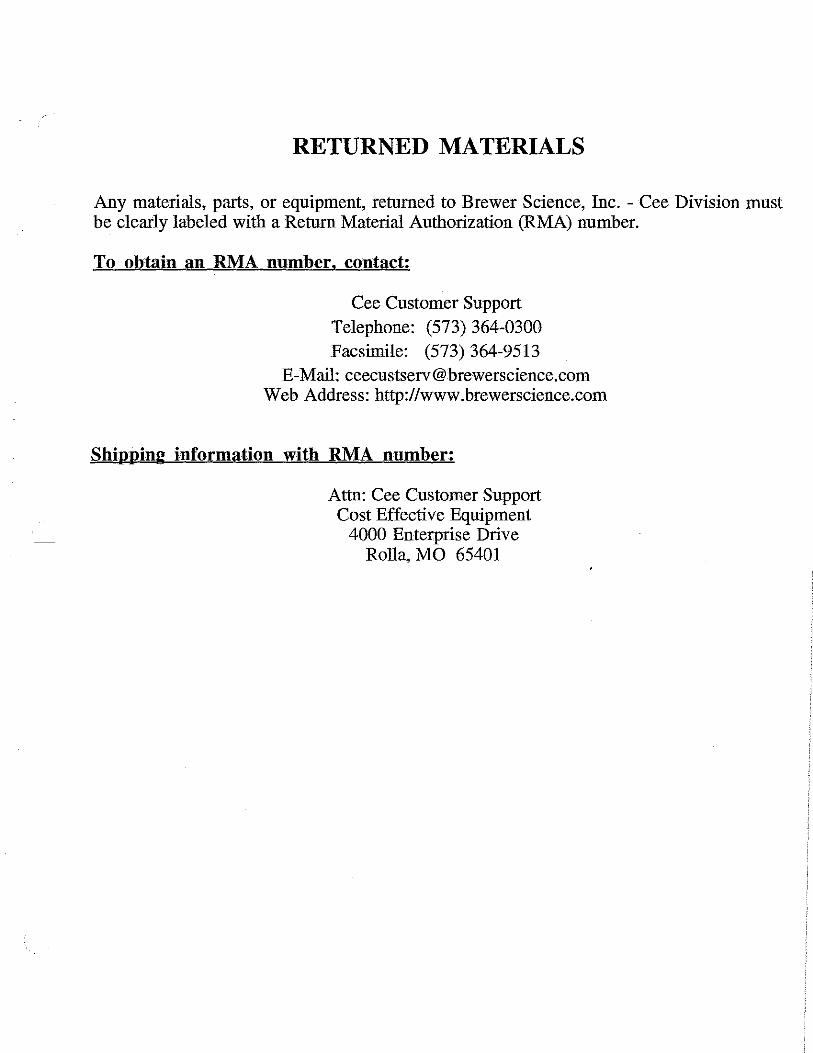
RETURNED MATERIALS
Any materials, parts, or equipment, returned to Brewer Science, Inc. - Cee Division must be clearly labeled with a Return Material Authorization (RMA) number.
To obtain an RMA number. contact:
Cee Customer Support Telephone: (573) 364-0300 Facsimile: (573) 364-9513
E-Mail: [email protected] Web Address: http://www.brewerscience.com
Shipping information with RMA number:
Attn: Cee Customer Support Cost Effective Equipment
4000 Enterprise Drive Rolla, MO 65401
Theory of Operation
Theory of Operation
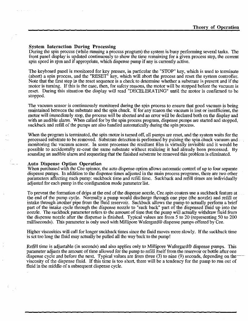
lntrodnction The Cee Model 100 and 150 spinner module incorporates a stainless steel spin bowl. The spin bowl drain and exhaust connect, through Teflon (PTFE) tubing, to the main utilities bracket on the rear of the machine. The main drive spindle for the spin chuck is made of hardened, corrosion-resistant, alloy steel. The spindle is driven by a toothed belt and a servo motor. An integral optical encoder provides feedback for the closed-loop, digital, motor control system. '
Spin Coating Process Theory Spin coating has been used for several decades for the application of thin films. A typical process involves depositing a small puddle of a fluid resin onto the center of a substrate and then spinning the substrate at high speed. Centripetal acceleration will cause the resin to spread to, and eventually off, the edge of the substrate. Final film thickness and other properties will depend on the nature of the resin (viscosity, drying rate, percent solids, surface tension, etc.) and the parameters chosen for the spin process. Factors such as final rotational speed, acceleration, and fume exhaust contribute to how the properties of coated films are defined.
One of the most important factors in spin coating is repeatability. Subtle variations in the parameters that define the spin process can result in drastic variations in the coated film. The following is an explanation of some of the effects .of these variations.
Spin Coating Process Description A typical spin process consists of a dispense step in which the resin fluid is deposited onto the substrate surface, a high speed spin step to thin the fluid, and a drying step to eliminate excess solvents from the resulting film. Two common methods of dispense are Static dispense, and Dynamic dispense.
Static dispense is simply depositing a small puddle of fluid on or near the center of the substrate. This can range from 1 to 10 cc depending on the viscosity of the fluid and the size of the substrate to be coated. Higher viscosity and or larger substrates typically require a larger puddle to ensure full coverage of the substrate during the high speed spin step.
Dynamic dispense is the process of dispensing while the substrate is turning at low speed. A speed of about 200 rpm is commonly used during this step of the process. This serves to spread the fluid over the substrate and can result in less waste of resin material since it is usually not necessary to deposit as much to wet the entire surface of the substrate. This is a particularly advantageous method when the fluid or substrate itself has poor wetting abilities and can eliminate voids that may otherwise form.
After the dispense step it is common to accelerate to a relatively high speed to thin the fluid to near its final desired thickness. Typical spin speeds for this step is 1000 to 2000 rpm, again depending on the properties of the fluid as well as the substrate. This step can take from 10 seconds to several minutes. The combination of spin speed and time selected for this step will generally define the final film thickness.
In general, higher spin speeds and longer spin times create thinner films. It is not recommended that the parameters of this step be adjusted for spin times of less than 30 seconds. The spin coating process involves a large number of variables that tend to cancel and average out during the spin process and it is best to allow sufficient time for this to occur. It is common for very viscous films tu require several minutes to thin out and to achieve a uniform coat thickness across the substrate.

Theory of Operation
A separate drying step is sometimes added after the high speed spin step to further dry the film without substantially thinning it. This can be advantageous for thick films since long drying times may be necessary to increase the physical stability of the film before handling. Without the drying step problems can occur during handling, snch as pouring off the side of the substrate when removing it from the spin bowl. In this case a moderate spin speed of about 25% of the high speed spin will generally suffice to aid in drying the film without significantly changing the film thickness. Each program on a Cee spin coater may contain up to ten separate process steps. While most spin processes require only two or three, this allows the maximum amount of flexibility for complex spin coating requirements.
Spin Speed Spin speed is one of the most important factors in spin coating. The speed of the substrate (rpm) affects the degree of radial (centrifugal) force applied to the liquid resin as well as the velocity and characteristic turbulence of the air immediately above it. In particular, the high speed spin step generally defines the final film thickness. Relatively minor variations of ±50 rpm atthis stage can cause a resulting thickness change of 10%. Film thickness is largely a balance between the force applied to shear the fluid resin towards the edge ofthe substrate and the drying rate which affects the viscosity of the resin. As the resin dries, the viscosity increases until the radial force of the spin process can no longer appreciably move the resin over the surface. At this point, the film thickness will not decrease significantly with increased spin time. All Cee spin coating systems are specified to be repeatable to within ±5 rpm at all speeds. Typical performance is ±1 rpm. Also, all programming and display of spin speed is given with a resolution of 1 rpm.
Acceleration The acceleration of the substrate towards the final spin speed can also affect the coated film properties. Since the resin begins to dry during the first part of the spin cycle, it is important to accurately control acceleration. In some processes, 50% of the solvents in the resin will be lost to evaporation in the first few seconds of the process.
Note: Acceleration can also damage your Motor Driver Board if set too high.
Acceleration also plays a large role in the coat properties of patterned substrates. In many cases the substrate will retain topographical features from previous processes; it is therefore important to uniformly coat the resin over and through these features. While the spin process iu general provides a radial (outward) force to the resin, it is the acceleration that provides a twisting force to the resin. This twisting aids in the dispersal of the resin around topography that might otherwise shadow portions of the substrate from the fluid. Acceleration of Cee spinners is programmable with a resolution of 1 rpm/second. In operation the spin motor accelerates (or decelerates) in a linear ramp to the final spin speed.
Fume Exhaust The drying rate of the resin fluid during the spin process is defined by the nature of the fluid itself (volatility of the solvent systems used) as well as by the air surrounding the substrate during the spin process. Just as a damp cloth will dry faster on a breezy dry day than during damp weather, the resin will dry depending on the ambient conditions around it. It is well known that such factors as air temperature and humidity play a large role in determining coated film properties. It is also very important that the airflow and associated turbulence above the substrate itself be minimized, or at least held constant, during the spin process.
All Cee spin coaters employ a "closed bowl'' design. While not actually an air-tight environment, the exhaust lid allows only minimal exhaust during the spin process. Combined with the bottom exhaust port located beneath the spin chuck, the exhaust lid becomes part of a system to minimize unwanted random turbulence. There are two distinct advantages to this system: slowed drying of the fluid resin and minimized susceptibility to ambient humidity variations.
Theory of Operation
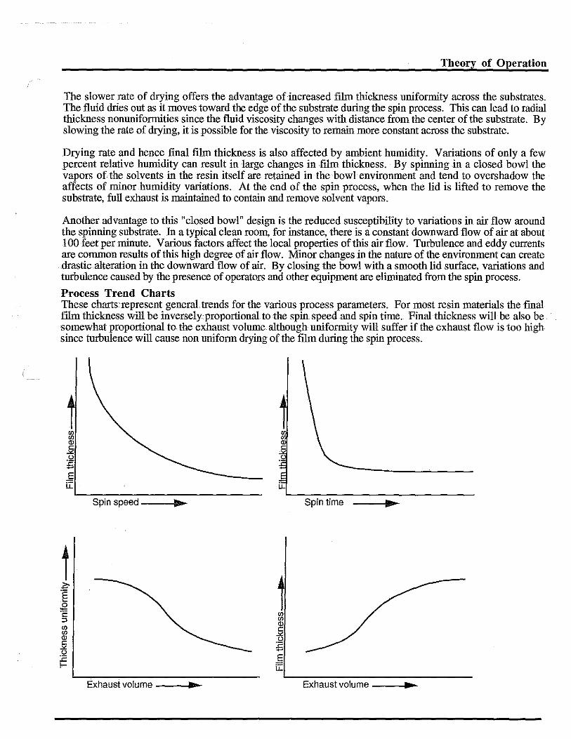
The slower rate of drying offers the advantage of increased film thickness uniformity across the substrates. The fluid dries out as it moves toward the edge of the substrate during the spin process. This can lead to radial thickness nonuniformities since the fluid viscosity changes with distance from the center of the substrate. By slowing the rate of drying, it is possible for the viscosity to remain more constant across the substrate.
Drying rate and hence final film thickness is also affected by ambient humidity. Variations of only a few percent relative humidity can result in large changes in film thickness. By spinning in a closed bowl the vapors of the solvents in the resin itself are retained in the bowl environment and tend to overshadow the affects of minor humidity variations. At the end of the spin process, when the lid is lifted to remove the substrate, full exhaust is maintained to contain and remove solvent vapors.
Another advantage to this "closed bowl" design is the reduced susceptibility to variations in air flow around the spinning substrate. In a typical clean room, for instance, there is a constant downward flow of air at about 100 feet per minute. Various factors affect the local properties of this air flow. Turbulence and eddy currents are common results of this high degree of air flow. Minor changes in the nature of the environment can create drastic.alteration in the downward flow of air. By closing the bowl with a smooth lid surface, variations and turbulence caused by the presence of operators and other equipment are eliminated from the spin process.
Process Trend Charts These chartsrepresent general.trends forthe various process parameters. For most resin materials the final ftlm thickness will be inversely proportional. to the spin speed and spin time. Final thickness will be also be somewhat proportional to the exhaust volume. although uniformity will suffer if the exhaust flow is too high since turbulence will cause non uniform drying of the film during the spin process.
t
Spin speed ---1111>-- Spin time
Exhaust volume __ ...,.,.._ Exhaust volume ---l.,._

Theory of Operation
Basic Operation of the Cee Model Spinner The Model 100 and 150 utilizes a single-board microcomputer as its main controlling element. This computer executes proprietary Cee software stored in read-only-memory (ROM) on the CPU board. Operatororiginated process programs are stored in battery-backed random-access-memory (RAM). Battery-backed RAM is protected from memory loss for up to 30 years.
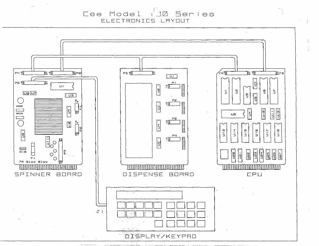
The CPU connects to the Spinner Board via two 34-pin ribbon cables. The Spinner Board uses commands from the CPU to control solenoid valves, the spin motor, and main keyboard display panel. Input from sensors on the machine is also fed through the Spinner Board on the way to the CPU.
Spinner Operation The Cee spin module is programmed using the front panel. There are ten (10) user programs available, each capable of storing ten program steps. Each step consists of a discrete rotation speed value (rpm), an acceleration value (rpm/second), and a step duration time value (seconds). In addition, on a machine equipped with the auto dispense option, each step contains a pump select value to allow up to fonr pumps to be activated during that step. Programs are edited in program mode by pressing the "PROG" key from the main menu.
Acceleration Constraints The Cee spin coater system is designed to process round substrates.up to eight inches in diameter and square plates up to six inches square. The motor drive system incorporates a PID control loop which allows optimum performance under varying conditions. It should be noted that while the motor drive is capable of peak output power that approaches one horsepower, it is finite. The maximum available acceleration available for a given substrate will depend on the mass and shape of the substrate and any special spin chucks needed to process the substrate. In some cases, the maximum acceleration may be less than the specified maximum unloaded acceleration given for the machine.
To run a spin process program the operator must press the "RUN" key from the model number display*. The display will request that the operator specify which program is to be used (0 - 9). After selecting a program, the display will read "READY PRESS START". At this point, the operator should load a wafer and press start. The system will turn on the spin chuck vacuum, and, after about 100 ms, will check the spin chuck vacuum sensing switch. The delay is preset in the system software and is designed to allow time for the spindle and associated tubing to achieve a partial vacuum. If the vacuum cannot be sensed at this time the system will declare an error. If a vacuum is present, the system will begin the centering test for the wafer.
The centering test rotates the chuck slowly, for a preselected amount of time, to allow the operator to verify that the substrate is centered on the spin chuck before beginning the actual spin process. The time for this step is a global adjustment made in the configuration parameters through the front panel and can be set for up to nine seconds. If the centering time is set to zero, then the centering test is omitted. The test is usually omitted when the system is used with a captive spin chuck which forces the substrate to be centered.
After the centering test, the system will turn off the vacuum to allow readjustment of the substrate position on the chuck. The operator may either repeat the centering test (to verify readjustment) or begin the spin process program. While in process (running a program), the display will indicate the step number currently being executed, the current rpm of the spin chuck, the time remaining for the current step, and, if applicable, the active dispense pump. Spin chuck vacuum is tested continuously during the spin process; a failure causes the motor to inunediately stop and the display to declare an error.
At the end of the program the motor will stop, the alarm will begin sounding, and the display will instruct the operator to remove the finished substrate. During this time the vacuum will pulse, allowing the system to check the vacuum and determine when the substrate has been removed. After the substrate is removed, the system will return to the point where the first substrate was loaded onto the chuck. Process programs can be terminated while in progress by pressing the "STOP" key. This causes the system to inunediately abort the program and behave as if the process was completed normally.
Theory of Operation
System Interaction During Processing During the spin process (while running a process program) the system is busy performing several tasks. The front panel display is updated continuously to show the time remaining for a given process step, the current spin speed in rpm and if appropriate, which dispense pump if any is currently active.
The keyboard panel is monitored for key presses, in particular the "STOP" key, which is used to tenninate (abort) a spin process, and the "RESET" key, which will abort the process and reset the system controller. Note that the first step in the reset sequence is a check to determine whether a substrate is present and if the motor is turning. If this is the case, then, for safety reasons, the motor will be stopped before the vacuum is reset. During this situation the display will read "DECELERATING" until the motor is confinned to be stopped.
The vacuum sensor is continuously monitored during the spin process to ensure that good vacuum is being maintained between the substrate and the spin chuck. If for any reason the vacuum is lost or insufficient, the motor will immediately stop, the process will be aborted and an error will be declared both on the display and with an audible alarm. When called for by the spin process program, dispense pumps are started and stopped, suckback and refill of the pumps are also handled automatically during the spin process.
Wben the program is terminated,.the spin motor is turned off, all pumps are reset, and the system waits for the processed substrate to be removed. Substrate detection is performed.by pulsing the spin chuck vacuum and monitoring the vacuum sensor. In some processes the resultant film is virtually invisible and it would be possible to accidentally re-coat the same substrate without realizing it had already been processed. By sounding an audible alarm and requesting that the finished substrate he removed this problem is eliminated.
Auto Dispense Option Operation Wben purchased with the Cee spinner, the auto dispense option allows automatic control of up to four separate dispense pumps. In addition to the dispense times adjusted in the main process programs, there are two other parameters affecting each pump: suckback time and refill time. Suckback and refill times are individually adjusted for each pump in the configuration mode parameter list.
To prevent the formation of drips at the end of the dispense nozzle, Cee spin coaters use a suckback feature at the end of the pump cycle. Normally a pump would discharge through one pipe (the nozzle} and refill or intake through another pipe from the fluid reservoir. Suckback allows the pump to actually perform a brief part of the intake cycle through the dispense nozzle to "suck back" part of the dispensed fluid up into the nozzle. The suckback parameter refers to the amount of time that the pump will actually withdraw fluid from the dispense nozzle after the dispense is finished. Typical values are from 5 to 20 (representing 50 to 200 milliseconds). This parameter is only used with Millipore Wafergard® dispense pumps offered by Cee.
Higher viscosities will call for longer suckback times since the fluid moves more slowly. If the suckback time is set too long the fluid may actually be pulled all the way back to the pump1
Refill time is adjustable (in seconds) and also applies only to Millipore Wafergard® dispense pumps. This parameter adjusts the amount of time allowed for the pump to refill itself from the reservoir or bottle after one dispense cycle and before the next. Typical values are from three (3) to nine (9) seconds, depending on the--~ viscosity of the dispense fluid. If this time is too short, there will be a tendency for the pump to run out of fluid in the middle of a subsequent dispense cycle.

Theory of Operation
Key Spinner Parameters - Eqnipment Process Variables Programming on the Cee series spin coaters allows the adjustment of process parameters. Each of the ten battery-backed programs may contain up to ten discrete process steps. Each step contains a spin speed in rpm (one rpm resolution), an acceleration in rpm/second (one rpm resolution) a step time in seconds (one second resolution) and a dispense pump identifier (if purchased with the auto dispense option).
In-addition, there are several global parameters that are very important for optimum system operation. The configuration mode parameter list contains values for the motor tuning constants as well as the pump parameters on auto dispense equipped systems. All Cee spin coaters use a PID (proportional, integral, derivative) control system for the motor drive. These parameters should be tuned for optimum performance with substrates of varying size, different spin chuck designs and other changes that affect the inertia of the spinning parts. Inertia is directly related to the mass of the chuck and substrate being spun. It is proportional to the square of the radius of the spun substrate. Thus a little bit larger substrate can make a large change in the performance of the spinner system. PID values that work fine with a 2" wafer will not give good results with an 8" wafer, and values that work well going to 2000 rpm may result in speed overshoot going to 5000 rpm. Some PID values will prevent the spinner from attaining a final stable speed, and the chuck may even oscillate forward and backward.

Spin Coating Process Troubleshooting
Spin coater:
Theory of Operation
As explained previously, there are several major factors affecting the coating process. Among these are spin speed, acceleration, spin time and exhaust.
Process parameters vary greatly for. differentresiu materials and substrates so there are no fixed .rules for spin· coatprocessing, only general guidelines. These are explained in the "Hotplate Process Description" section. Following is a list of issues to consider for specific process problems.
Film too thin
Spin speed too high Spin time too Jong Inappropriate choice of resin material
Film too thick
Spin speed too low Spin time too short Exhanst volnme too high Inappropriate choice of resin material
Poor reproducibility
Variable exhaust or ambient conditions Snbstrate not centered properly Insnfficient dispense volume Inappropriate application of resin material Unstable balance in speed I time parameters
Poor film quality
Exhanst volnme too high Acceleration too high Unstable balance in speed I time parameters Insnfficient dispense volnme Inappropriate application of resin material
Select lower speed Decrease time dnring high speed step Contact resin mannfacturer
Select higher speed Increase time during high speed step Adjnst exhanst lid or honse exhanst damper
Adjnst exhanst lid to fully closed Center substrate before operation Increase dispense volnme Contact resin mannfacturer Increase speed I decrease time or visa versa
Adjust exhanst lid or honse exhanst damper Select lower acceleration Increase speed I decrease time or visa versa Increase dispense volume Contact resin manufacturer

Theory of Operation
PID Control Features
Cee Equipment Spin/Coat modules and Hotplate modules use advanced technology controllers. These controllers allow a higher degree of precision in substrate processing. Some control systems try to get by with just a Proportional (P) or Proportional-Integral (PI) type of feedback loop. To maintain consistency and overcome the time lag inherent in real-time control, a more sophisticated system with some ability to predict system performance is necessary. This is achieved by adding the Derivative (D) type feedback loop to the Proportional-Integral (PI) loop, forming a PID feedback control loop (figure 1). This control loop performs with the precision necessary for today's complex process requirements.
- Proportional Gain
Desired
Temp/Speed +,
+ + Set Point 2 \ Integral " I Pl D 1 " Controlled
Generator I Gain ~ Device
-Actual
+
Temp/Speed Derivative - Gain
Figure 1 - PID Control Loop

Theory of Operation
Proportional Control Inertial loading of a system will present a following (or tracking) error back to the controller. This error is the difference between the output and the target or set-point. External disturbances or loading of the system produces a displacement error. The proportional filter provides a restoring force to minimize the error. This restoring force is linearly proportional to the error. Proportional adjustment is made using the proportional gain parameter. The proportional gain of a system sets the critical damping or stiffness. If the proportional gain is too low, the restoring force will be too slow or soft in response. If the gain is too high, the system will over- and undershoot the target for a period of time; a condition referred to as ringing or oscillation. Once the median value of proportional gain is determined, the system is said to be critically damped.
Integral Control The integral feedback loop will provide a corrective force that can eliminate tracking error. The integral force is proportional to the tracking error and increases linearly with time. Integral Adjustment is made with Integral Gain constant. Large values of integral gain provide quick compensation, but increase overshoot and ringing. Usually, integral gain should be set to a minimal value that provides a compromise between the three system characteristics of : overshoot, settling time, and the time necessary to cancel the effects of static loading. Another term usually associated with integral gain is the integral limit. This integral boundary limits the. magnitude .. of the feedback. Due to the nature of integration, the potential of extreme~error correction values;is.greae-The integral limit value.acts as a clamping force to prevent integral wind"up; a backlash effect occurring from a large tracking error.·
Derivative ·Control The differential feedback loop provides a damping effect to eliminate system oscillation and to minimize overshoot and ringing. The damping force adjustment, or Derivative Gain, is proportional to the rate of change of the tracking error. This parameter provides an overall stability to the system. It adds the capability of predicting system response and being able to interject corrective action well before tracking errors become visible. This prediction ability is possible because the response is determined by the systems reaction in a set time frame.
Control Comparisons Summary The graph of figure 2 shows the types of control discussed and the relative response to be expected. The proportional control at its optimum will have a lagging response and a slower rise-time. The proportional -integral feedback has a faster rise time, but tends to oscillate about the desired set-point until the controller values settle. The proportional - integral - derivative control has the fastest rise-time and the ability to lock on to the set-point quickly; the control response necessary for bake and spin/coat processing.
Set Point
Proportional
Proprtional - Integral
Proportional - Integral - Derivative
time
Figure 2 - Control Comparison
UJ w I u IO
z [
H 0
" (') (')
rl N .., ..,
IO
f- [ II II
I Ill
[9 E _J 3 I H
rl
w 0
000 "£1"
I
8 8 ..,
(J)
z 0 '-I
)
z w .L
0 0
H
0
!SJ !SJ ~
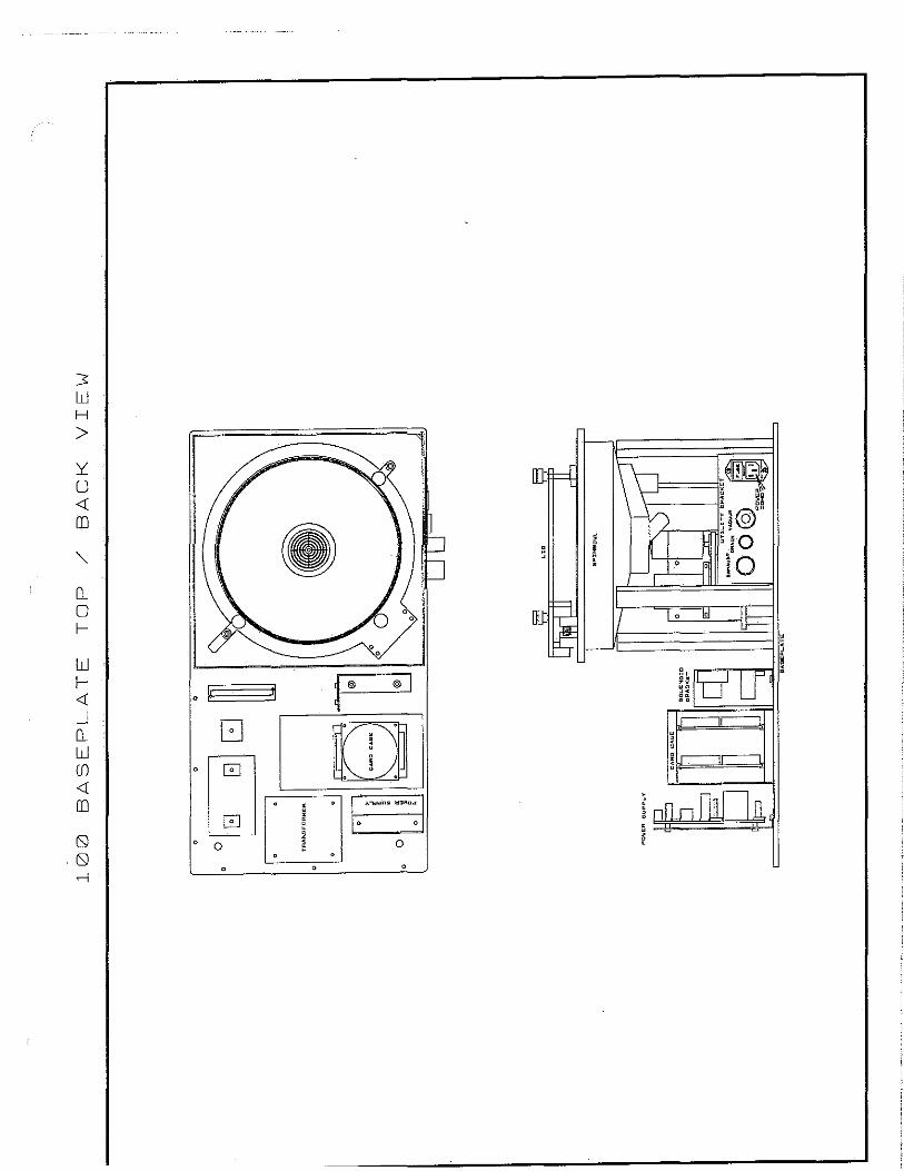
100 UTILITIES
EXHAUST
'@
lFusEI = w
@
g,.-, ' '
' '
POWER CONNECTION
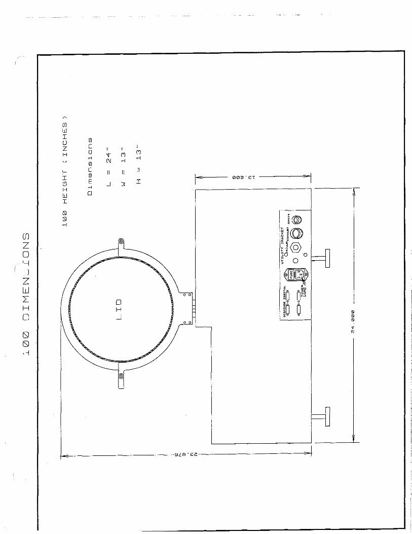
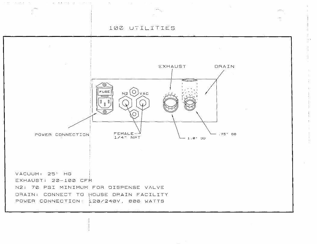
VACUUM: 25" HG EXHAUST: 20-l00 CFM
FEMALE 1/4" NPT
N2: 70 PSI MINIMUM FOR DISPENSE VALVE
DRAIN: CONNECT TD ~DUSE DRAIN FACILITY POWER CONNECTION: 120/240V, 800 WATTS
' ' ,, ~ - ~ ''•
:·~·: -=-:',''. ' '
' ~: --:
1, 0" OD
DRAIN
. 75" OD
3 w H
> :r:: u <(
ID
Q_
0 I--
w I-<( _J Q_
w (f) <(
ID
(9 . (9
,--j
0
0
G
l:J 0
0
0
• 0
" l
p ,..,....,.......JI!
m I
,.,.,,ms 11311a«
0 0
I 0
0 0
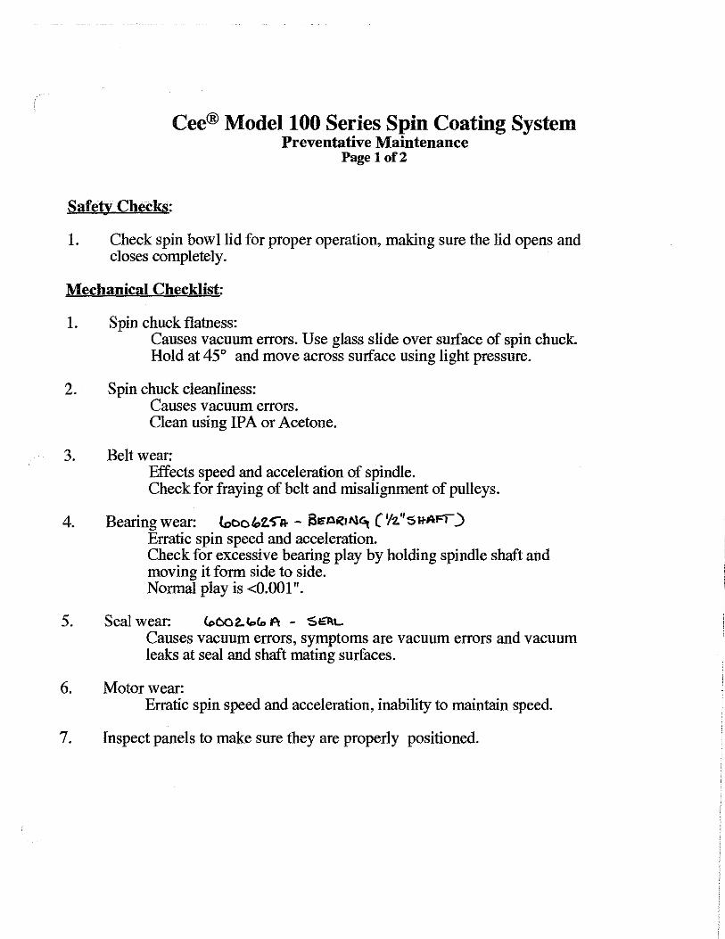
Cee® Model 100 Series Spin Coating System
Safety Checks:
Preventative Maintenance Page 1 of2
1. Check spin bowl lid for proper operation, making sure the lid opens and closes completely.
Mechanical Checklist:
1. Spin chuck flatness: Causes vacuum errors. Use glass slide over surface of spin chuck. Hold at 45° and move across surface using light pressure.
2. Spin chuck cleanliness: Causes vacuum errors. Clean using IPA or Acetone.
3. Belt wear: Effects speed and acceleration of spindle. Check for fraying of belt and misalignment of pulleys.
4. Bearing wear: looc&.2.S-A- - 2Et.lRrlllC, ('h.'1'51+AFI) Erratic spin speed and acceleration. Check for excessive bearing play by holding spindle shaft and moving it form side to side. Normal play is <0.001".
5. Seal wear: C..002.lolo A - 'S~L Causes vacuum errors, symptoms are vacuum errors and vacuum leaks at seal and shaft mating surfaces.
6. Motor wear: Erratic spin speed and acceleration, inability to maintain speed.
7. Inspect panels to make sure they are properly positioned.
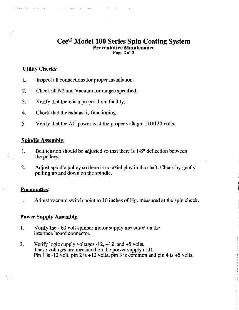
Cee® Model 100 Series Spin Coating System Preventative Maintenance
Page2of2
Utility Checks:
1. Inspect all connections for proper installation.
2. Check all N2 and Vacuum for ranges specified.
3. Verify that there is a proper drain facility.
4. Check that the exhaust is functioning.
5. Verify that the AC power is at the proper voltage, 110/120 volts.
Spindle Assembly:
1. Belt tension should be adjusted so that there is 118" deflection between the pulleys.
2. Adjust spindle pulley so there is no axial play in the shaft. Check by gently pulling up and down on the spindle.
Pneumatics:
1. Adjust vacuum switch point to 10 inches of Hg. measured at the spin chuck.
Power Supply Assembly:
1. Verify the +60 volt spinner motor supply measured on the interface board connector.
2. Verify logic supply voltages -12, + 12 and +5 volts. These voltages are measured on the power supply at Jl. Pin 1 is -12 volt, pin 2 is + 12 volts, pin 3 is common and pin 4 is +5 volts.
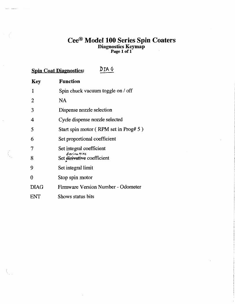
Cee® Model 100 Series Spin Coaters Diagnostics Keymap
Page lofl
Spin Coat Diagnostics:
Key Function
1 Spin chuck vacuum toggle on I off
2 NA
3 Dispense nozzle selection
4 Cycle dispense nozzle selected
5 Start spin motor ( RPM set in Prog# 5 )
6 Set proportional coefficient
7 Set integral coefficient J.er\110...+tre.
8 Set dir¥1ative coefficient •
9 Set integral limit
0 Stop spin motor
DIAG Firmware Version Number - Odometer
ENT Shows status bits

Purpose:
Cee® Model 100 Series Spin ,Coating System Spindle Vacuum Switch Adjustment
Page lofl
To adjust the switch point for the spin chuck vacuum. Use this procedure during scheduled preventive maintenance to ensure reliability.
Items needed:
• Solenoid bracket drawing for your Cee® system. • Allen wrench to remove the left most back panel. • Small flat screw driver with a 4" long shaft and 1/8" wide tip.
Adjustment:
From the back, remove the left most panel.
2. Enter diagnostic mode. The display will read the following; VAC 0 PUMP #1 VEL 0 V AC 0 indicates vacuum is not present at the spin chuck and therefore the system will not allow the spin motor to run.·
3. Start without a substrate on the spin chuck. Press #1 on the keyboard to tum on spin chuck vacuum.
4. Locate the vacuum switch and turn clock wise until the display reads vacuum on 01AC1). With the substrate still off and the display shows that the vacuum switch has vacuum, you have just found tlie most sensitive position or switch point (closed sensor switch).
5. Next, tum the vacuum adjustment screw counter clock wise until the display reads vacuum off 0/AC 0), this should only take 1116 of a tum. Once at V AC 0, tum another 1/16 or 1/4,

"100 SERIES " SOLENOID BRACKET
cy1 "our··
1/8" Teflon tubing attaches to the two·"IN" hose barbs. The length of these are determined by the type of machine which you are building and the routing path between the Solenoid Bracket, Spinner & Utility Bracket. Cut to f~ and allow some extra length for serviceing or changes.
Use approximately 4" of 1/4" clear tubing to connect the vacuum sensor port to the large hose barb on the ET3 solenoid.
The conslruction and hookup of the ribbon cable wiring hames for this subassembly is covered in the BASEPLATE WIRING module.
Mount Solenoids with 6-32 x 5/16" BHCS, flats & locks
Mount Piezo Buzzer with 4-40 x 3/8" SHCS, flats & locks
Mount Vacuum Sensor with 4-40 x 3/4" SHCS, flats & locks
VacSensor Port
VacSense Adj. Sere~
© Mount Bracket to Baseplate with 8-32 x 1/2" SHCS, flats & locks
BSI Doc#: D.4.3.0019.A Effective Date: 6/18/98
1 - Metal Bracket
2 - Piezo Buzzer
3 - Vac. Switch
4 - ET3 Solenoid
5 - ET2 Solenoid
6 - Adjustable L
7 - Adjustable T
8 - Small Hose Barb
9 - Large Hose Barb
10 - PEM Mtg. Nuts
Cee/5.04
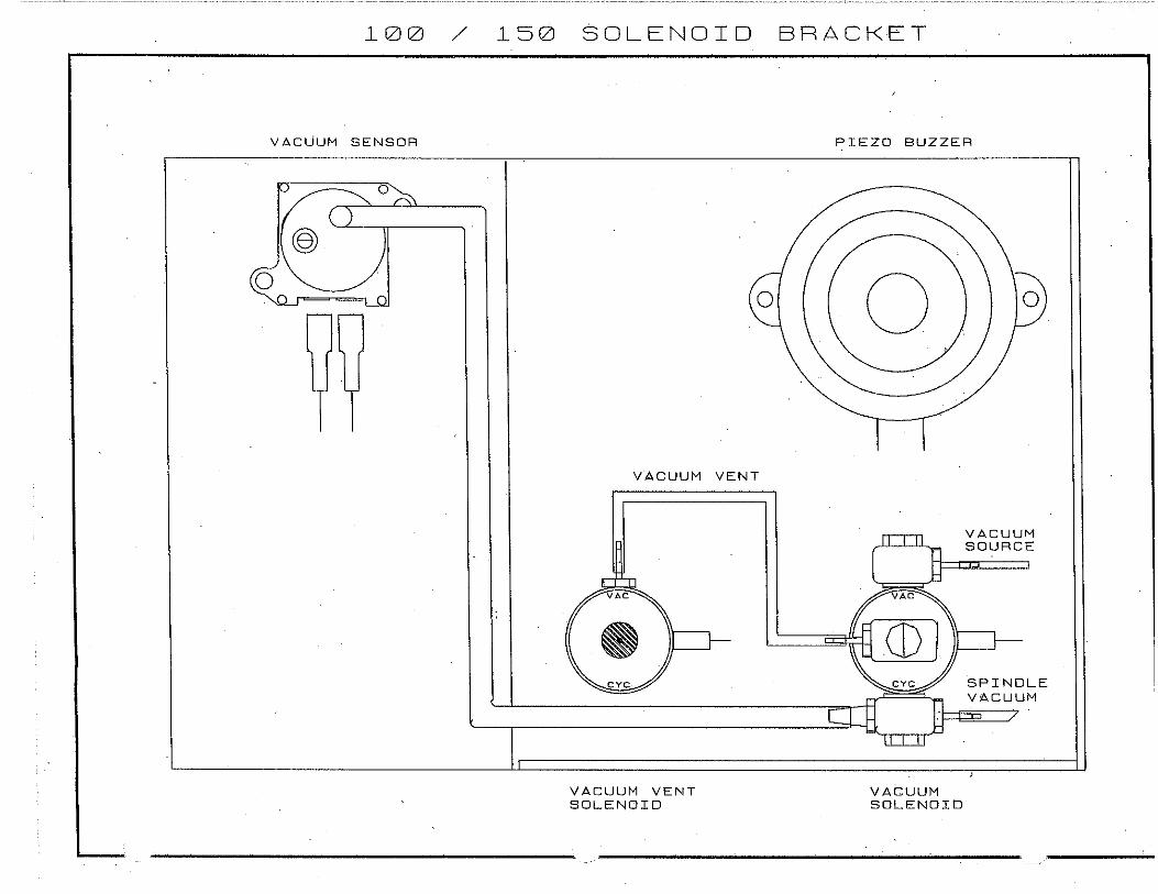
l00 / l50
VACUUM SENSOR
@
SOLENOID
0
VACUUM VENT
VACUUM VENT SOLENOID
BRACKET
PIEZO BUZZER
0
VACUUM SOLENOID
0
VACUUM SOURCE
SPINDLE VACUUM

51Zl!Zl27IZID I /2" Sp ind 1 e Sha-Fi:
Flny I /2" Spin Chuck
3 51Zl!Zl525FI 7 /8" x I /2" F 1 ange Bearing
5!ZllZl266FI Seals wii:h Spring
5 51Zl!Z13YIZIFI IM-21 Moi:or
5 51Zl!Zl339FI I B Gear Pu 1 1 ey
7 51Zl!ZllZl97FI 25 Gear Pulley
B 512l!Z112l96FI I /Y" Be 1 1 ev i 1 1 e \Vasher
9 512ll2ll2lBIE Moi:or Mouni:
1121 512ll2l!ZllZl3C Spindle Bearing Block
I I 512l!Zl396FI Timing Beii:
12 512l!ZIY5IZIFI Rei:aining Ring
13 512ll2l!ZIBIZIC Spindle Seal Block
IY 912ll2l!ZlllZIB Vacuum Reservoir
I 5 512l!ZI I IZl2FI I/ I 5" Yose Barb
I 5 512l!Zl09YFI I /B" Tef' 1 on Tubing
I 7 512l!ZI I 35FI Hose C 1 amp
I 6 c1 ====::;-i~
il 17
rn T1
IY 17
Fl bl
15
=12
I IZI 5
I I
1/2" SPINDLE Fl55M.

(.··< 0
,.-,--....
:1----------: [.·::.-~ .··
0
lfilt--------8 _) :-·~
10
1jj-1 ______ _,( 6
... ··"
.. n· i
n l @
.. ··· .... ··
12
15

1/11/00
ITEM 1
2 3 4 5 6 7 8 9 10 1 1 12 1 3 14 15 1 6 1 7 18
ASSEMBLY#: 900648A DESCRIPTION: 150 Spinner Assembly
DATE: 1/11/00
PART NUMBER DESCRIPTION 603886C 100/lOOCB Spindle 600627A 1/2" Retaining Ring
Bulk Bowl Seal 600625A 1/2" X 1 1/8" Flanged Bearing 603869B 100/4000 Spindle Block 600078A 1/4" Flat Washer 600096A 1/4" Belleville Washer 600097A HTD Timing Pulley (26 Grooves) 600266A 0.25" X 0.438" Seal w/med Spring 604142A 150 Spindle Assembly Base 604141A 150 Soindle Assemblv Standoff 600340A IM-21 Motor 603877A 4000/4500 Snin Motor Mount 600339A HTD Timina Pullev (18 Grooves\ 600396A Timino Belt 175 Grooves\ 600118A #8-32 SHCS, 5/8" Iona 600196A #10-32 SHCS. 1" Iona 600196A #10-32 SHCS 1" lonn
.
BOM 900648
QUANITY 1 1 1 2 1 1 1 1 1 1 1 1 1 1 1 2 4 4
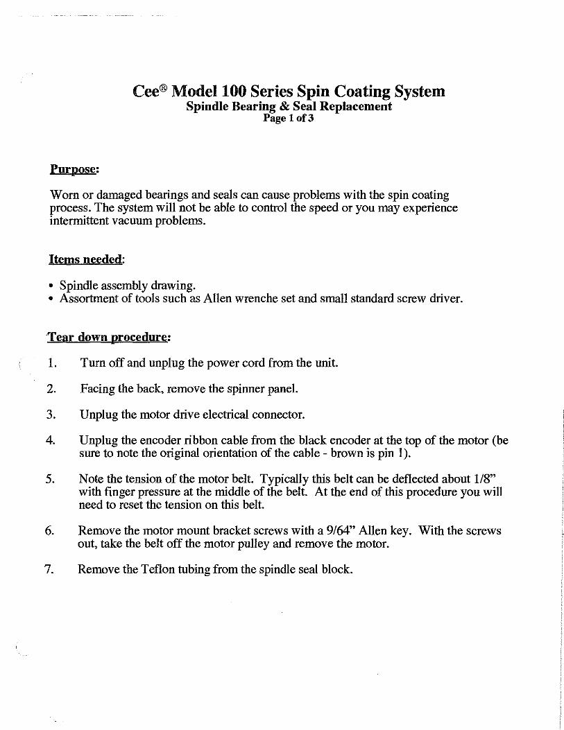
Cee® Model 100 Series Spin Coating System Spindle Bearing & Seal Replacement
Page lof3
Purpose:
Worn or damaged bearings and seals can cause problems with the spin coating process. The system will not be able to control the speed or you may experience intermittent vacuum problems.
Items needed:
• Spindle assembly drawing. • Assortment of tools such as Allen wrenche set and small standard screw driver.
Tear down procedure:
1. Tum off and unplug the power cord from the unit.
2. Facing the back, remove the spinner panel.
3. Unplug the motor drive electrical connector.
4. Unplug the encoder ribbon cable from the black encoder at the top of the motor (be sure to note the original orientation of the cable - brown is pin 1 ).
5. Note the tension of the motor belt. Typically this belt can be deflected about 118" with finger pressure at the middle of the belt. At the end of this procedure you will need to reset the tension on this belt.
6. Remove the motor mount bracket screws with a 9/64" Allen key. With the screws out, take the belt off the motor pulley and remove the motor.
7. Remove the Teflon tubing from the spindle seal block.

Cee® Model 100 Series Spin Coating System Spindle Bearing & Seal Replacement
Page2of3
8. Note the orientation and position of the pulley on the spindle shaft, loosen the two set screws in the side of the pulley.
9. From the spin bowl, pull the spindle straight up and out. You may need to place the spin chuck on the spindle to get leverage to pull the spindle out. Take care not to damage the spindle or the spin chuck. Do not use any tools or pry bars to remove the spindle.
10. From the bottom of the base plate, remove the screws that attach the spinner assembly to the baseplate of the machine.
11. Remove the right spin bowl support and then the spinner assembly.
12. Remove the bearings from the spindle block. This can be done by tapping on them from the inside out.
13. Remove the seal from the seal block.
14. Use solvent to clean any parts that have processing material on them.
Replacement procedure:
1. Insert the two spindle bearings into the bearing block. It is very important that the bearings are pressed in straight.
2. Insert the new seal with the spring side facing up. The top of the seal should be flush with the surface of the seal block. Apply a small amount of Teflon grease to the inside of the seal.
3. Place the spindle assembly back in to the machine and attach to the baseplate, do not tighten the bolts until after the spindle has been installed.
4. Before installing the spindle place the spindle pulley and the belleville washer (washer position is cupped up) on top of the seal block and centered over the seal. Be sure the belt is installed around the spindle pulley. Next, install the spindle shaft through the bearings, washer, pulley and into the seal

Cee® Model 100 Series Spin Coating System Spindle Bearing & Seal Replacement
Page3of3
5. Align one of the set screws of the pulley with the flat on the spindle. Before you tighten the set screw, push the pulley up and the spindle down at the same time. This will pre-load the bearings so the spindle will not move vertically. Tighten both set screws.
6. Install the motor and belt Belt tension should have an 118" deflection on both sides.
7. Tighten all bolts and reconnect the Teflon tubing
8. Connect the encoder cable to the motor and motor power.
Testing the spinner:
1. Program 5, set the first RPM value to 100 RPMs.
2. Enter diagnostic mode by pressing "DIAG".
3. Rotate the spin chuck counter clockwise. Did it display RPM's ?
4. If yes, place a substrate on the spin chuck and press 1.
5. If no, connect the encoder cable to the motor encoder.
6. Close the lid and press 5 to start the motor and 0 to stop.
7. When finished, press reset and remove the substrate.
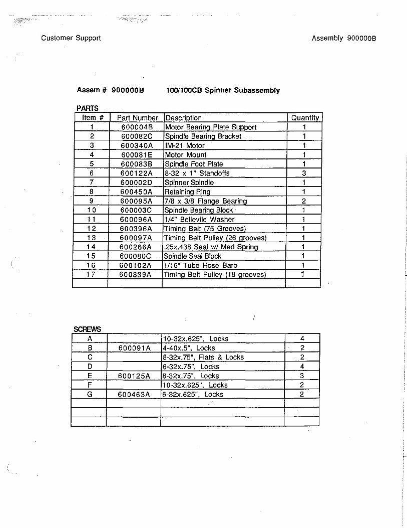
Customer Support Assembly 900000B
Assem # 9000008 100/100CB Spinner Subassembly
PARTS Item# Part Number Descriotion Quantitv
1 600004B Motor Bearina Plate Sunnort 1 2 600082C Snindle Bearinn Bracket 1 3 600340A IM-21 Motor 1 4 600081E Motor Mount 1 5 600083B Snindle Foot Plate 1 6 600122A 8-32 x 1" Standoffs 3 7 6000020 Soinner Snindle 1 8 600450A Retaininn Rina 1 9 600095A 718 x 3/8 Flanae Bearina 2
1 0 600003C Snindle Bearinn Block · 1 1 1 600096A 1/4" Bellevile Washer 1 1. 2 600396A Timina Belt 175 Grooves\ 1 1 3 600097A Timina Belt Pullev 126 aroovesl 1 14 600266A .25x.438 Seal w/ Med Snrina 1 15 600080C Snindle Seal Block 1 1 6 600102A 1/16" Tube Hose Barb 1 1 7 600339A Timinn Belt Pullev 118 arooves\ 1
A 10-32x.625", Locks 4 B 600091A 4-40x.5", Locks 2 c 8-32x. 75", Flats & Locks 2 D 6-32x. 75'', Locks 4 E 600125A 8-32x.75", Locks 3 F 10-32x.625", Locks 2 G 600463A 6-32x.625", Locks 2
'

Cee® Model 100 Series Spin Coater Vacuum Trouble Shooting
Pagel of3
Purpose:
To identify each component in the vacuum system for trouble shooting vacuum related errors. Cee® uses vacuum to pull down a substrate on the spin chuck, pull down a substrate on the hot plate, and controls suck back with syringe or Millipore pump dispense systems.
Items needed:
• Solenoid Bracket drawing for your Cee® system. • Card Cage Layout drawing for your Cee® system. • Spin Motor Board drawing. • SPL-50 Power Supply - test point drawing. • Allen wrench to remove the back panel. • Multi-meter.
Trouble Shooting:
1. Press DIAG.
Question #1- Does the display show "VAC 0 PUMP#l VEL O"?
Yes: Go to step number 2.
No: Go to step number 17 if the display shows "VAC 1 PUMP#l VEL 0".
2. With no wafer on the spin chuck press 1.
Question #2 - Do you hear or feel vacuum at the center of the spin chuck ?
Yes: Go to question number 3.
No: Go to step number 4.
3. Place a substrate on the spin chuck.
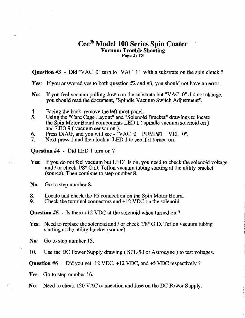
Cee® Model 100 Series Spin Coater Vacuum Trouble Shooting
Page2of3
Question #3 - Did "V AC 0" tum to "V AC 1" with a substrate on the spin chuck ?
Yes: If you answered yes to both question #2 and #3, you should not have an error.
No: If you feel vacuum pulling down on the substrate but "VAC 0" did not change, you should read the document, "Spindle Vacuum Switch Adjustment".
4. Facing the back, remove the left most panel. 5. Using the "Card Cage Layout" and "Solenoid Bracket" drawings to locate
the Spin Motor Board components LED 1 ( spindle vacuum solenoid on ) and LED 9 (vacuum sensor on).
6. Press DIAG, and you will see - "V AC 0 PUMP#l VEL O". 7. Next press 1 and then look at LED 1 to see if it turned on.
Question #4 - Did LED 1 tum on ?
Yes: If you do not feel vacuum but LEDl is on, you need to check the solenoid voltage and I or check 118" O.D. Teflon vacuum tubing starting at the utility bracket (source). Then continue to step number 8.
No: Go to step number 8.
8. Locate and check the PS connection on the Spin Motor Board. 9. Check the terminal connectors and+ 12 VDC on the solenoid.
Question #5 - Is there + 12 VDC at the solenoid when turned on ?
Yes: Need to replace the solenoid and I or check 118" 0.D. Teflon vacuum tubing starting at the utility bracket (source).
No: Go to step number 15.
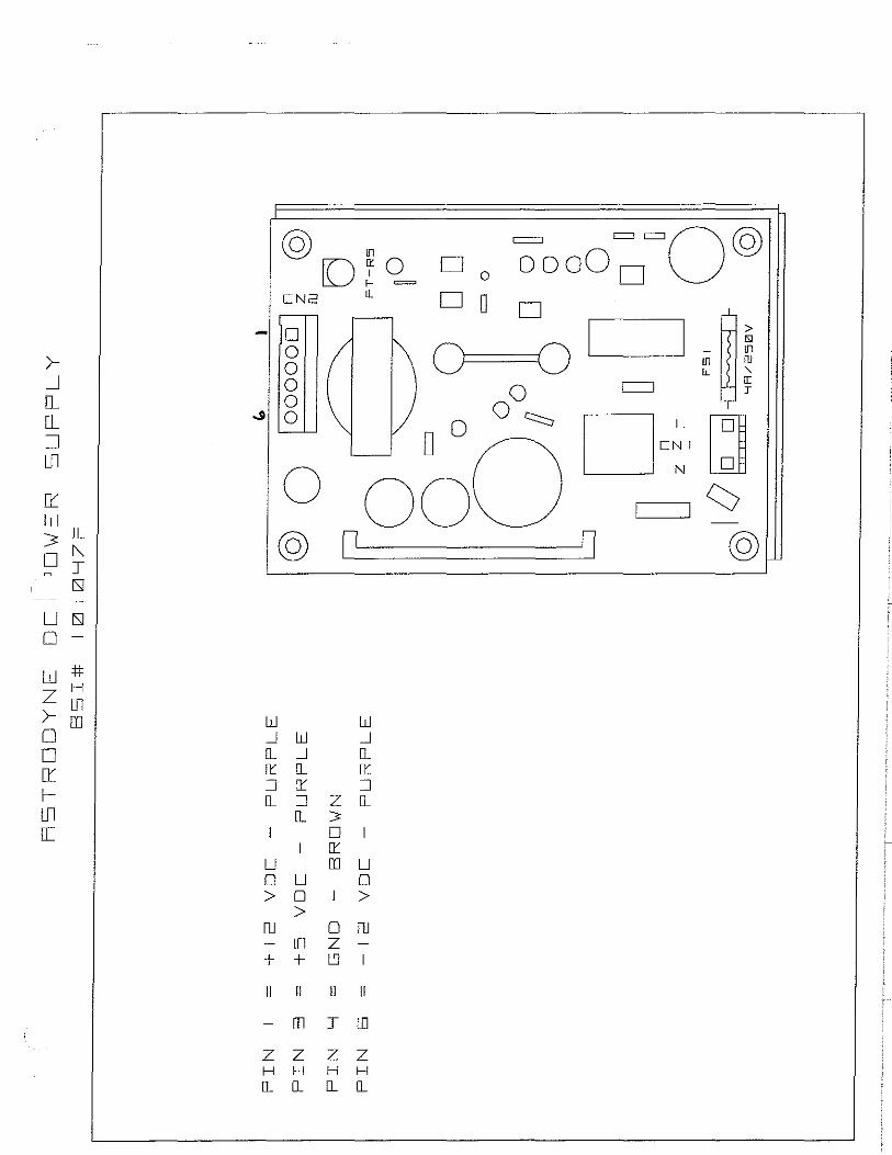
10. Use the DC Power Supply drawing ( SPL-50 or Astrodyne) to test voltages.
Question #6 - Did you get -12VDC,+12 VDC, and +5 VDC respectively ?
Yes: Go to step number 16.
No: Need to check 120 V AC connection and fuse on the DC Power Supply.
Cee® Model 100 Series Spin Coater Vacuum Trouble Shooting
Page3of3
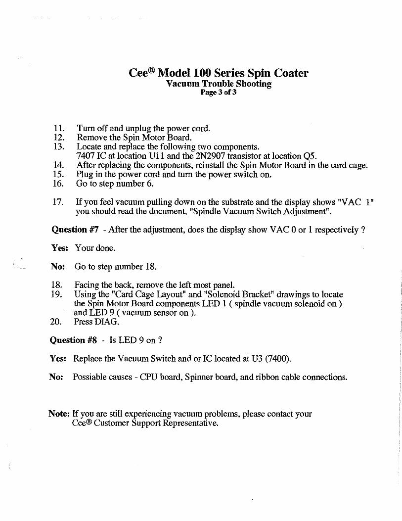
11. Tum off and unplug the power cord. 12. Remove the Spin Motor Board. 13. Locate and replace the following two components.
7407 IC at location Ul 1 and the 2N2907 transistor at location Q5. 14. After replacing the components, reinstall the Spin Motor Board in the card cage. 15. Plug in the power cord and tum the power switch on. 16. Go to step number 6.
17. If you feel vacuum pulling down on the substrate and the display shows "V AC 1" you should read the document, "Spindle Vacuum Switch Adjustment".
Question #7 - After the adjustment, does the display show V AC 0 or 1 respectively ?
Yes: Your done.
No: Go to step number 18.
18. Facing the back, remove the left most panel. 19. Using the "Card Cage Layout" and "Solenoid Bracket" drawings to locate
the Spin Motor Board components LED 1 ( spindle vacuum solenoid on ) and LED 9 ( vacuum sensor on ).
20. Press DIAG.
Question #8 - Is LED 9 on ?
Yes: Replace the Vacuum Switch and or IC located at U3 (7400).
No: Possiable causes - CPU board, Spinner board, and ribbon cable connections.
Note: If you are still experiencing vacuum problems, please contact your Cee® Customer Support Representative.
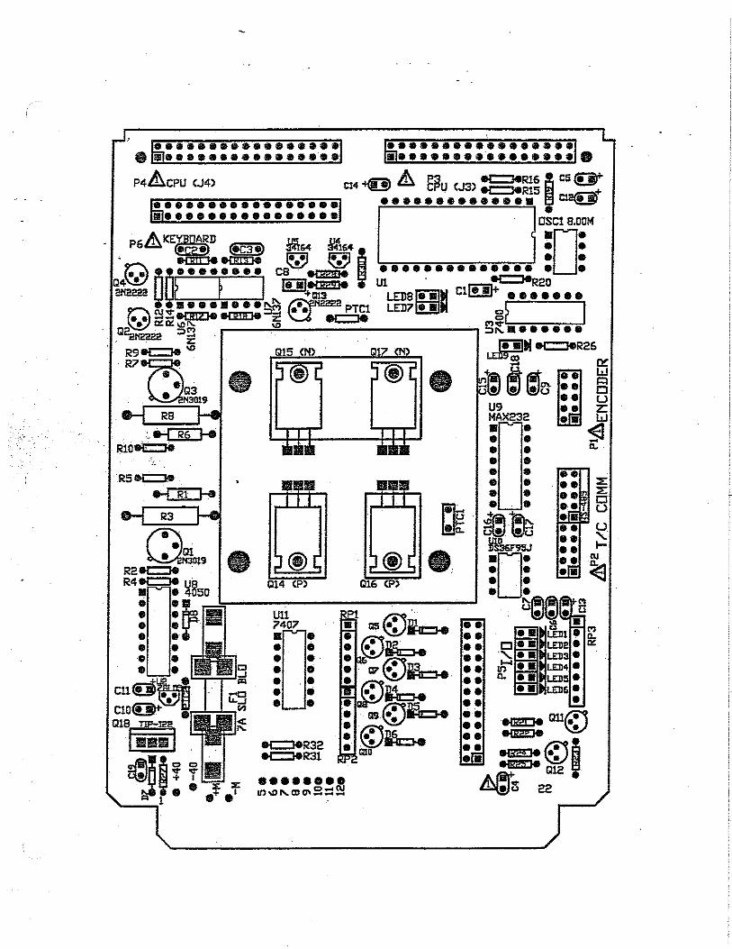
P'-i 7(g ~~ 7fg ~:P3
P67m ;: ! UI ~
~~ ~ 0 ~.
~ ~~ = c::::J = c::::J
rnJ ~. ru
o~ ·-0
~
SPINNER BOARD
Cee Model 1_JIZJ Serres ELECTRONICS LAYOUT
.:r I
PS 7(g- -~~
~
~ '61 P2
~ ;cc=J I ~ 701 ~ ;[~~,
DISPENSE BOARD
------ ... .. -------- ------ .. . --------
0 DD DD DODD DI:JDDD DODD.
DODOO DfSPLAY/KEYPFlO
~ :JLJ0~1~11~
I us s ~ ~ ~ ~
000000 D~~ ~~~~~~
C:PLJ

>_J
[]_ []_
::::J Ul [[
0::: ~ []]
I tJ ISJ ISJ
L] ISJ []_
LJ # 0 H
lJl []
ISi lfl I
_J
[]_
Ul
EJ ®
[J 11121V 0 Q
:3FV25121V
IEl5-112ll'W RC'I
0 @) @)
B
lJ I
D
z w w 0 [!'. w L'J [!'.
u u 0 0 > > f1J f1J
+ II II
oooO
w 1-H
'{ I u 3 [[ _J
m
0
lJ 0 >
Z ITT L'J + II II
ru m T
z z z z H H H H
IL IL IL IL
OD = 0
= =
D
0
0 w u [[ _J
IL w []'.'.
w m
D 1--
lil 0 w w z
>_J
IL W IL L'J :J 0:: lil 1--_J [!'.
D W > 3
D W IL i::: 0:: w lil I
1-w I ' 1-- lil
z w w > IL 0:: D I
w lil lil []'.'. :J D LL 1--u IL W L: z [[ z D m u
w -- m I w 1--1-- _J D _J LL Z [[ H
>_J o__ o__ :::J lJl
D:'. w .> 0:: D f'-. n J
ISi
LJ ISi 0 -
w # Z H
>- Lil o rn D D:'. 1-IJl 0:::
© !fl
o~o f- =
CN2 CL
D 0 0 0 0
.JI 0
w _J []_
11'. :::J []_
LJ 0 >
ru -
+ II
-
z H []_
0 ©
w _J []_
11'. :::J []_
LJ 0 >
ITT + II
m
z H []_
w _J []_
11'. :::J
z []_ 3' D I 11'. rn LJ
0 I >
0 ru z -L'J I
II II
J LO
z z H H []_ []_
D 0 ~ooo~=o©
DO D
0==01_1
©

I
.
Serial CPU .Boards - ~K KAlVl Jumper Positions ( Wl - W15 ) when using a SK RAM ( US )
Remove IC Pin# 26 ( U3 ) & Pin# 25 ( U2 )
U1
U8
U13 -
0
Solder Pin# 10 to 13 at IC Location U22 ------- _____ C:::u:J!IT Model 7530 & 7540
U2
U14
• _, , •
U3
U15
Wl
•· • c:::> W14
c:::> II . 0 Ln 0
:::> 0
-
U16
W2
U6
U17
U7
.-'-.
--_. ::l
.· -~
018 .
Wt5
ICL:lllJ
-------~····················
.
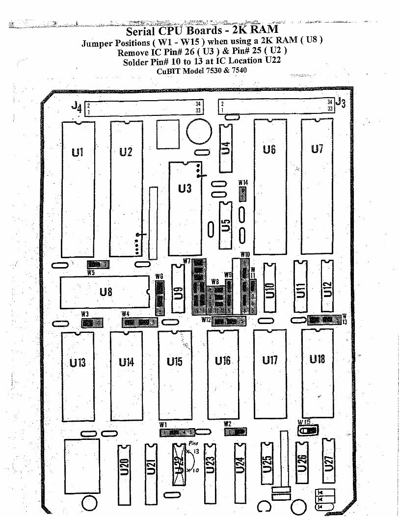
Jumper Positions ( Wl - W15 ) when using a 2K RAM ( U8 ) Remove IC Pin# 26 ( U3 ) & Pin# 25 ( U2 )
Solder Pin# 10 to 13 at IC Location U22
Ul
- -- .
- U13 -
0
U2
-
U14
• -. .. ..
-
CuBIT Model 7530 & 7540
U3
~---U15
·•
-
U16
us Ui
-- -::::> - :::>
-
U17 U18
•'
-•
,_
<-i (\J
:J :J
(') " <-i <-i :J :J
D (S) <-i (\J (\J
:J :J
135 ...
If) <-i :J
(')
:J
~
lO <-i :J
(') (\J
:J
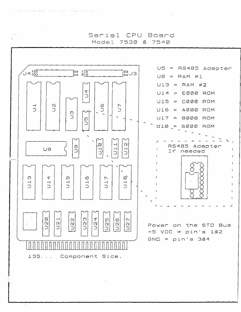
Serial CPU Board Model 7530 8 7540
U5 = RS485 Adapt: er
us RAM #1
U13 = RAM #2
U14 - E000 ROM
U15 = C000 ROM
U16 - A000 ROM
U17 = 8000 ROM
t:J 1-8 = 6000 ROM
r - - - - - - - -,_
RS485 Adapter If' needed
' ' o~
' 0 0
I' ro'
o~ <-i <-i
:J :J ' '
' 0 0 '
- - - - - - - - - - _J
" ~~~ (\J Power on the STD Bus :J
pin's 1&2 +5 voe =
GNO = pin's 3&4
Component Side.
t
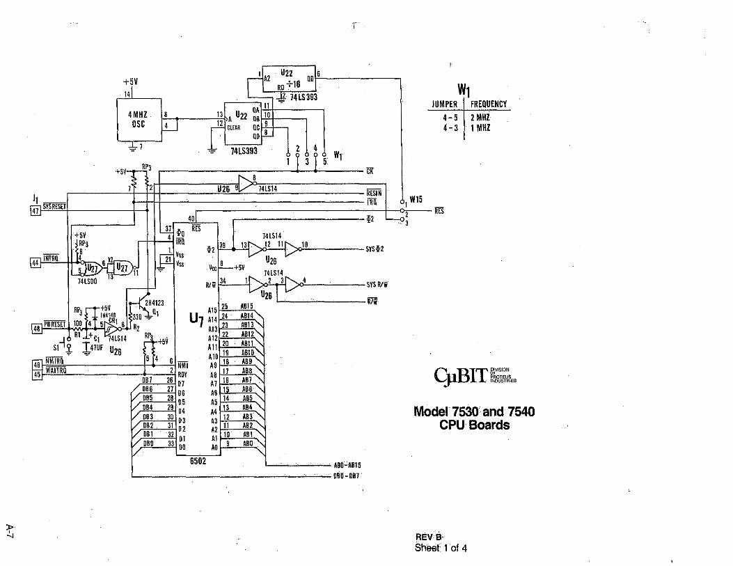
+5V 14
4MHZ 8 osc 4
=J .,),,.
+sv__,...J!\'3 .
r-1Ai! • •• QD'S
W1 QA 11
13 A U22 QB 10 12 CLEAR QC 9
QD 8
JUMPER FREQUENCY
4-5 2MHZ 4 - 3 1 MHZ
74LS393 I 2 I 4
GK 8 ,.,_____ --
74LS14
RESIN I ~ W15 iR!i I IB
2 ~2 - 3
10 SYS~2
>o4 SYS R/ii
R/ii L_-'-""'--
C BrT DMSIDN JI. . F~ocastl/:i~es
Model 7530 and 7540 CPU Boards
'-----'"-~-- ABD"AB15
'----------------"'-""---"'" DBD'DB7
REVB' Sheet fol 4
~¥:~,,:lffeli£f''ef.~.~iQ\@.¥1\?Jffe'f'fZJ73W'W:llii'.!fZll ?:!!\ii1f!1'!!1~"?f"t'~.J:\1im'WMptj"fu"""""'~::rt!Pm1t!WM'!"wnm!l1"cy['!i"f'??'T'?T""°1""'"." "'' ·-- -
l> j,
+
RP3
AB0-AB1
;v
1
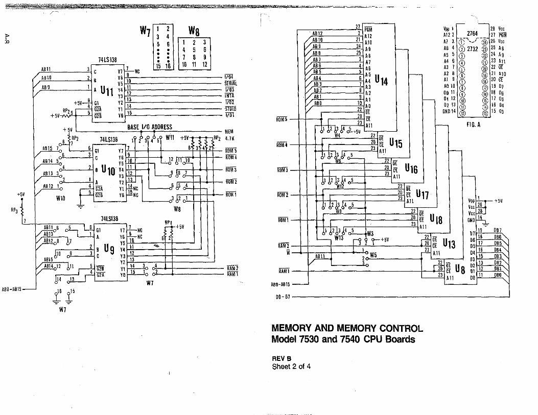
W7 I~ ! Wa 5 6 1 2 3 • • 4 5 6 • • • • 74LS138 .. -- . --
AB11 3 C Yl 1-Nc • • 1 8 9
11 t2 I t5 ts I I to tl t2 I / AB10 2 B Y6
9
/ AB9 1 10 Y5 ll
/ A U11 Y4 11
+5V_j_ Y3 13
Gl Y1 14 ___! G1A YI RP2 5 5 15 +5V G2B YO
+ 5V BASE 1/0 ADDRESS
RP2 74LS138 1 f3'/>5' Wll +5V B 7
AB15 1 SGl YJ 7 B' 3 4 2 v s 3 c vs 9
AB14 5 Y5 10 11 /,11J!L v 4 1BU1ov4ll AB13 3- Y3 J1.. - 9 bB J_ v 1 -
l A Y1 .ll.. AB12 L p G2A Yl .!!Ne ~665 4
,/ G28 YO llNc WtO J /,2 1
WB 74LSt38
RPI Alto6 ~ Gl Yl LNc - ~+5V A 13 1 ..L_,
/ AB11 8 67 A VS 10 NC S 2 1 u Y5 11 ""
. /,10 9 J B 9 14 12
A815 C VJ 13 . Y2
~~2 /,ll rl G2B YI 14 J 4 r1' GIT YO 15 1 2 )!4 lJ Ill,
i- t l 5
":;"" -=-W7
RP1
1/04 SERIAL 1103 ITITT 1701 STDIO VITT
MEM 4.1 K
ROM 5 ROM 4
ROM J
ROM2
ROM 1
RAM 2 li1Mi
ROM5
ROM4
ROMJ
ROM 2
ROM\
RAM2 ii
RAM\
ABO-A815
00- 01
- -17 PGM Vpp 1 18 Vee
AB11 1 Al 2 A112 ,_ __ ;76~-~- 27 PGM / AB 10 11 A10 Al J (i) ,_, @ 16 Vee VAB9 '4 AS >-- AG 4 CD 2132 @ 15 As / AB 8 25 A 8 A5 5 CD ® 24 A 9 [/ABl JAl A4S(i) @2J~1 I/ABS 4 AS AJ 7 (j) @ 22 OE [/ AB 5 5 A 5 1-- A2 8 (j) @ 21 ~O / AB4 6 A4 U 14 Al S (i) @ 20 CE /,ABJ 1 AJ A010 (j) @ 19 07 /AB2 8 A2 oo 11 (j) @ lB Os ·/. ABl 9 Al '--- 01 12 @ @ 11 05 VABO lOAO 0213® @1604 / 22 iiE GNO 14 @ @ 15 OJ
20 CE f 23 All <-- FIG. A
1 61 !,J 64 J.+5v W4 11 -
10 ~ U15 I 23 All ,___
1.t,2)Lb4~ 11 OE 10 CE U16
I 1J All >---,1 !,2 !l.~4 J_
1 22 OE 20 CE U17
I 2J All Vppoo- +5V )1!,2 ~ ,i,4 J_ _ Vee ~;
9 22 OE Vee 20 CE U 18 GNO~
I 2J All ~ 1 !,2!,3~4 5 19 OBJ
'o:c.- W3 12 - OJ 1s oes °"' ~ W13 r4 <>-+5V riO ~ U13 OS 11 085"-
1 CE 05 '-.. I 1 .Jl All 04 16 084
ABll 1 . W5 OJ 15 OBJ°" / 3 11 - 13 OB1"-
no~ u8 °2 12 0B1" CE 01 '-.
2J All 00 11 oeo...._
-
MEMORY ANO MEMORY CONTROL Model 7530 and 7540 CPU Boards
REV B Sheet 2 of 4

74LS244 J1
ABl5 17 A AB 14 15 A AB 13 13 A AB 12
1; : U23 AB II AB 10 4 A AB9 6 A ABB B A
fG I
J4LS244 l1
9 AB 7 II A Y J AB 6 13 A y 5 AB 5 15 A y 3 AB4
17 A U21 y 12 AB3 B A y 14 AB 2 6 A y 16 AB I 4
A y .IB ABO 2 A - y Th 2G
AB0-ABl5
~
~ '°
Rli'i ~2
SYS~2
SYS R/il
INTA
MEM
STDIO CK
ABB MX
RDM5 ROM4 ROM 3 ROM2 ROMl
110 4 1/03 1/02
SERIAL RAM 2 RAM 1
DBO-DB
..
9 JU27):,L
ID 74LSOO
+5V7
12 3
II
U121 9 15
. ID ~ I 74lS133
. 4 '
14 5 6
+5v----1.
. . 1/0 BUS. SIGNALS
9 74ALS10
I IDIU25' Iii F 13
i\ U25' 12
4
:-MU I~ : u27 3 5 25 74LSOO
J1 Ll I B '"Ji 4 A y 16 -
6 14 .E 17 43
U24 3 -
15 34 5 -
B 33
74ALS244 12 '49 11 9 --1 ~ 35
13 7 I-
2~ Th 2ii 36 -!3 W2 1l-{19 c::: 52
Tt ~
L= B-A L19 I
J1 G DIR DBD 15 B A 5 DD 7f
/.DBI 13 B A J DI 1-
V DB2 II B A 9 D 2 ill 9
/. .OB3 I J B U20 A :
03 '7 /. 084 14 B A D4 14 / DB5 12 B A B 05 -/ OB.6 16 B A 4 D6 1L V OBJ lB B A 2 0 J JQ.
B v +5v--1 74LS245 L2
-7 +-::t ~
Model 7530 ahd 7540 CPU Boards
REVS. Sheet3 ot 4
w
WR RO INTAK
MEMRU TORii CLOCK IOEXP MEMEX PCI PCO
~ ~
0 1/0 3 iRii RES $2
SYSR/W
M RESI
SERIA
ABO-AB
080-DB
'
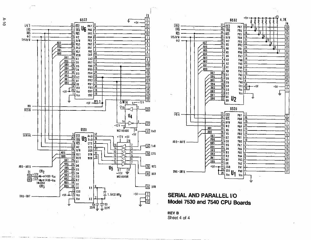
)3 6522 ~ +5v-+ 23 CS2 PA1 9 ~
,.!l 21 IRU us PA6 ~ J. 34 liES PAS ,.lQ 25 $ 2 PA4 6 ..l zz R/w PA3 S ..! ABJ 35 RS3 PA2 4 J_
/ AB2 36 RS2 PA! 3 J. I/ AB! 31 RSl PAO 2 J_ I/ ABO 38 RSO CA! 40 J.] I/ OB1 26 01 CAZ 39 ..! / OB6 21 06 PB1 11 Jl /OBS 28 OS PBG 16 .ll / OB4 29 04 PB5 15 ~ /OBJ 30 03 PB4 14 J! I/ OB2 31 02 PB3 13 ,.!! /OB! 32 Ot PB2 12 J1 1/ OB" 33 OO PBl 11 Jl / ,_d CSl PBO to 14
+5V ZO Vee CB! :: J! t Vss CB2 J! 23 = +SV RP3 3 W14 1,-+tzv
.
9ts - 2 -illJ
U4 14 3 -
i.111 -12V - v B
6551 MC145406 116 ,--{fil 12 +5V 3
est Ax o +12v +5V zs 1Ro U3 1xo 10 b f Its 4 - 9 Zl RES CTS B
1
1 ts 1-o_,,, 2 24 28 <1>2 RTS 17 I 14 ""' 3
R/W OSR 13 ~ 4 AB! . 14 RS! OTR ffiil 12 i':::I S 28 / ABO 13 RSO BCO 16 11 ~i 6 v OBJ ZS 01 to 7 / OB6 24 06 v 26 V oas 23 os U5 a 1 ~ \/ 084 22 -12V -:- L--[ill
1488-Vee / DB3 21 ii MC145406 1488-Vss / OB2 20 02
VoBt 19 ~ V DBO 18 Dl 6 25 \/ 2 00 x 1
y_j] CSO ~ +5Vl=i +5V 5 Vee T 1.8432 MHl 1 ,, 1
I vss x2_,.~J_"" 32
"' 33~1TI 33PF '=' "l:"'
RxO
TxO
CTS
RTS
OSR
DTR
6532 +5V 1\ 1
: 4.7K 37 CS2
1102 I 25 IRU
fifii 34 RES
PB7 l6 3 14 PB6 t J 4 ls PB5 IB 5 2e
liES I 35 R/W SYS R/w 1 39 <1>2 PB4 19 6 Zl
21 "" PB3 22
10 .1!_ $2 A81 36 RS
/. AB6 4o AG PB2 9 31 PB! 23 8 33
VAB5 2A5 ~AB4 3A4 V. ABJ 4 AJ / AB2 5 A2 V. AB! 6 Al V ABO J
AO I ..l!!<!'-;;0;-;B 7> i2!66 I D 7 OB6 27 06 OB5 2B 05 04 2904 OBJ JO 03 OB2 31 02 OB! 32 01 u2 OBO 33 00
~O M 1 11 PAJ 15 34 PA6 t4 30 PA5 l3 26 PA4 11 25 PA3 oil 23 PA2 10 2i PA! 9 Zo PAO ~8 J1 CSt~+SV 31 Vee~ +5V- 2
Vss 1 ,r- J. =
6520 rg 1
nm ~1:: 'to 1104 I J I 34 RES PB6 15 'J 21 R/W PB5
14 '8
I 25 <1>2 PB4 lJ S 1
ABI 35 RS PB3 12
G ABO 36 RS PB2
11 3
OB1 26 OJ PBI tO 4 V'. OB6 27 06 PBO
9 tB
V, OB5 28 05 PA1 8
16 V OB4 29 04 PA6 J 14 V, DB3 30 03 PAS
6 12
V OB2 31 02 PA4 5
'17 V, DB! 32 DI PA3
4 15
V, OBO 33 00 PA2 3
'i3
ABO-AB15---'
~
V +5v~22 cso PAt 2 '11 24 est PAO 1 -
OBO·OB15 20 Vee U1 Vss r-} =
SERIAL AND PARALLEL 1/0 Model 7530 and 7540 CPU Boards
REV B Sheet 4 of 4

"'""' ••• ;. "'• • .; ........ .; .; ;"~Al.Jta,;,;DISPEMSE CARD ,::-jL·· _ • • • • • • • e • • • • • • • • ~~:!T~_,.ioo1a~.1A .• ·.~ .. ··7:·c·~.J.~ ... ·.·.-....._,,. _ f .. ps.&.cpu (.J4) ·· , •• r .·. . , ...... ·I · ... r
·o o •······· ,,_ ••••••••••••••••• + + WI • • • • • o • • • • o • • • • • • BretJer Science .-;. U2 P.O. Box GG 6/
p6£,KEYB011Rll f1?'-=4 D$. TP!C:5e73 Rella. MC 65401 RPl
...__•~ II e ~ ~ ~···•••e! ... -----..-------iD,.._ "ll2 • • • 111111• ••••• cl • ·m • • • • •
l 5 lO l.5
CL : : ~~NI<l • •
•
•
•
•
•
•
• •
. •
•
•
•
•
• • • • • • • • • • • • 0 O-.f'IJRTI2 • •
C30+
• • • • • • • • 1t1:::::::1 • • • • • • ~~Nl<l •
• •
• • • • • 0 e ~RT34 • •'u3
• • • •
c:4 o+TPIC6273
• • • • • • • !!i•••···= • ••••• • • • •
• • • • • • • • • • • • • • /!'!RT~,; e e U4 • •
•
CS o+TPIC6273
• • • 11::::::= • • •• • • • ~~NI<l • • • • • • • • • • • • • • • • •• • 0-..PDRT>S
us IC6273
• • •
· RP2
• •
Rl"3
RP4

,;·
. ~ .
• • ~ .
v6 u
>
:;; !:: " ':
~i! = Q~ WO
~· u.~ ,.,. Q w ~ M
!: :: v•
~->
.. ;;r. "'r= ·~ -~o:;~ ..-.· ... ~ . '<U.0
' '
P' /·i'
11 I I
'.
~
-c ' v-
"' " _,, .,. ~ ~N
~ -,
> ~ " ~ " " .,
Q 0 .a
~
. L
.!
.!;
~ : - . ~ . 0 . • 5 VQ • "' u ~Q .: ~ •M ¥ 5 ~ 'i'~
u ov = g ~
·~· , ;;s
L • M ~ m ~ ·-__ ., ::l
~ o---. • CK (.
m Q..Q; .... -ii.
,l: .,
., =
~ Ji
~
0
s
............... ,.....,,,."A,,. B c b E
1
2
3
4
,--·------···-·----------- -~·--'------~-~--~---------·--------,--~---'-~---
.~:.A~·~an· ~~~ @:.~=-~=>----"1..--_..'>-- ii< "' 2N2907 - i:;" itl-193!:1 ~ 7~07 ~ NI~ · iK : v·
·._u~ ~--. __._f·_. '" ~-~07
•• 2N2907
+l2V_
0-1 4°RP3 -~ iN-4935 . IJ;,x . . . r-cu:I · U< V
~-_-.--.--'."v . .. ~'.~K . '" ·--------'<>J3<>-l .
. cuTa LATCH IM It . Ui lE ' :;r· ~ . Ii:- - . CUT3 1 ·r~"2
09 Off LA.-,RF'! QO o~ -~---''"'~ . . 2N2907 1N493!3~___:._.B_._,_·..._ __ -IEE~"- I -- 2N2907 !N-4935 t,..... 1K ' -~ --y.----- v v --::1
~ <K ~ ·-
,;
740? · . +tav +12V .
R3' II ·;!:.O;"l!IV
-----------· ~oOaA tN '
~.
0
0
v
PHA PIUS: +l!IV GNO.
U3: 14 7 u11: "'"' 7
_ ... - lnot:i~~: GNO J ~,...,...,,._... ~~~eo7 ~ tN4933 ~ .. J,11)1 Ue: i B
-· ~ .. M "* .. .,. f'cations * = 100GX MocJ_~ __ 1 ___________ _
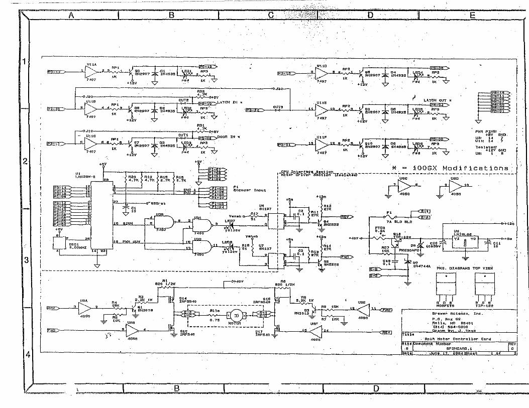
----------------------~~o ~IJ..Jt1!LJJl::t.'l.91t~§.~~;r,.f',jC,f11'1:.iciJ___ r{2;-"··· . ~ 1-Matar Driver eo_
~' RP< 07 03;g30i_~1'>~ .:~-; 2N2907 1N . rnd IK ~ <K
7407 +t2V
~A"'""_,· ~•v. . .. Aii\!o R'S ' -
~-' '·'" .: .. ~.. "" . - .
0SC1 II, OOMHZ
t •-~ 1.n :
' ~--. __.~· . -3 _gt_ -
~ ,, 'J' Cl __,,-.,,,,, . : ? 10 t.. -o
" !!ncodor Irii:iut
""
I .
I . 4000 I 40!10 "'= I 9 . l +i~m I ----1 I I
Ri<i ••• .. ~~" ~i -~ 9[ ___ ! Fl I ~~~2222 7A SLD 9LO r----C....------~+12m
P'TC<l
-41 <!.:5
I ~._.e>ill.JUJ_
V• LEOS
~" K "" y"i\10.w j·e:t
0.2A U2 "+- blii...~
+4ov + -f':'x · •lo I J£ ~ Ell'll
R27 to~~tvT 1. n I r 1;'5 1
1• ~- ! ~ ·~
C'9
'" 07 1N47'44A
"'F"
PKG, OlAGAAMS TOP VIEW
,j
I
SQ !----------------------------~----------------------------~-------~
-:;:- -v l!ED>--'--· I
I
"'
"' eao t/2W
;i..:,.~ ! URA
l:l 40!3;0~"---.~~R:·~K~A • ~,)_ ~fl:3019
!l:filt). "'?'" toK uea.
;;·: ·C> ' I ' -IOBO ...-
:"-!IOV
O.t-4 tH.S lRF9540 :CRF91340
r----~--~~-----------1 1111111
.. 920 l/2W ~
~ 2 ~
Ro ... R7"'1oi<1
UEIF T
uoe
40130
... IRFS4D "' ... -'"-<°''1" IFll'!'l-10+ ............ :-....tlt:OYI
.40!!0
"¥
G 0 S ll .C E! MOSF'ETS TIP-l2a
r--·-----;t'GW!!r' Sctalico. Inc.
1tlll
P,O, Bo)( GS· l'loll.,, HD 8eJ40t 0
13 toil 36-4-0:<IOO BVL_J •.. Hll.BB
S~ln Motor Controllnr C11rd
I --i
rt:iiroc~inOnt:--NUmb::lN~~-R-o-.-.-. ---, -.. . r~v1• ---------~...:.. _ _:. ___ ,_ ____ Jli>•;J.•ii•if•===·=·~•iioniii•::I•'iz:::lts~a..4,]™·q,_L-1, or #.
I '.-:--.I-- ·-----:-13 ""'" I ' " ' I 'D " • " I "" ' "~. '" ' "'
1
2
3
4
A B
.-----
=t=-..=-"' . .MAX2:li::!
c ..
"f:. " fiµ.L_, +l!'IV
11'.'_ . '7 l•---~~ ..
~-ui_llilla.
•
010 093BFBBJ
.D E
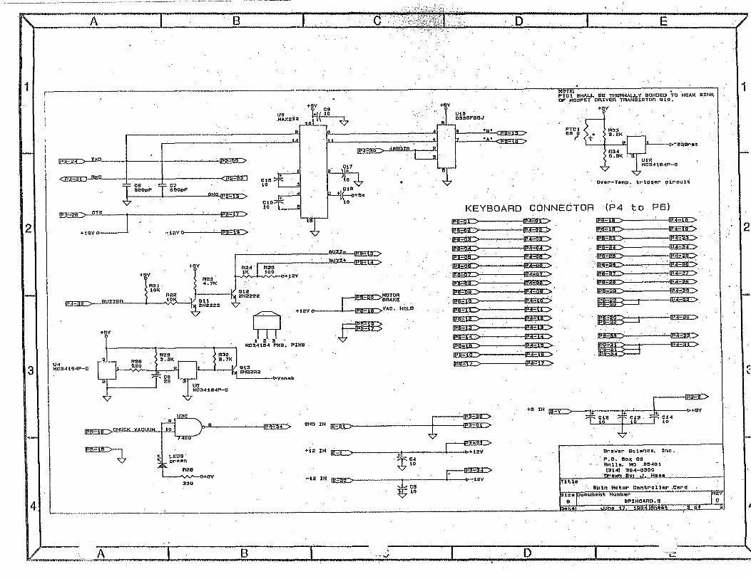
till:!i PTO 1 SHALL ea 'fH!OFIMAl.l. y SONOED TO HEAK 9'%NK OF M09FET DRIVER TAANS%STOR QiD.
PTCt
•• ' (t"
+•v
Fi33 'a.2K
""' B.BK
'7
~-ea9r'llt
ovor--T•mp, trt1111er ~1ro1.111i 1g: ... +~ ~=.•=--""' '""-ll!Eil::>
ClO •• KEYBOARP CONNECTOR (P4 to PB)
~ ~ ~·
~
+mo I ml:> --:!i'IV~·
HJ.V
Ft2i·
""
+l!'IV :~ ~.:...-~-'-~~-:::=::.. ~.~
~-.-.-v----~ R23. ~ MOTOR 4.7• . ~BRAKE ~ ~Al222 ~VAC. HOLD
tao>_=---""z:'" ~ .. mv . ~
1 2. 3 ·. PlNS ·
+av
U< MC3"11S<IP-!l
R2S 220
--~Tg~
MC34l8-i PKG,
11 I v. M~222 ~----••von11b
~ ~ ~ ~ ~ ·~
:::::; : .. ·. . . ,::::: : ~ lElEUL::: rn:v:> ~ ~ lEElL> rnr> ~ ll!EJlC: !PFlr>· ~·
~
·.~ ·~ rJ:r::- . . . 'FE!'C>
·e:a::- ~
~ mB==:t--~
·~. ~ ' --. .
~
~ . . .
LEliD I . ·~ •• '" IEC> :IE J£ . ~
U~E:...:JU' ~C.f:lw:at....:iAC.W
~ ~ LE09' grt'lon
R26
330
~
•v
GNO lN
~~ +i2 IN ~:1: . · ....l2V
i" . .. .. t.2IN~
er11wnr se1unc11, lnc.
. !"•D• Box GQ Rollo. Mo ee.<101
.J~!~~ ~a~-~30~a~~ Tlt~e
SPln Motor Controller ,cnr~
I
-
~c• . lO s1z111"ooument Number- ·r~v S SPlHCARO. ::! ;u'!t.!!!I .JUO!! 17,' 1.Jl
.. A 1 s 1 ,;-. -------r ---- o. -r~· .--.. ~ '""---·-,c-,.,., . I .L- ~
"i.'.::
1
2
< '

1 I 2 I 3 .. ~4 I 5 I I / REVISION INFORMATION• 1:oe111. o.i.u 1 5NOR OC.cl\IP110«
61·. I I .
A
AMP PLUGi BS!• 100079A View from Wire Side
SOCKETS' BSl•100080A
=" fa'~'"' . i I---""'·-·=· -1 ·:""" >-
1
2
4 a . I ~ ! •12 V• 22 AWG RED
5 P2
I : : ll'i• 'll ~ I -12 V• 22 AWG GRN •5 V• 22 AWG WHT f ® I D D g'., '• y,;--;q: I COMMON• 22 AWG BLK I
3 B
I D D D D ' D D I RED 16 AWG THHN 6 D D
I ' ' o ' ' o I 0 "'~" '" "' '""" I D D I . I D D
D D . I '-. I D D I
I D D I I D D I D D I MOLEX
0 0 I I PLUG1 I D D D D D D I BSI• 1000077 A ,.. ' .. , .. ·~ c D D D D IJ.;-,0 , (j) I D D I WHITE 16 AWG THHN 2 @ J3 I D D O,-JJ
D D - I GREEN 16 AWG THHN 3 @ 10 D DD -. • I . I D
0 - - SOCKETS!
o o 0 0 1 ,... I ss1• 10007sA
I~ I >-- ~---------------~ 44 PIN EDGE CONNECTORS
BSI• 100066A VIEW F'ROM PIN SIDE
UNLESS OTHERWISE MATERIAL Jeff Leith CEE OIVJSION Oon1'r-ol ltir' D J SPEClPIED LIMITS OliSIOl>I BREWER SCIENCE. INC. ON DIMENSIONS ARE t"N~ll>ll!"Eft 4000 ENTERPRISE DR. FRACTIONS - :!- l/t" ROLLA• MO 65401 OoTe'
PHONE1 1573) 364-0300 .xx - :!-.015 C>llKA110H 1/8/99 .xxx - :!'.005 TYP~ PINISH AEQD, 11 ... ,.
PAPER A I SHEET .xxxx - t.ooos TITLI!: 100 Series SIZE OF ,\l"l'ftOVU lllY Jeff. Leith Card Cage REMOVE ALL BURRS PART NO. ,\NO SHARP EDG~S lf'f'llC:TIW 1/8/99 Wiring Diagram 300013A ~"
/ 1 I 2 I 3 I 4 I 5 I 6 "

-
/
1 I 2 THESE DRAWINGS/SPEClFlCATIONS ARE THE EXCLUSIVE PROPERT'I OF BREWER SCIENCE, INC, THEY SkALL NOT BE REPRODUCED OR COMMUNJCATEO TO OTHERS. IN WHOLE OR IN f'ART· NOR BE USEO AS A BASIS FOR MANUFACTURE OR SALE OF THE ITEMS REPRESENTED• WITHOUT THE WRITTEN PERMISSION Of' BREWER SCIENCE• INC,
I 3 I 4 5 I REVISION lNFORMATIOtU
'ZOLi DATE I ENGR IDESCRiPl'lON
SIZE 4 SOLENOID C~Bl --- LIFT PIN SOLENOID CCB LIFT PIN SYSTEM>
PS ~
I> J ~
SIZE 3 SOLENOID fCBl N.o. *PINS DOWN CCB LIFT PIN SYSTEM>
1 --· ,fil!!i,____ i . . . . ... _ :g() :~ "" '" ~'""" """" ; -_;;;_ .. ------------ I . J J :5() ,:1.:: "~'~',·.:~~ •• , 5 ~RN
• ' HOT PLATE VACUUM fCBI
6 /
A
f-
6 BLU ~O 1 voo ~ N.c. LID CLOSED SWITCH CFX/GX/HX>
a ORY COM ~~ N.o. SIZE 1 SOLENOID ICB> 9 ~z N.C. fio LATCHED SWITCH IFX/GX/HXl! m ~
B
'--
~~='""-· --- -------1 11 :g()~ - ·~~ ™'""" 17 VI02 l 18- GRY2 _ ~
d~ _l'ilil r~~E~A~geEO 11 i, ····-·-·····--·············· ·BLK 0 :;7:~~0001A SENSOR crx)
1--
BSI# 100093A ... u
NOTES . c:::0 BS l# 100092A
* MODIFY SPIN CARD
USE NORMALLY OPEN CONTACTS ON SWJTCHES
I ? I
c © I VACUUM DETECT SWITCH
BSI• 60024 7 A In 0
' ~ '-- ;, VACUUM HOLD SOLENOID
I-
B
MOTOR BRAKE RELAY
A
DE:StON £NGINE:E:R ~ Brswer Sclence.lflC. CONTROLL 0 UNLESS OTHERWISf SPECtflED ~ "'"" C11$ Dlv1s1on · ,b=--------j UHITS DH 011-IE~IDNS ARE Jeff Le I th «KX/tJ/:.8Jrl~cff1wJ DATE ANGULAR = ! I pfVM(5T3J 354-0300 ffiACTIQNS· !'/e.t T r Cl'J.tdFff ve OU/Df11(J{1/ FoJld5TJJJ6+95/J hp~'"""''""'",...-,ra,m,~,,--j .XX • t.015 OOivrslM .,.. ~litii .XKX• 1.oos TT 100 Serles A or .XK)(X'" s.ooo!i Solenoid Braoket
Wiring Diagram ~~f'~ij~LEB~~~s lbATEI 1/8/99 .. I 4 I o; I G "

' 1 I 2 3 I 4 5 I 6 / THESE ORAWINGS/SPECIFICATJONS ARE THE EllCLUSJVE PROPERT'I OF" REVISION JNFORMATJON; BREWER SCIENCE, lNC, THEY SHALL NOT BE REPRODUCED OR COMMUNICATED SYt.eOL DATE ENClR DESCRIPTION TO OTHERS. IN WliOLE OR IN PART, NOR BE USED AS A BASIS FOR
& MANUFACTURE OR SALE OF THE ITEMS REPRESENTED, WITHOUT THE WRlTTEN 6/21/99 JAL CHANGED MOTOR WIRE COLORS PERMISSION OF BREWER SCIENCE, INC.
& 12/8/~9 JAL ADDED MOTOR BRAl:E OPTION
SSJ# IOOGISA & 3/28/00 JAL CHANGED CONNECTORS FOR NEW CARD CAGE CONNECTOR
I A 1
BSJ# \00141A SHELL
BS!# 10016'4A PINS - ~
30" ENCODER CABLE ~
__ 1. BROWN GRAY .. ORANGE GREEN
6- BCK
MOLEX VIOLET WHITE
CAP: est• 10103oA
20" SHIELD - )
l P3~ GRAY 16 AWG THHN B 2
I PINK 16 AWG THHN MOTOR 1
ffi PINS1 BSI• 100001A y· RED
~ - GRN/YEL 18" l '"""' I
' r-----------------------------------------""I I I
I I
I MOLEX I OIODE1 BSI• 100476A MOLEX RESISTOR: 0.75 Ohm, 50 w c 1004B3A I I c I PLUG: CAP: BSI• 100177 A
I I BSI• 101022A 2 ~ BSI• 101030A
I
I I
I < I 1----------------I I ' I b
~P3 I I I I
I J3
l!J 2 2 I I I
I 7 I I . =Ill '' I '=- -1 I I I ~ I 'T ~1 I
I I I I - SOCKETS: PINS1 I ' f-I I ' "'I I 851"" 100078A BSI• 100001A I I ' I TERMINALS A AND B I I CONNECTED TO RIBBON I 1 FX/GX/HX 1 I
FROM SPINNER CARD I 1 ________________ J
I MOTO.R BRAKE OPT ION : l------------------·-----------------------.
D UNLESS OTHERWISE SPECIFIED ~ DESICN ENt:INf'.u-11
~ """'" s~"""'"'" CONTROLLER D LttlTS ON Dl~NSIOllS ARE Jeff Leith Ced' D/vlSfOll
AN<i\JLAR II t ,. 4000 Eflferprtn Drive ~ FAACTIONS • tV&4 Rcffq.N~6540f
TYPE FINISH REOD.t PhDM:f5lJ1 JMOJOO .xx= :t.015 I DRAWN I C~ aJfJ!' Fax1(5TJ} .36+95/J .xxx. :t.005 PAP£t< SIZ1:c1 .~ .xxxx" :.0005 ~ µ.. A "
I/ REMOVE ALL BURRS
~ Model 100 Spinner ~-AND SHARP EOOES 1/11/99 Motor Wiring Diagram 3000150
1 I 2 I 3 I 4 5 J25 APR 20006 14:36:35 "

A
~
B
.._
c
f--
1 2 3 .. ~ THESE OAAWING5F$PE.CIFICATIONi ARE flt( EltCLUSIVE: PROPERTY OF REvlSICJ4 UFORW.lllJO REvlSIO\I II 8REft:.ll SCIENCE. INC, Til[Y SHALi. NOT 8E REPROOUCEO CR CQIMJNICATEO !LU MCA: OCSCR PT ON S OATE TO OTHERS• IN lllllOLE CR IN PART, NOR 8E USEQ AS A &\SIS FOR &. IMNUF'ACTUlle OR SALE OF THE: lfEUS AEPRESENTEO· •ITHOUT THll IJAITT£N 0 12.~.oo JAL tnllnged to QOtl""Q(lyne DOwOI'" l5Ul)l)ly PERMISSION OF" Bll:EIE:R SCIENCE, INC.
·--: ~: ~:
~! ~': <: \Q! ! !
BROWN
,~
CAP: PLUCi• ~·ROwN
I D0107A8SI• 'IQ0057A
1-1 8 ~JJ.Bm!> [~~ :1 c::J5_ROWN
J4 •
BSI• Xl0135A
'~ Fl :L..:_J 7 AYP S O·BLO ~ C4 AMP ~LO·BLO FOR 220VI .. ~~I ~ ~
" " ii: !l:i . ...:: .. . I ""' I I
------1 CE UAR<. IJNl Y I
I
: •s scirewl
~-
POWER SI.FPL Y
~Pl
BASEPLATE FAN~
Cl• !7000 IAFD, 75 VOl.T,B51•()0111A ~ 1-- • 70 VOL rs ORANGE 16 AWG nHI
l Rl: IOOO ~S. 5 WATT ( BSI• ll0749A.
I I I
r--
I ' '
TBI
!:= .. .. §' =l '-------, l ·-Le:::::} • I A SlO 8L0-11ov I
~.2~0 BL0-220V I (Cl_ __ F>i!J:.Y __ -
.. ,,., __ .... '\
T2 ' es1• 100147A ! ~- "" ' .~-J
nnv .•..
111.!QS 81.UE
..fil!1. GRAY
RFn
: l\DIJ
· VlO
UO VOLT WIRING SHQllN GXfflX USE VIO..ET WINOINC
•12 V: 22 AWG VIO ,.
I" - - -
t-
B
r---------------
l!_!i I fi~ i-: ~: '''":--::: .. I
I ~,'.'. :
I= It-
I Pl\I): •UV- - - - -PllhoUV I Plil6·.SV- - - - Piii: .sv
PlilS COll'IOll- - - Pll~: C01tt10N I fllrlZ: ·'llV- - - - -PIU1 -UV I Viw rr. lfh Sidi
"""" I AECEPJACU: la: •10m UICK£TS• ISll IOOOllA l---------
I PLIJG, Kif IOIOUA I
- - - - _I
-~ ----~-------I I I I I I
n I
I I I
c
I rn I IF- $# !::U I ~~1·1001m:
D 1 I t-I . GRAY I jJ GRAY1f V!O I
220 VO..T WIRllrlCi I 100 VO..T •IRING I CJr"4Jr U5£ Yin.ET WINClltil) I Clrlllx: USE: YHll.ET lllNCtllllGI
- ----~ -- ______ J
FROM SWITCl-EO AC TERUNAL. BLOCIC l• LINE= 18 AWG BROWN
O I l:J ;; NEUTRAL• ill A'IYG atut ' =~50:~~ soi E I 0 PLUG•SSl• 1007091. AM!ill.All•el' Jeff Leith CONTACTS• BSI• '00117A ~TICINS • ;~
.XU:• s.OOS .XXU: • :I .OOGS OF
~..or..#E8~ 2116/00 30001 GG
1 2 3 4 5 6 "
-
-
1 2 3 4 5 THESE DRAWINGS/SPEClf'lCATIONS ARE THE EXCLUSIVE PROPERTY Of' BREWER SCIENCE. JNC. THEY SHALL NOT BE REPRODUCED OR COMMUNICATED TO OTHERS, IN WHOLE OR IN PART. NOR BE USED AS A BASJS f'OR MANUF'ACTURE OR SALE OF THE ITEMS REPRESENTED, WJTHOUT THE WRITTEN PERMISSION OF BREWER SCIENCE. INC.
~
i "'
i ~-=::~~
CAP: PLUG: • 100107 A BSI • 100057 A
Fl 0 =JlRJl.l\'J; __.,,,. l:J 2 ~ROW~
J4
BS!• 100135A
L.:...J 7 AMP SLO·BLO 1-ll'fl\ F1 i"""!J <4 AMP SLO·BLO FOR 220V> -4-
~j 31~ .. 1
w "' ©II <> "' - ,. ,.
I < < ---------1 m co.----- CEMARKONLY 1 I .- .- MOV°' I
l I I I l I
•8 SCREWl-·- _ -:- _/
I J ,_ ____________ _
~~*~~Jri~A;,~U%b~~Ac1f'~,'lJ's1• 100123A
Nm p1/ I
,, ;n' .U,
llilil~-~~
FROM SWITCHED AC TERMINAL BLOCK
~-'
" " L_
~ ...,_jjllELl~"ll
/ o11: NEUTRAL: 18 AWG BLUE
PLUG: BSlt 100709A CONT ACTS: est• 100117A
2
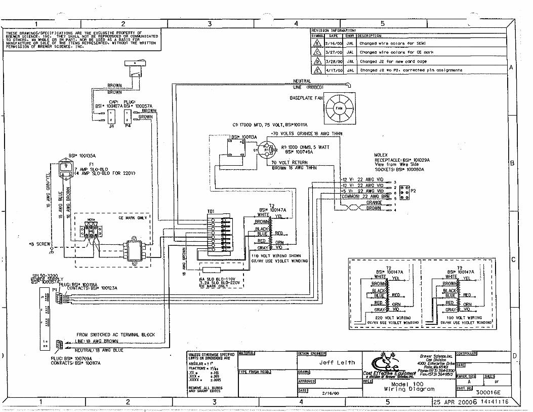
REVISION JNFORMATIONl fS:YMBfiL - tiATiC-- --ENGR DESCRIPTION
~ 2/16/00 JAL Chonoed wire colors for SEMI
& 3/27/00 JAL Chonged wire colors for CE m:lrk
I&,, 3/28/00 JAL Chanoed J2 for new card oaoe
l& 4/11/00 JAL Ch<mged J2 to p2, corrected pin oss!9nments IA
NEUTRAL UNE fRIBBEOl u
BASEPLATE fAN~
C1' 17000 MFO, 75 VOLT, BSl'100111A ~ I--
TB1
~·
I ii~ ~ I I
II
!§A SLO BL0-110V I 2·2A SLO BLD-220V ~ ~Afi.K_fJN.,b'I_,_ __ I
UNLESS OTHERWISf SPECIFIED LIMITS ON DIMfNSlOtlS ARE ,t,.tldtn..A.R,.!1• FRACTIONS • ~ 1/u .xx. :l.015 .X)()( • :t.005 .xxxx. :l.0005
REOOVE All BURRS AND SHARP EDGES
3
+70 VOL TS ORANGE 16 AWG THHN
R11 1000 OHMS, 5 WATT BSI• 100749A
_,_ t2
BSI• 10014 7 A WHITE yn
Jl!lQl\'l .BLACK·
BLUE
RED
GRAY
om
nou
VIO
110 VOLT WIRING SHOWN GlC/HX USE VIOLET WINDING
·-·-·-
DESIGN ENOKER
MOLEX RECEPTACLE: BSI• 101029A View from Wire Side SOCKETS: BSI• 100080A
•12 v~ 22 AWG VIO -3
1-12 V1 22 AWG VIO = 2 ~s V: 22 AWG VIO -= 6 ~.1UJYQ.Jl.Jlll,, 5
~: [;] P2
0
I- - - - - - - - - - - -1- - - - - - - - - - - - -, I T2 ; I 12 l I 1 BSl• 100147A l I BSI• 100147A j I 1 HITy I Hlly_JI I .I BROW 1 I I I I I I I I I I I I I I I
l 220 VOLT WIRING J 100 VOLT WIRING I I GXIHX USE VIOLET WlNDING I rJX/HX USE VIOLET WINDING!
~------------L------------1
CONlRCltER
Jeff Leith 4000 cr,.,/f)J/,': Dr/lie ~ """'" Sdence.lt>e. DATE RoJ/a,Mo.6540/
PIKXIBr (5T3) 364-0300 C~~ Fa:xr<5TJJ 364-95/J PAPER SI '"'' ITL Mode I 100 A "
2/16/00 Wiring Diagram
300016E
4 5 25 APR 20006 14:41:16
B
1--
c
1--
ID
Introduction
Precautions
2
Congratulations on your purchase of an Athena"" Series 16
Single-Loop Controller. It is designed for ease of use and
reliability wherever accurate closed-loop control is required.
Your Series 16 has been configured according to your order
ing specifications as either a universal process controller or
a dedicated temperature controller. In addition, special func
tions such as a heater break alarm, digital communications,
etc., do not require you to make any internal jumper or DIP switch settings.
Arter following the instructions for installation, simply step
through and set your desired parameters using the Series 16's easy menu system. The instrument may then be auto
matically or manually tuned to your process for optimum
setpoint control. A Quick-Start Reference Card is attached to
the back of the instruction manual for experienced users of
PlD controllers. If you still have questions or require any
assistance in setting up or operating your controller, please
contact your Athena representative or call 1-800-782-6776.
After unpacking, inspect the instrument for any physical
damage that may have occurred in shipping. Save all packing
materials and report any damage to the carrier immediately.
©Copyright 1998, Athenn Controls, Inc.
Safety Warning
In addition to presenting a potential fire hazard, high voltage
and high temperature can damage equipment and cause
severe injury or death. When installing or using this instru
ment, follow all instructions carefully and use approved
safety controls. Electrical connections and wiring should be
performed only by suitably trained personnel.
Do not locate this instrument where it is subject to excessive
shock, vibration, dirt, moisture, oil or other liquids.
Safe ambient operating temperature range is 32° to 131° F
(0° to 55' C).
<E NOTES ON CE EMC COMPLIANCE
This unit is compliant with the
following standards when properly
installed in a grounded metal panel:
EN55011 (CISPR 11 ), C1ass B ENSOOSZ-1
3

Table of Contents
4
Installation
Mounting
Wiring
Operation Notes on Outputs
Parameter Menu Organization
Notes on Alarms
Tuning
Special Functions
Auto/Manual
Remote Setpoint Select
Process Variable Retransmission
Heater Break Alarm
Transducer Excitation
8 8
12 15 20 28
34 34 36 37 39
Table of Contents limit Controller Option
Digital Communications
Recalibration Procedure
Error Codes
Warranty/Repair Information
Technical Specifications
Ordering Codes
41
47 55
56
57
59
62

Installation
Measurements between centerlines of panel cutouts are minimum recommended.
6
Figure 1. Recommended Panel Layout for Multiple Controllers
er. 1t. ....._ 2.850" (72.4 mm) __._ -
er.
2.' 50"(54.6mm)
er.
~1.171"(45mm).J
Installation
Bezel
Grips
Figure 2. Case Dimensions
2 100· 4.654" 1- (53.3mmJ--I o.71r~(118.21mm) a.937" ----=:i
T (U' mm) ~ (>OOmm) o,o,------i l 020L___J'"' =
2.100· ~;g = 1750" '"I:~~~ I~ I ll,1mm,
Prior to mounting the Series 16 in your panel, make sure that the cutout opening is of the right size, 1. 771" x 1.771" (45 mm x 45 mm), and deburred to enable a smooth fit.
A minimum of 4~ {100 mm) of depth behind the panel is required,
Case Clip
1111m 1,11
Figure 3. Series 16 Mechanical Coniponents
7
Mounting
Wiring
8
Slide the mounting collar off and remove any wrapping
material from the instrument. (To ease removal of the collar,
gently pry up all three tabs on each side with a thin-blade
screwdriver.)
Insert the Series 16 through the front panel cutout and slide
the mounting collar back onto the unit from behind the panel.
Press the tabs of the mounting collar into the ridges of the
case housing. The case should now be secure in the cutout.
It it can still be moved, reposition the mounting collar until
the unit is completely immobile within the panel.
Ir it is necessary to remove the Series 16 chassis from the
case housing, press the grips on each side of the front panel
bezel firmly until the tabs release. The chassis may then be
pulled out. To re-install, press both bezel grips simultaneously
and carefully push the chassis back into the case housing
until the tabs snap into place.
IMPORTANT: All electrical wiring connections should be made
only by trained personnel, and in strict accordance with the
National Electrical Code and local regulations.
Power and signal wires should always be kept separate and
input leads should never be placed in the same conduit as
power leads. We recommend separating connecting wires
into bundles: power, signal, alarms and outputs. These bun
dles should then be routed through individual conduits.
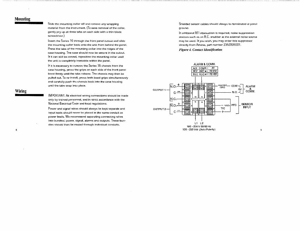
o,
Shielded sensor cables should always be terminated at panel
ground.
If additional RFI attenuation is required, noise suppression
devices such as an R.C. snubber at the external noise source
may be used. If you wish, you may order this suppressor
directly from Athena, part number 235ZOOSU01.
Figure 4. Contact ldentijication
ALARM & COMM. N.O. --··- ~.•
;,,:~~d- COM1&ALARM A2 & ll'!LI N.o.-' COMM.
-(
+ OUTPUT 1 c-=--1.Jlii
OUTPUT2
, C.-----HfVlll
{.a .. +
c~
L1 L2 100 • 250 V !50/00 Hz
100-250Vd:J (Auto Polarity)
RTJ SENSOR J INPUT
9
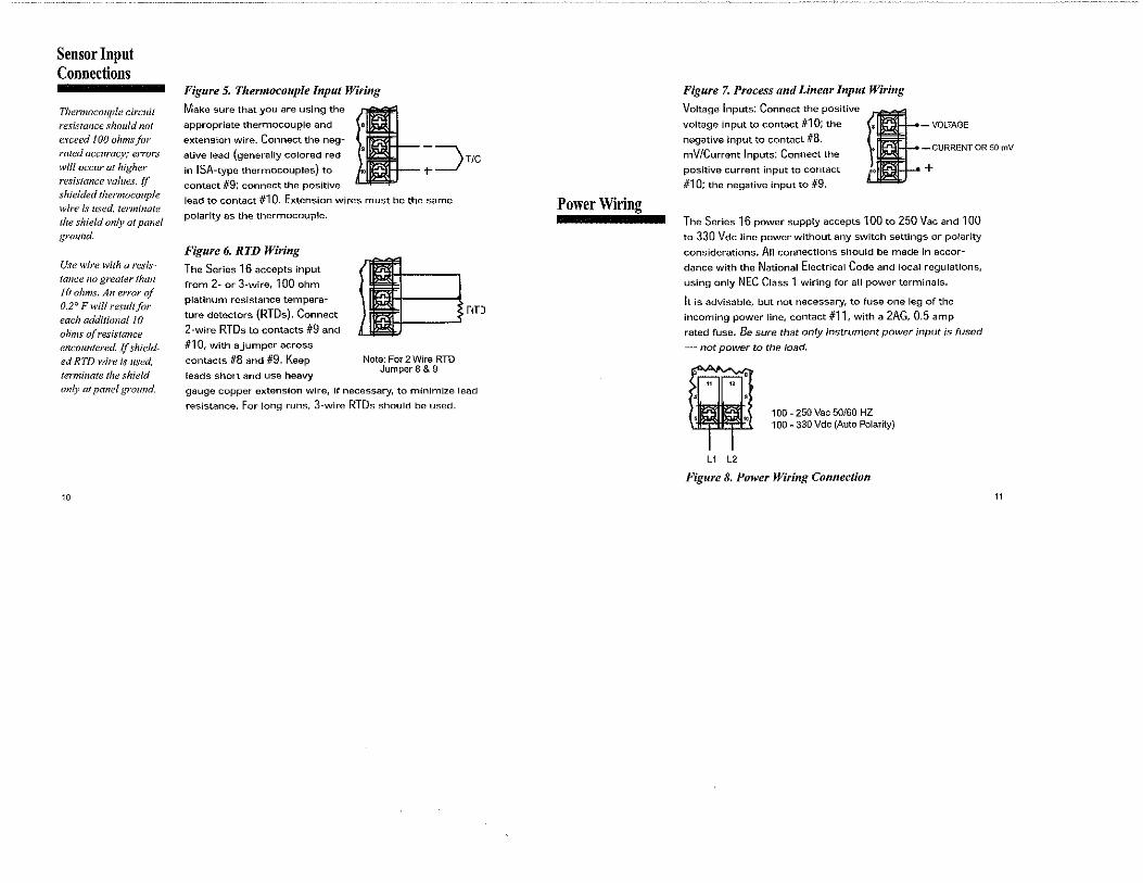
Sensor Input Connections
Thermoco11ple circuit resistance should not exceed JOO ohmsjOr rated accuracy; errors will occur at higher resistance values. {f shielded thermocouple wire is used, terminate Jhe shield only at panel ground.
Use wire with a resistance 110 greater than 10 ohms. An error of 0.2° Fwill result for each additional 10 ohms ({(resistance encountered. Ifshielded RTD wire is used. terminate the shield only al panel ground.
10
Figure 5. Ther111ocouple Input Wiring
appropriate thermocouple and e
extension wire. Connect the neg-
Make sure that you are using the l ative lead (generally colored red
9 - ~ T/C
in ISA-type thermocouples) to o t-__/ contact #9; connect the positive
lead to contact #10. Extension wires must be the same
polarity as the thermocouple.
Figure 6. RTD Wiring
The Serles 16 accepts input
from 2- or 3-wire, 100 ohm
platinum resistance tempera
ture detectors (RTDs). Connect
2-wire RTDs to contacts #9 and
#10, with a jumper across
contacts #8 and #9. Keep
leads short and use heavy
Note: For 2 Wire RTD Jumpers & 9
r.rJ
gauge copper extension wire, if necessary, to minimize lead
resistance. For long runs, 3-wire RTDs should be used.
Power Wiring
Figure 7. Process and Linear Input Wiring
Voltage Inputs: Connect the positive
voltage input to contact #1 O; the
negative input to contact #8. mV/Current Inputs: Connect the
positive current input to contact
#10; the negative input to #9. I -VOLTAGE
- CURRENT OR 50 rnV
+
The Series 16 power supply accepts 100 to 250 Vac and 100
to 330 Vdc line power without any switch settings or polarity
considerations. An connections should be made in accor
dance with the National Electrical Code and local regulations,
using only NEC Class 1 wiring for all power terminals.
It is advisable, but not necessary, to fuse one leg of the
incoming power line, contact #11, with a 2AG, 0.5 amp
rated fuse. Be sure that only instrument power input is fused
- not power to the load.
100 - 250 Vac 50/60 HZ 100 - 330 Vdc (Auto Polarity)
L1 L2
Figure 8. Power Wiring Connection
11
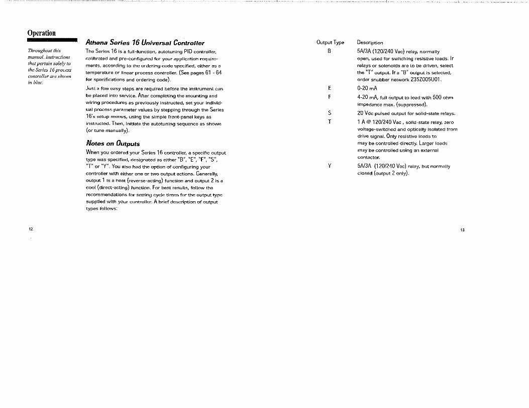
Operation
Throughout this manual, i11str11ctions that pertain solely to the Series 16 process controller are shown hi blue.
12
Athena Series 16 Universal Controller The Series 16 is a full-function, autotuning PID controller,
calibrated and pre-configured for your application require
ments, according to the ordering code specified, either as a
temperature or linear process controller. (See pages 61 - 64 for specifications and ordering code).
Just a few easy steps are required before the instrument can
be placed into service. After completing the mounting and
wiring procedures as previously instructed, set your individ
ual process parameter values by stepping through the Series
16's setup menus, using the simple front-panel keys as
instructed. Then, initiate the autotuning sequence as shown
(or tune manually).
Notes on Outputs When you ordered your Series 16 controller, a specific output
type was specified, designated as either "B", "E", "F", "S",
"T" or "Y". You also had the option of configuring your
controller with either one or two output actions. Generally,
output 1 is a heat {reverse~acting) function and output 2 is a
cool (direct-acting) function. For best results, follow the
recommendations for setting cycle times for the output type
supplied with your controller, A brief description of output
types follows:
Output Type
B
E
F
s T
y
Description
5A/3A (120/240 Vac} relay, normally
open, used for switching resistive loads. IF relays or solenoids are to be driven, select
the "T" output. IF a "B" output is selected,
order snubber network 235Z005U01.
0-20 mA
4-20 mA, full output to load with 500 ohm
impedance max. (suppressed).
20 Vdc pulsed output for solid·state relays.
1 A@ 120/240 Vac, solid·state relay, zero
voltage-switched and optically isolated from
drive signal. Only resistive loads to
may be controlled directly. Larger loads
may be controlled using an external
contactor.
5A/3A (120/240 Vac) relay, but normally
closed (output 2 only).
13

Operation Figure 10. Front Panel Controls and Indicators
Output 1 LED indication
of Heat cycle
(Output 1 action)
Output 2 LED indication
of Cool cycle
(Output 2 action)
Alarm 1 LED indication
of Alarm1 condition
Alarm 2 LED indication
of Alarm 2 condition
Function 1 LED indication of
Special Function 1
Function 2
LED indication of
Special Function 2
Ajier mounting and wiring your Series 16 controller, vou are ready to set the para;neter values required qfyour application. Take a moment to.familiarize yourself with the unit'sfront panel controls and indicators.
14
Process Value Displays measured
process temperature
in "F or "C or process
value in engineering
units
Setpoint Value
Displays programmed
setpoint temperature
in "For °C or setpoint value in engineering
units
Mode Key Used to access Standby,
Tune, Run or Manual modes.
Lower Key Used to scroll down through
available parameter settings, decrease values
or change menu levels (Hold for fast-step progression)
Raise Key Used to scroll up through available parameter settings, increase values or change menu levels (Hold for fast-step progression)
Parameter/Access Key Used to index through parameters or to access Menu Levels
Operation Power On
~~~~ When power is first applied to the Series 16, both displays
and all LED indicators are momentarily illuminated. The
Process Value (PV) window then displays [-At- ] or [ -Ap- ]
and the Setpoint Value (SV) window displays an initialization
code, e.g., [ u06 J. The last two digits of this code indicate the
software revision supplied with your controller. Please pro
vide this revision number when contacting us regarding your
controller. Depending upon whether Setpoint Target Time [
SP.tt] is enabled, you may also see this symbol: b2j orl".Sd.
This means that the controller is ramping up or down to set
point according to its previously programmed parameters.
The default setpoint on initial power up is equal to the
process temperature (process value). Before proceeding
further, wait until the display has stabilized and then use the
Raise &. or Lower W keys to enter or adjust your desired
Setpoint Value.
Parameter Menu Organization Your Series 16 controller has five distinct menu levels. This
enables quick access to relevant parameters without the need
for scrolling through long menus. Menu "05" is used for
15

Operation
You cannot enter
Standby Mode from
menu level "00".
Follow the instructions
for changing menu
levels to select another
level.
16
initial controller configuration and menus "02" and "03" are
used for setting or changing parameters. Menus "00" and
"01" are used when the controller is in regular unattended
operation and are not used for setting parameters. For safety
and security purposes, we recommend placing the con
troller in menu level "00" or "01" when in regular opera
tion; however, it is not required.
IF you wish to "escape" from parameter selection within
these menus at any time, simply press the Mode = key
once. A description of the menu hierarchy and a detailed list
ing of menus and parameters begins on page 20.
StandbyModel=l IScb~I When the controller is placed in Standby Mode, outputs are
disabled; however, access is permitted to all menu levels and,
unless the controller is at Run menu levels "00" or "01 ", operating parameters may still be changed. Use this mode for
tuning the controller. To enter Standby Mode, press and hold
the Mode key a for four seconds until the lower window
display flashes { StbY ]. To exit Standby Mode from Menu
Levels "01" to "05", press and hold the Mode 5 key for four
seconds until the lower window display flashes [ tUnE]. (Ir the Damping setting in menu "02" is [OFF]. then [HEAt]
or [Cool ] will be displayed instead of [ tUnE]. Press and
hold the Mode key for four more seconds until the lower
window returns to a steady display of Setpoint Value.
Operation (This procedure will not affect tuning). Removing power to
the controller will also take the instrument out of Standby
Mode.
Accessing Menu levels IQll Rr:,Cd I To access menu levels from Standby Mode from menu
levels "02" to "05", press the Parameter/Access Q key
once. From menu levels "00" and "01 ",press and hold the
Parameter/Access Q key for approximately 11 seconds
until the lower window display alternates between [Ac.Cd ]
and the menu level number last activated.
Changing or Displaying [4J ~ I as I Menu levels To change menu levels, access the menu level display as
instructed in the previous paragraph, then use the Raise &. or Lower W key to set the desired menu level number. To
display the current menu level setting in menu levels "02" to
"05", from Standby or while adjusting/viewing parameters,
press the Parameter/Access Q key once. For menu levels
"00" and "01", press and hold the Parameter/Access Q key
for approximately 11 seconds.
17
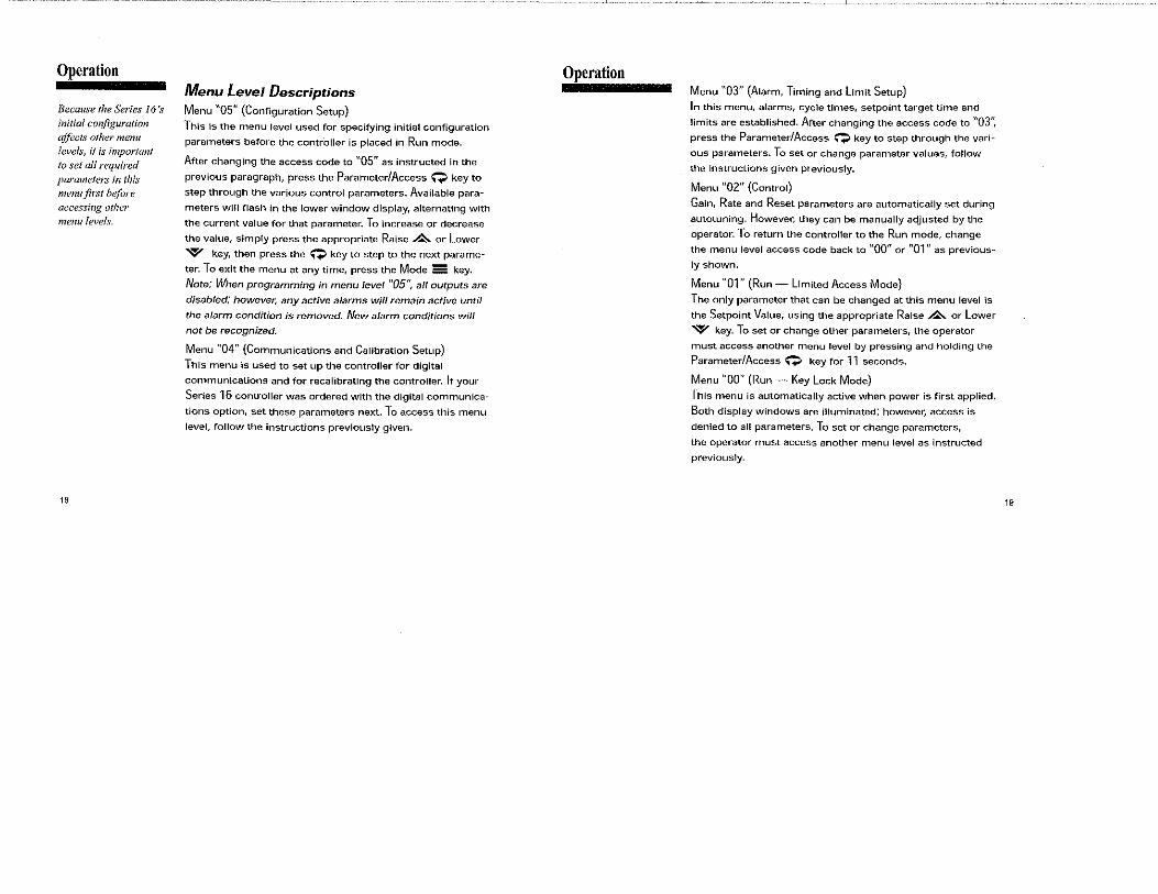
Operation
Because the Series 16 's initial co11figuration affects o!her menu lei·els, ii is important to set all required parameters in this menu.first h~fvre accessing other menu levels.
18
Menu Level Descriptions Menu "05" (Configuration Setup)
This is the menu level used for specifying initial configuration
parameters before the contr'oller is placed in Run mode.
After changing the access code to "05" as instructed in the
previous paragraph, press the Parameter/Access Q key to
step through the various control parameters. Available para
meters will flash !n the lower window display, alternating with
the current value for that parameter. To increase or decrease
the value, simply press the appropriate Raise £. or Lower
W key, then press the Q key to step to the next parame"
ter. To exit the menu at any time, press the Mode = key.
Note: When programming in menu level "05", all outputs are
disabled; however, any active alarms will remain active until
the alarm condition is removed. New alarm conditions will
not be recognized.
Menu "04" (Communications and Calibration Setup)
This menu is used to set up the controller for digital
communications and for recalibrating the controller. Ir your
Series 16 controller was ordered with the digital communica
tions option, set these parameters next. To access this menu
level, follow the instructions previously given.
Operation Menu "03" (Alarm, Timing and Limit Setup)
In this menu, alarms, cycle times, setpoint target time and
limits are established. Arter changing the access code to "03",
press the Parameter/Access Q key to step through the vari
ous parameters. To set or change parameter values, follow
the instructions given previously.
Menu "02" (Control)
Gain, Rate and Reset parameters are automatically set during
autotuning. However, they can be manually adjusted by the
operator. To return the controller to the Run mode, change
the menu level access code back to "00" or "01" as previous"
ly shown.
Menu "01" (Run - Limited Access Mode}
The only parameter that can be changed at this menu level is
the Setpoint Value, using the appropriate Raise &. or Lower
W key. To set or change other parameters, the operator
must access another menu level by pressing and holding the
Parameter/Access Q key for 11 seconds.
Menu "00" (Run - Key Lock Mode)
This menu is automatically active when power is first applied.
Both display windows are illuminated; however, access is
denied to all parameters. To set or change parameters,
the operator must access another menu level as instructed
previously.
19

Operation
20
Notes on Alarms Either [OUT 1 ] or [OUT 2] in menu level "05" (but not both)
may be configured as an alarm [ Alr] if your Series 16 was
ordered with a "B", "S" or "T" type of output module. (With
"Y" modules, an alarm may be configured only on [ OUT 2 ]}
When one of the two available Outputs is configured as an
alarm, the other Output may be used for control .
When the controller is provided with the Dual Alarm option,
two independent alarms are automatically enabled for both
outputs. DO NOT USE THE [Ale] SETTINGS FOR [OUT 1 ] OR [ OUT 2 ] . Otherwise, follow the regular instructions for
configuring the Dual Alarms in menu level "05''.
The Series 16 offers a unique capability that provides for the
activation of two software alarms {in addition to the dual
alarms) to monitor a total of four possible alarm conditions.
To enable these software alarms, set the [OUT 1 ] and [OUT 2]
parameter(s) in menu level "05" to on/off mode [ Ht.0], [ CL.O
] or [ On.F]. Set the Setpoint Value to your first alarm point.
Switch to menu level "02" and set Spread [ C.Spr] [ Spr.2 J to the desired deviation value from the first alarm point. Set
[H.HYS] and [C.HYS] to 1. Then switch to menu level 11
03"
and set the desired values for the third and fourth alarm
points at [ Alr 1 ] and [ Alr 2 ], respectively. Press the Mode = key to resume operation.
Operation
When a latching alarm has been activated and the alarm condition has been removed, the Mode 55 key must be pressed to unlatch the alarm.
Available Alarm Types { A1.P.d.] { A2.P.d.] Selectable at menu level "05", as either Process [Pr] or
Deviation [ dE] and either high or low [ A1 .HL] or [ A2.HL].
Process Alarm: Activates at preset value independent of
setpoint. "High" process alarm activates at and above alarm
setting. "Low" process alarm activates at and below alarm
setting.
Deviation Alarm: Activates at a preset deviation value from
setpoint. "High" or "Low" deviation alarm activates above or
below setpoint according to the preset deviation value.
Latching Alarms The Series 16's alarms may also be configured as latching
alarms by selecting "LAt" in the [ A1 .O.P.] or [ A2.0.P.] para·
meter selection at menu level "05".
2t

Parameter Descriptions
Series 16 Temperature/Process Controller Figure 11. Series 16 Controller Menu Hierarchy Menu "05"
Display Parameter Selection Code
I MENuol ~ I MENu2 I I MENU3 I I MENU4 I I MENU!) I SnSr Sensor type Thermocouple:
K o.A DD 01 ~ 03 Cl'f OS J J
G;J I R<;CJI IR<;CJI I Rc.CJI IR<;CJI IRc.CJI N 0
K jsETP01ml R
l1il!iil ~ T s s
TVith heater break i(~'t1i lbRUJI ~
Platine! II PLll
option, [id.no] changes
~ m miil RTD p
to [Ht.rd]; [baud] R RTD (decimal range) d
changes to [lit.SP} I: WO 0Ut1 Output 1 action Heat PIO Ht.P
in menu level "04". rmm nrun IDUHI Heat On/Orr Ht.O Alarm Ale
Rm,) ~ [IDlt2l The Digital Filtering 0Ut2 Output 2 action Cool PIO CLP
• = temperature mil.:11 rm! mB
setting [ FILt Jon the Cool On/Off CLO
controller only Series 16 process con- Alarm Ale
l1lHI m;Jfl IR!HLI
trailer a/lo~t·s the aper- SN.00 Input Zero level Unsuppressed U.Su
•=process ~ ator to compensatefbr Suppressed So
controller only ~ [II noise which may cause Dec.P Decimal Point 999, 99.9, 9.99 the last digits of the PV Fl Lt Digital Filtering 0.1, 1, 10
D = temperature and L display to become OUtl Output 1 action PIO Pw
process controller Note: Serles 16 Limit Controller Menu IRaPJI unstable. Sampling rate On/On On.F Hierarchy appears on p.~g(I 43. IR2DPI is not affected. The set- Alarm Ale
tings are time con- 0Ut2 Output 2 action PID Pid
m:m slants, in seconds, with On/Off ON.F 0.1 equivalent to "no Alarm Ale
22 filtering." 23

Parameter Descriptions
With the Heater Break Alarm option, [Id.no] changes to Heater Current Reading [Ht.rd J (indication only) and [ bAUd] changes to Heater Break Alarm Setpoint [Ht.SP j (indication only, either 00-30 A or 00-60 A).
24
CoLt* Cooling type Water H2o (non-linear output)
Normal nor (linear output)
A1.H.L. Alarm 1 select Enable Lo/HI A1.P.d. Alarm 1 type Process/Deviation Pr/dE A1.0.P. Alarm 1 output Off/Normal/latching OFF/norfLAt A2.H.L. Alarm 2 select Enable Lo/HI A2.P.d. Alarm 2 type Process/Deviation Pr/dE A2.0.P. Alarm 2 output Off/Normal/latching OFF/nor/LAt Una Measurement units 'For "C F/C • For water-cooled extruders, solect H2o.
Menu ''04" Display Parameter Allowable Values
Id.no Device ID number 00 to 99 (remote communications)
bAUd Baud, parity and See chart below
data bit selection
CALL Calibration low Preset at factory
CAL.H Calibration high Preset at factory
Available. Communic.ation~··Set~in~s Display DeS.::riptiqn
Ba~d Rate Pa.rit~ · · · · ' Data. Bits
3.o.7 300. Odd:, :7 6.o.7 600 : : odd '.)
12,o.7 1200 Odd 7 24.o.7 2400 odd J. 3.n.8 300 none B. 6.n.8 600 none 8 1
12.n.8 1200 .n9ne 8 1 24.n.8 2400 none 8 1
Parameter Descriptions
Setting output cycle time to "00" initiates a 200 ms timebase. A cycle time setting is required.for smooth proportional action. Too long a setting will cause proportional ripple; too short will decrease relay contactor life.
When changing thermocouple t}pes, be sure to check/adj11st upper and lower set" point limit values.
Menu "03"
Display
Alr1
Alr2
CY.t1
CY.t2
SP.tt
l.SP.L U.SP.L L.SCL H.SCL Output Type
B (5Al3A) E (0-20 mA) F (4-20 mA) S (pulsed 20 Vdc)
T (S.S. relay)
Y (5A/3A) N.C.
Parnmeter
Alarm 1 preset
Alarm 2 preset
(if ordered)
Cycle time output 1
Cycle time output 2
Setpoint target time
{ramp-to-setpoint)
Allowable Values
Dependent on sensor range
Dependent on sensor range
00 to 120 seconds
00 to 120 seconds
0ffl1 to 100 minutes
lower setpoint limit Dependent on sensor range
Upper setpoint limit Dependent on sensor range
low scale setting -1999 to 9999
High scale setting -1999 to 9999
Recommended Setting (seconds)
15to120
00 MUST be set to 00
00to120
15 to 120
15 to 120 (Output 2 only)
Note: Shorter cycle times
may be used when driving
heater loads directly.
.~()~~s ~n.Setp0
0ir1tTa0
r9etfi~~:'.°The'[ SP.~t·] ~.ammeter allows.the open1tOr.to enter a tirTie delay-for' the Pro:cess, to. rtlach_ se~polr:~ ~~!11peratu;e (rar:nP (0 s6tpoln,t), fr,om disab!e(! [,OFF J or 1 to 100 minutes .. When ~n,abl~~!'.th:e nfrnp :sequence sif!rts on power:up. 'Trye ramp_-to-setpolrt,foawre.wlll also be Initiated whenever
a:n~v.: se~p!J. i.Ot P3~goi.'i. f. Im. e'.ls .. '. ntered·A. ND·'"' .•. S.etpolnt VaJu~H~ 5• For. -.ore from the c,urrent p~~ce~s tem,~erat~r~: Jn op~r~ti6n; the:t:ontrollers_lower w!nciow di splay will flash b:!:::J or E5J to md!cate that It Is ramping. Up or down to,setpolnt, Ttw Setpolnt Value cannot be changed during this procedure. After It Is
: finished, the operator can ac!Justthe. setpoint'temperature to ma desired value,
WrJi~Jn_ r~m-~.startup; the, ;a~p·to:setpo;~t ~ode:can ~e aborted and the cont~oll11r returned to regular' 'oparatlon by pressfng,the Param~te~/Access Q key ~ntil.param11ters are dlsplayecl and then pressing the Mode:.~·_key o.nce: ' '' '
25
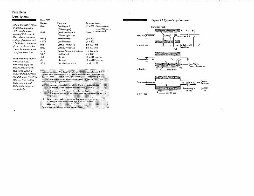
Parameter Descriptions
Setting Rate (Derivative) or Reset (Integral) to [ 00 j disables that aspect of PID control. The ratio fbr non-zero settings qfrate-to-reset is limited to a minimum of 1:4, i.e., Reset value cannot be set any lower than/our times Rate.
The parameters of Heat f!ysteresis, Cool Hysteresis and Cool Spread are only available when Output 1 and/or Output 2 are set to onlqff mode [Ht.OJ or [CL.OJ. 11iey replace Gain Output I and Gain Ratio Output 2. respectively.
26
Menu "02" Display Parameter Allowable Values
Gn.o1 Gain Output 1 00 to 400 (This value may
(PIO heat gain) exceed 400 during
Gr.o2 Gain Ratio Output 2 O.Q to Z.Q autotuning.}
(PIO cool gain ratio)
H.HYS Heat Hysternsis 01to100° C.HYS Cool Hysteresis 01 to 100" HYSl Output 1 Hysteresis 1 to 100 units
HYS2 Output 2 Hysteresis 1 to 100 units
SPr.2 Spread Aq;ustment, Output 2 0 to 100 units
C.SPr Cool Spread 0to100'
rAtE PIO rate 00 to 900 seconds
rSEt PID reset 00 to 3600 seconds
dPnG Damping (see notes) Lo, nL Hi, Otf
Notes on Damping: The damping parameter 1S an autOtuno'.fo~tf.ire.that enableS more precise co:ntrOI of set.pqin't.ovcrshoOi: durihg r.i~ove~ from process upsets ,in which thermal o.r tr.a,n,_sf~r)a91.s a{a.cto;. ?e:e, f;9ufe J 2,: Use the correc~ s":tting prior to autotuni.ng to qornPens"!te .ror, power' atid: : load/sensor coupling characteristics. '
lo" Fast recovery ~ith slight overshoot. For single-lag procossos. Ex. Adequate power and e~c<;!llent J~ad/sensOr'coupling.
nl " Nor1n81 recovery with no ove.rsho~t.: ~o·r two·t.a9 ·l>;~~esses: Ex. Properly si;i;ed heaters or con:ipo,nents' anp goo<;l loaPlsensor coupling., : : , ':':.:
Hi Stow tecqvery With no ovel'$hool,' f~r .three:;a:g ~r~Cess£!S< Ex. Ove.rpowered.wlth ,,'..ultlple lags. PoOr load/sensor: coupling. . , , '
.Orr"" Autctunr,.disabl(l.d; manual ou.tput co\l\C~ol.
Figure 12. Typical Lag Processes
lmrmrsbn Hooliaor
fblDUit@l!!uMllMt!/J/M-- "" --1 Fbw -+:-> ="· \,,,.,r A=; ~-+
a. Si~I:. ~ !:! n I I a1. Si~le. L:i::i with 11 T/C2 DiEW:Jd Ti mo
Fbw r---.--b.T"'° L:i:=i
Fbw-!=~
c. ThiM la::i
T/CI
Tl-.e.rmal -w- ~istanoo.
TM-.rmal Ccpo::ity
27

Tuning Procedures
For best results in tun
ing the temperature
controller, the setpoint
value should be at least
J00°F above or below
ambient temperature.
While some processes
other than heat or cool
applications may
respond successfully to
autotuning procedures,
the controller must be
manually tuned for
most non-temperature
processes.
28
Introduction
The Series 16 is an "on demand" autotuning controller that
automatically sets PIO parameter values (Proportional Band,
Reset and Rate) before the process reaches setpoint. A damp
ing setting (menu level "02") MUST be selected for autotuning
to take place. {see Notes on Damping, page 28). The con
troller may also be tuned manually (see page 33).
Autotuning the Series 16 Temperature Controller
1) With the power off and the process at ambient, apply
power and immediately put the controller in Standby mode
by holding the E key for four seconds until [ StbY]
flashes in the lower display window,
2) Enter the desired Setpoint Vatue using the appropriate
Raise& or Lower W key. [ StbV] will continue to flash.
3) If controller is in menu level "00" or "01 ",hold the
Parameter/ Access Q key for 11 seconds until [Ac.Cd ]
appears. Then change to menu level "OS". Otherwise,
press the Q key once and use the A key to select
menu level "OS''.
4) Press the Parameter/Access Q key twice until [ SnSr] is
displayed to make sure that the proper sensor has been
selected. Then set the controller's heating mode or alarm
functions by pressing the Parameter/Access Q key again
Tuning Procedures
until [ 0Ut1 ] is displayed. (Ir you scroll past it, just
continue scrolling until the parameter menu repeats.) Using
the appropriate Raise&. or Lower W key, select the one
of the following settings according to the requirements of
your process. Note: For autotuning, at least one output
MUST be set to PIO mode.
Mode
PIO On/Ort
Alarm
011tm1t 1 (H1rn1) Settjng
[Ht.P] [ Ht.O I [Ale]
Output 2 (Cooil Settjng
[CLP] [CL.OJ [Ale]
Press the Parameter/Access Q key again to step to output
2 [ 0Ut2 ] . Repeat the selection process for cooling mode or
alarm. (If only one output is PIO, set the other output to
either On/Orr or Alarm.)
5) Press the Parameter/Access Q key again to display the
Cooling Type parameter [ CoL.t ], and select either
Normal/Linear output [ nor] or Water-Cooled/Non-Linear
output [ H2o ] .
6) Exit menu level "05" by pressing the Mode= key once.
The lower window will flash [StbY]. Now press the
Parameter/Access Q key once. The lower window will
display [Ac.Cd J and [ 05 ]. Press the Lower W key twice
to select menu level "03".
7) Press the Parameter/Access Q key and select Cycle Time
for Output 1 [ CY.t1 ] and Cycle Time for Output 2 [ CY.t2].
For Control Output type B, T or Y, enter "15". For Control
Output type E, For S, enter "00". 29

Tuning Procedures
Before autotuning can
take place, you must
select a damping set
ting. {[the damping
parameter does not
appear on the menu,
you have not selected a
PID optionfor outputs
1 or 2. Refer back to
step (4) and select the
proper setting{.s).
During autotuning, the
process temperature
will gradually cycle
.from ambient to setpoint. TYhen autotuning is complete, the [tUnE] display will stop/lashing and the Gain, Rate
and Reset 11wnhers "learned" will he kept in me1noryfiir suhseq11e11t startups.
30
8) Press the Parameter/Access key until Setpoint Target Time
[ SP.tt] is displayed. Select [OFF].
9) Press the Mode = key once. The lower window will again
flash [StbY]. Press the Parameter/Access Q key once and
the lower window will display [Ac.Cd] and [ 03 ]. Press the
Lower W key once to select menu level "02".
1 O) Press the Parameter/Access Q key and scroll through
the displayed parameters. If Gain Ratio [ Gr.o2 ] is dis
played, set it to [ 1.0], Otherwise, continue scrolling until
[dPnG] appears. Set Damping initially to Normal [ nL ].
(This setting may have to be changed later. See Notes on
Damping, page 28).
11) Press and hold the Mode = key until [ tUnE] flashes
in the lower display window. The controller is now autotun
ing. When it stops flashing, the autotuning procedure is
completed and the controller is ready for your process .
As a security measure, you may wish to place the controller
in Key Lock "00" or Limited Access "01" Run mode by
changing menu levels as instructed previously.
Note: Re-tune controller only from ambient temperature.
Autotuning will not functio when process is at setpoint.
Figure 13. Typical '"~,"';; ----------------~ "Autotune" lnlllm -..._.w__.,.,,,/ tlJnE
Aoto~on•
Temperature Profile. -I,,=.~.,~----------on111 .. 11mi, ... 1.,. (limo)
Tuning Procedures
If overcooling exists on
heat/cool processes
after autotuning,
decrease Gain Ratio
[ Gr.o2 J in steps of 0. 1
until oscillation is
minimal. If cooling is
sluggish, increase the
value in steps o.fO.l
until optimum results
are achieved.
Gain ratio [ Gr.o2] is
the cooling gain
expressed as a/actor
of the heating gain.
Ex. [On.OJ]= 100
Cooling Gain = 50
(Gr.o2] = .5
Manual Tuning Procedure - Temperature Controller (Zeigler-Nichols PIO Method) This tuning method may be used if the spread between ambi
ent temperature and process operating temperature is small.
For best results, the use of a recording device is suggested
when tuning with this method.
1) Disable any cooling device used.
2) Apply power and place the controller in Standby by
pressing and holding the Mode = key for four seconds.
3) Using Raise£. or Lower W key, adjust setpoint to
desired value.
4) Access menu level "02" following instructions given
previously.
5) Using the Parameter/Access Q key, index to Heat Gain
[ Gn.o1 ]. Select [ 01 ].
6) Index to Gain Ratio [ Gr.o2] and select [ 1.0].
7) Index to Rate [ rAtE] and select [ 00 ].
8) Index to Reset [ rSEt] and select [ 00 ], Note: In order to
set Reset to [ 00 ] , Rate must first be set to [ 00 ] .
9) Change to menu level "03''.
10) Index to Cycle Time 1 [ CY.t1 ] and select the timebase,
in seconds, appropriate to the device being controlled,
(See note on page 27 .)
31

Tuning Procedures
32
11) Repeat for Cycle Time 2 [ CY.t2 ].
12) Change to menu level "05".
13) Set Cooling Type [ Col.t] to [nor].
14) Press the Mode = key once. Setpoint Value will be
displayed. The recording device should now be tracking
process temperature.
15) Double the Gain [ Gn.o1] until a small, sustained oscilla
tion is visible on the recording device's trace.
16) Measure the period of one cycle of oscillation ("T" on the
diagram below).
~ 17) Divide the period of oscillation (T) by eight (8). The
resulting number is the correct Rate time [ rAtE] in sec
onds. Multiply this number by four. This is the correct
Reset time [ rSEt] in seconds.
18) Multiply the gain (from step #15) by 0.6 and enter this
number as Gain I Gn.o 1 ] ,
19) Enable the cooling device. If overcooling exists, decrease
the Gain Ratio [ Gr.o2] in steps of 0.1 until temperature
oscillation stops. If cooling is sluggish, increase the Gain
Ratio in steps of 0.1 until optimum results are achieved.
Tuning Procedures
Calculate and enter thGse
numbers: Rate [ rAtE J "T/8 Reset [ rSEt] = T/2 Gain [ Gn.01 ] = Gain from
Step (6)
On noisy processes, whem Rate cannot be used: Gain ( Gn.01 ] =from Step
(6) x 0.45 Reset [ rSEt] "'T/1.2
~
Manual Tuning Procedure - Process Controller (Zeigler-Nichols P/D Method) A chart recorder to monitor the process variable is required.
The controller must be properly scaled and filtering set as
instructed previously.
1) Apply power and place the controller in Standby by holding
the Mode = key for four seconds.
2) Acljust the setpoint to the desired value.
3) Access menu level "05" and select one output: [ OUt 1 ]
for reverse-acting control or [ OUt 2 ] for direct-acting
control. Set the active output to PIO [ Pid ] and the unused
output to Alarm [ Alr] or On/Off [ On.F ].
4) Access menu level "02" and set [ Gn.01 ] to 1.0; [ Gr.o2] to
1.0; and [ rAtE] and [ rSEt J to "00''.
5) Press the Mode 5 key for four seconds until display
flashes [ tUnE ]. Press the Mode key for another four sec
onds and the process will run in closed loop mode.
6) While monitoring the chart, increase Gain [ Gn.o 1 ] by dou
bling the gain number until the process variable becomes
unstable. Then decrease Gain until the process oscillations
are sustained, neither increasing nor decreasing in ampli
tude as a result of momentary setpoint change.
7) Multiply the Gain from Step (6) by 0.6.
8) Measure the period of one complete cycle of oscillation,
"T'; in seconds. 33
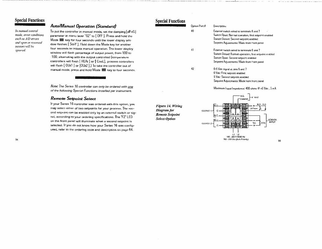
Special Functions
In manual control mode, error conditions such as AID errors and open or reversed sensors will be ignored.
34
Auto/Manual Operation (Standard) To put the controller in manual mode, set the damping [dPnG] parameter in menu level "02" to [OFF]. Press and hold the
Mode 5!5 key for four seconds until the lower display win
dow flashes [ Stb Y ] , Hold down the Mode key for another
four seconds to initiate manual operation. The lower display
window will flash percentage of output power, from 100 to
~ 100, alternating with the output controlled (temperature
controllers will flash [ HEAt] or [Cool], process controllers
will flash [ 0Ut1 ] or [0Ut2 ].) To take the controller out of
manual mode, press and hold Mode 5 key to four seconds.
Note: The Series 16 controller can only be ordered with one
of the foflowing Special Functions installed per instrument.
Remote Setpoint Select lf your Series 16 controller was ordered with this option, you
may select either of two setpoints for your process. The sec
ond setpoint can be enabled only by an external switch or sig
nal, according to your ordering specifications. The "F2" LED
on the front panel will illuminate when a second setpoint is
selected. If you do not know how your Series 16 was config
ured, refer to the ordering code and description on page 64.
Special Functions
Figure I 4. Wiring Diagram/or Remote Setpoi11t Select Option
Option Part#
40
41
42
Description
External switch wired to terminals 6 and 7
Switch Open: Normal operation, first setpoint enabled
Switch Closed: Second setpoint enabled
Setpoint Adjustments: Made from front panel
External switch wired to terminals 6 and 7
Switch Closed: Normal operation, first sctpoint enabled
Switch Open: Second setpoint enabled
Sctpoint Adjustments: Made from front panel
0-5 Vdc signal at pins 6 and 7
0 Vdc: First setpoint enabled
5 Vdc: Second setpoint enabled
Setpoint Adjustments: Made from front panel
Maximum Input Impedance: 400 ohms@ +5 Vdc, 5 mA
{
o.
OUTPUT 1 C
+- N.O. N.C
5Vln~
.C.
[No. OUTPUT 21_ C
" " 100 - 250 V 50/60 Hz 100. 330 Vele {Auto Polarity)
'IC ,_ l SENSOR RT1 INPUT
35
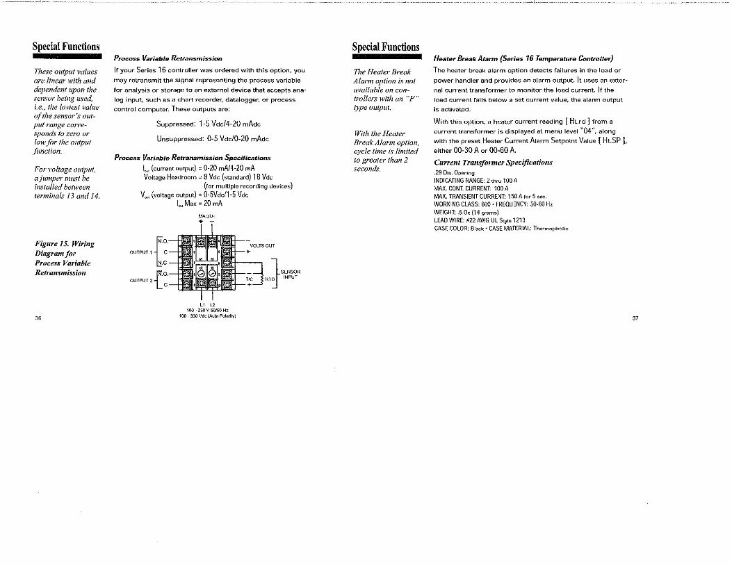
Special Fuuctious
These output values are linear with and dependent upon the sensor being used, i.e., the lowest value of the sensor's output range corresponds to zero or low for the output ji1nction.
For voltage output, a jumper nu1st be installed between tern1inals 13 and 14.
Figure 15. Wiring Diagram for Proces,v Variable Retra11sn1issio11
36
Process Variable Retransmission
Ir your Series 16 controller was ordered with this option, you
may retransmit the signal representing the process variable
for analysis or storage to an external device that accepts ana
log input, such as a chart recorder, datalogger, or process
control computer. These outputs are:
Suppressed: 1-5 Vdc/4-20 mAdc
Unsuppressed: 0-5 Vdc/0-20 mAdc
Process Variable Retransmission Specifications
I"", (current output) = 0-20 mA/4-20 mA Voltage Headroom= 8 Vdc (standard) 18 Vdc
(for multiple recording devices)
V"'" (voltage output) = 0-5Vdc/1-5 Vdc
{
o.
OUTPUT 1 C
c
[No. OUTPUT 21_ C
I"", Max = 20 mA
MA OUT + -
L1 L2 100" 250 V 50160 Hz
100 - 330 Vdc (Auto Polarity}
VOLTS OUT +
"' +
l SCNSOR
RTi INPUT
Special Functions
The l-Ieater Break Alarm option is not available on controllers with an "F" type output.
With the Heater Break Alarm option, cycle time is liniited to greater than 2 second'i.
Heater Break Alarm {Series 16 Temperature Controller}
The heater break alarm option detects failures in the load or
power handler and provides an alarm output. It uses an exter
nal current transformer to monitor the load current. If the
load current falls below a set current value, the alarm output
is activated.
With this option, a heater current reading [ Ht.rd ] from a
current transformer is displayed at menu level 11
04", along
with the preset Heater Current Alarm Setpoint Value [ Ht.SP ],
either 00-30 A or 00-60 A. Current Transformer Specifications .29 Dia. Opening INDICATING RANGE: 2 thru 100 A MAX. CONT. CURRENT: 100 A MAX. TRANSIENT CURRENT: 150 A for 5 sec. WORKING CLASS: 600 ·FREQUENCY: 50-60 Hz WEIGHT: .5 Dz (14 grams) LEAD WIRE: 1122 AWG UL Style 1213 CASE COLOR: B1ack ·CASE MATERIAL: Thermoplastic
37
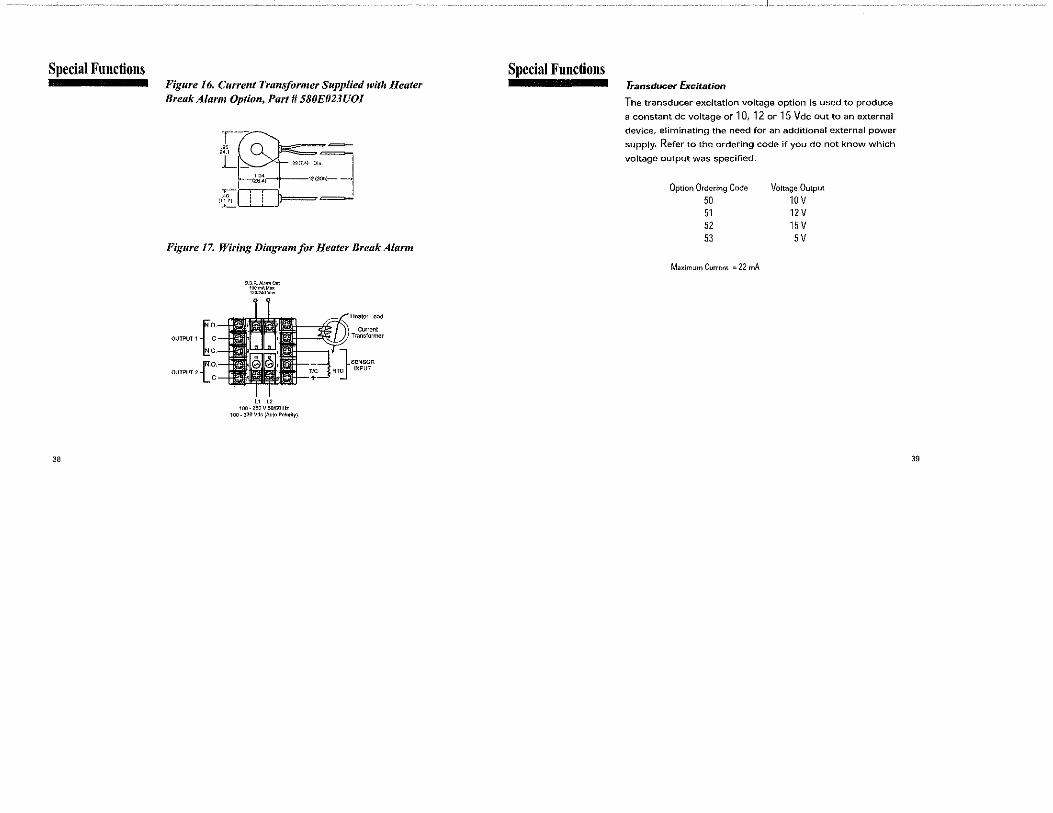
Special Functions
38
Figure 16. Current Transfornier Supplied with Heater Break Alarm Option, Part# 580E023UOI
""·'' ,,:==-~ >M
(26.4)
.;;-CIIJ==' ""'"~
(117) : : -·- '' ~
Figure 17. Wiring Diagram for Heater Break Alarm
{
o
OUTPUT 1 C.
0
OUTPUT 2 t·~·
9 9 R Alonn Out
i~i;;.~~
L1 L2 100-250V50l60Hz
Haatar Lead
Current ~Transformer
100.JJOVdc(AuloPol•tily)
Special Functions Transducer Excitation
The transducer excitation voltage option is used to produce
a constant de voltage of 10, 12 or 15 Vdc out to an external
device, eliminating the need for an additional external power
supply. Refer to the ordering code if you do not know which
voltage output was specified.
Option Ordering Code
50 51 51 53
Maximum Current "'22 mA
Voltage Output
10V 11V 15 v 5V
39
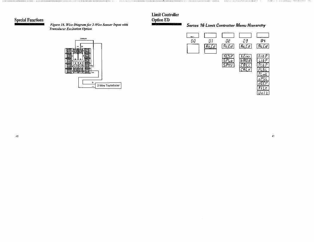
Special Functions
40
Figure 18. Wire Diagra1nfor 2-Wire Sensor Input with Transducer Excitation Option
Jumper
+ _ , 2 Wire Transducer
Limit Controller Option ED
Series 16 Limit Controller Menu Hierarchy
c::::J c=J c=J c=J c=J ,-, .., .., "
D DI
I Re.Cd I c=J
D2 I Re.rd I
HL5P 5PLo 5PHI
D:I I Rc.L:l I
o~
I Re.Cd I
ln~P LI I: P fJLtP Rm: FJLot
loPSL I ldffPI I FJU: I luntt-1
41
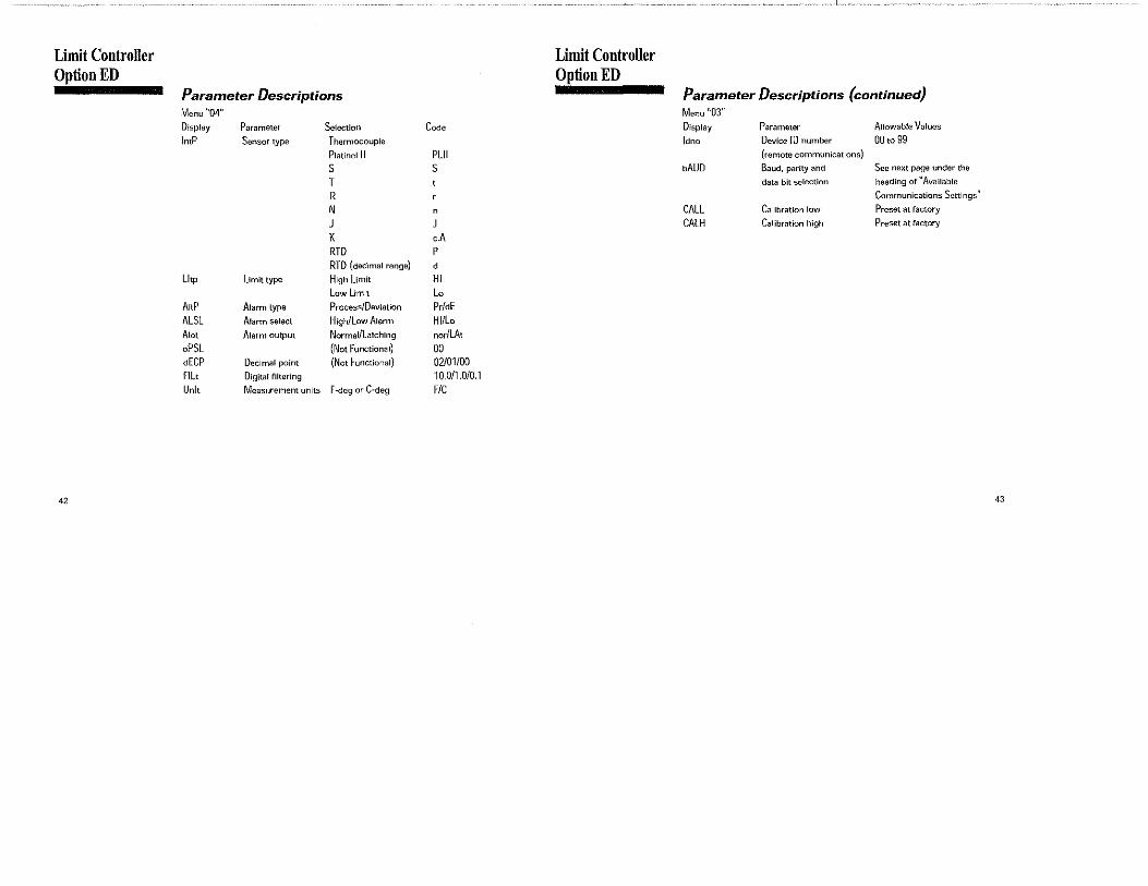
Limit Controller Option ED
Parameter Descriptions Menu "04" Display Parameter Selection
lntP Sensor type Thermocouple
Platincl II
s T R N J K RTD RTD (decimal range)
Lltp limit type High Limit
Low Limit
ArtP Alarm type Process/Deviation
ALSL Alarm select High/low Alarm
Atot Alarm output Normal/latching
oPSL (Not Functional) ciECP Decimal point (Not Functional)
fl Lt Digital filtering
Unit Measurement units F-deg or C-deg
42
Code
PLll s
0
o.A p
d
HI Lo Pr/dE HI/Lo nor/LAt 00 02/01/00 10.0/1.0/0.1 F/C
Limit Controller Option ED
Parameter Descriptions (continued) Menu "03" Display Parameter Allowable Values
ldno Device ID number 00 to 99 (remote communications)
bAUD Baud, parity and Sec next page under the
data bit selection heading or"Available
Communications Settings
CALL Calibration low Preset at factory
CALH Calibration high Preset at factory
43

Limit Controller Option ED
44
Parameter Descriptions (continued) Menu "02" Display
ALSP SPLo
SPHI
Display
24.n.8 .. 12.n.R 6,n,S: 3.rl.8. 24:o.7. 12.o.7. 6.o.l. 3.o.7.
Parameter
A1arm setpoint
Setpoim low
(lower sctpoint limit)
Setpofnt high
(upper sctpoint limit)
Allowable Values
Oto 8191 Dependent on sensor range
Dependent on sensor range
Ava i 1.ab!E,': Com.mun i ca ti On$ '~.e~ti !195: DeScription , ,
BaJd Rate Parity Data Bits·: , ~;t?P B.its 2400 none 8 :1, 1200 none 8 600 none 8 300 none .8
2400 odd 1200 odd
600 odd
300 'odd
Limit Controller Option ED
Operation High Limit Operation - During normal operation the
mechanical relay in output "1" is closed. If the process
temperature exceeds the high limit setting, then the
mechanical relay in output "1" will open ("01" LED is
now lit) cutting o'ff power to the load. When the process
temperature drops back down to below the limit setting,
output "1" will remain open until you press the mode key
to reset the controller.
Low Limit Operation - During normal operation the
mechanical relay in output "1" is closed. Ir the process
temperature drops below the low limit setting, then the
mechanical relay in output "1" will open ("01" LED is
now lit) cutting off power to the load. When the process
temperature rises back above the limit setting, output "1"
will remain open until you press the mode key to reset
the controller.
Mode Key (Reset Button) - Operates as a reset button.
The Parameter Access Key - Used to index through
parameters or to access menu levels.
Raise Key - Used to scroll up through available parameter
settings, increase values or change menu levels (Hold for
fast-step progression).
Lower Key - Used to scroll down through available
parameter settings, decrease values or change menu levels
{Hold for fast-step progression}. 45
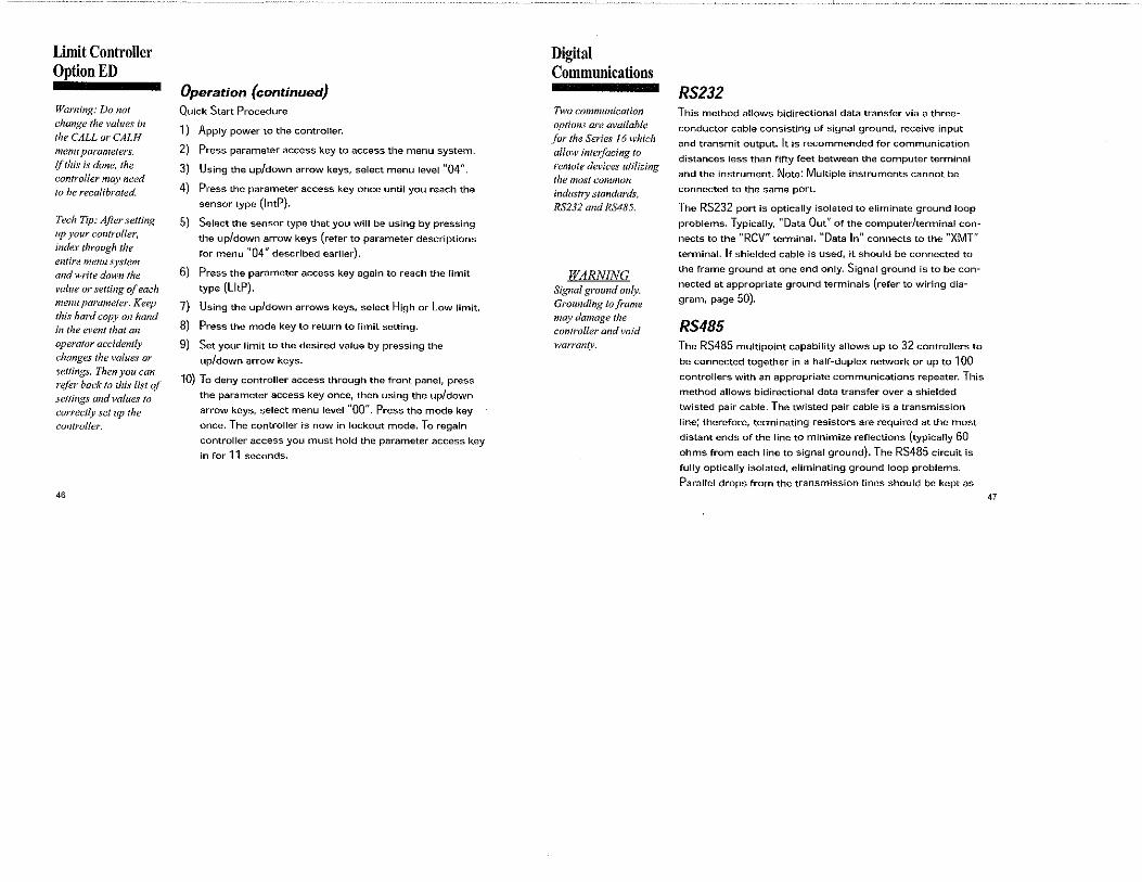
Limit Controller Option ED
Warning: Do not
change the values in
the CALL or CALH
menu parameters. ~f this is done, the controller may need
to he recalibrated.
Tech Tip: After setting up your co11trolfer, index through the
entire menu system and write down the
value or setting of each menu parameter. Keep this hard copy on hand in the event that an
operator accident(v
changes the values or
settings. Then you can refer back to this list ql settings and values to correctly set up the
con/roller.
46
Operation (continued) Quick Start Procedure
1) Apply power to the controller.
2) Press parameter access key to access the menu system.
3) Using the up/down arrow keys, select menu level "04".
4) Press the parameter access key once until you reach the
sensor type (lntP).
5) Select the sensor type that you will be using by pressing
the up/down arrow keys (refer to parameter descriptions
for menu "04" described earlier).
6) Press the parameter access key again to reach the limit
typo (LltP).
7) Using the up/down arrows keys, select High or Low limit.
8) Press the mode key to return to limit setting.
9) Set your limit to the desired value by pressing the
up/down arrow keys.
10) To deny controller access through the front panel, press
the parameter access key once, then using the up/down
arrow keys, select menu level "00". Press the mode key
once. The controller is now in lockout mode. To regain
controller access you must hold the parameter access key
in for 11 seconds.
Digital Communications
Two communication
options are available fOr the Series 16 which
allow inte1:facing to
remote devh:cs utilizing the most common industry standards,
RS232 and RS485.
WARNING Signal ground only. Grounding to frame
may damage the controller and void warran(v.
RS232 This method allows bidirectional data transfer via a three
conductor cable consisting of signal ground, receive input
and transmit output. It is recommended for communication
distances less than fifty feet between the computer terminal
and the instrument. Note: Multiple instruments cannot be
connected to the same port.
The RS232 port is optically isolated to eliminate ground loop
problems. Typically, "Data Out" of the computer/terminal con
nects to the "RCV" terminal. "Data In" connects to the "XMT"
terminal. If shielded cable is used, it should be connected to
the frame ground at one end only. Signal ground is to be con
nected at appropriate ground terminals (refer to wiring dia
gram, page 50).
RS485 The RS485 multipoint capability allows up to 32 controllers to
be connected together in a half-duplex network or up to 100
controllers with an appropriate communications repeater. This
method allows bidirectional data transfer over a shielded
twisted pair cable. The twisted pair cable is a transmission
line; therefore, terminating resistors are required at the most
distant ends of the line to minimize reflections (typically 60
ohms from each line to signal ground). The RS485 circuit is
fully optically isolated, eliminating ground loop problems.
Parallel drops from the transmission lines should be kept as
47

Digital Communications
Note: Calf factory.for a recommended RS485 converter.
48
short as possible; however, the line may be daisy-chained at
each controller. The polarity of the line is important and each
device will specify an "A"(+) and "B" (-)connection.
o0o
0o
0'bo
0o
0o0o0o0o
r
~~
- - -
*One PC to one controller only
Figure 19. Wiring diagram j'or digital co1nmunications.
Digital Communications
Table 1. Conununications Para11teter List (Temperature Controller)
Parameter No. Description Display Minimum Maximum
00 Process Value nnnn Sensor Oepondent
01 Setpoint nnnn Low Limit High limit
02 Access Code Ac.Cd 00 05 03 Gain Output 1 Gn.o1 00 400 04 Gain Ratio 2 Gr,o2 0.0 2.0 05 Rate rAtE 00 900 06 Reset rSEt 00 3600 OJ Heat Hysteresis H.HYS 01 100 08 Cool Hysteresis C.HYS 01 100 09 Cool Spread C.SPc 00 100 10 Damping ciPnG 00 Low/Normal/High
11 Alarm 1 Alr1 Range Dependent
12 Alarm 2 Alr2 Range Dependent
13 Cycle Time 1 CY.t1 00 120 14 Cycle Time 2 CY.t2 00 120 15 Setpolnt Target Time Sp.tt 00 (OFF) 100 16 Low Setpoint limit L.SP.l Sensor Dependent
17 High Setpoint limit U.SP.l Sensor Dependent
18 Controller ID Id.no 00 99 19 Baud Rate bAUd 300 2400
Table 2. Co111n1unications Parameter List (Process Controller)
Parameter No. Description Display Minimum Maximum
00 Process Value nnnn Low Scale High Scale
01 Set point nnnn Low Scale High Scale
02 Access Code Ac.Cd 00 05 49

Digital Communications
03 Gain Output 1 Gn.o1 00 04 Gain Ratio 2 Gr.o2 0.0 05 Rate rAtE 00 06 Reset rSEt 00 07 Hysteresis 1 HYS.1 01 08 Hysteresis 2 HYS.2 01 09 Spread 2 SPr.2 00 10 Damping ciPnG 00 11 Alarm 1 Alr1 low Scale
12 Alarm2 ALrZ Low Scale
13 Cycle Time 1 CY.t1 00 14 Cycle Time 2 CY.t2 00 15 Setpoint Target Time Sp.tt 00 (OFF) 16 Low Scale L.SCL -1999 17 High Scale H.SCL -1999 18 Controller ID Id.no 00 19 Baud Rate bAUci 300
Table 3. Serial Co111ni11nications Data Fonnat Baud Baud Parity Data
Code Rate Bits
0 300 Odd 7 600 Odd 7
2 1200 Odd 7 3 2400 Odd 7 4 300 None 8
600 None 8 6 1200 None 8 7 2400 None 8
50
400 2.0 900 3600 100 100 100 Low/Normal/High
High Scala
High Scale
120 120 100 9999 9999 99 2400
Stop
Bits
2 2 2
Digital Communications
Interface Examples
This section describes the protocol for communication
between an Series 16 controller and either a video display ter
minal or computer (referred to below as "the host").
Message strings may be of two types - commands to con
troller or responses from controller.
General Comments One host and multiple controllers may be interconnected on a
single bus. The host may send commands to any controller
and may receive responses from any controller. Each con
troller on the bus is assigned an identification code between
00 and 99. No two controllers on a given bus may have the
same identification code. Controllers are not capable of com
municating with other controllers.
Every valid message begins with a pound-sign (#} character.
Every valid message ends with a carriage-return (<CR>}
character.
A valid message is composed of: Start Message, Controller ID
Code, Command, Parameter and Data.
Every response begins with a line-feed (<LF>} character and
ends with a carriage-return, line-feed pair (<CRLF>).
51
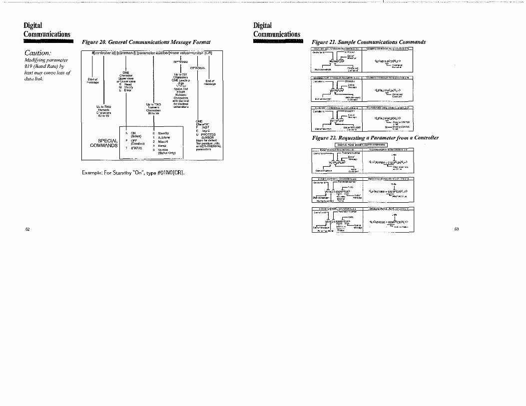
Digital Commuuications
Caution: Nlod(fj;ing parameter #19 (Baud Rate) by host muy cause loss of data link.
52
Figure 20. General Communications Message Fonnat
#[controller id] [command] [parameter number]<new value>< units> [CR]
I OPTl~NAL I I OPTIONAL
o" Character Up to SIX
Start of Uppercase Characters ONE Leading Endo! message or Lower case
Sign R Read message M Modify ·-·;+·or E Enler Space and
FOUR Numeric
Characters with declmel
U~J~~~o for decimal Up to TWO parameters Numeric Characters
Characters 00l99 00\oSS
o" Ch.,racier
I F Deg F C OegC
' 0, 0 Standby U PROCESS (Select) ' Autotune SENSOR
SPECIAL F OFF 2 Mnnual None for default
COMMANDS (Deselect) 3 Ramp
Temperafura units
' STATUS or NON-THERMAL
g Vernion pnrameters (Status Only)
Example: For Standby "On'', type #01 NO[CR].
Digital Communications
Figure 21. Sample Comniunications Co1n1nands g 'NDT<>rnNtoouo. j '""""'"""-'N'"FeoMrn"'1m"rR j %\NOilY '9'" CUM•
"•"'""j j-""'""' Eodo!
W01NO<~""'""
S'"'1ot~~::~I
Oon .. -IO----, 15TANO!IY
ll.r """"' '#01FO<c~ 11""'" ,--' '-----,
s~" o! "'"""'" OF,f,%1.:,'~"'"I
_,_1ANDOY •r<,,MMhNLJ'Lu<'<i'N.1'itcliJ:Fti-
Coo"°'l"ld----, ISTANOBY
l l ..r:- ~~~."!,. 'll01?0<cR>
,--' '-----, """"' M""'' ""'~;~~,urr
'(Lf)ll01NO<cRXLF>'
-,:__ ~~::'t:"
>fhNO>llY Rr:Sr<>N,.F.FROM C"NTR"'-1 '"
·(LF)#Q1Fo<cRl<LF)· "1:.._ C00">1<>nd
E'"'""''
'<LF)#01FO(CR)(LF)' -,:__ ~~~bySThTUS
N-~'?;_l!'>l'STAlVS
Figure 22. Requesting a Para1neter from a Controller I MMP'-"1 RE/\O, MODI I MM•'-"' RE/\O, MODIFY, EN"'" CoMMANDS I
•rw,1ES>huO •LADMES>hUO to CDNTI<QU'" RE/ID"'""'"'" '''OJ.troNTROI r l•lt
~"'""'"-i1 ·----··--l E"do!
~J01ROiJ<G~ Mom'°
r' "'-------, St,..o!M"'"'" Co':,~,d
\1<)[>1ViOJMMh~[diJi:'lN1RCllLER
Con'"""'"l [""''m~"""'"'" r"""'
'jl01M01 0200F<CR)' .----' I ... -,:_, .. ,, "''" ,,.,,,.,,, ~~:~7 .,.,,.,,. "'""-"""'"'"""' """"'
mnll <ilMMhNb 1DrnNrnm '-'"
""""'" .. l[""'''""""""""' r-""1~
'#-01E01 0200F<CR)' .----' T ... -c_.,.,,, """"'"''"''' !;;:,~~7 ~,,,,,,
En"'CommooO '"""'
""'" <t_F)ff01ROO ~ 0120~CR)4-f)•
---=~~n'lr'..~""'"
1 •(LF)#Q1MOO • 0200F{cR)(LF)'
-c-;.,,,,.,d Vol"'
Ur <lFli/o1~00 • 0200F<CR)(Lf)'
-C-Eo1orndVoloo 53
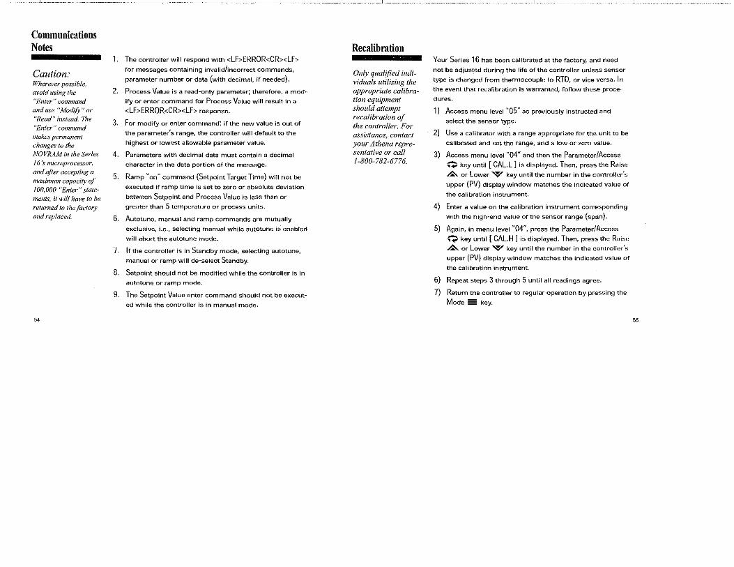
Communications Notes
Caution: Wherever possible, avoid using the "Enter" command and use "ModifY" or "Read" instead. The "Enter" command makes permanent changes to the NO VRAM in the Series 16 's microprocessor, and q(ter accepting a
maximum capacity of 100,000 "Enter" statements, it will have to be returned to the.factory and replaced.
54
1. The controller will respond with <LF>ERROR<CR><LF>
for messages containing invalid/incorrect commands,
parameter number or data (with decimal, if needed).
2. Process Value is a read-only parameter; therefore, a mod
ify or enter command for Process Value will result in a
<LF>ERROR<CR><LF> response.
3. For modify or enter command: if the new value is out of
the parameter's range, the controller will default to the
highest or lowest allowable parameter value.
4. Parameters with decimal data must contain a decimal
character in the data portion of the message,
5. Ramp "on" command (Setpoint Target Time) will not be
executed if ramp time is set to zero or absolute deviation
between Setpoint and Process Value is less than or
greater than 5 temperature or process units.
6. Autotune, manual and ramp commands are mutually
exclusive, i.e., selecting manual while autotune is enabled
will abort the autotune mode.
7. If the controller is in Standby mode, selecting autotune,
manual or ramp will de-select Standby.
8. Setpoint should not be modified while the controller is in
autotune or ramp mode.
9. The Setpoint Value enter command should not be execut
ed while the controller is in manual mode.
Recalibration
Only qual!fied individuals utilizing the appropriate calibration equipment should attempt recalibration of the controller .. For assistance, contact your Athena representative or call 1-800-782-6776.
Your Series 16 has been calibrated at the factory, and need
not be adjusted during the life of the controller unless sensor
type is changed from thermocouple to RTD, or vice versa. In
the event that recalibration is warranted, follow these proce
dures.
1) Access menu level "05" as previously instructed and
select the sensor type.
2) Use a calibrator with a range appropriate for the unit to be
calibrated and set the range, and a low or zero value.
3) Access menu level "04" and then the Parameter/Access
Q key until [CALL] is displayed. Then, press the Raise
&. or Lower W key until the number in the controller's
upper (PV) display window matches the indicated value of
the calibration instrument.
4) Enter a value on the calibration instrument corresponding
with the high-end value of the sensor range (span).
5) Again, in menu level "04'', press the Parameter/Access
Q key until [ CAL.H ] is displayed. Then, press the Raise
£.or Lower W key until the number in the controller's
upper (PV) display window matches the indicated value of
the calibration instrument.
6) Repeat steps 3 through 5 until all readings agree.
7) Return the controller to regular operation by pressing the
Mode 55 key.
55

Error Codes Display Problem
I En.HJ Open sensor
[ Err.L] Reversed sensor
I En.OJ AID error
[ Err.J] AID error
Display out·of·range
56
Action
Check sensor and wiring
Check type of sensor
Recalibrate
Check sensor and wiring
Check type of sensor
Recalibrate
Return to factory
Return to factory
Sensor over- or under-range
Warranty/Repair Information
Two-Year limited Warranty
Other than those expressly stated herein, THERE ARE
NO OTHER WARRANTIES OF ANY KIND, EXPRESS OR IMPLIED, AND SPECIFICALLY EXCLUDED BUT NOT BY WAY OF LIMITATION, ARE THE IMPLIED WARRANTIES OF FITNESS FOR A PARTICULAR PURPOSE AND MERCHANTABILITY.
IT IS UNDERSTOOD AND AGREED THE SELLER'S LIABILITY WHETHER IN CONTRACT, IN TORT, UNDER ANY WARRANTY, IN NEGLIGENCE OR OTHERWISE SHALL NOT EXCEED THE RETURN OF THE AMOUNT OF THE PURCHASE PRICE PAID BY THE PURCHASER AND UNDER NO CIRCUMSTANCES SHALL SELLER BE LIABLE FOR SPECIAL, INDIRECT, INCIDENTAL OR CONSEQUENTIAL DAMAGES. THE PRICE STATED FOR THE EQUIPMENT IS A CONSIDERATION IN LIMITING SELLER'S LIABILITY. NO ACTION, REGARDLESS OF FORM, ARISING OUT OF THE TRANSACTIONS OF THIS AGREEMENT MAY BE BROUGHT BY PURCHASER MORE THAN ONE YEAR AFTER THE CAUSE OF ACTION HAS ACCRUED.
SELLER'S MAXIMUM LIABILITY SHALL NOT EXCEED AND BUYER'S REMEDY IS LIMITED TO EITHER(;) REPAIR OR REPLACEMENT OF THE DEFECTIVE PART OR PRODUCT, OR AT SELLER'S OPTION (;;) RETURN OF THE PRODUCT AND REFUND OF THE PURCHASE PRICE, AND SUCH REMEDY SHALL BE BUYER'S ENTIRE AND EXCLUSIVE REMEDY.
57
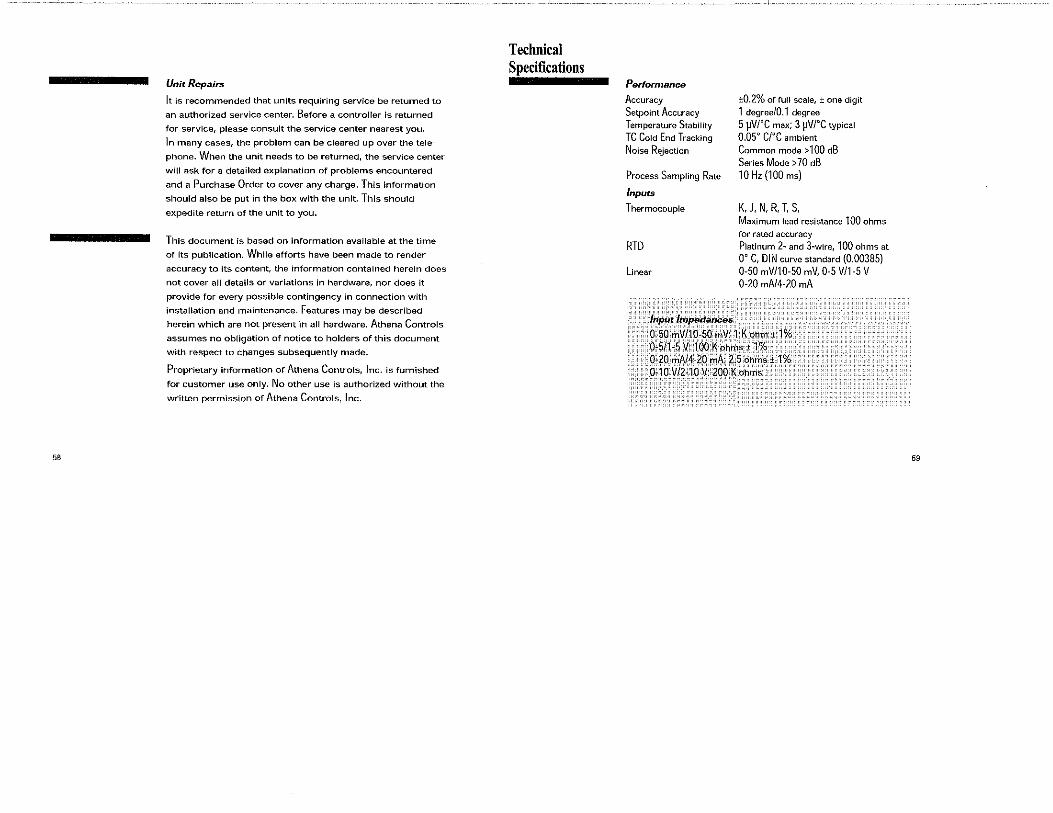
58
Unit Repairs
It is recommended that units requiring service be returned to
an authorized service center. Before a controller is returned
for service, please consult the service center nearest you.
ln many cases, the problem can be cleared up over the tele
phone. When the unit needs to be returned, the service center
will ask for a detailed explanation of problems encountered
and a Purchase Order to cover any charge. This information
should also be put in the box with the unit. This should
expedite return of the unit to you.
This document is based on information available at the time
of its publication. While efforts have been made to render
accuracy to its content, the information contained herein does
not cover all details or variations in hardware, nor does it
provide for every possible contingency in connection with
installation and maintenance. Features may be described
herein which are not present in all hardware. Athena Controls
assumes no obligation of notice to holders of this document
with respect to changes subsequently made.
Proprietary infonnation of Athena Controls, Inc. is furnished
for customer use only. No other use is authorized without the
written permission of Athena Controls, Inc.
Technical Specifications
Performance
Accuracy
Setpoint Accuracy
Temperature Stability
TC Cold End Tracking
Noise Rejection
Process Sampling Rate
Inputs
Thermocouple
RTD
Linear
. lnpµ,t ~ittpedances
±0.2% of full scale, ±one digit
1 degree/0.1 degree
5 µVl°C max; 3 µV/°C typical 0.05° ere ambient
Common mode > 100 dB
Series Mode > 70 dB
10 H, (100 mo)
K,J, N, R, T, S, Maximum lead resistance 100 ohms
for rated accuracy
Platinum 2- and 3-wire, 100 ohms at
0° C, DIN curve standard (0.00385)
0-50 mV/10-50 mV, 0-5 V/1-5 V 0-20 mA/4-20 mA
0-50 mV/10-50mV: 1Kohm±1% :o·~S/1~5 Vt 100K~h~s±,1'%, O)O _,,A/Ho mA: 2.5 ohms± 1% 0-10 V/2·.10 v:: 200 Kohtns
59

Technical Technical Specifications Specifications
Outputs Gain 0 to 400 #1 Reverse acting (heating or alarm) Gain Ratio 0 to 2.0 (in 0.1 increments)
#2 Direct acting (cooling or alarm) Control Hysteresis 1 to 100 units {on/off configuration)
B Relay, 5 A@ 120 Vac resistive Cool Spread, Output 2 0 to 100° F/C (above setpoint)
3A@240Voe (Temperature Controller}
E 0-20 mAdc Spread 2, Output 2 0to100 units (above setpoint)
F 4-20 mAdc, 500 ohms max. (Process Controller)
s 20 Vdc pulsed Damping Selectable (low, normal, high, off)
T Solid-state relay, 120/240 Vac, Setpoint Target Time 0 (off) to 100 minutes
zero voltage-switched, (Ramp-to-Setpoint)
1 A continuous, 10 A surge @ 25 ° C Autotune Operator-initiated from front panel
Y (Output 2 only) N.C. Relay, 5 A@ 120 Vac resistive Manua! Operator-initiated from front panel
3 A@ 240 Voe General
Alarms line Voltage 115 to 230V±10%, 50-60 H, Electromechanical relay, 5 A@ 120 Vac, 115 to 300 Vdc ±10% (Auto-Polarity) 3 A@ 240 Voe (Output 1 OR 2 only) Display Dual, 4-digit 0.36" {9.2 mm) LED display
Process Value: Orange Dual-Alarm option: Two solid-state Setpoint Value/Menu: Green relays, 120/240 Vac, zero voltage- Power Consumption Leoo thon 6 VA(@ 120/240 Voe) switched, 1 A continuous, 10 A surge Panel Cutout 1.771"' 1.771" (45 mm' 45 mm) @25"C Depth Behind Panel 3.937" (100 mm)
Control Characteristics Front Panel Rating NEMA 4X Operating Temperature 32to131" F (Oto 55" C)
Setpoint Limits Limited to configured range Humidity Conditions 90% R.H. max., non-condensing Alarms Adjustable for highliow; selectable Parameter Retention Solid-state, non-volatile memory
process or deviation Connections Input and output via barrier strip Rate 0 to 900 seconds with locking terminals Reset 0 to 3600 seconds Contacts Twin bifurcated Cycle Time 0.2 (zero setting) to 120 seconds
61 60

I .
MARCH 1993
INSTRUCTIONS FOR THE 1600 SERIES MICROPROCESSOR BASED
TEMPERATURE I PROCESS CONTROL
INCLUDES FUZZY LOGIC OPTION
LOVE
I . ,- Ii Ii . I 0 LJ LJ
I ,- Ii Ii '0 u u.
If all else fails, please read these
instructions
CONTROLS DIVISmON :l'mye;;; Instruments, Incorporated
1475 S. WHEELING ROAD • WHEELING lWNOIS 60090 (708) 541-3232 • FAX (708) 541-7366
949-1239-2
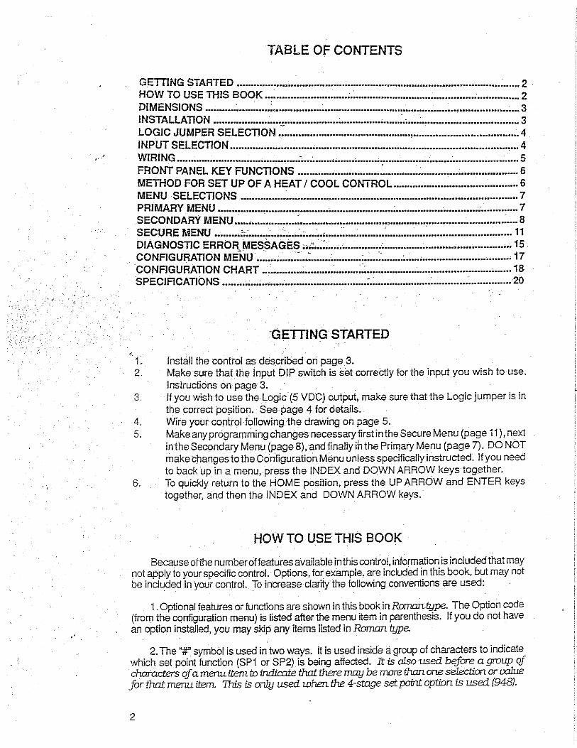
·'
TABLE OF CONTENTS
GETTING STARTED .................................................................................................... 2 . HOW TO USE THIS BOOK ............................. ;.~ ..............................................•........... 2 DIMENSIONS ........... ; ........... '. .......... ~ ...... ; ..................................................................... 3 INSTALLATION ............................................ ; ..................... ~.; .... ; .................................. 3 LOGIC JUMPER SELECTION:: .................................................................•................. 4 INPUT SELECTION ...................................................................................................... 4 WIRING ...... ; .................................... :; ... ; ............................................................ ; ........... 5 FRONT PANEL KEY FUNCTIONS ............................. : ................................................ 6 METHOD FOR SET UP OF A HEAT I COOL CONTROL ............................................ 6 MENU SELECTIONS .................................................................................................. 7 PRIMARY MENU ................ , ...................... , .................................................... ; ............. 7 SECONDARY MENU .....•................ : ............................................................................. 8 SECURE MENU · · · ' . · .. ' . 11 DIA G Nos TI c ERRoit~;;EssA"Gi~s·'.:~::::::::::::::::::::::::::::::::::::::::::::::::::: ::::::::::::::::::: 15
N - . ·. ·. . . .. - ·. CO FIGURATION MENU ..................................... : ....................•......................•.......• 17 ·coNFIGURATION CHART .............. ; •......... ~ ........ ::: ..............•.............................•...... 18 SPECIFICATIONS ........• ; ... ; . .-.................................. : .................................. : ............... 20
GETTING STARTED
t. lnstail the control as described on page 3. 2. Make sure that the Input DIP switch is set correctly for the input you wish to use.
Instructions on page 3. 3. If you wish to use the Logic (5 VDC) output, make sure that the Logic jumper is in
the correct position. See page 4 for details. 4. Wire your control following the drawing on page 5. 5. Make any programming changes necessary first in the Secure Menu (page 11), next
in the Secondary Menu (page 8), and finally ih the Primary Menu (page 7). DO NOT make changes to the Configuration Menu unless specifically instructed. If you need to back up in a menu, press the INDEX and DOWN ARROW keys together.
6. To quickly return to the HOME position, press the UP ARROW and ENTER keys together, and then the INDEX and DOWN ARROW keys.
HOW TO USE THIS BOOK
Because of!he number of features available in this control, information is included that may not apply to your specific control. Options, for example, are included in this book, but may not be included in your control. To increase clariiy the following conventions are used:
1. bptional features or functions are shown in this book in Romantype. The Option code (from the configuration menu) is listed after the menu item in parenthesis. If you do not have an option installed, you may skip any items listed in Roman type.
2. The "#" symbol is used in two ways. It is used inside a group of characters to indicate which set point function (SP1 or SP2) is being affected. It is also used before a group of characters qf a menu item to indicate that there mny be more than one selection or val11e for that menu item This is only used when the 4-stage set potnt option is used (948).
2
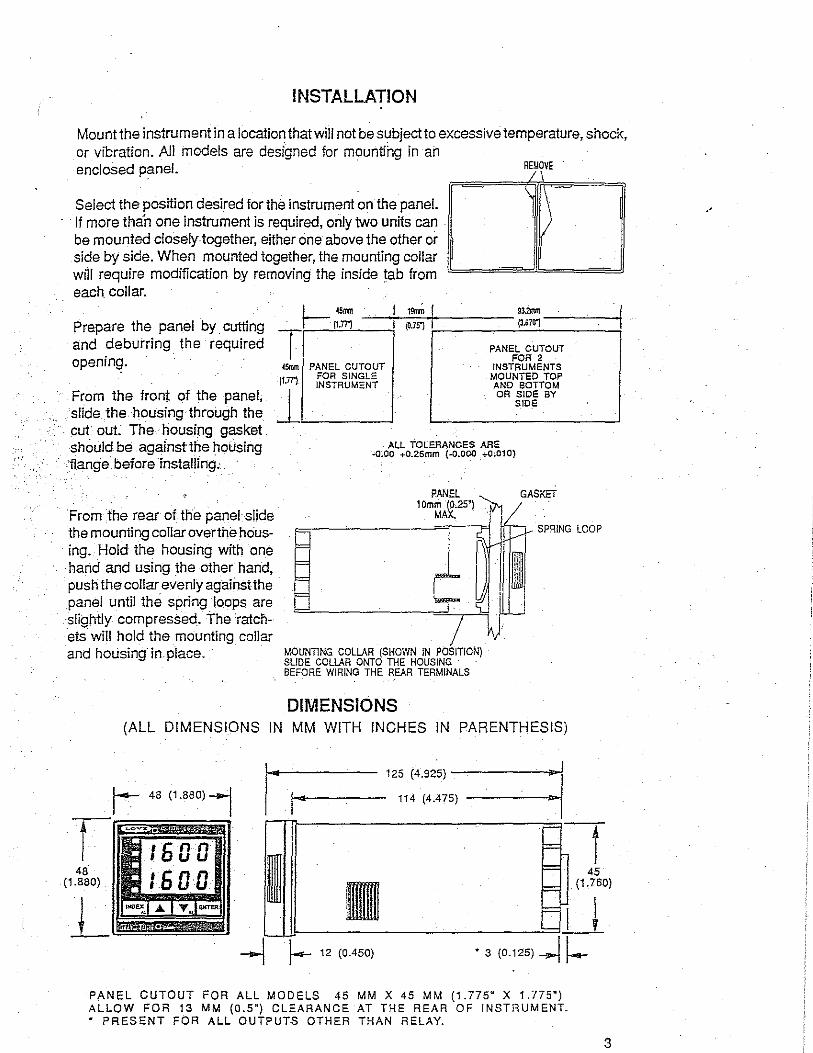
INSTALLATION
Mount the instrument in a location that will not be subject to excessive temperature, shock, or vibration. All models are designed for mounting in an enclosed panel. RfJOVE
Select the position desired for the instrument on the panel. · · If more than one instrument is required, only two units can
be mounted closely together, either one above the other or side by side. When mounted together, the mounting collar will require modification by removing the inside tab from each collar.
Prepare the panel by cutting and deburring the required opening.
I- 4Smm 19!ml I 9l.2mm - / 117TJ ~--(-0.75j--+------ {3.S71T)--~--+ T,__-"."'-'----i
From the front of the panel, slide .the housing through the .
. cut out The housing gasket should be .against the hollsing
· •flange before installing:.
From the rear of the panel slide the mounting collar overthe housing. Hold the housing with one hand and using the other hand, pushthe collar evenly againstthe panel until the spring loops are slightly· compressed. The ratchets will hold the mounting collar and housing in. place.
45nm PANEL CUTOUT FOR SINGLE
ll.7TJ INSTRUMENT
l~
PANEL CUTOUT FOR 2
INSTRUMENTS MOUNTED TOP AND sonoM OR SIDE BY
SIDE
ALL TOLERANCES ARE .a~oo +0.25mm (-0.000 _+-0;010)
PANEL 10mm (0.25"}
MAX.
MOUNTING COLLAR (SHOWN IN POSITION} SLIDE COLLAR ONTO THE HOUSING BEFORE WIRING THE REAR TERMINALS
DIMENSIONS
GASKET
SPRING LOOP
(ALL DIMENSIONS IN MM WITH INCHES IN PARENTHESIS)
lf.<4ot------ 125 (4.925) -------...-:
114 (4.475) ____ _,.,....ii I
.
= 48
(1.880) I n = =
45 (1.760)
= u I -....J 1-- 12 (0.450) • 3 (0.125) -...1 !--.-
PANEL CUTOUT FOR ALL MODELS 45 MM X 45 MM (1.775" X 1.775") ALLOW FOR 13 MM (0.5") CLEARANCE AT THE REAR OF INSHlUMENT. " PRESENT FOR ALL OUTPUTS OTHER THAN RELAY.
3
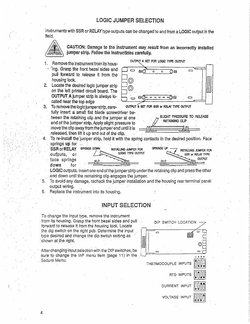
LOGIC JUMPER SELECTION
Instruments with SSR or RELAY type outputs can be changed to and from a LOGIC output in the field.
CAUTION: Damage to. the iiistrument may result from an incorrectly installed jumper strip. Follow the instructions carefully.
1. Remove the instrument from its hous-• 'ing. Grasp the front bezel sides and
pull forward to release it from the housing Jock.
2. Locate the desired logic jumper strip · on the left printed circuit board. The OUTPUT A jumper strip is always located near the top edge
Oll!PUT A SET FOR LOGIC Tfl'E Oll!PUT
© ©
=
= 3. To remove the logic jumper strip, care- O\ITPUT s SET FOR SSR or RELAY Tfl'E Oll!PUT
fully insert a small flat blade screwdriver between the retaining clip and the jumper at one end of the jumper strip. Apply slight pressure to move the clip away from the jumper end until it is
. relea§ed, then lift it up and out of the dip.
{_ SLIGHT. PRESSURE TO R. ELEAS. E · · RETAINING CUP
=t'!IOS . ,11~1\;== ··.
4. To re~install the.jumper strip, hold it with the spring contacts in the desired position. Face . springs upJor
SSR or RELAY SPRINGS DOWN INSTAll!NG JUMPER FOR
oufp.uts,_ or . ~. ~i.OOicclYPEoUTPur face springs =;{)~~!\;--= down tor -
INSTALLING JUMPER FOR
LOGIC outputs. Insert one end of the jumper strip underthe retaining clip and press the other end down until the remaining clip engages the jumper. ·
5. To avoid any damage, rechf)ck the jumper installation and the housing rear terminal panel output wiring. . ·
6. Replace the instrument into its housing.
INPUT SELECTION
To change the input type, remove the instrument from its housing. Grasp the front bezel sides and pull forward to release it from the housing lock. Locate the dip $Witch on the right pcb. Determine the input type desired and change the dip switch setting as shown at the right.
After changing input selection with the DIP switches, be sure to change the lnP menu item (page 11) in the Secura Menu.
4
DIP SWITCH LOCATIONZ,
THERMOCOUPLE INPUTS
RTD INPUTS
CURRENT INPUT
VOLTAGE INPUT 1aoo~1

01
RELAY OUTPUT tt
RTD fcE-e+ ®
~------~·
® ©
UP
1'
10 I OUTPUT A*
L©·
~ ALARM (IF PRES
©--{ (13
~ lfT B'
1 (IF ~ESENT)
14)~
LOGIC OUTPUT
<?_) .... · ~--6 voe 1<r 25 mA MAX
© +
© -6 V00 AT 25 mA MAX.
® +
WIRING
SSR OUTPUT
c e
CURRENT OR VOLTAGE OUTPUT
.0 + O lQ 20- mA 600 OHMS MAX. OR 0 iO 10 V, 600 OHMS MIN.
© -
SSR DERATING CHART F1
LINE SEE LABEL ON CONTROL FOR RATINGS
F1: FOR LINES OVER. 65 V USE 1/4 AMP .3AG 250 VAC, FOR LINES LESS THAN 30 V (OPTIONAL), USE 1/2 AMP 3AG 250 VAC LOAD POWER: SEE SPECIFICATIONS FOR OUTPUT RATINGS _ . FOR RELAY OR SSA OUTPUTS: TYPE MDA OR 3AB 3.6A MEDIUM LAG. FUSE RECOMMENDED
INPUT WIRING: Do not run thermocouple or other Input wlrlng In the same conduit as power leads. Lise only the type of thermocouple or RTD probe for which the control has been programmed. See the 'Secure Menu' for Input .selection. ·For thermocouple Input always use extension leads of lhe same type designated for your lhermocouple.
• SOFlWARE CONflGURABLE AS SP1 OR SP2 •• RIC SNUBBER RECOMMENDED FOR DRIVING SOLENOID OR CONTACTOR LOADS Install 121 ohm re.Islar
on last control In chain. >----)'
OPTIONS
046
~8 SWITCH A
H\ M\ ©
936 +
o TO 10 voe .c 26Ma
11)
~-
992
RS-465 SERIAL COMMUNICATION LINE
11\ M © L.wmJ
\
B
A

FRONT PANEL KEY FUNCTIONS
Set Point 1 Lamp ---Alarm Lamp ------Set Point 2 Lamp ___ _
°F Indicator ------0C Indicator------
- Process Variable
1. INDEX: Pressing the INDEX key advances the display to the next menu item. May also be used in conjunction with other keys as noted below.
2 UP ARROW: Increments a value, changes a menu item, or selects the item to ON in the upper display.
3. DOWN ARROW: · Decrements a value, changes a menu item; or selects the item to . OFF in the upper display.
4. ENTER: Pressing ENTER stores the value or the item changed. If not pressed, the previously stored value or item will be retained.
5. UPARROW & ENTER: Pressing these keys simultaneously brings up the secondary menu starting atthe auto/manual selection. Pressing these keys for 5 seconds will . bring up the secure menu. ·
6. INDEX & ·DOWNARF!OW: Pressing these keys simultaneously will allow backing up one menu item, or if at the first menu item they will cause the display to return to the primary menu •. If an alarm condition has occurred, these keys may be used to reset the alarm.
7. INDEX & ENTER: Pressing these keys simultaneously and holding them for 5 seconds allows recovery from the various error messages. The following menu items will be reset:
LPbr: Loop break SEnC: Sensor rate of change · . ALiH: Alarm inhibit OPEn lnP: Open input error message bAd lnP: Bad input error message ArEA: Area error message CHEC CAL: Check calibration error message
Correct the problems associated with the above conditions first before using these reset keys. More than one error could be present. Caution is advised since several items are reset at one time.
While in the Primary or Secondary menu, if no key is pressed for a period of 30 seconds, the display will return to the HOME position displaying the PV and SV values. The time is increased to 1 minute when in the Secure menu.
NOTE: To move to the primary menu quickly from any other menu, press the UP ARROW & ENTER keys followed by pressing the INDEX & DOWN ARROW keys.
NOTE: Program the Secure Menu first, the Secondary Menu second, and the Primary Menu last.
METHOD FOR SET UP OF A HEAT I COOL CONTROL WITH SELF TUNE
Determine if the process is predominantly heating or cooling. An extruder, for example, is predominantly cooling when running product. An environmental chamber can be either heating or cooling. (For explanation of !er.ms see pages 12 & 13.)
6
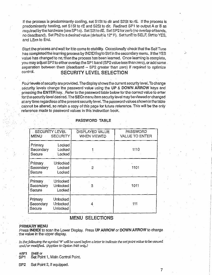
If the process is predominantly cooling, set S1 St to dir and S2St to rE. If the process is predominantly heating, set S1 St to rE and S2St to dir. Redirect SP1 to output A or Bas required by the hardware (seeSP1o). SetS2ttodE. Set SP2forzero (no overlap of bands, no deadband). Set Pb2to a desired value (defaultis 12° F). SettunEto SELF, Strtto YES, and LErn to End. ·
Start the process and wait for it to come to stability. Occasionally check that the Self Tune has completed the learning process by INDEXingto Strt in the secondary menu. If the YES ·· value has changed to no;tnen the process has been learned. Once learning is complete, you may adjust SP2 to either overlap the SP1 band (SP2 value less than zero), or add some . separation between them (deadband -- SP2 greater than zero) if required to optimize
control. SECURITY LEVEL SELECTION
Four levels of security are provided. The display shows the current security level. To change security levels change the password value using the UP & DOWN ARROW keys and pressing the ENTER key .. Refer to the password table below for the correct value to enter forthe·security level desired. The SE Cr menu item security level may be viewed or changed at anytime regardless of the present security level. The password values shown in the table caonot be altered, so retain a copy of this page for future reference. This will be the only reference made to password values in this instruction book.
PASSWORD TABLE
SECURITY LEVEL DISPLAYED VALUE PASSWORD MENU SECURITY WHEN VIEWED VALUE TO ENTER
Primary Locked Secondary Locked 1 1110 Secure Locked
Primary Unlocked Secondary Locked 2 1101 Secure Locked
Primary Unlocked Secondary Unlocked 3 1011 Secure Locked
.
Primary Unlocked Secondary Unlocked 4 111 Secure Unlocked
MENU SELECTIONS
PRIMARY MENU Press INDEX to scan the Lower Display. Press UP ARROW or DOWN ARROW to change the value in the upper display.
In the following the symbol"#" will be used before a letter tn indicate the set point valne tn be viewed and/ or madified- (Applies tn Optinn 948 only.)
#SPl (948) or SP1 Set Point 1, Main Control Point.
SP2 Set Point 2, if equipped. 7
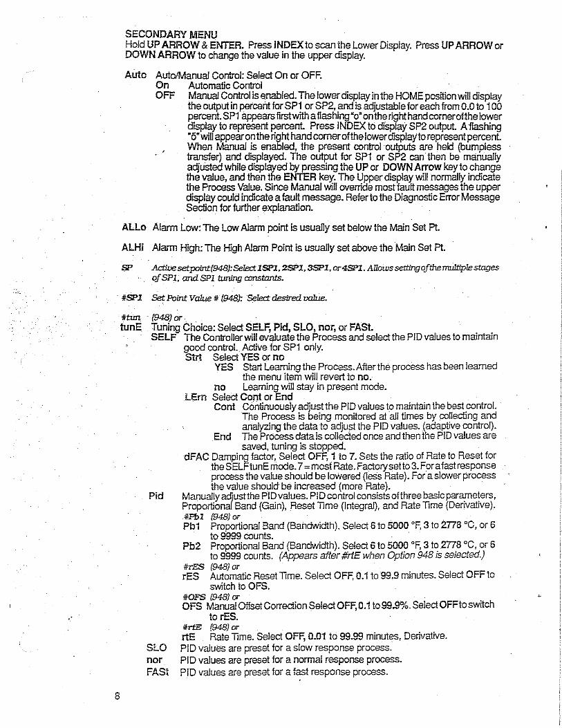
. ·
8
SECONDARY MENU Hold UP ARROW & ENTER. Press INDEX to scan the Lower Display. Press UP ARROW or DOWN ARROW to change the value in the upper display.
Auto Auto/Manual Control: Select On or OFF. On Automatic Control OFF Manual Control is enabled. The lower display in the HOME position will display
the output in percent for SP1 or SP2, and is adjustable for each from 0.0 to 100 percent. SP1 appears first with a flashing "o" on the right hand comerofthe lower display to represent percent. Press INDEX to display SP2 output. A fiashing •5• will appear on the right hand comer of the lower display to represent percent. When Manual is enabled, the present control outputs are held (bumpless transfer) and displayed. The output for SP1 or SP2 can then be manually adjusted while displayed by pressing the UP or DOWN Arrow key to change the value, and then the ENTER key. The Upper display will normally indicate the Process Value. Since Manual will override most fault messages the upper display could indicate a fault message. Refer to the Diagnostic Error Message Section for further explanation.
ALLo Alarm Low: The Low Alarm point is usually set below the Main Set Pt.
ALHi Alarm High: The High Alarm Point is usually set above the Main Set Pt.
SP ActiVesetpoin1:(948):SeTect lSPl, 2SPl, 3SP1, or4SP1. Allows settingofthe11UJlttp1estages ofSPl. andSPl tuning constants.
itSPl Set Point Value it {948): Select desired value.
ittun (948) or. tunE Tuning Choice: Select SELF, Pid, SLO, nor, or FASt.
SELF The Controller will evaluate the Process and select the PIO values to maintain good control. Active for SP1 only. Strt Select YES or no
YES Start Leaming the Process. After the process has been learned the menu item will revert to no.
no Leaming will stay in present mode. LEm Select Cont or End
Cont Continuously adjust the PIO values to maintain the best control. The Process is being monitored at all times by collecting and analyzing the data to adjust the PIO values. {adaptive control).
End The Process data is collected once and then the PID values are saved, tuning is stopped.
dFAC Damping factor, Select OFF, 1 to 7. Sets the ratio of Rate to Reset for the SELFtunE mode. 7 =most Rate. Factorysetto3. Fora fast response process the value should be lowered (less Rate). For a slower process !he value should be increased (more Rate).
Pid Manually adjust the PID values. PID control consists of three basic parameters, Proportional Band (Gain), Reset Time (Integral), and Rate Time (Derivative). itPbl (948) or Pb1 Proportional Band (Bandwidth). Select 6 to 5000 °F, 3 to 2778 °C, or 6
to 9999 counts. Pb2 Proportional Band (Bandwidth). Select 6 to 5000 °F, 3 to 2778 °C, or 6
to 9999 counts. (Appears after #rtE when Option 948 is selected.) itrES (948) or rES Automatic Reset Time. Select OFF, 0.1 to 99.9 minutes. Select OFF to
switch to OFS. itOFS 1948) or OFS Manual Offset Correction Select OFF, 0.1 to 99.9%. Select OFF to switch
to rES . itrtE (948) or rtE Rate Time. Select OFF, 0.01 to 99.99 minutes, Derivative.
SLO PID values are preset for a slow response process. nor PIO values are preset for a normal response process. FASt PID values are preset for a fast response process.

Pid2 Linkage of PID parameters between SP1 and SP2: Select On or OFF. On Links SP2 to SP1 or #SP1 rEs and rtE terms for heat'cool applications. OFF Sp2 functions without rEs and rtE.
ArUP Anti- Reset Wind-up Feature: Select.On or OFF. On When ArUP is On the accumulated Reset Offset value will be clea;ed io 0%
when the process input is not within the Proportional Band. OFF WhenArUPis OFF, the accumulated Reset Offset Value is retained in memory
when the process input is not within the Proportional Band.
ArtE Approach Hate Time: Select OFF, 0.01 to 99.99 minutes. The function defines the amount of Rate applied when the input is outside of the Proportional Band. The ArtE lime and the rtE time are independent and have no effect on each other. To increase damping effect and reduce overshootsetthe approach rate time for a value greaterthan the natural rise lime of the process (natural rise time= process value time to set point).
Pint Fu=!}Logiclntensity{942): SelectOto 100%. C/16 is OFF{disablesFu=!}Logic). The junction de.fines the amount of impact Fu=!} Logic will hnve on the output.
Fbnd Fu=!}LogicErrorBand{942): Seled0to4000 °F, Oto2222°C, or0to4000 counts. Sets the lxmdwidth of the Fu=!} Lq]ic. Set Fbnd equal to PID proportional band (Pb I) for best results. · .
FrtE F'r.=y LogiC Rate Qf Change{942J: Select o.oo to 99.99°F /sec., o.oo to 55.55°C/ sec., or 0.00 to 99.99 counts/sec For best initial setting,jind the degree/sec cliangeQfprocessvaluenearsetpointl wiihoutputON 100%; Multiplythisvalue . by 3. SetFrtE to this calculated value. . .
. PEA · Peak arid Valley feature will remember the HigheSt (PEA} and lowest (VAL) Input the Instrument has had since the last reset or Power On. At Power On they are reset to the present input, and VAL therefore may have to be manually reset. To manually resetthe value, PEA or VAL must be in. the lower display and then press the ENTER key. This will cause the Item to be reset to the present input value.
In the following the symbol "#"will be used following letters to refer to either a number ""I' or number "2". The '.1 "will relate to SP1 functions, the "2'for SP2. If your control is not equipped with a second set poih!, no SP2functions will appear. The appearance of CY#, SP#d, or PUL# is dependent upon the output type selected in the Secure Menu 1tem ,S#Ot. lftime propcrlioning (cycle time) was selected, then CY# is adjustable. If On - Off was _selected, then. SP#d is adjustable. If pulsed time proportioning was selected then PUL# is adjustable. If none of the above are selected the menu indexes directly to S#Ot.
CY# Cycle Rate:Select 2to 80 sec. Time Proportioning Control is adjustable iri 2 sec. steps. For best contact life, a time should be selected as long as possible without causing the process to wander.
SP#d Set Point On-Off Differential. Select 1 to 1999 deg. or counts. When adjusting SP#d keep in mind !hat SPL and SPH have to be considered to avoid a CHEC error message.
,_ :::> a. ,_ :::> 0
0 I- OIFF. -j [SP#d)
DIRECT ACTING !S#St • dir) {UPSCALE DIFF~AENTIAL)
INPUT
. SP# {DISPLAYED VALUE)
>- -:::> a. >:::> 0 • REVERSE ACTING (S#St .. rE)
{DOWNSCALE DlFFERB>ITIAL)
0
' . . -}-DIFF. -j~
[SP#d) "'
INPUT
SP# (DISPLAYED VALUE)
PUL# Pulsed lime Proportioning Output: Select 1 to 7. 1 =Linear and 7 = most non-linear. Changes output linearjyforuse in cooling applications orfor an extremely fast response processes.Atthe center of the proportional band, a pulse value of 1 provides an output ofonesecond on and one second off (50% output). Apulsevalue of 2 provides an output of one second on and two seconds off (33"/o output). Output at center of band equals one second on, 2f""""'""ue-1> seconds off.
9
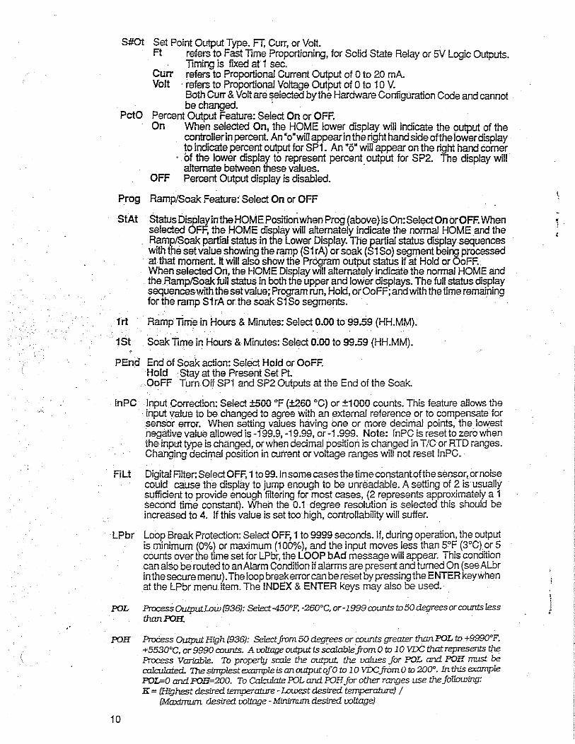
.·
S#Ot
PctO
Set Point Output Type. FT. Curr, or Volt. Ft refers to Fast Time Proportioning, for Solid State Relay or SI/ Logic Outputs.
Timir.g is fixed at 1 sec. Curr refers to Proportional Current Output of 0 to 20 mA. Volt , refers to Proportional Voltage Output of O to 1 O V.
Both Curr & Volt are $elected by the Hardware Configuration Code and cannot be changed. ,
Percent Output Feature: Select On or OFF. On When selected On, the HOME lower display will indicate the output of the
controller in percent. An "o"will appear in the right hand side of the lower display to indicate percent output for SP1. An •5• will appear on the right hand comer
· bf the lower display to represent percent output for SP2. The display will' alternate between these values. ·
OFF Percent Output display is disabled.
Prog Ramp/Soak Feature: Select On or OFF
StAt Status Display in the HOME Position when Prog (above) is On:SelectOnorOFF. When selected OFF, the HOME display will alternately indicate the normal HOME and the Ramp/Soak partial status in the Lower Display. The partial status display sequences with the set value showing the ramp (S1 rA) or soak (S1 So) segment being processed at that moment. It will also show the Pregram output status if at Hold or OoFF., When selected On, the HOME Display will alternately indicate the normal HOME and the Ramp/Soak full status in both the upper arid lower displays. The full status display sequences with the set value; Program run, Hold, orOoFF; and with the time remaining for the ramp S1 rA or the soak S1 So segments. ,
1 rt Ramp Time in Hours & Minutes: Select 0.00 to 99.59 (HH.MM).
1St Soak Time in Hours & Minutes: Select o:oo to 99.59 (HH.MM).
PEnd End of Soak aciion: Select Hold or OoFF. Hold Stay at the Present Set Pt.
, OoFF Tum Off SPi and SP2 Outputs at the End of the Soak.
In PC Input Correction: Select ±500 °F (±260 °C) or ±1000 counts. This feature allows the , input value to be changed to agree with an external reference or to compensate for sensor error. When setting values having one or more decimal points, the lowest negative value allowed is -199.9, ·19.99, or-1.999. Note: lnPC is reset to zero when the input type is changed, or when decimal postliori is changed in T/C or RTD ranges. Changing decimal position in current or voltage ranges will not reset lnPC.
Fi Lt Diaital Fitter: Select OFF, 1 to 99. In some cases the timeconstantofthe sensor, ornoise could cause the display to jump enough to be unreadable. A setting of 2 is usually sufficient to provide enough filtering for most cases, (2 represents approximately a 1 second time constant). When the 0.1 degree resolution is selected this should be increased to 4. If this value is set too high, controllability will suffer.
, LPbr Loop Break Protection: Select OFF, 1 to 9999 seconds. If, during operation, the output is minimum (0%) or maximum (100%), and the input moves less than 5°F (3°C) or 5 counts over the time set for LPbr, the LOOP bAd message will appear. This condition can also be routed to an Alarm Condition if alarms are present and turned On (see ALbr inthe secure menu). The loop break error can be reset by pressing the ENTER key when at the LPbr menu. item. The INDEX & ENTER keys may also be used. ,
' POL ProcessOutputLow(936): Select-450°F,·260°C.or·1999rountsto50degreesorrountsless )
thanPOH.
POH Process Output High (936): Select.from 50 ctegcees or rounts greater than POL to +9990°F. +5530°C, or 9990 rounts. A voltage output is scalable from 0 to 10 VDC that represents the Process Variable. Tu properly scale the output. the values for POL and POH must be calcrilated. The simplest example is anoutputofO to 10 VDCfromO to 200°. In this example POL=O andPOH=200. To Calculate POL and POH for other ranges use thefoUowing:
10
K = (Highest desired temperature -~t desired temperature) I IMaximWn desired voltage - Minimwn desired voltnge)

·.
' r
l
POH = ((10 - Maximum desired ooltage} • K} +Highest desired temperature POL= {(M'mimum desired voltage - OJ • K} - Lowest desired temperature
LOrE Local I Remote Stntus [992): Select LOG or rE. When I.DC is selected. the host cnmputer is advised not to send remote commands. When rE is selected. CFU=2, and nAt is set> 0, if the conJrol is not accessed by the host cnmputer in the ttme set in nAt. the cnnJrol will revert totheCFSP
CFSP Communications Fail SetPoint [992): Set to desired value.
Atidr ConJrolAddress [992): Set.from 1 1D FF. This 11W11ber [hexadecimal. base 16) TTUlSt match the address number used by the host computer. Viewed only in this menu.
SECURE MENU Hold UP ARROW & ENTER for 5 Seconds. Press INDEX to change the lower display. Press
. UP ARROW or DOWN ARROW to change the value in the upper display.
SE Cr Security Code:Seethe Security Level Selection and the Password Table in this manual, in order to enter the correct password.
lnP -lnputType: Select one of the following. The Inputs are based on four different groups; Thermocouples, RTD's, Current, and Voltage. If changing from oneofthesegroups, the DIP switch on the AID circuit board will have to be chan!;ied to match that particular group. Refer to the Input wiring section for the proper switch settings. · · J-IC Type •J• Thermocouple, lron/Constantan. (NISD
. CA Type "K" Thermocouple Chromel/Alumel E- Type "E" Thermocouple Chromel/Constantan t- Type "T" Thermocouple Copper/Constantan L- Type "L"Thermocouple lron/Constantan (DIN) n- Type "N" Thermocouple NicrosiVNisil r-13 Type "R"Thermocouple Pl 13%Rh/Pl S-10 Type "S"Thermocouple Pl 10%Rh/Pl b- · Type "B" Thermocouple Pl 6"!.Rh/Pl 30%Rh C- Type ·c· Thermocouple W 5%Re/W 26"/oRe P392 100 ohm Platinum (NIST 0.00392 WW°C), Love Cal. 104. n120 120 ohm Nickel, Love Cal. 105. P385 100 ohm Platinum (DIN 0.00385 D/Q/°C), Love Cal. 106. Curr DC Current Input 0.0 to 20.0 or 4.0 to 20.0 milliamperes. Volt DC Voltage lhput 0.0 to 5.0 or 1.0 to 5.0 volts. - - - - Reserved
· OSUP Zero Suppression: Select On or OFF. Only with Current and Voltage input types. OFF The input range will start at O (zero) Input. On . The input range will start at 4.00 mA or 1.00 V.
Unit F, C or None F °F descriptor is On and temperature inputs will be displayed in actual degrees
Fahrenheit. · C · °C descriptor is On and temperature inputs will be displayed in actual degrees
Celsius. nonE °F and °C descriptors will be Off. This is only available with Current and Voltage
Inputs.
dPt Decimal Point Positioning: Select 0, 0.0, 0.00, or 0.000. On temperature type inputs this will only effect the Process Value, SP1, SP2,Allo,ALHi, and lnPC. For Current and Voltage Inputs all Menu Items related to the Input will be affected. 0 No decimal Point is selected: This is available for all Input Types. 0.0 . One decimal place is availableforTypeJ, K, E, T, L, RTD's, Current and Voltage
Inputs. 0.00 Two decimal places is only available for Current and Voltage Inputs. 0.000 Three decimal places is only available for Current and Voltage inputs.
11
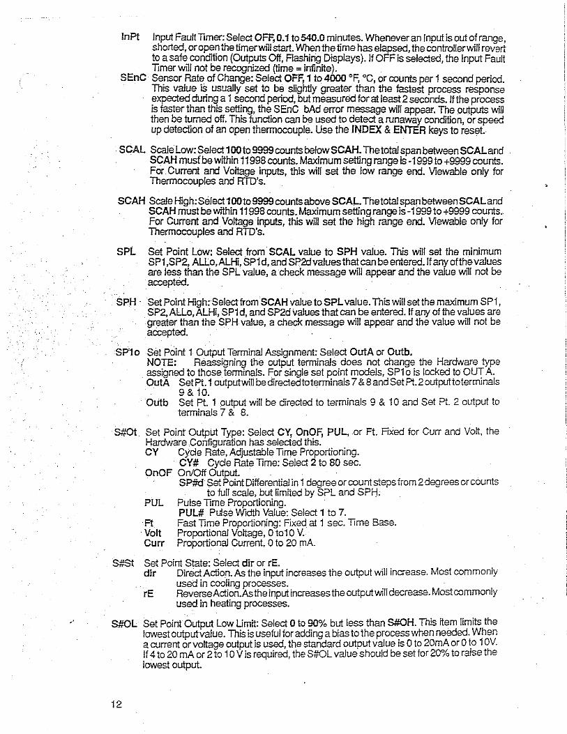
•'
lnPt Input Fault Timer: Select OFF, 0.1 to 540.0 minutes. Whenever an Input is out of range, shorted, or open the timerwill start. When the lime has elapsed, the controller will revert to a safe condition (Outputs Off, Flashing Displays). If OFF is selected, the Input Fault Timer will not be recognized (time = infinite).
SEnC Se.nsor Rat~ of Change: Select OFF, 1 to 4000 °F, 0 c, or counts per 1 second period. This value 1s usually set to be slightly greater than the fastest process response expected during a 1 second period, but measured for at least 2 seconds. If the process is faster than this setting, the SEnC bAd error message will appear. The outputs will then be turned off. This function can be used to detect a runaway condition, or speed up detection of an open thermocouple. Use the INDEX & ENTER keys to reset.
SCAL Scale Low: Select 100 to 9999 counts belowSCAH. The total span between SCALand SCAH musf be within 11998 counts. Maximum setting range is -1999 to +9999 counts. For Current and Voltage inputs, this will set the low range end. Viewable only for Thermocouples and RTD's.
SCAH Scale High: Select 1OOto9999 counts above SCAL. The total span between SCALand . SCAH must be wtthin 11998 counts. Maximum setting range is -1999 to +9999 counts ..
For Current and Voltage inputs, this will set the high range end. Viewable only for Thermocouples and RTD's.
SPL Set Point Low: Select from SCAL value to SPH value. This will set the minimum SP1 ,SP2, ALLo,ALHi, SP1 d, and SP2d values that can be entered. If any of the values are less than the SPL value, a check message will appear and the value will not be accepted.
SPH · Set Point High: Select fromSCAH value to SPL value. This will set the maximum SP1, SP2, AlLo, ALHi, SP1 d, and SP2d values that can be entered. If any of the values are
·greater th.an the SPH value, a check message will appear and the value will not be accepted.
SP'1 o Set Point 1 Output Terminal Assignment: Select OutA or Outb. NOTE: Reassigning the output terminals does not change the Hardware type assigned to those terminals. For single set point models, SP1 o is locked to OUT A. OutA Set Pt. 1 outputwill bedirectedtoterminals 7 & 8 and Set Pt.2 outputtoterminals
9& 10. Outb Set Pt. 1 output will be directed to terminals 9 & 10 and Set Pt. 2 output to
terminals 7 & 8.
S...uot Set Point Output Type: Select CY, OnOF, PUL, or Ft. Fixed for Curr and Volt, the Hardware Configuration has selected this.
S#St
S#OL
12
CY Cycle Rate, Adjustable Time Proportioning. CY# Cycle Rate Time: Select 2 to 80 sec.
OnOF On/Off Output. . . · · SP#d Set Point Differential in 1 degree or count steps from 2 degrees or counts
to full scale, but limited by SPL and SPH. PUL Pulse Time Proportioning.
PUL# Pulse Width Value: Select 1 to 7. ·Ft Fast Time Proportioning: Fixed at 1 sec. Time Base. ·Volt Proportional Voltage, O to10 V. Curr Proportional Current, 0 to 20 mA.
Set Point State: Select dir or rE. dir Direct Action. As the input increases the output will increase. Most commonly
used in cooling processes. rE Reverse Action.As the input increases the output will decrease. Most commonly
used in heating processes.
Set Point Output Low Limit: Select 0 to 90% but less than S#OH. This item limits the lowest outputvalue. This is useful for adding a bias to the process when needed. When a current or voltage output is used, the standard output value is 0 to 20mA or 0 '.o 1 OV. If 4 to 20 mA or 2 to 1 O Vis required, the S#OL value should be set for 20% to raise the lowest output.
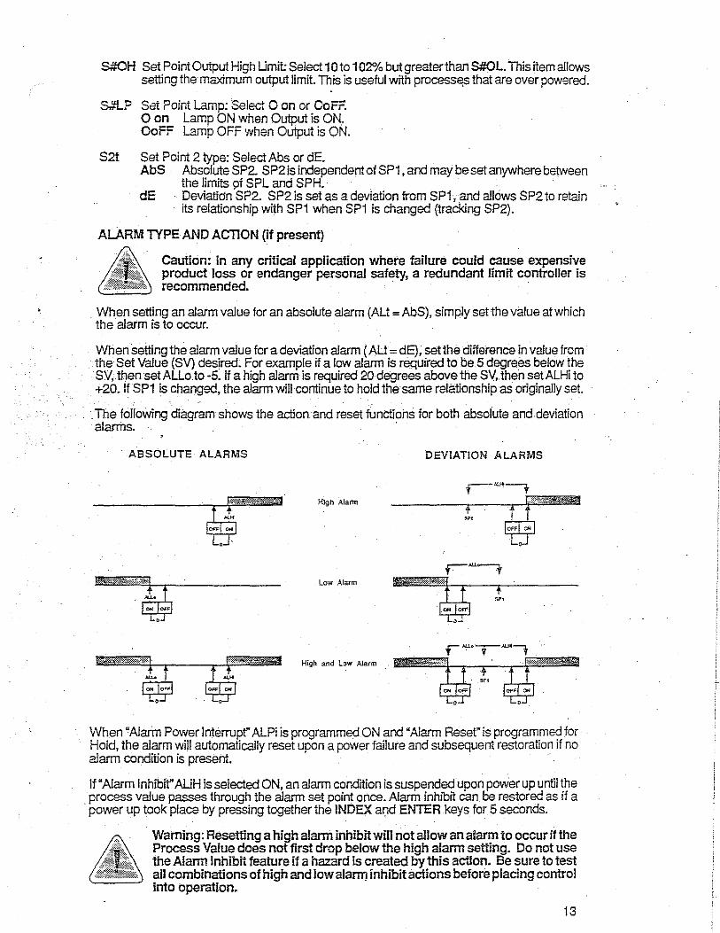
S#OH Set Point Output High Limit: Select 10to 102°/o but greater than S#OL. This item allows setting the maximum output limit. This is useful with process~s that are over powered.
S,,."L? Set Point Lamp: Select 0 on or OoFF. O on Lamp ON when Output is ON. OoFF Lamp OFF when Output is ON.
S2t Set Point 2 type: Select Abs or dE. AbS Absolute SP2. SP2is independent of SP1, and may be set anywhere between
the limits of SPL and SPH. dE · Deviatidn SP2. SP2 is set as a deviation from SP1, and allows SP2 to retain
its relationship with SP1 when SP1 is changed {tracking SP2).
ALARM TYPE AND ACTION (if present)
Caution: in any critical application where failure could cause expensive product loss or endanger personal safety, a redundant limit controller is
'-='-'----~__, recommended. · ·
When setting an alarm value for an absolute alarm (AU= AbS), simply set the value at which the alarm is to occur.
When setting the alarm value for a deviation alarm (AU = dE), set the difference in value from the Set Value (SV) desired. For example if a low alarm is required to be 5 degrees below the SV, then set ALLo to -5. If a high alarm is required 20 degrees above the SV, then setALHi to +20. If SP1 is changed, the alarm will continue to hold the same relationship as originally set.
·. The following diagram shows the action and reset functions for both absolute and deviation alarms. ·
. ABSOLUTE ALARMS
~;c,4 ~·
'~ ~
' .
High Alann
Low Alarm
High and low Alarm
DEVIATION ALARMS
'.;~~ !. ~'0¥ OOI ~ OFF ON
' '
When "Alarm Power Interrupt" ALPi is programmed ON and "Alarm Reset" is programmed for Hold, the alarm will automatically reset upon a power failure and subsequent restoration if no alarm condition is present. ·
If "Alarm Inhibit" AUH is selected ON, an alarm condition is suspended upon power up until the process value passes through the alarm set point once. Alarm inhibit can be restored as if a
· power up took place by pressing together the INDEX and ENTER keys for 5 seconds.
Warning: Resetting a high alarm inhibit will not allow an alarm to occur if the Process Value does not first drop below the high alarm setting. Do not use the Alarm Inhibit feature if a hazard is created by this action. Be sure to test all combinations of high and law alarm inhibit actions before placing control into operation.
13
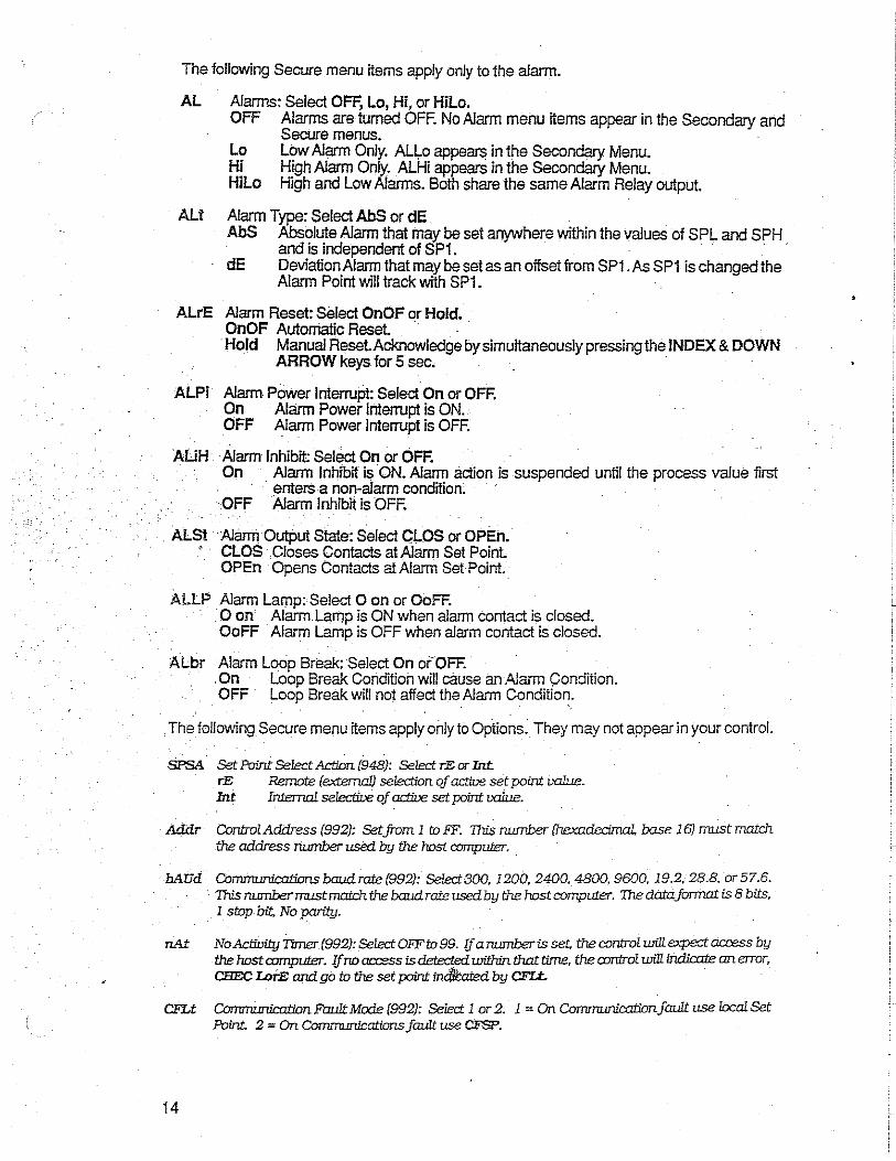
The following Secure menu items apply only to the alarm.
AL Alarms: Select OFF, Lo, Hi, or Hilo. OFF Alarms are turned OFF. No Alarm menu items appear in the Secondary and
Secure menus. . Lo Low Alarm Only. Alla appears in the Secondary Menu. Hi High Alarm Only. ALHi appears in the Secondary Menu. Hilo High and Low Alarms. Both share the same Alarm Relay output.
AU Alarm Type: Select AbS or dE . AbS Absolute Alarm that may be set anywhere within the values of SPL and SPH
and is independent of SP1. · · · dE Deviation Alarm that may be set as an offset from SP1. As SP1 is changed the
Alarm Point will track with SP1.
ALrE Alarm Reset: Select OnOF or Hold. OnOF Automatic Reset. · Hold Manual Reset.Acknowledge by simultaneously pressing the INDEX & DOWN
ARROW keys for 5 sec.
ALPi Alarm Power Interrupt: Select On or OFF. On Alarm Power Interrupt is ON. OFF Alarm Power Interrupt is OFF.
ALiH ·Alarm Inhibit: Select On or OFF. On Alarm Inhibit is ON. Alarm action is suspended until the process value first
enters a non-alarm condition; OFF Alarm Inhibit is OFF.
ALSt Alarm Output State: Select CLOS or OPEn. CLOS .Closes Contacts at Alarm Set Point. OPEn Opens Contacts at Alarm Set Point.
ALLP . Alarm Lamp: Select 0 on or OoFF. 0 on Alarm Lamp is ON when alarm contact is closed. OoFF Alarm Lamp is OFF when alarm contact is closed.
ALbr Alarm Loop Break: Select On or OFF. On Loop Break Condition will cause an Alarm condition. OFF Loop Break will not affect the Alarm Condition .
. The following Secure menu items apply only to Options. They may not appear in your control.
SPSA Set Point Select Action (948): Select rE or Int. rE Remote (extemal) selection of active set point ualue. Int IntemaI selectit:e of active set point ualue.
Addr ControlAddress (992): Setjrom 1 ID FF. This nwnter /hexadecimal, base 16) must match the address number used by the host computer.
hAUd Communications baud rate (992): Select 300, 1200, 2400, 4800, 9600, 19.2, 28.8. or 57.6. · This nwnbenruistmatchthe baud.rate used by the host computer. Thedntafonnatis 8 bits,
1 stop bit, No parity.
nAt NoActivityTimer(992):SelectOFFto99. lf anwnberis set thecontrolwillexpectaccess by the host computer. lf no aa:ess is detected. within that time, the control will iru:lirote an error, CHEC LorE and go to the set point dated by CFLt.
CFLt Commwlication FruI1t Mode (992): Select 1 or 2. 1 = On CoT11ITU.JI1irotin jaWt use local Set Point. 2 = On Communications jaWt use CFSP.
14
•
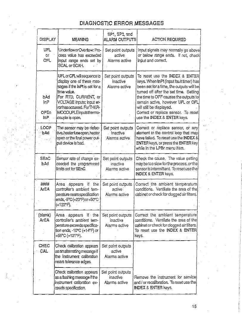
DIAGNOSTJG ERROR MESSAGES ' I "P1 "?" snd · I I ! i DISPLAY I - , - ., . I MEANING ALARM OUTPUTS ACTlON REQUIRED
UFL Ur.deriloworOverflow: Pro- Set point outputs Input signals may normally go above or cass value has excaeded active or below range ends. If not, check
OFL input range ends set by Alarms active input and correct. SCAL or SCAH.
UFLcrCF1..wiilsequencato Set point outputs To reset use the INDEX & ENTER display one of these. mes- inactive keys. When lnFt (input fault timer) has sages if the lnPt is set for a Alarms active been set for a time, the outputs will be time value. turned off after the 'set time. Setting
bAd For RTD, CURRENT, or the time to OFF causes the outputs to lnP VOLTAGE inputs; input er- remain active, however UFL. or OFL
rorhascccurred ForTHER- will still be displayed. OP En MCCOUPLEinputsthermo- Correct or replace sensor. To reset lnP couple is open. use the lNDEX & ENTER keys.
.
LOOP . The sensor may be defec- Set point outputs Correct or replace sensor, or any bAd live, heateriuseopen, heater inactive element in the control loop that may
. open crthe iinal power cut: Alarms active have !ailed. To reset use the INDEX & put device is bad. ENTER keys, or press the ENTER key
while in the LPBr menu item.
SEnC Sensor rate of change ex- Set point outputs Check the cause. The value setting bAd caeded the programmed inactive may be too slow iorthe process, orthe
limils set for SEnC. Alarms active sensor is intermittent To reset use the INDEX & ENTER keys.
.
#### Area appears if the Set point outputs Correct .the ambient temperature ArEA controller's ambient tern- active condiiions. Ventilate the area of the
perah.lre nears speciiication Alarms active cabinet orchecl< for clogged 8irfilters. ends, -5°C{+23°F)or +50"C (+122'F) .
.
(blank) Area appears if· the Set point outputs Correct the ambient temperature ArEA controller's ambient tern- inactive conditions. Ventilate the area of the
perature exceedss,:eciiica- Alarms active cabinet or check for clogged airfilters. tion ends, -10°c (+ 14°F) or To reset use the INDEX & ENTER +55°C (+131°F). keys.
CHEC Check calibration appears Set point outputs CAL as an alternating message if active
the instrument calibration Alarms active nears tolerance edges.
Check calibration appears Set point outputs as a flashing message if the inactive Remove the instrument for service instrument calibration ex- Alarms active and I or recalibration. To reset use the ceeds specification. INDEX & ENTER keys.
15

SP1,SP2AND DISPLAY MEANING ALARM OUTPUTS ACTION REQUIRED
.
No displays Both cf1Splays are blank. Set points inactive Checkthatthe power supply is on, or lighted Instrument may not be Alanms inactive that the external fuses are good.
getting power, orthe sup- ' plyvoltage is too low.
FAIL Fail test appears upon Set points inactive Press the INDEX key to displayJhe tESt power up if the internal Alanms inactive following messages: FAct dFLt:
diagnostics detect a fall- Memory may be corrupted. Press ure. This message may the ENTER key and the DOWN oca.Jr during operation if ARROW key to start the factory a failure is detected. Dis- default proceedure. Re-check plays ffash. controller programming. bAd A-cl:
TheA'D board is bad, retumto factory. rE! FAG!: Can not recover from error, return to factory for service .
.
CHEC The differenC:e between Set points inactive Program parameter within the SCAL scale low and scale high Alanms inactive allowed .count range.
or is programmed for more CHEC than 11,998 or less than .SCAH 100 counts during pro-
gramming of the voltage , or current ranges.
CHECSP1, One or more of these Set points inactive Check that each of the set points are CHEC#SP1, messages will appear Alarms inactive within SPL, SPH range, or reprogram CHEC SP1d, upon power up if any of SPL and/ or SPH values to be at or CHECSP2, these set points or differ- beyond the set points values found CHECSP2d, entials are set outside of in error. Do not exceed the range CHECALLo, the SPLorSPHvalues,or ends (SCAL or SCAH). CHECALHi, the range ends (SCAL or
or SCAH). CHECCFSP
.
CHEC This message appears al Set points inactive Correct the SPL or SPH values by SPL power up if SPL or SPH Alarms inactive 1 programming new values. or values are programmed CAUTION: The old values are
CHEC aboveorbelowthe range retained when these messages SPH ends (SCAL or SCAH). appear during set point
This message also ap- programming. pears if one or more set points are set above or below SPL orSPH during normal programming.
CHEC POL This message appears if Set points active Correct the POL or POH by or the POL or POH values Alarms active programming new values.
CHEC POH are incorrectly pro-gram med.
16
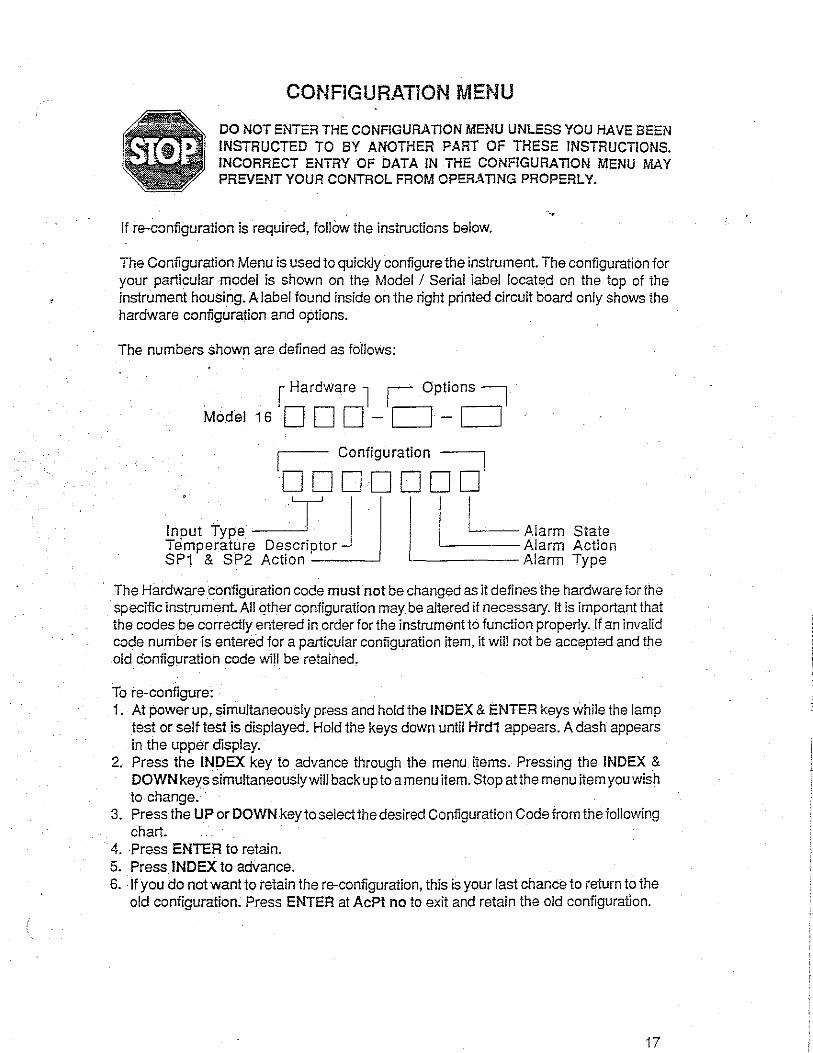
CONFIGURATION MENU
DO NOT ENTER THE CONFIGURATION MENU UNLESS YOU HAVE BEEN INSTRUCTED TO BY ANOTHER PART OF THESE INSTRUCTIONS. INCORRECT ENTRY OF DATA IN THE CONFIGURATION MENU MAY PREVENT YOUR CONTROL FROM OPERATING PROPERLY.
--. If re-configuration is required, follow the instructions below.
The Configuration Menu is used to quickly configure the instrument. The configuration for your particular model is shown on the Model I Serial label located on the top of the instrument housing. A label found inside on the right printed circuit board only shows the hardware configuration and options.
The numbers shown are defined as follows:
f Hardware l L Options =i Model 16 ODD-CJ-CJ
I Configuration ,
DDDDDDD , .· iJ_j• Input Type --~ Temperature Descriptor SP1 & SP2 Action
I 1~- Alarm State
'------Alarm Action '-------Alarm Type
The Hardware configllration code must not be changed as it defines the hardware tor the specific instrument. All qther configuration may be altered if necessary. It is important that the codes be correctly entered in order for the instrument to function properly. If an invalid code number is entered for a particular configuration item, it will not be accepted and the old c'onliguration code will be retained.
To re-co nligure: 1. At power up, simultaneously press and hold the INDEX & ENTER keys while the lamp
test or self test is displayed. Hold the keys down until Hrd1 appears. A dash appears in the upper display.
2. Press the INDEX key to advance through the menu items. Pressing the INDEX & DOWN keys simultaneously will back up to a menu item. Stop atthe menu item you wish to change.
3. Press the UP or DOWN key to select the desired Configuration Code from the following chart.
4. Press ENTER to retain. 5. Press INDEX to advance. 6. -If you do not want to retain the re-configuration, this is your last chance to return to the
old configuration~ Press ENTER at AcPt no to exit and retain the old configuration.
17

.·
CONFIGURATION CHART
Do not change Hrd1, Hrd2 or Hrd3 to codes different from those on the controller labels. Codes in boldface type indicate factory defaults. See FACt dFLt.
DISPLAY MENU ITEM CONFIGURATION CODE
Hrd1 Alarm Hardware O=NO 1 =YES .
Hrd2 Output A 1 = SSR/LOOIC 3 =RELAY/LOGIC 5=CURRENT Hardware 2 = LOOIC/SSR 4 = LOGIC/RELAY 6=YOLTAGE
Hrd3 Output B O=NONE · 2 = LOGIC/SSR 4 = LOGIC/RELAY Hardware 1 = SSRILOOIC 3 =RELAY/LOGIC
0Pt1 Option 942 = Fuzzy Logic Software Hardware 936 = Process Output 937 = Isolated 0 to 20mADC (Monitor)
948 = 4-Stage Set Point 992 = Serial Communications If number ff ashes, option is NOT selected. Press ENTER to select (numberwill not flash). .
CnF1 Input Type 01 :J1° 10 = L 0.1° 19 = RTD 1° (NIST) 02=J0.1° 11=N1° 20 = RTD 0.1° (NIST) 03=K1° 12 =N 0.1° 21=RTD1°Ni
. 04=K0.1° 13=R1° 22 = RTD 0.1° Ni 05= E 1° 14 = s 1° 23=0to20mA 06=E0.1° 15 = B 1° 24=4to20 mA , 07 = T1° 16 = c 1° 25=0to5YDC 08=T0.1° 17 = RTD 1° (DIN) 26= 1to5 YDC 09 = L 1° 18 = RTD 0.1° (DIN)
CnF2 Temperature O = No Descriptor 2 =Degree C Descriptor 1 ::iDegreeF
CnF3 SP1 and SP2 O = SP1 = Output A, rev. act. (Single set point Models) Action 1 = SP1 = Outpu!A, dir. act (Single set point Models)
2 = SP1 = Output A, rev. act.; SP2 = Output B, dir. act. 3 = SP1 =Output B, rev. act.; SP2 = OutputA, dir. act
. 4 = SP1 = Output A, dir. act.; SP2 = Output B, rev. act 5 = SP1 =Output B, dir. act.; SP2 = OutputA, rev. act. 6 = SP1 =Output A, rev. act.; SP2 =Output B, rev. act. 7 = SP1 =Output B, rev. act.; SP2 = OutputA, rev. act 8 = SP1 = OulputA, dir. act.; SP2 =Output B, dir.act. 9 = SP1 =Output B, dir. act.; SP2 = OutputA, dir. act.
CnF4 Alarm Type O=NoAlarm 4 = Deviation Low Alarm 1 =Absolute High Alarm 5 = Absolute High - Low Alarms 2 = Deviation High Alarm 6 = Deviation High - Low Alarms 3 =Absolute Low Alarm
CnF5 Alarm Action O=NoAlarm 4 = On - Off with Inhibit 1 :On·Off 5 =Manual Resetwith Inhibit
.
2 = Manual Reset with Pcmer Interrupt · 3 = Manual Reset without Pcmer Interrupt
CnF6 Alarm State O=NoAlarm 3 = Close at SP, LED off 1 = Close at SP, LED 4 = Open at SP, LED off
flashing 2 =Open at SP; LED flashing
18
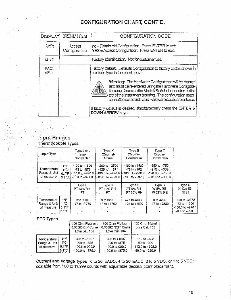
.
CONFlGURATlON CHART, CONT'D.
D!S?LA'f MENU !TE?il CCNFiGURATIOl'J CODE
Ac Pt Ac::spt r.o = Retain cld Ccnf~uraiicn. Press E:\fiC:=t io sxii. YES =Accept Configuration. Press ENTER to exit
id##
FA Ct dFlt
Configuration
Factory Identification. Not fer rustomer use.
Factory default Defaul!s Configuration to factory ccees shewn in boldface type in the chart above.
Warning: The Hardware Conf.-guralion willt:e deared ard must t:e re-€fl!ered using the Hardware Configura-1icn codefcundonthe Mcd€l/Seriaf labe!lcca:ted onthe
I'----' tcp of the instrument hcusing. The ccnfiguraiion menu cannott:eexiteduntilvalid Hardwarec::Cssareentered.
If factcry default is desired, simuftar.ecusly prsss the ENTER & OOWN ARROW keys.
Input Ranges Thermocouple Types
.· ·.
1ypeJ orl TypeK Type E
I Type I I Input Type Iron- Chrome!- Chrome/- Copper·
Constantan AJumel Constantan Constant an I 1°F ·100 to +1600 -200 to +2500 -100to+1800 -350 to +750 l
I Terriperature 1'C -73 to -i-871 -129 to +1371 -73 to +982 -212 to +398 I Range & Unit 0.1'F -100.0 to +990:0 -190.0 to +990.0 -100.0 to +990.0 ·190.0 to +750.0 ' of measure o.1°c -73.o to +871.0 '129.0 to+990.0 -73.0 to +982.0 -212.0 to +398.0
TypeR Types TypeB TypeC TypeN PT 13% RH- PT.10% RH- PT6% RH- W 5°/o RE- Ni Cro Sil-
PT PT PT30%RH W26%RE Ni Sil
Temperature 1°F Oto 3200 o to 3200 +75to +3308 Oto 4208 -"IOO to +2372 _ Rang_e & Unit 1°c -17to+1760 -17to+1760 +24to +1820 -17to +2320 I -73to+1300
of measure 0.1°F - - - . i -100.0 to +990.0 o.1·c . - . - I -73.0 to +990.0
RTDTypes . ..
100 Ohm Platinum 100 Ohm Platinum 120 Ohm Nickel 0.00385 DIN Curve 0.00392 NIST Cuive Love Cal. 105
Love Cal. 106 Love Cal. 104
Temperature 1°F -328 to + 1607 ·328 to + 1607 -112 to +608 Range & Unit 1·c ·200 to +875 -200 to +875 -80 to +320 of measure 0.1°F -190.0 to 990.0 -190.0 to 990.0 -112.0 to +608.0
o.1°c -190.0to+875.0 ~190.0 to +875.0 -80.0 to +320.0
Current and Voltage Types Oto 20 mADC, 4 to 20 mADC, Oto 5 VDC, or i to 5 VDC; scalable from 100 to 11,999 counts with adjustable decimal point placement.
19
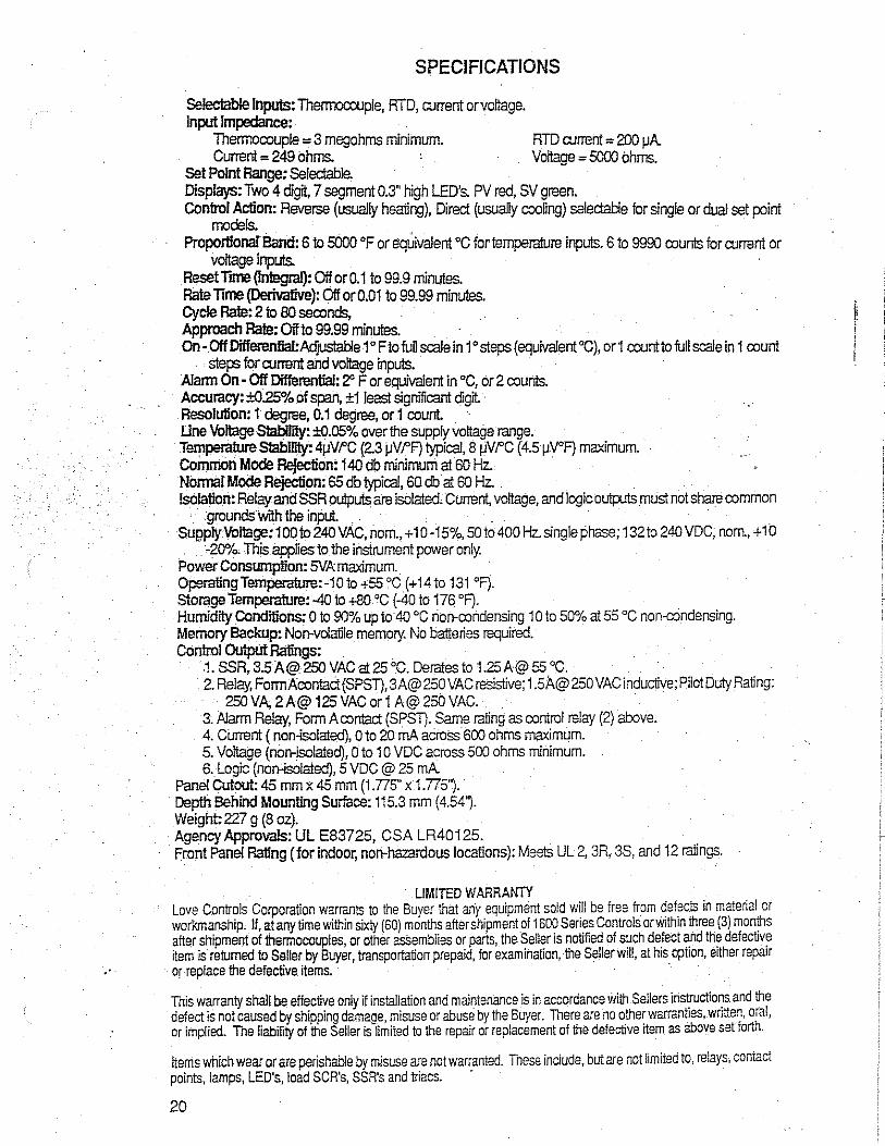
SPECIFICATIONS
Selectable Inputs: Thermocouple, RTD, current orvoltage. Input Impedance:
Thermocouple= 3 megohms minimum. RTD current= 200 µA Current = 249 ohms. Voltage = 5000 ohms.
Set Point Range: Selectable. Displays: Two 4 digit, 7 segment 0.3" high LED's. PV red, SV green. Control Action: Reverse (usually healing), Direct (usually cooling) selectable for single or dual set point
models. Proportionaf Band: 6 to 5000 °F or equivalent 0c for temperature inputs. 6 to 9990 counts for current or
voltage inputs. . Reset iime ~nl!!gral): Off or 0.1 to 99.9 minutes. Rate iime (Derivative): Off or0.01to99.99 minutes. Cycle Rate: 2 to 80 seconds, ! Approach Rate: Offto 99.99 minutes. ! On· OlfDifferenlial:Adjustable 1°FtofuUscalein1°steps(equivalent°C), or1 counttofull scale in 1 count I
. steps for current and voltage inputs. Alann On - Off Differential: 2" F or equivalent in °C, ot 2 counts. Accuracy: ±025% of span, ±1 least significant digit. Resolu1ion: 1 degree, 0.1 degree, or 1 count Line Voltage Slability: ±0.05% over the supply voltage range. Temperature S1abllity: 4µVt'C (2.3 µV t'F) typical, 8 µV t'C ( 4.5 µV°F) maximum. Common Mode Rejection: 140 db minimum at 60 Hz. · Nonna! Mode Rejection: 65 db typical, so db at 60 Hz. . . ls61alion: Relay and SSR outputs are isolated.Current, voltage, and logic outputs must not share common
· grouncls.with the input. . . . . Supply Voltage: 1ODto240 VAC, norri., + 10-15%, 50 to 400 Hz. single phase; 132to 240 VDC; norn., + 10
-20%. This appfies to the instrument power only. Power Consumption: SVA maximum. OperalingTemperature:-10to +55 °C (+ 14 to 131 °F). Storage Temperature:-40 to +80 °C (-40to176 °F). Humidity Conditions: O to 90% up to 40 °C non-condensing 1 O to 50% at 55 °C non-condensing. Memory Backup: Non-volatile memory. Na batteries required. Control Output Ratings:
1. SSR, 3.5 A@ 250 VAC at 25 °C. Derates to 1.25 A@55 °C; 2. Relay, FormAcontact(SPSD,3A@250 VAC resistive; 1.5A@250 VACinduclive; Pilot Duty Rating:
· 250VA;2A@125VACar1A@250VAC. . 3; Alarm Relay, Form A contact (SPSD. Sarne rating as control relay (2) above. 4. Current (nan-isolated), Oto 20 rnA across 600 ohms maximum. 5. Voltage (non-isolated), o to 1 o VDC across 500 ohms minimum. 6. Logic (non-isolated), 5 VDC @ 25 rnA
Panel CUtout: 45 mm x 45 mm (1.775" x 1.775''). Depth Behind Mounting Surface: 115.3 mm (4.54'1· Weight: 227 g (8 oz). Agency Approvals: UL E83725, CSA LR40125. Front Panel Rating (for indoor, non-hazardous locations): Meets UL 2, 3R, 3S, and 12 ratings.
LIMITED WARRANTY Love Controls Corporation warrants to the Buyer that any equipment so!d will be free from defects in material or workmanship, If, at any time within sixiy (60) months after shipment of 1600 Series Controls or within three (3) months afW shipment of thermocouples, or other as5emblies or parts, the Seller is notified of such defect and the defective item is returned to Seller by Buyer, transportation prepaid, for examination, the Sellerwil!, at his option, either repair or replace the defective items. ·
This warranty shall be effective only if installation and maintenance is in accordance with Sellers instructiors and the defect is not caused by shipping damaae, misuse or abuse by the Buyer. There are no other warranties, written, oral, or implied. The liability of the Seller is-limited to the repair or replacement of the defective item as above set forth.
Items which wear or are perishable by misuse are not warranted. Tnese include, but are not iimited to, relays, contact points, lamps, LED's, load SCR's, SSR's and triacs. ·
20

1 .. l
If you require any assistance, or have specific questions, please call us.
1-800•556-3484 (US and Canada) Between 8:30 am and 6:00 pm ES"( (in Rhode Island, 434-1680) Fax: (401) 431-0237
United Kingdom Ring free on: 0800 585 733 Telephone: (01582) 29444 Fax: (01582) 451184
· EFD Inc., 977 Waterman Avenue, East Providence,· RI 02914-1378 USA
Contents introduction f 2
Specifications 13
Description I 4
How The Valve Operates/ 5
Setup Schematic 16
Setup Instructions/ 7-8
Fluid CompatibilttY 19
Dispensing Specific Fluids_/ 10-11
Troubleshooting 112-13
Maintenance and Cleaning / 14-17
Applications 118-19
/
Accessories, Part Number Listings by Material 120
Questions & Answers, Warranty/ 21
This manual is for the express and sole use Of EFD valve purchasers and users, and no portion of this manual may be reproduced in any form.
.!" -- ' It·;~}~;--....
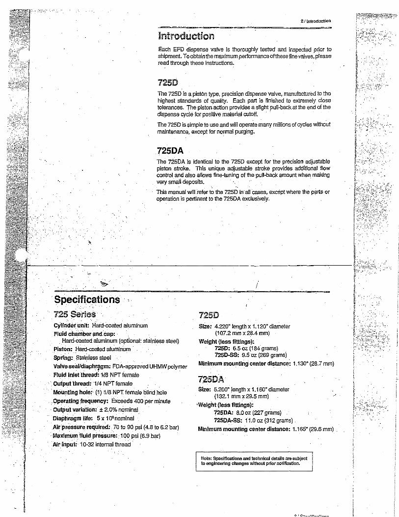
•,
·Specifications 725 ·series -Cylinder unit: Hard-Coated aluminum Fluid chamber and cap: -
2 r Introduction
Introduction Each EFD dispense valve is thoroughly tested and inspected prtor to shipment. To obtain the maximum performance of!hese fine valves, please read through these instructions.
7250 The 725D is a piston type, precision dispense valve, manufactured to the highest standards of qualil'/. Each part is finished to extremely close tolerances. The piston action provides a slight pull-back at the end of the dispense cycle for posttive material cutoff.
The 725D is simple to use and will operate many millions of cycles without maintenance, except for normal purging.
725DA The 725DA is identical to the 7250 except for the precision adjustable piston stroke. This unique adjustable stroke provides additional flow control and also allows fine-tuning of the pull-back amount when making very small deposns.
This man.ual will refer!~ the 7250 in·a11 cases, except where the parts or operation is pertinent to the 725DA exclusively.
7250 Size: 4.220" length x 1.120" diameter
(107.2 mm x 28.4 mm) Hard-coated aluminum (optional: stainless steel)
Piston: Hard-coated aluminum · Weight (less fittings):
7250: 6.5 oz (184 grams) 7250-SS: 9.5 oz (269 grams) Spring; Stainless steel
ValveseaUdiaph~gm: FDA-approved UHMWpolymer
Fluid inlet thread; HS NPT female · Output thread: 1/4 NPT female
Mounting hole: (1) 1/8 NPTfemale blind hole
.Operating frequency: Exceeds 400 per minute
Output variation: ± 2. 0% nominal
Diaphragm life: 5 x 1 O'nominal
Air pressure required: 70 to 90 psi (4.8 to 6.2 bar)
• Maximum fluid pressure: -100 psi (6.9 bar) Air input: 10-32 internal thread ·
Minimum mounting center distance: 1.130" (28.7 mm)
725DA Size: 5.200" length x 1. t 60" diameter
(132.1 mmx29.5mm) ·Weight {19Ss fittings):
7250A: 8.0 oz (227 grams) 7250A-SS: 11.0 oz (312 grams)
Minimum mounting center distance: 1.165" (29.6 mm)
Nots: Specifications and technical details are subject to engineering changes without prior notification.

I I
- !
Control __ -I Air Hose
Air Cylinder Cap
Air Cyfinder
Wrench Flats Drain_-1--0 Hole
Fluid .Supply Line-
Tip =:---J:'.l:::I:J Adapter
Dispensing TiP-~---11
41 Oescription
Description The eX!ertor components are listed in the illustration to the left. (Refer to page 8 for the 7250A exterior view.) The exploded views !or the 7250 and 7250A are shown on pages 15 and 16.
Each valve is shipped with a #2186polypropylenetip adapter insfalled. The input fitting for the supply line is specified at the ftme of order.
The 5-ft air hose, with male quick-<:onnect fitting, is installed on the valve.
The output thread size is 1/4 NPT and accepts 114 NPT metal or plastic nozzles with the #2186 tip adapter removed.
Internally, the valve chamber is sealed from the air-actuated piston and cylinder by a UHMW polyethylene diaphragm. In the unlikely event that the diaphragm ruptures, fluid will exit !!)rough the drain hole in the cylinder body.
Using the 7250 valve is easy and requires no special techniques. However, to avoid difficuHies, and to maximize the effectiveness of this valve, please carefully read the operating instructions on the following pages.
i
How The Valve Operates . &
The 7250 is. a nonTially closed, fail-safe valve. Wrth no input air pressure, jhe internal spring holds the sealing head closed, preventing liquid flow.
Input air pressure at 70-90 psi (4.8-6.2 bar) forces the internal piston G) to move, causing ttie diaphragm seal @to deflect and the sealing head @to open and permit liquid flow. When the input air pressure exhausts, the sealing head closes, stopping the liquid flow.
By using a UHMW polyethylene diaphragm s~al @, no shaft seals or seal adjustments are required to isolate the fluid from the piston cylinder.
;,--,--,,.--,:--,,-- @ The amount offluid dispensed will depend on thetime the valve is open,.the
(A) (B)
Illustration (A) shows the valve closed. Illustration (BJ shows the sealing head ® open and the diaphragm seal @ slightly deflected.
viscosity of the fluid, the ·air pressure in the liquid reservoir and the dispensing lip size.
® The 7250 can be operated in any position without affecting the dispensing characteristics. Vibration has no effect on perfonTiance. The valve can be moved in and out of dispense positions (such as on a recycling cylinder) at high. cycle speeds without affecting the dispensing perfonTiance.
Because the diaphragm seal area is larger than the sealing head area, increasing the pressure of the incoming fluid causes a tighter seal, preventing any tendency. to leak under higher pressures.
The unique design of the 7250 valve, with slight "suck-back" at the end of the dispense cycle, provides extremely fast cycle rates with close output tolerances.
. ' .~ .
':.:,·-:
.. __ -,.

-- _.,.
MaintenanAA Tools:
1/B" Hex wrench
1/4" Flat tip screwdriver
3/8" Box wrench
718" Open end wrench
. 1 O" Adjustable wrench
1/8" NPT male pipe or rod
tt Annular
Piston
Ring --. """""""""""' Diaphragm
Shaft
7250 assembly of piston, diaphragm and shaft.
#72530: Air Cap, includes_ 0-ring (Buna N)
#72530A: 0-ring only
-#72531: Shaft Locking Screw
#72532: Air Piston, inCiudes 0-~ng (Buna N)
#72532A: 0-ring only
#72533: Thrust Washer
#72534: Spring
#72535: Air Cylinder ~orly. n.· Wrench Rats ~:
#72536: Diaphragm ~
! 7250 E~ploded
· View
#72537: Shaft
Shoulder"A .. ~· #72538: Valve Chamber
(#72538-SS. : Stainless Steel . 0 Valve Chamber) ..--
#72539: Sealing Head with Screw _!! _ #72543 Chamber Cap, ~
includes 0-ring Vrton ~
. #72540A: 0-ring only ~
(#72543--SS Stainless Steel Chamber cap)
#2186: Tip Adapter ~
14 f Maintenance and Cleaning
Maintenance and Cleaning First, follow these precau1ions to avoid the need for any major disassembly and maintenance. For normal cleaning, purgelhevaive with an appropriate solvent Please note that cleaning can be accomplished without dismounting the vaive.
1. Always operate the valve at an air pressure between 70 psi and 90 psi (4.8-6.2 bar) .
Note: Operation at less than 60 psi prevents full opening of the sealing head and can cause incoilsistent deposits.
2. Maximum input fluid pressure is 90 psi (6,2 bar).
3. After use, immediately purge with appropriate flush matertal or solvent. Routine cleaning is the best method to avoid more complex maintenance.
4. Periodically, depending on the type offfuid being dispensed; the sealing head, chamber cap and valve chamber should be removed and thoroughly cleaned to prevent harmful buildup bf solidified fluid
STEP 1: To Thoroughly Clean Valye Chamb.er
Note: For the 725DA only, set stroke adjustment to the full open position (two complete rotations). Refer to illustration on page 8. Stroke.adjustment must stay open throughout reassembly •.
A. Remove tip adapter.
B_ Remove Chamber cap, using a wrench.
C. Remove sealing head, using a screwdriver.
D. Put rod in threaded mounting hole or fluid feed inlet hole and, with a wrench on flats of air cylinder body, tum to loose.n valve chamber.
E. Remove valve chamber. {Do not loosen or remove the shaft.)
F. Clean valve chamber with appropriate solvent. It is not necessary to remove the diaphragm seal unless it is to be replaced.
. . . . .
Nata: The diaphragm can be carefullywiped clean. Do not use sharp instrument, as damage to diaphragm may result.
To reassemble
G. Apply thin film of lubricant on shoulder "A" {see illustration at left). Screw on valve chamber and tighten approximately 15-20 fool pounds.
H. Reinstall sealing head and tighten screw.
I. Reinstall chamber cap and tip adapter.
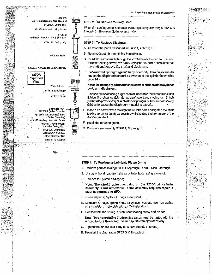
. -c,._,·:~
#72530: I L:J I J';ir-Cap, includes G-ring (Buna N)
#72559A:::::::::: CT
Air Piston, includes o-n·ng (Buna N) #72555: n _ -#72532A: 0-rtng only
#72534: Spring
#12560A: Air Cylinder Body Assembly I 725DA
Exploded View -~-~
#72536: Diaphragm ---
-#72537: Shaft
' ·· · ShOulder"A" ~ #72558A; Valve-Chamber 0
(#72558}-SS·:-.Stain. !esS Steel - _ · . -. · _ _ - Valve Chamber) -
#72557: searing Head Wittt Screw I #"]2543 Ct:iamber. cap, 9 - incl~es-Q-ring·Vrton a
-#72540}\; 0-ri.ng.oniy ~ (#12543-SS.Stainless CcD · ·steel-~hamber.cap l...J
#2186: l.Tp Adapter
·.
16 I Replacing Sealing Head or Diaphragm
. STE!>'2: To Replace Sealing Head
When the sealing head becomes worn, replace by following STEP 1, A through C. Reassemble in reverse order.
STEP 3: To Replace Diaphragm
A. Remove the parts described in STEP 1, A through E.
B. Remove input air hose fitting from air cap.
C. Insert 1/8" hex wrench through the air inlet hole in the cap and back out the shaft locking screw, two turns. Using the hex on the shaft, unthread the shaft and remove the shaft and diaphragm.
D. Place a new diaphragm agalnstthe cylinder body. The convex annular ring on the diaphragm should be away from the cylinder body. (See page 14.)
Note: Do not apply lubricantto the contact surface of the cylinder body and diaphragm.
Reinsertthe shaft using alight coat of lubricant on the threads and then tighten the shaft sufficiently (approximate torque value or 15 inch pounds) to provide a tight seal of the diaphragm, but not so excessively tight as to cause the diaphragm material to extrude.
. E. Insert 1/8" hex wrench through the air inlet hole and tighten the shaft . locking screw as tightly as possible while holding the hex portion of the diaphragm shaft.
F. Install the air hose fitting.
G. Ccmplete reassembly STEP 1, G through I.
STEP 4: To Replace or Lubricate Pj~on 0-ring
A. Remove parts following STEP 1 A through E and STEP 3 B through C.
B. Unscrew the air cap from the air cylinder body, using a wrench.
C. Remove the piston and spring.
Note: The stroke adjustment ring on the 725DA air cylinder assembly is not removable. If this assembly requires repair, it must be returned to EFD.
D. Clean all parts; replace 0-rings as required.
E. lubricate 0-rings; spring ends, air cylinder wall and two nonrotating pins on piston, preferably wtlh an 0-ring lubricant
F. Reassemble the spring, piston, shaft locking screw and air cap.
Mote: Two nonrotating Studs on the piston must be mated with the air cap before threading the air cap.into the cylinder body.
G. Tighten the air cap into body (8-10 foot pounds of torque).
H. Reinstall the diaphragm STEP 3, D through G;

..
1 l
Air Hose #231 OS
-v,,.,-~~
Five Micron Filter Regulator (#2000F755)
VALVEMATE"' 7000
"""""" · Material ~ Constant Air .- a P-ulsedAir __
.
_Setup
ll
Pressurized Reservoir 1, 3.8or19 ltter
Mounting Rod
~Ozzie
!
6 J Setup sc11ematic
Fluid Inlet Fitting
Tip Adapter
Dispensing Trp
© Mountthevalve on the holderrod<D using the 1/8 NPTblind hole. Any other mounting fixture should grip the valve around the air cap(!> only.
.-_-<JJ_-_-_ _,,_ _ __,, Install the ffuid inlet fitting® in the 1/8 NPT fluid inlet port. . • - • I •
®
0-
©
Refer to the schematic on page 6 and to the EFD Dispense Valve Systems . Price LIS! for proper fittings and fe_ed hose.
Connect the liquid reservoir hose® to the flui_d inlet filling ®.
.. Connect the control" air .hose © to a ·Valve cantr_oller or other pneumatic switch that is fu be used to control the ON time of the valve. (Refer to th~ EFD VALVEMATE™ 7000 or 7020 operating manual, if appropriate.)
The liquid reservoir (cartridge, pressure tank) must be pressurized. -How much pressure depends on the size of the deposit you require and the viscosity of the fluid you are dispensing.
For example, small deposits of~ low viscosity fl0
uid may require only 2 to 5 psi (O. l-0.3 bar). High viscosity fluids require higher reservoir pressures.
Connect an appropriate size dispensing tip® to the output adapter®. The standard fitting. accepts EFD Safety Lok™ dispensing tips. Use small diameter tips (21to22 gage) for low viscosity liquids. Use larger tips (15 to 20 gage), tapered tips or nozzles for more viscous fluids. ·
(Setup continues on page 8.)
. ~'
I.:
.'-·.
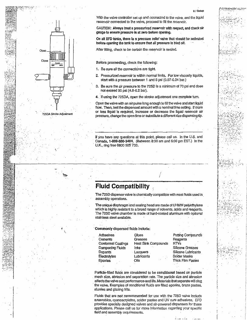
725DA Stroke Adjustment
8/Setup
Wrth the valve controller set up and connected to the valve, and the liquid reservoir connected to the valve, proceed to fill the reservoir.
CAUTION: Always treat a pressurized reservoir with respect, and check air gauge to ensura pressure is at zero before opening.
On all EFD tanks, there is a pressure relief valve that should be aclivated before opening the tank lo ensure !hat all pressure is bled off.
After fillii1g, check to be certain the reservoir is sealed.
Before proceeding, check the following:
1. Be sure all !he connections are tight.
2. Pressurized reservoir is within normal limits. For low viscosity liquids, start with a pressure between 1 and 5 psi (0.07-0.34 bar.)
3. Be sure the air pressure to the 7250 is a minimum ol 70 psi and does notexceed 90 psi (4.8-6.2 bar).
4. II using the 725DA, open the stroke adjustrnerrt one complete tum.
Open the valve with an air pulse long enoughtofillthevaive and start liquid flow. Then, testthe dispensed amourrt with a nominal time setting. II more or fess liquid is required, increase or decrease- the liquid reservoir air pressure, change the open time or substiMe a different size dispensing tip.
II you have any questions at this point, please call us. In the U.S. and Canada, 1-800-556-3484. (Between 8:30 am and 6:00 pm EST.) In the U.K., ring free 0800 585 733.
~----~-~-------------~----------~---------------- ..
Fluid Compatibility , The 7250 dispense valve is chemically compatible wfih most fluids used in assembly operations.
The unique diaphragm and seaiing head are made of UHMW polyethylene which is highly resistant to a broad range of solvents, acids and reagents. The 7250 valve chamber is made of hard-coated aluminum with optional stainless steel available.
·Commonly dispensed fluids include:
Adhesives Glues Cements Greases Conformal Coatings Heat Sink Compounds Dampening Fluids Inks Doparrts Lacquers Electrolytes Lubricants Epoxies Oils
Potting Compounds Reagerrts RTVs Silicone Greases Silicone Lubricants Solder Masks Thick Film Pastes
Particle-filled fluids are considered to be conditional based on particle mesh size, abrasion and separation rate. The particle size and abrasion affects the vaive seat performanc&and life. Materials that separate will clog the valve. Examples of condtlional fluids are filled epoxies, braze pastes, slurries and glazing frits.
Fluids that are not racommendad for use with the 7250 valve include anaerobics, cyanoacry!ates, solder pastes and UV cure adhesives. EFD provides specially designed valves and air-powered dispensers for these applications. Please call us for more information regarding your specific fluid and assembly requirements.
.;,_~ -. .
;.·,
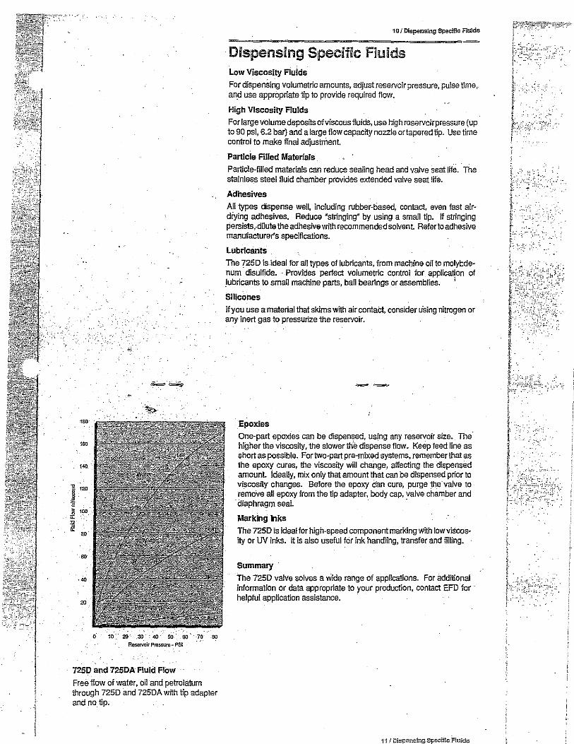
l
I '
l
6 1b:·~, .~ =• ~--oo m oo Aei;ervoir Pressure-· PSI
· 7250 and 725DA Fluid Flow
Free flow of water, oil and petrolatum through 7250 and 7250A wtth tip adapter and no tip.
10 I Dispensing Specific Fluids
Dispensing Specific Fluids Low Viscosity Fluids
For dispenSing volumetric amounts, adjust reservoir pressure, pulse time,. and use appropriate tip to provide required flow.
High Viscosity Fluids
Forlargevolumedepositsofviscous fluids, use high reservoirpressure {up lo 90 psi, 6.2 bar) and a large ftow capacity nozzle or tapered lip. Use time control to make final adjusinient.
Particle Filled Materials
Particle-filled materials can reduce sealing head and valve seat ltte. The stainless steel fluid chamber provides extended valve seat lite.
Adhesives
All types dispense well, including rubber-tiased, contact, even fast airdiying adhesives. Reduce "sllinging" by using a small tip. W stringing persists,duute the adhesive with recommended solvent Refer to adhesive manufacturer's specifications.
Lubricants
The 7250 is ideal for all types of lubricants, from machine oil to molybdenum disulfide. · Provides perfect volume!Jic control for applica~on of lubricants to small machine parts, ball bearings or assemblies. '
Silicones
If you use a-material that skims with air contact, consider u·sing nitrogen or any inert gas to pressurize the reservoir.
Epoxies One-part epoxies can be dispensed, using any reservoir size. The. higher the viscosity, the slowerttie dispense flow_ Keep feed line as short as possible. For two-part pre-mixed systems, remember that as the epoxy cures, the viscosity will change, affecting the dispensed amount ideally, mix only that amount that can be dispensed prior to viscosity changes. Before the epoxy can cure, purge the valve to remove all epoxy from the tip adapter, body cap, valve chamber and ·diaphragm seal. · ·
Marking Inks
The 7250 is ideal for high-speed component marking with low viscosity or UV inks. It is also useful for ink handling, transfer and filling.
Summary
The 7250 valve solves a Wide range of applications. For additional information or data appropriate to your production, contact EFO for helpful application assistance.
11 / Dis~ensing.Spscffic.-Fluids
' .. ' : ·'··· ..

. · ·1 . .
lff~{~~il . . --. ~ . : . :_ i
' : - ..
I !
12 /Troubleshooting
Troubleshooting Guide
Trouble
No fluid flow.
Fluid drools after the valve closes, eventually stopping.
Fluid drips at a steady rate after the valve closes.
Trouble
Valve responds slowly when opening and closing.
Fluid flows out of the drain hole.
' Inconsistent deposits!·
Possible cause and correction
If valve operating air pressure iS too low, the valve will not open. Increase air pressure to 70 psi (4.8 bar) minimum. The reservoir air pressure may not be- high enough. Increase pressure.
The dispensing tip may be clogged. Replace tip. If using the 725DA, the stroke adjustment may be dosed. Open stroke adjustment.
Fluid may have solidified in the valve chamber. Clean the valve chamber.
Fluid feed line is installed into blind mounting hole. Remove and reinstall properly.
This is caused by air trapped in the outlet section of the valve chamber, or the fluid has entrapped air. The air will expand alter the valve closes, causing extrusion until the air reaches atmospheric pressure. Purge the valve by dispensing at a steady flow until clear .. If a small tip is used, tt may be necessaiy to remove the tip wh.ile purging to obtain sufficient flow to carry the air down through the lip adapter.
If the fluid has entrapped air, the'material must be degassed before dispensing . . .
A steady drip indicates failure of the sealing head to close fully due to particle buildup or wear. In either case, replace the sealing head in accordance wtth the maintenance instructions starting on page 14.
/
Possible cause and correction
Valve response is related to control air line Jen9th and size. EFD valves are supplied with 5-!t of tf8" ID tubing attached. Any addttional length or size change will affect response time. Check to be sure the length and size have not been changed •
. Fluid flowing out of the drain hole indicates a ruptured diaphragm. Replace in accordance wtth the maintenance instructions starting on page t4.
Inconsistent deposits can result if the air pressure controlling the varve andfor supplying the reservoir is fluctuating, or if the valve operating pressure is less than70 psi (4.8 bar). Check to be sure air pressures are constant and the valve operating pressure is 70 psi (4.8 bar). The time the valve is open must be constant Check to be sure the valve controller is providing a consistent output.
If trouble cannot be corrected, or if you need further assistance, please call us. ·in the U.S. and Canada, 1-800-556-3484. (Between 8:30 am and 6:00 pm EST.) In the U.K., ring free 0800 585 733.
,-,,.

Tip in contact wittrwork surface.-
·.
Make Remove tip from deposit deposit by lifting
straight up.
Tip travels away from the bead.
;_:.--
· ..
18 I Applications
Applications The 7250 dispense valve provides productive solutions to many types of applications. The following information is a guide to provide application data that will help you to utilize the valves most effectively. For specific application assistance, please call EFD. We welcome the opportuniiy to share our experience with you.
Correct Method to Dispense Dots. Bring valve to part, or part to valve tip, at the angle shown. Cycle valve. Withdraw tip as indicated. This technique ensures consistent dot deposit. Very low viscosif'f liquids may tend to flow up the outside of the tip. The angle shown will prevent this.
Micro-deposits. To achieve very small deposits, use a combination of settings of valve open time, rese1Voir air pressure, dispensing tip size and stroke adjustment if using a 725DA Thetipmustcontacttheworksurface prior ta the dispense cycle to ensure transfer of liquid.
Applying beads. Bring thetlp in contact with the part or close enough to ensure fluid transfer. If the bead is to be applied in one direction only, position the valve at a 45° angle as shown. If the installation requires X-Y motion, position the valve perpendicular to the work surface with the gap determined by thickness of the bead.
Multiple valves-one controller. CAUTION: Valve timing is the primary control of deposit size. When several valves· are manifolded frorri one controller, deposit size adjustment must be made using a secondary control such as reservoir pressure or stroke control. This adds more setup time, and these settings may end up in undesirable ranges, causing inconsistent output When consistency is critical, we recommend using one vaive controller per valve.
Rack-mounted Valves. For filling, It is often expedient to mount several valves for multiple, simullaneous filling. This can result in significantly increased production speeds, while retaining precise fill control.
· Reservoirs. Standard EFD reservoirs include 2.5, 6 and 12 ounce cartridges; and 1,3.8 and 19 llter pressure tanks. Standard fittings are availabfe to connect these reservoirs to the ?250.
Fluids wlth Entrapped Air. After the dispense cycle, some post extrusion can be expected as the compressed air bubbles in the fluid in the output side of the valve expand to atmospheric pressure. This effect will cause addition al material ftowfor a very short period. Within limits, this effect can be measured and the ft ow adjusjed to compensate for this post extrusion. Ideally, be sure all entrapped air is eliminated from the fluid before attempting to dispense it.
Temperature. The 7250 is designed to operate between 50°F (10°C) and 110°F (43°C).
Fluid Pull-back. After each dispense cycle, fluid ftow is stopped by the pull-back of the sealing head. During this shut-off process, there is a negative displacement of the sealing head in the output side of th!l valve chamber. Fluid fills this displacement, causing a slight "suck back" effect atthe output end of the dispensing tip. This effect is minimized to prevent air from being pulled into the tip. The result of this positive slight pull-back means a clean cutoff of dispensed ftuid. The adjustable stroke of 1he 725DA allows fine tuning of the pull-back _amount.
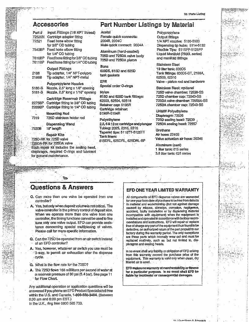
Accessories Part# Input Fillings (1/8 NPT lhraad) 72520N Cartridge adapter fitting 72521 Feed hose elbow fitting
for 3/8" OD tubing 75438P Feed hose elbow fitting
for 1/4" OD tubing 7610BP Feed hose fittingfor3/8" OD tubing 76118P Feed hosefittingfor 1/4" OD tubing
Oulput F"mings 2186 Tip adapter, 114" NPT-polypro 21868 Tip adapter, 1/4" NPT-metal
5180-8 Polypropylene Nozzles Nozzle, 2.5" Jong x 1/8" opening
5181-8 Nozzle, 2.5" Jong x 1/16" opening
Cartridge Reservoir Fittings 22758P Cartridge fitting to 318" OD tubing 22698P Cartridge fitting to 1/4" OD tubing
Mounting Rod 7319 725D stainless holder rod
Dispensing Wand 75308 18" length
Repair Kits 725D-RK foi 725D vaive 125DA-RKfur 725lJA valve . . ·. •·. .
.. Elitn·:rJp'1ir ki includes the se>lling head, diapnriigm, required 0-rings and iubricant
. : _fOr ~~ne~ ~ai~enance. ·
.·~
·Questions & Answers
20 I Parts Listing
Part Number listings by Material Acatal Female quick connects:. 20048, 2004C Male quick connect: 2004A
Aluminum (hard-coated) 7250 and 725DA valve body 725D and 725DA piston
Buna 60005, 615D and 625D tank gaskets
EPR Special order 0-rings
Nylon 6150 and 625D tank fittings: 62503,62504,62516 Retainercap:5195R Cartridge retainer: 5190R-5194R
Polyethylene 2.5, 6&12oz cartridge and plunger Tubing: 2025, 2315, 2316 Tapered lips: 5116TT-5125TT Tank tiners: 615DRL, 625DRL, 625DRL-BP
PolypropyJsne Output fittings 1/4 NPT nozzles: 5180-5183 Dispensing tip hubs: 5114-5132 FleXJble Tips: 5115PP-5125PP Liquid Manifold (7600L series) and manifold fillings
Slainless Steel 19 liter tank: 60005 Tank fittings: 60005-DT, 2198A, 62509,62510 Valve - piston rod and hardware
StSinless Steel: optional 725D valve chamber: 72538-SS 725D chamber cap: 72543'SS 725DA valve chamber: 72558A-SS 725DA chamber cap: 72543-SS
UHMW Polyethylene. Diaphragm: 72536 725D sealing head: 72539 , 725DA sealing head: 72557
Urethane Air hose: 231 OS
·Valve actuation air hose: 20246
Aluminum (cast) 1 liter lank: 615 series 3.8 liter tank: 625 series
EFD ONE YEAR LIMITED WARRANTY Q. Can .more than one vaive be operated from one
controller? All-componeriis of EFD dispense valves clre warranted. for one year_ from date of purchase to be free from-defects
A.. Yes, but only when deposityolutne is not crifical. The valve controller is the primary control of deposit size. When we operate more than one valve froni one controller, the liming functions cannot be used to fine tune. only one valve output EFD can provide assistance concerning special multiplexing of valves. Please call for mqre specific i.nformation.
Q. Can !\le 72SD be operated from an air switch instead of an EFD controller?
A. Yes, however, whatever air switch you use must be · 3-way, to permit air exhaustion after the dispense • cycl... .
o. )/Vhat is the flow rate for the 725D?
. A. The i25Dffows 168 milliliters per second of water at a reservoir pressure of 80 psi (5.4 bar). See page 11
· for Flow Chart.
Any additional operation or application questions will be answered if you phone an EFD Product Speciaiisttoll free within the U.S. and Canada, 1-800-556-3484. (Between 8:30 am and 6:00 pm EST.) In ·the U.K., ring free 0800 585 733.
- iil material and wor!<mfillship (but not against damage caused. by mis.use, abrasip_n, -corrosion, negligence,_ accident, f8.i.Ilty installation or" by diSpSnsing. material incompatible wtth equipment) when the equipment is · install6d and operated in accordance with factoryrecortlmendatiOns aild instructions. EFD will repair or replace free· of charge any part of the equipment thus found to be detective; on_ authorized return_ of the part prepaid to our factory during the-warrantrperiod. The only exceptions are those parts Which normally wear out and must be replaced routinely, such as but nqt limited to, diaphragms and·se~ing heads.
In no eV-ent shall any liability or obligation of EFO arising from this Wairartty exceed the purchase price of the equip_menL This warranty is valid only when clean, dry ffltered air·is used.
EFD makes no warranty of merchantability Or fitness for a particular purpose. In no event shall EFD be liable for lncidentaf or consequential dainages..
. -:·
.

!""- 1 I 2 I 3 4 I 5 I 6 / REVlSION IN~ORMATIONI
5VMllaL DATC •MD~ llU!;!IUl>TlON
!:::, 17/a/991 JAL I CHANGED COLOR ON SPINNER WIRES
A A
AMP PLUG: ss1• 100079A View frorn Wire Side
SOCKETS: ss1•1ooosoA
~
r/''c-;~·:,::,--/''':'" 1- ~ I-,
2
4 E l i,.." .................. ~ I~ ...--'-- ~ I •12 V• 22 AWG RED i J
5 n a J P2
I D a lf22 zn D22 zq -12 v: 22 AWG GRN +5 v: 22 AWG WHT J @ B ~ ......... ~. . ..................... v ...... '. ........ ·············· -l .................................. .................................... ........................... . ............................................ ~· ......----~ :l B I a n ~21 Y!l a2, '4 COMMON• 22 AWG BLK t
o o I , ........................................................................................................... ································" ...-..= 6 I 0 0 n n n n I l ORANGE 1s AWG
I o o 0 n 0 0 I f BROWN 1e AWG
I o o I x " 0 l ! I o o I i
I o o I ) -~
I o o I / I o o I 0 0 I MOLEX
0 0 I PLUG• I n o o o o o I es1• 1000077A
i ! i : : .;_:,--1- '+ ~=-=~: ~,, c c
r "2 is· I I ~ ~ D D G;··· ·;;&· ..•.....•.•••••.•• "l ........ ,/ ~~l~K~~~78A 1~ ~ ~ I
~ ~ ~---------------~ 44 PIN EDGE CONNECTORS BSI"" 100066A VIEW FROM PIN SlDE
D UNLESS OTHERWISE MATER l AL Jeff Leith CEE DIVISION Contro I I etr D SPECIFIED llMlTS OES!ON BREWER SCIENCE. INC· ON DIMENSIONS ARE O:NO!N0:0:" 4000 ENTERPRISE OR. FRACTIONS = :!: '/04 AOL.LA• MO 65401 Oc1""'' . xx "' ±. 015 PHONE: (573) ~64-0~00
OREA1"l0!< • )<XX - ! . oo;; TYPE FINISH REQQ. OATE 1 /8/99 PAPER
A I SHEET . xxxx = ! . 0005 T ! TLE 100 Series SIZE "' APP~OV~O SY Jeff Leith Coed Cage REMOVE All BURRS PAR'f NO. ANO SHARP EDGES E~?E<::Tl~E 7/8/99 Wiring Diagram 3000138 OATO:
I/ '
I 2 I 3 I 4 I 5 I 6 "'