CD 377 Requirements for road restraint systems - Standards ...
113
Design Manual for Roads and Bridges Highway Structures & Bridges Design CD 377 Requirements for road restraint systems (formerly TD 19/06) Revision 0 Summary This document details the requirements for permanent and temporary safety barriers, vehicle parapets, terminals, transitions, crash cushions, pedestrian parapets, pedestrian guardrails and pedestrian restraint and protection, vehicle arrester beds, anti-glare systems and cattle grids. Application by Overseeing Organisations Any specific requirements for Overseeing Organisations alternative or supplementary to those given in this document are given in National Application Annexes to this document. Feedback and Enquiries Users of this document are encouraged to raise any enquiries and/or provide feedback on the content and usage of this document to the dedicated Highways England team. The email address for all enquiries and feedback is: [email protected] This is a controlled document.
-
Upload
khangminh22 -
Category
Documents
-
view
1 -
download
0
Transcript of CD 377 Requirements for road restraint systems - Standards ...
Design Manual for Roads and Bridges
Highway Structures & BridgesDesign
CD 377Requirements for road restraint systems(formerly TD 19/06)
Revision 0
SummaryThis document details the requirements for permanent and temporary safety barriers, vehicleparapets, terminals, transitions, crash cushions, pedestrian parapets, pedestrian guardrails andpedestrian restraint and protection, vehicle arrester beds, anti-glare systems and cattle grids.
Application by Overseeing OrganisationsAny specific requirements for Overseeing Organisations alternative or supplementary to those given in this documentare given in National Application Annexes to this document.
Feedback and EnquiriesUsers of this document are encouraged to raise any enquiries and/or provide feedback on the content and usageof this document to the dedicated Highways England team. The email address for all enquiries and feedback is:[email protected]
This is a controlled document.
CD 377 Revision 0 Contents
Contents
Release notes 4
Foreword 5Publishing information . . . . . . . . . . . . . . . . . . . . . . . . . . . . . . . . . . . . . . . . . . . . . . . . 5Contractual and legal considerations . . . . . . . . . . . . . . . . . . . . . . . . . . . . . . . . . . . . . . . . 5
Introduction 6Background . . . . . . . . . . . . . . . . . . . . . . . . . . . . . . . . . . . . . . . . . . . . . . . . . . . . . . 6Assumptions made in the preparation of this document . . . . . . . . . . . . . . . . . . . . . . . . . . . . . 6Mutual Recognition . . . . . . . . . . . . . . . . . . . . . . . . . . . . . . . . . . . . . . . . . . . . . . . . . . 6
Abbreviations and symbols 7
Terms and definitions 8
1. Scope 14Aspects covered . . . . . . . . . . . . . . . . . . . . . . . . . . . . . . . . . . . . . . . . . . . . . . . . . . . 14Implementation and application . . . . . . . . . . . . . . . . . . . . . . . . . . . . . . . . . . . . . . . . . . . 14Use of GG 101 . . . . . . . . . . . . . . . . . . . . . . . . . . . . . . . . . . . . . . . . . . . . . . . . . . . . 15
2. General requirements 16Risk assessment and hazard mitigation . . . . . . . . . . . . . . . . . . . . . . . . . . . . . . . . . . . . . . 16Information to be provided and/or specified . . . . . . . . . . . . . . . . . . . . . . . . . . . . . . . . . . . . 17
3. Requirements for permanent safety barriers 18Minimum containment levels . . . . . . . . . . . . . . . . . . . . . . . . . . . . . . . . . . . . . . . . . . . . 18Impact severity level . . . . . . . . . . . . . . . . . . . . . . . . . . . . . . . . . . . . . . . . . . . . . . . . . 19Normalised working width classes and normalised vehicle intrusion classes . . . . . . . . . . . . . . . . . . 19Length of need . . . . . . . . . . . . . . . . . . . . . . . . . . . . . . . . . . . . . . . . . . . . . . . . . . . . 19Set-back . . . . . . . . . . . . . . . . . . . . . . . . . . . . . . . . . . . . . . . . . . . . . . . . . . . . . . . 19General requirements . . . . . . . . . . . . . . . . . . . . . . . . . . . . . . . . . . . . . . . . . . . . . . . . 22
Drainage and kerbs . . . . . . . . . . . . . . . . . . . . . . . . . . . . . . . . . . . . . . . . . . . . . . 24Motorcyclists . . . . . . . . . . . . . . . . . . . . . . . . . . . . . . . . . . . . . . . . . . . . . . . . . . 24Other factors . . . . . . . . . . . . . . . . . . . . . . . . . . . . . . . . . . . . . . . . . . . . . . . . . . 24
Passively safe road furniture and equipment, and vehicle restraint systems . . . . . . . . . . . . . . . . . . 25Safety barrier provision at structural supports . . . . . . . . . . . . . . . . . . . . . . . . . . . . . . . . . . . 25Safety barrier provision at vehicle parapets . . . . . . . . . . . . . . . . . . . . . . . . . . . . . . . . . . . . 28Safety barrier provision at gantries . . . . . . . . . . . . . . . . . . . . . . . . . . . . . . . . . . . . . . . . . 29Vulnerable users . . . . . . . . . . . . . . . . . . . . . . . . . . . . . . . . . . . . . . . . . . . . . . . . . . . 29Safety barrier provision at nosing areas and junctions . . . . . . . . . . . . . . . . . . . . . . . . . . . . . . 32Safety barrier provision in central reserves - general . . . . . . . . . . . . . . . . . . . . . . . . . . . . . . . 34Requirements for gaps in the central reserve . . . . . . . . . . . . . . . . . . . . . . . . . . . . . . . . . . . 34
General requirements for an emergency crossing point/maintenance crossing point (ECP/MCP) . . . 35Use of gates at an ECP/MCP . . . . . . . . . . . . . . . . . . . . . . . . . . . . . . . . . . . . . . . . . 35Use of demountable permanent barrier at an MCP . . . . . . . . . . . . . . . . . . . . . . . . . . . . . 35Additional requirements for "open" ECPs . . . . . . . . . . . . . . . . . . . . . . . . . . . . . . . . . . 36Additional requirements for maintenance crossing points and maintenance access . . . . . . . . . . . 38Winter maintenance crossing points (WMCP) . . . . . . . . . . . . . . . . . . . . . . . . . . . . . . . . 38Other gaps in the central reserve, and provision at start and end points of dual carriageways . . . . . 38
4. Requirements for vehicle parapets 39Minimum containment levels where the road is not carried over or adjacent to a railway . . . . . . . . . . . 39Minimum containment level requirements where the road is carried over or adjacent to a railway . . . . . . 39
New bridges and structures (except accommodation bridges) . . . . . . . . . . . . . . . . . . . . . . . 40Existing bridges and structures (except accommodation bridges) . . . . . . . . . . . . . . . . . . . . . 40New and existing accommodation bridges . . . . . . . . . . . . . . . . . . . . . . . . . . . . . . . . . . 40
1
CD 377 Revision 0 Contents
Impact severity level . . . . . . . . . . . . . . . . . . . . . . . . . . . . . . . . . . . . . . . . . . . . . . . . . 40Normalised working width class and normalised vehicle intrusion class . . . . . . . . . . . . . . . . . . . . . 40Length of need . . . . . . . . . . . . . . . . . . . . . . . . . . . . . . . . . . . . . . . . . . . . . . . . . . . . 40Minimum height of parapets . . . . . . . . . . . . . . . . . . . . . . . . . . . . . . . . . . . . . . . . . . . . . 43General requirements . . . . . . . . . . . . . . . . . . . . . . . . . . . . . . . . . . . . . . . . . . . . . . . . 43
Verges on bridges and structures . . . . . . . . . . . . . . . . . . . . . . . . . . . . . . . . . . . . . . . 43Plinth upstands . . . . . . . . . . . . . . . . . . . . . . . . . . . . . . . . . . . . . . . . . . . . . . . . . 44
Parapets on historic monuments and bridges . . . . . . . . . . . . . . . . . . . . . . . . . . . . . . . . . . . 44Infilling of parapets . . . . . . . . . . . . . . . . . . . . . . . . . . . . . . . . . . . . . . . . . . . . . . . . . . 45Provision for divided structures . . . . . . . . . . . . . . . . . . . . . . . . . . . . . . . . . . . . . . . . . . . 45Additional requirements for vehicle parapets over or adjacent to railways . . . . . . . . . . . . . . . . . . . 45
Infilling of parapets over railways . . . . . . . . . . . . . . . . . . . . . . . . . . . . . . . . . . . . . . . 46Design requirements for parapets and supporting structures . . . . . . . . . . . . . . . . . . . . . . . . . . . 46Anchorages and structural loading . . . . . . . . . . . . . . . . . . . . . . . . . . . . . . . . . . . . . . . . . 47Reinforced concrete parapets . . . . . . . . . . . . . . . . . . . . . . . . . . . . . . . . . . . . . . . . . . . . 47Stone or precast concrete copings . . . . . . . . . . . . . . . . . . . . . . . . . . . . . . . . . . . . . . . . . 48Masonry or brickwork facings . . . . . . . . . . . . . . . . . . . . . . . . . . . . . . . . . . . . . . . . . . . . 48Masonry parapets . . . . . . . . . . . . . . . . . . . . . . . . . . . . . . . . . . . . . . . . . . . . . . . . . . 48
5. Requirements for terminals 49Performance class . . . . . . . . . . . . . . . . . . . . . . . . . . . . . . . . . . . . . . . . . . . . . . . . . . 49Impact severity level . . . . . . . . . . . . . . . . . . . . . . . . . . . . . . . . . . . . . . . . . . . . . . . . . 49Permanent lateral displacement zone class . . . . . . . . . . . . . . . . . . . . . . . . . . . . . . . . . . . . 49Vehicle exit box class . . . . . . . . . . . . . . . . . . . . . . . . . . . . . . . . . . . . . . . . . . . . . . . . 50General requirements . . . . . . . . . . . . . . . . . . . . . . . . . . . . . . . . . . . . . . . . . . . . . . . . 50
6. Requirements for transitions 51Introduction . . . . . . . . . . . . . . . . . . . . . . . . . . . . . . . . . . . . . . . . . . . . . . . . . . . . . . 51Minimum containment levels . . . . . . . . . . . . . . . . . . . . . . . . . . . . . . . . . . . . . . . . . . . . 51
Transitions and vehicle parapets . . . . . . . . . . . . . . . . . . . . . . . . . . . . . . . . . . . . . . . 51Impact severity level . . . . . . . . . . . . . . . . . . . . . . . . . . . . . . . . . . . . . . . . . . . . . . . . . 52Normalised working width classes and normalised vehicle intrusion classes . . . . . . . . . . . . . . . . . . 52Transitions between safety barriers not on a motorway or all-purpose trunk road, and parapets over a mo-
torway or all-purpose trunk road . . . . . . . . . . . . . . . . . . . . . . . . . . . . . . . . . . . . . . . 52
7. Requirements for crash cushions 53Introduction . . . . . . . . . . . . . . . . . . . . . . . . . . . . . . . . . . . . . . . . . . . . . . . . . . . . . . 53Performance levels . . . . . . . . . . . . . . . . . . . . . . . . . . . . . . . . . . . . . . . . . . . . . . . . . . 53Re-directive and non re-directive types of crash cushion . . . . . . . . . . . . . . . . . . . . . . . . . . . . . 53Bi-directional and directional types of crash cushion . . . . . . . . . . . . . . . . . . . . . . . . . . . . . . . 53Impact severity level . . . . . . . . . . . . . . . . . . . . . . . . . . . . . . . . . . . . . . . . . . . . . . . . . 54Vehicle redirection zone class . . . . . . . . . . . . . . . . . . . . . . . . . . . . . . . . . . . . . . . . . . . . 54Permanent lateral displacement zone class . . . . . . . . . . . . . . . . . . . . . . . . . . . . . . . . . . . . 54Crash cushions used in temporary situations . . . . . . . . . . . . . . . . . . . . . . . . . . . . . . . . . . . 54
8. Requirements for pedestrian restraint systems 55General requirements for pedestrian parapets . . . . . . . . . . . . . . . . . . . . . . . . . . . . . . . . . . . 55
Additional requirements for pedestrian parapets over or adjacent to railways . . . . . . . . . . . . . . . 56General requirements for pedestrian guardrails . . . . . . . . . . . . . . . . . . . . . . . . . . . . . . . . . . 56Requirements for pedestrian restraint and protection to prevent a fall from a height . . . . . . . . . . . . . . 57
9. Requirements for temporary safety barriers at roadworks 60Minimum containment levels . . . . . . . . . . . . . . . . . . . . . . . . . . . . . . . . . . . . . . . . . . . . 60Impact severity level . . . . . . . . . . . . . . . . . . . . . . . . . . . . . . . . . . . . . . . . . . . . . . . . . 63Normalised working width classes and classes of normalised vehicle intrusion classes . . . . . . . . . . . . 63Length of need . . . . . . . . . . . . . . . . . . . . . . . . . . . . . . . . . . . . . . . . . . . . . . . . . . . . 63Set-back . . . . . . . . . . . . . . . . . . . . . . . . . . . . . . . . . . . . . . . . . . . . . . . . . . . . . . . 63
2
CD 377 Revision 0 Contents
Method of termination for temporary safety barriers . . . . . . . . . . . . . . . . . . . . . . . . . . . . . . . . 64General requirements . . . . . . . . . . . . . . . . . . . . . . . . . . . . . . . . . . . . . . . . . . . . . . . . 64Temporary speed limits . . . . . . . . . . . . . . . . . . . . . . . . . . . . . . . . . . . . . . . . . . . . . . . 65Use of temporary safety barriers in contraflow operations . . . . . . . . . . . . . . . . . . . . . . . . . . . . 65
10. Legacy systems 66
11. Vehicle arrester beds 67
12. Anti-glare systems 68
13. Cattle grids 69Design of cattle grids . . . . . . . . . . . . . . . . . . . . . . . . . . . . . . . . . . . . . . . . . . . . . . . . . 69Siting of cattle grids . . . . . . . . . . . . . . . . . . . . . . . . . . . . . . . . . . . . . . . . . . . . . . . . . 69
14. Normative references 70
15. Informative references 72
Appendix A. Guidance on the specification of vehicle restraint systems for low speed and/or low flowroads 73
Appendix B. Guidance on factors for ECPs and MCPs 77B1 Emergency and maintenance crossing points . . . . . . . . . . . . . . . . . . . . . . . . . . . . . . . . . 77
B1.1 Gates at MCP/ECP . . . . . . . . . . . . . . . . . . . . . . . . . . . . . . . . . . . . . . . . . . . . 77B1.2 Permanent safety barrier at ECP/MCP . . . . . . . . . . . . . . . . . . . . . . . . . . . . . . . . . 77
Notification 78
3

CD 377 Revision 0 Release notes
Release notesVersion Date Details of amendments0 Mar 2020 CD 377 replaces TD 19/06. This full document has been re-written to make it
compliant with the new Highways England drafting rules.
4

CD 377 Revision 0 Foreword
Foreword
Publishing informationThis document is published by Highways England.
This document supersedes TD 19/06, and partially supersedes IAN 68/05 and IAN 75/06 which arewithdrawn.
Contractual and legal considerationsThis document forms part of the works specification. It does not purport to include all the necessaryprovisions of a contract. Users are responsible for applying all appropriate documents applicable totheir contract.
5
CD 377 Revision 0 Introduction
Introduction
BackgroundThis document is an update to TD 19/06 and reflects changes to the Overseeing Organisations'requirements. It also takes account of updated and new EU standards and legislation.
This document gives requirements for road restraint systems and it, together with the associatedRRRAP [Ref 43.N] and RRRAP User Guide [Ref 14.N], assists those involved in determining whereroad restraint systems are warranted, and the minimum required parameters.
Assumptions made in the preparation of this documentThe assumptions made in GG 101 [Ref 18.N] apply to this document.
This document is written on the basis that road restraint systems will be supplied and constructed inaccordance with the MCHW [Ref 21.N] and all other works will be designed and specified inaccordance with the Design Manual for Roads and Bridges.
Mutual RecognitionWhere there is a requirement in this document for compliance with any part of a British Standard,technical specification or quality mark, that requirement may be met by compliance with the MutualRecognition clause in GG 101 [Ref 18.N].
6
CD 377 Revision 0 Abbreviations and symbols
Abbreviations and symbols
AbbreviationsAbbreviation Definition
AADT Average annual daily traffic
AIP Approval in Principle
ALARP As low as reasonably practicable
CPR Construction Products Regulation
DfT Department for Transport
ECP Emergency crossing point
EqIA Equality Impact Assessment
ISL Impact severity level
LGV Large Goods Vehicle
LoN Length of Need
m Metres
MCP Maintenance crossing point
mm Millimetre
mph Miles per hour
OLE Overhead line equipment
PNR Point of no recovery
Psb Point from which set-back is measured
RRRAP Road Restraint Risk Assessment Process
RRS Road restraint system
SO Special Order
STGO Special Types General Order
TTM Temporary traffic management
VI Vehicle intrusion
VMS Variable message sign
VRS Vehicle restraint system
WMCP Winter maintenance crossing point
W Working width
Symbols
Symbol Definition
kN Kilo Newtons
Wn Normalised working width
γfl Partial factor for load
Ym Partial factor on material strength
7
CD 377 Revision 0 Terms and definitions
Terms and definitions
TermsTerm DefinitionRisk associated terms, also refer to GG 104 [Ref 31.N]
'Acceptable', 'broadly acceptable' and 'as low asreasonably practicable level of risk.
The Road Restraint Risk Assessment Process( RRRAP [Ref 43.N]) that forms part of thisdocument uses the term 'acceptable' to indicatewhere a 'broadly acceptable' level of risk isachieved in respect of vehicle restraint systemprovision.
NOTE: Depending on the situation, this can bewhere safety barrier is not warranted, or can beachieved over a range of safety barrier lengths.
Hazard A source of potential harm, loss or failure.
Other Parties (referred to as "Others" in theRRRAP [Ref 43.N])
A group or collection of people in a public place,such as a school, hospital or railway, that can beinjured in numbers by an errant vehicle or by ahazard that is hit by an errant vehicle; or a highvalue asset or facility that can be adverselyaffected by an impact from an errant vehicle orby a hazard this is hit by an errant vehicle.
Safety risk
The expected consequence of a specified hazardbeing realised with the combination of thelikelihood and expected severity of the outcome.
NOTE: Safety risk is a measure of harm or lossassociated with an activity
Secondary event
An incident that can arise as a result of an initialevent.
NOTE: For instance, if a lighting column is struckand falls onto a carriageway or a railway, thestruck lighting column has the potential to causea secondary event, such as being hit by a vehicleor train and hence creates a risk of a secondaryincident occurring.
Other terms
Adjoining paved surfaceThe paved area on the traffic side of a parapetimmediately adjacent to the plinth or base of theparapet.
Bi-directional crash cushion
A crash cushion which has successfully beentested with tests 1 to 5 inclusive, in accordancewith BS EN 1317-1 [Ref 33.N] and BS EN 1317-32010 [Ref 25.N]
8
CD 377 Revision 0 Terms and definitions
Terms (continued)
Term Definition
Cattle grid
A device set into a road that consists of a numberof transverse members supported over a pit. Itforms a barrier to livestock but allows access forvehicles.
Crash cushionAn energy absorption device installed in front ofone or more hazards to reduce the severity of animpact.
Deformable safety barrierA safety barrier that when tested in accordancewith BS EN 1317-1 [Ref 33.N] and BS EN 1317-2[Ref 32.N], deflects from its pre-impact position.
Directional crash cushion
A crash cushion which has successfully beentested with tests 1 to 3 inclusive, and either test 4or test 5 in accordance with BS EN 1317-3 2010[Ref 25.N]
Energy absorbing terminal
A terminal attached to a VRS which, in testApproach 1 (i.e. head-on centre - refer to BS DDENV 1317-4 [Ref 26.N]), does not allow the mostforward point of the car to cross the vehicle exitline R, or which crosses line R at a speed lessthan or equal to 11 km/h.
Front face of parapet The face or part of the parapet nearest tovehicular traffic.
Impact severity level (ISL)
A measure of the severity of an impact with avehicle restraint system using a combination ofvehicle acceleration and the theoretical headimpact velocity.
NOTE 1: Refer to BS EN 1317-2 [Ref 32.N]).
NOTE 2: Impact severity level A affords a greaterlevel of safety for the occupant of an errantvehicle than level B.
Large goods vehicles (LGV)
A vehicle with a gross combination mass of over3500kg.
NOTE: Previously referred to as heavy goodsvehicle (HGV)
Legacy system
Permanent safety barriers, parapets and crashcushions currently on the road network that weremanufactured and installed before CE Markingunder the Construction Products Regulations (2011/305/EU [Ref 29.N]) became a statutoryrequirement.
9
CD 377 Revision 0 Terms and definitions
Terms (continued)
Term Definition
Length of need
The total minimum length of full containmentvehicle restraint systems (VRS) stipulated asbeing required in advance of, alongside, andafter a hazard(s) to achieve a 'broadlyacceptable' level of risk.
NOTE 1: The length over which various VRSreach full containment can vary and need to bechecked with the manufacturer.
NOTE 2: When assessing whether the length ofneed and containment level are sufficient for atemporary situation, the speed limit used in theRRRAP [Ref 43.N] is usually the temporarymandatory limit that is to be in force.
Main structureAny part of a bridge, viaduct, retaining wall orsimilar structure upon which a pedestrian orvehicle parapet is mounted, including the plinth.
Non re-directive crash cushion
A crash cushion which has successfully beentested with tests 1 to 3 inclusive, in accordancewith BS EN 1317-1 [Ref 33.N] and BS EN 1317-32010 [Ref 25.N]
Normalised values (of working width and vehicleintrusion)
Values that have been adjusted to take accountof any differences between the specified totalmass of a vehicle, its velocity and angle ofapproach, and the values measured duringtesting.
NOTE: Refer to BS EN 1317-2 [Ref 32.N].
ParapetA restraint system that is installed on the edge ofa bridge, retaining wall or similar elevatedstructure where there is a vertical drop.
Pedestrian parapet
A restraint system that is installed on the edge ofa bridge, retaining wall or similar elevatedstructure where there is a vertical drop wherevehicular traffic is excluded, but wherepedestrians, equestrians, cyclists or livestockcan be present.
Pedestrian restraint system
A restraint system installed to reduce the risk of afall from a height at locations where pedestrianmovement could occur due to highway use ormaintenance activities.
Pedestrian guardrail
A restraint system along the edge of a footway orfootpath intended to restrain pedestrians andother users from stepping onto or crossing aroad, or entering other areas likely to behazardous.
10
CD 377 Revision 0 Terms and definitions
Terms (continued)
Term Definition
Planned maintenance
Planned work required to parts of the motorwayand all-purpose trunk roads that have becomeunserviceable because of general wear or tear,or due to a major upgrade or changes to parts ofthe network.
NOTE: This excludes work associated withincident damage.
PlinthA continuous upstand on the edge of a structureupon which a vehicle parapet or pedestrianparapet is mounted.
Point of no recovery
The point at which the driver of an errant vehiclehas no chance of recovering an errant vehicleback on the carriageway and, unless hit ordiverted by an intervening hazard, is going to endup on (in) the adjacent road, railway, waterhazard, etc.
NOTE: This point can be the top of anembankment slope, the top of the cutting to arailway, the bank of a water hazard if the road isat grade, etc.
Psb
Point from which set-back of the safety barrier orparapet face is measured.
NOTE: Refer to CD 127 [Ref 4.N] for minimumrequirements for permanent safety barriers.
Railway authority Authority responsible for the railwayinfrastructure (e.g. Network Rail)
Re-directive crash cushion
A crash cushion which has successfully beentested with tests 1 to 4 inclusive for a directionalcrash cushion, and tests 1 to 5 inclusive for abidirectional crash cushion, in accordance withBS EN 1317-3 2010 [Ref 25.N]
Rigid safety barrier
A safety barrier that when tested in accordancewith BS EN 1317-1 [Ref 33.N] and BS EN 1317-2[Ref 32.N], does not deflect from its pre-impactposition.
Road restraint system (RRS) General name for vehicle restraint system orpedestrian restraint system used on the road.
Routine maintenanceWorks which include all routine and cyclic work,and ad-hoc repairs.
11
CD 377 Revision 0 Terms and definitions
Terms (continued)
Term Definition
Running lane
That part of the trafficked carriageway nearest tothe verge or central reserve that is underconsideration.
NOTE: Under normal running conditions, thehard shoulder of a motorway would not betrafficked and would therefore not be classed asthe running lane. It can however become atemporary running lane under temporary trafficmanagement.
Safety barrier
A type of vehicle restraint system installedalongside or on the central reserve of a roadwhich is typically comprised of metal and/orconcrete and/or plastic components.
Set-back
The distance between the Psb and the trafficface of a RRS.
NOTE: Refer to CD 127 [Ref 4.N] for minimumrequirements for permanent safety barriers.
Sidelong ground
Ground that falls away from the carriageway,where the road is not on a formed embankment.
NOTE: Sidelong ground typically occurs wherethe road is cut into the side of a hill such that theroad is effectively in cutting on one side and theground drops away from the carriageway on theother.
Smooth face
A face which has a surface finish with amaximum size of any undulation or depression inthe surface not exceeding 30mm, whenmeasured with respect to a plane through thepeaks, the plane being broadly parallel to theroad alignment.
A structure having a 25mm wide chamferedconstruction joint in its surface is also regardedas smooth.
Temporary safety barriers Safety barriers that are to be in place for lessthan 4 years.
Vehicle intrusion (VI)
The vehicle intrusion of an LGV is the maximumdynamic lateral position from the undeformedtraffic side of the barrier in consideration of anotional load having the width and length of thevehicle platform, and a total height of 4 m. Thevehicle intrusion of a bus is the maximumdynamic lateral position of the bus from theundeformed traffic side of the barrier.
NOTE: Further detail is given in BS EN 1317-2[Ref 32.N].
12
CD 377 Revision 0 Terms and definitions
Terms (continued)
Term Definition
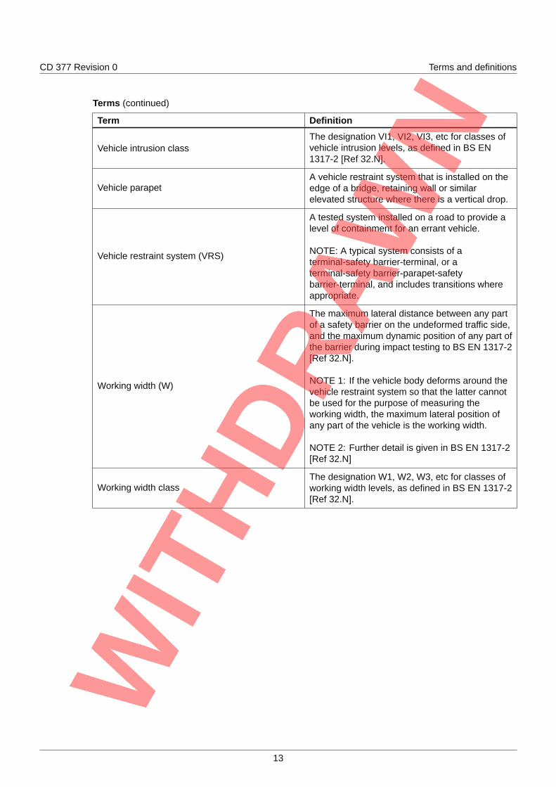
Vehicle intrusion classThe designation VI1, VI2, VI3, etc for classes ofvehicle intrusion levels, as defined in BS EN1317-2 [Ref 32.N].
Vehicle parapetA vehicle restraint system that is installed on theedge of a bridge, retaining wall or similarelevated structure where there is a vertical drop.
Vehicle restraint system (VRS)
A tested system installed on a road to provide alevel of containment for an errant vehicle.
NOTE: A typical system consists of aterminal-safety barrier-terminal, or aterminal-safety barrier-parapet-safetybarrier-terminal, and includes transitions whereappropriate.
Working width (W)
The maximum lateral distance between any partof a safety barrier on the undeformed traffic side,and the maximum dynamic position of any part ofthe barrier during impact testing to BS EN 1317-2[Ref 32.N].
NOTE 1: If the vehicle body deforms around thevehicle restraint system so that the latter cannotbe used for the purpose of measuring theworking width, the maximum lateral position ofany part of the vehicle is the working width.
NOTE 2: Further detail is given in BS EN 1317-2[Ref 32.N]
Working width classThe designation W1, W2, W3, etc for classes ofworking width levels, as defined in BS EN 1317-2[Ref 32.N].
13
CD 377 Revision 0 1. Scope
1. Scope
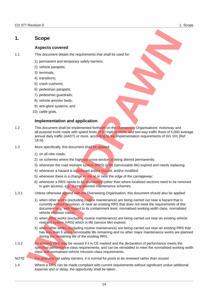
Aspects covered1.1 This document details the requirements that shall be used for:
1) permanent and temporary safety barriers;
2) vehicle parapets;
3) terminals;
4) transitions;
5) crash cushions;
6) pedestrian parapets;
7) pedestrian guardrails;
8) vehicle arrester beds;
9) anti-glare systems; and
10) cattle grids.
Implementation and application1.2 This document shall be implemented forthwith on the Overseeing Organisations' motorway and
all-purpose trunk roads with speed limits of 50 mph or more, and two-way traffic flows of 5,000 averageannual daily traffic (AADT) or more, according to the implementation requirements of GG 101 [Ref18.N].
1.3 More specifically, this document shall be applied:
1) on all new roads;
2) on schemes where the highway cross-section is being altered permanently;
3) whenever the road restraint system (RRS) is life (serviceable life) expired and needs replacing;
4) whenever a hazard is introduced and/or moved, and/or modified;
5) whenever there is a change in risk at or near the edge of the carriageway;
6) whenever a RRS needs to be dismantled (other than where localised sections need to be removedto gain access), e.g. during planned maintenance schemes.
1.3.1 Unless otherwise agreed with the Overseeing Organisation, this document should also be applied:
1) when other works (excluding routine maintenance) are being carried out near a hazard that iscurrently without provision, or near an existing RRS that does not meet the requirements of thisdocument (e.g. with regard to its containment level, normalised working width class, normalisedvehicle intrusion class);
2) when other works (excluding routine maintenance) are being carried out near an existing vehiclerestraint system (VRS) which is life (service life) expired;
3) when other works (excluding routine maintenance) are being carried out near an existing RRS thathas less than 5 years serviceable life remaining and no other major maintenance works are plannedduring the remaining life of the existing RRS.
1.3.2 An existing VRS may be reused if it is CE marked and the declaration of performance meets thespecified performance class requirements, and can be reinstalled to meet the normalised working widthclass and normalised vehicle intrusion class requirements.
NOTE For post and rail safety barriers, it is normal for posts to be renewed rather than reused.
1.4 Where a RRS can be made compliant with current requirements without significant undue additionalexpense and or delay, the opportunity shall be taken.
14
CD 377 Revision 0 1. Scope
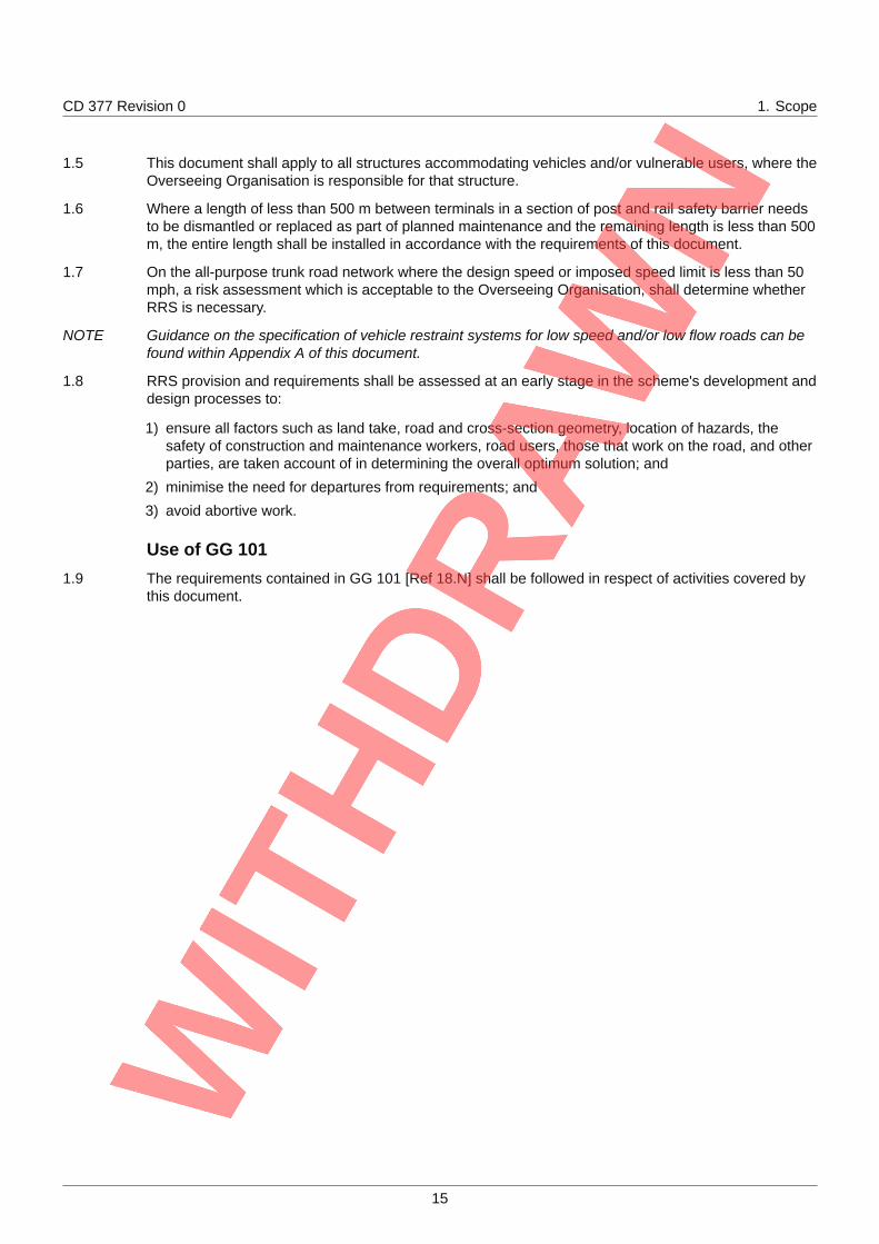
1.5 This document shall apply to all structures accommodating vehicles and/or vulnerable users, where theOverseeing Organisation is responsible for that structure.
1.6 Where a length of less than 500 m between terminals in a section of post and rail safety barrier needsto be dismantled or replaced as part of planned maintenance and the remaining length is less than 500m, the entire length shall be installed in accordance with the requirements of this document.
1.7 On the all-purpose trunk road network where the design speed or imposed speed limit is less than 50mph, a risk assessment which is acceptable to the Overseeing Organisation, shall determine whetherRRS is necessary.
NOTE Guidance on the specification of vehicle restraint systems for low speed and/or low flow roads can befound within Appendix A of this document.
1.8 RRS provision and requirements shall be assessed at an early stage in the scheme's development anddesign processes to:
1) ensure all factors such as land take, road and cross-section geometry, location of hazards, thesafety of construction and maintenance workers, road users, those that work on the road, and otherparties, are taken account of in determining the overall optimum solution; and
2) minimise the need for departures from requirements; and
3) avoid abortive work.
Use of GG 1011.9 The requirements contained in GG 101 [Ref 18.N] shall be followed in respect of activities covered by
this document.
15
CD 377 Revision 0 2. General requirements
2. General requirements
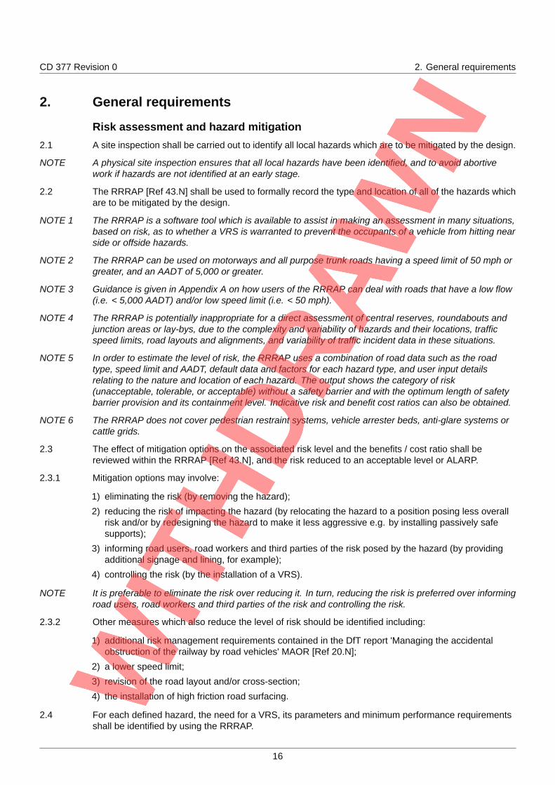
Risk assessment and hazard mitigation2.1 A site inspection shall be carried out to identify all local hazards which are to be mitigated by the design.
NOTE A physical site inspection ensures that all local hazards have been identified, and to avoid abortivework if hazards are not identified at an early stage.
2.2 The RRRAP [Ref 43.N] shall be used to formally record the type and location of all of the hazards whichare to be mitigated by the design.
NOTE 1 The RRRAP is a software tool which is available to assist in making an assessment in many situations,based on risk, as to whether a VRS is warranted to prevent the occupants of a vehicle from hitting nearside or offside hazards.
NOTE 2 The RRRAP can be used on motorways and all purpose trunk roads having a speed limit of 50 mph orgreater, and an AADT of 5,000 or greater.
NOTE 3 Guidance is given in Appendix A on how users of the RRRAP can deal with roads that have a low flow(i.e. < 5,000 AADT) and/or low speed limit (i.e. < 50 mph).
NOTE 4 The RRRAP is potentially inappropriate for a direct assessment of central reserves, roundabouts andjunction areas or lay-bys, due to the complexity and variability of hazards and their locations, trafficspeed limits, road layouts and alignments, and variability of traffic incident data in these situations.
NOTE 5 In order to estimate the level of risk, the RRRAP uses a combination of road data such as the roadtype, speed limit and AADT, default data and factors for each hazard type, and user input detailsrelating to the nature and location of each hazard. The output shows the category of risk(unacceptable, tolerable, or acceptable) without a safety barrier and with the optimum length of safetybarrier provision and its containment level. Indicative risk and benefit cost ratios can also be obtained.
NOTE 6 The RRRAP does not cover pedestrian restraint systems, vehicle arrester beds, anti-glare systems orcattle grids.
2.3 The effect of mitigation options on the associated risk level and the benefits / cost ratio shall bereviewed within the RRRAP [Ref 43.N], and the risk reduced to an acceptable level or ALARP.
2.3.1 Mitigation options may involve:
1) eliminating the risk (by removing the hazard);
2) reducing the risk of impacting the hazard (by relocating the hazard to a position posing less overallrisk and/or by redesigning the hazard to make it less aggressive e.g. by installing passively safesupports);
3) informing road users, road workers and third parties of the risk posed by the hazard (by providingadditional signage and lining, for example);
4) controlling the risk (by the installation of a VRS).
NOTE It is preferable to eliminate the risk over reducing it. In turn, reducing the risk is preferred over informingroad users, road workers and third parties of the risk and controlling the risk.
2.3.2 Other measures which also reduce the level of risk should be identified including:
1) additional risk management requirements contained in the DfT report 'Managing the accidentalobstruction of the railway by road vehicles' MAOR [Ref 20.N];
2) a lower speed limit;
3) revision of the road layout and/or cross-section;
4) the installation of high friction road surfacing.
2.4 For each defined hazard, the need for a VRS, its parameters and minimum performance requirementsshall be identified by using the RRRAP.
16
CD 377 Revision 0 2. General requirements
2.5 Where, having reviewed all the options, a solution is found within the RRRAP that produces an"acceptable" level of risk, then this option shall be used as the basis for the final design.
2.6 A record of the design for hazard mitigation shall include the hazards identified and the assumptionsmade to mitigate each of these hazards to demonstrate that the design meets the requirements of thisdocument.
Information to be provided and/or specified2.7 The following shall be provided for each adopted hazard mitigation layout:
1) the risk assessment;
2) the output from the RRRAP;
3) a completed contract specific specification, using contract specific Appendix 4/1 as detailed inMCHW Series NG400 [Ref 23.N];
4) all relevant supporting information for each design as part of the Health and Safety documentationrequired under the Construction (Design and Management) Regulations SI 2015/51 [Ref 41.N].
NOTE The minimum risk assessment information required is:
1) basic common details;2) collation of data;3) user comments;4) detailed results;5) VRS summary output;6) temporary hazards (where applicable); and7) barrier and options costs worksheets.
2.8 Factors relevant to the installation, maintenance and demolition of the RRS that can influence thechoice of RRS shall be identified in the contract specific specification, using contract specific Appendix4/1 as detailed in MCHW Series NG400 [Ref 23.N] to ensure that suitable systems are used.
17
CD 377 Revision 0 3. Requirements for permanent safety barriers
3. Requirements for permanent safety barriers3.1 All VRS installations that include permanent safety barriers shall be compatible with each other
throughout the entire installation length (including any other safety barriers, parapets, terminals,transitions and crash cushions) and meet the requirements of this Section 3.
3.2 For each permanent safety barrier installation, based on the site specific conditions, the following andall other relevant requirements of MCHW Series 400 [Ref 22.N] and the associated MCHW SeriesNG400 [Ref 23.N] shall be specified in the contract specific specification, using contract specificAppendix 4/1 as detailed in MCHW Series NG400 [Ref 23.N]:
1) containment level;
2) impact severity level (ISL);
3) set-back;
4) normalised working width class (W);
5) normalised vehicle intrusion class (VI);
6) location and maximum height that allows the required visibility (refer to CD 127 [Ref 4.N] and CD109 [Ref 15.N]);
7) length of need;
8) any special requirements (e.g. environmental considerations, motorcyclist protection, lengths ofremovable safety barrier, ground conditions, proximity to embankment slopes, requirements toaccommodate pedestrians on verges, clearance to hazards that are vulnerable to residual loadingand loading requirements for structures, measures to reduce the risk of injury to pedestrians,equestrians and other vulnerable users (e.g. no sharp edges));
9) specific connection requirements to existing safety barriers, vehicle parapets or other structures.
NOTE 1 The objective of installing safety barriers alongside or within a motorway and/or all-purpose trunk roadis to reduce the consequences of vehicles leaving the carriageway and entering areas where hazardsexist.
NOTE 2 Safety barriers are intended to contain and redirect vehicles along the line of the barrier in the directionof travel, so they do not rotate or overturn, for the benefit of road users.
3.3 The design shall be the optimum solution for the hazard having achieved compliance with themandatory requirements, the conditions of a relaxation (where applicable), a broadly acceptable levelof risk, or having obtained a departure from requirements.
3.3.1 Guidance may be sought from safety barrier manufacturers on the most appropriate arrangement toprevent vehicles from hitting the ends of parapets, hazards in the verges and the adjacent road at entryslip and link roads, where the safety barrier arrangement is determined by the local geometry.
Minimum containment levels3.4 On roads with a speed limit of 50 mph or more, the minimum containment level for permanent safety
barriers shall be:
1) normal containment level: N2;
2) higher containment level: H1;
3) very high containment level: H4a.
3.5 On roads with a speed limit of less than 50 mph, the minimum containment level for permanent safetybarriers shall be:
1) normal containment level: N1;
2) higher containment level: H1;
3) very high containment level: H4a.
18
CD 377 Revision 0 3. Requirements for permanent safety barriers
3.6 Where a site-specific risk assessment indicates that a containment level higher than the minimum levelis required, the higher containment level shall be specified.
3.7 Where the need for a higher containment level or very high containment level safety barrier has beenidentified, the nature of the risk, any mitigation with the steps taken to reduce the risk and the resultingcontainment level required shall be recorded.
Impact severity level3.8 The impact severity level (ISL) shall be either level A or B.
Normalised working width classes and normalised vehicle intrusion classes3.9 For normal containment level safety barriers, the maximum identified value of normalised working width
class that the local hazard(s) allow, shall be used.
3.10 For higher and very high containment level safety barriers, the maximum identified values of normalisedworking width class and normalised vehicle intrusion class that the local hazard(s) allow, shall be used.
3.11 For all higher and very high containment level safety barriers included in the contract specificspecification Appendix 4/1 as detailed in MCHW Series NG400 [Ref 23.N], the required clearance toany hazard that is vulnerable to residual loading shall be given in the site specific information.
Length of need3.12 During testing to BS EN 1317-2 [Ref 32.N], the test length of the safety barrier shall be sufficient to
demonstrate the full performance characteristics of the barrier at the length of need.
3.13 The length of full containment safety barrier, i.e. the length of need in advance of and beyond ahazard(s), required to reduce the risk to occupants of an errant vehicle and to other parties that can beaffected to an acceptable level as identified by the RRRAP [Ref 43.N], shall be specified (refer tocontract specific specification Appendix 4/1 as detailed in MCHW Series NG400 [Ref 23.N]).
3.13.1 In the case of structures, part of the length of need may be provided by a vehicle parapet of sufficientcontainment, connected to lengths of safety barrier via transitions.
3.13.2 Where traffic can travel in both directions along the same carriageway, either under normal conditionsor under temporary traffic management such as contraflow, it should be determined whether theminimum length of need is sufficient under both conditions.
3.13.3 The greater of the two lengths of need should be used.
3.13.4 Where the length of need for a temporary situation exceeds the length of need for normal conditions,the extra length of need may be provided only for the period of time that the temporary situation is inoperation, or provided as a permanent solution.
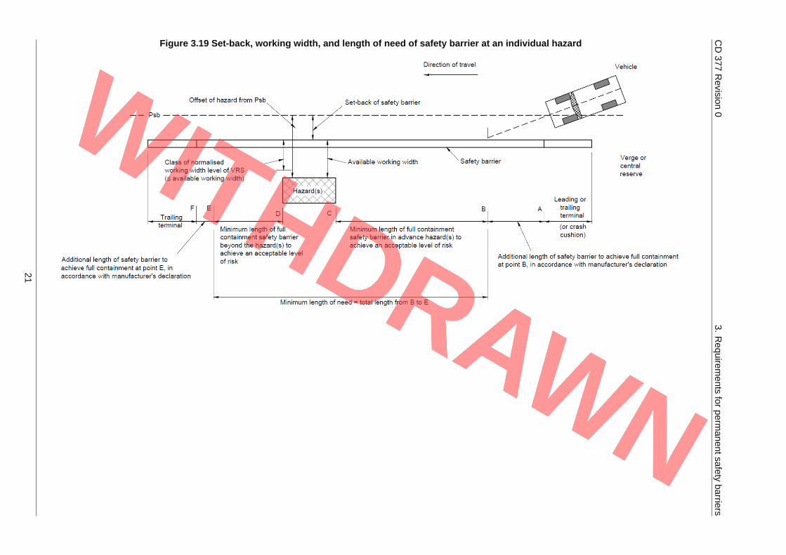
3.14 The total length of safety barrier shall be the length of need plus the additional lengths declared by themanufacturer in advance of, and after the length of need, to ensure that the safety barrier attains fullcontainment at the points required (see Figure 3.19).
NOTE 1 Example 1: a gantry in the verge of a dual carriageway has a length of 5.5m. If the length of need of anN2 safety barrier is 43 m (30m + hazard length of 5.5m + 7.5m), but full containment is only achieved20m from the safety barrier end of the terminal, then the minimum required length of safety barrierbetween terminals will be 83 m (i.e. 20 m + 30 m + hazard length of 5.5 m +7.5 m + 20 m).
NOTE 2 Example 2: a gantry in the verge of a single carriageway has a length of 5.5 m. If the length of need ofan N2 safety barrier is 65.5 m (30m + hazard length of 5.5m + 30m), but full containment is onlyachieved 20m from the safety barrier end of the terminal, then the minimum required length of safetybarrier between terminals will be 105.5 m (i.e. 20 m + 30 m + hazard length of 5.5 m + 30 m + 20 m).
Set-back3.15 All parts of a permanent VRS, including the terminals, shall meet the minimum set-back requirements
of CD 127 [Ref 4.N].
19
CD 377 Revision 0 3. Requirements for permanent safety barriers
3.15.1 Greater set-back should be provided where space allows.
3.16 Rates of change of set-back shall not be greater than that declared by the manufacturer.
3.17 The proposed design layout of the safety barrier shall be such that it:
1) has a flowing alignment along the length of the safety barrier;
2) changes in safety barrier profile do not occur abruptly;
3) any changes in angle of the safety barrier presented to oncoming traffic (i.e. the approach angle) arenot going to be significantly different in effect on an errant vehicle or on the safety barrier, to theangle(s) of approach at which the safety barrier has been tested or those declared by themanufacturer;
4) changes in alignment do not give rise to a 'pocketing' effect.
3.18 On the approach to structures, where the existing site geometry is restricted, if the taper or part of thetaper is included in the length of need, the structure shall be fully collision resistant.
3.19 At locations other than the approach to structures, any taper catering for changes in set-back shall notbe placed beyond point A on the approach and in advance of point D on the departure to a hazard, asshown in Figure 3.19.
20
CD377
Revision
03.
Requirem
entsfor
permanentsafety
barriers
Figure 3.19 Set-back, working width, and length of need of safety barrier at an individual hazard
21
CD 377 Revision 0 3. Requirements for permanent safety barriers
General requirements3.20 All hazards within or immediately adjacent to the highway boundary that can cause a danger to the
occupants of a vehicle or give rise to a secondary event were the vehicle to reach the hazard, or affectother parties shall be identified and assessed.
3.20.1 Where appropriate, hazards within or immediately adjacent to the highway boundary that can cause adanger to the occupants of a vehicle or give rise to a secondary event were the vehicle to reach thehazard, or affect other parties should also be listed in the risk assessment.
3.20.2 Examples of common hazards which should be included in the risk assessment are listed below:
1) above ground structural supports, bases or foundations positioned less than 3 m above the adjacentpaved carriageway where local conditions at the site make it possible for the hazard to be reached;
2) drainage culvert head walls and ditches where the depth of the ditch relative to the adjacent groundlevel is 1 m or greater;
3) restricted headroom at a structure or part of a structure (refer to CD 127 [Ref 4.N]);
4) surface of a rigid structure or construction (such as retaining and abutment walls) that do not have asmooth face adjacent to the traffic that extends at least 1.5 m above the adjacent carriageway level;
5) exposed rock faced cutting slopes, rock filled gabions, crib walling or similar structures;
6) soil cutting slopes and earth bunds greater than 1 m high and with a side slope gradient of 1:1 orsteeper;
7) embankments and vertical drops;
8) parapets (although these can form part of the VRS, their traffic facing ends can be a hazard andtheir presence needs to be identified);
9) strengthened or geotextile reinforced slopes;
10) environmental barriers or screens;
11) highway boundary fences and walls;
12) dwarf retaining walls surrounding hazards such as drainage access manholes and communicationcabinets;
13) permanent or expected water hazard with a depth of water of 0.6 m or more, such as a river,reservoir, stilling pond or lake or other hazard which, if entered, can potentially cause harm to thevehicle occupants;
14) road lighting columns, not certified as meeting the requirements of BS EN 12767 [Ref 24.N];
15) high mast road lighting columns;
16) sign and signal gantry supports including variable message signs (VMS);
17) sign/signal posts not certified as meeting the requirements of BS EN 12767 [Ref 24.N] and/or whichexceed the equivalent section properties of a tubular steel post having an external diameter of 89mm and a nominal wall thickness of 3.2 mm;
18) large signs (typically those higher than 2m) located in a position where the fascia is 1.5m or lessabove the adjacent carriageway and can potentially be struck by a vehicle;
19) above ground communications control cabinets, pillars and equipment (other than emergencytelephones), CCTV masts and telephone masts (refer to CD 354 [Ref 7.N], and TD 131 [Ref 34.N]);
20) stores for emergency/diversion signs and similar permanent structures;
21) wooden telegraph poles;
22) A tree or trees having, or expected to have, trunk girths of 250 mm or more (measured at a height of0.3 m above ground level) at maturity;
23) hazards where other parties can be affected:
a) subway entrance for vulnerable users or agricultural underbridge passing under the highway;b) a railway, canal or separate road or carriageway;
22
CD 377 Revision 0 3. Requirements for permanent safety barriers
c) public meeting places where a number of people are present for a significant time such as busshelters, places of worship, schools, hospitals, recreational, retail facilities or factories;
d) chemical works, petroleum storage tanks or depots, domestic gas canisters or tanks, facilitiesmanufacturing or storing hazardous materials in bulk;
e) other infrastructure, where the impact on the community / society as a whole is disproportional tothe damage caused. This can include significant utility (electrical, gas) or communicationsinfrastructure.
NOTE Vegetation such as small trees, shrubs and hedges in front of a safety barrier can cause a vehicle toimpact the safety barrier at a point higher than that at which it was tested, causing the vehicle to mountthe vegetation and/or launch the vehicle over the barrier.
3.21 Where assessment identifies which hazards or groups of hazards require a safety barrier, the length ofneed, set-back, normalised working width class, normalised vehicle intrusion class (where applicable)and other parameters for each hazard shall be determined.
3.22 Neither road furniture nor equipment shall be positioned on the carriageway side of the safety barrier,adjacent to a terminal or, with reference to Figure 3.19, within the length AC in advance of a hazard(s)or the length DF beyond a hazard(s).
3.23 A VRS shall not be placed within the normalised working width class or normalised vehicle intrusionclass of an adjacent VRS other than where a double sided safety barrier is designed to bifurcate intotwo separate single sided safety barriers.
3.24 Safety barrier layouts shall be planned to minimise the number of approach ends of safety barriers,gaps of 50 m or less between adjacent safety barrier installations closed, and the safety barrier madecontinuous, unless gaps are required for access or maintenance or the safety barriers are at differentoffsets.
3.25 Gaps of up to 100 m shall be closed, unless there are significant cost, technical and/or accessrequirements for the gap to remain open.
3.26 Where a gap between safety barrier installations cannot be physically closed due to the safety barriersbeing at different offsets, or where maintenance or access for vulnerable users is required, theinstallations shall be arranged to minimise the probability of a vehicle impacting the first safety barrierand being directed into the leading terminal of the second safety barrier, or into the hazard that thesecond safety barrier is protecting.
3.27 The verge and central reserve below and immediately in front of and behind the safety barrier shall bewithout abrupt changes in level.
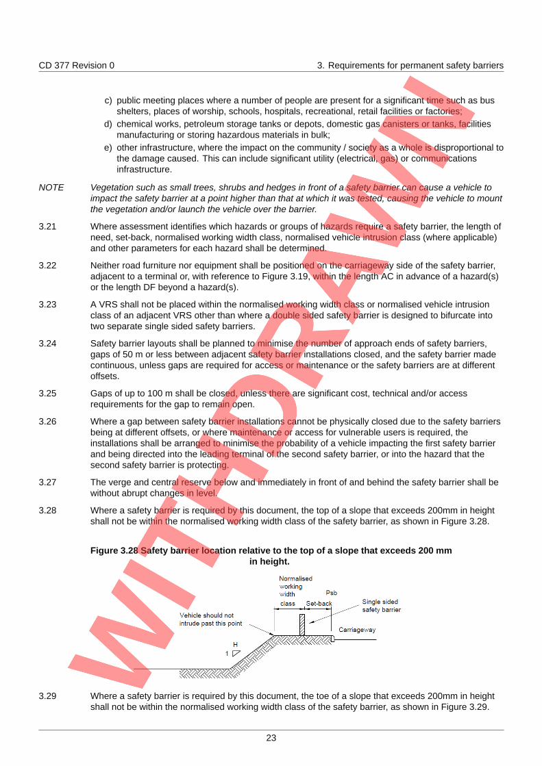
3.28 Where a safety barrier is required by this document, the top of a slope that exceeds 200mm in heightshall not be within the normalised working width class of the safety barrier, as shown in Figure 3.28.
Figure 3.28 Safety barrier location relative to the top of a slope that exceeds 200 mmin height.
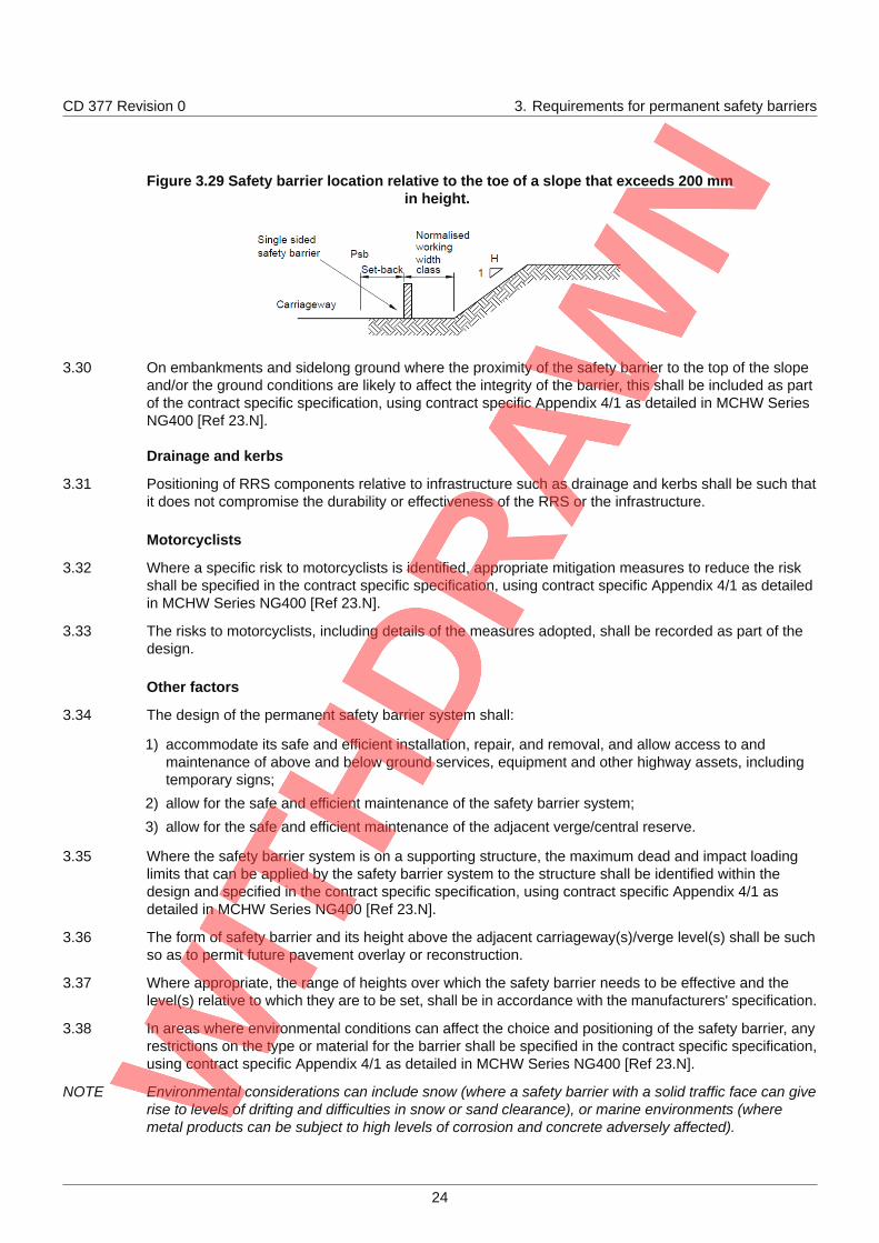
3.29 Where a safety barrier is required by this document, the toe of a slope that exceeds 200mm in heightshall not be within the normalised working width class of the safety barrier, as shown in Figure 3.29.
23
CD 377 Revision 0 3. Requirements for permanent safety barriers
Figure 3.29 Safety barrier location relative to the toe of a slope that exceeds 200 mmin height.
3.30 On embankments and sidelong ground where the proximity of the safety barrier to the top of the slopeand/or the ground conditions are likely to affect the integrity of the barrier, this shall be included as partof the contract specific specification, using contract specific Appendix 4/1 as detailed in MCHW SeriesNG400 [Ref 23.N].
Drainage and kerbs
3.31 Positioning of RRS components relative to infrastructure such as drainage and kerbs shall be such thatit does not compromise the durability or effectiveness of the RRS or the infrastructure.
Motorcyclists
3.32 Where a specific risk to motorcyclists is identified, appropriate mitigation measures to reduce the riskshall be specified in the contract specific specification, using contract specific Appendix 4/1 as detailedin MCHW Series NG400 [Ref 23.N].
3.33 The risks to motorcyclists, including details of the measures adopted, shall be recorded as part of thedesign.
Other factors
3.34 The design of the permanent safety barrier system shall:
1) accommodate its safe and efficient installation, repair, and removal, and allow access to andmaintenance of above and below ground services, equipment and other highway assets, includingtemporary signs;
2) allow for the safe and efficient maintenance of the safety barrier system;
3) allow for the safe and efficient maintenance of the adjacent verge/central reserve.
3.35 Where the safety barrier system is on a supporting structure, the maximum dead and impact loadinglimits that can be applied by the safety barrier system to the structure shall be identified within thedesign and specified in the contract specific specification, using contract specific Appendix 4/1 asdetailed in MCHW Series NG400 [Ref 23.N].
3.36 The form of safety barrier and its height above the adjacent carriageway(s)/verge level(s) shall be suchso as to permit future pavement overlay or reconstruction.
3.37 Where appropriate, the range of heights over which the safety barrier needs to be effective and thelevel(s) relative to which they are to be set, shall be in accordance with the manufacturers' specification.
3.38 In areas where environmental conditions can affect the choice and positioning of the safety barrier, anyrestrictions on the type or material for the barrier shall be specified in the contract specific specification,using contract specific Appendix 4/1 as detailed in MCHW Series NG400 [Ref 23.N].
NOTE Environmental considerations can include snow (where a safety barrier with a solid traffic face can giverise to levels of drifting and difficulties in snow or sand clearance), or marine environments (wheremetal products can be subject to high levels of corrosion and concrete adversely affected).
24
CD 377 Revision 0 3. Requirements for permanent safety barriers
3.39 Where there is a risk of falling materials/rocks reaching the verge, mitigation shall be put in place toensure the safety barrier is not required to contain or restrain this material.
3.40 Any mitigation to reduce the risk of falling materials/rocks shall not effect the performancecharacteristics of the safety barrier.
3.41 As part of the assessment of appropriate VRS provision, the costs of protecting an asset identified as ahazard against the costs of replacing the asset and/or the costs and implications of the asset being outof service or unavailable for a period of time shall be assessed and recorded.
Passively safe road furniture and equipment, and vehicle restraint systems3.42 Passively safe road furniture shall be used in accordance with the National Annex to BS EN 12767 [Ref
24.N], such as sign/signal supports and lighting columns, as an alternative to protecting the hazardthrough safety barriers:
1) unless there is another hazard at the location which cannot be removed, relocated or madepassively safe and that requires the provision of VRS;
2) at roundabouts or junctions where there is insufficient room for full VRS provision;
3) where VRS can be vulnerable to full frontal impact or cannot be provided with the correct orientationfor all the anticipated directions of traffic movement.
3.43 Passively safe road furniture or equipment placed within the normalised working width class of a safetybarrier shall have an energy absorption category of NE (as defined by BS EN 12767 [Ref 24.N]).
3.43.1 Passively safe road furniture or equipment may be located within the normalised working width class ofa single sided safety barrier in the verge, as long as it is demonstrated that:
1) space is limited and the passively safe furniture cannot be located outside the normalised workingwidth class of the existing safety barrier; and
2) a safety barrier with a sufficiently small normalised working width class cannot be used; and
3) it is necessary to install the safety barrier for hazard(s) other than the passively safe furniture (i.e.the barrier cannot be removed); and
4) the sign/signal posts demonstrates the same collapse mechanism(s) as that witnessed in the BS EN12767 [Ref 24.N] testing if impacted in the proposed installation location; and
5) the arrangement does not present a risk of a secondary incident.
3.43.2 Passively safe sign/signal posts (excluding those with slip bases) may be located within the normalisedworking width class of a single sided safety barrier in the central reserve, as long as it is demonstratedthat:
1) space is limited and the sign/signal posts cannot be placed outside the working width of the safetybarrier; and
2) a safety barrier with a sufficiently small working width class cannot be used; and
3) it is necessary to install the safety barrier for hazard(s) other than the passively safe furniture (i.e.the barrier cannot be removed); and
4) the sign/signal posts demonstrates the same collapse mechanism(s) as that witnessed in the BS EN12767 [Ref 24.N] testing if impacted in the proposed installation location; and
5) the arrangement does not present a risk of a secondary incident.
3.43.3 Reducing the size of sign/signal support posts by providing more posts should not be used to overcomethe requirement to provide a safety barrier.
NOTE As post spacing decreases, there is an increasing tendency for more than one post to be hit by avehicle and for the sign and posts to act together as a relatively stiff and rigid hazard, thus significantlyincreasing its aggressiveness and potential to cause damage and injury. Further information can befound within BS EN 12767 [Ref 24.N].
25
CD 377 Revision 0 3. Requirements for permanent safety barriers
Safety barrier provision at structural supports3.44 Where a safety barrier is required at a collision resistant structure or abutment to give an acceptable
level of risk to the occupants of an errant vehicle, the structure or abutment's structural integrity shall bemaintained following an impact (see CS 453 [Ref 40.N]).
NOTE 1 Where a normal containment level safety barrier is required, this safety barrier is generally not intendedto provide protection for the structure, only to reduce the risk of injury to road users.
NOTE 2 Abutments are not normally considered to be at risk as a result of vehicle collision as they are assumedto have sufficient mass to withstand the collision loads for global purposes; (see CS 453 [Ref 40.N] (forexisting bridges) or BS EN 1991-1-7 [Ref 11.N] (for new structures).
3.45 Structural supports, such as bridge abutments and piers shall be assessed in accordance with CS 453[Ref 40.N] (existing structures) or designed in accordance with BS EN 1991-1-7 [Ref 11.N] (newstructures) to determine the minimum containment level and normalised working width class requiredby a safety barrier.
3.46 Where a safety barrier is required and a CS 453 [Ref 40.N] assessment or BS EN 1991-1-7 [Ref 11.N]design determines that the structure is assessed/designed for main load conditions, a minimum N2containment level safety barrier with full normalised working width class shall be specified in thecontract specific specification Appendix 4/1 as detailed in MCHW Series NG400 [Ref 23.N].
3.47 Where a safety barrier is required and a CS 453 [Ref 40.N] assessment or BS EN 1991-1-7 [Ref 11.N]design determines that the structure is not assessed/designed for main load or residual load conditions,higher or very high containment level safety barrier shall be specified in the contract specificspecification Appendix 4/1 as detailed in MCHW Series NG400 [Ref 23.N].
3.48 Where a safety barrier is required and a CS 453 [Ref 40.N] assessment or BS EN 1991-1-7 [Ref 11.N]design determines that the structure is not assessed/designed for main load or residual load conditions,the normalised working width class and normalised vehicle intrusion class shall be specified tominimise the risk of the structure being struck by a vehicle.
3.49 Where the assessment of impact of an overhanging or intruding part of a vehicle with the structure isaccepted by the Overseeing Organisation, a higher or very high containment level safety barrier with aminimum height of 1.5 m shall be specified in the contract specific specification Appendix 4/1 asdetailed in MCHW Series NG400 [Ref 23.N].
3.50 Where the assessment of impact of an overhanging or intruding part of a vehicle with the structure isaccepted by the Overseeing Organisation, the structure shall be assessed/designed for residualloading.
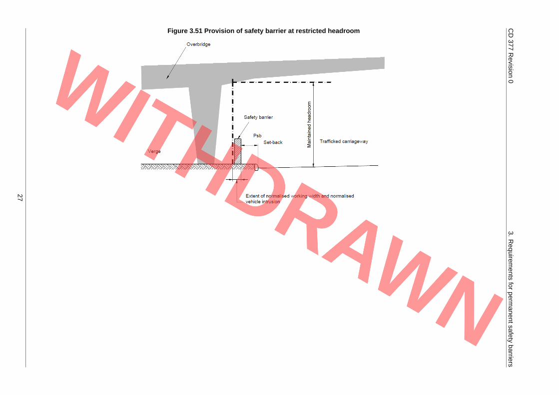
3.51 Where the minimum headroom to an overbridge in the verge is less than the required maintainedheadroom, a safety barrier shall be placed no closer to the point where the maintained headroom islost, than as shown in Figure 3.51.
26
CD377
Revision
03.
Requirem
entsfor
permanentsafety
barriers
Figure 3.51 Provision of safety barrier at restricted headroom
27
CD 377 Revision 0 3. Requirements for permanent safety barriers
3.52 Where the minimum headroom to an overbridge in the verge is less than the required maintainedheadroom, and where the set-back to the safety barrier is greater than or equal to 1.5 m, themaintained headroom shall be measured from the adjacent verge level rather than from the edge ofcarriageway level.
3.53 Where any part of an abutment or structure that is less than the maintained headroom above theadjacent edge of carriageway level is within the normalised working width class and/or normalisedvehicle intrusion class, it shall be assessed for main and residual loading.
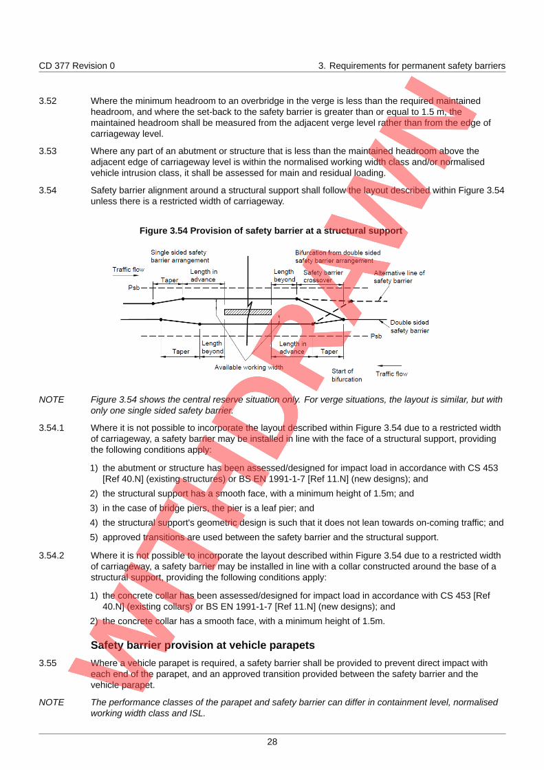
3.54 Safety barrier alignment around a structural support shall follow the layout described within Figure 3.54unless there is a restricted width of carriageway.
Figure 3.54 Provision of safety barrier at a structural support
NOTE Figure 3.54 shows the central reserve situation only. For verge situations, the layout is similar, but withonly one single sided safety barrier.
3.54.1 Where it is not possible to incorporate the layout described within Figure 3.54 due to a restricted widthof carriageway, a safety barrier may be installed in line with the face of a structural support, providingthe following conditions apply:
1) the abutment or structure has been assessed/designed for impact load in accordance with CS 453[Ref 40.N] (existing structures) or BS EN 1991-1-7 [Ref 11.N] (new designs); and
2) the structural support has a smooth face, with a minimum height of 1.5m; and
3) in the case of bridge piers, the pier is a leaf pier; and
4) the structural support's geometric design is such that it does not lean towards on-coming traffic; and
5) approved transitions are used between the safety barrier and the structural support.
3.54.2 Where it is not possible to incorporate the layout described within Figure 3.54 due to a restricted widthof carriageway, a safety barrier may be installed in line with a collar constructed around the base of astructural support, providing the following conditions apply:
1) the concrete collar has been assessed/designed for impact load in accordance with CS 453 [Ref40.N] (existing collars) or BS EN 1991-1-7 [Ref 11.N] (new designs); and
2) the concrete collar has a smooth face, with a minimum height of 1.5m.
Safety barrier provision at vehicle parapets3.55 Where a vehicle parapet is required, a safety barrier shall be provided to prevent direct impact with
each end of the parapet, and an approved transition provided between the safety barrier and thevehicle parapet.
NOTE The performance classes of the parapet and safety barrier can differ in containment level, normalisedworking width class and ISL.
28
CD 377 Revision 0 3. Requirements for permanent safety barriers
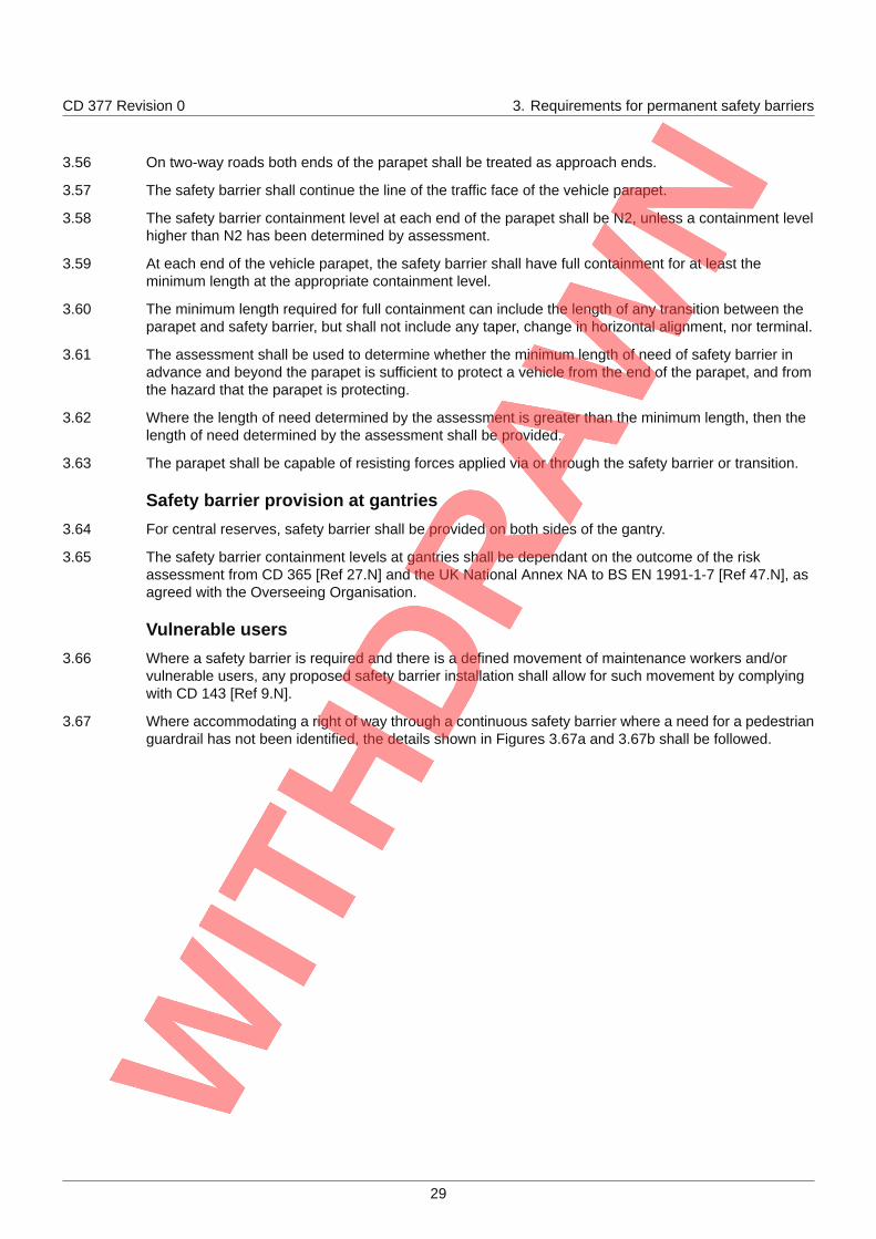
3.56 On two-way roads both ends of the parapet shall be treated as approach ends.
3.57 The safety barrier shall continue the line of the traffic face of the vehicle parapet.
3.58 The safety barrier containment level at each end of the parapet shall be N2, unless a containment levelhigher than N2 has been determined by assessment.
3.59 At each end of the vehicle parapet, the safety barrier shall have full containment for at least theminimum length at the appropriate containment level.
3.60 The minimum length required for full containment can include the length of any transition between theparapet and safety barrier, but shall not include any taper, change in horizontal alignment, nor terminal.
3.61 The assessment shall be used to determine whether the minimum length of need of safety barrier inadvance and beyond the parapet is sufficient to protect a vehicle from the end of the parapet, and fromthe hazard that the parapet is protecting.
3.62 Where the length of need determined by the assessment is greater than the minimum length, then thelength of need determined by the assessment shall be provided.
3.63 The parapet shall be capable of resisting forces applied via or through the safety barrier or transition.
Safety barrier provision at gantries3.64 For central reserves, safety barrier shall be provided on both sides of the gantry.
3.65 The safety barrier containment levels at gantries shall be dependant on the outcome of the riskassessment from CD 365 [Ref 27.N] and the UK National Annex NA to BS EN 1991-1-7 [Ref 47.N], asagreed with the Overseeing Organisation.
Vulnerable users3.66 Where a safety barrier is required and there is a defined movement of maintenance workers and/or
vulnerable users, any proposed safety barrier installation shall allow for such movement by complyingwith CD 143 [Ref 9.N].
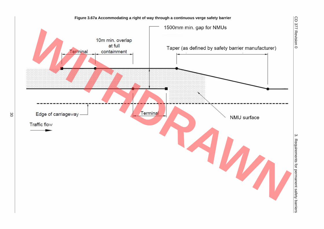
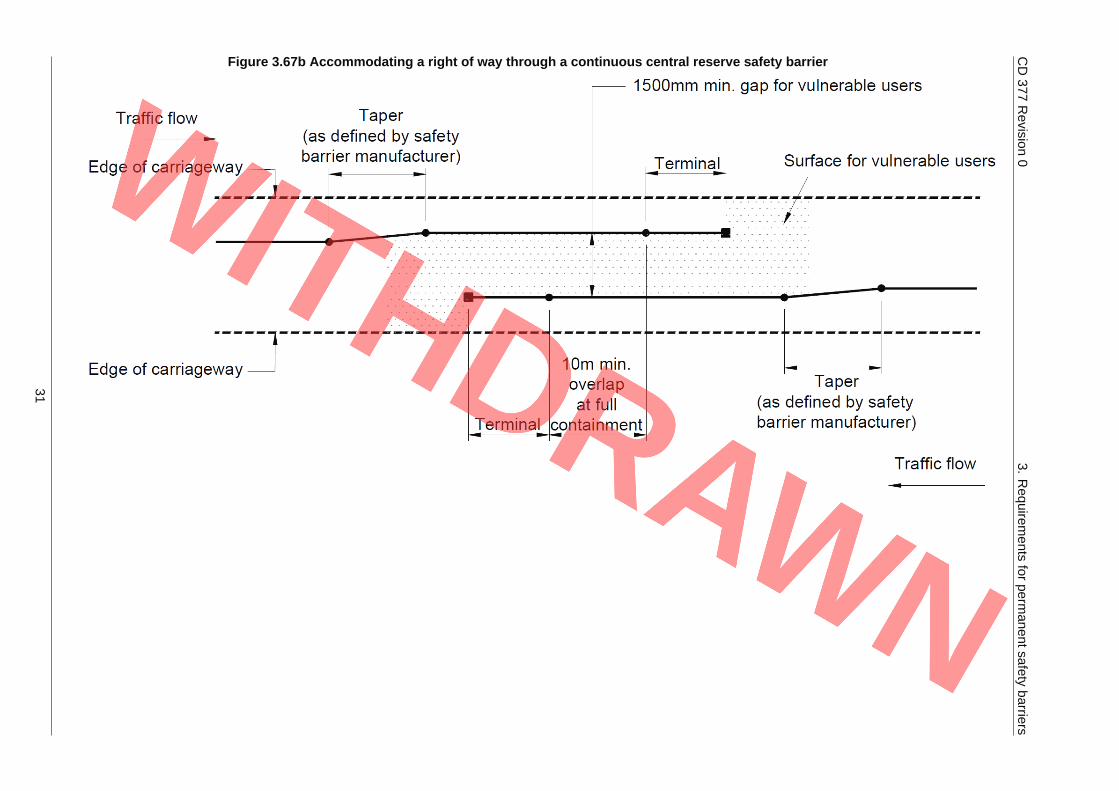
3.67 Where accommodating a right of way through a continuous safety barrier where a need for a pedestrianguardrail has not been identified, the details shown in Figures 3.67a and 3.67b shall be followed.
29
CD377
Revision
03.
Requirem
entsfor
permanentsafety
barriers
Figure 3.67a Accommodating a right of way through a continuous verge safety barrier
30
CD377
Revision
03.
Requirem
entsfor
permanentsafety
barriers
Figure 3.67b Accommodating a right of way through a continuous central reserve safety barrier
31
CD 377 Revision 0 3. Requirements for permanent safety barriers
NOTE The detail shown in Figure 3.67b is for high speed limit roads where pedestrian use is expected to below, and either there is no requirement for pedestrian guardrail, or its use cannot be justified.
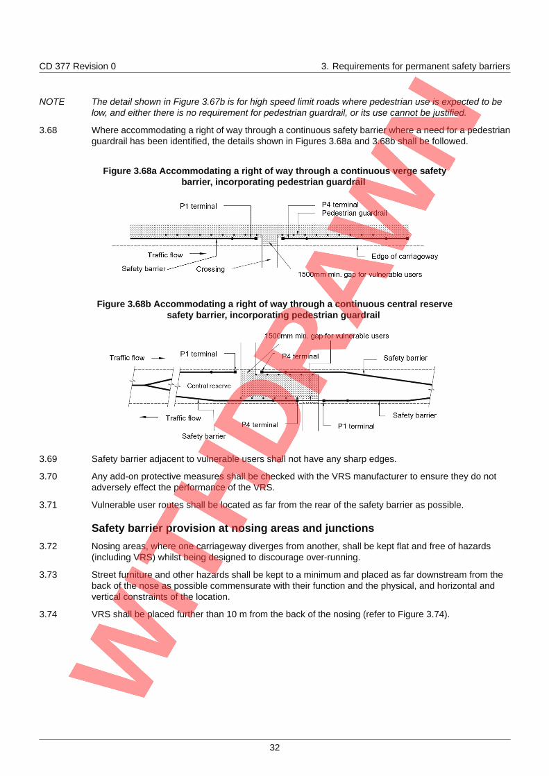
3.68 Where accommodating a right of way through a continuous safety barrier where a need for a pedestrianguardrail has been identified, the details shown in Figures 3.68a and 3.68b shall be followed.
Figure 3.68a Accommodating a right of way through a continuous verge safetybarrier, incorporating pedestrian guardrail
Figure 3.68b Accommodating a right of way through a continuous central reservesafety barrier, incorporating pedestrian guardrail
3.69 Safety barrier adjacent to vulnerable users shall not have any sharp edges.
3.70 Any add-on protective measures shall be checked with the VRS manufacturer to ensure they do notadversely effect the performance of the VRS.
3.71 Vulnerable user routes shall be located as far from the rear of the safety barrier as possible.
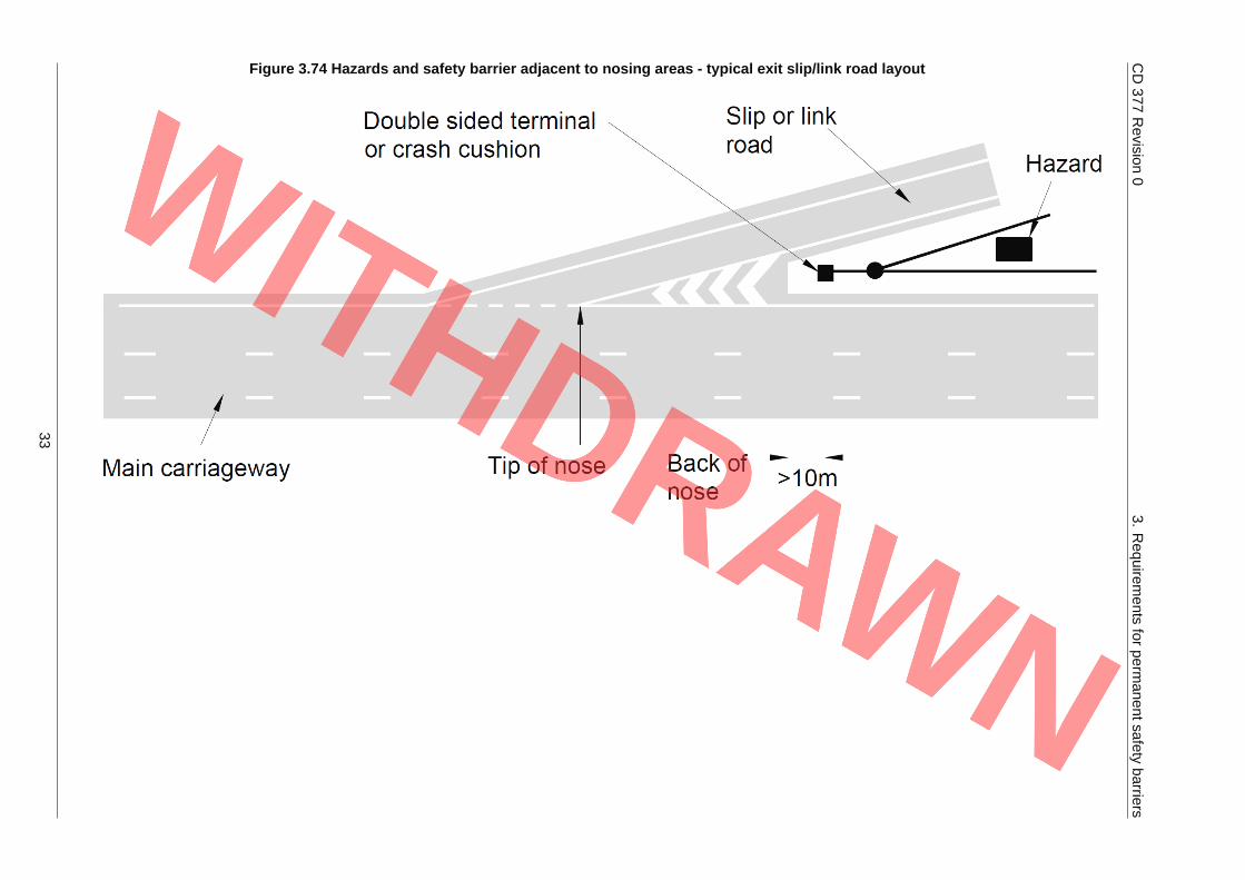
Safety barrier provision at nosing areas and junctions3.72 Nosing areas, where one carriageway diverges from another, shall be kept flat and free of hazards
(including VRS) whilst being designed to discourage over-running.
3.73 Street furniture and other hazards shall be kept to a minimum and placed as far downstream from theback of the nose as possible commensurate with their function and the physical, and horizontal andvertical constraints of the location.
3.74 VRS shall be placed further than 10 m from the back of the nosing (refer to Figure 3.74).
32
CD377
Revision
03.
Requirem
entsfor
permanentsafety
barriers
Figure 3.74 Hazards and safety barrier adjacent to nosing areas - typical exit slip/link road layout
33
CD 377 Revision 0 3. Requirements for permanent safety barriers
3.75 Where safety barrier protection is required to protect hazards, (including the level difference betweenthe adjacent carriageways), the safety barrier shall be positioned relative to the hazard such that theminimum requirements of the safety barrier and its associated terminals (or crash cushions), transitionsand tapers are met.
NOTE 1 Traffic on an adjacent slip or link road that is following a broadly parallel alignment and similar level tothe mainline carriageway is not seen as a hazard to traffic on the mainline carriageway, and vice versa.
NOTE 2 Safety barrier can be warranted due to the intervening ground profile and the presence of hazards suchas street furniture.
3.76 At junctions without VRS, the level of risk of injury to road users shall be minimised.
3.76.1 The risk of injury may be mitigated through the use of passively safe signs, larger signs placed furtherfrom the carriageway, vehicle actuated signs, road markings, high friction surfacing, improved sightlines.
3.76.2 At junctions, where other solutions are unavailable to lower the level of risk of injury to road users, thenVRS may be proposed.
Safety barrier provision in central reserves - general3.77 Where the distance across the central reserve between the points from which set-back for each
carriageway is measured (i.e. Psb to Psb) is 10m or less, a central reserve safety barrier shall beprovided.
3.78 Where the distance Psb to Psb across the central reserve is more than 10m, a risk assessment shall beused to determine the need for, location and extent of safety barrier(s) and their containment levelbased on:
1) the hazards that are present and their location; and
2) the intervening topography; and
3) the likelihood of a vehicle crossing to the other carriageway.
3.79 Where a safety barrier in the central reserve is required, it shall be provided on both sides of a hazardexcept:
1) where the topography of the central reserve makes it impossible for the hazard to be reached fromone carriageway, or
2) where the Overseeing Organisation agrees that road lighting columns, signals or signs, passivelysafe or fully collision resistant gantry legs or signs can be mounted on the central reserve safetybarrier, and the width of the safety barrier is increased to accommodate the column or post and itsfixings.
3.80 Where the topography of the central reserve makes it impossible for the hazard to be reached from onecarriageway, the safety barrier shall be placed only on the side of the hazard that can be reached.
3.81 Where there are no hazards in the central reserve and there is a difference in the opposing edge ofcarriageway levels of 200 mm or more, the safety barrier shall be installed adjacent to the highercarriageway.
3.82 Where there is a risk of vehicle impact with a non-traffic face of a safety barrier, vehicles mounting orgetting under it or overturning on the slope due to the height difference between the carriageways andthe ground profile across the central reserve, a separate safety barrier shall be placed adjacent to thelower carriageway.
3.83 The Overseeing Organisation's specific requirements for the containment level and performance of thecentral reserve safety barrier shall apply.
NOTE The specific requirements for the minimum containment level and performance of central reservesafety barrier are provided in the National Application Annexes.
34
CD 377 Revision 0 3. Requirements for permanent safety barriers
Requirements for gaps in the central reserve3.84 Other than where it has been determined that no safety barrier is required, there shall be no gaps in the
central reserve safety barrier on motorways or on roads constructed to motorway requirements.
3.85 Existing gaps in central reserve safety barriers on motorways or all-purpose trunk roads shall be closedunless they are required for the efficient operation and management of the road.
3.86 On other dual carriageway roads, gaps in an otherwise continuous central reserve safety barrier shallbe restricted to the absolute minimum necessary for the efficient operation and management of theroad.
General requirements for an emergency crossing point/maintenance crossing point (ECP/MCP)
3.87 An emergency crossing point/maintenance crossing point (ECP/MCP) shall only be installed with theapproval of the Overseeing Organisation.
NOTE For the majority of the time, the ECP/MCP is in the closed configuration and hence, is required tofunction as a permanent safety barrier.
3.88 Where an ECP/MCP exists on a road which is to be improved or which is subjected to majormaintenance, assessment shall be undertaken to confirm the need for the ECP to be retained with theOverseeing Organisation and relevant Emergency Services.
3.89 An ECP shall have a maximum length of 25 m and be designed using a location specific swept pathanalysis.
NOTE An ECP will typically have a minimum length of 16 m, but this can be as short as 4 m, for specificapplications.
3.90 The safety barrier system for an ECP/MCP shall be specified in the contract specific specificationAppendix 4/1 as detailed in MCHW Series NG400 [Ref 23.N], in terms of containment level andnormalised working width class.
3.91 The ECP/MCP containment level shall be equal to or greater than that of the adjacent safety barrier.
3.92 Transitions in accordance with the requirements of this document shall be used between the safetybarrier and the ECP/MCP system.
3.93 The normalised working width class of the ECP/MCP shall not encroach into the opposing carriageway.
3.94 Any location specific requirements for the ECP/MCP shall be specified in contract specific Appendix 4/1as detailed in MCHW Series NG400 [Ref 23.N], such as maximum acceptable time taken for openingand closing, and storage requirements whilst the ECP/MCP is open (where applicable).
NOTE An opening time of 30 minutes or less is generally acceptable for an ECP.
Use of gates at an ECP/MCP
3.95 Where a gate is provided at an ECP/MCP, the gate shall meet the requirements of BS DD ENV 1317-4[Ref 26.N].
3.95.1 The length of the openable leaves of the gate (and hence, the overall length of the crossing) should beidentified so that it is ensured that, when in the open position, the requisite number of lanes areprotected by the safety barrier.
3.95.2 The means by which the openable leaves of the gate are opened/closed and the effect that thisoperation can have on the practicability of opening and closing the gate, should be identified.
3.95.3 Any tools required for the operation of a gate at an ECP should be supplied within the ECP and/or beeasily accessible.
Use of demountable permanent barrier at an MCP
3.96 For an MCP, it shall be possible to dismantle and reinstate the permanent safety barrier quickly.
35
CD 377 Revision 0 3. Requirements for permanent safety barriers
3.96.1 Socketed posts may be specified to allow the permanent safety barrier to be dismantled and reinstatedquickly.
NOTE The time for the dismantling and reinstatement of barriers varies depending on the safety barrier and, ifused, can mean a lot of repair work to reinstate the safety barrier.
3.97 With the exception of emergency usage, whenever a section of safety barrier is removed, the ends ofthe safety barrier shall be made safe.
NOTE The ends of a safety barrier can be made safe through the use of terminals, crash cushions, transitionsand/or a gate.
Additional requirements for "open" ECPs
3.98 Retained "open" ECPs shall be closed with a row of suitable traffic cylinders of at least 600 mm inheight.
3.98.1 Retained "open" ECPs should be gated.
3.99 Traffic cylinders used in retained "open" ECPs shall be spaced at a maximum of 1.0m centres betweenthe end terminals of the safety barriers.
3.100 Verge and central reserve marker posts and/or reflectors shall be erected on each approach to the ECP.
3.101 The alignment of the two opposing sections of safety barrier and their end terminals at an "open" ECP(or other open central reserve crossing point) shall be such that a vehicle impacting the safety barrierprior to the gap is directed away from and not towards the leading terminal of the downstream safetybarrier.
3.102 At "open" ECPs, the terminal specification shall be in accordance with Section 5 of this document.
NOTE Typical alignments are shown in Figure 3.102N.
36
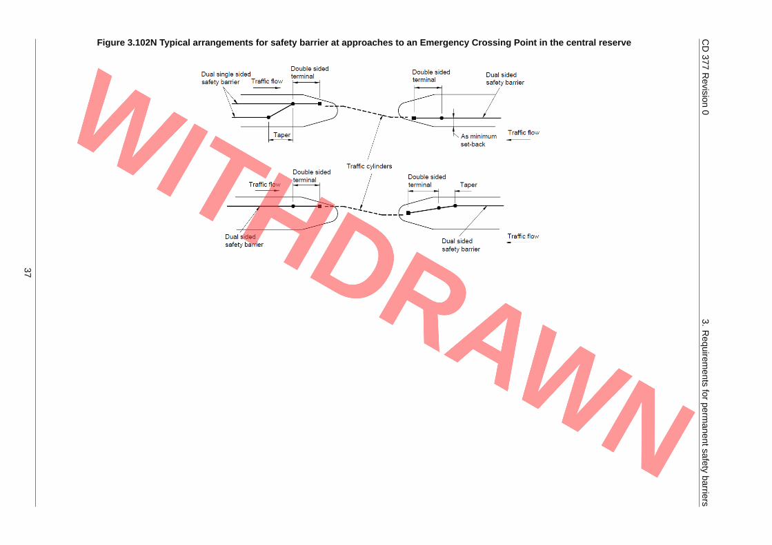
CD377
Revision
03.
Requirem
entsfor
permanentsafety
barriers
Figure 3.102N Typical arrangements for safety barrier at approaches to an Emergency Crossing Point in the central reserve
37

CD 377 Revision 0 3. Requirements for permanent safety barriers
Additional requirements for maintenance crossing points and maintenance access
3.103 Where MCPs (see CD 192 [Ref 42.N]) are provided to facilitate contraflow traffic flows during schemesand tunnel maintenance, the layout shall be such that the open and closed layouts and the gatedeployment do not present additional hazards to the road user or road worker.
NOTE Guidance on factors relating to ECPs and MCPs is given in Appendix B of this document.
3.104 Allowance shall be made in the length of gate specified for any impact resistant terminal end to thesafety barrier.
3.105 Where the regular routine maintenance regime requires short period contraflow operation, the safetybarrier used to close the gap shall have a minimum containment level equal to that of the adjacentsafety barrier.
3.106 Where the regular routine maintenance regime does not require short period contraflow operation, oncompletion of the works, any MCP gap(s) shall be closed by re-instating the original safety barrier(s).
3.107 Any 'above ground' elements of the temporary end termination(s) of the safety barrier shall be removed.
3.108 Transitions shall be used between the permanent sections of safety barrier and 'removable' sectionsand temporary end termination(s).
Winter maintenance crossing points (WMCP)
3.109 Where directed by the Overseeing Organisation, a central reserve WMCP shall be provided.
3.110 The WMCP shall preclude unauthorised access or use.
3.111 The central reserve at a WMCP shall safely accommodate transversely between the carriageway andthe gate, all winter maintenance vehicles and associated equipment likely to be deployed.
3.112 When open, gates shall not encroach into the set-back of either carriageway.
3.113 Signs and traffic cylinders complying with Diagram 7103 of TSRGD [Ref 45.N] and of the TSR(NI) 1997[Ref 44.N] at 1.0m (maximum) centres shall be placed within the WMCP and either side of any gatethat is installed to limit misuse of the WMCP.
Other gaps in the central reserve, and provision at start and end points of dual carriageways
3.114 Where directed by the Overseeing Organisation to provide a gap complying with CD 123 [Ref 13.N],the arrangement of the safety barrier ends shall comply with the requirements of this document.
3.115 Assessment shall investigate and weigh options and mitigation (other than the provision of safetybarrier) against the use of safety barrier, and mitigation in combination with safety barrier, identifyingwhere fully compliant and partially compliant safety barrier installations can be achieved.
38
CD 377 Revision 0 4. Requirements for vehicle parapets
4. Requirements for vehicle parapets4.1 All VRS installations that include vehicle parapets shall be compatible with each other throughout the
entire installation length (including any safety barriers, other parapets, terminals, transitions and crashcushions) and meet the requirements of this Section 4.
4.2 For each vehicle parapet installation, based on the site specific conditions, the following and all otherrelevant requirements of MCHW Series 400 [Ref 22.N] and the associated MCHW Series NG400 [Ref23.N] shall be specified in the contract specific specification, using contract specific Appendix 4/1, asdetailed in MCHW Series NG400 [Ref 23.N]:
1) containment level;
2) impact severity level (ISL);
3) set-back;
4) normalised working width class (W);
5) normalised vehicle intrusion class (VI);
6) maximum height that allows the required visibility (refer to CD 127 [Ref 4.N] and CD 109 [Ref 15.N]);
7) length of need;
8) any special requirements (e.g. environmental considerations, minimum height above the pavedsurface for the purpose intended, clearance to hazards that are vulnerable to residual loading andloading requirements for structures, parapet plinth width).
NOTE 1 Vehicle parapets are intended to contain errant vehicles and protect road users from a vertical or nearvertical drop that is not protected by a safety barrier or other suitable restraint. In addition, they can berequired to protect the area below.
NOTE 2 A vehicle parapet typically extends along the full length of a bridge deck (including the wing-walls)and/or along the full length of any other structure.
4.3 The design shall be the optimum solution for the hazard having achieved compliance with themandatory requirements, the conditions of a relaxation (where applicable), a broadly acceptable levelof risk or having obtained a departure from requirements.
Minimum containment levels where the road is not carried over or adjacent to arailway
4.4 On roads with a speed limit of 50 mph or more, the minimum containment levels for vehicle parapetsshall be:
1) normal containment level: N2;
2) higher containment level: H2;
3) very high containment level: H4a.
4.5 On roads with a speed limit of less than 50 mph, the minimum containment level for vehicle parapetsshall be:.
1) normal containment level: N1;
2) higher containment level: H2;
3) very high containment level: H4a.
4.6 Where a site-specific risk assessment indicates that a containment level higher than the minimum levelis required, the higher containment level shall be specified.
4.7 Where the need for a higher containment level or very high containment level vehicle parapet has beenidentified, the nature of the risk, any mitigation with the steps taken to reduce the risk and the resultingcontainment level required shall be recorded.
39
CD 377 Revision 0 4. Requirements for vehicle parapets
Minimum containment level requirements where the road is carried over oradjacent to a railwayNew bridges and structures (except accommodation bridges)
4.8 On a new bridge or structure (except accommodation bridges) over or adjacent to a railway, an H4acontainment level vehicle parapet shall be provided, regardless of the road class.
Existing bridges and structures (except accommodation bridges)
4.9 On an existing structure over or adjacent to a railway (except accommodation bridges), an H4acontainment parapet shall be provided.
4.9.1 Where an H4a parapet cannot be provided without undue cost, the highest containment provisionpossible should be provided, which incorporates the output from the RRRAP and the cost of providing asuitable support structure.
4.9.2 Where an H4a parapet cannot be provided without undue cost, the vehicle parapet containment levelshould not be lower than the normal containment level.
4.9.3 Where an H4a parapet cannot be provided without undue cost, agreement should be sought throughearly engagement with the Railway Authority and the Overseeing Organisation.
New and existing accommodation bridges
4.10 The minimum vehicle parapet containment level shall be the normal containment level.
4.11 Where a site-specific risk assessment indicates that a containment level higher than the minimum levelis required, the higher containment level shall be specified following confirmation from the OverseeingOrganisation and the Railway Authority.
4.12 Where the need for a higher containment level or very high containment level vehicle parapet has beenidentified, the nature of the risk, any mitigation with the steps taken to reduce the risk and the resultingcontainment level required shall be recorded.
Impact severity level4.13 The ISL shall be either level A or B.
Normalised working width class and normalised vehicle intrusion class4.14 For normal containment level vehicle parapets, the maximum identified value of normalised working
width class that the local hazard(s) allow, shall be used.
4.15 For higher and very high containment level vehicle parapets, the maximum identified values ofnormalised working width class and normalised vehicle intrusion class that the local hazard(s) allow,shall be used.
4.15.1 The edge of the bridge deck should be included as a hazard in the risk assessment.
4.16 An assessment shall be undertaken to determine whether modification of the structure is viable and anAIP obtained.
Length of need4.17 During testing to BS EN 1317-2 [Ref 32.N], the test length of the vehicle parapet shall be sufficient to
demonstrate the full performance characteristics of the vehicle parapet at the length of need.
4.18 Where higher containment level (H2) or very high containment level (H4a) vehicle parapet is required ata hazard adjacent to the vehicle parapet where other parties can be affected (such as at an adjacentroad or railway), the length of the higher or very high containment parapet shall extend to the lesser of:
40
CD 377 Revision 0 4. Requirements for vehicle parapets
1) the length of the bridge deck and along the full length of the wing-walls where they broadly follow theroad alignment, or along the full length of the structure where it runs alongside and or over theadjacent hazard;
2) on two-way carriageways, between a position 25m in advance of the nearer point of no recovery tothe adjacent hazard in each direction i.e. 25m plus length of adjacent hazard between these pointsof no recovery plus 25m; but not further at either end than required by (1) above;
3) on one-way carriageways, from a position 25m in advance of the nearer point of no recovery to theadjacent hazard to a position 10m beyond the further point of no recovery to the adjacent hazard,i.e. 25m plus length of adjacent hazard between these points of no recovery plus 10m; but notfurther at either end than required by (1) above.
4.18.1 On a long structure spanning more than one adjacent hazard, where the higher containment or veryhigh containment level parapet extents from clause 4.18(2) or clause 4.18(3) do not overlap or extendto the limits in clause 4.18(1) above, normal containment level parapet with suitable transitions may beused over the intermediate length(s).
4.19 Where the length of need for each hazard overlaps and the required containment levels differ, the riskassessment shall confirm that the higher of the containment levels starts/finishes so as to achieve thecorrect length of need for the hazard requiring the higher containment.
NOTE Refer to Figure 4.19N for examples of length of need and localised parapet containment level, where Aand B are short structures and C and D are long structures (such as viaducts).
41
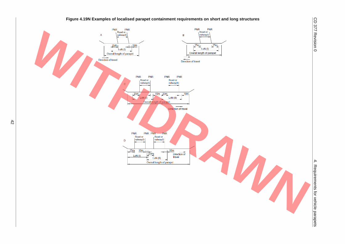
CD377
Revision
04.
Requirem
entsfor
vehicleparapets
Figure 4.19N Examples of localised parapet containment requirements on short and long structures
42
CD 377 Revision 0 4. Requirements for vehicle parapets
Minimum height of parapets4.20 The height of vehicle parapets (including combined vehicle/pedestrian parapets) shall not be less than
1000mm.
4.21 For cycleways immediately adjacent to the vehicle parapet and for accommodation bridges, theminimum height of the parapet shall be 1500mm.
4.22 For very high containment level applications that are not over or adjacent to a railway, the minimumheight of the parapet shall be 1500mm.
4.23 For bridleways or equestrian usage immediately adjacent to the vehicle parapet , the minimum heightof the parapet shall be 1800mm.
4.24 For all bridges and structures over railways, the minimum height of the parapet shall be 1800mm.
4.25 The height of vehicle parapets (including combined vehicle/pedestrian parapets) shall be measuredabove the adjoining paved surface.
4.26 At particular sites where a feasibility study as outlined in CD 353 [Ref 6.N] has been undertaken, anyheight and form of parapet requirements so determined shall be agreed with the OverseeingOrganisation and any other responsible authority.
NOTE 1 Particular sites where a feasibility study as outlined in CD 353 [Ref 6.N] could be undertaken includethose where there is a high risk of suicide, vandalism, unauthorised access and/or antisocial behaviour.
NOTE 2 Other responsible authorities can include the Railway Authority/Environment Agency/Canals and RiverTrust.
4.27 Where it is necessary to increase the height of an existing legacy parapet, any extension shall becompatible with, and not be detrimental to, the performance of the parapet system to which it isattached.
4.27.1 The additional height may be provided by the use of a suitable additional non-participating structuralextension to the parapet (designed neither to become detached under impact nor participate incontainment and redirection of the vehicle).
4.27.2 The addition of a non-participating structural extension to a legacy parapet should be confirmed asacceptable by the manufacturer/promoter of the parapet system, where the manufacturer/promoter ofthe system still exists.
4.27.3 The addition of a non-participating structural extension to a legacy parapet should be confirmed asacceptable by the Overseeing Organisation, where the manufacturer/promoter of the system no longerexists.
4.27.4 Where repair parts are available and the increased height variant of the parapet exists, the change inheight should be achieved by the exchange of standard parts compliant with the original manufacturer'sspecification.
4.28 Where it is necessary to increase the height of an existing CE marked parapet product, any extensionshall not invalidate the Declaration of Performance for the parapet system to which it is attached.
4.29 Where the height of an existing parapet is to be increased, the effect of any additional loading on thesupporting structure as a result of this modification, shall be assessed and remedial measuresundertaken, where necessary.
General requirements4.30 Vehicle parapets shall be provided on bridges and structures where a safety risk assessment
determines that there is a risk of a vehicle falling over a vertical or near vertical drop that is notprotected by a safety barrier or other suitable restraint.
4.31 The risk assessment shall determine whether the minimum requirements are sufficient in the particularcircumstances being examined and record the proposed containment level and length of need.
43
CD 377 Revision 0 4. Requirements for vehicle parapets
Verges on bridges and structures
4.32 Where deck limitations permit, a raised verge with a kerb shall be provided to discourage the stationingof vehicles with their wheels close to the vehicle parapet.
4.33 The design of the verge on bridges and structures shall minimise the build up of effluents and debrisagainst the base of the vehicle parapet.
4.33.1 Build up may be reduced by ensuring that any paved surfaces and verges fall away from the base ofthe vehicle parapet.
NOTE The dimensions of kerbs and raised verges at parapets are given in CD 524 [Ref 10.N] and CD 127[Ref 4.N] respectively.
4.33.2 Where a wide verge, for example one used for vehicle access, is carried over a bridge or structure andwhere agreed by the maintenance authority and the emergency services, the safety barrier may becontinued across it on its conventional alignment as long as normalised working width class andset-back requirements are met.
4.34 The crossfall of any designed verge with pedestrian access shall be in the region of 5% (1:20), but nomore than 10% (1:10) or less than 2.5% (1:40).
4.34.1 Where there is no pedestrian access permissible, the crossfall of any designated verge may beincreased to 20% (1:5).
4.35 The parapet system used shall be suitable for use on the particular bridge, taking into account theheight, width and gradient of the verge.
4.36 Any generated gradient shall meet the parapet manufacturer's specifications.
4.37 Where the road does not have a continuous kerb, the kerb and verge shall slope down gradually to thelevel of the paved surface on the approaches.
4.38 The verge width requirements to accommodate pedestrians and other users shall be met by complyingwith CD 143 [Ref 9.N] and CD 143 [Ref 9.N].
4.39 A separate pedestrian parapet of the appropriate height and infill for the expected usage shall beprovided on the bridge or structure's edge where a need is identified by assessment.
4.40 Protection to prevent injury to the users of the wide verge from the vehicle parapet shall be provided,where necessary.
4.41 Any non-compliance in the above requirements shall be identified in contract specific Appendix 4/1 asdetailed in MCHW Series NG400 [Ref 23.N].
Plinth upstands
4.42 Where metal parapets are proposed, a plinth upstand of 50mm high with a tolerance of -0/+50mm shallbe specified.
NOTE Not having a plinth affects the overall parapet height and rail positions relative to vehicle impact.
4.43 Any non-compliance with the requirement for a plinth upstand of 50mm high with a tolerance of-0/+50mm shall be identified in the parapet specification in contract specific Appendix 4/1 as detailed inMCHW Series NG400 [Ref 23.N].
4.43.1 An upstand to aid drainage and/or reduce the amount of small stones and other debris kicked over theedge of the bridge may be specified in contract specific Appendix 4/1 as detailed in MCHW SeriesNG400 [Ref 23.N].
Parapets on historic monuments and bridges4.44 Where a structure is subject to a cultural heritage management plan (refer to LA 116 [Ref 5.N]), it shall
managed in accordance with the conservation strategies of conservation of highway structures (refer toCG 304 [Ref 3.N]).
44
CD 377 Revision 0 4. Requirements for vehicle parapets
4.44.1 New and replacement parapets on historical monuments and bridges may be designed from firstprinciples to meet the requirements of the cultural heritage asset management plan and the particularperformance class requirements.
Infilling of parapets4.45 Metal vehicle parapets of open construction shall be fitted with anti-climb infill complying with Chapter 8
of BS 6779-1 [Ref 17.N].
4.46 The parapet shall not provide toe-holds nor have projections that would assist climbing of the parapet.
4.47 The bottom 600mm height of infill panel shall be solid where there is a bridleway or equestrian usageadjacent to the vehicle parapet.
4.48 Full height infilling shall be used on motorway underbridges and structures where they cross or areadjacent to a railway.
4.49 Where full height infilling is proposed, the effect of wind loading on the structure to which the parapet isattached, shall be assessed.
Provision for divided structures4.50 Where the longitudinal gap between the two decks on a divided structure is less than 100 mm, vehicle
parapets shall not be installed in the central reserve, unless warranted by risk assessment.
4.51 Where a gap between 100 mm and 2 m is unavoidable, a horizontal grid or slab designed inaccordance with BS 6779-2 [Ref 16.N] shall be provided, unless it is impractical to do so.
4.52 Where the provision of a horizontal grid or slab designed in accordance with BS 6779-2 [Ref 16.N] isimpractical, or the gap is more than 2 m, vehicle parapets shall be provided.
4.53 Where vehicle parapets are provided on structures other than those over railways and the longitudinalgap is between 100 mm and 2 m, the gap shall be protected by a horizontal grid, slab, mesh or platedesigned to carry the following nominal loads:
1) uniformly distributed load – 0.75 kN/m2;
2) patch load – 1kN over area of 200 mm x 200 mm positioned to give the most adverse effect.
4.54 Where the divided structure is over a railway and the longitudinal gap is between 100 mm and 2 m, thegap shall be infilled by a solid slab or plate designed to carry special types general order (STGO) andspecial order (SO) vehicles loading, irrespective of the type of VRS.
Additional requirements for vehicle parapets over or adjacent to railways4.55 Assessment shall confirm local overhead line equipment (OLE) clearances and / or trespass risk
through early liaison with the Railway Authority, British Transport Police or any other Police Authority.
4.56 Parapets on new structures over or adjacent to railways shall comply with the Railway Authorityrequirements for height, electrical clearance and protection; refer to NR/L3/CIV/020 Issue 1 [Ref 8.N]incorporating NR/BS/LI/331 Issue 2 [Ref 30.N] and/or any successor documents.
4.57 Where existing vehicle or pedestrian parapets on bridges and structures over or adjacent to a railwayare to be replaced, reconstructed or strengthened, the location specific desirable parapet height andelectrical clearance and protection requirements shall be met.
4.58 Vehicle parapets over the railway shall be provided with steeple copings that comply NR/BS/LI/331Issue 2 [Ref 30.N] and/or any successor documents.
4.59 A safety barrier shall be provided on both the vehicle parapet approach and departure ends to preventa vehicle reaching the railway.
4.60 The minimum lengths of safety barrier required by this document shall be increased where theassessment determines that a significant risk still exists from a vehicle leaving the highway at a greaterdistance from the bridge and reaching the railway.
45
CD 377 Revision 0 4. Requirements for vehicle parapets
Infilling of parapets over railways
4.61 Infilling for vehicle parapets on bridges or structures over or adjacent to railways shall meet with therequirements of BS EN 12676-1 [Ref 1.N], and this section.
NOTE Where reference is made in BS EN 12676-1 [Ref 1.N] to "where electrification is likely" this denoteselectrification included within the Railway Authority's Investment Programme current at the time whenthe vehicle parapet provision is being considered.
4.62 Metal vehicle parapets of open construction shall have smooth solid infill.
NOTE Toe-holds on the traffic face of the parapet are prohibited.
4.62.1 Metal vehicle parapets should be provided with additional solid sheeting on the outer (non-traffic) faceof the parapet/parapet posts.
4.62.2 The sheeting should extend vertically to the full height of the parapet with the lower part shaped tocover the outer ledge and horizontally for at least the greater of one panel length or 2m.
4.62.3 Sheeting should be fitted at the ends of the vehicle parapet or on both sides of the railway tracks.
4.63 The parapet, the infill sheeting and all conductive (metal) components shall be at least 3m from theouter limit of any railway tracks or any live overhead electrification equipment.
4.64 In the event of failure of or damage to any part of the parapet, no part of the parapet or infill sheetingshall come into contact with any live overhead electrification equipment.
4.65 The outer ledge of a parapet shall not be accessible from any area adjacent to the bridge.
4.65.1 Sheeting should be extended for situations where the outer ledge is accessible from any area adjacentto the bridge.
4.66 All methods of denying access to the outer ledge of the vehicle parapet shall be subject to theagreement of the Railway Authority and the Railway Inspectorate.
Design requirements for parapets and supporting structures4.67 Main structural members of bridges shall not be designed to act as vehicle parapets.
NOTE The design requirements given in this document for vehicle parapets are based on a cantilever actionfrom the bridge deck.
4.68 The resistance of the member supporting the parapet shall be assessed in accordance with CS 454[Ref 2.N].
4.69 Any need to modify a bridge or structure to accommodate a CE marked parapet shall be discussed withthe structures representatives of the Overseeing Organisation at the earliest opportunity to agree a wayforward.
NOTE 1 For existing bridges and structures, the aim is to provide a CE marked parapet that is compatible withthe existing site specific restrictions.
NOTE 2 It can be uneconomical or undesirable, perhaps for aesthetic reasons, to strengthen an existingstructure to take a parapet of the required containment level and normalised working width class, andor to strengthen the verge of the bridge deck to take the full vehicle loading requirements.
NOTE 3 If so, strengthening to allow provision of a vehicle safety barrier meeting the containment level andnormalised working width class requirements of this document between the existing parapet and edgeof carriageway could warrant investigation.
4.69.1 In cases where it is decided to strengthening to allow provision of a vehicle safety barrier (meeting thecontainment and working width requirements of this document) between the existing parapet and edgeof carriageway, the existing parapet may be deemed a pedestrian restraint system in accordance withthis document.
46
CD 377 Revision 0 4. Requirements for vehicle parapets
4.70 For structures with non-carriageway elements that are unsuitable for unrestricted live loading, theassessment shall determine the suitability of intermediate VRS with reference to CS 470 [Ref 19.N].
Anchorages and structural loading4.71 The anchorages, plinth and main structure shall be designed to resist, without damage, all loads which
the vehicle parapet is theoretically capable of transmitting, up to and including failure, in any mode thatcan be induced by vehicular impact.
4.72 Removal and replacement of damaged sections of the vehicle parapet shall be readily achievable,without damage to the supporting structure.
4.73 The design shall allow for replacement of holding down bolts or sleeved threaded bar that can bewithdrawn from the plinth.
4.74 For new concrete highway bridges and structures, BS EN 1992-2 [Ref 12.N] and, for existing concretehighway bridges and structures on motorways and other trunk roads, CS 455 [Ref 39.N], respectively,shall be used to determine the design resistance of the reinforced concrete support member forconcrete cone failure.
4.75 Loads applied to the supporting structure by the parapet potentially have to be estimated, and anylimitations arising shall be clearly identified.
4.76 The loading and anchorage requirements that the structure is capable of meeting shall be specified incontract specific Appendix 4/1 as detailed in MCHW Series NG400 [Ref 23.N] such that a compliantparapet product and its associated anchorages can be selected.
4.77 Where a parapet system complying with the minimum containment level and normalised working widthclass requirements but imparting loads on the structure exceeding those specified is proposed, theadequacy of the proposed anchors shall be checked and calculations undertaken to confirm that thestructure is capable of resisting, without damage, all loads which the vehicle parapet system istheoretically capable of transmitting, in any mode that can be induced by vehicular impact.
Reinforced concrete parapets4.78 Vehicle parapets in concrete construction shall be CE marked in accordance with BS EN 1317-5 [Ref
28.N].
4.78.1 Vehicle parapets in concrete construction may, subject to a departure from requirements, be designedin accordance with BS 6779-2 [Ref 16.N].
4.78.2 Where vehicle parapets in concrete construction are designed in accordance with BS 6779-2 [Ref16.N], the following amendments to BS 6779-2 [Ref 16.N] should apply:
1) reinforced concrete vehicle parapet panel walls are to have a minimum thickness of 180mm fornormal containment level (N2), and 325mm at the critical design section for very high containmentlevel (H4a).
2) reinforced concrete vehicle parapet panel walls are to have a minimum length of 2.0m and amaximum length of 3.5m.
3) Ym for the reinforcement in the in-situ vehicle parapet wall is to be 1.0, and not 0.8 as given in Table4 of BS 6779-2 [Ref 16.N].
4.78.3 Where N2 containment vehicle parapets in concrete construction are designed in accordance with BS6779-2 [Ref 16.N], the following amendments should also apply:
1) the parapets are to be designed for an equivalent static nominal load for a nominal bending momentof 100kN over 1.0m, and not 50kN over 1.0m as given in Table 2 of BS 6779-2 [Ref 16.N];
2) the parapets are to be designed with shear transfer provision between adjacent panels;
3) an equivalent static nominal load of 50kN is to be transferred between adjacent panels within the top0.5m of the sections.
47
CD 377 Revision 0 4. Requirements for vehicle parapets
NOTE When designing to BS 6779-2 [Ref 16.N], the normal level of containment of BS 6779-2 [Ref 16.N] isconsidered to be equivalent to the normal containment (N2) in BS EN 1317-2 [Ref 32.N], and the highcontainment level of BS 6779-2 [Ref 16.N] is considered to be equivalent to the very high containmentlevel (H4a) in BS EN 1317-2 [Ref 32.N].
Stone or precast concrete copings4.79 Stone or precast concrete copings shall only be used with vehicle parapets of concrete construction
where the permitted speed limit is 30 mph or less.
Masonry or brickwork facings4.80 Masonry or brickwork facings shall only be provided after consultation with the responsible authorities
and with the prior agreement by the Overseeing Organisation.
Masonry parapets4.81 New and replacement masonry vehicle parapets shall not be installed except where agreed by the
Overseeing Organisation.
4.82 New and replacement masonry vehicle parapets shall not be used on road bridges and structures overor adjacent to railways except where agreed by the Overseeing Organisation and the Railway Authority.
4.83 The treatment of existing masonry parapet structures shall be agreed with the Overseeing Organisation.
NOTE Existing parapets can have a number of faults and need to be examined and assessed.
48
CD 377 Revision 0 5. Requirements for terminals
5. Requirements for terminals5.1 All VRS installations that include terminals shall be compatible with each other throughout the entire
installation length (including any safety barriers, parapets, other terminals, transitions and crashcushions) and meet the requirements of this Section 5.
5.2 For each terminal installation, based on the site specific conditions, the following and all other relevantrequirements of MCHW Series 400 [Ref 22.N] and the associated MCHW Series NG400 [Ref 23.N]shall be specified in the contract specific specification, using contract specific Appendix 4/1 as detailedin MCHW Series NG400 [Ref 23.N]:
1) performance class;
2) impact severity level (ISL);
3) set-back;
4) permanent lateral displacement zone;
5) vehicle exit box class;
6) maximum height that allows the required visibility (refer to CD 127 [Ref 4.N] and CD 109 [Ref 15.N]);
7) any special requirements [e.g. environmental considerations, ground conditions, measures toreduce the risk of injury to pedestrians, equestrians and other vulnerable users (e.g. no sharpedges)];
8) specific connection requirements to existing safety barriers, vehicle parapets or other structures.
5.3 Terminal performance class shall be specified in accordance with BS DD ENV 1317-4 [Ref 26.N] forboth the approach and departure ends of safety barriers.
NOTE 1 Terminals are applied to the end of safety barriers such that the barrier ends do not represent a hazard.They are designed to provide a smooth transition from no containment to the containment of the barrierwithout introducing additional hazards for head on vehicle impacts.
NOTE 2 The performance or mode of operation of some types of terminal can make them unsuitable for use incertain situations, e.g. where there is a hazard close to the end of the full height safety barrier, in thecentral reserve, where space is limited, restricted clear zone, narrow verge, distance to side road orother access, or on the elevated approaches to bridges and other structures.
NOTE 3 A full height anchor based on legacy systems details is not considered to be a terminal in the context ofthis section.
Performance class5.4 On roads with a speed limit of 50 mph or more, terminals that face oncoming traffic, e.g. on both ends
of a safety barrier on a two-way single carriageway road, shall have a performance class of P4 and beenergy absorbing.
5.5 On roads with a speed limit of 50 mph or more, terminals that do not face oncoming traffic, e.g. ondeparture ends on dual carriageways or on a one-way road, shall have a minimum performance classof P1.
5.6 On other roads, terminals shall have a minimum performance class of P1.
Impact severity level5.7 The ISL shall be either level A or B.
Permanent lateral displacement zone class5.8 The maximum permissible permanent lateral displacement zone class (D.x.y) for the terminal shall be
selected to ensure that clearance of the terminal to any hazard or area used by motorists and/ornon-motorised users is maintained and not compromised.
49
CD 377 Revision 0 5. Requirements for terminals
5.9 Where the safety barrier is to be flared to maintain set-back to the end terminal, this shall be included inthe measurement of the permanent lateral displacement zone characteristic D.x.y.
Vehicle exit box class5.10 For each installation, the maximum vehicle exit box class that the local hazard(s) allow, shall be used.
5.11 The vehicle exit box class for the terminal (Z1, Z2, Z3 or Z4) shall be selected to ensure that anyredirected impacting vehicle can not encroach into any hazard or area used by road users, roadworkers and/or other parties.
5.11.1 Errant vehicles can end up on the departure side of terminals with exit box classes Z3 and Z4 andtherefore systems with exit box classes Z3 and Z4 should be used with caution because of theunlimited dimension for the exit box on the departure side.
General requirements5.12 Factors that limit the choice of terminal for a particular situation shall be clearly identified in Appendix
4/1 as detailed in MCHW Series NG400 [Ref 23.N].
50
CD 377 Revision 0 6. Requirements for transitions
6. Requirements for transitions
Introduction6.1 All VRS installations that include transitions shall be compatible with each other throughout the entire
installation length (including any safety barriers, parapets, terminals, other transitions and crashcushions) and meet the requirements of this Section 6.
6.2 For each transition installation, based on the site specific conditions, the following and all other relevantrequirements of MCHW Series 400 [Ref 22.N] and the associated MCHW Series NG400 [Ref 23.N]shall be specified in the contract specific specification, using contract specific Appendix 4/1 as detailedin MCHW Series NG400 [Ref 23.N]:
1) containment level;
2) impact severity level (ISL);
3) set-back;
4) class of normalised working width class (W);
5) class of normalised vehicle intrusion class (VI);
6) maximum height that allows the required visibility (refer to CD 127 [Ref 4.N] and CD 109 [Ref 15.N]);
7) length of need;
8) any special requirements (e.g. environmental considerations, motorcyclist protection, groundconditions, proximity to embankment slopes, requirements to accommodate pedestrians on verges,clearance to hazards that are vulnerable to residual loading and loading requirements for structures,measures to to reduce the risk of injury to pedestrians, equestrians and other vulnerable users (e.g.no sharp edges))
9) specific connection requirements to existing safety barriers, vehicle parapets or other structures.
6.3 A transition complying with BS DD ENV 1317-4 [Ref 26.N] shall be specified between two VRS ofdifferent cross section and/or lateral stiffness and/or containment level and/or material, whose workingwidths differ by more than one class.
6.4 The transition shall provide a smooth change in alignment and not allow the safety barrier or parapet asapplicable to become exposed to end on impact.
NOTE 1 The purpose of transitions is to provide a gradual change in performance from the first barrier to thesecond, and to prevent the hazards of abrupt variations.
NOTE 2 A transition is designed to connect two specified VRS.
NOTE 3 The length of a transition is the distance between the ends of the two VRS which are connected by thetransition.
Minimum containment levels6.5 On roads with a speed limit of 50 mph or more, the minimum containment level for transitions shall be:
1) normal containment level: N2;
2) higher containment level: H1;
3) very high containment level: H4a.
6.6 On roads with a speed limit of less than 50 mph, the minimum containment level for transitions shall be:
1) normal containment level: N1;
2) higher containment level: H1;
3) very high containment level: H4a.
51
CD 377 Revision 0 6. Requirements for transitions
Transitions and vehicle parapets
6.7 Where a transition is used to connect an H4a containment vehicle parapet to an N1 containmentvehicle parapet, the end section of the N1 containment vehicle parapet shall be strengthened to N2containment.
6.8 Where a connection is required between a vehicle parapet and a transition, the parapet shall becapable of providing an anchorage to the transition and attached safety barrier such that the fullstrength of the transition and the safety barrier can be realised.
6.8.1 Adding a connection between the vehicle parapet and a transition may require the end post(s) of theparapet to be modified.
Impact severity level6.9 The ISL shall be either level A or B.
Normalised working width classes and normalised vehicle intrusion classes6.10 For each transition installation, the maximum identified value of normalised working width class that the
local hazard(s) allow, shall be used.
6.11 For higher and very high containment level transition installations, the maximum identified values ofnormalised working width class and normalised vehicle intrusion class that the local hazard(s) allow,shall be used.
6.12 For all higher and very high containment systems included in the contract-specific specificationAppendix 4/1 as detailed in MCHW Series NG400 [Ref 23.N]), the required clearance to any hazardthat is vulnerable to residual loading shall be given in the site specific information.
Transitions between safety barriers not on a motorway or all-purpose trunkroad, and parapets over a motorway or all-purpose trunk road
6.13 Where a safety barrier not on a motorway or all-purpose trunk road connects to a bridge parapet (viatransitions) on a bridge which cross over a motorway or all-purpose trunk road, the safety barrier andtransitions shall meet the requirements of this document.
6.14 Where a safety barrier not on a motorway or all-purpose trunk road connects to a bridge parapet (viatransitions) on a bridge which cross over a motorway or all-purpose trunk road, the design andspecification for the safety barriers and transitions shall be agreed between all parties.
52
CD 377 Revision 0 7. Requirements for crash cushions
7. Requirements for crash cushions
Introduction7.1 All VRS installations that include crash cushions shall be compatible with each other throughout the
entire installation length (including any other safety barriers, parapets, terminals, and transitions) andmeet the requirements of this Section 7.
7.2 For each crash cushion installation, based on the site specific conditions, the following and all otherrelevant requirements of MCHW Series 400 [Ref 22.N] and the associated MCHW Series NG400 [Ref23.N] shall be specified in the contract specific specification, using contract specific Appendix 4/1 asdetailed in MCHW Series NG400 [Ref 23.N]:
1) performance level;
2) re-directive or non re-directive type of crash cushion;
3) directional or bidirectional type of crash cushion;
4) impact severity level (ISL);
5) set-back;
6) vehicle redirection zone class
7) permanent lateral displacement zone class
8) maximum height that allows the required visibility (refer to CD 127 [Ref 4.N] and CD 109 [Ref 15.N]);
9) any special requirements (e.g. environmental considerations, ground conditions, proximity toembankment slopes, measures to to reduce the risk of injury to pedestrians, equestrians and othervulnerable users (e.g. no sharp edges));
7.3 Crash cushions shall be provided in front of fixed and/or rigid objects which cannot be removed,relocated or made passively safe, to reduce the risk of injury to vehicle occupants in the event of animpact.
NOTE Fixed and/or rigid objects include roadside features such as bridge piers and toll booths.
Performance levels7.4 For roads with a speed limit greater than 50 mph, the performance level of the crash cushion shall be
110, as defined by BS EN 1317-3 2010 [Ref 25.N].
7.5 For roads with a speed limit of 50 mph or less, the minimum performance level of the crash cushionshall be 100, as defined by BS EN 1317-3 2010 [Ref 25.N].
Re-directive and non re-directive types of crash cushion7.6 Where an assessment has identified that the redirection of an errant vehicle by a crash cushion results
in additional risk to the road user, road workers, or other parties, a non re-directive crash cushion shallbe specified in the contract-specific specification Appendix 4/1 as detailed in MCHW Series NG400[Ref 23.N]).
7.7 Where an assessment has not identified that the redirection of an errant vehicle by a crash cushionresults in additional risk to the road user, road workers, or other parties, a re-directive crash cushionshall be specified in the contract-specific specification Appendix 4/1 as detailed in MCHW SeriesNG400 [Ref 23.N]).
Bi-directional and directional types of crash cushion7.8 Crash cushions located such that they could be struck in either direction shall be bi-directional.
7.9 Crash cushions located such that can be struck in one direction only (e.g. on a one-way road) shall bedirectional.
53
CD 377 Revision 0 7. Requirements for crash cushions
7.9.1 A check should be made to ensure that the direction in which the crash cushion has been tested is thesame as the direction in which it could be struck, when installed.
7.10 The type of crash cushion (bidirectional or directional) shall be specified in the contract-specificspecification Appendix 4/1 as detailed in MCHW Series NG400 [Ref 23.N]).
Impact severity level7.11 The ISL shall be either level A or B.
Vehicle redirection zone class7.12 The vehicle redirection zone class for the crash cushion (Z1, Z2, Z3 or Z4) shall be selected to ensure
that any redirected impacting vehicle does not encroach into any hazard or area used by motoristsand/or non-motorised users.
Permanent lateral displacement zone class7.13 The permanent lateral displacement zone class for the crash cushion (D1 to D8) shall be selected to
ensure that no part of the deformed crash cushion encroaches into any hazard or area used bymotorists and/or non-motorised users.
Crash cushions used in temporary situations7.14 Crash cushions used in temporary situations shall be subject to site specific risk assessment in
accordance with the TSM Chapter 8 [Ref 46.N].
NOTE Crash cushions are one of a suite of options possible for the termination of temporary safety barriers.
7.15 Crash cushions used in temporary situations shall be successfully tested to BS EN 1317-1 [Ref 33.N]and BS EN 1317-3 2010 [Ref 25.N], and CE marked to BS EN 1317-5 [Ref 28.N] in combination withthe system and arrangement they are proposed to be used with, or as a stand-alone system.
54
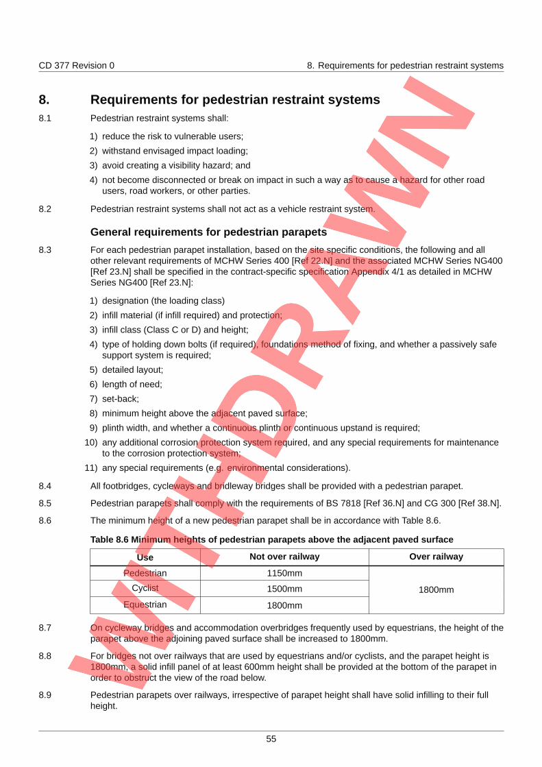
CD 377 Revision 0 8. Requirements for pedestrian restraint systems
8. Requirements for pedestrian restraint systems8.1 Pedestrian restraint systems shall:
1) reduce the risk to vulnerable users;
2) withstand envisaged impact loading;
3) avoid creating a visibility hazard; and
4) not become disconnected or break on impact in such a way as to cause a hazard for other roadusers, road workers, or other parties.
8.2 Pedestrian restraint systems shall not act as a vehicle restraint system.
General requirements for pedestrian parapets8.3 For each pedestrian parapet installation, based on the site specific conditions, the following and all
other relevant requirements of MCHW Series 400 [Ref 22.N] and the associated MCHW Series NG400[Ref 23.N] shall be specified in the contract-specific specification Appendix 4/1 as detailed in MCHWSeries NG400 [Ref 23.N]:
1) designation (the loading class)
2) infill material (if infill required) and protection;
3) infill class (Class C or D) and height;
4) type of holding down bolts (if required), foundations method of fixing, and whether a passively safesupport system is required;
5) detailed layout;
6) length of need;
7) set-back;
8) minimum height above the adjacent paved surface;
9) plinth width, and whether a continuous plinth or continuous upstand is required;
10) any additional corrosion protection system required, and any special requirements for maintenanceto the corrosion protection system;
11) any special requirements (e.g. environmental considerations).
8.4 All footbridges, cycleways and bridleway bridges shall be provided with a pedestrian parapet.
8.5 Pedestrian parapets shall comply with the requirements of BS 7818 [Ref 36.N] and CG 300 [Ref 38.N].
8.6 The minimum height of a new pedestrian parapet shall be in accordance with Table 8.6.
Table 8.6 Minimum heights of pedestrian parapets above the adjacent paved surface
Use Not over railway Over railway
Pedestrian 1150mm
Cyclist 1500mm
Equestrian 1800mm
1800mm
8.7 On cycleway bridges and accommodation overbridges frequently used by equestrians, the height of theparapet above the adjoining paved surface shall be increased to 1800mm.
8.8 For bridges not over railways that are used by equestrians and/or cyclists, and the parapet height is1800mm, a solid infill panel of at least 600mm height shall be provided at the bottom of the parapet inorder to obstruct the view of the road below.
8.9 Pedestrian parapets over railways, irrespective of parapet height shall have solid infilling to their fullheight.
55
CD 377 Revision 0 8. Requirements for pedestrian restraint systems
8.10 Steel pedestrian parapets shall be of framed construction consisting of posts and longitudinal memberswith suitable infilling.
8.11 Pedestrian parapets shall be mounted on a continuous plinth or continuous upstand of 50mm heightwith a tolerance of -0/+50 mm above the adjoining paved surface.
8.12 The pedestrian parapet specification in contract specific Appendix 4/1 as detailed in MCHW SeriesNG400 [Ref 23.N]) shall identify where the parapet does not have a continuous plinth or continuousupstand of 50mm height with a tolerance of -0/+50 mm above the adjoining paved surface.
NOTE Not having a plinth affects the overall height.
8.13 The rails and posts shall meet the Class 3 nominal live loads in BS 7818 [Ref 36.N].
8.14 The bar, sheet or mesh infill shall meet the Class C nominal loads in BS 7818 [Ref 36.N].
8.15 Where the Class 3 nominal live loads for posts and rails and/or the Class C nominal loads for infill areassessed to be inadequate, Class 4 nominal live loads for posts and rails and/or Class D nominal loadsfor infill shall be used.
8.16 Pedestrian parapets of concrete construction shall be designed in accordance with BS 5400-4 [Ref37.N].
8.17 Pedestrian parapets of solid construction shall be designed to resist the more severe of a nominal liveload of 1400 N/m applied transversely at the level of the top of the pedestrian parapet or wind loading inaccordance with CS 454 [Ref 2.N].
8.17.1 The partial load factor γfl should be taken as 1.5 for live load and 1.4 for wind load at the ultimate limitstate, or 1.0 for both at the serviceability limit state.
8.17.2 The strength of infilling panels may be proved for a prototype design by test loading with the loadssituated in the most adverse positions.
8.17.3 The minimum overload factor should be taken as equal to the product of the partial safety factors usedfor ultimate limit state design.
8.17.4 When the appropriate design document given in the Technical Approvals Schedule is not to limit stateformat, a 50% overload should be assumed.
8.18 Stone or precast copings used with pedestrian parapets shall be secured to the concrete backing byfixings capable or resisting at the ultimate limit state a horizontal force of 33 kN per metre of coping.
Additional requirements for pedestrian parapets over or adjacent to railways
8.19 No toeholds shall be provided on the pedestrian traffic face of the parapet or the infill panel.
8.20 Infill panels on the front face of a parapet over a railway shall be of a design and material approved bythe Railway Authority.
General requirements for pedestrian guardrails8.21 For each pedestrian guardrail installation, based on the site specific conditions, the following and all
other relevant requirements of MCHW Series 400 [Ref 22.N] and the associated MCHW Series NG400[Ref 23.N] shall be specified in the contract-specific specification Appendix 4/1 as detailed in MCHWSeries NG400 [Ref 23.N]:
1) designation (the loading class)
2) infill material (if infill required) and protection;
3) infill class (Class C or D) and height;
4) type of holding down bolts (if required), foundations method of fixing, and whether a passively safesupport system is required;
5) detailed layout;
56
CD 377 Revision 0 8. Requirements for pedestrian restraint systems
6) length of need;
7) set-back;
8) minimum height above the adjacent paved surface;
9) any additional corrosion protection system required, and any special requirements for maintenanceto the corrosion protection system;
10) any special requirements (e.g. environmental considerations).
8.22 Pedestrian guardrails shall be of steel construction.
8.23 Pedestrian guardrails shall comply with BS 7818 [Ref 36.N].
8.24 Where a guardrail is required for pedestrian safety in close proximity to a road, the guardrail and its endposts shall be designed to be passively safe in accordance with BS EN 12767 [Ref 24.N] unless it isinstalled outside the working width of safety barrier that is required for other reasons.
8.24.1 Pedestrian guardrails should not be provided as a deterrent to kerbside vehicle parking.
Requirements for pedestrian restraint and protection to prevent a fall from aheight
8.25 Pedestrian restraint and protection, where determined through design and assessment, shall bespecified where any pedestrian movement can occur within the highway boundary from use ormaintenance and there is a risk to health and safety from a fall from a height.
NOTE Typical locations requiring pedestrian restraint and protection are shown in the Figure 8.25N.
57
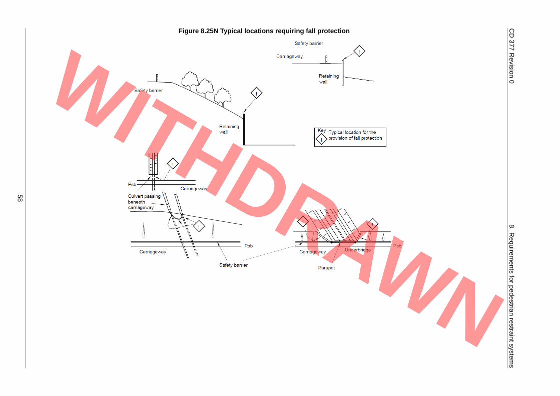
CD377
Revision
08.
Requirem
entsfor
pedestrianrestraintsystem
s
Figure 8.25N Typical locations requiring fall protection
58
CD 377 Revision 0 8. Requirements for pedestrian restraint systems
8.26 Where a structure, such as a retaining wall, head wall or wing wall, presents a vertical or near verticalface 1.5 m or more in height and it is possible for a person to gain access to the upper edge of thestructure, a pedestrian restraint system such as a protective barrier or guardrail shall be installed closeto, or on top of, the structure.
8.27 A pedestrian protective barrier or guardrail shall be installed at walls less than 1.5 m high if a particularhazard, such as a watercourse or road, is in close proximity to the wall.
8.28 The form of pedestrian restraint and protection provided, its components, articulation, location andarrangement shall be designed to minimise the risk of injury to the occupants of vehicles, e.g. bypenetration of a vehicle cab.
8.29 Handrails within 2 m of Psb that can be reached by an errant vehicle shall be designed to be passivelysafe unless they are protected by a safety barrier that is required for other purposes.
8.30 Where appropriate, the VRS (if deployed) shall be extended to include the approaches to the structureor potentially hazardous differences in ground levels.
59
CD 377 Revision 0 9. Requirements for temporary safety barriers at...
9. Requirements for temporary safety barriers at roadworks9.1 All VRS installations that include temporary safety barriers shall be compatible throughout the entire
installation length (including any other safety barriers, parapets, terminals, transitions and crashcushions) and meet the requirements of this Section 9.
9.1.1 A temporary safety barrier may be either a permanent type safety barrier erected temporarily, or apurpose made temporary safety barrier.
NOTE Temporary safety barriers are classed as safety barriers that are to be in place for less than 4 years.
9.2 All safety barriers used in temporary situations shall be successfully tested to BS EN 1317-1 [Ref 33.N]and BS EN 1317-2 [Ref 32.N].
9.3 All safety barriers used in temporary situations shall be assessed by one of the independent reviewersappointed by the Overseeing Organisation.
Minimum containment levels9.4 On roads where road works are being undertaken and a speed limit of 50 mph or more is in operation,
the minimum containment levels for temporary safety barriers shall be:
1) normal containment level: N2;
2) higher containment level: H1;
3) very high containment level: H4a.
9.5 On roads where road works are being undertaken and a speed limit of less than 50 mph is in operation,the minimum containment levels for temporary safety barriers shall be:
1) normal containment level: N1;
2) higher containment level: H1;
3) very high containment level: H4a.
9.6 Low angle containment safety barrier systems referenced in Table 2 of BS EN 1317-2 [Ref 32.N] shallnot be used.
9.7 At temporary or permanent bridge supports and other vulnerable structures, very high containmentlevel (H4a) temporary safety barriers shall be used unless the assessment determines that normalcontainment level (N1 or N2) is sufficient, or no barrier is required.
9.8 At temporary or permanent bridge supports and other vulnerable structures, the principles shown withinFigure 9.8a and Figure 9.8b shall be followed, and the structures assessed in accordance with CS 453[Ref 40.N].
60
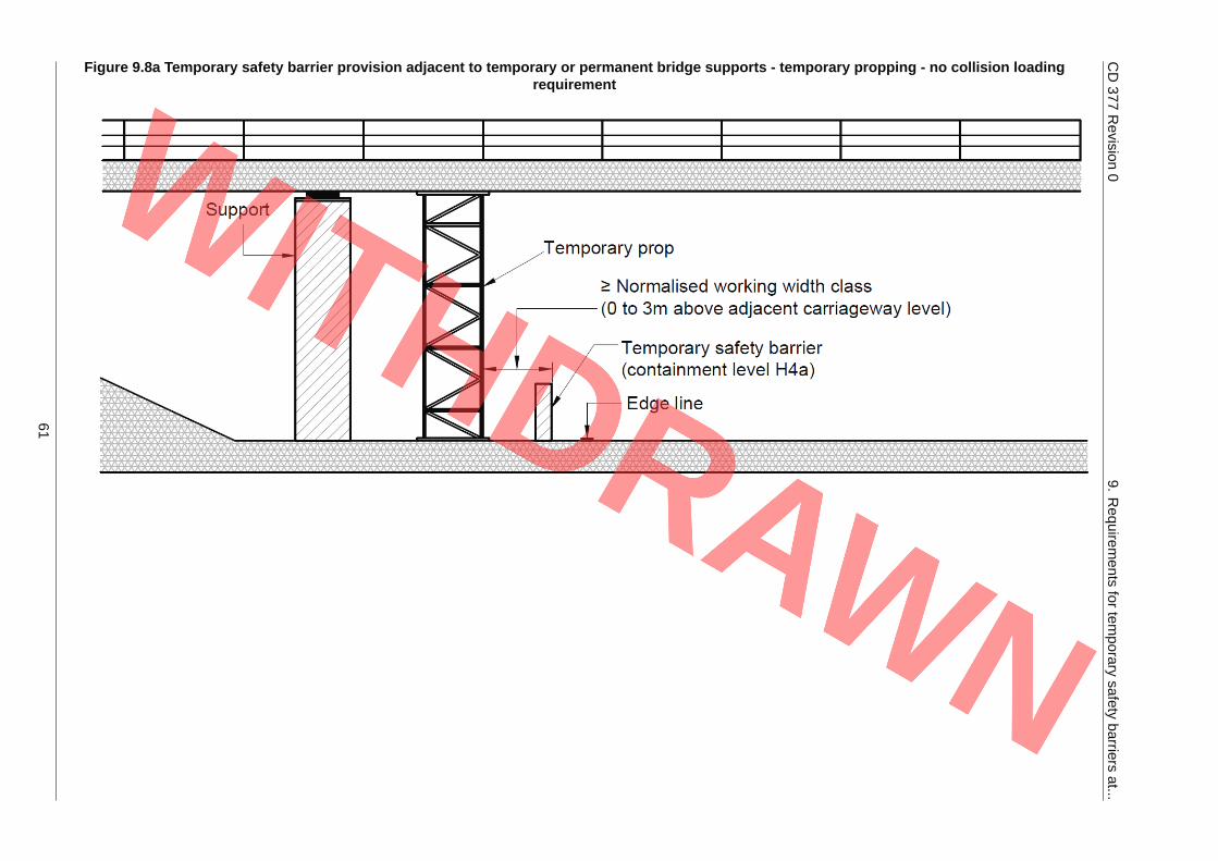
CD377
Revision
09.
Requirem
entsfor
temporary
safetybarriers
at...
Figure 9.8a Temporary safety barrier provision adjacent to temporary or permanent bridge supports - temporary propping - no collision loadingrequirement
61
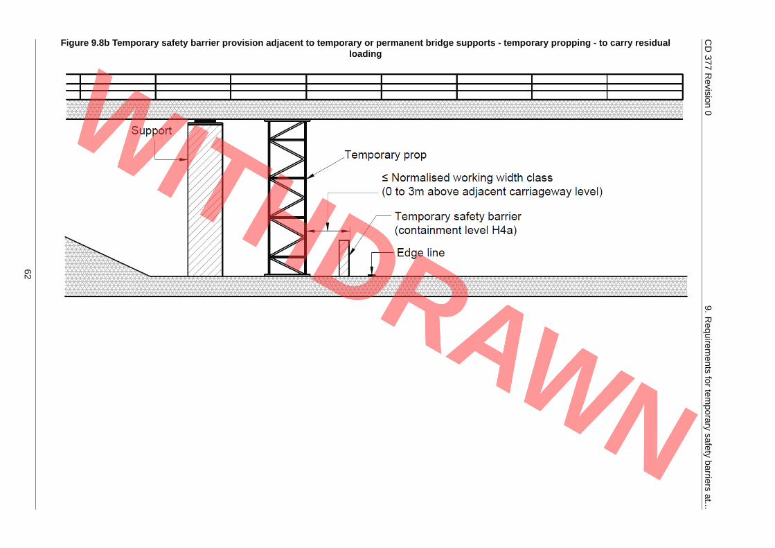
CD377
Revision
09.
Requirem
entsfor
temporary
safetybarriers
at...
Figure 9.8b Temporary safety barrier provision adjacent to temporary or permanent bridge supports - temporary propping - to carry residualloading
62
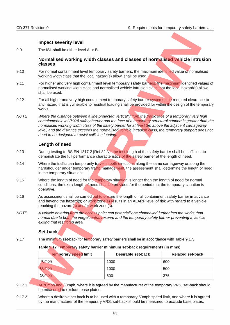
CD 377 Revision 0 9. Requirements for temporary safety barriers at...
Impact severity level9.9 The ISL shall be either level A or B.
Normalised working width classes and classes of normalised vehicle intrusionclasses
9.10 For normal containment level temporary safety barriers, the maximum identified value of normalisedworking width class that the local hazard(s) allow, shall be used.
9.11 For higher and very high containment level temporary safety barriers, the maximum identified values ofnormalised working width class and normalised vehicle intrusion class that the local hazard(s) allow,shall be used.
9.12 For all higher and very high containment temporary safety barrier systems, the required clearance toany hazard that is vulnerable to residual loading shall be provided for within the design of the temporaryworks.
NOTE Where the distance between a line projected vertically from the traffic face of a temporary very highcontainment level (H4a) safety barrier and the face of a temporary structural support is greater than thenormalised working width class of the safety barrier for at least 3m above the adjacent carriagewaylevel, and the distance exceeds the normalised vehicle intrusion class, the temporary support does notneed to be designed to resist collision loading.
Length of need9.13 During testing to BS EN 1317-2 [Ref 32.N], the test length of the safety barrier shall be sufficient to
demonstrate the full performance characteristics of the safety barrier at the length of need.
9.14 Where the traffic can temporarily travel in both directions along the same carriageway or along thehardshoulder under temporary traffic management, the assessment shall determine the length of needin the temporary situation.
9.15 Where the length of need for the temporary situation is longer than the length of need for normalconditions, the extra length of need shall be provided for the period that the temporary situation isoperative.
9.16 As assessment shall be carried out to ensure the length of full containment safety barrier in advanceand beyond the hazard(s) or work zone(s) results in an ALARP level of risk with regard to a vehiclereaching the hazard(s) and/or work zone(s).
NOTE A vehicle entering from the access point can potentially be channelled further into the works thannormal due to both the verge/central reserve and the temporary safety barrier preventing a vehicleexiting that restricted area.
Set-back9.17 The minimum set-back for temporary safety barriers shall be in accordance with Table 9.17.
Table 9.17 Temporary safety barrier minimum set-back requirements (in mms)
Temporary speed limit Desirable set-back Relaxed set-back
70mph 1000 600
60mph 1000 500
50mph 600 375
9.17.1 At 70mph and 60mph, where it is agreed by the manufacturer of the temporary VRS, set-back shouldbe measured to exclude base plates.
9.17.2 Where a desirable set back is to be used with a temporary 50mph speed limit, and where it is agreedby the manufacturer of the temporary VRS, set-back should be measured to exclude base plates.
63
CD 377 Revision 0 9. Requirements for temporary safety barriers at...
9.17.3 Where a relaxed set back is to be used with a temporary 50mph speed limit, set-back should bemeasured to include base plates.
9.18 Where relaxed values of set-back are proposed, a risk assessment compliant with TSM Chapter 8 [Ref46.N] shall be undertaken and documented.
NOTE A TSM Chapter 8 [Ref 46.N] risk assessment can include where extra lanes or extra lane width can begenerated, or where other space can be released for operative working and where such space isimportant.
9.18.1 Where space is available, an increase in lane widths should be specified as the risk to drivers has thepotential to be minimised where lane widths are greater than the minimum in TSM Chapter 8 [Ref 46.N].
9.19 Temporary safety barrier performance in restricted situations is unpredictable and siting of the barriershall allow for deflection into the lateral clearance safety zone or into the adjacent running lane(s)depending upon demonstrated system performance.
Method of termination for temporary safety barriers9.20 The safety barrier and terminal provision shall be assessed in the temporary situation taking account of
any temporary traffic flow direction and location, and mandatory speed limit.
9.21 Individual temporary safety barrier ends and the temporary safety barrier shall be installed to themanufacturer's instructions.
9.22 A risk assessment shall be conducted as part of the TSM Chapter 8 [Ref 46.N] temporary trafficmanagement (TTM) design and the benefits and dis-benefits of the options available for the sitespecific circumstances evaluated.
9.22.1 The risk assessment may include the use of crash cushions for the termination of a temporary safetybarrier.
9.23 A record shall be made of the termination layout adopted and reasons for that layout.
General requirements9.24 Permanent and temporary local hazards having the potential to cause danger to the occupants of a
vehicle, the workforce or to other parties shall be identified within a site specific risk assessment, asrequired by TSM Chapter 8 [Ref 46.N].
9.24.1 Examples of common design factors that should be evaluated when using temporary safety barriers atroad works are listed below:
1) length of time for which a temporary safety barrier is likely to be deployed;
2) speed limits both existing and proposed;
3) traffic flows including the percentage of large goods vehicles (LGVs);
4) containment level required and vehicle intrusion class for 'L' containment safety barriers;
5) length of safety barrier;
6) road alignments, cross-section-pinch points, set-back, headroom clearance, available workingwidths, etc;
7) sight lines;
8) drainage of carriageway;
9) ground support for temporary safety barrier;
10) clearances for operation and construction;
11) requirements for temporary signing, lighting and road markings;
12) obstructions that can affect the performance of the safety barrier, e.g. lighting columns, signposts,etc;
13) other VRS in the vicinity of the works;
64
CD 377 Revision 0 9. Requirements for temporary safety barriers at...
14) access arrangements for works vehicles, emergency and recovery vehicles;
15) end of safety barrier details to ensure errant vehicles cannot pass behind into the work zone; thereduced risk of the leading end of a temporary safety barrier being impacted by a vehicle if flaredaway from the running lane, but the reduced space available for site vehicles;
16) the risk of an errant vehicle stopping abruptly in the running lane if a crash cushion is installed;
17) the risk of a ramped leading end being installed causing a vehicle to end up in either the runninglane or the works area in the event of an impact;
18) traffic movements approaching the safety barrier;
19) where applicable, the effect of a safety barrier on movement of road workers, pedestrians, cyclists,etc;
20) maintenance requirements;
21) traffic management and working space and widths required for installation and removal of safetybarriers;
22) where a temporary very high containment level (H4a) safety barrier is to be used, whether it is to bebe surface mounted or inset into the carriageway;
23) compliance with contract specific details.
NOTE 1 This list is not exhaustive and other factors potentially need to be assessed.
NOTE 2 The sight stopping distances and visibility requirements of CD 127 [Ref 4.N] and CD 109 [Ref 15.N] areto be taken into account when positioning the temporary safety barrier.
9.25 The factors evaluated and decisions made shall be recorded and temporary safety barriers withappropriate terminations provided where the conclusion from the site specific risk assessment indicatesthey are necessary to adequately control the risks.
Temporary speed limits9.26 A temporary speed limit of less than 50 mph shall not be imposed on roads to protect short sections of
work that can be carried out without closure or restriction of any of the running lanes, solely to allow useof temporary safety barriers with a containment level of N1.
9.27 Where, after undertaking a risk assessment, it is determined that it is necessary to provide protectionover a short length (e.g. for the replacement of a vehicle parapet) then a temporary safety barrier with acontainment level of N2, H1, or H4a shall be incorporated into the temporary works.
Use of temporary safety barriers in contraflow operations9.28 Where temporary safety barrier is used within contraflow, the following parameters shall also apply:
1) a buffer zone between opposing traffic flows of a width relevant to the mandatory speed limit inforce, but not less than two times the normalised working width of the temporary safety barrier minusthe width of the temporary safety barrier, or the width of the temporary safety barrier plus twice theset-back value, whichever is the greater;
2) the ends of the safety barrier continue beyond the end of the contraflow into a coned off area, toreduce the risk of traffic impacting the ends;
3) no gaps created in the temporary safety barrier between the two opposing flows of traffic in thecontraflow;
4) an acceptable means of access provided for the emergency services and recovery vehicles toattend to accidents or breakdowns within the contraflow, if identified as a necessary measure.
NOTE An acceptable means of access provided for the emergency services and recovery vehicles to attendcan include temporary removable sections in the barrier.
65
CD 377 Revision 0 10. Legacy systems
10. Legacy systems10.1 Where a new hazard is introduced in advance of, alongside or beyond an existing legacy system, an
assessment shall be made to compare the merits of merging and retaining the legacy system, orreplacing it.
10.2 Where a new hazard is introduced in advance of, alongside or beyond an existing legacy system, anyproposal to maintain an existing legacy system shall be justified to the Overseeing Organisation.
66
CD 377 Revision 0 11. Vehicle arrester beds
11. Vehicle arrester beds11.1 On an existing road where there is a known problem involving runaway vehicles on a downhill gradient,
both in terms of personal injuries and damage to vehicles or property, the provision of an arrester bedshall be evaluated in conjunction with the relevant landowners, Police, local authorities and theOverseeing Organisation.
NOTE 1 The function of an arrester bed is to decelerate a runaway vehicle on long, steep descending gradientswithout causing significant damage to the vehicle, its occupants, other road users, adjacent buildings orproperty.
NOTE 2 Whilst arrester beds are suitable for most types of vehicle, they are particularly effective in bringing torest large commercial vehicles which suffer brake or gear change mechanism failures.
NOTE 3 There are two basic layouts for arrester beds; 'remote' which are incorporated into a separate escapelane leading off the main carriageway and 'adjacent' which are constructed adjacent to the nearside ofthe carriageway in a widened section of the highway.
11.2 On new or improved roads where a long, downhill gradient is unavoidable and a potential problemassociated with runaway vehicles is identified, the possibility of including an escape lane arrester bedshall be investigated.
NOTE At severely restricted sites, it is potentially not feasible to construct a full width 'remote' or 'adjacent'arrester bed. In such cases a reduced width 'adjacent' arrester bed, which just accommodates thenearside wheels of a runaway vehicle, can be the only feasible option.
11.2.1 A 'single track' type of arrester bed only has about 50% of the stopping effect of a full width bed, sorequires an increased bed length and should only be proposed when there are no suitable alternatives.
11.3 The provision of any type of arrester bed shall be supported by a risk assessment and details ofdiscussions with the Overseeing Organisation, relevant local authorities and emergency services.
11.4 The bed material shall be free draining and the base of the bed drained to avoid water ponding andpotential freezing in winter conditions.
11.5 The sides of the bed shall be restrained by kerbing which restricts sideways movement and scatter ofthe aggregate.
11.6 On 'remote' arrester beds the horizontal alignment of the bed shall diverge from that of the maincarriageway to minimise the potential for the nearside wheels of the vehicle being in the gravel bed andthe offside wheels being on an increasingly adverse cross slope, which can induce vehicle overturning.
11.7 On the 'adjacent' type of arrester bed any kerbing used for the edge restraint between the gravel bedand the main carriageway pavement shall be level with the carriageway so that a vehicle driver, whohas the potential to overshoot the signed entry to the bed, can still steer into the arrester bed.
67
CD 377 Revision 0 12. Anti-glare systems
12. Anti-glare systems12.1 All new anti-glare systems shall be specified to BS EN 12676-1 [Ref 1.N] and the specific requirements
of MCHW Series 400 [Ref 22.N] and the associated MCHW Series NG400 [Ref 23.N].
NOTE The purpose of an anti-glare system is to cut off light from oncoming vehicle headlights on adjacentroads.
12.2 Anti-glare screens shall be designed so that light directed towards the driver at oblique angles (12° to20°) is reduced whilst relatively open vision (around 70°) is maintained in the sideways direction.
NOTE The height to effectively screen headlight glare from all types of vehicles on level ground is 2.0m.
12.3 The risks associated with attaching an anti-glare system to a new or existing VRS shall be assessedprior to installation.
12.3.1 The risk assessment should include the change in the performance of the VRS due to the attachmentof the anti-glare system, and the risks associated with the detachment of the anti-glare system in theevent of an impact with the VRS.
12.4 The police authority responsible for road surveillance and patrol shall be consulted prior to theinstallation of any anti-glare system that can restrict the police's view of the opposing carriageway.
68
CD 377 Revision 0 13. Cattle grids
13. Cattle grids
Design of cattle grids13.1 Cattle grids shall be designed in accordance with BS 4008 [Ref 35.N].
NOTE The Office of Rail Regulation document 'Level Crossings: A guide for managers, designers andoperators' ORR Level crossings [Ref 1.I] provides additional requirements and advice for the provisionof cattle grids at railway level crossings.
13.1.1 Cattle grids should only be provided where alternative measures, such as gates, have beeninvestigated and found unsuitable.
13.2 An alternative means of by-passing a cattle grid shall be provided for users that are unable to safelycross the grid but are entitled by law to travel along the particular highway in question (such aspedestrians and equestrians).
NOTE BS 4008 [Ref 35.N] provides design criteria for by-pass facilities.
Siting of cattle grids13.3 Cattle grids and any associated by-pass shall be located within highway land unless a legal agreement
with the relevant land owner has been entered in to.
13.3.1 New cattle grids should be located within the highway boundary.
NOTE The legal responsibility for animals straying or lying on or at the side of the highway lies with theirkeepers; however, the Overseeing Organisation has a vested interest in ensuring animals cannotaccess the motorway and trunk road network due to the safety implications this can have. Placingcattle grids within the highway boundary therefore provides the Overseeing Organisation with a greaterlevel of control over this risk.
13.4 Cattle grids shall not be located within 18 metres of a junction, measured from the projected kerb line,or edge of carriageway if kerbs are not present, of the adjoining road to the start of the grid.
13.4.1 Cattle grids should only be located where there is a minimum of 18 metres of straight road on eitherside of the grid.
NOTE Cattle grids can be a skid/slip hazard, which is a particular problem for pedal and motor cycles.Providing a straight section on the approaches removes the need for road users to turn while traversingthe grid, which reduces the risk of skidding/slipping.
13.4.2 Cattle grids should only be sited where there is desirable minimum stopping sight distance available oneach approach to the grid in accordance with CD 109 [Ref 15.N] for the relevant design speed.
13.4.3 In situations where a cattle grid is to be placed closer to a major road junction than the desirableminimum stopping sight distance, unobstructed visibility should be available between the edge of themajor road and the grid, measured from centre point to centre point in the approach lane.
NOTE It is necessary for vehicles to cross cattle grids at relatively low speeds. It is therefore important thatadequate visibility is available on the approach to cattle grids to ensure that road users can react andslow down safely prior to reaching them.
69

CD 377 Revision 0 14. Normative references
14. Normative referencesThe following documents, in whole or in part, are normative references for this document and areindispensable for its application. For dated references, only the edition cited applies. For undatedreferences, the latest edition of the referenced document (including any amendments) applies.
Ref 1.N BSI. BS EN 12676-1, 'Anti-glare systems for roads. Performance and characteristics'
Ref 2.N Highways England. CS 454, 'Assessment of highway bridges and structures'
Ref 3.N Highways England. CG 304, 'Conservation of highway structures'
Ref 4.N Highways England. CD 127, 'Cross-sections and headrooms'
Ref 5.N Highways England. LA 116, 'Cultural heritage asset management plans'
Ref 6.N Highways England. CD 353, 'Design criteria for footbridges'
Ref 7.N Highways England. CD 354, 'Design of minor structures'
Ref 8.N Network Rail. NR/L3/CIV/020 Issue 1, 'Design of Railway Bridges'
Ref 9.N Highways England. CD 143, 'Designing for walking, cycling and horse riding(vulnerable users)'
Ref 10.N Highways England. CD 524, 'Edge of pavement details'
Ref 11.N BSI. BS EN 1991-1-7, 'Eurocode 1 - Actions on structures - Part 1-7 General actions -Accidental actions'
Ref 12.N BSI. BS EN 1992-2, 'Eurocode 2. Design of concrete structures. Part 2: Concretebridges. Design and detailing rules'
Ref 13.N Highways England. CD 123, 'Geometric design of at-grade priority andsignal-controlled junctions'
Ref 14.N Highways England. RRRAP User Guide, 'Guidance on the use of the Road RestraintRisk Assessment Process (RRRAP) associated with CD 377'
Ref 15.N Highways England. CD 109, 'Highway link design'
Ref 16.N BSI. BS 6779-2 , 'Highway parapets for bridges and other structures - Part 2:Specification for vehicle containment parapets of concrete construction'
Ref 17.N BSI. BS 6779-1, 'Highway parapets for bridges and other structures. Part 1:Specification for vehicle containment parapets of metal construction.'
Ref 18.N Highways England. GG 101, 'Introduction to the Design Manual for Roads andBridges'
Ref 19.N Highways England. CS 470, 'Management of sub-standard highway structures'
Ref 20.N Department for Transport. MAOR, 'Managing the accidental obstruction of the railwayby road vehicles'
Ref 21.N Highways England. MCHW, 'Manual of Contract Documents for Highway Works'
Ref 22.N Highways England. MCHW Series 400, 'Manual of Contract Documents for HighwayWorks, Volume 1 Specification for Highway Works, Series 400 Road RestraintSystems'
Ref 23.N Highways England. MCHW Series NG400, 'Manual of Contract Documents forHighway Works, Volume 2 Notes for Guidance on the Specification for HighwayWorks, Series 400 Road Restraint Systems'
Ref 24.N BSI. BS EN 12767, 'Passive safety of support structures for road equipment.Requirements, classification and test methods.'
70

CD 377 Revision 0 14. Normative references
Ref 25.N BS EN 1317-3, 'Performance classes, impact test acceptance criteria and testmethods for crash cushions' , 2010
Ref 26.N BSI. BS DD ENV 1317-4, 'Performance classes, impact test acceptance criteria andtest methods for terminals and transitions of safety barriers'
Ref 27.N Highways England. CD 365, 'Portal and cantilever signs/signals gantries'
Ref 28.N BS EN 1317-5, 'Product requirements and evaluation of conformity for vehiclerestraint systems'
Ref 29.N 2011/305/EU, 'Regulation (EU) No 305/2011 of the European Parliament and of theCouncil of 9 March 2011 laying down harmonised conditions for the marketing ofconstruction products and repealing Council Directives 89/106/EEC'
Ref 30.N Network Rail. NR/BS/LI/331 Issue 2, 'Requirements for parapet heights on overbridge and footbridge structures spanning overhead line electrification equipment'
Ref 31.N Highways England. GG 104, 'Requirements for safety risk assessment'
Ref 32.N BSI. BS EN 1317-2, 'Road restraint systems. Performance classes, impact testacceptance criteria and test methods for safety barriers including vehicle parapets '
Ref 33.N BSI. BS EN 1317-1, 'Road restraint systems. Terminology and general criteria for testmethods.'
Ref 34.N Highways England. TD 131, 'Roadside technology and communications'
Ref 35.N BSI. BS 4008, 'Specification for Cattle Grids'
Ref 36.N BSI. BS 7818, 'Specification for pedestrian restraint systems in metal '
Ref 37.N BSI. BS 5400-4, 'Steel, concrete and composite bridges. Code of practice for designof concrete bridges'
Ref 38.N Highways England. CG 300, 'Technical approval of highway structures'
Ref 39.N Highways England. CS 455, 'The assessment of concrete highway bridges andstructures'
Ref 40.N Highways England. CS 453, 'The assessment of highway bridge supports'
Ref 41.N The National Archives. legislation.gov.uk. SI 2015/51, 'The Construction (Design andManagement) Regulations 2015'
Ref 42.N Highways England. CD 192, 'The design of crossovers and changeovers'
Ref 43.N Highways England. RRRAP, 'The Road Restraint Risk Assessment Process '
Ref 44.N The Stationery Office (TSO). Department for Infrastructure (DfI). TSR(NI) 1997, 'TheTraffic Signs Regulations (Northern Ireland) 1997'
Ref 45.N The Stationery Office. TSRGD, 'The Traffic Signs Regulations and General Directions2016'
Ref 46.N TSO. Department for Transport. TSM Chapter 8, 'Traffic Signs Manual Chapter 8 -Road works and temporary situations'
Ref 47.N BSI. NA to BS EN 1991-1-7, 'UK National Annex to Eurocode 1 - Actions onstructures - Part 1-7 General actions - Accidental actions'
71
CD 377 Revision 0 15. Informative references
15. Informative referencesThe following documents are informative references for this document and provide supportinginformation.
Ref 1.I Office of Rail Regulation. ORR Level crossings, 'Level Crossings: A guide formanagers, designers and operators'
72
CD 377 Revision 0 Appendix A. Guidance on the specification of vehicle rest...
Appendix A. Guidance on the specification of vehicle restraint systems forlow speed and/or low flow roadsThe guidance given below is intended to assist in dealing with situations where the use of a fullycompliant vehicle parapet or vehicle safety barrier system may be impracticable or may itself present asimilar or greater hazard to the public. These situations, where the application of these requirements isnot appropriate, are particularly prevalent on local roads.
73
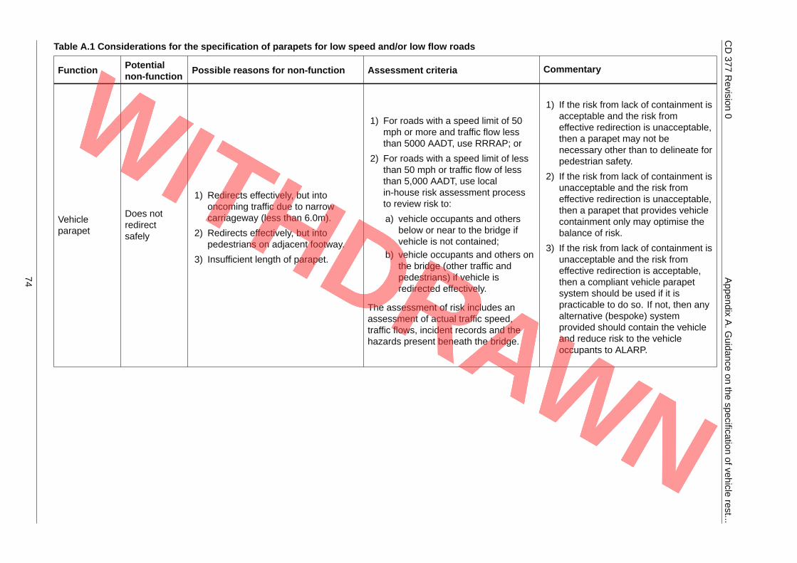
CD377
Revision
0Appendix
A.G
uidanceon
thespecification
ofvehiclerest...
Table A.1 Considerations for the specification of parapets for low speed and/or low flow roads
Function Potentialnon-function Possible reasons for non-function Assessment criteria Commentary
Vehicleparapet
Does notredirectsafely
1) Redirects effectively, but intooncoming traffic due to narrowcarriageway (less than 6.0m).
2) Redirects effectively, but intopedestrians on adjacent footway.
3) Insufficient length of parapet.
1) For roads with a speed limit of 50mph or more and traffic flow lessthan 5000 AADT, use RRRAP; or
2) For roads with a speed limit of lessthan 50 mph or traffic flow of lessthan 5,000 AADT, use localin-house risk assessment processto review risk to:
a) vehicle occupants and othersbelow or near to the bridge ifvehicle is not contained;
b) vehicle occupants and others onthe bridge (other traffic andpedestrians) if vehicle isredirected effectively.
The assessment of risk includes anassessment of actual traffic speed,traffic flows, incident records and thehazards present beneath the bridge.
1) If the risk from lack of containment isacceptable and the risk fromeffective redirection is unacceptable,then a parapet may not benecessary other than to delineate forpedestrian safety.
2) If the risk from lack of containment isunacceptable and the risk fromeffective redirection is unacceptable,then a parapet that provides vehiclecontainment only may optimise thebalance of risk.
3) If the risk from lack of containment isunacceptable and the risk fromeffective redirection is acceptable,then a compliant vehicle parapetsystem should be used if it ispracticable to do so. If not, then anyalternative (bespoke) systemprovided should contain the vehicleand reduce risk to the vehicleoccupants to ALARP.
74
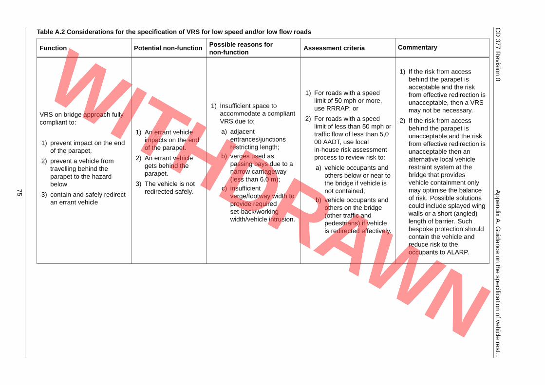
CD377
Revision
0Appendix
A.G
uidanceon
thespecification
ofvehiclerest...
Table A.2 Considerations for the specification of VRS for low speed and/or low flow roads
Function Potential non-function Possible reasons fornon-function Assessment criteria Commentary
VRS on bridge approach fullycompliant to:
1) prevent impact on the endof the parapet,
2) prevent a vehicle fromtravelling behind theparapet to the hazardbelow
3) contain and safely redirectan errant vehicle
1) An errant vehicleimpacts on the endof the parapet.
2) An errant vehiclegets behind theparapet.
3) The vehicle is notredirected safely.
1) Insufficient space toaccommodate a compliantVRS due to:
a) adjacententrances/junctionsrestricting length;
b) verges used aspassing bays due to anarrow carriageway(less than 6.0 m);
c) insufficientverge/footway width toprovide requiredset-back/workingwidth/vehicle intrusion.
1) For roads with a speedlimit of 50 mph or more,use RRRAP; or
2) For roads with a speedlimit of less than 50 mph ortraffic flow of less than 5,000 AADT, use localin-house risk assessmentprocess to review risk to:
a) vehicle occupants andothers below or near tothe bridge if vehicle isnot contained;
b) vehicle occupants andothers on the bridge(other traffic andpedestrians) if vehicleis redirected effectively.
1) If the risk from accessbehind the parapet isacceptable and the riskfrom effective redirection isunacceptable, then a VRSmay not be necessary.
2) If the risk from accessbehind the parapet isunacceptable and the riskfrom effective redirection isunacceptable then analternative local vehiclerestraint system at thebridge that providesvehicle containment onlymay optimise the balanceof risk. Possible solutionscould include splayed wingwalls or a short (angled)length of barrier. Suchbespoke protection shouldcontain the vehicle andreduce risk to theoccupants to ALARP.
75
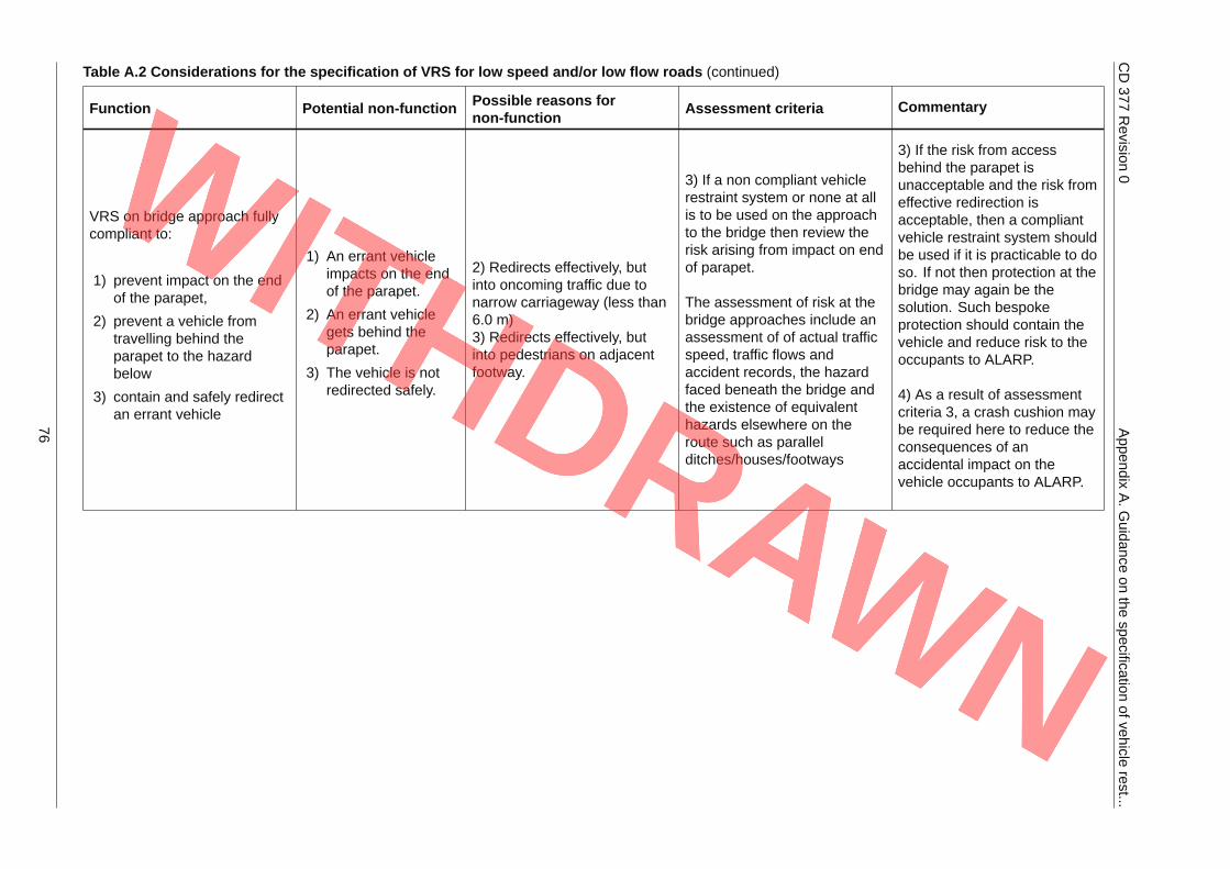
CD377
Revision
0Appendix
A.G
uidanceon
thespecification
ofvehiclerest...
Table A.2 Considerations for the specification of VRS for low speed and/or low flow roads (continued)
Function Potential non-function Possible reasons fornon-function Assessment criteria Commentary
VRS on bridge approach fullycompliant to:
1) prevent impact on the endof the parapet,
2) prevent a vehicle fromtravelling behind theparapet to the hazardbelow
3) contain and safely redirectan errant vehicle
1) An errant vehicleimpacts on the endof the parapet.
2) An errant vehiclegets behind theparapet.
3) The vehicle is notredirected safely.
2) Redirects effectively, butinto oncoming traffic due tonarrow carriageway (less than6.0 m)3) Redirects effectively, butinto pedestrians on adjacentfootway.
3) If a non compliant vehiclerestraint system or none at allis to be used on the approachto the bridge then review therisk arising from impact on endof parapet.
The assessment of risk at thebridge approaches include anassessment of of actual trafficspeed, traffic flows andaccident records, the hazardfaced beneath the bridge andthe existence of equivalenthazards elsewhere on theroute such as parallelditches/houses/footways
3) If the risk from accessbehind the parapet isunacceptable and the risk fromeffective redirection isacceptable, then a compliantvehicle restraint system shouldbe used if it is practicable to doso. If not then protection at thebridge may again be thesolution. Such bespokeprotection should contain thevehicle and reduce risk to theoccupants to ALARP.
4) As a result of assessmentcriteria 3, a crash cushion maybe required here to reduce theconsequences of anaccidental impact on thevehicle occupants to ALARP.
76
CD 377 Revision 0 Appendix B. Guidance on factors for ECPs and MCPs
Appendix B. Guidance on factors for ECPs and MCPs
B1 Emergency and maintenance crossing pointsThere are various options available to create an ECP/MCP. They may take the form of a gate or apermanent safety barrier. Each option varies in cost and ease of operation. Systems that are notsuitable to be removed should be avoided near ECPs and MCPs.
For ECPs, the main requirement is the speed with which the ECP can be opened and operational; thisdepends on the option chosen. It also depends on whether specialist equipment or personnel arerequired to operate or open the ECP. In most cases, a time of less than 30 minutes to open the gate ordismantle a permanent safety barrier would be desirable.
For MCPs, speed may not be an issue as the opening can be planned. Where regular maintenance isrequired, for example, near tunnels or on long structures, then it may be beneficial to providepermanent MCPs at each end that can be opened and closed quickly. For other situations, there aretwo options. Provide an MCP from the outset, or create an MCP only when required (i.e. take down orbreak out the permanent system; this can often be the most cost effective solution).
B1.1 Gates at MCP/ECP
A gate is the easiest to open, generally requires no, or minimal, specialist equipment and can beopened in less than 30 minutes. However, personnel do need to be trained to ensure that they knowhow to operate the gate and close it properly so that it is correctly fixed to the permanent or temporarysafety barrier when not in operation. Gates are generally quite expensive. They also have largeworking widths that can make them unsuitable for narrow central reserves. If they are used, wherethere is a mismatch in the working widths between the gate and the permanent system, a transition isrequired to connect the two systems. Any transitions increase the length of the MCP.
B1.2 Permanent safety barrier at ECP/MCP
A permanent safety barrier may be used to form an ECP/MCP.
If this option is chosen for an ECP, specialist personnel and equipment may be required to dismantle orremove the safety barrier and this can take some time and may exceed the normal 30 minuterecommendation required for operational reasons. For an MCP it is a viable option.
Where a concrete H1 or H2 safety barrier is used, an MCP can be created by breaking out the concreteand removing the debris. This operation might take some time depending on length and requirespecialist equipment. An in-situ concrete section can then be inserted when the MCP is no longerrequired.
77

CD 377 Revision 0 Notification
NotificationThis document was notified in draft to the European Commission in accordance with TechnicalStandards and Regulations Directive 2015/1535/EU.
78

© Crown copyright 2020.You may re-use this information (not including logos) free of charge in any format or medium, under the terms of the
Open Government Licence. To view this licence:visit www.nationalarchives.gov.uk/doc/open-government-licence/,
write to the Information Policy Team, The National Archives, Kew, London TW9 4DU,or email [email protected].
Design Manual for Roads and Bridges
Highway Structures & BridgesDesign
CD 377England National Application Annex to CD 377Requirements for road restraint systems(formerly TD 19/06)
Revision 0
SummaryThis National Application Annex contains the Highways England specific requirements related toroad restraint systems.
Feedback and EnquiriesUsers of this document are encouraged to raise any enquiries and/or provide feedback on the content and usageof this document to the dedicated Highways England team. The email address for all enquiries and feedback is:[email protected]
This is a controlled document.
CD 377 Revision 0 Contents
Contents
Release notes 2
Foreword 3Publishing information . . . . . . . . . . . . . . . . . . . . . . . . . . . . . . . . . . . . . . . . . . . . . . . . 3Contractual and legal considerations . . . . . . . . . . . . . . . . . . . . . . . . . . . . . . . . . . . . . . . . 3
Introduction 4Background . . . . . . . . . . . . . . . . . . . . . . . . . . . . . . . . . . . . . . . . . . . . . . . . . . . . . . 4Assumptions made in the preparation of this document . . . . . . . . . . . . . . . . . . . . . . . . . . . . . 4Mutual Recognition . . . . . . . . . . . . . . . . . . . . . . . . . . . . . . . . . . . . . . . . . . . . . . . . . . 4
Abbreviations 5
Terms and definitions 6
E/1. Requirements for permanent safety barriers 8General requirements (additional to CD 377) . . . . . . . . . . . . . . . . . . . . . . . . . . . . . . . . . . . 8Safety barrier provision in central reserves - general (CD 377, 3.85) . . . . . . . . . . . . . . . . . . . . . . 8Requirements for gaps in safety barrier (additional to CD 377) . . . . . . . . . . . . . . . . . . . . . . . . . 8
Emergency areas (EA) on smart motorway schemes . . . . . . . . . . . . . . . . . . . . . . . . . . . . 8
E/2. Cattle grids 9Siting of cattle grids (CD 377, 13.3) . . . . . . . . . . . . . . . . . . . . . . . . . . . . . . . . . . . . . . . . . 9
E/3. Normative references 10
1

CD 377 Revision 0 Release notes
Release notesVersion Date Details of amendments0 Mar 2020 Highways England National Application Annex to CD 377.
2
CD 377 Revision 0 Foreword
Foreword
Publishing informationThis document is published by Highways England.
This document supersedes TD 19/06, and partially supersedes IAN 68/05 and IAN 75/06 which arewithdrawn.
Contractual and legal considerationsThis document forms part of the works specification. It does not purport to include all the necessaryprovisions of a contract. Users are responsible for applying all appropriate documents applicable totheir contract.
3

CD 377 Revision 0 Introduction
Introduction
BackgroundThis National Application Annex contains the Highways England specific requirements related to roadrestraint systems.
This document is an update to TD 19/06 and reflects changes to the Overseeing Organisations'requirements. It also takes account of updated and new EU standards and legislation.
This document gives requirements for road restraint systems and it, together with the associatedRRRAP [Ref 9.N] and RRRAP User Guide [Ref 2.N], assists those involved in determining where roadrestraint systems are warranted, and the minimum required parameters.
Assumptions made in the preparation of this documentThe assumptions made in GG 101 [Ref 4.N] apply to this document.
This document is written on the basis that road restraint systems will be supplied and constructed inaccordance with the MCHW [Ref 5.N] and all other works will be designed and specified in accordancewith the Design Manual for Roads and Bridges.
Mutual RecognitionWhere there is a requirement in this document for compliance with any part of a British Standard,technical specification or quality mark, that requirement may be met by compliance with the MutualRecognition clause in GG 101 [Ref 4.N].
4

CD 377 Revision 0 Abbreviations
Abbreviations
AbbreviationsAbbreviation Definition
AADT Average annual daily traffic
EA Emergency area
ESS Entry slip signal
LGV Large Goods Vehicle
m Metres
Psb Point from which set-back is measured
RRS Road restraint system
VRS Vehicle restraint system
5
CD 377 Revision 0 Terms and definitions
Terms and definitions
TermsTerm DefinitionCattle grid A device set into a road that consists of a number of
transverse members supported over a pit. It forms abarrier to livestock but allows access for vehicles.
Normalised values (of working width andvehicle intrusion)
Values that have been adjusted to take account ofany differences between the specified total mass ofthe vehicle, its velocity and angle of approach and thevalues measured during testing.
NOTE: Refer to BS EN 1317-2 [Ref 7.N].
ParapetA safety barrier that is installed on the edge of abridge, retaining wall or similar structure where thereis a vertical drop.
Pedestrian restraint system
A restraint system installed to reduce the risk of a fallfrom a height at locations where pedestrianmovement could occur due to highway use ormaintenance activities.
Psb
Point from which set-back of the safety barrier orparapet face is measured.
NOTE: Refer to CD 127 [Ref 1.N] for minimumrequirements for permanent safety barriers.
Rigid safety barrierA safety barrier that when tested in accordance withBS EN 1317-1 [Ref 8.N] and BS EN 1317-2 [Ref 7.N],does not deflect from its pre-impact position.
Road restraint system (RRS) General name for vehicle restraint system orpedestrian restraint system used on the road.
Set-back
The distance between the Psb and the traffic face ofa RRS.
NOTE: Refer to CD 127 [Ref 1.N] for minimumrequirements for permanent safety barriers.
Vehicle restraint system (VRS)
A tested system installed on a road to provide a levelof containment for an errant vehicle.
NOTE: A typical system consists of a terminal-safetybarrier-terminal, or a terminal-safetybarrier-parapet-safety barrier-terminal, and includestransitions where appropriate.
6
CD 377 Revision 0 Terms and definitions
Terms (continued)
Term Definition
Vehicle intrusion
The vehicle intrusion of an LGV is the maximumdynamic lateral position from the undeformed trafficside of the barrier in consideration of a notional loadhaving the width and length of the vehicle platform,and a total height of 4 metres. The vehicle intrusionof a bus is the maximum dynamic lateral position ofthe bus from the undeformed traffic side of the barrier.
NOTE: Further detail is given in BS EN 1317-2 [Ref7.N].
Working width
The maximum lateral distance between any part of asafety barrier on the undeformed traffic side, and themaximum dynamic position of any part of the barrierduring impact testing to BS EN 1317-2 [Ref 7.N].
NOTE 1: If the vehicle body deforms around the roadvehicle restraint system so that the latter cannot beused for the purpose of measuring the working width,the maximum lateral position of any part of thevehicle is the working width.
NOTE 2: Further detail is given in BS EN 1317-2 [Ref7.N]
7
CD 377 Revision 0 E/1. Requirements for permanent safety barriers
E/1. Requirements for permanent safety barriers
General requirements (additional to CD 377)E/1.1 For post mounted entry slip signal (ESS) sites, a lack of protection by a vehicle restraint system (VRS),
or provision of the required approach length of safety barrier, shall be permitted as acceptable.
E/1.2 Each ESS site shall be assessed, and the decision as to whether to provide VRS, the length of VRS,and the decision making process, recorded in the design strategy record.
E/1.3 Clause 3.26 of CD 377 shall not apply.
E/1.4 Gaps of up to 100 m shall be closed, unless the road is within a smart motorway scheme where theclosure of a gap is subject to a risk assessment.
E/1.4.1 A gap may not be closed if there are significant cost, technical and/or access requirements for the gapto remain open.
Safety barrier provision in central reserves - general (CD 377, 3.85)E/1.5 On motorways with a two-way annual average daily traffic (AADT) greater or equal to 25,000
vehicles/day where a safety barrier is required in accordance with this document and the distance Psbto Psb is 10 metres or less, the safety barrier shall have a minimum containment level of H1.
E/1.5.1 Where the length of safety barrier to be installed in the central reserve is 500 m or less, an N2containment level non rigid safety barrier may be installed instead.
NOTE The installation of a minimum H1 containment rigid safety barrier is to minimise cross-over incidentsand reduce the need for safety barriers to be repaired or maintained and hence, minimise the costs andcongestion arising from temporary traffic management and reduce the risk to maintenance workers.
E/1.6 On motorways with a two-way AADT greater or equal to 25,000 vehicles/day where a VRS greater than500m in length is required in accordance with this document, and the distance Psb to Psb is 10 m orless, the safety barrier shall be rigid, have a serviceable life of not less than 50 years, and be designedsuch that after testing in accordance with BS EN 1317-1 [Ref 8.N] and BS EN 1317-2 [Ref 7.N], it doesnot require realignment, replacement or repair.
E/1.7 On new and upgraded all-purpose trunk roads, the requirements of GD 300 [Ref 6.N] shall apply.
E/1.8 On all other roads where a safety barrier is required in accordance with this document and the distancePsb to Psb is 10 m or less, the safety barrier shall have a minimum containment level of N2.
Requirements for gaps in safety barrier (additional to CD 377)Emergency areas (EA) on smart motorway schemes
E/1.9 Full height anchorages shall only be used at EA locations where VRS is required and where there isinsufficient room for two full length terminals.
E/1.10 Full height anchorages shall only be used at EA locations where they do not face oncoming traffic,unless behind another VRS (and outside of its working width and vehicle intrusion).
8

CD 377 Revision 0 E/2. Cattle grids
E/2. Cattle grids
Siting of cattle grids (CD 377, 13.3)E/2.1 Cattle grids and any associated by-pass shall be located within highway land unless a legal agreement
with the relevant land owner has been entered in to.
NOTE For cattle grids to be located on non-highway land, a legal agreement is entered into under Section 87of the Highways Act 1980 [Ref 3.N].
9
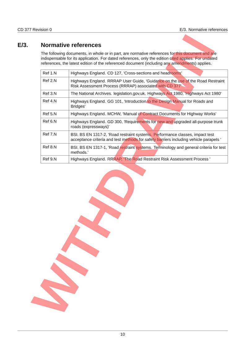
CD 377 Revision 0 E/3. Normative references
E/3. Normative referencesThe following documents, in whole or in part, are normative references for this document and areindispensable for its application. For dated references, only the edition cited applies. For undatedreferences, the latest edition of the referenced document (including any amendments) applies.
Ref 1.N Highways England. CD 127, 'Cross-sections and headrooms'
Ref 2.N Highways England. RRRAP User Guide, 'Guidance on the use of the Road RestraintRisk Assessment Process (RRRAP) associated with CD 377'
Ref 3.N The National Archives. legislation.gov.uk. Highways Act 1980, 'Highways Act 1980'
Ref 4.N Highways England. GG 101, 'Introduction to the Design Manual for Roads andBridges'
Ref 5.N Highways England. MCHW, 'Manual of Contract Documents for Highway Works'
Ref 6.N Highways England. GD 300, 'Requirements for new and upgraded all-purpose trunkroads (expressways)'
Ref 7.N BSI. BS EN 1317-2, 'Road restraint systems. Performance classes, impact testacceptance criteria and test methods for safety barriers including vehicle parapets '
Ref 8.N BSI. BS EN 1317-1, 'Road restraint systems. Terminology and general criteria for testmethods.'
Ref 9.N Highways England. RRRAP, 'The Road Restraint Risk Assessment Process '
10

© Crown copyright 2020.You may re-use this information (not including logos) free of charge in any format or medium, under the terms of the
Open Government Licence. To view this licence:visit www.nationalarchives.gov.uk/doc/open-government-licence/,
write to the Information Policy Team, The National Archives, Kew, London TW9 4DU,or email [email protected].
Design Manual for Roads and Bridges
Highway Structures & BridgesDesign
CD 377Northern Ireland National Application Annex toCD 377 Requirements for road restraintsystems(formerly TD 19/06)
Revision 0
SummaryThis National Application Annex contains the Department for Infrastructure Northern Irelandspecific requirements for road restraint systems.
Feedback and EnquiriesUsers of this document are encouraged to raise any enquiries and/or provide feedback on the content and usage ofthis document to the dedicated team in the Department for Infrastructure, Northern Ireland. The email address for allenquiries and feedback is: [email protected]
This is a controlled document.
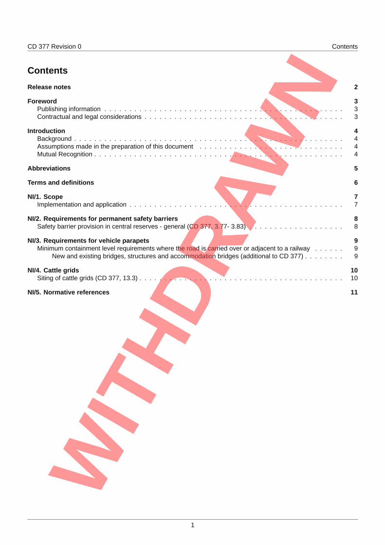
CD 377 Revision 0 Contents
Contents
Release notes 2
Foreword 3Publishing information . . . . . . . . . . . . . . . . . . . . . . . . . . . . . . . . . . . . . . . . . . . . . . . . 3Contractual and legal considerations . . . . . . . . . . . . . . . . . . . . . . . . . . . . . . . . . . . . . . . . 3
Introduction 4Background . . . . . . . . . . . . . . . . . . . . . . . . . . . . . . . . . . . . . . . . . . . . . . . . . . . . . . 4Assumptions made in the preparation of this document . . . . . . . . . . . . . . . . . . . . . . . . . . . . . 4Mutual Recognition . . . . . . . . . . . . . . . . . . . . . . . . . . . . . . . . . . . . . . . . . . . . . . . . . . 4
Abbreviations 5
Terms and definitions 6
NI/1. Scope 7Implementation and application . . . . . . . . . . . . . . . . . . . . . . . . . . . . . . . . . . . . . . . . . . . 7
NI/2. Requirements for permanent safety barriers 8Safety barrier provision in central reserves - general (CD 377, 3.77- 3.83) . . . . . . . . . . . . . . . . . . . 8
NI/3. Requirements for vehicle parapets 9Minimum containment level requirements where the road is carried over or adjacent to a railway . . . . . . 9
New and existing bridges, structures and accommodation bridges (additional to CD 377) . . . . . . . . 9
NI/4. Cattle grids 10Siting of cattle grids (CD 377, 13.3) . . . . . . . . . . . . . . . . . . . . . . . . . . . . . . . . . . . . . . . . . 10
NI/5. Normative references 11
1

CD 377 Revision 0 Release notes
Release notesVersion Date Details of amendments0 Mar 2020 Department for Infrastructure Northern Ireland National Application Annex to
CD 377.
2
CD 377 Revision 0 Foreword
Foreword
Publishing informationThis document is published by Highways England on behalf of Department for Infrastructure, NorthernIreland.
This document supersedes TD 19/06, and partially supersedes IAN 68/05 and IAN 75/06 which arewithdrawn.
Contractual and legal considerationsThis document forms part of the works specification. It does not purport to include all the necessaryprovisions of a contract. Users are responsible for applying all appropriate documents applicable totheir contract.
3
CD 377 Revision 0 Introduction
Introduction
BackgroundThis National Application Annex contains the Department for Infrastructure Northern Ireland specificrequirements related to road restraint systems.
This document is an update to TD 19/06 and reflects changes to the Overseeing Organisations'requirements. It also takes account of updated and new EU standards and legislation.
This document gives requirements for road restraint systems and it, together with the associatedRRRAP [Ref 8.N] and RRRAP User Guide [Ref 3.N], assists those involved in determining where roadrestraint systems are warranted, and the minimum required parameters.
Assumptions made in the preparation of this documentThe assumptions made in GG 101 [Ref 4.N] apply to this document.
This document is written on the basis that road restraint systems will be supplied and constructed inaccordance with the MCHW [Ref 5.N] and all other works will be designed and specified in accordancewith the Design Manual for Roads and Bridges.
Mutual RecognitionWhere there is a requirement in this document for compliance with any part of a British Standard,technical specification or quality mark, that requirement may be met by compliance with the MutualRecognition clause in GG 101 [Ref 4.N].
4
CD 377 Revision 0 Abbreviations
Abbreviations
AbbreviationsAbbreviation Definition
AADT Average annual daily traffic
LGV Large Goods Vehicle
m Metres
mph Miles per hour
Psb Point from which set-back is measured
RRS Road restraint system
VRS Vehicle restraint system
5
CD 377 Revision 0 Terms and definitions
Terms and definitions
TermsTerm DefinitionCattle grid A device set into a road that consists of a number of transverse
members supported over a pit. It forms a barrier to livestock butallows access for vehicles.
Parapet A restraint system that is installed on the edge of a bridge, retainingwall or similar elevated structure where there is a vertical drop.
Pedestrian restraint systemA restraint system installed to reduce the risk of a fall from a heightat locations where pedestrian movement could occur due to highwayuse or maintenance activities.
Psb
Point from which set-back of the safety barrier or parapet face ismeasured.
NOTE: Refer to CD 127 [Ref 2.N] for minimum requirements forpermanent safety barriers.
Railway Authority Authority responsible for the railway infrastructure.
Rigid safety barrierA safety barrier that when tested in accordance with BS EN 1317-1[Ref 7.N] and BS EN 1317-2 [Ref 6.N], does not deflect from itspre-impact position.
Road restraint system (RRS) General name for vehicle restraint system or pedestrian restraintsystem used on the road.
Set-back
The distance between the Psb and the traffic face of a RRS.
NOTE: Refer to CD 127 [Ref 2.N] for minimum requirements forpermanent safety barriers.
Vehicle restraint system(VRS)
A tested system installed on a road to provide a level of containmentfor an errant vehicle.
NOTE: A typical system consists of a terminal-safetybarrier-terminal, or a terminal-safety barrier-parapet-safetybarrier-terminal, and includes transitions where appropriate.
6
CD 377 Revision 0 NI/1. Scope
NI/1. Scope
Implementation and applicationNI/1.1 Clause 1.2 of CD 377 shall not apply.
NI/1.2 This document shall apply to all trunk and non-trunk roads with permanent speed limits of 50mph ormore and two-way traffic flows of 5,000 annual average daily traffic (AADT) or more.
NI/1.3 For the application of clause 1.3.1 across the NI road network, contact shall be made with theOverseeing Organisation.
NI/1.4 For all trunk and non-trunk roads with permanent speed limits of less than 50 mph, contact shall bemade with the Overseeing Organisation for design standards and guidance on the introduction orreplacement of RRS.
7
CD 377 Revision 0 NI/2. Requirements for permanent safety barriers
NI/2. Requirements for permanent safety barriers
Safety barrier provision in central reserves - general (CD 377, 3.77- 3.83)NI/2.1 On motorways with a two-way AADT greater or equal to 25,000 vehicles/day where a safety barrier is
required in accordance with this document and the distance Psb to Psb is 10 m or less, the safetybarrier shall have a minimum containment level of H1.
NOTE The installation of a minimum H1 containment rigid safety barrier is to minimise cross-over incidentsand reduce the need for safety barriers to be repaired or maintained and hence, minimise the costs andcongestion arising from temporary traffic management and reduce the risk to maintenance workers.
NI/2.2 On motorways with a two-way AADT greater or equal to 25,000 vehicles/day where a VRS is requiredin accordance with this document and the distance Psb to Psb is 10 m or less, the safety barrier shallbe rigid, have a serviceable life of not less than 50 years, and be designed such that after testing inaccordance with BS EN 1317-1 [Ref 7.N] and BS EN 1317-2 [Ref 6.N], it does not require realignment,replacement or repair.
NI/2.2.1 Where the length of rigid safety barrier to be installed in the central reserve is 500 m or less, an N2containment level non rigid safety barrier may be installed instead.
8
CD 377 Revision 0 NI/3. Requirements for vehicle parapets
NI/3. Requirements for vehicle parapets
Minimum containment level requirements where the road is carried over oradjacent to a railway
NI/3.1 Clauses 4.8 to 4.12 inclusive of CD 377 shall not apply.
New and existing bridges, structures and accommodation bridges (additional to CD 377)
NI/3.2 The minimum vehicle parapet containment level shall be normal containment level (N2).
NI/3.3 Where a site-specific risk assessment indicates that a containment level higher than the minimum levelis required, the higher containment level shall be specified following confirmation from the OverseeingOrganisation and the Railway Authority.
9
CD 377 Revision 0 NI/4. Cattle grids
NI/4. Cattle grids
Siting of cattle grids (CD 377, 13.3)NI/4.1 Cattle grids and any associated by-pass shall be located within highway land unless a legal agreement
with the relevant land owner has been entered in to.
NOTE For cattle grids to be located on non-highway land, a legal agreement is entered into under Article 63 ofthe R(NI)O 1993 Art 63 [Ref 1.N].
10
CD 377 Revision 0 NI/5. Normative references
NI/5. Normative referencesThe following documents, in whole or in part, are normative references for this document and areindispensable for its application. For dated references, only the edition cited applies. For undatedreferences, the latest edition of the referenced document (including any amendments) applies.
Ref 1.N R(NI)O 1993 Art 63, 'Article 63 of the Roads (Northern Ireland) Order 1993'
Ref 2.N Highways England. CD 127, 'Cross-sections and headrooms'
Ref 3.N Highways England. RRRAP User Guide, 'Guidance on the use of the Road RestraintRisk Assessment Process (RRRAP) associated with CD 377'
Ref 4.N Highways England. GG 101, 'Introduction to the Design Manual for Roads andBridges'
Ref 5.N Highways England. MCHW, 'Manual of Contract Documents for Highway Works'
Ref 6.N BSI. BS EN 1317-2, 'Road restraint systems. Performance classes, impact testacceptance criteria and test methods for safety barriers including vehicle parapets '
Ref 7.N BSI. BS EN 1317-1, 'Road restraint systems. Terminology and general criteria for testmethods.'
Ref 8.N Highways England. RRRAP, 'The Road Restraint Risk Assessment Process '
11

© Crown copyright 2020.You may re-use this information (not including logos) free of charge in any format or medium, under the terms of the
Open Government Licence. To view this licence:visit www.nationalarchives.gov.uk/doc/open-government-licence/,
write to the Information Policy Team, The National Archives, Kew, London TW9 4DU,or email [email protected].
Design Manual for Roads and Bridges
Highway Structures & BridgesDesign
CD 377Scotland National Application Annex to CD377 Requirements for road restraint systems(formerly TD 19/06)
Revision 0
SummaryPlease contact Transport Scotland for the application of CD 377. The email address is:[email protected]
Feedback and EnquiriesUsers of this document are encouraged to raise any enquiries and/or provide feedback on the content and usageof this document to the dedicated Transport Scotland team. The email address for all enquiries and feedback is:[email protected]
This is a controlled document.

CD 377 Revision 0 Contents
Contents
Release notes 2
1

CD 377 Revision 0 Release notes
Release notesVersion Date Details of amendments0 Mar 2020 Transport Scotland National Application Annex to CD 377.
2

© Crown copyright 2020.You may re-use this information (not including logos) free of charge in any format or medium, under the terms of the
Open Government Licence. To view this licence:visit www.nationalarchives.gov.uk/doc/open-government-licence/,
write to the Information Policy Team, The National Archives, Kew, London TW9 4DU,or email [email protected].
Design Manual for Roads and Bridges
Highway Structures & BridgesDesign
CD 377Wales National Application Annex to CD 377Requirements for road restraint systems(formerly TD 19/06)
Revision 0
SummaryPlease contact Welsh Government for the application of CD 377. The email address is:[email protected]
Feedback and EnquiriesUsers of this document are encouraged to raise any enquiries and/or provide feedback on the content and usageof this document to the dedicated Welsh Government team. The email address for all enquiries and feedback is:[email protected]
This is a controlled document.

CD 377 Revision 0 Contents
Contents
Release notes 2
1

CD 377 Revision 0 Release notes
Release notesVersion Date Details of amendments0 Mar 2020 Welsh Government National Application Annex to CD 377.
2

© Crown copyright 2020.You may re-use this information (not including logos) free of charge in any format or medium, under the terms of the
Open Government Licence. To view this licence:visit www.nationalarchives.gov.uk/doc/open-government-licence/,
write to the Information Policy Team, The National Archives, Kew, London TW9 4DU,or email [email protected].