

Catalogue 2019 LV power circuit breakers and switch ...
224
Masterpact NT and NW Catalogue 2019 LV power circuit breakers and switch-disconnectors schneider-electric.com ● WEB3 cat.2018
-
Upload
khangminh22 -
Category
Documents
-
view
2 -
download
0
Transcript of Catalogue 2019 LV power circuit breakers and switch ...

Masterpact NT and NW
Catalogue 2019LV power circuit breakers and switch-disconnectors
schneider-electric.com
WEB3 cat.2018

Green Premium is the only label that allows you to effectively develop and promote an environmental policy whilst preserving your business efficiency. This ecolabel guarantees compliance with up-to-date environmental regulations, but it does more than this.
Discover what we mean by green …
Check your products!
Schneider Electric’s Green Premium ecolabel is committed to offering transparency, by disclosing extensive and reliable information related to the environmental impact of its products:
RoHSSchneider Electric products are subject to RoHS requirements at a worldwide level, even for the many products that are not required to comply with the terms of the regulation. Compliance certificates are available for products that fulfil the criteria of this European initiative, which aims to eliminate hazardous substances.
REAChSchneider Electric applies the strict REACh regulation on its products at a worldwide level, and discloses extensive information concerning the presence of SVHC (Substances of Very High Concern) in all of these products.
PEP: Product Environmental ProfileSchneider Electric publishes complete set of environmental data, including carbon footprint and energy consumption data for each of the lifecycle phases on all of its products, in compliance with the ISO 14025 PEP ecopassport program. PEP is especially useful for monitoring, controlling, saving energy, and/or reducing carbon emissions.
EoLI: End of Life InstructionsAvailable at the click of a button, these instructions provide:• Recyclability rates for Schneider Electric products.• Guidance to mitigate personnel hazards during the dismantling of
products and before recycling operations.• Parts identification for recycling or for selective treatment, to mitigate
environmental hazards/ incompatibility with standard recycling processes.
Endorsing eco-friendly products in the industry
Green PremiumTM
Over 75% of Schneider Electric manufactured products have been awarded the Green Premium ecolabel

I
Masterpact NT and NW
The standard for power circuit breakers around the world.Over the years, other major manufacturers have tried to keep up by developing products incorporating Masterpact’s most innovative features, including the breaking principle, modular design and the use of composite materials.
In addition to the traditional features of power circuit breakers (withdrawability, selectivity and low maintenance), Masterpact NT and NW ranges offer built-in communications and metering functions, all in optimised frame sizes.
Masterpact NT and NW incorporate the latest technology to enhance both performance and safety. Easy to install, with user-friendly, intuitive operation and environment-friendly design, Masterpact NT and NW are, quite simply, circuit breakers of their time.

II
Covering all your applicationsMasterpact meets the needs of all types of LV electrical distribution networks.
Building> Hotels> Hospitals> Offices> Retail
Data Centres and Networks
Industry> Mining and minerals> Automotive> Food and beverage> Chemical industry
Energy and Infrastructures
> Airports> Oil and gas> Water> Electrical energy> Marine
An answer to specific applications
> 1000 V for mining applications> Direct current networks> Corrosion protection> Switch-disconnectors and earthing switches> Automatic transfer switching equipment
(ATSE) for emergency power systems> High electrical endurance applications:
Masterpact NT H2 is a high performance device offering high breaking capacity (Icu: 50 kA/480 V) and a high level of selectivity, all in a small volume.
Whenever high short circuit is involved
Masterpact UR is a low voltage ultra rapid opening circuit breaker. Its fault detection rate and its reaction speed mean that it will stop a short circuit from developing. As a result, this is the key component in very high power installations equipped with a number of power sources connected in parallel.
Masterpact UR truly comes into its own when short circuit currents can reach very high levels and when continuity of service is a must: offshore installations, cement plants, petrochemical industry. It is also especially suited to electrical installations on board merchant.
All standardsDifferent Masterpact offers complying with different international standards are available : - IEC 60947- UL489 /CSA C22.2 No. 5- ANSI C37 / UL1066CCC, EAC and other local certifications are available for the IEC rated products.
III
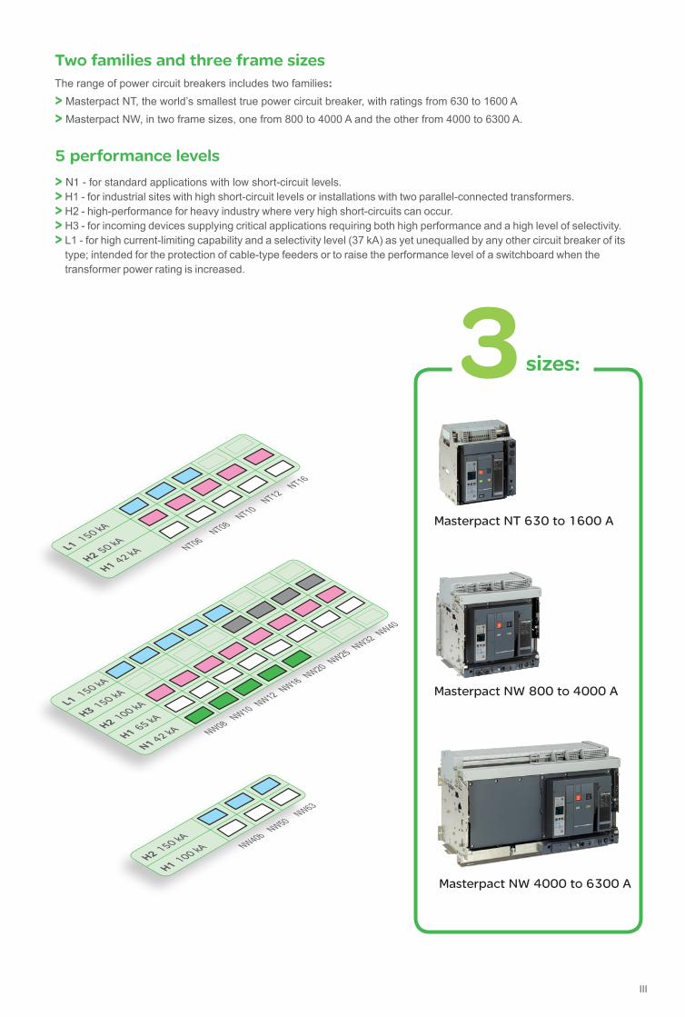
Two families and three frame sizesThe range of power circuit breakers includes two families:
> Masterpact NT, the world’s smallest true power circuit breaker, with ratings from 630 to 1600 A> Masterpact NW, in two frame sizes, one from 800 to 4000 A and the other from 4000 to 6300 A.
5 performance levels
> N1 - for standard applications with low short-circuit levels.> H1 - for industrial sites with high short-circuit levels or installations with two parallel-connected transformers.> H2 - high-performance for heavy industry where very high short-circuits can occur.> H3 - for incoming devices supplying critical applications requiring both high performance and a high level of selectivity.> L1 - for high current-limiting capability and a selectivity level (37 kA) as yet unequalled by any other circuit breaker of its
type; intended for the protection of cable-type feeders or to raise the performance level of a switchboard when the transformer power rating is increased.
Masterpact NW 800 to 4000 A
Masterpact NT 630 to 1600 A
Masterpact NW 4000 to 6300 A
NW08
L1 150 kA
H1 65 kA
N1 42 kANW10 NW12 NW16 NW20 NW25 NW32 NW40
H3 150 kA
H2 100 kA
NW40b
H2 150 kA
H1 100 kA
NW50NW63
NT06L1 150 kA
H2 50 kA
H1 42 kA
NT08NT10
NT12NT16
sizes:
IV
Optimised volumes and ease of installationAiming at standardising electrical switchboards at a time when installations are increasingly complex, Masterpact provides an unequalled simplicity, both concerning choice and installation.
The smallest circuit breaker in the worldMasterpact NT innovates by offering all the performance of a power circuit breaker in an extremely small volume. The 70 mm pole pitch means a three-pole drawout circuit breaker can be installed in a switchboard section 400 mm wide and 400 mm deep.
Maximum securityThe arc chutes absorb the energy released during breaking, thus limiting the stresses exerted on the installation.They filter and cool the gases produced, reducing effects perceptible from the outside.
Optimised volumesUp to 4000 A, Masterpact NW circuit breakers are all the same size, the same as the old M08 to 32 range.From 4000 to 6300 A, there is just one size.
More than
60 patents are used to design Masterpact
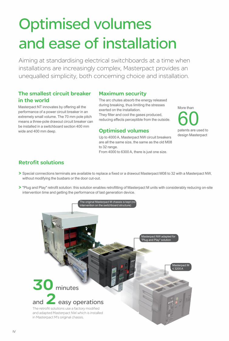
Retrofit solutions
> Special connections terminals are available to replace a fixed or a drawout Masterpact M08 to 32 with a Masterpact NW, without modifying the busbars or the door cut-out.
> "Plug and Play" retrofit solution: this solution enables retrofitting of Masterpact M units with considerably reducing on-site intervention time and getting the performance of last generation device.
The original Masterpact M chassis is kept (no intervention on the switchboard structure)
Masterpact NW adapted for "Plug and Play" solution
Masterpact My 3200 A
30 minutes
and 2 easy operationsThe retrofit solutions use a factory modified and adapted Masterpact NW which is installed in Masterpact M’s original chassis.

V
Optimised volumes and ease of installation
Standardisation of the switchboard With optimised sizes, the Masterpact NT and NW ranges simplify the design of switchboards and standardise the installation of devices:> a single connection layout for Masterpact NT > three connection layouts for Masterpact NW: • one from 800 to 3200 A • one for 4000 A • one up to 6300 A> horizontal or vertical rear connections can be modified on-site by turning the connectors 90° or they can even be replaced by front connection terminals> identical connection terminals for the fixed or draw-out version for each rating (Masterpact NW)> front connection requires little space because the connectors not increase the depth of the device.
Practical installation solutionsThe Masterpact NW range further improves the installation solutions that have built the success of its predecessors:> incoming connection to top or bottom terminals> no safety clearance required> connection: • horizontal or vertical rear connection • front connection with minimum extra space • mixed front and rear connections 115 mm pole pitch on all versions> no derating up to 55 °C and 4000 A.
Compliance with environmental requirements
The materials used for Masterpact are not potentially dangerous to the environment and are marked to facilitate sorting for recycling.
Production facilities are non-polluting in compliance with the ISO 14001 standard.

VI
Keep your Masterpact NT/NW features year after year by performing requested maintenance
To maintain Masterpact’s operating and safety characteristics from the beginning to the end of its service life, Schneider Electric requests that systematic checks and periodic maintenance be carried out by qualified personnel, as indicated in the “Masterpact Maintenance Guide”.
The Maintenance Guide defines 3 types of maintenance:> the corrective maintenance repairs a system in view of fulfilling a required function
> the preventive maintenance consists in carrying out, at predetermined intervals, checks intended to reduce the probability of a failure or deterioration in the operation of a system
> the predictive maintenance, based on the recording and analysis of system parameters, is the means to detect drift from the initial state and significant trends. Using predictive maintenance makes possible to anticipate on the corrective action required to ensure equipment safety and continuity of service, and plan the action for the most convenient time.
VII
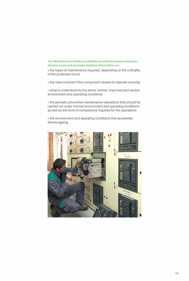
The Maintenance Guide is available on Internet (www.schneider-electric.com) and provides detailed information on:> the types of maintenance required, depending on the criticality of the protected circuit
> the risks involved if the component ceases to operate correctly
> what is understood by the terms normal, improved and severe environment and operating conditions
> the periodic preventive maintenance operations that should be carried out under normal environment and operating conditions as well as the level of competence required for the operations
> the environment and operating conditions that accelerate device ageing.

VIII
Ethernet-ready Smart PanelsEthernet-ready Smart Panels enable electrical distribution control and expertise. ‘Protect’ - ’Measure’ - ’Connect’ are the 3 pillars of their technology.
PB11
9232
.eps
Electrical protection is at the core of Smart PanelReliable and high-performance technology is present in every breaker and every residual current device.
1- Protect
Keeping a close eye on energy flowsThe switchboard plays a key role in capturing building-related data, by gathering the critical protection and metering components.
2- Measure
Give a voice to the panelSafe Ethernet network data transmission is now part of the intrinsic design of protection and metering devices
3- Connect
Architecture overview
4- Act

IX
Future savings, peace-of-mind Access to Smart Panel status, values, is essential for taking advantages of monitoring and management services, locally or remotely.
Act in small/medium buildingswith FDM 128, Com’X 510, Power View, EcoStruxure™ Facility Expert
DD
3859
19.a
i
DB4
2305
6.ai
Increasing maintenance efficiency p Operate preventive maintenance tools
p Follow maintenance & planning
p Provide business owner instant access to maintenance reports
Distance management with EcoStruxure™ Facility Expert on Smartphone, tablet, PC
Optimizing energy-efficiency p Visualize, record energy consumption and WAGES.
p Comply with regulation .
PB11
1801
-60.
eps
Electrical device monitoring and control with FDM 128, locally
Improving continuity of service p Get instant notifications
p Manage with assets-maintenance platform
p Get and analyze data for quick crisis-recovery
DD
3859
18.a
i
Com’X 510 web pages direct display, or Cloud based pages from other devices with Power View.
Architecture overview

X
Monitoring electrical network p Observe voltage disturbances, harmonics on graphics. p Read power factor.
Managing equipment & key assets p Check operating status, faults on custom
on-line diagrams.
Accounting energy p Record power meter data on dashboards. p Allocate energy consumption with costs. p Follow conservation goals.
Act in large non-critical buildingswith EcoStruxure™ Energy Expert
Monitoring Power quality p Be alerted of equipment affected by power quality issue. p Compare power quality against industry standards. p Collect facts for future discussion with Utility.
Analysing Power Events p Speed up downtime crisis recovery p Determine incident root cause, events sequence. p Troubleshoot power quality issues.
Analysing Energy Performance p Evaluate building energy saving performance; p Identify underperforming loads; p Analyze Energy Conservation Measures (ECMs)
according ISO50001 program.
Act in large critical buildingswith EcoStruxure™ Power Monitoring Expert [1]
[1] EcoStruxure™ Power Monitoring Expert, http://pmedemo.biz/web/ ID: demo & Password: demo
DB4
2565
7.ai
DB4
2565
8.ai
DB4
2565
9.ai
DB4
2566
0.ai
DB4
2566
1.ai
DB4
2533
4.ai
Architecture overview
Day-to-day energy management >> Power availability & quality, energy performance For simply dealing with building user’s needs and energy constraints. EcoStruxure™ Building Management provides electrical management, monitoring and energy accounting.Energy decisions are often crucial in large critical buildings, they must be informed. EcoStruxure™ Power Monitoring Expert (software for PC) collects Smart Panels values to provide expert analysis.

Masterpact NT and NW
Gen
eral
con
tent
sPresentation
Functions and characteristics
Installation recommendations
Dimensions and connection
Electrical diagrams
Additional characteristics
Catalogue numbers and order form
www.schneider-electric.com
1
A
B
C
D
E
F

Presentation
General overviewDetailed contents
This overview describes all the functions offered by Masterpact NT and NW devices. The two product families have identical functions implemented using the same or different components depending on the case.
Circuit breakers and switch-disconnectors
> page A-2
Power meter functions> page A-20
PB11
9233
.eps
PB11
1801
-19_
r.eps
Masterpact equipped with Micrologic 2 / 5 / 6 / 7 trip units offer type A (ammeter) or E (energy) metering functions as well as communication. Using Micrologic sensors and intelligence, Masterpact provides access to measurements of all the main electrical parameters on the built-in screen, on a dedicated FDM display unit or via the communication system.
Operating assistance functions> page A-22
Integration of measurement functions provides operators with operating assistance functions including alarms tripped by user-selected measurement values, time-stamped event tables and histories, and maintenance indicators.
Switchboard display unit functions> page A-24
The main measurements can be read on the built-in screen of Micrologic 2 / 5 / 6 / 7 trip units. They can also be displayed on the FDM switchboard display unit along with pop-up windows signalling the main alarms.
Communication> page A-32
scre
en 2
b.ep
s b COM option in Masterpact. b Masterpact in a communication network. b IFM: Modbus interface module. b IFE: Ethernet interface module. b I/O application module. b Ecoreach software.
PB11
9234
.eps
PB11
5852
_L20
.eps
PB11
9111
_L8.
eps
PB10
6363
A50.
eps
b Ratings: v Masterpact NT 630 to 1600 A v Masterpact NW 800 to 6300 A. b Circuit breakers type N1, H1, H2, H3, L1. b Switch-disconnectors type NA, HA, HF, HH. b 3 or 4 poles. b Fixed or drawout versions. b Option with neutral on the right. b Protection derating.
Micrologic control units> page A-8
PB10
4804
.eps Ammeter A and Energy E
b 2.0 basic protection b 5.0 selective protection b 6.0 selective + earth-fault protection b 7.0 (1) selective + earth-leakage protection
Power meter P b 5.0 selective protection b 6.0 selective + earth-fault protection b 7.0 selective + earth-leakage protection
Harmonic meter H b 5.0 selective protection b 6.0 selective + earth-fault protection b 7.0 selective + earth-leakage protection b External sensor for earth-fault protection. b Rectangular sensor for earth-leakage protection. b Setting options (long-time rating plug): v low setting 0.4 to 0.8 x Ir v high setting 0.8 to 1 x Ir v without long-time protection. b External AD power-supply module. b Battery module.
(1) Only for ammeter A.
www.schneider-electric.com
2

Connections> page A-46
Remote operation> page A-54
PB10
0818
-16.
eps
PB10
0809
-16.
eps b Remote ON/OFF:
v gear motor v XF closing or MX opening voltage releases v PF ready-to-close contact
options: - RAR automatic or RES electrical remote reset- BPFE electrical closing pushbutton.
b Remote tripping function: v MN voltage release
- standard- adjustable or non-adjustable delay
v or second MX voltage release.
Accessories> page A-58
PB10
0776
-42.
eps
PB10
4382
A32.
eps
b Auxiliary terminal shield. b Operation counter. b Escutcheon. b Transparent cover for escutcheon. b Escutcheon blanking plate.
PB10
4347
A55.
eps
PB10
4357
A40.
eps
PB10
4362
A30.
eps
b Rear connection (horizontal or vertical). b Front connection. b Mixed connections. b Optional accessories: v bare-cable connectors and connector shields v terminal shields v vertical-connection adapters v cable-lug adapters v interphase barriers v spreaders v disconnectable front-connection adapter v safety shutters, shutter locking blocks, shutter
position indication and locking.
Locking> page A-50
PB10
0810
-32.
eps
PB10
0812
-32.
eps
b Pushbutton locking by padlockable transparent cover.
b OFF-position locking by padlock or keylock. b Chassis locking in disconnected position by keylock.
b Chassis locking in connected, disconnected and test positions.
b Door interlock (inhibits door opening with breaker in connected position).
b Racking interlock (inhibits racking with door open).
b Racking interlock between crank and OFF pushbutton.
b Automatic spring discharge before breaker removal.
b Mismatch protection.
Indication contacts> page A-52
PB10
0807
-20.
eps
PB10
0820
-32.
eps
b Standard or low-level contacts: v ON/OFF indication (OF) v “fault trip” indication (SDE) v carriage switches for connected (CE) disconnected (CD) and test (CT) positions.
b Programmable contacts: v 2 contacts (M2C).
www.schneider-electric.com
3
Masterpact NT and NW
Functions and characteristics
Presentation >2Installation recommendations >B-1Dimensions and connections >C-1Electrical diagrams >D-1Additional characteristics >E-1Catalogue numbers and order form >F-1
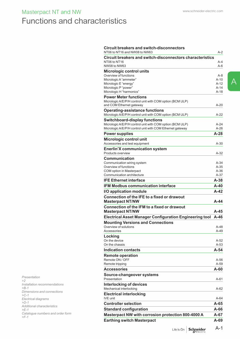
Circuit breakers and switch-disconnectorsNT06 to NT16 and NW08 to NW63 A-2
Circuit breakers and switch-disconnectors characteristicsNT06 to NT16 A-4NW08 to NW63 A-6
Micrologic control unitsOverview of functions A-8Micrologic A “ammeter” A-10Micrologic E “energy” A-12Micrologic P “power” A-14Micrologic H “harmonics” A-18
Power Meter functionsMicrologic A/E/P/H control unit with COM option (BCM ULP) and COM Ethernet gateway A-20
Operating-assistance functionsMicrologic A/E/P/H control unit with COM option (BCM ULP) A-22
Switchboard-display functionsMicrologic A/E/P/H control unit with COM option (BCM ULP) A-24Micrologic A/E/P/H control unit with COM Ethernet gateway A-26
Power supplies A-28Micrologic control unitAccessories and test equipment A-30
Enerlin’X communication systemProducts overview A-32
CommunicationCommunication wiring system A-34Overview of functions A-35COM option in Masterpact A-36Communication architecture A-37
IFE Ethernet interface A-38IFM Modbus communication interface A-40I/O application module A-42Connection of the IFE to a fixed or drawout Masterpact NT/NW A-44Connection of the IFM to a fixed or drawout Masterpact NT/NW A-45Electrical Asset Manager Configuration Engineering tool A-46Mounting Versions and ConnectionsOverview of solutions A-48Accessories A-49
LockingOn the device A-52On the chassis A-53
Indication contacts A-54Remote operationRemote ON / OFF A-56Remote tripping A-59
Accessories A-60Source-changeover systemsPresentation A-61
Interlocking of devicesMechanical interlocking A-62
Electrical interlockingIVE unit A-64
Controller selection A-65Standard configuration A-66Masterpact NW with corrosion protection 800-4000 A A-67Earthing switch Masterpact A-69
www.schneider-electric.com
A-1
A

Functions and characteristics
Circuit breakers and switch-disconnectors NT06 to NT16 and NW08 to NW63
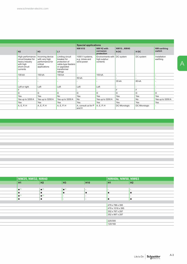
NT and NW selection criteria Masterpact NT Masterpact NWStandard applications Standard applications Special applicationsNT06, NT08, NT10, NT12, NT16 NT06, NT08, NT10 NW08...NW16 NW08...NW40 NW H10 NW H2 with
corrosion protection
NW10...NW40 NW earthing switchH1 H2 L1 N1 H1 H2 H3 L1 N DC H DC
Type of application Standard applications with low short-circuit currents
Applications with medium-level short-circuit currents
Limiting circuit breaker for protection of cable-type feeders or upgraded transformer ratings
Standard applications with low short-circuit currents
Circuit breaker for industrial sites with high short-circuit currents
High-performance circuit breaker for heavy industry with high short-circuit currents
Incoming device with very high performance for critical applications
Limiting circuit breaker for protection of cable-type feeders or upgraded transformer ratings
1000 V systems, e.g. mines and wind power
Environments with high sulphur contents
DC system DC system Installation earthing
Icu/Ics at 440 V 42 kA 50 kA 130 kA 42 kA 65 kA 100 kA 150 kA 150 kA - 100 kA - - -Icu/Ics at 1000 V - - - - - - - - 50 kA - - - -Icu/Ics at 500 V DC L/R < 15 ms - - - - - - - - - - 35 kA 85 kA -
Position of neutral Left Left Left Left Left or right Left or right Left Left Left Left - - -Fixed F F F F F F - - - - F F -Drawout D D D D D D D D D D D D DSwitch-disconnector version Yes No No Yes Yes Yes Yes No Yes Yes Yes Yes YesFront connection Yes Yes Yes Yes Yes up to 3200 A Yes up to 3200 A Yes up to 3200 A Yes up to 3200 A No Yes up to 3200 A No No Yes up to 3200 ARear connection Yes Yes Yes Yes Yes Yes Yes Yes Yes Yes Yes Yes YesType of Micrologic control unit A, E, P, H A, E, P, H A, E, P, H A, E, P, H A, E, P, H A, E, P, H A, E, P, H A, E, P, H A, consult us for P
and HA, E, P, H DC Micrologic DC Micrologic -
Masterpact NT06 to NT16 installation characteristicsCircuit breaker NT06, NT08, NT10 NT12, NT16Type H1 H2 L1 H1 H2Connection
Drawout FC b b b b b
RC b b b b b
Fixed FC b b b b b
RC b b b b b
Dimensions (mm) H x W x DDrawout 3P 322 x 288 x 277
4P 322 x 358 x 277Fixed 3P 301 x 276 x 196
4P 301 x 346 x 196Weight (kg) (approximate)
Drawout 3P/4P 30/39Fixed 3P/4P 14/18
Masterpact NW08 to NW63 installation characteristicsCircuit breaker NW08, NW10, NW12, NW16 NW20 NW25, NW32, NW40 NW40b, NW50, NW63Type N1 H1 H2 L1 H10 H1 H2 H3 L1 H10 H1 H2 H3 H10 H1 H2Connection
Drawout FC b b b b - b b b b - b (1) b (1) b (1) - - -RC b b b b b b b b b b b b b b b b
Fixed FC b b b - - b b - - - b (1) b (1) - - - -RC b b b - - b b - - - b b - - b b
Dimensions (mm) H x W x DDrawout 3P 439 x 441 x 395 479 x 786 x 395
4P 439 x 556 x 395 479 x 1016 x 395Fixed 3P 352 x 422 x 297 352 x 767 x 297
4P 352 x 537 x 297 352 x 997 x 297Weight (kg) (approximate)
Drawout 3P/4P 90/120 225/300Fixed 3P/4P 50/65 120/160
(1) Except 4000.
www.schneider-electric.com
A-2
A
NT and NW selection criteria Masterpact NT Masterpact NWStandard applications Standard applications Special applicationsNT06, NT08, NT10, NT12, NT16 NT06, NT08, NT10 NW08...NW16 NW08...NW40 NW H10 NW H2 with
corrosion protection
NW10...NW40 NW earthing switchH1 H2 L1 N1 H1 H2 H3 L1 N DC H DC
Type of application Standard applications with low short-circuit currents
Applications with medium-level short-circuit currents
Limiting circuit breaker for protection of cable-type feeders or upgraded transformer ratings
Standard applications with low short-circuit currents
Circuit breaker for industrial sites with high short-circuit currents
High-performance circuit breaker for heavy industry with high short-circuit currents
Incoming device with very high performance for critical applications
Limiting circuit breaker for protection of cable-type feeders or upgraded transformer ratings
1000 V systems, e.g. mines and wind power
Environments with high sulphur contents
DC system DC system Installation earthing
Icu/Ics at 440 V 42 kA 50 kA 130 kA 42 kA 65 kA 100 kA 150 kA 150 kA - 100 kA - - -Icu/Ics at 1000 V - - - - - - - - 50 kA - - - -Icu/Ics at 500 V DC L/R < 15 ms - - - - - - - - - - 35 kA 85 kA -
Position of neutral Left Left Left Left Left or right Left or right Left Left Left Left - - -Fixed F F F F F F - - - - F F -Drawout D D D D D D D D D D D D DSwitch-disconnector version Yes No No Yes Yes Yes Yes No Yes Yes Yes Yes YesFront connection Yes Yes Yes Yes Yes up to 3200 A Yes up to 3200 A Yes up to 3200 A Yes up to 3200 A No Yes up to 3200 A No No Yes up to 3200 ARear connection Yes Yes Yes Yes Yes Yes Yes Yes Yes Yes Yes Yes YesType of Micrologic control unit A, E, P, H A, E, P, H A, E, P, H A, E, P, H A, E, P, H A, E, P, H A, E, P, H A, E, P, H A, consult us for P
and HA, E, P, H DC Micrologic DC Micrologic -
Masterpact NT06 to NT16 installation characteristicsCircuit breaker NT06, NT08, NT10 NT12, NT16Type H1 H2 L1 H1 H2Connection
Drawout FC b b b b b
RC b b b b b
Fixed FC b b b b b
RC b b b b b
Dimensions (mm) H x W x DDrawout 3P 322 x 288 x 277
4P 322 x 358 x 277Fixed 3P 301 x 276 x 196
4P 301 x 346 x 196Weight (kg) (approximate)
Drawout 3P/4P 30/39Fixed 3P/4P 14/18
Masterpact NW08 to NW63 installation characteristicsCircuit breaker NW08, NW10, NW12, NW16 NW20 NW25, NW32, NW40 NW40b, NW50, NW63Type N1 H1 H2 L1 H10 H1 H2 H3 L1 H10 H1 H2 H3 H10 H1 H2Connection
Drawout FC b b b b - b b b b - b (1) b (1) b (1) - - -RC b b b b b b b b b b b b b b b b
Fixed FC b b b - - b b - - - b (1) b (1) - - - -RC b b b - - b b - - - b b - - b b
Dimensions (mm) H x W x DDrawout 3P 439 x 441 x 395 479 x 786 x 395
4P 439 x 556 x 395 479 x 1016 x 395Fixed 3P 352 x 422 x 297 352 x 767 x 297
4P 352 x 537 x 297 352 x 997 x 297Weight (kg) (approximate)
Drawout 3P/4P 90/120 225/300Fixed 3P/4P 50/65 120/160
(1) Except 4000.
www.schneider-electric.com
A-3
A

Functions and characteristics
Circuit breakers and switch-disconnectors characteristicsNT06 to NT16
PB10
6365
A49.
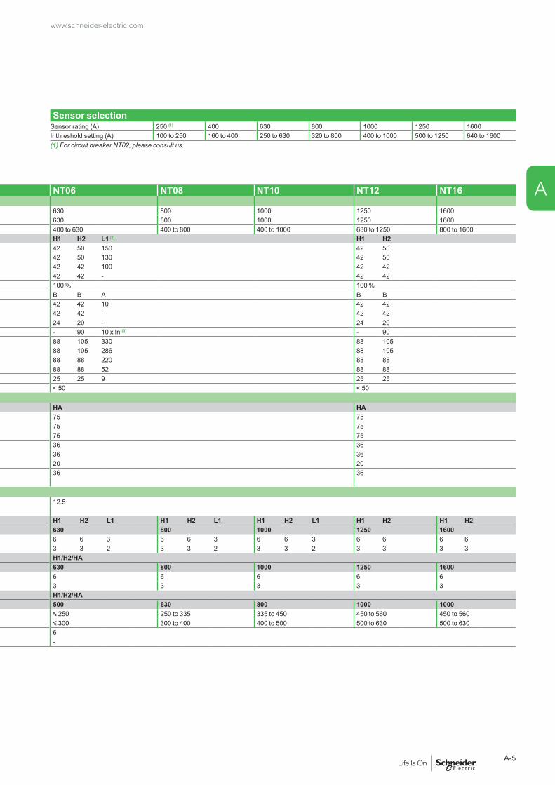
eps Common characteristics Sensor selection
Sensor rating (A) 250 (1) 400 630 800 1000 1250 1600Ir threshold setting (A) 100 to 250 160 to 400 250 to 630 320 to 800 400 to 1000 500 to 1250 640 to 1600(1) For circuit breaker NT02, please consult us.
Number of poles 3/4Rated insulation voltage (V) Ui 1000Impulse withstand voltage (kV) Uimp 12Rated operational voltage (V AC 50/60 Hz) Ue 690Suitability for isolation IEC 60947-2 Degree of pollution IEC 60664-1 3
Basic circuit breaker NT06 NT08 NT10 NT12 NT16Circuit breaker as per IEC 60947-2
Rated current (A) In at 40 °C/50 °C (1) 630 800 1000 1250 1600Rating of 4th pole (A) 630 800 1000 1250 1600Sensor ratings (A) 400 to 630 400 to 800 400 to 1000 630 to 1250 800 to 1600Type of circuit breaker H1 H2 L1 (2) H1 H2
Ultimate breaking capacity (kA rms) Icu 220/415 V 42 50 150 42 50V AC 50/60 Hz 440 V 42 50 130 42 50
525 V 42 42 100 42 42690 V 42 42 - 42 42
Rated service breaking capacity (kA rms) Ics % Icu 100 % 100 %Utilisation category B B A B BRated short-time withstand current (kA rms)V AC 50/60 Hz
Icw 0.5 s 42 42 10 42 421 s 42 42 - 42 423 s 24 20 - 24 20
Integrated instantaneous protection (kA peak ±10 %) - 90 10 x In (3) - 90Rated making capacity (kA peak) Icm 220/415 V 88 105 330 88 105V AC 50/60 Hz 440 V 88 105 286 88 105
525 V 88 88 220 88 88690 V 88 88 52 88 88
Break time (ms) between tripping order and arc extinction 25 25 9 25 25Closing time (ms) < 50 < 50Switch-disconnector as per IEC 60947-3 and Annex AType of switch-disconnector HA HA
Rated making capacity (kA peak) Icm 220 V 75 75AC23A/AC3 category V AC 50/60 Hz 440 V 75 75
525/690 V 75 75Rated short-time withstand current (kA rms) Icw 0.5 s 36 36AC23A/AC3 category V AC 50/60 Hz 1 s 36 36
3 s 20 20Ultimate breaking capacity Icu (kA rms) with an external protection relay Maximum time delay: 350 ms
690 V 36 36
Mechanical and electrical durability as per IEC 60947-2/3 at In/IeDurability Mechanical without maintenance 12.5C/O cycles x 1000Type of circuit breaker H1 H2 L1 H1 H2 L1 H1 H2 L1 H1 H2 H1 H2Rated current In (A) 630 800 1000 1250 1600
C/O cycles x 1000 Electrical without maintenance 440 V 6 6 3 6 6 3 6 6 3 6 6 6 6IEC 60947-2 690 V 3 3 2 3 3 2 3 3 2 3 3 3 3Type of circuit breaker or switch-disconnector H1/H2/HARated operationnal current Ie (A) AC23A 630 800 1000 1250 1600
C/O cycles x 1000 Electrical without maintenance 440 V 6 6 6 6 6IEC 60947-3 690V 3 3 3 3 3Type of circuit breaker or switch-disconnector H1/H2/HARated operationnal current Ie (A) AC3 (4) 500 630 800 1000 1000
Motor power 380/415 V (kW) y 250 250 to 335 335 to 450 450 to 560 450 to 560440 V (kW) y 300 300 to 400 400 to 500 500 to 630 500 to 630
C/O cycles x 1000 Electrical without maintenance 440 V 6IEC 60947-3 Annex M/IEC 60947-4-1 690 V -
(1) 50 °C: rear vertical connected. Refer to temperature derating tables for other connection types.
(2) See the current-limiting curves in the “additional characteristics” section.
(3) SELLIM system.(4) Suitable for motor control (direct-on-line starting).
www.schneider-electric.com
A-4
A
PB10
6365
A49.
eps Common characteristics Sensor selection
Sensor rating (A) 250 (1) 400 630 800 1000 1250 1600Ir threshold setting (A) 100 to 250 160 to 400 250 to 630 320 to 800 400 to 1000 500 to 1250 640 to 1600(1) For circuit breaker NT02, please consult us.
Number of poles 3/4Rated insulation voltage (V) Ui 1000Impulse withstand voltage (kV) Uimp 12Rated operational voltage (V AC 50/60 Hz) Ue 690Suitability for isolation IEC 60947-2 Degree of pollution IEC 60664-1 3
Basic circuit breaker NT06 NT08 NT10 NT12 NT16Circuit breaker as per IEC 60947-2
Rated current (A) In at 40 °C/50 °C (1) 630 800 1000 1250 1600Rating of 4th pole (A) 630 800 1000 1250 1600Sensor ratings (A) 400 to 630 400 to 800 400 to 1000 630 to 1250 800 to 1600Type of circuit breaker H1 H2 L1 (2) H1 H2
Ultimate breaking capacity (kA rms) Icu 220/415 V 42 50 150 42 50V AC 50/60 Hz 440 V 42 50 130 42 50
525 V 42 42 100 42 42690 V 42 42 - 42 42
Rated service breaking capacity (kA rms) Ics % Icu 100 % 100 %Utilisation category B B A B BRated short-time withstand current (kA rms)V AC 50/60 Hz
Icw 0.5 s 42 42 10 42 421 s 42 42 - 42 423 s 24 20 - 24 20
Integrated instantaneous protection (kA peak ±10 %) - 90 10 x In (3) - 90Rated making capacity (kA peak) Icm 220/415 V 88 105 330 88 105V AC 50/60 Hz 440 V 88 105 286 88 105
525 V 88 88 220 88 88690 V 88 88 52 88 88
Break time (ms) between tripping order and arc extinction 25 25 9 25 25Closing time (ms) < 50 < 50Switch-disconnector as per IEC 60947-3 and Annex AType of switch-disconnector HA HA
Rated making capacity (kA peak) Icm 220 V 75 75AC23A/AC3 category V AC 50/60 Hz 440 V 75 75
525/690 V 75 75Rated short-time withstand current (kA rms) Icw 0.5 s 36 36AC23A/AC3 category V AC 50/60 Hz 1 s 36 36
3 s 20 20Ultimate breaking capacity Icu (kA rms) with an external protection relay Maximum time delay: 350 ms
690 V 36 36
Mechanical and electrical durability as per IEC 60947-2/3 at In/IeDurability Mechanical without maintenance 12.5C/O cycles x 1000Type of circuit breaker H1 H2 L1 H1 H2 L1 H1 H2 L1 H1 H2 H1 H2Rated current In (A) 630 800 1000 1250 1600
C/O cycles x 1000 Electrical without maintenance 440 V 6 6 3 6 6 3 6 6 3 6 6 6 6IEC 60947-2 690 V 3 3 2 3 3 2 3 3 2 3 3 3 3Type of circuit breaker or switch-disconnector H1/H2/HARated operationnal current Ie (A) AC23A 630 800 1000 1250 1600
C/O cycles x 1000 Electrical without maintenance 440 V 6 6 6 6 6IEC 60947-3 690V 3 3 3 3 3Type of circuit breaker or switch-disconnector H1/H2/HARated operationnal current Ie (A) AC3 (4) 500 630 800 1000 1000
Motor power 380/415 V (kW) y 250 250 to 335 335 to 450 450 to 560 450 to 560440 V (kW) y 300 300 to 400 400 to 500 500 to 630 500 to 630
C/O cycles x 1000 Electrical without maintenance 440 V 6IEC 60947-3 Annex M/IEC 60947-4-1 690 V -
(1) 50 °C: rear vertical connected. Refer to temperature derating tables for other connection types.
(2) See the current-limiting curves in the “additional characteristics” section.
(3) SELLIM system.(4) Suitable for motor control (direct-on-line starting).
www.schneider-electric.com
A-5
A
Functions and characteristics
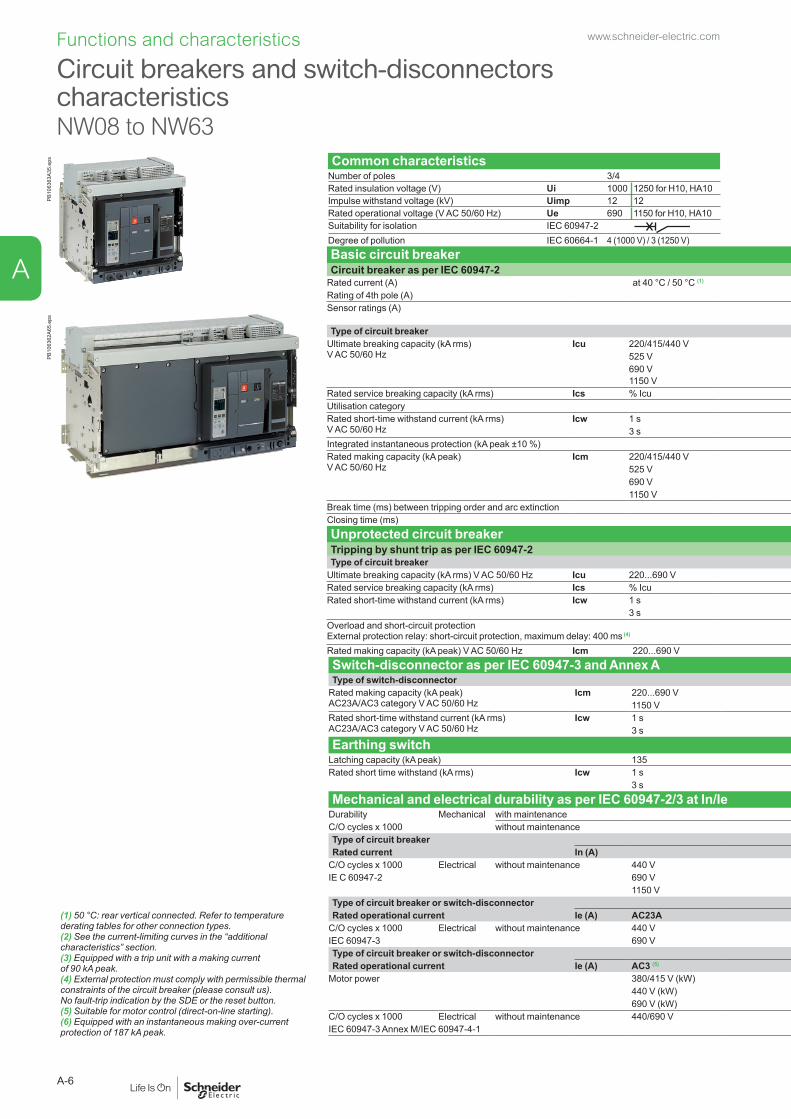
Circuit breakers and switch-disconnectors characteristicsNW08 to NW63
PB10
6363
A35.
eps Common characteristics Sensor selection
Number of poles 3/4 Sensor rating (A) 250 (1) 400 630 800 1000 1250 1600 2000 2500 3200 4000 5000 6300Rated insulation voltage (V) Ui 1000 1250 for H10, HA10 Ir threshold setting(A) 100 160 250 320 400 500 630 800 1000 1250 1600 2000 2500Impulse withstand voltage (kV) Uimp 12 12 to 250 to 400 to 630 to 800 to 1000 to 1250 to 1600 to 2000 to 2500 to 3200 to 4000 to 5000 to 6300Rated operational voltage (V AC 50/60 Hz) Ue 690 1150 for H10, HA10 (1) For circuit breaker NW02, please consult us.Suitability for isolation IEC 60947-2 Degree of pollution IEC 60664-1 4 (1000 V) / 3 (1250 V)Basic circuit breaker NW08 NW10 NW12 NW16 NW20 NW25 NW32 NW40 NW40b NW50 NW63Circuit breaker as per IEC 60947-2
Rated current (A) at 40 °C / 50 °C (1) 800 1000 1250 1600 2000 2500 3200 4000 4000 5000 6300Rating of 4th pole (A) 800 1000 1250 1600 2000 2500 3200 4000 4000 5000 6300Sensor ratings (A) 400
to 800400to 1000
630to 1250
800 to 1600 1000 to 2000 1250to 2500
1600to 3200
2000 to 4000 2000to 4000
2500to 5000
3200to 6300
Type of circuit breaker N1 H1 H2 L1 (2) H10 N1 H1 H2 H3 L1 (2) H10 H1 H2 H3 H10 H1 H2Ultimate breaking capacity (kA rms)V AC 50/60 Hz
Icu 220/415/440 V 42 65 100 150 - 42 65 100 150 150 - 65 100 150 - 100 150525 V 42 65 85 130 - 42 65 85 130 130 - 65 85 130 - 100 130690 V 42 65 85 100 - 42 65 85 100 100 - 65 85 100 - 100 1001150 V - - - - 50 - - - - - 50 - - - 50 - -
Rated service breaking capacity (kA rms) Ics % Icu 100 % 100 % 100 % 100 %Utilisation category B B B BRated short-time withstand current (kA rms)V AC 50/60 Hz
Icw 1 s 42 65 85 30 50 42 65 85 65 30 50 65 85 65 50 100 1003 s 22 36 50 30 50 22 36 75 65 30 50 65 75 65 50 100 100
Integrated instantaneous protection (kA peak ±10 %) - - 190 80 - - - 190 150 80 - - 190 150 - - 270Rated making capacity (kA peak)V AC 50/60 Hz
Icm 220/415/440 V 88 143 220 330 - 88 143 220 330 330 - 143 220 330 - 220 330525 V 88 143 187 286 - 88 143 187 286 286 - 143 187 286 - 220 286690 V 88 143 187 220 - 88 143 187 220 220 - 143 187 220 - 220 2201150 V - - - - 105 - - - - - 105 - - - 105 - -
Break time (ms) between tripping order and arc extinction 25 25 25 10 25 25 25 25 25 10 25 25 25 25 25 25 25Closing time (ms) < 70 < 70 < 70 < 70 < 80Unprotected circuit breakerTripping by shunt trip as per IEC 60947-2Type of circuit breaker HA HF (3) HA HF (3) HA HF (3) HA HH (6)
Ultimate breaking capacity (kA rms) V AC 50/60 Hz Icu 220...690 V 65 85 65 85 65 85 85 100Rated service breaking capacity (kA rms) Ics % Icu 100 % 100 % 100 % 100 % 100 %Rated short-time withstand current (kA rms) Icw 1 s 65 85 65 85 65 85 85 100
3 s 36 50 36 75 55 75 85 100Overload and short-circuit protection External protection relay: short-circuit protection, maximum delay: 400 ms (4)
- - - - - - - -
Rated making capacity (kA peak) V AC 50/60 Hz Icm 220...690 V 143 187 143 187 143 187 187 220
PB10
6362
A65.
eps
(1) 50 °C: rear vertical connected. Refer to temperature derating tables for other connection types.(2) See the current-limiting curves in the “additional characteristics” section.(3) Equipped with a trip unit with a making current of 90 kA peak.(4) External protection must comply with permissible thermal constraints of the circuit breaker (please consult us). No fault-trip indication by the SDE or the reset button.(5) Suitable for motor control (direct-on-line starting).(6) Equipped with an instantaneous making over-current protection of 187 kA peak.
Switch-disconnector as per IEC 60947-3 and Annex A NW08/NW10/NW12/NW16 NW20 NW25/NW32/NW40 NW40b/NW50/NW63Type of switch-disconnector NA HA HF HA10 HA HF HA10 HA HF HA10 HA HH
Rated making capacity (kA peak)AC23A/AC3 category V AC 50/60 Hz
Icm 220...690 V 88 143 187 - 143 187 - 143 187 - 187 2201150 V - - - 105 - - 105 - - 105 - -
Rated short-time withstand current (kA rms)AC23A/AC3 category V AC 50/60 Hz
Icw 1 s 42 65 85 50 65 85 50 65 85 50 85 1003 s - 36 50 50 36 75 50 55 75 50 85 100
Earthing switchLatching capacity (kA peak) 135Rated short time withstand (kA rms) Icw 1 s 60
3 s 50Mechanical and electrical durability as per IEC 60947-2/3 at In/Ie
Durability Mechanical with maintenance 25 20 10C/O cycles x 1000 without maintenance 12.5 10 5Type of circuit breaker N1/H1/H2 L1 H10 N1/H1/H2 H3 L1 H10 H1/H2 H3 H10 H1 H2Rated current In (A) 800/1000/1250/1600 2000 2500/3200/4000 4000b/5000/6300
C/O cycles x 1000 Electrical without maintenance 440 V 10 3 - 8 2 3 - 5 1.25 - 1.5 1.5IE C 60947-2 690 V 10 3 - 6 2 3 - 2.5 1.25 - 1.5 1.5
1150 V - - 0.5 - - - 0.5 - - 0.5 - -Type of circuit breaker or switch-disconnector H1/H2/NA/HA/HF H1/H2/H3/HA/HF H1/H2/H3/HA/HF H1/H2/HA/HHRated operational current Ie (A) AC23A 800/1000/1250/1600 2000 2500/3200/4000 4000b/5000/6300
C/O cycles x 1000 Electrical without maintenance 440 V 10 8 5 1.5IEC 60947-3 690 V 10 6 2.5 1.5Type of circuit breaker or switch-disconnector H1/H2/NA/HA/HF H1/H2/H3/HA/HFRated operational current Ie (A) AC3 (5) 800 1000 1250 1600 2000
Motor power 380/415 V (kW) 335 to 450 450 to 560 560 to 670 670 to 900 900 to 1150440 V (kW) 400 to 500 500 to 630 500 to 800 800 to 1000 1000 to 1300690 V (kW) y 800 800 to 1000 1000 to 1250 1250 to 1600 1600 to 2000
C/O cycles x 1000 Electrical without maintenance 440/690 V 6IEC 60947-3 Annex M/IEC 60947-4-1
www.schneider-electric.com
A-6
A

PB10
6363
A35.
eps Common characteristics Sensor selection
Number of poles 3/4 Sensor rating (A) 250 (1) 400 630 800 1000 1250 1600 2000 2500 3200 4000 5000 6300Rated insulation voltage (V) Ui 1000 1250 for H10, HA10 Ir threshold setting(A) 100 160 250 320 400 500 630 800 1000 1250 1600 2000 2500Impulse withstand voltage (kV) Uimp 12 12 to 250 to 400 to 630 to 800 to 1000 to 1250 to 1600 to 2000 to 2500 to 3200 to 4000 to 5000 to 6300Rated operational voltage (V AC 50/60 Hz) Ue 690 1150 for H10, HA10 (1) For circuit breaker NW02, please consult us.Suitability for isolation IEC 60947-2 Degree of pollution IEC 60664-1 4 (1000 V) / 3 (1250 V)Basic circuit breaker NW08 NW10 NW12 NW16 NW20 NW25 NW32 NW40 NW40b NW50 NW63Circuit breaker as per IEC 60947-2
Rated current (A) at 40 °C / 50 °C (1) 800 1000 1250 1600 2000 2500 3200 4000 4000 5000 6300Rating of 4th pole (A) 800 1000 1250 1600 2000 2500 3200 4000 4000 5000 6300Sensor ratings (A) 400
to 800400to 1000
630to 1250
800 to 1600 1000 to 2000 1250to 2500
1600to 3200
2000 to 4000 2000to 4000
2500to 5000
3200to 6300
Type of circuit breaker N1 H1 H2 L1 (2) H10 N1 H1 H2 H3 L1 (2) H10 H1 H2 H3 H10 H1 H2Ultimate breaking capacity (kA rms)V AC 50/60 Hz
Icu 220/415/440 V 42 65 100 150 - 42 65 100 150 150 - 65 100 150 - 100 150525 V 42 65 85 130 - 42 65 85 130 130 - 65 85 130 - 100 130690 V 42 65 85 100 - 42 65 85 100 100 - 65 85 100 - 100 1001150 V - - - - 50 - - - - - 50 - - - 50 - -
Rated service breaking capacity (kA rms) Ics % Icu 100 % 100 % 100 % 100 %Utilisation category B B B BRated short-time withstand current (kA rms)V AC 50/60 Hz
Icw 1 s 42 65 85 30 50 42 65 85 65 30 50 65 85 65 50 100 1003 s 22 36 50 30 50 22 36 75 65 30 50 65 75 65 50 100 100
Integrated instantaneous protection (kA peak ±10 %) - - 190 80 - - - 190 150 80 - - 190 150 - - 270Rated making capacity (kA peak)V AC 50/60 Hz
Icm 220/415/440 V 88 143 220 330 - 88 143 220 330 330 - 143 220 330 - 220 330525 V 88 143 187 286 - 88 143 187 286 286 - 143 187 286 - 220 286690 V 88 143 187 220 - 88 143 187 220 220 - 143 187 220 - 220 2201150 V - - - - 105 - - - - - 105 - - - 105 - -
Break time (ms) between tripping order and arc extinction 25 25 25 10 25 25 25 25 25 10 25 25 25 25 25 25 25Closing time (ms) < 70 < 70 < 70 < 70 < 80Unprotected circuit breakerTripping by shunt trip as per IEC 60947-2Type of circuit breaker HA HF (3) HA HF (3) HA HF (3) HA HH (6)
Ultimate breaking capacity (kA rms) V AC 50/60 Hz Icu 220...690 V 65 85 65 85 65 85 85 100Rated service breaking capacity (kA rms) Ics % Icu 100 % 100 % 100 % 100 % 100 %Rated short-time withstand current (kA rms) Icw 1 s 65 85 65 85 65 85 85 100
3 s 36 50 36 75 55 75 85 100Overload and short-circuit protection External protection relay: short-circuit protection, maximum delay: 400 ms (4)
- - - - - - - -
Rated making capacity (kA peak) V AC 50/60 Hz Icm 220...690 V 143 187 143 187 143 187 187 220
PB10
6362
A65.
eps
(1) 50 °C: rear vertical connected. Refer to temperature derating tables for other connection types.(2) See the current-limiting curves in the “additional characteristics” section.(3) Equipped with a trip unit with a making current of 90 kA peak.(4) External protection must comply with permissible thermal constraints of the circuit breaker (please consult us). No fault-trip indication by the SDE or the reset button.(5) Suitable for motor control (direct-on-line starting).(6) Equipped with an instantaneous making over-current protection of 187 kA peak.
Switch-disconnector as per IEC 60947-3 and Annex A NW08/NW10/NW12/NW16 NW20 NW25/NW32/NW40 NW40b/NW50/NW63Type of switch-disconnector NA HA HF HA10 HA HF HA10 HA HF HA10 HA HH
Rated making capacity (kA peak)AC23A/AC3 category V AC 50/60 Hz
Icm 220...690 V 88 143 187 - 143 187 - 143 187 - 187 2201150 V - - - 105 - - 105 - - 105 - -
Rated short-time withstand current (kA rms)AC23A/AC3 category V AC 50/60 Hz
Icw 1 s 42 65 85 50 65 85 50 65 85 50 85 1003 s - 36 50 50 36 75 50 55 75 50 85 100
Earthing switchLatching capacity (kA peak) 135Rated short time withstand (kA rms) Icw 1 s 60
3 s 50Mechanical and electrical durability as per IEC 60947-2/3 at In/Ie
Durability Mechanical with maintenance 25 20 10C/O cycles x 1000 without maintenance 12.5 10 5Type of circuit breaker N1/H1/H2 L1 H10 N1/H1/H2 H3 L1 H10 H1/H2 H3 H10 H1 H2Rated current In (A) 800/1000/1250/1600 2000 2500/3200/4000 4000b/5000/6300
C/O cycles x 1000 Electrical without maintenance 440 V 10 3 - 8 2 3 - 5 1.25 - 1.5 1.5IE C 60947-2 690 V 10 3 - 6 2 3 - 2.5 1.25 - 1.5 1.5
1150 V - - 0.5 - - - 0.5 - - 0.5 - -Type of circuit breaker or switch-disconnector H1/H2/NA/HA/HF H1/H2/H3/HA/HF H1/H2/H3/HA/HF H1/H2/HA/HHRated operational current Ie (A) AC23A 800/1000/1250/1600 2000 2500/3200/4000 4000b/5000/6300
C/O cycles x 1000 Electrical without maintenance 440 V 10 8 5 1.5IEC 60947-3 690 V 10 6 2.5 1.5Type of circuit breaker or switch-disconnector H1/H2/NA/HA/HF H1/H2/H3/HA/HFRated operational current Ie (A) AC3 (5) 800 1000 1250 1600 2000
Motor power 380/415 V (kW) 335 to 450 450 to 560 560 to 670 670 to 900 900 to 1150440 V (kW) 400 to 500 500 to 630 500 to 800 800 to 1000 1000 to 1300690 V (kW) y 800 800 to 1000 1000 to 1250 1250 to 1600 1600 to 2000
C/O cycles x 1000 Electrical without maintenance 440/690 V 6IEC 60947-3 Annex M/IEC 60947-4-1
www.schneider-electric.com
A-7
A

All Masterpact circuit breakers are equipped with a Micrologic control unit that can be changed on site.Control units are designed to protect Power circuits and loads. Alarms may be programmed for remote indications.Measurements of current, voltage, frequency, power and power quality optimise continuity of service and energy management.
DependabilityIntegration of protection functions in an ASIC electronic component used in all Micrologic control units guarantees a high degree of reliability and immunity to conducted or radiated disturbances.On Micrologic A, E, P and H control units, advanced functions are managed by an independent microprocessor.
AccessoriesCertain functions require the addition of Micrologic control unit accessories, described on page A-30.The rules governing the various possible combinations can be found in the documentation accessible via the Products and services menu of the www.schneider-electric.com web site.
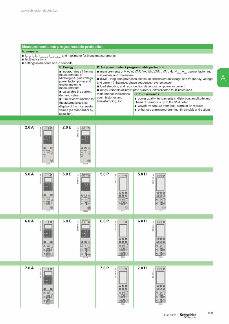
Measurements and programmable protectionA: ammeter
b I1, I2, I3, IN, Iearth-fault, Iearth-leakage and maximeter for these measurements b fault indications b settings in amperes and in seconds.
E: Energy P: A + power meter + programmable protection b incorporates all the rms
measurements of Micrologic A, plus voltage, power factor, power and energy metering measurements
b calculates the current demand value
b "Quickview" function for the automatic cyclical display of the most useful values (as standard or by selection).
b measurements of V, A, W, VAR, VA, Wh, VARh, VAh, Hz, Vpeak, Apeak, power factor and maximeters and minimeters
b IDMTL long-time protection, minimum and maximum voltage and frequency, voltage and current imbalance, phase sequence, reverse power
b load shedding and reconnection depending on power or current b measurements of interrupted currents, differentiated fault indications,
maintenance indications, event histories and time-stamping, etc.
H: P + harmonics b power quality: fundamentals, distortion, amplitude and
phase of harmonics up to the 31st order b waveform capture after fault, alarm or on request b enhanced alarm programming: thresholds and actions.
Micrologic name codes Current protection
X: type of protection b 2 for basic protection b 5 for selective protection b 6 for selective + earth-fault protection b 7 for selective + earth-leakage protection.
Y: control-unit generationIdentification of the control-unit generation.“0” signifies the first generation.Z: type of measurement
b A for “ammeter” b E for “energy” b P for “power meter” b H for “harmonic meter”.
Micrologic 2: basic protection
DB1
0111
6.ep
s
Protection:long time + instantaneous
2.0 A Micrologic 2.0 A
40
100%
%
menu
long timealarm
instantaneous
DB1
2740
4.ep
s 2.0 E Micrologic 2.0 E
40
100%
%
menu
long timealarm
instantaneous
DB1
2740
5.ep
s
Micrologic 5: selective protection
DB1
0111
7.ep
s
Protection: long time + short time + instantaneous
5.0 A Micrologic 5.0 A
40
100%
%
menu
short time
long timealarm
DB1
2740
6.ep
s 5.0 E Micrologic 5.0 E
40
100%
%
short time
long timealarm
menu
DB1
2740
7.ep
s 5.0 P
DB1
0112
2.ep
s 5.0 H
DB1
0112
2.ep
s
Micrologic 6: selective + earth-fault protection
DB1
0111
7.ep
s
DB1
0111
8.ep
s
Protection: long time + short time + instantaneous + earth fault
6.0 A
DB1
0112
3.ep
s 6.0 E Micrologic 6.0 E
40
100%
%
short time
long timealarm
ground fault
menu
DB1
2740
8.ep
s 6.0 P
DB1
0112
4.ep
s 6.0 H
DB1
0112
4.ep
s
Micrologic 7: selective + earth-leakage protection
DB1
0111
7.ep
s
DB1
0111
9.ep
s
Protection: long time + short time + instantaneous + earth leakage up to 3200A
7.0 AD
B101
123.
eps 7.0 P
DB1
0112
4.ep
s 7.0 H
DB1
0112
4.ep
s
2.0 EX Y Z
Functions and characteristics
Micrologic control units Overview of functions
PB10
0772
-32.
eps
PB10
6351
A32.
eps
www.schneider-electric.com
A-8
A
All Masterpact circuit breakers are equipped with a Micrologic control unit that can be changed on site.Control units are designed to protect Power circuits and loads. Alarms may be programmed for remote indications.Measurements of current, voltage, frequency, power and power quality optimise continuity of service and energy management.
DependabilityIntegration of protection functions in an ASIC electronic component used in all Micrologic control units guarantees a high degree of reliability and immunity to conducted or radiated disturbances.On Micrologic A, E, P and H control units, advanced functions are managed by an independent microprocessor.
AccessoriesCertain functions require the addition of Micrologic control unit accessories, described on page A-30.The rules governing the various possible combinations can be found in the documentation accessible via the Products and services menu of the www.schneider-electric.com web site.
Measurements and programmable protectionA: ammeter
b I1, I2, I3, IN, Iearth-fault, Iearth-leakage and maximeter for these measurements b fault indications b settings in amperes and in seconds.
E: Energy P: A + power meter + programmable protection b incorporates all the rms
measurements of Micrologic A, plus voltage, power factor, power and energy metering measurements
b calculates the current demand value
b "Quickview" function for the automatic cyclical display of the most useful values (as standard or by selection).
b measurements of V, A, W, VAR, VA, Wh, VARh, VAh, Hz, Vpeak, Apeak, power factor and maximeters and minimeters
b IDMTL long-time protection, minimum and maximum voltage and frequency, voltage and current imbalance, phase sequence, reverse power
b load shedding and reconnection depending on power or current b measurements of interrupted currents, differentiated fault indications,
maintenance indications, event histories and time-stamping, etc.
H: P + harmonics b power quality: fundamentals, distortion, amplitude and
phase of harmonics up to the 31st order b waveform capture after fault, alarm or on request b enhanced alarm programming: thresholds and actions.
Micrologic name codes Current protection
X: type of protection b 2 for basic protection b 5 for selective protection b 6 for selective + earth-fault protection b 7 for selective + earth-leakage protection.
Y: control-unit generationIdentification of the control-unit generation.“0” signifies the first generation.Z: type of measurement
b A for “ammeter” b E for “energy” b P for “power meter” b H for “harmonic meter”.
Micrologic 2: basic protection
DB1
0111
6.ep
s
Protection:long time + instantaneous
2.0 A Micrologic 2.0 A
40
100%
%
menu
long timealarm
instantaneous
DB1
2740
4.ep
s 2.0 E Micrologic 2.0 E
40
100%
%
menu
long timealarm
instantaneous
DB1
2740
5.ep
s
Micrologic 5: selective protection
DB1
0111
7.ep
s
Protection: long time + short time + instantaneous
5.0 A Micrologic 5.0 A
40
100%
%
menu
short time
long timealarm
DB1
2740
6.ep
s 5.0 E Micrologic 5.0 E
40
100%
%
short time
long timealarm
menu
DB1
2740
7.ep
s 5.0 P
DB1
0112
2.ep
s 5.0 H
DB1
0112
2.ep
s
Micrologic 6: selective + earth-fault protection
DB1
0111
7.ep
s
DB1
0111
8.ep
s
Protection: long time + short time + instantaneous + earth fault
6.0 A
DB1
0112
3.ep
s 6.0 E Micrologic 6.0 E
40
100%
%
short time
long timealarm
ground fault
menu
DB1
2740
8.ep
s 6.0 P
DB1
0112
4.ep
s 6.0 H
DB1
0112
4.ep
s
Micrologic 7: selective + earth-leakage protection
DB1
0111
7.ep
s
DB1
0111
9.ep
s
Protection: long time + short time + instantaneous + earth leakage up to 3200A
7.0 A
DB1
0112
3.ep
s 7.0 P
DB1
0112
4.ep
s 7.0 H
DB1
0112
4.ep
s
2.0 EX Y Z
www.schneider-electric.com
A-9
A

Functions and characteristics
Micrologic control unitsMicrologic A “ammeter”
Micrologic A control units protect power circuits. They also offer measurements, display, communication and current maximeters. Version 6 provides earth-fault protection, version 7 provides earth-leakage protection.
"Ammeter" measurementsMicrologic A control units measure the true (rms) value of currents.They provide continuous current measurements from 0.2 to 1.2 In and are accurate to within 1.5 % (including the sensors).A digital LCD screen continuously displays the most heavily loaded phase (Imax) or displays the I1, I2, I3, IN, Ig,I∆n, stored-current (maximeter) and setting values by successively pressing the navigation button.The optional external power supply makes it possible to display currents < 20 % In.Below 0.1 In, measurements are not significant. Between 0.1 and 0.2 In, accuracy changes linearly from 4 % to 1.5 %.
Communication optionIn conjunction with the COM communication option, the control unit transmits the following:
b settings b all “ammeter” measurements b tripping causes b maximeter readings.
ProtectionProtection thresholds and delays are set using the adjustment dials.Overload protectionTrue rms long-time protection.Thermal memory: thermal image before and after tripping.Setting accuracy may be enhanced by limiting the setting range using a different long-time rating plug.Overload protection can be cancelled using a specific LT rating plug "Off".Short-circuit protectionShort-time (rms) and instantaneous protection.Selection of I2t type (ON or OFF) for short-time delay.Earth-fault protectionResidual or source ground return earth fault protection.Selection of I2t type (ON or OFF) for delay.Residual earth-leakage protection (Vigi).Operation without an external power supply. q Protected against nuisance tripping. k DC-component withstand class A up to 10 A.Neutral protectionOn three-pole circuit breakers, neutral protection is not possible.On four-pole circuit breakers, neutral protection may be set using a three-position switch: neutral unprotected (4P 3d), neutral protection at 0.5 Ir (4P 3d + N/2), neutral protection at Ir (4P 4d).Zone selective interlocking (ZSI)A ZSI terminal block may be used to interconnect a number of control units to provide total selectivity for short-time and earth-fault protection, without a delay before tripping.
Overload alarmA yellow alarm LED goes on when the current exceeds the long-time trip threshold.
Fault indicationsLEDs indicate the type of fault:
b overload (long-time protection Ir) b short-circuit (short-time Isd or instantaneous li protection) b earth fault or earth leakage (Ig or I∆n) b internal fault (Ap).
Battery powerThe fault indication LEDs remain on until the test/reset button is pressed. Under normal operating conditions, the battery supplying the LEDs has a service life of approximately 10 years.
TestA mini test kit or a portable test kit may be connected to the test connector on the front to check circuit breaker operation. For Micrologic 6.0 A and 7.0 A control units, the operation of earth-fault or earth-leakage protection can be checked by pressing the test button located above the test connector.
DB4
0146
3.ep
s
1 long-time threshold and tripping delay2 overload alarm (LED) at 1,125 Ir3 short-time pick-up and tripping delay4 instantaneous pick-up5 earth-leakage or earth-fault pick-up and tripping delay6 earth-leakage or earth-fault test button7 long-time rating plug screw8 test connector9 lamp test, reset and battery test10 indication of tripping cause11 digital display12 three-phase bargraph and ammeter13 navigation buttons
Note: Micrologic A control units come with a transparent lead-seal cover as standard.
www.schneider-electric.com
A-10
A

Protection Micrologic 2.0 ALong time ANSI Code 49
DB1
0112
6.ep
s
Current setting (A) 0.4 0.5 0.6 0.7 0.8 0.9 0.95 0.98 1Tripping between 1.05 and 1.20 x Ir Other ranges or disable by changing long-time rating plug Time setting tr (s) 0.5 1 2 4 8 12 16 20 24Time delay (s) Accuracy: 0 to -30 % 1.5 x Ir 12.5 25 50 100 200 300 400 500 600
Accuracy: 0 to -20 % 6 x Ir 0.7(1) 1 2 4 8 12 16 20 24Accuracy: 0 to -20 % 7.2 x Ir 0.7(2) 0.69 1.38 2.7 5.5 8.3 11 13.8 16.6
Thermal memory 20 minutes before and after tripping(1) 0 to -40 % - (2) 0 to -60 %Instantaneous ANSI Code 50
Pick-up (A) Isd = Ir x … 1.5 2 2.5 3 4 5 6 8 10Accuracy: ±10 %Time delay Max resettable time: 20 ms
Max break time: 80 ms
Protection Micrologic 5.0 / 6.0 / 7.0 ALong time ANSI Code 49 Micrologic 5.0 / 6.0 / 7.0 A
DB1
0112
7.ep
s
Current setting (A) Ir = In x … 0.4 0.5 0.6 0.7 0.8 0.9 0.95 0.98 1Tripping between 1.05 and 1.20 x Ir Other ranges or disable by changing long-time rating plug Time setting tr (s) 0.5 1 2 4 8 12 16 20 24Time delay (s) Accuracy: 0 to -30 % 1.5 x Ir 12.5 25 50 100 200 300 400 500 600
Accuracy: 0 to -20 % 6 x Ir 0.7(1) 1 2 4 8 12 16 20 24Accuracy: 0 to -20 % 7.2 x Ir 0.7(2) 0.69 1.38 2.7 5.5 8.3 11 13.8 16.6
Thermal memory 20 minutes before and after tripping(1) 0 to -40 % - (2) 0 to -60 % Short time ANSI Code 51
Pick-up (A) Isd = Ir x … 1.5 2 2.5 3 4 5 6 8 10Accuracy: ±10 %Time setting tsd (s) Settings I2t Off 0 0.1 0.2 0.3 0.4
I2t On - 0.1 0.2 0.3 0.4Time delay (ms) at 10 x Ir tsd (max resettable time) 20 80 140 230 350(I2t Off or I2t On) tsd (max break time) 80 140 200 320 500Instantaneous ANSI Code 50
Pick-up (A) Ii = In x … 2 3 4 6 8 10 12 15 offAccuracy: ±10 %Time delay Max resettable time: 20 ms
Max break time: 50 ms
Earth fault ANSI Code 51N Micrologic 6.0 A
DB1
0112
8.ep
s
Pick-up (A) Ig = In x … A B C D E F G H JAccuracy: ±10 % In y 400 A 0.3 0.3 0.4 0.5 0.6 0.7 0.8 0.9 1
400 A < In < 1250 A 0.2 0.3 0.4 0.5 0.6 0.7 0.8 0.9 1In u 1250 A 500 640 720 800 880 960 1040 1120 1200
Time setting tg (s) Settings I2t Off 0 0.1 0.2 0.3 0.4I2t On - 0.1 0.2 0.3 0.4
Time delay (ms) tg (max resettable time) 20 80 140 230 350at In or 1200 A (I2t Off or I2t On) tg (max break time) 80 140 200 320 500Residual earth leakage (Vigi) ANSI Code 51G Micrologic 7.0 A
DB1
0112
9.ep
s
Sensitivity (A) IΔn 0.5 1 2 3 5 7 10 20 30Accuracy: 0 to -20 % Time delay Δt (ms) Settings 60 140 230 350 800
Δt (max resettable time) 60 140 230 350 800Δt (max break time) 140 200 320 500 1000
Ammeter Micrologic 2.0 / 5.0 / 6.0 / 7.0 A Type of measurements Range Accuracy
Instantaneous currents I1, I2, I3, IN 0.2 x In to 1.2 x In ±1.5 %Ig (6.0 A) 0.2 x In to In ±10 %IΔn (7.0 A) 0 to 30 A ±1.5 %
Current maximeters of I1, I2, I3, IN 0.2 x In to 1.2 x In ±1.5 %Note: all current-based protection functions require no auxiliary source. The test / reset button resets maximeters, clears the tripping indication and tests the battery.
www.schneider-electric.com
A-11
A

Functions and characteristics
Micrologic control unitsMicrologic E “energy”
Micrologic E control units protect power circuits. They also offer measurements, display, communication and current maximeters. Version 6 provides earth-fault protection.
"Energy meter" measurementsIn addition to the ammeter measurements of Micrologic AMicrologic E control units measure and display:
b current demand b voltages: phase to phase, phase to neutral, average (1) and unbalanced (1)
b instantaneous power: P, Q, S b power factor: PF b power demand: P demand b energy: Ep, Eq (1), Es (1).
Accuracy of active energy Ep is 2 % (including the sensors). The range of measurement is the same as current with Micrologic A, depending of an external power supply module (24 V DC).
Communication optionIn conjunction with the COM communication option, the control unit transmits the following:
b settings b all "ammeter" and "energy" measurements b enable connection to FDM b tripping causes b maximeter / minimeter readings.
ProtectionProtection thresholds and delays are set using the adjustment dials.Overload protectionTrue rms long-time protection.Thermal memory: thermal image before and after tripping.Setting accuracy may be enhanced by limiting the setting range using a different long-time rating plug. Overload protection can be cancelled using a specific LT rating plug "Off".Short-circuit protectionShort-time (rms) and instantaneous protection. Selection of I2t type (ON or OFF) for short-time delay.Earth-fault protectionResidual or source ground return earth fault protection.Selection of I2t type (ON or OFF) for delayNeutral protectionOn three-pole circuit breakers, neutral protection is not possible.On four-pole circuit breakers, neutral protection may be set using a three-position switch: neutral unprotected (4P 3d), neutral protection at 0.5 Ir (4P 3d + N/2), neutral protection at Ir (4P 4d).Zone selective interlocking (ZSI)A ZSI terminal block may be used to interconnect a number of control units to provide total selectivity for short-time and earth-fault protection, without a delay before tripping.
Overload alarmA yellow alarm LED goes on when the current exceeds the long-time trip threshold.
M2C programmable contactsThe M2C (two contacts) programmable contacts may be used to signal envents (Ir, Isd, Alarm Ir, Alarm Ig, Ig). They can be programmed using the keypad on the Micrologic E control unit or remotely using the COM option (BCM ULP).
Fault indicationsLEDs indicate the type of fault:
b overload (long-time protection Ir) b short-circuit (short-time Isd or instantaneous li protection) b earth fault (Ig) b internal fault (Ap).
Trip historyThe trip history displays the list of the last 10 trips. For each trip, the following indications are recorded and displayed:
b the tripping cause: Ir, Isd, li, Ig or Auto-protection (Ap) trips b the date and time of the trip (requires communication option).
Battery powerThe fault indication LEDs remain on until the test/reset button is pressed. Under normal operating conditions, the battery supplying the LEDs has a service life of approximately 10 years.
TestA mini test kit or a portable test kit may be connected to the test connector on the front to check circuit breaker operation. For Micrologic 6.0 E control units, the operation of earth-fault or earth-leakage protection can be checked by pressing the test button located above the test connector.
1415
DB1
2664
9.ep
s
1 long-time threshold and tripping delay2 overload alarm (LED) at 1,125 Ir3 short-time pick-up and tripping delay4 instantaneous pick-up5 earth-leakage or earth-fault pick-up and tripping delay6 earth-leakage or earth-fault test button7 long-time rating plug screw8 test connector9 lamp test, reset and battery test10 indication of tripping cause11 digital display12 three-phase bargraph and ammeter13 navigation button "quick View" (only with Micrologic E)14 navigation button to view menu contents15 navigation button to change menu
(1) Display on FDM only.
Note: Micrologic E control units come with a transparent lead-seal cover as standard.
www.schneider-electric.com
A-12
A
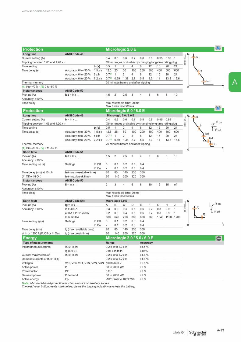
Protection Micrologic 2.0 ELong time ANSI Code 49
DB1
0112
6.ep
s
Current setting (A) 0.4 0.5 0.6 0.7 0.8 0.9 0.95 0.98 1Tripping between 1.05 and 1.20 x Ir Other ranges or disable by changing long-time rating plug Time setting tr (s) 0.5 1 2 4 8 12 16 20 24Time delay (s) Accuracy: 0 to -30 % 1.5 x Ir 12.5 25 50 100 200 300 400 500 600
Accuracy: 0 to -20 % 6 x Ir 0.7 (1) 1 2 4 8 12 16 20 24Accuracy: 0 to -20 % 7.2 x Ir 0.7 (2) 0.69 1.38 2.7 5.5 8.3 11 13.8 16.6
Thermal memory 20 minutes before and after tripping(1) 0 to -40 % - (2) 0 to -60 %Instantaneous ANSI Code 50
Pick-up (A) Isd = Ir x … 1.5 2 2.5 3 4 5 6 8 10Accuracy: ±10 %Time delay Max resettable time: 20 ms
Max break time: 80 ms
Protection Micrologic 5.0 / 6.0 ELong time ANSI Code 49 Micrologic 5.0 / 6.0 E
DB1
0112
7.ep
s
Current setting (A) Ir = In x … 0.4 0.5 0.6 0.7 0.8 0.9 0.95 0.98 1Tripping between 1.05 and 1.20 x Ir Other ranges or disable by changing long-time rating plug Time setting tr (s) 0.5 1 2 4 8 12 16 20 24Time delay (s) Accuracy: 0 to -30 % 1.5 x Ir 12.5 25 50 100 200 300 400 500 600
Accuracy: 0 to -20 % 6 x Ir 0.7(1) 1 2 4 8 12 16 20 24Accuracy: 0 to -20 % 7.2 x Ir 0.7(2) 0.69 1.38 2.7 5.5 8.3 11 13.8 16.6
Thermal memory 20 minutes before and after tripping(1) 0 to -40 % - (2) 0 to -60 % Short time ANSI Code 51
Pick-up (A) Isd = Ir x … 1.5 2 2.5 3 4 5 6 8 10Accuracy: ±10 %Time setting tsd (s) Settings I2t Off 0 0.1 0.2 0.3 0.4
I2t On - 0.1 0.2 0.3 0.4Time delay (ms) at 10 x Ir tsd (max resettable time) 20 80 140 230 350(I2t Off or I2t On) tsd (max break time) 80 140 200 320 500Instantaneous ANSI Code 50
Pick-up (A) Ii = In x … 2 3 4 6 8 10 12 15 offAccuracy: ±10 %Time delay Max resettable time: 20 ms
Max break time: 50 ms
Earth fault ANSI Code 51N Micrologic 6.0 E
DB1
0112
8.ep
s
Pick-up (A) Ig = In x … A B C D E F G H JAccuracy: ±10 % In y 400 A 0.3 0.3 0.4 0.5 0.6 0.7 0.8 0.9 1
400 A < In < 1250 A 0.2 0.3 0.4 0.5 0.6 0.7 0.8 0.9 1In u 1250 A 500 640 720 800 880 960 1040 1120 1200
Time setting tg (s) Settings I2t Off 0 0.1 0.2 0.3 0.4I2t On - 0.1 0.2 0.3 0.4
Time delay (ms) tg (max resettable time) 20 80 140 230 350at In or 1200 A (I2t Off or I2t On) tg (max break time) 80 140 200 320 500
Energy Micrologic 2.0 / 5.0 / 6.0 E Type of measurements Range Accuracy
Instantaneous currents I1, I2, I3, IN 0.2 x In to 1.2 x In ±1.5 %Ig (6.0 E) 0.05 x In to In ±10 %
Current maximeters of I1, I2, I3, IN 0.2 x In to 1.2 x In ±1.5 %Demand currents of I1, I2, I3, Ig 0.2 x In to 1.2 x In ±1.5 %Voltages V12, V23, V31, V1N, V2N, V3N 100 to 690 V ±0.5 %Active power P 30 to 2000 kW ±2 %Power factor PF 0 to 1 ±2 %Demand power P demand 30 to 2000 kW ±2 %Active energy Ep -1010 GWh to 1010 GWh ±2 %Note: all current-based protection functions require no auxiliary source. The test / reset button resets maximeters, clears the tripping indication and tests the battery.
www.schneider-electric.com
A-13
A

Functions and characteristics
Micrologic control units Micrologic P “power”
Micrologic P control units include all the functions offered by Micrologic A. In addition, they measure voltages and calculate power and energy values.They also offer new protection functions based on currents, voltages, frequency and power reinforce load protection in real time.
Protection ........................................................ + Protection settingsThe adjustable protection functions are identical to those of Micrologic A (overloads, short-circuits, earth-fault and earth-leakage protection).Fine adjustmentWithin the range determined by the adjustment dial, fine adjustment of thresholds (to within one ampere) and time delays (to within one second) is possible on the keypad or remotely using the COM option (BCM ULP).IDMTL (Inverse Definite Minimum Time lag) settingCoordination with fuse-type or medium-voltage protection systems is optimised by adjusting the slope of the overload-protection curve. This setting also ensures better operation of this protection function with certain loads.Neutral protectionOn three-pole circuit breakers, neutral protection may be set using the keypad or remotely using the COM option (BCM ULP), to one of four positions: neutral unprotected (4P 3d), neutral protection at 0.5 Ir (4P 3d + N/2), neutral protection at Ir (4P 4d) and neutral protection at 1.6 Ir (4P 3d + 1.6N). Neutral protection at 1.6 Ir is used when the neutral conductor is twice the size of the phase conductors (major load imbalance, high level of third order harmonics).On four-pole circuit breakers, neutral protection may be set using a three-position switch or the keypad: neutral unprotected (4P 3d), neutral protection at 0.5 Ir (4P 3d + N/2), neutral protection at Ir (4P 4d). Neutral protection produces no effect if the long-time curve is set to one of the IDMTL protection settings.
Programmable alarms and other protectionDepending on the thresholds and time delays set using the keypad or remotely using the COM option (BCM ULP), the Micrologic P control unit monitors currents and voltage, power, frequency and the phase sequence. Each threshold overrun is signalled remotely via the COM option (BCM ULP). Each threshold overrun may be combined with tripping (protection) or an indication carried out by an optional M2C programmable contact (alarm), or both (protection and alarm).
Load shedding and reconnectionLoad shedding and reconnection parameters may be set according to the power or the current flowing through the circuit breaker. Load shedding is carried out by a supervisor via the COM option (BCM ULP) or by an M2C programmable contact.
M2C / M6C programmable contactsThe M2C (two contacts) auxiliary contacts may be used to signal threshold overruns or status changes. They can be programmed using the keypad on the Micrologic P control unit or remotely using the COM option (BCM ULP).
Communication option (COM)The communication option may be used to:
b remotely read and set parameters for the protection functions b transmit all the calculated indicators and measurements b signal the causes of tripping and alarms b consult the history files and the maintenance-indicator register. b maximeter reset.
An event log and a maintenance register, stored in control-unit memory but not available locally, may be accessed in addition via the COM option (BCM ULP).
DB1
2096
8.ep
s
1 Long-time current setting and tripping delay.2 Overload signal (LED).3 Short-time pick-up and tripping delay.4 Instantaneous pick-up.5 Earth-leakage or earth-fault pick-up and tripping delay.6 Earth-leakage or earth-fault test button.7 Long-time rating plug screw.8 Test connector.9 Lamp + battery test and indications reset.10 Indication of tripping cause.11 High-resolution screen.12 Measurement display.13 Maintenance indicators.14 Protection settings.15 Navigation buttons.16 Hole for settings lockout pin on cover.
Note: Micrologic P control units come with a non-transparent lead-seal cover as standard.
www.schneider-electric.com
A-14
A

Protection Micrologic 5.0 / 6.0 / 7.0 P
Long time (rms) ANSI Code 49 Micrologic 5.0 / 6.0 / 7.0 P
DB1
0113
0.ep
s
Current setting (A) Ir = In x … 0.4 0.5 0.6 0.7 0.8 0.9 0.95 0.98 1Tripping between 1.05 and 1.20 x Ir Other ranges or disable by changing long-time rating plug Time setting tr (s) 0.5 1 2 4 8 12 16 20 24Time delay (s) Accuracy: 0 to -30 % 1.5 x Ir 12.5 25 50 100 200 300 400 500 600IDMTL (EIT) Accuracy: 0 to -20 % 6 x Ir 0.7(1) 1 2 4 8 12 16 20 24
Accuracy: 0 to -20 % 7.2 x Ir 0.7(2) 0.69 1.38 2.7 5.5 8.3 11 13.8 16.6IDMTL setting Curve slope SIT VIT EIT HVFuse DTThermal memory 20 minutes before and after tripping(1) 0 to -40 % - (2) 0 to -60 %Short time (rms) ANSI Code 51
Pick-up (A) Isd = Ir x … 1.5 2 2.5 3 4 5 6 8 10Accuracy: ±10 %Time setting tsd (s) Settings I2t Off 0 0.1 0.2 0.3 0.4
I2t On - 0.1 0.2 0.3 0.4Time delay (ms) at 10 Ir tsd (max resettable time) 20 80 140 230 350(I2t Off or I2t On) tsd (max break time) 80 140 200 320 500Instantaneous ANSI Code 50
Pick-up (A) Ii = In x … 2 3 4 6 8 10 12 15 off
DB1
0112
8.ep
s
Accuracy: ±10 %Time delay Max resettable time: 20 ms
Max break time: 50 ms
Earth fault ANSI Code 51N Micrologic 6.0 PPick-up (A) Ig = In x … A B C D E F G H JAccuracy: ±10 % In y 400 A 0.3 0.3 0.4 0.5 0.6 0.7 0.8 0.9 1
400 A < In < 1250 A 0.2 0.3 0.4 0.5 0.6 0.7 0.8 0.9 1In u 1250 A 500 640 720 800 880 960 1040 1120 1200
Time setting tg (s) Settings I2t Off 0 0.1 0.2 0.3 0.4I2t On - 0.1 0.2 0.3 0.4
Time delay (ms) tg (max resettable time) 20 80 140 230 350
DB1
0112
9.ep
s
at In or 1200 A (I2t Off or I2t On) tg (max break time) 80 140 200 320 500Residual earth leakage (Vigi) ANSI Code 51G Micrologic 7.0 P
Sensitivity (A) IΔn 0.5 1 2 3 5 7 10 20 30Accuracy: 0 to -20 % Time delay Δt (ms) Settings 60 140 230 350 800
Δt (max resettable time) 60 140 230 350 800Δt (max break time) 140 200 320 500 1000
Alarms and other protection Micrologic 5.0 / 6.0 / 7.0 PCurrent ANSI Code 46 Threshold Delay
DB1
0114
2.ep
s
Current unbalance Iunbalance 0.05 to 0.6 Iaverage 1 to 40 sMax. demand current Imax demand : I1, I2, I3, IN, 0.2 In to In 15 to 1500 sEarth fault alarm
It 10 to 100 % In (3) 1 to 10 sVoltage ANSI Code
Voltage unbalance Uunbalance 47 2 to 30 % x Uaverage 1 to 40 sMinimum voltage Umin 27 100 to Umax between phases 1.2 to 10 sMaximum voltage (4) Umax 59 Umin to 1200 between phases 1.2 to 10 sPower
Reverse power rP 32P 5 to 500 kW 0.2 to 20 sFrequency
Minimum frequency Fmin 81L 45 to Fmax 1.2 to 5 sMaximum frequency Fmax 81H Fmin to 440 Hz 1.2 to 5 sPhase sequence
Sequence (alarm) ΔØ Ø1/2/3 or Ø1/3/2 0.3 s
Load shedding and reconnection Micrologic 5.0 / 6.0 / 7.0 P Measured value Threshold Delay
DB1
0114
3.ep
s
Current I 0.5 to 1 Ir per phases 20 % tr to 80 % trPower P 200 kW to 10 MW 10 to 3600 s
(3) In y 400 A 30 %400 A < In < 1250 A 20 %In u 1250 A 10 %(4) For 690 V applications, a step-down transformer must be used if the voltage exceeds the nominal value of 690 V by more than 10 %.
Note: all current-based protection functions require no auxiliary source. Voltage-based protection functions are connected to AC power via a voltage measurement input built into the circuit breaker.
+
www.schneider-electric.com
A-15
A

DB1
0113
3.ep
s
Default display.
DB1
0113
4.ep
s
Display of a maximum current.
Measurements .........................................................The Micrologic P control unit calculates in real time all the electrical values (V, A, W, VAR, VA, Wh, VARh, VAh, Hz), power factors and cos φ factors.The Micrologic P control unit also calculates demand current and demand power over an adjustable time period. Each measurement is associated with a minimeter and a maximeter.In the event of tripping on a fault, the interrupted current is stored. The optional external power supply makes it possible to display the value with the circuit breaker open or not supplied.Instantaneous valuesThe value displayed on the screen is refreshed every second. Minimum and maximum values of measurements are stored in memory (minimeters and maximeters).Currents
DB1
0113
3.ep
s
DB1
0113
3.ep
s
I rms A 1 2 3 NA E-fault E-leakage
I max rms A 1 2 3 NA E-fault E-leakage
VoltagesU rms V 12 23 31V rms V 1N 2N 3NU average rms V (U12 + U23 + U31) / 3U unbalance %Power, energy
P active, Q reactive, S apparent W, Var, VA TotalsE active, E reactive, E apparent Wh, VARh, VAh Totals consumed - supplied
Totals consumedTotals supplied
Display of a voltage. Display of a power. Power factor PF TotalFrequencies
DB1
0113
7.ep
s
Display of a frequency.
DB1
0113
8.ep
s
Display of a demand power.
F Hz
Demand meteringThe demand is calculated over a fixed or sliding time window that may be programmed from 5 to 60 minutes. According to the contract signed with the power supplier, an indicator associated with a load shedding function makes it possible to avoid or minimise the costs of overrunning the subscribed power. Maximum demand values are systematically stored and time stamped (maximeter).
CurrentsI demand A 1 2 3 N
A E-fault E-leakageI max demand A 1 2 3 N
A E-fault E-leakagePower
P, Q, S demand W, Var, VA TotalsP, Q, S max demand W, Var, VA Totals
scre
en 2
b.ep
s Minimeters and maximetersOnly the current and power maximeters may be displayed on the screen.Time-stampingTime-stamping is activated as soon as time is set manually or by a supervisor.No external power supply module is required (max. drift of 1 hour per year).ResetAn individual reset, via the keypad or remotely, acts on alarms, minimum and maximum data, peak values, the counters and the indicators.Additional measurements accessible with the COM option (BCM ULP)Some measured or calculated values are only accessible with the COM communication option:
b I peak / 2, (I1 + I2 + I3)/3, I unbalance b load level in % Ir b total power factor.
The maximeters and minimeters are available only via the COM option (BCM ULP) for use with a supervisor.Additional infoAccuracy of measurements (including sensors):
b voltage (V) 0.5 % b current (A) 1.5 % b frequency (Hz) 0.1 % b power (W) and energy (Wh) 2 %.
Logiciel PME.
Functions and characteristics
Micrologic control units Micrologic P “power”
www.schneider-electric.com
A-16
A

DB1
1704
1.ep
s
Display of a tripping history.
DB1
0114
0.ep
s
Display after tripping.
Histories and maintenance indicators ...................The last ten trips and alarms are recorded in two separate history files that may be displayed on the screen:
b tripping history: v type of fault v date and time v values measured at the time of tripping (interrupted current, etc.) b alarm history: v type of alarm v date and time v values measured at the time of the alarm.
All the other events are recorded in a third history file which is only accessible through the communication network.
b Event log history (only accessible through the communication network) v modifications to settings and parameters v counter resets v system faults v fallback position v thermal self-protection v loss of time v overrun of wear indicators v test-kit connections v etc.
Note: all the events are time stampled: time-stamping is activated as soon as time is set manually or by a supervisor. No external power supply module is required (max. drift of 1 hour per year).
Maintenance indicators with COM option (BCM ULP)A number of maintenance indicators may be called up on the screen to better plan for device maintenance:
b contact wear b operation counter: v cumulative total v total since last reset.
Additional maintenance indicators are also available through the COM network, and can be used as an aid in troubleshooting:
b highest current measured b number of test-kit connections b number of trips in operating mode and in test mode.
Additional technical characteristicsSafetyMeasurement functions are independent of the protection functions.The high-accuracy measurement module operates independently of the protection module.Simplicity and multi-languageNavigation from one display to another is intuitive. The six buttons on the keypad provide access to the menus and easy selection of values. When the setting cover is closed, the keypad may no longer be used to access the protection settings, but still provides access to the displays for measurements, histories, indicators, etc.Micrologic is also multi-language, including the following languages: English, Spanish, Portuguese, Russian, Chinese, French, German...Intelligent measurementMeasurement-calculation mode:
b energies are calculated on the basis of the instantaneous power values, in two manners:
v the traditional mode where only positive (consumed) energies are considered v the signed mode where the positive (consumed) and negative (supplied) energies
are considered separately b measurement functions implement the new “zero blind time” concept which
consists in continuously measuring signals at a high sampling rate. The traditional “blind window” used to process samples no longer exists. This method ensures accurate energy calculations even for highly variable loads (welding machines, robots, etc.).Always poweredAll current-based protection functions require no auxiliary source. Voltage-based protection functions are connected to AC power via a voltage measurement input built into the circuit breaker.Stored informationThe fine setting adjustments, the last 100 events and the maintenance register remain in the control-unit memory even when power is lost.
www.schneider-electric.com
A-17
A

Functions and characteristics
Micrologic H control units include all the functions offered by Micrologic P. Integrating significantly enhanced calculation and memory functions, the Micrologic H control unit offers in-depth analysis of power quality and detailed event diagnostics. It is intended for operation with a supervisor.
In addition to the Micrologic P functions, the Micrologic H control unit offers: b in-depth analysis of power quality including calculation of harmonics and the
fundamentals b diagnostics aid and event analysis through waveform capture b enhanced alarm programming to analyse and track down a disturbance on the AC
power system.
Measurements ................................................................................The Micrologic H control unit offers all the measurements carried out by Micrologic P, with in addition:
b phase by phase measurements of: v power, energy v power factors b calculation of: v current and voltage total harmonic distortion (THD) v current, voltage and power fundamentals v current and voltage harmonics up to the 31st order.
Instantaneous values displayed on the screen
DB1
1743
7.ep
s CurrentsI rms A 1 2 3 N
A E-fault E-leakageI max rms A 1 2 3 N
A E-fault E-leakageVoltages
U rms V 12 23 31V rms V 1N 2N 3NU average rms V (U12 + U23 + U31) / 3U unbalance %Power, energy
P active, Q reactive, S apparent W, Var, VA Totals 1 2 3E active, E reactive, E apparent Wh, VARh, VAh Totals consumed - supplied
Totals consumedTotals supplied
Power factor PF Total 1 2 3Frequencies
F HzPower-quality indicators
Total fundamentals U I P Q STHD % U I U and Iharmonics Amplitude 3 5 7 9 11 13Harmonics 3, 5, 7, 9, 11 and 13, monitored by electrical utilities, are displayed on the screen.
Demand measurementsSimilar to the Micrologic P control unit, the demand values are calculated over a fixed or sliding time window that may be set from 5 to 60 minutes. Currents
I demand A 1 2 3 NA E-fault E-leakage
I max demand A 1 2 3 NA E-fault E-leakage
PowerP, Q, S demand W, Var, VA TotalsP, Q, S max demand W, Var, VA Totals
MaximetersOnly the current maximeters may be displayed on the screen.
Histories and maintenance indicatorsThese functions are identical to those of the Micrologic P.
Note: Micrologic H control units come with a non-transparent lead-seal cover as standard.
Micrologic control units Micrologic H “harmonics”
www.schneider-electric.com
A-18
A

With the communication optionAdditional measurements, maximeters and minimetersCertain measured or calculated values are only accessible with the COM communication option:
b I peak / 2 (I1 + I2 + I3)/3, Iunbalance b load level in % Ir b power factor (total and per phase) b voltage and current THD b K factors of currents and average K factor b crest factors of currents and voltages b all the fundamentals per phase b fundamental current and voltage phase displacement b distortion power and distortion factor phase by phase b amplitude and displacement of current and voltage harmonics 3 to 31 etc. b the maximeters and minimeters are available only via the COM option (BCM ULP) for use with a supervisor.
Waveform captureThe Micrologic H control unit stores the last 4 cycles of each instantaneous current or voltage measurement. On request or automatically on programmed events, the control unit stores the waveforms. The waveforms may be displayed in the form of oscillograms by a supervisor via the COM option (BCM ULP). Definition is 64 points per cycle.Pre-defined analogue alarms (1 to 53)Each alarm can be compared to user-set high and low thresholds. Overrun of a threshold generates an alarm. An alarm or combinations of alarms can be linked to programmable action such as selective recording of measurements in a log, waveform capture, etc.Event log and maintenance registersThe Micrologic H offers the same event log and maintenance register functions as the Micrologic P. In addition, it produces a log of the minimums and maximums for each “real-time” value.
Additional technical characteristicsSetting the display languageSystem messages may be displayed in six different languages. The desired language is selected via the keypad.Protection functionsAll current-based protection functions require no auxiliary source. Voltage-based protection functions are connected to AC power via a voltage measurement input built into the circuit breaker.Measurement functionsMeasurement functions are independent of the protection functions.The high-accuracy measurement module operates independently of the protection module, while remaining synchronised with protection events.Measurement-calculation modeAn analogue calculation function dedicated to measurements enhances the accuracy of harmonic calculations and the power-quality indicators. The Micrologic H control unit calculates electrical magnitudes using 1.5 x In dynamics (20 x In for Micrologic P).Measurement functions implement the new “zero blind time” conceptEnergies are calculated on the basis of the instantaneous power values, in the traditional and signed modes.Harmonic components are calculated using the discrete Fourier transform (DFT).Accuracy of measurements (including sensors)
b voltage (V) 0.5 % b current (A) 1.5 % b frequency (Hz) 0.1 % b power (W) and energy (Wh) 2 % b total harmonic distortion 1 %.
Stored informationThe fine-setting adjustments, the last 100 events and the maintenance register remain in the control-unit memory even when power is lost.Time-stampingTime-stamping is activated as soon as time is set manually or by a supervisor no external power supply module is required (max. drift of 1 hour per year).ResetAn individual reset, via the keypad or remotely, acts on alarms, minimum and maximum data, peak values, the counters and the indicators.
www.schneider-electric.com
A-19
A

Functions and characteristics
Power Meter functionsMicrologic A/E/P/H control unit with COM option (BCM ULP) and COM Ethernet gatewayIn addition to protection functions, Micrologic A/E/P/H control units offer all the functions of Power Meter products as well as operating-assistance for the circuit breaker.
Micrologic A/E/P/H measurement functions are made possible by Micrologic intelligence and the accuracy of the sensors. They are handled by a microprocessor that operates independent of protection functions.
Display ......................................................................FDM121 display unit (one to one)The FDM121 switchboard display unit can be connected to a COM option (BCM ULP) using a breaker ULP cord to display all measurements on a screen (1). The result is a veritable 96 x 96 mm Power Meter.The FMD121 display unit requires a 24 V DC power supply. The COM option (BCM ULP) unit is supplied by the same power supply via the breaker ULP cord connecting it to the FDM121.
(1) See page A-30.
FDM128 display unit (one to eight)Using an IFE Ethernet interface for LV breakers.
For all FDM, in addition to the information displayed on the Micrologic LCD, the FDM screen shows demand, power quality and maximeter/minimeter values along with histories and maintenance indicators.
Measurements .........................................................Instantaneous rms measurementsThe Micrologic continuously display the RMS value of the highest current of the three phases and neutral (Imax). The navigation buttons can be used to scroll through the main measurements.In the event of a fault trip, the trip cause is displayed.The Micrologic A measures phase, neutral, ground fault currents.The Micrologic E offers voltage, power, Power Factor, measurements in addition to the measurements provided by Micrologic A.The Micrologic P/H offer frequency, cos φ in addition to the measurements provided by Micrologic E.
Maximeters / minimetersEvery instantaneous measurement provided by Micrologic A or E can be associated with a maximeter/minimeter. The maximeters for the highest current of the 3 phases and neutral, the demand current and power can be reset via the FDM display unit or the communication system.
Energy meteringThe Micrologic E/P/H also measures the energy consumed since the last reset of the meter. The active energy meter can be reset via Micrologic keypad or the FDM display unit or the communication system.
Demand and maximum demand valuesMicrologic E/P/H also calculates demand current and power values. These calculations can be made using a block or sliding interval that can be set from 5 to 60 minutes in steps of 1 minute. The window can be synchronised with a signal sent via the communication system. Whatever the calculation method, the calculated values can be recovered on a PC via Modbus communication. Ordinary spreadsheet software can be used to provide trend curves and forecasts based on this data. They will provide a basis for load shedding and reconnection operations used to adjust consumption to the subscribed power.
Power qualityMicrologic H calculates power quality indicators taking into account the presence of harmonics up to the 15th order, including the total harmonic distortion (THD) of current and voltage.
FDM121
Quick viewMeteringControl
OK
ServicesAlarms
Main menu
DB4
3251
6.ep
s
20.12.2011 12:00:05
S1-1 - Lighting/Level1
Quick view
Measures
Alarm history
Control
Maintenance
ESC 1/7
Quick view Open Auto
I1 A000Ir A000
20.12.2011 12:00:05
S1-1 - Lighting/Level1
Measures
Alarm history
Control
Maintenance
ESC 1/7
Quick view Open Auto
I1 A000Ir A000
DB4
1764
0.ep
s
FDM121 display: navigation. FDM128 display: navigation.
FDM121
179 A
888
I2
I 1/11
186 A
I1
10 A
IN184 A
I3
225 A 225 A
225 A 225 A
DB4
3251
7.ep
s
20.12.2011 12:00:05
S1-1 - Lighting/Level1
Quick view
Measures
Alarm history
Control
Maintenance
ESC
I1 AI2 AI3 AIN A
431385426
2
EPQSU-VI
Measures
1/10
I Current
20.12.2011 12:00:05
S1-1 - Lighting/Level1
Quick view
Alarm history
Control
Maintenance
ESC
I1 AI2 AI3 AIN A
431385426
2
EPQSU-VI
Measures
1/10
I CurrentI Current
DB4
1440
0.ep
s
FDM121 display: current. FDM128 display: current.
FDM121
225 A0I 1/11
I1= 186 A0
I2= 179 A225 A
225 A0I3= 184 A
0IN= 10 A
225 A
DB4
3251
8.ep
s
20.12.2011 12:00:05
S1-1 - Lighting/Level1
Quick view
Measures
Alarm history
Control
Maintenance
ESC
V12 VV23 VV31 V
406415409
1/10
EPQSU-VIVL-L
Measures
20.12.2011 12:00:05
S1-1 - Lighting/Level1
Quick view
Alarm history
Control
Maintenance
ESC
V12 VV23 VV31 V
406415409
1/10
EPQSU-VIVL LVL-L
Measures
DB4
1440
1.ep
s
FDM121 display: voltage. FDM128 display: voltage.
FDM121
Ptot 109 kW
85 kVAr
138 kVA
Qtot
Stot
P Q S 6/8
DB4
3251
9.ep
s
20.12.2011 12:00:05
S1-1 - Lighting/Level1
Quick view
Measures
Alarm history
Control
Maintenance
ESC
Ptot kWQtot kVAr
12713
Stot kVA129
1/12
EPQSU-VIPQS
Measures
20.12.2011 12:00:05
S1-1 - Lighting/Level1
Quick view
Alarm history
Control
Maintenance
ESC
Ptot kWQtot kVAr
12713
Stot kVA129
1/12
EPQSU-VIPQSPQS
Measures
DB4
1440
2.ep
s
FDM121 display: power. FDM128 display: power.
FDM121
Ep 15 kwh
12 kVArh
20 kVAh
Eq
Es
Energy 7/8
DB4
3252
0.ep
s
20.12.2011 12:00:05
S1-1 - Lighting/Level1
Quick view
Measures
Alarm history
Control
Maintenance
ESC
EpIn kWhEpOut kWh
16545
EPQSU-VIE cumul
1/3
Measures Reset
20.12.2011 12:00:05
S1-1 - Lighting/Level1
Quick view
Alarm history
Control
Maintenance
ESC
EpIn kWhEpOut kWh
16545
EPQSU-VIE cumulE cumul
1/3
Measures Reset
DB4
1440
3.ep
s
FDM121 display: consumption.
FDM128 display: consumption.
Examples of measurement screens on the FDM121 display unit.
www.schneider-electric.com
A-20
A

Micrologic A/E/P/H integrated Power Meter functions Type DisplayA/E P/H Micrologic
LCDFDM display
Display of protection settingsPick-ups (A) and delays
All settings can be displayed Ir, tr, Isd, tsd, Ii, Ig, tg A/E P/H b -
MeasurementsInstantaneous rms measurements
Currents (A) Phases and neutral I1, I2, I3, IN A/E P/H b b
Average of phases Iavg = (I1 + I2 + I3) / 3 A/E P/H - b
Highest current of the 3 phases and neutral
Imax of I1, I2, I3, IN A/E P/H b b
Ground fault (Micrologic 6) % Ig (pick-up setting) A/E P/H b b
Current unbalance between phases % Iavg - /E P/H - b
Voltages (V) Phase-to-phase V12, V23, V31 - /E P/H b b
Phase-to-neutral V1N, V2N, V3N - /E P/H b b
Average of phase-to-phase voltages Vavg = (V12 + V23 + V31) / 3 - /E P/H - b
Average of phase-to-neutral voltages Vavg = (V1N + V2N + V3N) / 3 - /E P/H - b
Ph-Ph and Ph-N voltage unbalance % Vavg and % Vavg - /E P/H - b
Phase sequence 1-2-3, 1-3-2 - / - P/H b b (3)
Frequency (Hz) Power system f - / - P/H b b
Power Active (kW) P, total - /E P/H b b
P, per phase - /E P/H b (2) b
Reactive (kVAR) Q, total - /E P/H b b
Q, per phase - / - P/H b b
Apparent (kVA) S, total - /E P/H b b
S, per phase - / - P/H b b
Power Factor PF, total - /E P/H b b
PF, per phase - / - P/H b b
Cos.φ Cos.φ, total - / - P/H b b
Cos.φ, per phase - / - P/H b b
Maximeters / minimetersAssociated with instantaneous rms measurements
Reset via FDM display unit and Micrologic keypad
A/E P/H b b
Energy meteringEnergy Active (kW), reactive (kVARh),
apparent (kVAh)Total since last reset - /E P/H b b
Demand and maximum demand valuesDemand current (A) Phases and neutral Present value on the selected
window- /E P/H b b
Maximum demand since last reset - /E P/H b (2) b
Demand power Active (kWh), reactive (kVAR), apparent (kVA)
Present value on the selected window
- /E P/H b b
Maximum demand since last reset - /E P/H b (2) b
Calculation window Sliding, fixed or com-synchronised Adjustable from 5 to 60 minutes in 1 minute steps (1)
- /E P/H - -
Power qualityTotal harmonic distortion (%)
Of voltage with respect to rms value THDU,THDV of the Ph-Ph and Ph-N voltage
- / - H b b
Of current with respect to rms value THDI of the phase current - / - H b b
(1) Available via the communication system only.(2) Available for Micrologic P/H only.(3) FDM121 only.
PB11
1801
-21_
r.eps
PB10
6363
A35.
eps
PB11
9233
.eps
www.schneider-electric.com
A-21
A
Functions and characteristics
Operating-assistance functionsMicrologic A/E/P/H control unit with COM option (BCM ULP)
Histories .................................................................. b Trip indications in clear text in a number of user-selectable languages. b Time-stamping: date and time of trip.
Maintenance indicators ..........................................Micrologic control unit have indicators for, among others, the number of operating cycles, contact wear P/H, load profile and operating times (operating hours counter) of the Masterpact circuit breaker. It is possible to assign an alarm to the operating cycle counter to plan maintenance.The various indicators can be used together with the trip histories to analyse the level of stresses the device has been subjected to.
Management of installed devicesEach circuit breaker equipped with a COM option (BCM ULP) can be identified via the communication system:
b serial number b firmware version b hardware version b device name assigned by the user.
This information together with the previously described indications provides a clear view of the installed devices.
www.schneider-electric.com
A-22
A

Micrologic A/E/P/H operating assistance functions Type DisplayA/E P/H Micrologic
LCDFDM display
Operating assistanceTrip historyTrips Cause of tripping Ir, Isd, Ii, Ig, IΔn - /E P/H b b
Maintenance indicatorsCounter Mechanical cycles Assignable to an alarm A/E P/H - b
Electrical cycles Assignable to an alarm A/E P/H - b
Hours Total operating time (hours) (1) A/E P/H - -Indicator Contact wear % - / - P/H - b
Load profile Hours at different load levels % of hours in four current ranges: 0-49 % In, 50-79 % In, 80-89 % In and u 90 % In
A/E P/H - b
(1) Available via the communication system only.
Additional technical characteristicsContact wearEach time Masterpact opens, the Micrologic P/H trip unit measures the interrupted current and increments the contact-wear indicator as a function of the interrupted current, according to test results stored in memory. Breaking under normal load conditions results in a very slight increment. The indicator value may be read on the FDM display. It provides an estimation of contact wear calculated on the basis of the cumulative forces affecting the circuit breaker. When the indicator reaches 100 %, it is advised to inspect the circuit breaker to ensure the availability of the protected equipment.
Circuit breaker load profileMicrologic A/E/P/H calculates the load profile of the circuit breaker protecting a load circuit. The profile indicates the percentage of the total operating time at four current levels (% of breaker In):
b 0 to 49 % In b 50 to 79 % In b 80 to 89 % In b u 90 % In.
This information can be used to optimise use of the protected equipment or to plan ahead for extensions.
PB11
1801
-21_
r.eps
PB10
6363
A35.
eps
PB11
9233
.eps
www.schneider-electric.com
A-23
A

Functions and characteristics
Switchboard-display functionsMicrologic A/E/P/H control unit with COM option (BCM ULP)
Micrologic measurement capabilities come into full play with the FDM121 switchboard display. It connects to COM option (BCM ULP) via a breaker ULP cord and displays Micrologic information. The result is a true integrated unit combining a circuit breaker and a Power Meter. Additional operating assistance functions can also be displayed.
FDM121 switchboard displayAn FDM121 switchboard display unit can be connected to a ULP IMU using a prefabricated cord to display all measurements, alarms, histories and event tables, maintenance indicators, management of installed devices on a screen. The result is a veritable 96 x 96 mm Power Meter. The FMD121 display unit requires a 24 V DC power supply.The FDM121 is a switchboard display unit that can be integrated in the Compact NSX100 to 630 A, Powerpact H/J/L/P/R, compact NS or Masterpact systems. It uses the sensors and processing capacity of the Micrologic trip unit. It is easy to use and requires no special software or settings. It is immediately operational when connected to the Compact NSX by a simple cord. Also, it provides monitoring and control with the use of the I/O application module, the motor mecanism module, or the Breaker Status module.The FDM121 is a large display, but requires very little depth. The anti-glare graphic screen is backlit for very easy reading even under poor ambient lighting and at sharp angles.Display of Micrologic measurements and alarmsThe FDM121 is intended to display Micrologic 5 / 6 measurements, alarms and operating information. It cannot be used to modify the protection settings. Measurements may be easily accessed via a menu. All user-defined alarms are automatically displayed. The display mode depends on the priority level selected during alarm set-up:
b high priority: a pop-up window displays the time-stamped description of the alarm and the orange LED flashes
b medium priority: the orange "Alarm" LED goes steady on b low priority: no display on the screen.
All faults resulting in a trip automatically produce a high-priority alarm, without any special settings required. In all cases, the alarm history is updated. Micrologic saves the information in its non-volatile memory in the event of an FDM121 power failure.Status indications and remote controlWhen the circuit breaker is equipped with the Breaker Status Module, the FDM121 display can also be used to view circuit breaker status conditions:
b O/F: ON/OFF b SD: trip indication b SDE: Fault-trip indication (overload, short-circuit, ground fault).
When the circuit breaker system is equipped with the I/O application module, the FDM121 can monitor and control:
b craddle management b circuit breaker operation b light and load control b custom application.
When the circuit breaker system is equipped with the motor mechanism module, the FDM121 offers remote closing and opening control.Main characteristics
b 96 x 96 x 30 mm screen requiring 10 mm behind the door (or 20 mm when the 24 V power supply connector is used).
b White backlighting. b Wide viewing angle: vertical ±60°, horizontal ±30°. b High resolution: excellent reading of graphic symbols. b Alarm LED: flashing orange for alarm pick-up, steady orange after operator reset if
alarm condition persists. b Operating temperature range -10 °C to +55 °C. b CE / UL / CSA marking (pending). b 24 V DC power supply, with tolerances 24 V -20 % (19.2 V) to 24 V +10 % (26.4 V).
When the FDM121 is connected to the communication network, the 24 V DC can be supplied by the communication system wiring system.
b Consumption 40 mA.MountingThe FDM121 is easily installed in a switchboard.
b Standard door cut-out 92 x 92 mm. b Attached using clips.
To avoid a cut-out in the door, an accessory is available for surface mounting by drilling only two 22 mm diameter holes.The FDM121 degree of protection is IP54 in front. IP54 is maintained after switchboard mounting by using the supplied gasket during installation. ConnectionThe FDM121 is equipped with:
b a 24 V DC terminal block: v plug-in type with 2 wire inputs per point for easy daisy-chaining v power supply range of 24 V DC -20 % (19.2 V) to 24 V DC +10 % (26.4 V).
A 24 V DC type auxiliary power supply must be connected to a single point on the ULP system. The FDM121 display unit has a 2-point screw connector on the rear panel of the module for this purpose. The ULP module to which the auxiliary power supply is connected distributes the supply via the ULP cable to all the ULP modules connected to the system and therefore also to Micrologic.
PB11
9233
.eps
FDM121 display.
PB10
3807
-32.
eps
Surface mount accessory.
PB11
9235
.eps
Connection with FDM121 display unit.
www.schneider-electric.com
A-24
A

FDM121
179 A
888
I2
I 1/11
186 A
I1
10 A
IN184 A
I3
225 A 225 A
225 A 225 A
1 2 3 4 5 6
DB4
3252
1.ep
s 1 escape2 down3 ok4 up5 context6 alarm LED
FDM121
Product ID 2/8
SN 3N114850015TRV00911PN
Version V1.0.9
MaintenanceModuleD
B432
522.
eps
Product identification.
FDM121
P Q S
OK
EF PF COS
Metering
V L-L V L-NDB4
3252
3.ep
s
Metering: sub-menu.
FDM121
Ep 15 kwh
12 kVArh
20 kVAh
Eq
Es
Energy 7/8
DB4
3252
0.ep
s
Metering: meter.
FDM121
Load Prole0...49% 19466Hours
50..79% 0Hours
80..89% 0Hours
90.100% 0Hours
DB4
3252
4.ep
s
Services.
b two RJ45 jacks.The Micrologic connects to the internal communication terminal block on the Masterpact via the breaker ULP cord. Connection to one of the RJ45 connectors on the FDM121 automatically establishes communication between the Micrologic and the FDM121 and supplies power to the Micrologic measurement functions.When the second connector is not used, it must be fitted with a line terminator.
NavigationFive buttons are used for intuitive and fast navigation.The “Context” button may be used to select the type of display (digital, bargraph, analogue).The user can select the display language (Chinese, English, French, German, Italian, Portuguese, Spanish, etc.).
ScreensMain menuWhen powered up, the FDM121 screen automatically displays the ON/OFF status ofthe device.
Quick view Alarms Metering Services Control
When not in use, the screen is not backlit. Backlighting can be activated by pressing one of the buttons. It goes off after 3 minutes.Fast access to essential information
b “Quick view” provides access to five screens that display a summary of essential operating information (I, U, f, P, E, THD, circuit breaker On / Off).Access to detailed information
b "Metering" can be used to display the measurement data (I, U-V, f, P, Q, S, E, THD, PF) with the corresponding min/max values.
b Alarms displays active alarms and the alarm history. b Services provides access to the operation counters, energy and maximeter reset b function, maintenance indicators, identification of modules connected to the
internal bus and FDM121 internal settings (language, contrast, etc.).
Communication components and FDM121 connections
LV434195
1.3 m
LV434196 LV434197
Breaker ULP cord
DB4
1674
1.ep
s DB4
3253
0.ep
s
B’ / R
x + D1
A’ / Rx - D
0
B / Tx + D
1
A / Tx - D0
0 V
24 V
E1
Red Black Blue
E2 E3 E4 E5 E6
Customer terminal block
White
B’ / R
x + D1
A’ / Rx - D
0
B / Tx + D
1
A / Tx - D0
0 V
24 V
E1
Red Black Blue
E2 E3 E4 E5 E6
Customer terminal block
White
D
E
FC
Test
24 V DC
IFM
Ethernet
LV434002
Enerlin'X IFE
24 V DC
IFE
OR
B
D
E
FC
A
Connections b Masterpact is connected to the ULP
devices (FDM121 display, IFM, IFE or I/O) unit via the breaker ULP cord.
v cord available in three lengths: 0.35 m, 1.3 m and 3 m.
v lengths up to 10 m possible using extensions.
A Modbus networkB Ethernet networkC NSX cord
D FDM121 displayE ULP terminationF ULP cable
www.schneider-electric.com
A-25
A

Functions and characteristics
Switchboard-display functionsMicrologic A/E/P/H control unit with COM Ethernet gateway
Micrologic measurement capabilities come into full play with the FDM128 switchboard display. It connects to Ethernet communication via RJ45 port and displays Micrologic information. The result is a true integrated unit combining a circuit breaker and a Power Meter. Additional operating assistance functions can also be displayed.
FDM128 switchboard displayThe FDM128 is an intelligent Ethernet display. It collects the data from up to 8 devices via Ethernet network.The FDM128 switchboard display unit can be connected to a Micrologic COM option (BCM ULP via IFE). It uses the sensors and processing capacity of the Micrologic control unit. It is easy to use and requires no special software or settings. The FDM128 is a large display, but requires very little depth. The anti-glare graphic screen is backlit for very easy reading even under poor ambient lighting and at sharp angles. FDM128 switchboard display is designed to manage up to 8 devices (Masterpact NT/NW, Compact NS, Compact NSX or Smartlink).
Display of Micrologic measurements and tripsThe FDM128 is intended to display Micrologic A/E measurements, trips and operating information. It cannot be used to modify the protection settings.Measurements may be easily accessed via a menu. Trips are automatically displayed. A pop-up window displays the time-stamped description of the trip.
Status indicationsWhen the circuit breaker is equipped with the Breaker Status Command Module (BSCM) and NSX cord, the FDM128 display can also be used to view circuit breaker status conditions:
b O/F: ON/OFF b SDE: Fault-trip indication (overload, short-circuit, ground fault) b CE, CD cradle management with I/O application module.
Remote controlWhen the circuit breaker is equipped with the BSCM, NSX cord and Communication Motor Mechanism (MTC), the FDM128 display can also be used to control (open/close) the circuit breaker.
Main characteristics b 115.2 x 86.4 mm with 5.7" QVGA display 320 x 240 pixels. b Color TFT LCD, LED backlight. b Wide viewing angle: vertical ±80°, horizontal ±70°. b High resolution: excellent reading of graphic symbols. b Operating temperature range -10 °C to +55 °C. b CE / UL / CSA marking (pending). b 24 V DC power supply, with tolerances 24 V (limit 20.4 - 28.8 V DC). b Consumption y 6.8 W.
MountingThe FDM128 is easily installed in a switchboard.
b Standard door hole Ø 22 mm.The FDM128 degree of protection is IP65 in front and IP54.
ConnectionThe FDM128 is equipped with:
b a 24 V DC terminal block: v power supply range of 24 V DC (limit 20.4 - 28.8 V DC). The FDM128 display unit
has a 2-point screw connector on the rear panel of the module for this purpose. b One RJ45 Ethernet jacks.
The Micrologic connects to the internal communication terminal block on the Masterpact via the breaker ULP cord and Ethernet connection through IFE.
PB11
1801
-32_
r.eps
FDM128 display.
PB11
1802
-32_
r.eps
Surface mount accessory.
PB11
1805
-32_
r.eps
www.schneider-electric.com
A-26
A

20.12.2011 12:00:05
S1-1 - Lighting/Level1
Quick view
Measures
Alarm history
Control
Maintenance
ESC
Maintenance
3/3
Operation
Trip SDE
Close command
Product ID Information Reset allCounter
xxx
xxx
xxx
20.12.2011 12:00:05
S1-1 - Lighting/Level1
Quick view
Measures
Alarm history
Control
ESC
Maintenance
3/3
Operation
Trip SDE
Close command
Product ID Information Reset allCounterCounter
xxx
xxx
xxx
DB4
1440
5.ep
s
20.12.2011 12:00:05
S1-1 - Lighting/Level1
Quick view
Measures
Alarm history
Control
Maintenance
ESC
Energy
Ep kWhEq kVArhEs kVAh
11 318257
13 815
6/7
Quick view
20.12.2011 12:00:05
S1-1 - Lighting/Level1
Measures
Alarm history
Control
Maintenance
ESC
Energy
Ep kWhEq kVArhEs kVAh
11 318257
13 815
6/7
Quick view
DB4
1440
7.ep
s NavigationTouch screen is used for intuitive and fast navigation. The user can select the display language (Chinese, English, French, German, Italian, Portuguese, Spanish, etc.).
ScreensMain menu
Quick view Alarms
Metering Maintenance.
Control
When not in use, the screen is automatically shifted to low back-lighting.Fast access to essential information
b “Quick view” provides access to five screens that display a summary of essential operating information (I, U, f, P, E, THD, circuit breaker On / Off).Access to detailed information
b "Metering" can be used to display the measurement data (I, U-V, f, P, Q, S, E, THD, PF) with the corresponding min/max values.
b Alarms displays the trip history. b Services provides access to the operation counters, energy and maximeter reset
function, maintenance indicators, identification of modules connected to the internal bus and FDM128 internal settings (language, contrast, etc.).
Product identification. Metering: meter.
20.12.2011 12:00:05
S1-1 - Lighting/Level1
Quick view
Measures
Alarm history
Control
Maintenance
ESC
Maintenance
0 to 49%
50 to 79%
80 to 89%
2/3
90 to 100%
Product ID Information Reset allLoad profile
20.12.2011 12:00:05
S1-1 - Lighting/Level1
Quick view
Measures
Alarm history
Control
ESC
Maintenance
0 to 49%
50 to 79%
80 to 89%
2/3
90 to 100%
Product ID Information Reset allLoad profileLoad profile
DB4
1440
8.ep
s
Services.
www.schneider-electric.com
A-27
A

Power suppliesFunctions and characteristics www.schneider-electric.com
A-28
A
External 24 V DC power-supply module (AD)The external power-supply module makes it possible:
b to use the display even if the circuit breaker is open or not supplied (for the exact conditions of use, see the “electrical diagrams” part of this catalogue)
b to display fault currents after tripping b to modify settings when the circuit breaker is open (OFF position)
An external 24 V DC power supply is required for installation with communication, whatever the type of trip unit.This module is not designed to power on 24 V DC voltage releases and electric motor mechanism.This module powers both the control unit and the M2C programmable contacts.We recommended using the AD power supply due to its low stray primary secondary capacitance. Good operation of the Micrologic control unit in noisy environment is not guaranteed with other power supplies.If the COM option is used, a second dedicated power supply shall be used.This module powers both the control unit and the M2C programmable contacts or ESM module.
Characteristics b Power supply AC-to-DC or DC-to-DC b Output voltage: 24 V DC ±5 %. b Output current: 1 A. b DIN rail or platine Fixing with Acti9 form factor b Conducted emissions power line: class B per EN 61000-6-3.
LV45
4444
.eps
External 24 V DC power supply module (AD)
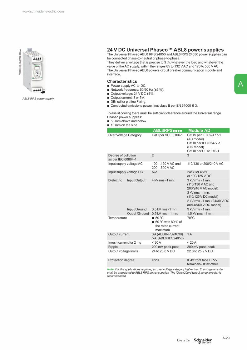
www.schneider-electric.com
A-29
A
24 V DC Universal Phaseo™ ABL8 power suppliesThe Universal Phaseo ABL8 RPS 24050 and ABL8 RPS 24030 power supplies can be connected phase-to-neutral or phase-to-phase.They deliver a voltage that is precise to 3 %, whatever the load and whatever the value of the AC supply, within the ranges 85 to 132 V AC and 170 to 550 V AC.The Universal Phaseo ABL8 powers circuit breaker communication module and interface.
Characteristics b Power supply AC-to-DC. b Network frequency: 50/60 Hz (±5 %). b Output voltage: 24 V DC ±3%. b Output current: 3 or 5 A. b DIN rail or platine Fixing. b Conducted emissions power line: class B per EN 61000-6-3.
To assist cooling there must be sufficient clearance around the Universal range Phaseo power supplies:
b 50 mm above and below b 10 mm on the side.
ABL8RPSpppp Module AD Over Voltage Category Cat I per VDE 0106-1 Cat IV per IEC 62477-1
(AC model)Cat III per IEC 62477-1 (DC model)Cat III per UL 61010-1
Degree of pollution as per IEC 60664-1
2 3
Input supply voltage AC 100…120 V AC and 200…500 V AC
110/130 or 200/240 V AC
Input supply voltage DC N/A 24/30 or 48/60 or 100/125 V DC
Dielectric Input/Output 4 kV rms -1 mn. 3 kV rms - 1 mn. (110/130 V AC and 200/240 V AC model)3 kV rms - 1 mn. (110/125 V DC model)2 kV rms - 1 mn. (24/30 V DC and 48/60 V DC model)
Input/Ground 3.5 kV rms -1 mn. 3 kV rms - 1 mn.Ouput /Ground 0,5 kV rms - 1 mn. 1.5 kV rms - 1 mn.
Temperature b 50 °C b 60 °C with 80 % of the rated current maximum
70°C
Output current 3 A (ABL8RPS24030) 5 A (ABL8RPS24050)
1 A
Inrush current for 2 ms < 30 A < 20 ARipple 200 mV peak-peak 200 mV peak-peakOutput voltage limits 24 to 28.8 V DC 22.8 to 25.2 V DC
Protection degree IP20 IP4x front face / IP2x terminals / IP3x other
Note: For the applications requiring an over voltage category higher than 2, a surge arrester shall be associated to ABL8 RPS power supplies. The iQuick20prd type 2 surge arrester is recommended.
ABL8 RPS power supply
PF10
6349
SE_A
BL8R
PS24
050.
eps

Db1
0152
4.ep
s External sensorsExternal sensor for earth-fault and neutral protectionThe sensors, used with the 3P circuit breakers, are installed on the neutral conductor for:
b neutral protection (with Micrologic P and H) b residual type earth-fault protection (with Micrologic A, E, P and H).
The rating of the sensor (CT) must be compatible with the rating of the circuit breaker: b NT06 to NT16: TC 400/1600 b NW08 to NW20: TC 400/2000 b NW25 to NW40: TC 1000/4000 b NW40b to NW63: TC 4000/6300.
For oversized neutral protection the sensor rating must be compatible with the measurement range: 1.6 x In (available up to NW40 and NT16).Rectangular sensor for earth-leakage protectionThe sensor is installed around the busbars (phases + neutral) to detect the zero-phase sequence current required for the earth-leakage protection. Rectangular sensors are available in two sizes.Inside dimensions (mm)
b 280 x 115 up to 1600 A for Masterpact NT and NW / L1 b 470 x 160 up to 3200 A for Masterpact NW / L2.
External sensor for source ground return protection (SGR)The sensor is installed around the connection of the transformer neutral point to earth and connects to the Micrologic 6.0 control unit via an MDGF module to provide the source ground return (SGR) protection.Voltage measurement inputsVoltage measurement inputs are required for power measurements (Micrologic P or H) and for earth-leakage protection (Micrologic 7...).As standard, the control unit is supplied by internal voltage measurement inputs placed downstream of the pole for voltages between 220 and 690 V AC. On request, it is possible to replace the internal voltage measurement inputs by an external voltage input (PTE option) which enables the control unit to draw power directly from the distribution system upstream of the circuit breaker. An 3 m cable with ferrite comes with this PTE option.
Long-time rating plugFour interchangeable plugs may be used to limit the long-time threshold setting range for higher accuracy. The time delay settings indicated on the plugs are for an overload of 6 Ir (for further details, see the characteristics on page A-11 and page A-15).As standard, control units are equipped with the 0.4 to 1 plug.
External sensor (CT).
PB10
0834
-48.
eps
Rectangular sensor.
0613
3779
A.ep
s
External sensor for source ground return protection.
PB10
0773
-32.
eps
Long time rating plug.
Setting rangesStandard Ir = In x… 0.4 0.5 0.6 0.7 0.8 0.9 0.95 0.98 1Low-setting option Ir = In x… 0.4 0.45 0.50 0.55 0.60 0.65 0.70 0.75 0.8High-setting option Ir = In x… 0.80 0.82 0.85 0.88 0.90 0.92 0.95 0.98 1Off plug No long-time protection (Ir = In for Isd setting)Important: long-time rating plugs must always be removed before carrying out insulation or dielectric withstand tests.
Micrologic control units Accessories and test equipment
Functions and characteristics www.schneider-electric.com
A-30
A

PB10
0771
-24.
eps Battery module
The battery module maintains display operation and communication with the supervisor if the power supply to the Micrologic control unit is interrupted. It is installed in series between the Micrologic control unit and the AD module.Characteristics
b Battery run-time: 4 hours (approximately). b Mounted on vertical backplate or symmetrical rail.
M2C programmable contacts These contacts are optional equipment for the Micrologic E, P and H control units.They are described with the indication contacts for the circuit breakers.
Micrologic Type E, P, HCharacteristics M2C
Minimum load 100 mA/24 VBreaking capacity (A) p.f.: 0.7 V AC 240 5
380 3V DC 24 1.8
48 1.5125 0.4250 0.15
M2C: 24 V DC power supplied by control unit (consumption 100 mA).
Battery module
PB10
0774
-32.
eps
M2C.
PB10
0775
-32.
eps Spare parts
Lead-seal coversA lead-seal cover controls access to the adjustment dials.When the cover is closed:
b it is impossible to modify settings using the keypad unless the settings lockout pin on the cover is removed
b the test connector remains accessible b the test button for the earth-fault and earth-leakage protection function remains
accessible.Characteristics
b Transparent cover for basic Micrologic and Micrologic A, E control units b Non-transparent cover for Micrologic P and H control units.
Spare batteryA battery supplies power to the LEDs identifying the tripping causes. Battery service life is approximately ten years.A test button on the front of the control unit is used to check the battery condition. The battery may be replaced on site when discharged.
Lead-seal cover.
PB10
0837
-68.
eps Test equipment
Hand-held test kitThe hand-held mini test kit may be used to:
b check operation of the control unit and the tripping and pole-opening system by sending a signal simulating a short-circuit
b supply power to the control units for settings via the keypad when the circuit breaker is open (Micrologic P and H control units).Power source: standard LR6-AA battery.Full function test kitThe test kit can be used alone or with a supporting personal computer.The test kit without PC may be used to check:
b the mechanical operation of the circuit breaker b the electrical continuity of the connection between the circuit breaker
and the control unit b operation of the control unit: v display of settings v automatic and manual tests on protection functions v test on the zone-selective interlocking (ZSI) function v inhibition of the earth-fault protection v inhibition of the thermal memory.
The test kit with PC offers in addition: b the test report (software available on request).
Portable test kit.
www.schneider-electric.com
A-31
A

Functions and characteristics
Enerlin’X communication systemProducts overview
Ethernet has become the universal link between switchboards, computers and communication devices inside the building. The large amount of information which can be transferred makes the connection of Enerlin'X digital system to hosted web services of Schneider Electric a reality. More advantages are offered to integrators thanks to configuration web pages available remotely or on the local Ethernet network.
Modbus SL is the most widely used communication protocol in industrial networks. It operates in master-slave mode. The devices (slaves) communicate one after the other with a gateway (master).
Enerlin'X communication system provides access to status, electrical values and devices control using Ethernet and Modbus SL communication protocols.
DB4
0668
9-55
.eps
DB4
0668
8-30
2.ep
s
A
B
C
F
F
D E E E E
H
G
G
H
Main switchboard
Module SL
Masterpact +
Micrologic
Ethernet
Compact + Micrologic
ULPModbusEthernet
Hard wiredSigle Wireless IEEE 802.15.4
Final distribution switchboard
Internet
Energy Server
www.schneider-electric.com
A-30
A
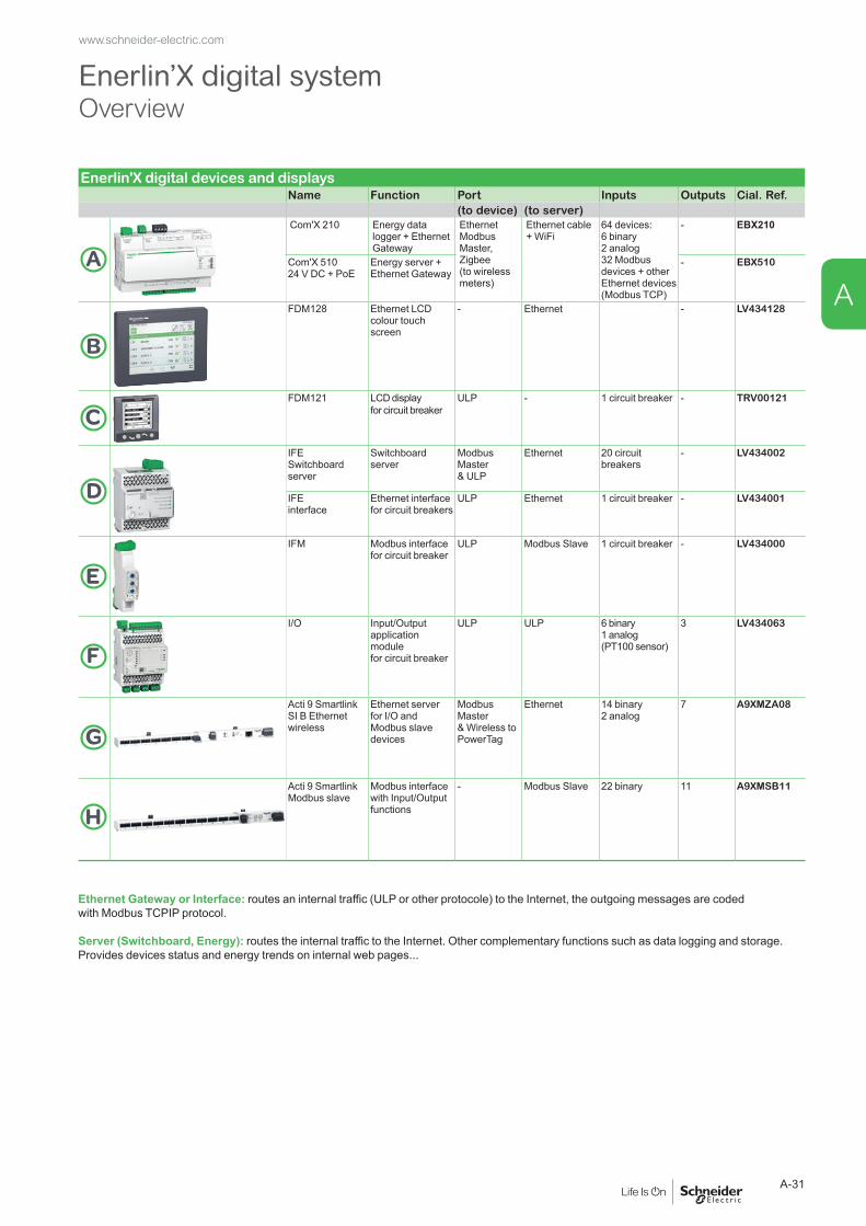
Enerlin’X digital systemOverview
Enerlin'X digital devices and displaysName Function Port Inputs Outputs Cial. Ref.
(to device) (to server)
A
Com'X 210 Energy data logger + Ethernet Gateway
Ethernet Modbus Master, Zigbee (to wireless meters)
Ethernet cable + WiFi
64 devices: 6 binary 2 analog 32 Modbus devices + other Ethernet devices (Modbus TCP)
- EBX210
Com'X 51024 V DC + PoE
Energy server + Ethernet Gateway
- EBX510
B
FDM128 Ethernet LCD colour touch screen
- Ethernet - LV434128
CFDM121 LCD display
for circuit breakerULP - 1 circuit breaker - TRV00121
D
IFE Switchboard server
Switchboard server
Modbus Master & ULP
Ethernet 20 circuit breakers
- LV434002
IFE interface
Ethernet interface for circuit breakers
ULP Ethernet 1 circuit breaker - LV434001
E
IFM Modbus interface for circuit breaker
ULP Modbus Slave 1 circuit breaker - LV434000
F
I/O Input/Output application module for circuit breaker
ULP ULP 6 binary 1 analog(PT100 sensor)
3 LV434063
G
Acti 9 Smartlink SI B Ethernet wireless
Ethernet server for I/O and Modbus slave devices
Modbus Master & Wireless to PowerTag
Ethernet 14 binary 2 analog
7 A9XMZA08
H
Acti 9 Smartlink Modbus slave
Modbus interface with Input/Output functions
- Modbus Slave 22 binary 11 A9XMSB11
Ethernet Gateway or Interface: routes an internal traffic (ULP or other protocole) to the Internet, the outgoing messages are coded with Modbus TCPIP protocol.
Server (Switchboard, Energy): routes the internal traffic to the Internet. Other complementary functions such as data logging and storage. Provides devices status and energy trends on internal web pages...
www.schneider-electric.com
A-31
A
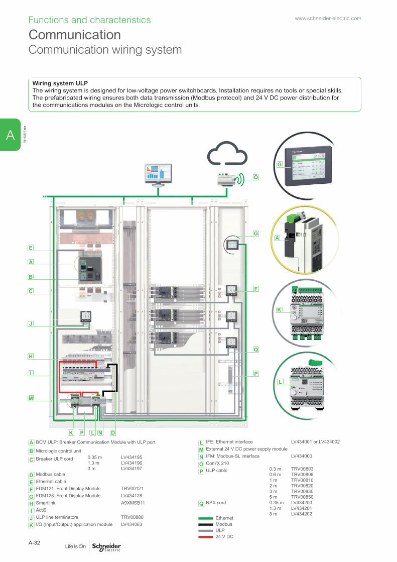
CommunicationCommunication wiring system
Functions and characteristicsPB
1192
37.e
ps
A BCM ULP: Breaker Communication Module with ULP port L IFE: Ethernet interface LV434001 or LV434002
M External 24 V DC power supply module
N IFM: Modbus-SL interface LV434000
O Com'X 210
P ULP cable 0.3 m0.6 m1 m2 m3 m5 m
TRV00803TRV00806TRV00810TRV00820TRV00830TRV00850
Q NSX cord 0.35 m1.3 m3 m
LV434200LV434201LV434202
Ethernet Modbus ULP 24 V DC
B Micrologic control unit
C Breaker ULP cord 0.35 m1.3 m3 m
LV434195LV434196LV434197
D Modbus cable
E Ethernet cable
F FDM121: Front Display Module TRV00121
G FDM128: Front Display Module LV434128
H Smartlink A9XMSB11
I Acti9
J ULP line terminators TRV00880
K I/O (Input/Output) application module LV434063
Wiring system ULPThe wiring system is designed for low-voltage power switchboards. Installation requires no tools or special skills.The prefabricated wiring ensures both data transmission (Modbus protocol) and 24 V DC power distribution for the communications modules on the Micrologic control units.
E
A
B
C
J
H
I
M
K P L N D
O
G
F
Q
P
G
A
K
L
www.schneider-electric.com
A-32
A

Overview of functions
PB10
4804
.eps Four functional levels
The Masterpact can be integrated into Ethernet and Modbus communication environment. There are four possible functional levels that can be combined.
Switch-disconnectors
Circuit breaker
Status indicationsON/OFF (O/F) b A E P HSpring charged CH b A E P HReady to close b A E P HFault-trip SDE b A E P HConnected / disconnected / test position CE/CD/CT (I/O application module only)
b A E P H
Controls MX1 open b A E P HXF close b A E P HMeasurements
Instantaneous measurement information b A E P HAveraged measurement information b E P HMaximeter / minimeter b A E P HEnergy metering b E P HDemand for current and power b E P HPower quality b HOperating assistance
Protection and alarm settings A E P HHistories A E P HTime stamped event tables A E P HMaintenance indicators A E P H
A: Micrologic with ammeterE: Micrologic “Energy”P: Micrologic “Power”H: Micrologic “Harmonics”Note: see the description of the Micrologic control units for further details on protection and alarms, measurements, waveform capture, histories, logs and maintenance indicators.
Modbus principleThe Modbus RS 485 (RTU protocol) system is an open bus on which communicating Modbus devices (Compact NS with Modbus COM, Power Meter PM700, PM800, Sepam, Vigilohm, Compact NSX, etc.) are installed. All types of PLCs and microcomputers may be connected to the bus.
AddressesThe Modbus communication parameters (address, baud rate, parity) are entered using the keypad on the Micrologic A, E, P, H. For a switch-disconnector, it is necessary to use the Electrical Asset Manager or RSU (Remote Setting Utility) Micrologic utility.
Number of devicesThe maximum number of devices that may be connected to the Modbus bus depends on the type of device (Compact with Modbus COM, PM700, PM800, Sepam, Vigilohm, Compact NSX, etc.), the baud rate (19200 is recommended), the volume of data exchanged and the desired response time. The RS 485 physical layer offers up to 32 connection points on the bus (1 master, 31 slaves).A fixed device requires only one connection point (communication module on the device). A drawout device uses two connection points (communication modules on the device and on the chassis).The number must never exceed 31 fixed devices or 15 drawout devices.
Length of busThe maximum recommended length for the Modbus bus is 1200 meters.
Bus power sourceA 24 V DC power supply is required (less than 20 % ripple, insulation class II).
Ethernet principleEthernet is a data link and physical layer protocol defined by IEEE 802 10 and 100 Mbps specifications that connects computer or other Ethernet devices. Ethernet is an asynchronous Carrier Sense Multiple Access with Collision detection (referred as CSMA/CD) protocol. Carrier Sense means that the hosts can detect whether the medium (coaxial cable) is idle or busy. Multiple Access means that multiple hosts can be connected to the common medium. Collision Detection means a host detects whether its transmission has collided with the transmission of another host (or hosts).IFE Ethernet interface can be connected to a PC or a laptop over Ethernet. The maximum length of Ethernet cable is 100 meters. IFE Ethernet interface + gateway provides a Modbus TCP/IP gateway over Ethernet to enable Modbus TCP communication from a Modbus TCP master to any Modbus slave devices connected to it. The maximum active Modbus TCP client connection is twelve.IFE Ethernet interface has an embedded web server (web page).The Modbus RS 485 (RTU protocol) system is an open bus on which communicating Modbus devices (Compact NS with Modbus COM, Power Meter PM700, PM800, Sepam, Vigilohm, Compact NSX, etc.) are installed. All types of PLCs and microcomputers may be connected to the bus.
www.schneider-electric.com
A-33
A

Communication COM option in Masterpact
Functions and characteristics
All the Masterpact devices can be fitted with the communication function thanks to the COM option.Masterpact uses the Ethernet or Modbus communications protocol for full compatibility with the supervision management systems.Eco COM is limited to the transmission of metering data and status. It is not used to communicate controls.
For fixed and Drawout devices, the common communication option is made up of:
b a BCM ULP module, installed behind the Micrologic control unit and supplied with its set of sensors (OF, SDE, PF and CH micro switches) its kit for connection to XF and MX1 communicating voltage releases and its COM terminal block (inputs E1 to E6). This module is independent of the control unit. It receives and transmits information on the communication network. An infra-red link transmits data between the control unit and the communication module. Consumption: 30 mA, 24 V.
b IFM, this module required for connection to the network, contains the Modbus address (1 to 99) declared by the user via the two dials in front. It automatically adapts (baud rate, parity) to the Modbus network in which it is installed.Or
b IFE, the Ethernet interface for LV circuit breaker enables an intelligent modular unit (IMU), for example a Masterpact NT/NW or Compact NSX circuit breaker to be connected to an Ethernet network. Each circuit breaker has its own IFE and a corresponding IP address.
For drawout device the Cradle Management option must be added:I/O (Input/Output) application module for LV breaker, the I/O application module is delivered with withdrawable devices ordered with the COM option, for cradle management. It must be installed on a DIN rail near the device. It must be connected to the ULP system and to the position contacts (CD, CT, CE) that transmit the position of the device in the cradle.For communicating remote control, option with XF and MX1 communicating voltage releases must be added:The XF and MX1 communicating voltage releases are equipped for connection to the "device" communication module.The remote-tripping function (MX2 or MN) are independent of the communication option. They are not equipped for connection to the "device" communication module.
PB10
6674
-20.
eps
BCM ULP.
PB11
9234
.eps
I/O application module.
www.schneider-electric.com
A-34
A

Communication architecture
Electrical operatedFixed device Drawout device
LV434002
Enerlin'X IFE
ULP system
or
Modbus
I
Ethernet
Test
MX1 XF
OFSD SDEPFCH
B
D
A
C
F
J
DB4
3075
0.ep
s
ULP system
or
Modbus
Test
J
E
A
B
C MX1 - XF D
CTCECD
LV434002
Enerlin'X IFE
I
Ethernet
G
H
F
OFSDEPFCH
+24VDC
13
O1
+
I1
24VDC
I2I3
I4I5
I6
C
C
C
1423 24
3334
T1 T2
O2
O3
A1
LV434063
IO
I1
A1
O1
O2
O3I2I3
I4I5
I6
APP
I1I2
I3I4
I5I6
C
C
C
DB4
3256
4.ep
s
A BCM ULPB OF, SDE ... microswitchesC COM terminal block (E1 to E6)D MX1 and XF communicating voltage releasesE CE, CD and CT contacts
F Breaker ULP cordG I/O application moduleH ULP cableI IFE moduleJ IFM module
www.schneider-electric.com
A-35
A

Functions and characteristics
IFE Ethernet interfacePB
1158
52.e
ps IFE interface, IFE interface + gateway descriptionIntroductionThe IFE interface and IFE interface + gateway enable LV circuit breakers as Masterpact NT/NW, Compact NSX or Powerpact to be connected to an Ethernet network.
IFE interface: ref. LV434001Provides an Ethernet access to a single LV circuit breaker.Function Interface - one circuit breaker is connected to the IFE interface via its ULP port.
IFE interface + gateway: ref. LV434002 Provides an Ethernet access to one or several LV circuit breakers.Functions
b Interface - one circuit breaker is connected to the IFE interface via its ULP port. b Gateway: several circuit breakers on a Modbus network are connected via
the IFE interface + gateway master Modbus port.
IFE interface, IFE interface + gateway features b Dual 10/100 Mbps Ethernet port for simple daisy chain connection. b Device profile web service for discovery of the IFE interface, IFE interface +
gateway on the LAN. b ULP compliant for localization of the IFE interface in the switchboard. b Ethernet interface for Compact, Masterpact and Powerpact circuit breakers. b Gateway for Modbus-SL connected devices (IFE interface + gateway only). b Embedded set-up web pages. b Embedded monitoring web pages. b Embedded control web pages. b Built-in e-mail alarm notification.
MountingThe IFE interface, IFE interface + gateway are DIN rail mounting devices. A stacking accessory enables the user to connect several IFMs (ULP to Modbus interfaces) to an IFE interface + gateway without additional wiring.
24 V DC power supplyThe IFE interface, IFE interface + gateway must always be supplied with 24 V DC. The IFMs stacked to an IFE interface + gateway are supplied by the IFE interface + gateway, thus it is not necessary to supply them separately. It is recommended to use an UL listed and recognized limited voltage/limited current or a class 2 power supply with a 24 V DC, 3 A maximum.
IFE interface, IFE interface + gateway firmware updateThe firmware can be updated using:
b FTP b customer engineering tool.
Required circuit breaker communication modulesThe connection to IFE interface or IFE interface + gateway requires a communication module embedded into the circuit breaker:
b Masterpact NT/NW (Fixed or drawout): BCM ULP communication module b Drawout Masterpact NT/NW: BCM ULP and its respective I/O (Input/Output)
application module.All connection configurations for Masterpact NT/NW require the breaker ULP cord. The insulated NSX cord is mandatory for system voltages greater than 480 V AC. When the second ULP RJ45 connector is not used, it must be closed with an ULP terminator (TRV00880).Network communication interface
IFE interface, ref.: LV434001
PB11
9224
.eps
IFE interface + gateway, ref.: LV434002
DB4
0674
3.ep
s
Characteristic ValueType of interface module Modbus RTU, RS485 serial connection
Modbus TCP/IP EthernetTransmission Modbus RS485 Transfer rate: 9,600...19,200 Baud
Medium Double shielded twisted pairImpedance 120 Ω
Ethernet Transfer rate : 10/100 MbpsMedium STP, Cat5e, straight cable
Structure Type Modbus, EthernetMethod Master/Slave
Device type Modbus MasterEthernet Server
Turnaround time Modbus 10 msEthernet 1 ms
Maximum length of cable Modbus 1000 mEthernet 100 m
Type of bus connector Modbus 4-pin connectorEthernet RJ45 (Shielded)
www.schneider-electric.com
A-36
A
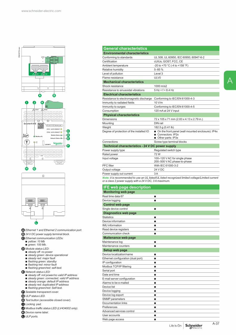
General characteristicsEnvironmental characteristics
Conforming to standards UL 508, UL 60950, IEC 60950, 60947-6-2Certification cUIUs, GOST, FCC, CEAmbient temperature -20 to +70 °C (-4 to +158 °F)Relative humidity 5–85 %Level of pollution Level 3Flame resistance ULV0Mechanical characteristics
Shock resistance 1000 m/s2Resistance to sinusoidal vibrations 5 Hz < f < 8.4 HzElectrical characteristics
Resistance to electromagnetic discharge Conforming to IEC/EN 61000-4-3Immunity to radiated fields 10 V/mImmunity to surges Conforming to IEC/EN 61000-4-5Consumption 120 mA at 24 V inputPhysical characteristics
Dimensions 72 x 105 x 71 mm (2.83 x 4.13 x 2.79 in.)Mounting DIN railWeight 182.5 g (0.41 lb)Degree of protection of the installed IO b On the front panel (wall mounted enclosure): IP4x
b Connectors: IP2x b Other parts: IP3x
Connections Screw type terminal blocksTechnical characteristics - 24 V DC power supply
Power supply type Regulated switch typeRated power 72 WInput voltage 100–120 V AC for single phase
200–500 V AC phase-to-phasePFC filter With IEC 61000-3-2Output voltage 24 V DCPower supply out current 3 ANote: it is recommended to use an UL listed/UL listed recognized limited voltage/Limited current or a class 2 power supply with a 24 V DC, 3 A maximum.
IFE web page descriptionMonitoring web page
Real time data 67 b Device logging b Control web page
Single device control b Diagnostics web page
Statistics b Device information b IMU information b Read device registers b Communication check b Maitenance web page
Maintenance log b Maintenance counters b Setup web page
Device localization/name b Ethernet configuration (dual port) b IP configuration b Modbus TCP/IP filtering b Serial port b Date and time b E-mail server configuration b Alarms to be e-mailed b Device list b Device logging b Device log export b SNMP parameters b Documentation links b Preferences b Advanced services control b User accounts b Web page access b
ETH1 ETH2
Modbus-SL
LV434011
ETH1 LK/10-100/ACT
ETH2 LK/10-100/ACT
Module Status
Network Status
R
Enerlin'X IFEIFE-XX.YY.ZZ (factory set)
T
24VDC
ETH1 ETH2
GH
B
L
A
CDE
I
F
J K
DB4
3075
2.ep
s
A Ethernet 1 and Ethernet 2 communication port. B 24 V DC power supply terminal block.C Ethernet communication LEDs:
b yellow: 10 Mb b green: 100 Mb.
D Module status LED: b steady off: no power b steady green: device operational b steady red: major fault b flashing green: standby b flashing red: minor fault b flashing green/red: self-test.
E Network status LED: b steady off: not power/no valid IP address b steady green: connected, valid IP address b steady orange: default IP address b steady red: duplicated IP address b flashing green/red: Self-test.
F Sealable transparent cover.G ULP status LED.H Test button (accessible closed cover). I Locking pad.J Modbus traffic status LED (LV434002 only).K Device name label.L ULP ports.
www.schneider-electric.com
A-37
A

IFM Modbus communication interfaceFunctions and characteristics
A Modbus screw clamp connector.
B Modbus address switches.
C Modbus traffic LED.D Modbus locking pad.
FunctionA IFM - Modbus communication interface - is required for connection of a Masterpact or Compact to a Modbus network as long as this circuit breaker is provided with a ULP (Universal Logic Plug) port. The port is available on respectively a BCM ULP or BSCM embedded module.The IFM is defined as an IMU (Intelligent Modular Unit) in the ULP connection System documentation.
Once connected, the circuit breaker is considered as a slave by the Modbus master. Its electrical values, alarm status, open/close signals car be monitored or controlled by a Programmable Logic Controller or any other system.
CharacteristicsULP port2 RJ45 sockets, internal parallel wiring.
b Connection of a single circuit breaker (eventually via its I/O application module). b A ULP line terminator or an FDM121 display unit must be connected to the second
RJ45 ULP socket.The RJ45 sockets deliver a 24 VDC supply fed from the Modbus socket.Built-in test function, for checking the correct connection to the circuit breaker and FDM121 display unit.
Modbus slave port b Top socket for screw-clamp connector, providing terminals for: v 24 VDC input supply (0 V, +24 V) v Modbus line (D1, D2, Gnd). b Lateral socket, for Din-rail stackable connector.
Both top and lateral sockets are internally parallel wired. b Multiple IFM can be stacked, thus sharing a common power supply and Modbus
line without individual wiring. b On the front face: v Modbus address setting (1 to 99): 2 coded rotary switches v Modbus locking pad: enables or disable the circuit breaker remote control
and modification of IFM parameters. b Self adjusting communication format (Baud rate, parity).
IFM Modbus communication interface.Ref.: LV434000.
E ULP activity LED.F Test button.G Mechanical lock.H ULP RJ45 connectors.I Stacking accessory
connection.
PB11
9111
_L17
.eps
DB4
3075
3.ep
s
x10
COM
1234
0
5
9876
x1
1234
0
5
9876
Modbus0V 24V
COM
1
A
B
CD
E
F
GHI
www.schneider-electric.com
A-38
A

Technical characteristicsIFM Modbus communication interface
Dimensions 18 x 72 x 96 mmMaximum number of stacked IFM 12Degree of protection of the installed module
Part projecting beyond the escutcheon
IP4x
Other module parts IP3xConnectors IP2x
Operating temperature -25...+70 °CPower supply voltage 24 V DC -20 %/+10 % (19.2...26.4 V DC)Consumption Typical 21 mA/24 V DC at 20 °C
Maximum 30 mA/19.2 V DC at 60 °CCertification
CE IEC/EN 60947-1UL UL 508 - Industrial Control EquipmentCSA No. 142-M1987 - Process Control
Equipment b CAN/CSA C22.2 No. 0-M91 -
General requirements - Canadian Electrical Code Part
b CAN/CSA C22.2 No. 14-05 - Industrial Control Equipment
Simplified IFM installationStaking IFM
DB4
3075
4.ep
s
Test
TestTest
DB4
3075
5.ep
s
Stacking accessories Up to 12 stacked IFM
Stacking an IFE interface + gateway with IFMs
DB4
3075
6.ep
s
Test
Test
Test
Test
Test
Test
LV434002
Enerlin'X IFE
www.schneider-electric.com
A-39
A
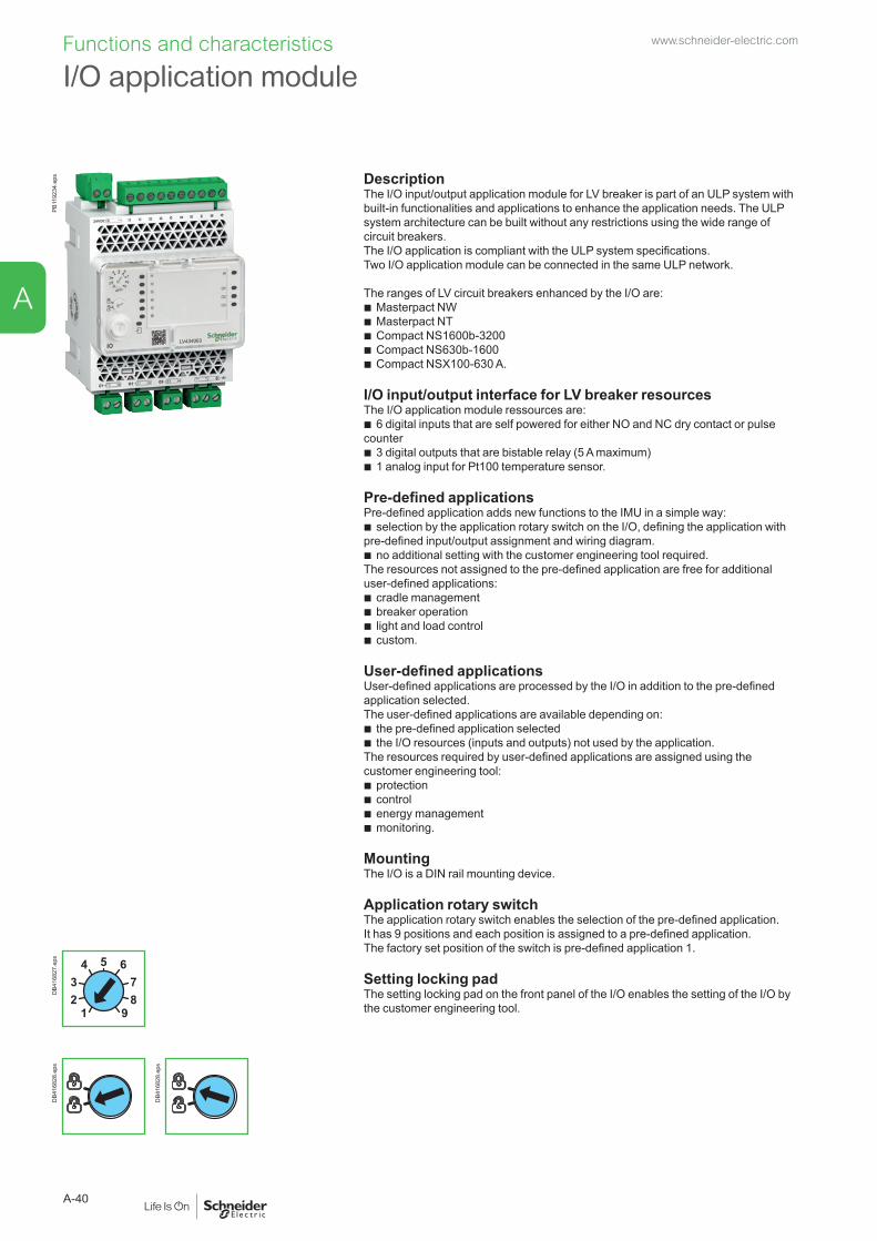
Functions and characteristicsPB
1192
34.e
ps
DescriptionThe I/O input/output application module for LV breaker is part of an ULP system with built-in functionalities and applications to enhance the application needs. The ULP system architecture can be built without any restrictions using the wide range of circuit breakers.The I/O application is compliant with the ULP system specifications. Two I/O application module can be connected in the same ULP network.
The ranges of LV circuit breakers enhanced by the I/O are: b Masterpact NW b Masterpact NT b Compact NS1600b-3200 b Compact NS630b-1600 b Compact NSX100-630 A.
I/O input/output interface for LV breaker resourcesThe I/O application module ressources are:
b 6 digital inputs that are self powered for either NO and NC dry contact or pulse counter
b 3 digital outputs that are bistable relay (5 A maximum) b 1 analog input for Pt100 temperature sensor.
Pre-defined applicationsPre-defined application adds new functions to the IMU in a simple way:
b selection by the application rotary switch on the I/O, defining the application with pre-defined input/output assignment and wiring diagram.
b no additional setting with the customer engineering tool required.The resources not assigned to the pre-defined application are free for additional user-defined applications:
b cradle management b breaker operation b light and load control b custom.
User-defined applicationsUser-defined applications are processed by the I/O in addition to the pre-defined application selected.The user-defined applications are available depending on:
b the pre-defined application selected b the I/O resources (inputs and outputs) not used by the application.
The resources required by user-defined applications are assigned using the customer engineering tool:
b protection b control b energy management b monitoring.
MountingThe I/O is a DIN rail mounting device.
Application rotary switchThe application rotary switch enables the selection of the pre-defined application. It has 9 positions and each position is assigned to a pre-defined application. The factory set position of the switch is pre-defined application 1. Setting locking padThe setting locking pad on the front panel of the I/O enables the setting of the I/O by the customer engineering tool.1
23
4 5 678
9
DB4
1682
7.ep
sD
B416
828.
eps
DB4
1682
8.ep
s
I/O application modulewww.schneider-electric.com
A-40
A

General characteristicsEnvironmental characteristics
Conforming to standards UL 508, UL 60950, IED 60950, 60947-6-2Certification cUIUs, GOST, FCC, CEAmbient temperature -20 to +70 °C (-4 to +158 °F)Relative humidity 5–85 %Level of pollution Level 3Flame resistance ULV0Mechanical characteristics
Shock resistance 1000 m/s2Resistance to sinusoidal vibrations
5 Hz < f < 8.4 Hz
Electrical characteristicsResistance to electromagnetic discharge
Conforming to IEC/EN 61000-4-3
Immunity to radiated fields 10 V/mImmunity to surges Conforming to IEC/EN 61000-4-5Consumption 165 mAPhysical characteristics
Dimensions 71.7 x 116 x 70.6 mm (2.83 x 4.56 x 2.78 in.)Mounting DIN railWeight 229.5 g (0.51 lb)Degree of protection of the installed I/O application module
b On the front panel (wall mounted enclosure): IP4x b IO parts: IP3x b Connectors: IP2x
Connections Screw type terminal blocksTechnical characteristics - 24 V DC power supply
Power supply type Regulated switch typeRated power 72 WInput voltage 100–120 V AC for single phase
200–500 V AC phase-to-phasePFC filter With IEC 61000-3-2Output voltage 24 V DCPower supply out current 3 ANote: it is recommended to use an UL listed/UL listed recognized limited voltage/Limited current or a class 2 power supply with a 24 V DC, 3 A maximum.Digital inputs
Digital input type Self powered digital input with current limitations as per IEC 61131-2 type 2 standards (7 mA)
Input limit values at state 1 (close)
19.8–25.2 V DC, 6.1–8.8 mA
Input limit values at state 0 (open)
0–19.8 V DC, 0 mA
Maximum cable length 10 m (33 ft)Note: for a length greater than 10 m (33 ft) and up to 300 m (1,000 ft), it is mandatory to use a shielded twisted cable. The shield cable is connected to the I/O functional ground of the I/O application module.Digital outputs
Digital output type Bistable relayRated load 5 A at 250 V ACRated carry current 5 AMaximum switching voltage 380 V AC, 125 V DCMaximum switch current 5 AMaximum switching power 1250 VA, 150 WMinimum permissible load 10 mA at 5 V DCContact resistance 30 mΩMaximum operating frequency b 18000 operations/hr (Mechanical)
b 1800 operations/hr (Electrical)Digital output relay protection by an external fuse
External fuse of 5 A or less
Maximum cable length 10 m (33 ft)Analog inputs
The I/O application module analog input can be connected to a Pt100 temperature sensorRange -30 to 200 °C -22 to 392 °FAccuracy ±2 °C from -30 to 20 °C
±1 °C from 20 to 140 °C±2 °C from 140 to 200 °C
±3.6 °F from -22 to 68 °F±1.8 °F from 68 to 284 °F±3.6 °F from 284 to 392 °F
Refresh interval 5 s 5 s
I1 I2 I3 I4 I5 I6C C C
A B
DB4
1923
3.ep
s
13 14 23 24 33 34 T1
12
T2
NO
DB4
1923
5.ep
s
13O1 O2 O3 A1
I1 I2 I3 I4 I5 I6C C C
14 23 24 33 34 T1 T2
24VDC
1APP
23
4 5 678
9
I1 AI
O1
O2
O3
I2
I3
I4
I5
I6
LV434063IO
T
C
D
E
F
G
MLKJ
HI
DB4
3253
6.ep
s
A 24 Vdc power supply terminal block.B Digital input terminal block: 6 inputs,
3 commons and 1 shield.C 6 input status LEDs.D Analog input status LED.E 3 output status LEDs.F I/O application module identification labels.G Sealable transparent cover.H Analog input terminal block.I Digital output terminal blocks.J ULP status LED.K Test/reset button (accessible with cover closed).L Setting locking pad.M Application rotary switch: 1 to 9.N Switch for I/O addressing (I/O 1 or I/O 2).O ULP connectors.
www.schneider-electric.com
A-41
A

Functions and characteristics
Connection of the IFE to a fixed or drawout Masterpact NT/NW
Connect the IFE to a fixed electrically operated Masterpact NT/NW or circuit breaker using the breaker ULP cord
Connect the IFE to a drawout Masterpact NT/NW or circuit breaker using the breaker ULP cord
Ethernet
LV434002
Enerlin'X IFE
24 Vdc
A
B
D
C
E
DB4
3256
7.ep
s
+24VDC
13
O1
+
I1
24VDC
I2I3
I4I5
I6
C
C
C
1423
2433 34
T1 T2
O2
O3
A1
LV434063
IO
I1
A1
O1
O2
O3I2I3
I4I5
I6
APP
Ethernet
LV434002
Enerlin'X IFE
24 Vdc
A
B
C
D
E
G
K
J
HI
F
DB4
3256
5.ep
s
A IFE Ethernet interface for LV circuit breakerB Breaker ULP cordC Fixed terminal blockD BCM ULP communication moduleE Fixed electrically operated circuit breaker
A IFE Ethernet interface for LV circuit breakerB ULP cableC Breaker ULP cordD Circuit breaker disconnected position contact (CD)E Circuit breaker cradleF BCM ULP communication moduleG Drawout circuit breakerH Drawout terminal blockI Circuit breaker connected position contact (CE)J Circuit breaker test position contact (CT)K I/O (Input/Output) application module for LV circuit breaker
www.schneider-electric.com
A-42
A

Connection of the IFM to a fixed or drawout Masterpact NT/NW
Connect the IFM to a fixed electrically operated Masterpact NT/NW or circuit breaker using the breaker ULP cord
Connect the IFM to a drawout Masterpact NT/NW or circuit breaker using the breaker ULP cord
Test
Modbus
A
B
D
C
E
DB4
3256
8.ep
s
Test
Modbus
+24VDC
13
O1
+
I1
24VDC
I2I3
I4I5
I6
C
C
C
1423
2433 34
T1 T2
O2
O3
A1
LV434063
IO
I1
A1
O1
O2
O3I2I3
I4I5
I6
APP
A
B
C
D
E
G
K
J
HI
F
DB4
3256
6.ep
s
A IFM Ethernet interface for LV circuit breakerB Breaker ULP cordC Fixed terminal blockD BCM ULP communication moduleE Fixed electrically operated circuit breaker
A IFM Ethernet interface for LV circuit breaker
B ULP cableC Breaker ULP cordD Circuit breaker disconnected position
contact (CD)E Circuit breaker cradle
F BCM ULP communication moduleG Drawout circuit breakerH Drawout terminal blockI Circuit breaker connected position contact
(CE)J Circuit breaker test
position contact (CT)K I/O (Input/Output) application module
for LV circuit breaker
www.schneider-electric.com
A-43
A

Functions and characteristics
Electrical Asset Manager Configuration Engineering tool
IntroductionElectrical Asset Manager is a software application that helps the user to manage a project as part of designing, testing, site commissioning, and maintenance of the project life cycle. It enables the user to prepare the settings of the devices offline (without connecting to the device) and configure them when connected with the devices. Also it provides lot of other value added features for the user to manage the project such as, safe repository in cloud, attach artifacts to each device or at the project level, organize devices in switchboard wise, manage a hierarchical structure of the installation etc.
Compatible devices (configuration and device management)Electrical Asset Manager is compatible with the following devices:
b Compact NSX100-630 (IEC) b PowerPactTM (UL) circuit breaker b Compact NS630b-3200 (IEC) b Masterpact NT/NW (IEC and UL) circuit breaker b Acti9 Smartlink. b Compatible devices (Device Management in the project) b Switch disconnectors (Compact NSX, Masterpact & PowerPact Family) b Third party devices.
References: Electrical Asset Manager software package can be downloaded from our website www.schneider-electric.com.
FeaturesElectrical Asset Manager supersedes the Schneider Electric customer engineering tools such as Remote setting Utility (RSU) and Remote Control Utility (RCU) with additional features.Electrical Asset Manager supports the connection of Schneider Electric communicable devices to:
b create projects by device discovery, selection of devices, and import Bill of Material (BOM)
b monitor the status of protection and IO status b read information (alarms, measurements, parameters) b check protection selectivity between two devices b upload and download of configuration or settings in batch mode to multiple
devices. b carry out commands and tests b generate and print device settings report and communication test report b manage multiple devices with electrical and communication hierarchy model b manage artifacts (project documents) b check consistency in settings between devices on a communication network b compare configuration settings between PC and device (online) b download latest firmware.
Electrical Asset Manager enables the user to avail the advanced features of the software once the project is saved in Schneider Electric cloud.
Cap
ture
1b.e
psC
aptu
re2b
.eps
Cap
ture
3b.e
psC
aptu
re4b
.eps
www.schneider-electric.com
A-44
A
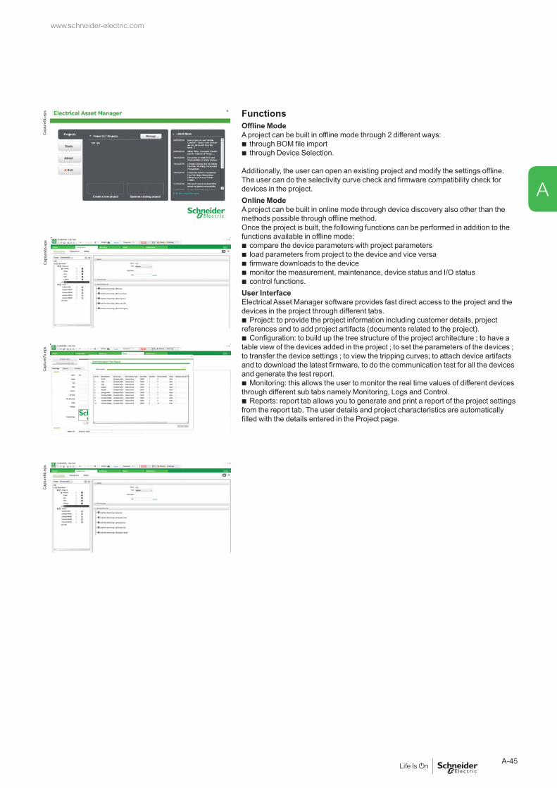
FunctionsOffline ModeA project can be built in offline mode through 2 different ways:
b through BOM file import
b through Device Selection.
Additionally, the user can open an existing project and modify the settings offline. The user can do the selectivity curve check and firmware compatibility check for devices in the project. Online Mode A project can be built in online mode through device discovery also other than the methods possible through offline method. Once the project is built, the following functions can be performed in addition to the functions available in offline mode:
b compare the device parameters with project parameters b load parameters from project to the device and vice versa b firmware downloads to the device b monitor the measurement, maintenance, device status and I/O status b control functions.
User InterfaceElectrical Asset Manager software provides fast direct access to the project and the devices in the project through different tabs.
b Project: to provide the project information including customer details, project references and to add project artifacts (documents related to the project).
b Configuration: to build up the tree structure of the project architecture ; to have a table view of the devices added in the project ; to set the parameters of the devices ; to transfer the device settings ; to view the tripping curves; to attach device artifacts and to download the latest firmware, to do the communication test for all the devices and generate the test report.
b Monitoring: this allows the user to monitor the real time values of different devices through different sub tabs namely Monitoring, Logs and Control.
b Reports: report tab allows you to generate and print a report of the project settings from the report tab. The user details and project characteristics are automatically filled with the details entered in the Project page.
Cap
ture
5b.e
psC
aptu
re6b
.eps
Cap
ture
7b.e
psC
aptu
re8b
.eps
www.schneider-electric.com
A-45
A
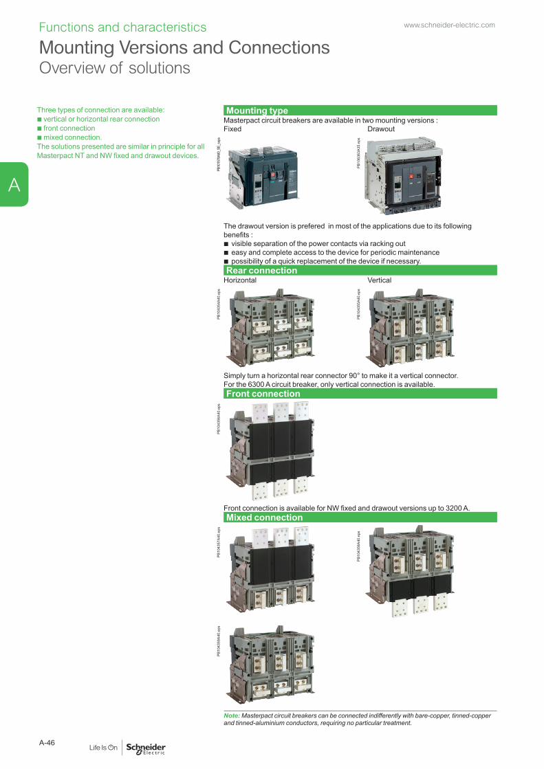
Three types of connection are available:b vertical or horizontal rear connection b front connection b mixed connection. The solutions presented are similar in principle for all Masterpact NT and NW fixed and drawout devices.
Mounting typeMasterpact circuit breakers are available in two mounting versions :Fixed Drawout
PB10
1578
A60_
SE_r.
eps
PB10
6363
A35.
eps
The drawout version is prefered in most of the applications due to its following benefits :
b visible separation of the power contacts via racking out b easy and complete access to the device for periodic maintenance b possibility of a quick replacement of the device if necessary.Rear connection
Horizontal Vertical
PB10
4354
A40.
eps
PB10
4355
A40.
eps
Simply turn a horizontal rear connector 90° to make it a vertical connector.For the 6300 A circuit breaker, only vertical connection is available.Front connection
PB10
4356
A40.
eps
Front connection is available for NW fixed and drawout versions up to 3200 A.Mixed connection
PB10
4357
A40.
eps
PB10
4358
A40.
eps
PB10
4359
A40.
eps
Note: Masterpact circuit breakers can be connected indifferently with bare-copper, tinned-copper and tinned-aluminium conductors, requiring no particular treatment.
Mounting Versions and Connections Overview of solutions
Functions and characteristics www.schneider-electric.com
A-46
A

Type of accessory Masterpact NT06 to NT16 Masterpact NW08 to NW63Fixed Drawout Fixed DrawoutFront connection
Rear connection
Front connection
Rear connection
Front connection
Rear connection
Front connection
Rear connection
Vertical connection adapters
DB1
0115
6.ep
s
(4)
DB1
0115
6.ep
s
(4)
Cable lug adapters
DB1
0114
7.ep
s
(4)
DB1
0114
7.ep
s
(4)
Interphase barriers
DB1
0114
8.ep
s
(1) DB1
0114
9.ep
s
(1) DB1
0114
9.ep
s
(2) DB1
0114
9
(2)
Spreaders
DB1
0115
0.ep
s
(4) DB1
0115
0.ep
s
(4)
Disconnectable front-connection adapter
DB1
0115
1.ep
s
DB4
1815
6.ep
s
Safety shutters with padlocking
DB1
0115
2.ep
s
standard
Db1
0115
3.ep
s
standardShutter position indication and locking
DB1
0115
4.ep
s
Arc chute screen
DB1
0115
5.ep
s
(3)
DB1
0115
5.ep
s
(1) Mandatory for voltages u 500 V, not compatible with spreaders.(2) Except for an NW40 equipped for horizontal rear connection, and for fixed NW40b-NW63.(3) Mandatory for fixed NT front-connection versions with vertical-connection adapters oriented towards the front.(4) Spreaders, vertical connection adapters and cable lugs adapters are not compatible with voltages u 500 V.
Masterpact M replacement kitA set of connection parts is available to allow replacement of a Masterpact M08 to M32 circuit breaker by a Masterpact NW without modifying the busbars (please consult us).
Mounting on a switchboard backplate using special bracketsMasterpact NT and NW fixed front-connected circuit breakers can be installed on a backplate without any additional accessories.Masterpact NW circuit breakers require a set of special brackets.
Accessories
www.schneider-electric.com
A-47
A

PB10
4360
A30.
eps Vertical-connection adapters (option)
Mounted on front-connected devices or chassis, the adapters facilitate connection to a set of vertical busbars.
PB10
4361
A30.
eps Cable-lug adapters (option)
Cable-lug adapters are used in conjunction with vertical-connection adapters.They can be used to connect a number of cables fitted with lugs.To ensure adequate mechanical strength, the connectors must be secured together via spacers (catalogue number 04691).
PB10
4350
A30.
eps Interphase barriers (option)
These barriers are flexible insulated partitions used to reinforce isolation of connection points in installations with busbars, whether insulated or not. For Masterpact NT/NW devices (up to NW40), they are installed vertically between rear connection terminals. They are mandatory for NT devices at voltages > 500 V.They are not compatible with spreaders.
PB10
4362
A30.
eps Spreaders (option)
Mounted on the front or rear connectors, spreaders are used to increase the distance between bars in certain installation configurations.
DB1
1703
9.ep
s Arc chute screen (option)For fixed Masterpact NT front-connection versions and with vertical-connection adapters oriented towards the front, an arc chute screen must be installed to respect safety clearances.
The arc chute screen is delivered in standard on the NT and NW drawout version.
ConnectionsAccessories
Functions and characteristics www.schneider-electric.com
A-48
A

PB10
4363
A50.
eps Disconnectable front-connection adapter (option)
Mounted on a fixed front-connected device, the adapter simplifies replacement of a fixed device by enabling fast disconnection from the front.
PB10
4364
A50.
eps Safety shutters (VO standard)
Mounted on the chassis, the safety shutters automatically block access to the disconnecting contact cluster when the device is in the disconnected or test positions (degree of protection IP 20) When the device is removed from its chassis, no live parts are accessible.The shutter-locking system is made up of a moving block that can be padlocked (padlock not supplied). The block:
b prevents connection of the device b locks the shutters in the closed position.
For Masterpact NW08 to NW63A support at the back of the chassis is used to store the blocks when they are not used:
b 2 blocks for NW08 to NW40 b 4 blocks for NW40b to NW63.
DB1
0115
8.ep
s Shutter position indication and locking on front face (VIVC, NW only)This option located on the chassis front plate indicates that the shutters are closed. It is possible to independently or separately padlock the two shutters using one to three padlocks (not supplied).
www.schneider-electric.com
A-49
A

Micrologic 6.0 E
40
100%
%
delay
short time
on I2t
.2
.3.4 .4
.1
.2
.10
long time
alarm
ground fault
setting
4
test
.4.5.6
.7.8 .9
.95
.98
1
Ir
x In
.512
48 12
16
20
tr(s)
at 6 Ir24
x Ir
22.5
34 5
68
10
Isd
1.5
tsd(s)
x In
3
68 10
12
15
off2
BC
DE F
GH
I
Ig
Aon I
2t.2.3
.4.4
.1
.2.3
.10off
tg(s)
.1
.3
instantaneous
I i
menu
DB1
2665
0.ep
s 1 Reset button for mechanical trip indication.
2 OFF pushbutton.3 OFF position lock.4 Electrical closing
pushbutton.5 ON pushbutton.6 Springs charged
indication.7 Pushbutton locking.8 Contact position
indication.9 Operation counter.
PB10
0811
-32.
eps Pushbutton locking VBP
The transparent cover blocks access to the pushbuttons used to open and close the device.It is possible to independently lock the opening button and the closing button. The locking device is often combined with a remote operating mechanism.The pushbuttons may be locked using either:
b padlock (not supplied), 5 to 8 mm b lead seal b two screws.
Device locking in the OFF position VCPO by padlocks, VSPO by keylocksThe circuit breaker is locked in the OFF position by physically maintaining the opening pushbutton pressed down:
b using padlocks (one to three padlocks, not supplied), shackle diameter: 5 to 8 mm b using keylocks (one or two different keylocks, supplied).
Keys may be removed only when locking is effective (Profalux or Ronis type locks). The keylocks are available in any of the following configurations:
b one keylock b one keylock mounted on the device + one identical keylock supplied separately
for interlocking with another device b two different key locks for double locking.
Profalux and Ronis keylocks are compatible with each other.A locking kit (without locks) is available for installation of one or two keylocks (Ronis, Profalux, Kirk or Castell).Accessory-compatibility For Masterpact NT: 3 padlocks or 1 keylock.For Masterpact NW: 3 padlocks and/or 2 keylocks.
Cable-type door interlock IPAThis option prevents door opening when the circuit breaker is closed and prevents circuit breaker closing when the door is open.For this, a special plate associated with a lock and a cable is mounted on the right side of the circuit breaker.With this interlock installed, the source changeover function cannot be implemented.This option is identical for fixed and drawout version.
Access to pushbuttons protected by transparent cover.
PB10
0810
-32.
eps
Pushbutton locking using a padlock.
PB10
0812
-32.
eps
OFF position locking using a padlock.
PB10
4365
A40.
eps
OFF position locking using a keylock.
Locking On the device
Functions and characteristics www.schneider-electric.com
A-50
A
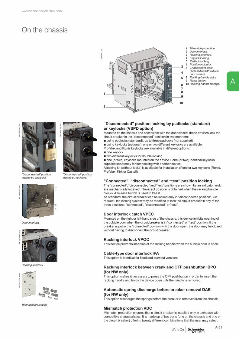
DB1
2665
1.ep
s 1 Mismatch protection.2 Door interlock.3 Racking interlock.4 Keylock locking.5 Padlock locking.6 Position indicator.7 Chassis front plate
(accessible with cubicle door closed).
8 Racking-handle entry.9 Reset button.10 Racking-handle storage.
PB10
4366
A32.
eps
PB10
4367
A34.
eps “Disconnected” position locking by padlocks (standard)
or keylocks (VSPD option)Mounted on the chassis and accessible with the door closed, these devices lock the circuit breaker in the “disconnected” position in two manners:b using padlocks (standard), up to three padlocks (not supplied)b using keylocks (optional), one or two different keylocks are available.Profalux and Ronis keylocks are available in different options:b one keylockb two different keylocks for double lockingb one (or two) keylocks mounted on the device + one (or two) identical keylocks supplied separately for interlocking with another device.A locking kit (without locks) is available for installation of one or two keylocks (Ronis, Profalux, Kirk or Castell).
“Connected”, “disconnected” and “test” position lockingThe “connected”, “disconnected” and “test” positions are shown by an indicator andc are mechanically indexed. The exact position is obtained when the racking handle blocks. A release button is used to free it.As standard, the circuit breaker can be locked only in "disconnected position". On request, the locking system may be modified to lock the circuit breaker in any of the three positions: "connected", "disconnected" or "test".
Door interlock catch VPECMounted on the right or left-hand side of the chassis, this device inhibits opening of the cubicle door when the circuit breaker is in “connected” or “test” position. It the breaker is put in the “connected” position with the door open, the door may be closed without having to disconnect the circuit breaker.
Racking interlock VPOCThis device prevents insertion of the racking handle when the cubicle door is open.
Cable-type door interlock IPAThis option is identical for fixed and drawout versions.
Racking interlock between crank and OFF pushbutton IBPO (for NW only)This option makes it necessary to press the OFF pushbutton in order to insert the racking handle and holds the device open until the handle is removed.
Automatic spring discharge before breaker removal DAE (for NW only)This option discharges the springs before the breaker is removed from the chassis.
Mismatch protection VDC Mismatch protection ensures that a circuit breaker is installed only in a chassis with compatible characteristics. It is made up of two parts (one on the chassis and one on the circuit breaker) offering twenty different combinations that the user may select.
”Disconnected” position locking by padlocks.
”Disconnected” position locking by keylocks.
PB10
4352
A32.
eps
Door interlock.
PB10
4368
A32.
eps
Racking interlock.
PB10
0815
-32R
_SE.
eps
Mismatch protection.
On the chassis
www.schneider-electric.com
A-51
A
Indication contacts are available:b in the standard version for relay applications b in a low-level version for control of PLCs and electronic circuits. M2C contacts may be programmed via the Micrologic E, P and H control units.
ON/OFF indication contacts OFTwo types of contacts indicate the ON or OFF position of the circuit breaker:
b micro switch type changeover contacts for Masterpact NT b rotary type changeover contacts directly driven by the mechanism for Masterpact
NW. These contacts switch when the minimum isolation distance between the main circuit breaker contacts is reached. These rotary type changeover contacts are used for both standard and low level versions for Masterpact NW.OF NT NW
Supplied as standard 4 4Maximum number 4 12Breaking capacity (A)p.f.: 0.3AC12/DC12
Standard Minimum load: 100 mA/24 V
PB10
0806
-32.
eps
PB10
0807
-20.
eps V AC 240/380 6 10/6 (1)
480 6 10/6 (1)
690 6 6V DC 24/48 2.5 10/6 (1)
125 0.5 10/6 (1)
250 0.3 3Low-level Minimum load: 2 mA/15 V
V AC 24/48 5 6ON/OFF indication contacts (OF) (rotary type).
240 5 6380 5 3
V DC 24/48 5/2.5 6125 0.5 6250 0.3 3
(1) Standard contacts: 10 A; optional contacts: 6 A.
“Fault-trip” indication contacts SDECircuit breaker tripping due to a fault is signalled by:
b a red mechanical fault indicator (reset) b one changeover contact SDE.
Following tripping, the mechanical indicator must be reset before the circuit breaker may be closed. One SDE is supplied as standard. An optimal SDE may be added.This latter is incompatible with the electrical reset after fault-trip option (RES).
ON/OFF indication contacts (OF) (micro switch type).
SDE NT/NW
PB10
0820
-32.
eps Supplied as standard 1
Maximum number 2Breaking capacity (A)p.f.: 0.3AC12/DC12
Standard Minimum load: 100 mA/24 VV AC 240/380 6
480 2V DC 24/48 3
125 0.3250 0.15
Low-level Minimum load: 2 mA/15 V V AC 24/48 3
240 3380 3
V DC 24/48 3Additional “fault-trip” indication contacts (SDE)
125 0.3250 0.15
PB10
0816
-32.
eps Combined “connected/closed” contacts EF
The contact combines the “device connected” and the “device closed” information to produce the “circuit closed” information. Supplied as an option for Masterpact NW, it is mounted in place of the connector of an additional OF contact.EF NW
Maximum number 8Breaking capacity (A)p.f.: 0.3AC12/DC12
Standard Minimum load: 100 mA/24 VV AC 240/380 6
480 6690 6
V DC 24/48 2.5125 0.8
Combined contacts. 250 0.3Low-level Minimum load: 2 mA/15 V
V AC 24/48 5240 5380 5
V DC 24/48 2.5125 0.8250 0.3
Indication contacts Functions and characteristics www.schneider-electric.com
A-52
A

PB10
0817
-32.
eps “Connected”, “disconnected” and “test” position carriage
switchesThree series of optional auxiliary contacts are available for the chassis:
b changeover contacts to indicate the “connected” position CE b changeover contacts to indicate the “disconnected” position CD. This position is
indicated when the required clearance for isolation of the power and auxiliary circuits is reached
b changeover contacts to indicate the “test” position CT. In this position, the power circuits are disconnected and the auxiliary circuits are connected.Additional actuatorsA set of additional actuators may be installed on the chassis to change the functions of the carriage switches.
CE, CD and CT “connected/disconnected/test” position carriage switches.
NT NWContacts CE/CD/CT CE/CD/CT
PB10
0778
-32.
eps Maximum number Standard
with additional actuators3 2 1 3 3 3
9 0 06 3 06 0 33 6 0
Breaking capacity (A)p.f.: 0.3AC12/DC12
Standard Minimum load: 100 mA/24 VV AC 240 8 8
380 8 8480 8 8690 6 6
V DC 24/48 2.5 2.5125 0.8 0.8
M2C programmable contacts: circuit breaker internal relay with two contacts.
250 0.3 0.3Low-level Minimum load: 2 mA/15 V
V AC 24/48 5 5240 5 5380 5 5
V DC 24/48 2.5 2.5125 0.8 0.8250 0.3 0.3
M2C programmable contactsThese contacts, used with the Micrologic E, P and H control units, may be programmed via the control unit keypad or via a supervisory station with the COM communication option. They require an external power supply module. The M2C (two contacts) auxiliary contacts may be used to signal threshold overruns or status changes. They can be programmed using the keypad on the Micrologic P control unit or remotely using the COM option (BCM ULP).
Micrologic Type E, P, HCharacteristics M2C
Minimum load 100 mA/24 VBreaking capacity (A)p.f.: 0.7
V AC 240 5380 3
V DC 24 1.848 1.5125 0.4250 0.15
DB1
1703
8.ep
s M2C: 24 V DC power supplied by control unit (consumption 100 mA).
Indication contactswww.schneider-electric.com
A-53
A

Two solutions are available for remote operation of Masterpact devices:b a point-to-point solution b a bus solution with the COM communication option.
The remote ON / OFF function is used to remotely open and close the circuit breaker. It is made up of:
b an electric motor MCH equipped with a “springs charged” limit switch contact CH b two voltage releases: v a closing release XF v an opening release MX.
Optionally, other functions may be added: b a “ready to close” contact PF b an electrical closing pushbutton BPFE b remote RES following a fault.
A remote-operation function is generally combined with: b device ON / OFF indication OF b “fault-trip” indication SDE.
Wiring diagram of a point-to-point remote ON / OFF function
PB10
4349
A68.
eps
DB1
1178
3.ep
s
Note: an opening order always takes priority over a closing order. If opening and closing orders occur simultaneously, the mechanism discharges without any movement of the main contacts. The circuit breaker remains in the open position (OFF). In the event of maintained opening and closing orders, the standard mechanism provides an anti-pumping function by blocking the main contacts in open position.Anti-pumping function. After fault tripping or intentional opening using the manual or electrical controls, the closing order must first be discontinued, then reactivated to close the circuit breaker.When the automatic reset after fault trip (RAR) option is installed, to avoid pumping following a fault trip, the automatic control system must take into account the information supplied by the circuit breaker before issuing a new closing order or blocking the circuit breaker in the open position (information on the type of fault, e.g. overload, short-time fault, earth fault, earth leakage, short-circuit, etc.).
Note: MX communicating releases are of the impulse type only and cannot be used to lock a circuit breaker in OFF position. For locking in OFF position, use the remote tripping function (2nd MX or MN).When MX or XF communicating releases are used, the third wire (C3, A3) must be connected even if the communication module is not installed. When the control voltage (C3-C1 or A3-A1) is applied to the MX or XF releases, it is necessary to wait 1.5 seconds before issuing an order. Consequently, it is advised to use standard MX or XF releases for applications such as source-changeover systems.
Wiring diagram of a bus-type remote ON / OFF function
COM
DB4
1300
5.ep
s
Remote operation Remote ON / OFF
Functions and characteristics www.schneider-electric.com
A-54
A

PB10
0797
-23.
eps
PB10
0808
-32.
eps Electric motor MCH
The electric motor automatically charges and recharges the spring mechanism when the circuit breaker is closed. Instantaneous reclosing of the breaker is thus possible following opening. The spring-mechanism charging handle is used only as a backup if auxiliary power is absent.The electric motor MCH is equipped as standard with a limit switch contact CH that signals the “charged” position of the mechanism (springs charged).Characteristics
Power supply V AC 50/60 Hz 48/60 - 100/130 - 200/240 - 277- 380/415 - 400/440 - 480V DC 24/30 - 48/60 - 100/125 - 200/250
Operating threshold 0.85 to 1.1 UnConsumption (VA or W) 180Motor overcurrent 2 to 3 In for 0.1 sCharging time maximum 3 s for Masterpact NT
maximum 4 s for Masterpact NWOperating frequency maximum 3 cycles per minuteCH contact 10 A at 240 V
Voltage releases XF and MXTheir supply can be maintained or automatically disconnected.Closing release XFThe XF release remotely closes the circuit breaker if the spring mechanism is charged.Opening release MXThe MX release instantaneously opens the circuit breaker when energised, the minimum duration of the pulse operating order must be 200 ms. The MX release locks the circuit breaker in OFF position if the order is maintained (except for MX “communicating” releases).Note: whether the operating order is maintened or automatically disconnected (pulse -type), XF or MX “communicating” releases (“bus” solution with “COM” communication option) always have an impulse-type action (see diagram).Characteristics XF MX
Power supply V AC 50/60 Hz 24 - 48 - 100/130 - 200/250 - 277 - 380/480V DC 12 - 24/30 - 48/60 - 100/130 - 200/250
Operating threshold 0.85 to 1.1 Un 0.7 to 1.1 UnConsumption (VA or W) Hold: 4.5
Pick-up: 200 (200 ms)Hold: 4.5Pick-up: 200 (200 ms)
Circuit breaker response time at Un
55 ms ±10 (Masterpact NT) 50 ms ±1070 ms ±10 (NW y 4000 A)80 ms ±10 (NW > 4000 A)
Electric motor MCH for Masterpact NT.
Electric motor MCH for Masterpact NW.
200 ms min. for MX
DB4
1715
5.ep
sPB
1008
09-1
6.ep
s
"Ready to close" contact PFThe “ready to close” position of the circuit breaker is indicated by a mechanical indicator and a PF changeover contact. This signal indicates that all the following are valid:
b the circuit breaker is in the OFF position b the spring mechanism is charged b a maintained opening order is not present: v MX energised v fault trip v remote tripping second MX or MN v device not completely racked in v device locked in OFF position v device interlocked with a second device.
Characteristics NT/NWMaximum number 1Breaking capacity (A)p.f.: 0.3AC12/DC12
Standard Minimum load: 100 mA/24 VV AC 240/380 5
480 5690 3
V DC 24/48 3125 0.3250 0.15
Low-level Minimum load: 2 mA/15 V V AC 24/48 3
240 3380 3
V DC 24/48 3125 0.3250 0.15
XF and MX voltage releases.
PB10
0818
-16.
eps
“Ready to close” contacts PF.
www.schneider-electric.com
A-55
A

PB10
0798
-56.
eps Electrical closing pushbutton BPFE
Located on the front panel, this pushbutton carries out electrical closing of the circuit breaker. It is generally associated with the transparent cover that protects access to the closing pushbutton.Electrical closing via the BPFE pushbutton takes into account all the safety functions that are part of the control/monitoring system of the installation.The BPFE connects to the closing release (XF com) in place of the COM module.The COM module is incompatible with this option.Different types of voltage exist and the XF electromagnet is compulsary if the BPFE option is selected.
Electrical closing pushbutton BPFE.
Remote reset after fault tripElectrical reset after fault trip RESFollowing tripping, this function resets the “fault trip” indication contacts SDE and the mechanical indicator and enables circuit breaker closing.Power supply: 110/130 V AC and 200/240 V AC.The use of XF closing release is compulsory with this option.The additional "Fault Trip" indication contact SDE2 is not compatible with RES.
Automatic reset after fault trip RARFollowing tripping, a reset of the mechanical indicator (reset button) is no longer required to enable circuit breaker closing. The mechanical (reset button) and electrical SDE indications remain in fault position until the reset button is pressed.The use of XF closing release is compulsory with this option.
DB1
0116
7.ep
sD
B116
359.
eps
Functions and characteristics
Remote operation Remote ON / OFF
www.schneider-electric.com
A-56
A

PB10
4369
A68.
eps This function opens the circuit breaker via an electrical order. It is made up of:
b a shunt release second MX b or an undervoltage release MN b or a delayed undervoltage release MNR: MN + delay unit.
These releases (2nd MX or MN) cannot be operated by the communication bus.The delay unit, installed outside the circuit breaker, may be disabled by an emergency OFF button to obtain instantaneous opening of the circuit breaker.Wiring diagram for the remote-tripping function
DB1
0117
2.ep
s
DB1
0117
5.ep
s
DB1
1718
8.ep
s
PB10
0809
-16.
eps
Voltage releases second MXWhen energised, the MX voltage release instantaneously opens the circuit breaker. A continuous supply of power to the second MX locks the circuit breaker in the OFF position.
MX or MN voltage release. CharacteristicsPower supply V AC 50/60Hz 24 - 48 - 100/130 - 200/250 - 277- 380/480
V DC 12 - 24/30 - 48/60 - 100/130 - 200/250Operating threshold 0.7 to 1.1 UnPermanent locking function 0.85 to 1.1 UnConsumption (VA or W) Pick-up: 200 (80 ms) Hold: 4.5Circuit breaker response time at Un 50 ms ±10
Instantaneous voltage releases MNThe MN release instantaneously opens the circuit breaker when its supply voltage drops to a value between 35 % and 70 % of its rated voltage. If there is no supply on the release, it is impossible to close the circuit breaker, either manually or electrically. Any attempt to close the circuit breaker has no effect on the main contacts. Circuit breaker closing is enabled again when the supply voltage of the release returns to 85 % of its rated value.
CharacteristicsPower supply V AC 50/60 Hz 24 - 48 - 100/130 - 200/250 - 380/480
V DC 24/30 - 48/60 - 100/130 - 200/250Operating threshold Opening 0.35 to 0.7 Un
Closing 0.85 UnConsumption (VA or W) Pick-up: 200 (200 ms) Hold: 4.5MN consumption with delay unit (VA or W)
Pick-up: 200 (200 ms) Hold: 4.5
Circuit breaker response time at Un 40 ms ±5 for NT90 ms ±5 for NW
MN delay unitsTo eliminate circuit breaker nuisance tripping during short voltage dips, operation of the MN release can be delayed. This function is achieved by adding an external delay unit in the MN voltage-release circuit. Two versions are available, adjustable and non-adjustable.Characteristics
Power supply Non-adjustable 100/130 - 200/250V AC 50-60 Hz /DC Adjustable 48/60 - 100/130 - 200/250 - 380/480Operating threshold Opening 0.35 to 0.7 Un
Closing 0.85 UnDelay unit consumption Pick-up: 200 (200 ms) Hold: 4.5Circuit breaker response time at Un Non-adjustable 0.25 s
Adjustable 0.5 s - 1 s - 1.5 s - 3 s
Remote tripping
www.schneider-electric.com
A-57
A

Accessories PB
1047
40.e
ps Auxiliary terminal shield CBOptional equipment mounted on the chassis, the shield prevents access to the terminal block of the electrical auxiliaries.
PB10
4382
A32.
eps Operation counter CDM
The operation counter sums the number of operating cycles and is visible on the front panel. It is compatible with manual and electrical control functions.This option is compulsory for all the source-changeover systems.
DB1
0117
3.ep
s Escutcheon CDPOptional equipment mounted on the door of the cubicle, the escutcheon increases the degree of protection to IP 40 (circuit breaker installed free standing: IP30). It is available in fixed and drawout versions.
Blanking plate OP for escutcheonUsed with the escutcheon, this option closes off the door cut-out of a cubicle not yet equipped with a device. It may be used with the escutcheon for both fixed and drawout devices.
Escutcheon CDP with blanking plate.
PB10
0776
-42.
eps Transparent cover CCP for escutcheon
Optional equipment mounted on the escutcheon, the cover is hinged and secured by a screw. It increases the degree of protection to IP54, IK10. It adapts to drawout devices.
Transparent cover CCP for escutcheon.
DB4
1477
6.ep
s
Grounding kit KMT.
Grounding kit KMTThis option allows the grounding of the breaker mechanism while the front cover is removed. The grounding is made via the chassis for the drawout version and via the fixation side plate for the fixed version.
Functions and characteristics www.schneider-electric.com
A-58
A

Source-changeover systemsPresentation
Functions and characteristics
Some installations use two supply sources to counter the temporary loss of the main supply. A source-changeover system is required to safely switch between the two sources.The replacement source can be a generator set or another network.
Manual source-changeover system or MTSE: Manual Transfer Switching Equipment The simplest way to switch the load. It is controlled manually by an operator. The time required to switch from the S1 source to S2 source is variable.
System2 or 3 mechanically interlocked circuit breakers or switch-disconnectors.
ApplicationsSmall commercial buildings and small and medium industrial activities where the need for continuity of service is significant but not a priority.
PB19
1613
-50.
eps
6558
7-11
7.ep
s Automatic source-changeover system or ATSE: Automatic Transfer Switching EquipmentA controller may be added to automatically control the operation of a changeover system. This may be achieved either by means of a dedicated ready to use controler (UC-BC) or by a traditonal programmable logic controler (PLC).These solutions ensure optimum energy management.The time required to switch from the S1 source to S2 source is fixed.
System2 or 3 circuit breakers or switch-disconnectors linked by an electrical interlocking system. A mechanical interlocking system protects also against incorrect manual operations, with an automatic control system (dedicated controllers).
ApplicationsLarge infrastructures, industry, critical buildings & process where the continuity of service is a priority.
www.schneider-electric.com
A-59
A

Functions and characteristics
Schneider Electric offers source change-over systems based on Masterpact NT and NW devices.They are made of up to 3 circuit breakers or switch-disconnetors linked by an electrical interlocking system that may have different configurations. Moreover, a mechanical interlocking system must be added to protect against electrical malfunctions or incorrect manual operations. In addition, a controller can be used for automatically control the source transfer.The following pages present the different solutions for mechanical and electrical interlocking and associated controllers.
For implementing the mechanical interlocking 2 different possibilities are offered : b interlocking with rods b interlocking with cables.
Interlocking of two Masterpact NT or NW devices using connecting rodsThe two devices must be mounted one above the other (either 2 fixed or 2 drawout devices).Combinations are possible between Masterpact NT and between Masterpact NW devices.InstallationThis function requires:
b an adaptation fixture on the right side of each circuit breaker or switch-disconnector
b a set of connecting rods with no-slip adjustments b the use of a mecahnical operation counter is mandatory.
The adaptation fixtures, connecting rods, circuit breakers and switch-disconnectors are supplied separately, ready for assembly by the customer.The maximum vertical distance between the fixing planes is 900 mm.
PB11
3431
_R.e
ps
Interlocking of two Masterpact NT or NW circuit breakers using connecting rods.
Interlocking of devicesMechanical interlocking
www.schneider-electric.com
A-60
A

PB10
0842
_68_
SE.e
ps Interlocking of two Masterpact NT/NW or up to three Masterpact NW devices using cablesFor cable interlocking, the circuit breakers may be mounted one above the other or side-by-side.The interlocked devices may be fixed or drawout, three-pole or four-pole, and may have different ratings and sizes.Interlocking between two Masterpact NT or NWThis function requires:
b an adaptation fixture on the right side of each device b a set of cables without slip adjustments b the use of a mechanical operation counter CDM is mandatory.
The maximum distance between the fixing planes (vertical or horizontal) is 2000 mm.Interlocking between three Masterpact NWThis function requires:
b a specific adaptation fixture installed on the right side of each device b two sets of cables without slip adjustments b the use of a mechanical operation counter CDM is mandatory.
The maximum distance between the fixing planes (vertical or horizontal) is 1000 mm.InstallationThe adaptation fixtures, sets of cables and circuit breakers or switch-disconnectors are supplied separately, ready for assembly by the customer.Installation conditions for cable interlocking systems:
b cable length: 2.5 m b radius of curvature: 100 mm b maximum number of curves: 3.
Interlocking of two Masterpact circuit breakers using cable.
Possible combinations of “Normal” and “Replacement” source circuit breakers
“Normal N” “Replacement” RNT06 to NT16 NW08 to NW40 NW40b to NW63
NT06 to NT16Ratings 250... 1600 A b b b
NW08 to NW40Ratings 320... 4000 A b b b
NW40b to NW63Ratings 4000... 6300 A b b b
All combinations of two Masterpact NT and Masterpact NW devices are possible, whatever the rating or size of the devices.
Possible combinations of three device
NT06 to NT16 NW08 to NW40 NW40b to NW63NT06 to NT16Ratings 250... 1600 A
NW08 to NW40Ratings 320... 4000 A b b
NW40b to NW63Ratings 4000... 6300 A b b
Only Masterpact NW may be used for three-device combinations.Types of mechanical interlocking and combinations
Interlocking of two Masterpact circuit breakers using cable. Choice criteriaIn the applications where the continuity of service is critical (1) (data centers, airports, hospitals, marine, oil & gas, process industry, …) the mechanical interlocking by rods and the drawout version devices are strongly recommended.Mechanical interlocking by rods is preferred as less energy is consumed by friction, so it has less effect on the circuit breaker closing energy.In terms of breaker mounting type, the drawout version is preferred as :
b it provides mechanical isolation of the circuit breaker from possible external stress on the terminals by having a flexible connection at the clusters level
b it allows simple and total access for periodic maintenance b it allows quick replacement of the device if necessary.
When not possible, cable interlocking or fixed versions can be used, but the installation rules detailed in the 2 sections below must be strictly respected and mainly :
b the busbars or the cables used for the power connections must apply no stress on the circuit breakers terminals. Their weight must be supported by the switchboard frame.Please refer to the “Switchboard integration - Installation rules – Power connection” section in this catalogue as well as to the Data Bulletin “Installation of Fixed Masterpact NW Circuit Breakers in Electrical Equipment – Class 0613” available on www.schneider-electric.com for more details.
PB11
3432
_R.e
ps
(1) for more details please contact your local support.Note: for cable length higher than 2,5m please consult us before ordering the circuit breakers for a customised solution.See catalogue “Source changeover systems”, ref. LVPED211022EN.
www.schneider-electric.com
A-61
A
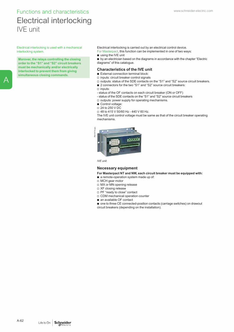
Functions and characteristics
Electrical interlocking is used with a mechanical interlocking system.
Morover, the relays controlling the closing order to the “S1” and “S2” circuit breakers must be mechanically and/or electrically interlocked to prevent them from giving simultaneous closing commands.
Electrical interlocking is carried out by an electrical control device.For Masterpact, this function can be implemented in one of two ways:
b using the IVE unit b by an electrician based on the diagrams in accordance with the chapter “Electric
diagrams” of this catalogue.
Characteristics of the IVE unit b External connection terminal block: v inputs: circuit breaker control signals v outputs: status of the SDE contacts on the “S1” and “S2” source circuit breakers. b 2 connectors for the two “S1” and “S2” source circuit breakers: v inputs:
- status of the OF contacts on each circuit breaker (ON or OFF) - status of the SDE contacts on the “S1” and “S2” source circuit breakers
v outputs: power supply for operating mechanisms. b Control voltage: v 24 to 250 V DC v 48 to 415 V 50/60 Hz - 440 V 60 Hz.
The IVE unit control voltage must be same as that of the circuit breaker operating mechanisms.
PB11
9174
.eps
IVE unit.
Necessary equipmentFor Masterpact NT and NW, each circuit breaker must be equipped with:
b a remote-operation system made up of: v MCH gear motor v MX or MN opening release v XF closing release v PF “ready to close” contact v CDM mechanical operation counter b an available OF contact b one to three CE connected-position contacts (carriage switches) on drawout
circuit breakers (depending on the installation).
Electrical interlockingIVE unit
www.schneider-electric.com
A-62
A

Controller selection
By combining a remote-operated source-changeover system with an integrated BA or UA automatic controller, it is possible to automatically control source transfer according to user-selected sequences.These controllers can be used on source-changeover systems comprising 2 circuit breakers.For source-changeover systems comprising 3 circuit breakers, the automatic control diagram must be prepared by the installer as a complement to to diagrams provided in the “electrical diagrams” section of this catalogue.
Controller BA UACompatible circuit breakers All Masterpact circuit
breakers4-position switch
Automatic operation b b Forced operation on “Normal” source b b Forced operation on “Replacement” source b b Stop (both “Normal” and “Replacement” sources off) b b Automatic operation
Monitoring of the “Normal” source and automatic transfer b b Generator set startup control b Delayed shutdown (adjustable) of generator set b Load shedding and reconnection of non-priority circuits b Transfer to the “Replacement” source if one of the phases of the “Normal” phase is absent
b
DB4
0380
9.ep
s
TestBy opening the P25M circuit breaker supplying the controller b By pressing the test button on the front of the controller b Indications
Circuit breaker status indication on the front of the controller: on, off, fault trip
b b
Automatic mode indicating contact b b Other functions
Selection of type of “Normal” source (single-phase or three-phase) (1) b Voluntary transfer to “Replacement” source (e.g. energy management commands)
b b
During peak-tariff periods (energy management commands) forced operation on “Normal” source if “Replacement” source not operational
b
Additional contact (not part of controller). Transfer to “Replacement” source only if contact is closed. (e.g. used to test the frequency of UR).
b b
BA controller. Setting of maximum startup time for the replacement source b Options
DB4
0381
0.ep
s Communication optionPower supply
Control voltages (2) 110 V b b 220 to 240 V 50/60 Hz b b 380 to 415 V 50/60 Hz and 440 V 60 Hz
b b
Operating thresholdsUndervoltage 0.35 Un y voltage y 0.7 Un b b Phase failure 0.5 Un y voltage y 0.7 Un b Voltage presence voltage u 0.85 Un b b IP degree of protection (EN 60529) and IK degree of protection against external mechanical impacts (EN 50102)
Front IP40 b b Side IP30 b b Connectors IP20 b b
UA controller. Front IK07 b b Characteristics of output contacts (dry, volt-free contacts)
Rated thermal current (A) 8Minimum load 10 mA at 12 VOutput contacts:Position of the Auto/Stop switch b b Load shedding and reconnection order b Generator set start order b
AC DCUtilisation category (IEC 947-5-1) AC12 AC13 AC14 AC15 DC12 DC13Operational current (A) 24 V 8 7 5 5 8 2
48 V 8 7 5 5 2 -110 V 8 6 4 4 0.6 -220/240 V 8 6 4 3 - -250 V - - - - 0.4 -380/415 V 5 - - - - -440 V 4 - - - - -660/690 V - - - - - -
(1) For example, 220 V single-phase or 220 V three-phase.(2) The controller is powered by the ACP control plate. The same voltage must be used for the ACP plate, the IVE unit and the circuit-breaker operating mechanisms. If this voltage is the same as the source voltage, then the “Normal” and “Replacement” sources can be used directly for the power supply. If not, an isolation transformer must be used.
www.schneider-electric.com
A-63
A

Masterpact NT and NW Types of mechanical interlocking Possible combinations Typical electrical diagrams Diagram no.2 devices
Db1
0157
4.ep
s QN QR Masterpact NT and NW:0 0 b electrical interlocking with lockout after fault:1 0 v permanent replacement source (with IVE) 512011420 1 v with EPO by MX (with IVE) 51201143
v with wEPO by MN (with IVE) 51201144 b automatic control without lockout after fault: b automatic control with lockout after fault: v permanent replacement source (with IVE) 51156904 v engine generator set (with IVE) 51156905 b BA/UA controller (with IVE) 51156903
Masterpact NW onlyTypes of mechanical interlocking Possible combinations Typical electrical diagrams Diagram no.3 devices: 2 “Normal” sources and 1 “Replacement” source
Db1
0157
5.ep
s QN1 QN2 QR b electrical interlocking:0 0 0 v without lockout after fault 511569061 1 0 v with lockout after fault 511569070 0 1
3 devices: 2 “Normal” sources and 1 “Replacement” source with source selection
Db1
0157
6.ep
s QN1 QN2 QR b automatic control with engine generator set:0 0 0 v without lockout after fault (with MN) 511569081 0 0 v with lockout after fault (with MN) 511569090 0 11 1 00 1 0
3 devices: 3 sources, only one device
Db1
0157
7.ep
s QS1 QS2 QS3 b electrical interlocking:0 0 0 v without lockout after fault 511569101 0 0 v with lockout after fault 511569110 1 00 0 1
3 devices: 2 sources + 1 coupling
Db1
0157
8.ep
s QS1 QC QS2 b electrical interlocking:0 0 0 v without lockout after fault 511569121 0 1 v with lockout after fault 511569131 1 0 b automatic control with lockout after fault 511569140 1 11 0 0 (1)
0 0 1 (1)
(1) possible by forcing operation
“Lockout after fault” option. This option makes it necessary to manually reset the device following fault tripping.
Standard configurationFunctions and characteristics www.schneider-electric.com
A-64
A

PB10
6363
A50.
eps Masterpact NW circuit breakers with corrosion protection are designed for use in
industrial environments with high concentrations of sulphur compounds. Examples include paper mills, oil refineries, steel works and water treatment plants, all of which produce large quantities of sulphur dioxide (SO2) or hydrogen sulphate (H2S).Under such conditions, silver-plated parts rapidly turn black due to the formation of silver sulphate (AgS) on the surface, an insulating material that can lead to abnormal temperature rise in electrical contacts. This phenomenon can have serious consequences on all equipment installed inside a switchboard.Circuit breakers used in such environments generally require frequent maintenance and therefore a large number of replacement devices on the site. Furthermore, problems are often encountered even with intensive maintenance.Masterpact NW circuit breakers with corrosion protection receive special surface treatment on all parts exposed to corrosion and critical with respect to electrical continuity. In this way, the availability of electrical power and operating safety are ensured without special maintenance for the following environmental condition classes as defined by standard IEC 721-3-3:
b 3C3 for H2S (concentrations from 2.1 to 7.1 x 10⁻⁶ ) b 3C4 for SO2 (concentrations from 4.8 to 14.8 x 10⁻⁶).
The Masterpact NW range of power circuit breakers with corrosion protection offers the following features:
b rated current from 800 A to 4000 A b 3 and 4-pole models b drawout circuit breaker b operational voltage up to 690 V AC b Ics breaking capacity of 100 kA at 220/415 V AC b reverse feed possible b stored-energy mechanism for instantaneous closing (source coupling). b 3 types of RMS electronic protection b adjustable long-time settings from 0.4 to 1 In, with fine adjustment via local keypad
or remote supervisor b electronic functions dedicated to energy management and power-quality analysis.
The Masterpact NW range complies with the main standards and certifications
b IEC 60947-1 and 60947-2 b IEC 68230 (damp heat) and IEC 68252 severity level 2 (salt mist) b IEC 60068-2-42 and IEC 60068-2-43 for corrosive environments: v SO2 : tested to IEC 60068-2-42 in a 3C4 environment as defined by
IEC 60721-3-3 v H2S: tested to IEC 60068-2-43 in a 3C3 environment as defined IEC 60721-3-3.
A complete range of electrical accessories and auxiliaries
b Motor mechanism (MCH). b Undervoltage release (MN, MNR). b Shunt trip unit (MX). b Closing release (XF). b Auxiliary contacts (OF). b Low-level indication contacts (SDE, PF, CD, CT, CE and EF). b Electrical closing button (BPFE). b Locking by padlocks and/or keylocks. b Source-changeover systems for 2 or 3 devices.
Maximum safetyThe Masterpact NW range with corrosion protection offers the same safety features as the standard version:
b positive contact indication b high impulse withstand voltage (12 kV) b suitable for isolation in compliance with IEC 60947-2, as indicated
by the disconnector symbol on the front face: b front face insulation class 2, allowing class 2 installations with breaker control
from outside.
Masterpact NW with corrosion protection 800-4000 AFunctions and characteristics www.schneider-electric.com
A-65
A

Functions and characteristics
Characteristics according to IEC 60 947-2NW08H2 NW10H2 NW12H2 NW16H2 NW20H2 NW25H2 NW32H2 NW40bH2
Number of poles 3, 4Rated insulation voltage Ui (V) 1000Rated operational voltage Ue (V) 690Closing time (ms) < 50Rated current In (A) Vertical connection 40 °C 800 1000 1250 1600 2000 2500 3200 4000
45 °C 800 1000 1250 1600 2000 2500 3200 400050 °C 800 1000 1250 1600 2000 2500 3200 400055 °C 800 1000 1250 1550 1900 2500 3150 400060 °C 800 1000 1250 1500 1800 2500 3000 4000
Horizontal connection 40 °C 800 1000 1250 1600 2000 2500 - 400045 °C 800 1000 1250 1550 1900 2500 - 400050 °C 800 1000 1250 1500 1800 2500 - 400055 °C 800 1000 1250 1450 1700 2400 - 400060 °C 800 1000 1250 1400 1600 2300 - 3900
4th pole rating 800 1000 1250 1600 2000 2500 3200 4000Rated utlimate breaking capacity
Icu (kA rms)CA 50/60 Hz 220/440 V 100 100 100 100 100 100 100 150690 V 85 85 85 85 85 85 85 100
Rated service breaking capacity
Ics = lcu x... 100 % 100 % 100 % 100 % 100 % 100 % 100 % 100 %
Break time (ms) Total maxi 25 to 30 with no intentional delay
Dimensions and connection
PL
H
DB1
2495
1.ep
s
P L
H
DB1
2495
2.ep
s
Masterpact NW08 to NW32 with corrosion protection. Masterpact NW40b with corrosion protection.
Drawout device L (mm) H (mm) P (mm)3P 4P
800 to 3200 A 441 556 439 3954000 A 786 1016 479 395
Connections b Power circuits: v vertical rear connections as standard v possibility of conversion to horizontal rear connections on-site by rotating
the connectors, except for NW32, available with vertical rear connections only. b Auxiliaries connected to terminal block on circuit breaker front face.
Masterpact NW with corrosion protection 800-4000 Awww.schneider-electric.com
A-66
A

The Masterpact Earthing Switch can be racked into any compatible Masterpact NW chassis in place of a Masterpact circuit breaker. It is used to interconnect and earth the phase and neutral conductors of an electrical installation to ensure the safety of personnel during servicing. It can be locked in earthed position.
Main characteristicsRated insulation voltageRated operational voltageRated currentLatching capacityRated short-time withstand current
1000 V690 V800 to 4000 A135 kA peak60 kA/1s50 kA/3s
Compatibility Compatible with drawout NW08 to NW40 circuit breakers, types N1/H1/NA/HA, 3-pole and 4-pole rear connected versions
Remote indication 12 ON/OFF indication contacts that can be used according to the chassis auxiliary wiring
PB10
4426
A50.
eps
The Earthing Switch is compatible with Masterpact NW08 to NW40 type N1, H1, NA and HA circuit breakers in both 3-pole and 4-pole versions. It has two parts:
b a chassis earthing kit for installation on the Masterpact NW chassis. Two different versions are available for 3-pole and 4-pole chassis.
b the Earthing Switch itself, which is a specific Masterpact NW device that can be racked into any chassis equipped with an earthing kit, in place of the circuit breaker. Two versions are available (3-pole and 4-pole). An earthing kit must be installed on the chassis of each circuit breaker protecting a circuit that may require earthing while work is being carried out. However, a single earthing switch is often sufficient for an entire installation if only one circuit is to be serviced at any given time. The standard Earthing Switch comes with the short-circuit bar installed across the bottom (downstream) connections for earthing of the upstream portion of the circuit. The user can easily move the short-circuit bar to the top connections if the downstream portion of the circuit needs to be earthed.Earthing kit(for chassis)
Earthing switch(front view)
DB1
2555
7.ep
s
DB1
2555
8.ep
s
Earthing switch (rear view)
DB1
2555
9.ep
s
DB1
2556
0.ep
s
With short-circuit bar on the bottom connections. With short-circuit bar on the top connections.
DB1
2556
1.ep
s Locking in earthed position by 3 padlocks The standard Earthing Switch can be locked in earthed position by one to three padlocks as long as the following conditions are satisfied:
b the Earthing Switch must be in "connected" position in a chassis equipped with an earthing kit
b the Earthing Switch must be in “ON” position.Under these conditions, the installation is earthed. When the Earthing Switch is locked in earthed position:
b it cannot be moved to "disconnected" position (a shutter prevents insertion of the racking handle)
b it cannot be turned "OFF" (a shutter prevents access to the "OFF" pushbutton).
Earthing switch Masterpactwww.schneider-electric.com
A-67
A

Earthing switch MasterpactFunctions and characteristics
Typical applications The earthing switch is used to protect maintenance personnel working on an installation against the risk of accidental connection of a parallel source or energisation by reverse power. Protection is provided by earthing the part of the installation that is to be worked on.
Application n°1 Earthing of one section of a coupled busbar arrangement
DB1
2086
5.EP
S When working on section B, the bus coupler is normally open. To protect personnel in the event of accidental closing of this device, an earthing switch with the upstream terminals earthed is installed in place of the circuit breaker at B. In this way section B will remain at earth potential under all circumstances and the personnel can work in complete safety.
Application n°2 Earthing an outgoer
DB1
2086
6.EP
S When working on outgoer C, installation of an earthing switch with the upstream terminals earthed (in place of the circuit breaker at C) ensures complete safety even if all the other devices on the installation are closed.
Application n°3 Earthing of an MV/LV transformer
DB1
2086
7.EP
S When working on an MV/LV transformer, upstream earthing is carried out by means of the usual medium voltage and high voltage procedures. Installation of an earthing switch with the downstream terminals earthed (in place of the circuit breaker at B) maintains the part of the installation between the upstream MV circuit breaker and the downstream LV circuit breaker at earth potential. In this way, the personnel can work in complete safety even if the rest of the installation is energised.
www.schneider-electric.com
A-68
A
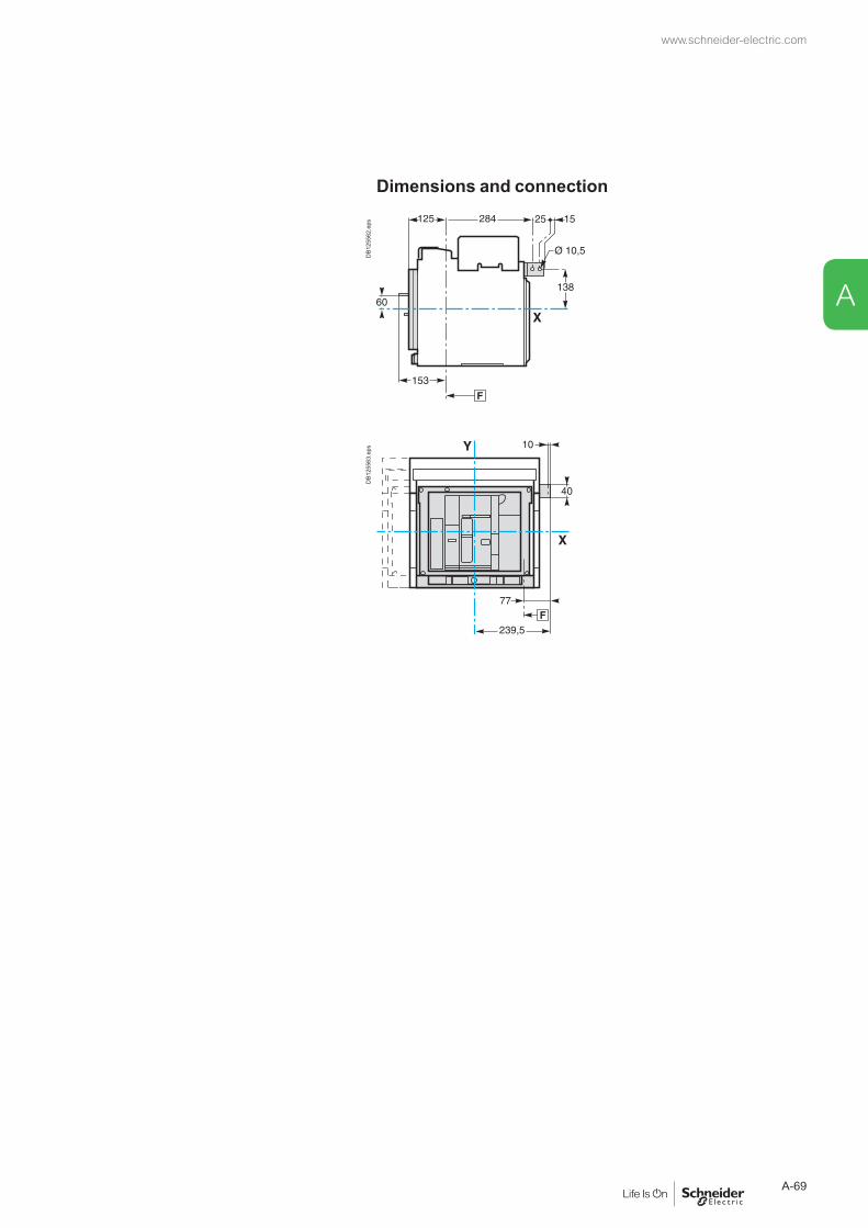
Dimensions and connection
DB1
2556
2.ep
sD
B125
563.
eps
www.schneider-electric.com
A-69
A
Masterpact NT and NW
Installation recommendations
Presentation 2Functions and characteristics A-1
Operating conditions B-2
Installation in switchboard B-4
Door interlock catch B-6
Power connection B-8
Recommended busbars drillingMasterpact NT06 to NT16 B-10Masterpact NW08 to NW63 B-11
Busbar sizing B-12
Temperature derating Power dissipation and input / output resistance B-14
Derating in switchboards B-15
Substitution kitFixed / drawout devices 800 to 3200 A B-22
Control wiring B-23
Masterpact M Retrofit B-24Dimensions and connections C-1Electrical diagrams D-1Additional characteristics E-1Catalogue numbers and order form F-1
www.schneider-electric.com
B-1
B

Installation recommendations
Masterpact circuit breakers have been tested for operation in industrial atmospheres. It is recommended that the equipment be cooled or heated to the proper operating temperature and kept free of excessive vibration and dust.
DB4
0205
1.ep
s Ambient temperatureMasterpact devices can operate under the following temperature conditions:
b the electrical and mechanical characteristics are stipulated for an ambient temperature of -25 °C to +70 °C
b circuit breaker closing is guaranteed down to -35 °C by manual operation (push button).Storage conditions are as follows:
b -40 to +85 °C for a Masterpact device without its control unit b -25 °C to +85 °C for the control unit.
DB4
0205
2.ep
s Extreme atmospheric conditionsMasterpact devices have successfully passed the tests defined by the following standards for extreme atmospheric conditions:
b IEC 60068-2-1: dry cold at -40 °C b IEC 60068-2-2: dry heat at +85 °C b IEC 60068-2-30: damp heat (temperature +55 °C, relative humidity 95 %) b IEC 60068-2-52 level 2: salt mist.
Masterpact devices can operate in the industrial environments defined by standard IEC 60947 (pollution degree up to 4).It is nonetheless advised to check that the devices are installed in suitably cooled switchboards without excessive dust.
DB1
2816
3.ep
s VibrationsMasterpact devices have successfully passed testing in compliance with IEC 60068-2-6 for the following vibration levels:
b 2 to 13.2 Hz: amplitude ±1 mm b 13.2 to 100 Hz: constant acceleration 0.7 g.
Vibration testing to these levels is required by merchant marine inspection organisations (Veritas, Lloyd’s, etc).
Some applications have vibration profiles outside of this standard and require special attention during application design, installation, and use. Excessive vibration may cause unexpected tripping, damage to connections or to other mechanical parts. Please refer to the Masterpact maintenance guide (causes of accelerated ageing / operating conditions / vibrations) for additional information.Examples of applications with high vibration profiles could include:
b wind turbines b power frequency converters that are installed in the same switchboard or close
proximity to the Masterpact circuit breaker b emergency generators b high vibration marine applications such as thrusters, anchor positioning systems,
etc.
Operating conditionswww.schneider-electric.com
B-2
B

2000(m)
DB1
2816
2.ep
s Altitude At altitudes higher than 2000 metres, the modifications in the ambient air (electrical resistance, cooling capacity) lower the following characteristics as follows:
Altitude (m) 2000 3000 4000 5000Impulse withstand voltage Uimp (kV) 12 11 10 8Rated insulation voltage (Ui) 1000 900 780 700Maximum rated operationnal voltage 50/60 Hz Ue (V)
NT, NW except H10 690 690 630 560NW H10 1000 890 795 700
Rated current 40 °C 1 x In 0.99 x In 0.96 x In 0.94 x InNote: intermediate values may be obtained by interpolation.
DB1
2816
4.ep
s Electromagnetic disturbancesMasterpact devices are protected against:
b overvoltages caused by devices that generate electromagnetic disturbances b overvoltages caused by atmospheric disturbances or by a distribution-system
outage (e.g. failure of a lighting system) b devices emitting radio waves (radios, walkie-talkies, radar, etc.) b electrostatic discharges produced by users.
Masterpact devices have successfully passed the electromagnetic-compatibility tests (EMC) defined by the following international standards:
b IEC 60947-2, appendix F b IEC 60947-2, appendix B (trip units with earth-leakage function).
The above tests guarantee that: b no nuisance tripping occurs b tripping times are respected.
www.schneider-electric.com
B-3
B

Installation recommendations
Possible positions
DB1
0142
7.ep
s
Db1
0142
8.ep
s
Db1
0142
9.ep
s
Power supplyMasterpact devices can be supplied either from the top or from the bottom without reduction in performance, in order to facilitate connection when installed in a switchboard.
DB1
0143
0.ep
s
Mounting the circuit breakerIt is important to distribute the weight of the device uniformily over a rigid mounting surface such as rails or a base plate.This mounting plane should be perfectly flat (tolerance on support flatness: 2 mm). This eliminates any risk of deformation which could interfere with correct operation of the circuit breaker.Masterpact devices can also be mounted on a vertical plane using the special brackets.
Db1
0143
1.ep
s
DB1
0143
2.ep
s
Mounting on rails.
Db1
0143
3.ep
s
Mounting with vertical brackets.
Installation in switchboardwww.schneider-electric.com
B-4
B
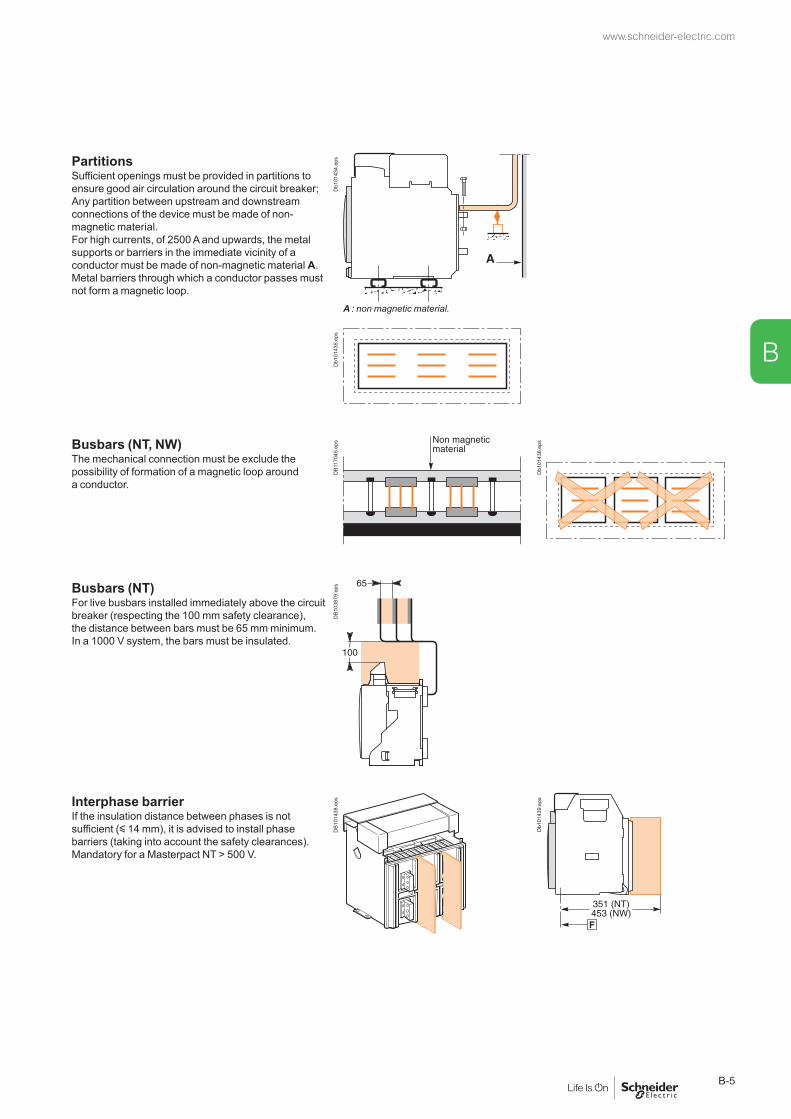
PartitionsSufficient openings must be provided in partitions to ensure good air circulation around the circuit breaker; Any partition between upstream and downstream connections of the device must be made of non-magnetic material.For high currents, of 2500 A and upwards, the metal supports or barriers in the immediate vicinity of a conductor must be made of non-magnetic material A.Metal barriers through which a conductor passes must not form a magnetic loop.
Db1
0143
4.ep
s
A : non magnetic material.
Db1
0143
5.ep
s
Busbars (NT, NW)The mechanical connection must be exclude the possibility of formation of a magnetic loop around a conductor.
DB1
1704
5.ep
s
Db1
0143
6.ep
s
Busbars (NT)For live busbars installed immediately above the circuit breaker (respecting the 100 mm safety clearance), the distance between bars must be 65 mm minimum. In a 1000 V system, the bars must be insulated.
DB1
0387
9.ep
s
Interphase barrierIf the insulation distance between phases is not sufficient (y 14 mm), it is advised to install phase barriers (taking into account the safety clearances).Mandatory for a Masterpact NT > 500 V.
DB1
0143
8.ep
s
Db1
0143
9.ep
s
www.schneider-electric.com
B-5
B
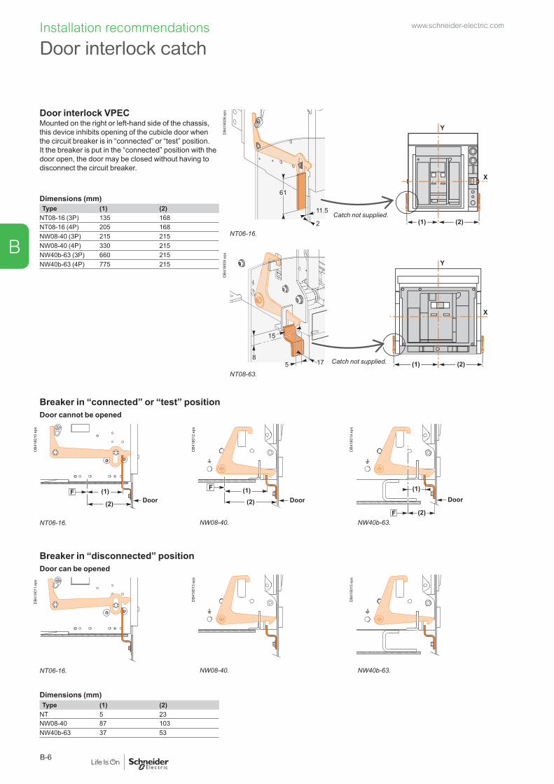
Installation recommendations
Door interlock VPECMounted on the right or left-hand side of the chassis, this device inhibits opening of the cubicle door when the circuit breaker is in “connected” or “test” position. It the breaker is put in the “connected” position with the door open, the door may be closed without having to disconnect the circuit breaker.
X
Y
2
11.5
61
(1) (2)D
B418
008.
eps
Catch not supplied.
Dimensions (mm)Type (1) (2)
NT08-16 (3P) 135 168NT08-16 (4P) 205 168NW08-40 (3P) 215 215NW08-40 (4P) 330 215NW40b-63 (3P) 660 215NW40b-63 (4P) 775 215
NT06-16.
17 (1) (2)
X
Y
58
15
DB4
1800
9.ep
s
Catch not supplied.
NT08-63.
Breaker in “connected” or “test” positionDoor cannot be opened
DoorF (1)
(2)
DB4
1801
0.ep
s
F (1)Door(2)
DB4
1801
2.ep
s
F
(1)
(2)
Door
DB4
1801
4.ep
s
NT06-16. NW08-40. NW40b-63.
Breaker in “disconnected” positionDoor can be opened
DB4
1801
1.ep
s
DB4
1801
3.ep
s
DB4
1801
5.ep
s
NT06-16. NW08-40. NW40b-63.
Dimensions (mm)Type (1) (2)
NT 5 23NW08-40 87 103NW40b-63 37 53
Door interlock catchwww.schneider-electric.com
B-6
B

Cable-type door interlock IPAThis option prevents door opening when the circuit breaker is closed and prevents circuit breaker closing when the door is open.For this, a special plate associated with a lock and a cable is mounted on the right side of the circuit breaker.With this interlock installed, the source changeover function cannot be implemented.
Db1
0144
5.ep
s
Db1
0144
6.ep
s
Note: the door interlock can either be mounted on the right side or the left side of the breaker.
: datum.
Db1
0144
7.ep
s
www.schneider-electric.com
B-7
B

Installation recommendations
Cables connectionsIf cables are used for the power connections, make sure that they do not apply excessive mechanical forces to the circuit breaker terminals.For this, make the connections as follows:
b extend the circuit breaker terminals using short bars designed and installed according to the recommendations for bar-type power connections:
v for a single cable, use solution B opposite v for multiple cables, use solution C opposite b in all cases, follow the general rules for connections
to busbars: v position the cable lugs before inserting the bolts v the cables should firmly secured to the framework E.
Db1
0144
8.ep
s
Db1
0144
9.ep
s
Db1
0145
0.ep
s
Busbars connectionsThe busbars should be suitably adjusted to ensure that the connection points are positioned on the terminals before the bolts are inserted B.The connections are held by the support which is solidly fixed to the framework of the switchboard, such that the circuit breaker terminals do not have to support its weight C (this support should be placed close to the terminals).
Db1
0145
1.ep
s
Db1
0145
2.ep
s
Db1
0145
3.ep
s
Electrodynamic stressesThe first busbar support or spacer shall be situated within a maximum distance from the connection point of the breaker (see table below). This distance must be respected so that the connection can withstand the electrodynamic stresses between phases in the event of a short circuit.Maximum distance A between busbar to circuit breaker connection and the first busbarsupport or spacer with respect to the value of the prospective short-circuit current.
Isc (kA) 30 50 65 80 100 150Distance A (mm) 350 300 250 150 150 150
Power connectionwww.schneider-electric.com
B-8
B
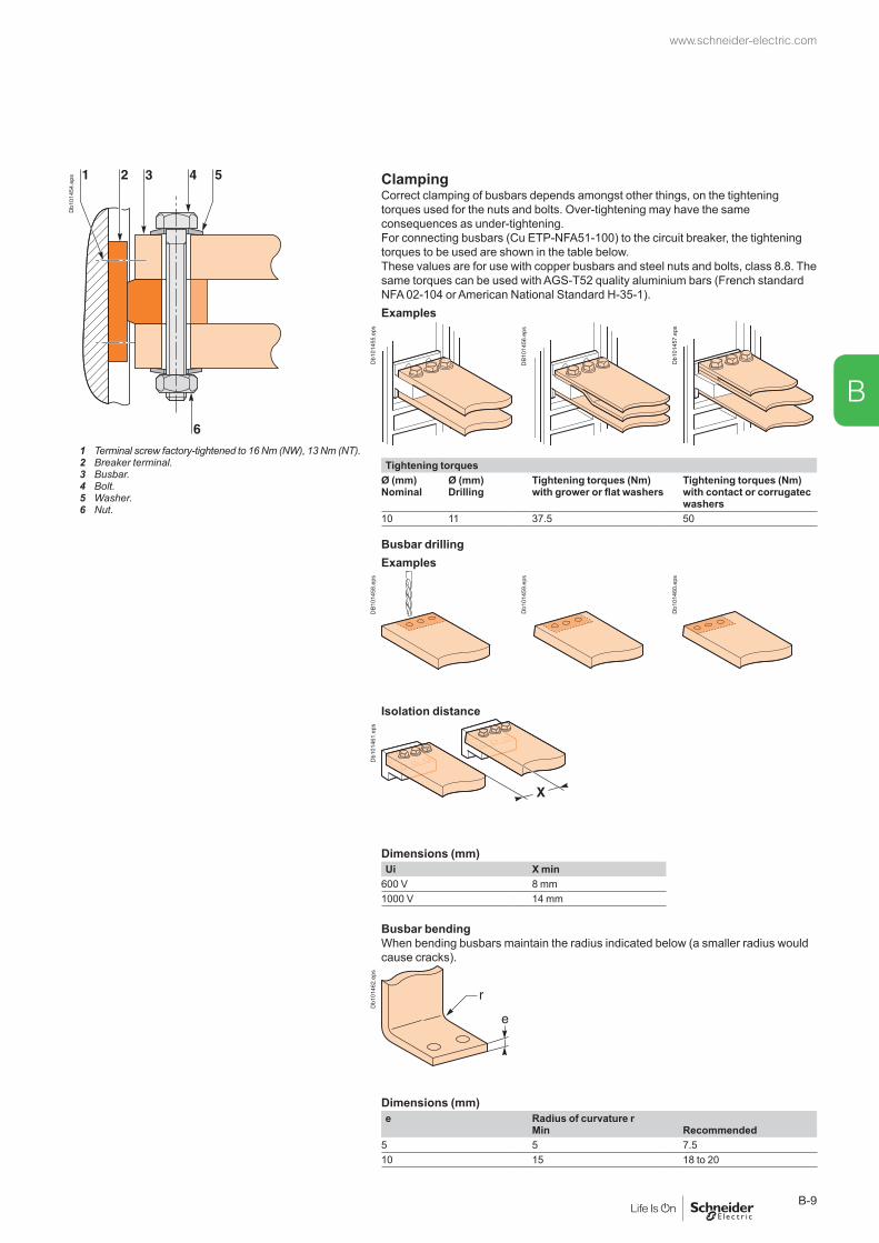
Db1
0145
4.ep
s ClampingCorrect clamping of busbars depends amongst other things, on the tightening torques used for the nuts and bolts. Over-tightening may have the same consequences as under-tightening.For connecting busbars (Cu ETP-NFA51-100) to the circuit breaker, the tightening torques to be used are shown in the table below.These values are for use with copper busbars and steel nuts and bolts, class 8.8. The same torques can be used with AGS-T52 quality aluminium bars (French standard NFA 02-104 or American National Standard H-35-1).Examples
Db1
0145
5.ep
s
DB1
0145
6.ep
s
Db1
0145
7.ep
s
1 Terminal screw factory-tightened to 16 Nm (NW), 13 Nm (NT).2 Breaker terminal.3 Busbar.4 Bolt.5 Washer.6 Nut.
Tightening torquesØ (mm) Ø (mm)Nominal Drilling
Tightening torques (Nm)with grower or flat washers
Tightening torques (Nm)with contact or corrugatec washers
10 11 37.5 50
Busbar drillingExamples
DB1
0145
8.ep
s
Db1
0145
9.ep
s
Db1
0146
0.ep
s
Isolation distance
Db1
0146
1.ep
s
Dimensions (mm)Ui X min
600 V 8 mm1000 V 14 mm
Busbar bendingWhen bending busbars maintain the radius indicated below (a smaller radius would cause cracks).
Db1
0146
2.ep
s
Dimensions (mm)e Radius of curvature r
Min Recommended5 5 7.510 15 18 to 20
www.schneider-electric.com
B-9
B

Installation recommendations
Rear connection Rear connection with spreaders
DB1
0146
3.ep
s
DB1
0146
3.ep
s
DB1
0146
4.ep
s
Db1
0146
5.ep
s
Middle left or middle right spreader for 4P
Middle spreader for 3P Left or right spreader for 4P
Left or right spreader for 3P
Db1
0146
6.ep
s
Db1
0146
7.ep
s
Db1
0148
0.ep
s
Db1
0146
8.ep
s
Db1
0146
9.ep
s
Vertical rear connection
Db1
0147
0.ep
sD
b101
471.
eps
Front connection Front connection via vertical connection adapters
DB1
0146
3.ep
s
DB1
0146
3.ep
s
DB1
0146
4.ep
s
Db1
0146
5.ep
s
Top connection Bottom connection
Db1
0148
1.ep
s
Db1
0148
2.ep
s
Db1
0148
3.ep
s
Recommended busbars drilling Masterpact NT06 to NT16
www.schneider-electric.com
B-10
B

Horizontal rear connection NW08 to NW32 NW40b to NW50
DB1
0146
3.ep
s
DB1
0146
4.ep
s
Db1
0146
5.ep
s
Db1
0147
2.ep
s
Db1
0147
3.ep
s
Db1
0147
4.ep
s
Db1
0147
5.ep
s
Vertical rear connection NW08 to NW32, NW40b to NW50
Db1
0147
6.ep
sD
b101
477.
eps
Front connection NW08 to NW32
DB1
0146
3.ep
s
DB1
0146
4.ep
s
Db1
0146
5.ep
s
Top connection Bottom connection
Db1
0147
8.ep
s
Db1
0147
9.ep
s
Masterpact NW08 to NW63
www.schneider-electric.com
B-11
B
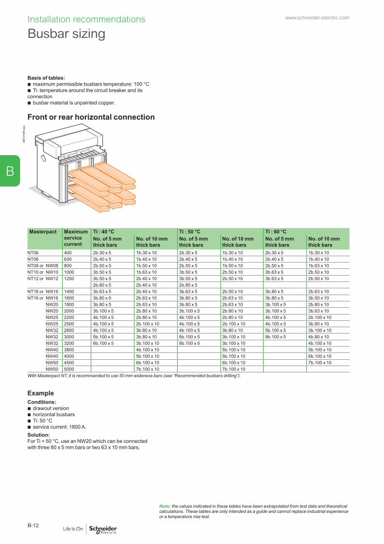
Installation recommendations
Basis of tables: b maximum permissible busbars temperature: 100 °C b Ti: temperature around the circuit breaker and its
connection b busbar material is unpainted copper.
Front or rear horizontal connection
DB1
0148
4.ep
s
Masterpact Maximum service current
Ti : 40 °C Ti : 50 °C Ti : 60 °CNo. of 5 mm thick bars
No. of 10 mm thick bars
No. of 5 mm thick bars
No. of 10 mm thick bars
No. of 5 mm thick bars
No. of 10 mm thick bars
NT06 400 2b.30 x 5 1b.30 x 10 2b.30 x 5 1b.30 x 10 2b.30 x 5 1b.30 x 10NT06 630 2b.40 x 5 1b.40 x 10 2b.40 x 5 1b.40 x 10 2b.40 x 5 1b.40 x 10NT08 or NW08 800 2b.50 x 5 1b.50 x 10 2b.50 x 5 1b.50 x 10 2b.50 x 5 1b.63 x 10NT10 or NW10 1000 3b.50 x 5 1b.63 x 10 3b.50 x 5 2b.50 x 10 3b.63 x 5 2b.50 x 10NT12 or NW12 1250 3b.50 x 5 2b.40 x 10 3b.50 x 5 2b.50 x 10 3b.63 x 5 2b.50 x 10
2b.80 x 5 2b.40 x 10 2b.80 x 5NT16 or NW16 1400 3b.63 x 5 2b.40 x 10 3b.63 x 5 2b.50 x 10 3b.80 x 5 2b.63 x 10NT16 or NW16 1600 3b.80 x 5 2b.63 x 10 3b.80 x 5 2b.63 x 10 3b.80 x 5 3b.50 x 10
NW20 1800 3b.80 x 5 2b.63 x 10 3b.80 x 5 2b.63 x 10 3b.100 x 5 2b.80 x 10NW20 2000 3b.100 x 5 2b.80 x 10 3b.100 x 5 2b.80 x 10 3b.100 x 5 3b.63 x 10NW25 2200 4b.100 x 5 2b.80 x 10 4b.100 x 5 2b.80 x 10 4b.100 x 5 2b.100 x 10NW25 2500 4b.100 x 5 2b.100 x 10 4b.100 x 5 2b.100 x 10 4b.100 x 5 3b.80 x 10NW32 2800 4b.100 x 5 3b.80 x 10 4b.100 x 5 3b.80 x 10 5b.100 x 5 3b.100 x 10NW32 3000 5b.100 x 5 3b.80 x 10 6b.100 x 5 3b.100 x 10 8b.100 x 5 4b.80 x 10NW32 3200 6b.100 x 5 3b.100 x 10 8b.100 x 5 3b.100 x 10 4b.100 x 10NW40 3800 4b.100 x 10 5b.100 x 10 5b.100 x 10NW40 4000 5b.100 x 10 5b.100 x 10 6b.100 x 10NW50 4500 6b.100 x 10 6b.100 x 10 7b.100 x 10NW50 5000 7b.100 x 10 7b.100 x 10
With Masterpact NT, it is recommanded to use 50 mm wideness bars (see “Recommended busbars drilling”).
ExampleConditions:
b drawout version b horizontal busbars b Ti: 50 °C b service current: 1800 A.
Solution:For Ti = 50 °C, use an NW20 which can be connected with three 80 x 5 mm bars or two 63 x 10 mm bars.
Note: the values indicated in these tables have been extrapolated from test data and theoretical calculations. These tables are only intended as a guide and cannot replace industrial experience or a temperature rise test.
Busbar sizingwww.schneider-electric.com
B-12
B

Basis of tables: b maximum permissible busbars temperature: 100 °C b Ti: temperature around the circuit breaker and its
connection b busbar material is unpainted copper.
Rear vertical connection
Db1
0148
7.ep
s
Masterpact Maximum service current
Ti : 40 °C Ti : 50 °C Ti : 60 °CNo. of 5 mm thick bars
No. of 10 mm thick bars
No. of 5 mm thick bars
No. of 10 mm thick bars
No. of 5 mm thick bars
No. of 10 mm thick bars
NT06 400 2b.30 x 5 1b.30 x 10 2b.30 x 5 1b.30 x 10 2b.30 x 5 1b.30 x 10NT06 630 2b.40 x 5 1b.40 x 10 2b.40 x 5 1b.40 x 10 2b.40 x 5 1b.40 x 10NT08 or NW08 800 2b.50 x 5 1b.50 x 10 2b.50 x 5 1b.50 x 10 2b.50 x 5 1b.50 x 10NT10 or NW10 1000 2b.50 x 5 1b.50 x 10 2b.50 x 5 1b.50 x 10 2b.63 x 5 1b.63 x 10NT12 or NW12 1250 2b.63 x 5 1b.63 x 10 3b.50 x 5 2b.40 x 10 3b.50 x 5 2b.40 x 10NT16 or NW16 1400 2b.80 x 5 1b.80 x 10 2b.80 x 5 2b.50 x 10 3b.63 x 5 2b.50 x 10NT16 or NW16 1600 3b.63 x 5 2b.50 x 10 3b.63 x 5 2b.50 x 10 3b.80 x 5 2b.63 x 10
NW20 1800 2b.100 x 5 1b.80 x 10 2b.100 x 5 2b.50 x 10 3b.80 x 5 2b.63 x 10NW20 2000 3b.100 x 5 2b.63 x 10 3b.100 x 5 2b.63 x 10 3b.100 x 5 2b.80 x 10NW25 2200 3b.100 x 5 2b.63 x 10 3b.100 x 5 2b.63 x 10 3b.100 x 5 2b.80 x 10NW25 2500 4b.100 x 5 2b.80 x 10 4b.100 x 5 2b.80 x 10 4b.100 x 5 3b.80 x 10NW32 2800 4b.100 x 5 2b.100 x 10 4b.100 x 5 2b.100 x 10 4b.100 x 5 3b.80 x 10NW32 3000 5b.100 x 5 3b.80 x 10 6b.100 x 5 3b.100 x 10 5b.100 x 5 4b.80 x 10NW32 3200 6b.100 x 5 3b.100 x 10 6b.100 x 5 3b.100 x 10 4b.100 x 10NW40 3800 4b.100 x 10 4b.100 x 10 4b.100 x 10NW40 4000 4b.100 x 10 4b.100 x 10 4b.100 x 10NW50 4500 5b.100 x 10 5b.100 x 10 6b.100 x 10NW50 5000 5b.100 x 10 6b.100 x 10 7b.100 x 10NW63 5700 7b.100 x 10 7b.100 x 10 8b.100 x 10NW63 6300 8b.100 x 10 8b.100 x 10
ExampleConditions:
b drawout version b vertical connections b Ti: 40 °C b service current: 1100 A.
Solution :For Ti = 40 °C use an NT12 or NW12 which can be connected with two 63 x 5 mm bars or with one 63 x 10 mm bar.
Note: the values indicated in these tables have been extrapolated from test data and theoretical calculations. These tables are only intended as a guide and cannot replace industrial experience or a temperature rise test.
www.schneider-electric.com
B-13
B

Installation recommendations
Temperature deratingThe table below indicates the maximum current rating, for each connection type, as a function of Ti around the circuit breaker and the busbars. Circuit breakers with mixed connections have the same derating as horizontally connected breakers.For Ti greater than 60 °C, consult us.Ti: temperature around the circuit breaker and its connection.Version DrawoutConnection Front or rear horizontal Rear verticalTemp. Ti 40 45 50 55 60 65 70 40 45 50 55 60 65 70
NT06 H1/H2/L1 630 630NT08 H1/H2/L1 800 800NT10 H1/H2/L1 1000 1000NT12 H1/H2 1250 1200 1140 1250NT16 H1/H2 1600 1560 1520 1480 1440 1400 1360 1600 1560 1520 1480 1440
NW08 N/H/L 800 800NW10 N/H/L 1000 1000NW12 N/H/L 1250 1250NW16 N/H/L 1600 1520 1600NW20 H1/H2/H3 2000 1900 1830 1750 2000NW20 L1 2000 1950 1900 2000NW25 H1/H2/H3 2500 2450 2370 2500NW32 H1/H2/H3 3200 3100 3030 2950 2880 2800 3200 3100NW40 H1/H2/H3 4000 3900 3800 3700 3600 3500 3400 4000 3900 3800 3700 3600
NW40b H1/H2 4000 4000NW50 H1/H2 5000 5000NW63 H1/H2 – – – – – 6300 6200 6000 5800
Version FixedConnection Front or rear horizontal Rear verticalTemp. Ti 40 45 50 55 60 65 70 40 45 50 55 60 65 70
NT06 H1/H2/L1 630 630NT08 H1/H2/L1 800 800NT10 H1/H2/L1 1000 1000NT12 H1/H2 1250 1250NT16 H1/H2 1600 1560 1520 1480 1600 1560
NW08 N/H/L 800 800NW10 N/H/L 1000 1000NW12 N/H/L 1250 1250NW16 N/H/L 1600 1600NW20 H1/H2/H3 2000 1920 1850 1770 2000NW20 L1 – – – – – – – – – – – – – –NW25 H1/H2/H3 2500 2500NW32 H1/H2/H3 3200 3140 3050 2960 3200NW40 H1/H2/H3 4000 3900 3800 3700 3600 4000 3900 3800
NW40b H1/H2 4000 4000NW50 H1/H2 5000 5000NW63 H1/H2 – – – – – – – 6300 6200
Version Drawout FixedPower dissipation (Watts) Power dissipation (Watts)
NT06 H1/H2/L1 55/115 (H1/L1) 30/45NT08 H1/H2/L1 90/140 (H1/L1) 50/80NT10 H1/H2/L1 150/230 (H1/L1) 80/110NT12 H1/H2 250 130NT16 H1/H2 460 220NW08 N1 137 62NW08 H/L 100 42NW10 N1 220 100NW10 H/L 150 70NW12 N1 330 150NW12 H/L 230 100NW16 N1 480 220NW16 H/L 390 170NW20 H/L 470 250NW25 H1/H2/H3 600 260NW32 H1/H2/H3 670 420NW40 H1/H2/H3 900 650NW40b H1/H2 550 390NW50 H1/H2 950 660NW63 H1/H2 1200 1050
Temperature derating Power dissipation and input / output resistance
Power dissipationTotal power dissipation is the value measured at In, 50/60 Hz, for a 3 pole or 4 pole breaker, warm steady state temperature as per IEC 60947.
www.schneider-electric.com
B-14
B

Factors affecting switchboard designThe temperature around the circuit breaker and its connections:This is used to define the type of circuit breaker to be used and its connection arrangement.Vents at the top and bottom of the cubicles:Vents considerably reduce the temperature inside the switchboard, but must be designed so as to respect the degree of protection provided by the enclosure. For weatherproof heavy-duty cubicles, a forced ventilation system may be required.The heat dissipated by the devices installed in the switchboard:This is the heat dissipated by the circuit breakers under normal conditions (service current).The size of the enclosure:This determines the volume for cooling calculations.Switchboard installation mode:Free-standing, against a wall, etc.Horizontal partitions:Partitions can obstruct air circulation within the enclosure.
Basis of tables b switchboard dimensions
b number of circuit breakers installed b type of breaker connections b drawout versions b ambient temperature outside of the switchboard: Ta (IEC 60439-1).
Masterpact NT06-16 H1/H2/L1 (switchboard 2000 x 400 x 400) - area of outlet vents: 150 cm2
Type NT06 H1/H2/L1 NT08 H1/H2/L1 NT10 H1/H2/L1 NT12 H1/H2 NT16 H1/H2Switchboard composition
4321
Connection type
Busbar dimensions (mm) 2b. 40 x 5 2b. 50 x 5 3b. 63 x 5 3b. 63 x 5 3b. 80 x 53b. 50 x 5 3b. 63 x 5
Ventilated switchboard ( IP31)
4 H1/L1 H1/L13 630 630 800 800 1000/1000 1000/1000 1250 1250 1400 1520
DB1
0843
7.ep
s Ta = 35 °C 21
Ta = 45 °C
43 630 630 800 800 1000/950 1000/1000 1250 1250 1330 144021
Ta = 55 °C
43 630 630 800 800 1000/890 1000/960 1200 1250 1250 134021
(1) Area of outlet vents: 150 cm².(2) Area of inlet vents: 150 cm².Non ventilated switchboard ( IP54)
43 630 630 800 800 1000/960 1000/1000 1250 1250 1330 1400
Db1
0149
5.ep
s Ta = 35 °C 21
Ta = 45 °C
43 630 630 800 800 1000/910 1000/980 1220 1250 1260 133021
Ta = 55 °C
43 630 630 800 800 1000/860 1000/930 1150 1230 1200 126021
Note: the values indicated in these tables have been extrapolated from test data and theoretical calculations. These tables are only intended as a guide and cannot replace industrial experience or a temperature rise test. The values indicated for the cross-sectional area of the vents should be considered as general indications only given that the thermal performance of a switchboard with natural ventilation depends on many parameters, e.g. shape, porosity and location of vents and air flow within the switchboard.
Derating in switchboardswww.schneider-electric.com
B-15
B
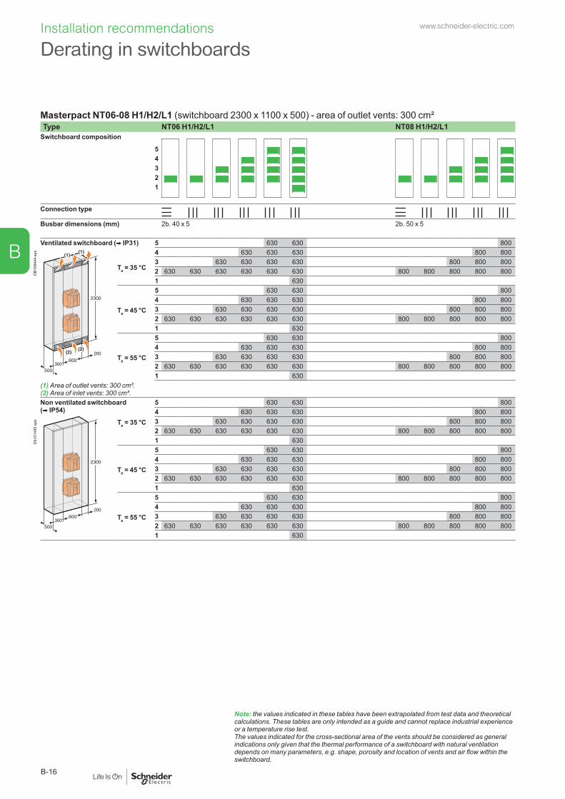
Installation recommendations
Masterpact NT06-08 H1/H2/L1 (switchboard 2300 x 1100 x 500) - area of outlet vents: 300 cm²Type NT06 H1/H2/L1 NT08 H1/H2/L1
Switchboard composition
54321
Connection type
Busbar dimensions (mm) 2b. 40 x 5 2b. 50 x 5
Ventilated switchboard ( IP31) 5 630 630 800
DB1
0844
4.ep
s
Ta = 35 °C
4 630 630 630 800 8003 630 630 630 630 800 800 8002 630 630 630 630 630 630 800 800 800 800 8001 630
Ta = 45 °C
5 630 630 8004 630 630 630 800 8003 630 630 630 630 800 800 8002 630 630 630 630 630 630 800 800 800 800 8001 630
Ta = 55 °C
5 630 630 8004 630 630 630 800 8003 630 630 630 630 800 800 8002 630 630 630 630 630 630 800 800 800 800 8001 630
(1) Area of outlet vents: 300 cm².(2) Area of inlet vents: 300 cm².Non ventilated switchboard ( IP54)
5 630 630 8004 630 630 630 800 800
Db1
0148
9.ep
s Ta = 35 °C 3 630 630 630 630 800 800 8002 630 630 630 630 630 630 800 800 800 800 8001 630
Ta = 45 °C
5 630 630 8004 630 630 630 800 8003 630 630 630 630 800 800 8002 630 630 630 630 630 630 800 800 800 800 8001 630
Ta = 55 °C
5 630 630 8004 630 630 630 800 8003 630 630 630 630 800 800 8002 630 630 630 630 630 630 800 800 800 800 8001 630
Note: the values indicated in these tables have been extrapolated from test data and theoretical calculations. These tables are only intended as a guide and cannot replace industrial experience or a temperature rise test. The values indicated for the cross-sectional area of the vents should be considered as general indications only given that the thermal performance of a switchboard with natural ventilation depends on many parameters, e.g. shape, porosity and location of vents and air flow within the switchboard.
Derating in switchboardswww.schneider-electric.com
B-16
B

Masterpact NT10-16 H1/H2/L1 (switchboard 2300 x 1100 x 500) - area of outlet vents: 300 cm²Type NT10 H1/H2/L1 NT12 H1/H2 NT16 H1/H2
Switchboard composition
54321
Connection type
Busbar dimensions (mm) 3b. 63 x 5 3b. 63 x 5 3b. 80 x 52b. 63 x 5 3b. 50 x 5 3b. 63 x 5
Ventilated switchboard ( IP31) 5 H1/L1 H1/L1 H1/L1 H1/L1
DB1
0844
4.ep
s
Ta = 35 °C
4 1000/1000 12503 1000/10001000/1000 1250 1250 15002 1000/10001000/10001000/10001000/1000 1250 1250 1250 1250 1460 1600 15501
Ta = 45 °C
54 1000/1000 12503 1000/10001000/1000 1250 1250 14202 1000 /960 1000/10001000/10001000/1000 1250 1250 1250 1250 1400 1500 14801
Ta = 55 °C
54 1000 /920 12503 1000 /950 1000 /930 1250 1250 13302 1000 /900 1000/10001000 /970 1000 /950 1250 1250 1250 1250 1300 1400 13701
(1) Area of outlet vents: 300 cm².(2) Area of inlet vents: 300 cm².Non ventilated switchboard ( IP54)
54 1000 /950 1250
Db1
0148
9.ep
s Ta = 35 °C 3 1000/10001000 /960 1250 1250 13702 1000/10001000/10001000/10001000 /970 1250 1250 1250 1250 1400 1500 1400
Ta = 45 °C
54 1000 /900 11803 1000 /950 1000 /910 1250 1190 13002 1000 /950 1000/10001000 /960 1000 /930 1250 1250 1250 1220 1350 1430 1320
Ta = 55 °C
54 1000/850 11203 1000 /900 1000 /860 1200 1130 12102 1000/880 1000 /970 1000 /910 1000 /870 1210 1250 1210 1150 1250 1350 1250
Note: the values indicated in these tables have been extrapolated from test data and theoretical calculations. These tables are only intended as a guide and cannot replace industrial experience or a temperature rise test. The values indicated for the cross-sectional area of the vents should be considered as general indications only given that the thermal performance of a switchboard with natural ventilation depends on many parameters, e.g. shape, porosity and location of vents and air flow within the switchboard.
www.schneider-electric.com
B-17
B
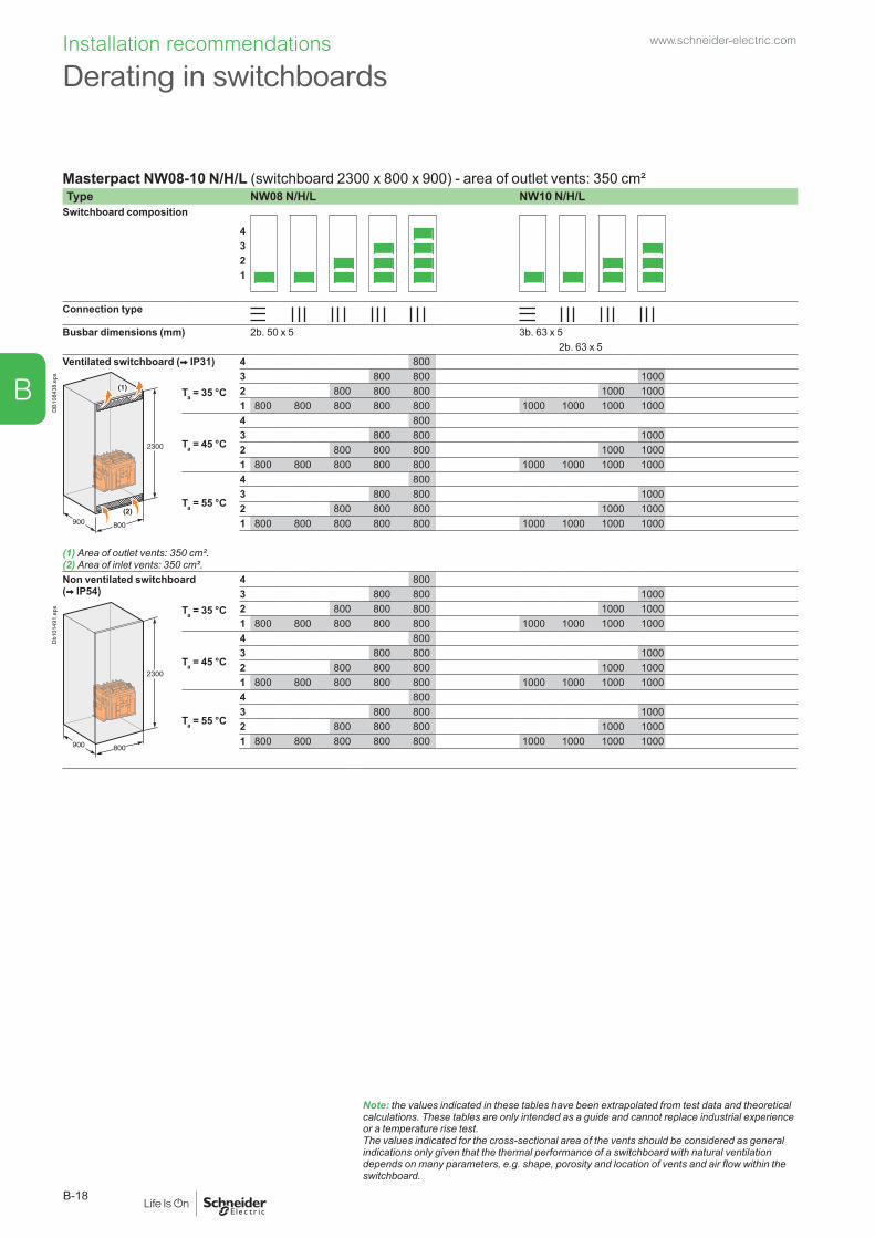
Installation recommendations
Masterpact NW08-10 N/H/L (switchboard 2300 x 800 x 900) - area of outlet vents: 350 cm²Type NW08 N/H/L NW10 N/H/L
Switchboard composition
4321
Connection type
Busbar dimensions (mm) 2b. 50 x 5 3b. 63 x 52b. 63 x 5
Ventilated switchboard ( IP31) 4 800
DB1
0843
8.ep
s
Ta = 35 °C3 800 800 10002 800 800 800 1000 10001 800 800 800 800 800 1000 1000 1000 1000
Ta = 45 °C
4 8003 800 800 10002 800 800 800 1000 10001 800 800 800 800 800 1000 1000 1000 1000
Ta = 55 °C
4 8003 800 800 10002 800 800 800 1000 10001 800 800 800 800 800 1000 1000 1000 1000
(1) Area of outlet vents: 350 cm².(2) Area of inlet vents: 350 cm².Non ventilated switchboard ( IP54)
4 8003 800 800 1000
Db1
0149
1.ep
s Ta = 35 °C 2 800 800 800 1000 10001 800 800 800 800 800 1000 1000 1000 1000
Ta = 45 °C
4 8003 800 800 10002 800 800 800 1000 10001 800 800 800 800 800 1000 1000 1000 1000
Ta = 55 °C
4 8003 800 800 10002 800 800 800 1000 10001 800 800 800 800 800 1000 1000 1000 1000
Note: the values indicated in these tables have been extrapolated from test data and theoretical calculations. These tables are only intended as a guide and cannot replace industrial experience or a temperature rise test. The values indicated for the cross-sectional area of the vents should be considered as general indications only given that the thermal performance of a switchboard with natural ventilation depends on many parameters, e.g. shape, porosity and location of vents and air flow within the switchboard.
Derating in switchboardswww.schneider-electric.com
B-18
B
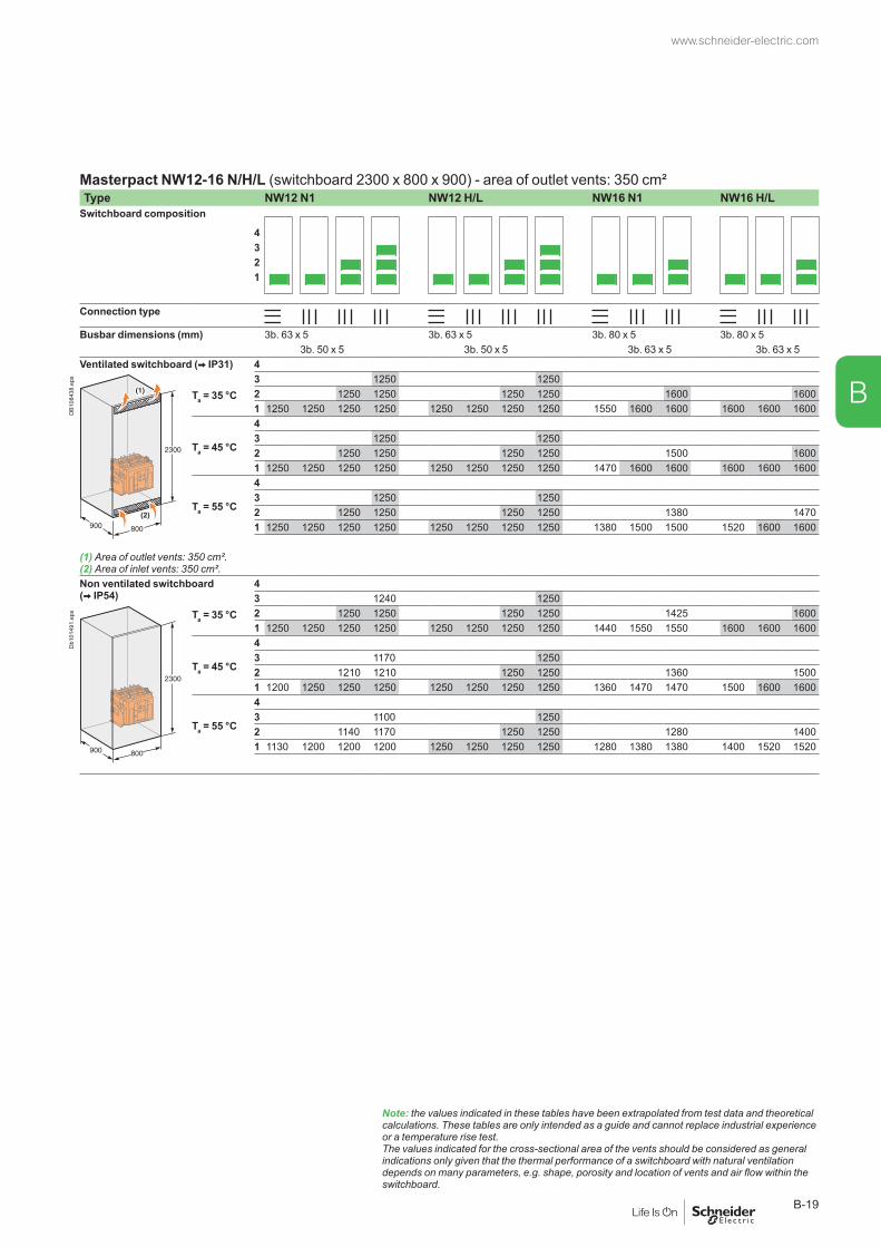
Masterpact NW12-16 N/H/L (switchboard 2300 x 800 x 900) - area of outlet vents: 350 cm²Type NW12 N1 NW12 H/L NW16 N1 NW16 H/L
Switchboard composition
4321
Connection type
Busbar dimensions (mm) 3b. 63 x 5 3b. 63 x 5 3b. 80 x 5 3b. 80 x 53b. 50 x 5 3b. 50 x 5 3b. 63 x 5 3b. 63 x 5
Ventilated switchboard ( IP31) 4
DB1
0843
8.ep
s
Ta = 35 °C3 1250 12502 1250 1250 1250 1250 1600 16001 1250 1250 1250 1250 1250 1250 1250 1250 1550 1600 1600 1600 1600 1600
Ta = 45 °C
43 1250 12502 1250 1250 1250 1250 1500 16001 1250 1250 1250 1250 1250 1250 1250 1250 1470 1600 1600 1600 1600 1600
Ta = 55 °C
43 1250 12502 1250 1250 1250 1250 1380 14701 1250 1250 1250 1250 1250 1250 1250 1250 1380 1500 1500 1520 1600 1600
(1) Area of outlet vents: 350 cm².(2) Area of inlet vents: 350 cm².Non ventilated switchboard ( IP54)
43 1240 1250
Db1
0149
1.ep
s Ta = 35 °C 2 1250 1250 1250 1250 1425 16001 1250 1250 1250 1250 1250 1250 1250 1250 1440 1550 1550 1600 1600 1600
Ta = 45 °C
43 1170 12502 1210 1210 1250 1250 1360 15001 1200 1250 1250 1250 1250 1250 1250 1250 1360 1470 1470 1500 1600 1600
Ta = 55 °C
43 1100 12502 1140 1170 1250 1250 1280 14001 1130 1200 1200 1200 1250 1250 1250 1250 1280 1380 1380 1400 1520 1520
Note: the values indicated in these tables have been extrapolated from test data and theoretical calculations. These tables are only intended as a guide and cannot replace industrial experience or a temperature rise test. The values indicated for the cross-sectional area of the vents should be considered as general indications only given that the thermal performance of a switchboard with natural ventilation depends on many parameters, e.g. shape, porosity and location of vents and air flow within the switchboard.
www.schneider-electric.com
B-19
B
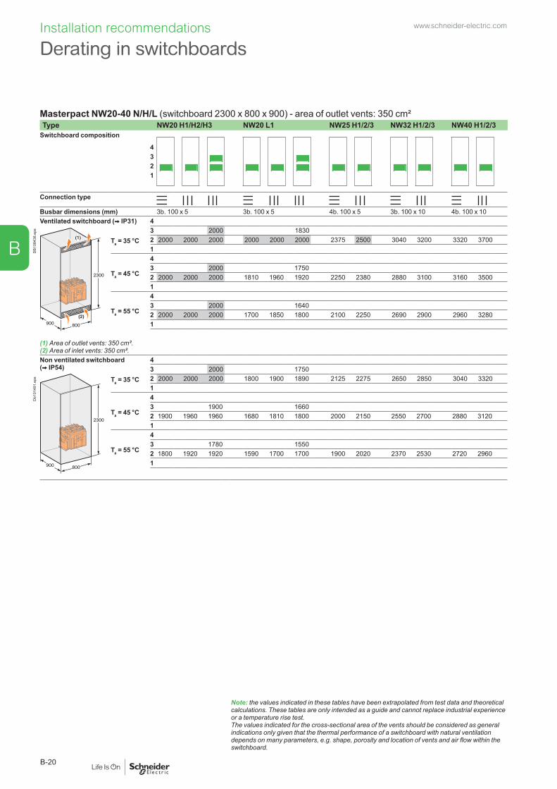
Installation recommendations
Masterpact NW20-40 N/H/L (switchboard 2300 x 800 x 900) - area of outlet vents: 350 cm²Type NW20 H1/H2/H3 NW20 L1 NW25 H1/2/3 NW32 H1/2/3 NW40 H1/2/3
Switchboard composition
4321
Connection type
Busbar dimensions (mm) 3b. 100 x 5 3b. 100 x 5 4b. 100 x 5 3b. 100 x 10 4b. 100 x 10Ventilated switchboard ( IP31) 4
DB1
0843
8.ep
s
Ta = 35 °C3 2000 18302 2000 2000 2000 2000 2000 2000 2375 2500 3040 3200 3320 37001
Ta = 45 °C
43 2000 17502 2000 2000 2000 1810 1960 1920 2250 2380 2880 3100 3160 35001
Ta = 55 °C
43 2000 16402 2000 2000 2000 1700 1850 1800 2100 2250 2690 2900 2960 32801
(1) Area of outlet vents: 350 cm².(2) Area of inlet vents: 350 cm².Non ventilated switchboard ( IP54)
43 2000 1750
Db1
0149
1.ep
s Ta = 35 °C 2 2000 2000 2000 1800 1900 1890 2125 2275 2650 2850 3040 33201
Ta = 45 °C
43 1900 16602 1900 1960 1960 1680 1810 1800 2000 2150 2550 2700 2880 31201
Ta = 55 °C
43 1780 15502 1800 1920 1920 1590 1700 1700 1900 2020 2370 2530 2720 29601
Note: the values indicated in these tables have been extrapolated from test data and theoretical calculations. These tables are only intended as a guide and cannot replace industrial experience or a temperature rise test. The values indicated for the cross-sectional area of the vents should be considered as general indications only given that the thermal performance of a switchboard with natural ventilation depends on many parameters, e.g. shape, porosity and location of vents and air flow within the switchboard.
Derating in switchboardswww.schneider-electric.com
B-20
B

Masterpact NW40b-63 H1/H2 (switchboard 2300 x 1400 x 1500) - area of outlet vents: 500 cm²Type NW40b H1/H2 NW50 H1/H2 NW63 H1/H2
Switchboard composition
4321
Connection type
Busbar dimensions (mm) 5b. 100 x 10 7b. 100 x 10 8b. 100 x 10Ventilated switchboard ( IP31) 4
DB1
0844
5.ep
s
Ta = 35 °C32 4000 4000 4700 5000 58501
Ta = 45 °C
432 4000 4000 4450 4850 56701
Ta = 55 °C
432 4000 4000 4200 4600 53501
(1) Area of outlet vents: 500 cm².(2) Area of inlet vents: 500 cm².Non ventilated switchboard ( IP54)
43
Db1
0149
2.ep
s Ta = 35 °C 2 4000 4000 4350 4650 52901
Ta = 45 °C
432 4000 4000 4100 4400 50401
Ta = 55 °C
432 3840 3840 3850 4150 47301
Note: the values indicated in these tables have been extrapolated from test data and theoretical calculations. These tables are only intended as a guide and cannot replace industrial experience or a temperature rise test. The values indicated for the cross-sectional area of the vents should be considered as general indications only given that the thermal performance of a switchboard with natural ventilation depends on many parameters, e.g. shape, porosity and location of vents and air flow within the switchboard.
www.schneider-electric.com
B-21
B
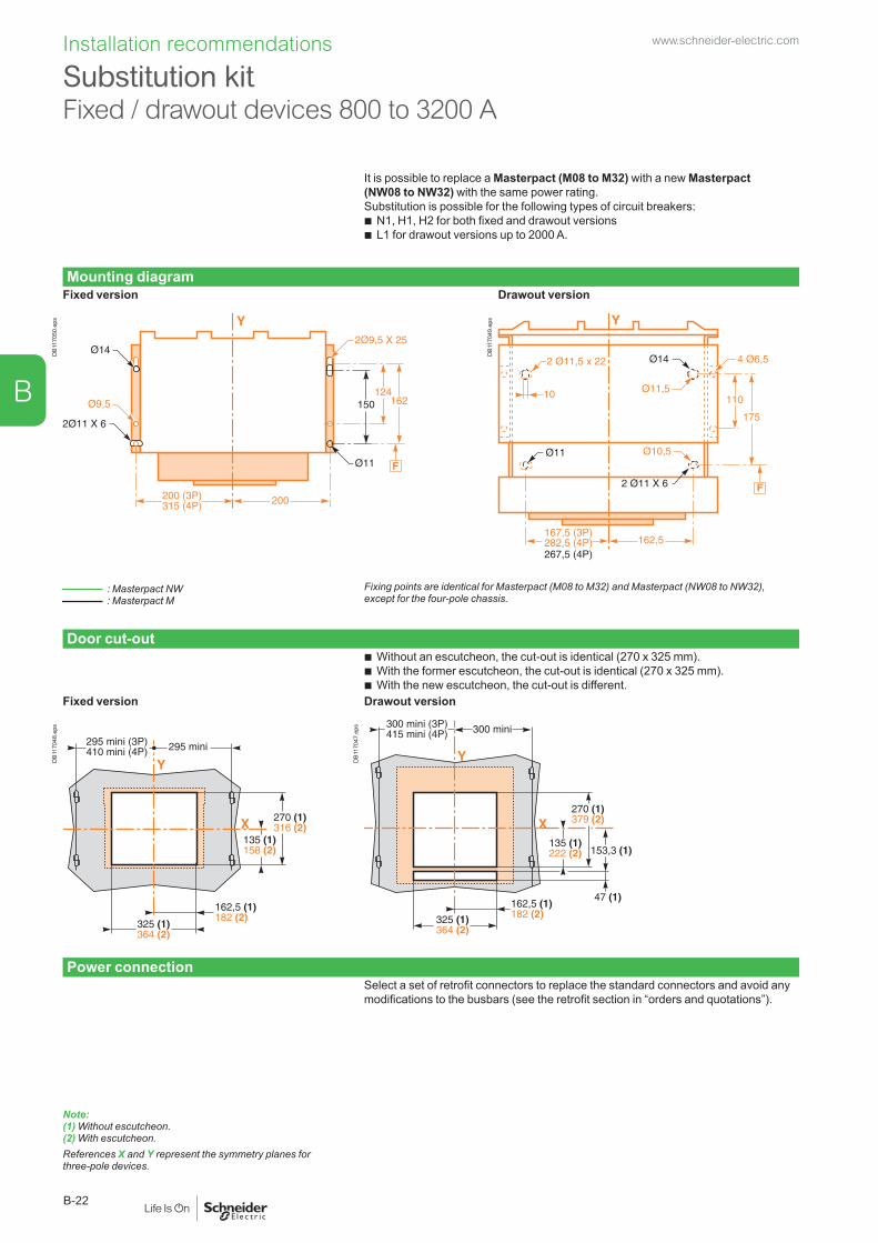
Installation recommendations
It is possible to replace a Masterpact (M08 to M32) with a new Masterpact (NW08 to NW32) with the same power rating.Substitution is possible for the following types of circuit breakers:
b N1, H1, H2 for both fixed and drawout versions b L1 for drawout versions up to 2000 A.
Mounting diagramFixed version Drawout version
DB1
1705
0.ep
s
DB1
1704
9.ep
s
: Masterpact NW : Masterpact M
Fixing points are identical for Masterpact (M08 to M32) and Masterpact (NW08 to NW32), except for the four-pole chassis.
Door cut-out b Without an escutcheon, the cut-out is identical (270 x 325 mm). b With the former escutcheon, the cut-out is identical (270 x 325 mm). b With the new escutcheon, the cut-out is different.
Fixed version Drawout version
DB1
1704
8.ep
s
DB1
1704
7.ep
s
Power connection
Note: (1) Without escutcheon.(2) With escutcheon.References X and Y represent the symmetry planes for three-pole devices.
Select a set of retrofit connectors to replace the standard connectors and avoid any modifications to the busbars (see the retrofit section in “orders and quotations”).
Substitution kit Fixed / drawout devices 800 to 3200 A
www.schneider-electric.com
B-22
B

Wiring of voltage releasesDuring pick-up, the power consumed is approximately 150 to 200 VA. For low control voltages (12, 24, 48 V), maximum cable lengths are imposed by the voltage and the cross-sectional area of cables.Recommended maximum cable lengths (meter).
12 V 24 V 48 V2.5 mm2 1.5 mm2 2.5 mm2 1.5 mm2 2.5 mm2 1.5 mm2
MN U source 100 % – – 58 35 280 165U source 85 % – – 16 10 75 45
MX-XF U source 100 % 21 12 115 70 550 330U source 85 % 10 6 75 44 350 210
Note: the indicated length is that of each of the two wires.
24 V DC power-supply moduleExternal 24 V DC power-supply module for Micrologic (F1-, F2+)
b It is recommended to use the AD power supply due to its low stray primary-secondary capacitance. Good operation of the Micrologic Trip Unit in noisy environment is not guaranteed with other power supplies.
b The dedicated AD power supplies shall be used only for the Micrologic trip units. If the COM option is used, a second dedicated power supply shall be used.
b M2C modules can be supplied by Micrologic external AD power supply. b The consumption of a Micrologic Trip Unit is approximately 100mA. b The consumption of M2C modules is approximately 100mA. b A number of 5 devices (Micrologic control units with M2C) can be connected to the
same AD power supply. Add other AD power supply for more than 5 devices. b For Micrologics control units alone, a number of 10 devices can be connected to
the same AD power supply. Add other AD power supply for more than 10 Micrologics. b If the installation is shared between several panels, one AD power supply shall be
added for each panel. b AD power supply dedicated to Micrologics trip units shall not be connected to
earth. (F1-, F2+).External 24 V DC power supply for Communication bus
b A dedicated 24 V DC power supply shall be used for the communication devices. b Do not connect the positive terminal (E1) to earth. b The negative terminal (E2) can be connected to earth. b A number of communication modules (BCM, IFE, IFM, I/O, FDM…) can be
connected to the same 24 V DC power supply. Refer bellow the devices consumption table to avoid exceeding the maximum current delivered by the 24 V DC power supply.ULP module consumptionThe table below lists the ULP module consumption.Module Typical Consumption
(24 V DC at 20 °C / 68 °F)Maximum Consumption (19.2 V DC at 60 °C / 140 °F)
BCM ULP for Masterpact and Compact NS
40 mA 65 mA
Micrologic 5 or 6 trip unit for Compact NSX circuit breakers
30 mA 55 mA
BSCM for Compact NSX circuit breakers
9 mA 15 mA
2-wire RS 485 isolated repeater 15 mA 19 mAFDM121 display for LV circuit breaker 21 mA 30 mAIFM Modbus-SL interface for LV circuit breaker
21 mA 30 mA
IFE Ethernet interface for LV circuit breaker
120 mA 3 A (with gateway)
I/O input/output interface module for LV circuit breaker
165 mA 420 mA
Maintenance module 0 mA (the maintenance module has its own power supply)
0 mA (the maintenance module has its own power supply)
Installation recommendation b The 24 V DC wires (output of the 24 V DC power supply) shall be twist together. b The 24 V DC wires (output of the 24 V DC power supply) must cross all power
cables perpendicularly. b The technical characteristics of the external 24 V DC power-supply module for
Micrologic control units are indicated on page A-30.Note: wiring of ZSI: it is recommended to use twisted shielded cable. The shield must be connected to earth at both ends.
Control wiringwww.schneider-electric.com
B-23
B

Masterpact M Retrofitting: electrical diagramsCorrespondences between Masterpact NW and Masterpact M terminal blocks.
Power Control unit Remote operation
DB4
3256
9.ep
s
Indication contacts Chassis contacts
DB1
1705
1.ep
s
Identical to Masterpact M. Different than Masterpact M.
New or additional functions. (1) The current transformer for the external neutral must be replaced.
Masterpact M RetrofitInstallation recommendations www.schneider-electric.com
B-24
B

Masterpact NT and NW
Dimensions and connections
Presentation 2Functions and characteristics A-1Installation recommendations B-1
NT06 to NT16 circuit breakersFixed 3/4-poles device C-2Drawout 3/4-poles device C-6
NW08 to NW32 circuit breakersFixed 3/4-poles device C-10Drawout 3/4-poles device C-12
NW40 circuit breakersFixed 3/4-poles device C-14Drawout 3/4-poles device C-16
NW40b to NW63 circuit breakersFixed 3/4-poles device C-18Drawout 3/4-poles device C-20
NT/NW accessories C-22
NT/NW external modules C-24
FDM121 switchboard display C-29
FDM128 switchboard display C-30
Electrical diagrams D-1Additional characteristics E-1Catalogue numbers and order form F-1
www.schneider-electric.com
C-1
C

Dimensions and connections
Dimensions
DB1
0118
8.ep
s
Db1
0118
9.ep
s
Bottom mounting (on base plate or rails) Rear mounting detail (on upright or backplate)
Db1
0119
0.ep
s
Db1
0119
1.ep
s
Db1
0119
2.ep
s
Safety clearances Door cutout Rear panel cutout
Db1
0119
3.ep
s
Db1
0119
4.ep
s
Db1
0119
5.ep
s
DB1
1718
9.ep
s
For voltages < 690 VPartsInsulated Metal Energised
A 0 0 100B 0 0 60
: datum.
(1) Without escutcheon.(2) With escutcheon.
Note: X and Y are the symmetry planes for a 3-pole device. A(*) An overhead clearance of 50 mm is required to remove the arc chutes. An overhead clearance of 20 mm is required to remove the terminal block.
NT06 to NT16 circuit breakersFixed 3/4-poles device
www.schneider-electric.com
C-2
C
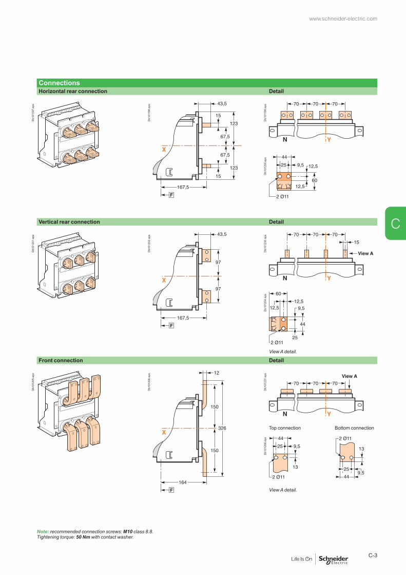
ConnectionsHorizontal rear connection Detail
Db1
0119
7.ep
s
Db1
0119
8.ep
s
Db1
0119
9.ep
sD
b101
200.
eps
Vertical rear connection Detail
Db1
0120
1.ep
s
Db1
0120
2.ep
s
Db1
0123
0.ep
sD
b101
204.
eps
View A detail.
Front connection Detail
Db1
0120
5.ep
s
Db1
0120
6.ep
s
Db1
0123
1.ep
s
Top connection Bottom connection
Db1
0120
8.ep
s
View A detail.
Note: recommended connection screws: M10 class 8.8. Tightening torque: 50 Nm with contact washer.
www.schneider-electric.com
C-3
C

Dimensions and connections
ConnectionsFront connection with spreaders Detail
Db1
0121
0.ep
s
Db1
0121
1.ep
s
Db1
0152
7.ep
sD
b101
528.
eps
Rear connection with spreaders Detail
DB1
0121
4.ep
s
Db1
0121
5.ep
s
Db1
0121
6.ep
sD
b101
217.
eps
Spreader detail
Middle left or middle right spreader for 4P.
Middle spreader for 3P. Left or right spreader for 4P. Left or right spreader for 3P.
Db1
0121
8.ep
s
Db1
0121
9.ep
s
Db1
0122
0.ep
s
Db1
0122
1.ep
s
View A detail.
: datum. Note: X and Y are the symmetry planes for a 3-pole device.
NT06 to NT16 circuit breakersFixed 3/4-poles device
www.schneider-electric.com
C-4
C
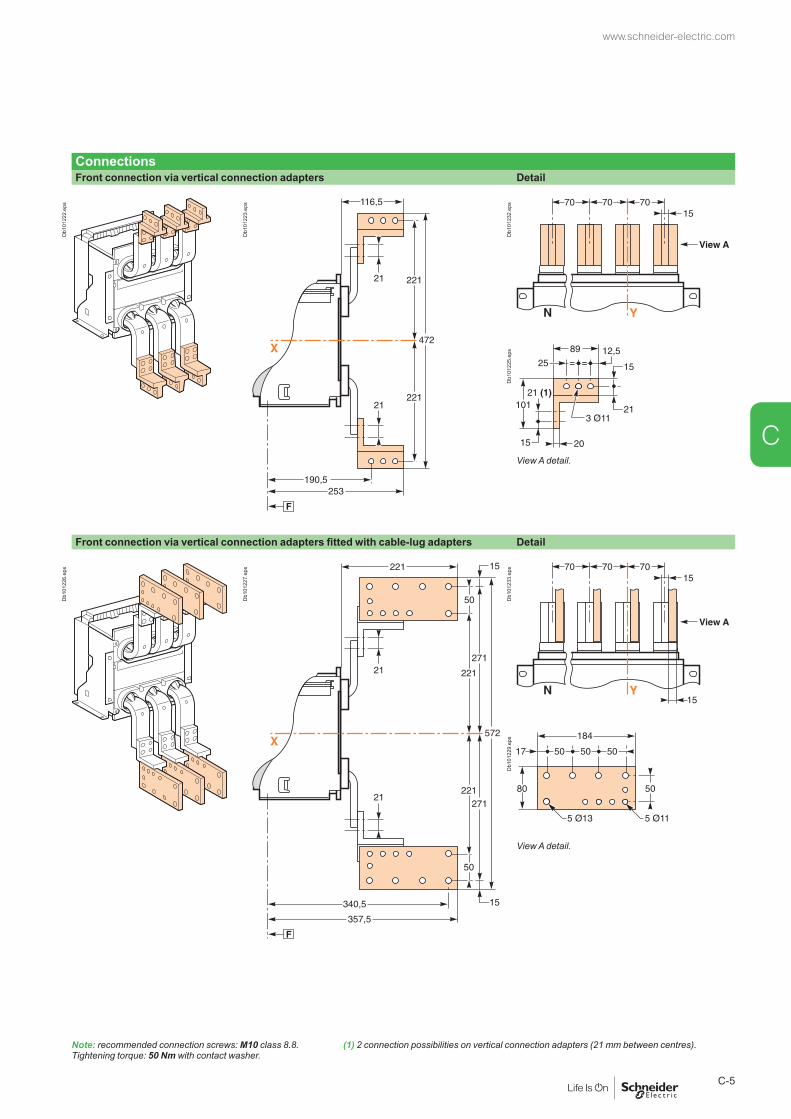
ConnectionsFront connection via vertical connection adapters Detail
Db1
0122
2.ep
s
Db1
0122
3.ep
s
Db1
0123
2.ep
sD
b101
225.
eps
View A detail.
Front connection via vertical connection adapters fitted with cable-lug adapters Detail
Db1
0122
6.ep
s
Db1
0122
7.ep
s
Db1
0123
3.ep
sD
b101
229.
eps
View A detail.
Note: recommended connection screws: M10 class 8.8. Tightening torque: 50 Nm with contact washer.
(1) 2 connection possibilities on vertical connection adapters (21 mm between centres).
www.schneider-electric.com
C-5
C

Dimensions and connections
Dimensions
DB1
0123
4.ep
s
Db1
0123
5.ep
s
(*) Disconnected position.
Bottom mounting (on base plate or rails) Rear mounting detail (on upright or backplate)
Db1
0123
6.ep
s
Db1
0123
7.ep
s
Db1
0123
8.ep
s
Safety clearances Door cutout Rear panel cutout
Db1
0125
6.ep
s
Db1
0123
9.ep
s
Db1
0124
0.ep
s
Db1
0124
1.ep
s
For voltages y 690 VParts
: datum.
(1) Without escutcheon.(2) With escutcheon.Note: X and Y are the symmetry planes for a 3-pole device.
Insulated Metal EnergisedA 0 0 30B 10 10 60C 0 0 30
NT06 to NT16 circuit breakersDrawout 3/4-poles device
www.schneider-electric.com
C-6
C

ConnectionsHorizontal rear connection Detail
Db1
0124
2.ep
s
Db1
0124
3.ep
s
Db1
0124
4.ep
sD
b101
200.
eps
Vertical rear connection Detail
Db1
0124
6.ep
s
Db1
0124
7.ep
s
Db1
0124
9.ep
sD
b101
250.
eps
View A detail.
Front connection Detail
Db1
0125
1.ep
s
Db1
0125
2.ep
s
Db1
0125
4.ep
s
Top connection Bottom connection
Db1
0125
5.ep
s
View A detail.
Note: recommended connection screws: M10 class 8.8. Tightening torque: 50 Nm with contact washer.
www.schneider-electric.com
C-7
C

Dimensions and connections
ConnectionsFront connection with spreaders
Db1
0125
7.ep
s
Db1
0125
8.ep
s
Db1
0126
5.ep
sD
b101
266.
eps
Spreader detail
Middle left or middle right spreader for 4P.
Middle spreader for 3P. Left or right spreader for 4P. Left or right spreader for 3P.
Db1
0121
8.ep
s
Db1
0121
9.ep
s
Db1
0122
0.ep
s
Db1
0122
1.ep
s
View A detail.
: datum. Note: X and Y are the symmetry planes for a 3-pole device.
NT06 to NT16 circuit breakers0 Drawout 3/4-poles device
www.schneider-electric.com
C-8
C

ConnectionsFront connection via vertical connection adapters fitted with cable-lug adapters
Db1
0126
1.ep
s
Db1
0126
2.ep
s
Db1
0126
4.ep
sD
b101
229.
eps
View A detail.
Note: recommended connection screws: M10 class 8.8. Tightening torque: 50 Nm with contact washer.
www.schneider-electric.com
C-9
C
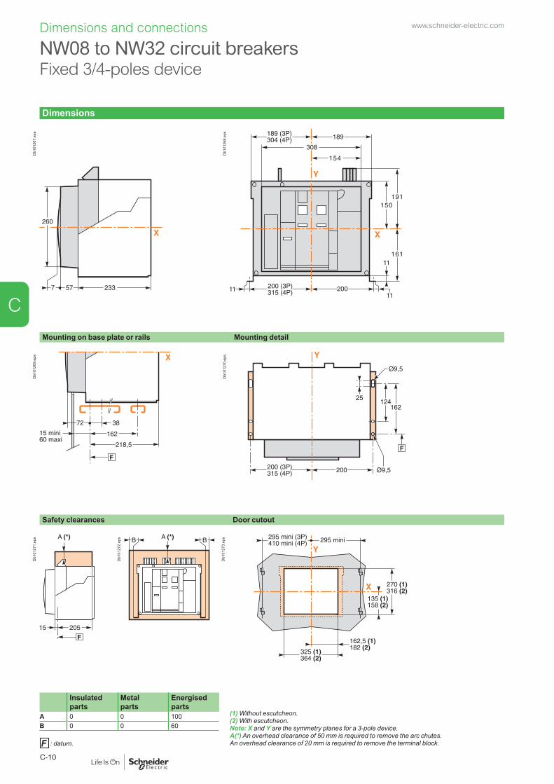
Dimensions and connections
Dimensions
Db1
0126
7.ep
s
Db1
0126
8.ep
s
Mounting on base plate or rails Mounting detail
Db1
0126
9.ep
s
Db1
0127
0.ep
s
Safety clearances Door cutout
Db1
0127
1.ep
s
Db1
0127
2.ep
s
Db1
0127
3.ep
s
Insulated parts
Metal parts
Energised parts
(1) Without escutcheon.(2) With escutcheon.Note: X and Y are the symmetry planes for a 3-pole device. A(*) An overhead clearance of 50 mm is required to remove the arc chutes. An overhead clearance of 20 mm is required to remove the terminal block.
A 0 0 100B 0 0 60
: datum.
NW08 to NW32 circuit breakers Fixed 3/4-poles device
www.schneider-electric.com
C-10
C
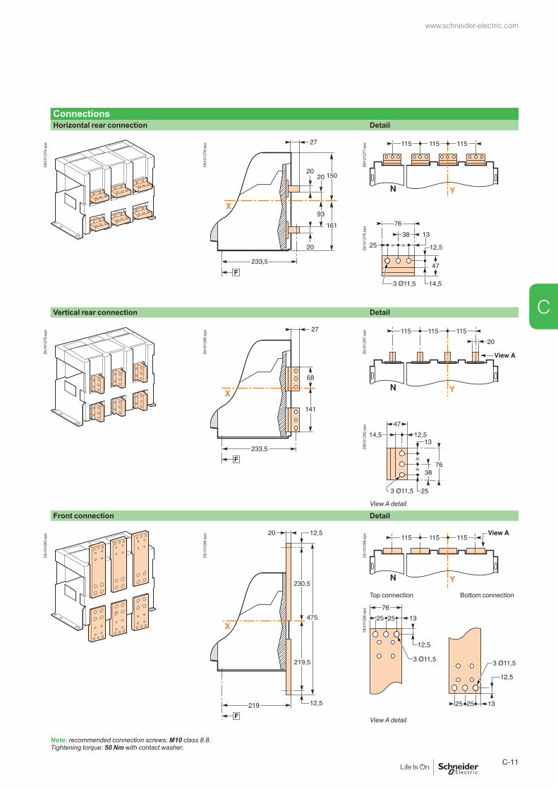
ConnectionsHorizontal rear connection Detail
Db1
0127
4.ep
s
Db1
0127
6.ep
s
DB1
0127
7.ep
sD
b101
278.
eps
Vertical rear connection Detail
Db1
0127
9.ep
s
Db1
0128
0.ep
s
Db1
0128
7.ep
sD
B101
282.
eps
View A detail.
Front connection Detail
Db1
0128
3.ep
s
Db1
0128
4.ep
s
Db1
0128
8.ep
s
Top connection Bottom connection
Db1
0128
6.ep
s
View A detail.
Note: recommended connection screws: M10 class 8.8. Tightening torque: 50 Nm with contact washer.
www.schneider-electric.com
C-11
C
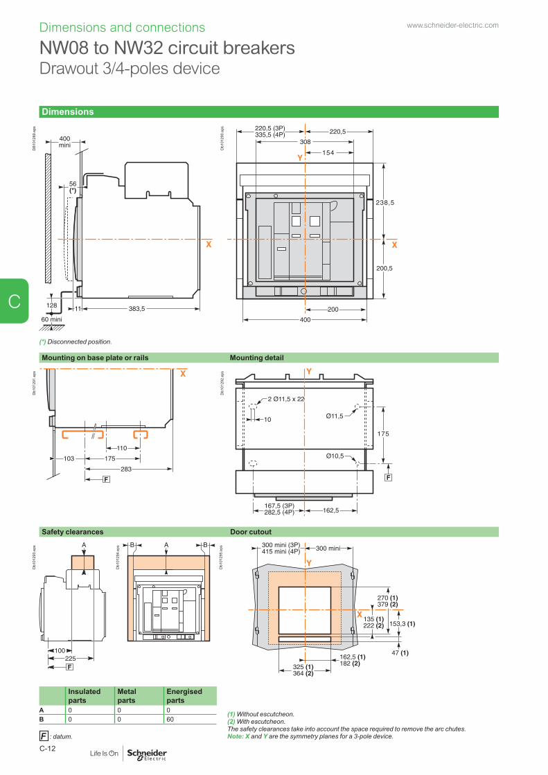
Dimensions and connections
Dimensions
DB1
0128
9.ep
s
Db1
0129
0.ep
s
(*) Disconnected position.
Mounting on base plate or rails Mounting detail
Db1
0129
1.ep
s
Db1
0129
2.ep
s
Safety clearances Door cutout
Db1
0129
3.ep
s
Db1
0129
4.ep
s
Db1
0129
5.ep
s
Insulated parts
Metal parts
Energised parts
(1) Without escutcheon.(2) With escutcheon.The safety clearances take into account the space required to remove the arc chutes.Note: X and Y are the symmetry planes for a 3-pole device.
A 0 0 0B 0 0 60
: datum.
NW08 to NW32 circuit breakers Drawout 3/4-poles device
www.schneider-electric.com
C-12
C

ConnectionsHorizontal rear connection Detail
Db1
0129
6.ep
s
Db1
0129
7.ep
s
Db1
0129
8.ep
s
Db1
0127
8.ep
s
Vertical rear connection Detail
Db1
0130
0.ep
s
Db1
0130
1.ep
s
Db1
0130
7.ep
sD
B101
282.
eps
View A detail.
Front connection Detail
Db1
0130
3.ep
s
Db1
0130
4.ep
s
Db1
0130
8.ep
s
Top connection Bottom connection
Db1
0130
6.ep
s
View A detail.
Note: recommended connection screws: M10 class 8.8. Tightening torque: 50 Nm with contact washer.
www.schneider-electric.com
C-13
C
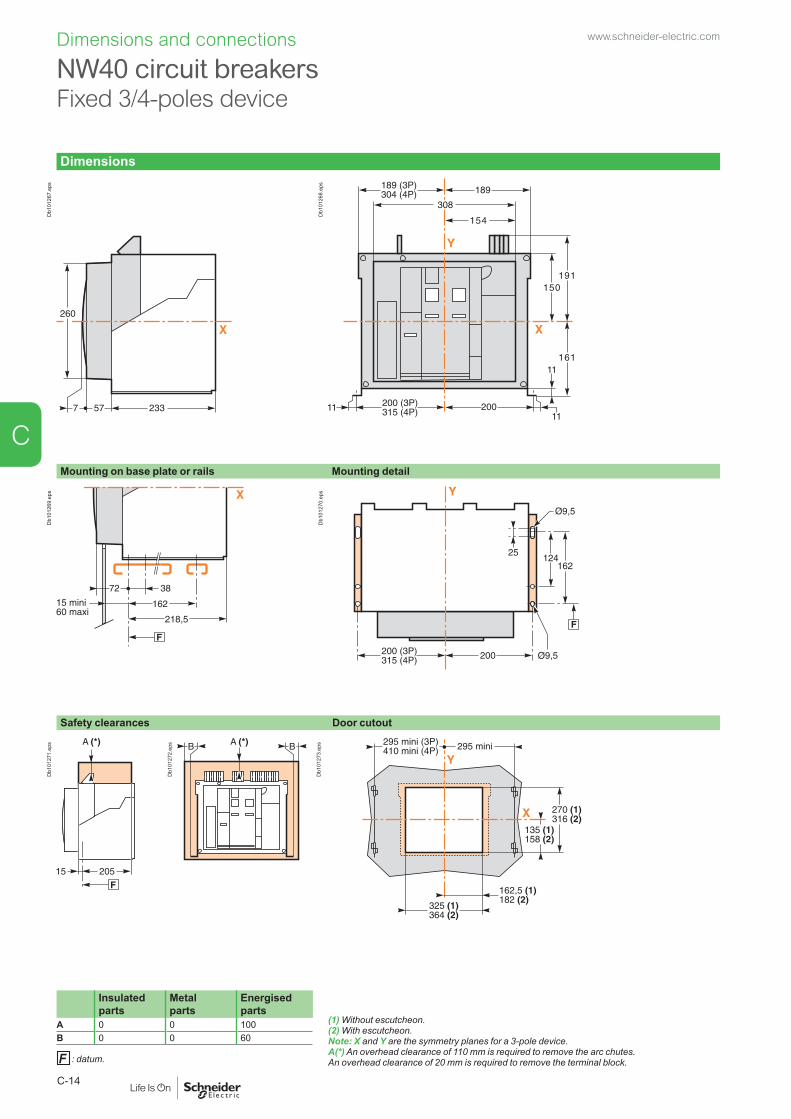
Dimensions and connections
NW40 circuit breakers Fixed 3/4-poles device
Dimensions
Db1
0126
7.ep
s
Db1
0126
8.ep
s
Mounting on base plate or rails Mounting detail
Db1
0126
9.ep
s
Db1
0127
0.ep
s
Safety clearances Door cutout
Db1
0127
1.ep
s
Db1
0127
2.ep
s
Db1
0127
3.ep
s
Insulated parts
Metal parts
Energised parts
(1) Without escutcheon.(2) With escutcheon.Note: X and Y are the symmetry planes for a 3-pole device. A(*) An overhead clearance of 110 mm is required to remove the arc chutes. An overhead clearance of 20 mm is required to remove the terminal block.
A 0 0 100B 0 0 60
: datum.
www.schneider-electric.com
C-14
C

ConnectionsHorizontal rear connection
DB1
0130
9.ep
s
Db1
0127
6.ep
s
Detail
Db1
0131
0.ep
s
DB1
0131
1.ep
sD
b101
315.
eps
Vertical rear connection
Db1
0131
2.ep
s
Db1
0131
3.ep
s
Detail
Db1
0128
7.ep
s
Db1
0131
4.ep
s
View A detail.Note: recommended connection screws: M10 class 8.8. Tightening torque: 50 Nm with contact washer.
www.schneider-electric.com
C-15
C

Dimensions and connections
NW40 circuit breakersDrawout 3/4-poles device
Dimensions
DB1
0128
9.ep
s
Db1
0129
0.ep
s
(*) Disconnected position.
Mounting on base plate or rails Mounting detail
Db1
0129
1.ep
s
Db1
0129
2.ep
s
Safety clearances Door cutout
Db1
0129
3.ep
s
Db1
0129
4.ep
s
Db1
0129
5.ep
s
Insulated parts
Metal parts
Energised parts
(1) Without escutcheon.(2) With escutcheon.Note: X and Y are the symmetry planes for a 3-pole device.
A 0 0 0B 0 0 60
: datum.
www.schneider-electric.com
C-16
C

ConnectionsHorizontal rear connection
Db1
0131
6.ep
s
Db1
0129
7.ep
s
Detail
Db1
0131
7.ep
s
DB1
0131
1.ep
sD
b101
315.
eps
Vertical rear connection
Db1
0131
8.ep
s
Db1
0131
9.ep
s
Db1
0131
4.ep
s
View A detail.
Detail
Db1
0130
7.ep
s
Note: recommended connection screws: M10 class 8.8. Tightening torque: 50 Nm with contact washer.
www.schneider-electric.com
C-17
C

Dimensions and connections
NW40b to NW63 circuit breakers Fixed 3/4-poles device
Dimensions
Db1
0126
7.ep
s
Db1
0132
0.ep
s
Mounting on base plate or rails Mounting detail
Db1
0126
9.ep
s
Db1
0132
1.ep
s
Safety clearances Door cutout
Db1
0127
1.ep
s
Db1
0132
3.ep
s
Db1
0132
2.ep
s
Insulated parts
Metal parts
Energised parts
(1) Without escutcheon.(2) With escutcheon.Note: X and Y are the symmetry planes for a 3-pole device. A(*) An overhead clearance of 110 mm is required to remove the arc chutes. An overhead clearance of 20 mm is required to remove the terminal block.
A 0 0 100B 0 0 60
: datum.
www.schneider-electric.com
C-18
C

ConnectionsHorizontal rear connection Detail
Db1
0133
2.ep
s
Db1
0132
4.ep
s
Db1
0132
5.ep
sD
b101
278.
eps
Vertical rear connection Detail
Db1
0132
7.ep
s
Db1
0132
8.ep
s
Db1
0133
3.ep
sD
B101
282.
eps
View A detail.
Front connection Detail
Db1
0133
0.ep
s
Db1
0133
1.ep
s
Db1
0133
3.ep
sD
b101
314.
eps
Note: recommended connection screws: M10 class 8.8. Tightening torque: 50 Nm with contact washer.
View A detail.
www.schneider-electric.com
C-19
C

Dimensions and connections
NW40b to NW63 circuit breakers Drawout 3/4-poles device
Dimensions
DB1
0133
4.ep
s
DB1
0133
5.ep
s
(*) Disconnected position.
Mounting on base plate or rails Mounting detail
Db1
0133
6.ep
s
Db1
0133
7.ep
s
Safety clearances Door cutout
Db1
0129
3.ep
s
Db1
0133
8.ep
s
Db1
0133
9.ep
s
Insulated parts
Metal parts
Energised parts
(1) Without escutcheon.(2) With escutcheon.The safety clearances take into account the space required to remove the arc chutes.Note: X and Y are the symmetry planes for a 3-pole device.
: datum.
A 0 0 0B 0 0 60
www.schneider-electric.com
C-20
C

ConnectionsHorizontal rear connection (NW40b - NW50) Detail
Db1
0134
1.ep
s
Db1
0134
2.ep
s
Db1
0134
3.ep
s
Db1
0127
8.ep
sVertical rear connection (NW40b - NW50) Detail
Db1
0134
4.ep
s
Db1
0134
5.ep
s
Db1
0134
9.ep
sD
B101
282.
eps
View A detail.
Vertical rear connection (NW63) Detail
Db1
0134
7.ep
s
Db1
0134
8.ep
s
Db1
0134
9.ep
sD
b101
314.
eps
Note: recommended connection screws: M10 s/s class A4 80. Tightening torque: 50 Nm with contact washer.
View A detail.
www.schneider-electric.com
C-21
C

Dimensions and connections
Mounting on backplate with special brackets (Masterpact NW08 to 32 fixed)
Db1
0135
0.ep
s
Db1
0135
1.ep
s
Disconnectable front-connection adapter (Masterpact NW08 to 32 fixed)Horizontal rear connection Detail
Db1
0135
2.ep
s
Db1
0135
3.ep
s
Db1
0135
4.ep
sD
b101
278.
eps
View A detail.
Vertical rear connection Detail
DB4
1798
4.ep
s
Db1
0135
6.ep
s
Db1
0135
8.ep
sD
B101
282.
eps
Note: recommended connection screws: M10 class 8.8. Tightening torque: 50 Nm with contact washer.
: datum.
View A detail.
NT/NW accessorieswww.schneider-electric.com
C-22
C

Rear panel cutout (drawout devices)NW08 to NW40
Rear view
Db1
2569
5.ep
s
Db1
0136
0.ep
sNW40b to NW63
Rear view
DB1
0136
1.ep
s
Db1
0136
2.ep
s
EscutcheonMasterpact NT
Fixed device Drawout device
Db1
0136
3.ep
s
Db1
0136
4.ep
s
Masterpact NWFixed device Drawout device
Db1
0136
5.ep
s
Db1
0136
6.ep
s
: datum.
www.schneider-electric.com
C-23
C

Dimensions and connections
Connection of auxilary wiring to terminal block
DB1
0136
7.ep
s
Db1
0136
8.ep
s
One conductor only per connection point.
External power supply module (AD)
2 Ø4
82
G3G4
Output
LN
AC/DC Power supply
LVA454444
Input: 200/240V
0.25A50/60Hz
Output: 24VDC
1A
High level Overvoltage(OVC4)
90
67.5 108
DB4
2199
6.ai
Battery module (BAT)2 Ø660
61
73
75112
DB4
2199
7.ai
NT/NW external moduleswww.schneider-electric.com
C-24
C

Delay unit for MN release
Db1
0137
5.ep
s
DB1
1702
5.ep
s
External sensor for source ground return (SGR) protectionSensor “MGDF summer” module
Db1
0137
9.ep
s
Db1
0138
0.ep
s
IFE - Ethernet interface
DB4
2583
3.ep
s
ETH1 ETH2
R
Modbus-SL
LV434002
ETH1 LK/10-100/ACT
ETH2 LK/10-100/ACT
Module Status
Network Status
Enerlin'X IFEIFE-XX.YY.ZZ (factory set)
T
72
DB4
1669
8.ep
s
71
63.6
4584.8
92105
www.schneider-electric.com
C-25
C
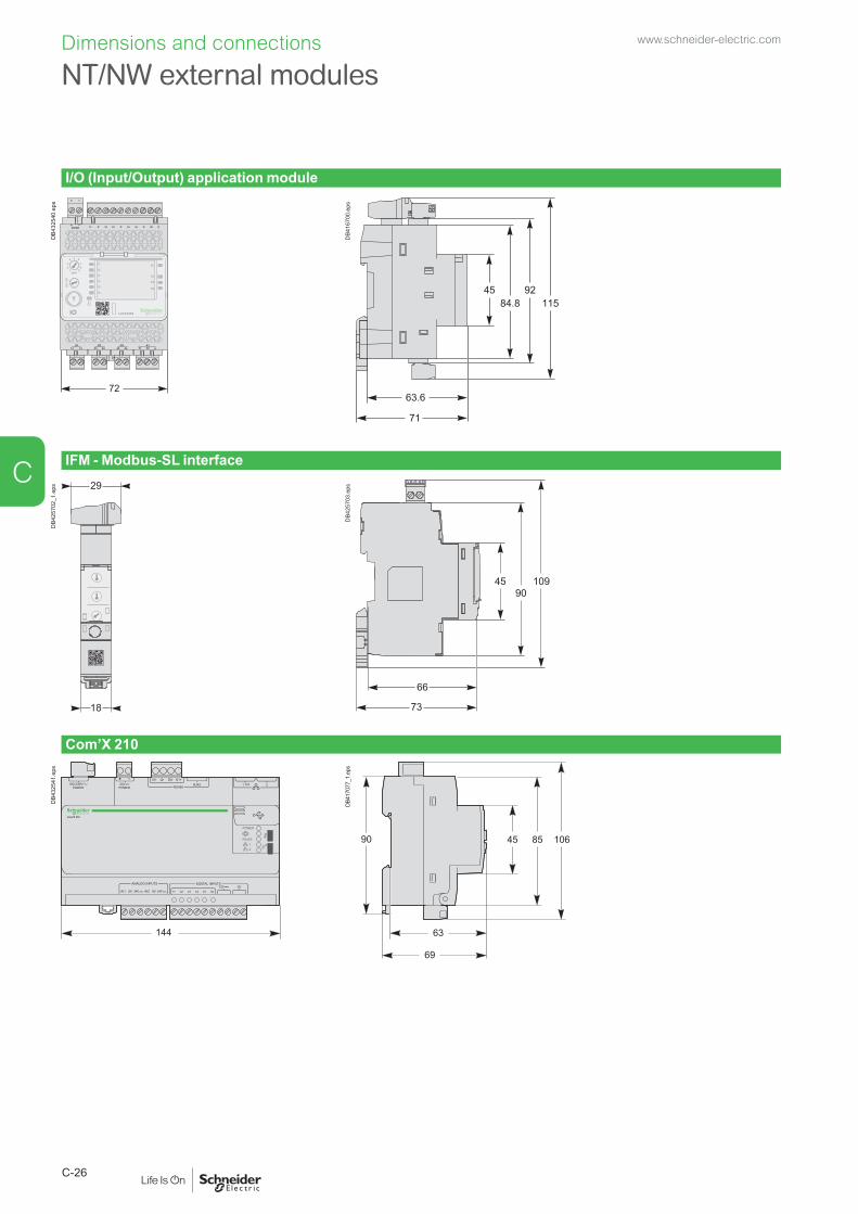
Dimensions and connections
I/O (Input/Output) application module
DB4
3254
0.ep
s
13O1 O2 O3 A1
I1 I2 I3 I4 I5 I6C C C
14 23 24 33 34 T1 T2
24VDC
1APP
23
4 5 678
9
I1 AI
O1
O2
O3
I2
I3
I4
I5
I6
LV434063IO
T
72
DB4
1670
0.ep
s
92
63.6
4584.8 115
71
IFM - Modbus-SL interface
DB4
2570
2_1.
eps
18
29
DB4
2570
3.ep
s
4590
109
66
73
Com’X 210
144
3
Com’X 210
DB4
3254
1.ep
s
90
63
45 10685
69
DB41
7077
_1.e
ps
NT/NW external moduleswww.schneider-electric.com
C-26
C

External sensor for external neutralDimensions
400/1600 A (NT06 to NT16) 400/2000 A (NW08 to NW20)
Db1
0138
1.ep
s
DB1
1702
4.ep
s
High: 137 mm.
High: 162 mm.
1000/4000 A (NW025 to NW40) 4000/6300 A (NW40b to NW63)
DB1
1702
3.ep
s
DB1
1702
7.ep
s
High: 162 mm.
High: 168 mm.
Installation400/1600 A (NT06 to NT16) 400/2000 A (NW08 to NW20)
Db1
0138
5.ep
s
Db1
0138
6.ep
s
1000/4000 A (NW025 to NW40) 4000/6300 A (NW40b to NW63)
Db1
0138
7.ep
s
Db1
0138
8.ep
s
www.schneider-electric.com
C-27
C

Rectangular sensor for earth leakage protection (Vigi)280 x 115 mm window
DB1
0138
9.ep
s
Db1
0139
0.ep
s
470 x 160 mm window
Db1
0139
1.ep
s
Db1
0139
2.ep
s
Busbars I y 1600 A I y 3200Window (mm) 280 x 115 470 x 160Weight (kg) 14 18
Busbars path280 x 115 mm windowBusbars spaced 70 mm centre-to-centre
470 x 160 mm windowBusbars spaced 115 mm centre-to-centre
Db1
0139
3.ep
s M1M2M3
DB1
1702
9.ep
s
2 bars 50 x 10.
4 bars 100 x 5.
Db1
0139
5.ep
s
DB1
1702
8.ep
s
2 bars 100 x 5.
4 bars 125 x 5.
Dimensions and connections
NT/NW external moduleswww.schneider-electric.com
C-28
C

FDM121 switchboard display
Dimensions
DB4
3254
2.ep
s
Y
X96
96
FDM121
DB4
3254
3.ep
s
MountingThrough panel
DB4
3254
4.ep
s
X
2320.710.6
Z
DB4
2461
2.ep
s
Y
X92+ 0.80
92+ 0.80
DB4
2467
9.ep
s
On panel
DB4
3254
5.ep
s
DB1
1527
0_1.
eps
3715
Z
X
DB4
2468
1.ep
s
Connector (optional).
Y
X
33+1.5-
32+0.5-
19
16.5
1320
17
99.3
99.3
+0.3- 2 Ø22.5
2 Ø22.5
DB4
3254
6.ep
s
www.schneider-electric.com
C-29
C

FDM128 switchboard display
Dimensions
DB4
1670
3.ep
s
163
129 X
Y
DB4
1673
6.ep
s
MountingOn panel
DB4
1670
4.ep
s
39
30.617.5
1.5...6
X
DB4
1673
7.ep
s
100D
B416
738.
eps
100
100
100100
DB4
1673
9.ep
s
Ø 22,5+0-0,30
30+0-0,20
X
Y
DB4
1674
0.ep
s
Dimensions and connections www.schneider-electric.com
C-30
C
Masterpact NT and NW
Electrical diagrams
Presentation 2Functions and characteristics A-1Installation recommendations B-1Dimensions and connections C-1
Masterpact NT06 to NT16Fixed and drawout devices D-2
Masterpact NW08 to NW63Fixed and drawout devices D-4
Masterpact NT and NWEarth-fault and earth-leakage protection Neutral protection - Zone selective interlocking D-6Communication D-8
Fixed, electrically operated Masterpact NT and NWConnection to the communication interface module D-9
Withdrawable Masterpact NT and NWConnection to the I/O and communication interface module D-10
Masterpact NT and NW24 V DC external power supply AD module D-11
Additional characteristics E-1Catalogue numbers and order form F-1
www.schneider-electric.com
D-1
D

Electrical diagrams
Masterpact NT06 to NT16Fixed and drawout devices
The diagram is shown with circuits de-energised, all devices open, connected and charged and relays in normal position.
Power Control unit Remote operation
DB4
3257
0.ep
s
Control unit Remote operationTerminal block marking
Com UC1 UC2 UC3 UC4 / M2C SDE2 / Res SDE1 MN / MX2 MX1 XF PF MCH
E5 E6 Z5 M1 M2 M3 F2+ V3 / 484 184 / K2 84 D2 / C12 C2 A2 254 B2
E3 E4 Z3 Z4 T3 T4 VN V2 / 474 182 82 C3 A3 252 B3
E1 E2 Z1 Z2 T1 T2 F1 – V1 / 471 181 / K1 81 D1 / C11 C1 A1 251 B1
A E P H Control unit Remote operationb b b b Com : E1-E6 communication SDE2 : fault-trip indication contact
orRes : remote reset
SDE1 : fault-trip indication contact (supplied as standard)
MN : undervoltage releaseorMX2 : shunt release
MX1 : shunt release (standard or communicating)
XF : closing release (standard or communicating)
PF : ready-to-close contact
MCH : electric motor
Note: when communicating MX or XF releases are used, the third wire (C3,A3) must be connected even if the communication module is not installed.
b b b b UC1 : Z1-Z5 zone selective interlockingZ1 = ZSI OUT SOURCEZ2 = ZSI OUT ; Z3 = ZSI IN SOURCEZ4 = ZSI IN ST (short time)Z5 = ZSI IN GF (earth fault)
b b b M1 = Vigi module input (Micrologic 7)b b b b UC2 : T1, T2, T3, T4 = external neutralb b b M2, M3 = Vigi module input (Micrologic 7)
b b b b UC3 : F2+, F1– external 24 V DC power supplyb b b VN external voltage connector (must be
connected to the neutral with a 3P circuit breaker)
b b UC4 : External Voltage Connector (PTE option)or
b b b M2C : 2 programmable contacts (external relay) ext. 24 V DC power supply required.
A : digital ammeter. P : A + power meter + additional protection.E : energy. H : P + harmonics.
www.schneider-electric.com
D-2
D
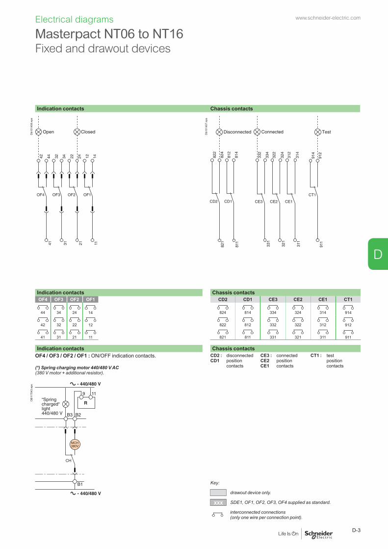
Electrical diagrams
Masterpact NT06 to NT16Fixed and drawout devices
Indication contacts Chassis contacts
Db1
0140
6.ep
s
Db1
0140
7.ep
s
Indication contacts Chassis contactsOF4 OF3 OF2 OF1 CD2 CD1 CE3 CE2 CE1 CT1
44 34 24 14 824 814 334 324 314 914
42 32 22 12 822 812 332 322 312 912
41 31 21 11 821 811 331 321 311 911
Indication contacts Chassis contactsOF4 / OF3 / OF2 / OF1 : ON/OFF indication contacts.
(*) Spring charging motor 440/480 V AC(380 V motor + additional resistor).
CD2 :CD1
disconnectedposition contacts
CE3 : CE2CE1
connectedposition contacts
CT1 : testposition contacts
DB1
1704
3.ep
s
Key:
drawout device only.
XXX SDE1, OF1, OF2, OF3, OF4 supplied as standard.
interconnected connections (only one wire per connection point).
www.schneider-electric.com
D-3
D

Electrical diagrams
Masterpact NW08 to NW63Fixed and drawout devices
The diagram is shown with circuits de-energised, all devices open, connected and charged and relays in normal position.
Power Control unit Remote operation
DB4
3257
0.ep
s
Control unit Remote operationTerminal block marking
Com UC1 UC2 UC3 UC4 M2C SDE2 / Res SDE1 MN / MX2 MX1 XF PF MCH
E5 E6 Z5 M1 M2 M3 F2+ V3 484 184 / K2 84 D2 / C12 C2 A2 254 B2
E3 E4 Z3 Z4 T3 T4 VN V2 474 182 82 C3 A3 252 B3
E1 E2 Z1 Z2 T1 T2 F1 – V1 471 181 / K1 81 D1 / C11 C1 A1 251 B1
A E P H Control unit Remote operationb b b b Com : E1-E6 communication SDE2 : fault-trip indication contact
orRes : remote reset
SDE1 : fault-trip indication contact (supplied as standard)
MN : undervoltage releaseorMX2 : shunt release
MX1 : shunt release (standard or communicating)
XF : closing release (standard or communicating)
PF : ready-to-close contact
MCH : electric motor
Note: when communicating MX or XF releases are used, the third wire (C3,A3) must be connected even if the communication module is not installed.
b b b b UC1 : Z1-Z5 zone selective interlockingZ1 = ZSI OUT SOURCEZ2 = ZSI OUT ; Z3 = ZSI IN SOURCEZ4 = ZSI IN ST (short time)Z5 = ZSI IN GF (earth fault)
b b b M1 = Vigi module input (Micrologic 7)b b b b UC2 : T1, T2, T3, T4 = external neutralb b b M2, M3 = Vigi module input (Micrologic 7)
b b b b UC3 : F2+, F1– external 24 V DC power supplyb b b VN external voltage connector (must be
connected to the neutral with a 3P circuit breaker)
b (1) b b UC4 : External Voltage Connector (PTE option)
b b b M2C : 2 programmable contacts (internal relay)ext. 24 V DC power supply required
A : digital ammeter. P : A + power meter + additional protection.E : energy. H : P + harmonics.(1) The PTE option with Micrologic E is not compatible with an external potential CT.
www.schneider-electric.com
D-4
D

Electrical diagrams
Masterpact NW08 to NW63Fixed and drawout devices
Indication contacts Chassis contacts
Db1
0140
9.ep
s
Indication contacts Chassis contactsOF4 OF3 OF2 OF1 OF24 OF23 OF22 OF21 OF14 OF13 OF12 OF11 CD3 CD2 CD1 CE3 CE2 CE1 CT3 CT2 CT1
44 34 24 14 244 234 224 214 144 134 124 114 834 824 814 334 324 314 934 924 914
42 32 22 12 242 232 222 212 142 132 122 112 832 822 812 332 322 312 932 922 912
41 31 21 11 241 231 221 211 141 131 121 111 831 821 811 331 321 311 931 921 911or or or or or or or or or or
EF24 EF23 EF22 EF21 EF14 EF13 EF12 EF11 CE6 CE5 CE4 CE9 CE8 CE7
248 238 228 218 148 138 128 118 364 354 344 394 384 374
246 236 226 216 146 136 126 116 362 352 342 392 382 372
245 235 225 215 145 135 125 115 361 351 341 391 381 371
Indication contacts Chassis contactsOF4 :OF3OF2OF1
ON/OFF indication contacts OF24 orEF24OF23 orEF23OF22 orEF22OF21 orEF21OF14 or EF14OF13 or EF13OF12 or EF12OF11 orEF11
Combined “connected-deconnected” indication contacts
CD3 CD2CD1
disconnected position contacts
CE3CE2CE1
connected position contacts
CT3CT2CT1
test position contacts
or orCE6 CE5CE4
connected position contacts
CE9CE8CE7
connected position contacts
orCD6CD5CD4
disconnected position contacts
Key:
drawout device only.
XXX SDE1, OF1, OF2, OF3, OF4 supplied as standard.
interconnected connections (only one wire per connection point).
www.schneider-electric.com
D-5
D

Electrical diagrams
External sensor (CT) for residual earth-fault protection
Connection of current-transformer secondary circuit for external neutralMasterpact equipped with a Micrologic 6 A/E/P/H:
b shielded cable with 2 twisted pairs b T1 twisted with T2 b maximum length 4 meters b cable cross-sectional area 0.4 to 1.5 mm2
b recommended cable: Belden 9552 or equivalent.For proper wiring of neutral CT, refer to instructionBulletin 48041-082-03 shipped with it. Do not remove Micrologic factory-installed jumper between T1 and T2 unless neutral CT is connected.If supply is via the top, follow the shematics.If supply is via the bottom, control wiring is identical; for the power wiring, H1 is connected to the source side, H2 to the load side.For four-pole versions, for residual earth-fault protection, the current transformer for the external neutral is not necessary.Connection for signal VN is required only for power measurements (3 Ø, 4 wires, 4CTs).
Shield Drain
DB1
2560
1.ep
s
External transformer for source ground return (SGR) earth-fault protection
Connection of the secondary circuitMasterpact equipped with a Micrologic 6 A/E/P/H:
b unshielded cable with 1 twisted pair b maximum length 150 meters b cable cross-sectional area 0.4 to 1.5 mm2
b terminals 5 and 6 may not be used at the same time b use terminal 5 for NW08 to 40 b use terminal 6 for NW40b to 63 b recommended cable: Belden 9409 or equivalent.
DB4
1670
5.ep
s
Masterpact NT and NW Earth-fault and earth-leakage protection Neutral protection - Zone selective interlocking
www.schneider-electric.com
D-6
D

Earth-leakage protectionConnection of the rectangular-sensor secondary circuitUse the cable shipped with the rectangular sensor.
Db1
0141
5.ep
s
Neutral protection b Three pole circuit breaker: v neutral protection is impossible with Micrologic A, E v Masterpact equipped with Micrologic P or H v the current transformer for external neutral is
necessary (the wiring diagram is identical to the one used for the residual earth-fault protection)
b Four pole circuit breaker: v Masterpact equipped with Micrologic A, E, P or H v the current transformer for external neutral is not
necessary.
Zone selective interlockingZone-selective interlocking is used to reduce the electrodynamic forces exerted on the installation by shortening the time required to clear faults, while maintaining time selectivity between the various devices.A pilot wire interconnects a number of circuit breakers equipped with Micrologic A/E/P/H control units, as illustrated in the diagram above.The control unit detecting a fault sends a signal upstream and checks for a signal arriving from downstream. If there is a signal from downstream, the circuit breaker remains closed for the full duration of its tripping delay. If there is no signal from downstream, the circuit breaker opens immediately, regardless of the tripping-delay setting.Fault 1.Only circuit breaker A detects the fault. Because it receives no signal from downstream, it opens immediately, regardless of its tripping delay set to 0.3.Fault 2.Circuit breakers A and B detect the fault. Circuit breaker A receives a signal from B and remains closed for the full duration of its tripping delay set to 0.3. Circuit breaker B does not receive a signal from downstream and opens immediately, in spite of its tripping delay set to 0.2.Wiring
b Maximum impedance: 2.7 Ω / 300 m. b Capacity of connectors: 0.4 to 2.5 mm2. b Wires: single or multicore. b Maximum lenght: 3000 m. b Limits to device interconnection: v the common ZSI - OUT (Z1) and the output ZSI - OUT (Z2)
can be connected to a maximum of 10 upstream device v a maximum of 100 downstream devices may be connected
to the common ZSI - IN (Z3) and to an input ZSI - IN CR ( Z4) or GF (Z5).
Db1
0142
0.ep
s
Electrical diagrams
Masterpact NT and NW Earth-fault and earth-leakage protection Neutral protection - Zone selective interlocking
www.schneider-electric.com
D-7
D

Electrical diagrams
Communication architecture
+24VDC
13
O1
+
I1
24VDC
I2I3
I4I5
I6
C
C
C
1423
2433
34T1 T2
O2
O3
A1
LV434063
IO
I1
A1
O1
O2
O3I2I3
I4I5
I6
APP
+24VDC
13
O1
+
I1
24VDC
I2I3
I4I5
I6
C
C
C
1423
2433
34T1 T2
O2
O3
A1
LV434063
IO
I1
A1
O1
O2
O3I2I3
I4I5
I6
APP
Test
Test
LV434002
Enerlin'X IFE
Modbus
L
Enerlin'X IFE
LV434001
Enerlin'X IFE
24 V DC
24 V DC
24 V DC
Ethernet
DC
E
F
F G H H
C
B
A A A
KK
K
L L L M M
K
K
J
I I
I I I
I
+24VDC
13
O1
+
I1
24VDC
I2I3
I4I5
I6
C
C
C
1423
2433
34T1 T2
O2
O3
A1
LV434063
IO
I1
A1
O1
O2
O3I2I3
I4I5
I6
APP
DB4
3257
1.ep
s
Masterpact NT and NW Communication
K ULP cable
L Breaker ULP cord
M NSX cord
Ethernet
Modbus
A FDM121 (TRV00121) E I/O application module (LV434063) I ULP termination (TRV00880)
B IFE master (LV434002) F Masterpact MTZ1/MTZ2 J FDM128 (LV434128)
C IFE (LV434001) G Compact NS630b-3200 N Modbus Termination [1]
(VW3A8306DRC)D IFM (LV434000) H Compact NSX
[1] Modbus termination is mandatory, see ULP system user guide TRV99101.
www.schneider-electric.com
D-8
D

Electrical diagrams
Fixed, electrically operated Masterpact NT and NWConnection to the communication interface module
B’ / R
x + D1
A’ / Rx - D
0
B / Tx + D
1
A / Tx - D0
0 V
24 VE1
Red
Breaker ULP cord
Black Blue
E2 E3 E4 E5 E6
Customer terminal block
White
ColorRed E1Black E2White E5Blue E6
24 V0 VHL
Ethernet
ULP TerminationULP Termination
LV434002
Enerlin'X IFE
24 V DC
IFMIFE
Test
24 V DC
OR
DB4
3254
8.ep
s
www.schneider-electric.com
D-9
D
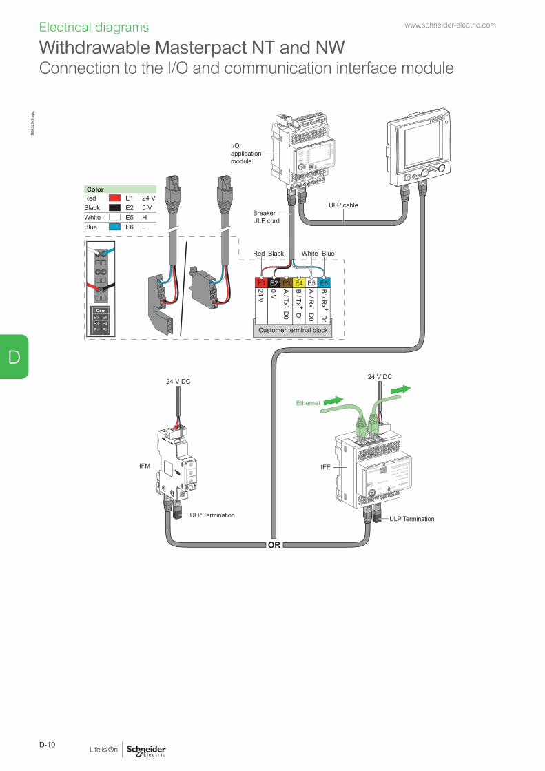
Withdrawable Masterpact NT and NWConnection to the I/O and communication interface module
Electrical diagrams
ColorRed E1Black E2White E5Blue E6
24 V0 VHL
B’ / R
x + D1
A’ / Rx - D
0
B / Tx + D
1
A / Tx - D0
0 V
24 VE1
Red Black Blue
E2 E3 E4 E5 E6
White
Customer terminal block
Ethernet
OR
ULP cable
ULP Termination
FDM121
BreakerULP cord
ULP Termination
LV434002
Enerlin'X IFE
24 V DC
IFM IFE
Test
24 V DC
+24VDC
13
O1
+
I1
24VDC
I2I3
I4I5
I6
C
C
C
1423
2433
34T1 T2
O2
O3
A1
LV434063
IO
I1
A1
O1
O2
O3I2I3
I4I5
I6
APP
I/O application module
DB4
3254
9.ep
swww.schneider-electric.com
D-10
D
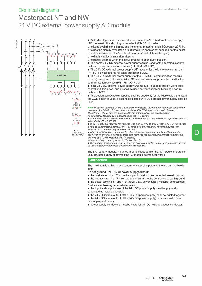
Electrical diagrams
Masterpact NT and NW 24 V DC external power supply AD module
DB4
3226
8.ep
s b With Micrologic, it is recommended to connect 24 V DC external power-supply (AD module) to the Micrologic control unit (F1- F2+) in order
v to keep available the display and the energy metering, even if Current < 20 % In. v to use the display even if the circuit breaker is open or not supplied (for the exact
conditions of use, see the “electrical diagrams” part of this catalogue) v to display fault currents after tripping v to modify settings when the circuit breaker is open (OFF position) b The same 24 V DC external power supply can be used for the micrologic control
unit and the communication devices (IFE, IFM, I/O, FDM). b The 24 V DC external power-supply (AD module) for the Micrologic control unit
(F1- F2+) is not required for basic protections LSIG. b The 24 V DC external power-supply for the BCM ULP communication module
(E1-E2) is required. The same 24 V DC external power supply can be used for the communication devices (IFE, IFM, I/O, FDM).
b If the 24 V DC external power supply (AD module) is used to supply Micrologic control unit, this power supply shall be used only for supplying Micrologic control units and M2C.
b The dedicated AD power supplies shall be used only for the Micrologic trip units. If the COM option is used, a second dedicated 24 V DC external power supply shall be used.
Note: In case of using the 24 V DC external power supply (AD module), maximum cable length between 24 V DC (G1, G2) and the control unit (F1-, F2+) must not exceed 10 meters.The internal voltage taps are connected to the bottom side of the circuit breaker.An external voltage taps are possible using the PTE option:b With this option, the internal voltage taps are disconnected and the voltage taps are connected to terminals VN, V1, V2, V3.b The PTE option is required for voltages less than 220 V and greater than 690 V (in which case a voltage transformer is compulsory). For three-pole devices, the system is supplied with terminal VN connected only to the control unit.b When the PTE option is implemented, the voltage measurement input must be protected against short-circuits. Installed as close as possible to the busbars, this protection function is ensured by a P25M circuit breaker (1 A rating)with an auxiliary contact (cat. no. 21104 and 21117).b This voltage measurement input is reserved exclusively for the control unit and must not ever be used to supply other circuits outside the switchboard.
The BAT battery module, mounted in series upstream of the AD module, ensures an uninterrupted supply of power if the AD module power supply fails.
ConnectionThe maximum length for each conductor supplying power to the trip unit module is 10 m.Do not ground F2+, F1-, or power supply output:
b the positive terminal (F2+) on the trip unit must not be connected to earth ground b the negative terminal (F1-) on the trip unit must not be connected to earth ground b the output terminals (- and +) of the 24 V DC power supply must not be grounded.
Reduce electromagnetic interference: b the input and output wires of the 24 V DC power supply must be physically
separated as much as possible b the 24 V DC wires (output of the 24 V DC power supply) shall be twisted together. b the 24 V DC wires (output of the 24 V DC power supply) must cross all power
cables perpendicularly b power supply conductors must be cut to length. Do not loop excess conductor.
www.schneider-electric.com
D-11
D

Masterpact NT and NW
Additional characteristics
Presentation 2Functions and characteristics A-1Installation recommendations B-1Dimensions and connections C-1Electrical diagrams D-1
Tripping curves E-2
Limitation curvesCurrent limiting E-4Energy limiting E-5
Catalogue numbers and order form F-1
www.schneider-electric.com
E-1
E

Additional characteristics
Micrologic 2.0
DB1
0511
2.EP
S
Micrologic 5.0, 6.0, 7.0
Db1
0511
3.ep
s
Tripping curveswww.schneider-electric.com
E-2
E
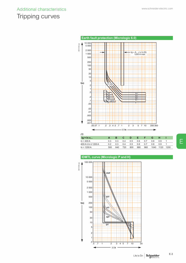
Additional characteristics
Earth fault protection (Micrologic 6.0)
DB1
0150
5.ep
s
(1)Ig = In x... A B C D E F G H I
In < 400 A 0.3 0.3 0.4 0.5 0.6 0.7 0.8 0.9 1400 A y In y 1200 A 0.2 0.3 0.4 0.5 0.6 0.7 0.8 0.9 1In > 1200 A 500 640 720 800 880 960 1040 1120 1200
IDMTL curve (Micrologic P and H)
DB1
0150
6.ep
s
Tripping curveswww.schneider-electric.com
E-3
E

Additional characteristics
Voltage 380/415/440 V ACLimited short-circuit current (k peak)
Db1
0151
5.ep
s
Rated short-circuit current (kA rms)
Voltage 660/690 V ACLimited short-circuit current (k peak)
Db1
0151
6.ep
s
Rated short-circuit current (kA rms)
Limitation curves Current limiting
www.schneider-electric.com
E-4
E

Voltage 380/415/440 V ACLimited energy
Db1
0151
3.ep
s
Rated short-circuit current (kA rms)
Voltage 660/690 V ACLimited energy
Db1
0151
4.ep
s
Rated short-circuit current (kA rms)
Limitation curvesEnergy limiting
Additional characteristics www.schneider-electric.com
E-5
E

Masterpact NT and NW
Catalogue numbers and order form
Presentation 2Functions and characteristics A-1Dimensions and connections C-1Installation recommendations B-1Electrical diagrams D-1Additional characteristics E-1
NT06 to NT16 fixed circuit breakersCircuit breakers F-3Connections F-4Indication contacts F-5Remote operation F-6
NT06 to NT16 drawout circuit breakersCircuit breakers F-7Connections F-8Chassis locking and accessories F-9Indication contacts F-10Remote operation F-11
Accessories for NT06 to NT16 fixed or drawout circuit breakers F-12
NT06 to NT16 fixed switch-disconnectorsSwitch-disconnectors F-14Connections F-15
NT06 to NT16 drawout switch-disconnectorsSwitch-disconnectors F-16Connections F-17
NW08 to NW63 fixed circuit breakersCircuit breakers F-18Connections F-19Indication contacts F-20Remote operation F-21
NW08 to NW63 drawout circuit breakersCircuit breakers F-22Chassis and connections F-23Chassis locking and accessories F-24Indication contacts F-26Remote operation F-27
Accessories for NW08 to NW63 fixed and drawout circuit breakers F-28
NW08 to NW63 fixed switch-disconnectorsSwitch-disconnectors F-30Connections F-31
NW08 to NW63 drawout switch-disconnectorsSwitch-disconnectors F-32Connections F-33
NW08 to NW63 circuit breakers with neutral on the rightCircuit breakers F-34
NW08 to NW40Earthing switch F-35
www.schneider-electric.com
F-1
F
Masterpact NT and NW
Catalogue numbers and order form
NW08 to NW40 1000 V ACDrawout circuit breakers and switch-disconnectors F-36Chassis and connections F-37
NW08 to NW40 with corrosion protectionCircuit breakers F-38
Retrofit solutions (*)Connections for fixed devices F-39Connections for drawout devices F-40
Masterpact NTConnection F-41Micrologic control unit, communication option, accessories F-42Remote operation F-43Chassis locking and accessories F-44Clusters F-45Circuit breaker locking and accessories F-46Mechanical interlocking for source changeover F-47Indication contacts F-48Instructions F-49
Communication, monitoring and control, for NT/NW F-50
Masterpact NWConnection F-51Micrologic control unit, communication option, accessories F-52Remote operation F-53Chassis locking and accessories F-54Clusters F-55Circuit breaker locking and accessories F-56Mechanical interlocking for source changeover F-57Indication contacts F-58Instructions F-59
Communication, monitoring and control F-60
Masterpact NT and NW F-61
www.schneider-electric.com
F-2
F
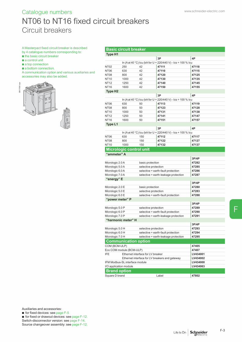
NT06 to NT16 fixed circuit breakers Circuit breakers
A Masterpact fixed circuit breaker is described by 4 catalogue numbers corresponding to: b the basic circuit breaker b a control unit b a top connection b a bottom connection. A communication option and various auxiliaries and accessories may also be added.
Basic circuit breakerType H1
3P 4PIn (A at 40 °C) Icu (kA for U = 220/440 V) - Ics = 100 % Icu
NT02 250 42 47111 47118NT06 630 42 47110 47115NT08 800 42 47120 47125NT10 1000 42 47130 47135
DB1
1708
1.ep
s NT12 1250 42 47140 47145NT16 1600 42 47150 47155Type H2
3P 4PIn (A at 40 °C) Icu (kA for U = 220/440 V) - Ics = 100 % Icu
NT06 630 50 47113 47119NT08 800 50 47123 47128NT10 1000 50 47131 47138NT12 1250 50 47141 47147NT16 1600 50 47151 47157Type L1
3P 4PIn (A at 40 °C) Icu (kA for U = 220/440 V) - Ics = 100 % Icu
NT06 630 150 47112 47117NT08 800 150 47122 47127NT10 1000 150 47132 47137Micrologic control unit“ammeter” A
3P/4PMicrologic 2.0 A basic protection 47282Micrologic 5.0 A selective protection 47285Micrologic 6.0 A selective + earth-fault protection 47286Micrologic 7.0 A selective + earth-leakage protection 47287“energy” E
3P/4PMicrologic 2.0 E basic protection 47280Micrologic 5.0 E selective protection 47283Micrologic 6.0 E selective + earth-fault protection 47288“power meter” P
3P/4PMicrologic 5.0 P selective protection 47289Micrologic 6.0 P selective + earth-fault protection 47290Micrologic 7.0 P selective + earth-leakage protection 47291“harmonic meter” H
3P/4PMicrologic 5.0 H selective protection 47293Micrologic 6.0 H selective + earth-fault protection 47294Micrologic 7.0 H selective + earth-leakage protection 47295Communication option
COM (BCM-ULP) 47405Eco COM module (BCM-ULP) 47407IFE Ethernet interface for LV breaker LV434001
Ethernet interface for LV breakers and gateway LV434002IFM Modbus-SL interface module LV434000I/O application module LV434063Brand option
Square D brand Label 47802
Auxiliaries and accessories: b for fixed devices: see page F-5 b for fixed or drawout devices: see page F-12.
Switch-disconnector version: see page F-14.Source changeover assembly: see page F-12.
Catalogue numbers www.schneider-electric.com
F-3
F

Catalogue numbers
Front connection
DB1
1710
0.ep
s 3P 4P250/630-1600 A Top 47328 47330
Bottom 47329 47331
Front connection accessoriesVertical connection adapters 250/630-1600 A
DB1
1708
0.ep
s 3P (3 parts) 336424P (4 parts) 33643
Interphase barriers
DB1
1710
9.ep
s 3P/4P top (3 parts) 336463P/4P bottom (3 parts) 33646
Arc chute screen
DB1
1709
0.ep
s 3P 473354P 47336
Rear connectionVertical connection
DB1
1707
7.ep
s 3P 4P250/630-1600 A Top 33604 33614
Bottom 33605 33615
Horizontal connection
DB1
1707
6.ep
s 3P 4P250/630-1600 A Top 33606 33616
Bottom 33607 33617
Rear connection accessories
DB1
1710
9.ep
s Interphase barriers3P/4P top (3 parts) 336483P/4P bottom (3 parts) 33648
Common accessories for front and rear connectionsSpreaders
DB1
1707
5.ep
s 250/630-1600 A 3P 336224P 33623
For front and horizontal rear connection
Cable lug adapters 250/630-1600 A
DB1
1707
9.ep
s 3P (3 parts) 336444P (4 parts) 33645
Cable lug kits
DB1
1709
4.ep
s 240 mm2 3P (6 lug kit) 330134P (8 lug kit) 33014
300 mm2 3P (6 lug kit) 330154P (8 lug kit) 33016
NT06 to NT16 fixed circuit breakersConnections
www.schneider-electric.com
F-4
F
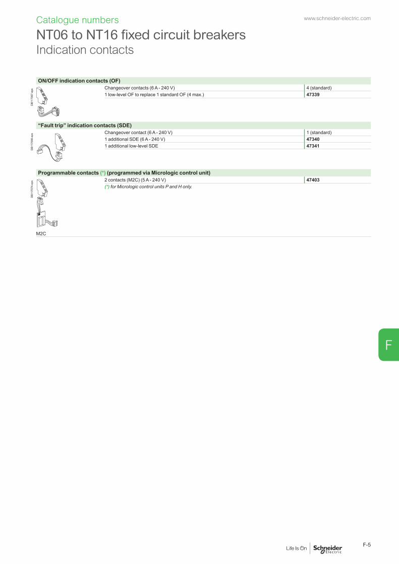
ON/OFF indication contacts (OF)
DB1
1706
7.ep
s Changeover contacts (6 A - 240 V) 4 (standard)1 low-level OF to replace 1 standard OF (4 max.) 47339
“Fault trip” indication contacts (SDE)
DB1
1709
9.ep
s Changeover contact (6 A - 240 V) 1 (standard)1 additional SDE (6 A - 240 V) 473401 additional low-level SDE 47341
Programmable contacts (*) (programmed via Micrologic control unit)
DB1
1707
4.ep
s 2 contacts (M2C) (5 A - 240 V) 47403(*) for Micrologic control units P and H only.
M2C
NT06 to NT16 fixed circuit breakersIndication contacts
Catalogue numbers www.schneider-electric.com
F-5
F

Remote ON/OFFGear motor
DB1
1707
2.ep
s MCHAC 50/60 Hz 48 V 47391
100/130 V 47395200/240 V 47396277/415 V 47398440/480 V 47400
DC 24/30 V 4739048/60 V 47391100/130 V 47392200/250 V 47393
Instantaneous voltage releases
DB1
1707
1.ep
s Closing release Opening releaseStandard XF MXAC 50/60 Hz 12 V DC 47349 47359DC 24/30 V DC, 24 V AC 47350 47360
48/60 V DC, 48 V AC 47351 47361100/130 V AC/DC 47352 47362200/250 V AC/DC 47353 47363277 V AC 47354 47364380/480 V AC 47355 47365
Communicating XF com MX comAC 50/60 Hz 12 V DC 47310 47320DC 24/30 V DC, 24 V AC 47311 47321
48/60 V DC, 48 V AC 47312 47322100/130 V AC/DC 47313 47323200/250 V AC/DC 47314 47324277 V AC 47315 47325380/480 V AC 47316 47326
“Ready to close” contact (1 max.)
DB1
1707
0.ep
s PF1 changeover contact (5 A - 240 V) 473421 low-level changeover contact 47343
Electrical closing pushbutton
DB1
1706
9.ep
s BPFE1 pushbutton 47512
Remote reset after fault trip
DB1
1706
2.ep
s Electrical reset RES110/130 V AC 47344220/240 V AC 47345Automatic reset RARAdaptation 47346
Remote trippingInstantaneous voltage release
DB1
1707
1.ep
s 2nd MX or MNAC 50/60 Hz 12 V DC 47369DC 24/30 V DC, 24 V AC 47370 47380
48/60 V DC, 48 V AC 47371 47381100/130 V AC/DC 47372 47382200/250 V AC/DC 47373 47383277 V AC 47374380/480 V AC 47375 47385
MN delay unit
DB1
1710
5.ep
s R (non-adjustable) Rr (adjustable)AC 50/60 Hz 48/60 V AC/DC 33680DC 100/130 V AC/DC 33684 33681
200/250 V AC/DC 33685 33682380/480 V AC/DC 33683
NT06 to NT16 fixed circuit breakers Remote operation
Catalogue numbers www.schneider-electric.com
F-6
F
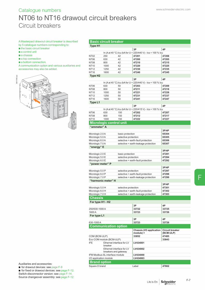
A Masterpact drawout circuit breaker is described by 5 catalogue numbers corresponding to: b the basic circuit breaker b a control unit b a chassis b a top connection b a bottom connection. A communication option and various auxiliaries and accessories may also be added.
Basic circuit breakerType H1
3P 4PIn (A at 40 °C) Icu (kA for U = 220/440 V) - Ics = 100 % Icu
NT02 250 42 47201 47208NT06 630 42 47200 47205NT08 800 42 47210 47215NT10 1000 42 47220 47225NT12 1250 42 47230 47235NT16 1600 42 47240 47245
DB1
1708
5.ep
s Type H23P 4P
In (A at 40 °C) Icu (kA for U = 220/440 V) - Ics = 100 % IcuNT06 630 50 47203 47209NT08 800 50 47211 47218NT10 1000 50 47221 47228NT12 1250 50 47231 47237NT16 1600 50 47241 47247Type L1
3P 4PIn (A at 40 °C) Icu (kA for U = 220/415 V) - Ics = 100 % Icu
NT06 630 150 47202 47207NT08 800 150 47212 47217NT10 1000 150 47222 47227Micrologic control unit“ammeter” A
3P/4PMicrologic 2.0 A basic protection 65304Micrologic 5.0 A selective protection 65305Micrologic 6.0 A selective + earth-fault protection 65306Micrologic 7.0 A selective + earth-leakage protection 65307“energy” E
3P/4PMicrologic 2.0 E basic protection 47281Micrologic 5.0 E selective protection 47284Micrologic 6.0 E selective + earth-fault protection 47292“power meter” P
3P/4PMicrologic 5.0 P selective protection 47297Micrologic 6.0 P selective + earth-fault protection 47298Micrologic 7.0 P selective + earth-leakage protection 47299“harmonic meter” H
3P/4PMicrologic 5.0 H selective protection 47301Micrologic 6.0 H selective + earth-fault protection 47302Micrologic 7.0 H selective + earth-leakage protection 47303ChassisFor type H1 - H2
3P 4P250/630-1000 A 33722 337251600 A 33723 33726For type L1
3P 4P630-1000 A 33723 33726Communication option
Chassis (I/O application module) +
Circuit breaker (BCM-ULP)
COM (BCM-ULP) 33852 47485Eco COM module (BCM-ULP) 33843IFE Ethernet interface for LV
breakerLV434001
Ethernet interface for LV breakers and gateway
LV434002
IFM Modbus-SL interface module LV434000I/O application module LV434063
Auxiliaries and accessories: b for drawout devices: see page F-9 b for fixed or drawout devices: see page F-12.
Switch-disconnector version: see page F-14.Source changeover assembly: see page F-12.
Brand optionSquare D brand Label 47802
NT06 to NT16 drawout circuit breakers Circuit breakers
Catalogue numbers www.schneider-electric.com
F-7
F

Chassis front connection
DB1
1706
8.ep
s 3P 4P250/630-1600 A Top 33727 33733
Bottom 33728 33734
Front connection accessoriesVertical connection adapters 250/630-1600 A
DB1
1708
0.ep
s 3P (3 parts) 336424P (4 parts) 33643
Chassis rear connectionVertical connection
DB1
1707
7.ep
s 3P 4P250/630-1600 A Top 33729 33735
Bottom 33730 33736
Horizontal connection
DB1
1707
6.ep
s 3P 4P250/630-1600 A Top 33731 33737
Bottom 33732 33738
Rear connection accessories
DB1
1707
8.ep
s Interphase barriers3P/4P (3 parts) 33768
Common accessories for front and rear connectionSpreaders
DB1
1707
5.ep
s 250/630-1600 A 3P 336224P 33623
For front and horizontal rear connection.
Cable lug adapters 250/630-1600 A
DB1
1707
9.ep
s 3P (3 parts) 336444P (4 parts) 33645
Cable lug kits
DB1
1709
4.ep
s 240 mm2 3P (6 lug kit) 330134P (8 lug kit) 33014
300 mm2 3P (6 lug kit) 330154P (8 lug kit) 33016
NT06 to NT16 drawout circuit breakers
Connections
Catalogue numbers www.schneider-electric.com
F-8
F
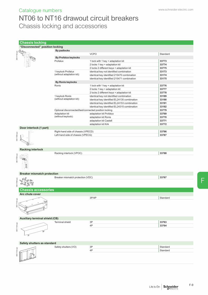
Chassis locking“Disconnected” position locking
DB1
1710
8.ep
s By padlocksVCPO Standard
By Profalux keylocksProfalux 1 lock with 1 key + adaptation kit 33773
2 locks 1 key + adaptation kit 337742 locks 2 different keys + adaptation kit 33775
1 keylock Profalux (without adaptation kit):
identical key not identified combination 33173identical key identified 215470 combination 33174identical key identified 215471 combination 33175
By Ronis keylocksRonis 1 lock with 1 key + adaptation kit 33776
2 locks 1 key + adaptation kit 337772 locks 2 different keys + adaptation kit 33778
1 keylock Ronis (without adaptation kit):
identical key not identified combination 33189identical key identified EL24135 combination 33190identical key identified EL24153 combination 33191identical key identified EL24315 combination 33192
Optional disconnected/test/connected position locking 33779Adaptation kit (without keylock):
adaptation kit Profalux 33769adaptation kit Ronis 33770adaptation kit Castell 33771adaptation kit Kirk 33772
Door interlock (1 part)
DB1
1706
6.ep
s Right-hand side of chassis (VPECD) 33786Left-hand side of chassis (VPECG) 33787
Racking interlock
DB1
1706
5.ep
s Racking interlock (VPOC) 33788
Breaker mismatch protection
DB1
1709
6.ep
s Breaker mismatch protection (VDC) 33767
Chassis accessoriesArc chute cover
DB1
1710
2.ep
s 3P/4P Standard
Auxiliary terminal shield (CB)
DB1
1710
4.ep
s Terminal shield 3P 337634P 33764
Safety shutters as standard
DB1
1710
3.ep
s Safety shutters (VO) 3P Standard4P Standard
NT06 to NT16 drawout circuit breakers Chassis locking and accessories
Catalogue numbers www.schneider-electric.com
F-9
F
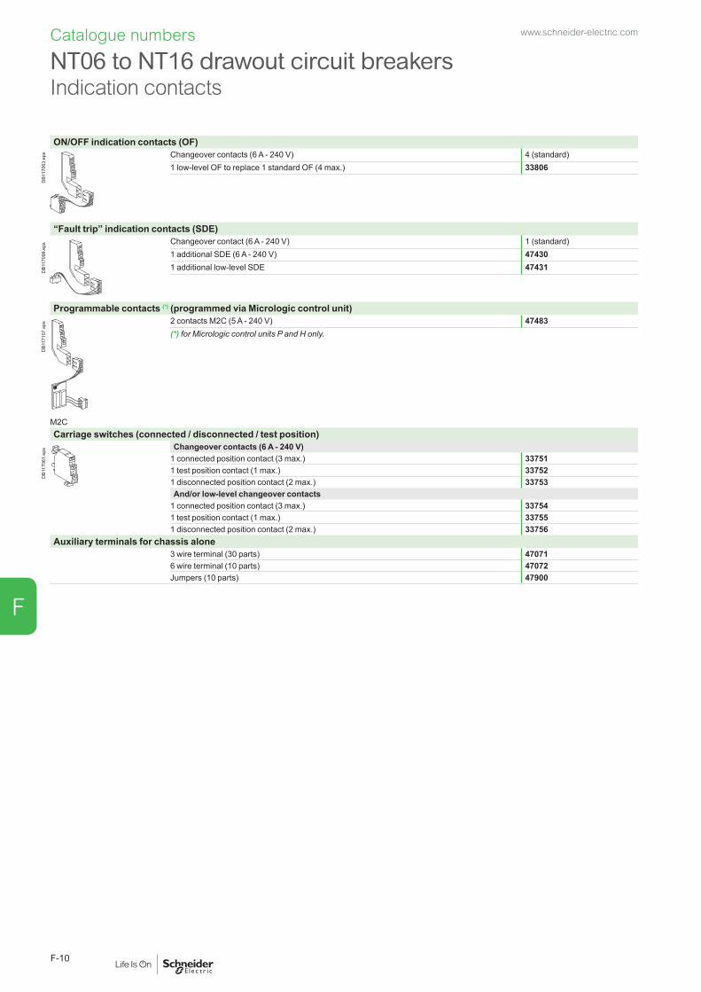
ON/OFF indication contacts (OF)
DB1
1706
3.ep
s Changeover contacts (6 A - 240 V) 4 (standard)1 low-level OF to replace 1 standard OF (4 max.) 33806
“Fault trip” indication contacts (SDE)
DB1
1709
8.ep
s Changeover contact (6 A - 240 V) 1 (standard)1 additional SDE (6 A - 240 V) 474301 additional low-level SDE 47431
Programmable contacts (*) (programmed via Micrologic control unit)
DB1
1710
7.ep
s 2 contacts M2C (5 A - 240 V) 47483(*) for Micrologic control units P and H only.
M2CCarriage switches (connected / disconnected / test position)
DB1
1706
1.ep
s Changeover contacts (6 A - 240 V)1 connected position contact (3 max.) 337511 test position contact (1 max.) 337521 disconnected position contact (2 max.) 33753And/or low-level changeover contacts
1 connected position contact (3 max.) 337541 test position contact (1 max.) 337551 disconnected position contact (2 max.) 33756
Auxiliary terminals for chassis alone3 wire terminal (30 parts) 470716 wire terminal (10 parts) 47072Jumpers (10 parts) 47900
NT06 to NT16 drawout circuit breakersIndication contacts
Catalogue numbers www.schneider-electric.com
F-10
F

Remote ON/OFFGear motor
DB1
1706
0.ep
s MCHAC 50/60 Hz 48 V 47461
100/130 V 47465200/240 V 47466277/415 V 47468440/480 V 47470
DC 24/30 V 4746048/60 V 47461100/130 V 47462200/250 V 47463
Instantaneous voltage releaseClosing release Opening release
Standard XF MXAC 50/60 Hz 12 V DC 47439 33809DC 24/30 V DC, 24 V AC 47440 33810
48/60 V DC, 48 V AC 47441 33811100/130 V AC/DC 47442 33812200/250 V AC/DC 47443 33813277 V AC 47444 33814380/480 V AC 47445 33815
Communicating XF com MX comAC 50/60 Hz 12 V DC 47411 33791DC 24/30 V DC, 24 V AC 47412 33792
48/60 V DC, 48 V AC 47413 33793100/130 V AC/DC 47414 33794200/250 V AC/DC 47415 33795277 V AC 47416 33796380/480 V AC 47417 33797
“Ready to close” contact (1 max.)
DB1
1705
9.ep
s PF1 changeover contact (5 A - 240 V) 474321 low-level changeover contact 47433
Electrical closing pushbutton
DB1
1706
9.ep
s BPFE1 pushbutton 47512
Remote reset after fault trip
DB1
1706
2.ep
s Electrical reset RES110/130 V AC 47434220/240 V AC 47435Automatic reset RARAdaptation 47346
Remote trippingInstantaneous voltage release
DB1
1706
7.ep
s 2nd MX or MNAC 50/60 Hz 12 V DC 47449DC 24/30 V DC, 24 V AC 47450 33819
48/60 V DC, 48 V AC 47451 33820100/130 V AC/DC 47452 33821200/250 V AC/DC 47453 33822277 V AC 47454380/480 V AC 47455 33824
MN delay unit
DB1
1710
5.ep
s R (non-adjustable) Rr (adjustable)AC 50/60 Hz 48/60 V AC/DC 33680DC 100/130 V AC/DC 33684 33681
200/250 V AC/DC 33685 33682380/480 V AC/DC 33683
NT06 to NT16 drawout circuit breakersRemote operation
Catalogue numbers www.schneider-electric.com
F-11
F

Circuit breaker lockingPushbutton locking device
DB1
1705
8.ep
s By padlocks 33897
OFF position locking
DB1
1710
1.ep
s By padlocks + BPFE supportVCPO 47514
By Profalux keylocksProfalux 1 lock with 1 key + adaptation kit 47519
2 locks 1 key + adaptation kit 475201 keylock Profalux (without adaptation kit):
identical key not identified combination 33173identical key identified 215470 combination 33174identical key identified 215471 combination 33175
By Ronis keylocks + BPFE supportRonis 1 lock with 1 key + adaptation kit 47521
2 locks 1 key + adaptation kit 475221 keylock Ronis (without adaptation kit):
identical key not identified combination 33189identical key identified EL24135 combination 33190identical key identified EL24153 combination 33191identical key identified EL24315 combination 33192
Adaptation kit (without keylock):
adaptation kit Profalux 47515adaptation kit Ronis 47516adaptation kit Kirk 47517adaptation kit Castell 47518
Cable-type door interlock
DB1
1709
1.ep
s 1 complete assembly for Masterpact NT fixed devices 339201 complete assembly for Masterpact NT drawout devices 33921
Mechanical interlocking for source changeoverInterlocking using connecting rods
DB1
1709
7.ep
s Complete assembly with 2 adaptation fixtures + rods2 Masterpact NT fixed devices 339122 Masterpact NT drawout devices 33913
Interlocking using cables (*)
DB4
1684
0.ep
s Choose 2 adaptation fixtures (1 for each breaker) + 1 set of cables1 adaptation fixture for Masterpact NT fixed devices 332001 adaptation fixture for Masterpact NT drawout devices 332011 set of 2 cables 33209(*) Can be used with any combination of NT or NW, fixed or drawout devices.
Other circuit breaker accessoriesMechanical operation counter
DB1
1705
7.ep
s Operation counter CDM 33895
Escutcheon and accessories
DB1
1705
6.ep
s
DB1
1705
5.ep
s
DB1
1705
3.ep
s Fixed DrawoutEscutcheon 33718 33857Transparent cover (IP54) 33859Escutcheon blanking plate 33858
Escutcheon Cover Blanking plate
Accessories for NT06 to NT16 fixed or drawout circuit breakers
Catalogue numbers www.schneider-electric.com
F-12
F

Accessories for Micrologic control unitsExternal sensorsExternal sensor for earth-leakage protection (TCE)
DB1
1705
4.ep
s Sensor rating 400/1600 A (for Micrologic P and H with 3P devices) 33576
Rectangular sensor for earth-leakage protection
DB1
2610
0.ep
s 280 mm x 115 mm / L1 56053
Source ground return (SGR) earth fault protection
DB1
1708
9.ep
s External sensor (SGR) 33579MDGF summing module 48891
Voltage measurement input (for breakers supplied via bottom terminals)
DB1
1708
8.ep
s Voltage measurement input Fixed 47506Drawout 47507
Long-time rating plug (limits setting range for higher accuracy)
DB1
1708
7.ep
s Standard 0.4 to 1 x Ir 33542Low-setting option 0.4 to 0.8 x Ir 33543High-setting option 0.8 to 1 x Ir 33544Without long-time protection off 33545
Zone Selective Interlocking option for Micrologic P and H ZSI Standard
External power supply module (AD)
G3G4
Output
LN
DB4
3260
8.ep
s 24/30 V DC LV45444048/60 V DC LV454441100/125 V DC LV454442110/130 V AC LV454443200/240 V AC LV454444
Battery module (BAT)
DB1
1709
5.ep
s 1 battery 24 V 54446
Test equipmentMini test kit
DB1
1709
2.ep
s Hand held test kit (HHTK) 33594
Portable test kit
DB1
1709
3.ep
s Full function test kit (FFTK) 33595Test report edition come from FFTK 34559FFTK test cable 2 pin for STR trip unit 34560FFTK test cable 7 pin for Micrologic trip unit 33590
Special settingsSensor ratingTo be specified when ordering
Rating NT02 NT06 NT08 NT10 NT12 NT16250 b
400 b b b
630 b b b
800 b b b
1000 b b
1250 b
1600 b
Accessories for NT06 to NT16 fixed or drawout circuit breakers
Catalogue numbers www.schneider-electric.com
F-13
F

A Masterpact fixed switch-disconnector is described by 3 catalogue numbers corresponding to: b the basic switch-disconnector b a top connection b a bottom connection. A communication option and various auxiliaries and accessories may also be added.
Basic switch-disconnectorType HA
3P 4PIn (A at 40 °C) Icm (kA peak for U = 220/690 V)
NT06 630 60 47159 47160NT08 800 60 47161 47162NT10 1000 60 47163 47164NT12 1250 60 47165 47166
DB1
1708
6.ep
s NT16 1600 60 47167 47168Communication option
Modbus COM 47405Brand option
Square D brand Label 47802
Auxiliaries and accessories: b for fixed devices: see page F-5 b for fixed or drawout devices: see page F-12.
Source changeover assembly: see page F-12.
NT06 to NT16 fixed switch-disconnectorsSwitch-disconnectors
Catalogue numbers www.schneider-electric.com
F-14
F

Front connection
DB1
1710
0.ep
s 3P 4P250/630-1600 A Top 47328 47330
Bottom 47329 47331
Front connection accessoriesVertical connection adapters 250/630-1600 A
DB1
1708
0.ep
s 3P (3 parts) 336424P (4 parts) 33643
Interphase barriers
DB1
1710
9.ep
s 3P/4P top (3 parts) 336463P/4P bottom (3 parts) 33646
Rear connectionVertical connection
DB1
1707
7.ep
s 3P 4P250/630-1600 A Top 33604 33614
Bottom 33605 33615
Horizontal connection
DB1
1707
6.ep
s 3P 4P250/630-1600 A Top 33606 33616
Bottom 33607 33617
Rear connection accessories
DB1
1710
9.ep
s Interphase barriers3P/4P top (3 parts) 336483P/4P bottom (3 parts) 33648
Common accessories for front and rear connectionSpreaders
DB1
1707
5.ep
s 250/630-1600 A 3P 336224P 33623
For front and horizontal rear connection
Cable lug adapters 250/630-1600 A
DB1
1707
9.ep
s 3P (3 parts) 336444P (4 parts) 33645
Cable lug kits
DB1
1709
4.ep
s 240 mm2 3P (6 lug kit) 330134P (8 lug kit) 33014
300 mm2 3P (6 lug kit) 330154P (8 lug kit) 33016
NT06 to NT16 fixed switch-disconnectorsConnections
Catalogue numbers www.schneider-electric.com
F-15
F

A Masterpact drawout switch-disconnector is described by 4 catalogue numbers corresponding to: b the basic switch-disconnector b a chassis b a top connection b a bottom connection. A communication option and various auxiliaries and accessories may also be added.
Basic switch-disconnectorType HA
3P 4PIn (A at 40 °C) Icm (kA peak for U = 220/690 V)
NT06 630 75 47248 47249NT08 800 75 47250 47251NT10 1000 75 47252 47253NT12 1250 75 47254 47255NT16 1600 75 47256 47257
DB1
1708
4.ep
s Chassis3P 4P
630/1250 A 33722 337251600 A 33723 33726Communication option
Chassis + Switch-disconnectorCOM (BCM-ULP) 33852 47485Brand option
Square D brand Label 47802
Auxiliaries and accessories: b for fixed devices: see page F-9 b for fixed or drawout devices: see page F-12.
Source changeover assembly: see page F-12.
NT06 to NT16 drawout switch-disconnectors Switch-disconnectors
Catalogue numbers www.schneider-electric.com
F-16
F

Chassis front connection
DB1
1706
8.ep
s 3P 4P250/630-1600 A Top 33727 33733
Bottom 33728 33734
Front connection accessoriesVertical connection adapters 250/630-1600 A
DB1
1708
0.ep
s 3P (3 parts) 336424P (4 parts) 33643
Chassis rear connectionVertical connection
DB1
1707
7.ep
s 3P 4P250/630-1600 A Top 33729 33735
Bottom 33730 33736
Horizontal connection
DB1
1707
6.ep
s 3P 4P250/630-1600 A Top 33731 33737
Bottom 33732 33738
Rear connection accessories
DB1
1707
8.ep
s Interphase barriers3P/4P (3 parts) 33768
Common accessories for front and rear connectionSpreaders
DB1
1707
5.ep
s 250/630-1600 A 3P 336224P 33623
For front and horizontal rear connection
Cable lug adapters 250/630-1600 A
DB1
1707
9.ep
s 3P (3 parts) 336444P (4 parts) 33645
Cable lug kits
DB11
7094
.eps 240 mm2 3P (6 lug kit) 33013
4P (8 lug kit) 33014300 mm2 3P (6 lug kit) 33015
4P (8 lug kit) 33016
NT06 to NT16 drawout switch-disconnectorsConnections
Catalogue numbers www.schneider-electric.com
F-17
F
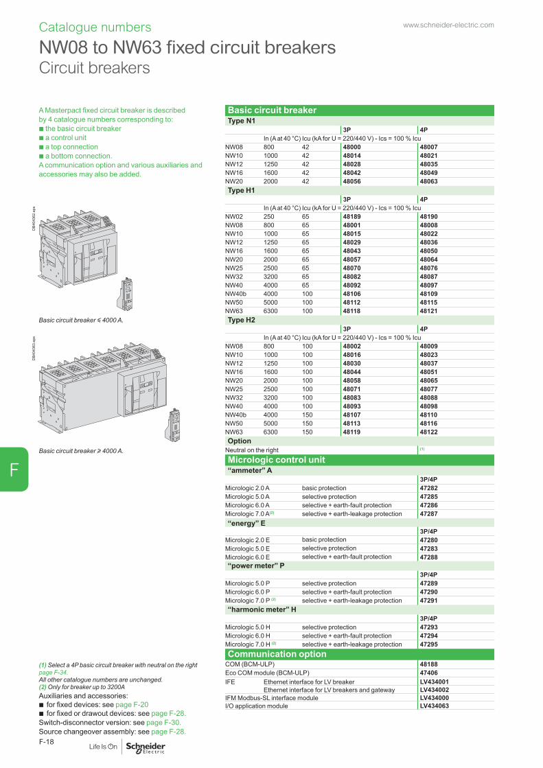
Catalogue numbers
A Masterpact fixed circuit breaker is described by 4 catalogue numbers corresponding to: b the basic circuit breaker b a control unit b a top connection b a bottom connection. A communication option and various auxiliaries and accessories may also be added.
Basic circuit breakerType N1
3P 4PIn (A at 40 °C) Icu (kA for U = 220/440 V) - Ics = 100 % Icu
NW08 800 42 48000 48007NW10 1000 42 48014 48021NW12 1250 42 48028 48035NW16 1600 42 48042 48049NW20 2000 42 48056 48063Type H1
3P 4P
DB4
0436
2.ep
s In (A at 40 °C) Icu (kA for U = 220/440 V) - Ics = 100 % IcuNW02 250 65 48189 48190NW08 800 65 48001 48008NW10 1000 65 48015 48022NW12 1250 65 48029 48036NW16 1600 65 48043 48050NW20 2000 65 48057 48064NW25 2500 65 48070 48076NW32 3200 65 48082 48087NW40 4000 65 48092 48097NW40b 4000 100 48106 48109NW50 5000 100 48112 48115NW63 6300 100 48118 48121
Basic circuit breaker y 4000 A. Type H23P 4P
DB4
0436
3.ep
s In (A at 40 °C) Icu (kA for U = 220/440 V) - Ics = 100 % IcuNW08 800 100 48002 48009NW10 1000 100 48016 48023NW12 1250 100 48030 48037NW16 1600 100 48044 48051NW20 2000 100 48058 48065NW25 2500 100 48071 48077NW32 3200 100 48083 48088NW40 4000 100 48093 48098NW40b 4000 150 48107 48110NW50 5000 150 48113 48116NW63 6300 150 48119 48122Option
Basic circuit breaker u 4000 A. Neutral on the right (1)
Micrologic control unit“ammeter” A
3P/4PMicrologic 2.0 A basic protection 47282Micrologic 5.0 A selective protection 47285Micrologic 6.0 A selective + earth-fault protection 47286Micrologic 7.0 A(2) selective + earth-leakage protection 47287“energy” E
3P/4PMicrologic 2.0 E basic protection 47280Micrologic 5.0 E selective protection 47283Micrologic 6.0 E selective + earth-fault protection 47288“power meter” P
3P/4PMicrologic 5.0 P selective protection 47289Micrologic 6.0 P selective + earth-fault protection 47290Micrologic 7.0 P (2) selective + earth-leakage protection 47291“harmonic meter” H
3P/4PMicrologic 5.0 H selective protection 47293Micrologic 6.0 H selective + earth-fault protection 47294Micrologic 7.0 H (2) selective + earth-leakage protection 47295Communication option
(1) Select a 4P basic circuit breaker with neutral on the right page F-34. All other catalogue numbers are unchanged.(2) Only for breaker up to 3200AAuxiliaries and accessories:
b for fixed devices: see page F-20 b for fixed or drawout devices: see page F-28.
Switch-disconnector version: see page F-30.Source changeover assembly: see page F-28.
COM (BCM-ULP) 48188Eco COM module (BCM-ULP) 47406IFE Ethernet interface for LV breaker LV434001
Ethernet interface for LV breakers and gateway LV434002IFM Modbus-SL interface module LV434000I/O application module LV434063
NW08 to NW63 fixed circuit breakers Circuit breakers
www.schneider-electric.com
F-18
F
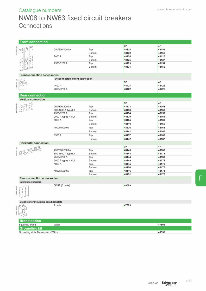
Catalogue numbers
Front connection
DB4
0436
4.ep
s 3P 4P250/800-1600 A Top 48128 48153
Bottom 48130 481552000 A Top 48124 48126
Bottom 48125 481272500/3200 A Top 48129 48154
Bottom 48131 48156
Front connection accessories
DB4
0436
5.ep
s Disconnectable front connection3P 4P
1600 A 48421 484242000/3200 A 48422 48425
Rear connectionVertical connection
DB4
0436
6.ep
s 3P 4P250/800-2000 A Top 48133 48158800-1600 A type L1 Bottom 48138 481632500/3200 A Top 48134 481592000 A types H3/L1 Bottom 48139 481644000 A Top 48135 48160
Bottom 48140 481654000b/5000 A Top 48136 48161
Bottom 48141 481666300 A Top 48137 48162
Bottom 48142 48167Horizontal connection
DB4
0436
7.ep
s 3P 4P250/800-2000 A Top 48143 48168800-1600 A type L1 Bottom 48148 481732500/3200 A Top 48144 481692000 A types H3/L1 Bottom 48149 481744000 A Top 48145 48170
Bottom 48150 481754000b/5000 A Top 48146 48171
Bottom 48151 48176Rear connection accessoriesInterphase barriers
DB4
0436
8.ep
s 3P/4P (3 parts) 48599
Brackets for mounting on a backplate
DB4
0436
9.ep
s 2 parts 47829
Brand optionSquare D brand Label 47802Grounding kit
Grounding kit for Masterpact NW fixed 48558
NW08 to NW63 fixed circuit breakersConnections
www.schneider-electric.com
F-19
F
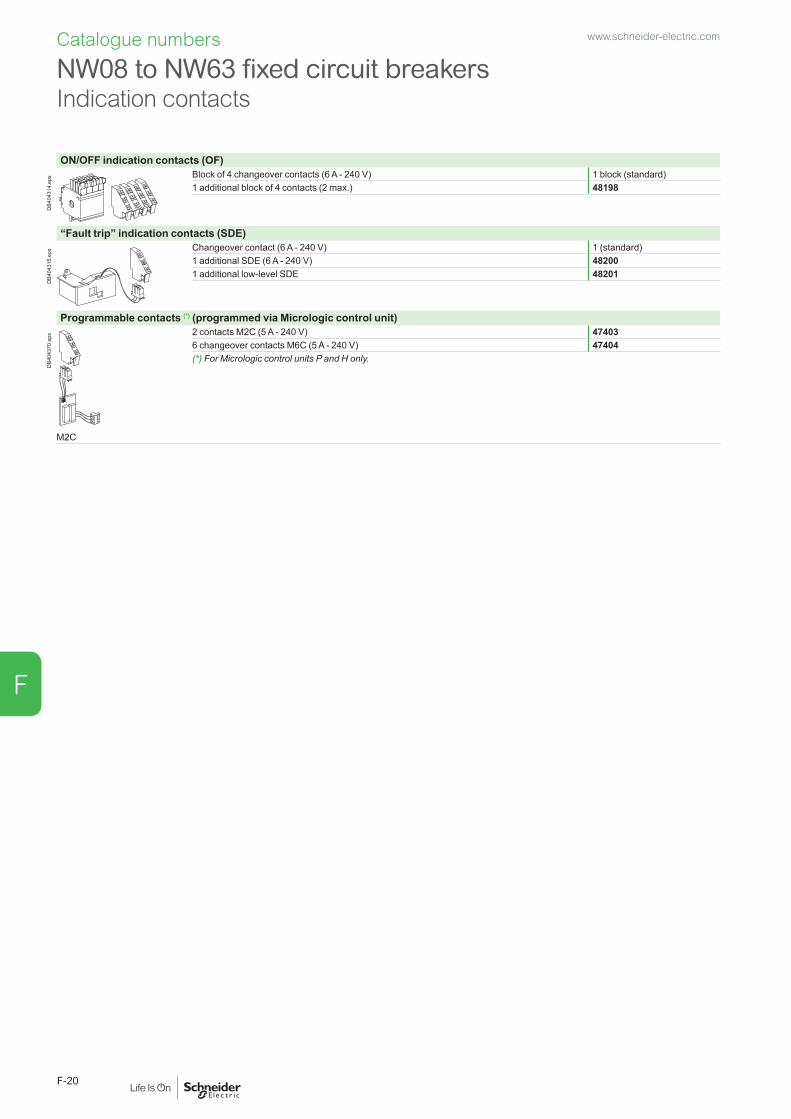
Catalogue numbers
ON/OFF indication contacts (OF)
DB4
0431
4.ep
s Block of 4 changeover contacts (6 A - 240 V) 1 block (standard)1 additional block of 4 contacts (2 max.) 48198
“Fault trip” indication contacts (SDE)
DB4
0431
5.ep
s Changeover contact (6 A - 240 V) 1 (standard)1 additional SDE (6 A - 240 V) 482001 additional low-level SDE 48201
Programmable contacts (*) (programmed via Micrologic control unit)
DB4
0437
0.ep
s 2 contacts M2C (5 A - 240 V) 474036 changeover contacts M6C (5 A - 240 V) 47404(*) For Micrologic control units P and H only.
M2C
NW08 to NW63 fixed circuit breakersIndication contacts
www.schneider-electric.com
F-20
F
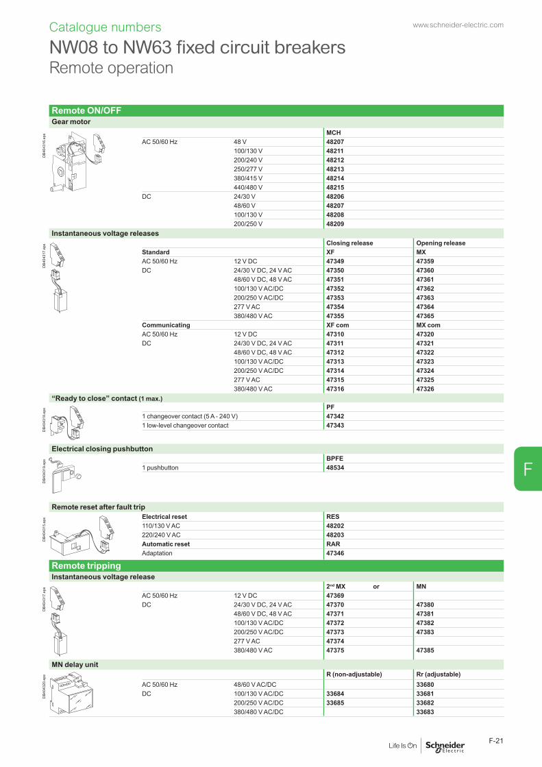
Remote ON/OFFGear motor
DB4
0431
6.ep
s MCHAC 50/60 Hz 48 V 48207
100/130 V 48211200/240 V 48212250/277 V 48213380/415 V 48214440/480 V 48215
DC 24/30 V 4820648/60 V 48207100/130 V 48208200/250 V 48209
Instantaneous voltage releases
DB4
0431
7.ep
s Closing release Opening releaseStandard XF MXAC 50/60 Hz 12 V DC 47349 47359DC 24/30 V DC, 24 V AC 47350 47360
48/60 V DC, 48 V AC 47351 47361100/130 V AC/DC 47352 47362200/250 V AC/DC 47353 47363277 V AC 47354 47364380/480 V AC 47355 47365
Communicating XF com MX comAC 50/60 Hz 12 V DC 47310 47320DC 24/30 V DC, 24 V AC 47311 47321
48/60 V DC, 48 V AC 47312 47322100/130 V AC/DC 47313 47323200/250 V AC/DC 47314 47324277 V AC 47315 47325380/480 V AC 47316 47326
“Ready to close” contact (1 max.)
DB4
0431
8.ep
s PF1 changeover contact (5 A - 240 V) 473421 low-level changeover contact 47343
Electrical closing pushbutton
DB4
0431
9.ep
s BPFE1 pushbutton 48534
Remote reset after fault trip
DB4
0431
5.ep
s Electrical reset RES110/130 V AC 48202220/240 V AC 48203Automatic reset RARAdaptation 47346
Remote trippingInstantaneous voltage release
DB4
0431
7.ep
s 2nd MX or MNAC 50/60 Hz 12 V DC 47369DC 24/30 V DC, 24 V AC 47370 47380
48/60 V DC, 48 V AC 47371 47381100/130 V AC/DC 47372 47382200/250 V AC/DC 47373 47383277 V AC 47374380/480 V AC 47375 47385
MN delay unit
DB4
0432
0.ep
s R (non-adjustable) Rr (adjustable)AC 50/60 Hz 48/60 V AC/DC 33680DC 100/130 V AC/DC 33684 33681
200/250 V AC/DC 33685 33682380/480 V AC/DC 33683
NW08 to NW63 fixed circuit breakers Remote operation
Catalogue numbers www.schneider-electric.com
F-21
F

Catalogue numbers
A Masterpact drawout circuit breaker is described by 5 catalogue numbers corresponding to: b the basic circuit breaker b a control unit b a chassis b a top connection b a bottom connection. A communication option and various auxiliaries and accessories may also be added.
Basic circuit breaker3P 4P
Type N1In (A at 40 °C) Icu (kA for U = 220/440 V) - Ics = 100 % Icu
NW08 800 42 48230 48237NW10 1000 42 48244 48251NW12 1250 42 48258 48265NW16 1600 42 48272 48279NW20 2000 42 48286 48293Type H1
In (A at 40 °C) Icu (kA for U = 220/440 V) - Ics = 100 % IcuNW02 250 65 48386 48387
DB1
0191
1.EP
S NW08 800 65 48231 48238NW10 1000 65 48245 48252NW12 1250 65 48259 48266NW16 1600 65 48273 48280NW20 2000 65 48287 48294NW25 2500 65 48300 48306NW32 3200 65 48312 48317NW40 4000 65 48322 48327NW40b 4000 100 48336 48339NW50 5000 100 48342 48345NW63 6300 100 48348 48351Type H2
In (A at 40 °C) Icu (kA for U = 220/440 V) - Ics = 100 % IcuNW08 800 100 48232 48239NW10 1000 100 48246 48253NW12 1250 100 48260 48267
Basic circuit breaker + chassis y 4000 A NW16 1600 100 48274 48281NW20 2000 100 48288 48295
DB1
0191
2.EP
S NW25 2500 100 48301 48307NW32 3200 100 48313 48318NW40 4000 100 48323 48328NW40b 4000 150 48337 48340NW50 5000 150 48343 48346NW63 6300 150 48349 48352Type H3
In (A at 40 °C) Icu (kA for U = 220/440 V) - Ics = 100 % IcuNW20 2000 150 48289 48296NW25 2500 150 48302 48308NW32 3200 150 48314 48319NW40 4000 150 48324 48329Type L1
In (A at 40 °C) Icu (kA for U = 220/440 V) - Ics = 100 % IcuNW08 800 150 48233 48240
Basic circuit breaker + chassis u 4000 A NW10 1000 150 48247 48254NW12 1250 150 48261 48268NW16 1600 150 48275 48282NW20 2000 150 48290 48297Option
Neutral on the right (1)
Micrologic control unit“ammeter” A
3P/4PMicrologic 2.0 A basic protection 48358Micrologic 5.0 A selective protection 48360Micrologic 6.0 A selective + earth-fault protection 48361Micrologic 7.0 A(2) selective + earth-leakage protection 48362“energy” E
3P/4PMicrologic 2.0 E basic protection 48498Micrologic 5.0 E selective protection 48499Micrologic 6.0 E selective + earth-fault protection 48500“power meter” P
3P/4PMicrologic 5.0 P selective protection 48363Micrologic 6.0 P selective + earth-fault protection 48364Micrologic 7.0 P(2) selective + earth-leakage protection 48365“harmonic meter” H
3P/4PMicrologic 5.0 H selective protection 48366Micrologic 6.0 H selective + earth-fault protection 48367Micrologic 7.0 H(2) selective + earth-leakage protection 48368
(1) Select a 4P basic circuit breaker with neutral on the right page F-34. All other catalogue numbers are unchanged.(2) Only for breaker up to 3200 A.
Grounding kitGrounding kit for Masterpact NW drawout 48559
NW08 to NW63 drawout circuit breakers Circuit breakers
www.schneider-electric.com
F-22
F
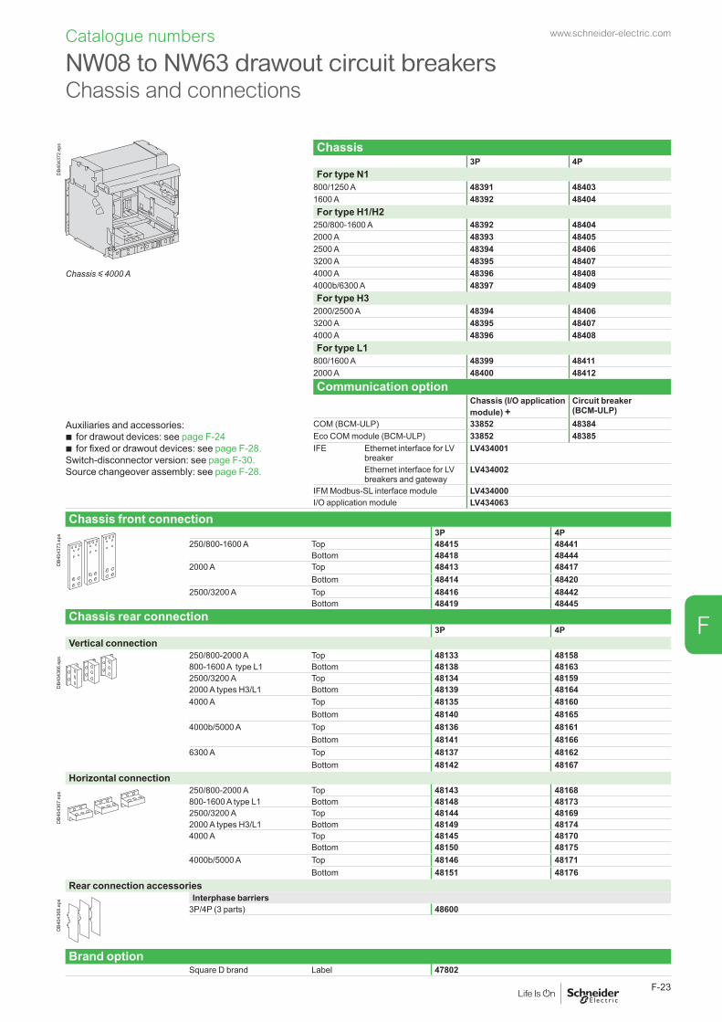
DB4
0437
2.ep
s Chassis3P 4P
For type N1800/1250 A 48391 484031600 A 48392 48404For type H1/H2
250/800-1600 A 48392 484042000 A 48393 484052500 A 48394 484063200 A 48395 48407
Chassis y 4000 A 4000 A 48396 484084000b/6300 A 48397 48409For type H3
2000/2500 A 48394 484063200 A 48395 484074000 A 48396 48408For type L1
800/1600 A 48399 484112000 A 48400 48412Communication option
Chassis (I/O application module) +
Circuit breaker (BCM-ULP)
Auxiliaries and accessories: b for drawout devices: see page F-24 b for fixed or drawout devices: see page F-28.
Switch-disconnector version: see page F-30.Source changeover assembly: see page F-28.
COM (BCM-ULP) 33852 48384Eco COM module (BCM-ULP) 33852 48385IFE Ethernet interface for LV
breakerLV434001
Ethernet interface for LV breakers and gateway
LV434002
IFM Modbus-SL interface module LV434000I/O application module LV434063
Chassis front connection
DB4
0437
3.ep
s 3P 4P250/800-1600 A Top 48415 48441
Bottom 48418 484442000 A Top 48413 48417
Bottom 48414 484202500/3200 A Top 48416 48442
Bottom 48419 48445Chassis rear connection
3P 4PVertical connection
DB4
0436
6.ep
s 250/800-2000 A Top 48133 48158800-1600 A type L1 Bottom 48138 481632500/3200 A Top 48134 481592000 A types H3/L1 Bottom 48139 481644000 A Top 48135 48160
Bottom 48140 481654000b/5000 A Top 48136 48161
Bottom 48141 481666300 A Top 48137 48162
Bottom 48142 48167Horizontal connection
DB4
0436
7.ep
s 250/800-2000 A Top 48143 48168800-1600 A type L1 Bottom 48148 481732500/3200 A Top 48144 481692000 A types H3/L1 Bottom 48149 481744000 A Top 48145 48170
Bottom 48150 481754000b/5000 A Top 48146 48171
Bottom 48151 48176Rear connection accessories
DB4
0436
8.ep
s Interphase barriers3P/4P (3 parts) 48600
Brand optionSquare D brand Label 47802
NW08 to NW63 drawout circuit breakers Chassis and connections
Catalogue numbers www.schneider-electric.com
F-23
F

Catalogue numbers
Chassis locking“Disconnected” position locking
DB4
0432
5.ep
s By padlocksVCPO Standard
By Profalux keylocksProfalux 1 lock with 1 key + adaptation kit 48568
2 locks 1 key + adaptation kit 485692 locks 2 different keys + adaptation kit 48570
1 keylock Profalux (without adaptation kit):
identical key not identified combination 33173identical key identified 215470 combination 33174identical key identified 215471 combination 33175
By Ronis keylocksRonis 1 lock with 1 key + adaptation kit 48572
2 locks 1 key + adaptation kit 485732 locks 2 different keys + adaptation kit 48574
1 keylock Ronis (without adaptation kit):
identical key not identified combination 33189identical key identified EL24135 combination 33190identical key identified EL24153 combination 33191identical key identified EL24315 combination 33192
Optional disconnected/test/connected position locking 33779Adaptation kit (without keylock):
adaptation kit Profalux / Ronis 48564adaptation kit Castell 48565adaptation kit Kirk 48566
Door interlock (1 part)
DB4
0432
6.ep
s Right-hand side of chassis 48579Left-hand side of chassis 48580
Racking interlock
DB4
0432
7.ep
s 1 part 48582
Racking interlock between crank and OFF pushbutton1 part 48585
Automatic spring discharge before breaker removal
DB4
0432
8.ep
s 1 part 48554
Breaker mismatch protection
DB4
0432
9.ep
s Breaker mismatch protection VDC 33767
NW08 to NW63 drawout circuit breakers
Chassis locking and accessories
www.schneider-electric.com
F-24
F

Catalogue numbers
NW08 to NW63 drawout circuit breakers
Chassis locking and accessories
Chassis accessoriesArc chute cover
DB4
0433
0.ep
s 3P/4P Standard
Auxiliary terminal shield (CB)
DB4
0433
1.ep
s 800/4000 A 3P 485954P 48596
4000b/6300 A 3P 485974P 48598
Safety shutters + locking block
DB4
0433
2.ep
s 800/4000 A 3P Standard4P Standard
4000b/6300 A 3P Standard4P Standard
Shutter locking block (for remplacement)
DB4
0433
3.ep
s 2 parts for 800/4000 A 48591
Front face shutter position indication and locking
DB4
0437
4.ep
s 800/4000 A 3P/4P 485924000b/6300 A 3P 48593
4P 48594
www.schneider-electric.com
F-25
F

Catalogue numbers
ON/OFF indication contacts (OF)
DB4
0432
1.ep
s Block of 4 changeover contacts (6 A - 240 V) 1 block (standard)1 additional block of 4 contacts (2 max.) 48468
Combined closed / connected contacts for use with 1 auxiliary contact
DB4
0432
2.ep
s 1 contact (5 A - 240 V) (8 max.) 48477or 1 low-level contact (8 max.) 48478
“Fault trip” indication contacts (SDE)
DB4
0432
3.ep
s Changeover contact (6 A - 240 V) 1 (standard)1 additional SDE (6 A - 240 V) 48475or 1 additional low-level SDE 48476
Programmable contacts (*) (programmed via Micrologic control unit)
DB4
0437
5.ep
s 2 contacts M2C (5 A - 240 V) 48382(*) For Micrologic control units P and H only.
M2CCarriage switches (connected / disconnected / test position)
DB4
0432
4.ep
s Changeover contacts (8 A - 240 V)1 connected position contact (3 max.) 337511 test position contact (3 max.) 337521 disconnected position contact (3 max.) 33753and/or low-level changeover contacts
1 connected position contact (3 max.) 337541 test position contact (3 max.) 337551 disconnected position contact (3 max.) 33756Actuator for additional carriage switches 48560
Auxiliary terminals for chassis alone3 wire terminal (30 parts) 478986 wire terminal (10 parts) 47899Jumpers (10 parts) 47900
NW08 to NW63 drawout circuit breakersIndication contacts
www.schneider-electric.com
F-26
F
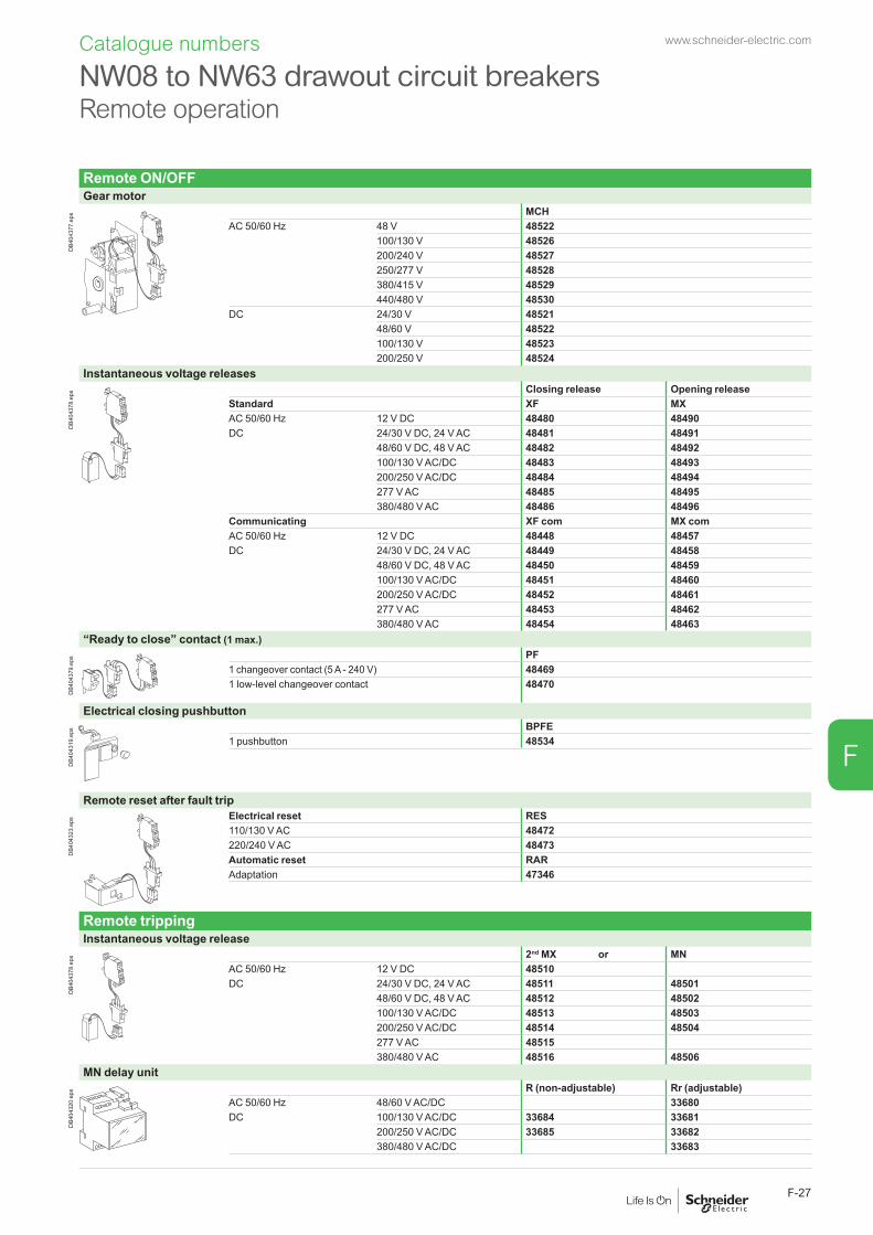
Remote ON/OFFGear motor
DB4
0437
7.ep
s MCHAC 50/60 Hz 48 V 48522
100/130 V 48526200/240 V 48527250/277 V 48528380/415 V 48529440/480 V 48530
DC 24/30 V 4852148/60 V 48522100/130 V 48523200/250 V 48524
Instantaneous voltage releases
DB4
0437
8.ep
s Closing release Opening releaseStandard XF MXAC 50/60 Hz 12 V DC 48480 48490DC 24/30 V DC, 24 V AC 48481 48491
48/60 V DC, 48 V AC 48482 48492100/130 V AC/DC 48483 48493200/250 V AC/DC 48484 48494277 V AC 48485 48495380/480 V AC 48486 48496
Communicating XF com MX comAC 50/60 Hz 12 V DC 48448 48457DC 24/30 V DC, 24 V AC 48449 48458
48/60 V DC, 48 V AC 48450 48459100/130 V AC/DC 48451 48460200/250 V AC/DC 48452 48461277 V AC 48453 48462380/480 V AC 48454 48463
“Ready to close” contact (1 max.)
DB4
0437
9.ep
s PF1 changeover contact (5 A - 240 V) 484691 low-level changeover contact 48470
Electrical closing pushbutton
DB4
0431
9.ep
s BPFE1 pushbutton 48534
Remote reset after fault trip
DB4
0432
3.ep
s Electrical reset RES110/130 V AC 48472220/240 V AC 48473Automatic reset RARAdaptation 47346
Remote trippingInstantaneous voltage release
DB4
0437
8.ep
s 2nd MX or MNAC 50/60 Hz 12 V DC 48510DC 24/30 V DC, 24 V AC 48511 48501
48/60 V DC, 48 V AC 48512 48502100/130 V AC/DC 48513 48503200/250 V AC/DC 48514 48504277 V AC 48515380/480 V AC 48516 48506
MN delay unit
DB4
0432
0.ep
s R (non-adjustable) Rr (adjustable)AC 50/60 Hz 48/60 V AC/DC 33680DC 100/130 V AC/DC 33684 33681
200/250 V AC/DC 33685 33682380/480 V AC/DC 33683
NW08 to NW63 drawout circuit breakers Remote operation
Catalogue numbers www.schneider-electric.com
F-27
F
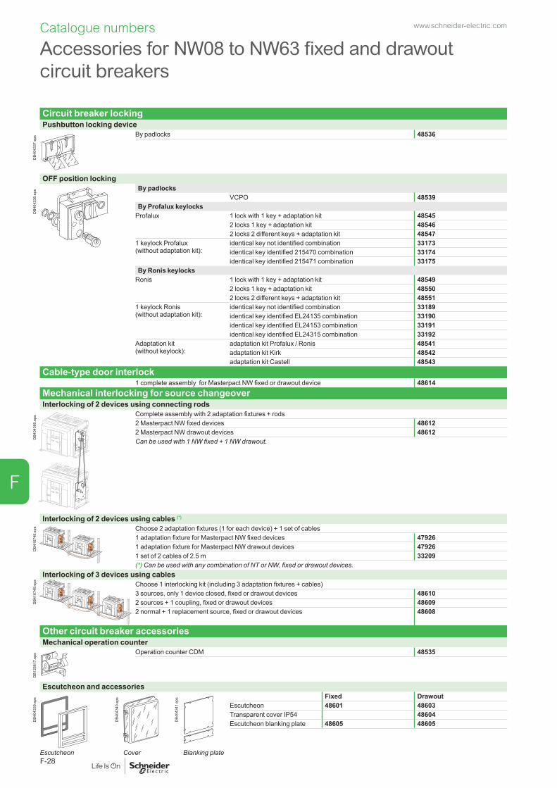
Catalogue numbers
Circuit breaker locking Pushbutton locking device
DB4
0433
7.ep
s By padlocks 48536
OFF position locking
DB4
0433
8.ep
s By padlocksVCPO 48539
By Profalux keylocksProfalux 1 lock with 1 key + adaptation kit 48545
2 locks 1 key + adaptation kit 485462 locks 2 different keys + adaptation kit 48547
1 keylock Profalux (without adaptation kit):
identical key not identified combination 33173identical key identified 215470 combination 33174identical key identified 215471 combination 33175
By Ronis keylocksRonis 1 lock with 1 key + adaptation kit 48549
2 locks 1 key + adaptation kit 485502 locks 2 different keys + adaptation kit 48551
1 keylock Ronis (without adaptation kit):
identical key not identified combination 33189identical key identified EL24135 combination 33190identical key identified EL24153 combination 33191identical key identified EL24315 combination 33192
Adaptation kit (without keylock):
adaptation kit Profalux / Ronis 48541adaptation kit Kirk 48542adaptation kit Castell 48543
Cable-type door interlock1 complete assembly for Masterpact NW fixed or drawout device 48614
Mechanical interlocking for source changeoverInterlocking of 2 devices using connecting rods
DB4
0438
0.ep
s Complete assembly with 2 adaptation fixtures + rods2 Masterpact NW fixed devices 486122 Masterpact NW drawout devices 48612Can be used with 1 NW fixed + 1 NW drawout.
Interlocking of 2 devices using cables (*)
DB4
1674
8.ep
s Choose 2 adaptation fixtures (1 for each device) + 1 set of cables 1 adaptation fixture for Masterpact NW fixed devices 479261 adaptation fixture for Masterpact NW drawout devices 479261 set of 2 cables of 2.5 m 33209(*) Can be used with any combination of NT or NW, fixed or drawout devices.
Interlocking of 3 devices using cables
DB4
1674
9.ep
s
Choose 1 interlocking kit (including 3 adaptation fixtures + cables) 3 sources, only 1 device closed, fixed or drawout devices 486102 sources + 1 coupling, fixed or drawout devices 486092 normal + 1 replacement source, fixed or drawout devices 48608
Other circuit breaker accessoriesMechanical operation counter
DB1
2561
7.ep
s Operation counter CDM 48535
Escutcheon and accessories
DB4
0433
9.ep
s
DB4
0434
0.ep
s
DB4
0434
1.ep
s Fixed DrawoutEscutcheon 48601 48603Transparent cover IP54 48604Escutcheon blanking plate 48605 48605
Escutcheon Cover Blanking plate
Accessories for NW08 to NW63 fixed and drawout circuit breakers
www.schneider-electric.com
F-28
F

Catalogue numbers
Accessories for NW08 to NW63 fixed and drawout circuit breakers
Accessories for Micrologic control unitsExternal sensorsExternal sensor for earth-fault protection (TCE)
DB4
0438
1.ep
s Sensor rating 400/2000 A 340351000/4000 A 340364000/6300 A (for NW40b, NW50, NW63) 48182
Rectangular sensor for earth-leakage protection
DB1
2610
0.ep
s 470 mm x 160 mm / L2 In max. 3200 A 56054
Source ground return (SGR) earth fault protection
DB4
0438
2.ep
s External sensor (SGR) 33579MDGF summing module 48891
Voltage measurement input (for breakers supplied via bottom terminals)
DB1
2564
2.ep
s Voltage measurement input Fixed 47506Drawout 48533
Long-time rating plug (limits setting range for higher accuracy)
DB4
0438
3.ep
s Standard 0.4 at 1 x Ir 33542Low-setting option 0.4 at 0.8 x Ir 33543High-setting option 0.8 at 1 x Ir 33544Without long-time protection off 33545
Zone Selective Interlocking option for Micrologic P and HZSI Standard
External power supply module (AD)
G3G4
Output
LN
DB4
3260
8.ep
s 24/30 V DC LV45444048/60 V DC LV454441100/125 V DC LV454442110/130 V AC LV454443200/240 V AC LV454444
Battery module (BAT)
L3
G1
AD 220A
L4
G2
Input
24VDC
Output
24VDCDB4
0438
4.ep
s 1 battery 24 V 54446
Test equipmentMini test kit
DB4
0438
5.ep
s Hand held test kit (HHTK) 33594
Portable test kit
DB4
0438
6.ep
s Full function test kit (FFTK) 33595Test report edition come from FFTK 34559FFTK test cable 2 pin for STR trip unit 34560FFTK test cable 7 pin for Micrologic trip unit 33590
Special settingsSensor ratingTo be specified when ordering
Rating NW02 NW08 NW10 NW12 NW16 NW20 NW25 NW32250 b
400 b b
630 b b b
800 b b b
1000 b b b
1250 b b b
1600 b b b
2000 b b
2500 b
3200Rating NW40 NW40b NW50 NW632000 b b
2500 b b b
3200 b b b b
4000 b b
5000 b
6300
www.schneider-electric.com
F-29
F

Catalogue numbers
A Masterpact fixed switch-disconnector is described by 3 catalogue numbers corresponding to: b the basic switch-disconnector b a top connection b a bottom connection. A communication option and various auxiliaries and accessories may also be added.
Basic switch-disconnectorType NA
3P 4PIn (A at 40 °C) Icm (kA peak for U = 220/690 V)
NW08 800 88 48004 48011NW10 1000 88 48018 48025NW12 1250 88 48032 48039NW16 1600 88 48046 48053
DB4
0431
3.ep
s Type HA3P 4P
In (A at 40 °C) Icm (kA peak for U = 220/690 V)NW08 800 143 48005 48012NW10 1000 143 48019 48026NW12 1250 143 48033 48040NW16 1600 143 48047 48054NW20 2000 143 48061 48068
Basic switch-disconnector y 4000 A. NW25 2500 143 48074 48080NW32 3200 143 48085 48090
DB4
0438
7.ep
s NW40 4000 143 48095 48100NW40b 4000 187 48108 48111NW50 5000 187 48114 48117NW63 6300 187 48120 48123Type HF
3P 4PIn (A at 40 °C) Icm (kA peak for U = 220/690 V)
NW08 800 187 48006 48013NW10 1000 187 48020 48027NW12 1250 187 48034 48041
Basic switch-disconnector u 4000 A. NW16 1600 187 48048 48055NW20 2000 187 48062 48069NW25 2500 187 48075 48081NW32 3200 187 48086 48091NW40 4000 187 48096 48101Type HH
3P 4PIn (A at 40°C) Icm (kA peak for U = 220/690 V)
NW40b 4000 220 46130 46135NW50 5000 220 46131 46136NW63 6300 220 46132 46137Communication option
COM (BCM ULP) 48188
Auxiliaries and accessories: b for fixed devices: see page F-20 b for fixed or drawout devices: see page F-28.
Source changeover assembly: see page F-28.
IFE Ethernet interface for LV breaker
LV434001
Ethernet interface for LV breakers and gateway
LV434002
IFM Modbus-SL interface module LV434000I/O application module LV434063
NW08 to NW63 fixed switch-disconnectors Switch-disconnectors.
www.schneider-electric.com
F-30
F

Front connection
DB4
0436
4.ep
s 3P 4P800-1600 A Top 48128 48153
Bottom 48130 481552000 A Top 48124 48126
Bottom 48125 481272500-3200 A Top 48129 48154
Bottom 48131 48156
Front connection accessories
DB4
0436
5.ep
s Disconnectable front connection3P 4P
1600 A 48421 484242000/3200 A 48422 48425
Rear connectionVertical connection
DB4
0436
6.ep
s 3P 4P800-2000 A Top 48133 48158
Bottom 48138 481632500-3200 A Top 48134 48159
Bottom 48139 481644000 A Top 48135 48160
Bottom 48140 481654000b/5000 A Top 48136 48161
Bottom 48141 481666300 A Top 48137 48162
Bottom 48142 48167Horizontal connection
DB4
0436
7.ep
s 3P 4P800-2000 A Top 48143 48168
Bottom 48148 481732500-3200 A Top 48144 48169
Bottom 48149 481744000 A Top 48145 48170
Bottom 48150 481754000b/5000 A Top 48146 48171
Bottom 48151 48176Rear connection accessoriesInterphase barriers
DB4
0436
8.ep
s 3P/4P (3 parts) 48599
Brackets for mounting on a backplate
DB4
0436
9.ep
s 2 parts 47829
NW08 to NW63 fixed switch-disconnectors Connections
Catalogue numbers www.schneider-electric.com
F-31
F
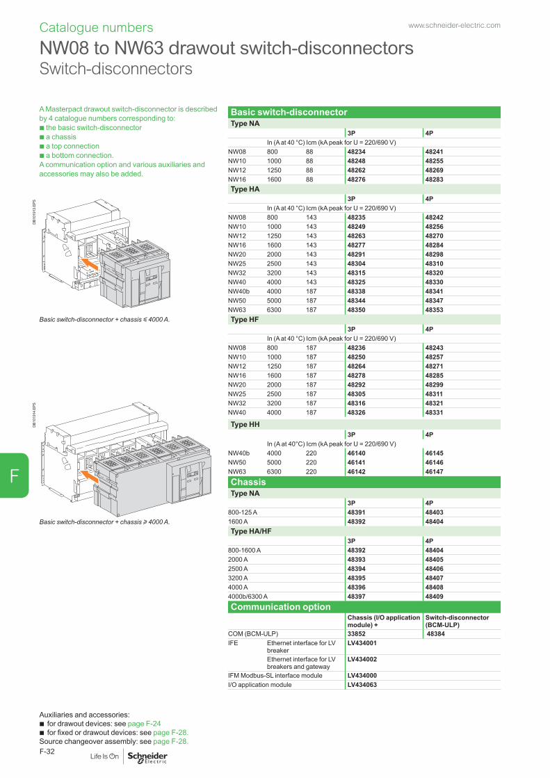
Catalogue numbers
A Masterpact drawout switch-disconnector is described by 4 catalogue numbers corresponding to: b the basic switch-disconnector b a chassis b a top connection b a bottom connection. A communication option and various auxiliaries and accessories may also be added.
Basic switch-disconnectorType NA
3P 4PIn (A at 40 °C) Icm (kA peak for U = 220/690 V)
NW08 800 88 48234 48241NW10 1000 88 48248 48255NW12 1250 88 48262 48269NW16 1600 88 48276 48283Type HA
DB1
0191
3.EP
S 3P 4PIn (A at 40 °C) Icm (kA peak for U = 220/690 V)
NW08 800 143 48235 48242NW10 1000 143 48249 48256NW12 1250 143 48263 48270NW16 1600 143 48277 48284NW20 2000 143 48291 48298NW25 2500 143 48304 48310NW32 3200 143 48315 48320NW40 4000 143 48325 48330NW40b 4000 187 48338 48341NW50 5000 187 48344 48347NW63 6300 187 48350 48353
Basic switch-disconnector + chassis y 4000 A. Type HF3P 4P
DB1
0191
4.EP
S
In (A at 40 °C) Icm (kA peak for U = 220/690 V)NW08 800 187 48236 48243NW10 1000 187 48250 48257NW12 1250 187 48264 48271NW16 1600 187 48278 48285NW20 2000 187 48292 48299NW25 2500 187 48305 48311NW32 3200 187 48316 48321NW40 4000 187 48326 48331
Type HH3P 4P
In (A at 40°C) Icm (kA peak for U = 220/690 V)NW40b 4000 220 46140 46145NW50 5000 220 46141 46146NW63 6300 220 46142 46147ChassisType NA
3P 4P800-125 A 48391 48403
Basic switch-disconnector + chassis u 4000 A. 1600 A 48392 48404Type HA/HF
3P 4P800-1600 A 48392 484042000 A 48393 484052500 A 48394 484063200 A 48395 484074000 A 48396 484084000b/6300 A 48397 48409Communication option
Chassis (I/O application module) +
Switch-disconnector (BCM-ULP)
COM (BCM-ULP) 33852 48384IFE Ethernet interface for LV
breakerLV434001
Ethernet interface for LV breakers and gateway
LV434002
IFM Modbus-SL interface module LV434000I/O application module LV434063
Auxiliaries and accessories: b for drawout devices: see page F-24 b for fixed or drawout devices: see page F-28.
Source changeover assembly: see page F-28.
NW08 to NW63 drawout switch-disconnectors Switch-disconnectors
www.schneider-electric.com
F-32
F
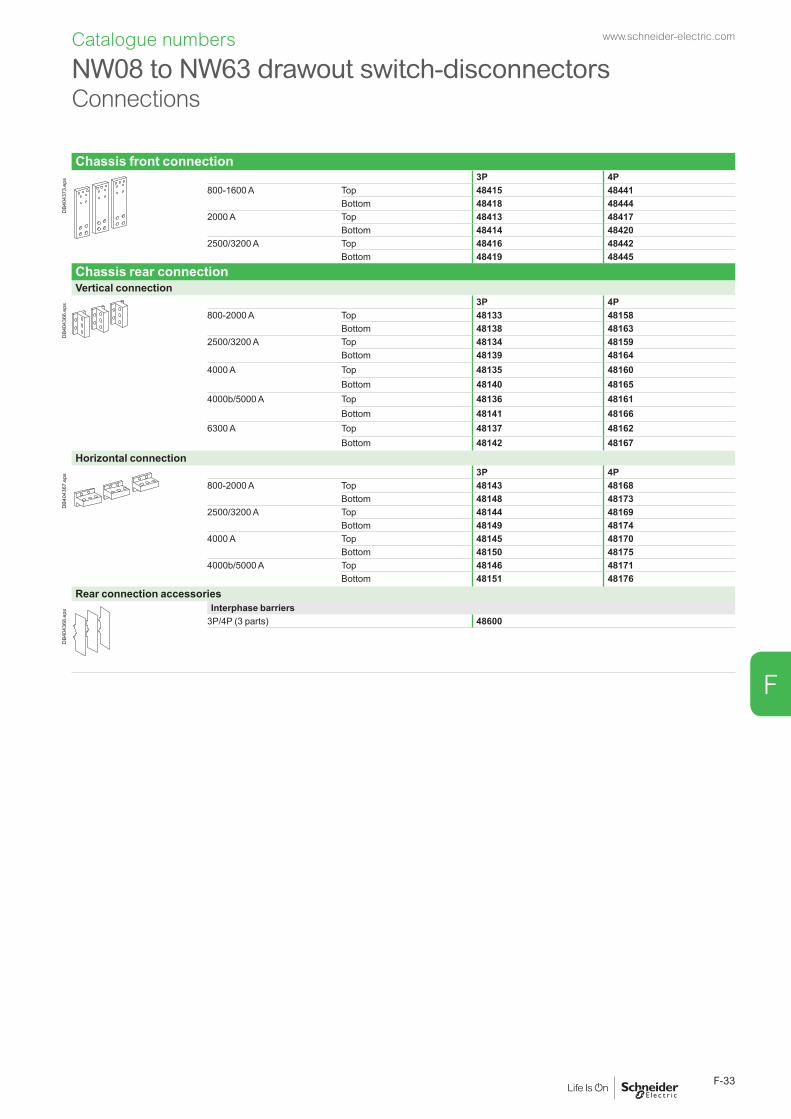
Chassis front connection
DB4
0437
3.ep
s 3P 4P800-1600 A Top 48415 48441
Bottom 48418 484442000 A Top 48413 48417
Bottom 48414 484202500/3200 A Top 48416 48442
Bottom 48419 48445Chassis rear connectionVertical connection
DB4
0436
6.ep
s 3P 4P800-2000 A Top 48133 48158
Bottom 48138 481632500/3200 A Top 48134 48159
Bottom 48139 481644000 A Top 48135 48160
Bottom 48140 481654000b/5000 A Top 48136 48161
Bottom 48141 481666300 A Top 48137 48162
Bottom 48142 48167Horizontal connection
DB4
0436
7.ep
s 3P 4P800-2000 A Top 48143 48168
Bottom 48148 481732500/3200 A Top 48144 48169
Bottom 48149 481744000 A Top 48145 48170
Bottom 48150 481754000b/5000 A Top 48146 48171
Bottom 48151 48176Rear connection accessories
DB4
0436
8.ep
s Interphase barriers3P/4P (3 parts) 48600
NW08 to NW63 drawout switch-disconnectorsConnections
Catalogue numbers www.schneider-electric.com
F-33
F

Catalogue numbers
A 4 pole Masterpact circuit breaker with neutral on the right is described by the same catalogue numbers as a standard 4 pole one, except for the basic circuit breaker, which is specific.
Fixed circuit breakers with neutral on the rightType H1
4PIn (A at 40 °C) Icu (kA for U = 220/440 V) - Ics = 100 % Icu
NW08 800 65 48183NW10 1000 65 48184NW12 1250 65 48185NW16 1600 65 48186NW20 2000 65 48060NW25 2500 65 48073NW32 3200 65 48187NW40 4000 65 48193NW40b 4000 100 48194NW50 5000 100 48195NW63 6300 100 48196Type H2
4PIn (A at 40 °C) Icu (kA for U = 220/440 V) - Ics = 100 % Icu
NW08 800 100 48177NW10 1000 100 48178NW12 1250 100 48179NW16 1600 100 48180NW20 2000 100 48067NW25 2500 100 48079NW32 3200 100 48181NW40 4000 100 48102NW40b 4000 150 48103NW50 5000 150 48104NW63 6300 150 48105Drawout circuit breakers with neutral on the rightType H1
4PIn (A at 40 °C) Icu (kA for U = 220/440 V) - Ics = 100 % Icu
NW08 800 65 48226NW10 1000 65 48227NW12 1250 65 48228NW16 1600 65 48229NW20 2000 65 48436NW25 2500 65 48303NW32 3200 65 48437NW40 4000 65 48332NW40b 4000 100 48333NW50 5000 100 48334NW63 6300 100 48335Type H2
4PIn (A at 40 °C) Icu (kA for U = 220/440 V) - Ics = 100 % Icu
NW08 800 100 48426NW10 1000 100 48427NW12 1250 100 48428NW16 1600 100 48429NW20 2000 100 48438NW25 2500 100 48309NW32 3200 100 48439NW40 4000 100 48354NW40b 4000 150 48355NW50 5000 150 48356NW63 6300 150 48357
NW08 to NW63 circuit breakers with neutral on the right Circuit breakers
www.schneider-electric.com
F-34
F
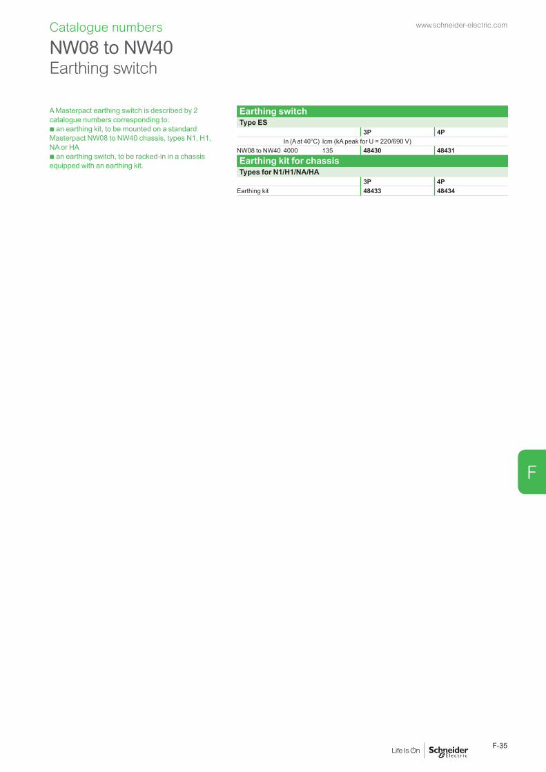
A Masterpact earthing switch is described by 2 catalogue numbers corresponding to: b an earthing kit, to be mounted on a standard Masterpact NW08 to NW40 chassis, types N1, H1, NA or HA b an earthing switch, to be racked-in in a chassis equipped with an earthing kit.
Earthing switchType ES
3P 4PIn (A at 40°C) Icm (kA peak for U = 220/690 V)
NW08 to NW40 4000 135 48430 48431Earthing kit for chassisTypes for N1/H1/NA/HA
3P 4PEarthing kit 48433 48434
NW08 to NW40 Earthing switch
Catalogue numbers www.schneider-electric.com
F-35
F
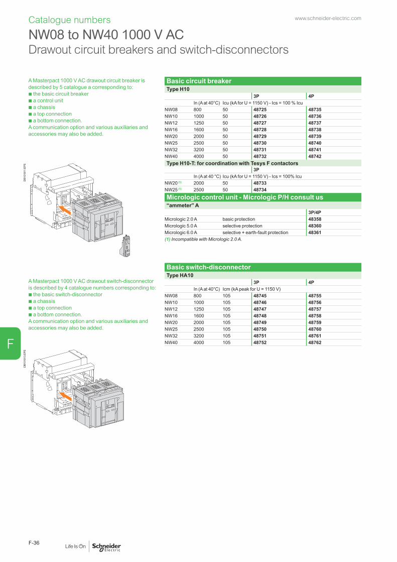
Catalogue numbers
A Masterpact 1000 V AC drawout circuit breaker is described by 5 catalogue a corresponding to: b the basic circuit breaker b a control unit b a chassis b a top connection b a bottom connection.A communication option and various auxiliaries and accessories may also be added.
Basic circuit breakerType H10
3P 4PIn (A at 40°C) Icu (kA for U = 1150 V) - Ics = 100 % Icu
NW08 800 50 48725 48735NW10 1000 50 48726 48736NW12 1250 50 48727 48737NW16 1600 50 48728 48738NW20 2000 50 48729 48739NW25 2500 50 48730 48740NW32 3200 50 48731 48741NW40 4000 50 48732 48742
DB1
0191
1.EP
S Type H10-T: for coordination with Tesys F contactors3P
In (A at 40 °C) Icu (kA for U = 1150 V) - Ics = 100% IcuNW20 (1) 2000 50 48733NW25 (1) 2500 50 48734Micrologic control unit - Micrologic P/H consult us“ammeter” A
3P/4PMicrologic 2.0 A basic protection 48358Micrologic 5.0 A selective protection 48360Micrologic 6.0 A selective + earth-fault protection 48361(1) Incompatible with Micrologic 2.0 A.
A Masterpact 1000 V AC drawout switch-disconnector is described by 4 catalogue numbers corresponding to: b the basic switch-disconnector b a chassis b a top connection b a bottom connection. A communication option and various auxiliaries and accessories may also be added.
Basic switch-disconnectorType HA10
3P 4PIn (A at 40°C) Icm (kA peak for U = 1150 V)
NW08 800 105 48745 48755NW10 1000 105 48746 48756NW12 1250 105 48747 48757NW16 1600 105 48748 48758NW20 2000 105 48749 48759NW25 2500 105 48750 48760NW32 3200 105 48751 48761NW40 4000 105 48752 48762
DB1
0191
3.EP
S
NW08 to NW40 1000 V AC0 Drawout circuit breakers and switch-disconnectors
www.schneider-electric.com
F-36
F

DB4
0437
2.ep
s Chassis3P 4P
For type H10 and HA10800-1600 A 48392 484042000 A 48393 484052500 A 48394 484063200 A 48395 484074000 A 48396 48408Communication option
Chassis (I/O application module) +
Circuit breaker and switch-disconnector (BCM-ULP)
COM (BCM-ULP) 33852 48384Eco COM (BCM-ULP) 33852 48385IFE Ethernet interface for LV
breakerLV434001
Ethernet interface for LV breakers and gateway
LV434002
IFM Modbus-SL interface module LV434000I/O application module LV434063
Chassis rear connection3P 4P
Vertical connection
DB4
0436
6.ep
s 800-2000 A Top 48133 48158Bottom 48138 48163
2500/3200 A Top 48134 48159Bottom 48139 48164
4000 A Top 48135 48160Bottom 48140 48165
Horizontal connection
DB4
0436
7.ep
s 800-2000 A Top 48143 48168Bottom 48148 48173
2500/3200 A Top 48144 48169Bottom 48149 48174
4000 A Top 48145 48170Bottom 48150 48175
Rear connection accessories
DB4
0436
8.ep
s Interphase barriers3P/4P (3 parts) 48600
NW08 to NW40 1000 V ACDrawout circuit breakers and switch-disconnectors Chassis and connections
Catalogue numbers www.schneider-electric.com
F-37
F

Catalogue numbers
A Masterpact NW circuit breaker with corrosion protection is described by 3 catalogue numbers corresponding to:b the basic circuit breakerb a Micrologic control unitb a chassis, complete with vertical rear connections as standard (convertible to horizontal rear connections on-site simply by rotating the connectors, except for the NW32, available with vertical rear connections only).The various auxiliaries and accessories for Masterpact NW rear-connected circuit breakers may be added.The auxiliary contacts should be “low level” type only.
Basic circuit breakerType H2
3P 4PIn (A at 55°C) Icu (kA for U = 440 V)
NW08 800 100 48620 48630NW10 1000 100 48621 48631NW12 1200 100 48622 48632NW16 1600 100 48623 48633NW20 2000 100 48624 48634NW25 2500 100 48625 48635NW32 3200 100 48626 48636NW40b 4000 150 48627 48637Micrologic control unit“ammeter” A
3P/4PMicrologic 2.0 A basic protection 48358Micrologic 5.0 A selective protection 48360Micrologic 6.0 A selective + earth-fault protection 48361Micrologic 7.0 A selective + earth-leakage protection 48362“energy” E
3P/4PMicrologic 2.0 E basic protection 48498Micrologic 5.0 E selective protection 48499Micrologic 6.0 E selective + earth-fault protection 48500“power meter” P
3P/4PMicrologic 5.0 P selective protection 48363Micrologic 6.0 P selective + earth-fault protection 48364Micrologic 7.0 P selective + earth-leakage protection 48365“harmonic meter” H
3P/4PMicrologic 5.0 H selective protection 48366Micrologic 6.0 H selective + earth-fault protection 48367Micrologic 7.0 H selective + earth-leakage protection 48368Chassis with rear connections
3P 4P800-1250 A 48765 487701600-2000 A 48766 487712500 A 48767 487723200 A 48768 487734000 A 48769 48774Communication option
Chassis (I/O application module) +
Circuit breaker (BCM-ULP)
COM (BCM-ULP) 33852 48384Eco COM (BCM-ULP) 33852 48385IFE Ethernet interface for LV
breakerLV434001
Ethernet interface for LV breakers and gateway
LV434002
IFM Modbus-SL interface module LV434000I/O application module LV434063
NW08 to NW40 with corrosion protection Circuit breakers
www.schneider-electric.com
F-38
F

Catalogue numbers
To replace a Masterpact M with a Masterpact NW, order a retrofit device (without connections) and select a set of connectors corresponding to the replaced device.The Masterpact NW is installed in exactly the same place as the old Masterpact M device, without any modifications required on the switchboard.
Horizontal rear connectionDevice to be replaced Connection to be orderedMasterpact M08 to M12Type N1/NI
3P 4PTop 3 x EF548951 4 x EF548951Bottom 3 x EF548964 4 x EF548964Type H1/H2/HI/HF
Top 3 x EF548954 4 x EF548954Bottom 3 x EF548965 4 x EF548965Masterpact M16Type N1/NI/H1/H2/HI/HF
Top 3 x EF548954 4 x EF548954Bottom 3 x EF548965 4 x EF548965Masterpact M20 and M25Type N1/NI/H1/H2/HI/HF
Top 3 x EF548957 4 x EF548957Bottom 3 x EF548958 4 x EF548958Masterpact M32Type H1/H2/HI/HF
Top 1 x EF548962 1 x EF548960Bottom 1 x EF548961 1 x EF548960
Vertical rear connectionDevice to be replaced Connection to be orderedMasterpact M08 to M12Type N1/NI
3P 4PTop 3 x EF548952 4 x EF548952Bottom 3 x EF548952 4 x EF548952Type H1/H2/HI/HF
Top 3 x EF548953 4 x EF548953Bottom 3 x EF548953 4 x EF548953Masterpact M16Type N1/NI/H1/H2/HI/HF
Top 3 x EF548953 4 x EF548953Bottom 3 x EF548953 4 x EF548953Masterpact M20 and M25Type N1/NI/H1/H2/HI/HF
Top 3 x EF548956 4 x EF548956Bottom 3 x EF548956 4 x EF548956Masterpact M32Type H1/H2/HI/HF
Top 1 x EF548959 1 x EF548963Bottom 1 x EF548959 1 x EF548963
Installation kitsDevice to be replaced kit to be orderedMasterpact M08 to M12Type N1/NI/H1/H2/HI/HF
3P 4P1 x EF548927 1 x EF548927
Power isolation kits (optional)Device to be replaced kit to be orderedMasterpact M08 to M12Type N1/NI/H1/H2/HI/HF
3P 4P1 x EF548928 1 x EF548928
Auxiliaries wires strandDevice to be replaced kit to be orderedMasterpact M08 to M12Type N1/NI/H1/H2/HI/HF
3P 4P1 x EF548930 1 x EF548930
(*) For higher ratings (4000-6300 A) or for other Retrofit solutions, please contact Schneider Electric services.
Retrofit solutions (*) Connections for fixed devices
www.schneider-electric.com
F-39
F

To replace a Masterpact M with a Masterpact NW, order a retrofit device (without connections) and select a set of connectors corresponding to the replaced device. The Masterpact NW is installed in exactly the same place as the old Masterpact M device, without any modifications required on the switchboard.
Horizontal rear connectionDevice to be replaced Connection to be orderedMasterpact M08 to M12Type N1/NI
3P 4PTop 3 x EF548951 4 x EF548951Bottom 3 x EF548964 4 x EF548964Type H1/H2/HI/HF/L1
Top 3 x EF548954 4 x EF548954Bottom 3 x EF548965 4 x EF548965Masterpact M16Type N1/NI/H1/H2/HI/HF/L1
Top 3 x EF548954 4 x EF548954Bottom 3 x EF548965 4 x EF548965Masterpact M20 and M25Type N1/NI/H1/H2/HI/HF
Top 3 x EF548957 4 x EF548957Bottom 3 x EF548958 4 x EF548958Masterpact M32 neutral on left-hand sideType H1/H2/HI/HF/M20/L1
Top 1 x EF548973 1 x EF548976Bottom 1 x EF548973 1 x EF548977Masterpact M32 neutral on right-hand sideType H1/H2/HI/HF/M20/L1
Top 1 x EF548973 1 x EF548977Bottom 1 x EF548973 1 x EF548976
Vertical rear connectionDevice to be replaced Connection to be orderedMasterpact M08 to M12Type N1/NI
3P 4PTop 3 x EF548966 4 x EF548966Bottom 3 x EF548966 4 x EF548966Type H1/H2/HI/HF/L1
Top 3 x EF548969 4 x EF548969Bottom 3 x EF548969 4 x EF548969Masterpact M16Type N1/NI/H1/H2/HI/HF/L1
Top 3 x EF548969 4 x EF548969Bottom 3 x EF548969 4 x EF548969Masterpact M20 and M25Type N1/NI/H1/H2/HI/HF
Top 3 x EF548970 4 x EF548970Bottom 3 x EF548970 4 x EF548970Masterpact M32 and M20L1Type H1/H2/HI/HF
Top 1 x EF548974 1 x EF548978Bottom 1 x EF548974 1 x EF548978
Installation kitsDevice to be replaced kit to be orderedMasterpact M08 to M32Type N1/NI/H1/H2/HI/HF
3P 4P1 x EF548927 1 x EF548927
Power isolation kits (optional)Device to be replaced kit to be orderedMasterpact M08 to M32Type N1/NI/H1/H2/HI/HF
3P 4P1 x EF548928 1 x EF548928
Auxiliaries wires strandDevice to be replaced kit to be orderedMasterpact M08 to M32Type N1/NI/H1/H2/HI/HF
3P 4P(*) For higher ratings (4000-6300 A) or for other Retrofit solutions, please contact Schneider Electric services.
1 x EF548930 1 x EF5489301 x EF548929 1 x EF548929
Retrofit solutions (*) Connections for drawout devices
Catalogue numbers www.schneider-electric.com
F-40
F

Catalogue numbers: spare parts
Connection3P 4P
Fixed circuit breakersFront connection / Replacement kit (3 or 4 parts)
DB4
0438
8.ep
s Top or bottom 250/630-1600 A 47069 47070
Installation manual 47102Rear connection (vertical or horizontal mounting) / Replacement kit (3 or 4 parts)
DB4
0283
5.ep
s
DB4
0283
6.ep
s 250/630-1600 A 33584 33585
Vert. mounting. Horiz. mounting. Installation manual 47102Drawout circuit breakersFront connection / Replacement kit (6 or 8 parts)
DB4
0286
9.ep
s Top and bottom 250/630-1600 A 33588 33589
Installation manual 47102Rear connection (vertical or horizontal mounting) / Replacement kit (3 or 4 parts)
DB4
0283
5.ep
s
DB4
0283
6.ep
s 250/630-1600 A 33586 33587
Vert. mounting. Horiz. mounting. Installation manual 47102Connection accessories
3P 4PVertical connection adapters 250/630-1600 A / Replacement kit (3 or 4 parts)
DB4
0438
9.ep
s For fixed and drawout front-connected circuit breakers 33642 33643
Installation manual 47102Cable lug adapters 250/630-1600 A / Replacement kit (3 or 4 parts)
DB4
0439
0.ep
s For fixed and drawout front-connected circuit breakers 33644 33645
Installation manual 47102Spreaders / Replacement kit 250/630-1600 A (3 or 4 parts)
DB4
0439
1.ep
s For fixed and drawout front and rear-connected circuit breakers 33622 33623
Installation manual 47102Interphase barriers / Replacement kit (3 parts)
DB4
0439
2.ep
s For fixed front and rear-connected circuit breakers (take 2 kits : 1 for the top, 1 for the buttom connections)
33648 33648
DB1
2843
3.ep
s
For drawout rear-connected circuit breakers (the same kit covers the top and the bottom connections on the same time)
33768 33768
Installation manual 47102
Arc chute screen (1 part)
DB4
0439
3.ep
s For fixed front-connected circuit breakers 47335 47336
Installation manual 47102
Masterpact NTConnection
www.schneider-electric.com
F-41
F

Replacement parts for Micrologic control unitsLong-time rating plug (limits setting range for higher accuracy) / 1 part
DB4
0439
4.ep
s Standard 0.4 at 1 x Ir 33542Low-setting option 0.4 at 0.8 x Ir 33543High-setting option 0.8 at 1 x Ir 33544Without long-time protection off 33545
Battery + cover
menu
DB4
0439
5.ep
s Battery (1 part) 33593Cover (1 part) For Micrologic A, E 33592
For Micrologic P and H 47067
Communication option
DB4
2586
8.ep
s
LV434002
Enerlin'X IFE
IFE Ethernet interface LV breaker LV434001Ethernet interface for LV breakers and gateway LV434002
Test
DB4
2570
6.ep
s IFM Modbus-SL interface module LV434000I/O application module LV4340636 wires terminals drawout (1 part) 330996 wires terminals fixed (1 part) 47075
DB4
3255
0.ep
s
+24VDC
13
O1
+
I1
24VDC
I2I3
I4I5
I6
C
C
C
1423
2433
34T1 T2
O2
O3
A1
LV434063
IO
I1
A1
O1
O2
O3I2I3
I4I5
I6
APP
User guide IFE DOCA0084EN-00User guide I/O application module DOCA0055EN-00
AccessoriesExternal sensorsExternal sensor for earth-fault protection (TCE) / 1 part
DB4
0438
1.ep
s Sensor rating 400/1600 A 33576
Source ground return (SGR) earth-fault protection / 1 part
DB4
0438
2.ep
s
External sensor (SGR) 33579MDGF summing module 48891
Rectangular sensor for earth-leakage protection + Vigi cable / 1 part
DB1
2610
0.ep
s 280 mm x 115 mm / L1 56053
Vigi cable or external voltage cable / 1 partVigi cable or external voltage cable (1 part) 47090
External power supply module (AD) / 1 part
G3G4
Output
LN
DB4
3260
8.ep
s 24-30 V DC LV45444048-60 V DC LV454441100-125 V DC LV454442110-130 V AC LV454443200-240 V AC LV454444
Battery module (BAT) / 1 part
L3
G1
AD 220A
L4
G2
Input
24VDC
Output
24VDC
DB4
0438
4.ep
s 1 battery 24 V DC 54446
Test equipments / 1 part
DB4
0438
6.ep
s Hand held test kit (HHTK) 33594Full function test kit (FFTK) 33595Test report edition come from FFTK 34559FFTK test cable 2 pin for STR trip unit 34560FFTK test cable 7 pin for Micrologic trip unit 33590
Masterpact NTMicrologic control unit, communication option, accessories
Catalogue numbers: spare parts www.schneider-electric.com
F-42
F

Remote operationGear motor
DB4
0439
7.ep
s MCH (1 part)AC 50/60 Hz 48 V 33186
100/130 V 33176200/240 V 33177277/415 V 33179440/480 V 33179+ resistor 33193
DC 24/30 V 3318548/60 V 33186100/125 V 33187200/250 V 33188
Terminal block (1 part) For fixed circuit breaker 47074. For drawout circuit breaker 33098
DB4
0439
8.ep
s
DB4
0439
9.ep
s
Fixed. Drawout. Installation manual 47103Closing and opening release (XF or MX)
DB4
0440
0.ep
s Standard coil (1 part)AC 50/60 HzDC
12 V DC 3365824/30 V DC, 24 V AC 3365948/60 V DC, 48 V AC 33660100/130 V AC/DC 33661200/250 V AC/DC 33662277 V AC 33663380/480 V AC 33664
Communicating coil (1 part)AC 50/60 HzDC
12 V DC 3303224/30 V DC, 24 V AC 3303348/60 V DC, 48 V AC 33034100/130 V AC/DC 33035200/250 V AC/DC 33036277 V AC 33037380/480 V AC 33038
Terminal block (1 part) For fixed circuit breaker 47074For drawout circuit breaker 33098
DB4
0439
8.ep
s
DB4
0439
9.ep
s
Fixed. Drawout. Installation manual 47103Undervoltage release MN
DB4
0440
0.ep
s Undervoltage release (1 part)AC 50/60 Hz 24/30 V DC, 24 V AC 33668DC 48/60 V DC, 48 V AC 33669
100/130 V AC/DC 33670200/250 V AC/DC 33671380/480 V AC 33673
Terminal block (1 part) For fixed circuit breaker 47074For drawout circuit breaker 33098
DB4
0439
8.ep
s
DB4
0439
9.ep
s
Fixed. Drawout. Installation manual 47103MN delay unit
DB4
0432
0.ep
s MN delay unit (1 part)R (non-adjustable) Rr (adjustable)
AC 50/60 Hz 48/60 V AC/DC 33680DC 100/130 V AC/DC 33684 33681
200/250 V AC/DC 33685 33682380/480 V AC/DC 33683
Installation manual 47103
Masterpact NTRemote operation
Catalogue numbers: spare parts www.schneider-electric.com
F-43
F

Chassis locking“Disconnected” position locking / 1 part
DB4
0287
5.ep
s By padlocksVCPO Standard
By Profalux keylocksProfalux 1 lock with 1 key + adaptation kit 64909
2 locks 1 key + adaptation kit 649102 locks 2 different keys + adaptation kit 64911
1 keylock Profalux (without adaptation kit):
identical key not identified combination 33173identical key identified 215470 combination 33174identical key identified 215471 combination 33175
By Ronis keylocksRonis 1 lock with 1 key + adaptation kit 64912
2 locks 1 key + adaptation kit 649132 locks 2 different keys + adaptation kit 64914
1 keylock Ronis (without adaptation kit):
identical key not identified combination 33189identical key identified EL24135 combination 33190identical key identified EL24153 combination 33191identical key identified EL24315 combination 33192
Adaptation kit (without keylock):
adaptation kit Profalux 33769adaptation kit Ronis 33770adaptation kit Castell 33771adaptation kit Kirk 33772
Installation manual 47104Door interlock / 1 part
DB4
0440
1.ep
s Right and left-hand side of chassis (VPECD or VPECG) 33172
Installation manual 47104Racking interlock / 1 part
DB4
0440
2.ep
s Racking interlock (VPOC) 33788
Installation manual 47104Breaker mismatch protection / 1 part
DB4
0432
9.ep
s Breaker mismatch protection (VDC) 33767
Installation manual 47104Chassis accessoriesAuxiliary terminal shield (CB) / 1 part
DB4
0287
2.ep
s Terminal shield 3P 337634P 33764
Installation manual 47104Safety shutters + locking / 1 part
DB4
0440
3.ep
s Safety shutters (VO) 3P 337654P 33766
Installation manual 47104Note: the locking of safety shutters is integrated.
Masterpact NTChassis locking and accessories
Catalogue numbers: spare parts www.schneider-electric.com
F-44
F

Clusters
DB4
0328
0.ep
s 1 disconnecting contact cluster for chassis (see table below) 1 part 64906
Table : number of clusters required for the different chassis models
Chassis rating (A) Masterpact NT3P 4P
250 12 18630 12 18800 12 181000 12 181250 12 181600 18 24Note: the minimum order is 6 parts.
DB4
1799
0.ep
s Set of 2 clusters fitters for 2 and 3 clusters 47554
DB4
1800
7.ep
s
Racking handle / 1 part
DB4
0328
1.ep
s Racking handle 47098
Masterpact NTClusters
Catalogue numbers: spare parts www.schneider-electric.com
F-45
F

Circuit breaker lockingPushbutton locking device / 1 part
DB4
0433
7.ep
s By padlocks 33897
Installation manual 47103OFF position locking / 1 part
DB4
0289
2.ep
s By padlocks + BPFE support47514
By Profalux keylocks + BPFE supportProfalux 1 lock with 1 key + adaptation kit 64918
2 locks 1 key + adaptation kit 649191 keylock Profalux (without adaptation kit):
identical key not identified combination 33173identical key identified 215470 combination 33174identical key identified 215471 combination 33175
By Ronis keylocks + BPFE supportRonis 1 lock with 1 key + adaptation kit 64920
2 locks 1 key + adaptation kit 649211 keylock Ronis (without adaptation kit):
identical key not identified combination 33189identical key identified EL24135 combination 33190identical key identified EL24153 combination 33191identical key identified EL24315 combination 33192
Adaptation kit (without keylock):
adaptation kit Profalux 47515adaptation kit Ronis 47516adaptation kit Kirk 47517adaptation kit Castell 47518
Installation manual 47103Other circuit breaker accessoriesMechanical operation counter / 1 part
DB1
2561
7.ep
s Operation counter CDM 33895
Installation manual 47103Escutcheon and accessories / 1 part
DB4
0309
7.ep
s
DB4
0309
8.ep
s
DB4
0309
9.ep
s Fixed DrawoutEscutcheon 33718 33857Transparent cover (IP54) 33859Escutcheon blanking plate 33858
Escutcheon Cover Blanking plate Installation manual 47103Front cover (3P / 4P) / 1 part
DB4
0440
4.ep
s Front cover 47094
Installation manual 47103
Spring charging handle / 1 part
DB4
0440
5.ep
s Spring charging handle 47092
Installation manual 47103
Arc chute for Masterpact NT / 1 part
DB4
0440
6.ep
s 3P 4PType H1/H2/HA 3 x LV846737SP 4 x LV846737SPType L1 3 x 47095 4 x 47095
Installation manual 47103
Masterpact NT Circuit breaker locking and accessories
Catalogue numbers: spare parts www.schneider-electric.com
F-46
F

Mechanical interlocking for source changeoverInterlocking using connecting rods
DB4
0440
7.ep
s Complete assembly with 2 adaptation fixtures + rods2 Masterpact NT fixed devices 339122 Masterpact NT drawout devices 33913Note: the installation manual is enclosed.
Interlocking using cables (1)
DB4
1684
0.ep
s Choose 2 adaptation fixtures (1 for each breaker) + 1 set of cables1 adaptation fixture for Masterpact NT fixed devices 332001 adaptation fixture for Masterpact NT drawout devices 332011 set of 2 cables 33209(1) Can be used with any combination of NT or NW, fixed or drawout devices.
Cable-type door interlock
DB4
0286
7.ep
s 1 complete assembly for Masterpact NT fixed devices 339201 complete assembly for Masterpact NT drawout devices 33921Note: the installation manual is enclosed.
Masterpact NTMechanical interlocking for source changeover
Catalogue numbers: spare parts www.schneider-electric.com
F-47
F

Indication contactsON/OFF indication contacts (OF) / 1 part
DB4
0283
7.ep
s Changeover contacts (6 A - 240 V) 470761 low-level OF to replace 1 standard OF (4 max.) 47077Wiring For fixed circuit breaker 47074
For drawout circuit breaker 33098Installation manual 47103
“Fault trip” indication contacts (SDE) / 1 part
DB4
0283
8.ep
s 1 additional SDE (6 A - 240 V) 470781 additional low-level SDE 47079Wiring For fixed circuit breaker 47074
For drawout circuit breaker 33098Installation manual 47103
“Ready to close” contact (1 max.) / 1 part
DB4
0287
6.ep
s PF1 changeover contact (6 A - 240 V) 470801 low-level changeover contact 47081Wiring For fixed circuit breaker 47074
For drawout circuit breaker 33098Installation manual 47103
Electrical closing pushbutton / 1 part
DB4
0286
5.ep
s BPFE1 pushbutton 64917
Installation manual 47103Carriage switches (connected / disconnected / test position) / 1 part
DB4
0291
6.ep
s Changeover contacts (6 A - 240 V)1 connected position contact (3 max.) 331701 test position contact (1 max.) 331701 disconnected position contact (2 max.) 33170And/or low-level changeover contacts
1 connected position contact (3 max.) 331711 test position contact (1 max.) 331711 disconnected position contact (2 max.) 33171
Auxiliary terminals for chassis alone
DB4
0439
9.ep
s 3 wire terminal (1 part), terminal block (1 part) 330986 wires terminals drawout (1 part) 33099Jumpers (10 parts) 47900Installation manual 47104
Masterpact NT Indication contacts
Catalogue numbers: spare parts www.schneider-electric.com
F-48
F

InstructionsChassis accessories 47104Circuit breaker accessories 47103Fixed and drawout circuit breaker 47102Micrologic user manual 20/50 (French) 33076
20/50 (English) 330772A/7A (French) 330792A/7A (English) 330802E/6E (French) 330792E/6E (English) 330805P/7P (French) 330825P/7P (English) 330835H/7H (French) 330855H/7H (English) 33086
NT user manual French 47106English 47107
Modbus communication notice for manual 33088
Masterpact NTInstructions
Catalogue numbers: spare parts www.schneider-electric.com
F-49
F

Communication, monitoring and control, for NT/NWCatalogue numbers: spare parts
Communication option
DB4
2586
8.ep
s
LV434002
Enerlin'X IFE
IFE Ethernet interface for LV breaker LV434001Ethernet interface for LV breakers and gateway LV434002
Test
DB4
2570
6.ep
s IFM Modbus-SL interface module LV434000I/O application module LV4340636 wires terminals drawout (1 part) 478506 wires terminals fixed (1 part) 47075
DB4
3255
0.ep
s
+24VDC
13
O1
+
I1
24VDC
I2I3
I4I5
I6
C
C
C
1423
2433
34T1 T2
O2
O3
A1
LV434063
IO
I1
A1
O1
O2
O3I2I3
I4I5
I6
APP
User guide IFE DOCA0084EN-00User guide I/O application module DOCA0055EN-00
Monitoring and controlULP display module (1)
DB4
3255
1.ep
s Switchboard front display module FDM121 TRV00121FDM mounting accessory (diameter 22 mm) TRV00128
Ethernet display module
DB4
1748
9.ep
s Switchboard front display module FDM128 LV434128
ULP wiring accessories
DB1
2798
5.ep
s Breaker ULP cord L = 0.35 m LV434195Breaker ULP cord L = 1.3 m LV434196Breaker ULP cord L = 3 m LV434197
DB1
1562
1.ep
s 10 stacking connectors for communication interface modules TRV00217
DB4
3258
4.ai 2 Modbus line terminators VW3A8306DRC (2)
DB1
1562
3.ep
s 5 RJ45 connectors female/female TRV00870
DB1
1144
4.ep
s 10 ULP line terminators TRV00880
DB1
1144
5.ep
s 10 RJ45/RJ45 male cord L = 0.3 m TRV0080310 RJ45/RJ45 male cord L = 0.6 m TRV008065 RJ45/RJ45 male cord L = 1 m TRV008105 RJ45/RJ45 male cord L = 2 m TRV008205 RJ45/RJ45 male cord L = 3 m TRV008301 RJ45/RJ45 male cord L = 5 m TRV00850
(1) For measurement display with Micrologic A, E, P and H.(2) See www.schneider-electric.com.
www.schneider-electric.com
F-50
F

Connection3P 4P
Fixed circuit breakersFront connection / Replacement kit (3 or 4 parts)
DB40
4373
.eps 800-1600 A Top 47990 47991
2000/3200 A Top 47992 47993
DB40
4408
.eps 800-1600 A Bottom 47932 47933
2000/3200 A Bottom 47942 47943
Installation manual 47950Rear connection (vertical or horizontal mounting) / Replacement kit (3 or 4 parts)
DB4
0436
6.ep
s 800-2000 A Vertical 47964 47965Horizontal 47964 47965
2500/3200 A Vertical 47966 47967Horizontal 47966 47967
Vertical mounting 4000 A Vertical 47968 47969
DB4
0436
7.ep
s Horizontal 47970 479714000b/5000 A Vertical 2x 47966 2x 47967
Horizontal 2x 47966 2x 479676300 A Vertical 2x 47968 2x 47969
Horizontal mounting Installation manual 47950Drawout circuit breakersFront connection / Replacement kit (3 or 4 parts)
DB40
4373
.eps 800-1600 A Top or bottom 47960 47961
2000/3200 A Top or bottom 47962 47963
Installation manual 47950Rear connection (vertical or horizontal mounting) / Replacement kit (3 or 4 parts)
DB4
0436
6.ep
s 800-2000 A types N1/H1/H2 Vertical 47964 47965800-1600 A types H3/L1 Horizontal 47964 479652500/3200 A types H1/H2 Vertical 47966 479672000/3200 A types H3/L1 Horizontal 47966 47967
Vertical mounting 4000 A Vertical 47968 47969
DB4
0436
7.ep
s Horizontal 47970 479714000b/5000 A Vertical 2x 47966 2x 47967
Horizontal 2x 47966 2x 479676300 A Vertical 2x 47968 2x 47969
Horizontal mounting Installation manual 47950Connection accessories
3P 4PDisconnectable front-connection adapter for fixed circuit breaker (3 or 4 parts)
DB4
0440
9.ep
s
DB4
1815
6.ep
s 1600 A 48464 484662000/3200 A 48465 48467
Installation manual Notice inside the kitInterphase barriers / Replacement kit (3 parts)
DB4
0436
8.ep
s For fixed rear-connected circuit breaker 48599 48599For drawout rear-connected circuit breaker 48600 48600
Installation manual 47950Additional support brackets for mounting on a backplate
DB4
0436
9.ep
s For fixed rear-connected circuit breaker (2 parts) 47829
Grounding kit KTM
DB4
1477
5.ep
s Grounding kit for Masterpact NW fixedSide plate kit 48556Device earthing kit 48557
Grounding kit for Masterpact NW drawout 48557
Masterpact NW Connection
Catalogue numbers: spare parts www.schneider-electric.com
F-51
F
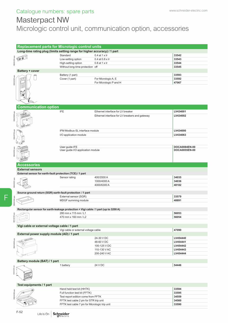
Catalogue numbers: spare parts
Replacement parts for Micrologic control unitsLong-time rating plug (limits setting range for higher accuracy) / 1 part
DB4
0439
4.ep
s Standard 0.4 at 1 x Ir 33542Low-setting option 0.4 at 0.8 x Ir 33543High-setting option 0.8 at 1 x Ir 33544Without long-time protection off 33545
Battery + cover
menu
DB4
0439
5.ep
s Battery (1 part) 33593Cover (1 part) For Micrologic A, E 33592
For Micrologic P and H 47067
Communication option
DB4
2586
8.ep
s
LV434002
Enerlin'X IFE
IFE Ethernet interface for LV breaker LV434001Ethernet interface for LV breakers and gateway LV434002
Test
DB4
2570
6.ep
s IFM Modbus-SL interface module LV434000I/O application module LV434063
DB4
3255
0.ep
s
+24VDC
13
O1
+
I1
24VDC
I2I3
I4I5
I6
C
C
C
1423
2433
34T1 T2
O2
O3
A1
LV434063
IO
I1
A1
O1
O2
O3I2I3
I4I5
I6
APP
User guide IFE DOCA0084EN-00User guide I/O application module DOCA0055EN-00
AccessoriesExternal sensorsExternal sensor for earth-fault protection (TCE) / 1 part
DB4
0438
1.ep
s Sensor rating 400/2000 A 340351000/4000 A 340364000/6300 A 48182
Source ground return (SGR) earth-fault protection / 1 part
DB4
0438
2.ep
s External sensor (SGR) 33579MDGF summing module 48891
Rectangular sensor for earth-leakage protection + Vigi cable / 1 part (up to 3200 A)
DB1
2610
0.ep
s 280 mm x 115 mm / L1 56053470 mm x 160 mm / L2 56054
Vigi cable or external voltage cable / 1 partVigi cable or external voltage cable 47090
External power supply module (AD) / 1 part
G3G4
Output
LN
DB4
3260
8.ep
s 24-30 V DC LV45444048-60 V DC LV454441100-125 V DC LV454442110-130 V AC LV454443200-240 V AC LV454444
Battery module (BAT) / 1 part
L3
G1
AD 220A
L4
G2
Input
24VDC
Output
24VDC
DB4
0438
4.ep
s 1 battery 24 V DC 54446
Test equipments / 1 part
DB4
0438
6.ep
s Hand held test kit (HHTK) 33594Full function test kit (FFTK) 33595Test report edition come from FFTK 34559FFTK test cable 2 pin for STR trip unit 34560FFTK test cable 7 pin for Micrologic trip unit 33590
Masterpact NW Micrologic control unit, communication option, accessories
www.schneider-electric.com
F-52
F
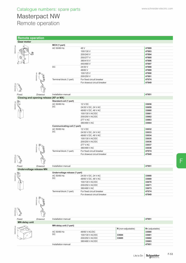
Remote operationGear motor
DB4
0441
0.ep
s MCH (1 part)AC 50/60 Hz 48 V 47889
100/130 V 47893200/240 V 47894250/277 V 47895380/415 V 47896440/480 V 47897
DC 24/30 V 4788848/60 V 47889
DB4
0439
8.ep
s
DB4
0432
2.ep
s 100/125 V 47890200/250 V 47891
Terminal block (1 part) For fixed circuit breaker 47074For drawout circuit breaker 47849
Fixed. Drawout. Installation manual 47951Closing and opening release (XF or MX)
DB4
0440
0.ep
s Standard coil (1 part)AC 50/60 HzDC
12 V DC 3365824/30 V DC, 24 V AC 3365948/60 V DC, 48 V AC 33660100/130 V AC/DC 33661200/250 V AC/DC 33662277 V AC 33663380/480 V AC 33664
Communicating coil (1 part)AC 50/60 HzDC
12 V DC 3303224/30 V DC, 24 V AC 3303348/60 V DC, 48 V AC 33034100/130 V AC/DC 33035200/250 V AC/DC 33036
DB4
0439
8.ep
s
DB4
0432
2.ep
s 277 V AC 33037380/480 V AC 33038
Terminal block (1 part) For fixed circuit breaker 47074For drawout circuit breaker 47849
Fixed. Drawout. Installation manual 47951Undervoltage release MN
DB4
0440
0.ep
s Undervoltage release (1 part)AC 50/60 HzDC
24/30 V DC, 24 V AC 3366848/60 V DC, 48 V AC 33669100/130 V AC/DC 33670200/250 V AC/DC 33671380/480 V AC 33673
Terminal block (1 part) For fixed circuit breaker 47074For drawout circuit breaker 47849
DB4
0439
8.ep
s
DB4
0432
2.ep
s
Fixed. Drawout. Installation manual 47951MN delay unit
DB4
0432
0.ep
s MN delay unit (1 part)R (non-adjustable) Rr (adjustable)
AC 50/60 HzDC
48/60 V AC/DC 33680100/130 V AC/DC 33684 33681200/250 V AC/DC 33685 33682380/480 V AC/DC 33683
Installation manual 47951
Masterpact NWRemote operation
F-53
Catalogue numbers: spare parts www.schneider-electric.com
F-53
F

Chassis locking“Disconnected” position locking / 1 part
DB4
0432
5.ep
s By padlocksVCPO Standard
By Profalux keylocksProfalux 1 lock with 1 key + adaptation kit 64934
2 locks 1 key + adaptation kit 649352 locks 2 different keys + adaptation kit 64936
1 keylock Profalux (without adaptation kit):
identical key not identified combination 33173identical key identified 215470 combination 33174identical key identified 215471 combination 33175
By Ronis keylocksRonis 1 lock with 1 key + adaptation kit 64937
2 locks 1 key + adaptation kit 649382 locks 2 different keys + adaptation kit 64939
1 keylock Ronis (without adaptation kit):
identical key not identified combination 33189identical key identified EL24135 combination 33190identical key identified EL24153 combination 33191identical key identified EL24315 combination 33192
Adaptation kit (without keylock):
adaptation kit Profalux / Ronis 48564adaptation kit Kirk 48565adaptation kit Castell 48566
Installation manual 47952Door interlock / 1 part
DB4
0432
6.ep
s Right and left-hand side of chassis (VPECD or VPECG) 47914
Installation manual 47952Racking interlock
DB4
0432
7.ep
s 5 parts 64940
Installation manual 47952Breaker mismatch protection / 1 part
DB4
0432
9.ep
s Breaker mismatch protection (VDC) 33767
Installation manual 47952
Chassis accessoriesAuxiliary terminal shield (CB) / 1 part
DB4
0433
1.ep
s 800/4000 A 3P 649424P 48596
4000b/6300 A 3P 485974P 48598
Safety shutters + locking block / 1 part
DB4
0433
2.ep
s 800/4000 A 3P 487214P 48723
4000b/6300 A 3P 487224P 48724
Installation manual 47952Shutter locking block (for replacement) / 1 part
DB4
0433
3.ep
s 2 parts for 800/4000 A 48591
Installation manual 47952
Earthing kit for chassis3P 4P
Types for N1/H1/NA/HA48433 48434
Note: the installation manual is enclosed.
Masterpact NW Chassis locking and accessories
Catalogue numbers: spare parts www.schneider-electric.com
F-54
F

Clusters
DB4
0328
0.ep
s 1 disconnecting contact cluster for chassis (see table below) (part 1) 64906
Table : number of clusters required for the different chassis modelsChassis rating (A) Masterpact NW 3P Masterpact NW 4P
N1 H1/H2 H3 L1 N1 H1/H2 H3 L1250 12 (H1)630 6 12 24 8 16 32800 6 12 24 8 16 321000 6 12 24 8 16 321250 6 12 24 8 16 321600 12 12 24 16 16 322000 24 24 42 32 32 562500 24 24 32 323200 36 36 48 484000 42 42 56 564000b 72 965000 72 966300 72 96Note: the minimum order is 6 parts.
DB4
1799
0.ep
s Set of 2 clusters fitters for 2 and 3 clusters 47554
DB4
1800
7.ep
s
Racking handle
DB4
0328
1.ep
s Racking handle 47944
DC rear connectionSerial connection kit
DB10
5109
.eps
For NW10/20 DC 48642
DB10
5110
.eps
For NW40 DC 48643
Masterpact NWClusters
Catalogue numbers: spare parts www.schneider-electric.com
F-55
F
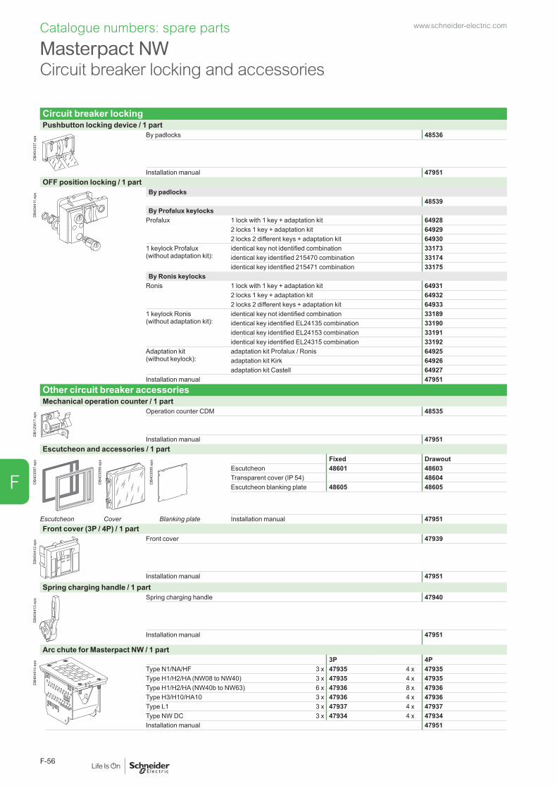
Circuit breaker lockingPushbutton locking device / 1 part
DB4
0433
7.ep
s By padlocks 48536
Installation manual 47951OFF position locking / 1 part
DB4
0441
1.ep
s By padlocks48539
By Profalux keylocksProfalux 1 lock with 1 key + adaptation kit 64928
2 locks 1 key + adaptation kit 649292 locks 2 different keys + adaptation kit 64930
1 keylock Profalux (without adaptation kit):
identical key not identified combination 33173identical key identified 215470 combination 33174identical key identified 215471 combination 33175
By Ronis keylocksRonis 1 lock with 1 key + adaptation kit 64931
2 locks 1 key + adaptation kit 649322 locks 2 different keys + adaptation kit 64933
1 keylock Ronis (without adaptation kit):
identical key not identified combination 33189identical key identified EL24135 combination 33190identical key identified EL24153 combination 33191identical key identified EL24315 combination 33192
Adaptation kit (without keylock):
adaptation kit Profalux / Ronis 64925adaptation kit Kirk 64926adaptation kit Castell 64927
Installation manual 47951Other circuit breaker accessoriesMechanical operation counter / 1 part
DB1
2561
7.ep
s Operation counter CDM 48535
Installation manual 47951Escutcheon and accessories / 1 part
DB4
0309
7.ep
s
DB4
0309
8.ep
s
DB4
0309
9.ep
s Fixed DrawoutEscutcheon 48601 48603Transparent cover (IP 54) 48604Escutcheon blanking plate 48605 48605
Escutcheon Cover Blanking plate Installation manual 47951Front cover (3P / 4P) / 1 part
DB4
0441
2.ep
s Front cover 47939
Installation manual 47951Spring charging handle / 1 part
DB4
0441
3.ep
s Spring charging handle 47940
Installation manual 47951
Arc chute for Masterpact NW / 1 part
DB4
0441
4.ep
s 3P 4PType N1/NA/HF 3 x 47935 4 x 47935Type H1/H2/HA (NW08 to NW40) 3 x 47935 4 x 47935Type H1/H2/HA (NW40b to NW63) 6 x 47936 8 x 47936Type H3/H10/HA10 3 x 47936 4 x 47936Type L1 3 x 47937 4 x 47937Type NW DC 3 x 47934 4 x 47934Installation manual 47951
Masterpact NW Circuit breaker locking and accessories
Catalogue numbers: spare parts www.schneider-electric.com
F-56
F

Mechanical interlocking for source changeoverInterlocking of 2 devices using connecting rods
DB4
0438
0.ep
s Complete assembly with 2 adaptation fixtures + rods2 Masterpact NW fixed devices 486122 Masterpact NW drawout devices 48612Can be used with 1 NW fixed + 1 NW drawout.Note: the installation manual is enclosed.
Interlocking of 2 devices using cables (*)
DB4
1674
8.ep
s Choose 2 adaptation sets (1 for each device + 1 set of cables) 1 adaptation fixture for Masterpact NW fixed devices 479261 adaptation fixture for Masterpact NW drawout devices 479261 set of 2 cables 33209(*) Can be used with any combination of NT or NW, fixed or drawout devices.
Interlocking of 3 devices using cables
DB4
1674
9.ep
s Choose 3 adaptation (inclusing 3 adaptation fixtures + cables) 3 sources, only 1 device closed, fixed or drawout devices 486102 sources + 1 coupling, fixed or drawout devices 486092 normal + 1 replacement source, fixed or drawout devices 48608
Cable-type door interlock1 complete assembly for Masterpact NW fixed or drawout device 48614Note: the installation manual is enclosed.
Masterpact NWMechanical interlocking for source changeover
Catalogue numbers: spare parts www.schneider-electric.com
F-57
F

Indication contactsON/OFF indication contacts (OF) / 12 parts
DB4
0432
1.ep
s 1 additional block of 4 contacts 64922Wiring For fixed circuit breaker 47074
For drawout circuit breaker 47849
Installation manual 47951“Fault trip” indication contacts (SDE) / 1 part
DB4
0432
3.ep
s Changeover contact (SDE) 6 A - 240 V 47915Low-level 47916
Wiring For fixed circuit breaker 47074For drawout circuit breaker 47849
Installation manual 47951“Ready to close” contact (1 max.) / 1 part
DB4
0441
5.ep
s PF1 changeover contact (5 A - 240 V) 470801 low-level changeover contact 47081Wiring For fixed circuit breaker 47074
For drawout circuit breaker 47849Installation manual 47951
“Connected, disconnected, test position” indication contact (carriage switches) / 1 part
DB4
0432
4.ep
s Changeover contacts 6 A - 240 V 33170CE, CD, CT Low-level 33171
Installation manual 47952Set of additional actuaters for carriage switches / 1 set
1 set 48560
Combined closed / connected contacts for use with 1 auxiliary contact / 1 part
DB4
0432
2.ep
s 1 contact (5 A - 240 V) 48477or 1 low-level contact 48478
Installation manual 47952Electrical closing pushbutton / 1 part
DB4
0431
9.ep
s BPFE1 pushbutton 48534
Installation manual 47951Auxiliary terminals for chassis alone
3 wire terminal (1 part) 478496 wire terminal (1 part) 47850Jumpers (10 parts) 47900
Masterpact NW Indication contacts
Catalogue numbers: spare parts www.schneider-electric.com
F-58
F

InstructionsChassis accessories 47952Circuit breaker accessories 47951Fixed and drawout circuit breaker 47950User manual NW AC (French) 47954
NW AC (English) 47955NW DC (French) 64923NW DC (English) 64924
Micrologic user manual 20/50 (French) 3307620/50 (English) 330772A/7A (French) 330792A/7A (English) 330802E/6E (French) 330792E/6E (English) 330805P/7P (French) 330825P/7P (English) 330835H/7H (French) 330855H/7H (English) 33086
Modbus communication notice for manual 33088
Masterpact NWInstructions
Catalogue numbers: spare parts www.schneider-electric.com
F-59
F

Catalogue numbers: spare parts
Communication, monitoring and control
Communication option
DB4
2586
8.ep
s
LV434002
Enerlin'X IFE
IFE Ethernet interface for LV breaker LV434001Ethernet interface for LV breakers and gateway LV434002
Test
DB4
2570
6.ep
s IFM Modbus-SL interface module LV434000I/O application module LV434063
DB4
3255
0.ep
s
+24VDC
13
O1
+
I1
24VDC
I2I3
I4I5
I6
C
C
C
1423
2433
34T1 T2
O2
O3
A1
LV434063
IO
I1
A1
O1
O2
O3I2I3
I4I5
I6
APP
User guide IFE DOCA0084EN-00User guide I/O application module DOCA0055EN-00
Monitoring and controlULP display module (1)
DB4
3255
1.ep
s Switchboard front display module FDM121 TRV00121FDM mounting accessory (diameter 22 mm) TRV00128
Ethernet display module
DB4
1748
9.ep
s Switchboard front display module FDM128 LV434128
ULP wiring accessories
DB12
7985
.eps Breaker ULP cord L = 0.35 m LV434195
Breaker ULP cord L = 1.3 m LV434196Breaker ULP cord L = 3 m LV434197
DB1
1562
1.ep
s 10 stacking connectors for communication interface modules TRV00217
DB4
3258
4.ai 2 Modbus line terminators VW3A8306DRC (2)
DB1
1562
3.ep
s 5 RJ45 connectors female/female TRV00870
DB1
1144
4.ep
s 10 ULP line terminators TRV00880
DB1
1144
5.ep
s 10 RJ45/RJ45 male cord L = 0.3 m TRV0080310 RJ45/RJ45 male cord L = 0.6 m TRV008065 RJ45/RJ45 male cord L = 1 m TRV008105 RJ45/RJ45 male cord L = 2 m TRV008205 RJ45/RJ45 male cord L = 3 m TRV008301 RJ45/RJ45 male cord L = 5 m TRV00850
(1) For measurement display with Micrologic A, E, P and H.(2) See www.schneider-electric.com.
www.schneider-electric.com
F-60
F

Indication contactsOF - ON/OFF indication contacts Standard 4 OF 6 A-240 V AC (10 A-240 V AC and low-level for NW)Alternate 1 OF low-level for NT Max. 4 qtyAdditional 1 block of 4 OF for NW Max. 2 qtyEF - combined “connected/closed” contacts
1 EF 6 A-240 V AC for NW Max. 8 qty1 EF low-level for NW Max. 8 qty
SDE - “fault-trip” indication contactStandard 1 SDE 6 A-240 V ACAdditional 1 SDE 6 A-240 V AC 1 SDE low levelProgrammable contacts 2 M2C contactsCarriage switches Low level 6 A-240 V ACCE - “connected” position Max. 3 for NW/NT qtyCD - “disconnected” position Max. 3 for NW - 2 for NT qtyCT - “test” position Max. 3 for NW - 1 for NT qtyAC - NW actuator for 6 CE - 3 CD - 0 CT additional carriage switches qtyRemote operation
Remote ON/OFF MCH - gear motor VXF - closing voltage release VMX - opening voltage release VPF - “ready to close” contact Low level
6 A-240 V ACBPFE - electrical closing pushbutton VRES - electrical reset option VRAR - automatic reset option
Remote tripping MN - undervoltage release VR - delay unit (non-adjustable)Rr - adjustable delay unit2nd MX - shunt release V
LockingVBP - ON/OFF pushbutton locking (by transparent cover + padlocks)OFF position locking:VCPO - by padlocks VSPO - by keylocks Keyock kit (w/o keylock) Profalux Ronis
Kirk Castell1 keylock Profalux Ronis2 identical keylocks, 1 key Profalux Ronis2 keylocks, different keys (NW) Profalux Ronis
Chassis locking in “disconnected” position:VSPD - by keylocks Keyock kit (w/o keylock) Profalux Ronis
Kirk Castell1 keylock Profalux Ronis2 identical keylocks, 1 key Profalux Ronis2 keylocks, different keys Profalux RonisOptional connected/disconnected/test position lock
VPEC - door interlock On right-hand side chassisOn left-hand side chassis
VPOC - racking interlockIPA - cable-type door interlockVDC - mismatch protectionVIVC - shutter position indication and locking for NWIBPO - racking interlock between crank and OFF pushbutton for NWDAE - automatic spring discharge before breaker removal for NWAccessories
VO - safety shutters on chassis for NT and NWCDM - mechanical operation counter NT, NWCB - auxiliary terminal shield for chassis NT, NWCC - arc chute cover for fixed NTCDP - escutcheon NT, NWCP - transparent cover for escutcheon NT, NWOP - blanking plate for escutcheon NT, NWKMT - Grounding kit NWBrackets for mounting NW fixed On backplatesTest kits Mini test kit Portable test kit
To indicate your choice, check the applicable square boxes
and enter the appropriate information in the rectangles
Circuit breaker or switch-disconnector QtyMasterpact type NT NWRating ASensor rating ACircuit breaker N1, H1, H2, H3, L1Special circuit breaker H2 anticorrosion, H10 (NW)Special circuit breaker NW16/32 H1T, NT16 H2TSwitch-disconnector NA, HA, HF, ES, HA10 (NW)Number of poles 3 or 4 Brand Schneider ElectricOption: neutral on right side (NW)Type of equipment Fixed
Drawout with chassisDrawout without chassis(moving part only)Chassis alone
Earthing switch kit for chassisMicrologic control unit
A - ammeter 2.0 5.0 6.0 7.0E - energy 2.0 5.0 6.0P - power meter 5.0 6.0 7.0H - harmonic meter 5.0 6.0 7.0LR - long-time rating plug Standard 0.4 to 1 Ir
Low setting 0.4 to 0.8 IrHigh setting 0.8 to 1 IrLR OFF
AD - external power-supply module VBAT - battery moduleTCE - external sensor (CT) for neutral and residual earth-fault protectionTCE - external sensor (CT) for over sized neutral (3P - Micrologic P / H) and residual earth-fault protectionTCW - external sensor for SGR protectionRectangular sensorfor earth-leakage protection
NT (280 x 115 mm)NW (470 x 160 mm)
PTE - external voltage connectorCommunication
COM moduleDevice (BCM-ULP)
with Ethernet interface Cradle management with I/O application module(Chassis)
with Ethernet interface + Gateway
with Modbus interface
Eco COM module Device (BCM-ULP)
with Ethernet interface
with Ethernet interface + Gatewaywith Modbus interface
Front Display Module Mounting accessories(FDM121)Breaker ULP Cord
L = 0.35 mL = 1.3 mL = 3 m
ConnectionHorizontal Top BottomVertical Top BottomFront Top BottomVertical-connection adapters NT - FC fixed, draw.Cable-lug adapters NT - FC fixed, draw.Arc chute screen NT - FC fixedInterphase barriers NT, NW fixed, drawoutSpreaders NT fixed, drawoutDisconnectable front connection adapter
NW fixed
Lugs for 240v or 300v cables NT fixed, drawout
Masterpact NT and NW
Micrologic control unit functions:2.0 : basic protection (long time + inst.)5.0 : selective protection (long time + short time + inst.)6.0 : selective + earth-fault protection (long time + short time + inst. + earth-fault)7.0 : selective + earth-leakage protection (long time + short time + inst. + earth-leakage)
Order form www.schneider-electric.com
F-61
F


Schneider Electric Industries SAS
35, rue Joseph MonierCS 3032392506 Rueil Malmaison Cedex France
RCS Nanterre 954 503 439Capital social 896 313 776 €www.schneider-electric.com
10-2018
© 2018 - Schneider Electric. All Rights Reserved.All trademarks are owned by Schneider Electric Industries SAS or its affiliated companies.Document reference: LVPED208008EN
This document has beenprinted on recycled paper
LVPED208008EN WEB3 cat.2018