
Catalogue 2015 Ammended - Flann Microwave
135
1 www.flann.com Flann Microwave FLANN MICROWAVE LIMITED Founded in 1956, internationally renowned, Flann Microwave Limited specialise in the design and manufacturer of precision, high quality, high performance microwave equipment and components in the frequency range of 320 MHz to 500 GHz. MISSION STATEMENT To provide the Microwave Industry with the design, development and manufacture of reliable and consistent product with competitive pricing. CAPABILITY RF Design: tools include Ansoft HFSS, Mician Microwave Wizard, Mathematical Modelling and In-house Developed Design and Synthesis tools Mechanical Design: AutoCAD Inventor 3D modelling and Edge CAM Electronic Design: Motion Control/Robotics, System Design, Control Software & Control Processors utilizing IEEE-488, RS-232, RS-485 and Ethernet Manufacturing: CNC Machine tools, Vertical machining centres, Lathes, Manual Machine tools – Milling and Turning Fabrication & In-house Processes: Highly skilled fitters / assemblers, soldering and brazing, Electro-Plating, Electro-Forming, Anodising, Alochrome and Paint Spraying Test and Measurement: Vector Network Analysers up to 500 GHz, Strong relations with Research and National Standards Laboratories. CUSTOMERS We serve our customers in a broad range of markets including Test & Measurement, Commercial & Military Communications, Radar, Satellite, Industrial Applications, EW as well as Research and National Standards Laboratories. Flann are actively involved in easing customer project time, space and weight limitations by design and optimisation of multi-function assemblies, using either discrete components or single block designs. PRODUCTS Standard and custom waveguide components, antennas, sub assemblies and programmable instrumentation available from 320 MHz to 500 GHz in rectangular waveguide and 2 GHz to 40 GHz in double ridged, with power capability ranging from microwatts to Megawatts.
-
Upload
khangminh22 -
Category
Documents
-
view
0 -
download
0
Transcript of Catalogue 2015 Ammended - Flann Microwave

1www.flann.com
Flann Microwave
FLANN MICROWAVE LIMITED
Founded in 1956, internationally renowned, Flann Microwave Limited specialise in the design and manufacturer of precision, high quality, high performance microwave equipment and components in the frequency range of 320 MHz to 500 GHz.
MISSION STATEMENT
To provide the Microwave Industry with the design, development and manufacture of reliable and consistent product with competitive pricing.
CAPABILITY
RF Design: tools include Ansoft HFSS, Mician Microwave Wizard, Mathematical Modelling and In-house Developed Design and Synthesis tools Mechanical Design: AutoCAD Inventor 3D modelling and Edge CAM
Electronic Design: Motion Control/Robotics, System Design, Control Software & Control Processors utilizing IEEE-488, RS-232, RS-485 and Ethernet
Manufacturing: CNC Machine tools, Vertical machining centres, Lathes, Manual Machine tools – Milling and Turning
Fabrication & In-house Processes: Highly skilled fitters / assemblers, soldering and brazing, Electro-Plating, Electro-Forming, Anodising, Alochrome and Paint Spraying
Test and Measurement: Vector Network Analysers up to 500 GHz, Strong relations with Research and National Standards Laboratories.
CUSTOMERS
We serve our customers in a broad range of markets including Test & Measurement, Commercial & Military Communications, Radar, Satellite, Industrial Applications, EW as well as Research and National Standards Laboratories.
Flann are actively involved in easing customer project time, space and weight limitations by design and optimisation of multi-function assemblies, using either discrete components or single block designs.
PRODUCTS
Standard and custom waveguide components, antennas, sub assemblies and programmable instrumentation available from 320 MHz to 500 GHz in rectangular waveguide and 2 GHz to 40 GHz in double ridged, with power capability ranging from microwatts to Megawatts.
2 www.flann.com
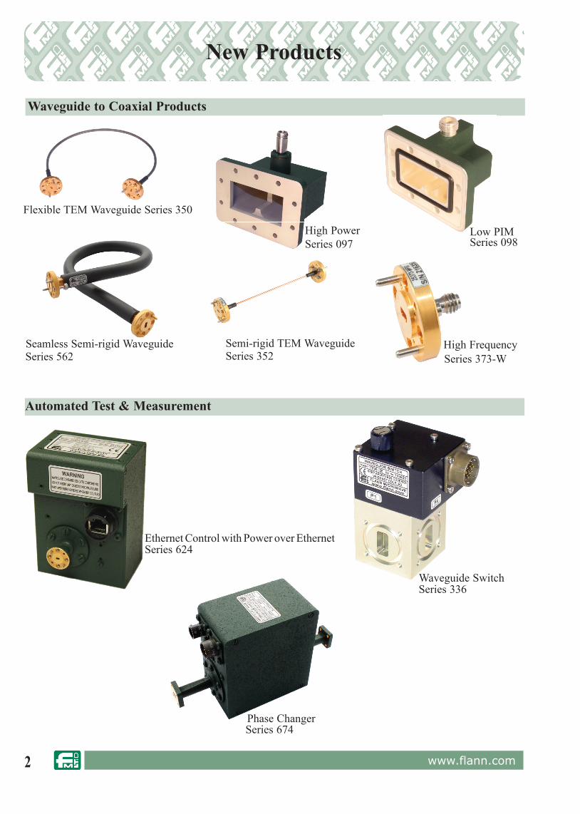
New Products
Series 098
Series 373-WSeries 352Series 562
Flexible TEM Waveguide Series 350
Phase Changer
Waveguide Switch
Low PIM
High FrequencySemi-rigid TEM WaveguideSeamless Semi-rigid Waveguide
Ethernet Control with Power over Ethernet
High PowerSeries 097
Series 674
Series 336
Series 624
Waveguide to Coaxial Products
Automated Test & Measurement
3www.flann.com
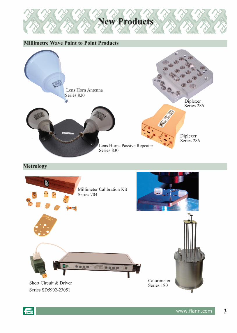
New Products
Diplexer
Lens Horn Antenna
Diplexer
Lens Horns Passive Repeater
Short Circuit & Driver
Millimeter Calibration Kit
Calorimeter
Series 820
Series 286
Series 286
Series 830
Series 704
Series SD5902-23051Series 180
Millimetre Wave Point to Point Products
Metrology

4 www.flann.com
Adaptors Waveguide to Coax Adaptors - Model Selection 51Broadband Waveguide to Coax N Type Adaptors 52Narrow Band Waveguide to N Type Coax Adaptors 53Waveguide to APC7 Coax Adaptors Full & Narrow Band 54Waveguide to APC7 Coax Adaptors Full Band Low VSWR 55Waveguide to SMA Coax Adaptors Full Band 56Narrow Band Waveguide to SMA Coax Adaptors 57 Waveguide to K Type Coax Adaptors 58Waveguide to 1.85 mm V Connector ®* Coax Adaptors 59Waveguide to 2.4 mm Coax Adaptors 60Broad Band End Launch Adaptors 61End Launch Adaptor 373 62-63Waveguide to 1mm Coax End Launch Adaptor 64Waveguide to 0.8mm Coax End Launch Adaptor 65Double Ridge end Launch Adaptor 66-67Low PIM Waveguide to Coaxial Adaptor 68-69Coaxial Guide, Flange to Flange Adaptor 70Seamless Semi-Rigid Waveguide Flange to Flange Adaptor 71Double Ridge Waveguide to Coax Adaptors 72Rectangular Waveguide to Waveguide Tapered Transitions 73Flange to Flange Waveguide Straights, Adaptors 74Rectangular to Circular Waveguide Transitions 75
AntennasLens Horn Antennas 90-91Sectoral Horns 92Standard Gain Horns 93NRL Standard Gain Horns 94Near Field Probes 95Dual Polarized Horn 96-97Omni Directional Antenna 98
Attenuators Precision Rotary Vane Attenuators 14-15Field Useable Rotary Vane Attenuators 16Variable Attenuators 17Precision Fixed Attenuators 18Calibrated Variable Attenuators 19-20Fixed Attenuators 21
Attenuators / Phase Changers, ProgrammableProgrammable Rotary Vane Attenuators, Phase Changers 7& Control Processors Programmable Rotary Vane Attenuators & Phase Changers 8Programmable Rotary Vane Attenuators 9-11Programmable Rotary Vane Phase Changers 12
BendsWaveguide E and H Plane Bends 77
Calibration KitsWaveguide Calibration Kits 104-105A Guide to Calibration Kit Selection 106Metrology Bronze Calibration Kits 107Metrology Silver Calibration Kits 108 Metrology Gold Calibration Kits 109Double Ridge Waveguide Calibration Kits 110Millimeter & Submillimeter Calibration Kits 111
Combiners - See Couplers
Control Processors Control Processor 13
CouplersSelection Guide 25General Information 26Double Ridge Couplers 30Multihole Directional Couplers 26-35Crossguide Directional Couplers 36Branch Guide Directional Couplers 37Special & Customised Directional Couplers 38-39
Diplexers, V & E Band 99
Divider- Multiple - See Couplers
Double RidgeDouble Ridge Couplers 30Double Ridge High Power Terminations 48Double Ridge Waveguide to Coax Adaptors 72DC-Motor Driven Waveguide Switches 83DC-Operated 2-Channel Waveguide Switches 84Double Ridge Waveguide Calibration Kits 110
Hybrid TeesMatched Hybrid Tees 86Un-Matched Tees 87Matched E & H Plane Tees 88Un-Matched E & H Plane Tees 89
FiltersDiplexers V & E Band 99Low Pass Filters 101Microwave Tuneable Filters 102
FlangesWaveguide and Flange Data 118Waveguide Flanges, General Information 119“Standard” Flange Data 120-125Precision Style Flange Details 126-128Anti-Cocking Flanges 129
LoadsGeneral Information 40Short Low Power Terminations 41Ultra - Short Terminations 42Precision Low Power Terminations 43Sliding Terminations 44High Power Terminations 45-47Double Ridge High Power Terminations 48
New Products 2-3
Frequency MetersCalibrated Frequency Meters 49Direct Reading Frequency Meters 50
Orthomode TransducersOrthomode Transducers 103
Contents

5www.flann.com
Phase Changers Programmable Rotary Vane Attenuators, Phase Changers 7& Control Processors Programmable Rotary Vane Attenuators & Phase Changers 8 - 9 Programmable Rotary Vane Phase Changers 12 Rotary Vane Phase Changers 22Calibrated Phase Changers 23-24
Product Series Number index 6
Programmable Waveguide Switches & Drivers Waveguide Switches & Driver 79Motorised Waveguide Switches 81Switch Driver 82
Programmable Attenuators / Phase ChangersProgrammable Rotary Vane Attenuators, Phase Changers 7& Control Processors Programmable Rotary Vane Attenuators & Phase Changers 8Programmable Rotary Vane Attenuators 9-11Programmable Rotary Vane Phase Changers 12
Power Combiners / Splitters See - Couplers
Radio ProductsSee - Adaptors, Antennas, Filters & Couplers
Reference Data VSWR & Return Loss Data 130-131Waveguide Parameters 132Reference Data 133
Reflectometer Couplers Multihole Directional Couplers 26-35Double Ridge Couplers 30Multihole Directional Couplers 31-35
Screw TunersWaveguide Screw Tuners 116
Slide Tuners Waveguide Slide Tuners 117
Slotted LineWaveguide Slotted Lines 114
Short CircuitsPrecision, Variable Waveguide Short Circuits 115
Switch DriversWaveguide Switches & Driver 79Switch Driver 82
Systems Customised Waveguides and Assemblies 78
Switches Waveguide Switches & Driver 79Manual Waveguide Switches 80Motorised Waveguide Switches 81Switch Driver 82DC-Motor Driven Waveguide Switches 83DC-Operated 2-Channel Waveguide Switches 84Phase Combining / Redundancy Solutions 85
TerminationsTerminations General Information 40Short Low Power Terminations 41Ultra - Short Terminations 42Precision Low Power Terminations 43Sliding Terminations 44High Power Terminations 45-47Double Ridge High Power Terminations 48
TransitionsRectangular Waveguide to Waveguide Tapered Transitions 73Flange to Flange Waveguide Straights, Adaptors 74and Spacers Rectangular to Circular Waveguide Transitions 75
TunersWaveguide Screw Tuners 116Waveguide Slide Tuners 117
TwistsWaveguide Twists 76
Waveguide Assemblies Customised Waveguides and Assemblies 78
Waveguide Calibration Kits Waveguide Calibration Kits 104-105A Guide to Calibration Kit Selection 106Metrology Bronze Calibration Kits 107Metrology Silver Calibration Kits 108 Metrology Gold Calibration Kits 109Double Ridge Waveguide Calibration Kits 110Millimeter & Sub-millimeter Calibration Kits 111
Waveguide and Flange Data Waveguide and Flange Data 118Waveguide Flanges, General Information 119“Standard” Flange Data 120-125Precision Style Flange Details 126-128Anti-Cocking Flanges 129
Waveguide Verification KitsWaveguide Verification Kits 113
Waveguide Raw Material Waveguide and Flange Data 118
Contents
For the latest in our product range please view our web site at www.flann.com Or contact our Sales Team, details on the back cover of this catalogue.
6 www.flann.com
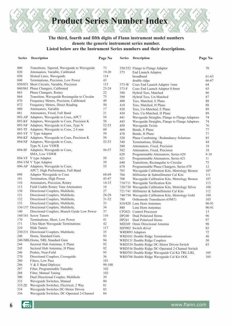
000 Transitions, Tapered, Waveguide to Waveguide 73020 Attenuators, Variable, Calibrated 19-20030 Slotted Lines, Waveguide 114040 Terminations, Precision, Low Power 43050/051 Short Circuits, Variable, Precision 115060/061 Phase Changers, Calibrated 23-24063 Phase Changers, Rotary 22064 Transition, Waveguide Rectangular to Circular 75070 Frequency Meters, Precision, Calibrated 49072 Frequency Meters, Direct Reading 50080 Attenuators, Variable 17081 Attenuators, Fixed, Full Band 21093-AP Adaptors, Waveguide to Coax, APC7 54093-KF Adaptors, Waveguide to Coax, Precision K 58093-NF Adaptors, Waveguide to Coax, Type N 52-53093-TF Adaptors, Waveguide to Coax, 2.4 mm 60093-VF V Type Adaptor 59094-KF Adaptors, Waveguide to Coax, Precision K 58094-NF Adaptors, Waveguide to Coax, 52-53 Type N, Low VSWR094-SF Adaptors, Waveguide to Coax, 56-57 SMA, Low VSWR 094-VF V type Adaptor 59094-VM V Type Adaptor 59096-AP Adaptors, Waveguide to Coax, 55 APC7, High Performance, Full Band098 Adaptor Waveguide to Coax 68-69101 Termination, High Power 45-47110 Attenuators, Precision, Rotary 14-15113 Field Usable Rotary Vane Attenuators 16130 Directional Couplers, Multihole, 27131 Directional Couplers, Multihole, 28-29 132 Directional Couplers, Multihole, 31-32133 Directional Couplers, Multihole, 33136/137 Directional Couplers, Multihole, 34140 Directional Couplers, Branch Guide Low Power 37160/161 Screw Tuners 116170 Terminations, Short, Low Power 41171 Ultra Short Waveguide Terminations 42 210 Slide Tuners 117 230/231 Directional Couplers, Multihole, 35240 Horns, Standard Gain 93240-NRLHorns, NRL Standard Gain 94244 Sectoral Hub Antennas, E Plane 92245 Sectoral Hub Antennas, H Plane 92246 Probes, Near-Field 95270 Directional Couplers, Crossguide 36280 Filters, Low Pass 101286 V & E Band Diplexes 99-100 287 Filter, Programmable Tuneable 102288 Filter, Manual Tuning 102300 Dual Directional Coupler, Multihole 39333 Waveguide Switches, Manual 80333-2E Waveguide Switches, Electrical, 2 Way 81334 Waveguide Switches DC-Motor Driven 83336 Waveguide Switches, DC-Operated 2-Channel 84
350/352 Flange to Flange Adaptor 70373 End Launch Adaptor, broadband 61-63 double ridge 66-67373-W Coax End Launch Adaptor 1mm 64373-F Coax End Launch Adaptor 0.8mm 65380 Hybrid Tees, Matched 86390 Hybrid Tees, Un-Matched 87400 Tees, Matched, E Plane 88410 Tees, Matched, H Plane 88420 Tees, Un-Matched, E Plane 89430 Tees, Un-Matched, H Plane 89441 Waveguide Straights, Flange to Flange Adaptors 74445 Waveguide Straights, Flange to Flange Adaptors 74450 Waveguide Twists 76460 Bends, E Plane 77470 Bends, H Plane 77520 Phase Combining / Redundancy Solutions 85540 Terminations, Sliding 44580 Attenuators, Fixed, Precision 18582 Attenuators, Fixed, Precision 18620 Programmable Attenuators, Series 620 9-10621 Programmable Attenuators, Series 621 11640 Transitions, Rectangular to Circular 75670 Programmable Phase Changers, Series 670 12703 Waveguide Calibration Kits, Metrology Bronze 107704 Millimeter & Submillimeter Cal Kits 111708 Waveguide Calibration Kits, Metrology Bronze 107710/711 Waveguide Verification Kits 113720/730 Waveguide Calibration Kits, Metrology Silver 108721/741 Millimeter & Submillimeter Cal Kits 112740/750 Waveguide Calibration Kits, Metrology Gold 109780 Orthomode Transducers (OMT) 103810/820 Lens Horn Antennas 90-91880 Lens Horn Antennas 90-91CP2021 Control Processor 13DP240 Dual Polarized Horns 96DP241 Dual Polarized Horns 97MD249 Omni Directional Antenna 98SD5902 Switch driver 82WRD093 Adaptors 72WRD101 Double Ridge Terminations 48 WRD131 Double Ridge Couplers 30WRD334 Double Ridge DC-Motor Driven Switch 83WRD336 Double Ridge DC-Operated 2-Channel Switch WRD703 Double Ridge Waveguide Cal Kit TRL/LRL 105WRD708 Double Ridge Waveguide Cal Kit OOL 105
Series DescriptionSeries Description
Product Series Number Index
The third, fourth and fifth digits of Flann instrument model numbers denote the generic instrument series number.
Listed below are the Instrument Series numbers and their descriptions.
Page No Page No

7www.flann.com
Features:• Models from 3.22 GHz (WR229) to 330 GHz (WR3) • IEEE-488.2 (GPIB) and USB control interfaces• Full waveguide frequency ranges• High accuracy• High repeatability• Proven reliability
Programmable Rotary Vane Attenuators:• 0 dB to 60 dB continuously variable
attenuators - up to 85 dB in Steps Mode• Direct dB scale read-out with manual
control option• Low phase change variation with attenuation • Attenuation increments of 0.1 dB or better (0.01 dB below 21 dB)
Programmable Rotary Vane Phase Changers:• Continuously variable 0° to 360°• Phase change increments of 0.2 degrees• Direct reading
Applications:• Automated test & measurement
systems (ATE)• Remote control systems• Automated production testing of
microwave radios - Fade margin - Bit error rate (BER) - Gain control
Programmable Rotary Vane Attenuators, Phase Changers & Control Processors
Our new generation of Programmable Attenuators & Phase Changers provide higher measurement resolution, faster drive speed and an extendable attenuation range (85 dB) when used with the new Flann Control Processor CP2021. Additionally, the CP2021 will recognise any Flann Programmable unit connected to either of its drive ports.
Model CP2021Model 23621
8 www.flann.com
Programmable Rotary Vane Attenuators & Phase Changers
General Description
Flann Programmable Rotary Vane Attenuators and Phase Changers are well proven Precision Rotary Vane in stru ments driven by high resolution stepper motors, ensuring high accuracy and repeatability. The translation between the mechanical positioning of the instruments and the attenuation or phase shift characteristics is interpreted by the mi cro proc es sor based Control Processor.
Control Processors are available offering com bi na tions of local (front panel) control and control via GPIB (IEEE-488.2) and USB interfaces. Sophisticated error detection and reporting verifies system performance, guaranteeing error free system operation. Positional stepping errors are non-cumulative.
Programmable Rotary Vane Attenuators
This range of Programmable Rotary Vane Attenuators uses a very high speed five phase stepper motor which, when used in conjunction with the sophisticated motor control circuitry and software of the Control Processor, provides precise, very fast positioning typically 1 second from 0 dB to 60 dB.
Programmable Rotary Vane Phase Changers
The Series 670 Rotary Vane Phase Changers employ the same high performance drive circuitry and precision mechanisms as the programmable attenuator range and operate at a repositioning rate of 1480 degrees per second with continuous phase change in both the forward and reverse directions. The smallest incremental phase change is 0.2˚.
Attenuation Setting (dB)
Rep
ositi
onin
g Ti
me
(sec
)
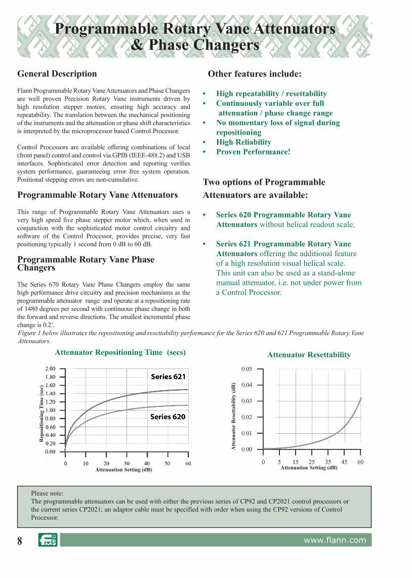
Attenuator Repositioning Time (secs)
Attenuation Setting (dB)
Att
enua
tor
Res
etta
bilit
y (d
B)
Attenuator Resettability
Other features include:
• High repeatability / resettability• Continuously variable over full
attenuation / phase change range• No momentary loss of signal during
repositioning• High Reliability• Proven Performance!
Two options of Programmable Attenuators are available:
• Series 620 Programmable Rotary Vane Attenuators without helical readout scale.
• Series 621 Programmable Rotary Vane Attenuators offering the additional feature of a high resolution visual helical scale. This unit can also be used as a stand-alone manual attenuator, i.e. not under power from a Control Processor.
Figure 1 below illustrates the repositioning and resettability performance for the Series 620 and 621 Programmable Rotary Vane Attenuators.
Please note:The programmable attenuators can be used with either the previous series of CP92 and CP2021 control processors or the current series CP2021; an adaptor cable must be specified with order when using the CP92 versions of Control Processor.

9www.flann.com
Two basic types of Programmable Rotary Vane Attenuators, Series 620 and 621, are available. The Series 620 has been extended to include models down to 3.22 GHz. The new Series 621 models offer an additional high resolution helical readout scale offering manual control.
High Speed Operation:
Programmable Rotary Vane At ten u a tors are fitted with a high speed drive motor capable of re po si tion ing the attenuator from 0 dB to 60 dB(see note 1) in less than 1.1 seconds when driven by our dedicated Control Processors.
Programmable Rotary Vane Attenuators Series 620 and Series 621
Model Series620 or 621
FrequencyRange(GHz)
Waveguide VSWR(better than)
Max InsertionLoss(dB)
Max Power(Watts)
WG WM R WR
11A620/11A621 3.22 - 4.90 11A - 40 229 1.15 0.25 10.0
12620/12621 3.94 - 5.99 12 - 48 187 1.15 0.25 10.0
13620/13621 4.64 - 7.05 13 - 58 159 1.15 0.25 9.0
14620/14621 5.38 - 8.18 14 - 70 137 1.15 0.25 8.0
15620/15621 6.58 - 10.0 15 - 84 112 1.15 0.25 6.0
16620/16621 8.20 - 12.5 16 - 100 90 1.15 0.25 4.0
17620/17621 9.84 - 15.0 17 - 120 75 1.15 0.25 3.0
18620/18621 11.9 - 18.0 18 - 140 62 1.15 0.3 2.0
19620/19621 14.5 - 22.0 19 - 180 51 1.15 0.4 1.5
20620/20621 17.6 - 26.7 20 - 220 42 1.15 0.6 1.0
21620/21621 21.7 - 33.0 21 - 260 34 1.15 0.8 0.75
22620/22621 26.4 - 40.1 22 - 320 28 1.15 0.9 0.5
23620/23621 33.0 - 50.1 23 - 400 22 1.15 1.0 0.3
24620/24621 39.3 - 59.7 24 - 500 19 1.15 1.0 0.25
25620/25621 49.9 - 75.8 25 - 620 15 1.15 1.0 0.15
26620/26621 60.5 - 92.0 26 - 740 12 1.15 1.3 0.1
27620/27621 73.8 - 112.0 27 - 900 10 1.15 1.5 0.07
28620/28621 92.3 - 140 28 - 1200 8 1.20 1.8 0.05
29620/29621 114 - 173 29 - 1400 6 1.25 2.2 0.035
30620/30621 145 - 220 30 - 1800 5 1.30 2.7 0.02
31620/31621 172 - 261 31 - 2200 4 1.40 3.0 0.015
32620/32621 217 - 330 32 - 2600 3 1.55 3.5 0.01
710620/710621 260 - 400 - 710 - '2.8' 1.75 4.0 0.007
570620/570621 330 - 500 - 570 - '2.2' 2.20 4.5 0.005
Model 15620
Model 23621
Series 620/621
ORDERING INFORMATION Model: DescriptionExample: Model 19620 or 19621 Programmable Rotary Vane AttenuatorOutline dimensions available on request.
Specifications: All ranges 0 dB to 60 dB with the following accuracy1
WG10 to WG29 WG30 WG31 WG32 (260-400) (325-500)
Attenuation accuracy0 dB to 60 dB 0 dB to 50 dB 0 dB to 45 dB 0 dB to 40 dB 0 dB to 35 dB 0 dB to 30 dB
0.1 dB or 1%whichever is greater
0.15 dB or 1.2%whichever is greater
0.2 dB or 1.5%whichever is greater
0.3 dB or 2%whichever is greater
0.4 dB or 2.5%whichever is greater
0.5 dB or 3%whichever is greater
Operating temperature range: +5°C to +35°C (Refer to Flann for wider temperature range consideration)Note 1: Customised models with extended attenuation ranges can be supplied. Please contact our Sales Team for further details.
10 www.flann.com
Customised systems are available to suit special applications. Please contact our sales team for full details.
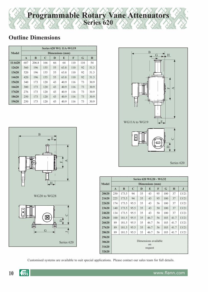
Programmable Rotary Vane Attenuators Series 620
Outline Dimensions
Model Series 620 WG 11A-WG19
Dimensions (mm)A B C D E F G H
11A620 687 206.8 166 66 64 110 110 5412620 560 196 155 55 63.8 110 92 51.313620 520 196 155 55 63.8 110 92 51.314620 420 196 155 55 63.8 110 92 51.315620 340 173 120 43 40.9 116 73 30.916620 300 173 120 43 40.9 116 73 30.917620 276 173 120 43 40.9 116 73 30.918620 250 173 120 43 40.9 116 73 30.919620 250 173 120 43 40.9 116 73 30.9
ModelSeries 620 WG20 - WG32
Dimensions (mm)A B C D E F G H J
20620 250 173.5 94 35 43 95 100 37 13/2121620 225 173.5 94 35 43 95 100 37 13/2122620 174 173.5 95.5 35 43 56 100 37 13/2123620 140 173.5 95.5 35 43 50 100 37 13/2124620 134 173.5 95.5 35 43 50 100 37 13/2125620 100 181.5 95.5 35 46.7 56 103 41.7 13/2126620 89 181.5 95.5 35 46.7 56 103 41.7 13/2127620 89 181.5 95.5 35 46.7 56 103 41.7 13/2128620 89 181.5 95.5 35 46.7 56 103 41.7 13/2129620
Dimensions availableon
request
306203162032620
BG
E
CD
H
F A
Series 620
WG11A to WG19
BE
H
G J
D
CF A
WG20 to WG28
Series 620

11www.flann.com
Customised systems are available to suit special applications. Please contact our sales team for full details.
Programmable Rotary Vane AttenuatorsSeries 621
Series 621 WG11A -WG19
Dimensions (mm)A B C D E F G H
11A621 687 311 166 66 148.5 110 110 54.012621 560 296 155 55 145.8 110 92 51.313621 520 296 155 55 145.8 110 92 51.314621 420 296 155 55 145.8 110 92 51.315621 340 273 120 43 122.9 116 73 32.916621 300 273 120 43 122.9 116 73 32.917621 276 273 120 43 122.9 116 73 32.918621 250 273 120 43 122.9 116 73 32.919621 250 273 120 43 122.9 116 73 32.9
Outline Dimensions
ModelSeries 621 WG20 -WG32
Dimensions (mm)A B C D E F G H J
20621 250 273.5 95.5 35 118.7 95 100 37 13/2121621 225 273.5 95.5 35 118.7 95 100 37 13/2122621 174 274.5 95.5 35 118.7 56 100 37 13/2123621 140 274.5 95.5 35 118.7 50 100 37 13/2124621 134 274.5 95.5 35 118.7 50 100 37 13/2125621 100 281.5 95.5 35 125.7 56 103 41.7 13/2126621 89 281.5 95.5 35 125.7 56 103 41.7 13/2127621 89 281.5 95.5 35 125.7 56 103 41.7 13/2128621 89 281.5 95.5 35 125.7 56 103 41.7 13/2129621
Dimensions availableon
request
306213162132621Series 621
B
E
H
G J DC
F A
WG20 to WG28
Series 621
BE
HG
AF
C
D
WG11A to WG19

12 www.flann.com
Specifications:Operating Temperature Range 5˚C to 35˚C(Please refer to Flann for wider temperature range consideration.)
Features• 3.22 GHz - 500 GHz• 0.2 Degree Increments
Programmable Rotary Vane Phase ChangersSeries 670
The Pro gram ma ble Rotary Vane Phase Changers Series 670 includes models suitable for operation in frequency bands from 3.22 GHz to 500 GHz.
The stepper motor driven units provide continuous phase change in both for ward and reverse direction with the smallest increment of 0.2 degrees; the rate of phase change is 1480 degrees per second when driven by the CP2021 Flann Control Processor.
ORDERING INFORMATION Model: DescriptionExample: Model 12670 Programmable Rotary Vane Phase ChangerOutline dimensions available on request.
Model
Frequency Range(GHz)
Waveguide Accuracy VSWR(better than)
MaxInsertion
Loss(dB)
MaxPower(Watts)WG WM R WR
11A670 3.22 - 4.90 11A 40 229 3˚ 1.25 1.0 10.0
12670 3.94 - 5.99 12 48 187 3˚ 1.25 1.0 10.0
13670 4.64 - 7.05 13 58 159 3˚ 1.25 1.0 10.0
14670 5.38 - 8.18 14 70 137 3˚ 1.25 1.0 10.0
15670 6.58 -10.0 15 84 112 3˚ 1.25 1.0 10.0
16670 8.20 - 12.5 16 100 90 3˚ 1.25 1.0 10.0
17670 9.84 - 15.0 17 120 75 3˚ 1.25 1.0 5.0
18670 11.9 - 18.0 18 140 62 4˚ 1.30 1.0 5.0
19670 14.5 - 22.0 19 180 51 4˚ 1.30 1.0 4.0
20670 17.6 - 26.7 20 220 42 4˚ 1.30 1.0 3.0
21670 21.7 - 33.0 21 260 34 4˚ 1.30 1.0 2.5
22670 26.4 - 40.1 22 320 28 4˚ 1.30 1.0 2.0
23670 33.0 - 50.1 23 400 22 4˚ 1.30 1.0 1.5
24670 39.3 - 59.7 24 500 19 4˚ 1.30 1.5 1.0
25670 49.9 - 75.8 25 620 15 5˚ 1.30 1.5 0.7
26670 60.5 - 92.0 26 740 12 5˚ 1.30 2.0 0.5
27670 73.8 -112.0 27 2540 900 10 6˚ 1.30 2.5 0.2
28670 92.3 -140.0 28 2032 1200 8 6˚ 1.50 2.5 0.2
29670 114 - 173 29 1651 1400 6
Specifications availableon
request
30670 145 - 220 30 1295 1800 5
31670 172 - 261 31 1092 2200 4
32670 217 - 330 32 864 2600 3
710670 260 - 400 - 710 -
570670 330 - 500 - 570 -
Dimensions: Full details are available on request
Model 19670

13www.flann.com
Attenuator Performance• 0 dB to 60 dB in less than 1.1 seconds• 0 dB to 120 dB in less than 2.2 seconds (2 attenuators connected in series)• 3 GHz to 140 GHz (in waveguide bands)• IEEE488.2 GPIB Bus and USB Control Will position to: 0.01 dB between 0 dB & 21 dB 0.02 dB between 21 dB & 30 dB 0.05 dB between 30 dB & 48 dB 0.1 dB between 48 dB & 60 dB
Control Processor Model CP2021 controls all Flann programmable products including Rotary Vane Attenuators, Phase Changers and Polarizers.
Applications:• Automated production testing of microwave radios and satellite communication payloads - Fade margin testing - Gain control - Bit Error Rate• Automated test and measurement systems• Remote control systems• Extraordinary resolution & settability at low attenuations
Phase Changer Performance• Continuous phase change in either forward or
reverse direction • Smallest phase change increment is 0.2°• Rate of phase change is 1480 degrees per
second.Controlling Cable Requirements• A conversion cable is required when driving
• Series 610• Series 611• Series 660instrumentation using a CP2021
• Unchallenged accuracy, reliability and repeatability• Built in self test and diagnostics• Control of 1 or 2 attenuators giving a possible attenuation range of 120 dB• Universal line input, automatically switched between 115 V and 230 V• Steps mode operation allows greater control over instrument positioning• Recognises any Flann programmable products when connected to the drive ports• Extended drive cable capability to 20 meters, with extended (slower drive) up to 50 meters• HS488 High speed GPIB capability - up to 8 Mb/s• Ability to learn previous CP92 series GPIB commands
Model CP2021
Control ProcessorSeries CP2021

14 www.flann.com
Precision Rotary Vane AttenuatorsSeries 110
Features• 1% accuracy• 0 dB - 60 dB• Direct Reading• Unsurpassed Reliability• 2.60 GHz to 500 GHz
Flann Precision Rotary Vane Attenuators are considered by many to represent the ‘Industry Standard’ in precision waveguide attenuators, offering high accuracy and unsurpassed repeatability and reliability.
The Rotary Vane Attenuator is the ideal instrument for use in waveguide systems where broadband direct reading of attenuation is required, particularly as a standard for reflectometer and swept systems.
The Flann Rotary Vane Attenuator consists of a rotating circular waveguide section flanked by a pair of low VSWR rectangular to circular transitions. The three waveguide sections are fitted with stable high attenuation elements which ensure close agreement of the attenuation characteristic to the theoretical law. The attenuation is directly related to the relative angular position of the attenuating element in the centre section (Ø) and can be seen to follow the law 40 log (sec Ø). The attenuation is insensitive to frequency;
variations of phase with attenuation are negligible. Choking of the rotating joints is employed to minimise RF leakage whilst sound mechanical design ensures the instruments are free from backlash. A precision 10 turn, 75 mm diameter helical drum scale provides extremely high resolution as the table below indicates:-
By using high value attenuation markings on the scale, symmetrically positioned about the maximum attenuation position, the user is able to verify the attenuation characteristic alignment which gives the highest confidence in the accuracy of subsequent measurements.Custom Built Units:-Special attenuators can be supplied with a calibration range in excess of 60 dB. Combined rotary vane attenuator and rotary vane phase changer units are also available; these units are usually coupled at the circular waveguide section thereby minimising mismatch errors at low attenuation settings.
Model 32110
Discrimination of the drum scale over a 0 dB to 60 dB attenuation range
Attenuation scale range
Scale increment
1-4dB 4-30dB 30-40dB 40-60dB
0.01dB 0.1dB 0.2dB 0.5dB
Applications• Instrumentation• Calibration
Attenuation(dB)
Repeatibility(dB)
10 0.00220 0.00340 0.00560 0.008
Attenuation repeatibility over a 0 dB to 60 dB attenuation range

15www.flann.com
Precision Rotary Vane AttenuatorsSeries 110
* Non-adjustable mounting feet**5.3 dB @ 500 GHz
For standard flange types and rec om men da tions see pages 118 onwards
Model
FrequencyRange (GHz)
Waveguide VSWR(better than)
MaximumInsertion
Loss(dB)
MaximumPower(Watts)
Dimensions (mm) Weight(kg)
WG WM R WR A B C D E
10110 2.60 - 3.95 10 - 32 284 1.15 0.25 12 935 358 198 88.2* 108 28
11A110 3.22 - 4.90 11A - 40 229 1.15 0.25 10 687 358 198 81.2* 108 13
12110 3.94 - 5.99 12 - 48 187 1.15 0.25 10 560 244 149 66/75 58 8.5
13110 4.64 - 7.05 13 - 58 159 1.15 0.25 9 520 244 149 66/75 58 8.0
14110 5.38 - 8.18 14 - 70 137 1.15 0.25 8 420 244 149 66/75 58 6.0
15110 6.58 - 10.0 15 - 84 112 1.15 0.25 6 340 226 119 45/54 44 4.0
16110 8.20 - 12.5 16 - 100 90 1.15 0.25 4 300 226 119 45/54 44 3.8
17110 9.84 - 15.0 17 - 120 75 1.15 0.25 3 276 226 119 45/54 44 3.8
18110 11.9 - 18.0 18 - 140 62 1.15 0.3 2 250 226 119 45/54 44 3.4
19110 14.5 - 22.0 19 - 180 51 1.15 0.4 1.5 250 226 119 45/54 44 3.4
20110 17.6 - 26.7 20 - 220 42 1.15 0.6 1 250 226 119 45/54 44 3.3
21110 21.7 - 33.0 21 - 260 34 1.15 0.8 0.75 225 226 119 45/54 44 3.2
22110 26.4 - 40.1 22 - 320 28 1.15 0.9 0.5 174 227 119 55/64 36 2.6
23110 33.0 - 50.1 23 - 400 22 1.15 1.0 0.3 140 227 119 55/64 36 2.6
24110 39.3 - 59.7 24 - 500 19 1.15 1.0 0.25 134 227 119 55/64 36 2.6
25110 49.9 - 75.8 25 - 620 15 1.15 1.0 0.15 100 227 119 55/64 36 2.5
26110 60.5 - 92.0 26 - 740 12 1.15 1.3 0.1 89 227 119 55/64 36 2.5
27110 73.8 -112.0 27 - 900 10 1.15 1.5 0.07 89 227 119 55/64 36 2.5
28110 92.3 - 140 28 - 1200 8 1.20 1.8 0.05 89 227 119 55/64 36 2.3
29110 114 - 173 29 - 1400 6 1.25 2.2 0.035 58 227 119 55/64 36 2.3
30110 145 - 220 30 - 1800 5 1.28 2.7 0.02 42.8 127.5 79.5 46/55 41.5 1.1
31110 172 - 261 31 - 2200 4 1.40 3.0 0.015 38 127.5 79.5 46/55 41.5 1.1
32110 217 - 330 32 - 2600 3 1.55 3.5 0.01 32 127.5 79.5 46/55 41.5 1.1
710110 260 - 400 - 710 - '2.8' 1.75 4.0 0.007 28 127.5 79.5 46/55 41.5 1.1
570110 330 - 500 - 570 - '2.2' 2.20 4.5** 0.005 23 127.5 79.5 46/55 41.5 1.1
Series 110
ORDERING INFORMATIONModel: DescriptionExample: Model 16110 Rotary Vane Attenuator
B
D
E
C
A
Specifications: All ranges 0 dB to 60 dB with the following accuracy1
WG10 to WG29 WG30 WG31 WG32 WM710 WM570
Attenuation accuracy0 dB to 60 dB 0 dB to 50 dB 0 dB to 45 dB 0 dB to 40 dB 0 dB to 35 dB 0 dB to 30 dB
0.1 dB or 1%whichever is greater
0.15 dB or 1.2%whichever is greater
0.2 dB or 1.5%whichever is greater
0.2 dB or 1.5%whichever is greater
0.3 dB or 2.0%whichever is greater
0.4 dB or 2.5%whichever is greater
Operating temperature range: +5°C to +35°C (Refer to Flann for wider temperature range consideration)Note 1: Customised models with extended attenuation ranges can be supplied. Please contact our Sales Team for further details.

16 www.flann.com
ModelWaveguide Frequency
Range(GHz)
Flange to Flange
Length (mm)WG WR R
15113 15 112 84 6.58 - 10.0 34017113 17 75 120 9.84 - 15.0 27618113 18 62 140 11.9 - 18.0 25020113 20 42 220 17.6 - 26.7 25022113 22 28 320 26.4 - 40.1 174
Field Useable Rotary Vane AttenuatorsSeries 113
Features• Direct Reading• Continuously Variable• Splash Proof• Ruggedised
Transportation Case• Low Cost
The Flann range of Field Useable Rotary Vane Attenuators, Series 113, has been developed in response to the specific requirements of major UK and European communication companies, operating national point to point Microwave Radio Networks, for Fade Margin and Bit Error Rate measurements in a field test environment.
Models in the range utilise many of the components from the highly regarded precision rotary vane attenuators produced by the company. Each instrument features a direct reading scale calibrated in 1 dB increments from 0 dB to 50 dB. The attenuation accuracy is 0.5 dB over the full waveguide frequency band. Models with an extended attenuation range up to 60 dB are available to special order.
Reliability in a field test environment is enhanced by the splash proof design. Two expandable securing straps allow hands-free attenuator operation in difficult situations. The units are optionally available housed in a fitted rugged aluminium transportation case.
The attenuators can be supplied fitted with ancillary pieces of test equipment to suit specific applications; in some instances these may be accommodated within the transportation case. For example, ancillary components could include flexible waveguides, waveguide to coaxial adaptors or fixed attenuators for an extended attenuation range.
Models are available in other waveguide sizes and frequency ranges. Details on request.
Model 20113-01
ORDERING INFORMATIONModel: option suffix; descriptionExample: Model 17113-01 special rotary vane attenuator, 50 dB option with case and securing straps
Series 113
ØJ
ØK
A
E
H
B
C
GF
D
E
Option Model Suffix
50 dB model - case and securing straps supplied -01
50 dB model - case and securing straps not supplied -02
60 dB model - case and securing straps supplied -11
60 dB model - case and securing straps not supplied -12
Specifications Attenuation Range 0 dB to 50 dB (Optionally 0 dB to 60dB) Attenuation Accuracy 0.5 dB VSWR 1.15 : 1
ModelDimensions (mm)
A B C D E F G H ØJ ØK15113 340 140 95.5 55 89 44.5 12 10 120 2817113 276 108 79.5 39 57 28.5 12 10 120 2818113 250 108 79.5 39 57 28.5 12 10 120 2820113 250 108 79.5 39 57 28.5 12 10 120 2822113 174 108 79.5 39 57 28.5 12 10 120 28
17www.flann.com
ModelFrequency
Range(GHz)
Waveguide MaximumInsertion
Loss(dB)
MaximumPower(Watts)
Dimensions (mm)
WG R WR A B C
11A080 3.22 - 4.90 11A 40 229 0.2 2.0 275 125 2212080 3.94 - 5.99 12 48 187 0.2 2.0 229 11 2213080 4.64 - 7.05 13 58 159 0.2 1.5 ON REQUEST14080 5.38 - 8.18 14 70 137 0.2 1.0 240 93 2215080 6.58 - 10.0 15 84 112 0.2 1.0 180 85 1916080 8.20 - 12.5 16 100 90 0.2 0.75 131 84 1917080 9.84 - 15.0 17 120 75 0.2 0.75 120 80 1918080 11.9 - 18.0 18 140 62 0.3 0.75 100 70 1919080 14.5 - 22.0 19 180 51 0.3 0.75 90 67 1920080 17.6 - 26.7 20 220 42 0.3 0.5 76 56 1921080 21.7 - 33.0 21 260 34 0.4 0.5 76 52 1922080 26.4 - 40.1 22 320 28 0.4 0.5 70 45 1623080 33.0 - 50.1 23 400 22 0.5 0.5 69 42 1624080 39.3 -59.7 24 500 19 0.6 0.5 90 45 1625080 49.9 - 75.8 25 620 15 0.5 0.3 90 45 3026080 60.5 - 92.0 26 740 12 0.5 0.3 90 45 3027080 73.8 - 112 27 900 10 0.6 0.3 90 45 30
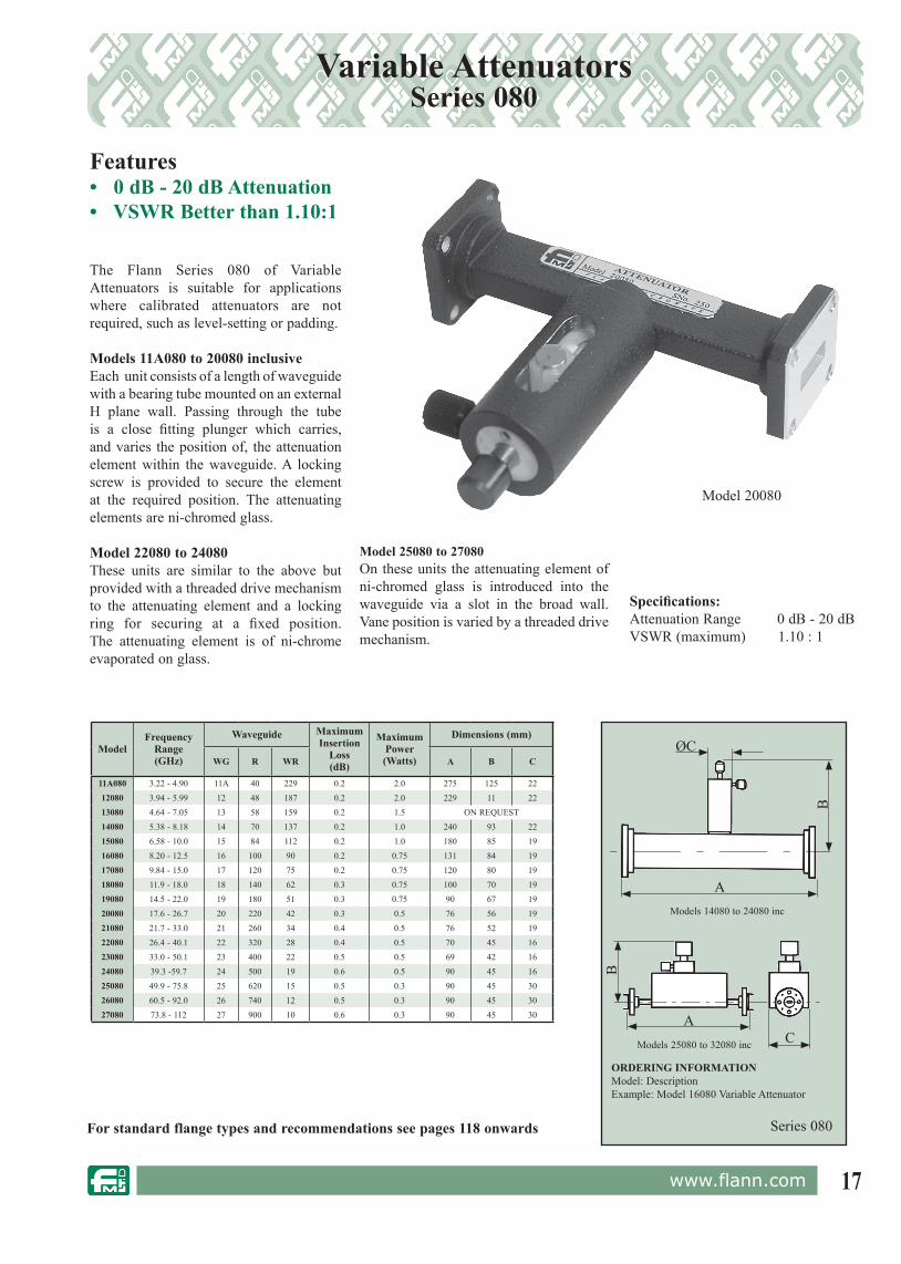
The Flann Series 080 of Variable Attenuators is suitable for applications where calibrated attenuators are not required, such as level-setting or padding.
Models 11A080 to 20080 inclusiveEach unit consists of a length of waveguide with a bearing tube mounted on an external H plane wall. Passing through the tube is a close fitting plunger which carries, and varies the position of, the attenuation element within the waveguide. A locking screw is provided to secure the element at the required position. The attenuating elements are ni-chromed glass.
Model 22080 to 24080These units are similar to the above but provided with a threaded drive mechanism to the attenuating element and a locking ring for securing at a fixed position. The attenuating element is of ni-chrome evaporated on glass.
Variable AttenuatorsSeries 080
Features• 0 dB - 20 dB Attenuation• VSWR Better than 1.10:1
For standard flange types and rec om men da tions see pages 118 onwards
Model 20080
Specifications:Attenuation Range 0 dB - 20 dBVSWR (maximum) 1.10 : 1
Model 25080 to 27080On these units the attenuating element of ni-chromed glass is introduced into the waveguide via a slot in the broad wall. Vane position is varied by a threaded drive mechanism.
ORDERING INFORMATIONModel: DescriptionExample: Model 16080 Variable Attenuator
A
ØC
B
Models 14080 to 24080 inc
A
B
CModels 25080 to 32080 inc
Series 080

18 www.flann.com
Precision Fixed AttenuatorsSeries 580 / 582
Features• Very High Stability• Attenuation variation with frequency less than ± 1.5 dB over full waveguide band @ 500 GHz• Very Low Coupling Sensitivity vs Temperature • High Power Versions AvailableThe Flann range of Precision Fixed Attenuators, Series 580 & 582, are very highly stable devices eminently suitable for use in attenuation transfer standards and verification standards for attenuation measurement systems or network analysers. The units are based on directional couplers and offer low attenuation variation with frequency, typically less than 0.5 dB, and low VSWR over the full waveguide band.
ORDERING INFORMATIONModel: attenuation value suffix; description Example: Model 22580-20 precision fixed 20 dB attenuator
Model 22580-20
For standard flange types and rec om men da tions see pages 118 onwards
ModelFrequency
Range(GHz)
Waveguide Attenuation
VSWR(better than)WG WM R WR Sensitivity
(±dB)
NominalAccuracy
(dB)3 - 6 10 20 - 60
14580 5.38 - 8.18 14 - 70 137 0.5 0.5 0.5 1.0 1.10
15580 6.58 - 10.0 15 - 84 112 0.5 0.5 0.5 1.0 1.10
16580 8.20 - 12.50 16 - 100 90 0.5 0.5 0.5 1.0 1.10
17580 9.84 - 15.0 17 - 120 75 0.5 0.5 0.5 1.0 1.10
18580 11.9 - 18.0 18 - 140 62 0.5 0.5 0.5 1.0 1.10
19580 14.5 - 22.0 19 - 180 51 0.5 0.5 0.5 1.0 1.10
20580 17.6 - 26.7 20 - 220 42 0.75 0.5 0.75 1.2 1.10
21580 21.7 - 33.0 21 - 260 34 0.75 0.5 0.75 1.2 1.10
22580 26.4 - 40.1 22 - 320 28 0.75 0.5 0.75 1.2 1.10
23582 33.0 - 50.1 23 - 400 22 0.75 0.5 0.75 1.2 1.15
24582 39.3 - 59.7 24 - 500 19 0.75 0.5 0.75 1.2 1.15
25582 49.9 - 75.8 25 - 620 15 0.75 0.5 0.75 1.2 1.15
26582 60.5 - 92.0 26 - 740 12 1.0 0.5 0.75 1.5 1.15
27582 73.8 - 112 27 - 900 10 1.0 0.75 1.0 1.5 1.15
28582 92.3 - 140 28 - 1200 8 1.0 0.75 1.0 1.5 1.15
29582 114 - 173 29 - 1400 6 1.0 0.75 1.0 1.5 1.20
30582 145 - 220 30 - 1800 5 1.0 0.85 1.2 2.0 1.25
31582 172 - 261 31 - 2200 4 1.2 0.85 1.2 2.0 1.30
32582 217 - 330 32 - 2600 3 1.2 0.85 1.2 2.0 1.40
710582 260 - 400 - 710 - '2.8' 1.5 1.0 1.5 2.5 1.60
570582 330 - 500 - 570 - '2.2' 1.5 1.0 1.5 2.5 2.00
Model 22580-20
Model 17580-10-AA (10 Watts)
Standard attenuation values 3, 6, 10, 20, 30, 40, 50 and 60 dB.Alternative attenuation value and high power whandling units can be manufactured to special requirements.

19www.flann.com
Model
FrequencyRange(GHz)
Waveguide VSWR(Max)
CalibrationAccuracy
(±dB)
CalibrationFrequency
(GHz)
MaximumInsertion
Loss(dB)
MaximumPower(Watts)
WG WM R WR
08020 1.72 - 2.61 8 - 22 430 1.07 0.2 2.17 0.2 4.010020 2.60 - 3.95 10 - 32 284 1.07 0.2 3.28 0.2 2.5
11A020 3.22 - 4.90 11A - 40 229 1.07 0.2 4.10 0.2 2.012020 3.94 - 5.99 12 - 48 187 1.07 0.2 4.97 0.2 2.013020 4.64 - 7.05 13 - 58 159 1.07 0.2 5.85 0.2 2.014020 5.38 - 8.18 14 - 70 137 1.07 0.2 6.78 0.2 1.015020 6.58 - 10.0 15 - 84 112 1.07 0.2 8.29 0.2 1.016020 8.20 - 12.5 16 - 100 90 1.07 0.2 10.35 0.2 1.017020 9.84 - 15.0 17 - 120 75 1.07 0.2 12.42 0.2 0.7518020 11.9 - 18.0 18 - 140 62 1.07 0.3 14.95 0.3 0.7519020 14.5 - 22.0 19 - 180 51 1.07 0.3 18.25 0.3 0.7520020 17.6 - 26.7 20 - 220 42 1.07 0.3 22.15 0.3 0.521020 21.7 - 33.0 21 - 260 34 1.07 0.35 27.35 0.3 0.522020 26.4 - 40.1 22 - 320 28 1.07 0.4 33.25 0.4 0.423020 33.0 - 50.1 23 - 400 22 1.07 0.2 41.55 0.2 0.3524020 39.3 - 59.7 24 - 500 19 1.07 0.2 49.50 0.2 0.325020 49.9 - 75.8 25 - 620 15 1.07 0.25 62.85 0.2 0.2526020 60.5 - 92.0 26 - 740 12 1.07 0.3 76.25 0.3 0.227020 73.8 - 112 27 - 900 10 1.07 0.4 92.9 0.4 0.1528020 92.3 - 140 28 - 1200 8 1.09 0.6 116.2 0.5 0.12
29020* 114 - 173 29 - 1400 6 1.11 0.9 140 0.7 0.130020* 145 - 220 30 - 1800 5 1.15 1.3 180 0.8 0.0831020* 172 - 261 31 - 2200 4 1.18 1.0 215 0.7 0.0632020* 217 - 330 32 - 2600 3 1.24 1.5 275 1.0 0.05
710020* 260 - 400 - 710 - '2.8' 1.3 2.0 330 1.2 0.04570020* 330 - 500 - 570 - '2.2' 1.4 2.0 415 3.0 0.03
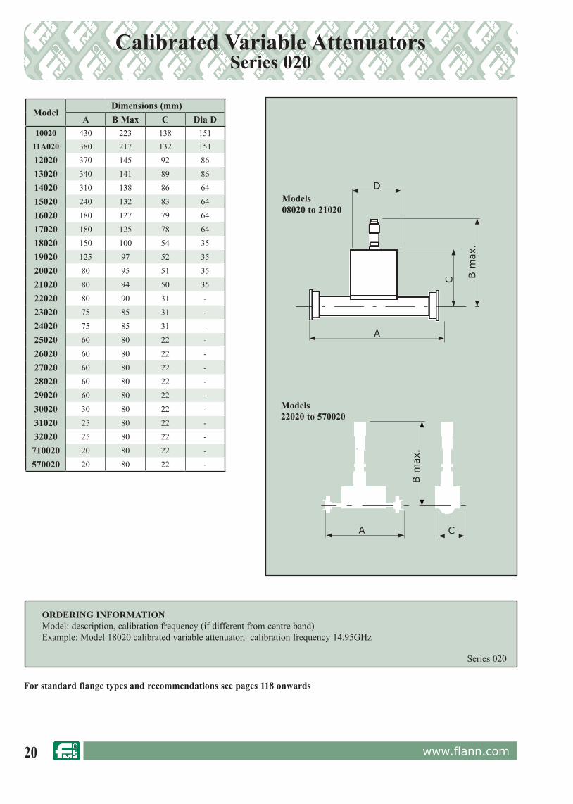
Calibrated Variable AttenuatorsSeries 020
Features• Models from 1.72 GHz to 500 GHz • 0 dB - 30 dB* Calibrated Attenuation Range• Low VSWR
The Flann Series 020 of Calibrated Variable attenuators are fitted with a stable precision attenuating elements driven across the waveguide section by a micrometer.
The micrometer drive is free from backlash, permitting attenuation calibration to a high accuracy. The micrometer is fitted with a locking device which enables the adjusting mechanism to be set and locked at any setting. The attenuating elements are constructed from an extremely stable ni-chromed glass composite.
On models 08020 to 21020 the vane is introduced transversely across the waveguide.
Models 22020 - 570020 have a vane introduced through a slot in the centre of the broad wall.
A calibration is provided at the centre band frequency unless otherwise specified.
Calibration at additional frequencies can be provided at extra cost.
Model 32020
*WG29 - WM570 calibrated attenuation range 0 - 25 dB
20 www.flann.com
Model Dimensions (mm)
A B Max C Dia D10020 430 223 138 151
11A020 380 217 132 15112020 370 145 92 86
13020 340 141 89 86
14020 310 138 86 64
15020 240 132 83 64
16020 180 127 79 64
17020 180 125 78 64
18020 150 100 54 35
19020 125 97 52 35
20020 80 95 51 35
21020 80 94 50 35
22020 80 90 31 -
23020 75 85 31 -
24020 75 85 31 -
25020 60 80 22 -
26020 60 80 22 -
27020 60 80 22 -
28020 60 80 22 -
29020 60 80 22 -
30020 30 80 22 -
31020 25 80 22 -
32020 25 80 22 -
710020 20 80 22 -
570020 20 80 22 -
Series 020
ORDERING INFORMATIONModel: description, calibration frequency (if different from centre band)Example: Model 18020 calibrated variable attenuator, calibration frequency 14.95GHz
For standard flange types and rec om men da tions see pages 118 onwards
Calibrated Variable AttenuatorsSeries 020
C
A
D
B m
ax.
A C
B m
ax.
Models08020 to 21020
Models22020 to 570020

21www.flann.com
ModelFrequency
Range (GHz)Waveguide VSWR (better than) Mean
Power(W)
Flange to Flange length
(mm)WG R WR Models3 to 25 dB
Models>30 dB
12081 3.94 - 5.99 15 48 187 1.10 1.20 1.0 22914081 5.38 - 8.18 14 70 137 1.10 1.20 0.5 28015081 6.58 - 10.0 15 84 112 1.10 1.20 0.5 18016081 8.20 - 12.5 16 100 90 1.10 1.20 0.5 13017081 9.84 - 15.0 17 120 75 1.10 1.20 0.5 12018081 11.9 - 18.0 18 140 62 1.10 1.20 0.5 12019081 14.5 - 22.0 19 180 51 1.10 12.0 0.4 11020081 17.6 - 26.7 20 220 42 1.10 1.20 0.3 7621081 21.7 - 33.0 21 260 34 1.10 1.20 0.3 7622081 26.4 - 40.1 22 320 28 1.10 1.20 0.3 7023081 33.0 - 50.1 23 400 22 1.10 1.20 0.25 7024081 39.3 - 59.7 24 500 19 1.10 1.20 0.25 7025081 49.9 - 75.8 25 620 15 1.10 1.20 0.2 6026081 60.5 - 92.0 26 740 12 1.10 1.20 0.2 5027081 73.8 - 112 27 900 10 1.10 1.20 0.15 5028081 92.3 - 140 28 1200 8 1.10 1.20 0.1 5029081 114 - 173 29 1400 6 1.10 1.20 0.1 4030081 145 - 220 30 1800 5 1.10 1.20 0.5 4031081 172 - 261 31 2200 4 1.10 1.20 0.5 4032081 217 - 330 32 2600 3 1.10 1.20 0.5 50
Fixed AttenuatorsSeries 081
Model 26081-06
Features • Full Waveguide Band• Low Frequency Sensitivity
The fixed attenuators, Series 081, are low VSWR devices suitable for operating over the full waveguide band.
The absolute attenuation is within ± 10% of nominal value.
Standard models are available in a range of attenuation values from 3 dB to 30 dB. Units with attenuation values of 40 dB and 50 dB are available to special order. Higher attenuation values can also be accommodated details on request.
ORDERING INFORMATIONModel: attenuation value suffix; descriptionExample: Model 26081-06 fixed attenuator
OTHER ATTENUATION VALUES AREAVAILABLE TO ORDER Series 081
For standard flange types and rec om men da tions see pages 118 onwards
Standard Attenuation Values
Suffix
3 dB 036 dB 0610 dB 1020 dB 2030 dB 30
Model 26081-06

22 www.flann.com
Rotary Vane Phase Changers: Series 063
Features• Direct Reading• 0˚ – 360˚ Continuous Phase Change• High Repeatability• Low Insertion Loss
For Programmable Rotary Phase Changers see page 12
Model 18063
The Flann Series 063 of instruments facilitates the continuous control of phase change over the range 0˚ to 360˚. A ten turn drum scale is linearly calibrated in degrees and indicates differential phase change to a smallest increment of 0.2˚.
The rotary vane phase changer consists of a pair of rectangular to circular, stepped or tapered, electroformed transitions providing good VSWR whilst ensuring minimal overall length. Each transition incorporates a mode suppression vane and dielectric quarter wave plate.The differential phase change is determined by the relative angular position of the
dielectric half wave plate housed in the rotating circular waveguide section. The Rotary Vane Phase Changer is direct reading and frequency insensitive making it suitable for use in microwave bridges and precise phase change measurements.
For standard flange types and rec om men da tions see pages 118 onwards * Non adjustable mounting feet
ModelFrequency
Range (GHz)
WaveguideAccuracy
MaximumInsertionLoss (dB)
VSWR(better than)
MaximumPower(Watts)
Dimensions (mm)
WG R WR A B C D E
08063 1.72 - 2.61 8 22 430 3˚ 1.0 1.25 15 ON REQUEST
10063 2.60 - 3.95 10 32 430 3˚ 1.0 1.25 15 1375 358 198 88.2* 108
11A063 3.22 - 4.90 11A 40 229 3˚ 1.0 1.25 15 991 340 153 81.2* 85
12063 3.94 - 5.99 12 48 187 3˚ 1.0 1.25 10 777 244 147 66/75 58
13063 4.64 - 7.05 13 58 159 3˚ 1.0 1.25 10 750 244 147 66/75 58
14063 5.38 - 8.18 14 70 137 3˚ 1.0 1.25 10 680 244 147 66/75 58
15063 6.58 - 10.0 15 84 112 3˚ 1.0 1.25 10 620 226 117 45/54 44
16063 8.20 - 12.5 16 100 90 3˚ 1.0 1.25 10 496 226 117 45/54 44
17063 9.84 - 15.0 17 120 75 3˚ 1.0 1.25 5 446 226 117 45/54 44
18063 11.9 - 18.0 18 140 62 4˚ 1.0 1.30 5 388 226 117 45/54 44
19063 14.5 - 22.0 19 180 51 4˚ 1.0 1.30 4 388 226 117 45/54 44
20063 17.6 - 26.7 20 220 42 4˚ 1.0 1.30 3 378 226 117 45/54 44
21063 21.7 - 33.0 21 260 34 4˚ 1.0 1.30 2.5 335 226 117 45/54 44
22063 26.4 - 40.1 22 320 28 4˚ 1.0 1.30 2.0 230 227 117 55/64 36
23063 33.0 - 50.1 23 400 22 4˚ 1.0 1.30 1.5 196 227 117 55/64 36
24063 39.3 - 59.7 24 500 19 4˚ 1.5 1.30 1.0 184 227 117 55/64 36
25063 49.9 - 75.8 25 620 15 5˚ 1.5 1.30 0.7 156 227 117 55/64 36
26063 60.5 - 92.0 26 740 12 5˚ 2.0 1.30 0.5 136 227 117 55/64 36
27063 73.8 - 112 27 900 10 6˚ 2.5 1.30 0.2 119 227 117 55/64 36
28063 92.3 - 140 28 1200 8 6˚ 2.5 1.50 0.2 119 227 117 55/64 36
29063 114 - 173 29 1400 6
Specifications availableon
request
Dimensions availableon
request
30063 145 - 220 30 1800 5
31063 172 - 261 31 2200 4
32063 217 - 330 32 2600 3
ORDERING INFORMATIONModel: DescriptionExample: Model 23063 Rotary Vane Phase Changer
Series 063
A
B
E
D
C

23www.flann.com
ModelFrequency
Range (GHz)
WaveguideAccuracy
MaximumInsertionLoss (dB)
VSWR(better than)
MaximumPower(Watts)
Dimensions (mm)
WG R WR A B C D E
08063 1.72 - 2.61 8 22 430 3˚ 1.0 1.25 15 ON REQUEST
10063 2.60 - 3.95 10 32 430 3˚ 1.0 1.25 15 1375 358 198 88.2* 108
11A063 3.22 - 4.90 11A 40 229 3˚ 1.0 1.25 15 991 340 153 81.2* 85
12063 3.94 - 5.99 12 48 187 3˚ 1.0 1.25 10 777 244 147 66/75 58
13063 4.64 - 7.05 13 58 159 3˚ 1.0 1.25 10 750 244 147 66/75 58
14063 5.38 - 8.18 14 70 137 3˚ 1.0 1.25 10 680 244 147 66/75 58
15063 6.58 - 10.0 15 84 112 3˚ 1.0 1.25 10 620 226 117 45/54 44
16063 8.20 - 12.5 16 100 90 3˚ 1.0 1.25 10 496 226 117 45/54 44
17063 9.84 - 15.0 17 120 75 3˚ 1.0 1.25 5 446 226 117 45/54 44
18063 11.9 - 18.0 18 140 62 4˚ 1.0 1.30 5 388 226 117 45/54 44
19063 14.5 - 22.0 19 180 51 4˚ 1.0 1.30 4 388 226 117 45/54 44
20063 17.6 - 26.7 20 220 42 4˚ 1.0 1.30 3 378 226 117 45/54 44
21063 21.7 - 33.0 21 260 34 4˚ 1.0 1.30 2.5 335 226 117 45/54 44
22063 26.4 - 40.1 22 320 28 4˚ 1.0 1.30 2.0 230 227 117 55/64 36
23063 33.0 - 50.1 23 400 22 4˚ 1.0 1.30 1.5 196 227 117 55/64 36
24063 39.3 - 59.7 24 500 19 4˚ 1.5 1.30 1.0 184 227 117 55/64 36
25063 49.9 - 75.8 25 620 15 5˚ 1.5 1.30 0.7 156 227 117 55/64 36
26063 60.5 - 92.0 26 740 12 5˚ 2.0 1.30 0.5 136 227 117 55/64 36
27063 73.8 - 112 27 900 10 6˚ 2.5 1.30 0.2 119 227 117 55/64 36
28063 92.3 - 140 28 1200 8 6˚ 2.5 1.50 0.2 119 227 117 55/64 36
29063 114 - 173 29 1400 6
Specifications availableon
request
Dimensions availableon
request
30063 145 - 220 30 1800 5
31063 172 - 261 31 2200 4
32063 217 - 330 32 2600 3
* For full waveguide band coverage order Model 061.
ModelFrequency
Range(GHz)
Waveguide VSWR(better than)
CalibrationAccuracy
Standard CalibrationFrequencies
(GHz)WG R WR
06060* 1.14 - 1.73 6 14 650 1.1 2˚ 1.34 1.53
08060* 1.72 - 2.61 8 22 430 1.1 2˚ 2.02 2.31
10060* 2.60 - 3.95 10 32 284 1.1 2˚ 3.05 3.50
11A060* 3.22 - 4.90 11A 40 229 1.1 2˚ 3.83 4.37
12060* 3.94 - 5.99 12 48 187 1.1 2˚ 4.62 5.31
13060* 4.64 - 7.05 13 58 159 1.1 2˚ 5.44 6.25
14060* 5.38 - 8.18 14 70 13 1.1 2˚ 6.31 7.25
15060* 6.58 - 10.0 15 84 112 1.1 2˚ 7.72 8.86
16060* 8.20 - 12.5 16 100 90 1.1 2˚ 9.63 11.07
17060* 9.84 - 15.0 17 120 75 1.1 2˚ 11.56 13.28
18060* 11.9 - 18.0 18 140 62 1.1 2˚ 13.93 15.97
19060* 14.5 - 22.0 19 180 51 1.1 2˚ 17.00 19.50
20060* 17.6 - 26.7 20 220 42 1.15 2˚ 20.63 23.67
21060* 21.7 - 33.0 21 260 34 1.15 3˚ 25.46 29.23
22060* 26.4 - 40.1 22 320 28 1.15 3˚ 30.97 35.53
23061 33.0 - 50.1 23 400 22 1.15 3˚ 38.70 44.40
24061 39.3 - 59.7 24 500 19 1.15 3˚ 46.10 52.90
25061 49.9 - 75.8 25 620 15 1.25 3˚ 58.53 67.17
26061 60.5 - 92.0 26 740 12 1.25 3˚ 71.00 81.50
27061 73.8 - 112 27 900 10 1.25 3˚ 85.87 97.93
28061 92.3 - 140 28 1200 8 1.25 3˚ 108.20 124.1
29061 114 - 173 29 1400 6Specifications available
onrequest
30061 145 - 220 30 1800 5
31061 172 - 261 31 2200 4
32061 217 - 330 32 2600 3
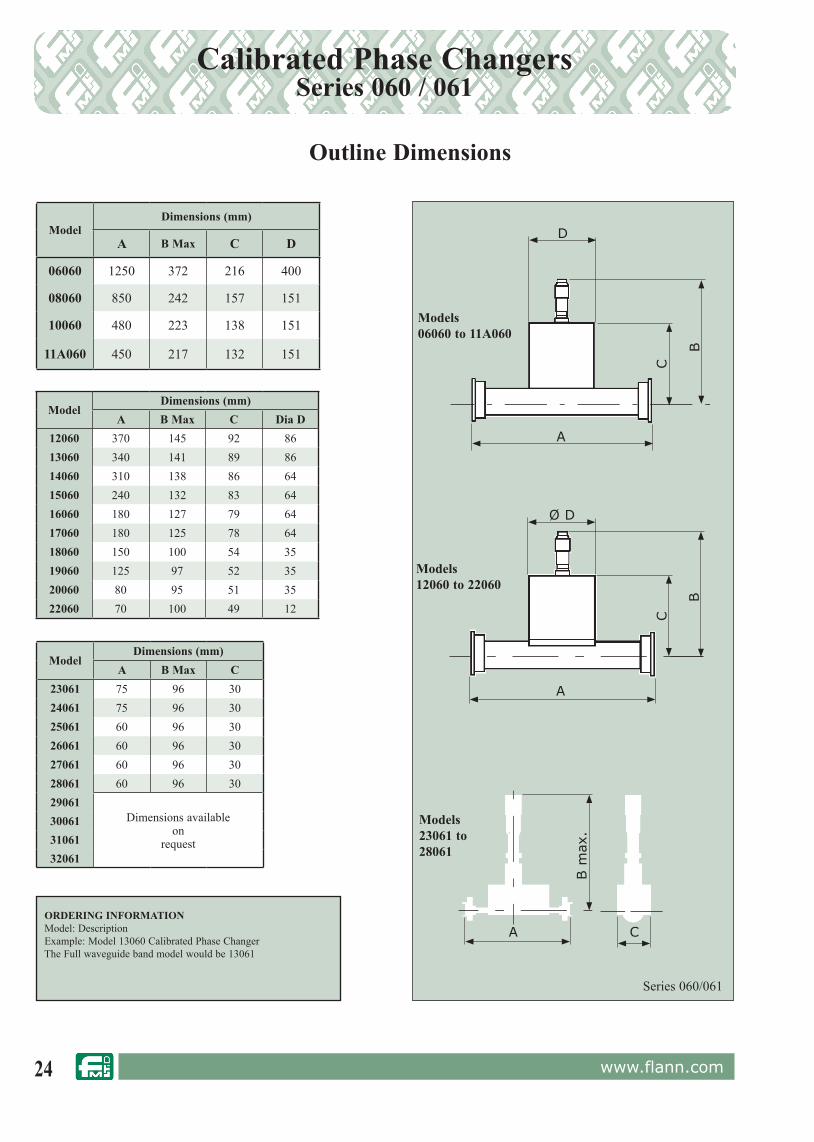
Calibrated Phase Changers: Series 060 / 061
Features• 0˚ – 180˚ Calibrated Phase
Change Range• Low Insertion LossThe Flann Series 060 / 061 instruments are fitted with low VSWR dielectric elements coupled to a precision micrometer drive. The micrometer indicates the relative position of the dielectric element in the waveguide. All models provide a minimum of 180 degrees phase change and exhibit a very low insertion loss. The micrometer is fitted with a locking device which enables the adjusting mechanism to be locked at any setting. Two calibrations are provided at standard frequencies within each waveguide band. Alternatively the two calibration frequencies may be specified by the customer.
In the standard models 06060 to 22060 the dielectric element is introduced into the waveguide in a transverse manner. The standard 060 series instruments do not cover the top 15% of the waveguide frequency band.
Model 20060When full band coverage is essential special models can be supplied at extra cost and are designated the 061 Series. For example, model 18061 is a full band model covering the frequency range 11.9 GHz to 18.0 GHz. Models 06061 to 22061 have VSWR better than 1.3:1 over the full waveguide band.Models in the waveguide sizes WG23 (WR22) to WG32 (WR8) introduce the dielectric element into the waveguide via a slot on the centre line of the broad wall and are suitable for the full band operation as standard.
24 www.flann.com
Outline Dimensions
ModelDimensions (mm)
A B Max C D
06060 1250 372 216 400
08060 850 242 157 151
10060 480 223 138 151
11A060 450 217 132 151
ModelDimensions (mm)
A B Max C23061 75 96 3024061 75 96 3025061 60 96 3026061 60 96 3027061 60 96 3028061 60 96 3029061
Dimensions availableon
request
300613106132061
Model Dimensions (mm)
A B Max C Dia D12060 370 145 92 8613060 340 141 89 8614060 310 138 86 6415060 240 132 83 6416060 180 127 79 6417060 180 125 78 6418060 150 100 54 3519060 125 97 52 3520060 80 95 51 3522060 70 100 49 12
ORDERING INFORMATION Model: Description Example: Model 13060 Calibrated Phase Changer The Full waveguide band model would be 13061
Calibrated Phase ChangersSeries 060 / 061
Models06060 to 11A060
Models12060 to 22060
C
A
D
B
C
A
Ø D
B
A C
B m
ax.
Models23061 to 28061
Series 060/061

25www.flann.com
CouplersSelection Guide
Series 130 Systems Grade Page 27
Full band, 35 dB nominal directivity entry level multihole directional coupler. 2.6 GHz to 40.1 GHz.
Series 131 High Directivity Pages 28-29
Full band, 40 dB nominal directivity multihole directional coupler. 2.6 GHz to 40.1 GHz
Series WRD131/WRD132 High Directivity Page 30
Full band, 40 dB nominal directivity double ridged multihole directional coupler. 2.0 GHz to 40 GHz
Series 132 Very High Directivity Page 31-32
Full band, 46 dB nominal directivity multihole directional coupler. 2.6 GHz to 40.1 GHz
Series 133 Ultra High Directivity Page 33
Full band, 50 dB nominal directivity multihole directional coupler. 3.22 GHz to 40.1 GHz
Series 136 High Directivity Page 34
Full band, 40 dB nominal directivity multihole directional coupler. 33.0 GHz to 330 GHz
Series 137 Very High Directivity Page 34
Full band, 44 dB nominal directivity multihole directional coupler. 33.0 GHz to 330 GHz
Series 230 3 Way Splitter Page 35
Full band, 40 dB nominal directivity multihole 3 way splitter. 2.6 GHz to 140 GHz
Series 231 3 Way Splitter Page 35
Full band, 40 dB nominal directivity multihole 3 way splitter. 140 GHz to 220 GHz
Series 270 Crossguide (Relatively compact design) Page 36
Full band, 20 dB nominal directivity crossguide coupler. 2.6 GHz to 330 GHz
Series 140 Branch Guide Couplers Page 37
Narrow band, 25 dB nominal directivity branch guide coupler.
Special and Customised Directional Couplers & Series 300/301 Dual Couplers Page 38-39
OPTIONS AVAILABLE:

26 www.flann.com
Multihole Directional CouplersGeneral Information
Flann Directional Couplers have many applications: it is important that their capabilities and specifications are understood.
Consider the 4 port directional coupler illustrated schematically.
For the purpose of this analysis if P1 is the power incident at Port 1 then the output powers at Ports 2, 3 and 4 are P2, P3 and P4 respectively. If P2’ is the power incident at Port 2 then P1’, P3’ and P4’ are the output powers at Ports 1, 3 and 4 respectively.
The three most important parameters in the specification of directional coupler performance are Coupling, Directivity and Through Loss which can be defined as follows:- Coupling (dB) = 10 log (P1/P3) .....(1) or = 10 log (P2’/P4’) Directivity (dB) = 10 log (P3/P4) or = 10 log (P4’/P3’) Through Loss (dB) = 10 log (P1/P2) .....(2) or = 10 log (P2’/P1’)In determining the above expressions, unused ports should be terminated with reflectionless loads.
A parameter referred to as Isolation is sometimes used when characterising directional couplers where:- Isolation (dB) = 10 log (P1/P4) or = 10 log (P2’/P3’)It can be shown that:- Isolation (dB) = Coupling (dB) + Directivity (dB)This must be borne in mind whilst comparing the specifications from other manufacturers. For a matched coupler in low loss waveguide the main arm through power, P2, is equal to the input power minus the powers coupled to the secondary arm, i.e. P2 = P1 - (P3 + P4) or P1’ = P2’ - (P4’ + P3’)For a high directivity coupler P4 and P3’ are negligible, hence:- P2 = P1 - P3 or P1’ = P2’ - P4’also Through Loss (dB) = 10 log (P1/(P1 - P3)) or = 10 log (P2/(p2’ - P4’))
The table shows, for power incident at Port 1 only, the percentage powers at Ports 2 and 3 and Through Loss for a matched high-directivity coupler of negligible waveguide loss. At lower frequencies waveguide absorption losses are small. However at millimetric frequencies absorption losses are significant and affect the measured performance of couplers. If the power absorbed within the coupler is Pa then the through loss in dB can be defined as:- Through loss = 10 log (P1/(P1 - P3 - Pa)......(3) assuming P4<<P3 (ie high directivity).
Consider a 3 dB coupler with an absorption loss of 0.5 dB. If engineered to have a coupling of 3 dB, as in expression (1), 50.11% of the input power at Port 1 is coupled to Port 3. By using expression (3) it can be shown that an absorption loss of 0.5 dB represents 10.875% of the input power, thus effectively reducing the power at Port 2 to 39.01%. This represents a Through Loss of 4.09 dB.
The table also illustrates the effect of an absorption loss of 0.1 dB and 0.25 dB on the relative powers at Ports 2 and 3:- the coupling value of Flann directional couplers is the true value as defined in the expression (1) above. Millimetre band models must be used with the understanding that there is an additional main guide loss.
The Directivity of a coupler is essentially dependent on the following factors:-(i) The design of coupling structure and the accuracy to which it can be manufactured.(ii) The inherent VSWR of the coupler’s internal termination (3 port devices).(iii) Discontinuities and perturbations in the waveguide.(iv) The dimensional accuracy of the waveguide at the measurement port.In four port couplers the VSWR of the bends in the secondary arm are often the most significant factor limiting directivity performance. For example a 4 port coupler with a 1.05 VSWR bend in the secondary arm
will give, at best, a 32.2 dB directivity.
Flann directional couplers have specified directivities which include the interface at the measurement port when connected to an ideal termination. It is important when making comparisons that users should enquire whether alternative manufacturers have also followed similar test procedures when quoting performance. It is not uncommon that when measuring directivity, terminations are inserted into the measuring port’s terminal flange. This is not a Flann recommended procedure.
The terms used in Flann Directional Coupler specifications are:-
Nominal Coupling Accuracy
This is the mean coupling value expressed as a percentage of the Nominal Coupling. For example a 10 dB coupler which has a specified Nominal Coupling Accuracy of 5% could have a mean coupling value within the limits 9.5 to 10.5 dB.
Coupling Sensitivity
This is the variation of actual coupling about the mean coupling value over the specified operating frequency band. For example the actual coupling value of a nominal 9.6 dB coupler could vary from 9.1 to 10.1 dB over the specified frequency range.
Directivity
The directivity of a directional coupler is the ratio, in dB, of the power in the forward direction of the secondary guide to that in the reverse direction of the secondary guide when the primary guide is fed only in the forward direction.i.e. Directivity (dB) = 10 log10 (P3/P4) when signal is input to P1 only.
Coupling(dB)
%Power
atPort 3
Waveguide Absorption Loss
0 dB @ 5 GHz 0.1 dB @ 25 GHz 0.25 dB @ 65 GHz 0.5 dB @ 140 GHz
% Power at
Port 2
ThroughLoss(dB)
%Power
atPort 2
ThroughLoss(dB)
%Power
atPort 2
ThroughLoss(dB)
%Power
atPort 2
ThroughLoss(dB)
3 50.1 49.0 3.02 47.60 3.22 44.29 3.54 39.01 4.09
6 25.1 74.9 1.26 72.60 1.39 69.29 1.59 64.01 1.94
10 10.0 90.0 0.46 87.72 0.57 84.41 0.74 79.13 1.02
20 1.09 9.0 0.044 96.72 0.14 93.41 0.30 88.13 0.55
30 0.1 99.9 0.044 97.62 0.10 94.31 0.255 89.03 0.505
40 0.01 99.99 0.0004 97.71 0.10 94.40 0.250 89.12 0.500
Four Port Directional Coupler Schematic
P1
P4 P3
P2

27www.flann.com
Multihole Directional CouplersSeries 130
Model 19130-20
Specifications:
The Flann series 130 of multihole directional couplers provides the user with a measurement facility over the entire waveguide frequency range at very modest cost.
These couplers have a good directivity performance whilst retaining the minimal frequency sensitivity associated with higher quality units. The standard coupling values are 10 dB and 20 dB.
IMPORTANT! All directivities quoted include the measuring port and flange performance when connected to an ideal termination.
ModelFrequency
Range(GHz)
Waveguide MinimumDirectivity
(dB)
Coupling (10 dB &20 dB) PrimaryArm
VSWR
SecondaryArm
VSWRWG R WR Sensitivity(± dB)
NominalAccuracy (dB)
10130 2.60 - 3.95 10 32 284 35 0.5 5% 1.03 1.1011A130 3.22 - 4.90 11A 40 229 35 0.5 5% 1.03 1.1012130 3.94 - 5.99 12 48 187 35 0.5 5% 1.03 1.1013130 4.64 - 7.05 13 58 159 35 0.5 5% 1.03 1.1014130 5.38 - 8.18 14 70 137 35 0.5 5% 1.03 1.1015130 6.58 - 10.0 15 84 112 35 0.5 5% 1.03 1.1016130 8.20 - 12.5 16 100 90 35 0.5 5% 1.03 1.1017130 9.84 - 15.0 17 120 75 35 0.5 5% 1.03 1.1018130 11.9 - 18.0 18 140 62 35 0.5 5% 1.03 1.1019130 14.5 - 22.0 19 180 51 33 0.5 5% 1.03 1.1020130 17.6 - 26.7 20 220 42 33 0.75 7% 1.03 1.2021130 21.7 - 33.0 21 260 34 33 0.75 7% 1.03 1.2022130 26.4 - 40.1 22 320 28 33 0.75 7% 1.03 1.20
Features• Systems Grade• Ideal For Power / Frequency
Sampling & Monitoring
ORDERING INFORMATIONModel: Coupling Value Suffix; DescriptionExample: Model 10130-10 Multihole Directional Coupler 10 dB coupling Directivity >35 dB
Series 130
A
B
C
Model
Dimensions (mm)Weight (kg)
AB C
10 dB 20 dB 10 dB 20 dB10130 1215 1029 85 130 10.6 8.0
11A130 965 817 70 100 5.7 4.6
12130 853 733 60 90 4.3 3.0
13130 785 676 55 75 3.5 2.6
14130 706 615 50 60 2.6 2.2
15130 534 460 35 50 1.5 1.3
16130 476 417 35 45 1.0 0.8
17130 387 338 35 40 0.8 0.6
18130 340 298 30 35 0.5 0.4
19130 300 262 30 35 0.4 0.3
20130 228 201 25 25 0.18 0.16
21130 215 194 25 25 0.18 0.16
22130 180 162 24 29 0.16 0.14
Coupling Values Suffix
10 dB 10
20 dB 20

28 www.flann.com
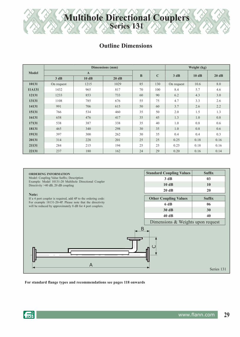
Multihole Directional CouplersSeries 131
Model 18131-10
See overleaf for dimensions and ordering information.
* Primary arm VSWR specification is 1.10:1 for all 3 dB couplers** Nominal coupling accuracy for 3 dB and 6 dB couplers is ± 0.5 dB.
Features• High Directivity• Models from 2.6 GHz to 40.1 GHz
The Flann Series 131 Directional Couplers are suitable where high quality is to be incorporated at moderate cost.
A high directivity is offered in all waveguide sizes within the frequency range 2.6 GHz to 40.1 GHz. The standard coupling values are 3, 10 and 20 dB, other values for example 6, 30 and 40 dB can be supplied.
IMPORTANT! All directivities quoted include the measuring port and flange performance when connected to an ideal termination.
4 port couplers can be supplied to order, however the directivity will be less than for 3 port units.
Model
FrequencyRange(GHz)
Waveguide MinimumDirectivity
(dB)
Coupling (3, 10 & 20 dB) AdditionalPrimary
Arm Loss(dB)
PrimaryArm
VSWR *
SecondaryArm
VSWRWG R WRSensitivity
(±dB)Nominal
Accuracy (dB)**
10131 2.60 - 3.95 10 32 284 40 0.5 5%
Not Applicable
1.03 1.10
11A131 3.22 - 4.90 11A 40 229 40 0.5 5% 1.03 1.10
12131 3.94 - 5.99 12 48 187 40 0.5 5% 1.03 1.10
13131 4.64 - 7.05 13 58 159 40 0.5 5% 1.03 1.10
14131 5.38 - 8.18 14 70 137 40 0.5 5% 1.03 1.10
15131 6.58 - 10.0 15 84 112 40 0.5 5% 1.03 1.10
16131 8.20 - 12.5 16 100 90 40 0.5 5% 1.03 1.10
17131 9.84 - 15.0 17 120 75 40 0.5 5% 1.03 1.10
18131 11.9 - 18.0 18 140 62 40 0.5 5% 1.03 1.10
19131 14.5 - 22.0 19 180 51 40 0.5 5% 1.03 1.10
20131 17.6 - 26.7 20 220 42 40 0.75 7% 0.3 1.03 1.20
21131 21.7 - 33.0 21 260 34 40 0.75 7% 0.4 1.03 1.20
22131 26.4 - 40.1 22 320 28 40 0.75 7% 0.5 1.03 1.20
Specifications:
See Series 136 for higher frequency models up to 330 GHz.
29www.flann.com
Series 131
ORDERING INFORMATIONModel: Coupling Value Suffix; DescriptionExample: Model 10131-20 Multihole Directional Coupler Directivity >40 dB, 20 dB coupling
Note:If a 4 port coupler is required, add 4P to the ordering code: For example 18131-20-4P. Please note that the directivity will be reduced by approximately 8 dB for 4 port couplers.
B
C
A
For standard flange types and rec om men da tions see pages 118 onwards
Multihole Directional CouplersSeries 131
ModelDimensions (mm) Weight (kg)
AB C 3 dB 10 dB 20 dB
3 dB 10 dB 20 dB10131 On request 1215 1029 85 130 On request 10.6 8.0
11A131 1432 965 817 70 100 8.4 5.7 4.612131 1233 853 733 60 90 6.2 4.3 3.013131 1108 785 676 55 75 4.7 3.3 2.614131 991 706 615 50 60 3.7 2.6 2.215131 766 534 460 35 50 2.0 1.5 1.316131 658 476 417 35 45 1.3 1.0 0.817131 538 387 338 35 40 1.0 0.8 0.618131 465 340 298 30 35 1.0 0.8 0.619131 397 300 262 30 35 0.4 0.4 0.320131 314 228 201 25 25 0.25 0.18 0.1621131 284 215 194 25 25 0.25 0.18 0.1622131 237 180 162 24 29 0.20 0.16 0.14
Outline Dimensions
Standard Coupling Values Suffix3 dB 0310 dB 1020 dB 20
Other Coupling Values Suffix6 dB 0630 dB 3040 dB 40
Dimensions & Weights upon request
30 www.flann.com
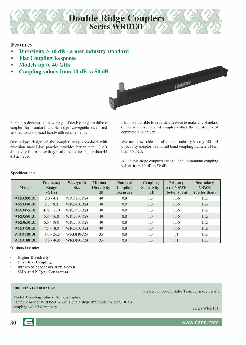
Double Ridge CouplersSeries WRD131
Flann has developed a new range of double ridge multihole coupler for standard double ridge waveguide sizes and tailored to any special bandwidth requirements.
Our unique design of the coupler array combined with precision machining practice provides better than 40 dB directivity full band with typical directivities better than 45 dB achieved.
Flann is now able to provide a service to make any standard or non-standard type of coupler within the constraints of commercial viability.
We are now able to offer the industry’s only 40 dB directivity coupler with a full band coupling flatness of less than +/-1 dB.
All double ridge couplers are available in nominal coupling values from 10 dB to 50 dB.
ORDERING INFORMATION
Model: Coupling value suffix; description Example Model WRD650131-10 Double ridge multihole coupler, 10 dB coupling, 40 dB directivity
ModelFrequency
Range (GHz)
WaveguideSize
MinimumDirectivity
dB
NominalCouplingAccuracy
CouplingSensitivity
± dB
Primary Arm VSWR(better than)
Secondary VSWR
(better than)WRD200131 2.0 - 4.8 WRD200D24 40 0.8 1.0 1.06 1.35WRD350131 3.5 - 8.2 WRD350D24 40 0.8 1.0 1.06 1.35WRD475131 4.75 - 11.0 WRD475D24 40 0.8 1.0 1.06 1.35WRD580131 5.8 - 16.0 WRD580D28 40 0.8 1.0 1.06 1.35WRD650131 6.5 - 18.0 WRD650D28 40 0.8 1.0 1.06 1.35WRD750131 7.5 - 18.0 WRD750D24 40 0.8 1.0 1.06 1.35WRD110131 11.0 - 26.5 WRD110C24 35 0.8 1.0 1.1 1.35WRD180131 18.0 - 40.0 WRD180C24 35 0.8 1.0 1.1 1.35
Please contact our Sales Team for more details.
Series WRD131
Features• Directivity > 40 dB - a new industry standard• Flat Coupling Response• Models up to 40 GHz• Coupling values from 10 dB to 50 dB
Specifications:
Options Include:
• Higher Directivity• Ultra Flat Coupling• Improved Secondary Arm VSWR• SMA and N Type Connectors

31www.flann.com
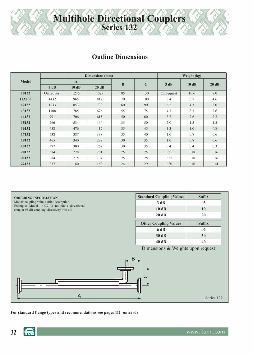
Model 22132-20
IMPORTANT! All directivities quoted include the measuring port and flange performance when connected to an ideal termination.
* Primary arm VSWR specification is 1.10:1 for all 3 dB couplers.** Nominal coupling accuracy for 3 dB and 6 dB couplers is ± 0.5 dB. Please refer to page 26 for definitions of Flann coupler specifications.
Features• 46 dB High Directivity• Models up to 40.1 GHz• Low Coupling Sensitivity
The Flann Series 132 directional couplers provide a very high directivity and have been designed for use in quality waveguide measurement systems within the frequency range 3.3 GHz to 40.1 GHz.
The configuration is of a 3 port instrument incorporating a built-in low reflection termination. The coupling array is designed to achieve low sensitivity of coupling versus frequency whilst maintaining main arm VSWR. The standard coupling values are 3, 10 and 20 dB for each waveguide size. Other values can be supplied, for example 6, 30 and 40 dB.
Multihole Directional CouplersSeries 132
Model
FrequencyRange(GHz)
Waveguide MinimumDirectivity
(dB)
Coupling (3, 10 & 20 dB) AdditionalPrimary
Arm Loss(dB)
PrimaryArm
VSWR*
SecondaryArm
VSWRWG R WRSensitivity
(±dB)NominalAccuracy
(dB)**
10132 2.60 - 3.95 10 32 284 46 0.5 5% N/A 1.03 1.10
11A132 3.22 - 4.90 11A 40 229 46 0.5 5% N/A 1.03 1.10
12132 3.94 - 5.99 12 48 187 46 0.5 5% N/A 1.03 1.10
13132 4.64 - 7.05 13 58 159 46 0.5 5% N/A 1.03 1.10
14132 5.38 - 8.18 14 70 137 46 0.5 5% N/A 1.03 1.10
15132 6.58 - 10.0 15 84 112 46 0.5 5% N/A 1.03 1.10
16132 8.20 - 12.5 16 100 90 46 0.5 5% N/A 1.03 1.10
17132 9.84 - 15.0 17 120 75 43 0.5 5% N/A 1.03 1.10
18132 11.9 - 18.0 18 140 62 43 0.5 5% N/A 1.03 1.10
19132 14.5 - 22.0 19 180 51 43 0.5 5% 0.2 1.03 1.10
20132 17.6 - 26.7 20 220 42 43 0.75 7% 0.3 1.03 1.20
21132 21.7 - 33.0 21 260 34 43 0.75 7% 0.4 1.03 1.20
22132 26.4 - 40.1 22 320 28 43 0.75 7% 0.5 1.03 1.20
Specifications:
See Series 137 for higher frequency models up to 330 GHz.
See overleaf for dimensions and ordering information.
32 www.flann.com
Series 132
Multihole Directional CouplersSeries 132
ORDERING INFORMATIONModel: coupling value suffix; descriptionExample: Model 16132-03 multihole directional coupler 03 dB coupling, directivity >46 dB
B
C
A
For standard flange types and rec om men da tions see pages 111 onwards
Outline Dimensions
ModelDimensions (mm) Weight (kg)
AB C 3 dB 10 dB 20 dB
3 dB 10 dB 20 dB10132 On request 1215 1029 85 130 On request 10.6 8.0
11A132 1432 965 817 70 100 8.4 5.7 4.612132 1233 853 733 60 90 6.2 4.3 3.013132 1108 785 676 55 75 4.7 3.3 2.614132 991 706 615 50 60 3.7 2.6 2.215132 766 534 460 35 50 2.0 1.5 1.316132 658 476 417 35 45 1.3 1.0 0.817132 538 387 338 35 40 1.0 0.8 0.618132 465 340 298 30 35 1.0 0.8 0.619132 397 300 262 30 35 0.4 0.4 0.320132 314 228 201 25 25 0.25 0.18 0.1621132 284 215 194 25 25 0.25 0.18 0.1622132 237 180 162 24 29 0.20 0.16 0.14
Standard Coupling Values Suffix3 dB 0310 dB 1020 dB 20
Other Coupling Values Suffix6 dB 0630 dB 3040 dB 40
Dimensions & Weights upon request

33www.flann.com
ModelFrequency
Range(GHz)
Waveguide MinimumDirectivity
(dB)
Coupling (10 dB & 20 dB) PrimaryArm
VSWR
SecondaryArm
VSWRWG R WRSensitivity
(± dB)NominalAccuracy
(dB)11A133 3.22 - 4.90 11A 40 229 50 0.5 5% 1.03 1.1012133 3.94 - 5.99 12 48 187 50 0.5 5% 1.03 1.1013133 4.64 - 7.05 13 58 159 50 0.5 5% 1.03 1.1014133 5.38 - 8.18 14 70 137 50 0.5 5% 1.03 1.1015133 6.58 - 10.0 15 84 112 50 0.5 5% 1.03 1.1016133 8.20 - 12.5 16 100 90 50 0.5 5% 1.03 1.1017133 9.84 - 15.0 17 120 75 50 0.5 5% 1.03 1.1018133 11.9 - 18.0 18 140 62 48 0.5 5% 1.03 1.1019133 14.5 - 22.0 19 180 51 48 0.5 5% 1.03 1.1020133 17.6 - 26.7 20 220 42 46 0.75 7% 1.03 1.2021133 21.7 - 33.0 21 260 34 46 0.75 7% 1.03 1.2022133 26.4 - 40.1 22 320 28 46 0.75 7% 1.03 1.20
Multihole Directional CouplersSeries 133
Note: Please refer to page 26 for definitions of Flann coupler specifications.
Specifications:
IMPORTANT! All directivities quoted include the measuring port and flange performance when connected to an ideal termination.
Features• 50 dB Directivity• Low Coupling Sensitivity
The Flann Series 133 of ultra-high directivity multihole couplers has been developed principally for laboratory applications involving network analyser or reflectometer systems.
The couplers are a 3 port design with an extremely low reflection termination built into the fourth arm. The standard coupling values are 10 dB and 20 dB.
Model 20133-10
ModelDimensions (mm)
Weight(kg)
AB C
10 dB 20 dB11A133 1044 1044 70 100 6.012133 920 920 60 90 5.013133 802 802 55 75 2.514133 765 765 50 60 3.015133 620 620 35 50 1.816133 528 528 35 45 1.117133 427 427 35 40 0.8518133 356 356 30 35 0.5019133 330 330 30 35 0.4020133 250 250 25 25 0.2021133 235 235 25 25 0.2022133 180 180 24 29 0.18 Series 133
ORDERING INFORMATIONModel: coupling value suffix; descriptionExample: Model 14133-20 multihole directional coupler 20 dB coupling, directivity >50 dB
A
B
C
34 www.flann.com
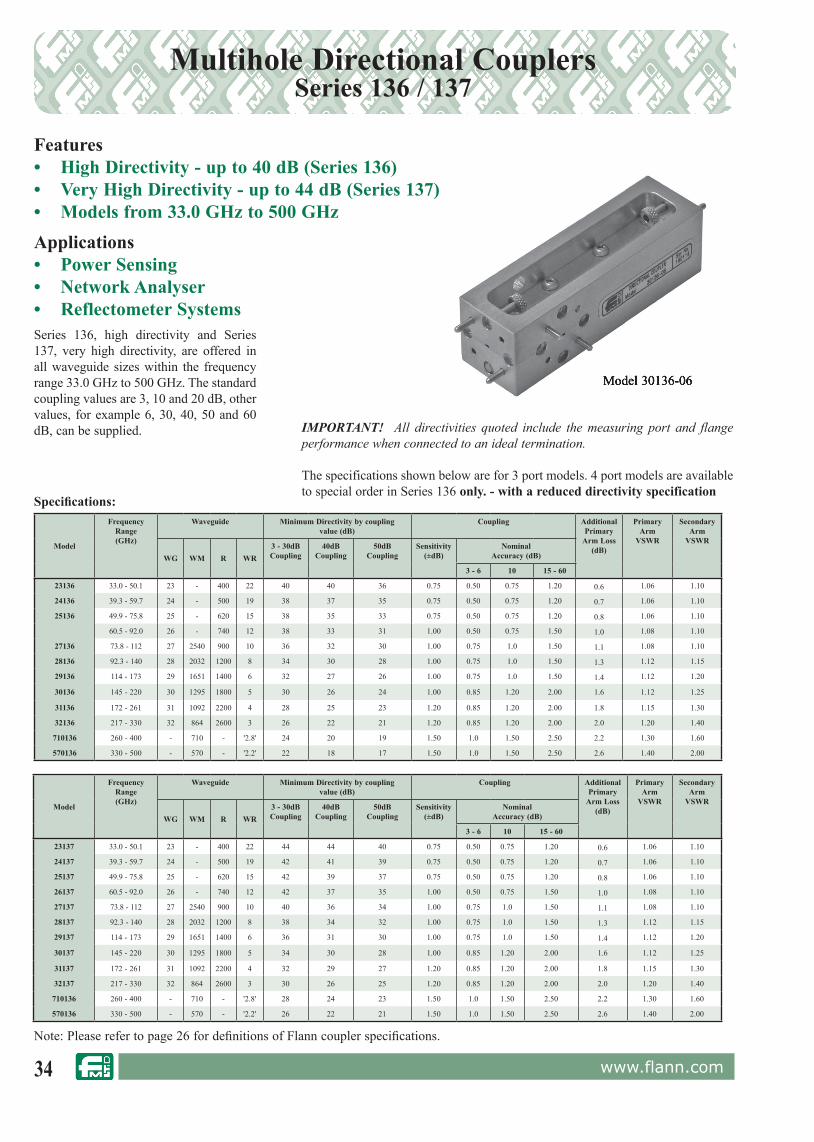
Multihole Directional CouplersSeries 136 / 137
Model 30136-06
Features• High Directivity - up to 40 dB (Series 136)• Very High Directivity - up to 44 dB (Series 137)• Models from 33.0 GHz to 500 GHzApplications• Power Sensing• Network Analyser• Reflectometer SystemsSeries 136, high directivity and Series 137, very high directivity, are offered in all waveguide sizes within the frequency range 33.0 GHz to 500 GHz. The standard coupling values are 3, 10 and 20 dB, other values, for example 6, 30, 40, 50 and 60 dB, can be supplied.
Model
FrequencyRange(GHz)
Waveguide Minimum Directivity by coupling value (dB)
Coupling AdditionalPrimary
Arm Loss(dB)
PrimaryArm
VSWR
SecondaryArm
VSWR
WG WM R WR3 - 30dBCoupling
40dBCoupling
50dBCoupling
Sensitivity(±dB)
NominalAccuracy (dB)
3 - 6 10 15 - 60
23136 33.0 - 50.1 23 - 400 22 40 40 36 0.75 0.50 0.75 1.20 0.6 1.06 1.10
24136 39.3 - 59.7 24 - 500 19 38 37 35 0.75 0.50 0.75 1.20 0.7 1.06 1.10
25136 49.9 - 75.8 25 - 620 15 38 35 33 0.75 0.50 0.75 1.20 0.8 1.06 1.10
60.5 - 92.0 26 - 740 12 38 33 31 1.00 0.50 0.75 1.50 1.0 1.08 1.10
27136 73.8 - 112 27 2540 900 10 36 32 30 1.00 0.75 1.0 1.50 1.1 1.08 1.10
28136 92.3 - 140 28 2032 1200 8 34 30 28 1.00 0.75 1.0 1.50 1.3 1.12 1.15
29136 114 - 173 29 1651 1400 6 32 27 26 1.00 0.75 1.0 1.50 1.4 1.12 1.20
30136 145 - 220 30 1295 1800 5 30 26 24 1.00 0.85 1.20 2.00 1.6 1.12 1.25
31136 172 - 261 31 1092 2200 4 28 25 23 1.20 0.85 1.20 2.00 1.8 1.15 1.30
32136 217 - 330 32 864 2600 3 26 22 21 1.20 0.85 1.20 2.00 2.0 1.20 1.40
710136 260 - 400 - 710 - '2.8' 24 20 19 1.50 1.0 1.50 2.50 2.2 1.30 1.60
570136 330 - 500 - 570 - '2.2' 22 18 17 1.50 1.0 1.50 2.50 2.6 1.40 2.00
Specifications:
Model 30136-06
IMPORTANT! All directivities quoted include the measuring port and flange performance when connected to an ideal termination.
The specifications shown below are for 3 port models. 4 port models are available to special order in Series 136 only. - with a reduced directivity specification
Note: Please refer to page 26 for definitions of Flann coupler specifications.
Model
FrequencyRange(GHz)
Waveguide Minimum Directivity by coupling value (dB)
Coupling AdditionalPrimary
Arm Loss(dB)
PrimaryArm
VSWR
SecondaryArm
VSWR
WG WM R WR3 - 30dBCoupling
40dBCoupling
50dBCoupling
Sensitivity(±dB)
NominalAccuracy (dB)
3 - 6 10 15 - 60
23137 33.0 - 50.1 23 - 400 22 44 44 40 0.75 0.50 0.75 1.20 0.6 1.06 1.10
24137 39.3 - 59.7 24 - 500 19 42 41 39 0.75 0.50 0.75 1.20 0.7 1.06 1.10
25137 49.9 - 75.8 25 - 620 15 42 39 37 0.75 0.50 0.75 1.20 0.8 1.06 1.10
26137 60.5 - 92.0 26 - 740 12 42 37 35 1.00 0.50 0.75 1.50 1.0 1.08 1.10
27137 73.8 - 112 27 2540 900 10 40 36 34 1.00 0.75 1.0 1.50 1.1 1.08 1.10
28137 92.3 - 140 28 2032 1200 8 38 34 32 1.00 0.75 1.0 1.50 1.3 1.12 1.15
29137 114 - 173 29 1651 1400 6 36 31 30 1.00 0.75 1.0 1.50 1.4 1.12 1.20
30137 145 - 220 30 1295 1800 5 34 30 28 1.00 0.85 1.20 2.00 1.6 1.12 1.25
31137 172 - 261 31 1092 2200 4 32 29 27 1.20 0.85 1.20 2.00 1.8 1.15 1.30
32137 217 - 330 32 864 2600 3 30 26 25 1.20 0.85 1.20 2.00 2.0 1.20 1.40
710136 260 - 400 - 710 - '2.8' 28 24 23 1.50 1.0 1.50 2.50 2.2 1.30 1.60
570136 330 - 500 - 570 - '2.2' 26 22 21 1.50 1.0 1.50 2.50 2.6 1.40 2.00

35www.flann.com
Note: Please refer to page 26 for definitions of Flann coupler specifications.
Features• High Directivity• 3 Way Signal Splitter• ± 0.2 dB Balance Between Coupled ArmsThe Flann Multihole Power Splitter consists of a central waveguide with coupling arrays in the broad walls designed to divide the input signal into three signals of equal magnitude.
Normally the instrument is a 4 port device as illustrated. However, for network analyser applications where only two equal amplitude signals are required the central output port may be terminated. Precision machining methods ensure that the full band frequency sensitivity between secondary waveguide ports is better than ± 0.2 dB. The coupling to each output port is 4.8 dB down with respect to the input signal. Directivity for most models is greater than 40 dB.
IMPORTANT! All directivities quoted include the measuring port and flange performance when connected to an ideal termination.
Model 22230
For standard flange types and rec om men da tions see pages 118 onwards
Multihole Directional CouplersSeries 230 / 231
Model
Frequency
Range
(GHz)
Waveguide Maximum
Directivity
(dB)
Sensitivity
Between Coupled
Ports (dB)
Dimensions (mm) Weight
(kg)WG R WR A B C
10230 2.60 - 3.95 10 32 284 40 ±0.2 1773 85 130 19.0
11A230 3.22 - 4.90 11A 40 229 40 ±0.2 1407 79 100 9.3
12230 3.94 - 5.99 12 48 187 40 ±0.2 1213 60 90 8.4
14230 5.38 - 8.18 14 70 137 40 ±0.2 976 50 60 5.0
15230 6.58 - 10.0 15 84 112 40 ±0.2 753 35 50 3.0
16230 8.20 - 12.5 16 100 90 40 ±0.2 649 35 45 1.9
17230 9.84 - 15.0 17 120 75 40 ±0.2 522 35 40 1.4
18230 11.9 - 18.0 18 140 62 40 ±0.2 438 30 35 0.9
19230 14.5 - 22.0 19 180 51 40 ±0.2 392 30 35 0.7
20230 17.6 - 26.7 20 220 42 38 ±0.3 314 25 25 0.4
22230 26.4 - 40.1 22 320 28 38 ±0.3 228 24 29 0.3
23231 33.0 - 50.1 23 400 22 36 ±0.3
24231 39.3 - 59.7 24 500 19 33 ±0.3
25231 49.9 - 75.8 25 620 15 33 ±0.3
26231 60.5 - 92.0 26 740 12 30 ±0.4
27231 73.8 - 112 27 900 10 27 ±0.5
28231 92.3 - 140 28 1200 8
Specifications availableon
request
29231 114 - 173 29 1400 6
30231 145 - 220 30 1800 5
31231 172 - 261 31 2200 4
32231 217 - 330 32 2600 3
Specifications:
ORDERING INFORMATIONModel DescriptionExample: Model 20230 Multihole Directional Coupler3 Way Power Splitter
Series 230
ABC
C
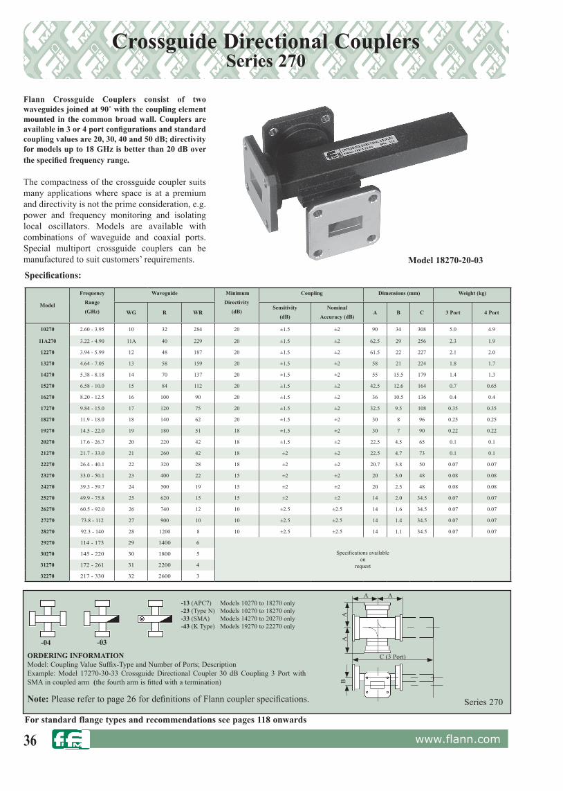
36 www.flann.com
Crossguide Directional CouplersSeries 270
Flann Crossguide Couplers consist of two waveguides joined at 90˚ with the coupling element mounted in the common broad wall. Couplers are available in 3 or 4 port configurations and standard coupling values are 20, 30, 40 and 50 dB; directivity for models up to 18 GHz is better than 20 dB over the specified frequency range.
The compactness of the crossguide coupler suits many applications where space is at a premium and directivity is not the prime consideration, e.g. power and frequency monitoring and isolating local oscillators. Models are available with combinations of waveguide and coaxial ports. Special multiport crossguide couplers can be manufactured to suit customers’ requirements.
Model
Frequency
Range
(GHz)
Waveguide Minimum
Directivity
(dB)
Coupling Dimensions (mm) Weight (kg)
WG R WRSensitivity
(dB)
Nominal
Accuracy (dB)A B C 3 Port 4 Port
10270 2.60 - 3.95 10 32 284 20 ±1.5 ±2 90 34 308 5.0 4.9
11A270 3.22 - 4.90 11A 40 229 20 ±1.5 ±2 62.5 29 256 2.3 1.9
12270 3.94 - 5.99 12 48 187 20 ±1.5 ±2 61.5 22 227 2.1 2.0
13270 4.64 - 7.05 13 58 159 20 ±1.5 ±2 58 21 224 1.8 1.7
14270 5.38 - 8.18 14 70 137 20 ±1.5 ±2 55 15.5 179 1.4 1.3
15270 6.58 - 10.0 15 84 112 20 ±1.5 ±2 42.5 12.6 164 0.7 0.65
16270 8.20 - 12.5 16 100 90 20 ±1.5 ±2 36 10.5 136 0.4 0.4
17270 9.84 - 15.0 17 120 75 20 ±1.5 ±2 32.5 9.5 108 0.35 0.35
18270 11.9 - 18.0 18 140 62 20 ±1.5 ±2 30 8 96 0.25 0.25
19270 14.5 - 22.0 19 180 51 18 ±1.5 ±2 30 7 90 0.22 0.22
20270 17.6 - 26.7 20 220 42 18 ±1.5 ±2 22.5 4.5 65 0.1 0.1
21270 21.7 - 33.0 21 260 42 18 ±2 ±2 22.5 4.7 73 0.1 0.1
22270 26.4 - 40.1 22 320 28 18 ±2 ±2 20.7 3.8 50 0.07 0.07
23270 33.0 - 50.1 23 400 22 15 ±2 ±2 20 3.0 48 0.08 0.08
24270 39.3 - 59.7 24 500 19 15 ±2 ±2 20 2.5 48 0.08 0.08
25270 49.9 - 75.8 25 620 15 15 ±2 ±2 14 2.0 34.5 0.07 0.07
26270 60.5 - 92.0 26 740 12 10 ±2.5 ±2.5 14 1.6 34.5 0.07 0.07
27270 73.8 - 112 27 900 10 10 ±2.5 ±2.5 14 1.4 34.5 0.07 0.07
28270 92.3 - 140 28 1200 8 10 ±2.5 ±2.5 14 1.1 34.5 0.07 0.07
29270 114 - 173 29 1400 6
Specifications availableon
request
30270 145 - 220 30 1800 5
31270 172 - 261 31 2200 4
32270 217 - 330 32 2600 3
Model 18270-20-03
For standard flange types and rec om men da tions see pages 118 onwards
Note: Please refer to page 26 for definitions of Flann coupler specifications.
-13 (APC7) Models 10270 to 18270 only-23 (Type N) Models 10270 to 18270 only-33 (SMA) Models 14270 to 20270 only-43 (K Type) Models 19270 to 22270 only
Series 270
ORDERING INFORMATIONModel: Coupling Value Suffix-Type and Number of Ports; DescriptionExample: Model 17270-30-33 Crossguide Directional Coupler 30 dB Coupling 3 Port with SMA in coupled arm (the fourth arm is fitted with a termination)
C (3 Port)
A
B
A
AA
-03-04
Specifications:

37www.flann.com
Branch Guide Directional CouplersSeries 140
Branch Guide Directional Couplers from the Flann Series 140 are particularly suited to applications where multihole couplers cannot be accommodated or tighter coupling values than those achievable from cross guide couplers are required.
Models are available in both 3 and 4 port configurations and standard coupling values are 3 dB, 6 dB and 10 dB. Couplers operating over the full waveguide band are available but for optimum coupling and directivity performance we recommend that the operating frequency range is limited to 25% of the full waveguide band. Please state the operating frequency range required when ordering. Model 17140
Note: When ordering please state the required operating frequency range. For 4 Ports add -4P
Models are available in other waveguide sizes and alternative coupling values for special applications. Full details on request.
Series 140Please refer to page 26 for definitions of Flann coupler specifications.
ORDERING INFORMATIONModel: Coupling value suffix: number of ports: operating frequency range; DescriptionExample: Model 16140-06 8.93 GHz to 11.07 GHz Branch Guide Directional Coupler, 6 dB, 3 Port, 8.93 GHz to 11.07 GHz (operating frequency range)
For standard flange types and rec om men da tions see pages 118 onwards
Model
FrequencyRange (GHz)
Waveguide Typical performance for models operating over 25% of the full waveguide band.
Coupling Accuracy (dB) CouplingSensitivity(dB)
Directivitybetter than
(dB)WG R WR 3 dB 6 dB 10 dB
10140 2.60 - 3.95 10 32 284 0.3 0.4 0.5 ±0.25 25
11A140 3.22 - 4.90 11A 40 229 0.3 0.4 0.5 ±0.25 25
12140 3.94 - 5.99 12 48 187 0.3 0.4 0.5 ±0.25 25
13140 4.64 - 7.05 13 58 159 0.3 0.4 0.5 ±0.25 25
14140 5.38 - 8.18 14 70 137 0.3 0.4 0.5 ±0.25 25
15140 6.58 - 10.0 15 84 112 0.3 0.4 0.5 ±0.25 25
16140 8.20 - 12.5 16 100 90 0.3 0.4 0.5 ±0.25 25
17140 9.84 - 15.0 17 120 75 0.3 0.4 0.5 ±0.25 25
18140 11.9 - 18.0 18 140 62 0.3 0.4 0.5 ±0.25 25
19140 14.5 - 22.0 19 180 51Specifications available
onrequest
20140 17.6 - 26.7 20 220 42
21140 21.7 - 33.0 21 260 34
22140 26.4 - 40.1 22 320 28
Specifications:
Standard Coupling Values Suffix3 dB 036 dB 0610 dB 10

38 www.flann.com
Model 22140-AC
Special & Customised Directional Couplers
Example:• 20 kW peak at 30 GHz to 39 GHz• 30 % Bandwidth • Compact• Robust• Models up to 330 GHz
To provide the compactness of a crossguide coupler but with greater power handling capability, Flann have developed a special branchguide coupler design.
Evaluation has shown the coupler to be able to handle a pulsed signal of 20 kW peak through the main arm with no degradation over time. The 20 dB coupler illustrated above has been manufactured in WG22 (WR28) and is capable of operating over a 30% bandwidth.This model has been proven to operate at greater than 20 kW peak power.
Model Frequency (GHz) Coupling (dB) Directivity (dB)22140 - AC 30 - 39 20 20
Flann are able to design and manufacture Directional Couplers for special customer applications. Shown below is an example of a special very high power coupler; many other configurations of multi-hole, branch guide and cross guide are available up to 330 GHz.
ORDERING INFORMATION
PLEASE CONTACT THE SALES TEAM FOR MORE INFORMATION ON OUR STANDARD AND OPTIONAL MODELS

39www.flann.com
Special & Customised Directional Couplers
In addition to our standard range of Multihole, Crossguide and Branch Guide Directional Couplers we are able to provide special and multiple couplers designed and manufactured to meet customer requirements.All Couplers can be manufactured in brass, copper or aluminium.
Customised designs for systems applications include:• Non-standard coupling values• Special configurations• Custom designs for narrowband applications• Multiple Element
• Couplers integrated with other devices for example Attenuators, Phase Changers and Waveguide to Coax Adaptors.
• Compact, lightweight Aluminium units for system applications
• High Power applications
Dual Multihole Couplers - Series 300Flann is able to provide Dual Multihole Couplers designed and manufactured to meet the requirements of your special applications. The units may have coupling values, directivities, coupling directions and input/output ports configured to suit customer requirements. Please contact our sales office for applications assistance.
Dual Coupler Model 17300-AA
Double and Triple Crossguide CouplersAmong the most commonly requested special directional couplers are Double and Triple Crossguide Couplers. The elements of the coupler may have differing coupling values, coupling directions and port configurations. Special couplers are also available which include the integration of other devices such as attenuators, phase changers and waveguide to coax adaptors.
Due to the specialised nature of multiple element coupler applications it is not possible to detail fully specific models. Please contact our sales office to discuss your special application requirements.
Note: Please refer to page 26 for definitions of Flann coupler specifications.
For standard flange types and rec om men da tions see pages 118 onwards
mmWaveDual CouplerModel 27301-AA
40 www.flann.com
TerminationsProduct Overview
Low PowerShort
Series 170 Compact models offering VSWR better than 1.10:1 Page 41
Series 171 Ultra Short, narrow band Page 42
PrecisionFixed (Rectangular and Double Ridge)
Series 040 VSWR better than 1.01:1Models available up to 330 GHz
Page 43
Series WRD040 Double Ridge full bandModels up to 40 GHz
Details on request
Series 043, 044 & 045 Metrology Grade, VNA Calibration Kit modelsPrecision FlangesModels up to 110 GHz
Pages 107 - 109
Sliding (Rectangular and Double Ridge)Series 540 Low VSWR Page 44
Series 541, 542 & 543 Metrology Grade, VNA Calibration Kit ModelsVery Low VSWRPrecision FlangesModels up to 110 GHz
Pages 107 - 109
Series 54* Metrology Grade, VNA Calibration Kit ModelsFinite VSWR of sliding elementPrecision FlangesModels up to 110 GHz
Details on request
High PowerRectangular
Series 101 Models up to 10 kWNatural ConvectionForced AirLiquid cooled
Pages 45 - 47
Double RidgeSeries WRD101 Models up to 10 kW
Natural ConvectionForced AirLiquid cooled
Page 48
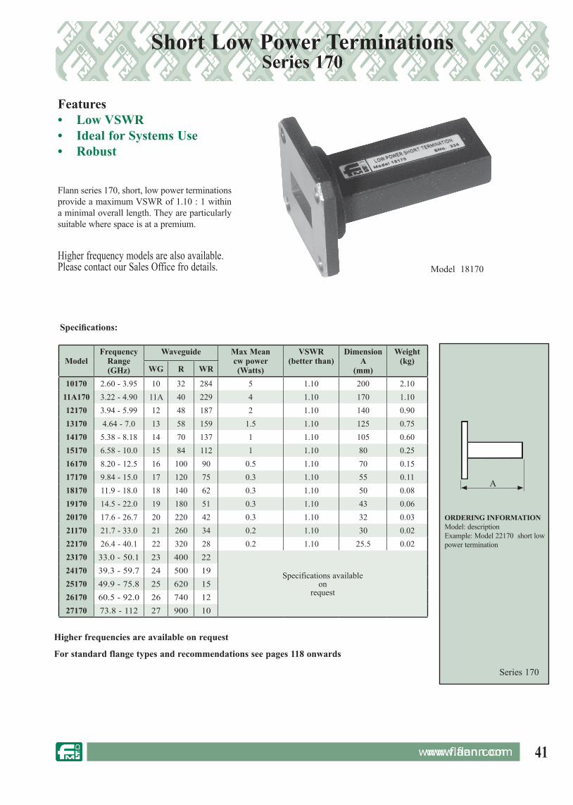
41www.flann.com
ModelFrequency
Range (GHz)
Waveguide Max Meancw power(Watts)
VSWR(better than)
DimensionA
(mm)
Weight(kg)
WG R WR
10170 2.60 - 3.95 10 32 284 5 1.10 200 2.1011A170 3.22 - 4.90 11A 40 229 4 1.10 170 1.1012170 3.94 - 5.99 12 48 187 2 1.10 140 0.9013170 4.64 - 7.0 13 58 159 1.5 1.10 125 0.7514170 5.38 - 8.18 14 70 137 1 1.10 105 0.6015170 6.58 - 10.0 15 84 112 1 1.10 80 0.2516170 8.20 - 12.5 16 100 90 0.5 1.10 70 0.1517170 9.84 - 15.0 17 120 75 0.3 1.10 55 0.1118170 11.9 - 18.0 18 140 62 0.3 1.10 50 0.0819170 14.5 - 22.0 19 180 51 0.3 1.10 43 0.0620170 17.6 - 26.7 20 220 42 0.3 1.10 32 0.0321170 21.7 - 33.0 21 260 34 0.2 1.10 30 0.0222170 26.4 - 40.1 22 320 28 0.2 1.10 25.5 0.0223170 33.0 - 50.1 23 400 22
Specifications availableon
request
24170 39.3 - 59.7 24 500 1925170 49.9 - 75.8 25 620 1526170 60.5 - 92.0 26 740 1227170 73.8 - 112 27 900 10
Short Low Power TerminationsSeries 170
Flann series 170, short, low power terminations provide a maximum VSWR of 1.10 : 1 within a minimal overall length. They are particularly suitable where space is at a premium.
Specifications:
Model 18170
Series 170
ORDERING INFORMATIONModel: descriptionExample: Model 22170 short low power termination
A
For standard flange types and rec om men da tions see pages 118 onwards
Features• Low VSWR• Ideal for Systems Use• Robust
www.flann.com
Higher frequencies are available on request
Higher frequency models are also available.Please contact our Sales Office fro details.

42 www.flann.com
Ultra - Short TerminationsSeries 171
Features• Minimal Length• Broadband• Higher Power Options
A very short termination has been developed for integration into systems were space is a premium. The WG22 version offers the following performance for a total length of 8 mm.Other frequencies and higher powered versions are also available, specifications on request.
ModelFrequency
Range(GHz)
VSWR(better than)
16171-AA 9.3 - 9.9 1.1222171 26.4 - 40.1 1.8
22171-A* 30 - 33 1.322171-AA 33.0 - 35.0 1.1522171-A* 36.0 - 40.0 1.25
Specifications:
ORDERING INFORMATION
PLEASE CONTACT THE SALES TEAM FOR MORE INFORMATION ON OUR STANDARD AND OPTIONAL MODELS
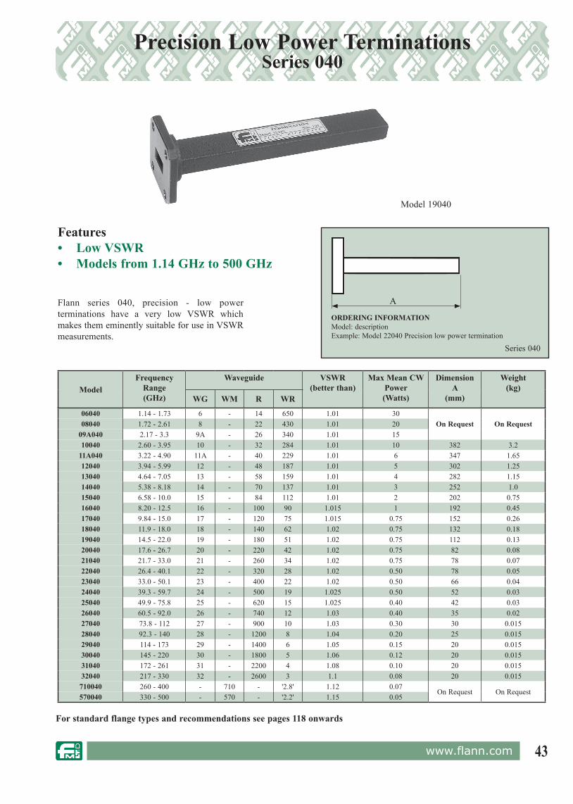
43www.flann.com
ModelFrequency
Range(GHz)
Waveguide VSWR(better than)
Max Mean CWPower(Watts)
DimensionA
(mm)
Weight(kg)
WG WM R WR
06040 1.14 - 1.73 6 - 14 650 1.01 30On Request On Request08040 1.72 - 2.61 8 - 22 430 1.01 20
09A040 2.17 - 3.3 9A - 26 340 1.01 1510040 2.60 - 3.95 10 - 32 284 1.01 10 382 3.2
11A040 3.22 - 4.90 11A - 40 229 1.01 6 347 1.6512040 3.94 - 5.99 12 - 48 187 1.01 5 302 1.2513040 4.64 - 7.05 13 - 58 159 1.01 4 282 1.1514040 5.38 - 8.18 14 - 70 137 1.01 3 252 1.015040 6.58 - 10.0 15 - 84 112 1.01 2 202 0.7516040 8.20 - 12.5 16 - 100 90 1.015 1 192 0.4517040 9.84 - 15.0 17 - 120 75 1.015 0.75 152 0.2618040 11.9 - 18.0 18 - 140 62 1.02 0.75 132 0.1819040 14.5 - 22.0 19 - 180 51 1.02 0.75 112 0.1320040 17.6 - 26.7 20 - 220 42 1.02 0.75 82 0.0821040 21.7 - 33.0 21 - 260 34 1.02 0.75 78 0.0722040 26.4 - 40.1 22 - 320 28 1.02 0.50 78 0.0523040 33.0 - 50.1 23 - 400 22 1.02 0.50 66 0.0424040 39.3 - 59.7 24 - 500 19 1.025 0.50 52 0.0325040 49.9 - 75.8 25 - 620 15 1.025 0.40 42 0.0326040 60.5 - 92.0 26 - 740 12 1.03 0.40 35 0.0227040 73.8 - 112 27 - 900 10 1.03 0.30 30 0.01528040 92.3 - 140 28 - 1200 8 1.04 0.20 25 0.01529040 114 - 173 29 - 1400 6 1.05 0.15 20 0.01530040 145 - 220 30 - 1800 5 1.06 0.12 20 0.01531040 172 - 261 31 - 2200 4 1.08 0.10 20 0.01532040 217 - 330 32 - 2600 3 1.1 0.08 20 0.015
710040 260 - 400 - 710 - '2.8' 1.12 0.07On Request On Request
570040 330 - 500 - 570 - '2.2' 1.15 0.05
Precision Low Power TerminationsSeries 040
Model 19040
Features• Low VSWR• Models from 1.14 GHz to 500 GHz
Flann series 040, precision - low power terminations have a very low VSWR which makes them eminently suitable for use in VSWR measurements.
Series 040
ORDERING INFORMATIONModel: descriptionExample: Model 22040 Precision low power termination
A
For standard flange types and rec om men da tions see pages 118 onwards

44 www.flann.com
Sliding TerminationsSeries 540
Model 17540
The Flann Series 540 Terminations consist of a length of uniformly sized waveguide. Within the waveguide is a close fit sliding load which moves in a precisely controlled manner. It is desirable to use a sliding termination when measuring low VSWR values.
The effect of sliding the termination enables the user to deduce low VSWR values to a greater accuracy than that achieved by a fixed termination technique.
Note: Other models of sliding terminations are available from our range of calibration kit components detailed on pages 104 to 110. Special models are available with micrometer drive and extra low leakage levels, for use in high sensitivity systems.
Features• Low Housing VSWR• Low Sliding Element VSWR• Models from 1.14 GHz to 140 GHz
ORDERING INFORMATIONModel: DescriptionExample: Model 24540 Sliding Terminations
Series 540
AB
For standard flange types and rec om men da tions see pages 118 onwards
ModelFrequency
Range(GHz)
Waveguide HousingVSWR
(better than)
Sliding ElementVSWR
(better than)
Dimensions (mm)
WG R WR A B C
06540 1.14 - 1.73 6 14 650 1.006 1.020 On Request
08540 1.72 - 2.61 8 22 430 1.006 1.020 1097 856 73
10540 2.60 - 3.95 10 32 284 1.006 1.015 719 543 48
11A540 3.22 - 4.90 11A 40 229 1.006 1.015 771 632 42
12540 3.94 - 5.99 12 48 187 1.006 1.010 638 506 37
13540 4.64 - 7.05 13 58 159 1.006 1.010 575 462 32
14540 5.38 - 8.18 14 70 137 1.006 1.010 492 388 28
15540 6.58 - 10.0 15 84 112 1.006 1.008 406 322 24
16540 8.20 - 12.5 16 100 90 1.006 1.006 347 289 19
17540 9.84 - 15.0 17 120 75 1.008 1.006 317 255 18
18540 11.9 - 18.0 18 140 62 1.010 1.008 267 218 18
19540 14.5 - 22.0 19 180 51 1.010 1.010 237 184 15
20540 17.6 - 26.7 20 220 42 1.010 1.010 185 140 14
22540 26.4 - 40.1 22 320 28 1.012 1.015 117 97 12
23540 33.0 - 50.1 23 400 22 1.015 1.020 156 136 15
24540 39.3 - 59.7 24 500 19 1.02 1.025 156 136 15
25540 49.9 - 75.8 25 620 15 1.025 1.030 101 85 14
26540 60.5 - 92.0 26 740 12 1.03 1.035 94 79 14
27540 73.8 - 112 27 900 10 1.035 1.040 84 71 14

45www.flann.com
High Power TerminationsSeries 101
ModelFrequency
Range (GHz)
Waveguide Maximum Power Mean /CW (Watts) Maximum
VSWR
Dimensions(mm)
WG R WR Natural Convection
Forced Air(3 m/s) L BX AX
10101-150-CN0 2.60 - 3.95 10 32 284 150 220 1.08 247 38.1 76.2
10101-200-CV1 200 300 1.08 273 80.4 84
11A101-125-CN0 3.22 – 4.90 11A 40 229 125 180 1.08 205 32.3 61.4
11A101-200-CV1 200 300 1.08 243 75.5 84
12101-100-CN0 3.94 – 5.99 12 48 187 100 150 1.08 170 25.4 50.8
12101-300-CH3 300 450 1.08 170 63 88.9
13101-75-CN0 4.64 – 7.05 13 58 159 75 110 1.08 140 23.4 43.6
13101-250-CH3 250 370 1.08 140 62.7 81.8
14101-55-CN0 5.38 – 8.2 14 70 137 55 80 1.08 120 19.1 38.1
14101-300-CH1 300 450 1.08 173 122.2 120
15101-40-CN0 6.58 – 10.0 15 84 112 40 60 1.08 106 15.6 31.8
15101-250-CH1 250 370 1.08 131 119 94
16101-27-CN0 8.20 – 12.5 16 100 90 27 40 1.08 82 12.7 25.4
16101-240-CV1 240 600 1.08 240 81 84
17101-19-CN0 9.84 – 15.0 17 120 75 19 28 1.08 63.5 12.1 21.6
17101-300-CH1 300 450 1.08 240 121.8 45
18101-19-CN0 11.9 – 18.5 18 140 62 19 28 1.08 76 9.9 17.8
18101-275-CH1 275 410 1.08 240 113 40
19101-14-CN0 14.5 - 22.0 19 180 51 14 21 1.08 62 8.5 15.0
19101-275-CH1 275 410 1.08 240 117 40
20101-11-CN0 17.6 – 26.7 20 220 42 11 16 1.08 58 6.4 12.7
20101-250-CH1 250 375 1.07 237 106 35
21101-9-CN0 21.7 – 33.0 21 260 34 9 13 1.08 52 6.4 10.7
21101-250-CH1 250 375 1.07 237 106 35
22101-7-CN0 26.4 – 40.1 22 320 28 7 10 1.08 47 5.6 9.1
22101-250-CH1 250 375 1.08 127 119 81
23101-6-CN0 33.0 – 50.1 23 400 22 6 9 1.08 45 4.9 7.7
23101-250-CV1 250 375 1.08 127 68.5 138
Features• 0.32 GHz to 330 GHz• Industry leading performance• Low VSWR over full waveguide range• Sealed, 15 psig Standard• Models up to 10 kWApplications• System Dummy Loads• HPA TestingPlease note the tables below detail Flann standard high power terminations that are available from stock or on short delivery. Other models with alternative power handling or body styles are also available - please contact our Sales Team for product assistance.
Please note the tables below detail Flann standard high power terminations that are available from stock or on short delivery. Other models with alternative power handling or body styles are also available - please contact
Many models available from
STOCK
Natural Convection High Power Range up to 300 Watts
Natural Convection Ratings
Natural Convection specified power rating @ +20°C ambient – no direct sunlight.Ambient power rating adjustment is -/+5%W per +/-10°C.Vertical design rating is with flange mounted below heatsink - or derate 25%Vertical design mounted horizontally derate 35%Horizontal design mounted vertically derate 30%Horizontal design mounted horizontally but axis through 90° derate 15%
Model 18101-1500-CH10 UBR140
General Specifications
Maximum Power is Mean /CWNon shedding ceramic elements.Low out-gassing (load element total mass loss < 1.0%, collected volatile condensable materials < 0.10%)
Natural Convection
Terminations incorporating heat sinks are orientation sensitive due to the direction of air flow over the heat sink. Flann model number includes a ‘V’ or ‘H’ code to differ-entiate which is the recommeded orientation. It should be noted that the waveguide broad wall should be vertical in the ‘H’ configuration.
Forced Air
Where stated the standard natural convection design can be used at 1.5 times its rated power with forced air cooling; 3 m/s velocity over all heatsink surfaces.
Blown Version (Fan Assisted) details on request
Liquid Cooled (Water, Oil, Glycol) details on request

46 www.flann.com
High Power TerminationsSeries 101
ModelFrequency
Range (GHz)
Waveguide Maximum Power Mean / CW (Watts) Maximum
VSWR
Dimensions(mm)
WG R WR Natural Convection
Forced Air(3 m/s) L BX AX
10101-600-CV1 2.60 – 3.95 10 32 284 600 900 1.08 273 124.4 200
11A101-1500-CH1 3.22 – 4.90 11A 40 229 1500 2250 1.10 438 154 198
12101-1500-CH1 3.94 – 5.99 12 48 187 1500 2250 1.10 438 147 198
13101-1500-CH1 4.64 – 7.05 13 58 159 1500 2250 1.09 438 145.5 198
14101-1500-CH1 5.38 – 8.2 14 70 137 1500 2250 1.08 438 132.8 198
15101-1500-CH2 6.58 – 10.0 15 84 112 1500 2250 1.10 247 215.5 161
16101-1500-CH1 8.20 – 12.5 16 100 90 1500 2250 1.08 415 125 198
17101-1500-CH2 9.84 – 15.0 17 120 75 1500 2250 1.07 415 205.8 92
18101-1500-CV2 11.9 – 18.5 18 140 62 1500 2250 1.07 430 233 90
19101-1500-CV2 14.5 - 22.0 19 180 51 1500 2250 1.07 430 233 90
20101-1000-CV2 17.6 – 26.7 20 220 42 1000 1500 1.07 237 222 90
21101-1000-CV2 21.7 – 33.0 21 260 34 1000 1500 1.07 237 222 90
22101-1000-CV2 26.4 – 40.1 22 320 28 1000 1500 1.08 237 219 90
23101-500-CV2 33.0 – 50.1 23 400 22 500 750 1.08 127 218.5 90
Model
FrequencyRange (GHz)
Waveguide Maximum Power Mean / CW (Watts)
MaximumVSWR
Dimensions(mm)
WG R WR Natural Convection
Forced Air(3 m/s) L BX AX
11A101-4000-CH2 3.22 – 4.90 11A 40 229 4000 6000 1.10 438 238 278
12101-3800-CH2 3.94 – 5.99 12 48 187 3800 5700 1.10 438 231 262
13101-3700-CH2 4.64 – 7.05 13 58 159 3700 5500 1.09 438 229.5 253
14101-3600-CH2 5.38 – 8.2 14 70 137 3600 5400 1.08 438 216.8 246
15101-3400-CH2 6.58 – 10.0 15 84 112 3400 5100 1.08 422 215.5 229
16101-3200-CH2 8.20 – 12.5 16 100 90 3200 4800 1.08 415 209 214
17101-2900-CH2 9.84 – 15.0 17 120 75 2900 4350 1.07 415 205.8 191
18101-2700-CH2 11.9 – 18.5 18 140 62 2700 4000 1.07 415 201 176
19101-2500-CH2 14.5 - 22.0 19 180 51 2500 3750 1.07 415 201 161
Natural Convection Very High Power Rangeup to 1.5 kWatts
Natural Convection Ultra High Power Range up to 10.0 kWatts
Many models available from
STOCK
ORDERING INFORMATION: - BASIC OPTIONS
Model Description: Waveguide WG15, 1500 Watts, Model Number: 15 101 -1500 -C H 2 0 PBR84
PBR 84 Flange
Waveguide: WG Waveguide Designation
Series: 101
Power: Maximum Power Handling (Watts)*
Cooling Style: C = Convection, F = Integral Fan, L = Liquid, P = Plate/Heatpipe
Preferred Orientation: N = None, H = Horizontal, V = Vertical
Heat Sink Style: 0 = No Fins, 1 = Single, 2 = Double, 3 = Peripheral
Other Options: 0 = Standard
Flange Type: For standard flange types and recommendations see page 111 onwards
* Dependent on Cooling / Heat Sink Style and orientation. Please contact the Sales Team for other standard values
AXAX
278
262262
Model 17101-1500-CH20 UBR120
TML (Total Mass Loss) < 1%CVCM (Collected Volatile Condensable Mass) < 0.1%
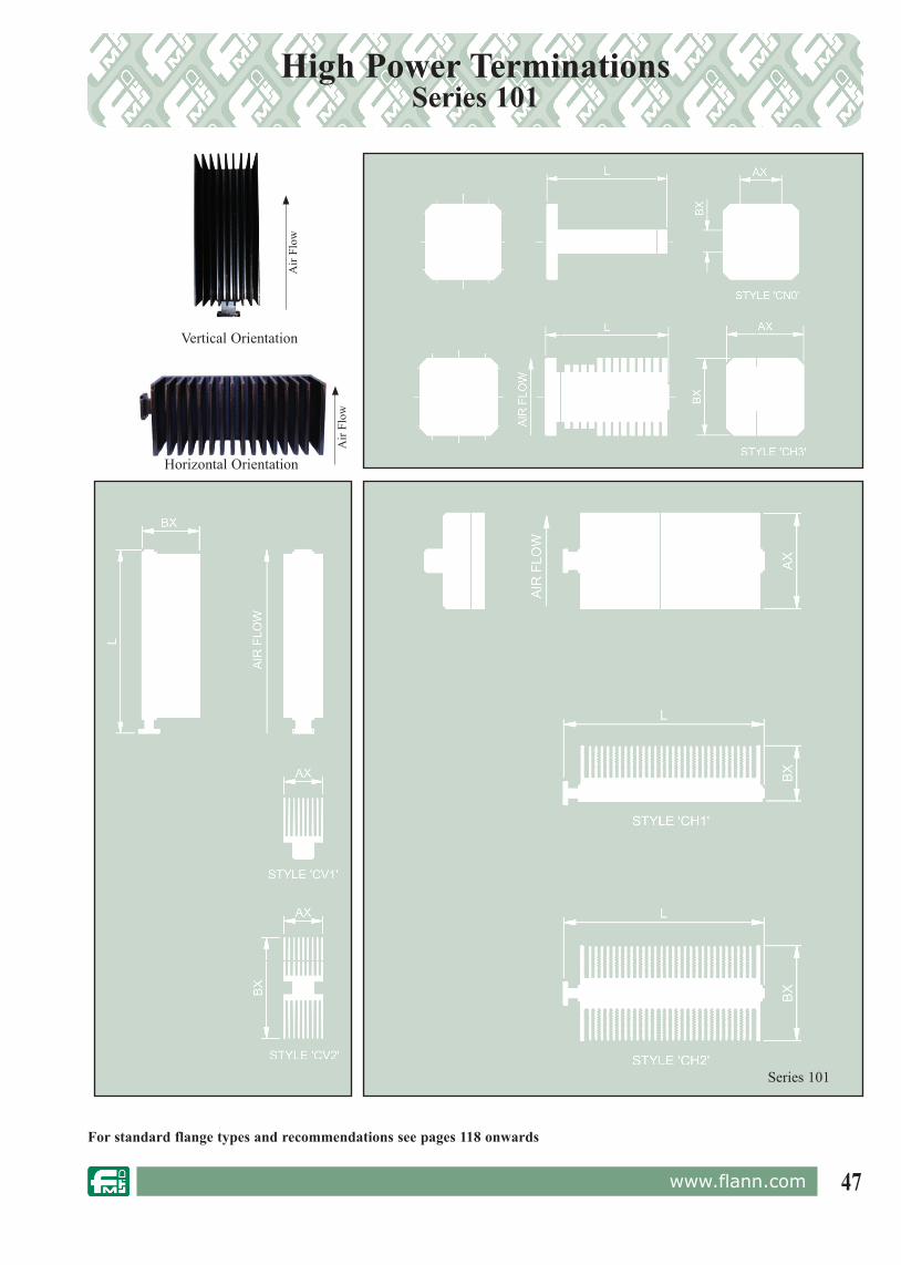
47www.flann.com
High Power TerminationsSeries 101
For standard flange types and rec om men da tions see pages 118 onwards
Series 101
Vertical Orientation
Horizontal Orientation
Air
Flow
Air
Flow
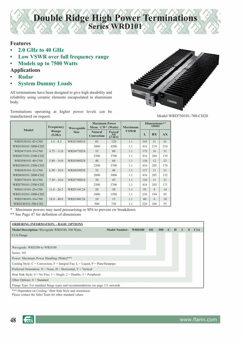
48 www.flann.com
Double Ridge High Power TerminationsSeries WRD101
Features• 2.0 GHz to 40 GHz• Low VSWR over full frequency range• Models up to 7500 WattsApplications• Radar• System Dummy LoadsAll terminations have been designed to give high durability and reliability using ceramic elements encapsulated in aluminium body.
Terminations operating at higher power levels can be manufactured on request.
ORDERING INFORMATION: - BASIC OPTIONS
Model Description: Waveguide WRD180, 500 Watts, Model Number: WRD180 101 -500 -C H 2 0 C1A
C1A Flange
Waveguide: WRD200 to WRD180
Series: 101
Power: Maximum Power Handling (Watts)***
Cooling Style: C = Convection, F = Integral Fan, L = Liquid, P = Plate/Heatpipe
Preferred Orientation: N = None, H = Horizontal, V = Vertical
Heat Sink Style: 0 = No Fins, 1 = Single, 2 = Double, 3 = Peripheral
Other Options: 0 = Standard
Flange Type: For standard flange types and recommendations see page 111 onwards
*** Dependent on Cooling / Heat Sink Style and orientation. Please contact the Sales Team for other standard values
ModelFrequency
Range (GHz)
WaveguideSize
Maximum Power Mean / CW* (Watts) Maximum
VSWR
Dimensions**(mm)
Natural Convection
Forced Air
(3 m/s)L BX AX
WRD350101-85-CN0 3.5 - 8.2 WRD350D24 85 120 1.1 245 21 41WRD350101-3000-CH2 3000 4500 1.1 416 219 210WRD475101-55-CN0 4.75 - 11.0 WRD475D24 55 80 1.1 175 16 31
WRD475101-2500-CH2 2500 3700 1.1 416 204 170WRD580101-40-CN0 5.80 - 16.0 WRD580D28 40 60 1.1 136 12 23
WRD580101-2500-CH2 2500 3700 1.1 416 203 170WRD650101-32-CN0 6.50 - 18.0 WRD650D28 32 48 1.1 117 11 21
WRD650101-2000-CH2 2000 3000 1.1 416 203 132WRD750101-30-CN0 7.50 - 18.0 WRD750D24 30 45 1.1 110 11 21
WRD750101-2500-CH2 2500 3700 1.1 416 203 171WRD110101-20-CN0 11.0 - 26.5 WRD110C24 20 30 1.1 95 8 14
WRD110101-1000-CH2 1000 1500 1.1 236 194 95WRD180101-10-CN0 18.0 - 40.0 WRD180C24 10 15 1.1 60 6 10
WRD180101-500-CH1 500 750 1.1 226 106 95
Model WRD750101-700-CH20
* Maximum powers may need pressurising or SF6 to prevent cw breakdown** See Page 47 for definition of dimensions

49www.flann.com
Calibrated Frequency MetersSeries 070
Features• High Accuracy• High Q• Full Band
In designing a satisfactory frequency meter cavity, great care must be used in the selection of the operating mode of resonance, the diameter and the coupling elements in order that non-ambiguous operation is achieved over the full waveguide band.
The Flann Series 070 Frequency Meters consist of a high Q electroformed precision cavity located on the rectangular waveguide narrow wall. The cavity operates in the TE111 mode and is tuned by a non-contacting choked piston. All models have a minimum tuned response of 1 dB. A micrometer drive ensures precise control of the piston position enabling frequency measurement to a high accuracy. Each instrument is supplied with calibration data.
Model 17070
ORDERING INFORMATIONModel: DescriptionExample: Model 22070 Calibrated frequency meter
Series 070Ø
BA
C
For standard flange types and rec om men da tions see pages 118 onwards
Model
FrequencyRange(GHz)
Waveguide Calibrated Accuracy
(%)
Typical Loaded
Q
Dimensions(mm)
WG W WR A B C
14070 5.38 - 8.18 14 70 137 0.010 7000 110 63 173
15070 6.58 - 10.0 15 84 112 0.010 6300 102 63 161
16070 8.20 - 12.5 16 100 90 0.010 5500 90 50 125
17070 9.84 - 15.0 17 120 75 0.010 5200 90 50 111
18070 11.9 - 18.0 18 140 62 0.012 4700 90 50 107
19070 14.5 - 22.0 19 180 51 0.012 4200 90 50 104
20070 17.6 - 26.7 20 220 42 0.012 3700 90 50 101
22070 26.4 - 40.1 22 320 28 0.025 3000 70 50 122
23070 33.0 - 50.1 23 400 22 0.025 2800 60 50 113
24070 39.3 - 59.7 24 500 19 0.030 2300 60 50 104
25070 49.9 - 75.8 25 620 15 0.035 2100 60 50 103
26070 60.5 - 92.0 26 740 12 0.035 1800 60 50 105
27070 73.8 - 112.0 27 900 10 0.050 1600 60 50 101
28070 92.0 - 140 28 1200 8 0.080 1200 60 50 95
29070 114 - 173 29 1400 6Specification available
on
request
30070 145 - 220 30 1800 5
31070 172 - 261 31 2200 4
32070 217 - 330 32 2600 3
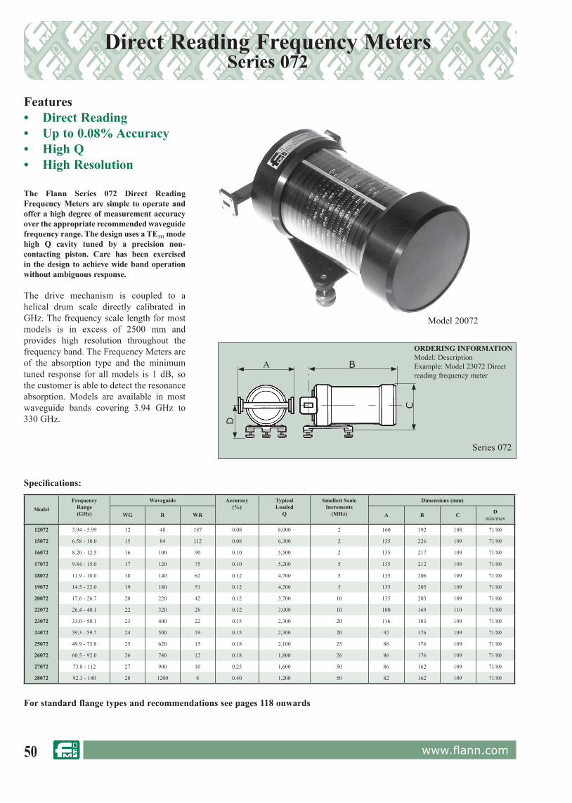
50 www.flann.com
Direct Reading Frequency MetersSeries 072
Features• Direct Reading• Up to 0.08% Accuracy• High Q• High Resolution
The Flann Series 072 Direct Reading Frequency Meters are simple to operate and offer a high degree of measurement accuracy over the appropriate recommended waveguide frequency range. The design uses a TE111 mode high Q cavity tuned by a precision non-contacting piston. Care has been exercised in the design to achieve wide band operation without ambiguous response.
The drive mechanism is coupled to a helical drum scale directly calibrated in GHz. The frequency scale length for most models is in excess of 2500 mm and provides high resolution throughout the frequency band. The Frequency Meters are of the absorption type and the minimum tuned response for all models is 1 dB, so the customer is able to detect the resonance absorption. Models are available in most waveguide bands covering 3.94 GHz to 330 GHz.
Model 20072
ORDERING INFORMATIONModel: DescriptionExample: Model 23072 Direct reading frequency meter
Series 072
D
A B
C
For standard flange types and rec om men da tions see pages 118 onwards
ModelFrequency
Range(GHz)
Waveguide Accuracy(%)
TypicalLoaded
Q
Smallest ScaleIncrements
(MHz)
Dimensions (mm)
WG R WR A B C Dmin/max
12072 3.94 - 5.99 12 48 187 0.08 8,000 2 160 192 108 71/80
15072 6.58 - 10.0 15 84 112 0.08 6,300 2 135 226 109 71/80
16072 8.20 - 12.5 16 100 90 0.10 5,500 2 135 217 109 71/80
17072 9.84 - 15.0 17 120 75 0.10 5,200 5 135 212 109 71/80
18072 11.9 - 18.0 18 140 62 0.12 4,700 5 135 206 109 71/80
19072 14.5 - 22.0 19 180 51 0.12 4,200 5 135 205 109 71/80
20072 17.6 - 26.7 20 220 42 0.12 3,700 10 135 203 109 71/80
22072 26.4 - 40.1 22 320 28 0.12 3,000 10 100 169 110 71/80
23072 33.0 - 50.1 23 400 22 0.15 2,300 20 116 183 109 71/80
24072 39.3 - 59.7 24 500 19 0.15 2,300 20 92 176 109 71/80
25072 49.9 - 75.8 25 620 15 0.18 2,100 25 86 176 109 71/80
26072 60.5 - 92.0 26 740 12 0.18 1,800 26 86 176 109 71/80
27072 73.8 - 112 27 900 10 0.25 1,600 50 86 162 109 71/80
28072 92.3 - 140 28 1200 8 0.40 1,200 50 82 162 109 71/80
Specifications:

51www.flann.com
Waveguide to Coax AdaptorsModel Selection
Models 750 MHz to 173 GHz
Male (Plug) and Female (Jack) variants available
Brass, Copper & Aluminium Options
Standard & Special Flange Styles
Narrow-band versions available with further improved return
loss performance
Cable Direct EntrySpecial & Customised
Other connector types are also available including:
Connector Full Band - 90 degree High Power - 90 degree Low PIM - 90 degree7/16 DIN 097-DF10 098-DFN 093-NF10 & 094-NF10 097-NF10 098-NF10SMA 094-SF40K (2.9mm) 093-KF20 & 094-KF20 097-KF20 098-KF10APC7 093-AP70
096-AP702.4mm 093-TF30 097-TF 098-TFV(1.85mm) 093-VF50 & 093-VF50 097-VF 098-VF1.00mm 093-WF60 097-WF0.8mm 093-FF60 097-FF
Connector Full Band - End Launch High Power - End Launch Low PIM - End Launch7/16 DIN 373-DF10 377-DF10 378-DFN 373-NF10 377-NF10 378-NFSMAK (2.9mm) 373-KF20 377-KF20 378-KF20APC7 373-AP2.4mm 373-TF 377-TF 378-TFV(1.85mm) 373-VF50 377-VF50 378-VF501.00mm 373-WF60 377-WF600.88mm 373-FF60 377-FF60
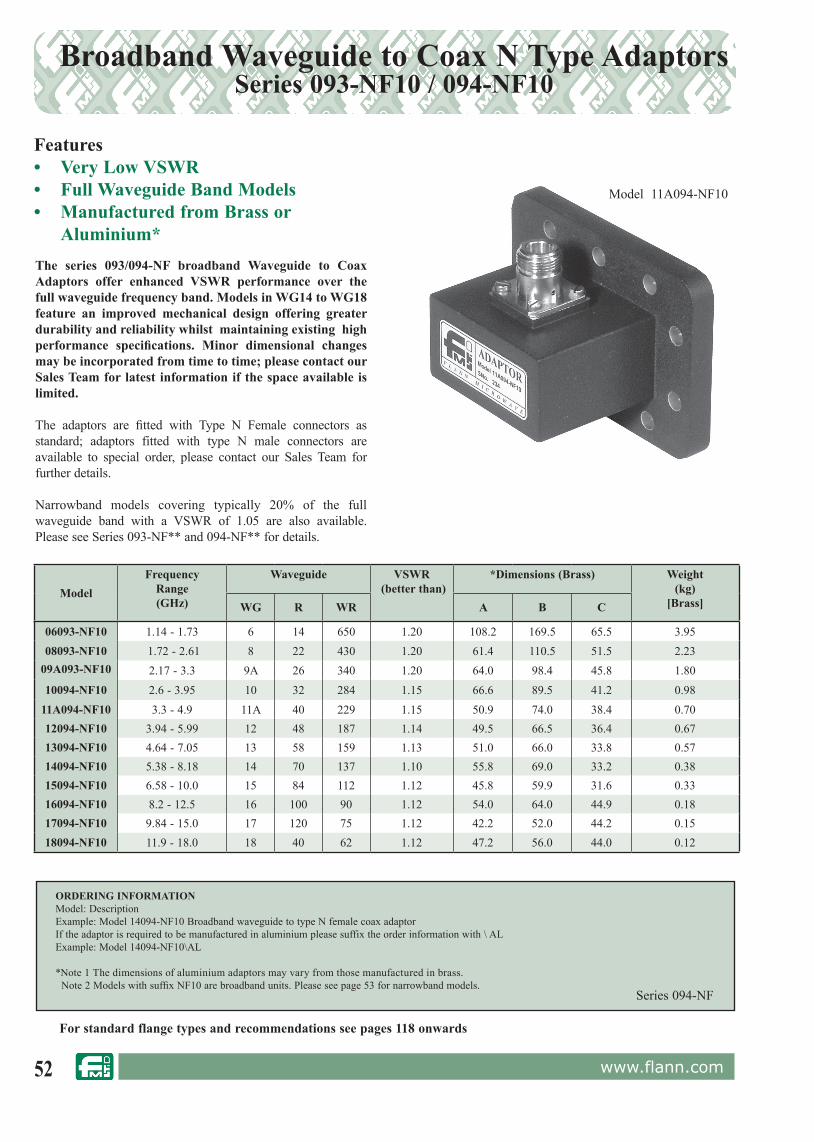
52 www.flann.com
Broadband Waveguide to Coax N Type AdaptorsSeries 093-NF10 / 094-NF10
ORDERING INFORMATIONModel: Description Example: Model 14094-NF10 Broadband waveguide to type N female coax adaptorIf the adaptor is required to be manufactured in aluminium please suffix the order information with \ ALExample: Model 14094-NF10\AL
*Note 1 The dimensions of aluminium adaptors may vary from those manufactured in brass. Note 2 Models with suffix NF10 are broadband units. Please see page 53 for narrowband models.
Features• Very Low VSWR• Full Waveguide Band Models• Manufactured from Brass or
Aluminium*The series 093/094-NF broadband Waveguide to Coax Adaptors offer enhanced VSWR performance over the full waveguide frequency band. Models in WG14 to WG18 feature an improved mechanical design offering greater durability and reliability whilst maintaining existing high performance specifications. Minor dimensional changes may be incorporated from time to time; please contact our Sales Team for latest information if the space available is limited.
The adaptors are fitted with Type N Female connectors as standard; adaptors fitted with type N male connectors are available to special order, please contact our Sales Team for further details.
Narrowband models covering typically 20% of the full waveguide band with a VSWR of 1.05 are also available. Please see Series 093-NF** and 094-NF** for details.
Series 094-NF
Model 11A094-NF10
For standard flange types and rec om men da tions see pages 118 onwards
ModelFrequency
Range(GHz)
Waveguide VSWR (better than)
*Dimensions (Brass) Weight(kg)
[Brass]WG R WR A B C
06093-NF10 1.14 - 1.73 6 14 650 1.20 108.2 169.5 65.5 3.9508093-NF10 1.72 - 2.61 8 22 430 1.20 61.4 110.5 51.5 2.23
09A093-NF10 2.17 - 3.3 9A 26 340 1.20 64.0 98.4 45.8 1.8010094-NF10 2.6 - 3.95 10 32 284 1.15 66.6 89.5 41.2 0.98
11A094-NF10 3.3 - 4.9 11A 40 229 1.15 50.9 74.0 38.4 0.7012094-NF10 3.94 - 5.99 12 48 187 1.14 49.5 66.5 36.4 0.6713094-NF10 4.64 - 7.05 13 58 159 1.13 51.0 66.0 33.8 0.5714094-NF10 5.38 - 8.18 14 70 137 1.10 55.8 69.0 33.2 0.3815094-NF10 6.58 - 10.0 15 84 112 1.12 45.8 59.9 31.6 0.3316094-NF10 8.2 - 12.5 16 100 90 1.12 54.0 64.0 44.9 0.1817094-NF10 9.84 - 15.0 17 120 75 1.12 42.2 52.0 44.2 0.1518094-NF10 11.9 - 18.0 18 40 62 1.12 47.2 56.0 44.0 0.12
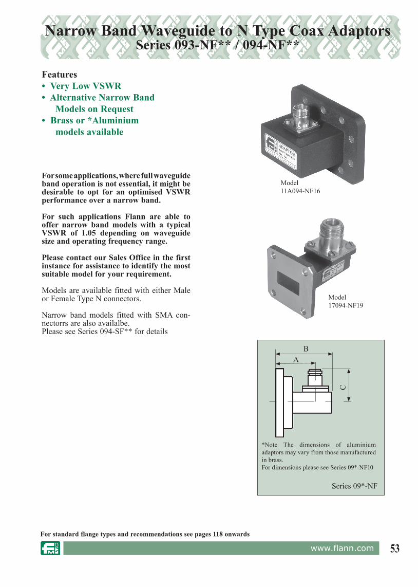
53www.flann.com
Narrow Band Waveguide to N Type Coax Adaptors Series 093-NF** / 094-NF**
Features• Very Low VSWR• Alternative Narrow Band
Models on Request• Brass or *Aluminium
models available
Model 17094-NF19
Model 11A094-NF16
For standard flange types and rec om men da tions see pages 118 onwards
Series 09*-NF
AB
C
*Note The dimensions of aluminium adaptors may vary from those manufactured in brass.For dimensions please see Series 09*-NF10
For some applications, where full waveguide band operation is not essential, it might be desirable to opt for an optimised VSWR performance over a narrow band.
For such applications Flann are able to offer narrow band models with a typical VSWR of 1.05 depending on waveguide size and operating frequency range.
Please contact our Sales Office in the first instance for assistance to identify the most suitable model for your requirement.
Models are available fitted with either Male or Female Type N connectors.
Narrow band models fitted with SMA con-nectorrs are also availalbe. Please see Series 094-SF** for details
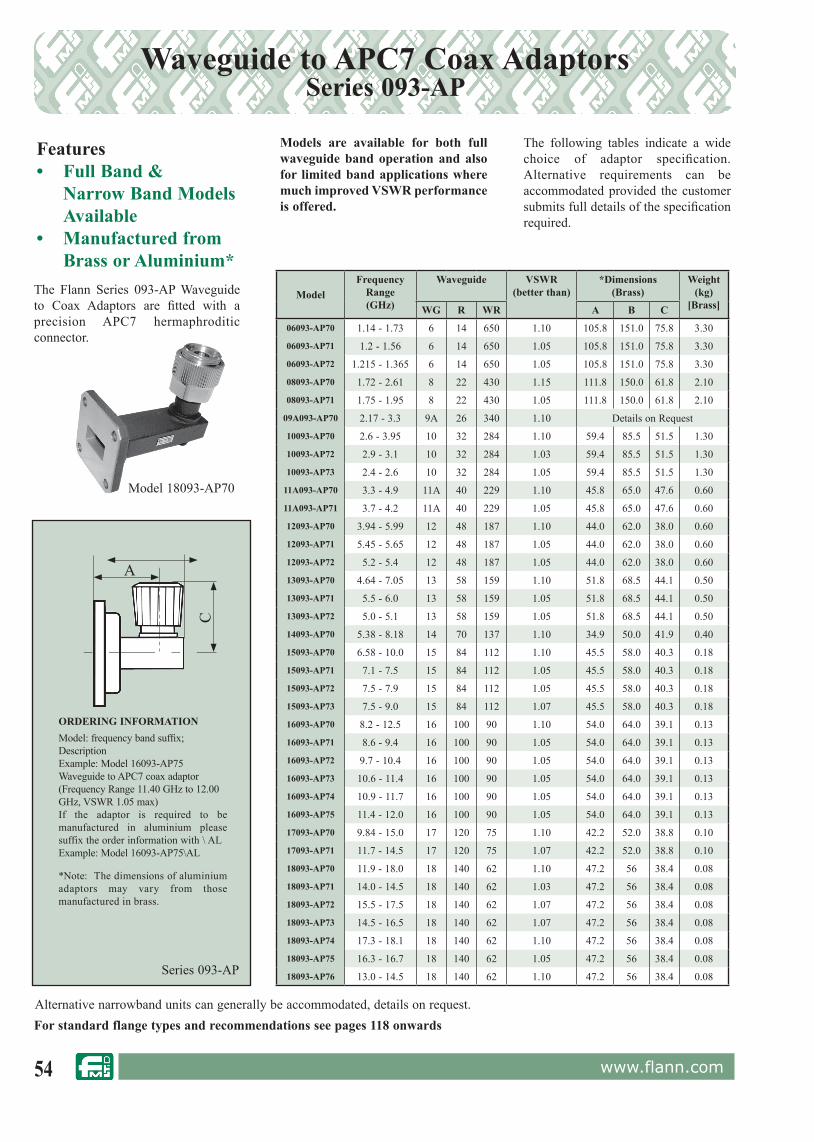
54 www.flann.com
Waveguide to APC7 Coax Adaptors Series 093-AP
Alternative narrowband units can generally be accommodated, details on request.
Features• Full Band &
Narrow Band Models Available
• Manufactured from Brass or Aluminium*
The Flann Series 093-AP Waveguide to Coax Adaptors are fitted with a precision APC7 hermaphroditic connector.
Models are available for both full waveguide band operation and also for limited band applications where much improved VSWR performance is offered.
The following tables indicate a wide choice of adaptor specification. Alternative requirements can be accommodated provided the customer submits full details of the specification required.
B
Series 093-AP
ORDERING INFORMATIONModel: frequency band suffix; DescriptionExample: Model 16093-AP75 Waveguide to APC7 coax adaptor(Frequency Range 11.40 GHz to 12.00 GHz, VSWR 1.05 max)If the adaptor is required to be manufactured in aluminium please suffix the order information with \ ALExample: Model 16093-AP75\AL
*Note: The dimensions of aluminium adaptors may vary from those manufactured in brass.
A
C
Model 18093-AP70
For standard flange types and rec om men da tions see pages 118 onwards
ModelFrequency
Range(GHz)
Waveguide VSWR(better than)
*Dimensions (Brass)
Weight (kg)
[Brass]WG R WR A B C06093-AP70 1.14 - 1.73 6 14 650 1.10 105.8 151.0 75.8 3.30
06093-AP71 1.2 - 1.56 6 14 650 1.05 105.8 151.0 75.8 3.30
06093-AP72 1.215 - 1.365 6 14 650 1.05 105.8 151.0 75.8 3.30
08093-AP70 1.72 - 2.61 8 22 430 1.15 111.8 150.0 61.8 2.10
08093-AP71 1.75 - 1.95 8 22 430 1.05 111.8 150.0 61.8 2.10
09A093-AP70 2.17 - 3.3 9A 26 340 1.10 Details on Request
10093-AP70 2.6 - 3.95 10 32 284 1.10 59.4 85.5 51.5 1.30
10093-AP72 2.9 - 3.1 10 32 284 1.03 59.4 85.5 51.5 1.30
10093-AP73 2.4 - 2.6 10 32 284 1.05 59.4 85.5 51.5 1.30
11A093-AP70 3.3 - 4.9 11A 40 229 1.10 45.8 65.0 47.6 0.60
11A093-AP71 3.7 - 4.2 11A 40 229 1.05 45.8 65.0 47.6 0.60
12093-AP70 3.94 - 5.99 12 48 187 1.10 44.0 62.0 38.0 0.60
12093-AP71 5.45 - 5.65 12 48 187 1.05 44.0 62.0 38.0 0.60
12093-AP72 5.2 - 5.4 12 48 187 1.05 44.0 62.0 38.0 0.60
13093-AP70 4.64 - 7.05 13 58 159 1.10 51.8 68.5 44.1 0.50
13093-AP71 5.5 - 6.0 13 58 159 1.05 51.8 68.5 44.1 0.50
13093-AP72 5.0 - 5.1 13 58 159 1.05 51.8 68.5 44.1 0.50
14093-AP70 5.38 - 8.18 14 70 137 1.10 34.9 50.0 41.9 0.40
15093-AP70 6.58 - 10.0 15 84 112 1.10 45.5 58.0 40.3 0.18
15093-AP71 7.1 - 7.5 15 84 112 1.05 45.5 58.0 40.3 0.18
15093-AP72 7.5 - 7.9 15 84 112 1.05 45.5 58.0 40.3 0.18
15093-AP73 7.5 - 9.0 15 84 112 1.07 45.5 58.0 40.3 0.18
16093-AP70 8.2 - 12.5 16 100 90 1.10 54.0 64.0 39.1 0.13
16093-AP71 8.6 - 9.4 16 100 90 1.05 54.0 64.0 39.1 0.13
16093-AP72 9.7 - 10.4 16 100 90 1.05 54.0 64.0 39.1 0.13
16093-AP73 10.6 - 11.4 16 100 90 1.05 54.0 64.0 39.1 0.13
16093-AP74 10.9 - 11.7 16 100 90 1.05 54.0 64.0 39.1 0.13
16093-AP75 11.4 - 12.0 16 100 90 1.05 54.0 64.0 39.1 0.13
17093-AP70 9.84 - 15.0 17 120 75 1.10 42.2 52.0 38.8 0.10
17093-AP71 11.7 - 14.5 17 120 75 1.07 42.2 52.0 38.8 0.10
18093-AP70 11.9 - 18.0 18 140 62 1.10 47.2 56 38.4 0.08
18093-AP71 14.0 - 14.5 18 140 62 1.03 47.2 56 38.4 0.08
18093-AP72 15.5 - 17.5 18 140 62 1.07 47.2 56 38.4 0.08
18093-AP73 14.5 - 16.5 18 140 62 1.07 47.2 56 38.4 0.08
18093-AP74 17.3 - 18.1 18 140 62 1.10 47.2 56 38.4 0.08
18093-AP75 16.3 - 16.7 18 140 62 1.05 47.2 56 38.4 0.08
18093-AP76 13.0 - 14.5 18 140 62 1.10 47.2 56 38.4 0.08

55www.flann.com
ORDERING INFORMATIONModel: DescriptionExample: Model 16096-APC70 Waveguide to APC7 coax adaptor
Model 11A096-AP70
Features• VSWR better than 1.05:1 • Full Waveguide Band Coverage• 7 mm Precision (APC) Connector• Manufactured from Brass or
Aluminium*
The Series 096-AP Waveguide to Coax Adaptors offer a very low VSWR over full waveguide bands up to 18 GHz. The units are fitted with a precision 7 mm (APC7) connector for repeatable connection.
Waveguide to APC7 Coax AdaptorsSeries 096-AP
Series 096-AP
Please note: Narrowband op tions are not available for this series of Waveguide to Coax Adaptors.If the adaptor is required to be manufactured in aluminium please suffix the order information with \ ALExample: Model 16096-APC70\AL
*Note The dimensions of aluminium adaptors may vary from those manufactured in brass.
AB
C
For standard flange types and rec om men da tions see pages 118 onwards
Model Frequency
Range(GHz)
Waveguide VSWR(better than)
*Dimensions (Brass)
WG R WR A B C
06096-AP70 1.14 - 1.73 6 14 650 1.05 105.8 151.0 75.808096-AP70 1.72 - 2.61 8 22 430 1.05 111.81 148.5 61.810096-AP70 2.6 - 3.95 10 32 284 1.05 59.4 85.5 51.5
11A096-AP70 3.3 - 4.9 11A 40 229 1.05 55.8 76.0 47.612096-AP70 3.94 - 5.99 12 48 187 1.05 62.70 81.5 41.713096-AP70 4.64 - 7.05 13 58 159 1.05 51.8 68.5 42.914096-AP70 5.38 - 8.18 14 70 137 1.05 55.9 71.0 41.9015096-AP70 6.58 - 10.0 15 84 112 1.05 45.5 58.0 40.316096-AP70 8.20 - 12.5 16 100 90 1.05 54.0 64.0 39.117096-AP70 9.84 - 15.0 17 120 75 1.07 42.2 52.0 38.818096-AP70 11.9 - 18.0 18 140 62 1.07 47.2 56.0 38.5

56 www.flann.com
Waveguide to SMA Coax AdaptorsSeries 094-SF40
Features• Very Low VSWR• Full Waveguide Band models• Manufactured from Brass or *Aluminium
The Flann Series 094-SF waveguide to coax adaptors offer enhanced VSWR performance over the full waveguide frequency band.
The adaptors are fitted with SMA Female connectors as standard. However, models are optionally available with male connectors, please contact our sales team for further details.
Narrowband models covering typically 20% of the full waveguide band with a VSWR of 1.05 are also available. Please see Series 094-SF** for details.
Series 094-SF
ORDERING INFORMATIONModel: descriptionExample: Model 18094-SF40 waveguide to SMA female coax adaptor
If the adaptor is required to be manufactured in aluminium please suffix the order information with \ ALExample: Model 18094-SF40\ALNote: models with suffix SF40 are full band units. Please see page 58 for narrowband models.
*Note The dimensions of aluminium adaptors may vary from those manufactured in brass.
Model 16094-SF40
AB
C
For standard flange types and rec om men da tions see pages 118 onwards
ModelFrequency
Range(GHz)
Waveguide VSWR(better than)
*Dimensions (Brass)
WG R WR A B C
11A094-SF40 3.3 - 4.9 11A 40 229 1.15 51.5 72.3 59.0 12094-SF40 3.94 - 5.99 12 48 187 1.15 60.2 78.5 24.513094-SF40 4.64- 7.05 13 58 159 1.15 32.6 46.5 22.814094-SF40 5.38 - 8.18 14 70 137 1.15 35.8 46.5 21.415094-SF40 6.58 - 10.0 15 84 112 1.12 37.5 48.5 19.816094-SF40 8.2 - 12.5 16 100 90 1.12 34.5 45.3 17.917094-SF40 9.84 - 15.0 17 120 75 1.12 26.2 34.5 17.118094-SF40 11.9 - 18.0 18 140 62 1.12 38.5 47.3 17.019094-SF40 14.5 - 22.0 19 180 51 1.20 27.3 34.5 16.420094-SF40 17.6 - 26.7 20 220 42 1.20 21.5 27.9 15.1
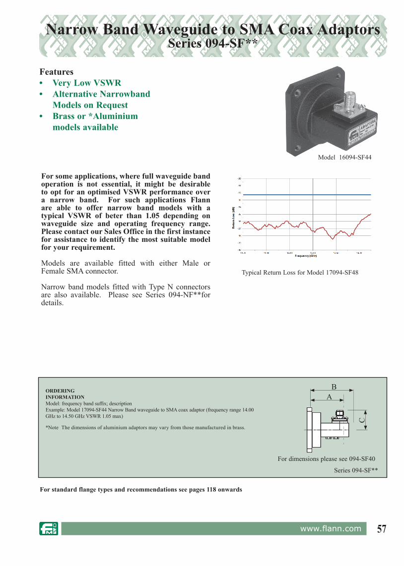
57www.flann.com
Narrow Band Waveguide to SMA Coax Adaptors Series 094-SF**
Model 16094-SF44
Features• Very Low VSWR• Alternative Narrowband
Models on Request• Brass or *Aluminium
models available
Series 094-SF**
ORDERINGINFORMATIONModel: frequency band suffix; descriptionExample: Model 17094-SF44 Narrow Band waveguide to SMA coax adaptor (frequency range 14.00 GHz to 14.50 GHz VSWR 1.05 max)
*Note The dimensions of aluminium adaptors may vary from those manufactured in brass.
AB
C
For standard flange types and rec om men da tions see pages 118 onwards
For some applications, where full waveguide band operation is not essential, it might be desirable to opt for an optimised VSWR performance over a narrow band. For such applications Flann are able to offer narrow band models with a typical VSWR of beter than 1.05 depending on waveguide size and operating frequency range. Please contact our Sales Office in the first instance for assistance to identify the most suitable model for your requirement.
Models are available fitted with either Male or Female SMA connector.
Narrow band models fitted with Type N connectors are also available. Please see Series 094-NF**for details.
For dimensions please see 094-SF40
Typical Return Loss for Model 17094-SF48
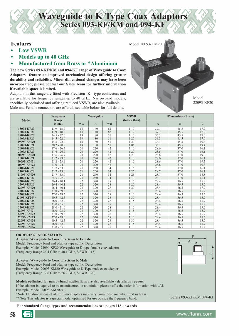
58 www.flann.com
Waveguide to K Type Coax AdaptorsSeries 093-KF/KM and 094-KF
ORDERING INFORMATIONAdaptor, Waveguide to Coax, Precision K FemaleModel: Frequency band and adaptor type suffix; DescriptionExample: Model 22094-KF20 Waveguide to K type female coax adaptor(Frequency Range 26.4 GHz to 40.1 GHz, VSWR 1.15)
Adaptor, Waveguide to Coax, Precision K MaleModel: Frequency band and adaptor type suffix; DescriptionExample: Model 20093-KM20 Waveguide to K Type male coax adaptor(Frequency Range 17.6 GHz to 26.7 GHz, VSWR 1.20)
Models optimised for narrowband applications are also available - details on request.If the adaptor is required to be manufactured in aluminium please suffix the order information with \ ALExample: Model 20093-KM20\AL*Note The dimensions of aluminium adaptors may vary from those manufactured in brass.**Note This adaptor is a special model optimised for use outside the frequency band.
Features• Low VSWR• Models up to 40 GHz• Manufactured from Brass or *Aluminium
Model 22093-KF20
Model 20093-KM20
Series 093-KF/KM 094-KF
The new Series 093-KF/KM and 094-KF range of Waveguide to Coax Adaptors feature an improved mechanical design offering greater durability and reliability. Minor dimensional changes may have been incorporated; please contact our Sales Team for further information if available space is limited.Adaptors in this range are fitted with Pre ci sion ‘K’ type connectors and are avail a ble for frequency ranges up to 40 GHz. Narrowband models, specifically optimised and offering reduced VSWR, are also avail a ble.Male and Female connectors are of fered, see table below for full details.
AB
C
For standard flange types and rec om men da tions see pages 118 onwards
ModelFrequency
Range(GHz)
Waveguide VSWR(better than)
*Dimensions (Brass)
WG R WR A B C18094-KF20 11.9 - 18.0 18 140 62 1.10 37.1 45.5 17.918093-KF20 11.9 - 18.0 18 140 62 1.12 37.1 45.5 17.919094-KF20 14.5 - 22.0 19 180 51 1.10 36.3 45.5 17.019093-KF20 14.5 - 22.0 19 180 51 1.20 36.3 45.5 17.019093-KM20 14.5 - 22.0 19 180 51 1.20 36.3 45.5 19.419093-KF21 20.2 - 20.8 19 180 51 1.05 36.3 45.5 19.420094-KF20 17.6 - 26.7 20 220 42 1.10 28.6 37.0 16.120093-KF20 17.6 - 26.7 20 220 42 1.20 28.6 37.0 16.120093-KM20 17.6 - 26.7 20 220 42 1.20 28.6 37.0 19.320093-KF21 21.2 - 23.6 20 220 42 1.10 28.6 37.0 16.120093-KM21 21.2 - 23.6 20 220 42 1.10 28.6 37.0 19.320093-KM23 23.0 - 24.0 20 220 42 1.10 28.6 37.0 19.321094-KF20 21.7 - 33.0 21 260 34 1.15 28.7 37.0 16.121093-KF20 21.7 - 33.0 21 260 34 1.25 28.7 37.0 16.121093-KM20 21.7 - 33.0 21 260 34 1.25 28.7 37.0 18.821093-KF22 24.5 - 27.0 21 260 34 1.10 28.7 37.0 16.122094-KF20 26.4 - 40.1 22 320 28 1.15 28.4 36.5 15.722093-KF20 26.4 - 40.1 22 320 28 1.20 28.4 36.5 15.722093-KM20 26.4 - 40.1 22 320 28 1.20 28.4 36.5 17.922093-KF22 37.0 - 39.5 22 320 28 1.10 28.4 36.5 15.722093-KF23 27.0 - 29.5 22 320 28 1.10 28.4 36.5 15.7
22093-KF24** 40.5 - 42.5 22 320 28 1.30 28.4 36.5 15.722093-KF25 28.0 - 32.0 22 320 28 1.15 28.4 36.5 15.722093-KF26 33.0 - 35.0 22 320 28 1.10 28.4 36.5 15.722093-KF27 28.0 - 31.0 22 320 28 1.10 28.4 36.5 15.722093-KM21 28.0 - 28.7 22 320 28 1.15 28.4 36.5 15.722093-KM22 37.0 - 39.5 22 320 28 1.10 28.4 36.5 15.722093-KM23 27.0 - 29.0 22 320 28 1.10 28.4 36.5 15.722093-KM24 40.5 - 42.5 22 320 28 1.30 28.4 36.5 15.722093-KM25 28.0 - 32.0 22 320 28 1.15 28.4 36.5 15.722093-KM26 33.0 - 35.0 22 320 28 1.10 28.4 36.5 15.7

59www.flann.com
ORDERING INFORMATION
Adaptor, waveguide to coax, precision V femaleModel: descriptionExample: Model 24094-VF50 Waveguide to 1.85 female coax adaptor(frequency range 39.3 GHz to 60 GHz, VSWR 1.30)
Adaptor, waveguide to coax, precision V maleModel: descriptionExample: Model 25094-VM50 Waveguide to 1.85 male coax adaptor(frequency range 50 GHz to 67 GHz, VSWR 1.25)
Series 093/094-VF/VM
Waveguide to 1.85 mm V Connector®* Coax Adaptor Series 093/094-VF and VM
Model 25094-VF50
Features• 1.85 mm V Connector®*• Low VSWR• Models Available in 3 bands from 33 GHz• Male or Female Connectors Available• Two Grades Available
* V Connector® is a registered trademark of the Anritsu Corporation
B
C
A
The Flann adaptors fitted with 1.85 mm coax connectors incorporate a split pin centre conductor providing excellent reliability and repeatability; these adaptors can also be integrated with filters, couplers, attenuators and antennas. The model illustrated above is a 25094-VF50, fitted with a standard UG-385/U flange.Please contact our Sales Team with your requirements for all waveguide to coax adaptors. If you cannot find a suitable waveguide to coax adaptor in our extensive range we are able to design a model to your specific needs.
For standard flange types and rec om men da tions see pages 118 onwards
ModelFrequency
Range(GHz)
Waveguide VSWR(better than)
Dimensions(mm)
WG R WR A B C
23093-VF50 33.0 to 50.0 23 400 22 1.40 24.0 29.0 16.6
23094-VF50 33.0 to 50.0 23 400 22 1.30 24.0 29.0 16.6
23093-VM50 33.0 to 50.0 23 400 22 1.40 24.0 29.0 21.2
23094-VM50 33.0 to 50.0 23 400 22 1.30 24.0 29.0 21.2
24093-VF50 39.3 to 60.0 24 500 19 1.40 20.0 25.0 14.5
24094-VF50 39.3 to 60.0 24 500 19 1.30 20.0 25.0 14.5
24093-VM50 39.3 to 60.0 24 500 19 1.40 20.0 25.0 19.3
24094-VM50 39.3 to 60.0 24 500 19 1.30 20.0 25.0 19.3
25093-VF50 49.9 to 67.0 25 620 15 1.30 30.4 35.0 14.4
25094-VF50 49.9 to 67.0 25 620 15 1.25 30.4 35.0 14.4
25093-VM50 49.9 to 67.0 25 620 15 1.30 30.4 35.0 19.2
25094-VM50 49.9 to 67.0 25 620 15 1.25 30.4 35.0 19.2
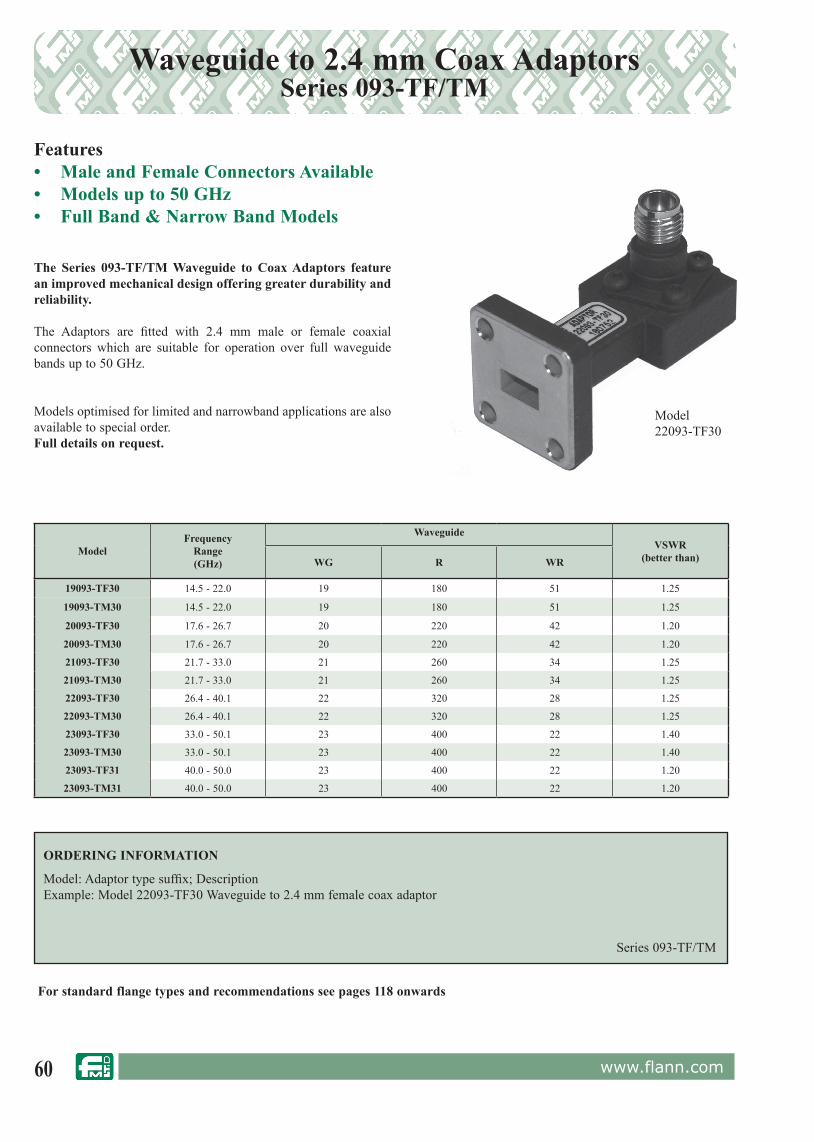
60 www.flann.com
Waveguide to 2.4 mm Coax AdaptorsSeries 093-TF/TM
Features• Male and Female Connectors Available• Models up to 50 GHz• Full Band & Narrow Band Models
The Series 093-TF/TM Waveguide to Coax Adaptors feature an improved mechanical design offering greater durability and reliability.
The Adaptors are fitted with 2.4 mm male or female coaxial connectors which are suitable for operation over full waveguide bands up to 50 GHz.
Models optimised for limited and narrowband applications are also available to special order.Full details on request.
Model 22093-TF30
Series 093-TF/TM
ORDERING INFORMATION
Model: Adaptor type suffix; DescriptionExample: Model 22093-TF30 Waveguide to 2.4 mm female coax adaptor
ModelFrequency
Range(GHz)
WaveguideVSWR
(better than)WG R WR
19093-TF30 14.5 - 22.0 19 180 51 1.25
19093-TM30 14.5 - 22.0 19 180 51 1.25
20093-TF30 17.6 - 26.7 20 220 42 1.20
20093-TM30 17.6 - 26.7 20 220 42 1.20
21093-TF30 21.7 - 33.0 21 260 34 1.25
21093-TM30 21.7 - 33.0 21 260 34 1.25
22093-TF30 26.4 - 40.1 22 320 28 1.25
22093-TM30 26.4 - 40.1 22 320 28 1.25
23093-TF30 33.0 - 50.1 23 400 22 1.40
23093-TM30 33.0 - 50.1 23 400 22 1.40
23093-TF31 40.0 - 50.0 23 400 22 1.20
23093-TM31 40.0 - 50.0 23 400 22 1.20
For standard flange types and rec om men da tions see pages 118 onwards

61www.flann.com
Broad Band End Launch AdaptorsSeries 373
Features• Compact Design • Low VSWR across the band• Designs up to WG29 (WR6)• Available in DC or Non-DC coupled
designs• Narrow Band Models Available
Flann is pleased to announce our new line of end launch waveguide to coaxial adaptors. The Series 373 of end launch adaptors are available in waveguide sizes from WG10 (WR284) to WG29 (WR6)
The compact, precision Flann design keeps costs to a minimum and enables short lead times to be offered. Depending on the operating frequency band, coaxial connectors are available in APC7, Type N, SMA, 2.92, 2.4 mm and 1.85 mm configuration.
Series 373
ORDERING INFORMATION
Model: Adaptor type suffix; DescriptionExample: Model 23373-TF30 Waveguide to 2.4 mm female coax adaptor
ModelFrequency
Range(GHz)
Waveguide VSWR(better than)
WG R WR
19373-TF30 14.5 - 22.0 19 180 51 1.25
19373-TM30 14.5 - 22.0 19 180 51 1.25
20373-KF20 17.6 - 26.7 20 220 42 1.25
20373-KM20 17.6 - 26.7 20 220 42 1.25
21373-TF30 21.7 - 33.0 21 260 34 1.25
21373-TF31 19.7 - 30.0 21 260 34 1.25
22373-KF20 26.4 - 40.1 22 320 28 1.25
22373-KM20 26.4 - 40.1 22 320 28 1.25
23373-TF30 33.0 - 50.1 23 400 22 1.25
23373-TM30 33.0 - 50.1 23 400 22 1.25
25373-VF50 49.9 - 67.0 25 400 22 1.25
For standard flange types and rec om men da tions see pages 118 onwards
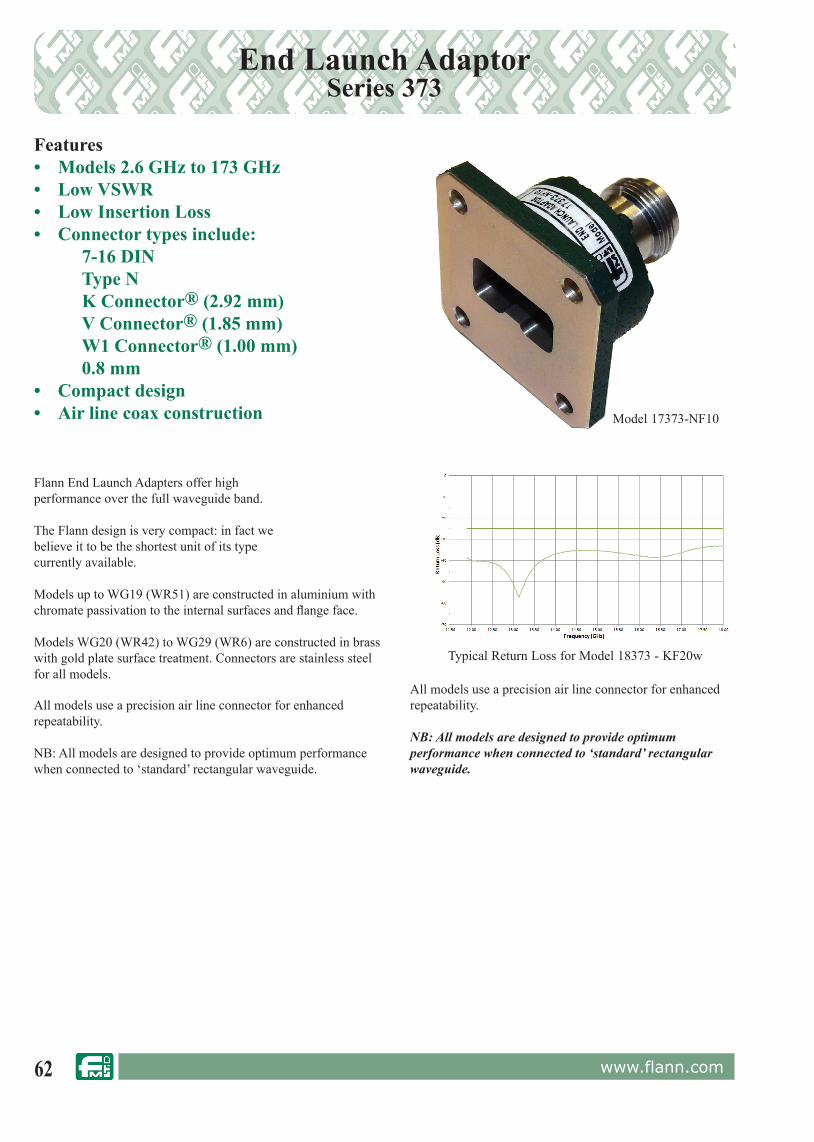
62 www.flann.com
End Launch Adaptor Series 373
Features• Models 2.6 GHz to 173 GHz• Low VSWR• Low Insertion Loss• Connector types include:
7-16 DIN Type N
K Connector® (2.92 mm) V Connector® (1.85 mm) W1 Connector® (1.00 mm) 0.8 mm• Compact design• Air line coax construction Model 17373-NF10
Flann End Launch Adapters offer high performance over the full waveguide band.
The Flann design is very compact: in fact we believe it to be the shortest unit of its type currently available.
Models up to WG19 (WR51) are constructed in aluminium with chromate passivation to the internal surfaces and fl ange face.
Models WG20 (WR42) to WG29 (WR6) are constructed in brass with gold plate surface treatment. Connectors are stainless steel for all models.
All models use a precision air line connector for enhanced repeatability.
NB: All models are designed to provide optimum performance when connected to ‘standard’ rectangular waveguide.
All models use a precision air line connector for enhanced repeatability.
NB: All models are designed to provide optimum performance when connected to ‘standard’ rectangular waveguide.
Typical Return Loss for Model 18373 - KF20w
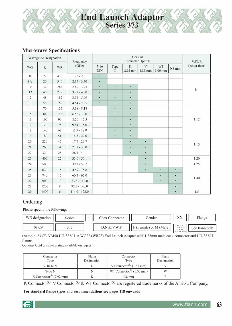
63www.flann.com
End Launch Adaptor Series 373
For standard flange types and rec om men da tions see pages 118 onwards
Example: 23373-VM50 UG-383/U. A WG22 (WR28) End Launch Adapter with 1.85mm male coax connector and UG-383/U f lange.
OrderingPlease specify the following:
WG designation
373
Coax Connector Gender Flange
See flann.comF (Female) or M (Male)
-
08-29 D,N,K,V,W,F
XXSeries
AP = 70D & N = 10
K = 40V, W & F = 60
ConnectorType
FlannDesignation
ConnectorType
FlannDesignation
7-16 DIN D V Connector® (1.85 mm) VType N N W1 Connector® (1.00 mm) W
K Connector® (2.92 mm) K 0.8 mm F
Microwave Specifi cationsWaveguide Designation
Frequency (GHz)
Coaxial Connector Options VSWR
(better than)WG R WR 7-16 DIN
TypeN
K2.92 mm
V1.85 mm
W11.00 mm 0.8 mm
8 22 430 1.72 - 2.61 •
1.1
9A 26 340 2.17 - 3.30 •10 32 284 2.60 - 3.95 • • •
11A 40 229 3.22 - 4.90 • • •12 48 187 3.94 - 5.99 • • •13 58 159 4.64 - 7.05 • • •14 70 137 5.38 - 8.18 • •
1.1215 84 112 6.58 - 10.0 • •16 100 90 8.20 - 12.5 • •17 120 75 9.84 - 15.0 • •18 140 62 11.9 - 18.0 • •19 180 51 14.5 - 22.0 • •
1.1520 220 42 17.6 - 26.7 • •
21 260 34 21.7 - 33.0 • •
22 320 28 26.4 - 40.1 • •
23 400 22 33.0 - 50.1 • 1.20
24 500 19 39.3 - 59.7 • 1.25
25 620 15 49.9 - 75.8 • • •
1.4026 740 12 60.5 - 92.0 • •27 900 10 73.8 - 112.0 • •28 1200 8 92.3 - 140.0 •29 1400 6 114.0 - 173.0 • 1.5
Options- Gold or silver plating available on request
K Connector®, V Connector® & W1 Connector® are registered trademarks of the Anritsu Company.

64 www.flann.com
Waveguide to 1 mm Coax End Launch AdapterSeries 373-W
Features• Models 49.9 Ghz to 110 Ghz• Female and male models avaliable • Very low loss• Very Compact• Precision 1mm airline W1 Connector®
The new Flann series 373-W End Launch Adaptors offer a compace option to the bulky size usually associated with both right angle and end launch transitions
The simpler robust construction gives low VSWR performance over the full waveguide band
Models are avaliable in waveguide bands from 49.9 to 110GHz. The precision 1mm w1 airline connector is avaliable in both female and male variants
Also avaliable with 0.8mm connector for use up to 173Ghz - see Model 373-F
Example: 26373-WF60 UG-387/U. A WG26 End Launch Adapter with 1.00mm female connector and UG387/U f lange.
OrderingPlease specify the following:
WG designation
373
Coax Connector Gender Flange
See flann.comF (Female) or M (Male)
-
25-27 W1(1mm)
60Series
Options
Models offering enhanced VSWR of 1.25 and 1.20 are also avaliable - details on request. Models with precision and anti-cocking flanges are also avaliableAlso available with 0.8mm connector for use up to 173 GHz - see model 373-F
Microwave Specifi cationsWaveguide Designation Frequency
(GHz)VSWR*
(better than)VSWR Options*
(better than)WG R WR25 620 15 49.9 - 75.8 1.40 1.25 TBA26 740 12 60.5 - 92.0 1.40 1.25 TBA27 900 10 73.8 - 110 1.40 1.25 1.20
Typical Return Loss for Model 25373-WF60
Model: 27373-WF60

65www.flann.com
Waveguide to 0.8 mm Coax End Launch AdapterSeries 373-F
Features• Models 50 GHz to 173 GHz• Female and male models avaliable • Low VSWR• Very low loss• Very compact• Precision 0.8mm airline connectorFlann are proud to announce the introduction of a 173 GHz Waveguide to Coaxial Adaptor using a precision 0.8mm connector.
The design offers the same compact construction as the Flann series 373-W 1 mm model but features a precision 0.8mm airline connector avaliable in both female and male variants
Example: 26373-WF60 UG-387/U. A WG26 End Launch Adapter with 1.00mm female connector and UG387/U f lange.
OrderingPlease specify the following:
WG designation
373
Coax Connector Gender Flange
See flann.comF (Female) or M (Male)
-
25-29 F (0.8mm)
60Series
Options
*Models offering enhanced VSWR are also avaliable - details on request. Models with precision and anti-cocking flanges are also avaliable - details on request
Microwave Specifi cationsWaveguide Designation Frequency
(GHz)VSWR*
(better than) Standard FlangeWG R WR25 620 15 49.9 - 75.8 1.4 UG - 385/U Mod26 740 12 60.5 - 92.0 1.4 UG - 385/U27 900 10 73.8 - 110 1.4 UG - 387/U Mod28 1200 8 92.3 - 140.0 1.4 UG - 387/U Mod29 1400 6 114.0 - 173.0 1.5 UG - 387/U Mod
Typical Return Loss for Model 28373-FF60
Model: 27373-FF60
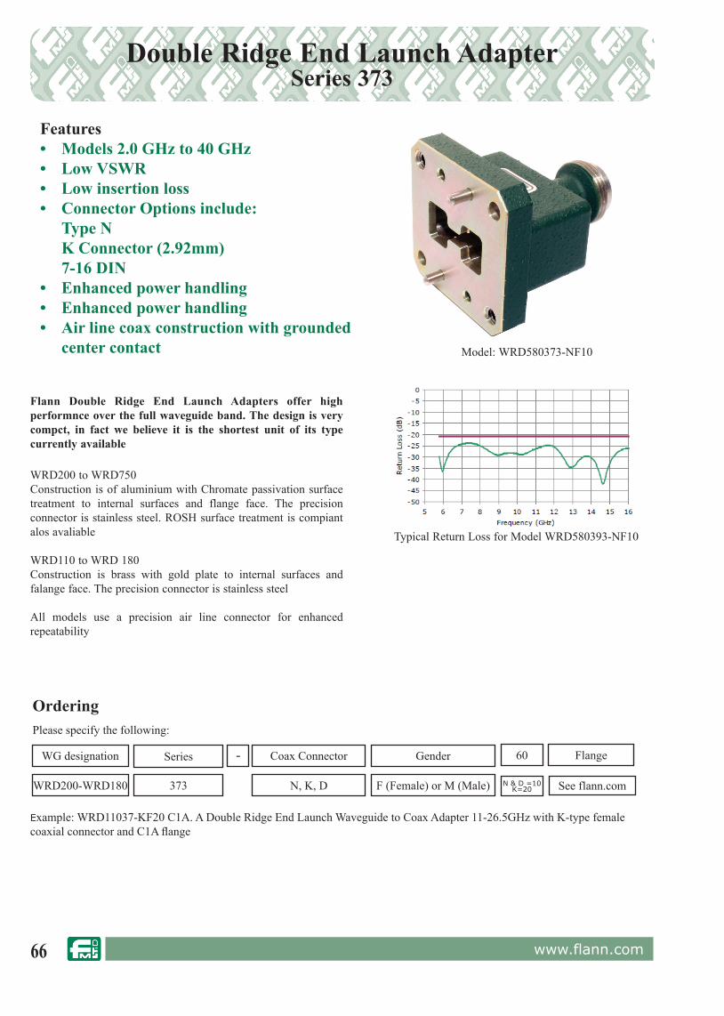
66 www.flann.com
Double Ridge End Launch AdapterSeries 373
Features• Models 2.0 GHz to 40 GHz• Low VSWR• Low insertion loss• Connector Options include: Type N K Connector (2.92mm) 7-16 DIN• Enhanced power handling• Enhanced power handling• Air line coax construction with grounded
center contact
Flann Double Ridge End Launch Adapters offer high performnce over the full waveguide band. The design is very compct, in fact we believe it is the shortest unit of its type currently available
WRD200 to WRD750Construction is of aluminium with Chromate passivation surface treatment to internal surfaces and flange face. The precision connector is stainless steel. ROSH surface treatment is compiant alos avaliable
WRD110 to WRD 180Construction is brass with gold plate to internal surfaces and falange face. The precision connector is stainless steel
All models use a precision air line connector for enhanced repeatability
Example: WRD11037-KF20 C1A. A Double Ridge End Launch Waveguide to Coax Adapter 11-26.5GHz with K-type female coaxial connector and C1A fl ange
OrderingPlease specify the following:
WG designation
373
Coax Connector Gender Flange
See flann.comF (Female) or M (Male)
-
WRD200-WRD180 N, K, D
60Series
Typical Return Loss for Model WRD580393-NF10
N & D =10K=20
Model: WRD580373-NF10

67www.flann.com
Options
- Iridite NCP, Silver and Gold finish are also available- Sealed and pressurised models
Microwave Specifi cationsWaveguide Designation
Frequency (GHz)
CoaxialConnector
VSWR(max)
Insertion Loss(Db)
WRD200373 2.0 -4.8 7-16 DINw 1.20 0.15WRD250373 2.5 - 8.0
Type N 1.200.15
WRD350373 3.5 - 8.2WRD475373 4.75 - 11.0WRD580373 5.80 - 16.0WRD650373 6.50 - 18.0
0.20WRD750373 7.50 - 18.0WRD110373 11.0 - 26.5
K Connector 1.25 0.25WRD180373 18.0 - 40.0
Environmental Specifications
- Operating ambient temperature : 30o C to 70o C- Non operting ambient temperature: -40o C to 80o C
Construction
- Aluminium with chromate passivtion (Alcrom 1200) s standard on all models up to 18GHz- Brass with gold plate on WRD 110 and WRD180 models- Iridite NCP (RoHS compliant), silver and gold finish are also available
Waveguide Designation
Insertion Loss(Db)
7-16 DIN DType N N
K Connector(2.92 mm) K
Double Ridge End Launch AdapterSeries 373

68 www.flann.com
Low PIM Waveguide to Coaxial AdapterSeries 098
Features• Low PIM• Models 1.72GHz to 40 GHz• Low VSWR• Low insertion loss• Connector Options include: Type N K Connector (2.92mm) 7-16 DIN• Minimal junctions/surface materials• Low Outgassing (TML <1% CVCH
<0.1%• Grounded center conductor• Precision Air Line Connector
The Flann Series 098 Waveguide to Coaxial Adpters have been designed and constructed to provide optimally low levels of Passive Intermodulation (PIM)
Standard connector types include:Type N, K Connector and 7-16 DIN
For High Power Models please see series 097
Example: 17098-NF10 UBR120 A WG17 (WR75) Low PIM Waveguide to Coax Adapter with N-type female coax connector with UBR 120 fl ange
OrderingPlease specify the following:
WG designation
098
Coax Connector Gender Flange
See flann.comF (Female) or M (Male)
-
08 - 22 N, K, D
XXSeries
Typical Return Loss for Model 12098-NF10
N & D =10K=20
Model: 12098-NF CPR187G

69www.flann.com
Waveguide DesignationFrequency
(GHz)
Coaxial Connector Options
VSWRmax
Insertion Loss
max (dB)WG R WRD N K
8 22 430 1.72 - 2.61 •
1.10
1.19A 26 340 2.17 - 3.30 •
10 32 284 2.60 - 3.95 • •
11A 40 229 3.22 - 4.90 • •
0.1212 48 187 3.94 - 5.99 • •
13 58 159 4.64 - 7.05 • •14 70 137 5.38 - 8.18 • •
0.1515 84 112 6.58 - 10.0 • •
1.1216 100 90 8.20 - 12.5 • •17 120 75 9.84 - 15.0 • •18 140 62 11.9 - 18.0 • •19 180 51 14.5 - 22.0 •
0.201.17
20 220 42 17.6 - 26.7 •21 260 34 21.7 - 33.0 •
1.2022 320 28 26.4 - 40.1 •
Environmental Specifications
- Operating ambient temperature : 30o C to 70o C- Non operting ambient temperature: -40o C to 80o C- TML (Total Mass Loss) : <1%- CVCM (Collected Volatile Condensable Mass) : <0.1%
Construction
- D option - Aluminium and Chromate Passivation- N option - Aluminium and Chromate Passivation- K option - Brass and Gold Plate
Microwave Specifi cations
Waveguide Designation
Insertion Loss(Db)
7-16 DIN DType N N
K Connector(2.92 mm) K
Low PIM Waveguide to Coaxial AdapterSeries 098
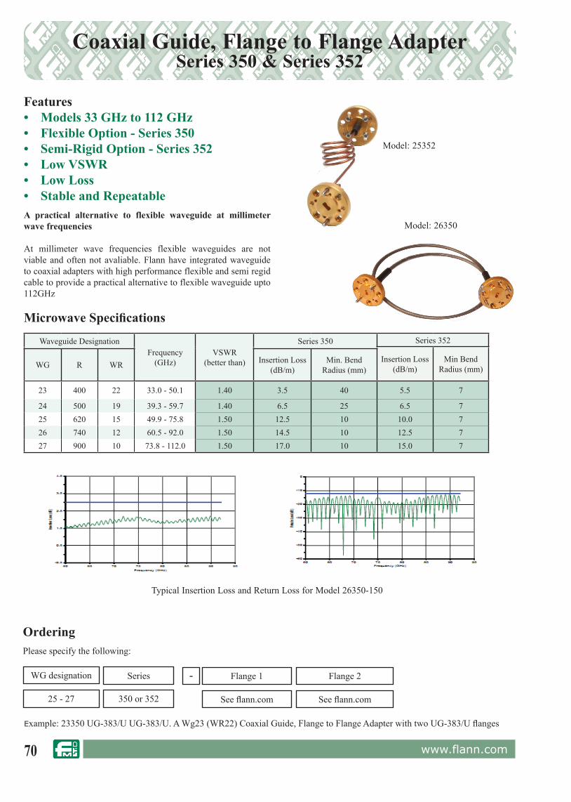
70 www.flann.com
Coaxial Guide, Flange to Flange AdapterSeries 350 & Series 352
Features• Models 33 GHz to 112 GHz• Flexible Option - Series 350• Semi-Rigid Option - Series 352• Low VSWR• Low Loss• Stable and RepeatableA practical alternative to flexible waveguide at millimeter wave frequencies
At millimeter wave frequencies flexible waveguides are not viable and often not avaliable. Flann have integrated waveguide to coaxial adapters with high performance flexible and semi regid cable to provide a practical alternative to flexible waveguide upto 112GHz
Example: 23350 UG-383/U UG-383/U. A Wg23 (WR22) Coaxial Guide, Flange to Flange Adapter with two UG-383/U fl anges
OrderingPlease specify the following:
WG designation
350 or 352
Flange 1 Flange 2
See fl ann.com
-
25 - 27 See fl ann.com
Series
Waveguide DesignationFrequency
(GHz)VSWR
(better than)
Series 350 Series 352
Insertion Loss(dB/m)
Min BendRadius (mm)WG R WR Insertion Loss
(dB/m)Min. Bend
Radius (mm)
23 400 22 33.0 - 50.1 1.40 3.5 40 5.5 7
24 500 19 39.3 - 59.7 1.40 6.5 25 6.5 725 620 15 49.9 - 75.8 1.50 12.5 10 10.0 726 740 12 60.5 - 92.0 1.50 14.5 10 12.5 727 900 10 73.8 - 112.0 1.50 17.0 10 15.0 7
Typical Insertion Loss and Return Loss for Model 26350-150
Microwave Specifi cations
Model: 26350
Model: 25352

71www.flann.com
Seamless Semi-Rigid Waveguide Flange to Flange Adapter - Series 562
Features• Models 50 GHz to 112 GHz*• A practicable alternative to fl exible
waveguide• Low Loss - Comparable to drawn copper
wavelength• Low VSWR• Ideal for installations• Can be formed/reformed up to 5 times• Weatherproofed & Waterproofed
A low loss, hand formable waveguide section suitable for millimeter wave applications
At millimeter wave frequencies flexible waveguides are often not available or the performance and reliability are considered unsatisfactory. For most applications a low loss flexible section that could be bent or formed a few times might be all that is required
To meet the needs of this type of application Flann have introduced the Series 562 range of Seamless Semi-Rigid Waveguides which provide a low loss formable section encased in a ruggedised jacket *, with an insertion loss comparable to that of drawn copper waveguide.
Example: 25562-L300 UG-385/U A WG25 (WR15) Seamless Semi-Rigid Waveguide, Flange to Flange Adaptor 300mm long with UG-385/U fl ange
OrderingPlease specify the following:
WG designation
562
L (Length mm) Flange
See fl ann.com
-
25 - 27 Nominal Flange toFlange Length in mm
Series
The data above shows the change in Insertion Loss of a 300mm length of a Flann WG25 (WR15) Semi Rigid Waveguide when formed 90o and strightened 3 times in the E plane then formed 90o and straightened 3 times in the H Plane. In each case the internal bend radius was 40mmRelated Products
Series350: Coaxial Guide, Flange to Flange Adaptor (Cable Version)352: Coaxial Guide, Flange to Flange Adaptor (Semi-Rigid Cable Version)
Construction
Performed models can be built to customer requirments.Custom built instruments can be supplied;Please contact the sales team for more information
* Higher frequency models are avaliable - details on request
Model: 25562 - L300 UG-385/UFitted to a pair of Flann Lens Horn Antennas Series 800

72 www.flann.com
Double Ridge Waveguide to Coax AdaptorsSeries WRD093
Features• 1.25:1 VSWR Fullband• Narrow Band Versions Available• Models up to 40GHz• Female & Male Coax ConnectorsWe are proud to include in our latest catalogue, our new series of WRD waveguide to coax adaptors which have been designed to give high durability and reliability.
Adaptors can be fitted with SMA, APC7 and N type connectors for use up to 18 GHz, K connectors are fitted to the WRD 180 units covering the 18 GHz to 40 GHz band.
Narrowband models, specifically optimised can be manufactured on request.
ModelFrequency
RangeGHz
WaveguideSize
ConnectorOptions
Waveguide Flange
FullbandVSWR Max
WRD200093-SF40 2.0-4.8 WRD-200D24 SMA WRD200C1 1.25WRD350093-SF40 3.5-8.2 WRD-350D24 SMA WRD350C1 1.25WRD475093-SF40 4.75-11.0 WRD-475D24 SMA WRD475C1 1.25WRD580093-SF40 5.8-16.0 WRD-580D28 SMA WRD580C1 1.25WRD650093-SF40 6.5-18.0 WRD-650D28 SMA WRD650C1 1.25WRD750093-SF40 7.5-18.0 WRD-750D24 SMA WRD750C1 1.25WRD200093-AP70 2.0-4.8 WRD-200D24 APC WRD200C1 1.25WRD350093-AP70 3.5-8.2 WRD-350D24 APC WRD350C1 1.25WRD475093-AP70 4.75-11.0 WRD-475D24 APC WRD475C1 1.25WRD580093-AP70 5.8-16.0 WRD-580D28 APC WRD580C1 1.25WRD650093-AP70 6.5-18.0 WRD-650D28 APC WRD650C1 1.25WRD750093-AP70 7.5-18.0 WRD-750D24 APC WRD750C1 1.25WRD200093-NF10 2.0-4.8 WRD-200D24 N WRD200C1 1.25WRD350093-NF10 3.5-8.2 WRD-350D24 N WRD350C1 1.25WRD475093-NF10 4.75-11.0 WRD-475D24 N WRD475C1 1.25WRD580093-NF10 5.8-16.0 WRD-580D28 N WRD580C1 1.25WRD650093-NF10 6.5-18.0 WRD-650D28 N WRD650C1 1.25WRD750093-NF10 7.5-18.0 WRD-750D24 N WRD750C1 1.25WRD110093-KF20 11.0-26.5 WRD-110C24 K(female) WRD110C1 1.25WRD110093-KM20 11.0-26.5 WRD-110C24 K(Male) WRD110C1 1.25WRD180093-KF20 18.0-40.0 WRD-180C24 K(Female) WRD180C1 1.25WRD180093-KM20 18.0-40.0 WRD-180C24 K(Male) WRD180C1 1.25
Series WRD093
ORDERING INFORMATION
Model: Adaptor type suffix; DescriptionExample: Model WRD18093-KF20 Double Ridge Waveguide to K female coax adaptor

73www.flann.com
Rectangular Waveguide to Waveguide Tapered Transitions Series 000
Model 18000-20
Waveguide to waveguide tapered transitions provide a gradual dimensional change between two sizes of waveguide.
The larger components are accurately fabricated from laser cut plates; smaller tapers are precision electroformed “in house”. In applications where waveguide frequency bands overlap the transitions exhibit low VSWR and low insertion loss whilst maintaining high mode purity.
For most models with overlapping frequency bands, the VSWR is typically better than 1.03 in the common part of the frequency ranges. Tapered Transitions not listed can be made to special order.
Features• Low VSWR• Minimal length
Series 000
ORDERING INFORMATIONModel: DescriptionExample: Model 18000-22 Waveguide tapered transitionWG18 (WR62) to WG22 (WR28)
A
For standard flange types and rec om men da tions see pages 118 onwards
ModelWaveguide to Waveguide Overall
Length(mm)
Weight(kg)
WG R WR WG R WR
08000-10 8 22 430 10 32 284 210 Details on09A000-10 9A 26 340 10 32 284 134 request10000-11A 10 32 284 11A 40 229 130 1.6010000-12 10 32 284 12 48 187 130 1.5810000-15 10 32 284 15 84 112 173 1.3810000-16 10 32 284 16 100 90 173 1.36
11A000-12 11A 40 229 12 48 187 110 0.9311A000-14 11A 40 229 14 70 137 135 0.9512000-13 12 48 187 13 58 159 85 0.9012000-14 12 48 187 14 70 137 85 0.8512000-17 12 48 187 17 120 75 105 0.7513000-14 13 58 159 14 70 137 80 0.7814000-15 14 70 137 15 84 112 75 0.4514000-16 14 70 137 16 100 90 75 0.4015000-16 15 84 112 16 100 90 72 0.2516000-17 16 100 90 17 120 75 58 0.1816000-18 16 100 90 18 140 62 50 0.2516000-20 16 100 90 20 220 42 50 0.1316000-25 16 100 90 25 620 15 75 0.1016000-26 16 100 90 26 740 12 69 0.0917000-18 17 120 75 18 140 62 60 0.1517000-19 17 120 75 19 180 51 60 0.1517000-22 17 120 75 22 320 28 65 0.1018000-19 18 140 62 19 180 51 60 0.1318000-20 18 140 62 20 220 42 56 0.1018000-22 18 140 62 22 320 28 50 0.1019000-20 19 180 51 20 220 42 50 0.1220000-22 20 220 42 22 320 28 50 0.0520000-23 20 220 42 23 400 22 40 0.0520000-24 20 220 42 24 500 19 40 0.0520000-25 20 220 42 25 620 15 60 0.0521000-22 21 260 34 22 320 28 50 0.0522000-23 22 320 28 23 400 22 50 0.0522000-24 22 320 28 24 500 19 35 0.0522000-25 22 320 28 25 620 15 35 0.0422000-26 22 320 28 26 740 12 30 0.0422000-28 22 320 28 28 1200 28 30 0.0323000-24 23 400 22 24 500 19 35 0.0423000-25 23 400 22 25 620 15 30 0.0524000-25 24 500 19 25 620 15 35 0.0524000-26 24 500 19 26 740 12 35 0.0425000-26 25 620 15 26 740 12 25 0.0325000-27 25 620 15 27 900 10 35 0.0326000-27 26 740 12 27 900 10 25 0.0326000-28 26 740 12 28 1200 8 25 0.0327000-28 27 900 10 28 1200 8 25 0.0227000-29 27 900 10 29 1400 6 25 0.0328000-31 28 1200 8 31 2200 4 25 0.0228000-32 28 1200 8 32 2600 3 25 0.0230000-31 30 1800 5 31 2200 4 25 0.0230000-32 30 1800 5 32 2600 3 Specification available
on request31000-32 31 2200 4 32 2600 3

74 www.flann.com
Flange to Flange Waveguide Straights, Adaptorsand Spacers Series 441 / 445
Model 17441-120, fitted with a non standard flange type PDR 120 and a standard flange, 120 mm long
The overall length and flange types fitted at each end, must be specified at time of enquiry.Note: Waveguide Straights are supplied fitted with Flann standard flanges unless otherwise specified by the customer. See page 111 for standard flange types and recommendations.
Customers requiring precision waveguide sections offering greater aperture and length dimensional accuracy are requested to refer to the Waveguide Calibration Kit section, (starting on page 104) for details.
The Flann Series 441/445 of Waveguide Straights and Flange to Flange Adaptors are available in waveguide bands from 1.14 GHz to 330 GHz.
Series 441/445
Model 17441-140
ORDERING INFORMATIONSTRAIGHTS & FLANGE TO FLANGE ADAPTORS - SERIES 441Model - Length (mm) Input Flange : Output Flange If the adaptor Spacer is required to be manufactured in aluminium please suffix the order information with \ ALDescription Example: Model 22441-120-UG599/U. UBR 320 WG flange to flange Adaptor, 120 mm long, flange UG599/U. And PBR 320
Manufactured in:-• Brass • Copper• Aluminium
Waveguide Straights and Flange to Flange Adaptors Waveguide Spacers
For standard flange types and rec om men da tions see pages 118 onwards
Model 22445-10
Model 22445-5
ModelFrequency
Range(GHz)
Waveguide
WG R WR
06441 1.14 - 1.73 6 14 650
08441 1.72 - 2.61 8 22 430
10441 2.60 - 3.95 10 32 284
11A441 3.22 - 4.90 11A 40 229
12441 3.94 - 5.99 12 48 187
13441 4.64 - 7.05 13 58 159
14441 5.38 - 8.18 14 70 137
15441 6.58 - 10.0 15 84 112
16441 8.20 - 12.5 16 100 90
17441 9.84 - 15.0 17 120 75
18441 11.9 - 18.0 18 140 62
19441 14.5 - 22.0 19 180 51
20441 17.6 - 26.7 20 220 42
22441 26.4 - 40.1 22 320 28
23441 33.0 - 50.1 23 400 22
24441 39.3 - 59.7 24 500 19
25441 49.9 - 75.8 25 620 15
26441 60.5 - 92.0 26 740 12
27441 73.8 - 112 27 900 10
28441 92.3 - 140.0 28 1200 8
29441 114.0 - 173.0 29 1400 6
30441 145 - 220 30 1800 5
31441 172 - 261 31 2200 4
32441 217 - 330 32 2600 3
ModelFrequency
Range(GHz)
Waveguide
WG R WR
16445 8.20 - 12.5 16 100 90
17445 9.84 - 15.0 17 120 75
18445 11.9 - 18.0 18 140 62
19445 14.5 - 22.0 19 180 51
20445 17.6 - 26.7 20 220 42
22445 26.4 - 40.1 22 320 28
23445 33.0 - 50.1 23 400 22
24445 39.3 - 59.7 24 500 19
25445 49.9 - 75.8 25 620 15
26445 60.5 - 92.0 26 740 12
27445 73.8 - 112 27 900 10
28445 92.3 - 140.0 28 1200 8
29445 114.0 - 173.0 29 1400 6
30445 145 - 220 30 1800 5
31445 172 - 261 31 2200 4
32445 217 - 330 32 2600 3
ORDERING INFORMATIONSpacers - Series 445Description Example: Model 22445-5-UG599/U WG22 Spacer, 5 mm long, flange detail: UG.599/U

75www.flann.com
Rectangular to Circular Waveguide TransitionsSeries 64*
Features• Low Ellipticity Ratio• Precision Electroformed• Linear to Linear Polarization Versions• Linear to Circular Polarization VersionsEach transition consists of a short length of rectangular waveguide and a stepped or tapered section leading into circular waveguide.
Models are available optionally fitted with combinations of rectangular port flanges, circular port flanges, resistive elements and dielectric elements. The standard rectangular flange types are listed in the table below. Alternative flange types can be fitted to order. The circular waveguide ports are fitted with the flange as detailed below or to customers requirements as other flange styles are available to special order.
The simple rectangular to circular waveguide transition will launch linearly polarized waves into the circular waveguide section (10643 to 32643). However, line reflections from the circular waveguide section may interact with the incident wave resulting in cross polarization.
If cross polarization is undesirable then the transition selected should be one fitted with a resistive film element to absorb the cross polarized waves (models 10644 to 32644).
For circular polarization, the transitions are fitted with resistive film element and have an extended circular waveguide section containing a dielectric quarter wave plate (models 10648 to 32648).
Model 17648-LH
Model 17648-RH
For standard flange types and rec om men da tions see pages 118 onwards
ModelFrequency
Range(GHz)
Waveguide Overall Length A RectangularPort Flange Type
Circular Port Flange Dimensions Weight (kg)Series 643/4
OnlyWG R WR Series643 & 644
Series 648 B C D(PCD) E H
1064* 2.6 - 3.95 10 32 284 241 on request 5985-99-083-1560/0010 146 6.9 132.0 11 73.91 4.30
11A64* 3.22 - 4.9 11A 40 229 178 330 UDR 40 101 5.4 93.0 7 59.69 1.90
1264* 3.94 - 5.99 12 48 187 140 249 UAR 48 89 5.4 80.0 7 48.77 1.50
1364* 4.64 - 7.05 13 58 159 120 on request UAR 58 89 5.4 80.0 7 41.42 1.10
1464* 5.38 - 8.18 14 70 137 102 232 UAR 70 76 4.4 60.3 7 35.81 0.80
1564* 6.58 - 10.0 15 84 112 82.5 222 UBR 84 60 3.2 52.0 7 28.58 0.30
1664* 8.2 - 12.5 16 100 90 76.0 174 UBR 100 56 3.2 48.0 6 23.36 0.25
1764* 9.84 - 15.0 17 120 75 64.0 149 UBR 120 56 3.2 48.0 6 19.35 0.20
1864* 11.9 - 18.0 18 140 62 51.0 120 UBR 140 50 3.2 41.0 6 16.10 0.10
1964* 14.5 - 22.0 19 180 51 51.0 120 UBR 180 50 3.2 41.0 6 13.25 0.10
2064* 17.6 - 26.7 20 220 42 77.5 141 UBR 220 50 3.2 41.0 5 10.93 0.10
2164* 21.7 - 33.0 21 260 34 67.5 122.5 UBR 260 50 3.2 41.0 5 8.76 0.10
2264* 26.4 - 40.1 22 320 28 51.5 79.5 UG-599/U 44 3.2 35.0 3.5 7.24 0.06
2364* 33.0 - 50.1 23 400 22 46.0 on request UG-383/UFixing detail as for UG-383/U
5.80 0.06
2464* 39.3 - 59.7 24 500 19 43.0 68 UG-383/U MOD 4.85 0.05
2564* 49.9 - 75.8 25 620 15 33.5 61.5 UG-385/U Fixing detail as for UG-385/U 3.86 0.03
2664* 60.5 - 92.0 26 740 12 28.0 51.5 UG-387/U Fixing detail as for UG-387/U 3.12 0.03
2764* 73.8 - 112 27 900 10 28.0 43 UG 387/U MOD 2.57 0.03
2864* 92.3 - 140 28 1200 8 28.0 on request UG 387/U MOD 2.03 0.03
2964* 114 - 173 29 1400 6
Dimensions availableon
request
3064* 145 - 220 30 1800 5
3164* 172 - 261 31 2200 4
3264* 217 - 330 32 2600 3
Series 64*
ORDERING INFORMATIONModel: polarization suffix (Series 648 only); description
Example: Model 18648-RH rectangular to circular waveguide transition, right hand polarization (fitted with a dielectric quarter wave plate producing right hand polarization)
Series
RectangularPort
FlangeFitted
CircularPort
FlangeFitted
ResistiveVaneFitted
DielectricQuarter
Wave PlateFitted
643 Yes Yes No No
644 Yes Yes Yes No
648-** Yes Yes Yes Yes
LH for left hand polarization (standard)
RH for right hand polarization (optional)
A
ØH
E
ØB
8 x C holes
Equispaced on D PCD

76 www.flann.com
Waveguide Twists Series 450
Flann Twists are manufactured from sections of standard waveguide which have been precisely twisted whilst maintaining the internal waveguide dimensions. Standard models are 90˚ left hand twists. Other configurations are available to special order, including:
Features• Manufactured from Brass or Aluminium• Low VSWR• Right and Left Hand Models Available• Models from 2.60 GHz to 330 GHz
a) 90˚ left hand (standard)c) 90˚ right handb) 45˚ left handd) 45˚ right hand
ORDERING INFORMATIONModel: angle of twist, LH (left hand) or RH (right hand); descriptionExample: Model 22450-90LH 90˚ left hand waveguide twist
Series 450
For standard flange types and rec om men da tions see pages 118 onwards
Model 21450-90LH
A
ModelFrequency
Range(GHz)
Waveguide DimensionA
(mm)
VSWR(max)
Weight(kg)
WG R WR
10450 2.60 - 3.95 10 32 284
Specification/dimensions availableon
request
11A450 3.22 - 4.90 11A 40 22912450 3.94 - 5.99 12 48 18713450 4.64 - 7.05 13 58 15914450 5.38 - 8.18 14 70 13715450 6.58 - 10.0 15 84 112 187 1.03 0.4516450 8.20 - 12.5 16 100 90 150 1.03 0.2517450 9.84 - 15.0 17 120 75 150 1.03 0.2018450 11.9 - 18.0 18 140 62 150 1.03 0.1419450 14.5 - 22.0 19 180 51 120 1.03 0.1020450 17.6 - 26.7 20 220 42 85 1.03 0.0621450 21.7 - 33.0 21 260 34 85 1.055 0.0522450 26.4 - 40.1 22 320 28 54 1.035 0.03523450 33.0 - 50.1 23 400 22 54 1.06 0.03524450 39.3 - 59.7 24 500 19 54 1.06 0.03525450 49.9 - 75.8 25 620 15 46 1.07 0.04526450 60.5 - 92.0 26 740 12 46 1.08 0.02527450 73.8 -112.0 27 900 10 42 1.09 0.02528450 92.3 -140 28 1200 8 42 1.07 0.025
29450 114 - 173 29 1400 6
Specifcations/dimensions availalbe on request
30450 145 - 220 30 1800 531450 172 - 261 31 2200 432450 217 - 330 32 2600 3
Model 24450 - 90LH
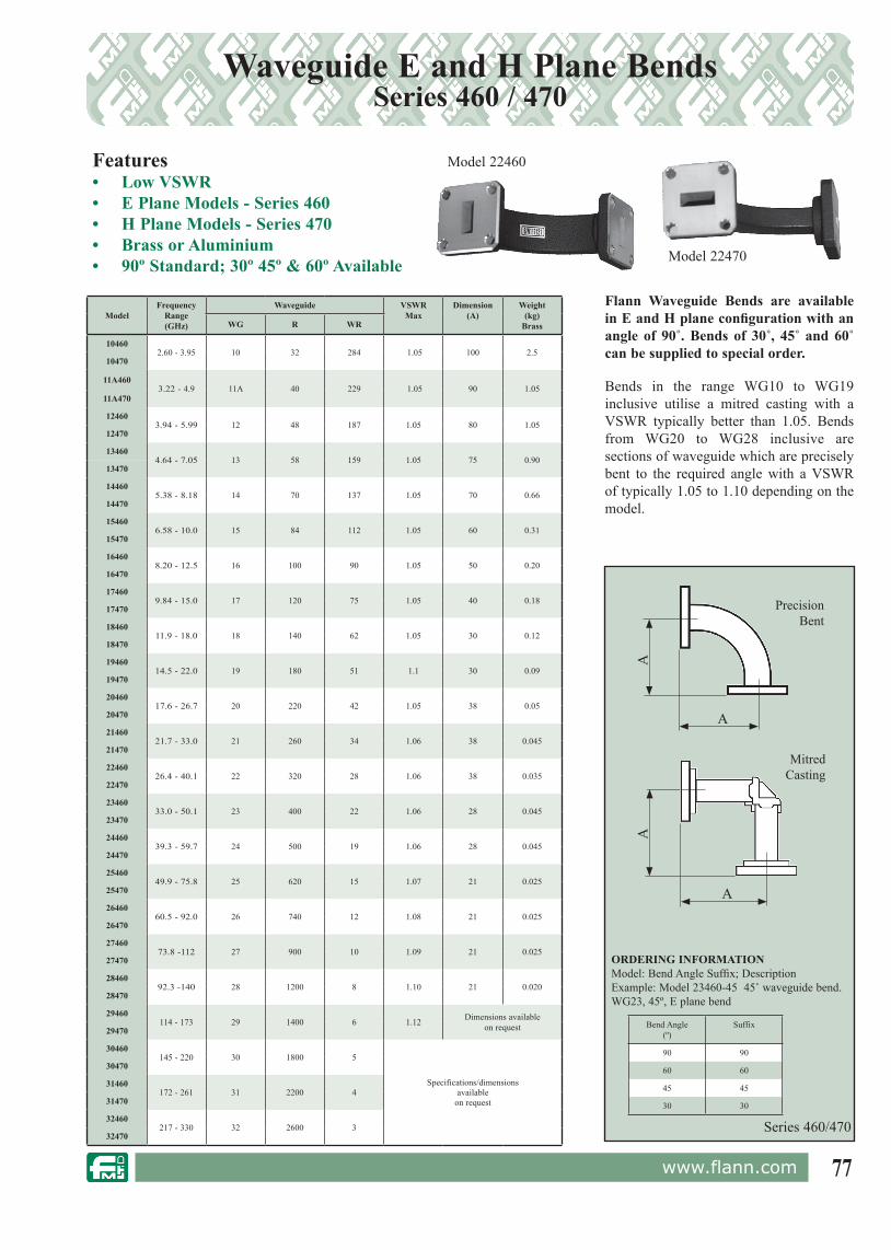
77www.flann.com
Waveguide E and H Plane BendsSeries 460 / 470
Model 22470
Flann Waveguide Bends are available in E and H plane configuration with an angle of 90˚. Bends of 30˚, 45˚ and 60˚ can be supplied to special order.
Bends in the range WG10 to WG19 inclusive utilise a mitred casting with a VSWR typically better than 1.05. Bends from WG20 to WG28 inclusive are sections of waveguide which are precisely bent to the required angle with a VSWR of typically 1.05 to 1.10 depending on the model.
Features• Low VSWR• E Plane Models - Series 460• H Plane Models - Series 470• Brass or Aluminium• 90º Standard; 30º 45º & 60º Available
Model 22460
ModelFrequency
Range(GHz)
Waveguide VSWRMax
Dimension(A)
Weight(kg)
BrassWG R WR
104602.60 - 3.95 10 32 284 1.05 100 2.5
10470
11A4603.22 - 4.9 11A 40 229 1.05 90 1.05
11A470
124603.94 - 5.99 12 48 187 1.05 80 1.05
12470
134604.64 - 7.05 13 58 159 1.05 75 0.90
13470
144605.38 - 8.18 14 70 137 1.05 70 0.66
14470
154606.58 - 10.0 15 84 112 1.05 60 0.31
15470
164608.20 - 12.5 16 100 90 1.05 50 0.20
16470
174609.84 - 15.0 17 120 75 1.05 40 0.18
17470
1846011.9 - 18.0 18 140 62 1.05 30 0.12
18470
1946014.5 - 22.0 19 180 51 1.1 30 0.09
19470
2046017.6 - 26.7 20 220 42 1.05 38 0.05
20470
2146021.7 - 33.0 21 260 34 1.06 38 0.045
21470
2246026.4 - 40.1 22 320 28 1.06 38 0.035
22470
2346033.0 - 50.1 23 400 22 1.06 28 0.045
23470
2446039.3 - 59.7 24 500 19 1.06 28 0.045
24470
2546049.9 - 75.8 25 620 15 1.07 21 0.025
25470
2646060.5 - 92.0 26 740 12 1.08 21 0.025
26470
2746073.8 -112 27 900 10 1.09 21 0.025
27470
2846092.3 -140 28 1200 8 1.10 21 0.020
28470
29460114 - 173 29 1400 6 1.12 Dimensions available
on request29470
30460145 - 220 30 1800 5
Specifications/dimensionsavailable
on request
30470
31460172 - 261 31 2200 4
31470
32460217 - 330 32 2600 3
32470
ORDERING INFORMATIONModel: Bend Angle Suffix; DescriptionExample: Model 23460-45 45˚ waveguide bend.WG23, 45º, E plane bend
Series 460/470
Precision Bent
Mitred Casting
A
A
A
A
Bend Angle(º)
Suffix
90 90
60 60
45 45
30 30

78 www.flann.com
Customised Waveguides and Assemblies
Millimetric waveguide sections in WG25 [R620, WR15]
Please contact our Sales Team for further information.
Microwave Radio fade margin (bit error rate) network inWG20 [R220, WR42]
CustomWaveguide Networks
High power pulsed radar subsystem in WG22 [R320, WR28]
CustomisedWaveguide Assemblies
Hybrid flexible / rigid waveguide system assembly in WG14 & 15 [R70 & R84, WR137 & WR112]
Below are examples of customised and customer specific designs, please consult our Sales Team for your special requirements.
High power pulsed radar subsystem in WG6 [R14, WR650]

79www.flann.com
Waveguide Switches & Driver
SWITCHESFeatures• Manual and Motorised Models• 2 or 3-Channel Rotor• High Repeatability• High Reliability• High Isolation• Motorised Speed & Precision modes of operation• Low VSWR
DRIVERFeatures• GPIB• USB• 19" Rack MountableThe Flann range of waveguide switches, Series 333, includes manual and motorised models operating in the frequency bands up to 140 GHz. The 4 port switches are optionally available with 2-channel or 3-channel rotors in most waveguide sizes and offer high isolation between non-coupled ports.
Test & Measurement Manual Switches - Series 333-2 (or -3) Page 80
Precision manual switches offering unsurpassed accuracy and repeatability. Available with 2 or 3-channel rotor.
Test & Measurement Motorised Switches - Series 333-2E (or -3E) Page 81
Stepper motor driven switches offering superior reliability and repeatability to alternative solenoid operated units.A feature unique to the Flann Series 333 of electrical switches is the user’s ability to choose between “speed” and “precision” modes of operation. In “speed” mode switching time is minimised by using all possible rotor positions. In “precision” mode, only one of the two possible rotor positions is used ensuring optimum microwave path repeatability. Standard drive cable length is 2 metres for all models - cable lengths of up to 5 metres available. Available with 2 or 3- channel rotor.
Switch Driver - Model SD5902 Page 82
Available for the control of one or two Series 333 switches. The Model SD5902 offers local control via the front panel and remote control via both USB and GPIB interfaces. Refer to page 74 for specifications.
Test & Measurement DC Motor Driven Switches - Series 334-2E (or -3E) Page 83
Series 334 is a DC motor driven switch operating in the frequency bands from 8.2 GHz to 112 GHz with the same high performance specification as the Series 333 manual switch. A high speed DC Motor driven switch offering high reliability alternative to solenoid or TTL operated units. Available with 2 or 3-channel rotor.
Test & Measurement Double Ridge Waveguide Switches DC Motor Driven - Series WRD334-2E Page 83
Double ridge waveguide version switches of the Series 334 switch. Manual versions also available on request.
System & Network Switches - Series 336 Page 84
2.6 GHz to 40.1 GHzLow Loss & High PowerVery Cost CompetitiveMany Models available from stock
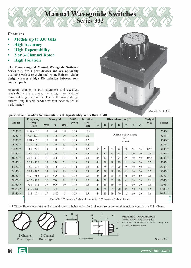
80 www.flann.com
Manual Waveguide SwitchesSeries 333
Features• Models up to 330 GHz• High Accuracy• High Repeatability• 2 or 3-Channel Rotor• High IsolationThe Flann range of Manual Waveguide Switches, Series 333, are 4 port devices and are optionally available with 2 or 3-channel rotor. Efficient choke design ensures a high RF isolation between non-coupled ports.
Accurate channel to port alignment and excellent repeatability are achieved by a light yet positive rotor indexing mechanism. The well proven design ensures long reliable service without deterioration in performance.
ORDERING INFORMATIONModel: Rotor Type; DescriptionExample: Model 22333-2 Manual waveguide switch 2-Channel Rotor
Series 3332-Channel
Rotor Type 23-Channel
Rotor Type 3
Model 20333-2
G
A Flange to Flange
DC
BE
E FSpecification: Isolation (minimum): 75 dB Repeatability better than -50dB
** These dimensions refer to 2-channel rotor switches only; for 3-channel rotor switch dimensions consult our Sales Team.
ModelFrequency
Range (GHz)
Waveguide VSWR(max)
InsertionLoss(dB)
Dimensions (mm)** Weight(kg) Model
WG R WR A B C D E F G
15333-* 6.58 - 10.0 15 84 112 1.10 0.15Dimensions available
onrequest
15333-*16333-* 8.2 - 12.5 16 100 90 1.10 0.15 16333-*17333-* 9.84 - 15.0 17 120 75 1.10 0.2 17333-*18333-* 11.9 - 18.0 18 140 62 1.10 0.2 18333-*19333-* 14.5 - 22.0 19 180 51 1.10 0.2 55 29 71 92 50 60 56 0.95 19333-*20333-* 17.6 - 26.7 20 220 42 1.10 0.3 44 30 73 94 45 60 50 0.8 20333-*21333-* 21.7 - 33.0 21 260 34 1.10 0.3 44 30 73 94 45 60 50 0.55 21333-*22333-* 26.4 - 40.1 22 320 28 1.10 0.3 44 28 69 90 45 60 50 0.7 22333-*23333-* 33.0 - 50.1 23 400 22 1.10 0.3 47 28 69 90 45 60 50 0.7 23333-*24333-* 39.3 - 59.7 24 500 19 1.10 0.4 47 28 69 90 45 60 50 0.7 24333-*25333-* 49.9 - 75.8 25 620 15 1.10 0.5 44 28 69 90 45 60 50 0.6 25333-*26333-* 60.5 - 92.0 26 740 12 1.10 0.5 44 28 69 90 45 60 50 0.6 26333-*27333-* 73.8 - 112 27 900 10 1.10 0.6 44 28 69 90 45 60 50 0.6 27333-*28333-* 93.2 - 140 28 1200 8 1.15 0.8 44 28 69 90 45 60 50 0.6 28333-*29333-* 114 - 173 29 1400 6 1.20 1.3 44 28 69 90 45 60 50 0.6 29333-*
The suffix “-2” denotes a 2-channel rotor whilst “-3” denotes a 3-channel rotor.

81www.flann.com
Features• Models up to 330 GHz• High Accuracy• High Repeatability• 2 or 3-Channel Rotor• High Isolation
Model 27333-3ESpecification: Isolation (minimum): 75 dBRepeatability better than -50 dB
Motorised Waveguide SwitchesSeries 333-*E
For standard flange types and rec om men da tions see pages 118 onwards
** These dimensions refer to 2-channel rotor switches only; for 3-channel rotor switch dimensions consult our Sales Team.
ModelFrequency
Range(GHz)
Waveguide VSWR(Max)
InsertionLoss Max (dB)
DimensionsModel
WG R WR A(mm)
B(mm)
C(mm)
15333-*E 6.58 - 10.0 15 84 112 Specification/dimensionsavailable on request
15333-*E
16333-*E 8.2 - 12.5 16 100 90 16333-*E
17333-*E 9.84 - 15.0 17 120 75 1.10 0.2 56.0 152 34.8 17333-*E
18333-*E 11.9 - 18.0 18 140 62 1.10 0.2 50.0 147 32.2 18333-*E
19333-*E 14.5 - 22.0 19 180 51 1.10 0.3 55.0 140 29 19333-*E
20333-*E 17.6 - 26.7 20 220 42 1.10 0.3 44.0 140 29.7 20333-*E
21333-*E 21.7 - 33.0 21 260 34 1.10 0.4 44.0 140 30 21333-*E
22333-*E 26.4 - 40.1 22 320 28 1.10 0.4 44.0 137 28 22333-*E
23333-*E 33.0 - 50.1 23 400 22 1.10 0.4 47.0 137 28 23333-*E
24333-*E 39.3 - 59.7 24 500 19 1.10 0.5 47.0 137 28 24333-*E
25333-*E 49.9 - 75.8 25 620 15 1.10 0.6 44.0 137 28 25333-*E
26333-*E 60.5 - 92.0 26 740 12 1.10 0.8 44.0 137 28 2633 -*E
27333-*E 73.8 - 112 27 900 10 1.10 1.0 44.0 137 28 27333-*E
28333-*E 92.3 - 140 28 120 8 1.15 1.2 44.0 137 28 28333-*E
The suffix “-2E” denotes a 2-channel rotor whilst “-3E” denotes a 3-channel rotor.
ORDERING INFORMATIONModel: rotor type, E; descriptionExample: Model 22333-2E Motorised waveguide switch, 2-channel rotorOur range of waveguide switches is subject to continual development and additional models, not detailed in this catalogue, may be available to special order. Please consult our sales office for information.A Flann switch driver is essential for driving any of the electrically operated switches listed. Please see page 82 for details.
Series 333-*E
50
45
45
A 79
50
C
62 B
2-ChannelRotor Type 2
3-ChannelRotor Type 3
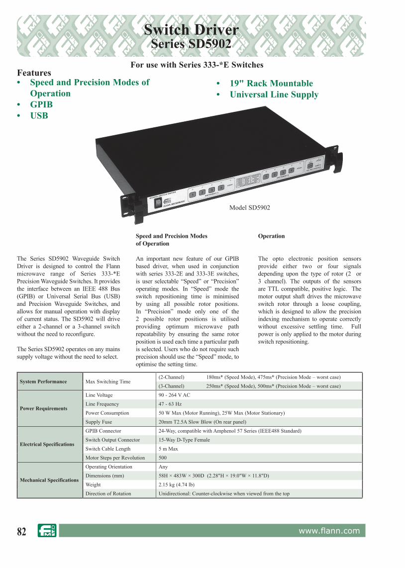
82 www.flann.com
Speed and Precision Modesof Operation
An important new feature of our GPIB based driver, when used in conjunction with series 333-2E and 333-3E switches, is user selectable “Speed” or “Precision” operating modes. In “Speed” mode the switch repositioning time is minimised by using all possible rotor positions. In “Precision” mode only one of the 2 possible rotor positions is utilised providing optimum microwave path repeatability by ensuring the same rotor position is used each time a particular path is selected. Users who do not require such precision should use the “Speed” mode, to optimise the setting time.
The Series SD5902 Waveguide Switch Driver is designed to control the Flann microwave range of Series 333-*E Precision Waveguide Switches. It provides the interface between an IEEE 488 Bus (GPIB) or Universal Serial Bus (USB) and Precision Waveguide Switches, and allows for manual operation with display of current status. The SD5902 will drive either a 2-channel or a 3-channel switch without the need to reconfigure.
The Series SD5902 operates on any mains supply voltage without the need to select.
Switch DriverSeries SD5902
• Speed and Precision Modes of Operation
• GPIB• USB
Model SD5902
Features• 19" Rack Mountable• Universal Line Supply
Operation
The opto electronic position sensors provide either two or four signals depending upon the type of rotor (2 or 3 channel). The outputs of the sensors are TTL compatible, positive logic. The motor output shaft drives the microwave switch rotor through a loose coupling, which is designed to allow the precision indexing mechanism to operate correctly without excessive settling time. Full power is only applied to the motor during switch repositioning.
System Performance Max Switching Time(2-Channel) 180ms* (Speed Mode), 475ms* (Precision Mode – worst case)
(3-Channel) 250ms* (Speed Mode), 500ms* (Precision Mode – worst case)
Power Requirements
Line Voltage 90 - 264 V AC
Line Frequency 47 - 63 Hz
Power Consumption 50 W Max (Motor Running), 25W Max (Motor Stationary)
Supply Fuse 20mm T2.5A Slow Blow (On rear panel)
Electrical Specifications
GPIB Connector 24-Way, compatible with Amphenol 57 Series (IEEE488 Standard)
Switch Output Connector 15-Way D-Type Female
Switch Cable Length 5 m Max
Motor Steps per Revolution 500
Mechanical Specifications
Operating Orientation Any
Dimensions (mm) 58H × 483W × 300D (2.28"H × 19.0"W × 11.8"D)
Weight 2.15 kg (4.74 lb)
Direction of Rotation Unidirectional: Counter-clockwise when viewed from the top
For use with Series 333-*E Switches

83www.flann.com
Model WRD180334-2E
DC-Motor Driven Waveguide SwitchesSeries 334-*E / WRD334-*E
Features• Switching Time < 500 ms• High Accuracy• High Repeatability• High Isolation• 2 or 3-Channel • Simple TTL - Level Control & Indicators
Series 334/WRD334
ORDERING INFORMATIONModel descriptionExample: Model 22334-2E D.C. Operated waveguide switch, 75 dB isolation, 2-channel rotor.
Our range of waveguide switches is subject to continual development and additional models, not detailed in this catalogue may be available to special order. Please consult our sales office for information.
Model 20334-2EModel 20334-2E
ModelFrequency
Range(GHz)
Waveguide VSWR(Max)
InsertionLoss Max
(dB)
IsolationMinimum
(dB)Model
WG R WR
16334-*E 8.2 - 12.5 16 100 90 1.10 0.2 75 16334-*E
17334-*E 9.84 - 15.0 17 120 75 1.10 0.2 75 17334-*E
18334-*E 11.9 - 18.0 18 140 62 1.10 0.2 75 18334-*E
19334-*E 14.5 - 22.0 19 180 51 1.10 0.3 75 19334-*E
20334-*E 17.6 - 26.7 20 220 42 1.10 0.3 75 20334-*E
21334-*E 21.7 - 33.0 21 260 34 1.10 0.4 75 21334-*E
22334-*E 26.4 - 40.1 22 320 28 1.10 0.4 75 22334-*E
23334-*E 33.0 - 50.1 23 400 22 1.10 0.4 75 23334-*E
24334-*E 39.3 - 59.7 24 500 19 1.10 0.5 75 24334-*E
25334-*E 49.9 - 75.8 25 620 15 1.10 0.6 75 25334-*E
26334-*E 60.5 - 92.0 26 740 12 1.10 0.8 75 2633 -*E
27334-*E 73.8 - 112 27 900 10 1.10 1.0 75 27334-*E
WRD180334-*E 18.0 - 40.0 WRD180-C24 1.15 0.2 75 WRD180334-*E
The suffix “-2E” denotes a 2-channel rotor whilst “-3E” denotes a 3-channel rotor.
Electrical Specifications
Supply voltage 10 V - 28 V DC
Power Consumption 2 W Peak
Control Interface TTL-level control and indicators
ConnectorMIL-C-26482 Shell 12, 10 Pin Plug(Mating cable socket supplied)(Pattern 105 compatible)
OperationThe Flann Series 334 DC-Motor driven waveguide switches use the same high-repeatability rotor/stator design as the unrivalled Series 333 switches. They may be controlled directly by a PC (for example by the standard printer port) or remote buttons and indicators. TTL-level control pins are provided for each of the switch positions: four for 3-channel switches and two for 2-channel switches. A logic ‘low’ on the appropriate control line causes the switch to move to the corresponding position. Indicator pins are provided for each switch position that indicate ‘high’ when the switch is correctly positioned. These are capable of sourcing up to 25mA at 5V (more than adequate to directly drive an LED).
2-ChannelRotor Type 2
3-ChannelRotor Type 3

84 www.flann.com
DC-Operated 2-Channel Waveguide SwitchesSeries 336
Features• 2.6 GHz to 40.1 GHz • Low Loss & High Power• High Speed• High Reliability• Internal and External Usage• Sealed, 15 psig StandardApplications• SATCOM Systems• Networks• SNG
Model Number
FrequencyRange (GHz)
Waveguide Return Loss(dB)
Isolation(dB)
InsertionLoss(dB)
MaxMean Power(kW)
SwitchingSpeed(ms)WG R WR
14336 5.38 – 8.20 14 70 137 > 32.3 > 85 < 0.02 12 < 7015336 6.58 – 10.0 15 84 112 > 32.3 > 85 < 0.03 8 < 6016336 8.2 - 12.5 16 100 90 > 32.3 > 85 < 0.04 5.5 < 6017336 9.84 – 15.0 17 120 75 > 32.3 > 85 < 0.04 5 < 5018336 11.9 - 18.5 18 140 62 > 32.3 > 85 < 0.05 3.5 < 50
22336 26.4 - 40.1 22 320 28 > 28.3 > 75 < 0.10 0.8 < 50
WRD580336 5.8 - 16.0 WRD580-D28 > 23.1 > 65 < 0.20 1.1 < 60
Model Number
BWmm
(inch)
FFmm (inch)
H1mm (inch)
H2mm (inch)
Mmm (inch)
Weightkg (lb)
14336 62 (2.44) 57.2 (2.25) 34.9 (1.37) 119 (4.69) 44.5 (1.75) < 0.8 (1.76)15336 62 (2.44) 57.2 (2.25) 25.5 (1.00) 101 (3.98) 44.5 (1.75) < 0.7 (1.54)16336 57.2 (2.25) 47.6 (1.87) 26.7 (1.05) 98 (3.86) 34.9 (1.375) < 0.6 (1.32)17336 57.2 (2.25) 47.6 (1.87) 22.2 (0.87) 90 (3.55) 34.9 (1.375) < 0.55 (1.21)18336 57.2 (2.25) 47.6 (1.87) 19.7 (0.78) 84 (3.31) 34.9 (1.375) < 0.55 (1.21)22336 47.6 (1.87) 35.0 (1.38) 14.6 (0.57) 73.5 (2.89) 28.6 (1.125) <0.4 (0.88)
WRD580336 57.2 (2.25) 47.6 (1.87) 22.2 (0.87) 90.5 (3.56) 34.9 (1.375) < 0.55 (1.21)
Dimensions & Weight:
Specifications:
Many models available from
STOCK
ORDERING INFORMATION: - BASIC OPTIONS
Model Description: Waveguide WG17, PBR 120 Flange, Model Number: 17 336 -0 0 0 S 0 A L 0 0
+28 Volt DC, M4 34.9mm, Side Connector, MIL connector 14 shell 19 Pin,
Circuit A, Latching, No Locking Key, No additional option
Waveguide Type / Size: WG10 (WR284) to WG22 (WR28) and WRD580 to WRD180
Series: 336
Flange Type: 0 = Grooved, 1 = Cover
Voltage: 0 = +28Vdc, 1 = -28Vdc, 2 = +12Vdc, 3 = -12Vdc
Mounting Holes: 0 = Metric, 1 = Imperial
Connector Position: S = Side, T = Top
Control/Connector Type/Style: 0 = MIL 14-19, 1 = MIL 14-12, 2 = MIL 12-10, 3 = MIL 10-6, 4= RS-485 MIL 10-6, 8-2
Electrical Arrangement: Circuits A, B, C, D, E, F, G, H, I, J, K, L M
Latching: L = Latching, F = Fail-Safe
Locking and Key Removal: 0 = No locking, 1 = Tubular lockable position '1'
Options: 0 = No option, 1 = Weatherproof (Manual override knob protected from ice)
PLEASE CONTACT OUR SALES TEAM FOR MORE INFORMATION ON OUR STANDARD AND OTHER MODELS

85www.flann.com
Phase Combining / Redundancy SolutionsSeries 520
`
CRU
HPA A
HPA B
Splitter RF IN
Dump Load
DDA 214 Controller
ANTENNA
EXTERNAL LOAD
Motorised Phase Shifter
Switch
ANTENNA MONITOR
Serial Parallel Alarm
Features• Efficient HPA Combining• Full Power HPA Redundancy• High Speed Switching• Fully Integrated Solution
Applications• Mobile Installations• Fixed / Ground Installations• SNG Trucks
Typical RF Specification
Frequency Range 12.75 GHz - 14.5 GHz
RF Power handling > 1 kW on both channels simultaneously
System Insertion Loss(Redundancy Mode) < 0.35 dB
Switching Speed(Combining to Redundancy Mode) < 50 ms
VSWR < 1.25 : 1
Antenna Power Monitor -50 dB
ORDERING INFORMATION
PLEASE CONTACT THE SALES TEAM FOR MORE INFORMATION ON OUR STANDARD AND OPTIONAL MODELS
A Typical System Schematic
DC Power / Control
HPA “A”
HPA “B”
Antenna (A+B or A or B)
Dump LoadCRU
The Series 520 suite offers various solutions supporting multiple High Power Amplifi er con-fi guration and combining requirements.The entry level CRU module routes the outputs of two HPAs to an Antenna and High Power Load as in a "Hot Standby" system. Or it combines both HPA outputs to an Antenna to in-crease power in diffi cult Satcom uplink budget situations.The complete phase optimised Combiner / Redundancy System is available with a separate Hub Box and rack mount Controller or fully integrated into a single box controlled via a laptop dialogue box.
General System Schematic
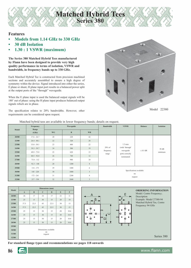
86 www.flann.com
Matched Hybrid TeesSeries 380
Features• Models from 1.14 GHz to 330 GHz• 30 dB Isolation• 1.30 : 1 VSWR (maximum)
Model 22380
The Series 380 Matched Hybrid Tees manufactured by Flann have been designed to provide very high quality performance in terms of isolation, VSWR and bandwidth, in frequency bands up to 330 GHz.
Each Matched Hybrid Tee is constructed from precision machined sections and accurately assembled to ensure a high degree of symmetry within the device. Signal introduced into either the series, E plane or shunt, H plane input port results in a balanced power split at the output ports of the “through” waveguide.
When the E plane input is used the balanced output signals will be 180˚ out of phase: using the H plane input produces balanced output signals which are in phase.
The specification relates to 20% bandwidths. However, other requirements can be considered upon request.
For standard flange types and rec om men da tions see pages 118 onwards
Series 380
ORDERING INFORMATIONModel: Centre Frequency; DescriptionExample: Model 27380-94Matched Hybrid Tee, Centre Frequency 94 GHz
A E
CD
B F
Matched hybrid tees are available in lower frequency bands; details on request.
Model
Frequency
Range
(GHz)
Waveguide Bandwidth VSWR Balance Isolation
WG R WR
20380 17.6 - 26.7 20 220 42
20% of
frequency
range
1.3 max
(with ‘through’
waveguide
ports correctly
terminated)
± 0.5 dB30 dB
minimum
22380 26.4 - 40.1 22 320 28
23380 33.0 - 50.1 23 400 22
24380 39.3 - 59.7 24 500 19
25380 49.9 - 75.8 25 620 15
26380 60.5 - 92.0 26 740 12
27380 73.8 - 112 27 900 10
28380 92.3 - 140 28 1200 8
29380 114 - 173 29 1400 6Specifications available
on
request
30380 145 - 220 30 1800 5
31380 172 - 261 31 2200 4
32380 217 - 330 32 2600 3
Model Dimensions (mm)
A B C D E F
20380 28 17 34 17 22 11
22380 25 15 30 15 20 10
23380 37.5 22.5 45 22.5 30 15
24380 37.5 22.5 45 22.5 30 15
25380 25 15 30 15 20 10.4
26380 25 15 30 15 20 10.4
27380 25 15 30 15 20 10.4
28380 25 15 30 15 20 10.4
29380
Dimensions availableon
request
30380
31380
32380
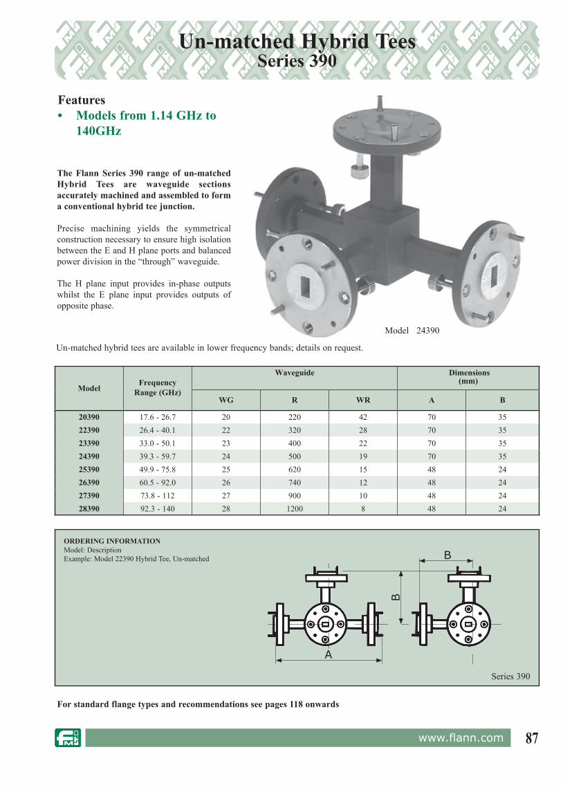
87www.flann.com
Un-matched Hybrid TeesSeries 390
Model 24390
The Flann Series 390 range of un-matched Hybrid Tees are waveguide sections accurately machined and assembled to form a conventional hybrid tee junction. Precise machining yields the symmetrical construction necessary to ensure high isolation between the E and H plane ports and balanced power division in the “through” waveguide.
The H plane input provides in-phase outputs whilst the E plane input provides outputs of opposite phase.
ModelFrequency
Range (GHz)
Waveguide Dimensions(mm)
WG R WR A B
20390 17.6 - 26.7 20 220 42 70 3522390 26.4 - 40.1 22 320 28 70 3523390 33.0 - 50.1 23 400 22 70 3524390 39.3 - 59.7 24 500 19 70 3525390 49.9 - 75.8 25 620 15 48 2426390 60.5 - 92.0 26 740 12 48 2427390 73.8 - 112 27 900 10 48 2428390 92.3 - 140 28 1200 8 48 24
For standard flange types and rec om men da tions see pages 118 onwards
Features• Models from 1.14 GHz to
140GHz
ORDERING INFORMATIONModel: DescriptionExample: Model 22390 Hybrid Tee, Un-matched
Series 390
A
B
B
Un-matched hybrid tees are available in lower frequency bands; details on request.

88 www.flann.com
Matched E and H Plane TeesSeries 400 / 410
Features• Models from 1.14 GHz to 330 GHz• E Plane Models - Series 400• H Plane Models - Series 410
Model 25400
The Series 400 E plane and Series 410 H plane matched tees are constructed from precision machined sections accurately assembled to form the completed component.
H plane tees, when fed via the shunt arm, divide the signal equally between the through ports and in phase. When E plane tees are fed via the series arm the signal divides equally but 180˚ out of phase.
For standard flange types and rec om men da tions see pages 118 onwards
Model FrequencyRange(GHz)
Waveguide VSWR Balance Between Co-linear
PortsEPlane
HPlane WG R WR
20400 20410 17.6 - 26.7 20 220 42
1.3 max(with ‘through’
waveguideports correctly
terminated)
±0.5 dB
22400 22410 26.4 - 40.1 22 320 28
23400 23410 33.0 - 50.1 23 400 22
24400 24410 39.3 - 59.7 24 500 19
25400 25410 49.9 - 75.8 25 620 15
26400 26410 60.5 - 92.0 26 740 12
27400 27410 73.8 - 112 27 900 10
28400 28410 92.3 - 140 28 1200 8
29400 29410 114 - 173 29 1400 6
Specifications availableon
request
30400 30410 145 - 220 30 1800 5
31400 31410 172 - 261 31 2200 4
32400 32410 217 - 330 32 2600 3
Model Dimensions(mm)
EPlane
HPlane A B C D E F
20400 20410 28 17 34 17 22 11
22400 22410 25 15 30 15 20 10
23400 23410 37.5 22.5 45 22.5 30 15
24400 24410 37.5 22.5 45 22.5 30 15
25400 25410 25 15 30 15 20 10.4
26400 26410 25 15 30 15 20 10.4
27400 27410 25 15 30 15 20 10.4
28400 28410 25 15 30 15 20 10.4
29400 29410
Dimensions availableon
request
30400 30410
31400 31410
32400 32410
ORDERING INFORMATIONModel: DescriptionExample: Model 25410; Tee, Matched, H Plane
Series 400/410
BA
DC
FE
Matched tees are available in lower frequency bands; details on request.
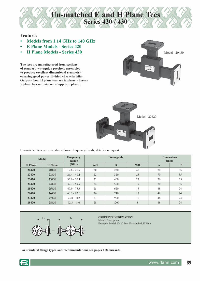
89www.flann.com
Un-matched E and H Plane TeesSeries 420 / 430
The tees are manufactured from sections of standard waveguide precisely assembled to produce excellent dimensional symmetry ensuring good power division characteristics. Outputs from H plane tees are in phase whereas E plane tees outputs are of opposite phase.
Features• Models from 1.14 GHz to 140 GHz• E Plane Models - Series 420• H Plane Models - Series 430
Series 420/430
For standard flange types and rec om men da tions see pages 118 onwards
Model FrequencyRange(GHz)
Waveguide Dimensions(mm)
E Plane H Plane WG R WR A B20420 20430 17.6 - 26.7 20 220 42 70 3522420 22430 26.4 - 40.1 22 320 28 70 3523420 23430 33.0 - 50.1 23 400 22 70 3524420 24430 39.3 - 59.7 24 500 19 70 3525420 25430 49.9 - 75.8 25 620 15 48 2426420 26430 60.5 - 92.0 26 740 12 48 2427420 27430 73.8 - 112 27 900 10 48 2428420 28430 92.3 - 140 28 1200 8 48 24
Model 20430
Model 20420
ORDERING INFORMATIONModel: DescriptionExample: Model 27420 Tee, Un-matched, E Plane
AB
Un-matched tees are available in lower frequency bands; details on request.

90 www.flann.com
Features• 4 - 140 GHz• High Radiation effi ciency (20% smaller
aperture than equivqlent parabolic antenna)
• Superior sidelobe and crosspolar performance
• Linear and circular feed• Weatherproofi ng on Series 820 / 880• Low wind loading• Inherently robust• 30 - 500m diameter
Flann's range of Lens Horn Antenna have many significant microwave and mechanical advantages over the parabolic or printed antennas, particularly at E-band
Standard flange designs are avaliable but custom interconnections have been developed to interface directly with customer hardware
Example: 26820-PA UG-387/U. A WG26, Series 820, 250mm Lens Horn Antenna with UG 387/U fl ange
OrderingPlease specify the following:
WG designation
810 820 880
Lens Diameter* Flange
See fl ann.com
-
26 Assigned by Flann
Series
Typical Return Loss for model 26810-QA 50mm AntennaCustom Design
Custom built instruments can be supplied; please contact the sales team for more information
Lens Horn AntennaSeries 810 / 820 / 880
Series Typical VSWR (max)
810 1.50
820 1.50
880 1.25
Microwave Specifi cations Telecommunication Standards
- ETSI EN 302 217-3 VI.3.1 (2009-07)- ETSI EN 302 217-4-2 VI.4.1 (2008-11)- FCC 47 C.F.R. Part 101, FCC Report 05-45- TELEC
Model: 26810-QA
* Letter assigned by Flann at time of quotation/order
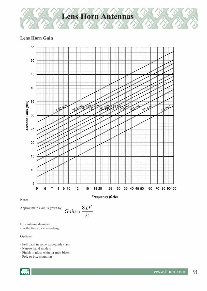
91www.flann.com
Lens Horn Antennas
Options
- Full band in some waveguide sizes- Narrow band models- Finish in gloss white or matt black- Pole or box mounting
Lens Horn Gain
Notes
Approximate Gain is given by:
D is antenna diameter λ is the free space wavelength
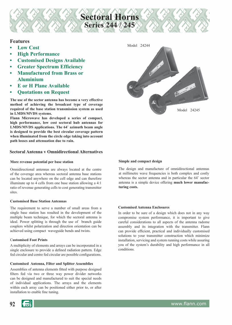
92 www.flann.com
Sectoral HornsSeries 244 / 245
Features• Low Cost• High Performance• Customised Designs Available• Greater Spectrum Efficiency• Manufactured from Brass or
Aluminium• E or H Plane Available • Quotations on Request
The requirement to serve a number of small areas from a single base station has re sult ed in the development of the multiple beam technique, for which the sectoral antenna is ideal. Power split ting is through the use of branch guide cou plers whilst po lar i za tion and di rec tion ori en ta tion can be achieved us ing com pact waveguide bends and twists.
Customised Foot PrintsA multiplicity of elements and arrays can be incorporated in a single enclosure to provide a defined radiation pattern. Edge fed circular and centre fed circular are pos si ble configurations.
Customised Antenna, Filter and Splitter AssembliesAssemblies of antenna elements fitted with purpose designed filters fed via two or three way power divider networks can be designed and manufactured to suit the special needs of individual applications. The arrays and the elements within each array can be positioned either prior to, or after installation to enable fine tuning.
Customised Antenna EnclosuresIn order to be sure of a design which does not in any way compromise system performance, it is important to give careful considerations to all aspects of the antenna radome assembly and its integration with the transmitter. Flann can provide efficient, practical and individually customised solutions to your transmitter construction which minimize installation, servicing and system running costs while assuring you of the system’s durability and high performance in all conditions.
The use of the sector antenna has become a very effective method of achieving the broadcast type of coverage required of the base station transmission system as used in LMDS/MVDS systems. Flann Microwave has developed a series of compact, high perform ance, low cost sectoral hub antennas for LMDS/MVDS ap pli ca tions. The 64˚ azimuth beam angle is designed to provide the best circular coverage pattern when il lu mi nat ed from the circle edge tak ing into account path losses and at ten u a tion due to rain.
More revenue potential per base sta tion
Omnidirectional antennas are always located at the centre of the coverage area whereas sectoral antenna base stations can be located anywhere on the cell edge and can therefore illuminate up to 4 cells from one base station allowing a 4:1 ratio of rev e nue generating cells to cost gen er at ing transmitter sites.
Sectoral Antenna v Omnidirectional Alternatives
Customised Base Station Antennas
Model 24244
Model 24245
Simple and compact design
The design and manufacture of om ni di rec tion al antennas at millimetre wave frequencies is both complex and costly where as the sector an ten na and in particular the 64˚ sector antenna is a simple device of fer ing much lower man u fac-tur ing costs.

93www.flann.com
Standard Gain HornsSeries 240
Features• Weatherproof Options• Mounting Brackets Options• Manufactured Brass or Aluminium• Higher frequency models available
In general the lower frequency horns, models 06240 to 17240 inclusive, are accurately fabricated from brass sheet or aluminium. Models 18240 to 32240 inclusive are copper electroformed on precision mandrels which ensure high accuracy and repeatability. Typical gain/bandwidth curves are provided for all standard gain horns. 10 dB, 15 dB, 20 dB, 25 dB, 30 dB and 33 dB gain horns are also available in many waveguide sizes.
NB:- 25 dB models are approximately three times the overall length of the corresponding 20 dB models
The Flann Standard Gain Horns have a wide range of applications, (e.g. as transmitting, receiving or sampling antennas or for feeding reflectors).
The absolute gain of a standard gain horn is calculable from the flare dimensions. Flann Standard Gain Horns are precision components providing accurate and repeatable gain references.
Specifications:Variation of mid-band gain with frequency .......................... ± 2 dBMaximum VSWR (20 dB models) ........................................ 1.2 : 1
For more compact horn antennas and higher gains see Lens Horn Antennas pages 90 and 91
ORDERING INFORMATIONModel: Gain Suffix; DescriptionExample: Model16240-20 Standard Gain Horn, 20 dB-01 Membrane-02 Mounting Bracket-03 Membrane and Mounting Bracket
Series 240
Model 22240-25
A B
C
For standard flange types and rec om men da tions see pages 118 onwards
Model
FrequencyRange(GHz)
Waveguide Standard Mid-Band Gain
(dB)
Dimensions (mm)
WG R WR A Overall B Internal C Internal
06240 1.14 - 1.73 6 14 650 10 478 240 17508240 1.72 - 2.61 8 22 430 10 318 160 11510240 2.60 - 3.95 10 32 284 15 352 203 145
11A240 3.22 - 4.90 11A 40 229 15 290 154 11412240 3.94 - 5.99 12 48 187 20 495 230 16513240 4.64 - 7.05 13 58 159 20 419 209 14814240 5.38 - 8.18 14 70 137 20 375 170 12315240 6.58 - 10.0 15 84 112 20 328 146 11016240 8.20 - 12.5 16 100 90 20 245 109 7917240 9.84 - 15.0 17 120 75 20 215 94 6718240 1.9 - 18.0 18 140 62 20 153 75 5719240 14.5 - 22.0 19 180 51 20 139 67 5020240 17.6 - 26.7 20 220 42 20 120 52 3822240 26.4 - 40.1 22 320 28 20 85 35 2523240 33.0 - 50.1 23 400 22 20 68 28 2024240 39.3 - 59.7 24 500 19 20 54.5 23 1825240 49.9 - 75.8 25 620 15 20 45.5 19 1326240 60.5 - 92.0 26 740 12 20 38.5 15 1127240 73.8 - 112 27 900 10 20 32.5 12.4 928240 92.3 - 140 28 1200 8 20 27.5 10 829240 114 - 173 29 1400 6 20 24.5 8.5 6.530240 145 - 220 30 1800 5 20 21.0 7.0 5.031240 172 - 261 31 2200 4 20 18.0 6.5 4.532240 217 - 330 32 2600 3 20 12.0 6.0 4.0
Gain Suffix
10 dB 10
15 dB 15
20 dB 20
25 dB 25
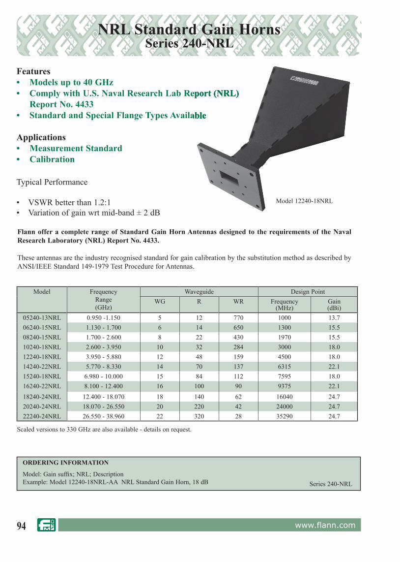
94 www.flann.com
NRL Standard Gain HornsSeries 240-NRL
Features• Models up to 40 GHz• Comply with U.S. Naval Research Lab Report (NRL) Report No. 4433• Standard and Special Flange Types Available
Applications• Measurement Standard• Calibration
• Comply with U.S. Naval Research Lab Report (NRL)• Comply with U.S. Naval Research Lab Report (NRL)
• Standard and Special Flange Types Available• Standard and Special Flange Types Available
Model 12240-18NRL
Series 240-NRL
ORDERING INFORMATION
Model: Gain suffix; NRL; DescriptionExample: Model 12240-18NRL-AA NRL Standard Gain Horn, 18 dB
Flann offer a complete range of Standard Gain Horn Antennas designed to the requirements of the Naval Research Laboratory (NRL) Report No. 4433.
These antennas are the industry recognised standard for gain calibration by the substitution method as described by ANSI/IEEE Standard 149-1979 Test Procedure for Antennas.
Typical Performance
• VSWR better than 1.2:1• Variation of gain wrt mid-band ± 2 dB
Model FrequencyRange(GHz)
Waveguide Design PointWG R WR Frequency
(MHz)Gain(dBi)
05240-13NRL 0.950 -1.150 5 12 770 1000 13.706240-15NRL 1.130 - 1.700 6 14 650 1300 15.508240-15NRL 1.700 - 2.600 8 22 430 1970 15.510240-18NRL 2.600 - 3.950 10 32 284 3000 18.012240-18NRL 3.950 - 5.880 12 48 159 4500 18.014240-22NRL 5.770 - 8.330 14 70 137 6315 22.115240-18NRL 6.980 - 10.000 15 84 112 7595 18.016240-22NRL 8.100 - 12.400 16 100 90 9375 22.118240-24NRL 12.400 - 18.070 18 140 62 16040 24.720240-24NRL 18.070 - 26.550 20 220 42 24000 24.722240-24NRL 26.550 - 38.960 22 320 28 35290 24.7
Scaled versions to 330 GHz are also available - details on request.

95www.flann.com
Near Field ProbesSeries 246
Features• Models up to 330 GHz• Low End Diffraction
Applications• Planar & Cylindrical Near Field Measurements• Calibration
Series 246
ORDERING INFORMATION
Model: DescriptionExample: Model 18246 WG18 Near-field probe
Flann offer a complete range of small aperture open-ended near field waveguide probes designed specifically for planar and cylindrical near field measurements and calibration.
The end diffraction is minimised by utilising a 10° chamfer to give a knife edge aperture of less than 0.5 mm.
Standard probe lengths include 100 mm, 200 mm & 300 mm.
Custom lengths and flanges are available on request.
Typical Performance
• VSWR better than 2.5:1• Gain 5.5 dB• Gain variation ± 2 dB

96 www.flann.com
Dual Polarized HornSeries DP240
The Flann Dual Polarized Horn, Model DP240 is a multi-octave, coaxially fed, quadridged horn suitable for many applications requiring a high performance over a broad band.
These high performance units covering the frequency range 2 GHz to 18 GHz offer high isolation with low phase and amplitude imbalance between ports. The horn maintains a low VSWR while the precision electroformed construction ensures very low cross polarization levels.
Typical applications include:• Electromagnetic Interference (EMI) Measurement• Antenna Measurement• Radar Cross Section Measurement
Features• Frequency Range 2 GHz to 18 GHz• Dual Polarization• Close Phase and Amplitude Tracking Between Ports• High Isolation• Low Cross Polarization• Integral Mounting Bracket Option• Rated to IP54*
Model DP240-AB
ORDERING INFORMATION:
Model DP240-AA; Dual Polarized Horn, 2 GHz to 18 GHzModel DP240-AB; Dual Polarized Horn, 2 GHz to 18 GHz with integral mounting bracket
Series DP240
Electrical Specifications
Frequency Range 2 GHz to 18 GHz
Gain 5 dBi to 18 dBi
Polarization Simultaneous Horizontal & Vertical
3 dB Beamwidth 60° to 10° Nominal
Typical VSWR Better than 2.5:1
Cross Polarization -20 dB Maximum
Isolation Between Ports 25 dB Typical
Maximum Power CW 10 Watts
Phase Tracking Between Ports ± 17° Maximum
Amplitude Tracking Between Ports ± 1.3 dB Maximum
RF Coaxial Connectors SMA Female
Dimensions
Aperture Diameter 135 mm
Overall Length 300 mm
Weight 2.75 kg (3.2 kg DP240-AB)
*SMA, K and 2.4mm connectors are not hermetically sealed. Therefore to achieve IP54 rating the mated cable connection must be adequately sealed.

97www.flann.com
Dual Polarized HornSeries DP241
Features• Frequency Range 18 GHz to 40 GHz• Optional Ranges in 6 GHz to 50 GHz• Close Phase and Amplitude
Tracking Between Ports • High Isolation • Low Cross Polarization • Rated to IP54*
• Electromagnetic Interface (EMI) measurement• Antenna Measurement • Radar Cross Section Measurement
The Flann Dual Polarized Horn, Model DP241 - AB, is a multi-octave, coaxially fed, quadridged horn suitable for many applications requiring a high performance over a broad band. The standard antenna covers the frequency range 18 GHz - 40 GHz and offers high isolation with low phase and amplitude imbalance between ports. Other frequency options are available within the 6 GHz to 50 GHz band.
Typical applications include
The horn maintains a low VSWR while the precision-machined construction ensures very low cross polarization levels.
Special Dual Polarized Horns are also available operating up to 50 GHz using 2.4 connectors.
The standard DP241-AB will function down to 6 GHz with a reduced performance.
Model DP241- AB
ORDERING INFORMATION:
Model DP241-AB; Dual Polarized Horn, 18 GHz to 40 GHz with integral mounting bracketModel DP241-AC; Dual Polarized Horn, 6 GHz to 50 GHz (2.4 mm connector) Series DP241
Electrical Specifications
Frequency Range 18 GHz to 40 GHz(Options, operational from 6 GHz to 50 GHz
Gain 10 dBi to 18 dBi
Polarization Simultaneous Horizontal & Vertical
3 dB Beamwidth 25° to 17° Nominal
Typical VSWR Better than 2.5:1
Cross Polarization -20 dB
Isolation Between Ports 25 dB
Maximum Power CW 5 Watts
Phase Tracking Between Ports ± 25° Maximum
Amplitude Tracking Between Ports ± 1.5 dB Maximum
RF Coaxial Connectors 2.9 K Type Female
Dimensions
Aperture 50 mm x 50 mm
Overall Length 150 mm
Weight < 0.5 kg
*SMA, K and 2.4mm connectors are not hermetically sealed. Therefore to achieve IP54 rating the mated cable connection must be adequately sealed.

98 www.flann.com
Series DP241
Features• Low VSWR • 360˚ Azimuth Coverage • 60˚ Elevation Coverage• Models within the range 1.5 GHz - 330 GHz available• Waveguide Interface Models available
The Flann Omni Directional Antennas series MD249, provide 360˚ coverage in azimuth and 60˚ coverage in elevation; these antennas are suitable for applications requiring a good all round coverage.
Typical applications include:-
• Wireless LAN• Source Tracking• Outside Broadcast• Air to Ground Downlinks
Typical Specfication:- (Model MD 249-AA)
Specified Frequency RangeFunctional Frequency RangeNominal GainGain Variation ElevationGain Variation AzimuthPolarizationNominal Half Angle 3 dB Beamwidth Nominal Half Angle 10 dB BeamwidthVSWR (Max)Typical Power Handling RF Coaxial Connectors
59 GHz to 65.5 GHz All Broadband widths up to 2:150 GHz to 70 GHz All Broadband widths up to 2:12 dB±1.5 dB±1 dBVerticalTypically Greater than 30˚Typically Greater than 60˚1.65:15 Watts1.85 mm Male or Female or Type N, SMA, K for lower frequency ranges
Omni Directional AntennaSeries MD249
Model MD249-AA
Model MD249-AB
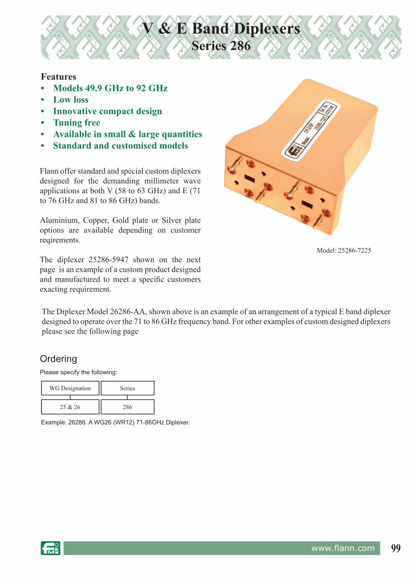
99www.flann.com
V & E Band Diplexers Series 286
Features• Models 49.9 GHz to 92 GHz• Low loss• Innovative compact design• Tuning free• Available in small & large quantities• Standard and customised models
Model: 25286-7225
Flann offer standard and special custom diplexers designed for the demanding millimeter wave applications at both V (58 to 63 GHz) and E (71 to 76 GHz and 81 to 86 GHz) bands.
Aluminium, Copper, Gold plate or Silver plate options are available depending on customer reqirements.
The diplexer 25286-5947 shown on the next page is an example of a custom product designed and manufactured to meet a specifi c customers exacting requirement.
The Diplexer Model 26286-AA, shown above is an example of an arrangement of a typical E band diplexer designed to operate over the 71 to 86 GHz frequency band. For other examples of custom designed diplexers please see the following page
OrderingPlease specify the following:
Example: 26286. A WG26 (WR12) 71-86GHz Diplexer.
WG Designation Series
28625 & 26

100 www.flann.com
WG25/WR15 V-band Diplexer (25286-5947)Band port Low High
Frequency (GHz) 58.5 to 59.5 61 to 62VSWR (max) 1.9 1.9
Insertion Loss (dB) 2.5 2.5
Group delay variation 600ps max 600ps max
Stop Band Rejection 60dB
Operating temperature -45° C to +85° C
Flange types custom interface
WG26/WR12 E-band Diplexer (26286-AA)Band port Low High
Frequency (GHz) 71-76 81-86VSWR (max) 1.5
Insertion loss (dB) 0.7 max
Amplitude variation ≤ 0.1 dB in any 150MHz Band
Group delay variation ≤ 0.1 ns in any 150 MHz Band Isolation (dB) ≥63
Rejection >20 dB @ 1.5 GHz from passbandsOperating temperature -30° C to +70° C
Flange types UG-387/U
Specfication:- Model 25286-5947 Specfication:- Model 26286-AA
Typical Return Loss for model 25286-5947
Typical Transmission Loss for model 25286-5947 Typical Transmission Loss for model 26286-AA
Typical Return Loss for model 26286-AA
V & E Band Diplexers Series 286
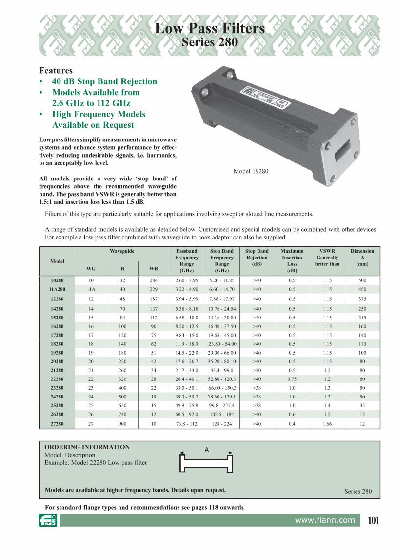
101www.flann.com
Low pass filters simplify measurements in microwave systems and enhance system performance by ef fec-tive ly reducing undesirable sig nals, i.e. harmonics, to an acceptably low level. All models provide a very wide ‘stop band’ of frequencies above the recommended waveguide band. The pass band VSWR is generally better than 1.5:1 and in ser tion loss less than 1.5 dB.
Low Pass FiltersSeries 280
Features• 40 dB Stop Band Rejection• Models Available from 2.6 GHz to 112 GHz• High Frequency Models
Available on Request
Filters of this type are particularly suitable for applications involving swept or slotted line measurements.
A range of standard models is available as de tailed below. Customised and special models can be combined with other devices. For example a low pass filter combined with waveguide to coax adaptor can also be supplied.
Models are available at higher frequency bands. Details upon request.
Model 19280
For standard flange types and rec om men da tions see pages 118 onwards
A
Series 280
Model
Waveguide PassbandFrequency
Range(GHz)
Stop Band Frequency
Range(GHz)
Stop BandRejection
(dB)
MaximumInsertion
Loss(dB)
VSWRGenerally
better than
DimensionA
(mm)WG R WR
10280 10 32 284 2.60 - 3.95 5.20 - 11.85 >40 0.5 1.15 500
11A280 11A 40 229 3.22 - 4.90 6.60 - 14.70 >40 0.5 1.15 450
12280 12 48 187 3.94 - 5.99 7.88 - 17.97 >40 0.5 1.15 375
14280 14 70 137 5.38 - 8.18 10.76 - 24.54 >40 0.5 1.15 250
15280 15 84 112 6.58 - 10.0 13.16 - 30.00 >40 0.5 1.15 215
16280 16 100 90 8.20 - 12.5 16.40 - 37.50 >40 0.5 1.15 160
17280 17 120 75 9.84 - 15.0 19.68 - 45.00 >40 0.5 1.15 140
18280 18 140 62 11.9 - 18.0 23.80 - 54.00 >40 0.5 1.15 110
19280 19 180 51 14.5 - 22.0 29.00 - 66.00 >40 0.5 1.15 100
20280 20 220 42 17.6 - 26.7 35.20 - 80.10 >40 0.5 1.15 80
21280 21 260 34 21.7 - 33.0 43.4 - 99.0 >40 0.5 1.2 80
22280 22 320 28 26.4 - 40.1 52.80 - 120.3 >40 0.75 1.2 60
23280 23 400 22 33.0 - 50.1 66.00 - 150.3 >38 1.0 1.3 50
24280 24 500 19 39.3 - 59.7 78.60 - 179.1 >38 1.0 1.3 50
25280 25 620 15 49.9 - 75.8 99.8 - 227.4 >38 1.0 1.4 35
26280 26 740 12 60.5 - 92.0 102.5 - 184 >40 0.6 1.5 15
27280 27 900 10 73.8 - 112 128 - 224 >40 0.4 1.66 12
ORDERING INFORMATIONModel: DescriptionExample: Model 22280 Low pass filter
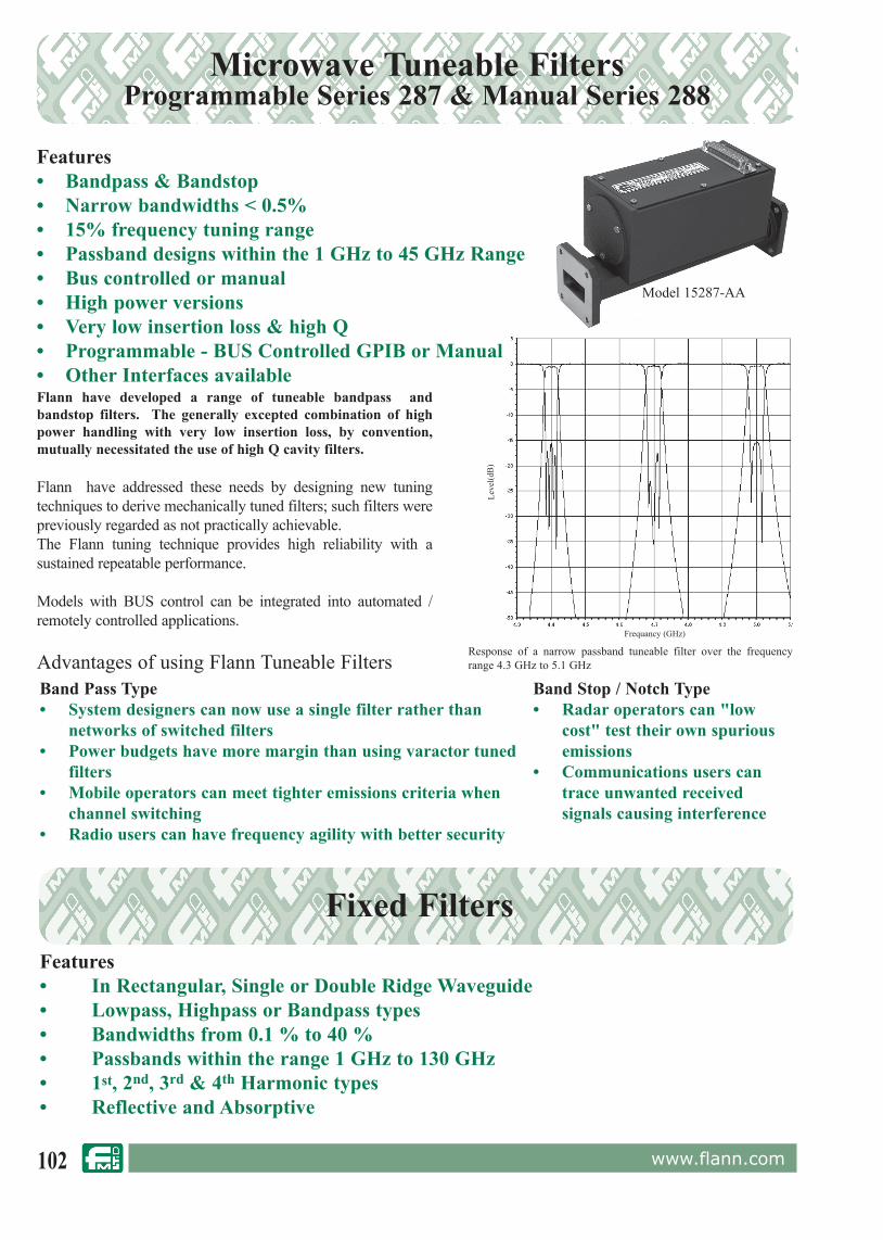
102 www.flann.com
Microwave Tuneable FiltersProgrammable Series 287 & Manual Series 288
Flann have developed a range of tuneable bandpass and bandstop filters. The generally excepted combination of high power handling with very low insertion loss, by convention, mutually necessitated the use of high Q cavity filters.
Flann have addressed these needs by designing new tuning techniques to derive mechanically tuned filters; such filters were previously regarded as not practically achievable.The Flann tuning technique provides high reliability with a sustained repeatable performance.
Models with BUS control can be integrated into automated / remotely controlled applications.
Features• Bandpass & Bandstop• Narrow bandwidths < 0.5%• 15% frequency tuning range• Passband designs within the 1 GHz to 45 GHz Range• Bus controlled or manual• High power versions• Very low insertion loss & high Q• Programmable - BUS Controlled GPIB or Manual• Other Interfaces available
Band Pass Type• System designers can now use a single filter rather than
networks of switched filters• Power budgets have more margin than using varactor tuned
filters• Mobile operators can meet tighter emissions criteria when
channel switching• Radio users can have frequency agility with better security
Band Stop / Notch Type• Radar operators can "low
cost" test their own spurious emissions
• Communications users can trace unwanted received signals causing interference
Advantages of using Flann Tuneable Filters
Features• In Rectangular, Single or Double Ridge Waveguide• Lowpass, Highpass or Bandpass types• Bandwidths from 0.1 % to 40 % • Passbands within the range 1 GHz to 130 GHz • 1st, 2nd, 3rd & 4th Harmonic types• Reflective and Absorptive
Response of a narrow passband tuneable filter over the frequency range 4.3 GHz to 5.1 GHz
Frequancy (GHz)
Leve
l(dB
)
Model 15287-AA
Fixed Filters

103www.flann.com
Orthomode TransducersSeries 780
Features• Isolation > 50 dB• Models up to 140 GHz• Broad & Narrow Band Options• High Polarization Purity 50 dB (typical)• Circular or Square Guide Interface Options
Applications• For Use With Dual Polarized Antennas• For Polarization Diplexing
Flann's OMT’s offer the high performance demanded by today’s communication systems, in which high polarization purity and high isolation are paramount.
The combination of low cross polar and high isolation characteristics provide optimum link performance.
Some examples of the models available are detailed in the table below. Other models are available to suit many applications, frequency bands and power levels. Details on Request.
Series 780
For other radio products:See pages 101 & 102 for filters, page 51 for waveguide to coax adaptors & page 90 for antennas.Please contact our Sales Team for more information on our new range of Radio Products.
Model 17780-AB
Complimentary components are available for a complete antenna fed system from:- High performance lens horn Antennas- Polarizers - linear and circular- Filters and Diplexers- Isolators- Waveguide to Coax adaptors (including NEW range of end feed coax)
Model In-Line Port(GHz)
Ortho Port(GHz)
Port Isolation(dB)
X- Polarization (dB)
Return Loss (dB)
Insertion Loss (dB)
15780 ** 7.25 -7.75 7.9 - 8.4 50 50 26 0.117780 ** 10.7 -12.75 13.75 - 14.5 48 48 26 0.120780 ** 21.2 - 23.6 21.2 - 23.6 47 47 25 0.122780 ** 27.5 - 29.5 27.5 - 29.5 45 45 23 0.2
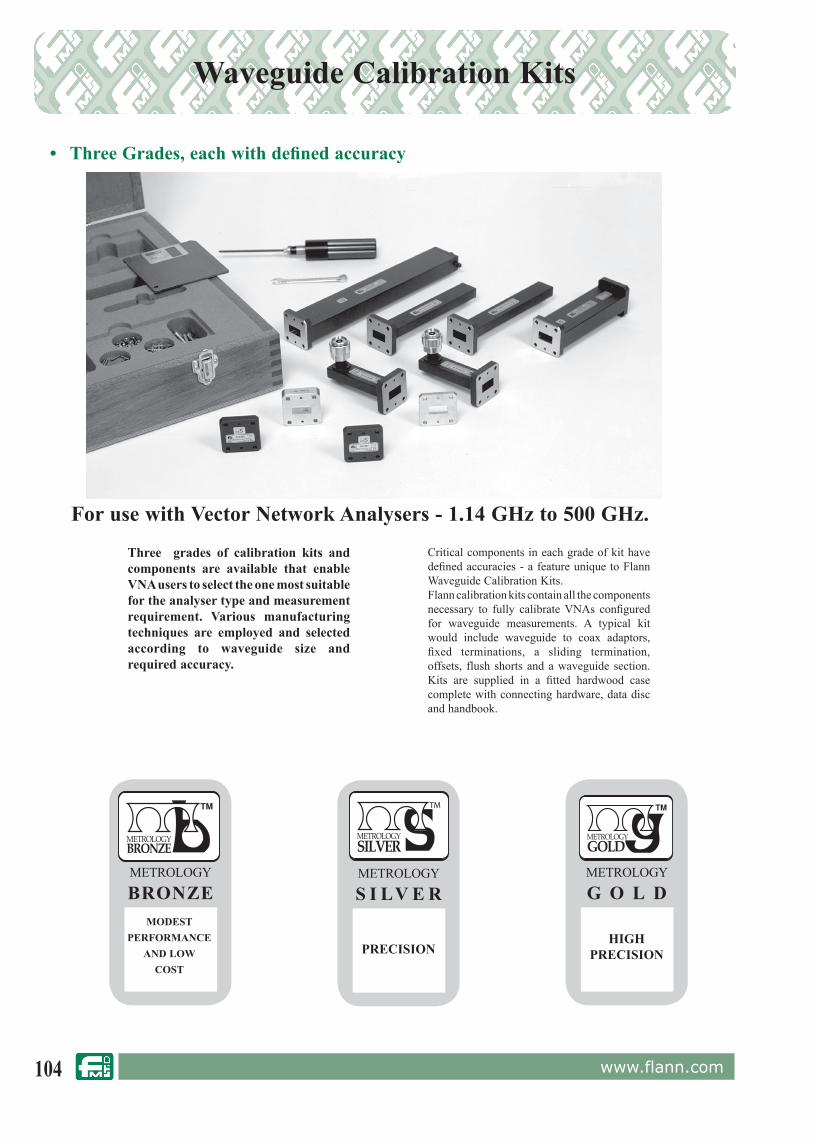
104 www.flann.com
Waveguide Calibration Kits
• Three Grades, each with defined accuracy
For use with Vector Network Analysers - 1.14 GHz to 500 GHz.
Three grades of calibration kits and components are available that enable VNA users to select the one most suitable for the analyser type and measurement requirement. Various manufacturing techniques are employed and selected according to waveguide size and required accuracy.
Critical components in each grade of kit have defined accuracies - a feature unique to Flann Waveguide Calibration Kits.Flann calibration kits contain all the components necessary to fully calibrate VNAs configured for waveguide measurements. A typical kit would include waveguide to coax adaptors, fixed terminations, a sliding termination, offsets, flush shorts and a waveguide section. Kits are supplied in a fitted hardwood case complete with connecting hardware, data disc and handbook.
HIGHPRECISION
METROLOGY
G O L DMODEST
PERFORMANCE AND LOW
COST
METROLOGY
BRONZE
PRECISION
METROLOGY
S I LV E R
TM

105www.flann.com
Model Selection Table
Each kit type contains the following components
Waveguide Calibration Kits
ORDERING INFORMATION REQUIRED1. Waveguide designation (size)Example: WG27 2. Series selected Example: 730 see above3. DescriptionExample: Metrology Silver Grade, OOL type4. Vector analysers to be usedExample: HP8513
Complete Ordering Example: 27730 Metrology Silver Waveguide Calibration Kit type OOL for use with HP8513 vector network analysers
Please Note: Calibration Kits in WG 20 and higher frequencies (17.6 GHz upwards) do not include Waveguide to Coax Adaptors. Please state at time of ordering if adaptors are required to be included in the kit.
Note 1 - Flanges
Flann Calibration Kit components are fitted with “Precision Flanges” that are fully compatible with standard flanges whilst providing enhanced accuracy and repeatability. Please see page 126 - 128 for details. Kits are also available fitted with alternative flange styles or special flanges to customer specification. Details on request.
Note 2 - Waveguide to Coax Adaptors
The Waveguide to Coax Adaptors supplied with Flann Calibration Kits are of sufficient length to ensure the decay of unwanted evanescent modes.
Note 3 - Offsets
The length of each Flann offset section is designed to provide a phase balanced response over the recommended frequency range. Fractional wavelengths are specified with respect to a wavelength λg° where:-
λg° = 2
λghf . λglfλλghfl . λglf λghf + λglf
λglf is the waveguide wavelength at the lowest frequency of the operating range and λghf is the waveguide wavelength at the highest frequency of the operating range.
Kit GradeKit Type
OOL TRL / LRLMetrology Bronze 708 series 703 seriesMetrology Silver 730 series 720 seriesMetrology Gold 750 series 740 series
ComponentsContents
OOL TRL / LRLWaveguide to Coax Adaptors 2 off 2 off1.14 GHz to 22 GHz
(WG6, WR650, R14) to (WG19, WR51, R180)2 off
optional extra2 off
optional extra17.6 GHz to 110 GHz(WG20, WR42, R220) to (WG27, WR10, R900)Fixed Termination 2 off 2 offFlush Short 2 off 2 off1/8 λ Offset 1 off optional extra1/4 λ Offset optional extra 1 off3/8 λ Offset 1 off optional extra Waveguide Section 1 off 1 offSliding Termination 1 off optional extraData Disk included includedTorque Driver included includedFlange Bolts etc 1 set included 1 set includedPrecision Flange dowels 1 set included 1 set includedHardwood Case included includedHandbook included included

106 www.flann.com
Flann Calibration Kits have been developed in close cooperation with manufacturers and users of network analysers. Kits are available in each of the three grades, suitable for analyser configurations requiring OOL, TRL and LRL calibration kit styles. The selection of a calibration kit and its contents is largely dictated by the combination of analyser model, test set model and type of calibration routine to be implemented, i.e. full 12 term, single path 2 port, reflection only or TRL/LRL.
OOL - Offset/Offset/Load TRL - Thru/Reflect/Line LRL - Line/Reflect/Line
The waveguide Calibration Kits, as described in the preceding pages, contain the components necessary to fully calibrate Vector Network Analysers. Flann Calibration Kit components are available individually or to supplement standard kits. Specialised Calibration Kits or components for use with alternative measurement systems, such as six port reflectometers, are also available. Full details are available on request.
Note: The components included in Flann Offset/Offset/Load type calibration kits can also be used with the Anritsu/Wiltron 360 to achieve an LRL calibration.
The specifications and capabilities of network analysers are subject to constant evolution and development. Please consult us for Calibration Kit applications assistance if required.
A Guide to Calibration Kit Selection
ORDERING INFORMATIONCalibration Kit Model: model of specific analyser model with which Calibration Kit is to be used; Description Example: Model 22730-HP8513 waveguide calibration kit, metrology silver, OOL, for use with HP 8513 analyser
Note 1 - Flanges
Flann Calibration Kit components are fitted with “Precision Flanges” that are fully compatible with standard flanges whilst providing enhanced accuracy and repeatability. Please see page 126 - 129 for details. Kits are also available fitted with alternative flange styles or special flanges to customer specification. Details on request.
Note 2 - Waveguide to Coax Adaptors
The Waveguide to Coax Adaptors supplied with Flann Calibration Kits are of sufficient length to ensure the decay of unwanted evanescent modes.
Note 3 - Corner Radius
Calibration Kits with specified corner radius are available - please contact our Sales Department for more details
Please Note: Calibration Kits in WG 20 and higher frequency sets (17.6 GHz upwards) do not include waveguide to coax adaptors. Please state at time of ordering if adaptors will be required.
Double Ridge Waveguide Calibration Kits are also available - please see page 110
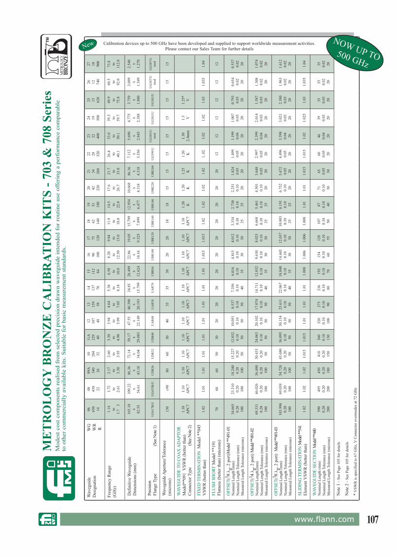
107www.flann.com
ME
TR
OL
OG
Y B
RO
NZ
E C
AL
IBR
ATIO
N K
ITS
- 703
& 7
08 S
erie
sM
odes
t cos
t com
pone
nts
real
ised
fro
m s
elec
ted
prec
isio
n dr
awn
wav
egui
de in
tend
ed f
or r
outin
e us
e of
feri
ng a
per
form
ance
com
para
ble
to o
ther
com
mer
cial
ly a
vaila
ble
kits
. Sui
tabl
e fo
r ba
sic
mea
sure
men
t sta
ndar
ds.
Wav
egui
de
W
GD
esig
natio
n
WR
R
06 650
14
08 430
22
09A
340
26
10 284
32
11A
229
40
12 187
48
13 159
58
14 137
70
15 112
84
16 90 100
17 75 120
18 62 140
19 51 180
20 42 220
21 34 260
22 28 320
23 22 400
24 19 500
25 15 620
26 12 740
27 10 900
Calibration devices up to 500 GHz have been developed and supplied to support worldwide measurement activities.Please contact our Sales Team for further details
Freq
uenc
y R
ange
(GH
z)1.
14 to1.
7 3
1.72 to 2.61
2.17 to 3.30
2.60 to 3.95
3.30 to 4.90
3.94 to 5.99
4.64 to 7.05
5.38 to 8.18
6.58 to 10.0
8.20 to
12.5
0
9.84 to 15.0
11.9 to 18.0
14.5 to 22.0
17.6 to 26.7
21.7 to 33.0
26.4 to 40.1
33.0 to 50.1
39.3 to 59.7
49.9 to 75.8
60.5 to 92.0
73.8 to
112.
0
Def
initi
ve W
aveg
uide
Dim
ensio
ns (m
m)
165.
10 x82
.55
109.
22 x54
.61
86.3
6x
43.1
8
72.1
4x
34.0
4
58.1
7x
29.0
83
47.5
5x
22.1
49
40.3
90 x20
.193
34.8
5x
15.7
99
28.4
99 x12
.624
22.8
6x
10.1
6
19.0
5x
9.52
5
15.7
99 x7.
899
12.9
54 x6.
477
10.6
68 x4.
318
86.3
6x
4.31
8
7.11
2x
3.55
6
5.69
0x
2.84
5
4.77
5x
2.38
8
3.75
9x
1.88
0
3.09
9x
1.54
9
2.54
0x
1.27
0
Prec
ision
Flan
ge T
ype
(S
ee N
ote 1
)U
G41
7B/U
UG
435B
/UU
DR
26U
DR
32U
DR
40U
AR
48U
AR
58U
AR
70U
BR
84U
BR
100
UB
R12
0U
BR
140
UB
R18
0U
BR
220
UB
R26
0U
G59
9/U
UG
383/
Um
odU
G38
3/U
UG
385/
UU
G38
7/U
mod
UG
387/
Um
od
Wav
egui
de A
pertu
re/T
oler
ance
(mic
rons
)13
0 v
9080
6050
4035
3530
2020
1818
1515
1515
1515
1515
WAV
EGU
IDE
TO C
OA
X A
DA
PTO
RM
odel
**09
1 V
SWR
(bet
ter t
han)
Conn
ecto
r Typ
e
(Se
e Not
e 2)
1.10
APC
71.
10A
PC7
1.10
APC
71.
10A
PC7
1.10
APC
71.
10A
PC7
1.10
APC
71.
10A
PC7
1.10
APC
71.
10A
PC7
1.10
APC
71.
10A
PC7
1.20 K
1.20 K
1.25 K
1.20 K
1.30
2.4m
m1.
3 V1.
25*
V
FIX
ED T
ERM
INAT
ION
Mod
el *
*045
VSW
R (b
ette
r tha
n)1.
021.
011.
011.
011.
011.
011.
011.
011.
011.
015
1.01
51.
021.
021.
021.
021.
.02
1.02
1.02
1.03
1.03
51.
04
FLU
SH S
HO
RT M
odel
**1
91Fl
atne
ss (b
ette
r tha
n) (m
icro
ns)
7060
6050
3020
2020
2020
2020
2020
2012
1212
1212
12
OFF
SET(
1 ⁄8 λ
g, 2
por
t)Mod
el **
491-
01N
omin
al L
engt
h (m
m)
Nom
inal
Len
gth
Tole
ranc
e (m
m)
Mea
sure
d Le
ngth
Tol
eran
ce (m
icro
ns)
34.6
650.
20 100
23.3
100.
20 100
18.2
400.
20 100
15.2
270.
20 50
12.0
320.
10 50
10.0
510.
10 50
8.53
70.
10 50
7.35
60.
10 40
6.01
60.
10 35
4.81
50.
10 30
4.01
20.
10 30
3.33
40.
10 25
2.73
00.
10 25
2.25
10.
10 20
1.82
40.
05 20
1.49
90.
05 20
1.19
90.
04 20
1.00
70.
03 20
0.79
30.
03 20
0.65
40.
02 20
0.53
70.
02 20
OFF
SET(
1 ⁄4 λ
g, 2
por
t) M
odel
**49
1-02
Nom
inal
Len
gth,
(mm
)N
omin
al L
engt
h To
lera
nce
(mm
)M
easu
red
Leng
th T
oler
ance
(mic
rons
)
69.3
310.
20 100
46.0
260.
20 100
36.4
800.
20 100
30.4
530.
20 50
24.0
630.
10 50
20.1
020.
10 50
17.0
740.
10 50
14.7
110.
10 40
12.0
320.
10 35
9.63
00.
10 30
8.02
50.
10 30
6.66
80.
10 25
5.46
10.
10 25
4.50
10.
10 20
3.64
80.
05 20
2.99
70.
05 20
2.39
90.
04 20
2.01
40.
03 20
1.58
70.
03 20
1.30
80.
02 20
1.07
40.
02 20
OFF
SET(
3 ⁄8 λ
g, 2
por
t) M
odel
**49
1-03
Nom
inal
Len
gth
(mm
)N
omin
al L
engt
h To
lera
nce
(mm
)M
easu
red
Leng
th T
oler
ance
(mic
rons
)
103.
996
0.20 100
69.0
390.
20 100
54.7
200.
20 100
45.6
800.
20 50
36.0
950.
10 50
30.1
540.
10 50
25.6
110.
10 50
22.0
670.
10 40
18.0
480.
10 35
14.4
450.
10 30
12.0
370.
10 30
10.0
030.
10 25
8.19
10.
10 25
6.75
20.
10 20
5.47
20.
05 20
4.49
60.
05 20
3.59
80.
04 20
3.02
10.
03 20
2.38
00.
03 20
1.96
30.
02 20
1.61
20.
02
20
SLID
ING
TER
MIN
ATIO
N M
odel
**54
1El
emen
t VSW
R (b
ette
r tha
n)1.
021.
021.
021.
015
1.01
51.
011.
011.
011.
008
1.00
61.
006
1.00
81.
011.
011.
015
1.01
51.
021.
025
1.03
1.03
51.
04
WAV
EGU
IDE
SECT
ION
Mod
el **
440
Nom
inal
Len
gth
(mm
)N
omin
al L
engt
h To
lera
nce
(mm
)M
easu
red
Leng
th T
oler
ance
(mic
rons
)
590
0.20 280
495
0.20 200
450
0.20 180
410
0.20 150
360
0.10 130
320
0.10 100
273
0.10 90
236
0.10 80
192
0.10 70
154
0.10 60
128
0.10 55
107
0.10 50
87 0.10 40
71 0.10 30
65 0.05 30
60 0.05 20
46 0.04 20
39 0.03 20
35 0.03 20
35 0.02 20
35 0.02 20
Not
e 1
- See
Pag
e 10
5 fo
r det
ails
Not
e 2
- See
Pag
e 10
5 fo
r det
ails
* V
SWR
is s
peci
fied
to 6
7 G
Hz,
V C
onne
ctor
ove
rmod
es a
t 72
GH
z
New NOW UP TO500 GHz

108 www.flann.com
ME
TR
OL
OG
Y S
ILV
ER
CA
LIB
RAT
ION
KIT
S - 7
20 &
730
Ser
ies
Prec
isio
n co
mpo
nent
s su
itabl
e fo
r ap
plic
atio
ns w
here
mod
est a
ccur
acie
s ar
e re
quir
ed.
TM
Wav
egui
de
W
GD
esig
natio
n
WR
R
06 650
14
08 430
22
09A
340
26
10 284
32
11A
229
40
12 187
48
13 159
58
14 137
70
15 112
84
16 90 100
17 75 120
18 62 140
19 51 180
20 42 220
21 34 260
22 28 320
23 22 400
24 19 500
25 15 620
26 12 740
27 10 900
Calibration devices up to 500 GHz have been developed and supplied to support worldwide measurement activities.Please contact our Sales Team for further details
Freq
uenc
y R
ange
(GH
z)1.
14 to 1.73
1.72 to 2.61
2.17 to 3.30
2.60 to 3.95
3.30 to 4.90
3.94 to 5.99
4.64 to 7.05
5.38 to 8.18
6.58 to 10.0
8.20 to
12.5
0
9.84 to 15.0
11.9 to 18.0
14.5 to 22.0
17.6 to 26.7
21.7 to 33.0
26.4 to 40.1
33.0 to 50.1
39.3 to 59.7
49.9 to 75.8
60.5 to 92.0
73.8 to
112.
0
Def
initi
ve W
aveg
uide
Dim
ensio
ns (m
m)
165.
10 x82
.55
109.
22 x54
.61
86.3
6x
43.1
8
72.1
4x
34.0
4
58.1
7x
29.0
83
47.5
5x
22.1
49
40.3
90 x20
.193
34.8
5x
15.7
99
28.4
99 x12
.624
22.8
6x
10.1
6
19.0
5x
9.52
5
15.7
99 x7.
899
12.9
54 x6.
477
10.6
68 x4.
318
86.3
6x
4.31
8
7.11
2x
3.55
6
5.69
0x
2.84
5
4.77
5x
2.38
8
3.75
9x
1.88
0
3.09
9x
1.54
9
2.54
0x
1.27
0
Prec
ision
Flan
ge T
ype
(S
ee N
ote 1
)U
G41
7A/U
UG
435A
/UU
DR
26U
DR
32U
DR
40U
AR
48U
AR
58U
AR
70U
BR
84U
BR
100
UB
R12
0U
BR
140
UB
R18
0U
BR
220
UB
R26
0U
G59
9/U
UG
383/
Um
odU
G38
3/U
UG
385/
UU
G38
7/U
mod
UG
387/
Um
od
Wav
egui
de A
pertu
re/T
oler
ance
(mic
rons
)65
4540
3030
2020
1515
1010
1010
1010
1010
1010
1010
WAV
EGU
IDE
TO C
OA
X A
DA
PTO
RM
odel
**09
4 V
SWR
(bet
ter t
han)
Conn
ecto
r Typ
e
(Se
e Not
e 2)
1.05
APC
71.
05A
PC7
1.05
APC
71.
05A
PC7
1.05
APC
71.
05A
PC7
1.05
APC
71.
05A
PC7
1.05
APC
71.
05A
PC7
1.07
APC
71.
07A
PC7
1.10 K
1.10 K
1.15 K
1.15 K
1.30
2.4m
m1.
3 V1.
25*
V
FIX
ED T
ERM
INAT
ION
Mod
el *
*043
VSW
R (b
ette
r tha
n)1.
021.
011.
011.
011.
011.
011.
011.
011.
011.
015
1.01
51.
021.
021.
021.
021.
.02
1.02
1.02
1.03
1.03
51.
04
FLU
SH S
HO
RT M
odel
**1
92Fl
atne
ss (b
ette
r tha
n) (m
icro
ns)
3530
3025
1510
1010
1010
1010
1010
106
66
66
6
OFF
SET(
1 ⁄8 λ
g, 2
por
t)Mod
el **
492-
01N
omin
al L
engt
h (m
m)
Nom
inal
Len
gth
Tole
ranc
e (m
m)
Mea
sure
Len
gth
Tole
ranc
e (m
icro
ns)
34.6
650.
20 50
23.3
100.
20 50
18.2
400.
20 50
15.2
270.
20 25
12.0
320.
10 25
10.0
510.
10 25
8.53
70.
10 25
7.35
60.
10 20
6.01
60.
10 15
4.81
50.
10 15
4.01
20.
10 10
3.33
40.
10 10
2.73
00.
10 10
2.25
10.
10 10
1.82
40.
05 10
1.49
90.
05 10
1.19
90.
04 10
1.00
70.
03 10
0.79
30.
03 10
0.65
40.
02 10
0.53
70.
02 10
OFF
SET(
1 ⁄4 λ
g, 2
por
t) M
odel
**49
2-02
Nom
inal
Len
gth
(mm
)N
omin
al L
engt
h To
lera
nce
(mm
)M
easu
re L
engt
h To
lera
nce
(mic
rons
)
69.3
310.
20 50
46.0
260.
20 50
36.4
800.
20 50
30.4
530.
20 25
24.0
630.
10 25
20.1
020.
10 25
17.0
740.
10 25
14.7
110.
10 20
12.0
320.
10 15
9.63
00.
10 15
8.02
50.
10 10
6.66
80.
10 10
5.46
10.
10 10
4.50
10.
10 10
3.64
80.
05 10
2.99
70.
05 10
2.39
90.
04 10
2.01
40.
03 10
1.58
70.
03 10
1.30
80.
02 10
1.07
40.
02 10
OFF
SET(
3 ⁄8 λ
g, 2
por
t) M
odel
**49
2-03
Nom
inal
Len
gth
(mm
)N
omin
al L
engt
h To
lera
nce
(mm
)M
easu
re L
engt
h To
lera
nce
(mic
rons
)
103.
996
0.20 50
69.0
390.
20 50
54.7
200.
20 50
45.6
800.
20 25
36.0
950.
10 25
30.1
540.
10 25
25.6
110.
10 25
22.0
670.
10 20
18.0
480.
10 15
14.4
450.
10 15
12.0
370.
10 10
10.0
030.
10 10
8.19
10.
10 10
6.75
20.
10 10
5.47
20.
05 10
4.49
60.
05 10
3.59
80.
04 10
3.02
10.
03 10
2.38
00.
03 10
1.96
30.
02 10
1.61
20.
02 10
SLID
ING
TER
MIN
ATIO
N M
odel
**54
2El
emen
t VSW
R (b
ette
r tha
n)1.
021.
021.
021.
015
1.01
51.
011.
011.
011.
008
1.00
61.
006
1.00
81.
011.
011.
015
1.01
51.
021.
025
1.03
1.03
51.
04
WAV
EGU
IDE
SECT
ION
Mod
el **
442
Nom
inal
Len
gth
(mm
)N
omin
al L
engt
h To
lera
nce
(mm
)M
easu
re L
engt
h To
lera
nce
(mic
rons
)
590
0.20 140
495
0.20 100
450
0.20 90
410
0.20 75
360
0.10 65
320
0.10 50
273
0.10 45
236
0.10 40
192
0.10 35
154
0.10 30
128
0.10 30
107
0.10 25
87 0.10 20
71 0.10 15
65 0.05 15
60 0.05 10
46 0.04 10
39 0.03 10
35 0.03 10
35 0.02 10
35 0.02 10
Not
e 1
- See
Pag
e 10
5 fo
r det
ails
Not
e 2
- See
Pag
e 10
5 fo
r det
ails
* V
SWR
is s
peci
fied
to 6
7 G
Hz,
V C
onne
ctor
ove
rmod
es a
t 72
GH
z
NewNOW UP TO500 GHz
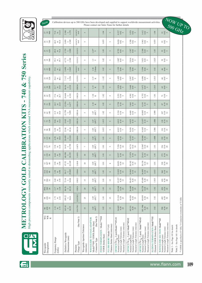
109www.flann.com
ME
TR
OL
OG
Y G
OL
D C
AL
IBR
ATIO
N K
ITS
- 740
& 7
50 S
erie
sH
igh
prec
isio
n co
mpo
nent
s em
inen
tly s
uite
d to
dem
andi
ng a
pplic
atio
ns w
hich
ext
end
VN
A m
easu
rem
ent c
apab
ility
.
Wav
egui
de
W
GD
esig
natio
n
WR
R
06 650
14
08 430
22
09A
340
26
10 284
32
11A
229
40
12 187
48
13 159
58
14 137
70
15 112
84
16 90 100
17 75 120
18 62 140
19 51 180
20 42 220
21 34 260
22 28 320
23 22 400
24 19 500
25 15 620
26 12 740
27 10 900
Calibration devices up to 500 GHz have been developed and supplied to support worldwide measurement activities.Please contact our Sales Team for further details
Freq
uenc
y R
ange
(GH
z)1.
14 to 1.73
1.72 to 2.61
2.17 to 3.30
2.60 to 3.95
3.30 to 4.90
3.94 to 5.99
4.64 to 7.05
5.38 to 8.18
6.58 to 10.0
8.20 to
12.5
0
9.84 to 15.0
11.9 to 18.0
14.5 to 22.0
17.6 to 26.7
21.7 to 33.0
26.4 to 40.1
33.0 to 50.1
39.3 to 59.7
49.9 to 75.8
60.5 to 92.0
73.8 to
112.
0
Def
initi
ve W
aveg
uide
Dim
ensio
ns (m
m)
165.
10 x82
.55
109.
22 x54
.61
86.3
6x
43.1
8
72.1
4x
34.0
4
58.1
7x
29.0
83
47.5
5x
22.1
49
40.3
90 x20
.193
34.8
5x
15.7
99
28.4
99 x12
.624
22.8
6x
10.1
6
19.0
5x
9.52
5
15.7
99 x7.
899
12.9
54 x6.
477
10.6
68 x4.
318
86.3
6x
4.31
8
7.11
2x
3.55
6
5.69
0x
2.84
5
4.77
5x
2.38
8
3.75
9x
1.88
0
3.09
9x
1.54
9
2.54
0x
1.27
0
Prec
ision
Flan
ge T
ype
(S
ee N
ote 1
)U
G41
7B/U
UG
435B
/UU
DR
26U
DR
32U
DR
40U
AR
48U
AR
58U
AR
70U
BR
84U
BR
100
UB
R12
0U
BR
140
UB
R18
0U
BR
220
UB
R26
0U
G59
9/U
UG
383/
Um
odU
G38
3/U
UG
385/
UU
G38
7/U
mod
UG
387/
Um
od
Wav
egui
de A
pertu
re/T
oler
ance
(mic
rons
)35
2520
1515
1010
77
55
55
55
55
55
55
WAV
EGU
IDE
TO C
OA
X A
DA
PTO
RM
odel
**09
5 V
SWR
(bet
ter t
han)
Conn
ecto
r Typ
e
(Se
e Not
e 2)
1.05
APC
71.
05A
PC7
1.05
APC
71.
05A
PC7
1.05
APC
71.
05A
PC7
1.05
APC
71.
05A
PC7
1.05
APC
71.
05A
PC7
1.07
APC
71.
07A
PC7
1.10 K
1.10 K
1.15 K
1.15 K
1.30
2.4m
m1.
3 V1.
25*
V
FIX
ED T
ERM
INAT
ION
Mod
el *
*044
VSW
R (b
ette
r tha
n)1.
021.
011.
011.
011.
011.
011.
011.
011.
011.
015
1.01
51.
021.
021.
021.
021.
.02
1.02
1.02
1.03
1.03
51.
04
FLU
SH S
HO
RT M
odel
**1
93Fl
atne
ss (b
ette
r tha
n) (m
icro
ns)
1515
1512
88
55
55
55
55
53
33
33
3
OFF
SET(
1 ⁄8 λ
g, 2
por
t)Mod
el **
493-
01N
omin
al L
engt
h (m
m)
Nom
inal
Len
gth
Tole
ranc
e (m
m)
Mea
sure
d Le
ngth
Tol
eran
ce (m
icro
ns)
34.6
650.
20 25
23.3
100.
20 25
18.2
400.
20 25
15.2
270.
20 15
12.0
320.
10 15
10.0
510.
10 12
8.53
70.
10 12
7.35
60.
10 10
6.01
60.
10 7
4.81
50.
10 7
4.01
20.
10 5
3.33
40.
10 5
2.73
00.
10 5
2.25
10.
10 5
1.82
40.
05 5
1.49
90.
05 5
1.19
90.
04 5
1.00
70.
03 5
0.79
30.
03 5
0.65
40.
02 5
0.53
70.
02 5
OFF
SET(
1 ⁄4 λ
g, 2
por
t) M
odel
**49
3-02
Nom
inal
Len
gth
(mm
)N
omin
al L
engt
h To
lera
nce
(mm
)M
easu
red
Leng
th T
oler
ance
(mic
rons
)
69.3
310.
20 25
46.0
260.
20 25
36.4
800.
20 25
30.4
530.
20 15
24.0
630.
10 15
20.1
020.
10 12
17.0
740.
10 12
14.7
110.
10 10
12.0
320.
10 7
9.63
00.
10 7
8.02
50.
10 5
6.66
80.
10 5
5.46
10.
10 5
4.50
10.
10 5
3.64
80.
05 5
2.99
70.
05 5
2.39
90.
04 5
2.01
40.
03 5
1.58
70.
03 5
1.30
80.
02 5
1.07
40.
02 5
OFF
SET(
3 ⁄8 λ
g, 2
por
t) M
odel
**49
3-03
Nom
inal
Len
gth
(mm
)N
omin
al L
engt
h To
lera
nce
(mm
)M
easu
red
Leng
th T
oler
ance
(mic
rons
)
103.
996
0.20 25
69.0
390.
20 25
54.7
200.
20 25
45.6
800.
20 15
36.0
950.
10 15
30.1
540.
10 12
25.6
110.
10 12
22.0
670.
10 10
18.0
480.
10 7
14.4
450.
10 7
12.0
370.
10 5
10.0
030.
10 5
8.19
10.
10 5
6.75
20.
10 5
5.47
20.
05 5
4.49
60.
05 5
3.59
80.
04 5
3.02
10.
03 5
2.38
00.
03 5
1.96
30.
02 5
1.61
20.
02 5
SLID
ING
TER
MIN
ATIO
N M
odel
**54
3El
emen
t VSW
R (b
ette
r tha
n)1.
021.
021.
021.
015
1.01
51.
011.
011.
011.
008
1.00
61.
006
1.00
81.
011.
011.
015
1.01
51.
021.
025
1.03
1.03
51.
04
WAV
EGU
IDE
SECT
ION
Mod
el **
443
Nom
inal
Len
gth
(mm
)N
omin
al L
engt
h To
lera
nce
(mm
)M
easu
red
Leng
th T
oler
ance
(mic
rons
)
590
0.20 70
495
0.20 50
450
0.20 45
410
0.20 40
360
0.10 35
320
0.10 30
273
0.10 25
236
0.10 20
192
0.10 18
154
0.10 15
128
0.10 15
107
0.10 12
87 0.10 10
71 0.10 7
65 0.05 7
60 0.05 5
46 0.04 5
39 0.03 5
35 0.03 5
35 0.02 5
35 0.02 5
Not
e 1
- See
Pag
e 10
5 fo
r det
ails
Not
e 2
- See
Pag
e 10
5 fo
r det
ails
* V
SWR
is s
peci
fied
to 6
7 G
Hz,
V C
onne
ctor
ove
rmod
es a
t 72
GH
z
NewNOW UP TO500 GHz

110 www.flann.com
ModelWaveguide Designation
Frequency Range(GHz)
Calibration Type*
WRD200703 WRD200D24 2.0 to 4.8 TRL/LRLWRD200708 WRD200D24 2.0 to 4.8 OOL WRD350703 WRD350D24 3.5 to 8.2 TRL/LRL WRD350708 WRD350D24 3.5 to 8.2 OOL WRD580703 WRD580D28 5.8 to 16.0 TRL/LRL WRD580708 WRD580D28 5.8 to 16.0 OOL WRD650703 WRD650D28 6.5 to 18.0 TRL/LRL WRD650708 WRD650D28 6.5 to 18.0 OOL WRD750703 WRD750D24 7.5 to 18.0 TRL/LRL WRD750708 WRD750D24 7.5 to 18.0 OOL WRD180703 WRD180C24 18.0 to 40.0 TRL/LRL WRD180708 WRD180C24 18.0 to 40.0 OOL
Double Ridge Waveguide Calibration Kits
A range of Double Ridge Calibration Kits has been added to the company’s extensive selection of rectangular waveguide Kits.
The Double Ridge Calibration Kits contain the standards and components required to fully calibrate VNA’s configured for waveguide measurements. Kits are available to suit all models of VNA’s in double ridge waveguide sizes from 3.5 GHz to 40 GHz.
A kit would typically include: Waveguide to Coaxial Adaptors Fixed Terminations Flush Short Offsets Offset Shorts Sliding Termination (optional - depending on analyser type and calibration method) Data disc, hardware and handbookAll the components are supplied in a fitted hardwood case.
* TRL signifies Thru’ Reflect Line LRL signifies Line Reflect Line OOL signifies Offset Offset Load
Also NEW to the Flann range of components is a comprehensive selection of other Double Ridge products including special designs to suit customer applications
NEW• Double Ridge Directional Couplers - including dual and triple designs to customer requirement• Double Ridge Waveguide to Coax Adaptors• Double Ridge Terminations, Fixed, Sliding & High Power• Double Ridge Switches, Manual & Electrically Operated• Double Ridge Waveguide Assemblies
Kits in other double ridge waveguide sizes are also available. Details are available upon request.
Double Ridge Components additional to the Flann rangeNew

111www.flann.com
Millimeter & Sub-millimeter Calibration Kits series 704/721/741
Features• Models 90 GHz to 500 GHz• Thru-Refl ect-Line (TRL) Calibration• 3⁄4 λg or 5/4 λg lines• 3 Grades -Bronze Grade (Series 704) -Sliver Grade (Series 721) - Gold Grade (Series 704)• National Physical Laboratory Technology
AppliedAt millimeter wave frequencies the quarter wavelength lines required to carry out a TRL calibration become so thin as to become fragile and prone to damage and distortion.
By using multiple 1⁄4 λg lines the need to use very thin, fragile sections is negated, ensuring a more reliable and repeatable calibration.
Flann millimeter wave calibration kits have been designed in close co-operation with NPL and incorporate 3⁄4 λg or 5⁄4 λg sections. Flann has been awarded a licence by NPL to manufacure devices using this technology.
Further information on this calibration technique can be found from:21st International Symposium on Space Terahertz Technology, Oxford, 23-25 March 2010
Example: 570704. A WM570 Bronze Grade Calibration Kit 500 GHz
OrderingPlease specify the following:
WG designation
704721741
Vector analyzer used-
WG28 - 32WM 2032-570
Series
Typical Return Loss for termination Model 32045
Microwave Specifi cationsWaveguide Designation Frequency
(GHz)
Termination VSWR (max)WM WG R WR
2032 28 1200 8 90- 140 1.041651 29 1400 6 110 - 170 1.051295 30 1800 5 140 - 220 1.061092 31 2200 4 170 - 260 1.08864 32 2600 3 220 - 330 1.10710 - - 2.8* 260 - 400 1.12570 - - 2.2* 330 - 500 1.15 * Designation not formally standardised
Standard Kit Contents
2 x Fixed Terminations
2 x Flush Shorts
2 x Waveguide Sections
2 x 3/4λg or 3 x 5/4λg Lines
Set of fl ange bolts
Precision fl ange dowels
Torque driver
USB data stick
Hardwood case
Handbook

112 www.flann.com
Dimensional Specifi cations
WM* Waveguide Dimensions (microns)
Dimensional Tolerances from Nominal (microns) Flush ShortFlatness better than
(microns)Waveguide Aperture Line Length Waveguide Section Overall Length
Bronze Silver Gold Bronze Silver Gold Bronze Silver Gold Bronze Silver Gold2032 2032 x 1016 12.0 8.0 4.0 18.0 9.0 4.5
20 10 5 12 6 3
1651 1651 x 826 10.0 6.0 3.0 15.0 7.5 4.01295 1295 x 648 8.0 5.0 2.5 12.0 6.0 3.01092 1092 x 546 6.5 4.5 2.5 9.5 5.0 2.5864 864 x 432 5.0 3.5 2 .0 7.0 3.5 2.0710 710 x 355 4.0 3.0 1.5 6.5 3.0 1.5570 570 x 285 3.5 2.5 1.2 5.0 2.5 1.5
WM* - IEEE 1785.1:2012 Standard for Rectangular Metallic Waveguides and Their Interfaces for Frequencies of 110 GHz and Above.
WM* Line Nominal Length(mm ± 0.01)
Line Changeover Frequency (GHz)
20321 3.39
1082 2.31
16511 2.81
1312 1.91
12951 2.22
1682 1.47
10921 1.74
2032 1.24
8641 1.29
2602 1.00
7101 2.10
2912 1.61
3343 1.26
5701 1.74
3622 1.33
4163 1.02
Millimeter & Sub-millimeter Calibration Kits series 704/721/741
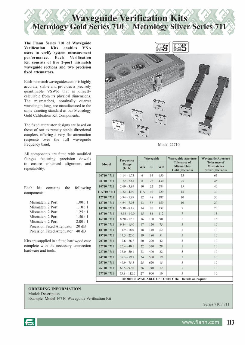
113www.flann.com
Waveguide Verification Kits Metrology Gold Series 710 Metrology Silver Series 711
The Flann Series 710 of Waveguide Verification Kits enables VNA users to verify system measurement performance. Each Verification Kit consists of five 2-port mismatch waveguide sections and two precision fixed attenuators.
Each mismatch waveguide section is highly accurate, stable and provides a precisely quantifiable VSWR that is directly calculable from its physical dimensions. The mismatches, nominally quarter wavelength long, are manufactured to the same exacting standard as our Metrology Gold Calibration Kit Components.
The fixed attenuator designs are based on those of our extremely stable directional couplers, offering a very flat attenuation response over the full waveguide frequency band.
All components are fitted with modified flanges featuring precision dowels to ensure enhanced alignment and repeatability.
Model 22710
Each kit contains the following components:-
Mismatch, 2 Port 1.00 : 1 Mismatch, 2 Port 1.10 : 1 Mismatch, 2 Port 1.25 : 1 Mismatch, 2 Port 1.50 : 1 Mismatch, 2 Port 2.00 : 1 Precision Fixed Attenuator 20 dB Precision Fixed Attenuator 40 dB
Kits are supplied in a fitted hardwood case complete with the necessary connection hardware and tools.
ORDERING INFORMATIONModel: DescriptionExample: Model 16710 Waveguide Verification Kit
Series 710 / 711
ModelFrequency
Range (GHz)
Waveguide Waveguide Aperture Tolerance of Mismatches
Gold (microns)
Waveguide Aperture Tolerance of Mismatches
Silver (microns)WG R WR
06710 / 711 1.14 - 1.73 6 14 650 35 65
08710 / 711 1.72 - 2.61 8 22 430 25 45
10710 / 711 2.60 - 3.95 10 32 284 15 40
11A710 / 711 3.22 - 4.90 11A 40 229 15 30
12710 / 711 3.94 - 5.99 12 48 187 10 30
13710 / 711 4.64 - 7.05 13 58 159 10 20
14710 / 711 5.38 - 8.18 14 70 137 7 20
15710 / 711 6.58 - 10.0 15 84 112 7 15
16710 / 711 8.20 - 12.5 16 100 90 5 15
17710 / 711 9.84 - 15.0 17 120 75 5 10
18710 / 711 11.9 - 18.0 18 140 62 5 10
19710 / 711 14.5 - 22.0 19 180 51 5 10
20710 / 711 17.6 - 26.7 20 220 42 5 10
22710 / 711 26.4 - 40.1 22 320 28 5 10
23710 / 711 33.0 - 50.1 23 400 22 5 10
24710 / 711 39.3 - 59.7 24 500 19 5 10
25710 / 711 49.9 - 75.8 25 620 15 5 10
26710 / 711 60.5 - 92.0 26 740 12 5 10
27710 / 711 73.8 - 112.0 27 900 10 5 10
MODELS AVAILABLE UP TO 500 GHz. Details on request
TM
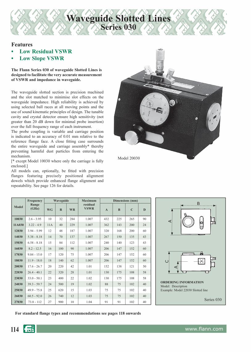
114 www.flann.com
Waveguide Slotted LinesSeries 030
Features• Low Residual VSWR• Low Slope VSWR
The Flann Series 030 of waveguide Slotted Lines is designed to facilitate the very accurate measurement of VSWR and impedance in waveguide.
Series 030
ORDERING INFORMATIONModel: DescriptionExample: Model 22030 Slotted line
The waveguide slotted section is precision machined and the slot matched to minimise slot effects on the waveguide impedance. High reliability is achieved by using selected ball races at all moving points and the use of sound kinematic principles of design. The tunable cavity and crystal detector ensure high sensitivity (not greater than 20 dB down for minimal probe insertion) over the full frequency range of each instrument.The probe coupling is variable and carriage position is indicated to an accuracy of 0.01 mm relative to the reference flange face. A close fitting case surrounds the entire waveguide and carriage assembly* thereby preventing harmful dust particles from entering the mechanism.[* except Model 10030 where only the carriage is fully enclosed.]All models can, optionally, be fitted with precision flanges featuring precisely positioned alignment dowels which provide enhanced flange alignment and repeatability. See page 126 for details.
Model 20030
For standard flange types and rec om men da tions see pages 118 onwards
A
CA
BModel
FrequencyRange(GHz)
Waveguide MaximumresidualVSWR
Dimensions (mm)
WG R WR A B C D
10030 2.6 - 3.95 10 32 284 1.007 432 225 265 90
11A030 3.22 - 4.9 11A 40 229 1.007 362 143 200 24
12030 3.94 - 5.99 12 48 187 1.007 320 168 200 60
14030 5.38 - 8.18 14 70 137 1.007 267 150 135 43
15030 6.58 - 8.18 15 84 112 1.007 240 140 123 43
16030 8.2 - 12.5 16 100 90 1.007 206 147 152 60
17030 9.84 - 15.0 17 120 75 1.007 206 147 152 60
18030 11.9 - 18.0 18 140 62 1.007 206 147 152 60
20030 17.6 - 26.7 20 220 42 1.01 152 138 121 50
22030 26.4 - 40.1 22 320 28 1.01 130 175 108 58
23030 33.0 - 50.1 23 400 22 1.02 130 175 108 58
24030 39.3 - 59.7 24 500 19 1.02 88 75 102 40
25030 49.9 - 75.8 25 620 15 1.03 75 75 102 40
26030 60.5 - 92.0 26 740 12 1.03 75 75 102 40
27030 73.8 - 112 27 900 10 1.04 91 91 102 40

115www.flann.com
Precision, Variable Waveguide Short Circuits Series 050 / 051
Features• Non-Contacting Choked Piston• Precision Micrometer Lockable Drive
Model 22050
The Flann Series 050 of Waveguide Short Circuits features a length of waveguide which houses a non-contacting choked, low-high-low impedance piston.
Millimetre wave units utilise a precision machined waveguide section. Careful choke design ensures freedom from spurious resonances. The piston is driven by a precision calibrated mechanism which enables accurate and resettable piston positioning.
The drive mechanism is fitted with a lock.All units provide a high VSWR and an accurate reference to the flange face.
The piston movement for each model is greater than half of the waveguide wavelength at the lowest frequency. Variable short circuits can be used to establish an accurate reference plane for VSWR and impedance measurements.
Series 050
ORDERINGINFORMATIONModel: DescriptionExample: Model 22050 Precision variable waveguide short circuit
For standard flange types and rec om men da tions see pages 111 onwards
A m
ax
ModelFrequency
Range(GHz)
Waveguide Reflectioncoefficient
DimensionA
(mm)WG R WR
10050 2.6 - 3.95 10 32 284 >0.995 493
11A050 3.22 - 4.9 11A 40 229 >0.995 456
12050 3.94 - 5.99 12 48 187 >0.995 410
13050 4.64 - 7.05 13 58 159 >0.995 364
14050 5.38 - 8.18 14 70 137 >0.995 318
15050 6.58 - 8.18 15 84 112 >0.995 278
16050 8.20 - 12.5 16 100 90 >0.995 263
17050 9.84 - 15.0 17 120 75 >0.995 253
18050 11.9 - 18.0 18 140 62 >0.995 260
19050 14.5 - 22.0 19 180 51 >0.995 204
20050 17.6 - 26.7 20 220 42 >0.990 205
22050 26.4 - 40.1 22 320 28 >0.985 150
23050 33.0 - 50.1 23 400 22 >0.985 140
24050 39.3 - 59.7 24 500 19 >0.985 140
25050 49.9 - 75.8 25 620 15 >0.985 127
26050 60.5 - 92.0 26 740 12 >0.980 127
27050 73.8 - 112 27 900 10 >0.980 126
28050 92.3 - 140 28 1200 8 >0.980 126
29050 114 - 173 29 1400 6
Specification / dimensions available on request
30050 145 - 220 30 1800 5
31050 172 - 261 31 2200 4
32050 217 - 330 32 2600 3
The Flann Series 051 of Waveguide Short Circuits offers the user an automated version. Please contact Sales for further information.
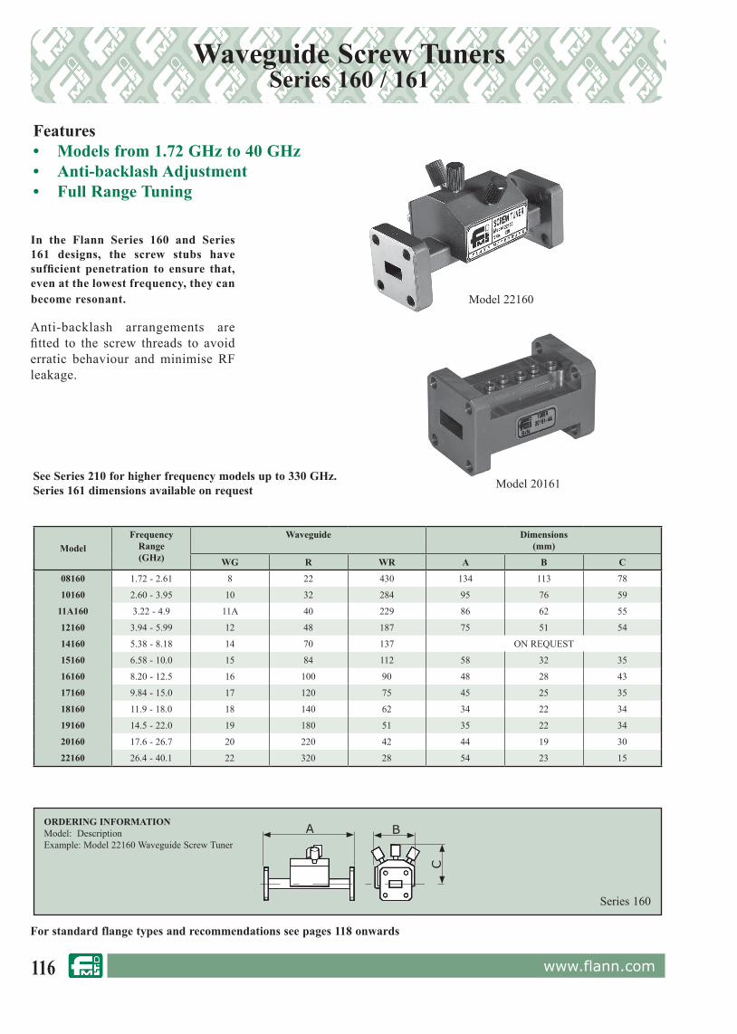
116 www.flann.com
Waveguide Screw TunersSeries 160 / 161
Series 160
ORDERING INFORMATIONModel: DescriptionExample: Model 22160 Waveguide Screw Tuner
Model 22160
For standard flange types and rec om men da tions see pages 118 onwards
Features• Models from 1.72 GHz to 40 GHz• Anti-backlash Adjustment• Full Range Tuning
In the Flann Series 160 and Series 161 designs, the screw stubs have sufficient penetration to ensure that, even at the lowest frequency, they can become resonant.
Anti-backlash arrangements are fitted to the screw threads to avoid erratic behaviour and minimise RF leakage.
A B
C
ModelFrequency
Range(GHz)
Waveguide Dimensions(mm)
WG R WR A B C
08160 1.72 - 2.61 8 22 430 134 113 78
10160 2.60 - 3.95 10 32 284 95 76 59
11A160 3.22 - 4.9 11A 40 229 86 62 55
12160 3.94 - 5.99 12 48 187 75 51 54
14160 5.38 - 8.18 14 70 137 ON REQUEST
15160 6.58 - 10.0 15 84 112 58 32 35
16160 8.20 - 12.5 16 100 90 48 28 43
17160 9.84 - 15.0 17 120 75 45 25 35
18160 11.9 - 18.0 18 140 62 34 22 34
19160 14.5 - 22.0 19 180 51 35 22 34
20160 17.6 - 26.7 20 220 42 44 19 30
22160 26.4 - 40.1 22 320 28 54 23 15
Model 20161See Series 210 for higher frequency models up to 330 GHz.Series 161 dimensions available on request

117www.flann.com
Waveguide Slide Tuners Series 210
The Flann Series 210 Slide Tuners consist of a precision waveguide machined in two halves, with a slot along the centre of one broad wall. A variable penetration capacitive probe is introduced through the slotted wall of the waveguide.
Longitudinal movement of the probe is adjusted by a vernier control which may be locked after positioning. Slide tuners are often easier to adjust than other types of tuners in which the tuning controls are interactive. The units are of a mechanically sound design and adequate precautions are taken to avoid erratic tuning and slot resonance.
Series 210
ORDERING INFORMATIONModel: DescriptionExample: Model 23210 Slide Tuner
Model 27210
For standard flange types and rec om men da tions see pages 118 onwards
Features• Models up to 330 GHz• Highly Repeatable• Full Range Tuning• Lockable
A
C max
B
ModelFrequency
Range(GHz)
Waveguide Dimensions(mm)
WG R WR A B C
23210 33.0 - 50.1 23 400 22 31.5 49 113
24210 39.3 - 59.7 24 500 19 31.5 49 112
25210 49.9 - 75.8 25 620 15 31.5 49 108
26210 60.5 - 92.0 26 740 12 31.5 49 108
27210 73.8 - 112 27 900 10 31.5 49 108
28210 92.3 - 140 28 1200 8 31.5 49 108
29210 114 - 173 29 1400 6Dimensionsavailable on
request
30210 145 - 220 30 1800 5
31210 172 - 261 31 2200 4
32210 217 - 330 32 2600 3

118 www.flann.com
Waveguide and Flange Data
Note: Products fitted with flange types marked thus * are supplied with two fixing screws per flange and provided with alignment dowels in accordance with MIL-DTL-3922/67C.
Standard product finishesPlate: Tin nickel for the larger, low frequency products; gold plate for smaller and millimetric products.Paint: Two part epoxy paint in mid brunswick green.
FrequencyRange(GHz)
Waveguide Designation InternalDimensions
(mm)
Flann ‘Standard’ flange details Please see page 113 - 118 for outline dimensions
BritishWG
IECR
EIAWR Flange Designation Description
1.14 - 1.73 6 14 650 165.100 x 82.550 UG-417B/U Type (but without groove) Rectangular, Ten hole fixing + 2 dowel holes
1.72 - 2.61 8 22 430 109.220 x 54.610 UG-435B/U Type (but without groove) Rectangular, Ten hole fixing + 2 dowel holes
2.17 - 3.30 9A 26 340 90.42 x 47.24 UDR26 Rectangular, Ten hole fixing
2.60 - 3.95 10 32 284 72.140 x 34.040 5985-99-083-1560 also drilled for the 5985-99-083-0010 Circular, Six/Eight hole fixing
3.22 - 4.90 11A 40 229 58.170 x 29.083 UDR 40 Rectangular, Ten hole fixing
3.94 - 5.99 12 48 187 47.550 x 22.149 UAR 48 Circular, Eight hole fixing
4.64 - 7.05 13 58 159 40.390 x 20.193 UAR 58 Circular, Six hole fixing
5.38 - 8.18 14 70 137 34.850 x 15.799 UAR 70 Circular, Six hole fixing
6.58 - 10.0 15 84 112 28.449 x 12.624 UBR 84 Square, Four hole fixing
8.20 - 12.5 16 100 90 22.860 x 10.160 UBR 100 Square, Four hole fixing
9.84 - 15.0 17 120 75 19.050 x 9.525 UBR 120 Square, Four hole fixing
11.9 - 18.0 18 140 62 15.799 x 7.899 UBR 140 Square, Four hole fixing
14.5 - 22.0 19 180 51 12.954 x 6.477 UBR 180 Square, Four hole fixing
17.6 - 26.7 20 220 42 10.668 x 4.318 UBR 220 Type Square, Four hole fixing
21.7 - 33.0 21 260 34 8.636 x 4.318 UBR 260 Type Square, Four hole fixing
26.4 - 40.1 22 320 28 7.112 x 3.556 UG-599/U Square, Four hole fixing
33.0 - 50.1 23 400 22 5.690 x 2.845 *UG-383/U Circular, Four hole fixing/doweled
39.3 - 59.7 24 500 19 4.775 x 2.388 *UG-383/U (Modified) Circular, Four hole fixing/doweled
49.9 - 75.8 25 620 15 3.759 x 1.880 *UG-385/U Circular, Four hole fixing/doweled
60.5 - 92.0 26 740 12 3.099 x 1.549 *UG-387/U Circular, Four hole fixing/doweled
73.8 - 112 27 900 10 2.540 x 1.270 *UG-387/U (Modified) Circular, Four hole fixing/doweled
92.3 - 140.0 28 1200 8 2.032 x 1.016 *UG-387/U (Modified) Circular, Four hole fixing/doweled
114.0 - 173.0 29 1400 6 1.651 x 0.826 *UG-387/U (Modified) Circular, Four hole fixing/doweled
145.0 - 220.0 30 1800 5 1.295 x 0.648 *UG-387/U (Modified) Circular, Four hole fixing/doweled
172.0 - 261.0 31 2200 4 1.092 x 0.546 *UG-387/U (Modified) Circular, Four hole fixing/doweled
217.0 - 330.0 32 2600 3 0.864 x 0.432 *UG-387/U (Modified) Circular, Four hole fixing/doweled
The following table details the Flann standard flanges. Most products are available with other flange styles and special Flanges
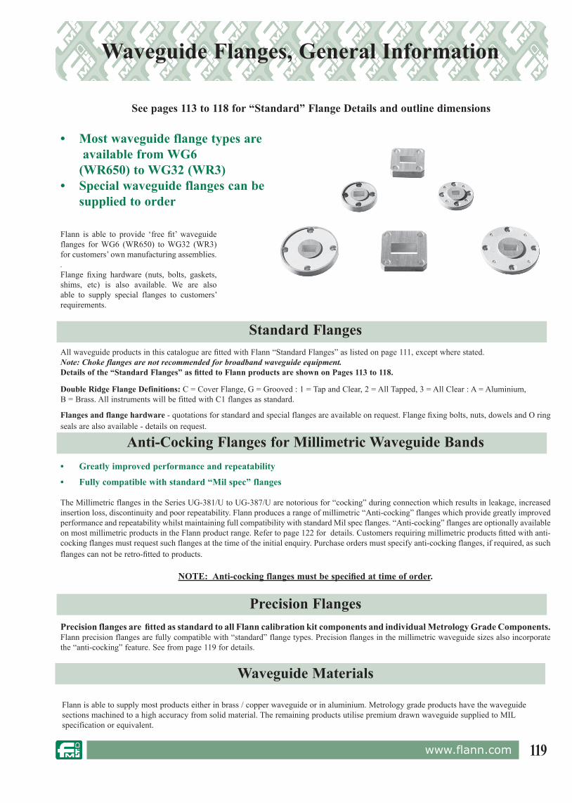
119www.flann.com
• Most waveguide flange types are available from WG6 (WR650) to WG32 (WR3)• Special waveguide flanges can be
supplied to order
Waveguide Flanges, General Information
Flann is able to provide ‘free fit’ waveguide flanges for WG6 (WR650) to WG32 (WR3) for customers’ own manufacturing assemblies..Flange fixing hardware (nuts, bolts, gaskets, shims, etc) is also available. We are also able to supply special flanges to customers’ requirements.
Standard FlangesAll waveguide products in this catalogue are fitted with Flann “Standard Flanges” as listed on page 111, except where stated.Note: Choke flanges are not recommended for broadband waveguide equipment.Details of the “Standard Flanges” as fitted to Flann products are shown on Pages 113 to 118.
Double Ridge Flange Definitions: C = Cover Flange, G = Grooved : 1 = Tap and Clear, 2 = All Tapped, 3 = All Clear : A = Aluminium, B = Brass. All instruments will be fitted with C1 flanges as standard.
Flanges and flange hardware - quotations for standard and special flanges are available on request. Flange fixing bolts, nuts, dowels and O ring seals are also available - details on request.
Anti-Cocking Flanges for Millimetric Waveguide Bands• Greatly improved performance and repeatability
• Fully compatible with standard “Mil spec” flanges The Millimetric flanges in the Series UG-381/U to UG-387/U are notorious for “cocking” during connection which results in leakage, increased insertion loss, discontinuity and poor repeatability. Flann produces a range of millimetric “Anti-cocking” flanges which provide greatly improved performance and repeatability whilst maintaining full compatibility with standard Mil spec flanges. “Anti-cocking” flanges are optionally available on most millimetric products in the Flann product range. Refer to page 122 for details. Customers requiring millimetric products fitted with anti-cocking flanges must request such flanges at the time of the initial enquiry. Purchase orders must specify anti-cocking flanges, if required, as such flanges can not be retro-fitted to products.
NOTE: Anti-cocking flanges must be specified at time of order.
Precision FlangesPrecision flanges are fitted as standard to all Flann calibration kit components and individual Metrology Grade Components. Flann precision flanges are fully compatible with “standard” flange types. Precision flanges in the millimetric waveguide sizes also incorporate the “anti-cocking” feature. See from page 119 for details.
Waveguide Materials
Flann is able to supply most products either in brass / copper waveguide or in aluminium. Metrology grade products have the waveguide sections machined to a high accuracy from solid material. The remaining products utilise premium drawn waveguide supplied to MIL specification or equivalent.
See pages 113 to 118 for “Standard” Flange Details and outline dimensions

120 www.flann.com
“Standard” Flange Data
The following flange details show the “standard” flange types as fitted to Flann products, unless otherwise stated. Full dimensional details of all “standard” flange types are available on request.
Flann Standard Flanges Non-Standard FlangesFull details on request
A .............................106.38 B .............................161.14 E ..............................43.69 F ..............................23.83 G .............................45.39 H .............................70.99 Holes .......................10 x 6.71 dia Dowel Holes ..........6.35dia
WG8 R22 WR430UG435B/U TYPE (without groove)
Alternative and custom flanges can be fitted to special order.
Flann is also able to supply most types of Flanges as separate items. Please contact our sales office for price and availability information.
A .............................138.90 B .............................221.50 E ..............................58.69 F ..............................31.73 G .............................60.30 H .............................100.00 Holes .......................10 x 8.20 dia Dowel Holes ...........6.35dia
WG6 R14 WR650UG417B/U TYPE (without groove)
UDR 14CPR 650F
UDR 22CPR 430F
Holes A ...................6 x 6.52 dia on 136.52 PCD Holes B ...................8 x 6.52 dia on 120.65 PCD D .............................149.20 dia
WG10 R32 WR2845985 - 99 - 083 --1560/0010
UDR 32CPR 284F5985-99-083-0058 TypeUAR 32UG-53/U
E E
A
E E
A
A
A
AB B
BB
BB
B
22°30'
30°
B
A
A
A
H
B
G
B
HH
H
G
D
FF
FF
GG
NOTE: ALL DIMENSIONS ARE IN MILLIMETERSSee pages 126 - 129 for details of Flann precision style flanges.
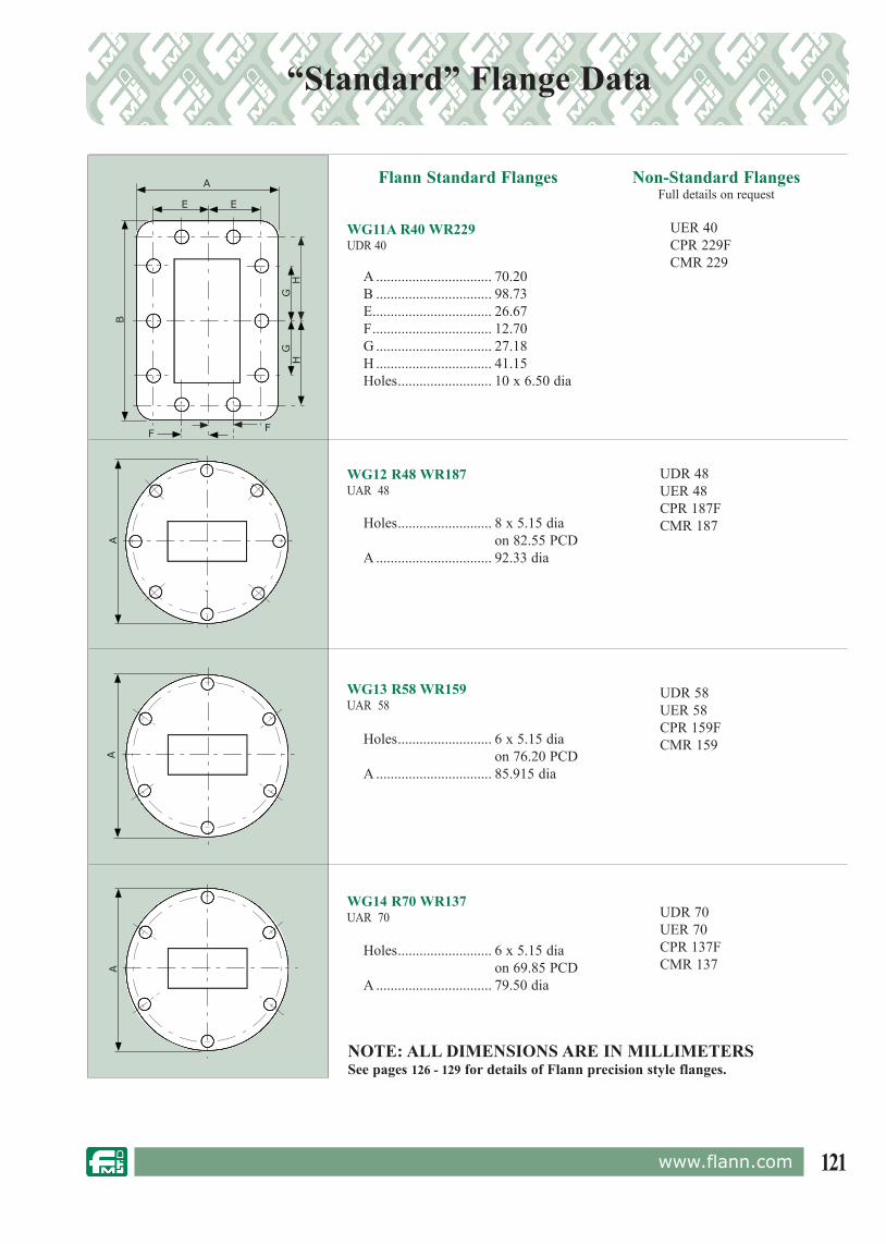
121www.flann.com
“Standard” Flange Data
Flann Standard Flanges Non-Standard FlangesFull details on request
Holes .......................... 6 x 5.15 dia on 69.85 PCD A ................................ 79.50 dia
WG14 R70 WR137UAR 70
Holes .......................... 6 x 5.15 dia on 76.20 PCD A ................................ 85.915 dia
WG13 R58 WR159UAR 58
A ................................ 70.20 B ................................ 98.73 E ................................. 26.67 F ................................. 12.70 G ................................ 27.18 H ................................ 41.15 Holes .......................... 10 x 6.50 dia
WG11A R40 WR229UDR 40
UER 40CPR 229FCMR 229
UDR 48UER 48CPR 187FCMR 187
UDR 58UER 58CPR 159FCMR 159
UDR 70UER 70CPR 137FCMR 137
Holes .......................... 8 x 5.15 dia on 82.55 PCD A ................................ 92.33 dia
WG12 R48 WR187UAR 48
E E
A
HH
B
GG
A
F F
AA
NOTE: ALL DIMENSIONS ARE IN MILLIMETERSSee pages 126 - 129 for details of Flann precision style flanges.
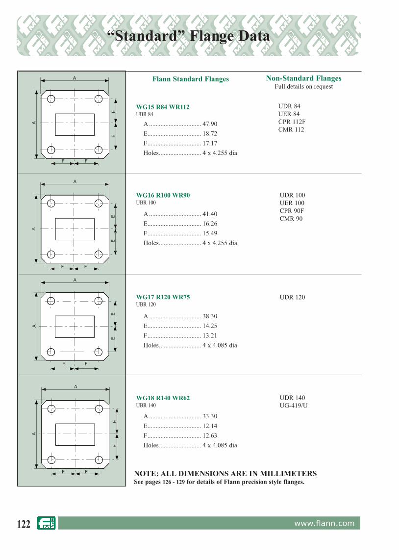
122 www.flann.com
“Standard” Flange Data
Flann Standard Flanges Non-Standard FlangesFull details on request
A ................................ 33.30 E ................................. 12.14 F ................................. 12.63 Holes .......................... 4 x 4.085 dia
WG18 R140 WR62UBR 140
A ................................ 38.30 E ................................. 14.25 F ................................. 13.21 Holes .......................... 4 x 4.085 dia
WG17 R120 WR75UBR 120
A ................................ 47.90 E ................................. 18.72 F ................................. 17.17 Holes .......................... 4 x 4.255 dia
WG15 R84 WR112UBR 84
A ................................ 41.40 E ................................. 16.26 F ................................. 15.49 Holes .......................... 4 x 4.255 dia
WG16 R100 WR90UBR 100
UDR 84UER 84CPR 112FCMR 112
UDR 100UER 100CPR 90FCMR 90
UDR 120
UDR 140UG-419/U
A
A
EE
A
A
EE
F F
A
A
EE
F F
FF
A
A
EE
F F NOTE: ALL DIMENSIONS ARE IN MILLIMETERSSee pages 126 - 129 for details of Flann precision style flanges.
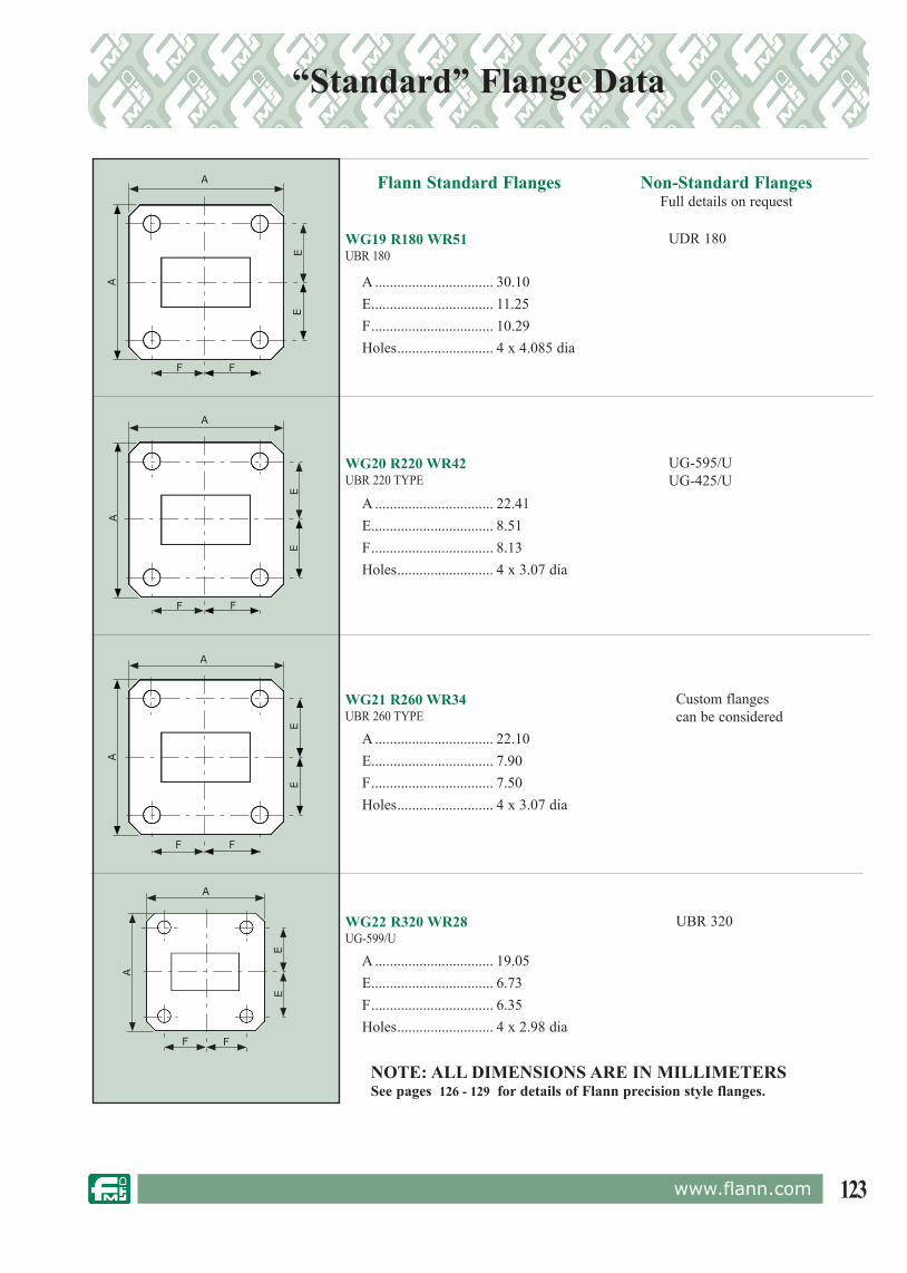
123www.flann.com
“Standard” Flange Data
Flann Standard Flanges Non-Standard FlangesFull details on request
A ................................ 22.41 E ................................. 8.51 F ................................. 8.13 Holes .......................... 4 x 3.07 dia
WG20 R220 WR42UBR 220 TYPE
A ................................ 30.10 E ................................. 11.25 F ................................. 10.29 Holes .......................... 4 x 4.085 dia
WG19 R180 WR51UBR 180
UDR 180
UG-595/UUG-425/U
A ................................ 22.10 E ................................. 7.90 F ................................. 7.50 Holes .......................... 4 x 3.07 dia
WG21 R260 WR34UBR 260 TYPE
Custom flangescan be considered
A ................................ 19.05 E ................................. 6.73 F ................................. 6.35 Holes .......................... 4 x 2.98 dia
WG22 R320 WR28UG-599/U
UBR 320
A
A
EE
F F
A
A
EE
F F
A
A
EE
F F
A
A
EE
F F
NOTE: ALL DIMENSIONS ARE IN MILLIMETERSSee pages 126 - 129 for details of Flann precision style flanges.

124 www.flann.com
Note: Products fitted with Circular, Four hole fixing/Doweled flanges WG23 (WR22) to WG28 (WR8) are supplied with two captive fixing screws per flange.
“Anti-cocking” Flanges - We strongly recommend that customers specify “anti-cocking” flanges on instruments in the waveguide range WG23 (WR22) to WG28 (WR8). “Anti-cocking” flanges provide better performance and repeatability than standard flanges whilst maintaining full compatibility with MIL spec types. Please refer to page 122 for details and outline dimensions.
Flann Standard Flanges
Non-Standard FlangesFull details on request
Holes C ................4 x 4-40 UNC-2B Holes D ................2 x 1.65 dia Holes E ................2 x dowels 1.549/ 1.562 dia x 4 projection All Holes on 14.29 PCD A ..........................19.05
WG25 R620 WR15UG-385/U modified (MIL-DTL-3922/67C-08)
Holes C ................4 x 4-40 UNC-2B Holes D ................2 x 1.65 dia Holes E ................2 x dowels 1.549/ 1.562 dia x 4 projection All Holes on 23.81 PCD A ..........................28.55
WG23 R400 WR22UG-383/U ( MIL-DTL-3922/67C-006)
Holes C ................4 x 4-40 UNC-2B Holes D ................2 x 1.65 dia Holes E ................2 x dowels 1.549/ 1.562 dia x 4 projection All Holes on 23.81 PCD A ..........................28.55
WG24 R500 WR19UG-383/U Modified (MIL-DTL-3922/67C-007)
NOTE: ALL DIMENSIONS ARE IN MILLIMETERSSee pages 126 - 129 for details of Flann precision style flanges.
“Standard” Flange Data
A
A
E
E
D
D
C
45°
A
C
45°
E
E D
D
C
E
D E
D
45°

125www.flann.com
“Standard” Flange Data
Note: Products fitted with Circular, Four hole fixing/Doweled flanges WG23 (WR22) to WG28 (WR8) are supplied with two captive fixing screws per flange.
“Anti-cocking” Flanges - We strongly recommend that customers specify “anti-cocking” flanges on instruments in the waveguide range WG23 (WR22) to WG28 (WR8). “Anti-cocking” flanges provide better performance and repeatability than standard flanges whilst maintaining full compatibility with MIL spec types. Please refer to page 122 for details and outline dimensions.
MIL-F3922/74-001
Holes C ................4 x 4-40 UNC-2B Holes D ................2 x 1.65 dia Holes E ................2 x dowels 1.549/ 1.562 dia x 4 projection All Holes on 14.29 PCD A ..........................19.05
WG27 R900 WR10UG-387/U Modified (MIL-DTL-3922/67C-010)
Holes C ................4 x 4-40 UNC-2B Holes D ................2 x 1.65 dia Holes E ................2 x dowels 1.549/ 1.562 dia x 4 projection All Holes on 14.29 PCD A ..........................19.05
WG28 R1200 WR8UG-387/U Modified
MIL-F3922/74-001
Holes C ....................4 x 4-40 UNC-2B Holes D ................2 x 1.65 dia Holes E ................2 x dowels 1.549/ 1.562 dia x 4 projection All Holes on 14.29 PCD A ..........................19.05
WG26 R740 WR12UG-387/U (MIL-DTL-3922/67C-009)
NOTE: ALL DIMENSIONS ARE IN MILLIMETERSSee pages 126 - 129 for details of Flann Precision Style Flanges.
Flann Standard Flanges
Non-Standard FlangesFull details on request
A
E
E
D
D
C
45°
A
E
E
D
D
C
45°
A
E
E
D
D
C
45°
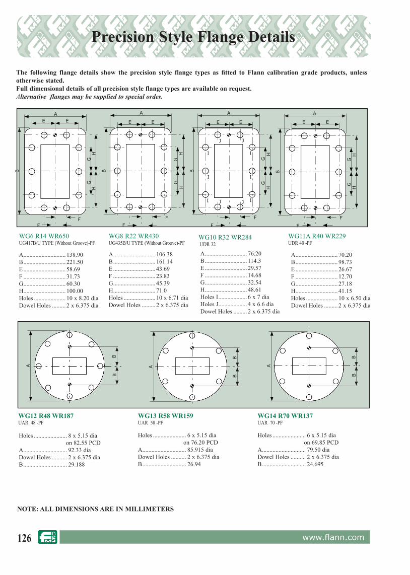
126 www.flann.com
Precision Style Flange Details
The following flange details show the precision style flange types as fitted to Flann calibration grade products, unless otherwise stated.Full dimensional details of all precision style flange types are available on request.Alternative flanges may be supplied to special order.
Holes ...................... 8 x 5.15 dia on 82.55 PCD A ............................. 92.33 dia Dowel Holes .......... 2 x 6.375 dia B ............................. 29.188
WG12 R48 WR187UAR 48 -PF
Holes ...................... 6 x 5.15 dia on 76.20 PCD A ............................. 85.915 dia Dowel Holes .......... 2 x 6.375 dia B ............................. 26.94
WG13 R58 WR159UAR 58 -PF
Holes ...................... 6 x 5.15 dia on 69.85 PCD A ............................. 79.50 dia Dowel Holes .......... 2 x 6.375 dia B ............................. 24.695
WG14 R70 WR137UAR 70 -PF
A ............................ 138.90 B ............................ 221.50 E ............................ 58.69 F ............................ 31.73 G ............................ 60.30 H ............................ 100.00 Holes ..................... 10 x 8.20 dia Dowel Holes ......... 2 x 6.375 dia
WG10 R32 WR284 UDR 32
A ............................ 106.38 B ............................ 161.14 E ............................ 43.69 F ............................ 23.83 G ............................ 45.39 H ............................ 71.0 Holes ..................... 10 x 6.71 dia Dowel Holes ......... 2 x 6.375 dia
A ............................ 70.20 B ............................ 98.73 E ............................ 26.67 F ............................ 12.70 G ............................ 27.18 H ............................ 41.15 Holes ..................... 10 x 6.50 dia Dowel Holes ......... 2 x 6.375 dia
WG11A R40 WR229UDR 40 -PF
WG6 R14 WR650UG417B/U TYPE (Without Groove)-PF
WG8 R22 WR430UG435B/U TYPE (Without Groove)-PF
E EA
E E
A
E E
A
H
B
G
B
H
HH
G
HH
B
GG
FF
F
F
F
F
GG
A A A
NOTE: ALL DIMENSIONS ARE IN MILLIMETERS
E E
A
HH
B
GG
F
F
A ............................ 76.20 B ............................ 114.3 E ............................ 29.57 F ............................ 14.68 G ............................ 32.54 H ............................ 48.61 Holes I ................... 6 x 7 dia Holes J................... 4 x 6.6 dia Dowel Holes ......... 2 x 6.375 dia
I
J
I
I
I
I
IJJ
J
BB B
B BB
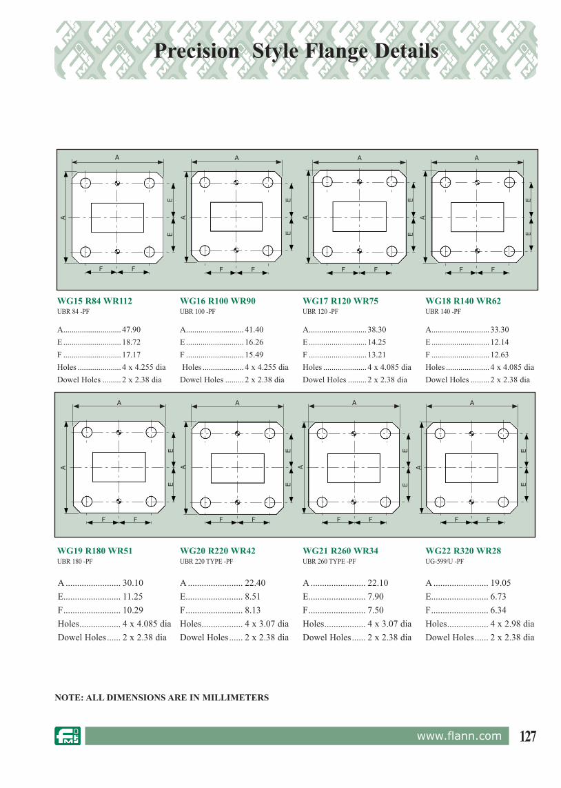
127www.flann.com
Precision Style Flange Details
A ........................ 30.10 E ......................... 11.25 F ......................... 10.29 Holes .................. 4 x 4.085 dia Dowel Holes ...... 2 x 2.38 dia
WG19 R180 WR51UBR 180 -PF
A ........................ 22.40 E ......................... 8.51 F ......................... 8.13 Holes .................. 4 x 3.07 dia Dowel Holes ...... 2 x 2.38 dia
WG20 R220 WR42UBR 220 TYPE -PF
A ........................ 22.10 E ......................... 7.90 F ......................... 7.50 Holes .................. 4 x 3.07 dia Dowel Holes ...... 2 x 2.38 dia
WG21 R260 WR34UBR 260 TYPE -PF
WG15 R84 WR112UBR 84 -PF
A ............................ 33.30 E ............................ 12.14 F ............................ 12.63 Holes ..................... 4 x 4.085 dia Dowel Holes ......... 2 x 2.38 dia
WG18 R140 WR62UBR 140 -PF
A ............................ 38.30 E ............................ 14.25 F ............................ 13.21 Holes ..................... 4 x 4.085 dia Dowel Holes ......... 2 x 2.38 dia
WG17 R120 WR75UBR 120 -PF
A ............................ 41.40 E ............................ 16.26 F ............................ 15.49 Holes .................... 4 x 4.255 dia Dowel Holes ......... 2 x 2.38 dia
WG16 R100 WR90UBR 100 -PF
A ............................ 47.90 E ............................ 18.72 F ............................ 17.17 Holes ..................... 4 x 4.255 dia Dowel Holes ......... 2 x 2.38 dia
WG22 R320 WR28UG-599/U -PF
A ........................ 19.05 E ......................... 6.73 F ......................... 6.34 Holes .................. 4 x 2.98 dia Dowel Holes ...... 2 x 2.38 dia
A
A
EE
F F
A
A
EE
F F
A
A
EE
F F
A
A
EE
F F
A
A
EE
F F
A
AE
E
F F
A
A
EE
F F
A
A
EE
F F
NOTE: ALL DIMENSIONS ARE IN MILLIMETERS

128 www.flann.com
Precision Style Flange Details
• Enhanced accuracy & performance• Fully compatible with the standard “MIL spec” flangesFlann Precision millimetric flanges are fitted as standard to the Company’s range of Network Analyser Calibration Kits and Metrology grade components. Our precision millimetric flanges incorporate an “anti-cocking” feature which minimizes the risk of leakage or discontinuity occuring at the interface.
Note: Flann Precision flanges are compatible with standard MIL spec types if the additional precision dowels are not used.
A Holes 4 off - 4.40 UNC-2B. C’bore 3.56 dia x 1.6 deep from flange faceB Holes 2 off - 1.65/1.66 dia. C’sink 2.0 dia @ 90˚ on front faceC Holes 2 off - Alignment pins 1.562/1.549 diaD Holes 2 off - Drill and bore 2.25 dia through C’sink 2.8 dia @ 90˚ and ream 2.395/2.379 diaNote: Dowels ‘C’ & Dowel holes ‘B’ & ‘D’ are precisely positioned with respect to the waveguide aperture after the flange has been fitted to the waveguide.
A Holes 4 off - 4.40 UNC-2B. C’bore 3.56 dia x 1.6 dia deep from flange faceB Holes 2 off - 1.65/1.66 dia. C’sink 2.0 dia @ 90˚ on front faceC Holes 2 off - Alignment pins 1.562/1.549 diaD Holes 2 off - Drill and bore 1.5 dia through C’sink 2.3 dia @ 90˚ and ream 1.588/1.600 diaNote: Dowels ‘C’ & Dowel holes ‘B’ & ‘D’ are precisely positioned with respect to the waveguide aperture after the flange has been fitted to the waveguide.Note: Instruments fitted with precision flanges are supplied with two fixing screws per flange.
NOTE: ALL DIMENSIONS ARE IN MILLIMETERS
WG 23 (WR 22) to WG 32 (WR 3) inclusive
90° 45°
A
C
A
BA
D C
A
BD
∅ 1
1.5
6
11.3
0
23.8
1 P
.C.D
∅ 2
6.8
7
26.7
3
15.9
95
16.0
05
∅ 1
2.0
2
11.7
6
∅ 2
8.5
8
28.5
3
CHAM 0.3⁄/0.4 x 45°
0.5
4.18 3.94
6.476.22
Details of the WG23 (WR22) & WG24 (WR19) Precision flanges, which are fully compatible with the standard UG383/U style flange.
90° 45°
C
A
BA
D
D
C A
B
A
∅ 9
.2
14.2
9 P
.C.D
∅ 1
7.3
4
17.2
4
6.6
16
6.5
92
0.5
4.183.94
6.476.22
∅ 9
.0
∅ 1
9.0
5
19.0
0
CHAM 0.3⁄/0.4 x 45°
Details of the WG25 (WR15) & WG28 (WR8) Precision flanges, which are fully compatible with the standard UG385/U style flange.
A

129www.flann.com
Anti-Cocking Flanges
• Greatly improved performance & repeatability• Fully compatible with standard “MIL spec” flangesThe standard MIL spec style of flanges, normally used in the frequency bands from 26.0 to 220 GHz, are designs with the serious disadvantage that “cocking” can easily take place unless extreme care is taken when tightening the clamping screws. “Cocked” flanges introduce high leakage levels and unnecessary discontinuities. In common with many other major manufacturers Flann offers “anti-cocking” flanges, which prevent cocking when connected to similar “anti-cocking” flanges; these flanges are fully compatible with standard MIL spec designs.
“Anti-cocking” flanges must be specified at time of order.The Flann “anti-cocking” flanges are detailed below.
A Holes 4 off - 4.40 UNC-2B. C’bore 3.56 dia x 1.6 deep from flange faceB Holes 2 off - 1.65/1.66 dia. C’sink 2.0 dia x 90˚ on front faceC Holes 2 off - Alignment pins 1.562/1.549 diaNote: Dowels ‘C’ & Dowel holes ‘B’ are precisely positioned with respect to the waveguide aperture after the flange has been fitted to the waveguide.
A Holes 4 off - Drill 4.40 UNC-2B. C’bore 3.56 dia x 1.6 dia deep from flange faceB Holes 2 off - 1.65/1.66 dia. C’sink 2.0 dia x 90˚ on front faceC Holes 2 off - Alignment pins 1.562/1.549 diaNote: Dowels ‘C’ & Dowel holes ‘B’ are precisely positioned with respect to the waveguide aperture after the flange has been fitted to the waveguide.Note: Instruments fitted with an anti-cocking flange are supplied with two fixing screws per flange.
NOTE: ALL DIMENSIONS ARE IN MILLIMETERS
90°45°
ABC
AA
CBA
∅ 1
1.5
6
11.3
023.8
1 P
.C.D
∅ 2
6.8
7
26.7
3
16.8
36
0.5
4.183.94
6.476.22
∅ 2
8.5
8
28.5
3
∅ 1
1.5
6
11.3
0
CHAM 0.3⁄/0.4 x 45°
Details of the WG23 (WR22) & WG24 (WR19) “Anti-cocking” flange which is fully compatible with the standard UG383/U style flange.
90° 45°
AB
C
A
A
CB
A
∅ 9
.2
14.2
9 P
.C.D
∅ 1
7.3
4
17.2
4
10.1
04
0.5
4.183.94
6.476.22
∅ 9
.0
∅ 1
9.0
5
19.0
0
CHAM 0.3⁄/0.4 x 45°
Details of the WG25 (WR15) to WG32 (WR3) “Anti-cocking” flange which is fully compatible with the standard UG385/U style flange.

130 www.flann.com
VSWR & Return Loss Data
VSWRSTANDING
WAVE RATIO (dB)
RETURNLOSS (dB)
TRANSMISSIONLOSS (dB)
REFLECTIONCOEFFICIENT
TRANSMITTEDPOWER %
REFLECTEDPOWER %
1.00 0 ∞ 0 0 100.0 0
1.01 0.1 46.1 0 0 100.0 0
1.02 0.2 40.1 0 0.01 100.0 0
1.03 0.3 36.6 0.001 0.01 100.0 0
1.04 0.3 34.2 0.002 0.02 100.0 0
1.05 0.4 32.3 0.003 0.02 99.9 0.1
1.06 0.5 30.7 0.004 0.03 99.9 0.1
1.07 0.6 29.4 0.005 0.03 99.9 0.1
1.08 0.7 28.3 0.006 0.04 99.9 0.1
1.09 0.7 27.3 0.008 0.04 99.8 0.2
1.10 0.8 26.4 0.010 0.05 99.8 0.2
1.11 0.9 25.7 0.012 0.05 99.7 0.3
1.12 1.0 24.9 0.014 0.06 99.7 0.3
1.13 1.1 24.3 0.016 0.06 99.6 0.4
1.14 1.1 23.7 0.019 0.07 99.6 0.4
1.15 1.2 23.1 0.021 0.07 99.5 0.5
1.16 1.3 22.6 0.024 0.07 99.5 0.5
1.17 1.4 22.1 0.027 0.08 99.4 0.6
1.18 1.4 21.7 0.030 0.08 99.3 0.7
1.19 1.5 21.2 0.033 0.09 99.2 0.8
1.20 1.6 20.8 0.036 0.09 99.2 0.8
1.21 1.7 20.4 0.039 0.10 99.1 0.9
1.22 1.7 20.1 0.043 0.10 99.0 1.0
1.23 1.8 19.7 0.046 0.10 98.9 1.1
1.24 1.9 19.4 0.050 0.11 98.9 1.1
1.25 1.9 19.1 0.054 0.11 98.8 1.2
1.26 2.0 18.8 0.058 0.12 98.7 1.3
1.27 2.1 18.5 0.062 0.12 98.6 1.4
1.28 2.1 18.2 0.066 0.12 98.5 1.5
1.29 2.2 17.9 0.070 0.13 98.4 1.6
1.30 2.3 17.7 0.075 0.13 98.3 1.7
1.32 2.4 17.2 0.083 0.14 98.1 1.9
1.34 2.5 16.8 0.093 0.15 97.9 2.1
1.36 2.7 16.3 0.102 0.15 97.7 2.3
1.38 2.8 15.9 0.112 0.16 97.5 2.5
1.40 2.9 15.6 0.122 0.17 97.2 2.8
1.42 3.0 15.2 0.133 0.17 97.0 3.0
1.44 3.2 14.9 0.144 0.18 96.7 3.3
1.46 3.3 14.6 0.155 0.19 96.5 3.5
1.48 3.4 14.3 0.166 0.19 96.3 3.7
1.50 3.5 14.0 0.177 0.20 96.0 4.0
1.52 3.6 13.7 0.189 0.21 95.7 4.3
1.54 3.8 13.4 0.201 0.21 95.5 4.5
1.56 3.9 13.2 0.213 0.22 95.2 4.8
1.58 4.0 13.0 0.225 0.22 94.9 5.1
1.60 4.1 12.7 0.238 0.23 94.7 5.3
1.62 4.2 12.5 0.250 0.24 94.4 5.6

131www.flann.com
VSWR & Return Loss Data
VSWRSTANDING
WAVE RATIO (dB)
RETURNLOSS (dB)
TRANSMISSIONLOSS (dB)
REFLECTIONCOEFFICIENT
TRANSMITTEDPOWER %
REFLECTEDPOWER %
1.64 4.3 12.3 0.263 0.24 94.1 5.9
1.66 4.4 12.1 0.276 0.25 93.8 6.2
1.68 4.5 11.9 0.289 0.25 93.6 6.4
1.70 4.6 11.7 0.302 0.26 93.3 6.7
1.72 4.7 11.5 0.315 0.26 93.0 7.0
1.74 4.8 11.4 0.329 0.27 92.7 7.3
1.76 4.9 11.2 0.342 0.28 92.4 7.6
1.78 5.0 11.0 0.356 0.28 92.1 7.9
1.80 5.1 10.9 0.370 0.29 91.8 8.2
1.82 5.2 10.7 0.384 0.29 91.5 8.5
1.84 5.3 10.6 0.398 0.30 91.3 8.7
1.86 5.4 10.4 0.412 0.30 91.0 9.0
1.88 5.5 10.3 0.426 0.31 90.7 9.3
1.90 5.6 10.2 0.440 0.31 90.4 9.6
1.92 5.7 10.0 0.454 0.32 90.1 9.9
1.94 5.8 9.9 0.468 0.32 89.8 10.2
1.96 5.8 9.8 0.483 0.32 89.5 10.5
1.98 5.9 9.7 0.497 0.33 89.2 10.8
2.00 6.0 9.5 0.512 0.33 88.9 11.1
2.50 8.0 7.4 0.881 0.43 81.6 18.4
3.00 9.5 6.0 1.249 0.50 75.0 25.0
3.50 10.9 5.1 1.603 0.56 69.1 30.9
4.00 12.0 4.4 1.938 0.60 64.0 36.0
4.50 13.1 3.9 2.255 0.64 59.5 40.5
5.00 14.0 3.5 2.553 0.67 55.6 44.4
5.50 14.8 3.2 2.834 0.69 52.1 47.9
6.00 15.6 2.9 3.100 0.71 49.0 51.0
6.50 16.3 2.7 3.351 0.73 46.2 53.8
7.00 16.9 2.5 3.590 0.75 43.7 56.2
7.50 17.5 2.3 3.817 0.76 41.5 58.5
8.00 18.1 2.2 4.033 0.78 39.5 60.5
8.50 18.6 2.1 4.240 0.79 37.7 62.3
9.00 19.1 1.9 4.437 0.80 36.0 64.0
9.50 19.6 1.8 4.626 0.81 34.5 65.5
10.00 20.0 1.7 4.807 0.82 33.1 66.9
11.00 20.8 1.6 5.149 0.83 30.6 69.4
12.00 21.6 1.5 5.466 0.85 28.4 71.6
13.00 22.3 1.3 5.762 0.86 26.5 73.5
14.00 22.9 1.2 6.040 0.87 24.9 75.1
15.00 23.5 1.2 6.301 0.88 23.4 76.6
16.00 24.1 1.1 6.547 0.88 22.1 77.9
17.00 24.6 1.0 6.780 0.89 21.0 79.0
18.00 25.1 1.0 7.002 0.89 19.9 80.1
19.00 25.6 0.9 7.212 0.90 19.0 81.0
20.00 26.0 0.9 7.413 0.90 18.1 81.9
25.00 28.0 0.7 8.299 0.92 14.8 85.2
30.00 29.5 0.6 9.035 0.94 12.5 87.5

132 www.flann.com
Waveguide Parameters
* Suffix /A, /B or /S denotes material alloy of aluminium, brass or silver
Rigid Rectangular Waveguide DataFrequency
Range (GHz)For TE10
Mode
Cut-offFreq (GHz)For TE10
Mode
Band Designation WG Designation Internal Dimensions TheoreticalPeak
Power Rating(MW)
TheoreticalAttenuation
dB/30m /A, /B, /S*
UK USA New 53-IECR
RCSCWG
EIAWR US (JAN) Inches mm approx
0.32-0.49 0.256 B 3 00 2300 23.0 x 11.5 584.0 x 292.0 153.0-212.0 0.051-0.031/A
0.35-0.53 0.281 B, C 4 0 2100 21.0 x 10.5 533.0 x 267.0 120.0-173.0 0.054-0.034/A
0.41-0.62 0.328 B, C 5 1 1800 RG-201/U 18.0 x 9.0 457.0 x 229.0 93.4-131.9 0.056-0.038/A
0.49-0.75 0.393 C 6 2 1500 RG-202/U 15.0 x 7.5 381.0 x 191.0 67.6-93.3 0.069-0.050/A
0.64-0.98 0.513 P C 8 3 1150 RG-203/U 11.5 x 5.75 292.0 x 146.0 35.0-53.8 0.128-0.075/A
0.76-1.15 0.605 C, D 9 4 975 RG-204/U 9.75 x 4.875 248.0 x 124.0 27.0-38.5 0.137-0.095/A
0.96-1.46 0.766 D 12 5 770 RG-205/U 7.7 x 3.85 196.0 x 98.0 17.2-24.1 0.201-0.136/A
1.14-1.73 0.908 L L D 14 6 650 RG-69/U 6.5 x 3.25 165.1 x 82.55 11.9-17.2 0.317-0.212/B
0.269-0.178/A
1.45-2.20 1.157 D. E 18 7 510 5.1 x 2.55 129.54 x 64.77 7.5-10.7
1.72-2.61 1.372 LS, R E 22 8 430 RG-104/U 4.3 x 2.15 109.22 x 54.61 5.2-7.5 0.588-0.385/B
0.501-0.330/A
2.17-3.30 1.736 E, F 26 9A 340 RG-112/U 3.4 x 1.7 86.36 x 43.18 3.1-4.5 0.877-0.572/B
0.751-0.492/A
2.60-3.95 2.078 S S E, F 32 10 284 RG-48/U 2.84 x 1.34 72.14 x 34.04 2.2-3.2 1.102-0.752/B
0.940-0.641/A
3.22-4.90 2.577 F, G 40 11A 229 2.29 x 1.145 58.17 x 29.083 1.6-2.2
3.94-5.99 3.152 C C F, G 48 12 187 RG-49/U 1.872 x 0.872 47.55 x 22.149 1.4-2.0 2.08-1.44/B
1.77-1.12/A
4.64-7.05 3.711 G, H 58 13 159 1.590 x 0.795 40.39 x 20.193 0.79-1.0
5.38-8.18 4.301 H 70 14 137 RG-50/U 1.372 x 0.622 34.85 x 15.799 0.56-0.71 2.87-2.30/B
2.45-1.94/A
6.58-10.0 5.259 I 84 15 112 RG-51/U 1.122 x 0.497 28.499 x 12.624 0.35-0.46 4.12-3.21/B
3.50-2.74/A
8.20-12.50 6.557 X X I, J 100 16 90 RG-52/U 0.9 x 0.4 22.86 x 10.16 0.20-0.29 6.45-4.48/B
9.84-15.00 7.868 J 120 17 75 0.75 x 0.375 19.05 x 9.525 0.17-0.23 5.49-3.83/A
11.90-18.00 9.486 J Ku J 140 18 62 RG-91/U 0.622 x 0.311 15.799 x 7.899 0.12-0.16 9.51-8.31/B-/A
6.14-5.36/S
14.50-22.00 11.574 J, K 180 19 51 0.510 x 0.255 13.0 x 6.48 0.080-0.107
17.60-26.70 14.047 J, K 220 20 42 RG-53/U 0.420 x 0.170 10.668 x 4.318 0.043-0.058 20.7-14.8/B
17.6-12.6/A
21.70-33.00 17.328 K 260 21 34 0.340 x 0.170 8.636 x 4.318 0.034-0.048 13.3-9.5/S
26.40-40.10 21.081 Q Ka K 320 22 28 RG-96/U 0.280 x 0.140 7.112 x 3.556 0.022-0.031 -/B
-/A
21.9-15.0/S
33.00-50.10 26.342 K, L 400 23 22 RG-97/U 0.224 x 0.112 5.69 x 2.845 0.014-0.020 -/B
31.0-20.9/S
39.30-59.70 31.357 L 500 24 19 0.188 x 0.094 4.775 x 2.388 0.011-0.015
49.90-75.80 39.863 V L, M 620 25 15 RG-98/U 0.148 x 0.074 3.759 x 1.880 0.0063-0.0090 -/B
52.9-39.1/S
60.50-92.00 48.350 O E M 740 26 12 RG-99/U 0.122 x 0.061 3.099 x 1.549 0.0042-0.0060 -/B
93.3-52.2/S
73.80-112.0 59.010 W M 900 27 10 0.100 x 0.050 2.54 x 1.27 0.0030-0.0041
92.30-140.00 73.840 M 1200 28 8 RG-138/U 0.080 x 0.040 2.032 x 1.016 0.0018-0.0026 152-99/S
114.0-173.00 90.840 1400 29 6 RG-136/U 0.065 x 0.0325 1.651 x 0.826 0.0012-0.0017 163-137/S
145.00-220.00 115.750 T 1800 30 5 RG-135/U 0.051 x 0.0255 1.295 x 0.648 0.00071-0.00107 308-193/S
172.00-261.00 131.520 2200 31 4 RG-137/U 0.043 x 0.0215 1.1 x 0.55 0.00052-0.00075 384-254/S
217.00-330.00 173.280 2600 32 3 RG-139/U 0.034 x 0.017 0.87 x 0.44 0.00035-0.00047 512-348/S
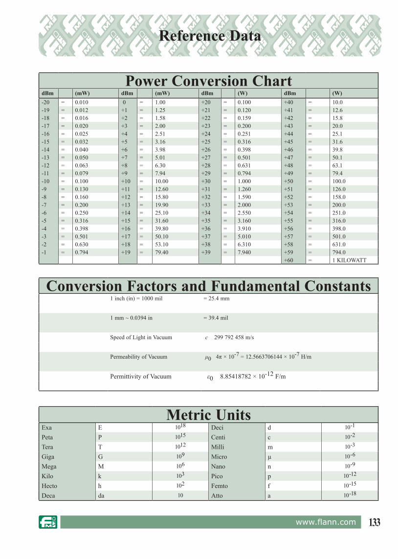
133www.flann.com
Reference Data
Conversion Factors and Fundamental Constants1 inch (in) = 1000 mil = 25.4 mm
1 mm ~ 0.0394 in = 39.4 mil
Speed of Light in Vacuum c 299 792 458 m/s
Permeability of Vacuum μ0 4π × 10-7 = 12.5663706144 × 10⁻⁷ H/m
Permittivity of Vacuum ε0 8.85418782 × 10⁻¹² F/m
Metric UnitsExa E 1018 Deci d 10-1
Peta P 1015 Centi c 10-2
Tera T 1012 Milli m 10-3
Giga G 109 Micro µ 10-6
Mega M 106 Nano n 10-9
Kilo k 103 Pico p 10-12
Hecto h 102 Femto f 10-15
Deca da 10 Atto a 10-18
Power Conversion ChartdBm (mW) dBm (mW) dBm (W) dBm (W)-20 = 0.010 0 = 1.00 +20 = 0.100 +40 = 10.0-19 = 0.012 +1 = 1.25 +21 = 0.120 +41 = 12.6-18 = 0.016 +2 = 1.58 +22 = 0.159 +42 = 15.8-17 = 0.020 +3 = 2.00 +23 = 0.200 +43 = 20.0-16 = 0.025 +4 = 2.51 +24 = 0.251 +44 = 25.1-15 = 0.032 +5 = 3.16 +25 = 0.316 +45 = 31.6-14 = 0.040 +6 = 3.98 +26 = 0.398 +46 = 39.8-13 = 0.050 +7 = 5.01 +27 = 0.501 +47 = 50.1-12 = 0.063 +8 = 6.30 +28 = 0.631 +48 = 63.1-11 = 0.079 +9 = 7.94 +29 = 0.794 +49 = 79.4-10 = 0.100 +10 = 10.00 +30 = 1.000 +50 = 100.0-9 = 0.130 +11 = 12.60 +31 = 1.260 +51 = 126.0-8 = 0.160 +12 = 15.80 +32 = 1.590 +52 = 158.0-7 = 0.200 +13 = 19.90 +33 = 2.000 +53 = 200.0-6 = 0.250 +14 = 25.10 +34 = 2.550 +54 = 251.0-5 = 0.316 +15 = 31.60 +35 = 3.160 +55 = 316.0-4 = 0.398 +16 = 39.80 +36 = 3.910 +56 = 398.0-3 = 0.501 +17 = 50.10 +37 = 5.010 +57 = 501.0-2 = 0.630 +18 = 53.10 +38 = 6.310 +58 = 631.0-1 = 0.794 +19 = 79.40 +39 = 7.940 +59 = 794.0
+60 = 1 KILOWATT

134 www.flann.com
Notes

135www.flann.com
Notes


![BALL Watch Catalogue Collection 2014 / 2015 [v.14.1.0.ENG]](https://static.fdokumen.com/doc/165x107/63270a425c2c3bbfa803fb39/ball-watch-catalogue-collection-2014-2015-v1410eng.jpg)