Catalog D 17 04/2022 - Siemens LDA Portal
94
-
Upload
khangminh22 -
Category
Documents
-
view
0 -
download
0
Transcript of Catalog D 17 04/2022 - Siemens LDA Portal


Catalog D 17 | Global Edition | 04/2022 Table of contents
© Siemens 2022 SINAMICS PERFECT HARMONY GH180 Catalog D 17 3
SINAMICS medium voltage drives ........................................................................................................................... 4
Overview .............................................................................................................................................................. 5
SINAMICS medium voltage drives: always the right solution ............................................................................ 6
SINAMICS PERFECT HARMONY GH180 air- and water-cooled drives .................................................................... 7
SINAMICS PERFECT HARMONY GH180 benefits ................................................................................................. 8
SINAMICS PERFECT HARMONY GH180 design .................................................................................................. 10
PERFECT HARMONY GH180 cell bypass evolution ........................................................................................... 12
SINAMICS PERFECT HARMONY GH180 solutions ................................................................................................. 13
Options ................................................................................................................................................................... 23
Availability by manufacturing location ............................................................................................................. 23
Option descriptions ........................................................................................................................................... 29
Article number structure ....................................................................................................................................... 49
Technical data ........................................................................................................................................................ 52
General technical data ....................................................................................................................................... 52
Storage, transportation and operation data .................................................................................................... 55
Air-cooled technical data ................................................................................................................................... 56
Air-cooled dimension drawings ......................................................................................................................... 71
Water-cooled technical data ............................................................................................................................. 76
Water-cooled dimension drawings ................................................................................................................... 79
Engineering information ........................................................................................................................................ 80
Control performance ......................................................................................................................................... 80
Protection and monitoring functions ................................................................................................................ 82
Interfaces............................................................................................................................................................ 83
Air cooling requirements ................................................................................................................................... 84
Water cooling requirements ............................................................................................................................. 85
Current product information ............................................................................................................................. 87
Drives Technology Configurator and other engineering tools ......................................................................... 87
Services for Large Drives Applications .................................................................................................................. 88
SIDRIVE IQ .............................................................................................................................................................. 90
Scope of Supply ...................................................................................................................................................... 91
Recommended List of Spare Parts ........................................................................................................................ 91
Contents

SINAMICS medium voltage drives Catalog D 17 | Global Edition | 04/2022
© Siemens 2022 4 SINAMICS PERFFECT HARMONY GH180 Catalog D 17
SINAMICS medium voltage drives One single topology or drive configuration does not fit all applications. This is the reason Siemens offers drives featuring six different technologies, motor voltage classes from 2.3 kV to 13.8 kV and power ratings from 150 kW to 85 MW. Plus, the drive systems match perfectly with Siemens high-voltage motors to provide you with unparalleled levels of reliability, availability, flexibility and performance.
SINAMICS PERFECT HARMONY GH180
SINAMICS PERFECT HARMONY GH150 SINAMICS GM150 SINAMICS GL150
Technical Specifications
Type of converter Multi-cell voltage source inverter featuring
H-Bridge Perfect Harmony technology
(H-Bridge VSI)
Multi-cell voltage source inverter featuring
Modular multilevel converter technology
(M2C VSI)
3-level Neutral Point Clamped voltage source
inverter with Diode Front End (3L NPC DFE)
Current Source inverter with load-commutated
inverter technology (LCI)
Converter cooling Air (A), water (W) Air (A), water (W) Air (A), water (W) Air (A), water (W)
Power range A: 0.15 to 17 MVA W: 3.5 to 48.8 MVA
A: 4 to 70 MVA W: 4 to 47 MVA
A: 1-10.1 MVA W: 2-24 MVA
A: 1-30 MVA W: 6-85 MVA (higher on request)
Transformer Integrated transformer Separate transformer Separate transformer Separate transformer
Rectifier section A: 2Q (DFE), 4Q W: 2Q (DFE), 4Q 2Q (DFE) 2Q (DFE) 4Q
Output voltage A: 2.3 to 11 kV W: 2.3 to 11 kV
A: 4 to 13.8 kV W: 4 to 11 kV
2.3 to 4.16 kV 6.6 kV (tandem)
1.4 to 10.3 kV
SINAMICS SH150 SINAMICS SM150 SINAMICS SL150
Technical Specifications
Type of converter Multi-cell voltage source inverter featuring Modular multilevel
converter technology (M2C VSI) with Active Front End (AFE)
3-level Neutral Point Clamped voltage source inverter with
Active Front End (3L NPC AFE) Cycloconverter (CC)
Converter cooling Water (W) Air (A), water (W) Air (A), water (W)
Power range W: 3 to 16 MVA A: 3.4 to 5.8 MVA W: 4.6 to 31.5 MVA
A: 3 to 18.8 MVA W: 3 to 40 MVA
Transformer Separate transformer Separate transformer Separate transformer
Rectifier section 2Q (DFE) or 4Q (AFE) 2Q (DFE) or 4Q (AFE) 4Q
Output voltage 3.3 to 7.2 kV IGBT: 3.3 to 4.16 kV IGCT: 3.3 kV
A: up to 3.3 kV W: up to 4.0 kV

Catalog D 17 | Global Edition | 04/2022 SINAMICS medium voltage drives
© Siemens 2022 SINAMICS PERFECT HARMONY GH180 Catalog D 17 5
Overview Siemens has more than four decades of experience manufacturing nearly every type of medium-voltage converter or inverter that exists today. We have chosen our portfolio of drives to meet your specific needs with the optimal solution for every type of medium-voltage application:
• Standard applications such as pumps, fans, compressors and conveyors
• Specialized applications such as rolling mills, horizontal mills, shaft generators and high-speed compressors
SINAMICS PERFECT
HARMONY GH180
SINAMICS PERFECT
HARMONY GH150
SINAMICS GM150
SINAMICS GL150
SINAMICS SH150
SINAMICS SM150
SINAMICS SL150
Pumps X X X X
Fans X X X X
Conveyors (downhill) X X X
Conveyors (uphill) X X X X
Crushers X X
Extruders X X X
Mixers X X
Compressors X X X X X
Excavators X X
Kilns X
High-pressure grinders X X
Vertical mills X X
Horizontal mills (geared) X X X X
Horizontal mills (gearless) X
Existing line motors X X X X
Blast furnace blowers X X X X
Pump storage X X
Rolling mills X X
Propulsion X X X X
Thrusters X
Mine winders X X
Boiler feed pumps X X X X
Starting generators X
Starting blast furnace blowers X
Onshore power supply X
Test stands X X X X X
Shaft generators X X X
Shaft generator / booster X X
LNG start / helper (all-electric) X X X X
SINAMICS medium voltage drives Catalog D 17 | Global Edition | 04/2022
© Siemens 2022 6 SINAMICS PERFFECT HARMONY GH180 Catalog D 17
SINAMICS medium voltage drives: always the right solution SINAMICS frequency converters - drives for every drive application
Siemens is the leading manufacturer of electric drive technology. With SINAMICS frequency converter technology, you can address each and every drive application – whether low voltage, medium voltage or DC. You can operate synchronous motors as well as induction motors according to the characteristics of the machine you are driving. Our variable frequency drives, electric motors and control systems for the variable-speed control of machines are perfectly coordinated with one another and can be very simply integrated into your existing system and automation landscape.
Discover why no other drive portfolio can match the flexibility and performance of our SINAMICS medium voltage drives. With systems in motor voltage classes from 1.4 kV to 13.8 kV, and power ratings from 100 kW to 85 MW, Siemens drives are built to provide the reliability, longevity and quality that modern applications demand – because in today’s competitive market, downtime is not an option. Due to complex project requirements, it is always recommended that users contact their Siemens sales partner for more advanced assistance in selecting the correct drive for the application. Designed to save energy, reduce operating costs and reinforce reliability, SINAMICS VFDs are the industry’s preferred choice in power conversion:
• Wide range of input voltage capability: from 480 V to 35 kV
• Wide range of output voltage capability: from 1.4 to 13.8 kV
• A seamless range of power ratings: from 100 kW to 85 MW
• Single-motor drives and multi-motor systems
• Oldest motor retrofitted – 1942 (68 years old at time of retrofitting)
• Motor speeds from 7 to 15,900 rpm
• Operates induction, wound rotor, synchronous, permanent magnet, slipring and super-conducting motors
Strong foundation For decades, Siemens has offered our customers medium voltage drives with the highest degree of reliability and availability in the world.
More than 50 years of experience, power of innovation and comprehensive knowledge have enabled Siemens to become the trusted name in the medium voltage drive arena.
• 1969: Develops variable-speed medium voltage drive systems with current-source DC link
• 1970: Introduces Cycloconverter for low speed applications
• 1994: Revolutionizes medium voltage drives with cell-based topology of ROBICON Perfect Harmony
• 1995: Launches SIMOVERT ML for rolling mill applications
• 1998: Pioneered the use of high-voltage IGBTs for medium voltage drives
• 2003: Produces the highest-rated high-speed drive (LCI) for an LNG compressor (65 MW)
• 2005: Launches water-cooled 4Q technology
• 2013: Launches SINAMICS SM120 CM – first medium voltage drive featuring M2C technology
• 2014: Launches SINAMICS GH150 – general purpose medium voltage drive featuring M2C technology
• 2020: Reaches 20,000+ SINAMICS PERFECT HARMONY GH180 drives installed worldwide
• 2021: Launches air-cooled 4Q offering
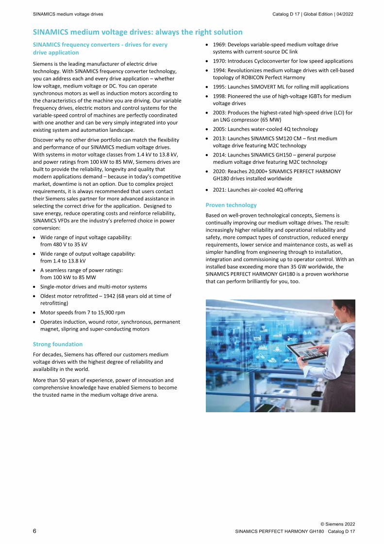
Proven technology Based on well-proven technological concepts, Siemens is continually improving our medium voltage drives. The result: increasingly higher reliability and operational reliability and safety, more compact types of construction, reduced energy requirements, lower service and maintenance costs, as well as simpler handling from engineering through to installation, integration and commissioning up to operator control. With an installed base exceeding more than 35 GW worldwide, the SINAMICS PERFECT HARMONY GH180 is a proven workhorse that can perform brilliantly for you, too.

Catalog D 17 | Global Edition | 04/2022 SINAMICS PERFECT HARMONY GH180 air- and water-cooled drives
© Siemens 2022 SINAMICS PERFECT HARMONY GH180 Catalog D 17 7
SINAMICS PERFECT HARMONY GH180 air- and water-cooled drives Technical characteristics Air-cooled drives Water-cooled drives
The SINAMICS PERFECT HARMONY GH180 drive family consists of core design configurations, where they are functionally identical and share a common controller. These designs are targeted at distinct output power configurations with little overlap between the frame sizes. The SINAMICS PERFECT HARMONY GH180 family is summarized in the tables below.
SINAMICS PERFECT HARMONY GH180 characteristics at a glance
Line-side rectifier 6SR5 6SR327
24 to 54 pulse diode rectifier 18 to 48 pulse diode rectifier
Motor-side inverter Multilevel drive (PWM)
Power cells A 6SR5 6SR327
40, 70, 100, 140, 200, 260, 340, 430, 550, 600, 720, 750 880, 1000, 1250, 1375
Input voltage range kV 6SR5 6SR327
480 V to 13.8 (higher input voltage on request) 2.3 to 13.8
Input voltage tolerance +10 %, –10 %1) of nominal rated input voltage Input overvoltage (swell) +20 % Input undervoltage (dip or sag) –34 %, continues operation with reduced torque
Medium voltage ride through 500 ms – 2Q only (30 cycles @ 60 Hz and 25 cycles @ 50 Hz)
Input frequency Hz 50/60 ± 5 % Input power factor ≥ 0.95 above 10 % load Input harmonics ≤ 3 % total demand distortion (TDD) 2)
Output voltages kV 6SR5 6SR327
2.3/2.4, 3.3, 4.0/4.16, 4.6/4.8, 6.0, 6.6, 6.9/7.2, 10.0, 11.0 2.3/2.4, 3.3, 4.0/4.16, 4.6/4.8, 6.0, 6.6, 6.9/7.2, 10.0, 11.0
Output frequency and drift Hz 0.5 ... 330 ± 0.5 % (sensor-less or open loop vector control),
or ± 0.1 % with encoder (encoder or closed loop vector control) Output Torque 100 % from 10 to 167 Hz without derating 3) Drive quadrants 2 or 4
Power range hp 6SR5 6SR327
150 to 17000 (100 kW to 12.7 MW) 4000 to 33000 (3 to 24.6 MW)
Overload 1min/ 10min
6SR5 6SR3274)
110 % built-in, 150 % available as an option, higher on request 110 % built-in, 150 % available as an option, higher on request
Drive Control methods Sensor-less or open loop vector control, encoder or closed loop
vector control, volts-hertz control
Motor control Induction, Synchronous, Permanent magnet motors, and Wound
rotor motors 1) ±10 % of nominal depending on tap. Output power derating required for –5 to –10 % voltage tolerances 2) As measured at the drive input, actual performance at the site will depend on the present harmonic distortion 3) Proper drive sizing is required. When derated properly, the drives are available for low frequency (0.5 to 10 Hz) and high frequency (168 to
330 Hz) with de-rated torque. 4) 6SR327 drives with 1000 and 1375 A are only available with 100 % rated current.
SINAMICS PERFECT HARMONY GH180 air- and water-cooled drives Catalog D 17 | Global Edition | 04/2022
© Siemens 2022 8 SINAMICS PERFFECT HARMONY GH180 Catalog D 17
SINAMICS PERFECT HARMONY GH180 benefits Clean input power The SINAMICS PERFECT HARMONY GH180 drive:
• Meets the most stringent IEEE 519-2014 requirements for voltage and current harmonic distortion, even if the source capacity is no larger than the drive rating1):
– The SINAMICS PERFECT HARMONY GH180 drive is supplied with a minimum 18-pulse input with versions available up to 54-pulse input, resulting in less than 3 percent total voltage distortion and less than 3 percent total current distortion. It eliminates the need for costly and inefficient harmonic filters and the associated resonance problems.
• Protects other online equipment from harmonic interference (computers, telephones and other power converters)
Sinusoidal output power (waveforms) The SINAMICS PERFECT HARMONY GH180 drive:
• Minimizes drive induced torque pulsations and associated torsional analysis compared to other medium voltage topologies, by using a motor friendly pulse width modulation (PWM) output: – Less than 1 % induced torque ripple for any given
frequency results in no motor heating and no bearing wear
• Eliminates additional losses due to harmonics; thus, it can be used with new or existing motors without de-rating: – Depending on configuration generates 13 to 33 level
output waveform line to line – Small output voltage steps produce no voltage spikes at
the motor which allows the use of a motor with standard insulation
– No need for filters up to 7500 ft (2.3 km) – Waveforms remain high quality at lower speeds due to
multi-level PWM output
1) IEEE 519-2014 compliance can only be guaranteed in networks without prior disturbances or harmonics already present.
Maximized availability The SINAMICS PERFECT HARMONY GH180 drive:
• Remains operational in the event of a cell failure by using the cell bypass option which bypasses the faulted cell
• Achieves near 100 percent reliability and 99.99 percent availability, delivers greater productivity and a significantly reduced total cost of ownership over the drive’s life cycle
• Offers a Process Tolerant Protection Strategy (ProToPS™). ProToPS™ protects customer process from faulty sensors or data. Unlike typical systems that simply trip the drive and shut down the system due to a malfunction, it offers a proactive control approach based on a hierarchical warning system that allows the operator to evaluate the drive and system condition and respond appropriately or initiate controlled shutdown.
Extended reliability The SINAMICS PERFECT HARMONY GH180 drive with an integrated transformer provides the following advantages:
• Protects drive semiconductors from line transients
• Completely protects the motor in case of a ground fault in the converter, the motor cabling or insulation
Exceptional input line performance Robust design provides immunity from most input power disturbances and interruptions to insure protection of customer equipment and trip free operation during most common and frequent power quality issues:
• Best in class input voltage brownout conditions - no trip down to 66 percent of nominal voltage. Output power is reduced by limiting the available motor torque, drive can operate continuously in this mode
• When the line voltage drops below 66 percent, it results in "Ride Through Mode / Power Loss Ride Through" of up to 500 ms – 30 cycles @ 60 Hz and 25 cycles @ 50 Hz systems. (Not available for 4Q drives.)
• Built-in input transformer with lightning arrestors to provide protection from excessive peak voltage
Over 25 years of performance and more than 21,000 units in operation exceeding 35 million kW installed power worldwide, Siemens has only one goal in mind: optimizing customer profitability
Catalog D 17 | Global Edition | 04/2022 SINAMICS PERFECT HARMONY GH180 air- and water-cooled drives
© Siemens 2022 SINAMICS PERFECT HARMONY GH180 Catalog D 17 9
Extensive testing
SINAMICS PERFECT HARMONY GH180 will get your process up and running because we have the ability to test every product at full load – prior to delivery:
• At our factory, we test every transformer and power converter together to ensure performance meets precise specifications.
• We verify sequence of operation and protection to ensure that the SINAMICS PERFECT HARMONY GH180 drive matches your needs.
• As an option, factory testing allows accurate efficiency measurements if customer requests it.
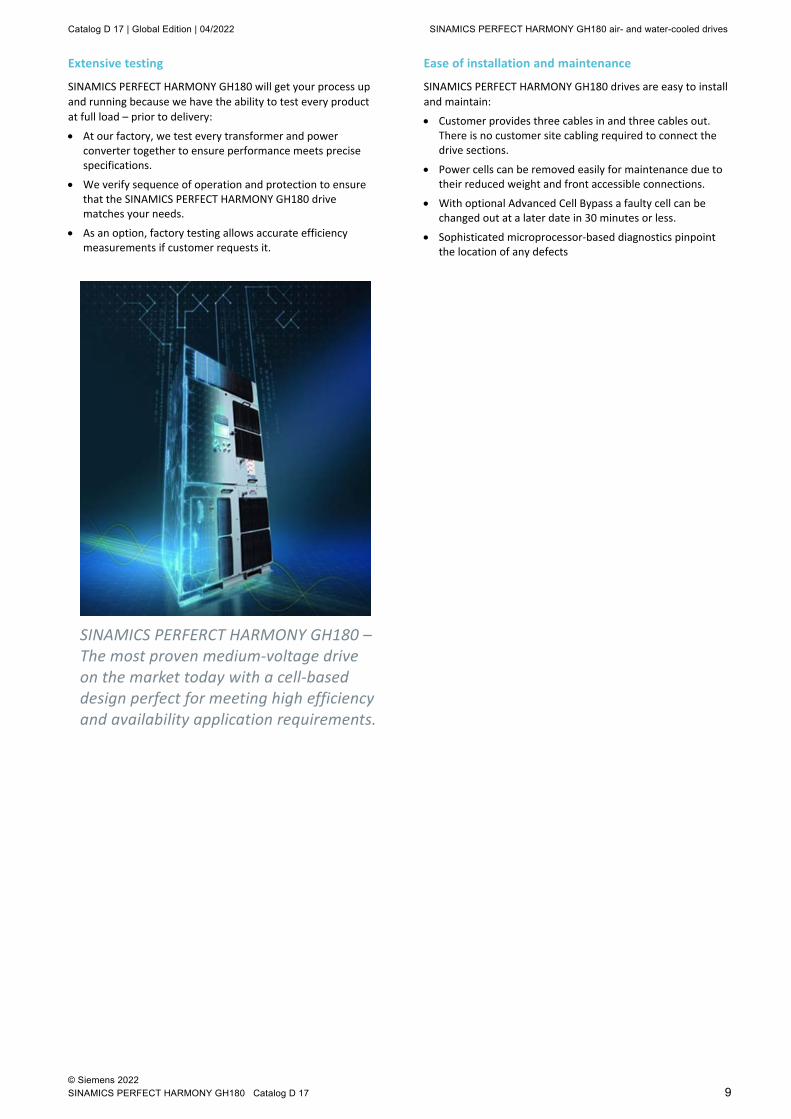
SINAMICS PERFERCT HARMONY GH180 – The most proven medium-voltage drive on the market today with a cell-based design perfect for meeting high efficiency and availability application requirements.
Ease of installation and maintenance
SINAMICS PERFECT HARMONY GH180 drives are easy to install and maintain:
• Customer provides three cables in and three cables out. There is no customer site cabling required to connect the drive sections.
• Power cells can be removed easily for maintenance due to their reduced weight and front accessible connections.
• With optional Advanced Cell Bypass a faulty cell can be changed out at a later date in 30 minutes or less.
• Sophisticated microprocessor-based diagnostics pinpoint the location of any defects

SINAMICS PERFECT HARMONY GH180 air- and water-cooled drives Catalog D 17 | Global Edition | 04/2022
© Siemens 2022 10 SINAMICS PERFFECT HARMONY GH180 Catalog D 17
SINAMICS PERFECT HARMONY GH180 design Drive topology
The SINAMICS PERFECT HARMONY GH180 series drives achieve an uncompromising performance by employing well-proven technology in a modular configuration, as shown in Figure 1. Medium voltage levels are obtained by adding together the outputs of multiple power cells. The power cells are simplified variations of standard 2-level PWM low voltage drives, which have been built in high volume for many years.
Figure 1: Topology of SINAMICS PERFECT HARMONY GH180 Drive (3 cells per phase)
For higher output voltage capabilities, the SINAMICS PERFECT HARMONY GH180 topology can be extended up to eight power cells in series in each phase, with additional secondary windings (number of secondaries equals number of power cells) on the integral isolation transformer.
Transformer
Since the early 1990s, Siemens has collaborated extensively with transformer suppliers to perfect the design of the transformers used in each SINAMICS PERFECT HARMONY GH180 drive. The patented design provides several benefits in the drive topology, including the adaptability to input voltage, a multi-pulse input, and a reduction in common mode voltage.
The transformers used in the SINAMICS PERFECT HARMONY GH180 are VPI dry-type, forced-air or water- cooled. They are designed specifically for use with a particular SINAMICS PERFECT HARMONY GH180 drive configuration and have 9 to 24 extended delta secondaries.
The SINAMICS PERFECT HARMONY GH180 transformers are designed, constructed, and tested as per IEC 60076-11 standard. The transformer is an integral part of the drive that cannot be specified or obtained externally to Siemens.
Proven IGBTs
Low voltage Insulated Gate Bipolar Transistors (IGBTs) form the backbone of the SINAMICS PERFECT HARMONY GH180 drive. Built in high volumes and serving as a proven power device across the industrial power control industry, IGBT technology has been in existence for more than two decades. The stability and availability of IGBTs give reliable, long-term, lifecycle confidence.
Linked power cells
In the SINAMICS PERFECT HARMONY GH180, power cells (see Figure 2) are linked together in series to build the medium voltage power output (see Figure 1) of the drive system. This modular configuration gives the SINAMICS PERFECT HARMONY GH180 many advantages when it comes to maintenance, power quality and reliability. It also provides the basis for one of its most important advantages – increased availability through the advanced cell bypass option.
Figure 2: Schematic of a typical power cell
Advanced cell bypass
The SINAMICS PERFECT HARMONY GH180 is designed to withstand failures that would overwhelm conventional drives because redundancy options are added into the system. The patented, cell-based configuration maximizes uptime and simplifies modifications.
Through a redundant bypass control that is completely separated from each power cell, SINAMICS PERFECT HARMONY GH180 ensures automatic bypass of a failed power cell in 250 ms. The mechanical cell bypass option is implemented by providing a contactor at the output of each cell. One of the many benefits of mechanical cell bypass includes the ability to be tested during customer factory acceptance test.
Since the cells in each phase are in series, bypassing a cell has no effect on the current capability of the drive, but the voltage capability will be reduced. Usually the required motor voltage is roughly proportional to frequency (speed). With a power cell or cells in bypass, the maximum speed the motor can operate at may be reduced approximately in line with the reduced voltage. The reduction in speed is somewhat load dependent.

Catalog D 17 | Global Edition | 04/2022 SINAMICS PERFECT HARMONY GH180 air- and water-cooled drives
© Siemens 2022 SINAMICS PERFECT HARMONY GH180 Catalog D 17 11
It is important to maximize the motor voltage available after one or more cells have been bypassed. The following figures illustrate the voltage available from a SINAMICS PERFECT HARMONY GH180 drive, where the cells, represented by circles, are shown as simple voltage sources. Figure 3 shows a 15-cell drive in which no cells are bypassed. With 100 % of the cells in use, 100 % of the original voltage is available. The voltage commands to the three phase groups of cells will have phase A displaced from phase B by 120°, and from phase C by 120°.
Figure 3: Simplified diagram of a 15 cell drive
When two cells are bypassed in phase A, the output voltage will tend to become unbalanced, as illustrated in Figure 4 and not suitable for operating a motor.
Figure 4: Drive output with 2 cells bypassed in phase A
One possible remedy is to bypass an equal number of cells in all three phases, even though some may not have faulted. Figure 5 illustrates this approach.
Obviously, this method prevents unbalance but sacrifices possible voltage capability. In this figure, 87 % of the cells are functional, but only 60 % are in use, and only 60 % of full voltage is available.
A better approach is illustrated in figure 6. This method takes advantage of the fact that the star-point of the cells is floating and is not connected to the ground. Therefore, the star-point can be shifted away from the motor neutral, and the phase angles of the cell voltages can be adjusted, so that a balanced set of motor voltages is obtained even though the cell group voltages are not balanced. Siemens calls this approach Neutral Shift (Siemens patented technology).
Figure 5: Drive output rebalanced by bypassing functional cells
In figure 6, the full remaining 87 % of functional cells are in use, and 80 % of the original voltage is available. The phase angles of the cell voltages have been adjusted so that phase A is displaced from phase B and from phase C by 132.5°, instead of the normal 120°.
Figure 6: Drive output rebalanced by adjusting phase angles (Neutral Shift)
The figure 7 below demonstrates the available output voltage after one cell is bypassed based on number of cells in configuration and bypass method used. For example, SINAMICS PERFECT HARMONY GH180 (3 cells per phase) with neutral point shift is capable to provide 83 % of output voltage compared to below 70 % for the drive with the same number of cell but without neutral point shift capability.
Figure 7: Available output voltages after bypass

SINAMICS PERFECT HARMONY GH180 air- and water-cooled drives Catalog D 17 | Global Edition | 04/2022
© Siemens 2022 12 SINAMICS PERFFECT HARMONY GH180 Catalog D 17
PERFECT HARMONY GH180 cell bypass evolution The SINAMICS PERFECT HARMONY GH180 has revolutionized medium voltage power conversion. Perfect Harmony multilevel topology was invented by Robicon (now Siemens) in 1994. Siemens continues to be the technology leader for multilevel topology inverters and has over 50 unique patents and 100 international patents filed around Perfect Harmony topology. In 2017 Siemens began releasing its 5th generation of SINAMICS PERFECT HARMONY GH180. The complete 5th generation air-cooled range was released in 2021.
The SINAMICS PERFECT HARMONY GH180 drive continues to set industry standards for reliability and innovation. Siemens improves each generation in three key areas: increased reliability and availability, increased efficiency, and a smaller drive footprint. The innovation includes further improving cell bypass technology: evolving from an electronic thyristor based bypass (SCR) integrated to each cell to a mechanical bypass totally independent of the cell.
Cell bypass evolution
In the original concept as implemented 25 years ago, each cell contained a single phase rectifier bridge with a thyristor. The AC inputs of this rectifier bridge were connected to the cell output terminals. In the event of the failure bypass SCR is shorted effectively disconnecting the cell from the input power. Although this approach was effective under certain failure conditions, it had several drawbacks:
• Since cell and bypass share fiber optic communication, if it is lost, then the bypass can not be engaged because the control can not activate cell bypass due to the failed communications. Therefore, this bypass system is less effective and less reliable.
• If there is any component failure in the cell such as IGBT, gate drive, cell control board power supply that may lead to bypass control malfunction resulting in the loss of the bypass functionality.
• To protect cell from exposure to fault current bypass circuitry had built-in fuse, that would automatically blow when cell bypass is engaged. If it was a nuisance trip customer could not automatically reset it which required a new cell for replacement.
In 2000, to overcome these difficulties, bypass was changed to an external mechanical contactor supplied from a completely independent power source and controlled by a separate control means. This contactor does not have to interrupt current, so it doesn’t need arc control measures. The contactor is a single pole double throw arrangement so that it can disconnect the cell from the output string and apply a shorted contact in place of the cell. With this bypass, the cells do not have to function at all for bypass to work.
Advantages of the mechanical cell bypass
• The SINAMICS PERFECT HARMONY GH180 bypass is based on traction DC contactor – proven and trusted technology!
• It does not matter which of the components has failed within the cell. In fact, even a failure in the fiber optic link that communicates to the cell can be detected and bypassed. This approach protects against the failure of any component in the power circuits or in the communications circuits, rather than protecting the drive against power semiconductor failure only.
• Mechanical bypass has separate communication with the drive control and independent regulated power supply to ensure maximum availability.
• In the instance of a nuisance trip customer can automatically reset bypass and continue the operation.
• During the fault, drive control performs a quick check to verify if the motor output voltage can be supported by the functional cells before a cell is bypassed. This voltage can be near the drive rated output voltage for a few seconds before dropping over time. If a cell is bypassed too fast, the remaining cells may not be able to support this voltage and leading to cells malfunction. SINAMICS PERFECT HARMONY GH180 has built-in control function to perform all necessary checks to ensure safe and reliable operation.
• When a cell is bypassed, it allows for process ride through with an interruption of only 250 ms or less.

Catalog D 17 | Global Edition | 04/2022 SINAMICS PERFECT HARMONY GH180 Solutions
© Siemens 2022 SINAMICS PERFECT HARMONY GH180 Catalog D 17 13
SINAMICS PERFECT HARMONY GH180 solutionsDrive heat load management During operation, every drive generates heat that needs to be removed from the room to avoid equipment overheating. In many installations, it is very common to use air-conditioning to reduce the heat in the control room. The amount of heat dissipated into the room by the drive depends on the drive size, its running load, cooling method and efficiency. Other equipment located in the same space may also have losses requiring cooling.
The more heat rejected into the room, the higher operational cost and total costs of ownership of the drive are. The drive typical losses are 3.0 to 3.5 % of the motor rating when operating at full load (losses reduce as load reduces). Air-cooled drives usually dissipate heat directly into the room and require additional measures to keep operating within the manufacturer specified range; while water-cooled drives reject most of the losses into the water, less than 5% of losses are rejected into the room.
The difference in cooling requirements for installations where heat rejected directly into the room could be 20 times higher compared to solution where losses are ducted outside the room. For example, 4000 Hp (3000 kW) drive losses in the room are 96 kW while the same drive with ducted air outside or heat exchanger (air-to-air or air-to-water), has only 4.8 kW losses resulting in significant reduction in cooling requirements. In this case heat losses in the room are similar to water-cooled drive performance. In order to reduce the requirement for air-conditioning of a control room, it is worth evaluating various heat management options available for air-cooled drives:
• The air can be ducted directly outside (options M64 or M68)
• Air-to-air heat exchanger (option W41)
• Air-to-water heat exchanger
Each approach has its own advantages and limitations and each case should be evaluated based on customer application, site conditions, availability of water, etc. Below are highlights of each option.
Ducting hot air outside is one of the most economical implementations but it does require upfront engineering from a customer. Engineering is required to design proper air flow in the room to avoid creating a vacuum or wind tunnel effect in the room. The air can be drawn either from outside with proper filtration to meet drive installation requirements or in some cases, HVAC is capable of supporting the necessary airflow. It is critical to design the solution properly to prevent unnecessary trips due to lack of air. The regular maintenance of outside filters is required to ensure that no contaminates get into the drive.
Utilization of heat exchangers creates close loop cooling systems. In close loop systems air is drawn through ventilation openings at the bottom or the front of the drive, depending on the product line, then circulated through the transformer and power cell sections and exhausted through the back of the drive enclosure. Warm air is cooled via the heat exchanger and circulated back to the drive. The hot and cooled air is transferred to the heat exchanger by duct work through the control room or power distribution center exterior wall. In case
of air-to-water heat exchangers, heat is removed from the hot air and transferred to the customers' water system.
There are two possible ways to implement this configuration the first one is similar to air-to-air heat exchanger set up where heat exchanger itself located outside and the hot air from the drive ducted. The second one is when the VFD blower cage assembly is replaced with the heat exchanger assembly. This solution does not require ducting work done to the building thus reducing additional engineering effort.
The heat exchanger option (either air-to-air or air-to-water) is a self-contained solution that does not require additional engineering on the customer's behalf. Compared to open loop systems, this solution provides higher degree of contamination protection due to the two separate airflow design, which keeps dirt, moisture, and other elements from getting into the equipment.
Heat exchangers might require higher initial investment compared to open loop system or HVAC solution, it typically has the lowest total cost of ownership compared to traditional HVAC and a pay back of 2 to 3 years depending on size of the drive or solution saving operators cost of electricity for the next 17 years of the drive life.
Figure 8 Installation with air-to-air heat exchangers and two drives in the building
Not only this solution reduces overall cost of drive operation, the Heat Exchanger is also about 5 to 10 % more reliable compared to industrial redundant HVAC systems and about 20 to 30 % more reliable compared to commercial HVAC systems. This reliability improvement is due to fewer components in the Heat Exchanger compared to HVAC system which consists of compressors, fans, belts, valves, etc. The above figures are based on the data collected by our field support team over past 10 years.
The air-to-air heat exchanger solution has built-in fan redundancy and comes complete with heat exchanger controls. It is rated for ambient temperatures from 32º F to 104º F (0º C to 40º C). When required, they can be equipped with options to meet –40º F (–40º C) including space heaters, louvers and snow hoods for cold environments.
SINAMICS PERFECT HARMONY GH180 Solutions Catalog D 17 | Global Edition | 04/2022
© Siemens 2022 14 SINAMICS PERFFECT HARMONY GH180 Catalog D 17
Advanced motor protection – a true variable speed performance SINAMICS PERFECT HARMONY GH180 is the only medium voltage drive that offers a patented solution (patent pending) for motor protection at variable speed operations. The drive protection uses integral closed-loop hall effect current sensors and output attenuators to obtain accurate motor data.
Option A84 offers additional features and allows operators to set pick up and trip levels at various points across the speed curve. Some of the features included in this option are:
• Undercurrent (37)
• Underspeed (14)
• Current unbalance, negative sequence (46_2)
• Machine thermal overload RTD (49 RTD)
• Differential protection equivalent (87M)
Most functions offered within the option can be enabled to start monitoring and protecting the motor along the speed curve. The operator can set protection at any point that is critical for their application and process including time delays. No other solution available today on the market offers this flexibility and capability. The standard motor protection available with most VFDs only allows fixed default settings.
The graph below serves as an example and shows flexibility to set up process defined curves. The gray color is normal operating conditions, the yellow color represents the alarm setting area and the orange color represents the fault setting area. Many of the protection curves have a latched minimum speed enable at which point protection settings do not apply. The thermal protection function offer either an alarm or trip setting. All other functions provide an alarm or fault setting.
The big difference between standard protection and an advanced one is enhanced thermal motor protection (ANSI 49T). The algorithm is designed to meet the requirements of IEC 60255-149 standard. This is the only function that offers both an alarm setting and the trip setting to give customers advanced warning before the process and the motor are taken off line. The Advanced Motor Protection Option has a patented thermal model to provide locked rotor and running overload protection. It includes the following elements:
• Motor thermal capacity
• Biasing based on both measured stator and ambient temperatures (optional)
• Measure of negative sequence current
• Average RMS phase currents
• Motor Run and Stop status
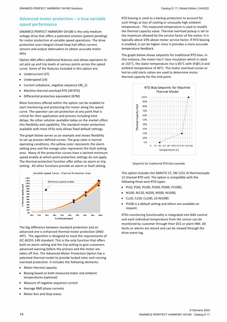
RTD biasing is used as a backup protection to account for such things as loss of cooling or unusually high ambient temperature. This measured temperature is used to modify the thermal capacity value. Thermal overload pickup is set to the maximum allowed by the service factor of the motor. It is typically about 10% above motor service factor. If RTD biasing is enabled, it can be higher since it provides a more accurate temperature feedback.
The graph below shows setpoints for traditional RTD bias. In this instance, the motor has F class insulation which is rated at 155°C, the stator temperature rise is 85°C with [email protected] and ambient temperature of 40°C. The motor overload curves or hot-to-cold starts ration are used to determine motor thermal capacity for the mid-point.
Setpoints for traditional RTD bias example
This option includes the SIMATIC S7, SM 1231 AI thermocouple 12 channel RTD unit. The option is compatible with the following three-wire RTD types:
• Pt10, Pt50, Pt100, Pt200, Pt500, Pt1000,
• Ni100, Ni120, Ni200, Ni500, Ni1000,
• Cu10, Cu50, Cu100, LG-Ni1000.
• Pt100 is a default setting and others are available on request.
RTDs monitoring functionality is integrated into NXG control and each individual temperature from the sensor can be monitored by customer through their DCS or plant HMI. All faults or alarms are stored and can be viewed through the drive event log.
Minimum speed enable

Catalog D 17 | Global Edition | 04/2022 SINAMICS PERFECT HARMONY GH180 Solutions
© Siemens 2022 SINAMICS PERFECT HARMONY GH180 Catalog D 17 15
Bidirectional synchronous transfer There are two primary applications that require synchronous transfer:
• The first one is a drive used as a soft-starter to reduce stress from starting motors directly on line.
• The second one is used for process/flow control: starting up multiple motors and synchronizing them to the line according to process specifications.
The key difference between these applications is sizing of the drive. When variable frequency drive (VFD) is used to start the motor in an unloaded condition, the VFD does not have to match the full rating of the motor. For example, a 20,000HP motor may be started by a 5000HP VFD if the drive output can provide sufficient output current and develop enough motor torque to accelerate the motor up to full speed. In this instance, the VFD is at full power only for a very short period of time. The drive transfers a motor across the line after the motor is at full speed. In all cases the motor is started in either unloaded or partially loaded condition.
The drive is often used in this application when incoming line is soft and cannot support the inrush current of the motor during starting. Sometimes, the incoming line is even too weak to support a reduced-voltage start even though inrush current is less it is still about 250% to 300% of the motor full load current rating. Starting motors with VFDs have the following benefits:
• Multiple starts per day
• Draws minimal inrush currents while starting, minimizing voltage drop and system electrical stress
• Reduces mechanical shock (starting torque is controlled at nominal levels)
For such applications the SINAMICS PERFECT HARMONY GH180 has a function for single motor synchronous transfer option (L29) that does not require any PLC, it is done by the drive’s control and in most cases without need for an output reactor.
For the second option, the drive is sized to run the motor full time. In a pumping station, the demand can change significantly within a day for the water and wastewater industry and seasonally for oil pipelines. One variable frequency drive can be used in combination with multiple motors to adjust the flow to meet the demand. In this case, the last pump is always run by VFD for flow and pressure control.
Siemens can design your sync transfer system to suit your application. With standard, pre-configured systems that utilize our best-in-class VFD and motor control products, Siemens can provide a full spectrum of standard and flexible options.
Once the sync transfer system has been completely assembled, Siemens performs full power testing to ensure seamless integration and operation. Components are assembled and tested. The Sync Transfer Control System (STC) supports transfer of two to eight motors directly to or from a line source of power. The system is designed to handle induction motors or synchronous motors and connection of motors to a source the same as the drive or to an alternate source.
Figure 9: Switchgear and reactor lineup for 3 motor synchronous transfer application (for drive manufactured in the USA only)
Optimized synchronous transfer
The traditional synchronous transfer option uses output reactor for a bump-less closed transfer (figure 10). Connecting voltage source VFDs to a motor in parallel to the line (closed transfer) can result in excessive currents. The solution used to prevent such excessive currents has always been to add a reactor between the VFD output and the motor.
Figure 10: Typical multi-motor synchronous transfer application with reactor
The advantage of this implementation is the ability to operate for periods of time in parallel with the line. This makes the transfer from the line to the VFD as smooth as possible. The limitation of this solution is higher initial capital cost, increase of the losses within the drive system and reduced output voltage capability of the drive system. While the losses and voltage drop are negligible with regards to motor operation, the reactor losses require additional cooling. The cooling of these losses is either can be done by placing the reactor outside or increasing the HVAC capability of the cooling system. Regardless, the capital cost of including a reactor is considerable.
Due to increases in drive control processing power synchronous transfer can be optimized to eliminate the use of an output reactor. This optimized synchronous transfer can be applied to most motor drive applications.
SINAMICS PERFECT HARMONY GH180 Solutions Catalog D 17 | Global Edition | 04/2022
© Siemens 2022 16 SINAMICS PERFFECT HARMONY GH180 Catalog D 17
Figure 11: Optimized multi-motor synchronous transfer
The benefit of this approach is the ability to remove the reactor between the VFD and the motor, and the associated motor line contactor feedback to the SINAMICS PERFECT HARMONY GH180 VFD. Synchronous transfer of the motor to the line remains as a closed bump-less transfer.
The optimized synchronous transfer does differ during “down” transfer. When the motor is transferred from the line back to VFD while it is still closed transfer, it will result in a step torque change to the motor but it has minimal impact on process. The magnitude of this step change is limited to the allowable torque.
Optimized synchronous transfer of motor to line (up transfer)
Optimized synchronous transfer operates in the same manner as the traditional GH180 transfer operation with regards to “up” transfer so the same operational logic and application methods apply. The graph below shows the motor operation during an “up” transfer:
• The magenta waveform is the voltage magnitude as seen by the motor.
• The blue waveform is the output voltage of the VFD.
• The green waveform is motor current
• The red waveform is the control voltage for the VFD’s output contactor
Figure 12: Optimized Synchronous Up Transfer
As shown in the graph, there is no observable change in motor voltage or current. This means that there is no meaningful change in motor torque during an “up” transfer, and it is synchronized with the line phase and frequency.
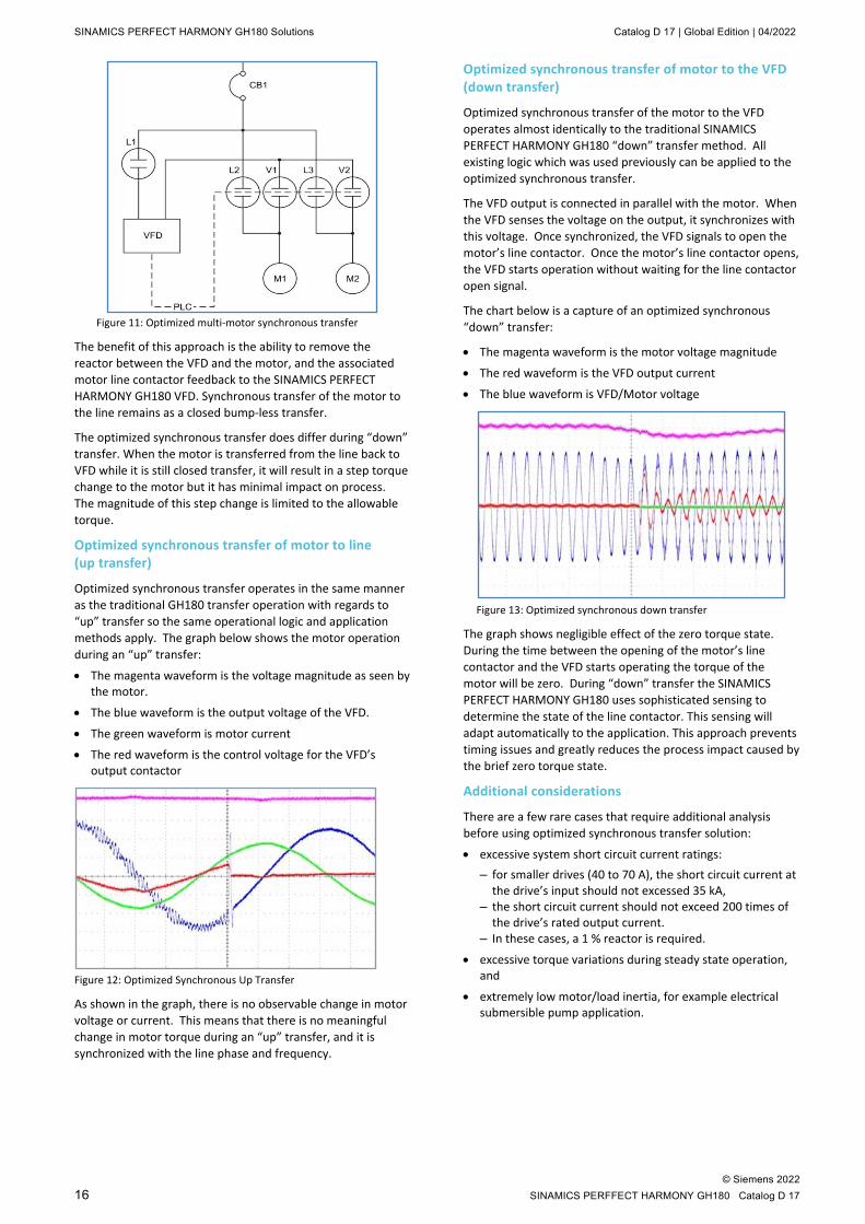
Optimized synchronous transfer of motor to the VFD (down transfer)
Optimized synchronous transfer of the motor to the VFD operates almost identically to the traditional SINAMICS PERFECT HARMONY GH180 “down” transfer method. All existing logic which was used previously can be applied to the optimized synchronous transfer.
The VFD output is connected in parallel with the motor. When the VFD senses the voltage on the output, it synchronizes with this voltage. Once synchronized, the VFD signals to open the motor’s line contactor. Once the motor’s line contactor opens, the VFD starts operation without waiting for the line contactor open signal.
The chart below is a capture of an optimized synchronous “down” transfer:
• The magenta waveform is the motor voltage magnitude
• The red waveform is the VFD output current
• The blue waveform is VFD/Motor voltage
Figure 13: Optimized synchronous down transfer
The graph shows negligible effect of the zero torque state. During the time between the opening of the motor’s line contactor and the VFD starts operating the torque of the motor will be zero. During “down” transfer the SINAMICS PERFECT HARMONY GH180 uses sophisticated sensing to determine the state of the line contactor. This sensing will adapt automatically to the application. This approach prevents timing issues and greatly reduces the process impact caused by the brief zero torque state.
Additional considerations
There are a few rare cases that require additional analysis before using optimized synchronous transfer solution:
• excessive system short circuit current ratings: – for smaller drives (40 to 70 A), the short circuit current at
the drive’s input should not excessed 35 kA, – the short circuit current should not exceed 200 times of
the drive’s rated output current. – In these cases, a 1 % reactor is required.
• excessive torque variations during steady state operation, and
• extremely low motor/load inertia, for example electrical submersible pump application.

Catalog D 17 | Global Edition | 04/2022 SINAMICS PERFECT HARMONY GH180 Solutions
© Siemens 2022 SINAMICS PERFECT HARMONY GH180 Catalog D 17 17
If your site or load falls into this category, the optimized synchronous transfer may be modified to fit your application. If this is not possible, the traditional synchronous transfer remains available to ensure all applications have the opportunity to use synchronous transfer for bypass operation.
Summary
The optimized synchronous transfer system allows for bypass operation without the need for an output reactor.
• Optimized and traditional synchronous “up” transfers are equivalent with no interruption of motor torque.
• Optimized synchronous transfer has a brief torque interruption during “down” transfer operation - interruption is kept brief by an adaptive algorithm which senses contactor status via motor behavior
When selecting the synchronous transfer option, Siemens recommends that customers install motor protection relay (MPR). Once the motor is transferred directly on line, it is no longer protected by the VFD. In case of the multi motor synchronous transfer option (N18), Siemens integrates an MPR with associated CTs and PTs into the switchgear line-up. If switchgear is supplied by the customer (L20), it is customer responsibility to install the MPR.
For both options, Siemens provides a synchronous transfer controller with predefined and tested logic up to 8 motors and built-in HMI for display. The controller can be installed as a part of the line-up or separate in a control room depending on customer requirements. Siemens solution is the most flexible and provides support for the customers’ selection of switchgear and motor protection relay to ensure the best fit for their site and application.
Unmanned station solution Many pumping and compressor stations are often located remotely where input power is more susceptible to disruptions caused by line surges, dips, and short outages. These can cause nuisance trips that lead to loss of production. In such cases equipment including its control needs to be robust to withstand these events. Most stations are unmanned and continuously operated and monitored to ensure safe operation. If there is a trip, there is additional cost associated with travel time to reset the equipment and restart the process.
Unmanned station solution (option S17) provides features and functionalities that maximize customer uptime by providing robust control and input line tolerance capabilities. If customer selects this option, the following features will automatically be implemented unless otherwise specified by the customer:
• Automatic fault reset – certain faults within a drive can be reset automatically
• Automatic restart – switches the drive on again when the medium voltage is restored after a power failure or a general fault, the drive then ramps up the motor to the current speed setpoint. The number of restarts and the time delay is customer specified to provide additional flexibility and accommodate various site requirements.
• Local display and classification of faults and alarms to indicate to an operator: – Whether a drive experienced the fault and it was reset
automatically – Or there is a fault and it is safe to reset remotely – Or it is recommended to go to the site for inspection
prior to fault reset.
• Robust process tolerant control logic is enabled. The drive is designed to operate continuously with reduced torque down to 66 % of available input voltage and fault free ride through of power loss up to 30 cycles to ensure equipment trip free operation.
Recommended option for the switchgear/circuit breaker:
• An integrated, electric-racking system, that includes a fixed-mounted, high-torque motor and logic control module powered by control power in the switchgear or an external supply (either 120 VAC or 125 VDC) when necessary. One control pendant is supplied per lineup. Siemens offers SIERS integrated, electric-racking system.
Other options recommended but not required for customer who selected this option:
• UPS supply to the control section (option L53) is required to provide fast response during power losses up to 8 minutes for stations where low voltage network does not have an UPS back up.
• Serial communication (options G22 to G91)
• Process Tolerant Protection Strategy (ProToPS™, option U10)
SINAMICS PERFECT HARMONY GH180 Solutions Catalog D 17 | Global Edition | 04/2022
© Siemens 2022 18 SINAMICS PERFFECT HARMONY GH180 Catalog D 17
Electrical Submersible Pump Application Approximately 90% of all oil wells require some form of artificial lift to improve oil flow. Electrical Submersible Pump (ESP) is one of several methods used in the industry. Once the oil reservoir stops producing oil under free flow, electrical submersible pumps are used to pump the oil to the surface.
Historically, low voltage drives have dominated in ESP applications, but recently more and more end-users are considering and using medium voltage drives. An ESP is a centrifugal pump that is driven by a medium voltage electric motor that ranges from 1000 V to 4800 V.
More often than not, ESPs are installed in remote locations. The power is more susceptible to disruptions from outages, poor voltage regulation, and transient voltage conditions. The design, operational and site constraints make these motors sensitive to the following conditions:
• Input line overvoltage and transient spikes
• High inrush torques
• High dv/dt
• Torque pulsations
One of the most common ESP motor and cable failures is short-circuited motors and cables. The reason for short circuit events is insulation break down. The LV drive solution, if not properly selected and engineered, may produce high output voltage spikes that lead to insulation break down of both cable and motor. The ESP failures have a very high cost. The total cost to an end-user of one ESP failure is about $154K. Below is the breakdown of the average cost associated with the onshore ESP operation:
• Average loss of revenue $60x200x7=$84K based on: – Price per barrel - $60 (can be as high as $100 depends on
market conditions); average oil production per well: 200 bopd (barrels of oil per day) and average workover & waiting time: 7 days
– Average intervention cost is $20K (maybe higher depending on a cost and availability of a rig) and average equipment cost of $50K
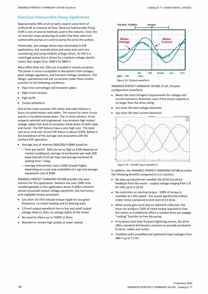
SINAMICS PERFECT HARMONY GH180 provides the best solution for this application. Siemens has over 1000 units installed globally in this application alone. It offers inherent almost sinusoidal output voltage waveform, low harmonics and negligible torque pulsations:
• Less than 1% VFD induced torque ripple for any given frequency: no motor heating and no bearing wear
• 13 level output waveform line to line and small output voltage steps (1.3kV): no voltage spikes at the motor
• No need for filters up to 7500ft (2.3km)
• Waveforms remain high quality at lower speeds
Figure 14: Output waveform
SINAMICS PERFECT HARMONY GH180, 9 cell, 54 pulse configuration waveform:
• Meets the most stringent requirements for voltage and current harmonic distortion, even if the source capacity is no larger than the drive rating
• Less than 3% total voltage distortion
• Less than 3% total current distortion
Figure 15: GH180 Input waveform
In addition, the SINAMICS PERFECT HARMONY GH180 provides the following benefits compared to a LV solution:
• No step-up transformer needed, the drive has direct feedback from the motor - output voltage ranging from 1.8 kV volts up to 4.16 kV.
• No restriction on starting torque - 100% of torque is available at 1.6Hz speed - this would significantly reduce motor stress compared to kick start of LV drive.
• When pump gets stuck due to sediment collection, the drive can produce 150% of rated torque required to free the motor or if additional effort is needed drive can engage “rocking” function to free the pump.
• In locations that have frequent lightning storms, the drive offers standard distribution arrestors to provide protection to drive, cables and motor.
• Flexibility with simplified and optimized input voltages from 480 V up to 7.2 kV.

Catalog D 17 | Global Edition | 04/2022 SINAMICS PERFECT HARMONY GH180 Solutions
© Siemens 2022 SINAMICS PERFECT HARMONY GH180 Catalog D 17 19
Torque during ride-through
ESP applications typically operate in regions where momentary power interruptions occur. These momentary power interruptions cause a loss of input power feeding the drive. The drive will respond by entering a mode called ride-through. The VFD performance during the voltage sag tolerance and ride-through of momentary power loss depend on the amount of capacitance available in the DC link. The tolerance level varies from manufacturer to manufacturer and ranges from 90% to 75% of nominal input voltage.
At full speed, the SINAMICS PERFECT HARMONY GH180 provides regular operation for dips down to 90% of nominal voltage. After that the drive output power is rolled-back linearly from 100% power at 90% of input voltage down to 50% power at 66% of nominal input voltage. Output power is reduced by limiting the available motor torque. The VFD can operate continuously in this mode. When the input voltage falls below 66%, then the power is quickly reduced to a slightly negative value (regenerative limit) (figure16). This limit forces the drive to absorb power from the motor and maintain the DC bus voltages in case the input voltage recovers during MV ride-through.
This typical ride-through action is the most effective drive response for most applications. However, some applications with very low system inertia and high loads are willing to sacrifice ride-through duration to maintain enough torque to prevent stopping the process.
Figure 16: GH180 torque during Input voltage sag and ride-through
ESPs have low system inertia and a high load. Losing torque, even for a short time, will cause the flow to stop and reverse direction. At this point, one must wait for the column of fluid to drain back through the pump and sediment to settle before restarting the pump. Once started, one must refill the column of fluid before production is restored. This all wastes energy and time resulting in less revenue.
Given the cost of time and energy to restore production in ESP applications, it is more important to maintain the process through application of torque during a short power interruption than the ability to instantly reapply torque after an extended power interruption.
Solution
For applications such as ESPs, SINAMICS PERFECT HARMONY GH180 drives implement a scheme which allows to maintain some torque for a short time during ride-through. The power for this torque is the power stored within the DC filter banks of the power cells.
During ride-through, drive will provide torque to hold a preset speed for up to 100 milliseconds (5 cycles). After this period, the drive returns to the original ride-through algorithm where a slight regenerative torque is applied, and motor flux is maintained until DC power is exhausted or line voltage returns.
Figure 17: Typical pump speed response during extended torque ride-through
Summary
Extended torque ride through uses the energy stored in the DC filter capacitors to extend the torque available from the drive when a brief power interruption occurs. The benefits are:
• Enough torque is supplied to maintain minimum flow to prevent pump cavitation
• No reverse flow following momentary power outages
• No waiting for the column of fluid to drain sediment to settle before restarting
• No wasted energy refilling the column of fluid before production begins
Time
0
65
100
(%)
Erms
Pump Speed (%)
100ms

SINAMICS PERFECT HARMONY GH180 Solutions Catalog D 17 | Global Edition | 04/2022
© Siemens 2022 20 SINAMICS PERFFECT HARMONY GH180 Catalog D 17
Outdoor duty drive Siemens offers standout flexibility with a full range of solutions: Outdoor Duty Drive for drives up to 1000HP (746kW), Containerized NEMA 3R solution up to 2000HP (1400kW), or Power Distribution Center (PDC) for all power ratings. The Harsh-Environment Drive Solutions have been successfully deployed to protect drives against a wide range of harsh conditions. These conditions include:
• Heat, dirt and sand at remote stations in the deserts of West Texas
• Subarctic temperatures –40 °C (–40 °F), snow and ice on the north slope of Alaska
• Air contamination and cold temperatures in the Canadian oil sands
• Salt and shipboard conditions in the Persian Gulf
Containerized NEMA 3R and PDC are fully engineered according to customer specific requirements and projects, while an outdoor duty drive is standardized for optimal solution. SINAMICS PERFECT HARMONY GH180 is the only medium voltage drive that offers Outdoor Enclosure Type 4 option and is also third party certified by both UL and CSA.
The environmental extension of SINAMICS PERFECT HARMONY GH180 provides reliable operation in remote locations and offers additional flexibility for those customers that have limited space. Siemens Outdoor Duty Drive has the following features:
• Exceeds NEMA 3R standard: customer can rest assured that even during severe storms their equipment is safe with Type 4 option that is designed to protect from falling dirt and windblown dust, rain, sleet, snow, and splashing water.
• Integral Air-to-Air Heat Exchanger creates separate airflows within the enclosure: one for outdoor air and a separate one for drive internal air flow. This provides a completely closed system which keeps dirt, moisture, and other elements from getting into the equipment.
• In addition to full insulation, the drive is equipped with advanced scheme for temperature and humidity control to prevent condensation to ensure safe operating conditions.
• Drive has built-in arrestors to protect transformer from current surges caused by lightings.
• Maintain consistent temperature control, even in environments approaching –45ºC (–49 ºF) up to +45 ºC (113 ºF)
• Reduced maintenance requirements since there are no filters and accumulated particles in the heat exchanger can be easily washed.
Outdoor duty drive has the following standard options:
• Three cables In, three cables out (N73) for low voltage input
• Input voltage 460 to 575 V with integral circuit breaker
• Mechanical door interlocks provide security (M08)
• Off-Local-Remote selector switch (K31) provides the ability to choose between off, local control and remote control of the three-position selector switch via I/O terminal strip.
• Anti-condensation heating for cabinet (L55)
• The drive is equipped with UPS (L53) to maximize your up time during low voltage power interruptions. The UPS provides back up power for the drive control and is configured for a buffer time of up to 8 min.
• Earthing studs (N94), this option provides protective grounds to create an electrically safe work condition during maintenance.
• Ethernet port (G47)
Other available options include:
• Integral fused switch disconnect for input voltage 2.4 to 7.2 kV
• Communication protocols: – Modbus RTU interface (G22) – DeviceNet profile 12 (G23) – ControlNet (G26) – Modbus Ethernet (G28) – PROFINET (G34) – ETHERNET/IP (G37) – PROFIBUS DP (G91)
• Redundant blower for drive (M61) and redundant blower for heat exchanger
• Cell bypass (U11) provides higher level of system availability and process reliability. In less than a quarter of a second (250 ms), the GH180 drive can bypass failed cells and maintain a balanced output voltage.
• Single redundant cell (U13); processes that cannot tolerate a reduction in drive power at rated speed when one cell is in bypass should select cell redundancy option.
• Drive status display with five signal lamps (K20) that shows the operating status of the drive: Fault, Drive ready, Alarm, Local operation, Operation
Outdoor duty drive is available for 9 cell configuration: 2.3 to 4.16 kV output voltage and 40 to 140 A output current.
Catalog D 17 | Global Edition | 04/2022 SINAMICS PERFECT HARMONY GH180 Solutions
© Siemens 2022 SINAMICS PERFECT HARMONY GH180 Catalog D 17 21
SINAMICS PERFECT HARMONY GH180 54-pulse solution IEEE 519-2014, "Recommended Practices and Requirements for Harmonic Control in Electric Power Systems", is the standard for input harmonics in North America. It recommends limits for individual harmonics and total distortion. The goal is to limit harmonics at Point on a Public Power Supply System Coupling (Point of Common Coupling), defined as the utility/customer connection point, focusing on current distortion limits for the user and on voltage distortion limits for the supplying utility.
The primary reason for harmonic distortion is non-linear loads including but not limited to VFD. Such loads draw non-sinusoidal currents from the power supply which, in turn, causes distortion in the voltage waveform at the point-of-common coupling. This distortion may impact other customers by reducing system efficiency or adding additional stress for equipment connected to the same power supply.
Siemens traditional implementation has a proven record that the performance of an 18-pulse drive is within the limits of IEEE 519. Typically, a VFD with 9 cell configuration lowers harmonic distortion at its input by phase shifting its transformer windings. The windings (one per each phase) are shifted 20° apart to achieve 18 pulse. As shown in Figure 18, with an 18-pulse VFD input, the current THD is 3.5% — well below the 5% limit set forth by IEEE 519. Telephone Interference Factor (TIF) is 114.
Figure 18: Input current harmonics with an 18-pulse VFD
As Siemens continue to improve performance of the SINAMICS PERFECT HARMONY GH180, we further reduce input harmonics with the same number of windings. Siemens new standard solution is 54-pulse 9-cell configuration. Each cell in SINAMICS PERFECT HARMONY GH180 has 6 pulse rectifier that in the past was shifted in the group of three (see figure 19). In the new configuration each individual cell winding is shifted 6.6° apart (see figure 19) to achieve 54 pulse rectification without additional hardware and does not affect the drive footprint. The new design offers more than 15 % improvement in current distortion and more than 30 % in TIF compared to 18-pulse configuration.
Figure 19: Example of transformer winding phase shifting
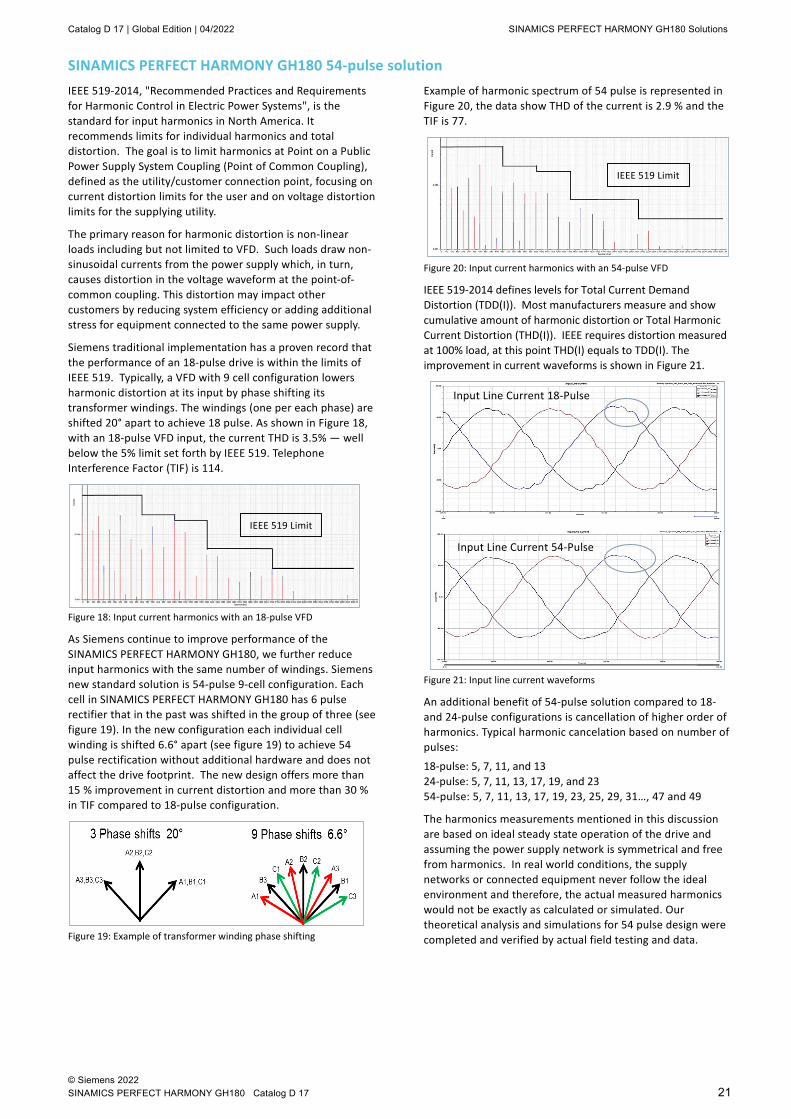
Example of harmonic spectrum of 54 pulse is represented in Figure 20, the data show THD of the current is 2.9 % and the TIF is 77.
Figure 20: Input current harmonics with an 54-pulse VFD
IEEE 519-2014 defines levels for Total Current Demand Distortion (TDD(I)). Most manufacturers measure and show cumulative amount of harmonic distortion or Total Harmonic Current Distortion (THD(I)). IEEE requires distortion measured at 100% load, at this point THD(I) equals to TDD(I). The improvement in current waveforms is shown in Figure 21.
Figure 21: Input line current waveforms
An additional benefit of 54-pulse solution compared to 18- and 24-pulse configurations is cancellation of higher order of harmonics. Typical harmonic cancelation based on number of pulses:
18-pulse: 5, 7, 11, and 13 24-pulse: 5, 7, 11, 13, 17, 19, and 23 54-pulse: 5, 7, 11, 13, 17, 19, 23, 25, 29, 31…, 47 and 49
The harmonics measurements mentioned in this discussion are based on ideal steady state operation of the drive and assuming the power supply network is symmetrical and free from harmonics. In real world conditions, the supply networks or connected equipment never follow the ideal environment and therefore, the actual measured harmonics would not be exactly as calculated or simulated. Our theoretical analysis and simulations for 54 pulse design were completed and verified by actual field testing and data.
IEEE 519 Limit
IEEE 519 Limit
Input Line Current 18-Pulse
Input Line Current 54-Pulse
SINAMICS PERFECT HARMONY GH180 Solutions Catalog D 17 | Global Edition | 04/2022
© Siemens 2022 22 SINAMICS PERFFECT HARMONY GH180 Catalog D 17
SINAMICS PERFECT HARMONY GH180 Water-Cooled Drive
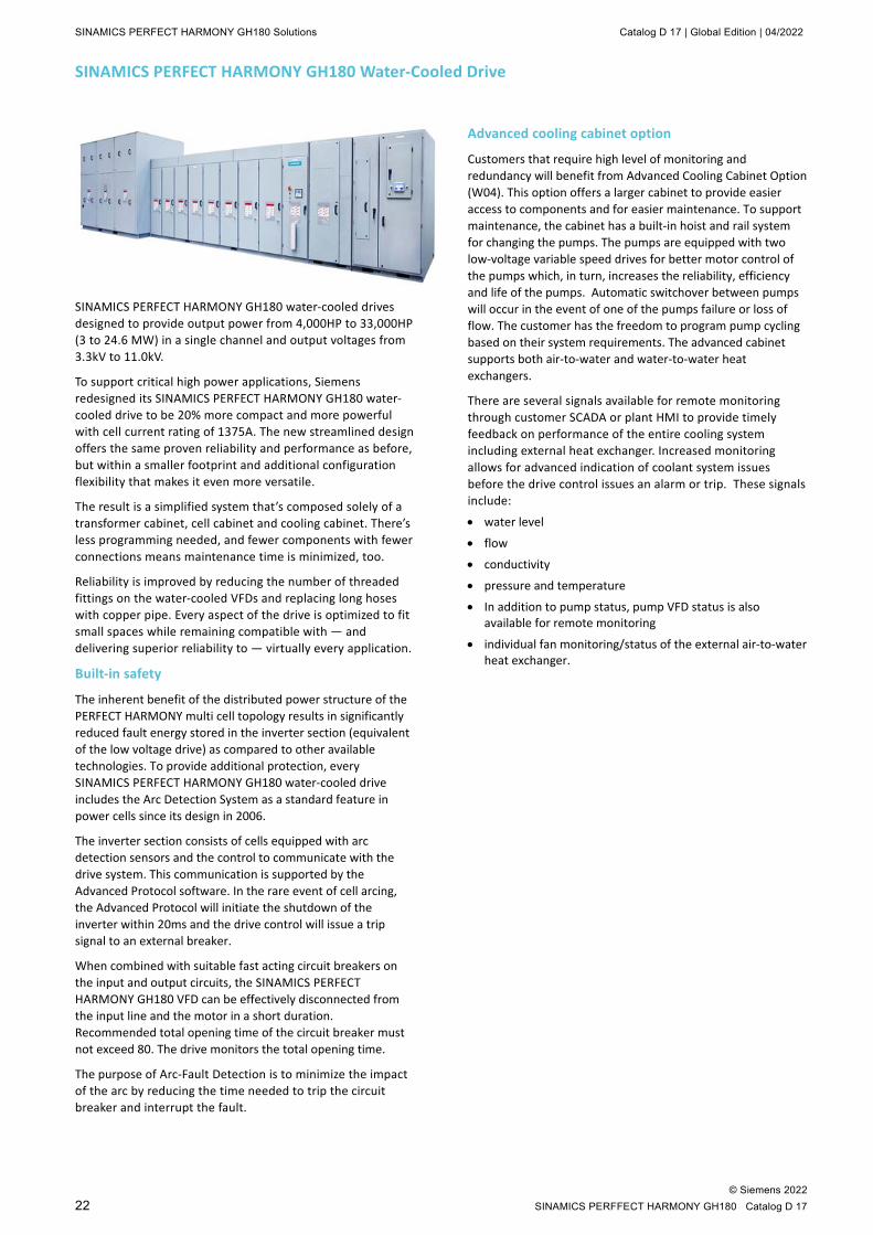
SINAMICS PERFECT HARMONY GH180 water-cooled drives designed to provide output power from 4,000HP to 33,000HP (3 to 24.6 MW) in a single channel and output voltages from 3.3kV to 11.0kV.
To support critical high power applications, Siemens redesigned its SINAMICS PERFECT HARMONY GH180 water-cooled drive to be 20% more compact and more powerful with cell current rating of 1375A. The new streamlined design offers the same proven reliability and performance as before, but within a smaller footprint and additional configuration flexibility that makes it even more versatile.
The result is a simplified system that’s composed solely of a transformer cabinet, cell cabinet and cooling cabinet. There’s less programming needed, and fewer components with fewer connections means maintenance time is minimized, too.
Reliability is improved by reducing the number of threaded fittings on the water-cooled VFDs and replacing long hoses with copper pipe. Every aspect of the drive is optimized to fit small spaces while remaining compatible with — and delivering superior reliability to — virtually every application.
Built-in safety
The inherent benefit of the distributed power structure of the PERFECT HARMONY multi cell topology results in significantly reduced fault energy stored in the inverter section (equivalent of the low voltage drive) as compared to other available technologies. To provide additional protection, every SINAMICS PERFECT HARMONY GH180 water-cooled drive includes the Arc Detection System as a standard feature in power cells since its design in 2006.
The inverter section consists of cells equipped with arc detection sensors and the control to communicate with the drive system. This communication is supported by the Advanced Protocol software. In the rare event of cell arcing, the Advanced Protocol will initiate the shutdown of the inverter within 20ms and the drive control will issue a trip signal to an external breaker.
When combined with suitable fast acting circuit breakers on the input and output circuits, the SINAMICS PERFECT HARMONY GH180 VFD can be effectively disconnected from the input line and the motor in a short duration. Recommended total opening time of the circuit breaker must not exceed 80. The drive monitors the total opening time.
The purpose of Arc-Fault Detection is to minimize the impact of the arc by reducing the time needed to trip the circuit breaker and interrupt the fault.
Advanced cooling cabinet option
Customers that require high level of monitoring and redundancy will benefit from Advanced Cooling Cabinet Option (W04). This option offers a larger cabinet to provide easier access to components and for easier maintenance. To support maintenance, the cabinet has a built-in hoist and rail system for changing the pumps. The pumps are equipped with two low-voltage variable speed drives for better motor control of the pumps which, in turn, increases the reliability, efficiency and life of the pumps. Automatic switchover between pumps will occur in the event of one of the pumps failure or loss of flow. The customer has the freedom to program pump cycling based on their system requirements. The advanced cabinet supports both air-to-water and water-to-water heat exchangers.
There are several signals available for remote monitoring through customer SCADA or plant HMI to provide timely feedback on performance of the entire cooling system including external heat exchanger. Increased monitoring allows for advanced indication of coolant system issues before the drive control issues an alarm or trip. These signals include:
• water level
• flow
• conductivity
• pressure and temperature
• In addition to pump status, pump VFD status is also available for remote monitoring
• individual fan monitoring/status of the external air-to-water heat exchanger.
Catalog D 17 | Global Edition | 04/2022 Options
© Siemens 2022 SINAMICS PERFECT HARMONY GH180 Catalog D 17 23
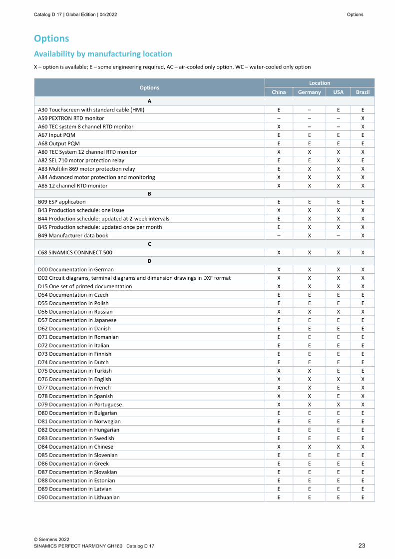
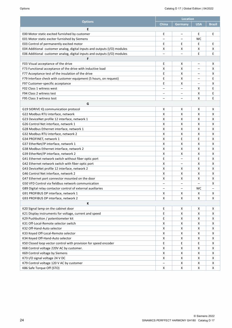
Options Availability by manufacturing location X – option is available; E – some engineering required, AC – air-cooled only option, WC – water-cooled only option
Options Location
China Germany USA Brazil A
A30 Touchscreen with standard cable (HMI) E – E E A59 PEXTRON RTD monitor – – – X A60 TEC system 8 channel RTD monitor X – – X A67 Input PQM E E E E A68 Output PQM E E E E A80 TEC System 12 channel RTD monitor X X X X A82 SEL 710 motor protection relay E E X E A83 Multilin 869 motor protection relay E X X X A84 Advanced motor protection and monitoring X X X X A85 12 channel RTD monitor X X X X
B B09 ESP application E E E E B43 Production schedule: one issue X X X X B44 Production schedule: updated at 2-week intervals E X X X B45 Production schedule: updated once per month E X X X B49 Manufacturer data book – X – X
C C68 SINAMICS CONNNECT 500 X X X X
D D00 Documentation in German X X X X D02 Circuit diagrams, terminal diagrams and dimension drawings in DXF format X X X X D15 One set of printed documentation X X X X D54 Documentation in Czech E E E E D55 Documentation in Polish E E E E D56 Documentation in Russian X X X X D57 Documentation in Japanese E E E E D62 Documentation in Danish E E E E D71 Documentation in Romanian E E E E D72 Documentation in Italian E E E E D73 Documentation in Finnish E E E E D74 Documentation in Dutch E E E E D75 Documentation in Turkish X X E E D76 Documentation in English X X X X D77 Documentation in French X X E X D78 Documentation in Spanish X X E X D79 Documentation in Portuguese X X X X D80 Documentation in Bulgarian E E E E D81 Documentation in Norwegian E E E E D82 Documentation in Hungarian E E E E D83 Documentation in Swedish E E E E D84 Documentation in Chinese X X X X D85 Documentation in Slovenian E E E E D86 Documentation in Greek E E E E D87 Documentation in Slovakian E E E E D88 Documentation in Estonian E E E E D89 Documentation in Latvian E E E E D90 Documentation in Lithuanian E E E E
Options Catalog D 17 | Global Edition | 04/2022
© Siemens 2022 24 SINAMICS PERFFECT HARMONY GH180 Catalog D 17
Options Location
China Germany USA Brazil E
E00 Motor static excited furnished by customer E – E E E01 Motor static exciter furnished by Siemens – – WC E03 Control of permanently excited motor E E E E E04 Additional customer analog, digital inputs and outputs (I/O) modules X X X X E06 Additional customer analog, digital inputs and outputs (I/O) modules – – E E
F F03 Visual acceptance of the drive E X – X F73 Functional acceptance of the drive with inductive load X X – X F77 Acceptance test of the insulation of the drive E X – X F79 Interface check with customer equipment (5 hours, on request) E X – E F97 Customer-specific acceptance E X – X F02 Class 1 witness west – – X E F94 Class 2 witness test – – X E F95 Class 3 witness test – – X E
G G19 SIDRIVE IQ communication protocol X X X X G22 Modbus RTU interface, network X X X X G23 DeviceNet profile 12 interface, network 1 X X X X G26 Control Net interface, network 1 X X X X G28 Modbus Ethernet interface, network 1 X X X X G32 Modbus RTU interface, network 2 X X X X G34 PROFINET, network 1 X E E X G37 EtherNet/IP interface, network 1 X X X X G38 Modbus Ethernet interface, network 2 X X X X G39 EtherNet/IP interface, network 2 X X X X G41 Ethernet network switch without fiber optic port E – E X G42 Ethernet network switch with fiber optic port X – X X G43 DeviceNet profile 12 interface, network 2 X X X X G46 Control Net interface, network 2 X X X X G47 Ethernet port connector mounted on the door X X X X G50 VFD Control via fieldbus network communication – – – X G89 Digital relay contactor control of external auxiliaries – – WC – G91 PROFIBUS DP interface, network 1 X X X X G93 PROFIBUS DP interface, network 2 X X X X
K K20 Signal lamp on the cabinet door E X X X K21 Display instruments for voltage, current and speed E X X X K29 Pushbutton / potentiometer kit E X X X K31 Off-Local-Remote selector switch X X X X K32 Off-Hand-Auto selector X X X X K33 Keyed Off-Local-Remote selector X X X X K34 Keyed Off-Hand-Auto selector X X X X K50 Closed loop vector control with provision for speed encoder E E E X K68 Control voltage 220V AC by customer. X X X X K69 Control voltage by Siemens X X X X K73 I/O signal voltage 24 V DC X X X X K79 Control voltage 120 V AC by customer – X X X K86 Safe Torque Off (STO) X X X X
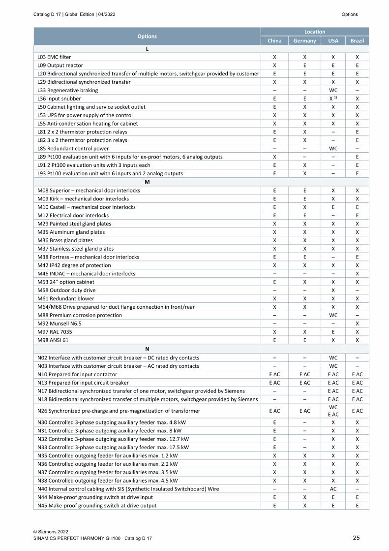
Catalog D 17 | Global Edition | 04/2022 Options
© Siemens 2022 SINAMICS PERFECT HARMONY GH180 Catalog D 17 25
Options Location
China Germany USA Brazil L
L03 EMC filter X X X X L09 Output reactor X E E E L20 Bidirectional synchronized transfer of multiple motors, switchgear provided by customer E E E E L29 Bidirectional synchronized transfer X X X X L33 Regenerative braking – – WC – L36 Input snubber E E X 1) X L50 Cabinet lighting and service socket outlet E X X X L53 UPS for power supply of the control X X X X L55 Anti-condensation heating for cabinet X X X X L81 2 x 2 thermistor protection relays E X – E L82 3 x 2 thermistor protection relays E X – E L85 Redundant control power – – WC – L89 Pt100 evaluation unit with 6 inputs for ex-proof motors, 6 analog outputs X – – E L91 2 Pt100 evaluation units with 3 inputs each E X – E L93 Pt100 evaluation unit with 6 inputs and 2 analog outputs E X – E
M M08 Superior – mechanical door interlocks E E X X M09 Kirk – mechanical door interlocks E E X X M10 Castell – mechanical door interlocks E X E E M12 Electrical door interlocks E E – E M29 Painted steel gland plates X X X X M35 Aluminum gland plates X X X X M36 Brass gland plates X X X X M37 Stainless steel gland plates X X X X M38 Fortress – mechanical door interlocks E E – E M42 IP42 degree of protection X X X X M46 INDAC – mechanical door interlocks – – – X M53 24” option cabinet E X X X M58 Outdoor duty drive – – X – M61 Redundant blower X X X X M64/M68 Drive prepared for duct flange connection in front/rear X X X X M88 Premium corrosion protection – – WC – M92 Munsell N6.5 – – – X M97 RAL 7035 X X E X M98 ANSI 61 E E X X
N N02 Interface with customer circuit breaker – DC rated dry contacts – – WC – N03 Interface with customer circuit breaker – AC rated dry contacts – – WC – N10 Prepared for input contactor E AC E AC E AC E AC N13 Prepared for input circuit breaker E AC E AC E AC E AC N17 Bidirectional synchronized transfer of one motor, switchgear provided by Siemens – – E AC E AC N18 Bidirectional synchronized transfer of multiple motors, switchgear provided by Siemens – – E AC E AC
N26 Synchronized pre-charge and pre-magnetization of transformer E AC E AC WC E AC E AC
N30 Controlled 3-phase outgoing auxiliary feeder max. 4.8 kW E – X X N31 Controlled 3-phase outgoing auxiliary feeder max. 8 kW E – X X N32 Controlled 3-phase outgoing auxiliary feeder max. 12.7 kW E – X X N33 Controlled 3-phase outgoing auxiliary feeder max. 17.5 kW E – X X N35 Controlled outgoing feeder for auxiliaries max. 1.2 kW X X X X N36 Controlled outgoing feeder for auxiliaries max. 2.2 kW X X X X N37 Controlled outgoing feeder for auxiliaries max. 3.5 kW X X X X N38 Controlled outgoing feeder for auxiliaries max. 4.5 kW X X X X N40 Internal control cabling with SIS (Synthetic Insulated Switchboard) Wire – – AC – N44 Make-proof grounding switch at drive input E X E E N45 Make-proof grounding switch at drive output E X E E
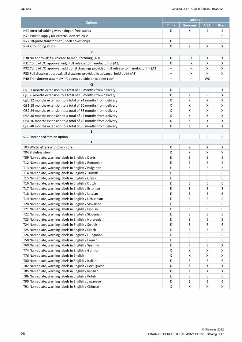
Options Catalog D 17 | Global Edition | 04/2022
© Siemens 2022 26 SINAMICS PERFFECT HARMONY GH180 Catalog D 17
Options Location
China Germany USA Brazil N50 Internal cabling with halogen-free cables E X E E N75 Power supply for external devices 24 V – – – E N77 18-pulse transformer (9-cell drives only) X – – E N94 Grounding studs X X X X
P
P30 No approval; full release to manufacturing (A0) X X X X P31 Control I/O approval only; full release to manufacturing (A1) X X X X P32 Control I/O approval; additional drawings provided; full release to manufacturing (A2) – – X X P33 Full drawing approval; all drawings provided in advance; hold point (A3) – X X X P40 Transformer assembly lift points outside on cabinet roof – – WC –
Q Q78 3 months extension to a total of 15 months from delivery X – – X Q79 6 months extension to a total of 18 months from delivery X X – X Q80 12 months extension to a total of 24 months from delivery X X X X Q81 18 months extension to a total of 30 months from delivery X X X X Q82 24 months extension to a total of 36 months from delivery X X X X Q83 30 months extension to a total of 42 months from delivery X X X X Q84 36 months extension to a total of 48 months from delivery X X X X Q85 48 months extension to a total of 60 months from delivery X X X X
S S17 Unmanned station option – – E E
T T03 White letters with black core X X X X T04 Stainless steel X X X X T09 Nameplate, warning labels in English / Danish E E E E T12 Nameplate, warning labels in English / Romanian E E E E T13 Nameplate, warning labels in English / Bulgarian E E E E T14 Nameplate, warning labels in English / Turkish E E E E T15 Nameplate, warning labels in English / Greek E E E E T16 Nameplate, warning labels in English / Dutch E E E E T17 Nameplate, warning labels in English / Estonian E E E E T18 Nameplate, warning labels in English / Latvian E E E E T19 Nameplate, warning labels in English / Lithuanian E E E E T20 Nameplate, warning labels in English / Slovakian E E E E T21 Nameplate, warning labels in English / Finnish E E E E T22 Nameplate, warning labels in English / Slovenian E E E E T23 Nameplate, warning labels in English / Norwegian E E E E T24 Nameplate, warning labels in English / Swedish E E E E T25 Nameplate, warning labels in English / Czech E E E E T26 Nameplate, warning labels in English / Hungarian E E E E T58 Nameplate, warning labels in English / French E E E E T60 Nameplate, warning labels in English / Spanish E E E X T74 Nameplate, warning labels in English / German X X X X T76 Nameplate, warning labels in English X X X X T80 Nameplate, warning labels in English / Italian E E E E T82 Nameplate, warning labels in English / Portuguese X X X X T85 Nameplate, warning labels in English / Russian X X X X T86 Nameplate, warning labels in English / Polish E E E E T90 Nameplate, warning labels in English / Japanese E E E E T91 Nameplate, warning labels in English / Chinese X X X X
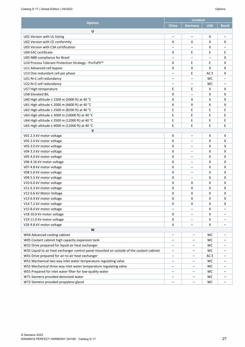
Catalog D 17 | Global Edition | 04/2022 Options
© Siemens 2022 SINAMICS PERFECT HARMONY GH180 Catalog D 17 27
Options Location
China Germany USA Brazil U
U01 Version with UL listing – – X – U02 Version with CE conformity X X X X U03 Version with CSA certification – – X – U04 EAC certificate X E E E U05 NBR compliance for Brazil – – – X U10 Process Tolerant Protection Strategy - ProToPS™ X E E X U11 Advanced cell bypass X X X X U13 One redundant cell per phase – E AC E X U21 N+1 cell redundancy – – WC – U22 N+2 cell redundancy – – WC – U57 High temperature E E X X U58 Elevated BIL X – X X U60 High altitude ≤ 1500 m (5000 ft) at 40 °C X X X X U61 High altitude ≤ 2000 m (6600 ft) at 40 °C X X X X U62 High altitude ≤ 2500 m (8200 ft) at 40 °C E E E E U63 High altitude ≤ 3000 m (10000 ft) at 40 °C E E E E U64 High altitude ≤ 3500 m (12000 ft) at 40 °C E E E E U65 High altitude ≤ 4000 m (13300 ft) at 40 °C E E E E
V V01 2.3 kV motor voltage X – X X V02 2.4 kV motor voltage X – X X V03 3.0 kV motor voltage X – X X V04 3.3 kV motor voltage X – X X V05 4.0 kV motor voltage X – X X V06 4.16 kV motor voltage X – X X V07 4.8 kV motor voltage X – X X V08 5.0 kV motor voltage X – X X V09 5.5 kV motor voltage X – X X V10 6.0 kV motor voltage X X X X V11 6.3 kV motor voltage X X X X V12 6.6 kV Motor Voltage X X X X V13 6.9 kV motor voltage X X X X V14 7.2 kV motor voltage X X X X V15 8.0 kV motor voltage – – X – V18 10.0 kV motor voltage X – X – V19 11.0 kV motor voltage X – X – V26 9.8 kV motor voltage X – X –
W W04 Advanced cooling cabinet – – WC – W05 Coolant cabinet high capacity expansion tank – – WC – W32 Drive prepared for liquid-air heat exchanger – – WC – W35 Liquid to air heat exchanger control panel mounted on outside of the coolant cabinet – – WC – W41 Drive prepared for air-to-air heat exchanger – – AC E – W51 Mechanical two way inlet water temperature regulating valve – – WC – W52 Mechanical three way inlet water temperature regulating valve – – WC – W55 Prepared for inlet water filter for low-quality water – – WC – W71 Siemens provided deionized water – – WC – W72 Siemens provided propylene glycol – – WC –
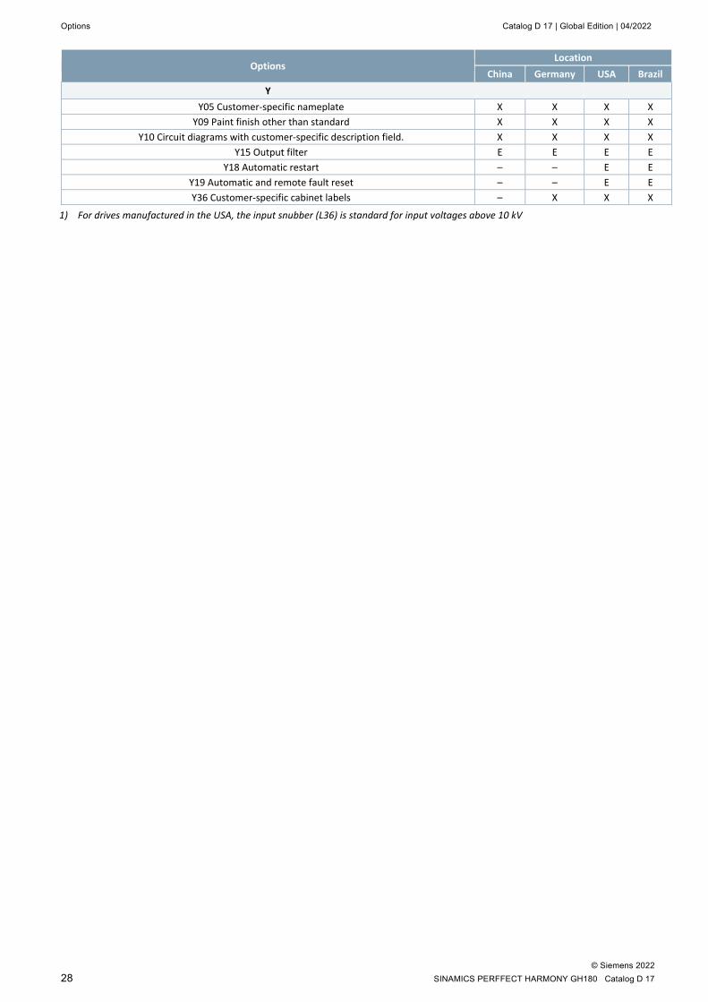
Options Catalog D 17 | Global Edition | 04/2022
© Siemens 2022 28 SINAMICS PERFFECT HARMONY GH180 Catalog D 17
Options Location
China Germany USA Brazil Y
Y05 Customer-specific nameplate X X X X Y09 Paint finish other than standard X X X X
Y10 Circuit diagrams with customer-specific description field. X X X X Y15 Output filter E E E E
Y18 Automatic restart – – E E Y19 Automatic and remote fault reset – – E E Y36 Customer-specific cabinet labels – X X X
1) For drives manufactured in the USA, the input snubber (L36) is standard for input voltages above 10 kV
Catalog D 17 | Global Edition | 04/2022 Options
© Siemens 2022 SINAMICS PERFECT HARMONY GH180 Catalog D 17 29
Option descriptions
Availability options
Cell redundancy
Processes that cannot tolerate a reduction in drive power when one or more cells are in bypass should select the cell redundancy option. This option significantly increases drive availability when long intervals between services are required. This option is scalable depending on your process requirements. Cell Redundancy options require cell bypass.
Option Description
U13 One redundant cell per phase (for air cooling only) Option U13 provides full output power with a bypassed cell in each phase. This option adds extra three cells to the drive (i.e. one cell per phase).
Note: Option U13 requires cell bypass (U11) and redundant blower (M61). Not available for output voltages 6.6, 6.9, 7.2, 11 kV.
U21 N+1 cell redundancy (for water cooling only) Option U21 provides rated power operation with one cell bypassed.
Note: Option U21 requires cell bypass option (U11) and redundant pump. Not available with all output voltages. For details, please contact your Siemens sales partner.
U22 N+2 cell redundancy (for water cooling only) Option U22 provides rated power operation with two cells bypassed.
Note: Option U22 requires cell bypass option (U11) and redundant pump. Not available with all output voltages. For details, please contact your Siemens sales partner.
Option Description
U11 Advanced cell bypass Cell bypass provides a higher level of system availability and process reliability. In less than a quarter of a second (250 ms), the drive can bypass failed cells and maintain a balanced output voltage. With one cell in bypass, the drive still produces sufficient voltage to allow the process to continue uninterrupted, and the quality of the voltage and the waveform remain virtually unchanged. To ensure the most reliability and availability, the VFD is equipped with mechanical cell bypass with independent power supply and control communication. This cell bypass can be tested and demonstrated during witness testing.
Loss of cells reduces the drive’s power capability; torque is reduced only when the drive’s power capability exceeds the designed limit. Faulted cells can be replaced at a convenient planned maintenance window.
For some applications with low load inertia, such as an ESP, during the cell bypass the speed may rapidly decelerate. In such applications where a process trip may be issued by the system control, use of manual cell bypass is recommended.
Manual cell bypass is configured in the drive operating system. When a cell fault occurs, the drive will trip on the cell fault. The user can reset the fault, which triggers a cell bypass, and can then proceed to re-start the drive. The reset can be done through plant HMI or SCADA.
Option Description
U10 Process Tolerant Protection Strategy - ProToPS™ With a proven record of 99.99 percent process uptime, ProToPS™ protects the customer process from faulty sensors or data. ProToPS™ offers a proactive control strategy for applications where failure avoidance is critical. It provides a hierarchical system of warnings in advance of potential drive system trip. This control strategy allows time for the operator to evaluate the situation and respond appropriately to avoid a system shutdown. This option requires advanced cell bypass (option U11) and redundant blower (option M61) for maximum performance.
Option Description
M61 Redundant blower To improve system availability, an additional blower is added to the air-cooled drive. If a blower fails, the cooling system is automatic switched over to redundant blower to ensure uninterrupted drive operation. A fan alarm fault will be annunciated. This prevents production down time or disruptions.
Option Description
L53 UPS for power supply of the control In the instances where UPS back up for low voltage network is not available on site, the drive can be equipped with a UPS to maximize up time during low voltage power interruptions. The UPS provides back up power for the drive control and is configured for a buffer time of up to 8 min.
Note: Option L53 is available for 120 V or 220V AC only.
Option Description
L85 Redundant control power (for water cooling only) This option provides a second low voltage network control input with automatic switch over to prevent unnecessary interruptions and down time in case the first low voltage supply fails. This option includes UPS.
Note: Option L85 is available for water-cooled drives only and requires an additional cabinet.
Options Catalog D 17 | Global Edition | 04/2022
© Siemens 2022 30 SINAMICS PERFFECT HARMONY GH180 Catalog D 17
Safety options
Option Description
K86 Safe Torque Off (STO) The option K86 provides an efficient electronically based "Safe Torque Off" (STO) sub function which can be easily integrated into a completed machine's Safe Torque Off safety function. The safety related STO function is a mechanism for preventing the drive from unexpectedly starting according to EN 60204-1:2006/A1:2009, Section 5.4. The function is integrated in the drive and is independent of the converter operating functions. It is used in conjunction with a machine function – or in the case of a fault – to disconnect the torque-generating energy feed to the motor in a safety-related fashion. There are two independent switch-off signal paths, which are both failsafe (low-active). This ensures that when a component fails or a cable is interrupted, the system always goes into the safe state. The following points apply when the STO function is selected: • The motor cannot inadvertently start. • The torque-generating energy feed to the motor is
safely interrupted because of the safety-related pulse cancellation.
• VFD output is not electrically disconnected.
The STO function is certified in accordance with IEC 61800-5-2 with a safety integrity level (SIL) of up to 3 with a hardware fault tolerance (HFT) of 1 as defined in IEC 61508. STO meets EN ISO 13849-1:2015 Safety Category 3 Performance Level e.
Door interlocks SINAMICS PERFECT HARMONY GH180, 6SR5 drives are designed with bolted covers as a standard option. For customers that would like to have keyed access, there are 4 types of mechanical interlocks available depending on customer preference. Safety closing/interlocking system is based on the key transfer system. Typically, the circuit breaker is opened, and a feeder earthed to release a key to the drive key exchange unit which in turn releases the keys to the cabinet bolted covers of the power section(s). This ensures that the drive is isolated from the input medium voltage and that the medium voltage is no longer present. The number of keys will depend on the number of cabinets.
Option Description
M08 Superior - mechanical door interlocks M09 Kirk - mechanical door interlocks M10 Castell - mechanical door interlocks M38 Fortress - mechanical door interlocks M46 INDAC - mechanical door interlocks M12 Electrical door interlocks
The electrical door interlock system prevents access to the energized sections in the drive as long as hazardous voltages are present. This system also prevents the drive from being switched on until all doors of the energized sections in the drive are closed.
Note: GH180 air-cooled as a default is supplied with M09, Kirk key interlocks in North America or M12 electrical door interlocks in Europe and China.
Option Description
N10 Prepared for input contactor Input contactor allows customers to isolate medium voltage drive for maintenance or repairs purposes without disconnecting primary protection. This option is recommended when multiple medium voltage drives are installed at the single site connected to common upstream protection. The benefit of an input contactor is that it is capable to break full current while input disconnect only can be opened after primary protection is opened. Selecting this option will add switchgear to the drive on the side. When option N10 is chosen, the appropriate switchgear sizing is automatically selected based on the other drive parameters.
Note The input contactor option is available when the primary input voltage is less than 7.2 kV.
Option Description
N13 Prepared for input circuit breaker Input contactors are only available for input voltage up to 7200V. When input voltage exceeds this, a circuit breaker is an appropriate solution. Selecting this option will add switchgear to the drive on the side. When option N13 is chosen, the appropriate switchgear sizing is automatically selected based on the other drive parameters.

Catalog D 17 | Global Edition | 04/2022 Options
© Siemens 2022 SINAMICS PERFECT HARMONY GH180 Catalog D 17 31
Option Description
N94 Grounding studs This option provides protective grounds to create an electrically safe work condition during maintenance. The ground studs will be installed in the following locations: Input and output power terminations and ground pads. The terminations will be equipped with a ball type ground stud.
Note: Grounding cable and/or clamps are not included
Option Description
N44 Make-proof grounding switch at drive input With option N44, a grounding switch is installed at the drive input. The switch connects each phase to ground to prevent unexpected reconnections during maintenance. For safety reasons, the drive control locks the ground switch open (OFF) using electromagnetic interlocks until the drive input voltage is removed (OFF) and 10 min have passed to allow the power cell capacitors to discharge; only then can the ground switch be closed (ON). The control is integrated into the protection and monitoring circuit of the drive. In the event of maintenance work on the drive, it must be ensured on the plant side that there is no external voltage present, e.g. auxiliary voltage for blowers, the cooling system, controller and closed-loop control and any external drive outputs.
Note: This option for 9 cell air-cooled configuration requires an additional cabinet
N45 Make-proof grounding switch at drive output With option N45, a grounding switch is installed at the drive output. Some applications (ex: gas turbines or permanent magnet motor) may regenerate and feed energy back to the drive. In such instances, a make-proof grounding switch is recommended. The switch connects each phase to ground to prevent unexpected voltage during maintenance. For safety reasons, the drive control locks the ground switch open (OFF) using electromagnetic interlocks until the drive input voltage is removed (OFF) and 10 min have passed to allow the power cell capacitors to discharge; only then can the ground switch be closed (ON). The control is integrated into the protection and monitoring circuit of the drive.
Note: This option for 9 cell air-cooled configuration requires an additional cabinet Options N44 and/or N45 are recommended for applications within Europe.
Control and display Instruments
Option Description
A30 Touchscreen with standard cable Standard Siemens touchscreen with standard Ethernet cable will be provided on the door of the drive. Standard HMI shall be loaded with ToolSuite software only.
Note: Air-cooled 9-cell configuration and all water-cooled drives require an additional cabinet
Control selector switches and push buttons
These switches provide the operator with the flexibility to select preferred drive control mode: local through keypad, remote/auto control through digital inputs or serial communication.
Option Description
K29 Pushbutton / Potentiometer kit With option K29, a pushbutton kit is located on the control door. It includes • a start and a stop pushbutton • a fault reset button and a manual speed
potentiometer Emergency Stop pushbutton is standard.
K31 Off-Local-Remote selector switch Option K31 provides the ability to choose between off, local control and remote control of the three position selector switch mounted on the control door.
K32 Off-Hand-Auto selector A three-position selector switch mounted on the control door.
K33 Keyed Off-Local-Remote selector It offers the same functionality as option K31 but this option provides additional protection as it requires keys (password) to change the position.
K34 Keyed Off-Hand-Auto selector It offers the same functionality as option K32 but this option provides additional protection as it requires keys (password) to change the position.
Note: Option K31 is the default configuration.
Option Description
L50 Cabinet lighting and service socket outlet This option includes a universal lamp and a service socket outlet (Schuko version) installed in the control cabinet. The voltage supply for the cabinet lighting and socket outlet (on terminal block) is provided externally. The cabinet lighting is switched on manually via a switch.
Note: This option for 9 cell air-cooled configuration requires an additional cabinet. Air-cooled option only.
Options Catalog D 17 | Global Edition | 04/2022
© Siemens 2022 32 SINAMICS PERFFECT HARMONY GH180 Catalog D 17
Auxiliary and control voltage supply
Option Description
K69 Control voltage by Siemens This option provides control voltage that is generated internally from the auxiliary supply.
K68 Control voltage 220/230/240V AC by customer Using option K68, the customer will supply control voltage to the drive. Typical current consumption is 8 A. The internal control voltage will be 120 V AC in any case. For water-cooled drives, it requires an additional cabinet.
K73 I/O signal voltage 24 V DC This option provides 24 V DC that is available as I/O control signals.
K79 Control voltage 120 V AC by customer The customer will provide control voltage to the drive
Signal lamp and display instruments
Signal lamps and display instruments are hardwired options that provide quick visual display of drive performance and health. The same parameters are also available through the drive HMI.
Option Description
K20 Signal lamp in the cabinet door With option K20, five signal lamps that display the operating status of the drive are provided in the cabinet door of the control section. • Fault (red) • Alarm (yellow) • Operation (green) • Drive ready (white) • Local operation (white)
K21 Display instruments for voltage, current and speed For display of process variables, analog display instruments are installed in the cabinet door indicating the measured value in %: • Motor current (0 to +120 %) • Motor speed (–120 % … 0 … +120 %) • Motor voltage (0 to +120 %)
Note: For manufacturing location USA, K21 option requires additional cabinet.
Controlled outgoing feeder for auxiliaries
This option provides a control of outgoing feeder for the operation of external auxiliary equipment, e.g. separate blowers on the motor, anti-condensation heating for the motor or pump/oil supplies. It is controlled and protected by motor circuit-breakers. The contactor is switched on with the ON command at the drive and switched off with the OFF command. Should local regulations require earth leakage protection then that is done from the external feeder supply.
Option Description
N30 Controlled outgoing feeder for auxiliaries 400 V 3 AC, 50 Hz, max. 4 kW 469 V / 480 V 3 AC, 60 Hz, max. 4.8 kW (cos φ = 0.8; setting range of motor circuit-breaker from 9 A to 12.5 A).
N31 Controlled outgoing feeder for auxiliaries 400 V 3 AC, 50 Hz, max. 7 kW 469 V / 480 V 3 AC, 60 Hz, max. 8 kW (cos φ = 0.8; setting range of motor circuit-breaker from 14 A to 20 A).
N32 Controlled outgoing feeder for auxiliaries 400 V 3 AC, 50 Hz, max. 11 kW 469 V / 480 V 3 AC, 60 Hz, max. 12.7 kW (cos φ = 0.8; setting range of motor circuit-breaker from 18 A to 25 A).
N33 Controlled outgoing feeder for auxiliaries 400V, 3Φ AC, 50Hz, max. 15kW 469 V / 480 V, 3 AC, 60 Hz, max. 17.5 kW (cos φ = 0.8; setting range of motor circuit-breaker from 28 A to 40 A).
N35 Controlled outgoing feeder for auxiliaries 110/120 or 220/240 V 1 AC, max. 1.2 kW
N36 Controlled outgoing feeder for auxiliaries 110/120 or 220/240 V 1 AC, max. 2.2 kW
N37 Controlled outgoing feeder for auxiliaries 110/120 or 220/240 V 1 AC, max. 3.5 kW
N38 Controlled outgoing feeder for auxiliaries 110/120 or 220/240 V 1 AC, max. 4.5 kW
Note: These options for 9 cell air-cooled configuration require an additional cabinet.
Option Description
N75 Power supply for external devices 24 V DC With option N75 the drive is delivered with a power supply unit for 24 V DC auxiliaries. It provides 6 output terminals each for +24 V and 0 V. The total power con-sumption across all output terminals is limited to 2.5 A.

Catalog D 17 | Global Edition | 04/2022 Options
© Siemens 2022 SINAMICS PERFECT HARMONY GH180 Catalog D 17 33
Option Description
L55 Anti-condensation heating for cabinet Anti-condensation heaters are recommended at low ambient temperatures and high levels of humidity to prevent condensation. The number of cabinet heaters fitted depends on the number of cabinet panels. The anti-condensation heaters are controlled with a thermostat.
Note: This option includes over-temperature protection. The supply voltage for the anti-condensation heating (110/120 or 220/240 V AC) must be supplied externally.
Should local regulation require earth leakage protection then that is done from the external feeder supply.
If drives are placed in storage for any period of time, Siemens recommends anti-condensation heaters. The number of heaters depends on the size and quantity of cabinets in the drive.
Heat management options
Option Description
W41 Drive prepared for air-to-air heat exchanger
When this option is purchased, the drive is equipped with necessary plenums to ensure proper drive airflow when connected to the heat exchanger. The drive comes with the heat exchanger control box.
All heat exchanger fan motors are wired to the control box and can be either mounted on the side of the drive or outside on the heat exchanger itself in the NEMA 4 enclosure.
Note: The heat exchanger is standalone equipment specified and provided by Siemens. It is enclosed in polycoated housing with fans for N+1 redundancy. The enclosure includes a top hat that directs the outside air horizontally out of the top of the unit. The top contains louvers to prevent a draft when the fans are not running. The heat exchanger requires outdoor installation by others.
The heat exchanger can include optional provisions, such as integral space heaters and motor/fan assemblies designed for low ambient operation at up to -40º C.
Option Description
M64 M68
Drive prepared for duct flange connection in front/rear With these options, the drive is prepared for connection to an external exhaust air system, which shall connect to the front (M64) of the blower assembly or to the rear (M68) of it. Only one of the options per drive.
These options are applicable when the customer is providing external exhaust ducting to carry the hot air blowing out of the drive cabinet outside the room.
When configuring the exhaust air ducts for the drive ventilation system, it is essential to ensure that the air flow rates stipulated in the technical data are observed. The pressure drop between the air inlet and the air outlet of the drive is different for different configurations.
Note: The following requirements shall be met when connecting to external air duct:
• Provide openings in the air duct to allow for the blowers’ maintenance.
• After fitting the air duct, the cabinet doors must still be able to be opened and closed for maintenance purposes.
This option can affect the values for sound pressure level depending on the design of the exhaust air system. For more details, please contact your Siemens sales partner.
Synchronous transfer options
Option Description
L29 Bidirectional synchronized transfer Option L29 provides the capability for synchronized, seamless transfer of the one motor to the line and take-over of the motor from the line. Before connecting the motor to the line, the converter synchronizes the motor to the supply/utility voltage phase, frequency and amplitude. Most applications do not require output reactor. Output reactor should be considered when the following conditions are present: • Excessive system short circuit current ratings • Excessive torque variations during steady state
operation, and • Extremely low motor/load inertia
Note: The circuit-breakers/contactors are not included in the scope of delivery. A motor protection relay should also be considered in the bypass circuit by the customer.
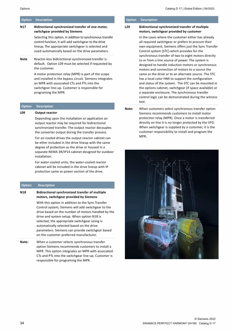
Options Catalog D 17 | Global Edition | 04/2022
© Siemens 2022 34 SINAMICS PERFFECT HARMONY GH180 Catalog D 17
Option Description
N17 Bidirectional synchronized transfer of one motor, switchgear provided by Siemens
Selecting this option, in addition to synchronous transfer control function, it will add switchgear to the drive lineup. The appropriate switchgear is selected and sized automatically based on the drive parameters.
Note Reactor-less bidirectional synchronized transfer is default. Option L09 must be selected if requested by the customer.
A motor protection relay (MPR) is part of the scope and installed in the bypass circuit. Siemens integrates an MPR with associated CTs and PTs into the switchgear line-up. Customer is responsible for programing the MPR.
Option Description
L09 Output reactor
Depending upon the installation or application an output reactor may be required for bidirectional synchronized transfer. The output reactor decouples the converter output during the transfer process.
For air-cooled drives the output reactor cabinet can be ether included in the drive lineup with the same degree of protection as the drive or housed in a separate NEMA 3R/IP14 cabinet designed for outdoor installation.
For water-cooled units, the water-cooled reactor cabinet will be included in the drive lineup with IP protection same as power section of the drive.
Option Description
N18 Bidirectional synchronized transfer of multiple motors, switchgear provided by Siemens
With this option in addition to the Sync Transfer Control system, Siemens will add switchgear to the drive based on the number of motors handled by the drive and system setup. When option N18 is selected, the appropriate switchgear sizing is automatically selected based on the drive parameters. Siemens can provide switchgear based on the customer preferred manufacturer.
Note: When a customer selects synchronous transfer option Siemens recommends customers to install a MPR. This option integrates an MPR with associated CTs and PTs into the switchgear line-up. Customer is responsible for programing the MPR.
Option Description
L20 Bidirectional synchronized transfer of multiple motors, switchgear provided by customer
In the cases where the customer either has already all required switchgear or prefers to procure their own equipment, Siemens offers just the Sync Transfer Control system (STC) which provides for the synchronous transfer of two to eight motors directly to or from a line source of power. The system is designed to handle induction motors or synchronous motors and connection of motors to a source the same as the drive or to an alternate source. The STC has a local color HMI to support the configuration and status of the system. The STC can be mounted in the options cabinet, switchgear (if space available) or a separate enclosure. The synchronous transfer control logic can be demonstrated during the witness test.
Note: When customers select synchronous transfer option Siemens recommends customers to install motor protection relay (MPR). Once a motor is transferred directly on line it is no longer protected by the VFD. When switchgear is supplied by a customer, it is the customer responsibility to install and program the MPR.

Catalog D 17 | Global Edition | 04/2022 Options
© Siemens 2022 SINAMICS PERFECT HARMONY GH180 Catalog D 17 35
Motor protection, monitoring and meters Motor temperature monitoring and protection solution by Siemens
Option Description
A84 Advanced Motor Protection and Monitoring
This option provides full featured integral motor protection and monitoring functions. The following functions included in the protection: • Overspeed (12) • Machine Thermal Model (49T) • Zero sequence overvoltages (59G*) • Motor Short Circuit (50) • Motor Ground Fault (51G*) • Starts per hour (66) • Inverse Time Overcurrent (51) • Undercurrent (37) • Underspeed (14) • Underpower (37P) • Bearing Temperature RTD (38) • Mechanical Condition Monitoring (39) • Current Unbalance, Negative Sequence (46_2) • Incomplete Sequence – maximum start time/
maximum stop time (48) • Machine Thermal Overload RTD (49 RTD) • Power Factor (55) • Over/Under Frequency (81) • High Frequency Rate of Change (81) • Differential protection equivelent (87M**)
This option includes the SIMATIC S7, SM 1231 AI thermocouple 12 channel RTD unit. It is compatible with most three-wire RTD types: • Pt100 is a default setting and others are available
on request.
The status and actual temperature are sent through the drive serial network to a customer DCS or Plant HMI.
All faults or alarms are stored and can be viewed through the drive event log.
Note: *Ground Fault detection in SINAMICS PERFECT HARMONY GH180 is based on detection of voltage imbalance or residual voltage. ** Differential protection equivelent 87M=46_2+59G Customer is responsible for programing based on their motor and process data. Customer is responsible for RTD programing based on their motor data. Distance between motor RTD and drive RTD input is 328 ft (100 m), for longer distances contact your Siemens sales partner.
Option Description
A85 12 channel RTD monitor
This option includes the SIMATIC S7, SM 1231 AI thermocouple 12 channel RTD unit. Each RTD input has an alarm and trip level. Thermal pickup setting is available in degrees C and F. Each RTD can be individually monitored.
A wide range of three-wire RTDs is supported: • Pt10, Pt50, Pt100, Pt200, Pt500, Pt1000, • Ni100, Ni120, Ni200, Ni500, Ni1000, • Cu10, Cu50, Cu100, LG-Ni1000.
Pt100 is a default setting and others are available on request
Ambient temperature reading: min. –145.0 °C, max. 145.0 °C
Accuracy: ±1.0 °C
Temperature: min. –200.0 °C, max. 850.0 °C
Trip temperature: Default: 150 °C
Range: 0 °C to 572 °C in steps of 1 °C
Dropout level: default 2 %; range 0 … 50 %
Pickup delay: default 10 s; range 0 … 180 s
Dropout delay: Default 5 s;
Range: 0 … 180 s
Maximum response time: 50 ms
The status and actual temperature are sent through the drive serial network to a customer DCS or Plant HMI.
All faults or alarms are stored and can be viewed through the drive event log.
Note: Customer is responsible for RTD programing based on their motor data.
Distance between motor RTD and drive RTD input is 328 ft (100 m), for longer distances contact your Siemens sales partner.

Options Catalog D 17 | Global Edition | 04/2022
© Siemens 2022 36 SINAMICS PERFFECT HARMONY GH180 Catalog D 17
Motor temperature monitoring and protection systems by other manufacturers
Option Description
A59 PEXTRON 8 channel RTD monitor A device installed in the drive to monitor motor temperature in windings and/or bearings. Basic 8-channel RTD monitor includes Modbus RTU communication protocol.
A60 TEC System 8 channel RTD monitor A device installed in the drive to monitor motor temperature in windings and/or bearings. Basic 8-channel RTD monitor.
A80 TEC System 12 channel RTD monitor A device installed in the drive to monitor motor temperature in windings and/or bearings. Basic 12-channel RTD monitor. Communication Protocol: None (default) RS 485 Modbus (option)
Note: Customer is responsible for RTD programing. If other protocols are required, please contact your Siemens sales partner..
Option Description
L81 2 x 2 thermistor protection relays
Option L81 includes four thermistor protection relays for PTC thermistors (type A) for alarm and trip. The power supply for the relay and the evaluation is provided in the drive.
L82 3 x 2 thermistor protection relays
Option L82 includes six thermistor protection relays for PTC thermistors (type A) for alarm and trip. The power supply for the relay and the evaluation is provided in the drive.
L89 Pt100 evaluation unit with 6 inputs for ex-proof motors and 6 analog outputs
For use in explosion-proof motors, Zone 2, Zone 22 (non-conductive dusts) Div. 2, and nonhazardous zones, six evaluation units are available. Marking, explosion protection: II (1) GD (Eex ia) IIC/IIB and II 3 G Eex nAC II T4.
L91 2 Pt100 evaluation units with 3 inputs each Each Pt100 unit can monitor up to three sensors. For all three sensors, the limits for alarm and trip must be set centrally. The output relays are integrated into the internal fault and shutdown circuit of the drive.
Option Description
L93 Pt100 evaluation unit with 6 inputs and 2 analog outputs
The Pt100 evaluation unit can monitor up to six sensors. The limit values can be programmed by the user for each channel. In the standard setting, the measuring channels are divided into two groups of three channels each. With motors, for example, three Pt100 can be monitored in the stator windings and two Pt100 in the motor bearings. Channels that are not used can be suppressed using appropriate parameter settings.
The output relays are integrated into the internal fault and shutdown circuit of the drive. There are two programmable analog outputs available (0/4 mA to 20 mA and 0/2 V to 10 V).
Option Description
A82 SEL 710 motor protection relay Full featured high-end motor protection/management relay with miscellaneous sensors monitoring capability installed. Communication Protocol: • none (default) • RS 485 Modbus (option) Includes output phase CTs and PTs.
A83 Multilin 869 motor protection relay Full featured high-end motor protection/management relay with miscellaneous sensors monitoring capability installed. Communication Protocol: • None (default) • RS 485 Modbus (option) Includes output phase CTs and PTs.
Note: These options for 9-cell air-cooled configuration and water-cooled drives require an additional cabinet.
Input and output meters
Option Description
A67 Input Power Quality Meter (PQM) Power quality meter installed at the input of the drive. Requires an additional cabinet
A68 Output Power Quality Meter (PQM) Power quality meter installed at the output of the drive. Requires an additional cabinet

Catalog D 17 | Global Edition | 04/2022 Options
© Siemens 2022 SINAMICS PERFECT HARMONY GH180 Catalog D 17 37
Customer communication, interface and control software options Communication options
As a default the SINAMICS PERFECT HARMONY GH180 drive provides an interface for our ToolSuite software that allows monitoring and configuring of the drive from a PC running windows operating system. Serial communication protocols and network communication are offered as options.
SINAMICS PERFECT HARMONY GH180 provides a wide range of protocols to meet customer requirements. As an option, customers may select an additional independent fieldbus as a backup (two networks maximum) in case the first communication network fails to avoid unnecessary interruptions.
The supported fieldbus protocols and drive control provide the capability to monitor up to 64 different drive and motor parameters according to the customers’ application and specification. They can select from more than 200 parameters and variables available in the system. Serial communication
Option Description
G22 Modbus RTU interface, network 1 RS 485
G23 DeviceNet profile 12 interface, network 1
G26 ControlNet interface, network 1
G28 Modbus Ethernet interface, network 1
G91 PROFIBUS DP interface, network 1
G37 EtherNet/IP interface, network 1
G32 Modbus RTU interface, network 2
G34 PROFINET, network 1
G38 Modbus Ethernet interface, network 2
G39 EtherNet/IP interface, network 2
G43 DeviceNet profile 12 interface, network 2
G46 Control Net interface, network 2
G93 PROFIBUS DP interface, network 2
Option Description
G50 VFD control via fieldbus network communication This option enables drive control via communication network (network 1 only). It enables control of the following parameters: speed control, start/stop and fault reset. Hardwired control is standard.
Note: Other parameters/functionality is available upon request. Control via network 2 is available as a separate option when dual networks are installed.
Network communications
Option Description
G41 Ethernet network switch without fiber optic port
G42 Ethernet network switch with fiber optic port
G47 Ethernet port connector mounted on the door This port is used in conjunction with our ToolSuite software that allows one to monitor and configure the drive from a PC running windows operating system.
Option Description
G19 SIDRIVE IQ communication protocol (converter) The drive is equipped with an Ethernet converter for the ability to connect to SIDRIVE IQ.
C68 SINAMICS CONNECT 500
Using SIDRIVE IQ, the relevant data of the drive sys-tems can be easily accessed at any time and from anywhere, to be digitally monitored, analyzed and optimized. As a consequence, the status and operat-ing data of the drive components are transparent; maintenance requirements and optimization poten-tial can be identified.
To use SIDRIVE IQ, MV drives and HV motors must be equipped with the SINAMICS CONNECT 500 or SIMOTICS CONNECT 600 connectivity modules.
For SINAMICS PERFECT HARMONY GH180, in the standard version, the matching SINAMICS CONNECT 500 connectivity is integrated in the closed-loop control section via the already prese-lected option C68. Important operating parameters of the closed-loop converter control – for example that indicate the state, the temperature, the load and the status messages – are transferred to the SIDRIVE IQ digital platform for analysis via a secure, encrypted data link.
SINAMICS CONNECT 500 provides the basis to establish a link with the SIDRIVE IQ digital platform to be able to utilize the many associated advantages!
Additional information on SIDRIVE IQ is provided in the Internet at siemens.com/sidrive-iq.

Options Catalog D 17 | Global Edition | 04/2022
© Siemens 2022 38 SINAMICS PERFFECT HARMONY GH180 Catalog D 17
Option Description
K50 Closed loop vector control with provision for speed encoder This option allows for integration of an encoder signal feedback into the drive control through I/O. It is used in applications that require accurate speed control, especially at low speeds. Speed accuracy is up to 0.1 % rated speed. Power to the encoder is supplied by the VFD. To accomplish an optically isolated encoder design, the customer must install additional components provided by Siemens.
Note: It is not available for Permanent Magnet Motors. Encoder itself is not part of the scope of supply.
Customer interface
Option Description
E04 Additional customer analog, digital Inputs/outputs (I/O) modules Drive has predefined analog and digital I/O associated with drive operation. Option E04 is offered when the customer process requires additional inputs and outputs. Below are the additional I/O that available with this option: • 4 digital inputs • 4 digital outputs • 2 analog inputs • 2 analog outputs
Note: This option for 9-cell air-cooled configuration and water-cooled drives require an additional cabinet.
E06 Additional customer analog, digital Inputs/outputs (I/O) modules Drive has predefined analog and digital I/O associated with drive operation. Option E06 is offered when the customer process requires additional inputs and outputs. Below are the additional I/O that available with this option: • 8 digital inputs • 8 digital outputs • 4 analog inputs • 4 analog outputs
Note: This option is mutually exclusive with A84, A85 and E04. A84, A85 and E06 can be combined – please contact your Siemens sales partner for more details.
Control software options
Option Description
E03 Control of Permanently Excited Motor With this option permanent magnet motor (PMM) control feature is enabled to ensure proper starting sequence.
In addition to special starting requirements, the SINAMICS PERFECT HARMONY GH180 control scheme offers additional capabilities on request: • Ability to control motor power factor • Ability to provide overspeed operation when
required
Note:
Danger, high voltage may be present that
could cause injury or death Due to the use of a rotor with permanent magnets any rotation of the shaft will induce voltage on the motor terminals. This has several implications:
• Precautions must be taken to ensure there is no voltage induced on the motor terminals.
• Equipment such as Variable Frequency Drives (VFD) must be applied such that power flow back from the motor will not damage equipment.
• The selected VFD must be able to tolerate the highest possible voltage which could be generated by a spinning PM motor. This is especially important for ESPs which may backspin after shutdown or motors operated in overspeed
Output contactor may be required.
Catalog D 17 | Global Edition | 04/2022 Options
© Siemens 2022 SINAMICS PERFECT HARMONY GH180 Catalog D 17 39
Option Description
Y18 Automatic Restart
After the ride through interval is over (500 ms with all cells functioning and 100 ms with cell in bypass), automatic restart option switches the drive on again when the medium voltage is restored. The drive then ramps up the motor to the current speed setpoint. The control power has UPS back up supplied by the customer. If UPS back up is not available, L53 options can be provided by Siemens.
With this option drive will have the following control logic: if medium voltage is gone during drive operation and returns within 10 minutes the drive will automatically restart.
For the drives: • Without pre-charge: once the cell diagnostics is
completed, and no other faults were found the drive will restart.
• With pre-charge: customer is required to provide status of MV availability
• Automatic restart will not get engaged if power is not available for longer than 10 minutes.
This option shall be hard-key or password protected to avoid unwanted changes by unauthorized personnel.
Y19 Automatic and Remote fault reset This option includes the following features Automatic and Remote fault reset option will allow customer either automatically or remotely reset to certain non-critical drive internal faults and safely restart the drive. This option provides customer with fault classification based on their severity. The following information will be available to a customer:
• Local display and classification of faults and alarms.
• If a drive experienced the fault and it was reset automatically.
• If there is a fault and it is safe to reset remotely. • Or it is recommended to go to the site for
inspection prior to fault reset Restart must be initiated by the customer, the drive will accept up to 3 attempts for remote restart within a 5-minute interval, manual intervention is required after that.
Option Description
S17 Unmanned station option This option includes the following features unless otherwise specified by the customer: • Automatic fault reset (Y18) • Automatic restart (Y19) • Robust process tolerant control logic is enabled
designed to ensure equipment trip free operation
Note Other options recommended but not required for customers who selected this option: • UPS supply to the control section (L53) • Serial communication (G22 to G91) • VFD control via fieldbus network communication
(G50) • Process Tolerant Protection Strategy
(ProToPS™, U10)
B09 ESP Application Drive controls configured for Electric Submer-sible Pump (ESP) applications. Specific drive parameterization for: • Backspin detection • Stalled motor detection • Underload protection • Short-circuit protection • Stuck pump and motor release (“rocking”
function) • Extended torque power loss ride through
(5 cycle – 100 ms) Note If the cable length is longer than 2.3km the
output filter parameters are calculated and loaded as filter data (inductance and capacitance) into the drive parameter set.
Mechanical options
Option Description
M42 IP42 degree of protection
As standard, all 6SR5 drives are supplied with IP42 degree of protection. For all other air-cooled drives IP42 is an option.
M53 24” option cabinet
24” cabinet attached to the side of the drive for housing additional hardware as needed.
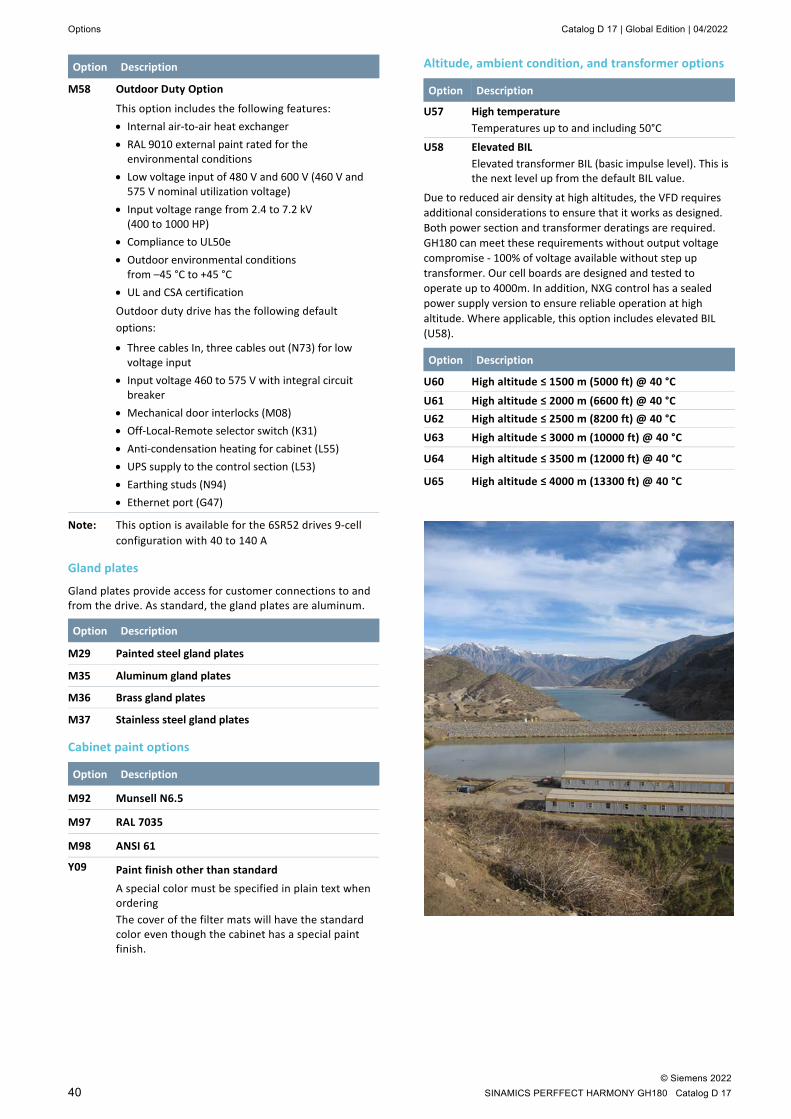
Options Catalog D 17 | Global Edition | 04/2022
© Siemens 2022 40 SINAMICS PERFFECT HARMONY GH180 Catalog D 17
Option Description
M58 Outdoor Duty Option
This option includes the following features: • Internal air-to-air heat exchanger • RAL 9010 external paint rated for the
environmental conditions • Low voltage input of 480 V and 600 V (460 V and
575 V nominal utilization voltage) • Input voltage range from 2.4 to 7.2 kV
(400 to 1000 HP) • Compliance to UL50e • Outdoor environmental conditions
from –45 °C to +45 °C • UL and CSA certification Outdoor duty drive has the following default options:
• Three cables In, three cables out (N73) for low voltage input
• Input voltage 460 to 575 V with integral circuit breaker
• Mechanical door interlocks (M08) • Off-Local-Remote selector switch (K31) • Anti-condensation heating for cabinet (L55) • UPS supply to the control section (L53) • Earthing studs (N94) • Ethernet port (G47)
Note: This option is available for the 6SR52 drives 9-cell configuration with 40 to 140 A
Gland plates
Gland plates provide access for customer connections to and from the drive. As standard, the gland plates are aluminum.
Option Description
M29 Painted steel gland plates
M35 Aluminum gland plates
M36 Brass gland plates
M37 Stainless steel gland plates
Cabinet paint options
Option Description
M92 Munsell N6.5
M97 RAL 7035
M98 ANSI 61
Y09 Paint finish other than standard A special color must be specified in plain text when ordering The cover of the filter mats will have the standard color even though the cabinet has a special paint finish.
Altitude, ambient condition, and transformer options
Option Description
U57 High temperature Temperatures up to and including 50°C
U58 Elevated BIL Elevated transformer BIL (basic impulse level). This is the next level up from the default BIL value.
Due to reduced air density at high altitudes, the VFD requires additional considerations to ensure that it works as designed. Both power section and transformer deratings are required. GH180 can meet these requirements without output voltage compromise - 100% of voltage available without step up transformer. Our cell boards are designed and tested to operate up to 4000m. In addition, NXG control has a sealed power supply version to ensure reliable operation at high altitude. Where applicable, this option includes elevated BIL (U58).
Option Description
U60 High altitude ≤ 1500 m (5000 ft) @ 40 °C
U61 High altitude ≤ 2000 m (6600 ft) @ 40 °C U62 High altitude ≤ 2500 m (8200 ft) @ 40 °C U63 High altitude ≤ 3000 m (10000 ft) @ 40 °C
U64 High altitude ≤ 3500 m (12000 ft) @ 40 °C
U65 High altitude ≤ 4000 m (13300 ft) @ 40 °C
Catalog D 17 | Global Edition | 04/2022 Options
© Siemens 2022 SINAMICS PERFECT HARMONY GH180 Catalog D 17 41
Option Description
N26 Synchronized pre-charge and transformer pre-magnetization
Remote locations with such weak lines where starting a large VFD can cause a voltage dip, synchronized pre-charge and pre-magnetization of transformer option is recommended. The inrush current is reduced to only 1 to 2 per unit.
With option N26, the synchronized pre-charge option is configured and installed. It allows precharge of not only the DC-link capacitors in all power cells, but in addition, to build-up the input transformer flux in close phase relation with the incoming medium voltage feed; hence, minimizing the transformer inrush currents when the circuit-breaker is closed. When the synchronous pre-charge option is selected, a separate auxiliary voltage supply is required by others.
This option is available for air-cooled 500 to 750 A and water-cooled drives.
Note It is the responsibility of the supplier of the auxiliary feed to ensure the voltage phase difference between the medium voltage feed and the auxiliary feed are within the +/-15 degrees tolerance and that there is the same frequency between the medium voltage input and precharge to allow proper operation of the synchronous precharge.
N77 18-pulse transformer (9-cell drives only) With option N77 an 18-pulse drive transformer is provided for 9-cell drives (standard: 54-pulse).
Option Description
L36 Input snubber
Siemens recommends for the customer to provide a snubber on their existing input breaker to prevent high transients caused by the breaker following IEEE C57.142.
If the customer cannot provide an input snubber Siemens can offer it as an option.
Note For drives manufactured in the USA, the input snubber is standard for input voltages above 10 kV.
Cable options
Option Description
N50 Internal cabling with halogen-free cables
With option N50, only halogen-free cables are used for cabling inside the drive. The insulating materials and color coding are in compliance with IEC standards (EN 50178/VDE 0160 (IEC 62103) and EN 60204-1/VDE 0113-1 (IEC 60204-1)).
Note: Halogen-free cables are only used on units manufactured in Nuremberg, Germany.
Option Description
N40 Internal control cabling with synthetic insulated switchboard (SIS) wire
SIS wire is provided for the control section and blower control of the drive. It is traditionally used in the environments that require higher level of coating. It has thermosetting insulation which is usually heat resistant, moisture-resistant, and flame-retarding grade. It consists of a stranded copper conductor that is coated with XLP (cross-linked polyethylene) insulation.
Note: The standard EPDM (ethylene propylene dienemonomer) cable is replaced with SIS wires in the following parts of the drive: the drive control and blower/pump control sections. DCR rack, cell and bypass pre-manufactured harnessed cables along with power cables are excluded from this option. This is air-cooled drive option only
Nameplate options Unless specified otherwise, standard is black phenolic nameplate with white letters. Use the following option codes to specify a nameplate other than the standard offering.
Option Description
T03 White phenolic nameplate with black letters
T04 Stainless steel
Nameplate, keypad and warning label languages
The options below specify the primary languages used for the drive nameplate, warning labels and keypad selection buttons. The secondary language – always English – is used only on the nameplate and warning labels. It provides an English translation of the information listed.
The respective option has to be selected (mandatory option) if the country of the end customer is an EU country or Turkey.
Option Description
T09 Nameplate, warning labels in English/Danish Operator panel language in English
T12 Nameplate, warning labels in English/Romanian Operator panel language in English

Options Catalog D 17 | Global Edition | 04/2022
© Siemens 2022 42 SINAMICS PERFFECT HARMONY GH180 Catalog D 17
Option Description
T13 Nameplate, warning labels in English/Bulgarian Operator panel language in English
T14 Nameplate, warning labels in English/Turkish Operator panel language in English
T15 Nameplate, warning labels in English/Greek Operator panel language in English
T16 Nameplate, warning labels in English/Dutch Operator panel language in English
T17 Nameplate, warning labels in English/Estonian Operator panel language in English
T18 Nameplate, warning labels in English/Latvian Operator panel language in English
T19 Nameplate, warning labels in English/Lithuanian Operator panel language in English
T20 Nameplate, warning labels in English/Slovakian Operator panel language in English
T21 Nameplate, warning labels in English / Finnish Operator panel language in English
T22 Nameplate, warning labels in English/Slovenian Operator panel language in English
T23 Nameplate, warning labels in English/Norwegian Operator panel language in English
T24 Nameplate, warning labels in English/Swedish Operator panel language in English
T25 Nameplate, warning labels in English/Czech Operator panel language in English
T26 Nameplate, warning labels in English/Hungarian Operator panel language in English
T58 Nameplate, warning labels in English/French Operator panel language in English
T60 Nameplate, warning labels in English/Spanish Operator panel language in English
T74 Nameplate, warning labels in English/German Operator panel language in English An operator panel in German is only available in conjunction with option D00 (documentation in German).
T76 Nameplate, warning labels in English Operator panel language in English
T80 Nameplate, warning labels in English/Italian Operator panel language in English
T82 Nameplate, warning labels in English/Portuguese Operator panel language in Portuguese
T85 Nameplate, warning labels in English/Russian Operator panel language in Russian
T86 Nameplate, warning labels in English/Polish Operator panel language in English
T90 Nameplate, warning labels in English/Japanese Operator panel language in English
T91 Nameplate, warning labels in English/Chinese Operator panel language in Chinese
Note: Please contact your Siemens sales partner for languages different from the ones specified above.
Compliance options
Option Description
L03 EMC filter
CE mark drives require an EMC line filter. With option L03, the filter will be installed downstream from the 3-phase control power disconnect switch.
Note: Option L03 is required for the CE mark and is included in option U02.
Option Description
U01 Version with UL listing (for core drive only)
With option U01, a drive version for the North American market is supplied. It is approved and listed by the Underwriter Laboratories (UL).
It includes option M08 (mechanical door interlocks – Superior). It requires shielded cable and stress cones and 36” transition cabinet.
U02 Version with CE conformity
With option U02, a drive version with CE conformity is supplied.
Note: Drives manufactured in Nuremberg, Germany are supplied with CE conformance
U03 Version with CSA certification
With option U03, a drive version certified by the Canadian Standards Association (CSA) is supplied. Option U03 includes option M08 (mechanical door interlocks – Superior).
U04 EAC certificate
With option U04, a drive version in conformance with EAC is supplied.
Catalog D 17 | Global Edition | 04/2022 Options
© Siemens 2022 SINAMICS PERFECT HARMONY GH180 Catalog D 17 43
Documentation options The standard documentation is supplied in English on CD-ROM. The circuit diagrams / terminal diagrams are available only in English.
If option D00 or one of the options D54 to D95 is ordered, the operating instructions, and safety notes on the drive are delivered according to the ordered language option. The respective option has to be selected (mandatory option) if the country of the end customer is an EU country or Turkey.
The quality documents (e.g. approval, certificates, etc) and the technical documents (e.g. circuit diagrams, dimensional drawings, etc) are only available in English or German. Supplementary documentation for the components installed in the drive (provided by the manufacturers of these components) is included on the CD-ROM in English/German. For technical reasons, it is not possible to provide this supplementary documentation for only the options that the customer has ordered.
Please contact your Siemens sales partner for documentation in a language different from the ones specified below.
On customer request, Siemens will provide documentation in the language required as an option.
Note: The documentation is supplied electronically in the respective option code language. Language options are mutually exclusive, but can be combined with option D76 as a second documentation language. An additional CD-ROM with documentation in English as second documentation language will be issued. To get printed documentation in English, select option D15.
Option Description
D02 Circuit diagrams, terminal diagrams and dimension drawings in DXF format (English only) Documents such as circuit diagrams, terminal diagrams, the arrangement diagram and the dimension drawing can be ordered with order code D02 in DXF format, e.g. for use in AutoCAD systems.
D15 One set of printed documentation If documentation is also required on paper, this must be ordered using order code D15. Multiple quantities are possible.
D00 Documentation in German
D54 Documentation in Czech
D55 Documentation In Polish
D56 Documentation in Russian
D57 Documentation in Japanese
D62 Documentation in Danish
D71 Documentation in Romanian
D72 Documentation in Italian
D73 Documentation in Finnish
D74 Documentation in Dutch
D75 Documentation In Turkish
D76 Documentation in English
D77 Documentation in French
D78 Documentation in Spanish
D79 Documentation in Portuguese (Brazil)
D80 Documentation in Bulgarian
D81 Documentation in Norwegian
D82 Documentation in Hungarian
D83 Documentation in Swedish
D84 Documentation in Chinese
D85 Documentation in Slovenian
D86 Documentation In Greek
D87 Documentation in Slovakian
D88 Documentation in Estonian
D89 Documentation in Latvian
D90 Documentation in Lithuanian

Options Catalog D 17 | Global Edition | 04/2022
© Siemens 2022 44 SINAMICS PERFFECT HARMONY GH180 Catalog D 17
Production Schedules
The options B43 to B45 provide production schedule documents. These are sent via e-mail as PDF file in English after order clarification.
Option Description
B43 Production schedule: one issue
B44 Production schedule: updated at 2-week intervals
B45 Production schedule: updated once per month
B49 Manufacturer data book
Customer approval drawings
Siemens offers several levels of customer drawings depending on customer needs and requirements. The approval ranges from simple interface drawing approval to complex full drawing approval from the customer. Details of approval would vary by product line and location, please, contact your Siemens sales partner for more details.
Option Description
P30 Full release to manufacturing
P31 I/O interface approval Drawing showing customer I/O interface points will be provided for approval. All other material will be released to manufacturing.
P32 I/O interface approval and additional engineering documentation Drawing showing customer I/O interface points will be provided for approval. Additional engineering documentation (preliminary factory acceptance test, system operating description, component data sheets / checklists, preliminary harmonic analysis, and preliminary operation manuals) will be provided at the request of the customer. All other material will be released to manufacturing.
P33 Full drawing approval All customer drawings (general arrangement / outlines and schematics) will be provided for approval. Additional engineering documents (preliminary factory acceptance test, system operating description, compo-nent data sheets / checklists, preliminary harmonic analysis, and preliminary operation manuals) will be provided at the request of the customer. All material will be held from manufacturing until full approval is received from customer.
Options Requiring Customer Specific Input
Option Description
Y05 Customer-specific nameplate
As standard the nameplate shows the rated data of the drive under nominal conditions.
If data on the nameplate should be adapted to special ambient conditions (temperature, altitude) or should reflect special load conditions (e.g. derating because of operation at low frequency) the option Y05 must be selected.
Information to be supplied: • Altitude • Coolant temperature • Rated voltages • Rated current • Rated power
Y10 Circuit diagrams with customer-specific description field
The circuit diagrams are given customer-specific headers. The data for the header must be specified in plain text (up to three lines of 45 characters per line).
Y15 Output filter
The filter is typically required when cable lengths at the drive output exceed 2.3 km (7500 ft). At such long distances, the effective switching frequency harmonics and sidebands may excite a cable resonance resulting in transmission line overvoltages at the motor terminals.
This option may also be used to address EMI or dV/dt requirements. The filter effectively removes all frequency components above 2000 Hz in the drive output voltage. Because SINAMICS PERFECT HARMONY GH180 is already free of low-order output harmonics, the result is a nearly perfect sinusoidal output waveform.
Depending on the drive configuration, the filter may be located in transition cabinets. The filter components are dimensioned based on the continuous current rating of the power cells and maximum drive voltage.
For more detailed information, please contact your Siemens sales partner.
Y36 Customer-specific cabinet labels
Labels with customer-specific information are attached to the drive cabinets according to Siemens standard. The text and quantity of these labels need to be specified as plain text. As standard, the labels will be manufactured out of Formica, using black letters on a white background.

Catalog D 17 | Global Edition | 04/2022 Options
© Siemens 2022 SINAMICS PERFECT HARMONY GH180 Catalog D 17 45
Output voltage
Option Description
V01 2.3 kV Motor Voltage
V02 2.4 kV Motor Voltage
V03 3.0 kV Motor Voltage
V04 3.3 kV Motor Voltage
V05 4.0 kV Motor Voltage
V06 4.16 kV Motor Voltage
V07 4.8 kV Motor Voltage
V08 5.0 kV Motor Voltage
V09 5.5 kV Motor Voltage
V10 6.0 kV Motor Voltage
V11 6.3 kV Motor Voltage
V12 6.6 kV Motor Voltage
V13 6.9 kV Motor Voltage
V14 7.2 kV Motor Voltage
V15 8.0 kV Motor Voltage
V18 10.0 kV Motor Voltage
V19 11.0 kV Motor Voltage
V26 9.8 kV Motor Voltage
Extension of liability for defects on drives
Siemens provides customer with the option of extending existing liability for defect periods beyond the standard ones. The liability for defect period listed in our standard terms and conditions is 12 months. The USA factory offers 24 months as a standard. Details and conditions will vary by location. This can be extended as follows:
Option Description
Q78 3 months extension to a total of 15 months from delivery
Q79 6 months extension to a total of 18 months from delivery
Q80 12 months extension to a total of 24 months from delivery
Q81 18 months extension to a total of 30 months from delivery
Q82 24 months extension to a total of 36 months from delivery
Q83 30 months extension to a total of 42 months from delivery
Q84 36 months extension to a total of 48 months from delivery
Q85 48 months extension to a total of 60 months from delivery
Customer acceptance tests
Siemens performs rigorous factory acceptance test on all drives. Additional testing both witnessed and un-witnessed are available, please contact your Siemens sales partner for any questions or inquiries. Below is the example of some of the test available:
Option Description
F03 Visual acceptance of the drive Open doors/panels; inspection of drive before shipping
F73 Functional acceptance of the drive with inductive load Visual acceptance; functional test with inductive load, cooling system test. Option F73 includes option F03 (visual acceptance).
F77 Acceptance test of the insulation of the drive The following is included in the scope of the acceptance tests: – High-voltage test – The insulation resistance is measured
F79 Interface check with customer equipment (5 hours, on request) For details, please contact your Siemens sales partner.
F97 Customer-specific acceptance For details, please contact your Siemens sales partner.

Options Catalog D 17 | Global Edition | 04/2022
© Siemens 2022 46 SINAMICS PERFFECT HARMONY GH180 Catalog D 17
Witness tests Witness test set up will vary by customer and factory location. Below is an example of witness test offered at our USA factory. For details contact your Siemens sales partner. Witness tests may include: • A copy of the factory acceptance test plan for each
attendee. Final certified copies of this data are published approximately two weeks after all testing is completed and shipment has occurred.
• Required PPE (Non-Prescription Safety Glasses with Side shields, Arc Flash retardant clothing, and hearing protection available upon request).
• Customer must provide their own EH rated safety shoes as required per Siemens Safety
Option Description
F02 Class 1 witness test
Witnessed testing of a VFD will consist of tests that are part of the Siemens standard factory accept-ance test defined herein for two attendees. Defined witnessed tests include visual inspection and operational overview. Operational test includes the following:
• Input protection fault simulation • Precharge sequence and fault check • Motor space heater control (if purchased) • Blower cycling • Loss of flow protection (WC) • Local/Remote control • Emergency Stop local/remote • Motor Logic • Customer control interface (excludes customer
supplied equipment) • Thermal sensors • Cell bypass operation (if purchased) • Spinning load • VFD run (unloaded)
F94 Class 2 witness test
Witnessed testing of a VFD will consist of tests that are part of the Siemens standard standard factory acceptance test defined herein for five attendees
In addition to the test mentioned in Class 1, witness test class 2 offers: • Up to 1-hour VFD current run on a dyno motor or
load reactor at 60 Hz
F95 Class 3 witness test
Witnessed testing of a VFD will consist of tests that are part of the Siemens standard factory accept-ance test defined herein for up to ten attendees.
In addition to the test mentioned in Class 1 and 2, witness test class 3 offers:
• Efficiency, power factor and harmonics tests demonstrated at defined points on a loaded VFD
Water-cooled specific options
Option Description
E00 Motor static exciter furnished by Customer
For synchronous motor applications the static exciter cabinet will be provided by Customer independent of the drive lineup.
E01 Motor static exciter furnished by Siemens
For synchronous motor applications the static exciter cabinet will be provided by Siemens as part of the drive lineup with the same degree of protection as the drive.
Note Please contact your Siemens sales partner for technical requirements when controlling synchronous motors.
Option Description
G89 Digital relay contactor control of external auxiliaries This option provides the ability to control the external motor space heaters via digital relay contact. When the motor is not energized the drive activates the space heaters to maintain motor internal air temperature above the dewpoint during shutdown.
Note: This option requires an additional cabinet.
Option Description
L33 Regenerative braking
For the applications that require intermittent regenerative operation for controlled or quick stop, the drive is equipped with regenerative cells to support this option.
Note: Available for 880 A and 1250 A. This option does not support continued operation.
Option Description
N02 Interface with customer circuit breaker – DC rated dry contacts
These contacts are used for the drive trip signal and the close signal. These relays are rated at: 125 V AC 20 A Minimum: 12 V DC 1 A
N03 Interface with customer circuit breaker – AC rated dry contacts
These contacts are used for the drive trip signal and the close signal. These relays are rated at: 240 VAC 25 A, 277 V AC 20 A and 600 V AC 10 A Minimum: 12 V AC 1 A.
Note: Option N02 is a default setting.

Catalog D 17 | Global Edition | 04/2022 Options
© Siemens 2022 SINAMICS PERFECT HARMONY GH180 Catalog D 17 47
Option Description
M88 Premium corrosion protection
The water-cooled drive is by design a self-contained configuration, so it is less affected by environmental contamination compared to an air-cooled solution. If the environment requires additional corrosion protection above the standard, the drive incorporates upgraded finishes & hardware to reduce the effects of this environment on the drive components. These additional measures include:
• Premium anti-corrosion cabinet paint capable of withstanding a maximum salt spray resistance of 5000 hours
• Coated printed circuit boards • Plated bus • External stainless steel hardware • Stainless steel gland plates
Note: Option M88 is only available for water-cooled drives.
Option Description
P40 Transformer assembly lift points outside on cabinet roof
External lift points for overseas transportation are added to reduce potential for damage during overseas ship transportation.
Option Description
W51 Mechanical two way inlet water temperature regulating valve
With option W51 Mechanical On/Off valve is supplied. Mechanical On/Off valve is recommended when cooling water is supplied from well or tap.
W52 Mechanical three way inlet water temperature regulating valve
With option W52 mechanical three way valve is supplied. Three way valve is recommended in the following cases: • a constant flow is available • water is supplied directly from river or lake • one cooling system for both drive and motor
Note Option W51 is a default setting.
Option Description
W71 Siemens provided deionized water
Siemens will provide the required amount of deionized water for the inner closed loop cooling system.
W72 Siemens provided propylene glycol
Siemens will provide the required amount of glycol for the inner closed loop cooling system.
Option Description
W04 Advanced Cooling Cabinet
Compared to the standard cooling cabinet, this option provides customer additional features and sensors: • Advanced control • Additional sensors • Monitoring of expansion tank level of 4 to 20 mA
sensors – the signal level is available via PLC communication
• PLC for monitoring / control • Dual auxiliary voltage feed available for easy
installation • Dual deionizer tanks, active & spare, in separate
section at front of cabinet • VFD driven pumps • Built in lift system (hoist) for changing pumps • Control of the external water-air heat exchanger: up
to 12 external HEX fans cycled in pairs (multi-stage cycling)
Note This cooling cabinet is 60” (1522mm) wide; it will add 12” (305mm) to the drive length.
Option Description
W32 Drive prepared for liquid-to-air heat exchanger
This option allows drive to operate with glycol in its system. Up to 60 % glycol mix is available. The amount of glycol will depend on freezing point of each site. No current derating is required.
Drive can be combined with external liquid-to-air heat exchanger.
W35 Liquid-to-air heat exchanger control panel mounted on outside of the coolant cabinet
W05 Coolant cabinet high capacity expansion tank
A drive in a system with total volume between 250 to 500 U.S. gallons requires one high capacity coolant expansion tank.

Options Catalog D 17 | Global Edition | 04/2022
© Siemens 2022 48 SINAMICS PERFFECT HARMONY GH180 Catalog D 17
Option Description
W55 Prepared for inlet water filter for low-quality water
With option W55 an inlet water filter is supplied. The filter protects water-to-water heat exchanger from clogging and fouling. It prevents blockages in the cooling water system by removing debris and marine life. The filter is automatically backflushed at regular intervals to keep it clean.
Automatic flushing is carried out at regular intervals without interrupting the filtering process. This filter reduces the need for redundant water-to-water heat exchanger.
Note It is a drop ship option. Unit will be installed by the customer upstream of heat exchanger and outside of the drive.
Example of installation with W32 option: there are 2 WC drives in the building

Catalog D 17 | Global Edition | 04/2022 Article Number Structure
© Siemens 2022 SINAMICS PERFECT HARMONY GH180 Catalog D 17 49
Article number structure 1 2 3 4 5 6 7 - 8 9 10 11 12 - 13 14 15 16
SINAMICS PERFECT HARMONY GH180 6 S R ● ● ● ●
● ■ ● ● ●
● ■ ■ 0
4th digit: generation number
Generation 3 3
Generation 4 4
Generation 5 5
5th digit: manufacturing location
Nuremberg, Germany 1
Pittsburgh, PA, USA 2
Shanghai, China 5
Jundiai, Brazil 6
6th digit: cooling method
Air-cooled 0
Water-cooled 7
7th digit: line-side behavior
Diode Front End (2Q) 2
6-step regen (4Q) 4
8th digit: rated max. output voltage
4.16 kV 3 AC, 9 cells 0
5.3 kV 3 AC, 12 cells 1
6.9 kV 3 AC, 15 cells 2
8.0 kV 3 AC, 18 cells 3
11.0 kV 3 AC, 24 cells 5
2.4 kV 3 AC, 9 cells 6
9th digit: line voltage
3 AC 2400 V A
3 AC 3000 V B
3 AC 3300 V C
3 AC 4160 V D
3 AC 4800 V E
3 AC 6000 V F
3 AC 6300 V G
3 AC 6600 V H
3 AC 6900 V J
3 AC 7200 V K
3 AC 8400 V L
3 AC 10000 V M
3 AC 11000 V N
3 AC 12000 V P
3 AC 12470 V Q
3 AC 13200 V R
3 AC 13800 V S
460 V 3 AC1) T
575 V 3 AC1) U
1) Utilization voltages, system voltages are 480 V or 600 V

Article Number Structure Catalog D 17 | Global Edition | 04/2022
© Siemens 2022 50 SINAMICS PERFFECT HARMONY GH180 Catalog D 17
1 2 3 4 5 6 7 - 8 9 10 11 12 - 13 14 15 16
SINAMICS PERFECT HARMONY GH180 6 S R ● ● ● ●
● ■ ● ● ●
● ■ ■ 0
10th digit: Cell rating AC (2Q)
40 A cell A
70 A cell B
100 A cell C
140 A cell D
200 A cell E
260 A cell F
340 A cell G
430 A cell H
550 A cell J
600 A cell K
720/750 A cell L
Cell rating AC 6-step regen (4Q)
120 A cell D 160 A cell E 325 A cell G
Cell rating WC
880 A cell (regenerative braking only) B
1000 A cell D
1250 A cell (regenerative braking only) C
1375 A cell E
Drive rating: AC - transformer primary2) kVA; WC - drive power HP
150 3 1 5
200 3 2 0
300 3 3 0
400 3 4 0
500 3 5 0
600 3 6 0
700 3 7 0
800 3 8 0
900 3 8 7
1000 4 1 0
1100 4 1 1
1250 4 1 2
1500 4 1 5
1750 4 1 7
2000 4 2 0
2250 4 2 2
2500 4 2 5
3000 4 3 0
3500 4 3 5
4000 4 4 0
5000 4 5 0
6000 4 6 0
7000 4 7 0
8000 4 8 0
9000 4 8 7
10000 5 2 0
11000 5 2 2

Catalog D 17 | Global Edition | 04/2022 Article Number Structure
© Siemens 2022 SINAMICS PERFECT HARMONY GH180 Catalog D 17 51
1 2 3 4 5 6 7 - 8 9 10 11 12 - 13 14 15 16
SINAMICS PERFECT HARMONY GH180 6 S R ● ● ● ●
● ■ ● ● ●
● ■ ■ 0
12000 5 2 4
13000 5 2 6
14000 5 2 8
15000 5 3 0
16000 5 3 2
17000 5 3 4
18000 5 3 6
19000 5 3 8
20000 5 4 0
21000 5 4 2
22000 5 4 4
23000 5 4 6
24000 5 4 8
25000 5 5 0 26000 5 5 2
27000 5 5 4
28000 5 5 6
29000 5 5 8
30000 5 6 0
31000 5 6 2
32000 5 6 4
33000 5 6 6
14th digit: transformer configuration (copper, aluminum) 60 Hz, Cu A 50 Hz, Cu B
60 Hz, Al E
50 Hz, Al F
60 Hz, Cu, high efficiency L
50 Hz, Cu, high efficiency M
60 Hz, Cu, starting duty N
50 Hz, Cu, starting duty P
60 Hz, Al, starting duty Q
50 Hz, Al, starting duty R
15th digit: auxiliary voltage and frequency
200 V / 50 Hz A
208 V / 50 Hz B
230 V / 60 Hz C
380 V / 50 Hz F
400 V / 50 Hz G
415 V / 50 Hz H
460 V / 60 Hz J
480 V / 60 Hz K
575 V / 60 Hz L
690 V / 50 Hz N
Other voltage and/or frequency combination than above X
2) Represents primary kVA unless option U13 (one redundant cell per phase) is selected
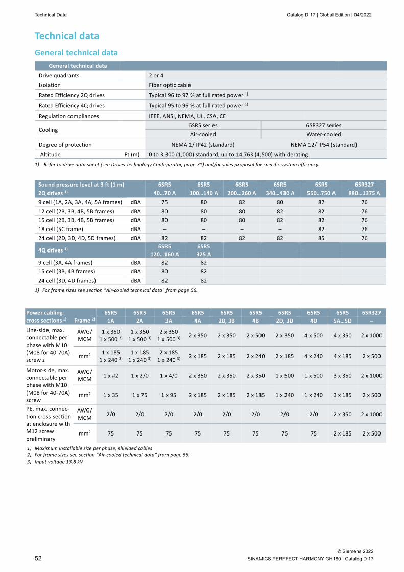
Technical Data Catalog D 17 | Global Edition | 04/2022
© Siemens 2022 52 SINAMICS PERFFECT HARMONY GH180 Catalog D 17
Technical data General technical data
General technical data Drive quadrants 2 or 4
Isolation Fiber optic cable
Rated Efficiency 2Q drives Typical 96 to 97 % at full rated power 1)
Rated Efficiency 4Q drives Typical 95 to 96 % at full rated power 1)
Regulation compliances IEEE, ANSI, NEMA, UL, CSA, CE
Cooling 6SR5 series 6SR327 series Air-cooled Water-cooled
Degree of protection NEMA 1/ IP42 (standard) NEMA 12/ IP54 (standard)
Altitude Ft (m) 0 to 3,300 (1,000) standard, up to 14,763 (4,500) with derating 1) Refer to drive data sheet (see Drives Technology Configurator, page 71) and/or sales proposal for specific system efficency.
Sound pressure level at 3 ft (1 m) 6SR5 6SR5 6SR5 6SR5 6SR5 6SR327 2Q drives 1) 40…70 A 100…140 A 200…260 A 340…430 A 550…750 A 880…1375 A 9 cell (1A, 2A, 3A, 4A, 5A frames) dBA 75 80 82 80 82 76 12 cell (2B, 3B, 4B, 5B frames) dBA 80 80 80 82 82 76 15 cell (2B, 3B, 4B, 5B frames) dBA 80 80 80 82 82 76 18 cell (5C frame) dBA – – – – 82 76 24 cell (2D, 3D, 4D, 5D frames) dBA 82 82 82 82 85 76
4Q drives 1) 6SR5 6SR5 120…160 A 325 A
9 cell (3A, 4A frames) dBA 82 82 15 cell (3B, 4B frames) dBA 80 82 24 cell (3D, 4D frames) dBA 82 82
1) For frame sizes see section "Air-cooled technical data" from page 56.
Power cabling cross sections 1) Frame 2)
6SR5 6SR5 6SR5 6SR5 6SR5 6SR5 6SR5 6SR5 6SR5 6SR327 1A 2A 3A 4A 2B, 3B 4B 2D, 3D 4D 5A…5D –
Line-side, max. connectable per phase with M10 (M08 for 40-70A) screw z
AWG/ MCM
1 x 350 1 x 500 3)
1 x 350 1 x 500 3)
2 x 350 1 x 500 3)
2 x 350 2 x 350 2 x 500 2 x 350 4 x 500 4 x 350 2 x 1000
mm2 1 x 185 1 x 240 3)
1 x 185 1 x 240 3)
2 x 185 1 x 240 3)
2 x 185 2 x 185 2 x 240 2 x 185 4 x 240 4 x 185 2 x 500
Motor-side, max. connectable per phase with M10 (M08 for 40-70A) screw
AWG/ MCM 1 x #2 1 x 2/0 1 x 4/0 2 x 350 2 x 350 2 x 350 1 x 500 1 x 500 3 x 350 2 x 1000
mm2 1 x 35 1 x 75 1 x 95 2 x 185 2 x 185 2 x 185 1 x 240 1 x 240 3 x 185 2 x 500
PE, max. connec-tion cross-section at enclosure with M12 screw preliminary
AWG/ MCM 2/0 2/0 2/0 2/0 2/0 2/0 2/0 2/0 2 x 350 2 x 1000
mm2 75 75 75 75 75 75 75 75 2 x 185 2 x 500
1) Maximum installable size per phase, shielded cables 2) For frame sizes see section "Air-cooled technical data" from page 56. 3) Input voltage 13.8 kV

Catalog D 17 | Global Edition | 04/2022 Technical Data
© Siemens 2022 SINAMICS PERFECT HARMONY GH180 Catalog D 17 53
Auxiliary supply 2Q drives
Auxiliary voltage Three phase Single phase
Configuration 380 V 460 V 575 V 120 V 220 V
6SR5 9 cell 40-70A K791) A 2.0 2.5 2.0 4.0 2.0 6SR5 9 cell 40-70A K692) A 3.5 4.0 3.0 – – 6SR5 9 cell 100-140A K791) A 3.5 4.0 3.5 4.0 2.0 6SR5 9 cell 100-140A K692) A 5.0 5.5 4.5 – – 6SR5 9 cell 200-260A K791) A 6.5 8.0 6.5 4.0 2.0 6SR5 9 cell 200-260A K692) A 8.0 9.5 7.5 – – 6SR5 9 cell 340-430A K791) A 10.0 11.5 9.5 4.0 2.0 6SR5 9 cell 340-430A K692) A 11.5 12.5 10.5 – – 6SR5 9 cell 550A K68/K791) A 16.0 13.0 9.2 7 3.5 6SR5 9 cell 550A K692) A 18.2 14.8 10.7 – – 6SR5 9 cell 600A K68/K791) A 16.0 15.7 11.8 7 3.5 6SR5 9 cell 600A K692) A 18.2 17.5 13.2 – – 6SR5 9 cell 720A K68/K791) A 18.2 15.7 11.8 7 3.5 6SR5 9 cell 720A K692) A 20.4 17.5 13.2 – – 6SR5 12/15 cell 340-430A K68/ K791) A 16.5 15.0 12.0 4.0 2.0 6SR5 12/15 cell 340-430A K692) A 17.5 16.0 13.0 – – 6SR5 12/15 cell 550A K68/K791) A 26.7 21.7 15.4 7 3.5 6SR5 12/15 cell 550A K692) A 28.9 23.5 16.8 – – 6SR5 12/15 cell 600A K68/K791) A 26.7 27.1 20.5 7 3.5 6SR5 12/15 cell 600A K692) A 28.9 28.9 21.9 – – 6SR5 12/15 cell 750A K68/K791) A 31.0 27.1 20.5 7 3.5 6SR5 12/15 cell 750A K692) A 33.2 28.9 21.9 – – 6SR5 18 cell 550A K68/K791) A 32.0 26.1 18.5 7 3.5 6SR5 18 cell 550A K692) A 34.2 27.8 19.9 – – 6SR5 18 cell 600A K68/K791) A 32.0 31.5 23.6 7 3.5 6SR5 18 cell 600A K692) A 34.2 33.2 25.0 – – 6SR5 18 cell 750A K68/K791) A 36.3 31.5 23.6 7 3.5 6SR5 18 cell 750A K692) A 38.5 33.2 25.0 – – 6SR5 24 cell 40-70A K681) A 11.0 12.4 – – 3.5 6SR5 24 cell 40-70A K692) A 13.0 14.4 – – 3.5 6SR5 24 cell 100-140A K681) A 16.4 19.6 – – 3.5 6SR5 24 cell 100-140A K692) A 18.4 21.6 – – 3.5 6SR5 24 cell 200-260A K681) A 27.8 34.2 – – 3.5 6SR5 24 cell 200-260A K692) A 29.8 36.2 – – 3.5 6SR5 24 cell 550A K68/K791) A 37.3 30.4 21.6 7 3.5 6SR5 24 cell 550A K692) A 39.5 32.2 23.0 – – 6SR5 24 cell 600A K68/K791) A 37.3 38.5 29.2 7 3.5 6SR5 24 cell 600A K692) A 39.5 40.3 30.6 – – 6SR5 24 cell 750A K68/K791) A 43.8 38.5 29.2 7 3.5 6SR5 24 cell 750A K692) A 46.0 40.3 30.6 – –
1) Single phase for NXG control 2) K69 includes CPT: control power transformer Note: Temporary overcurrent needed for 30 s during precharge for units with 550/600/750 A or 4Q cells; please contact your Siemens sales
partner for more details. Values include cooling blowers; largest unit shown. Option L55 (anti-condensation heating for cabinet) requires separate source.

Technical Data Catalog D 17 | Global Edition | 04/2022
© Siemens 2022 54 SINAMICS PERFFECT HARMONY GH180 Catalog D 17
Auxiliary voltage
Three phase Single phase
Configuration 380 V 460 V 575 V 120 V 220 V
6SR327 K691) A 1.6 1.3 1.1 – – 6SR327 K691) and W043) A 3.2 2.6 2.2 – – 6SR327 9 cell 880-1375A K792) A 13.4 8.4 6.8 5.0 – 6SR327 9 cell 880-1375A K792) and W043) A 33.1 27.2 21.4 10.0 – 6SR327 12 cell 880-1375A K792) A 14.6 12.7 10.1 – – 6SR327 12 cell 880-1375A K792) and W043) A 34.3 28.4 22.3 10.0 – 6SR327 15 cell 880-1375A K792) A 19.4 16.9 13.5 – – 6SR327 15 cell 880-1375A K792) and W043) A 35.5 29.6 23.3 10.0 – 6SR327 18 cell 880-1375A K792) A 20.6 18.1 14.5 – –
6SR327 18 cell 880-1375A K792) and W043) A 36.7 30.8 24.3 10.0 – 6SR327 24 cell 880-1375A K79 2) A 30.4 26.5 21.2 5.0 – 6SR327 24 cell 880-1375A K792) and W043) A 39.1 33.2 26.2 10.0 –
System pre-charge4) % 0.5 0.5 0.5 – –
1) K69 includes CPT: control power transformer 2) Single phase for NXG control and 120 V AC internal heat exchanger in water-cooled systems 3) Includes cooling pumps; largest unit shown 4) Percentage of transformer kVA
Note: Options A30, A82, A83, and E04 will require slightly more current from the 120 V source. If either the option cabinet or the exciter cabinet (E01) are present, an additional 2.1 A will be required per cabinet.
4Q drives
Auxiliary voltage
Three phase Single phase
Configuration 380 V 460 V 575 V 120 V 220 V
6SR5 9 cell 120-160A K791) A 6.5 8.0 6.5 4.0 – 6SR5 9 cell 120-160A K692) A 8.0 9.5 7.5 – – 6SR5 9 cell 325A K791) A 10.0 11.5 9.5 4.0 – 6SR5 9 cell 325A K692) A 11.5 12.5 10.5 – – 6SR5 12/15 cell 120-160A K791) A 10.0 11.5 9.5 4.0 – 6SR5 12/15 cell 120-160A K692) A 11.5 12.5 10.5 – – 6SR5 12/15 cell 325A K791) A 18 14 11.5 4.0 – 6SR5 12/15 cell 325A K692) A 22 17 14.5 – – 6SR5 24 cell 120-160A K681) A 27.8 34.2 – – 3.5 6SR5 24 cell 120-160A K692) A 29.8 36.2 – – 3.5 6SR5 24 cell 325A K681) A 23.1 28.3 – – 3.5 6SR5 24 cell 325A K692) A 25.1 30.3 – – 3.5
1) Single phase for NXG control 2) K69 includes CPT: control power transformer
Note: Temporary overcurrent needed for 30 s during precharge; please contact your Siemens sales partner for more details. Values include cooling blowers; largest unit shown. Option L55 (anti-condensation heating for cabinet) requires separate source.

Catalog D 17 | Global Edition | 04/2022 Technical Data
© Siemens 2022 SINAMICS PERFECT HARMONY GH180 Catalog D 17 55
Cell overload capability 2Q Drives 6SR5 6SR327
Cell rating [A] 40 70 100 140 200 260 340 430 550 600 720 1) 750 2) 880 1000 1250 1375
110 % overload [A] (1min/10min)
40 70 100 140 200 260 340 430 550 600 655 682 880 909 1250 1250
150 % overload [A] (1min/10min) 29 51 73 103 147 191 249 315 403 440 480 500 667 667 917 917
1) 720 A for 9 cell configurations 2) 750 A for 12 through 24 cell configurations
4Q Drives 6SR5
Cell rating [A] 120 160 325
110 % overload [A] (1min/10min)
120 160 325
150 % overload[A] (1min/10min)
88 117 238
Storage, transportation and operation data Storage Transport Operation
Climatic environmental conditions Ambient temperature Outdoor Type 4
°C +5 to +40 1)
-25 to +60 1)
+5 to +40 2) +5 to +50 3)
–45 to +45 Relative air humidity < 95 %
(only slight condensation permitted; drive must be completely dry before commissioning)
< 95 % (only slight condensation permitted; drive must be completely dry before commissioning)
< 95 % (condensation not permitted)
Other climatic conditions in accordance with class
1K3, 1Z2 in acc. with IEC 60721-3-1 5)
2K2 in acc. with IEC 60721-3-2 6)
3K3 in acc. with IEC 60721-3-3 7)
Degree of pollution 2 without significant conduc-tive or corrosive dust/gases in acc. with IEC 61800-5-1
2 without significant conduc-tive or corrosive dust/gases in acc. with IEC 61800-5-1
2 without significant conduc-tive or corrosive dust/gases in acc. with IEC 61800-5-1
Mechanical environmental conditions Stationary vibration, sinusoidal
• Displacement mm 1.5 (2 to 9 Hz) 3.5 (2 to 9 Hz) 0.3 (2 to 9 Hz) • Acceleration m/s 5 (9 to 200 Hz) 10 (9 to 200 Hz) 1 (9 to 200 Hz)
m/s 15 (200 to 500 Hz) Other mechanical conditions in accordance with class
1M2 in acc. with IEC 60721-3-1 5)
2M2 in acc. with IEC 60721-3-2 4)
3M1 in acc. with IEC 60721-3-3 7)
Other environmental conditions Biological ambient conditions in accordance with class
1B1 in acc. with IEC 60721-3-1 5)
2B1 in acc. with IEC 60721-3-2 6)
3B1 in acc. with IEC 60721-3-3 7)
Chemical active substances in accordance with class
1C1 in acc. with IEC 60721-3-1 5)
2C1 in acc. with IEC 60721-3-2 6)
3C1 in acc. with IEC 60721-3-3 7) 8)
Mechanical active substances in accordance with class
1S1 in acc. with IEC 60721-3-1 5)
2S1 in acc. with IEC 60721-3-2 6)
3S1 in acc. with IEC 60721-3-3 7) 9)
1) For water-cooled drives: no cooling water in system 2) For water-cooled drive: maximum 40 °C drive ambient air temperature with maximum 47 °C drive inlet water temperature 3) 50 °C is available with current derating for air-cooled drives; water-cooled drives – maximum 50 °C drive ambient air temperature with maximum
40 °C drive inlet water temperature 4) Siemens equipment meets all 2M2 conditions except free fall and pitch and roll. 5) IEC 60721-3-1; amendment 2, 1987 - 1993 6) IEC 60721-3-2; second edition, 1997/3 7) IEC 60721-3-3; second edition, 1994/12 8) Accumulation of dust, dirt or debris is not permitted. Drives must be installed in a controlled environment and properly maintained according to the
Operating Instructions. 9) With optional NEMA 12/IP54 LV enclosures for water-cooled drives

Technical Data Catalog D 17 | Global Edition | 04/2022
© Siemens 2022 56 SINAMICS PERFFECT HARMONY GH180 Catalog D 17
Air-cooled technical data
2Q drives, 6SR5 40 to 750 A 2.3 kV motor voltage, 9 cell configuration (2Q)
Drive series Shaft output 1) Motor
current 1) Cell rating Dimensions 2) WxHxD Weight 2)
Hp kW A A in mm Frame lb kg 6SR5.020.A315..0 150 112 34 40
48.0x102.0x40.0 1219x2591x1016 1A 3) 3300 1497
6SR5.020.B320..0 200 149 45 70
3700 1679 6SR5.020.B330..0 300 224 67 4100 1860 6SR5.020.C340..0 400 298 91 100
60.0x110.0x42.0 1524x2794x1067 2A 4400 1996
6SR5.020.D350..0 500 372 112 140
4700 2132 6SR5.020.D360..0 600 450 136 5100 2313 6SR5.020.E370..0 700 522 155
200 75.0x110.0x45.0 1905x2794x1143 3A
5800 2631 6SR5.020.E380..0 800 597 177 6100 2767 6SR5.020.E387..0 900 671 199 6700 3039 6SR5.020.F410..0 1000 746 221
260 6800 3130
6SR5.020.F411..0 1100 820 246 7300 3312 6SR5.020.G412..0 1250 932 276
340 133.9x115.6x47.3 3400x2936x1200 4A
11377 5161 6SR5.020.G415..0 1500 1120 331 11877 5388 6SR5.020.H417..0 1750 1304 386 430 12375 5614 6SR5.020.J420..0 2000 1491 442
550
228.4x114.9x53.9 5800x2916x1370 5A
18241 8291 6SR5.020.J422..0 2250 1679 497 18804 8547 6SR5.020.K425..0 2500 1865 552 600 19369 8804 6SR5.020.L427..0 2750 2052 607
720 19932 9060
6SR5.020.L430..0 3000 2238 662 20496 9316 6SR5.020.L432..0 3250 2425 717 21624 9829
2.4 kV motor voltage, 9 cell configuration (2Q)
Drive series Shaft output 1) Motor current 1) Cell rating Dimensions 2)
WxHxD Weight 2)
Hp kW A A in mm Frame lb kg 6SR5.020.A315..0 150 112 32 40
48.0x102.0x40.0 1219x2591x1016 1A 3) 3300 1497
6SR5.020.B320..0 200 149 43 70
3700 1679 6SR5.020.B330..0 300 224 65 4100 1860 6SR5.020.C340..0 400 298 87 100
60.0x110.0x42.0 1524x2794x1067 2A
4400 1996 6SR5.020.D350..0 500 373 108
140 4700 2132
6SR5.020.D360..0 600 448 130 5100 2313 6SR5.020.D370..0 700 522 148 5800 2631 6SR5.020.E380..0 800 597 169
200 75.0x110.0x45.0 1905x2794x1143 3A
6100 2767 6SR5.020.E387..0 900 671 190 6700 3039 6SR5.020.F410..0 1000 746 212
260 6800 3130
6SR5.020.F411..0 1100 821 233 7300 3312 6SR5.020.G412..0 1250 932 264
340 133.9x115.6x47.3 3400x2936x1200 4A
11377 5171 6SR5.020.G415..0 1500 1118 317 11877 5399 6SR5.020.H417..0 1750 1306 370
430 12375 5614
6SR5.020.H420..0 2000 1492 423 12877 5841 6SR5.020.J422..0 2250 1679 476
550
228.4x114.9x53.9 5800x2916x1370 5A
18804 8547 6SR5.020.J425..0 2500 1865 529 19369 8804 6SR5.020.K427..0 2750 2051 582 600 19932 9060 6SR5.020.L430..0 3000 2238 635
720 20496 9316
6SR5.020.L432..0 3250 2425 688 21624 9829 1) The typical motor current and the power data are approximate values only; these have been calculated for operation with induction motors and
for typical power factor cos φ of 88 % and motor efficiency of 94.0 % if motor current ≤ 140 A or 96.4 % if motor current > 140 A. 2) Height includes blower cage; 40 to 70 A frame 1A configuration blowers are part of a cabinet, other configurations blowers are removed for
shipping. Certain options might change drive dimensions and weights. Depth does not include door components, key interlocks or handles. 3) Frame 1A not available from China, units are built in frame 2A.
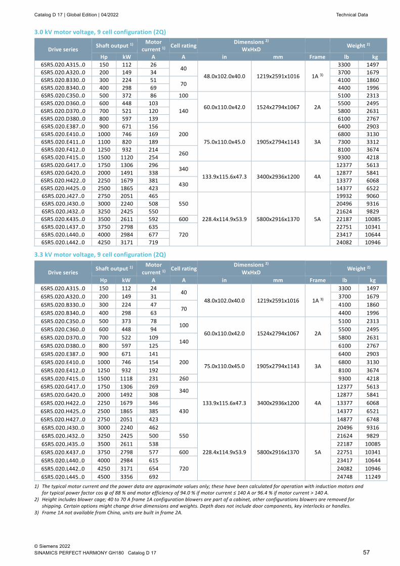
Catalog D 17 | Global Edition | 04/2022 Technical Data
© Siemens 2022 SINAMICS PERFECT HARMONY GH180 Catalog D 17 57
3.0 kV motor voltage, 9 cell configuration (2Q)
Drive series Shaft output 1) Motor current 1) Cell rating Dimensions 2)
WxHxD Weight 2)
Hp kW A A in mm Frame lb kg 6SR5.020.A315..0 150 112 26
40 48.0x102.0x40.0 1219x2591x1016 1A 3)
3300 1497 6SR5.020.A320..0 200 149 34 3700 1679 6SR5.020.B330..0 300 224 51
70 4100 1860
6SR5.020.B340..0 400 298 69 4400 1996 6SR5.020.C350..0 500 372 86 100
60.0x110.0x42.0 1524x2794x1067 2A
5100 2313 6SR5.020.D360..0 600 448 103
140 5500 2495
6SR5.020.D370..0 700 521 120 5800 2631 6SR5.020.D380..0 800 597 139 6100 2767 6SR5.020.E387..0 900 671 156
200 75.0x110.0x45.0 1905x2794x1143 3A
6400 2903 6SR5.020.E410..0 1000 746 169 6800 3130 6SR5.020.E411..0 1100 820 189 7300 3312 6SR5.020.F412..0 1250 932 214
260 8100 3674
6SR5.020.F415..0 1500 1120 254 9300 4218 6SR5.020.G417..0 1750 1306 296
340 133.9x115.6x47.3 3400x2936x1200 4A
12377 5613 6SR5.020.G420..0 2000 1491 338 12877 5841 6SR5.020.H422..0 2250 1679 381
430 13377 6068
6SR5.020.H425..0 2500 1865 423 14377 6522 6SR5.020.J427..0 2750 2051 465
550
228.4x114.9x53.9 5800x2916x1370 5A
19932 9060 6SR5.020.J430..0 3000 2240 508 20496 9316 6SR5.020.J432..0 3250 2425 550 21624 9829 6SR5.020.K435..0 3500 2611 592 600 22187 10085 6SR5.020.L437..0 3750 2798 635
720 22751 10341
6SR5.020.L440..0 4000 2984 677 23417 10644 6SR5.020.L442..0 4250 3171 719 24082 10946
3.3 kV motor voltage, 9 cell configuration (2Q)
Drive series Shaft output 1) Motor
current 1) Cell rating Dimensions 2)
WxHxD Weight 2)
Hp kW A A in mm Frame lb kg 6SR5.020.A315..0 150 112 24
40 48.0x102.0x40.0 1219x2591x1016 1A 3)
3300 1497 6SR5.020.A320..0 200 149 31 3700 1679 6SR5.020.B330..0 300 224 47
70 4100 1860
6SR5.020.B340..0 400 298 63 4400 1996 6SR5.020.C350..0 500 373 78
100 60.0x110.0x42.0 1524x2794x1067 2A
5100 2313 6SR5.020.C360..0 600 448 94 5500 2495 6SR5.020.D370..0 700 522 109
140 5800 2631
6SR5.020.D380..0 800 597 125 6100 2767 6SR5.020.E387..0 900 671 141
200 75.0x110.0x45.0 1905x2794x1143 3A
6400 2903 6SR5.020.E410..0 1000 746 154 6800 3130 6SR5.020.E412..0 1250 932 192 8100 3674 6SR5.020.F415..0 1500 1118 231 260 9300 4218 6SR5.020.G417..0 1750 1306 269
340
133.9x115.6x47.3 3400x2936x1200 4A
12377 5613 6SR5.020.G420..0 2000 1492 308 12877 5841 6SR5.020.H422..0 2250 1679 346
430 13377 6068
6SR5.020.H425..0 2500 1865 385 14377 6521 6SR5.020.H427..0 2750 2051 423 14877 6748 6SR5.020.J430..0 3000 2240 462
550
228.4x114.9x53.9 5800x2916x1370 5A
20496 9316 6SR5.020.J432..0 3250 2425 500 21624 9829 6SR5.020.J435..0 3500 2611 538 22187 10085 6SR5.020.K437..0 3750 2798 577 600 22751 10341 6SR5.020.L440..0 4000 2984 615
720 23417 10644
6SR5.020.L442..0 4250 3171 654 24082 10946 6SR5.020.L445..0 4500 3356 692 24748 11249
1) The typical motor current and the power data are approximate values only; these have been calculated for operation with induction motors and for typical power factor cos φ of 88 % and motor efficiency of 94.0 % if motor current ≤ 140 A or 96.4 % if motor current > 140 A.
2) Height includes blower cage; 40 to 70 A frame 1A configuration blowers are part of a cabinet, other configurations blowers are removed for shipping. Certain options might change drive dimensions and weights. Depth does not include door components, key interlocks or handles.
3) Frame 1A not available from China, units are built in frame 2A.
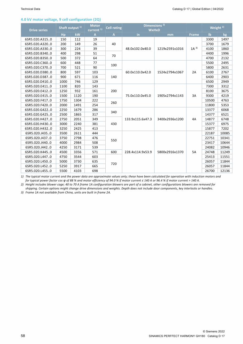
Technical Data Catalog D 17 | Global Edition | 04/2022
© Siemens 2022 58 SINAMICS PERFFECT HARMONY GH180 Catalog D 17
4.0 kV motor voltage, 9 cell configuration (2Q)
Drive series Shaft output 1) Motor current 1) Cell rating Dimensions 2)
WxHxD Weight 2)
Hp kW A A in mm Frame lb kg 6SR5.020.A315..0 150 112 19
40 48.0x102.0x40.0 1219x2591x1016 1A 3)
3300 1497 6SR5.020.A320..0 200 149 26 3700 1679 6SR5.020.A330..0 300 224 39 4100 1860 6SR5.020.B340..0 400 298 51
70 4400 1996
6SR5.020.B350..0 500 372 64 4700 2132 6SR5.020.C360..0 600 448 77
100
60.0x110.0x42.0 1524x2794x1067 2A
5500 2495 6SR5.020.C370..0 700 521 90 5800 2631 6SR5.020.D380..0 800 597 103
140 6100 2767
6SR5.020.D387..0 900 671 116 6400 2903 6SR5.020.D410..0 1000 746 129 6500 2949 6SR5.020.E411..0 1100 820 143
200 75.0x110.0x45.0 1905x2794x1143 3A
7300 3312 6SR5.020.E412..0 1250 932 161 8100 3675 6SR5.020.E415..0 1500 1120 190 9300 4219 6SR5.020.F417..0 1750 1304 222
260 10500 4763
6SR5.020.F420..0 2000 1491 254 11800 5353 6SR5.020.G422..0 2250 1679 286
340
133.9x115.6x47.3 3400x2936x1200 4A
13377 6068 6SR5.020.G425..0 2500 1865 317 14377 6521 6SR5.020.H427..0 2750 2051 349
430 14877 6748
6SR5.020.H430..0 3000 2240 381 15377 6975 6SR5.020.H432..0 3250 2425 413 15877 7202 6SR5.020.J435..0 3500 2611 444
550
228.4x114.9x53.9 5800x2916x1370 5A
22187 10085 6SR5.020.J437..0 3750 2798 476 22751 10341 6SR5.020.J440..0 4000 2984 508 23417 10644 6SR5.020.J442..0 4250 3171 539 24082 10946 6SR5.020.K445..0 4500 3356 571 600 24748 11249 6SR5.020.L447..0 4750 3544 603
720
25413 11551 6SR5.020.L450..0 5000 3730 635 26057 11844 6SR5.020.L452..0 5250 3917 665 26057 11844 6SR5.020.L455..0 5500 4103 698 26700 12136
1) The typical motor current and the power data are approximate values only; these have been calculated for operation with induction motors and for typical power factor cos φ of 88 % and motor efficiency of 94.0 % if motor current ≤ 140 A or 96.4 % if motor current > 140 A.
2) Height includes blower cage; 40 to 70 A frame 1A configuration blowers are part of a cabinet, other configurations blowers are removed for shipping. Certain options might change drive dimensions and weights. Depth does not include door components, key interlocks or handles.
3) Frame 1A not available from China, units are built in frame 2A.

Catalog D 17 | Global Edition | 04/2022 Technical Data
© Siemens 2022 SINAMICS PERFECT HARMONY GH180 Catalog D 17 59
4.16 kV motor voltage, 9 cell configuration (2Q)
Drive series Shaft output 1) Motor current 1) Cell rating Dimensions 2)
WxHxD Frame Weight 2)
Hp kW A A in mm lb kg 6SR5.020.A315..0 150 112 19
40 48.0x102.0x40.0 1219x2591x1016 1A 3)
3300 1497 6SR5.020.A320..0 200 149 26 3700 1678 6SR5.020.A330..0 300 224 38 4100 1860 6SR5.020.B340..0 400 298 50
70 4400 1996
6SR5.020.B350..0 500 373 63 4700 2132 6SR5.020.C360..0 600 448 75
100
60.0x110.0x42.0 1524x2794x1067 2A
5500 2495 6SR5.020.C370..0 700 522 88 5800 2631 6SR5.020.C380..0 800 597 100 6100 2767 6SR5.020.D387..0 900 671 113
140 6400 2903
6SR5.020.D410..0 1000 746 125 6500 2948 6SR5.020.D411..0 1100 821 138 7300 3312 6SR5.020.E412..0 1250 933 153
200 75.0x110.0x45.0 1905x2794x1143 3A
8100 3674 6SR5.020.E415..0 1500 1119 183 9300 4218 6SR5.020.F417..0 1750 1306 214
260 10500 4763
6SR5.020.F420..0 2000 1492 244 11800 5352 6SR5.020.G422..0 2250 1679 275
340
133.9x115.6x47.3 3400x2936x1200 4A
13377 6068 6SR5.020.G425..0 2500 1865 305 14377 6521 6SR5.020.G427..0 2750 2052 336 14877 6748 6SR5.020.H430..0 3000 2238 366
430 15377 6975
6SR5.020.H432..0 3250 2425 397 15877 7202 6SR5.020.H435..0 3500 2611 427 16377 7429 6SR5.020.J440..0 4000 2984 488
550
228.4x114.9x53.9 5800x2916x1370 5A
23417 10644 6SR5.020.J442..0 4250 3171 519 24082 10946 6SR5.020.K445..0 4500 3357 549
600 24748 11249
6SR5.020.K447..0 4750 3544 580 25413 11551 6SR5.020.L450..0 5000 3730 610
720
26057 11844 6SR5.020.L452..0 5250 3917 641 26057 11844 6SR5.020.L455..0 5500 4103 671 26700 12136 6SR5.020.L457..0 5750 4290 702 27349 12431
1) The typical motor current and the power data are approximate values only; these have been calculated for operation with induction motors and for typical power factor cos φ of 88 % and motor efficiency of 94.0 % if motor current ≤ 140 A or 96.4 % if motor current > 140 A.
2) Height includes blower cage; 40 to 70 A frame 1A configuration blowers are part of a cabinet, other configurations blowers are removed for shipping. Certain options might change drive dimensions and weights. Depth does not include door components, key interlocks or handles.
3) Frame 1A not available from China, units are built in frame 2A.

Technical Data Catalog D 17 | Global Edition | 04/2022
© Siemens 2022 60 SINAMICS PERFFECT HARMONY GH180 Catalog D 17
4.8 kV motor voltage, 12 cell configuration (2Q)
Drive series Shaft output 1) Motor
current 1) Cell rating Dimensions 2) WxHxD Frame
Weight 2)
Hp kW A A in mm lb kg 6SR5.021.A330..0 300 224 33 40
114.2x115.6x42.0 2900x2936x1065 2B
5390 2450 6SR5.021.B340..0 400 298 43
70 5740 2610
6SR5.021.B350..0 500 373 54 6070 2760 6SR5.021.B360..0 600 448 65 6400 2910 6SR5.021.C370..0 700 522 76
100 6730 3060
6SR5.021.C380..0 800 597 87 7060 3210 6SR5.021.C387..0 900 671 98 7390 3360 6SR5.021.D410..0 1000 746 108
140 7740 3520
6SR5.021.D412..0 1250 933 136 8580 3900 6SR5.021.E415..0 1500 1119 159
200 133.9x115.6x47.3 3400x2936x1200 3B
10890 4950 6SR5.021.E417..0 1750 1306 185 11460 5210 6SR5.021.F420..0 2000 1492 212
260 12030 5470
6SR5.021.F422..0 2250 1679 238 12610 5730 6SR5.021.G425..0 2500 1865 264
340
218.8x114.9x52.1 5550x2916x1323 4B
17854 8115 6SR5.021.G427..0 2750 2052 291 18116 8234 6SR5.021.G430..0 3000 2238 317 18366 8348 6SR5.021.H432..0 3250 2435 344
430 18897 8589
6SR5.021.H435..0 3500 2611 370 19497 8862 6SR5.021.H440..0 4000 2984 423 18886 8580 6SR5.021.J442..0 4250 3171 450
550
266.2x114.9x53.9 6759x2916x1370 5B
27129 12331 6SR5.021.J445..0 4500 3356 476 27794 12633 6SR5.021.J447..0 4750 3544 502 28460 12936 6SR5.021.J450..0 5000 3730 529 29125 13238 6SR5.021.K452..0 5250 3917 555
600 29769 13531
6SR5.021.K455..0 5500 4103 582 30412 13823 6SR5.021.L457..0 5750 4290 608
750
31054 14115 6SR5.021.L460..0 6000 4476 635 31699 14408 6SR5.021.L465..0 6500 4847 688 33074 15033 6SR5.021.L470..0 7000 5222 740 278.0x128.2x53.9 7059x3256x1370 34103 15501
1) The typical motor current and the power data are approximate values only; these have been calculated for operation with induction motors and for typical power factor cos φ of 88 % and motor efficiency of 94.0 % if motor current ≤ 140 A or 96.4 % if motor current > 140 A.
2) Height includes blower cage; blowers are removed for shipping. Certain options might change drive dimensions and weights. Depth does not include door components, key interlocks or handles.
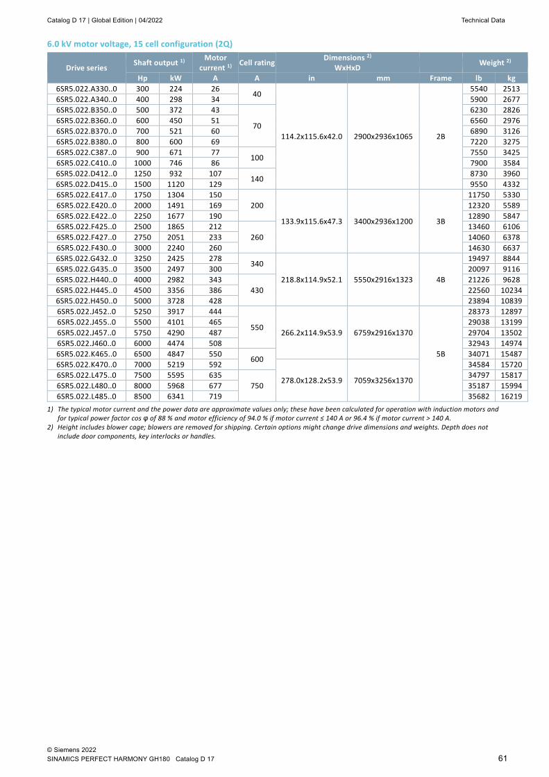
Catalog D 17 | Global Edition | 04/2022 Technical Data
© Siemens 2022 SINAMICS PERFECT HARMONY GH180 Catalog D 17 61
6.0 kV motor voltage, 15 cell configuration (2Q)
Drive series Shaft output 1) Motor current 1) Cell rating Dimensions 2)
WxHxD Weight 2)
Hp kW A A in mm Frame lb kg 6SR5.022.A330..0 300 224 26
40
114.2x115.6x42.0 2900x2936x1065 2B
5540 2513 6SR5.022.A340..0 400 298 34 5900 2677 6SR5.022.B350..0 500 372 43
70
6230 2826 6SR5.022.B360..0 600 450 51 6560 2976 6SR5.022.B370..0 700 521 60 6890 3126 6SR5.022.B380..0 800 600 69 7220 3275 6SR5.022.C387..0 900 671 77
100 7550 3425
6SR5.022.C410..0 1000 746 86 7900 3584 6SR5.022.D412..0 1250 932 107
140 8730 3960
6SR5.022.D415..0 1500 1120 129 9550 4332 6SR5.022.E417..0 1750 1304 150
200
133.9x115.6x47.3 3400x2936x1200 3B
11750 5330 6SR5.022.E420..0 2000 1491 169 12320 5589 6SR5.022.E422..0 2250 1677 190 12890 5847 6SR5.022.F425..0 2500 1865 212
260 13460 6106
6SR5.022.F427..0 2750 2051 233 14060 6378 6SR5.022.F430..0 3000 2240 260 14630 6637 6SR5.022.G432..0 3250 2425 278
340
218.8x114.9x52.1 5550x2916x1323 4B
19497 8844 6SR5.022.G435..0 3500 2497 300 20097 9116 6SR5.022.H440..0 4000 2982 343
430 21226 9628
6SR5.022.H445..0 4500 3356 386 22560 10234 6SR5.022.H450..0 5000 3728 428 23894 10839 6SR5.022.J452..0 5250 3917 444
550 266.2x114.9x53.9 6759x2916x1370
5B
28373 12897 6SR5.022.J455..0 5500 4101 465 29038 13199 6SR5.022.J457..0 5750 4290 487 29704 13502 6SR5.022.J460..0 6000 4474 508 32943 14974 6SR5.022.K465..0 6500 4847 550
600 34071 15487
6SR5.022.K470..0 7000 5219 592
278.0x128.2x53.9 7059x3256x1370
34584 15720 6SR5.022.L475..0 7500 5595 635
750 34797 15817
6SR5.022.L480..0 8000 5968 677 35187 15994 6SR5.022.L485..0 8500 6341 719 35682 16219
1) The typical motor current and the power data are approximate values only; these have been calculated for operation with induction motors and for typical power factor cos φ of 88 % and motor efficiency of 94.0 % if motor current ≤ 140 A or 96.4 % if motor current > 140 A.
2) Height includes blower cage; blowers are removed for shipping. Certain options might change drive dimensions and weights. Depth does not include door components, key interlocks or handles.

Technical Data Catalog D 17 | Global Edition | 04/2022
© Siemens 2022 62 SINAMICS PERFFECT HARMONY GH180 Catalog D 17
6.6 kV motor voltage, 15 cell configuration (2Q)
Drive series Shaft output 1) Motor
current 1) Cell rating Dimensions 2) WxHxD Frame
Weight 2)
Hp kW A A in mm lb kg 6SR5.022.A330..0 300 223 24
40
114.2x115.6x42.0 2900x2936x1065 2B
5540 2520 6SR5.022.A340..0 400 298 31 5900 2680 6SR5.022.A350..0 500 372 39 6230 2830 6SR5.022.B360..0 600 450 47
70 6560 2980
6SR5.022.B370..0 700 521 55 6890 3130 6SR5.022.B380..0 800 600 62 7220 3280 6SR5.022.C387..0 900 671 70
100 7550 3430
6SR5.022.C410..0 1000 746 78 7900 3590 6SR5.022.C412..0 1250 932 100 9550 4340 6SR5.022.D415..0 1500 1120 117
140 10380 4720
6SR5.022.D417..0 1750 1304 138 11750 5340 6SR5.022.E420..0 2000 1492 154
200 133.9x115.6x47.3 3400x2936x1200 3B
12320 5600 6SR5.022.E422..0 2250 1679 173 12890 5860 6SR5.022.E425..0 2500 1865 192 13460 6120 6SR5.022.F427..0 2750 2051 212
260 14060 6390
6SR5.022.F430..0 3000 2238 231 14630 6650 6SR5.022.G435..0 3500 2600 296
340
218.8x114.9x52.1 5550x2916x1323 4B
20097 9135 6SR5.022.G440..0 4000 2982 312 25452 11569 6SR5.022.H445..0 4500 3356 351
430 26580 12082
6SR5.022.H450..0 5000 3728 389 27707 12594 6SR5.022.H455..0 5500 4101 428 29038 13199 6SR5.022.J457..0 5750 4290 448
550 266.2x114.9x53.9 6759x2916x1370
5B
29704 13502 6SR5.022.J460..0 6000 4474 467 32943 14974 6SR5.022.J465..0 6500 4847 506 34071 15487 6SR5.022.J470..0 7000 5219 545
278.0x128.2x53.9 7059x3256x1370
34584 15720 6SR5.022.K475..0 7500 5595 584 600 34797 15817 6SR5.022.L480..0 8000 5965 623
750
35187 15994 6SR5.022.L485..0 8500 6341 662 35682 16219 6SR5.022.L487..0 9000 6714 701 36177 16444 6SR5.022.L488..0 9500 7087 699 36709 16686 6SR5.022.L520..0 10000 7460 779 37241 16928
1) The typical motor current and the power data are approximate values only; these have been calculated for operation with induction motors and for typical power factor cos φ of 88 % and motor efficiency of 94.0 % if motor current ≤ 140 A or 96.4 % if motor current > 140 A.
2) Height includes blower cage; blowers are removed for shipping. Certain options might change drive dimensions and weights. Depth does not include door components, key interlocks or handles.

Catalog D 17 | Global Edition | 04/2022 Technical Data
© Siemens 2022 SINAMICS PERFECT HARMONY GH180 Catalog D 17 63
6.9 kV motor voltage, 15 cell configuration (2Q)
Drive series Shaft output 1) Motor current 1) Cell rating Dimensions 2)
WxHxD Weight 2)
Hp kW A A in mm Frame lb kg 6SR5.022.A330..0 300 224 22
40
114.2x115.6x42.0 2900x2936x1065 2B
5540 2513 6SR5.022.A340..0 400 298 30 5900 2677 6SR5.022.A350..0 500 372 37 6230 2826 6SR5.022.B360..0 600 450 45
70
6560 2976 6SR5.022.B370..0 700 521 52 6890 3126 6SR5.022.B380..0 800 600 60 7220 3275 6SR5.022.B387..0 900 671 70 7550 3425 6SR5.022.C410..0 1000 746 75
100 7900 3584
6SR5.022.C412..0 1250 932 100 8730 3960 6SR5.022.D415..0 1500 1120 112
140 9550 4332
6SR5.022.D417..0 1750 1304 130 10380 4709 6SR5.022.E420..0 2000 1491 147
200
133.9x115.6x47.3 3400x2936x1200 3B
12320 5589 6SR5.022.E422..0 2250 1677 166 12890 5847 6SR5.022.E425..0 2500 1862 186 13460 6106 6SR5.022.F427..0 2750 2051 202
260 14060 6378
6SR5.022.F430..0 3000 2240 221 14630 6637 6SR5.022.F435..0 3500 2611 258 15770 7170 6SR5.022.G440..0 4000 2982 294
340 218.8x114.9x52.1 5550x2916x1323 4B
21226 9628 6SR5.022.G445..0 4500 3356 331 22560 10234 6SR5.022.H450..0 5000 3730 368
430 23894 10839
6SR5.022.H455..0 5500 4101 405 25183 11423 6SR5.022.J460..0 6000 4474 442
550 266.2x114.9x53.9 6759x2916x1370
5B
32943 14974 6SR5.022.J465..0 6500 4847 478 34071 15487 6SR5.022.J470..0 7000 5219 515
278.0x128.2x53.9 7059x3256x1370
34584 15720 6SR5.022.K475..0 7500 5595 552
600 34797 15817
6SR5.022.K480..0 8000 5968 589 35187 15994 6SR5.022.L485..0 8500 6341 625
750
35682 16219 6SR5.022.L487..0 9000 6714 662 36177 16444 6SR5.022.L488..0 9500 7087 699 36709 16686 6SR5.022.L520..0 10000 7460 736 37241 16928
1) The typical motor current and the power data are approximate values only; these have been calculated for operation with induction motors and for typical power factor cos φ of 88 % and motor efficiency of 94.0 % if motor current ≤ 140 A or 96.4 % if motor current > 140 A.
2) Height includes blower cage; blowers are removed for shipping. Certain options might change drive dimensions and weights. Depth does not include door components, key interlocks or handles.

Technical Data Catalog D 17 | Global Edition | 04/2022
© Siemens 2022 64 SINAMICS PERFFECT HARMONY GH180 Catalog D 17
7.2 kV motor voltage, 18 cell configuration (2Q)
Drive series Shaft output 1) Motor
current 1) Cell rating Dimensions 2) WxHxD Frame Weight 2)
Hp kW A A in mm lb kg 6SR5.023.J440..0 4000 2984 282
550 281.9x114.9x53.9 7159x2916x1370
5C
28435 12925 6SR5.023.J442..0 4250 3171 300 29101 13228 6SR5.023.J445..0 4500 3356 317 29766 13530 6SR5.023.J447..0 4750 3544 335 30432 13833 6SR5.023.J450..0 5000 3728 353 31097 14135 6SR5.023.J452..0 5250 3917 370 31741 14428 6SR5.023.J455..0 5500 4101 388 32384 14720 6SR5.023.J457..0 5750 4290 405 32947 14976 6SR5.023.J460..0 6000 4474 423 33510 15232 6SR5.023.J465..0 6500 4847 458 34639 15745 6SR5.023.J470..0 7000 5219 494
293.7x128.2x53.9 7459x3256x1370
35094 15952 6SR5.023.J475..0 7500 5595 529 35246 16021 6SR5.023.K480..0 8000 5968 564
600 35840 16291
6SR5.023.K485..0 8500 6341 599 36434 16561 6SR5.023.L487..0 9000 6714 635
750
37028 16831 6SR5.023.L488..0 9500 7087 670 37622 17101 6SR5.023.L520..0 10000 7460 705 38216 17371 6SR5.023.L521..0 10500 7830 740 326.0x135.9x53.9 8279x3453x1370 38810 17641
8.0 kV motor voltage, 18 cell configuration (2Q)
Drive series Shaft output 1) Motor current 1) Cell rating Dimensions 2)
WxHxD Weight 2)
Hp kW A A in mm Frame lb kg 6SR5.023.J440..0 4000 2982 254
550
281.9x114.9x53.9 7159x2916x1370
5C
28435 12925 6SR5.023.J442..0 4250 3171 270 29101 13228 6SR5.023.J445..0 4500 3356 286 29766 13530 6SR5.023.J447..0 4750 3544 301 30432 13833 6SR5.023.J450..0 5000 3728 317 31097 14135 6SR5.023.J452..0 5250 3917 333 31741 14428 6SR5.023.J455..0 5500 4101 349 32384 14720 6SR5.023.J457..0 5750 4290 365 32947 14976 6SR5.023.J460..0 6000 4474 381 33510 15232 6SR5.023.J465..0 6500 4847 413 34639 15745 6SR5.023.J470..0 7000 5219 444
293.7x128.2x53.9 7459x3256x1370
35094 15952 6SR5.023.J475..0 7500 5595 476 35246 16021 6SR5.023.J480..0 8000 5965 508 35840 16291 6SR5.023.J485..0 8500 6341 539 36434 16561 6SR5.023.K487..0 9000 6714 571 600 37028 16831 6SR5.023.L488..0 9500 7087 603
750
37622 17101 6SR5.023.L520..0 10000 7460 635 38216 17371 6SR5.023.L521..0 10500 7833 667
326.0x135.9x53.9 8279x3453x1370 38810 17641
6SR5.023.L522..0 11000 8206 698 39404 17911 6SR5.023.L523..0 11500 8579 730 40596 18453
1) The typical motor current and the power data are approximate values only; these have been calculated for operation with induction motors and for typical power factor cos φ of 88 % and motor efficiency of 94.0 % if motor current ≤ 140 A or 96.4 % if motor current > 140 A.
2) Height includes blower cage; blowers are removed for shipping. Certain options might change drive dimensions and weights. Depth does not include door components, key interlocks or handles.
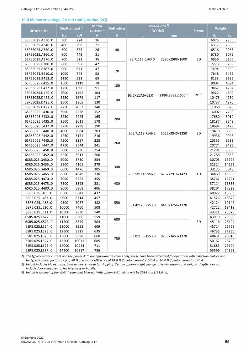
Catalog D 17 | Global Edition | 04/2022 Technical Data
© Siemens 2022 SINAMICS PERFECT HARMONY GH180 Catalog D 17 65
10.0 kV motor voltage, 24 cell configuration (2Q)
Drive series Shaft output 1) Motor
current 1) Cell rating Dimensions 2) WxHxD Frame
Weight 2)
Hp kW A A in mm lb kg 6SR55025.A330..0 300 224 16
40
93.7x117.6x63.0 2380x2988x1600 2D
6075 2755 6SR55025.A340..0 400 298 21 6317 2865 6SR55025.A350..0 500 373 26 6516 2955 6SR55025.A360..0 600 448 31 6780 3075 6SR55025.A370..0 700 522 36 6956 3155 6SR55025.B380..0 800 597 42
70
7273 3299 6SR55025.B387..0 900 671 47 7494 3399 6SR55025.B410..0 1000 746 52 7648 3469 6SR55025.B412..0 1250 933 65 8133 3689 6SR55025.C415..0 1500 1119 78
100
93.7x117.6x63.0 3) 2380x2988x1600 3) 2D 3)
9004 4084 6SR55025.C417..0 1750 1306 91 9467 4294 6SR55025.D420..0 2000 1492 104
140
9922 4500 6SR55025.D422..0 2250 1679 117 10473 4750 6SR55025.D425..0 2500 1865 130 10737 4870 6SR55025.D427..0 2750 2052 140 11068 5020 6SR55025.E430..0 3000 2238 152
200
205.7x119.7x49.2 5226x3040x1250 3D
16002 7258 6SR55025.E432..0 3250 2425 165 17680 8019 6SR55025.E435..0 3500 2611 178 18187 8249 6SR55025.E437..0 3750 2798 190 18694 8479 6SR55025.F440..0 4000 2984 203
260
19418 8808 6SR55025.F442..0 4250 3171 216 19936 9043 6SR55025.F445..0 4500 3357 228 20355 9233 6SR55025.F447..0 4750 3544 241 20774 9423 6SR55025.F450..0 5000 3730 254 21281 9653 6SR55025.F452..0 5250 3917 260 21788 9883 6SR5.025.G450..0 5000 3730 254
340
266.5x114.9x56.1 6767x2916x1423 4D
30703 13927 6SR5.025.G455..0 5500 4101 279 32324 14662 6SR5.025.G460..0 6000 4476 305 33175 5048 6SR5.025.G465..0 6500 4849 330 34469 15635 6SR5.025.H470..0 7000 5222 355
430 35761 16221
6SR5.025.H475..0 7500 5595 381 37114 16835 6SR5.025.H480..0 8000 5968 406 38204 17329 6SR5.025.J485..0 8500 6341 432
550 331.4x128.2x53.9 8418x3256x1370
5D
40927 18603 6SR5.025.J487..0 9000 6714 457 41526 18875 6SR5.025.J488..0 9500 7087 482 42124 19147 6SR5.025.J520..0 10000 7460 508 42722 19419 6SR5.025.J521..0 10500 7830 540 43321 25678 6SR5.025.K522..0 11000 8206 559
600 43919 25950
6SR5.025.K523..0 11500 8579 584
363.8x136.1x53.9 9238x3453x1370
45116 26494 6SR5.025.L524..0 12000 8952 609
750
45714 26766 6SR5.025.L525..0 12500 9325 635 46735 27230 6SR5.025.L526..0 13000 9698 660 48451 28010 6SR5.025.L527..0 13500 10071 685 50167 28790 6SR5.025.L528..0 14000 10444 711 51883 29570 6SR5.025.L587..0 14500 10817 736 53599 24363
1) The typical motor current and the power data are approximate values only; these have been calculated for operation with induction motors and for typical power factor cos φ of 88 % and motor efficiency of 94.0 % if motor current ≤ 140 A or 96.4 % if motor current > 140 A.
2) Height includes blower cage; blowers are removed for shipping. Certain options might change drive dimensions and weights. Depth does not include door components, key interlocks or handles.
3) Height is without option M61 (redundant blower). With option M61 height will be 3088 mm (121.6 in).
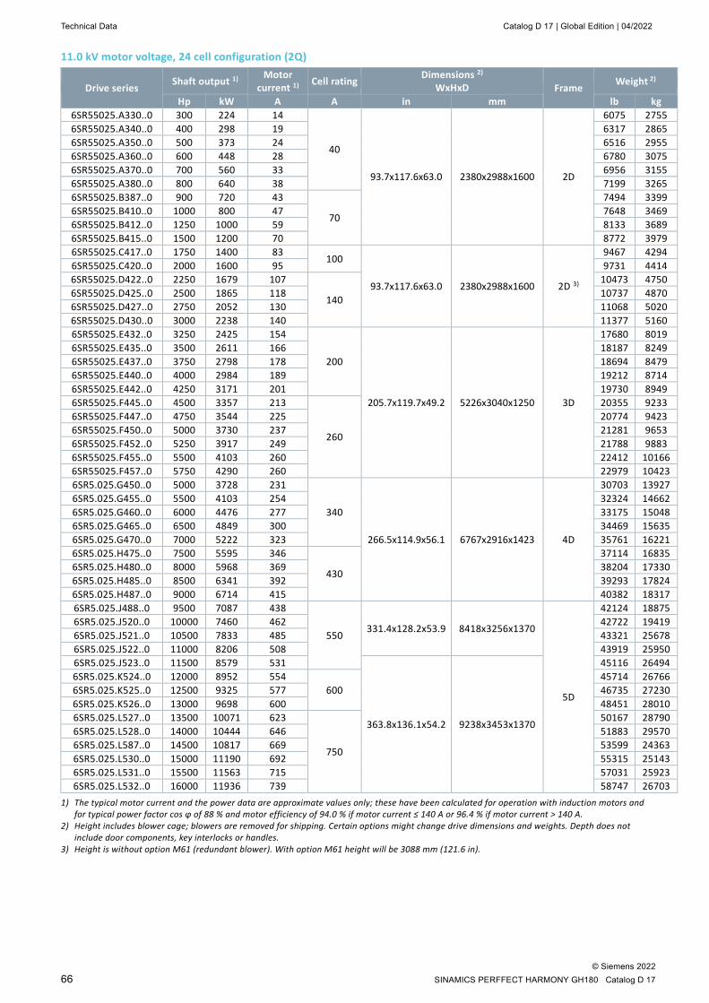
Technical Data Catalog D 17 | Global Edition | 04/2022
© Siemens 2022 66 SINAMICS PERFFECT HARMONY GH180 Catalog D 17
11.0 kV motor voltage, 24 cell configuration (2Q)
Drive series Shaft output 1) Motor
current 1) Cell rating Dimensions 2) WxHxD Frame
Weight 2)
Hp kW A A in mm lb kg 6SR55025.A330..0 300 224 14
40
93.7x117.6x63.0 2380x2988x1600 2D
6075 2755 6SR55025.A340..0 400 298 19 6317 2865 6SR55025.A350..0 500 373 24 6516 2955 6SR55025.A360..0 600 448 28 6780 3075 6SR55025.A370..0 700 560 33 6956 3155 6SR55025.A380..0 800 640 38 7199 3265 6SR55025.B387..0 900 720 43
70
7494 3399 6SR55025.B410..0 1000 800 47 7648 3469 6SR55025.B412..0 1250 1000 59 8133 3689 6SR55025.B415..0 1500 1200 70 8772 3979 6SR55025.C417..0 1750 1400 83
100
93.7x117.6x63.0 2380x2988x1600 2D 3)
9467 4294 6SR55025.C420..0 2000 1600 95 9731 4414 6SR55025.D422..0 2250 1679 107
140
10473 4750 6SR55025.D425..0 2500 1865 118 10737 4870 6SR55025.D427..0 2750 2052 130 11068 5020 6SR55025.D430..0 3000 2238 140 11377 5160 6SR55025.E432..0 3250 2425 154
200
205.7x119.7x49.2 5226x3040x1250 3D
17680 8019 6SR55025.E435..0 3500 2611 166 18187 8249 6SR55025.E437..0 3750 2798 178 18694 8479 6SR55025.E440..0 4000 2984 189 19212 8714 6SR55025.E442..0 4250 3171 201 19730 8949 6SR55025.F445..0 4500 3357 213
260
20355 9233 6SR55025.F447..0 4750 3544 225 20774 9423 6SR55025.F450..0 5000 3730 237 21281 9653 6SR55025.F452..0 5250 3917 249 21788 9883 6SR55025.F455..0 5500 4103 260 22412 10166 6SR55025.F457..0 5750 4290 260 22979 10423 6SR5.025.G450..0 5000 3728 231
340
266.5x114.9x56.1 6767x2916x1423 4D
30703 13927 6SR5.025.G455..0 5500 4103 254 32324 14662 6SR5.025.G460..0 6000 4476 277 33175 15048 6SR5.025.G465..0 6500 4849 300 34469 15635 6SR5.025.G470..0 7000 5222 323 35761 16221 6SR5.025.H475..0 7500 5595 346
430
37114 16835 6SR5.025.H480..0 8000 5968 369 38204 17330 6SR5.025.H485..0 8500 6341 392 39293 17824 6SR5.025.H487..0 9000 6714 415 40382 18317 6SR5.025.J488..0 9500 7087 438
550 331.4x128.2x53.9 8418x3256x1370
5D
42124 18875 6SR5.025.J520..0 10000 7460 462 42722 19419 6SR5.025.J521..0 10500 7833 485 43321 25678 6SR5.025.J522..0 11000 8206 508 43919 25950 6SR5.025.J523..0 11500 8579 531
363.8x136.1x54.2 9238x3453x1370
45116 26494 6SR5.025.K524..0 12000 8952 554
600 45714 26766
6SR5.025.K525..0 12500 9325 577 46735 27230 6SR5.025.K526..0 13000 9698 600 48451 28010 6SR5.025.L527..0 13500 10071 623
750
50167 28790 6SR5.025.L528..0 14000 10444 646 51883 29570 6SR5.025.L587..0 14500 10817 669 53599 24363 6SR5.025.L530..0 15000 11190 692 55315 25143 6SR5.025.L531..0 15500 11563 715 57031 25923 6SR5.025.L532..0 16000 11936 739 58747 26703
1) The typical motor current and the power data are approximate values only; these have been calculated for operation with induction motors and for typical power factor cos φ of 88 % and motor efficiency of 94.0 % if motor current ≤ 140 A or 96.4 % if motor current > 140 A.
2) Height includes blower cage; blowers are removed for shipping. Certain options might change drive dimensions and weights. Depth does not include door components, key interlocks or handles.
3) Height is without option M61 (redundant blower). With option M61 height will be 3088 mm (121.6 in).
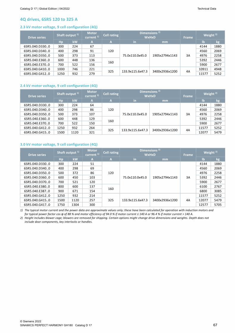
Catalog D 17 | Global Edition | 04/2022 Technical Data
© Siemens 2022 SINAMICS PERFECT HARMONY GH180 Catalog D 17 67
4Q drives, 6SR5 120 to 325 A 2.3 kV motor voltage, 9 cell configuration (4Q)
Drive series Shaft output 1) Motor
current 1) Cell rating Dimensions 2) WxHxD Frame
Weight 2)
Hp kW A A in mm lb kg 6SR5.040.D330..0 300 224 67
120 75.0x110.0x45.0 1905x2794x1143 3A
4144 1880 6SR5.040.D340..0 400 298 91 4560 2069 6SR5.040.D350..0 500 373 113 4976 2258 6SR5.040.E360..0 600 448 136
160 5392 2446
6SR5.040.E370..0 700 522 156 5900 2677 6SR5.040.G410..0 1000 746 221
325 133.9x115.6x47.3 3400x2936x1200 4A 10911 4948
6SR5.040.G412..0 1250 932 279 11577 5252
2.4 kV motor voltage, 9 cell configuration (4Q)
Drive series Shaft output 1) Motor
current 1) Cell rating Dimensions 2) WxHxD Frame
Weight 2)
Hp kW A A in mm lb kg 6SR5.040.D330..0 300 224 64
120 75.0x110.0x45.0 1905x2794x1143 3A
4144 1880 6SR5.040.D340..0 400 298 86 4560 2069 6SR5.040.D350..0 500 373 107 4976 2258 6SR5.040.E360..0 600 448 129
160 5392 2446
6SR5.040.E370..0 700 522 150 5900 2677 6SR5.040.G412..0 1250 932 264
325 133.9x115.6x47.3 3400x2936x1200 4A 11577 5252
6SR5.040.G415..0 1500 1120 321 12077 5479
3.0 kV motor voltage, 9 cell configuration (4Q)
Drive series Shaft output 1) Motor
current 1) Cell rating Dimensions 2) WxHxD Frame
Weight 2)
Hp kW A A in mm lb kg 6SR5.040.D330..0 300 224 51
120 75.0x110.0x45.0 1905x2794x1143 3A
4144 1880 6SR5.040.D340..0 400 298 69 4560 2069 6SR5.040.D350..0 500 372 86 4976 2258 6SR5.040.D360..0 600 450 103 5392 2446 6SR5.040.D370..0 700 521 120 5900 2677 6SR5.040.E380..0 800 600 137
160 6100 2767
6SR5.040.E387..0 900 671 154 6800 3085 6SR5.040.G412..0 1250 932 214
325 133.9x115.6x47.3 3400x2936x1200 4A 11577 5252
6SR5.040.G415..0 1500 1120 257 12077 5479 6SR5.040.G417..0 1750 1304 300 12577 5705
1) The typical motor current and the power data are approximate values only; these have been calculated for operation with induction motors and for typical power factor cos φ of 88 % and motor efficiency of 94.0 % if motor current ≤ 140 A or 96.4 % if motor current > 140 A.
2) Height includes blower cage; blowers are removed for shipping. Certain options might change drive dimensions and weights. Depth does not include door components, key interlocks or handles.
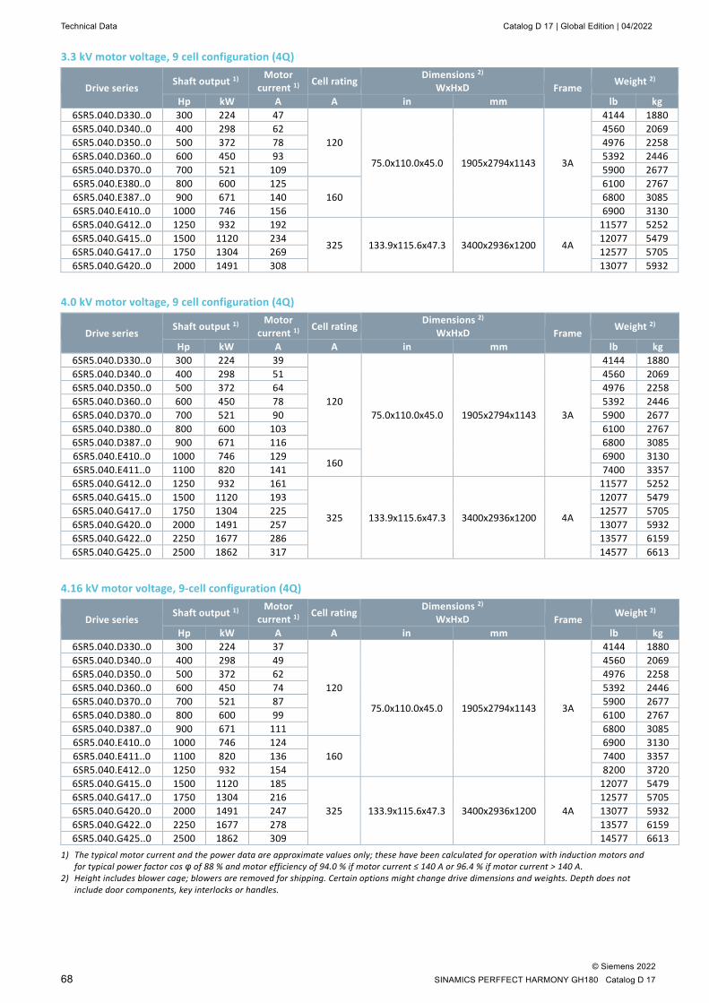
Technical Data Catalog D 17 | Global Edition | 04/2022
© Siemens 2022 68 SINAMICS PERFFECT HARMONY GH180 Catalog D 17
3.3 kV motor voltage, 9 cell configuration (4Q)
Drive series Shaft output 1) Motor
current 1) Cell rating Dimensions 2) WxHxD Frame
Weight 2)
Hp kW A A in mm lb kg 6SR5.040.D330..0 300 224 47
120
75.0x110.0x45.0 1905x2794x1143 3A
4144 1880 6SR5.040.D340..0 400 298 62 4560 2069 6SR5.040.D350..0 500 372 78 4976 2258 6SR5.040.D360..0 600 450 93 5392 2446 6SR5.040.D370..0 700 521 109 5900 2677 6SR5.040.E380..0 800 600 125
160 6100 2767
6SR5.040.E387..0 900 671 140 6800 3085 6SR5.040.E410..0 1000 746 156 6900 3130 6SR5.040.G412..0 1250 932 192
325 133.9x115.6x47.3 3400x2936x1200 4A
11577 5252 6SR5.040.G415..0 1500 1120 234 12077 5479 6SR5.040.G417..0 1750 1304 269 12577 5705 6SR5.040.G420..0 2000 1491 308 13077 5932
4.0 kV motor voltage, 9 cell configuration (4Q)
Drive series Shaft output 1) Motor
current 1) Cell rating Dimensions 2) WxHxD Frame
Weight 2)
Hp kW A A in mm lb kg 6SR5.040.D330..0 300 224 39
120 75.0x110.0x45.0 1905x2794x1143 3A
4144 1880 6SR5.040.D340..0 400 298 51 4560 2069 6SR5.040.D350..0 500 372 64 4976 2258 6SR5.040.D360..0 600 450 78 5392 2446 6SR5.040.D370..0 700 521 90 5900 2677 6SR5.040.D380..0 800 600 103 6100 2767 6SR5.040.D387..0 900 671 116 6800 3085 6SR5.040.E410..0 1000 746 129
160 6900 3130
6SR5.040.E411..0 1100 820 141 7400 3357 6SR5.040.G412..0 1250 932 161
325 133.9x115.6x47.3 3400x2936x1200 4A
11577 5252 6SR5.040.G415..0 1500 1120 193 12077 5479 6SR5.040.G417..0 1750 1304 225 12577 5705 6SR5.040.G420..0 2000 1491 257 13077 5932 6SR5.040.G422..0 2250 1677 286 13577 6159 6SR5.040.G425..0 2500 1862 317 14577 6613
4.16 kV motor voltage, 9-cell configuration (4Q)
Drive series Shaft output 1) Motor
current 1) Cell rating Dimensions 2) WxHxD Frame
Weight 2)
Hp kW A A in mm lb kg 6SR5.040.D330..0 300 224 37
120
75.0x110.0x45.0 1905x2794x1143 3A
4144 1880 6SR5.040.D340..0 400 298 49 4560 2069 6SR5.040.D350..0 500 372 62 4976 2258 6SR5.040.D360..0 600 450 74 5392 2446 6SR5.040.D370..0 700 521 87 5900 2677 6SR5.040.D380..0 800 600 99 6100 2767 6SR5.040.D387..0 900 671 111 6800 3085 6SR5.040.E410..0 1000 746 124
160 6900 3130
6SR5.040.E411..0 1100 820 136 7400 3357 6SR5.040.E412..0 1250 932 154 8200 3720 6SR5.040.G415..0 1500 1120 185
325 133.9x115.6x47.3 3400x2936x1200 4A
12077 5479 6SR5.040.G417..0 1750 1304 216 12577 5705 6SR5.040.G420..0 2000 1491 247 13077 5932 6SR5.040.G422..0 2250 1677 278 13577 6159 6SR5.040.G425..0 2500 1862 309 14577 6613
1) The typical motor current and the power data are approximate values only; these have been calculated for operation with induction motors and for typical power factor cos φ of 88 % and motor efficiency of 94.0 % if motor current ≤ 140 A or 96.4 % if motor current > 140 A.
2) Height includes blower cage; blowers are removed for shipping. Certain options might change drive dimensions and weights. Depth does not include door components, key interlocks or handles.
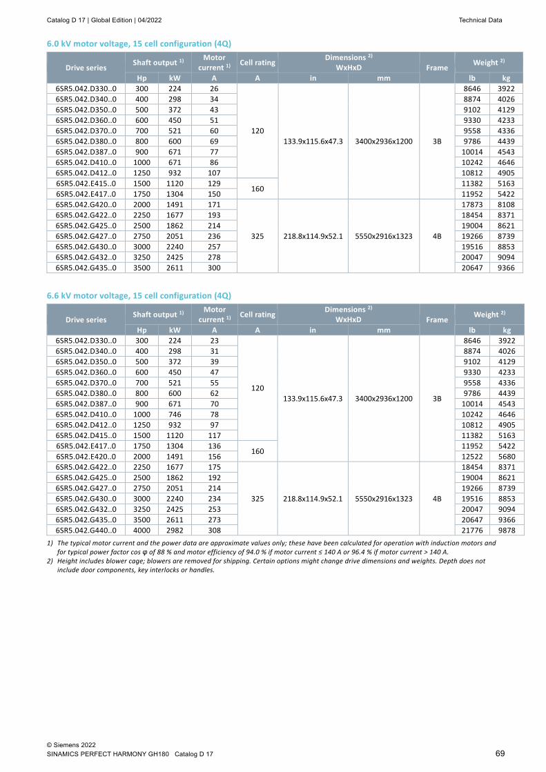
Catalog D 17 | Global Edition | 04/2022 Technical Data
© Siemens 2022 SINAMICS PERFECT HARMONY GH180 Catalog D 17 69
6.0 kV motor voltage, 15 cell configuration (4Q)
Drive series Shaft output 1) Motor
current 1) Cell rating Dimensions 2) WxHxD Frame
Weight 2)
Hp kW A A in mm lb kg 6SR5.042.D330..0 300 224 26
120 133.9x115.6x47.3 3400x2936x1200 3B
8646 3922 6SR5.042.D340..0 400 298 34 8874 4026 6SR5.042.D350..0 500 372 43 9102 4129 6SR5.042.D360..0 600 450 51 9330 4233 6SR5.042.D370..0 700 521 60 9558 4336 6SR5.042.D380..0 800 600 69 9786 4439 6SR5.042.D387..0 900 671 77 10014 4543 6SR5.042.D410..0 1000 671 86 10242 4646 6SR5.042.D412..0 1250 932 107 10812 4905 6SR5.042.E415..0 1500 1120 129
160 11382 5163
6SR5.042.E417..0 1750 1304 150 11952 5422 6SR5.042.G420..0 2000 1491 171
325 218.8x114.9x52.1 5550x2916x1323 4B
17873 8108 6SR5.042.G422..0 2250 1677 193 18454 8371 6SR5.042.G425..0 2500 1862 214 19004 8621 6SR5.042.G427..0 2750 2051 236 19266 8739 6SR5.042.G430..0 3000 2240 257 19516 8853 6SR5.042.G432..0 3250 2425 278 20047 9094 6SR5.042.G435..0 3500 2611 300 20647 9366
6.6 kV motor voltage, 15 cell configuration (4Q)
Drive series Shaft output 1) Motor
current 1) Cell rating Dimensions 2) WxHxD Frame
Weight 2)
Hp kW A A in mm lb kg 6SR5.042.D330..0 300 224 23
120 133.9x115.6x47.3 3400x2936x1200 3B
8646 3922 6SR5.042.D340..0 400 298 31 8874 4026 6SR5.042.D350..0 500 372 39 9102 4129 6SR5.042.D360..0 600 450 47 9330 4233 6SR5.042.D370..0 700 521 55 9558 4336 6SR5.042.D380..0 800 600 62 9786 4439 6SR5.042.D387..0 900 671 70 10014 4543 6SR5.042.D410..0 1000 746 78 10242 4646 6SR5.042.D412..0 1250 932 97 10812 4905 6SR5.042.D415..0 1500 1120 117 11382 5163 6SR5.042.E417..0 1750 1304 136
160 11952 5422
6SR5.042.E420..0 2000 1491 156 12522 5680 6SR5.042.G422..0 2250 1677 175
325 218.8x114.9x52.1 5550x2916x1323 4B
18454 8371 6SR5.042.G425..0 2500 1862 192 19004 8621 6SR5.042.G427..0 2750 2051 214 19266 8739 6SR5.042.G430..0 3000 2240 234 19516 8853 6SR5.042.G432..0 3250 2425 253 20047 9094 6SR5.042.G435..0 3500 2611 273 20647 9366 6SR5.042.G440..0 4000 2982 308 21776 9878
1) The typical motor current and the power data are approximate values only; these have been calculated for operation with induction motors and for typical power factor cos φ of 88 % and motor efficiency of 94.0 % if motor current ≤ 140 A or 96.4 % if motor current > 140 A.
2) Height includes blower cage; blowers are removed for shipping. Certain options might change drive dimensions and weights. Depth does not include door components, key interlocks or handles.

Technical Data Catalog D 17 | Global Edition | 04/2022
© Siemens 2022 70 SINAMICS PERFFECT HARMONY GH180 Catalog D 17
10.0 kV motor voltage, 24 cell configuration (4Q)
Drive series Shaft output 1) Motor
current 1) Cell rating Dimensions 2) WxHxD Frame
Weight 2)
Hp kW A A in mm lb kg 6SR55045.D350..0 500 373 25
120 205.7×119.7×49.2 5226×3040×1250 3D
10783 4891 6SR55045.D375..0 750 560 38 11480 5207 6SR55045.D410..0 1000 746 51 12176 5523 6SR55045.D412..0 1250 933 63 12688 5755 6SR55045.D415..0 1500 1119 76 13408 6082 6SR55045.D417..0 1750 1306 89 13919 6314 6SR55045.D420..0 2000 1492 102 14329 6500 6SR55045.D422..0 2250 1679 114 14737 6685 6SR55045.E427..0 2750 2052 140
160 15930 7226
6SR55045.E430..0 3000 2238 152 17120 7766 6SR55045.G432..0 3250 2425 165
325 266.5x114.9x56.1 6767x2916x1423 4D
27485 12468 6SR55045.G437..0 3750 2798 190 28201 12793 6SR55045.G400..0 4000 2984 203 28675 13008 6SR55045.G442..0 4250 3171 216 29160 13228 6SR55045.G450..0 4500 3357 228 29645 13448 6SR55045.G447..0 4750 3544 241 30119 13663 6SR55045.G450..0 5000 3730 254 30813 13978 6SR55045.G452..0 5250 3917 267 31497 14288 6SR55045.G455..0 5500 4101 280 32340 14670 6SR55045.G457..0 5750 4290 292 32875 14913 6SR55045.G460..0 6000 4476 305 33569 15228
11.0 kV motor voltage, 24 cell configuration (4Q)
Drive series Shaft output 1) Motor
current 1) Cell rating Dimensions 2) WxHxD Frame
Weight 2)
Hp kW A A in mm lb kg 6SR55045.D350..0 500 373 23
120
205.7×119.7×49.2 5226×3040×1250 3D
10783 4891 6SR55045.D375..0 750 560 35 11480 5207 6SR55045.D410..0 1000 746 46 12176 5523 6SR55045.D412..0 1250 933 58 12688 5755 6SR55045.D415..0 1500 1119 69 13201 5988 6SR55045.D417..0 1750 1306 81 13919 6314 6SR55045.D420..0 2000 1492 92 14329 6500 6SR55045.D422..0 2250 1679 104 14737 6685 6SR55045.E427..0 2750 2052 127
160 15930 7226
6SR55045.E430..0 3000 2238 138 17120 7766 6SR55045.E432..0 3250 2425 150 18478 8382 6SR55045.G437..0 3750 2798 173
325 266.5x114.9x56.1 6767x2916x1423 4D
28201 12793 6SR55045.G400..0 4000 2984 185 28675 13008 6SR55045.G442..0 4250 3171 196 29160 13228 6SR55045.G450..0 4500 3357 208 29645 13448 6SR55045.G447..0 4750 3544 219 30119 13663 6SR55045.G450..0 5000 3730 231 30813 13978 6SR55045.G452..0 5250 3917 242 31497 14288 6SR55045.G455..0 5500 4101 250 32340 14670 6SR55045.G457..0 5750 4290 265 32875 14913 6SR55045.G460..0 6000 4476 277 33569 15228 6SR55045.G465..0 6500 4849 300 34076 15458 6SR55045.G470..0 7000 5222 323 34605 15698
1) The typical motor current and the power data are approximate values only; these have been calculated for operation with induction motors and for typical power factor cos φ of 88 % and motor efficiency of 94.0 % if motor current ≤ 140 A or 96.4 % if motor current > 140 A.
2) Height includes blower cage; blowers are removed for shipping. Certain options might change drive dimensions and weights. Depth does not include door components, key interlocks or handles.
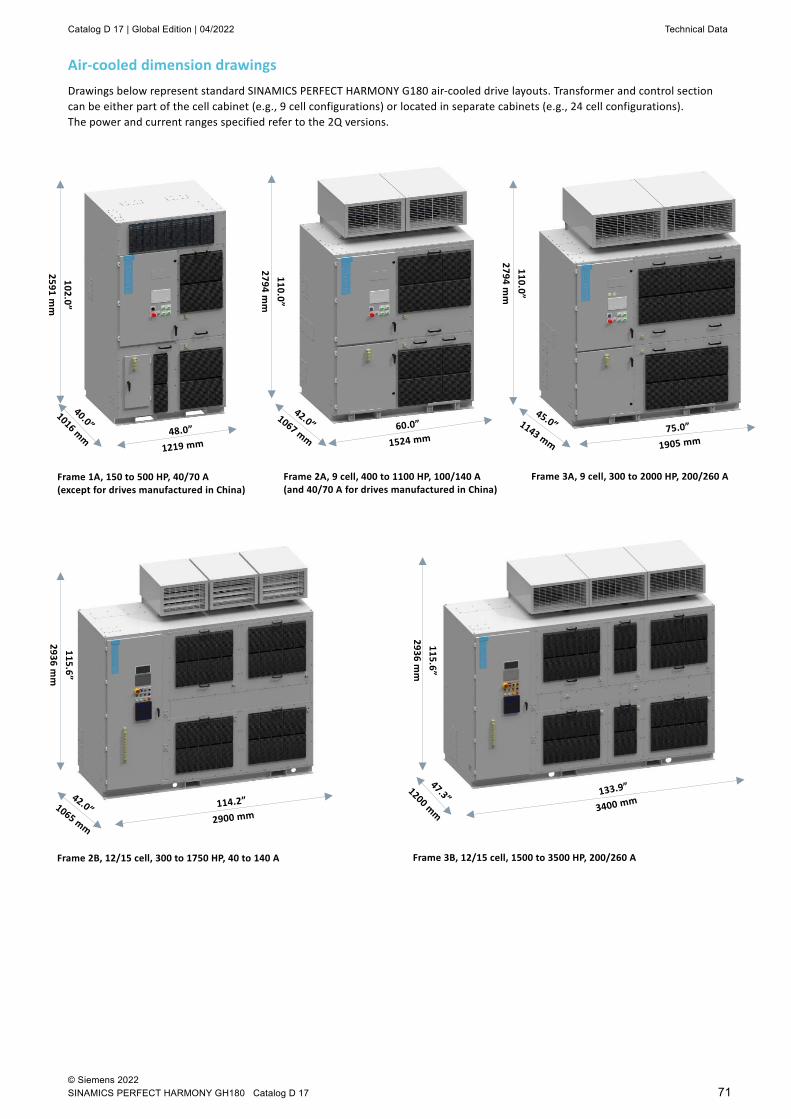
Catalog D 17 | Global Edition | 04/2022 Technical Data
© Siemens 2022 SINAMICS PERFECT HARMONY GH180 Catalog D 17 71
Air-cooled dimension drawings Drawings below represent standard SINAMICS PERFECT HARMONY G180 air-cooled drive layouts. Transformer and control section can be either part of the cell cabinet (e.g., 9 cell configurations) or located in separate cabinets (e.g., 24 cell configurations). The power and current ranges specified refer to the 2Q versions.
Frame 1A, 150 to 500 HP, 40/70 A (except for drives manufactured in China)
Frame 2A, 9 cell, 400 to 1100 HP, 100/140 A (and 40/70 A for drives manufactured in China)
Frame 3A, 9 cell, 300 to 2000 HP, 200/260 A
Frame 2B, 12/15 cell, 300 to 1750 HP, 40 to 140 A Frame 3B, 12/15 cell, 1500 to 3500 HP, 200/260 A
102.0”
2591 mm
110.0”
2794 mm
110.0”
2794 mm
115.6”
2936 mm
115.6”
2936 mm
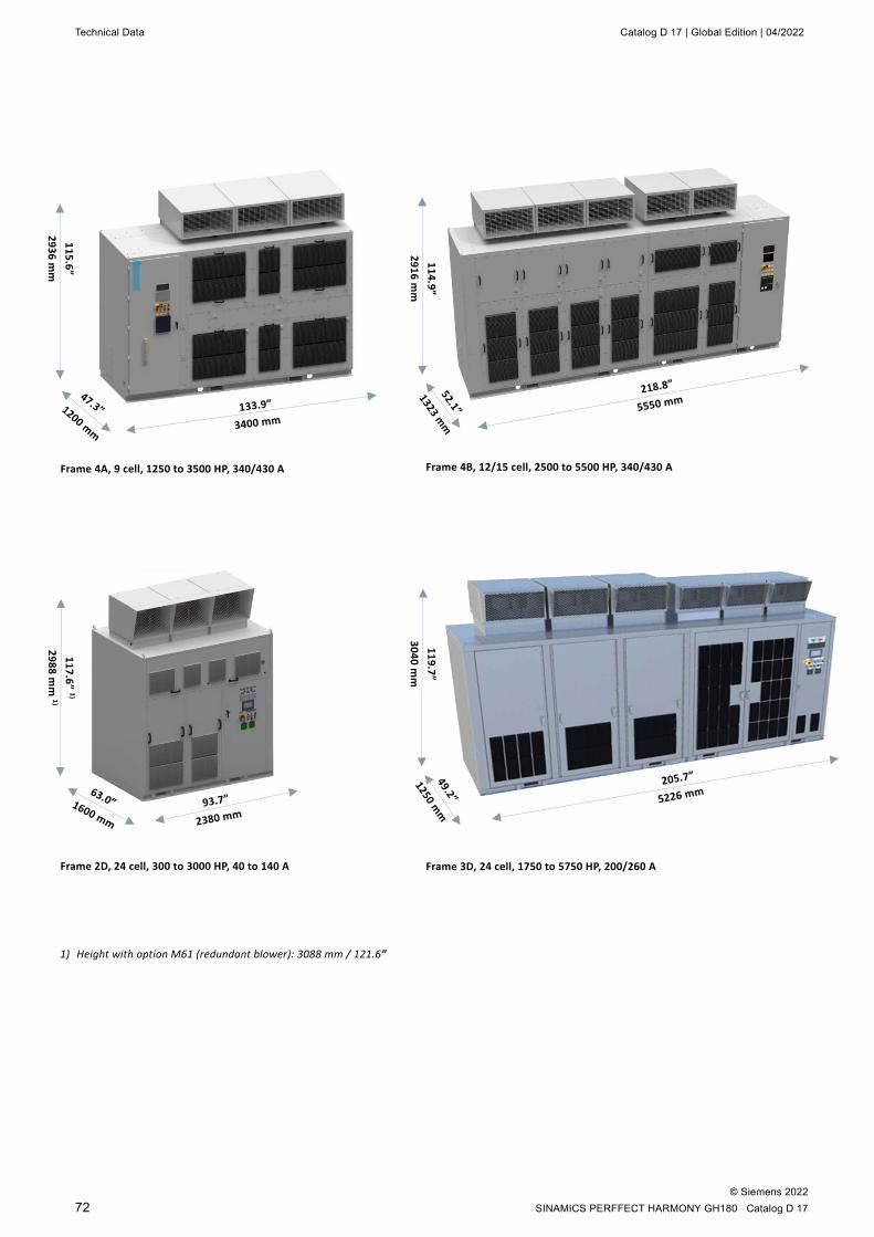
Technical Data Catalog D 17 | Global Edition | 04/2022
© Siemens 2022 72 SINAMICS PERFFECT HARMONY GH180 Catalog D 17
Frame 4A, 9 cell, 1250 to 3500 HP, 340/430 A Frame 4B, 12/15 cell, 2500 to 5500 HP, 340/430 A
115.6”
2936 mm
114.9”
2916 mm
Frame 2D, 24 cell, 300 to 3000 HP, 40 to 140 A
Frame 3D, 24 cell, 1750 to 5750 HP, 200/260 A
119.7”
3040 mm
117.6” 1)
2988 mm
1)
1) Height with option M61 (redundant blower): 3088 mm / 121.6”

Catalog D 17 | Global Edition | 04/2022 Technical Data
© Siemens 2022 SINAMICS PERFECT HARMONY GH180 Catalog D 17 73
Frame 4D, 24 cell, 5000 to 9000 HP, 340/430A
114.9”
2916 mm
Frame 5A, 9 cell, 2000 to 5750 HP, 550/600/720 A
114.9”
2916 mm
128.2/136.1”
3256/3453 mm
Frame 5D, 24 cell, 8500 to 16000 HP, 550/600/750 A
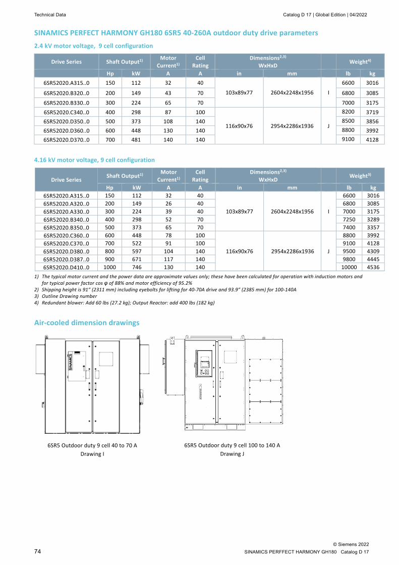
Technical Data Catalog D 17 | Global Edition | 04/2022
© Siemens 2022 74 SINAMICS PERFFECT HARMONY GH180 Catalog D 17
SINAMICS PERFECT HARMONY GH180 6SR5 40-260A outdoor duty drive parameters 2.4 kV motor voltage, 9 cell configuration
Drive Series Shaft Output1) Motor
Current1) Cell
Rating Dimensions2,3)
WxHxD Weight4)
Hp kW A A in mm lb kg 6SR52020.A315..0 150 112 32 40
103x89x77 2604x2248x1956 I
6600 3016
6SR52020.B320..0 200 149 43 70 6800 3085
6SR52020.B330..0 300 224 65 70 7000 3175
6SR52020.C340..0 400 298 87 100
116x90x76 2954x2286x1936 J
8200
3719 6SR52020.D350..0 500 373 108 140 8500
3856
6SR52020.D360..0 600 448 130 140 8800
3992 6SR52020.D370..0 700 481 140 140 9100
4128
4.16 kV motor voltage, 9 cell configuration
Drive Series Shaft Output1)
Motor Current1)
Cell Rating
Dimensions2,3) WxHxD Weight3)
Hp kW A A in mm lb kg 6SR52020.A315..0 150 112 32 40
103x89x77 2604x2248x1956 I
6600 3016 6SR52020.A320..0 200 149 26 40 6800 3085 6SR52020.A330..0 300 224 39 40 7000 3175 6SR52020.B340..0 400 298 52 70 7250 3289 6SR52020.B350..0 500 373 65 70 7400 3357 6SR52020.C360..0 600 448 78 100
116x90x76 2954x2286x1936 J
8800
3992 6SR52020.C370..0 700 522 91 100 9100
4128
6SR52020.D380..0 800 597 104 140 9500 4309 6SR52020.D387..0 900 671 117 140 9800 4445 6SR52020.D410..0 1000 746 130 140 10000 4536
1) The typical motor current and the power data are approximate values only; these have been calculated for operation with induction motors and for typical power factor cos φ of 88% and motor efficiency of 95.2%
2) Shipping height is 91” (2311 mm) including eyebolts for lifting for 40-70A drive and 93.9” (2385 mm) for 100-140A 3) Outline Drawing number 4) Redundant blower: Add 60 lbs (27.2 kg); Output Reactor: add 400 lbs (182 kg)
Air-cooled dimension drawings
6SR5 Outdoor duty 9 cell 40 to 70 A Drawing I
6SR5 Outdoor duty 9 cell 100 to 140 A Drawing J
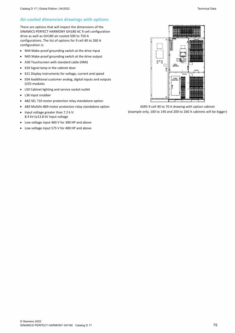
Catalog D 17 | Global Edition | 04/2022 Technical Data
© Siemens 2022 SINAMICS PERFECT HARMONY GH180 Catalog D 17 75
Air-cooled dimension drawings with options There are options that will impact the dimensions of the SINAMICS PERFECT HARMONY GH180 AC 9 cell configuration drive as well as GH180 air-cooled 500 to 750 A configurations. The list of options for 9 cell 40 to 260 A configuration is:
• N44 Make-proof grounding switch at the drive input
• N45 Make-proof grounding switch at the drive output
• A30 Touchscreen with standard cable (HMI)
• K20 Signal lamp in the cabinet door
• K21 Display instruments for voltage, current and speed
• E04 Aadditional customer analog, digital inputs and outputs (I/O) modules
• L50 Cabinet lighting and service socket outlet
• L36 Input snubber
• A82 SEL 710 motor protection relay standalone option
• A83 Multilin 869 motor protection relay standalone option
• Input voltage greater than 7.2 k V: 8.4 kV to13.8 kV input voltage
• Low voltage input 460 V for 300 HP and above
• Low voltage input 575 V for 400 HP and above
6SR5 9 cell 40 to 70 A drawing with option cabinet (example only, 100 to 140 and 200 to 260 A cabinets will be bigger)

Technical Data Catalog D 17 | Global Edition | 04/2022
© Siemens 2022 76 SINAMICS PERFFECT HARMONY GH180 Catalog D 17
Water-cooled technical data 3.3 kV motor voltage, 9 cell configuration
Drive Series Shaft Output1)
Motor Current1)
Cell Rating
Dimensions2,3) WxHxD
Weight
Hp kW A A in mm lb kg
6SR32720.D440..0 4000 2984 623 1000
305x115x70 7747x2921x1778 M
35659 16175 6SR32720.D450..0 5000 3730 779 1000 37920 17200 6SR32720.D460..0 6000 4476 935 1000 40869 18538 6SR32720.C465..0 6500 4849 1013 1250 40869 18538 6SR32720.C470..0 7000 5222 1091 1250 41830 18974 6SR32720.C475..0 7500 5595 1168 1250 42755 19393 6SR32720.C480..0 8000 5968 1246 1250 43649 19799 6SR32720.E485..0 8500 6341 1324 1375 43742 19841
4.16 kV motor voltage, 9 cell configuration
1) The typical motor current and the power data are approximate values only; these have been calculated for operation with induction motors and for typical power factor cos φ of 88% and motor efficiency of 95.2%
2) Outline Drawing number 3) Certain options will change drive dimensions, for more details see outline page
Drive Series Shaft Output1)
Motor Current1)
Cell Rating
Dimensions2,3) WxHxD
Weight
Hp kW A A in mm lb kg
6SR32720.D440..0 4000 2984 494 1000
305x115x70 7747x2921x1778 M
35266 15996 6SR32720.D450..0 5000 3730 634 1000 37419 16973 6SR32720.D460..0 6000 4476 742 1000 39370 17858 6SR32720.D465..0 6500 4849 803 1000 39370 17858 6SR32720.D470..0 7000 5222 865 1000 40285 18273 6SR32720.D475..0 7500 5595 926 1000 42067 19081 6SR32720.D480..0 8000 5968 989 1000 42242 19161 6SR32720.C485..0 8500 6341 1050 1250 43742 19841 6SR32720.C490..0 9000 6714 1112 1250 44541 20203 6SR32720.C495..0 9500 7087 1174 1250 44541 20203 6SR32720.C520..0 10000 7460 1235 1250 45317 20555 6SR32720.E522..0 11000 8206 1359 1375 46808 21232

Catalog D 17 | Global Edition | 04/2022 Technical Data
© Siemens 2022 SINAMICS PERFECT HARMONY GH180 Catalog D 17 77
4.8 kV motor voltage, 12 cell configuration
6.6/6.9 kV motor voltage, 15 cell configuration
1) The typical motor current and the power data in hp and KW are approximate values only; these have been calculated for operation with induction motors and for typical power factor cos φ of 88% and motor efficiency of 95.2%
2) Outline Drawing number 3) Certain options will change drive dimensions, for more details see outline page
Drive Series Shaft Output1)
Motor Current1)
Cell Rating
Dimensions2,3) WxHxD
Weight
Hp kW A A in mm lb kg
6SR32721.D440..0 4000 2984 428 1000
331x115x70 8395x2921x1778 M
38647 17530 6SR32721.D450..0 5000 3730 536 1000 40823 18517 6SR32721.D460..0 6000 4476 643 1000 42793 19411 6SR32721.D465..0 6500 4849 696 1000 42793 19411 6SR32721.D470..0 7000 5222 750 1000 43718 19830 6SR32721.D475..0 7500 5595 803 1000 44608 20234 6SR32721.D480..0 8000 5968 857 1000 45468 20624 6SR32721.D485..0 8500 6341 910 1000 47500 21546 6SR32721.D487..0 9000 6714 964 1000 48307 21912 6SR32721.C488..0 9500 7087 1017 1250 48307 21912 6SR32721.C520..0 10000 7460 1071 1250 49091 22267 6SR32721.C522..0 11000 8206 1178 1250 50598 22951 6SR32721.E524..0 12000 8952 1285 1375 52032 23601
Drive Series Shaft Output1) Motor
Current1) Cell
Rating Dimensions2,3)
WxHxD Weight
Hp kW A A in mm lb kg
6SR32722.D460..0 6000 4474 468 1000
356x115x70 9043x2921x1778 M
46214 20962
6SR32722.D470..0 7000 5219 545 1000 47148 21386
6SR32722.D480..0 8000 5968 623 1000 48916 22188
6SR32722.D485..0 8500 6341 662 1000 49756 22569
6SR32722.D487..0 9000 6714 701 1000 50571 22939
6SR32722.D488..0 9500 7087 740 1000 50571 22939
6SR32722.D520..0 10000 7460 779 1000 51363 23298
6SR32722.D522..0 11000 8206 857 1000 52884 23988
6SR32722.D524..0 12000 8952 935 1000 55833 25325
6SR32722.C526..0 13000 9698 1013 1250 57219 25954
6SR32722.C528..0 14000 10444 1091 1250 57890 26258
6SR32722.C530..0 15000 11190 1169 1250 59195 26850
6SR32722.C532..0 16000 11936 1246 1250 60453 27421
6SR32722.E534..0 17000 12682 1324 1375 61669 27973
6SR32722.E536..0 18000 13428 1341 1375 62885 28524
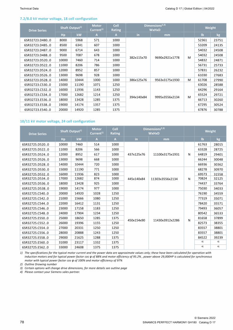
Technical Data Catalog D 17 | Global Edition | 04/2022
© Siemens 2022 78 SINAMICS PERFFECT HARMONY GH180 Catalog D 17
7.2/8.0 kV motor voltage, 18 cell configuration
Drive Series Shaft Output1) Motor
Current1) Cell
Rating Dimensions2,3)
WxHxD Weight
Hp kW A A in mm lb kg 6SR32723.D480..0 8000 5968 571 1000
382x115x70 9690x2921x1778 M
52361 23751 6SR32723.D485..0 8500 6341 607 1000 53209 24135 6SR32723.D487..0 9000 6714 643 1000 54032 24508 6SR32723.D488..0 9500 7087 678 1000 54032 24508 6SR32723.D520..0 10000 7460 714 1000 54832 24871 6SR32723.D522..0 11000 8206 786 1000 56731 25733 6SR32723.D524..0 12000 8952 857 1000 57831 26232 6SR32723.D526..0 13000 9698 928 1000 61030 27683 6SR32723.D528..0 14000 10444 1000 1000 386x125x76 9563x3175x1930 M 61708 27990 6SR32723.C530..0 15000 11190 1071 1250
394x140x84 9995x3556x2134 M
63026 28588 6SR32723.C532..0 16000 11936 1143 1250 64296 29164 6SR32723.C534..0 17000 12682 1214 1250 65524 29721 6SR32723.E536..0 18000 13428 1285 1375 66713 30260 6SR32723.E538..0 19000 14174 1357 1375 67295 30524 6SR32723.E540..0 20000 14920 1285 1375 67876 30788
10/11 kV motor voltage, 24 cell configuration
Drive Series Shaft Output1) Motor
Current1) Cell
Rating Dimensions2,3)
WxHxD Weight
Hp kW A A in mm lb kg 6SR32725.D520..0 10000 7460 514 1000
437x125x76 11100x3175x1931 N
61763 28015 6SR32725.D522..0 11000 8206 566 1000 63328 28725 6SR32725.D524..0 12000 8952 617 1000 64819 29401 6SR32725.D526..0 13000 9698 668 1000 66244 30048 6SR32725.D528..0 14000 10444 720 1000 66936 30362 6SR32725.D530..0 15000 11190 771 1000
445x140x84 11303x3556x2134 N
68278 30970 6SR32725.D532..0 16000 11936 823 1000 69573 31558 6SR32725.D534..0 17000 12682 874 1000 70824 32125 6SR32725.D536..0 18000 13428 925 1000 74437 33764 6SR32725.D538..0 19000 14174 977 1000 75030 34033 6SR32725.C540..0 20000 14920 1028 1250
450x154x90 11430x3912x2286 N
76190 34559 6SR32725.C542..0 21000 15666 1080 1250 77319 35071 6SR32725.C544..0 22000 16412 1131 1250 78420 35571 6SR32725.C546..0 23000 17158 1183 1250 79493 36057 6SR32725.C548..0 24000 17904 1234 1250 80542 36533 6SR32725.E550..0 25000 18650 1285 1375 81658 37899 6SR32725.C552..0 26000 19396 1155 1250 82573 38355 6SR32725.C554..0 27000 20331 1250 1250 83557 38801 6SR32725.C556..0 28000 20888 1243 1250 83557 38801 6SR32725.E558..0 29000 21625 1288 1375 84522 39239 6SR32725.E560..0 31000 23117 1332 1375 4) 4) 6SR32725.E562..0 33000 24608 1375 1375 4) 4)
1) The specifications for the typical motor current and the power data are approximate values only; these have been calculated for operation with induction motors and for typical power factor cos φ of 88% and motor efficiency of 95.2% , power above 29,000HP is calculated for synchronous motor with typical power factor cos φ of 100% and motor efficiency of 97%
2) Outline Drawing number 3) Certain options will change drive dimensions, for more details see outline page 4) Please contact your Siemens sales partner.
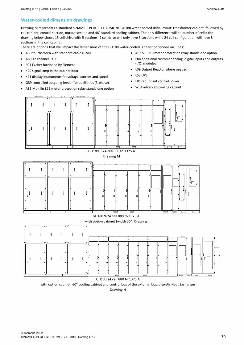
Catalog D 17 | Global Edition | 04/2022 Technical Data
© Siemens 2022 SINAMICS PERFECT HARMONY GH180 Catalog D 17 79
Water-cooled dimension drawings Drawing M represents a standard SINAMICS PERFECT HARMONY GH180 water-cooled drive layout: transformer cabinet, followed by cell cabinet, control section, output section and 48” standard cooling cabinet. The only difference will be number of cells: the drawing below shows 15 cell drive with 5 sections; 9 cell drive will only have 3 sections while 24 cell configuration will have 8 sections in the cell cabinet. There are options that will impact the dimensions of the GH180 water-cooled. The list of options includes:
• A30 touchscreen with standard cable (HMI)
• A80 12 channel RTD
• E01 Exciter furnished by Siemens
• K20 signal lamp in the cabinet door
• K21 display instruments for voltage, current and speed
• G89 controlled outgoing feeder for auxiliaries (3-phase)
• A83 Multilin 869 motor protection relay standalone option
• A82 SEL 710 motor protection relay standalone option
• E04 additional customer analog, digital inputs and outputs (I/O) modules
• L09 Output Reactor where needed
• L53 UPS
• L85 redundant control power
• W04 advanced cooling cabinet
GH180 9-24 cell 880 to 1375 A Drawing M
GH180 9-24 cell 880 to 1375 A with option cabinet (width 36”) Drawing
GH180 24 cell 880 to 1375 A with option cabinet, 60” cooling cabinet and control box of the external Liquid-to-Air Heat Exchanger
Drawing N
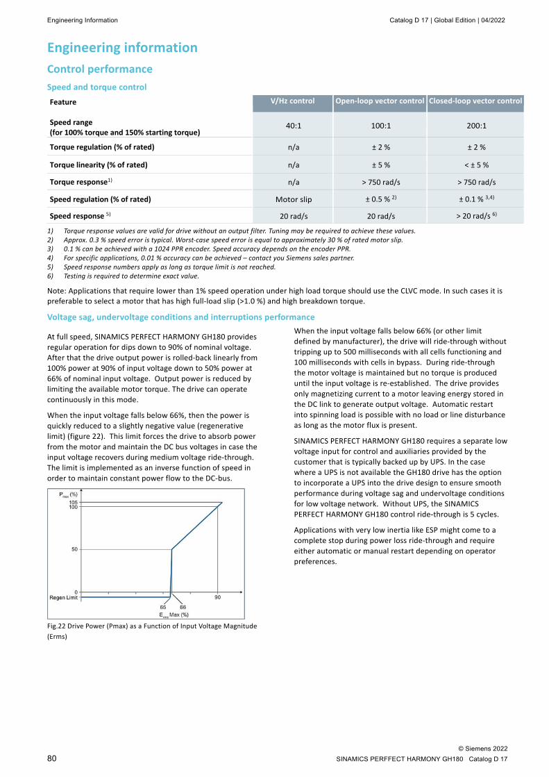
Engineering Information Catalog D 17 | Global Edition | 04/2022
© Siemens 2022 80 SINAMICS PERFFECT HARMONY GH180 Catalog D 17
Engineering information Control performance Speed and torque control
Feature Speed range (for 100% torque and 150% starting torque)
V/Hz control Open-loop vector control Closed-loop vector control
40:1 100:1 200:1
Torque regulation (% of rated) n/a ± 2 % ± 2 %
Torque linearity (% of rated) n/a ± 5 % < ± 5 %
Torque response1) n/a > 750 rad/s > 750 rad/s
Speed regulation (% of rated) Motor slip ± 0.5 % 2) ± 0.1 % 3,4)
Speed response 5) 20 rad/s 20 rad/s > 20 rad/s 6)
1) Torque response values are valid for drive without an output filter. Tuning may be required to achieve these values. 2) Approx. 0.3 % speed error is typical. Worst-case speed error is equal to approximately 30 % of rated motor slip. 3) 0.1 % can be achieved with a 1024 PPR encoder. Speed accuracy depends on the encoder PPR. 4) For specific applications, 0.01 % accuracy can be achieved – contact you Siemens sales partner. 5) Speed response numbers apply as long as torque limit is not reached. 6) Testing is required to determine exact value.
Note: Applications that require lower than 1% speed operation under high load torque should use the CLVC mode. In such cases it is preferable to select a motor that has high full-load slip (>1.0 %) and high breakdown torque.
Voltage sag, undervoltage conditions and interruptions performance
At full speed, SINAMICS PERFECT HARMONY GH180 provides regular operation for dips down to 90% of nominal voltage. After that the drive output power is rolled-back linearly from 100% power at 90% of input voltage down to 50% power at 66% of nominal input voltage. Output power is reduced by limiting the available motor torque. The drive can operate continuously in this mode.
When the input voltage falls below 66%, then the power is quickly reduced to a slightly negative value (regenerative limit) (figure 22). This limit forces the drive to absorb power from the motor and maintain the DC bus voltages in case the input voltage recovers during medium voltage ride-through. The limit is implemented as an inverse function of speed in order to maintain constant power flow to the DC-bus.
Fig.22 Drive Power (Pmax) as a Function of Input Voltage Magnitude (Erms)
When the input voltage falls below 66% (or other limit defined by manufacturer), the drive will ride-through without tripping up to 500 milliseconds with all cells functioning and 100 milliseconds with cells in bypass. During ride-through the motor voltage is maintained but no torque is produced until the input voltage is re-established. The drive provides only magnetizing current to a motor leaving energy stored in the DC link to generate output voltage. Automatic restart into spinning load is possible with no load or line disturbance as long as the motor flux is present.
SINAMICS PERFECT HARMONY GH180 requires a separate low voltage input for control and auxiliaries provided by the customer that is typically backed up by UPS. In the case where a UPS is not available the GH180 drive has the option to incorporate a UPS into the drive design to ensure smooth performance during voltage sag and undervoltage conditions for low voltage network. Without UPS, the SINAMICS PERFECT HARMONY GH180 control ride-through is 5 cycles.
Applications with very low inertia like ESP might come to a complete stop during power loss ride-through and require either automatic or manual restart depending on operator preferences.
Catalog D 17 | Global Edition | 04/2022 Engineering Information
© Siemens 2022 SINAMICS PERFECT HARMONY GH180 Catalog D 17 81
NXGPro ToolSuiteThe NXGPro ToolSuite is a PC-based high-level Graphical User Interface application that integrates various software tools used for NXGPro based drives. ToolSuite, equipped with the Microsoft Windows Operating System, allows navigation through a drive’s features by using a PC or by using a touch- screen allowing customer to monitor and control drive’s functions quickly and easily. ToolSuite contains the following tools: Drive Tool, Debug Tool, and SOP Utilities.
Configuration • Multilevel password to limit access: the same password
used as in drive
• Folders for each drive configuration category (i.e., VFD Menu system) – Icon colors to indicate default and modified parameter
values – On screen parameter identifier (matches operator panel
IDs for speed menus) – Parameter editing assisted by minimum/maximum limits
and defaults
• Ability to upload logs, parameters, system program
• Ability to download system program and/or configuration data files
Graphing • Adjustable time scale
• Predefined variable list to select variable to be graphed
• Graph up to 10 variables
• Individual variable offsets
• Customizable graphics: fonts, color, styles
• Freeze graphics
• Freeze graph on fault
• Freeze on selectable trigger
• Zoom graph
• Printable and exportable graphics
Status • Programmable display variables
• Pick list selectable variables, same as drive operator panel display list. The drive control provides the capability to monitor up to 64 different drive and motor parameters according to customer application and specification. They can be selected from more than 200 parameters and variables available in the system. The table below shows some of the parameters available.
• First 4 synchronized to operator panel display
• Fault and alarm indicators (traffic lights: red = fault, yellow = alarm, green = none)
Drive tool
Its purpose is to manage all of the drive features and provide the user with a user-friendly view of the drive. The Drive Tool’s main features include:
• Drive configuration
• Drive variable graphing
• Drive status (provides real time status of various parameters, measured values, and calculations)
Debug tool
This application provides a remote graphical user interface for Siemens medium-voltage SINAMICS PERFECT HARMONY GH180 NXGPro series drives. With the Debug Tool, the user can examine drive variables using a PC in a simple and quick manner. The debug utility is intended for use during test, commissioning, and troubleshooting of the drive.
SOP utilities
The System Operating Program (SOP) is the logic that maps the internal and external I/O into the functionality of the drive. In its simplest form, it just maps internal states to external points. It performs most of the functionality on the PC running the ToolSuite, it also offers serial communications capability for uploading and downloading the System Program directly to the drive via an Ethernet interface between the drive and the PC.
Input parameters Motor parameters Drive parameters Input voltage Output power (kW) Transformer overload Input voltage harmonics (one at a time) Output energy kW-Hr VFD efficiency Input current Output current – RMS Drive State Input current harmonics (one at a time) Output voltage – RMS Drive Internal Losses Input power factor Motor torque Power Cell Status Input power (kW) Motor speed (RPM) Bypass status Input reactive power (kVAR) Motor slip (%) Auxiliary Demand Input kW-Hr Drive output frequency (Hz) Output of energy saver Input phase sequence Magnetizing current High starting torque mode state Loss of phase Torque current Drive neutral voltage Low voltage Motor flux Max available output voltage Stator resistance Synchronous transfer state Full load speed Critical speed avoidance output

Engineering Information Catalog D 17 | Global Edition | 04/2022
© Siemens 2022 82 SINAMICS PERFFECT HARMONY GH180 Catalog D 17
Protection and monitoring functions
Vector control The drive can be controlled by means of vector control algorithm without an encoder: open-loop control (standard) or with it: closed-loop control (option).
Auto tuning Auto tuning is available to optimize the control performance of the drive. Automatic restart Automatic restart is a custom feature used to purposely restart and restore the drive operation
after a power failure or power removal. When Automatic Restart function is specified by the customer, qualified Siemens personnel must configure and ensure the function executes as specified.
Energy saver Energy saver control allows the reduction of motor losses, and improves overall efficiency, when the demanded motor load is low. Depending on the motor load, the control will reduce motor flux.
As motor load increases, the control will increase motor flux.
Flying restart The flying restart function permits smooth connection of the drive to a rotating motor.
Diagnostics functions • Self-diagnosis of control hardware
• Non-volatile memory for reliable diagnosis when the power supply fails
• Monitoring of IGBTs with individual messages for each cell
• User-friendly local operator panel with plain text messages
• The alarm/fault log consists of a circular buffer that records up to 256 faults or alarms, so that customer can access the most recent faults and/or alarms that have been detected
• The historic log records operating data of the drive and is frozen upon detection of a fault
User configurable digital meters
The user can select indication of speed, voltage, current, input/output power, and efficiency on the operator panel.
Operating hours and switching cycle counter
The amount of time that the drive was operational since it was commissioned can be displayed.
The switching cycle counter can be generated by means of an event log from the drive controller.
Detection of actual motor speed
The control algorithm calculates actual motor speed from currents and voltages measured at the drive output.
Emergency stop button The drives are equipped as standard with an Emergency Stop button (red mushroom button with yellow collar) which is fitted in the cabinet door. The contacts of the pushbutton are connected in parallel to the terminal block so they can be integrated in a protection concept on the plant side.
Ground fault protection An optional output signal can be provided to operate the customer protection.
I/O monitoring I/O signals allow user customization of the system and they can be monitored remotely or by using the operator panel display.
Thermal overload protection Based on the output signals of the drive, the thermal motor model is calculated. The motor thermal overload protection algorithm prevents the motor from being exposed to excessive temperatures.

Catalog D 17 | Global Edition | 04/2022 Engineering Information
© Siemens 2022 SINAMICS PERFECT HARMONY GH180 Catalog D 17 83
Interfaces Air-Cooled SINAMICS PERFECT HARMONY GH180 drives offer digital and analog input and output capabilities. Please note, for specific options and applications additional input and output modules can be added (Option E04 or E06). The following tables provide an overview of the pre-assignment function of interfaces in the standard versions of the air-cooled drives.
Signal type Total Quantity
Configuration
Digital inputs 20 24 V DC or 120 V AC Digital Outputs 16 Dry form “C” contacts, rated 250 V AC at 1 A or 30 V DC at 1 A Analog Inputs 3 4-20 mA or 0 ... 10 V DC Analog Outputs 2 4-20 mA
Digital inputs 0a Remote Inhibit (NC) 1a Remote Start 2a Remote Stop (NC) 3a Fault Reset 0b Off Select 1b Remote or Auto Select (K31-34) 2b Start Push Button (K29) 3b Stop Push Button (K29) 0c Output reactor over-temperature alarm or MPM alarm (if option selected) (l09) 1c Reactor Over-Temperature trip alarm or MPM trip (if option selected) 2c Aux Voltage Monitor Relay feedback - loss of 3Ø Control 3c Transformer Over Temperature Alarm (NC) 0d Transformer Over Temperature Trip Alarm (NC) 1d Blower 1 TOL feedback O.K. 2d Blower 2 TOL feedback O.K. 3d Blower 3 TOL feedback O.K. 0e Blower 4 TOL feedback O.K. 1e Blower 5 TOL feedback O.K. 2e Blower 6 TOL feedback O.K. 3e Latch Fault Relay Feedback Digital Outputs 0 Drive control in local at VFD 1 Drive Ready to run 2 Drive Running 3 Drive Alarm 4 Drive Fault (NO) 5 ProToPS Process Alarm active (if option selected) 6 ProToPS Trip Alarm Active (if option selected) 7 Motor Heater Control 8 Blower 1 starter 9 Blower 2 starter
10 Blower 3 starter 11 Blower 4 starter 12 Blower 5 starter 13 Blower 6 starter 14 Reserved 15 Latch Fault Relay Set output
Analog Inputs 1 Speed reference (default), 4…20 mA 2 Auxiliary speed reference (default) 3 Reserved (default)
Analog Outputs 1 Motor speed (default) 2 Motor torque (default)

Engineering Information Catalog D 17 | Global Edition | 04/2022
© Siemens 2022 84 SINAMICS PERFFECT HARMONY GH180 Catalog D 17
Air cooling requirements Power losses of drive system Traditional way to publish heat losses for a VFD is based on the drive’s efficiency - heat rejection of the drive itself or
kW.loss = (100%-Drive Efficiency)xkW.Drive Power
The limitation of this approach is incorrect sizing of the VFD at full load resulting in less current required by the motor – potentially starving the motor at full load. That is why Siemens uses system approach and includes not only VFD efficiency but also motor efficiency when calculating losses for the drive:
kW.Loss = kW.Input-kW.Output.
This ensures that a customer can not only get properly size HVAC but also properly sized drive. Typical motor efficiency used to calculate heat losses in the tables below is 95.2%.
Air cooled drives rely on circulating air to cool the components within the drive. The amount of heat generated is equivalent to the drive losses. As the drives take in as much air as is output, no building make-up air is required unless the drive has the option “drive prepared for duct flange connection” (M64 or M68), in this instance depending on your site and building configuration, Siemens will provide the required airflow and pressure drop to ensure proper drive function.
Drive Series Shaft Output w/ Copper Transformer w/ Aluminum Transformer1)
hp kW kW BTU/h kW BTU/h 6SR5 150 112 4.3 14,541 4.9 16,705 6SR5 200 149 5.7 19,388 6.5 22,273 6SR5 300 224 8.5 29,081 9.8 33,409 6SR5 400 298 11.4 38,775 13.1 44,545 6SR5 500 373 14.2 48,469 16.3 55,682 6SR5 600 447 17.0 58,163 19.6 66,818 6SR5 700 522 19.9 67,857 22.8 77,954 6SR5 800 597 22.7 77,551 26.1 89,091 6SR5 900 671 25.6 87,244 29.4 100,227 6SR5 1000 746 28.4 96,938 32.6 111,364 6SR5 1100 820 31.3 106,632 35.9 122,500 6SR5 1250 932 35.5 121,173 40.8 139,204 6SR5 1500 1119 42.6 145,407 49.0 167,045 6SR5 1750 1305 49.7 169,642 57.1 194,886 6SR5 2000 1491 56.8 193,876 65.3 222,727 6SR5 2250 1678 63.9 218,111 73.4 250,568 6SR5 2500 1864 71.0 242,346 81.6 278,409 6SR5 3000 2237 85.2 290,815 97.9 334,091 6SR5 3500 2610 99.4 339,284 114.2 389,772 6SR5 4000 2983 113.6 387,753 130.5 445,454 6SR5 4500 3356 127.8 436,222 146.9 501,136 6SR5 5000 3729 142.0 484,691 163.2 556,818 6SR5 5500 4101 156.3 533,160 179.5 612,500 6SR5 6000 4474 170.5 581,629 195.8 668,181 6SR5 6500 4847 184.7 630,098 212.1 723,863 6SR5 7000 5220 169.6 578,631 198.9 678,568 6SR5 8000 5966 193.8 661,293 227.3 775,506 6SR5 9000 6711 218.0 743,954 255.7 872,444 6SR5 10000 7457 242.3 826,616 284.1 969,382 6SR5 11000 8203 266.5 909,278 312.5 1,066,320 6SR5 12000 8948 290.7 991,939 340.9 1,163,259 6SR5 13000 9694 314.9 1,074,601 369.3 1,260,197 6SR5 14000 10440 339.2 1,157,262 397.7 1,357,135 6SR5 15000 11186 363.4 1,239,924 426.1 1,454,073 6SR5 16000 11931 387.6 1,322,586 454.6 1,551,011 6SR5 17000 12677 411.8 1,405,247 483.0 1,647,950
1) Transformer efficiency at 4500 hp and above is the same for both copper and aluminum transformers
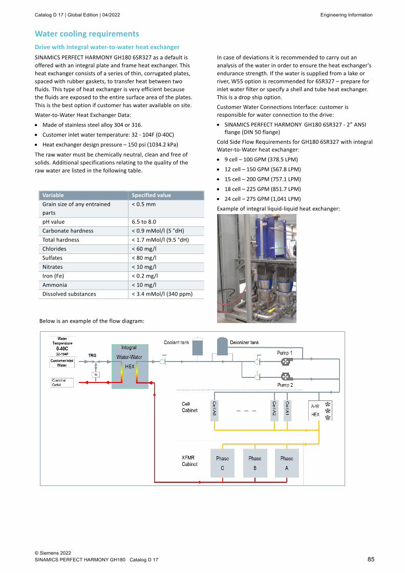
Catalog D 17 | Global Edition | 04/2022 Engineering Information
© Siemens 2022 SINAMICS PERFECT HARMONY GH180 Catalog D 17 85
Water cooling requirements Drive with Integral water-to-water heat exchanger SINAMICS PERFECT HARMONY GH180 6SR327 as a default is offered with an integral plate and frame heat exchanger. This heat exchanger consists of a series of thin, corrugated plates, spaced with rubber gaskets, to transfer heat between two fluids. This type of heat exchanger is very efficient because the fluids are exposed to the entire surface area of the plates. This is the best option if customer has water available on site.
Water-to-Water Heat Exchanger Data:
• Made of stainless steel alloy 304 or 316.
• Customer inlet water temperature: 32 - 104F (0-40C)
• Heat exchanger design pressure – 150 psi (1034.2 kPa)
The raw water must be chemically neutral, clean and free of solids. Additional specifications relating to the quality of the raw water are listed in the following table.
In case of deviations it is recommended to carry out an analysis of the water in order to ensure the heat exchanger's endurance strength. If the water is supplied from a lake or river, W55 option is recommended for 6SR327 – prepare for inlet water filter or specify a shell and tube heat exchanger. This is a drop ship option.
Customer Water Connections Interface: customer is responsible for water connection to the drive:
• SINAMICS PERFECT HARMONY GH180 6SR327 - 2” ANSI flange (DIN 50 flange)
Cold Side Flow Requirements for GH180 6SR327 with integral Water-to-Water heat exchanger:
• 9 cell – 100 GPM (378.5 LPM)
• 12 cell – 150 GPM (567.8 LPM)
• 15 cell – 200 GPM (757.1 LPM)
• 18 cell – 225 GPM (851.7 LPM)
• 24 cell – 275 GPM (1,041 LPM)
Example of integral liquid-liquid heat exchanger:
Variable Specified value Grain size of any entrained parts
< 0.5 mm
pH value 6.5 to 8.0 Carbonate hardness < 0.9 mMol/l (5 °dH) Total hardness < 1.7 mMol/l (9.5 °dH) Chlorides < 60 mg/l Sulfates < 80 mg/l Nitrates < 10 mg/l Iron (Fe) < 0.2 mg/l Ammonia < 10 mg/l Dissolved substances < 3.4 mMol/l (340 ppm)
Below is an example of the flow diagram:
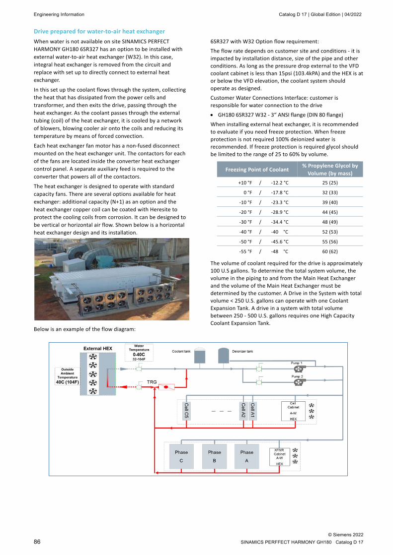
Engineering Information Catalog D 17 | Global Edition | 04/2022
© Siemens 2022 86 SINAMICS PERFFECT HARMONY GH180 Catalog D 17
Drive prepared for water-to-air heat exchanger When water is not available on site SINAMICS PERFECT HARMONY GH180 6SR327 has an option to be installed with external water-to-air heat exchanger (W32). In this case, integral heat exchanger is removed from the circuit and replace with set up to directly connect to external heat exchanger.
In this set up the coolant flows through the system, collecting the heat that has dissipated from the power cells and transformer, and then exits the drive, passing through the heat exchanger. As the coolant passes through the external tubing (coil) of the heat exchanger, it is cooled by a network of blowers, blowing cooler air onto the coils and reducing its temperature by means of forced convection.
Each heat exchanger fan motor has a non-fused disconnect mounted on the heat exchanger unit. The contactors for each of the fans are located inside the converter heat exchanger control panel. A separate auxiliary feed is required to the converter that powers all of the contactors.
The heat exchanger is designed to operate with standard capacity fans. There are several options available for heat exchanger: additional capacity (N+1) as an option and the heat exchanger copper coil can be coated with Heresite to protect the cooling coils from corrosion. It can be designed to be vertical or horizontal air flow. Shown below is a horizontal heat exchanger design and its installation.
Below is an example of the flow diagram:
6SR327 with W32 Option flow requirement:
The flow rate depends on customer site and conditions - it is impacted by installation distance, size of the pipe and other conditions. As long as the pressure drop external to the VFD coolant cabinet is less than 15psi (103.4kPA) and the HEX is at or below the VFD elevation, the coolant system should operate as designed.
Customer Water Connections Interface: customer is responsible for water connection to the drive
• GH180 6SR327 W32 - 3“ ANSI flange (DIN 80 flange)
When installing external heat exchanger, it is recommended to evaluate if you need freeze protection. When freeze protection is not required 100% deionized water is recommended. If freeze protection is required glycol should be limited to the range of 25 to 60% by volume.
Freezing Point of Coolant % Propylene Glycol by
Volume (by mass) +10 °F / -12.2 °C 25 (25)
0 °F / -17.8 °C 32 (33)
-10 °F / -23.3 °C 39 (40)
-20 °F / -28.9 °C 44 (45)
-30 °F / -34.4 °C 48 (49)
-40 °F / -40 °C 52 (53)
-50 °F / -45.6 °C 55 (56)
-55 °F / -48 °C 60 (62)
The volume of coolant required for the drive is approximately 100 U.S gallons. To determine the total system volume, the volume in the piping to and from the Main Heat Exchanger and the volume of the Main Heat Exchanger must be determined by the customer. A Drive in the System with total volume < 250 U.S. gallons can operate with one Coolant Expansion Tank. A drive in a system with total volume between 250 - 500 U.S. gallons requires one High Capacity Coolant Expansion Tank.

Catalog D 17 | Global Edition | 04/2022 Engineering Information
© Siemens 2022 SINAMICS PERFECT HARMONY GH180 Catalog D 17 87
Current product information You can find current information on SINAMICS PERFECT HARMONY GH180 in the Siemens LDA Portal: lda-portal.siemens.com
Drives Technology Configurator and other engineering tools The Drives Technology Configurator is the entry point when it comes to configuring high-voltage motors and medium-voltage converters. It supports you when selecting options and provides all of the relevant technical data sheets and dimension drawings.
Tools information and access
• Drives Technology Configurator: siemens.com/dt-configurator
• Selection and Configuration website : siemens.com/lda-tools
Services for Large Drives Applications Catalog D 17 | Global Edition | 04/2022
© Siemens 2022 88 SINAMICS PERFFECT HARMONY GH180 Catalog D 17
Services for Large Drives Applications
Keep your business running and shape your digital future – with Services for Large Drives Applications
Optimizing the productivity of your equipment and opera-tions can be a challenge, especially with constantly changing market conditions. Working with our service experts makes it easier. We understand your industry's unique processes and provide the services needed so that you can better achieve your business goals.
You can count on us to maximize your uptime and minimize your downtime, increasing your operations' productivity and reliability. When your operations have to be changed quickly to meet a new demand or business opportunity, our services give you the flexibility to adapt.
We assist in keeping your operations as energy and resource efficient as possible and reducing your total cost of owner-ship. As a trendsetter, we ensure that you can capitalize on the opportunities of digitalization and by applying data ana-lytics to enhance decision making: You can be sure that your plant reaches its full potential and retains this over the longer lifespan.
You can rely on our highly dedicated team of engineers, tech-nicians and specialists to deliver the services you need – safely, professionally and in compliance with all regulations. We are there for you, where you need us, when you need us.
siemens.com/lda-service
Portfolio overview
Our LDA Portal delivers comprehensive information, applica-tion examples, FAQs and support requests: lda-portal.siemens.com
Technical Support and Diagnostic: Advice and answers for all inquiries about functionality, handling, and fault clearance.
A worldwide network of specially trained service personnel provides you with a highly quality service and an optimized commissioning time. By making use of a regular inspection and health check, you can maximize the availability of your plant and optimize your production processes.
Repair Services are offered on-site and in regional repair centers for fast restoration of faulty devices' functionality. Also available are extended repair services, which include additional diagnostic and repair measures, as well as emergency services.
Catalog D 17 | Global Edition | 04/2022 Services for Large Drives Applications
© Siemens 2022 SINAMICS PERFECT HARMONY GH180 Catalog D 17 89
Spare Parts Services are available worldwide for smooth and fast supply of spare parts – and thus optimal plant availabil-ity. Genuine spare parts are available for up to ten years. Lo-gistic experts take care of procurement, transport, custom clearance, storage and order management. Reliable logistics processes ensure that components reach their destination as fast as needed.
Since not all spare parts can be kept in stock at all times, Siemens offers a preventive measure for spare parts provi-sioning on the customer's premises with optimized Spare Parts Packages for individual products, custom-assembled drive components and entire integrated drive trains – includ-ing risk consulting.
From the basics and advanced to specialist skills, LDA training courses provide expertise right from the manufacturer – and encompass the entire spectrum of Siemens LDA products and systems for the industry. Courses are offered at various locations as well as online.
Use Siemens Retrofit Services to extend the lifetime of your machinery and plants. Optimize the availability, reliability and energy efficiency of your installed motors and drives by retrofitting existing products and systems.
To provide you with optimum support in your work, we have put together two digital service packages as part of our digi-tal offering SIDRIVE IQ. The first package, SIDRIVE IQ Rapid Response, is all about getting your equipment up and running again as quickly as possible. The second package, SIDRIVE IQ Guided Supervision, is a service package specifically for continuous monitoring.
A Service Agreement enables you to easily bundle a wide range of services into a single annual or multiyear agreement. You pick the services you need to match your unique require-ments or fill gaps in your organization’s maintenance capabili-ties. Programs and agreements can be customized as KPI-based and/or performance-based contracts.

SIDRIVE IQ Catalog D 17 | Global Edition | 04/2022
© Siemens 2022 90 SINAMICS PERFFECT HARMONY GH180 Catalog D 17
SIDRIVE IQ
Drive systems play a key role in countless production processes and are ultimately what keeps the entire production going. Faults or failures involving components like motors and drives have costly consequences. Avoiding these faults by taking timely and deliberate action requires intelligent transparency – which allows for measures like targeted, proactive, and well-timed maintenance.
The future is digital – especially in the industrial sector. Thanks to digitalization and networked processes, companies can produce more flexibly and reliably, and they can respond to events more rapidly. Digitally enhanced drive components are an important step toward digitalized automation. With SIDRIVE IQ, you can now benefit from an Industrial Internet of Things (IIoT) digitalization solution for drive systems. Take advantage of digitalization to enter a new dimension of availability, serviceability, productivity and efficiency.
Reap the fruits of digitalization for medium voltage drives and high voltage motors with SIDRIVE IQ. The trinity of smart products, optimized plant designs and services provides you, with the insights you need, to make proactive choices you can trust – every single time.
With our smart products and systems with edge-capability you are able to make drive systems an “Industrial IoT platform device” for interoperability with automation and application.
Our digital platform gives you the perfect integration in IoT ecosystems through modularity, scalability and connectivity with data model and processing libraries and functional user interaction and experience. Increase availability, optimize your asset management and processes for faster decision-making and a boost of productivity.
Digital Services by SIDRIVE IQ is the cloud-based approach for the next generation of remote and condition monitoring services. With SIDRIVE IQ, condition data from the drive train components is transferred to the cloud and analyzed by our service experts.
SIDRIVE IQ – our holistic solution and service to IIoT for your drive systems.
siemens.com/sidrive-iq
Catalog D 17 | Global Edition | 04/2022 Scope of Supply / Recommended List of Spare Parts
© Siemens 2022 SINAMICS PERFECT HARMONY GH180 Catalog D 17 91
Scope of Supply The standard scope of delivery of the SINAMICS PERFECT HARMONY GH180 includes:
• Input section
• Transformer section
• Cell section
• Control section
• Output section
The basic unit of each SINAMICS PERFECT HARMONY GH180 Water-cooled product line consists of the following:
• Input section
• Transformer cabinet section
• Cell cabinet section
• Control section
• Output section
• If Water-to-Water Heat Exchanger is selected: coolant cabinet section comes with integral water-to-water heat exchanger
SINAMICS PERFECT HARMONY GH180 6SR327 Water-to-Air heat exchanger is delivered and located separately.
The water-cooled drive coolant cabinet is delivered without de-ionized water.
The necessary pipes and connection pieces from converter coolant system to raw-water supply on the plant side are not included in the scope of supply.
Input and output cables are not included in the scope of supply.
Accessories
Cell lifter
The power cells of SINAMICS PERFECT HARMONY GH180 drives can be replaced as a unit. To replace, the entire power cell must be removed from the drive and transported on a cell lifter. Appropriate cell lifters are available.
Some cell lifters can be used to replace blowers as well. Please, contact your Siemens sales partner for more details.
Recommended List of Spare Parts Spare Part Packages ensure that a customer has necessary components to deal with emergencies. These packages are recommended but not required. The components within the kits will vary depending on drive generation and cooling method.
Each manufacturing location identifies components that meet their customers base requirements. For more details about available spares contact your Siemens Service Representative.
Below is the list of spare part packages recommended for GH180:
Basic spare parts package list Description Quantity
Power Cell 1 NXG Control Box (DCR) 1 System Interface Board 1 User I/O Board 1 Cell Fiber Optic Kit 1
Below is an example of the advanced spare parts package with some of the components included in it. This package is typically sold after the equipment is commissioned or at any time during drive operating life. For more complete list contact your Siemens Service Representative.
Air-cooled advanced spare parts package list Description Quantity
Control (NXG) Power Supply 1 Keypad 1 Fuses Blower and Blower Accesories 1 Bypass Contactor 1 Bypass Power Supply Fuse 1 Bypass Control Board 1 Water-cooled advanced package spare parts list
Description Quantity Control (NXG) Power Supply 1 Keypad 1 Fuses Pump and Pump Accesories 1 Bypass Contactor 1 Bypass Power Supply Fuse 1 Bypass Control Board 1


Get more information SINAMICS Drives: siemens.com/sinamics
SINAMICS PERFECT HARMONY GH180: siemens.com/sinamics-perfect-harmony-gh180
Published by Siemens AG Large Drives Applications Vogelweiherstr. 1-15 90441 Nuernberg Germany
Produced in Germany © Siemens 2022
Subject to changes and errors. The information given in this document only contains general descriptions and/or performance features which may not always specifically reflect those described, or which may undergo modification in the course of further development of the products. The requested performance features are binding only when they are expressly agreed upon in the concluded contract.
All product designations may be trademarks or other rights of Siemens AG, its affiliated companies or other companies whose use by third parties for their own purposes could violate the rights of the respective owner.
Security information Siemens provides products and solutions with industrial security functions that support the secure operation of plants, systems, machines and networks.
In order to protect plants, systems, machines and networks against cyber threats, it is necessary to implement – and continuously maintain – a holistic, state-of-the-art industrial security concept. Siemens’ products and solutions constitute one element of such a concept.
Customers are responsible for preventing unauthorized access to their plants, systems, machines and networks. Such systems, machines and components should only be connected to an enterprise network or the internet if and to the extent such a connection is necessary and only when appropriate security measures (e.g. firewalls and/or net-work segmentation) are in place.
For additional information on industrial security measures that may be implemented, please visit https://www.siemens.com/industrialsecurity
Siemens’ products and solutions undergo continuous development to make them more secure. Siemens strongly recommends that product updates are applied as soon as they are available and that the latest product versions are used. Use of product versions that are no longer supported, and failure to apply the latest updates may increase customer’s exposure to cyber threats.
To stay informed about product updates, subscribe to the Siemens Industrial Security RSS Feed under https://www.siemens.com/cert
© Siemens 2022
For the U.S. published by Siemens Industry Inc. 100 Technology Drive Alpharetta, GA 30005 United States