Cast Iron Microstructure Anomalies and Their Causes
15
AFS Transactions 669 Cast Iron Microstructure Anomalies and Their Causes Cast Iron Quality Control Committee 5J Report Principle Author: G.M. Goodrich Bodycote Taussig, Inc. Skokie, Illinois INTRODUCTION For the past eight years, The American Foundrymen’s Society’s Cast Iron Division, Quality Control Committee has collected examples of microstructures that are considered anomalies, or unusual with respect to normal cast iron production. Not only the Cast Iron Quality Control Committee 5J but other committees, including the Cast Iron Molten Metal Processing Committee, the Gray Iron Research Com- mittee and the Ductile Iron Research Committee, have contributed. The purpose for this report is to present these anomalies, with the understanding of their causes, so that other foundrymen can benefit from the learning experience. Many of these anomalies, individually, have already been pub- lished as “Cast Facts” articles in Modern Casting magazine. The rate of collection and publication of these individual stories has slowed somewhat in recent months, and the number of anomalies being received by the Committee has significantly dropped. As a conse- quence, it has been decided that the time has come to present this collection of anomalies for publication in AFS Transactions as a historical documentation for future reference. These anomalies have been divided into three basic categories: anomalies associated with solidification; anomalies associated with cooling after solidification and heat treatment; and the catch-all category, “other” anomalies. ANOMALIES ASSOCIATED WITH SOLIDIFICATION Faulty Inoculation Foundrymen depend on two key processing steps to achieve the desired microstructure of ductile cast iron. If the process fails, a number of other types of graphite may develop, causing structural imperfections. The first step introduces a nodulizing agent, such as magnesium, which creates the condition for the graphite to precipitate and grow in a nodular shape. If insufficient Mg is added, or if the molten metal is held for an extended period after the Mg has been added, the graphite will not precipitate in a round shape. Figures 1 and 2 show unacceptable graphite nodularity that was identified in the cover plate for a floor-level utility box in a major convention center. The designated material for this cover was ASTM A536-80, Grade 65-45-12 ductile cast iron. The second critical processing step is to add an inoculant. The inoculant is usually a ferrosilicon that contains small amounts of calcium and/or aluminum and/or other special-purpose elements. The principal purpose of the inoculant is to prevent chill. More 97-30 specifically, the inoculant enhances graphite nucleation, preventing the formation of primary carbides. Using the covers from the floor-level utility boxes as examples, Figs. 3, 4 and 5 illustrate the presence of primary carbides in a ferritic structure and in structures that contain both ferrite and pearlite. These utility box covers failed immediately after installation, due to the movement of heavy equipment across them. The ductile iron covers that met the A536-80 requirements for 65-45-12 ductile iron grade performed acceptably without failure. The presence of the degenerate graphite illustrated in Figs. 1 and 2 impairs mechanical properties. The presence of primary carbides in the structure can also reduce mechanical properties. In both instances, the ductility, as measured by the percent elongation, is most dramatically reduced. The observed structures can be the consequence of fade. Fade occurs when the effects of Mg treatment and inoculation decrease with time. If the molten metal is held for an extended period after Mg treatment and inoculation, both degenerate graphite and primary carbides can occur in the structure. Another possibility for the observed structures could be high sulfur-base iron contaminated with deleterious trace elements. Fig. 1. Poor ductile iron nodularity caused this utility cover plate to fail; (100X, unetched). Fig. 2. Photomicrograph of ductile iron shows unfavorable graphite nodule formation; (100X, unetched). Note: All photos were reduced to 75% for publication.
-
Upload
independent -
Category
Documents
-
view
0 -
download
0
Transcript of Cast Iron Microstructure Anomalies and Their Causes

AFS Transactions 669
Cast Iron MicrostructureAnomalies and TheirCauses
Cast Iron Quality Control Committee 5J Report
Principle Author:
G.M. Goodrich
Bodycote Taussig, Inc.
Skokie, Illinois
INTRODUCTION
For the past eight years, The American Foundrymen’s Society’s Cast
Iron Division, Quality Control Committee has collected examples of
microstructures that are considered anomalies, or unusual with
respect to normal cast iron production. Not only the Cast Iron Quality
Control Committee 5J but other committees, including the Cast Iron
Molten Metal Processing Committee, the Gray Iron Research Com-
mittee and the Ductile Iron Research Committee, have contributed.
The purpose for this report is to present these anomalies, with the
understanding of their causes, so that other foundrymen can benefit
from the learning experience.
Many of these anomalies, individually, have already been pub-
lished as “Cast Facts” articles in Modern Casting magazine. The rate
of collection and publication of these individual stories has slowed
somewhat in recent months, and the number of anomalies being
received by the Committee has significantly dropped. As a conse-
quence, it has been decided that the time has come to present this
collection of anomalies for publication in AFS Transactions as a
historical documentation for future reference.
These anomalies have been divided into three basic categories:
anomalies associated with solidification; anomalies associated with
cooling after solidification and heat treatment; and the catch-all
category, “other” anomalies.
ANOMALIES ASSOCIATED WITH SOLIDIFICATION
Faulty Inoculation
Foundrymen depend on two key processing steps to achieve the
desired microstructure of ductile cast iron. If the process fails, a
number of other types of graphite may develop, causing structural
imperfections.
The first step introduces a nodulizing agent, such as magnesium,
which creates the condition for the graphite to precipitate and grow
in a nodular shape. If insufficient Mg is added, or if the molten metal
is held for an extended period after the Mg has been added, the
graphite will not precipitate in a round shape.
Figures 1 and 2 show unacceptable graphite nodularity that was
identified in the cover plate for a floor-level utility box in a major
convention center. The designated material for this cover was ASTM
A536-80, Grade 65-45-12 ductile cast iron.
The second critical processing step is to add an inoculant. The
inoculant is usually a ferrosilicon that contains small amounts of
calcium and/or aluminum and/or other special-purpose elements.
The principal purpose of the inoculant is to prevent chill. More
97-30
specifically, the inoculant enhances graphite nucleation, preventing
the formation of primary carbides.
Using the covers from the floor-level utility boxes as examples,
Figs. 3, 4 and 5 illustrate the presence of primary carbides in a ferritic
structure and in structures that contain both ferrite and pearlite. These
utility box covers failed immediately after installation, due to the
movement of heavy equipment across them. The ductile iron covers
that met the A536-80 requirements for 65-45-12 ductile iron grade
performed acceptably without failure.
The presence of the degenerate graphite illustrated in Figs. 1 and
2 impairs mechanical properties. The presence of primary carbides
in the structure can also reduce mechanical properties. In both
instances, the ductility, as measured by the percent elongation, is
most dramatically reduced. The observed structures can be the
consequence of fade.
Fade occurs when the effects of Mg treatment and inoculation
decrease with time. If the molten metal is held for an extended period
after Mg treatment and inoculation, both degenerate graphite and
primary carbides can occur in the structure. Another possibility for
the observed structures could be high sulfur-base iron contaminated
with deleterious trace elements.
Fig. 1. Poor ductile iron nodularity caused this utility cover plate to
fail; (100X, unetched).
Fig. 2. Photomicrograph of ductile iron shows unfavorable graphite
nodule formation; (100X, unetched).
Note: All photos were reduced to 75% for publication.
670 AFS Transactions
Figures 4 and 5 also reveal a third kind of ductile iron anomaly.
In some instances, the graphite structure at the surface of ductile iron
castings is flake graphite, more commonly associated with gray iron.
Flake graphite structures at the surface can occur in ductile iron as the
consequence of surface reactions with contaminants in the sand,
usually sulfur.
This structure can become even more pronounced, depending on
the Mg content in the iron versus the contaminant level in the sand.
High contaminant and/or low Mg produce relatively more flakes.
Primary Carbides in Ductile Cast Iron
Ductile cast iron is particularly prone to the formation of primary
carbides during solidification. A primary reason for this susceptibil-
ity is that the graphite forms into a spherical shape, which is the
lowest surface area-to-volume ratio for the graphite. The limited
surface area available for graphite precipitation, during solidifica-
tion, increases the carbide-forming tendency. In addition, the prin-
ciple element added for the nodulizing treatment is Mg, a known
carbide stabilizer.
Another factor is that the S content in ductile iron is purposely
lowered to less than 0.02%, to facilitate the formation of spherical
graphite nodules. Therefore, inoculation is crucial to successfully
cast ductile iron without carbides. Even after effective inoculation,
fade can occur and result in the formation of primary carbides.
Figures 6, 7 and 8 are three different examples of primary carbides
in a ferritic ductile iron. Figures 9, 10, 11 and 12 show four different
examples of primary carbides in a pearlitic ductile iron.
These carbides have several names, including ledeburite, chill,
primary carbide, Fe3C, iron carbide cementite, white iron and
hard iron.
The principle step in controlling the occurrence of primary
carbides in ductile iron calls for close attention to detail concerning
inoculation and fade time. The effects of inoculation fade with time
and, therefore, processing time within the foundry should be closely
controlled. In many instances, modern-day foundries have utilized
late-stream inoculation or mold inoculation to counteract effects
of fade.
Fig. 3. Ductile iron microstructure is illustrated at a fracture site.
Note pearlite (dark constituents) and ferrite (white constituents).
White platelets are primary carbides resulting from inadequate
inoculation or inoculant fade; (400X, nital etch).
Fig. 4. Ductile iron microstructure shows flake surface graphite and
nonspheroidal graphite. Dark matrix is pearlite; white is ferrite.
Primary carbide is evidenced by blocky white structures occurring
in pearlite and ferrite; (400X, nital etch).
Fig. 5. Ductile iron microstructure illustrates poor graphite
nodularity in matrix of pearlite (dark constituent) and ferrite (white
regions surrounding graphite). Small, angular, white particles in
matrix are primary carbides; (400X, nital etch).
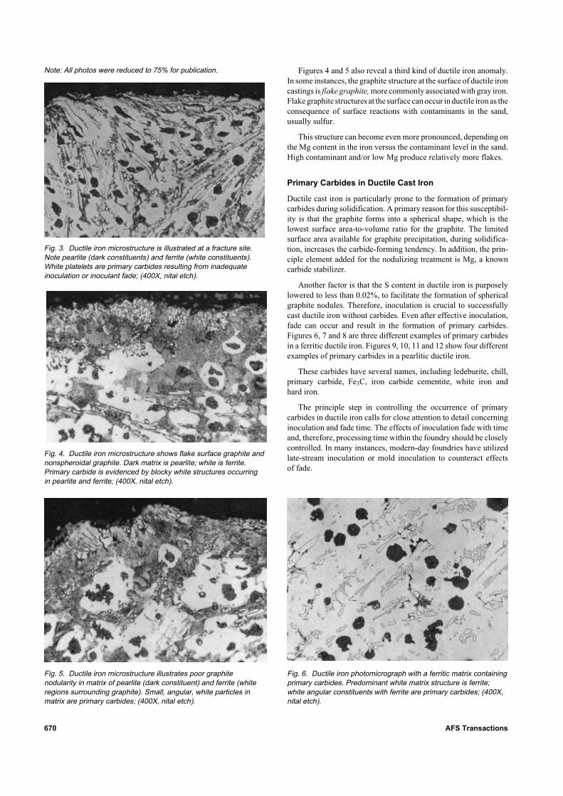
Fig. 6. Ductile iron photomicrograph with a ferritic matrix containing
primary carbides. Predominant white matrix structure is ferrite;
white angular constituents with ferrite are primary carbides; (400X,
nital etch).
Note: All photos were reduced to 75% for publication.

AFS Transactions 671
Fig. 7. Ductile iron photomicrograph with a ferritic matrix containing
primary carbides. Predominant white matrix structure is ferrite;
white angular constituents within ferrite are primary carbides;
(400X, nital etch).
Fig. 8. Ductile iron photomicrograph with a ferritic matrix containing
primary carbides. Predominant white matrix structure is ferrite;
white angular constituents within ferrite are primary carbides;
(400X, nital etch).
Fig. 9. Ductile iron photomicrograph illustrating primary carbides in
a pearlitic ductile iron. Matrix is predominantly pearlite. The white
angular constituents within pearlite are primary carbides; (400X,
nital etch).
Fig. 10. Ductile iron photomicrograph illustrating primary carbides
in a pearlitic ductile iron. Matrix is predominantly pearlite. The white
angular constituents within pearlite are primary carbides; (200X,
nital etch).
Fig. 11. Ductile iron photomicrograph illustrating primary carbides
in a pearlitic ductile iron. Matrix is predominantly pearlite. The white
angular constituents within pearlite are primary carbides; (400X,
nital etch).
Fig. 12. Ductile iron microstructure illustrating primary carbides in a
pearlitic ductile iron. Matrix is predominantly pearlite. The white
angular constituents within pearlite are primary carbides; (400X,
nital etch).

672 AFS Transactions
In addition to the inoculating effects and fade effects, some
contaminants can cause primary carbides. In ductile iron, chromium
is particularly noted for the formation of stable primary carbides that
are not easily removed with heat treatment and are not easily
removed with proper inoculation. Hydrogen is also noted for causing
primary carbides. In this instance, however, the primary carbides can
occur in the last iron to solidify because of H segregation to the liquid
during solidification. When this occurs, a particular carbide form
results, known as inverse chill. Figure 13 shows an example.
Primary Carbides and Steadite
in Gray Cast Iron
Two microstructure constituents in gray cast iron can cause hard
spots, which aggravate machinists. These two constituents are iron
carbides and iron phosphides. Figures 14 and 15 show a typical
example of iron carbides, and Figs. 16 and 17 show a typical example
of iron phosphides.
Fig. 13. Ductile iron microstructure illustrating inverse chill primary
carbides in a pearlitic ductile iron. Needle-like carbides toward
middle bottom of photograph are inverse chill; (200X, nital etch).
Fig. 14. Photomicrograph showing primary carbides in gray cast
iron with a predominantly ferrite matrix. Black constituent at right is
graphite that appears to have precipitated after solidification; (100X,
nital etch).
Fig. 15. Photomicrograph showing primary carbides (white
constituent) in a predominantly pearlitic gray iron matrix; (400X,
nital etch).
Fig. 16. Photomicrograph showing steadite in a predominantly
pearlitic gray cast iron; (200X, nital etch).
Fig. 17. Photomicrograph showing same area seen at lower
magnification in Fig. 16 to illustrate “pepper marks” within steadite
plate constituent; (400X, nital etch).
Note: All photos were reduced to 75% for publication.

AFS Transactions 673
As indicated previously, iron carbide has several names. The
machinists have appropriately applied several other unprintable
names. Iron phosphide is more commonly known as steadite. Both of
these constituents are eutectic phases between iron and carbon, and
iron and phosphorus, respectively. Because they are eutectic, they
are the last to solidify. The solidification temperature for iron carbide
is 2066F (1130C). For iron phosphide, the solidification temperature
is 1920F (1049C).
When these two eutectics combine, a tertiary iron-carbon-phos-
phorus eutectic, with a still lower melting point, will occur in the
microstructure. An example of this combined eutectic structure is
shown in Figs. 18 and 19. Although the melting point for this
constituent is not published, it is believed to be lower than the melting
points for the individual eutectics.
Since these eutectics are the last to solidify, they can be present
in the cast iron structure as liquid surrounded by solid, and can be
drawn from thin sections to feed thick sections. The consequence can
be microscopic shrinkage voids in thin sections. These voids have a
shape that is similar to the carbide and steadite constituents that
would be found in the structure. Figures 20–23 show an example of
the microscopic voids that form from drawing the liquid eutectic
phases from thin sections.
Fig. 18. Photomicrograph showing tertiary iron/carbon/phosphorus
eutectic in a predominantly pearlite matrix gray cast iron; (400X,
nital etch).
Fig. 19. Photomicrograph showing tertiary iron/carbon/phosphorus
eutectic in a pearlite matrix gray cast iron; (1000X, nital etch).
Fig. 20. Photomicrograph showing presence of a “shrinkage” void
in a thin section at upper right; (200X, unetched condition).
Fig. 21. Photomicrograph showing same area seen unetched in
Fig. 20 to further illustrate nature of matrix associated with void.
Matrix is predominantly pearlite; white constituent is steadite;
(200X, nital etch).
Fig. 22. Photomicrograph showing same void seen at lower
magnification in Fig. 22. Note how void appears to be associated
with steadite phase that is present in structure; (400X, nital etch).

674 AFS Transactions
As with ductile iron, inoculation in gray cast iron is primarily used
to control the occurrence of primary carbides. Ladle inoculation,
mold inoculation, late stream inoculation or a combination of the
various inoculation techniques have all proven effective. Control of
tramp elements that are known carbide stabilizers, such as chro-
mium, vanadium and molybdenum, and other less common ele-
ments in gray cast iron, such as antimony, tellurium and hydrogen,
are also essential.
Fig. 25. Photomicrograph illustrating a dross defect in ductile iron.
Dark constituent is pearlite; white constituent is ferrite. Note that
ferrite concentrates with dross structure; (50X, nital etch).
Fig. 27. Spectrum of elements representing base metal in Fig. 26.
Fig. 28. Spectrum of elements representing partially dissolved
inoculant in Fig. 26.
Fig. 26. Photomicrograph illustrating a line of demarkation between
a “normal” structure and a partially dissolved inoculant area (200X,
unetched condition) (see Figs. 27 and 28).
Fig. 23. Photograph showing same area seen at lower magnifi-
cation in Figs. 21 and 22 to further illustrate how void that appeared
as “shrinkage” in Fig. 20 is actually the absence of steadite;
(1000X, nital etch).
Fig. 24. Ductile iron microstructure with a dross type defect. This
dross defect results from a reaction between magnesium dissolved
in iron and oxygen in surrounding air; (100X, unetched condition).
Note: All photos were reduced to 75% for publication.

AFS Transactions 675
Dross in Ductile Iron
The addition of Mg to cast iron is an essential processing step for
manufacturing ductile iron. Magnesium, however, is a very reactive
element. As a consequence, ductile iron has a higher tendency to
form slag than does gray iron or malleable iron. The reaction
products that result are often called dross. The presence of Mg in
molten iron also causes the iron to generate slag, almost continu-
ously. Ductile iron pourers often complain that ductile iron “makes
slag” while it is sitting in the ladle. This dross is the result of the Mg
dissolved in the iron reacting with oxygen. As a consequence, a good
slagging practice must be exercised when pouring ductile iron.
Since molten ductile iron “makes slag,” an undesired
microconstituent that can occur is dross. Figure 24 shows an ex-
ample of the graphite structure associated with dross that has oc-
curred in the casting. When etched, the area associated with the dross
will often have a ferritic structure, as shown in Fig. 25. The occur-
rence of dross in a casting can be the consequence of poor slagging
practices. When slag enters the mold cavity during pouring, the
dross-type structure shown in Figs. 24 and 25 can occur.
These dross-type structures can also occur, even though slag-free
metal was poured. Keeping in mind that ductile iron “makes slag,”
any time the iron experiences turbulent flow in the mold, a reaction
can occur between the Mg in the iron and the oxygen in the
surrounding environment. This reaction can form dross, even in the
mold. Dross defects such as this can occur, for example, in castings
with knife gates. Dross can also be generated in the runner system
when fluid dynamics causes turbulent flow conditions to exist.
Dross-type structures can also be present if the metal is poured
too cold.
Sometimes, the dross is associated with undissolved or partially
dissolved inoculant. Figure 26 shows an example. In this instance,
the structure on one side of a demarkation line from the dross will
have a normal silicon level, whereas the structure on the opposite side
will have a high Si level. Energy dispersive x-ray (EDX) spectro-
graphic analysis has been helpful in identifying this type of dross
defect. Figures 27 and 28 show a typical example of analysis in the
normal structure vs. analysis in the dross region.
ANOMALIES RESULTING FROM
PROCESSING AFTER SOLIDIFICATION
Widmanstätten Graphite
Widmanstätten graphite can occur in cast iron as the result of lead
contamination. Other elements are also known to cause this problem.
Lead levels as low as 0.005% have been known to create the
Widmanstätten graphite. Widmanstätten graphite occurs after solidi-
fication with the precipitation of carbon atoms on crystallographic
planes creating a spiky appearance to existing graphite flakes. If the
condition becomes significant, the precipitation onto crystallographic
planes can occur, aside from the primary graphite flakes, creating
hatch marks in the structure. Figures 29–31 show Widmanstätten
graphite in the unetched structure and Figs. 32–34 show the
Widmanstätten graphite in an etched structure.
Fig. 29. Photomicrograph showing a “normal” graphite structure;
(100X, unetched condition).
Fig. 30 Photomicrograph showing same area seen at lower
magnification in Fig. 29. Note that graphite appears “fuzzy.” Also
note that other graphite forms have precipitated within regions
between flakes; (400X, unetched condition).
Fig. 31. Photomicrograph showing same area seen at lower
magnification in Figs. 29 and 30. Note that “fuzzy” graphite is
consequence of small fingers of graphite growing on sides of
graphite flakes. Also note graphite forms with thin graphite forms in
between graphite flakes toward middle and middle top; (1000X,
unetched condition).

676 AFS Transactions
Fig. 37. Shown is iron-iron carbide-silicon ternary diagram
sectioned at 2% silicon. “At the tip of the arrow head, X” shows
austenitizing temperature reached, in three-phase region indicated
by arrow, in two castings examined. Reprinted from “Iron Casting
Handbook,” American Cast Metals Association.
Fig. 32. Photomicrograph showing a pearlitic gray cast iron with
Widmanstätten graphite. This area is shown at progressively higher
magnifications in Figs. 33 and 34; (100X, nital etch).
Fig. 33. Photomicrograph showing same area seen at lower
magnification in Fig. 32 to illustrate Widmanstätten form of graphite.
Note that graphite has precipitated at angles representative of
crystallographic planes; (400X, nital etch).
Fig. 34. Photomicrograph showing same area seen at lower
magnification in Figs. 32 and 33 to further illustrate graphite
precipitated on crystallographic planes; (1000X, nital etch).
Fig. 35. Photomicrograph of ductile cast iron. This structure was
intended to be normalized (100% pearlite); (200X, nital etch).
Fig. 36. Photomicrograph of same area shown at lower magnifica-
tion in Fig. 35. This structure was intended to be annealed (100%
ferrite); (400X, nital etch).
Note: All photos were reduced to 75% for publication.

AFS Transactions 677
Often, this graphite structure is associated with phosphorus-
rich steadite regions. Research1,2 has shown that this graphite type
can be controlled with the addition of rare earth elements, primarily
cerium. As a consequence, the condition does not often occur in
ductile cast iron because of the presence of rare earth elements in the
treatment alloy. If the condition is occurring in gray cast iron, it can
be controlled by eliminating the lead. However, inoculation with a
cerium-bearing inoculant can also reduce the effect.
The presence of this graphite form greatly reduces the mechanical
properties of the resulting iron. For example, a normal Class 30 gray
iron, having a Pb concentration of 0.05% without the benefit of Ce
or other rare earths, can actually have a tensile strength of less than
15,000 psi because of the presence of Widmanstätten graphite form.
This graphite form will become Type F in the soon-to-be-published
revised ASTM specification A247.
Unusual Ferrite Microstructure in
Heat-Treated Ductile Iron
Analyzing microstructures can sometimes be confusing. For ex-
ample, the two microstructures shown in Figs. 35 and 36 contain
pearlite (the dark constituent), ferrite (the white constituent) and
nodular graphite. All of these constituents are normally expected
for ductile iron microstructures. However, the shapes and the con-
stituents as shown in these photomicrographs are not normal.
Both structures resulted from heat treatment. The structure was the
consequence of a normalizing heat treatment intended to produce
100% pearlite. As these structures clearly show, the goal was not
achieved.
Ductile iron is in a family of metals called cast iron, which has
three principal elements: iron, carbon and silicon. The fact that Si is
present is often forgotten. At certain temperatures, this element
allows austenite, ferrite and carbides to exist in equilibrium as a
three-phase field. The presence of this field can cause difficulties,
particularly during heat treatment.
To normalize or anneal ductile cast iron, the casting must be
heated to a high enough temperature for the matrix to become
Fig. 38. Photomicrograph illustrating retained austenite in a
martensitic ductile cast iron. Small angular white constituents
(arrows) in matrix are retained austenite; remainder of matrix is
martensite; (200X, nital etch).
Fig. 39. Photomicrograph illustrating retained austenite in a
martensitic ductile cast iron. Small angular white constituents
(arrows) in matrix are retained austenite; matrix is martensite;
(400X, nital etch).
completely austenite. In the two examples, the austenitizing tem-
perature reached the three-phase region, indicated by the arrow in
the phase diagram in Fig. 37.
As a consequence, the austenite that was present transformed to
the desired pearlite or ferrite constituent. However, the ferrite or
pearlite that was present in the structure, but was not transformed,
remained intact as the sample was cooled. The structures shown in
the photomicrographs reflect both the transformed constituents and
the untransformed constituents. The untransformed constituents are
the cause of the unusual shapes in the photomicrographs.
Retained Austenite in
Gray and Ductile Iron
Cast irons that are quenched and tempered to form martensite can
have unusual microconstituents. In addition to the expected marten-
site, an unexpected white constituent in the structure can occur.
This white constituent is shown in Figs. 38 and 39 for ductile iron
and in Figs. 40 and 41 for gray iron. The constituent is retained
austenite.
Carbon can stabilize austenite and, since cast irons are hypereu-
tectoid, the austenitizing temperature can affect the amount of carbon
dissolved in the austenite, prior to quenching. As the temperature
increases above the eutectoid reaction, the amount of carbon dis-
solved in the austenite increases. When this iron is quenched, some
of the high carbon austenite is retained, leaving a mixed structure of
martensite and austenite. More specifically, this is a mixed structure
of martensite and high carbon austenite.
To prevent retained austenite from occurring in quenched mar-
tensitic cast iron structures, the temperature from which the iron is
quenched should be lowered to a temperature immediately above the
eutectoid. The correct temperature may require trial and error to
establish it for individual irons. The reason is that the eutectoid
temperature varies significantly, as a function of Si, and no single
temperature for gray iron or for ductile iron can be stated. Nickel also
stabilizes austenite. As Ni content increases, so does the tendency for
retained austenite.

678 AFS Transactions
OTHER ANOMALIES
Microstructure Anomalies That
Affect Ductile Iron Properties
The microstructure of ductile iron plays a vital role in affecting the
mechanical properties of the final casting. To illustrate this vital role
and how to determine the cause of failure, an example of a foundry’s
experience with a certain casting is provided.
In this example, the customer desired a ductile iron grade of
80-55-06 per ASTM 536. This grade is an as-cast pearlitic ductile
iron with a minimum ultimate tensile strength of 80,000 psi, a
minimum yield strength with 0.2% offset of 55,000 psi and a
minimum 6% elongation.
Inconsistencies
The customer, who regularly purchased the casting, was confused
about the inconsistencies with the test results in different heats.
Problem 1: The castings failed to meet the elongation require-
ment, exhibiting only 3% maximum elongation.
Problem 2: The castings failed to meet the yield strength require-
ment, with only a 50,000 psi at 0.2% offset.
Problem 3: The castings failed to meet the yield strength and the
elongation requirements.
Metallographic evaluation of the microstructures revealed the
reasons for these inconsistencies.
In Problem 1, the microstructure at the tensile fractured surface
had a required graphite nodularity (greater than 80%) and pearlite
content (greater than 50%), but the structure had a high incidence of
intercellular carbides (Fig. 42). As shown in Fig. 43, EDX spectro-
graphic analysis revealed these carbides were high in titanium,
vanadium, molybdenum and niobium. These carbides significantly
detracted from the ability of the casting to meet the elongation
requirements.
In Problem 2, the microstructure had acceptable nodularity, but
the ferrite content was excessive. Figure 44 shows that the ferrite
content was about 70% of the matrix. For this grade, the matrix
should be in excess of 50% pearlite. Excessively high ferrite content
detracts from the yield strength.
In Problem 3, the microstructure exhibited an acceptable pearlite
content (Fig. 45), but the graphite nodularity (Fig. 46) was not
acceptable. Poor nodularity negatively affects both the yield strength
and elongation.
Correcting the Problem
Correcting these problems required different approaches. For Prob-
lem 1 (failing to meet the elongation requirement), closer scrutiny of
the charge material was required to minimize the influx of tramp
elements.
For Problem 2 (failing to meet the yield strength requirement),
either an increase in the amount of pearlite stabilizers was required
or the foundry needed to shake out the castings at a temperature hot
enough to force rapid cooling from “red heat.”
For Problem 3 (failing to meet both yield strength and elongation
requirements), the magnesium/cerium content was not adequate as
the result of fade or ineffective treatment.
Lustrous Carbon Defects
in Cast Iron3–5
Lustrous carbon defects generally appear on the surface or just
under the surface formed by the cope mold or top of the core. This
defect often appears as adherent, shiny, “wrinkled” deposits of
carbon, and is also known as resin, kish or a soot defect. It can be
found on castings made in urethane-bonded sands, shell molds,
(expandable polystyrene) EPS molds or green sand molds. Lustrous
carbon is caused by high levels of volatile gases trapped at the
mold or core surface. The volatile gases are released as the organic
binders (especially urethane-based cold-set and shell mold sys-
tems) break down during the pouring process, releasing the hydro-
carbons.
In lesser amounts, the carbonaceous material provides a reducing
atmosphere in the mold, which minimizes casting surface oxidation
and improves casting surface quality or peel. It is often removed from
the casting surface by casting cleaning operations. As the level of
these volatile gases increases, the severity of the defect increases and
the lustrous carbon folds into solidifying metal, causing unaccept-
able cold shuts and laps.
Fig. 41. Photomicrograph illustrating retained austenite in a
martensitic gray cast iron. White angular constituent is retained
austenite; remainder of matrix is martensite; (1000X, nital etch).
Fig. 40. Photomicrograph illustrating retained austenite in a
martensitic gray cast iron. White angular constituent in structure is
retained austenite; remainder of matrix is martensite; (400X, nital
etch).

AFS Transactions 679
Figures 47–50 show a typical example of a lustrous carbon defect.
Figures 47 and 49 illustrate the depth of the discontinuities and their
microstructural differences. Figures 48 and 50 illustrate a lap defect
resulting from folding the graphite layer into the metal.
The frequency and severity of the defect can be reduced and
controlled by the following means:
• Lowering the binder content, especially the isocyanate com-
ponent in urethane bonded systems.
• Increasing the mold and core mechanical venting and perme-
ability.
• Increasing the pouring temperature.
• Reducing the fill time and pouring turbulence.
• Applying a low-carbon coating to the core and/or mold
coating.
• Adding 0.5%–1.0% oxidizing materials, such as iron oxide,
to the core sand.
Unusual Hard Spots
The use of tin as a pearlite stabilizer is well established.6–9 Tin has
been a popular alloy addition because it does not promote chill, is
effective in stabilizing pearlite on the skin of the casting and has a
predictable, 100% recovery. Tin decreases the sensitivity of the
casting to variations in shakeout time. However, excess Sn, espe-
cially in the presence of high S, can cause serious problems.
Fig. 42. Photomicrograph showing high incidence of intercellular
carbides in casting. See Fig. 43 for composition of carbides; (400X,
nital etch).
Fig. 44. At 100X, this casting is 70% ferrite (white area) and only
30% pearlite—20% below its specified pearlitic minimum.
Fig. 45. At 100X, casting’s pearlitic content is acceptable (80%).
Fig. 46. At 100X, this photomicrograph shows microstructure’s low
graphite nodularity.
Fig. 43. Spectrum of elements representing intercellular carbides in
Fig. 42.

680 AFS Transactions
Fig. 49. Photomicrograph illustrating same area shown unetched in
Fig. 46. This etched structure further exemplifies differences
between individual layers; (50X, nital etch).
Fig. 50. Photomicrograph illustrating same area shown unetched in
Fig. 47. The etched structure further exemplifies differences
between two regions and graphite film that developed from
lustrous-carbon defect; (400X, nital etch).
Fig. 47. Photomicrograph illustrating a cross section through one of
the defective regions on casting. Note difference in graphite
structure between three different “layers.” These differences are
characteristic of laps and cold shuts; (50X, unetched condition).
Fig. 48. Photomicrograph illustrating same area shown at lower
magnification in Fig. 46. Note how graphite film at center left has
been folded into metal. Also note that these individual “layers” have
a graphite film liner; (400X, unetched condition).
Vern Patterson, in Foote Foundry Facts, No. 18, describes a
situation where a buildup of Sn to levels of 0.15% resulted in castings
cracking in service. There was no observable change in microstruc-
ture, tensile strength or hardness. The only quantifiable change was
the increase of Sn from the desired 0.10% max up to 0.15%, as the
returns were run back through the system over a period of time,
without any adjustment for the buildup of Sn in the system. The Sn
level was reduced to 0.10% and the breakage/cracking problems
were eliminated.
Machining operations sensitive to hard spots quickly identify the
presence of undesired constituents. Normally, these constituents are
easily identified as primary carbides, intercellular alloy carbides,
steadite or a tertiary iron/iron phosphide (steadite)/iron carbide. In
this instance, however, the hard spots were areas of fine pearlite with
relatively large ASTM type A graphite in an otherwise coarse
pearlite matrix with smaller ASTM types A and D graphite. Figure
51 shows an unusual hard spot in an otherwise acceptable gray iron
Note: All photos were reduced to 75% for publication.
structure. Figures 52 and 53 compare the pearlite in the surrounding
matrix with the fine pearlite in the hard spot. Energy dispersive x-ray
analysis of the matrix revealed traces of Sn, Cr and S in the fine
pearlite that were not present in the coarse pearlite. The results of this
EDX analysis are shown in Figs. 54 and 55. The Sn content of this
casting was 0.14%, Cr was 0.09% and the S content was 0.12%.
A Foreign Object
With the new mold filter technology being used today, it has been
found that, occasionally, portions of the filter become entrapped in
the iron. This is shown in Fig. 56. Apparently, the quality of the iron
in the immediate vicinity of the filter segment can be unaffected, as
can be seen by comparing Figs. 57 with 58 and 59. However,
depending upon what materials might be trapped on the filter, the
iron in the immediate vicinity of the filter segment could be compro-
mised. Sometimes, cold shuts and degenerate graphite can occur, as
shown in Fig. 60.

AFS Transactions 681
Fig. 54. Spectrum of elements representing fine pearlite in Fig. 52.
Fig. 51. Photomicrograph showing “hard spot;” (50X, nital etch).
Fig. 53. Photomicrograph emphasizing coarse pearlite matrix in
Fig. 51. See Fig. 55 for composition of matrix in this coarse area;
(400X, nital etch).
Fig. 52. Photomicrograph emphasizes fine pearlite in “hard spot” in
Fig. 51. See Fig. 54 for composition of pearlite matrix in this “fine”
area; (400X, nital etch).
Nitrogen in Gray Cast Iron
The nitrogen level in gray cast iron normally has an equilibrium of
70 ppm. Occasionally, high N can occur. When the dissolved N
increases, the graphite is affected, producing fat graphite, as shown
in Fig. 61. Nitrogen in excess of 150 ppm can generate the type of
graphite that is shown in Fig. 61. Nitrogen is generally controlled
with the use of Ti. Ordinarily, at high N content, if Ti is present, the
graphite structure will be normal (Fig. 58).
Calcium in Gray Cast Iron
The calcium content in gray cast iron can increase locally, beyond
trace levels approaching 0.5%, with some inoculants that have failed
to completely dissolve. Calcium is a graphite nodulizing agent,
although it is rarely used for this purpose. The microstructure
anomaly that occurs with high Ca in gray cast iron is an occasional
spheroidal graphite particle. Figure 62 shows an example.
CONCLUSIONS AND COMMENTS
Tons of cast iron are produced with normal cast iron microstructures.
This article is not intended to detract from those castings produced
with acceptable quality. Occasionally, foundrymen encounter un-
usual microstructure anomalies that are not ordinarily associated
with their good foundry practice.
This article is intended to provide some insight in detecting the
cause for these microstructure anomalies. It is not intended to be a
total glossary of all possible anomalies. Therefore, the Cast Iron
Division, Quality Control Committee invites anyone who has anoma-
lies to submit them for consideration.
Fig. 55. Spectrum of elements representing coarse pearlite in Fig. 53.

682 AFS Transactions
Fig. 56. Photomicrograph showing a cross section where a filter
segment was trapped in microstructure; (50X, nital etch).
Fig. 57. Photomicrograph showing same area seen at lower
magnification in Fig. 56. This photograph illustrates that no ill
effects have occurred with respect to microstructure quality; (400X,
nital etch).
Fig. 58. Photomicrograph showing graphite structure of casting,
away from defect; (100X, unetched condition).
Fig. 59. Photomicrograph showing etched structure of casting,
away from filter segment. Compare this structure with that shown in
Fig. 56 near filter segment; (400X, nital etch).
It is our conclusion that, as foundry technology develops, more
and different anomalies can be encountered. Any information that
we can generate, which will be beneficial in identifying and elimi-
nating unusual microstructures or anomalies, can do nothing but
benefit the foundry industry in their efforts to produce quality
products.
ACKNOWLEDGMENTS
The Cast Iron, Quality Control Committee respectfully acknowl-
edges each and every member who has contributed examples of
anomalies for consideration. In particular, the Committee wishes to
recognize B. Henning from Miller and Company, Bodycote Taussig,
Inc. for their willingness to provide microstructure preparation and
photographs, and to Modern Casting magazine for their willingness
to publish many of these anomalies as they were developed through-
out the years.
REFERENCES
1. “Influence of Lead-Contaminated Charge Materials on the Structure and
Mechanical Properties of Gray Iron Melted in a Vertical Channel
Induction Furnace,” N.K. Datta, AFS Transactions, 1981, vol 89, pp
547-552.
2. “Trace Elements in Gray Iron,” C.E. Bates and J.F. Wallace, AFS
Transactions, 1966, vol 74, pp 513 -523.
3. “Lustrous-Carbon Defects in Castings,” BCIRA Broadsheet 222.
4. “Lustrous-Defective,” BCIRA Forecast, Oct 1984.
5. “Formation and Control of Lustrous Carbon Surface Defects,” R.L
Naro, R.D., Tenaglia, AFS Transactions, 1971, vol 79, pp 65-74.
6. BCIRA Broadsheet No. 45.
7. “Recent Developments in Tin-Alloyed Cast Iron,” Chatterjee, S. et al.,
Castings, pp 16, 18, 20-21, 24, 27, Sep-Oct 1976.
8. “Pearlite Stabilization in Cast Irons, B.V. Kovacs, AFS Transactions,
vol 88, pp 79-96, 1980.
9. “Tin as a Promoter for Pearlitic Iron Castings” S. Karpel, Tin and Its
Uses, No. 156, pp 8-11, 1988.

AFS Transactions 683
Fig. 60. Photomicrograph showing quality of cast iron in vicinity of a filter segment
where casting has sustained a cold shut and degenerate graphite; (50X, unetched
condition).
Fig. 61. Photomicrograph illustrating “fat” graphite morphology
associated with gray cast iron when nitrogen content becomes
excessive (greater than 150 ppm); (100X, unetched condition).
Fig. 62. Photomicrograph showing spheroidal graphite in a gray
iron casting; (400X, unetched condition)
Note: All photos were reduced to 75% for publication.