CASE-BASED EXPLORATION OF THE AUGMENTED PROTOTYPING DIALOGUE TO SUPPORT DESIGN
10
Proceedings of the TMCE 2004, April 12-16, 2004, Lausanne, Switzerland, Edited by Horváth and Xirouchakis 2004 Millpress, Rotterdam, ISBN 1 CASE-BASED EXPLORATION OF THE AUGMENTED PROTOTYPING DIALOGUE TO SUPPORT DESIGN Jouke Verlinden Faculty of Design, Engineering, and Production Delft University of Technology The Netherlands [email protected] Bram de Smit Imre Horváth Faculty of Design, Engineering, and Production Delft University of Technology The Netherlands {a.desmit, i.horvath}@io.tudelft.nl ABSTRACT The concept of Augmented Prototyping combines Rapid Prototyping techniques (e.g. Stereolithography, CNC milling) with Augmented Reality systems. The aim is to establish a high sense of engagement in the design process, supporting both exploration and presentation. In this paper, two Augmented Prototyping Systems are discussed: kitchen layout and a nightclub interior. These differ in a variety of aspects (most notably scale), yet are representative of typical prototyping scenarios. Our objective is to identify key issues and guidelines of the multimodal design interface for Augmented Prototyping systems. The systems were evaluated by senior design students, resulting in positive potential for exploration and evaluation tasks. A prototyping platform called WARP and four categories of design support are introduced. Future versions of our systems will support better tracking technologies and more elaborate simulation means. KEYWORDS Augmented Prototyping, Augmented Reality, Rapid Prototyping, design process. 1. INTRODUCTION Tangible Prototypes and scale models play an important role in the design of physical artifacts, e.g. in the field of Industrial Design, in which ergonomic, aesthetic, mechanic, and manufacturing aspects all need consideration. In (Stappers and Hennessey, 1998), three common visualization techniques are mentioned for the early stages of design: sketching, modeling, and collage-making. In particular, modeling is said to “probe three-dimensional relations and proportions of certain design solutions”. The act of creating such visualizations is as important as its result; often new solutions emerge during this process. In the literature, a number of models are described, including sight models, cardboard mockups, working prototypes, and so on (Hilton, 1983). The prototypes are considered to act as a tool in the reflective dialogue between designer and artifact (Schon, 1994). Their main function is to gain insight in a design and to communicate important aspects of an artifact. A significant advantage of the employment of prototypes is that these are accessible by all stakeholders in the design process –it forces the designer to concretize his or her more or less abstract thoughts and ideas to a concrete representation. Furthermore, prototypes have an integrative character– combining spatial structure with the aspects mentioned above. The sense of engagement (Laurel, 1989) seems to play an important role in creation and evaluation of prototypes (Smyth, 2000). Horvath et al. (2003) mention as key issue related to any practical technique for shape conceptualization the time to get from ideation to model creation. The average speed in the internal loop of activities comprising ideation, presentation and reasoning is 10 -1 to 10 0 s, and in the external loop involving presentation, reasoning and model building is 10 1 to 10 2 s. Horvath et al. state that techniques that lag behind these values hold back creativity. In recent years, powerful computer aided design engineering tools have been introduced to realize so- called Virtual Prototypes: digital displays of the product in a simulated environment, offering various evaluation and modification means. A vast range of
Transcript of CASE-BASED EXPLORATION OF THE AUGMENTED PROTOTYPING DIALOGUE TO SUPPORT DESIGN
Proceedings of the TMCE 2004, April 12-16, 2004, Lausanne, Switzerland, Edited by Horváth and Xirouchakis 2004 Millpress, Rotterdam, ISBN
1
CASE-BASED EXPLORATION OF THE AUGMENTED PROTOTYPING DIALOGUE TO SUPPORT DESIGN
Jouke Verlinden Faculty of Design, Engineering, and Production
Delft University of Technology The Netherlands
Bram de Smit Imre Horváth
Faculty of Design, Engineering, and Production Delft University of Technology
The Netherlands {a.desmit, i.horvath}@io.tudelft.nl
ABSTRACT The concept of Augmented Prototyping combines Rapid Prototyping techniques (e.g. Stereolithography, CNC milling) with Augmented Reality systems. The aim is to establish a high sense of engagement in the design process, supporting both exploration and presentation. In this paper, two Augmented Prototyping Systems are discussed: kitchen layout and a nightclub interior. These differ in a variety of aspects (most notably scale), yet are representative of typical prototyping scenarios. Our objective is to identify key issues and guidelines of the multimodal design interface for Augmented Prototyping systems. The systems were evaluated by senior design students, resulting in positive potential for exploration and evaluation tasks. A prototyping platform called WARP and four categories of design support are introduced. Future versions of our systems will support better tracking technologies and more elaborate simulation means. KEYWORDS Augmented Prototyping, Augmented Reality, Rapid Prototyping, design process.
1. INTRODUCTION Tangible Prototypes and scale models play an important role in the design of physical artifacts, e.g. in the field of Industrial Design, in which ergonomic, aesthetic, mechanic, and manufacturing aspects all need consideration. In (Stappers and Hennessey, 1998), three common visualization techniques are mentioned for the early stages of design: sketching, modeling, and collage-making. In particular, modeling is said to “probe three-dimensional
relations and proportions of certain design solutions”. The act of creating such visualizations is as important as its result; often new solutions emerge during this process. In the literature, a number of models are described, including sight models, cardboard mockups, working prototypes, and so on (Hilton, 1983). The prototypes are considered to act as a tool in the reflective dialogue between designer and artifact (Schon, 1994). Their main function is to gain insight in a design and to communicate important aspects of an artifact. A significant advantage of the employment of prototypes is that these are accessible by all stakeholders in the design process –it forces the designer to concretize his or her more or less abstract thoughts and ideas to a concrete representation.
Furthermore, prototypes have an integrative character– combining spatial structure with the aspects mentioned above. The sense of engagement (Laurel, 1989) seems to play an important role in creation and evaluation of prototypes (Smyth, 2000). Horvath et al. (2003) mention as key issue related to any practical technique for shape conceptualization the time to get from ideation to model creation. The average speed in the internal loop of activities comprising ideation, presentation and reasoning is 10-1 to 100 s, and in the external loop involving presentation, reasoning and model building is 101 to 102 s. Horvath et al. state that techniques that lag behind these values hold back creativity.
In recent years, powerful computer aided design engineering tools have been introduced to realize so-called Virtual Prototypes: digital displays of the product in a simulated environment, offering various evaluation and modification means. A vast range of
Jouke Verlinden, Bram de Smit, Imre Horváth 2
activities can be performed with the model, enabling improved analysis, and communication. Furthermore, it establishes a tight relationship between modeling and simulating, as the prototyping results are easily propagated into product changes.
The current threshold to create physical prototypes that provide a rich sense of engagement is high (in time and costs). The objective of our work is to effectively decrease this by combining new physical and virtual prototyping technologies. Although prior projects indicate this as a promising avenue, the augmentation of physical prototyping hasn’t been explored in the specific context of design. Furthermore, existing systems are proprietary and support a limited set of interaction techniques and models. This paper attempts to investigate key user interface issues in augmentation by surveying the state of art in this field and by presenting two case studies.
2. AUGMENTED PROTOTYPING The concept of augmented prototyping (AP) was introduced in Verlinden et al. (2003a)(2003b); this section elaborates on its main ingredients: augmentation means, the creation of augmented prototypes, and existing user interface guidelines for augmented systems.
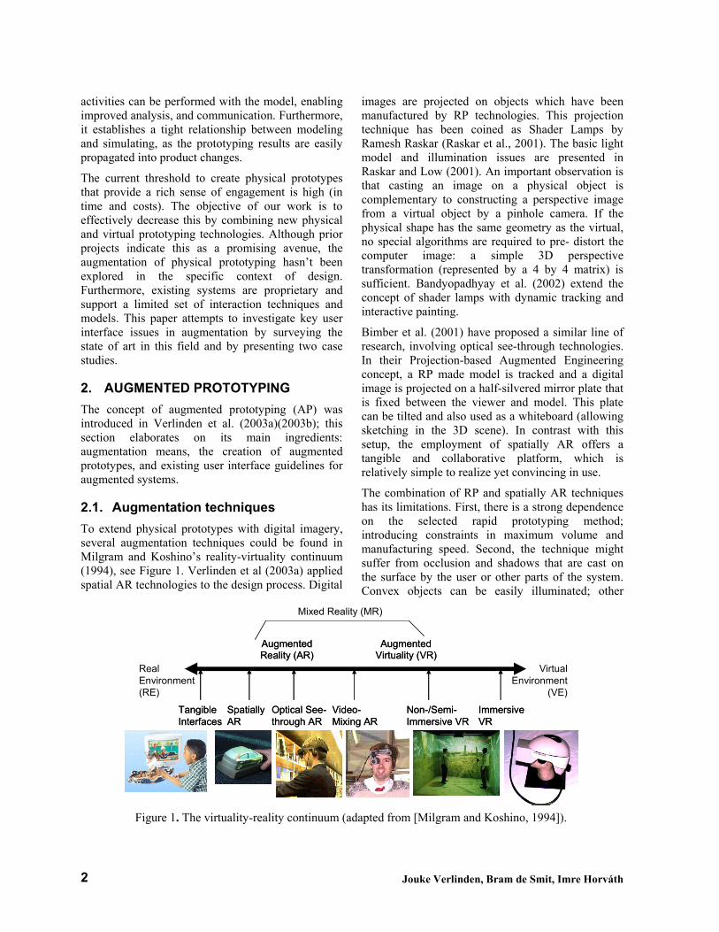
2.1. Augmentation techniques To extend physical prototypes with digital imagery, several augmentation techniques could be found in Milgram and Koshino’s reality-virtuality continuum (1994), see Figure 1. Verlinden et al (2003a) applied spatial AR technologies to the design process. Digital
images are projected on objects which have been manufactured by RP technologies. This projection technique has been coined as Shader Lamps by Ramesh Raskar (Raskar et al., 2001). The basic light model and illumination issues are presented in Raskar and Low (2001). An important observation is that casting an image on a physical object is complementary to constructing a perspective image from a virtual object by a pinhole camera. If the physical shape has the same geometry as the virtual, no special algorithms are required to pre- distort the computer image: a simple 3D perspective transformation (represented by a 4 by 4 matrix) is sufficient. Bandyopadhyay et al. (2002) extend the concept of shader lamps with dynamic tracking and interactive painting.
Bimber et al. (2001) have proposed a similar line of research, involving optical see-through technologies. In their Projection-based Augmented Engineering concept, a RP made model is tracked and a digital image is projected on a half-silvered mirror plate that is fixed between the viewer and model. This plate can be tilted and also used as a whiteboard (allowing sketching in the 3D scene). In contrast with this setup, the employment of spatially AR offers a tangible and collaborative platform, which is relatively simple to realize yet convincing in use.
The combination of RP and spatially AR techniques has its limitations. First, there is a strong dependence on the selected rapid prototyping method; introducing constraints in maximum volume and manufacturing speed. Second, the technique might suffer from occlusion and shadows that are cast on the surface by the user or other parts of the system. Convex objects can be easily illuminated; other
RealEnvironment(RE)
AugmentedReality (AR)AugmentedReality (AR)
AugmentedVirtuality (VR)Augmented
Virtuality (VR)Virtual
Environment(VE)
Mixed Reality (MR)
Tangible InterfacesTangible Interfaces
Optical See-through AROptical See-through AR
Video-Mixing ARVideo-Mixing AR
Non-/Semi-Immersive VRNon-/Semi-Immersive VR
Immersive VRImmersive VR
SpatiallyARSpatiallyAR
Figure 1. The virtuality-reality continuum (adapted from [Milgram and Koshino, 1994]).
Case-Based Exploration of the Augmented Prototyping Dialogue to Support Design 3
geometries strongly depend on granularity and projector orientation. The perceived quality is in some cases receptive to projection errors (also known as registration errors), especially projection overshoot (Verlinden et al., 2003b). As with shadow casting, this phenomenon depends on geometry and location of the projector. Solutions to this problem are to include a dilatation (generic offset) of the physical model or pixel masking in the rendering pipeline. A number of alternative algorithms exist to support the latter, including a one that uses a probabilistic function to gradually fade out the virtual object around the edges (Fuhrmann et al., 1999). Given these objections, we still hypothize that this augmented prototyping approach significantly lowers the threshold to establish prototypes with a rich sense of engagement. However, in order to test this, more knowledge needs to be developed on the employment of augmented prototyping in the design process.
2.2. Augmented Prototype manufacturing
In (Verlinden at al., 2003b), the inclusion of Rapid Prototyping means is discussed and tested. Rapid Prototyping (RP) refers to the automatic manufacturing of physical shapes based on a digital model. It extends the advantages of traditional physical prototyping by ensuring an accurate correspondence between the artifact specification (in a CAD model) and its “hardcopy”, and allows (semi) automatic manufacturing of the prototypes. These methods enable relatively fast and cheap manufacturing of models in a broad range of materials (Campbell, 2002). Rapid prototyping can be divided in incremental, decremental and hybrid technologies.
Our present experience mainly encompasses decremental technologies. The following steps in the fabrication process of augmented prototypes are recognized: 1) Model conversion and adjustment, in which orientation/scale is determined and a differentiation is made between virtual and physical prototyping of features. 2a) Creation of the virtual model, which might include addition of additional attributes to the model and the selection of functions and options (e.g. texture maps). 2b) Rapid prototyping of physical components, special attention has to be given to speed up the process and to influence its granularity. 3) Calibration, by using parameters of the previous steps, virtual and real world coordinate systems are adjusted.
Furthermore, some guidelines in balancing virtual and physical have been identified, a summary is presented in Table 3.
Table 1. Selection criteria for physical or virtual
prototyping (Verlinden et al., 2003b). Physical • Global shape.
• Elements for probing physical ergonomics. • Existing objects, to be extended with some
virtual features. Both • Perceptual enforcement of local features; edges,
rivets et cetera. • Buttons and other interactive components.
Virtual • Details that fit in the global shape. • Dynamic features, subject to change. • Textures, materials. • Sounds.
We can conclude that these concepts are applicable to future research and development of augmented prototyping and will utilize these in this article.
2.3. Present guidelines of tangible and augmented dialogue
Ideally, the interaction with augmented prototypes is compatible with existing physical models. However, the inclusion of virtual models and simulation (both control and visualization) complicates the dialogue between designer and artifact model. Although similar setups have been developed in the past decennium, not much is documented on the design of user interfaces of augmented reality systems or related setups (such as tangible interfaces). Ullmer and Ishii (2000) present a descriptive categorization of all major works in the area of tangible interfaces. Here, a preliminary distinction is made between spatial, constructive, relational, and associative interface instances. Our notion of augmented prototyping can belong to any of these, depending on the purpose and domain of design. However, no guidelines or design approaches are mentioned.
A philosophical grounding can be found in Dourish (2001), who presents a phenomenological backdrop to tangible and social interfaces, and mentions design principles that we consider to be design stances. Slightly more concrete steps could be found in by Kato et al. (2000), who present the following user interface design principles:
A. Object affordances should match the physical constraints of the object to the requirements of the task

Jouke Verlinden, Bram de Smit, Imre Horváth 4
B. Enable the support of parallel activity where multiple objects or interface elements are being manipulated at once.
C. Support physically based interaction techniques (such as using object proximity or spatial relations).
D. The form of objects should encourage and support spatial manipulation.
E. Support multi-handed interaction.
We will revisit and extend these guidelines after our exploratory cases.
3. CASE STUDIES After the development of some proofs-of-concept for augmented prototyping, we have defined a variety of usage scenarios to employ this means in the early phases of design. To test the scenarios and technologies, a number of pilot studies were performed, focusing on a variety of design problems. In each case, a system was developed and evaluated qualitatively. In this article, we will present two cases, for identification purposes labeled “nightclub” and “kitchen”.
3.1. Nightclub In order to test the capabilities of collaborative use of augmented prototyping, we developed a system that contained a number of relatively small elements that could be manipulated simultaneously. In the spirit of URP (Underkoffer et al., 1999)(Ishii et al., 2002), this design system included simulation capabilities. Rather than copying the urban architecture setting, an
interior design scenario was chosen: modeling layout and style of a nightclub.
The physical configuration is shown in Figure 2, a number of physical objects could be moved across the rectangular floor (16x20 meters, scale 1:40). Each of these objects corresponds to a piece of furniture: dance floors (hexagonal pieces), bars (long elements, in different sizes) and seating areas (chairs mounted on a small piece of tile). These were made by hand from polystyrene slabs and wood. The boundaries of the floor plan were simply drawn with a marker, while two physical walls are used for projection. Apart from the moveable furniture, some fixed components were projected, including a main entrance, emergency exits, and toilet entry. A single video projector was used to beam 3D perspective images on these components. This projector was located relative to a corner of the floor plan, facing down with a 35 degree angle (height approx. 2.2 meters). This allowed collaborative use of the setup and presented a complete projection of floor and walls.
The augmentation of the model supported selection of a preset style, tracking the movements of the furniture, and a pedestrian flow simulation. The styles corresponded to a collection of bitmaps that are mapped to the walls, floor and pieces of furniture. Four different styles were prepared: metal-look, psychedelic-disco, modern/lounge, and traditional (the third is shown in Figure 3). A hardcopy of these styles was made to switch from one to another (by voice command). Each preset corresponded with a music piece that was played, belonging to the same genre (respectively dance, disco, lounge, and blues).
Figure 2 Physical mockup nighclub model. Figure 3 Augmented nightclub model.
Case-Based Exploration of the Augmented Prototyping Dialogue to Support Design 5
Tracking of the furniture was required for both style projection and simulation purposes (2D position and rotation). When not in use, pieces could be moved aside. A simple pedestrian flow simulation would display individual persons as 3D entities in the scene, each with their own location and orientation. Based on the current layout and simulation time (represented by a projected clock), they would move among the elements of the nightclub. The time could be changed by pretending to move the arms of the projected clock. By inserting a “fire” object, evacuation scenarios were performed as well.
The pedestrian flow simulation is based on the theory of Okazaki and Matsushita (1993). This theory introduces magnetism-type of attraction and propulsion forces among the simulation, in which persons and blocking objects are represented as positive particles, and target objects as negative ones. Longitudinal pieces, like the bar, had 2 to 3 forces attached. Coulomb’s law is then used to calculate the magnetic forces:
F= (k*q1*q2/ |r|3)*r
In which F is the magnetic force (a vector), k is a constant value, q1 is the intensity of magnetic load of a pedestrian, q2 is the intensity of another magnetic pole, and r is the vector between the two particles. The pedestrians all had a fixed value. The forces of the furniture pieces depended on the clock – for example, at ten o’clock, most nightclub visitors will scatter to either the dance floor or the bar, while at 4 am the seating areas and exits were of particular interest. The fire object was simply given a very large positive value. After some careful tweaking with the intensity values, the pedestrian flow simulation gave a convincing yet limited impression of actual use.
The system was built in Open Inventor. To support projection on top of the furniture, the components were modeled in SolidWorks and converted to VRML files. We used a Wizard of Oz technique for object tracking: a human operator would monitor hand motions of the users and, by mouse and keyboard interaction, would propagate the changes in style, furniture position/rotation and time of the virtual clock. Furniture movement was easily supported by Open Inventor’s concepts of draggers and engines, which we constrained to a 2D plane in space. Some queuing behavior could not be implemented by ambiguities in the pedestrian flow paper mentioned above. For reasons of performance, only a small number of pedestrians was included in
the scene (25 persons, performing at 20 Hz on a standard Pentium III PC).
The evaluation of the system was done in three sessions; each included a team of two subjects (see Figure 5). The subjects were senior design students (2 architecture, 4 industrial design). All had considerable experience in designing, planning and coordinating parties and exhibitions. During the sessions, an assignment was given. This included a design context and a particular role that each participant had to play (corresponding with a responsibility found in real life). In two cases, the teams played owner (main focus: commercial affairs and safety) and manager (main focus: practical use, style/attractiveness), in the third, they acted as the design team (main focus: attractiveness/ functionality). One of the examiners acted as a facilitator of the design session, making sure that the subjects understood the assignment and giving feedback regarding the resulting designs.
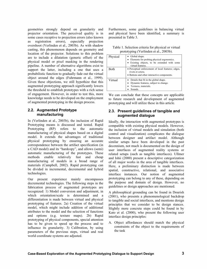
Dance floor
Seating 1
Long Bar
Toilet entrance
Seating 2
Main Entrance
Emergency Exits
Figure 4 Floor plan of start condition, containing configuration errors.
For each session, the same configuration “errors” were introduced at start time – a bar in front of toilet entrance, illogical placement of a seating area (see Figure 4). One of the benchmarks was to observe whether these would be noticed and fixed.
The assignments on average took 6 minutes per style – the maximum was 10 minutes. This included discussion, reconfiguration and evaluation. The “errors” were directly noticed and corrected. In all sessions, it was clearly remarked that the augmentation added an engaging factor. The participants shared this view, especially the fact that it stimulated the discussion. The subjects had no problems in finding out how the basic operation worked (moving furniture pieces around and seeing

Jouke Verlinden, Bram de Smit, Imre Horváth 6
the pedestrian flows), nor to explore completely different configurations when another style was chosen.
The Wizard of Oz setup worked surprisingly well; participants adapted to limited speed of picking and moving elements. As for the multimodal interface, there was confusion about the interactive components that had no or poor physical means: the clock and the style selection. The pedestrian simulation was considered useful. However, the dynamic visualization sometimes distracted the participants when they were switching to another style (the simulation could not be switched off).
As all subjects had a background in organizing and designing dance parties, many suggestions for enhancements were given. This included the addition of lighting effects, more styles and furniture pieces (or possibilities to use scanners and cameras to create new ones), to include consideration of infrastructure such as air circulation, sound isolation and the logistics of beverages. Furthermore, they would expect a more sophisticated pedestrian simulation (including more accurate queuing behavior).
3.2. Kitchen As a second exploration, we selected the domain of kitchen design. In this field, aesthetics and function are given consideration simultaneously. This typically happens by exploring spatial layout, finishing and kitchen appliances. A key element is the sense of scale, which is difficult to recreate in small models or virtual spaces. We have built a simple system to explore these issues in a full-scale realm. It consisted of four of wood-reinforced cardboard mockups of realistic sizes (3 58x52x83 cm and 1 58x52x208 cm). These represented generic kitchen elements that could be reconfigured
physically. Two projectors were employed to project both front and top surfaces. The top projector was located 7.5 meters away from the ground, the front projector 6.25 meters distance from the objects. The augmentation presented finishing and appliances (Figure 6). When the user would grab and move the physical cabinets, the projections would follow (Figure 7). For our system, the kitchen floor was limited to four cells of 58x52 cm, placed next to each other.
As the projectors were oriented perpendicular to the working surfaces, simple 2D bitmaps could be used to augment the mockups. These bitmaps were scans from a recent kitchen catalog. As with the nightclub system, movement of the furniture was tracked by a Wizard of Oz solution; a hidden person monitored the user’s actions and selected and updated the virtual counterparts in the top projection (by dragging the bitmaps). The software was implemented in Macromedia Director. Through a network connection, position updates and style changes were automatically propagated to the front projection system. For the selection of a finishing, thumbnails of all styles were displayed on the floor (thus included in the top projection). The user could verbally select style and compartment to be changed. Calibration of the projections was performed manually; for each cell, a marker was shown on the PC screen, which could be moved around in 2 dimensions. Furthermore, the bitmaps could be scaled individually to match the size of the physical
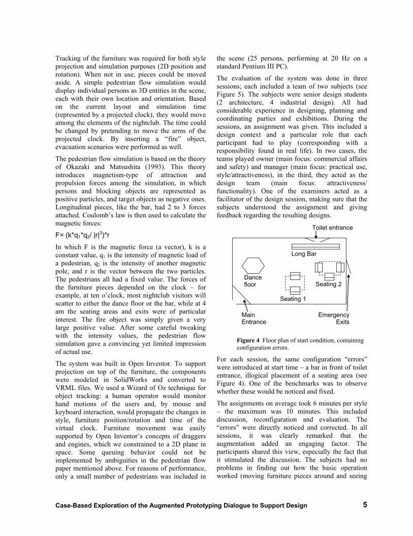
Figure 5 Collaborative use during evaluation.
Figure 6 Kitchen system with projections.

Case-Based Exploration of the Augmented Prototyping Dialogue to Support Design 7
mockups (both in front and top projections). With this setup, positioning the projectors was a challenge. These had to be far enough to cover the working space (more than 6 meters away), yet have sufficient light intensity.
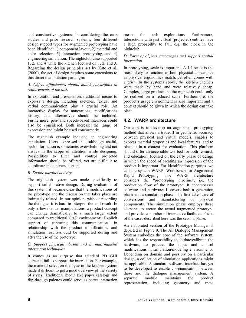
The system was evaluated by 5 people, 3 senior design students and 2 design teachers. Their assignment was to create a design that would fit to certain requirements and mood (presented in one photograph of a living room). In practice, the system was easy to use. We could definitely observe design activities such as reflection and action. A combined activity trial of all sessions is shown on Figure 8. Participants did not only configure the kitchen but also simulated a number of typical cooking activities and then altered their arrangement. Most participants changed physical configuration and their details simultaneously. As the design assignment was abstract, we did not assess nor compare the resulting configurations, yet all seemed plausible with the given constraints.
Participants gave positive feedback about the
technique. However, a drawback was the limited number of locations that could be used to configure the kitchen. Furthermore, neither walls nor wall-mounted cupboards were included. Future solutions could use Velcro or wire straps to create more realistic designs.
4. DISCUSSION The time to develop the systems was considerable. Manufacturing the hardware and setting up the projector configuration was tedious (especially the case with the kitchen projectors), while software development was relatively easy implemented. For the nightclub system, the implementation of the pedestrian flow algorithms was straightforward, while more time had to be spent on finalizing the styles and managing the interaction.
Both systems described above use some form of Wizard of Oz workaround to support tracking and user interaction. For global tracking scenarios, this technique is sufficient for the experiments; subjects were not aware of a human link between them and the computerized system. Calibration was performed manually, by setting standard parameters as (virtual) camera position/orientation, field of view, and scale. This worked for the setups, as it had to be done only once. Furthermore, the physical components had simple, convex geometries, which were quite tolerant to inaccuracies in the projections.
4.1. Augmented Prototyping guidelines As mentioned in section 2.3, augmented prototypes function as a tangible interface: users relocate or adapt the physical components, the virtual counterparts are updated and simulation results are projected. . Of the characterizations that Ullmer and Ishii (2000) made, these can be grouped under spatial
Figure 8 Activity trial of the kitchen experiment per subject.
Figure 7 Relocating cabinets.
Jouke Verlinden, Bram de Smit, Imre Horváth 8
and constructive systems. In considering the case studies and prior research systems, four different design support types for augmented prototyping have been identified: 1) component layout, 2) material and color selection, 3) interaction prototyping, and 4) engineering simulation. The nightclub case supported 1, 2, and 4 while the kitchen focused on 1, 2, and 3. Regarding the design principles set by Kato et al. (2000), the act of design requires some extensions to this direct manipulation paradigm:
A. Object affordances should match constraints to requirements of the task
In exploration and presentation, traditional means to express a design, including sketches, textual and verbal communication play a crucial role. An interactive display for annotations, modifications history, and alternatives should be included. Furthermore, pen- and speech-based interfaces could also be considered. Both increase the range of expression and might be used concurrently.
The nightclub example included an engineering simulation. Users expressed that, although useful, such information is sometimes overwhelming and not always in the scope of attention while designing. Possibilities to filter and control projected information should be offered, yet are difficult to coordinate in a universal setup.
B. Enable parallel activity
The nightclub system was made specifically to support collaborative design. During evaluation of this system, it became clear that the modifications of the prototype and the discussion that takes place are intimately related. In our opinion, without recording the dialogue, it is hard to interpret the end result. In only a few manual manipulations, a product concept can change dramatically, to a much larger extent compared to traditional CAD environments. Explicit support of capturing this communication –in relationship with the product modifications and simulation results-should be supported during and after the use of the prototype.
C. Support physically based and E. multi-handed interaction techniques.
It comes as no surprise that standard 2D GUI elements fail to support the interaction. For example, the material selection dialogue in the kitchen system made it difficult to get a good overview of the variety of styles. Traditional media like paper catalogs and flip-through palettes could serve as better interaction
means for such explorations. Furthermore, interactions with just virtual (projected) entities have a high probability to fail, e.g. the clock in the nightclub
D. Form of objects encourages and support spatial interaction.
In prototyping, scale is important. A 1:1 scale is the most likely to function as both physical appearance as physical ergonomics match, yet often comes with a price. In the systems above, the kitchen cabinets were made by hand and were relatively cheap. Complex, large products as the nightclub could only be realized on a reduced scale. Furthermore, the product’s usage environment is also important and a context should be given in which the design can take place.
4.2. WARP architecture Our aim is to develop an augmented prototyping method that allows a tradeoff in geometric accuracy between physical and virtual models, enables to express material properties and local features, and to place it in a context for evaluation. This platform should offer an accessible test bed for both research and education, focused on the early phase of design in which the speed of creating an impression of the product is important. For identification purposes, we call the system WARP: Workbench for Augmented Rapid Prototyping. The WARP architecture considers the “prototyping pipeline”, i.e. the production flow of the prototype. It encompasses software and hardware. It covers both a generation phase and a simulation phase. The first takes care of conversions and manufacturing of physical components. The simulation phase employs these elements to create the actual augmented prototype and provides a number of interactive facilities. Focus of the cases described here was the second phase.
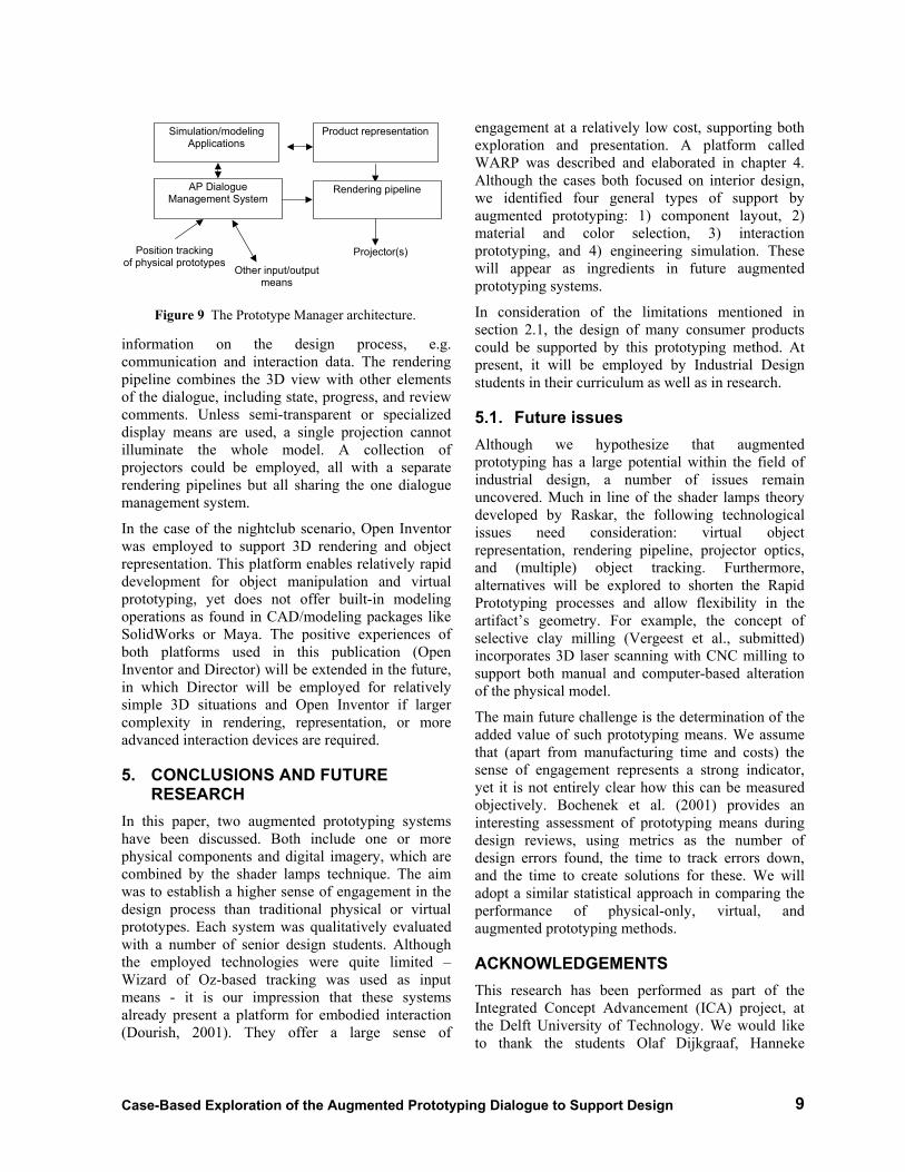
An elaborated version of the Prototype Manager is depicted in Figure 9. The AP Dialogue Management System embodies the core of the software system, which has the responsibility to initiate/calibrate the hardware, to process the input and control modifications in simulation/modeling environments. Depending on domain and possibly on a particular design, a collection of simulation applications might be applicable. A standard software interface has yet to be developed to enable communication between these and the dialogue management system. A separate module maintains the product representation, including geometry and meta
Case-Based Exploration of the Augmented Prototyping Dialogue to Support Design 9
information on the design process, e.g. communication and interaction data. The rendering pipeline combines the 3D view with other elements of the dialogue, including state, progress, and review comments. Unless semi-transparent or specialized display means are used, a single projection cannot illuminate the whole model. A collection of projectors could be employed, all with a separate rendering pipelines but all sharing the one dialogue management system.
In the case of the nightclub scenario, Open Inventor was employed to support 3D rendering and object representation. This platform enables relatively rapid development for object manipulation and virtual prototyping, yet does not offer built-in modeling operations as found in CAD/modeling packages like SolidWorks or Maya. The positive experiences of both platforms used in this publication (Open Inventor and Director) will be extended in the future, in which Director will be employed for relatively simple 3D situations and Open Inventor if larger complexity in rendering, representation, or more advanced interaction devices are required.
5. CONCLUSIONS AND FUTURE RESEARCH
In this paper, two augmented prototyping systems have been discussed. Both include one or more physical components and digital imagery, which are combined by the shader lamps technique. The aim was to establish a higher sense of engagement in the design process than traditional physical or virtual prototypes. Each system was qualitatively evaluated with a number of senior design students. Although the employed technologies were quite limited –Wizard of Oz-based tracking was used as input means - it is our impression that these systems already present a platform for embodied interaction (Dourish, 2001). They offer a large sense of
engagement at a relatively low cost, supporting both exploration and presentation. A platform called WARP was described and elaborated in chapter 4. Although the cases both focused on interior design, we identified four general types of support by augmented prototyping: 1) component layout, 2) material and color selection, 3) interaction prototyping, and 4) engineering simulation. These will appear as ingredients in future augmented prototyping systems.
In consideration of the limitations mentioned in section 2.1, the design of many consumer products could be supported by this prototyping method. At present, it will be employed by Industrial Design students in their curriculum as well as in research.
5.1. Future issues Although we hypothesize that augmented prototyping has a large potential within the field of industrial design, a number of issues remain uncovered. Much in line of the shader lamps theory developed by Raskar, the following technological issues need consideration: virtual object representation, rendering pipeline, projector optics, and (multiple) object tracking. Furthermore, alternatives will be explored to shorten the Rapid Prototyping processes and allow flexibility in the artifact’s geometry. For example, the concept of selective clay milling (Vergeest et al., submitted) incorporates 3D laser scanning with CNC milling to support both manual and computer-based alteration of the physical model.
The main future challenge is the determination of the added value of such prototyping means. We assume that (apart from manufacturing time and costs) the sense of engagement represents a strong indicator, yet it is not entirely clear how this can be measured objectively. Bochenek et al. (2001) provides an interesting assessment of prototyping means during design reviews, using metrics as the number of design errors found, the time to track errors down, and the time to create solutions for these. We will adopt a similar statistical approach in comparing the performance of physical-only, virtual, and augmented prototyping methods.
ACKNOWLEDGEMENTS This research has been performed as part of the Integrated Concept Advancement (ICA) project, at the Delft University of Technology. We would like to thank the students Olaf Dijkgraaf, Hanneke
Position tracking of physical prototypes
Other input/output means
AP Dialogue Management System
Product representationSimulation/modeling Applications
Rendering pipeline
Projector(s)
Figure 9 The Prototype Manager architecture.

Jouke Verlinden, Bram de Smit, Imre Horváth 10
Jacobs, Martijn Klitsie, and Koos Looijesteijn for their contributions.
REFERENCES Bandyopadhyay, D.; Raskar, R.; Fuchs, H. (2002)
"Dynamic Shader Lamps: Painting on Movable Objects", IEEE and ACM International Symposium on Mixed and Augmented Reality (ISMAR), To Appear September 2002
Bimber, Oliver; Stork, André; Branco, Pedro (2001) “Projection-based Augmented Engineering” In Proceedings of the Ninth International Conference on Human-Computer Interaction (HCI’2001). Volume 1. Mahwah, New Jersey 2001, pp. 787-791
Bochenek, G.M., Ragusa, J.M., Malone, L.C. (2001) “Integrating virtual 3-D display systems into product design reviews: some insights from empirical testing”, International Journal Technology Management, vol 21(3/4), pp. 340-352.
Campbell, I.R. (2002) “Rapid prototyping: Yesterday, today, tomorrow”, in proceedings of the TMCE 2002 symposium, pp. 65-74.
Dourish, P. (2001) “Where the Action Is: the Foundations of Embodied Interaction” MIT Press, ISBN 0-262-04196-0.
Fritzmaurice, G. Ishii, H. Buxton, W. (1995) “Bricks: Laying the Foundations of Graspable User Interfaces”, CHI’95 Mosaic of Creativity, pp 442-449.
Fuhrmann, A. Hesina, G., Faure, F., Gervautz, M. (1999) “Occlusion in collaborative augmented environments”, Computers& Graphics, vol 23(6), pp. 809-819.
Hilton, J. (1983) “Models as an Aid to Design”, in Industrial Design in Engineering, Charles H. Flurscheim (ed), the Design Council 1983.
Horváth, I., Tromp, N., Daalhuizen, J. (2003) “comprehending a hand motion language in shape conceptualization” in ASME DETC2003/CIE-123.
Ishii, H., Underkoffer, J., Chak, D., Piper, B., Ben-Joseph, E., Yueng, L., Kanji, Z. (2002) “Augmented Urban Planning Workbench: Overlaying Drawings, Physical Models and Digital Simulation”, Proceedings of IEEE & ACM ISMAR, 2002.
Kato, H., Billinghurst, M., Poupyrev, I., Imamoto, K., Tachibana, K. (2000) “Virtual Object Manipulation on a Table-Top AR Environment”, in proceedings of Int.. Symposium on Augmented Reality (ISAR), p 111-119.
Laurel, B. (1989) “Computers as Theatre”, Addison-Wesley, Reading.
Milgram, P., Kishino, F. A, (1994) "Taxonomy of Mixed Reality Visual Displays." IECE Trans. on Information and Systems (Special Issue on Networked Reality), vol. E77-D, no. 12, pp.1321-1329 .
Okazaki , S., Matsushita, S. (1993) “study of simulation model for pedestrian movement with evacuation and queuing”, in Proceedings of the International Conference on Engineering for crowd safety, (London, UK, 17-18 march).
Raskar, R., Low, K-L (2001) “Interacting with Spatially Augmented Reality”, ACM international conference on Virtual Reality, Computer Graphics and Visualization in Africa (AFRIGRAPH).
Raskar, R.; Welch, G.; Low, K-L.; Bandyopadhyay, D. (2001) "Shader Lamps: Animating Real Objects with Image Based Illumination", Eurographics Workshop on Rendering, June 2001.
Schon, D.A. (1994) "Designing as a reflective conversation with the materials of a design situation," Research in Engineering Design, Vol 3 New York:Springer Verlag, pp131-147
Smyth, M. (2000) “Design tools as agents of disclosure”, Knowledge-Based Systems, Elsevier, vol 13, pp. 27-35.
Stappers, P., Hennessey, J. (1998) ”Toward electronic napkins and beermats, computer support for visual ideation skills” in Paton and Neilson (eds), Visual Representations and Interpretations, Springer, London, pp. 220-225.
Ullmer, B., Ishii, H. (2000) “Emerging frameworks for tangible user interfaces”, IBM Systems Journal, vol 39(3&4), pp. 915-931.
Underkoffer, J Ishii, H. (1999) “Urp: A Luminous-Tangible Workbench for Urban Planning and Design”, CHI’99, Proceedings of the CHI’99 conference, pp. 386-393.
Vergeest, J., Song, W., Broek, J. “integrating traditional and digital modeling of freeform product concepts using 3d scanning technology”, submitted to the TMCE 2004 symposium.
Verlinden, J.C., de Smit, A., Peeters, A.W.J., van Gelderen, M.H.(2003) ”Development of a Flexible Augmented Prototyping System”, Journal of WSCG, vol 11(3), pp. 496-503.
Verlinden,J., de Smit, A., Horváth, I., Epema, E.., de Jong, M. (2003) “Time compression characteristics of the Augmented Prototyping Pipeline”, proceedings of the Euro-uRapid conference.