CaRINA Intelligent Robotic Car: Architectural design and applications
25
CaRINA Intelligent Robotic Car: Architectural Design and Applications Leandro C. Fernandes, Jefferson R. Souza, Gustavo Pessin, Patrick Y. Shinzato, Daniel Sales, Caio Mendes, Marcos Prado, Rafael Klaser, Andr´ e Chaves Magalh˜ aes, Alberto Hata, Daniel Pigatto Kalinka Castelo Branco, Valdir Grassi Jr., Fernando S. Osorio and Denis F. Wolf Mobile Robotics Laboratory, University of S˜ao Paulo (USP) Av. Trabalhador S˜ao-Carlense, 400 - P.O. Box 668 - 13.560-970, Sao Carlos, Brazil {lnd, jrsouza, pessin, shinzato, dsales, mgprado, rlklaser, hata, pigatto, kalinka, fosorio, denis}@icmc.usp.br, {acmagalhaes,vgrassi}@sc.usp.br Abstract This paper presents the development of two outdoor intelligent vehicles platforms named CaRINA I and CaRINA II, their system architecture, simulation tools, and control modules. It also describes the development of the intelligent control system modules allowing the mobile robots and vehicles to navigate autonomously in controlled urban environments. Research work has been carried out on tele-operation, driver assistance systems, and autonomous navigation using the vehicles as platforms to experiments and validation. Our robotic platforms include mechanical adaptations and the development of an embedded software architecture. This paper addresses the design, sensing, decision making, and acting infrastructure and several experimental tests that have been carried out to evaluate both platforms and proposed algorithms. The main contributions of this work is the proposed architecture, that is modular and flexible, allowing it to be instantiated into different robotic platforms and applications. The communication and security aspects are also investigated. Keywords: Autonomous Vehicle Architecture, Embedded System Design, Robotic Vehicle Navigation, Computer Vision, Machine Learning, Intelligent Systems. 1. Introduction According to World Health Organization [70], each year, approximately 1,2 million lives are lost due to traffic acci- dents worldwide, and around 50 million people suffer non- fatal car accidents. The majority of these are due to hu- man error, like small distractions when driver uses a mo- bile phone or eats something, or more seriously faults like drunk driving or exceeding the speed limit. Self-driving cars promise to reduce this number of deaths and injuries as well as bring other benefits like optimal fuel usage, effi- ciency with freight transportation and traffic flow improve- ment in big cities, providing transportation for children and adults unable to drive like physically handicapped or visually impaired people. This paper describes the soft- ware and hardware architectures, and experimental results of the CaRINA project (Intelligent Robotic Car for Au- tonomous Navigation), which aims the development of an autonomous vehicle for urban environments. In recent years, the Defense Advanced Research Projects Agency (DARPA) encouraged this research area by orga- nizing three competitions for autonomous vehicles. The Grand Challenges [10], performed in 2004 and 2005, had focus on crossing the desert and skills known as “road fol- lowing” and “obstacle avoidance”. The first edition was disappointing. The best team traveled just 12 km from 224 km proposed by DARPA. In 2005, this challenge was proposed again and five vehicles finished the new route. In 2007, perhaps the most famous and relevant competition was launched, the Urban Challenge [11] where robot-cars should be able to safely navigate in an urban environment with other robot-cars and human-driven vehicles. They also had to obey some of the driving rules of California. This competition had 11 finalist teams and 6 robots fin- ished the route of 96 km. Despite the impressive results of the 2007 edition which proved the feasibility of this kind of technology, it is important to highlight that the au- tonomous navigation in urban environments problem was simplified in order to evaluate the robots and perform this competition. In Europe, the European Land-Robot Trial (ELROB) [16] is an initiative similar to DARPA competitions but without a winner. It is performed every year since 2006 alternating between military and civilian. Europe has also initiatives where companies, universities and research cen- ters have cooperation projects to develop technologies to improve safety and intelligence from vehicles. Some of them are “The European Field Operational Test” (Euro- Fot) [17] and “Highly Automated Vehicles for Intelligent Transport” (HAVEit) [26] which had focused on develop- ing systems like ACC (Adaptative Cruise Control), FCW (Foward Collision Warning), BSIS (Blind Spot Informa- Preprint submitted to Journal of Systems Architecture October 30, 2013
-
Upload
independent -
Category
Documents
-
view
0 -
download
0
Transcript of CaRINA Intelligent Robotic Car: Architectural design and applications

CaRINA Intelligent Robotic Car: Architectural Design and Applications
Leandro C. Fernandes, Jefferson R. Souza, Gustavo Pessin, Patrick Y. Shinzato, Daniel Sales,Caio Mendes, Marcos Prado, Rafael Klaser, Andre Chaves Magalhaes, Alberto Hata, Daniel Pigatto
Kalinka Castelo Branco, Valdir Grassi Jr., Fernando S. Osorio and Denis F. Wolf
Mobile Robotics Laboratory, University of Sao Paulo (USP)Av. Trabalhador Sao-Carlense, 400 - P.O. Box 668 - 13.560-970, Sao Carlos, Brazil
{lnd, jrsouza, pessin, shinzato, dsales, mgprado, rlklaser, hata, pigatto, kalinka, fosorio, denis}@icmc.usp.br,{acmagalhaes,vgrassi}@sc.usp.br
Abstract
This paper presents the development of two outdoor intelligent vehicles platforms named CaRINA I and CaRINA II, theirsystem architecture, simulation tools, and control modules. It also describes the development of the intelligent controlsystem modules allowing the mobile robots and vehicles to navigate autonomously in controlled urban environments.Research work has been carried out on tele-operation, driver assistance systems, and autonomous navigation using thevehicles as platforms to experiments and validation. Our robotic platforms include mechanical adaptations and thedevelopment of an embedded software architecture. This paper addresses the design, sensing, decision making, andacting infrastructure and several experimental tests that have been carried out to evaluate both platforms and proposedalgorithms. The main contributions of this work is the proposed architecture, that is modular and flexible, allowing itto be instantiated into different robotic platforms and applications. The communication and security aspects are alsoinvestigated.
Keywords: Autonomous Vehicle Architecture, Embedded System Design, Robotic Vehicle Navigation, ComputerVision, Machine Learning, Intelligent Systems.
1. Introduction
According to World Health Organization [70], each year,approximately 1,2 million lives are lost due to traffic acci-dents worldwide, and around 50 million people suffer non-fatal car accidents. The majority of these are due to hu-man error, like small distractions when driver uses a mo-bile phone or eats something, or more seriously faults likedrunk driving or exceeding the speed limit. Self-drivingcars promise to reduce this number of deaths and injuriesas well as bring other benefits like optimal fuel usage, effi-ciency with freight transportation and traffic flow improve-ment in big cities, providing transportation for childrenand adults unable to drive like physically handicapped orvisually impaired people. This paper describes the soft-ware and hardware architectures, and experimental resultsof the CaRINA project (Intelligent Robotic Car for Au-tonomous Navigation), which aims the development of anautonomous vehicle for urban environments.
In recent years, the Defense Advanced Research ProjectsAgency (DARPA) encouraged this research area by orga-nizing three competitions for autonomous vehicles. TheGrand Challenges [10], performed in 2004 and 2005, hadfocus on crossing the desert and skills known as “road fol-lowing” and “obstacle avoidance”. The first edition wasdisappointing. The best team traveled just 12 km from
224 km proposed by DARPA. In 2005, this challenge wasproposed again and five vehicles finished the new route. In2007, perhaps the most famous and relevant competitionwas launched, the Urban Challenge [11] where robot-carsshould be able to safely navigate in an urban environmentwith other robot-cars and human-driven vehicles. Theyalso had to obey some of the driving rules of California.This competition had 11 finalist teams and 6 robots fin-ished the route of 96 km. Despite the impressive results ofthe 2007 edition which proved the feasibility of this kindof technology, it is important to highlight that the au-tonomous navigation in urban environments problem wassimplified in order to evaluate the robots and perform thiscompetition.
In Europe, the European Land-Robot Trial (ELROB)[16] is an initiative similar to DARPA competitions butwithout a winner. It is performed every year since 2006alternating between military and civilian. Europe has alsoinitiatives where companies, universities and research cen-ters have cooperation projects to develop technologies toimprove safety and intelligence from vehicles. Some ofthem are “The European Field Operational Test” (Euro-Fot) [17] and “Highly Automated Vehicles for IntelligentTransport” (HAVEit) [26] which had focused on develop-ing systems like ACC (Adaptative Cruise Control), FCW(Foward Collision Warning), BSIS (Blind Spot Informa-
Preprint submitted to Journal of Systems Architecture October 30, 2013
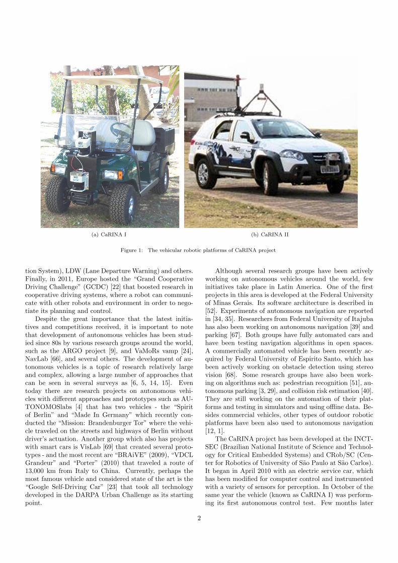
(a) CaRINA I (b) CaRINA II
Figure 1: The vehicular robotic platforms of CaRINA project
tion System), LDW (Lane Departure Warning) and others.Finally, in 2011, Europe hosted the “Grand CooperativeDriving Challenge” (GCDC) [22] that boosted research incooperative driving systems, where a robot can communi-cate with other robots and environment in order to nego-tiate its planning and control.
Despite the great importance that the latest initia-tives and competitions received, it is important to notethat development of autonomous vehicles has been stud-ied since 80s by various research groups around the world,such as the ARGO project [9], and VaMoRs vamp [24],NavLab [66], and several others. The development of au-tonomous vehicles is a topic of research relatively largeand complex, allowing a large number of approaches thatcan be seen in several surveys as [6, 5, 14, 15]. Eventoday there are research projects on autonomous vehi-cles with different approaches and prototypes such as AU-TONOMOSlabs [4] that has two vehicles - the “Spiritof Berlin” and “Made In Germany” which recently con-ducted the “Mission: Brandenburger Tor” where the vehi-cle traveled on the streets and highways of Berlin withoutdriver’s actuation. Another group which also has projectswith smart cars is VisLab [69] that created several proto-types - and the most recent are “BRAiVE” (2009), “VDCLGrandeur” and “Porter” (2010) that traveled a route of13,000 km from Italy to China. Currently, perhaps themost famous vehicle and considered state of the art is the“Google Self-Driving Car” [23] that took all technologydeveloped in the DARPA Urban Challenge as its startingpoint.
Although several research groups have been activelyworking on autonomous vehicles around the world, fewinitiatives take place in Latin America. One of the firstprojects in this area is developed at the Federal Universityof Minas Gerais. Its software architecture is described in[52]. Experiments of autonomous navigation are reportedin [34, 35]. Researchers from Federal University of Itajubahas also been working on autonomous navigation [39] andparking [67]. Both groups have fully automated cars andhave been testing navigation algorithms in open spaces.A commercially automated vehicle has been recently ac-quired by Federal University of Espirito Santo, which hasbeen actively working on obstacle detection using stereovision [68]. Some research groups have also been work-ing on algorithms such as: pedestrian recognition [51], au-tonomous parking [3, 29], and collision risk estimation [40].They are still working on the automation of their plat-forms and testing in simulators and using offline data. Be-sides commercial vehicles, other types of outdoor roboticplatforms have been also used to autonomous navigation[12, 1].
The CaRINA project has been developed at the INCT-SEC (Brazilian National Institute of Science and Technol-ogy for Critical Embedded Systems) and CRob/SC (Cen-ter for Robotics of University of Sao Paulo at Sao Carlos).It began in April 2010 with an electric service car, whichhas been modified for computer control and instrumentedwith a variety of sensors for perception. In October of thesame year the vehicle (known as CaRINA I) was perform-ing its first autonomous control test. Few months later
2
CaRINA I was able to autonomously traverse a 1 km tra-jectory in a controlled urban environment. The work onCaRINA II (a standard Fiat Palio Adventure) started inJuly 2011. One year later, to the best of our knowledge ithas been the first commercial vehicle from Latin Americacapable to perform autonomous navigation in the streets1.Figure 1 shows the CaRINA I and II research platforms.
The main contributions of this paper are: (i) The pro-posed system architecture that is modular and flexible, al-lowing to instantiate it into different hardware platforms(CaRINA I and II), and allowing to be customized to dif-ferent specific practical applications, as presented in thiswork; (ii) The system development methodology propo-sition based on an Open platform (ROS - described insection 2.1) exploiting its main characteristics as a service-based architecture, and also integrating it with a simula-tion facility based on Gazebo, that allows to perform realis-tic virtual simulations (switching between virtual and realcomponents into the system architecture); (iii) The dif-ferent navigation systems which present original solutionsallowing practical autonomous vehicle navigation based onreactive behaviors, path planning and topological naviga-tion based on state detection; (iv) The discussion, propo-sition and introduction of facilities regarding the commu-nication security, in order to provide a safer service-basedand distributed processing architecture/components; (v)The study, development and practical evaluation of VANETs(Vehicular Networks) integrated into this context of dis-tributed services architecture, also providing a safe com-munication. The main advantages of the proposed archi-tecture related to other works found in the literature arethe flexibility of the proposed architecture, demonstratedby the different possible applications/configurations ob-tained using it, and also the aspects related to the commu-nication security which usually are not provided/discussedin other works.
This paper describes the hardware and the softwarearchitectures of the CaRINA Project, experimental plat-forms, as well as the autonomous navigation results ob-tained. It is organized as follows: Section 2 describes thesystem archicture based on ROS, the hardware and soft-ware of the CaRINA experimental platforms, and aspectsof the simulated models. Section 3 presents the applica-tion of the proposed architecture into four different navi-gation systems, along with experimental results. Section 4describes an investigation on vehicular networks and secu-rity communication. Finally, Section 5 presents the con-clusions and future work.
2. System Architecture
In order to design, build and test intelligent roboticcar systems, we should be able to select, integrate andconfigure the hardware, and then develop the software to
1http://www.youtube.com/lrmicmc
operate with different types of sensors and actuators. Thesensors range from LIDARS (Laser sensors), monocular-stereo-spherical-panoramic cameras, GPS, Compass, IMU,and also, other devices used to obtain the feedback fromthe vehicle state (e.g. wheels odometer and steering an-gle encoder), which require specific drivers, interfaces andsoftware setup. It is also necessary to consider the differ-ent types of actuators, used to control the steering wheel,the acceleration and brake pedals, and, if necessary, tomake the gearbox shift. This is a very difficult and timeconsuming task if you do not have adequate tools to dealwith this system design complexity.
Intelligent and autonomous vehicles applications de-sign requires the development of different hardware andsoftware modules, and also interfaces that connect users,robot control systems and the embedded hardware com-ponents. In the particular case of the intelligent roboticcar design, the modeling and simulation of the systemcan be successfully done using VST (Virtual SimulationTools/Technology) and after transpose the virtual systeminto an actual robotic system. Adopting VSTs to modeland simulate autonomous vehicles, testing and evaluatingthe different aspects of the system before implementing itphysically, is an efficient manner to decrease the develop-ment time. Also, it allows to guarantee the safety duringthe initial and critical phase of tests/validations of the sys-tem. This type of approach is becoming more and morecommon not only in the robotics design but also in otherindustrial products design [45, 44, 46, 20, 19].
Furthermore, it is also required a middleware provid-ing tools for interfacing with different embedded systemmodules, hardware abstraction, and also providing com-munication facilities, since the implementation of the in-telligent robotic car system usually requires the adoptionof a distributed processing system with multiple dedicatedprocessing modules.
ROS (Robotic Operating System) was chosen as themain software package tool to allow us to develop CaRINAI and CaRINA II, because it provides several different re-sources, as for example: hardware abstraction, communi-cation facilities, management of distributed process, imple-mentation of useful debugging tools (e.g. logging services,visualization and simulation tools). The ROS provides analmost complete suite of tools and resources that allowsthe design, simulation, validation, test and practical de-ploy of complex robotic systems.
2.1. Embedded System Design using ROS
ROS is a service-based architecture and has becomingone of the most important platforms for robotic researchand development [73]. It is also fully integrated with im-portant tool and libraries, such as: OpenCV that providesan extensive library of functions and methods for Com-puter Vision and Image Processing; PCL, which allowsthe 3D Point Cloud (e.g. Laser and Stereo-Camera data)processing and visualization; Gazebo that is a 3D Real-istic Virtual Simulation Tool (VST); and Player, which
3
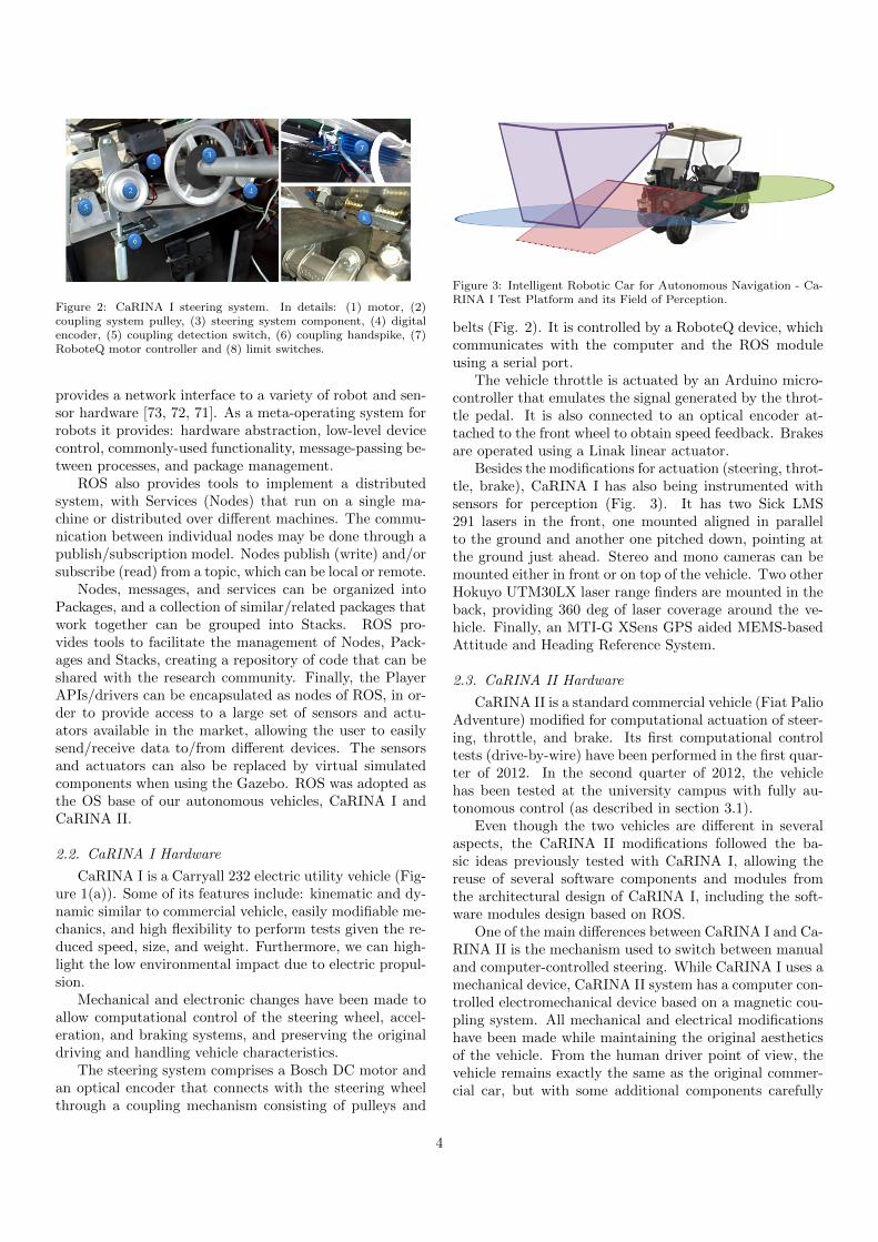
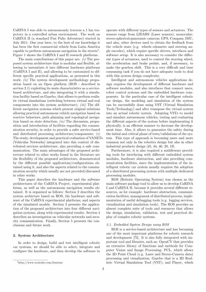
Figure 2: CaRINA I steering system. In details: (1) motor, (2)coupling system pulley, (3) steering system component, (4) digitalencoder, (5) coupling detection switch, (6) coupling handspike, (7)RoboteQ motor controller and (8) limit switches.
provides a network interface to a variety of robot and sen-sor hardware [73, 72, 71]. As a meta-operating system forrobots it provides: hardware abstraction, low-level devicecontrol, commonly-used functionality, message-passing be-tween processes, and package management.
ROS also provides tools to implement a distributedsystem, with Services (Nodes) that run on a single ma-chine or distributed over different machines. The commu-nication between individual nodes may be done through apublish/subscription model. Nodes publish (write) and/orsubscribe (read) from a topic, which can be local or remote.
Nodes, messages, and services can be organized intoPackages, and a collection of similar/related packages thatwork together can be grouped into Stacks. ROS pro-vides tools to facilitate the management of Nodes, Pack-ages and Stacks, creating a repository of code that can beshared with the research community. Finally, the PlayerAPIs/drivers can be encapsulated as nodes of ROS, in or-der to provide access to a large set of sensors and actu-ators available in the market, allowing the user to easilysend/receive data to/from different devices. The sensorsand actuators can also be replaced by virtual simulatedcomponents when using the Gazebo. ROS was adopted asthe OS base of our autonomous vehicles, CaRINA I andCaRINA II.
2.2. CaRINA I Hardware
CaRINA I is a Carryall 232 electric utility vehicle (Fig-ure 1(a)). Some of its features include: kinematic and dy-namic similar to commercial vehicle, easily modifiable me-chanics, and high flexibility to perform tests given the re-duced speed, size, and weight. Furthermore, we can high-light the low environmental impact due to electric propul-sion.
Mechanical and electronic changes have been made toallow computational control of the steering wheel, accel-eration, and braking systems, and preserving the originaldriving and handling vehicle characteristics.
The steering system comprises a Bosch DC motor andan optical encoder that connects with the steering wheelthrough a coupling mechanism consisting of pulleys and
Figure 3: Intelligent Robotic Car for Autonomous Navigation - Ca-RINA I Test Platform and its Field of Perception.
belts (Fig. 2). It is controlled by a RoboteQ device, whichcommunicates with the computer and the ROS moduleusing a serial port.
The vehicle throttle is actuated by an Arduino micro-controller that emulates the signal generated by the throt-tle pedal. It is also connected to an optical encoder at-tached to the front wheel to obtain speed feedback. Brakesare operated using a Linak linear actuator.
Besides the modifications for actuation (steering, throt-tle, brake), CaRINA I has also being instrumented withsensors for perception (Fig. 3). It has two Sick LMS291 lasers in the front, one mounted aligned in parallelto the ground and another one pitched down, pointing atthe ground just ahead. Stereo and mono cameras can bemounted either in front or on top of the vehicle. Two otherHokuyo UTM30LX laser range finders are mounted in theback, providing 360 deg of laser coverage around the ve-hicle. Finally, an MTI-G XSens GPS aided MEMS-basedAttitude and Heading Reference System.
2.3. CaRINA II Hardware
CaRINA II is a standard commercial vehicle (Fiat PalioAdventure) modified for computational actuation of steer-ing, throttle, and brake. Its first computational controltests (drive-by-wire) have been performed in the first quar-ter of 2012. In the second quarter of 2012, the vehiclehas been tested at the university campus with fully au-tonomous control (as described in section 3.1).
Even though the two vehicles are different in severalaspects, the CaRINA II modifications followed the ba-sic ideas previously tested with CaRINA I, allowing thereuse of several software components and modules fromthe architectural design of CaRINA I, including the soft-ware modules design based on ROS.
One of the main differences between CaRINA I and Ca-RINA II is the mechanism used to switch between manualand computer-controlled steering. While CaRINA I uses amechanical device, CaRINA II system has a computer con-trolled electromechanical device based on a magnetic cou-pling system. All mechanical and electrical modificationshave been made while maintaining the original aestheticsof the vehicle. From the human driver point of view, thevehicle remains exactly the same as the original commer-cial car, but with some additional components carefully
4
(a) CaRINA II Sensors (b) CaRINA II Perception
Figure 4: Intelligent Robotic Car for Autonomous Navigation - CaRINA II test platform and its Field of Perception.
projected and added to the vehicle in order not to disturbthe normal way of conducting the vehicle.
This is very important for the following reasons: thevehicle still preserves its original characteristics, and canbe used normally by human conductors in accordance withthe public regulations; the vehicle can be used to capturedata (logging) from the external sensors but also from theconductor behavior when in human controlled mode; thehuman can quickly regain the total control of the vehicle,or even overwrite commands from the computer controlledmode. All those features allow for improved security andalso ensure that the human can always have the last deci-sion about the actions and commands sent to the vehicle.
CaRINA features standard drive-by-wire throttle sys-tem, hydraulic steering, automated gearbox shift, and anti-lock braking system (ABS). It is able to develop muchhigher speeds than the electric vehicle. Therefore the mod-ification process redoubled security concerns and the use ofsafety systems already available in vehicle was imperative.
The adaptation of the throttle and brake systems werethe first implemented. For the brake system, a Linak linearactuator has been mounted directly on the shaft of thebrake pedal. As the vehicle originally features a drive-by-wire gas pedal, we design a system coupling the onboardcomputer with an I/O interface device and a dedicatedelectronic circuit, which is capable to control the throttle.
Steering wheel system adaptations take advantage ofexisting resources in the vehicle. A gearbox has been at-tached to the steering column using an electromagneticcoupling device. Hidden behind the vehicle panel, thismechanism allows the electronic drive system to couple aMaxon RE40 motor and an optical encoder to the vehi-cle steering wheel system. Both steering and brake arecontrolled by a RoboteQ HDC 2450 device.
The current version of the CaRINA II vehicle has alocal network of three embedded computers: the first onecontrolling the RoboteQ and related devices, responsiblefor low-level steering and speed control (throttle and break);the second one responsible for the sensorial perception de-vices (Laser, Cameras) and the third one responsible for
the user interface system (e.g. data visualization, logging)and overall car management system.
Besides actuators, the vehicle is also equipped withGPS, IMU, cameras (stereo and spherical), and LIDAR(Velodyne HDL32 and SICK LMS). They are used for po-sitioning/localization, obstacle detection, and navigationcontrol (Fig. 4).
A Sick LMS 291 laser was mounted in the front bumperof the vehicle, providing a 180 degrees frontal view witha planar scanning parallel to ground, and covering up to80 meters ahead of the vehicle. Additionally, a VelodyneHDL-32E was attached on top of the vehicle, allowingcovering the entire area around of the vehicle (360 de-grees) and ranging up to 100 meters of distance. Thetop mounted rack also has a PointGrey Bumblebee2 stereocamera and a LadyBug2 spherical camera. An integratedGPS/IMU (Xsens MTI-G) is also available for positionand attitude estimation (Figure 4(b)).
2.4. Simulated Model
The CaRINA platforms have been modeled in the Gazebo(Figure 5), a 3D physics simulator compatible to ROS. Itsphysics simulation is based on ODE (Open Dynamics En-gine) that provides rigid body dynamics.
Gazebo specific modelling descriptions are used to plugsensors and controllers to the virtual models and also allowthe description of mechanical restrictions. The AckermannGeometry used to model both CaRINA platforms is anexample of that.
We also developed a virtual suspension mechanism thatis independent on each wheel 2. It allows us to simulate thevehicle behavior on uneven terrains, avoiding the kickingcollision effect with the ground caused by the rigid bodyphysics simulation. It keeps the four wheels in contact withthe ground to avoid loss of traction, slippages and unsta-ble poses of the vehicle that diverges from real situations.Other desired effect from the simulated suspension is the
2Video CaRINA I: Ackermann/Suspension http://goo.gl/KqHb3f
5
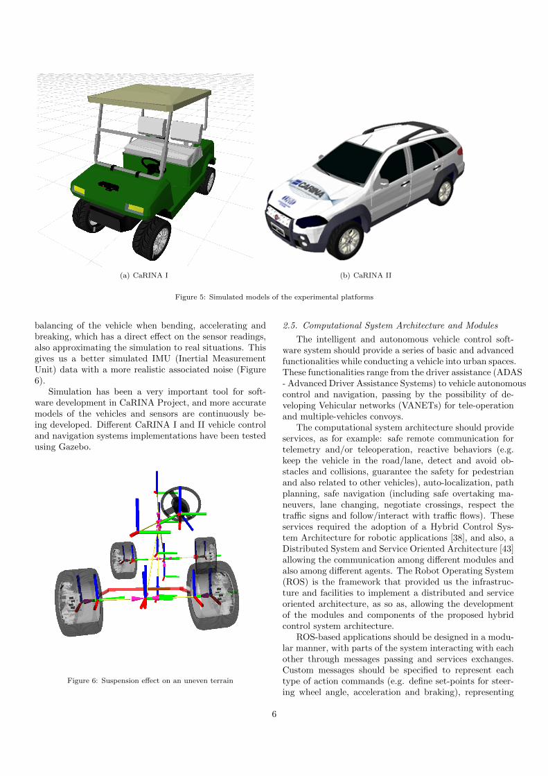
(a) CaRINA I (b) CaRINA II
Figure 5: Simulated models of the experimental platforms
balancing of the vehicle when bending, accelerating andbreaking, which has a direct effect on the sensor readings,also approximating the simulation to real situations. Thisgives us a better simulated IMU (Inertial MeasurementUnit) data with a more realistic associated noise (Figure6).
Simulation has been a very important tool for soft-ware development in CaRINA Project, and more accuratemodels of the vehicles and sensors are continuously be-ing developed. Different CaRINA I and II vehicle controland navigation systems implementations have been testedusing Gazebo.
Figure 6: Suspension effect on an uneven terrain
2.5. Computational System Architecture and Modules
The intelligent and autonomous vehicle control soft-ware system should provide a series of basic and advancedfunctionalities while conducting a vehicle into urban spaces.These functionalities range from the driver assistance (ADAS- Advanced Driver Assistance Systems) to vehicle autonomouscontrol and navigation, passing by the possibility of de-veloping Vehicular networks (VANETs) for tele-operationand multiple-vehicles convoys.
The computational system architecture should provideservices, as for example: safe remote communication fortelemetry and/or teleoperation, reactive behaviors (e.g.keep the vehicle in the road/lane, detect and avoid ob-stacles and collisions, guarantee the safety for pedestrianand also related to other vehicles), auto-localization, pathplanning, safe navigation (including safe overtaking ma-neuvers, lane changing, negotiate crossings, respect thetraffic signs and follow/interact with traffic flows). Theseservices required the adoption of a Hybrid Control Sys-tem Architecture for robotic applications [38], and also, aDistributed System and Service Oriented Architecture [43]allowing the communication among different modules andalso among different agents. The Robot Operating System(ROS) is the framework that provided us the infrastruc-ture and facilities to implement a distributed and serviceoriented architecture, as so as, allowing the developmentof the modules and components of the proposed hybridcontrol system architecture.
ROS-based applications should be designed in a modu-lar manner, with parts of the system interacting with eachother through messages passing and services exchanges.Custom messages should be specified to represent eachtype of action commands (e.g. define set-points for steer-ing wheel angle, acceleration and braking), representing
6
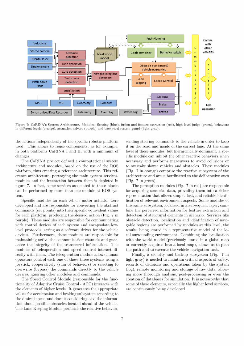
Figure 7: CaRINA′s System Architecture. Modules: Sensing (blue), fusion and feature extraction (red), high level judge (green), behaviorsin different levels (orange), actuation drivers (purple) and backward system guard (light gray).
the actions independently of the specific robotic platformused. This allows to reuse components, as for example,in both platforms CaRINA I and II, with a minimum ofchanges.
The CaRINA project defined a computational systemarchitecture and modules, based on the use of the ROSplatform, thus creating a reference architecture. This ref-erence architecture, portraying the main system services-modules and the interaction between them is depicted infigure 7. In fact, some services associated to these blockscan be performed by more than one module at ROS sys-tem.
Specific modules for each vehicle motor actuator weredeveloped and are responsible for converting the abstractcommands (set points) into their specific equivalent valuesfor each platform, producing the desired action (Fig. 7 inpurple). These modules are responsible for communicatingwith control devices of each system and encapsulate low-level protocols, acting as a software driver for the vehicledevices. Furthermore, these modules are responsible formaintaining active the communication channels and guar-antee the integrity of the transferred information. Themodules of teleoperation and speed control interact di-rectly with them. The teleoperation module allows humanoperators control each one of these three systems using ajoystick, cooperatively (sum of behaviors) or selecting tooverwrite (bypass) the commands directly to the vehicledevices, ignoring other modules and commands.
The Speed Control Module (responsible for the func-tionality of Adaptive Cruise Control - ACC) interacts withthe elements of higher levels. It generates the appropriatevalues for acceleration and braking subsystem according tothe desired speed and does it considering also the informa-tion about possible obstacles located ahead of the vehicle.The Lane Keeping Module performs the reactive behavior,
sending steering commands to the vehicle in order to keepit on the road and inside of the correct lane. At the samelevel of these modules, but hierarchically dominant, a spe-cific module can inhibit the other reactive behaviors whennecessary and performs maneuvers to avoid collisions orto overtake slower vehicles and obstacles. These modules(Fig. 7 in orange) comprise the reactive subsystem of thearchitecture and are subordinated to the deliberative ones(Fig. 7 in green).
The perception modules (Fig. 7 in red) are responsiblefor acquiring sensorial data, providing them into a richerrepresentation that allows simple, fast, and reliable identi-fication of relevant environment aspects. Some modules ofthis same subsystem, localized in a subsequent layer, com-bine the perceived information for feature extraction anddetection of structural elements in scenario. Services likeobstacle detection, localization and identification of navi-gable regions are performed by modules at this level, theresults being stored in a representative model of the lo-cal surrounding environment. Combining the localizationwith the world model (previously stored in a global mapor currently acquired into a local map), allows us to planthe path and to execute the vehicle navigation task.
Finally, a security and backup subsystem (Fig. 7 inlight gray) is needed to maintain critical aspects of safety,records of decisions and operations taken by the system(log), remote monitoring and storage of raw data, allow-ing more thorough analysis, post-processing or even thecreation of databases for simulation. It is noteworthy thatsome of these elements, especially the higher level services,are continuously being developed.
7
3. Navigation Systems
We have developed four navigation systems based onthe proposed architecture. Though these systems use dif-ferent approaches, they originate from the proposed archi-tecture and exemplify the variety of navigation systemsthat can be developed depending on the application andavailable sensors. This section presents the navigation sys-tems and their experimental results.
The first two systems presented in this section relymostly on computer vision for maintaining the vehicle onthe navigable lane and for avoiding obstacles. The navi-gation in these systems is guided by a destination pointor sequence of waypoints (GPS coordinates). The othertwo systems rely on a representation of the environmentfor planning and navigation. One of the systems uses atopologic map for navigation, and the other uses a plan-ning method that considers the model of the vehicle tofind suitable maneuvers for obstacle avoidance on an oc-cupancy metric map.
3.1. Supervised Learning for Autonomous Navigation
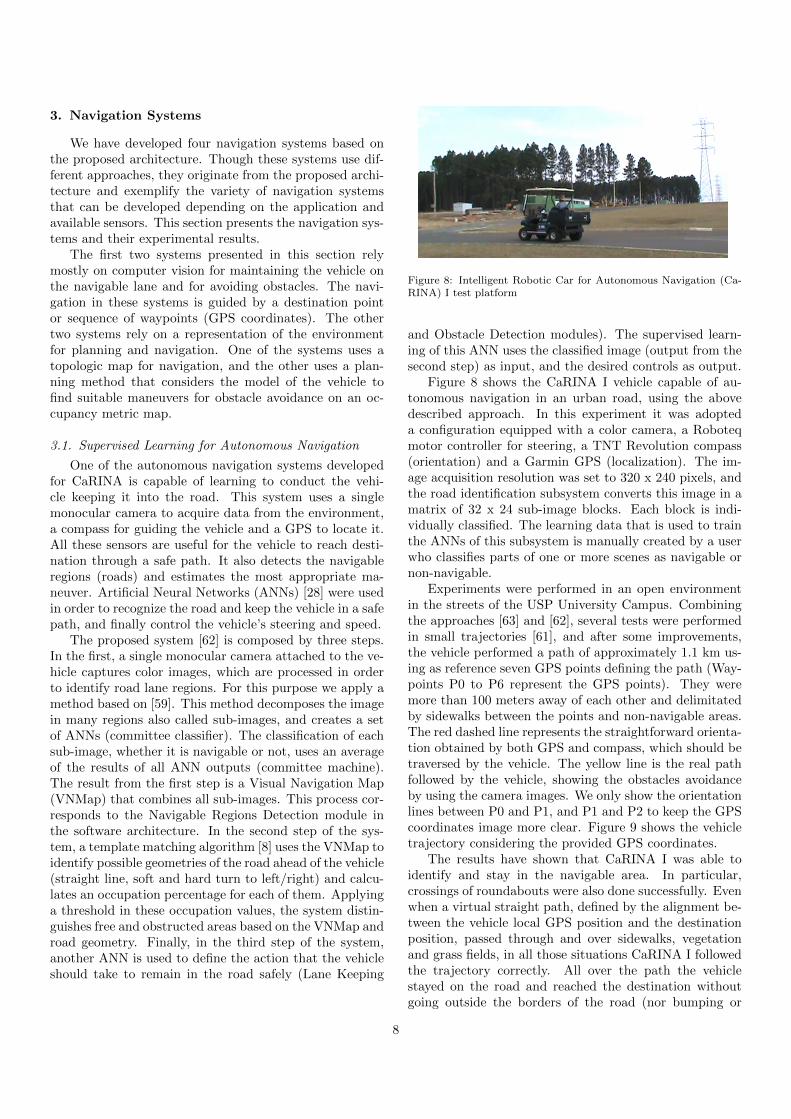
One of the autonomous navigation systems developedfor CaRINA is capable of learning to conduct the vehi-cle keeping it into the road. This system uses a singlemonocular camera to acquire data from the environment,a compass for guiding the vehicle and a GPS to locate it.All these sensors are useful for the vehicle to reach desti-nation through a safe path. It also detects the navigableregions (roads) and estimates the most appropriate ma-neuver. Artificial Neural Networks (ANNs) [28] were usedin order to recognize the road and keep the vehicle in a safepath, and finally control the vehicle’s steering and speed.
The proposed system [62] is composed by three steps.In the first, a single monocular camera attached to the ve-hicle captures color images, which are processed in orderto identify road lane regions. For this purpose we apply amethod based on [59]. This method decomposes the imagein many regions also called sub-images, and creates a setof ANNs (committee classifier). The classification of eachsub-image, whether it is navigable or not, uses an averageof the results of all ANN outputs (committee machine).The result from the first step is a Visual Navigation Map(VNMap) that combines all sub-images. This process cor-responds to the Navigable Regions Detection module inthe software architecture. In the second step of the sys-tem, a template matching algorithm [8] uses the VNMap toidentify possible geometries of the road ahead of the vehicle(straight line, soft and hard turn to left/right) and calcu-lates an occupation percentage for each of them. Applyinga threshold in these occupation values, the system distin-guishes free and obstructed areas based on the VNMap androad geometry. Finally, in the third step of the system,another ANN is used to define the action that the vehicleshould take to remain in the road safely (Lane Keeping
Figure 8: Intelligent Robotic Car for Autonomous Navigation (Ca-RINA) I test platform
and Obstacle Detection modules). The supervised learn-ing of this ANN uses the classified image (output from thesecond step) as input, and the desired controls as output.
Figure 8 shows the CaRINA I vehicle capable of au-tonomous navigation in an urban road, using the abovedescribed approach. In this experiment it was adopteda configuration equipped with a color camera, a Roboteqmotor controller for steering, a TNT Revolution compass(orientation) and a Garmin GPS (localization). The im-age acquisition resolution was set to 320 x 240 pixels, andthe road identification subsystem converts this image in amatrix of 32 x 24 sub-image blocks. Each block is indi-vidually classified. The learning data that is used to trainthe ANNs of this subsystem is manually created by a userwho classifies parts of one or more scenes as navigable ornon-navigable.
Experiments were performed in an open environmentin the streets of the USP University Campus. Combiningthe approaches [63] and [62], several tests were performedin small trajectories [61], and after some improvements,the vehicle performed a path of approximately 1.1 km us-ing as reference seven GPS points defining the path (Way-points P0 to P6 represent the GPS points). They weremore than 100 meters away of each other and delimitatedby sidewalks between the points and non-navigable areas.The red dashed line represents the straightforward orienta-tion obtained by both GPS and compass, which should betraversed by the vehicle. The yellow line is the real pathfollowed by the vehicle, showing the obstacles avoidanceby using the camera images. We only show the orientationlines between P0 and P1, and P1 and P2 to keep the GPScoordinates image more clear. Figure 9 shows the vehicletrajectory considering the provided GPS coordinates.
The results have shown that CaRINA I was able toidentify and stay in the navigable area. In particular,crossings of roundabouts were also done successfully. Evenwhen a virtual straight path, defined by the alignment be-tween the vehicle local GPS position and the destinationposition, passed through and over sidewalks, vegetationand grass fields, in all those situations CaRINA I followedthe trajectory correctly. All over the path the vehiclestayed on the road and reached the destination withoutgoing outside the borders of the road (nor bumping or
8
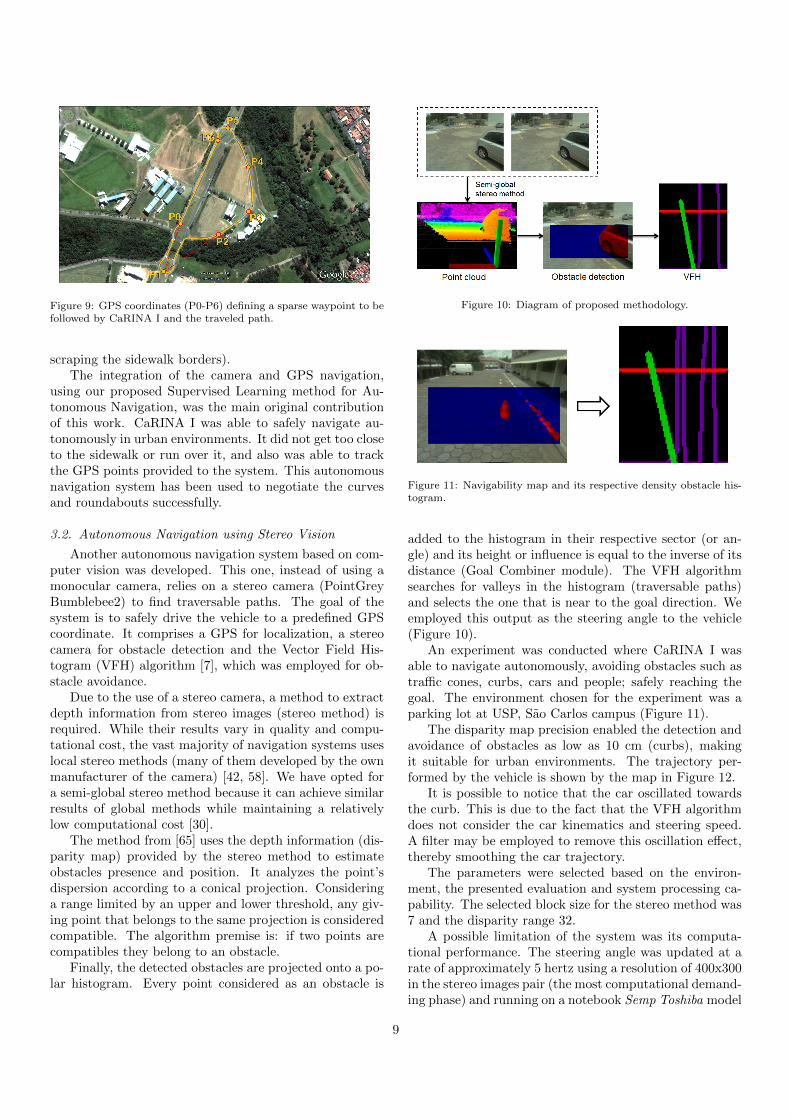
Figure 9: GPS coordinates (P0-P6) defining a sparse waypoint to befollowed by CaRINA I and the traveled path.
scraping the sidewalk borders).The integration of the camera and GPS navigation,
using our proposed Supervised Learning method for Au-tonomous Navigation, was the main original contributionof this work. CaRINA I was able to safely navigate au-tonomously in urban environments. It did not get too closeto the sidewalk or run over it, and also was able to trackthe GPS points provided to the system. This autonomousnavigation system has been used to negotiate the curvesand roundabouts successfully.
3.2. Autonomous Navigation using Stereo Vision
Another autonomous navigation system based on com-puter vision was developed. This one, instead of using amonocular camera, relies on a stereo camera (PointGreyBumblebee2) to find traversable paths. The goal of thesystem is to safely drive the vehicle to a predefined GPScoordinate. It comprises a GPS for localization, a stereocamera for obstacle detection and the Vector Field His-togram (VFH) algorithm [7], which was employed for ob-stacle avoidance.
Due to the use of a stereo camera, a method to extractdepth information from stereo images (stereo method) isrequired. While their results vary in quality and compu-tational cost, the vast majority of navigation systems useslocal stereo methods (many of them developed by the ownmanufacturer of the camera) [42, 58]. We have opted fora semi-global stereo method because it can achieve similarresults of global methods while maintaining a relativelylow computational cost [30].
The method from [65] uses the depth information (dis-parity map) provided by the stereo method to estimateobstacles presence and position. It analyzes the point’sdispersion according to a conical projection. Consideringa range limited by an upper and lower threshold, any giv-ing point that belongs to the same projection is consideredcompatible. The algorithm premise is: if two points arecompatibles they belong to an obstacle.
Finally, the detected obstacles are projected onto a po-lar histogram. Every point considered as an obstacle is
Figure 10: Diagram of proposed methodology.
Figure 11: Navigability map and its respective density obstacle his-togram.
added to the histogram in their respective sector (or an-gle) and its height or influence is equal to the inverse of itsdistance (Goal Combiner module). The VFH algorithmsearches for valleys in the histogram (traversable paths)and selects the one that is near to the goal direction. Weemployed this output as the steering angle to the vehicle(Figure 10).
An experiment was conducted where CaRINA I wasable to navigate autonomously, avoiding obstacles such astraffic cones, curbs, cars and people; safely reaching thegoal. The environment chosen for the experiment was aparking lot at USP, Sao Carlos campus (Figure 11).
The disparity map precision enabled the detection andavoidance of obstacles as low as 10 cm (curbs), makingit suitable for urban environments. The trajectory per-formed by the vehicle is shown by the map in Figure 12.
It is possible to notice that the car oscillated towardsthe curb. This is due to the fact that the VFH algorithmdoes not consider the car kinematics and steering speed.A filter may be employed to remove this oscillation effect,thereby smoothing the car trajectory.
The parameters were selected based on the environ-ment, the presented evaluation and system processing ca-pability. The selected block size for the stereo method was7 and the disparity range 32.
A possible limitation of the system was its computa-tional performance. The steering angle was updated at arate of approximately 5 hertz using a resolution of 400x300in the stereo images pair (the most computational demand-ing phase) and running on a notebook Semp Toshiba model
9
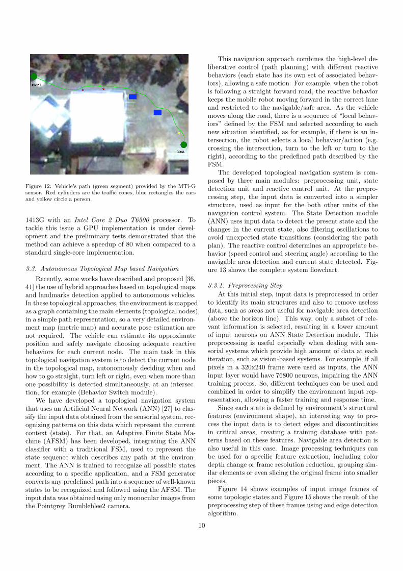
Figure 12: Vehicle’s path (green segment) provided by the MTi-Gsensor. Red cylinders are the traffic cones, blue rectangles the carsand yellow circle a person.
1413G with an Intel Core 2 Duo T6500 processor. Totackle this issue a GPU implementation is under devel-opment and the preliminary tests demonstrated that themethod can achieve a speedup of 80 when compared to astandard single-core implementation.
3.3. Autonomous Topological Map based Navigation
Recently, some works have described and proposed [36,41] the use of hybrid approaches based on topological mapsand landmarks detection applied to autonomous vehicles.In these topological approaches, the environment is mappedas a graph containing the main elements (topological nodes),in a simple path representation, so a very detailed environ-ment map (metric map) and accurate pose estimation arenot required. The vehicle can estimate its approximateposition and safely navigate choosing adequate reactivebehaviors for each current node. The main task in thistopological navigation system is to detect the current nodein the topological map, autonomously deciding when andhow to go straight, turn left or right, even when more thanone possibility is detected simultaneously, at an intersec-tion, for example (Behavior Switch module).
We have developed a topological navigation systemthat uses an Artificial Neural Network (ANN) [27] to clas-sify the input data obtained from the sensorial system, rec-ognizing patterns on this data which represent the currentcontext (state). For that, an Adaptive Finite State Ma-chine (AFSM) has been developed, integrating the ANNclassifier with a traditional FSM, used to represent thestate sequence which describes any path at the environ-ment. The ANN is trained to recognize all possible statesaccording to a specific application, and a FSM generatorconverts any predefined path into a sequence of well-knownstates to be recognized and followed using the AFSM. Theinput data was obtained using only monocular images fromthe Pointgrey Bumbleblee2 camera.
This navigation approach combines the high-level de-liberative control (path planning) with different reactivebehaviors (each state has its own set of associated behav-iors), allowing a safe motion. For example, when the robotis following a straight forward road, the reactive behaviorkeeps the mobile robot moving forward in the correct laneand restricted to the navigable/safe area. As the vehiclemoves along the road, there is a sequence of “local behav-iors” defined by the FSM and selected according to eachnew situation identified, as for example, if there is an in-tersection, the robot selects a local behavior/action (e.g.crossing the intersection, turn to the left or turn to theright), according to the predefined path described by theFSM.
The developed topological navigation system is com-posed by three main modules: preprocessing unit, statedetection unit and reactive control unit. At the prepro-cessing step, the input data is converted into a simplerstructure, used as input for the both other units of thenavigation control system. The State Detection module(ANN) uses input data to detect the present state and thechanges in the current state, also filtering oscillations toavoid unexpected state transitions (considering the pathplan). The reactive control determines an appropriate be-havior (speed control and steering angle) according to thenavigable area detection and current state detected. Fig-ure 13 shows the complete system flowchart.
3.3.1. Preprocessing Step
At this initial step, input data is preprocessed in orderto identify its main structures and also to remove uselessdata, such as areas not useful for navigable area detection(above the horizon line). This way, only a subset of rele-vant information is selected, resulting in a lower amountof input neurons on ANN State Detection module. Thispreprocessing is useful especially when dealing with sen-sorial systems which provide high amount of data at eachiteration, such as vision-based systems. For example, if allpixels in a 320x240 frame were used as inputs, the ANNinput layer would have 76800 neurons, impairing the ANNtraining process. So, different techniques can be used andcombined in order to simplify the environment input rep-resentation, allowing a faster training and response time.
Since each state is defined by environment’s structuralfeatures (environment shape), an interesting way to pro-cess the input data is to detect edges and discontinuitiesin critical areas, creating a training database with pat-terns based on these features. Navigable area detection isalso useful in this case. Image processing techniques canbe used for a specific feature extraction, including colordepth change or frame resolution reduction, grouping sim-ilar elements or even slicing the original frame into smallerpieces.
Figure 14 shows examples of input image frames ofsome topologic states and Figure 15 shows the result of thepreprocessing step of these frames using and edge detectionalgorithm.
10
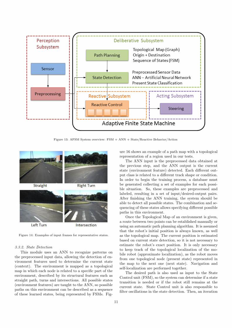
Figure 13: AFSM System overview: FSM + ANN + State/Reactive Behavior/Action
Figure 14: Examples of input frames for representative states.
3.3.2. State Detection
This module uses an ANN to recognize patterns onthe preprocessed input data, allowing the detection of en-vironment features used to determine the current state(context). The environment is mapped as a topologicalmap in which each node is related to a specific part of theenvironment, described by its structural features such asstraight path, turns and intersections. All possible states(environment features) are taught to the ANN, so possiblepaths on this environment can be described as a sequenceof these learned states, being represented by FSMs. Fig-
ure 16 shows an example of a path map with a topologicalrepresentation of a region used in our tests.
The ANN input is the preprocessed data obtained atthe previous step, and the ANN output is the currentstate (environment feature) detected. Each different out-put class is related to a different track shape or condition.In order to begin the training process, a database mustbe generated collecting a set of examples for each possi-ble situation. So, these examples are preprocessed andlabeled, resulting in a set of input/desired-output pairs.After finishing the ANN training, the system should beable to detect all possible states. The combination and se-quencing of these states allows specifying different possiblepaths in this environment.
Once the Topological Map of an environment is given,a route between two points can be established manually orusing an automatic path planning algorithm. It is assumedthat the robot’s initial position is always known, as wellas the topological map. The current position is estimatedbased on current state detection, so it is not necessary toestimate the robot’s exact position. It is only necessaryto keep track of the topological localization of the mo-bile robot (approximate localization), as the robot movesfrom one topological node (present state) represented inthe map to the next one (next state). Navigation andself-localization are performed together.
The desired path is also used as input to the StateControl unit (FSM), so the system can determine if a statetransition is needed or if the robot still remains at thecurrent state. State Control unit is also responsible tofilter oscillations in the state detection. Then, an iteration
11
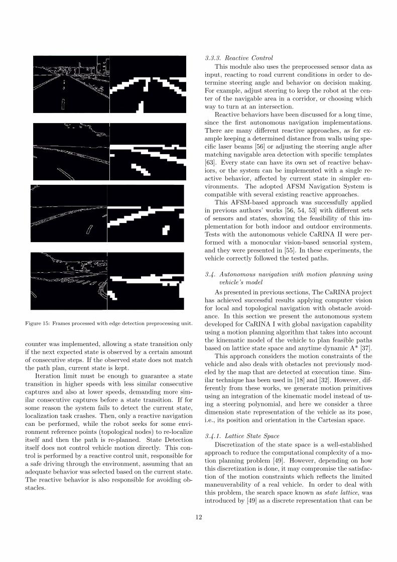
Figure 15: Frames processed with edge detection preprocessing unit.
counter was implemented, allowing a state transition onlyif the next expected state is observed by a certain amountof consecutive steps. If the observed state does not matchthe path plan, current state is kept.
Iteration limit must be enough to guarantee a statetransition in higher speeds with less similar consecutivecaptures and also at lower speeds, demanding more sim-ilar consecutive captures before a state transition. If forsome reason the system fails to detect the current state,localization task crashes. Then, only a reactive navigationcan be performed, while the robot seeks for some envi-ronment reference points (topological nodes) to re-localizeitself and then the path is re-planned. State Detectionitself does not control vehicle motion directly. This con-trol is performed by a reactive control unit, responsible fora safe driving through the environment, assuming that anadequate behavior was selected based on the current state.The reactive behavior is also responsible for avoiding ob-stacles.
3.3.3. Reactive Control
This module also uses the preprocessed sensor data asinput, reacting to road current conditions in order to de-termine steering angle and behavior on decision making.For example, adjust steering to keep the robot at the cen-ter of the navigable area in a corridor, or choosing whichway to turn at an intersection.
Reactive behaviors have been discussed for a long time,since the first autonomous navigation implementations.There are many different reactive approaches, as for ex-ample keeping a determined distance from walls using spe-cific laser beams [56] or adjusting the steering angle aftermatching navigable area detection with specific templates[63]. Every state can have its own set of reactive behav-iors, or the system can be implemented with a single re-active behavior, affected by current state in simpler en-vironments. The adopted AFSM Navigation System iscompatible with several existing reactive approaches.
This AFSM-based approach was successfully appliedin previous authors’ works [56, 54, 53] with different setsof sensors and states, showing the feasibility of this im-plementation for both indoor and outdoor environments.Tests with the autonomous vehicle CaRINA II were per-formed with a monocular vision-based sensorial system,and they were presented in [55]. In these experiments, thevehicle correctly followed the tested paths.
3.4. Autonomous navigation with motion planning usingvehicle’s model
As presented in previous sections, The CaRINA projecthas achieved successful results applying computer visionfor local and topological navigation with obstacle avoid-ance. In this section we present the autonomous systemdeveloped for CaRINA I with global navigation capabilityusing a motion planning algorithm that takes into accountthe kinematic model of the vehicle to plan feasible pathsbased on lattice state space and anytime dynamic A* [37].
This approach considers the motion constraints of thevehicle and also deals with obstacles not previously mod-eled by the map that are detected at execution time. Sim-ilar technique has been used in [18] and [32]. However, dif-ferently from these works, we generate motion primitivesusing an integration of the kinematic model instead of us-ing a steering polynomial, and here we consider a threedimension state representation of the vehicle as its pose,i.e., its position and orientation in the Cartesian space.
3.4.1. Lattice State Space
Discretization of the state space is a well-establishedapproach to reduce the computational complexity of a mo-tion planning problem [49]. However, depending on howthis discretization is done, it may compromise the satisfac-tion of the motion constraints which reflects the limitedmaneuverability of a real vehicle. In order to deal withthis problem, the search space known as state lattice, wasintroduced by [49] as a discrete representation that can be
12
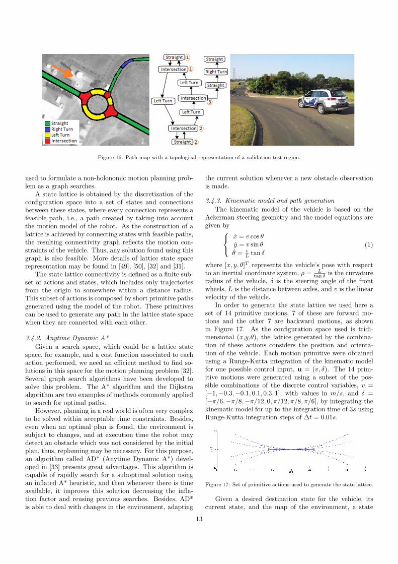
Figure 16: Path map with a topological representation of a validation test region.
used to formulate a non-holonomic motion planning prob-lem as a graph searches.
A state lattice is obtained by the discretization of theconfiguration space into a set of states and connectionsbetween these states, where every connection represents afeasible path, i.e., a path created by taking into accountthe motion model of the robot. As the construction of alattice is achieved by connecting states with feasible paths,the resulting connectivity graph reflects the motion con-straints of the vehicle. Thus, any solution found using thisgraph is also feasible. More details of lattice state spacerepresentation may be found in [49], [50], [32] and [31].
The state lattice connectivity is defined as a finite sub-set of actions and states, which includes only trajectoriesfrom the origin to somewhere within a distance radius.This subset of actions is composed by short primitive pathsgenerated using the model of the robot. These primitivescan be used to generate any path in the lattice state spacewhen they are connected with each other.
3.4.2. Anytime Dynamic A*
Given a search space, which could be a lattice statespace, for example, and a cost function associated to eachaction performed, we need an efficient method to find so-lutions in this space for the motion planning problem [32].Several graph search algorithms have been developed tosolve this problem. The A* algorithm and the Dijkstraalgorithm are two examples of methods commonly appliedto search for optimal paths.
However, planning in a real world is often very complexto be solved within acceptable time constraints. Besides,even when an optimal plan is found, the environment issubject to changes, and at execution time the robot maydetect an obstacle which was not considered by the initialplan, thus, replanning may be necessary. For this purpose,an algorithm called AD* (Anytime Dynamic A*) devel-oped in [33] presents great advantages. This algorithm iscapable of rapidly search for a suboptimal solution usingan inflated A* heuristic, and then whenever there is timeavailable, it improves this solution decreasing the infla-tion factor and reusing previous searches. Besides, AD*is able to deal with changes in the environment, adapting
the current solution whenever a new obstacle observationis made.
3.4.3. Kinematic model and path generation
The kinematic model of the vehicle is based on theAckerman steering geometry and the model equations aregiven by
x = v cos θy = v sin θ
θ = vL tan δ
(1)
where [x, y, θ]T represents the vehicle’s pose with respectto an inertial coordinate system, ρ = L
tan δ is the curvatureradius of the vehicle, δ is the steering angle of the frontwheels, L is the distance between axles, and v is the linearvelocity of the vehicle.
In order to generate the state lattice we used here aset of 14 primitive motions, 7 of these are forward mo-tions and the other 7 are backward motions, as shownin Figure 17. As the configuration space used is tridi-mensional (x,y,θ), the lattice generated by the combina-tion of these actions considers the position and orienta-tion of the vehicle. Each motion primitive were obtainedusing a Runge-Kutta integration of the kinematic modelfor one possible control input, u = (v, δ). The 14 prim-itive motions were generated using a subset of the pos-sible combinations of the discrete control variables, v =[−1,−0.3,−0.1, 0.1, 0.3, 1], with values in m/s, and δ =[−π/6,−π/8,−π/12, 0, π/12, π/8, π/6], by integrating thekinematic model for up to the integration time of 3s usingRunge-Kutta integration steps of ∆t = 0.01s.
Figure 17: Set of primitive actions used to generate the state lattice.
Given a desired destination state for the vehicle, itscurrent state, and the map of the environment, a state
13
lattice is created using these motion primitives, and a pathis found searching the lattice using the AD* algorithm.
3.4.4. Localization
In this navigation system, the vehicle uses three laserbased sensors mounted one in the front of the vehicle andthe other two mounted at the rear left and rear right cor-ners to detect obstacles and to map the environment. Thesignal of these three sensors are integrated and we apply anICP (Iterative Closest / Corresponding Point) [13] basedalgorithm for pose estimation. The purpose of ICP is find-ing a geometric transformation between two point cloudsobtained from the laser sensors in different time frames.A Kalman filter combines the pose estimation provided bythe three laser sensors with the vehicle’s odometry systemand an IMU (Inertial Measurement Unit) positioned in thecenter of rear axle.
3.4.5. Results
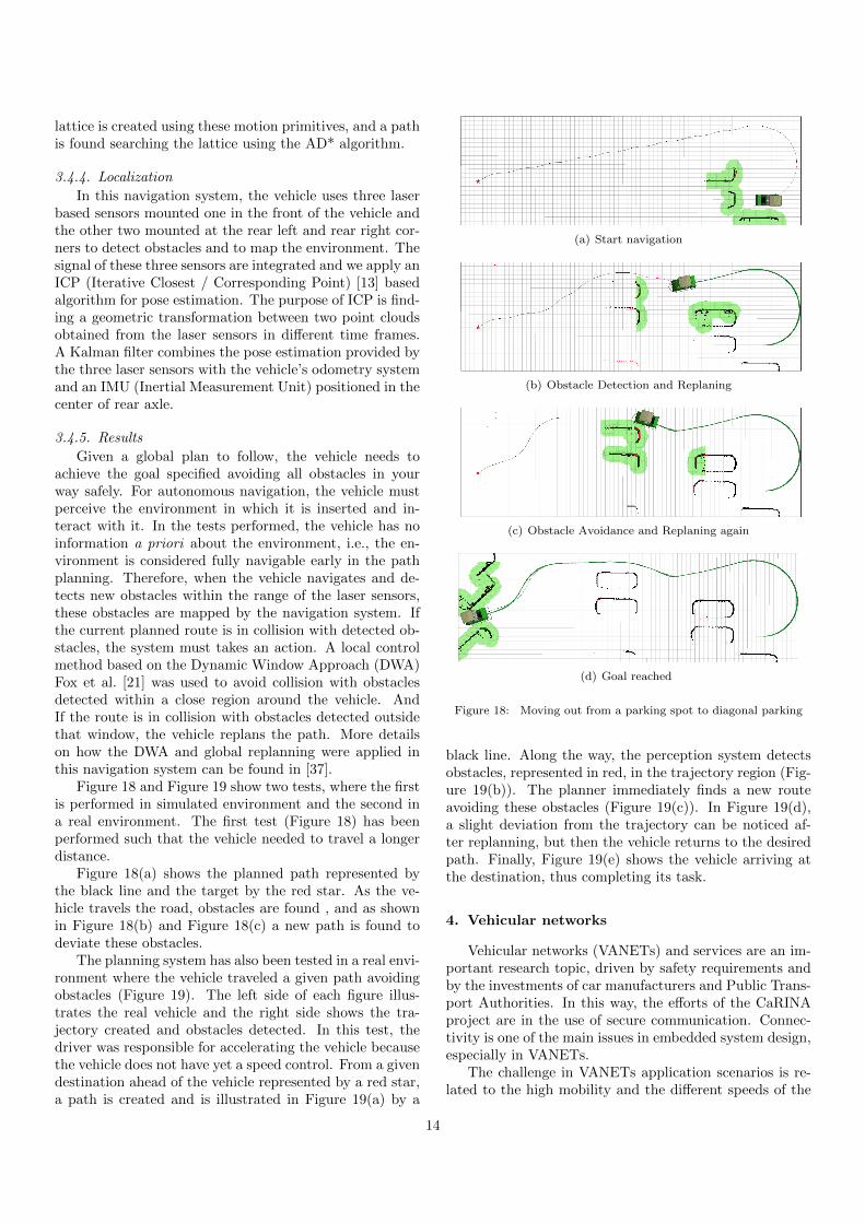
Given a global plan to follow, the vehicle needs toachieve the goal specified avoiding all obstacles in yourway safely. For autonomous navigation, the vehicle mustperceive the environment in which it is inserted and in-teract with it. In the tests performed, the vehicle has noinformation a priori about the environment, i.e., the en-vironment is considered fully navigable early in the pathplanning. Therefore, when the vehicle navigates and de-tects new obstacles within the range of the laser sensors,these obstacles are mapped by the navigation system. Ifthe current planned route is in collision with detected ob-stacles, the system must takes an action. A local controlmethod based on the Dynamic Window Approach (DWA)Fox et al. [21] was used to avoid collision with obstaclesdetected within a close region around the vehicle. AndIf the route is in collision with obstacles detected outsidethat window, the vehicle replans the path. More detailson how the DWA and global replanning were applied inthis navigation system can be found in [37].
Figure 18 and Figure 19 show two tests, where the firstis performed in simulated environment and the second ina real environment. The first test (Figure 18) has beenperformed such that the vehicle needed to travel a longerdistance.
Figure 18(a) shows the planned path represented bythe black line and the target by the red star. As the ve-hicle travels the road, obstacles are found , and as shownin Figure 18(b) and Figure 18(c) a new path is found todeviate these obstacles.
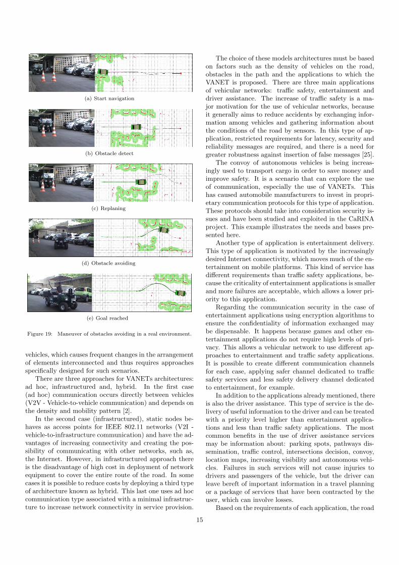
The planning system has also been tested in a real envi-ronment where the vehicle traveled a given path avoidingobstacles (Figure 19). The left side of each figure illus-trates the real vehicle and the right side shows the tra-jectory created and obstacles detected. In this test, thedriver was responsible for accelerating the vehicle becausethe vehicle does not have yet a speed control. From a givendestination ahead of the vehicle represented by a red star,a path is created and is illustrated in Figure 19(a) by a
(a) Start navigation
(b) Obstacle Detection and Replaning
(c) Obstacle Avoidance and Replaning again
(d) Goal reached
Figure 18: Moving out from a parking spot to diagonal parking
black line. Along the way, the perception system detectsobstacles, represented in red, in the trajectory region (Fig-ure 19(b)). The planner immediately finds a new routeavoiding these obstacles (Figure 19(c)). In Figure 19(d),a slight deviation from the trajectory can be noticed af-ter replanning, but then the vehicle returns to the desiredpath. Finally, Figure 19(e) shows the vehicle arriving atthe destination, thus completing its task.
4. Vehicular networks
Vehicular networks (VANETs) and services are an im-portant research topic, driven by safety requirements andby the investments of car manufacturers and Public Trans-port Authorities. In this way, the efforts of the CaRINAproject are in the use of secure communication. Connec-tivity is one of the main issues in embedded system design,especially in VANETs.
The challenge in VANETs application scenarios is re-lated to the high mobility and the different speeds of the
14
(a) Start navigation
(b) Obstacle detect
(c) Replaning
(d) Obstacle avoiding
(e) Goal reached
Figure 19: Maneuver of obstacles avoiding in a real environment.
vehicles, which causes frequent changes in the arrangementof elements interconnected and thus requires approachesspecifically designed for such scenarios.
There are three approaches for VANETs architectures:ad hoc, infrastructured and, hybrid. In the first case(ad hoc) communication occurs directly between vehicles(V2V - Vehicle-to-vehicle communication) and depends onthe density and mobility pattern [2].
In the second case (infrastructured), static nodes be-haves as access points for IEEE 802.11 networks (V2I -vehicle-to-infrastructure communication) and have the ad-vantages of increasing connectivity and creating the pos-sibility of communicating with other networks, such as,the Internet. However, in infrastructured approach thereis the disadvantage of high cost in deployment of networkequipment to cover the entire route of the road. In somecases it is possible to reduce costs by deploying a third typeof architecture known as hybrid. This last one uses ad hoccommunication type associated with a minimal infrastruc-ture to increase network connectivity in service provision.
The choice of these models architectures must be basedon factors such as the density of vehicles on the road,obstacles in the path and the applications to which theVANET is proposed. There are three main applicationsof vehicular networks: traffic safety, entertainment anddriver assistance. The increase of traffic safety is a ma-jor motivation for the use of vehicular networks, becauseit generally aims to reduce accidents by exchanging infor-mation among vehicles and gathering information aboutthe conditions of the road by sensors. In this type of ap-plication, restricted requirements for latency, security andreliability messages are required, and there is a need forgreater robustness against insertion of false messages [25].
The convoy of autonomous vehicles is being increas-ingly used to transport cargo in order to save money andimprove safety. It is a scenario that can explore the useof communication, especially the use of VANETs. Thishas caused automobile manufacturers to invest in propri-etary communication protocols for this type of application.These protocols should take into consideration security is-sues and have been studied and exploited in the CaRINAproject. This example illustrates the needs and bases pre-sented here.
Another type of application is entertainment delivery.This type of application is motivated by the increasinglydesired Internet connectivity, which moves much of the en-tertainment on mobile platforms. This kind of service hasdifferent requirements than traffic safety applications, be-cause the criticality of entertainment applications is smallerand more failures are acceptable, which allows a lower pri-ority to this application.
Regarding the communication security in the case ofentertainment applications using encryption algorithms toensure the confidentiality of information exchanged maybe dispensable. It happens because games and other en-tertainment applications do not require high levels of pri-vacy. This allows a vehicular network to use different ap-proaches to entertainment and traffic safety applications.It is possible to create different communication channelsfor each case, applying safer channel dedicated to trafficsafety services and less safety delivery channel dedicatedto entertainment, for example.
In addition to the applications already mentioned, thereis also the driver assistance. This type of service is the de-livery of useful information to the driver and can be treatedwith a priority level higher than entertainment applica-tions and less than traffic safety applications. The mostcommon benefits in the use of driver assistance servicesmay be information about: parking spots, pathways dis-semination, traffic control, intersections decision, convoy,location maps, increasing visibility and autonomous vehi-cles. Failures in such services will not cause injuries todrivers and passengers of the vehicle, but the driver canleave bereft of important information in a travel planningor a package of services that have been contracted by theuser, which can involve losses.
Based on the requirements of each application, the road
15
conditions where a VANET will be implemented and theservices it intends to offer for drivers and passengers, gen-erates a plan for a vehicular and better defines the archi-tecture to be adopted. Subsequently, it sets up the routingalgorithms best suited for the case, taking into considera-tion once again, the requirements posed.
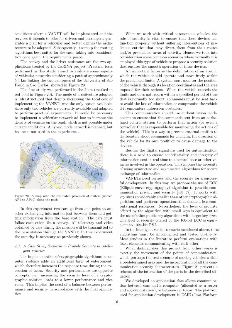
The convoy and the driver assistance are the two ap-plications treated by the CaRINA project. Practical testsperformed in this study aimed to evaluate some aspectsof vehicular networks considering a path of approximately5.4 km linking the two campuses of the University of SaoPaulo in Sao Carlos, showed in Figure 20.
The first study was performed in the 2 km (marked inred bold in Figure 20). The mode of architecture adoptedis infrastructured that despite increasing the total cost ofimplementing the VANET, was the only option available,since only two vehicles are currently available and adaptedto perform practical experiments. It would be necessaryto implement a vehicular network ad hoc to increase thedensity of vehicles on the road, which is not possible undercurrent conditions. A hybrid mode network is planned, buthas been not used in the experiments.
Figure 20: A map with the estimated provision of routers (namedAP1 to AP19) along the path.
In this experiment two cars go from one point to an-other exchanging information just between them and get-ting information from the base station. The cars mustfollow each other like a convoy. All telemetry and videoobtained by cars during the mission will be transmitted tothe base station through the VANET. In this experimentthe security is necessary as previously shown.
4.1. A Case Study Scenario to Provide Security in intelli-gent vehicles
The implementation of cryptographic algorithms in com-puter systems adds an additional layer of enforcement,which therefore increases the response time during the ex-ecution of tasks. Security and performance are oppositeconcepts, i.e. increasing the security level of a crypto-graphic solution leads to a lower performance and viceversa. This implies the need of a balance between perfor-mance and security in accordance with the final applica-tion.
When we work with critical autonomous vehicles, therole of security is vital to ensure that these devices canfunction properly without suffering interventions of ma-licious entities that may divert them from their routesand/or pre-defined areas of activity. Hence, we took intoconsideration some common scenarios where normally it isemployed this type of vehicle to propose a security solutionthat ensures the smooth operation of these devices.
An important factor is the delimitation of an area inwhich the vehicle should operate and move freely withinthe predefined limits. A system must monitor the positionof the vehicle through its location coordinates and the areaimposed for their actions. When the vehicle exceeds thelimits and does not return within a specified period of timethat is normally too short, commands must be sent backto avoid the loss of information or compromise the vehicleif it encounters unforeseen obstacles.
This communication should use authentication mech-anisms to ensure that the commands sent from an autho-rized control station to perform that action (or even acontroller that is responsible for monitoring the actions ofthe vehicle). This is a way to prevent external entities todeliberately shoot commands for changing the direction ofthe vehicle for its own profit or to cause damage to thedevices.
Besides the digital signature used for authentication,there is a need to ensure confidentiality and integrity ofinformation sent in real time to a control base or other ve-hicles involved in the operation. This implies the necessityof using symmetric and asymmetric algorithms for secureexchange of information.
VANETs need privacy and the security for a success-ful development. In this way, we propose the use of ECC(Elliptic curve cryptography) algorithm to provide com-munication privacy and security [48] [57]. It works withkey sizes considerably smaller than other cryptographic al-gorithms and performs operations that demand less com-putational resources. Nevertheless, the level of securityoffered by the algorithm with small keys is equivalent tothe use of other public key algorithms with larger key sizes.The level of security offered by the 160-bit ECC is equiv-alent to 1024-bit RSA.
In the intelligent vehicle scenario mentioned above, thesealgorithms must be implemented and tested on-the-fly.Most studies in the literature perform evaluations withfixed elements communicating with each other.
What distinguishes this project from other works isexactly the movement of the points of communication,which portrays the real scenario of moving vehicles withina predetermined area and the incorporation of all the com-munication security characteristics. Figure 21 presents aschema of the interaction of the parts in the described sit-uation.
We developed an application that allows communica-tion between cars and a computer (allocated as a serverand a ground station), or between car to car. The platformused for application development is J2ME (Java Platform
16
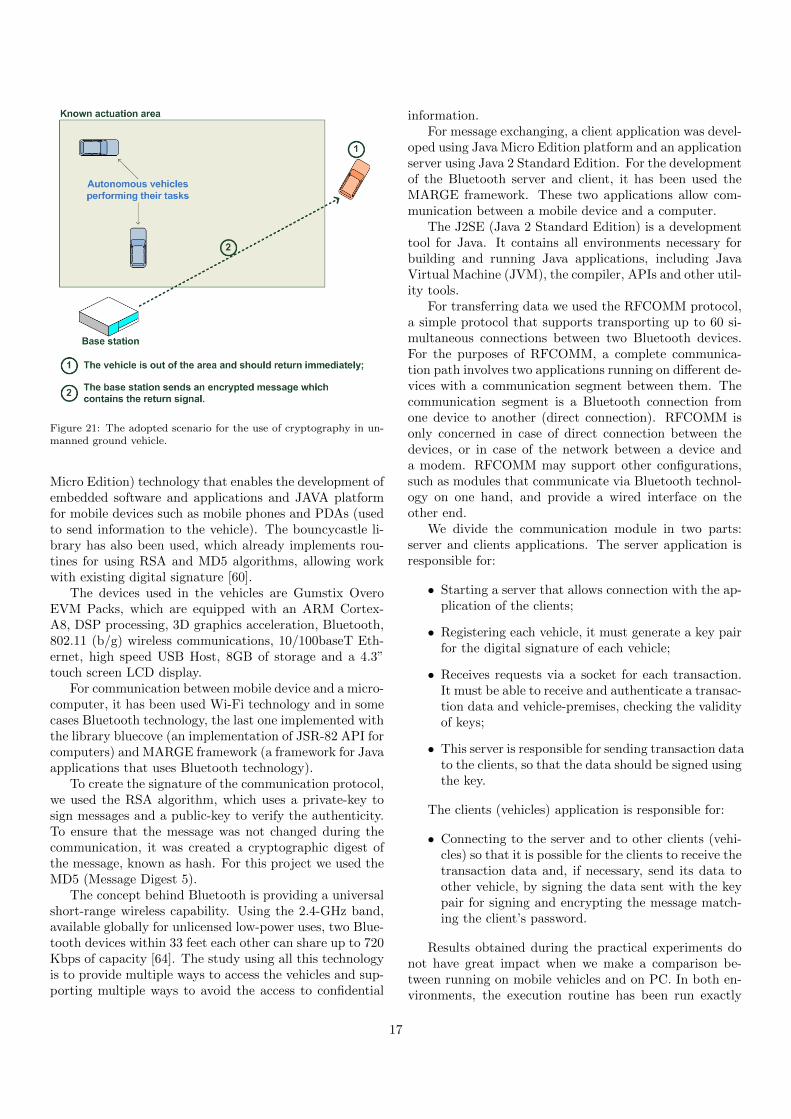
Figure 21: The adopted scenario for the use of cryptography in un-manned ground vehicle.
Micro Edition) technology that enables the development ofembedded software and applications and JAVA platformfor mobile devices such as mobile phones and PDAs (usedto send information to the vehicle). The bouncycastle li-brary has also been used, which already implements rou-tines for using RSA and MD5 algorithms, allowing workwith existing digital signature [60].
The devices used in the vehicles are Gumstix OveroEVM Packs, which are equipped with an ARM Cortex-A8, DSP processing, 3D graphics acceleration, Bluetooth,802.11 (b/g) wireless communications, 10/100baseT Eth-ernet, high speed USB Host, 8GB of storage and a 4.3”touch screen LCD display.
For communication between mobile device and a micro-computer, it has been used Wi-Fi technology and in somecases Bluetooth technology, the last one implemented withthe library bluecove (an implementation of JSR-82 API forcomputers) and MARGE framework (a framework for Javaapplications that uses Bluetooth technology).
To create the signature of the communication protocol,we used the RSA algorithm, which uses a private-key tosign messages and a public-key to verify the authenticity.To ensure that the message was not changed during thecommunication, it was created a cryptographic digest ofthe message, known as hash. For this project we used theMD5 (Message Digest 5).
The concept behind Bluetooth is providing a universalshort-range wireless capability. Using the 2.4-GHz band,available globally for unlicensed low-power uses, two Blue-tooth devices within 33 feet each other can share up to 720Kbps of capacity [64]. The study using all this technologyis to provide multiple ways to access the vehicles and sup-porting multiple ways to avoid the access to confidential
information.For message exchanging, a client application was devel-
oped using Java Micro Edition platform and an applicationserver using Java 2 Standard Edition. For the developmentof the Bluetooth server and client, it has been used theMARGE framework. These two applications allow com-munication between a mobile device and a computer.
The J2SE (Java 2 Standard Edition) is a developmenttool for Java. It contains all environments necessary forbuilding and running Java applications, including JavaVirtual Machine (JVM), the compiler, APIs and other util-ity tools.
For transferring data we used the RFCOMM protocol,a simple protocol that supports transporting up to 60 si-multaneous connections between two Bluetooth devices.For the purposes of RFCOMM, a complete communica-tion path involves two applications running on different de-vices with a communication segment between them. Thecommunication segment is a Bluetooth connection fromone device to another (direct connection). RFCOMM isonly concerned in case of direct connection between thedevices, or in case of the network between a device anda modem. RFCOMM may support other configurations,such as modules that communicate via Bluetooth technol-ogy on one hand, and provide a wired interface on theother end.
We divide the communication module in two parts:server and clients applications. The server application isresponsible for:
• Starting a server that allows connection with the ap-plication of the clients;
• Registering each vehicle, it must generate a key pairfor the digital signature of each vehicle;
• Receives requests via a socket for each transaction.It must be able to receive and authenticate a transac-tion data and vehicle-premises, checking the validityof keys;
• This server is responsible for sending transaction datato the clients, so that the data should be signed usingthe key.
The clients (vehicles) application is responsible for:
• Connecting to the server and to other clients (vehi-cles) so that it is possible for the clients to receive thetransaction data and, if necessary, send its data toother vehicle, by signing the data sent with the keypair for signing and encrypting the message match-ing the client’s password.
Results obtained during the practical experiments donot have great impact when we make a comparison be-tween running on mobile vehicles and on PC. In both en-vironments, the execution routine has been run exactly
17
30 times, allowing a statistical precision, by simple arith-metic average, eliminating cases in which other factors mayhave influenced during the experiments. In the first sce-nario, when running experiments on the mobile device, theresponse time was 0,4 seconds. This results that our signa-ture algorithm is working in an embedded system and thatwill not overload and damage the complete communicationtime.
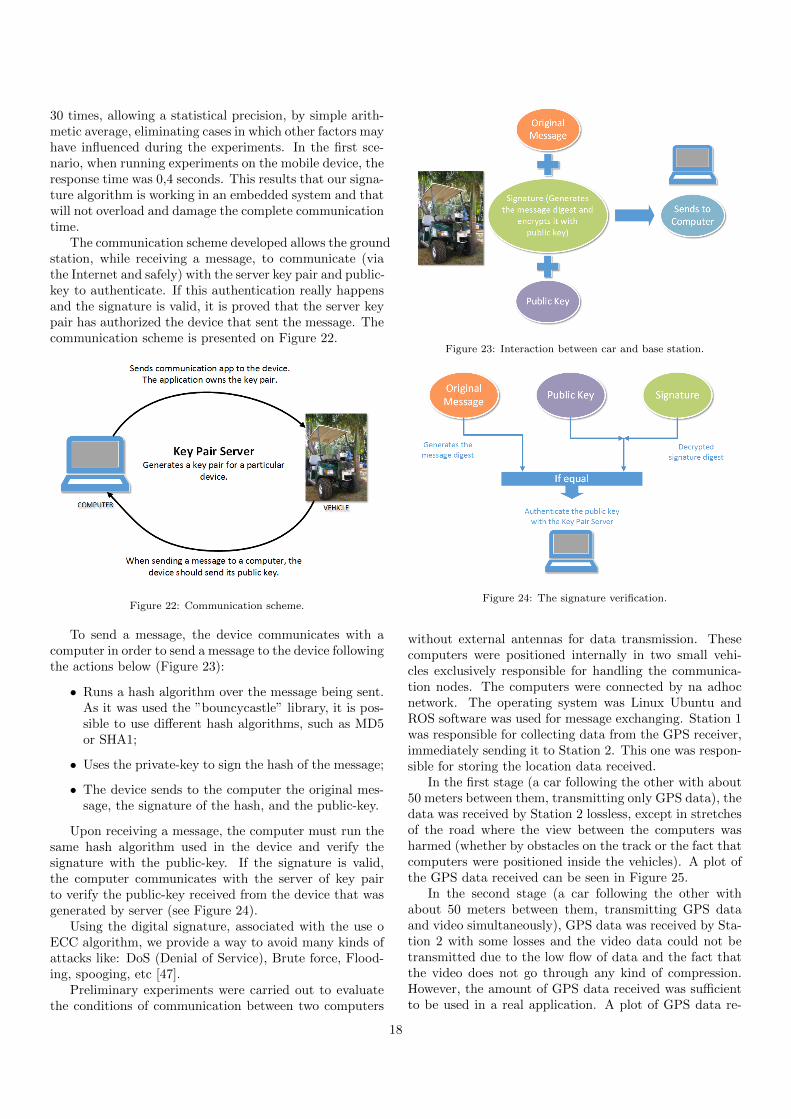
The communication scheme developed allows the groundstation, while receiving a message, to communicate (viathe Internet and safely) with the server key pair and public-key to authenticate. If this authentication really happensand the signature is valid, it is proved that the server keypair has authorized the device that sent the message. Thecommunication scheme is presented on Figure 22.
Figure 22: Communication scheme.
To send a message, the device communicates with acomputer in order to send a message to the device followingthe actions below (Figure 23):
• Runs a hash algorithm over the message being sent.As it was used the ”bouncycastle” library, it is pos-sible to use different hash algorithms, such as MD5or SHA1;
• Uses the private-key to sign the hash of the message;
• The device sends to the computer the original mes-sage, the signature of the hash, and the public-key.
Upon receiving a message, the computer must run thesame hash algorithm used in the device and verify thesignature with the public-key. If the signature is valid,the computer communicates with the server of key pairto verify the public-key received from the device that wasgenerated by server (see Figure 24).
Using the digital signature, associated with the use oECC algorithm, we provide a way to avoid many kinds ofattacks like: DoS (Denial of Service), Brute force, Flood-ing, spooging, etc [47].
Preliminary experiments were carried out to evaluatethe conditions of communication between two computers
Figure 23: Interaction between car and base station.
Figure 24: The signature verification.
without external antennas for data transmission. Thesecomputers were positioned internally in two small vehi-cles exclusively responsible for handling the communica-tion nodes. The computers were connected by na adhocnetwork. The operating system was Linux Ubuntu andROS software was used for message exchanging. Station 1was responsible for collecting data from the GPS receiver,immediately sending it to Station 2. This one was respon-sible for storing the location data received.
In the first stage (a car following the other with about50 meters between them, transmitting only GPS data), thedata was received by Station 2 lossless, except in stretchesof the road where the view between the computers washarmed (whether by obstacles on the track or the fact thatcomputers were positioned inside the vehicles). A plot ofthe GPS data received can be seen in Figure 25.
In the second stage (a car following the other withabout 50 meters between them, transmitting GPS dataand video simultaneously), GPS data was received by Sta-tion 2 with some losses and the video data could not betransmitted due to the low flow of data and the fact thatthe video does not go through any kind of compression.However, the amount of GPS data received was sufficientto be used in a real application. A plot of GPS data re-
18
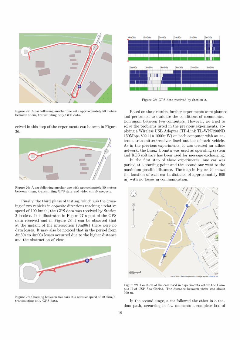
Figure 25: A car following another one with approximately 50 metersbetween them, transmitting only GPS data.
ceived in this step of the experiments can be seen in Figure26.
Figure 26: A car following another one with approximately 50 metersbetween them, transmitting GPS data and video simultaneously.
Finally, the third phase of testing, which was the cross-ing of two vehicles in opposite directions reaching a relativespeed of 100 km/h, the GPS data was received by Station2 lossless. It is illustrated in Figure 27 a plot of the GPSdata received and in Figure 28 it can be observed thatat the instant of the intersection (3m00s) there were nodata losses. It may also be noticed that in the period from3m30s to 4m00s losses occurred due to the higher distanceand the obstruction of view.
Figure 27: Crossing between two cars at a relative speed of 100 km/h,transmitting only GPS data.
Figure 28: GPS data received by Station 2.
Based on these results, further experiments were plannedand performed to evaluate the conditions of communica-tion again between two computers. However, we tried tosolve the problems listed in the previous experiments, ap-plying a Wireless USB Adapter (TP-Link TL-WN7200ND150Mbps 802.11n 1000mW) on each computer with an an-tenna transmitter/receiver fixed outside of each vehicle.As in the previous experiments, it was created an adhocnetwork, the Linux Ubuntu was used as operating systemand ROS software has been used for message exchanging.
In the first step of these experiments, one car wasparked at a starting point and the second one went to themaximum possible distance. The map in Figure 29 showsthe location of each car (a distance of approximately 900m) with no losses in communication.
Figure 29: Location of the cars used in experiments within the Cam-pus II of USP Sao Carlos. The distance between them was about900 m.
In the second stage, a car followed the other in a ran-dom path, occurring in few moments a complete loss of
19
view. These cases occurred when there were obstacles suchas buildings and trees interrupting the view between bothvehicles. However, the GPS data was received in satisfac-tory amount for implementating e.g. a convoy of vehicles.
Using the solutions proposed here we can provide an ef-ficient way to guarantee that the Unmanned Ground Vehi-cle will be protect against the most common attacks whenusing VANETs. This solution has also been tested in a realenvironment where the vehicle traveled 2 km. For furtherwork we intend to travel 5,4 km in an autonomous way,providing video in real time and using a secure transmis-sion both in video and in telemetry.
5. Conclusions and Future Work
The development of self-driving cars is an important re-search topic that has direct impact in the society. Some ofthe main goals of this technology are: reducing the numberof car deaths and injuries, improving efficiency with freighttransportation, fuel usage, and traffic flow in huge cities,providing transportation for children and adults unable todrive like physically handicapped or visually impaired peo-ple. It also has direct applications in agriculture, miningand several other activities that heavily rely on mobility.
Although several research groups have been workingon autonomous vehicles since 80s, the efforts to developrobust and reliable software algorithms to safely conductcars in the streets have increased considerably in the lastdecade. It is mainly due to the increase in funding fromgovernment and industry, associated with the developmentof more sophisticated and accessible sensors and compu-tational systems.
Most research in the field is still concentrated in NorthAmerica and Europe but few initiatives are taking placein Latin America, where there are several potential appli-cations for intelligent self-driving vehicles.
In this paper we presented the hardware and softwarearchitectures of the vehicles used for experimental testsof the CaRINA project under development at the LRMLab 3. Both mechanical and electrical modifications havebeen described, a well as the main software modules forperception, planning, and control.
Our system is based on ROS, which has becoming astandard software tool for robotic applications. It pro-vides libraries, tools, and a message-passing interface forprocesses that allows distributed robotic control systemsto be executed. We also address the security and commu-nications issues in such systems along with a descriptionof the work in progress in these fields.
Finally, four navigation systems, ranging from reactiveto a more deliberative approach, are presented to illus-trate the use of the proposed software and hardware ar-chitectures. The tests have been performed in a variety ofscenarios with both experimental platforms.
3LRM: Mobile Robotics Laboratory of ICMC/USP -http://lrm.icmc.usp.br (Videos, Publications, Resources)
As future work, we plan to develop and integrate higherlevel planning algorithms and maps of the environment. Itwill allow for more robust path planning and longer tra-jectories. The perception and planning modules are alsobeing improved for more precise and efficient results, allow-ing faster speed operation of the vehicles in more complexenvironments.
Acknowledgments
The authors would like to acknowledge the supportgranted by CAPES, CNPq and FAPESP to the INCT-SEC (National Institute of Science and Technology - Criti-cal Embedded Systems - Brazil) - processes 573963/2008-9and 08/57870-9.
References
[1] Adams, M., Mullane, J., Vo, B.-N., 2011. Laser and radar basedrobotic perception. Now Publications, Foundations and Trendsin Robotics 1(3), 135–252.
[2] Alves, R. S., Abdesslem, F. B., Cavalcanti, S. R., Campista,M. E. M., Costa, L. H. M. K., Rubinstein, M. G., Amorim,M. D., Duarte, O. C. M. B., september 2008. An experimentalanalysis of vehicular ad hoc networks capacity (original textin portuguese). XXVI Simposio Brasileiro de Telecomunicacoes(SBrT’08). Rio de Janeiro., 1–6.
[3] Andrade, K. O., Hernandes, A. C., Becker, M., ???? Simulatinga neural controller for mobile robot parallel parking (originaltext in portuguese).
[4] AUTONOMOSlabs, 2012. Artificial vision and intelligent sys-tems laboratory. http://autonomos.inf.fu-berlin.de/, visi-tado em Abril.
[5] Bertozzi, M., Broggi, A., Fascioli, A., 2000. Vision-based intel-ligent vehicles: State of the art and perspectives. Robotics andAutonomous Systems 32 (1), 1–16.
[6] Bonin-Font, F., Ortiz, A., Oliver, G., 2008. Visual navigationfor mobile robots: A survey. Journal of Intelligent & RoboticSystems 53, 263–296, 10.1007/s10846-008-9235-4.
[7] Borenstein, J.and Koren, Y., 1991. The vector field histogram-fast obstacle avoidance for mobile robots. IEEE Transactionson Robotics and Automation 7(3), 278–288.
[8] Bradski, G., Kaehler, A., 2008. Learning OpenCV. O’Reilly Me-dia.
[9] Broggi, A., Bertozzi, M., Fascioli, A., January 1999. Argo andthe millemiglia in automatico tour. Intelligent Systems and theirApplications, IEEE 14 (1), 55 –64.
[10] Buehler, M., Iagnemma, K., Singh, S., 2007. The 2005 DARPAGrand Challenge: The Great Robot Race, 1st Edition. SpringerPublishing Company, Incorporated.
[11] Buehler, M., Iagnemma, K., Singh, S., 2009. The DARPA Ur-ban Challenge: Autonomous Vehicles in City Traffic, 1st Edi-tion. Springer Publishing Company, Incorporated.
[12] Bueno, S. S., Azevedo, H., Mirisola, L. G. B., Paiva, E., Ramos,J. J. G., Victorino, A. C., Azinheira, J. R., 2009. A platformfor research and development of outdoor ground robotics (orig-inal title in portuguese). In: Simposio Brasileiro de AutomacaoInteligente.
[13] Censi, A., May 2008. An ICP variant using a point-to-line met-ric. In: Proceedings of the IEEE International Conference onRobotics and Automation (ICRA). Pasadena, CA.URL http://purl.org/censi/2007/plicp
[14] Desouza, G., Kak, A., Feb. 2002. Vision for mobile robot nav-igation: a survey. Pattern Analysis and Machine Intelligence,IEEE Transactions on 24 (2), 237 –267.
20
[15] Dickmanns, E. D., August 1998. Vehicles capable of dynamicvision: a new breed of technical beings? Artif. Intell. 103, 49–76.
[16] ELROB, 2012. Eureopean land-robot trial. http://www.elrob.org, visitado em Abril.
[17] EuroFOT, 2012. European field operational test. http://www.eurofot-ip.eu, visitado em Abril.
[18] Ferguson, D., Howard, T. M., Likhachev, M., 2008. Motionplanning in urban environments. Journal of Field Robotics25 (11-12), 939–960.
[19] Fischer, X.; Bennis, F., 2005. An overview of interactive meth-ods in design and manufacture. In: Fischer, X., Coutellier, D.(Eds.), Virtual Concept Proceedings (Research in InteractiveDesign) - Biarritz, France. Vol. 1. ESTIA - IEEE - Springer-Verlag.
[20] Fischer, X., 2005. Characteristics, development and use of mod-els in interactive design. In: Fischer, X., Coutellier, D. (Eds.),Virtual Concept Proceedings (Research in Interactive Design) -Biarritz, France. Vol. 1. ESTIA - IEEE - Springer-Verlag.
[21] Fox, D., Burgard, W., Thrun, S., Mar. 1997. The dynamic win-dow approach to collision avoidance. IEEE Robotics Automa-tion Magazine 4 (1), 23 –33.
[22] GCDC, 2012. Grand cooperative driving challenge. http://www.gcdc.net, visitado em Abril.
[23] Google, 2012. The official google blog, 2010. http://
googleblog.blogspot.com/2010/10/what-were-driving-at.
html by Sebastian Thrun, visitado em Abril.[24] Gregor, R., Lutzeler, M., Pellkofer, M., Siedersberger, K., Dick-
manns, E., 2000. Ems-vision: a perceptual system for au-tonomous vehicles. In: Intelligent Vehicles Symposium, 2000.IV 2000. Proceedings of the IEEE. pp. 52 –57.
[25] Hartenstein, H., Laberteaux, K., june 2008. A tutorial surveyon vehicular ad hoc networks. Communications Magazine, IEEE46 (6), 164 –171.
[26] HAVEit, 2012. Highly automated vehicles for intelligent trans-port. http://www.haveit-eu.org, visitado em Abril.
[27] Haykin, S., 1998. Neural Networks: A Comprehensive Founda-tion, 2nd Edition. Prentice Hall PTR, Upper Saddle River, NJ,USA.
[28] Haykin, S., 2008. Neural Networks and Learning Machines.Prentice Hall.
[29] Heinen, M., Osorio, F., Heinen, F., Kelber, C., 2006. Seva3d:Using artificial neural networks to autonomous vehicle park-ing control. In: IEEE International Joint Conference on NeuralNetworks - IJCNN’06. IEEE, IEEE Press, pp. 4704–4711.
[30] Hirschmuller, H., June 2005. Accurate and efficient stereo pro-cessing by semi-global matching and mutual information. In:Computer Vision and Pattern Recognition, 2005. CVPR 2005.IEEE Computer Society Conference on. Vol. 2. pp. 807 – 814vol. 2.
[31] Knepper, R. A., Kelly, A., 2006. High performance state latticeplanning using heuristic look-up tables. In: 2006 IEEE/RSJInternational Conference on Intelligent Robots and Systems. pp.3375 – 3380.
[32] Likhachev, M., Ferguson, D., 2009. Planning long dynamicallyfeasible maneuvers for autonomous vehicles. International Jour-nal of Robotics Research 28(8), 933–945.
[33] Likhachev, M., Ferguson, D. I., Gordon, G. J., Stentz, A.,Thrun, S., 2005. Anytime dynamic a*: An anytime, replanningalgorithm. In: International Conference on Automated Plan-ning and Scheduling/Artificial Intelligence Planning Systems.pp. 262–271.
[34] Lima, D. A., Pereira, G. A. S., 2010. Stereo vision system forautonomous vehicle navigation into environments with obsta-cles (original text in portuguese). In: Congresso Brasileiro deAutomatica. pp. 224 – 231.
[35] Lima, D. A., Pereira, G. A. S., 2011. Autonomous vehicle safenavigation using vector fields and the dynamic window method(original text in portuguese). In: Simposio Brasileiro de Au-tomacao Inteligente. pp. 1167–1172.
[36] Luettel, T., Himmelsbach, M., Wuensche, H.-J., 13 2012. Au-
tonomous ground vehicles – concepts and a path to the future.Proceedings of the IEEE 100 (Special Centennial Issue), 1831–1839.
[37] Magalhaes, A. C., Prado, M., Grassi Jr, V., Wolf, D. F., 2013.Autonomous vehicle navigation in semi-structured urban envi-ronment. In: Proc. of the 8th IFAC Symposium on IntelligentAutonomous Vehicles. Vol. 8. pp. 42–47.
[38] Medeiros, A. A. D., 04 1998. A survey of control architecturesfor autonomous mobile robots. Journal of the Brazilian Com-puter Society vol.4, no.3.URL http://www.scielo.br/scielo.php?script=sci_
arttext&pid=S0104-65001998000100004&nrm=iso
[39] MG, L., Honorio, L. M., Rodrigo, M. A. A., 2010. Modelingpath searching for local navigation of an intelligent autonomousvehicle (original text in portuguese). In: Congresso Brasileiro deAutomatica.
[40] Miranda Neto, A., Victorino, A. C., Fantoni, I., Ferreira, J. V.,2013. Real-time collision risk estimation based on pearson’s cor-relation coefficient. In: IEEE Workshop on Robot Vision. pp. 1–6.
[41] Mueller, A., Himmelsbach, M., Luettel, T., v Hundelshausen,F., Wuensche, H.-J., oct. 2011. Gis-based topological robotlocalization through lidar crossroad detection. In: IntelligentTransportation Systems (ITSC), 2011 14th International IEEEConference on. pp. 2001 –2008.
[42] Murarka, A., Kuipers, B., October 2009. A stereo vision basedmapping algorithm for detecting inclines, drop-offs, and obsta-cles for safe local navigation. In: Intelligent Robots and Sys-tems, 2009. IROS 2009. IEEE/RSJ International Conferenceon. pp. 1646 –1653.
[43] Oliveira, L. B. R., Osorio, F., Nakagawa, E. Y., 2013. An investi-gation into the development of service-oriented robotic systems.ACM SAC 2013 Proceedings 1, 223–228.
[44] Osorio, F., Musse, S., Santos, C. d., Heinen, F., Braun,A.and Silva, A. T. d., 2005. Intelligent virtual reality environ-ments (ivre): Principles, implementation, interaction, examplesand practical applications. In: Fischer, X., Coutellier, D. (Eds.),Virtual Concept Proceedings (Research in Interactive Design-Tutorials) - Biarritz, France. Vol. 1. IEEE - ESTIA, Springer-Verlag, Biarritz, France, pp. 1–64.
[45] Osorio, F., Musse, S., Vieira, R., Heinen, M., Paiva, D., 2006.Increasing reality in virtual reality applications through physicaland behavioural simulation. In: Fischer, X. (Ed.), Proceedingsof the Virtual Concept Conference. Vol. 1. ESTIA - VirtualConcept, Springer Verlag, pp. 1–46.
[46] Osorio, F., Wolf, D., Castelo Branco, K., Pessin, G., 2010. Mo-bile robots design and implementation: From virtual simula-tion to real robots. In: Proceedings of IDMME - Virtual Con-cept (Research in Interactive Design)- Bordeaux, France. Vol. 3.Springer-Verlag, pp. 1–6.
[47] Pigatto, D., Silva, N., Branco, K., 2012. Performance evaluationand comparison of algorithms for elliptic curve cryptographywith el-gamal based on miracl and relic libraries. Journal ofApplied Computing Research (JACR). 1 (6), 1–9.
[48] Pigatto, D., Silva, N., Sikansi, F., Branco, K., 2011. Applyingcryptography and digital signatures for safe communication forunmanned ground vehicles (original text in portuguese). In: IIEscola Regional de Alto Desempenho de Sao Paulo (ERAD-SP2011). pp. 1–4.
[49] Pivtoraiko, M., Kelly, A., 2005. Generating near minimal span-ning control sets for constrained motion planning in discretestate spaces. International Conference on Intelligent Robots andSystem.
[50] Pivtoraiko, M., Knepper, R. A., Kelly, A., 2009. Differentiallyconstrained mobile robot motion planning in state lattices.Journal of Field Robotics 26, 308–333.
[51] Roncancio, H., Hernandes, A. C., Becker, M., 2012. Vision-based system for pedestrian recognition using a tuned svm clas-sifier. In: IEEE Workshop on Engineering Applications. pp. 1–6.
[52] Sabbagh, V. B., Freitas, E. J. R., Castro, G. M. M. E., Santos,
21
M. M., Baleeiro, M. F., Silva, T. M., Iscold, P., Torres, L. A. B.,Pereira, G. A. S., 2010. Development of a control system for anautonomous car (original text in portuguese). In: CongressoBrasileiro de Automatica. pp. 928 – 933.
[53] Sales, D., Feitosa, D., Osorio, F., Wolf, D., may 2012. Multi-agent autonomous patrolling system using ann and fsm control.In: Critical Embedded Systems (CBSEC), 2012 Second Brazil-ian Conference on. pp. 48 –53.
[54] Sales, D. O., Feitosa, D., Osorio, F. S., Wolf, D. F., 2012. Vision-based autonomous navigation system using ann and kinect sen-sor. In: Conference Proceedings EANN 2012 – CCIS. Vol. 311.London, UK.
[55] Sales, D. O., Fernandes, L. C., Osorio, F. S., Wolf, D. F., 2012.Fsm-based visual navigation for autonomous vehicles. In: IIViCoMoR – IEEE/RSJ International Conference on IntelligentRobots and Systems (IROS). Vilamoura, Algarve, Portugal.
[56] Sales, D. O., Osorio, F. S., Wolf, D. F., 2011. Topological au-tonomous navigation for mobile robots in indoor environmentsusing ann and fsm. In: Proceedings of the I Brazilian Conferenceon Critical Embedded Systems (CBSEC). Sao Carlos, Brazil.
[57] Schoaba, V., Sikansi, F., Pigatto, D., Branco, L., Branco, K.,2010. Disimod digital signature for mobile devices. In: In theproceedings of the ICHIT-2010 - International Conference onConvergence and Hybrid Information Technology, Daejeon. pp.1–8.
[58] Sermanet, P., Hadsell, R., Scoffier, M., Muller, U., LeCun, Y.,September 2008. Mapping and planning under uncertainty inmobile robots with long-range perception. In: Intelligent Robotsand Systems, 2008. IROS 2008. IEEE/RSJ International Con-ference on. pp. 2525 –2530.
[59] Shinzato, P. Y., Wolf, D. F., 2010. A road following approachusing artificial neural networks combinations. Journal of Intel-ligent and Robotic Systems 62 (3), 527–546.
[60] Shoaba, V., Sikansi, F., Pigatto, D., Branco, L., Branco, K.,2011. Digital signature for mobile devices: A new implementa-tion and evaluation. IJFGCN - International Journal of FutureGeneration Communication and Networking. 4 (2), 23–36.
[61] Souza, J. R., Pessin, G., Buzogany, G., Mendes, C. C. T., Oso-rio, F. S., Wolf, D. F., 2012. Vision and gps-based autonomousvehicle navigation using templates and artificial neural net-works. Proceedings of the 27th Annual ACM Symposium onApplied Computing, 280–285.
[62] Souza, J. R., Pessin, G., Shinzato, P. Y., Osorio, F. S., Wolf,D. F., 2012. Vision based waypoint following using templatesand artificial neural networks. Neurocomputing (Elsevier), Ac-cepted for publication, 1–21.
[63] Souza, J. R., Sales, D. O., Shinzato, P. Y., Osorio, F. S., Wolf,D. F., 2011. Template-based autonomous navigation and obsta-cle avoidance in urban environments. ACM SIGAPP AppliedComputing Review 11, 49–59.
[64] Stallings, W., 2004. Wireless Communications & Networks (2ndEdition). Prentice-Hall, Inc., Upper Saddle River, NJ, USA.
[65] Talukder, A., Manduchi, R., Rankin, A., Matthies, L., june2002. Fast and reliable obstacle detection and segmentation forcross-country navigation. In: Intelligent Vehicle Symposium,2002. IEEE. Vol. 2. pp. 610 – 618 vol.2.
[66] Thorpe, C., Hebert, M., Kanade, T., Shafer, S., May 1988.Vision and navigation for the carnegie-mellon navlab. Pat-tern Analysis and Machine Intelligence, IEEE Transactions on10 (3), 362 –373.
[67] Veermas, L. L. G., Honorio, L. M., Vidigal, M. C. A. C. F.,MG, L., 2010. A methodology for supervised learning applied tointelligent vehicles (original text in portuguese). In: CongressoBrasileiro de Automatica.
[68] Veronese, L., J., J. L. L., Oliveira Neto, J., Forechi, A., Badue,C., de Souza, A. F., 2011. Parallel implementations of the csbpstereo vision algorithm. In: Simposio em Sistemas Computa-cionais. pp. 12 – 21.
[69] VISLAB, 2012. Artificial vision and intelligent systems labora-tory. http://www.vislab.it, visitado em Abril.
[70] WHO, 2012. World health organization. Road traffic deaths.
http://www.who.int/gho/road_safety/mortality/traffic_
deaths_number/en/index.html, visitado em Abril.[71] Willow-Garage, January 2013. Gazebo simulator - site:
http://ros.org/wiki/gazebo or http://gazebosim.org/.URL http://gazebosim.org/
[72] Willow-Garage, January 2013. Opencv - open source computervision library. site: http://opencv.willowgarage.com/wiki/ orhttp://opencv.org/.URL http://opencv.org/
[73] Willow-Garage, January 2013. Ros - robotic operating sys-tem - site: http://www.willowgarage.com/pages/software/ros-platform or http://www.ros.org.URL http://www.ros.org
Vitae
Leandro Carlos Fernandes is a PhD student in the In-stitute of Mathematics and Computer Science at the Uni-versity of Sao Paulo. He also serves as professor in com-puter science course at Paulista University and obtained aM.S. in Computer Science in 2003 from the University ofSao Paulo. Currently he has been working in autonomousvehicle architecture, low level interfaces and control sys-tems. His current research interests are Artificial Intelli-gence, Mobile Robotics, Perception and Sensors Fusion.
Jefferson R. Souza is a PhD student in the Instituteof Mathematics and Computer Science at the Universityof Sao Paulo. He obtained his MSc degree in ComputerScience at the Federal University of Pernambuco in 2010.At ICMC/USP, he has been working in machine learn-ing techniques for mobile robots and autonomous vehicles.More specifically, autonomous driving based on learninghuman behavior. His current research interests are Mo-bile Robotics, Machine Learning, Hybrid Intelligent Sys-tem and Gaussian Process.
Gustavo Pessinis a PhD student in the Institute ofMathematics and Computer Science at the University ofSao Paulo. He obtained an M.S. in Computer Science in2008 from the University of the Sinos Valley. At ICMC/USP,
22
he has been working on several research projects relatedto robotics and machine learning techniques. His currentresearch interests are Hybrid Intelligent System, MobileRobotics and Multi-agent Systems.
Patrick Yuri Shinzato is a PhD student in the Instituteof Mathematics and Computer Science at the Universityof Sao Paulo. He obtained a M.S. in Computer Science in2010 from the University of Sao Paulo. At ICMC/USP,he has been working in computer vision, machine learn-ing and neural networks. His current research interestsare Computational Vision, Artificial Intelligence, MobileRobotics and Sensors Fusion.
Daniel Oliva Sales is a PhD student at the Universityof Sao Paulo (ICMC-USP). He obtained a M.S. in Com-puter Science in 2012 from the University of Sao Paulo.At ICMC/USP, he has been working in Mobile RoboticsLab and his current research interests are Mobile Robotics,Computational Vision and Machine Learning.
Caio Cesar Teodoro Mendes is a PhD student in the In-stitute of Mathematics and Computer Science at the Uni-versity of Sao Paulo. He obtained a M.S. in ComputerScience in 2010 from the University of Sao Paulo. Hiscurrent research interests are Mobile Robotics, MachineLearning, GPGPU and Computer Vision.
Marcos Gomes Prado is a professor in the Indepen-dent Faculty of Northeast. He obtained a M.S. in Com-
puter Science in 2013 from the University of Sao Paulo.At ICMC/USP, he worked in path planning, sensor fu-sion and autonomous vehicles. His current research inter-ests are Path Planning, Artificial Intelligence and MobileRobotics.
Rafael Luiz Klaser, graduated in Computer Science atUNISINOS-RS, is a M.S student in the Institute of Math-ematics and Computer Science at the University of SaoPaulo. His main research area are Computer Vision andVisual Navigation. He also has been working with physi-cal simulations in autonomous navigation systems. He alsohave a background in IT industry and consulting servicesfor many years.
Andre Chaves Magalhaes is a Master’s student in theSchool of Engineering of Sao Carlos at the University ofSao Paulo At EESC-USP, he has working in motion plan-ner and mobile robots. His current research interests isAutonomous Vehicles.
23
Alberto Yukinobu Hata is PhD student in the Insti-tute of Mathematics and Computer Science at the Uni-versity of Sao Paulo. He obtained a M.S. in ComputerScience in 2010 from the University of Sao Paulo. He hasbeen working on Mobile Robotics, Terrain Mapping, Neu-ral Networks and Support Vector Machines. His currentresearch interests are Mobile Robotics, Gaussian Processand Robot Localization.
Daniel Fernando Pigatto is a PhD student in the Insti-tute of Mathematics and Computer Science at the Univer-sity of Sao Paulo. He obtained a M.S. in Computer Sci-ence in 2012 from the University of Sao Paulo. At ICMC-USP, he has been working in network security, embeddedsoftware development and critical embedded applications.His current research interests are Unmanned Aerial andGround Vehicles, Network Security and Mobile Robotics.
Kalinka Regina Lucas Jaquie Castelo Branco has Mas-ter in Computer Science from University of Sao Paulo(1999) and Ph.D. in Computer Science from Universityof Sao Paulo (2004). She is currently an Associate Pro-fessor of the Institute of Mathematics and Computer Sci-ence (ICMC-USP), working in the department of Com-puter Systems. She has experience in Computer Science,with emphasis on Computer Networks, Security, Embed-ded Systems, and Distributed Computing.
Valdir Grassi Jr is an Assistant Professor at the De-partment of Electrical Engineering of the Sao Carlos Schoolof Engineering at the University of Sao Paulo (EESC-USP). He received his Ph.D degree in Mechanical Engi-neering from the Escola Politecnica at the University ofSao Paulo (EPUSP). His current research interests includeautonomous mobile robot navigation, motion planning andcontrol, and computer vision applied to robotics.
Fernando Osorio is Professor/Researcher in the De-partment of Computer Systems at the University of SaoPaulo (ICMC-USP). He obtained his PhD degree in Com-puter Science at the INPG-IMAG (Grenoble, France - 1998).Currently he is member of the Mobile Robotics Laboratoryat ICMC-USP and also of the Center for Robotic USP SaoCarlos (CRob-USP). His main research interests are Intel-ligent Robotics, Machine Learning and Computer Vision,with a large number of journal and conference publishedpapers.
Denis Fernando Wolf is an Associate Professor in theDepartment of Computer Systems at the University of SaoPaulo (ICMC-USP). He obtained his PhD degree in Com-puter Science at the University of Southern California -USC in 2006. Currently he is Director of the MobileRobotics Laboratory at ICMC/USP and member of the
24

Center for Robotics . His current research interests areMobile Robotics, Machine Learning, Computer Vision andEmbedded Systems. He has published over 50 journal andconference papers in the last years.
25