CapSense Sigma-Delta Datasheet CSD V 2.00 Features and ...
56
Cypress Semiconductor Corporation • 198 Champion Court • San Jose, CA 95134-1709 • 408-943-2600 Document Number: 001-63217 Rev. *G Revised April 2, 2015 CapSense ® Sigma-Delta Datasheet CSD V 2.00 001-63217 Rev. *G CapSense Sigma-Delta Copyright © 2010-2015 Cypress Semiconductor Corporation. All Rights Reserved. Features and Overview Scan 1 to 28 capacitive sensors. Sensing possible with up to a 15 mm glass overlay. Proximity detection to 20 cm with a wire-based sensor. High immunity to AC mains noise, EMC noise, and power supply voltage changes. Supports different combinations of independent and slide capacitive sensors. Double slide sensor physical resolution using diplexing. Increase slide sensor resolution using interpolation. Touchpad support with two slide sensors. Sensing support through high resistive conductive materials (ITO films, for example). Shield electrode support for reliable operation in the presence of water film or droplets. Guided sensor and pin assignments using the CSD Wizard. Integrated baseline update algorithm for handling temperature, humidity, and electrostatic discharge (ESD) events. Easily adjustable operational parameters. PC GUI application support for raw data monitoring and parameter optimization in real time. Resources CapSense® Block API Memory (Bytes) Pins per sensor Flash RAM CY8C21x12, CY8CLED04. Use of flash, RAM, and pins varies by the number of sensors and configuration. PRS-based user module with 1 sensor 1 1017 26 2-5 PRS with prescaler based with 1 sensor 1 1006 26 2-5 Each additional CapSense button - 5 11 1 Static code and RAM increase when capacitive slider with five elements is used - 584 79 - Each additional slider element - 2 10 1 Static code and RAM increase when slider diplexing is used - 12 - 1
-
Upload
khangminh22 -
Category
Documents
-
view
0 -
download
0
Transcript of CapSense Sigma-Delta Datasheet CSD V 2.00 Features and ...

CapSense® Sigma-Delta Datasheet CSD V 2.00001-63217 Rev. *GCapSense Sigma-Delta
Copyright © 2010-2015 Cypress Semiconductor Corporation. All Rights Reserved.
Features and Overview Scan 1 to 28 capacitive sensors.Sensing possible with up to a 15 mm glass overlay.Proximity detection to 20 cm with a wire-based sensor.High immunity to AC mains noise, EMC noise, and power supply voltage changes.Supports different combinations of independent and slide capacitive sensors.Double slide sensor physical resolution using diplexing.Increase slide sensor resolution using interpolation.Touchpad support with two slide sensors.Sensing support through high resistive conductive materials (ITO films, for example).Shield electrode support for reliable operation in the presence of water film or droplets.Guided sensor and pin assignments using the CSD Wizard. Integrated baseline update algorithm for handling temperature, humidity, and electrostatic discharge (ESD) events. Easily adjustable operational parameters. PC GUI application support for raw data monitoring and parameter optimization in real time.
ResourcesCapSense®
Block
API Memory (Bytes)Pins per sensorFlash RAM
CY8C21x12, CY8CLED04. Use of flash, RAM, and pins varies by the number of sensors and configuration.
PRS-based user module with 1 sensor 1 1017 26 2-5
PRS with prescaler based with 1 sensor 1 1006 26 2-5
Each additional CapSense button - 5 11 1
Static code and RAM increase when capacitive slider with five elements is used
- 584 79 -
Each additional slider element - 2 10 1
Static code and RAM increase when slider diplexing is used
- 12 - 1
Cypress Semiconductor Corporation • 198 Champion Court • San Jose, CA 95134-1709 • 408-943-2600Document Number: 001-63217 Rev. *G Revised April 2, 2015
CapSense Sigma-Delta
Capacitive sensing using a sigma-delta modulator (CSD) gives CapSense® functionality using a switched capacitor technique with a sigma-delta modulator to convert the sensing switched capacitor current to digital code.Figure 1. CSD Application Diagram
Quick Start1. Select and place the user modules that require dedicated pins (for example, I2C and LCD), if used.
Assign ports and pins as required. 2. Select and place the CSD User Module. 3. Right click the CSD User Module in the Workspace Explorer to access the CSD Wizard (the wizard is
explained later in this datasheet). 4. Set the number of sensors, sliders, or rotary sliders that you want. 5. Set the sensor settings for each sensor.6. Set pins and global parameters. Read the parameter descriptions and follow the requirements and
guidelines.7. Generate the application and switch to the Application Editor. 8. Adapt the sample code as required to implement independent sensors, sliding sensors, or a touchpad.
9. Connect the I2C-USB bridge to the target board, and observe the signals.10. Change the CSD parameters to optimize your settings and rebuild the application. 11. Program the PSoC device and verify module operation. Tune the CSD parameters to achieve a 5:1
SNR requirement as discussed in CY8C21x34/B CapSense Design Guide.
See the Troubleshooting section in the Appendix if you encounter any problems.
Document Number: 001-63217 Rev. *G Page 2 of 56

CapSense Sigma-Delta
Functional Description The capacitive sensor consists of physical, electrical, and software components:
Physical: The physical sensor itself, typically a conductive pattern constructed on a PCB connected to the PSoC with an insulating cover, a flexible membrane, or a transparent overlay over a display.Electrical: A method to convert the sensor capacitance to digital format. The conversion system con-sists of a sensing switched capacitor, a sigma-delta modulator, and a counter-based digital filter to con-vert the modulator output bit stream to a readable digital format.Software: Detection and compensation software algorithms convert the count value into a sensor detection decision. In the case of consecutive, dependent sensors (such as sliders and touchpads) APIs are given to interpolate a position with greater resolution than the physical pitch of the sensors. For example, you can create a volume slider with 10 sensors and use the given firmware to expand the number of volume levels to 100. Alternatively, using the same APIs, you can use two capacitive sensors that taper into each other and determine the position of a conductive object (such as a finger) between them.
While there are several methods to measure capacitance, the method used in this user module is combination switching capacitor with delta-sigma modulator.
The sensor array consists of combinations of independent sensors, sliding sensors, and touchpads implemented as a pair of orthogonal sliders. High level decision logic gives compensation for environmental factors, such as temperature, humidity, and power supply voltage change. A separate shield electrode can be used for shielding the sensor array to reduce stray capacitance, giving more reliable operation in the presence of a water film or droplets.
The high level software functions accommodate slider diplexing so that a single electrical sensor may be used in two physical locations for resolution enhancement. The functions also give further interpolation of resolved sensor position between physical sensor locations.
The following document is recommended reading before you use the CSD User Module for the first time:
Technical Reference Manual for the PSoC device
The following design guides are recommended after reading the CSD User Module datasheet. These documents are available on the Cypress Semiconductor website at www.cypress.com:
Getting Started with CapSenseCY8C20xx6A/H CapSense Design Guide CY8C21x34/B CapSense Design Guide CY8C20x34 CapSense Design Guide CY8CMBR2044 CapSense Design Guide
Capacitance Measurement OperationThe decision logic is implemented in firmware. The firmware analyzes capacitance measurement, tracks the slow capacitance change due to environmental factors, and runs decision logic to detect button touches and calculate slider position.
Scanning an Array of SensorsThe CY8C21x12 family of devices have a built in analog bus. It allows capacitive sensor connections to any PSoC pin. The CSD User Module uses internal precharge switches to charge active sensors at clock signal phase Ph1 and connects the Analog Bus to the sensor at phase Ph2. The sigma-delta modulator modulation capacitor and comparator inputs are connected to the analog bus permanently.
Document Number: 001-63217 Rev. *G Page 3 of 56

CapSense Sigma-Delta
The firmware performs sensor scanning in series by setting corresponding bits in the MUX_CRx registers.Figure 2. Analog Bus with Precharge Switches and Driving Waveforms
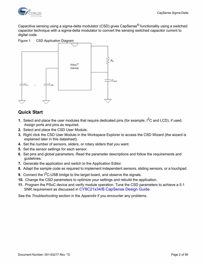
Sliders Sliders are used for controls requiring gradual adjustments. Examples include a lighting control (dimmer), volume control, graphic equalizer, and speed control. These sensors are mechanically adjacent to one another. Actuation of one sensor results in partial actuation of physically adjacent sensors. The actual position in the slider is found by computing the centroid location of the set of activated sensors. Sliders are accommodated in the CSD Wizard, by establishing groups in which each group of sliders has a specific order. The practical lower limit number for sensors slider is five, the upper limit is simply the number of sensor positions available on the PSoC device selected.
Document Number: 001-63217 Rev. *G Page 4 of 56
CapSense Sigma-Delta
Figure 3. Ordering Physical Sensor Locations
The close proximity of strong signals in one half of the slider results in the same levels aliased into the upper half, but the results are scattered. The sensing algorithms search for strong adjacent sets of signals to declare the resolved slider position.
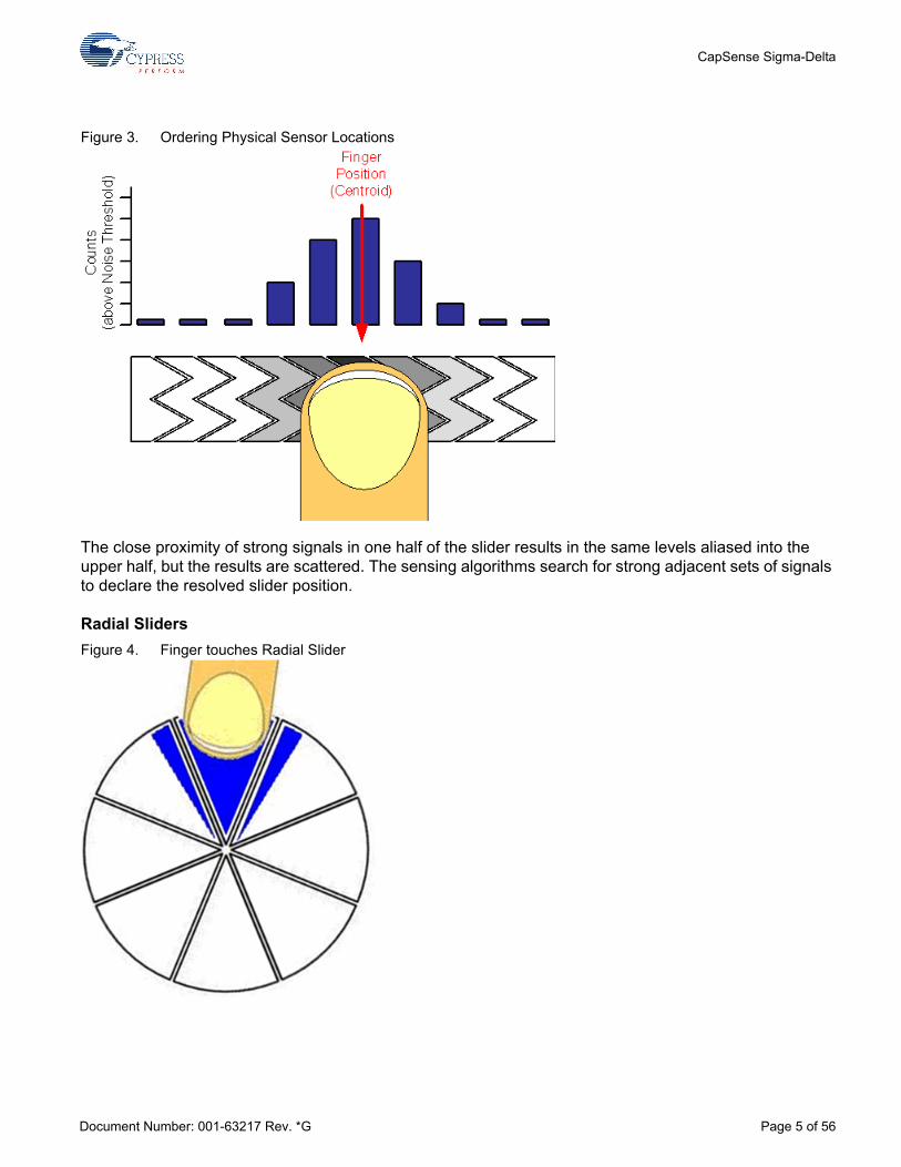
Radial SlidersFigure 4. Finger touches Radial Slider
Document Number: 001-63217 Rev. *G Page 5 of 56

CapSense Sigma-Delta
For the CSD User Module two slider types are available: linear and radial. Radial sliders are similar to linear ones. While linear sliders have a beginning and an end, radial sliders do not. When a touch happens, the centroid calculation algorithm takes into account sensor counts of the switches to the right and left of the current switch. Radial sliders are not diplexed.
The CSD User Module two API functions that support radial sliders. The first function CSD_wGetRadiaPos() returns centroid location and the second CSD_wGetRadialInc() returns finger shift in resolution units. When the finger moves in a clockwise direction it is a positive offset.
The reference point(0) is located in the middle of the first sensor. The Resolution for both linear and radial sliders is limited and is (number of pins used for sensors - 1) x 28 - 1 or (2 x number of pins used for sensors - 1) x 28 - 1 for diplexed sliders.
Diplexing Each PSoC sensor connection in a slider is mapped to two physical locations in the array of slider sensors. The first (or numerically lower) half of the physical locations is mapped sequentially to the base assigned sensors, with the port pin assigned by the designer using the CSD Wizard. The second (or upper) half of the physical sensor locations is automatically mapped by an algorithm in the Wizard and listed in an include file. The order is established so that adjacent sensor actuation in one half does not result in adjacent sensor actuation in the other half. Exercise care to determine this order and map it onto the printed circuit board.
There are many methods to order the second half of the physical sensor locations. The simplest is to index the sensors in the upper half, all of the even sensors, followed by all of the odd sensors. Other methods include indexing by other values. The method selected for this user module is to index by three. Figure 5. Index by 3
Document Number: 001-63217 Rev. *G Page 6 of 56

CapSense Sigma-Delta
You should balance sensor capacitance in the slider. Depending on sensor or PCB layouts, there may be longer routes for some of the sensor pairs. The diplex sensor index table is automatically generated by the CSD Wizard when you select diplexing. The following table lists the diplexing sequences for different slider segments count: Table 1. Diplexing Sequence for Different Slider Segment Counts
Total Slider
Segment Count Segment Sequence
10 0,1,2,3,4,0,3,1,4,2
12 0,1,2,3,4,5,0,3,1,4,2,5
14 0,1,2,3,4,5,6,0,3,6,1,4,2,5
16 0,1,2,3,4,5,6,7,0,3,6,1,4,7,2,5
18 0,1,2,3,4,5,6,7,8,0,3,6,1,4,7,2,5,8
20 0,1,2,3,4,5,6,7,8,9,0,3,6,9,1,4,7,2,5,8
22 0,1,2,3,4,5,6,7,8,9,10,0,3,6,9,1,4,7,10,2,5,8
24 0,1,2,3,4,5,6,7,8,9,10,11,0,3,6,9,1,4,7,10,2,5,8,11
26 0,1,2,3,4,5,6,7,8,9,10,11,12,0,3,6,9,12,1,4,7,10,2,5,8,11
28 0,1,2,3,4,5,6,7,8,9,10,11,12,13,0,3,6,9,12,1,4,7,10,13,2,5,8,11
30 0,1,2,3,4,5,6,7,8,9,10,11,12,13,14,0,3,6,9,12,1,4,7,10,13,2,5,8,11,14
32 0,1,2,3,4,5,6,7,8,9,10,11,12,13,14,15,0,3,6,9,12,15,1,4,7,10,13,2,5,8,11,14
34 0,1,2,3,4,5,6,7,8,9,10,11,12,13,14,15,16,0,3,6,9,12,15,1,4,7,10,13,16,2,5,8,11,14
36 0,1,2,3,4,5,6,7,8,9,10,11,12,13,14,15,16,17,0,3,6,9,12,15,1,4,7,10,13,16,2,5,8,11,14,17
38 0,1,2,3,4,5,6,7,8,9,10,11,12,13,14,15,16,17,18,0,3,6,9,12,15,18,1,4,7,10,13,16,2,5,8,11,14,17
40 0,1,2,3,4,5,6,7,8,9,10,11,12,13,14,15,16,17,18,19,0,3,6,9,12,15,18,1,4,7,10,13,16,19,2,5,8,11,14,17
42 0,1,2,3,4,5,6,7,8,9,10,11,12,13,14,15,16,17,18,19,20,0,3,6,9,12,15,18,1,4,7,10,13,16,19,2,5,8,11,14,17,20
44 0,1,2,3,4,5,6,7,8,9,10,11,12,13,14,15,16,17,18,19,20,21,0,3,6,9,12,15,18,21,1,4,7,10,13,16,19,2,5,8,11,14,17,20
46 0,1,2,3,4,5,6,7,8,9,10,11,12,13,14,15,16,17,18,19,20,21,22,0,3,6,9,12,15,18,21,1,4,7,10,13,16,19,22,2,5,8,11,14,17,20
48 0,1,2,3,4,5,6,7,8,9,10,11,12,13,14,15,16,17,18,19,20,21,22,23,0,3,6,9,12,15,18,21,1,4,7,10,13,16,19,22,2,5,8,11,14,17,20,23
Document Number: 001-63217 Rev. *G Page 7 of 56
CapSense Sigma-Delta
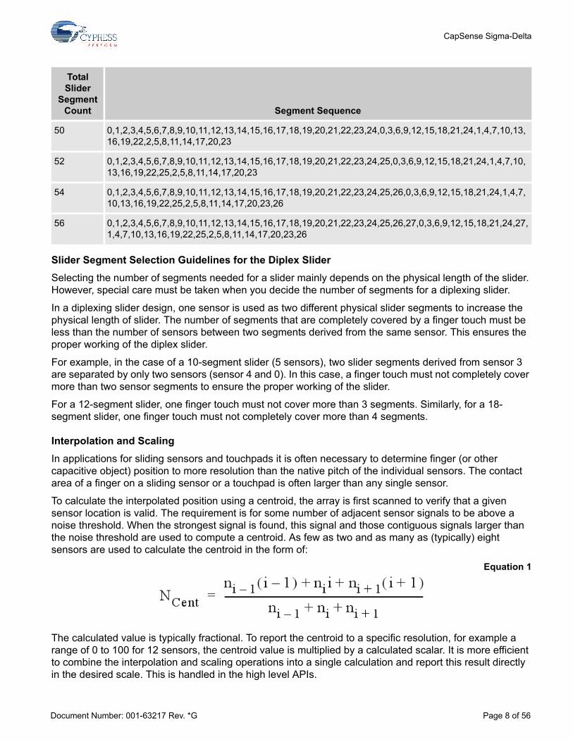
Slider Segment Selection Guidelines for the Diplex SliderSelecting the number of segments needed for a slider mainly depends on the physical length of the slider. However, special care must be taken when you decide the number of segments for a diplexing slider.
In a diplexing slider design, one sensor is used as two different physical slider segments to increase the physical length of slider. The number of segments that are completely covered by a finger touch must be less than the number of sensors between two segments derived from the same sensor. This ensures the proper working of the diplex slider.
For example, in the case of a 10-segment slider (5 sensors), two slider segments derived from sensor 3 are separated by only two sensors (sensor 4 and 0). In this case, a finger touch must not completely cover more than two sensor segments to ensure the proper working of the slider.
For a 12-segment slider, one finger touch must not cover more than 3 segments. Similarly, for a 18-segment slider, one finger touch must not completely cover more than 4 segments.
Interpolation and Scaling In applications for sliding sensors and touchpads it is often necessary to determine finger (or other capacitive object) position to more resolution than the native pitch of the individual sensors. The contact area of a finger on a sliding sensor or a touchpad is often larger than any single sensor.
To calculate the interpolated position using a centroid, the array is first scanned to verify that a given sensor location is valid. The requirement is for some number of adjacent sensor signals to be above a noise threshold. When the strongest signal is found, this signal and those contiguous signals larger than the noise threshold are used to compute a centroid. As few as two and as many as (typically) eight sensors are used to calculate the centroid in the form of:
Equation 1
The calculated value is typically fractional. To report the centroid to a specific resolution, for example a range of 0 to 100 for 12 sensors, the centroid value is multiplied by a calculated scalar. It is more efficient to combine the interpolation and scaling operations into a single calculation and report this result directly in the desired scale. This is handled in the high level APIs.
50 0,1,2,3,4,5,6,7,8,9,10,11,12,13,14,15,16,17,18,19,20,21,22,23,24,0,3,6,9,12,15,18,21,24,1,4,7,10,13,16,19,22,2,5,8,11,14,17,20,23
52 0,1,2,3,4,5,6,7,8,9,10,11,12,13,14,15,16,17,18,19,20,21,22,23,24,25,0,3,6,9,12,15,18,21,24,1,4,7,10,13,16,19,22,25,2,5,8,11,14,17,20,23
54 0,1,2,3,4,5,6,7,8,9,10,11,12,13,14,15,16,17,18,19,20,21,22,23,24,25,26,0,3,6,9,12,15,18,21,24,1,4,7,10,13,16,19,22,25,2,5,8,11,14,17,20,23,26
56 0,1,2,3,4,5,6,7,8,9,10,11,12,13,14,15,16,17,18,19,20,21,22,23,24,25,26,27,0,3,6,9,12,15,18,21,24,27,1,4,7,10,13,16,19,22,25,2,5,8,11,14,17,20,23,26
Total Slider
Segment Count Segment Sequence
Document Number: 001-63217 Rev. *G Page 8 of 56

CapSense Sigma-Delta
Slider sensor count and resolution are set in the CSD Wizard. A scaling value is calculated by the wizard and stored as fractional values.
The multiplier for the centroid resolution is contained in three bytes with these bit definitions:
The resolution is found by using this equation:
Resolution = (Number of Sensors – 1) x Multiplier
The centroid is held in a 24-bit unsigned integer and its resolution is a function of the number of sensors and the multiplier.
Selecting Feedback ComponentsThe user module requires an external modulation capacitor Cmod and a modulator feedback resistor Rb. The capacitor can be connected to the P0[1], P0[3] port pins and Vss ground. The feedback resistor Rb can be connected to port pins P1[1], P1[5], P3[1] and the capacitor pin. The pins are selected by the user module parameter setting. Do not use pins selected for modulator component connection for any other purposes.Figure 6. External Components Connection
The recommended value for the modulation capacitor is 4.7 to 47 nF. The optimal capacitance can be selected by experiment to get maximum SNR. A value of 5.6 to 10 nF gives good results in the most cases for the PRS16 and PRS8 configuration. If a configuration with a prescaler is selected, the recommended value of the integration capacitor is 22 to 47 nF. You can experiment with several capacitor values to get the best SNR after selecting the feedback resistor. A ceramic capacitor should be used. The temperature capacitance coefficient is not important. The resistor values depend on the total sensor capacitance Cs. The resistor value should be selected as:
Monitor the raw counts for different sensor touches.
Resolution Multiplier MSB
Bit 7 6 5 4 3 2 1 0
Multiplier 215 214 213 212 211 210 29 28
Resolution Multiplier ISB
Multiplier 128 64 32 18 16 8 4 2
Resolution Multiplier LSB
Multiplier 1/2 1/4 1/8 1/16 1/32 1/64 1/128 1/256
Document Number: 001-63217 Rev. *G Page 9 of 56

CapSense Sigma-Delta
Select a resistance value that provides maximum readings about 30% less than the full scale readings at the selected scanning resolution. The raw counts increase when resistor values increase.
Typical values are 500 Ω to 10 kΩ depending on sensor capacitance. You can start with 2 kΩ if you are using the CY3213 evaluation board.
Shielding ElectrodeSome applications require reliable operation in the presence of water films or droplets. White goods, automotive applications, various industrial applications, and others need capacitive sensors that do not give false triggering because of water, ice, and humidity changes. In this case a separate shielding electrode can be used. This electrode is located behind or outside the sensing electrode. When water films are located on the device insulation overlay surface, the coupling between the shielding and sensing electrodes is increased. The shielding electrode allows you to reduce the influence of parasitic capacitance, which gives you more dynamic range for processing sense capacitance changes.
In some applications it is useful to select the shielding electrode signal and its placement relative to the sensing electrode, such that increasing the coupling between these electrodes causes the opposite of the touch change of the sensing electrode capacitance measurement. This simplifies the high level software API work. The CSD User Module supports separate output for the shielding electrode.Figure 7. Possible Shield Electrode PCB Layout
The previous figure illustrates one possible layout configuration for the button’s shield electrode. The shield electrode is especially useful for transparent ITO touchpad devices, where it blocks the LCD drive electrode’s noise influence and reduces stray capacitance at the same time.
In this example, the button is covered by a shielding electrode plane. As an alternative, the shielding electrode can be located on the opposite PCB layer, including the plane under the button. A hatch pattern is recommended in this case, with a fill ratio of about 30 to 40%. No additional ground plane is required in this case.
When water drops are located between the shielding and sensing electrodes, the Cpar is increased and modulator current can be reduced. In practical tests, the modulator reference voltage can be increased by the API so that the raw count increase from water drops should be close to zero or be slightly negative. You can achieve this by selecting the appropriate modulator reference.
Document Number: 001-63217 Rev. *G Page 10 of 56

CapSense Sigma-Delta
In this user module, the same signal used for the precharge clock is supplied to the shielding electrode. The following figure illustrates its operation:
Cs – Total sensor capacitance
Cpar – Capacitance between the shielding and sensing electrodes
The switches Sw1 and Sw3 are on at phase Ph1, the switches Sw2 and Sw4 are on at phase Ph2. The Cpar is discharged at phase Ph1 phase and is charged at Ph2 phase. The modulator current is the algebraic sum of Cs and Cpar currents, and can be evaluated by the following equation:
Equation 2
Also, lowering the modulator reference voltage reduces the parasitic capacitance Cpar influence on total modulator current. Therefore, in the waterproof sensing optimal value for modulator reference can be minimal.
As shown in Equation 2, the modulator current is reduced with coupling increases between electrodes. This allows separate signals from the water and finger, which can be useful for firmware processing.
The shield electrode can be connected to any free row output bus.
Clock SourceThe clock source is used to control the switches on the sensing capacitor. The user module supports two selection options as the clock source for the precharge switches:
16-bit pseudo-random sequence generator (PRS16) 8-bit PRS source with prescaler
The required configuration should be selected when the user module is first selected. This selection can be changed later by right clicking the CSD User Module and selecting User Module Selection Options.
The PRS configuration uses the PRS16 module as a clock source. The PRS source gives spread-spectrum operation and ensures good immunity from external noise sources. In addition, designs with the spread-spectrum clock have lower electromagnetic emission levels. When your application is targeted to pass the EMC/EMI tests or must give reliable operation in the harsh environments, the PRS16 configuration is recommended. This table compares the two configurations:
Document Number: 001-63217 Rev. *G Page 11 of 56

CapSense Sigma-Delta
Comparator Reference SourceThe comparator reference source used to form the comparator reference voltage. The reference voltage value determines the sensitivity.
The Reference Source is an analog modulator, driven by a PRSPWM or a prescaler-PWM signal.
DC and AC Electrical Characteristics Table 2. Power Supply Voltage
Table 3. Noise
Configuration Operation Frequency EMC Noise Immunity
PRS16 Spread-spectrum, average is FIMO/4, peak is FIMO/2
High. Sensitive points are multiples of the PRS sequence repeat period and PRS fundamental frequency FIMO.
PRS8 with prescaler Adjustable spread spectrum, average is FIMO/8 – FIMO/1024, peak is FIMO/4 – FIMO/512
Moderate. Sensitive at more points due to the shorter PRS repeat period.
Parameter Min Typical Max Unit Test Conditions and Comments
Value 2.7 5.0 5.25 V
Parameter Min Typical Max Unit
Test Conditions(Vdd = 3.3 V, SysClk =12 MHz,
CPU Clock = 6 MHz,Baseline >= 70% of Resolution Max
Count)
Noisea Counts,peak-peak
a. SNR increases as the Scan Speed slows and the Baseline counts increase.
0.2 %(noise counts)/(baseline counts)
Resolution >= 14
Noise Counts,peak-peak
1 %(noise counts)/(baseline counts)
Resolution = 12
Noise Counts,peak-peak
10 %(noise counts)/(baseline counts)
Resolution = 10
Document Number: 001-63217 Rev. *G Page 12 of 56

CapSense Sigma-Delta
Table 4. Power Consumption
Placement The blocks for the user module are automatically placed when the user module is instantiated, alternate placements are not available. The CSD User Module consumes 3 digital blocks (DBB00, DBB01, DCB02). The DCB03 block is available for user purposes.
User modules that consume specific pin resources, including the LCD and I2CHW, must be placed before establishing port pin connections for the CSD User Module. The configuration selections are reflected in the Wizard when it is opened.
Avoid P1[0] and P1[1] when placing capacitive sensor connections. These pins are used for programming the part and may have excess routing capacitance affecting sensor sensitivity and noise.
CSD WizardThe CSD Wizard is used to set up the pinout for your CapSense buttons and sliders. Choose the configuration you want and assign the buttons and segments using a drag and drop interface.
Wizard Access
1. To access the Wizard, right click any block of the CSD in the Device Editor Interconnect View, then select the CSD Wizard with a left mouse click.
2. The Wizard opens showing the numeric entry boxes for the number of sensors and the number of slider sensors.
Parameter Min Typ Max UnitTest Conditions
(Vdd=3.3 V, SysClk = CPU Clock = 6 MHz)
Active Current 1.9 mA Average current during scan, 8 sensors
Standby Current 50 µA Scanning Speed = Ultra Fast, Resolution = 9, 100 ms report rate, 8 sensors
300 µA Scanning Speed = Fast, Resolution = 12 100 ms report rate, 8 sensors
Sleep/Wake Current 6 µA 1 s report rate, 1 sensor
Document Number: 001-63217 Rev. *G Page 13 of 56

CapSense Sigma-Delta
Wizard Pin Legend
White – The pin cannot be used as a CapSense input.
Gray – The pin is locked. There are two possible causes for this. The first possibility is that another user module such as the LCD or I2C has claimed the pin. The second possibility is that the name of the pin has been changed from its default. To return the pin name to its default, expand the pin in the Pinout view, and select Default from the Select menu. The pin is now available for assignment in the wizard.
Orange – The pin is available for assignment.
Green – The pin has been assigned as a CapSense input.
3. Type the number of independent sensors. The number of sensors is limited to the number of pins avail-able.
Document Number: 001-63217 Rev. *G Page 14 of 56

CapSense Sigma-Delta
4. Type the number of sliders. X-Y touchpads require two sliders (only one is selected below).
5. Select a slider to enter the settings for that slider. Type the number of sensor elements in the slider. The practical minimum number of sensors in a slider sensor is five. The maximum is limited by pin count.
6. Type the output resolution. The minimum value is five. The maximum value is (number of pins used for sensors – 1) x 28 – 1 or (2 x pins used for sensors – 1) x 28 -1 for diplexed sliders. The software will attempt to interpolate touches to this resolution based on the relative strength of the signals on adjacent slider sensors.
7. Select Diplex, if necessary. This maps the number of pins selected for sensors to twice as many sensor locations on the board. Only the first half of the diplex sensors is shown; the second half is automati-cally mapped as outlined in the previous section on Diplexing. See the Diplexing section to find Diplex-ing tables for pin connections.
Document Number: 001-63217 Rev. *G Page 15 of 56

CapSense Sigma-Delta
8. Select a sensor and drag it onto any available pin. The port pin is green after selection and is no longer available. Change sensor assignments by dragging the sensor of the port pin.
9. Repeat these steps for the remaining independent sensors. 10. Mapping of individual slider sensors onto physical port pins is the same as for individual sensors.11. Click OK to accept data and return to PSoC Designer.
Sensor placement is now complete. Right click in the Device Editor window and select Refresh to update the pin connections.
Set user module parameters and generate the application. You can adapt a sample project now, if you wish.
To change pin assignment, place your cursor on the assigned pin, click the pin, and drag and drop it outside the switches box. The pin is now unassigned and you can reassign it.
After completing the Wizard, click Generate Application. Based on your entries for sensor count, pin assignment, diplexing, and resolution, a set of tables is generated. The tables are located in CSD_Table.asm.
Document Number: 001-63217 Rev. *G Page 16 of 56

CapSense Sigma-Delta
Sensor TableThe Sensor Table consists of a 2-byte entry for each sensor. The first byte is the port number and the second byte is the bit mask for the bit (not the bit number). The table includes all independent sensors, then each sensor in order. An example for a table with six sensors is: CSD_Sensor_Table: _CSD_Sensor_Table:
dw 0x0140 // Port 1 Bit 6 dw 0x0301 // Port 3 Bit 0 dw 0x0304 // Port 3 Bit 2 dw 0x0308 // Port 3 Bit 3 dw 0x0302 // Port 3 Bit 1 dw 0x0108 // Port 1 Bit 3
This table is used by CSD_wGetPortPin() routine.
Group Table The Group Table defines each of the groups of button sensors or sliders. There is one entry for each slider plus one for the free button sensors. The first entry is always the free sensors. Each entry is six bytes. The first byte is the index in the Sensor Table where the group starts. The second byte is how many sensors are in that group. The third byte signifies whether the slider is diplexed or not (4 is diplexed, 0 is not diplexed). The fourth, fifth, and sixth bytes are the fixed point multiplier that the slider's calculated centroid is multiplied by to achieve the resolution desired in the CSD wizard. CSD_Group_Table:_CSD_Group_Table:; Group Table:; Origin Count Diplex? DivBtwSw(wholeMSB, wholeLSB, fractByte) db 0x0, 0x3, 0x00, 0x00, 0x00, 0x00 ; Buttons db 0x3, 0x8, 0x4, 0x0, 0x0, 0x44 ; Slider 1
Diplex Table Diplex table scan order data is produced for a group when it is a slider and is also diplexed. Otherwise a label is created but no data is placed. The table consists of two parts: sensor mapping for each slider, and a reference for each separate slider to its table. A typical example for an eight sensor slider is shown here: DiplexTable_0:; This group is not a diplexed sliderDiplexTable_1:db0,1,2,3,4,5,6,7,0,3,6,1,4,7,2,5// 8 switch slider
CSD_Diplex_Table:_CSD_Diplex_Table:db >DiplexTable_0, <DiplexTable_0db >DiplexTable_1, <DiplexTable_1
Document Number: 001-63217 Rev. *G Page 17 of 56

CapSense Sigma-Delta
Parameters and Resources Finger Threshold
This threshold is used to determine the state of each button sensor. If any sensor is active, the bIsA-nySensorActive() function returns a 1. If all sensors are off, the bIsAnySensorActive() function returns a 0.
The finger detection threshold values apply to all sensors and sliders. For individual sensors (not contained in a slider group), these thresholds are variable and given in the baBtnFThreshold[] array. The SetDefaultFingerThresholds() function may be used to set the thresholds to the default value set in the Device Editor. To adjust the sensitivity for individual sensors, change the baBtnFThreshold[] value for each sensor. (The size of this byte array is equal to the count of implemented individual sensors.)
Possible values range from 5 to 255; the default value is 40.
Noise ThresholdFor individual sensors, count values above this threshold do not update the baseline. For slider sensors, count values below this threshold are not counted in the calculation of the centroid. Possible values are 5 to 255; the default value is 20.
BaselineUpdate ThresholdWhen the new raw count value is above the current baseline and the difference is below the noise threshold (with the Sensors Autoreset parameter set to Disabled), the difference between the current baseline and the raw count is accumulated into what could be thought of as a bucket. When the bucket fills, the baseline is incremented by some value and the bucket is emptied. This parameter sets the threshold that the bucket must reach for the baseline to increment. Possible values are 0 to 255. Larger parameter values yield slower baseline update speeds. If you need more frequent baseline updates, decrease this parameter. The default value is 200.
LowBaselineResetThe LowBaselineReset parameter works together with the NegativeNoiseThreshold parameter. If the sample count values are below the baseline minus the NegativeNoiseTreshold for the specified number of samples, the baseline is set to the new raw count value. It essentially counts the number of abnormally low samples required to reset the baseline. It is generally used to correct for the finger-on-at-startup condition. The default value is 50.
Sensors AutoresetThis parameter determines whether the baseline is updated at all times or only when the signal differ-ence is below the Noise Threshold. When set to Enabled the baseline is updated constantly. This setting limits the maximum time duration of the sensor (typical values are 5 – 10 s), but it prevents the sensors from permanently turning on when the raw count suddenly rises without anything touching the sensor. This sudden rise can be caused by a large power supply voltage fluctuation, a high energy RF noise source, or a very quick temperature change.
When the parameter is set to Disabled the baseline is updated only when raw count and baseline difference is below the Noise Threshold parameter. You should leave this parameter Disabled unless you have problems with sensors permanently turning on when the raw count suddenly rises without anything touching the sensor. The default setting is Enabled.
Document Number: 001-63217 Rev. *G Page 18 of 56

CapSense Sigma-Delta
The following figure illustrates this parameter’s influence on the baseline update.
Figure 8. The Sensor Autoreset Parameter
HysteresisThe Hysteresis parameter adds or subtracts from the finger threshold depending on whether the sensor is currently active or inactive. If the sensor is inactive, the difference count must overcome the finger threshold plus hysteresis. If the sensor is active, the difference count must go below the finger threshold minus hysteresis. It is used to add debouncing and stickiness to the finger detection algo-rithm. The threshold with hysteresis is evaluated when bIsSensorActive() or bIsAnySensorActive() is called. The sensor state can be monitored with the return value of bIsSensorActive() or the baSnsOn-Mask[] array. Possible values are 0 to 255, but must be lower than the Finger Threshold parameter setting.
Proper selection of high level decision logic parameters allows you to effectively compensate for envi-ronmental factors (temperature, humidity changes, and so on), suppress noisy signals (ESD, power supply spikes), and give reliable touch detection under various conditions. The default value is 10.
DebounceThe Debounce parameter adds a debounce counter to the sensor active transition. For the sensor to transition from inactive to active, the difference count value must stay above the finger threshold plus hysteresis for the number of samples specified. The debounce counter is incremented by the bIsSen-sorActive or bIsAnySensorActive API functions.
Possible values are 1 to 255. A setting of 1 gives no debouncing. The default value is 3.
Document Number: 001-63217 Rev. *G Page 19 of 56

CapSense Sigma-Delta
NegativeNoiseThresholdThe NegativeNoiseThreshold parameter adds a negative difference count threshold. If the current raw count is below the baseline and the difference between them is greater than this threshold, the base-line is not updated. However, if the current raw count stays in the low state (difference greater than threshold) for the number of samples specified by the LowBaselineReset parameter, the baseline is reset. The default value is 20.
Scanning SpeedThis parameter affects the sensors’ scanning speed. The available selections are: Ultra Fast, Fast, Normal, Slow. Slower scanning speeds provide the following advantages:
- Improved SNR
- Better immunity to power supply and temperature changes
- Less demand for system interrupt latency; you can handle longer interrupts
See the warnings section for more about interrupt latency; the default setting is Normal.
ResolutionThis parameter determines the scanning resolution in bits. The sensors can be scanned with resolu-tions ranging from 9 to 16 bits. The maximum raw count for scanning resolution for N bits is 2N-1.
Increasing the resolution improves sensitivity and the SNR of touch detection. Use a high resolution for proximity detection. A 16-bit resolution, slow scanning mode, and a 20 cm wire allows you to detect a hand at 20 cm or more. The default value is 12.
The scanning speed and resolution affect the VC1, VC2, VC3, and ADCPWM dividers as shown in the following table:
Scanning Speed VC1
Ultra fast 1
Fast 2
Normal 4
Slow 8
Document Number: 001-63217 Rev. *G Page 20 of 56

CapSense Sigma-Delta
The VC1 divider depends on scanning speed only. The VC2, VC3, and ADCPWM depend on the resolution only.
Table 5. Scanning Time in µs vs. Scanning Speed and Resolution for 24 MHz IMO Operation, PRS16 Configuration
Table 6. Scanning Time in µs vs. Scanning Speed and Resolution for 24 MHz IMO Operation, PRS8 with Prescaler Configuration
Resolution, bits VC2 VC3 ADCPWM
9 8 16 4
10 8 32 4
11 8 64 4
12 8 128 4
13 8 256 4
14 8 256 8
15 8 256 16
16 8 256 32
Resolution, bits
Scanning speed
Ultra Fast Fast Normal Slow
9 75 110 170 300
10 110 170 300 510
11 170 300 510 1010
12 300 510 1010 2030
13 510 1010 2030 4060
14 850 1690 3380 6760
15 1520 3040 6080 12200
16 2880 5720 11500 23200
Resolution, bits
Scanning speed
Ultra Fast Fast Normal Slow
9 60 85 150 255
10 85 150 255 510
11 150 255 510 1020
12 255 510 1020 2040
Document Number: 001-63217 Rev. *G Page 21 of 56

CapSense Sigma-Delta
Note The scanning time was measured as the time interval between 2 sensor scans. This time includes the sensor setup time, modulator stabilization delay, sample conversion interval and data preprocessing time.
Modulator Capacitor PinThis parameter sets the pin to connect the external modulator capacitor (Cmod). Choose from the available pins P0[1] and P0[3]. The default setting is P0[1].
Feedback Resistor PinThis parameter sets the pin to connect the external feedback resistor (Rb). Choose from the available pins: P1[1], P1[5], and P3[1]. Some pins are not available on some device packages.
Tip If some of these pins are used for other purposes (for example, allocated for sensor connection), they are not available for selection in UM parameter list. Future versions of the CSD User Module may allow additional pins to be used for connecting the feedback resistor. This allows the use of a second I2C port on packages that have no P3 port. Use pins P1[5] or P3[1] to avoid programming problems. The default setting is P1[1].
Ref ValueThis parameter sets the comparator reference value, when comparator reference comes from an analog modulator (ASE11) or an externally filtered PWM/PRSPWM signal (from AnalogColumn_InputSelect_1 with RC filter).
When the reference increases, the sensitivity decreases; however, the influence on the shielding elec-trode increases. The generated reference voltage (Vref) depends on the ref value as shown in the following table.
If the design has sensors with noticeable capacitance differences (for example, sensors with different sized squares), you can balance raw counts by setting a higher reference for the sensors with larger capacitance using an API function. The default value is 2.
Prescaler PeriodThis parameter sets the prescaler period register and determines the precharge switch output frequency. This parameter is available for configuration with prescaler only. The prescaler period values can range from 1 to 255. The default value is 7.
The recommended values are 2n-1 to obtain the maximum signal to noise ratio (SNR):
13 510 1020 2040 4080
14 845 1700 3380 6760
15 1530 3060 6120 12100
16 2880 5800 11500 23000
Ref Value 0 1 2 3 4 5 6 7 8
Vref/VDD 0.25 0.3125 0.375 0.4375 0.5 0.5625 0.625 0.6875 0.75
Resolution, bits
Scanning speed
Ultra Fast Fast Normal Slow
Document Number: 001-63217 Rev. *G Page 22 of 56

CapSense Sigma-Delta
1
3
7
15
31
63
127
255
Other values can result in more noise, especially at low resolution and high scan speed.
ShieldElectrodeOutThe shielding electrode signal source can be selected from one of the free digital row buses (Row_0_Output_0 to Row_0_Output_3). Each row output can be routed to one of three pins. Set the Row LUT Function to A. The default setting is None.
CSD Calibration For optimum performance, the CSD parameters are tuned with the actual CapSense hardware and overlay. The following flowchart shows how to calibrate CSD:Figure 9. CSD Calibration Flowchart
Document Number: 001-63217 Rev. *G Page 23 of 56

CapSense Sigma-Delta
1. Start with the default settings of the CSD User Module.
2. Using the I2C-USB bridge or UART and the actual hardware and overlay, capture the raw counts, base-line, and difference counts for the sensors.
3. Coarse Tuning. Check if the signal-to-noise ratio (SNR) is greater than 5. If the SNR is less than 5, increase SNR by following recommended PCB guidelines, increasing the resolution of the CSD, and reducing the scan speed of the CSD. For PCB guidelines, see the design guide Getting Started with CapSense. For details about SNR and how to measure SNR, see CY8C21x34/B CapSense® Design Guide.
4. Fine Tuning. Check if the SNR is greater than 8. If it is less than 8, reduce the Ref Value parameter to increase SNR.
5. Check if the total scan time for all sensors meets requirements. If it does not, reduce the resolution and/or increase the scan speed. Because these parameters also affect SNR, go back to Step 3. With a couple of passes, find the optimum resolution and scan speed parameters that produce the best SNR and the desired scan time.
6. Capture the difference counts when the button is activated. Set the finger threshold parameter to 75 percent of the peak.
7. Set the noise threshold to 40 percent of the peak value.8. Set the negative noise threshold to half the noise threshold.9. Set finger thresholds for individual sensors if necessary. This is done by writing to the
CSD_baBtnFThreshold array in firmware.10. Set the baseline update threshold according to requirements. The frequency with which the baseline
is updated must be determined on a project-to-project basis. The baseline should be a slow moving reference, which helps to reduce the effects of noise and temperature on the capacitive sensor.
• Fast update baseline rates: This can create problems if you move your finger slowly to the button. This is called “Baselining out the finger”.
• Slow update baseline rates: This can leave the buttons vulnerable to temperature fluctuations and potentially lead to “button lock”.
11. Set AutoReset and Debounce parameters as required. Refer to the Parameters section for more infor-mation.
Sensor Scan Rate Selection GuidelinesScan rate is the rate at which sensors are scanned. An example of a 3-button design is shown in the following figure. All sensors in the design are scanned sequentially and there is a delay before the next sensor scan is initiated.Figure 10. Typical Sensor Scan
Document Number: 001-63217 Rev. *G Page 24 of 56
CapSense Sigma-Delta
To ensure proper working of the baseline, it is recommended to maintain a scan rate of 15 ms or more in a design. This indicates that a design with less number of sensors must add a delay to make the sensor scan rate equal to or greater than 15 ms. A design with more number of sensors may not need any delay as scanning all sensors itself may consume 15 ms. A good design may put the CapSense controller in sleep mode, instead of the firmware delay routine, to create a low power design.
Application Programming Interface The Application Programming Interface (API) functions are given as part of the user module to allow you to deal with the module at a higher level. This section specifies the interface to each function together with related constants provided by the include files.
Only one instance of this user module can be placed in the project and this also applies to loadable configurations.
Note ** In this, as in all user module APIs, the values of the A and X register may be altered by calling an API function. It is the responsibility of the calling function to preserve the values of A and X before the call if those values are required after the call. This "registers are volatile" policy was selected for efficiency reasons and has been in force since version 1.0 of PSoC Designer. The C compiler automatically takes care of this requirement. Assembly language programmers must also ensure their code observes the policy. Though some user module API functions may leave A and X unchanged, there is no guarantee they may do so in the future.
For Large Memory Model devices, it is also the caller's responsibility to preserve any value in the CUR_PP, IDX_PP, MVR_PP, and MVW_PP registers. Even though some of these registers may not be modified now, there is no guarantee that will remain the case in future releases.
Entry Points are supplied to initialize the CSD, start it sampling, and stop the CSD. In all cases the instance name of the module replaces the CSD prefix shown in the following entry points. Failure to use the correct instance name is a common cause of syntax errors.
API functions use different global arrays. You should not alter these arrays manually. You can inspect these values for debugging purposes, however. For example, you can use a charting tool to display the contents of the arrays. There several global arrays:
CSD_waSnsBaseline[]CSD_waSnsResult[]CSD_waSnsDiff[]CSD_baSnsOnMask[]
CSD_waSnsBaseline[] – This is an integer array that contains the baseline data of each sensor. The array size is equal to the sensor count. The CSD_waSnsBaseline[] array is updated by these functions:
CSD_UpdateAllBaselines(); CSD_UpdateSensorBaseline(); CSD_InitializeBaselines().
CSD_waSnsResult[] – This is an integer array that contains the raw data of each sensor. The array size is equal to the sensor count. The CSD_waSnsResult[] data is updated by these functions:
CSD_ScanSensor(); CSD_ScanAllSensors().
CSD_waSnsDiff [] – This is an integer array that contains the difference between the raw data and the baseline data of each sensor. The array size is equal to the sensor count.
Document Number: 001-63217 Rev. *G Page 25 of 56

CapSense Sigma-Delta
CSD_baSnsOnMask[] – This is a byte array that holds the sensor on or off state (for buttons or sliders). CSD_baSnsOnMask[0] contains the masked bits for sensors 0 through 7 (sensor 0 is bit 0, sensor 1 is bit 1). CSD_baSnsOnMask[1] contains the masked bits for sensors 8 through 15 (if they are needed), and so on. This byte array contains as many elements as are necessary to contain all the placed sensors. The value of a bit is 1 if the button is on and 0 if the button is off. The CSD_baSnsOnMask[] data is updated by CSD_blsSensorActive(BYTE bSensor) function or CSD_bIsAnySensorActive() routines.
CSD_Start
Description: Initializes registers and starts the user module. This function should be called before calling any other user module functions.
C Prototype: void CSD_Start()
Assembly: lcall CSD_Start
Parameters: None
Return Value: None
Side Effects: **
CSD_Stop
Description: Stops the sensor scanner, disables internal interrupts, and calls CSD_ClearSensors() to reset all sensors to an inactive state.
C Prototype: void CSD_Stop()
Assembly: lcall CSD_Stop
Parameters: None
Return Value: None
Side Effects: **
Document Number: 001-63217 Rev. *G Page 26 of 56

CapSense Sigma-Delta
CSD_Resume
Description:Resumes the user module operation after CSD_Stop call.
C Prototype:void CSD_Resume()
Assembly:lcall CSD_Resume
Parameters: None
Return Value: None
Side Effects**
CSD_ScanSensor
Description:Scans the selected sensor. Each sensor has a unique number within the sensor array. This number is assigned by the CSD Wizard in sequence. Sw0 is sensor 0, Sw1 is sensor 1, and so on.
C Prototype:void CSD_ScanSensor(BYTE bSensor)
Assembly:mov A, bSensorlcall CSD_ScanSensor
Parameters: A => Sensor Number
Return Value: None
Side Effects**
CSD_ScanAllSensors
Description:Scans all of the configured sensors by calling CSD_ScanSensor() for each sensor index.
C Prototype:void CSD_ScanAllSensors()
Document Number: 001-63217 Rev. *G Page 27 of 56

CapSense Sigma-Delta
Assembly:lcall CSD_ScanAllSensors
Parameters: None
Return Value: None
Side Effects**
CSD_UpdateSensorBaseline
Description:The historical count value, calculated independently for each sensor, is called the sensor's baseline. This baseline is updated using the Bucket Method.The Bucket Method uses the following algorithm:1.Each time CSD_UpdateSensorBaseline() is called, a difference count is calculated by subtracting the previous baseline from the raw count value. This difference is stored in the CSD_waSnsDiff[] array and is provided to you.2.If Sensors Autoreset is disabled, each time CSD_UpdateSensorBaseline() is called the difference count is compared to the noise threshold. If the difference is below the noise threshold, it is accumu-lated into a virtual bucket. If the difference is above the noise threshold, the bucket is not updated. If Sensors Autoreset is enabled, the difference is accumulated into a virtual bucket regardless of the noise threshold parameter.3.After the accumulated difference counts in the virtual bucket has reached the BaselineUpdate-Threshold, the baseline is incremented by one and the bucket is reset to 0.4.If the difference count is below the noise threshold, the value held in the waSnsDiff[] array is reset to 0. Therefore, this array does not contain elements with values greater than 0 but below the Noise-Threshold.
C Prototype:void CSD_UpdateSensorBaseline(BYTE bSensor)
Assembly:mov A, bSensorlcall CSD_UpdateSensorBaseline
Parameter: A => Sensor Number
Return Value:None
Side Effects:**
Document Number: 001-63217 Rev. *G Page 28 of 56

CapSense Sigma-Delta
CSD_UpdateAllBaselines
Description:Uses the CSD_bUpdateSensorBaseline() function to update the baselines for all sensors.
C Prototype:void CSD_UpdateAllBaselines()
Assembly:lcall CSD_UpdateAllBaselines
Parameters:None
Return Value:None
Side Effects:**
CSD_bIsSensorActive
Description:Checks the difference count array for the given sensor compared to its finger threshold. Hysteresis is taken into account. The Hysteresis value is added or subtracted from the finger threshold based on whether the sensor is currently on. If it is active, the threshold is lowered. If it is inactive, the threshold is raised. This function also updates the sensor's bit in the CSD_baSnsOnMask[] array.
C Prototype:BYTE CSD_bIsSensorActive(BYTE bSensor)
Assembly:mov A, bSensorlcall CSD_bIsSensorActive
Parameters:bSensor A => Sensor Number
Return Value:Return value of 1 if active, 0 if not activeA => 1 – Selected sensor is active, 0 – Selected sensor is not active.
Side Effects:**
Document Number: 001-63217 Rev. *G Page 29 of 56

CapSense Sigma-Delta
CSD_bIsAnySensorActive
Description:Checks the difference count array for all sensors compared to their finger threshold. Calls CSD_bIsSensorActive() for each sensor so the CSD_baSnsOnMask[] array is up to date after calling this function.
C Prototype:BYTE CSD_bIsAnySensorActive()
Assembly:lcall CSD_bIsAnySensorActive
Parameters:None
Return Value:Return value of 1 if active, 0 if not activeA => 1 – One or more sensors are active, 0 – No sensors are active.
Side Effects:**
CSD_wGetCentroidPos
Description:Checks a difference array for a centroid. If one exists, the offset and length are stored in temporary variables and the centroid position is calculated to the resolution specified in the CSD Wizard. This function is available only if slider is defined by the CSD Wizard.
C Prototype:WORD CSD_wGetCentroidPos(BYTE bSnsGroup)
Assembly:mov A, bSnsGrouplcall CSD_wGetCentroidPos
Parameters:bSnsGroup A => Group NumberThis parameter is a reference to a specific group of sensors used as a slider. Group 0 is for buttons. Sliders are contained in group 1 and higher.
Return Value:Position value of the slider, LSB in A and MSB in X.
Side Effects:This routine modifies the difference counts by subtracting the noise threshold value. The routine should be called only once after each scan to avoid getting negative difference values. If your appli-cation monitors difference count signals, call this routine after difference count data transmission.If any slider sensor is active, the function returns values from zero to the Resolution value set in the CSD Wizard. If no sensors are active, the function returns –1 (FFFFh). If an error occurs during execu-
Document Number: 001-63217 Rev. *G Page 30 of 56

CapSense Sigma-Delta
tion of the centroid/diplexing algorithm, the function returns –1 (FFFFh). You can use the CSD_blsSensorActive() routine to determine which slider segments are touched, if required.Note If noise counts on the slider segments are greater than the noise threshold, this subroutine may generate a false centroid result. The noise threshold should be set carefully (high enough above the noise level) so that noise does not generate a false centroid.
CSD_wGetRadialPos
Description:Checks a difference array for a centroid. If one exists, the centroid position is calculated to the reso-lution specified in the CSD Wizard. This function is available only for radial slider that is defined by the CSD Wizard.
C Prototype:WORD CSD_wGetRadialPos(BYTE bSnsGroup)
Assembly:mov A, bSnsGrouplcall CSD_wGetRadialPos
Parameters:bSnsGroup A => Group NumberThis parameter is a number of radial slider you are working with. You can get its number through the CSD User Module wizard on the left hand of radial slider representation (for example, for s2, the radial slider number is 2).
Return Value:Position value of the radial slider, LSB in A and MSB in X.
Side Effects:The routine should be called only once after each scan to avoid getting negative difference values and baseline update. If your application monitors difference count signals, call this routine after difference count data transmission.If any slider sensor is active, the function returns values from zero to the Resolution value set in the CSD Wizard. If no sensors are active, the function returns -1 (FFFFh).Note If noise counts on the slider segments are greater than the noise threshold, this subroutine may generate a false centroid result. The noise threshold should be set carefully (high enough above the noise level) so that noise does not generate a false centroid.
CSD_wGetRadialInc
Description:Returns actual finger shift, the difference between current and previous finger positions. This function works in pair with CSD_wGetRadialPos() and takes data generated by the latter (data is saved in internal variables).
C Prototype:WORD CSD_wGetRadialInc(BYTE bSnsGroup)
Document Number: 001-63217 Rev. *G Page 31 of 56

CapSense Sigma-Delta
Assembly:mov A, bSnsGrouplcall CSD_wGetRadialInc
Parameters:bSnsGroup A => Group NumberThis parameter is a number of radial slider you are working with. You can get its number through the CSD User Module wizard on the left hand of radial slider representation (for example, s2, the radial slider number is 2).
Return Value:Finger shift value, positive if clockwise and negative if anti-clockwise, LSB in A and MSB in X.Finger shift value is the difference between current and previous finger positions. If there was no touch during previous scan (the last but one time CSD_wGetRadialPos() returned -1 (FFFFh)) or there is no touch at the moment (this time CSD_wGetRadialPos() returned -1 (FFFFh))
Side Effects:The routine should be called only after CSD_wGetRadialPos() API. Because it uses internal data CSD_waSliderPrevPos and CSD_waSliderCurrPos that are set by the CSD_wGetRadialPos().
CSD_InitializeSensorBaseline
Description:Loads the CSD_waSnsBaseline[bSensor] array element with an initial value by scanning the selected sensor. The raw count value is copied in to the baseline array element for the selected sensor. This function can be used for resetting the baseline of an individual sensor.
C Prototype:void CSD_InitializeSensorBaseline(BYTE bSensor)
Assembly:mov A, bSensorlcall CSD_InitializeSensorBaseline
Parameters:A => Sensor Number
Return Value:None
Side Effects:**
Document Number: 001-63217 Rev. *G Page 32 of 56
CapSense Sigma-Delta
CSD_InitializeBaselines
Description:Loads the CSD_waSnsBaseline[] array with initial values by scanning each sensor. The raw count values are copied in to baseline array for each sensor.
C Prototype:void CSD_InitializeBaselines()
Assembly:lcall CSD_InitializeBaselines
Parameters:None
Return Value:None
Side Effects:**
CSD_SetDefaultFingerThresholds
Description:Loads the CSD_baBtnFThreshold[] array with the FingerThreshold parameter value. This function must be called before scanning if the CSD_baBtnFThreshold[] array is not manually loaded with custom values.
C Prototype:void CSD_SetDefaultFingerThresholds()
Assembly:lcall CSD_SetDefaultFingerThresholds
Parameters:None
Return Value:None
Side Effects:**
Document Number: 001-63217 Rev. *G Page 33 of 56

CapSense Sigma-Delta
CSD_SetScanMode
Description:Sets scanning speed and resolution. This function can be called at runtime to change the scanning speed and resolution. The function overwrites the user module parameter settings. This function is effective when some sensors need to be scanned with different scanning speed and resolution, for example, regular buttons and a proximity detector. The regular buttons can be scanned with 9-bit resolution and 300 μs scan time. The proximity detector can be scanned less often with 16-bit reso-lution and scanning time of more than 12 ms for long range detection. This function can be used in conjunction with CSD_ScanSensor() function.
C Prototype: void CSD_SetScanMode(BYTE bSpeed, BYTE bResolution)
Assembly:mov A, bSpeedmov X, bResolutionlcall CSD_SetScanMode
Parameters:bSpeed: Scanning Speed The following constants are given for the bSpeed parameter:
bResolution: Scanning Resolution. Set this value to the required number of bits of resolution. This parameter value must not be lower than 9 or greater than 16.The following possible constants are given for the bResolution parameter:
Constant Value
CSD_ULTRA_FAST_SPEED 0x00
CSD_FAST_SPEED 0x01
CSD_NORMAL_SPEED 0x02
CSD_SLOW_SPEED 0x03
Constant Value
CSD_9_BIT_RESOLUTION 9
CSD_10_BIT_RESOLUTION 10
CSD_11_BIT_RESOLUTION 11
CSD_12_BIT_RESOLUTION 12
CSD_13_BIT_RESOLUTION 13
CSD_14_BIT_RESOLUTION 14
CSD_15_BIT_RESOLUTION 15
CSD_16_BIT_RESOLUTION 16
Document Number: 001-63217 Rev. *G Page 34 of 56

CapSense Sigma-Delta
Return Value:None
Side Effects:**
CSD_SetRefValue
Description:Sets scanning reference value. Valid only when reference is supplied from the analog modulator (ASE11 in the Reference parameter) or from externally filtered PWM/PRSPWM signals. Accepted values are 0..8. Value 0 corresponds to the minimum reference voltage that provides the maximum sensitivity. The value 8 sets the maximum reference voltage and results in lower sensitivity. This func-tion can be used in conjunction with CSD_ScanSensor().
C Prototype: void CSD_SetRefValue(BYTE bRefValue)
Assembly: mov A, bRefValuelcall CSD_SetRefValue
Parameters: bRefValue - sets the scanning reference vale. Accepted values are 0..8.
Return Value: None
Side Effects: **
CSD_ClearSensors
Description: Clears all sensors to the non-sampling state by sequentially calling CSD_wGetPortPin() and CSD_DisableSensor() for each of the sensors.
C Prototype: void CSD_ClearSensors()
Assembly: lcall CSD_ClearSensors
Parameters: None
Return Value: None
Side Effects: **
Document Number: 001-63217 Rev. *G Page 35 of 56

CapSense Sigma-Delta
CSD_wReadSensor
Description: Returns the key Raw scan value in A (LSB) and X (MSB).
C Prototype: WORD CSD_wReadSensor(BYTE bSensor)
Assembly: mov A, bSensor lcall CSD_wReadSensor
Parameters: A => Sensor Number
Return Value: Scan value of sensor, LSB in A and MSB in X.
Side Effects: **
CSD_wGetPortPin
Description: Returns the port number and pin mask for a given sensor. The passed parameter indexes and selects the data from the CSD_Sensor_Table[]. The return value can be passed to the CSD_EnableSensor(), CSD_DisableSensor().
C Prototype: WORD CSD_wGetPortPin(BYTE bSensorNum)
Assembly: mov A, bSensorNumber lcall CSD_wGetPortPin
Parameters: bSensorNumber – The range is 0 to (n – 1) where n is the total of the number of sensors set in the CSD Wizard plus the number of sensors included in sliders. The sensor number is used by CSD_wGetPortPin() to determine port and bit mask for the selected active sensor.
Return Value: A => Sensor Bitmap X => Port Number
Side Effects: **
Document Number: 001-63217 Rev. *G Page 36 of 56

CapSense Sigma-Delta
CSD_EnableSensor
Description: Configures the selected sensor to measure during the next measurement cycle. The port and sensor can be selected using the CSD_wGetPortPin() function, with the port number and sensor bitmask loaded into X and A, respectively. Drive modes are modified to place the selected port and pin into Analog High Z mode and to enable the correct Analog Mux Bus input. This also enables the compar-ator function.
C Prototype: void CSD_EnableSensor(BYTE bMask, BYTE bPort)
Assembly: mov X, bPort mov A, bMask lcall CSD_EnableSensor
Parameters: A => Sensor Bitmap X => Port Number
Return Value: None
Side Effects: **
CSD_DisableSensor
Description: Disables the sensor selected by the CSD_wGetPortPin() function. The drive mode is changed to Strong (001). This effectively grounds the sensor. The connection from the port pin to the Analog-MuxBus is turned off. The function parameters are returned by CSD_wGetPortPin() function.
C Prototype: void CSD_DisableSensor(BYTE bMask, BYTE bPort)
Assembly: mov X, bPort mov A, bMask lcall CSD_DisableSensor
Parameters: A => Sensor Bitmap X => Port Number
Return Value: None
Side Effects: **
Document Number: 001-63217 Rev. *G Page 37 of 56

CapSense Sigma-Delta
Sample Firmware Source Code Example 1. This code starts the user module and continuously scans the sensors. The communication section can be used to communicate values to a PC charting tool.
//------------------------------------------------------------------------// Sample C code for the CSD module// Scanning all sensors continuously//------------------------------------------------------------------------
#include <m8c.h> // part specific constants and macros#include "PSoCAPI.h" // PSoC API definitions for all User Modules
void main(void){ M8C_EnableGInt; CSD_Start(); CSD_InitializeBaselines() ; //scan all sensors first time, init baseline CSD_SetDefaultFingerThresholds() ; // // Loop Forever // while (1) { CSD_ScanAllSensors(); //scan all sensors in array (buttons and sliders) CSD_UpdateAllBaselines(); //Update all baseline levels;
//detect if any sensor is pressedif(CSD_bIsAnySensorActive()){// Add user code here to proceed the sensor touching}
// now we are ready to send all status variables to chart program // communication here // // OUTPUT CSD_waSnsResult[x] <- Raw Counts // OUTPUT CSD_waSnsDiff[x] <- Difference // OUTPUT CSD_waSnsBaseline[x] <- Baseline // OUTPUT CSD_baSnsOnMask[x] <- Sensor On/Off } }
Example 2.The following code demonstrates the example of one sensor usage when a couple of sensors configured in the UM Wizard.//------------------------------------------------------------------------// Sample C code for the CSD module//------------------------------------------------------------------------
#include <m8c.h> // part specific constants and macros#include "PSoCAPI.h" // PSoC API definitions for all User Modules
void main(void){ M8C_EnableGInt; CSD_Start(); // Start CSD UM
Document Number: 001-63217 Rev. *G Page 38 of 56

CapSense Sigma-Delta
CSD_SetDefaultFingerThresholds(); // Set default thresholds for buttons // Initialize baseline for sensor number "3" CSD_InitializeSensorBaseline(3);
while (1){ // Scan continuously sensor number "3" which is connected CSD_ScanSensor(3); CSD_UpdateSensorBaseline(3); // Update Baseline for sensor 3 if(CSD_bIsSensorActive(3)) // check if sensor 3 is touched { // Add user code here to proceed the buttons pressing } }}
Example 3. The following example demonstrates the ability to scan different sensors with different scanning parameters using the CSD_SetScanMode() function. Useful when needed to perform buttons touch detection and proximity detection. The buttons are scanned with low resolution to reduce the scan time, the proximity is scanned with higher resolution to get maximum sensitivity. You can adapt this code to scan proximity less frequently and only when no button touch is detected.//------------------------------------------------------------------------// Sample C code for the CSD module// Scanning sensors with different scanning speed and resolution//------------------------------------------------------------------------
#include <m8c.h> // part specific constants and macros#include "PSoCAPI.h" // PSoC API definitions for all User Modules
void main(void){
M8C_EnableGInt;
CSD_Start(); CSD_SetDefaultFingerThresholds();
// Set UltraFast, 9-bit resolution mode for baseline calculations CSD_SetScanMode(0, 9);
// Initialize baselines for all of the sensors which operate in // Ultra Fast mode and 9-bit resolution
CSD_InitializeSensorBaseline(0); CSD_InitializeSensorBaseline(1); CSD_InitializeSensorBaseline(2);
// Set Slow, 14-bit resolution mode for baseline calculations CSD_SetScanMode(3, 14); // Initialize baselines for all of the sensors which operate in
// Slow mode and 14-bit resolution CSD_InitializeSensorBaseline(3);
while (1) { // Set UltraFast, 9-bit resolution mode for the following buttons CSD_SetScanMode(0, 9);
Document Number: 001-63217 Rev. *G Page 39 of 56

CapSense Sigma-Delta
// Scan sensor number "0" CSD_ScanSensor(0); // Scan sensor number "1" CSD_ScanSensor(1); // Scan sensor number "2" CSD_ScanSensor(2);
// Set Slow, 14-bit resolution mode for the following sensor CSD_SetScanMode(3, 14); // Scan sensor number "3" CSD_ScanSensor(3);
CSD_UpdateAllBaselines(); //detect if any sensor is pressed if(CSD_bIsAnySensorActive()){ // Add user code here to proceed the buttons pressing } }}
Example 4. The following example demonstrates the ability to set the different Finger Threshold levels for each sensor. Useful when different sensors are placed on different locations and some sensors are more sensitive than others.
//------------------------------------------------------------------------// Sample C code for the CSD module// Set individual finger threshold parameter for each sensor//------------------------------------------------------------------------
#include <m8c.h> // part specific constants and macros#include "PSoCAPI.h" // PSoC API definitions for all User Modules
void main(void){M8C_EnableGInt;
CSD_Start();CSD_InitializeBaselines();
// set finger threshold for sensor "0"CSD_baBtnFThreshold[0] = 10;// set finger threshold for sensor "1"CSD_baBtnFThreshold[1] = 20;// set finger threshold for sensor "2"CSD_baBtnFThreshold[2] = 30;// set finger threshold for sensor "3"CSD_baBtnFThreshold[3] = 40;// set finger threshold for sensor "4"CSD_baBtnFThreshold[4] = 50;// set finger threshold for sensor "5"CSD_baBtnFThreshold[5] = 255;// set finger threshold for sensor "6"CSD_baBtnFThreshold[6] = 200;
Document Number: 001-63217 Rev. *G Page 40 of 56

CapSense Sigma-Delta
while (1) {// Scan continuously all sensorsCSD_ScanAllSensors();CSD_UpdateAllBaselines();//detect if any sensor is pressedif(CSD_bIsAnySensorActive()){// Add user code here to process button presses}}}
Configuration Registers Table 7. Block CMP, Register: ACE_CR1
Table 8. Block CMP, Register: ACE_CR2
Power: 0x01 Turns on power to analog block. 0x00 Turns off power to analog block.Table 9. Block PWM, Register: Function
Table 10. Block PWM, Register: Input
Data input high, 0x10. Selects clock input from oscillator output (comparator bus routed through globals).Table 11. Block PWM, Register: Output
Table 12. Block PWM, Register: Period
PWM divides by 16, enabling counting time and post-count processing interval.
Bit 7 6 5 4 3 2 1 0
Value 0 1 0 0 1 1 1 1
Bit 7 6 5 4 3 2 1 0
Value 0 0 0 0 0 0 0 Power
Bit 7 6 5 4 3 2 1 0
Value 0 0 1 0 0 0 0 1
Bit 7 6 5 4 3 2 1 0
Value 0 0 0 1 1 1 0 0
Bit 7 6 5 4 3 2 1 0
Value 0 1 0 0 0 1 0 0
Bit 7 6 5 4 3 2 1 0
Value 0 0 0 0 1 1 1 1
Document Number: 001-63217 Rev. *G Page 41 of 56

CapSense Sigma-Delta
Table 13. Block PWM, Register: Compare
PWM counts time determined by Compare value. At start of sampling, counting is disabled while data from previous count is read and processed.Table 14. Block Counter16_LSB, Register: Function
Table 15. Block Counter16_LSB, Register: Input
Data = 0x80 (Row_output_0), Clock = 0x0X (SysClk direct, in output reg).Table 16. Block Counter16_LSB, Register: Output
Input clock = Use SysClk direct.Table 17. Block Counter16_LSB, Register: Data2
Table 18. Block Counter16_MSB, Register: Function
Table 19. Block Counter16_MSB, Register: Input
Data input chained from LSB, 0xC0.
Period Method: Input clock = 0x00, SysClk direct.Table 20. Block Counter16_MSB, Register: Output
Input clock = SysClk direct.
Mode/Bit 7 6 5 4 3 2 1 0
Value 0 0 0 0 0 1 1 0
Bit 7 6 5 4 3 2 1 0
Value 0 0 0 0 0 0 0 1
Mode/Bit 7 6 5 4 3 2 1 0
Value 1 0 0 0 1 1 0 0
Mode/Bit 7 6 5 4 3 2 1 0
Value 1 1 0 0 0 0 0 0
Bit 7 6 5 4 3 2 1 0
Value Data Out LSB
Bit 7 6 5 4 3 2 1 0
Value 0 0 1 0 0 0 0 1
Mode/Bit 7 6 5 4 3 2 1 0
Value 1 1 0 0 1 1 0 0
Mode/Bit 7 6 5 4 3 2 1 0
Value 1 1 0 0 0 0 0 0
Document Number: 001-63217 Rev. *G Page 42 of 56
CapSense Sigma-Delta
Table 21. Block Counter16_MSB, Register: Data2
AppendixThe following sections contain information beyond what is usually included in user module datasheets. The detailed information was developed by Cypress engineers to help you successfully design CapSense applications. Some of this information may be moved into application notes in the future.
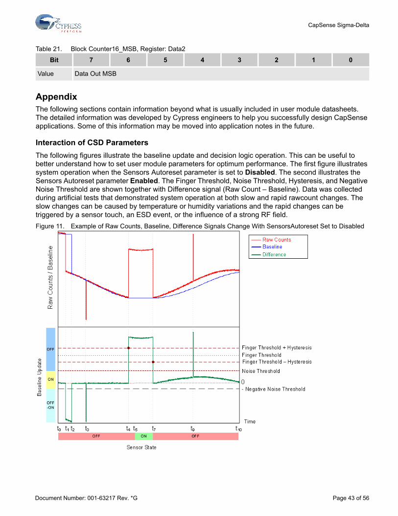
Interaction of CSD ParametersThe following figures illustrate the baseline update and decision logic operation. This can be useful to better understand how to set user module parameters for optimum performance. The first figure illustrates system operation when the Sensors Autoreset parameter is set to Disabled. The second illustrates the Sensors Autoreset parameter Enabled. The Finger Threshold, Noise Threshold, Hysteresis, and Negative Noise Threshold are shown together with Difference signal (Raw Count – Baseline). Data was collected during artificial tests that demonstrated system operation at both slow and rapid rawcount changes. The slow changes can be caused by temperature or humidity variations and the rapid changes can be triggered by a sensor touch, an ESD event, or the influence of a strong RF field.Figure 11. Example of Raw Counts, Baseline, Difference Signals Change With SensorsAutoreset Set to Disabled
Bit 7 6 5 4 3 2 1 0
Value Data Out MSB
Document Number: 001-63217 Rev. *G Page 43 of 56

CapSense Sigma-Delta
At t0, the raw counts are close to the baseline level and start to drop slowly because of humidity or temperature changes. Because the raw count change between two successive conversions does not exceed the NegativeNoiseThreshold parameter (by absolute value), the baseline is updated by tracking the Raw Count minimum value, holding the lower value of raw count signal.
At t1 the raw count drops sharply and the negative difference exceeds the NegativeNoiseThreshold. This situation can happen if the device is powered on when a finger is on the sensor and then the finger is removed after a period of time. At this time the baseline update mechanism is frozen and an internal timeout counter is activated. The baseline is reset when the difference signal is below the NegativeNoiseThreshold for LowBaselineReset samples. This happens at t2.
The second large negative difference signal spike happens at t3. This spike may have been triggered by an ESD event for example. Because the spike duration in the sample count is less than the LowBaselineReset parameter, the baseline is kept on hold and the spike is filtered. This prevents a false baseline reset and the resulting false touch detection.
The sensor is touched at t4. When the difference signal exceeds the FingerThreshold + Hysteresis value, the internal debounce counter is activated. If the signal exceeds this value for more than Debounce samples, the sensor state is set to on. This happens at t5. The sensor state reverts back to the off state immediately when the difference signal drops below the FingerThreshold – Hysteresis level at t7. The short positive spike at t9 is filtered by the debounce counter because the spike duration in sample units does not exceed the Debounce value.
The raw count drifts up slowly between t7 and t10. The baseline is updated using the bucket algorithm when the difference signal is below the NoiseThreshold (SensorsAutoreset is set to Disabled), the difference signal is proportional to the drift rate. It is possible to control the baseline update speed using the BaselineUpdate Threshold parameter. Lower parameter values give faster baseline update speeds.
Document Number: 001-63217 Rev. *G Page 44 of 56

CapSense Sigma-Delta
Figure 12. Example of Raw Counts, Baseline, Difference Signals Change With SensorsAutoreset Set to Enabled
The system operation in the previous figure is similar to the operation in the previous case, except for the following differences:
The touch duration is decreased because of the active baseline update algorithm while the sensor is touched, t6.After the finger is removed, the baseline is reset after LowBaselineReset samples (t8), which blocks touch detection for a short time. This serves as an additional debounce mechanism.
Step-By-Step Tuning GuideThe success of capacitive sensing depends on setting the parameters optimally for the given sensing electrodes. Variables that affect these settings include:
Geometric dimensions of the electrodesOverlay thickness and dielectric constantElectrode connection resistance to the PSoC deviceThe end application conditions such as:
– Presence of a power supply
– Temperature
– Humidity
Document Number: 001-63217 Rev. *G Page 45 of 56
CapSense Sigma-Delta
– Presence of moisture
– ESD, EMC, or EMI requirements
The best practices for different tasks (waterproof operation, sensing using high resistance materials, proximity detection, and operation through thick overlays and recommendations for passing certification tests) are described in separate application notes.
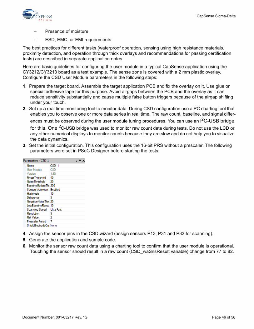
Here are basic guidelines for configuring the user module in a typical CapSense application using the CY3212/CY3213 board as a test example. The sense zone is covered with a 2 mm plastic overlay. Configure the CSD User Module parameters in the following steps:
1. Prepare the target board. Assemble the target application PCB and fix the overlay on it. Use glue or special adhesive tape for this purpose. Avoid airgaps between the PCB and the overlay as it can reduce sensitivity substantially and cause multiple false button triggers because of the airgap shifting under your touch.
2. Set up a real time monitoring tool to monitor data. During CSD configuration use a PC charting tool that enables you to observe one or more data series in real time. The raw count, baseline, and signal differ-ences must be observed during the user module tuning procedures. You can use an I2C-USB bridge for this. One 2C-USB bridge was used to monitor raw count data during tests. Do not use the LCD or any other numerical displays to monitor counts because they are slow and do not help you to visualize the data dynamics.
3. Set the initial configuration. This configuration uses the 16-bit PRS without a prescaler. The following parameters were set in PSoC Designer before starting the tests:
4. Assign the sensor pins in the CSD wizard (assign sensors P13, P31 and P33 for scanning). 5. Generate the application and sample code. 6. Monitor the sensor raw count data using a charting tool to confirm that the user module is operational.
Touching the sensor should result in a raw count (CSD_waSnsResult variable) change from 77 to 82.
Document Number: 001-63217 Rev. *G Page 46 of 56

CapSense Sigma-Delta
7. Tune the external components. Cypress used a 5.6 nF modulator capacitor (Cmod) and 1.6 kΩ feed-back resistor Rb initially. After observing raw count values from different sensors under touch conditions, Cypress found the sensor that produced the largest raw count value. The signal from this sensor is shown in the previous figure. The lower signal value corresponds to no fin-ger touch, the upper corresponds to touch conditions. By analyzing the signal values from this sensor, you can see that the system is using only 16% of the capacitance-to-code converter’s dynamic range. The full range for 9-bit resolution is Nm = 512 and the maximum raw count about 85. This means that the dynamic range utilization can be increased to the recom-mended 60-70% by increasing the feedback resistor value to 5.1 kΩ. You can use different resistor values for this work, depending your raw count observations. The following finger response is the result after the resistor was replaced. Response from a finger touch is increased.
8. Adjust for worst case. Use a finger simulator to be sure that the device works reliably in different condi-tions, for example, for very slight touch. A 10 mm unconnected coil placed on the overlay simulates a worst case. Move the coil is across the button using a dielectric object such as a match or a toothpick. The following figure shows the results. You can run this test if your board uses a ground plane around sensors. If the board is covered by a shielding electrode instead of a ground plane, you can simulate the worst case response by running a very slight touch with a finger.
Document Number: 001-63217 Rev. *G Page 47 of 56

CapSense Sigma-Delta
9. The signal from the coil is identified, but the SNR is too small for reliable detection. The difference is only about 8 dB. To increase the sensitivity, select higher scanning resolutions. In the test, the resolu-tion was increased from 9 bits to 12 bits. Here is the signal from the coil at these settings.
10. Increasing the scanning resolution from 9 to 12 bits improved the SNR to 23 dB, which is good for most practical applications. Signal from human finger is larger.
11. Set the thresholds. Make the following changes to the user module parameters:
Document Number: 001-63217 Rev. *G Page 48 of 56

CapSense Sigma-Delta
12. Set the optimal scanning speed. Suppose the test application power supply voltage is not well regu-lated and ± 5% sharp power supply fluctuations are possible due to the operation of other parts of the target device. In addition, suppose the PSoC device drives several 10 mA LEDs together with its CapSense functions. The current drop on the internal die resistance can cause the internal power sup-ply voltage to fluctuate. The CapSense system should continue to operate with this voltage transient. Test the changes that result in the raw count due to these fluctuations. The LEDs must be turned on and off at same time. The sleep timer interrupt is ideal for this job. Alternatively, an external pulse source can be used to simulate the external loads turning on and off. The following figure shows raw counts when LEDs are toggled while scanning is active.
13. As can be seen from this graph, the LED on/off while scanning is active has no visible influence on the raw count value. Test the CapSense stability for sharp power supply changes. Very slow power supply changes are handled by baseline update algorithms and do not create a problems in most cases. The LM1117-ADJ voltage regulator was used for this test. The output voltage was modulated by a feedback resistor network changing using a MOSFET, driven by external signal source. The following chart shows the raw count difference for a sensor when the power supply is oscillating between 4.75V to 5.25V.
14. As can be seen in this graph, the power supply transient raw count change (50) is close to the thresh-old values (35..45) and can cause a false touch detection. The workaround is to use a slower scan speed. The following figure shows the raw count data collected at Normal scanning speed:
Document Number: 001-63217 Rev. *G Page 49 of 56

CapSense Sigma-Delta
15. As this graph shows, reducing the scan speed decreased the influence of the power supply voltage change on the raw count. The transient difference is now about 12 counts. This is well below threshold values and has no undesirable influence on the CapSense module operation.
16. Tune the BaselineUpdateThreshold parameter. The application requires a maximum touch time detection of less than 1 sec. Set the SensorsAutoreset parameter to Enabled. Check whether the BaselineUpdateThreshold gives a baseline update speed that adequately compensates for environ-ment changes. For example, if the application is a kitchen application where quick temperature changes are possible due to cold air flowing over the board, the raw count drops due to the tempera-ture change. The baseline tracks this by resetting the baseline to the raw count value automatically. Therefore, dropping raw counts due to environmental factors should not be a problem inmost cases. If the raw count is increased due to the temperature variations, it is possible to trigger a false touch by interpreting this change as a touch. We need to adjust the baseline update speed so that the influence of temperature (or other environmental factors) on the raw count-baseline difference is well below the Finger Threshold value. The raw count-baseline difference was monitored during these tests. The monitored value was 0, making the difference below the Noise Threshold parameter. This parameter was set to the minimum value of five during these tests. This means that the preset BaselineUpdate Threshold parameter provides sufficient baseline tracking speed and temperature fluctuations should be no problem for our application.
17. With all parameters set you can run ESD tests. Your application should be able pass these tests with-out problems, even with ESD Debounce parameter set to Disabled. If required, you can enable the ESD Debounce parameter if there are problems with ESD tests. The cost of enabling this parameter is an increase in the size of the RAM buffer.
18. Many CapSense applications are required to pass various EMC/EMI compatibility tests. If your appli-cation has some problems with EMC/EMI, the design guide Getting Started with CapSensecontains information on fixing the problems. Other possible ways to address the problem are to use the slower PRS clock to reduce sensor path radiation. You can try the configuration with prescaler or use slower IMO mode (for example, run SYSCLK at 6 MHz instead 24 MHz). Any changes in PRS clock fre-quency or prescaler period settings require you to also adjust the feedback resistor to maximize use of the dynamic range to reach maximum sensitivity.
19. If your application fails EMC tests, try a reduced scanning speed and a higher resolution. This results in longer PRS polynomial sequences, yielding better noise immunity. The cost of this is increased sen-sor scanning time.
Document Number: 001-63217 Rev. *G Page 50 of 56

CapSense Sigma-Delta
Troubleshooting
If you see strange signal change spikes in multiples of 256 in the raw sensor count, reduce the scan-ning speed. If this helps, the problem origin is a missing counter overflow interrupt. Analyze your inter-rupt durations and optimize them. Re-enable global interrupts from lower priority interrupts. See the following section about interrupt duration management for details.You can use the precharge prescaler as a UART baud rate clock source. The recommended UART speed should be not less than 115,200 baud. The prescaler period should be set to 25 for 24 MHz IMO operation. Because this value is not a multiple of 2N, a slower scanning speed is recommended for better SNR. Test this by experiment.When you start working with the CSD select the Analog Modulator (ASE11) reference. Check the raw count signal-to-noise ratio. Switch to Bandgap for comparison. The noise should not be more than ±5..±7 LSB even at high resolutions.If you see large, periodic noise at your reference setting, try increasing the CSD_DELAY constant in the CSD.asm file. This delay sets the modulator startup time before the measurement is started. Reducing the modulator capacitor Cmod reduction can help as well. The reason for this noise is that the modulator capacitor was charged to a different voltage during the previous measurement cycle due to a low time constant on the internal analog modulator low-pass filter.The PRS configuration with prescaler provides faster scanning time for low resolutions. Select this configuration if you need very fast scan times.The scanning speed and resolution affect the signal-to-noise ratio (SNR). Slower scanning speeds and higher resolution give better SNR.When the electrode overlay is thick, higher resolution and slower scanning speed may be required.The PRS polynomial is automatically adjusted depending on the scanning speed and resolution so that the PRS sequence repeat period is close to the sample conversion cycle count. Slower scanning rates and higher resolutions give better noise immunity during EMC tests because it produces longer PRS sequences.Slower scanning speeds results in lower modulator operation frequency, making readings less depen-dent on the comparator dynamic characteristics. When you need good raw count stability despite power supply fluctuations or when the PSoC device controls high current loads, use the analog modu-lator to form the comparator reference internally. The recommended scanning speed in this situation is Normal or Slow.The Sigma-Delta conversion method belongs to the class of integrating methods. It demonstrates the best performance at higher resolutions. Use the longest scanning time possible. Use 1 ms for sensor scanning for best results.The shield electrode can be used effectively for reducing the stray capacitance influence even in the non-waterproof sensing applications. In this case the shield electrode can be located on the bottom layer of PCB under capacitive sensors zone. The hatch filling pattern is recommended in this case to decrease the shielding electrode’s capacitance.
Eliminate Possible Resource Use Conflicts Be careful not to alter the hardware configurations used by this user module. This includes:
The GlobalOutEven_0 and Row_0_Output_0 buses are used internally. Do not connect any sources to these buses.Do not change the Row_0_Output_0 bus output LUT function. It should be selected to A.Do not change the comparator buses LUT functions. The Comparator Bus_0 LUT function should be set to B, the Comparator Bus_1 LUT should be set to ~A.
Document Number: 001-63217 Rev. *G Page 51 of 56

CapSense Sigma-Delta
The analog module clock source should be set to VC1.The VC1, VC2, VC3 dividers, and the VC3 source are set internally by the user module. The values entered in the Global Resources are overwritten at runtime.When using a shield electrode, set the row LUT function to A.
Interrupt Duration ManagementCarefully manage your Interrupt Service Routine (ISR) duration when sensor scanning is active. The 8-bit counter is clocked directly from VC1. The worse case overflow interval for VC1 is:
Equation 3
FIMO – IMO frequency, VC1=1,2,4,8 for UltraFast, Fast, Normal, Slow scanning speeds respectively.
Special attention should be given to asynchronous communication routines, as I2C, SPI, UART, and sleep timer interrupts. Ensure that they are shorter than estimated worst case overflow time from Equation 3. Re-enable global interrupts from low priority interrupts (such as sleep timer and I2C) to avoid missing the counter overflow interrupt. In some cases, the source code of problematic ISRs should be optimized (for example, I2CHW and EZI2C have long interrupt handlers). Other interrupts should be re-enabled from the I2CHW interrupt by calling the M8C_EnableGInt macro.
ISSP Pins Possible Conflicts Permanent connection of a low resistance feedback resistor to the P1[1] pin can cause ISSP programming faults. Use another pin for this. Use the P3[1] pin on packages where it is available. Future versions of the CSD User Module may allow additional pins that can be used for connecting the feedback resistor that allow the use of a second I2C port.
Document Number: 001-63217 Rev. *G Page 52 of 56

CapSense Sigma-Delta
Version History
Version Originator Description
1.4 DHA 1. The Resolution maximum is (number of pins used for sensors - 1) x 28 - 1or (2 x number of pins used for sensors - 1) x 28 - 1 for diplexed sliders.
2. Removed 0.5 shift and added compensation for negative values.
3. Fixed pin list in wizard.
1.50 DHA Added support for CY8C21x12 devices.
1.50.b DHA 1. Changed max resolution of sensors in slider
2. Added help file to wizard
3. The following updates were done to this user module datasheet:a. Added description of analog bus for CY8C28xxx.b. Updated images.
1.60 DHA 1. Transferred the DiplexTable from "AREA UserModules" to "AREA lit".
2. Set the default "DiplexTable" parameter value to 0x0112.
3. Added the "DiplexUsed" parameter to improve code compression.
4. Added CSD_ScanAllSensors API call at the end of the Start API.
Document Number: 001-63217 Rev. *G Page 53 of 56

CapSense Sigma-Delta
1.70 DHA 1. Updated area declarations to support Imagecraft optimization.
2. Added symbolic names for the Resolution parameter in this user module datasheet.
3. Addressed issues with CSD and DelSig User Modules coexistence.
4. Added the precharge function to precharge the Cmod capacitor to reference voltage.
5. Added support for Rb pins P1[0], P1[4] and P3[0] on CY8C21x34 devices.
6. Added Design Rule Check when the wrong Feedback resistor parameter is set.
7. Added support for Rb pins P1[0],P3[0],P5[0],P1[4],P3[4], and P5[4] on CY8C24x94 devices.
8. Added max value limitation on the Resolution parameter for Slider and RadialSlider.
9. Updated the following sections in this user module datasheet: SetScanMode() API Function description Feedback Resistor Pin sectionISSP Pins Possible Conflicts sectionRb Pin Reference
10. Updated the resolution range calculation for Slider and Radial Slider in the user module wizard.
11. Updated the user module wizard help. Added a description of the slider resolution parameter min/max values.
Version Originator Description
Document Number: 001-63217 Rev. *G Page 54 of 56

CapSense Sigma-Delta
1.70.b DHA 1. Changed peak frequency from FIMO/4 to FIMO/2 for PRS8 and prescaler configurations
2. Moved setting of CSD_MODE bit from ScanSensor API to Start API for CY8C20xx7/S only.
3. Changed calibration resolution from 9 bits to 12 bits in CSD_Start API for CY8C20xx7/S only.
1.80 DHA 1. Changed default "Reference" value from VBG to ASE11.
2. Updated user module block diagram.
3. Updated RAM and ROM usage values in user module datasheet.
4. Deleted redundant register writing and corrected shield signal connection for PRS16 configuration.
5. Added CYRF89x35 device support.
6. Removed redundant comparator bus usage for CY8C24x94 chip architecture.
7. Analog mux resource freed when CSD is unplaced.
1.90 MYKZ 1. Added Resume() function to User Module API.
2. Fixed problem with saving information for sliders.
3. Updated baseline algorithm to check for negative difference counts.
4. Added build error message when user attempts to build project without first calling the user module wizard.
5. Updated UM Wizard sliders setting algorithm to take into account free pins.
6. Optimized Start User Module function code.
7. Removed default value for feedback resistor pin.
8. Updated Precharge() function to correct Cmod connection to GND.
9. Updated ScanSensor() function to reset PRS.
2.00 HPHA 1. Updated User Module Wizard so as not to allow assigning the Rb pin to sensor for CY8C21xxx devices.
2. Resolved the issue that the sensor on P1[5] is not working when the Rb pin is on P1[4] for CY8C21xxx devices.
3. Resolved the issue that the CSD_Start API disconnects Row_0_Output_1 connections to the Global Output busses for CY8C21x12 devices.
4. Resolved the issue with the RawCounts overflows for CY8C21xxx devices.
Version Originator Description
Document Number: 001-63217 Rev. *G Page 55 of 56

CapSense Sigma-Delta
Note PSoC Designer 5.1 introduces a Version History in all user module datasheets. This section docu-ments high level descriptions of the differences between the current and previous user module ver-sions.
Document Number: 001-63217 Rev. *G Revised April 2, 2015 Page 56 of 56Copyright © 2010-2015 Cypress Semiconductor Corporation. The information contained herein is subject to change without notice. Cypress Semiconductor Corporation assumes no responsibilityfor the use of any circuitry other than circuitry embodied in a Cypress product. Nor does it convey or imply any license under patent or other rights. Cypress products are not warranted nor intendedto be used for medical, life support, life saving, critical control or safety applications, unless pursuant to an express written agreement with Cypress. Furthermore, Cypress does not authorize itsproducts for use as critical components in life-support systems where a malfunction or failure may reasonably be expected to result in significant injury to the user. The inclusion of Cypress productsin life-support systems application implies that the manufacturer assumes all risk of such use and in doing so indemnifies Cypress against all charges.
PSoC Designer™ and Programmable System-on-Chip™ are trademarks and PSoC® is a registered trademark of Cypress Semiconductor Corp. All other trademarks or registered trademarksreferenced herein are property of the respective corporations.
Any Source Code (software and/or firmware) is owned by Cypress Semiconductor Corporation (Cypress) and is protected by and subject to worldwide patent protection (United States and foreign),United States copyright laws and international treaty provisions. Cypress hereby grants to licensee a personal, non-exclusive, non-transferable license to copy, use, modify, create derivative worksof, and compile the Cypress Source Code and derivative works for the sole purpose of creating custom software and or firmware in support of licensee product to be used only in conjunction witha Cypress integrated circuit as specified in the applicable agreement. Any reproduction, modification, translation, compilation, or representation of this Source Code except as specified above isprohibited without the express written permission of Cypress.
Disclaimer: CYPRESS MAKES NO WARRANTY OF ANY KIND, EXPRESS OR IMPLIED, WITH REGARD TO THIS MATERIAL, INCLUDING, BUT NOT LIMITED TO, THE IMPLIED WARRANTIESOF MERCHANTABILITY AND FITNESS FOR A PARTICULAR PURPOSE. Cypress reserves the right to make changes without further notice to the materials described herein. Cypress does notassume any liability arising out of the application or use of any product or circuit described herein. Cypress does not authorize its products for use as critical components in life-support systemswhere a malfunction or failure may reasonably be expected to result in significant injury to the user. The inclusion of Cypress' product in a life-support systems application implies that the manufacturerassumes all risk of such use and in doing so indemnifies Cypress against all charges.
Use may be limited by and subject to the applicable Cypress software license agreement.