The Lateral Torsional Buckling Strength of Steel I-Girders with ...
Upload
manchesterCategory
view
1download
0
Capacity assessment and strengthening of pre-stressed concrete girders: A case study
C. Maraveas1), Z. Fasoulakis2)
1), 2) Dept. of Structural Eng., C. MARAVEAS PARTNERSHIP-Consulting Engineers,
Athens, Greece 1)
School of M.A.C.E., University of Manchester, UK 1)
ABSTRACT
The present case study investigates the capacity assessment and subsequent strengthening of pre-stressed concrete girders and provides additional information on the strengthening measures taken for the whole of the structure involved. It is based on an existing concrete building constructed in 1971. Structural modifications had to be made to ensure a proposed load-bearing capacity upgrade due to change of use. The building contains concrete girders pre-stressed with the post-tensioning method, the mechanical and geometric properties of which were not available, although it was known that the two-span girders were intended to meet high-capacity demands. Nonetheless, an accurate simulation of the structure was essential. For this purpose, non-destructive methods had to be employed, while safety factors were introduced in accordance with the corresponding code provisions, in order to minimize structural uncertainties. Subsequently, finite element models were created to evaluate the response of the structure under the new loading conditions, and the necessary modifications were proposed. 1. INTRODUCTION Structural behavior assessment and strengthening demands have always been a great challenge for civil engineers, especially with increased structural complexity. Consequently, creative solutions and sophisticated methods have evolved through the years, providing engineers with the best possible results in that particular field. The reliable evaluation of the load-bearing capacity is of crucial importance for extending the life of structural elements. Thus, a subsurface radar application was used for determining the geometry of the steel tendons inside the girders, whereas the material properties were estimated through a combination of destructive and non-destructive methods. The girders under examination were subsequently simulated using commercial finite element software. For a more detailed response evaluation, the simulation was conducted for five different construction stages. The specifications of Eurocode 2 were also taken into consideration.
1)
Technical Director 2)
Structural Engineer
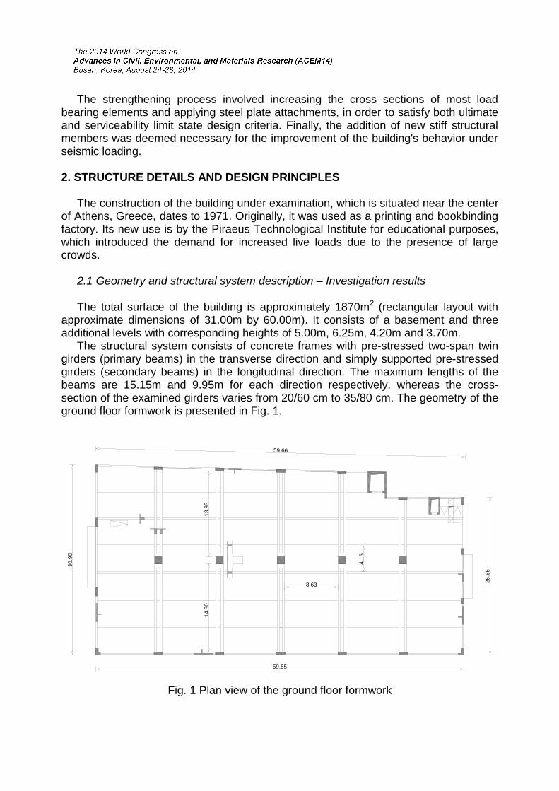
The strengthening process involved increasing the cross sections of most load bearing elements and applying steel plate attachments, in order to satisfy both ultimate and serviceability limit state design criteria. Finally, the addition of new stiff structural members was deemed necessary for the improvement of the building's behavior under seismic loading. 2. STRUCTURE DETAILS AND DESIGN PRINCIPLES The construction of the building under examination, which is situated near the center of Athens, Greece, dates to 1971. Originally, it was used as a printing and bookbinding factory. Its new use is by the Piraeus Technological Institute for educational purposes, which introduced the demand for increased live loads due to the presence of large crowds. 2.1 Geometry and structural system description – Investigation results The total surface of the building is approximately 1870m2 (rectangular layout with approximate dimensions of 31.00m by 60.00m). It consists of a basement and three additional levels with corresponding heights of 5.00m, 6.25m, 4.20m and 3.70m. The structural system consists of concrete frames with pre-stressed two-span twin girders (primary beams) in the transverse direction and simply supported pre-stressed girders (secondary beams) in the longitudinal direction. The maximum lengths of the beams are 15.15m and 9.95m for each direction respectively, whereas the cross-section of the examined girders varies from 20/60 cm to 35/80 cm. The geometry of the ground floor formwork is presented in Fig. 1.
59.55
25
.65
13
.93
59.66
14
.30
8.63
30
.90
4.1
5
Fig. 1 Plan view of the ground floor formwork

Inverted-T beams with a height of up to 3.00m were positioned along the structure’s perimeter in order to receive the horizontal and seismic loads, functioning as concrete walls, as the structure lacked them. This created the danger of possible short columns. In terms of load transferring, during the investigation of the structure it was determined that the slabs were simply supported on the secondary beams. Thus, the uniform distribution of vertical floor loads on the secondary beams and subsequent transfer on the primary beams as concentrated loads is justified. The original design specifically mentioned that the Morandi post-tensioning method was employed for pre-stressing the beams. However, any other information about the tendons was absent. During the visual in situ inspection, it was determined that steel reinforcement bars of various diameters and numbers were used as tendons, instead of multi-strand cables. In addition, after examining the anchoring positions, it resulted that the primary beams were first constructed as simply supported and then were stressed only from one end (the one at the perimeter of the building). All this led to the conclusion that, in fact, the proposed pre-stressing method had not been implemented, and instead an equivalent one had been used. Further investigation established the capacity of the tendons at the time of construction. Visual inspection of the building revealed that the concrete (at least at the perimeter frames of the building) was in unfavorable condition due to environmental factors, which implies that the outer steel reinforcement bars had not been adequately protected against corrosion; it was reasonable to assume that the situation was no different for the internal frame steel reinforcements. Special mention must also be made to the observed secondary beam cracking. This fact was attributed to either inadequate pre-stressing or tendon force relief over time. The aforementioned deterioration rate of the steel reinforcement bars was promptly evaluated via tests, estimating their dynamic variance, as the subsequent corrosion of the new steel reinforcements would be crucial for the safety of the structure. In Fig. 2, one can observe (a) the anchorage type at the exterior view of the building and (b) an interior view of the first floor, where the structural members are clearly visible. In Fig. 2a, steel plates can also be noticed, which contribute as shear reinforcement on the first floor external joints, most likely due to some kind of failure against seismic actions in the past.
Fig. 2 (a) Exterior and (b) interior views of pre-stressed concrete girders

2.2 Geophysical application For further assessment of the tendon geometry, other non destructive methods had to be applied. To this end, a georadar method was utilized, which consists of transmitting low frequency electromagnetic signals which give notification for each identified interface that separates areas that has a different dielectric constant. The reflected energy proportion depends on the variance of the dielectric constant. Subsurface radar has become an established investigative tool for assessment of concrete structures, while it has been proved useful for locating steel tendons in pre-stressed concrete; in this study it was applied according to ASTM specifications. Before the device is placed over a beam under examination, its last position is confirmed through an investigation on the transverse direction. The georadar device is presented in Fig. 3.
Fig. 3 Detection of tendons using modern geophysical methods For the detection of the tendons along the entire beam length, a continuous recording was preferred over selective point recording. In Fig. 4, one can identify the tendon pathway along the pre-stressed girder. The aforementioned procedure was repeated for a large number of beams for each floor (approximately 120 tests in total).
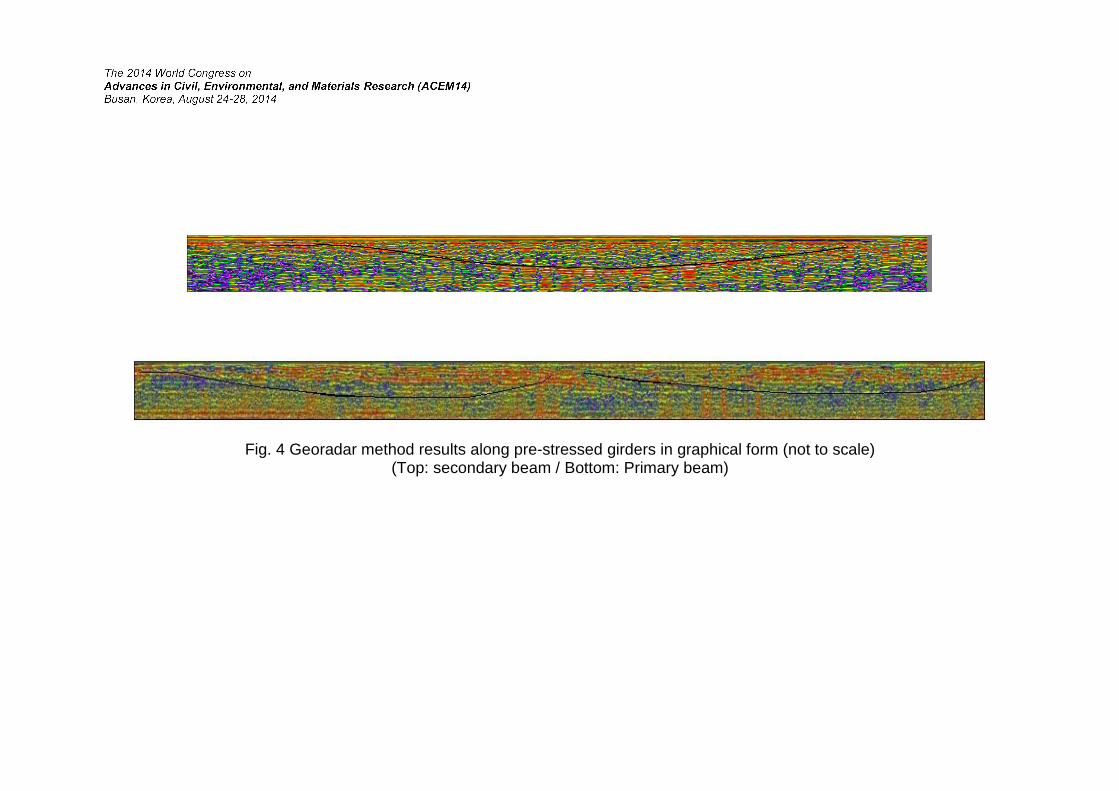
Fig. 4 Georadar method results along pre-stressed girders in graphical form (not to scale) (Top: secondary beam / Bottom: Primary beam)

2.3 Eurocode specifications In order to perform the capacity assessment, the specifications of the Eurocodes were used, namely (EN 1992) for both reinforced and the pre-stressed concrete members of the structure, while the imposed loads followed the specifications of (EN 1991). In addition to the self-weight of the structure, distributed dead loads of 0.50 kN/m2 were considered on the slabs. The live load is 6.00 kN/m2, for area Category C3 per (EN 1991), since the structure is intended to meet higher capacity demands than those it was originally designed for. The mechanical properties of the concrete were determined from laboratory tests on samples taken from the field. Furthermore, non destructive methods were combined for the concrete beams and columns. As a result, the concrete slab and columns were categorized as C20/25, while for the beams the properties corresponded to category C30/37. For the simulation of the tendons, high strength steel was recommended, namely with characteristic yield/ultimate stress values of 800/1050kN respectively, using tensile forces equivalent to 55% of the ultimate stress. Finally, steel reinforcement bar category was specified as B500c. For the design checks the following load combinations were used, as defined in (EN 1990). Eq. 1 indicates the combination of actions other than seismic:
i ikiiQkQPj jkjGd QQP"GS ,,0,1,1,,, ψγ""γ"γ""γ (1)
where “+” implies “to be combined with”, the summation symbol “Σ” implies “the combined effect of”, Gk,j denotes the characteristic value “k” of a permanent action j, P indicates the relevant pre-stressing actions and Qk,i refers to the characteristic value “k” of a variable action i. The seismic actions were combined according to Eq. 2 (EN 1998), while the combination of the horizontal components of the seismic actions is defined in Eq. 3:
i ikidj jkd Q"EGS ,,2, ψ""" (2)
YXd EEE 30.0 or XYd EEE 30.0 (3)
where Ed is the design value of the seismic action and ψ2,i is the combination coefficient for a quasi-permanent action i, taken equal to 0.60. EX and EY are the horizontal seismic actions along the X and Y direction of the structure (longitudinal and transverse respectively). In addition, serviceability requirements were taken into account, by combining actions (Eq. 4) according to (EN 1990):
i ikikj jkd QQP"GS ,,01,, """"" (4)

3. NUMERICAL ANALYSIS The existing structure was simulated as a three-dimensional model, using beam elements for the beams and columns. Apart from the overall structure, the separate simulation of singular pre-stressed beams was also deemed necessary. In this case, the columns were included for up to half the level height above and below the girders, in order to simulate the appropriate boundary conditions for the beam ends. In Fig. 5, 3D views of both models are presented. Particular attention was given to the numerical analysis of pre-stressed concrete. For the accurate computation of the internal forces, several load cases had to be taken into consideration. In particular, 5 load cases representing construction stages were chosen, activating in each one the corresponding elements, in order to consider time-dependent deformations of the concrete, i.e. shrinkage and creep. Seismic loads were not taken into consideration for these design checks, since the seismic response of the global structural model did not exceed 33% of the one derived from the combination defined in Eq. 1, according to the numerical analyses.
Fig. 5 3D views of the models used to simulate a) the overall structure and b) a two-span pre-stressed girder
4. STRUCTURAL EVALUATION OF THE EXISTING BUILDING In order to detect the critical areas of the concrete members, the stress distribution was first obtained from all the load cases. Subsequently, the code-based criteria were applied to evaluate the existing resistance (flexural, shear, and axial) of concrete members and perform the required adequacy checks. Results showed that capacity was exceeded in many concrete members due to lack of flexural or shear reinforcement, while slab thickness was found inadequate against shear and punching shear. 5. STRENGTHENING PROPOSAL Based on the analyses results, the strengthening strategy consisted of two parts, the strengthening of existing load bearing members (both pre-stressed and reinforced), and the addition of new stiff members in appropriate places. All concrete columns along the building perimeter were coated with reinforced concrete jackets of minimum 25cm thickness, in order to improve resistance against seismic loads. For the same purpose, 10cm thick jackets were applied on the internal columns. The primary pre-stressed beams were strengthened by increasing the adjacent slab thickness via reinforced jackets in areas around columns, thus improving their T-beam function. Their flexural strength was also enhanced locally by attaching steel plates around them. The increase in slab thickness also solved the problem of slab inadequacy against shear and punching shear forces. The perimeter inverted-T concrete beams functioning as concrete walls were partially demolished and reshaped as beams with a much shorter web height and greater width, in order to avoid short column effects. Thus unavoidably emerged an even greater need for horizontal load bearing elements than before, which was addressed by increasing the cross sections of the columns and constructing new concrete stairway cores, which contribute to the redistribution of the seismic forces. The adequate interaction between the existing and added concrete and reinforcement bars was ensured with the use of dowels, while new reinforcements were also welded with the old ones where possible, thus securing cooperation between them and proper transfer of forces. The modified structural members with additional steel reinforcements were checked in accordance with the minimum requirements of (EN 1992) specifications. Concrete quality C30/37 and reinforcing steel quality B500c was used for all the additions. The modified cross-sections of two perimeter columns of the ground floor are presented in Fig. 6.

0.80 0.95 0.25
0.2
51
.20
0.5
5
0.2
5
0.25
2.0
0
0.45 0.25
0.95
0.3
00
.25
2.01
0.8
0
Existing beam
0.25 0.45 0.25
0.95
1.0
00
.25
1.5
0
0.2
5
Existing
reinforcements
Existing beam
Additional
reinforcements
Existing column
Steel reinforcement
cooperation via welds
Additional
reinforcements
Existing
reinforcements
Steel reinforcement
cooperation via welds
Concrete jacket
Concrete jacket
Fig. 6 Cross-sections of modified concrete columns In Fig. 7, two examples of primary pre-stressed beam strengthening are illustrated. In particular, one can see the concrete reinforcement of the concrete slab in the area around the column for a first floor beam (Fig. 7a) and the beam strengthening by use of steel plates for a ground floor beam (Fig. 7b).
Existing
concrete slabAdditional reinforcing steel
0.1
0
Concrete jacket
Steel plate
Existing column
Existing
pre-stressed
beam
2.50 2.50
Existing concrete
Existing column
Modified column
Primary
pre-stressed
beams
Steel plates
Steel plates
Connection with bolts
Steel reinforcement
cooperation via welds
a)
b)
Dowels
Fig. 7 Cross-sections of pre-stressed concrete beams of a) first floor and b) ground floor after strengthening modifications
6. CONCLUSIONS The investigation in this study focused on the structural response and strengthening of pre-stressed concrete girders. The capacity assessment of the existing structure involved destructive methods for the evaluation of concrete mechanical properties, whereas the tendon geometry was specified through a geophysical method. In addition, non-destructive methods proved quite useful for determining the corrosion rate of the existing steel reinforcements and tendons. Numerical analyses followed with appropriate simulations of members and boundary conditions, while the European Standards were implemented in order to check the structural elements. Several load stages were taken into account for each analysis. The results demonstrated that the structure was in need of serious strengthening in order to cope with its new use requirements. The proposed modifications consisted of addition of new structural members and strengthening of existing ones, by increasing concrete cross sections and adding steel reinforcements and plates. REFERENCES EN 1990 (2002), Eurocode ─ Basis of structural design, CEN, Brussels. EN 1991 (2002), Eurocode 1 ─ Actions on structures, CEN, Brussels. EN 1992 (2004), Eurocode 2 ─ Design of concrete structures - Part 1-1: General rules
and rules for buildings, CEN, Brussels. EN 1998 (2003), Eurocode 8 ─ Design of structures for earthquake resistance - Part 1:
general rules, seismic actions and rules for buildings, CEN, Brussels. Earthquake Planning and Protection Organization, Greek Code for Seismic Intervention,
Greece. Earthquake Planning and Protection Organization, Greek Seismic Code, Greece. Hurst, M.K. (1998), Pre-stressed concrete design, Second Edition, E&FN Spon, New
York. Larson, N., Gomez, E.F., Garber, D., Bayrak, O. and Ghannoum, W. (2013), Strength
and serviceability design of reinforced concrete inverted-T beams, Center for Transportation Research, University of Texas, Austin.
Telford, W.M., Geldart, L.P. and Sheriff, R.E. (1990), Applied geophysics, Second Edition, Cambridge University Press, New York.
Bungey, J.H., Millard, S.G. and Shaw, M.R. (1997), “Radar assessment of post-tensioned concrete”, Proceedings of the 7th Int. Con. on Structural Faults and Repair, Edinburgh, UK, vol. 1.
Jaeger, B.J., Sansalone, M.J. and Poston, R.W. (1996) “Detecting voids in grouted tendon ducts of Post-Tensioned Concrete Structures Using the Impact-Echo Method”, Struct. J., 93(4), 462-473.
Copyright © 2022 FDOKUMEN