Wind Design Consideraxons for Joists and Joist Girders - NET
120
Presented by: Copyright © 2017 Steel Joist Ins;tute. All Rights Reserved. Wind Design Considera.ons for Joists and Joist Girders APRIL 19, 2017 Keith Juedemann, PE – Canam Buildings Tim Holtermann, PE, SE – Canam Buildings
-
Upload
khangminh22 -
Category
Documents
-
view
2 -
download
0
Transcript of Wind Design Consideraxons for Joists and Joist Girders - NET

Presentedby:
Copyright©2017SteelJoistIns;tute.AllRightsReserved.
WindDesignConsidera.onsfor
JoistsandJoistGirdersA P R I L 1 9 , 2 0 1 7
KeithJuedemann,PE–CanamBuildingsTimHoltermann,PE,SE–CanamBuildings

LearningObjec.ves
• Appropriateloadcombina.onsinvolvingwind.
• Appropriateloadpathsforwindforces.
• Detailsforconnec.onsandthetransferofwindforces.
• Newdevelopmentsaffec.ngwinddesign.
2

Outline
• Windforcesontheroof
– Fromthebuildingcode
– Loadcombina.ons
– UpliF– Downwardwind
• Windeffectsonjoistsystem
– Endanchorage– Bridging
3

Outline
• Lateralwindloads– Diaphragmsandcollectors
– Loadpathsandtransferdetails– Bracingforwindforces
• Membraneroofs
• Newcodedevelopments
4
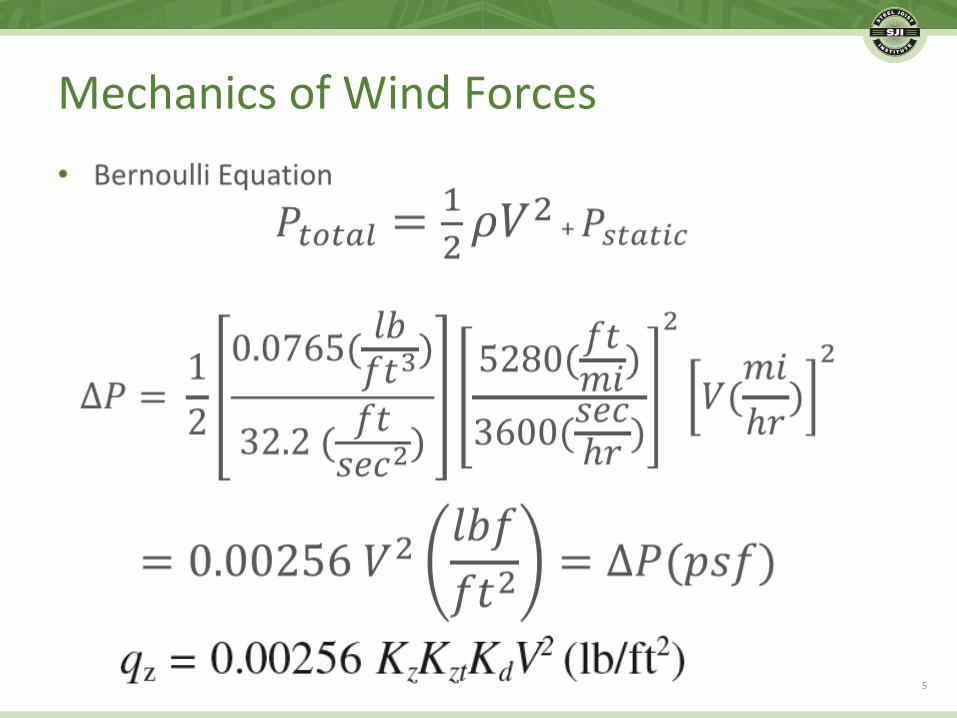
MechanicsofWindForces
5
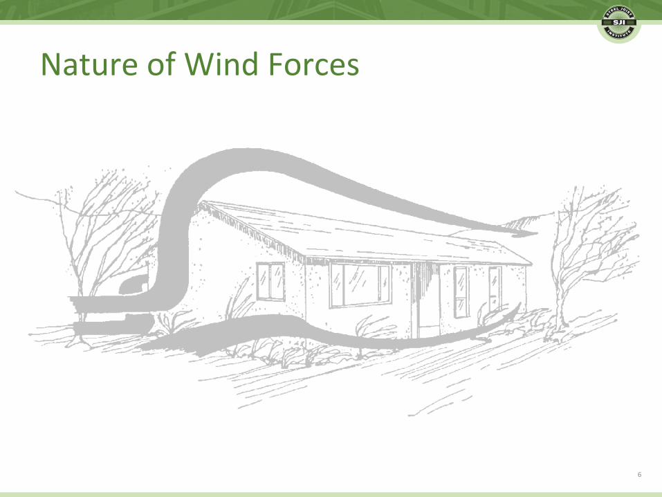
NatureofWindForces
6
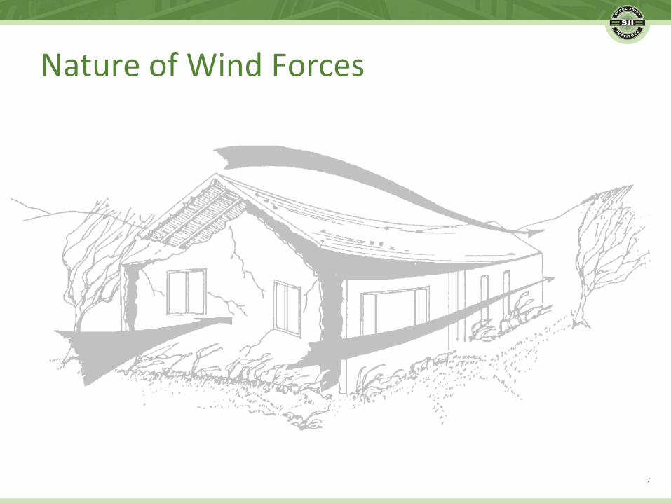
NatureofWindForces
7

8
NatureofWindForces

9
NatureofWindForces
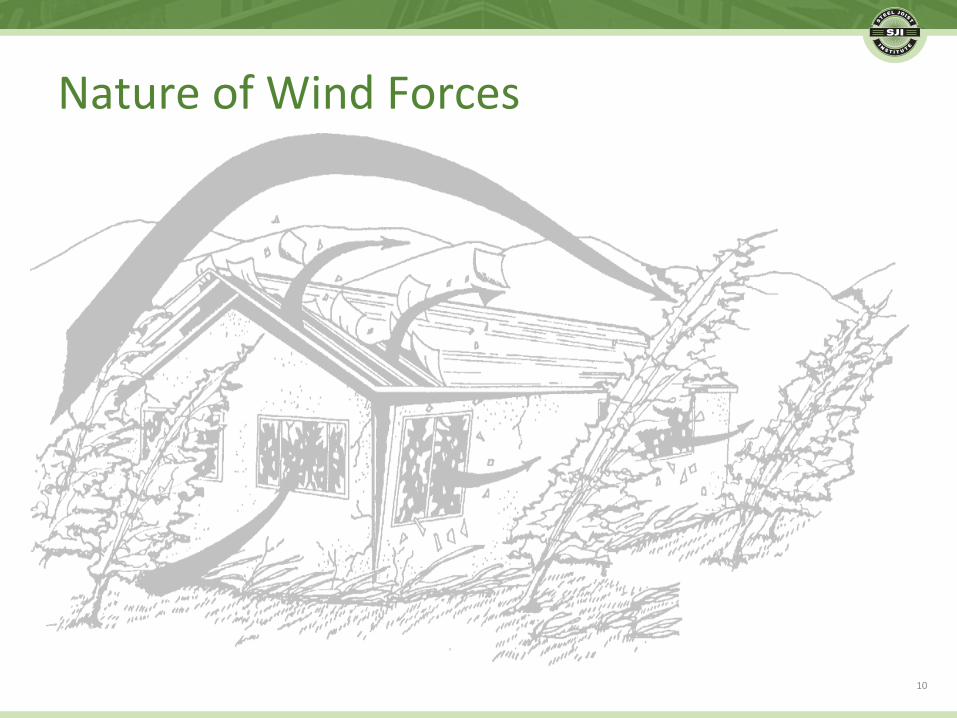
NatureofWindForces
10

WindUpliFonJoistsandDeck• Evenifthesystemisrobust,ithastostayonthe
building!
11

• 2015SteelJoistIns.tute(SJI)StandardSpecifica.onsandCodeofStandardPrac.ce
• ProvisionsfromASCE7-10
12
StandardsandCodes

13
History:1965StandardBuildingCode

14
History:1976UniformBuildingCode
• WindLoads
– 107pagesofcode– 62pagesofcommentary
• Fromtwohalf-sizepagesto169full-sizepages
• Over170.mesthelengthof40yearsago
American Society of Civil Engineers
ASCE 7-10 Minimum Design Loads for Buildings and Other Structures
15

• Itisrela.velysimplewithamonolithicbuildingstructuremadeupoflargerectangularelements.
• Whenthebuildingshapeismorecomplexandcomprisedofnumerouselements,itisnotaseasytodeterminetheloadingsonjoiststhatpassthroughbothedgeandcornerzones.
16
ASCE7-10WindLoads
ASCE7-10WindLoads
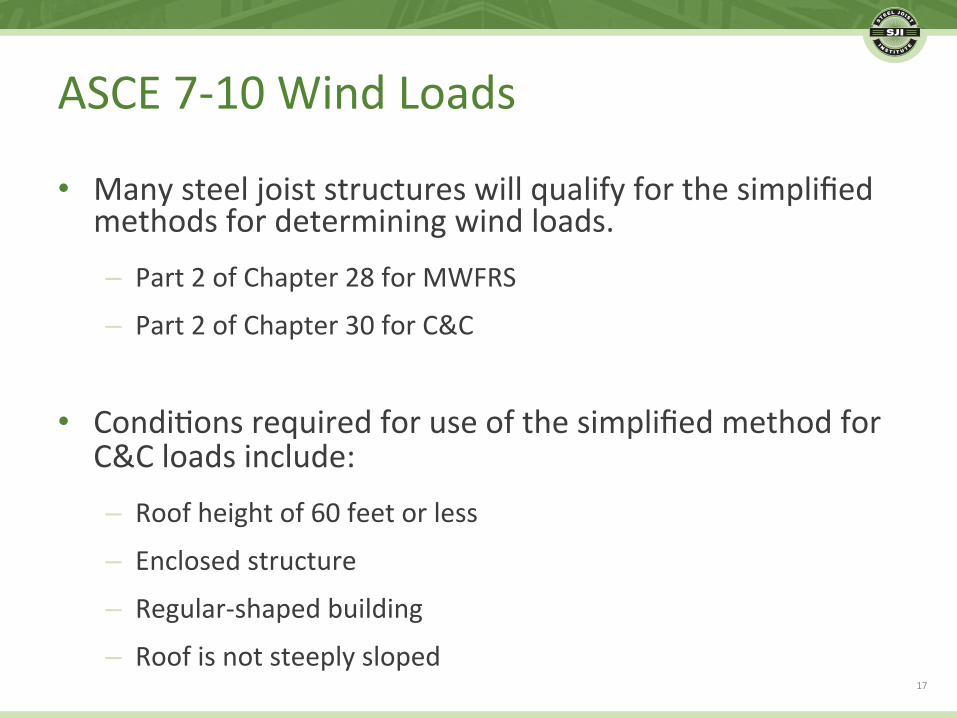
• Manysteeljoiststructureswillqualifyforthesimplifiedmethodsfordeterminingwindloads.
– Part2ofChapter28forMWFRS
– Part2ofChapter30forC&C
• Condi.onsrequiredforuseofthesimplifiedmethodforC&Cloadsinclude:
– Roofheightof60feetorless– Enclosedstructure– Regular-shapedbuilding– Roofisnotsteeplysloped
17

ASCE7-10WindLoads
18

19
ASCE7-10WindLoads

ASCE7-10WindLoads
20

21
ASCE7-10WindLoads

DeterminingWindLoadsforJoists
• SteelJoistIns.tute(SJI)CodeofStandardPrac.ce
22

DeterminingWindLoadsforJoists
• ASCEprovidesformulasfordesignwindpressuresandnetdesignwindpressures.TheseareNOTthesameastheNETupliFrequiredbySJI.
• ASCEnetisthesumofinternalandexternalpressures.• SJInet,isthefinalresultantpressure,lessappropriatedeadload–resultoftheloadcombina.on
23

• 2.3COMBININGFACTOREDLOADSUSINGSTRENGTHDESIGN– 2.3.2BasicCombina.ons
1. 1.4D 2. 1.2D + 1.6L + 0.5(Lr or S or R) 3. 1.2D + 1.6(Lr or S or R) + (L or 0.5W) 4. 1.2D + 1.0W + L + 0.5(Lr or S or R) 5. 1.2D + 1.0E + L + 0.2S 6. 0.9D + 1.0W 7. 0.9D + 1.0E
24
ASCE7-10LoadCombina.ons
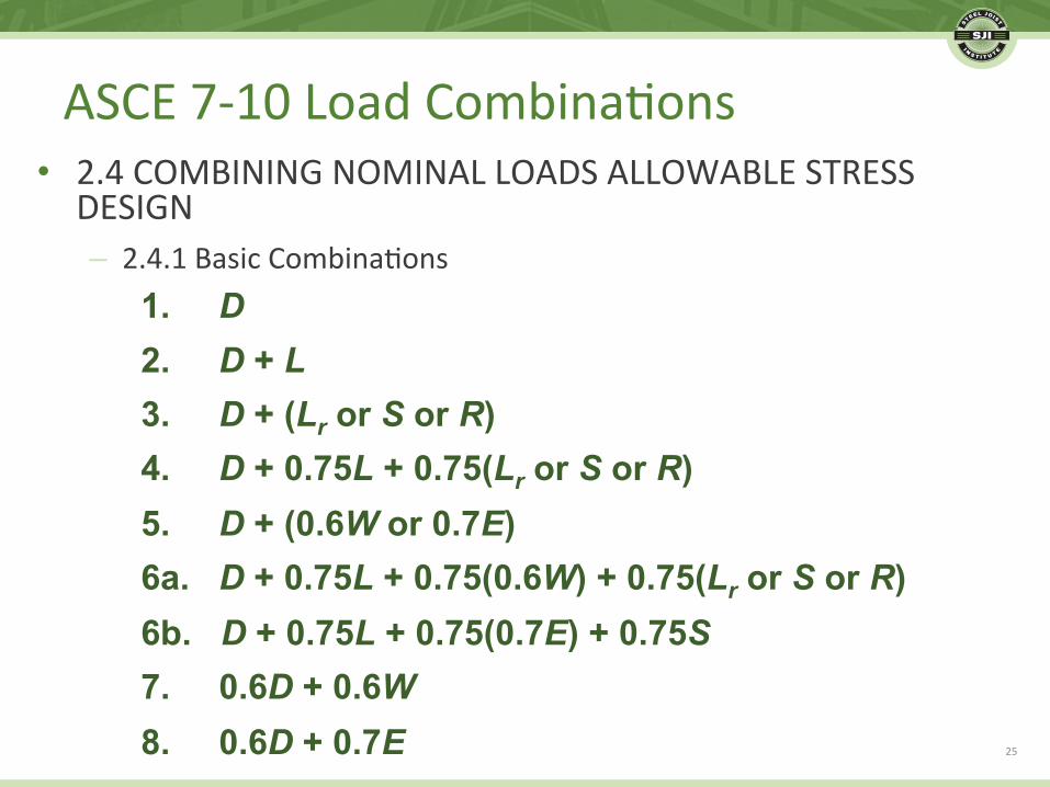
• 2.4COMBININGNOMINALLOADSALLOWABLESTRESSDESIGN– 2.4.1BasicCombina.ons
1. D 2. D + L 3. D + (Lr or S or R) 4. D + 0.75L + 0.75(Lr or S or R) 5. D + (0.6W or 0.7E) 6a. D + 0.75L + 0.75(0.6W) + 0.75(Lr or S or R) 6b. D + 0.75L + 0.75(0.7E) + 0.75S 7. 0.6D + 0.6W 8. 0.6D + 0.7E 25
ASCE7-10LoadCombina.ons

WindLoadFactorsHaveChanged
• ASCE7-05(nominalwindmaps)
– 1.0ASD/1.6LRFD
• ASCE7-10(ul.matewindmaps)
– 0.6ASD/1.0LRFD
26

DeterminingWindLoadsforJoists
• WhenwindupliFisadesignconsidera.on,itshouldbespecifiedasnetupliFonthesteeljoistsandjoistgirders.
• Thechartonthefollowingslideisatypicalcomponentsandcladdingroofwindpressuresprovidedonthecontractdocuments.
27

ROOF SURFACES
EFFECTIVE WIND AREA
POSITIVE PRESSURES (PSF)
NEGATIVE PRESSURES (PSF)
ZONE
1
2
3
1
2
3
10 SF
12.4
12.4
12.4
-30.4
-51.0
-76.8
20 SF
11.6
11.6
11.6
-29.6
-45.6
-63.6
50 SF
10.6
10.6
10.6
-28.6
-38.4
-46.2
100 SF
9.8
9.8
9.8
-27.8
-33.0
-33.0
28
DeterminingWindLoadsforJoists
DeterminingWindLoadsforJoists
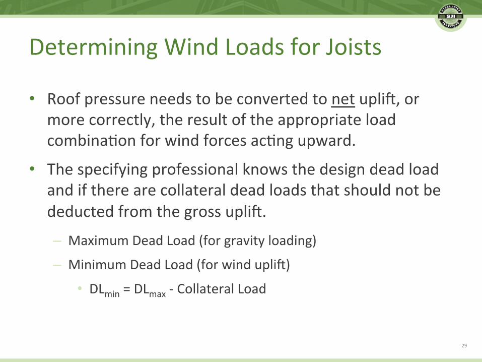
• RoofpressureneedstobeconvertedtonetupliF,ormorecorrectly,theresultoftheappropriateloadcombina.onforwindforcesac.ngupward.
• ThespecifyingprofessionalknowsthedesigndeadloadandiftherearecollateraldeadloadsthatshouldnotbedeductedfromthegrossupliF.
– MaximumDeadLoad(forgravityloading)
– MinimumDeadLoad(forwindupliF)
• DLmin=DLmax-CollateralLoad
29
DeterminingWindLoadsforJoists
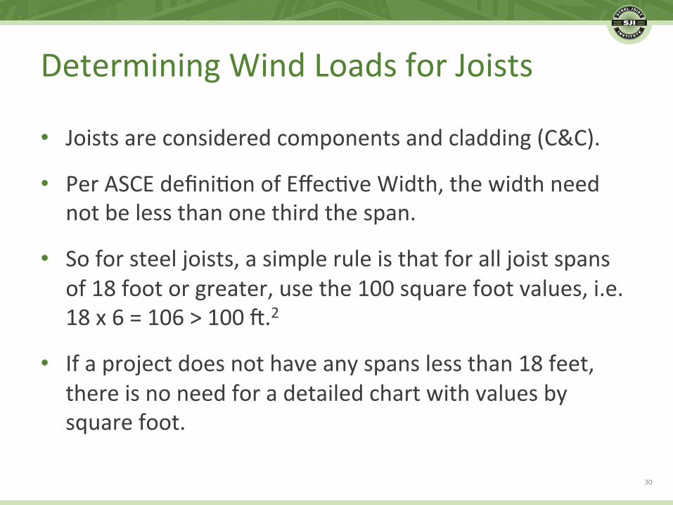
• Joistsareconsideredcomponentsandcladding(C&C).
• PerASCEdefini.onofEffec.veWidth,thewidthneednotbelessthanonethirdthespan.
• Soforsteeljoists,asimpleruleisthatforalljoistspansof18footorgreater,usethe100squarefootvalues,i.e.18x6=106>100F.2
• Ifaprojectdoesnothaveanyspanslessthan18feet,thereisnoneedforadetailedchartwithvaluesbysquarefoot.
30

DeterminingWindLoadsforJoists
• Joistgirderscanbeconsideredpartofthemainwindforce-resis.ngsystem(MWFRS).– Typically,separateMWFRSpressurevaluesarenotprovidedforthejoistgirders,andthejoistdesignerappliestheC&CnetupliFforcesfromthejoiststothejoistgirders.
• Joistgirdertensionwebsmustbedesignedtoresist,incompression,25percentoftheiraxialforce.
• UpliFloadsonaJoistGirderoflessthan25percentofthegravityloadshaveminimalornoeffectonthegirderdesign.
31

DeterminingWindLoadsforJoists
• OverhangshavesignificantupliF– Joisttopchordextensions(TCX)“automa.cally”havesamecapacityasdownwardgravity.
– UpliFonoverhangscaneasilyexceedgravity,par.cularlyincoastalareasorhurricaneproneregions.
32
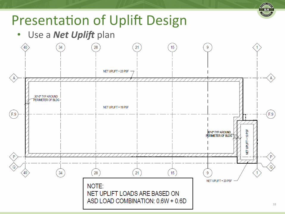
Presenta.onofUpliFDesign• UseaNetUpli)plan
33

Presenta.onofUpliFDesign• UseaNetUpli)plan
34

• Let’scompromise
35
Presenta.onofUpliFDesign

Presenta.onofUpliFDesign• Notenoughdirec.on
36

DesignExample
37

DesignExample
• RiskcategoryII• V=115(typicalforinteriorpor.onsofcon.guous
UnitedStates)
• Kzt=1.0• CompareexposurecategoriesB&C
• Rectangularbuildingwithheight=40’,andflatroof• Simplifiedmethodforcomponents&cladding:
38

DesignExample
• Joistsplacedat6’-0”oncenterandspanning50’• DL=15psf&LL=20psf• UseASD• Totaluniformgravityload=210plf
• Uniformliveload=120plf
• Select30K8(225/130loadingfromSJItables)
• Joistweightisapproximately460pounds
39

DesignExample

DesignExample
• ForexposureBand100squarefooteffec.vearea,pnet=1.09x1.0x-21.8=-23.8psf
• NetupliF=0.6D+0.6W=0.6(15)+0.6(-23.8)=-5.3psf
• @6’-0”spacing=32plfnetupliFOnly15%ofgravityloadingof210plf
• Thisloadcasedoesnotaddweightorcosttothejoist.NotethatupliFbridgingisrequired.
41

DesignExample
• Let’sassumeplansarenotclearandthejoistsupplierusesthepnet=-23.8psfasthenetupliF.
• @6’-0”spacing=143plfnetupliFNow68%ofgravityloadingof210plf
• 30K8with143plfnetupliFweightsabout610pounds.33%heavierthan30K8suppor.ngrequirednetupliF
42

DesignExample

DesignExample
• ForexposureCand10squarefooteffec.vearea,pnet=1.49x1.0x-23.8=-35.5psf
• NetupliF=0.6D+0.6W=0.6(15)+0.6(-35.5)=-12.3psf
• @6’-0”spacing=74plfnetupliF35%ofgravityloadingof210plf
• 30K8with74plfnetupliFweightsabout490pounds.7%heavierthan30K8suppor.ngrequirednetupliF
44

Posi.veWindPressureConsidera.ons
• Thetotaljoistloadforthepurposesofselec.ngajoistdesigna.onshouldrepresentthemaximumresultoftheloadcombina.ons,whichmayincludeadownward(posi.ve)windforceinthecontrollingloadcase.– ForLRFD
• 1.2D+1.6(LrorSorR)+(Lor0.5W)• 1.2D+1.0W+L+0.5(LrorSorR)
– ForASD• D+(0.6Wor0.7E)• D+0.75L+0.75(0.6W)+0.75(LrorSorR)
45

Posi.veWindPressureConsidera.ons
• Example(ASD)
DeadLoad(D)=15psf
LiveLoad(Lr)=20psf
Posi.veWind(W)=16psf (130mph,60’height,exposureC,100sq.F.eff.area)
TotalDesignLoad=D+Lr=35psf
Or
D+0.75(0.6W)+0.75(Lr)=37.2psfßGoverns
46

Wind–NottobeTakenLightly!
47

ApplyingWindUpliFtoJoists
• Connec.onsareacri.calpartoftheloadpath – Designofjoistseat
– Capacityofatachment
• Welds
• Bolts
48

Connec.onDesignforUpliF
• Anchoragefailureexample
49

Connec.onDesignforUpliF
• DivisionofResponsibility– SJISpecifica.onandCodeofStandardPrac.ce
• “ThejoistmanufacturerwillprovideaseatofsufficientthicknessandstrengthtoresisttheupliFendreac.onresul.ngfromthespecifiedupliF.”
• “Theadequacyoftheendanchorageconnec.on(boltedorwelded)betweenthejoistorJoistGirderbearingseatandthesuppor.ngstructureistheresponsibilityofthespecifyingprofessional.Thecontractdocumentsshallclearlyillustratetheendanchorageconnec.on.”
50

WeldedEndAnchorage
• ThestrengthofthejoistbearingseatforanupliFloadingcombina.onisafunc.onofboththejoistseatthicknessandlengthoftheendanchoragewelds.
• TheminimumanchorageweldsfromtheSJISpecifica.onmaynotdevelopthefullcapacityofthejoistseatassemblyforupliF.
• Longerendanchorageweldlengthaidsthejoistmanufacturerinprovidinganeconomicaldesignofthejoistbearingseat.
51
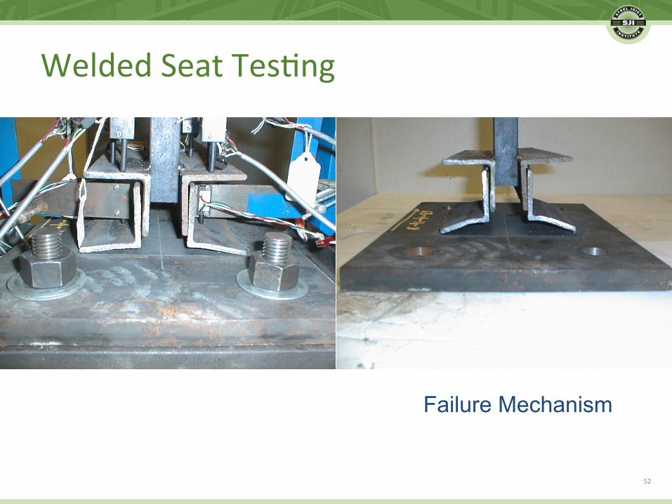
Failure Mechanism
52
WeldedSeatTes.ng

Yield Line Perimeter
53
WeldedSeatTes.ng
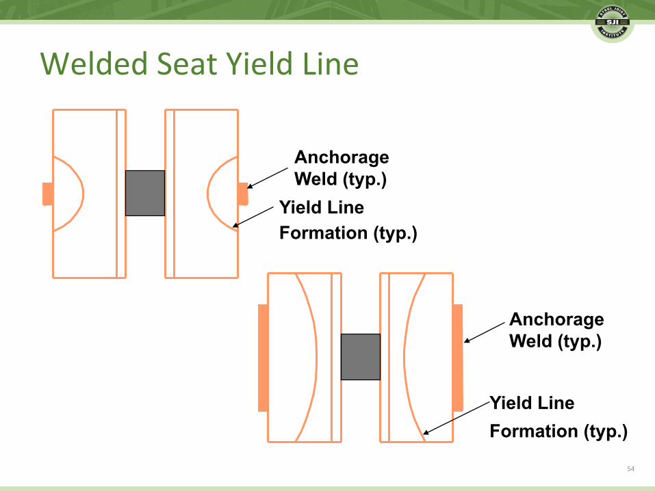
Anchorage Weld (typ.)
Yield Line Formation (typ.)
Anchorage Weld (typ.)
Yield Line Formation (typ.)
54
WeldedSeatYieldLine

a
Δθ
Plastic Hinge
Pu/2
Pu/2 Yield Line
a
Lw Ls
a
a
55
WeldedSeatYieldLine
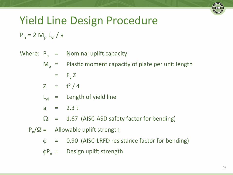
Pn=2MpLyl/a
Where: Pn = NominalupliFcapacity
Mp = Plas.cmomentcapacityofplateperunitlength
= FyZ
Z = t2/4
Lyl = Lengthofyieldline
a = 2.3t
Ω = 1.67(AISC-ASDsafetyfactorforbending)
Pn/Ω= AllowableupliFstrength
φ = 0.90(AISC-LRFDresistancefactorforbending)
φPn = DesignupliFstrength
YieldLineDesignProcedure
56

MinimumEndAnchorageWelds
JOIST SERIES and SECTION NUMBER
MINIMUM FILLET WELD
K Series (2) 1/8” x 2-1/2”
LH Series, 02-06 (2) 3/16” x 2-1/2”
LH/DLH Series, 07-17; JG (2) 1/4” x 2-1/2”
DLH Series, 18-25; JG* (2) 1/4” x 4”
*JoistGirderswithaselfweightgreaterthan50plf.
57

BoltedEndAnchorage
• Finalweldingistypicalforstability(lateralsupport)
• OnlyboltsareconsideredanchorageforupliF– Typeanddiameterbyspecifyingprofessional
– ProvidesufficienttensilestrengthforupliFreac.on
– HigherstrengththanminimumsperSJImayberequired
58

BoltedEndAnchorage
JOIST SERIES and SECTION NUMBER
MINIMUM BOLTS
K Series (2) 1/2” A307
LH Series, 02-06 (2) 1/2” A307
LH/DLH Series, 07-17; JG (2) 3/4” A307
DLH Series, 18-25; JG* (2) 3/4” A325
*JoistGirderswithaselfweightgreaterthan50plf.
59
BoltedConnec.onDesignforUpliF
• Thebearingseatdesignisacheckofpryingac.on– AISCdesignprocedureisfollowed– AnupliFreac.onequaltothefulltensilecapacityoftheboltsmaynotbeachievedwithmaximumprac.calseatthicknessesandwithouts.ffeners.
60
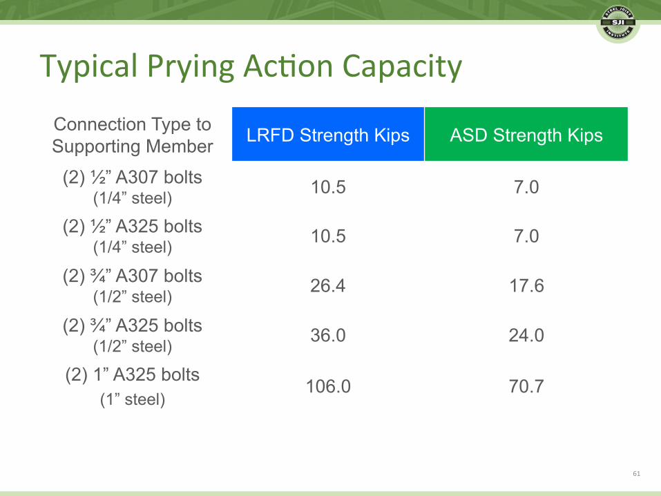
TypicalPryingAc.onCapacityConnection Type to Supporting Member LRFD Strength Kips ASD Strength Kips
(2) ½” A307 bolts (1/4” steel) 10.5 7.0
(2) ½” A325 bolts (1/4” steel) 10.5 7.0
(2) ¾” A307 bolts (1/2” steel) 26.4 17.6
(2) ¾” A325 bolts (1/2” steel) 36.0 24.0
(2) 1” A325 bolts (1” steel)
106.0 70.7
61

• Capaci.esonthepriorslidewerebetween51%and100%ofthefulltensileboltstrength,dependingonthethicknessofthebearingseatleg.
• Aruleofthumbwouldbetosizetheboltdiameter,grade,andquan.tyofboltsbaseduponusing75%ofthefulltensilestrength(allowingtheremainingcapacityforpryingac.on).
62
TypicalPryingAc.onCapacity

Connec.onDesignforUpliF• Whereajoistseathasbeendetailedforabolted
connec.on,andforanyreasontheboltisnotu.lized,theemptyslotinthebearingseatlegseverelydiminishesupliFcapacity.Insuchacondi.on,ifaweldandnoboltistobeusedonaslotedbearingseat,thentheweldshouldbeappliedwithintheemptyslot.
63
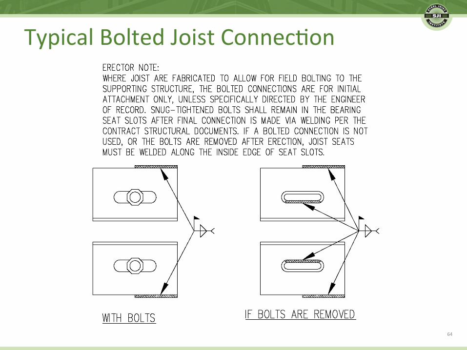
TypicalBoltedJoistConnec.on
64

EndAnchorage
• FormoreonEndAnchorageandjoistdesignforupliF,refertotheSteelJoistIns.tuteTechnicalDigest#6,DesignofSteelJoistRoofstoResistUpliNLoads
65

BotomChordBridgingforUpliF• UpliFProducesStressReversal
– Compressiveaxialloadinbotomchord
• Requireslateralbracing
• Onlybridgingisavailable

BotomChordBridgingforUpliF• SJIStandardSpecifica.onsrequirebridgingatthefirst
botomchordpanelpoint,sincetwoofthethreeintersec.ngprimarymembersareincompressionunderupliFloading.
67

BotomChordBridgingforUpliF
• SJIStandardSpecifica.ons,UpliFBridging– Botomchordbridgingneednotalignwithtopchordbridging
– Totalnumberofbotomchordrowsshallnotbelessthanthenumberoftopchordrows
– Canbeadvantageoustospacerowsmorecloselynearcenterofspan
– Commonlyequalspacingonbotomchord
68

BotomChordBridgingSpacing• Typicaldetailsused–equallyspacebetweenfirstbotom
chordpanelpoints
69

BotomChordBridgingforUpliF
• BridgingLoadRequirements
– Bridgingaxialloadisbasedonbotomchordcompressiveaxialload
• Pbr=0.005Pc• WherePcisthebotomchordcompressiveaxialload
– Bridgingdesignforcefornumberofjoists,n,doesnotaccumulatelinearly
– Randomnessofini.allateralout-of-straightness
70

BotomChordBridgingforUpliF
• BridgingLoadRequirements
– Thefollowingequa.oncanbeusedforthebridgingforce:• Pbr=0.001nPc+0.004Pc√n
• Pcisthebotomchordcompressiveaxialload
– ForsmalltomoderatenetupliFandreasonablenumberofjoists,n,Pbratbotomchordisnolargerthanattopchord
– FormoresevereupliF,Pbratbotomchordcanbecomputedandmaydeterminebridgingsize,orrequirealimitonthevalueofn.
71

External,Addi.onalForcesonBridging• Cananaddi.onal,externalwindforcebetransferred
throughthejoistbridging?
72

External,Addi.onalForcesonBridging
• DiagonalXbridgingwouldbeneededinmul.plejoistspacestotransferforcefromthebotomchordleveluptothedeckdiaphragm.
• Caremustbetakentonotexceedthebirdingconnec.oncapacity,andweldinginaddi.onaltobol.ngmayberequired.
• Thedeckweldatachmentsalsomustnotbeexceeded.
• Aseparatestructuralbracemaybemoreadvisable.
73

• UnbalancedSnowLoads
• LateralLoadResis.ngSystems
– DiaphragmandShearWalls
– BracedFrames
– RigidFrames
• LocalWindBracing(Kickers)
• RoofWindScreens
LateralWindLoads
74

• Onaroofwitharidge,windstendtoreducesnowloadsonwindwardpor.onsandincreasesnowloadsonleewardpor.ons.
• Unbalancedroofsnowloadsareapplicableforroofslopebetween2.38degrees(1/2:12)and30.2degrees(7:12)
• Iftheridgeisalineofsupportforthejoists,theunbalancedsnowneedstobeconsideredinthejoistdesigna.on.
75
UnbalancedRoofSnowLoads

• Forapitchedjoistthatcreatestheridgeline,theunbalancedsnowloadisnotimplicitlyaccountedforbytheSJISpecifica.ons,soacontractnotetorequireacheckisadvisable.
76
UnbalancedRoofSnowLoads

• Themostcommonlateralloadresis.ngsystemonstructureswithjoistsandJoistGirdersisadeckdiaphragmandshearwalls.
77
DiaphragmandShearWalls

• Steeljoistsmaybeusedasdiaphragmchordelements.
• Steeljoistsmaybecollectorelementsinframelines.
78
DiaphragmandBracedFrames
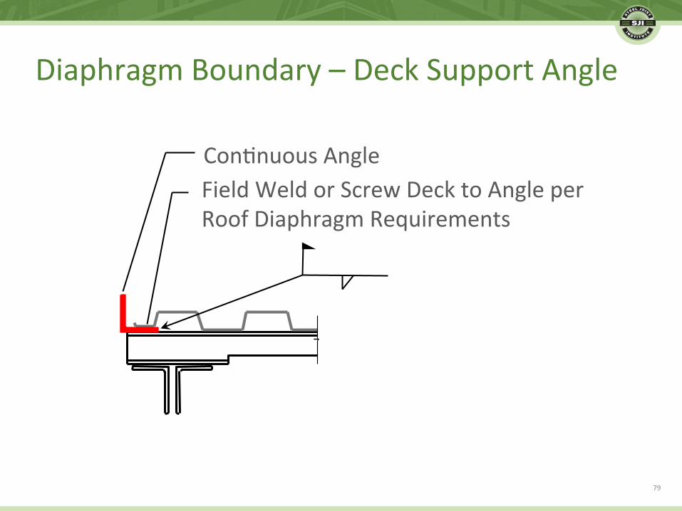
Con.nuousAngleFieldWeldorScrewDecktoAngleperRoofDiaphragmRequirements
79
DiaphragmBoundary–DeckSupportAngle

Note:ForceVshouldbegivenonthestructuraldrawingsasajoistdesignrequirement.
• Ifthereisnotadirectloadpathfromadeckedgeangleordiaphragmboundary,thejoistseatmaybesubjectedtoarolloverforce.
80
JoistSeatRollover

81
DiaphragmBoundary

JOISTGIRDERHSS21/2x21/2x3/16CENTERBETWEENJOISTS(NOTBYJOISTMANUFACTURER)
ROOFDECK
PERSIDELAPDIAPHRAGMREQUIREMENTS5/8"DIA.
• Wherethediaphragmorcollectorchordforceislarge,ashearcollectorcanbeused,betweenthejoistbearingseats.ShownhereisatypicaldetailforK-Series.
82
AlternateDetailtoJoistSeatRollover

JOISTGIRDER
ROOFDECK
5"
PERSIDELAPDIAPHRAGMREQUIREMENTS5/8"DIA.
CHANNELC5x6.7CENTERBETWEENJOISTS(NOTBYJOISTMANUFACTURER)
3/16"
• Hereisasimilardetail,forusewithLH/DLH-Seriesjoists.
83
AlternateDetailtoJoistSeatRollover
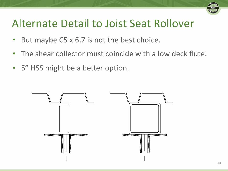
• ButmaybeC5x6.7isnotthebestchoice.
• Theshearcollectormustcoincidewithalowdeckflute.
• 5”HSSmightbeabeterop.on.
84
AlternateDetailtoJoistSeatRollover

• ChordForcesarecarriedasaddi.onalaxialloadsbythetopchordsofjoistsand/orJoistGirders.
• ChordForcesmayvaryfromoneendofthechordtotheother.Theaddi.onalaxialloadforeachjoistand/orJoistGirdermustbeindicated.
• TypeandmagnitudeofaxialforcesatthejoistandJoistGirderendsupportsshallbeshownonthestructuraldrawings.
• AvoidresolvingjoistorJoistGirderaxialforcesthroughthebearingseatconnec.on.
85
ChordForces-Axial

F F
86
DiaphragmChord
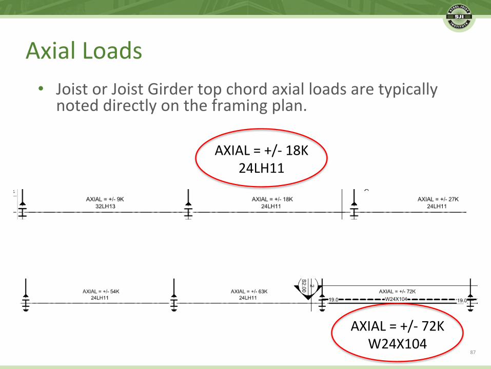
• JoistorJoistGirdertopchordaxialloadsaretypicallynoteddirectlyontheframingplan.
AXIAL=+/-18K24LH11
AXIAL=+/-72KW24X104
87
AxialLoads

• Foraxialcollectorloads,toavoidunnecessarytransferdesignoranRFIfromtheJoistManufacturer,itishelpfultoshowthemagnitudeoftheaxialloadatthebuildingperimeter.
AXIAL=0kips(Theaxialloadaccumulatesfromthisend)
88
AxialLoads–BoundaryCondi.ons
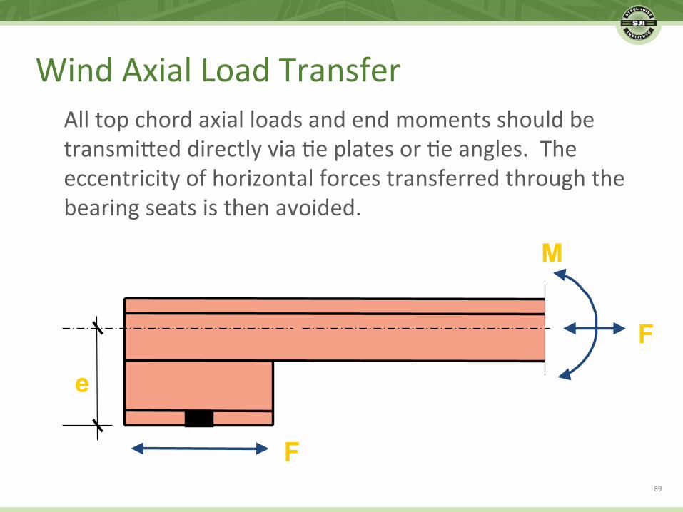
Alltopchordaxialloadsandendmomentsshouldbetransmiteddirectlyvia.eplatesor.eangles.Theeccentricityofhorizontalforcestransferredthroughthebearingseatsisthenavoided.
e
F
F
M
89
WindAxialLoadTransfer

TopChordofJoist
90
JoistTiePlate
TopChordofJoist
91
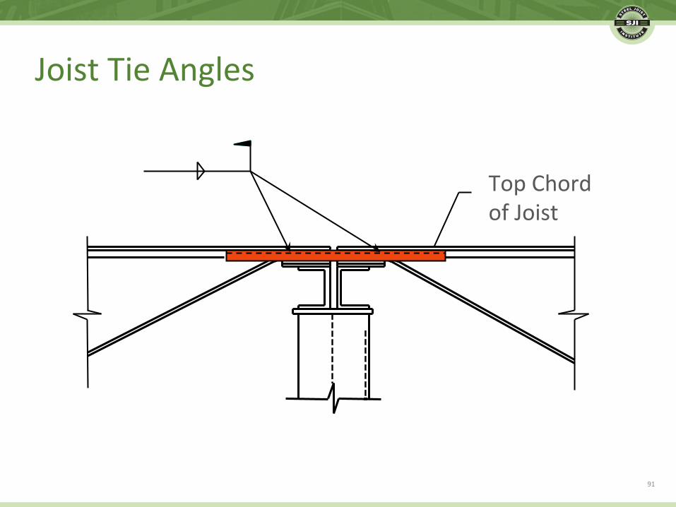
JoistTieAngles

• Notetheorienta.onofthe.eangles,toavoidthejoistendwebs,intheeventtheyareoutsidethatchordanglesratherthaninthechordgap.Thisalsoallowsforadown-handfieldweld.
92
JoistTieAngles

• IfajoistisusedintheXbracedframebay,theaxialloadwilltravelthroughthewebsandbotomchord,inaddi.ontothetopchord.
93
XBracedFrame

• Aten.onisrequiredforthecollectorjoisttobracedframebaytransferconnec.on.
Inthiscase,a“typical”detailneglectsthefactthatthereisactuallyacollectorjoistonthissideofthecolumn.
94
XBracedFrame
95
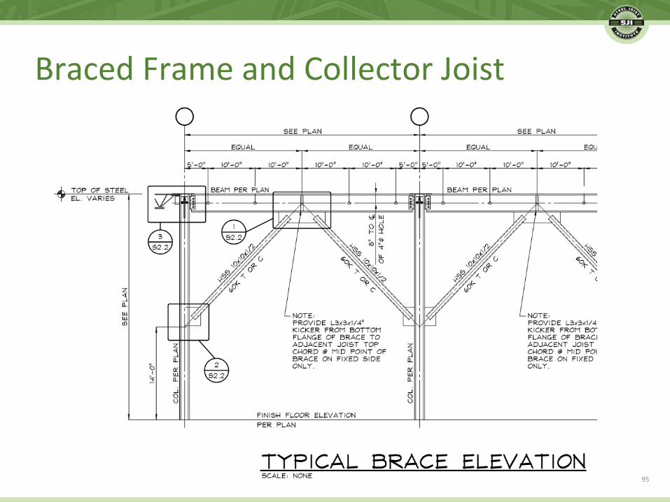
BracedFrameandCollectorJoist

• Thisisagood,completedetail.
96
BracedFrameandCollectorJoist

• TheSpecifyingProfessionalisresponsiblefortherigidframedesign.
• TypeandmagnitudeofendmomentsatthejoistandJoistGirderendsupportsshallbeshownonthestructuraldrawings.
• AvoidresolvingjoistorJoistGirderendmomentsthroughthebearingseatconnec.on.Thetopchorddetailscanbesimilartothoseshownforthetransferofaxialloads.
97
RigidFrames–EndMoments

• Thetopandbotomchordmomentconnec.ondetailsshallbedesignedbytheSpecifyingProfessional.ThejoistdesignershallfurnishtheSpecifyingProfessionalwiththejoistdetailinforma.onifrequested.
• Unlessspeciallydesignedanddetailedaswindonlyflexibleconnec.ons,rigidframeac.onwillinduceliveloadmoments,whichneedtobespecified.
98
RigidFrames–EndMoments

• TheSJIhasseveraltoolsavailableforframedesign:
– VirtualJoistGirderandVirtualJoisttablesforinser.oninstructuralmodelingprograms.
– Aseriesofdesigntoolsformomentconnec.onswithvariouscolumnconfigura.ons.
99
SteelJoistIns.tuteTools
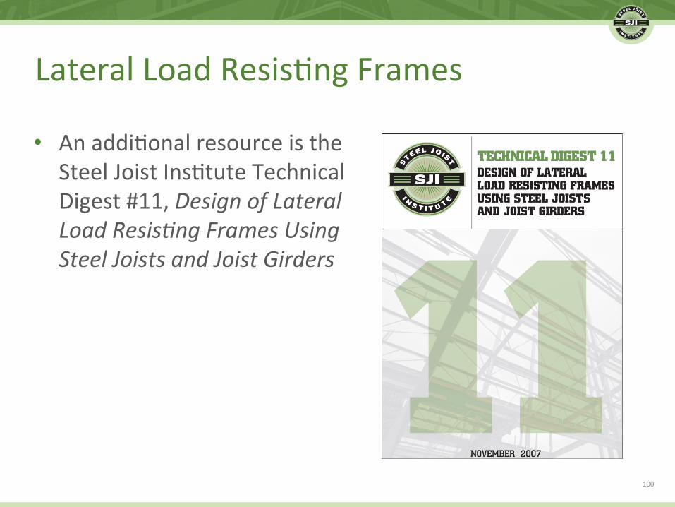
• Anaddi.onalresourceistheSteelJoistIns.tuteTechnicalDigest#11,DesignofLateralLoadResis;ngFramesUsingSteelJoistsandJoistGirders
100
LateralLoadResis.ngFrames

• SpecifyingProfessionaltoprovidehorizontalandver.calcomponentsofwindbracingforcesbeingtransmitedtojoists.
101
WindBracingKickers

• Thisexampledoesnotincludeahorizontalcomponent,butwithASD,assump.onscanbemadeaboutanaddedaxialwindloadcontrollingthejoisttopchorddesign.
• Itwouldbehelpfultohaveguidanceastotheloca.onoftheload.
Connectattopchordpanelpointclosestto3’-0fromendofjoist.
102
WindBracingKickers

• Thelateralhorizontalforcewillbeassumedtotransferintothedeckdiaphragmandthejoistwillnotbedesignedforalateral,out-of-planeload.
103
WindBracingKickers

• Thisisanexampleofanendwallcondi.on,withaseriesofwindbraceloadsalongthejoistspan.
104
WindBracingKickers
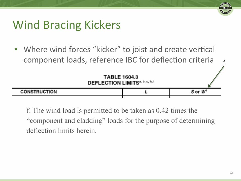
• Wherewindforces“kicker”tojoistandcreatever.calcomponentloads,referenceIBCfordeflec.oncriteria
f. The wind load is permitted to be taken as 0.42 times the “component and cladding” loads for the purpose of determining deflection limits herein.
f
105
WindBracingKickers

• Windcreatesanoverturningmomentfromroofscreens.
• Abracingmembercanbeusedtoresolvetheoverturningeffect,crea.ngver.calwindloadsontheroofjoists.
106
RoofScreens

• Wherethewindscreenpostisnotbraced,andthescreenisperpendiculartothejoists,itisbesttoextendthepostandatachtoboththetopandbotomchord,resolvingtheoverturningmomentintoacouple.
107
RoofScreens–PerpendiculartoJoist

ReplacewithKeith’ssec.oncut
• Wherethewindscreenpostisnotbracedabovetheroof,andthescreenisparalleltothejoists,thejoistscannottakeatorsionalload.
– Itisbesttoextendthepostandatachtoboththetopandbotomchord,resolvingtheoverturningmomentwithbracingmembersbelowtheroof.
108
RoofScreens–ParalleltoJoist

• Single-plymembraneroofingisthemostcommonsystemabovesteeljoists.
• Thesingle-plymembranemaybefullyadhered.
• Alternately,andincreasingly,aseam-fastened,mechanically-atachedmethodofinstalla.onisbeingu.lized.
• Since2000,thewidthofthemembranerollshasbeenincreasingdrama.cally.
109
MechanicallyFastenedMembraneRoofs

FromtheNa.onalResearchCouncilofCanada 110
MechanicallyFastenedMembraneRoofs

• Withthisinstalla.onmethod,thesingle-plymembranesheetismechanically-atachedalongitsouteredgesintotheroofdeck,whichresultsinalargertributaryupliFloadperfastenerandfastenersbeingplacedinlinear,non-uniformloadingconfigura.onsoftheroofdeckandunderlyingsuppor.ngstructure
• Thedirec.onalityoftheseamsrela.vetojoistanddeckspandirec.onisusuallynotknownorcontrolled.
111
MechanicallyFastenedMembraneRoofs

FromtheNa.onalResearchCouncilofCanada
• Windtunneltest
112
MechanicallyFastenedMembraneRoofs

FromtheNa.onalResearchCouncilofCanada
• Windtunneltest
113
MechanicallyFastenedMembraneRoofs

• Thetributarywidththatcreatesthe“lineloading”caneasilybecometwicetheactualjoisttributarywidth.
114
DeckandJoistLoading

• Typically,theroofingmembraneisnotconsideredinstructuralcontractdocuments.
• Theroofingmembranespecifica.oncanbevague,withreferenceslike“atachpermanufacturerrecommenda.ons”.
• AdesignforuniformloadsmaynotbeadequatewhereinfacttheupliFwillbeappliedaslinearloads.
• FMGlobalDataSheet1-29nowprovidesseparatetablesfordeckspanswhenthedistancebetweenroofcoverfastenersismorethanone-halfthedeckspan.
• Afullyadheredroofmembranemaybethebestop.onfromastructuralperspec.ve.
115
JoistDesignforMembraneRoof

• TheupcomingversionofASCE7-16islikelytoincludenewroofupliFzonepaternstomoreaccuratelydepictbehavior
– Twoedgezones– “L”shapedcornerzones
116
ASCE7-16Preview

• Thepressurecoefficientsarelikelytochange
– Black,solidline:7-10– Red,dashedline:7-16
• Ingeneral,morepressureatcornersandedges;lesspressureatinteriorfieldandwithlargerwindeffec.veareas
117
ASCE7-16Preview

• Morewindpressureat100squarefooteffec.vewindarea
• Tablesmaynotprovidevaluesbeyond100squarefeet
• Somoredetailedanalysismaybeadvantageous,asmostjoistsexceed100squarefooteffec.vewindarea
118
ASCE7-16Preview

• The44thEdi.onCatalogiscomingsoon.
• Formoreinforma.onorupdates,visittheSJIwebsite:www.steeljoist.org
119
SteelJoistIns.tute

Presentedby:
Copyright©2017SteelJoistIns;tute.AllRightsReserved.
THANKYOU
KeithJuedemann,PE–CanamBuildingsTimHoltermann,PE,SE–CanamBuildings