CAD SYSTEM USE IN FURNITURE DESIGN AND ... - Digikogu
29
Tallinn 2017 School of Engineering Department of Materials and Environmental Technology Laboratory of Wood Technology CAD SYSTEM USE IN FURNITURE DESIGN AND ENGINEERING CAD SÜSTEEMI KASUTAMINE MÖÖBLI PROJEKTEERIMISEL BACHELOR THESIS Student K.Jermolov Student code 120216KAOB Supervisor K.Kiiman
-
Upload
khangminh22 -
Category
Documents
-
view
0 -
download
0
Transcript of CAD SYSTEM USE IN FURNITURE DESIGN AND ... - Digikogu
Tallinn 2017
School of Engineering Department of Materials and Environmental Technology
Laboratory of Wood Technology
CAD SYSTEM USE IN FURNITURE DESIGN AND ENGINEERING
CAD SÜSTEEMI KASUTAMINE MÖÖBLI PROJEKTEERIMISEL
BACHELOR THESIS
Student K.Jermolov
Student code 120216KAOB
Supervisor K.Kiiman

AUTHOR’S DECLARATION
Hereby I declare, that I have written this thesis independently. No academic degree has been applied for based on this material. All works, major viewpoints and data of the other authors used in this thesis have been referenced.
“.......” .................... 201….. Author: ..............................
/signature / Thesis is in accordance with terms and requirements “.......” .................... 201…. Supervisor: ….........................
/signature/ Accepted for defence “.......”....................201… . Chairman of theses defence commission: ............................................................................. /name and signature/
3
TABLE OF CONTENTS Introduction ...................................................................................................................... 5
1 Introduction to CAD technology ................................................................................... 6
1.1 Development of first CAD systems: ....................................................................... 6
1.2 Three-dimensional CAD systems: .......................................................................... 6
1.3 CAM: ...................................................................................................................... 7
2 Instructions .................................................................................................................... 8
2.1 iLogic ...................................................................................................................... 8
2.1.1 Preparations ..................................................................................................... 8
2.1.2 iLogic ............................................................................................................... 9
2.1.3 Form .............................................................................................................. 13
2.1.4 iTrigger .......................................................................................................... 14
2.2 iCopy .................................................................................................................... 14
2.2.1 iCopy usage: .................................................................................................. 15
2.2.2 Preparations ................................................................................................... 15
2.2.3 iCopy ............................................................................................................. 16
2.2.4 iCopy pattern ................................................................................................. 17
3 iLogic Project – Kitchen module ................................................................................. 19
3.1 Theory ................................................................................................................... 19
3.1.1 Introduction ................................................................................................... 19
3.1.2 iCopy ............................................................................................................. 19
3.1.3 iCopy Pattern ................................................................................................. 19
3.1.4 iLogic ............................................................................................................. 20
3.2 Practice ................................................................................................................. 20
3.2.1 Model preparations ........................................................................................ 20
Conclusion ...................................................................................................................... 25
Summary ......................................................................................................................... 26
Kokkuvõtte: .................................................................................................................... 27
Dictionary/ Abbreviatures .............................................................................................. 28
References ...................................................................................................................... 29
4
DRAWING CONTENT Drawing 1 example of hierarchy inside assembly ............................................................ 8
Drawing 2 iLogic working window................................................................................ 11
Drawing 3 iLogic working window................................................................................ 12
Drawing 4 Form working window ................................................................................. 14
Drawing 5 iCopy control ................................................................................................ 16
Drawing 6 iCopy author ................................................................................................. 16
Drawing 7 Constrain iCopy ............................................................................................ 17
Drawing 8 iCopy Pattern working window .................................................................... 18
TABLE CONTENT Table 1 Example of CNC machine code .......................................................................... 7
Table 2 Parameters ......................................................................................................... 10
CODE CONTENT Code 1 Drawer assembly connection ............................................................................. 21
Code 2 Drawer parameters connected with main assembly ........................................... 22
Code 3 Supress/ Unsupress drawers depending on „Configuration“ ............................. 23
Code 4 Connecting assembly and Excel parameters ...................................................... 23
5
Introduction
Kitchen furniture is mainly made of standardized modules with multiple values for each
dimension. In order to exclude additional work in a design process, engineers could use
pre-made modules, where its dimensions are connected for example to an Excel table.
So, next time engineer should make a cabinet with drawers, he can use pre-made smart
modules.
Kitchen design process:
1) Planning what parts could be described as pre-made standard modules, its
dimensions, materials, joints and screws.
2) Choosing standards for dimensions, joints and screws.
3) Designer should prepare system logic (what parts in particular, and in which
manner will be connected to each other; parts, sub-assemblies, assembly’s
hierarchy and naming with codes)
4) Consideration of all preparations and plans, parts and assemblies.
5) Connecting all parts and sub-assemblies with planed program logic.
6) Making drawings and rendering pictures.
The aim of this thesis is to give an overview of Autodesk Inventor’s iLogic functionality
and show that it can be implemented in the furniture industry.
Work is divided into two main parts:
1) Theoretical introduction, where is described how logical instruments in
Autodesk Inventor work
2) Practical information, where is explained how instruments from theoretical
introduction work in the project.

6
1 Introduction to CAD technology
CAD – Computer Aided Design programs were invented with a development of
computer technology. These type of programs engineers use for prototyping, designing,
manufacturing and performing different calculations of manufactured products.
1.1 Development of first CAD systems:
The main idea of implementing such programs were: to reduce time of making and
remaking drawings (compared to making handmade drawings), and what is more
important, to perform automatically different calculations of a model. (1) The result of
calculations is depended on model’s properties and parameters. Consequently,
AutoCAD was firstly invented in 1982 only with opportunities to make drawings in 2D.
Nowadays, AutoCAD can work also in 3D, but mainly it is used for making
complicated 2D drawings with different layers fast and mostly in a straightforward way
(i.e. with use of dynamic blocks, which are made once and then could be reused with an
opportunity to make changes inside and outside of dynamic blocks). (2)
1.2 Three-dimensional CAD systems:
Using 2D technologies it is always a problem to make changes in design. In specific, if
a model is complicated, with changing the size of one part there are a possibility to miss
the need to change dimensions of another part, which is depended on the first one.
Moreover, it is more natural to use 3D CAD technologies for making complicated
assemblies. There are a bunch of different computer program products on technology
market that uses 3D environment for designing use. Such products are: Solid Edge,
Solid Works, Autodesk Inventor and others. Each product on the market has its own
advantages and disadvantages. Nevertheless, weldment frames functionality in
SolidEdge is very pour and not as simple and reliable as it is in Inventor or Solid
Works. (3) Working with drawings is more natural and native for the user in SolidEdge,
however it doesn’t have such user-friendly computer logic functionality as Inventor
with its iLogic function.
7
1.3 CAM:
Simultaneously with the development of CAD technologies, producers of different
manufacturing machinery have been developing benches with computer driven tools.
With the development of independent computer numeric control (CNC) machinery
where machine programmer should input numeric code by hand using machines own
computer, come out technology that connected desktop PC with CAD program and
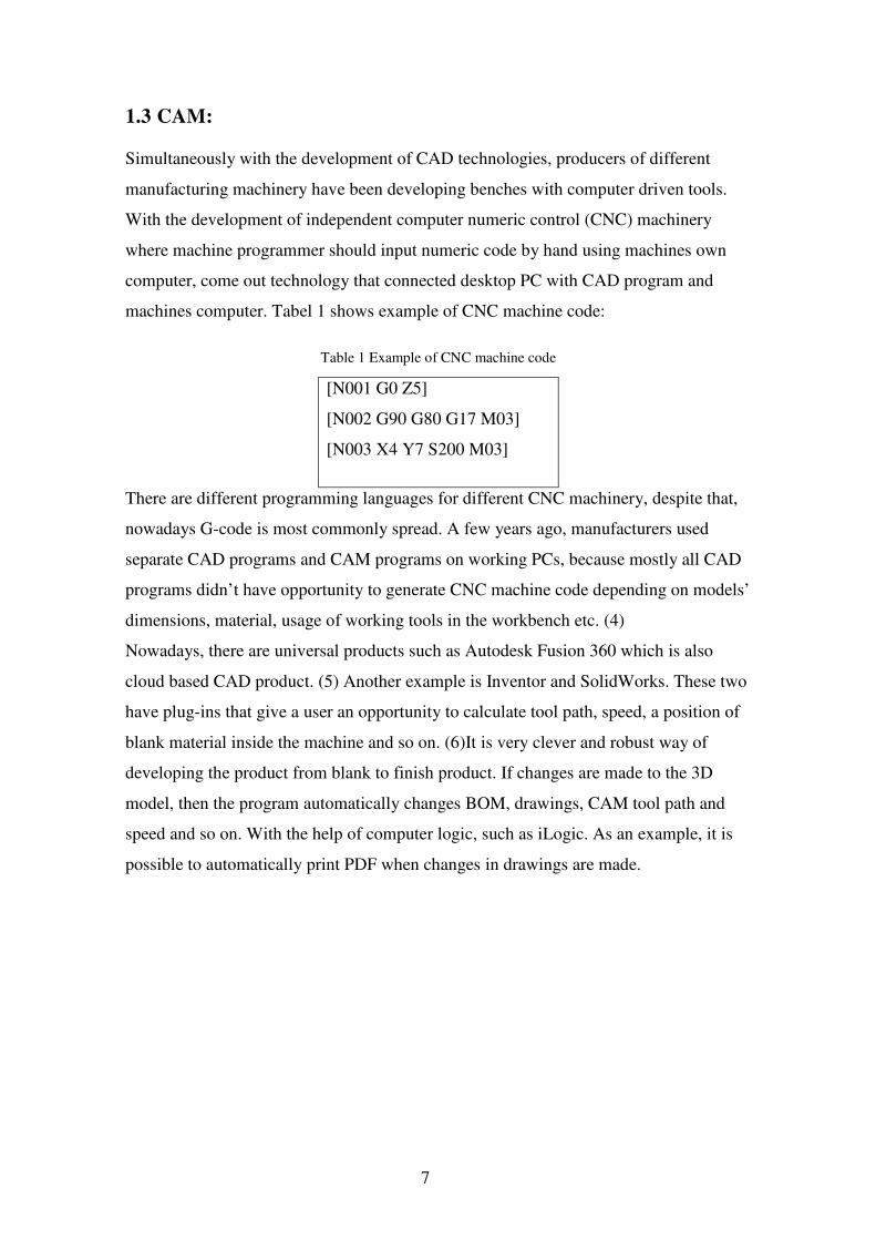
machines computer. Tabel 1 shows example of CNC machine code:
Table 1 Example of CNC machine code
[N001 G0 Z5]
[N002 G90 G80 G17 M03]
[N003 X4 Y7 S200 M03]
There are different programming languages for different CNC machinery, despite that,
nowadays G-code is most commonly spread. A few years ago, manufacturers used
separate CAD programs and CAM programs on working PCs, because mostly all CAD
programs didn’t have opportunity to generate CNC machine code depending on models’
dimensions, material, usage of working tools in the workbench etc. (4)
Nowadays, there are universal products such as Autodesk Fusion 360 which is also
cloud based CAD product. (5) Another example is Inventor and SolidWorks. These two
have plug-ins that give a user an opportunity to calculate tool path, speed, a position of
blank material inside the machine and so on. (6)It is very clever and robust way of
developing the product from blank to finish product. If changes are made to the 3D
model, then the program automatically changes BOM, drawings, CAM tool path and
speed and so on. With the help of computer logic, such as iLogic. As an example, it is
possible to automatically print PDF when changes in drawings are made.
8
2 Instructions
iLogic is Autodesk Inventor built-in function that controls computers’ logic in Inventor
between parts, assemblies, iParts, iAssemblies and Microsoft Excel. iLogic works
directly with equations, its own functions and written code. Choosing which way to use
iLogic mainly depends on knowledge of computer programming languages and the
problem that should be solved with the help of iLogic. (7)
2.1 iLogic
For this thesis was chosen only iLogic premade functions so that user-friendly working
process with iLogic could be shown. Most of the iLogic functions are easy to
understand even if user have no programming language knowledge or experience.
2.1.1 Preparations
Before starting working on practical part of making a 3D model and using iLogic, the
user should plan hierarchy and naming, choose dimensions, materials, joints and screws.
After when the model is made it is hard to find and change every link between
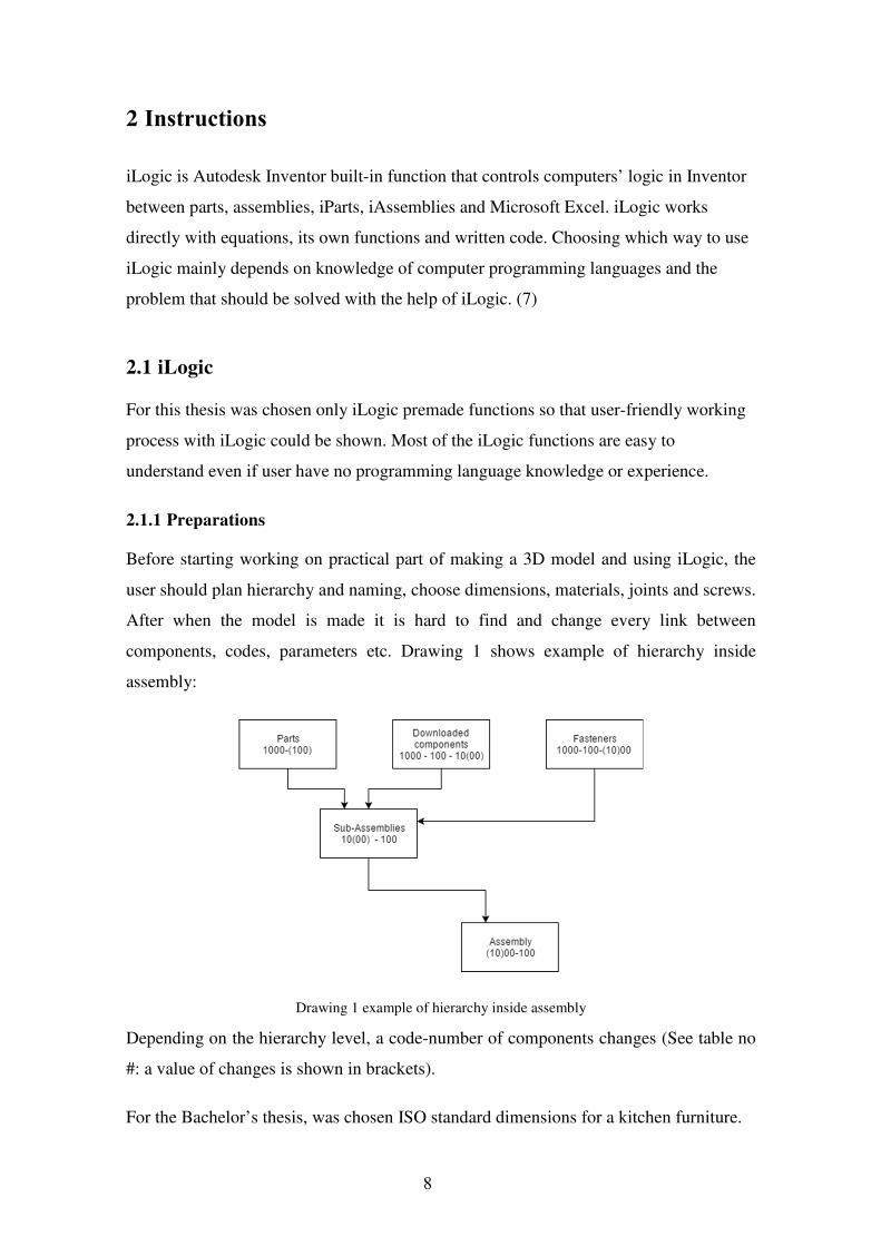
components, codes, parameters etc. Drawing 1 shows example of hierarchy inside
assembly:
Drawing 1 example of hierarchy inside assembly
Depending on the hierarchy level, a code-number of components changes (See table no
#: a value of changes is shown in brackets).
For the Bachelor’s thesis, was chosen ISO standard dimensions for a kitchen furniture.
9
Materials:
As for materials, was chosen a standard Inventor materials library – “Birch”. For specific
needs, user can make its own material library with user-defined materials. Such kind of
materials could have various physical parameters such as density, color, texture,
transparency etc. All additional information about part or assembly can be defined in
iProperties. In iProperties user also can add material cost, manufacturer, so that in future
this information could be connected to ERP system.
Screws:
Autodesk Inventor has its own fasteners library, however the user can make his own
library with downloaded or custom-made fasteners. Inventor fasteners use iMates
functionality to control how one specific fastener will be connected to hole in the material.
iMates could be described as a user pre-defined set of smart constraints. After fastener
3D model has iMates and dimensions table, it could be used faster, then without iMates.
After all, when such fastener component is placed into the content center, then it is simple
and fast to use such component. If designer needs a fastener with standard for
manufacturing size, then he should choose this fastener from content center, define all
iMates constraints and chose to find the right size in a table.
2.1.2 iLogic
Parameters:
For controlling parameters in parts and assemblies it is needed to make user parameters.
Those parameters can be defined in parameter working window, in model dimension (
when dimension is added, then Inventor automatically creates models parameter).
Numeric parameters can be numeric or equation. Additional to that, a user can define
parameters in different units, just typing “mm” for millimeters, “m” for meters and so on.

10
Autodesk Inventor has 6 different parameter types:
Table 2 Parameters
Model parameters Parameters that are made directly in a model
Dynamic simulation parameters Parameters that are made in dynamic strength analysis
Static analysis parameters Parameters made in static strength analysis
User numeric parameters User defined numeric parameters: single/ multiple
User text parameters User defined text parameters single/ multiple – text parameters mainly used for iLogic
User True/ False parameters Mainly used for iLogic
The user can choose parameter management strategy on its own. In the following thesis
was chosen following strategy: make text parameters for future iLogic table and connect
in iLogic those parameters with user numeric parameters that are connected with Excel
table data. Parameters can be single or multi-value. For making single value user
numeric/text parameters it is needed to open parameters window (fx sign in inventor
window). In parameter window in the left bottom corner can be seen a drop menu. Add
numeric/ Add text/ Add true/ false. After adding user parameter, it is possible to make
single value parameter or multi-value parameter. For multi-value parameter click right
mouse button – make multi-value. In opened window (Value List Editor) it is seen, that
upper part is for new values. Consequently, bottom part dedicated to existing values. The
same window will be in user text parameters.
Start using iLogic:
After making parts and sub-assemblies with user defined parameters that could be driven
by the iLogic, user can make codes in the iLogic. If it is needed to change/add parameters,
it is not a problem to make these changes.
For opening the iLogic window in a ribbon, choose – manage – iLogic Browser.

11
In iLogic browser there are 4 tabs:
Drawing 2 iLogic working window
1) Rules – here all rules that exist in a model in these levels of feature tree (assembly/
sub-assembly/ part)
2) Forms – forms for more comfortable control of the iLogic model.
3) Global Forms – forms that exist separately from level in feature tree (forms for
parts/ sub-assemblies)
4) External rules
Adding rule (Code):
For adding an own rule, it is needed to Click right mouse button in iLogic Browser, then
add a rule and name it. These rules can be suppressed, and unsuppressed. When the rule
is suppressed, it is not working, but also it is not deleted and can be used in future. On the
Drawing 3 is shown iLogic working window.

12
Drawing 3 iLogic working window
1) Main window for codes
2) Feature tree for selecting component
3) Parameters in selected component
4) Equations in selected component
5) Pre-made code fundamentals.
iLogic is very user-friendly. For making simple codes it is not necessary to know any
computer programming language, however knowledge of Visual Basic is an advantage.
(8) For connecting parameters, it is possible to do it just with equation.
13
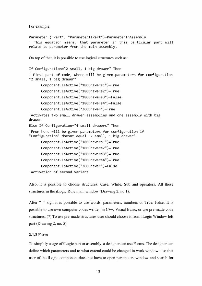
For example:
Parameter ("Part", "ParameterIfPart")=ParameterInAssembly
' This equation means, that parameter in this particular part will relate to parameter from the main assembly.
On top of that, it is possible to use logical structures such as:
If Configuration="2 small, 1 big drawer" Then
' First part of code, where will be given parameters for configuration
"2 small, 1 big drawer"
Component.IsActive("180Drawers1")=True
Component.IsActive("180Drawers2")=True
Component.IsActive("180Drawers3")=False
Component.IsActive("180Drawers4")=False
Component.IsActive("360Drawer")=True
'Activates two small drawer assemblies and one assembly with big drawer
Else If Configuration="4 small drawers" Then
'From here will be given parameters for configuration if "Configuration" doesnt equal "2 small, 1 big drawer"
Component.IsActive("180Drawers1")=True
Component.IsActive("180Drawers2")=True
Component.IsActive("180Drawers3")=True
Component.IsActive("180Drawers4")=True
Component.IsActive("360Drawer")=False
'Activation of second variant
Also, it is possible to choose structures: Case, While, Sub and operators. All these
structures in the iLogic Rule main window (Drawing 2, no.1).
After “=” sign it is possible to use words, parameters, numbers or True/ False. It is
possible to use own computer codes written in C++, Visual Basic, or use pre-made code
structures. (7) To use pre-made structures user should choose it from iLogic Window left
part (Drawing 2, no. 5)
2.1.3 Form
To simplify usage of iLogic part or assembly, a designer can use Forms. The designer can
define which parameters and to what extend could be changed in work window – so that
user of the iLogic component does not have to open parameters window and search for
14
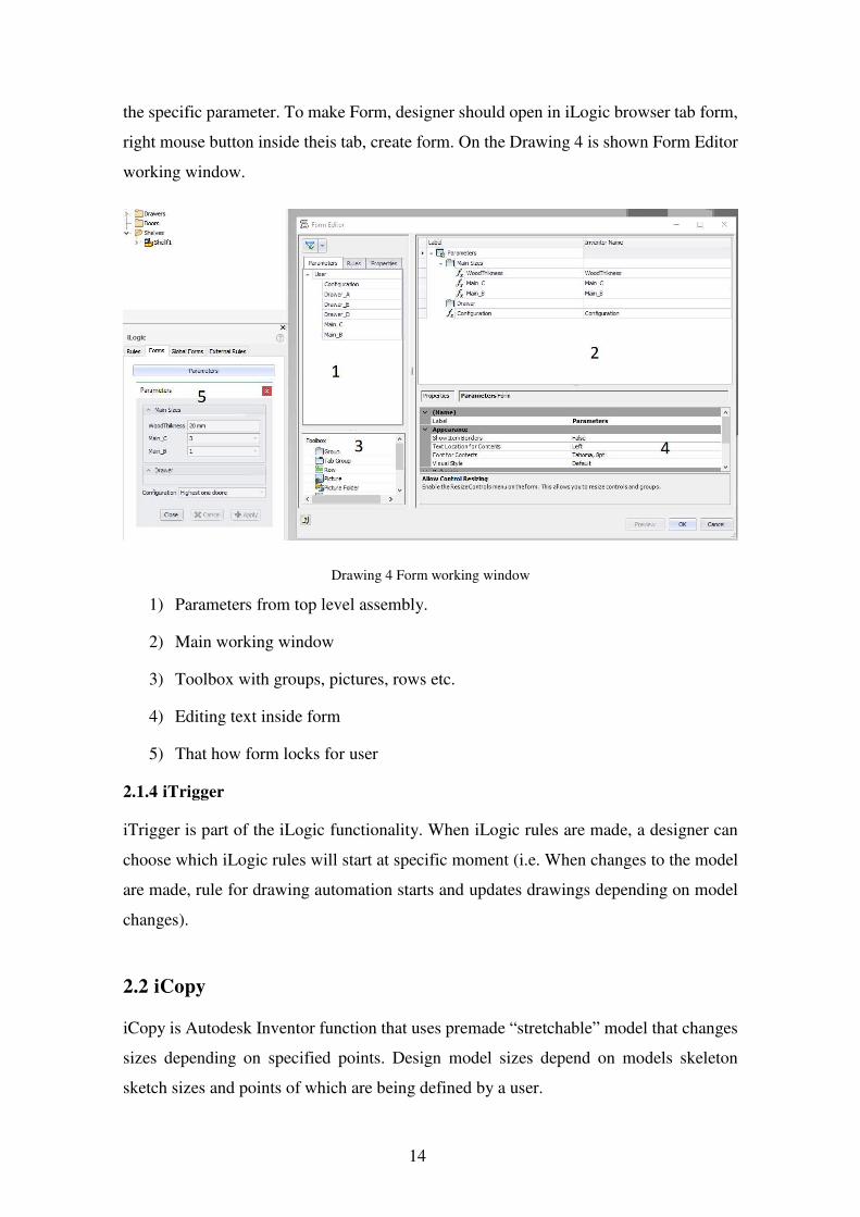
the specific parameter. To make Form, designer should open in iLogic browser tab form,
right mouse button inside theis tab, create form. On the Drawing 4 is shown Form Editor
working window.
Drawing 4 Form working window
1) Parameters from top level assembly.
2) Main working window
3) Toolbox with groups, pictures, rows etc.
4) Editing text inside form
5) That how form locks for user
2.1.4 iTrigger
iTrigger is part of the iLogic functionality. When iLogic rules are made, a designer can
choose which iLogic rules will start at specific moment (i.e. When changes to the model
are made, rule for drawing automation starts and updates drawings depending on model
changes).
2.2 iCopy
iCopy is Autodesk Inventor function that uses premade “stretchable” model that changes
sizes depending on specified points. Design model sizes depend on models skeleton
sketch sizes and points of which are being defined by a user.

15
2.2.1 iCopy usage:
For iCopy should be used a specific designing process which connects Skeleton part and
made from that part assembly.
iCopy design process:
1) Planning of designed model and how it could be standardized for future use
2) Making of skeleton 2D sketch
3) Making of 3D model with projected skeleton sketch
4) Connecting
There are main styles of modeling: solid body, bottom up, top down, skeleton modeling.
iCopy is a function that uses skeleton modeling. It means that an iCopy model is
connected to the 2D sketch skeleton, so that if skeletons dimensions are changed then the
model dimensions also changes.
2.2.2 Preparations
First, a designer should make 2D sketch-skeleton which sizes will be directly connected
with dimensions of the model. Then right mouse button in the future tree on skeleton-
sketch select “adaptivity” (Simply “adaptivity” means that adaptive part dimensions are
controlled by another part). Next, a user makes a new 2D sketch, projects skeleton sides
and extrudes shapes. For each individual future part, a designer in extrude editing window
should choose “new solid “. After that, in program future tree in folder Body’s will be
separate future details. Then in Ribbon, an engineer should choose Manage – Make
Component, select in folder Body Separate body’s. Then, turn off the visibility of all
extrusion features in skeleton-part. After that, in the new assembly that was automatically
made should choose in ribbon drop menu “create substitutes” – place at origin position.
In opened window find skeleton part with only skeleton sketch visibility turned on. Now
skeleton sketch and parts made from separate bodies are placed at one origin point and
their sizes are connected by projection.
16
2.2.3 iCopy
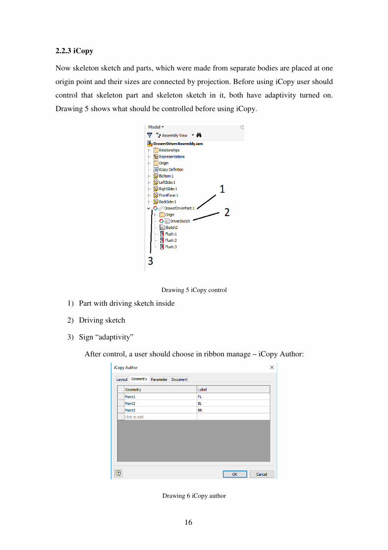
Now skeleton sketch and parts, which were made from separate bodies are placed at one
origin point and their sizes are connected by projection. Before using iCopy user should
control that skeleton part and skeleton sketch in it, both have adaptivity turned on.
Drawing 5 shows what should be controlled before using iCopy.
Drawing 5 iCopy control
1) Part with driving sketch inside
2) Driving sketch
3) Sign “adaptivity”
After control, a user should choose in ribbon manage – iCopy Author:
Drawing 6 iCopy author

17
In the left part of the window “Geometry” user selects geometry that will drive skeleton
sketch. With drawer example, chosen geometry is two points of a rectangle. The
functionality of window right part “label” is informative.
Use of iCopy:
In assembly level in ribbon user should choose drop menu Pattern – iCopy.
Drawing 7 Constrain iCopy
In Geometry/value, user should choose points of 2D sketch that will “drive” skeleton
sketch in iCopy assembly. When all predefined by iCopy author points are connected to
driving sketch, iCopy assembly with all parts will stretch to a new size. Drawing 7 shows
iCopy constrain working window.
Conclusion:
iCopy is a very powerful tool in scenarios such as cabinet doors with cuts outs and glass,
shelves, wood planks etc. The designer makes once iCopy door defining those sizes that
should change. In that way, each time designer needs to make a door with glass, he can
make 2D sketch in new cabinet assembly and connect the iCopy assembly points to this
new sketch.
2.2.4 iCopy pattern
There are two variants of the iCopy pattern: path pattern and feature pattern. Path pattern
means that at least one of iCopy points will be driven by some predefined path (doesn’t

18
matter 2D sketch or 3D path). Feature pattern – as the name says, iCopy will be driven
by pattern inside the sketch. The iCopy pattern could be necessary for example in stairs
construction. Some points will define dimensions of each step and pattern will define
where those steps are positioned in space.
ICopy pattern:
Drawing 8 iCopy Pattern working window
1) Path pattern tab
2) Selecting points skeleton sketch
3) Lines that are connected to points from no.2
4) Path that components will follow
5) Working plane where skeleton sketch is at
Then user defines no. iterations and distance between them
19
3 iLogic Project – Kitchen module
To show theoretical information about iLogic and iCopy in practice was created project
named “Kitchen module”.
3.1 Theory
3.1.1 Introduction
For the Bachelor’s thesis, was chosen an idea that kitchen furniture is usually made with
usage of almost same components each time. Only dimensions, visual style, connections
change but the main idea is the same. For example, the drawer could be used in kitchen
furniture, office work table etc. For solving that problem, were tested different ways:
iCopy assembly of a module with iCopy drawers, doors etc. inside; for drawers, was
tested use iCopy pattern inside assembly with multi parameter dimensions; iLogic inside
Inventor; iLogic that connects to the Excel and takes dimensions from a pre-made table.
For dimensions, was used standard kitchen furniture sizes. Fasteners were used from
Inventor Content library, the same applies to materials.
3.1.2 iCopy
At the beginning, was tested iCopy function with 3D Sketch. Idea was that points of
skeleton 3D sketch could be connected to some cubic shape or 3D Sketch afterward. At
the point on iCopy design pipeline, where a user should choose points of skeleton sketch,
Inventor gave an opportunity to choose only one point. Thus: iCopy can’t be used with
the 3D sketch because iCopy uses points on plane, not in 3D.
3.1.3 iCopy Pattern
After trying iCopy with a 3D sketch were made iCopy drawers traditional way with usage
of the usual sketch. When drawers were made as iCopy assemblies, they were inserted
into the box-shaped module so that 4 drawers fitted in.

20
For that was taken separate ways of connecting multiple iCopy drawer assemblies with a
module:
1) Putting into module assembly 4 planes with a 2D sketch in each. It will be very
hard to make changes in such design, so it is not the best variant to choose.
2) Use iCopy pattern
After iCopy drawers were completed, was made 3D sketch of rectangle with normal line
coming from one of rectangle corners. After using iCopy pattern, everything worked well.
However, when some drawers were suppressed, iCopy lost connections to 3D sketch and
dimensions of drawers then were separated from module dimensions.
As a result: It was impossible to use multi-value parameter of the main assembly with
iCopy pattern inside this assembly.
3.1.4 iLogic
When simple ideas did not worked, was used Inventor iLogic. As already was mentioned
iLogic is computer logic function inside Inventor, which can manipulate assembly; sub-
assembly; part parameters. Does not matter if it is dimensions, material type, material
parameters, or for example iProperties parameter such as material cost.
Was tested iCopy with iLogic but it did not work as well. Therefore, it became clear that
model could be totally controlled by iLogic. This way parts, sub-assemblies and main
assembly that relate to each other by iLogic codes via multi values in each component.
First, were planned all dimensions and in which way they will be connected (drawings
with dimensions: working drawings at the end of the thesis). On that step designer, should
remember that main assembly will control sub-assembly sizes, and consequently sub-
assembly will drive parts dimensions. Also, it is better to make parameters naming as
logic and simple as possible, so that in the future it takes less time for remembering which
name stands for the parameter in a specific part.
3.2 Practice
3.2.1 Model preparations
21
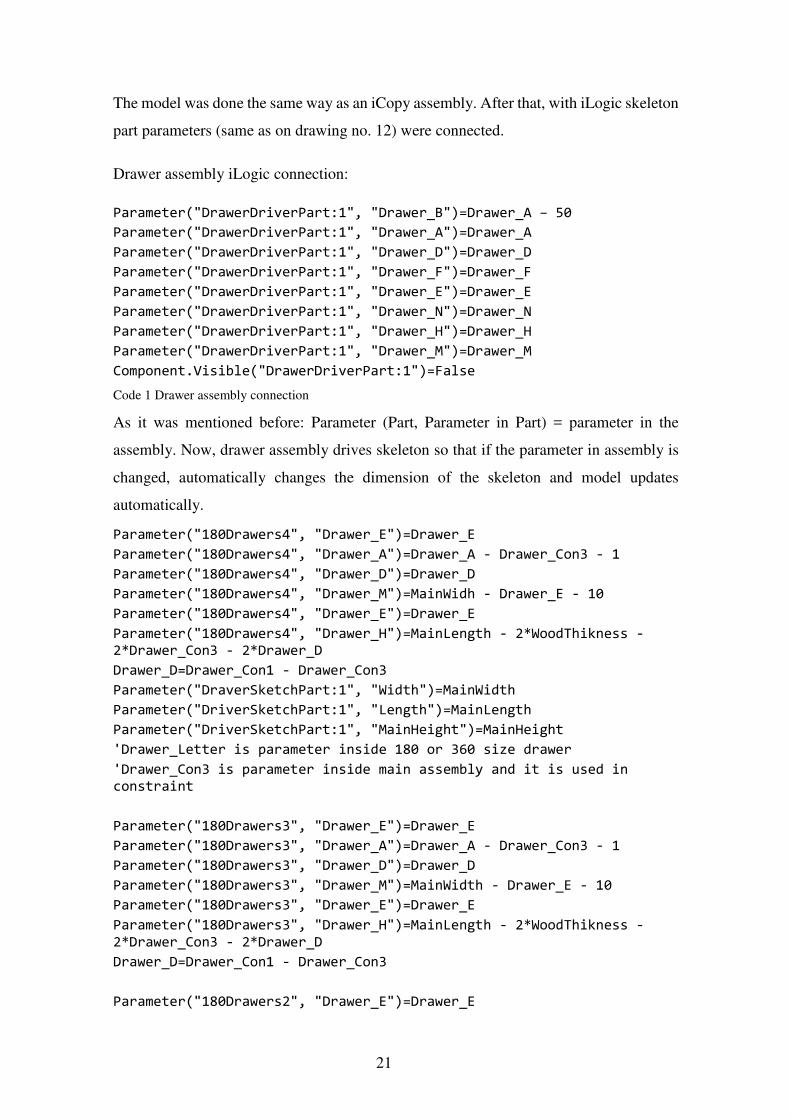
The model was done the same way as an iCopy assembly. After that, with iLogic skeleton
part parameters (same as on drawing no. 12) were connected.
Drawer assembly iLogic connection: Parameter("DrawerDriverPart:1", "Drawer_B")=Drawer_A – 50
Parameter("DrawerDriverPart:1", "Drawer_A")=Drawer_A
Parameter("DrawerDriverPart:1", "Drawer_D")=Drawer_D
Parameter("DrawerDriverPart:1", "Drawer_F")=Drawer_F
Parameter("DrawerDriverPart:1", "Drawer_E")=Drawer_E
Parameter("DrawerDriverPart:1", "Drawer_N")=Drawer_N
Parameter("DrawerDriverPart:1", "Drawer_H")=Drawer_H
Parameter("DrawerDriverPart:1", "Drawer_M")=Drawer_M
Component.Visible("DrawerDriverPart:1")=False
Code 1 Drawer assembly connection
As it was mentioned before: Parameter (Part, Parameter in Part) = parameter in the
assembly. Now, drawer assembly drives skeleton so that if the parameter in assembly is
changed, automatically changes the dimension of the skeleton and model updates
automatically.
Parameter("180Drawers4", "Drawer_E")=Drawer_E
Parameter("180Drawers4", "Drawer_A")=Drawer_A - Drawer_Con3 - 1
Parameter("180Drawers4", "Drawer_D")=Drawer_D
Parameter("180Drawers4", "Drawer_M")=MainWidh - Drawer_E - 10
Parameter("180Drawers4", "Drawer_E")=Drawer_E
Parameter("180Drawers4", "Drawer_H")=MainLength - 2*WoodThikness - 2*Drawer_Con3 - 2*Drawer_D
Drawer_D=Drawer_Con1 - Drawer_Con3
Parameter("DraverSketchPart:1", "Width")=MainWidth
Parameter("DriverSketchPart:1", "Length")=MainLength
Parameter("DriverSketchPart:1", "MainHeight")=MainHeight
'Drawer_Letter is parameter inside 180 or 360 size drawer
'Drawer_Con3 is parameter inside main assembly and it is used in constraint
Parameter("180Drawers3", "Drawer_E")=Drawer_E
Parameter("180Drawers3", "Drawer_A")=Drawer_A - Drawer_Con3 - 1
Parameter("180Drawers3", "Drawer_D")=Drawer_D
Parameter("180Drawers3", "Drawer_M")=MainWidth - Drawer_E - 10
Parameter("180Drawers3", "Drawer_E")=Drawer_E
Parameter("180Drawers3", "Drawer_H")=MainLength - 2*WoodThikness - 2*Drawer_Con3 - 2*Drawer_D
Drawer_D=Drawer_Con1 - Drawer_Con3
Parameter("180Drawers2", "Drawer_E")=Drawer_E
22
Parameter("180Drawers2", "Drawer_A")=Drawer_A - Drawer_Con3 - 1
Parameter("180Drawers2", "Drawer_D")=Drawer_D
Parameter("180Drawers2", "Drawer_M")=MainWidth - Drawer_E - 10
Parameter("180Drawers2", "Drawer_E")=Drawer_E
Parameter("180Drawers2", "Drawer_H")=MainLength - 2*WoodThikness - 2*Drawer_Con3 - 2*Drawer_D
Drawer_D=Drawer_Con1 - Drawer_Con3
Parameter("180Drawers1", "Drawer_E")=Drawer_E
Parameter("180Drawers1", "Drawer_A")=Drawer_A - Drawer_Con3 - 1
Parameter("180Drawers1", "Drawer_D")=Drawer_D
Parameter("180Drawers1", "Drawer_M")=MainWidth - Drawer_E - 10
Parameter("180Drawers1", "Drawer_E")=Drawer_E
Parameter("180Drawers1", "Drawer_H")=MainLength - 2*WoodThikness - 2*Drawer_Con3 - 2*Drawer_D
Drawer_D=Drawer_Con1 - Drawer_Con3
Parameter("360Drawer", "Drawer_E")=Drawer_E
Parameter("360Drawer", "Drawer_D")=Drawer_D
Parameter("360Drawer", "Drawer_M")=MainWidth - Drawer_E - 10
Parameter("360Drawer", "Drawer_E")=Drawer_E
Parameter("360Drawer", "Drawer_H")=MainLength - 2*WoodThikness - 2*Drawer_Con3 - 2*Drawer_D
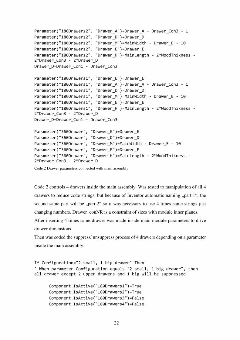
Code 2 Drawer parameters connected with main assembly
Code 2 controls 4 drawers inside the main assembly. Was tested to manipulation of all 4
drawers to reduce code strings, but because of Inventor automatic naming „part:1“, the
second same part will be „part:2“ so it was necessary to use 4 times same strings just
changing numbers. Drawer_conNR is a constraint of sizes with module inner planes.
After inserting 4 times same drawer was made inside main module parameters to drive
drawer dimensions.
Then was coded the suppress/ unsuppress process of 4 drawers depending on a parameter
inside the main assembly:
If Configuration="2 small, 1 big drawer" Then
' When parameter Configuration equals "2 small, 1 big drawer", then all drawer except 2 upper drawers and 1 big will be suppressed
Component.IsActive("180Drawers1")=True
Component.IsActive("180Drawers2")=True
Component.IsActive("180Drawers3")=False
Component.IsActive("180Drawers4")=False

23
Component.IsActive("360Drawer")=True
Else If Configuration="4 small drawers" Then
'All drawers except 360 size drawer will be unsupressed
Component.IsActive("180Drawers1")=True
Component.IsActive("180Drawers2")=True
Component.IsActive("180Drawers3")=True
Component.IsActive("180Drawers4")=True
Component.IsActive("360Drawer")=False
End If
Code 3 Supress/ Unsupress drawers depending on „Configuration“
As it was mentioned before, the same suppress/ unsuppressed code didn’t work with
iCopy pattern feature. After iCopy drawers are suppressed they also lose connection with
the point it is being connected to. Hence, when point changes its position in space and
drawer unsuppressed back, this drawer cannot connect to the point.
As a result: error appears and drawer dimensions are not changing.
GoExcel.Open("A:\Storage\OneDrive\3D\3DCAD\Inventor\Projects\WoodWork
TTU\MainConfigurationSizes.xlsx", "Main")
'Link to Excel file on PC. User should remmember, that direct link for each PC is different
If Main_C=1 Then
Parameter("MainLength")=GoExcel.CellValue("B2")
'Main_C is parameter inside assembly, B2 is value inside cell in Excel file "Main" Tab
Else If Main_C=2 Then
Parameter("MainLength")=GoExcel.CellValue("C2")
Else IF Main_C=3 Then
Parameter("MainLength")=GoExcel.CellValue("D")
End If
If Main_B=1 Then
Parameter("MainWidth")=GoExcel.CellValue("B3")
Else If Main_B=2 Then
Parameter("MainWidth")=GoExcel.CellValue("C3")
End If
GoExcel.Save
GoExcel.Close
Code 4 Connecting assembly and Excel parameters

24
The code 4, was used to connect modules of the main assembly parameters with Excel
table. First, Excel should be opened by iLogic: GoExcel. Open (location on disk, tab in
Excel) Here user should remember, that location in that code changes depending on used
PC.That problem can’t be fixed even with „Pack and Go “function. Then, if statement
and parameter (parameter in assembly) = GoExcel. CellValue (No. of excel cell inside
pre-selected tab). After that good practice to GoExcel. Save and GoExcel.Close. If the
user wants to make changes inside the Excel file, he or she should close iLogic code with
this particular excel file, then make changes and save. It is possible to use different tabs
inside one code, nevertheless for this bachelor work was choose to use different iLogic
codes for different Excel tabs.
25
Conclusion
The aim of this thesis is to give an overview of Autodesk Inventor’s iLogic functionality
and show that it can be implemented in the furniture industry. The iLogic codes can be
very easily used to automate designing process of complex furniture by making
assemblies with code configured parameters. It is possible to fix those modules
parameters to Excel table so that if changes made in Excel, component changes its sizes
automatically. It is possible to reuse once made with iLogic codes assembly or part so
that each parameter inside iLogic assembly connects to main assembly parameters. Also,
designer can prepare iCopy components so that next time that component should be
placed, it is much simpler and faster to just select point of sketch inside main assembly.
Using different Forms for the iLogic code designer can define what parameter will be
changed in fast opened window. By defining iTrigger rules designer can control when
every code should be activated depending on one or another action takes place with
current component. All “ i “ features inside Autodesk Inventor give designer great
opportunities to make automated components for future use.
26
Summary
Every user of Autodesk Inventor can use iLogic for programing computer logic inside
and outside models with almost no programming skills. Programmable logic can be used
mainly in mass production, or for assemblies that can be reused in future. It is possible to
make automated assemblies where elements properties such as size, color, material,
furniture and other are connected by code to the form. When the configuration in
programed form change, then assembly properties change as well. If Inventor is
connected to ERP system, then properties changes there as well. Even the whole
manufacturing process then can be changed automatically depending on the Inventor and
other systems connections.
In this Bachelor thesis it was described, how a designer or engineer can use iLogic, iCopy
and other Autodesk Inventor features to simplifying his or her every day work process.
Was shown theoretical information and given practical knowledge of using iLogic design
for furniture manufacturing. Was made module with changing number of drawers and
main module dimensions configuration. These models were made into drawings and into
a render picture. For carrying out the small project mostly simple iLogic structures were
used. No VBA or C++ programing languages were used. Also, were made tests of using
iLogic and iCopy. All the results of the test projects are described in this paper so that
they can be used as a practical knowledge.
As a result of this work it can be said that designers in furniture industry can use iLogic
programming to automate the designing process. The designer does not have to know any
programming language. Using iLogic allows to use automated assemblies that can be
used in future designs and what helps to reduce reiterations.
27
Kokkuvõtte:
AutoDesk Inventor iLogic funktsionaalsus annab mööbliprojekteerijatele võimaluse
kasutada programmi sisest programmeerimise võimekust ilma eelneva
programmeerimise oskuseta. Antud funktsionaalsuse kasutamine on eriti kasulik mass- ja
seeria toodangu valmistamisel, kus kasutatakse samasid ja sarnaseid detaile korduvalt.
iLogic funktsionaalsus võimaldab näiteks luua graafilise kasutajaliidese, kus on
kirjeldatud koostu erinevad omadused: mõõdud, materjalid ja furnituurid.
Kasutajaliidesesse saab programmeerida võimaluse muuta koostu konfiguratsiooni
kasutamata Inventori mudeldamis tööriistu, samuti on võimalik ka määrata eri koostu
osadele materjale, lisada ja eemaldada furnituuri jne. Juhul kui Inventor on seotud ERP
süsteemiga, siis muutes mudelis kasutuses olevat materjali ERP süsteemis muutub
materjal ka 3D mudelis. iLogic annab võimaluse siduda Invetori 3D mudeli ka teiste
juhtimissüsteemidega.
Käesolev bakalaureuse töö näitab, kuidas projekteerija saab kasutada AutoDesk Inventori
iLogic, iCopy ja muid sarnaseid tööriistu, et muuta igapäevane tööprotsess
efektiivsemaks. Töö esimeses pooles antakse ülevaade teoreetilistest alustest, mis on
vajalikud rakendamaks iLogic funktsionaalsust. Töö teises osas on kirjeldatud näidis
projekti valmistamist, milleks oli kapi moodul sahtlitega. Kasutades iLogic’it loodi
kasutajaliides, kust on võimalik muuta antud mooduli mõõte koos sahtlitega ja ka sahtlite
arvu moodulis. Antud moodulist on valmistatud joonised ja mudelist render’tatud foto.
Selles töös on kasutatud väga lihtsaid koodi juppe, selleks et rõhutada kui lihtsalt on juba
võimalik kasu lõigata Inventori iLogic funktsionaalsusest. Ning tõestada autori näitel, et
seda on võimalik kasutada ilma mingisuguse eelneva programmeerimise oskuseta.
Töö tulemusena võib väita, et kasutajad, kes kasutavad mööbli projekteerimiseks
AutoDesk Inventor tarkvara on võimelised ilma eelneva programmeerimise oskuseta
kasutama ka selle iLogic funktsionaalsust. Andes võimaluse luua näiteks
poolautomatiseeritud 3D mudeleid. Selliste mudelite kasutamine kiirendab
projekteerijate igapäeva tööd ja professionaalse rakendamise korral vähendab ka
inimveast tulenevaid eksimusi

28
Dictionary/ Abbreviatures
CAD – Computer Aided Design
C++ - computer programming language
Rendering – computer made picture from 3D model and all textures
VBA – Visual Basic for Applications – computer programming language
Microsoft Visual Studio – program for writing programs codes
Content Centre – library with all pre-defined or user fasteners smart parts etc.
Feature tree – left part of main working area in Inventor, where all features and used
functions appear
CNC – Computer Numeric Control
BOM – Bill of Material
ERP – Enterprise Resource Planning

29
References
1. Wikipedia, Computer Aided Design [WWW] https://en.wikipedia.org/wiki/Computer-aided_design. 2. Scan2CAD, A Brief History of AutoCAD [WWW] http://www.scan2cad.com/tips/autocad-brief-history/. 3. Siemens Product Lifecycle Management Software Icn. What is Solid Edge [WWW] https://www.plm.automation.siemens.com/en_us/products/solid-edge/index.shtml. 4. Wikiversity, Computer-aided design/ History, Present and Future [WWW] https://en.wikiversity.org/wiki/Computer-aided_design/History, _Present_and_Future. 5. Autodesk, Fusion 360 [WWW] https://www.autodesk.com/products/fusion-360/overview. 6. HSMWORKS, The CAM Solution for SOLIDWORKS [WWW] http://www.hsmworks.com/. 7. Autodesk Inventor 2014 Help http://help.autodesk.com/view/INVNTOR/2014/ENU/?guid=GUID-8DF6F761-1634-4D26-B13A-58AF275FD6F8. 8. ADN Open CIS, Запуск правил iLogic из внешнего приложения [WWW] http://adn-cis.org/zapusk-pravil-ilogic-iz-vneshnego-prilozheniya.html. 9. The MIT Press, The Art of Agent-Oriented Modeling Sterling, Leon S. The Art of Agent-Oriented Modeling. London : The MIT Press, 2009.