Butterfly Valve EUROSTOP - Buried type - Pamline
16
ISOLATING VALVES VALVES DN 150 to 2000 06/17/2022 RSEVP21REM225 Butterfly Valve EUROSTOP - Buried type Description Flanged Butterfly Valve (flange-flange) with joint in the automatic but- terfly (JPA) with double eccentricity and long spacing between the flanges. Ductile iron body and butterfly covered with blue epoxy powder thick- ness 250 microns mini average according prescriptions of EN 14901 (PECB). Range from DN150 to DN2000mm for pressures of PFA10 to 25 bar. Field of application Butterfly valves are isolating valves used on water supply networks, in the interconnections of network, in the factories, in pumping stations, on the general networks and on the fire protection networks in the industrial sites. Butterfly valves are compatible with drinking water and raw water with grid filtration. They will be installed on water networks in factories, in valves chambers or buried. Their main advantages are: • Low pressure loss • Good performance thanks to the choice of the materials, the coatings and the design • Easy operation per mechanism of the worm type/without end • Mechanisms equipped with a standardized flange carry-accessory for buried version and motorizable version Range The EUROSTOP butterfly valve is available in different configuration: manual, buried service, motorized and motorizable (for this three last configuration see the specific TDS). Version with gearbox without mechanical position indicator but with watertight seal cover. References with operating cap 10/22/2021 1
-
Upload
khangminh22 -
Category
Documents
-
view
0 -
download
0
Transcript of Butterfly Valve EUROSTOP - Buried type - Pamline

ISOLATING VALVESVALVES
DN 150 to 2000
06/17/2022
RSEVP21REM225
Butterfly Valve EUROSTOP - Buried type
Description
Flanged Butterfly Valve (flange-flange) with joint in the automatic but-terfly (JPA) with double eccentricity and long spacing between theflanges.
Ductile iron body and butterfly covered with blue epoxy powder thick-ness 250 microns mini average according prescriptions of EN 14901(PECB).
Range from DN150 to DN2000mm for pressures of PFA10 to 25 bar.
Field of application
Butterfly valves are isolating valves used on water supply networks, in the interconnections of network, in the factories, inpumping stations, on the general networks and on the fire protection networks in the industrial sites.
Butterfly valves are compatible with drinking water and raw water with grid filtration. They will be installed on water networksin factories, in valves chambers or buried.
Their main advantages are:
• Low pressure loss• Good performance thanks to the choice of the materials, the coatings and the design• Easy operation per mechanism of the worm type/without end• Mechanisms equipped with a standardized flange carry-accessory for buried version and motorizable version
Range
The EUROSTOP butterfly valve is available in different configuration: manual, buried service, motorized and motorizable(for this three last configuration see the specific TDS).
Version with gearbox without mechanical position indicator but with watertight seal cover.
References with operating cap
10/22/2021 1

ISOLATING VALVESVALVES
DN 150 to 2000
06/17/2022
RSEVP21REM225
DN Closing direction References PN10 References PN16 References PN25mm
150 Anti-clockwise 223968 223968 224006
200 Anti-clockwise 223994 223982 224007
250 Anti-clockwise 223995 223983 224008
300 Anti-clockwise 223996 223984 224009
350 Anti-clockwise 223997 223985 224010
400 Anti-clockwise 223998 223986 224011
450 Anti-clockwise 223999 223987 224012
500 Anti-clockwise 224000 223988 224013
600 Anti-clockwise 224001 223989 224014
700 Anti-clockwise 224002 223990 224016
800 Anti-clockwise 224003 223991 224015
900 Anti-clockwise 224004 223992 224017
1000 Anti-clockwise 224005 223993 224018
1200 Anti-clockwise 266337 266338 please contact us
References without operating cap
DN Closing direction References PN10 References PN16 References PN25mm
150 Clockwise RPB15NFCH RPB15NFCH RPB15NFDH
200 Clockwise RPB20NFBH RPB20NFAH RPB20NFDH
250 Clockwise RPB25NFBH RPB25NFAH RPB25NFDH
300 Clockwise RPB30NFBH RPB30NFAH RPB30NFDH
350 Clockwise RPB35NFBH RPB35NFAH RPB35NFDH
400 Clockwise RPB40NFBH RPB40NFAH RPB40NFDH
450 Clockwise RPB45NFBH RPB45NFAH RPB45NFDH
500 Clockwise RPB50NFBH RPB50NFAH RPB50NFDH
600 Clockwise RPB60NFBH RPB60NFAH RPB60NFDH
700 Clockwise RPB70NFBH RPB70NFAH RPB70MFDH
800 Clockwise RPB80NFBH RPB80MFAH RPB80MFDH
900 Clockwise RPB90MFBH RPB90MFAH RPB90MFDH
1000 Clockwise RPC10MFBH RPC10MFAH please contact us
1200 Clockwise RPC12MFBH RPC12MFAH please contact us
1400 Clockwise RPC14MFBH RPC14MFAH RPC14MFDH
1500 Clockwise RPC15MFBH RPC15MFAH RPC15MFDH
1600 Clockwise RPC16MFBH RPC16MFAH RPC16MFDH
1800 Clockwise RPC18MFBH RPC18MFAH please contact us
2000 Clockwise RPC20MFBH RPC20MFAH please contact us
10/22/2021 2

ISOLATING VALVESVALVES
DN 150 to 2000
06/17/2022
RSEVP21REM225
DN Closing direction References PN10 References PN16 References PN25mm
150 Anti-clockwise RPB15NRAH RPB15NRAH RPB15NRDH
200 Anti-clockwise RPB20NRBH RPB20NRAH RPB20NRDH
250 Anti-clockwise RPB25NRBH RPB25NRAH RPB25NRDH
300 Anti-clockwise RPB30NRBH RPB30NRAH RPB30NRDH
350 Anti-clockwise RPB35NRBH RPB35NRAH RPB35NRDH
400 Anti-clockwise RPB40NRBH RPB40NRAH RPB40NRDH
450 Anti-clockwise RPB45NRBH RPB45NRAH RPB45NRDH
500 Anti-clockwise RPB50NRBH RPB50NRAH RPB50NRDH
600 Anti-clockwise RPB60NRBH RPB60NRAH RPB60NRDH
700 Anti-clockwise RPB70NRBH RPB70NRAH RPB70MRDH
800 Anti-clockwise RPB80NRBH RPB80MRAH RPB80MRDH
900 Anti-clockwise RPB90MRBH RPB90MRAH RPB90MRDH
1000 Anti-clockwise RPC10MRBH please contact us 203188
1200 Anti-clockwise RPC12MRBH please contact us 203199
1400 Anti-clockwise please contact us please contact us please contact us
1500 Anti-clockwise please contact us please contact us please contact us
1600 Anti-clockwise please contact us please contact us please contact us
1800 Anti-clockwise please contact us please contact us please contact us
2000 Anti-clockwise please contact us please contact us please contact us
10/22/2021 3

ISOLATING VALVESVALVES
DN 150 to 2000
06/17/2022
RSEVP21REM225
Dimensions and mass
PN10 - Version with gearbox without mechanical position indicator but with watertight seal cover
DN G H I J K L M D R SMassclock-wise
Mass an-ti clock-
wisemm mm mm mm mm mm mm mm mm mm mm kg kg
150 210 217 142.9 165 143 63 150 285 62 62.5 35 36
200 230 241 171.0 165 170 63 180 340 62 62.5 46 49
250 250 294 215.3 165 200 63 230 400 62 62.5 67 81
300 270 318 239.3 165 228 63 250 455 62 62.5 86 101
350 290 340 258.3 162 253 63 260 505 62 62.5 111 123
400 310 371 311.4 162 283 63 310 565 62 62.5 139 159
450 330 427 342.4 170 308 80 340 615 66 62.5 183 223
500 350 452 367.4 170 335 80 320 670 66 62.5 215 254
600 390 524 421.4 230 390 100 300 780 84 62.5 302 319
700 430 594 495.5 299 448 100 440 895 84 62.5 453 497
800 470 675 569.5 304 508 125 480 1015 88 62.5 640 793
900 510 724 623 304 558 125 570 1115 88 62.5 839 861
1000 550 815 707 335 615 160 620 1230 116 62.5 1193 1249
1200 630 909 842 420 728 200 750 1455 121 62.5 1831 1831
1400 710 1051 953 500 838 250 850 1675 146 87.5 2512 2515
1500 750 1102 1004 500 893 250 900 1785 146 87.5 2873 2873
1600 790 1154 1056 500 958 250 950 1915 146 87.5 3470 3470
1800 870 1331 1179 725 1058 315 1000 2115 200 62.5 4965 4965
2000 950 1526 1367 826 1173 400 1050 2345 240 87.5 6560 6560
10/22/2021 4

ISOLATING VALVESVALVES
DN 150 to 2000
06/17/2022
RSEVP21REM225
PN16 - Version with gearbox without mechanical position indicator but with watertight seal cover
DN G H I J K L M D R SMassclock-wise
Mass an-ti clock-
wisemm mm mm mm mm mm mm mm mm mm mm kg kg
150 210 217 142.9 165 143 63 150 285 62 62.5 35 36
200 230 241 171.9 165 170 63 180 340 62 62.5 46 49
250 250 294 215.3 165 200 63 230 400 62 62.5 67 81
300 270 318 239.3 162 228 63 250 455 62 62.5 88 101
350 290 340 280.4 162 260 63 260 520 62 62.5 132 150
400 310 407 322.4 66 290 80 310 580 66 62.5 170 216
450 330 427 342.4 66 320 80 340 640 66 62.5 207 252
500 350 470 367.4 230 358 100 320 715 84 62.5 265 307
600 390 550 451.5 299 420 100 300 840 84 62.5 414 476
700 430 627 521.5 304 455 125 440 910 88 62.5 543 675
800 470 713 602 335 513 160 480 1025 116 62.5 830 986
900 510 764 653 335 563 160 570 1125 116 62.5 1021 1152
1000 550 815 748 420 628 200 620 1255 121 62.5 1432 1479
1200 630 950 852 500 743 250 750 1485 146 87.5 2357 2357
1400 710 1125 973 725 843 315 850 1685 200 62.5 3590 3590
1500 750 1156 1077 725 933 315 900 1865 200 62.5 5582 5582
1600 790 1229 1119 725 965 315 950 1930 200 87.5 4916 4916
1800 870 1431 1272 826 1065 400 1000 2130 240 87.5 6974 6974
2000 950 1526 1367 826 1173 400 1050 2345 240 87.5 8353 8353
10/22/2021 5

ISOLATING VALVESVALVES
DN 150 to 2000
06/17/2022
RSEVP21REM225
PN25 - Version with gearbox without mechanical position indicator but with watertight seal cover
DN G H I J K L M D R SMassclock-wise
Mass an-ti clock-
wisemm mm mm mm mm mm mm mm mm mm mm kg kg
150 210 219 147.9 165 150 63 150 300 62 62.5 39 43
200 230 219 190.3 165 180 63 180 360 62 62.5 63 73
250 250 297 214.3 162 213 63 230 425 62 62.5 88 93
300 270 321 260.4 162 243 63 250 485 62 62.5 120 138
350 290 376 290.4 170 278 80 310 555 66 62.5 174 213
400 310 425 321.4 230 310 100 310 620 84 62.5 221 249
450 330 471 371.4 299 335 100 340 670 84 62.5 300 280
500 350 498 398.5 299 365 100 320 730 84 62.5 348 404
600 390 581 474.5 304 423 125 380 845 88 62.5 636 636
700 430 665 552 335 480 160 470 960 116 62.5 782 975
800 470 713 645 420 543 200 480 1085 121 62.5 1130 1243
900 510 788 695 420 593 200 570 1185 121 62.5 1379 1693
1000 550 856 756 500 660 250 620 1320 146 87.5 2091 2091
1200 630 1024 872 725 765 315 750 1530 200 62.5 3398 3400
1400 710 1126 1016 725 878 315 850 1755 200 87.5 4067 4067
1500 750 1186 1078 826 933 400 900 1865 240 87.5 6052 6052
1600 790 1328 1169 826 988 400 950 1975 240 87.5 6200 4067
Material and coating
Versions DN150-800 PN10 - DN150-700 PN16 - DN150-600 PN25
Item Description Material Coating1 Body Ductile iron GS500-7
2 Disc Ductile iron GS500-7
Blue epoxy powder thick-ness 250 microns miniaverage according pre-scriptions of EN 14901
3 Retaining ring (*) Carbon Steel SR235JR -
4 Cover Stainless steel X2CrNiMo17-12-2 -
10/22/2021 6

ISOLATING VALVESVALVES
DN 150 to 2000
06/17/2022
RSEVP21REM225
Item Description Material Coating5 Rear shaft Stainless steel EN 10088 X30Cr13 (420) -
6 Drive shaft Stainless steel EN 10088 X30Cr13 (420) -
7 Seat ring Stainless steel EN 10088-2X2CrNiMo 17,12,2 (316L) -
8 Cylindrical pin (rear shaft) Stainless steel EN 10088-3X5CrNiCuNb 16-4 (630) -
9 Cylindrical pin (drive shaft) Stainless steel EN 10088-3X5CrNiCuNb 16-4 (630) -
10 Bearing Bronze EN 1982 CuSn12 -
11 Screw Stainless steel A2 -
12 Spring washer Stainless steel A2 -
13 Feather key Steel C40 -
14 Gasket EPDM -
15-16 O-ring EPDM -
17 Circular circlips Stainless steel EN 10088-3 X5CrNi 18-10 -
18 Screw Stainless steel EN 10088-3 X5CrNi 18-10 -
19 Spring washer Stainless steel EN 10088-3 X5CrNi 18-10 -
20 Nut Stainless steel EN 10088-3 X5CrNiMo 17-12 -
21 O-ring EPDM -
22 Bush POM-C -
23 External circlip Stainless steel EN 10088-3 X5CrNi 18-10 -
24-25 O-ring EPDM -
(*) DN150-200 : Stainless steel AISI 316L
Versions DN900-2000 PN10 - DN800-2000 PN16 - DN700-2000 PN25
10/22/2021 7

ISOLATING VALVESVALVES
DN 150 to 2000
06/17/2022
RSEVP21REM225
Item Description Material Coating1 Body Ductile Iron GS500-7
2 Disc Ductile Iron GS500-7
Blue epoxy powder thick-ness 250 microns miniaverage according pre-scriptions of EN 14901
3 Sealing ring EPDM -
4 Retaining ring Carbon Steel SR235JR -
5 Shaft -
6 SpindleStainless steel EN 10088 X30Cr13 (420)
-
7 Bearings Bronze EN 1982 CuSn12 -
8 Ring Gunmetal EN 1982 CuSn5Zn5Pb5 -
9 Rear cover Carbon Steel SR235JR
Blue epoxy powder thick-ness 250 microns miniaverage according pre-scriptions of EN 14901
10 Taper pin Stainless steel EN 10088-3X5CrNiCuNb 16-4 (630) -
11 Lock nut Gunmetal EN 1982 CuSn5Zn5Pb5 -
12 Sealing element PTFE -
13 Internal Screw Stainless steel type A2 -
14 Body seat ring Stainless steel EN 10088-2X2CrNiMo 17,12,2 (316L) -
15 External Screw- up to M20: Stainless steel EN 10088-3
- > M20: Steel class 8.8-
16 O-ring gasket EPDM -
10/22/2021 8
ISOLATING VALVESVALVES
DN 150 to 2000
06/17/2022
RSEVP21REM225
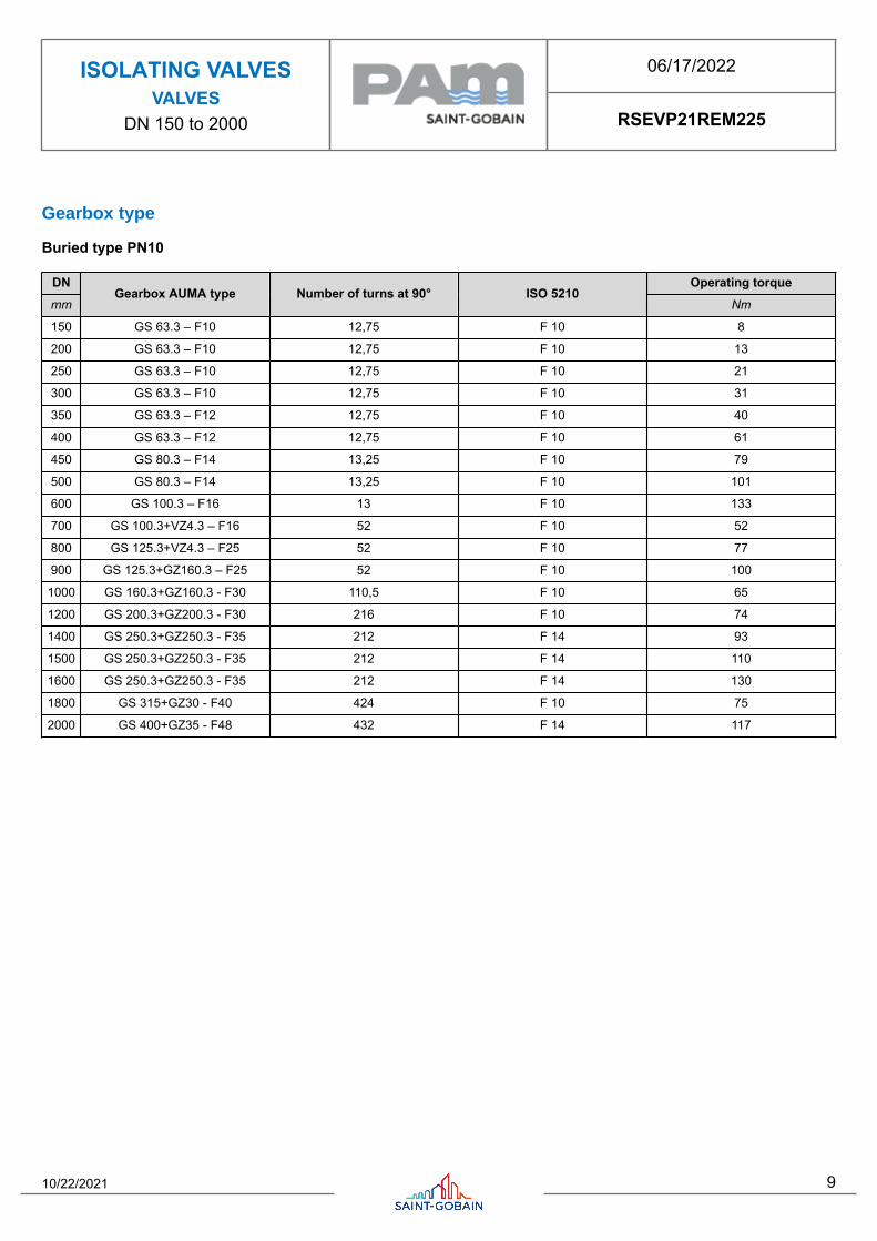
Gearbox type
Buried type PN10
DN Operating torquemm
Gearbox AUMA type Number of turns at 90° ISO 5210Nm
150 GS 63.3 – F10 12,75 F 10 8
200 GS 63.3 – F10 12,75 F 10 13
250 GS 63.3 – F10 12,75 F 10 21
300 GS 63.3 – F10 12,75 F 10 31
350 GS 63.3 – F12 12,75 F 10 40
400 GS 63.3 – F12 12,75 F 10 61
450 GS 80.3 – F14 13,25 F 10 79
500 GS 80.3 – F14 13,25 F 10 101
600 GS 100.3 – F16 13 F 10 133
700 GS 100.3+VZ4.3 – F16 52 F 10 52
800 GS 125.3+VZ4.3 – F25 52 F 10 77
900 GS 125.3+GZ160.3 – F25 52 F 10 100
1000 GS 160.3+GZ160.3 - F30 110,5 F 10 65
1200 GS 200.3+GZ200.3 - F30 216 F 10 74
1400 GS 250.3+GZ250.3 - F35 212 F 14 93
1500 GS 250.3+GZ250.3 - F35 212 F 14 110
1600 GS 250.3+GZ250.3 - F35 212 F 14 130
1800 GS 315+GZ30 - F40 424 F 10 75
2000 GS 400+GZ35 - F48 432 F 14 117
10/22/2021 9

ISOLATING VALVESVALVES
DN 150 to 2000
06/17/2022
RSEVP21REM225
Buried type PN16
DN Operating torquemm
Gearbox AUMA type Number of turns at 90° ISO 5210Nm
150 GS 63.3 – F10 12,75 F 10 8
200 GS 63.3 – F10 12,75 F 10 17
250 GS 63.3 – F10 12,75 F 10 30
300 GS 63.3 – F12 12,75 F 10 43
350 GS 63.3 – F12 12,75 F 10 60
400 GS 80.3 – F14 13,25 F 10 93
450 GS 80.3 – F14 13,25 F 10 112
500 GS 100.3 – F14 13 F 10 125
600 GS 100.3+VZ4.3 – F16 52 F 10 59
700 GS 125.3+VZ4.3 – F25 52 F 10 84
800 GS 160.3+GZ160.3 – F30 110,5 F 10 64
900 GS 160.3+GZ160.3 – F30 110,5 F 10 83
1000 GS 200.3+GZ200.3 - F30 216 F 10 65
1200 GS 250.3+GZ250.3 - F35 212 F 14 104
1400 GS 315+GZ30 - F40 424 F 10 65
1500 GS 315+GZ30 - F40 424 F 10 77
1600 GS 315+GZ30 - F40 424 F 14 94
1800 GS 400+GZ35 - F48 432 F 14 126
2000 GS 400+GZ35 - F48 432 F 14 161
10/22/2021 10
ISOLATING VALVESVALVES
DN 150 to 2000
06/17/2022
RSEVP21REM225
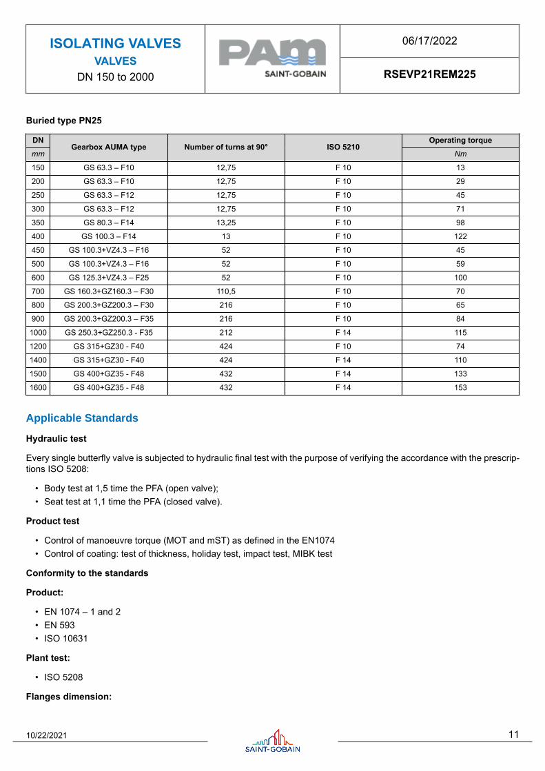
Buried type PN25
DN Operating torquemm
Gearbox AUMA type Number of turns at 90° ISO 5210Nm
150 GS 63.3 – F10 12,75 F 10 13
200 GS 63.3 – F10 12,75 F 10 29
250 GS 63.3 – F12 12,75 F 10 45
300 GS 63.3 – F12 12,75 F 10 71
350 GS 80.3 – F14 13,25 F 10 98
400 GS 100.3 – F14 13 F 10 122
450 GS 100.3+VZ4.3 – F16 52 F 10 45
500 GS 100.3+VZ4.3 – F16 52 F 10 59
600 GS 125.3+VZ4.3 – F25 52 F 10 100
700 GS 160.3+GZ160.3 – F30 110,5 F 10 70
800 GS 200.3+GZ200.3 – F30 216 F 10 65
900 GS 200.3+GZ200.3 – F35 216 F 10 84
1000 GS 250.3+GZ250.3 - F35 212 F 14 115
1200 GS 315+GZ30 - F40 424 F 10 74
1400 GS 315+GZ30 - F40 424 F 14 110
1500 GS 400+GZ35 - F48 432 F 14 133
1600 GS 400+GZ35 - F48 432 F 14 153
Applicable Standards
Hydraulic test
Every single butterfly valve is subjected to hydraulic final test with the purpose of verifying the accordance with the prescrip-tions ISO 5208:
• Body test at 1,5 time the PFA (open valve);• Seat test at 1,1 time the PFA (closed valve).
Product test
• Control of manoeuvre torque (MOT and mST) as defined in the EN1074• Control of coating: test of thickness, holiday test, impact test, MIBK test
Conformity to the standards
Product:
• EN 1074 – 1 and 2• EN 593• ISO 10631
Plant test:
• ISO 5208
Flanges dimension:
10/22/2021 11

ISOLATING VALVESVALVES
DN 150 to 2000
06/17/2022
RSEVP21REM225
• ISO 5752 series 14
Flanges drilling:
• EN 1092-2• ISO 7005-2
Suitability for potable water:
• Italian CM 102 of 02/12/78• Conformity to foreign norms: KTW (Germany), WRC (U.K.), ACS (France)
Marking
On the body like EN19:
• Nominal diameter in mm (DN);• Nominal pressure in bar (PN);• Type of ductile iron;• Manufacturer’s logo;• Model code;• Fusion date.
On the label like EN19:
• Nominal diameter in mm (DN);• Nominal pressure in bar (PN);• Maximum operating pressure (PFA);• Closing direction;• Model code;• Manufacturing order, Order confirmation;• Manufacturer’s logo.
On the disc:
• Nominal diameter in mm (DN);• Nominal pressure in bar (PN);• Type of ductile iron;• Manufacturer’s logo;• Model code.
The marking of the valves manufactured by Saint-Gobain refers to the EN 1074-2 and EN 19 international standards.
Markings are either integral markings, cast in the body, or markings made on plates, securely fixed to the body, in accordancewith the EN 19 standard specifications.
Specifications EN19Table1–Valve markings Requirements
Saint-Gobain valves process
1 DN Integral
2 PN Integral
3 Material Integral
4 Manufacturer's name or trade mark
EN 19 § 4.2.1
Mandatory markings
Shall be integral mark-ings or on a marking plate Plate
10/22/2021 12

ISOLATING VALVESVALVES
DN 150 to 2000
06/17/2022
RSEVP21REM225
Specifications EN19Table1–Valve markings Requirements
Saint-Gobain valves process
11 Reference to Standard Integral
12 Melt identification Integral
16 Quality test Printed on body
18 Manufacturing date Plate
21 Closing direction
EN 19 § 4.3
Supplementary markings
Items 7 to 21 in Table 1 are optionalPlate + sticker on body
Valve selection
The butterfly valves are generally used as isolating devices type on/off. In some particular case, in which there’s low differ-ences of pressure and low flow rate variation can be used like regulating devices, considering the hydraulic parametersnecessary to avoid the cavitation risk.
To do the right dimensioning of butterfly valve it’s necessary to know the followings parameters:
• Upstream hydrostatic pressure (that is the hydrostatic pressure with valve in closed position)• The maximum speed in water pipe (generally expressed in l/s) or the nominal diameter and the project flow rate from
which it is gained the speed V=Q/A
Moreover it’s necessary to control that the maximum speed in water pipe have to be equal or inferior to 5m/s, and theexercise temperature have to be between 0°C and 40 °C.
Hydraulic features
The head loss Δh are variable in function of valve open degree and can be calculated with the following expression:
10/22/2021 13

ISOLATING VALVESVALVES
DN 150 to 2000
06/17/2022
RSEVP21REM225
with Δh = head loss (m), ζ = head loss coefficient (dimensional), v = nominal speed (m/s), g = 9,81 (m/s²)
The head loss coefficient can be estimated from this diagram:
Determinates the head loss Δh it’s possible to calculate the flow rate Q in m3/h with the following expression (the sameexpression can be used to, having the project flow rate Q, to determinate the head loss Δh without using the head losscoefficient):
in which 10,2 is a corrective factor in meters, and Kv is the flow rate coefficient in m3/h, determinable from the followingdiagram in function of valve open degree:
10/22/2021 14

ISOLATING VALVESVALVES
DN 150 to 2000
06/17/2022
RSEVP21REM225
Example: Valve DN600 mm - Δh = 3 m
From the diagram with valve open to 100% the coefficient Kv is 20000 m3/h. Using this date in the flow rate expression:
Otherwise it’s possible to calculate the head loss with valve completely open, having the project flow rate Q, in function ofDN, using the following diagram:
Cavitation
If the butterfly valve is used only like isolating device there’s not cavitation risk.
In the particular case in which it’s used like regulating device, this can be possible only respecting the following parameters:
• The valve open degree have to be between 30° and 90° (valve completely open)• The downstream pressure P2 have to be: P2 ≥ 0,7 .P1 - 2,8 with P1 upstream pressure.
Instructions for use
Storage
The butterfly valve will have to be held (if possible) in covered places, the most possible protected from the sun (maximumallowable temperature 70°C in accordance to EN 1074), from the rain and generally from the atmospheric agents. Moreoverit will have to be avoided that the seal of the same air valves come to contact with powder or earth.
Installation
The butterfly valves are generally installed with retaining ring mounted in the opposite way respect to the direction of flowrate to permit the substitution of gasket without dismounting the valve from pipeline. In any case it is possible to install thebutterfly valve with flow rate in opposite direction and also, if required, in vertical position. We recommend to install thebutterfly with the operating device on the hydraulic right side of pipeline.
It’s possible to install the butterfly valve both in chamber valve that underground (choosing the right configuration).
We recommend to insert a dismounting joint for the operation of maintenance.
Maintenance
10/22/2021 15

ISOLATING VALVESVALVES
DN 150 to 2000
06/17/2022
RSEVP21REM225
The butterfly valve does not require a particular maintenance, all parts subjected to wear are perfectly auto-lubricating. Inany case, if for a long time will be not used, it is necessary to evaluate the functioning of valve doing (at least one time foryear) some manoeuvre of opening-closing.
All the maintenance operation have to be do after the total emptying of pipeline (no flow rate and pressure) to avoid everyrisk to the people during this operation.
In presence of particularly exercise condition or damage due to external cause, it will be necessary some maintenanceoperation. In this case the particular shape of EUROSTOP butterfly valve permits the simple gasket substitution without thedismounting of valve from pipeline (if the dismounting joint is present).
Accessories
To adapt the butterfly valves to the different exercise and installation conditions required, they can be equipped with particularaccessories used in combination with control devices: please refer to data sheet for accessories.
The technical features in this document are not contractual and can be changed without preliminary notification due to thecontinuous technical progress of product.
10/22/2021 16