Analysis of Deeply Buried Flexible Pipes
28
Analysis of Deeply Buried Flexible Pipes By: M. T. Suleiman Research Assistant, Iowa State University Department of Civil and Construction Engineering Ames, Iowa, 50011 Phone:515-294-6076 Fax:515-294-8216 E-mail: [email protected] R. A. Lohnes Professor of Civil Engineering Iowa State University Department of Civil and Construction Engineering Ames, Iowa 50011 Phone:515-294-8746 Fax:515-294-8216 E-mail:[email protected] T.J. Wipf Professor of Civil Engineering Iowa State University Department of Civil and Construction Engineering Ames, Iowa 50011 Phone: 515-294-6979 Fax: 515-294-7424 E-mail: [email protected] F. W. Klaiber Professor of Civil Engineering Iowa State University Department of Civil and Construction Engineering Ames, Iowa 50011 Phone: 515-294-8763 Fax: 515-294-7424 E-mail:[email protected] November, 14, 2002 Words: 7498 TRB 2003 Annual Meeting CD-ROM Paper revised from original submittal.
-
Upload
independent -
Category
Documents
-
view
2 -
download
0
Transcript of Analysis of Deeply Buried Flexible Pipes
Analysis of Deeply Buried Flexible Pipes
By:
M. T. Suleiman Research Assistant, Iowa State University
Department of Civil and Construction Engineering Ames, Iowa, 50011
Phone:515-294-6076 Fax:515-294-8216
E-mail: [email protected]
R. A. Lohnes Professor of Civil Engineering
Iowa State University Department of Civil and Construction Engineering
Ames, Iowa 50011 Phone:515-294-8746
Fax:515-294-8216 E-mail:[email protected]
T.J. Wipf
Professor of Civil Engineering Iowa State University
Department of Civil and Construction Engineering Ames, Iowa 50011
Phone: 515-294-6979 Fax: 515-294-7424
E-mail: [email protected]
F. W. Klaiber Professor of Civil Engineering
Iowa State University Department of Civil and Construction Engineering
Ames, Iowa 50011 Phone: 515-294-8763
Fax: 515-294-7424 E-mail:[email protected]
November, 14, 2002
Words: 7498
TRB 2003 Annual Meeting CD-ROM Paper revised from original submittal.

Suleiman, Lohnes, Wipf, Klaiber
1
ABSTRACT
CANDE is one of the most commonly used programs for buried pipe analysis; however CANDE is limited to applications with small deflections. This limitation is typically not problematic, but there are some instances where analysts may be interested in large deflection behavior. This limitation led to the consideration of other analysis tools. In this study ANSYS, a general finite element program, was used to model the soil-pipe system. Small and large deflection theories of ANSYS were used in the analysis of several case studies and the results were compared to those of CANDE. Also, a code was written to run within ANSYS to include the following soil constitutive models: the hyperbolic tangent modulus, power bulk modulus, and hyperbolic bulk modulus. Results obtained using ANSYS with the modified soil models were in good agreement, less than 10%, except in one case, with CANDE results for 6.1 m of soil cover above the spring line for the case of 610 mm pipe diameter with SM and ML soils. Use of large deflection theory resulted in an insignificant effect, less than 5%, when compared with ANSYS small deflection theory results for soil heights up to 6.1 m above the spring line which proves that small deflection theory is adequate for these cases. Comparing CANDE and ANSYS for 1200 mm diameter PE pipes with experimental results showed that ANSYS more accurately describe the PE pipe behavior for cases of 9 m of soil cover or more and that large deflection theory describes the PE pipe behavior better than small deflection theory for vertical deflection percent of 4% or more. The pipe material effect was investigated by comparing the results of ANSYS small and large deflection theories for both PE and PVC pipes. The difference between the small and large deflection theories for both pipe materials becomes significant, more than 10%, at a vertical deflection percent of 4%.
TRB 2003 Annual Meeting CD-ROM Paper revised from original submittal.

Suleiman, Lohnes, Wipf, Klaiber
2
GENERAL BACKGROUND The theoretical study of flexible pipes was started by Spangler’s work on metal pipes. Since then, more flexible materials (i.e. Aluminum, Polyvinyl Chloride (PVC), and Polyethylene (PE)) are being used in the pipe industry. Analytical tools such as finite element analysis (F.E.A.) have been used to understand the flexible pipe-soil interaction. One such analytical tool is Culvert ANalysis and DEsign (CANDE) a 2-D finite element program commonly used to analyze and design buried pipes that was developed by Katona (1). The stated notable limitations of CANDE are 1) small deflection theory, 2) neglecting out-of-plane effects such as longitudinal bending, and 3) neglecting time dependence material response (1).
A variety of other finite element analyses (F.E.A.) have been used to understand the response of buried pipes (i.e. 2, 3, 4, and 5). These analytical studies used a simplified soil constitutive law (elastic or elastic plastic) to model the soil. Katona (6 and 7) numerically studied the minimum depth and maximum allowable fill heights of soil cover for HDPE pipes. HDPE pipes with diameter up to 910 mm using SC soil with two different compaction levels were analyzed.
Sargand et al (8) investigated the behavior of thermoplastic pipes buried in sand and crushed limestone under 6.1 and 12.2 m embankment and measured the soil pressure at different depths. It was concluded that soil-pipe interaction zone, for PVC and HDPE pipes, extended for one pipe diameter above the pipes. The hyperbolic model parameters for the soil used around these pipes were not provided (8). Sargand et al (8) field investigation showed that the vertical pressure becomes constant at a distance of 3R horizontally away from the center of HDPE pipe. Sargand et al (9) studied the performance of HDPE pipes buried under 15.25 m embankment. The field test results were compared with CANDE F.E.A. using the soil hyperbolic model parameters reported in Musser (10). This comparison did not show a good agreement with the measured data because of the uncertainty in the soil parameters. Greenwood and Lang (11) stated that the soil stiffness is the most important parameter that affects the flexible pipe behavior. Hashash and Selig (12) studied the long term performance of 610 mm diameter HDPE pipes buried under 30.5 m fill with a 100% compaction well graded crushed stone as a backfill material. The reported maximum vertical deflection percent was 4%. Moser (13) studied the structural performance of buried 1200 mm diameter PE pipes. In this work, PE pipes were loaded using Utah State University (USU) pipe-soil cell using SM soil with compaction levels of 75, 85, and 96.5%. Interpolated results of 90% compaction were also reported. The soil properties available in Moser (14) are these for 90% compaction.
Watkins and Anderson (15) listed the differences between the analysis of soil-pipe interaction system and a simple linear elastic continuum. This list included the nonlinear stress-strain relationship of soil and large deflections that may be involved in flexible pipes. Although CANDE allows the use of the non-linear soil models, it does not accommodate large deflections. This paper describes analyses that include improving the capabilities of ANSYS to include the nonlinear soil behavior, and evaluating the importance of large deflections for flexible pipe. OBJECTIVES AND SCOPE The main advantage of CANDE relative to ANSYS is the use of hyperbolic and power soil models while ANSYS has the advantage of modeling large deflections. One objective of the theoretical analyses presented in this paper is to compare the results of CANDE with small and
TRB 2003 Annual Meeting CD-ROM Paper revised from original submittal.

Suleiman, Lohnes, Wipf, Klaiber
3
large deflection theories of ANSYS for the case of elastic soil properties for geostatic applied loads. A second objective is to develop a code using the ANSYS programming language to model the soil behavior using hyperbolic tangent modulus with both power and hyperbolic bulk soil modulus models and to study the effect of large deflection on the structural behavior of flexible pipes. MODELING In the F.E.A. presented here, the pipes are modeled using a beam-column element. Plastic pipes are modeled as elastic materials; however the Corrugated Polyethylene Pipe Association (CPPA) (16) described the polyethylene (PE) pipes as a viscoelastic material.
CANDE level 2 solution automatically generates the finite element mesh shown in Figure 1. This figure shows that the maximum soil cover above the pipe crown is 3R where R is the pipe radius. If the soil cover exceeds this limit, the program automatically truncates the cover at the 3R level and applies the truncated soil load as a distributed load on the soil surface. ELASTIC SOIL, COMPARISON OF ANSYS AND CANDE A plastic pipe 610 mm in diameter with four different soil covers of 1.5, 3.05, 4.6, and 6.1 m. above the pipe spring line was modeled using both CANDE and ANSYS as shown in Figure 1. In these models, the soil was assumed to be linear elastic material, no interface elements were used between the soil and pipe elements, and the pipe was modeled with a uniform thickness “no corrugation”. The soil and pipe properties used are given in Table 1. Plastic pipe properties included in this table are CANDE default plastic pipe properties. PE pipe properties included in Table 1 are taken from CPPA (17) that meet AASHTO M294 (18). The pipe wall thickness was adjusted so that the moment of inertia would remain the same as that specified in CPPA (17).
Figure 2 shows the vertical deflection of plastic pipe crown and invert with respect to soil cover above the pipe spring line using small and large deflection theories of ANSYS, CANDE for the soil pipe system described above. This figure shows that the three solutions result in nearly identical, less than 5% difference, pipe deflections. For the case of 1.5 m soil cover above spring line (1.22 m above pipe crown), the three solutions give approximately equal pipe crown deflections.
Figure 3 shows the vertical deflection at different angles (α) on the plastic pipe circumference for various depths of soil cover above the pipe spring line. This figure shows the same trend of a maximum deflection at the pipe crown and minimum deflection at pipe invert. As an overall comparison, the three different methods showed slight difference, less than 5%, for this range of soil covers. Large deflection analysis using ANSYS has an insignificant effect on the plastic pipe using elastic soil properties with uniformly distributed loads equivalent to 6.1 m of soil cover.
Results of the same pipe-soil system described above but using the properties of PE pipe shown in Table 1 are shown in Figure 4. This figure shows that both CANDE and ANSYS, using small and large deflection theories of ANSYS, give almost the same results for pipe invert and crown deflection with slight differences, less than 3%, for cases up to 6.1 m of soil height above the spring line. The vertical deflection percent, which is the change of vertical pipe diameter divided by the inside pipe diameter, of PE pipe with soil cover is shown in Figure 5. This figure
TRB 2003 Annual Meeting CD-ROM Paper revised from original submittal.

Suleiman, Lohnes, Wipf, Klaiber
4
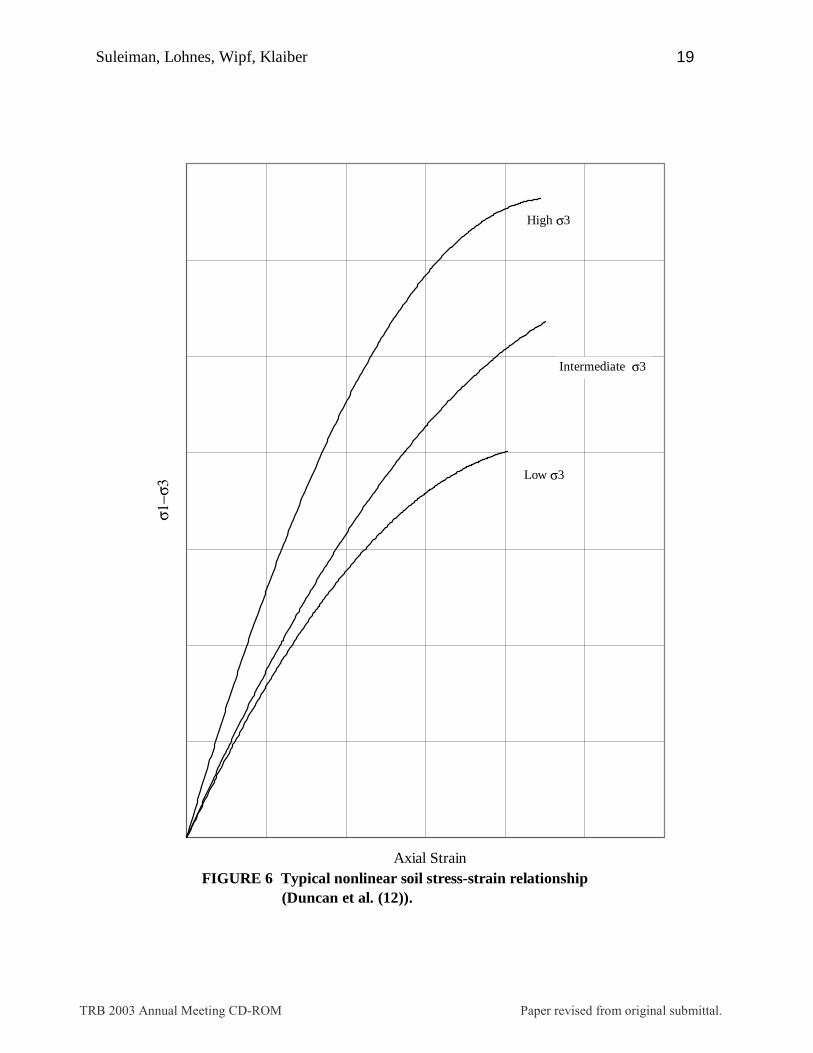
shows the same trend of increasing differences between the three methods as the soil height increases. SOIL MODELS Duncan and Chang (19) stated that the soil behavior is nonlinear and depends upon the magnitude of the applied stresses. Figure 6 shows a typical soil stress-strain relationship and the change of soil modulus with confining pressure according to Duncan et al. (20). This response has been modeled with a hyperbolic stress-strain relationship as shown in Equation 1. The initial tangent modulus (Ei) is a function of confining pressure. At constant confining pressure, the value of the soil modulus is a function of the stress level as shown in Equation 2 (20). Power bulk modulus model is given by Equation 3 (20) while the hyperbolic bulk modulus developed by Selig (21) is given by Equation 4 .
ultiE )(
1)(
31
31
σσε
εσσ
−+
=− (1)
n
aa
ft P
KPc
RE )(]
sin2cos2
)sin1)((1[ 32
3
31 σϕσϕϕσσ
+−−
−= (2)
m
aab P
PKB )( 3σ= (3)
2)](1[ui
mi B
BBε
σ+= (4)
Where: ε : vertical strain. σ1 : major principal stress (kPa). σ3 : minor principal stress (confining pressure) (kPa). Ei : initial tangent modulus (kPa). (σ1-σ3)ult : ultimate deviator stress (kPa). Et : tangent elastic modulus (kPa). φ : angle of soil internal friction. c : soil cohesion (kPa). Rf : failure ratio. n : elastic modulus exponent. K : elastic modulus constant. Pa : atmospheric pressure (kPa). B : bulk modulus (kPa). Kb : bulk modulus constant. m : bulk modulus exponent. Bi : initial bulk modulus (kPa). εu : ultimate volumetric strain. σm : mean stress (kPa). Figure 7 shows a flowchart of the code written in ANSYS for soil models using the
internal program language. The improved code works as a load step program where stress
TRB 2003 Annual Meeting CD-ROM Paper revised from original submittal.

Suleiman, Lohnes, Wipf, Klaiber
5
induced at the beginning of the first load step is based on the soil element depth to calculate the initial tangent modulus. Soil elements are considered as blocks of soil masses with an average soil modulus for each soil block. These blocks will enable modeling different regions and different soil materials used in the backfill. Each load step is solved using “n” sub-steps by applying a stepped load within each load step. The results of each sub-step are used to calculate a new average modulus for each soil block and solve again until the end of each load step. This solution procedure was used because solving the load step using the average calculated moduli at the beginning and at the end of each load step resulted in greater error when compared with CANDE. The model is solved using an average modulus for each soil block at the end of the load step to get soil and pipe stresses, strains, and deformations of different elements at the end of each load step. The resulting stresses are then used to calculate the soil element modulus at the beginning of the next load step, this cycle is repeated N (number of load steps) times. Comparison of ANSYS and CANDE ANSYS utilizing the hyperbolic soil model with power bulk modulus was compared with CANDE for a pipe soil system of 610 mm diameter pipe with pipe properties shown in Table 1. The pipe wall thickness was adjusted so that the moment of inertia would remain the same as that given in CPPA (17). The buried pipe structure analyzed is shown in Figure 1. The soil model parameters used in this analysis for SM soil with 90% compaction (14) are shown in Table 2. CANDE level 2 analysis was used to model the pipe soil system. Five cases of height of soil above the pipe spring line were used for comparison (1.5, 3.05, 3.8, 4.6, and 6.1 m).
Figure 8 shows the plastic pipe crown and invert deflections for all cases of soil cover using both CANDE and small deflection theory of ANSYS. This figure shows that the results of ANSYS with the improved code show good agreement with the results of CANDE. Figure 8 also shows a change in the slope of pipe deflection curve for both pipe invert and pipe crown at 3.8 m depth of soil cover. This is an indication of pipe flattening at both pipe invert and crown. Vertical deflection percent of the pipe for the same plastic pipe-soil system is presented in Figure 9. This figure also shows a good agreement between both ANSYS and CANDE. Figures 9 showed divergence and then convergence between 3.8 m and 6.1 m soil covers. This is due to the difference between CANDE and ANSYS models where CANDE uses a modulus for each soil element while ANSYS uses an average soil modulus for each soil block. The flattening at the pipe invert and crown changes the stresses in one or few soil elements around the pipe which affects the average modulus of soil blocks around the pipe.
The same soil pipe system was analyzed using PE pipe properties using the hyperbolic bulk modulus model for ML soil with parameters shown in Table 2 (10). The PE pipe invert and crown deflections using both ANSYS and CANDE are shown in Figure 10. The results of ANSYS with the improved tangent and bulk hyperbolic modulus code showed different deflections than those of CANDE for the case of 1.5 m of soil cover with a good agreement for the other depths of soil cover. This is due to the effect of the assumed initial stresses calculated at the beginning of the analysis. Vertical deflection percent of the PE pipe is presented in Figure 11. This figure shows the same trend described above. The Comparison of the cases above validates the use of ANSYS with the improved code to model pipe soil systems, especially for pipes buried at 3.0 m or more.
ANSYS large deflection theory was used and compared with the results of small deflection theory of both CANDE and ANSYS for the same soil pipe system above using PE
TRB 2003 Annual Meeting CD-ROM Paper revised from original submittal.
Suleiman, Lohnes, Wipf, Klaiber
6
pipe properties. Figure 12 shows the vertical deflection percent of PE pipes using CANDE and small and large deflection theories of ANSYS. Large deflection theory for PE pipes has little effect on the results for the cases up to 3.05 m of soil cover. Increasing the fill height from 4.6 to 6.1 m increased the effect of large deflection theory. These figures show that both ANSYS with small deflection theory and CANDE have a good agreement for soil covers up to 6.1 m.
Moser (13) studied the behavior of 1200 mm PE pipes using (USU) cell with SM soil. The hyperbolic model parameters for SM soil with 90% compaction are available in Moser (14). In USU soil-pipe cell, the depth of the pipe is more than 3R which is greater than the extent on the pipe-soil interaction zone reported in Sargand et al (8). Watkins and Anderson (15) discussed the shape and the effect of boundary conditions of USU test cell. They concluded that “the effects of the boundary conditions were negligible for pipes up to 1.5 m diameter”, so the curved shape of the test cell was not considered in the finite element model used to this study.
The pipe-soil system shown in Figure 13, which represents the finite element mesh of USU cell, was analyzed using ANSYS and CANDE level 3 analyses for SM soil with 90% compaction. The results of these analyses were compared with Moser (13) results as shown in Figure 14. This figure showed that both ANSYS and CANDE results showed a good agreement with Moser (14) results up soil cover of 9 m. CANDE overestimated the pipe deflection as the applied load increase. This is due to the fact that one soil element around the pipe reached the shear failure. ANSYS results showed better agreement than CANDE with Moser (13) results with a maximum difference of 7% between small and large deflection theories of ANSYS for loads equivalent to 12.2 m depth of soil cover. Large deflection theory showed better agreement than small deflection theory of ANSYS for the cases of soil cover more than 12.2 m where the vertical deflection percent is greater or equal 4%. Pipe Material Effect
ANSYS small and large deflection theories were used to compare the performance of both PE and PVC pipes for deeply buried pipes. A 610 mm diameter flexible pipe with different soil covers up to 18 m above the pipe spring line was modeled using ANSYS with both small and large deflection theories. The material and cross sectional properties for different pipe materials are shown in Table 1.
The PVC pipe properties used are specified in ASTM F-679 (22), while the PE pipe properties used are taken from CPPA (17). The soil is modeled using the hyperbolic tangent soil modulus with power bulk modulus model. The SM soil parameters for these models are shown in Table 2. The pipe-soil system shown in Figure 1 was used to investigate the effect of the large deflection theory as the height of soil cover increased for both PE and PVC pipes. The results of the pipe vertical deflection percent are presented in Figure 15. This figure shows that the PE pipe exhibited a greater deflection percent than the PVC pipes with a difference of 19% at 12 m cover. Sargand et al (23) reported a difference of 20% between PVC and PE pipes buried under 12.2 m. The difference between the small and the large deflection theories is greater for PE pipes than for PVC pipes. PE pipes are more sensitive to the consideration of the large deflection theory than PVC pipes. Figure 15 also shows that the large deflection theory effect becomes significant for vertical deflection percents greater or equal 4%.
TRB 2003 Annual Meeting CD-ROM Paper revised from original submittal.

Suleiman, Lohnes, Wipf, Klaiber
7
CONCLUSION
CANDE is one of the most commonly used programs for buried pipe analysis, however the limitations of CANDE, such as small deflections, led to the consideration of another analysis method. ANSYS, which is a general F.E.A. program, was used with a written code to provide a better analysis tool for the cases involving large deflections. There is a little difference in the results calculated for both ANSYS and CANDE for the case of elastic soil. The improved soil models code in ANSYS used to model the soil material behavior showed good agreement with CANDE results for cases up to 6.1 m depth of burial; and therefore validates the use of improved soil models in ANSYS for buried pipe analysis. The results also show that CANDE can be used for shallow buried pipes. Using CANDE for deeply buried pipes did not show a good agreement with either ANSYS or the results provided by Moser (13) for cases of 9 m of soil cover or more. These results and the comparison of PE and PVC pipe responses showed that large deflection theory needs to be considered for vertical deflections percent of 4% or more.
TRB 2003 Annual Meeting CD-ROM Paper revised from original submittal.

Suleiman, Lohnes, Wipf, Klaiber
8
REFERENCES
[1] Katona, M. G. CANDE: A Modern Approach for the Structural Design and Analysis of Buried Culverts. Report FHWA-RD-77-5. FHWA, U.S. Department of Transportation, 1976. [2] Morgan, B.C., Lohnes, R.A., Klaiber F.W., and B. H. Kjartanson. Design Method for Preventing Longitudinal Uplift of Corrugated Metal Pipe. In Transportation Research Record 1541, TRB, National Research Council, Washington, D.C., 1996, pp. 107-111. [3] Taleb, B., and I.D. Moore. Metal Culvert Response to Earth Loading- Performance of Two Dimensional Analysis. In Transportation Research Record 1656, TRB, National Research Council, Washington, D.C., 1999, pp. 25-36. [4] Moore, I.D., and B. Taleb. Metal Culvert Response to Live Loading Performance of Three Dimensional Analysis. In Transportation Research Record 1656, TRB, National Research Council, Washington D.C., 1999, pp. 37-44. [5] El-Sawy, K., Moore, I.D., and B. Taleb. Analysis of Stability Limit States for Long Span Culverts, 50th Canadian Geotechnical Conference of the Canadian Geotechnical Society, October 1997, pp. 178-184. [6] Katona M.G., 1990. Minimum Cover Height for Corrugated Plastic Pipe Under Vehicle Loading. In Transportation Research Record 1288, Washington D.C. pp127-135. [7] Katona M.G., 1988. Allowable Fill Heights for Corrugated Polyethylene Pipe. In Transportation Research Record 1191, Washington D.C. pp30-38. [8] Sargand, S. M., Masada, T. and Schehl, D. J. Soil pressure Measured at Various Fill Heights Above Deeply Buried Thermoplastic Pipe. In Transportation Research Record 1770, Washington, D.C., 2001, pp. 227-235. [9] Sargand, M. S. and Masada, T. Performance of Large-diameter Honeycomb Design HDPE Pipe Under a Highway Embankment. Canadian Geotechnical Journal, Vol. 37, 2000, pp.1099-1108. [10] Musser, S.C. CANDE-89 User Manual. Report FHWA-RD-89-169. FHWA, U.S. Department of Transportation, 1989. [11] Greenwood, M. E. and Lang, D. C., 1990. Vertical Deflection of Buried Flexible Pipes. Buried Plastic Pipe Technology. Philadelphia, PA: ASTM [12] Hashash, N., and E. T. Selig, 1990. Analysis of the Performance of a Buried High Density Polyethylene Pipe. The First National Conference on Flexible Pipes, Columbus, Ohio, pp 95-109.
TRB 2003 Annual Meeting CD-ROM Paper revised from original submittal.

Suleiman, Lohnes, Wipf, Klaiber
9
[13] Moser, A.P. The Structural Performance of Buried 48 inch diameter N-12 HC Polyethylene Pipes. Buried Structural Laboratory, Utah State University, Logan, Utah, September, 1994. [14] Moser, A. P. Buried Pipe Designs. McGraw Hill, Inc., New York, 1990. [15] Watkins, R. K., Anderson, L.R. Structural Mechanics of Buried Pipes. CRC Press, New York, 1999. [16] Corrugated Polyethylene Pipe Association. Structural Integrity of Non-Pressure Corrugated Polyethylene Pipe. 1997. [17] Corrugated Polyethylene Pipe Association. Structural Design Method for Corrugated Polyethylene Pipe. 1997. [18] American Association of State and Highway Transportation Officials. Corrugated Polyethylene pipe, 300- to 1200- mm Diameter, M294. 1990. [19] Duncan, J. M. and Chang, C. Y., 1970. Nonlinear Analysis of Stress and Strain In Soils”. Journal of the Soil Mechanics and Foundations Division. Proceedings of the American Society of Civil Engineers, Vol. 96, No. SM5, pp. 1629-1654. [20] Duncan, J.M., Byrne, P., Wong, K.S., and P. Mabry. Strength, Stress-Strain and Bulk Modulus Parameters for Finite Element Analysis of Stresses and Movement in Soil Masses.“ Report No. UCB/GT/80-01. University of California, Berkeley, 1980. [21] Selig, E.T., Soil Parameters for design of buried pipelines. Pipeline infrastructure, proceeding of pipeline infrastructure conference of ASCE, ASCE, NY, 1988. [22] American Society for Testing and Materials. Poly(Vinyl Chloride) (PVC) Large-Diameter Plastic Gravity Sewer Pipe and Fittings, ASTM F679. 1989. [23] Sargand, S. M., Hazen, G. A, White, K. and Moran, A. Time-Dependent Deflection of Thermoplastic Pipes Under Dep Burial. In Transportation Research Record 1770, TRB, National Research Council, Washington, D.C., 2001, pp. 236-242.
TRB 2003 Annual Meeting CD-ROM Paper revised from original submittal.

Suleiman, Lohnes, Wipf, Klaiber
10
LIST OF TABLE TABLE 1 Pipe and Elastic Soil Properties Used in the Analysis TABLE 2 Soil Parameters Used in the Analysis LIST OF FIGURES FIGURE 1 A schematic homogenous model for CANDE solution level 2. FIGURE 2 Plastic pipe deflection with respect to height of soil cover for the case of elastic soil. FIGURE 3 Plastic pipe vertical deflection with respect to position on pipe circumference for different soil covers for the case of elastic soil. FIGURE 4 PE pipe vertical deflection with respect to height of soil cover for the case of elastic soil. FIGURE 5 PE pipe vertical deflection percent with respect to height of soil cover for the case elastic soil. FIGURE 6 Typical nonlinear soil stress-strain relationship (Duncan et al. (12)). FIGURE 7 Flowchart of nonlinear soil models code written in ANSYS. FIGURE 8 Plastic pipe vertical deflection using hyperbolic tangent soil modulus and power bulk soil modulus for both ANSYS and CANDE. FIGURE 9 Plastic pipe vertical deflection percent using hyperbolic tangent soil modulus and Power bulk modulus for both ANSYS and CANDE. FIGURE 10 PE pipe vertical deflection using hyperbolic tangent and bulk soil moduli models for both ANSYS and CANDE. FIGURE 11 PE pipe vertical deflection percent using hyperbolic tangent and bulk soil moduli For both ANSYS and CANDE. FIGURE 12 PE pipe vertical deflection percent using hyperbolic tangent soil modulus with Power bulk modulus for both ANSYS and CANDE. FIGURE 13 Finite element mesh used to model Utah State University soil-pipe cell. FIGURE 14 Vertical deflection percent with respect to soil cover for PE pipes compared with Moser (6). FIGURE 15 Vertical deflection percent with respect to soil cover above the spring line for 610 mm diameter PE and PVC pipes.
TRB 2003 Annual Meeting CD-ROM Paper revised from original submittal.
Suleiman, Lohnes, Wipf, Klaiber
11
TABLE 1 Pipe and Elastic Soil Properties Used in the Analysis. Property CANDE plastic
pipe PE pipe PVC pipe Elastic soil
E (kPa) 11,024,000 757,900 2,756,000 6,890 µ 0.3 0.45 0.45 0.35
t (mm) 12.7* 29.0 18.0 -- Notes: * assumed value. Soil γ = 1,920 kg/m3
TRB 2003 Annual Meeting CD-ROM Paper revised from original submittal.

Suleiman, Lohnes, Wipf, Klaiber
12
TABLE 2 Soil Parameters Used in the Analysis. Soil
Type Density (kg/m3)
Φ (deg.)
∆ φ (deg.)
C (kPa)
K n Rf Kb m Bi/Pa εu
SM 1,800 30 0 57 480 0.44 0.75 80 0.38 -- -- ML 2,300 34 0 28 440 0.4 0.95 -- -- 120.8 0.043
TRB 2003 Annual Meeting CD-ROM Paper revised from original submittal.

Suleiman, Lohnes, Wipf, Klaiber
13
CL
R
3R
6R
3RMaximum
R
Beam-columnelement
Quadrilateral element
CL
R
FIGURE 1 A schematic homogenous model for CANDE solution level 2.
TRB 2003 Annual Meeting CD-ROM Paper revised from original submittal.

Suleiman, Lohnes, Wipf, Klaiber
15
-20
-18
-16
-14
-12
-10
-8
-6
-4
-2
0
0 1 2 3 4 5 6 7
Height of soil cover above springline (m)
Ver
tical
def
lect
ion
(mm
)ANSYS, small
ANSYS, large
CANDE
Figure 2. Plastic pipe deflection with respect to height of soil cover for the case of elastic soil
Pipe Invert
Pipe Crown
Crown
Invert
TRB 2003 Annual Meeting CD-ROM Paper revised from original submittal.

Suleiman, Lohnes, Wipf, Klaiber
16
-20
-18
-16
-14
-12
-10
-8
-6
-4
-2
0
0 20 40 60 80 100 120 140 160 180 200
α: Position on pipe circumference (deg)
Ver
tica
l def
lect
ion
(mm
)
ANSYS, small
ANSYS, large
CANDE
1.5 m soil cover
3.05 m soil cover
4.6 m soil cover
6.1 m soil cover
Figure 3 Plastic pipe vertial deflection with respect to position on pipe circumference for different height of soil covers for the case of elastic soil.
Invert
Crown
α
0
180
TRB 2003 Annual Meeting CD-ROM Paper revised from original submittal.

Suleiman, Lohnes, Wipf, Klaiber
17
-20
-18
-16
-14
-12
-10
-8
-6
-4
-2
0
0 1 2 3 4 5 6 7
Height of soil cover above springline (m)
Ver
tical
def
lect
ion
(mm
)
CANDE
ANSYS, small
ANSYS, large
CANDE
ANSYS, small
ANSYS, large
Pipe invert
Pipe crown
Figure 4 PE pipe vertical deflection with respect to height of soil cover for the case of elastic soil.
TRB 2003 Annual Meeting CD-ROM Paper revised from original submittal.

Suleiman, Lohnes, Wipf, Klaiber
18
0
0.2
0.4
0.6
0.8
1
1.2
1.4
0 1 2 3 4 5 6 7
Height of soil cover above spring line (m)
Ver
tical
def
lect
ion
perc
ent
CANDE
ANSYS, small
ANSYS, large
FIGURE 5 PE pipe vertical deflection percent with respect to height of soil cover for the case of elastic soil.
TRB 2003 Annual Meeting CD-ROM Paper revised from original submittal.
Suleiman, Lohnes, Wipf, Klaiber
19
Axial Strain
σ1−σ
3 Low σ3
Intermediate σ3
High σ3
FIGURE 6 Typical nonlinear soil stress-strain relationship (Duncan et al. (12)).
TRB 2003 Annual Meeting CD-ROM Paper revised from original submittal.

Suleiman, Lohnes, Wipf, Klaiber
20
N load steps
n substeps
FIGURE 7 Flowchart of nonlinear soil models code written in ANSYS.
Assume initial stress for soil element based
on its depth
Calculate the soil element modulus at the beginning of this
load step and average for all soil
blocks
Solve the ith sub-step
Get the results and use them in calculating new material
properties and average them for each soil block
Get the last set of results for this load step
END
Create the structure with all nodes and elements
TRB 2003 Annual Meeting CD-ROM Paper revised from original submittal.

Suleiman, Lohnes, Wipf, Klaiber
21
-40
-30
-20
-10
0
0 1 2 3 4 5 6 7
Height of soil cover above spring line (m)
Ver
tical
def
lect
ion
(mm
)
Pipe crown, CANDE
Pipe crown, ANSYS
Pipe invert, CANDE
Pipe invert, ANSYS
FIGURE 8 Plastic pipe vertical deflection using hyperbolic tangent soil modulus and power bulk soil modulus for both ANSYS and CANDE.
TRB 2003 Annual Meeting CD-ROM Paper revised from original submittal.

Suleiman, Lohnes, Wipf, Klaiber
22
0
0.5
1
1.5
2
2.5
3
0 1 2 3 4 5 6 7
Height of soil above springline (m)
Ver
tical
def
lect
ion
perc
ent
CANDE
ANSYS, small
FIGURE 9 Plastic pipe vertical deflection percent using hyperbolic tangent soil modulus and power bulk modulus for both ANSYS and CANDE.
TRB 2003 Annual Meeting CD-ROM Paper revised from original submittal.

Suleiman, Lohnes, Wipf, Klaiber
23
-20
-18
-16
-14
-12
-10
-8
-6
-4
-2
0
0 1 2 3 4 5 6 7 8
Height of soil cover above spring line (m)
Ver
tical
def
lect
ion
(mm
)
Pipe invert, CANDE
Pipe crown, CANDE
Pipe invert, ANSYS
Pipe crwon, ANSYS
FIGURE 10 PE pipe vertical deflection using hyperbolic tangent and bulk soil moduli models for . both ANSYS and CANDE.
TRB 2003 Annual Meeting CD-ROM Paper revised from original submittal.

Suleiman, Lohnes, Wipf, Klaiber
24
0
0.2
0.4
0.6
0.8
1
1.2
1.4
1.6
0 1 2 3 4 5 6 7
Height of soil cover above spring line (m)
Ver
tica
l def
lect
ion
perc
ent
CANDE
ANSYS
FIGURE 11 PE pipe deflection percent using hyperbolic tangent and bulk soil moduli for both ANSYS and CANDE.
TRB 2003 Annual Meeting CD-ROM Paper revised from original submittal.

Suleiman, Lohnes, Wipf, Klaiber
25
0
0.5
1
1.5
2
2.5
3
0 1 2 3 4 5 6 7
Height of soil above spring line (m)
Ver
tica
l def
lect
ion
perc
ent
CANDE
ANSYS, small
ANSYS, large
FIGURE 12 PE vertical deflection percent using hyperbolic tangent soil modulus with power bulk modulus for both ANSYS and CANDE.
TRB 2003 Annual Meeting CD-ROM Paper revised from original submittal.

Suleiman, Lohnes, Wipf, Klaiber
26
FIGURE 13. Finite element mesh used to model Utah State University soil-pipe cell.
2.3 m
5.5 m
R=600 mm
2.3 m
5.5 m
R=600 mm
TRB 2003 Annual Meeting CD-ROM Paper revised from original submittal.

Suleiman, Lohnes, Wipf, Klaiber
27
0.0
1.0
2.0
3.0
4.0
5.0
6.0
7.0
8.0
9.0
10.0
0.0 2.0 4.0 6.0 8.0 10.0 12.0 14.0 16.0 18.0
Height of soil cover (m)
Ver
tica
l def
lect
ion
%Moser (13)
CANDE
ANSYS, Large
ANSYS, Small
FIGURE 14 Vertical deflection percent with respect to soil cover for PE pipe compared with Moser (13).
TRB 2003 Annual Meeting CD-ROM Paper revised from original submittal.

Suleiman, Lohnes, Wipf, Klaiber
28
FIGURE 15. Vertical deflection percent with respect to soil cover above springline for 610 mm diameter
0.0
1.0
2.0
3.0
4.0
5.0
6.0
7.0
8.0
9.0
0 2 4 6 8 10 12 14 16 18 20
Soil height (m)
Ver
tical
def
lect
ion
perc
ent
PE, small
PE, large
PVC, small
PVC, large
PE and PVC pipes.
TRB 2003 Annual Meeting CD-ROM Paper revised from original submittal.