Foundry Alloys, Processes and Characteristics - Drive Aluminum
Upload
gsidarmstadtCategory
view
0download
0
Materials Transactions, Vol. 43, No. 8 (2002) pp. 2017 to 2025Special Issue on Bulk Amorphous, Nano-Crystalline and Nano-Quasicrystalline Alloys IVc©2002 The Japan Institute of Metals
Structural Characterisation and Mechanical Properties ofNanocomposite Al-based Alloys
Fernando Audebert1,2, Frederic Prima1, Marina Galano1, Marilena Tomut1,Paul J. Warren1, Ian C. Stone1 and Brian Cantor1
1Department of Materials, University of Oxford, Parks Road, OX1 3PH, United Kingdom2Facultad de Ingenierıa, Universidad de Buenos Aires, Paso Colon 850, Buenos Aires (1063), Argentina
Nanocomposite Al-based alloys can be obtained with a combination of amorphous, crystalline and quasicrystalline phases. In order tounderstand the correlation between the nanostructure and the mechanical behaviour, four nanocomposite alloys with different characteristicswere studied: two alloys from the Al–Fe–Cr–Ti system consisting of a spherical nanoquasicrystalline phase in anα-Al matrix; one alloy fromthe Al–Fe–V–Ti system consisting of a mixture of amorphous andα-Al phases; and one alloy from the Al–Mn–Cr–Cu system consistingof nanocrystalline particles embedded in anα-Al matrix. Melt-spun samples were prepared and the structure was characterised by meansof X-ray diffraction and transmission electron microscopy. Differential scanning calorimetry was used to study the thermal stability and thetransformation processes. Tensile tests, fractographic analysis and Vickers microhardness at room temperature were performed in order toevaluate the mechanical behaviour. A combination of solid solution, particle dispersion and grain refinement strengthening was responsible forthe high strength of the alloys. The microstructure of the alloy Al93Fe3Cr2Ti2 (at%) remained acceptably stable up to 703 K, due to the slowcoarsening rate of the icosahedral phase.
(Received May 16, 2002; Accepted July 16, 2002)
Keywords: rapid solidification, aluminium-based alloys, nanostructured alloys, mechanical properties, nanoquasicrystalline particles,icosahedral phases
1. Introduction
Since the first non-brittle amorphous Al alloys were ob-tained in 19881,2) several processes and new Al alloys havebeen developed. At present, it is possible to produce awide variety of nanostructured Al-based alloys containingdifferent combinations of amorphous, crystalline and qua-sicrystalline phases.3,4) Nanocrystalline Al-based alloys pro-duced using rapid solidification and powder metallurgy tech-niques have been developed with improved mechanical prop-erties in comparison to conventional crystalline alloys.5,6)
One important route in the development of new high strengthAl alloys has been focused on the concept of nanocompositealloys.4,7)
One type of nanocomposite that has been studied in-tensively is amorphous nanocomposites composed ofα-Alnanocrystals finely dispersed in an amorphous matrix.8,9) Themost important characteristic of these nanocomposites is theirhigh strength, having up to 50% higher tensile strength thanthe precursor amorphous alloy.8,9) In the Al–Ni–Y system,it has been shown that the strength is controlled by the so-lute concentration in the amorphous matrix.10) During thecrystallisation process, which produces the dispersedα-Alnanocrystals, the average chemical composition of the amor-phous matrix changes resulting in an increase in the strength.The resulting strengths can be described by a simple rule ofmixtures involving the strengthened amorphous matrix andα-Al nanocrystals of ideal strength.11)
Another promising new type of nanocomposite that hasbeen studied intensively is nanoquasicrystalline compos-ites, composed of nanoquasicrystals dispersed in anα-Almatrix.12,13) These alloys have higher microstructural stabil-ity and higher ductility than the amorphous nanocompos-
ites.14,15) At present, three important groups of nanoqua-sicrystalline composites can be distinguished: (i) Al–(Mn/Cr)–Ln (Ln = lanthanides) based with very highstrength;12,16) (ii) Al–(Mn/Cr)–Cu based with the best duc-tility; 17,18) and (iii) Al–Fe–(Cr/V)–Ti based with the best sta-bility.19,20)The deformation and strengthening mechanisms inthe nanoquasicrystalline composites are still not well known.It has been proposed that an approximant interface phase mayimprove interfacial bonding between the Al matrix and thequasicrystalline particles, increasing the nanoquasicrystallinecomposite strength.12)
Another type of nanocomposite is that obtained in the Al–(V/Ti)–Fe systems, composed of a very fine nanogranularamorphous phase embedded in anα-Al matrix. The forma-tion of the nanogranular amorphous phase has been related tothe presence of icosahedral clusters in the liquid before solid-ification.21,22)
The different types of Al-based nanocomposites are allmetastable alloys with good mechanical properties and po-tential for structural application. It is important therefore todevelop a fundamental understanding of the microstructureformation, stability and mechanical properties of the differenttypes of alloy. In the present work, four nanocomposite alloysfrom three different alloy systems were studied. One alloyfrom the Al–Mn–Cu–Cr system was selected for good ductil-ity,17) another from the Al–Fe–V–Ti system20) was selectedfor its fine-scale nanogranular amorphous composite struc-ture, and two alloys from the Al–Fe–Cr–Ti system19) were se-lected as nanoquasicrystalline composites with high thermalstability.

2018 F. Audebertet al.
Table 1 Chemical composition of the alloys studied.
Ti-1
Composition (at%) Al Fe Cr Ti Si
Nominal 91 5 2 2 —
Measured 90.48± 0.09 4.94± 0.11 2.16± 0.05 2.39± 0.06 0.04± 0.01
Ti-2
Composition (at%) Al Fe Cr Ti Si
Nominal 93 3 2 2 —
Measured 92.37± 0.10 3.32± 0.04 2.14± 0.07 2.12± 0.07 0.05± 0.01
V-1
Composition (at%) Al Fe V Ti Si
Nominal 92 3 3 2 —
Measured 91.42± 1.65 3.10± 0.18 3.28± 0.18 2.17± 0.1 0.03± 0.01
Mn-1
Composition (at%) Al Mn Cu Cr Si
Nominal 94 3 2 1 —
Measured 94.39± 0.12 2.61± 0.09 1.94± 0.07 1.02± 0.05 0.04± 0.01
2. Experimental
Table 1 shows the nominal chemical composition, the mea-sured composition determined by WDX and the code num-ber of the rapidly solidified alloys. Master alloys were pre-pared in an arc furnace under He atmosphere using pure ele-ments, Al(99.99%), Cr(99.99%), Fe(99.98%), Mn(99.98%),Cu(99.99%), V(99.7%) and Ti(99.7%). Rapidly solidifiedsamples were obtained by melt spinning onto a rotating cop-per wheel (40 m/s) in a reduced He atmosphere (200 KPa)using a quartz nozzle, and with a closed-loop controlled ejec-tion temperature of 1200◦C. As can be seen in Table 1, asmall amount of Si contamination from the quartz nozzle wasdetected.
The microstructures of ribbon samples were characterisedby X-ray diffraction (XRD) in aθ -2θ diffractometer (Philips1810) using Cu–Kα radiation, and by transmission elec-tron microscopy (TEM) using a Philips CM-20 microscope.The thin foils for TEM were prepared by electropolishing in20 vol% nitric acid in methanol at 233 K and a voltage of∼ 15 V. The structural stability and the transformation pro-cesses were monitored by differential scanning calorimetry(DSC) in a TA Instruments model 2200 thermal analyser fit-ted with a 2010 DSC, using a heating rate of 40 K/min undera dynamic Ar atmosphere. The structural evolution was anal-ysed by means of XRD and TEM on samples heat treated for45 min at selected temperatures representative of the end ofeach transformation step as determined by DSC.
In order to study the mechanical behaviour, tensile testson the melt spun samples were carried out using a micro-tensile machine (Oxford Instruments). The tests were per-formed on ribbons with an initial length of 10 mm at a strainrate of 10−4 s−1 at room temperature. Fractographic analysiswas carried out by scanning electron microscopy (SEM) in aJEOL JSM-840F, and Vickers microhardness was measuredin a Leitz Miniload instrument with a load of 100 g. The mi-crohardness was measured at room temperature on samples inboth as-spun and heat treated states.
36 38 40 42 44 46 48 50
i:icosahedral phase -A
l-(C
r,Fe
)
(103
)Al 3T
i
(20/
32) i
(18/
29) i
(200
) Al
(111
) Al
Inte
nsity
(a.u
.)As Melt-Spun
2
Mn-1
V-1
Ti-2
Ti-1
Fig. 1 XRD diffractograms from the as melt-spun alloys.
3. Results
3.1 As melt-spun alloysAll melt-spun samples were obtained with a thickness of
approximately 30µm and with the exception of the Ti-1 alloy,could be hand bent up to 180◦ without fracture, which impliesgood ductility.3.1.1 XRD analysis
XRD traces from the as melt-spun samples are shown inFig. 1. The presence of theα-Al phase was confirmed in allfour alloys. In the XRD traces from the Ti-1 and Ti-2 meltspun alloys, in addition to theα-Al phase were present smallpeaks at 2θ ∼ 22.9◦, 41.3◦, 43.5◦, 61.6◦ and 73.7◦, whichcould be indexed as an icosahedral phase (i-phase) using theindexation scheme for icosahedral quasiperiodic crystals pro-posed by Cahnet al.23) The Ti-2 melt spun alloy exhibitedtwo additional small peaks which could be assigned to thetetrahedral t-Al3Ti and distortedθ -Al–(Cr, Fe) phases.24,25)
The XRD traces from the V-1 melt spun alloy had a verybroad, low intensity peak, corresponding to an amorphousphase, between the two main peaks of theα-Al phase. Theα-
Structural Characterisation and Mechanical Properties of Nanocomposite Al-based Alloys 2019
Al peaks for the V-1 melt spun alloy were broader than thosefor the other melt spun alloys, perhaps indicating a high levelof crystal distortion caused by residual stresses.
The peaks corresponding to theα-Al phase in the XRDtraces from the Mn-1 melt spun alloy showed a small dis-placement towards the high angle side. In addition, two smallpeaks which could not be indexed were present. Severalphases, such as icosahedral and approximant phases, havereflections in these positions.26,27)
3.1.2 TEM observationFigure 2 shows bright field (BF) TEM images of each al-
loy in the as melt spun state. The Ti-1 melt spun alloy had auniform distribution of small near-spherical quasicrystallineparticles 10–20 nm in diameter embedded in anα-Al matrixwith grains∼ 0.5–2µm in size (Fig. 2(a)). The Ti-2 melt spunalloy (Fig. 2(b)), had a lower volume fraction distribution ofcoarser near-spherical quasicrystalline particles 50–80 nm indiameter embedded in anα-Al matrix. Some non-sphericalsmall particles were observed but could not be identified, pos-sibly the intermetallic compounds detected by XRD (Fig. 1).The inset of Fig. 2(b) shows a nano beam electron diffractionpattern, taken from a near-spherical particle, that denotes a
Fig. 2 Bright field TEM images of the as melt-spun alloys: (a) Ti-1, (b)Ti-2, with the inset of a nano beam electron diffraction pattern from anear-spherical particle (beam diameter∼ 15 nm), (c) V-1, with the inset ofthe selected area electron diffraction pattern, (d) Mn-1.
five-fold symmetry characteristic of an icosahedral phase, inagreement with the XRD profiles (Fig. 1).
The V-1 melt spun alloy (Fig. 2(c)) had the finest scalemicrostructure. A large, dark-imagingα-Al grain (∼ 0.7–1.5µm) is shown with a high fraction of 5–10 nm embeddedparticles. In agreement with the XRD traces, correspondingselected area electron diffraction patterns showed a continu-ous diffraction halo corresponding to the nanogranular amor-phous phase and diffraction spots corresponding to theα-Almatrix (see inset of Fig. 2(c)).
The Mn-1 melt spun alloy (Fig. 2(d)) had the most con-ventional microstructure of∼ 1–2µm sizedα-Al grains with20–40 nm intermetallic particles decorating the grain bound-aries and a low fraction of 10–20 nm precipitates within theα-Al grains. The presence of the i-phase could not be verifiedin this alloy by TEM observation.
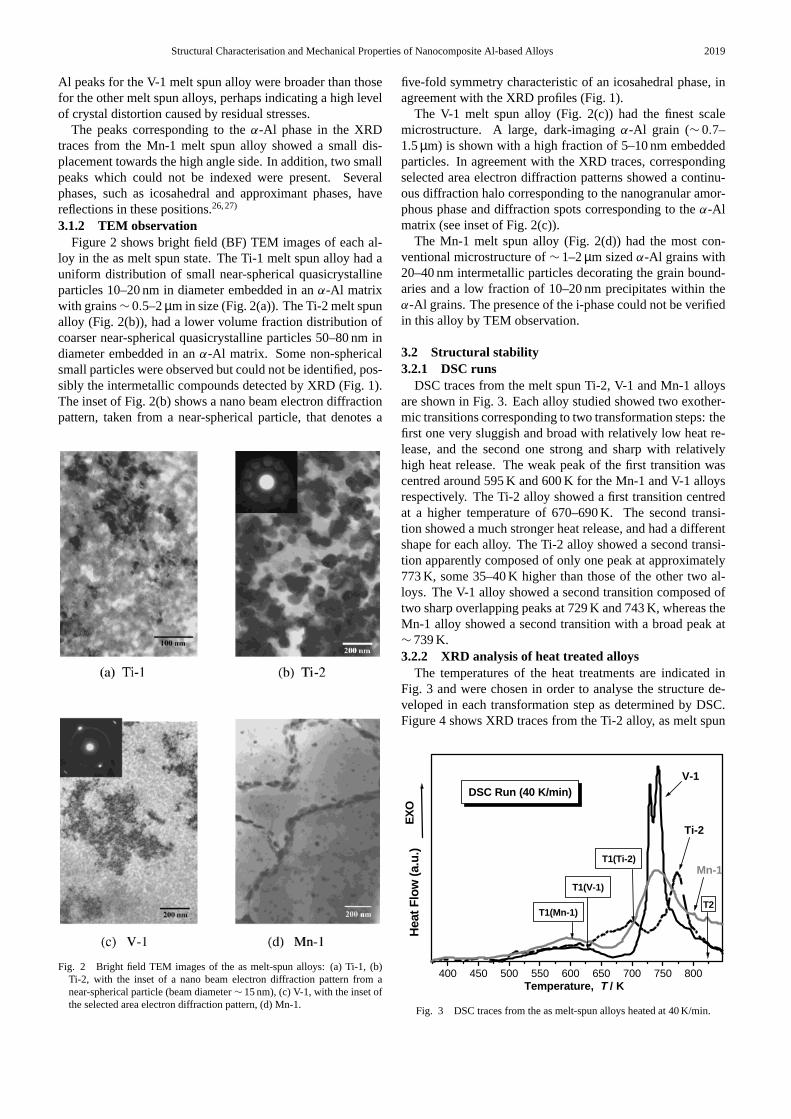
3.2 Structural stability3.2.1 DSC runs
DSC traces from the melt spun Ti-2, V-1 and Mn-1 alloysare shown in Fig. 3. Each alloy studied showed two exother-mic transitions corresponding to two transformation steps: thefirst one very sluggish and broad with relatively low heat re-lease, and the second one strong and sharp with relativelyhigh heat release. The weak peak of the first transition wascentred around 595 K and 600 K for the Mn-1 and V-1 alloysrespectively. The Ti-2 alloy showed a first transition centredat a higher temperature of 670–690 K. The second transi-tion showed a much stronger heat release, and had a differentshape for each alloy. The Ti-2 alloy showed a second transi-tion apparently composed of only one peak at approximately773 K, some 35–40 K higher than those of the other two al-loys. The V-1 alloy showed a second transition composed oftwo sharp overlapping peaks at 729 K and 743 K, whereas theMn-1 alloy showed a second transition with a broad peak at∼ 739 K.3.2.2 XRD analysis of heat treated alloys
The temperatures of the heat treatments are indicated inFig. 3 and were chosen in order to analyse the structure de-veloped in each transformation step as determined by DSC.Figure 4 shows XRD traces from the Ti-2 alloy, as melt spun
400 450 500 550 600 650 700 750 800
T2
T1(Ti-2)
T1(V-1)
T1(Mn-1)
Temperature, T / K
DSC Run (40 K/min)
Ti-2
Mn-1
V-1
EX
OH
eat F
low
(a.u
.)
Fig. 3 DSC traces from the as melt-spun alloys heated at 40 K/min.
2020 F. Audebertet al.
36 38 40 42 44 46 48 50
Ti-2
-Fe, Al13
Fe4
-Cr, Al13
Cr2
i, i-phase
, -Al-(Fe,Cr)3Ti
ii
ii
-Fe-C
r
-Fe
-Cr
-Cr
-Cr
-Cr
(200
) Al
(111
) Al
Step-2(Annealed at 823 K)
Step-1(Annealed at 703 K)
As Melt-Spun
Inte
nsity
(a.u
.)
2
Fig. 4 X-ray diffractograms from the Ti-2 alloy, as melt-spun and after heattreatment at 703 K and 823 K.
36 38 40 42 44 46 48 50
3Ti-V: -Al45V7
-Fe: -Al13Fe4
+ -F
e+
-Fe
-Fe
-V-V
+ -V
-Fe
-V-Fe
-Fe -F
e
-V-V-V
2
V-1
(200
) Al
(111
) Al
Inte
nsity
(a.u
.)
As Melt-Spun
Step-1(Annealed at 628 K)
Step-2(Annealed at 823 K)
Fig. 5 X-ray diffractograms from the V-1 alloy, as melt-spun and after heattreatment at 683 K and 823 K.
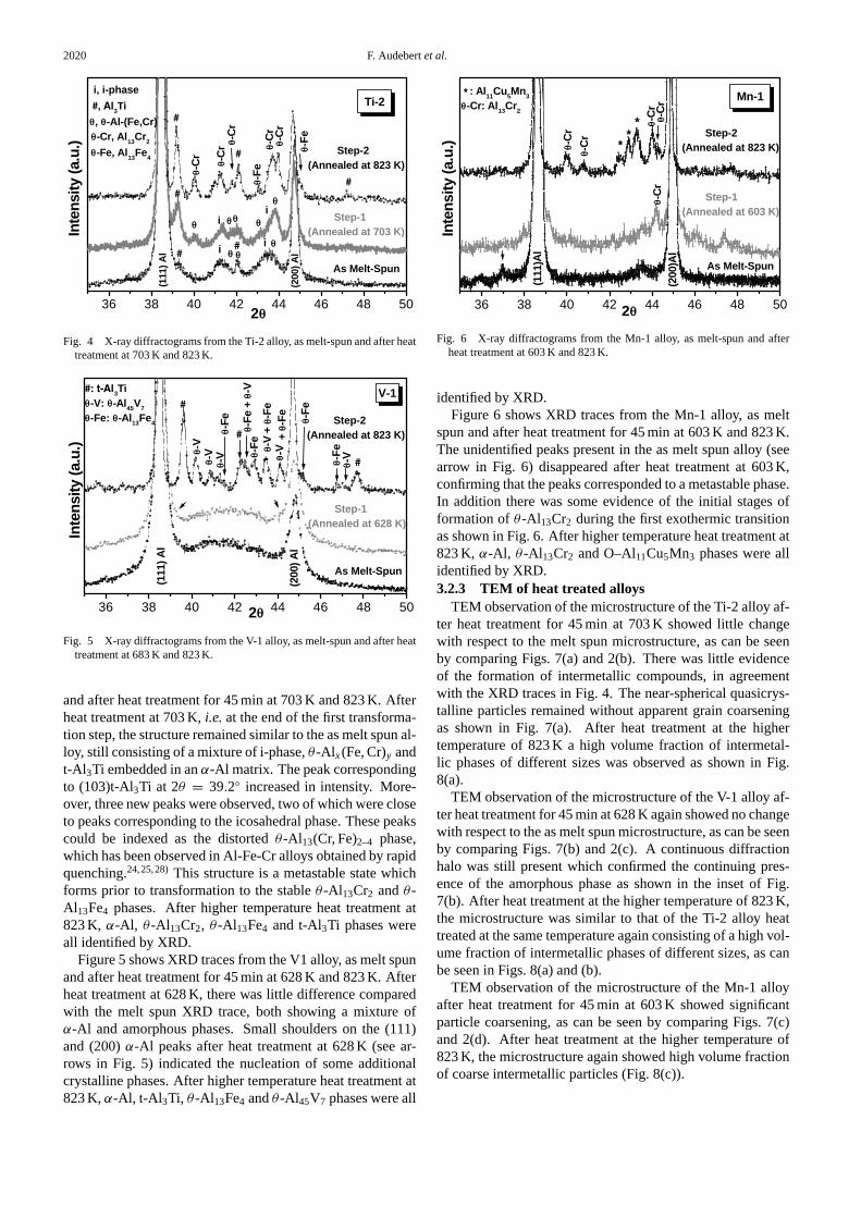
and after heat treatment for 45 min at 703 K and 823 K. Afterheat treatment at 703 K,i.e. at the end of the first transforma-tion step, the structure remained similar to the as melt spun al-loy, still consisting of a mixture of i-phase,θ -Al x(Fe, Cr)y andt-Al3Ti embedded in anα-Al matrix. The peak correspondingto (103)t-Al3Ti at 2θ = 39.2◦ increased in intensity. More-over, three new peaks were observed, two of which were closeto peaks corresponding to the icosahedral phase. These peakscould be indexed as the distortedθ -Al13(Cr, Fe)2–4 phase,which has been observed in Al-Fe-Cr alloys obtained by rapidquenching.24,25,28)This structure is a metastable state whichforms prior to transformation to the stableθ -Al13Cr2 andθ -Al13Fe4 phases. After higher temperature heat treatment at823 K, α-Al, θ -Al13Cr2, θ -Al13Fe4 and t-Al3Ti phases wereall identified by XRD.
Figure 5 shows XRD traces from the V1 alloy, as melt spunand after heat treatment for 45 min at 628 K and 823 K. Afterheat treatment at 628 K, there was little difference comparedwith the melt spun XRD trace, both showing a mixture ofα-Al and amorphous phases. Small shoulders on the (111)and (200)α-Al peaks after heat treatment at 628 K (see ar-rows in Fig. 5) indicated the nucleation of some additionalcrystalline phases. After higher temperature heat treatment at823 K,α-Al, t-Al 3Ti, θ -Al13Fe4 andθ -Al45V7 phases were all
36 38 40 42 44 46 48 50
(200
)Al
(111
)Al
: Al11
Cu5Mn
3
-Cr: Al13Cr2
-Cr
-Cr
-Cr
-Cr-C
r
Step-1(Annealed at 603 K)
Step-2(Annealed at 823 K)
As Melt-Spun
Mn-1
2
Inte
nsity
(a.u
.)
Fig. 6 X-ray diffractograms from the Mn-1 alloy, as melt-spun and afterheat treatment at 603 K and 823 K.
identified by XRD.Figure 6 shows XRD traces from the Mn-1 alloy, as melt
spun and after heat treatment for 45 min at 603 K and 823 K.The unidentified peaks present in the as melt spun alloy (seearrow in Fig. 6) disappeared after heat treatment at 603 K,confirming that the peaks corresponded to a metastable phase.In addition there was some evidence of the initial stages offormation ofθ -Al13Cr2 during the first exothermic transitionas shown in Fig. 6. After higher temperature heat treatment at823 K, α-Al, θ -Al13Cr2 and O–Al11Cu5Mn3 phases were allidentified by XRD.3.2.3 TEM of heat treated alloys
TEM observation of the microstructure of the Ti-2 alloy af-ter heat treatment for 45 min at 703 K showed little changewith respect to the melt spun microstructure, as can be seenby comparing Figs. 7(a) and 2(b). There was little evidenceof the formation of intermetallic compounds, in agreementwith the XRD traces in Fig. 4. The near-spherical quasicrys-talline particles remained without apparent grain coarseningas shown in Fig. 7(a). After heat treatment at the highertemperature of 823 K a high volume fraction of intermetal-lic phases of different sizes was observed as shown in Fig.8(a).
TEM observation of the microstructure of the V-1 alloy af-ter heat treatment for 45 min at 628 K again showed no changewith respect to the as melt spun microstructure, as can be seenby comparing Figs. 7(b) and 2(c). A continuous diffractionhalo was still present which confirmed the continuing pres-ence of the amorphous phase as shown in the inset of Fig.7(b). After heat treatment at the higher temperature of 823 K,the microstructure was similar to that of the Ti-2 alloy heattreated at the same temperature again consisting of a high vol-ume fraction of intermetallic phases of different sizes, as canbe seen in Figs. 8(a) and (b).
TEM observation of the microstructure of the Mn-1 alloyafter heat treatment for 45 min at 603 K showed significantparticle coarsening, as can be seen by comparing Figs. 7(c)and 2(d). After heat treatment at the higher temperature of823 K, the microstructure again showed high volume fractionof coarse intermetallic particles (Fig. 8(c)).

Structural Characterisation and Mechanical Properties of Nanocomposite Al-based Alloys 2021
Fig. 7 Bright field TEM images of the alloys after heat treatment beyond the first transformation step: (a) Ti-2 after 45 min at 703 K,(b) V-1 after 45 min at 628 K, (c) Mn-1 after 45 min at 603 K.
Fig. 8 Bright field TEM images of the alloys after heat treatment beyond the second transformation step,i.e. for 45 min at 823 K: (a) Ti-2,(b) V-1, (c) Mn-1.
3.3 Mechanical properties3.3.1 Tensile testing of melt spun alloys
Figure 9 shows typical examples of stress-strain curves ob-taining from tensile tests of the four as melt spun alloys atroom temperature. The Ti-1 alloy was very brittle and frac-tured at low tensile stress, in the range of 200–250 MPa. TheTi-2 alloy, with a lower volume fraction of the icosahedralphase than the Ti-1 alloy, had higher ultimate tensile strengthand showed a small plastic deformation zone, with fracturestresses and total strains (elastic and plastic) typically of 510–575 MPa and 3–3.5% respectively. The V-1 alloy had thehighest strength but without showing macroscopic ductile be-haviour. Conversely, the Mn-1 alloy had comparatively goodductility, with a parabolic behaviour similar to conventionalductile Al alloys, albeit with a low yield strength, with frac-ture stresses and strains typically of 210–300 MPa and 3.5–4.5% respectively.3.3.2 Fractography of melt-spun alloys
The fracture surfaces of the as melt spun Ti-1 samplesshowed no evidence of plastic flow. They were flat with some
undulations as a consequence of catastrophic brittle fracturein a stressed material (Fig. 10(a)). On the other hand, thefracture surfaces of the as melt spun Mn-1 samples exhib-ited necking and a dimpled fracture surface characteristic ofplastic deformation in crystalline Al alloys, as shown in Fig.10(b). The fracture surfaces of the as melt spun Ti-2 samplesshowed the characteristic ribs of ductile fracture, as shown inFig. 10(c) (see details in the inset of Figure) with slip bandsclose to the fracture surface. The fracture surfaces of the asmelt spun V-1 samples, that had not shown macroscopic plas-tic deformation, again showed ribs and vein patterns charac-teristic of a ductile fracture (Fig. 10(d)) similar to those foundin ductile amorphous or partially amorphous alloys.29,30)Fur-thermore typical shear bands, as are observed in glassymetals,30) were found near the fracture surface.3.3.3 Microhardness as a function of heat treatment
Figure 11 shows microhardness results for Ti-2, V-1 andMn-1 alloys as melt spun and after heat treatment at the dif-ferent temperatures corresponding to the end of each transfor-mation step. The Ti-2 and V-1 alloys had similar microhard-

2022 F. Audebertet al.
0.00 0.02 0.04 0.06 0.080
100
200
300
400
500
600
700
Str
ess,
/
MP
a
Strain
Mn-1
Ti-1
Ti-2
V-1
0.031 0.032 0.033
Ti-2
CrackPropagation
Slip Band Process
Str
ess,
/
MP
a
Strain
Fig. 9 Room temperature stress-strain tensile curves from the as melt-spunalloys. The inset shows an enlarged view of the region of plasticity in thecurve for the Ti-2 alloy.
ness values in the as melt-spun state and again after heat treat-ment at high temperature (823 K). The microhardness valuesof the Ti-2 and Mn-1 alloys decreased continuously, whereasthe microhardness of the V-1 alloy increased initially, afterheat treatment at intermediate temperature (628 K), before de-creasing, after heat treatment at higher temperature (823 K).The Mn-1 alloy had the lowest microhardness values and de-creased faster with the increasing heat treatment temperaturein comparison with the other alloys.
4. Discussion
4.1 Structure and stabilityAll samples had theα-Al phase as a matrix, although the
alloys of the different systems showed different microstruc-tures. The Ti-1 and Ti-2 alloys had finer microstructuresthan observed previously for a melt spun sample with a com-position close to the icosahedral phase,20) and for the samecomposition produced in bulk by warm extrusion of atomisedpowders.31) The XRD profiles of both Ti-1 and Ti-2 showedonly the P-type i-phase peaks, and no other peaks relatedto the F-type ordered i-phase found previously by Inoueetal.20) in similar alloys containing Fe. The weakness of the(18/29) and (20/32) i-phase peaks may be related to the pres-ence of a disordered P-type i-phase, and reflections from thedistorted planes of approximant phases, such as monoclinicθ -Al–(Cr, Fe).24,25,28)The two other small peaks in XRD tracesof the Ti-2 alloy could be assigned to t-Al3Ti and θ -Al–(Cr, Fe). The sample heat treated at 703 K showed clearerpeaks fromθ -Al–(Cr, Fe), and after heat treatment at 823 K allthe equilibrium phases were formed following decompositionof the i-phase. The i-phase at higher alloy content than Ti-1 or Ti-2, i.e. with a composition close to Al84.2Fe7Cr6.3Ti2.5
(at%), has been shown previously to transform via two DSCpeaks at∼ 850 K and∼ 925 K.19) The Ti-2 sample, of the
present study has a lower alloy content, and also shows twopeaks, although at lower temperatures (Fig. 3). The differencein transformation temperatures results from the lower alloycontent and the P-type disordered structure of the i-phase.
XRD (Fig. 1) and TEM (Fig. 2(c)) show that as melt-spunV-1 has a microstructure composed of a nanogranular amor-phous phase embedded in anα-Al matrix. The formationof this kind of microstructure is related to glass formationin icosahedral alloys.32–34) These alloys have, in the liquid,an icosahedral short range order around the transition metalatoms which provides a barrier to the formation of crystallinephases.33,35) Therefore, an icosahedral phase can form com-posed of interpenetrating clusters of icosahedral symmetry.36)
When the transition metal in the i-cluster has low atomic dif-fusivity in the Al liquid (such as Ti and V), quasicrystallineformation becomes difficult and a nanogranular amorphousregion with icosahedral short range order can be retained inthe α-Al matrix. It has been reported34,37) that a decreasein cooling rate allows the formation of the quasicrystallinephase. The subsequent annealing of the V-1 alloy shows afirst heat treatment step where no microstructural changes areobserved (Figs. 5 and 7(b)), perhaps caused by structural re-laxation. On the other hand, the second transformation stepis characterized by two exothermic DSC peaks around 729 Kand 743 K (Fig. 3). Similar behaviour has been observed forthe ternary nanogranular amorphous alloys Al93Fe3Ti4 andAl94Fe2V4
32,38) although at lower temperature, which con-firms the higher stability of the quaternary alloy. After thesecond heat treatment step, only the crystalline stable phasesare observed (Fig. 5).
The as melt spun Mn-1 alloy has a conventional mi-crostructure with fine particles in the grain boundaries andinside theα-Al grains. The presence of the i-phase could notbe confirmed. Haaset al.17) have reported the presence of thei-phase for a sample with a similar composition produced bywarm extrusion. That means that the formation of the i-phasein this alloy is very sensitive to the chemical composition andthe kinetic conditions. The lower alloy content of the Mn-1alloy with respect to Ti-1, Ti-2 and V-1, and the higher sol-ubility of Cu in α-Al (3 to 8 times higher than Fe, Cr, Mnand Ti) may hinder the formation of the i-phase. In agree-ment with this hypothesis, there is a small displacement inthe positions of theα-Al peaks observed in the XRD profiles(Fig. 1), indicating that theα-Al matrix has a higher solutecontent. The first heat treatment step (Fig. 2) is characterisedby intermetallic coarsening (Fig. 7(c)) and decomposition ofthe unindexed metastable phase (Fig. 6). The second DSCstep, with a broad exothermic peak at∼ 740 K is associatedwith the formation of coarse intermetallic compounds (Fig.8(c)). The decomposition of the quasicrystalline particles wasreported by Haaset al.,17) to occur at∼ 700 K at 10 K/min.Considering the peak displacement with the DSC scan rate,39)
that means that the stability of the metastable alloy is reachedat a similar temperature for the decomposition of either themetastable crystalline or quasicrystalline precursor phase.
4.2 Mechanical properties4.2.1 Al–Fe–Cr–Ti system
The tensile stress-strain curves in Fig. 9 and the SEMfractographs in Fig. 10, show that the volume fraction of

Structural Characterisation and Mechanical Properties of Nanocomposite Al-based Alloys 2023
Fig. 10 Secondary electron SEM image of the fracture surfaces of the tensile tested as melt-spun alloys. (a) Ti-1, (b) Mn-1, (c) slip stepsin Ti-2, with the inset showing ribs on the fracture surface, and (d) V-1, with the inset showing an enlarged view of a region with avein pattern.
300 400 500 600 700 800
100
200
300
400
500
Microhardness at Room Temperature
HV
100
V-1
Ti-2
Mn-1
Heat Treatment Temperature, T / K
Fig. 11 Room temperature microhardness of the Ti-2, V-1 and Mn-1 alloysas melt-spun and after heat treatments.
the icosahedral phase has a great influence on mechanicalproperties in the Al–Fe–Cr–Ti system (Ti-1 and Ti-2). Theless highly alloyed Ti-2 material shows a tensile strength(∼ 550 MPa) similar to that reported by Inoueet al.19) ona bulk warm extruded sample, although the failure strain(∼ 3.5%) is slightly lower. The volume fraction of particlescan be estimated, assuming that particles are arranged likepoints of a fcc lattice, from the relationship:
f = r 2p/(λ/2)2
whererp is the mean planar particle radius andλ is the meandistance between the centres of the planar particles.40) FromTEM observation the average values are〈2rp〉 ∼ 65 nm and〈λ〉 ∼ 100 nm for the Ti-2 alloy, givingf ∼ 0.42, similar tothe value of 0.45 reported by Inoueet al.19) Similar calcula-tion for the more highly alloyed Ti-1 material givef ∼ 0.46.The importance of the volume fraction of the second phase innanocomposites has been demonstrated by Scanlonet al.41)
They observed in nanoscale mixtures of a pure plastic metaland hard oxide nanoparticles, that the microhardness has adifferent relationship with respect to the volume fraction afterthe percolation threshold of∼ 0.5. A similar concept has beenproposed to explain the ductile-brittle transition as a functionof chemical composition in heterogeneous amorphous met-als42) and nanocomposites containing hard nanocrystals.11)
The high volume fraction Ti-1 alloy has the highest micro-hardaness value (µHV100 ∼ 450 kg/mm2) and shows com-pletely brittle behaviour (Fig. 9) without traces of microplas-
ticity or evidence of second phase particles on the fracturesurface (Fig. 10). This mode of fracture results presumablyfrom the presence of pre-existing internal or surface flawsor cracks, so that crack nucleation is not necessary. Thestress is concentrated progressively ahead of the pre-existingflaws or cracks, crack propagation takes place throughout thematrix between the high volume fraction of hard quasicrys-talline particles as soon as it is accompanied by reductionin total system energy,43) leading to brittle fracture. Neithersheared nor cleaved quasicrystalline particles have been ob-served on fracture surfaces in other nanoquasicrystalline Al-based alloys.17,18)
The low volume fraction Ti-2 alloy, shows significant duc-tility (Fig. 9), and shear flow associated with heterogeneousmicroscopic plasticity can be seen clearly on the fracture sur-face (inset of Fig. 10(c)). The lower volume fraction of sec-ond phase particles allows plastic deformation and preventscatastrophic brittle failure at pre-existing flaws or cracks.Fracture is initiated at higher stress level than the more brit-tle Ti-1 alloy, when the applied stress is sufficient to acti-vate multiple slip or twinning leading to formation of micro-cracks.43) The enlarged view of the high stress region of plas-ticity in the stress-strain curve of the Ti-2 alloy (Fig. 9), showsserrated yielding at constant stress, as was observed previ-ously in rapid solidification processed Al–Li alloys.44) Thisyield stress is that required to nucleate and grow slip bandswhich propagate until specimen failure by crack propagationthroughout the Al matrix, as can be deduced by the rib markswith small grains in the fracture surface (inset of Fig. 10(c)).Two different regions can be observed in the fracture surface(inset of Fig. 10(c)) that can be explained as follows: (i) Thesurface of the ribbon is unable to support a stress, deforms un-der plane stress conditions, and produces shear lips. (ii) Thecentral portion of the ribbon is subjected to plane strain con-ditions and the cracks advance faster as a result of a smallerplastic zone size and a triaxial stress state. This results in areduced fracture toughness but with a ductile fracture.43)
Heat treatment for 45 min at 703 K,i.e.after the first trans-formation step, on the Ti-2 alloy produces∼ 40% reduction inthe microhardness from∼ 396 to∼ 240 kg/mm2. This soften-ing is related to the relaxation of residual stresses in theα-Almatrix, and the reduction of solute content in the matrix, asintermetallic particles are formed. The decomposition of theicosahedral phase and the coarsening of the intermetallic par-ticles reduces the microhardness value still further, by∼ 28%to ∼ 173 kg/mm2 (Fig. 11).

2024 F. Audebertet al.
4.2.2 Al–Fe–Cr–V systemThe V-1 alloy has around 0.5 volume fraction of the
nanogranular amorphous phase, which acts as a strengtheningagent. The homogeneous distribution of a high volume frac-tion of very fine hard particles is a well known alloy strength-ening mechanism.43) In agreement, V-1 alloy shows a veryhigh ultimate tensile strength,σUTS ∼ 650 MPa (Fig. 9). Thisvalue is higher than that reported by Kimuraet al.20) for analloy with the same composition produced by warm extrusionof atomised powders (σUTS ∼ 500 MPa), with a microstruc-ture of 120 nm sized icosahedral particles distributed in anα-Al matrix. The larger icosahedral particle size (120 nm com-pared with the 5 to 10 nm sized amorphous regions) may ex-plain the difference inσUTS values between the extruded andthe present melt-spun alloys.
SeveralσUTS values have been reported for Al-based alloyswith a microstructure similar to the V-1 alloy: 1000 MPa forAl94Fe2V2Ti2,45) 1350 MPa for Al94Fe2V4,21) 1320 MPa forAl93Fe3Ti432) and 760 MPa for Al92Fe2V4Si2.34) The latter al-loy has the same Al concentration as the V-1 alloy, and has aσUTS value closer to that of the V-1 alloy than the other alloys.The similarity in behaviour between Al92Fe2V4Si2 and V-1may be related to a similar volume fraction of hard particleswith similar macroscopically brittle failure mode (Fig. 9).
Fractographic investigation shows that fracture in V-1 is aductile process, resulting in a fracture surface with rib marksand vein patterns (Fig. 10(d)) characteristic of adiabatic frac-tures in fully or partially amorphous metals.8,29) A vein pat-tern on the fracture surface of nanogranular amorphous Al-based alloys has been observed previously by Inoueet al.38)
The V-1 alloy also has an acceptable ductility in bending tests,but nanocomposites obtained by crystallisation with a similarvolume fraction ofα-Al nanograins in the amorphous ma-trix are often completely brittle.10,11) This indicates the im-portance of the mechanical properties of the matrix on themechanical behaviour of such nanocomposites.
Structural relaxation in the amorphous phase and coherentprecipitation in theα-Al phase, may be responsible for theincrease in the microhardness from∼ 395 to∼ 514 kg/mm2
after heat treatment for 45 min at 628 K (Fig. 11). Afterheat treatment for 45 min at 823 K, transformation of thefine nanoscale microstructure to a coarser distribution ofsubmicron intermetallic compounds precipitated in theα-Almatrix, drastically reduces the microhardness to a value of∼ 165 kg/mm2.4.2.3 Al–Mn–Cr–Cu system
The Mn-1 alloy was the most ductile of the four alloysstudied, showing significant macroscopic plastic deformation(Fig. 9), in agreement with a microstructure containing thelowest volume fraction of strengthening particles (Fig. 2).Plastic deformation takes place by conventional dislocationmovement in theα-Al matrix grains. Dislocations pile uparound the strengthening particles increasing the local normalstresses leads to particle fracture and microvoid nucleation atthe particle interface.43) The voids begin to grow or elongatein the direction of the applied tensile stress and the final frac-ture stage is eventually reached when the voids link up byrupture of theα-Al matrix.
The ultimate tensile strengthσUTS and fracture strainεare ∼ 300 MPa and∼ 4.5% respectively, lower than those
(σUTS ∼ 570–460 MPa,ε ∼ 10.3%) reported by Haaset al.17)
in a warm extruded powder alloy of similar composition. Thedifference can be explained by the different microstructuresobtained by the different processing routes. Haaset al.17)
reported a microstructure composed of icosahedral particlesembedded in anα-Al matrix, whereas the Mn-1 alloy, pro-duced by liquid quenching, exhibits a fine scale distributionof particles at theα-Al grain boundaries which can decreasethe toughness and hence the strength and the ductility.46)
After heat treatment for 45 min at 603 K, the microhard-ness of the Mn-1 alloy decreases by about 60%, from∼ 340to ∼ 124 kg/mm2, which could be related to the formationof additional incoherent precipitates in theα-Al matrix andcoarsening of the particles (Fig. 7(c)). After the second stageof heat treatment for 45 min at 823 K, the Mn-1 alloy showsa microstructure of rod-shaped submicron intermetallic com-pounds in anα-Al matrix, and the microhardness decreasesfurther, by∼ 33% to∼ 78 kg/mm2.
5. Conclusion
Four Al-based nanocomposite alloys with different kinds ofmicrostructure composed of crystalline, amorphous or qua-sicrystalline phases dispersed in anα-Al matrix have beenstudied.
The Ti-2 alloy contained icosahedral particles in anα-Al matrix, and exhibited a high strength and a very stablemicrostructure during heat treatment, with the icosahedralparticles resistant to coarsening prior to decomposition intocrystalline phases. The V-1 alloy contained a nanogranularamorphous phase in anα-Al matrix, and exhibited a high-est strength with a moderately stable microstructure up to628 K, but relaxation in the amorphous structure made thealloy harder and more brittle. The Mn-1 alloy containedstrengthening crystalline intermetallic particles in theα-Almatrix, and exhibited a high ductility, with a significant de-crease in strength during heat treatment caused by incoherentprecipitation and particle coarsening.
A combination of classical strengthening mechanisms(solid solution, grain refinement and dispersion particles) wasobserved to be responsible for the high strength of the differ-ent kinds of nanocomposites studied.
Acknowledgments
The work described forms part of a European Unionfunded Research Training Network Project on Manufac-ture and Characterisation of Nanostructured Al Alloys, con-tract no. HPRN-CT-2000-00038. F. Audebert acknowledgesthe financial support of the Universidad de Buenos Aires,Argentina.
REFERENCES
1) A. Inoue, K. Othera, A. Tsai and T. Masumoto: Jpn. J. Appl. Phys.27(1988) L280–L282.
2) G. Shiflet, Y. He and S. Poon: Scr. Metall.22 (1988) 1661–1664.3) A. Inoue and H. Kimura: Current Opinion in Solid State & Mater. Sci.
2 (1997) 305–310.4) A. Inoue and H. Kimura: J. Light Metals1 (2001) 31–41.5) J. Q. Guo and K. Othera: Acta Mater.46 (1998) 3829–3838.

Structural Characterisation and Mechanical Properties of Nanocomposite Al-based Alloys 2025
6) K. Othera, A. Inoue, T. Terbayashi, H. Nagahama and T. Masumoto:Mater. Trans., JIM33 (1992) 775–781.
7) T. Kobayashi:Aerospace Materials, (Series in Materials Science andEngineering, ed. by B. Cantor, H. Assender and P. Grant, Institute ofPhysics, UK, 2001) pp. 170–178.
8) A. Inoue, Y. Horio, Y. H. Kim and T. Masumoto: Mater. Trans., JIM33(1992) 669–674.
9) A. A. Csontos and G. J. Shiflet: Nano Structured Mater.9 (1997) 281–289.
10) Z. C. Zhong, X. Y. Jiang and A. L. Greer: Mater. Sci. Eng. A226–228(1997) 531–535.
11) H. S. Kim, P. J. Warren, B. Cantor and H. R. Lee: Nano StructuredMater.11 (1999) 241–247.
12) A. Inoue, M. Watanabe, H. M. Kimura, F. Takahashi, A. Nagata and T.Masumoto: Mater. Trans., JIM33 (1992) 723–729.
13) F. Schurack, J. Eckert and L. Schultz: Nano Structured Mater.12 (1999)107–110.
14) A. Inoue: Nano Structured Mater.6 (1995) 53–64.15) E. H. Buchler, E. Watanabe and N. S. Kazama: Int. J. Non-Equil.
Processing10 (1997) 35–47.16) A. Inoue, H. M. Kimura, K. Sasamori and T. Masumoto: Mater. Trans.,
JIM 36 (1995) 6–15.17) V. Haas, M. Cho, H. Ishil and A. Inoue: Nano Structured Mater.12
(1999) 829–834.18) F. Schurack, J. Eckert and L. Schultz: Acta Mater.49 (2001) 1351–
1361.19) A. Inoue and H. Kimura: Nano Structured11 (1999) 221–231.20) H. M. Kimura, K. Sasamori and A. Inoue: J. Mater. Res.15 (2000)
2737–2744.21) A. Inoue, H. M. Kimura, K. Sasamori and T. Masumoto: Mater. Sci.
Eng. A217–218 (1996) 401–406.22) E. S. Humphreys, P. J. Warren, A. Cerezo and G. D. W. Smith: Mater.
Sci. Eng. A270 (1999) 48–54.23) J. W. Cahn, D. Shechtman and D. Gratias: J. Mater. Res.1 (1986) 13–26.24) R. Manaila, V. Florescu, A. Jianu and O. Radulescu: Philos. Mag. B60
(1989) 589–599.25) F. Audebert, R. Colaco, R. Vilar and H. Sirkin: Scr. Mater.40 (1999)
551–557.26) K. Kobayashi, N. Tachibana and P. H. Shingu: J. Mater. Sci.24 (1989)
2437–2443.27) D. Schectman and I. A. Blech: Metall. Trans. A16A (1985) 1005–1012.28) J. Copola, F. Audebert and S. Duhalde: J. Metastable and Nanocryst.
Mater.14 (2002) 27–32.29) C. Pampillo: J. Mater. Sci.10 (1975) 1194–1227.30) G. J. Shiflet, Y. He and S. J. Poon: Scr. Metall.22 (1988) 1661–1664.31) H. M. Kimura, K. Sasamori and A. Inoue: Mater. Sci. Eng.294–296
(2000) 168–172.32) H. M. Kimura, K. Sasamori, T. Negishi and A. Inoue: Nano Structured
Mater.8 (1997) 833–844.33) F. Audebert, B. Arcondo, D. Rodriguez and H. Sirkin: J. Metastable and
Nanocryst. Mater.10 (2001) 155–160.34) E. S. Humphreys, P. J. Warren, J. M. Titchmarsh and A. Cerezo: Mater.
Sci. Eng. A304–306 (2001) 844–848.35) V. Simonet, F. Hippert, M. Audier and R. Bellissent: Mater. Sci. Eng.
294–296 (2000) 116–119.36) M. Boudard, M. De Boissieu, C. Janot, G. Heger, C. Beeli, H. Nissen, H.
Vincent, R. Ibberson, M. Audier and J. M. Dubois: J. Phys.: Condens.Matter.4 (1992) 10149–10168.
37) A. Inoue, H. M. Kimura, K. Sasamori and T. Masumoto: Mater. Trans.,JIM 36 (1995) 1219–1228.
38) A. Inoue, H. M. Kimura, K. Sasamori and T. Masumoto: Nano Struc-tured Mater.7 (1996) 863–382.
39) L. C. Chen and F. Spaepen: J. Appl. Phys.69 (1991) 679–687.40) M. Ashby: Z. Metallk.55 (1964) 5–17.41) M. R. Scanlon, R. C. Cammarata: J. Appl. Phys.76 (1994) 3387–3393.42) F. Audebert, A. Garcia Escorial, J. Reyes Gasga and H. Sirkin:Proc. of
First Journees Franco-Espagnoles des Noveaux Materiaux, ed. by R.Yavari and J. L. Uriarte (Grenoble, France, 1997) 138–142.
43) T. H. Courtney: Mechanical Behavior of Materials, (McGraw-Hill,Series in Materials Science and Engineering, New York, 1990).
44) L. Zhen, D. Yang, S. Sun and G. Yu: Mater. Sci. Eng. A248 (1998)221–229.
45) A. Inoue, H. Kimura and K. Sasamori: Nano Structured Mater.9 (1997)493–496.
46) R. W. K. Honeycombe:The Plastic Deformation of Metals, (ed. byEdward Arnod pub., London, 1984).
Copyright © 2022 FDOKUMEN