Building An Elastic Query Engine on Disaggregated Storage
14
Building An Elastic Query Engine on Disaggregated Storage Midhul Vuppalapati Cornell University Justin Miron Cornell University Rachit Agarwal Cornell University Dan Truong Snowflake Computing Ashish Motivala Snowflake Computing Thierry Cruanes Snowflake Computing Abstract We present operational experience running Snowflake, a cloud- based data warehousing system with SQL support similar to state-of-the-art databases. Snowflake design is motivated by three goals: (1) compute and storage elasticity; (2) support for multi-tenancy; and, (3) high performance. Over the last few years, Snowflake has grown to serve thousands of customers executing millions of queries on petabytes of data every day. We discuss Snowflake design with a particular focus on ephemeral storage system design, query scheduling, elastic- ity and efficiently supporting multi-tenancy. Using statistics collected during execution of 70 million queries over a 14 day period, our study highlights how recent changes in cloud infrastructure have altered the many assumptions that guided the design and optimization of Snowflake, and outlines several interesting avenues of future research. 1 Introduction Shared-nothing architectures have been the foundation of traditional query execution engines and data warehousing systems. In such architectures, persistent data (e.g., customer data stored as tables) is partitioned across a set of compute nodes, each of which is responsible only for its local data. Such shared-nothing architectures have enabled query execu- tion engines that scale well, provide cross-job isolation and good data locality resulting in high performance for a variety of workloads. However, these benefits come at the cost of several major disadvantages: • Hardware-workload mismatch: Shared-nothing archi- tectures make it hard to strike a perfect balance between CPU, memory, storage and bandwidth resources provided by compute nodes, and those required by workloads. For instance, a node configuration that is ideal for bandwidth- intensive compute-light bulk loading may be a poor fit for compute-extensive bandwidth-light complex queries. Many customers, however, want to run a mix of queries without setting up a separate cluster for each query type. Thus, to meet performance goals, resources usually have to be over- provisioned; this results in resource underutilization on an average and in higher operational costs. • Lack of Elasticity: Even if one could match the hardware resources at compute nodes with workload demands, static parallelism and data partitioning inherent to (inelastic) shared-nothing architectures constrain adaptation to data skew and time-varying workloads. For instance, queries run by our customers have extremely skewed intermedi- ate data sizes that vary over five orders of magnitude (§4), and have CPU requirements that change by as much as an order of magnitude within the same hour (§7). More- over, shared-nothing architectures do not admit efficient elasticity; the usual approach of adding/removing nodes to elastically scale resources requires large amounts of data to be reshuffled. This not only increases network bandwidth requirements but also results in significant performance degradation since the set of nodes participating in data reshuffling are also responsible for query processing. Traditional data warehousing systems were designed to oper- ate on recurring queries on data with predictable volume and rate, e.g., data coming from within the organization: trans- actional systems, enterprise resource planning application, customer relationship management applications, etc. The sit- uation has changed significantly. Today, an increasingly large fraction of data comes from less controllable, external sources (e.g., application logs, social media, web applications, mobile systems, etc.) resulting in ad-hoc, time-varying, and unpre- dictable query workloads. For such workloads, shared-nothing architectures beget high cost, inflexibility, poor performance and inefficiency, which hurts production applications and clus- ter deployments. To overcome these limitations, we designed Snowflake — an elastic, transactional query execution engine with SQL sup- port comparable to state-of-the-art databases. The key insight in Snowflake design is that the aforementioned limitations of shared-nothing architectures are rooted in tight coupling of compute and storage, and the solution is to decouple the
-
Upload
khangminh22 -
Category
Documents
-
view
0 -
download
0
Transcript of Building An Elastic Query Engine on Disaggregated Storage

Building An Elastic Query Engine on Disaggregated Storage
Midhul VuppalapatiCornell University
Justin MironCornell University
Rachit AgarwalCornell University
Dan TruongSnowflake Computing
Ashish MotivalaSnowflake Computing
Thierry CruanesSnowflake Computing
AbstractWe present operational experience running Snowflake, a cloud-based data warehousing system with SQL support similar tostate-of-the-art databases. Snowflake design is motivated bythree goals: (1) compute and storage elasticity; (2) support formulti-tenancy; and, (3) high performance. Over the last fewyears, Snowflake has grown to serve thousands of customersexecuting millions of queries on petabytes of data every day.
We discuss Snowflake design with a particular focus onephemeral storage system design, query scheduling, elastic-ity and efficiently supporting multi-tenancy. Using statisticscollected during execution of 70 million queries over a 14day period, our study highlights how recent changes in cloudinfrastructure have altered the many assumptions that guidedthe design and optimization of Snowflake, and outlines severalinteresting avenues of future research.
1 Introduction
Shared-nothing architectures have been the foundation oftraditional query execution engines and data warehousingsystems. In such architectures, persistent data (e.g., customerdata stored as tables) is partitioned across a set of computenodes, each of which is responsible only for its local data.Such shared-nothing architectures have enabled query execu-tion engines that scale well, provide cross-job isolation andgood data locality resulting in high performance for a varietyof workloads. However, these benefits come at the cost ofseveral major disadvantages:
• Hardware-workload mismatch: Shared-nothing archi-tectures make it hard to strike a perfect balance betweenCPU, memory, storage and bandwidth resources providedby compute nodes, and those required by workloads. Forinstance, a node configuration that is ideal for bandwidth-intensive compute-light bulk loading may be a poor fit forcompute-extensive bandwidth-light complex queries. Manycustomers, however, want to run a mix of queries withoutsetting up a separate cluster for each query type. Thus, to
meet performance goals, resources usually have to be over-provisioned; this results in resource underutilization on anaverage and in higher operational costs.
• Lack of Elasticity: Even if one could match the hardwareresources at compute nodes with workload demands, staticparallelism and data partitioning inherent to (inelastic)shared-nothing architectures constrain adaptation to dataskew and time-varying workloads. For instance, queriesrun by our customers have extremely skewed intermedi-ate data sizes that vary over five orders of magnitude (§4),and have CPU requirements that change by as much asan order of magnitude within the same hour (§7). More-over, shared-nothing architectures do not admit efficientelasticity; the usual approach of adding/removing nodes toelastically scale resources requires large amounts of data tobe reshuffled. This not only increases network bandwidthrequirements but also results in significant performancedegradation since the set of nodes participating in datareshuffling are also responsible for query processing.
Traditional data warehousing systems were designed to oper-ate on recurring queries on data with predictable volume andrate, e.g., data coming from within the organization: trans-actional systems, enterprise resource planning application,customer relationship management applications, etc. The sit-uation has changed significantly. Today, an increasingly largefraction of data comes from less controllable, external sources(e.g., application logs, social media, web applications, mobilesystems, etc.) resulting in ad-hoc, time-varying, and unpre-dictable query workloads. For such workloads, shared-nothingarchitectures beget high cost, inflexibility, poor performanceand inefficiency, which hurts production applications and clus-ter deployments.
To overcome these limitations, we designed Snowflake —an elastic, transactional query execution engine with SQL sup-port comparable to state-of-the-art databases. The key insightin Snowflake design is that the aforementioned limitationsof shared-nothing architectures are rooted in tight couplingof compute and storage, and the solution is to decouple the

two! Snowflake thus disaggregates compute from persistentstorage; customer data is stored in a persistent data store (e.g.,Amazon S3 [5], Azure Blob Storage [8], etc.) that provideshigh availability and on-demand elasticity. Compute elasticityis achieved using a pool of pre-warmed nodes, that can beassigned to customers on an on-demand basis.
Snowflake system design uses two key ideas (§2). First, ituses a custom-designed storage system for management andexchange of ephemeral/intermediate data that is exchangedbetween compute nodes during query execution (e.g., tablesexchanged during joins). Such an ephemeral storage systemwas necessary because existing persistent data stores [5, 8]have two main limitations: (1) they fall short of providing thenecessary latency and throughput performance to avoid com-pute tasks being blocks on exchange of intermediate data; and(2) they provide stronger availability and durability semanticsthan what is needed for intermediate data. Second, Snowflakeuses its ephemeral storage system not only for intermediatedata, but also as a write-through “cache” for persistent data.Combined with a custom-designed query scheduling mecha-nism for disaggregated storage, Snowflake is able to reducethe additional network load caused by compute-storage disag-gregation as well as alleviate the performance overheads ofreduced data locality.
Snowflake system has now been active for several yearsand today, serves thousands of customers executing millionsof queries over petabytes of data, on a daily basis. This paperdescribes Snowflake system design, with a particular focus onephemeral storage system design, query scheduling, elasticityand efficiently supporting multi-tenancy. We also use statisticscollected during execution of ∼70 million queries over aperiod of 14 contiguous days in February 2018 to present adetailed study of network, compute and storage characteristicsin Snowflake. Our key findings are:
• Customers submit a wide variety of query types; for exam-ple, read-only queries, write-only queries and read-writequeries, each of which contribute to ∼28%, ∼13% and∼59%, respectively, of all customer queries.
• Intermediate data sizes can vary over multiple orders ofmagnitude across queries, with some queries exchanginghundreds of gigabytes or even terabytes of intermediatedata. The amount of intermediate data generated by a queryhas little or no correlation with the amount of persistentdata read by the query or the execution time of the query.
• Even with a small amount of local storage capacity, skewedaccess distributions and temporal access patterns commonin data warehouses enable reasonably high average cachehit rates (60-80% depending on the type of query) for per-sistent data accesses.
• Several of our customers exploit our support for elasticity(for ∼20% of the clusters). For cases where customers dorequest elastic scaling of resources, the number of compute
nodes in their cluster can change by as much as two ordersof magnitude during the lifetime of the cluster.
• While the peak resource utilization can be high, the averageresource utilization is usually low. We observe averageCPU, Memory, Network Tx and Network Rx utilizationsof ∼51%, ∼19%, ∼11%, ∼32%, respectively.
Our study both corroborates exciting ongoing research direc-tions in the community, as well as highlights several interest-ing venues for future research:
• Decoupling of compute and ephemeral storage:Snowflake decouples compute from persistent storageto achieve elasticity. However, currently, compute andephemeral storage are still tightly coupled. As we showin §4, the ratio of compute capacity and ephemeral stor-age capacity in our production clusters can vary by severalorders of magnitude, leading to either under utilization ofCPU or thrashing of ephemeral storage, for ad-hoc queryprocessing workloads. To that end, recent academic workon decoupling compute from ephemeral storage [22, 27]is of extreme interest. However, more work is needed inephemeral storage system design, especially in terms ofproviding fine-grained elasticity, multi-tenancy, and cross-query isolation (§4, §7).
• Deep storage hierarchy: Snowflake ephemeral storagesystem, similar to recent work on compute-storage disag-gregation [14, 15], uses caching of frequently read persis-tent data to both reduce the network traffic and to improvedata locality. However, existing mechanisms for improvingcaching and data locality were designed for two-tier storagesystems (memory as the main tier and HDD/SSD as thesecond tier). As we discuss in §4, the storage hierarchy inour production clusters is getting increasingly deeper, andnew mechanisms are needed that can efficiently exploit theemerging deep storage hierarchy.
• Pricing at sub-second timescales: Snowflake achievescompute elasticity at fine-grained timescales by servingcustomers using a pool of pre-warmed nodes. This wascost-efficient with cloud pricing at hourly granularity. How-ever, most cloud providers have recently transitioned tosub-second pricing [6], leading to new technical challengesin efficiently achieving resource elasticity and resourcesharing across multiple tenants. Resolving these challengesmay require design decisions and tradeoffs that may bedifferent from those in Snowflake’s current design (§7).
This paper focuses on Snowflake system architecture alongwith compute, storage and network characteristics observedin our production clusters. Accordingly, we focus on detailsthat are necessary to make the paper self-contained (§2). Fordetails on Snowflake query planning, optimization, concur-rency control mechanisms, etc., please refer to [12]. To aidfuture research and studies, we are releasing an anonymized

version of the dataset used in this paper; this dataset compris-ing statistics collected per-query for∼70 million queries. Thedataset is available publicly along with documentation andscripts to reproduce all results in this paper athttps://github.com/resource-disaggregation/snowset.
Our study has an important caveat. It focuses on a specificsystem (Snowflake), a specific workload (SQL queries), anda specific cloud infrastructure (S3). While our system islarge-scale, has thousands of customers executing millions ofqueries, and runs on top of one of the most prominent infras-tructures, it is nevertheless limited. We leave it to future workan evaluation of whether our study and observations general-ize to other systems, workloads and infrastructures. However,we are hopeful that just like prior workload studies on networktraffic characteristics [9] and cloud workloads [28] (each ofwhich also focused on a specific system implementation run-ning a specific workload on a specific infrastructure) fueledand aided research in the past, our study and publicly releaseddata will be useful for the community.
2 Design OverviewWe provide an overview of Snowflake design. Snowflaketreats persistent and intermediate data differently; we describethese in §2.1, followed by a high-level overview of Snowflakearchitecture (§2.2) and query execution process (§2.3).
2.1 Persistent and Intermediate dataLike most query execution engines and data warehousingsystems, Snowflake has three forms of application state:
• Persistent data is customer data stored as tables in thedatabase. Each table may be read by many queries, overtime or even concurrently. These tables are thus long-livedand require strong durability and availability guarantees.
• Intermediate data is generated by query operators (e.g.,joins) and is usually consumed by nodes participating inexecuting that query. Intermediate data is thus short-lived.Moreover, to avoid nodes being blocked on intermediatedata access, low-latency high-throughput access to inter-mediate data is preferred over strong durability guarantees.Indeed, in case of failures happening during the (short)lifetime of intermediate data, one can simply rerun the partof the query that produced it.
• Metadata such as object catalogs, mapping from databasetables to corresponding files in persistent storage, statistics,transaction logs, locks, etc.
This paper primarily focuses on persistent and intermediatedata, as the volume of metadata is typically relatively smalland does not introduce interesting systems challenges.
Persistent Storage
Distributed Ephemeral Storage
OSOSOS OS OS
RuntimeRuntimeRuntime Run time Runtime
Snowflake Cloud Services
oo ooo ooo o oo o oo o
Figure 1: Snowflake (Virtual) Warehouse Architecture (§2.2).
2.2 End-to-end System ArchitectureFigure 1 shows the high-level architecture for Snowflake.It has four main components — a centralized service fororchestrating end-to-end query execution, a compute layer,a distributed ephemeral storage system and a persistent datastore. We describe each of these below1.
Centralized Control via Cloud Services. All Snowflake cus-tomers interact with and submit queries to a centralized layercalled Cloud Services (CS) [12]. This layer is responsiblefor access control, query optimization and planning, schedul-ing, transaction management, concurrency control, etc. CS isdesigned and implemented as a multi-tenant and long-livedservice with sufficient replication for high availability andscalability. Thus, failure of individual service nodes does notcause loss of state or availability, though some of the queriesmay fail and be re-executed transparently.
Elastic Compute via Virtual Warehouse abstraction. Cus-tomers are given access to computational resources inSnowflake through the abstraction of a Virtual Warehouse(VW). Each VW is essentially a set of AWS EC2 instanceson top which customer queries execute in a distributed fash-ion. Customers pay for compute-time based on the VW size.Each VW can be elastically scaled on an on-demand basisupon customer request. To support elasticity at fine-grainedtimescales (e.g., tens of seconds), Snowflake maintains a poolof pre-warmed EC2 instances; upon receiving a request, wesimply add/remove EC2 instances to/from that VW (in caseof addition, we are able to support most requests directlyfrom our pool of pre-warmed instances thus avoiding instancestartup time). Each VW may run multiple concurrent queries.In fact, many of our customers run multiple VWs (e.g., onefor data ingestion, and one for executing OLAP queries).
Elastic Local Ephemeral Storage. Intermediate data hasdifferent performance requirements compared to persistentdata (§2.1). Unfortunately, existing persistent data stores donot meet these requirements (e.g., S3 does not provide thedesired low-latency and high-throughput properties needed
1This paper describes design and implementation of Snowflake usingAmazon Web Services as an example infrastructure; however, Snowflakeruns on Microsoft Azure and Google Cloud Platform as well.

0
20000
40000
60000
80000
100000
120000
140000
160000
02/22 02/24 02/26 02/28 03/02 03/04 03/06
Qu
ery
Co
un
t
Time
Read-Only Write-Only Read-Write
Figure 2: Persistent data read/write, and submission time characteristics of queries in our dataset. (left) Scatter plot with each pointrepresenting a query based on the total number of persistent data bytes read and written by the query. The density of points is concentrated alongthree regions: (1) read-only queries along x-axis; (2)write-only queries along y-axis; and, (3) read-write queries along the middle region. (right)for each query class, the number of queries submitted at different times of day over the 14 day period, binned on an hourly basis. Read-onlyqueries have significantly higher variation in load compared to the other query classes, with spikes during daytime hours on weekdays.
for intermediate data to ensure minimal blocking of computenodes); hence, we built a distributed ephemeral storage systemcustom-designed to meet the requirements of intermediatedata in our system. The system is co-located with computenodes in VWs, and is explicitly designed to automaticallyscale as nodes are added or removed. We provide more de-tails in §4 and §6, but note here that as nodes are added andremoved, our ephemeral storage system does not require datarepartitioning or reshuffling (thus alleviating one of the corelimitations of shared-nothing architectures). Each VW runsits own independent distributed ephemeral storage systemwhich is used only by queries running on that particular VW.
Elastic Remote Persistent Storage. Snowflake stores all itspersistent data in a remote, disaggregated, persistent data store.We store persistent data in S3 despite the relatively modestlatency and throughput performance because of S3’s elasticity,high availability and durability properties. S3 supports storingimmutable files — files can only be overwritten in full and donot even allow append operations. However, S3 supports readrequests for parts of a file. To store tables in S3, Snowflakepartitions them horizontally into large, immutable files thatare equivalent to blocks in traditional database systems [12].Within each file, the values of each individual attribute orcolumn are grouped together and compressed, as in PAX [2].Each file has a header that stores offset of each column withinthe file, enabling us to use the partial read functionality of S3to only read columns that are needed for query execution.
All VWs belonging to the same customer have access tothe same shared tables via remote persistent store, and hencedo not need to physically copy data from one VW to another.
2.3 End-to-end query execution
Query execution begins with customers submitting their querytext to CS for execution on a specific customer VW. At thisstage, CS performs query parsing, query planning and opti-mization, producing a set of tasks that need to be executed. It
then schedules these tasks on compute nodes of the VW; eachtask may perform read/write operations on both ephemeralstorage system and remote persistent data store. We describethe scheduling and query execution mechanisms in Snowflakein §5. CS continually tracks the progress of each query, col-lects performance counters, and upon detecting a node failure,reschedules the query on compute nodes within the VW. Oncethe query is executed, the corresponding result is returnedback to the CS and eventually to the customer.
3 Dataset
Snowflake collects statistics at each layer of the system —CS collects and stores information for each individual VW(size over time, instance types, failure statistics, etc.), perfor-mance counters for individual queries, time spent in differentphases of query execution, etc. Each node collects statisticsfor ephemeral and persistent store accesses, resource (CPU,memory and bandwidth) utilization characteristics, compres-sion properties, etc. To aid future research and studies, weare publicly releasing a dataset containing most of thesestatistics for ∼70 million queries over a period of 14 days,aggregated per-query. The dataset is publicly available athttps://github.com/resource-disaggregation/snowset.For privacy reasons, the dataset does not contain informationon query plans, table schemas and per-file access frequencies.To ensure reproducibility, this paper uses only those statisticsthat are contained in publicly released dataset.
Query Classification. We classify queries in the datasetbased on number of persistent data bytes read and written(Figure 2 (left)). Figure 2 (right) shows number of queriessubmitted at different times of day for each query class.
• Read-only queries: Queries along the x-axis are the onesthat do not write any persistent data; however, the amountof data read by these queries can vary over nine orders ofmagnitude. These queries contribute to ∼28% of all cus-tomer queries, and represent ad-hoc and interactive OLAP

0
0.2
0.4
0.6
0.8
1
100 102 104 106 108 1010 1012 1014
Fract
ion
of
Qu
eri
es
Intermediate Data Exchanged (Bytes)
Read-OnlyWrite-OnlyRead-Write
Figure 3: Intermediate data characteristics. (left) Intermediate data sizes vary over multiple orders of magnitude across queries; a non-trivialfraction of queries in each query class exchange zero intermediate data, while some read-only and read-write queries exchange 10−100TB ofintermediate data. (center) Scatter plot with each point representing a query based on its total CPU time and amount of intermediate dataexchanged by the corresponding query; queries with the same total CPU time exchange vastly different amounts of intermediate data. (right)Scatter plot with each point representing a query based on its total persistent data read and amount of intermediate data exchanged by thecorresponding query; queries that read the same amount of persistent data exchange vastly different amounts of intermediate data.
workloads [10] typical in data warehouses, where the resultis usually small in size and is directly returned to the client.The right figure demonstrates an interesting trend for read-only queries — the number of such queries submitted bycustomers spike during daytime hours on weekdays.
• Write-only queries: Queries along the y-axis are the onesthat do not read any persistent data; however, the amountof data written by these queries can vary over eight ordersof magnitude. These queries contribute to ∼13% of allcustomer queries, and essentially represent data ingestionqueries that bring data into the system. Unlike read-onlyqueries, we observe that the rate of submission for write-only queries is fairly consistent across time.
• Read-Write (RW) queries: The region in the middle ofthe plot contains∼59% of customer queries, and representsqueries that both read and write persistent data. Here wesee a wide spectrum of queries. Many queries have read-write ratio close to 1, in terms of number of bytes, thatrepresent Extract Transform Load (ETL) pipelines [29, 31,32] typical in data warehouses. For other queries, the read-write ratio can vary over multiple orders of magnitude.
The above classification is based on number of persistent databytes read and written by the queries, a measure that is not anartifact of Snowflake’s architecture; rather, it is a property ofthe queries themselves. Indeed, even if these queries were torun on, say, any other data analytics framework (e.g., Hadoop)or even a single node database (e.g., MySQL), the persistentread/write characteristics would remain the same. We do notclassify queries based on semantics as the focus of this paperis on systems characteristics, and our dataset does not containdetailed information about individual query plans. We willuse the above query classification throughout the paper.
4 Ephemeral Storage SystemSnowflake uses a custom-designed distributed storage sys-tem for management and exchange of intermediate data, due
to two limitations in existing persistent data stores [5, 8].First, they fall short of providing the necessary latency andthroughput performance to avoid compute tasks being blockson intermediate data exchange. Second, they provide muchstronger availability and durability semantics than what isneeded for intermediate data. Our ephemeral storage systemallows us to overcome both these limitations. Tasks executingquery operations (e.g., joins) on a given compute node writeintermediate data locally; and, tasks consuming the interme-diate data read it either locally or remotely over the network(depending on the node where the task is scheduled, §5).
4.1 Storage Architecture, and Provisioning
We made two important design decisions in our ephemeralstorage system. First, rather than designing a pure in-memorystorage system, we decided to use both memory and localSSDs — tasks write as much intermediate data as possible totheir local memory; when memory is full, intermediate datais spilled to local SSDs. Our rationale is that while purelyin-memory systems can achieve superior performance whenentire data fits in memory, they are too restrictive to handlethe variety of our target workloads. Figure 3 (left) shows thatthere are queries that exchange hundreds of gigabytes or eventerabytes of intermediate data; for such queries, it is hard tofit all intermediate data in main memory.
The second design decision was to allow intermediate datato spill into remote persistent data store in case the localSSD capacity is exhausted. Spilling intermediate data to S3,instead of other compute nodes, is preferable for a number ofreasons — it does not require keeping track of intermediatedata location, it alleviates the need for explicitly handlingout-of-memory or out-of-disk errors for large queries, andoverall, allows to keep our ephemeral storage system thin andhighly performant.
Future Directions. For performance-critical queries, we wantintermediate data to entirely fit in memory, or at least in SSDs,
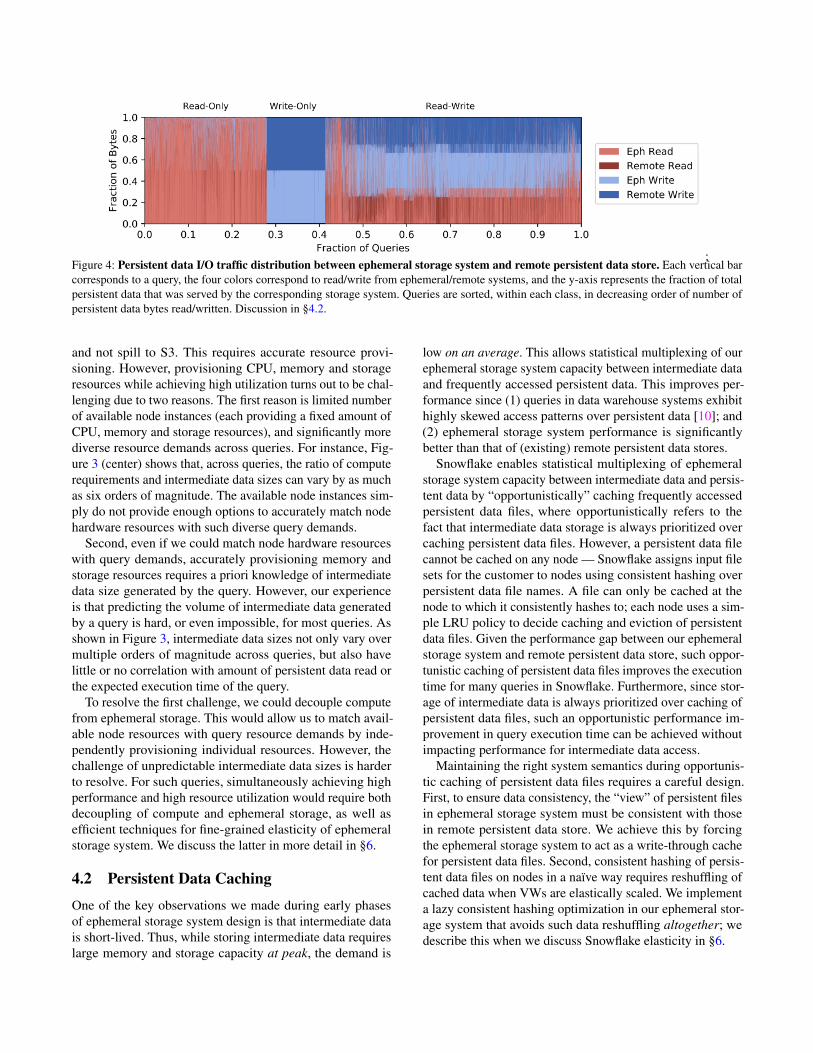
;Figure 4: Persistent data I/O traffic distribution between ephemeral storage system and remote persistent data store. Each vertical barcorresponds to a query, the four colors correspond to read/write from ephemeral/remote systems, and the y-axis represents the fraction of totalpersistent data that was served by the corresponding storage system. Queries are sorted, within each class, in decreasing order of number ofpersistent data bytes read/written. Discussion in §4.2.
and not spill to S3. This requires accurate resource provi-sioning. However, provisioning CPU, memory and storageresources while achieving high utilization turns out to be chal-lenging due to two reasons. The first reason is limited numberof available node instances (each providing a fixed amount ofCPU, memory and storage resources), and significantly morediverse resource demands across queries. For instance, Fig-ure 3 (center) shows that, across queries, the ratio of computerequirements and intermediate data sizes can vary by as muchas six orders of magnitude. The available node instances sim-ply do not provide enough options to accurately match nodehardware resources with such diverse query demands.
Second, even if we could match node hardware resourceswith query demands, accurately provisioning memory andstorage resources requires a priori knowledge of intermediatedata size generated by the query. However, our experienceis that predicting the volume of intermediate data generatedby a query is hard, or even impossible, for most queries. Asshown in Figure 3, intermediate data sizes not only vary overmultiple orders of magnitude across queries, but also havelittle or no correlation with amount of persistent data read orthe expected execution time of the query.
To resolve the first challenge, we could decouple computefrom ephemeral storage. This would allow us to match avail-able node resources with query resource demands by inde-pendently provisioning individual resources. However, thechallenge of unpredictable intermediate data sizes is harderto resolve. For such queries, simultaneously achieving highperformance and high resource utilization would require bothdecoupling of compute and ephemeral storage, as well asefficient techniques for fine-grained elasticity of ephemeralstorage system. We discuss the latter in more detail in §6.
4.2 Persistent Data Caching
One of the key observations we made during early phasesof ephemeral storage system design is that intermediate datais short-lived. Thus, while storing intermediate data requireslarge memory and storage capacity at peak, the demand is
low on an average. This allows statistical multiplexing of ourephemeral storage system capacity between intermediate dataand frequently accessed persistent data. This improves per-formance since (1) queries in data warehouse systems exhibithighly skewed access patterns over persistent data [10]; and(2) ephemeral storage system performance is significantlybetter than that of (existing) remote persistent data stores.
Snowflake enables statistical multiplexing of ephemeralstorage system capacity between intermediate data and persis-tent data by “opportunistically” caching frequently accessedpersistent data files, where opportunistically refers to thefact that intermediate data storage is always prioritized overcaching persistent data files. However, a persistent data filecannot be cached on any node — Snowflake assigns input filesets for the customer to nodes using consistent hashing overpersistent data file names. A file can only be cached at thenode to which it consistently hashes to; each node uses a sim-ple LRU policy to decide caching and eviction of persistentdata files. Given the performance gap between our ephemeralstorage system and remote persistent data store, such oppor-tunistic caching of persistent data files improves the executiontime for many queries in Snowflake. Furthermore, since stor-age of intermediate data is always prioritized over caching ofpersistent data files, such an opportunistic performance im-provement in query execution time can be achieved withoutimpacting performance for intermediate data access.
Maintaining the right system semantics during opportunis-tic caching of persistent data files requires a careful design.First, to ensure data consistency, the “view” of persistent filesin ephemeral storage system must be consistent with thosein remote persistent data store. We achieve this by forcingthe ephemeral storage system to act as a write-through cachefor persistent data files. Second, consistent hashing of persis-tent data files on nodes in a naïve way requires reshuffling ofcached data when VWs are elastically scaled. We implementa lazy consistent hashing optimization in our ephemeral stor-age system that avoids such data reshuffling altogether; wedescribe this when we discuss Snowflake elasticity in §6.

0
0.2
0.4
0.6
0.8
1
0 0.2 0.4 0.6 0.8 1
Fract
ion
Cache hit rate
Fraction of queriesFraction of bytes
0
0.2
0.4
0.6
0.8
1
0 0.2 0.4 0.6 0.8 1
Fract
ion
Cache hit rate
Fraction of queriesFraction of bytes
Figure 5: Cache hit rate distribution of Read-only (left) and Read-Write queries (right). We plot the CDFs for both, the queries (indepen-dent of their persistent data read sizes) and for bytes (queries weighed by the amount of persistent data read). For example, for Read-onlyqueries, 80% of the queries have hit rate greater than 75%, but these queries account for only a little more than 60% of the total number ofpersistent bytes read by all Read-only queries.
Persistent data being opportunistically cached in theephemeral storage system means that some subset of per-sistent data access requests could be served by the ephemeralstorage system (depending on whether or not there is a cachehit). Figure 4 shows the persistent data I/O traffic distribution,in terms of fraction of bytes, between the ephemeral storagesystem and remote persistent data store. The write-throughnature of our ephemeral storage system results in amount ofdata written to ephemeral storage being roughly of the samemagnitude as the amount of data written to remote persistentdata store (they are not always equal because of prioritizingstorage of intermediate data over caching of persistent data).
Even though our ephemeral storage capacity is significantlylower than that of a customer’s persistent data (around 0.1%on an average), skewed file access distributions and temporalfile access patterns common in data warehouses [7] enablereasonably high cache hit rates (avg. hit rate is close to 80%for read-only queries and around 60% for read-write queries).Figure 5 shows the hit rate distributions across queries. Themedian hit rates are even higher.
Future Directions. Figure 4 and Figure 5 suggest that morework is needed on caching. In addition to locality of referencein access patterns, cache hit rate also depends on effectivecache size available to the query relative to the amount ofpersistent data accessed by the query. The effective cache size,in turn, depends on both the VW size and the volume of in-termediate data generated by concurrently executing queries.Our preliminary analysis has not led to any conclusive obser-vations on the impact of the above two factors on the observedcache hit rates, and a more fine-grained analysis is needed tounderstand factors that impact cache hit rates.
We highlight two additional technical problems. First, sinceend-to-end query performance depends on both, cache hit ratefor persistent data files and I/O throughput for intermediatedata, it is important to optimize how the ephemeral storagesystem splits capacity between the two. Although we currentlyuse the simple policy of always prioritizing intermediate data,it may not be the optimal policy with respect to end-to-endperformance objectives (e.g., average query completion time
across all queries from the same customer). For example, itmay be better to prioritize caching a persistent data file thatis going to be accessed by many queries over intermediatedata that is accessed by only one. It would be interestingto explore extensions to known caching mechanisms thatoptimize for end-to-end query performance objectives [7] totake intermediate data into account.
Second, existing caching mechanisms were designed fortwo-tier storage systems (memory as the main tier andHDD/SSD as the second tier). In Snowflake, we alreadyhave three tiers of hierarchy with compute-local memory,ephemeral storage system and remote persistent data store;as emerging non-volatile memory devices are deployed inthe cloud and as recent designs on remote ephemeral storagesystems mature [22], the storage hierarchy in the cloud willget increasingly deeper. Snowflake uses traditional two-tiermechanisms — each node implements a local LRU policyfor evictions from local memory to local SSD, and an inde-pendent LRU policy for evictions from local SSD to remotepersistent data store. However, to efficiently exploit the deep-ening storage hierarchy, we need new caching mechanismsthat can efficiently coordinate caching across multiple tiers.
We believe many of the above technical challenges are notspecific to Snowflake, and would apply more broadly to anydistributed application built on top of disaggregated storage.
5 Query (Task) Scheduling
We now describe the query execution process in Snowflake.Customers submit their queries to the Cloud Services (CS)for execution on a specific VW. CS performs query parsing,query planning and optimization, and creates a set of tasks tobe scheduled on compute nodes of the VW.
Locality-aware task scheduling. To fully exploit theephemeral storage system, Snowflake colocates each task withpersistent data files that it operates on using a locality-awarescheduling mechanism (recall, these files may be cached inephemeral storage system). Specifically, recall that Snowflakeassigns persistent data files to compute nodes using consistent

20
210
220
230
0.5 1.0 0
Byte
s
0.5 1.0 0 0.5 1.0 0 0.5 1.0 0 0.5 1.0 0 0.5 1.0 02
0
22
24
26
Nodes U
sed
Persistent Data Read Persistent Data Write Persistent Data Read + Write Intermediate Data Nodes Used
Fraction of Queries Fraction of QueriesFraction of Queries
(a) Read-only (b) Write-only (c) Read-Write
Figure 6: Persistent data read / write and intermediate data exchange characteristics of queries sorted by the number of nodes used.Each plot uses the same axis for bytes (left axis) and nodes used (right axis). Persistent Read and write bytes vary by three orders of magnitudeacross each node count.
hashing over table file names. Thus, for a fixed VW size, eachpersistent data file is cached on a specific node. Snowflakeschedules the task that operates on a persistent data file to thenode on which its file consistently hashes to.
As a result of this scheduling scheme, query parallelism istightly coupled with consistent hashing of files on nodes — aquery is scheduled for cache locality and may be distributedacross all the nodes in the VW. For instance, consider a cus-tomer that has 1million files worth of persistent data, and isrunning a VW with 10 nodes. Consider two queries, wherethe first query operates on 100 files, and the second queryoperates on 100,000 files; then, with high likelihood, bothqueries will run on all the 10 nodes because of files beingconsistently hashed on to all the 10 nodes.
Figure 6 illustrates this— the number of persistent bytesread and written vary over orders of magnitude, almost inde-pendent of the number of nodes in the VW. As expected, theintermediate data exchanged over the network increases withthe number of nodes used.
Work stealing. It is known that consistent hashing can leadto imbalanced partitions [19]. In order to avoid overloadingof nodes and improve load balance, Snowflake uses workstealing, a simple optimization that allows a node to steal atask from another node if the expected completion time ofthe task (sum of execution time and waiting time) is lower atthe new node. When such work stealing occurs, the persistentdata files needed to execute the task are read from remotepersistent data store rather than the node at which the taskwas originally scheduled on. This avoids increasing load onan already overloaded node where the task was originallyscheduled (note that work stealing happens only when a nodeis overloaded).
Future Directions. Schedulers can place tasks onto nodesusing two extreme options: one is to colocate tasks with theircached persistent data, as in our current implementation. Asdiscussed in the example above, this may end up schedulingall queries on all nodes in the VW; while such a scheduling
policy minimizes network traffic for reading persistent data,it may lead to increased network traffic for intermediate dataexchange. The other extreme is to place all tasks on a singlenode. This would obviate the need of network transfers forintermediate data exchange but would increase network trafficfor persistent data reads. Neither of these extremes may be theright choice for all queries. It would be interesting to codesignquery schedulers that would pick just the right set of nodesto obtain a sweet spot between the two extremes, and thenschedule individual tasks onto these nodes.
6 Resource Elasticity
In this section, we discuss how Snowflake design achievesone of its core goals: resource elasticity, that is, scaling ofcompute and storage resources on an on-demand basis.
Disaggregating compute from persistent storage enablesSnowflake to independently scale compute and persistent stor-age resources. Storage elasticity is offloaded to persistent datastores [5]; compute elasticity, on the other hand, is achievedusing a pre-warmed pool of nodes that can be added/removedto/from customer VWs on an on-demand basis. By keepinga pre-warmed pool of nodes, Snowflake is able to providecompute elasticity at the granularity of tens of seconds.
6.1 Lazy Consistent HashingOne of the challenges that Snowflake had to resolve in order toachieve elasticity efficiently is related to data management inephemeral storage system. Recall that our ephemeral storagesystem opportunistically caches persistent data files; eachfile can be cached only on the node to which it consistentlyhashes to within the VW. The problem is similar to shared-nothing architectures: any fixed partitioning mechanism (inour case, consistent hashing) requires large amounts of data tobe reshuffled upon scaling of nodes; moreover, since the verysame set of nodes are also responsible for query processing,the system observes a significant performance impact duringthe scaling process.

T3T2T1 T4 T5 T6
Elastic scaling
T6
T6
No cache-locality
F2 F3F1 F6 F4 F5
T3T2T1,T6 T4 T5
T6
T6
Cache locality
F2 F3F1 F6 F4 F5
Figure 7: Snowflake uses lazy consistent hashing to avoid datareshuffling during elastic scaling of VWs. (Top) VW in steadystate with all task inputs cached. (Bottom) VW immediately afteradding one node. See discussion in §6.1.
Snowflake resolves this challenge using a lazy consistenthashing mechanism, that completely avoids any reshufflingof data upon elastic scaling of nodes by exploiting the factthat a copy of cached data is stored at remote persistent datastore. Specifically, Snowflake relies on the caching mecha-nism to eventually “converge” to the right state. For instance,consider the example in Figure 7 that shows a VW with 6tasks T1,T2, . . . ,T6, with task Ti operating on a single file Fi.Suppose at time t0, we have 5 nodes in the VW and that nodeN1 stores files F1 and F6, and nodes N2−N5 store file F2−F5,respectively. Suppose at time t > t0, a node N6 is added to thewarehouse. Then, rather than immediately reshuffling the files(which would result in F6 being moved from node N1 to N6),Snowflake will wait until task T6 is executed again. When thenext time T6 is scheduled (e.g., due to work stealing or thesame query being executed again), Snowflake will scheduleit on N6 since consistent hashing will now place file F6 onthat node. At this time, file F6 will be read by N6 from remotepersistent store and cached locally. File F6 on node N1 willno longer be accessed and will eventually be evicted from thecache. Such lazy caching allows Snowflake to achieve localitywithout reshuffling data and without interfering with ongoingqueries on nodes already in the VW.
6.2 Elasticity CharacteristicsOur customer warehouses exhibit several interesting elasticitycharacteristics. Figure 8 shows that many of our customersalready exploit our support for elasticity (for ∼20% of theVW). For such cases where customers do request VW resizing,the number of nodes in their VW can change by as muchas two orders of magnitude during the lifetime of the VW!Figure 9 (top) shows two cases where customers leverageelasticity rather aggressively (even at hourly granularity).
0
0.2
0.4
0.6
0.8
1
100
101
102
Fra
ction o
f V
Ws
Maximum VW Resize
Figure 8: VW elasticity usage. 82% of all VW never exploit elastic-ity; however, some of the customers elastically scale their VW sizeby as much as two orders of magnitude!
Future Directions. Figure 8 also shows that our customers donot exploit our support for elasticity for more than 80% of theVW. Even for customers that do request VW resizing, thereare opportunities for further optimizations — Figure 9 showsthat query inter-arrival times in these VW are much finer-grained than the granularity of VW scaling requested by ourcustomers. We believe the main reason for these characteris-tics is that customers lack the visibility (and the right demandestimation) into the system to accurately request scaling theirVW to meet the demand. VW1 in Figure 9, for instance, is oneof the heavily utilized VW from a large customer; the char-acteristics for this VW demonstrate how elastic scaling canmismatch the demand (approximated by query inter-arrivaltime). Since the time the dataset in the paper was recorded, alot of work has been done to improve support for auto-scalingVW at the granularity of inter-query arrival times. However,much more work needs to be done.
First, we would like to achieve elasticity at intra-querygranularity. Specifically, resource consumption can vary sig-nificantly even within the lifetime of individual queries. Thisis particularly prevalent in long running queries with manyinternal stages. Hence, in addition to auto-scaling VW at thegranularity of query inter-arrivals, we would ideally like tosupport some level of task-level elasticity even during theexecution of a query.
Second, we would like to explore serverless-like platforms.Serverless infrastructures such as AWS Lambda, Azure Func-tions and Google Cloud Functions which provide auto-scaling,high elasticity and fine-grained billing, are seeing increasingadoption across many application types. However, the keybarrier for Snowflake to transition to existing serverless infras-tructures is their lack of support for isolation, both in terms ofsecurity and performance [34]. Snowflake serves several cus-tomers who store and query sensitive and confidential data,and thus require strong isolation guarantees. One possibil-ity for Snowflake is to build its own custom serverless-likecompute platform. We believe this is an intriguing directionto explore, but will require resolving several challenges inefficient remote ephemeral storage access (§4.1), and in multi-tenant resource sharing (which we will discuss in §7).

2-22 2-23 2-24 2-25 2-26 2-27 2-28
Event t im e
101
103
105
Inte
r-a
rriv
al
tim
e
20
22
24
26
Ware
house S
ize
Query Inter-arrival
Warehouse Size
2-22 2-23 2-24 2-25
Event t im e
101
102
103
Inte
r-a
rriv
al
tim
e
20
21
22
23
Ware
house S
ize
Query Inter-arrival
Warehouse Size
Figure 9: Comparison of VW resizing (elastic scaling) and query inter-arrival times, binned per minute, for two heavily utilized VW1(left) and VW2 (right). Customers request VW resizing at much coarser grained timescales than query inter-arrival times for both VW. Notethe difference in x-axis: 7 days and 4 days for VW1 and VW2, respectively.
7 Multi-tenancy
Snowflake currently supports multi-tenancy through the VWabstraction. Each VW operates on an isolated set of nodes,with its own ephemeral storage system. This allows Snowflaketo provide performance isolation to its customers. In thissection, we present a few system-wide characteristics for ourVWs and use these to motivate an alternate sharing basedarchitecture for Snowflake.
The VW architecture in Snowflake leads to the traditionalperformance isolation versus utilization tradeoff. Figure 10(top four) show that our VWs achieve fairly good, but notideal, average CPU utilization; however, other resources areusually underutilized on an average. Figure 11 provides somereasons for the low average resource utilization in Figure 10(top four): the figure shows the variability of resource usageacross VW; specifically, we observe that for up to 30% ofVW, standard deviation of CPU usage over time is as large asthe mean itself. This results in underutilization as customerstend to provision VWs to meet peak demand. In terms ofpeak utilization, several of our VWs experience periods ofheavy utilization, but such high-utilization periods are notnecessarily synchronized across VWs. An example of this isshown in Figure 10 (bottom two), where we see that overa period of two hours, there are several points when oneVW’s utilization is high while the other VW’s utilizationis simultaneously low.
While we were aware of this performance isolation ver-sus utilization tradeoff when we designed Snowflake, recenttrends are pushing us to revisit this design choice. Specifically,maintaining a pool of pre-warmed instances was cost-efficientwhen infrastructure providers used to charge at an hourly gran-ularity; however, recent move to per-second pricing [6] byall major cloud infrastructure providers has raised interest-ing challenges. From our (provider’s) perspective, we wouldlike to exploit this finer-grained pricing model to cut downoperational costs. However doing so is not straightforward, asthis trend has also led to an increase in customer-demand for
finer-grained pricing. As a result, maintaining a pre-warmedpool of nodes for elasticity is no longer cost-effective: pre-viously in the hourly billing model, as long as at least onecustomer VW used a particular node during a one hour du-ration, we could charge that customer for the entire duration.However, with per-second billing, we cannot charge unusedcycles on pre-warmed nodes to any particular customer. Thiscost-inefficiency makes a strong case for moving to a sharingbased model, where compute and ephemeral storage resourcesare shared across customers: in such a model we can pro-vide elasticity by statistically multiplexing customer demandsacross a shared set of resources, avoiding the need to maintaina large pool of pre-warmed nodes. In the next subsection, wehighlight several technical challenges that need to be resolvedto realize such a shared architecture.
7.1 Resource SharingThe variability in resource usage over time across VW, asshown in Figure 11, indicates that several of our customerworkloads are bursty in nature. Hence, moving to a shared ar-chitecture would enable Snowflake to achieve better resourceutilization via fine-grained statistical multiplexing. Snowflaketoday exposes VW sizes to customers in abstract “T-shirt”sizes (small, large, XL etc.), each representing different re-source capacities. Customers are not aware of how these VWsare implemented (no. of nodes used, instance types, etc.). Ide-ally we would like to maintain the same abstract VW interfaceto customers and change the underlying implementation touse shared resources instead of isolated nodes.
The challenge, however, is to achieve isolation propertiesclose to our current architecture. The key metric of interestfrom customers’ point of view is query performance, that is,end-to-end query completion times. While a purely sharedarchitecture is likely to provide good average-case perfor-mance, maintaining good performance at tail is challenging.The two key resources that need to be isolated in VWs arecompute and ephemeral storage. There has been a lot of work[18, 35, 36] on compute isolation in the data center context,

0
0.2
0.4
0.6
0.8
1
02/23 02/25 02/27 03/01 03/03 03/05 03/07
CP
U U
tilization
Time
0
0.2
0.4
0.6
0.8
1
02/23 02/25 02/27 03/01 03/03 03/05 03/07
Mem
ory
Utiliz
ation
Time
0
0.2
0.4
0.6
0.8
1
02/23 02/25 02/27 03/01 03/03 03/05 03/07Netw
ork
TX
Utilization
Time
0
0.2
0.4
0.6
0.8
1
02/23 02/25 02/27 03/01 03/03 03/05 03/07Netw
ork
RX
Utilization
Time
0.0
0.2
0.4
0.6
0.8
1.0
00:00 00:15 00:30 00:45 01:00 01:15 01:30 01:45 02:00
CP
U U
tiliza
tion
Time
VW 1 VW 2
0.0
0.2
0.4
0.6
0.8
1.0
00:00 00:15 00:30 00:45 01:00 01:15 01:30 01:45 02:00M
em
ory
Utiliz
atio
n
Time
VW 1 VW 2
Figure 10: System-wide CPU, Memory, and Network TX/RX utilization over time, averaged across all VWs. (top four). Average CPU,Memory, Network TX and Network RX utilizations are roughly 51%, 19%, 11%, 32%, respectively, indicating that there is significant roomfor improvement. (bottom two) zoomed-in CPU and Memory utilization for two highly active VW over a 2 hour duration. At several points,we see that one of the warehouses experiences high utilization while the other sees low utilization.
that Snowflake could leverage. Moreover, the centralized taskscheduler and uniform execution runtime in Snowflake makethe problem easier than that of isolating compute in generalpurpose clusters. Here, we instead focus on the problem ofisolating memory and storage, which has only recently startedto receive attention in the research community [25].
The goal here is to design a shared ephemeral storage sys-tem (using both memory and SSDs) that supports fine-grainedelasticity without sacrificing isolation properties across ten-ants. With respect to sharing and isolation of ephemeral stor-age, we outline two key challenges. First, since our ephemeralstorage system multiplexes both cached persistent data and in-termediate data, both of these entities need to be jointly sharedwhile ensuring cross-tenant isolation. While Snowflake couldleverage techniques from existing literature [11, 26] for shar-ing cache, we need a mechanism that is additionally aware ofthe co-existence of intermediate data. Unfortunately, predict-ing the effective lifetime of cache entries is difficult. Evictingidle cache entries from tenants and providing them to othertenants while ensuring hard isolation is not possible, as wecannot predict when a tenant will next access the cache entry.Some past works [11, 33] have used techniques like idle-memory taxation to deal with this issue. We believe there ismore work to be done, both in defining more reasonable iso-lation guarantees and designing lifetime-aware cache sharingmechanisms that can provide such guarantees.
The second challenge is that of achieving elasticity withoutcross-tenant interference: scaling up the shared ephemeralstorage system capacity in order to meet the demands of a par-ticular customer should not impact other tenants sharing thesystem. For example, if we were to naïvely use Snowflake’scurrent ephemeral storage system, isolation properties willbe trivially violated. Since all cache entries in Snowflakeare consistently hashed onto the same global address space,scaling up the ephemeral storage system capacity would endup triggering the lazy consistent hashing mechanism for alltenants. This may result in multiple tenants seeing increasedcache misses, resulting in degraded performance. Resolvingthis challenge would require the ephemeral storage system toprovide private address spaces to each individual tenant, andupon scaling of resources, to reorganize data only for thosetenants that have been allocated additional resources.
Memory Disaggregation. Average memory utilization inour VWs is low (Figure 10); this is particularly concern-ing since DRAM is expensive. Although sharing resourcesharing would improve CPU and memory utilization, it isunlikely to lead to optimal utilization across both dimensions.Further, variability characteristics of CPU and memory aresignificantly different (Figure 11), indicating the need for in-dependent scaling of these resources. Memory disaggregation[1, 14, 15] provides a fundamental solution to this problem.However, as discussed in §4.2, accurately provisioning re-

0
1
2
3
4
5
6
0 0.2 0.4 0.6 0.8 1
Co
effic
ient
of V
ariation
(C
V)
(Sta
nda
rd D
evia
tion /
Mean)
Fraction of warehouses (warehouses sorted by CV of CPU usage)
CV of Memory usageCV of CPU usage
Figure 11: Coefficient of Variation (CV) of CPU and memory us-age over time, across customer VWs. We see significant variabilitywith respect to both resources.
sources is hard; since over-provisioning memory is expensive,we need efficient mechanisms to share disaggregated memoryacross multiple tenants while providing isolation guarantees.
8 Related WorkIn this section we discuss related work and other systemssimilar to Snowflake. Our previous work [12] discusses SQL-related aspects of Snowflake and presents related literatureon those aspects. This paper focuses on the disaggregation,ephemeral storage, caching, task scheduling, elasticity andmulti-tenancy aspects of Snowflake; in the related work dis-cussion below, we primarily focus on these aspects.
SQL-as-a-Service systems. There are several other systemsthat offer SQL functionality as a service in the cloud. These in-clude Amazon Redshift [16], Aurora [4], Athena [3], GoogleBigQuery [30] and Microsoft Azure Synapse Analytics [24].While there are papers that describe the design and opera-tional experience of some of these systems, we are not awareof any prior work that undertakes a data-driven analysis ofworkload and system characteristics similar to ours.
Redshift [16] stores primary replicas of persistent datawithin compute VM clusters (S3 is only used for backup);thus, it may not be able to achieve the benefits that Snowflakeachieves by decoupling compute from persistent storage.Aurora [4] and BigQuery [30] (based on the architectureof Dremel [23]) decouple compute and persistent storagesimilar to Snowflake. Aurora, however, relies on a custom-designed persistent storage service that is capable of offload-ing database log processing, instead of a traditional blob store.We are not aware of any published work that describes howBigQuery handles elasticity and multi-tenancy.
Decoupling compute and ephemeral storage systems. Pre-vious work [20] makes the case for flash storage disaggrega-tion by studying a key-value store workload from Facebook.Our observations corroborate this argument and further extend
it in the context of data warehousing workloads. Pocket [22]and Locus [27] are ephemeral storage systems designed forserverless analytics applications. If we were to disaggregatecompute and ephemeral storage in Snowflake, such systemswould be good candidates. However, these systems do notprovide fine-grained resource elasticity during the lifetimeof a query. Thus, they either have to assume a priori knowl-edge of intermediate data sizes (for provisioning resources atthe time of submitting queries), or suffer from performancedegradation if such knowledge is not available in advance.As discussed in §4.1, predicting intermediate data sizes isextremely hard. It would be nice to extend these systemsto provide fine-grained elasticity and cross-query isolation.Technologies for high performance access to remote flash stor-age [13, 17, 21] would also be integral to efficiently realizedecoupling of compute and ephemeral storage system.
Multi-tenant resource sharing. ESX server [33] pioneeredtechniques for multi-tenant memory sharing in the virtual ma-chine context, including ballooning and idle-memory taxation.Memshare [11] considers multi-tenant sharing of cache capac-ity in DRAM caches in the single machine context, sharingun-reserved capacity among applications in a way that maxi-mizes hit rate. FairRide [26] similarly considers multi-tenantcache sharing in the distributed setting while taking into ac-count sharing of data between tenants. Mechanisms for shar-ing and isolation of cache resources similar to the ones usedin these works would be important in enabling Snowflake toadopt a resource shared architecture. As discussed previously,it would be interesting to extend these mechanisms to makethem aware of the different characteristics and requirementsof intermediate and persistent data.
9 ConclusionWe have presented operational experience running Snowflake,a data warehousing system with state-of-the-art SQL support.The key design and implementation aspects that we have cov-ered in the paper relate to how Snowflake achieves computeand storage elasticity, as well as high-performance in a multi-tenancy setting. As Snowflake has grown to serve thousandsof customers executing millions of queries on petabytes ofdata every day, we consider ourselves at least partially success-ful. However, using data collected from various componentsof our system during execution of ∼70 million queries overa 14 day period, our study highlights some of the shortcom-ings of our current design and implementation and highlightsnew research challenges that may be of interest to the broadersystems and networking communities.
AcknowledgmentsWe would like to thank our shepherd, Asaf Cidon, and theanonymous NSDI reviewers for their insightful feedback. Thiswork was supported in part by NSF 1704742 and a GoogleFaculty Research Award.

References
[1] M. K. Aguilera, N. Amit, I. Calciu, X. Deguillard,J. Gandhi, P. Subrahmanyam, L. Suresh, K. Tati,R. Venkatasubramanian, and M. Wei. Remote mem-ory in the age of fast networks. In SOCC, 2017.
[2] A. Ailamaki, D. J. DeWitt, M. D. Hill, and M. Skounakis.Weaving relations for cache performance. In VLDB,2001.
[3] Amazon. Amazon Athena. "https://aws.amazon.com/athena/".
[4] Amazon. Amazon Aurora Serverless. "https://aws.amazon.com/rds/aurora/serverless/".
[5] Amazon. Amazon simple storage service (S3). "http://aws.amazon.com/s3/".
[6] Amazon. Per-second billing for EC2 instances."https://aws.amazon.com/blogs/aws/new-per-second-billing-for-ec2-instances-and-ebs-volumes/".
[7] G. Ananthanarayanan, A. Ghodsi, A. Wang,D. Borthakur, S. Kandula, S. Shenker, and I. Sto-ica. PACMan: Coordinated memory caching for paralleljobs. In NSDI, 2012.
[8] M. Azure. Azure blob storage. "https://azure.microsoft.com/en-us/services/storage/blobs/".
[9] T. Benson, A. Akella, and D. A. Maltz. Network trafficcharacteristics of data centers in the wild. In IMC, 2010.
[10] S. Chaudhuri and U. Dayal. An overview of data ware-housing and OLAP technology. SIGMOD, 1997.
[11] A. Cidon, D. Rushton, S. M. Rumble, and R. Stutsman.Memshare: a dynamic multi-tenant key-value cache. InATC, 2017.
[12] B. Dageville, T. Cruanes, M. Zukowski, V. Antonov,A. Avanes, J. Bock, J. Claybaugh, D. Engovatov,M. Hentschel, J. Huang, et al. The snowflake elasticdata warehouse. In SIGMOD, 2016.
[13] N. Express. Nvme over fabricsoverview. "https://nvmexpress.org/wp-content/uploads/NVMe_Over_Fabrics.pdf".
[14] P. X. Gao, A. Narayan, S. Karandikar, J. Carreira, S. Han,R. Agarwal, S. Ratnasamy, and S. Shenker. Networkrequirements for resource disaggregation. In OSDI,2016.
[15] J. Gu, Y. Lee, Y. Zhang, M. Chowdhury, and K. G. Shin.Efficient memory disaggregation with Infiniswap. InNSDI, 2017.
[16] A. Gupta, D. Agarwal, D. Tan, J. Kulesza, R. Pathak,S. Stefani, and V. Srinivasan. Amazon Redshift and thecase for simpler data warehouses. In SIGMOD, 2015.
[17] J. Hwang, Q. Cai, A. Tang, and R. Agarwal. TCP ≈RDMA: Cpu-efficient remote storage access with I10.In NSDI, 2020.
[18] C. Iorgulescu, R. Azimi, Y. Kwon, S. Elnikety, M. Sya-mala, V. Narasayya, H. Herodotou, P. Tomita, A. Chen,J. Zhang, et al. PerfIso: Performance isolation for com-mercial latency-sensitive services. In ATC, 2018.
[19] D. Karger and M. Ruhl. New algorithms for load bal-ancing in peer-to-peer systems. 2003.
[20] A. Klimovic, C. Kozyrakis, E. Thereska, B. John, andS. Kumar. Flash storage disaggregation. In EuroSys,2016.
[21] A. Klimovic, H. Litz, and C. Kozyrakis. ReFlex: Remoteflash ≈ local flash. In ASPLOS, 2017.
[22] A. Klimovic, Y. Wang, P. Stuedi, A. Trivedi, J. Pfefferle,and C. Kozyrakis. Pocket: Elastic ephemeral storage forserverless analytics. In OSDI, 2018.
[23] S. Melnik, A. Gubarev, J. J. Long, G. Romer, S. Shivaku-mar, M. Tolton, and T. Vassilakis. Dremel: interactiveanalysis of web-scale datasets. VLDB, 2010.
[24] Microsoft. Azure synapse analytics. "https:/ / azure . microsoft . com / en-us / services /
synapse-analytics/".
[25] M. Nanavati, J. Wires, and A. Warfield. Decibel: Isola-tion and sharing in disaggregated rack-scale storage. InNSDI, 2017.
[26] Q. Pu and H. Li. FairRide: Near-optimal, fair cachesharing. In NSDI, 2016.
[27] Q. Pu, S. Venkataraman, and I. Stoica. Shuffling, fastand slow: scalable analytics on serverless infrastructure.In NSDI, 2019.
[28] C. Reiss, A. Tumanov, G. R. Ganger, R. H. Katz, andM. A. Kozuch. Heterogeneity and dynamicity of cloudsat scale: Google trace analysis. In SoCC, 2012.
[29] R. J. Santos and J. Bernardino. Real-time data ware-house loading methodology. In IDEAS, 2009.
[30] K. Sato. An inside look at google bigquery. "https://cloud.google.com/files/BigQueryTechnicalWP.
pdf".
[31] A. Simitsis, P. Vassiliadis, and T. Sellis. OptimizingETL processes in data warehouses. In ICDE, 2005.

[32] P. Vassiliadis. A survey of extract–transform–load tech-nology. IJDWM, 2009.
[33] C. A. Waldspurger. Memory resource management inVMware ESX server. ACM SIGOPS Operating SystemsReview, 2002.
[34] L. Wang, M. Li, Y. Zhang, T. Ristenpart, and M. Swift.Peeking behind the curtains of serverless platforms. InATC, 2018.
[35] X. Yang, S. M. Blackburn, and K. S. McKinley.Elfen scheduling: Fine-grain principled borrowing fromlatency-critical workloads using simultaneous multi-threading. In ATC, 2016.
[36] X. Zhang, E. Tune, R. Hagmann, R. Jnagal, V. Gokhale,and J. Wilkes. CPI2: CPU performance isolation forshared compute clusters. In EuroSys, 2013.