Build a - World Radio History
114
14278 EASY-TO-BUI;D BURGLAR ALARM FOR APARTMENT USE cc roni WORLD'S LARGEST- SELLING ELECTRONICS MAGAZINE MOBILE COMMUNICATIONS: CB vs. 2 -METER FM Microwave Ovens for the Home CMOS Probe Extends Multimeter Use I Guide to Choosing TV & FM Antennas Learning Electronic Theory With Hand Calculators TEST REPORTS: Nikko 7075 AM/FM Stereo Receiver MXR Stereo w; 3S0 NdS SBE "Opti/Scan" u Scanner Hickok 370 .__ Analog Multimeter o- --' i, . 11' 1I11C 961i3E- JULY 1976/$1 Now You Can Build a HIGH-QUAI,ITY INTELLIGENT TERMINAL I, 1R,.o.ct. .. , .: «.-t , ; -1,T4 . LOW . ;boa o AmericanRadioHistory.Com
-
Upload
khangminh22 -
Category
Documents
-
view
1 -
download
0
Transcript of Build a - World Radio History
14278
EASY-TO-BUI;D BURGLAR ALARM FOR APARTMENT USE
cc roni WORLD'S LARGEST- SELLING ELECTRONICS MAGAZINE
MOBILE
COMMUNICATIONS:
CB vs. 2 -METER FM
Microwave Ovens
for the Home
CMOS Probe Extends
Multimeter Use
I Guide to Choosing TV & FM Antennas
Learning Electronic Theory With Hand Calculators
TEST REPORTS: Nikko 7075 AM/FM
Stereo Receiver
MXR Stereo w; 3S0 NdS
SBE "Opti/Scan" u
Scanner
Hickok 370 .__
Analog Multimeter
o- --'
i, .
11'
1I11C 961i3E-
JULY 1976/$1
Now You Can Build a
HIGH-QUAI,ITY
INTELLIGENT TERMINAL
I,
1R,.o.ct. .. ,
.: «.-t , ;
-1,T4
. LOW . ;boa
o
AmericanRadioHistory.Com
Experience is the; best tea-Cher.' You -
might settle for any CB first time' around. 'Understandably. A lot of people think they're all pretty much alike. But you'll soon discover that, like everything else, there are exceptions.
Ask the pros. America's long distance truckers. These guys talk. CB day in and day out. And they demand the best. That's why truckers refer to the Cobra 29 as "The Diesel Mobile"
-Listen to Cobra. You'll hear a big difference. Because the Cobra -29 gives you features which assure crystal clear reception. Like switchable noise limiting and blanking, to cut out practically all pulse and ignition interference. Add -
squelch control aríd RE gain and you've got exceptional - adjustable - receiver clarity: Even,in the heaviest CB traffic. You also get Delta Tuning -which makes up for the other guy, because even off - frequency transmitters are pulled in. Perfectly.
Talk to Cobra. And you know you're punching' through. One glance at the
29's -over -sized illuminated meter tells you just how much power you're punch- ing out: and pulling in. For voice modula- tion the .DynaMike delivers at 100%. Same,way with power: The 29 transmits. at maximum power levels.
Sooner or later you'll get a Cobra. And you'll get engineering and crafts- manship second to none.'Performance -
that will make . your first CB seem obsolete. Reliability and durability that.. have set standards for the industry. Above all, you'll get power. The power to punch t Zróugh loud and clear like =
nothing else. Because when'it comes to CB 'radio, nothing punches, through loud and clear -like a 'Cobra.
o bra Punches through loud and clear. Cobra Communications, Products of Dynascan Corp. "
1801 W. Belle Plaine, Chicago, Illinois.60613
CIRCLE NO. 14 ON FREE INFORMATION CARO
IF YOUR FIRST CB ISN'T A COBRA YOUR, SECOND ONE WILL BE.
COBRA -29 VIOQ i19
'ó DYMIKE VOLUME SQUELCH
RF GAIN DELTA rur
I OFF OFF 1 1
11111i,, rah..., r° . " _.
TX
1
Ir,
I
AmericanRadioHistory.Com
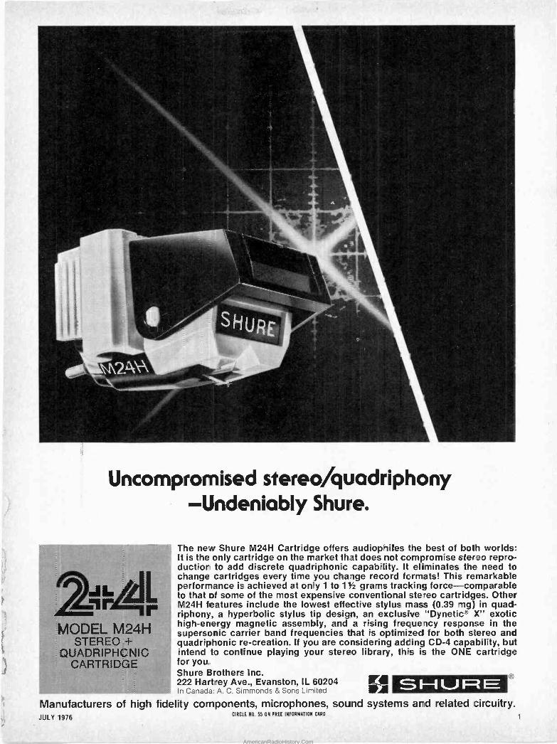
Uncompromised stereo/quadriphony -Undeniably Shure.
MODEL M24H STEREO=+
QUADRIPHCNIC CARTRIDGE
The new Shure M24H Cartridge offers audiophiles the best of both worlds: It is the only cartridge on the market that does not compromise stereo repro- duction to add discrete quadriphonic capability. It eliminates the need to change cartridges every time you change record formats! This remarkable performance is achieved at only 1 to 11/2 grams tracking force-comparable to that of some of the most expensive conventional stereo cartridges. Other M24H features include the lowest effective stylus mass (0.39 mg) in quad- riphony, a hyperbolic stylus tip design, an exclusive "Dynetic® X" exotic high-energy magnetic assembly, and a rising frequency response in the supersonic carrier band frequencies that is optimized for both stereo and quadriphonic re-creation. If you are considering adding CD -4 capability, but intend to continue playing your stereo library, this is the ONE cartridge for you.. Shure Brothers Inc. 222 Harkey Ave., Evanston, IL 60204 In Canada: A. C. Simmonds & Sons Limited °.SHURE e
Manufacturers of high fidelity components, microphones, sound systems and related circuitry. JULY 1976
CIRCLE NO 55 ON FREE INFORMATION CARO
AmericanRadioHistory.Com
D-_ (:RS)
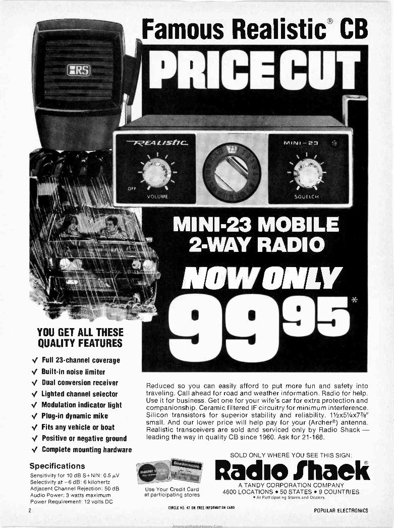
YOU GET ALL THESE QUALITY FEATURES
./ Full 23 -channel coverage
./ Built-in noise limiter
./ Dual conversion receiver
1 Lighted channel selector
./ Modulation indicator light
./ Plug-in dynamic mike
./ Fits any vehicle or boat
./ Positive or negative ground
./ Complete mounting hardware
Specifications Sensitivity for 10 dB S+N/N: 0.5 µV Selectivity at -6 dB: 6 kilohertz Adjacent Channel Rejection: 50 dB Audio Power: 3 watts maximum Power Requirement: 12 volts DC
Famous Realistic® CB iA,
fi
fY11Nd-23
\ /
t1
SQUELCH
MI Ni'23 MOBILE 2 -WAY RADIO
Reduced so you can easily afford to put more fun and safety into traveling. Call ahead for road and weather information. Radio for help. Use it for business. Get one for your wife's car for extra protection and companionship. Ceramic filtered IF circuitry for minimum interference. Silicon transistors for superior stability and reliability. 11/2x5'/ax77/a" small. And our lower price will help pay for your (Archer®) antenna. Realistic transceivers are sold and serviced only by Radio Shack - leading the way in quality CB since 1960. Ask for 21-168.
Use Your Credit Card at participating stores
SOLD ONLY WHERE YOU SEE THIS SIGN:
Radie IhaeK A TANDY CORPORATION COMPANY
4600 LOCATIONS 50 STATES 9 COUNTRIES At Participating Stores and Dealers.
2 CIRCLE NO. 41 ON FREE INFORMATION CARD
POPULAR ELECTRONICS
AmericanRadioHistory.Com
JULY 1976 VOLUME 10, NUMBER 1
PopularWORLD'S LARGEST SELLING ELECTRONICS MAGAZINE
FEATURE ARTICLES MICROWAVE OVENS FOR THE HOME Bill Eva
How they work and what to look for in selecting one. LEARNING ELECTRONIC THEORY WITH HAND CALCULATORS Edward M. Noll
Part One: Basic Equations and Ohm's Law. GUIDE TO CHOOSING TV & FM ANTENNAS Julius Green MOBILE COMMUNICATIONS: CB VS. 2 -METER FM John T. Frye
The advantages and disadvantages of each type of system. TEMPORARY PERMIT FORM 555-B FOR CB RADIO
CONSTRUCTION ARTICLES BUILD SOL, AN INTELLIGENT COMPUTER TERMINAL Robert M. Marsh & Lee Felsenstein
Video terminal can interface with any mini- or microcomputer. A FLASHER/BATTERY INDICATOR Dave Hileman
Indicates power is on to prevent using up the battery. UPDATE YOUR MULTIMETER WITH A CMOS MILLIVOLTER David H. Dage
Converts any voltmeter to read in the low -millivolt range. A LOW-COST APARTMENT BURGLAR ALARM Randy J. Soule
Self -powered system features adjustable time delay.
BUILD THE ULTIMATE METRONOME Milton L. Chesnut Provides accented beats for timing and syncopation.
COLUMNS STEREO SCENE Ralph Hodges 22
Perfecting Phono. HOBBY SCENE John McVeigh 30 SOLID STATE Lou Garner 81
Build Your Own Sonar System. COMPUTER BITS Hal Chamberlain 86
Computer Graphics. INSIDE BASIC ELECTRONICS 94
Fixed and Variable Resistors. CB SCENE Ray Newhall 97
A CB Primer. EXPERIMENTER'S CORNER Forrest M. Mims 104
The Avalanche Transistor.
39
43
61
79
98
PRODUCT TEST REPORTS NIKKO MODEL 7075 AM/STEREO FM RECEIVER PIONEER MODEL SF -850 ELECTRONIC CROSSOVER MXR STEREO GRAPHIC EQUALIZER SBE MODEL 12SM OPTI/SCAN DIGITIAL SCANNING RECEIVER HICKOK MODEL 370 ANALOG MULTIMETER
35
46
47
50
61
66 74 75 76 77
DEPARTMENTS EDITORIAL Art Salsberg 4
Who Killed TV Picture Quality? LETTERS 6
OUT OF TUNE 6 "A Simple Logic Probe," (May 1976) "Solid State," (April 1976)
NEW PRODUCTS 12 NEW LITERATURE 16 NEWS HIGHLIGHTS 32 OPERATION ASSIST 102 ELECTRONICS LIBRARY 103 ADVERTISERS INDEX 123
POPULAR ELECTRONICS. July 1976, Volume 10. Number 1, Published monthly at One Park Avenue, New York. NY 10016. One year subscription rate for U.S.. $9.98; U.S. Possessions and Canada, $11.98; all other coun- tries. $12.98 (cash orders only, payable In U.S. currency). Second Class postage paid at New York. NY and at additional mailing offices. Authorized as second class mail by the Post Office Department. Ottawa. Canada and for payment of postage in cash.
POPULAR ELECTRONICS including ELECTRONICS WORLD. Trade Mark Registered. Indexed in the Reader's Guide to Periodical Literature.
COPYRIGHT r 1976 BY ZIFF-DAVIS PUBLISHING COMPANY. ALL RIGHTS RESERVED.
Ziff -Davis also publishes Boating, Car and Driver, Cycle, Flying, Modern Bride, Popular Photography, Skiing and Stereo Review.
Material In this publication may not be reproduced in any form without permission. Requests for permission should be directed to Jerry Schneider, Rights and Permissions, Ziff -Davis Publishing Co.. One Park Ave.. New York, NY 10016.
Editorial correspondence: POPULAR ELECTRONICS, 1 Park Ave., New York, NY 10016. Editorial contributions must be accompanied by return postage and will be handled with reasonable care; however. publisher assumes no responsibility for return or safety of manuscripts, art work, or models.
Forms 3579 and all subscription correspondence: POPULAR ELEC- TRONICS, Circulation Dept., P.O. Box 2774, Boulder, CO 80302. Please allow at least eight weeks for change of address. Include your old address. enclosing, if possible, an address label from a recent issue.
JULY 1976 3
AmericanRadioHistory.Com
Popular Electronics® EDGAR W. HOPPER
Publisher
ARTHUR P. SALSBERG Editorial Director
LESLIE SOLOMON Technical Editor
JOHN R. RIGGS Managing Editor
ALEXANDER W. BURAWA Feature Editor
EDWARD I. BUXBAUM Art Director
JOHN McVEIGH Associate Editor
ANDRE DUZANT Technical Illustrator
PATRICIA BROWN Editorial Assistant
LOU GARNER GLENN HAUSER
JULIAN D. HIRSCH RALPH HODGES ART MARGOLIS FORREST MIMS
HAL CHAMBERLAIN WILFRED M. SCHERER
Contrdnrting Editors
JOSEPH E. HALLORAN Advertising Director
JOHN J. CORTON Advertising Sales
LINDA BLUM Advertising See' ice !Manager
PEGI McENEANEY Executive Assistant
STANLEY NEUFELD Associate Publisher
ZIFF-DAVIS PUBLISHING COMPANY Popular Electronics
Editorial and Executive Offices One Park Avenue New York. New York 10016
212-725-3500 Hershel B. Sarbin, President
Furman Hebb. Executive Vice President Phillip T. Heffernan. Senior Vice President, Marketing
Edward D. Muhlfeld,SeniorVice President, Sports Division Philip Sine, Senior Vice President
Frank Pomerantz. Vice President, Creative Services Arthur W. Butzow, Vice President, Production Lawrence Sporn. Vice President, Circulation
George Morrissey, Vice President Sydney H. Rogers, Vice President
Sidney Holtz, Vice President Al Traina. Vice President
Philip Korsant, Vice President Paul H. Chock, Vice President, Market Planning
Charles B. Seton. Secretary Edgar W. Hopper, Vice President. Electronics Div.
William Ziff, Chairman W. Bradford Briggs. Vice Chairman
Midwestern Office The Pattis Group. 4761 West Touhy Ave., Lincolnwood, Illinois 60644, 312 679-1100 GERALD E. WOLFE, THOMAS HOCKNEY
Western Office 9025 Wilshire Boulevard, Beverly Hills, CA 90211
213 273-8050; BRadshaw 2-1161 Western Advertising Manager, BUD DEAN
Japan: James Yagi -
Oji Palace Aoyama: 6-25, Minami Aoyama 6 Chome, Minato-Ku, Tokyo 407-1930/6821,
582-2851
MPA 'Aetryb c° Member Audd Bureau
of Circulations
The publisher has no knowledge of any proprietary rights which will be violated by the making or using of any items disclosed in this issue.
Cx
Editorial WHO KILLED TV PICTURE QUALITY?
The April 3 issue of TV Guide observed that U.S. citizens returning from Europe or Japan often "rave about beautiful TV reception there, the vividness of colors and detail in the picture ..." Obviously, their system of TV must be better than ours, they conclude. Not so! The capabilities are essentially the same.
Whereas the European TV system employs a 625 -line picture linked with 50 Hz, Japan (and the U.S.) use a 525 -line system in sync with 60 Hz. Then why is our TV video reception so poor compared to that in other countries? The inconclusive reasons include: Americans just don't care or won't bother to adjust receivers properly, antenna systems and TV receivers are allowed to deteriorate, broadcasters are shortchanging us by transmitting poor -quality video and color, and receiver manufacturers take design shortcuts that prevent reception of good, clean signals.
There's probably some truth in all the foregoing speculations. Certainly, there is no question that many TV broadcasts are poor. You can prove this by switching from channel to channel, observe differences between film source and tape source, etc. But things are getting better (slowly, very slowly):
The "purple plague" rarely touches the faces of TV performers nowadays. Broadcasters at least have a transmitted reference of tint and color intensity
with which to make adjustments or to acknowledge that their equipment is obsolete. Broadcasters are also experimenting with "circular polarized" transmitting
antennas, which might eliminate "ghosts" (a different outdoor receiving antenna design would be needed to take advantage of this).
Receiver manufacturers have introduced models with automatic color screen grid tracking (RCA) and automatic adjustment to the broadcaster's color/tint intensity reference (General Electric). The latter is VIR, for vertical interval reference, but you cannot see it without a decoder and it's not yet universally used.
Surely these advances are welcome. But how come the other countries managed to produce substantially better color and black -and -white TV pictures without them? Ignoring all the possible causes for our "picture -quality lag" except for the TV receiver itself, we know that U.S. video reception can be significantly improved at the consumer equipment end.
Our technical editor, Les Solomon, for example, observed in his August 1973 "Test Scene" that most TV receivers are incapable of even reproducing 2621/2 lines, let alone close to our 525 -line "standard." What interlace there is in most receivers (trace on "odd" lines and retrace on "even" lines) is reproduced as "pairing." That is, scanning lines of one field are positioned directly behind the lines of the other field. The result is a TV picture lacking good detail.
Another video -quality degenerator is the absence of good, if any, dc restoration. Instead óf being capable of shifting to deep black, the typical receiver can only go to "tattle -tale gray." The black level is simply lost because the dc signal level, destroyed by capacitive coupling, hasn't been restored. Sadly, all it takes is a diode and a resistor to do the job.
Another improvement that is long overdue is providing an inexpensive audio output jack from the detector on a TV receiver. FM TV sound can go to 15 kHz. For the future, a video jack would be in order to handle TV electronic games, computers and video tape decks.
So the question is: in our free -enterprise system, why hasn't some TV manufacturer scooped the competition and come out with a model that has full interlaced scanning, proper dc restoration, etc.? Believe me, the American public would recognize a vastly superior TV picture and "latch on" to the unit. The hi-fi component industry proved that we recognize and appreciate good quality!
4 POPULAR ELECTRONICS
AmericanRadioHistory.Com

.. ,
l
'.
A
tt
{.
i , _{ i
2;.. - - n
Pace.. The best-selling CB in the world.
More people buy Pace than any other CB, based en estimates by Pazhcbm Inc. Maybe it's because: We wantec zc be #1 -and we put our money & determinatibn on the I ne to make the kinc of radios that wDuld máke us the leader. .
The warranty we offer - just ask anybody about it. -
Our quality control - which means we don't just test an occasional sample off the line, we iiJrate-test almost every mobile`radia we make.
Our 23 models-the IargestCB line in the world with suggested prices from $50 to $500. Which makes i: easier to choose the right radic. Is Pace fcr you? We think Number On deserves K#1.
Write us - Pathcom Inc.; _Los Angeles), Harbor City, CA..90710.
PACE CB When you've gct a Pace,
you've gct the wart by the ems. PACE TWO -WA' RADIOS', PRODUCTS OF PATHCJM INC.
CIRCLE NO. 42 ON FREE INFORMATION CAR)
AmericanRadioHistory.Com
Flexible alternative
!
IIIIIIÍ:'1111II 11111111111-1i
1111111111111.11a JIJIIIIt'1111 II;1 '- U11111.9.111111 ; UIlI11^111111
J1111 LI." I I I ILI I IJ I I LÍ" ! IIUJJ.
! 111111"I I I I I I I I I I I II''! I I1111
I_IIIIII"!111111
IIIIII "IIIIII 111111J,'lllll
1111 I I'' I I I I I I
1111J11.-111111 I'" 111111 i 11 I 1111_111911_1111i
IIIJI11111111L ; 1111(.11111
1111111 ;2 111111 21111111 I1111I1i'I111111 I 4/.111111111111111111111
111I1I11,t'IIIIIII
111111 ll' 1111111 [11.111J111.1.111
Q IIIIIIIIIIIIIII 11111111.1 11111
I{IIIIt'lllllll; lili11111 1!1!11 111111Y1:.1111111 IIIIII N:.11lllól . . , . . I.
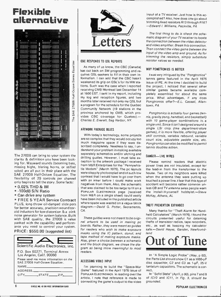
The 2700B can bring to your system the clarity & definition you have been look- ing for. Wayward sounds (booming bass, missing highs, blaring horns, or stifled solos) are all put in their place with the SAE 2700B Half -Octave Equalizer. The flexibility of 20 controls per channel only begins to tell the story. Some facts:
0.02% THD & IM -100dB S/N Ratio
* Can drive any system * FREE 5 YEAR Service Contract PLUS, long -throw oil -damped slide pots for better accuracy, precision wound tor- oid inductors for low distortion & a pink noise generator for system balance. Built with SAE quality, the 27006 is value packed with the capability and perform- ance you need to control your system.
PRICE: $550.00 (suggested list) A Scientific Audio Electronics, Inc.
P.O. Box 60271, Terminal Annex Los Angeles, Calif. 90060 Please send me more information on the SAE 2700B Half -Octave Equalizer. NAME
ADDRESS
CITY STATE ZIP
Letters CBC RESPONDS TO QSL REPORTS
As many of us know, the CBC (Canada) has cut back on SW programming and re- quires QSL-seekers to fill in their own in- formation. I can add that the CBC hasn't weakened its grip on QSL's for its MW sta- tions. Such was the case when I reported receiving CMB Montreal last December 14
at 1600 EST. I sent in my report, including my log and reception figures, and two months later received not only my QSL but a program for the schedule for the Quebec Community Network (19 stations in the province anchored by CMB, which pro- vides CBC coverage for Quebec).- Charles E. Everett, Sag Harbor, NY.
ARTWORK PACKAGE BLUES
With today's technology, some projects are so complex that they would occupy too much magazine space if they were de- scribed completely. Needless to say, I un- derstand your problem in making available separately schematics and/or etching and drilling guides. However, I must take ex- ception to the artwork package I received from M&R Enterprises for the "Pennywhis- tle Modem" (March 1976). The pc layouts were sloppily photocopied and of such low contrast that I would have to go over them with an inker before I could make work negatives from them. Also, the schematic that was claimed to be too large to fit on a
POPULAR ELECTRONICS page (received from M&R on a single sheet) could easily have been included in the published article where space was wasted on a vague block diagram.-David G. Potter, Sacramento, CA.
These guides were not meant to be origi- nal artwork to be used in making pc boards. Rather, they were meant as guides for readers who wish to make exposure masks using the IC pattern, donut, and tape method of making exposure masks. Also, given a choice between a schematic and the block diagram, we chose the dia- gram as being more meaningful to most readers.
ACCESSING VIDEO INPUT
I'm planning to build the "Space -War Game" featured in the April 1976 issue of POPULAR ELECTRONICS. In reading over the article, I note that reference is made to connecting the game's output to the video
input of a TV receiver. Just how is this ac- complished? Also., how does one go about trimming fixed resistors R13 through R16? -Edward I. Williams, Peckville, PA
The first thing to do is check the sche- matic diagram of your TV receiver to locate the connection between the video detector and video amplifier. Break this connection. Then connect the video game between the input of the video amp and ground. As for trimming the resistors, simply substitute resistor values -as needed.
WHY PONGTRONICS IS BETTER
I was very intrigued by the "Pongtronics" tennis game featured in the April 1976 issue of PE. At the time I decided to build the project, I noticed that several other similar games became available com- pletely assembled for about the same price. What advantages, if any does Pongtronics offer?-E.L. Cassell, Allen- town, PA
Pongtronics is actually four games (ten- nis, gravity pong, handball, and basketball) with 10 game -player combinations in, a
single unit. Since it isn't designed around a
single LSI chip. (like department -store games), it is more flexible, offering player skill controls, variable rebound, variable court size, adjustable paddle size, etc. Pongtronics can also be modified to permit tennis doubles action.
DANGER-LIVE WIRES
Please remind readers that electric power lines are not insulated, except for the lead-in from the transformer to the house. Two of my neighbors were killed when the antenna they were putting up touched a power line. I fear that this type of accident will become rather common un- less CB and TV antenna sales people warn the install -it -yourself hobbyist.-Steve McKay, Athens, AL
THEFT PREVENTION EXPANDED
Many thanks for "Theft Alarm for Hand- held Calculators" (March 1976). I found the circuits presented useful for deterring thefts of transistor radios, tape recorders, etc., as well as keeping my calculator safe.-David Hayes, Gander, Newfound- land
Out of Tune In "A Simple Logic Probe" (May, p 60),
the Parts List should show Cl as a 1000-pF disc capacitor; C2 and C3 as 1-pF, 25-V tantalum capacitors. The schematic is cor- rect.
In "Solid State" (April, p 90), pins 7 and 8
of IC1O and IC11, in Fig. 3, should be grounded.
6 CIRCLE NO. 49 ON FREE INFORMATION CANO POPULAR ELECTRONICS
AmericanRadioHistory.Com
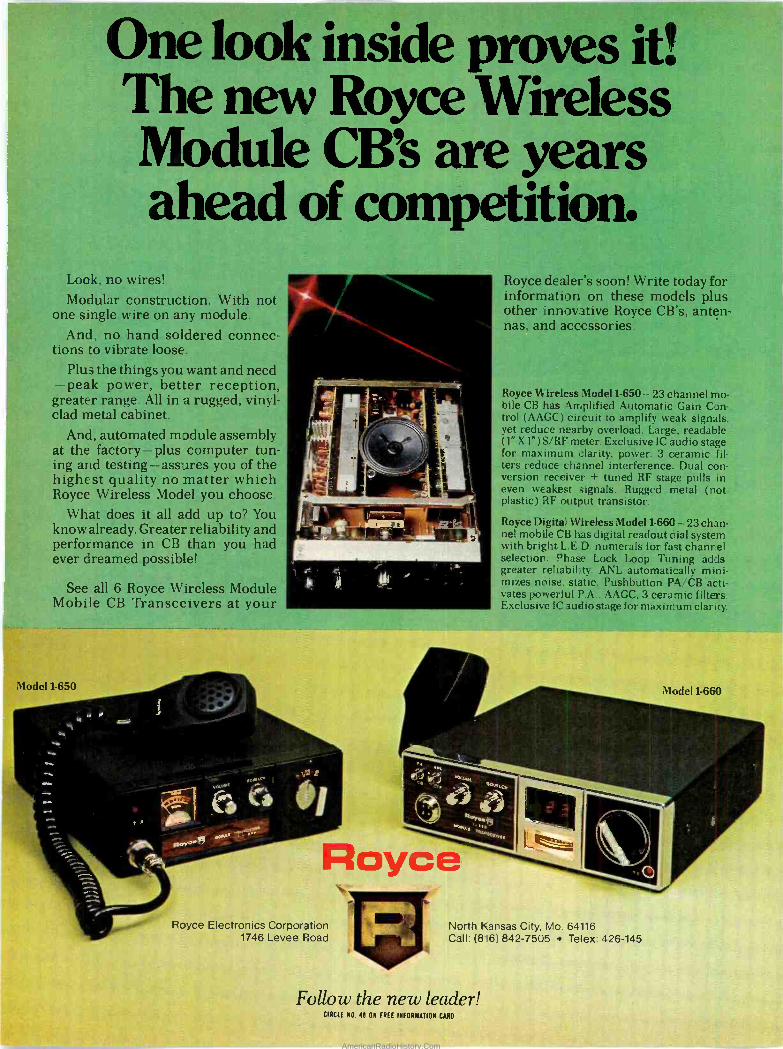
One look inside proves it! The new Royce Wireless Module CB's are years ahead of competitión.
Look, no wires! Modular construction. With not
one single wire on any module. 'And, no hand soldered connec-
tions to vibrate loose. Plus the things you want and need
-peak power, better reception, greater range. All in a rugged, vinyl- clad metal cabinet.
And, automated module assembly at the factory-plus computer tun- ing and 'testing =assures you of the highesf quality no matter'which Royce Wireless Model you. choose.
What does it 'all add up to? You know already. Greater reliability and performance in CB º than you had ever dreamed possible!
See all 6 Royce Wireless Module Mobile CB Transceivers at your
Model 1-650
r
,,.0
b.
_5
/.
a
Royce dealer's soon! Write today for information on these models plus -
other innovative Royce CB's, anten- nas, and accessories.
Royce Wireless Model 1-650-23 channel mo- bile CB has Amplified Automatic'Gain Con- trol (AAGC),circuit to amplify weak signals, yet reduce nearby overload. Large, readable (1" X l') S/RF meter. Exclusive IC audio stage for maximum clarity, power. 3 ceramic fil- ters reduce channel interference: Dual con-, version receiver + tuned RF stage pulls in even weakest signals. Rugged meta) (not plastic) RF output transistor.
Royce Digital Wireless Model 1-660 23 chan - nel mobile CB has digital readout dial system with bright L.E.D. numerals for fast channel selection. Phase Lock Loop Tuning adds greater reliability. ANL automatically mizes noise,- static. Pushbutton PA/CB acti- vates powerful P.A.. AAGC, 3 ceramic filters. Exclusive IC audio stage for maximum clarity.
- l. cr.
44 A \
Róycé Royce Electronics Corporation
1746 Levee Road North Kansas City, Mo. 64116 Call: (816) 842-7505 ± Telex: 426-145
Model 1-660
7
Follow the new leader! CIRCLE N0. 48 ON FREE INFORMATION CARD
AmericanRadioHistory.Com

II agine a microcomputer Imagine a microcomputer:with all the design savvy, ruggedness, and sophistication of the best minicomputers.
- Imagine a microcomputer supported by dozens of Interface, memory, and processor option boards. One that 'can be Interfaced to an indefinite number of peripheral devices Including dual floppy discs, CRT's, Ilne printers; cassette recorders, video displays, paper tape readers, teleprinters, plotters, and custom devices.
Imagine a microcomputer supported by extensive software Including Extended BASIC, Disk BASIC, DOS and a complete library of business, developmental, and industrial programs. '
imagine a microcomputer that will do everything a mini will do; only at a fractioh of the cost. You are imagining the AltatrTM'8800b. The Altair 8800b is here today, and it may very'well be the
mainframe of the 70's.
The Altair 8800b is a second generation design of the most popular microcomputer in the field, -the, Altair 8800. Built around the -8800A microprocessor, the Altair 8800b is an open ended machine that is compatible with all Altair 8800 hardware and software. It can be configured to match móst any system'need.
MITS' plug -In compatible boards for the Altair 8800b now Include: 4K static memory, 4K dynamic -memory, 16K static memory, multi -port serial interface, Multi -port parallel interface, audio cassette record interface, vectored interrupt, real time clock, PROM board, multiplexer, A/D convertor, extender card, disc controller, and line printer Interface.
MITS' peripherals`for the Altair 8800b include the Altair Floppy Disc, Altair Line Printer, teletypewriters, and the soon -to -be -announced Altair CRT terminal.
Introductory prices for the Altair 8800b are 6840 -for a kit with cómplete assembly instructions, and $1100 for an assembled unit. Complete documentation, membership into the Altair Users Club, subscription to "Computer Notes;' access to the Altair Software Library, and a copy of Charles J. Sippl'sMicrocomputer Dictionary are included. BankAmericard or Master Charge accepted for mall order sales.. Include $8 for postage'and handling:
Shouldn't you know more about the Altair 8800b7 Send for our free Altair Information Package, or contact one of our many retáli Altair Computer Centers.
mlts 2450 ALAMO S' E. ALBUQUERQUE, NEW MEXICO 87106 (505) 243-7821
)
Ann
PQS(R
O -- 1
_ O.lC7 A,Ae Anw' M u OW .,11 STACK .v0 LN y
1 I. 1 . ALIT 'eoA ,.,A», ne
o Al
DÓ an
- o .
Q LIS AI LIS AAA All AR Le U le A] AA
A AP A fYF A]
( Al. A,
- - . .- I ! ic'
---- /t ti. a Arn
flr!/1 1
C¡Cfts : s o o[13 f'
AmericanRadioHistory.Com

1'
Redesigned front panel. Totally synchro- nous logic design. Same switch and LED arrangement as original Altair 8800. New back -lit Duralith (laminated plastic and mylar, bonded to aluminum) dress panel with multi -color graphics. New longer, flat toggle switches. Five new functions stored on front panel PROM including: DISP_AY ACCUMULATOR (displays con- tents of accumulator), LOAD ACCUMU- LATOR (loads contents of the 8 data switches (A7-AO1-into accumulator), OUT- PUT aCUMULATOR (0J puts contents of accumulator to 1/0 device addressed by the upper 8 address switches), INPUT ACCUMULATOR (inputs to the accumu: lator from the I/O device), and SLOW' (causes program execution at a rate of -
about 5 cycles per second-for. program debuocing).
MOTE: Altair -is a trademart'Df MITS.
S°
4
f9
.. tt
Il f
411, j
' i t oY, .31o ó ` .
-) d ,
a +
:
Full 18 slot motherboard.
Tugged, commeréial grade Optima cabinet.
--Jew front panel interface board buffers all lines to and from -8800b bus
'Two; 34 conductor ribbon cable assem- blies. Connects frónt panel board to front Fanel interface board. Eliminates need fir complicated front panel/bus wiring.
áItair..
New, -maw duty power supply: +8 volts at "8 amps; + 18 volts at 2 amps, -18 volts at 2 amps. 110 volt or 220 volt operation (50/60 H_). Primary tapped for either hick or low lire operatics.
flew CPL board with 8083A micro- proce'ssor and Intel 8224clocc generator and 8216 bus crivers. Clock pulse widths and phasing as well as frequency are crystal contro led. Compatib e with all aurren: Altair 8800 software and hardwa-e.
2450 Alamo SE/Albuquerque, NM 87106/505-2437E21 Prizes. delivey and specifications abject to change.
AmericanRadioHistory.Com

New Products Additional information on new products covered in this section is available from -the manufacturers. Either circle the item's code number on the Reader Service Card inside the back cover or write to the man-
ufacturer at the address given.
B&K-PRECISION CB TEST INSTRUMENT
The B&K-Precision Model 1040 is a new test instrument designed for fast, efficient servicing of CB equipment. It features a
peak -indicating r -f wattmeter, dummy load, audio signal generator, and audio
o
`.. I I
wattmeter. When used with an oscillo- scope, stable r -f signal generator, and fre- quency counter, it becomes a complete CB service center. It tests r -f output power, AM and SSB modulation, and antenna SWR in the transmitter section. In the receiver sec- tion, it checks sensitivity (S/N ratio), audio output power and distortion, frequency re- sponse, agc and squelch action, and adjacent -channel rejection. All tests can be performed without changes in the initial connections to the transceiver. $250.
CIRCLE NO. 85 ON FREE INFORMATION CARD
FINNEY MOBILE FM SIGNAL BOOSTER
The Finney Co. "Stereo One" mobile FM
signal booster is designed to help elimi- nate signal fade and flutter associated with weak-signál FM reception. It can be used with any AM/FM car receiver without intro- ducing adverse effects to normal recep- tion. The device is said to more than triple the received signal level to provide clear FM reception in fringe signal areas. Even so, it is designed to avoid overloading the receiver in strong -signal areas. The two- piece Stereo One consists of an amplifier section that mounts close to the receiver and a small ON/OFF control box that self mounts where it is easily accessible.
CIRCLE NO. 86 ON FREE INFORMATION CARD
ADC REMOTE -CONTROL LOGIC TURNTABLE
The Audio Dynamic Corp. has introduced a
unique single -play turntable called the Ac- cutrac 4000. The direct -drive turntable
4i,
marries a digital -logic memory bank with an infrared generator and detector built into its special phono cartridge. The user can thus program which bands of an LP will be played in whatever desired se- quence. Electronic controls include: au- tomatic reject, cue and repeat, 13 track selection pushbuttons and separate all - tracks button, and 33 1/3- and 45 -rpm speed -selector buttons. A handheld remote -control transmitter and remote re- ceiver provide full track selection, reject, repeat, and cue control from a distance. Wow and flutter are reported to be less than 0.03% wrms, with DIN -weighted rum- ble down 70 dB. Tracking force range with the supplied cartridge is 3/4 to 11/2 grams, and low -capacitance wiring is used. Price is $499.95, which includes base and dust cover.
CIRCLE NO. 81 ON FREE INFORMATION CARD
GBC HIGH-PERFORMANCE CCTV CAMERA
The "Mini -Max" Model CTC-3000 from GBC Closed Circuit TV Corp. features 600 lines of resolution; 10,000:1 automatic light compensation; adjustable white clip; and automatic voltage regulation. The camera employs a Vidicon tube and fea- tures plug-in circuit module construction. The case is heavy die cast aluminum. The camera can be operated from 24-, 117-, and 220 -volt ac sources. When powered from a 24 -volt source, it allows installation with a
single cable as far away as 2500' (762 m) without 117 volts ac being required at the camera points. The camera includes a
16 -mm f/1.6 "C" mount lens. $199.50. CIRCLE N0. 88 ON FREE INFORMATION CARD
ROGERS ELECTRO-MATICS CB SWITCH!
The new solid-state "Killer" switching sy- stem from Rogers Electro-Matics permits hands -free operation of both AM/FM radio and CB transceiver in a car. The device can be actuated by an incoming CB call, which immediately switches the speaker(s) from the AM/FM radio to the CB rig. The mes- sage is then heard through the radio's speakers. The Killer can also be activated when the CB mike button is pressed. A
small time delay on drop -out prevents switching back and forth between words and transmissions, while virtually nc time delay on pull -in cuts off the first part of a
message. The Killer is designed to operate with almost all types of two-way radio sys- tems, monitor receivers, scanners, etc. It is capable of controlling two speakers operating either monaurally or in stereo. Price is $49.95.
CIRCLE NO. 89 ON FREE INFORMATION CARD
SIMPSON PORTABLE DIGITAL VOM
The Model 360 Series 2 from Simpson is a
31/2 -decade DMM designed for both bench and field use. It can be operated on ac line power or its own internal batteries. The in- strument has 29 ranges for measuring ac
I ----*,---77..-,,,,, - --,,
B. c1 9 1+
iy ; i=°4 +-_'-'`-s ... 1})
rms and dc voltage, ac and dc current, and resistance. The 0.43" (11 -mm) LED display automatically indicates polarity on ,ic and flashes when an overrange condition exists. All ranges are overload projected. Two low -power -ohms ranges (200 mV maximum full-scale voltage) allow the user to make in -circuit tests without biasing on most semiconductor junctions. A zero - center analog meter movement is provided for peaking and nulling operations. Special analog output terminals are provided for connection to a graphic recorder. S257.
CIRCLE NO. 91 ON FREE INFORMATION CARD
VERO INSTRUMENT CASES
PVC -clad steel instrument cases are now available in five sizes from Verc Elec- tronics, Inc. The three widths currently
12 POPULAR ELECTRONICS
AmericanRadioHistory.Com
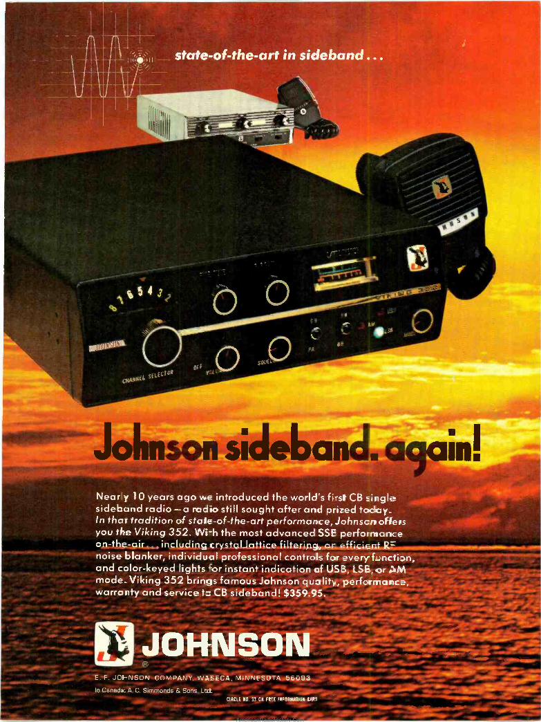
state-of-the-art in sideband . . .
dip
7 - In
I_"
YIC
-§iAvNEl 5EltCiOA
Johnson sid ba Nearly '10 years ago we introduced the world's first CB single sideband radio-a radio still sought after and prized tadmr_
- . In that tradition of stale -of -the -art performance, Johnscrr offers you the Viking 352. Wi-h the most advanced SSE performance op-the: air including crystgljattice-filtering,, on-efficient R= noise blanker, individual professional controls for every function, and color -keyed lights for instant indication of USB, LSE, or aliM mode_ Viking 352 brings famous Johnson quality, performance; warranty and service CB sideband! $359.95. -
;,JO E. F. JOI-NSON COMPANY, WASECA: MINNESOTA 56093 In Canada: A. C. Simmonds & Sonsr, Ltd.
CIRCLE N0. 33 ON FEE INFORMATION CU
- sr
Nano
AmericanRadioHistory.Com
The problem
solver
() .....
-.._.
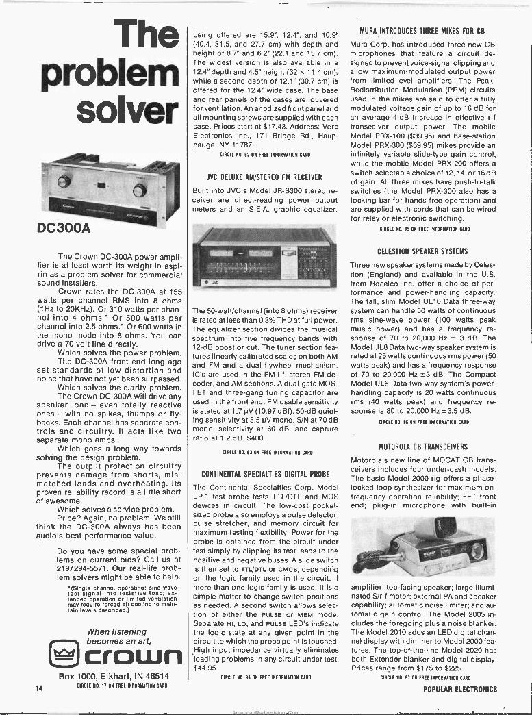
DC300A
The Crown DC -300A power ampli- fier is at least worth its weight in aspi- rin as a problem -solver for commercial sound installers.
Crown rates the DC -300A at 155 watts per channel RMS into 8 ohms (1Hz to 20KHz). Or 310 watts per chan- nel into 4 ohms.* Or 500 watts per channel into 2.5 ohms.* Or 600 watts in the mono mode into 8 ohms. You can drive a 70 volt line directly.
Which solves the power problem. The DC -300A front end long ago
set standards of low distortion and noise that have not yet been surpassed.
Which solves the clarity problem. The Crown DC -300A will drive any
speaker load - even totally reactive ones - with no spikes, thumps or fly - backs. Each channel has separate con- trols and circuitry. It acts like two separate mono amps.
Which goes a long way towards solving the design problem.
The output protection circuitry prevents damage from shorts, mis- matched loads and overheating. Its proven reliability record is a little short of awesome.
Which solves a service problem. Price? Again, no problem. We still
think the DC -300A always has been audio's best performance value.
Do you have some special prob- lems on current bids? Call us at 219/294-5571. Our real -life prob- lem solvers might be able to help.
*(Single channel operating; sine wave test signal into resistive load; ex- tended operation or limited ventilation may require forced air cooling to main- tain levels described.)
14
When listening becomes an art, crown
Box 1000, Elkhart, IN 46514 CIRCLE NO. 11 ON FREE INFORMATION CARD
being offered are 15.9", 12.4", and 10.9" (40.4, 31.5, and 27.7 cm) with depth and height of 8.7" and 6.2" (22.1 and 15.7 cm). The widest version is also available in a
12.4" depth and 4.5" height (32 x 11.4 cm), while a second depth of 12.1" (30.7 cm) is
offered for the 12.4" wide case. The base and rear panels of the cases are louvered for ventilation. An anodized front panel and all mounting screws are supplied with each case. Prices start at $17.43. Address: Vero Electronics Inc., 171 Bridge Rd., Haup- pauge, NY 11787.
CIRCLE NO. 92 ON FREE INFORMATION CARO
JVC DELUXE AM/STEREO FM RECEIVER
Built into JVC's Model JR-S300 stereo re-
ceiver are direct -reading power output meters and an S.E.A. graphic equalizer.
The 50-watt/channel (into 8 ohms) receiver is rated at less than 0.3%THD at full power. The equalizer section divides the musical spectrum into five frequency bands with 12 -dB boost or cut. The tuner section fea- tures linearly calibrated scales on both AM and FM and a dual flywheel mechanism. IC's are used in the FM i -f, stereo FM de- coder, and AM sections. A dual -gate MOS- FET and three -gang tuning capacitor are used in the front end. FM usable sensitivity is stated at 1.7 µV (10.97 dBf), 50 -dB quiet- ing sensitivity at 3.5 µV mono, S/N at 70 dB mono, selectivity at 60 dB, and capture ratio at 1.2 dB. $400.
CIRCLE N0. 93 ON FREE INFORMATION CARD
CONTINENTAL SPECIALTIES DIGITAL PROBE
The Continental Specialties Corp. Model LP -1 test probe tests TTL/DTL and MOS devices in circuit. The low-cost pocket - sized probe also employs a pulse detector, pulse stretcher, and memory circuit for maximum testing flexibility. Power for the probe is obtained from the circuit under test simply by clipping its test leads to the positive and negative buses. A slide switch is then set to TTL/DTL or cMos, depending on the logic family used in thé circuit. If
more than one logic family is Used, it is a simple matter to change switch positions as needed. A second switch allows selec- tion of either the PULSE or MEM mode. Separate HI, Lo, and PULSE LED's indicate the logic state at any given point in the circuit to which the probe point is touched. High input impedance virtually eliminates loading problems in any circuit under test. $44.95.
CIRCLE NO. 94 ON FREE INFORMATION CARD
MURA INTRODUCES THREE MIKES FOR CB
Mura Corp. has introduced three new CB microphones that feature a circuit de- signed to prevent voice -signal clipping and allow maximum modulated output power from limited -level amplifiers. The Peak - Redistribution Modulation (PRM) circuits used in the mikes are said to offer a fully modulated voltage gain of up to 16 dB for an average 4 -dB increase in effective r -f transceiver output power. The mobile Model PRX-100 ($39.95) and base -station Model PRX-300 ($69.95) mikes provide an infinitely variable slide -type gain control, while the mobile Model PRX-200 offers a
switch -selectable choice of 12, 14, or 16 dB of gain. All three mikes have push -to -talk switches (the Model PRX-300 also has a
locking bar for hands -free operation) and are supplied with cords that can be wired for relay or electronic switching.
CIRCLE NO. 95 ON FREE INFORMATION CARD
CELESTION SPEAKER SYSTEMS
Three new speaker systems made by Celes- tion (England) and available in the U.S. from Rocelco Inc. offer a choice of per- formance and power -handling capacity. The tall, slim Model UL10 Data three-way system can handle 50 watts of continuous 'rms sine -wave power (100 watts peak music power) and has a frequency re-
sponse of 70 to 20,000 Hz ± 3 dB. The Model UL8 Data two-way speaker system is rated at 25 watts continuous rms power (50 watts peak) and has a frequency response of 70 to 20,000 Hz ±3 dB. The Compact Model UL6 Data two-way system's power - handling capacity is 20 watts continuous rms (40 watts peak) and frequency re- sponse is 80 to 20,000 Hz ±3.5 dB.
CIRCLE NO. 96 ON FREE INFORMATION CARD
MOTOROLA CB TRANSCEIVERS
Motorola's new line of MOCAT CB trans- ceivers includes four under -dash models. The basic Model 2000 rig offers a phase - locked loop synthesizer for maximum on - frequency operation reliability; FET front end; plug-in microphone with built-in
O
amplifier; top -facing speaker; large illumi- nated S/r-f meter; external PA and speaker capability; automatic noise limiter; and au- tomatic gain control. The Model 2005 in- cludes the foregoing plus a noise blanker. The Model 2010 adds an LED digital chan- nel display with dimmer to Model 2000 fea- tures. The top -of -the -line Model 2020 has both Extender blanker and digital cisplay. Prices range from $175 to $225.
CIRCLE NO. 97 ON FREE INFORMATION CARD
POPULAR ELECTRONICS
AmericanRadioHistory.Com
1
.,. Y dr
:1- o
c A
''v r w.
: t..- -J
L-,1
.01 i
c , y _!L
- I9 . . . I ,' .
1'
Ja -;.."'Y':- "1" . I:4'A
? dt
.
I. '
Wien ~1.
.
ow 11'1) 1) OMB'.
3
``á- -.._m ̀
' ~ . ' ; ,,
t
e
`t.JY '
t..Lf r-
f LMii! !M '
3
. y
'''. , .ti -+ T x.,- t ....,N,
sy 4 w r- +;or\a.ry^'jc.
1 -= ;+ rL{.{ -- = .==-^
=- 7,1:1::::::'-V,w:>1
.
.1..':,:..!,,,...,11.:191..,..11:1:
'.Qt .r:::,.".i'
- k ' L. 1t,%. -
v -' 4° 7
17.. -Y " ¡e ?* . ,
+ . : ,y'.". ' t r. , '~ ..,. fi` '13..' - 3 Ly..L,.
IF P 1 7R °. ..- 7. s1 .% . It `. - f # , s,. LYa + " r. .. . . . .,
ra/ I-. :,. f`
.M.::.1... ^ ,.:.71,..,... it - ..
1.» ^ i- 4 1
,Y /'?,.r . I. , á
a r `
i u;:Y::le'Tal °,; ^ s.. ..... .f... S Y .
- - - ' '' '- t; .'. :a.. -.1
. '= -
- mo>=at o-rs.oan w
r 01~.. C1:91 °Z -z,
,r7
-
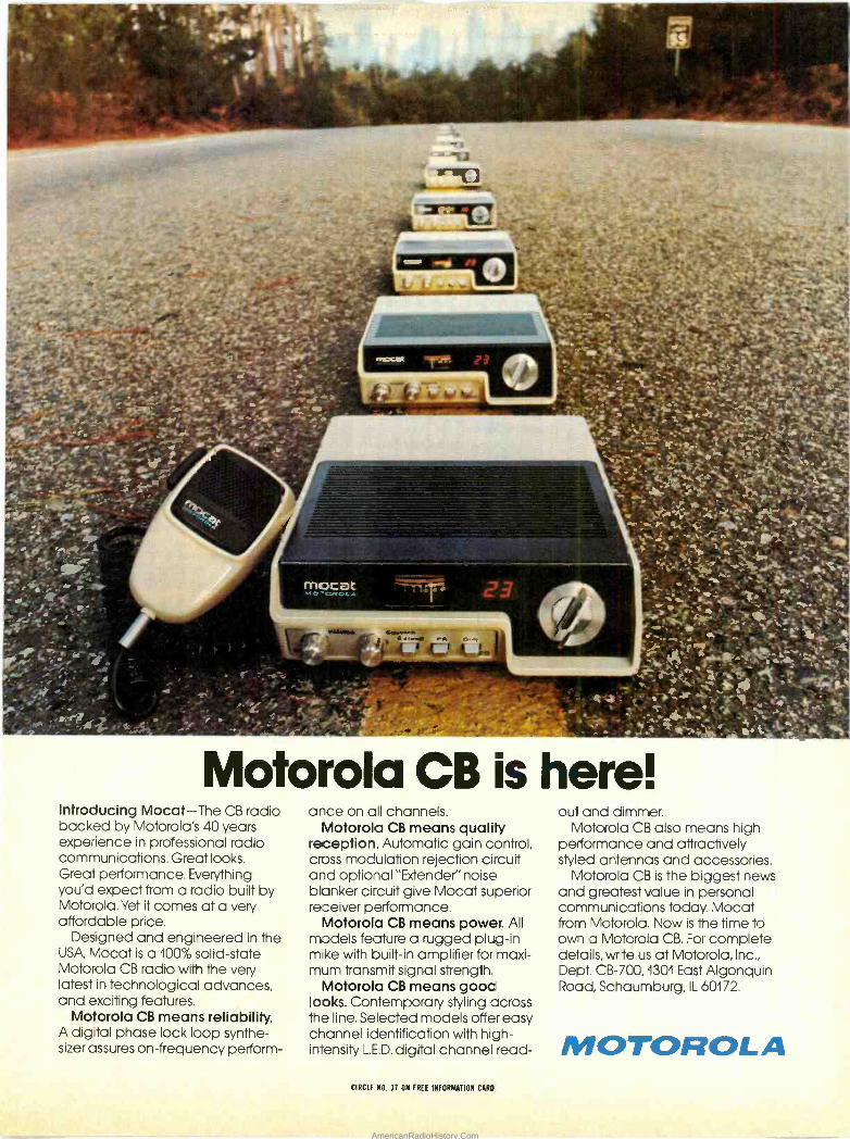
Motorola CB is here! Introducing Mocat-The CB radio backed by Motorola's 40 years experience in professional radio communications. Great looks. Great performance. Everything you'd expect from a radio built by Motorola. Yet it comes at a very affordable price.
Designed and engineered in the USA, Mocat is a 100% solid-state Motorola CB radio with the very latest in technological advances, and exciting features.
Motorola CB means reliability. A digital phase lock loop synthe- sizer assures on -frequency perform-
ance on all channels. Motorola CB means quality
reception. Automatic gain control, cross modulation rejection circuit and optional "Extender" noise blanker circuit give Mocat superior receiver performance.
Motorola CB means power. All models feature a rugged plug-in mike with built-in amplifier for maxi- mum transmit signal strength.
Motorola CB means gooc looks. Contemporary styling across the line. Selected models offer easy channel identification with high - intensity L.E.D. digital channel read-
out and dimmer. Motorola CB also means high
performance and attractively styled antennas and accessories.
Motorola CB is the biggest news and greatest value in personal communications today. Mocat from Motorola. Now is the time to own a Motorola CB. For complete details, write us at Motorola, Inc., Dept. CB -700,1301 East Algonquin Road, Schaumburg, IL 60172.
MOTOROLA CIRCLE NO, 37 ON FREE INFORMATION CARD
AmericanRadioHistory.Com
1111111111.-
New Literature PRINTED CIRCUIT ROTARY SWITCHES
An 8 -page brochure from Oak Industries describes its family of rotary printed circuit switches. A chart illustrates the 17
categories of conventional rotary switches available with terminations. Diagrams and pictures of Oak's line of pc and pcb switches are also shown including 12- and 24 -position models. Also covered is a
technique for attaching conductor cable to rotary switches, and advantages such as
compactness and elimination of harnes- sing are outlined. Address: Switch Divi- sion, Oak Industries, Inc. Crystal Lake, IL
60014.
ABOUT COMBINERS
"About Combiners," a new 20 -page book- let from Decibel Products, describes, in de- tail, various types of transmitter and re- ceiver combiners. The text, written for those engaged in two-way radio communi-
cations, but who are not engineers, in- cludes a nontechnical presentation of dif- ferent methods of combining a number of duplex or repeater and/or simplex systems on the same antenna. Address: Decibel Products, Inc. Box 47128, Dallas, TX 75247.
VHF EQUIPMENT CATALOG
Hamtronics' new catalog highlights vhf preamplifiers and FM communications subsystems for amateur and monitor ap- plications. Included in the catalog are a vhf preamp, a uhf grounded -gate preamp for the 400 -500 -MHz region (both available in kit or wired form), a uhf converter, a vhf receiver and a uhf/vhf model (all in kit form). Address: Hamtronics, Inc., 182 Bel- mont Road, Rochester, NY 14612.
SEMICONDUCTOR REPLACEMENT SUPPLEMENT
GTE Sylvania announces its ECG Semiconductor Replacement Guide Sup- plement No. 1 (ECG 212F-1). Designed as a
quick reference for technicians, engineers and hobbyists, the 18 -page booklet in- cludes substitute components for transis- tors, gate -controlled switches and inte- grated circuits for communications, audio, television and industrial applications. The booklet contains a product index, device specifications, package line drawings and dimensions, pin designations and a com- ponent cross-reference. A list of errata to
Replacement Catalog "ECG212F is in- cluded, as well as a list of additions and deletions which reflect changes in the Syl- vania ECG semicondudtor line. Available. for 35 cents from the GTE Sylvania Adver- tising Services Center, 70 Empire Dr., West Seneca, NY 14224.
SCAN CONVERTER TRANSCEIVER
Robot Research, Inc. offers complete liter- ature on its Model 300 Scan Converter Transceiver. Used in conjunction with any black -and -white monitor (or commercial TV receiver), this $995 - converter can transmit pictures anywhere by telephone. Pictures have 256 -line resolution. An entire image can be transmitted full -frame in 34 seconds or half -frame in 17 seconds. Ad- dress: Robot Research, Inc., 7591 Convoy Ct., San Diego, CA 92111.
CONTROL KNOBS CATALOG
Radial Controls offers a 16 -page catalog illustrating its line of control knobs. Cov- ered are low -profile knobs of uniform height, as well as calibrated, spinner, pointer and bar knobs. All are available in round, skirted, wing and concentric styles. Custom designs and optional indexing marks are also described. The catalog illus- trates each knob and provides dimensional data. Address: Radial Controls, 2555 East 55th Pl., Indianapolis, IN '46220..
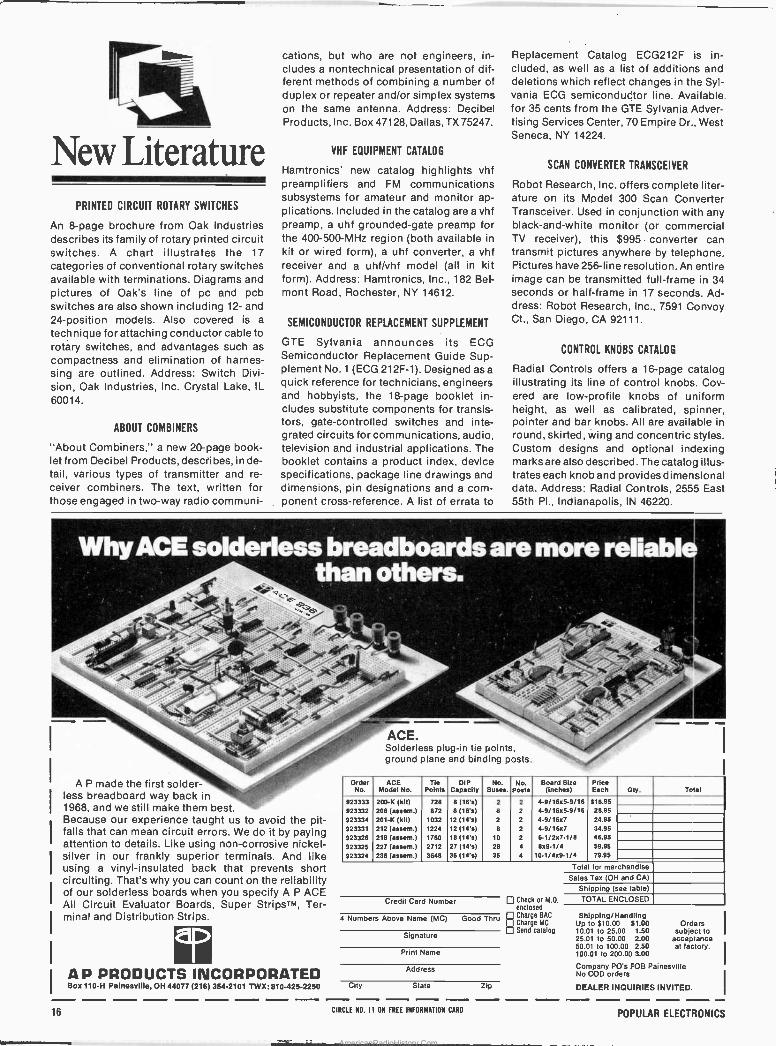
Why ACE' sóldérléss'.bréadbóards aré .rñóré : r_ éÍiábi than others: . .
A P made the first solder - less breadboard way back in 1968, and we still make them best. Because our experience taught us to avoid the pit- falls that can mean circuit errors. We do it by paying attention to details. Like using non -corrosive nickel - silver in our frankly superior terminals. And like using a vinyl -insulated back that prevents short circuiting. That's why you can count on the reliability of our solderless boards when you specify A P ACE All Circuit Evaluator Boards, Super StripsTM, Ter- minal and Distribution Strips.
A P PRODUCTS INCORPORATED Box 110-H Painesville, OH 44077 (216) 354-2101 TWX: 810-425-2250
16
ACE. Solderless plug-in tie points, ground plane and binding posts.
Order No.
ACE Model No.
Tie Points
DIP Capacity
No. 3uses.
No. Posts
Board Size (inches)
Price Each Oly. Total
923333 200-K (kit) 728 8 (16's) 2 2 4-9/16x5-9/16 518.95 923332 208 (assem.) 872 8 (16'5) 8 2 4-9/16x5-9/16 28.95
923334 201-K (kit) 1032 12 (14's) 2 2 4-9/16x7 24.95
923331 212 (assem.) 1224 12 (14's) 8 2 4-9/16x7 34.95
923326 218 (assem.) 1760 18 (14's) 10 2 6-1/2x7-1/8 46.95
923325 227 (assem.) 2712 27 (14's) 28 4 809-1/4 59.95
923324 236 (assem.) 3648 36 (14's) 36 4 10-1/4x9-1/4 79.95
Total for merchandise
Sales Tax (OH and CA)
Shipping (see table)
Credit Card Number Check or M.O. TOTAL ENCLOSED
4 Numbers Above Name (MC)
Signature
enclose
Good Thru Charge BAC E Charge MC
Send catalog
Print Name
Address
City State Zip
CIRCLE N0. 11 ON FREE INFORMATION CARO
Shipping/Handling Up to $10.00 51.00 Orders 10.01 to 25.00 1.50 subject to 25.01 to 50.00 2.00 acceptance 50.01 to 100.00 2.50 at factory. 100.01 to 200.00 3.00
Company PO's FOB Painesville No COD orders
DEALER INQUIRIES INVITED.
POPULAR ELECTRONICS
AmericanRadioHistory.Com
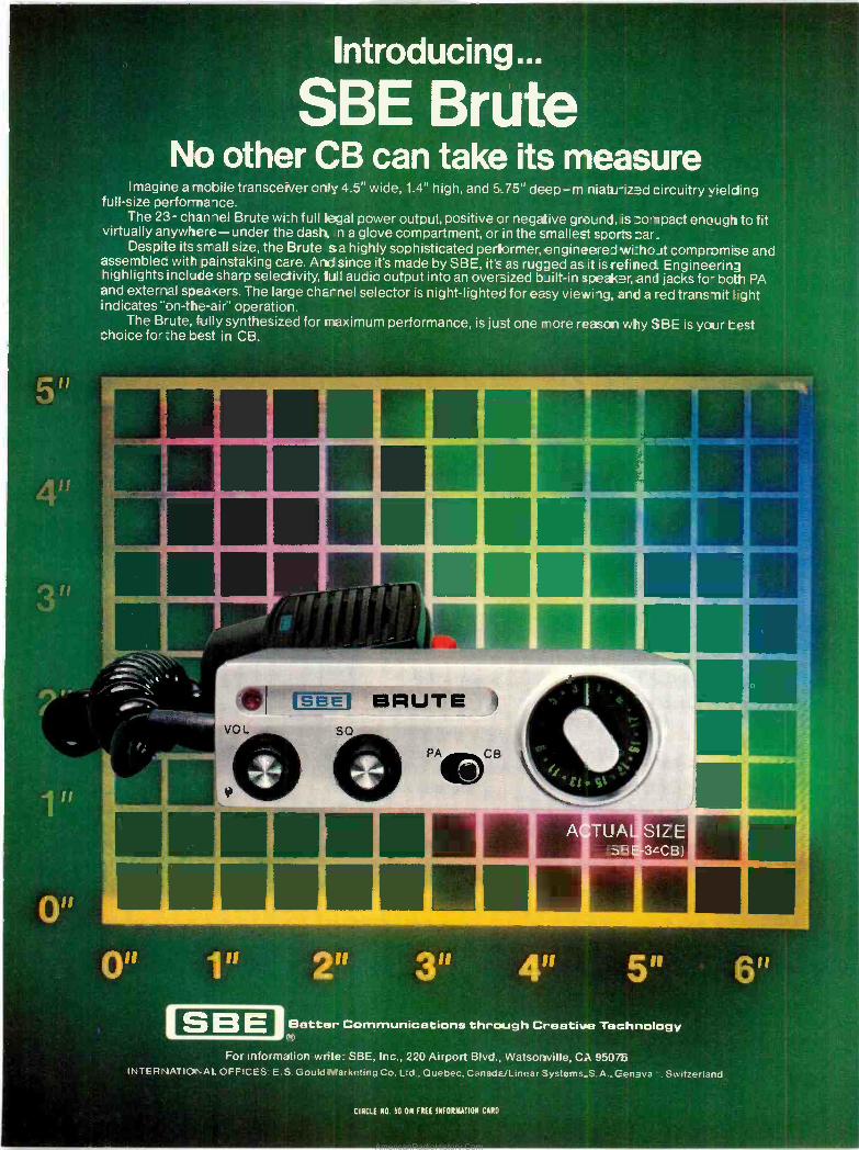
Introducing...
SBE. Brúté No other CBcafl táke its measure
Imagine a mobile transceiver only 4.5" wide, 1.4" high,'and 5.75" deep-m-niatu-ized circuitry vieldíng full-size performance. '
The 23- channel Brute wi:h full legal power output, positive or negative ground, is compact enough to fit virtually anywhere-under the dash, to a glove compartment, or in the smallest sports oar.
Despite its small size, the Brute sa highly sophisticated pertlormer, engineeredwi:hout compromise and assembled with painstaking care. And since it's made by SBE, its as rugged as it is refined_ Engineering highlights include sharp selectivity, lull audio output into an oversized built-in speaicer,and jacks fo- both PA and external spea..cers. The large charnel selector is night -lighted for easy viewing, and a red transmit light indicates "on -the -air" operation.
The Brute, fully synthesized for maximum performance, is just one more.reason why SBE is ycUr test choice for :he best in CB.
1f
11 '
r 4. 11,
VOL
1"
SBE
E--_ 4 BRUTE
J {
2" , 3" 4" Bettar,Communications through Creative Technology'
For information write: SBE, Inc., 220 Airport Blvd., Watsonville, Ca 9507B INTERNATIONAL OFFICES: E.S. GouldMarketing Co. Ltd., Quebec, Canada/Linear Systems.S.A..Geneva Switzerland
CIRCLE NO. 50 ON FREE INFORMATION CARO
o
I
AmericanRadioHistory.Com
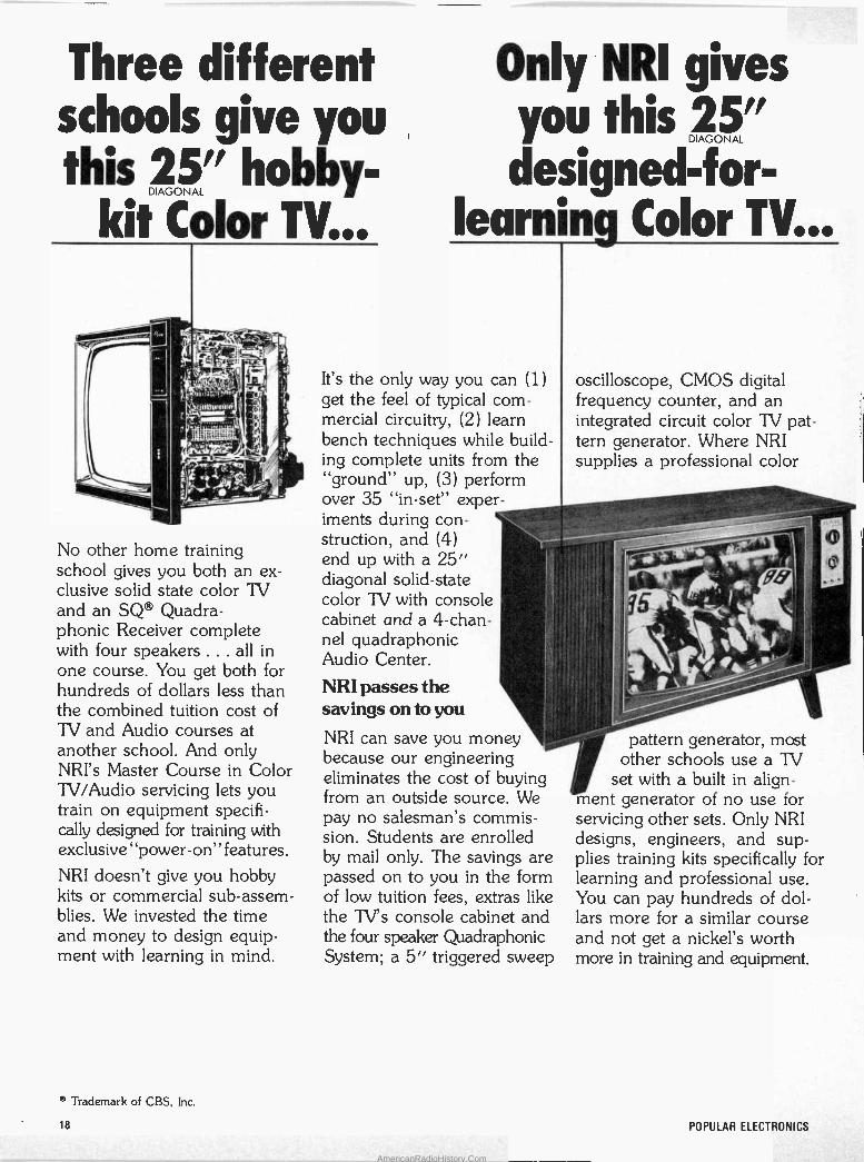
Three different schools give you this " hobby-
Color TV...
No other home training school gives you both an ex- clusive solid state color TV and an SQ® Quadra- phonic Receiver complete with four speakers ... all in one course. You get both for hundreds of dollars less than the combined tuition cost of TV and Audio courses at another school. And only NRI's Master Course in Color TV/Audio servicing lets you train on equipment specifi- cally designed for training with exclusive "power -on" features.
NRI doesn't give you hobby kits or commercial sub -assem- blies. We invested the time and money to design equip- ment with learning in mind.
Only NRI gives you this 15" designed-for-
earnin Color TV...
It's the only way you can (1) get the feel of typical com- mercial circuitry, (2) learn bench techniques while build- ing complete units from the
ground" up, (3) perform over 35 "in -set" exper- iments during con- struction, and (4) end up with a 25" diagonal solid-state color TV with console , cabinet and a 4 -chan- nel quadraphonic Audio Center.
NRI passes the savings on to you
NRI can save you money because our engineering eliminates the cost of buying from an outside source. We pay no salesman's commis- sion. Students are enrolled by mail only. The savings are passed on to you in the form of low tuition fees, extras like the TV's console cabinet and the four speaker Quadraphonic System; a 5" triggered sweep
oscilloscope, CMOS digital frequency counter, and an integrated circuit color TV pat- tern generator. Where NRI supplies a professional color
pattern generator, most other schools use a TV
set with a built in align- rent generator of no use for servicing other sets. Only NRI designs, engineers, and sup- plies training kits specifically for learning and professional use. You can pay hundreds of dol- lars more for a similar course and not get a nickel's worth more in training and equipment.
' Trademark of CBS, Inc.
18 POPULAR ELECTRONICS
AmericanRadioHistory.Com

More know-how per dollar That's what it all boils down to, the quality of training you get for the money you spend. In our 62 -year history, more than a million students have come to NRI and we're fully approved for career study under the G.I. Bill. We must be teaching something right: Some of those "right" things are bite -size lessons to ease understanding and speed learning ... personal consul- tation, and prompt grading of all tests ... a full-time staff of engineer/instructors to help if you need it ... plenty of kits and experiments to give you hands-on training .. and fully professional a
,
...plus complete Quadraphonic Audio Center!
programs oriented to full or part-time career needs. Widest Choice of Courses with Communications, CB, Digital Computer, and other careers.
4.$ :
{ y sy ell'
NRI offers not one, but five excellent TV/Audio servicing courses so you can tailor your training to your budget.
, C7 -.:17:1111.0t:"
.401131 "r.
Or you can study other opportunity fields like Digital Computer Electronics, Citi- zens Band Radio, Commu-
nications, Aircraft or Marine Elec- tronics, Mobile Ra-
-. dio, and more. Send
,:.i for our free_ cata- lag and see for yourself that no one gives you more training and equip-
ment for your dollar. There's no obligation, and no sales- man will call.
If card is missing, write to:
NRI NRI SCHOOLS McGraw-Hill Continuing Education Center 3939 Wisconsin Avenue, Washington, D.C. 20016
JULY 1976 21
AmericanRadioHistory.Com
00: il
Stereo Scene
PERFECTING PHONO
FROM all indications, the prin- cipal program source for most
hi-fi listeners is still the phonograph record. This is sensible, because phono discs continue to offer the (potentially) best signal-to-noise ratio of any consumer -available recording medium. But it is also nonsensical because the motional stability of most record -playing systems ranges from poor to abominable. By this, I don't mean to say that turntables suffer excessively from wow and flutter. On the contrary, most of them are excellent in this respect. I do mean that the typical cartridge/tonearm/ turntable/record combination is troubled by what might be termed wow and flutter, and worse.
The Insidious Jiggle. In an ideal record -playing system, only two things move: the turntable platter, which spins the record at a uniform rate, and the phono stylus, which gets buffeted around by the record groove in a (hopefully) musical way. In a real record -playing system, everything moves. The turntable base shudders with the seismic impact of traffic passing outside and other stimuli. The motorboard, even if it is well isolated from the base by spring mounts and dampers, sings the tune of the motor's vibrational rate as well as the acoustic feedback from the loudspeakers. And the tone arm, under the influence of all these inputs, plus the warps and wriggles of the record, does a dance all its own. Usually you can observe this dance by watching the stylus closely as it plays a record. The bobbing around that it does has nothing to do with information in the record groove; it's a sign that the tone arm is moving grossly relative to the stylus tip, which it should not do.
This insidious jiggle has three effects. First, it generates within the cartridge infrasonic output signals of very high intensity. These are of
By Ralph Hodges
course boosted by the RIAA equaliza- tion in the phono preamplifier, posing a serious threat of distortion or overdrive to subsequent stages and transducers. Second, the jiggle "modulates" the recorded informa- tion on the record. Third, it reduces the cartridge/record-groove align- ment to complete ambiguity. Up to a
few years ago this was probably a
relatively minor side effect, but with modern stylus shapes there is mount- ing evidence that alignment is a cause for greater concern than heretofore.
The infrasonic signals are obvious enough on an oscilloscope. Often they even show up on the output -level meters of amplifiers equipped with them. The amount of trouble they cause depends heavily on the charac- teristics of the individual system, but in any case they are a persuasive argument for the use of sharp in- frasonic cutoff filters in phono preamplifiers-features that are still all too rare in currently available equipment.
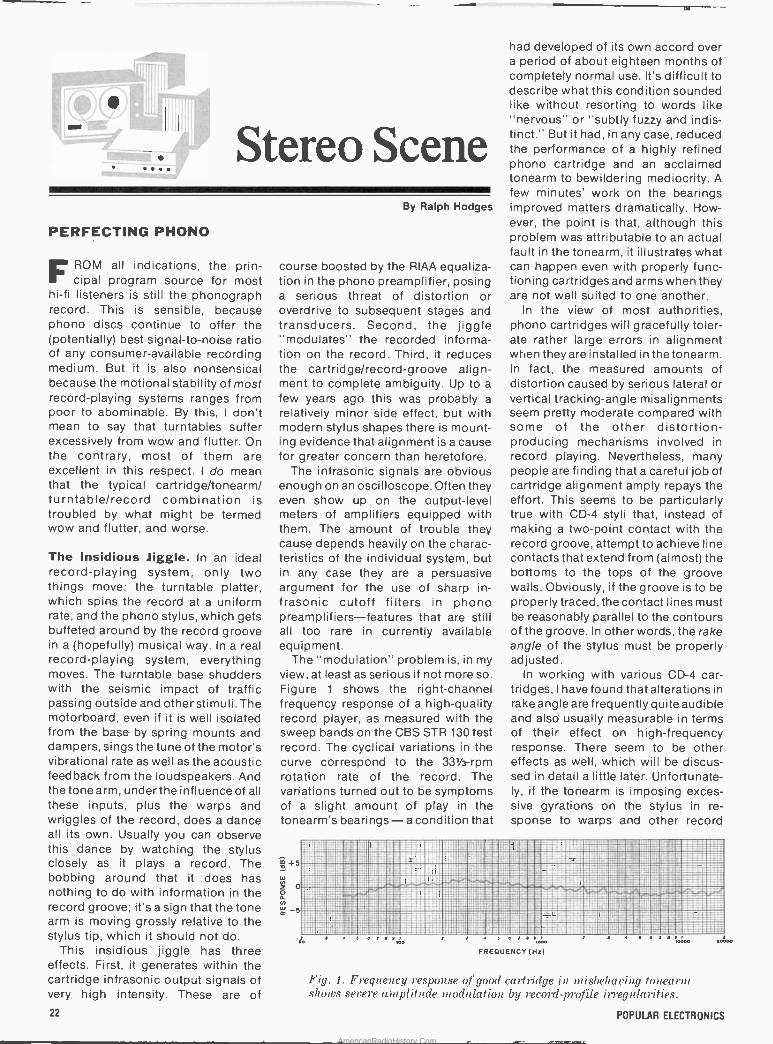
The "modulation" problem is, in my view, at least as serious if not more so. Figure 1 shows the right -channel frequency response of a high -quality record player, as measured with the sweep bands on the CBS STR 130 test record. The cyclical variations in the curve correspond to the 331 -rpm rotation rate of the record. The variations turned out to be symptoms of a slight amount of play in the tonearm's bearings- a condition that
had developed of its own accord over a period of about eighteen months of completely normal use. It's difficult to describe what this condition sounded like without resorting to words like "nervous" or "subtly fuzzy and indis- tinct." But it had, in any case, reduced the performance of a highly refined phono cartridge and an acclaimed tonearm to bewildering mediocrity. A few minutes' work on the bearings improved matters dramatically. How- ever, the point is that, although this problem was attributable to an actual fault in the tonearm, it illustrates what can happen even with properly func- tioning cartridges and arms when they are not well suited to one another.
In the view of most authorities, phono cartridges will gracefully toler- ate rather large errors in alignment when they are installed in the tonearm. In fact, the measured amounts of distortion caused by serious lateral or vertical tracking -angle misalignments seem pretty moderate compared with some of the other distortion - producing mechanisms involved in record playing. Nevertheless, many people are finding that a careful job of cartridge alignment amply repays the effort. This seems to be particularly true with CD -4 styli that, instead of making a two -point contact with the record groove, attempt to achieve line contacts that extend from (almost) the bottoms to the tops of the groove walls. Obviously, if the groove is to be properly traced, the contact lines must be reasonably parallel to the contours of the groove. In other words, the rake angle of the stylus must be properly adjusted.
In working with various CD -4 car- tridges, I have found that alterations in rake angle are frequently quite audible and also' usually measurable in terms of their effect on high -frequency response. There seem to be other effects as well, which will be discus- sed in detail a little later. Unfortunate- ly, if the tonearm is imposing exces- sive gyrations on the stylus in re- sponse to warps and other record
r,:---*
r.
II', -. .
r
'.JtlHr : .F,: _ . ;..' .; .i,, ___ :... Piiii.'ii! ' iMi1l: . __:- ` i.q¡®,-' º ; -- a::--_ _INEH_11_
10 0
FREQUENCY(Hz) 10 o
Fig. 1. Frequency response of good cartridge in misbehaving tonearm shows severe amplitude modulation by record -profile irregularities.
22 POPULAR ELECTRONICS
AmericanRadioHistory.Com
hat's 4 -han
ansui is.
ne
Sansui is already the leading name in advanced high performance 4 -channel sound reproduction and technology. And only with Sansui's exclusive QS vario matrix system can you enjoy the full potential of quad- raphonic sound. But there is still always something new in the Sansui world of 4 -channel.
Now every Sansui 4 -channel receiver and the new QSD-1 decoder from Sansui incorporate the unique QS vario matrix circuitry. Now you can synthesize brilliantly clear 4 -channel from any mono or stereo source to create a 4 -channel library in a moment. Any 4 -channel matrix source material, QS- or SQ- encoded records, tapes and broadcasts, can be effectively decoded by any of Sansui's remarkable QRX receivers. These receivers also incorporate circuitry to demodulate CD -4.
All 4 -channel Sansui receivers command excel- lent cost -to -performance ratios. The QRX-70011, at less than $880.00* delivers a full 35 watts per channel, min. RMS, all channels driven into 8 ohms, from 20Hz to 20kHz with no more than 0.4% total harmonic distortion. Every design element of this outstanding receiver lives up to Sansui's reputation for advanced high quality high fidel-
QRX-5001
"G
QRX-6000.1.00.!'
o.;
on nel?
ity performance. Available in the same series are the QRX-60011, at less than S760.00,* and the QRX-50012, at less than $600.00,* with many of the same outstanding features.
Sansui'slnewIQSD-1 is the most exciting and ef- fective decoder available today. Its QS vario matrix allows for very high inter -channel separation, as high as 20dB betweer adjacent channels and 30dB across the diagonally opposite channels, without any of the annoy- ing side effects found in other decoders.
-Jir ,
S..W o
® IiMRt crmuim R[Ru 1 -I ® Quadraphonic sound is all around you. More
than 70 FM stations now broadcast in the QS 4 -channel way 24 hours a day. Hundreds of quadraphonic en- coded records have been released - rock, classical, jazz, country, and "beautiful" music.
Stop in soon at your nearest Sansui franchised dealer to hear what Sansui 4 -channel equipment can do. Whatever your preference, surround or hall, what- ever your needs - synthesize, decode, or demodulate - Sansui 4 -channel can do it all - and do it best.
o
111 , r.U elN1
.. t' .. ... I . , ®r
_. .
:0 _...__..r.- o Anr,oro ;.á . - -`-
;,iil fIlitiiiiiillll\1iz;\ le , -:o 11 n CCC .
11
e,--l__.ri =w..,_ _- AA A nAAnAA a s ® - fr 1 f j l k::._.1-..,v 11 f 1. o f non i<.
C 1, .. 1. simulated walnut grain wood cabinet f 2. all metal cabinet with simulated walnut grain *The value shown is for informational purposes only. The actual resale price will be set by the individual Sansui dealer at his option.
a
I:1171-.1-o.vo_o: -;::--1.":.."..,_ 15.-1-:.;.1-14--1,; fI 1 N .3 a ^T*r" a^¡ .:..
I'
SANSUI ELECTRONICS CORP. Woodside, New York 11377 Gardena, California 90247
SANSUI ELECTRIC CO., LTD., Tokyo, Japan SANSUI AUDIO EUROPE S.A., Antwerp, Belgium In Canada: Electronic Distributors
1
I
'
'.Q.ttsFu i JULY 1976 CIRCLE NO. 52 ON FREE INFORMATION CARD
23
AmericanRadioHistory.Com
undulations, the rake angle won't have any fixed value. Instead, it will change radically as the stylus can- tilever squashes (down and springs back up. The unappetizing prospect is that of a system in which record warps "modulate" the playback signal with tracing errors! Usually this is heard as an unsteadiness in the noise (tape hiss, for example) that exists on many records and which should have a very smooth and uniform character. Usu- ally it is a bit too subtle to be identified readily in the musical information, although its presence tends to cause in the listener a vague feeling that all is not quite right.
Arm -Cartridge Resonance. The first step to take to avoid tonearm misbehavior is to adjust the arm's effective mass so that it interacts with the stylus compliance and produces a
resonant frequency somewhat above 10 Hz but below 20 Hz. This range of frequencies is below that of the recorded information and above that of most warps and record -surface irregularities. Thus the arm -cartridge combination, with no stimulus to set it off, will theoretically behave in a very stable manner.
There are a few commercially available record players designed to meet this criterion, and hearing them at their best can be a genuine revelation. Unfortunately, however, this ideal condition is almost never achieved by accident. It must be designed into the arm and cartridge in anticipation of their being used to- gether. Most top-quality cartridges are so compliant (and most tonearms so massy) that the resonance falls con- siderably below 10 Hz, where record warps can drive the system crazy.
Human nature being what it is, it's unlikely that many people will start selecting cartridges solely on the basis of how well they suit their tonearms' effective mass (although this may be a very logical way to as- semble a high-performance system).
t5 W
Z 0
á N
-5
110
24
Instead, audiophiles are resorting to such stratagems as arm modifications to reduce effective mass and, recently, to tonearm damping.
A few tonearms, mostly of English origin, are designed with damped pivots. Others can have damping added, the usual procedure being to attach a "paddle" to the arm that dips down into a reservoir of some suitably viscous fluid. There is every reason to believe that damping can help with problem record players, but the amount must be worked out empirical- ly, too much being as bad in its way as too little. It is also of limited or doubtful effectiveness with certain specific tonearm problems, such as the sloppy bearings of Figure 1, or tonearm resonances that extend up into the audible range. Spectrum analyses made on some tonearms have shown significant resonant con- tributions extending well past 1000 Hz. The effects of these resonances (when audible) run the gamut from a
muddying of the sound to an increase in the system noise level. Moreover, they are exceedingly difficult to pin down without the assistance of a good spectrum analyzer.
Flex Mounting. Before getting into the complications of arm damping (which indeed may be necessary to coax the system into performing at its peak), it's worthwhile to experiment with some simpler ways of nullifying the tonearm's troubles. To begin with, installing the cartridge with nylon mounting hardware will reduce the coupling between cartridge and arm and also usually bring about a reduction in overall mass. This ap- proach can be carried a step further with the use of adhesive foam.
This foam, which comes in rolls about an inch wide by a little under 1/8
inch thick with a strong adhesive on both sides, can be used to mount the cartridge in the arm without screws. If the cartridge requires standoffs for proper alignment the foam can be
FREQUENCY (Hz)
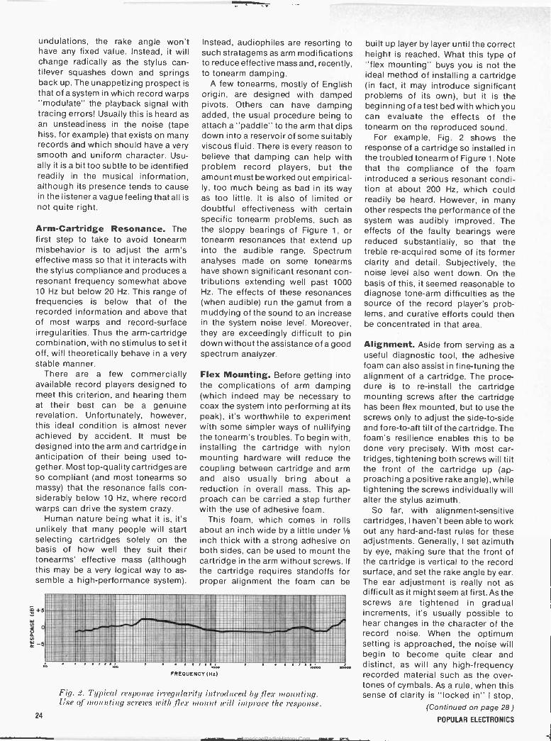
Fig. 2. Typical response irregularity introduced by. flex mounting. Use of mounting screws with .flex mount will improve the response.
built up layer by layer until the correct height is reached. What this type of "flex mounting" buys you is not the ideal method of installing a cartridge (in fact, it may introduce significant problems of its own), but it is the beginning of a test bed with which you can evaluate the effects of the tonearm on the reproduced sound.
For example, Fig. 2 shows the response of a cartridge so installed in the troubled tonearm of Figure 1. Note that the compliance of the foam introduced a serious resonant condi- tion at about 200 Hz, which could readily be heard. However, in many other respects the performance of the system was audibly improved. The effects of the faulty bearings were reduced substantially, so that the treble re -acquired some of its former clarity and detail. Subjectively, the noise level also went down. On the basis of this, it seemed reasonable to diagnose tone -arm difficulties as the source of the record player's prob- lems, and curative efforts could then be concentrated in that area.
Alignment. Aside from serving as a
useful diagnostic tool, the adhesive foam can also assist in fine-tuning the alignment of a cartridge. The proce- dure is to re -install the cartridge mounting screws after the cartridge has been flex mounted, but to use the screws only to adjust the side -to -side and fore -to -aft tilt of the cartridge. The foam's resilience enables this to be done very precisely. With most car- tridges, tightening both screws will tilt the front of the cartridge up (ap- proaching a positive rake angle), while tightening the screws individually will alter the stylus azimuth.
So far, with alignment -sensitive cartridges, I haven't been able to work out any hard-and-fast rules for these adjustments. Generally, I set azimuth by eye, making sure that the front of the cartridge is vertical to the record surface, and set the rake angle by ear. The ear adjustment is really not as difficult as it might seem at first. As the screws are tightened in gradual increments, it's usually possible to hear changes in the character of the record noise. When the optimum setting is approached, the noise will begin to become quite clear and distinct, as will any high -frequency recorded material such as the over- tones of cymbals. As a rule, when this sense of clarity is "locked in" I stop,
(Continued on page 28 )
POPULAR ELECTRONICS
AmericanRadioHistory.Com
EPC Electronic
Parts
Sant t'
switch
Controls and £witches
= E'G -1-- `, - - ,IYR t1INCC o .1,- .bc; OA_ ' 4. UMW x -a Iis MaiuiFY j ^ NaioRY
IJ.~."'--....;,,...-La..,'"
=- --_- -'Rf sarrpom MatioRY" e w-R p mar $ _ ...___-- -
-
'_T_---' - AilloRY'_... MaIToRY ' .
IbaleRY
°'" _ ... Merchandise Cabinets.
T'--'".:- s = ._ I - Iñt_3'aYJ MañoR!
MALLORY
Sonalert" Audible Signals
O
MO er,.
MóRY _
Duraeel' Batteries
Duratape - -
and Fliptapee Cassettes
r M1
p t
lij r
PTC Semiconductors
-
Mallobins
".1 r...
_r Rechargeable , Bat eries
Resistor
y I `
_" ^ -- Capacitors
r' -
Mallory-Richco Fastening Devices
With á line like this; no wonder your Mallory distributor is a yes man.
He- almost never has to say no.- Which' adds up -to a. lot of süngle-source buying convenience for you.
Give your Mallory distributor a call. You'll like what you hear. You'll like what he delivers.
MALLORY MALLORY DISTRIBUTOR PRODUCTS COMPANY a division of P. R. MALLORY & CO. INC. Box 1284. Indianapolis. Indiana 46206; Telephone: 317.856.3731
JULY 1976
5) Registered trademark of P. R. Mallory 8 Co. Inc.
CIRCLE NO. 95 011 FREE INFORMATION CARD 25
AmericanRadioHistory.Com
..
r",.._5^C.;)
bSGpE0 Ettcroohrct
AmericanRadioHistory.Com
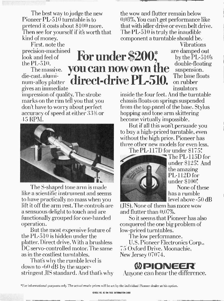
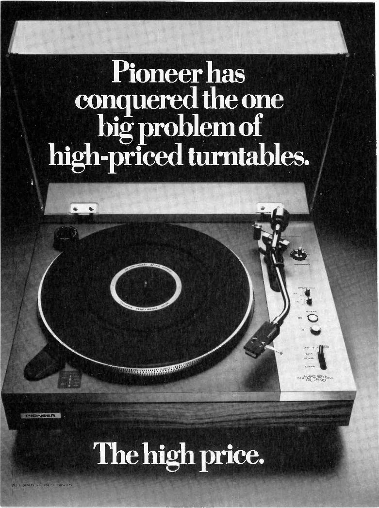
The best way to judge the new the wow and flutter remain below Pioneer PL -510 turntable is to 0.03%. You can't get performance like pretend it costs about $100 more. that with idler drive or even belt drive. Then see for yourself if it's worth that The PL -510 is truly the inaudible kind of money. component a turntable should be.
First, note the Vibrations precision -machined a are damped out look and feel of For under $200*by the PL -510's the PL -510. double -floating
The massive,you can now own the suspension. die-cast, alumi- direct drive PL-510.The base floats num-alloy platter on rubber gives an immediate impression of quality. The strobe marks on the rim tell you that you donft have to worry about perfect accuracy of speed at either 33V3 or 45 RPM.
411"1,
_:11111111k
The S-shaped tone arm is made like a scientific instrument and seems to have practically no mass when you lift it off the arm rest. The controls are a sensuous delight to touch and are functionally grouped for one -handed operation.
But the most expensive feature of the PL -510 is hidden under the platter. Direct drive. Vs, ith a brushless DC servo -controlled motor. The same as in the costliest turntables.
That's why the rumble level is down to -60 dB by the super - stringent JIS standard. And that's why
insulators inside the four feet. And the turntable chassis floats on springs suspended from the top panel of the base. Stylus hopping and tone arm skittering become virtually impossible.
But if all this won't persuade you to buy a high-priced turntable, even without the high price, Pioneer has three other new models for even less.
The PL -117D for under $175. The PL -115D for under $125*. And the amazing PL -112D for under $100*
.r ,. None of these has a rumble level above -50 dB
(JIS). None of them has more wow and flutter than 0.07%.
So it seems that Pioneer has also conquered the one big problem of low-priced turntables.
The low performance. U.S. Pioneer Electronics Corp.,
75 Oxford Drive. Moonachie, New Jersey, 07074.
ID PIONEER Anyone can hear the difference.
*For informational purposes only. 'The actual resale prices will be set by the individual Pioneer dealer at his option.
CIRCLE -NO. 62 ON FREE INFORMATION CARD
AmericanRadioHistory.Com

although some of my correspondents go to much greater lengths, optimiz- ing the rake angle for every record they play.
Ultimately, after going through this procedure (provided your cartridge is one of those that benefits from it), you will have a good idea of how the cartridge should be aligned when you remove the foam and re -install it in the conventional way. Or, as sometimes happens, you may find the flex mount has no deleterious effects on system
performance, in which case you can retain it.
Maintenance. Even with a record player that has been carefully aligned and damped as necessary, there may be a tendency for performance to go downhill over a period of time. The usual reason for this is, again, that something is moving that shouldn't. Check the cartridge shell to see that it is securely fixed to the bódy of the arm. Then grasp the shell and tug on it
Swedish -designed quality in cb accessories, too!
3
4
11-?
00 «0 9
: hañdic®
U.S.A inc.
10
IMpinl;lilllllllll
li,lhr
12
1) FS -11 7 Universal Tester- It's a power meter; SWR: a modulaban meter a crystal condition tester; and a tone Ireq'y plus 27MHz signal generator! Checks entire CB band.
2) SWR Bridge- Measures field strength 8 SWR. Equipped with special Whip Antenna for checking SW conditions uP 10 1:3 On 50 Ohm cable.
3) SP -1 Inline Watt Meter- Monitors output power 6 SWR for top CB performance! 0-200W power range; 3-150MHz Ireq. range. Dual scale.
4) LO -707 DC Converter-Converts 6V to 12V (DC to DC) ... for use with all transceivers Compact. Rugged.
5) Nil 2 -SA AC Adapter- Converts 100VAC to 12VDC (2 Amp). Has variable control: electronic fuse 8 volt meter.
6) HN/HMT Handset Telephone-Handset telephone 8 holder with switch -over relay 8 cables. For all hand is mobile & base units.
7) "Powerpack" Sleeve - Exclusive. portable power supply with stabilizer. Converts hand lc portables to mobile or base: connects directly to 12VDC - it's A Battery Recharger, too!
8) BK-305 "Powerpack"- Portable power supply. Converts hand ic' S 3 -Ch. mobile 6 006 Mini -Scanner Into portables! Uses normal dry cells or rechargeable balt'ys.
9) Connectors- Modern design, space saving, quality products for lasting connections. Use with cables, chassis & panel mounts. antennas, etc.
10) Battery "10 -Pack"- Load into all 11.1 n d is portables and converted mobiles. Features 10 Nickel Cadmium batteries, rechargeable more than 1000 times.
11) Speaker/Microphone-Use with hand is 4 -Ch. 8 6 -Ch. Portables that convert for mobile 8 base use.
12) External Speaker- A widerange speaker design useful for cars, boats 8 indoors.
13) Crystals -0.003% freq'y tolerance 2'/2 times better than FCC regulations! Assure high quality trouble -free performance.
14)Antennas - State-of-the-art design -B for portables: 6 for mobiles including motor -driven retractables; 2 marine
types: and 2 base models. Noise suppressor kits also available.
H an d,C CB radios ,nclude: mobile/base trancelvers: hand-held personal 14 ponabie C8 systems: scanners with FM radio option; antennas:
microphones: selective call: and a run line of accessories.
Send For FREE Catalog!
II14560 N.W. 60th Ave.. Kennedy Bldg., Miami Lakes, Fla. 33014 (305) 558-1522 In Canada: Scotcomm Radio Inc., Chomedey, Laval. Quebec
28 CIRCLE NO. 28 ON FREE INFORMATION CARD
r-y,ti r V
in , - mum THE DEPENDABLE CB FROM SWEDEN
a bit to see if any play is detectable throughout the arm mechanism. Any feeling of looseness is suspect, al- though there are some arms that are designed with loose bearings and seem to perform very well none- theless. It is here that diagnosis gets tricky.
The great majority of tonearms have cone -type bearings that fit into ball races or finely machined sockets. Typically the cones are threaded, with a screwdriver slot at their rear; a
locking nut holds the assembly in place. These are areas of potential wear, the effects of which can even differ with different cartridges. It's a
good idea to ask the manufacturer how to adjust these bearings and to obtain from him whatever tools are used for the operation. One such tool is often a small spanner that engages the locking nut and has a hole through its center to accommodate a screw- driver for the cone. The spanner is an absolute necessity for working on this kind of bearing, since the cone and locking nut must be set simultaneous- ly.
With proper adjustment and maintenance a good record player can attain a dazzling level of performance. Without it, there is little hope of its equaling the capabilities of a
medium-priced cassette deck. As cartridges become more refined, it's likely that the demands on the tonearm and turntable will become more critical and complex. However, attention to the above considerations will take you a long way toward the best utilization of existing cartridges as we know them today. 4
vrlr.....
iowrOur o
"Hour about that? Twenty-six woofers, fourteen
tweeters, and 1250 watts!" POPULAR ELECTRONICS
AmericanRadioHistory.Com
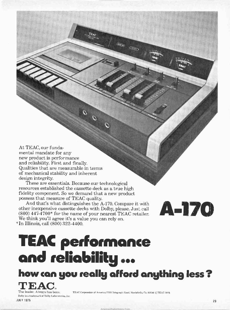
,,c ct,.. uo _ _
F
o
.
J . ,.. ,'[
At TEAC, our funda- mental mandate for any new product is performance and reliability. First and finally. Qualities that are measurable in terms of mechanical stability and inherent design integrity.
These are essentials. Because our technological resources established the cassette deck as a true high fidelity component. So we demand that a new product possess that measure of TEAC quality.
And that's what distinguishes the A-170. Compare it with other inexpensive cassette decks with Dolby, please. Just call (800) 447-4700* for the name of your nearest TEAC retailer. We think you'll agree it's a value you can rely on.
*In Illinois, call (800) 322-4400.
TEAL performance and reliability ... how con you really afford anything less ? TEAC® The leader. Always has been. TEAC Corporation of America/7733 Telegraph Road, Montebelks Ca. 90640 eTEAC 1975 Dolby is a trademark of Dolby Laboratories, Inc.
JULY 1976 29
AmericanRadioHistory.Com
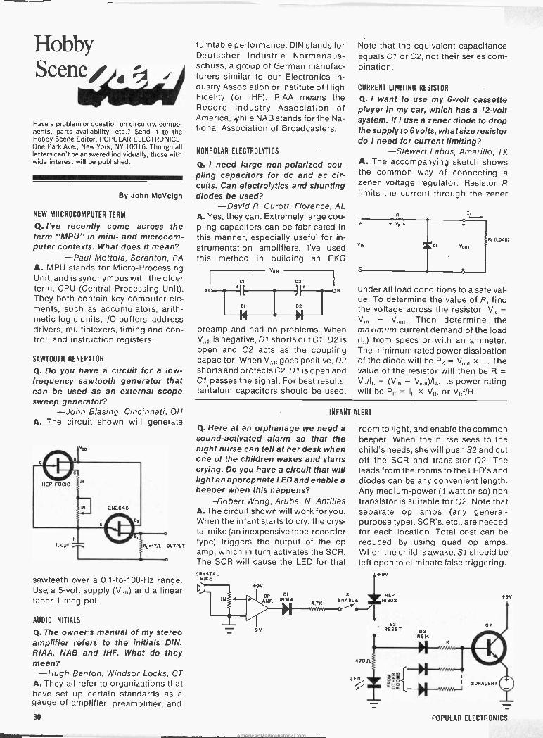
Hobby Scene/ ',
Have a problem or question on circuitry, compo- nents, parts availability,' etc.? Send it to 'the Hobby Scene Editor, POPULAR ELECTRONICS, One Park Ave., New York, NY 10016. Though all letters can't be answered individually, those with wide interest will be published.
By John McVeigh
NEW MIICROCOMPUTER TERM
Q. I've recently come across the term "MPU" in mini- and microcom- puter contexts. What does it mean?
-Paul Mottola, Scranton, PA A. MPU stands for Micro -Processing Unit, and is synonymous with the older term, CPU (Central Processing Unit). They both contain key computer ele- ments, such as accumulators, arith- metic logic units, I/O buffers, address drivers, multiplexers, timing and con- trol, and instruction registers.
SAWTOOTH GENERATOR
Q. Do you have a circuit for a low - frequency sawtooth generator that can be used as an external scope sweep generator?
-John Biasing, Cincinnati, OH A. The circuit shown will generate
9L'4T.0 OUTPUT
o
sawteeth over a 0.1 -to -100 -Hz range. Use, a 5 -volt supply (V,,,,) and a linear taper 1-meg pot.
AUDIO INITIALS
Q. The owner's manual of my stereo amplifier refers to the initials DIN, RIAA, NAB and IHF. What do they mean?
-Hugh Banton, Windsor Locks, CT A. They all refer to organizations that have set up certain standards as a gauge of amplifier, preamplifier, and
turntable performance. DIN stands for Deutscher Industrie Normenaus- schuss, a group of German manufac- turers similar to our Electronics In- dustry Association or Institute of High Fidelity (or IHF). RIAA means the Record Industry Association of America, while NAB stands for the Na- tional Association of Broadcasters.
NONPOLAR ELECTROLYTICS
Q. I need large non -polarized cou- pling capacitors for .dc and ac cir- cuits. Can electrolytics and shunting diodes be used?
-David R. Curott, Florence, AL A. Yes, they can. Extremely large cou- pling capacitors can be fabricated in this manner, especially useful for in- strumentation amplifiers. I've used this method in building an EKG
o-ICI A 1(
VAS
DI D2
preamp and had no problems. When is negative, D1 shorts out Cl, D2 is
open and C2 acts as the coupling capacitor. When VA goes positive, D2 shorts and protects C2, D1 is open and Cl passes the signal. For best results, taritalum capacitors should be used.
Note that the equivalent capacitance equals Cl or C2, not their series com- bination.
CURRENT LIMITING RESISTOR
Q. I want to use my 6 -volt cassette player in my car, which has a 12 -volt system. If I use a zener diode to drop the supply to 6 volts, what size resistor do I need for current limiting?
-Stewart Labus, Amarillo, TX A. The accompanying sketch shows the common way of connecting a
zener voltage regulator. Resistor R limits the current through the zener
RL (LOAD)
under all load conditions to a safe val- ue. To. determine the value of R, find the voltage across the resistor: VI, = V,,, - V,,,,,. Then determine the maximum current demand of the load (I,) from specs or with an ammeter. The minimum rated power dissipation of the diode will be P, = V,,,,, x ll.. The value of the resistor will then be R =
= (V,,, -V,)/I,. Its power rating will be P = l, x V)), or V12/R.
INFANT ALERT
Q. Hereat an orphanage we need a
sound -activated alarm so that the night nurse can tell at her desk when one of the children wakes and starts crying. Do you have a circuit that will light an appropriate LED and enable a beeper when this happens?
-Robert Wong, Aruba, N. Antilles A. The circuit shown will work for you. When the infant starts to cry, the crys- tal mike (an inexpensive tape -recorder type) triggers the output of the op amp, which in turn, activates the SCR. The SCR will cause the LED for that CRYSTAL
MIKE +9V
-9V
OP DI
AMP. IN9)4 4.7K
+9V
02
l
room to light, and enable the common beeper. When the nurse sees to the child's needs, she will push S2 and cut off the SCR and transistor Q2. The leads from the rooms to the LED's and diodes can be any convenient length. Any medium -power (1 watt or so) npn transistor is suitable for Q2. Note that separate op amps (any general- purpose type), SCR's, etc., are needed for each location. Total cost can be reduced by using quad op amps. When the child is awake, SI should be left open to eliminate false triggering.
SI ENABLE
47011
+9V
HEP R1202
52 RESET D2
IN914
"W" Qw r
LED ó=ó II SONALERT
_L_
30 POPULAR ELECTRONICS
AmericanRadioHistory.Com
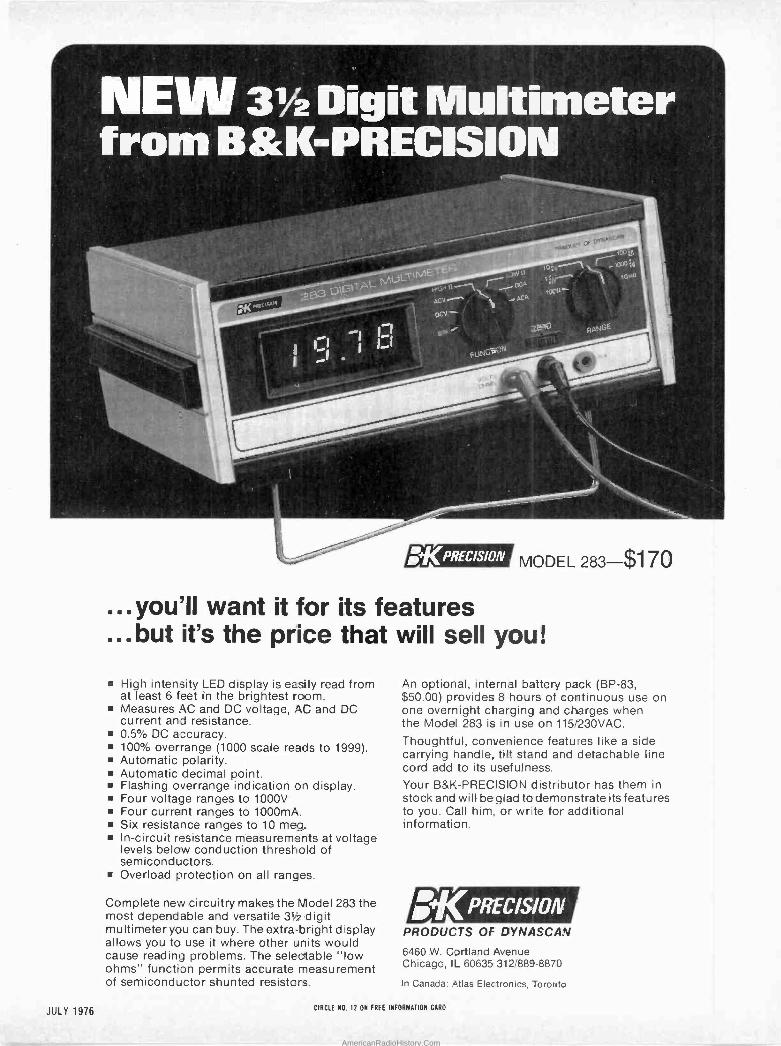
v2 Drgt.Multimetér
r=` 71 ` _- t7t Ta Mti,4 , ,-- ,,,.
I' I j Í h ...I .
. ' = MNPSC
= til
t0ii¡_\ u ,..t000:11
aWu _, ` ,p,.n gcP
,oc r
e i PCP ` t
Fu-NG9OM
Eig3PRECISIM , MODEL 283-$170
...you'll want it for its features
...but it's the price that will sell you!
High intensity LED display is easily read from at least 6 feet in the brightest room. Measures AC and DC voltage, AC and DC current and resistance. 0.5% DC accuracy. 100% overrange (1000 scale reads to 1999). Automatic polarity. Automatic decimal point. Flashing overrange indication on display. Four voltage ranges to 1000V Four current ranges to 1000mA. Six resistance ranges to 10 meg, In -circuit resistance measurements at voltage levels below conduction threshold of semicondluctors. Overload protection on all ranges.
Complete new circuitry makes the Model 283 the most dependable and versatile 3V2 digit multimeter you can buy. The extra bright display allows you to use it where other units would cause reading problems. The selectable "low ohms" function permits accurate measurement of semiconductor shunted resisters.
An optional, internal battery pack (BP -83, $50.00) provides 8 hours of continuous use on one overnight charging and charges when the Model 283 is in use on 115/230VAC.
Thoughtful, convenience features like a side carrying handle, tilt stand and detachable line cord add to its usefulness. Your B&k:-PRECISION distributor has them in stock and will be glad to demonstrate its features to you. Call him, or write for additional information.
t('I'RECISIoflf. PRODUCTS OF DYNASCAN
6460 W. Cortland Avenue Chicago, IL 60635 312/889-8870
In Canada: Atlas Electronics, Toronto
JULY 1976 CIRCLE NO. 12 ON FREE INFORMATION CARA
AmericanRadioHistory.Com
HIGHLIGHTS Teaching Computers To Speak English The trouble with computers is that operators must learn to think like computers and communicate in their language. Professor David Waltz of the Univer- sity of Illinois at Urbana -Champaign wants things the other way around, for the computer to think and listen to instructions like a human. The professor is for- mulating an intelligent program that will accept queries in conventional English to allow a nontechni- cal user to talk to, rather than program, computers. The completion of the natural -language program will be particularly helpful to individuals with limited computer skills. Most important, man and machine will be speaking the same language, English.
FCC Clobbers TV Game Makers Nine violation notices have been issued by the Federal Communications Commission to companies marketing electronic TV devices that allegedly disre- gard Commission regulations. The home TV games did not have an approved Class 1 TV device, necessary when video games are connected directly to a TV re- ceiver's antenna terminals. Such a TV game cannot be advertised, announced or sold before being tested and approved by the FCC. All nine companies cited replied to the FCC within the deadline of 15 days, stating that none of the TV games had been shipped and would not be shipped until official Commission approval is obtained. The Commission plans to issue more viola- tion notices in the near future.
Pioneer Sets Guinness Record In a nonstop marathon of playing records for almost 12 days (284.5 hours), Pioneer beat the previous re- cord of 268 hours established in Norway, ranking it a feat that belongs in the "Guinness Book of Records," Royal Air Force Senior Aircraftsman Mike Buckley worked toward the new record with two PL -12D turntables. In all, more than 5690 single -disc changes were required between the two turntables during the record -breaking period.
Amateur Radio Changes Code-The FCC is deleting part of Section 97.29(c) of the Commission rules concerning the standard an Amateur radio licensee must meet in reception and transmission of international Morse Code. The Rules currently require the licensee to transmit and receive one full minute of code, free of omissions and other errors, at the prescribed speed during a five-minute testing period. Believing this to be unduly restrictive, the FCC is planning to use one or more alternative test methods. One of them is a multiple choice examina- tion covering a five -Minute transmission of plain text.
Such a test would relieve the applicant of copying one minute of mixed text without error, yet would provide an accurate gauge of competency in reception of code message content. Study Guides-The FCC is releasing new study guides for amateur radio operator license examina- tions. They are in the form of a syllabus that outlines the various categories of questions from which the exams are devised and include sample questions rep- resentative of those appearing in the exams. The new guides have been reorganized to reduce the possibility of an individual acquiring a ham license simply by memorizing the answers to specific questions. Addi- tionally, the guides have been designed to permit much greater flexibility in the selection of exam ques- tions. This flexibility will allow more frequent revision of amateur examinations and, therefore, result in a more equitable exam program for all trainees.
Two Electronics Pioneers Die On January 16, 1976, Dr. Hidetsugu Yagi died at the age of 89 in Tokyo, Japan. Dr. Yagi was the inventor of the Yagi array antenna commonly used in vhf and hf radio and TV communication.
On April 4, Swedish born and Yale educated Dr. Harry Nyquist died at the age of 87. Dr. Nyquist dis- covered a set of conditions to keep feedback circuits stable. The "Nyquist Criterion" is used to study elec- tronic devices and to examine human reactions, such as driver responses to conditions while steering a car.
FCC Holds Off CB Expansion The Federal Communications Commission has de- cided not to take immediate action on expanding the number of Class D CB radio channels on 27 MHz. Seems that there is a serious question of interference to CB operators on existing 23 channels. The FCC said that tighter specifications would be needed before there will be any approval of expansion.
Number of "E" Graduates Down For 1975
The engineering graduating class for the year ending June 1975 was the smallest in the last seven years, according to data compiled by the Engineering Man- power Commssion of the Engineers Joint Council. Among engineering specialties, electrical engineer- ing had the largest number of graduates at all degree levels-14,537-followed by civil engineering with 11,237. A separate engineering category, computers, produced 1384 degrees. Women and minorities are showing rapid growth in engineering. Women earned more than 2% and minorities more than 7% of the 1975 bachelor's degrees. A survey of 2 -year technol- ogy schools, though not including many smaller schools, revealed 4805 associate degrees in electronics and 1541 in computers for the year ending June 1975.
32 POPULAR ELECTRONICS
AmericanRadioHistory.Com

Tie world's largest catalog of easy-to-Uuild; money -saving
electronic kits
H 7-1(-7. E. Excaurs al .vv ar.:Tdr,ota. nonatas ®s.e.. ar.d 01 -dm.
Ic rt.a.ce your m,rnrnrtr hi,bLiIdir,pmor.. Its, -
/.1
J
Car..pr..B.n a ePno.,eA..... á.w..r.v- á +o ?_, j
NRMI Amrr...- glad. R.eMv..-. Sa. p.p. 77.
`lri ~Pe CalMypwny S.F. Ind.= an y.yra 3.
.
n Flnrmng Ca.a, tipu..l.... !'i.e e ware Ew.,I..n.o FLLTay. A,r C,.M.. ..r.f-.a pa11. e MaYn wnr-Ar+wna üK9n1 R.Itros. c'ia..Irdla _ xa. {rCa 4F. , M.wI i..e10 Coe.rti.t.a .V rWan. 6.a sali. at
Hlgn-To.que VQasrva. Se. p.,i.4s.a #rCW 1 Elmo l.elFire wlnlq.li« paQ. U. - ' soya on aM.Ctee Han- Sp.sl.e.I Mr papaf..1111.13. BAY! on e.Ieclea Tae± Equl . m pg.-^G.; 32-10.. PL m bi UB Propr.o,.a LNgit.l SI - ,IuSu _ _
System,l-FI El.ot.row.c. LanrM. .pri _
and w,or. - ovar 4o0 Wt. In ant
= ttaatMttH malt ~dew catatop rMaatlt^ .nO7Fr..N.k14' Br. rptWwó Wes o4 tY..11t oonpe,tes.
Power Supplies Oscilloscopes Frequency Counters VTVM's and VOM's Ham Radio Gear Color TV's Hi -Fi Components Electronic Clocks Electronics Learning Programs Auto, Fishing, Marine and Aircraft Accessories - over 400 kits in all!
Every Heathkit product comes with a fully - illustrated, step-by-step assembly manual that tells you everything yoJ need to know to make kitbuilding fun and easy. Thousands of people have discovered the satisfaction-and sav- ings-of handcrafting a fine piece of electronic equipment. You can build it better...let us ' show you how.
Send for your FREE Catalog today! Heath Company, Dept. 10-19, Benton Harbor, Michigan 49022
HEATH
Schlumberger
1
NAME
1 all ~I MIN IZIM MIN MIN MN ~I WIC MIR
' Heath Company, Dept. 10-19 Benton Harbor, Michigan 49022
ADDRESS
CITY STATE CL -601 ZIP
1
1
1
1
JULY 1576
~II ~I ----~I CIRCLE NO. 5 ON FREE INFORMATION CARD 33
AmericanRadioHistory.Com
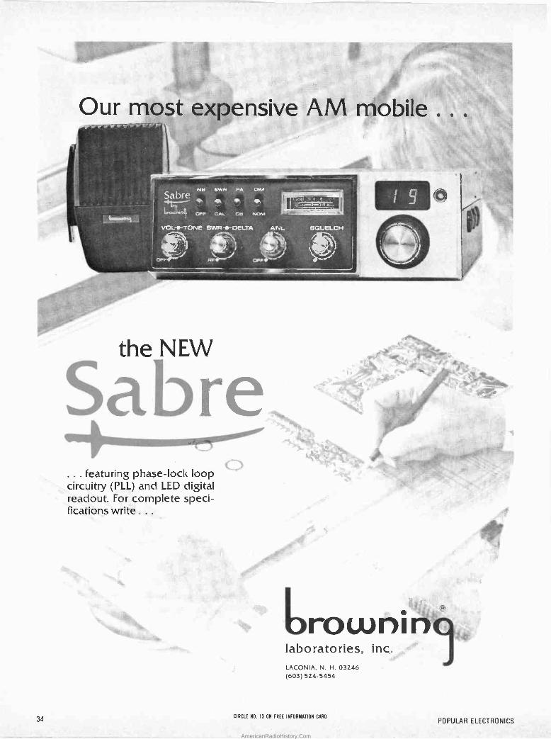
Our most expensive AM=móbile
the NEW
a re ... featuring phase -lock loop circuitry (PLL) and LED digital readout. For complete speci- fications write .. .
. -1111:4.
.*,- V..
u rowni n o: laboratories, inc. LACONIA, N. H. 03246 (603) 524-5454
34 CIRCLE NO. 13 ON FREE INFORMATION CARO
POPULAR ELECTRONICS
AmericanRadioHistory.Com
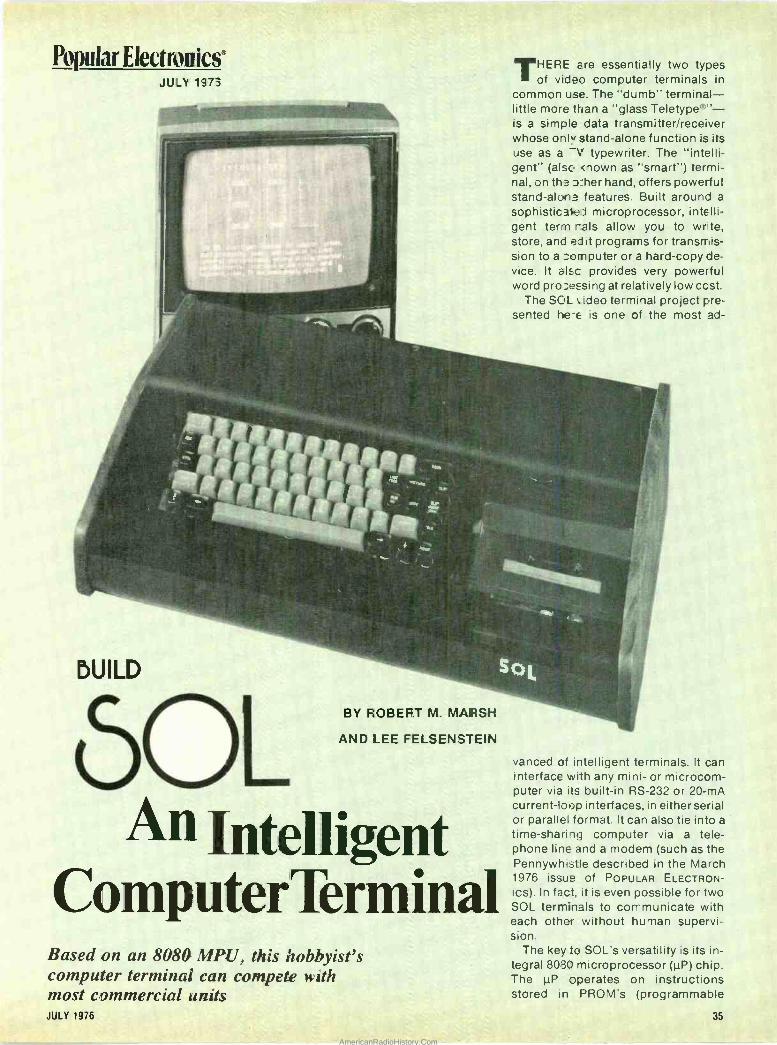
Popular Electronics JULY 1973
BUILD
- BY ROBERT M. MARSH
AND LEE FELSENSTEIN
An InteIligent CornputerTerm,inal
Based on an 8080 MPU, this hobbyist's computer terminal can compete with most commercial units JULY 1976
THERE are essentially two types of video computer terminals in
common use. The "dumb" terminal- little more than a "glass Teletype®"- is a simple data transmitter/receiver whose only stand-alone function is its use as a -\' typewriter. The "intelli- gent" (also mown as "smart") termi- nal, on th> >_her hand, offers powerful stand-aloxa features. Built around a
sophisticalei microprocessor, intelli- gent term rals allow you to write, store, and edit programs for transmis- sion to a computer or a hard -copy de- vice. It al;c provides very powerful word processing at relatively low ccst.
The SOL video terminal project pre- sented be -e is one of the most ad -
R-
SQL
vanced of intelligent terminals. It can interface with any mini- or microcom- puter via its built-in RS -232 or 20-mA current -loop interfaces, in either serial or parallel format. It can also tie into a
time-sharing computer via a tele- phone line and a modem (such as the Pennywhistie described in the March 1976 issue Of POPULAR ELECTRON-
ics). In fact, it is even possible for two SOL terminals to communicate with each other without human supervi- sion.
The key to SOL's versatility is its in- tegral 8080 microprocessor (µP) chip. The µP operates on instructions stored in PROM's (programmable
35
AmericanRadioHistory.Com
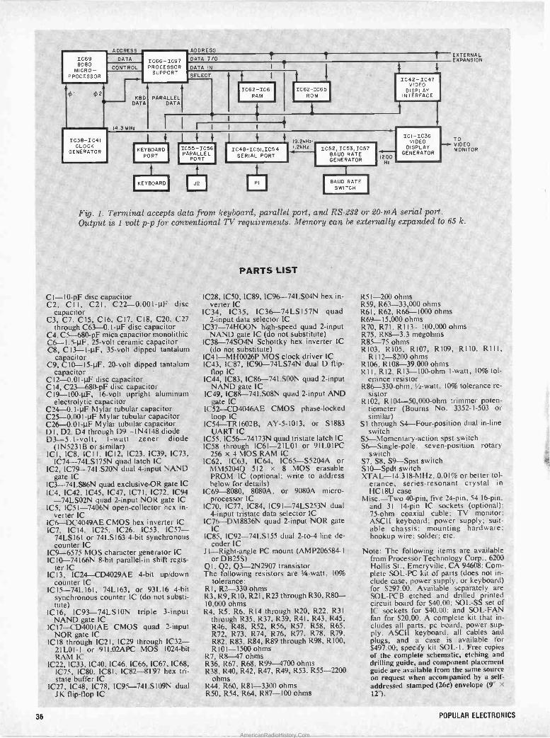
IC69 8080
MICRO- PROCESSOR
ADDRESS
DATA
CONTROL
-*--i 952 9-
1C38 -1C41 CLOCK
GENERATOR
y IC66-IC97 PROCESSOR
SUPPORT
ADDRESS
DATA I/O DATA IN I
SELECT
KBD PARALLEL DATA DATA
14.3 MHz
IKEYBOARD PORT
KEYBOARD
IC62-IC65 ROM
1C42 -1C47 VIDEO
DISPLAY INTERFACE
EXTERNAL EXPANSION
19.2kHz- I.2kHz
IC 1-1C36 VIDEO
DISPLAY GENERATOR
TO - VIDEO MONITOR IC55-IC56
PARALLEL PORT
IC48-IC51, IC54 SERIAL PORT
IC52, IC53,IC57 BAUD RATE GENERATOR
4 1200
Hz
J2 PI BAUD RATE SWITCH
Fig. 1. Terminal accepts data from keyboard, parallel port, and RS -232 or 20-mA serial port. Output is / volt p -p for conventional TV requirements. Memory can be externally expanded to 65 k.
C I-10-pF disc capacitor C2, CI I, C21. C22 -0.001-µF disc
capacitor C3, C7. C15, C16, C17, C18, C20, .C27
through C63-0. I -µF disc capacitor C4. C5-680-pF mica capacitor monolithic C6 -1,5-µF. 25 -volt ceramic capacitor C8, C13 -1-µF, 35 -volt dipped tantalum
capacitor C9, CIO -45-1.1F, 20 -volt dipped tantalum
capacitor C 12-0,01-µF disc capacitor C14, C23-680-pF disc capacitor C19 -100-µF, 16 -volt upright aluminum
electrolytic capacitor C24-0. I -µF Mylar tubular -capacitor C25 -0.001-µF Mylar tubular capacitor C26 -0,01-µF Mylar tubtílar capacitor DI, D2, D4 through D9-IN4148 diode D3 -5.1 -volt, I -watt zener diode
(IN5231B or similar), ICI, IC8, ICI I', IC 12, IC23, IC39, 1C73,
IC74-74LS 175N quad latch IC IC2, IC79-74LS20N dual 4 -input NAND
gate IC IC3-74LS86N quad exclusive -OR gate IC IC4, IC42. IC45, IC47, IC71, IC72, IC94
-74LS02N quad 2 -input NOR gate IC IC5, 1051-7406N open -collector hex in-
verter IC IC6-DC4049AE CMOS hex inverter IC. IC7, IC 14, IC25, IC26. IC53. 1057-
74LS161 or 74LSI63 4 -bit synchronous counter,1C
IC9-6575 MOS character generator IC IC 10-74166N 8 -bit parallel -in shift regis-
ter IC IC 13, 1C24 CD4029AE 4 -bit up/down
counter IC IC I5 -74L 161, 74L163, or 93L 16 4 -bit
synchronous counter IC (do not substi- -cute)
IC16, íC93-74LSION triple 3 -input NAND gate IC
IC 17-CD400IAE CMOS quad 2 -input NOR gate IC
1C18 through 1C21, IC29 through IC32- 2I L01- I or 91 L02APC MOS 1024 -bit RAM IC
IC22, 1C33, 1C40, 1C46, IC66, 1067, IC68, IC75, IC80, 1C81, IC82-8T97 hex tri- state buffer IC
IC27, IC48, IC78, 1C95-74LSI09N dual JK flip-flop IC
PARTS LIST
C28, IC50, IC89, IC96-74LSO4N hex in- verter IC
IC34, IC35, 1C36-74LS157N quad 2 -input data selector IC
IC37-74HOON high-speed quad 2 -input NAND gate IC (do not substitute)
IC38-74SO4N Schottky hex inverter IC (do not substitute)
IC41-MH0026P MOS clock driver IC IC43, IC87, IC90-74LS74N dual D flip-
flop IC IC44, 1C83, IC86-74LSOON quad 2 -input
NAND gate IC IC49, IC88-74LS08N quad 2 -input AND
gate IC IC52-CD4046AE ' CMOS phase -locked
loop IC IC54-TR 1602B, AY -5-1013, or S 1883
UART IC ,IC55, IC56-74173N quad tristate latch IC 1058 through ,IC6l-21L01 or 91LOIPC
256 x 4 MOS RAM IC IC62, IC63, IC64, IC65-S5204A or
MM5204Q 512 z 8 MOS erasable PROM IC (optional; write to address below for details)
IC69-8080, 8080A. or 9080A micro- processor IC
IC70, IC77, IC84; IC9l-74LS253N dual 4 -input tristate data selector IC
IC76-DM8836N quad 2 -input NOR gate IC
IC85, 1C92-74LS155 dual 2 -to -4 line de- coder IC
JI -Right-angle PC mount (AMP206584-I- or DB25S)
QI. Q2, Q3 -2N2907 transistor The following resistors are '/4 -watt. 10%
tolerance: R I, R2-330 ohms R3, R9, R 10, R21, R23 through R30, R80- 10,000 ohms
R4, R5, R6. R 14 through R20, R22. R3I through R35, R37, R39. R41, R43, R45, R46, R48, R52, R56, R57. R58, R65, R72, R73. R74, R76, R77. R78, R79. R82, R83, R84, R89 through R98, R100, R101-1500 ohms
R7, R8 47 ohms R36, R67, R68, R99-4700 ohms R38, R40, R42, R47, R49, R53, R55-2200
ohms R44. R60. R8I-3300 ohms R50. R54, R64, R87-100 ohms
R51-200 ohms R59, R63-33,000 ohms R61, R62, R66-1000 ohms R69-I5,000.ohms R70, R7I, R113-100,000 ohms R75, R88-3.3 megohms R85-75 ohms R103. R105, R107. R109, R110, RIII,
R 112-8200 ohms R106, R108-39.000 ohms RI I, R12, R13 -100 -ohm I -watt, 10%tol-
erance resistor .,R86 -330 -ohm, 1/2 -watt, 10% tolerance re-
sistor R 102. R104 -50,000 -ohm trimmer poten-
tiometer (Bourns No. 3352-1-503 or similar)
SI through S4 -Four -position dual in -line switch
S5 -Momentary -action spst switch S6 -Single -pole, seven -position rotary
switch S7. S8. S9-Spst switch S I O-Spdt switch XTAL-14.318-MHz, 0.01% or better tol-
erance, series -resonant crystal in HC I8U case
Misc.-Two 40 -pin, five 24 -pin, 54 16 -pin. and '31 14 -pin IC sockets (optional):
' 75 -ohm coaxial cable: TV monitor; ASCII keyboard: power supply; suit- able chassis: mounting hardware; hookup wire: solder: etc.
Note: The following items are available from Processor Technology Corp.. 6200 Hollis St.. Emeryville, CA 94608: Com- plete SOL -PC kit of parts (does not in- clude case, power supply, or keyboard) for $297.00. Available separately are SOL -PCB etched and drilled printed circuit board for $40.00; SOL -SS set of IC sockets for $40.00; and SOL -FAN fan for $20.00. A complete kit that in- cludes all parts. pc hoard,. power sup- ply. ASCII keyboard. all cables and plugs, and a case is available for $497.00; specify kit SOL -I. Free copies of the complete schematic, etching and drilling guide, and component placement guide are available from the same source on request when accompanied by a self- addressed stamped (26¢) envelope (9" x 12").
36 POPULAR ELECTRONICS
AmericanRadioHistory.Com
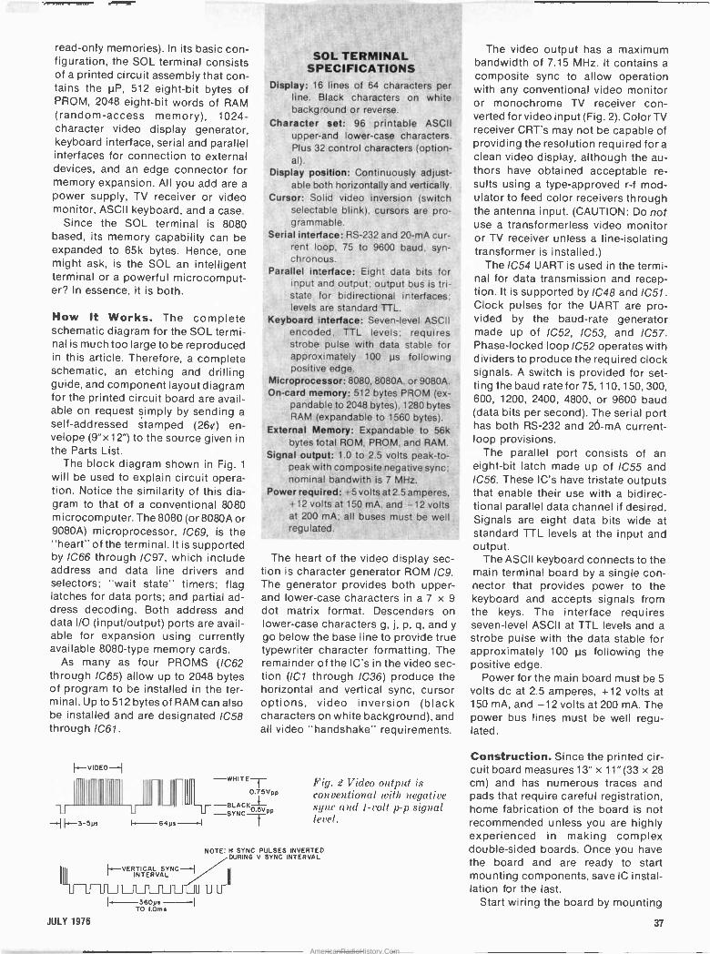
read-only memories). In its basic con- figuration, the SOL terminal consists of a printed circuit assembly that con- tains the µP, 512 eight -bit bytes of PROM, 2048 eight -bit words of RAM (random-access memory), 1024 - character video display generator, keyboard interface, serial and parallel interfaces for connection to external devices, and an edge connector for memory expansion. All you add are a power supply, TV receiver or video monitor, ASCII keyboard, and a case.
Since the SOL terminal is 8080 based, its memory capability can be expanded to 65k bytes. Hence, one might ask, is the SOL an intelligent terminal or a powerful microcomput- er? In essence, it is both.
How It Works. The complete schematic diagram for the SOL termi- nal is much too large to be reproduced in this article. Therefore, a complete schematic, an etching and drilling guide, and component layout diagram for the printed circuit board are avail- able on request simply by sending a self-addressed stamped (26t) en- velope (9"x12") to the source given in the Parts List.
The block diagram shown in Fig. 1
will be used to explain circuit opera- tion. Notice the similarity of this dia- gram to that of a conventional 8080 microcomputer. The 8080 (or 8080A or 9080A) microprocessor, IC69, is the "heart" of the terminal. It is supported by IC66 through IC97, which include address and data line drivers and selectors; "wait state" timers; flag latches for data ports; and partial ad- dress decoding. Both address and data I/O (input/output) ports are avail- able for expansion using currently available 8080 -type memory cards.
As many as four PROMS (IC62 through /C65) allow up to 2048 bytes of program to be installed in the ter- minal. Up to 512 bytes of RAM can also be installed and are designated IC58 through IC61.
I..-V DEO--I
-- 4 ~~3-53s
SOL TERMINAL. SPECIFICATIONS
Display: 16 lines of 64 characters per . line. Black characters on white
background or reverse.
Character. set: 96 printable ASCII upper -and lower-case characters. Plus 32 control characters (option- al).
Display position: Continuously adjust- able both horizontally and vertically.
Cursor: Solid videp inversion (switch selectable blink), cursors are pro- grammable.
Serial interface: RS -232 and 20-mA cur- rent loop, 75 to 9600 baud, syn- chronous.
Parallel interface: Eight data bits for input and output; output bus is tri- state for bidirectional interfaces; levels are standard TTL.
Keyboard interface: Seven -level ASCII encoded, TTL levels; requires strobe pulse with data stable for approximately 100 us following positive edge.
Microprocessor: 8080, 8080A, or 9080A. On -card memory: 512 bytes PROM (ex-
pandable to 2048 bytes), 1280 bytes RAM (expandable to 1560 bytes).
External Memory: Expandable to 56k bytes total ROM, PROM, and RAM.
Signal output: 1.0 to 2.5 volts peak -to - peak with composite negative syric; nominal bandwi-th is 7 MHz.
Power required: +5 volts at2.5 amperes, +12 volts at 150 mA, and -12 volts at 200 mA; all buses must be well regulated.
The heart of the video display sec- tion is character generator ROM IC9. The generator provides both upper - and lower-case characters in a 7 x 9
dot matrix format. Descenders on lower-case characters g, j, p, q, and y go below the base line to provide true typewriter character formatting. The remainder of the IC's in the video sec- tion (ICI through IC36) produce the horizontal and vertical sync, cursor options, video inversion (black characters on white background), and all video "handshake" requirements.
- - -WHITET 0.75VGp
BLACKÓ u ` U -SYNC PP
64ys--I
HVERTICAL SYNC INTERVAL
36095 TO 1.0ms
JULY 1976 37
Fig. 2 Video output is conventional with negative sync and 1 -volt p -p signal level.
NOTE: H SYNC PULSES INVERTED DURING V SYNC INTERVAL
The video output has a maximum bandwidth of 7.15 MHz. It contains a
composite sync to allow operation with any conventional video monitor or monochrome TV receiver con- verted for video input (Fig. 2). Color TV receiver CRT's may not be capable of providing the resolution required for a
clean video display, although the au- thors have obtained acceptable re- sults using a type -approved r -f mod- ulator to feed color receivers through the antenna input. (CAUTION: Do not use a transformerless video monitor or TV receiver unless a line -isolating transformer is installed.)
The IC54 UART is used in the termi- nal for data transmission and recep- tion. It is supported by 1C48 and IC51. Clock pulses for the UART are pro- vided by the baud -rate generator made up of /C52, /C53, and /C57. Phase -locked loop IC52 operates with dividers to produce the required clock signals. A switch is provided for set- ting the baud rate for 75, 110, 150, 300, 600, 1200, 2400, 4800, or 9600 baud (data bits per second). The serial port has both RS -232 and 26-mA current - loop provisions.
The parallel port consists of an eight -bit latch made up of IC55 and /C56. These IC's have tristate outputs that enable their use with a bidirec- tional parallel data channel if desired. Signals are eight data bits wide at standard TTL levels at the input and output.
The ASCII keyboard connects to the main terminal board by a single con- nector that provides power to the keyboard and accepts signals from the keys. The interface requires seven -level ASCII at TTL levels and a strobe pulse with the data stable for approximately 100 µs following the positive edge.
Power for the main board must be 5 volts dc at 2.5 amperes, +12 volts at 150 mA, and -12 volts at 200 mA. The power bus lines must be well regu- lated.
Construction. Since the printed cir- cuit board measures 13" x 11"(33 x 28 cm) and has numerous traces and pads that require careful registration, home fabrication of the board is not recommended unless you are highly experienced in making complex double -sided boards. Once you have the board and are ready to start mounting components, save IC instal- lation for the last.
Start wiring the board by mounting
AmericanRadioHistory.Com
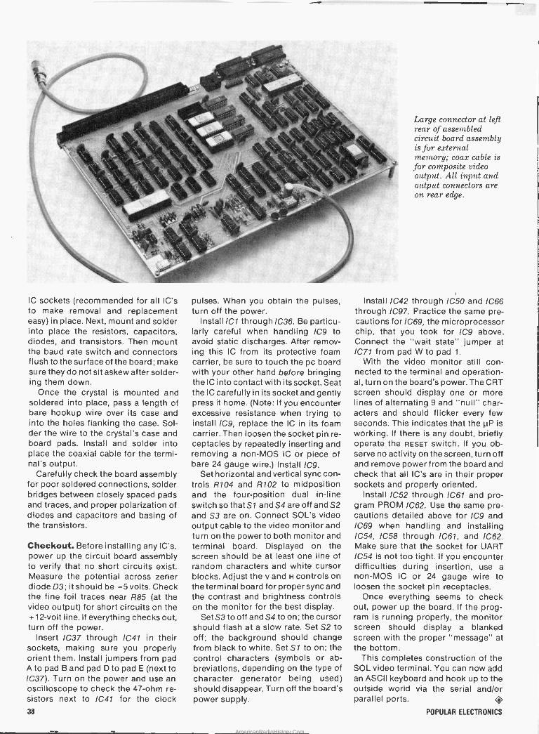
IC sockets (recommended for all IC's to make removal and replacement easy) in place. Next, mount and solder into place the resistors, capacitors, diodes, and transistors. Then mount the baud rate switch and connectors flush to the surface of the board; make sure they do not sit askew after solder- ing them down.
Once the crystal is mounted and soldered into place, pass a length of bare hookup wire over its case and into the holes flanking the case. Sol- der the wire to the crystal's case and board pads. Install and solder into place the coaxial cable for the termi- nal's output.
Carefully check the board assembly for poor soldered connections, solder bridges between closely spaced pads and traces, and proper polarization of diodes and capacitors and basing of the transistors.
Checkout. Before installing any IC's, power up the circuit board assembly to verify that no short circuits exist. Measure the potential across zener diode D3; it should be -5 volts. Check the fine foil traces near R85 (at the video output) for short circuits on the +12 -volt line. If everything checks out, turn off the power.
Insert IC37 through IC41 in their sockets, making sure you properly orient them. Install jumpers from pad A to pad B and pad D to pad E (next to IC37). Turn on the power and use an oscilloscope to check the 47 -ohm re- sistors next to IC41 for the clock 38
pulses. When you obtain the pulses, turn off the power.
Install /C1 through IC36. Be particu- larly careful when handling IC9 to avoid static discharges. After remov- ing this IC from its protective foam carrier, be sure to touch the pc board with your other hand before bringing the IC into contact with its socket. Seat the IC carefully in its socket and gently press it home. (Note: If you encounter excessive resistance when trying to install /C9, replace the IC in its foam carrier. Then loosen the socket pin re- ceptacles by repeatedly inserting and removing a non-MOS IC or piece of bare 24 gauge wire.) Install IC9.
Set horizontal and vertical sync con- trols R104 and R102 to midposition and the four -position dual in -line switch so that S1 and S4 are off and S2 and S3 are on. Connect SOL's video output cable to the video monitor and turn on the power to both monitor and terminal board. Displayed on the screen should be at least one line of random characters and white cursor blocks. Adjust the y and H controls on the terminal board for proper sync and the contrast and brightness controls on the monitor for the best display.
Set S3 to off and S4 to on; the cursor should flash at a slow rate. Set S2 to off; the background should change from black to white. Set S1 to on; the control characters (symbols or ab- breviations, depending on the type of character generator being used) should disappear. Turn off the board's power supply.
Large connector at left rear of assembled circuit board assembly is for external memory; coax cable is for composite video output. All put and output connectors are on rear edge.
Install IC42 through IC50 and 1066 through IC97. Practice the same pre- cautions for IC69, the microprocessor chip, that you took for /C9 above. Connect the "wait state" jumper at IC71 from pad W to pad 1.
With the video monitor still con- nected to the terminal and operation- al, turn on the board's power. The CRT screen should display one or more lines of alternating 9 and "null" char- acters and should flicker every few seconds. This indicates that the µP is working. If there is any doubt, briefly operate the RESET switch. If you ob- serve no activity on the screen, turn off and remove power from the board and check that all IC's are in their proper sockets and properly oriented.
Install /C52 through IC61 and pro- gram PROM IC62. Use the same pre- cautions detailed above for /C9 and IC69 when handling and installing IC54, IC58 through IC61, and IC62. Make sure that the socket for UART /C54 is not too tight. If you encounter difficulties during insertion, use a non-MOS IC or 24 gauge wire to loosen the socket pin receptacles.
Once everything seems to check out, power up the board. If the prog- ram is running properly, the monitor screen should display a blanked screen with the proper "message" at the bottom.
This completes construction of the SOL video terminal. You can now add an ASCII keyboard and hook up to the outside world via the serial and/or parallel ports. 4
POPULAR ELECTRONICS
AmericanRadioHistory.Com

c icrowve Ovens on- e o e
How they work and what to
look for in selecting one.. BY BILL EVA
ONCE used almost exclusively for line -of -sight radio communi-
cation and in industrial heating appli- cations, microwaves are now cooking food in homes. While the microwave oven existed as far back as 1945 and was first marketed by Tappan in 1955, its popularity as a consumer appliance didn't become established until the beginning of this decade. As a result of a reduction in prices, improvements in the ovens themselves, and availability of convenience features, microwave ovens are capturing a significant per- centage of the total consumer dollar spent on major cooking appliances.
Microwaves cook foods faster than
conventional gas and electric ovens; and because the microwave oven is considerably more efficient than a
radiant -heat oven, it is a great deal more economical to operate. Con- venience features and noncooking aesthetics have also helped to make the microwave oven an attractive con- sumer appliance.
Market Trends. As can be seen from the graphs, the microwave -oven mar- ket began a meteoric rise in 1970 when it captured about 1.5% of the large cooking appliance market. By the end of last year, an estimated 26% 'of the consumer dollar had gone into pur-
chases of microwave ovens and com- bination conventional/microwave ranges. Extrapolating from this per- formance, estimates have been made that the- microwave appliance will ac- count for almost 50% of the worldwide market by the end of this decade.
It is interesting to note that the early microwave oven market was domi- nated by a few Japanese name brands but that the U.S. has since taken over the major portion of the market. Cur- rent figures give 75% of the market to U.S. manufacturers and the remainder to the Japanese manufacturers.
Ten manufacturers currently supply microwave -oven appliances to the
JULY 1976 39
AmericanRadioHistory.Com
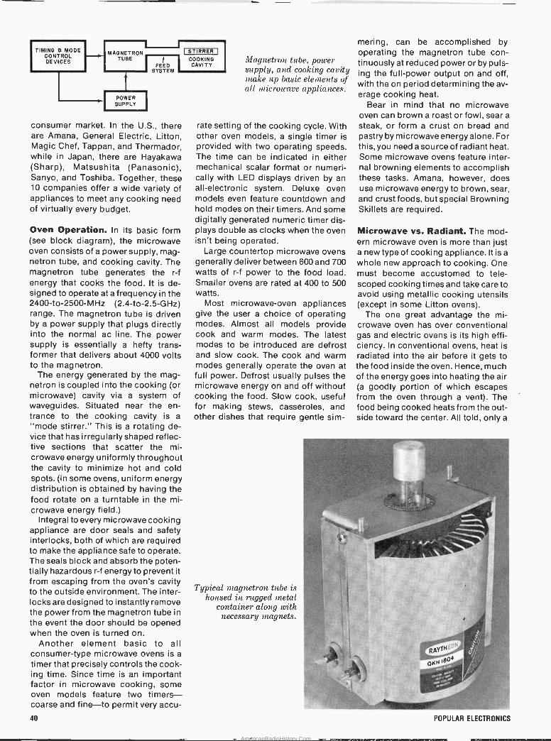
FEED SYSTEM
POWER SUPPLY
COOKING CAVITY
consumer market. In the U.S., there are Amana, General Electric, Litton, Magic Chef, Tappan, and Thermador, while in Japan, there are Hayakawa (Sharp), Matsushita (Panasonic), Sanyo, and Toshiba. Together, these 10 companies offer a wide variety of appliances to meet any cooking need of virtually every budget.
Oven Operation. In its basic form (see block diagram), the microwave oven consists of a power supply, mag- netron tube, and cooking cavity. The magnetron tube generates the r -f energy that cooks the food. It is de- signed to operate at a frequency in the 2400 -to -2500 -MHz (2.4-to-2.5-GHz) range. The magnetron tube is driven by a power supply that plugs directly into the normal ac line. The power supply is essentially a hefty trans- former that delivers about 4000 volts to the magnetron.
The energy generated by the mag- netron is coupled into the cooking (or microwave) cavity via a system of waveguides. Situated near the en- trance to the cooking cavity is a "mode stirrer." This is a rotating de- vice that has irregularly shaped reflec- tive sections that scatter the mi- crowave energy uniformly throughout the cavity to minimize hot and cold spots. (In some ovens, uniform energy distribution is obtained by having the food rotate on a turntable in the mi- crowave energy field.)
Integral to every microwave cooking appliance are door seals and safety interlocks, both of which are required to make the appliance safe to operate. The seals block and absorb the poten- tially hazardous r -f energy to prevent it from escaping from the oven's cavity to the outside environment. The inter- locks are designed to instantly remove the power from the magnetron tube in the event the door should be opened when the oven is turned on.
Another element basic to all consumer -type microwave ovens is a
timer that precisely controls the cook- ing time. Since time is an important factor in microwave cooking, some oven models feature two timers- coarse and fine-to permit very accu-
STIRRER I
Magnetron tube, power supply, and cooking cavity make up basic elements of all microwave appliances.
rate setting of the cooking cycle. With other oven models, a single timer is provided with two operating speeds. The time can be indicated in either mechanical scalar format or numeri- cally with LED displays driven by an all -electronic system. Deluxe oven models even feature countdown and hold modes on their timers. And some digitally generated numeric timer dis- plays double as clocks when the oven isn't being operated.
Large countertop microwave ovens generally deliver between 600 and 700 watts of r -f power to the food load. Smaller ovens are rated at 400 to 500 watts.
Most microwave -oven appliances give the user a choice of operating modes. Almost all models provide cook and warm modes. The latest modes to be introduced are defrost and slow cook. The cook and warm modes generally operate the oven at full power. Defrost usually pulses the microwave energy on and off without cooking the food. Slow cook, useful for making stews, casseroles, and other dishes that require gentle sim-
Typical magnetron tube is housed in rugged metal
container along with necessary magnets.
mering, can be accomplished by operating the magnetron tube con- tinuously at reduced power or by puls- ing the full -power output on and off, with the on period determining the av- erage cooking heat.
Bear in mind that no microwave oven can brown a roast or fowl, sear a
steak, or form a crust on bread and pastry by microwave energy alone. For this, you need a source of radiant heat. Some microwave ovens feature inter- nal browning elements to accomplish thesé tasks. Amana, however, does use microwave energy to brown, sear, and crust foods, but special Browning Skillets are required.
Microwave vs. Radiant. The mod- ern microwave oven is more than just a new type of cooking appliance. It is a whole new approach to cooking. One must become accustomed to tele- scoped cooking times and take care to avoid using metallic cooking utensils (except in some Litton ovens).
The one great advantage the mi- crowave oven has over conventional gas and electric ovens is its high effi- ciency. In conventional ovens, heat is radiated into the air before it gets to the food inside the oven. Hence, much of the energy goes into heating the air (a goodly portion of which escapes from the oven through a vent). The food being cooked heats from the out- side toward the center. All told, only a
SW-
, rtx;
..d
40 POPULAR ELECTRONICS
AmericanRadioHistory.Com
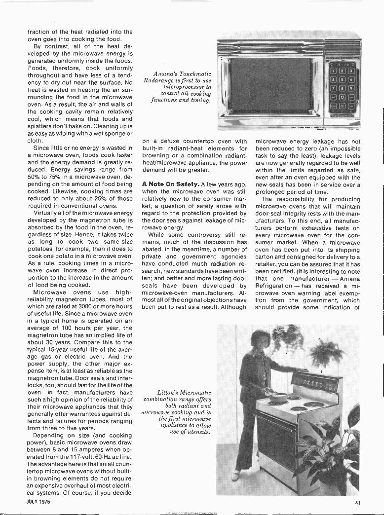
fraction of the heat radiated into the oven goes into cooking the food.
By contrast, all of the heat de- veloped by the microwave energy is
generated uniformly inside the foods. Foods, therefore, cook uniformly throughout and have less of a tend- ency to dry out near the surface. No heat is wasted in heating the air sur- rounding the food in the microwave oven. As a result, the air and walls of the cooking cavity remain relatively cool, which means that foods and splatters don't bake on. Cleaning up is
as easy as wiping with a wet sponge or cloth.
Since little or no energy is wasted in a microwave oven, foods cook faster and the energy demand is greatly re- duced. Energy savings range from 50% to 75% in a microwave oven, de- pending on the amount of food being cooked. Likewise, cooking times are reduced to only about 25% of those required in conventional ovens.
Virtually all of the microwave energy developed by the magnetron tube is absorbed by the food in the oven, re- gardless of size. Hence, it takes twice as long to cook two same -size potatoes, for example, than it does to cook one potato in a microwave oven. As a rule, cooking times in a micro- wave oven increase in direct pro- portion to the increase in the amount of food being cooked.
Microwave ovens use high - reliability magnetron tubes, most of which are rated at 3000 or more hours of useful life. Since a microwave oven in a typical home is operated on an average of 100 hours per year, the magnetron tube has an implied life of about 30 years. Compare this to the typical 15 -year useful life of the aver- age gas or electric oven. And the power supply, the other major ex- pense item, is at least as reliable as the magnetron tube. Door seals and inter- locks, too, should last for the life of the oven. In fact, manufacturers have such a high opinion of the reliability of their microwave appliances that they generally offer warrantees against de- fects and failures for periods ranging from three to five years.
Depending on size (and cooking power), basic microwave ovens draw between 8 and 15 amperes when op- erated from the 117 -volt, 60 -Hz ac line. The advantage here is that small coun- tertop microwave ovens without built- in browning elements do not require an expensive overhaul of most electri- cal systems. Of course, if you decide
JULY 1976
Amane's Touch matic Radarange is, first to use
nricroprocessor to control all cooking
functions and timing.
on a deluxe countertop oven with built-in radiant -heat elements for browning or a combination radiant- heat/microwave appliance, the power demand will be greater.
A Note On Safety. A few years ago, when the microwave oven was still relatively new to the consumer mar- ket, a question of safety arose with regard to the protection provided by the door seals against leakage of mic- rowave energy.
While some controversy still re- mains, much of the discussion has abated. In the meantime, a number of private and government agencies have conducted much radiation re- search; new standards have been writ- ten; and better and more lasting door seals have been developed by microwave -oven manufacturers. Al- most all ofthe original objections have been put to rest as a result. Although
Litton's Micromatic combination range offers
both radiant and microwave cooking and is
the first microwave appliance to allow
use of utensils.
microwave energy leakage has not been reduced to zero (an impossible task to say the least), leakage levels are now generally regarded to be well within the limits regarded as safe, even after an oven equipped with the new seals has been in service over a prolonged period of time.
The responsibility for producing microwave ovens that will maintain door -seal integrity rests with the man- ufacturers. To this end, all manufac- turers perform exhaustive tests on every microwave oven for the con- sumer market. When a microwave oven has been put into its shipping carton and consigned for delivery to a
retailer, you can be assured that it has been certified. (It is interesting to note that one manufacturer - Amana Refrigeration - has received a mi- crowave oven warning label exemp- tion from the government, which should provide some indication of
_..
1.. -
.,
-.
41
AmericanRadioHistory.Com
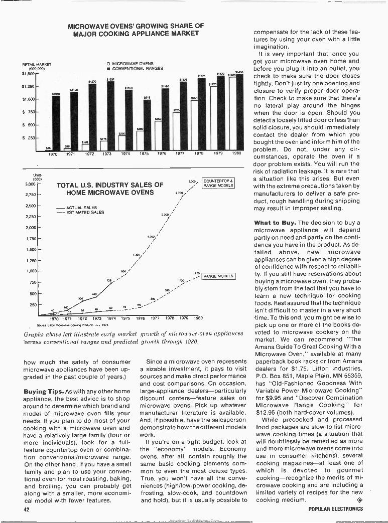
RETAIL MARKET (000,000)
$1,500 - $1,250
$1,000
$ 750
$ 500
$ 250
MICROWAVE OVENS' GROWING SHARE OF MAJOR COOKING APPLIANCE MARKET
31120
31050
'
31270
ti
3120
316
1970 1971 1972
MICROWAVE OVENS CONVENTIONAL RANGES
31332
3175
$290
91150
1973 1974
3975
3360
31180
$725
3,325
,
1975 1976 1977
51375
31225
31820 51450
1!00 '
1978 1979 1980
Units (000)
3,000
2,750
2,500
2,250
2,000
1,750
1,500
1,250
1,000
750
500
250
TOTAL U.S. INDUSTRY SALES OF HOME MICROWAVE OVENS
ACTUAL SALES --- ESTIMATED SALES
20 a0 60
1970 1971 1972 1973 1974
Source Untan M.crowave Cooh,n9 Or00utt3 July 7975
2200/
300
75 1 500
3.000,
2.700
850 i
700
"".
COUNTERTOP& RANGE MODELS
RANGE MODELS
1975 1976 1977 1978 1979 1980
Graphs above left illustrate earl// market growth of microwave -oven appliances versus conventional ranges and predicted growth through 1980.
how much the safety of consumer microwave appliances have been up- graded in the past couple of years.)
Buying Tips. As with any other home appliance, the best advice is to shop around to determine which brand and model of microwave oven fills your needs. If you plan to do most of your cooking with a microwave oven and have a relatively large fámily (four or more individuals), look for a full - feature countertop oven or combina- tion conventional/microwave range. On the other hand, if you have a small family and plan to use your conven- tional oven for most roasting, baking, and broiling, you can probably get along with a smaller, more economi- cal model with fewer features.
42
Since a microwave oven represents a sizable investment, it pays to visit sources and make direct performance and cost comparisons. On occasion, large -appliance dealers-particularly discount centers-feature sales on microwave ovens. Pick up whatever manufacturer literature is available. And, if possible, have the salesperson demonstrate how the different models work.
If you're on a tight budget, look at the "economy" models. Economy ovens, after all, contain roughly the same basic cooking elements com- mon to even the most deluxe types. True, you won't have all the conve- niences (high/low-power cooking, de- frosting, slow -cook, and countdown and hold), but it is usually possible to
compensate for the lack of these fea- tures by using your oven with a little imagination.
It is very important that, once you get your microwave oven home and before you plug it into an outlet, you check to make sure the door closes tightly. Don't just try one opening and closure to verify proper door opera- tion. Check to make sure that there's no lateral play around the hinges when the door is open. Should you detect a loosely fitted door or less than solid closure, you should immediately contact the dealer from which you bought the oven and inform him of the problem. Do not, under any . cir- cumstances, operate the oven if a
door problem exists. You will run the risk of radiation leakage. It is rare that a situation like this arises. But even with the extreme precautions taken by manufacturers to deliver a safe pro- duct, rough handling during shipping may result in improper sealing.
What to Buy. The decision to buy a
microwave appliance will depend partly on need and partly on the confi- dence you have in the product. As de- tailed above, new microwave appliances can be given a high degree of confidence with respect to reliabili- ty. If you still have reservations about buying a microwave oven, they proba- bly stem from the fact that you have to learn a new' technique for cooking foods. Rest assured that the technique isn't difficult to master in a very short lime. To this end, you might be wise to pick up one or more of the books de- voted to microwave cookery on the market. We can recommend "The Amana Guide To Great Cooking With a
Microwave Oven," available at many paperback book racks or from Amana dealers for $1.75. Litton Industries, P.O. Box 851, Maple Plain, MN 55359, has "Old -Fashioned Goodness With Variable Power Microwave Cooking" for $9.95 and "Discover Combination Microwave Range Cooking" for $12.95 (both hard -cover volumes).
While precooked and processed food packages are slow to list micro- wave cooking times (a situation that will doubtlessly be remedied as more and more microwave ovens come into use in consumer kitchens), several cooking magazines-at least one of which is devoted to gourmet cooking-recognize the merits of mi- crowave cooking and are including a
limited variety of recipes for the new cooking medium. O
POPULAR ELECTRONICS
AmericanRadioHistory.Com
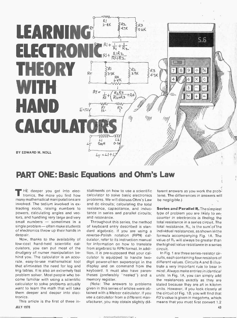
WITH
h wvYVY Ti ÍZ )
1 4K
NGi
ELECTRONIV: RIRz -
Ri+Rz
THEORY
HAND
1
R1 R ly.. .
CALCULATO!s.
BY EDWARD M. NOLL
Í'r-
,,, LI
Lr Sc tt 0-1
LT =Lt+L
LZ
R3 5.6 f¿.
PART ONE: Basic Equations and Ohm's Law
THE deeper you get into elec- tronics, the more you find how
mahy mathematical manipulations are involved. The tedium involved in ex- tracting roots, raising numbers to powers, calculating angles and vec- tors, and handling very large and very small numbers - sometimes in a
single problem- often make students of electronics throw up their hands in despair.
Now, thanks to the availability of low-cost hand-held scientific cal- culators, you can put most of the drudgery of numer manipulation be- hind you. The calculator is an accu- rate, easy -to -use mathematical tool that eliminates the need for log and trig tables. It is also an extremely fast problem solver. Most people who be- come familiar with using a scientific calculator to solve problems actually want to learn the math that will take them deeper and deeper into elec- tronics.
This article is the first of three in -
JULY 1976
stallments on how to use a scientific calculator to solve basic electronics problems, We will discuss Ohm's Law and dc circuits; calculating the total resistance, capacitance, and induc- tance in series and parallel circuits; and resonance.
Throughout this series, the method of keyboard entry described is stan- dard algebraic. If you are using a reverse -Polish notation (RPN) cal- culator, refer to its instruction manual for information on how to translate from algebraic to RPN format. In addi- tion, it is pre -supposed that your cal- culator is equipped to handle two - digit power -of -ten superscript in the display and on command from the keyboard. It must also have paren- theses (preferably "nested") and a memory register.
(Note: The answers to problems given in this series of artcles were ob- tained with a Melcor calculator. If you use a calculator from a different man- ufacturer, you may obtain slightly dif-
ferent answers as you work the prob lems. The differrences in answers will be negligible.) -;
Series and Parallel R. The simplest type of problem you are likely to en- counter in electronics is fi'ndin,g the total resistance in a series circuit. The total resistance, R,, is the sum'of the individual resistances, as shown iri'the formula accompanying Fig. 1A. The value of Rr will always be greater than the highest value resistance in a series circuit.
In Fig. 1 are three series -resistor cir- cuits, each containing four resistors of different values. Circuits A and B illus- trate a very important rule to bear in mind: Always make entries in identical units. In Fig. 1A, you can simply add the resistances exactly as they are stated because they are all in kilohm units. However, if you look closely at the circuit of Fig. 1 B, you will find that R3's value is given in megohms, which means that you must first convert 1.2
43
AmericanRadioHistory.Com
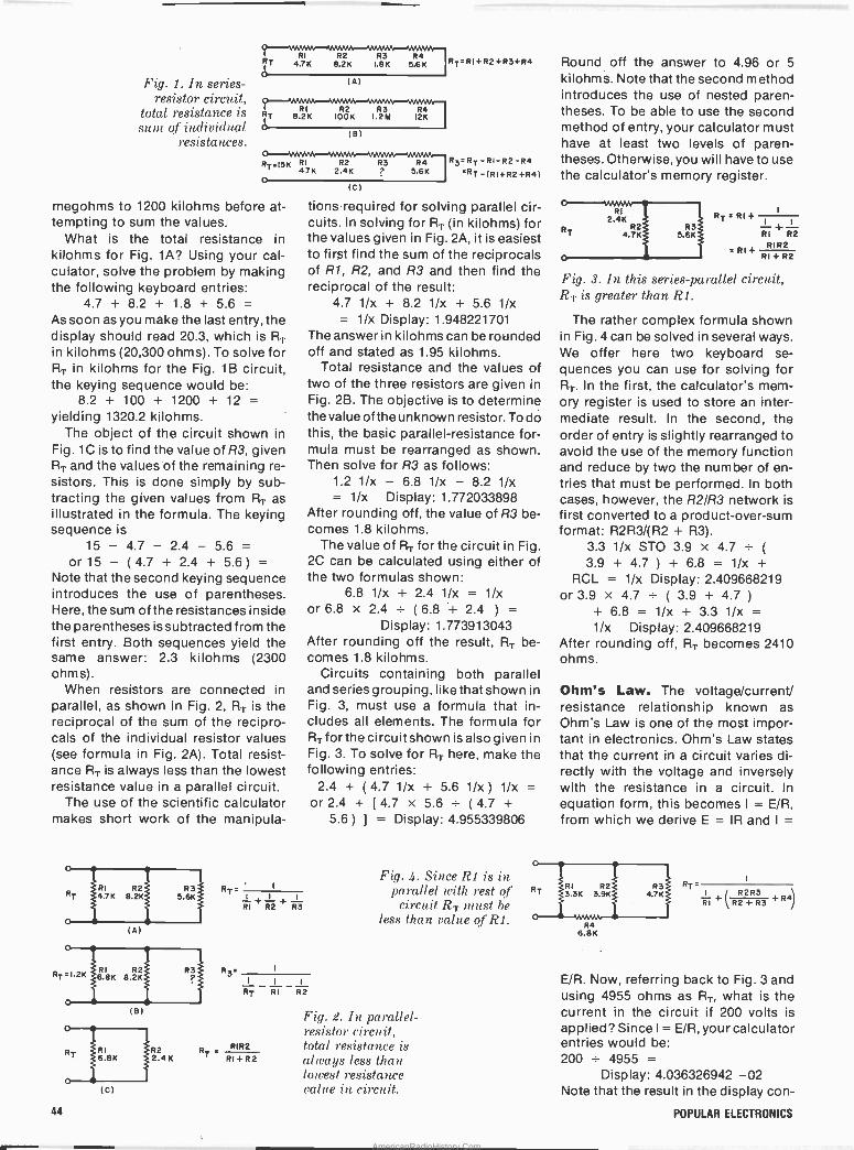
Fig. 1. In series - resistor circuit,
total resistance is stun of individual
. resistances.
67
IT
RI 4.7K
R2 8.2K
R3 1.8K
R4 5.6K RT=RI+R2+R3+R4.
(A)
8.2K IOOK I.2M 12K
(B)
RT=I5K RI R2 4.7K 2.4K
o
megohms to 1200 kilohms before at- tempting to sum the values.
What is the total resistance in kilohms for Fig. 1A? Using your cal- culator, solve the problem by making the following keyboard entries:
4.7 + 8.2 + 1.8 + 5.6 = As soon as you make the last entry, the display should read 20.3, which is RT
in kilohms (20,300 ohms). To solve for RT in kilohms for the Fig. 1 B circuit, the keying sequence would be:
8.2 + 100 + 1200 + 12 = yielding 1320.2 kilohms.
The object of the circuit shown in Fig. 1C is to find the value of R3, given RT and the values'of the remaining re- sistors. This is done simply by sub- tracting the. given values from RT as illustrated in the formula. The keying sequence is
15 - 4.7 - 2.4 - 5.6 = or15 - (4.7 + 2.4 + 5.6) =
Note that the second keying sequence introduces the use of parentheses. Here, the sum of the resistances inside the parentheses issubtracted from the first entry. Both sequences yield the same answer: 2.3 kilohms (2300 ohms).
When resistors are connected in parallel, as shown in Fig. 2, R,r is the reciprocal of the sum of the recipro- cals of the individual resistor values (see formula in Fig. 2A). Total resist- ance RT is always less than the lowest resistance value in a parallel circuit.
The use of the scientific calculator makes short work of the manipula -
(8)
(C)
. 1
RI + R2 + R3
R3=RT-RI-R2-R4 'RT -(RI+R2+R4)
(c)
tionsrequired for solving parallel cir- cuits. In solving for AT (in kilohms) for the values given in Fig. 2A, it is easiest to first find the sum of the reciprocals of R1, R2, and R3 and then find the reciprocal of the result:
4.7 1/x + 8.2 1/x + 5.6 1/x = 1/x Display: 1.948221701
The answer in kilohms can be rounded off and stated as 1.95 kilohms.
Total resistance and the values of two of the three resistors are given in Fig. 2B. The objective is to determine the value of the unknown resistor. To do this, the basic parallel -resistance for- mula must be rearranged as shown. Then solve for R3 as follows:
1.2 1/x - 6.8 1/x - 8.2 1/x = 1/x Display: 1.772033898
After rounding off, the value of R3 be- comes 1.8 kilohms.
The value of RT for the circuit in Fig. 2C can be calculated using either of the two formulas shown:
6.8 1/x + 2.4 1/x = 1/x or 6.8 x 2.4 _ (6.8 + 2.4 ) =
Display: 1.773913043 After rounding off the result, RT be- comes 1.8 kilohms.
Circuits containing both parallel and series grouping, like that shown in Fig. 3, must use a formula that in- cludes all elements. The formula for RT for the circuit shown is also given in Fig. 3. To solve for RT here, make the following entries:
2.4 + (4.7 1/x + 5.6 1/x) 1/x = or 2.4 + [4.7 x 5.6 - (4.7 +
5.6) J
= Display: 4.955339806
R3_
_ i RT RI R2
R2 RT RIR2 - 2.4K RI+R2
Fig. 4. Since R1 is in parallel with rest qt. RT
circuit RT must be less than valve of R1.
Fig. 2. In parallel - resistor circuit, total resistance is always less than lowest resistance value in circuit.
Round off the answer to 4.96 or 5
kilohms. Note that the second method introduces the use of nested paren- theses. To be able to use the second method of entry, your calculator must have at least two levels of paren- theses. Otherwise, you will have to use the calculator's memory register.
RI 2.4K
R2 4.7K
RT = RI +
RI + R2
= RI+ RIR2 RI + R2
Fig. 3. In this series -parallel circuit, RT is greater than R1.
The rather complex formula shown in Fig. 4 can be. solved in several ways. We offer here two keyboard se- quences you can. use for solving for RT. In the first, the calculator's mem- ory register is used to store an inter- mediate result. In the second, the order of entry is slightly rearranged to avoid the use of the memory function and reduce by two the number of en- tries that must be performed. In both cases, however, the R2/R3 network is first converted to a product -over -sum format: R2R3/(R2 + R3).
3.3 1/x STO 3.9 x 4.7 3.9 + 4.7 ) + 6.8 = 1/x +
RCL = 1/x Display: 2.409668219 or 3.9x4.7-(3.9+4.7)
+ 6.8 = 1/x + 3.3 1/x = 1/x Display: 2.409668219
After rounding off, RT becomes 2410 ohms.
'Ohm's Law. The voltage/current/ resistance relationship known as Ohm's Law is one of the most impor- tant in electronics. Ohm's Law states that the current in a circuit varies di- rectly with the voltage and inversely with the resistance in a circuit. In
equation form, this becomes 1 = E/R, from which we derive E = IR and I =
RT-
R4 6.8K
I R2R3 RI +(R2+R3 +R4)
E/R. Now, referring back to Fig. 3 and using 4955 ohms as RT, what is the current. in the circuit if 200 volts is applied? Since I = E/R, your calculator entries would be: 200 - 4955 =
Display: 4.036326942 -02 Note that the result in the display con -
44 POPULAR ELECTRONICS
AmericanRadioHistory.Com
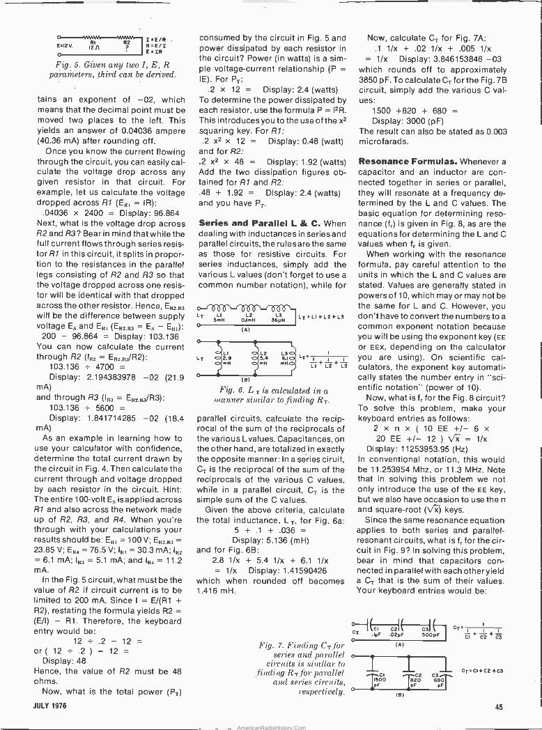
E=12 V. 1111
o.
Fig. 5. Given any two I, E, R parameters, third can he derived.
\MAMA MA RMM-.+ I = E / R .
R=E/Z E=IR
tains an exponent of -02, which means that the decimal point must be moved two places to the left. This yields an answer of 0.04036 ampere (40.36 mA) after rounding off.
Once you know the current flowing through the circuit, you can easily cal- culate the voltage drop across any given resistor in that circuit. For example, let us calculate the voltage dropped across R1 (Es, = IR):
.04036 x 2400 = Display: 96.864 Next, what is the voltage drop across R2 and R3? Bear in mind that while the full current flows through series resis- tor R1 in this circuit, it splits in propor- tion to the resistances in the parallel legs consisting of R2 and R3 so that the voltage dropped across one resis- tor will be identical with that dropped across the other resistor. Hence, E,32.83
will be the difference between supply voltage ES and ER, (EH2.R3 = ES - E111):
200 - 96.864 = Display: 103.136 You .can now calculate the current through R2 (11t2 = EH2,1i3/R2):
103.136 - 4700 = Display: 2.194383978 -02 (21.9
mA) and through R3 (l,<3 = E82.It:;/R3):
103.136 - 5600 = Display: 1.841714285 -02 (18.4
mA) As an example in learning how to
use your calculator with confidence, determine the total current drawn by the circuit in Fig. 4. Then calculate the current through and voltage dropped by each resistor in the circuit. Hint: The entire 100 -volt Es is applied across R1 and also across the network made up of R2, R3, and R4. When you're through with your calculations your results shouldbe: E,t, = 100 V; E1i2.13:1 = 23.85 V; E,34 = 76.5 V; IHI = 30.3 mA; I,¿,
= 6.1 mA; 113:3 = 5.1 mA; and 1,34 = 11.2 mA.
In the Fig. 5 circuit, what must be the value of R2 if circuit current is to be limited to 200 mA. Since I = E/(R1 + R2), restating the formula yields R2 = (E/I) - R1. Therefore, the keyboard entry would be:
12 _ .2 - 12 = or ( 12 _ .2 ) - 12 =
Display: 48 Hence, the value of R2 must be 48 ohms.
Now, what is the total power (Pr)
consumed by the circuit in Fig. 5 and power dissipated by each resistor in the circuit? Power (in watts) is a sim- ple voltage -current relationship (P = IE). For PT:
.2 x 12 = Display: 2.4 (watts) To determine the power dissipated by each resistor, use the formula P = I2R.
This introduces you to the use of the x2
squaring key. For R1: .2 x2 x 12 = Display: 0.48 (watt)
and for R2: .2 x2 x 48 = Display: 1.92 (watts) Add the two dissipation figures ob- tained for R1 and R2: .48 + 1.92 = Display: 2.4 (watts) and you have PT.
Series and Parallel L & C. When dealing with inductances in series and parallel circuits, the rules are the same as those for resistive circuits. For series inductances, simply add the various L values (don't forget to use a
common number notation), while for
LT LI L2 L3 531H O.ImH 36yH
0 (A)
LT=LI+L2+L3
LT= L I+ L2 + L3
(B)
Fig. 6. L T is calculated in a manner similar to finding RT.
parallel circuits, calculate the recip- rocal of the sum of the reciprocals of the various L values. Capacitances, on the other hand, are totalized in exactly the opposite manner: In a series ciruit, CT is the reciprocal of the sum of the reciprocals of the various C values, while in a parallel circuit, CT is the simple sum of the C values.
Given the above criteria, calculate the total inductance, L T, for Fig. 6a:
5+.1 +.036= Display: 5.136 (mH)
and for Fig. 6B: 2.8 1/x + 5.4 1/x + 6.1 1/x = 1/x Display: 1.41590426
which when rounded off becomes 1.416 mH.
Fig. 7. Finding CT for series and parallel o
circuits is similar to finding RT for parallel
and series circuits, respectively.
Now, calculate CT for Fig. 7A: .1 1/x + .02 1/x + .005 1/x
= 1/x Display: 3.846153846 -03 which rounds off to approximately 3850 pF. To calculate CT for the Fig. 7B circuit, simply add the various C val- ues:
1500 +820 + 680 = Display: 3000 (pF)
The result can also be stated as 0.003 microfarads.
Resonance Formulas. Whenever a
capacitor and an inductor are con- nected together in series or parallel, they will resonate at a frequency de- termined by the L and C values. The basic equation for determining reso- nance (fr) is given in Fig. 8, as are the equations for determining the L and C values when fr is given.
When working with the resonance formula, pay careful attention to the units in which the L and C values are stated. Values are generally stated in powers of 10, which may or may not be the same for L and C. However, you don't have to convert the numbers to a
common exponent notation because you will be using the exponent key (EE or EEx, depending on the calculator you are using). On scientific cal- culators, the exponent key automati- cally states the number entry in "sci- entific notation" (power of 10).
Now, what is fr for the Fig. 8 circuit? To solve this problem, make your keyboard entries as follows:
2 x n x ( 10 EE +/- 6 x 20 EE +/- 12 ) \ = 1/x
Display: 11253953.95 (Hz) In conventional notation, this would be 11.253954 Mhz, or 11.3 MHz. Note that in solving this problem we not only introduce the use of the EE key, but we also have occasion to use the n and square -root ( keys.
Since the same resonance equation applies to both series and parallel - resonant circuits, what is fr for the cir- cuit in Fig. 9? In solving this problem, bear in mind that capacitors con- nected in parallel with each other yield a CT that is the sum of their values. Your keyboard entries would be:
1 CI C2 C3 CT .IyF .02yF 500pF
C+
(A)
CI 1500 DF
i. TC2 20
pF
(B)
C3 6BT pF
CI + C2 + C3
CT=CI+C2+C3
JULY 1976 45
AmericanRadioHistory.Com
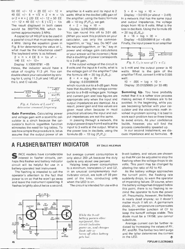
50 EE +/- 12 + 20 EE +/- 12 x 40 EE +/- 6=\ x x 2 x n= 1/x or 2 x n x [ (20 EE +/- 12 + 50 EE +/- 12 x 40 EE+/ -6 )\x]= 1/x The result displayed in both cases would be, 3007745.709, which be- comes approximately 3 MHz.
A capacitor of 140 pF is to be used in a parallel circuit that must resonate at 4 MHz. Using the equation given in Fig. 8 for determining the value of L,
what must be the inductance used? The keyboard entry is as follows:
2 x n x 4 EE 6= 1/x x2
140 EE +/- 12= Display: 1.130816781 -05
Hence, the inductor would have a
value of roughly 11.3 µH. You can double check your calculation by solv- ing for f,. using 11.3 pH and 140 pF as the L and C values.
O VVV L
10yH 20pF o
(r - 2n LC
L. (2irF)2C'
C= (2nF)2L
Fig. 8. Values of I, and C determine resonant f'Ie(lN('11(1/.
Gain Formulas. Calculating power and voltage gain with a scientific cal- culator is a cinch because the cal- culator's built-in logarithm function eliminates the need for log tables. To see how simple the procedure is, let us
assume that the output power of an
amplifier is 4 watts and its input is 2
watts. What is the decibel (dB) gain of the amplifier, using the basic formula dB = 10 log (P/P;,,), we get:
4 ± 2 = log x 10 = Display: 3.010299954 (dB)
You can round this off to 3.01 dB. (When you work this problem on your calculator, use only the common - logarithm, or "log," key. Do NOT use the natural -logarithm, or "In," key in
power and voltage gain calculations or your answer will be incorrect.) Note that a doubling of power corresponds to a 3 dB gain.
If the output voltage of the circuit is
8 volts and the input is 4 volts, what is
the voltage gain of the amplifier? Use the formula dB = 20 log (E/E,,,):
8 - 4 = log x 20 = Display: 6.020599908
which rounds out to a 6 -dB gain. Note here that doubling the voltage corres- ponds to a 6 -dB voltage gain. Voltage and current gain and loss figures are appropriate only when the input and output impedances are identical. As a
result, power gain and loss values are given most often because in most practical situations the input and out- put impedances are not the same.
In passing through a network, the output power drops from 6 watts at the input to 3 watts at the output. What is the power loss in decibels, using the formula dB = 10 log (P,jP,,,):
3 ± 6 = log x 10 = Display: -3.0103 (or about - 3 dB)
In a network that has the same input and output impedance, the voltage drops from 16 to 8 volts. What is the loss in decibels. Using the formula dB = 20 log (E/E;,,):
8 ± 16 = log x 20 = Display: -6.020599918 (or -6 dB)
Finally, the input power to an amplifier
CI 50pF
Fig. 9. CT is S1U11 of CI + C2.
is 5 mW and the output power is 10
watts. What is the gain of the amplifier? First, convert 5 mW to 0.005 watt:
10 - .005 = log x 10 = Display: 33.01029995 (or 33 dB)
LI C2 40
20pF yH 2n LI(CI+C2)
Summing Up. You have probably noted that it is a rather slow process making entries if mistakes are to be avoided. In the beginning, while you are becoming familiar with your cal- culator and the electronics math in- volved in problem solving, it is best to work each problem two or three times to avoid errors. As your confidence builds, however, you will find the process considerably speeded up.
In our second installment, we dis- cuss impedance and ac formulas. O
A FLASHER/BATTERY INDICATOR BY DALE HILEMAN
SINCE readers have considerable interest in flasher circuits, per-
haps this flasher and battery indicator circuit will be helpful for use in a
battery -operated test instrument. Th'e flashing is intended to call the
operator's attention to the fact that power is on so that he won't go away and leave the instrument operating. It flashes brightly about twice a second,
46
but average current consumption is
only about 200 µA because the duty cycle is only about one percent.
Helping keep power consumption to a minimum, transistors Q1 and Q2, in an unusual complementary mul- tivibrator circuit, are both cff 99 per- cent of the time, conducting only when the LED is on.
The circuit is intended for use with a
While the 9 -toll battery potters other equipment, this circuit indicates porter on, and changes flash rate or hi111,5 off when batters/ gets /oft.
9 -volt battery, and values are chosen so that R4 can be adjusted to stop the flashing when the voltage drops to six volts. This point may be changed by
altering the ratio.of R2 to R3. As the battery voltage approaches
the turnoff point, the flashing rate suddenly drops, to warn the operator of impending failure. Of course, when the battery voltage has dropped below this point, there is no flashing to re- mind the operator to turn the power off. Presumably, however, the battery is nearly dead anyway; so it doesn't matter much if left ón. A germanium diode, D1, temperature -compensates the base -emitter junction of Q1 to keep the turnoff voltage stable. This diode must be a 1N198; you cannot substitute.
Average current can be further re- duced by increasing the values of R1, R7, and R9. The former two limit surge and the latter determines the current in the LED. O
POPULAR ELECTRONICS
AmericanRadioHistory.Com

I, -..n C"-Ar ,
I ,J --! -
Update Your Multimeter with a
CMOS Millivolter Converts any voltmeter into a
high -sensitivity input meter
for low millivolts measurements.
YOU CAN inexpensively update
any dc voltmeter to measure in the low -millivolt range at an input sen- sitivity of 1000 megohms/volt with the Millivolter. The self-contained, battery -powered Millivolter is basi- cally a high -sensitivity amplifier housed in a 5" (12.7 -cm) long probe
BY DAVID H. DAGE
that plugs into the standard input of any voltmeter rated at 1000 ohms (or greater) per volt.
When the Millivolter is used with an ordinary dc voltmeter, it can supply gains of x10 or x100 through its built-in CMOS operational amplifier circuit. This means that a 3 -volt range
in the meter effectively becomes a
30 -mV range and a 1 -volt range be- comes a 10 -mV range full scale. Addi- tionally, the probe can be used to measure current, with 1 nA indicating full scale on a 1 -volt range.
You can build the Millivolter for about $12, which is a great deal less than you would have to pay for a new instrument capable of providing its measurement features.
How It Works. The Millivolter is built around a new CA3130 linear CMOS op amp (IC1 in Fig. 1) that has extremely low bias current requirements. This permits large values of input resis- tance to be effectively used. In this case, 10 megohms is used without seriously affecting the output voltage when the probe inputs are shorted.
When using a CA3130 op amp with a
10-megohm input resistor (R1), the output changes only 5 mV, or 0.5% of the full-scale indication. This is a
sharp contrast to the unusual be- havior of most other op amps on the market.
The output of the new op amp con- sists of CMOS transistors that operate as a class -A amplifier whose gain is dependent on the load impedance that it drives. With a gain of 100 and a
reasonably high -input -impedance voltmeter (5000 ohms/volt), negligible error is introduced even when driving the output to within a few millivolts of the supply potential. When driving low -impedance voltmeters (1000 ohms/volt), the output is reliable to within ±3 volts with less than 2% load error. Shorting the output to ground will not damage the IC.
The circuit shown in Fig. 1 employs 1% tolerance resistors in the -gain- setting feedback loop, which means that no gain -adjusting trimmer poten- tiometers are required. The offset vol- tage can be adequately trimmed to null by adjusting potentiometer R6.
With S1 in the OFF position, the probe is completely bypassed, the voltmeter operates in the normal manner, and power is removed from the probe's circuit. In either of the other two positions (x10 and x100), S3 applies power to the probe's circuit and simultaneously performs all switching functions for the gain selected.
A single 9.8 -volt battery, 81, powers the op amp amplifier circuit through Q1 and the resistor network consist- ing of R7, R8, and R9. This network provides a common (ground) refer -
JULY 1976 47
AmericanRadioHistory.Com

OFF
X 10
.5100
(TIP PROBE
GND
Fig. 1 Use of a
new CMOS op amp enables Milli-
volter to have a 1000-nt.egohtu per
volt input sen- sitivity. Gain
is switch se- lectable between
10 and 100 times.
RI 10M
R2 2.2M
3
CI
OIyF
R5 10K
+V
7
ICi CA3130
2
' 8
8
R3 'V IM
R4 100K
R 100
C2 7.00IyF
OFF
XIO SIB
"HOT"
5100
FF
SIC X10 XIOC
GND
+ B1 -9.8V
SID
R7 39K
,OFF
X100
01 2N3860
R8 R9 56K 5.6K
+V
PARTS LIST
BI -9.8 -volt mercury battery (RCA No. VSI77 or similar)
CI -0.01-µF disc capacitor C2 -0.001-µF disc capacitor ICI-CA3130 CMOS linear op amp IC
(RCA) i11 -2N3860 or similar transistor RI-IO-megohm, 5% resistor R2-2.2-megohm, 5% resistor R3-1-megohm, 1% resistor R4 -100,000 -ohm. I% resistor R5 -10,000 -ohm. I% resistor R6 -100,000 -ohm miniature trimmer
potentiometer R7 -39.000 -ohm, 5% resistor R8 -56,000 -ohm, 5% resistor R9 -5600 -ohm, 5% resistor SI-Four-pole, three -position miniature
slide switch
v
OUTPUT
Misc.-Suitable probe assembly (see text); printed circuit or perforated board; battery connector clips; probe tip; shielded cable (audio or coaxial) for output; miniature alligator clip; brass angle bracket; rubber grommet and silicone adhesive (optional-see text); hookup and test -lead wire; machine. hardware; dry -transfer lettering -kit; sol- der: etc.
Note: The following items are available from Dage Scientific Instruments, P.O. Box 1054, Livermore, CA 94550: Com- plete kit of parts (less battery and output cable connectors) for $11.95 plus $1.00 shipping and handling; RCA No. VS177 9.8 -volt mercury battery for $2.50. California residents. please add sales tax.
ence at approximately half the battery potential, or 4.9 volts.
Construction. The Millivolter circuit can be assembled on either a printed circuit board -or perforated board using point-to-point wiring tech- niques. It can also be housed in a small box instead of in a probe housing, al- though the latter is more convenient for testing purposes.
If you use pc wiring at?d plan to house the circuit in a probe body, use the actual -size etching and drilling guide in Fig. 2. Mount a small brass (not aluminum) angle bracket at the battery end of the board, sweat - soldering it into place. Then either solder or rivet a female,battery con- nector clip to the bracket. This clip will accommodate the positive (+) termi- nal of the battery. Mount and solder into place trimmer potentiometer R6, about 1/16" (1.6mm) away from the
surface of the board. This pot mounts on the foil side of the board. Mount and solder into place all remaining components on the blank side of the board as shown in Fig. 2.
Although the input of ICI is pro -
Fig. 2 Actual -size foil pattern and com-
ponent installation on (1 board that
can fit a 7/8" ID tube. The positive
battery clip is soldered to one end
of the board, with wire connection
to the negative terminal.
., _.ÁuKC1i1 '
tected, it is still a MOS device and should be handled with care. There- fore, it is best not to handle the IC by its leads. Once ICI is soldered to the board pads, all pins will be properly terminated and no further safety pre- cautions need be practiced.
You can use just about any plastic tube that has a 7/8" (22.2 -mm) inner diameter and measures 5" (12.7 cm) in length to house the pc board assem- bly. If you want to reduce the amount of ac pickup, you can use a metal tube, but make absolutely certain that none of the components on the board touch the metal probe body. (Only the com- mon ground circuit should make good electrical contact with the metal tube.)
Before sliding the circuit assembly into the probe body, accurately locate and cut a slot in the body for Si. Pre- pare a length of stranded (preferably test -lead) wire; fasten one end to the circuit's common ground point and to the other end attach a small alligator clip.
If your voltmeter normally uses an isolation resistor (usually 1 megohm) in its "hot" probe, connect the same value resistor in series with the Mil- livolter's output pad and output cable. You can conveniently mount this re -
OUTPUT (LOW)
OUTPUT (HIGH)
----- 81 +
-BI RI
R2 -- INPUT \
I
= GND
PROBE
48 POPULAR ELECTRONICS
AmericanRadioHistory.Com

FULL-SCALE CURRENT RANGES
Shunt Resistor 1 -volt FS probe x100
3 -volt FS probe x100
1 -volt FS probe x10
3 -volt FS probe x10
none 100,000 ohms 1000 ohms 10 ohms
1 nA 100 nA
10 µA 1 mA
3 nA 300 nA
30 µA 3 mA
10 nA 1 µA
100 µA 10 mA
30 nA 3 µA
300 pA 30 mA
sistor on the bottom (foil) side of the board.
Fashion a wood or plastic plug to fit the front of the probe body and mount a conventional test probe tip in it. Drill a hole through the rear of the probe body to allow the coaxial output cable to pass through. (If you're using a tube that's open at both ends for the probe body, you'll need another plug; drill the cable exit hole through the plug in this case.) The exit hole should be just large enough for a snug fit around the cable.
Solder the output cable to the ap- propriate points in the Millivolter's circuit. You can fashion a strain relief for the cable by sliding onto it a snug - fitting rubber grommet and fixing the grommet into place with silicone adhesive. (Trial fit the circuit assembly into the probe body to locate where along the cable the grommet is to be positioned before cementing it into place.)
With Si set to the OFF position, con- nect the battery to the clip mounted on the brass bracket. To the free end of a length of hookup wire connected to the wiper contact of S1D, solder a male battery connector. Snap this connector onto the negative (-) ter- minal of 81. Then slide the entire cir- cuit assembly into the probe body, positioning the slider of S1 in the cut- out, and fasten the front plug into place with small machine screws. Fi- nally, fit to the conductors at the free end of the output cable the appro- priate connector(s) to mate with the input of your voltmeter.
Operation. Connect the assembled probe to your voltmeter, first setting the meter to the 1- or 3 -volt dc range. The probe's output swing will be typi- cally 4.5 volts in both the positive and negative directions. However, the maximum reliable output range should be limited to±3 volts. What this means is that if you were measuring voltages with the meter set to a range higher than 3 volts, an indication of 4
volts might represent a saturated out -
JULY 1976
put and not a true voltage measure- ment.
Make sure that the pointer of your voltmeter is set at mechanical zero and to a low dc voltage range. Then short the ground lead to the probe tip. Zero the probe by adjusting R6 (you'll have to partially disassemble the probe to do this) in first the x10 and then the x100 positions of S1. Re- move the ground clip from the probe tip and reassemble the probe. A very slight negative voltage variation can be expected when you remove the ground clip from the probe tip. Don't attempt to zero this offset. If you find this slight offset objectionable you can reduce the value of R1 until it dis- appears.
The Millivolter probe is highly sensi- tive. Just touching the probe tip with
be greater than 3.5 V in both directions and greater than 8 V between the two readings. When the voltage drops below these levels, it's time to replace the battery.
Accidental application of up to 200 volts dc to the input of the probe will not damage the Millivolter's circuit. Under no circumstances should you apply a voltage to the probe's output lead.
Other Applications. From Ohm's Law, we know that when 1 µA is flow- ing through a 1 -ohm resistor, the vol- tage dropped across the resistor is 1
µV. If you connect the Millivolter probe in series with a circuit (assuming the value of R1 is 10 megohms), you have a 0-to-1-nA current probe. Since there isn't much demand for such a sensi- tive current scale, you can add ap- propriate shunt resistors across R1 to produce the ranges detailed in the Ta- ble. Keep a supply of 1% resistors of the values indicated to use as current shunts.
The probe also makes an ideal nul- ling device for use with a precision bridge. If your voltmeter can be set up for center -scale zero, the probe will turn it into 500-0-500-pA nulling meter.
., .v5177 I a Milli
=9.6 volts -- __.., - -
+'*+ .0, 514
Photo shows component mounting details and location of battery bracket/connectou' at left end of pc board.
your finger is enough to cause the meter pointer to peg against its up- scale mechanical stop. Keep this in mind when measuring voltages in high -impedance circuits.
Switch S1 should be kept in the OFF
position when you're not using the probe's amplification function and when your meter is stored away: If you turn off the probe (Si set to OFF) when not in use and when you're measuring voltages in the bypass mode, you can expect the battery to last in excess of 70 hours when power is actually applied to the probe's circuit. (Current drain of the Millivolter's circuit is less than 5 mA.)
You can check the condition of the probe's battery by applying a positive and then a negative potential great enough to drive the probe's amplifier into saturation. The saturation voltage at the output of the Millivolter should
You can use current shunts if this range is too sensitive. Resistance in the milli -ohm range can be measured with the aid of a constant -current source pegged at 10 or 100 mA. Full- scale range will be 100 milliohms on a
1 -volt meter scale with 100 mA test current.
You can also make a megohmmeter insulation tester by placing a 10 -volt constant -voltage source in series with the unknown high resistance, while measuring the current flow with the probe. Resolution of up to 1012 ohms is possible with a full-scale reading of 100,000 megohms.
All in all, for a very small investment and a few hours of assembly time, you can build a really versatile Millivolter probe that can make an inexpensive VOM perform like a laboratory instru- ment that ordinarily costs several hundred dollars.
49
AmericanRadioHistory.Com
BY RANDY J. SOULE
A Low-cost APARTMEHT BURGLAR ALARM Self -powered system features adjustable time delay.
if:iiii's1;r,±!:i=1`iti+0:g .ü.Ciufltiüki .:,';-e"
`
MOST home intruder/burglar alarms employ sensors of some
sort scattered throughout the prem- ises which, when tripped, sound a
loud gong or siren. Although such elaborate alarm systems may be a
necessity for private homes, the apartment dweller living above the ground floor can get by with a simpler system. With access usually limited to a single door and perhaps one or two windows that feed onto a fire escape, only a few sensors are needed. In addi- tion the piercing tone of a Sonalert'y
50 POPULAR ELECTRONICS
AmericanRadioHistory.Com
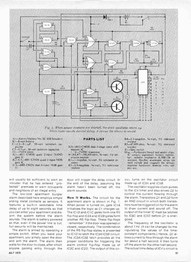
Fig. 1. When sensor contacts are shorted, the clock oscillátor starts up. When timer counts de.' iced delay. it causes the alarm to sound.
A 1-Alarm (Mallory No. SC -628 Sonalert) B1 -9 -volt battery Cl .C2 -0.1-µF, 50 -volt tantalum ca-
pacitor C3 -11.2-µF, 50 -volt tantalum capacitor DI-IN914 diode ICI -4011 CMOS quad 2 -input NAND.
gate IC 1C2,IC5-4001 CMOS quad 2-input'NOR
gate IC 1C3-4002 CMOS dual 4 -input NOR gate
IC
will usually be sufficient to alert an intruder that he has entered "pro- tected" premises or warn occupants and neighbors of an illegal entry.
The low-cost apartment burglar alarm described here employs simple sliding metal contacts as sensors. It
features a built-in selectable time delay of up to eight seconds so that you can enter your apartment and dis- arm the system before the alarm sounds. The alarm is battery powered so that, even if the power line is cut, full security will be maintained.
The alarm is armed by operating a simple switch. When you leave your apartment, you simply open the door and arm the alarm. The alarm then waits for the door to close, after which anyone gaining' entry through the
- PARTS LIST
IC4-4015 CMOS dual 4 -stage static shift register IC 1, ,2-2N339I transistor
RI,R6,R7-100,000-ohm, %a -watt. 59f erance resistor
R2-I-megohm, 1/4 -watt, 5% tolerance re- _
sistor R3-3.9-megohm, 1 -watt, 57 tolerance',
resistor '
door will trigger the delay circuit. At the end of the delay, assuming the alarm hasn't been turned off, the alarm sounds.
How It Works. The circuit for the apartment alarm is shown in Fig. 1.
When power is turned on, gate IC1A initializes the logic as Cl charges up. The IC1B and IC1C gates form one RS flip-flop and IC2A and IC2B gates form another RS flip-flop. These flip-flops "remember" if the door was opened or closed, respectively. The combination of the RS flip-flop states is presented to IC1D to latch the IC3A/IC38 circuit. The IC3A/IC38 latch provides all the proper conditions for triggering the alarm control flip-flop made up of IC2C and IC2D. The output of this cir-
R4----2.21-megohm,;14-watt,' 5%' tolerance resistor
R5-47,$X)0-óhm, '1/4 -watt 5% tolerance resistor
S I-Spst switch Misc.-Perforated board and solder clips:
IC sockets (optional); battery connec- tor; suitable enclosure (LMB-136 or Similar); flexible aluminum strips (or reed sv, itch and magnet) for sensor; machine hardware; hookup wire; sol- der: etc.
cult turns on the oscillator circuit made up of ICSA and IC5B.
The oscillator supplies clock pulses to the IC4 timer and also drives Q2 to control the current flowing through the alarm. Transistors Q1 and Q2 form an AND circuit in which both transis- tors must be triggered on for the alarm to draw current and sound off. The output of the timer IC must be latched by /C5C and IC5D before Q1 is ener- gized.
The frequency of the oscillator is about 1 Hz. (It can be changed by ma- nipulating the values of the time - constant components.) Hence, Q2 al- lows current to flow through the alarm for about a half second. It then turns off the alarm for the other half second. The actual time delay of 1C4's circuit is
JULY 1976 51
AmericanRadioHistory.Com

Have ever askedyou vo se "dan I ake it
Electro 'es CIE may be the answer if you have a technical aptitude and a serious desire to get ahead.
Right now, you're reading a technical magazine with articles that require a certain amount of electronics know-how. And that says a couple of things about you.
First, you're involved in Electronics ... on the job, or as a hobby.
Second, you obviously realize the importance of staying up-to-date on the latest technical applications and devel- opments. Reading a technical magazine helps, but it takes more than that to get you where you want to be ... if you're serious about Electronics.
How can you afford ... not to continue with your electronics training?
You know the answer to that as well as we do. To achieve continuing success, you have to keep build-
ing more knowledge into the Electronics background and experience you already have. You have to sharpen the tech skills you've already got and add new ones.
And one of the most logical ways for you to get what you need is to seriously consider an in-depth electronics training program that could help you achieve your am- bitions in Electronics.
How can you afford ... the time and trouble of going back to school?
An excellent and convenient way for you to develop and expand your electronics knowledge is to "let the school come to you."
CIE's independent education plan does just that. Because we can effectively train you with an "education by mail" electronics training program that makes sense. And it makes sense for these reasons:
. I
You can master career E ectronics without missing one day of work. Without sacrificing one paycheck! Because you study in your free time ... setting the study pace that best fits your schedule. You decide when and where you want to study. So you can go right on enjoying your leisure time because there are no rigid classroom schedules to be met. You're in control!
How can you afford ... the expense of the additional education you need?
A lot depends on which CIE course best fits your educa- tional goals and background. We have a variety of electronics courses at beginner, intermediate, and ad- vanced college -level. And there's a convenient payment plan available for every course. But, one way to evaluate your investment in CIE is this . .. you can graduate from CIE for about the cost of one year's tuition at some colleges or universities.
How can you afford ... to learn Career Electronics from anyone other than an electronics specialist?
If you are serious about your career in Electronics, you owe it to yourself to investigate the home study school that devotes its entire curriculum and instructional efforts to Electronics. That's CIE - Cleveland Institute of Electronics.
We have specialized exclusively in Electronics education - by -mail for more than 40 years. Just Electronics. Nothing else. And, the courses we offer today are the result of these years of teaching experience and proven methods of training ... all based on the expert guidance of our
52 POPULAR ELECTRONICS
AmericanRadioHistory.Com
u aa.
specialized Electronics Instruction Staff. Our lessons reflect this specialized experience. No frills. No unneces- sary fancy stuff. Instruction is thorough ... designed to meet the demands of electronics employers.
Each CIE course is built on the principle that the best way for you to learn and retain what you've learned is to explain; then to check your understanding; then to reinforce your comprehension with practical applications. In some courses, you will perform experiments and tests with your CIE Experimental Electronics Laboratory using authentic electronic components and gear. And, if you select a course that includes Color TV technology, you will not only build and keep a big screen Color TV which features digital circuitry ... you'll also learn how to troubleshoot your TV.
The course you select will be a complete educational program, designed by experts to give you the best in Electronics independent home -study education. It will not be a "snap" course. No easy exams. It will make you work ...and think. So that when you've earned your CIE Diploma, you'll really know your stuff.
In education just like in the "real world" of Electronics, your success depends on you and the effort you make. That's a real plus in CIE independent home -study .. .
you build a strong foundation of self-discipline. And that pays off!
How can you afford ... to stop now? There is a lot more to CIE than this advertisement can tell you. And because you're looking for the best, we think it's well worth your while to find out what CIE is
JULY 1976
all about. Detailed Courses of Study outlines. In-depth training programs in Electronics Technology, Broad- casting, Industrial, Color TV, Engineering, and 1st Class FCC License preparation. Special CIE Student Services.
All this information is available to you, FREE, when you mail the card or coupon to us. For your convenience, we'll try to have a school representative contact you to review the benefits of CIE training and assist in course selection. And as soon as we hear from you, we'll mail a complete package of information, including our school catalog, G. I. Bill details, special FCC License informa- tion. All the facts you need to start your Electronics career program with CIE.
Send TODAY for CIE'S FREE information. r
PE -07
L
CIECleveland Institute of Electronics, Inc. 1776 East 17th Street. Cleveland, Ohio 44114
Accredited Member Notional Home Study Council
Yes, I want your FREE school catalog and career information package today. I am especially interested in:
Electronics Technology Industrial Electronics FCC License Preparation Electronics Engineering Color TV Maintenance Other Mobile Communications
Print Name
Address Apt.
City
1
State Zip Age Check box forG.l. Bill information. Veteran On Active Duty
-I
55
AmericanRadioHistory.Com
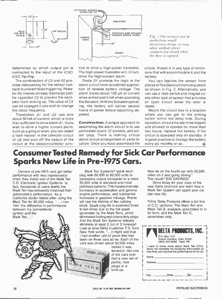
HOLE FOR MTG
SCREW
I/4"
determined by which output pin is
connected to the input of the IC5C/ IC5D flip-flop.
The combination of C2 and R2 pro- vides debouncing for the sensor con- tacts to prevent false triggering. Resis- tor R5 insures an easy discharge path for capacitor C3 to prevent the oscil- lator from locking up. The value of C3 can be changed if you wish to change the clock frequency.
Transistors Q1 and Q2 can sink about 50 mA of current, which is more than sufficient to drive alarm Al. If you wish to drive a higher current alarm, such as a gong or siren, you can install a load resistor in the collector circuit of Q2 and pick off the output of the circuit at the resistor/collector junc-
ATTACHED ACROSS CAPACITOR C2
(HINGED SIDE)
(MOLDING)
STRIPPED WIRE SECURED AROUND SCREW HEADS
(DOOR) -_ tion to drive a high -power transistor. The high -power transistor will, in turn, drive the high -current alarm.
Diode D1 protects the logic in the alarm circuit from accidental applica- tion of reverse battery voltage. The alarm draws about 100 µA of current when armed and 5 mA when sounding the Sonalert. With the Sonalert operat- ing, the battery will deliver several hours of power before becoming de- pleted.
Construction. A simple approach to assembling the alarm circuit is to use perforated board, IC sockets, and sol- der clips. There is nothing critical about circuit arrangement or parts lo- cation. Once you have assembled the
Fill. 2 7'he sensors cart he
made Iron! small alrurriunm strips, or any other rrretlrod where (outaC/N tyre closed when the dour is opened.
circuit, mount it in any type of enclo- sure that will accommodate it and the battery.
You can fashion the sensor from pieces of flexible aluminum strip stock as shown in Fig. 2. Alternatively, you can use a reed switch and magnet (or any other type of sensor that provides an open circuit when the door is open).
Mount the circuit box in a location where you can get to the arming switch within the delay time. During operation, should the alarm be tripped and allowed to operate for more than two hours, replace the battery. If the circuit is operated only on standby, it is good practice to change the battery every six months or so.
Consumer Tested Remedy for Sick Car Performance Sparks New Life in Pre -1975 Cars.
Owners of pre -1975 cars get better performance with less maintenance when they install one of the Mark Ten C.D. Electronic Ignition Systems. In fact, thousands of users testify the Mark Ten has noticeably improved their automobile's performance. As a California doctor stated after using the Mark Ten for 95,000 miles. "...I can 'feel' the difference in performance between my conventional ignition and the Mark Ten ..."
`KSM1TN
Mark Ten Systems* spark each plug with 50,000 to 60,000 volts in secondary output compared to a mere 25,000 volts in standard and most pointless systems. This means dramatic increases in acceleration and general engine performance, and substantial increases in gasoline mileage. Points will last the lifetime of the rubbing block. Spark plug life is extended three to ten times due to the hot spark generated by the Mark Tens, which eliminates fouling and cleans dirty plugs. And the Mark Ten Systems virtually eliminate at least 2 out of 3 tuneups! Look at what Delta Customer P.S. from New York wrote, "...I might add that I had another unit of yours that has been on three cars so far. Each of the cars was driven about 50,000 miles
before it was turned in. Not one of the cars ever had a new set of 14
c points, new plugs or a tune-up.
Now its on the fourth car with 20,000 miles on it and going strong." The result? BIG SAVINGS!
Send today for your copy of the new Delta brochure and learn how a Mark Ten System can spark your car into new life.
*Only Delta Products offers a full line of C.D. ignitions: The Mark Ten and Mark Ten B, available assembled or in kit form; and the Mark Ten C, assembled only.
DELTA PRODUCTS, INC .1 \ P.O. Box 1147
Grand Junction, Colo. 81501 (303) 242-9000 Dept. PE
I want to know more about Mark Ten COI's. Send me complete no-nonsense information on how they can improve the performance of my car.
Name
Address
I City State _Zip 1------ -------J 56 CIRCLE NO. 18 ON FREE INFORMATION CARD POPULAR ELECTRONICS
AmericanRadioHistory.Com
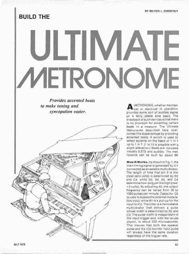
BY MILTON L. CHESTNUT
BUILD THE
Provides accented beats to make tuning and
syncopation easier.
1
AMETRONOME, whether mechan- ical or electrical in operation,
provides some sort of audible signal on a fairly stable time basis. The dravvback of such devices is that there is no provision for accenting certain beats in a measure. The Ultimate Metronome described here over- comes this disadvantage by providing accented beats. A switch is used to select accents on the basis of 1 in 1
up to 1 in 7. (1 in 15 is possible with a slight alteration.) Beats are indicated visually (LED) and audibly. The met- ronome can be built for about $8.
How It Works. As shown in Fig. 1, the main timing signal is generated by IC1 connected as an astable multivibrator. The length of time that pin 3 is low (near zero volts) is determined by R3 and C4, while R3, R4, R5, and C4 determine how long pin 3 is high (near +5 volts). By adjusting R5, the output frequency can be varied from 30 to 1000 pulses per minute. Capacitor C5 is used to bypass the external modula- tion input, while R1 is a pull-up for the input to IC2. The latter is a monostable multivibrator that delivers a pulse whose width is determined by R2 and C3. The pulse width is independent of the input trigger and, with the values shown, is about 250 microseconds. This insures that both the speaker pulse and the 1C3 counter input pulse willl always have the same duration regardless of the trigger rate.
1~ JULY 1976 57
AmericanRadioHistory.Com
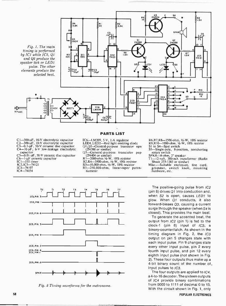
Fig. 1. The main timing is performed
. by ICI while 1C2, Ql and Q2 produce the
speaker tick or LED1 pulse. The other
elements produce the selected beat.
II7 VAC
R3 10K
RECTI
CI -500-µF, 16-V electrolytic capacitor C2 -300-µF, 10-V electrolytic capacitor C3 -0.1-µF, 50-V ceramic disc capacitor C4 -10-µF, 6-V low -leakage electrolytic
capacitor C5 -0.01-µF, 50-V ceramic disc capacitor C6 -1-µF ceramic capacitor ICI -555 timer IC2,1C5-74121 IC3-74197 IC4-74154
RI 2K
5
C5 T.D1yF
LM309
C2i 300yF
ad I
II 10
IC2 74121
14 7
R2 3.9K
PARTS LIST
R9 IK
2N388
2N 404
S2Q LEDI LED2
IC6-LM309, 5-V, I -A regulator LEDI,LED2-Red light emitting diode í1I ,Q2 --General-purpose transistor npn
(2N388 or similar) Q3-General-purpose transistor pnp
(2N404 or similar) RI -2000 -ohm Ih-W, 10% resistor R2,R4-3900-ohm, 'h -W, 10% resistor R3 -10,000 -ohm, I/z-W, 10% resistor R5 -250,000 -ohm, linear -taper poten-
tiometer
23
2N388
G
C6 F
10 11
6 3
I 4
IC5 74121
7 14
F RIO -.111-~-! RIO
IC4 5 S5: IK
74154 6
/C7 7_L 8 M 7
3N 4
1
R6,R7,R8-1500-ohm, 11/2-W, 10% resistor R9,R10-1000-ohm, Ih-W, 10% resistor SI to S4-Spst switch S5-Single-pole, 8 -position, nonshorting
rotary switch SPKR-8-ohm, 2" speaker TI -12 -volt, 300-mA transformer (Radio
Shack 273-1385 or similar) Misc.-Suitable enclosure, line cord,
grommet, switch knob, mounting hardware, etc.
TO TI I
ICI, PIN 3
IC2,PIN I
IC2, PIN 6
IC3,PIN 5
IC3, PIN 9
IC3, PIN 2
IC4, PIN 6 IC5, PIN I
T2 T3I T4 T5 T6 T7 1
I I I I 1 I I
I I I I I I I
ICS, PIN .6
SPKR
Fig. 2 Timing waveforms for the metronome.
The positive -going pulse from IC2 (pin 6) drives Q1 into conduction and, when S2 is open, causes LED1 to glow. When Q1 conducts, it also forward -biases Q3, causing a current surge through the speaker (when S4 is
closed). This provides the main beat. To generate the accented beat, the
output from IC2 (pin 1) is fed to the clock -1 (pin 8) input of IC3, a
binary-counter/latch. As shown in the timing diagram in Fig. 2, the 1C3
output on pin 5 changes state with each input pulse. Pin 9 changes state. every other input pulse, pin 2 every fourth input pulse, and pin 12 every eighth input pulse (not shown in Fig. 2). These four outputs thus make up a
4 -bit binary count of the number of 1
input pulses to IC3. The four outputs are applied to IC4,
a 4 -to -16 decoder. The sixteen outputs of IC4 provide binary combinations from 0000 to 1111 of decimal 0 to 15. With the circuit shown in Fig. 1, only
58 POPULAR ELECTRONICS
AmericanRadioHistory.Com
the first .7 of these outputs can be selected by S5. The timing in Fig. 2
assumes that S5 is set to position 5 so that the accent pulse will occur every 5
beats. The signal selected by S5 is used to
trigger IC5, a monostable multivi- brator that operates like IC2 except that the timing components (R8, C6) are selected to produce an output pulse of about 1 ms (instead of the 250 is of IC2). When pin 6 of IC5 goes high, Q1 is driven into saturation, causing LED2 to glow (S3 open) for about 750 ms after Q1 has stopped conducting due to the main beat. This action causes the speaker to produce a louder tone. When pin 6 of IC5 goes high, pin 1 goes low, resetting IC3 to a zero output. The next pulse from IC2 then counts as the first beat of the next series of pulses. This same action takes place regardless of the beats per minute or the setting of S5.
When S5 is in the F position, the trigger input of IC5 (pins 3 and 4) is
held high by R10 to prevent any possibility of a stray accented beat. This also permits the use of the circuit as a conventional metronome. With S5 in position G, every beat is accented to provide a volume increase. As men- tioned before, other outputs of IC4 and other positions of S5 can be used to select accented beats up to a rate of 1 in 15.
Construction. Any type of construc- tion can be used to build the metronome; and surplus or junkbox components will do. However, the LED's should be selected for similar light output. The size of the trans- former given in the Parts List will fit on a pc board. Mount the finished board in a small enclosure with the switches, R5 and LED's on the cover. Punch some holes in the cover for the speaker.
Calibration. Close S1 and S4 and set R5 to midscale with S5 in position F.
Count the number of beats per minute (checking the operation of LED1 at the same time). Calibrate the dial of R5 accordingly. At higher speeds, use the accented beat to count. For example, with a 1 -in -5 accent, count 27 ac- cented beats in 60 seconds with R5 set for 135 beats per minute.
LED1 is for the main beat, while LED2 displays the accented beat. If
you don't need these indicators, they and their associated switches can be omitted. Q
11 SOLID STATE,:.BREAKERLESS ELECTRONIC IGNITION.
The BEST...The ULTIMATE, Min of All Ignition Systems W
ALLISON- ,
OPTO=ELECTRTCv'. No Breaker -Points or Condenser to EVER wear out or need any maintenance. * Once installed and properly timed
your Distributor will give you
CONTINUOUS PEAK PERFORMANCE!
The Allison OPTO -ELECTRIC System ELIMINATES the Points and Condenser, replacing them with an OPTO - Electronic Trigger, using a Light -Emitting Diode and Phototransistor. This System operates on a BEAM of LIGHT. There is NO "Breaker -Point Wiper -Arm" to wear down, Point bounce and erosion are completely eliminated thereby giving longer riming ACCURACY than any System using "Mechanical" Breaker -Points. (and No Timing Fluctuation as with Magnetic Impulse Units). ACCURATE Timing gives the BEST in Engine EFFICIENCY...and that's the name of the Game for the BEST in GAS MILEAGE and ECONOMY.
*The Allison's "Built -In" DWELL never needs adjustment, it is PRE-SET to supply the OPTIMUM Performance at BOTH High and Low speeds. The RPM capability of the "OPTO - ELECTRIC" unit exceeds that of any known automotive in- ternal combustion engine. Positive spark intensity and duration helps eliminate "misfire" and extends the Spark -Plug life.
The Allison "OPTO -ELECTRIC" was engineered to OUT- LAST the LIFE OF YOUR CAR. Only the Highest Grade Solid -State Components are used ... UNAFFECTED by Moisture or Vibration! Easier engine starting under ANY Weather Condition. Solid, DEPENDABLE PERFORMANCE. * Installed in your Distributor in same location as Points.
COMPLETE INSTRUCTIONS FURNISHED. io ̀ (Not Necessary to Dismantle your Distributor).
* PROVEN RELIABILITY Factory Tested to 15,000 RPM
Road and Race PROVEN (Opto -Electric Systems Won at
INDY Two Years in a Row)
Only $5995 COMPLETE (Calif. Res. add Tab' ,that's EVERYTHING!
including
Send Check or M.O. Postage á Insurance.
State Make, Year, Engine Size, (4 6, or 8 -cylinder).
You may use your MASTER CHARGE or BANKAMERICARD. Send us (1) Your Number. (2) Interbank No., (3) Exp. Date
MC or BA Card Holders, ORDER by TOLL FREE PHONE: (800) 423-6525. Ext. 2. (When in Cont nental U.S.A.)
Before Buying any other Type ignition system .. .
4.7 Send Postcard for our FREE BROCHURE. * If you have already installed a "Capacitive -Discharge" Ignition .
Modernize and Increase its Efficiency ... CONVERT YOUR "C -D" UNIT TO BREAKERLESSI Opto -Electric "TRIGGER UNIT" ... Only 534.95.
America's Oldest and Largest Manufacturer of Opto -Electronic Ignition Systems.
ALLISON
* ORDER with CONFIDENCE ... FACTORY -BACKED 10 -YEAR Free Repair or Replacement on ANY
Detects in Materials or Workmanship.
* SAVE! ORDER FACTORY DIRECT
Our BEST Salesmen are the USERS of ouli ALLISON System
AUTOMOTIVE COMPANY 1267-E8 East EDNA PL., COVINA, CAL. 91722k
CIRCLE NO. 3 ON FREE INFORMATION CARD
IFIEIRETHE COMPUTER PEOPLE WITH THE LINE OF
COMPLETE, VERSATILE, EXPANDABLE, EASY -TO -USE, COMPUTERS___
44524~ t4 ym, 6~(.ite.t y~yeate.. The 4K ROM BOARD 44
A 4000 bytes Read Only Memory (ROM) board featuring: INSTANT CALL UP as you turn the power on. (No more tedious programming of the most used programs.)
NO LOSS OF PROGRAM as the power is turned off (Your PROGRAM is always there.)
A MEMORY BOARD designed to use the 1702A -programmable ROMS.(256 bytes per ROM)
A BOARD completely assembled and tested with the SOCKETS for the PROMS already mounted.
SIMPLY PLUG IN ONE OF THE APPLICATIONS PROMS available from SPHERE or Insert your own
specially programmed prom and with power -on immediately begin playing that computer game or using your own application.
THE 4K ROM BOARD may be plugged right in to the standard SPHERE computer bus cable.
TWO SPECIALLY PROGRAMMED ROMS NOW AVAILABLE FROM SPHERE are:
The GAME OF LIFE (1 chip) 03n.00 This program provides either a generation at a time solution or a continuous dynamic solution of the LIFE algorithim. Available in V3A. V3N. 5D0S version.
TELETYPE HANDLER (Ichip) 530.00 Allows paper tape transmission of data on teletype. Available in V3A. V3N versions.
Contact SPHERE for special programming price
4K ROM BOARD(w/o roms)SIS6.0n
unprogrammed ROMS 545.00
WHAT A POWERFUL, VERSATILE, EXPANDABLE, EASY -TO -USE, COMPUTER YOU HAVE WHEN... YOU GET IT ALL TOGETHER FROM SPHERE...THE COMPUTER PEOPLE!!
and arrangements.
SPHERE CORPORATION
940 North 400 East North Salt Lake, Utah 84054
(801) 292-8466
JULY 1976 59
AmericanRadioHistory.Com

IF YOU'RE NOT DESIGNING WITH ACSC PROTO-BOARDILOOK
AT ALLYOU'RE MISSING. Utility-Models are available with or without built-in regulated power supplies (fixed or adjustable).
Economy-Eliminate heat and mechanical damage to expensive parts. Save money by re -using components,
Versatility-Use with virtually all types of parts, including resistors, capacitors, transistors, DIP's, .
TO -5's, LED's, transformers, relays, pots, etc. Most plug in directly, in seconds.
Durability-All Proto-Board models are carefully constructed of premium materials, designed and tested for long, trouble -free service.
Expandability- Proto-Board units can be instantly inter- connected for greater capacity.
Visibility-All parts are instantly and easily visible, for quick circuit analysis and diagramming.
Speed-Assemble,- test and modify circuits 1 as fast as you can push in or pull out a lead. Save hours on every project. ti
I
4..r24
tiK . Mvaii
^
Accessibility-All parts are instantly and easily accessible, for quick signal tracing, circuit modifications, etc.
Adaptability-Use in design, packaging, inspection, QC, etc. Works with most types of circuits, in many, many applications.
Flexibility-Use independently, or in conjunction with other accessories, such as scopes, counters, CSC Proto-Clip' connectors, Design Mate test equipment, etc. One Proto-Board unit can serve a thousand
Variety-A wide variety of models are available with capacities ranging from 630 to 3060 solderless tie -points (6 to 32 14 -pin DI P's), to fit every technical and budget requirement.
*-' A
O l ^ d SqMp 9
Whatever type of electronic circuits you
work with, you can do more in less time with
CSC's solderless Proto- Board systems. As fast -and
easy as pushing in or pulling out a lead, you can design, test and
modify circuits at will. Com- ponents plug into rugged 5 -point
terminals, and jumpers, where needed, are lengths of #22 AWG
solid wire. In the same time you took to read this ad, you could be well on
your way to assembling a new circuit. For more information, see your CSC
dealer, or write for our catalog and distributor list.
CSC PROTO-BOARD SOLDERLESS BREADBOARDS
" N0. OF
MODEL SOLDERLESS IC CAPACITY MANUFACTURER'S OTHER DIP'S) SUGG LIST FEATURES applications. NUMBER TIE -POINTS (14 -PIN
PB-6
PB-100
PB-101
630
760
940
6
10
10 CONTINENTAL SPECIALTIES CORPORATION =M= PB-102
PB-103
1240
2250
12
24
EASY DOES IT 44 Kendall Street, Box 1942 PB-104 3060 32
New Haven, CT 06509. 203-624-3103 TWX: 710-465-1227 West Coast office: Box 7809, San Francisco, CA PB-203 2250 24
94119 415-421-8872 TWX: 910-372-7992 Canada: Len Finkler Ltd., Ontario
PB-203A 2250 24
© 1976 Continental Specialties Corp. Prices and specifications subject to change without notice.
Ri
$15.95
19.95
29.95
39.95
59.95
79.95
75.00 .
120.00
Kit -10 -minute assembly
Kit - with larger capacity
8 distribution buses, higher capacity
Large capacity, moderate price
Even larger capacity; only 2.7¢ per tie -point
Largest capacity; lowest price per tie -point
Built-in 1% -regulated 5V, lA low -ripple power supply
As above plus separate 1/2 -amp +15V and -15V internally adjustable regulated power supplies
CIRCLE NO. 16 ON FREE INFORMATION CARD
60 POPULAR ELECTRONICS
AmericanRadioHistory.Com
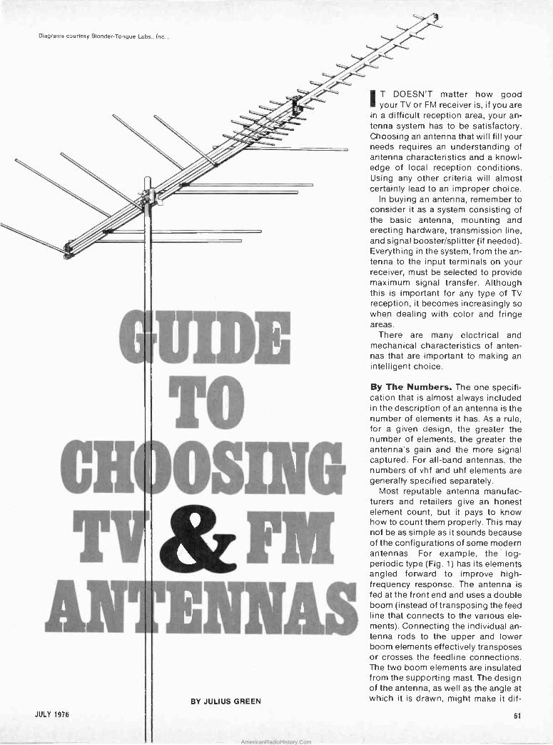
Diagrams courtesy Blonder -Tongue Labs., Inc..
1
I
1 i
BY JULIUS GREEN
1
IT DOESN'T matter how good your TV or FM receiver is, if you are
in a difficult reception area, your an- tenna system has to be satisfactory. Choosing an antenna that will fill your needs requires an understanding of antenna characteristics and a knowl- edge of local reception conditions. Using any other criteria will almost certainly lead to an improper choice.
In buying an antenna, remember to consider it as a system consisting of the basic antenna, mounting and erecting hardware, transmission line, and signal booster/splitter (if needed). Everything in the system, from the'an- tenna to the input terminals on your receiver, must be selected to provide maximum signal transfer. Although this is important for any type of TV reception, it becomes increasingly so when dealing with color and fringe areas.
There are many electrical and mechanical characteristics of anten- nas that are important to making an intelligent choice.
By The Numbers. The one specifi- cation that is almost always included in the description of an antenna is the number of elements it has. As a rule, for a given design, the greater the number of elements, the greater the antenna's gain and the more signal captured. For all -band antennas, the numbers of vhf and uhf elements are generally specified separately.
Most reputable antenna manufac- turers and retailers give an honest element count, but it pays to know how to count them properly. This may not be as simple as it sounds because of the configurations of some modern antennas. For example, the log - periodic type (Fig. 1) has its elements angled forward to improve high - frequency response. The antenna is fed at the front end and uses a double boom (instead of transposing the feed line that connects to the various ele- ments). Connecting the individual an- tenna rods to the upper and lower boom elements effectively transposes or crosses the feedline connections. The two boom elements are insulated from the supporting mast. The design of the antenna, as well as the angle at which it is drawn, might make it dif-
JULY 1976 61
AmericanRadioHistory.Com
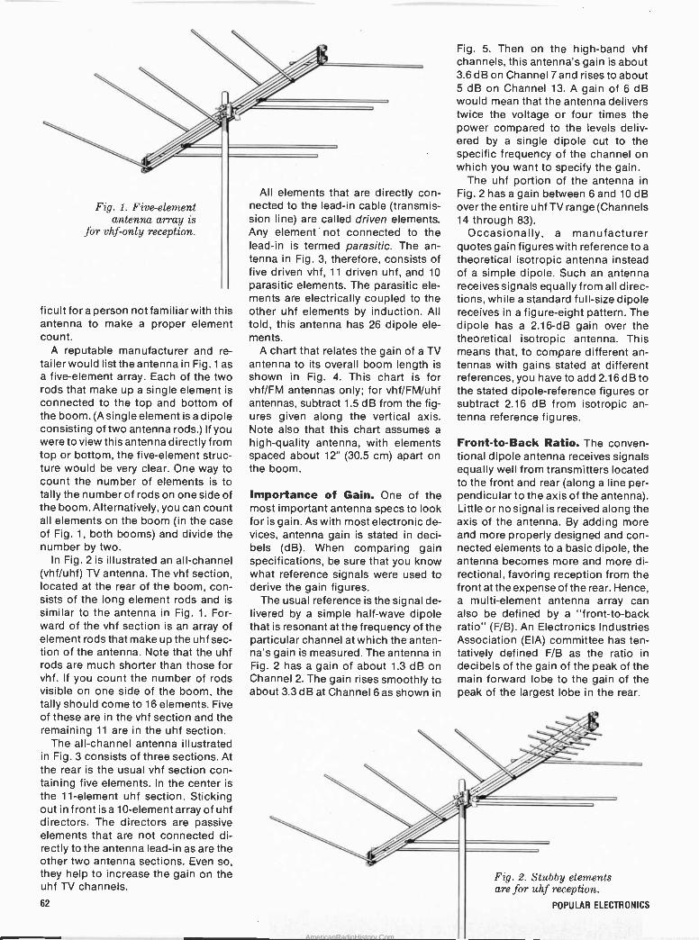
Fig. 1 Five -element antenna array is
%or vhf --only reception.
ficult for a person not familiar with this antenna to make a proper element count.
A reputable manufacturer and re- tailer would list the antenna in Fig.1 as a five -element array. Each of the two rods that make up a single element is connected to the top and bottom of the boom. (A single element is a dipole consisting of two antenna rods.) If you were to view this antenna directly from top or bottom, the five -element struc- ture would bé very clear. One way to count the number of elements is to tally the number of rods on one side of the boom. Alternatively, you can count all elements on the boom (in the case of Fig. 1, both booms) and divide the number by two.
In Fig. 2 is illustrated an all -channel (vhf/uhf) TV antenna. The vhf section, located at the rear of the boom, con- sists of the long element rods and is similar to the antenna in Fig. 1. For- ward of the vhf section is an array of element rods that make up the uhf sec- tion of the antenna. Note that the uhf rods are much shorter than those for vhf. If you count the number of rods visible on one side of the boom, the tally should come to 16 elements. Five of these are in the vhf section and the remaining 11 are in the uhf section.
The all -channel antenna illustrated in Fig. 3 consists of three sections. At the rear is the usual vhf section con- taining five elements. In the center is the 11 -element uhf section. Sticking out in front is a 10 -element array of uhf directors. The directors are passive elements that are not connected di- rectly to the antenna lead-in as are the other two antenna sections. Even so, they help to increase the gain on the uhf TV channels.
62
All elements thatare directly con- nected to the lead-in cable (transmis- sion line) are called driven elements. Any element' not connected to the lead-in is termed parasitic. The an- tenna in Fig. 3, therefore, consists of five driven vhf, 11 driven uhf, and 10
parasitic elements. The parasitic. ele- ments are electrically coupled to the other uhf elements by induction. All told, this antenna has 26 dipole ele- ments.
A chart that relates the gain of a TV antenna to its overall boom length is shown in Fig. 4. This chart is for vhf/FM antennas only; for vhf/FM/uhf antennas, subtract 1.5 dB from the fig- ures given along the vertical axis. Note also that this chart assumes a
high -quality antenna, with elements spaced about 12" (30.5 cm) apart on the boom.
Importance. of Gain. One of the most important antenna specs to look for is gain. As with most electronic de- vices, antenna gain is stated in deci- bels (dB). When comparing gain specifications, be sure that you know what reference signals were used tc derive the gain figures.
The usual reference is the signal de- livered by a simple half -wave dipole that is resonant at the frequency of the particular channel at which the anten- na's gain is measured. The antenna in Fig. 2 has a gain of about 1.3 dB on Channel 2. The gain rises smoothly to about 3.3 dB at Channel 6 as shown in
Fig. 5. Then on the high -band vhf channels, this antenna's gain is about 3.6 dB on Channel 7 and rises to about 5 dB on Channel 13. A gain of 6 dB would mean that the antenna delivers twice the voltage or four times the power compared to the levels deliv- ered by a single dipole cut to the specific frequency of the channel on which you want to specify the gain.
The uhf portion of the antenna in Fig. 2 has a gain between 6 and 10 dB over the entire uhf TV range (Channels 14 through 83).
Occasionally, a manufacturer quotes gain figures with reference to a
theoretical isotropic antenna instead of a simple dipole. Such an antenna receives signals equally from all direc- tions, while a standard full-size dipole receives in a figure -eight pattern. The dipole has a 2.16 -dB gain over the theoretical isotropic antenna. This means that, to compare different an- tennas with gains stated at different references,.you have to add 2.16 dB to the stated dipole -reference figures or subtract 2.16 dB from isotropic an- tenna reference.figures.
Front -to -Back Ratio. The conven- tional dipole antenna receives signals equally well from transmitters located to the front and rear (along a line per- pendicular to the axis of the antenna). Little or no signal is received along the axis of the antenna. By adding more and more properly designed and con- nected elements to a basic dipole, the antenna becomes more and more di- rectional, favoring reception from the front at the expense of the rear. Hence, a multi -element antenna array can also be defined by a "front -to -back ratio" (F/B). An Electronics Industries Association (EIA) committee has ten- tatively defined F/B as the ratio in decibels of the gain of the peak of the main forward lobe to the gain of the peak of the largest lobe in the rear.
Fig. 2. Stubby elements are for uhf reception.
POPULAR ELECTRONICS
AmericanRadioHistory.Com
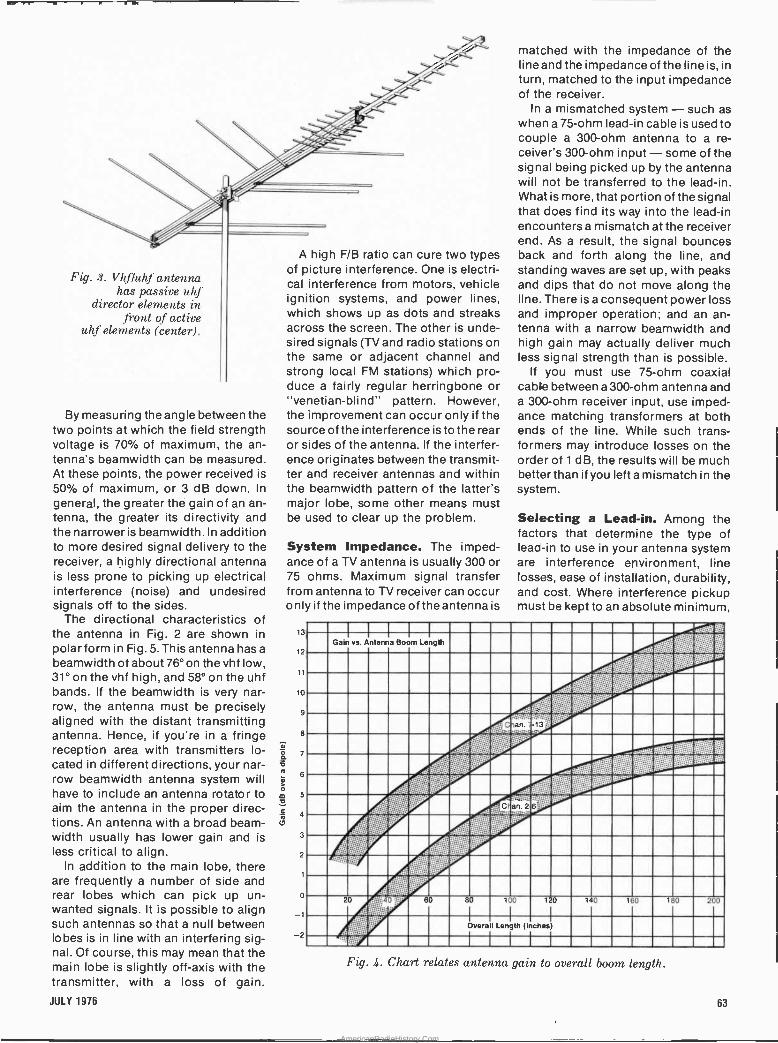
Fig. 3. Vhf'luhf antenna has passive uhf
director elements in front of active
uhf elements (center).
By measuring the angle between the two points at which the field strength voltage is 70% of maximum, the an- tenna's beamwidth can 'be measured. At these points, the power received is 50% of maximum, or 3 dB down. In
general, the greater thé gain of an an- tenna, the greater its directivity and the narrower is beamwidth. In addition to more desired signal delivery to the receiver, a highly directional antenna is less prone to picking up electrical interference (noise) and undesired signals off to the sides.
The directional characteristics of the antenna in Fig. 2 are shown in 13
polar form in Fig. 5. This antenna has a 12
beamwidth of about 76° on the vhf low, 31° on the vhf high, and 58° on the uhf bands. If the beamwidth is very nar- to
row, the antenna must be precisely g
aligned with the distant transmitting antenna. Hence, if you're in a fringe 8
reception area with transmitters lo- ó 7
cated in different directions, your nar- row beamwidth antenna system will 6
have to include an antenna rotator to m 5
aim the antenna in the proper direc- a
tions. An antenna with a broad beam - width usually has lower gain and is 3
less critical to align. 2
In addition to the main lobe, there are frequently a number of side and rear lobes which can pick up un- o
wanted signals. It is possible to align 1
such antennas so that a null between lobes is in line with an interfering sig- 2
nal. Of course, this may mean that the main lobe is slightly off -axis with the transmitter, with a loss of gain.
A high F/B ratio can cure two types of picture interference. One is electri- cal interference from motors, vehicle ignition systems, and power lines, which shows up as dots and streaks across the screen. The other is unde- sired signals (TV and radio stations on the same or adjacent channel and strong local FM stations) which pro- duce a fairly regular herringbone or "venetian -blind" pattern. However, the improvement can occur only if the source of the interference is to the rear or sides of the antenna. If the interfer- ence originates between the transmit- ter and receiver antennas and within the beamwidth pattern of the latter's major lobe, some other means must be used to clear up the problem.
System Impedance. The imped- ance of a TV antenna is usually 300 or 75 ohms. Maximum signal transfer from antenna to TV receiver can occur only if the impedance of the antenna is
Gain vs. Antenna Boom Length
20 a 60 80
CF
matched with the impedance of the line and the impedance of the line is, in turn, matched to the input impedance of the receiver.
In a mismatched system - such as when a 75 -ohm lead-in cable is used to couple a 300 -ohm antenna, to a re- ceiver's 300 -ohm input - some of the signal being picked up by the antenna will not be transferred to the lead-in. What is more, that portion of the signal that does find its way into the lead-in encounters a mismatch at the receiver end. As a result, the signal bounces back and forth along the line, and standing waves are set up, with peaks and dips that do not move along the line. There is a consequent power loss and. improper operation; and an an- tenna with a narrow beamwidth and high gain may actually deliver much less signal strength than is possible.
If you must use 75 -ohm coaxial cable between a 300 -ohm antenna and a 300 -ohm receiver input, use imped- ance matching transformers at both ends of the line. While such trans- formers may introduce losses on the order of 1 dB, the results will be much better than if you left a mismatch in the system.
Selecting a Lead-in. Among the factors that determine the type of lead-in to use in your antenna system are interference environment, line losses, ease of installation, durability, and cost. Where interference pickup must be kept to an absolute minimum,
an 2
100 120
Overa I Length (inches)
.. , .... ...r ' 1 0 160 180 200
Fig. 4. Chart relates antenna gain to overall boom length.
JULY 1976 63
AmericanRadioHistory.Com
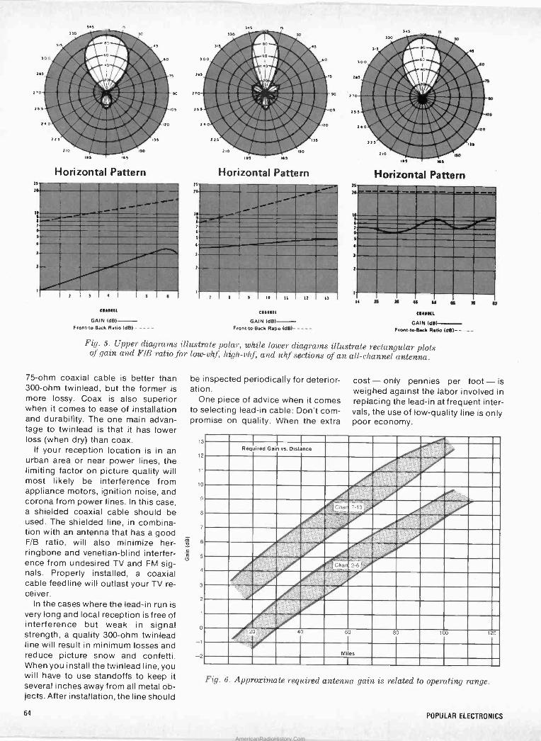
ZS
7
Horizontal Pattern
1'
1
7
4
i
Cuna
GAIN (dB)- Front.to-Back Ratio IdB)
))a
ec )1#4411 60I t0
.0 _,, ,, lath :.: 210 '; t :¡ I1r. .!411 o i)e
25
.2 e
I.)
Horizontal Pattern
24
15
7
4
7
i oh.
' 1. u
GAIN (dB) - Front -to -Back Ratio IdB)
12 13
).5 330
)i)
)no
rri:10".,. o;or 23 5 *" o
¡r .I"
t.]
).o
:01IMO 1.5
Horizontal Pattern
~111:d~ «11111~14
IIMMERIZZIIMI1ZIMIZEM _--MINE__ .--.-1111- M." 4. II
Cn..11
GAIN (dB) Front -to -Back Redo (del- -
Fig. 5. Upper diagrams illustrate polar, while lower diagrams illustrate rectangular plots of gain and F/B ratio for low -vhf, high -vhf, and uhf sections of an all -channel antenna.
75 -ohm coaxial cable is better than 300 -ohm twinlead, but the former is more lossy. Coax is also superior when it comes to ease of installation and durability. The one main advan- tage to twinlead is that it has lower loss (when dry) than coax.
If your reception location is in an urban area or near power lines, the limiting factor on picture quality will most likely be interference from appliance motors, ignition noise, and corona from power lines. In this case, a shielded coaxial cable should be used. The shielded line, in combina- tion with an antenna that has a good F/B ratio, will also minimize her- ringbone and venetian -blind interfer- ence from undesired TV and FM sig- nals. Properly installed, a coaxial cable feedline will outlast your TV re- ceiver.
In the cases where the lead-in run is very long and local reception is free of interference but weak in signal strength, a quality 300 -ohm twinlead line will result in minimum losses and reduce picture snow and confetti. When you install the twinlead line, you will have to use standoffs to keep it several inches away from all metal ob- jects. After installation, the line should
be inspected periodically for deterior- ation.
One piece of advice when it comes to selecting lead-in cable: Don't com- promise on quality. When the extra
13
12
11
10
9
8
7
6
5
4
3
2
0
1
2
cost- only pennies per foot- is weighed against the labor involved in replacing the lead-in at frequent inter- vals, the use of low -quality line is only poor economy.
Required Gain vs. Distance
I!:
40
Caan 7-13 ie- ..`¡:..
Cka
60
2-6 ,r..
Miles
80 100 120
Fig. 6. Approximate required antenna gain is related to operating range.
64 POPULAR ELECTRONICS
AmericanRadioHistory.Com
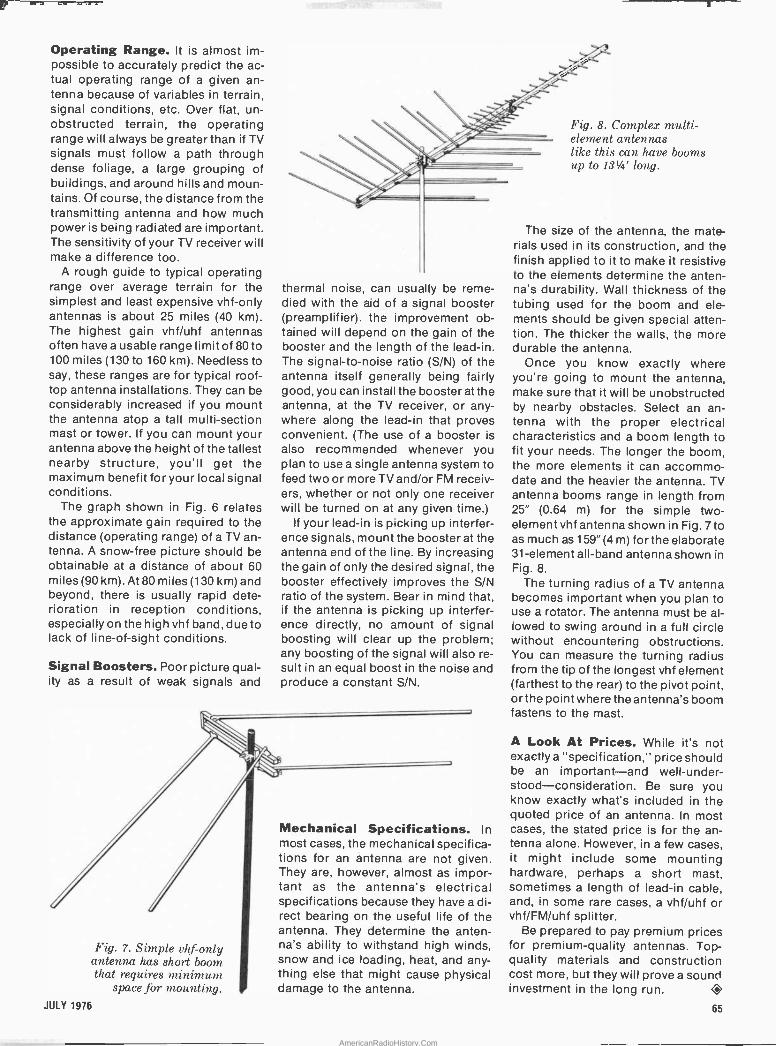
Operating Range. It is almost im- possible to accurately predict the ac- tual operating range of a given an- tenna because of variables in terrain, signal conditions, etc. Over flat, un- obstructed terrain, the operating range will always be greater than if TV signals must follow a path through dense foliage, a large grouping of buildings, and around hills and moun- tains. Of course, the distance from the transmitting antenna and how much power is being radiated are important. The sensitivity of your TV receiver will make a difference too.
A rough guide to typical operating range over average terrain for the simplest and least expensive vhf -only antennas is about 25 miles (40 km). The highest gain vhf/uhf antennas often have a usable range limit of 80 to 100 miles (130 to 160 km). Needless to say, these ranges are for typical roof- top antenna installations. They can be considerably increased if you mount the antenna atop a tall multi -section mast or tower. If you can mount your antenna above the height of the tallest nearby structure, you'll get the maximum benefit for your local signal conditions.
The graph shown in Fig. 6 relates the approximate gain required to the distance (operating range) of a TV an- tenna. A snow -free picture should be obtainable at a distance of about 60 miles (90 km). At 80 miles (130 km) and beyond, there is usually rapid dete- rioration in reception conditions, especially on the high vhf band, due to lack of line -of -sight conditions.
Signal Boosters. Poor picture qual- ity as a result of weak signals and
Fig. 7. Simple vhf -only antenna has short boom that requires minimum
space for mounting.
thermal noise, can usually be reme- died with the aid of a signal booster (preamplifier). the improvement ob- tained will depend on the gain of the booster and the length of the lead-in. The signal-to-noise ratio (S/N) of the antenna itself generally being fairly good, you can install the booster at the antenna, at the TV receiver, or any- where along the lead-in that proves convenient. (The use of a booster is also recommended whenever you plan to use a single antenna system to feed two or more TV and/or FM receiv- ers, whether or not only one receiver will be turned on at any given time.)
If your lead-in is picking up interfer- ence signals, mount the booster at the antenna end of the line. By increasing the gain of only the desired signal, the booster effectively improves the S/N ratio of the system. Bear in mind that, if the antenna is picking up interfer- ence directly, no amount of signal boosting will clear up the problem; any boosting of the signal will also re- sult in an equal boost in the noise and produce a constant S/N.
Mechanical Specifications. In most cases, the mechanical specifica- tions for an ántenna are not given. They are, however, almost as impor- tant as the antenna's electrical specifications because they have a di- rect bearing on the useful life of the antenna. They determine the anten- na's ability to withstand high winds, snow and ice loading, heat, and any- thing else that might cause physical damage to the antenna.
Fig. 8. Complex multi - element antennas like this can have booms up to 13'/4' long.
The size of the antenna, the mate- rials used in its construction, and the finish applied to it to make it resistive to the elements determine the anten- na's durability. Wall thickness of the tubing used for the boom and ele- ments should be given special atten- tion. The thicker the walls, the more durable the antenna.
Once you know exactly where you're going to mount the antenna, make sure that it will be unobstructed by nearby obstacles. Select an an- tenna with the proper electrical characteristics and a boom length to fit your needs. The longer the boom, the more elements it can accommo- date and the heavier the antenna. TV antenna booms range in length from 25" (0.64 m) for the simple two - element vhf antenna shown in Fig. 7 to as much as 159" (4 m) for the elaborate 31 -element all -band antenna shown in Fig. 8.
The turning radius of a TV antenna becomes important when you plan to use a rotator. The antenna must be al- lowed to swing around in a full circle without encountering obstructions. You can measure the turning radius from the tip of the longest vhf element (farthest to the rear) to the pivot point, or the point where the antenna's boom fastens to the mast.
A Look At Prices. While it's not exactly a "specification," price should be an important-and well-under- stood-consideration. Be sure you know exactly what's included in the quoted price of an antenna. In most cases, the stated price is for the an- tenna alone. However, in a few cases, it might include some mounting hardware, perhaps a short mast, sometimes a length of lead-in cable, and, in some rare cases, a vhf/uhf or vhf/FM/uhf splitter.
Be prepared to pay premium prices for premium -quality antennas. Top- quality materials and construction cost more, but they will prove a sound investment in the long run.
JULY 1976 65
AmericanRadioHistory.Com

Product Test Reports
ABOUT THIS MONTH'S HI-FI REPORTS
Stereo receivers in a given price range tend to have very similar specifica- tions and features, as well as a strong physical resemblance to each other. However, among this large group of components, some are "more equal than others". The Nikko Model 7075 is an excellent example of unusually high performance from one of the lesser -known brands.
Modern receivers and amplifiers are equipped to interface with a wide variety of signal processing accessories. The Pioneer Model SF -850 elec- tronic crossover is a h ghly versatile two- or three-way adjustable filter, which is placed in the signal path ahead of the power amplifiers. Driving each of the speaker groups in a multi -way system from its own amplifier avoids most of the distortion attributed to passive crossover networks, and the Pioneer system gives the user a wide choice of crossover frequencies and filter slopes.
The other product tested is an octave -band graphic equalizer. The re- markably compact MXR equalizer adjusts the response for each channel in 10 separate frequency bands. In the real world, our listening rooms, speak- ers, and program sources are rarely `flat" in their frequency characteris- tics, but this handy accessory can go a long way toward correcting any response aberrations.
NIKKO MODEL 7075 AM/STEREO FM RECEIVER Medium-priced receiver, excellent performance.
- 4. M..p - .-1mr-
"4,N_ II
Ir¡ II4
/
HIRSCH. HOUCK LABS
..REPORT- ._ plement of op- erating controls, extensive use of in- tegrated circuits, and performance of the highest order. The audio amplifiers are rated at 38 watts/ channel into 8 ohms with both chan- nels driven over a frequency range of 20 to 20,000 Hz, with less than 0.5% total harmonic distortion (THD). The FM tuner's sensitivity is rated at 1.9 µV, the alternate -channel selectivity at 65 66
The Nikko Model 7075 AM/stereo FM receiver fea- tures a full corn -
-Julian D. Hirsch
dB, and distortion at less than 0.2% in mono and 0.4% in stereo.
The receiver's extensive use of IC's results in a relatively inexpensive prod- uct. Following three pairs of linear - phase ceramic i -f filters in the FM tuner section, a single IC supplies vir- tually all the required gain, limiting, muting, and quadrature detection. Another IC, a phase -locked loop (PLL), supplies multiplex detection, while still another IC performs all the functions of the entire active portion of the AM tuner. In the audio section, an operational amplifier IC serves as a
feedback -type tone -control amplifier. The power amplifiers are composed of discrete elements and employ direct coupling all the way to the speakers. The outputs are complementary sym- metry.
Supplied in a walnut -veneered wood cabinet, the receiver measures 19"W x 16"DX 63/8" H (48.3 x 40.6 x 16.2 cm) and weighs approximately 26.4 lb (12 kg). Price is $399.95.
General Description. The receiv- er's front panel is conventional in ap- pearance with a satin gold finish and matching control knobs and switch levers. A "blackout" dial area across the upper portion of the'panel has be- hind it the blue -illuminated FM and AM dial scales, large center -channel FM. tuning and relative signal -strength meters, and illuminated legends that identify the selected program source. The last correspond to the settings of the input SELECTOR switch: AM, FM,
PRONO, MIC, AUX, and DUB (for copying from one tape recorder to another). A red STEREO indicator above the dial area comes on when a stereo FM sig- nal is received.
Lever switches control the POWER,
LOW and HIGH cut filters, LOUDNESS
compensation, FM MUTING, STEREO/ MONO mode select, and TAPE MONITOR functions, the last from either of two decks that can 'be con- nected via jacks on the rear of the re- ceiver. The SPEAKERS control allows selection of either, both, or neither of two pairs of speaker systems to the amplifier's outputs. (A PHONES jack next to it is always energized.)
The BASS and TREBLE tone controls; concentric for left and right channels, have 11 detented positions. The voL- UME and BALANCE controls, the latter detented at its center position, are also concentrically mounted. A Mic jack is also provided on the front panel for driving both amplifier outputs from a single dynamic microphone.
In addition to. all the usual signal input and output jacks, the rear apron of the receiver also has a DIN connec- tor that parallels the functions of the TAPE jacks. There is also a group of four jacks and a 4CH ADAPTOR slide switch for driving a quadraphonic adaptor and returning its front - channel outputs to the receiver's power amplifiers. The speaker con- nectors are insulated spring clips.
One of the three accessory ac out- lets on the rear apron is switched. Rounding out the connector comple-
POPULAR ELECTRONICS
AmericanRadioHistory.Com

lówa to move:ahead n eléc l .w .
. . ' .
Choose the one that's just right for you... the one that can make your future more rewarding, more secure, more enjoyable...starting now! These ways to move ahead are yours from Electronics Tech- nical Institute..,the finest elec- tronics home study courses and programs ever offered!
Fundamental Electronics Get a solid foundation for enter- ing the fast-moving world of elec- tronics where today is great, and tomorrow will be greater. Learn it the simple, easy, step-by-step, programmed way called Autotexi, exclusive with ETI!
Electronics Drafting Learn a vitally needed specialty that translates new technological concepts and developments to the practical drawing board. Become a specialist -in -demand, through ETI's training. Learn it at home ...get your future moving now!
Color TV Servicing There's a real future waiting for the established color television technician. You become that tech- nician through this program that takes you step-by-step to theoreti- cal and practical mastery of color TV. Get your tomorrow started today!
Master TV/Radio Servicing Here is true "master" preparation for a career that can take you as far as you want to go into radio and television servicing, both black and white, and color. The helpful, practical ETI way can be your way to more money. secur- ity, success!
Communications ETI's communications program opens up a whole range of career development possibilities in elec- tronics. Solid-state receivers, solid-state audio equipment, com- munications equipment, CATV, as well as preparation for FCC - licensed positions in commercial broadcasting and mobile com- munications. You can find a real future here!
Industrial Electronics You open great career opportuni- ties through.this program, as instrumentation technician, elec- tronic equipment maintenance technician, electronic calculating machine technician and audio technician. It also prepares you to move into and up in communica- tions, automation and industrial electronics!
Digital Technology Join the digital revolution which is radically altering our lives today and tomorrow. Get solidly trained in the new digital specialties that can lead to a real future as a digi- tal control technician, electronic calculating machine technician, field representative, computer sales representative, manufac- turer's representative.
Electronics Technology Learn electronics across the board! You'll be ready for real career advancement with training that can lead to technical positions in communication, automation and industrial electronics, and can also help you in sales positions, management and administration.
Computers ETI offers training opportunities in Computer Technology and Computer Programming. Learn at home, and get ready to enter a field where incredible developments are sure to continue. It's practical, useful-the step-by-step ETI way!
Advanced Electronics Want greater challenges and ca- reer advancement? This course is for you. It can be valuable prepa- ration not only for a technical career, but also for the fields of sales, management and adminis- tration. Make your move now!
Digital Electronics-Advanced Here's a special course for those already in the field of digital elec- tronics, ready to move into more advanced areas. This is how to move up in sales, management and administration. Here's your tomorrow!
7
I
o
Black and White TV Servicing- Advanced
This can be your own "advance" course to black -and -white TV competence from A to Z. You'll construct a receiver yourself, if you wish. A key to lifetime success!
Industrial Instruntentatioiu- Advanced
Move up in the world...the won- derful electronics world!: This course opens up a whole range of careers in the industrial field, as instrumentation technician, labo- ratory technician, process control technician or electronic calculat- ing machine technician. Get ready ,,.and go!
Color TV Servicing-Advanced Here is the "graduate" course in color TV for those who already know television fundamentals. You'll learn color TV from top to bottom, build your own set if you choose. A great way to build your future!
Solid -State Electronics- Advanced
Applications of transistors are in- creasing all the time and the transistor may be a breakthrough
r
comparable in importance to the development of nuclear energy. Solid-state can mean your solid career development, too, through ETI!
FCC License Preparation Here is real down-to-earth practi- cal preparation to take your 3rd, 2nd or 1st class Federal Com- munication Commission Radio- telephone License examinations. Get yourself ready now for any of the FCC -licensed positions in- volving broadcasting, mobile communications, microwave communications links, marine communications equipment or in many other positions in solid- state, communications, CATV. Get ready for tomorrow..,today!
Get all the facts...free! Send the coupon now for
ETI's colorfully illustrated new
mdECTRONICS 44 -page cata- log giving you all the details. You owe it to yourself. There's no ob- ligation, and no salesman will call. Send for yours today!
TECHNICAL
t
,
'
Electronics Technical Institute
Division of Technical Home Study Schools ptiati---mititititititi-IZZ I= alllt Electronics Technical Institute, Dept. 2-473-076 ' Little Falls, New Jersey 07424 ' Send me the Electronics Technical Institute Catalog, ' Name
(please print) Address
City State Zip
IInterested in another field! Check the Technical Home Study School program ' that interests you most. No salesman will call. PLEASE CHECK ONLY ONE. Typewriter and Otftce Machne Repair E Locksmithing
E E Upholstery and Decorating Legal Investigation E Accident and Insurance Claim Adjusting E Security/Alarm Business
Outdoor Careers in Conservation Photography
' Check here for information on Veterrns Benefits. Check here for information on learning by cassettes.
L--------t11MIMI all ll MI EMI MI IN
1
1
1
1
1
1
JULY 1976 CIRCLE NO. 25 ON FREE INFORMATION CARD
67
AmericanRadioHistory.Com
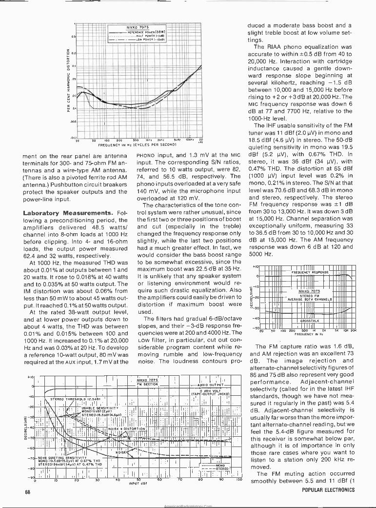
1
0.5
0.2
0.1
NIKKO 7075 REFERENCE POwER(38W)
POWERI-3d81 .BALF
----LOW POW ER1-10481
.05
.02'
01
^. . ' /
---r....."."=,....,
.005
002 ln sn 1nn nn snn 11147 2h14, 5187 10
1-
8z 20
FREQUENCY IN Hz (CYCLES PER SECOND)
ment on the rear panel are antenna terminals for 300- and 75 -ohm FM an- tennas and a wire -type AM antenna. (There is also a pivoted ferrite rod AM
antenna.) Pushbutton circuit breakers protect the speaker outputs and the power -line input.
Laboratory Measurements. Fol- lowing a preconditioning period, the amplifiers delivered 48.5 watts/ channel into 8 -ohm loads at 1000 Hz
before clipping. Into 4- and 16 -ohm loads, the output power measured 62.4 and 32 watts, respectively.
At 1000 Hz, the measured THD was about 0.01% at outputs between 1 and 20 watts. It rose to 0.018% at 40 watts and to 0.035% at 50 watts output. The IM distortion was about 0.06% from less than 50 mW to about 45 watts out- put. It reached 0.1% at 50 watts output.
At the rated 38 -watt output level, and at lower power outputs down to about 4 watts, the THD was between 0.01% and 0.015% between 100 and 1000 Hz. It increased to 0.1% at 20,000 Hz and was 0.03% at 20 Hz. To develop a reference 10 -watt output, 80 mV was required at the AUX input, 1.7 mV at the
+10
2
m -3
N J 4
5
6
-7
8
-9
PHONO input, and 1.3 mV at the MIc
input. The corresponding S/N ratios, referred to 10 watts output, were 82,
74, and 56.5 dB, respectively. The phono inputs overloaded at a very safe 140 mV, while the microphone input overloaded at 120 mV.
The characteristics of the tone con- trol system were rather unusual, since the first two or three positions of boost and cut (especially in the treble) changed the frequency response only slightly, while the last two positions had a much greater effect. In fact, we would consider the bass boost range to be somewhat excessive, since the maximum boost was 22.5 dB at 35 Hz.
It is unlikely that any speaker system or listening environment would re-
quire such drastic equalization. Also the amplifiers could easily be driven to distortion if maximum boost were used.
The filters had gradual 6-dB/octave slopes, and their -3-dB response fre- quencies were at 200 and 4000 Hz. The Low filter, in particular, cut out con- siderable program content while re-
moving rumble and low -frequency noise. The loudness contours pro-
NIKKO170751 . . . I!
' AUDIO OUTPUTI FM SECTION ` . ,(TAPE-OUTPUTOLT , '
I.
l: JACKS)
.1; I' II, STEREO
I
THRESHOLD 12.5dBf '
(; I,1
i
;
I I
' t
tI', USABLE MONO:IIdBf(2yV) STEREOIB.SdBf(4.6YV)
SENSITIVITY
II 1
111i
ill ' I
I``
i
I
1h' I
# {f i
; , l
1 _
.L )I
NOISE
`_ ,.1,I .+ DISTOIRTION
t )' (
I I ,
If i
,
I 1, l
1I
j .
f
I 1
1
1t I IIr I . . . y
.. .
. .
i . ,I. 1', I !
_5 dB 0 QUIETING SENSITIVITY NOISE.1.¡, e.___ I rrr . .
MON0:19.5dBf(5 25V) AT 0.67% THD STEREO36dB1(34yV)AT 0.47% THD
1¡ ;II.
I MONO - ---STEREO) 1 .I
: lil.ii ¡ I
l 7I
I I
1
il li :Il I 1 1 I 11 I
IO 20 30 40 SO INPUT dBf
60 80 90 100
duced a moderate bass boost and a
slight treble boost at low volume set- tings.
The RIAA phono equalization was accurate to within ±0.5 dB from 40 to 20,000 Hz. Interaction with cartridge inductance caused a gentle down- ward response slope beginning at several kilohertz, reaching -1.5 dB between 10,000 and 15,000 Hz before rising to +2 or +3 dB at 20,000 Hz. The MIc frequency response was down 6
dB at 77 and 7700 Hz, relative to the 1000 -Hz level.
The IHF usable sensitivity of the FM
tuner was 11 dBf (2.0µV) in mono and 18.5 dBf (4.6 µV) in stereo. The 50 -dB quieting sensitivity in mono was 19.5 dBf (5.2 µV), with 0.67% THD. In
stereo, ít was 36 dBf (34 µV), with 0.47% THD. The distortion at 65 dBf (1000 µV) input level was 0.2% in mono, 0.21% in stereo. The S/N at that level was 70.6 dB and 68.3 dB in mono and stereo, respectively. The stereo FM frequency response was ±1 dB from 30 to 13,000 Hz. It was down 3 dB at 15,000 Hz. Channel separation was exceptionally uniform, measuring 33 to 36.5 dB from 30 to 10,000 Hz and 30 dB at 15,000 Hz. The AM frequency response was down 6 dB at 120 and 5000 Hz.
+10
o
10
20
30
-4
- 50
i 1
FREQUENCY RESPONSE
N KKO 7075 STEREO FM
AVERAGE BOTH CHANNELS
` . . CROSSTALK
20 50 00 200 500 IK 2K
FREQUENCY IN Hz
SK 106 20K
The FM capture ratio was 1.6 dB, and AM rejection was an excellent 73
dB. The image rejection and alternate -channel selectivity figures of 86 and 75 dB also represent very good performance. Adjacent -channel selectivity (called for in the latest IHF
standards, though we have not mea- sured it regularly in the past) was 5.4
dB.. Adjacent -channel selectivity is
usually far worse than the more impor- tant alternate -channel reading, but we feel the 5.4 -dB figure measured for this receiver is somewhat below par, although it is of importance in only those rare cases where you want to listen to a station only 200 kHz re-
moved. The FM muting action occurred
smoothly between 5.5 and 11 dBf (1
68 POPULAR ELECTRONICS
AmericanRadioHistory.Com
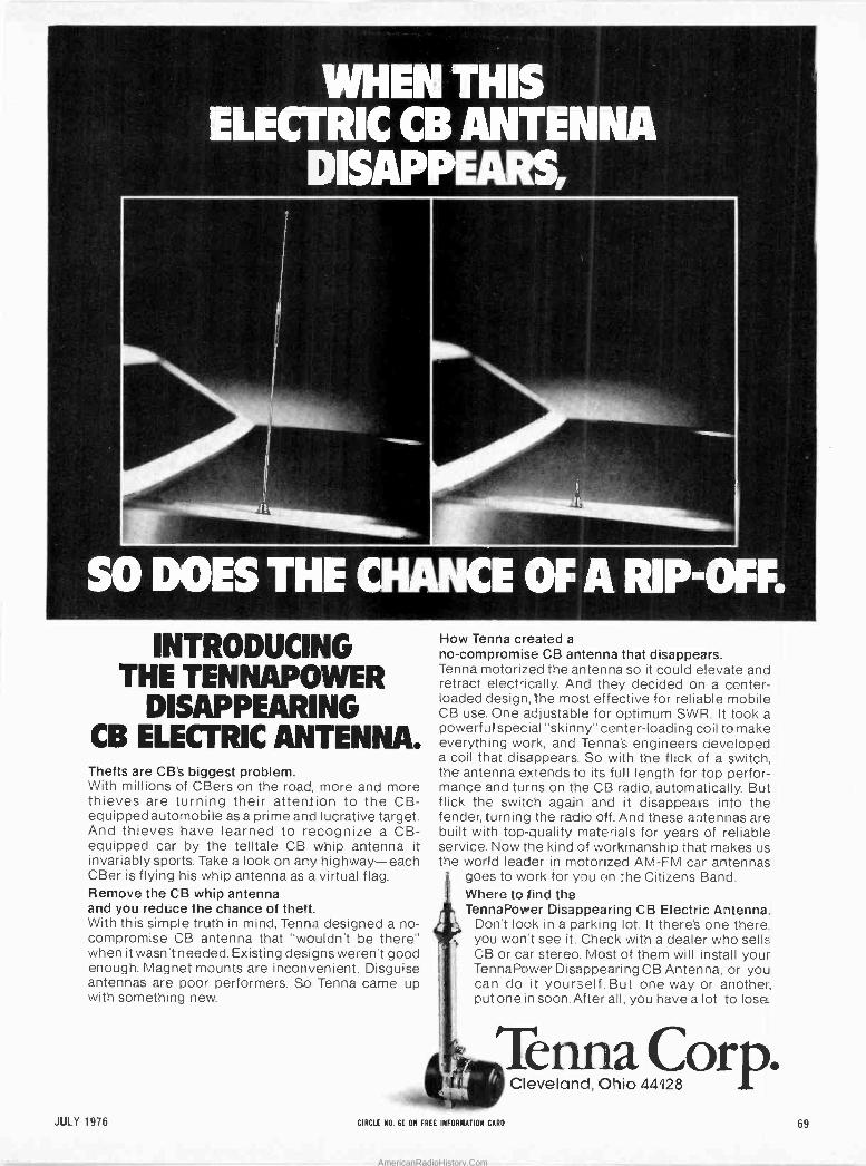
ENTHIS ELICTRIC:,CBANTINIIA
DISAPP
so ooEs 'THE c INTRODUCING
THE TENNAPOWER DISAPPEARING
CB ELECTRIC ANTENNA. Thefts are CB's biggest problem. With millions of CBers on the road, more and more thieves are turning their attention to the CB - equipped automobile as a prime and lucrative target. And thieves have learned to recognize a CB - equipped car by the telltale CB whip antenna it invariably sports. Take a look on any highway-each CBer is flying his whip antenna as a virtual flag. Remove the CB whip antenna and you reduce the chance of theft. With this simple truth in mind, Tenna designed a no - compromise CB antenna that "wouldn't be there" when it wasn't needed. Existing designs weren't good enough. Magnet mounts are inconvenient. Disguise antennas are poor performers. So Tenna came up with something new.
CE OFARPOFF.: How Tenna created a
no -compromise CB antenna that disappears. Tenna motorized the antenna so it could elevate and retract electrically. And they decided on a center - loaded design, the most effective for reliable mobile CB use. One adjustable for optimum SWR. It took a powerful special "skinny" center -loading coil to make everything work, and Tenna's engineers developed a coil that disappears. So with the flick of a switch, the antenna extends to its full length for top perfor- mance and turns on the CB radio, automatically. But flick the switch again and it disappears into the fender, turning the radio off. And these antennas are built with top-quality materials for years of reliable service. Now the kind of workmanship that makes us the world leader in motorized AM -FM car antennas
goes to work for you on the Citizens Band. Where to find the TennaPower Disappearing CB Electric Antenna.
Don't look in a parking lot. It there's one there, you won't see it. Check with a dealer who sells. CB or car stereo. Most of them will install your TennaPower Disappearing CB Antenna, or you can do it yourself. But one way or another, put one in soon. After all, you have a lot to lose_
Tenna Corp. Cleveland, Ohio 44128
JULY 1976 CIRCLE NO. 60 ON FREE INFORMATION CARD 69
AmericanRadioHistory.Com
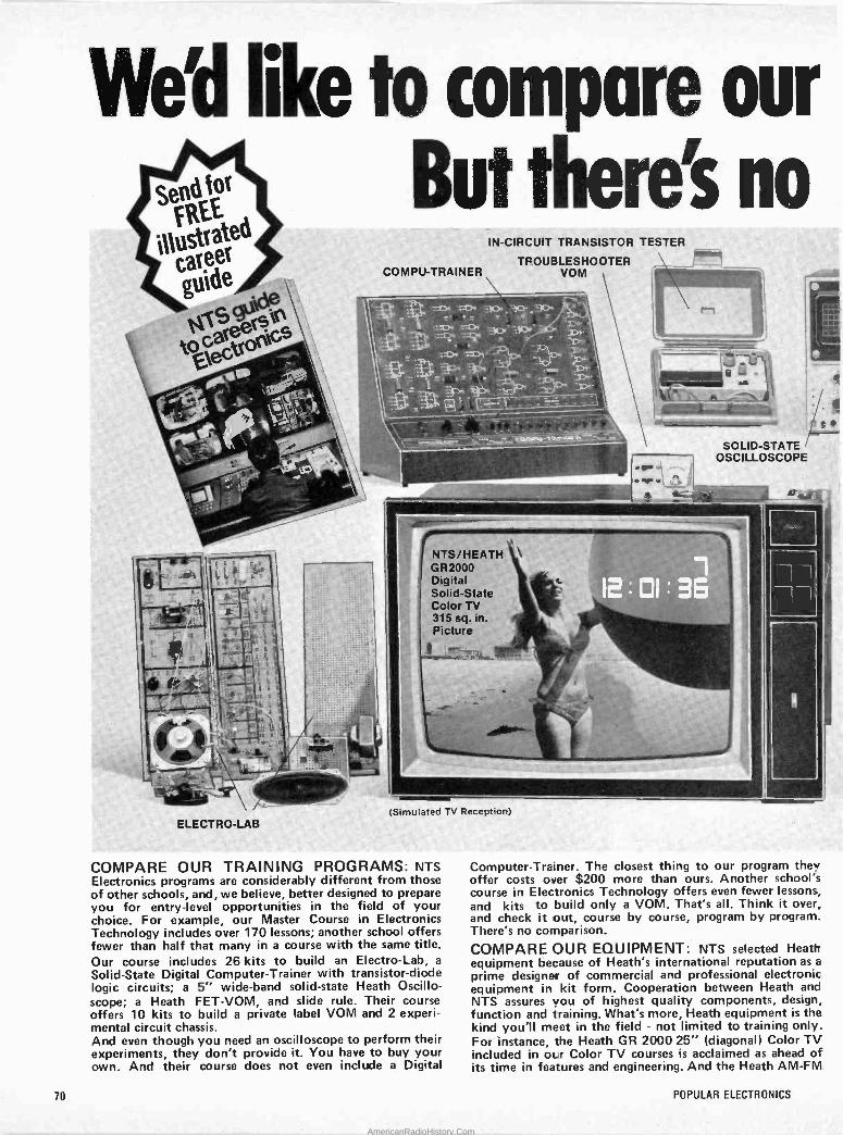
Sena for
FREE ed illustr é care
:10Oec 9
ELECTRO-LAB-
ta comiar. our ut ti':eret no
COMPU-TRAINER
:. . p: arl g o- j
.=:>e ;i:4
IN -CIRCUIT TRANSISTOR TESTER
TROUBLESHOOTER - VOM
i: r - - .. _ .. -
---
NTS/HEATH e
GR2000 Digital Solid -State Color TV 315 sq. in. Picture
i
(Simulated TV Reception)
COMPARE OUR TRAINING PROGRAMS: NTS Electronics programs are considerably different from those of other schools, and, we believe, better designed to prepare you for entry-level opportunities in the field of your choice. For example, our Master Course in Electronics Technology includes over 170 lessons; another school offers fewer than half that many in a course with the same title. Our course includes 26 kits to build an Electro -Lab, a
Solid -State Digital Computer -Trainer with transistor -diode logic circuits; a 5" wide -band solid-state Heath Oscillo- scope; a Heath FET-VOM, and slide rule. Their course offers 10 kits to build a private label VOM and 2 experi- mental circuit chassis. And even though you need an oscilloscope to perform their experiments, they don't provide it. You have to buy your own. And their course does not even include a Digital
Computer -Trainer.. The closest thing to our program they offer costs over $200 more than ours. Another school's course in Electronics Technology offers even fewer lessons, and kits to build only a VOM. That's all. Think it over, and check it out, course by course, program by program. There's no comparison.
COMPARE OUR EQUIPMENT: NTS selected Heath equipment because of Heath's international reputation as a
prime designer of commercial and professional electronic. equipment in kit form. Cooperation between Heath and NTS assures you of highest quality components, design, function and training. What's more, Heath equipment is the kind you'll meet in the field - not limited to training only. For instance, the Heath GR 2000 25" (diagonal) Color TV included in our Color TV courses is acclaimed as ahead of its time in features and engineering. And the Heath AM -FM
70 POPULAR ELECTRONICS
AmericanRadioHistory.Com
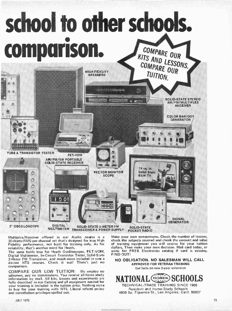
SC dl ,00
1 '
ii,, z '1-
parison.
é I
..
Y ; f
, 'r ,f*;- 1 4-14-r
TUBE & TRANSISTOR TESTER
HIGH FIDELITY SPEAKERS
c o
'Fl- o
o ¡ r
J
5" OSCILLOSCOPE
l.:
FET-VOM
AM/FM/SW PORTABLE -
SOLID-STATE RECEIVER
DIGITAL MULTIMETER
SOLID-STATE 2 -METER FM SOLID-STATE TRANSCEIVER& POWER SUPPLY POCKET RADIO
Sc 00'; S. COMPARE
OUR KITS AND LESSONS. COMPARE
TUITION.
1 1
- e
._- _-.,'.2r ..c
o -= SCLID-STATE STEREO
_- , __ y AM/FM/MULTIPLEX RECEIVER
- VECTOR MONITOR SCOPE
I
d 74 sq. ún. I Solid -State
=B&W TV
Multiplex/Receiver offered in our Audio course is a
30-Watts-RMS-per-channel set that's designed for true Hugh Fidelity performance, not built for training only. As for reliability, that's another word for Heath. The same holds true for Heath Oscilloscopes, FET-1/01V1, Digital Multimeter, In -Circuit Transistor Tester, Solid -State 2 -Meter FM Transceiver, and much more included in over a
dozen NTS courses. Check it out! There's just no comparison.
COMPARE OUR LOIN TUITION: We employ no salesmen, pay no commissions. You receive all home study information by mail. All kits, lessons and experiments are fully described in our Catalog and all equipment needed for your training is included in the tuition price. Nothing extra to buy for your training with NTS. Liberal refund pollicy and cancellation privileges spelled out.
':
COLOR BAR/DOT GENERATOR
L -. e é m
SIGNAL GENERATOR
Make your own comparisons. Check the number of lessons, check the subjects covered and check the amount and value of training equipment you will receive for your tuition dollars. Then make your own decision. Mail card today, or write for FREE Electronics catalog if card is missing. FIND OUT!
NO OBLIGATION. NO SALESMAN WILL CALL APPROVED FOR VETERAN TRAINING
Get facts on new 2 -year extension
NATIONAL TECHEYECAL SCHOOLS TECHNICAL -TRADE TRAINING SINCE 1905
Resident and Home -Study Schools 4000 So. Figueroa St., Los Anceles, Calif. 90037
JULY 1976 73
AmericanRadioHistory.Com
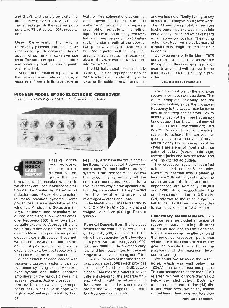
and 2 µV), and the stereo switching threshold was 12.5 dBf (2.3 µV). Pilot carrier leakage into the receiver's out- puts was 73 dB below 100% modula- tion.
User Comment. This was a
thoroughly pleasant and satisfactory receiver to use. No operating "bugs" appeared during our extensive use tests. The controls operated smoothly and positively, and the sound quality was excellent.
Although the manual supplied with the receiver was quite complete, it made no reference to the 4cH ADAPTOR
feature. The schematic diagram re- veals, however, that this circuit is really the equivalent of the separate preamplifier output/main amplifier input facility found in many receivers today. Setting the switch to 4cH inter- rupts the signal path at the approp- riate point. Obviously, this feature can be used equally well for installing graphic equalizers, signal processors, electronic crossover networks, etc., into the system.
The FM dial calibrations are linearly spaced, but markings appear only at 2 -MHz intervals. In spite of this wide spacing, the calibration was accurate,
and we had no difficulty tuning to any desired frequency without guesswork. The FM sound was notably free from background hiss and was the audible equal of any FM sound we have heard in our laboratory location. The muting action was free from noise bursts and revealed only a slight "thump" as it cut in and out.
Our experience with the Model 7075 convinces us that this receiver is easily the equal of others we have used at or near its price and with respect to the features and listening quality it pro- vides.
CIRCLE NO. BO ON FREE INFORMATION CARO
PIONEER MODEL SF -850 ELECTRONIC CROSSOVER Active C'rossov'er gets 1110.1 out of speaker systems.
CT' Q34.
-
f ( .
HIRSCH- HOUCK LABS REPORT
-.` /i; k,
v..;...
^onozcn u.v.,r.. m........ _-.'
Passive cross- over networks, it has been claimed, can de- grade the per-
formance of the speaker systems in which they are used. Nonlinear distor- tion can be created by the iron -core inductors and electrolytic capacitors in many speaker systems. Some power loss is also inevitable in the windings of inductors. Because of the large inductors and capacitors re- quired, achieving a low woofer cross- over frequency (200 Hz or lower) can be quite expensive. Although there is
some difference of opinion as to the desirability of using crossover slopes steeper than 6-dB/octave, those net- works that provide 12- and 18 -dB/ octave slopes require prohibitively expensive (for a low-cost speaker sys- tem) close -tolerance components.
All the difficulties encountered with passive crossover systems can be overcome by using an active cross- over system and using separate amplifiers for the various drivers in a
speaker system. Active crossover fil- ters are inexpensive (using compo- nents that do not have to cope with high power) and essentially distortion - 74
less. They also have the virtue of mak- ing it easy to adjust cutoff frequencies and slopes. One such active crossover system is the Pioneer Model SF -850 that accomplishes virtually all the crossover operations needed for a
two- or three-way stereo speaker sys- tem. Separate selectors are provided for the woofer/midrange and midrange/tweeter transitions.
The Model SF -850 measures 133/4" W x 13"D x 51/2"H(35 x 33 x 14 cm) and weighs 12 lb 6 oz (5.6 kg). Price is
$199.95.
General Description. The low-pass switch for the woofer has frequencies of 125, 250, 500, 700, and 1000 Hz,
while the frequencies for the tweeter's high-pass switch are 1000, 2000, 4000, 6000, and 8000 Hz. The corresponding low- and high-pass filters for the mid- range driver have matching cutoff fre- quencies. For each of the cutoff selec- tors, a separate SLOPE switch provides a choice of 6-, 12-, or 18-dB/octave slopes. This makes it possible to use different slopes for the separate driv- ers, which might be advantageous from a sonic point of view or merely to protect the tweeter against excessive low -frequency drive levels.
The slope controls for the midrange section also have FLAT positions. This offers complete flexibility for the two-way system, since the crossover frequency to the tweeter can be set at any of the frequencies from 125 to 8000 Hz. Each of the three frequency - band outputs has its own level control (concentric for the two channels). This is vital for any electronic crossover system to achieve the correct fre- quency balance with drivers of differ- ent efficiency. On the rear apron of the chassis are a pair of input and three pairs of output (woofer, midrange, tweeter) jacks and two switched and one unswitched ac outlets.
The crossover system's specified gain is rated nominally at unity. Maximum insertion loss is stated at less than 2 dB with any settings of the crossover controls. Input and output impedances are nominally 100,000 and 1000 ohms, respectively. The rated maximum output is 3.5 volts; S/N, referred to the rated output, is better than 85 dB; and harmonic dis- tortion is specified at 0.3% or less.
Laboratory Measurements. Dur- ing our tests, we plotted a number of response curves using different crossover frequencies and slope set- tings. In every case, the attenuation at -
the indicated crossover point was within 1 dB of the ideal 3 -dB value. The gain, as specified, was 1.0 in the passbands at the maximum level - control settings.
We could not measure the output noise, which was well below the .100-µV limit of our test equipment. This corresponds to better than 80 dB referred to 1 volt, or more than 91 dB below the rated output. Both har- monic and intermodulation (IM) dis- tortion were very low at any usable output level. They measured less than
POPULAR ELECTRONICS
AmericanRadioHistory.Com

0.025% up to 1 volt output and about 0.1% at the rated 3 -volt output. The output clipped at slightly greater than 5 volts.
User Comment. Since we did not have a two- or three-way speaker sys- tem that provided separate access to the individual drivers, we simulated a
three-way system with three different full -range loudspeakers. Each speaker was driven by its own power amplifier. The crossover system was connected between the preamplifier and three power amplifiers.
As we experimented with different combinations of crossover frequen- cies and slopes, it became obvious that a hit-or-miss or arbitrary selection
of parameters, by means óf a fixed passive crossover network, would be unlikely to produce the optimum per- formance of which the speakers are capable. Not only did the choice of crossover frequence make an appre- ciable difference in the sound, but we usually heard at least as much differ- ence between different slope settings.
For the loudspeaker/speaker sys- tem experimenter, we can think of no accessory as useful as a fully adjusta- ble electronic crossover system like the Model SF -850. The need for two or three amplifiers when using an elec- tronic crossover system might seem to be a drawback, but it should be under- stood that only the woofer normally requires a powerful amplifier with a
very good low -frequency response and that the midrange and tweeter drivers normally require much less power. In fact, lower -power amplifiers are strongly recommended for the tweeter, which can easily be damaged by excessive driving power.
Whether or not bi- or tri-ampli- fication has inherent sound advan- tages is not a question we will attempt to answer here. However, one thing is
certain: there is no simpler or more convenient means of getting the most out of such a system than by using an active electronic crossover system. And the Pioneer Model SF -850 cross- over system does everything claimed for it and does it very well indeed.
CIRCLE NO. 81 ON FREE INFORMATION CARD
MXR STEREO GRAPHIC EQUALIZER flab/\' effective, moderately priced, 10 -octave -band equalizer.
HIRSCH- HOUCK
1 '
REPO s
Graphic equal- izersareacknowl- edged to provide an effective means of mod-
ifying the frequency response of a home audio system. Usually, slide - type potentiometers are used on a graphic equalizer to vary the response at different frequencies. The positions of the pot "knobs" roughly outline the frequency response curve of the equalizer, which accounts for the "graphic" part of the device's name.
In a sense, these equalizers are ac- tually highly versatile tone controls. Practically speaking, a graphic equalizer should have at least five separate control frequencies; some of the more elaborate models have seven control frequencies. A much more de- sirable form, however, is the octave - band equalizer, which generally di- vides the audio range into 10 bands. A good example of such an equalizer is the very compact and relatively low -
JULY 1976
cost octave -band equalizer from MXR Innovations. This equalizer has excel- lent performance characteristics, 10 frequency controls, and provides a
boost and cut range in excess of 10 dB for each of its two stereo channels.
The MXR graphic equalizer mea- sures 91/4" W x 71/4" D x 2" H (32.5 x 18.4 x 5.1 cm) and weighs 4.5 lb (2 kg). It sells for $199.95 in the consumer version. (There are two electrically identical versions of the graphic equalizer. The consumer version uses phono-type input and output jacks and provides the tape monitor facility that would otherwise be eliminated when the equalizer is connected into a hi-fi system. The professional version uses standard phone jacks and does not supply tape monitoring facilities.)
General Description. The MXR equalizer is finished in satin aluminum with a pebbled black vinyl front panel to provide a pleasant contrast. In addi- tion, it has walnut end panels.
On the forward section of the top panel are 22 small white knobs, 20 of which permit adjustments of the slide potentiometers and the remaining two provide the means for separately set- ting the gains of the two stereo chan- nels. The center frequencies of the fil- ters are plainly marked in front of the slide controls (31, 62, 125, 250, 500, 1000, 2000, 4000, 8000, and 16,000 Hz). Scales that extend across the control surface provide a means for indicating the approximate amount of boost and cut for each filter over a range of ±-12 d B.
On the rear apron are the line inputs and outputs and the tape recording inputs and outputs that replace the normal amplifier tape monitoring cir- cuit. A slide switch replaces the usual program source with the tape playback output, while another switch bypasses the equalizer circuits. Since the equalizer draws negligible power and can safely and economically be left on at all times, there is no power switch.
The published specifications for the equalizer are in terms of professional program levels. The maximum output is rated at +15 dBm into 600 ohms, or +22 dBm into a high -impedance load. The gain is nominally unity; ±1 dB from 20 to 20,000 Hz with the controls centered. The equivalent noise is rated at 95 dBm down. The stated input impedance is 47,000 ohms, while the output is designed to drive loads of 600 ohms or greater. The harmonic and IM distortion are rated at 0.05% or less at 0 dBm (0.775 volt).
Laboratory Measurements. The 75
AmericanRadioHistory.Com
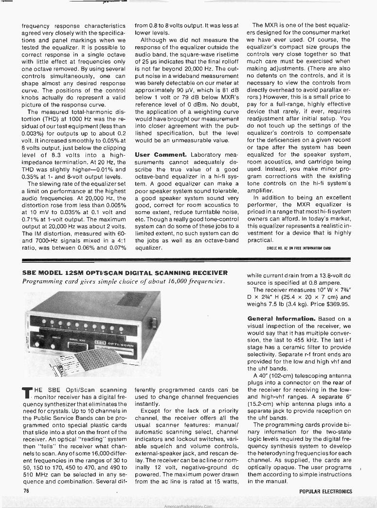
frequency response characteristics agreed very closely with the specifica- tions and panel markings when we tested the equalizer. It is possible to correct response in a single octave with little effect at frequencies only one octave removed. By using several controls simultaneously, one can shape almost any desired response curve. The positions of the control knobs actually do represent a valid picture of the response curve.
The measured total -harmonic dis- tortion (THD) at 1000 Hz was the re- sidual of our test equipment (less than 0.003%) for outputs up to about 0.2 volt. It increased smoothly to 0.05% at 8 volts output, just below the clipping level of 8.3 volts into a high - impedance termination. At 20 Hz, the THD was slightly higher -0.01% and 0.35% at 1- and 8 -volt output levels.
The slewing rate of the equalizer set a limit on performance at the highest audio frequencies. At 20,000 Hz, the distortion rose from less than 0.005% at 10 mV to 0.035% at 0.1 volt and 0.71% at 1 -volt output. The maximum output at 20,000 Hz was about 2 volts. The IM distortion, measured with 60 - and 7000 -Hz signals mixed in a 4:1
ratio, was between 0.06% and 0.07%
from 0.8 to 8 volts output. It was less at lower levels.
Although we did not measure the response of the equalizer outside the audio band, the square -wave risetime of 25 µs indicates that the final rolloff is not far beyond 20,000 Hz. The out- put noise in a wideband measurement was barely detectable on our meter at approximately 90 µV, which is 81 dB below 1 volt or 79 dB below MXR's reference level of 0 dBm. No doubt, the application of a weighting curve would have brought our measurement into closer agreement with the pub- lished specification, but the level would be an unmeasurable value.
User Comment. Laboratory mea- surements cannot adequately de- scribe the true value of a good octave -band equalizer in a hi-fi sys- tem. A good equalizer can make a
poor speaker system sound tolerable, a good speaker system sound very good, correct for room acoustics to some extent, reduce turntable noise, etc. Though a really good tone -control system can do some of these jobs to a
limited extent, no such system can do the jobs as well as an octave -band equalizer.
The MXR is one of the best equaliz- ers designed for the consumer market we have ever used. Of course, the equalizer's compact size groups the controls very close together so that much care must be exercised when making adjustments. (There are also no detents on the controls, and it is
necessary to view the controls from directly overhead to avoid parallax er- rors.) However, this is a small price to pay for a full -range, highly effective device that rarely, if ever, requires readjustment after initial setup. You do not touch up the settings of the equalizer's controls to compensate for the deficiencies on a given record or tape after the system has been equalized for the speaker system, room acoustics, and cartridge being used. Instead, you make minor pro- gram corrections with the existing tone controls on the hi-fi system's amplifier.
In addition to being an excellent performer, the MXR equalizer is priced in a range that most hi-fi system owners can afford. In today's market, this equalizer represents a realistic in- vestment for a device that is highly practical.
CIRCLE NO. 82 ON FREE INFORMATION CARD
SBE MODEL 12SM OPTI/SCAN DIGITAL SCANNING RECEIVER Programming card gives simple choice of about 16,000 frequencies.
i ,_ T1A'
_ ---=`
b .1114.' - a..^.M ¡-. .j_ ® oP
R N . -
~Rr b .144t
Ou OO Ó_a
THE SBE Opti/Scan scanning monitor receiver has a digital fre-
quency synthesizer that eliminates the need for crystals. Up to 10 channels in the Public Service Bands can be pro- grammed onto special plastic cards that slide into a slot on the front of the receiver. An optical "reading" system then "tells" the receiver what chan- nels to scan. Any of some 16,000 differ- ent frequencies in the ranges of 30 to 50, 150 to 170, 450 to 470, and 490 to 510 MHz can be selected in any se- quence and combination. Several dif-
ferently programmed cards can be used to change channel frequencies instantly.
Except for the lack of a priority channel, the receiver offers all the usual scanner features: manual/ automatic scanning select, channel indicators and lockout switches, vari- able squelch and volume controls, external -speaker jack, and rescan de- lay. The receiver can be ac line or nom- inally 12 volt, negative -ground dc powered. The maximum power drawn from the ac line is rated at 15 watts,
while current drain from a 13.8 -volt do source is specified at 0.8 ampere.
The receiver measures 10" W x 73/4"
D x 23/4" H (25.4 x 20 x 7 cm) and weighs 7.5 lb (3.4 kg). Price $369.95.
General Information. Based on a
visual inspection of the receiver, we. would say that it has multiple conver- sion, the last to 455 kHz. The last i -f stage has a ceramic filter to provide selectivity. Separate r -f front ends are provided for the low and high vhf and the uhf bands.
A 40" (102 -cm) telescoping antenna plugs into a connector on the rear of the receiver for receiving in the low - and high -vhf ranges. A separate 6" (15.2 -cm) whip antenna plugs into a
separate jack to provide reception on the uhf bands.
The programming cards provide bi- nary information for the two -state logic levels required by the digital fre- quency synthesis system to develop the heterodyning frequencies for each channel. As supplied, the cards are optically opaque. The user programs them according to simple instructions in the manual.
76 POPULAR ELECTRONICS
AmericanRadioHistory.Com
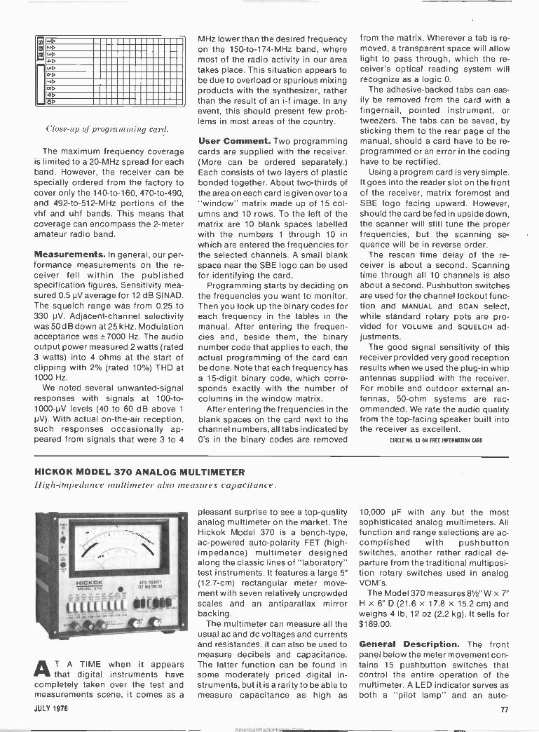
m m
n.+D
WD aD uD oD -4D
OD
Close-up of programming card.
The maximum frequency coverage is limited to a 20 -MHz spread for each band. However, the receiver can be specially ordered from the factory to cover only the 140 -to -160, 470 -to -490, and 492 -to -512 -MHz portions of the vhf and uhf bands. This means that coverage can encompass the 2 -meter amateur radio band.
Measurements. In general, our per- formance measurements on the re- ceiver fell within the published specification figures. Sensitivity mea- sured 0.5 µV average for 12 dB SINAD. The squelch range was from 0.25 to 330 µV. Adjacent -channel selectivity was 50 dB down at 25 kHz. Modulation acceptance was ±7000 Hz. The audio output power measured 2 watts (rated 3 watts) into 4 ohms at the start of clipping with 2% (rated 10%) THD at 1000 Hz.
We noted several unwanted -signal responses with signals at 100 -to - 1000 -µV levels (40 to 60 dB above 1
µV). With actual on -the -air reception, such responses occasionally ap- peared from signals that were 3 to 4
MHz lower than the desired frequency on the 150 -to -174 -MHz band, where most of the radio activity in our area takes place. This situation appears to be due to overload or spurious mixing products with the synthesizer, rather than the result of an i -f image. In any event, this should present few prob- lems in most areas of the country.
User Comment. Two programming cards are supplied with the receiver. (More can be ordered separately.) Each consists of two layers of plastic bonded together. About two-thirds of the area on each card is given over to a
"window" matrix made up of 15 col- umns and 10 rows. To the left of the matrix are 10 blank spaces labelled with the numbers 1 through 10 in which are entered the frequencies for the selected channels. A small blank space near the SBE logo can be used for identifying the card.
Programming starts by deciding on the frequencies you want to monitor. Then you look up the binary codes for each frequency in the tables in the manual. After entering the frequen- cies and, beside them, the binary number code that applies to each, the actual programming of the card can be done. Note that each frequency has a 15 -digit binary code, which corre- sponds exactly with the number of columns in the window matrix.
After entering the frequencies in the blank spaces on the card next to the channel numbers, all tabs indicated by 0's in the binary codes are removed
from the matrix. Wherever a tab is re- moved, a transparent space will allow light to pass through, which the re- ceiver's optical reading system will recognize as a logic 0.
The adhesive -backed tabs can eas- ily be removed from the card with a
fingernail, pointed instrument, or tweezers. The tabs can be saved, by sticking them to the rear page of the manual, should a card have to be re- programmed or an error in the coding have to be rectified.
Using a program card is very simple. It goes into the reader slot on the front of the receiver, matrix foremost and SBE logo facing upward. However, should the card be fed in upside down, the scanner will still tune the proper frequencies, but the scanning se- quence will be in reverse order.
The rescan time delay of the re- ceiver is about a second. Scanning time through all 10 channels is also about a second. Pushbutton switches are used for the channel lockout func- tion and MANUAL and SCAN select, while standard rotary pots are pro- vided for VOLUME and SQUELCH ad- justments.
The good signal sensitivity of this receiver provided very good reception results when we used the plug-in whip antennas supplied with the receiver. For mobile and outdoor external an- tennas, 50 -ohm systems are rec- ommended.,We rate the audio quality from the top -facing speaker built into the receiver as excellent.
CIRCLE NO. 83 ON FREE INFORMATION CARD
HICKOK MODEL 370 ANALOG MULTIMETER High -impedance multimeter also measures capacitance.
I ,
O
HICKOK AUtO MOM' mo e »o FET NUtiIME1EA
F.L, CCCt l ú%. µ,
O
AT A TIME when it appears that digital instruments have
completely taken over the test and measurements scene; it comes as a
pleasant surprise to see a top-quality analog multimeter on the market. The Hickok Model 370 is a bench -type, ac -powered auto -polarity FET (high - impedance) multimeter designed along the classic lines of "laboratory" test instruments. It features a large 5" (12.7 -cm) rectangular meter move- ment with seven relatively uncrowded scales and an antiparallax mirror backing.
The multimeter can measure all the usual ac and dc voltages and currents and resistances. It can also be used to measure decibels and capacitance. The latter function can be found in some moderately priced digital in- struments, but it is a rarity to be able to measure capacitance as high as
10,000 µF with any but the most sophisticated analog multimeters. All function and range selections are ac- complished with pushbutton switches, another rather radical de- parture from the traditional multiposi- tion rotary switches used in analog VOM's.
The Model 370 measures 81/2"W x 7" H x 6" D (21.6 x 17.8 x 15.2 cm) and weighs 4 Ib, 12 oz (2.2 kg). It sells for $189.00.
General Description. The front panel below the meter movement con- tains 15 pushbutton switches that control the entire operation of the multimeter. A LED indicator serves as both a "pilot lamp" and an auto -
JULY 1976 77
AmericanRadioHistory.Com
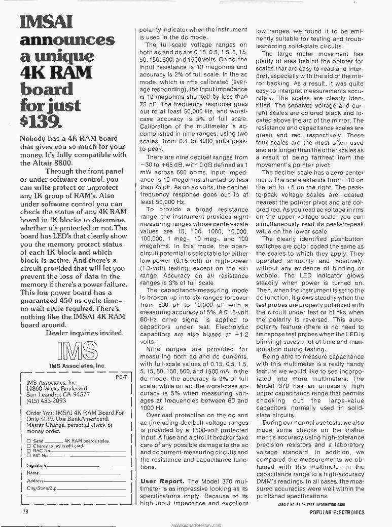
IMSAI announces a unique 4K .: board for just $139. Nobody has a 4K RAM board that gives you so much for your money. It's fully compatible with the Altair 8800.
Through the front panel or under software control, you can write protect or unprotect any 1K group of RAM's. Also under software control you can check the status of any 4K RAM board in 1K blocks to determine whether it's protected or not. The board has LED's that clearly show you the memory protect status of each 1K block and which block is active. And there's a circuit provided that will let you prevent the loss of data in the memory if there's a power failure. This low power board has a guaranteed 450 ns cycle time - no wait cycle required. There's nothing like the IMSAI 4K RAM board around.
Dealer inquiries invited.
IMS Associates, Inc.
IMS Associates, Inc. 14860 Wicks Boulevard San Leandro, CA 94577 (415) 483-2093
PE771
Order Your IMSAI 4K RAM Board For Only $139. Use BankAmericard. Master Charge, personal check or money order.
Send 4K RAM boards today. D Charge to my credit card. O BAC No D MC No
Signature
Name
Address
City/State/Zip -------J
polarity indicator when the instrument is used in the dc mode.
The full-scale voltage ranges on both ac and dc are 0.15, 0.5, 1.5, 5, 15,
50, 150, 500, and 1500 volts. On dc, the input resistance is 10 megohms and accuracy is 2% of full scale. In the ac mode, which is rms calibrated (aver- age responding), the input impedance is 10 megohms shunted by less than 75 pF. The frequency response goes out to at least 50,000 Hz, and worst - case accuracy is 5% of full scale. Calibration of the multimeter is ac- complished in nine ranges, using two scales, from 0.4 to 4000 volts peak - to -peak.
There are nine decibel ranges from -30 to +65 dB, with 0 dB defined as 1
mW across 600 ohms. Input imped- ance is 10 megohms shunted by less than 75 pF. As on ac volts, the decibel frequency response goes out to at least 50,000 Hz.
To provide a broad resistance range, the instrument provides eight measuring ranges whose center -scale values are 10, 100, 1000, 10,000, 100,000, 1 meg-, 10 meg-, and 100 megohms. In this mode, the open - circuit potential is selectable for either low -power (0.15 -volt) or high -power (1.3 -volt) testing, except on the Rx1
range. Accuracy on all resistance ranges is 3% of full scale.
The capacitance -measuring mode is broken up into six ranges to cover from 500 pF to 10,000 µF with a
measuring accuracy of 5%. A 0.15 -volt 60 -Hz drive signal is applied to capacitors under test. Electrolytic capacitors are also biased at +1.2 volts.
Nine ranges are provided for measuring both ac and dc currents, with full-scale values of 0.15, 0.5, 1.5, 5, 15, 50, 150, 500, and 1500 mA. In the dc mode, the accuracy is 3% of full scale; while on ac, the worst -case ac- curacy is 5% when measuring volt- ages at frequencies between 60 and 1000 Hz.
Overload protection on the dc and ac (including decibel) voltage ranges is provided by a 1500 -volt protected input. A fuse and a circuit breaker take care of any possible damage to the ac and dc current -measuring circuits and the resistance and capacitance func- tions.
User Report. The Model 370 mul- timeter is as impressive looking as its specifications imply. Because of its high input impedance and excellent
low ranges, we found it to be emi- nently suitable for testing and troub- leshooting solid-state circuits.
The large meter movement has plenty of area behind the pointer for scales that are easy to read and inter- pret, especially with the aid of the mir- ror backing. As a result, it was quite easy to interpret measurements accu- rately. The scales are clearly iden- tified. The separate voltage and cur- rent scales are colored black and lo- cated above the arc of the mirror. The resistance and capacitance scales are green and red, respectively. These four scales are the most often used and are longer than the other scales as a result of being farthest from the movement's pointer pivot.
The decibel scale has a zero -center mark. The scale extends from -10 on the left to T5 on the right. The peak - to -peak voltage scales are located nearest the pointer pivot and are col- ored red. As you read ac voltage in rms on the upper voltage scale, you can simultaneously read its peak -to -peak value on the lower scale.
The clearly identified pushbutton switches are color coded the same as the scales to which they apply. They operated smoothly and positively, without any evidence of binding or wobble. The LED indicator glows steadily when power is turned on. Then, when the instrument is set to the dc function, it glows steadily when the test probes are properly polarized with the circuit under test or blinks when the polarity is reversed. This auto - polarity feature (there is no need to transpose test probes when the LED is blinking) saves a lot of time and man- ipulation during testing.
Being able to measure capacitance with this multimeter is a really handy feature we would like to see incorpo- rated into more multimeters. The Model 370 has an unusually high upper capacitance range that permits checking out the large -value capacitors normally used in solid- state circuits.
During our normal use tests, we also made some ' checks on the instru- ment's accuracy using high -tolerance precision resistors and a laboratory voltage standard. In addition, we compared the measurements we ob- tained with this multimeter in the capacitance range to a high -accuracy DMM's readings. In all cases, the mea- sured accuracies were well within the published specifications.
CIRCLE N0. 84 ON FREE INFORMATION CARD
78 POPULAR ELECTRONICS
AmericanRadioHistory.Com
19 MAC'S SERVICE SHOP
Mobile Communications:
CB vs. 2 -METER FM
THE cool air in the service shop felt good to Barney as he stepped in-
side from the hot, humid weather out- side.
"Hi, Bart," he greeted the graying man sitting in a wheelchair chatting with Mac. "Why the antenna farm sprouting from the roof of your hotrod out front?"
"You like my guttermounts?" Bart asked with a grin. "The short one is a
CB loaded whip, and the long one is a
2 -meter 5/8 -wave vertical. I'm plan- ning on doing some travelling, and I'm checking out the relative effectiveness of these two modes of mobile com- munication for drivers in general and physically handicapped drivers in par- ticular. Since that bout with polio, I
figure I'm a representative 'worst case' of the latter group. Even a flat tire on my hand -controlled car means I must have help."
"What rigs are you using?" "The CB rig is a deluxe synthesized
23 -channel job with incremental tun- ing, mechanical filter, S -meter, 0.5 - microvolt sensitivity, r -f noise blanker, speech compression, 4 watts of r -f output, and a pi -network. I can plug a
little 5 -watt horn speaker into a jack on the back of the set and stick the speaker on the car -top with rubber suction feet and have my own portable PA system-a form of short range communication that has come in very handy on a couple of occasions.
"The 2 -meter rig is a hand-held transceiver with switchable r -f outputs of either 2 watts minimum or 1 watt maximum. It measures about 10" x 31/2" x 2" and weighs 2 lb., 4 oz with a
self-contained 14.4-V, 500-mAH NiCd battery. It has two ceramic i -f filters, provides 0.5 watts of audio output, and has a sensitivity of 0.7 µV for 20 dB quieting. There is provision for five
By John T. Frye, W9EGV
sets of transmit/receive crystals, and I
have three simplex and two repeater sets installed at present. These in- clude the national simplex fre- quency at 146.52 MHz and the old 146.94 MHz, plus the local repeater on 147.78/.18 and the popular 146.16/.76 that will access repeaters in neighbor- ing Indianapolis, Fort Wayne, Lafay- ette, and Chicago. When I start travel- ling, I plan to replace two of the simplex channels with .34/.94 and .22/ .82 that my knowledgeable 2 -meter friends recommend.
"There are probably two , dozen hand-held transceivers on the market, and each has special features to rec- ommend it; but I chose this one be- cause it and the accessories available made it particularly suited for my needs. I can take it with me in my wheelchair, in the motel, and in the car. Those accessories include an ex- ternal dynamic mike with PTT switch, a dc power cord with cigarette lighter plug, earphone, leather carrying case, a flexible rubber -ducky antenna that can replace the normal telescoping antenna, and a dual -rate battery charger into which the transceiver is droppéd for charging at a normal rate of 50 mA and a trickle rate of 15 mA. On squelched receive it draws 30 mA; so when it is operating in the charger set to a normal rate, the net charge is a
trickle charge. That's a handy feature for long-term monitoring, say in a
motel room." "Sounds to me like you're giving CB
a 2/1 power advantage." Before answering, Bart pulled a
black, metal -cased object from his coat pocket and handed it to Barney. It measured about 41/4" x 3" x 17/8" and had an SO -239 coax fitting extending from either side and two wires coming out a grommeted hole in one end. The
wires were attached to a cigarette lighter plug. Closer inspection re- vealed the object was actually a large finned heat sink with a shallow (1" deep) cover snapped over the flat side.
" 'It matters not how great their size; depend on me, I'll equalize,' " Bart quoted." Barney, this is an amplifier tha I bought as a kit and assembled on a furnished pc board that's fastened to the back side of the heat sink beneath the cover. It's a solid-state vhf amplifier utilizing a high -power Motorola module, and it covers the 135 -to -175 -MHz band. It's completely self-contained and requires no tuning or setup. With a minimum driving power of 100 mW, it will put out 20-25 watts with a supply of 12 to 13.6 volts dc. You just insert it in the antenna feedline, plug it into the cigarette lighter socket, and you're in business. It's assembled for the r -f input you in- tend to use. In my case, I wired it for 1
to 3 watts, but attenuator resistors are furnished for inputs of 250 mW or less, 250 to 500 mW, and 500 mW to 1 watt. Within limits, power out is a function of power in; so when I have my.hand- held transceiver on the lower output level, I get 12 watts out of the amplifier. This jumps to 25 watts when I switch the transceiver to 2 watts output. That means I have a choice of 25 watts, 12 watts, 2 watts, or less than 1 watt for my 2 -meter tests; but I usually run full power when trying to make an initial contact."
"I suppose you have to take the amplifier out of the feedline when you want to run the hand-held barefoot, don't you?" Barney asked.
"Not at all The unit contains a little carrier -operated relay (COR) that only inserts the amplifier into the feedline when both a carrier is present at the input and power is fed to the amplifier. When no carrier is present, as on re- ceive, the antenna connects through the COR contacts straight to the re- ceiver. If the cigarette lighter plug is pulled out, the COR is not operated by the transceiver carrier and the RF
goes, unamplified, to the antenna." "-Okay, Bart, now you've told us
about the equipment you're using, what about your findings?" Mac inter- rupted. "If you need help or just infor- mation on the highway, are you better off with CB or 2 -meter FM?"
Which Is Better? "Let's talk about CB first," Bart answered. "The chief thing it has going for it is the sheer number of CB units in use-some-
JULY 1976 . 79
AmericanRadioHistory.Com
thing like six million sets-and the fact that they are all concentrated on 23 channels in a single band. One out of every 28 American families has one or more CB sets, and 1 out of 5 longhaul trucks is CB equipped: While only about 2 million or so CB licenses are valid today, this doesn't tell the story. Many licenses usually cover several transceivers, and there are probably more unlicensed CB users than licensed. This last, though, is chang- ing, probably because the license fee has dropped from $20 to $4 and the FCC is cracking down on violators. In the last year 9000 CB violators have been belted with fines ranging from $100-$300. For repeat cases, licenses have been revoked and fines up to $10,000 levied. CB license applica- tions that Were running less than 15,000 a month in 1972 are now up to 500,000 a month.
"Yes, CB is becoming more re- spectable. REACT teams, as well as state and local police, monitor Chan- nel 9, CB's emergency channel; and it's estimated 5.2 million calls are made yearly on that channel. Missouri has installed CB radios in all 750 of its highway patrol cars, and in Indiana the state police operate several mobile units under the call of KFP2179; and they hope this year to install CB sets in all of the state police posts. Other states are taking similar action. In ad- dition to Channel 9, some state units monitor the old 'Trucker Channel 10,' or the 'New Trucker Channel 19.'
"But CB has disadvantages, too. The band is crowded, and popular channels are jammed with hétero- dynés and interferring signals. The AM receivers are subject to both natural and man-made noise. Often signals skipping in from 750 to 2000 miles away will be so strong that talking across town is nearly impossible. This condition will worsen as Sunspot Cycle 21 progresses. Some CB sta- tions run far more than the legal 4
watts output and overload the front ends of nearby receivers, "bleeding" across a half -dozen channels each side of the Offending signal."
"We don't have these troubles on two meters," Barney said smugly. "FM receivers reject static and man-made noise. While skip is not unheard of on two meters, it happens rarely com- pared to the 11 -meter CB band, and even then it produces no squealing heterodynes. A ham license is a hard-won and chériShed possession, and the vast majority of hams abide by
80
the rules and regulations of the FCC. If
one accidently puts out a broad and interferring signal, he hears about it immediately from fellow hams before the Friendly Candy Company, hopeful- ly, can take note."
"All true," Bart agreed, "but proba- bly repeaters are the main advantage 2 -meter FM has over CB. There are over 2000 repeater licenses extant, and new applications are coming in at the rate of a dozen a week. These machines run considerable power, and their antennas are put just as high as possible to take advantage of the line -of -sight propagation of 2 -meter signals. If a signal from your hand- held or mobile transceiver can access the repeater, the full power and ideal antenna site of the latter is at your command. If that repeater is on a
mountain top, as is often the case or the coasts, your hand-held's signal may be heard for a radius of a hundred miles by anyone monitoring the re- peater channel. Some repeaters even use satellite receivers linked to the re- peater receiver by vhf or- uhf to extend the weak -signal pickup. The satellite inputs. are sampled by a scanning or 'voting' device that selects the most noise -free signal for feeding to the re- peater receiver.
"A lot of good commercial service technicians are attracted to the 2 -meter band, and some of the repeat- ers they set up are unbelievably sophisticated. A few will respond only upon receipt of a special tone -coded command, thus restricting their use to the subscribers. Upon a different command, they will transmit time, weather, and road conditions. Many repeaters have autopatch facilities so that if the mobile or hand-held unit is equipped with a touch-tone pad, the owner can place a telephone call through the repeater to tell the wife he will be late for supper or to report an accident directly to the police..Note, however, he cannot engage a motel room, order a radio part, or engage in any other commercial activity on the ham band. He can do so on CB as it is intended for personal and business use.
"In all honesty, though, two meters has some disadvantages, too. On a
watts -per -dollar basis, 2 -meter equipment is more expensive than CB. My .CB set costs $200, but if you are willing to sacrifice a few features you can get a good set for around $150. The hand-held job, complete with ac- cessories and crystals for five chan-
nels runs about $350. On top of that, repeaters are expensive to set up and operate, and this money must come from the hams using them, either through club dues or subscriptions.
"But in spite of all the work, money, and dedicated cooperation hams pour into repeaters," Bart concluded, "there just aren't enough hams monitoring their 45 -odd simple and repeater frequencies during the weekday daylight hours out here in the sparsely settled flat lands to insure re- liable interception of signals from passing mobiles. There are only 255,000 hams spread out over their many bands and they have various in- terests. I greatly doubt if 100,000 of them operate on two meters. The pic- ture is undoubtedly different on the coasts where people and repeaters are more concentrated, but I plan to travel the width and breadth of the country; and I can't afford a hatfull of crystals or an expensive synthesizer to hit the many repeater frequencies shown in a repeater directory. Things may be different if proposed FCC changes regarding a 'no code' vhf phone ham license go through. That Opens up a lot of possibilities. But for now, I've repeatedly called on .52 and .94 and on the frequency of a local repeater for road information with only the repeater identification or its squelch -tail for a reply.
"On the other hand, I seldom need to make a second call on CB Channels 10 or 19, in the city or out on the high- way, to get an immediate answer. I
enjoy the ham contacts I do make, and I believe hand-helds and repeaters constitute the wave of the future. I cer- tainly plan to take my hand-held trans- ceiver with me wherever I go, but when I need help or information, I'll reach first for the CB mike.
"There are times, though," Bartsaid with a grin, "when both a belt and sus- penders are not enough. My ham friend, Joe, and his son-in-law, a non- believer in electronic wizardry, were going to Florida in a truck camper last year. About 30 miles west of Chat- tanooga on 124 á rod went out through the side of the motor. 'No sweat,' says Joe. 'I've got nine channels in my 2 -meter transceiver and all 23 in my CB set; so I'll just summon help.' An hour or so later, after vainly yelling himself hoarse on all channels of both transceivers, Joe unstrapped his trail bike from the front of the truck and rode off to get help. His son-in-law has never let him forget this."
POPULAR ELECTRONICS
AmericanRadioHistory.Com

El
l T.l Solid State
BUILD YOUR OWN SONAR SYSTEM SONAR - the name alone has an exciting quality,
whether you're old enough to remember World War II,
young enough just to have read about it in history books, or simply a viewer of the late -late TV movies. You have visions of determined, steely -jawed destroyer skippers searching relentlessly for killer U-boats. You hear the "ping -ping - ping" background sound as a tense and sweating Ameri- can submarine commander attempts to elude an enemy patrol. Now, with a little skill, a dash of patience, a single IC, and a few accessory components, you can build your own sonar - not a military version, to be sure, but a practical down-to-earth (water?) instrument which can be used as a
submerged object detector, depth finder, or fish locator, or, with a few modifications, for underwater data transmis- sion and remote control applications. If you're not a yachtsman (yachtsperson) or fisherman (fisherperson), you can use the same IC to assemble an air ranging version called sodar (for SOnic Detection and Ranging) suitable for remote sensing, collision avoidance, and intrusion or burglar alarm systems.
t1 560Ny O 50
1p 200 1111,
ZOO
TRANSDUCER
NOISE
REJECT
RI DC MOTOR S 221
0.2_F
CS J Ie 0 002uF
77.
Ci 1200 pF
CS
0.001yF
n
(GAIN I
NC
91
u II
1.2 11
CI
100 pF
CIO T 1200 FF
It II
II
II
1
By Lou Garner
Utilizing a number of novel circuit design techniques, engineers at the National Semiconductor Corporation (2900 Semiconductor Drive, Santa Clara, CA 95051) have developed a monolithic IC which contains all the essential electronic circuitry for a complete sonar system within a chip area of only 80 by 93 mils. Affectionately dubbed the fishfinder by the firm's application engineers, the device, type LM1812, was released just recently for general dis- tribution, although it has been in production on a semi - custom basis for over a year. Joining the manufacturer's growing family of special-purpose devices, which includes the LM3909 LED flasher, discussed in last year's July and October columns, and the NSL4944 universal LED, examined in our May issue, the LM1812's unusual circuit contains a 12 -watt ultrasonic transmitter and a selective receiver featuring a 10 -watt display driver. Despite its high peak power capabilities, the IC, in an 18 -pin Epoxy B molded DIP, can be operated without an external heat sink in most applications.
Designed for use on standard 12 -volt dc sources, the
RO
21
v'Iltv,c)
lo
Fig. 1. A typical sonar system circuit. The component values are for operation in water.
9 CE
1.,F
Note: A permanent magnet attached to a rotating wheel provides modulation pulses to pin 8. The time duration for the transmit mode is controlled by the voltage which is induced in a stationary pick-up coil. The neon display is also mounted on this wheel.
JULY 1976 81
AmericanRadioHistory.Com
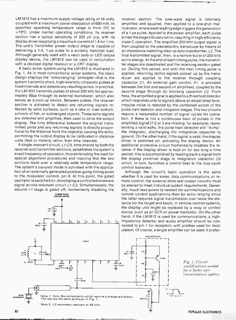
LM1812 has a maximum supply voltage rating of 18 volts, coupled with a maximum power dissipation of 600 mW. Its specified operating temperature range is from 0°C to +70°C. Under normal operating conditions, its receiver section has a typical sensitivity of 200 µV p -p, with its display driver supplying a maximum current of 1 A for 1 ms. The unit's transmitter power output stage is capable of delivering a 1-A, 1-µs pulse to a suitably matched load. Although generally used with a neon bulb or LED output display device, the LM1812 can be used in conjunction with a clocked digital readout or a CRT display.
A basic sonar system using the LM1812 is illustrated in Fig. 1. As in most conventional sonar systems, the basic design employs the "echo -ranging" principle-that is, the system transmits short, high -intensity ultrasonic pulses at fixed intervals and detects any resulting echos. In practice, the LM1812 transmits pulses of about 200 kHz for approx- imately 80µs through its external transducer, which also serves, as a pick-up device. Between pulses, the receiver section is activated to detect any returning signals re- flected by solid surfaces, such as a lake or river bottom, schools of fish, or submerged objects. These echo signals are detected and amplified, then used to drive the output display. The time differential between the original trans- mitted pulse and any returning signals is directly propor- tional to the distance from the object(s) causing the echo, permitting the output display to be calibrated in distance units (feet or meters) rather than time intervals.
A single resonant circuit, L1 -C3, time-shared by both the receiver and transmitter sections, establishes the system's exact frequency of operation, thus eliminating the need for special alignment procedures and insuring that the two sections track over a relatively wide temperature range. The system's transmit mode is activated with the applica- tion of an externally generated positive -going timing pulse to the modulator control, pin 8. At this point, the gated oscillator is switched on, developing a controlled sinewave signal across resonant circuit L1 -C3. Simultaneously, the second r -f stage is gated off, momentarily disabling the
V'
w rR.MSOUCERw
o
82
CS
71101E
TO 4O111E n[xCT REf11TOR q0 MT
a
I16 lit IIS I17 117 I11
141117
,t l7
CT TO
001 E 0A1Y ror
IS
- CI
receiver section. The sine -wave signal is internally amplified and squared, then applied to a one-shot mul- tivibrator, where each leading edge triggers the generation of a 1-µs pulse. Applied to the power amplifier, each pulse drives the stage into saturation, resulting in high -efficiency class -C operation. The amplified 200 -kHz outputsignal is then coupled to the piezoelectric transducer by means of an impedance matching step-up auto -transformer, L2. The final transmitted signal, then, is a narrow burst of 200 -kHz sonic energy. At the end of each timing pulse, the transmit- ter stages are deactivatéd and the receiving section gated on. During this period, and until the next timing pulse is applied, returning (echo) signals picked up by the trans- ducer are applied to the receiver through coupling capacitor C1. An external gain control, P1, is provided between the first and second r -f amplifiers, coupled to the second stage through dc blocking capacitor C2. From here, the amplified signal is applied to a threshold detector which responds only to signals above an established level. Impulse noise is rejected by the combined action of the pulse train detector and integrator stages. The two circuits require a reasonable number of signal cycles for opera- tion. If there is not a continuous train of pulses in the amplified signal (if 2 or 3 are missing, for example), repre- senting a valid echo, the pulse train detector will "dump" the integrator, discharging the integration capacitor to ground. On the other hand, if the signal is valid, the display driver is switched on, activating the display device. An additional protective circuit momentarily disables the re- ceiver if the display driver is kept on for too long a time period; this is accomplished by feeding back a signal from the display predriver stage to integration capacitor C8 which, in turn, furnishes a control bias to the duty -cycle control transistor.
Although the circuit's basic operation is the same whether it is used for sonar, data communications, or re- mote control, the external drive and output circuitry must be altered to meet individual system requirements. Gener- ally, much less power is needed for communications and remote control applications than for echo ranging since the latter requires signal transmission over twice the dis- tance (to the target and back). In remote -control systems, the display unit might be replaced by a relay or control device, such as an SCR or power transistor. On the other hand, if the LM1812 is used for communications, a high - impedance detector and audio amplifier should be con- nected to pin 1 for reception, with another used for mod- ulation. Of course, a single amplifier can be used, if prefer -
It CI OI7,E
Note 1: Only the components which require a change are shown. The rest are the same as shown in Fig. 1.
Note 2: L2 secondary resonant at 40 kHz.
MAST STRETCHER
Fig. 2. Circuit modifications needed for a Sodar (air transmission) system.
POPULAR ELECTRONICS
AmericanRadioHistory.Com
red, switched back and forth between the modulator and receiver sections for transmission and reception. Variable rate pulse or other modulation techniques may be used for digital data or code communications.
Naturally, some means must be provided for measuring the time interval between the transmitted and echo pulses when the LM1812 is used in a sonar system. Any of several techniques may be used, including digital control and a
clocked readout or an oscilloscope display with a cali- brated linear sweep, but one popular method is illustrated in Fig. 1. Here, a small permanent magnet and a neon bulb are mounted near the rim of a wheel, with slip rings pro- vided for applying a voltage to the bulb. The wheel is
rotated by a constant -speed dc motor. The magnet serves to generate modulation pulses inductively as it passes a
fixed pickup coil, L3. The neon bulb serves as the display device, driven by the receiver's output stage through trans- former Ti. Shunt diode D1 is included to suppress switch- ing transients, while a series filter, R2 -C9, is provided to limit excessive current build up in the transformer's prim- ary under rapid flashing conditions. The transformer must provide a substantial voltage step-up (from 12 to 100 volts or more) to insure flashing the bulb. In operation, the wheel's position at which the initial pulse is transmitted is
considered "0," while the arc length traveled by the bulb before it flashes an echo represents the time required for the ultrasonic pulse to travel to the target and back. Since this time period is directly proportional to target distance, a fixed calibrated scale can be positioned around the wheel to indicate distances in feet or meters. Within system sensitivity limits, the sonar's maximum scale range is de- termined by the repetition rate of the transmitted pulses, for echoes can be received only during the intervening intervals. With a system design similar to the one shown in Fig. 1, then, the scale range is determined by the display wheel's rotational speed (hence motor rpm), for this de- termines the pulse rate.
Considering the relative attenuation of high -frequency ultrasonic signals in water and in air, a much lower operat- ing frequency is recommended when the LM1812 is to be used in air transmission systems, such as sodar-typically 40 kHz rather than 200 kHz. The basic circuit modifications needed for operation in an air medium are given in Fig.2. A
different transducer is required, of course, together with a
matching drive coil, L2. In addition, bypass and coupling capacitor values should be increased as indicated and the tuning elements (Li and C3) changed to achieve 40 -kHz resonance, while an external "pulse stretcher" must be added to lengthen the drive pulse from 1 to 5 µs. Driven by the LM1812, the pulse stretcher consists of a simple RC integration network and pnp power driver. Except for these few changes, the circuit arrangement and compo- nent values are identical to those of the system shown in Fig. 1.
When using the LM1812 in practical designs, special attention must be given to ground loops and common coupling paths due to the close proximity of transmitter and receiver circuits in the same package. Three ground pins (5, 10, 15) are provided on the device to simplify layout problems, but the ground path(s) still must be adequate to handle peak currents of as much as 2 amperes when the transmitter and display are energized simultaneously. Local sources of high-energy impulse noise, such as lightly loaded motors, if not shielded properly, can cause erroneous display signals or "blips." Ideally, these noise
ro cast éLthät
gota radia
'Now you don't have to let everyone kncw = tha- you've gct a r-obilaCB radio. Oir
model MR264 disguise antenna looks and acts List lice a normal ca- radio antenna, _cperating or AM and FM as well as C3.
We <now the. disguise s ef`ective because we've been rnaking them for_lary
enlb,cernentagencies for -years. If ylcu dor t need a cisguise an:erna, but you do wart
su3eriorCB eerormancein acowl nourited 3 -way antenna, check out our model M-267.
Both models featiire a stain ess steel wt -lb that datachfes easilw so your antenna won't ge_ ria aed off in the car wash either. When
y ' o -e looking fer ante -mas. 3 -way, disguise .or otherwise, take advarrage of our 2C yrs. experenze Lookfcr the Stripes of Duality.
1
-
;the antenna scieCi81i5ts
-
y
' _ 3-Svmaa al -ember of heAiel3rcup Inc. a 12E35 EcclidAvén.e '
-- Cleveiand Ot o OE - Export: 2200 3hames trivia
Westtury. L.I.=N en/ "or- 115£0 Canada: A & Sr- s, Ltd.
Déstitnctty _
Superior - =
Perfarmañcé:
Cal ]7(_bY ale Antenna $.seccnslstiU
JULY 1976 CIRCLE NO. 9 ON FREE INFORMATION CARO
83
AmericanRadioHistory.Com

THE COMPLETE DVM
$348
+19.9.9 6 ENCORE
95-411'a . -v . :.F.r
FOR FASTER, MORE RELIABLE MEASUREMENTS
OVM36
A NEW STANDARD IS BORN High accuracy you can trust .
Versatile measuring capabilities . .
An efficient, easy to operate meter ..
All at an affordable price .
That's the DVM38 . .. The complete DVM that sets new performance stan- dards in 4 key areas.
A NEW ACCURACY STANDARD The 3'/:digit, .1% accuracy is backed by a 15 meg Si input impedance, compared to 10 meg LO input of conventional DVM's, which guarantees' up to 50% greater accuracy with 1/3 less circuit loading on every measurement far high
accuracy you can trust.
A STANDARD IN.CAPABILITIES The DVM38 is more accurate in MORE circuits with these versatile ranges: 1000V to 2000V DC, 1 KV AC; .01 St
to 20 meg i2 ; 0.1uA to 2A ... Plus
HI and LO ohms and a 50KVDC range with accessory Hv probe.
A NEW STANDARD IN SPEED AND EASE OF OPERATION Large pushbuttons and callouts = no need to hunt and peck. Large .4" L.E.D.'s with direct readout, down to V and mV indicators. SINGLE STEP AUTO -RANGING for maximum resolu. tion and efficiency. 2KV DC protection minimizes downtime.
THE AFFORDABLE STANDARD There are few .1% DVM's less expensive- there are none ás complete in this price range, plus backed by a LIFETIME guar- anteeagainst factory workmanship errors.
THE DVM38 . A NEW STANDARD IN DVM's FOR SPEED, VERSATILITY AND ACCURACY.
DVM38 BACKMADEERIGHT BY SENCORES
100% LIFETIME GUARANTEE f
NCO R 11,001::711%=',.F>11.'.:15111
CIRCLE NO. 54 ON FREE INFORMATION CARD
pulses should be filtered at the source, but their effects can be minimized by connecting a small capacitor (about 30 pF) across the first r -f stage (between pins 3 and 4) to reduce amplifier bandwidth. Finally, for optimum overall performance and maximum efficiency, the transducer driver coil (L2 in Figs. 1 and 2) should be designed to resonate at the proper frequency (200 kHz for water and 40 kHz for air systems) with the sum of all output circuit capacitances, including distributed wiring, that of the coax cable feeding the transducer, and the transducer itself.
Reader's Circuits. Submitted by Peter Lefferts (1640 Decker Ave., San Martin, CA 95046), the two ci rcuitsg iven in Fig. 3 illustrate additional applications for the versatile NSL4944 universal LED. Both designs utilize the LED's unique current regulation characteristic, both are suitable for home projects, both use standard components, and both are noncritical as far as layout and lead dress are concerned. Referring, first, to Fig. 3A, this decoupling network can be used wherever stage isolation is required, as when powering a preamp in an audio amplifier. Essen- tially a standard pi filter network with a constant current LED used in place of a resistor or inductance, the circuit attenuates power supply ripple by some 60 dB while at- tenuating back -coupled signals more than 70 dB. The only critical factor is the load current, which must be within the LED's capability, yet, at the same time, large enough to insure LED operation within its constant -current mode - typically about 13 mA. If the load requirements are unusu- ally small, as with some FET preamps, a shunt load resistor (R1) is needed to increase the LED's current to within the 84
.1. Some applications
tur ,VSL.494 4: (A) Ue<'oyrpli)fg
/!lt('!': (B) Capacitor
tester.
+15V
CI C2 500pF IOOpF
(A)
CHARGE TEST +I5VO-1 --111 6-
RI 47n
¡BPI BPI
CX
+1
L__ BP2
NSL4944
(B)
optimum range. The dc voltage drop across the LED is a
little over 2 volts. The second circuit, Fig. 3B, is an ex- tremely simple tester for large electrolytic capacitors. Con- trol switch S1 is a center -off, spdt toggle, lever, rotary or slide switch; series resistor R1 is a 1/2 -watt unit, and BP1 and BP2 are standard binding pasts. In operation, the test capacitor, Cx, is connected to terminals BP1 and BP2 with correct dc polarity. Switch Si is thrown first to the charge position, charging the capacitor from the dc source through series limiting resistor R1, then to the test posi- tion. The constant -current LED will discharge the capacitor from 15 volts to 2 volts linearly, staying lit during this period. If a typical 13-mA NSL4944 is used, a 1000-µF capacitor will discharge in just one second. Variations in the characteristics of individual LED's can be compen- sated by adjusting the supply voltage to a value just two volts more than the actual LED current in mA (i.e., an 11-mA LED would require a 13 -volt supply). By estimating (or measuring) the discharge time, an experienced user can check capacitors with values from about 500 µF to over 100,000 µF (from 1/2 to 100 seconds). Leakage can be esti- mated by charging the capacitor a second time, waiting for one discharge period, then testing. With a nominal LED (13 mA), a 10% decrease in discharge time would indicate a
leakage of 1.3 mA for the test unit. If the LED fails to light when Si is thrown to its test position, the capacitor is either shorted or open.
Device/Product News. Currently, microprocessors seem "to be dominating the technical news front. Fair- child's Microsystems Division (1725 Technology Drive, San Jose, CA 95110), for example, has introduced a new microprocessor design kit on a fully assembled circuit board which comes complete with a connecting cable for power supply and terminal hookup. The circuit board con- tains Fairchild's 3850 F8 CPU device, the 3851 program storage unit circuit, the 3853 static memory interface cir- cuit and eight 2102 static RAM's (1 kilobyte of memory). The complete kit is priced at $185.00 in small quantities.
Both Signetics, Inc. and Motorola Semiconductor Prod- ucts have slashed the prices of their microprocessors. Signetics has reduced the price of its Model 2650 general purpose, 8 -bit, 5 -volt, TTL compatible n -channel µP from $72.00 to $26.50 in small quantities (1-24). Motorola has reduced the price of its type 6800 8 -bit n -channel device from $69.00 to $35.00 in 1-9 units. The firm also has drop- ped the price of its MC6860 modem from $32.00 to $17.00 in small quantities. .
POPULAR ELECTRONICS
AmericanRadioHistory.Com
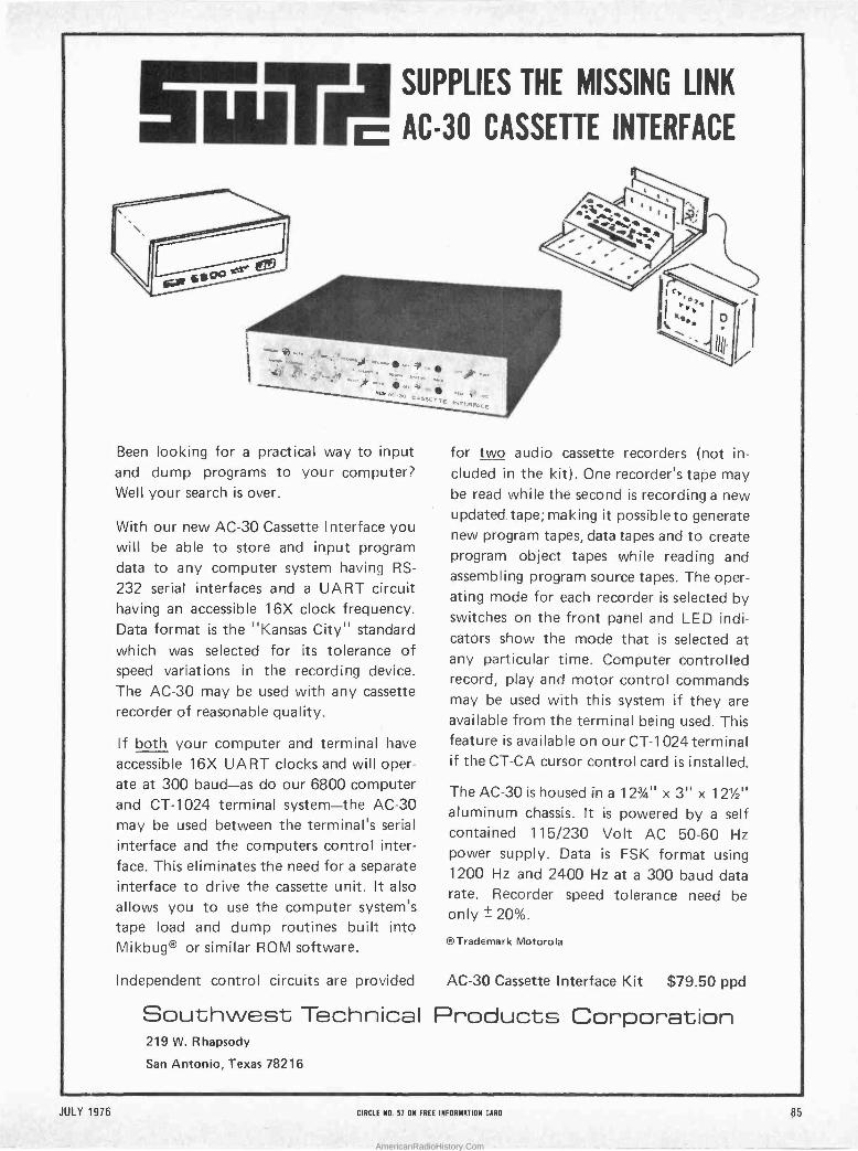
SUPPLIES THE MISSING LINK
AC -30 CASSETTE INTERFACE
i * w ,,10 ..1- < /
.-.oU °
e`
-f a. ...\.;:"i:11'ñ. :.s:: e;SQSET.I
i\.:EF;IpEE
Been looking for a practical way to input and dump programs to your computer? Well your search is over.
With our new AC -30 Cassette Interface you will be able to store and input program data to any computer system having RS-
232 serial interfaces and a UART circuit having an accessible 16X clock frequency. Data format is the "Kansas City" standard which was selected for its tolerance of speed variations in the recording device.
The AC -30 may be used with any cassette
recorder of reasonable quality.
If both your computer and terminal have
accessible 16X UART clocks and will oper- ate at 300 baud-as do our 6800 computer and CT -1024 terminal system-the AC -30 may be used between the terminal's serial
interface and the computers control inter- face. This eliminates the need for a separate interface to drive the cassette unit. It also
allows you to use the computer system's tape load and dump routines built into Mikbug® or similar ROM software.
-
I \ I
K e 111
for two audio cassette recorders (not in- cluded in the kit). One recorder's tape may be read while the second is recording a new updated tape; making it possible to generate new program tapes, data tapes and to create program object tapes while reading and assembling program source tapes. The oper- ating mode for each recorder is selected by switches on the front panel and LED indi- cators show the mode that is selected at any particular time. Ccmputer controlled record, play and motor control commands may be used with this system if they are available from the terminal being used. This feature is available on our CT -1024 terminal if the CT -CA cursor control card is installed.
The AC -30 is housed in a 123/4" x 3" x 121/2"
aluminum chassis. It is powered by a self contained 115/230 Volt AC 50-60 Hz power supply. Data is FSK format using 1200 Hz and 2400 Hz at a 300 baud data rate. Recorder speed tolerance need be only ± 20%.
®Trademark Motorola
Independent control circuits are provided AC -30 Cassette Interface Kit $79.50 ppd
Southwest Technical Products Corporation 219 W. Rhapsody
San Antonio, Texas 78216
JULY 1976 CIRCLE NO. 57 ON FREE INFORMATION CARD
.51.412
85
AmericanRadioHistory.Com
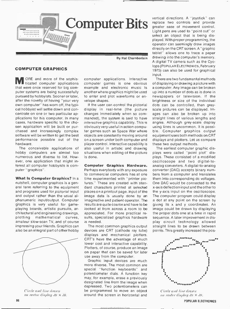
L'7,_ Computer Bits boo,. .: ..... . ::
COMPUTER GRAPHICS
MORE and more of the sophis- ticated computer applications
that were once reserved for big com- puter systems are being successfully pursued by hobbyists. Sooner or later, after the novelty of having "your very own computer" has worn off, the typi- cal hobbyist will settle down and con- centrate on one or two particular ap- plications for his computer. In many cases, hardware specific to the cho- sen application will be built or pur- chased and increasingly complex software will be written to get the best performance possible out of the hardware.
The conceivable applications of hobby computers are almost too numerous and diverse to list. How- ever, one application that might in- terest all computer hobbyists is com- puter "graphics".
What Is Computer Graphics? In a
nutshell, computer graphics is a gen- eral term referring to the equipment and programs used for pictorial input and output rather than the usual al- phanumeric input/output. Computer graphics is very useful for game - playing boards, artistic pursuits, ar- chitectural and engineering drawings, plotting mathematical curves, amateur slow -scan TV, and of course impressing your friends. Graphics can also be an integral part of other hobby
Circle and line dr0(rU an vector display .30 X .30.
By Hal Chamberlain
computer applications. Interactive computer games is one obvious example and electronic music is another where graphics might be used to enter and plot waveforms or en- velope shapes.
If the user can control the pictorial display in real-time (the picture changes immediately when so com- manded), the system is said to have interactive graphics capability. This is
obviously very useful in action compu- ter games such as Space War where objects are constantly moving around on a screen under both computer and player control. Interactive capability is
also useful in artistic and drawing situations when editing of the picture is done.
Computer Graphics Hardware. Perhaps everybody with any exposure to commercial computers has at one time experimented with "printer pic- tures." These are created with stan- dard characters printed at selected places on a printout page. Input of the image data is usually done by an imaginative and patient operator. The results are quite coarse and have to be looked at from across a room to be appreciated. For more practical re- sults, specialized graphics hardware is needed.
The most common graphics output devices are CRT (cathode ray tube) displays and mechanical plotters. CRT's have the advantage of much lower cost and interactive capability. Plotters, of course, produce an image on paper that can be saved for later use away from the computer.
Graphic input devices are much more diverse. The most common are special "function keyboards" and potentiometer dials. A function key may, for example, erase a previously designated line from the image when depressed. Two potentiometers can be programmed to move an object around the screen in horizontal and
N
vertical directions. A "joystick" can replace two controls and provide greater ease of movement control. Light pens are used to "point out" or select an object that is being dis- played. With proper programming, the operator can seemingly draw images directly on the CRT screen. A "graphic tablet" allows one to trace a paper drawing into the computer's memory. A digital TV camera such as the Cyc- lops (POPULAR ELECTRONICS, February 1975) can also be used for graphical input.
There are two fundamental methods of displaying or drawing a picture with a computer. Any image can be broken up into a number of dots as is done in newspapers or television. If the brightness or size of the individual dots can be controlled, then grey - scale pictures can be displayed. Im- ages can also be broken up into straight lines of various lengths and angles. Although grey -scale display using lines is uncommon, it is possi- ble. Computer graphics output equipment uses both methods on CRT displays and plotters. Let us compare these two output methods.
The earliest computer graphic dis- plays were called "point plot" dis- plays. These consisted of a modified oscilloscope and two digital -to - analog converters. A digital -to -analog converter (DAC) accepts binary num- bers from a computer and translates them into corresponding dc voltages. One DAC would be connected to the x-axis deflection input and the other to the y-axis input on the oscilloscope. The computer program could display a dot at any point on the screen by giving its x and y coordinates. An image could be drawn by displaying the proper dots one at a time in rapid sequence. A later improvement in dis- play circuit technology allowed straight lines to be drawn between points. This greatly increased the pos-
. . .. 1M N ° .. % .
.
Circle and line (/a wit on raster display 30 x d0.
POPULAR ELECTRONICS 86
AmericanRadioHistory.Com
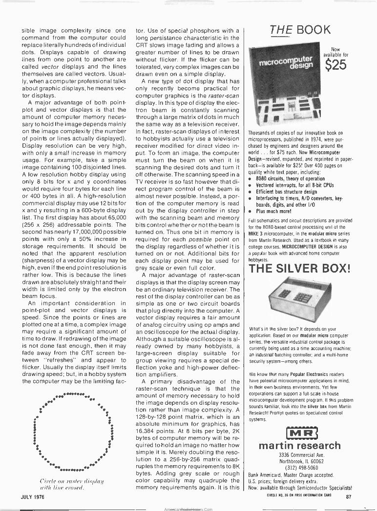
sible image complexity since one command from the computer could replace literally hundreds of individual dots. Displays capable of drawing lines from one point to another are called vector displays and the lines themselves are called vectors. Usual- ly, when a computer professional talks about graphic displays, he means vec- tor displays.
A major advantage of both point - plot and vector displays is that the amount of computer memory neces- sary to hold the image depends mainly on the image complexity (the number of points or lines actually displayed). Display resolution can be very high, with only a small increase in memory usage. For example, take a simple image containing 100 disjointed lines. A low resolution hobby display using only 8 bits for x and y coordinates would require four bytes for each line or 400 bytes in all. A high -resolution commercial display may use 12 bits for x and y resulting in a 600 -byte display list. The first display has about 65,000 (256 x 256) addressable points. The second has nearly 17,000,000 possible points with only a 50% increase in storage requirements. It should be noted that the apparent resolution (sharpness) of a vector display may be high, even if the end point resolution is rather low. This is because the lines drawn are absolutely straight and their width is limited only by the electron beam focus.
An important consideration in point -plot and vector displays is speed. Since the points or lines are plotted one at a time, a complex image may require a significant amount of time to draw. If redrawing of the image is not done fast enough, then it may fade away from the CRT screen be- tween "refreshes" and appear to flicker. Usually the display itself limits drawing speed; but, in a hobby system the computer may be the limiting fac-
:
$
N.0 1
Z . «: I. : i
S
Circle on raster display will, line erased.
tor. Use of special phosphors with a
long persistance characteristic in the CRT slows image fading and allows a
greater number of lines to be drawn without flicker. If the flicker can be tolerated, very complex images can be drawn even on a simple display.
A new type of dot display that has only recently become practical for computer graphics is the raster -scan display. In this type of display the elec- tron beam is constantly scanning through a large matrix of dots in much the same way as a television receiver. In fact, raster -scan displays of interest to hobbyists actually use a television receiver modified for direct video in- put. To form an image, the computer must turn the beam on when it is scanning the desired dots and turn it off otherwise. The scanning speed in a
TV receiver is so fast however that di- rect program control of the beam is
almost never possible. Instead, a por- tion of the computer memory is read out by the display controller in step with the scanning beam and memory bits control whether or not the beam is turned on. Thus one bit in memory is
required for each possible point on the display regardless of whether it is turned on or not. Additional bits for each display point may be used for grey scale or even full color.
A major advantage of raster -scan displays is that the display screen may be an ordinary television receiver. The rest of the display controller can be as simple as one or two circuit boards that plug directly into the computer. A
vector display requires a fair amount of analog circuitry using op amps and an oscilloscope for the actual display. Although a suitable oscilloscope is al- ready owned by many hobbyists, a
large -screen display suitable for group viewing requires a special de- flection yoke and high -power deflec- tion amplifiers.
A primary disadvantage of the raster -scan technique is that the amount of memory necessary to hold the image depends on display resolu- tion rather than image complexity. A 128 -by -128 point matrix, which is an absolute minimum for graphics, has 16,384 points. At 8 bits per byte, 2K bytes of computer memory will be re- quired to hold an image no matter how simple it is. Merely doubling the reso- lution to a 256 -by -256 matrix quad- ruples the memory requirements to 8K bytes. Adding grey scale or rough color capability may quadruple the memory requirements again. It is this
THE BOOK f
Now
uter available for
ocoráésign $25
o 13 El
MOM I 1-1wipm
gp,
Thousands of copies of our innovative book on
microprocessors, published in 1974, were pur-
chased by engineers and designers around the
world ... for $75 each. Now Microcomputer
Design-revised, expanded, and reprinted in paper-
back-is available for $25! Over 400 pages on
quality white text paper, including: 8080 circuits, theory of operation
Vectored interrupts, for all 8 -bit CPUs
Efficient bus structure design
Interfacing to timers, A/D converters, key-
boards, digits, and other I/O Plus much more!
Full schematics and circuit descriptions are provided
tor the 8080 -based central processing unit of the
MIKE 3 microcomputer, in the modular micro series
from Marlin Research. Used as a textbook in many
college courses, MICROCOMPUTER DESIGN is also
a popular book with advanced home computer
hobbyists.
THE SILVER BOX!
What's in the silver box? It depends on your
application. Based on our modular micro computer
series, the versatile industrial control package is
currently being used as a time accounting machine;
an industrial batching controller; and a multi -home
security system-among others.
We know that many Popular Electronics readers
have potential microcomputer applications in mind,
in their own business environments. Yet few
corporations can support a full-scale in-house
microcomputer development program. If this problem
sounds familiar, look into the silver box from Martin
Research! Prompt quotes on specialized control
systems.
MR martin research
3336 Commercial Ave.
Northbrook, IL 60062
(312) 498-5060
Bank Americard, Master Charge accepted.
U.S. prices; foreign delivery extra. Now: available through Semiconductor Specialists!
JULY 1976 CIRCLE N0.36 ON FREE INFORMATION CARD 87
AmericanRadioHistory.Com
Advanced Electronics
can O co
r our career in
e ec ronics reap
CREI brings college -level training to you with eight educational advantages, including special
arrangements for engineering degrees
The best way to qualify for top positions and top pay in electronics is obviously with college -level training. The person with such training usually steps more quickly into an engineering level posi- tion and is paid considerably more than the average technician who has been on the job several years.
A regular college engineering pro- gram, however, means several years of full-time resident training-and it often means waiting several years before you can even start your career. This, of course, is difficult if you must work full time to support yourself and your fam- ily.
If your career in electronics is limited without college -level training, take a
look at the advantages a CREI home study program can offer you.
1. Convenient Training CREI brings the college to you. Through the convenience of home study, you receive exactly the same level of training you will find in any college or university offering programs in elec- tronic engineering technology. With CREI, however, you can "go to college" whenever you have spare time at home or on the job.
2. Specialized Programs With CREI, you enjoy the advantage of specialized training. That is, your pro- gram will include only those courses directly applicable to your career in
electronics. We omit such courses as English, social studies and other sub- jects, which are usually required in resident schools. Therefore, with CREI, you move ahead faster to the more in- teresting and useful part of your train- ing.
3. Practical Engineering CREI programs give you a practical engineering knowledge of electronics. That is, each part of your training is
planned for your "use on the job." By using your training, you reinforce the learning process. And by demonstrating your increased knowledge to your em- ployer, you may qualify for faster ca- reer advancement.
4. Engineering Degrees CREI offers you a number of special arrangements for earning engineering degrees at recognized colleges and uni- versities. You can earn college credit while you are taking your CREI pro- gram or apply later, whatever is best for your career plans.
88 POPULAR ELECTRONICS
AmericanRadioHistory.Com
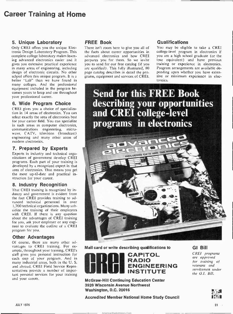
Career Training at Home
5. Unique Laboratory Only CREI offers you the unique Elec- tronic Design Laboratory Program. This complete college laboratory makes learn- ing advanced electronics easier and it gives you extensive practical experience in many areas of engineering, including design of electronic circuits. No other school offers this unique program. It is a
better "Lab" than we have found in many colleges. And the professional equipment included in the program be- comes yours to keep and use throughout your professional career.
6. Wide Program Choice CREI gives you a choice of specializa- tion in 14 areas of electronics. You can select exactly the area of electronics best for your career field. You can specialize in such areas as computer electronics, communications engineering, micro- wave. CATV, television (broadcast) engineering and many other areas of modern electronics.
7. Prepared by Experts Experts in industry and technical orga- nizations of government develop CREI programs. Each part of your training is
developed by a recognized expert in that area of electronics. That means you get the most up -tó -date and practical in- struction for your career.
8. Industry Recognition That CREI training is recognized by in- dustry and government is evident from the fact CREI provides training to ad- vanced technical personnel in over 1,700 technical organizations. Many sub- sidize the training of their employees with CREI. If there is any question about the advantages of CREI training for you, ask your employer or any engi- neer to evaluate the outline of a CREI program for you.
Other Advantages Of course, there are many other ad- vantages to CREI training. For ex- ample, throughout your training, CREI's stall gives you personal instruction for each step of your program. And in many industrial areas, both in the U. S.
and abroad, CREI Field Service Repre- sentatives provide a number of impor- tant personal services for your training and your career.
FREE Book There isn't room here to give you all of the facts about career opportunities in advanced electronics and how CREI prepares you for them. So we invite you to send for our free catalog (if you are qualified). This fully illustrated, 80 page catalog describes in detail the pro- grams, equipment and services of CREI.
Qualifications You may be eligible to take a CREI college -level program in electronics if you are a high school graduate (or the true equivalent) and have previous training or experience in electronics. Program arrangements are available de- pending upon whether you have exten- sive or minimum experience in elec- tronics.
Send for this FREE Book describing your opportunities and CREI college =level os 9
programs in elelctlonics ~Ira!~ aewRvf,!
-5 35.0 \ 7 1C
tNc`vcaN6GaNO
THE NuCti-F4 / -
_- - .:
-1,11C %,.
r. o .~le --1.,--
` s
_ -- 0 - 14" 4+
+ 1" 1; '. 0*
t
rA --- -
Mail card or write describing qualifications to s CAPITOL
w I RADIO ENGINEERIING
0 4 , INSTITUTE McGraw-Hill Continuing Education Center 3939 Wisconsin Avenue Northwest Washington, D.C. 20016
Accredited Member National Home Study Council
GI Bill CREI programs are approved -
for .training of veterans and servicemen under the G.1. Bill.
JULY 1976 91
AmericanRadioHistory.Com
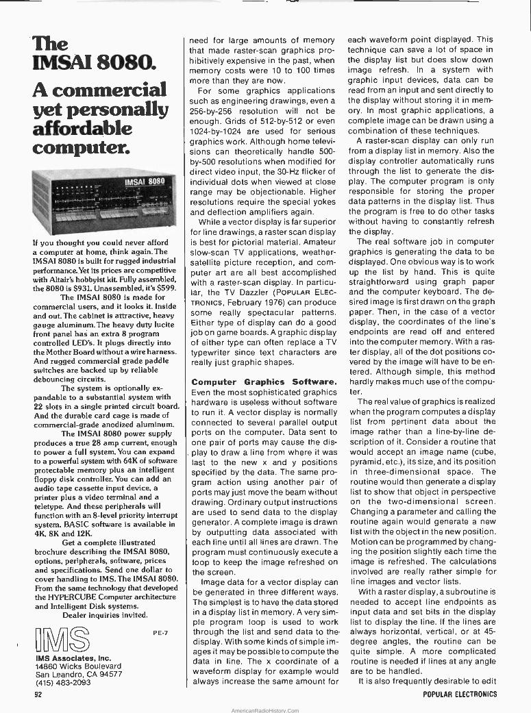
The IMSAI 8080. A commercial yet personally affordable computer.
IMSÁt¡80_,
fr
If you thought you could never afford a computer at home, think again. The IMSA1 8080 is built for rugged industrial performance.Yet its prices are competitive with Altair's hobbyist kit Fully assembled, the 8080 is $931. Unassembled, it's $599.
The IMSAI 8080 is made for commercial users, and it looks it. Inside and out. The cabinet is attractive, heavy gauge aluminum. The heavy duty lucite front panel has an extra 8 program controlled LED's.It plugs directly into the Mother Board without a wire harness. And rugged commercial grade paddle switches are backed up by réliable debouncing circuits.
The system is optionally ex- pandable to a substantial system with 22 slots in a single printed circuit board. And the durable card cage is made of commercial -grade anodized aluminum.
The IMSAI 8080 power supply produces a true 28 amp current, enough to power a full system. You can expand to a powerful system with 64K of software protectable memory plus an intelligent floppy disk controller. You can add an audio tape cassette input device, a
printer plus a video terminal and a
teletype. And these peripherals will function with an 8 -level priority interrupt system. BASIC software is available in 4K, 8K and 12K.
Get a complete illustrated brochure describing the IMSAI 8080, options, peripherals, software, prices and specifications. Send one dollar to cover handling to IMS. The IMSAI 8080. From the same technology that developed the HYPERCUBE Computer architecture and Intelligent Disk systems.
Dealer inquiries invited.
r -v-
MS Associates, Inc. 14860 Wicks Boulevard San Leandro, CA 94577 (415) 483-2093
92
P E-7
need for large amounts of memory that made raster -scan graphics pro- hibitively expensive in the past, when memory costs were 10 to 100 times more than they are now.
For some graphics applications such as engineering drawings, even a
256 -by -256 resolution will not be enough. Grids of 512 -by -512 or even 1024 -by -1024 are used for serious graphics work. Although home televi- sions can theoretically handle 500 - by -500 resolutions when modified for direct video input, the 30 -Hz flicker of individual dots when viewed at close range may be objectionable. Higher resolutions require. the special yokes and deflection amplifiers again.
While a vector display is far superior for line drawings, a raster scan display is best for pictorial material. Amateur slow -scan TV applications, weather - satellite picture reception, and com- puter art are all best accomplished with a raster -scan display. In particu- lar, the TV Dazzler (POPULAR ELEC- TRONICS, February 1976) can produce some really spectacular patterns. Either type of display can do a good job on game boards. A graphic display of either type can often replace a TV typewriter since text characters are really just graphic shapes.
Computer Graphics Software. Even the most sophisticated graphics hardware is useless without software to run it. A vector display is normally connected to several parallel output ports on the computer. Data sent to one pair of ports may cause the dis- play to draw a line from where it was last to the new x and y positions specified by the data. The same pro- gram action using another pair of ports may just move the beam without drawing. Ordinary output instructions are used to send data to the display generator. A complete image is drawn by outputting data associated with each line until all lines are drawn. The program must continuously execute a
loop to keep the image refreshed on the screen.
Image data for a vector display can be generated in three different ways. The simplest is to have the data stored in a display list in memory. A very sim- ple program loop is used to work through the list and send data to the display. With some kinds of simple im- ages it may be possible to compute the data in line. The x coordinate of a
waveform display for example would always increase the same amount for
each waveform point displayed. This technique can save a lot of space in
the display list but does slow down image refresh. In a system with graphic input devices, data can be read from an input and sent directly to the display without storing it in mem- ory. In most graphic applications, a
complete image can be drawn using a
combination of these techniques. A raster -scan display can only run
from a display list in memory. Also the display controller automatically runs through the list to generate the dis- play. The computer program is only responsible for storing the proper data patterns in the display list. Thus the program is free to do other tasks without having to constantly refresh the display.
The real software job in computer graphics is generating the data to be displayed. One obvious way is to work up the list by hand. This is quite straightforward using graph paper and the computer keybbard. The de- sired image is first drawn on the graph paper. Then, in the case of a vector display, the coordinates of the line's endpoints are read off and entered into the computer memory. With a ras- ter display, all of the dot positions co- vered by the image will have to be en- tered. Although simple, this method hardly makes much use of the compu- ter.
The real value of graphics is realized when the program computes a display list from pertinent data about the image rather than a line -by-line de- scription of it. Consider a routine that would accept an image name (cube, pyramid, etc.), its size, and its position in three-dimensional space. The routine would then generate a display list to show that object in perspective on the two-dimensional screen. Changing a parameter and calling the routine again would generate a new list with the object in the new position. Motion can be programmed by chang- ing the position slightly each time the image is refreshed. The calculations involved are really rather simple for line images and vector lists.
With a raster display, a subroutine is
needed to accept line endpoints as input data and set bits in the display list to display the line. If the lines are always horizontal, vertical, or at 45 - degree angles, the routine can be quite simple. A more complicated routine is needed if lines at any angle are to be handled.
It is also frequently desirable to edit
POPULAR ELECTRONICS
AmericanRadioHistory.Com
images on the display. The operator may want to add lines, delete lines, or move lines. With a vector display list, additions are handled by adding the extra lines to the end of the list. Dele- tions can be accomplished by replac- ing the deleted line coordinates with a
null line such as azero distance move. If the list gets too big during editing, a
"garbage collection" routine can compress the null lines out of the list. A line change can be easily made right in the list.
Making additions to a raster display list is also easy; just set the bits cov- ered by the added line or object. A
deletion might be handled by calling the line generation subroutine with the endpoints of the line to be deleted and have it reset the bits covered by the line, thus erasing it. All lines crossed by the deleted line will have little gaps left over. The same problem occurs when a line is moved since it must first be deleted and then added elsewhere. The only real solution to this problem is to have two display lists. One is a vector list and the other is the raster list that is actually dis- played. Editing is done on the vector list. Whenever any change is made to the vector list, the raster list is first cleared. Then it is completely regen- erated from the vector list by re- peatedly calling the line generation routine. Unfortunately, complete re- generation is slow, which restricts the kind of motion that can be program- med on a raster display.
In conclusion, graphics is one of the most creative applications for a hobby computer. It is simple enough to get gratifying results with only a little ef- fort yet has the potential of keeping the most serious hobbyist occupied for years. Graphic output is readily appreciated by those with no comput- er experience and at the same time is appreciated by the experts.
More Hobbyist Clubs:
Kentucky Louisville Area Users of Microproces- sors, Steve Roberts, Cybertronics, PO Box 18065, Louisville, KY 40218. North Carolina Triad Amateur Computer Society, Greensboro and Winston-Salem (NC) area. Doug Drye, (919) 373-0040. Triangle Area Computer Club (tem- porary name),Raleigh, Durham, and Chapel Hill (NC) area. Russell Lyday, (919) 787-4137.
mtintosh CATALOG "and FM DIRECTORY
Get all the newest and latest information on the new McIntosh Sol- id State equipment in the McIntosh catalog. In addition you will receive an FM station directory that covers all of North America.
_ 6_-O s± N II N IR n SI AlIn ~a ea low ila 1rc
Otnl.ah ,/ 9eulaarto1112
FM/FM STEREO
TODAY!
AM TUNER AND PREAMPLIFIER
McIntosh Laboratory, Inc. East Side Station P.O. Box 96 Binghamton, N.Y. 13904 Dept. PE
NAME
ADDRESS
CITY STATE ZIP
If you are in a hurry for your catalog please send the coupon to McIntosh. For non rush service send the Reader Service Card to the magazine.
CIRCLE N0. 38 ON FREE INFORMATION CARD
I
I
PERIPHERALS FOR TOUR
ALTAIR OR IMSAI
1I -
u
hiuw Muni- t.INuwilttlr t . ,Into. VI3EO TERMINAL INTERFACE
Connects to standard TV monitor (or modified receiver) to display 16 lines of 64 or 32 characters in a 7 x 9
matrix. Character set Includes 128 upper and lower case ASCII characters and 64 graphic characters for plotting 48 x 64 (128 with memory option) array. Text and graph- ics may be mixed on the same screen. 8 -bit keyboard Input port Is provided. Characters are stored In the on- board memory and may be read or written by the com- puter. Cursor control, text editing and graphics software is included. Fully compatible with Altair and IMSAI. Sockets included.
VTI/32 32 character line $185.00 kit VTI/64 64 character line $210.00 kit $285.00 assd.
ANALOG INTERFACE Complete interface for a CRT graphics display or X -Y plotter. Provides 8 channels of software -controlled A/D conversion. 1 or 2 channels of analog output with 10 -bit resolution (0-10v or ±5v out), 6 bits of latched digital output, and 8 analog comparators. Software included for A/D conversion by successive approximation and track- ing. Sockets included.
ADA/t 1 analog output $145.00 kit ADA/2 2 analog outputs $195.00 kit $255.00 assd.
,n,rtes one speciuc,nons suepci ro chanp..nnom none. vrmea m use .m,. call, mmems add 6".. uiea u.. Add 5% ampp,ng. handling. and mwranc..
POLYMORPHIC SYSTEMS 737 S. Kellogg, Goleta, CA 93017 (805] 967-2351
eankAmer,eard and Master Charge Accepted
CIRCLE NO. 45 ON FREE INFORMATION CARO
I'
r e 0l . over 2000
+unique tools, handy kits, w .2.1'
precision '.1instrumel '
ói = supplie
i( csa
technical
,p
Our 23re year of service to the World's '
finest craftsmen and technicians.
A carefully selected and tested assortment of unique, hard -to -find tools, clever gadgets, precision instruments, bargain kits. Onestop shopping for the technician, craftsman, hobbyist, lab specialist, production supervisor. Many tools and measuring instruments available nowhere else. One of the most unusual and complete tool catalogs anywhere. Get your copy of the NC FLASHER today.
National Cameral V2000 West Union Ave., Dept. GGA
,Englewood, Color¢don'80110, °
(303) 789-1893 I ,
CIRCLE M0.67 ON FREE INFORMATION CARD
JULY 1976 93
AmericanRadioHistory.Com

COLOR Black Brown Red Orange Yellow Green Blue Violet Grey White
Gold-±5%
MW I- Inside Basic
Electronics FIXED AND VARIABLE RESISTORS
THE FUNDAMENTAL ground rules of electronics are simple enough:
electronics deals with the flow of elec- trons, called current. Voltage is the pressure that causes electrons to flow, while resistance impedes the flow.
Though all material possesses resis- tance, resistors in electrical and elec- tronic applications are designed to in- troduce some desirable amount of re- sistance to current flow, perhaps to obtain a specific voltage drop. In con- trast, insulators may have a resistance as high as 1014 ohms, virtually stop- ping all current flow.
Resistors are considered to be pas- sive devices. That is, they do not gen- erate energy, but merely convert applied electrical energy into heat. Nor are resistors intended to be influ- enced. by frequency, though resis- tance can change at high frequencies (say, much over 100,000 hertz).
Resistors are specified by three fac- tors: resistance value (ohms), toler- ance (a percentage) and power or heat dissipation (watts).
Resistance Value & Tolerance. The small size of fixed carbon and deposited -metal resistors makes it
prohibitive to have resistance and tol- erance information printed on their cylindrical bodies. As a result, the use of circumferential color -coded bands was adopted to indicate ohmic value and tolerance at a glance.
Ten colors are used in the code to signify 0 through 9 for each of the first three bands. The third band is a mul- tiplier (the number of zeros to be added). A fourth band can be missing, silver or gold. Íf missing, the resistor has a 20% tolerance; if silver or gold, the tolerance is 10% or 5%, respective- ly. Thus, a resistor with bands of brown, black, yellow, and silver has a
value of 1 (brown), 0 (black), 0000 (yel- low) and a 10% (silver) tolerance. That is, it is a 100,000 -ohm ±10% resistor. A 1000 -ohm resistor with a 10% toler- ance will actually have a resistance somewhere between 900 and 1100 ohms.
Power. Power, in watts, tells us how much heat a resistor can safely dissi- pate with unrestricted air circulation over normal temperature variations specified by the manufacturer. Ex- ceeding this will either destroy the component or cause it to permanently
RESISTOR COLOR CODE
B 0 (A)
RETMA COLOR CODE VALUE
La 10 (B)
CHART
MULTIPLIER
i i i
o 1
1 10 2 100 3 1000 4 10,000 5 100,000 6 1,000,000 7 10,000,000 8 100.000,000 9 1.000,000,000
TOLERANCE CODE Silver-t-10%
No Color-±20%
The ohmic value of a resistor can be deter mined by means of the color code. There are two standard methods of indicating this value.
In Fig. A. the body (A) and end (B) indicate the first and second digits of the value while the dot (C) indicates the multiplier to be used. The tolerance of the unit is indicated by the end color (D). For example, if the body (A) is green the number is 5; if the end (B) is grey the second number is 8. If the dot (C) is red the multiplier is 100 or two zeros should be added. The resistor is then a 5800 ohm unit. If the end (D) has no color, the tolerance is :'.20%.
In Fig. B, the first two stripes indicate the first two digits; the third stripe the multiplier; the fourth stripe the tolerance. Thus, if stripe (A) is green, (B) is grey, (C) is red, and (D) is silver, the resistor is a 5800 ohm, d:10% unit.
94
change value, even when cooled.. To operate a resistor safely when
the temperature exceeds its norm, the power rating should be derated. For example, if a 2 -watt carbon composi- tion resistor is operated at 120°C when the maximum should be 80°C, the power rating should be reduced by 40% to 0.8 watt. In practice, it's a good idea to operate a resistor at less than half its rated power. Also, the resistor should have at least one diameter of space between it and another heat - dissipating component when mounted.
Fixed Resistors. There are many types of resistors manufactured with values that cannot be varied:
Carbon Composition. Electronics hobbyists are most familiar with this type, made of carbon and a binder, formed into a short rod and having wire connection leads (pigtails) on the ends. They're inexpensive (about 13 cents each for 1/2 -watt units), widely available, highly reliable and unaf- fected by frequencies below vhf.
Standard types are available in re- sistance ranges of 1 ohm to 22 megohms; tolerances of 5%, 10% and 20%, maximum power ratings of 1/8
watt, 1/4 Watt, 1/2 watt, 1 watt and 2
watts. They rapidly increase in resis- tance at temperatures much above 60°C; but they have a low temperature coefficient (TC) within a normal operating temperature range. The TC is usually +0.1% which means that a 1000 -ohm resistor at 20°C will in- crease to 1050 ohms at 70°C.
Resistance changes from an effec- tive dc value when operating much above 100 kHz due to a variety of reasons, including the shunt capaci- tance of the resistor's short body. Noise is a consideration, also, in ap- plications such as hi-fi and communi- cations. A carbon -core resistor, for example, generates electronic noise that can reduce the readability of a signal or even mask it completely.
Wirewound Resistors are used where carbón composition types are not suitable-in high -power close - tolerance and high -stability applica- tions, for example. They are made by wrapping a length of resistive wire around a ceramic core, which is then dipped in enamel to isolate the wire from the outside World. Precision wirewound resistors that are com- monly available to hobbyists have 1% tolerances, values from 1 ohm to 300 kilohms, and power ratings from 1 to
POPULAR ELECTRONICS
AmericanRadioHistory.Com

Put Professional Knowledge and a
50 watts. Typical costs vary from $0.85 to $5.60 in single -lot quantities . Power wirewounds can handle from 3 to 225 watts (depending on construction), and range from 0.5 to 100 kilohms with 5% tolerances. They cost between $0.70 and $4.00 in single -lot quan- tities.
Wirewound resistors hardly contri- bute any noise to circuits, but they are not used at frequencies above the audio range because their charac- teristics change with frequency.
In applications where wirewound characteristics (stability, precision, re- liability, and low noise) are required as well as good high -frequency perfor- mance, film resistors are often used. These are made by depositing carbon or metal films on a ceramic substrate. The thickness of the film (proportional to the amount of material deposited and the deposition time) determines the resistance. There are two categories of film resistors, thick (the resistive film is greater than one - millionth of an inch thick) and thin (the film is less than 10-6 inches thick).
Thin carbon -film resistors range from 10 ohms to 10 megohms, in quarter- and half -watt ratings and 1%
tolerance. They usually are priced from $0.95 to $2.20 individually. Thin -metal film models range from 10
ohms to 1.5 megohms, with tolerances of 0.1 to 1%, and power ratings of 1/2
and 1 watt. Some can be bought singly at $0.95 to $1.40, but others (notably close -tolerance and high -resistance models) are available only in lots of 10
or more at $1.35 to $2.50 each. Thick -film resistors offer many of
the advantages of thin-film compo- nents, but are lower in cost (in many cases competitive with carbon com- position types), are more durable, and can handle higher power levels. Be- sides thick -film carbon resistors, there are a number of metal types that fall into this class. Among them are metal oxide, metal glaze, cermet and bulk property types. Metal -oxide and metal -glaze resistors come in power and semi -precision varieties. Semi - precision types have tolerances of 2
and 5%, can dissipate between 1/4 and 2 watts, with resistance values of 10
ohms to 1.5 megohms. Power models have 5 and 10% tolerances, power rat- ings of 2 to 115 watts, with resistance values of 10 ohms to 4.2 megohms.
Cermet types are rated to 10 watts, with 1% tolerance and resistances of 10 ohms to 10 megohms. Bulk prop- erty resistors vary from 30 ohms to 100
JULY 1976
kilohms, with tolerances of 0.1 to 1%
and power ratings of 0.3 to 0.75 watts. In general, thick -film resistors can be
substituted for carbon -composition types without paying a premium price - their cost is fairly close (and in some cases competitive) to that of carbon compositions. Thick -film components can replace thin-film re-
sistors (their noise contribution is
small and high -frequency perfor- mance is good) at a substantial sav- ings.
Variable Resistors. It is often de- sirable to have a resistor that can change its resistance over a specified range. For example, the volume con- trol of a radio is a variable resistor which allows a given amount of signal to reach the speaker. Variable resis- tors can respond to many phenomena-some change resis- tance when a control shaft is rotated, others are affected by heat, light, or the voltage impressed across them.
Potentiometers are carbon compo- sition, wirewound, or metal -film resis- tors formed in a linear or circular con- figuration. In circular potentiometers, a "wiper" contacts the resistive ele- ment. By turning the control shaft (mechanically linked to the wiper), a
given amount of resistance is set be- tween it and each of the two resistive terminals (see Fig. 1). As the shaft is
turned clockwise, RA increases while R decreases. If the wiper is con- nected to one resistive terminal, the
RESISTIVE TERMINALB'
RESISTIVE TERMINAL"A" (A)
(B)
Fig. 1. Potentiometer operation.
potentiometer (or "pot") becomes a
two -terminal variable resistor. Pots are specified by a resistance value, power rating, and tolerance. The resis- tance figure denotes the total resis- tance between terminals A and B (RA
+ RB). The power and tolerance rat- ings are analogous to those of a fixed resistor.
COLLEGE DEGREE in your Electronics Career through
Earn Your DEGREE 7! - by correspondence, while continuing your pres- ent job. No commuting to class. Study at your own pace. Learn from complete and explicit lesson materials, with additional assistance from our home study instructors. Advance as fast as you wish, but take all the time you need to master each topic. Profit from, and enjoy, the advantages of independent study.
The Grantham electronics degree program begins with basics, leads first to the A.S.E.T. degree, and then continues through the B.S.E.E. degree level. Our free bulletin gives complete details of the program itself, the degrees award- ed, the requirements for each degree, and how to enroll. Write or phone (no collect calls please) and ask for BULLETIN E-76.
Grantham School of Engineering 2000 Stoner Ave., Los Angeles, CA 90025
Telephone (213) 477-1901
Worldwide Career Training thru Home Study CIRCLE NO. 26 ON FREE INFORMATION CARD
Completely assembled or in easy -to -build -kits.
Wri:e for free 24 page color catalog
IIIa Dept.:a,,Box188, Blackwood, N.J. 03012
CIRCLE NO. 64 ON FREE INFORMATION CARD 95
AmericanRadioHistory.Com
The control shaft typically rotates a
total of 330°, and is made for either knob or screwdriver adjustment. Some pots have a power switch which is turned on in the first 20° of rotation, and some are ganged - with as many as four separate units controlled by the same shaft. Another variable in circular pots is the taper, which can be linear or logarithmic. That is, the way the values RA and R vary with the amount of angular rotation. In linear pots, RA and R vary directly with the rotation angle. If the shaft of a 10- kilohm, linear -taper pot is rotated 165° (out of a possible 330°), both RA and R equal 5 kilohms. Other angular rota- tions will give proportional values of the two resistances. Log -taper pots, on the other hand, will give a
logarithmic increase in RA rather than a linear one. These are chiefly used in audio circuits, as volume and tone controls, because of the ear's logarithmic response.
Circular general-purpose pots are available with resistance of 500 ohms to 2 Megohms, with tolerances of 10 or 20%. Power dissipation runs up to 3 watts. They are generally used as panel -mounted controls, but some miniature models are made for printed circuit board installation. Cost ranges from $0.50 to $2.50 each. Precision circular models are available, in either one- or ten -turn configurations. They range from 100 ohms to 400 kilohms, with tolerances of 5, 3, or 1%, and power dissipations up to 5 watts.
Pots are available in two other configurations-rectangular and sliding -contact wirewound. Rectan- gular trimmer pots are ideal for pc board applications. They consist of a
screw -driven sliding contact (wiper) which moves along a resistive wind- ing. The three terminals are in the form of small pins (the middle one is the wiper). Most rectangular trimmers are wire -wound types, but metal -film units are also made. Common rectangular trimmers have 10 or 5% tolerances, half- or one -watt power ratings, and maximum resistance ratings of 10 ohms to 5 megohms. Since rectangu- lar pots are ten -turn units, resistances can be set with great accuracy. Their prices vary from $1.75 to $6.00 each.
Sliding -contact wirewound pots look like a common wirewound resis- tor with two important differences. First, a portion of the enamel coating is missing, allowing access to a band of the resistive wire. Also, an adjustable -tension ring is slipped over
96
the body of the resistor, which can tap the resistive element at any point. Once the desired resistance is ob- tained, a tension screw or knob on the ring is tightened, holding the tap at that point. These variable resistors are used in high -wattage applications, such as power supplies. They are available with maximum resistances of 1 to 100,000 ohms, with power rat- ings of 12 to 100 watts, and a tolerance of 10%. They typically cost from $1.30 to $2.50 each.
Other Variable Resistors. The thermal- and light-sensitive properties of certain elements are employed to produce heat- or light -variable resis- tors.
Thermistors (thermal -sensitive re-
sistors), which are used to protect power transistors in audio amplifiers, and as temperature transducers, may decrease or increase their resistance as temperature rises. Their coefficient of resistance (if negative, resistance goes down as temperature increases; if positive, resistance increases with temperature) specifies how resistance will change for a one -degree Celsius change in temperature. They are also rated in catalogs by their resistance at 25°C, and by giving the ratio of resis- tances at 0°C and 50°C. Values vary from 2.5 ohms to 1 megohm (room temperature), with power ratings from 0.1 to 1 watt.
Photocells (light-sensitive) resis- tors) are used in electric -eye circuits, streetlight control, and similar appli- cations. They are rated by specifying their resistance at low and high light levels. These typically vary from 600
ohms to 110 kilohms (bright), and from 100 kilohms to 200 megohms (dark). Power dissipation lies between 0.005 and 0.75 watts.
Pressure -sensitive resistors are also used by hobbyists. The two most common examples are strain gauges and carbon microphones. As the resis- tive element is physically deformed, its resistance varies. If a constant voltage is impressed across a carbon micro- phone element, a variable current, which is an electrical analog of the voice, will be generated. Most have re- sistances of 500 ohms or so in the ab- sence of compression.
A final variety of variable resistors you are likely to encounter is the voltage -sensitive resistor (Varistor). It
is chiefly used to protect equipment from power -line surges by limiting the peak voltage across its terminals to a
certain value. Above this voltage, the resistance drops, which in turn makes the voltage decrease. Catalogs specify voltage -variable resistors by power dissipation (0.25 to 1.5 watts) and peak voltage (30 to 300 volts). Varistors typ- ically cost $2.00 to $6.00 each.
Resistors and Ohm's Law. How are voltage, current and resistance re- lated? A simple expression links these three parameters, and is called Ohm's Law. This states that the voltage across a resistor is proportional to the current flowing through it and its re- sistance. Mathematically expressed, it appears as E = IR, where E is mea- sured in volts, I in amperes, and R in ohms. It can be manipulated to appear as I = E/R and R = E/I. For example, if we know that 2 amps is flowing through aten -ohm resistor, what is the voltage across it? By Ohm's Law, E = 2
x 10 or 20 volts. The power dissipated by a resistor
as heat is easily found by using the formula P = El, which can also be ex- pressed (by virtue of Ohm's Law) as P
= I2R or P = E2/R. Referring to our example, how much power is dissi- pated (in watts) by the ten -ohm resis- tor? Well, P = El (20 x 2 or 40 watts), but P = E2/R (400/10) and P = I2R (4 x
10) will give us the same results for power calculations.
Resistors and Heat. Resistors can be affected by many agents, especially heat and moisture. The moisture prob- lem (resistance can decrease if the re- sistive element is moistened) can usu- ally be corrected by drying out the re- sistor in a warm, nonhumid environ- ment. Resistance changes caused by heat, whether it is generated by the resistor itself or by a soldering iron, are usually permanent. If it is heavily overloaded, the resistor might actually burn up.
Two precautions should therefore be observed. Always use a resistor which can handle twice the amount of power that it will generate. The power formulas P = El, P = E2/R, and P = I2R
will determine this value. Also, use as little heat as possible during solder- ing. Leave "pigtails" of at least 1/4 -inch between the resistor body and the cir- cuit tie point.
The power dissipation ratings given to resistors assume the component will have an unrestricted air flow around it, and that its operating tem- perature will be close to a median figure for safe operation. Q
POPULAR ELECTRONICS
AmericanRadioHistory.Com
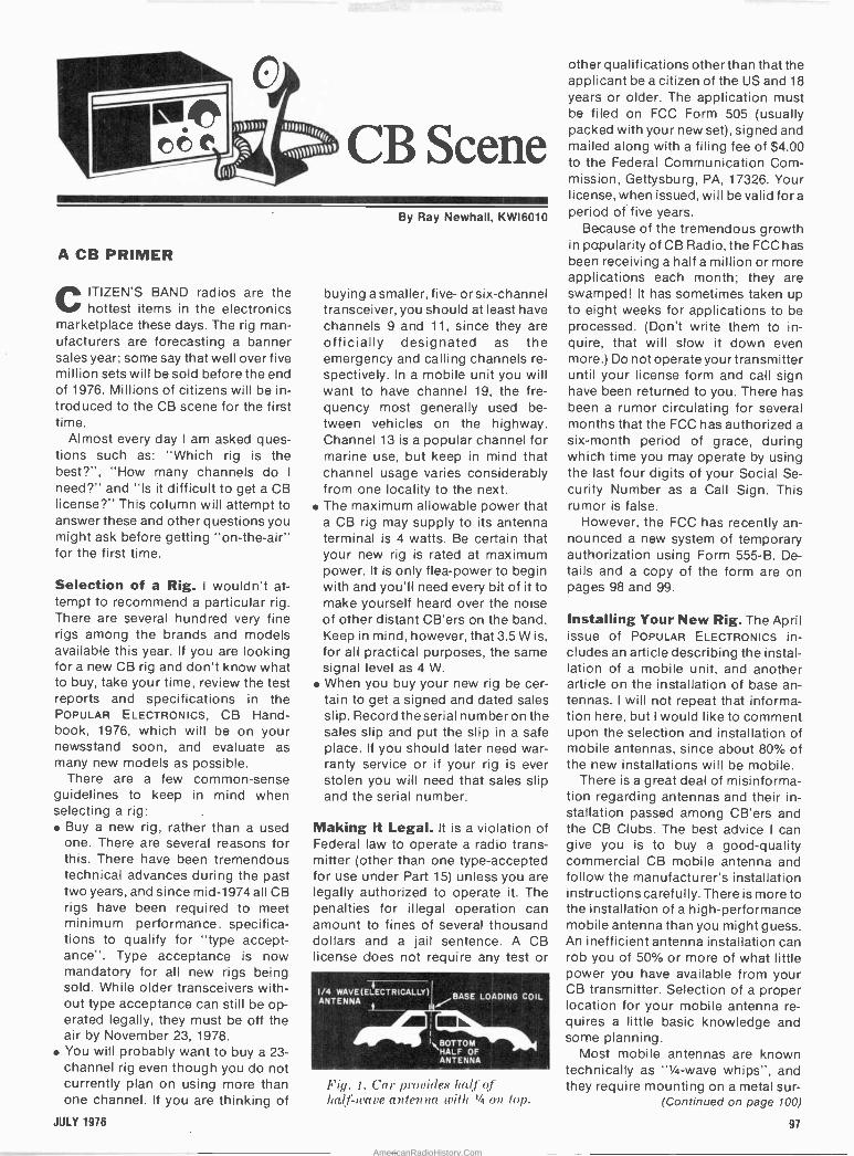
A CB PRIMER
CITIZEN'S BAND radios are the hottest items in the electronics
marketplace these days. The rig man- ufacturers are forecasting a banner sales year; some say that well over five million sets will be sold before the end of 1976. Millions of citizens will be in- troduced to the CB scene for the first time.
Almost every day I am asked ques- tions such as: "Which rig is the best?", "How many channels do I
need?" and "Is it difficult to get a CB license?" This column will attempt to answer these and other questions you might ask before getting "on -the -air" for the first time.
Selection of a Rig. I wouldn't at- tempt to recommend a particular rig. There are several hundred very fine rigs among the brands and models available this year. If you are looking for a new CB rig and don't know what to buy, take your time, review the test reports and specifications in the POPULAR ELECTRONICS, CB Hand- book, 1976, which will be on your newsstand soon, and evaluate as many new models as possible.
There are a few common-sense guidelines to keep in mind when selecting a rig:
Buy a new rig, rather than a used one. There are several reasons for this. There have been tremendous technical advances during the past two years, and since mid -1974 all CB rigs have been required to meet minimum performance. specifica- tions to qualify for "type accept- ance". Type acceptance is now mandatory for all new rigs being sold. While older transceivers with- out type acceptance can still be op- erated legally, they must be off the air by November 23, 1978. You will probably want to buy a 23 - channel rig even though you do not currently plan on using more than one channel. If you are thinking of
JULY 1976
By Ray Newhall, KWI6010
buying a smaller, five- or six -channel transceiver, you should at least have channels 9 and 11, since they are officially designated as the emergency and calling channels re- spectively. In a mobile unit you will want to have channel 19, the fre- quency most generally used be- tween vehicles on the highway. Channel 13 is a popular channel for marine use, but keep in mind that channel usage varies considerably from one locality to the next. The maximum allowable power that a CB rig may supply to its antenna terminal is 4 watts. Be certain that your new rig is rated at maximum power. It is only flea -power to begin with and you'll need every bit of it to make yourself heard over the noise of other distant CB'ers on the band. Keep in mind, however, that 3.5 W is, for all practical purposes, the same signal level as 4 W. When you buy your new rig be cer- tain to get a signed and dated sales slip. Record the serial number on the sales slip and put the slip in a safe place. It you should later need war- ranty service or if your rig is ever stolen you will need that sales slip and the serial number.
Making It Legal. It is a violation of Federal law to operate a radio trans- mitter (other than one type -accepted for use under Part 15) unless you are legally authorized to operate it. The penalties for illegal operation can amount to fines of several thousand dollars and a jail sentence. A CB license does not require any test or
0 ó l °°
1/4 WAVE (EL ANTENNA
ECTRICALLY)1/BASE LOADING COIL
IL
\BOTTOM HALF OF ANTENNA
Fig. 1. Car provides Ira°. of half -wave antenna with 1/4 on top.
other qualifications otherthan that the applicant be a citizen of the US and 18
years or older. The application must be filed on FCC Form 505 (usually packed with your new set), signed and mailed along with a filing fee of $4.00 to the Federal Communication Com- mission, Gettysburg, PA, 17326. Your license, when issued, will be valid fora period of five years.
Because of the tremendous growth in popularity of CB Radio, the FCC has been receiving a half a million or more applications each month; they are swamped! It has sometimes taken up to eight weeks for applications to be processed. (Don't write them to in- quire, that will slow it down even more.) Do not operate your transmitter until your license form and call sign have been returned to you. There has been a rumor circulating for several months that the FCC has authorized a
six-month period of grace, during which time you may operate by using the last four digits of your Social Se- curity Number as a Call Sign. This rumor is false.
However, the FCC has recently an- nounced a new system of temporary authorization using Form 555-B. De- tails and a copy of the form are on pages 98 and 99.
Installing Your New Rig. The April issue of POPULAR ELECTRONICS in- cludes an article describing the instal- lation of a mobile unit, and another article on the installation of base an- tennas. I will not repeat that informa- tion here, but I would like to comment upon the selection and installation of mobile antennas, since about 80% of the new installations will be mobile.
There is a great deal of misinforma- tion regarding antennas and their in- stallation passed among CB'ers and the CB Clubs. The best advice I can give you is to buy a good -quality commercial CB mobile antenna and follow the manufacturer's installation instructions carefully. There is more to the installation of a high-performance mobile antenna than you might guess. An inefficient antenna installation can rob you of 50% or more of what little power you have available from your CB transmitter. Selection of a proper location for your mobile antenna re- quires a little basic knowledge and some planning.
Most mobile antennas are known technically as "1/4 -wave whips", and they require mounting on a metal sur -
(Continued on page 100)
97
AmericanRadioHistory.Com

FCC FORM 555-B April 1976
111 Instructions
Certification Read, Fill In
Blanks, and Sign
Temporary Call Sign
Limitations
United States of America Federal Communications Commission
Temporary Permit Class D Citizens Radio Station
Use this form only if you want a temporary permit while your regular application , FCC Form 505, is being processed by the FCC.
Do not use this form if you already have a Class D license.
Do not use this form when renewing your Class D license.
I Hereby Certify:
lI L_I
I am at least 18 years of age.
I am not a representative of a foreign government.
I have applied for a Class D Citizens Radio Station License by mailing a completed Form 505 and $4.00 filing fee to the Federal Communications Commission, Box 1010, Gettysburg, PA. 17325.
I have not been denied a license or had my license revoked by the FCC.
I am not the subject of any other legal action concerning the operation of a radio station.
Name Signature
Address
Date Form 505 mailed to FCC
If you cannot certify to the above, you are not eligible for a temporary permit. Willful false statements void this permit and are punishable by fine and/or imprisonment.
Complete the blocks as indicated.
Use this temporary call sign until given
a call sign by the Federal Communica- tions Commission. t
Initial of
Applicant's First
Name
LLL t Initial of Applicant's Last Name
1
Applicant's Zip Code
Your authority under this permit is subject to all applicable laws, treaties and regulations and is subject to the right of use or control by the Government of the United States.
This permit is valid for 60 days from the date the Form 505 is mailed to the FCC.
You must have a temporary permit or a license from the FCC to operate your Citizens Band radio transmitter.
Do Not Mail this form, it is your Temporary Permit. See the reverse side of this form for a summary of operating instructions.
98 POPULAR ELECTRONICS
AmericanRadioHistory.Com
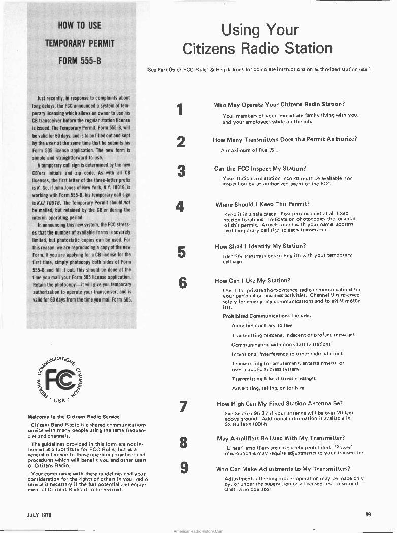
HOW TO USE
TEMPORARY PERMIT
FORM 555-B
Just recently, in response to complaints about
long delays, the FCC announced a system of tem-
porary licensing which allows an. owner to use his
CB transceiver before the regular station license
is issued. The Temporary Permit, Form 555-6, will
be valid for 60 days, and is to be filled out and kept
by the user at the same time that he submits his
Form 505 license application. The new form is
simple and straightforward to use.
A temporary call sign is determined by the new
CB'ers initials and zip` code. .As with ill CB
licenses, the first letter,of the three -letter prefix
is K. So, ii John Jones of New York, N.Y. 10016, is
working with Form 555-B, his temporary call sign
is KJJ 10016. The Temporary Permit should not
be mailed, but retained by the CB'er during the
interim operating period.
In announcing this new system, the FCC stress-
es'that the number of available forms is severely
limited, but photostatic copies -can be used. For
this reason; we are reproducing a copy of the new
Form. If you are applying for a CB license for the
first time, simply photocopy both sides of Form
555-6 and fill it out. This should be done at the
time you mail your Form 505 license application.
Retain the photocopy-it will give you temporary
authofization to. operate your transceiver, and is
valid for 60 days from the time you mail Form 505.
JpUCAT/Oys
ZFÇ) USA '
Welcome to the Citizens Radio Service
Citizens Band Radio is a shared communications service with many people using the same frequen- cies and channels.
The guidelines provided in this form are not in- tended as a substitute for FCC Rules, but as a
general reference to those operating practices and procedures which will benefit you and other users of Citizens Radio.
Your compliance with these guidelines and your consideration for the rights of others in your radio service is necessary if the full potential and enjoy- ment of Citizens Radio is to be realized.
Using Your Citizens Radio Station
(See Part 95 of FCC Rules & Regulations for complete instructions on authorized station use.)
1
2
3
4
5
6
7
8
9
Who May Operat3 Your Citizens Radio Station?
You, members of your immediate family living with you, and your employees,while on the job.
How Many Transmitters Does this Permit Authorize?
A maximum of five (5).
Can the FCC Inspect My Station?
Your station and station records must be available for inspection by an authorized agent of the FCC.
Where Should I Keep This Permit?
Keep it in a safe place. Post photocopies at all fixed station locations. Indicate on photocopies the location of this permit. Attach a card with your name, address and temporary call s -,n to eac`t transmitter .
How Shall I Identify My Station?
Identify transmissions in English with your temporary call sign.
How Can I Use My Station?
Use it for private short -distance radio -communications for your personal or business activities. Channel 9 is reserved solely for emergency communications and to assist motor - is ts.
Prohibited Communications Include:
Activities contrary to law
Transmitting obscene, indecent or profane messages
Communicating with non -Class D stations
Intentional interference to other radio stations
Transmitting for amusement, entertainment, or over a public address system
Transmitting false distress messages
Advertising, selling, or for hire
How High Can My Fixed Station Antenna Be?
See Section 95.37 if your antenna will be over 20 feet above ground. Additional information is available in SS Bulletin 1004-h.
May Amplifiers Be Used With My Transmitter?
'Linear' amplifiers are absolutely prohibited. 'Power' microphones may require adjustments to your transmitter
Who Can Make Adjustments to My Transmitters?
Adjustments affecting proper operation may be made only by, or under the supervision of a licensed first or second- class radio operator.
JULY 1976 99
AmericanRadioHistory.Com
346 Ways To Save On Instruments, Burglar Alarms, Automotive & Hobby Electronics! The more you know about electronics, the more you'll appreciate EICO. We have a wide range of products for you to
choose from, each designed to provide you with the most pleasure and quality performance for your money. The fact that more than 3 million EICO products are in use attests to their quality and performance.
"Build -it -Yourself" and save up to 50% with our famous electronic kits.
For latest EICO Catalog on Test Instruments, Automotive and Hobby Electronics, Eicocraft Project kits, Burglar -Fire Alarm Systems and name
of nearest EICO Distributor, check reader service card or send 500 for fast first class mail service.
EICO-283 Malta Street, Brooklyn, N.Y. 11207
Leadership in creative electronics since 1945.
102 CIRCLE NO. 21 ON FREE INFORMATION CARD
Operation Assist If you need information on outdated or rare
equipment -a schematic, parts list. etc. -another reader might be able to assist. Simply send a postcard to Opera- tion Assist, POPULAR ELECTRONICS. 7 Park Ave.. New York. NY 10016. For those who can help readers. please re- spond directly to them. They'll appreciate it. (Only those items regarding equipment not available from normal sources are published.)
DeForest type F-5 radio. Need schematic, power re- quirements, and operating instructions. William Anliker, Box 35, Bagdad, AZ 86321.
U.S. Navy Model RGB-2, CHC-46140 receiver. Built by Hammarlund, covers 0.54-30 MHz. Jim Brooks, 116 South Center St., Bardstown, KY 40004.
Aiwa Model TP-1012 open -reel tape recorder, serial 153107. Schematic, manual, or any information. Randal W. Davis, 2015 Chestnut, Fort Worth, TX 76106.
Gonset Model 3311 FM automotive converter. Schematic and alignment instructions. David J. Bopp, Box 119, Oceanport, NJ 07757.
Meissner Traffic Master. Dial, tuner unit, or any coils wanted, or source for same. L. Marks, 14 Avenue Rd., Kingston. Surrey. England.
Ampex Model FR -100A, 14 -channel tape recorder or 15,000 series tape deck. Documentation and schematics. Carol Ascolillo, Park Lane, North Windham, ME 04062.
Hammarlund HQ -129-X receiver, Heath AT -1. Schemat- ics. Information on whereabouts of DX100, property of W3ZHV, Mon. Valley ARC. XW8CRO/5, 608 E. Farmers Rd., Seagoville, TX 75159.
U.S. Govt. receivers, types AN-GRRS and R-392 (Collins). Radio amateur or technician wanted for alignment. NE PA area. James B. Fromel, 62Y: Gist St., Buttonwood, Wilkes-Barre, PA 18702.
Harman-Kardon Model CA -100 "Commander" PA am- plifier. Source or specifications for mike input transform- ers, XE-4 level equalizer, XT -4 line match transformer, and CPE-3 phone/tape preamp. Phil Anzel, Box 3952, Univer- sity Station, Laramie, WY 82071.
ARP Axxe synthesizer. Schematic, parts list, pc artwork. Scott Bell, 7752 Montgomery Rd., Apt. 29, Cincinnati, OH 45236.
Realistic Model TRC-X23 CB transceiver. Schematic, photofact listing, any available information, or a working or nonworking set for cross reference. Tom M. King, 169 Lakeside Dr., Guilford, CT 06437.
Sears Model 5248 tape recorder, chassis 38152480. In- struction book, parts list. Yagista 2 -volt storage batteries (sealed type). Source or importer address. Roy O. Kroeger, 3335 Eastern Ave., Davenport, IA 52807.
Squires 8 Sanders Model SS -310 CCTV camera. Schematic and service information. Allen Rees, Box 1271, Norman, OK 73069.
U.S. Navy oscilloscope TS-34/AP, NOA-s-1562. 1530 CW, O and R Ax 232. Any available information. Jonathan Huber, 520 Lincoln St., Boonton, NJ 07005.
Clough-Brengle Model OCA r -f signal generator serial 2601. Need schematic and manual. R.P. Hurlbut, 250 Verobeach Blvd., Weston, Ont. Canada M9M 1R6.
Candle Model MT510A black -and -white 4 -inch TV. Serv- ice manual and schematic. Al's Radio and TV, 9 Leonard Rd., Hyannis, MA 02601.
Dictograph Model HFMT-M-100 music system. Need schematic and parts list for the Williamson -type amplifier circuit serial 16966/106 or similar. Unit uses Collars RC 456 changer. Ben Layton, 6344 Laura Ave., St. Louis. MO 63136.
Atwater Kent Model 20, Tri-City Radio Electric Supply Co. Model W-41 one -tube regenerative receiver. Any res- toration information available. Sam Canup, 902 S. Goliad, Rockwall, TX 75087.
Research Associates, Inc. Model TR-32-12 transis- torized power supply, 6-32 V dc at 12 amps max. Operating/assembly manual or schematic. James De- Marr, 108 Laurel Ave., Gwinhurst, Wilmington, DE 19809.
Aetna Radio transceiver serial CX 367414. Contains 1A7, 1N5, 1H5, 1T5, and one unknown tube. Tim Childs, 3606 Tecumseh River Rd., Lansing, MI 48906.
v4 j4ajor Advance:.
E,1 500p6 Restrils- '
t
Rate --`` High Energ >1000mt Programmap'e Duration i
-High Outpu Arc -Curret-
ro
=7-7».7,-11MSCW
.141
Y
Fast RI
/6sil' *EFFICIENT ENGINE PERFORMANCE *REDUCED MAINTENANCE EXPENSE
*1 YEAR GUARANTEE OF PRODUCTS
For those who need maximum firing potential, Labtronics offers the Multiple Restrike Ignition. The system produces a high energy repetitive spark on each power stroke which insures the
greatest statistical chance for proper ignition. Dependable system triggering from breaker - points, magnetic pick-ups or the extremely accurate '13A1-xx' infrared triggering unit. Order your system and enjoy the economy and
peak performance of an efficient engine.
LABTRONICS, INCORPORATED 3633 N,Llsiee DRIVE E YRs,uvn, 11C11101448197
MULTIPLE RESTRIKE SYSTEM
I) Model VI Programmable Duration $79.95 (I Model VI -B Fixed Burst Duration $59.95 [I Model VI -C Complete Optical System $79.95 HIGH ENERGY SYSTEM (Single Strike) 11 Model V Points Triggering System $29.95 II Model V -C Complete Optical System $47.95 TRIGGERING UNITS I l 13A)-xx Optical Trigger Unit $24.95 [) 6129B Magnetic Amplifier $ 4.95
CIRCLE NO. 32 ON FREE INFORMATION CARD
1976 BREAKERLESS IGNITION
AT A PRICE LESS
THAN A TUNEUP
$38.00 No points or condenser - no more turN-ups. Improves the ENGINE EFFICIENCY and FUEL ECONOMY.
High timing accuracy & permanent dwell set Instant starting in all kinds of weather.
e One system fits all cars- U.S. or foreign. Uses a magnetic sensor for best timing accuracy as do ALL U.S. MFGD. AUTO- MOBILES IN1976.
Our magnetic pickup insures perfect timing with no fluctuation or retardation at any speed. Variable spark length- approx. 2 millisec. at low speeds & 0.7 millisec. at high- est speeds. This insures maximum engine performance- perfect for modern lean fuel mixtures. High spark intensity helps elimi- nate misfiring. The above superior operating features insure Challenge ignition systems will pay for themselves quickly. A high performance Breakerless Capacitor Discharge system is offered for those who want the best possible ignition system.
Free BROCHURE BANKAMERICARD / MASTERCHARGE
Model 10 Breakerless ignition system $38.00 Model 11 Easy to build kit $32.00 Model 12 Capaitor Discharge System $54.00 Model 13 C.D. system in kit form . . $44.00 Model 14 Trigger unit -
use with your present C.D. system . $30.00 CHALLENGE ELECTRONICS
P.O. Box 1991 / 1162 No. Huntington Blvd. Pomona, California 91768
CIRCLE NO. 15 ON FREE INFORMATION CARD
POPULAR ELECTRONICS
AmericanRadioHistory.Com
Electronics Library ),. o u
COMPUTER PROGRAMMING HANDBOOK
by Peter A. Stark This is a handy guide to computer pro- gramming and data processing written for the beginner with no special background in the field, including higher math. The 25 chapters are divided into five sectiohs: General, Machine Language Program- ming, Symbolic Programming, Program- ming and Mathematical Techniques, and Problem -Oriented Languages. Although the format is that of a classroom text, there is no reason someone studying on his own can't benefit from the information pre- sented. The author has provided examples of the various processes he discusses so that, even without access to a computer, the reader can pick up a lot of the tricks of the trade which will make his actual con- frontation with a keyboard easier. Published by Tab Books, Blue Ridge Sum- mit, PA 17214.503 pages. $8.95 soft bound.
THE RADIO AMATEUR'S HANDBOOK
FIFTY-THIRD EDITION
Fundamental theory and practices as well as the latest technical developments in radio communications are covered in this standard reference work. Transmitters, re- ceivers, oscillators, power supplies, an- tennas, transmission lines and active de- vices are discussed. Communications modes such as CW, AM, SSB, and FM (with a special section on repeaters) are examined in depth. Tested circuit designs complement theory. Revised sections in- clude receiving equipment, television in- terference reduction, test instruments, power supplies, speech processing, and station assembly. Among the new con-
struction projects are a regulated power supply, a 2 -kilowatt, 2 -meter amplifier, a
communications receiver with digital readout, a calibrated field strength meter, a
two -band solid-state transmitter, and a coupler for balanced lines. Published by the American Radio Relay League, Inc., Newington, CT 06111. 704
pages. $10.00 hardbound, $6.00 soft cover (US and Possessions).
ELECTRONIC PROJECTS FOR MUSICIANS
by Craig Anderton A number of the author's electronic music projects have appeared in these pages. Here he gets it all together in a series of "how-to" chapters, nineteen easy -to -build circuits, troubleshooting hints, and sources of additional information. The text is illustrated with sketches of' everything from electrolytics to needlenose pliers so a musician with no electronics background can build accessories for his instrument. A six -minute demo record of electronic ef- fects is bound into the book so that the musician -builder can compare how his project should sound with how it does sound. Published by Guitar Player Productions, P.O. Box 615, Saratoga, CA 95070. 132 pages. $6.95 soft cover.
OPERATIONAL AMPLIFIERS:
THEORY AND SERVICING
by Edward Bannon State of the art coverage of operational amplifiers is presented, with emphasis on practical circuit analysis, design, and ap- plication. Op amp theory and troubleshoot- ing techniques are explained so that those with a marginal technical background will understand the subject matter. Practical instrumentation application are given with analysis of each circuit. Among the specialized applications covered are func- tion generators, inductor simulation, au- tomobile speed control, fuel injection, and non-skid circuits. Published by Reston Publishing Co., Box 547, Reston, VA 22090, 195 pages. $13.95 hard cover.
LM -3 E
World's lowest priced precision dig tal multimeter - - more accurate and rugged than the old pointer meter - - ideal for field service.
0.H1, VAC V
(LO
I. _1 MODEL LM -3
C K/M11 1001000Mc1 10
1
OFF
With Rechargeable Batteries & Charger Unit. $125 Standard Features:
Automatic polarity and zeroing. Large 0.3" LED display. 13 ranges: vac, vdc &ohms with 1% accuracy. Size: 1.9"H x 2.7"W x 3.9"D. Also available in 3 -1/2 -digit or laboratory quality 4 -digit meter. Ask for LM -3. 5 or LM -4
See your local distributor! Distributor inquiries invited.
Non -Linear Systems, Inc. Originator of the digital voltmeter.
Box N, Del Mar, California 92014
Telephone (714) 7551134 TWX 910-322.1132
CIRCLE NO. 63 ON FREE INFORMATION CARD
T the PROFITME,TER AUTO ZERO/POLARITY
31/2 DIGIT MULTIMETER KIT WITH BRIGHT RED LED DISPLAY
$í995H LESS TEST LEADS
& BATTERIES
214-3,69-730.9 40414 ELECTR'ON;ICS,TEXAS PO BOX 64683 _o DALLAS, TEXAS ,75206 M1,
save on gas! save on tune-ups! save on maintenance! Electronic ignition is "IN"! So says Detroit. Update your car with either a TIGER CD or a TIGER I breakerless system.
Enjoy the benefits of better gas mileage, quicker starting, elimination of tune-ups, 50,000 miles on points and plugs, and reduced maintenance expenses.
TIGER MAX CID TIGER 500 CD TIGER SST CD SIMPLIKIT CD TIGER I
$69.95 59.95 42.95 31.95 45.95
Postpaid U.S.A. only.
7 Star Corporation Dept. ZZ, P.O. Box 1727 Grand Junction, Colorado 81501
CIRCLE NO. 61 ON FREE INFORMATION CARD JULY 1976 103
AmericanRadioHistory.Com
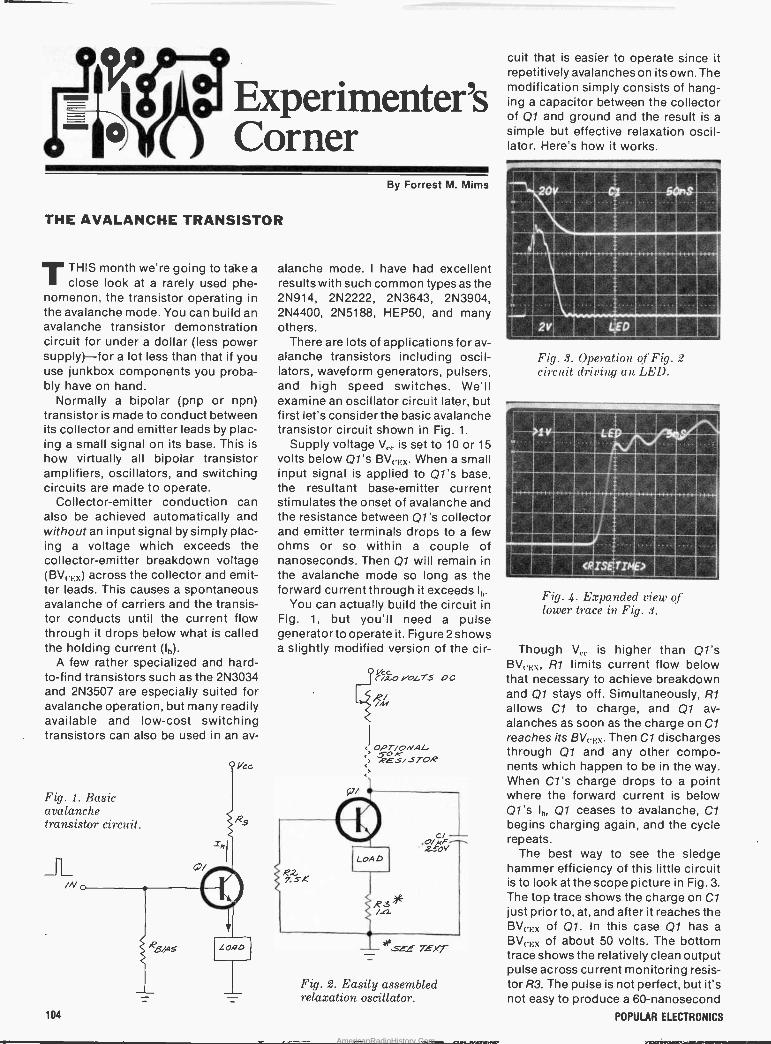
Experimenter's Corner
THE AVALANCHE TRANSISTOR
TTHIS month we're going to take a
close look at a rarely used phe- nomenon, the transistor operating in the avalanche mode. You can build an avalanche transistor demonstration circuit for under a dollar (less power supply)-for a lot less than that if you use junkbox components you proba- bly have on hand.
Normally a bipolar (pnp or npn) transistor is made to conduct between its collector and emitter leads by plac- ing a small signal on its base. This is how virtually all bipolar transistor amplifiers, oscillators, and switching circuits are made to operate.
Collector -emitter conduction can also be achieved automatically and without an input signal by simply plac- ing a voltage which exceeds the collector -emitter breakdown voltage (BV(.,.,;) across the collector and emit- ter leads. This causes a spontaneous avalanche of carriers and the transis- tor conducts until the current flow through it drops below what is called the holding current (l,,).
A few rather specialized and hard - to -find transistors such as the 2N3034 and 2N3507 are especially suited for avalanche operation, but many readily available and low-cost switching transistors can also be used in an av-
Fig. 1. Basic avalanche transistor circuit.
104
By Forrest M. Mims
alanche mode. I have had excellent results with such common types as the 2N914, 2N2222, 2N3643, 2N3904, 2N4400, 2N5188, HEP50, and many others.
There are lots of applications for av- alanche transistors including oscil- lators, waveform generators, pulsers, and high speed switches. We'll examine an oscillator circuit later, but first let's consider the basic avalanche transistor circuit shown in Fig. 1.
Supply voltage V.,. is set to 10 or 15 volts below Q1's BV(,;x. When a small input signal is applied to Ql's base, the resultant base -emitter current stimulates the onset of avalanche and the resistance between Ql's collector and emitter terminals drops to a few ohms or so within a couple of nanoseconds. Then Q1 will remain in the avalanche mode so long as the forward current through it exceeds Ih.
You can actually build the circuit in Fig. 1, but you'll need a pulse generator to operate it. Figure 2 shows a slightly modified version of the cir-
t'`/z0 vot_TS OC
%M
< OPT/OAAL 5-0
<> .PES/BYOB
Fig. 2. Easily assembled relaxation oscillator.
MEE
cuit that is easier to operate since it repetitively avalanches on its own. The modification simply consists of hang- ing a capacitor between the collector of Q1 and ground and the result is a simple but effective relaxation oscil- lator. Here's how it works.
Fig. 3. Operation of Fig. 2 circuit driving an LEI).
1110111111111111
F I 111111_
Fig. 4. Expanded view of lower trace in Fig. 3.
Though V,.,. is higher than Q1's BV,,;\, R1 limits current flow below that necessary to achieve breakdown and Q1 stays off. Simultaneously, R1 allows Cl to charge, and Q1 av- alanches as soon as the charge on Cl reaches its BVccx. Then Cl discharges through Q1 and any other compo- nents which happen to be in the way. When C/ 's charge drops to a point where the forward current is below Ql's I,,, Q1 ceases to avalanche, Cl begins charging again, and the cycle repeats.
The best way to see the sledge hammer efficiency of this little circuit is to look at the scope picture in Fig. 3. The top trace shows the charge on Cl just prior to, at, and after it reaches the BV(,,x of Q1. In this case Q1 has a
BV(. 1.:x of about 50 volts. The bottom trace shows the relatively clean output pulse across current monitoring resis- tor R3. The pulse is not perfect, but it's' not easy to produce a 60 -nanosecond
POPULAR ELECTRONICS
AmericanRadioHistory.Com
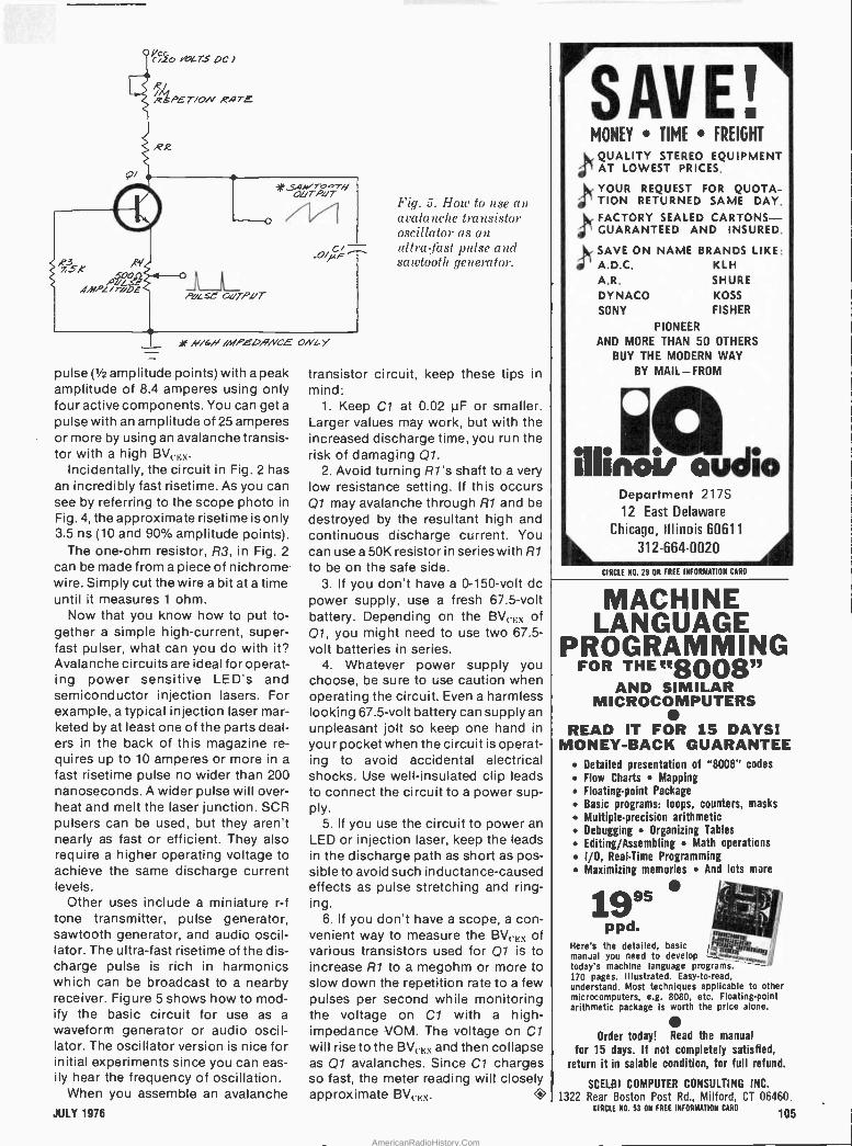
0CizO oLTSOCJ
R/ RMM PET/ON .PIJTE
R2
.11` yrwTo,,TH OVTPdT
PVL se OuTPdT
///bN /MPEORNCE OWL y
pulse (Y2 amplitude points) with a peak amplitude of 8.4 amperes using only four active components. You can get a
pulse with an amplitude of 25 amperes or more by using an avalanche transis- tor with a high BVc,:x.
Incidentally, the circuit in Fig. 2 has ah incredibly fast risetime. As you can see by referring to the scope photo in Fig. 4, the approximate risetime is only 3.5 ns (10 and 90% amplitude points).
The one -ohm resistor, R3, in Fig. 2
can be made from a piece of nichrome wire. Simply cut the wire a bit at a time until it measures 1 ohm.
Now that you know how to put to- gether a simple high -current, super- fast pulser, what can you do with it? Avalanche circuits are ideál for operat- ing power sensitive LED's and semiconductor injection lasers. For example, a typical injection laser mar- keted by at least one of the parts deal- ers in the back of this magazine re- quires up to 10 amperes or more in a
fast risetime pulse no wider than 200 nanoseconds. A wider pulse will over- heat and melt the laser junction. SCR pulsers can be used, but they aren't nearly as fast or efficient. They also require a higher operating voltage to achieve the same discharge current levels.
Other uses include a miniature r -f tone transmitter, pulse generator, sawtooth generator, and audio oscil- lator. The ultra -fast risetime of the dis- charge pulse is rich in harmonics which can be broadcast to a nearby receiver. Figure 5 shows how to mod- ify the basic circuit for use as a waveform generator or audio oscil- lator. The oscillator version is nice for initial experiments since you can eas- ily hear the frequency of oscillation.
When you assemble an avalanche JULY 1976
Fig. 5. How to use an avalanche transistor oscillator as an ultra -fast pulse and sawtootl, generator.
transistor circuit, keep these tips in mind:
1. Keep Cl at 0.02 µF or smaller. Larger values may work, but with the increased discharge time, you run the risk of damaging Ql.
2. Avoid turning RI's shaft to a very low resistance setting. If this occurs Q1 may avalanche through R1 and be destroyed by the resultant high and continuous discharge current. You can use a 50K resistor in series with R1
to be on the safe side. 3. If you don't have a 0 -150 -volt dc
power supply, use a fresh 67.5 -volt battery. Depending on the BV,. -Ex of Q1, you might need to use two 67.5 - volt batteries in series.
4. Whatever power supply you choose, be sure to use caution when operating the circuit. Even a harmless looking 67.5 -volt battery can supply an unpleasant jolt so keep one hand in
your pocket when the circuit is operat- ing to avoid accidental electrical shocks. Use well -insulated clip leads to connect the circuit to a power sup- ply.
5. If you use the circuit to power an LED or injection laser, keep the leads in the discharge path as short as pos- sible to avoid such inductance -caused effects as pulse stretching and ring- ing.
6. If you don't have a scope, a con- venient way to measure the BVcF;x of various transistors used for Q1 is to increase R1 to a megohm or more to slow down the repetition rate to a few pulses per second while monitoring the voltage on Cl with a hig'h- impedance VOM. The voltage on Cl will rise to the BV(.F;\ and then collapse as Q1 avalanches. Since Cl charges so fast, the meter reading will closely approximate BV(F;x. O
SAVE! MONEY TIME FREIGHT
QUALITY STEREO EQUIPMENT AT LOWEST PRICES.
sr YOUR REQUEST FOR QUOTA- TION RETURNED SAME DAY. FACTORY SEALED CARTONS- GUARANTEED AND INSURED.
SAVE ON NAME BRANDS LIKE: A.D.C. KLH A.R. SHURE DYNACO KOSS ,I
SONY FISHER
PIONEER
AND MORE THAN 50 OTHERS
BUY THE MODERN WAY
BY MAIL-FROM
¡IIinoi, audio Department 217S
12 East Delaware Chicago, Illinois 60611
312-664-0020 4'k CIRCLE NO. 29 ON FREE INFORMATION CARO
MACHINE LANGUAGE
PROGRAMMING FOR THE «8008"
AND SIMILAR MICROCOMPUTERS
READ IT FOR 15 DAYS! MONEY -BACK GUARANTEE
Detailed presentation of "8008" codes Flow Charts Mapping Floating-point Package
Basic programs: loops, counters, masks Multiple -precision arithmetic Debugging Organizing Tables Editing/Assembling Math operations I/O, Real -Time Programming Maximizing memories And lots more
1995 mneNoriE
Here's the detailed, basic 8 manual you need to develop
today's machine language programs. -
170 pages. Illustrated. Easy -to -read, understand. Most techniques applicable to other microcomputers, e.g. 8080, etc. Floating-point arithmetic package is worth the price alone.
Order today! Read the manual
for 15 days. If not completely satisfied, return it in salable condition, for full refund.
SCELBI COMPUTER CONSULTING INC. 1322 Rear Boston Post Rd., Milford, CT 06460.
CIRCLE NO. 53 ON FREE INFORMATION CARD 105
AmericanRadioHistory.Com
GIANT FREE CATALOG! NEW. 172 Pages. Over 4,500 Un- usual Bargains for Hobbyists. Schools. Industry.
JUST CHECK COUPON!
EDMUND SCIENTIFIC CO. 300 EDSCORP BUILDING Barrington, N. 1. 08001
(609) 547-3488
America's Greatest Science Optics Hobby Mart
ELECTRONICS RKET PLACE NON -DISPLAY CLASSIFIED: COMMERCIAL RATE: For firms or individuals offering commercial products or services, $2.00 per word (including name and address). Minimum order $30.00. Payment must accompany copy except when ads are placed by accreaited advertising agencies. Frequency discount; 5% for 6 months; 10% for 12 months paid in advance. READER RATE: For individuals with a personal item to buy or sell, $1.20 per word (including name and address.) No minimum! Payment must accompany copy. DISPLAY CLASSIFIED: 1" by 1 column (2-1/4" wide), $230.00. 2" by 1 column, $460.00. 3" by 1 column, $690.00. Advertiser to supply film positives. For frequency rates. please inquire. GENERAL INFORMATION: First word in all ads set in caps at no extra charge. All copy subject to publisher's approval. All advertisers using Post Office Boxes in their addresses MUST supply publisher with permanent address and telephone number before ad can be run. Advertisements will not be published which advertise or promote the use of devices for the surreptitious interception of communications. Ads are not acknowledged. They will appear in first issue to go to press after closing date. Closing Date: 1st of the 2nd month preceding cover date (for example, March issue closes January 1st. Send order and remittance to POPULAR ELECTRONICS, One Park Avenue, New York, New York 10016, Attention: Hal Cymes.
FOR SALE
FREE! Bargain Catalog-I.C.'s. LED's, readouts, fiber optics. calculators parts & kits. semiconductors, parts. Poly Paks. Box 942PE. Lynnfield, Mass. 01940.
SOUND SYNTHESIZER KITS -Surf $12.95. Wind $12.95, Wind Chimes $17.95, Electronic Songbird $6.95. Musical Accessories. many more. Catalog free. PAIA Electronics, Box J14359, Oklahoma City. OK 73114.
BUGGED??? New locator finds them fast. Write. Clifton. 11500-L N.W. 7th Avenue, Miami, Florida 33168.
GOVERNMENT Surplus Receivers. Transmitters. Snooperscopes, Radios. Parts, Picture Catalog 25 cents. e r Meshna Nahant, Mass. 01908.
LOWEST Prices Electronic Parts. Confidential Catalog Free. KNAPP, 3t74 8th Ave. S.W.. Largo, Fla. 33540.
ELECTRONIC PARTS. semiconductors, kits. FREE FLYER. Large catalog $1.00 deposit. BIGELOW ELECTRONICS. Bluffton, Ohio 45817.
RADIO-T.V. Tubes -36 cents each. Send for free catalog. Cornell, 4213 University. San Diego, Calif. 92105.
AMATEUR SCIENTISTS. Electronics Experimenters. Science Fair Students.. Construction plans -Complete. including drawings, schematics. parts list with prices and sources .Rcbot Man - Psychedelic shows - Lasers - Emotion/Lie Detector - Touch Tone Dial - Quadraphonic Adapter - Transistorized Ignition - Burglar Alarm - Sound Meter over 60 items. Send 50 cents coin (no stamps) for complete catalog. Technical Writers Group. Box 5994, University Station, Raleigh, N.C. 27607.
METERS -Surplus, new, used, panel or portable. Send for list. Hanchett, Box 5577, Riverside, CA 92507.
250 PIECE assortment of hard to find nuts used in the electronics Industry. Over 45 different sizes in brass, steel, aluminum. $4.75 postpaid. Fastening Products. Box 151.
Cheltenham. PA 19012.
DISCOUNT PRICES B&K, SENCORE, LEADER, RCA
EICO, FLUKE, HICKOK, SIMPSON
Test Equipment ICCSeivicemasler RCA and Raytheon Tubes
Complete line nl eteUrome supplies
Free Catalog FORDHAM RADIO SUPPLY CO., INC.
6558 Conklin St., Farmingdale. N.Y. 11735 (516) 752-0050
YOU WILL SAVE BIG MONEY! Surplus, Clearouts. Bankruptcy, Inventory, Deals. Catalog $1 (redeemable). ETCOA Electronics. Box 741, Montreal, H3C 2V2. U.S. Inquiries.
HEAR POLICE/FIRE Dispatchers! Catalog shows exclusive directories of "confidential" channels. scanners. Send postage stamp. Communications. Box 56 -PE, Commack. N.Y. 11725.
CD IGNITIONS. VHF/UHF monitors, crystals, CB radios. Southland. Box 3591-B, Baytown, Texas 77520.
SURPRISE! Build inexpensively the most Unusual Test Instruments, Futuristic Gadgets using Numerical Readouts! Catalogue Free! GBS. Box 100A, Green Bank West Virginia 24944.
9$ WORLD'S SMALLEST
RECHARGEABLE
CALCULATOR.99.95! Does Everything Big Ones Do
. Small but mighty! 8 -digit, 4 -function electronic calculator even has automatic % key ... for only $19.95. Take it any- where. Carry it in your pocket or purse - it's 2/3 the size of a pack of cigarettes. This 31/2 -ounce dynamo features floating decimal, constant key, lead zero depres- sion, clear entry, more! At Edmund's low price, the unit comes with a Ni -Cad rechargeable battery pack that can plug into any AC outlet. No need for special recharging adapters. Calculator overall is just 2 x 31/2 x 16" with plenty of room for most fingers. Another Edmund first with advanced technology. 519.95 ppd STOCK NO. 19451AV Only
COMPLETE AND MAIL COUPON NOW EDMUND SCIENTIFIC CO. 300 Edscorp Bldg., Barrington, N.
kiiikauccro 0 SEND FREE EIC 172 PAGE CATALOG 'AV' Charge my BankAmericard
O Charge my Master Charge
Interbank No
Card No
Expiration Date
30 -DAY MONEYBACK GUAR- ANTEE. You must be satis- fied or return any purchase in 30 days for full refund.
I. 08007
Send me: _ELECTRONIC CALCULATOR(S)
@ $19.95 ea. (No1945AV) $
Service and handling charge $_$1.00 Enclosed is r check, m.o. in amount of $
Signature
Name
Address Please print
_City State_Zip
HELPING TO DEVELOP AMERICA'S TECHNOLOGY FOR OVER 30 YEARS.
TELEPHONES UNLIMITED. equipment, supplies. Catalog 50 cents. Box 1654E, Costa Mesa, Calif. 92626.
UNSCRAMBLERS: Fits any scanner or monitor, easily ad- justs to alt scrambled frequencies. Only 4" square $29.95, fully guaranteed. Dealer inquiries welcomed. PDO Electronics, Box 841, North Little Rock, Arkansas 72115.
SURPRISE! SURPRISE! Digital Piano Tuning Device tunes musical instruments Accurately! Perfectly! Inexpensively! Construction -Instruction -Plans Complete $12.95 Airmailed Postpaid! Moonlighting quickly repays $40 electronics in- vestment! GBS, Box 100P, Green Bank, West Virginia 24944.
RECONDITIONED Test Equipment. $0.50 for catalog. Walter's Test Equipment. 2697 Nickel, San Pablo, CA 94806.
POLICE. Fire monitors. scanners, crystals, CB Transceivers, New Crystal -less scanners. Discount priced. Box 19224, Denver. CO 80219.
TELETYPE EQUIPMENT for sale for beginners and exper- ienced computer enthusiast. Teletype machines, parts, supplies. Catalogue $1.00 to: ATLANTIC SALES, 3730 Nautilus Ave.. Brooklyn, NY 11224. Tel: (212) 372-0349.
BUILD THAT ELECTRONIC ORGAN YOU ALWAYS WANTED AT A PRICE YOU CAN AFFORD. Third edition of "Organ Builder's Guide." pictured product kit line, cir- cuits, block diagrams, design rationale using IC divider and independent generators with diode keying. $3.00 post- paid. Also, free brochure on keyboards. DEVTRONIX ORGAN PRODUCTS, Dept. C, 5872 Amapola Dr., San Jose, CA 95129. MECHANICAL. ELECTRONIC devices catalog 10 cents. Greatest Values - Lowest Prices. Fertik's, 5249 "D", Philadelphia, Pa. 19120.
JAPANESE TRANSISTORS. all transistors original factory made. Free catalog. West Pacific Electronics, P.O. Box 3879, Torrance. CA 90510.
CB RADIO. Scanners, Antennas. The best for less. Free List. Capitol Sound, Box 3523, Des Moines, Iowa 50322.
YOU WANT TO BUILD IT: WE WANT TO HELP. WE SELL CONSTRUCTION PLANS with an Engineering Service. TELEPHONE: Answering Machines, Speakerphones, Car - phones. Phonevision, Touch Button Dialers. TELEVISION: VTR, 1" Color TV Set, PONG, $25.00 Camera, COLOR PROJECTION TV. HOBBYIST: Electron Microscope, $75 software programmable computer. BROADCAST: Special Effects Generator, Chroma Key, Audio Board, DA's. COURSES: Telephone Engineering $52.00, Detective Electronics $29.50, IC Engineering $65.00, PLUS MUCH MORE. NEW Super Hobby Catalog PLUS year's sub- scription to Electronic News Letter AIR MAILED $1.00. Don Britton Enterprises, 6200 Wilshire Blvd., Los Angeles, Calif. 90048.
WHOLESALE C.B., Scanners, Antennas. Catalog 25 cents. Crystals: Special cut. $4.95, Monitor $3.95. Send make. model, frequency. G. Enterprises, Box 461P, Clearfield, UT 84015.
SEMICONDUCTOR AND PARTS Catalogue, $1.00 refund- able, from the semiconductor specialists. J & J Elec- tronics. Box 1437P. Winnipeg. Manitoba, Canada. U.S. Inquiries.
ELECTRONIC ignition: Pointless. Transistor, Capacitor. Vapor inductors. Auburn Sparkplugs. Information 10 cente Anderson Engineering, Epsom, N.H. 03234.
TV PING PONG game. Plays through your set's antenna terminals: Plans 53.25. ARS SYSTEMS, Box 1922, Sunny- vale, CA 94088.
6 MHZ CRYSTALS including schematic and info to gen- erate 60 hz-12VAC to make your digital clock run on batteries. $10.50 pp in US. Eastern Sales, Box 510, Raleigh, N.C. 27602.
ELECTRONICS DESIGN NEWSLETTER * Logic Design Techniques Wh*
earnn Digital & Linear Design <-4;94' Der Theory 6 Procedures
!oá100 t c * Construction Projects 4i7,r
Subscription S6 Sample Copy SI
Lam/ VALLEY WEST Boa 2119-Y Sunnyvale, CA 94087
106 CIRCLE N0. 13 ON FREE INFORMATION CARO POPULAR ELECTRONICS
AmericanRadioHistory.Com
''EXCLUSIVE -s",P: ;Wr. 6'ózs.
100' S OF BARRELS -PURCHASED!, For the first time anywhere, Poly6Pak-' merchandisers introduce a new way' in buying 'the'económical way. Raw stock. :from the "barrel': Remember °
the"tgood,'ole days"? They're back: again. The same way merchandisers-',
-Y'ÜJ R ;' CHOICE OF ANY ,
KIT TEST EM,:YOURSELF 'N"S4VE1 throughout the. United: States 'My from varióus factories . .:.their over
,runs in barrels. Poly, Pak has' done the same. Therefore yoU;are getting, the 'same type of material as ' the RE -TESTERS DO! y' a
Every kit carries a !Hooey back
guarantee! ,j
., ay 'BARREL KIT #1 SN7400 DIP IC'S
,i75 for $1.98 Marked 14 and/or with iti pin dips, may include gales, regi ters, flip flop, count era's Who knows! GUARAN. TEED SATISFACTION!
,.Cat.No.7E 2415 Untested.
I BARREL KIT #2 LINEAR OP AMPS,
VnP575 for tested $1.98 May Include 709', 741.'x. 703'x, 560 .. 656 In- cludes marked and un- marked. Cat.No.7Et2416
' BARREL BIT #7 VOLUME CONTROL BONANZA! 40 for
o $1.98 ) good Singles, duals, variety of
ss values, styles, big ones - small ones. Cat.No. 7E12421
BARREL KIT #- 1N4148/914 SWITCHING DIODES
100 for $1.98 You never saw this before. Imagine famous switching diodes nt these P keel Cat.N.7E,2418 Untested.
BARREL BIT #4 "4000" RECTIFIERS 100 for $1.98
Untested. These are the famous micro miniature rectifiers of the 104000 serie May In- clude 25. 9 100, 200. 400, G00. 800 and 1000 val hers. Cat.No.17E 2417
BARREL KIT #5 SCRS, TRIACS, QUADRACS 40 for $1.98 All she famous Plastic pow- e tab type. Raw factor> stock! All the 10 amp tines. Cae.No. 7E.2419 Untested.
BARREL KIT f8 SUBMINIATURE IF TRANSFORMERS
100 %!good. 100 for $1.98 Amazing. Includes 466kea, one, antenna. rknows?
transistor Iioma From man- ufacturers. Cat.No. 7E2422
BARREL KIT #00 ROMS-REGISTERS 50 for $1.98
Untested "Ir 28 to 40 pin devices, marked. internal !adorn numbers, eta Cat. No.7 E 2424
BARREL KIT #12 POWER TAB TRANSISTORS 40 for $1.98
PSI', plastic 1.0220 type. Assorted 25 numbers. Cat.No.7E.2426 Untested.
BARREL KIT #13 RESISTOR NETWORK
60 for $1.98 Untested.
By Corning Glass, in 14 - Pin dip yaks. Cat. No. 7E242
BARREL KIT #145 MINI TRANSFORMER
15 for $1.98
Miniature transformer back again. Asst. outputs, inter - slag. and audio. Only 1" no, Wt. 2 Iba. 7E 3294 BARREL KIT #148 SEMI-KON SURPRISE
100 for $1.98 Imagine a factory sh9l.trmof
eto e,orÍÍ t reeu ó-
e raes f shapes
I believe. Catns No. 7 E 3300 to
BARREL KIT #147 OVE RFLO FLUORESCENT NIXIES
5 for $1.98 Vaed originally in table 'top calculators. Brand Gas discharge type, colon Blue. Cat. No. 7E3288 BARREL KIT #150 COIL FORMS
100 for )01( $1.98
Factory barrels make eco orne the runnel Wire your own coils. Imagine forms only 2( ea. Asst, sizes. Cat. No. 7E3304
BARREL KIT #152 VOLUME CONTROLS
15 for $1.98
Control maker discontindes Tine; demos controls with itches at ridiculous Prices. Asst values. Fat. No7(3306
BARREL KIT #155 MOLDED CAPACITORS
75 for -C2- $1.98 100"
Asst. size voltages, red, green, yellow, blue plastic cases. al leads. NO. 7E 3311
BARREL KIT #158 MAGNIFIED MAN -3'5
BARREL KIT #159 MODULAR SWITCHES
15 for $1.98= Cosmetic rejects
Famous style MAN -3. 7. sec readout, with built -on discon- tinued line.
Factory % d mate- rial. Wt. No. 7E3325
y Cntrolab switches. TV-mkers ex - a, Dadt, Gpdt, etc. Brand j no,. Cat. No,7E3150
25 1 or esib-
$1.98 I ry/7r.
BARREL KIT #15 MOSFET TRANSISTORS
60 for $1.98 All 4 lenders TO -18 case. Includes 1.711F1 I{F ransistors oo! Cet.No.7E2429
rtARREL KIT #17 LINEAR & 7400 DIPS
Untested 100 for $1.98
Marked and unmarked, in- ternal terna) u bers of . fat ore stock. Cat.No. 7E2431
BARREL KIT #19 DIPPED MYLARS
60 for $1.98
7000t2'e
Finest capacitors made, shiny finish. Imnelne facto- ry dumping 'en ,n barrels. Cat.No.7E 2597100 % good
BARREL KIT #20 LONG LEAD DISCS
150 for $1.98
Factory distrihator stock
n sale". Prime.
marked only. Long leads Cat.No 7E2598100% good
BARREL KIT #25 METAL CAN TRANSISTORS 100 for $1.98 tnntesled.
Include. TO -6, TO -1, TO. I.s eassorted 25 num- h ers.rs, unm rked etc. Cat.Nd.7E2603
'BARREL KIT #26 PLASTIC TRANSISTORS 100 for
BARREL KIT #35 PREFORMED RESISTORS
250 for $1.98 $1.98 JJJ We got barrels of IA and Untested. welters for pc Type TO -92 (TO -181, all. You'll get aunt manufacturers. .oriel. of 100: :4, 100 at' " wasters. 2N A's. Cat.No. 7E.2604 Cat.No.7E,2608100% good'
".BARREL KIT #32 BARREL KIT #35 TRANSISTORS NEON LAMPS WITH A HOLE IN IT 40 for
61 ° 50 for
z $10 .98 Untesea. $1.98 good. Can't name factory but weFamous NE -2'.. All prime, Nought barrels of 25 ,watt- but factory made millions
' ers with mtg. hole In n:id. and barreled 'em, Your ad- dle. PNI"S and SI'N'S. vitotese Cat.No17E42613
BARREL KIT #36 GERMANIUM DIODES 200 for
.98 Untested Famous maker, popular item. Never grows old. But ,this Is the he way the RE - TESTERS buy 'em from the foe lanes,' Cat, No. lE 2614
BARREL KIT #37 1 AMP "BULLETT" RECTIFIERS Untested.
100 for $1.98
style, asstd. volt- ages, Famous style,
al includes 11 type. of
a voltages to
1KV,Cat.No.7E2615
BARREL KIT #39 2N3055 HOBBY
15 for $1 98 100% load.
From I tots to you, these fallouts of the famous 203055. We have 10 bar= rela. Cat.No.7E 2617
BARREL KIT #40 PNP HIGH -POWER TRANSISTORS bit
20 for 25 for , $1.98 $1.98 Untested
Popular germanium TO- hobby w'e
typepur,ch fasedactory!themdin fa- vat te v l dole barrel"ow prices. ato.7E 2618100 Tv good, bnrrels. These are -.
.N kne,rnx. Cat.No.7E 2624un
BARREL KIT #46 G.E. 3.5 WATT AMPLIFIERS
BARREL KIT #10 BARREL IT 92
°
SIGNAL DIODES
SILICO, DISCS! 200 200 for $1.98 Includes many, many types
' of switching, signal sills. types' all axial leads.
, Some may be ra ners CatNo. 7E2628 Untested. BARBEL KIT #65 MIXED READOUTS 15 for $1.98 111,
Factory ref rn - such numbers MAN -4's, MAN - 7.s. MAN Y's, 11 barrel. &
BARREL KIT #53 JUMBO RESISTOR PAK 100 -pc. $1.98
500 for $1.98 CatNo.,7E2721 -DID- Cat.No 7E2630.100% goo Asaortm metal films, preni-
Th bargain
of offered lifetime! aiono. carbons, metal oxide
First Poly' Pak. for the economy. w
Y. watts. Color coda
t4 '& minded bargain bunters. 100% good. 114,111 $10.
BARREL KIT #88+ tBARREL KIT #71 2 WATTERS CAPACITOR SPECIA 100 for 100 Pcs. $1,98 100% good.. $1.98
Nobody seems to mvant 'em! Emptied atockrodms into So any' suppliers don't barrels al f,lare. POIc's.
jai d, plaxuea ant, but throw'emto the no time to net ate, barrel. It's It'1 gold mine Cat.No. 7E2733Unteat d ' All marked. Cat.No.7E12735 BARREL KIT #78 BARREL KIT #81
o 'TRAN"STOP RESISTORS TRANSISTORS 200 for 40 for $1.981 $1.98,m%
good. D-42 series, You tent -go 1'C. upright type, for cod. into your ownbiz! Bigl, d, t/ vnll. Axsl values,
hi-V,'NPN. Cnme to us in a barrel. Cat-No;7E7743 Untested Cal.No.17E 2746
(BARREL KIT #1 ',CLOCK CHIPS,' 5forp $1.98 No. 7E 3055' National is dumpngl MM-
. 5316 - what's wrong with m, w don't know. but we got barrels. Bobby special. Wt. 2 oz.
BARREL KIT #112 . MICRO MINI LEDS
40 for $1.98 At the tiny leds, axial, up -
of Monsanto, Litronix, variety of colors. Yield 60% or better. CatNo57E3139
BARREL KIT #123 CD -4002 C-MOS IC
115 for $1.98', mostly good. Bat have
250,000. Can c ell out, YOUR GAIN! Their
is CD -5802. number Cat. No, 7E3217
' BARREL KIT "140 LAMPS
'e20 for $1.98 Precision, mini lamp all- metal, hardware.
no Lampvitmaker`s
overstock. 7E3297
BARREL KIT #104 SLIDE VOLUME CONTROLS ll, 10 for $1.98 Cat.Nol7E3057 Used 10.1,1 -fi, volume con- trol maker unloads, Asst. values, what a buy. Worth $1 We've got barrel. of 100% material. BARREL KIT #113 STABISTORS 50 for $1.98 Cat-No17E3140
Regulator, sensing and Corn -, circuitry. Axial double
plug type. Discontinued fac- tory line. PIV 20 volts. 80% yield. U test 'n BARREL KIT #126
save'
UPRIGHT ELECTROS 40 for $1.98 Wide st, f values from leaf to 300m1 1 mixture of voltages. 100% marked
good. SVhy barreled? U-got-a-buyI Cat No..7E3226 BARREL KIT #141 10 WATT ZENERS 15 for $1.98
bite dumps to prepare for new styling, voltages 1l over the place Good yield. Cat. No. 7E3298'
ceromiey_disr.,' ete Nifty 100% good. Cat.No 7E2738 BARREL KIT #83 15 for $1.91; LM -340T Untested VOLTAGE REGULATORS Factory rejected them t
length of leads, May include b, 6, e.12, 16. 18.24 volts. Power tab ICat.No.7E 2635
BARREL KIT#107 SQUARE OHMS 60 for $1.98-Cat.No.7E 3098.
Factory people are some- times "squares" when they topple prime square ohms mix
mup in batrels. A.M.
values watt, Wt. 1 lb.
BARREL KIT #115 MOLEX SOCKETS
ZOO, for tt1 $1.98 100% good, I i Calculator maker Idumel We -ut a zillion of 'em. Used for IC sockets, etc. 1101.140.7E3144
TQT\
BARREL KIT 127 AXIAL ELECTROS
O for 1.98'
Truthfully the factories (by sing 'em In barrels) do
11 of us a favor. WUT A BUYI Asst. capacities and voltages. :at. N ,,7(3227 BARREL KIT #142 DARLINGTON TRANSISTORS
40 for $1.98 TO -92, a Motorola dame, unknown numbers, but high yield to good darlingtons. Retesters didn't get 'eml You will. 7E3285
BARREL KIT #58 SLIDE SWITCHES 30 for $1.98
All shapes, sizes. spat, dpdt, e tarien, etc. Tremen-
dous s shop pak for 100's of .witching Projects.
CatNo.7E,2726100 % good (BARREL KIT #73
TRANSISTOR ELECTROS
SO for $1.98 It 'hugs.' us why the far. torten dump in barrels. We don't wwismto separate wide asst voltages & values up to 300 mf,Cat.,7E 2747.
1,000.000 RCA ehono plugs, .for this one. You hl-11-ers, know wet they are 100 % material. i.00k as." the price. 7E3293
(100 for 51.98
Factory dumps into barrels. Type. 0000, 7400 series, DTI. , ROM s, reg,aters, clock & Pale, chip, linear., etc. C.t, N o.l7 E 20601Ualosted. BARREL KIT #108 TO -5 PLASTIC TRANSISTORS
Cat.No.7E 3101 40 for $1.98 ' !
Includes PNP, NPN, 20- 3638, 253841, 2N6000
etc. Untested. but guaranteed to 60%seel,f BARREL KIT #116 B UTTONS 'N FEE DTH RU'S 100 for $1.98
100%good. Truthfully worth a small fortune. Wide t. of but- ton-feedthrucaps! RAMS TAKE NOTE! RF UHF, etc. Wt. 1 lb. Cat.NA 7E 41 B ARREL KIT #128 MINI DIP ICS 75 for $1.98 Large mfg. dumped 100's of lbs Into barrels. Includes 741s, LM -380.8, 703, 687, 855, 888 -hut who knows? Factory to rou. All mixed, COY test. Wt, I Ib. Cat. No.7É 3245
BARREL KIT #59 POWER TRANSISTORS 40 for $1.98
18 watt Bendix 0-5000 Booed, transistors.
from ao
pr.teater, have millions of 100% goodCat,No.7E 2721 BARREL 1117'°#75
,400MW ZENERS '250 for
$1.98 Factory out of bltl Amazing offer: 6, 8, 10, 12 to 15V. 1 oa test. Hermetically sealed C.a. pak. Double plug. Cat.No.7(2140
ff BARREL KIT #87 BARREL 91 7S-BARREL KIT #94 NATIONAL IC BONANZA SILVER MICAS'- "BUBBLE" 100 for $1.98 READOUTS
Ca t. No. 7E 3018 F.,r the first time sliver micas so low in pries) Axial. red ease, variety of Physical sizes & Big savings from distribu- tor prices. Wt. I lb.
BARREL KIT #109 (TERMINAL STRIPS 1150 foY, $1.98 Wide asst. of terminal strip u tors, from 1 contact
manufacturer. barrel dumb s Your gain. Wt. 1 Ib<CaLNo.7 Eí3136
BARREL KIT #118 MINI SCRS
50 for $1.98 UNBELIEVABLE! TO -92 Plastic fr roSCRS
1[ etiory n Include.
all voltages up tbru 200 pre. 1E3135
B ARREL KIT #131 TANTALUM ELECTROS
30 for' $1.98 Mixed, marked prime, top grade asst. values, volt- ages, CE. Centralab, etc.
'7E 3255
12 for $1.98 DL -38 bubble magnifier., Seas missing. Truthfully
any sle
ofd. 'em oz,
a don't 7(3
c Uote 3 Na.097 BARREL KIT #110 SUPPRESSOR DIODES
50 $1.98 CatNa7E3137 Keeps ignition noises t
ml. Untested, but the of poor egpt.. car, Indus- trial etc, Double plug,
BARREL KIT #120 TRIGGER DIODES 25 for $1.98
Type ER -900, same type d to trigger acre, trines:
Sometimes called "diets". Untested. No.'7E3160
BARREL KIT #133 C OS IC'S
60 for$1.98 Deliberately thrown ,n h.,r- re1n, ao ave can't te.t Th. famous Cl/4000 selea. /low goodt Who known?. Who caree? It's only Se ea, Cat. No. 7E3257
BARREL KIT #144 Terms: Add postage Rated: net 30 RCA PHONO PLUGS Phone: Wakefield Macs. (617) 245-3829 40 for 0 Retail: 16-18 Del Carmine St., Wakefield, $1.98 t7Ly MINIMUM ORDIER-56.00
POLY PAKS
BARREL KIT #60 DTL'S IC'S i 75 for $1.98 Untested.
This Is prime barrelmate- rial. Who wants DTL's? 990, 936, 946's. Your gain is our loss. They're marked too. Cat.No. 7E 2728
BARREL KIT #76 1 -WATT ZENERS 100 for .--451" $1.98 Untested,
F.etory n its 400-m,v's. Never -to -nepe -again one., G, 8, 10, 12. 15V, under glen , Ilo,.ble plug. Cat.No.7E 2741
BARREL KIT #61 POLYSTYRENE CAPS
100 for $1.98
Finest caps made. As a gam- ble w bought 10 barrels from factory, mixed values;_ n!1 goad.,Cat.No.17E272IIA.
BARREL KIT#77 "BROWN" BODY TRANSISTORS 40 for $1.9
G -E 11-40 series: has 'iii. voltage. Darlingtons, hi- °
ant. non's. Factory line current. i continued. Power tabs.
Cat.No.7E'2742 Untested,
BARREL KIT #99 .I PHOTO ELECTRIC I
1' CELLS
10 for $1.98 Asst. GE types, CDS types. Mixed by factory, Big job 'tor an to neyarute. 100% good. Cat.Nd.7E 3652 BARREL KIT #111 MULTI DIGIT READOUTS
8 for $1.98 bnrrels of blemished 3, 4 and/or 5 digit readouts to USA foe "dump". Untested, 'C{tNo,7E3138 BARREL KIT #121 "MINI" MAGNETS
100 for $1.98
Magnet circulareC and - tangular cuttings from a major . maker -
micro -circuitry. reed '-
swl ea tch & icro- ircuitry, Cat. No.17E 3168 a
BARREL KIT #139 RIBBON CABLE
$1.98 $1.98
Wire maker loaenut (bar
rala of ml - ondueler,
#22 yellow Jacket. In 3 -ft - lengths or longer. 7E3296
Send for FREE Summer -Fall
P.O. BOX 942E LYNNIFIELDJ MASS. 01940 CATALOG
JULY 1976 CIRCLE N0. 44 ON FREE INFORMATION CARD
109
AmericanRadioHistory.Com
DELTA ELECTRONICS COOS P.O. BOX 2, AMESBURY, MASS. 01913
MAGNUS TONE GENERATOR BOARD
wasw. !- iserias,i,le.cs13 I ...r. ...» s t uso+«r
y t n l -
4t41(+1q444'trt4-. t elqrl'ILIRII 1t s.4. aY1'Y11.`t1 I I.f I`} N1fMR RI.e'
1
I' 15 t 1 t tt s t i-1 s '
.. . I
, -....°.
This MAGNUS tone generator board has 12 SCR oscillators & IC dividers for 37 notes (3 octaves), plus 3 chord oscillators. The basic component for your organ or synthesizer. Requires only +5v, +15v, and an amplifier. Use with our P5210 keyboard, below. 5%" x 19'/4.
STOCK NO. P5244 $17.95 each, 2/35.00
Matching 13 watt amplifier for use with P5244 tone generator. Complete with power supply rectifiers & filters. 4%" x 6". STOCK NO. P5245 $9.95 each, 2/18.00 STOCK NO. P5348 Power Transformer $3.75 ea, -2/7.00
. 111.
I'2 and 3 OCTAVE KEYBOARDS I 111111111
-^ We have a limited .0 number of matching 2 &
3 octave keyboards. Use with tone generator, above, or with a syn- thesizer of your own. P5210 has 37 keys, is
9%" x 19". P5280 has 25 keys, is 8%" x 13". STOCK NO. P5210 4 lbs. 3 octaves $17.95 each, 2/35.00 STOCK NO. P5280 3 lbs. 2 octaves $8.95 each, 2/17.00
Send for latest free catalog. Minimum order $5, phone orders welcome: (617) 388-4705. Include sufficient postage; excess will be refunded. BANKAMERICARD & MASTERCHARGE welcome, ALL numbers needed for processing. Minimum charge $15.
CIRCLE N0. 65 ON FREE INFORMATION CARD
For
faster service
USE
ZIP
CODE
on
all
DESCRAMBLERS: Several Professional Models that work with all Scanners. Tone Encoders/Decoders, Scanmale, AAPP. Radar Detectors. Big Ears. Alarms, Books, Kits, parts. Catalog 25 cents: KRYSTAL KITS. Box 445, Benton- ville. Ark. 72712.
CARBON FILM RESISTORS. Brand new as low as 1.7 cents. Discounts of 20%. Prompt delivery. FREE samples/specifications. COMPONENTS CENTER. Box 134P. N.Y.. N Y. 10038.
TV TECHNICIANS. SERVICEMEN. HOBBYISTS -Vista Model 740 Digital Crosshatch Generator. Compact crystal divider for lowest -priced ultra -stable 5x7 crosshatch or 56 dot patterns. AC powered. 531.95 Complete kit; S41.95 as- sembled. Postpaid in USA. Canada. Information available tree. Photolume Corporation. Dept. PE -76, 118 East 28th Street, New York, New York 10016.
PLANS -Video Pong 52.00. Laser. .52.00. Projection TV 52.00. Catalog 50 cents. Technologic. Box 5262, Orchard Lake, Michigan 48033.
IC BONANZA 'Dala Sneer meluded on these items
' M M 5330 National DVM on a chip 5 9.95 '2102 1K Static Ram 450 NS 1.60 '5203 0 Eraseable Prom 2K 11.95 '50310 Slide rule calculator chip 3.95 '50240 Top octave organ chip 595 '50250 Alarm clock chip 4,45 LM340K-5 5 Volt pos. regulator .89 LM340K-12 12 Volt pos. regulator .89 LM340K-15 15 Volt pos. regulator 89 LM340K-24 24 Volt pos. regulator 89 LM32oK-5 5 volt neg. regulator 84
LM320-5.2 52 Volt neg. regulator .84
LM320K-12 12 Volt neg. regulator .84 N8252B BCD to decimal decoder .79
962 Triple 3 input nand gate .09 2N6050 Darlington .75
2N6051 Darlington .79
2N6285 Darlington .99 2N62B6 Darlington 1.04
SEND FOR FREE CATALOG Minimum order 55.00. data sheets 25 cents each. Include 5% of order for postage and handling. Texas residents include 5% state sales tax.
BONANZA ELECTRONICS P. O. Box 24767 Dallas. Texas 75224
M S 1 h
MODULAR SCIENTIFIC _ Í
move
KIT 016 FREQ. COUNTER Features FET input front end with trigger circuit for measuring complex waveforms. Measures from 0.1Hz to 10MHz when used with Kit 015 or 019. Measures from .01Hz to 35MHz when used with Kit 013 and 014.
524.50
KIT 017 DVM 1.999V as basic, with polarity Indication. 1 M ohm input impedance and accuracy to 1% if properly adjusted
S13.50
KIT 020 RPM COUNTER Counts from 1 to 100,000 RPM. RPM counter kit contains components and PC board.
58.95
KIT 030 POWER SUPPLY
'Input voltage: 25V max. 'Output current: 1 amp max. 'Load regulation: 50mV. 'Output voltage: 5V. tine regulation: .01%. (requires 8.20V transformer)
$4.55
(Contains all parts except transformer)
INST RUMENTATION Now you can build some of the most advanced digital electronic instru- ments with our new series of low-cost modular scientific kits. These kits will expand the range of your electronic applications enormously --and all at a surprisingly low cost.
The heart of the system is our 4 -digit Decade Counter (Kit 012) which features a full 4 -digit LED readout (you choose the size best suited to your application). Combine this with a 5 -volt regulated power supply (Kit 030) and you have the basis of a wide range of sophisticated electronic instru- ments, including:
A Digital Voltmeter (DVM) .. Kit 012 + Kit 030 + Kit 017 Frequency Counter Kit 012 + Kit 030 + Kit 016 +Time Base RPM Counter Kit 012 + Kit 030 + Kit 020 + Kit 018
TIME BASES 1 Mhz crystal chain time base divider. Outputs; 1 Mhz-100Khz-10Khz-1 Khz-100Hz-1 OHz-1 Hz -0.1 Hz. Accuracy better than .005% with proper adjustment.
Kit 013 complete CMos with PC board .. S15.75 Buffer Circuit for TTL Interfacing
Kit 014 Same as Kit 013, but with TTL 513.75
Kit 015 50Hz or 60Hz chain time base using line frequence as reference. Accuracy 0.1-0.05%. Outputs 10Hz-1Hz-0.1Hz. Complete with CMos shaping cir- cuit and PC Board 59.75
Kit 019 Same as Kit 015, but with TTL and 60Hz only 57.75
Kit 018 60Hz chain time base using line frequence for Kit 020 RPM counter.
'Outputs: .6 sec.. 100th of RPM 6 sec.= 10th of RPM 60 sec. = full revolution
59.75
4 -DIGIT DECADE COUNTER KIT
$19.95 KIT 01>Z
One chip 4 digit decade counter kit, with both 7 segment and BCD output.
1. Chip features internal oscillator for scanning speed.
2. Overflow and count extent out- puts.
3. Transfer, reset, count, blanking and true compliment control in- puts.
4. PC Boards can be cascaded to 8-12-16, etc. digits.
5. Kit includes counter chip, drive circuit for 4 cathode type dis- plays and PC Board. (For read- out board see (FND70-FND503)
MORE TO COME
Watch this space in future issues for additional kits, including Multimeter, Timer, Capacitance Meter, Thermometer and many more. With our kits and your imagination, you'll find dozens of new and exciting applications.
A LTAJ ELECTRUNCS P. O. Boa 38544. Dalles. Texas 75238
TERMS: Check or money order. No COD. Telephone (214) 278-3561
Texas Residents Add 5%
MSI CLUB
Send for your membership card to the Modular Scientific Instrumentation Club and receive a
big 10% oft on future purchases of M.S.I. kits. Send 53.00 with your name and address. We will promptly send your very own registered membership card. Don't miss out on the savings. Write now.
Memberships valid for one year from date of registration.
NEW MANAGEMENT!
Free Postage No Minimum Order
' 48 Hour Service 24 Hour Phone Service
WE ARE EAGER TO SERVE YOUI
110 CIRCLE NO. 6 ON FREE INFORMATION CARD POPULAR ELECTRONICS
AmericanRadioHistory.Com
t
H P7730 .33 in. high red very bright 25mA per seg.
Common anode. $1.20
New .5 in, display by Fairchild. Common Cathode,
F N O 5 0 3 51.60
5/$1.50
TI
ay
DL727 One of our best readouts .5 in. high, 20mA per segment. Common anode.
53.75
FND B 0 7 ANODE
FND 800 CATHODE
.8 in. High. The Best on the market. Ideal for large readout application. 54.95
LEDS Mini red Jumbo red Jumbo green Jumbo yellow
Fully multiplexed common cathode. Goldplated. Idea for mini 6 digit, clock. $1.30
.12
.15
.20
.25
ai a_
.25 in high orange digit. 160v do Free socket. $2.50
BURROUGHS 12 DIGIT
OL33 1 If you like an
array of displays, we have it. Com- mon cathode.
$1.45
4 & 6 DIGIT PC BOARDS
PC Board for 4 digit display FND 800 or B07
PC Board for 6 digit display FND BOO or 8D7
PC Board for 4 digit display MAN series or DL707 PC Board for 6 digit display MAN series or 01.707 PC Board for 4 digit display FND503 PC Board for 6 digit display FND503 PC Board for 4 digit display 0L747 PC Board for 6 digit display DL747 PC Board for 4 digit display DL727 PC Board for 6 digit display 0L727 PC Board for 4 digit display FND70
All PC display boards are multiplexed for adding additional digits.
52.15 53.50 51.75 52.25 02.00 53.00 52.50 53.00 0225 53.00 51.75
4150 4 -DIGIT ALARM CLOCK KIT NO.1 $13.95
(with PC Board)
FEATURES: Direct drive display outputs, ' Current control regulation -on chip, Low power brightness
control -on chip. RFI eliminating slowup circuitry, Sleep Radio feature, 24 hr. snooze
alarm, Independent digit setting, Non multiplexed output circuitry. 12VAC CT 1/2 amp
4 transformer for Kit No. 1 $2.00
'KIT NO.2 Complete kit with components, PC Board, Transformer, wood grain case and filter for display window. Includes .25 in. .
readouts. $ 21.50 KIT NO.3
Complete kit with components, PC Board, Transformer, wood grain case, and filter for display window. Includes .5 inch read. Outs. $ 2 2.50
Components for Kit No. 2 or Kit No. 3 sleep radio feature, add 5.95
Kit No. 70250.1R (Red readouts) Kit No. 70250-1G (Green readouts) Kit No. 30250-1V ( Yellow readouts) Kit No. 70250.28 (DL727 readouts),,,,,, $28.50 Kit No. 702503R (FNDB07 readouts).... $29.50
THE KING OF ALTAJ INTRODUCING:
TANYA (60 Hz. Crystal Time Base)
ADDITIONAL FEATURES: 1.) Low Power Consumption 2.) Directly Interfaces with King MCS Clock Cnip. 3.) 60 Hz output with crystal time base accuracy 4.) Ideal for Cars, Boats, & Campers.
Kit Includes All Components, P.C. Board, and Instructions for Interfacing with 'THE KING' 6 -Digit Alarm Clock.
yt RR**firm*yr#-K+F+tkYricsH-rrfrikterttirOnk ****Herr
OELILA APPLIANCE STARTER ***R**
$9.95 (Example) Set your alarm for 7: a.m. , set timer for 15 min. At exactly 7: a.m., the appliance will start; at 7:15 your clock alarm will wake you.
Kit includes all components, PC Board and instructions for interfacing with THE KING 6 -digit alarm clock. Addition Number 2
************** FATIMA 4 -DIGIT TEMP. KIT
$19.95 Features 4. digit temperature display; farenheit or centigrade; complete C-Mos application; uses 7002 4- digit counter.
Kit includes all components, PC Board and instructions for interfacing with THE KING 6 -digit alarm clock. Addition Number 1
r*************** ..r AAA*-. srenVriTs******elrRf*iner**********inrfY*kTra
w*ershtstvritrrretet+ntrw..
THE KING $23.5° 6 -DIGIT ALARM CLOCK
THE KING FEATURES: 1) 6 digit , 12 hr. 60 cycle or 24 hr.
50 cycle alarm clock. 2) Time sharing capability for dis-
play of additional information 3) Single 12v. supply and a mini-
mum of Interface components. 4) AM.PM and automatic power fail.
ure indications, 5) 10 minute snooze 6) Intensity control of LEDs.
All kits include components, PC Boards, Transformer, case, and construction manual.
terksinkerminvervi treraerevr***s~itenerenvererer~rorenverevesteerarrerenirerstersveremeerer
TTL CMOS *****A
7400 7402 7404 7406 7408 7410 7413 7420 7427 7430 7437 7438 7440 7442
- .21 .21 .21
- .29 -.21 -.21 -.54 -.21 - .29
.21 .44 -.39
.21 - .74
7447 .94 7448 - .94 7453 - .21 7473 -.42 7474 ..42 7475 -.70 7476 -.44 7483 - .90 7490 - .74 7492 - .80 7493 - .80 7495 - .80 7496 - .80 74121 .43 74123 -.80
74157 - .80 74153 .94 74154 -1.00 7418 -1.04 74163 -1.24 74164 -1.94 7415 -1.54 74174 -1.34 7413 -1 44 74181 -2,80 74192 1.30 74193 1.30 74195 .84 74197 - .84
4000 4001 4002 4006 4007 4008 4009 4010 4011 4012 4013 4014 4015 4016 4017
.24
.24 - .24 -1.49 - .24 -1.15 - .59 - .55
- .24 - .59 -1.49 -1.19 - .59 -1.29
4018 -1.49 4019 - .59 4020 -1.59 4021 .1.49 4022 .1.19 4023 - .24 4024 - .99 4025 - .24 4026 -1.49 4027 - .59 4028 - .99 4029 -1.39 4030 - .49 4032 - .24 4033 -1.49 4034 -3.25
4035 -1.39 4037 -4.50 4040 -1.59 4041 - .89 4042 - .79 4043 - .80 4044 - .59 4047 .59 4049 - .59 4050 - .59 4066 - .99 4077 .39 74C92 - .29 74C04 - .29 74C107-1.29
. LSI INTEGRATION MM5316 - 4.6 digit alarm clock 40 pin dip w/spec S 4.25 7002 4 digit counter/latch decoder; 7 segment and
BCD outputs. 28 pin dip w/spec $12.50' 7005 4 digit counter/latch decoder; 7 segment output
only. 24 pin dip w/spec S 9.50 7007 4 digit counter/latch decoder with BCD output
11-111
only. 16 pin dip vv/specS 7.00 70250 4-6 digit alarm clock 28 pin dip w/spec S 5.50 PC Board for70250 $ 4.25 70380 - 4 digit nonmultiplexed radio alarm clock
featuring direct drive display output 40 pin dip w/spec $3.5 O
PCBoard for 70380.. ....... ... ...... ......... ......... ........ ....... ..... S 3.75 8008 - 8 bit parallel CPU $19.50 2102 1K static RAM for 8008 S 2.25 MM5203 - 2K UV eraseable PROM 012.25 75491 - segment driver $ 0.35 75492 digit driver S 0.45 7020 6 function calculator chip with direct
segment drive. 8 digit S 2.25
GE TRANSISTOR ASSORTMENT T098 cased Darling., SCRs, NPN,PNP, ect.
50 for S0.95 100 for $1.75 300 for $5.00
TTL BOARDS MEMO RE X computer boards with TTL's Diodes and Transistors, etc.
'5 Boards containing 150250 IC's $ 3.9 5
COf1TIftEf1TRI lPECIRITIE!
THE ONE SOURCE FOR EVERYTHING NEW IN BREAD BOARDING
Write for our FREE Brochure
- Pro tp sOQrd
,o
CSC 101
GOT A CASE? HERE'S THE CURE:
Ideal for Frequency counter case function generator, etc. Overall height 4", length 12", width 7 1/2".
(Includes top, bottom, and hardware.)
$5.95 MASTER E
!MI"
s.,I.I.I,I,I.I,I.I,I., SLIGHTS=
M Li SIC 60 WATT COLOR ORGAN
Completely self contained unit with 120 volt power cord included.
$1.50
1ke\ e
LINEARS
'555 Timer Mini dip 8038 Functional generator RCA 3043 FM If, Aud Preamp. 565 Phase Lock Loop 567V Tone Decoder LM723 Pos. Volt. Reg. LM309 5v. Lamp Reg' LM380 2w. Audio Amp. 8 pin dip LM741 Operational Amp.
A L TAJ ELECTRGM5 P.O. BOX 38544 , Dallas, Texas 75238
TERMS: Check or money order. No COD.
Telephone (214) 278-3561 Texas Residents Add 5%
0.65 4.25 1.20 1.95 1.50 0.55 1.10 1.00 025
TRANSISTORS -DIODES RCA200V 115W TO5 NPN 1.25 GE D40C1 NPN Darl. 0.25 2N4443SCR 400v8A T0220 0.65 2N2222 NPN Gen Ampl. 0.20 2N3904 NPN Driver 0.15 2N3906 PNP Compl. 2N3904 0.15 2N4400 NPN Low level noise 0.20 2N5401 PNP Nixie driver 0.25 1N4004 400PIV 15 for 1.00 1N4007 4000PIV 10 for 1.00 1N746 3.3 Zen. 4 for 1.00 1N4148 Switch 20 for 1.00
LOOK! Frosts Altaj to you, a special rifles,
Power Supply Kit: 5 Volt 1 Amp. Req. Line regulation .005% Load regulation 50mV
Kit includes Components, PC Board, Trans(., Fuse, Pilot Light $ 5,5 O Nothing else to buy:
JULY 1976 CIRCLE NO. 66 ON FREE INFORMATION CARO
AmericanRadioHistory.Com
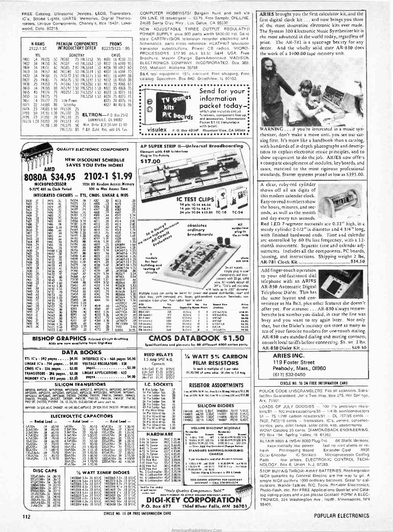
FREE Catalog. Ultrasonic Devices. LEDS, Transistors. IC's, Strobe Lights, UARTS. Memories, Digital Thermo- meters, Unique Components. Chaney's, Box 15431. Lake- wood, Colo. 80215.
N -RAMS PREMIUM COMPONENTS PROMS 2102-1.50 INTRODUCTORY OFFER 8223/S123.1.95
TTL SCHOTTKY CMOS
7400 .14 74123 .50 74502 .25 741.5153 .95 4001 .16 4030 .35 7402 .14 74150 .60 74537 .40 7415163 1.50 4002 16 4040 95 7404 .16 74151 .60 74585 2.00 7415164 1 50 4006 90 4042 60
1410 .14 74157 .60 745140 .50 741.5174 1.50 4007 16 4044 70
7420 .14 74160 .75 745172 3.50 741.5175 1.50 4011 .16 4049 38
7427 .25 74161 .75 745175 1.50 7415193 1.50 4012 .16 4050 38 7438 .25 74163 .75 745181 3.50 7415251 1.50 4013 .35 4066 .65 7440 .14 74165 .80 745197 1.50 7415253 1.50 4021 .95 4068 .35 7445 .45 74174 .75 74S257 1.50 741.5257 1.50 4023 .16 4071 .16 7450 .14 74175 .75 7415258 1.50 4024 .75 4073 16
1451 .14 74177 .70 Low Power 4025 .20 4075 16
7473 .22 74180 .80 Schottky 4027 .40 4516 95
7414 .23 74181 1.50 741500 .25 7493 7495
.50 74191 74192
1.00 741502 741510
.25 ELTRO N-P.O. Res 2542
74116 .49
1.00 74193 .70 .10 741573
.25
.40 SUNNYVALE. CA 94087
74198 1.00 741575 .5G Min. Older 810.00 Add $1.00
7415151 .85 P.68. Calif. Res. add 6% fax.
COMPUTER HOBBYISTS! Bargain hunt and sell via ON_LINE. 18 issues/year - 53.75. Free Sample. ON_LINE. 24695 Santa Cruz Hwy.. Los Gatos. CA 95030.
NEW ADJUSTABLE THREE OUTPUT REGULATED POWER SUPPLY. plus 900 parts worth $400.00 list. Solid slate CARTRI VISION television recorder electronic unit. Schematics. parts cross reference. HEATHKIT television transistor substitutions. Power CB radios. MICRO- PROCESSORS. S17.95 plus $3.50 S6 H. USA. Free Brochure, Master Charge, BankAmericard. MADISON ELECTRONICS COMPANY. INCORPORATED. Box 369. D55. Madison. Alabama 35758.
BSK test equipment. 1590 discount. Free shipping. Free alalog. Spacetron. Box 84B. Broadview. IL 60153.
gam kits P/C bo
Send for your Qs information
packet today - which also includes circuit functions, component lineup, and accessories. Information Packet 51.00 (refundable with order/.
visulex P.O. Box 4204P Mountain View, CA 94040
QUALITY ELECTRONIC COMPONENTS
NEW DISCOUNT SCHEDULE p
u l SAVES YOU EVEN MORET
o AMD
8080A $34.95 2102-1 $1.99 MICROPROCESSOR 1024 84 Random Access Memory
0-70'C 480 ns Clock Period 500 ns Max Access Time
INTEGRATED CIRCUITS - TTL, CMOS. LINEAR 8, MOS
7400 .21 7401 .21 7402 .21 7403 .21 7404 .21 740s .21 7406 .25 7407 .25 7408 .21 7409 .21 7410 .21 7411 .21 7412 .21 7413 .25 7414 .89 7416 .25 7417 .25 7420 .21 7421 .25 7423 .35 7425 .35 7426 .25 7427 .33 7428 .28 7430 .21 7432 .25 7433 .30 7437 .25 7438 .25 7440 .21 7441 .88 7442 .53 7443 .63 7444 .63 7445 .70 7446 .70 7447 .70 7440 .70 7450 .21 7453 .21 7454 .21 7460 .21 7470 .30 7472 .30
7473 30 7474 30 7475 49 7476 32 7480 70 7492 70 7483 70 7485 89 7486 28
7489 2 19 7490 44
7491 70 7492 44 7493 44 7494 70 7495 70 7496 70 74100 1 28 74107 3) 74109 33 74121 35 74122 44 74123 61 74125 40 74126 40 74132 7C
74141 88 74145 70 74147 1 63 74148 1 30 74150 1 16 74151 70 74153 65 74154 103 74155 70 74156 70 74157 70 74160 88 74161 88 74162 88 74163 88 74164 96 74166 1 26 74170 264 74173 1 42
74174 .98 74175 .93 74176 .79 74177 .79 74180 .70 74181 2.15 74182 .7º 74184 2.19 74185 2.19 74188 3.50 74189 3.50 74190 1.23 74191 1.23 74192 .88 74193 .88 74194 .88 74195 .88 74196 .88 74197 .88 74198 1.49 74199 1.49 74251 1.09 74279 .58 74365 .67 74366 .67 74367 .67 74368 .67 75150 1.31 75450 .88 75451 .61 75452 .61 75453 .61 75454 .61 75491 .81 75492 .84 75493 1.09 75494 1.19 8093 .40 8094 .40 8095 .67 8096 .67 8097 .67 8398 .67 82525 2.19 4000 .23
4001 4002 4006 4007 4008 4009 4010 4011 4012 4013 4014 4015 4016 4017 4018 4019 4020 4021 4022 4023 4024 4025 4026 4077 4028 4079 4030 233
4034 4035 4040 4041 4042 4043 4044
4051 4052 4053 4060 4066 4071 4072
.23
.13 1.23
.791
.44
.23
.40
.96 1.05 1.05 .23
1.14 1.14 .96 .23 .84 .23
1.18 .40 .89
1.14 .23
1.51 3.50 1.14 1.14 .79 .79 .70 .70
.40 1.26 1.26 .72
1.58 .79 .23 .23
4073 .23 4075 .23 4081 .z3 4082 .23 4502 .79 4510 1.14 4511 1.05 4514 2.80 4515 2.80 4516 1.23 4518 1.14 4520 1.14 4527 1.68 4528 .88 4585 1.23 1513090 1.80 LM324N 1.28 1543407-5 1.25 1883401.6 1.25 1M340T43 1.25 1883407.12 1.25 IA13401-15 1.25 IM340T-18 1.25 IM3401-24 1.25 IM39005 .88 5E5361 3.24 NE5401. 2.04 5E5550 .48 NES56A .88 NE5608 3.83 NE561 B 3.83 NE5628 3.83 NE565A 1.25 5E5668 1.28
NE567V 1.36 uA709CV .44 uA710CA .44 uA711CA .53 uA723CA .60 uA741CV .44 uA747CA .70 A748CV .49
MC1458V .53 2102 2.65 80804 34.95
obsoletas ordinary breadboards
All wldorler
plug-in tie-polnhe
On all models .... simply plug in your
components and ime:- onnect with 279o. sold
wire. All models accept all DTP's, TO -5's and discreteo
with lends up to .032" diameter. Multiple buses can eosily he linked for power and ground distriburibn, reset and
clock lines, shift command, etc. Boses: 9oldanodired aluminum. Terminals. non-
corrosive nickel -silver. Four rubber feet included
AP SUPER STRIP II -Universal Breadboarding Element with 040 Solderior Plug -1n Tia-Polnl.
$17.00
11121.:-
IC TEST CLIPS I
14 pin TC-14 $4.50 (.1 16 pin TC-16 54.70 24 pin TC-24 513.85 TC-16 TC-24
10 F19F s4V\
LM°yepL1' 05°45 rN Eo
7 modals for fast
building and /e.ting of
circuH.
ACT n. 1010491 No. Poltar
2o6x Dill 208 165.0.) 2010 1011 212 1.01111.1 Ore (Awn) 227 Anew.) 7561o,wn.)
722
»2 ron 1704
1760
M12 Mee
BISHOP GRAPHICS Printed Circuit Drafting Aid. ore now available from Digl-Key
DIP No. No. to-ch. flee Copeulty M... Post. (I.Hh9E)
Artr. each
9 (16Y1 2 0.0/16.59/16 n4.91 e 06's1 0.9/16d9/16 2095
12 114.0 12(14',)
2 0.006.1 0.506.1
24.95 4.95
le 114'd 77114's1
10
2e
61/2O.11e eA1/4
4.95
S9.0S 55 (14',) 2 16114r4r14 29.9s
CMOS DATABOOK $1.50 Specification. and pin -outs for 60 different 0000 serie. ports.
DATA BOOKS TTL IC's - 592 pages $4 CO INTERFACE IC's - 464 pages $4.00
LINEAR IC's 704 pages... $4.00 VOLTAGE REGULATORS 128
CMOS IC's 256 pages.... $3.00 Pagel $3.00
TRANSISTORS 288 pages.. $3.00 LINEAR APPLICATIONS - 432
MEMORY IC's - 592 pages . 53.0b pages S4 00
REED RELAYS 1.5 Amp SPST N.O.
Contacts
4.8v Coil 51.70 s125/C 6.0v Coil 51.70 5125/C 12v Coil 51.70 5125/C 240 Coil $1.70 s125/C
1/4 WATT 5% CARBON FILM RESISTORS Sc each in multiple, of 5 per Moe
51.70/100 of same value. 10 ohm to 1.0 mg
SILICON TRANSISTORS MPS918, MP5930, MP52222A, MP52369A, MP52712, MP52907A, MPS3392, MP53393, MPS3394, MP53395, MP53563, MP53565, MP53638, MP53638A, MP53640, MP53641, 88753643, MPS3645, 54753646, 2N3904, 2N3906, 2144124, 254126, 254401, 254403, 254410, P54888, 7115087, 2145089, P55129, 7115133, 755134, PN5137, PN138, PN5139, 2145210, P145964 .16, 51.55/10, 513.60/100 of same part no.
MPF102 .36 530.60/C 255457 .48 S41.00/0 MPSA13.28 524.00/C 253055 .99 $85.00/C
ELECTROLYTIC CAPACITORS - Redid Lead - - Axial Lead - - Axial Lead -
6ó/50v 221ó/50v 3.3uf/S0v l.7uf/25v 4.7uf/50v 10uí/75v 10uf/50v 22u1/25v 22uf/50v 100u8 /6.3v 100uf/16v 100uf/25v
.08 .65/10 00 .65/10 .00 .65/10 .08 .65/10 OB .70/10 08 .65/10 .10 .75/10 .09 .70/10 .12 1.00/10 .09 .75/10 .11 .85/10 .13 1.10/10
luf/50v .11 .90/10 2.2uf/50v .12 .90/10 3.36f/359 .12 .95/10 3.368/500 .12 1.00/10 .7uf/25v .11 .90/10
1.7uf/35v .12 .95/10 Ouf/16v .11 .90/10 Ouf/25v .12 1.00/10 Ouf/50v .14 1.15.10
22(d/16v .12 1.00/10 721ó/25v .13 1.05/10 33uf/16v .12 1.00.10 33uí /25v .14 1.15/10 47uf/16v .14 1.15/10
47178/250 .17 1006(/16v .17 100uf/25v .20 1001050v .29
.20 220uf/16 /25v .29 330uí/16v .29 3300125v .32 470uí/16v .32 470uí /25v .37 lAceo//16v .39 10001ó725v .56 2200178/164 .62
1.30/10 1.30/10 1.55/10 230/10 1.55/10 235/10 2.35/10 2.55/10 255/10 3.00/10 3.15/10 4.50/10 4.95/10
I.C. SOCKETS 8 Pin Solder Tob .17 14 Pin Solder Tab 16 Pin Solder Tab 18 Pin Solder lob
24 Pin Solder Tob 28 Pin Solder Tob .45
40 Pin Solder Tab .63 8 Pin Wire -Wrap .24 14 Pin Wire -Wrap .26 16 Pin Wire -Wrap .30 18 Pin Wire -Wrap .60 24 Pin Wire -Wrap .86 28 Pin Wire -Wrap 40 Pin Wire -Wrap
22
79 38
1.23 1.00
RESISTOR ASSORTMENTS dl 10% It W. v.l. from 2.2 I. 2í.y Hí3501512.00
55..0110% % M. Vol. Irawa to re 5.5..9 /000 ..1510.00
DISC CAPS 100pí/SODv .04 .36/10
500v .04 .36/10 4pfp8/5000 .04 .36/10 1
d/5000 .04.37/10
210Opf/5000 .04 .37/10 47 /5000 .04 .32/10 .O1 d/513014.06 .50/10 .01ufd/50v .03 .24/10 .022u91/250.03 .28/10 0471dd/25v .05 .42/10 lufd/25v .08 .62/10
Ye WATT ZENER DIODES 114521168 3.3v .15 511/C 15523613 7.5v .15 $11/C 1552278 3.6v .15 $11/C 1052378 8.2v .15 Sil/C 1N5728B 3.9v .15 $11/C 1N5238B 8.7v .15 $11/C 1552290 4.3v .15 511/C 155239B 9.1v .15 011/C 1552308 4.7v .15 511/C 1052408 10v .15 511/C 1552318 5.1v .15 $11/0 15524113 llv .15 $11/C 1552320 5.6v .15 $11/C 1552428 12v .15 511/C 1N5233B 6.0v .15 511/C 1552438 13v .15 $11/C 1552348 6.2v .15 511/C 1557448 14v .15 $11/C 1052359 6.8v .15 $11/0 1 N5245B 15v .15 811/C
HARDWARE 2.56 Y. Screw .99/C 7.20/M 2.56 h Screw .99/C 7.65/M 4-40 '/, Screw .55/C 3.60/0.1 4.40 0 Screw .60/C 4.05/M 632 '/. Screw .65/C 4.40/M 6.32 'h Snow .75/C 4.85/M 332 3/8 Screw .90/C 5.85/M 2-56 Hex Nut .55/C 3.60/M 4-40 Hext Nut .55/C 3.75/M 632 Hex Nut .60/C 4.00/M 8.32 Hex Nut .60/C 4.15/M No. 2 Lockwasher .85/C 5.75/M No. 4 Lockwasher 05/C 3.00/M No. 6 Lodswasher .45/C 3.00/M No. 8 Lockwasher .4S/C 3.00/M
SILICON DIODES 1114148 .40/10 3.50/C 1540004 .70/10 5.95/C 154001 .64/10 5.50/C 144005 .82/10 7.05/C 154802 .66/10 5.60/C 154006 .90/10 7.75/C' 1104003 .68/10 5.80/C 1114007 .99/10 8.60/C
VOLUME DISCOUNT SCEIEDULE Merck.. »woma.. Toed Sprd 0
S º.99 .... Nn S 10100.0100.0051.791.99 160S . 15%
S 10.665 24.09.03555% S 500.65999.99 LESS 20%
S 25.063 99.99165 10% 51000.00 S up.. LESS 25% - The,. Add II. Standard awe.. Ad.w STANDARD SHIPPING/HANDLING
CHARGE
Il 7..r n..Ymel.. IHM .her dl.wwn i, boro...:
0.065 4.99 . odd n.00 S 50.0659199 . oó410.25 f 5 00.124.99 .. odd 10.15 f100.00 e UP .. No C0.99 f 25.06040.99 . odd 01.50
I.lud.. .hirPM L Imu.m,. re USA L C.,.d.
coo ORDERS ACCEPTED Foe SAME DAT SHIPMENT- CALL 218..1.6074
5..1 r. Ira mew ..MI 1..0.' '1/015 Quelih- Cnrnpnnrn rev Sold!° "r""`d' DON/'OIron TO APR,' VOLUME DISCOUNT ABOVE
DIGI-KEY P.O. Box 677
CORPORATION Thief River Falls, MN 56701/
ARIES brought you, the first calculator kit, and the
first digital clock kit ... and now brings you three of the most innovative electronic kits ever made.
The System 300 Electronic Music Synthesizer kit is
the most advanced in the world today, regardless of price. The AR -781 is a space-age beauty for any
decor. And the wholly solid state AR -830 does the work of a $400.00 tape memory unit.
4111 43
M .....,^
l` 1Sw -mow .
WARNING ... if you're interested in a music syn- thesizer, don't make a move until you see our cat-
alog first. It's more like a handbook than a catalog, with hundreds of in-depth photographs and descrip- tions to explain electronic music principles, and to show equipment to do the job. ARIES now offers a complete complement of modules, keyboards, and cases, matched to the most rigorous professional standards. Starter systems priced as low as $395.00.
A clear, ruby -red cylinder shows off all six digits of ' ' ' .,,. this modern calendar clock.
5 ;
Easy -to -read nu mbers show /- ' . 103- the hours, minutes, and sec-
P 1
J onds, as well as the month-, and day every ten seconds. '- -
Red LED 7 -segment numerals are 0.33" high, in a
sturdy cylinder 2-1/2" in diameter and 4-3/4" long, with finished hardwood ends. Time and calendar are controlled by 60 Hz line frequency, with a 12 -
month movement. Separate time and calendar adj- ustments. Includes all the components, PC boards, housing, and instructions. Shipping weight 2 lbs, AR -781 Clock Kit $34.50
Add finger -touch operation to your old-fashioned dial telephone with an ARIES ' AR -830 Automatic Digital Telephone Dialer. This has
e
the same layout and con- .set
venience as Ma Bell, plus other features she doesn't offer yet. For instance ... AR -830 always remem- bers the last number you dialed, in case the line was
busy and you want to try again later. Not only that, but the Dialer's memory can store as many as
ten of your favorite numbers for une -touch dialing. AR -830 uses standard dialing and muting contacts; consult local tariffs before connecting. Sh. wt. 2 lbs.
AR -830 Dialer Kit $69.50
ARIES INC. 119 Foster Street Peabody, Mass., 01960 (617) 532-0450
CIRCLE NO. 10 ON FREE INFORMATION CARD
POLICE CODE UNSCRAMBLERS. Fits all scanners. Satis- faction Guaranteed. Jim's Two -Way. Box 275. Hot Springs, Ark. 71901.
LOADS OF JULY GOODIES - 100 1% precision resis- tors/$1 - 100 mica capacitors/$1 - 1/4 lb. semiconductors 51 - 75 1/2W carbon resistors/$1 - DL 707/95 cents - 7400,7402/10 cents - transistors. IC's, zeners, optoelec- tronics, pots, pilot lamps. solar cells. kits, assortments .. WOW! Catalog 25 cents. DIAMONDBACK ENGINEERING, PO Box 194. Spring Valley. III. 61362.
ALTAIR 8800 & IMSAI 8080 Plug -ins 81( Static Memory, exceptionally low power fast no wait states or re-
fresh Prototyping Board Extender Card .. 8800 Octal Encoder IC Sockets Microprocessor Coding Pads . low prices. ELECTRONIC CONTROL TECH- NOLOGY, Box 6. Union, N.J. 07083.
STOP BUYING THROW -AWAY BATTERIES. Rechargeable NiCd batteries by General Electric are the way to go. A
single NiCd outlives 1000 ordinary batteries. Great for cal- culators. Walkie -Talkies, R/C, Tools. Portable Electronics, Photo -flash, etc. For FREE Applications Booklet and Cata- log listing prices and sizes please Contact: FORM A ELEC- TRONICS. 224 Washington Ave., North, Minneapolis, MN
55401.
112 CIRCLE NO. 19 ON FREE INFORMATION CARO
POPULAR ELECTRONICS
AmericanRadioHistory.Com
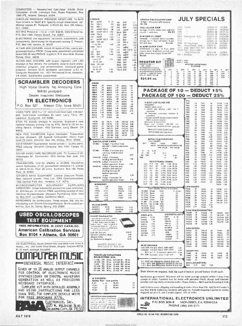
COMPUTERS - Hexadecimal Calculator: $35.95. Octal Calculator: 814.95. Literature Free. Radix Precision, Box 13861 -PE, Atlanta, Georgia 30324.
CIRCbLEX PRECISION PROCESS NEGATIVES. To 8x10 from artwork to 16x20 $15. Specify circuit dimensions. Ad- ditional copies $7. Postpaid. CIRCOLEX, Box 198, Marcy, N.Y. 13403.
500 MHZ Prescaler -10 or --100. $59.95. CBS Enterprise, P.O. Box 1356, Cocoa Beach, Fla. 32931.
ELECTRONIC test equipment, receivers, transmitters, and components. Send stamp for illustrated catalog. E. French, P.O. Box 249, Aurora, III. 60507.
ALTAIR 8800 OWNERS, install 2K bytes of fast, easily pro- grammed bipolar PROM. Completely assembled and tested board 556.95 less PROMS. Digitech. P.O. Box 6838, Grosse Pointe, Mich. 48236.
ALTAIR 8800 OWNERS, add output registers with LED displays at few dollars. For complete, easy -to -build plans: checkout program; and demonstration, computer -game program; forward $5.00 (postpaid continental U.S.) to' Computer Research. Inc., 1601 Pennwood Drive, Hampton. VA 23666. Satisfaction guaranteed.
SCRAMBLER DECODERS High Voice Quality No Annoying Tone
$69.95 postpaid Dealer Inquiries Welcome
TR ELECTRONICS P.O. Box 527 Mason City, Iowa 50401
VIDEO TAPE. 9200 ft x 112" rolls of certified tape. 518 each ppd. Cartrivision cartridges $5 each. Larry Terry. 281
Lakemuir, Sunnyvale. CA 94086.
ETCH PC boards cheaply in seconds. Engineer's new method reduces etching time by 90%. Send $1.00 for ex- citing details. Grissom. 1955 Sternlee, Long Beach, CA 90815.
NEW FIVE WAVEFORM Signal Generator. Transceiver Burglar Ultralarm. CB Speech Compander. More! Flyer send 25 cents. Minitron. Box 184, Anoka, Minn. 55303.
SAVE MONEY! Guaranteed: lowest prices - quality parts. FREE catalog. Chriskim Company. Box 1782. Tampa, FL
33601.
COLOR VIDEO TAPE RECORDER $250. TV Camera $150. Videotapes $4. Cartrivision, 5835 Herma, San Jose. CA 95123.
TRANSISTORS 10/51.00, 2N3904 or 2N3906. Horseshoe xenon Ilashtubes. $1.00. guaranteed! Motorola I.C. similar to 5481A $1.00. Flyer 25 cents. Aardvark. Box 155. Palos Park, III. 60465.
CITIZENS BAND EQUIPMENT. Lowest Discount Prices. Best national brands. Free List. CRS Communications. 1552 Central Park Ave.. Yonkers, N.Y. 10710.
MICROCOMPUTER EQUIPMENT SUPPLIERS DIRECTORY. Cross indexed by product for easy reference. $1. Entitles you to receive FREE upcoming catalog of new National Microcomputer Discount Purchasing Club. Mail to: Box 2427, La Habra, California 90631.
KEYBOARDS, for synthesizers. Three octave, $65. Info for interfacing with Gnome Microsynthesizer. Brinkwood Elec- tronics, Box 26, Sandy Spring, MD 20860.
USED OSCILLOSCOPES - TEST EQUIPMENT
FREE INFORMATION. 35 CENT CATALOG. American Calibration Services Box 8104 Athens, GA 30601
CB ELECTRICAL Quick Disconnect available from Waid 8 Assoc., inc.. 206 North West Street, Angola. Indiana 46703. 51.00 each postage included
Cof r1PU-rei MUSIC 11H1IfUNIVERSAL MUSIC INTERFACE1111D11111
GIVES UP TO 16 ANALOG OUTPUT CHANNELS FOR CONTROL OF ELECTRONIC MUSIC SYNTHESIZERS OR DIGITAL WAVEFORM GENERATION AS WELL AS PROVIDING KEYBOARD INTERFACE.
COMPLETE KIT WITH DETAILED ASSEMBLY AND USING INSTRUCTIONS FOR LESS THAN $40. FOR COMPLETE DETAILS WRITE FOR FREE BROCHURE #776,_
- r ELECTRONICS, INC. A A . 1020 W. WILSHIRE BLVD.
/ o OKLAHOMA CI Ty, OK 73116
LINEAR 301 01DIP S .33 181 DIP 1.7 304 TO -5 .92 383 DIP 1.75 305 10.5 .82 550 DIP 1.02 307 mDIP TO -5 .30 555 mDIP .69 708 mDIP TO -5 1.02 5564 DII' 1.71 109k TO -3 1.35 710 DIP .69 310 mDIP 1.23 711 DIP .30 311 mDIP 10-5 1.09 723 DIP .7 1
3201 TO.220 733 10.5 1.02 5, 12. 151 1.60 719 DIP 1.23
120k TO -3 741 mDIP .37 5. 12 1.60 747 DII' 10-S .82
324 DIP 1.75 748 mDIP .40 339 DIP 1.69 1456 mDIP 1.83 1401 10.220 1458 mDIP .71
5.6. 8, 12 1.71 1800 DIP 2.85 15. 18. 241 3900 DIP .49
340K 10.220 8038 DIP 4.89 5.6.8. 12, 75491 DIP .82 15, 18. 24V 1.94 754'12 DIP .92
380 DIP 1.30
CMOS 40000 .30 10180 1.39 40660 40010 .29 50200 1.49 40680 40020 .29 10210 1.39 40690 40060 1.55 40220 1.10 4071A 40070 .30 70230 .79 40720 40080 1.79 40240 1.02 40730 4009A .66 10250 .29 4075. 4010A .62 40270 .60 40780 40110 .33 4028A 1.13 40820 40120 40300 .51 45180 4013A .29 4035A 1.46 45280 4014A 1.49 40400 1.39 45854 40150 1.49 4042A 1.69 4901A 40160 .56 40490 .68 40170 1.19 40504 .68
74C00 .25 7IC71 1.20 74(162 74(02 .30 74C76 1.54 74(163 74(04 .51 74(107 1.30 74(164 74C08 .78 74C 151 3.00 74(173 74C10 .40 740154 162 74(195 74(20 .40 74C 157 2.02 80(95 74(42 1.55 74(160 2.85 80(97 74(73 1.20 740161 7.93
1.02
.51
.51
.30
.10
.45
.45
.45
.40
1.89 1.84
2.10
.45
2-93
106 3.06 2.61 2.66 1.35 1.13
CALCULATOR CHIPS Cl 5002 12 digit. 4 function lined
decimal - battery operalion 40 pin 2.79
C1 5001 12 digit, 4 (unction plus memory, lined decimal
8 1p.n MM5725 8 digit, 4 lunclion,
IloaSng decimal 2B pin MM5736 6 digit, 4 (unction. 9V
battery operation 18 pin 3.95 MM5738 8 digit. 5 lunclion plus
memory and constant 'loafing decimal, 9V
ballery operation 24 pin
MM5739 9 digit, 4 function, 9V
ballery operation 22 pin 5.35
2.99
1.8
4.50
1
CT30OS CALCULATOR CHIP 12 digit -4 Junction with memory 51.39
7001 CLOCK CHIP 4-6 digit. 12.24 hr. alum, lime. and dale circuits - with dala 16.95
DVM CHIP 4'/% DIGIT MM5330 - P channel device pro.,des all logic for 4'r digil wit meter. 16 pin DIP with data 812.06
ALARM CLOCK CHIP 51MS175AA 4-6 digit. 12 hour. 60844
snooze alum, brightness control capa- bail/ alarm lone oulpul 24 pin DIP $4.93
RESISTOR KUT CARRON IIIM 1 5N ' OR WAD , 455 R151510125 44 YAIUIY SUPPIItet IN A 15 DRAW 10, R QT 50 COMPARTMENT STORAGE II S
CABINET - TABLE OR WALL 31 MOUNT. READY TO USE 04.0
$24.95 ea. 3
42
JULY SPECIALS 1103 Menory 10/210.00 100/088 5260 10/011.90 100/$104 5261 10/311.90 I00/.104 5262 10/213.90 100/$122 5002 Calculator Chip 10/311.90 100/0104 il
10/313.90 9122 5005 10/220.00 100/11760 3091< 57 Regulator 10/010.00 100/589 741 Operational Anpl. 10/12.50 700/$22 3900 Zuad aaplifier DIP 10/23.20 100/329 74123 Dual Monosnable
Multivlbratoe 10/25.60 10C/$50 PAN 1 Display 10/511.90 100104
' WATT - 01055 .11191r1 - 01505
RESISTOR ASSORTMENT R (OHMS)
QTY R CPT Oro 11 On Olt. 44 1m 10 i.511
0
10
IOR
1511 10
1001%. 20
1s4x 10
1.164
1164 5
S
150 10 ].211 20 2211 10 22011 10 ISM S
220 10
]20 1211 3.31
10
10
nx n
27011 s
10
ATM 5
530 10
470
ó
3.911
4.711
6011
10
20
10
3911
471 ux
10
10
10
13011
011 10
bw;10
10
PACKAGE OF 10 - DEDUCT 15% PACKAGE OF 100 - DEDUCT 25%
6 DIGIT LED CLOCK KIT INCLUDES: MM314 clock circuit 6 END70 LEO displays 1.250" red 7
segment) All n essary Iransisto. tenino 8
cap..,
n ,, hors
1 double sided EC board accommodates LED's S clock circuitry
Schematic a inurucilons Does not include ,2V-300 ma
Iranslormerenilches A case 312.03 QUANTITY DISCOUNT NOT APPLICABLE ON THIS DEN
1
MEMORIES 1101 1.50 5262 1103 1.95 82623 17023 14.95 893410 2102 2.95 7489 5203 10.95 74187 5260 1.95 74200
5261 7.19
CLOCK CHIPS M845311 54.45 MM5312 195 MM5313 4.45
MM5314 MM5316 C17001
2.25 7.69 1.95
2.48
5.95 5.90
4.45
5.39 7.95
POCKET CALCULATOR ium .n plu,
r sable sorrow.. .nb md^,dad <es all
e diRn dpl., qt. o,e,llu. - 6.ner. ,.e, - ,se, , .ndard o.
ee61e b.uee, all or:r,- e u
p.ols grad.is. n,emblelo.m - en,' ,u ,on, Indus.,. (alt. Kil1 Kit only 510.95 Batteries (alkaline, disp.) 2.00
Adapler 60444 3.95
Kil, Batteries A Adapter 15.95
QUANTITY DISCOUNT NOT
APPLICABLE ON THIS ITEM
TANATLUN CAPACITORS SOLID -DIPPED 020% .1 mid 35V .25 ea 6.8 mid 6V .30 ea .33 mid 15V .25 ea. 6.8 mid 50V .40 ea. I mid 351/ .25 ea. 10 mid 25V .40 ea. 2.2 mid 2011 .25 ea. 15 mid 10V .40 ea. 2.2 mid 7SV .30 ea. 33 mid 10V .40 ea 4.7 mid 16V .30 ea 47 mld 6V .40 ea.
IC SOCKETS Solder Tell - low profile 8 pin 5 .19 24 pin 14 pin .22 28 pin 16 pin ,24 40 pin 18 pin .35
.45
.59
.69
METAL FILM RESISTORS 1%'/.WAIT
QT1 PRICE PRICE PRICE
EACH MINIMUM 10 MINIMUM 100 erg VALUE PER VALUE
0- 10
lo- 100
100 1000
1000 -
5.20 .20 5.15
.10 5.09
.10 .O8
RESISTANCE (OHMS) 22.6 71.5 182 887 11.86 40.26 23.7 78.7 187 1.15K 15.00 45.3K 25.5 84.5 191 1.5 6 11.00 48.76 30.9 105 205 2.496 18.21 54.96 34.8 110 232 3.571 19.10 60.4K 40.2 115 243 4.750 19.66 64.9 6
45.3 137 499 3.49K 22.66 69.86 51.1 147 601 6.041 24.9K 84.56 61.9 158 715 7.158 20.0K 64.9 I78 806 8.25K 34.46
Zener Diodes, Diodes a Rectifiers N 868 Diode 2501/ N 715A Zener 1111
N 747A Zener 3.6V N 754A Zener 6.8V
4 N 756A Zener 8.21/ N 904 Sw. Diode 3011
N 914 Sw. Diode 1001/ N 858 Zener 120V N 52300 Zener 4.70 N 52428 Zener 120
DISPLAYS MAN1 MAN2 MANIA MANS MAN6 MAN7 MANO MAN66 136100
S 1.95
3.95 .19
2.95 3.95 1.49
2.95
2.95
2.19
S .25 ea. .25 .25 .25 .25 .10 .10 .25
.25
.25
DISCRETE LED'S' ME4 S .29 MI 50
N51100 N5L101 NS/102 IC209-R 6415020 RID GREEN AMBER CLEAR
.15 .IS .15
.15
.18
.18
.18
.18
.18
TTL 7400 .16 7451 .20 74153 ' 1.14 7401 .18 7453 .20 74154 1.29 7402 .17 7454 .20 74155 1.23 7403 .18 7460 .20 74156 1.23 7404 .22 7464 .40 74157 1.14 7405 .22 7465 .40 74158 2.06 7406 .40 7470 .35 74160 1.60 7407 .40 7472 .3S 74161 1.44 7408 .21 7473 .40 74162 1.71 7409 .22 7474 .40 74163 1.60 7410 .18 7475 .66 74164 1.83 7411 .29 7476 .45 74165 1.83 7413 .63 7483 .91 74166 1.71
7414 .81 7116
7485 7486
1.27 74170 74173
2.65 1.71 .40
7417 .40 7489 .46
2.48 74174 1.86 "
7420 .18 7490 .59 74175 1.60 7422 .30 7491 1.12 74176 1.02 7423 .33 7492 .82 74171 .97 7425 .31 7493 .69 74180' 1.04 7426 .30 7494 1.08 74181 3.43 7427 37 7495 .91 74182 .91
7430 .23 7496 .91 74184 2.29 1432 .26 74100 1.50 74185 2.29 7437 .40 74105 .51 74187 4.50 7138 .40 74107 .44 74190 1.35 7440 .20 74121 74191 135 7441 1.13 74122 .52 74192 1.25
7442 .89 74123 .69 74193 1.19 7443 1.00 74125 .62 74194 1.25
7444 1.00 74126 .72 74195 1.02 7445 1.02 74132 1.02 74916 1.44 7446 1.07 74141 1.20 74197 1.02 7447 1.02 74145 1.20 74198 2.06 7448 1.20 74150 1.12 74199 2.86 7450 .20 74151 .91 74200 5.90
74279 1.08
LOW POWER 74100 .29 74151 .33 74190 1.71 741.02 .29 74155 .38 74191 1.67 74103 .29 74171 .29 74193 1.94 74L04 .29 74172 .45 74695 1.94 74106 .29 741.73 .56 741.98 3.21 741.10 .29 741.74 .56 741164 3.21 74120 .38 74078 .91 741165 3.21 71130 .38 74185 1.44 74642 1.71 74186 .79
1
MISC DEVICES U/N 2208 8M gai block 3448 mDIP 1.39 ULN1209 /M gain block 48á13 mDIP 1.59
2513 64. 8 5 5 ch araclrr generamr 11.00 CA 3046 Iramislor array 14 pin DIP .86
5% OFF ON ORDERS OVER $50.00 10% OFF ON ORDERS OVER $100.00 1500 OFF ON ORDERS OVER S 500.00
LOW POWER SCHOTTKY 741500 .36 741532 .38 741502 .36 746540 .45 741504 .36 741542 1.40 741508 .38 74L574 .59 741510 .36 741590 1.30 741S20 .36 741593 1.30
HIGH SPEED 74H00 .25 74H01 .25
748404 748408 748410
748411
748420
74H21
.25
.
.25
.25
.25
741122 748430
74H40 748450 74H52 74H53 74H55 74H40
SCHOTTKY 74500 .38 74508 .52 14502 .45 74510 .38 74503 .38 74520 .38 74504 .45
8000 (SIGNETICS) 8263 5.79 8267 2.59
741595 2.09 7465107 .59 7465164 2.20 7415193 2.20 7415197 220
74H61 .25 741162 .25 74H74 .39 7411101 .39
7144102 .49 11
7444103 .50 74H106 .58 ;
7184108 .60 1
74522 74S32 74574
UNIVERSAL BREADBOARD pteled nppee 1 Lot Nosed
b..edn514 nvu,, 31.50... 0
.30
.52 .8
Date sheets o. request. Add 304 each if item is priced below $1.00 each.
Satisfaction guaranteed. Shipment will be made postage prepaid within 5 days from receipt of order. Payment may be made with personal check, charge card (include number and exp. dale). or money order. Phone Orders - BolA and M/C card or C.O.D. I'
1
Add 51.00 to corer shipping and handling if order is less than 550. Add 52.00 if order is '
less than $10.00. California residents add sales tax. Include shipping expense for orders shipped out of U.S. and Canada approx. 15% of order. II
INTERNATIONAL ELECTRONICS UNLIMITED P.O. BOX 3036-R MONTEREY, CA. 93940 USA
PHONE (408) 659-3171
CIRCLE N0.30 ON FREE INFORMATION CARD JULY 1976 113
AmericanRadioHistory.Com
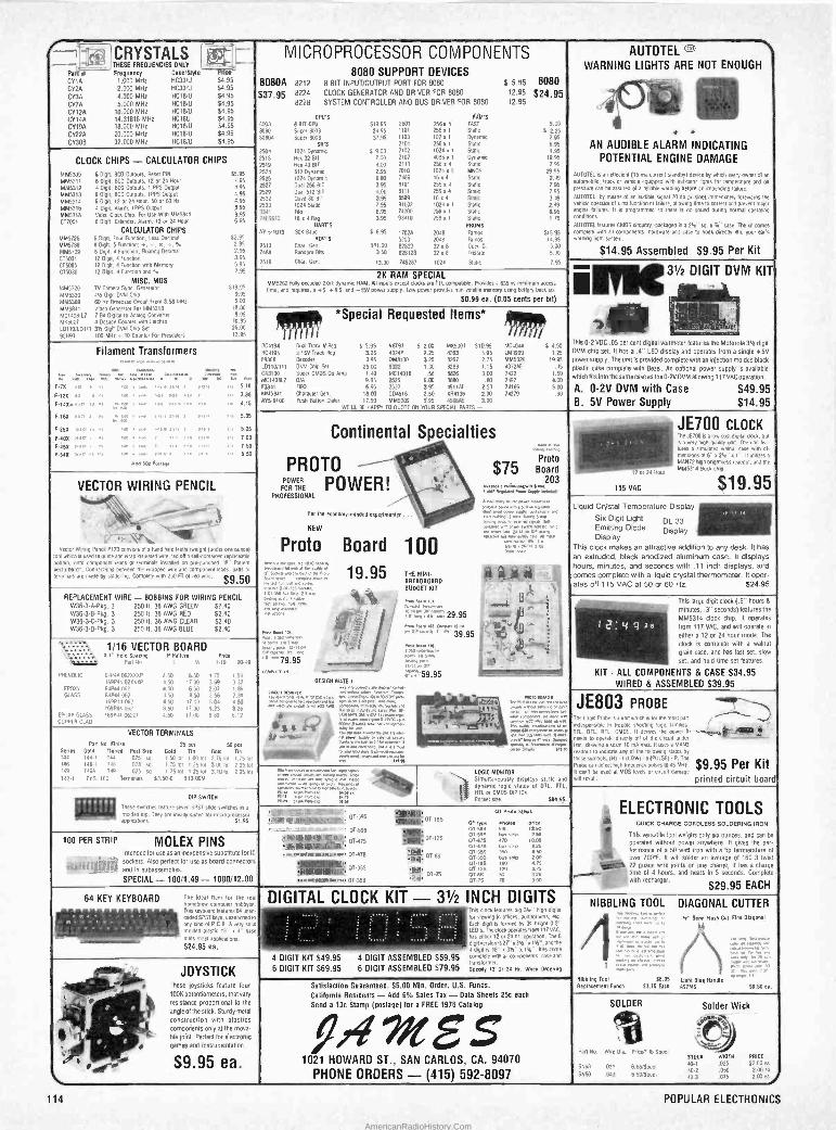
---L 1CRYSTALS 1
I THESE FREQUENCIES ONLY ->;
MICROPROCESSOR COMPONENTS 8080 SUPPORT DEVICES
8080A 8212 8 BIT INPUT/OUTPUT PORT FOR 8080 $ 5.95 8080 8224 CLOCK GENERATOR AND DRIVER FOR 8080 12.95 $37,95$24.95 8228 SYSTEM CONTROLLER AND BUS DRIVER FOR 8080 12.95
GMT'S HAM'S
0008 a BIT CPU 519.95 3601 256x I FAST 5.00 8080 Super 8008 24.95 1101 256. 1 Static 5 2.25 80804 Super 8008 37.95 1103 102 x 1 Dynamo 2.95
611'5 2101 256x1 Static 6.95
2504 1024 Dynan/ ' 5 9.00 2102 1024 x 1 Static 1.95
2518 Hex 3281I 7,00 2107 4096x1 Dynamic 19.95
2519 Hex 40 BIT 4.00 2111 256 x 4 Sum 7.95
2524 512 Dynamo 2.95 7010 1024 a I MHOS 29 95
2525 ,024 Dynamo600 7489 16 a d Static 2.49
2527 Dual 256 BIT 3.95 8101 255 x 4 Static 7.95
2529 Dual 512 BIT 4,00 0111 256 a 4 Statico795 2532 Oua4 80 BIT 1.95 8599 16 x 4 Static log 2533 1024 Sulk 7.95 91L02 1024 a I Static 2,49
3341 File 6.95 74250 256 x I Static 695 7415670 16 x a Req. 7.95 93410 256 a 1 Static 1.15
DART'S PROMS AY -51013 306 Baud 5 6 95 1702A 2048 Ramos 515,95
ROM'S 5203 2048 Faros 15.95 2513 Char. fen 511.00 02523 32 4 8 Open C 5.00 7488 Random Bits 3 50 825123 32 a 8 Tristan 5.00
2516 Char. Gen. 13,00 745287 1024 SultO 7.95
AUTOTEL u WARNING LIGHTS ARE NOT ENOUGH
-
r, +
° AN AUDIBLE ALARM INDICATING
POTENTIAL ENGINE DAMAGE
AUTOTEL K an ehecient IS ma current standby) device h¢,1 ever ( MI by w y owner of an
automobile. Puck or vehicle equipped wino idmxnr lights for temperature and oil
min be assured 01 a reliable warning before an impending failure.
AUTOTEL, co means of an audible signal 70 db pulsing) immediately torments the vehicle operator of a malfunction or failure, allowing time to correct and prevent mater engine failures. It is programmed so there ts no sound during normal operating conONons.
AUTOTEL natures CMOS oreu%ry. packaged Ina 2K" sq. a 1/4' case. The int comes complete with all components, hardware and case to hook directly into your ear's warning 09,11 system.
S14.95 Assembled $9.95 Per Kit
Pa Frequency Case/Style Price
CYIA 1.000 MHz HC33N 54.95 CY2A 2.000 MHz HC33N 54.95
CY3A 4.000 MHz HC18/U 54.95
CY7A 5.000 MHz HC18/U 54.95 CV12A 10.000 MHz HC18N 54.95 CY14A 14.31818 MHz HC18U 54.95 CY19A 18.000 MHz HC18N 54,95
CY22A 20.000 MHz HC18,11 54.95
Cv30B 32.000 MHz HCtBN 54.95
CLOCK CHIPS -CALCULATOR CHIPS
085309 6 Di g11. BCD Outputs, Reset PIN. $5,95 p
MM5111 6 Dp4, BCD Outputs, 12 or 24 Hour 4,95
MM5312 4 D BCD Outputs, 1 PPS Output 4.95 pit.pressure MM5313 60ign, BCD Outputs. IPPS Output 4.95
MM5J164 4 Digit, 1l I4 Hour, 5p 60 Hz 6.95
005316 4 Dpn, Alarm, IPPS Output 6.95 0515318 Video Dock Chip, For Use With MM5841 995 Mom 6 Dlprt, Colander. Alarm, 12 or 2d Hour 6.95
CALCULATOR CHIPS MM5725 6 Digit, Four Runcuon, Less Decimal 52 95
085738 8 DIN. 5 Function; t. _, 0, 0, 5. 2,95 MM5039 II Dim!, a Function, Floating Decimal 2.95
C15001 12 Digit, 4 Function 3.95
CT5005 1201911.4Wrxn0nwonMemory 5.95
C15030 12 Dpn. 4 Function and % 7.95
MISC. MOS 5105320 TV Camera Sync Generator 519.95 0185330 dw Digit DM Os Chip 9.95 0145369 60 He Tlmeoase Circuit From 358 MHz 500 MM5041 Video Generator For 51M5318 18 W
Analdg Convener 10.95
MC,4p8-L7 7 Bn Deade Counter 065007 d Decade Canter win latches
LOIID7LD111 311 Dips DVM Chip Set 25.00
95H90 IOo MHz 10 Counter For Presca'eis 13.95
- - 2K RAM SPECIAL
MM5262 fully decoded 2141 dynamic RAM. Alt inputssu except docks are TTL compatible. Provides a 635 ns minimum access lime, and requires, a +5. +8 5, and -15V power Supply, low power provides non volatile memory using DAlery back W.
50.99 ea. (0.05 cents per hit(
u
31/2 DIGIT DVM KIT
7
';4_' , ,.,. 417:5. 11 *Special Requested Items*
3 r y 311 /
RC4194 Dual Track V Reg 5 5.95 N8797 5 200 MK5007 510.95 MC4044 S 450 Rca195 .415V Tree/ Peg 3.25 40247 2.25 8263 5.95 LM3909 125 F9368 Decoder 395 DM8130 3.25 8261 2.75 MM532i1 1995 L01100111 DVM Chip Set 25.00 9322 1.70 0200 1.15 407208 .'5 W130 Super CMOS Op Amp I.49 M 14016 .56 8826
.80 7497
1.50 MC, dOBL7 D/A 9.95 2525 6.00 8880
300 7422 4 00
f3341 FIFO 695 2527 3.95 4511AT 2.50 74186 5'1' MM5841 Character fen, 18.00 CD4518 2.50 %114136 2.01 74279 .90
485.9100 Push Button Dialer 17.50 005309 595 45fifiAF 100 WE'LL BE HA7Py TO QUOTE ON YOUR SPECIAL PARTS -
Ns 0-2 VOC .05 per cent digital voltmeter features the Motorola 31/2 digit DVM chip set. It has a .4" LED display and operates Irom a single+5V power supply. The unit Is provided complete with an injection molded black plastic case complete with Bezel. An optional power supply is avalla0le
which tits Into the same case as the 0-25 DVM allowing 117VAC operation.
A. 0-2V DVM with Case $49.95 B. 5V Power Supply $14.95
Filament Transformers r0ay, I....W., 00.
^'" `^" "" ^"" '^'"'1°" ' ° r
u0, ,.4.,4 1 7 w 5.10 P.O7 s m ,w 04 0, F-13% 404 CI PI ,a ,... 934 111 > 3,. 310
F -14%w Ole e5 ", "+, rs 1ow'5 0, o 1.15 r F-16% 10 a To
` out. 1001.1 .n, sit 5.35
F.25% °411,1,° , um,.4311 r 111,° a, 5.28
7.4ox o, in ,m nK, u' -n 111" 1.5 7.00
F -05% 'n , m ,+W , ,m > ,. Cr. low ,,. 7.59
E54% mi.s `4 vii. new r.v, n inn 8.50
Add she Pot,
Continental Specialties d ., gigg ,
$ PROTO
1. Prato / 5 Board
FOH HE POWER `-.,,......,.,,.,...203 PROFESSIONALA 001
n9 " ready.. .. w.aa.
33
"r° For Inc economy-mMdea experimenter ...l - Min rue, 2 ̀,,;°tkat ópp, posts tot Talc.. San
NEW , .w.m.r4.,i m., .Mwi Prato Board ' " e 1 O 0 o am.V
ne..44 im mu..,e con.
19 95 (j y^i4 ,F rE4V THE MINI- 1 s! 1 lea
ARD j . Y ,1, ou.......o,101 3511115. 5155 Eco.
BREADBOARD
R ',P.O.. tot. 4 _
_
pá.m úpwon ,.,
M'ci" 'pr s
1I 1.áa s .^ 29.95
,tea /a(+ °Pv ma., 114 ?Os Ssl/ ,r ; 39.95 Egg
n ,>: a1 A '
r ; ;
ovum) a,°'1 1wz w Tasti.aufwa i.a.
79 95 .;;; ; IX "
JE700 CLOCK The JE100 isa1ow rosldpital clock, but
1 83 5 3 :'4 b is a very m9h'molty lino. The unit lea -
lures a simulated walnut cue with 0- measi n 16'a2W"x1". It utilizes
'i Maniz ilpn brightness readout, 4114 me 005314 dock chip.
z or 24 Hour
115 VAC $19.95 VECTOR WIRING PENCIL
_ y T.,atxzl* . ! _,.......:,.,_.5.....y.
Vector Wiring Pencil consists of a hand hem featherweight (under one morel tool ninon Is used logume and wraprnswated wire. led Oa sdncontained repaceame brbmn, onto component leads or terminals wstabed on pre -punched "P' Patter Vecturbord. Connections between the wrapped wire and component teals, pads o, tnnnnais are made M soldering, Complete with 250 FT d nee wire. $9.50
Liquid Crystal Temperature Display ' °
Six Digit Light DL 33 1 u
Emitting Diode Display _ .. ,. . . Display
y desk. It has This clock makes an attractive addition to an an extruded, black anodized aluminum case. It displays hours, minutes, and seconds with .11 inch displays, and comes complete with a liquid crystal thermometer. Ito er- ates off 115 VAC at 50 or 60 Hz. 524.95
REPLACEMENT WIRE - BOBBINS FOR WIRING PENCIL W36.3-A-Pkg. 3 250 It. 36 AWG GREEN 52.40 W36-3-B'Pkg. 3 250 ft. 36 AWG RED 52.40 W36-3-C-Pkg. 3 25011. 36 AWG CLEAR 52.40 W36-3.0-Pkg. 3 250 h. 36 AWG BLUE 52.40
h This large digit clock (.6" hours 8
minutes, .3" seconds) features the
1
MM5314 clock chip. It operates
r 2 : 4 9 3 8 from 117 VAC, and will operate in
either a 12 or 24 hour mode. The
clock o complete with a walnut
grain case, and has last set, slow
set. and hold time set features.
KIT - ALL COMPONENTS & CASE $34.95 WIRED & ASSEMBLED 539.95
hT T...a 1/16 VECTOR BOARD r Hole Spacing P Palter Trice ,;:::. Pan No w 119 20:9
EROTIC OtP4t062%%%7 450 6s0 172 154 169P4402xx%P 450 ,700 369 332
EPDXY 64044 067 450 6 50 2 07 1.86 Glass 61741062 45p 850 256 231
169741062 450 1700 504 153 169784 062 850 17 W 9 23 6.26
EPDXY GLASS 16971/ 062CI 4 50 17 00 680 6 12
COPPER CLAD
`°"""'""' - 0 59.95 °-' ------- . " `_- DESIGN MATE1
^ ̂ "'" m "'""' .CIRCU',1040 csc lee. 111 r 1,+e.ip¡ ó w, . '
44-'71-3-1 °^~ niv1,Zr w ," 0441 en:
- 1NNp6 x. n,..e., `w' 4Y0 : : á"i"á"Ór'N°v e°,s°'w ñ ` r-11 a m 5c,ueaa v.11. `C.% " 11791vxw u-,/,...+:
reef i T 1.q,I .0ue.yu._
,woe r e ; ̀e .. - ,"ree, - . I"'^
mx evcx, ."readout M 0.o 55Ow0'I¡y
JE803 PROBE5111~1-.0-
Toe spen:PleI isaunn whienslo me most pan ' "
eespensible m trouble shpotinq logic families vii. °TL. Rat CMOS It denies the power n --.-.e-, 41
m VECTOR TERMINALS
Pan No. Rinse 25 pes 50 pcf Series Gold Tinned Post Size Gold Tin Gold Tln
144 144.1 TM 025 s' 150 tot I00 lot 275lot 175 tot Vas 146-1 016 028 sg 175/01 825lot 300 tot 22510 149 1494 149 025 so 1 15 01 1 251ot 3 10 tin 1 251oí T42.1 PKG. 100 Terminals 53.500 513.000
needs to operate directly oft of a circuit under rest Maximo a scant 10 mA max. It uses a MANS
to indicate any of the loliowing slates by
mere symbol 181. 1 (LONG c(PIJLSE)' P.118 Probe can detect Non Ireouencypulsesl045485 $9.95 Per Kit II 530 t be used at YOS levels or court damage
wleresult printed circuit board. mg wennewweggegg'sue >w, ..00
V1.$02 tarn 0,°^°rve°e w,v í,°"0"i
os
rt? °
LOGIC MONITOR
Simultaneously displays stalk and
dynamic (ogle slates of DTL 171. HTL or CMOS DIP ICS
Pocketdge 584.95.
ELECTRONIC TOOLS QUICK CHARGE CORDLESS SOLDERING IRON
* This versatile tool weighs only Six ounces, and can be
operated without power anywhere. It gives the gem tormxnce of a 50 wan iron with a hp temperature of over 700F. It will solder an average of 160 3 twist 22 9uage wire joints on one charge. It has a charge
áF0+ th re 4 hours, and heats In 5 seconds. Complete with repharger.
' $29.95 EACH
DIP SWITCH
These switches teatime seven SPST sloe swiNNa n a
molded dip, They are ideally soiled for microprocessor uppliralirns 51.95
k OT Prato 511110
T +' "t' OT -595 !MM. OT -185 'Ik5T5i)_kc,w5,_ _ I°Sa°EY.WI' OT lope ri - -' - - m
A: 01E96 `PEI 07.5 11 sates vP aj
50
I198*819I li' '07.475 01125 44 I=ñ 100 PER STRIP MOLEX PINS intended for use asan inexpensive substitute for IC
sockets. Also elect for use as board connectors 1I p NlFL'digL`g} and In subassemblies.
SPECIAL - 100/1.49 - 1000/12.00
a,.,á e P191119g11111114K .ii. muumuus P,.. 07.470 11016. OT -ass El 50
,I.iy 0115 07oes b grip 2 es
(BINI 01.149 B' 4.75
1 Ni OTJ55 .y0, oT-115 í2o ass
..emennwe e,. T- Dby. DT -7s o7.es 70 325
O 358 0745 ro 0440
64 KEY KEYBOARD The ideal item for the real hrmebrew computer hobbyist
Ap .- . This keyboard lealutsr EA linen - r cooed SPST keys.uronached tp
I, u 0 any land of P C.B. A very solid I a.... y¡.,f-y molded olaslic 13" x 4" base i suns most applications.
DIGITAL CLOCK KIT - 31/2 INCH DIGITS _ Ton clock futures big 31e" high digits
loo viewing M offices, auditoriums. en. Each digit b formed Oe 35 , F70.2" LED's. the dock operates (rpm 117 VAL. has miner 12 m 204 M. operation. The 6
_ -4- dignyesmn'o -a1q". and me 4 digit is l8"x3H"x15)". Kos come
4 DIGIT KIT 549.95 4 DIGIT ASSEMBLED S59.95 compiemw+mau components. wmand vensmrmer.
6 DIGIT KIT 569.95 6 DIGIT ASSEMBLED 579.95 Sped'', 12 or 24 Hr, linen Ordering
NIBBLING
Nibbling T'rl 9
Replacement
TOOL DIAGONAL CUTTER W ml ush Cut Fine Diagonal "Se -Flush
- , 14 nogg _ r MI tlM
W. ....5.
. ¡, ,
1 1 "°" " .."
56.95 Ma" 0910 Blue Nand le Punch 53.75 Each 091145 58.50 ea.
524.95 ea.
a JOYSTICK _ .9 Ihese joysticks feature four
100K potentiometers, that vary W444
% resistance proportional to the . ! P angle of the stick. Sturdy metal ¡, with plastics
` O uip, components Only at the nova-
one 01111. Perfect for eledrOnlc
- y ! games and instrumentation.E 46 ' 9 . 9 5 e a .
Satisfaction Guaranteed. $5.00 Min. Order, U.S. Funds-
California Residents - Add 6% Sales Tax - Data Sheets 25c each
Send a 13c Stamp (postage) Ion a FREE 1976 Catalog iff5`' 1021 HOWARD ST., SAN CARLOS, CA. 94070
PHONE ORDERS - (415) 592-8097
SOLDER Solder Wick
°u
7..
Pan No. wire Dia. Pncw, ib spool 025 PRICE
SN60 031 6 BE/Spool 40', 025 52.00 ea
Shin 0:0 6sornpool 4E2 .050 2.°p ea
407 .075 2.90 ea
114 POPULAR ELECTRONICS
AmericanRadioHistory.Com
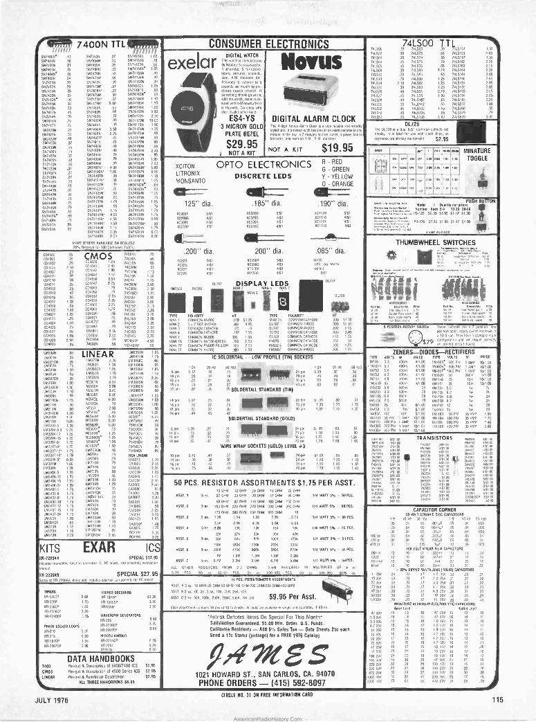
/ 7400N TTLff/l S974000 .13 SN7453N 27 56741505 100
0974019 .16 5674545 .20 55741519 7g
92074026 .21 51174594 25 56741536 89
5974039 .16 0674609 .22 55741540 1 25
91740464 .16 SN7470N .45 55141556 99
5674055 14 55747150 .69 55741566 99
5574069 .20 9174725 39 56741576 99
511740714 29 S6747311' .37 59741606 I 25
S574085 25 9174745 .32 59741616 99
SN74095 25 9474156' .50 55741636* .99
5974199* .16 5674166' .32 59741649 1.10
5674116 30 01174795' 500 56741656 1 10
5674125 33 5574806 .50 ,55741669 1.25
5971139 .45 557482N .98 59741676 5 50
5974146 .70 5674839 .70 56741106 2 10
5N74165 35 51474855 .89 59741726 18 00
5674179 35 SN74865 .39 56741739 150
5674209 .21 51274686 3 50 59741746 1 25
5674216 .33 5574899 2.25 55741759 99
5674229' .49 5974906' .45 66741766 90
51174236 37 5674919 .75 56741779 90
5974255 .29 0674926 .49 09741909 99
5974265 .29 SN749317 49 56741816 2 49
5974279 .37 S8174945 79 56741829 95
5974295 .42 5147/951 .79 56741845 1 95
5574305 26 51,74966 .89 56741536 2 20
51174325 .31 51174975' 4 00 567418617 5.00
59743)51 27 56741001' 1.00 59741679 6.00
5574389 .27 59741079 39 59741906 119
5974399 25 S9741215' .39 S674191N 125
51474414 .15 56741229 39 5674192e 89
5974119 .89 557412317 70 59741930 89
S974429 59 56741259 60 59741949 125
5974<36 .75 55741269 .60 567419584 75
561744474 .75 59741325 1 09 09741969 125
55744511 75 56741366 95 59741976 75
5974469 81 574741416 1.15 56741966 1 75
5674476* 69 56741425 4.00 511741999 1 75
3674189 .79 59741436' 4.50 55742006 5 59
5574509 26 511741446' 4.50 59742799' .90
5674516 27 59741456 1.15 561/25114 1.79
65741476 2.35 56742846 6.00 59741486 2 00 56742859 6.00
MANY OTHERS AVAILABLE ON REQUEST 20% D3cou11110r 100 COmmned 74024
CONSUMER ELECTRONICS
exelar 5
DIGITAL WATCH TINS watch 4 manutamured by Naii0nal Semiconductor. It provides 5 functions; hours, mru des. seconds.
dale. A.M Indicator dot. Accuracy S assured d 5
seconds pu month by Pre s4on quartz crystal. II
something should go wrong with the watch, repair is as.
sand within 48 hours alter 8
COmplele 0114
steel place leather hand
ES4-YS '3 MICRON GOLD
PLATE BEZEL
$29.95 NOTA KIT
Novas §~.
DIGITAL ALARM CLOCK Ttas 4 digit Novas Alarn Clock Is a very reliable and smartly shed unit. It provides such furores as an alarm sellable to any minute of the day, a 7 minutes snooze alarm. a powe failure Indicator, and even an A.M., P M indicator
NOT A KIT $19.95
74LS00 TTL 74500 39 741555 39 7.15151 155 741502 39 241.523 65 7415153 1.89
74503 .39 741574 .65 7445157 1.55
741504 .45 741575 .79 7411162 2 25
741505 .45 741.576 .65 7415163 2 25
744508 39 74583 2.19 7415164 2 25
741510 .39 741586 .65 7415181 3.69
741513 .79 741.990 125 7415190 2 65
741614 2 19 741592 1.25 7415191 2 85
741520 39 741593 1.25 7415197. 2 85
741526 .49 741595 2 19 7415193 2.85 74.027 .45 741596 1 89 1415194 2 25
741528 .49 74L5107 65 7445195 2.25
741530 39 7415112 .65 7415257 I 89
741532 45 7415132 1 55 7d1$260 .55 741540 49 7415136 .65 7415279 .79 711551 39 7415138 I 89 7415670 5 95
DL728 Ile 51728 91 dual 0.5" common cathode red
display 'l Is deal lot use wall Clock chip a5
segmems are already multi leaed S2.95
C04000 25747046 75
CD4001 25 CM O 5 74C109 65 C04035 1 85 C04002 25 C04040 2.4S
747206 65
C04006 2.50 704042 1 90
747306 65
C04W7 .25 74C426 215 C04009 59 701044 1.50 74C735 I 50
C04010 59 [p40474046
2.51 74C74 1 15
2.75 C04011 .25747906 3.00 C04012 25 04049 .M 740956 2.00
CD4013 .47 C04050 .79 7,m,125 154016 56 104051 2 95 74C151 2.90 C04017 1 35 CD4053 2.95 74C154 3.00 C04019 .55 C04060 3.25 74C157 2.15 C04020 1.49 104066 175 74C160 3 25 C04022 1,25 104069 45 740161 3.25 CD4023 25 C04071 45 74C163 3 00 C04024 1.50 C04072 .45 74C164 3 25
104025 25 104081 .45 74C173 2 60 C04027 .69 CD4511 2.50 74C193 2.75 C04028 1 65 C04518 2.50 74C195 2 75 CD4029 2 90 74C00N 39 MC4044' 4.50 C04030 65 717029 .55 11C14006' 56
1.630011
16130114
1M301CN 1M302H 11.130411
1M305H 1M307CN 103086 16130BCN 103096 163096 15131009 LM311H 1.513119 1M318CN
1513195
103190 1513206.5
1M320K.5 2 163206.72 1M370K-15 1M3201á' 1M770T-9' LM320T012' 1M3201.18' 1M323K-5' 1113246 163395 LM3406-5 103406.12 1113406.15 16340N-24 163401-5 15134076 LM340T-8' LM340T.18' L14310T.12 1.143401.15 163.10424 163305 10351CN LM370N 1613709 163736
8305 LINEAR M: 35
1513776 4.00 161458C 65
75 11.13806 139 11014966 95
1 pp LM3B0C5 1.05 1615561/ 1 85
.95 1113816 I 79 16121119 1 95
.35 1513829 1.79 19129015 2 95
1 W 9E5016 8.00 15130655 .69 I00 NE510A 6.00 18139006 55
1.10 6E53114 3 00 1939055 60
99 985361 6.00 163909 1.25
1.15 5E5401 6 00 1655569 1 85 gp NE5`A5 79 51755586 1.00
.90 NE553 2.50 11215254 .90 .Sp NE5551/' 45 1075359 1 25
30 NE5509' 5.00 80380' 4 95 .0p 9E56113' 5.00 1815450 49
,35 .1165620. 5.00 75451CN 39
35 74E5650° 99 )5452C9 39
JS 5556584*
I 25 7545315 39
35 NE566164 1.95 7545415 39 75
74E56)11A 1.25 1549110 79
,75 6E5679' 1 50 75492CN B9
.75 1670306 45 75494C9 89
.75 1M7090 29 RCA LINEAR
.95 1517066 29 743013 110
.80 167109 79 CA3023 2 15 70 107116 39 CA3035 7 25 95 1617236 55 CA3039 1.35 95 15172311 .55 CA3046 I 15
95 1617339 100 743059 2 46 95 467399 1 29 CA3060 2.80 75 16741C8I 35 CA3080 85 75 1674176 35 703081 1.75
.75 16741 145 .39 CA31262 2.00
.75 1.647416 19 CA3083 I 60 75 167479 79 C03086 59 75 15174811 39 70.3089 3 25 75 167486 39 CA3091 6 25 pp LM130311 90 C43123 1 85
.65 16113346 119 CA3130' 149
75 1013056 140 CÁ3600 175
15 1613079 85 RC4194 5 95
.25 1813109 2 95 RC4195 325
XCITON
LITRONIX
MONSANTO
125" dia.
OPTO ELECTRONICS R - RED
G - GREEN
DISCRETE LEDS Y - YELLOW
0 - ORANGE
.185" dia. .19011 dia.
072098 551 875260 5151 %CII1R 551
4C20910 451 XC526G 451 XCIIIG 451 BC2094 4151 915265 4.51 %CI1IY 451
872090 451 8C5760 451 %CIINO 4153
.200" dia. %7228 87225 XC22Y 8C220
/60503 881010
<WI= .2001' dia. .085" dia.
621 8055611 511 MV50
411 6C556G 451 085" da. 011ero
451 %C556Y 4/51 red led
4íE1 875560 451 611
017.47
01338
OA TYPE POLARITY HT TYPE POLARITY HT
MOOS 1 COMMON 6400E 0 53.25 MAN 74 COMMON CATHODE 300 5150 MAN 2 5 a 7 00T MATRIX 100 4.95 01707 COMMON ANODE 3110 5150
AN 3 COMMON CATHODE 025 .39 01747 COMMON ANODE 600 225 MAN 4 COMMON CATHODE .187 1.95 01750 COMMDHCATHODE .600 2_49
MAN 7 COMMON ANODE MO 150 04338 COMMON CATHODE 110 1.25
MAN 7G CO6IMON AN0DE6REEN 300 250 19070 701.1606 CATHODE 250 30 MAN70 COMMON ANUOE-YELLOW 000 250 P65573 COMMON CATHODE .500 1.75
MAN 72 COMMON ANODE 100 150 86050/ 7061009 ANODE .500 175
DL707 DISPLAY LEDS MAN 2 MAN 4 MAN 7
MAN3
)
+iv1 CI ae
Deana.. I1np JEP 4 End PNreIPUN S50 a or Dw4w94/NJ, 10 .f BB BN1N Bu4rIe4m1 40
M rvB ilNr Both leunl 40
OPOT
Off
ON
55510
oN »47..lasr.
30.04
sl
ti(C
).( o oN
00/ 2 os
Ess 42 1 30
0.3
MINATURE
TOGGLE
PUSH BUTTON 8155,^1"Cont Mode 1 oaamty nel prices Numb r Each 2.9 10.29 30-99
.7'..P8.123 52.35 51.95 51.47 51.30
1M-126 52.35 51.95 51.4 S1 .30
ANA A+nwOs I. THUMBWHEEL SWITCHES
1'4" ;'0.10-
011 SPNFP4 SR DP
SR BB
SR HB
o.MBnua. Ppae
E9uvmIWII 550 OM
2NNeaeaml BoM Hue 00
/411 Boerlexnl
IC SOLDERTAIL - LOW PROFILE (TIN) SOCKETS
1-24 25.49 50.100 1.24 25.49 50.100 8 P 5,17 .16 IS 24 Em 538 37 .36
14 Pin 20 19 18 9
YI 28 pin .05 .44 .43
16 pin .22 21 20 A
y 36 Em .60 .59 .58 18 pin 29 28 .17 1
40 pin .63 .62 .61
27 Pin .37 30 35 SOLDERTAIL STANDARD (TIN)
14 Don S 27 25 .24 alli pp 20 tin 5 .99 90 B1
16 pm 30 .27 .25 16 pin 1 39 1 26 1 15
18 pin .35 .32 30 40 pin 1.59 I 45 1.30
24 pm 49 45 ,42
SOLDERTAIL STANDARD .(GOLD)
8pm 530 .27 24 24 pin 670 63 57
14 pin 35 32 29 I.1T
2B Bin 1.10 1.00 90 16 pin 34 35 32 36 'In 1.75 1 40 1.26 18 pm 52 47 .43 40 pin 1.75 1 59 1.45
WIRE WRAP SOCKETS (GOLD) LEVEL #3
10 pin 545 AI .37 ICI 24 pn 51.05 .95 85 14 pin ,39 38 37 28 01n 1.40 125 110
16 pin .43 .42 .41 36 p'n 1 59 1 45 1 30
16 pin .75 68 62 40 pin 1.75 155 1 40
B POSITION ROTARY SWITCH These Switches 411 a 7 position. one
,4491.444.4 *SWOP open. mWry sw+lch enclosed In
+c_i a 70.5 can They have a standard 8 Din
579 conhgmalmInand will msum penecny on0*. ui 604'4
ZENERS-DIODES-RECTIFIERS TYPE VOLTS W PRICE TYPE VOLTS W PRICE
6746 33 400th 411.00 154005. 600 PIV I AMP 151.70 1147510 5.1 400m 4/1.00 1744006* BOO P16 1 AMP 10/1.00
19752 5.6 400th III CO 164007° 1000 PIV 1 ARP 10/1 CO 56753 6.2 400m 4/1.00 153600 50 700m 617.00 15754 6 8 400th 4/1.00 1144148 75 10m 161.00
996513 15 400. 4/1.00 164154 35 10m 12/1.70 155232 5.6 500m 28 164734 56 lw 2P
865234 6.2 500m 28 1N4735 6.2 lw 28 165235 6.8 50010 28 154736 6 8 lw 28 195236 7.5 500m 28 194738 8.2 lw 28
16456 25 40m 61.00 194742 12 Iw 28
15458 150 70 6100 154744 15 1w 29 164850 180 IOm 507.00 161183 50 PIV 35 AMP 160 194001 50 PIV I AMP 12/100 191864 100 PIV *AMP 1.70
'164002 100 PIV 1 AMP 12/1.00 151186 200 PIV 35 AMP 1,80 164003 200 PIV 1 AMP 12/1.00 151188 400 PIV 35 AMP 300 164004 400 PIV 1 AMP 12/1 00
KITS EXAR ics O6-2206KA SPECIAL 517.95 Includes monolithic Iuncrion generator IC, PC board, and assembly instruction
manual
00.220686 SPECIAL S27.95 Same as BR 220683 above and includes external components for PC board
50 PCS. RESISTOR ASSORTMENTS S1.75 PER ASST. 10 OHM 12 OHM 15 OHM 180184 22 OHM
ASST. I 5 ca. 17 006 33 OHM 39 OHM 47 OHM 56 OHM 1/4 WATT 5% w 50 PCS.
68 OHM 82 OHM 100 OHM 120 OHM 150 OHM
ASST. 2 5 ea. 180 OHM 270 OHM 270 OHM 330 OHM 390 OHM 1/4 WATT 5% * 50 PCS,
470 OHM 560 OHM 680 OHM 820 OHM I%
ASST. 3 5 e.. 1 26 1.5K 1.86 2.211 2.16 1/4 WAIT 5% . 56 PCS.
3.30 3.96 4.16 566 6 811
ASST. 4 5 ea. 826 10K 126 158 181 104 WATT 5% . 50 PCS.
226 276 336 390 47K
ASST. 5 5 ea. 56K 680 826 1000 1206 1/4 WATT 5% - 510 PCS.
15001 180K 2201 27011 330K
ASST. 6 5 ea. 3906 470g 5600 6800 8200 1/4 WATT 5% 50 PCS.
001 1.26 1.551 1.80 2 20 ASST. 7 5 ea. 2.10 3 3M 3.90 4.10 5,6M 1/4 WATT 5% * S3PCS.
ALL OTHER RESISTORS MOM 2 2 OHMS - 5 6M AVAILABLE Ill M017171E5 08 5 ea
5-25 PCS. .05 ea, 30.95 PCS 04 ea 100.495 PCS 03 ea 500.995. .025 ea
raes A05 51100 1.185 406 51140 252219a 315100 202721 45100 2522224 51100 292369 511 00 01 21694 ,5100 112415 551 00
252484 411.00 2129060 451 00 2529010 51100 2/2925 51100 2101$3 891 00 253055 5 89
611055 5103 MJE2955 51 25
281192 51100 151198 x100
TRANSISTORS P51557 151 CO
P51568 4 51 00 PN3569 451 00
290104 53100 253705 531.00 251106 551 00
2x1101 551 00
210111 551 00 211.1124 5 65
2143725 51.01 2143901 55100 253905 451 00 2113905 :11 00
2114016 4.1100 254013 351 00 2114014 3$100
PN4249 41' CO
P 4250 4151 00
254400 4/51 00 54:01 41100
264402 41100 2x401 44 00
3 CO
7115006 51. 00
25509' 45100 255069 451 00
255029 451 00
255129 551 00 255116 511 00
255I40 511 00
2N5909 51100 255951 511 00
t105115GR 15I CO
0.15412 52 00
TIMERS STEREO DECODERS 5R-555CP 5.69 86'1310P 53.20 XR-320P 15S XR-1710EP 3.20
XR.556CP I,a5 %RI800P 3.20
011.255670 3.20
811-22a0CP 3.25 WAVEFORM GENERATORS
014205 8.40
PHASE LOCKED LOOPS 40.220677 4,49
88-210 520 80 2207CP 3 85
X0.215 660 MISCELLANEOUS
5R567CP 1.95 611221177 6.10
XÁ -2567C6 2.99 012261 3 79 464130 200
14 PCS. POTENTIOMETER ASSORTMENTS
ASST A 2 ea. 10 OHM.20 OHM 50 000.100 096200 090.250 091-500 OHM
ASST B 2 ea 11, 26, 2.56. 106, 208. 256, 508
ASST C 2 ea 500. 1006. 2066, 2500 SINK. 1M, 20 S9.95 Per Asst.
Each asSolMenl contains 14 pcs 01 101um pots All pots are available in single un. puanNies 5.99 ea.
CAPACITOR CORNER 50 VOLT CERAMIC OISC CAPACITORS
1.9 10-49 10.704 1-9 10.49 50.100 .05 .04 03 00IwF .05 04 .035 .05 04 03 00474.E 05 04 035 .05 .04 .03 .00oF .05 04 .035
100 D1 05 .04 .03 022o1 06 05 04
1 22001 05 04 .03 047PF 06 05 .04
470 of 05 .04 .035 .168 12 09 075 100 4043 MAR FILM CAPACITORS
001101 12 .10 .07 .02271 13 II .08 .0022 .12 10 07 04701 21 17 .13 .0047n4 .12 10 07 Iml 27 23 17
01101 12 .10 01 22101 33 .27 22 0 20% DIPPED TANTALUMS 1301101 CAPACITORS
.1 35V .28 .23 .17 1 5 35V 30 26 .21 15 350 .28 .23 .17 2 2 25V .31 27 22 22 350 .28 .23 .17 3.3 25V .31 27 22
.33 35V .28 .23 .17 4 7 25V .32 .28 23 Á7351 .28 .23 17 6 8 25V .36 31 .25 18350 .28 .23 17 10 25V 40 .35 .29 1.0356 .28 .23 17 15 250 ,63 50 40
MINIATURE ALUMINUM ELECTROLYTIC CAPACITORS
Axial Lead Radial Lear, 15 13 10 .47 25V .15 13 10
.16 .14 .11 .07 50V ,16 14 .11
.15 .13 .10 1.0 16V 15 13 .10
.16 .14 .12 1.0 25V 16 .14 11
15 .13 .10 I 0 506 16 14 11
.16 14 .12 4 7 16V 15 .13 10
17 .15 12 4 7 25V 15 .13 10
24 .20 la 4 7 503 16 14 II 19 17 85 10 16V 14 12 09
.25 .21 .19 10 25V .15 13 .10 24 .20 18 10 50V 18 .11 12
.35 .30 28 47 500 24 .21 19
32 28 .25 100 16V 19 15 14
.45 .41 .38 100 25V 24 20 18
33 .29 27 IDO 500 35 30 .28 .55 50 45 220 l6V 23 17 16 70 62 55 470 25V 31 28 26
DATA HANDBOOKS 7400 Pin -out 6 Description o1 5400/7400 ICS 52.95
CMOS Pin -out & description o1 4000 Series ICS 52.95
LINEAR Pin -out 6 P01071ona1 OeStriptIDn 52.95
ALL THREE HANDBOOKS 56.95
AAstrisk Denotes Items On Special For This Month* Satlstacllgn Guaranteed. S5.00 Min. Order. U.S. Funds.
California Residents - Add 6% Sales Tax - Data Sheets 25c e2Ch
Send a 137 Stamp (postage) fora FREE 1376 Catalog
fi/II/ÍES 1021 HOWARD ST., SAN CARLOS, CA. 94070
PHONE ORDERS - (415) 592-8097
47 50V 1.0 504
3.3 505 4.7 254 10 256 10 500
22 256 22 501'
47 25V 41 50V
100 25V 100 50V
220 25V
220 504
470 25V
1000 16V
2200 16V
351.
CIRCLE NO. 31 ON FREE INFORMATION CARD
JULY 1976 115
AmericanRadioHistory.Com
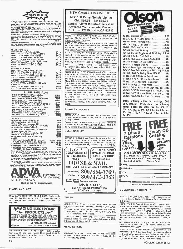
LOGIC PROBE KIT -use wan CMOS, TT L, OIL. RTL, MIL, HiNIL and most MOS IC's. Bulttan protection against polarity reversal and overvoltage. Draws only a few mA from circuit under test. Dual LED readout. Complete kit Includes case and clip leads. 5895 VARIABLE REGULATED POWER SUPPLY KIT -Continuously verb able Irom 3 to over 15 Volts. Short-circuit proof with electronic current IIm. Ding at 300 mA. Compact sae and typical regulation of 5.3% make this a great bench or lab powersuppty. 511.95 FIXED REGULATED POWER SUPPLY KITS -Shortclrcuu proof with thermal current limiting. Compact size and typical regulation of 0.05% make these ideal for most electronic projects. Available for 5V @ 500mA, 6V @ 500mA. 9V @ 50omA, 12V @ 40omA, 15V @ 300mA. Specify voltage when Ordering. 58.95 ea.
These easy.to-assemble kits Include all components, complete detailed instruc tiacs and plated fiberglass PC boards. Power supply kits do not Include case or meters. Add 5125 per kit for postage and handling.
TRANSISTORS INPN) 26918 TYPE RF Amp & Oscillator to 1 GHz 263563 TYPE RF Amp & Ore to 1 GB, (pl. 26918) 263565 TYPE Gen. Purpose Gain (T092/106) 253866 TYPE RF Power Amp 1.5 W @ 450 MHz 263904 TYPE GP Amp & Sw to 100 mA lIFE 100 Assort. NPN GP TYPES, e.g. 263694, 263903, eta. (15) 263638 TYPE (PNP) GP Amp & Sw to 300 mA 293906 TYPE (PNP) GP Amp & Sw to 30 MHz FET's: N.CHANNEL (LOWNOISEI 264091 TYPE RF Amp & Switch (T0.18/106) 2N4416 TYPE RF Amplifier to 450 MHz (T072) 265163 TYPE Gen. Purpose Amp & Sw (70.1061 295486 TYPE RF Amp to 450 MHz (plastic 2644161 6100 TYPE Low -Cost Audio Amplifier ITE4868 TYPE UltraL ow Noise Audio Amp TIS74 TYPE HighSSpeed Switch 408 Assort. RF & GP FET's, e.g. 265163, MPF102, etc. (e) P -CHANNEL: 264360 TYPE Gen. Purpose Amp & Sw (T0106) E175 TYPE High -Speed Switch 125S2(70106)
3/S1.00 6/51.00 6/S1.00
50.75 6/51.00
52.00 6/S1.00 6/S1.00
3/S1.00 2/S1.00 3/$1.00 2/41.00 4/S1.00 2/S1.0O 3/$1.00
52.00
3/51.00 3/S1.00
SUPER SPECIALS: 2N2222 NPN TRANSISTOR GP Amp& Switch 6/S1.00 262907 PNP TRANSISTOR GP Amp & Switch 6/$1.00 263553 RF Power Amp SW @150 MHz, 7W @50 MHz S1.50 MPF102 N.CHANNEL FET RF Amp200 MHz 3/S1.00 556 DUAL 555 TIMER 1 ysec 10 1 hour (0101 50.9111
723 VOLT. REGULATOR 3-30 V @ 1.200 mA (0IP/T03) 3/$1.00 2740 FET Op Amp, Like NE536 and pA740 ITO-5) 51.95 yÁ7805 VOLTAGE REGULATOR 5 V @ 1 A (T0.220) S1.25 '8038 WAVEFORM GENERATOR °.MWave w/ckts S4.50 164154 DIODE 30 V/10mA11914 except 30 25/S1.00 BR' BRIDGE RECTIFIER 50 V PIV, 500 mA (DIP) 4/S1.00 MM5314 DIGITAL CLOCK CHIP -With Specs/Schematics S4.95
LINEAR IC's: 308 MicroPower Op Amp (T05/MINIOIP) S1.00
096 Voltage Regulator 5 V @ 1 A ITO.3) $1.25 24 Quad 741 00 Amp, Compensated (DIP) 51.50 40T Volt. flag: 1 AmpSpecify 5, 6, 12,15 or 24 Vw/ckts $1.75 80 2-5 Watt Audio Amplifier 34 d8 (OIPI S1.29
555 Timer 1 4s to 1 hr. NE555, LM555, etc. (MINI -DIP) 2R1.00 709 Popular Op Amp (13IP/70.51 S0.29 739 Dual Low -Noise Audio Preamp/Op Amp (DIP/ S1.00 1458 Dual 741 op Amp (MINI -DIP) 2/S1.00 741 Freq. Comp. Op Amp (DIP/T05/MINI-DIP) 4/S1.00 DIODES: ZENERS-Specify Voltage 3.3, 3.9, 4.3, 5.1, 6.8, 8.2 400mW 4/S1.00
9.1, 10, 12, 15, 16, 18, 20, 22, 24, 27,or 33V (f10%) 1 Watt 3/S1.00 15914 or 164148 TYPE General Purpose 100V/10mA 15/S1.00 163893 TYPE RECTIFIER Stud Mount 400 V/12 A 2/S1.00 D5 VARACTOR 5.50 W Output @ 30-250 MHz. 7.70 pF 55.00 F7 VARACTOR 1.3 W Output @ 100.500 MHz, 5.30 pF 51.00 MAIL NOWT FREE DATA SHEETS supplied with every hem from this ad. FREE ON REQUEST -741 OpAmp with every order of $5 or more -749 Dual Op Amp or two EtOO FET's with every order of 510 or more postmarked ploy to 8131/76. one free item per order. ORDER TODAY -All items subject to prior sale and tutees subject to change without notice. All items are new surplus parts -100% functionally tested. WRITE FOR FREE CATALOG 07510 of feting over 350 semiconductors car. tied in stock. Send 130 stamp. TERMS: Send check or money order (U.S. funds) with order. We pay 1st Class postage to U.S.. Canada and Mexico (except on kits). $1.00 handling charge on orders under $10. Calf. residents add 6% sales tax. Foreign orders add postage. COD orders -add 51.00 service charge.
ADVA ELECTRONICS BOX 4181 BW, WOODSIDE, CA 94062 Tel. (415) 851-0455
CIRCLE NO. 2 ON FREE INFORMATION CARD
PLANS AND KITS
FREE CATALOGUE KITS, COMPONENTS. Audio equip- ment, Sinclair Kits, radio parts. Gladstone Electronics, 1736 Avenue RD.. Toronto, Canada, M5M 3Y7. U.S. Inquiries.
AMAZING ELECTRONIC . PRODUCTS as4 LASERS SUPER POWERED, RIFLE, PISTOL POCKET SEE IN DARK PYRO. TECHNICAL. SEWGGING - UNCRAMBLERS 01011 MLA. STUNWAN() - TV DISRUPTER ENERGY PRODUCING. SCIENTIFIC DETECTION, ELECTRIFYING. CHEMICAL. ULTRASONIC, CB, AERO. AUTO AND MECH DEVICES. HUNDREDS MORE ALL NEW PLUS INFO UN1TD PARTS SERVICE.
INFORMATION Ilnti,NdPd CATALOG St Res 626 Lord leOeeg Pl. Amherst N.N. 03031
ELECTRONICS kits for home or school project. Select from over 50 kits. Many under $5.00. Send $1.00 for catalog. Refundable with first order. Graymark, 1751 McGaw Ave., Irvine, CA 92714.
6 TV GAMES ON ONE CHIP MOS/LSI Design/Supply Limited
Chip $39.95 Kit $69.95 Send $1.00 for kit info & data sheet Advanced Microcomputer Products P.O. Box 17329, Irvine, CA 92713
CBers - "TRIPLE YOUR POWER" using NEW 46' all -di- rectional CB Antenna!!! Plans $2. Astrobeam-3, 704 Edwards, Visalia, CA 93277.
FREE ELECTRONIC siren plans with catalog. Send 25 cents for handling with self-addressed stamped envelope to: Duer Electronics, 733 Lower Donnelly Road, Charleston, West Virginia 25304.
ETCH IT YOURSELF Printed Circuit Kit, Photo -positive method - all the supplies for four P.C. Boards, direct from magazine article in less than 2 hours only $16.95. Liquid positive resist also available. SASE for details. Excel Circuits, 116 Delaware. Detroit, Michigan 48202.
FREE KIT Catalog contains Test and Experimenter's Equipment. Dage Scientific Instruments, Box 1054P, Liver- more, CA 94550.
PROFESSIONAL ELECTRONIC MUSIC PRODUCTS Avail- able in kit or assembled form. Plans and parts lists. Catalogue $2.00. ELECTRONIC PIANO, honkytonk, clavicord, piano / organ switch, top octave synthesizer. Plans 510.00. Kit $300.00, Assembled $450.00. COMBO ORGAN -61 Note. percussion, echo, sustain, bass. pianc, glide, rotator. etc. Plans $10.00, Kit $500.00. Assembled $750.00. RHYTHM UNIT -40 pin LSI, 10 patterns, 8 drums, manual drum keyboard, digital beatcounter. LED display, 4 measure patterns. Plans 58.00, Kit $150.00. Assembled $200.00. SKS SYSTEMS KIT, 205 East 17 Street. New York, New York 10003.
SPEAKER LAMP PLANS! Convert lamps to speakers. Send $3.00 to: B.J. Feeney, 15-10 Skytop Gardens, Partin, N,J. 08859.
BURGLAR ALARMS
BURGLAR -FIRE alarm supplies and information. Free catalog. Protecto Alarm Sales, Box 357-G, Birch Run. Michigan 48415.
DIALING Unit automatically calls police. Immediate delivery $29.95. Free literature. S&S Systems, 5619-C St. John, Kansas City, MO 64123. (816) 483-4612.
HIGH FIDELITY
DIAMOND NEEDLES and Stereo Cartridges at Discounh prices for Shure, Pickering, Stanton. Empire. Grado and ADC. Send for free catalog. LYLE CARTRIDGES. Dept. P, Box69, Kensington Station, Brooklyn, New York 11218.
r-T3UY HI-FI COMPONENTS THE MODERN
WAY:
AR HY-GAINc'\ DYNACODUAL KOSSSHURE
MANY OTHERS
PHONE & MAIL Call TOLL FREE or write for LOW PRICES
Nationwide
California 800/854-7769 800/472-1783 ® a' Approved by Phone
McK SALES 250 N THOMAS, PO BOX 2100
POMONA CA 91766
tá
eicsParts and
ccesctron - RANNA k
sories TL-477,ElA Soldering Iron 2 99 VC -214. 12 -Pc. Volume Control Kit .49c XM-501. 40 -Pc. Terminal Strip .79c XM-370. 7 Seg. L.E.D. Display 1 29 TR-446. 25 -Pc. Ass'td. SCR 1 49 SW -555. 90-120 V AC Relay ,59c SW -156. Ctr.-Off Toggle Switch DPDT. Pkg. 2 2.49 SW -460. 3 Button Push Switch .24c SW -636. Thermostatic Switch 50-600 NO .....39c SW -752. Unimak 15A Switch SPST ,49c SW -587. 5A Toggle SPST NO .39c SW -431. Phone Type lever Switch 4 SPST ....62c SW -632. Reed Switch W/Magnet SPST. Pkg. 10 1.29 M0-359. 1/30 RPM Timing Motor 120V AC .....49c TT -092. 2500 OHM Output Transformer ,64c TF-047. 6 V 1/2 A. Filament Transformer .44c TF-050. 12V .2A Filament Transformer .47c KN-030. 25-Pcs. Assorted Knobs .49c ME -182. 0-1 Ma Panel Meter 13/er" Mtg. Hole ..89c ME -205. 0-200 UA. Panel Meter 15/16 x 5/8r" ...74c ME -204. 0-150 UA. Panel Meter 1 x 1 x 7/8" ...14c ME -203. 100-0-100 UA. 1'xl'x7/8'r Meter ....74c
When ordering allow for postage. COD 20% Deposit. Residents of the following states please add Sales Tax: Ca. 5%, Fl. 4%, GA. 3%, D. 4%, Ky, 5%, Ma. 5%, Mi. 4%, Mo. 3%, N.Y. 4%, Oh. 4%, Pa. 6%, Tx. 4%.
:{ FREEFREE B 7 Olson Olson Catalogs Catalog
NEXT 7 WITH
ISSUES DEALERS SENT TO R PRICE YOU FREE LIST
Olson Electronics, 260 S. Forge St., Dept. IN , Akron, Ohio 44327 Please send me O Olson catalog O CB catalog O Both . Please Print
NAME
ADDRESS
CITY
STATE
L ZIP
CIRCLE NO. 41 ON FREE INFORMATION CARD
I
GOVERNMENT SURPLUS
TUBES
RADIO & T.V. Tubes -36 cents each. Send for free Catalog. Cornell, 4213 University, San Diego, Calif. 92105. TUBES receiving, factory boxed, low prices, tree price list. Transleteronic. Inc., 1365 39th Street, Brooklyn, N.V. 11218A, Telephone: 212-633-2800.
TUBES: "Oldies", Latest. Supplies, components, sche- matics. Catalog Free (stamp appreciated). Steinmetz, 7519 - PE Maplewood, Hammond, Ind. 46324.
REAL ESTATE
280 -PAGE CATALOG ... Free! Over 2,600 top values coast to coast! UNITED FARM AGENCY, 612 -EP, West 47th St., Kansas City, MO 64112.
MANUALS for Govt Surplus radios. test sets, scopes. List 50 cents (coin). Books, 7218 Roanr(e Drive, Washington, D.C. 20021.
JEEPS, TRUCKS. Typically From $52.40 . . Automobiles, Boats, Motorcycles, Airplanes, Oscilloscopes, Tools, Clothing. Sports. Camping, Photographic, Electronics Equipment ... 200,000 Bid Bargains Nationwide Direct From Government ... Low as 2 cents on Dollar! Surplus Catalog and Sales Directory $1.00 (refundable first order). National Surplus Center, 240 Eastcass-PEL, Joliet, IL 60432.
GOVERNMENT SURPLUS. Buy in your area. How, Where. Send $2.00. Surplus, 30177 -PE Headquarters Building, Washington, D.C. 20014.
SURPLUS ELECTRONIC EQUIPMENT, government and manufacturers' Grab Box Assortment -diverse, useful new and used parts, assemblies, etc. Carton packed: 50 lbs. $6.00; 100 lbs. $10.00. F.O.B. Lima. Send for BIG Free Cata- log! Fair Radio, Box 1105-E, Lima, Ohio 45802,
116 POPULAR ELECTRONICS
AmericanRadioHistory.Com

S. D. SALES CO. P. O. BOX 28810 DALLAS, TEXAS 75228 ALARM CLOCK KIT SIX DIGIT LED
Thousands of hobbyists have bought and built our original clock kit and were completely satisfied. But we have received many requests for an alarm clock kit with the same value and quality that you have come to expect from S.D. So, here it is! THE KIT INCLUDES:
1 Mostek 50252 Alarm Clock Chip 6 Hewlett Packard .30 in. common cathode readouts.
15 NPN Driver Transistors 2 Switches for time set 2 Slide Switches for alarm set and enable 1 Filter Cap 4 IN4002 Rectifiers 1 IN914 Diode 1 .01 Disc Cap
15 Resistors PCB - 3.00 1 Speaker for alarm VFMR - 1.50 1 LED lamp for PM indicator.
$9.95
2102 1K RAM's - 8 FOR $12.95 New units We bought a load on a super deal, hence this fantastic price.
Units tested for 500NS Speed.
MOTOROLA RTL IC'S Brand new, factory prime. Hard to find, but still used in a variety of projects. (See the RTL Cook- book by Howard W. Sams.)
MC724P-59c MC725P-59c MC764P-49c MC767P-69c MC771 P -49c MC775P-89c
M C780P-89c M C785 P -49c MC787P-89c MC788P-49c MC789P-59c MC790P-89c
MC791 P -69c M C792P-59c MC799P-59c M C9704 P -89c M C9709 P -69c M C9760 P -69c
MV -50 TYPE LED'. by LITRONIX
10 for $1 Factory Prime'
3 DIGIT LED ARRAY - 75c
by LITRONIX DL33MMB. 3 MAN -3 Size Readouts in one package. These are factory prime, not retested rejects as sold by others. compare this price! 75c 3 for $2.
60 Hz. Crystal Time Base FOR DIGITAL CLOCKS $5 95
S. D. SALES EXCLUSIVE! KIT FEATURES: A. 60 Hz output with accuracy comparable to a digital watch. B. Directly interfaces with all MOS clock.chips. 1 $% C. Super low power consumption (1.5 Ma typ.) D. Uses latest MOS 17 stage divider IC. E. Eliminates forever the problem of AC line glitches. F. Perfect for cars, boats, campers, or even for portable
clocks at ham field days. G. Small size, can be used in existing enclosures.
Kit includes crystal, divider IC, P.C. Board plus all other necessary parts and specs.
SALE ON CUT LEAD SEMICONDUCTORS Leads. were cut for PCB insertion. Still very useable.
1N914/1N4148 100/$2 1N40021 Amp 100 PIV 40/$1 1 N4745Á 16V 1W Zener 20/$1 ALL NEW. EN2222 NPN Transistor 25/$1 UNUSED. EN2907 PNP Transistor 25/$1 SOME ARE 2N3904 NPN Driver Xstr 25/$1 HOUSE II 2N3392 GE Pre -amp Xstr. 25!$1 C103Y SCR. 800M A. 60V. 10/$1
SLIDE SWITCH ASSORTMENT Our best seller. Includes miniature and standard sizes. single and multi -position units. All new. first Quality, nave brand switches. Try one pack- age and you II reorder more. Special - 12 for 51 IAss:xtmentl
DISC CAP ASSORTMENT PC leads. At least 10 different
values. Includes .001, .01, .05, plus other standard values.
60 FOR $1
UPRIGHT ELECTROLYTIC CAPS 47 mfd 35 V-10/$1 68 mid 25V-8/$1 Brand new by Sprague. PC leads.
RESISTOR ASSORTMENT 1/4 W 5% and 10%. PC leads. A good mix of values. 200/$2
171312),
MOS 4 DIGIT COUNTER I C
All In one 28 PIN DIP. 4 Decade counters, latches, MUX circuits, display decoders, etc. Features: 5VDC operation, 25 MW power consumption, BOTH 7 segment and BCD outputs. Perfect for DVM's, frequency meters, tach's, etc. Can be cascaded for more digits. #5002 - $8.95.
1000 MFD FILTER CAPS Rated 35 WVOC. Upright style with P.C. leads. Most popular value for hobbyists. Compare at up to $1.19 each from franchise type electronic parts storea.S. D. Speael4 for t 1
8008-1 MICRO PROCESSOR
New Units. High speed 8008. Almost twice as fast as units sold by others. Still a very versatile and widely used MPU. No data book, only pinout date included at this price. $12.50 LIMITED QTY.
FAIRCHILD BIG LED READOUTS A be .50inch easy to reed character. Now available in either common anode or common cathode, Take your pick. Super low current drain, only 5 MA pa segment typical.
YOUR FND - 510 Common Anode CHOICE FND - 503 Common Cathode $1.50 ea. 6 for $7.50
DUAL 741C (5558) OP AMPS Mini dip. New house numbered units
by RAYTHEON. 4 FOR S1
1101 A RAM IC 256 XI BITS. Perfect for 8008 or small systems such as telephone dials that do not require a lot of memory. Special 59c. 8 FOR $4.
C& K MINI TOGGLE SWITCH #7103 SUB MINI SPDT Center OFF. Special - 99c.
TTL IC'S 7400 - 19c 7420 - 19c 74153 - 75c 74154 1.00 7402 - 19c 7432 - 34c 7437 - 39c 74157 75c 7404 - 19c 7485 - 95c 7438 - 39c 74161 95c 74204 - 29c 7486 - 45c 7447 - 85c 74164 1.10 7406 - 29c 7490 - 65c 7448 - 85c 74165 1.10 7408 - 19c 7492 - 75c 7473 - 39c 74174 95c 74504 - 44c 7495 - 75c 7474 - 35c 74181 2.50 7410 - 19c 74121 - 38c 7475 - 69c 74191 1.25 7411 - 29c 74123 - 65c 7476 - 35c 74192 1.25 7413 - 50c 74141 - 75c 7483 - 95c 74193 1.00
FETS BY TEXAS INSTRUMENTS - SPECIAL 5 for $1 0T1S-75 but with an Internal house number. TO.92 plastic case. N. Channel, Junction type PET.
We do not sell junk. Money back guarantee on every item. No C.O.D. Texas Res. add 5% tax. Postage rates went up 30%! Please add 5% of your total order to help cover shipping.
ORDERS UNDER $10
ADD 75c HANDLING.
S. D. SALES Co. P.O. BOX 28810
DALLAS, TEXAS 75228
a . r - -
ORDERS OVER $15 CHOOSE $1 FREE MERCHANDISE
CIRCLE N0. 51 ON FREE INFORMATION CARD
JULY 1976 117
AmericanRadioHistory.Com
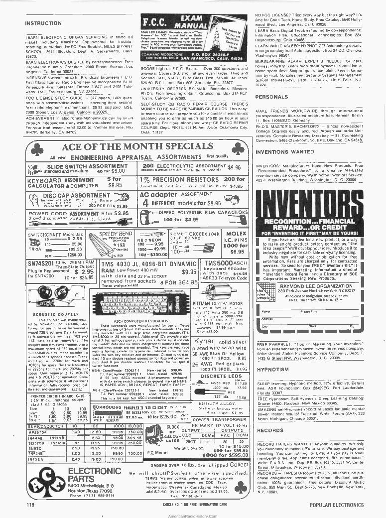
INSTRUCTION
NO FCC LICENSE? Tried every way but the right way? It's lime for Genn Tech. Home Study. Free Catalog. 5540 Holly- wood Blvd., Los Angeles, Calif. 90028.
LEARN ELECTRONIC ORGAN SERVICING at home all makes including transistor. Experimental kit -trouble- shooting. Accredited NHSC. Free Booklet. NILES BRYANT SCHOOL. 3631 Stockton. Dept. A. Sacramento. Calif. 95820.
EARN ELECTRONICS DEGREE by correspondence. Free
information bulletin. Grantham, 2000 Stoner Avenue. Los Angeles, California 90025.
INTENSIVE 5 week course for Broadcast Engineers. F.C.0 First Class license. Radio Engineering Incorporated. 6t N
Pineapple Ave.. Sarasota. Florida 33577 and 2402 Tide- water Trail. Fredericksburg. VA 22401.
FCC LICENSE STUDY GUIDE - 377 pages. 1465 ques- tions with answers/discussions -- covering third. second. first radiotelephone examinations. $9.95 postpaid. GSE. 2000 Stoner, Los Angeles, California 90025.
ACHIEVEMENT in Electronics -Mathematics can be yours through independent study with individualized instruction For your trial lesson, send S2.00 to: Vinther Institute. Box 9447P. Berkeley. CA 94709.
FCC ,EXAM L`- r P
i"r1.4]e ASS FCC E,AMSI Memorise, no" - Ten- h] fa
Answers- for FCC In Ana 2nd claw Radio d 1 rrr lr]]leS
Telephone tip,.. e. Newly riled multiple choice Remotion. end mprene toter Sr zrer
r 1 woad in FCC wen. pros "selaswa *MOW 1 0/
Teti' $9.96 portoed. Moneybeck Gusontee. ,5r zilg11 1
COMMAND PRODUCTIONS P.O. BOX 26348-P uo9 nuuuas hu lee,5AN FRANCISCO, CALIF. 94124
SCORE high on F.C.C. Exams Over 300 queslions and answers. Covers 3rd. 2nd, 1st and even Radar. Third and Second Test, $14.50: First Class Test. 515.00. All tests. $26.50. R.E.I., Inc.. Box 806, Sarasota. Fla. 33577.
UNIVERSITY DEGREES BY MAIL! Bachelors.Masters. Ph.D's. Free revealing details. Counseling. Box 317-PC7 Tustin, California 9.2680.
SELF -STUDY CB RADIO REPAIR COURSE. THERE'S MONEY TO BE MADE REPAIRING CB RADIOS. This easy - to -learn course can prepare you for a career in electronics enabling' you to earn as much as 516.00 an hour in your
spare time. For more information write: CB RADIO REPAIR COURSE. Dept. PE076. 531 N. Ann Arbor. Oklahoma City. Okla 73127.
91. All new ENGINEERING APPRAISAL ASSORTMENTS first quality
SLIDE SWITCH ASSORTMENT standard and miniature 40 for $5.00
200 ELECTROLYTIC ASSORTMENT 59.95 MINIATURE MUMIxMA. eons Los {KW kosy, ,o AfOul 750
KEYBOARD ASSORTMENT 5 for CALCULATOR &COMPUTER S9.95
1% PRECISION RESISTORS 200 for Ass..rtriri'trt c,ditainr ti bal;ineed invuui'r>' $4,95
en Includes :2 re Z70 a' sxM'r .J...'
SA DISC CAP ASSORTMENT
Prime thew 4:
loon -00,., on,d 200 PCS FOR 93.95
AC adapter 4 DIFFERENT models for $9.95
POWER CORD ASSORTMENT 6 for $2.95 2 and 3 conductor 6 -R -ft U. 7., I.isted
DIPPED POLYESTER FILM CAPACITORS r 100 for $4.95
SWITCHCRAFT Micro.Jax 10--S 2.95 ói ARM 25.00
::,, SPEEDY BEND \ ev r eooucnou \ pcy,til
195 -s1}ens
a,,, Res
KEMET CK06BX 104K 0.1 uF 1000 VDC
1-g-' 10 - .40 - MOLEX
I.C. PINS 1000 for
$6.95
: NEON
100 --9.95 1000-49.95 10M-5350.00
100
TR-2A 1000 199.50
IoM 1250.00 100-J4
SN74S201 Thre13 2e-Staati81t RAMte
Oti putTMS Thre Plug In Replacement $ 2 95 for SN74200 10 for 524.95
4030 JL, 4096 -BIT DYNAMIC RAM Low Power 400 mW S995 With data and 22'Pin SOCKET removed from sockets FOR $64.95
TMS5000AsctI keyboard encoder with data 514.95 ASR 33 Teletype Code
- Tested and guaranteed 8
¡/, 'N. ` w1511 7 ,e in Ill
/ r r...' _
1
I- Jr _N,
Tt , Vi%' l t. r-1 _.
r. rte': 'e+tlefefre;e lam'areAv q_'i PITTMAN 12 VDC' MOTOR 7y1le,e' Y/
í10.é, hlrea, 'é; N
runs on as low as 2 ..,I,c
ACOUSTIC COUPLER This coupler was manufactur-
ed by Novation, Inc. Tarzana, Calm
forma for use in Texas Instrument's model 725 Electronic Data Terminal. It is with Bell 103 and
,. - - - - - ASCii COMPUTER KEYBOARDS
These keyboards were manufactured for use on Texas Instrument's line of Silent 700 series data terminals. They are fully encoded with TTL large scale integrated circuits IT].
in Additional
nib,' 12 Volts 250' ma. 2.8 inch of torque al 5000 RPM Size 1 1 8" DIA X 2" long with 0 118 inch shaft. New Guaranteed 51.95 each 10 for 515.00
compatible 113 data sets or equivalent. The coupler operates asvnchronousiy to a
maximum speed of 450 baud in the full.orhalf-duplex mode coupled to a standard telephone handset. Trans inn freq. is 1270hz for mark and 1070hz for space. Receive frequency is 2225hz for mark and 2025hz for
Unit 12 VOLTS
TMS5000 28 pin socket). IC's provide a pa rallel 7 hit, without parity, code plus a strobe signal indicar. ing "valid" data and six other independent outputs for those special keys which are not encoded. The keys are reed type with a format similar to typewriter. Internal circuitry pro- vides for two key rollover and Output is on Stan lard 10 pin double readout connector for data and power in put. And 8 pm double readout connector for six special switch functions. KB -6 CIere/Pendar 7206271 New tested 539.95
K nar Y solid silver plated wire wrap wire 30 AWG Blue Or Yellow
1000 FT. SPOOL 9.95
26 AWG Red or Black 1000 FT. SPOOL 111.93
space. required ±
and u 5 VOLTS for operation. Com plate with schematic & all pertinent
fully reconditioned. cal ibrated, and guaranteed 547.50
T.I. Part number 959327.1 Used tested 529 95 A 56 key ASCii encoded Alphanumeric keyboard with six extra switch closures to ground marked HERE IS, PAPER ADV.. BREAK, REPEAT, TAPE+ TAPE S
KB.7 . Clare/Pendar 720731.1 New .tested 549.95
DISCRETE LEDS Mvso RED $17.50 ¢ see
.200" die. 17.50
PRINTED CIRCUIT BOARD 9.10- 1,16 thick, unetched copper
T.I. Pert number 959326.1 Used tested 539.95 This is a 64 key lull ASCii encoded keyboard.
RED .125" dia. 15.00
clad 1 oz. 2 sides Size 1 10 100 306".50 2 50 19.95
4%12" 5 00 39.95
rBl1RROUGHS ANAFIEXU 2 DIGIT 75 a ^n^
LuBR 16254160v DC ienilarinn anirav°z Lu witn
BISMUTH ALLOY. Melt, in boson x
4 " tnaa si. 9s .00
8x 8" 1.50 995 59.75 a a is
with soyget S2.9s . 101or 525.00 beta POWER TRANSFORMER
SEMICONDUCTOR 10 100 1000 10,000 CLOCK PRIMARY 117 VOLT 60 Hz
MPS3704 2.00 12.50 99.95 750.00 or OUTPUT t OUTPUT 2
1N4448 1N9146 5.60 48.00 394.45 Í`. " CALGU-VAC DCMa VAC DCM-s
5213709 - 1N749A I.95 14.95 99.95 750.00 s LATOR 2007 50 80 20
2N930 2.50 19.95 150.00 Weight, 512 oz. 10 for $15.00
2N5449 2.00 12.50 99.95 750.00 P.C. Mount 100 for $69.95 1000 for $595.00
IN7524 2.40 19.00 150.00
ELECTRONIC. PARIS
5400 MitCFlelkiale, V
B-8
We will ORDERS OVER 10 lbs. are shipped Collect shipUPSunless otherwise specified.
TERMS We pay Voltage, unless otherwise specified Include check or money order, no COD Teas residents add 5% sales tax Canada and Mexico
` Iiouston,Texas 77092 Phone 17131 688-8114
add $2.50 overseas countries add 55.00. TW5 910.88r.2411
LEARN Basic Digital Troubleshooting by correspondence. Information Free. Educational Technologies, Box 224, Reynoldsburg, Ohio 43068.
LEARN WHILE ASLEEP! HYPNOTIZE! Astonishing details. strange catalog free! Autosuggestion, Box 24-ZD. Olympia, Washington 98507.
BURGLAR/FIRE ALARM EXPERTS NEEDED for cars, homes. industry. Learn high profit systems installation at home spare time. Simple. quick, complete. Free Informa- tion by mail. No salesmen. Security Systems Management School (homestudy). Dept. 7373-076. Little Falls, N.J. 07424.
PERSONALS
MAKE FRIENDS WORLDWIDE through international correspondence. Illustrated brochure free. Hermes. Berlin 11. Box 110660/ZD. Germany.
Ph.D'S, MASTER'S. BACHELOR'S - official nonresident College Degrees easily acquired through maitorder Uni- versities. Complete Revealing Directory - 52. Counseling Connection. 5495 Claremont. No. BPE. Oakland. CA 94618.
INVENTIONS WANTED
INVENTORS: Manufacturers Need New Products. Free "Recommended Procedure.' by a creative lee -based invention service company. Washington Inventors Service. 422-T Washington Building. Washington. D. C. 20005.
7 "I .a I
1- 1 I
RECOGNITION. t. FINANCIAL. REWARD...OR CREDIT
FOR"INVENTING ITFIRST"MAY BE YOURS! IIf you have an idea for a new product, or a way
to make an old product better, contact us, "the idea people" We'll develop your idea, introduce it to industry, negotiate for cash sale or royalty licensing.
Write now without cost or obligation for free Iinformation. Fees are charged only for contracted services. So send for your FREE "Inventor's Kit." It has important Marketing Information, a special "Invention Record Form" and a Directory of 500 Corporations Seeking New Products.
RAYMOND LEE ORGANIZATION 230 Park Avenue North.New York,NY. 10017
At no cost or obligation, please rush my FREE "Inventor's Kit No. A-112 ".
IName Please Print
Address
C.ty state Zip - - - - - -
1
I i I I I
FREE PAMPHLET: "Tips on Marketing Your Invention," from an experienced fee -based invention service company. Write United States Inventors Service Company. Dept. T,
1435 G Street NW, Washington. D. C. 20005.
HYPNOTISM
SLEEP learning. Hypnotic method. 92% effective. Details free. ASR Foundation, Box 23429EG, Fort Lauderdale. Florida 33307.
FREE Hypnotism. Self -Hypnosis. Sleep Learning Catalog! Drawer H400. Ruidoso. New Mexico 88345.
AMAZING self-hypnosis record releases fantastic mental power. Instant results! Free trial. Write: Forum (AA7), 333 North Michigan, Chicago 60601.
RECORDS
RECORD RATERS WANTED! Anyone qualifies. We ship you nationally released LP's to rate. We pay postage and handling. You pay nothing for LP's. All you pay is small membership fee. Applicants accepted "first come basis." Write: E.A.R.S.. Inc.. Dept PE. Box 10245, 5521 W. Center Street. Milwaukee, Wisconsin 53210.
RECORDS - TAPES! Discounts to 73%; all labels: no pur- chase obligations: newsletter: discount dividend certifi- cates; 100% guarantees. Free details. Discount Music Club, 650 Main St.. Dept 5-776. New Rochelle, New York, N.Y. 10801.
113 CIRCLE NO. 1 ON FREE INFORMATION CARO POPULAR ELECTRONICS
AmericanRadioHistory.Com
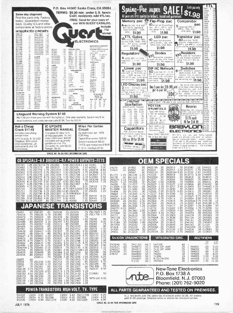
00 'llr d - , ... Same day shipment First line parts only. Factory tested. Guaranteed money back. Quality IC's and other components at factory prices
INTEGRATED CIRCUITS 7400 TTL 5147400N SN7404N 917101374 9.174104 5874101 SN7420N SN74304 5871381.4 SN7440N 5N7447N SN7.150V SN7473N 561747411 SN747584 94748914 SN74909 SN 7492N SN74ICON SN74121N SN7.1123N SN741494 SN741504 SN74154N 5H74157N $474161N SN74174N SN74175N 5N7418 1N
5N7419UN 5N74193N 5N74198N 5N 7125114 5N7429N 741.500 TTL 5N741e094 D1741 504N 5N741508N 5N741510N 51,7415203 SN741538N SN74LS74N 5N741575N 9N74L5903
17
19
39
39 17
n 37 17
78
36
36 39 69
]45
60 39 49 59 89 95 10
115 35 0 7 0
3 25 1 25 2 25 220 265
1 65
34 39 39 39 34
39 59 75
1 10
5N741593N SN741595N 5N74151078 9N74L5132N 5N7415151N SN7415157N SN74L5160N SN7aL51704 5N7n15192N 5N7415197H SN741525aN SN74192904 5N7415670N
LINEAR CA3p18 CA3026 CA3015 CA3016 CA30M7 C63054 C43082 CA3089 LM]01AN 1M301AH 11,13078 1,13088 LM309K 1M31111 LM339N LM35aN LM351N LM3B04 LM7104 LM723N 1M73.311 1.1.1741N
LMlWIN LM2111N 1M39004 MC1458V NE5401 NE550N NE553B NE555V
I10 1 89
52 1 50 128 1 40 205 2 85 260 200 220 200 3 50
1 00
90 1 00 1 90 2 25
35 35 35 89
1 25 90
1 55 I 0
60 1 25
65
69 35 82 95 55 59 5 0 65
230 3
P.O. Box 4430C Santa Clara, CA 95054.
TERMS: $5.00 min. order U.S. funds Calif. residents add 6% tax. FREE: Send for your copy of
our 1976 GUEST CATALOG. Include
.130 stamp.
if
NE556A NE 5691 NE566V 1415075 5N75i50CN SN754SIGN 5N75452CN 9N75a51CN SN75454CN
CMOS C034001 CDIODt C04011 C04012 C04013 CD4016 C04017 C04020 C04027 CD4030 CD4049 CDI050 C04071 Cd072 CD4082 CD4511 CD40192
INTERFACE 58125V N8T26V N87266 Ñ87802 8T90A
N87978
1 00 1 95
85 175
47 39 39 37 37
42 25
ELECTRONICS
DISPLAY LEOS MANI CA 270 I80 MAN3 CC 125 30 MAN4 CC 187 I 95 MAN/ CA 300 135 MAN72 CA 300 135 MANIA CC 300 135 03.707 CA 300 135 01727 CA 500 2 55 O1747 CA 600 200 ` ND503 CC 503 I 75 N0510 CA 500 175
25 MOSIMEMORY 25 RAM 75 50
200 2 30
55 55 62 42
0 40 40
3 00 3m
320 2 75 2 75 2 75 275 200
Liteguard Warning System $7.95 `` Won't let you leave your car with the lights on. One year warranty. Save many $ on
dead batteries and costly service calls $7.95. Two for $15.00
2102 2 75
2102.1 2 75
21024 2 75 21100 2 75
2107 1850 2112.2 7 90
UART V51013 620
A lo D CONVERTER 8700CN 16 00
17022PROM 13 00 1482523 2 90 N825123 2 90 711325126 1135
MICRO- PROCESSOR
8080 24 50 80804 39 50
MICROPROCESSOR KIT
SeiDoefics Bopolar 943000111000A 5234 CO
value Jus1610C 00 INCLUDES 4. 3 8:5114 I. 3001 2. 8026 1.745192 1.8131
6K o1 Memory
CRYSTALS 1 MHz
2 MHz 4 MHz 5 MHz O MH7
18 MHz 20 MHHz
32 MHz 32768 Hz
CLOCKS 61115311 11615312 MM5313 MM5314 MM5315 MM5316 CT 7001
154 .s
450 4 25 125 425 390
90 $90
80
360 480 160 a 30 a00 635 5 80
IC SOCKETS 541á6r Tln Low Profile
PIN 1 UP PIN 1 UP 8 15 24 36
14 8 28 3 16 20 36 58
18 27 40 61
22 35
Not a Cheap Clock $17.45 Includes everything except case. 2 -PC boards. 6-.50 LED Displays. 5314 clock chip transformer. all components and full instructions.
r
IC UPDATE MASTER MANUAL Complete IC data from all Manufacturers. 14.000 cross references. $30.00
, complete with quarterly update service. For Domestic Air, add $2.00, Foreign, $6.00.
Miles Per Gallon Circuit As described Jan. 1976 EDN mag. Digital Flow sensor 529.50 Speed transducer $8.00
CMOS rate multipliers $19.95' 2-.50 in. displays $2.50
CIRCLE N0. 46 ON FREE INFORMATION CARD
CB'SPECIALS-R.F.DRIVERS-R.F. POWER OUTPUTS-FETS 2SC481 1.85 2SC76715.75 2SC866 5.85 2SC1449-1 1.60 40081 1.50 2SC482 1.75 2SC773 .85 2SC013 1.50 2SC475 1.50 40082 3.00 2SC495 1.10 2SC774 1.75 2SC1014 1.50 2SC1678 5.50 2SC608 4.85 2SC502 3.75 2SC775 2.75 2SC1017 1.50 2SC1679 4.75 SK3046 2.15 2SC517 4.75 2SC776 3.00 2SC1018 1.50 2SC1728 2.15 SK3047 3.75 2SC614 3.80 2SC777 4.75 2SC1173 1.25 2SC1760 2.15 SJ2095 3.50 2SC615 3.90 2SC778 3.25 2SC1226A 1.25 2SC1816 5.50 SK3048 3.25 2SC616 4.15 2SC797 2.50 2SC1237 4.50 2SC1908 .70 SK3054 1.25 2SC617 4.25 2SC798 3.10 2SC1239 3.50 2SC1957 1.50 2SC699 4.75 2SC781 3.00 2SC1243 1.50 2SF8 3.00 2SK19 1.75 2SC710 .70 2SC789 1.00 2SC1306 4.75 HEP-S30013.25 2SK30 1.00 2SC711 .70 2SC796 3.15 2SC1306-14.90 2SD235 1.00 2SK33 1.20 2SC735 .70 2SC799 4.25 2SC1307 5.75 MRF8004 3.00 2SC756 3.00 2SC802 3.75 2SC1307.16.00 4004 3.00 3SK40 12.75 2SC765 9.50 2SC803 4.00 2SC1377 5.50 4005 3.00 3SK45 2.75 2SC766 10.15 2SC839 .85 2SC1449 1.30 40080 1.25 3SK49 2.75
pIJAPANESE TRANSISTORS 2SA52 .60 25B187 2SA316 .75 258235 2SA473 .75 258303 2SA483 1.95 2SB324 2SA489 .80 2SB337 2SA490 .70 2SB367 2SA505 .70 2SB370 2SA564 .50 2SB405 2SA628 .65 2SB407 2SA643 .85 2SB415 2SA647 2.75 2SB461 2SA673 .85 2SB463 2SA679 3.75 2513471 2SÁ682 .85 2SB474 2SA699 1.30 2SB476 2SA699A 1.75 2SB481
.60 2SC458 .7012SC815 .75 2SC1569 1.25 1.75 2SC460 .70 2SC828 .75 2SC1756 1.25 .65 2SC478 .80 2SC829 .75
1.00 2SC491 2.50 2SC830 1.60 2SD30 .95 2.10 2SC497 1.60 2SC839 .85 2SD45 2.00 1.60 2SC515 .80 2SC945 .65 2SD65 .75
.65 2SC535 .75 2SC1010 .80 2SD68 .90
.85 2SC536 .65 2SC1012 .80 2SD72 1.00 1.65 2SC537 .70 2SC1051 2.50 2SD88 1.50 .85 2SC563 2.50 2SC1061 1.65 25D151 2.25-
1.25 2SC605 1.00 2SC1079 3.75 25D170 2.00 1.65 2SC620 .80.2501096 1.20 2SD1S0 2.75 1.75 2SC627 1.75 2SC1098 1.15 2SD201 1.95 1.50 2SC642 3.50 2SC1115 2.75 2SD218 4.75 1.25 2SC643 3.75 2SC1166 .70 2SD300 2.50 2.10 2SC644 .70 2SC1170 4.00 2SD3I3 1.10
2SA705 .55 2SB492 1.25 2SC681 2.50 2SC1172B4.25 2SD315 .75 2SA815 .85 2SB495 .95 2SC684 2.10 2SC1209 .55 2SD318 .95 2SÁ816 .85 2SB507 .90 2SC687 2.50 2SC1213 .75 2SD341 .95
2S6511 .70 2SC696 2.35 2SC1226 1.25 2SD350, 3.25 2SB22 .65 2SC712 .70 2SC1243 1.50 2SD352 .80 2SB54 .70 2SC206 1.00 2SC713 .70 2SC1293 .85 250380 5.70 2S856 .70 2SC240 1.10 2SC732 .70 2SC1308 4.75 2SD339 .90 2SB77 .70 2SC261 .65 2SC733 .70 2SC1347 .80 2SD-390 .75 2SB128 2.25 2SC291 .65 2SC739 .70 2SC1383 .75 2SD437 5.50 2SB135 .95 2SC320 2.00 2SC715 1.75 2SC1409 1.25 2SB152 4.50 2SC352 .75 2SC762 1.90 2501410 1.25 C10681 .50 2S13173' .55 2SC353 .75 2SC783 1.00.2SC1447 1.25 2S8175 .55 2SC371 .70 2SC784 .70 2SC1448 1.25 MPS -U31 4.00 2SB178 1.00 2SC372 .70 2SC785 1.00.2SC1507 1.25 2SB186 .60 2SC394 .70 2SC793 2.50 2SC1509 1.25
1 POWER=TRAÑSISTÓRS HIGH -VOLT. 'TV. TYPE.
BÚ204 1300V 3.90 BU207 1300V 5.40 2SC1172B 1100V 4.25 BU205 1500V 4.70 BU208 1500V 6.25 2SC308 1100V 4.95 BU206 1700V 5.90 2SC1170 1100V 4.00 2SC1325 1100V 4.95
k
1N270 1N914
2N173 1.75 2N178 .90
2N327A 1.15 2N334 1.20 2N336 .90
2N338A 1.05 2N398B .90
2N404 .30 2N443 1.75 2N456 1.10 2N501A 3.00 2N508A .45 2N555 .45 2N652A .85 2N677C 6.00 2N706 .25 2N7068 .40 2N711 .50 2N7118 .60 2N718 .25 2N718A .30 2N720A .50
2N918 .35 2N930 .25 2N956 .30
A A Eachpaeonly 740 TL20, Spl4ing- Pali I 74000 .25
7401 .14
All pain are first qualit no fallout), tested and guaranteed. 98. 74021 .25
Memory pac I 48M5016 MC5 TO -5 51
BIT shift registers
from NATIONAL - with
data $1.98
Flip -Flop pac 10 xssor.ed Flip -Flops, Dua JK's, ',,ST's, and low power El's, with
data $1.98
TTL Gates \assorted DTP's 7400 series -7420, 7430, 7440
etc...411 prime, marked
parts, with data
$1.98
Regulators
LED pac 10 assorted discrete LEO's-green, red, and
infra -red, with data.
$1.98
Comparator 174Hó4 .30
pac 7405 .30
7406 .40 5 assorted DIP's 7408 .33 LM311, 710, 711.
1 7410 .12 w with data $1.98 7413 .40
Transistor pac 40assorted TO -92 plastic transistors --
1 PNP's and NPN's, mostl
\Fairchild house marked
$1.98
. a 171723 DIP iahle regulator:, 2 400 with
, data $1.98
Diodes NC/germanium computer signal di, des with leads
trimmed fir PCB mounting
$1.98
OResistors 10 y watt 5% resistors
of any single standard
value from 2.7 ohm to 10 ohm $1.98
Linear pac a assorted linears in
mini -DIP Or TO -4.741 o0
' amo, 10307 op amp, 1.'1
701 RF-IF amp, with data
and circuits $1.98
DIP RC Network. 50 assn-ted 14 ;^d 16
pin IC pa.L3ges ,untaiO- inn precision resistors and capacitors -n0 data available $1.98
Switches SPST momentary Contact push button N.O. Red
button fits in approx. panel, with lock washer
and mounting nut.$1,98
LED Display pac The above are special
2 0L33 - 3 digits each. Buy .5 pacs for $9.90 and offerings from Babylon
ird class approximately 1" mag- pic-a-pac for Electronics,be
shipped and will
R pins Dd digits do a 12¡'.=1 7 pin DID, with data
$1.98 rtt7ji,
3 Aln Power 5E4 A STAM; FOR OUR FLYER LISTING MORE BARGAINS!!
Silicon rectifiers MARKED 661AL PACKAGE
PRY EACH PRO EACH
50 5.08 600 5.24
100 .13 700 .27
200 .15 800 .30
300 .18 900 .40
400 .90 1000 .50
500 .22 1200 .60
1400 5.70
Capacitors PCB vertical mount
electrolytic capacitors. 2" low g, 3/4" dia.
590 ea. 10 for $5.00
----- U ELD
Type Relay m B MFI T KHP
- 4 'DI 3A Contacts 1, 24V DC . .$1.50
(650 coil) 1141.' 0200 AC. .51.75 ' '-
110.5 MA coil)
See bottom of ad for
ordering instructions.
Memories 91400-25681 RAM, lul ly do -
11911 speed (40 ns1 open collector output. 16 pin DIP with data.
$1.75 each
10 for $14.95 M311 orders t0: BfaF3yLO1'l P.O. Box 41778
64Crament0, CA ELECTROrlICS 95841 Phone (916) 334-2161
TRY I 910-367-352
a 7'
BAN RAMERICARD
«ám77,:,1 ºe
7420 .12
74120 .25
74H20 .18 7430 .l0 74830 .30
741.30 .30
7440 .10
74H40 .22
7442 1.00
7447 1.90
7450 .10 74H50 .30 7451 .10 74H51 .25 7453 .10
74154 .25' 741.55 .25
7460 .15
74171 .20
7472 .40
74172 .60 7473 .35
74173 .75
7474 .45
74874 .75
7475 .80
7476 .35 ,
74178 .70
7480 . 50 21
7a83 .70 7489 2.00, 7490 .70'
7492 .351
7493 1.00¡ 7495 .65
74195 1.00
74107 .25
7412.3 .75
74145 1.25
74155 .90
74174 1.00 74180 1.00 74192 1.00 74193 1.00 75492 1.00
A11 IC's are new and fully tested. Leads are plated with gold or solde". Due to increased costs, orders under 07.00 add 51.00 postage and handling.
Residents of California add sales tax.
Orders shipped promptly. 510 minim' order on C.O.D.'S.
u
:OEM 'SPECIALS' - .10 2N960 .55 .10 214962 .40
2N967 .50 2N1136 1.35 2N1142 2.25 2N1302 .25 2N1305 .30 2N1377 .75 2N1420 .20 2N1483 .95 2N1540 .90 2N1543 2.70 2N1544 .80 2N1549 1.25 2N1551 2.50 2N1552 3.25 2N1554 1.25 2N557 .15 2N1560 2.80 2N1605 .35 2N1613 .30 2N1711 .30 2N1907 4.10 2N2060 1.85 2N2102 .40 2N2218 .25 2N2218A .30 2N2219 .25
2N2219A .30 2N2221 .25 2N2221A .30 2N2222 .25 2N2222Á .30 2N2270 .40 2N2322 1.00 2N2323 1.00 2N2324 1.35 2N2325 2.00 2N2326 2.85 2N2327 3.80 2N2328 4.20 2N2329 4.75 2N2368 .25 2N2369 .25 2N2484 .32 2N2712 .18 2N2894 .40 2N2903 3.30 2N2904 .25 2N2904A .30 2N2905 .25 2N2905A .30 2N2906 .25 2N2906A .30 2N2907 .25 2N2907A .30
SILICON UNIJUNCTIONS I
2N2646 2N2647 2N6027 2N6028 D5E37
.50
.60
.55
.70
.25
2N2160 2N4870 2N4871 2N4891 2N4892 2N4893 2N4894 MU10
.65
.40
.50
.50
.50
.50
.50
.40
2N2913 .75 2N2914 1.20 2N2916A 3.65 2N3019 .50 2N3053 .30 2N3054 .70 2N3055 .75 2N3227 1.00 2N3247 3.40 2N3250 .50 2N3375 6.50 2N3393 .20 2N3394 .17 2N3414 .17 2N3415 .18 2N3416 .19 2N3417 .20 2N3442 1.85 2N3553 1.50 2N3563 .20 2N3565 .20 2N3638 .20 2N3642 .20 2N3643 .15 2N3645 .15 2N3646 .14 2N3730 1.50 2N3731 2.75
INTEGRATED CIRC.
UA703C 709C OP. AMP. 741C OP. AMP, 7400 7404N 7430N 9100/74LS00 74H55N
2N3740 1.00 2N4401 .20 2N3771 1.75 2N4402 .20 2N3732 1.90 2N4403 .20 2N3773 3.00 2N4409 .20 2N3819 .32 2N4410 .25 2N3823 .70 2N4416 .75 2N3856 .20 2N4441 .85 2N3866 .85 2N4442 .90 2N3903 .20 2N4443 1.20 2N3904 .20 2N4852 .55 2N3905 .20 2N5061 .30 2N3906 -.25 2N5064 .50 2N3925 3.75 2N5130 .20 2N3954 3.50 2N5133 .15 2N3954A3.75 2N5138 .15 2N3955 2.45 2N5198 3.75 2N3957 1.25 2N5294 2N3958 1.20 2N5296 2N4037 .60 2N5306 2N4093 .85 2N5354 2N4124 .20 2N5369 2N4126 .20 2N5400 2N4141 .20 2N5401 2N4142 .20 2N5457 2N4143 .20 C103Y 2N4220A .45 C103D 2N4234 .95 C106B1 2N4400 .20 C106D1
.40 .25 .25 .15 .18 .19 .35 .35
.50 .20 .20 .20 .40 .50 .35 .25 .40 .50 .75
-*RECTIFIERS ' D
10 100
N4001 N4002 N4003 N4004 N4005 N4006 N4007
.60
.70
.80
.90 1.00 1.10 1.20
5.00 6.00 7.00 8.00 9.00
10.00 11.00
New -Tone Electronics P.O. Box 1738 A Bloomfield, N.J. 07003 Phone: (201) 762-9020
ALL PARTS GUARANTEED AND TESTED ON PREMISES N.J. residents add 5% sales tax. Minimum order $5.00. All orders add $1.00 postage. Dealers write or phone for discount prices.
CIRCLE NO. 39 ON FREE INFORMATION CARD JULY 1976 119
AmericanRadioHistory.Com

TAPE AND RECORDERS N.E1$11-01111D--YOUR, OWN
d'TEIec'tro'1ó:'Gam'és, Each DIGIKIT Game is Quick, Easy & Fun to Build, Fun -to -Play, & Includes:
All PRE -TESTED, "state-of.theart" 100% warranted parts Detailed schematic diagram and assembly drawing PR EDRILLED PC boards for quick easy installation of IC logic diagrams digital components Exclusive .. screened film top panel overlay for Complete professional assembly instructions professional appearance
SLOT MACHINE An electronic "push button bandit". 3 LED's read out C for Cherry, O for Orange, L for Lemon and P for Prune. Hit any three alike, and you win. Oscillates at different rates, so game cannot be "fixed".
Reaction TENNIS Like Tennis. this is a game o1
timing. LED's firing in sequence show the flight of the ball. Player receiving serve must react in time to return the shot. Change speeds to fast or slow.
Order No. 10711 $20.95
SPINNER 10 sequentially lit LED's fire in a circle. Push the button and only one LED stays lit- Designed to indicate the number of moves in games that require a
numbered spinner.
Order No. 10705
Order No. 10712
95
$11.95
7 -LIGHT DICE -A PAIR A roll of the dice with all a` possible outcomes (2 thru 121
at the push of a button. 1a
LED's on dice. 4' Use to play MONOPOLY, LIFE, electronic -craps". any game 07.. \ that requires a roll of the dice.
Order No. 10710 $14.95
Regulated POWER SUPPLY ±15v. @ 500 ma. +5 v. @ 1 amp. ro Ideal for all hobbyists. Completely ,-tte
d Otty1
uce assembled. Used & tested. Includes line p cord, transformer & modification kit.
Order No. 10716 ... Only $29.95
Order Your DIG I K ITS Today I California residents add 6% sales tax.
Indicate quantity and order no. Add $1 postage & handling on orders under $10. Phone Orders - Call (213) 993-1311
Min. Charge $15. Send Check or Money Order to: Include all card No's. DIGIKIT ENTERPRISES, INC. Dept. PE 776
20450 Plummer St., Chatsworth, CA 91311
® FREE! DIGIKIT CATALOG Send for your copy.
CIRCLE NO. 20 ON FREE INFORMATION CARD
RENT 4 -Track open reel tapes -free brochure. Stereo - Patti, P.O. Box 7, Fulton. CA 95401.
1930-1962 Radio Programs. Reels. 51.00 Hour! Cassettes. $1.00 Show! Mammoth Catalog. S1.25. AM Treasures. Box 192PE, Babylon, N.Y. 11702.
RUBBER STAMPS
RUBBER ADDRESS STAMPS. Free Catalog. 45 type styles. Jackson's. Dept. K. Brownsville Rd., Mt. Vernon. III. 62864.
NEW Pocket Case Address STAMPER. 511.95 100,0001m- pressions without Re -Inking! 25 Yr. Unconditional Guaranty. NO INK PAD! LEE GARLAND. Box 17056. San Diego, CA 92117.
BOOKS AND MAGAZINES
FREE book prophet Elijah coming before Christ. Wonderful bible evidence. Megiddo Mission. Dept. 64. 481 Thurston Rd.. Rochester. N.Y. 14619.
FREE CATALOG. Aviation and Space Books. Aero Pub- lishers. 329PE West Aviation. Fallbrook. California 92028.
THE AUDIO AMATEUR -A quarterly publication for the serious audio constructor. Free prospectus. The Audio Amateur. Box 176Z. Peterborough. N.H. 03458.
CB SLANG DICTIONARY -Most complete CB Dictionary Handbook available. Hundreds of slang terms plus part 95 mandatory FCC rules. Great gift. Order NOW. Send $5.00 to: Communication Books. Inc.. Dept. PE. Box 10198. Mil- waukee. WI 53210.
CRIMEFIGHTERS! SHOPLIFTING! LOCKPICKING! DE- BUGGING! All 3 books for only $5.00. Don -O. 548 -PE. Seat- tle. Washington 98111.
WANTED
GOLD. Silver, Platinum. Mercury wanted. Highest prices paid by refinery. Ores assayed. Free circular. Mercury Terminal, Norwood, MA 02062.
WANTED HYCOM Model 622-D Power Transformer. Robert Jackson, 648 Broadway, Venice, Calif. 90291.
s50LYC > o U R. TEST COO NNCCTIION j I.
V A
P ROO LC/AS5 u/lITIHI E Z HOOK
E -Z Hooks have been designed and field tested throughout the industry to save time and money in commercial electronic production and servicing. The spring -loaded hook attaches . _
firmly, yet so gently it will not damage component - frees hands while testing. Durably --- - - - constructed and fully insulated to a single contact point assuring true readings. Meets exact-, - ing laboratory and space age computer technology requirements. AVAILABLE IN 10 - RETMA COLORS: Red, black, blue, green, orange, yellow, white, violet, brown or gray. . In ,µ,l The most unique field -serviceable test connectors available. Fast, safe, sure and trouble -free. 11 - NOW AVAILABLE FROM ANCRONA . . . the source you can trust for fine quality,
S. `' a industrial -grade electronic components and accessories, , - '1.
Specify color. Jumber with XM Micro Hooks
Order No. Length Price 204XM-12 12" $1.70 204XM-24 24" 1.70
Specify color.
EXTRA LONG MINI HOOK ,,.. .
ORDER P/N XL -1
XL -1 Mini Hook 15.0" long) combines all the proven features of the X100W with an extra long body. It will make safe, short -free test connections in card racks and through deep wiring nest up to 4".$1.25 ea.
Jumper with Xt00W Mini Hooks Order No. Length Price 204-12W 12" $1.60 204-24W 24" 1.60
<4~r. L.90,1,'í171t'''' t Jumper with
MICRO HOOK
--- <1 gram)
hookups and lever-
$.80 ea.
P/N XM
XL1 Mini Hooks Order No. Length Price er~IIIIII~ , ' I rat Vie '411 -'
204X L1.12 12" $2.80 204XL7-24 24" 2.80 Specify color.
XM Micro Hook 11.75' long, for difficult IC Testing. Permits
delicate wires where weight age may damage component... Specify co/or. ORDER
Jumper, XL -1 Mini Hook c y r -t.
-lipixdpito Jumber, Micro Hook to Banana Plug Order No. Length Price 201 XM' 32" $1.40 Specify color.
' ° Om !f to Stacking Banana Plug Order No. Length Price
MINI HOOK
- - All
combines size and the best enough enough
6.75 ea.
X100W
201 XL -1 32" $1.95 Specify color. s --Fr
MOW Mini Hook (2.25" long) rugged construction, miniature Finger-eze Hypo Action for all test connections. Hook is large for component leads, yet small to get into tight places
Specify color. ORDER P/N
'Specify co/or. 'Square hole tip for hooking laterally to leads or vertically over square wire wrap pins. `* Jumper X -100W Mini Hook` P
to Stacking Banana Plug Order No. Length Price
201W 32"" $1.35 Specify color,
NEW FROM Verewire® WIRING SYSTEM poly -- e'y WIRING PEN - The wiring Pen with self.contained spool of poly-
urthane lacquer insulated copper wire is used to route and wrap onto component leads, terminal pin, etc. Con-
,. ,a
nettions are completed by soldering which -+'' melts the insulation and at the same time makes a permanent sol --' --4-rte J 'yid der joint. ya+ Wiring pen
, +'-s- with unique integral . .. spring wire clamp for wire
retention advancement and retrac-
, non. With spool $7 99 each.
ADDITIONAL WIRE SPOOLS - Package of 2 spools 1120 meters) of 34 AWG wire $2.68
,a mlmum ore, Sí0.00. A e 51.00 to ce»r I+o,ta'ur °la 31.1976
a hanalln Cailrornl. rneanb aaa 6%tatat ta.. a PLEASE VISIT OUR ELECTRONIC STORES
ARIZONA CALIFORNIA CANADA 4518 East ar. V.y 11080 Jefferson 014. 1300 E. Ealn°ar Ave. 5656 Frrrrr Street
Tucson, Arizona 85711 Culver CIw, CA 90230 Santa Ans. CA 92705 Vancouver. B.C. v5W 224 SEND Cocee OR MDNEY ORDER TO: ®
,- ̀ r
a 1 0. ..'' '
s- a. orar:P.O.Rot 2 208P, cut.. 90230. Phone oraar: 12 1 31 6 4 1 -uno
e ie w v t » tn.<o er tl n
120 CIRCLE NO. 7 ON FREE INFORMATION CARD POPULAR ELECTRONICS
AmericanRadioHistory.Com
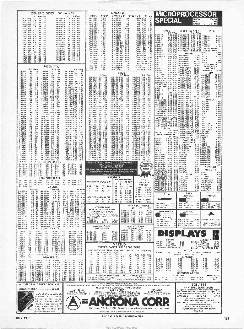
ZENER DIODES 500mw-5% V 1.9'Mop
952238 N5224B
2.7 2.8
.45
.45 .40 .40
N5225B 3.0 .46 .40 N5226B 3.3 .45 .40 N5227B 3.6 .45 .40 N62288 39 .45 .40 N5229B 4.3 .46 .40 N5230B 4.7 .45 .40 N52318 5.1 .45 .40 N52328 5.6 .45 .40 N52338 6.0 .45 .40 N52348 6.2 .45 .40 N52358 6.8 .45 .40 N52368 7.5 .45 .40 N62378 8.2 .45 .40 N52388 8.7 .45 .40 N5239B 9.1 .45 .40 N5240B 10 .45 .40 N5241B 11 .45 .40 N52428 12 .45 .40 N5243B 13 .45 .40 N5244B 14 .45 .40 952468 15 .45 .40
1-9 7400N .14 7401N .18 7402N .18 74039 .18
1 7404N .21 74059 .20
, 74069 .36 7407N .36
i 74089 .24 , 7409N .28
7410N .22 7411N .26 74129 .34 7413N .45 7414N .98 7416N .35
, 7417N .35 7418N .30 7420N .15 7421N .30 7422N .50 74239 .37 74259 .30 7426N .28 74279 .28
, 7428N .40 7430N .26 7432N .32 7433N .44 7437N .19 7438N .29 74399 .44 74409 .17 7441N .86 7442N .40 7443N .72 7444N .72 7445N .90 7446N .90 7447N .98 74489 .98 7450N .14 74519 .14 7453N .14 7454N .14 74599 .20 7460N .14
i 749009 .33 74H20N .33 749529 I 749019 .25 749219 .33 749539
749049 .33 749229 .33 749549 749059 .33 749309 .33 749559 749089 .40 749409 .36 74H60N 749109 .33 741.4509 .36 749719 74911N .33 749519 .36 749729
LOW POWER TTL 74LOON .24 74110N .24 741519 741029 .24 741209 .33 74L73N 741039 .39 741429 1.33 74L74N 741049 .33 74LS00
1-910up 1-910up 741S00N .36 .35 7415659 .39 .38 7415019 .44 .40 7410739 .58 .55 7415029 .36 .35 7415749 .56 .54 7415039 .45 .43 7415769 .65 .64 7415049 .44 .40 7415789 .92 .90 741_505N .45 .44 741_095N 2.082.00 7415089 .38 .37 74101079 .59 .58 7415099 .44 .40 74151099 .92 .86 74L0109 .36 .35 74151129 .58 .55
1741_511N .46 .42 74101139 .92 .85 7415,59 .68 .54 74101149 .92 .85 7415209 .44 .20 741512391.60 1.50 741.021N .58 .54 741513891.89 1.80 741-5229 .58 .54 741013992.00 1.80 7415279 .44 .40 741515191.68 1.50 741530N .39 .38 741_015391.80 1.79 7415329 .45 .44 741015791.55 1.54 7415389 .58 .53 741_015891.68 1.60 7415519 .39 .38 741516093.00 2.70 7415549 .58 .54 SCHOTTKY TTL
V 1.910up N52468 N6247B
16 17
.45
.45 .40 .40
952488 18 .45 .40 N52498 19 .45 .40 N52508 20 .45 .40 952518 22 .45 40 N5252B 24 .45 .40 N5253B 25 .45 .40 N52546 27 .45 .40 952558 28 .45 .40 952568 30 .45 .40 N52578 33 .45 .40 95258B 36 .45 .40 N5259B 39 .45 .40 N5260B 43 .45 .40 N52618 47 .45 .40 N5262B 51 .46 .40 N52638 56 .55 .50 N52648 60 .55 .50 N52658 62 .55 .50 N5266B 68 .55 .50 N5267B 75 .65 .50
7400N TTL
74500 74501 74502 74503 74$04 74505 74S08 74509 74510 74511 74515 74020 74021 74530
.44
.76
.60
.75
.55
.76
.80
.76
.55
.65
.76 .65 .76 .80
10up 1A 10up .13 7470N .40 .30 .16 7472N .40 .30 16 7473N .42 .38 .16 7474N .44 .40 .19 74789 .55 .50 .19 7476N .44 .40 .28 7480N .80 .72 .28 7481N 1.30 1.25 .21 74829 .98 .96 .21 7483N .82 .76 .19 7484N 1.80 1.70 .20 7485N 1.20 1.08 .32 7486N .44 .40 .42 7489N 2.20 2.10 .95 7490N .56 .51 .32 7491N .84 .76 .32 7492N .56 .50 .27 7493N .62 .56 .14 7494N .88 .80 .26 74959 .80 .72 .45 74969 .75 .68 .36 7497N 5.00 4.60 .23 74100N 1.10 1.00 .26 74104N 1.00 .90 .25 74105N 1.00 .90 .33 74107N .40 .36 .20 74109N .40 .36 .30 74110N 1.00 .90 .40 74111N 1.00 .90 .20 74116N 2.00 1.80 .27 74118N2.20 2.00 .40 74119N 4.00 3.60 .16 74121N .60 .54 .83 741229 .48 .43 .39 74123N .68 .62 .65 74125N .50 .45 .65 74126N .60 .45 .81 74128N .50 .45 .81 74132N .92 .85 .90 74136N .80 .72 .90 741419 1.70 1.50 .13 74145N 1.10 1.00 .13 74147N 1.90 1.70 .13 74148N 1.50 1.35 .13 74150N 1.52 1.40 .18 74151N1,02 .92 .13 HIGH SPEED TTL
74532 .80 74540 .65 74550 .76 74551 .80 74560 .80 74564 .80 74565 .80 74574 .90 74576 1.15 74578 1.16 74585 6.10 74586 2.50 745112 1.00
9300PC 51.00 9318PC 9301PC 1.20 9321PC 9304PC 1.50 9322PC 9306PC 6,90 9324PC 9308PC 2.50 9328PC 9309PC 1.60 9334PC 9310PC 1.50 9338PC 9311PC 2.30 9340PC 9312PC 1.20 9341PC 9314PC 1.30 9342PC 9316PC 1.50 9360PC
1-9 10up 741529 1.04 .94 74153N .85 .75 74154N 1.08 .94 7415591.02 .92 74156N 1.02 .92 74157N .90 .80 7415891.50 1.30 7416091.02 .92 74161N 1.10 1.00 74162N 1.40 1.30 74163N 1.00 .90 74164N 1.16 1.05 74165N 1.20 1.10 74166N 1.20 1.10 74167N 5.00 4.50 741709 2.00 1.80 74173N 1.66 1.50 74174N 1.00 .90 741759 .96 .90 74176N 1.08 1.00 74177N 1.08 1.00 74178N 1.42 1.30 74179N 1.80 1.70 74180N 1.12 1.02 74181N 300 2.70 74182N 1.00 .90 74184N 2.80 2.50 74186N 3.00 2.70 74188N 5.00 4.80 74190N 1.20 1.10 74191 N 1.20 1.10 74192N .98 .90 74193N .92 .88 74194N 1.36 1.23 74195N .75 .70 74196N 1.40 1.30 74197N 1.40 1.30 74198N 1.40 1.30 74199N 1.40 1.30 74200N 9.00 8.00 74221 N 1.36 1.25 74247N 2.40 2.20 742519 1.90 1.80 74278N 2.90 2.50 74279N .66 .60 742989 2.00 1.80
.36
.36
.36
.36
.36
.75
.75
.34
.43
.90
749739 .80 749749 .80 7411769 .75 74H102N .75 741410351 .90 7491069 .95
741909 1.62 741939 1.51 741959 1.62
H=TO-5 1M105H LM108H LM114H LM300H LM300N LM301AH LM301AM LM301AN LM302N LM302H LM304H LM305H LM305AH LM305N LM306N LM307H LM307M LM307N LM308H LM308AH LM308D LM308M LM309H LM309K LM310H LM310M LM311H
LINEAR IC's N=DIP M.MINI.DIP D=CER-DIP K=T0-3 3.90 LM311D .90 LM709CN .75 4.90 191311M 1.75 LM710CH .90 3.00 1M312H 1.75 LM710CN .90 1.20 1M3189 1.50 114711CH .90 1.20 LM318M 2.40 LM711C9 .90
.50 LM319N 3.40 1M715C9 3.50
.80 LM324N 1.90 LM715CD 4.60 1.10 1M3319 1.25 1M723CH .60 1.30 LM335K 2.40 LM723CN .65 1.40 191336K 2.40 LM725CH 1.50 1.20 LM337K 2.40 LM725CD 5.00
.85 1M3399 2.20 1M733CH 1.40 1.05 LM320-5K 2.90 LM733CD 3.50 1.00 LM320-57 2.50 LM733CN 1.30
.95 1M320.12K 2.90 LM741CH .40
.60 LM320.12T 2.50 LM741CD 1.25 1.50 LM340-5K 2.60 LM741CM .39 1.60 LM340-6K 2.60 LM747CH .75
.85 LM340.8K 2.60 1M747C9 .90 5.00 LM340-12K 2.60 LM748CM .55 2.25 LM340-15K 2.60 1N1777CH 2.15 1.00 1M340 -18K 2.60 191777CM 2.10 1.75 LM340-24K 2.60 LM3046CN .95 1.50 LM555CM .70 LM3054CN 1.50 1.50 LM556CM 1.30 SG4501T 2.40 1.80 LM667CM 1.70 SG4501N 2.40 1.20 LM709CH .75 LM5000K 7.50
1.9 10up 741_5161N 3.00 2.70 741S162N 3.06 2.80 74191639 3.00 2.70 74151709 5.80 5.30 74181749 2.20 2.00 74LS175N 2.40 2.20 74101819 3.69 3.68 74101909 2.85 2.701 74151919 2.85 2.70 74101939 2.50 2.40 74101949 2.25 2.20 74L5195AJ 2.40 2.20 741519644 2.76 2.50 74LS197Ai 2.20 2.10 741_S251AJ 2.08 1.90 74152534J2.42 2.20 741_52574J 1.89 1.80 74LS258A4 2.06 1.90
745113 1.50 745114 1.20 745133 .80 745138 2.20 745139 2.20 745140 .80 745151 2.20 745153 3.40 745157 2.40 745158 2.00 745160 3.90 745161 4.70 745172 6.00
9300 SERIES 2.30 9366PC 1.20 93100 1.30 93101 2.00 93L08 2.50 93109 2.95 93110 3.30 93L11 5.00 93112 4.10 93114 1.15 93116 1.75 93118
WAVEFORM GENERATOR KIT
EXAR XR205K $25.00
Here's e highly versatile lab instrument at a fraction of the cost of conventional unit. Kit includes 2 XR205 IC's, data & applications, PC
board (etched and drilled, ready for assembly) and
- detailed instructions.
745174 3.30 745175 2.90 745181 6.00 745189 4.40 745194 3.30 745195 3.30 745251 2.20 74525312.40 745257 2.40 745258 2.40 745260 1.20 745280 5.70 745289 4.00
1.75 93118 3.50 1.50 93L21 1.50 1.60 93122 1.80 3.20 93124 2.80 1.80 93128 3.70 2.80 - 93L34 4.00 4.20 93138 4.20 1.80 93140 6.50 1.70 93141 6.50 3.20 93160 3.00 3.50 93166 2.70
1-9 10up 40004E .15 .14 4000AF .28 .24 4000BE .19 .18 40014E .24 .20 4001BE .27 .24 40024E .24 .15 4002AF .34 .25 40028E .30 .18 4004AE4.00 3.80 40064E1.30 1.20 4006AF 1.50 1.30 40068E 1.35 1.25 4007AE .24 .23 4007AF .40 .35 4007BE .27 .28 40084E1.15 1.14 40084F 1.30 1.25 4009AE .50 .45 40098E .55 .50 40104E .50 .45 40108E .55 .60 40114E .24 .23 4012AE .24 .22 40124F .34 .32 40128E .29 .27 40134E .30 .28 4013AF .45 .43 4014AE 1.05 1.00 4014AF 1.30 1.15 40148E 1.10 7.05
CMOS 19 10up
4021BE 1.35 1.25 40224E1.05 1.00 40228E 1.10 1.05 40234E .24 .22 40238E .30 .28 4024AE .80 .70 4024AF .95 .85 40248E .85 .75 40254E .24 .20 4025AF .40 .35 4025BE .30 .28 40264E1.50 1.49 40274E .55 .50 4027BE .60 .55 4028AE .95 .90 40288E 1.00 .95 4029AE 1.20 1.10 4029BE 1.25 1.15 40304E .48 .40 4030AF .65 .60 40308E .55 .50 4033AE 2.00 1.90 40354E 1.20 1.10 40358E 1.25 1.15 40404E1.20 1.10 4040AF 1.50 1.40 40408E 1.30 1.20 40414E1.25 1.00 4042AE1.00 .85 40434E .95 .90
4015AE 1.15 1.10 4044AE .96 .90 4015 B E 1.20 1.15 4046 A E 3.10 3.05 4016AE .55 .49 4047AE 2.00 1.90 4016BE .60 .54 4048AE 1.43 1.40 4017AE 1.05 1.00 40494E .58 .53 40178E 1.10 1.05 40498E .63 .58 40184E 1.24 1.23 4050AE .58 .53 4018BE 1.30 128 4051AE 1.49 1.48 40194E .54 .49 4052AE 1.40 1.39 40194F .70 .68 40528E 1.45 1.44 40198E .60 .55 40534E 1.40 1.39 40204E 1.45 1.35 40638E 1.45 1.44 4021 AE 1.30 1.20 4055AE 1.95 1.94
1-9 10up 40564.E 1.99 1.98 40568E 2.04 2.03 406CAE 1.70 1.68 4063AE2.50 2.49 40664E .90 .89 4068AE .44 .43 4068BE .53 .48 4069AE .44 .43 4069BE .53 .48 4070BE .60 .59 407IAE .45 .44 40724E .34 .33 40734E .40 .39 4075AE .40 .39 4075AE 1.24 1.22 40774E .40 .39 4077BE .44 .43 4078AE .40 .39 4078BE .44 .43 4061BE 40 .39 4082AE .39 .38 40828E .43 .42 4093AE 1.65 1.64 409613E 1.95 1.94 40984E1.30 129 40994E2.90 2.89 45324E1.50 1.49 45078E .60 .55 45088E 2.20 2.19 46104E1.40 1.39 49108E 1.45 1.44 4911 BE 2.00 1.99 4612BE 1.30 1.29 46146E5.00 4.99 4515AE 5.00 4.99 4516AE 1.75 1.74 45184E1.213 .98 4520AE 1.28 .98 45284E2.20 2.19 45288E 2.25 2.24 4585AE 2.06 1.95 49014E .32 .31 49114E .32 .31
INDUSTRIAL QUALITY COMPONENTS What is more important?
QUALITY or PRICE? We have decided to offer only the highest quality
component'. When quality counts, you car count on Ancrona
IC SOCKETS '1
SOLDER -TIN DIP - T WIRE -WRAP GOLD DIP 1.24 25100 SOCKETS
8 .11 .19.17 TEFLON 14 .15 .22.20
3 PIN .55 EA 16 .28 .25 .23 4 PIN .65 EA 18 .34 .31 28
22 .37 .36 . 6 PIN .90 EA 24 .47 .43 ,40 8 PIN 1.10 EA
SOLDER - GOLD DIP 28 .88 .80.70 10 PIN 1.40 EA
14 .34 .31 .28 36 1.09 .98 .89 PLASTIC TOG 16 .37 .34 .31 40 1.24 1.12 .90 8 PIN .40 EA
PIN 14 16
1.24 25 100 .45 .41 .37 .64 .49 .44
INTERSIL 8038 PRECISION WAVEFORM 1N4001
GENERATOR & VCO 1N4002 For simultaneous sine. square 1N4003 and triangular waveforms <001 194004 Ha to 1MH0. ' 1N4005
Part No. 1-9 Li:. 1N4006 80381181.1 3.90 3.70 194007
HYBRID POWER AMPLIFIERS
SI -1010G SI -10200 51.10300 SI.1050E SI -10500
1619 20W 30W 5001 50W
MICROPROCESSOR" SPECIAL ., BDBDA
P1101A P1101A1 P1103 P2101 P2101.1 P2101-2 P2102 P2102.1 P2102.2 P2102A P2102A.2 P21024.4 P2111 P2111.1 P2111.2 P2112 P2112.2 P2401 P2405 26026 2602.18 2602.213
$34.90 '
8080 27.50 r 'I AM2901 31.50.'
I RAM'S SHIFT REGISTER 75107
1-9 10up 1.9 10up 2.20 2.10 AM2841PC 8.25 6.55 752089 2.70 3.50 3.30 AM2847PC 5.00 4.60 2.90 2.70 AM2855PC 7.15 5.75 752309 2.50 5.00 4.80 AM2856PC 7.15 5.75 75450N 1.00 25 5.10 4.85 AM2857PC 7.15 5.75 7545192N 1.00 6.20 4.90 AM2896PC 5.00 4.50 75453N 1.00 2.48 2.30 AM3341PC 8.25 6.50 2.90 2.65 AM3347PC 6.40 5.10 7520 SERIES 2.70 2.60 AM4025D 73.00 58.40 SENSE AMPS 200 2.70 AMDMSI 75209 4.00
75219 2.00 4.25 1.75 2.00
3A02.80 AM25010C 9.00 2.95 2.75 AM2502PC 9.50 7522N 570 6.50 A M2503PC 9.50 7523N
5.60 7524N 5.70 AM2504PC 16.06 7525N 4.50 AM2505PC 16.00 4.70 AM2506PC 8.80 TWO-PHASE
1 0 4.80 AM25L02PC 10.70
MOS CLOCK 99.80
A M25103PC 10891785089 0.70 DIiIVER l
851:9600:-8.00 A M25L04PC 16.05
MH0026CN 5.50 2.30 AM25L05PC 15.00 MM
2-8-02,65 AM25L06PC 8.80 MM404H 12.00
@@@@@@
2.702.60 MM405H 23.0011 7.48 2.30 AM25505PC 19.00 MM406M ' 6.50 I11
AN125SO7PG 3.78 IM7662CPE IM7552.1CPE ..80 2.65 MM407H 6.50 IM7557-2CPE2.702.60 AM25508PC 3.51 MM451H 11.40 TM54035NL 2.48 2.30 AM25509PC 5.40 MM454F 18.00 TM64034912.702.60 AM25010PC 4.60 MM500H 2.00 P8101 5.004.80 AM25518PC 5.40 MM506H 3.201 P8101.2 5.204.90 AM251507PC 2.79 MM5079 3.20 P8102 2.482.30 AM251508PC 2.76 MM5509 5.90 P8102.2 2.70 2.60 AM25LS09PC 3.49 MM551H 5.60 P8111 5.70 5.50 AM251S14PC 31.00 MM5559 5.60 P8111.2 5.90 5.70 AM25LS15PC 2.14 MOS-LSI AM9101APC 3.50 3.30 AM2515138PC 2.12 AM9101BPC 3.90 3.80 AM2515139PC 2.12 1402AN AM9101CPC 5.50 5.30 AM25LS151PC 2.14 140349 AM9101DPC 7.80 7.00 AM2515153PC 2.14 1403AN AM9102PC 2.702.60 AM251-5157PC 1.54 1404AH 49191024PC 3.00 2.80 AM25LS158PC 1.54 1404AN AN9102BPC 4.90 4.50 AM251S160PC 2.94 14o5A A59102CPC 6.20 6.00 AM2515161PC 2.94 1406 AIVL910213PC 7.80 7.00 AM25LS162PC 2.94 1407 LOW POWER RAM'S AN125L5163PC 2.94 1506 AM91102PC 2.75 2.70 AM2515174PC 3.10 1507 61911026003.90 3.70 AM2515175PC 2.76 1602 6N911028005.00 4.40 AM2515181PC 8.00 TMS3114J AM91L02CPC7.006.00 AM25LS190PC 3.87 TMS3120JC
PROMS AM25L5191PC 3.87 TMS3120NC 1-9 10up
1'9
TM53133NC AM26LS195APC 1.77 3341ADC AM25LS251PC 2.66 3341APC ii 1702A 15.95 14.50 e
SHIFT REGISTER AM25L5253PC 2.66 3347DC 19 10upAM25L5257PC 2.00 3347PC P2401 23.0019.00 4102
P2405 10.86 9.90 COMPUTER 7552 P2505K 3.70 3.30 INTERFACE 7552.1 2512K 4.30 4.05 DM88209 2.40 7552.2 2521V 2.50 2.20 DM8820AN 6.90 MM4055D 2524V 2.40 2.20 DM88309 2.40 M9140569 2525V 3.60 3.50 DM88319 5.20 MM4057D 2533V 10.50 8.50 DM8832N 6.00 MM50259 AM2802PC 4.40 3.50 N87268 4.40 MM5026N AM2803PC 4.40 3.50 9600PC 1.30 MM5027N AM2804PC 4.40 3.50 9601PC 1.20 MM5055N
M2805HC 3.70 3.30 9602PC 1.95 AM2806Ff' 7.00 5.60 9614PC 2.30 AM2807PC 2.40 2.20 9615PC 2.40 AM2808PC 3.60 3.50 9616PC 5.00 AM2809PC 2.50 2.20 9617PC 3.50 AM28100C 10.00 8.00 9620PC 4.00 AM2812ADC24.0019.20 9621PC 4.00 AM2812DC21.00 16.80 75107 AM281340C24.0019.20 75107BN AM281300 21.00 16.80 75108BN AM2814DC12.45 9.15 75109N AM2825PC 18.75 15.05 75110N AM282613C22.5018.00 751159 AM2827PC 18.75 15.00 75138N AM2833PC 10.85 8.70 75150N AM2841 APC 10.50=.40 751549
.125" dla. LEDs .160".dia.
209 1 -AMP RECTIFIERS 209
1 209 10 100 1000 0.00 7.00 60.00 1.10 8.00 70.00 1.20 9.00 80.00 1.30 10.00 90.00 1.40 11.00 100.00 1.50 12.00 110.00 1.60 13.00 120.00
HIGH VOLTAGE TRANSISTORS
BU204 3A 1300V 54.14 $6.40 BU205 3A 1500V 4.95
9.90 8U206 3A 1700V 5.94 18.70 8U207 6A 1300V 5.85 24.90 8U208 6A 1500V 6.93 24.90 BU209 6A 1700V 8.64
MATSUO DIPPED TANTALUM CAPACITORS
MFD WVDC 1-9 10up 50up MFD W'JDC 1.9 10up 50up 1
.1 35 5.30 $.25 5.20 .15 35 .30 .25 .20 4.7 35 540 5.32 5.26 .22 35 .30 .25 .20 6.8 35 .40 .32 .26 .33 35 .30 .25 .20 10.0 16 .38 .30 .24 .47 35 .30 .25 .20 10.0 26 .39 :31 .25 68 35 .30 .25 .20 10.0 35 .40 .32 .26 1.0 35 .30 .25 .20 15.0 35 .95 .64 .56 1.5 35 .35 .28 .23 22.0 16 .40 .32 .26 2.2 20 .30 .25 .20 33.0 20 .95 .64 .56 2.2 36 .35 .28 .23 47.0 20 1.40 1.05 .90 3.3 35 .38 .30 .24 68.0 16 1.40 1.05 .90
CARBON FILM RESISTORS. _. 'A WATT 5% 150 STANDARD VALUES .. . $1.69 per 100 10 Ohm to 10 megohms ... .Only In multiples of 100 per value
Prices effective through July 31. 1976 Minimum order 610.00. Add 51.00 to cover postage and handling. California residents add 6% sales tea.
PLEASE VISIT OUR ELECTRONIC STORES CALIFORNIA CANADA
11080 Jefferson Blvd. 1300 E. Edinger Ave. 5656 Fraser Street Culver City, CA 90230 Santa Asa, CA 92705 Vancouver, B.C. V 5W 2Z4
SEND CHECK OR MONEY ORDER TO:
ARIZONA 4518 East Broadway
Tucson, Arizona 85711
t. jr* .J I, \ o'er
Mail order: P.O, Box 2208P, Culver City, CA 90230. Phone 01401:12131641.4064 Prices may vary at ovar.theiounter locations.
RED YELLOW GREEN
5.25 .35 .35
3.80 4.00 3.80 4.50 2.90 4.00 8.40 8.40 3.00 3.00
33.00 9.40 7.00 6.00 7.50 8.00 7.00 5.80 4.60 4.95 4.95 5.40 5.50
12.00 9.70
13.00 20.00 20.00 20.00 5.50
MM5056N 5.50 MM5057N 5.50 MM5058N 5.50'
BIPOLAR MEMORY I
03101 6.50 P3101 4.90
2.60 C3101A 7.30 2.30 P3101A 5.80 2.20 IM5501CDE 7.30 2.20 IM5501CPE 5.80 2.25 MM55600 7.30, 2.95 MM5560N 5.80I 3.10 DM8599N 6.80 4.10 93403PC 5.80!
.200" dia.
216 RED 216 YELLOW 216 GREEN
5.25 220 RED 5.25 .30 220 YELLOW .30 .30 220 GREEN 30
LOW PROFILE .200"dia. "^"'
" .200" dia. 226 RED 0.25 5053 RED 5.35 226 YELLOW .30 5053 YELLOW .40 226 GREEN .30 5053 GREEN .40, 216 - MV5024 226 ORANGE .30 5053 ORANGE .40 5053 = MV5053
MV50 RED 5.30
DISPLAYS 0.6" IN. LARGE 1"
EP62R RED 3.00 EP1000 RED 5.50 EP62G GREEN 3.60 3 pcs EP1000 15.00 EP67Y YELLOW 3.60 5 pes EP1000 22.50 Data sheet for EP62 5.15 Data sheet for EP1000 0.25
XCITON X41172 RED 2.00 64952 GREEN 2.00
XAN82 YELLOW 2.00 LITRONIX
0180 RED 6.00 DL44 RED 6.00 DL8I RED 6.00 DL402 RED 4.00 DLIO RED 6.00 DL701 RED 3.40 01106 RED 4.00 D1704 RED 2.25 13L101 RED 4.90 D1707 RED 2.35 DL57 RED 9.90 01747 RED 2.50 DL61 RED 12.00 DL33 RED 4.00
OPTOISOLATORS LITRONIX MONSANTO
IL1 51.30 11-16 51.80 11074 $1.00 MCT2 1112 1.40 1174 1.35 11074 3.40 .60
SGS-ATES RHYTHM GENERATORS
Designed specifically for electronic organs and other musical instrument designs. De- tailed applications book, only.... $1.95. M252BIAA 16 PIN DIP 515.00
15 programmable rhythms which cannot be superimposed
M253BIAA 24 PIN DIP $19.50 I, 12 programmable rhythms
which can be superimposed 16.page data sheet for both devices
only $.90
JULY 1976 CIRCLE N0. 8 ON FREE INFORMATION CARD
121
AmericanRadioHistory.Com

VIDEO CAMERA KIT VERAS -8 MICROPROCESSOR KIT MUSICAL INSTRUMENTS
A UNIQUE ALL SOLID STATE CAMERA KIT FEATURING A ... 100 x 100 BIT
SELF SCANNING CHARGED COUPLED DEVICE
SCHEMATIC FOR COMPUTER
I$ INTERFACE SUPPLIED
INCLUDES THE FOLLOWING UNIOUE FEATURES... FOUND IN FAR MORE EXPENSIVE CAMERAS IF AVAILABLE
LOW VOLTAGE SUPPLY TOR BATTERIESI 5 AND , 15 VOLTS
SENSiTlvt TO INFRA S
AS WELL VISIBLE LIGHT
+ Y E USED FOR SURVEILLANCE WITH AN IR LoGHT SOURCE
EXCELLENT FOR STANDARD SURVEILLANCE WORK BECAUSE OF ITS LIGHT WE IGNE ANO SMALL SIZE
ALL COMPONENTS MOUNTED ON TWO PARALLEL 3".5" SiNGLE SIDED aOAROS.TOTAL
WE IGHT UNDER } LBS
Y BE VIREO BY PERSON WITH 501.1E TECHNICAL EXPERIENCE IN l6 HRS.
SUPER UNBELIEVABLE
MAY BE USED WITH AMATEUR RADIO FOR VIDEO
USED FOR CHARAC. TER RECOGNITION FOR COMPUTERS WITH EXTERNAL CIRCUITS
MAY BE USED IN A VACUUM, UN. DER WATER, HIGH ALTITUDE. AND IN MAGNETIC ENVIRONMENT BECAUSE THERE IS NO HIGH
' VOLTAGE OR MAGNETIC DEFLECTION
WE SUPPLY ALL SEMICONDUCTORS. BOARDS. DATA SHEETS, DIAGRAMS. RESISTORS
- AND CAPACITORS
SORRY, WE DO NOT SUPPLY THE CASE. BATTERIES
SUPPLY
ONLY 1225 °° (507 UPON THEUSEI
THE LENS DI DEPENDS
IS ONE OF THE MOST ADVANCED MCU SYSTEMS ON THE MARKET TODAY FOR ONLY
$159.00
10 II Ill minimum Upo response 1 MId2 13 22 MO Moe be ,
- The VERASB K t Res mrnon acew I og am up oIR
pros by,
and vid 0o debw IIaH n rw n hs
TN,: Mice chop WO m the lain, 4 .¡yammer supp
2 Two I/O pm Is on me CPU chwWu o ROM, maxim 32 Unluec,u,ul hoes 64 bytes of last RAM sesam ,d bust! ,moo the CPU chop.
power uI bum into the CPU chop. 5 A programmable mite ml mrvuilt moo Ilse ROM chop. 6 60%of the,nptuebom are I byte. 3 TTLI/oxmnwabibl0. 8 Consumes le, than 300nm of power Pw xnidK
local ,meeupl with mourn,. adieu ,senor. EFpMable to WK byres 121022.111 al memory. 20 mil loop end RS 232 included.
we supply: I ao CPU
. 3851 A FAIRiBUG n,w wnh an rl/Ow po9oa oIOJSM.rY oiulte,memo, Y. rxl,rynl Inmhnal. 3853 SIa ,c memory moeLne
8. 21021 posw Emus wiesa,wwnwe.rc semi, instrmown manuals. p,agra v n. 4K MEMORY KIT 5159 DO
11 81h11 Ixdxexiiumal not I On (ward decoding fro any Imo O«Mo n
3) e+biol 41 OK WILL of 2102.1 static RAM1. 51 No on U,xpd reVUNponto cause,seal l.robllms. 61 Only 5 volt sup. needed.
The memory mod. like n gold p d edge 1.156 sls,crnll This lepou,Imaim, 111e wstenr completely sptacaable to ..re InJes. wirierinblems. rind lu,d ,nony wolf alw allow plug -In cgmboloy lot o,, odsw cards when they become e.elal4e
EXPANDER BOARD
This boar) m I6 StiMiNt.+ w bid Bring 11IMn rlod Pow<'poY
cape t board.ry mod we on This system can be expanded son 11 64
1or exc., nÁ of
memo, IW a miry expander cards onto Om one with the! nU pin
EXPANDER KIT WITH ONE EDGE CONNECTOR S59.00 ..
To the I.nI 01av Ln W,Lir. mix, a me only arm on CO maha.IdenVPelfah easy cap,mx,0 to loll memory capeloolity. Ee.n4 Pm Connexion 52.50 Ea.
INTEL 8080 CPU S29.50 2518 -HEX 32 BIT SR 56.00 8008 8 BIT MICRO PROCESSING CHIP
'' (with Data Book) $19.00 2102.1 1024 BT RAM S 2.60 5202A UV PROM S12.55 MM5203 UV PROM 512.50 1702A UV PROM $12.50 52044K PROM
- 024.95
MAN IATURE MULTI -TURN TRIM POTS 100. 500, 5K, 10K, 25K, 50K, 100K. 200K S.75 each . . .... 3/02.00 MULTI -TURN TRIM POTS Similar to Bourns
I 3010 style 3/16"x5/8"x1.1/4", 50. 100, 1 K. 10K. 50K ohms 51.50 ea.. .. 3 04.00
o, LIGHTlSCfÍVATED SCR's TO -18. 200V lA S 1.75
, PRINTED CIRCUIT BOARD "r
4.1/2i 06.1/2" SINGLE SIDED EPDXY BOARD 1/16" thick, unetched
VECTOR BOARD 1" SPACING ' 4.5" x 6" SHEET 01.50
4 WATT IR LASER DIODE r7.55
2N 5460 P FET S .45 2N 5457 N FET S .45 2N 4891 UJT S .45 TIS43UJT S .35 ER 900 TRIGGER DIODES 4/$1.00 256028 PROG. UJT S .65
VERIPAX PC BOARD This board is a 1/16" single sided Paper epoxy board. 45"x6%" DRILLED and ETCHED which will hold up to 21 single 14 pin IC's or 8, 16. or LSI DIP IC's with busses for power supply cQnn$cmr. 55.25
MV 5691 YELLOW -GREEN BIPOLAR LED SI 25
MT.2 PHOTO TRANS S 60 RED, YELLOW, GREEN OR
AMBER LARGE LED's ... ea. 5 .20 14 PIN DIP SOCKETS S 35 16 PIN DIP SOCKETS 5 35 MOLEX PINS 100/51.00
1000/58.00 8215 MINI DIP SOCKETS $ 30
10 WATT ZENERS 3.9. 4.7, 18 OR 22V ..............5 .60
1 WATT ZENERS 4.7, 5.6, 10, 12, 15. 180R22V ea 5 25
na
Silicon Power Rectifiers
n. PRV 1A _3A.__12A SOA 125A 100 _06 .14 _30 .80 _3.70 200 .07 .20 .35 115 400 09_ _ .25 .50 1 40 6.50
o 600 .11.30 .70 1.50--8.50 ra 800 .15 35 90 _ 2.30 10.50
10_0_0_ .20 .45 1.10_ 2,71_2 REGULATED MODULAR
POWER SUPPLIES e - 15 VDC AT 100ma
115VAC INPUT .... ..... 027.95 5VDC AT 1A. 115VAC INPUT ... 524.95 12VDC AT .54 _ _ _ 524.95 IÑ_ 41_41331:5-1H) .. 15/51.01
SILICON SOLAR CELLS 2'''h" diameter
.5V at 500 ma $5.00 ea., 61S27.50
Toros: FOB Cambridge, Mass. Send Check or Money Order. .
Include Postage, Minimum Order $5.00, CPD'S $20.00
TRANSISTOR SPECIALS 2N3585 NPN Si TO -66 S .95 2N3772 NPN Si TO.3 S 1.60 254908 PNP Si TO.3 . . . . . . . S 1.00 256055 NPN Si TO.3 Darlington 5 1.30 255086 PNP Si TO.92 4/5 1.00 254898 PNP TO -66 S .60 25404 PNP GE TO.5 5/S 1.00 2N3919 NPN Si TO -3 RF 5 1.50 MPSA 13 NPN Si TO 92 3/S 1.00 2N3767 NPN Si T066 S .70 2N2222 NPN SI TO.18 51$ 1.00 2N3055 NPN Si TO.3 S .80 2N3904 NPN Si TO.92 5/S 1.00 2N3906 PNP Si TO.92 . . . . . 5/S 1.00 2N5296 NPN Si TO.220 $ .50 2N6109 PNP Si TO -220 S .55 253866 NPN Si TO -5 RF S .75 253638 PNP Si TO.S 5/0 1.00 256517 NPN TO.92 Si 3/5 1.00
TANTULUM CAPACITORS .22UF 35V 5/51.00 6.BUF 35V 3/51.00 .47UF 35V 5/S1 .00 33UF 25V S .40 .68UF 35V 5/51.00 300F 6V 5/51.00 (UF 35V 5/01.00 150UF 20V S .50 4.7UF 35V 4/$1.00 CT7001 ALARM CLOCK CHÍP _55_75
NATIONAL MOS DEVICES MM1402-3.20 MM5057-4.00 MM1403-3.20 MM5058 4.95 MM1404-2.50 MM5060 4.95 MM5013-7.75 MM5061-4.30 MM5016-3.50 MM5555-6.25 MM5017-4.75 MM5556 6.25 MM5055-4.00 MM5210-1.95 MM5056-4.00 M_M5260-2.95
TTL IC SERIES 74 L00- .25 7442- .50 74126- .90 7400- .16 7445- .80 74150-1.00 7401- .16 7446-' .90 74151- .80 7402- .16 7447- .87 74153- .79 7403- .20 7448- .80 74154-1.05 7404- .20 7472- .35 74155-1.00
74157- .75 7405- .22 7406- .35 7407- .33 7408- .22 7409- .25 7410- .16 7411- .25 7412- .30 7413- .60 7414- .80 7416- .33
7473- .40 7474- .35 7475- .50 7476- .35 7480- .48 7483- .80 7485- .95 7486- .45 7489-2 00 7490- .52
7417- .33 7491- .79 7492- .55 7420- .16
7426- .35 7493- .55
7427- .28 7494- 80 7430- .16 7495- 80 7432- .30 7496- .73
7437- .29 74107- .34
7438- .29 74121- .50
7440-74123- .70 .18 7441- .82
74125- .70
74161-1.00 74164- 1.05 74165- 1.05 74173-1.35 74174- 1.00 74175- .95 74177-1.00 74180-1.00 74181-2.10 74190-1.15 74191-1.10 74192- .75 74193- .95 74194-1.25 74195- .74 74196-1.10 74283-1.50 75324-1.75 75491- .60 75492- .60
MINIATURE DIP SWITCHES CTS.206.4 Four SPST switches
in one minidip package. . . 01.80 CTS -206-5 Eight SPST switches in a 16
pin DIP package. . . . . $2.75
AT -5.1013-30K ser./par., par./ser., uni versal UART. . . . . . . 58.50
ALCU MINIATURE TOGGLE SWITCHES MTA 106 SPOT 01 20 MTA 206 DPDT $1.70
CIMOS (DIODE CLAMPED) 74CO2- .30 4016- .50 4035-1.25 74C01- .30 401 /- 1.10 4042- .75 4001- .24 4018- 1.20 4046- 2.20 4002- .24 4019- .50 4047-2.20 4006-1.20 4007- .30 4009- .50 4010- .50 4011- .25 4012- .25 4013- .35 4015-1.10
LED READOUTS FND 500.5" C.C. 51 75 HP 7740.3" C.C. 01 40 MAN 4.25" C.C. $1.20 MAN -7..3" C.A 51.25 DL747-.6" C.A S1 95 NS 33.3 dig. array S1 35
Full Wave Bridges PRV 2A 6A 257+
200 .95 1.25 2.00 400 1.15 1.50 3.00 600 1.35 1.75 4.00 CD 116LINEAR 256 %TEIFT SE LF SCANNING CHARGED COUPLED DEVISE 0125.00
SANKEN AUDIO POWER AMPS Si 1010 G10 WATTS 56.90 Si 1020 0 20 WATTS 513.95 Si 1050 0 50 WATTS 524.95
LINEAR CIRCUITS LM 309K 5V IA REGULATOR ... 51.00 723 - 40 s 40 V V REGULATOR ... 5 .54 301/748 -Hi Per. Op. Amp S .35 320T 5, 12, 15, OR 24V
NEGATIVE REG. 51,35 741A or 741C OP AMP. S 35 710 COMPARATOR 0 32 307 OP AMP S 25 CA 3047 Hi Pel. Op. Amp... . S .95 340T 5, 6, 8, 12, 15, 18, 24 V POS
REG. TO.220 51.20 101 OPER. AMP. HI PERFORM S .75 LM 308 Oper. Amp., Low Power 01.05 747 -DUAL 741 S .65 556 -DUAL TIMER S .95 537 - PRECISION OP. AMP 01.70 540.70W POWER DRIVE 52.75 LM 3900 - QUAD OP. AMP 5 49 LM 324 - QUAD 741 51.50 560 - PHASE LOCK LOOP 52.00 561 - PHASE LOCK LOOP 0200 565 - PHASE LOCK LOOP 51 50 566 FUNCTION GEN Sl 65 567 - TONE DECODER $1.75 LM 1310N FM STEREO DEMOD. 52.75 8038 IC VOLTAGE CONT. OSC. 53.90 LM 370 - AGC SOUELCH AMP. 51.15 555-2Ps-2 HR. TIMER S 53 553 QUAD TIMER 52 50 FCD 810 OPTO -ISOLATOR S 80 1458 DUAL OP AMP. 5 .55 LM 380 - 2W AUDIO AMP. 5 95 LM 377 - 2W Stereo Audio Amp. 02.50 LM 381 - STEREO PREAMP. $1.25 LM 382 - DUAL AUDIO PREAMP 51.25 LM 311 - HI PER. COMPARATOR 5 .95 LM 319 - Dual Hi Speed Comp. . 51.10 LM 339 - QUAD COMPARATOR 01.40
TRIACS' SCR'S ..
PRV lA lOA 25A _1.SA 6A 2S 100 _.40 .70 1,30 .40_ .50 1.20 20o-_ .70 1.10 1,75 _ .60 .70 1.60 400 1 .10 1.60 2.60 100 1.20 2.20 600 1 .70 2.30 3.60 1.10 320
Send 254 For our catalog seat wring Transistors and Rectifiers
145 Hampshire St.. Cambridge, Mass.
4022-1.00 4049- .50 4023- .25 4050- .50 4024- .85 4055- 1.95 4025- .25 4066- 1.10 d 4027- .55 4071- .25 4028- .95 4077- .25 4029-1.25 4081- .25 4030- .95 4076- 1.20
Ir
,OQ0I ID STATE SALES- B
=, OF OUR ORDERS THE P.O. BOX 74A DAY WE RECEIVE THEM SOMERVILLE, MASS. 02143 TEL.,(617) 547.4005
UP TO 60% DISCOUNT. Name brand instruments catalog. Freeport Music, 114 N. Mahan St.. W. Babylon, N.Y. 11704.
WHOLESALE! Professional Guitars. PA Systems, Altec Speakers. 240W RMS Amplifiers. Free Catalog. Carvin. Escondido. Calif. 92028.
BUSINESS OPPORTUNITIES
I MADE $40.000.00 Year by Mailorderl Helped others make money! Free Proof. Torrey, Box 318 -NN. Ypsilanti. Michigan 48197.
FREE CATALOGS. Repair air conditioning. refrigeration. Tools. supplies. full instructions. Doolin. 2016 Canton. Dallas. Texas 75201.
MAILOROER MILLIONAIRE helps beginners make $500 weekly. Free report reveals secret plan! Executive (1K7). 333 North Michigan, Chicago 60601.
$178 WEEKLY. Work one hour daily. Completely Guaran- teed. Free. FAS. Box 13703-R. San Antonio, Texas 78213.
FREE SECRET BOOK "2042 UNIQUE, Proven Enterprises" Fabulous "Little Knowns". Work home! Haylings-B, Carls- bad, Calif. 92008.
r-vSTART YOUR OWN ....owl -- Electronics Mini -Shack!
CB BUYERS ¡WI BE A DEALER SELL ALL NAME BRANDS Royce, E F Johnson SSE, A/S. Pace, Handle ¢', Turner. Asiatic. Kris Pal. Regency. Hustler Channel Master. Pioneer
BRUSH me your FREE distributor/dealer Electronic Mini -1 (Shack Business Plan , (
(AddrNameess
(City S1 Zip I (CAMBRIDGE ELECTRONIC PRODUCTS, Depl. pasa 1
126 Downtl St. Kingston, NY 12401 914/331-82261 I J PIANO TUNING LEARNED QUICKLY AT HOME! Musical knowledge unnecessary. Free Information. Empire School, Box 450327, Miami 33145. GET RICH with Secret Law that smashes debts and brings you $500 to $5 Million cash, Free report! Credit 4K7. 333 North Michigan, Chicago 60601.
HOW TO MAKE $2.000 WEEKLY at home using other peo- ple's money. Guaranteed. Free details. Richlieu Box 25277, Dept. F7. Houston. Texas 77005.
HIGHLY PROFITABLE ONE-MAN
ELECTRONIC FACTORY Investment unnecessary, knowledge not required, sales handled by professionals. Postcard brings facts about this unusual opportunity. Write today! Barta-DG, Box 248, Walnut Creek, CA 94597,
FREE DETAILS on how to borrow S300-53.000 entirely by mail. Write Postal Finance. Dept. 613-07. 6018 Maple. Omaha. Nebraska 67104.
DO-IT-YOURSELF
TV PROBLEMS? Send symptoms / copy schematic / sell addressed -stamped envelope with $3.00. Troubleshooter. Box 4553 -PE, Downey. Calif, 90241.
MODULAR TELEPHONES now available. Sets and com- ponents. compatible with Western Electric concept. Cata- log 50 cents. Box 1654W. Costa Mesa, California 92626.
TREASURE FINDERS
TREASURE FINDER locates buried gold, silver, coins, treasures. 6 powerful models. Instant financing available. Write or call for free catalog. Phone (713) 682-2728 day or night. Dealer inquiries invited. Relco. Dept. AA20. Box 10839, Houston, Texas 77018
DISCOVER true treasure hunting with world-famous deep - detecting mineral/metal detectors from White's! Locate gold. silver, rings, coins, artifacts and more! Sold. serviced, warehoused world wide. Priced from $79.50. Free Catalog! While's Electronics, Dept. PD6U. 1011 Pleasant Valley Rd., Sweet Home. OR 97386.
122 CIRCLE NO, 56 $9 FREE INFORMATION CARD
POPULAR ELECTRONICS
AmericanRadioHistory.Com

PRO. SPORTS ACTION FILMS
CALIFORNIA companies hiring Engineers and Techni- cians. Current openings bulletin $3. Dynamics, Box 1867- K, Covina, Calif. 91722.
Popular Electronics
JULY 1916
ADVERTISERS INDEX
READER
SERVICE NO. ADVERTISER
PAGE
NUMBER
11 A P Products 16
1 Ace Electronics 118
2 Adva Electronics 116
3 Allison Automotive Company 59
Alpha Electronics 103
6 Altaj Electronics 110
66 Altaj Electronics I I I
7 Ancrona Corp 120
8 Ancrona Corp 121
9 Antenna Specialists Co 83
10 Aries Inc 112
12 B & Product of Dynascan 31
Babylon Electronics 119
13 Browning Labs 34
CREI Capitol Radio Engineering Institute 88 89. 90, 91
15 Challenge Electronics 102
Cleveland Institute of Electronics 52 53, 54. 55
14 Cobra. Product of Dynascan SECOND COVER
16 Continental Specialties Corporation 60
17 Crown 14
65 Delta Electronics Co 110
18 Delta Products. Inc 56
19 Digi ,.ey Corporation 112
20 Digikit Enterprises. Inc 120
64 Dynaco 95
21 EICO 102
22 Edlie Electronics Cc 123
23 Edmund Scientific Co 106
24 Edmund Scientific Co 124
25 Electronics Technical Institute 67
26 Grantham School of Electronics 95
21 Hal Communications Corp 101
28 Handic USA Inc 28
5 Heath Company 33
IMS Associates Inc 78 92
29 Illinois Audio 105
30 International Electronics Unlimited 113
31 James 114, 115
33 Johnson Co.. E.F. 13
32 Labtronics Inc 102
38 McIntosh Laboratory Inc 93
MITS .8 9 10 II 35 Mallory Distributor Products Co 25
36 Martin Research 87
31 Motorola 15
NRI Schools 18 19, 20 21
67 National Camera Supply 93
National Technical Schools 70 71. 72, 73
39 New -Tone 119
40 Non -Linear Systems 101
63 Non -Linear Systems 103
41 Olson Electronics 116
42 Pathcom Inc 5
43 Pickering & Co THIRD COVER
44 Poly Paks 109
45 Polymorphic Systems 93 Processor Technology .100
46 Quest Electronics 119
47 Radio Shack 2
48 Royce Electronics 7
49 SAE. Inc 6
50 SBE. Inc 17
51 S.D. Sales Co Ill 52 Sansui Electronics Corporation 23
53 Scelbi Computer Consulting. The 105
54 Sencore 84
55 Shure Brothers Inc I
56 Solid State Sales 122
57 Southwest Technical Products Corporation 85 Sphere 59
59 Stereo Discounters 101
TEAC Corporation 29
60 Tenna Corporation 69
61 Tri-Star Corporation 103
62 U.S. Pioneer Electronics 26 27
4 United Audio Products. Inc FOURTH COVER
CLASSIFIED ADVERTISING ..106. 110. 112, 113. 116, 118, 120, 122. 123
BONANZA:
ONLY
HIGHEST QUALITY
PRODUCTS . ,
(DP017) COPPER CLAD BOARDS!
Copper on ore side, 1/16" thick. Ex-
cellent quality for either production or experimental work. 8) 4"xl6Va" 990 ea. 3/$2.69 D) 8"xl6Vs" $1.19 ea. 3/$2.99 E) 63/e"x171k" $1.19 ea. 31$2.99
JUST ARRIVED
Copper on both sides. 1/16" thick. Size 12"x18" (DP018) $1.99 ea. 3/$4.99
(DP134) 8 ROTARY SWITCHES
Some multiple gang. $1.00
(DP128) 13 MINIATURE ELEC-
TROLYTIC CAPACITORS $1.00 Axial & upright, popular values.
(DP144) TRANSISTOR REPAIR KIT $1.19 Various parts used to repair trans- istorized devices.
(DP336) TO -3 TRANSISTOR
SOCKETS 12 for $1.00
O (DP298) 1 WATT ZENERS 604 Available in 5V, 9.1V, 12V, 20V.
(DP164) 4 ROLLS OF WIRE $1.00 ADprox 25 ft. per roll, 20.28ga.
(DPI40) TAPE RECORDER
SPARE PARTS KIT $2.95 Parts for repairing most tape record- ers: capacitors, meter, pilot lamp, jacks, and MUCH MORE.
(DP167) 1N MINIATURE POTENTIOMETERS
(DP182) 2 MISC. METERS
Miniature.
(DP156) 60 DISC
CAPACITOFS $1.00 Asst. from .0001 to .1, most 600v, Z5U, NPO, N750, etc.
EDLIE 'ELECTRONICS, 1NC
$1.00
$1.00
SAVE $2.00 ON EVERY PRINT YOU BUY! NFL Football Follies (bloopers), Standard 8, B&W. $6.95 ea; Color, $17.95 ea on 200' reels. '72 Super Bowl (Cowboys/Dol- phins), Super 8. B& W, $6.95 ea. 1970 Super Bowl (Vik- ings/KC Chiefs), Standard 8, B& W, 56.95 ea. World Cup Soccer (Italy/Brazil (Pele)l or (Germany/Italy). Super 8,
B& W, $6.95 ea. Take advantage of these specials while they last! 40 cents for new Castle catalog: 30 cents each for Columbia or Sportlite order forms (coins, stamps, no checks pls). SPORTLITE. Elect -7, Box 24-500, Speedway. Indiana 46224.
EMPLOYMENT OPPORTUNITIES
ELECTRONICS/AVIONICS EMPLOYMENT OPPORTUN- ITIES. Report on jobs now open. Details FREE. Aviation Employment Info'mation Service, Box 240E. Northport. New York 11768.
MAG NETS
MAGNETS. All types. Specials -20 disc. or 10 bar, or 2 stick or 8 assorted magnets, $1.00. Magnets, Box 192-H Ran- dallstown, Maryland 21133.
MISCELLANEOUS
WINEMAKERS: Free illustrated catalog yeasts, equipment. Semplex. Box 12276P. Minneapolis, Minn. 55412.
NAME YOUR BUDDY! "1001 exciting handles." $1 plus stamped addressed envelope. NAMESAKE, Box 481D, Maumee, Ohio 43537.
IDLI:EISSURPLUS TUBES All guaranteed for
° ANY13ull FOR $1.25 $ d" ' Acquired from U.S. Defense depots or
,CBARGAÍN
removed from equipment (new and used). These are laboratory tested and
' , guaranteed for one full year. Most are of
such standard makes as RCA, GE, etc.
3A3
3AF4 3BN6 3DG4 3KT6
3Q4 4BC5
4BN6 4BU8 4EZ7
5V6
6ÁF4
6ÁG5
6AG7
6A15
6AQ7 6AT6 6AU6 6AV6 6AX4 6AX5 6AY3 6BA6 6BG6 6818 6BQ6 61326
6CB6 6CG7
6CM7 6DE4 6DR7 6DW4 6E138
6EM7 6GF7
6GH8
666 6611 6166 6SN7 6T8 6W4
6X4
IDEW7 I2AE7 12AL5 12AU7
12AV6
12BE6
12BH7 18FW6 2516 35EH5 36AM3 50A5 5016
(DP147) 4 lb. GRAB BAG
SPECIAL $1.00 Full of exiitic and exciting electronics parts (DP55) TUBE BONANZA! $1.00 20 asst. popular tubes, untested.
C (DP142) 50 PRECISION
RESISTORS $1.00 All 1%, 1kw and lw. low and high ohmuges. (DPI50) 15 HI-FI KNOBS $1.00 Every one superb! Purchased from Harmon, Kardon, Fisher, etc. (DP102) CALCULATOR
KEYBOARD $2.95 Wild Rover C.1380. Can be used with CT5001. 4 function, clear, clear entry and constant. 7 cm x 9 cm. (DP175) 70 1/2w CARBON
RESISTORS $1.00 Asst. values. Some 5%. (DP154) 150 CUT LEAD
RESISTORS $1.00 Carbon, all leads long enough for soldering. (DP149) 20 POLYSTYRENE TOP
GRADE CAPACITORS $1.00 O (DP132) 20 DUAL POTS $1.00
241 C.T. FILAMENT TRANSFORMER 1/2A. WITH 150V. TAP.
(DP202) 991 ea 6 for $4.99
MONEY BACK GUARANTEE Terms: Minimum order $4.00. Include postage. Either full payment with order or 20% deposit, balance C.O.D.
o BONUS FREE CAPACITOR KIT
With Every $5 Purchase
WRITE FOR FREE 1976 VALUE PACKED CATALOG
Listing thousands of compo- nents, tubes, transistors, IC's, kits, test equipment.
THIS MONTH'S SPECIALS! TTL 0 7400 164 0 7446 801 O 7401 18c 0 7447 801
7402 22c 0 7448 80c 7403 23c 7473 49c
O 7404 23c 0 7474 49c O 7405 23c 0 7475 854 O 7406 23c 0 7476 53c O 7410 234 0 7490 790
7411 27c 0 7492 79c O 7413 40c 0 7493 696 O 7420 234 0 7495 791 O 7430 234 0 74121 574
7440 301 0 74122 574 0 7442 $1.12 0 74123 674
LINEARS O LM309K 5v la. reg. $1.15 O 555 Timer 751
556 Dual 555 $1.00 O 566 Function gen. 1.75
567 Tone decoder 1.95 O 741 comp. op amp 394
2102 1024 bit RAM $4.95 .0 8038 volt coot osc $4.25
CLOCK CHIPS WITH DATA (MM5314) 6 dig clock $4.95
0 CT7001 Alarm & Date $5.95 LED'S
(DP223) 10 Asst LEDs $1.00 (DP242) 5 Jumbo Green LEDs $1.00 (DP242)5 Med Yellow LEDs $1.00 DP001 5 Jumbo Red LEDs $1.00
(DPO11) 5 Med Red LEDs $1.00 (DP012) 5 Mini Red LEDs $1.00 (DP293) 0L707 (equiv.) 7 seg red LED, .31' char., comm anode $1.00 (DP006) DL 704 (equiv.) same as 01707 except comm cath $1.35 (DP007) DL747 7 seg red
LED, .6" char., comm anode $1.95 (DP013) MAN 5 (equiv.) 7 seg green LED, .27 char. comm. anode $1.49
IC BREADBOARDS & TERMINALS Boards have .042 holes. Made of 1/16" polyester glass.
(88663) 3"x4" 94c (BB664) 3"x6" $1.29 (BB665) 4"x6" $1.65 (BB666) 4"x8" $2.12
Push -in terminals (DP6601-20) pkg 20/90c (DP6601-100) pkg 100/$2.98
Push -in flanged pins (BB6602.20) pkg 20/90c
0 (886602.100) pkg 10042.98 Push -in flea clips 0 (886603.20)) pkpkg 20/90o
(B86603 -10B008)
140 pin DIP sockets 10042.983
fr $1 (DP1104) IC REMOVAL AND
INSERTION TOOL $4.95 "Pul-n-sertic" extracts and inserts ICS without damage.
_y
REED RELAYS
(DP203) SPST, 12V, 1000 ohms coil. Price 79c
(DP204) DPOT, 12V, 500 ohm coil. Price 99c
2700 -DP HEMPSTEAD TPKE., LEVITTOWN, N.Y. 11756
JULY 1976 CIRCLE N0. 22 ON FREE INFORMATION CARD 123
AmericanRadioHistory.Com
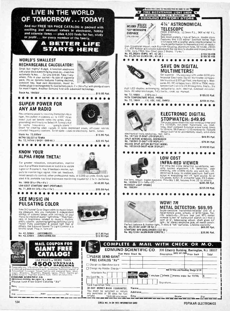
a -
'n5
ce
LIVE; IN THE WORLD' -9'
;:TOMOR.R.OW:..TODAY! And.our FREE .16.4 PAGE. CATALOG .is .packed with. exciting and úñusual values in electronic, hobby: and science items.- plus 000 finds for tinn, study or profit ... for everymember'óf- thé family.
A -BETTER LIFE S!TART.S.HERE
WORLD'S SMALLEST RECHARGEABLE CALCULATOR! Small but mighty! 8 -digit, 4 -function electronic calculator does everything big ones do-even has automatic % key ... for only $19.95. Take it any- where. Fits in your pocket -2h size of cigarette pack. 31/2 oz. dynamo features floating decimal, constant key, lead zero depression, more! In- cludes plug-in rechargeable Ni -Cad battery pack. 2 x 31/2 x 9/,s'with plenty of room for most fingers. Another Edmund first with advanced technology.
$19.95 Ppd.
es ,
Stock No. 1945AV
Q
S i S
SUPER POWER FOR ANY AM RADIO New antenna assist turns a tiny transistor into a tiger, has pulled in stations up to 1000- miles away! Just set beside radio (no wires, clips, grounding) and fine-tune Select-A-Tenna s dial to same frequency - "gangbusters"! Great for clearing weak signals in radio depressed areas, off -coast islands, crowded frequency stations. Solid state-uses no electricity, batts.. tubes. Stock No. 72,095AV ULTRA SELECT-A-TENNA No. 72,147AV ('OVER 1000 MI.) $22.95 Ppd.
KNOW YOUR ALPHA FROM THETA! For greater relaxation, concentration, monitor your Alpha/Theta brainwaves ml audible or visible signal on Biosone II. Has 3 feedback modes, out- puts to monitor logic signal, filter sel. feedback, broad sensitivity control; other professional feats. of $200 -up units. Easily oper- ated 4 -lb. portable has total brainwave monitoring capability! 2 9v tr. batteries. No. 1668 (91/2x5%x41/a") $149.95 Ppd. LOW COST STARTERS' UNIT (PORTABLE) No. 71,809 AV (41/2x2/1x41/a") $55.00 Ppd.
$15.95 Ppd.
SEE MUSIC IN PULSATING COLOR New 3 -Channel Color Organ adds to music listen- ing pleasure, lets you modulate 3 independent strings of colored lamps with intensity of your music to create an audio "light show." They flash, vary in brightness related to music's rhythm, pitch, volume-pulsating lighting performance to music! Fully assembled & priced half that of others, the Edmund Sound To Light Control is a terrific value. Plug in. turn on!
I -
No. 42,309AV...(ASSEMBLED) $17.95 Ppd. No. 42,336AV...(UNASSEMBLED) $13.95 Ppd.
MAIL "COUPON. FOR °
GIANT FREE °
' CATALO-G!' 164 PAGES MORE THAN
4500 UNUSUAL BARGAINS
Completely new 1976 edition, New items, categories illustrations. Dozens of electrical and electromagnetic parts, accessories. Enormous selection of Astronomical Telescopes. Unique I,gMing and ecological Items. Micro- scopes, Binoculars, Mognifiers, Magnets, Lenses, Prisms. Hard -to -get - surplus bargains. Ingenious scientific tools. 1000's of components. EDMUND SCIENTIFIC CO. 300 Edscorp Building, Barrington, N.1. 01003 Please rush Free Giant Catalog "AV" Name,
Address
Lty stale :,p
41/4" ASTRONOMICAL 533"ORIHUSGDPII/ TELESCOPE
EYEPIECE FREE EYEPIECE: 12.5mm F -L., 96X w/ 48" F.L. Objective See moon craters, rings of Saturn, double stars. Features fine f/10 mirror' (verified better than 1/10 wave with a scatter plate interferometer) to insure performance to theoretical limit of resolu-
tion. Equatorial mount; rack & pinion focusing; aluminum tube, 6X finder, 25mm F.L. 45X Kellner achromatic eyepiece & Barlow lens to double and triple power to 135X. Incls FREE Star Chart plus 2 Books. -Pyrex.". No. 85,260AV (SEfIPG. WT. 42 LB.) $159.50 FOB No. 85,261AV (CLOCK DR.; 45 LB.) $199.50 FOB
EgLWHEN YOU COME TO PHILAOELPNIA RE SURE TO SEE I © FREE BICENTENNIAL LIGHT SHOW L7 IN BARRINGTON N.1. ONLY 10 MINUTES AWAY AT "
,EDMUND FACTORY.STORE °
INCLUDED LSS
"ItilP\ 1
SAVE ON DIGITAL MULTIMETERS! Get superior . 1;i accuracy with under -$200 pro- fessional Electronic Digital Multimeter compara- ble to units at $320 up! Fast, one -hand op'n. Mea- sures AC. DC voltages from .001V to 750V, resis- tances f rom 1 ohm to 19.99 megohms. Feats.: 31/2
digit LED display; autoranging; autopolarity; auto- decimal; overload indicator. Incls. AC adaptor/charger, NiCd baits., case, op. manual. No. 72,199AV ... (101/2 oz.) $199.95 Ppd. WITH TEMPERATURE MEAS. PROBE No. 72,198AV ... (°C, VDC, VAC, OHMS) $259.95 Ppd.
i O
.. _ ELECTRONIC DIGITAL
How Many Stock No. PLEASE SEND GIANT
FREE CATALOG "AV" Charge my BankAmericard
Charge my Master Charge
Interbank No.
My Card No. Is
STOPWATCH: $49.95 The price alone obsoletes your wind-up timer and it's ±0.002% accurate! Hand-held, you start, stop, reset compact 6-ouncer w/one hand; times to 59 mins, 59.9 secs in 1/10 increments. Failsafe design (cannot be accidentally reset), solid-state
electronics! Incls neckstrap, repl. batts. No. 1671AV (5 -DIGIT LED DISPLAY) $49.95 Ppd. SPLIT ACTION W/NECADS, RECHARGER No. 1669AV (5 -DIGIT LED DISPLAY) $79.95 Ppd. DELUXE SPLIT ACTION BATTERY MODEL No. 1653AV(6-DIGIT NEON DISPLAY) $149.95 Ppd.
* t LOW COST INFRA -RED VIEWER For Infra -red crime detection surveillance, sec- urity system alignment, I.R. detection, laser checking, nite wildlife study, any work req. I.R. detection & cony. to visible spectrum. Self cont. , scope w/ everything incl I.R. light source. 6v or 12v power, 6032 I. R. converter tube, f/3.5 objec-
tive lens, adjust. triplet eyepiece. Provides 1.6X, focuses from 10' to infinity. No. 1659AV (11 x 141/2x3') $285.00 Ppd. WITHOUT LIGHT SOURCE No. 1663AV $225.00 Ppd.
WOW! TR METAL DETECTOR: $69.95 Super -sensitive transmitter/receiver unit at a never -before price, wifeats. of $150 types. Ter- rific selectivity -10 -turn (not just 90°) metal/ mineral tuner! 6" waterproof search coil find a cent at 6"; telescoping adjust. shaft gives 44" lath.; 1/4" stereo earphone jack; all metal constr.
Perfect balance & feather light, it incls 8 "AA" batteries. Lifetime warranty! No. 80,251AV (JUST 38 OZ 5) $69.95 Ppd. STARTERS' BFO CHALLENGER I (32 OZ.) No. 80,222AV (ALUMINUM CONSTR.) $39.95 Ppd.
-COMPLETE 8 MAIL -WITH, EDMUND SCIENTIFIC CO. 300 Edscorp Building, Barrington, N.1.08007
Description 16091 541-3400 Price Each Total
Add Service and Handling Charge $1.00 la 1 enclose check 0money order for TOTAL $ Z19:12111
Card Expiration Date 30 -DAY MONEY -BACK GUARANTEE. You must be satisfied or return any purchase in 30 days ,for full refund. $15.00 minimum
1J Signature
Name
Address City State Zip
ti
124 CIRCLE NO. 24 ON FREE INFORMATION CARO POPULAR ELECTRONICS
AmericanRadioHistory.Com
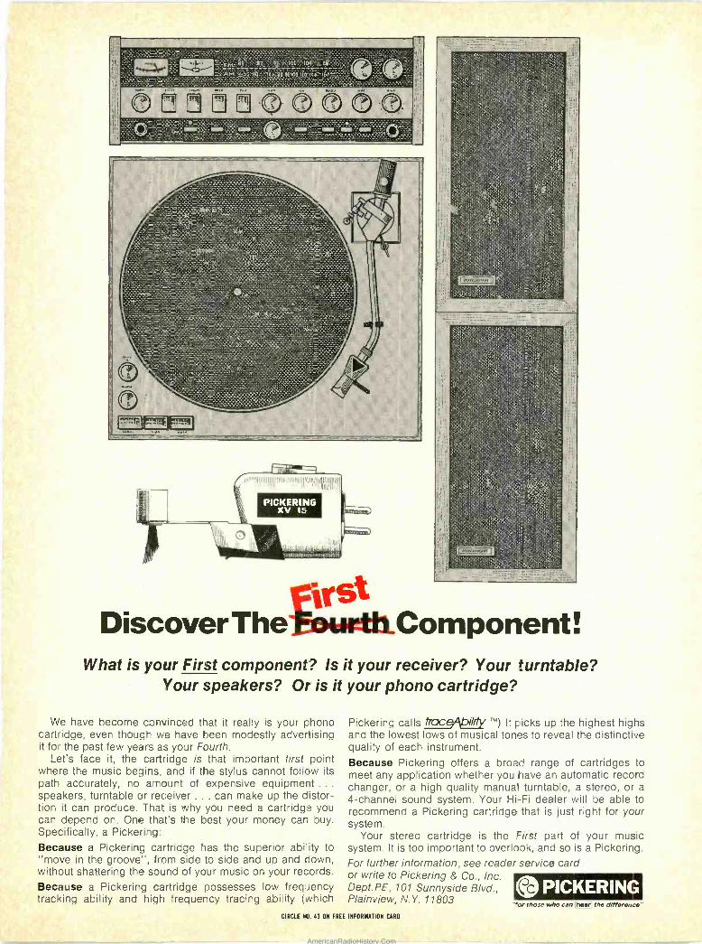
iitihul:
"ylll,ull IIIIIRMulnlll('GII Jn1IuIIInOI
PICKERING xv 15 !eel*
1--,
rirSt Discover The - r, :,.Component !
What is your First component? Is it your receiver? Your turntable? Your speakers? Or is it your phono cartridge?
We have become convinced that it really is your phono cartridge, even though we have been modestly advertising it for the past few years as your Fourth.
Let's face it, the cartridge is that important first point where the music begins, and if the stylus cannot follow its path accurately, no amount of expensive equipment .. speakers, turntable or receiver ... can make up the distor- tion it can produce. That is why you need a cartridge you can depend on. One that's the best your money can buy. Specifically, a Pickering: Because a Pickering cartridge has the superior ability to "move in the groove", from side to side and up and down, without shattering the sound of your music on your records.
Because a Pickerirg cartridge possesses low frequency tracking ability and high frequency tracing ability (which
Pickering calls lrca .It picks up the highest highs and the lowest lows of musical tones to reveal the distinctive quality of each instrument.
Because Pickering offers a broad range of cartridges to meet any application whether you have an automatic record changer, or a high quality manual turntable, a stereo, or a 4 -channel sound system. Your Hi -Fi dealer will be able to recommend a Pickering cartridge that is just right for your system.
Your stereo cartridge is the First part of your music system. It is too important to overlook, and so is a Pickering. For further information, see reader service card or write to Pickering & Co., Inc. Dept.PE, 101 Sunnyside Blvd., Plainview, N.Y. 11803
ogYPICKERING "for those who can IhearE the difference"
CIRCLE NO. 43 ON FREE INFORMATION CARO
AmericanRadioHistory.Com
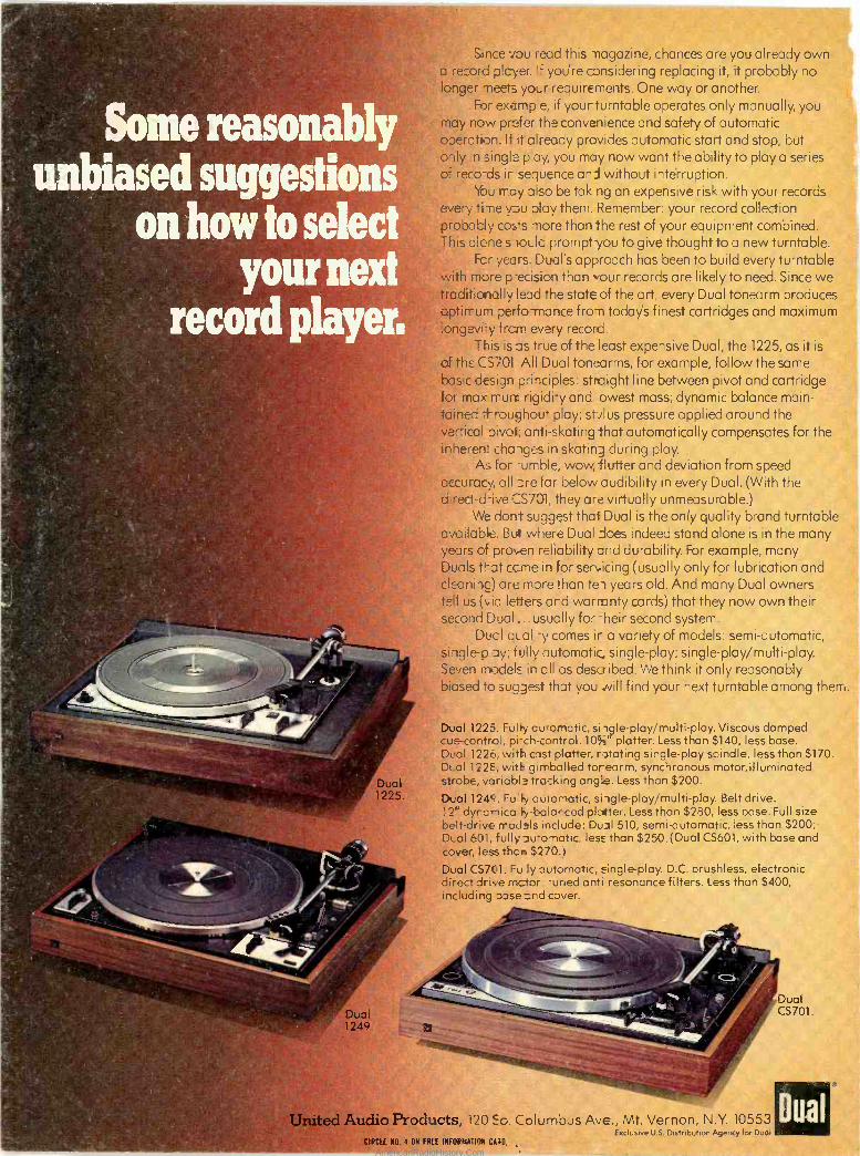
Some reasonably unbiased suggestions
óflhowtó select your next
record player:
r
'
t ° ,
q
5
ti ..
Dual / 1225.
e
Dual 1249
Since you read this magazine, chances are you already own a record player. lf you're considering replacing it, it probably no longer meets your requirements. One way or another.
For ex5mp'e, if yourturntable operates only manually, you 'may now prefer the convenience and safety of automatic operation. If it already provides automatic start and stop, but gnly n single pay, you may now want the ability to play a series of reco-ds it sequence and without interruption.
You n -ay also be tak ng an expensive risk with your records every time v u play them. Remember: your record collection probably costs more than the rest of your equipment combined. This alone s lould prompt you to give thought to a new turntable.
Fcr years. Dual's approach has been to build every turntable with more p-ecision than your records are likely to need. Since we tfadítionally lead the state of the art, every Dual tonearm produces cptirrum perfo-mance from today's finest cartridges and maximum 'rongevi-y frcrn every record.
This isas true of the least expensive Dual, the 1225, as it is
of the C5701 All Dual tonearms, for example, follow the same basic design principles: straight line between pivot and cartridge for max n-urrl rigidi'y and owest mass; dynamic balance main- tained throughout play; stylus pressure applied around the vertical Divot; anti -skating that automatically compensates for the inherent charges in skating during play.
As for -umble, wow -flutter and deviation from speed accuracy, all ore far below audibility in every Dual. (With the d:reet-drive CS701, they are virtually unmeasurable.)
We dont suggest that Dual is the only quality brand turntable available. But where Dual does indeed stand alone is in the many years of pro,,en reliability and durability. For example, many Duals that ccme in fdr ser'.icing (usually only for lubrication and cleaning) are mare than ten years old. And many Dual owners tell us (via letters and warranty cards) that they now own their second Dual _.. usually for -heir second system.
Duct qua! -y comes it a variety -of models: semi -automatic, sinle-p ay; fully automatic single -play; single-play/multi-play. Seven models in ell as described. We think it only reasonably biased to suggest that you will find your next turntable among them.
Dual 1225. Fully cutomatic, si igle-play/multi-play. Viscous damped cue -control, pi-ch-control. 10%' platter. Less than $140, less base. Dual 122, with cast platter, rotating single -play spindle, less than $170. Dt_al 122E, with gimballed torearm, synchronous motor, illuminated strobe, variable tracking angle. Less than $200.
Dual 1249. Fu'Fy automatic, single-play/multi-play. Belt drive. 12" dyranica ty-balarced platter. Less than $280, less base.Full size belt -drive rrode.ls include: Dual 510, semi -automatic, less than $200;- D..al 601, fully auronatic, less than $250. (Dual CS601, with base and cover, less than $270.)
Dual CS701. Fu ly automatic, single -play. D.C. brushless, electronic direct drive motor -uned anti -resonance filters. Less than $400, including Dose and cover.
ti' L, Ly
3
r
United -Audio Products, 120 5o. Columbus Ave., Mt. Vernon, N.Y. 10553 Exclusive U.S. Distribution Agency for Dual
CIRCEE410. 4 ON FREE INFORMATION CAM.
AmericanRadioHistory.Com