build this satellite -tv descrambler - World Radio History
134
NI a 1 PHONE-SYSTLM PRIMER i BUILD THIS SATELLITE -TV DESCRAMBLER For the Telease-Maast scrambling system SATELLITE JAMMING How Captain Midnight took on H1391,.., OSCILLATORS Circuits you can breadboard DELAY LINES A circuit cookbook OfF BUILD AN OLD TIME CRYSTAL RADIO Vintage circuitry and vintage looks OR BURN YOUR OWN EPROM's With R -E's easy -to -build programmer ALL ABOUT TELEPHONES A phone -system primer FI o> I I 0 11 a ¿ ¿s r 1 1. ' r rdit 1....'1* . _'t "...Iv. . J '. L ' J , 1o, CRYSTAt PNASt 441> . ' A 1 GERNSBACK T PUBLICATION f?-' " A ' J1 ' 419 K .117i !P. ...L-:,-- a' .' IP )4 t ik, ._;, © 7 : I : ` , I PLUS: *Ask R -E *PC Service * Antique Radios * Robotics COMPUi ERDIGEST * Video News
-
Upload
khangminh22 -
Category
Documents
-
view
2 -
download
0
Transcript of build this satellite -tv descrambler - World Radio History

NI
a 1 PHONE-SYSTLM PRIMER
i
BUILD THIS SATELLITE -TV DESCRAMBLER For the Telease-Maast scrambling system
SATELLITE JAMMING How Captain Midnight took on H1391,..,
OSCILLATORS Circuits you can breadboard
DELAY LINES A circuit cookbook OfF
BUILD AN OLD TIME CRYSTAL RADIO Vintage circuitry and vintage looks
OR
BURN YOUR OWN EPROM's With R -E's easy -to -build programmer
ALL ABOUT TELEPHONES A phone -system primer
FI o> I I 0
11 a ¿ ¿s r 1
1.
' r rdit 1....'1* . _'t
"...Iv. . J '. L ' J
, 1o,
CRYSTAt
PNASt
441>
. '
A
1
GERNSBACK T PUBLICATION
f?-' " A ' J1
' 419 K
.117i !P. ...L-:,-- a' .'
IP )4 t ik, ._;, © 7 :
I : ` ,
I
PLUS: *Ask R -E *PC Service * Antique Radios * Robotics
COMPUi ERDIGEST
* Video News

New GPS Series: Tek sets the pace with SmartCursorsM
and push-button ease. Work faster, smarter, with two new general purpose scopes from Tektronix. The four -channel, 100 MHz 2246 and 2245 set the new, fast pace for measurements at the bench or in the field. They're easy to use and afford, by design.
On top: the 2246 with exclusive integrated push-button measure- ments. Measurements are accessed through easy, pop-up menus and imple- mented at the touch of a button. Mea- sure peak volts, peak -to -peak, ± peak, dc volts and gated volts with new hands- off convenience and on -screen readout of values.
SmartCursors'" track voltmeter mea- surements in the 2246 and visually indi- cate where ground and trigger levels are located. Or use cursors in the manual mode for immediate, effortless measure- ment of waveform parameters.
Both scopes build on performance you haven't seen at the bandwidth or prices. Lab grade features include sweep speeds to 2 ns/div. Vertical sen- sitivity of 2 mV/div at full bandwidth for
r r
.
r=
6P1iE0. eNi t_
- 1
-%2R , " _ -
I
_"" ,ac, .
Features 2246 2245
Bandwidth
No. of Channels
100 MHz 100 MHz
4 4
Scale Factor Readout
SmartCursors'"
Yes
Yes
Yes
No
Volts Cursors Yes No
Time Cursors Yes No
Voltmeter Yes No
Vertical Sensitivity Max. Sweep Speed
VerVHor Accuracy
2 mV/div
2 ns/div
2%
2 mV/div
2 ns div
2%
Trigger Modes Auto Level, Auto, Norm, TV Field, TV Line, Single Sweep
Trigger Level Readout
Weight
Yes
6.1 kg
No
6.1 kg
Warranty 3 -year on parts and labor including CRT
low-level signal capture. Plus trigger sensitivity to 0.25 div at 50 MHz, to 0.5 div at 150 MHz.
Accuracy is excellent: 2% at vertical, 2% at horizontal. And four -channel capability includes two channels optimized for logic signals.
Best of all, high performance comes with unmatched
convenience. You can see it and feel it
-in the
r r""7"' Lit
Is
C °
11
responsive controls and simple front - panel design, in extensive on -screen scale factor readouts, and in simplified trigger operation that includes Tek's Auto Level mode for automatic trig- gering on any signal.
Contact the Tektronix office or sales representative nearest you for complete details. Each scope is backed by Tek's three-year warranty, plus excellent documentation, training programs and outstanding service sup- port-worldwide.
j
I '11
GL te-
Featuring four chan- nels, flexible triggering, extensive CRT readouts and push-button ease of use, the new Tek 2246 (left) and 2245 (above) bring high -qual- ity low-cost analysis to diverse applications in digital design, field ser- vice and manufacturing.
Téktronbc® Copyright '1986, Tektronix. Inc. All rights reserved. TTA-469
CIRCLE 92 ON FREE INFORMATION CARD
COMMITTED TO EXCELLE E

Radio -
Electronics. CTO E R Electronics publishers since 1908
Vol. 57 No. 10
BUILD THIS 50 SATELLITE -TV DESCRAMBLER With this easy -to -build device, you can watch satellite -TV broadcasts that are scrambled using the Telease-Maast encoding system. Victor J. Terrio, Jr. and James Perodi
54 OLD-TIME CRYSTAL RADIO
RADIO
92 COMMUNICATIONS CORNER Closed captioning. Herb Friedman
Bring hack the early clays of radio with this vintage receiver. Pat O'Brian
61 EPROM PROGRAMMER Here's a low-cost programmer that let's you get started with EPROM projects. It programs all popular devices. Luhomir B. Sawkiw
94 ANTIQUE RADIOS Cabinets and speaker baffles. Richard D. Fitch
75 PC SERVICE use our exclusive direct -etch foil patterns to make circuit boards for the satellite -TV descrambler. One side of the EPROM programmer board is shown this month.
COMPUTERS
Pollo++ing COMPUTER DIGEST page 88 Biofeedback, Dish
positioning, and more.
EQUIPMENT TECHNOLOGY 12 VIDEO NEWS Inside the fast -changing video scene. REPORTS David Lachenhruch
47 THE RAID ON HBO 27 Heathkit Model A look at how deliberate satellite interference can be accomplished and how Captain
GR-4500 Projection -TV Kit
Midnight might have done it. William Sheets and Rudolf Graf 32 Dioconix 150
56 INSIDE THE TELEPHONE Portable Printer The phone is so commonplace, we don't think of the technology involved. It's worth a look. Rudolf Graf and Calvin Graf
86 SATELLITE TV DEPARTMENTS
What's happening on the Ku band. 120 Advertising and Bob Cooper, Jr.
82 ROBOTICS Sales Offices
A look at a rover called Ernie. 120 Advertising Index
Mark J. Robillard 14 Ask R -E
4 Editorial CIRCUITS AND 67 ANALOG DELAY LINES COMPONENTS Perfect circuits for audio experimenters. 4 Free Information
Ray Marston Card 85 SERVICE CLINIC
Some thoughts on screwdrivers. Jack Darr 22 Letters
85 SERVICE QUESTIONS 98 Market Center Solutions to servicing problems.
89 STATE OF SOLID STATE 42 New Products
Condition sensing. Robert t Scott 6 What's News
RADIO -ELECTRONICS, (ISSN 0033-7862) October 1986. Published monthly by Gernsback Publications. Inc., 500-B Bi-Counly Boulevard, Farmingdale, NY 11735 Second -Class Postage paid at
Farmingdale, NY and additional mailing offices. Second -Class mail registration No. 9242 authorized at Toronto. Canada. One-year subscription rate U.S.A. and possessions 516.97, Canada
$22.97, all other countries $25.97. Subscription orders payable in US funds orly. international postal money order or check drawn on a U.S.A. bank. Single copies $1 95 < 1986 by Gernsback
Publications, Inc. All rights reserved. Printed in U.S.A. POSTMASTER: Please send address changes to RADIO -ELECTRONICS. Subscription Dept.. Box 55115, Boulder. CO 80321-5115. A stamped self-addressed envelope must accompany all submitted manuscripts and or artwork or photographs if their return is desired should they be retected. We disclaim any responsibility for the
loss or damage of manuscripts and or artwork or photographs while in our possession or otherwise.

Radio- PRONE -SYSTEM PRIMER
C OV E R 1 Electronics BUILD THIS SATELIJTE TV . . DESCRAMBLER
CÉ lky T
SATELLITE JARRING -.,r. ,.,, oSCLL/ITORS 6. you con Inenmaboara
oeIAY LINES
BULL AN OlD TINE CRYSDLL RADIO
rim
BURN YOUR OWN EPROM, VI. Re, ruffy.b-b.1 pnnywornor
Our cover story this month is part of our continuing coverage of one of the most important issues in the field of satellite TV: signal scrambling and descranhl)ling. The descrambler shown on the cover will decode programming en- crypted using the Telease-Maast system. the theory behind the en- coding is discussed and, of course, we describe how to restore the video to its proper form.
Before you build the descrambler, you should be aware that it may he unlawful to decode some scrambled satellite transmissions. But it's certainly not unlawful to learn as much as you can about descranT- bling! To learn more, turn to page 50.
f
ALL ABOUT TaIIDHOPI*5
11111 1,
NEXT MONTH THE NOVEMBER ISSUE IS
ON SALE OCTOBER 2
BUILD A CLOSED -CAPTION DECODER It decodes closed -captioning and Line 2! Teletext
BUILD AN EPROM PROGRAMMER Part 2 shows you how to add a hex display and gang - programming capability. The solder side of the main board appears in PC Service.
BUILD A LATCHING CONTINUITY TESTER
I ind those intermittent shorts and opens.
SATELLITE -TV SIGNAL DESCRAMBLING Part 5 looks at the SSAVI scrambling technique.
TELEPHONE INSTALLATION ACCESSORIES this month, you learned how the telephone system works. Next month, you'll learn how to make it work best for you.
THE EARLY DAYS OF RADIO Another installment in our series of occasional articles on electronics nostalgia.
As a service to readers. RADIO -ELECTRONICS publishes available plans or information relating to newsworthy products, techniques and scientific and technological developments. Because of possible variances in the quality and condition of materials and workmanship used by readers. RADIO -ELECTRONICS disclaims any responsibility for the safe and proper functioning of reader -built protects based upon or from plans or information published in this magazine.
Since some of the equipment and circuitry described in RADIO -ELECTRONICS may relate to or be covered by U.S. patents. RADIO -ELECTRONICS disclaims any liability for the infringement of such patents by the making. using, or selling of any such equipment or circuitry, and suggests that anyone interested in such projects consult a patent attorney.
Radio - Electronics Hugo Gernshack (1884-1967) founder M. Harvey Gernsback,
editor-in-chiet, emeritus
Larry Steckler I HF, CET, editor -in -chief
and publisher
EDITORIAL DEPARTMENT
Art Kleiman, editorial director Brian C. Fenton, managing editor Carl Iaron, \VB2S1 R, associate editor Jeffrey K. Holtzman,
assistant technical editor Robert A. Young, assistant editor Julian S. Martin, editorial associate
Byron G. Weis, editorial associate M. Harvey Gernshack,
contributing editor lack Darr, CET, service editor Robert F. Scott,
semiconductor editor Herb Friedman,
communications editor Bob Cooper, Jr. satellite -TV editor Robert Grosshlatt, circuits editor David Lachenbruch,
contributing editor Richard D. Fitch,
contributing editor Mark I. Robillard, robotics editor Teri Scaduto Wilson, editorial assis ant
PRODUCTION DEPARTMENT
Ruby M. Yee, production director Robert A. W. Lowndes,
editorial production Andre Duzanl, technical illustrator Karen Tucker, advertising production Geoffrey S. Weil, production traffic
CIRCULATION DEPARTMENT
Jacqueline P. Cheeseboro, circulation director
Wendy Alanko, circulation analyst
Theresa Lombardo, circulation assistant
Cover photo by Robert Lewis
Typography by Mates Graphics
Radio -Electronics, Gernshack Publica-
tions, Inc., Executive Offices, 500-B Bi-
County Blvd., Farmingdale, NY 11735,
516-293-3000
Radio -Electronics is indexed in Applied Science & Technology Index and Readers Guide to Periodical liter- ature. Microfilm & Microfiche editions are available. Contact circulation depart- ment for details.
Advertising Sales Offices listed on page 120.
2

NEW! Lower Price Scanners
Communications Electronics, the world's largest distributor of radio scanners, introduces new lower prices to celebrate our 15th anniversary.
Regency/ MX7000-GR List price $699.95/CE price $469.95 10 -Band, 20 Channel Crystalless AC/DC Frequency range: 25-550 MHz. continuous coverage and 800 MHz. to 1.3 GHz. continuous coverage. The Regency MX7000 scanner lets you monitor Military, Space Satellites, Government, Railroad, Justice Department, State Department, Fish & Game, Immigration, Marine, Police and Fire Depart- ments, Broadcast Studio Transmitter Links, Aero- nautical AM band, Aero Navigation, Paramedics, Amateur Radio, plus thousands of other radio frequencies most scanners can't pick up. The Regency MX7000 is the perfect scanner to receive the exciting 1.2 GHz. amateur radio band.
Regency® Z60-GR List price $299.95/CE price $179.95/SPECIAL 8 -Band, 60 Channel No -crystal scanner Bands: 30-50,88-108,118-136,144-174, 440-512 MHz. The Regency Z60 covers all the public service bands plus aircraft and FM music for a total of eight bands. The Z60 also features an alarm clock and priority control as well as AC/DC operation. Order today.
Regency° Z45-GR List price $259.95/CE price $159.95/SPECIAL 7 -Band, 45 Channel No -crystal scanner Bands: 30-50, 118-136, 144-174, 440-512 MHz. The Regency Z45 is very similar to the Z60 model listed above however it does not have the commer- cial FM broadcast band. The Z45, now at a special price from Communications Electronics.
Regency° RH250B-GR List price $659.00/CE price 5329.95/SPECIAL 10 Channel 25 Watt Transceiver Priority The Regency RH250B is a ten -channel VHF land mobile transceiver designed to cover any fre- quency between 150 to 162 MHz. Since this radio is synthesized, no expensive crystals are needed to store up to ten frequencies without battery backup. All radios come with CTCSS tone and scanning capabilities. A monitor and night/day switch is also standard. This trans- ceiver even has a priority function. The RH250 makes an ideal radio for any police or fire department volunteer because of its low cost and high performance. A60 Watt VHF 150-162 MHz. version called the RH600B is available for$454.95. A UHF 15 watt version of this radio called the RU150B is also available and covers 450-482 MHz. but the cost is $449.95.
NEW! Bearcat° 50XL-GR List price $199.95/CE price 5114.95/SPECIAL 10 -Band, 10 Channel Handheld scanner Bands: 29.7-54 136-174, 406-512 MHz. The Uniden Bearcat 50XL is an economical, hand-held scanner with 10 channels covering ten frequency bands. It features a keyboard lock switch to prevent accidental entry and more. Also order part # BP50 which is a rechargeable battery pack for $14.95, a plug-in wall charger, part # AD100 for $14.95, a carrying case part* VC001 for $14.95 and also order optional cigarette lighter cable part* PS001 for $14.95.
Regency RH250
GQQooD
NEW! Scanner Frequency Listings The new Fox scanner frequency directories will help you find all the action your scanner can listen to. These new listings include police, fire, ambulances & rescue squads, local government, private police agencies, hospitals, emergency medical channels, news media, forestry radio service, railroads, weather stations, radio common carriers, AT&T mobile telephone, utility com- panies, general mobile radio service, marine radio service, taxi cab companies, tow truck companies, trucking companies, business repeaters, business radio (simplex) federal government, funeral d rectors, vet- erinarians, buses, aircraft, space satelli:es, amateur radio, broadcasters and more. Fox frequency listings feature call letter cross reference as well as alphabetical listing by licensee name, police codes and signals. All Fox directories are $14.95 each plus $3.00 shipping. State of Alaska-RL019-1; State of Arizona-RL025-1; Baltimore, MD/Washington, DC-RL024-1; Buffalo, NY/ Erie, PA-RLOO9-2; Chicago, IL-RLo14-I; Cincinnati/ Dayton, OH-RL006.2; Cleveland, OH-RL017.1; Colum- bus, OH-RL003.2; Dallas/Ft. Worth, TX-RL013.1; Denver/Colorado Springs, CO-RL027-1; Detroit, MI/ Windsor, ON-AL008.3; Fort Wayne, IN/Lima, OH- RL001-1; Hawaii/Guam-RL015.1; Houston, TX- RL023-1; Indianapolis, IN-RL022-1; Kansas City, MO/ KS-RL011.2; Long Island, NY-RL026.1: Los Angeles, CA-RL016.1; Louisville/Lexington, KY-RL007-1; Mil- waukee, WI/Waukegan, IL-RL021.1; Minneapolis/St. Paul, MN-RL010-2; Nevada/E. Central CA-RL028.1; Oklahoma City/Lawton, OK-RL005-2; Orlando/Daytona Beach, FL-RL012.1; Pittsburgh, PA/Wheeling, WV- RL029-1; Rochester/Syracuse, NY-RLC20.1; San Diego, CA-RLO18.1; Tampa/St. Petersburg, FL- RL004-2; Toleco, OH-RLO02.3. New editions are being added monthly. For an area not shown above call Fox at 800-543-7892. In Ohio call 800-621-2513.
NEW! Regency° HX1500-GR List price $369.95/CE price $239.95 11 -Band, 55 Channel Handheld/Portable Search Lockout Priority Bank Select Sidelit liquid crystal display EAROM Memory Direct Channel Access Feature Scan delay Bands: 29-54, 118-136, 144-174, 406-420, 440-512 MHz The new handheld Regency HX1500 scanner is fully keyboard programmable for the ultimate in versatility. You can scan up to 55 channels at the same time including the AM aircraft band. The LCD display is even sidelit for night use. Includes belt clip, flexible antenna and earphone. Operates on 8 1.2 Volt rechargeable Ni -cad batteries (not included). Be sure to order batteries and battery charger from accessory list in this ad.
Bearcat° 100XL-GR List price $349.95/CE price 5203.95/SPECIAL D -Band, 16 Channel Priority Scan Delay Search Limit Hold Lockout AC/DC Frequency ranga: 30-50, 118-174, 406-512 MHz. The world's first no -crystal handheld scanner now has a LCD channel display with backlight for low light use and aircraft band coverage at the same low price. Size is 1%" x71/2" x 2'4:' The Bearcat 100XL has w de frequency coverage that includes all public service bands (Low, High, UHF and "T' bands), the AM aircraft band, the 2 - meter and 70 cm. amateur bands, plus military and federal government frequencies. Wow...what a scanner!
Included in our low CE price is a sturdy carrying case, earphone, battery charger/AC adapter, six AA ni -cad batteries and flexible antenna. Order yourscanner now.
Bearcat° 210XW-GR List price $339.95/CE price $209.95/SPECIAL 8 -Band, 20 Channel No -crystal scanner Automatic Weather Search/Scan AC/DC Frequency range: 30-50, 136-174, 406-512 MHz. The new Bearcat 210XW is an advanced third generation scanner with great performance at a low CE price.
NEW! Bearcat® 145XL-GR List price $179.95/CE price 5102.95/SPECIAL 10 Band, 16 channel AC/DC Instant Weather Frequency range: 29-54, 136-174, 420-512 MHz The Bearcat 145XL makes a great first scanner. Its low cost and high performance lets you hear all tie action with the touch of a key. Order your scanner from CE today.
TEST ANY SCANNER Test any scanner purchased from Communications Electronics' for 31 days before you decide to keep it. If for any reason you are not completely satisfied, return it in original condition with all parts in 31 days, for a prompt refund (less shipping/handling charges and rebate credits).
Regency MX7000
Regency HX1500
NEW! Bearcat° 800XLT-GR List price $499.95/CE price $317.95 12 -Bend, 40 Channel No -crystal scanner Priority control Search/Scan AC/DC Bands: 29-54, 118-174, 406-512, 806-912 MHz The Uniden BOOXLT receives 40 channels in two banks. Scans 15 channels per second. Size 91/4" x41/2" x 121/2."
OTHER RADIOS AND ACCESSORIES Panasonic RF-2600-GR Shortwave receiver $179.95 R D95 -G R Uniden Remote mount Radar Detector $128.95 R055-GR Uniden Visor mount Radar Detector $98.95 RD9-G ñ Uniden" Passport" size Radar Detector... $199.95 BC-WA-GR Bearcat Weather Alert' $49.95 DX1000-GR Bearcat shortwave receiver SALE... $349.95 PC22-GR Unlden remote mount CB transceiver $99.95 PC55-GR Unlden mobile mount CB transceiver $59.95 R1060-GR Regency 10 channel scanner SALE $92.95 MX3003-GR Regency 30 channel scanner $229.95 XLI56-GR Regency 10 channel scanner $139.95 UC102-GR Regency VHF 2 ch. 1 Watt transceiver $124.95 P1405-GR Regency 5 amp regulated power supply... $69.95 P141 2-GR Regency 12 amp reg. power supply $164.95 MA256-GR Drop -in charger for HX12008 HX1 500... $84.95 MA51 8-GR Wall charger for HX1500 scanner $14.95 MA516-GR Carrying case for HX1500 scanner 514.95 MA257-GR Cigarette lighter cord for HX12/1500 519.95 MA917-GR Ni -Cad battery pack for HX1200 $34.95 SMMXi 000-GR Svc man. for MX70008 MX5000 $19.95 SMMX3000-GR Service man. for Regency MX3000 519.95 13-4-GR 1.2 V AAA Ni -Cad batteries (set of four) $9.95 B-8-GR 1.2 V AA Ni -Cad batteries (set of eight).... 517.95 FB-E-GR Frequency Directory for Eastern U.S.A..... $14.95 FB-W-GR Frequency Directory for Western U.S.A.... 514.95 ASD-GR Air Scan Directory $14.95 SRF-GR. Survival Radio Frequency Directory $14.95 TSG-GR "Top Secret" Registry of U.S. Govt. Freq $14.95 TIC-GR Techniques for Intercepting Comm. $14.95 RRF-GF. Railroad frequency directory $14.95 CIE-GRCovert Intelligenct, Elect. Eavesdropping $14.95 A60-GR Magnet mount mobile scanner antenna $35.95 A70 -GP Base station scanner antenna $35.95 USAM M-GR Mag mount VHF/UHF ant. w/ 12' cable 539.95 USAK-GRl." hole mount VHF/UHFant. w/ 17' cable $35.95 USATLM-GR Trunk lip mount VHF/UHF antenna $35.95 Add $3.00 shipping for all accessories ordered at the same time. Add $12.00 shipping per shortwave receiver. Add $7.00 shipping per scanner and $3.00 per antenna.
BUY WITH CONFIDENCE To get rthe fastest delivery from CE of any scanner, send o- phone your order directly to our Scanner Distribution Center' Michigan residents please add 4% sales tax or supply your tax I.D. number. Written pur- chase ciders are accepted from approved government agencies and most well rated firms at a 10% surcharge for net 10 billing. All sales are subject to availability, acceptance and verification. All sales on accessories are fina Prices, terms and specifications are subject to changewithout notice. All prices are in U.S. dollars. Out of stock items will be placed on backorder automatically unless CE is Instructed differently. A $5.00 additional handling fee will be charged for all orders with a merchandise total under $50.00. Shipments are F.O.B. Ann Arbor, Michigan. No COD's. Most products that we sell have a manufacturer's warranty. Free copies of warranties on these products are available prior to purchase by writing to CE. Non -certified checks require bank clearance. Not responsible for typographical errors.
Mall orders to: Communications Electron- ics' Box 1045, Ann Arbor, Michigan 48106 U.S.A. Add $7.00 per scanner for R.P.S./U.P.S. ground shipping and handling in the continental U.S.A. For Canada, Puerto Rico, Hawaii, Alaska, or APO/FPO delivery, shipping charges are three times continental U.S. rates. If you have a Discover, Visa or MasterCard, you may call and place a credit card order. Order toll -free in the U.S. Dial 800 -USA -SCAN. In Canada, order toll - free by calling 800-221-3475. WUI Telex any- time, dial 671-0155. If you are outside the U.S. or in Michigan dial 313-973-8888. Order today. Scanner Distribution Center' and CE logos are trade- marks of Communications Electronics Inc. I Bearcat is a registered trademark of Uniden Corporation. f Regency is a registered trademark of Regency Electronics Inc. AD *070286-GR Copyright O 1986 Communications Electronics Inc.
For credit card orders call 1 -800 -USA -SCAN
rr
COMMUNICATIONS ELECTRONICS INC.
Consumer Products Division P.O. Bo:,1045 0 Ann Arbor, Michigan 48106-1045 U.S.A. Ca11 BOFUSA-SCAN or outside U.S.A. 313.973.8888 CIRCLE 79 ON FREE INFORMATION CARD 3

EDITORIAL
I just received a letter insisting that the editorial content of Radio -Electronics is being bought by our advertisers. The letter mentioned Dick Smith Electronics specifically and said: "Isn't it funny that one month you get this new advertiser out of nowhere, and then feature their kits in numerous articles?"
That's a very easy question to answer, because Radio -Electronics has a strict policy that separates our Editorial and Advertising departments. Even if Dick Smith Electronics buys twenty pages of advertising per issue, we'll never give one of their kits any coverage if we don't think that kit deserves it. On the other hand, if they never bought one single page of advertising, our January 1986 issue would still have featured their $99 satellite -TV receiver, and it would still have been our cover story.
Take a look at the projects that we've featured over the last few months. Our July cover displayed a l.2-GHz frequency counter that was designed and sold by a small company in Florida that has never (as far as I know) advertised with us. Our August cover featured a radar speed -gun calibrator that is available in kit form from another company that has never advertised in this magazine. Last month's cover shows a stun gun that is available as a kit from a company that usually runs a 1/6 -page ad, and this month's cover story is available as a kit from a company that has run a one -inch classified ad a few times.
What has me a little confused is that I don't really understand what some readers are complaining about. Are they saying that we
shouldn't cover a great construction project because it's commercially available as a kit? Just because a circuit is available as a kit doesn't mean we shouldn't cover it in Radio -Electronics. When we run a story based on a kit, we treat it as we do every other construction project-with complete schematics, circuit descriptions, and printed -circuit patterns. Remember: We're not just covering a kit; we're covering circuits and technology.
We do our best to ensure that you don't have to buy the kit or specific parts from a specific supplier. The circuit is there for you to build whether you buy parts or pull them out of your junkbox. But don't forget that, for many of our readers, having a supplier of parts and complete kits can make the difference between building or not building a project.
Now that I've re -affirmed our long-standing policy, it seems like a good time to offer an invitation to all individuals, companies, and corporations, whether or not you advertise in Radio -Electronics: It you have an electronics project that you think will interest our readers, let me know about it.
Brian C. Fenton Managing Editor
4

rssócu TEO PRfCISION AEfEAACK INC.
CI C"Tun^AI1~ IAI" C1_GV I 1lViVILrg,g IIVV.
FLUKE
TEST EQUIPMENT BONANZA POWER SUPPLIES
BAK 1601 0-50V.2A 1650 2* 0-25V.5A.5V5A 350.00
TOPWARD 2202 0-20v/2a 2203 0-20v/3a 2301 0-30v/1a
S345.00
150.00 165.00 150.00
2302 0-30v/2a 165.00
2303 0.30v/3a 180.00
2306 0-30v/6a 270.00 2310 0.30v/10a 450.00 2601 0.60v/1a 165.00
2603 0-60v/3a 280.00 2606 0.60v 6a 490.00
TOPWARD TRIPLES 4302 2.0-30v/2a.5v3a 270.00 4303 20.30v/3a,5v3a 325.00
TOWARD WITH DIGITAL MTR 23020 0.30v/2a 23030 0-30v/3a 43020 2 8 0-30v/2a.5v3a 43030 240.30v13a5v3a VIZ DIGITAL METERS WP -705A 0-50v/2a WP -706A 0-25v/2a WP -707A 2440.25v/2a WP -708A 2420v/2a.5v4a WP -709 50(13v.7.5a WP -711A 0-40v/1a WP -712A 0.20v/2a WP -713A 2100.20v/1a WP -714 A 240.20v/.75a.Sv4a WP -715A 0-36v/3a WP -716A 24 0-24v/0.5a
5v4a 0-20v/5a WP -717A
GLOBAL 1300 2 4 5.18v/.25a.5v1 a 109.00
1301 24 5.18 v/.5 a.5 v l a 199.00
1302 2.30v/1 a.5v5a 299.00
POWER DESIGN 5YR WRNTY 5015V 0.50v/1.5a 450.00
4050 0-40v/5a 595.00
195.00 215.00 340.00 395.00
COUNTERS/FREQUENCY ONLY
TOPWARD TfC-1201 100MHZ TFC-1204 650MHZ TFC-1207 1000 M HZ
SIMPSON 710 80MHZ
VIZ 4WD -754 100 MHZ
WD -756 1GHZ
BAK DYNASCAN 1803 100MHZ
330.00 327.00 419.00 453.00
329.00 254.00 266 00
349.00 372.00 319.00 369 00 349 00
349 00
195.00 305.00 380.00
199.00
219.00 399.00
149.00
LEADER LDC-831 150MHZ 188.00
GLOBAL MAX -100A 100MHZ 99.00 6000 650MHZ 379.00
COUNTERS/UNIVERSAL TOWARD TFC-1211 100MHZ 270.00 TFC-1214 650MHZ 395.00 TFC-1217 1GHZ 490.00
VIZ WD -755 125MHZ 255.00 WD -757 1GHZ 489.00
LEADER LDC-822 80MHZ 319.00 IDC-823S 250MHZ 424.00 IDC-824S 520MHZ 520.00 LDC-825 1GHZ 1.197.00
BAK DYNASCAN 1805 80MHZ 259.00 1822 175MHZ 399.00 1851 520MHZ 509.00
FLUKE 1900A 80MHZ 369.00 1910A 125MHZ 51300 GLOBAL 5001 10MHZ 359.00
FUNCTION GENERATORS TOPWARD TFG-8101 2MHZ 185.00 TFG-8104 2MHZ
AM/FM MOD. 240.00 TFG-8111 2MHZ +6 DIG 100MHZ COUNTER 275.00
TFG-8114 5MHZ SWEEP +5 DIG 100MHZ COUNTER 495.00
SIMPSON 420A 1MHZ 189.00 4200 1MHZ+BAT 219.00
BAK DYNASCAN 3010 1MHZ 175.00 3011 2MHZ+COUNTER 175.00
3020 2MHZ+SWEEP 349.00 3025 5MHZ+SWEEP 420.00
GLOBAL 2001 100KHZ 149.00
2002 2MHZ 19900
LEADER LFG-1300S 2MHZ+SWEEP 439.00
LFG-1310 10MHZ+SWEEP 989.00
HANDHELD DIGITAL METERS
FLUKE 73 .7% 3'/ 75 .5% 3'h 8060A .04% 4' TRMS
8062A .05% 4I4TRMS
80268 .1% 3' TRMS
80208 .1% 31/2
HITACHI 3525 .25% 31/2AUTO
OTY 3EA.+ SPECIAL
3510 .1 3' AUTO
0TV 3EA.+ SPECIAL
BAK DYNASCAN 2802 .7% 3' PROBE
2820 .4% 451TRMS
71.00
89.00 319.00 265.00 179.00 179.00
64.00 54.00 79.00 67.00
49.00 297.00
SIMPSON 470 .15% 31h
474 03% 4'h
KEITHLEY(TEGAM) 130A 25% 31/2
132F 25%+TEMP. 3'h 132C 25%+TE MP. 3'h 135A 05% 4'h
123.00 19700
125.00 235 00 235.00 245.00
BENCH DIGITAL METERS
FLUKE 8010A .1% 31/2
8012A 1% 31/2
8050A 03% 4%
BAK DYNASCAN 2834 04% 4' TRMS
KEITHLEYITEGAM) 169 25% 31/2
179A 04% 41/2TRMS
DATA PRECISION 2488 03% 41/2TRMS
25908 004% 51/2TRMS
248 05% 4' TRMS
SIMPSON 461-2 .1% 31/2TRMS
463 .1% 3' BAT.
HITACHI CCTV
VIDICON CAMERAS HV-720/721 HV-730'731
NEWVICON CAMERAS HV 725,726 HO.735/736
SOLID STATE CAMERAS KP-120 KP-130A HIGH RESOLUTION
KPC 100 COLOR
MONITORS BAW VM-900 9/500LINE VM-910 9"5001INE/RM VM-9064 9"/700LINE VM-129 12"/7001INE VM-173 17"I700LINE
LENS COSMICAR C MOUNT BI214DEX-2 12MM
C1614EX-2 16MM
C5018ES-3 50MM
C7518ES-3 75MM
OSCILLOSCOPES
249 00
329.00 359 00
440 00
179 00
399 00
339 00 789 00 379 00
220 00 18900
175.30
225 00
510.00 599 40
775.00 1.249 00 1,575.30
/ 101#a1u. V..... 1
IY
STANDARD BENCH HITACHI V212 2CH20MHZ V222 2CH2OMHZ V223 2CH20MHZDLYT.B. V422 2CH40MHZ V423 2CH40MHZDLYI.B. V650 3CH60MHZDLYT.B V1050 4CHIXOMHZDLYTB
135 30 176 40
220 00
289.00 329.00
225.00 189 00
135 00
27500
489.00 579.00 649.00 75900 809.00
1.019.00 1,359.03
HAMEG W/COMPONENT TESTER 203-6 2CH2OMHZ 489.00
204-2 2CH2OMHZDLYT.B. 629.00 605 2CH60MHZDLYT.B. 899.00
LEADER LBO -524L 2CH40MHZDLYT.B. 789.00
LBO -516 3CH100MHZDLYT.B. 1.195.00
IWATSU SS -5705 3CH40MHZDLYT.B 849.00 SS -5710 4CH60MHZDLYT.B. 1,179.00
SS -5710D +DVM,COUNTER 1.895.00
SS -5711 4CH100MHZDLYT.8. 1,599.00 SS -5711D +DVM,COUNTER 2,370.00 SS -5712 4CH200MHZDLYT.B. 2.850.00
BAK 1524 2CH2OMHZ 649.00 1541 2CH40MHZ 715.00 1564 3CH60MHZDLYT B. 1,075.00
MINI PORTABLES HITACHI 0209 2CH2OMHZ 875.00 0509 2CH50MHZDLYT.B. 1.295.00
LEADER 180-323 2CH2OMHZ 1,079.00
LBO -325 2CH60MHZDLYT.B. 1.359.00
IWATSU SS -3510 2CHSOMHZ 1.600.00
BAK 1120 2CH15MHZ 698.00
CRT READOUT HITACHI V680 3CH60MHZDLYT.B 1.395.00 V1070Á 2CH100MHZOLVT.B. 1.695.00 V1100Á 4CH100MHZDLYT.B. 2.250.00 01150 4CH150MHZDLYT.B. 2.750.00
STORAGE ANALOG HITACHI V134 2CH10MHZ50DIV/MS 1495.00
STORAGE DIGITAL HAMEG 205 2CH2OMHZ 100KHZ 799.00
208 2CHMHZ20MHZ 2.380.00 208-t WITH I EEE 2.860.00
BAK 2520 2CH2OMHZ2Ms/S 1.600.00
LEADER IBA 5025 2CH35MHZ5Ms/S 2,690.00
IWATSU 05.6121 100MHZ40Ms/S 5,550.00 DS -6121 A +GLITCH CAPTURE 5,950 00
CAP METER
ESCORT 31/2 HANDHELD EDC-110A 05% IPF-20MF
LCR BRIDGES
LEADER LCR-740 0.5% NULL TYPE
LCR-745 035%DIGITAL WAYNE KERR 4225 0 25% DIGITAL
PASS -HI -LOW 4220 0.25% DIGITAL
79.00
339.00 1.270.00
1.350.00 895.00
OK IND. SOLDER STATION SA -3.115 VAR TEMP 84.00
CALL US TOLL FREE
1-800-732-3457 IN CALIFORNIA TOLL FREE
1-800-272-4225
Master Charge VISA COD Money Order Check
ADD FOR SHIPPING AND INSURANCE SO to $250.00 54.50 5251.00 to 500.00 56.50 $501.00 to $750.00 $8.50 5751.00 to S 1000 512.50 over $1000.00 $15.00
CIRCLE 126 ON FREE INFORMATION CARD Prices subject to change without notice.
RAG ELECTRONICS, INC. / 21418 Parthenia Street/ Canoga Park, CA 91 304 / 1-81 8-998-6500
K E I T H LE Y LEADER Instruments t-ortXabon
Polaroid P O W E R
OESIGNS -4,411.11,i -la
D

HAT'S NEWS New CR display tube has flat tension mask
t.
. o a' ,.r
" ZENITH'S NEW FTM COLOR PICTURE TUBE has a perfectly flat face and truly square corners, so straight lines appear straight, rather than curved, as on a conventional picture tube.
A new cathode-ray display tube with a perfectly flat and almost re- flection -free faceplate was an- nounced by Zenith at the recent annual symposium of the Society for Information Display. The new Flat Tension Mask (FTM) tube is 80 percent brighter than a con- ventional tube at equivalent levels of resolution and contrast, and has a 70 percent increased contrast ratio, as well as greater resolution and color fidelity than con- ventional tubes. It is freer from glare and reflection because it does't reflect light like a convex tube, and because its flat surface can be economically treated with both anti -glare and anti -reflection coatings.
In a conventional color CRT, a
curved shadow mask is supported by a frame and suspended by springs inside the tube. As elec-
tron beams strike the mask, it heats up and moves. In the new Zenith FTM, the shadow mask is held under tension directly he - hind the tube's flat glass faceplate. It does not move even at bright- ness levels that cause discolored images in conventional tubes.
The new mask is sealed to the tube with melted ground glass (frit-sealed). Heated by that pro- cess, the mask goes into tension upon cooling to room tem- perature. Stretched tight, the mask is virtually immune to the deformation that plagues con- ventional shadow masks.
The flatness of the tube also sim- plifies the problem of a protective faceplate. Ordinary flat glass can be used for the plate, resulting in lower cost and facilitating both anti -reflection and anti -glare sur- face treatments.
Electrical measurements may be made with light
The National Bureau of Stan- dards is reviewing the economic and technical advantages that may result from using new optical tech- nologies for measuring voltages and current. Those advantages may be particularly great in power systems, where such measure- ments are traditionally made with bulky but accurate transformer systems.
The advantages are: isolation from electrical circuits (important at some of the extremely high volt- ages used in power transmission); high speed (optical methods have been used to measure nano- second pulses), and economy (op- tical fibers are much cheaper than transformers).
Optical measurements depend on three opto -electric phe- nomena: the Faraday effect, in which the application of a magnet- ic field to a suitable material pro- duces a change in the material's index of refraction; the Pockels effect, in which the application of an electric field produces the same kind of change, and the Kerr effect, also one in which the index of refraction is changed by an elec- tric field. In the Pockels effect, the change is proportional to the change in the field; in the Kerr effect it is proportional to the square of the change.
Various methods may be used to apply those effects to electrical measurement. For example, a number of turns of optical fiber may be coiled around a conductor. Light from a laser is beamed through the fiber. Changes in re- fraction due to the current result in changes in the intensity of the light transmitted by the fiber. The out- put of the optical fiber is focused on a photodiode that detects those changes in output and trans- forms them into changes in elec- trical current. R -E
6

IWATSU OSCILLOSCOPES...QUALITY BY DESIGN!
a DC -60 MHz
4 Input, 8 Trace, Portable Typical Frequency Of From DC To 70 MHz, -3 dB (10 MHz margin over the specified frequency response) Reliable Time Difference Between Channels Built -In TV Sync Separator 3 Year Warranty
SS -5710 - $1245 SS -5710C - With Counter $1799 SS -5710D - With Counter/DMM $1995
CIRCLE 64 ON FREE INFORMATION CARD
r'3°9-9_42-::
DC -40 MHz SS-5705-DC-40 MHz SS-5706-DC-30 MHz
3 Input, 6 Trace (SS5705); 3 Input, 3 Trace (SS5706) Versatile Trigger Capability With TV -SYNC Jitter -Free Circuitry And Variable Hold -Off High Accuracy For V And H (±2%) Accurate Calibrator (Amplitude ± 1% And Frequency ± 1%)
SS -5705 - $899 SS -5706 - $749
CIRCLE 201 ON FREE INFORMATION CARD
I
ó' .-~-;,_ 11.....1r 'wily "
41 moial
'-iii, Í - _ ri - nTi.tl
11aQ0 111' . 4a1".
DC -200 MHz 4 Input, 8 Trace, Portable
Reliable Time Difference Between Channels Freerunning Ground Facility High -Grade 6 Inch Quadrupole -Lens, Dome Mesh CRT Combination Trigger Probe (SS -0071) Optional 3 Year Warranty
SS -5712 - $2999 CIRCLE 203 ON FREE INFORMATION CARD
WATSU
/_boo u;a:
DC -100 MHz 4 Input, 8 Trace, Portable
Typical Frequency Of From DC To 120 MHz, -3 dB (20 MHz margin over the specified frequency response) Reliable Time Difference Between Channels Jitterless Circuitry For Stable Tr'ggering 3 Year Warranty
SS -5711 - $1695 SS -5711C - With Counter $2295 SS -5711D - With Counter/DMM $2495
CIRCLE 198 ON FREE INFORMATION CARD
`-'- '
as:b ol °6
DC -100 MHz Digital Storagescope
100 MHz Analog And Digital Bandwidth 40 Ms/s Sampling Rate Cursor Measurement (Analog And Digital) 4 Waveform & 7 Set -Up Memores GO/NO GO Judgement
DS -6121 - $5550 DS -6121A - With Envelope Mode $5950
CIRCLE 202 ON FREE INFORMATION CARD
- --111 - -- P _ iii
,I c,410 O
,,T@ @ ° n`+° Yiry: i
T
DC -10 MHz Digital Storage -scope
Built-in GP-IB (General-'urpose Interface Bus) High -Brightness CRT 3 -Channel 10 MHz Oscilloscope Function 8 -bit x 2048 Word/Channel, 1µs/word Digital Storage Both Real -Time And D gital Storage Waveforms Can Be Displayed On The CRT Simultaneously
SS -5802 - $2750 CIRCLE 204 ON FREE INFOPMATION CARD
Instruments For Your Success
IWATSU INSTRUMENTS, INC.
S
C
0 P E
S
430 Commerce Boulevard, Carlstadt, NJ 07072 PHONE: (201) 935-5220; TLX. 710-989-0255

I
-4
/1. N 4,
7
,
-II
<
Nit:54 "
. '
4
4-3
7.1 -st
N^-,
N
.. f / 7 . , r. * 1 '''
2 L ' .),,
'rt...? %if \,
C' ,.'":...-fr,. ,11_,- , .. -Iv --
- 1 . . rr - ''L , /
1 II 9 .. I.
,
:\ frL _
fi
a ?h;
-1-11
! 1111
-
).
..: 9Y
,f' t- ki-- --:" /\ .k
1°.#1.. 17
\ 0 . \ '1, , I
' 11 11 ti, 7/41
1.(../
1 (1.--1-%
' \ 11
Snlif_ j - ..........:.,
..
.,----'
8

r
oday's world is the world of electronics. To be part of it, you need the right kind of
training, the kind you get from Cleveland Institute of Electronics, the kind that can take you to a fast growing career in business, aerospace, medicine, science, government, communica- tions, and more.
Specialized training. You learn best from a specialist, and that's CIE. We're the leader in teaching electronics through independent study, we teach only electronics and we've been doing it for over 50 years. You can put that experience to work for you just like more than 25,000 CIE students are currently doing all around the world.
Practical training. You learn best with practical training, so CIE's Auto -Programmed® lessons are designed to take you step-by-step, principle -by -principle. You also get valuable hands-on experience at every stage with sophisticated electronics tools CIE -designed for teaching. Our 4K RAM Microprocessor Training Laboratory, for example, trains you to work with a broad range of computers in a way that working with a single, stock computer simply can't.
Personalized training. You learn best with flexible training, so we let you choose from a broad range of courses. You start
t
with what you know, a little or a lot, and you go wherever you want, as far as you want. With CIE, you can even earn your Associate in Applied Science Degree in Electronics Engineering Technology. Of course, you set your own pace, and, if you ever have questions or problems, our instructors are only a toll -free phone call away.
The first step is yours. To find out more, mail in the coupon below. Or, if you prefer, call toll -free 1-800-321-2155 (in Ohio, 1-800-523-9109). Well send a copy of CIE's school catalog and a complete package of enroll- ment information. For your convenience, we'll try to have a representative contact you to answer your questions.
CIE Cleveland Institute of Electronics 1776 East 17t6 St.. Clcseland. Ohio 44114
YES! I want to get started. Send me my CIE school catalog including details about the Associate Degree Program. I am most interested in: L computer repair (_ television/high fidelity service
telecommunications [- medical electronics E robotics/automation I broadcast engineering
,, other
Print Name
Addre., Apt.
City State Zip
Age Area Code 'Phone No.
Check box for G.I. Bulletin on Educational Benefits E Veteran E Active Duty MAIL TODAY!
OR CALL TOLL FREE
1-800-321-2155 (In Ohio, 1-800-523-9109)
RE -46 11

VIDEO NEWS
DAVID LACHENBRUCH CONTRIBUTING EDITOR
Beta I returns. In the beginning there was Beta I, which delivered excellent picture quality, but only about one hour of recording time. Then came VHS, which initially delivered two hours of recording time, but later could allow tapes as long as eight hours to be made. Of course, the longer tapes came at the expense of picture quality. The Beta camp responded with Beta II and later Beta III, which also offered longer recording times at the expense of video quality.
Much to the dismay of some Betaphiles, in the rush to offer longer playing time, the Beta group ceased to offer the Beta I recording speed, although some recorders that could playback Beta I tapes were still available. Those Betaphiles will be pleased to learn that Beta I has made a comeback. Sony's latest top -of -the -line SuperBeta VCR will record and play back in the Beta I speed as well as in all the others. In addition it has a wireless remote control containing a professional -type jog -and -shuttle dial, which can operate two VCR's and control editing functions previously possible ony with professional -type VCR's. The combination of the Beta I speed and the SuperBeta highband recording -technology provides what probably is the best picture available from a consumer VCR.
Tubeless TV. Trying to estimate the size of the market for TV -sets that use LCD's (Liquid Crystal Displays) instead of picture tubes is an exercise in futility. There are now four major brands offering those pocket TV's-Casio, Citizen, Epson, and Seiko-and their estimates of sales this year vary from 350,000-400,000 (Casio) to more than 2,000,000 (Citizen). The fact remains that those little sets are coming into the U.S. in increasing numbers, in both color and monochrome models, and that their picture quality is constantly improving. Some proponents estimate that the LCD TV's-after large -screen versions are developed-will represent 40-50% of all TV sets sold by 1995. No matter what, one thing is certain-most major TV -set manufacturers are seriously considering moving into the LCD -TV field, now occupied almost exclusively by Japanese watch and calculator makers.
Swansong for Beta? Although the Beta VCR - format is still preferred by many videophiles- particularly those who pioneered in the field-it seems to be fading from the mass -market scene. In this space we've enumerated the defections from the Beta camp in the past, as major Beta manufacturers have added VHS units to their lines. More recently, NEC, which was an original member of the Beta group and later added VHS, said it was phasing out of Beta in the U.S. because of low demand. Toshiba, whose VHS sales now eclipse those of its Beta line, is adding no new Beta models for the U.S. and says it will continue to supply Beta units upon demand. The only home VCR manufacturers in the Beta camp that do not now offer VHS models are Beta's inventor, Sony, and its affiliate, Aiwa. Sony is now pushing 8mm for both camcorders and home decks, while continuing tc offer Beta in the SuperBeta models, which produce pictures demonstrably better than the original Beta units.
HDTV on UHF band? High -definition TV may be coming down to earth. Many of the proposals for the new super service (more than 1,000 lines, widescreen aspect ratio) have centered on inaugurating it via direct satellite transmission, or possibly over special cable channels. An industrywide working group, Advanced Television Systems Committee (ATSC), has been looking into the entire subject. Now, for the first time, there are strong hints that HDTV could actually start on the standard broadcast frequencies-in the UHF band-as a compatible service. Here's how it would work: A UHF channel would transmit a standard 525 -line picture, receivable by any conventional TV set. An adjacent channel would simultaneously transmit the additional information needed to provide a 1,050 -line widescreen picture to special advanced HDTV receivers. (UHF probably would have to be used because there's no room in the VHF band for such adjacent -channel broadcasts.) CBS and others have already outlined basic parameters for such compatible systems, and there are indications that the FCC would look with favor on proposals for testing. R -E
12

BP Video Processor gives you precision picture control.
You'll get 5 units ín one! The BP Video Processor functions as a Stabilizer to end video guard distortion...as an Enhancer to provide peak sharpness...as an RF Con- verter to feed signals from video cameras, computer or VCR in your TV...as a Video Fader for professional fade-in and fade- out effects...and as a Dual Output Distri- bution Amplifier to send TV signals to other sets.
Model V-1880
Preserve your memories on videotape
J
Macro Lens Attachment g 95
investment,buys A 01011
7995Model V-14
'The video -cine con-
1 verts your slides and home movies to VCR
tape with any video f camera. This easy to use mocel features
precision optics and rear projection. Macro
lens attachment available for cameras without close-up capability.
Increase the life of your VCR head and tape with BP VHS or Beta Tape Aewinders.
Add Stereo -_ to your Video !
The mini speaker with maxi sound. 3" long throw woofer; 1" soft dome tweeter; 2" extended midrange speaker. Max power 50 watts.
Model HF-9 $2 9per pair
Send for FREE catalog of hundreds of items. Money orders, checks accepted. C.O.D.'s require 25% deposit.
Fordh 260 Motor Parkway, Hauppauge, NY 11788
Model V-1701
$ 3495
Don't risk worn-down head's and tape damage by rewinding on your VCR. BP Tape Rewinders feature counter, soft button action, controlled speed and automatic shutoff.
Model V-7779 Model V-7780
VHS$5995 BETAS5995
onFORMA"CE d stereo equjpme1t o FOPd!eeon
t O f your video Get true-to-life color. .. and Ogt Ou reduce noise ... with Audio
Get them Video Color Processor. FM Antenna fine-tunes
_ = your fm/stereo reception.
You'll get clear, crisp, undistorted sound from this high quality, directional FM antenna. Mounts instantly indoors, comes complete with coaxial cable and transformer.
95 Model FM -9700
495
lat Toll Free
800-645-9518
®
Thi3 versatile color processor corrects off color tape, eliminates single color dominance and restores sharpness in detail. Plus, it stabilizes copy guarded tapes and filters audio noise.
Model V-1895
In NY State 800-832-1446
$195 Service & Shipping Charge Schedule
Continental U.S.A.
FOR ORDERS 525-$100 5101-5250 :251-500. 5501.750 5751.1,000 .
01,001-1500. .
51,501-2000 .
$2,001 and up
ADD 54.50 56.00 56.00
510.50 512.50 $16.50 $20.00 $25.00

Asu RE
WHERE IS TRUE NORTH? I have all the components for a TVRO system and I'm ready to install the dish. I plan to use my old mag- netic army compass to orient the dish. But some "experts," including my son, say that I can't use the com- pass until I correct its readings for "True North," whatever that is. The compass seems to work OK and points north as far as I can tell. What are my friends talking about? How can I fix the compass?-H. W. McD., Orlando, FL.
Barring outside influences that might be exerted on the compass needle by large steel structures, nearby power lines, or magnetic ore deposits, a magnetic compass points to the magnetic North Pole, which is not located at exactly the same place as the Earth's geographic North Pole. It is some distance away in a location that is constantly and slowly changing with respect to the geographic or true North Pole.
From most points on the globe, there will be an angle between true north and the magnetic north indicated by the compass needle.
The angle of separation between these two poles is called variation and is measured in degrees east or west of true north. Variation varies with locality and time. In some areas, magnetic north is west of true north; that is called variation west or westerly variation. On the other hand, when magnetic north is east of true north, we have eas- terly variation.
At a number of points through the southeastern and central United States there is no (zero de- grees of) variation, and the direc- tions for true north and magnetic north coincide. An imaginary line passing through the points of zero -variation is called the agonic line. As a rule, magnetic variation ranges from about 25 east in the Washington State/British Colum- bia area to about 15 west in the Maine/Nova Scotia area.
So, to correct your compass to get a heading for true north, you must first determine the amount and direction of variation. You can get this from marine or aviation navigation charts. Check with the operators of a local airport or mari-
WRITE TO:
ASK R -E Radio -Electronics 500-B Bi-County Blvd. Farmingdale, NY 11735
na. If there are none in your area, check with a local surveyor.
When variation is westerly add the amount of variation to the compass reading to get the true bearing. And, when variation is easterly, subtract the amount of variation from the compass read- ing. For example, suppose varia- tion is 15 west in your area. True north will be 15° east of magnetic north.
If your are really out in the boon- docks and can't get help, you can use the stars. The North Star, or Polaris, appears directly over the geographic North Pole and its position is accurate to within 1 de- gree. The Big Dipper can help you locate the North Star.
The two stars (called pointers) forming the side of the dipper far- thest from the handle are in a line pointing directly to the North Star, as shown in Fig. 1. The distance (A) from the pointer star at the dip- per's lip is about five times the dis- tance (5A) between the two pointer stars. The Big Dipper con- stellation (among others) rotates around the North Star during the night and may not be aligned as shown in the drawing on your first attempt to locate the North Star. If you're not sure that you've identi- fied the Big Dipper or located the North Star, look to the east for a five-star grouping that forms the letter "W" or "M," depending on how you view it. In any case, the bottom of the "M" or top of the "W" points to the North Star.
When you've pin -pointed the North Star, drive a stake at the point where you're standing and then, sight along the line toward True North and drive a second stake 100 yards or so from the start- ing point. With this line indicating
14

Make your home into something special! That's exactly what your home will be when you fill it with Heathkit elec- tronic products - products that make your life easier and more enjoyable. Within our diverse line are kit and assembled products sure to enhance each room in your home. - 1. Make your entryway
more secure and easy to use with the Keyless Doorlock. You'll never again be locked out because of lost or forgotten keys.
,... All it takes is a simple fingertip entry of a four -digit code, and
the Keyless Doorlock unlocks your door.
2. Addanew dimension to your _ - .- living room withyour
own Comput- - -=
erized Weather Station. This Digital Weather Station -
displays up-to-the-minute temperature, wind, and barometric pressure readings, along with time and date.
3. Give your kitchen a unique blend of style and efficiency with our Digital Wall Clock. This - -2-11
easy -to -build kit keeps time -.
with quartz -crystal accuracy. And with its simulated oak wood -grain finish cabinet, you'll have a timepiece that fits into almost any decor.
4. Put your den to *yam greater use with this
IBM PC AT Compatible
..------ Computer. Do word processing, personal accounting and more V \\\ when you run exciting
IBM-compatible software on your fast and powerful HS -241. And you can build it yourself in just a few hours.
5. Bring the latest in digital tech- nology to your bathroom. This Dig- ital Scale lets you closely monitor your weight with electronic precision. And, it's battery operated so it's safe to use right out of the shower.
6. Add a video entertainment cen- ter to your bedroom. Our 19" -diagonal stereo TV kit gives you an extra -sharp color - corrected picture with full stereo sound, and convenient viewing that you can con- trol from your bed. Comes in a simulated walnut cabinet that complements your room.
7. Transform your__ rec room into a r haven for hobby r fun. Put our Deluxe ORP CW Transceiver in this room and en- joy superb HAM radio operation that ex - cells in performance and features. It offers expandable transmission and reception capabilities.
8. Give your workbench a touch of profession- alism with this oscillo- scope. Whether you're a
service technician or a hobbyist, you'll love the wide range of measurement capability our laboratory -grade Dual Trace 10 MHz Oscilloscope gives you.
9. Add practicality to the utility room and save money, too. Avoid expensive food spoilage with our Freezer Alarm that
Company CIRCLE 86 ON FREE INFORMATION CARD
warns you when the inside temperature of your freezer rises too high. Prevent water damage with our Food Alarm that warns you of water that's where it shouldn't be.
', 10. Make your . coming and going
easier than ever. Your garage door will open with incredible
ease and dependability with our Deluxe Garage Door Opener. Easy to install, this opener is durable and includes a handy security light.
You'll find fun and excitement with every Heathkit product. Whether they re in kit form or already as- sembled, our products will help you enjoy your home more than you ever dreamed possible.
Send NOW for your FREE Heathkit Catalog. Send to: Heath Company, Dept. 020-464
Benton Harbor, Michigan 49022
Name
Address
City State Zip A subsidiary of Zenith Electronics Corporation CL -789A

Capacitance, logic and more.
For less. Now, a fully -loaded DMM combines
a capacitance meter, logic probe, and an hFE meter, all for the price of a DMM.
TTL Logic Probe: 20 MHz
Hi/lo/off indications Detects 25nS pulse width
Capacitance: 5 ranges (2nF to 20µF) hFE (NPN or PNP): 1 range (1000) DMM: DCV-5 ranges (.2V to lkV)
ACV -5 ranges (.2V to 750V) DCA-4 ranges (200µA to l0A )
ACA -3 ranges (20mA to 10A)
Ohms -7 ranges ( 200 Ohms to 2000 Megohms)
Continuity beeper Diode check Built-in bail Anti-skid pads
See one now at your local Beckman Industrial distributor.
DM25L... s8995'
r- ---
/,¡,,/
CrqCun,M4Te pMeeL
i .
IOM
20
fr,..I M DC V 'f'9
20o 1000 j2so ACV , 200
20
'Suggested list price ( SUS) with battery, test lead and manual.
Bó`4 mars Ind Nécirrial rs
Beckman Industrial Corporation A Subsidiary of Emerson Electric Company 630 Puente Street, Brea, CA 92621
(714) 671-4800
r Copyright 1985 Beckman Industrial Corporation
True North, use it to calibrate your compass. Take your compass and sight along the line. Record the angle of variation between the line and magnetic north, as indicated on the compass.
Remember that if variation is west, add the deviation to the compass reading, and subtract de- viation when it is east. It you want to point the dish toward the west (270°) and variation is 12° west, sim- ply aim the dish on a compass heading of 282 degrees (270 + 12). If variation is 8 degrees east then aim for 262 degrees.
BALUN FOR TV RHOMBIC WHERE'S THE FIGURE?
You answered a question in your Au- gust issue regarding a balun for a
rhombic antenna. You referenced a
figure, but I couldn't find any. Am missing anything?-G.S.W., New York, NY.
No. Your weren't missing any- thing, but we certainly were miss- ing something! The figures that we
4.T $ ' -(eoon
z.81 " -S4on
I.1I" -4BOA
sa- I. Olt" -42011
.44" -3(,011
39" -30011
0.
.101 11111111[1
e
b
FIG. 2
referred to are shown here in Fig. 2. Please accept our apologies for that embarrassing omission.
ELECTRONIC TIME DELAY Please show me how to build a time - delay circuit that can be adjusted for up to five minutes. Either an elec- tromechanical or a solid-state relay will be OK.-C. C. S., Holiday, FL
Figure 3 shows the circuit of an inexpensive general-purpose timer based on a 555 IC. The time delay T in seconds is:
T=1.1C1(R1+R2)
Resistances should be specified in
21 tK
+sV-4tsv
FIG. 3
-ro CONTROLLED
CtRGWT
megohms and capacitance in mi- crotarads. The sum of RI and R2 should not be less that 1000 ohms nor higher than 20 megohms. Pressing Si starts the timing cycle. You could use a low -going pulse, instead of SI, to initiate the timing cycle.
Suppose that you have a good 5- megohm linear pot that you want to use as the adjustable control. Then CI = 300 / (1.1'5) = 55 µF. Since that's not a standard value, use the next highest standard val- ue, 75 p.F. The actual value of a device with 20% tolerance can range from 60 to 901.3.F. So the max- imum time delay (with R2 at 5 megohms) will be 5 minutes and 30 seconds it the value of CI is 60 µF, or 8 minutes and 15 seconds it C1 is 90 µF.
With the values shown in the di- agram, and allowing for the toler- ances of the 200-1.1.F capacitor, the delay will range from 4 minutes and 50 seconds to 7 minutes and 26 seconds.
The output terminal, pin 3, of a 555 is normally low and switches high during the timing cycle. The output can either sink or source currents up to 200 mA. Therefore a load such as a relay coil can be connected between pin 3 and Vcc or between pin 3 and ground, de- pending on circuit requirements. When the relay is connected be- tween pin 3 and ground, as in Fig. 3, it is normally de -energized, so it is energized only during the tim- ing cycle. Connecting the relay to ground will save power and allow the IC to run cool. R -E
16 CIRCLE 98 ON FREE INFORMATION CARD

. . i
1 1
1'
S' OUT OF THIS WORLD..: ..,:,
. rJ
7 a :;'ci.
. .
"PN .
; - 11Pá ^smoo, I` 1
I
I I:`',
MODEL 2000 20MHz . DUAL TRACE
K
r' t t,
- ~ ` ... ,01 i
f.._ .. - f la
t;1. II
A a ' i -
1 0 y
- - I - f D
i r y r ti ' T' - $38900 "t-- $54900
MODEL 3500 35MHz- DUAL TRACE DELAYED SWEEP!
. - , , , -',
. 1 . i .},
.;.AT -A DOWN. TO EARTH PRICE
At last! 'Truly affordable test equipment with no compromise in design, and features ` you would expect to find only on oscilloscopes costing `hundreds of dollars more! JDR
Instruments presents two, new, high-performance models backed by a two. year warranty and technical supcort which is only a phone call away. Perfect for the
' -téchnician or advanced hobbyist, both models feature Dual Trace capability and a
variety of operating and triggering modes, including CH -B Subt-act and X -Y operation.
MODEL2000 has a 20 MHz bandwidth and 20 calibrated
. sweeps ranging from .2s to .2ps. A convenient built-in component tester provides additional diagnostic.power.
ORDER TOLL FREE 800-538-5000 800-662-6279 (CA)
C
INCLUDES TWO HIGH QUALITY lx. 10x TEST PROBES
MODEL 3500 features a 35 MHz bandwidth and exceptional. lmV/DIV sensitivity. Delayed sweep and variable holdoff,allow, stable. viewing of complex waveforms.
IRCLE 59 ON FREE INFORMATION CARD
JDR INSTRUMENTS 1224 South Bascom Avenue
San Jose, California 95128 (408) 995-5430
COPYRIGHT 1985 JDR INSTRUMENTS. EARTH P-10-0 COURTESY OF NASA
THE JDR INSTROMENTE LOGO IS A REGISTERED TRADEMARK OF JDR MICRODEVICES JDR INSTRUMENTS IS A TRADEMARK OF JDR MICRODEVICES.

Train For the Fastest Growing Job Skill in America
Only NRI teaches you to service all computers as you build your own 16 bit I -compatible micro
Now that computers are firmly established in offices by the millions-and in homes, too- the demand for trained computer service technicians surges for- ward. The Department of Labor estimates that computer service jobs will actually double in the next ten years-a faster growth than any other occupation.
Total systems training No computer stands alone...
it's part of a total system. And if
you want to learn to service and repair computers, you have to understand computer systems. Only NRI includes a powerful
computer system as part of your training, centered around the IBM-PC compatible Sanyo 550 Series computer.
As part of your training, you'll build this highly rated 16 -bit IBM-compatible computer system, assemble Sanyo's "intelligent" keyboard, install the power supply and disk drive, interface the high - resolution monitor and dot matrix printer, even expand the memory from 128K to 256K RAM. It's confidence -building, real -world experience that includes training in programming, circuit design, and peripheral maintenance.
Even if you've never had any previous training in electronics, you can succeed with NRI at-home training.
No experience necessary, NRI builds it in
You'll start with the basics, then rapidly build on them to master such concepts as digital logic, microprocessor design, and computer memory. You'll build and test advanced electronic circuits using the exclusive NRI Discovery Lab, professional digital multi - meter, and logic probe. Like your computer system, they're all yours to keep as part of your hands-on
Learn Computer Servicing Skills with NRI's. "Hands -On" Training .
You'll set up and perform electronics experiments and demonstrations using your NRI Discovery Lab. You'll even interlace the lab with your computer to' see" keyboard generated data.
V :F.
9
íJ' . . After you build this digital logic probe, you'll explore the operation of the Sanyo detached "intelligent" keyboard and Its dedicated microprocessor.
\ \ The power supply is assembled in the main unit of the corn. puter. You check out keyboard connections and circuits with the digital multimeter Included for training and field use.
18

NRI's total systems training includes: NRI Discovery Lab, Digital multimeter,
Digital logic probe for visual examination of computer circuits Sanyo 550 Series com- puter with "intelligent" keyboard and 360K double -density, double -sided disk drive High -resolution monochrome monitor RAM expansion module gives you 256K memory Dot matrix printer EasyWríter I, WordStar, CalcStar bundled software
training. You even get over $1,000 worth of software, including the popular WordStar and CalcStar.
Send for 100 -page free catalog
See all the training equip- ment you get in this exciting, state-of-the-art computer course, including the educator -acclaimed NRI Discovery Lab, digital multi - meter, and logic probe. Read
s -
'ow
'"- ss ¡ c . - -
n 111-911srrrtt, : n -
8 LEI
. jül Sv? , IM 131 IV, Is I i Z)'- I I
gill a
res el
detailed descriptions of each lesson, each experiment you perform. And check out other NRI
high-tech training like Robotics, Digital Electronics Servicing, Data Communications, TV/Audio/ Video Servicing, and more.
Mail the postage -paid card today, and see how NRI can prepare you for advancement, a new career-even a business of
your own in the exciting world of electronics. If
the card has been used, write to NRI at the address below
SCHOOLS McGraw-Hill Continuing Education Center 3939 Wisconsin Avenue ea,
Irl2 Washington, DC 20016
We'll give you tomorrow
N as You Build Your Own Sanyó Computer System.
7 Next, you install the disk drive. You learn disk drive operation and adjustment, make a copy of MS-DOS operating disk and begin your exploration of the 8088 CPU.
A AL
- u---- ir b ,
Using the monitor, you focus on machine language program. ming, an indispensable troubleshooting tool for the techni- cian. You continue by learning BASIC language programming.
ar.1-
\ Finally, you install your dot matrix punter and perform experi- ments showing operating principles and maintenance and adjustment techniques, including changing the print head.
21
LETTERS
LASER TECHNOLOGY Thanks for Josef Bernard's re-
port on laser technology in the June 1986 Radio -Electronics. I agree with his view that the laser is one of the most significant inventions of this century.
Regarding the brief description of semiconductor lasers, I would like to add that such lasers can pro- duce high -power outputs. For ex- ample, pulsed gallium arsenide and aluminum arsenide laser di- odes can emit pulses having a
peak power of 100 watts or more. If
FIG. 1
the light -emitting region of the front facet of one of those lasers could be enlarged to a square cen- timeter, the device would emit a
million watts of optical power. That coincides nicely with the power available from crystal- and glass - host lasers. Large area, non -junc- tion, electron -beam pumped sem- iconductor lasers have been developed by several laboratories, and at least one was made com- mercially available.
The family of cw laser diodes used in compact -disc players, laser printers, and lightwave com- munications emit from 1 to50 milli -
watts continuously when driven by a forward current of from 25 to a
few hundred milliamperes. Experi- mental laser diodes with lasing thresholds on only a few mA have been fabricated. FORREST M. MIMS, Ill Seguin, TX
KIRLIAN PHOTOGRAPHY John Iovine's article on Kirlian
Photography (Radio -Electronics, May 1986) is an extremely interest- ing project. I hope that many of you carry out some of his interest- ing experiments and add your own observations to the phenomena, while observing all of the safety precautions-particularly the one about not grounding a live sub- ject!
If, however, any of you are en- couraged to experiment with Kirlian Photography, please let me recommend an article that ap- peared in The Skeptical Inquirer: "A Study of the Kirlian Effect," by Arleen J. Watkins and William S. Bickel (Spring 1986). The article de- scribes the numerous experimen- tal parameters and controls that must be considered before any Kirlian photographs can be, con- sidered as evidence of paranormal phenomena.
To receive a copy of the article, please send me a self-addressed, 22 -cent stamped envelope. (Per- mission to copy the article has been obtained). I believe that it is extremely important to carry out your experiments with adequate controls and an understanding of the many parameters that are in- volved. If that is not done, er- roneous conclusions will be drawn. ERNEST L. LIPPERT, JR.
2228 Barrington Drive Toledo, OH 43606-3149.
::; r r;: u)..,sx:,
as; ,SK9P - CP rn: ei;u
LETTERS .?AD/O- EC ECrRON/CS 500-B B/ -C oUNTY BOULEVARD FARM/NGQ4CE, N Y //7.75
COMPLEX CONSTRUCTION PROJECTS
I was scanning the "Letters" col- umn in the May 1986 issue, and noticed Troy Laminack's letter. I
have been a Radio -Electronics reader for some time now (+25 years), and have watched your magazine's direction change with the times...from vacuum tubes, to transistors, to integrated circuits. I
have also watched the demise of a few other electronics magazines at the same time.
Reader Laminack bemoans the inclusion of some of your more complex electronics construction projects in lieu of more simpler (and perhaps more practical) be- ginner's projects. To quote: "While the $2500 IBM look -alike PC Compatible Computer, July, 1985) would be great to build, and was fun to read, and while a $200 see-in-the-dark-doo-hickey (See - In -The -Dark Viewer, August, 1985) would be fun for a few weeks, how practical is it really, and how many of your thousands of readers have hundreds of bucks to spend on that type of tinkering?"
I'd like to answer his question. To begin with, I don't have hun- dreds of bucks to spend on that type of tinkering. I almost never build the more complex con- struction projects featured in Ra- dio -Electronics, or in any of the other magazines, either. What I do with those articles is to learn about how such devices work, and to ex- tract any circuit ideas from them that may be useful to me at a later date. Many of the projects that I
build result from fragments of cir- cuits that I have seen elsewhere.
While I haven't built many of the projects, I have learned a great deal about how things work, cir- cuitry in general, and various fac-
22

ets of electronics design. I owe a
great deal to the knowledge that I
have gained over the years from magazines such as Radio -Elec- tronics.
In closing, please enter my vote to keep the content of the maga- zine substantially the same. The balance you now present is good as it stands. Anything else would narrow your focus. RICK CHINN Redmond, IVA
OPPORTUNITIES FOR HANDICAPPED
We are a non-profit organization founded to help the handicapped and disabled to acquire job skills and jobs with the assistance of per- sonal computers. Our stall helps coordinate the efforts of re- habilitation agencies and educa- tional institutions; whenever pos- sible, we supply the needed PC equipment at no cost, and provide training in use ot the equipment.
to disseminate information, reach, and encourage the hand- icapped and disabled, we publish a bi-monthly newsletter, Personal Computer Opportunities for the Handicapped. Anyone wishing to subscribe, please send your name and address. \Ve ask that you make a contribution of at least $10.00. That contribution is fully tax de- ductible. It you are handicapped, or prefer not to make a contribu- tion, drop us a note and we will give you a subscription at no charge. JAMES R. NICHOLS, Chairman Personal Opportunities for the Handicapped, P.O. Box 374 Spicer, MN 562888
PHOTON BUSTER
We read your review of the Melville technologies Phot-On- Otf Cl) Cleaner with great interest.
The argument that photons may collect underneath the clear plas- tic surface ot a CI) sheds some light on the subject of telecom- munication via fiber -optics cables. A problem very similar to the one you described in the April, 1986
issue of Radio -Electronics exists with the fiber-optic telephone lines.
Everyone has, at one time or an -
it
Analyze defective waveforms faster, more accurately, and
more confidently - every time or your money back
s
ñrLn-7n
6FNCOF+E
L
_.
0
d DELTA
MODEL SCLI WAVEFORM ADALTERR
TRIGGER
with the SC61 Waveform Analyzer Patented $2,995
If you value your precious time, you will really want to check out what the exclusively patented SC61 Waveform Analyzer can do for you. 10 times faster, 10 times more accurate, with zero chance of error. End frustrating fiddling with confusing controls. Exclusive ultra solid ECL balanced noise cancelling sync amplifiers, simplified controls, and bright blue dual trace CRT help you measure signals to 100 MHz easier than ever.
Accurately and confidently measure waveforms from a tiny 5 mV all the way to a whopping 3,000 V without hesitation with patented 3,000 VPP input protection - eliminates expensive "front end" repairs and costly equipment downtime.
Make only one circuit connection and push one button for each circuit parameter test: You can instantly read out DC volts, peak -to -peak volts and frequency 100%r automatically with digital speed and accuracy. It's a real troubleshooting confidence builder.
Confidently analyze complex waveforms fast and easily. Exclusive Delta measurements let you intensify any waveform portion. Analyze glitches, interference signals, rise or fall times or voltage equivalents be- tween levels; direct in frequency or microseconds.
Speed your digital logic circuit testing. Analyzing troublesome divide and multiply stages is quicker and error free - no time-consuming graticule counting or calculations. Simply connect one test lead to any test point, push a button, for test of your choice, for ERROR FREE results.
To see what the SC61 can do for your troubleshooting personal productivity and analyzing confidence, CALL TODAY, WATS FREE, 1-800-843-3338, for a FREE 15 day Self Demo.
Call Today Wats Free 1-800-843-3338
SENCORE 3200 Sencore Drive Sioux Falls, SD 57107 605-339-0100 In SD Only
innovatively designed with your time in mind. i
CIRCLE 179 ON FFEE INFORMATION CARD 23
other, had the unfortunate experi- ence of using a "bad link." That bad link is usually a fiber-optic ca- ble which has a large photon ac- cumulation. It manifests itself as a "static" -like sound or a reduced received -voice level.
The solution to the problem is gamma radiation, as in the case with CD's. We are in the process of developing such a device for a ma- jor long-distance carrier. It will be introduced next April (1987). It will be called "Photon -buster," and
will allow the user to efficiently rid fiber-optic cable of excess photon buildup.
For further information, please telephone us at I-800-PHO-TONS. ART COPPER and HARRY STEEL, Engineers Photon Technologies 6006 West John Street Hicksville, NY 11802
MUSIC MAKERS Congratulations on the greatest
magazine ever! I look forward to
THEONESCANNER THAT'S REALLY GOING PLACES.
tt
- .
The Fox BMP 10/60' is the only scanner that goes everywhere. You can use it at home, on
the road, even as a battery -operated portable' Police, fire, mobile phone and weather are just a few of the action -packed frequencies you can listen in on. The BMP 10/60 is easy to program and ifs ideal for both personal and professional use. For
more information about the scanner that's going places, call 1-800-543-8000, MO OM 0I I I 1 Dept. M-779. Fox Marketing
`T, FOX® BMP 10/60 BASE/MOBILE/PORTABLE SCANNER
u,tt, opoonal wti-Pac
every single issue; even if the con- structional projects don't interest me, I always enjoy all the other sections-especially "Letters."
A new interest is developing at an incredible rate in projects de- voted to music -makers. I'm one of those musicians who struggle to hunt down a high -quality music peripheral (i.e. sequencer). As you know, computers and synthesizers are all one and inseparable in these days of the MIDI link. Please consider running a series on dedi- cated music -assisting tools that are on par with the overpriced ready - built units.
I'd like to describe my setup briefly: KORG MS -20 Modular Mono Synthesizer, which I'd love to accompany with a sequencer. How about a micro-interfaceable DAC, which is run off the Timex/ Sinclair 1000, with 16K RAM (very fair, don't you think?) I'm sure you'd have no problem in starting the design. I'll leave the rest of the design up to you, as I'm sure that you know the necessary require- ments of such a versatile musical instrument.
I'm hoping to spark an interest amongst your readers to support my request. Please consider it se- riously; many of us just can't at - ford the commercial units, and using a cheap micro (such as a
ZX81) as a dedicated controller is a
rock -bottom start for many strug- gling music experimenters. TONY KALOMIRIS Quebec, Canada
VOICE -SWITCHED SPEAKERPHONE
I would like to thank you for mentioning Motorola's Voice - Switched Speakerphone IC, the MC34018, in your April issue (page 6). We have received almost two dozen inquiries from hobbyists around the country since that is- sue's distribution. In order to speed up our response to those who write to Motorola for data sheets and applications informa- tion, I would like to provide a
more direct mailing address for the department responsible for the MC34018. Please send inquir- ies to: Dennis Morgan (PR340), Motorola Semiconductor Prod- ucts, 7402 S. Price Rd., Tempe, AZ 85283. All inquiries will be an -
24 CIRCLE 194 ON FREE INFORMATION CARD

swered with the latest available in- formation. DENNIS MORGAN Applications Engineering, Motorola, Inc.
IC PACKAGING I am writing in response to your
article entitled "A Revolution in IC Packaging," Radio -Electronics, May 1986.
The author, T. J. Byers, gave an excellent overall picture of the various packages and the handling of them. There is one very impor- tant feature that I think was glos- sed over. The SMD's (Surface Mounted Device) offer a substan- tially lesser amount of parasitic im- pedance than the DIP packages. At higher frequencies, that is of ex- treme importance. Above 100
MHz, although that figure may be argued, lead inductance (in series) and stray capacitance (in parallel) must be taken into account, and compensated for, to ensure a
"clean" signal. SOIC's, P1CC's and LCCC's have a 12 to 15% better rise/ falltime than DIP packages. Also Vcc noise, pin -to -pin crosstalk, and noise -margin problems are less of a problem.
An excellent article on the sub- ject appeared in the December 1985 issue of Design Technology, entitled "SMD's Make Bipolar Quick and Quiet." The authors are Charles Hefner and Rich Moore, from Texas Instruments. DANA C. GLEN San Leandro, CA
MORE ON IC PACKAGING I would like to comment on the
article, "A Revolution in IC Packag- ing," that appeared in the May 1986
issue of Radio -Electronics. It seems that our world is getting more complicated and changing at rapid pace, as well as being more "global" in nature.
For example: There was a time when you could say "TO -92, TO -3, or TO -5" and people would know what kind of package you were talking about. Now, some use a
number-TO-236; some use a
name-"super-mini type," and some another name-"small out- line transistor." Isn't that con- fusing?
We at JEDEC recognize TO -236 because it's our standard; the lap -
Exclusive, triple patented dynamic cap and coil analyzing ... guaranteed to pinpoint your problem every time
or your money back
.6222
DOD e£EN,CCD,Rie ro..l",.
CAPA C,-011 - l ..GIYUI,.r{
yE,e.j 24%.a,
w ' e 212~1111r°
",;-
wI.I.
o.
with the all new LC75 "Z METER 2" Capacitor Inductor Analyzer
Patented $995
The "Z METER" is the only LC tester that enables you to test all capacitors and coils dynamically - plus, it's now faster, more accurate, and checks Equivalent Series Resistance (ESR) plus small wire high resistance coils. Eliminate expensive part substitution and time-consuming shotgun- ning with patented tests that give you results you can trust every time. Test capacitor value, leakage, dielectric absorption, and ESR dynamically; with up to 600 volts applied for guaranteed 100% reliable results - it's exclusive - it's triple patented.
Save time and money with the only 100% reliable, in- or out -of -circuit inductor tester available. Dynamically test inductors for value, shorts, and opens, automatically under "dynamic" circuit conditions.
Reduce costly parts inventory with patented tests you can trust. No more need to stock a large inventory of caps, coils, flybacks, and IHVTs. The "Z METER" eliminates time-consuming and expensive parts substitut- ing with 100% reliable LC analyzing. Turn chaos into cash by quickly locating transmission line distance to opens and shorts to within feet, in any transmission line.
Test troublesome SCRs & TRIACs easily and automatically without investing in an expensive second tester. The patented "Z METER 2" even tests SCRs, TRIACs, and High -Voltage Diodes dynamically with up to 600 volts applied by adding the new SCR250 SCR and TRIAC Test Accessory for only $148 or FREE OF CHARGE on Kick Off promotion.
To try the world's only Dynamic LC Tester for yourself, CALL TODAY, WATS FREE, 1-800-843-3338, for a FREE 15 day Self Demo.
r r 7
r 1
Call Today Wats Free 1-800-843-3338 NCOR 3200 Sencore Drive Sioux Falls, SD 57107 605-339-0100 In SD Only
innovatively designed with your time in mind.
CIRCLE 180 ON FREE INFORMATION CARD 25

R -E Engineering Admart
CALL NOW AND
RESERVE YOUR SPACE
6 x rate $800.00 per each insertion. Reaches 239,312 readers. Fast reader service cycle. Short lead time for the placement of ads.
Call 516-293-3000 to reserve space. Ask for Arline Fishman. Limited number of pages available. Mail materials to: Engineering Admart, RADIO -ELEC- TRONICS, 500-B Bi-County Blvd., Farm- ingdale, NY 11735.
Rates: Ads are 2Y." x 2%". One insertion $825. Síx insertions $800 each. Twelve insertions $775 each. Clos ng date same as regular rate card. Send order with 'remittance to Engineering Pdmart, Radio Electronics Magazine, 500zB Bi-County Blvd., Farmingdale, NY 11735. Direct telephone inquiries to Arline Fishman, area code -516-293-3000. Only 100% Engineering ads are accepted for this Admart.
IBM -pc
SC ss1tt A professional package enabling you to design, edit, print & plot electronic schematics. Supports "A" - "E" size sheets, over 2000 Unique Library Parts. Auto Panning, Part Rotation, 5 Zoom Levels, Rubberbanding, Powerful Macros, HiRes Color & Monochrome Graphics. Much More! 5495 Includes Everything.
Call to Receive Free Demo Disk.
OrCAD Systems Corporation 1049 S.W. Baseline St.
Hillsboro, OR 97 123
(503) 640-5007
. alb 1111
]I:I FRE lATIONCARD
LINEAR IC EQUIVALENTS
& PIN CONNECTIONS Linear IC Equivalents and Pin Connections
r
'r 'C.( I,
BP141-Shows equivalents & pin con- nections of a popular user-orientec selection of European, American anc Japanese liner IC.'s 320 pages, 8 x 1C'
inches. $12.50 Plus $2.75 shipping. ELECTRONIC TECHNOLOGY TODAY INC., PO Box 240, Massapequa Park; New York 11762-0240.
CALL NOW AND
RESERVE YOUR SPACE
6 x rate $800.00 per each insertion. Reaches 239,312 readers. Fast reader service cycle. Short lead time for the placement of ads.
Call 516-293-3000 to reserve space. Ask for Arline Fishman. Limited number of pages available. Mail materials to: Engineering Admart, RADIO -ELEC- TRONICS, 500-B Bi-County Blvd., Farm- ingdale, NY 11735.
anese recognize SC -59, and others recognize Philips's designation SOT -23. Your article uses TO -236/ SOT -23, and then quickly drops the TO -236 part, saying that SOT -23 is popularly accepted. I don't see why we need to use three num- bers if the parts are the same; and if they are different, we should not say that they are the same.
But there are differences. And for the popular SOT -23, we get dis- agreement on how you make it, even to the extent of putting ¡- bend leads on it.
What furthers the confusion is that people want to use the JEDEC
2N numbers on surface -mount parts. For example, the popular 2N3904 transistor is registered in a
TO -92 (we know what it is) pack- age. Now people want the 2N3904 in an SOT -23 package-but the package cannot handle the heat generated by the part. Is it still a
2N3904? It can't meet the JEDEC specification.
The SO -8 SOIC package that your article referred to is also a
Philips design. JEDEC has a stan- dard width on SOIC's both in the .150" width (MS -012) and the .300" width (MS -013). We prefer to use the JEDEC numbers because they
have had the review of the entire semiconductor industry, and be- cause JEDEC controls the drawing.
The PLCC's that your article re- fers to are also JEDEC standards. The square version is the MO -047, and the rectangular is the MO -052 with 50 -mil leadspacing. If people would like to see the US -approved packaging standards, JEDEC sells Publication 95. Copies can be ob- tained from our address below. KEN McGHEE JEDEC Solid State Products Engi- neering Council, 2001 Eye Street NW Washington, DC 20006 R -E
26

EQUIPMENT REPORTS
Heathkit Model GR-4500 Projection -TV Kit
The first build -it -yourself projection TV
CIRCLE 9 ON FREE INFORMATION CARD
MANY YEARS BACK, IIEATHKIT (THE Heath company, Benton Harbor, MI 49022) developed and mar- keted the first color TV -set in kit form that was sold to the general public. Easy to build, thanks to the meticulous instructions that ac- companied the unit, that TV -set, as
well as many of the ones that fol- lowed, became favorites among electronics enthusiasts.
Now, Heath has a new first: It's the GR-4500, the first projection TV -set to be offered in kit form. As you might expect from Heath, the
WM. B. ALLEN has unbelievable prices on LEADER!
R Instruments Corporation
LPS151 TRIPLE OUTPUT POWER SUPPLY 0to+6V,0to+25V
0 to -25V all adjustable, 0 to 6V output -3.0A max.,
+25V -0.5A max. REGULARLY $425.00
NOW ONLY $392_00
H-..
ITtr'` ,n r.... . ..
- __ J L L i'
ti-- : ' L-,L
:-_
y
a. W e=é 141
CI- o -
J
J T
J i' . -11 -ii 41
- 4
I 11.1i y'IV S, i - M,
LAG -27 SINE/SQUARE WAVE GENERATOR 1 MHz
10MHz -1MHz range, 600 Ohm output impedence approx., Square wave frequency range 1OHz-100KHz,
Output voltage 5V p -p or more (unloaded). REGULARLY $225.00
NOW ONLY $207.00 FOR PRICES ON OTHER LEADER
PRODUCTS, CALL WM. B. ALLEN TOLL FREE!
NATIONWIDE 800-535-9593 NEW ORLEANS 504-525-8222
LOUISIANA 800-462-9520
R-
LB05825 TWO CHANNEL DIGITAL STORAGE OSCILLOSCOPE 5MHz sampling rate, 35MHz analog bandwidth, A/D conve-ter each channel, 1k word per channel, two channels, Memory protect, X -Y recorder,
Roll function, 5MHz storage.
REGULARLY $2850.00
NOW ONLY$2565.00
1 , ,.. ..
=- lb It) r) !) .í- v v
1 , n S. ií. 1(2
WM. B. ALLEN SUPPLY COMPANY, INC. ALLEN SQUARE
300 BLOCK, N. RAMPART STREET NEW ORLEANS, LA 70112
-
LFG1300S FUNCTION/ SWEEP GENERATOR Sine, square, triangle, ramp and pulse output,Adjustable pulse width, Linear or log sweep,1000:1 range. REGULARLY $495.00
NOW ONLY
$426.00
CIRCLE 103 ON FREE INFORMATION CARD 27

28
o M , Authorized Liquidator
B Amazing r tr Hearoid'" talks and serves you!
19" --
tan
Remote Control Unit (Batteries not incl.)
REMOTE CONTROLLED
HEAROID'M ROBOT Great Fun For Everyone! Liquidation due to famous Japanese manu- facturer discontinuing this model.
Loads of fun as Hearoid" delights the family by serving them, carrying objects in hand or on a removable tray. Amaze and impress friends as Hearoid'" serves them and guides them on a talk tour of home (built-in cassette recorder). Remote microphone lets you converse with guests through robot. Hearoid" obeys 12 voice commands. Performs programmed routines up to 45 minutes long. Switch from voice -activated to push- button control on remote unit Programmable digital alarm clock lets you schedule daily tasks at a set time. Rechargeable battery (included) runs up to 3 hours at a time. Recharger incl. Factory new, first quality product
90 -Day Limited Factory Warranty.
Mfr. List: 5399.95 $1 Liquidation Price . . . 414
Item H-1520-7000-862 Ship, handling: 58.00
Credit card customers can order by phone, 24 hours a day. ft .--. 7 days a week. V/S4 ro.'.,Co.a
Toll -Free: 1-800-328-0609 Sales outside the 48 contiguous states are subject to special conditions. Please call or write to Inquire.
(55
C.O.M.B. Direct Marketing Corp. Item H-1520 1405 Xenium Lane No./Minneapolis, MN 55441-4494
Send _Hearoid" Robot(s) Item H-1520-7000-862 at $149 each plus 58 each for ship, handling. (Minnesota residents add 6% sales tax. Sorry, no C.O.D. orders.)
My check or money order is enclosed. (No delays in processing orders paid by check, thanks to TeleCheck.)
Charge: O VISA810 MasterCard, O American Express' Exp I Acct. No
PLEASE PRINT CLEARLY Name -
Address City
State ZIP - -
Phone .1
Sign Here
C o M B Direct Marketing Corp.
Authorized Liquidator 1405 Xenium Lane North
Minneapolis, Minnesota 55441-4494
projection TV is not a stripped - down, bare -bones model. Instead it offers an array of features that will satisfy even the most ardent videophile, and at a price of only $1695.00
Heathkit GR-4500
OVERALL PRICE
[ I [Ll I
EASE [ IB OF USE
INSTRUCTION BBB MANUAL
PRICE/ VALUE
1 2 31415 6 7 8 9 10
Features The GR-4500 is a 45 -inch (diago-
nal measure) rear -projection tele- vision receiver. It uses liquid - cooled, high -definition projection tubes, with optically -coupled proj- ection optics, and a black matrix projection screen to yield a picture with superior contrast. Further, the screen acts to absorb ambient light, thus reducing glare and room reflections.
The top-notch optics are com- plimented by a stereo -audio sys- tem complete with MTS decoder for stereo -TV or SAP audio. The amplifier has an output of 5-watts- rms-per-channel into an 8 -ohm load with less than 2% THD (Total Harmonic Distortion). The built-in speakers include 2 61/2 -inch woofers and 2 21/2 -inch tweeters. For maximum flexibility, audio I/O jacks are provided that allow you to teed the output of the amplifier to a pair of external speakers, feed a line -level signal to a separate stereo -audio system, or to feed a
stereo -audio signal from an exter- nal source to the set's speakers.
The set has, of course, an in- frared remote control. Among other things, that remote offers parental lockout, a quick view function for rapid switching be- tween two stations, a volume con- trol, and a stereo -sound select function. If you own a Zenith VCR, it is likely that the remote can also be used to operate that unit.
Other features that one would expect to find on a high -end piece of video equipment are all pres- ent. Those include PLL tuning, on-
screen time and channel display, and a comb -filter for the highest possible resolution. The tuner is "cable -ready" and can receive 178 - channels of programming if avail- able. The set can be used with the newer HRC cable systems.
The set does not include a reso- lution control. Instead that func- tion is handled by a preset filter. When switched out, resolution is at its greatest, but so is the video - noise level. If you live in a fringe area, or otherwise suffer from low signal levels, the filter can be used to remove some of the video noise (static, sparkles, etc.), but it will also reduce the set's resolution somewhat.
One item you won't find in any other projection TV is a built-in cross -hatch generator. That is used in aligning the set and eliminates the need to buy additional test equipment. Therefore it is possi- ble to build the unit using just common tools.
Building the set That brings us to building the
unit. In the past, when we've re- viewed other kits in this space we've used the "Heathkit" test: That is, how good are the instruc- tions, etc., compared to those found in Heath products. The highest compliment we could pay a kit is to say that it is just as good as a Heathkit. This is a Heathkit.
Those of you that have dealt with that company's products in the past know what we are talking about. Illustrations are detailed and complete. Every step in the set-up, construction, and align- ment process is painstakingly ex- plained. As a result, if the instructions are carefully fol- lowed, the odds of obtaining a cor- rectly working product the first time are high.
To top it off, in keeping with Heath's policy, all stages that are difficult to build or align are pre - assembled. In a kit of the complex- ity of a projection TV -set, that means that just about the entire unit is contained within a series of pre -assembled modules. The elec- tronic construction is pretty much limited to a single small board. Even the wire harness conies pre - assembled. The result is that the kit can be built in just a few eve-

Discover-Explore-Experience Today's Electronics With ...
McGraw HilFs
Con em EI tro .Series
Now you can meet the challenges of today's electronics quickly and easily. This professional level learning series is as innovative as the circuitry it explains and as fascinating as the experiments you build and explore! And it's for anyone who has an interest in electronics.. .
from the hobbyist to the professional.
Thousands Have Already Experienced the Excitement! Today's high-tech world demands an entirely new and innovative approach to understanding elec- tronics. That's why McGraw-Hill has developed this unique "hands-on" learning method that brings to life the dynamics of the new electronics. It's a unique combination of interactive materials that gets you involved as you build and exper- iment with today's latest electronic circuitry.
Just how well this innovative learning approach meets the challenge of the new electronics is confirmed by those who have already completed the Series ... "You have put me right into the middle of an extraordinary learning experience. With each lab exercise I have gained a new understanding of the intricacies of today's electronics." Or .. .
"For me, the Series was just the answer. I felt confident within my specialty, but my grasp of other areas of electronics was slipping away. Your Series helped me upgrade my knowledge of the latest electronics concepts." Or this from a
company director of training... "We manu- facture sophisticated electronic products, with a lot of people in sales, assembly and purchasing. McGraw-Hill has answered a real need in helping our employees see the total picture. They now communicate with customers and each other more effectively."
Your Involvement in the New Electronics Begins Immediately. You master one subject at a time with 15
McGraw-Hill Concept Modules, sent to you one
1,1
7,'. .
.CZh,
á.
y
k
every 4 to 6 weeks. You waste no time on extraneous materials or outdated history. It's
an entertaining, lively, nontraditional approach to the most modern of subject matter.
Your very first module takes you right to the heart of basic circuit concepts and gets you ready to use integrated circuits to build a digital oscillator. Then, you'll verify the operation of different electronic circuits using a light emitting diode (LED).
And each successive module brings you up to speed quickly, clarifying the latest advances in today's electronics .. .
from digital logic and micro- processors to data communica- v Fi tions, robotics, \ ** lasers, fiber optics, N and more.
%
Unique Combination of Interactive Instruction Materials Makes Learning Easy. Laboratory experiments, vividly illustrated text and interactive cassette tapes all blend together to give you a dear, simplified understanding of contemporary electronics.
With each module, you receive a McGraw- Hill Action -Audio C'ncsette that brings to life the facts and makes you feel as if you're partici- pating in a lively dialogue with experts.
Your ability to quickly make this knowledge your own is further aided by strikingly illustrated texts that use diagrams, explanations, illustra- tions, and schematics to drive home and rein -
1._
1
force the meaning of each important point. Carefully indexed binders conveniently house all this material, as well as the instruc- tions that will guide you through your "hands-on" lab experiments.
Throughout your Series, laboratory experiments reinforce every significant concept. With this essential "hands-on" experience using actual electronic components, you master prin- ciples that apply all the way up to tomorrow's VLSI (Very Large Scale Integrated) circuitry.
t>üti1m .- ' *,
With your first module, you'll build this solderless breadboarding system. As you add additional boards, you create increasingly complex circuits easily and quickly, bringing today's electronics concepts to life.
Discover, Explore, Experience for Yourself -
15 -Day Trial. In all ways, the Contem- porary Electronics Series is
an exciting learning experience that offers
you the quickest and least expen- sive method available to master today's
electronics.. .
and the only one with "hands-on"
experience.
To order your first module for a lway
trial examination, simply complete the card and send today! If the card is missing, write to us for ordering information.
/f r) McGraw-Hill r. y Continuing
iÍÍ Education Center
3939 Wisconsin Avenue, NW Washington, DC 20016
31

rings Heath's estimate is 23 hours and we agree that it is accu- rate.
There was one probelm that bears mention. Those of you who are familiar with convergence ad- justments know how tricky they are to make, even for someone who does those adjustments on a
daily basis. The dynamic adjust- ments on our completed GR-4500 seemed particularly difficult to perform, even with Heath's de- tailed manual.
We eventually were able to ob- tain acceptable convergence, but we are still not completely satis- fied, so we plan to keep after it until it's perfect.
For those of you who run into that or other problems, Heath provides direct technical -as- sistance telephone numbers. By calling the appropriate number listed in the manual, you can reach directly a specialist in the type of product (computer, TV, ham, etc.) you are building. Even if you never need it, knowing that help is just a
telephone call away can be very reassuring. R -E
Diconix 150 Portable Printer
This battery -powered printer is IBM and Epson
compatible.
-..r...... . ".,
CIRCLE 10 ON FREE INFORMATION CARD
TAKE A CMOS MICROPROCESSOR IN AN
SMT package, five Ni-Cd C cells, a
couple of stepper motors, and a
bladder of ink. What do you come up with? How about a versatile portable printer? Diconix, Inc., (3100 Research Blvd., Dayton, OH 45420), a division of Kodak, came up with their model 150, an un- der -$500 printer that deserves at- tention from those needing a
portable printer with Epson FXand IBM-PC compatibility.
The model 150 is an ink -jet printer. A disposable printhead contains bladder of ink; the ink is forced electrostatically through a
vertical series of 12 nozzles to form characters and graphic images. The printheads (which bear the I fewlett-Packard logo) cost about $10 apiece, and are good for about 500 standard sheets of double- spaced text.
The model 150 can print on just about any kind of paper, but best results are obtained on special ink - jet paper, which is available from the manufacturer. The maximum page width is 8-1/2 inches; both sprocket -fed paper and single sheet (such as letterhead station- ery) can be accommodated.
In addition to the power switch, the model 150 has three pushbut- ton switches that control opera- tion. Each has several functions, depending on whether the printer is on- or off-line when it is pushed. The ON I INE switch selects and de- selects the printer. The FORM FEED
switch advances the paper to the top of the next page if it is pressed when the printer is off-line; if it is
The Best Now Costs Less Introducing lower pricing on 3M's A P Products' brand Super -Strip® and Circuit -Strip®
3M's A P Products brand Super -Strip and Circuit -Strip are the world's best solderless breadboard units. No others can compare on quality and reliability. Now the best costs less.
Design, prototype and test electronic cir- cuits, faster and easier, with A P Products brand Super -Strip and Circuit -Strip.
A P Products brand solderless bread- boards, laid out on a 0.1" x 0.1" matrix, accept all DIP sizes and a wide variety of discrete components with lead diameters of up to .032".
Super -strip features 840 plug-in tie points and Circuit -Strip has 610 tie points. Both have separate distribution buses for power, ground and signal lines.
Call your A P Products Prototype & Test Devices distributor today. For immediate response call 800-321-9668, or (216) 354-2101 in Ohio to find the name and location of your nearest distributor.
We Solve Problems.
L/ti a.C..
"4.11. `,11
at Super -Strip - WAS $20.95
NOW $16.95
Circuit -Strip - WAS $13.00 NOW $10.95
Suggested retail prices in U.S. currency.
Associated Electronics/3M
A P Prototype & Test Devices 9325 Progress Parkway P.O. Box 540 Mentor, Ohio 44060 CIRCLE 76 ON FREE INFORMATION CARD

FLUKE ,,r>Ec i:P+KPRfC/SION
re Ce%TIni1IIIIPAt@ IIIIfs CLGV 1 nVlné1% 3 II'IV. New and Used Electronic Test Equipment Sales Service Rental Leasng
H A 1"i E G Oscilloscopes with Component Tester war anty
HM 203-6 DC to 20MHz $489.00
Rectangular screen, internal graticule 8x10cm. Deflection: 5mV/cm to 20V/cm Timebase: 0.5us/cm to 0.2s/cm
X -Magnification x 10
Component Tester Test voltage: max. 8.5Vrms (open circuit) Test current: max. 24mA rms (shorted)
... . ;°- a'wf
y . 172« á
-1,
HM 204-2 DC to 20MHz $629.00
Component Tester Deflection: 5mV/cm to 20V/cm
Y -Magnification x 5
Timebase: 0.1 us/cm to 0.5s/cm X -Magnification x 10
Sweep delay: 100 ns to 0.1 s.
Calibrator: square -wave generator, 1 kHz/1MHz switchable, risetime<5ns,
for probe compensation, output voltages: 0.2V and 2V ± 1%.
- )
f 0., e7 , ..'.. p.......a
,
i
HM 605 DC to 60 MHz $899.00
Component Tester Deflection: 5mV/cm to 20V/cm
Y -Magnification x 5
Y -Output from Ch.I or Ch.II: X45 mV/cm into 50Sí.
Timebase: 5Ons/cm to 1 s/cm X -Magnification x 10
Sweep delay: 100ns to 0.1s.
!, (41--
H M 205 $799.00
Real-time - See 203-6 Specifications
Digital Storage Operating modes: Refresh and Single with Reset (incl. LED indication for Ready), Hold Ch.l, Hold Ch.lI.1024x8 bit for each than. Sample rate: max. 100kHz. Resolution: vertical 28 pts/cm, horiz. 100 pts/cm. Option: Interface for plotter.
Component Tester
r
Digital Storage
HM 208 $2,380.00
HM 208-I $2,860.00 (with IEEE Interface)
Real-time - See 203-6 Specifications
Operating modes: XV, Roll, Refresh, Single (LED ind.), Hold Ch.l, Hold Ch.11, Plot I and Plot II with read-out check on screen, backing storage, Dot Joining button. 2 x 1024 x 8bit for each ch. Sample rate: max. 20MHz. Resolution: vert. 28 pts/cm, horiz. 200 or 100 pts/cm. Plotter output: vertical 0.1V/cm, horizontal 0.1V/cm. Output imped.: 10012 each. Penlift: TTL/CMOS compat. Output speed rate: 5-10-20/10-20-40 s/cm.
Option: Lithium battery for memory backup.
a Modular
System 8000
ATTACHES TO ALL HAMEG SCOPES ON THIS PAGE!
HM 8001
HM 8002
HM 8011-2 HM 8014
HM 8021-2 HM 8027
HM 8030-2 HM 8032
HM 8035
HM 8037
HM 8040
HM 8045
2 BAY Mainframe 4 BAY Mainframe Digital Multimeter 41/2 digits Milli Ohm Meter Counter, 0.1 Hz -1 GHz Distortion Meter Function Gen. 0.1 Hz -1 MHz Sine Wave Gen. 20Hz-20MHz Pulse Generator, 2Hz-20MHz Low Dist. Sine Gen. 5Hz-50kHz Triple Power Supply Oscilloscope Calibrator
S228.00
call SOON
298.00 298.00
324.00 248.00
288.00 288.00 455.00
248.00
218.00 378.00
CIRCLE 126 ON FREE INFORMATION CARD CALL US TOLL FREE
1-800-732-3457 IN CALIFORNIA TOLL FREE
1-800-272-4225
Master Charge VISA COD Money Order Check
<11. ADD FOR SHIPPING AND INSURANCE
5251.00 to 500.00 56.50 5501.00 to 5750.00 58.50 5751.00 to 51000 512.50 over 51000.00 515.00/1000
Prices subject to change without notice. RAG ELECTRON ICS, INC. / 21418 Parthenia Street/ Canoga Park, CA 91 304 / 1-81 8-998-6500
145 HITACHILEADER Hitachi Oensh,. Ltd d Ins!, unents C orporabon
Polaroid POWER
DESIGNS
-. iI1JI-111-de
fi

CIRCLE 108 ON FREE INFORMATION CARD
Remember family or friends with Special Occasion, Get Well or Memorial cards.
WE'RE FIGHTING FOR YOUR LIFE
American Heart Association
,
35mm Co[l
p
I, '. .
Prints and Slides from the same roll Seattle FilmWorks has adapted Kodak's professional Motion Picture film for use in your 35mm camera. Now you can use the same film-with the same microfine grain and rich color saturation-Hollywood's top studios demand. Its wide exposure latitude is perfect for everyday shots. You can capture special effects, too. Shoot it in bright or low light-at up to 1200 ASA. What's more, it's economical. And remember, Seattle FilmWorks lets you choose prints or slides, or both, from the same roll. Try this remarkable film today!
MIR 1~ ' $2 INTRODUCTORY SPECIAL ' O RUSH me m'o 20 -exposure
rolls of Kodak MP film for my
Ú ' 35mm camera. Enclosed is $2 for Nnnitt,< 2 a 2 -roll starter pack including
cc ' Eastman 5247 and 5294." urn. <TATE /II'
11ká% Satisfaction Guaranteed wo Ntail to: Seattle FilmWorks J II Idealfor use in Canon. Nikon. Minolta, 500 Third Ave. W., P.O. Box 34056 w Olympus, Pentax any 35mm camera. CS... Seattle, \NA 98124
A..J,1 ;_4; md;..'4 a, n..t. nn,1. ..nu,n 1,...,Ií4, q , a,i, I g L\r ..4. 1. ,11,11, h,.n,.. p,, n, tr..n, dic mnua,urc, r....... k, \ u
NAME
pressed when the printer is on- line, the printer's correspondence mode (called Vintage -12 by Di- conix) is selected. Similarly, the LINE FEED switch advances the pa- per one line or selects the draft quality mode. Print quality may also be chosen through software.
Several other options are avail- able through the switches; some, but not all, are also available through software. One innovative and useful feature is the envelope mode. The printer enters the en- velope mode when you press the IINE FEED key while powering the printer up. Then you insert a #10 business envelope into the model 150 sideways. Last, you send the
Diconix 150
L OVERALE PRICEII - EASE
OF USE 1 im
INSTRUCTION MANUAL
PRICE ! VALUE
1 2 34 5 617 8 9 10
N.
data to be printed (as many as 20 lines of 100 characters each). Upon receipt of a form feed ICHR$(12)l, the model 150 will then print the envelope with all characters ro- tated 90° clockwise. Multiple cop- ies of an envelope can be printed without resending the same data.
Another special mode is en- abled by pressing all three push- button switches simultaneously. At that point, the ON LINE and PAPER
EMPTY LED's begin flashing alter- nately. The flashing indicates that the model 150 is recharging the five Ni-Cd cells. You cannot print while recharging.
To save space, Diconix has cleverly chosen to use the platen to store the Ni-Cd's. They must be purchased separately at extra cost. A fully -charged set of batteries will power the model 150 for about 50 minutes of continuous printing, in which time about 150 pages may be printed in draft mode.
The printer measures about 2 x 10V2 x 6' inches and weighs about four pounds-that's less than most portable computers! It comes with a parallel interface; a
34

What Pomona knóws about Grabbers"would°filfa bOok
The Pomóna Electronics line of Grabber test clips is a perf `example of our commitment to s on the leading edge of ele test technology. A quality product esigned to filfa specific need, and to do it well. -
Design engineers have made their professional lives a'little easier by using our Grabbers to reach and -test discrete components and terminals in tight places. They like the,ease of operation and positive connection. ' .
In our 1986 General Catalog you'll find more Fthan 50 different Grabber yersións to simplify your exacting"test requirements., We'havé' even added, seven 'new models to test "surface mounted devices. .
Here's how to get your copy of our 1986 General Catalog: Just circle the reader service
lldumber below; call us at (714) 623-3463; write us at ITT Pomona Electronics, a division of ITT Corporation, 1500 East Ninth Street, P.O. Box 2767,, Pomona,` California 91769.,
Our products are available , ti -,- <, - through your favorite elec- 57 tronics parts distributor. - ,
401
ect ctronic
J.1"..ecc -_
ITT Pomona Electronics
CIRCLE 101 ON FREE INFORMATION CARD

CaII us FREE 1-800-626-6343 or write for FREE Flyer.
;COPPER ELECTRONICS 4200 PRODUCE ROAD - LOUISVILLE, KY 40217
RAE3IT ,VCR Multlprylnq Sy.E.n, f . 6 LOT
Ik ` ,, 64.95
Retail 139 95
69.95 Snake
Charmer Retail 11995
59.95 QUANTITY' " PRICING AVAILABLE
I. FDR.4RC 641146E An REELECTED .411%e I. C41114414 FDA 5R41 4Y5641 S14RDI66 64VE
3. ROW 6A17A6E RM6E SE11166
V. SERL60 ICIER 1644461
WHISTLER
I
02500 Superhet Quadradyne Radar Detector
Rwl.all 22.9 95 119.95
unitlen ac n r4_ n r
800XLT AIR/POLICE/800 MHz SCANNING RADIO (
Retail 449 95 289.95 LOWEST PRICES IN THE COUNTRY! We have a national factory warranty service on many brands, and we service All CB, Amateur, and Commercial Equipment.
CIRCLE 125 ON FREE INFORMATION CARD
Card Size Digital Multimeter
139.9
ket. in our oc
putanace y -. s TESTON'S CHECKMAN MINI
fits any shirt pocket. Carry it with you at all times to test and measure AC/DC volts, ohms, and even do diode checks. Self-contained in a vinyl case, with probes attached, this compact 31/2 digit multimeter folds to approx. 4.5"H x 3"W x 0.5"D and weighs only 3 oz. Always ready for action, the high quality CHECKMAN MINI offers built-in autoranging, easy -to -read 0.4" high LCD, continuity/diode testing, and low cost.
To order, for shipment within the USA, send check or money order for $29.95 (CT residents add 71/2% sales tax) plus $1.50 for handling and shipping or call TOLL FREE: 1-800/221-5749. FULL ONE YEAR WARRANTY.
SIBER HEGNER NORTH AMERICA INC. 5 Landmark Square, Stamford, CT 06901 Call TOLL FREE: 1-800/221-5749 In CT: 203/967-4441 Telex: 279653 SANDH UR
CIRCLE 188 ON FREE INFORMATION CARD
unit with a serial interface should be available by the time you read this. No cable is included.
Our impressions The model 150 is certainly com-
pact enough to be stowed in a briefcase along with a portable computer such as the Radio Shack model 100. And its ability to oper- ate from batteries makes it very handy for field use.
The model ISO's print quality is not bad. It's definitely not good enough for business correspon- dence, but it is good enough for program listings, student papers, and the like. And its Epson/IBM compatibility should make it com- patible with 90% of the software on the market, for personal comput- ers ranging from Apples to CP/M machines to IBM PC's.
Print quality is very dependent on the paper that you use. Rough bond paper that is highly absor- bent gives smeared characters; polished tractor -fed paper we use for everyday printouts produced results almost indistinguishable from the special ink -jet paper.
One thing that we particularly like about the model /50 is that it is quiet-quiet enough to use with a sleeping baby in the next room. The printhead is easy to change, and configuring the single DIP switch for set-up is also easy.
There are several things we don't like about the model 150. The paper feed mechanism is weak and poorly designed. It's hard to get single sheets aligned properly, and it's easy for printed sheets (either single or tractor -fed) to loop back into the feed mecha- nism and jam it.
Also, the plastic cover that al- lows access to the batteries in the platen is held by two weak clips that look as if they could break easily. If one (or both) did break, there would be no way of keeping the batteries in place. The manual is only so-so and lacks an index.
The $479 price of the Diconix 150 is a little steep; other battery - powered portable printers are available for as little as $100. But most of the very inexpensive units are thermal types that require spe- cial paper, and that have much poorer print quality, as well as much less flexibility. R -E
36

Now electronics technicians can get into VCR Servicing quickly and easily
Learn professional VCR servicing at home or in your shop
with exclusive videotaped demonstrations
Today, there are more than 10 million VCRs in use. with people standing in line to have them serviced. You can bring this profitable business into your shop with NRI professional training in VCR servicing. This top-level training supports the industry's claim that the best technicians today are those who service VCRs.
Integrated Three -Way Self -Teaching Program In one integrated program, NRI
gives you a study guide, 9 instructional units, 2 hours of video training tapes accompanied by a 32 -page workbook that pulls it all together. At home or in your shop. you'll cover all the basic concepts of video recording. mechani- cal and electronic systems analyses, and the latest troubleshooting tech- niques. Your workbook and instruction- al units also contain an abundance of diagrams, data, and supplementary material that makes them valuable addi- tions to your servicing library.
The "How -To" Videotape Your NRI Action Videocassette uses
every modern communications tech- nique to make learning fast and easy. You'll enjoy expert lectures and see animation and video graphics that make every point crystal-clear. You'll follow the camera eye into the heart of the VCR as step-by-step servicing tech- niques are shown. Both electronic and mechanical troubleshooting are covered
. including everything from com- plete replacement and adjustment of the recording heads to diagnosing micro- processor control faults.
Plus Training On All The New Video Systems
Although your course concentrates on VCRs covering Beta. VHS. and 3/4"
U-Matic commercial VCRs. NRI also brings you up to speed in other key areas. You'll get training in capacitance and optical video disc players, projec- tion TV. and video cameras. All are in- cluded to make you the complete video technician. There's even an optional final examination for NRI's VCR Pro- fessional Certificate.
Covers Beta and VHS systems with actual
instruction on 4-. =ú=
1.0
'. 1. r
The Best Professional Training
This exclusive self -study course has been developed by the professionals at NRI. NRI has trained more television technicians than any other electronics school! In fact, NRI has consistently led the way in developing troubleshoot- ing techniques for servicing virtually every piece of home entertainment equipment as it appears in the market- place.
Satisfaction Guaranteed ... I5 -Day No -Risk Examination
Send today for the new NRI Self - Study Course in VCR Servicing for
I
videotape.
Professionals. Examine it for IS full days. look over the lessons, sample the videotape. If you're not fully satisfied that this is the kind of training you and your people need to get into the profit- able VCR servicing business, return it for a prompt and full refund, including postage. Act now, and start adding new business to your business.
Special Introductory Offer This complete VCR training course
with two hour videotape is being offered for a limited time only, on orders received from this ad, at our low introductory price of $179.95. Save $20 by acting now! NRI Training For Professionals McGraw-Hill Continuing Education Center
3939 Wisconsin Avenue Washington. DC 20016
CI Get me started in profitable 1 VCR servicing. Rush me my
NRI self -study course in VCR Servicing for Professionals. I understand I may return it for a full refund within 15 days if not completely satisfied.
PLEASE SPECIFY TAPE FORMAT DESIRED VHS BETA
NRI Training For Professionals
McGraw-Hill Continuing Education Center
3939 Wisconsin Avenue
Washington. DC 20016
Name (please print).
Company
Street
City StatelZip
Enclosed is my check money order for S179.95 (D.C. residents add 69 tax) Make check payable to NRI
Charge to VISA MasterCard
Interbank Number
Card Number Expiration Date
Signature
rrequired for credit card sales) 2600-106 37

he Electronics and Control Engineers' Book Club®
DESIGNING ELECTRONIC CIR- CUITS. By R. G. Middleton 351 pp.. 192 illus. Covers virtually every cate- gory of circuits commonly used. This practical manual provides the basic de- sign procedures, tables and formulas vital to effective electronic circuit de- sign. Plus over 60 start -to -finish pro- cedures are featured along with scores of computer programs to help you de- sign and analyze electronic circuits. 583673-4 Pub. Pr., $36.95 Club Pr., $21.50
POWER INTEGRATED CIRCUITS: Physics, Design, and Applica- tions. Edited by P. Antognetti. 544 pp.. 410 illus. This comprehensive book of- fers an exceptionally thorough overview of the state of the art in design and technology -including the latest de- sign advances in voltage regulators, au- dio amplifiers, power MOS devices, BiMOS power ICs, and improved tran- sistor structures. 021/295 Pub. Pr., $42.50 Club Pr., $31.95
TROUBLESHOOTING ELECTRONIC EQUIPMENT WITHOUT SERVICE DATA By R. G. Middleton. 303 pp., 162 illus. and tables. Packed with charts, diagrams, and case histories, this practical handbook shows you how to pinpoint defective electronic circui- try when no service data is available. 583134.1 Pub. Pr., $21.95 Club Pr., $19.95
STANDARD HANDBOOK OF ENGI- NEERING CALCULATIONS T. G. Hicks, Editor in Chief. 2nd Ed., 1,468 pp., 1,292 Illus. and tables. Now re- vised, updated, and considerably ex- panded, this huge handbook provides more than 5,100 step-by-step proce- dures for solving the kinds of engineer- ing problems you encounter most fre- quently in your work. 281/350 Pub. Pr., $59.50 Club Pr., $44.50
POWER CONTROL WITH SOLID- STATE DEVICES By Irving M. Got- tlieb. 372 pages, 218 Illustrations. This comprehensive book discusses every type of solid-state device and circuitry now available for power electronics. It covers both the proven -in -practice power control systems and the avant garde - as well as some promising combina- tions of the older and newer devices and circuitries. 583240-2 Pub. Pr., $28.95 Club Pr., $21.95
DIGITAL LOGIC DESIGN. By B. Holds - worth. 338 pp., 192 illus. All of the recent advances in digital design tech- niques are presented here in depth. It's both a text covering basic concepts and a practical guide to design techniques for combinational, clock -driven, and event -driven circuits. 582852-9 Pub. Pr., $39.95 Club Pr., $21.50
INTRODUCTION TO RADAR SYS- TEMS. By M. I. Skolnik. 2nd Ed.. 698 pp., 244 illus. Covering every radar fundamental and all important changes. this EE text exposes you fully to the sys- tems themselves -and to their appli- cations! Topics include radar equation. CW and frequency -modulated radar. MTI, pulse-doppler, tracking radar. re- ceivers. displays. duplexers. noise, and more. 579/091 Pub. Pr., $49.95 Club Pr., $35.15
oLogte il o M IL r
1'44 SYS
CHOÓ NG
pND.USIN6
C OS 1 Edlted Dy M J
.
Get the competitive edge with the newest and the best information
in your field ... with books from all the leading publishers
New members! Any one of these great
professional books
for only... as a premium with your
1st selection!
8
Spectacular values up to $105.00 ANTENNA ENGINEERING HAND- BOOK, 2/e. Edited by R. C. Johnson and H. Jasik, with contributions by 57 recognized authorities. 1,408 pp., 946 illus. This widely acclaimed Handbook gives you the guidance you need to solve problems in antenna design and appli- cation. 322/910 Pub. Pr., $105.00 Club Pr., $62.50
HANDBOOK OF PRACTICAL ELEC- TRICAL DESIGN. By J. F. McPartland. 416 pp.. 300 illus. This volume pro- vides a step-by-step explanation of de- signing electrical systems for indus- trial, commercial, and residential applications. 456/950 Pub. Pr., $44.50 Club Pr.. $33.50
ELECTRONICS ENGINEERS' HAND- BOOK, 2/e. Edited by D. G. Fink & D. Christiansen. 2,272 pp., 2,189 illus. This updated and enlarged edition cov- ers all the latest knowledge in the field, including new advances in integrated circuits, pulsed and logic circuits, laser technology, telecommunications, and much more. 209/812 Pub. Pr., $89.00 Club Pr., $50.00
CONTROL SYSTEM DESIGN: An In- troduction to State -Space Methods. By B. Friedland. 513 pp., illus. Covers feedback control, dynam- ics of linear systems, frequency -domain analysis, linear observers, linear, quad- ratic optimum control, random proc- esses. and many other topics. 224/412 Pub. Pr., $41.95 Club Pr., $31.50
FUNDAMENTALS OF LOGIC DE- SIGN AND SWITCHING THEORY. By A. D. Friedman and P. R. Menon. 261 pp., 233 Illus. Covering both theory and design techniques, this is an easy -to - understand introduction to the analysis and synthesis of digital circuits and their interconnection to create digital sys- tems. 583601-1 Pub. Pr., $26.95 Club Pr., $21.50
CHOOSING AND USING CMOS. By M. J. Walsh. 304 pp., 155 illus. Offers a comprehensive overview of the semi- conductor technology used . gives practical advice on circuit techniques to make your job easier. Specifications, characteristics and applications are in- cluded. 619/576 Pub. Pr.. $35.50 Club Pr.. $24.95
THE ENCYCLOPEDIA OF ELEC- TRONIC CIRCUITS. By R. Graf. 760 pp., 1,256 illus. This large volume pro- vides circuits for virtually every type of application in 98 different categories. Each has a clear and concise explana- tory text accompanying it. 583265-8 Pub. Pr., $50.00 Club Pr., $39.95
TELEVISION ENGINEERING HAND- BOOK. By K. B. Benson. 1,478 pp., 1.091 illus. Packed with the technical information and know-how you need to design, operate and maintain every type of TV equipment in current use. 041/190 Pub. Pr.. $89.50 Club Pr., $62.50
68000 MICROPROCESSOR. By W. A. Triebel and A. Singh. 335 pp.. 129 il- lus. This guide to Motorola's 68000 mi- croprocessor uses a systems approach that includes extensive coverage of the 68000. its architecture, assembly lan- guage programming, and hardware in- terfacing techniques. 583613-0 Pub. Pr., $34.95 Club Pr., $26.95
MICROPROCESSOR HANDBOOK. Edited by J. D. Greenfield. 656 pp.. 222 illus. This first -ever handbook helps you select the best microprocessor, en- ables you to understand the operation of a microprocessor you are now using and provides easily accessed coverage of the most popular 8 and 16 -bit mi- croprocessors currently available. 583636-0 Pub. Pr., $44.95 Club Pr., $33.50
MCGRAW-HILL CONCISE ENCY- CLOPEDIA OF SCIENCE AND TECH- NOLOGY. Editor -in -Chief S. P Parker and the Staff of the McGraw-Hill En- cyclopedia of Science and Technology. 2,065 pp., 1.600 illus. This volume serves every need for understanding to- day's science and technology. Written by over 3,000 of the world's topmost experts. including 19 Nobel Prize win- ners, it covers 75 disciplines from Acoustics to Zoology. 454/825 Pub. Pr., $95.00 Club Pr., $66.50
38

CONTEMPORARY ELECTRONICS CIRCUITS DESKBOOK Compiled By H. Helms. 272 pp.. 442 circuit dia- grams. Packed with clearly reproduced circuit diagrams, all proven -in -action, covering the entire spectrum of elec- tronics technology. Each diagram in- cludes a title, a brief description, type numbers or values for significant com- ponents and a citation of the original source. 2191802 Pub. Pr., $29.95 Club Pr., $23.50
INTRODUCTION TO RADIO FRE- QUENCY DESIGN. By W. H. Hayward. 383 pp., illus. This comprehensive vol- ume prepares you to actually design HF. VHF, and UHF equipment and enables you to follow much of the current liter- ature. Structured equation sets make it easy to write programs for small com- puters or calculators. 582148-4 Pub. Pr., $27.95 Club Pr., $22.95
MCGRAW-HILL ENCYCLOPEDIA OF ELECTRONICS AND COMPUTERS. By S. P. Parker, Editor -In -Chief 960 pp., 1.266 illus., outsized 81/2 x 11 format. It's a single -volume library that covers the entire world of electronics from Edi- son's pioneering work in electricity right up to optical fiber communications, control systems, lasers, radar, TV re- ceivers, artificial intelligence, and computer storage technology. 454/816 Pub. Pr., $61.50 Club Pr.. $41.50
ELECTRONICS ENGINEERING FOR PROFESSIONAL ENGINEERS' EX- AMINATIONS. By C. R. Hafer. 336 pp.. more than 200 illus. Actually two books in one -a quick prepara- tion manual to help you pass your P.E. exams on the first try and a rich source of practical electronics engineering information and know-how. 254/303 Pub. Pr.. $32.50 Club Pr., $25.50
computer methods for
and desigt n analysis
IN -4 standard
. ,,
+ DES for
Eglneers
COMPUTER METHODS FOR CIR- CUIT ANALYSIS AND DESIGN. 8y J. Vlach and K. Singhal. 656 pp . 148 II - /us. Computational methods have be- come an integral part of circuit ana ysis and design. And a solid understanding of the basics of computer -aided design is a must for engineers who want to achieve their career other trees. 582855-3 Pub. Pr.. $46.95 Club Pr., $35.95
MODERN ELECTRONIC CIRCUITS REFERENCE MANUAL. By J. Markus. 1,264 pp., 3,666 circuit diagrams. Complete with values of components and suggestions for revisions -plus the original source of each circuit in case you want additional performance or construct on details. 404/461 Pub. Pr.. $79.50 Club Pr., $51.95
STANDARD HANDBOOK FOR ELEC- TRICAL ENGINEERS, 11/e. By D. G. Fink and H. Beaty. 2.448 pp , 1 414 illus. Today's most widely used source of electrical engineering information and data serves you as no othe- single vork when you need detailed. timely. and re- liable facts. 209/74X Pub. Pr.. 585.00 Club Pr., $51.00
ELECTRONICS
FOR PRO
ÑÉE SI NA
EXAMINATIONS
CHARiES
RHAfER
Why YOU should join now! BEST AND \1:11'Ira'l'IiOOKSI\'1't)1111íILLI)- Books are selected from awide
range of publishers Ii\ expert editors and consultants to give you continuing access to the hest and latest hooks in your field.
BIG SAVINGS -Iitühl your library and sat/: money too! Savings ranging up to -III% or inure oil publishers' list prices -usually 2(I'1( iu 30".,.
ISO\ITS BOOKS -11,11 trill inirne(liale y begin to part icilrile in Our Bonus Bonk Plan Ihat allows you savings up In ;u^,i oil the publishers' prices of ninny professional and general interest honks!
0:(1 VEN I \(I,-12-I I times a vear labout once every 3-4 weeks) vuu receive the Club Bulletin liSL?. It fully ctevribes the \lain Selection and Alternate Selec- tjons.A dated Keith Care) is included. if s'ou want the Main Sell ylinn. s'uu simply do nothing -ii will he shipped automatically. Ifyuu want all Alternate Selection -or no hook at all -yuu simply indicate it on the Reply Cam'(t and return it by the state specified. loin will have al least 1(I (lays tin (le('icte II, her'ausc 01" late delivery Of the Bulletin you receiyr a \lain Selection you (lo not want, you may return it lip credit at the Cluh's expense. As a Club member you agree only to the pun:hasi uI three !milks lincluding 5uur first selection) (luring your first year of membership. \lernhershilt may he (liscon- inue(I In either you or the Club at alts' time after you have purchased the (fist
selection plus two additional hooks.
Other 11c :raw-lIill Book Gluon: Architects' (took (hub Itvte. Hook Club Chemical Engineers' Book Club
Civil I-ngineers (took Club Alechani(-al Engineers Bnok Club
For itlore information, write to: McGraw -11i11 Hook (:Iubs, P.O. Box 5$2, II igloo:tooth 'dew Jersey IIM52(1-9I5:)
r
Be sure to consider these important titles as well! DESIGN OF FEEDBACK CONTROL SYSTEMS. By G H Hostetter. C..1 Sa- vant, and R. T. Stefani. 583206-2 Pub. Pr., $41.95 Club Pr.. 131Á5
MODERN COMMUNICATION CIRCUITS. By J. Smith. 581/302 Pub. Pr.. $43.95 Club Pr.. 632.50
MICROPROCESSOR SUPPORT CHIPS: Theory, Design, and Applica- tions. By T. 1. Byers. 095 183 Pub. Pr.. 643.50 Club Pr., 635.25
DATA COMPRESSION: Techniques and Applications. By T. J Lynch. 583261-4 Pub. Pr., 644.50 Club Pr.. 531.25
DESIGNING DIGITAL FILTERS By C. W,iiiams 583621-0 Pub. Pr.. $36.95 Club Pr.. 621.95
ANALYSIS AND DESIGN OF DIGITAL INTEGRATED CIRCUITS. By D. A. Hodges and H. G Jackson 291 535 Pub. Pr.. 544.95 Club Pr.. $35.95
HANDBOOK OF OPERATIONAL AMPLIFIER CIRCUIT DESIGN. By D.
E. Stout & M Kaufman 611/910 Pub. Pr., 548 50 Club Pr., 534.95
ENGINEERING MATHEMATICS HANDBOOK, 2/e. By J. J. Tuma. 654/298 Pub. Pr.. 141.50 Club Pr.. $31.00
DIGITAL COMMUNICATIONS. By 1
Proakis 503/271 Pub. Pr.. $45.95 Club Pr., $32.95
CRYSTAL OSCILLATOR CIRCUITS. By R 1. Matthys. 583251-8 Pub. Pr., $37.95 Club Pr., $26.95
NEW DIGITAL TROUBLESHOOTING TECHNIQUES: A Complete, Illus- trated Guide. By R. G. Middleton 583351-4 Pub. Pr., $24.95 Club Pr., 518.15
M\ I l i'1'I l l iel COUPON, '1'I IOAY
McGraw -11W IiouL Clubs lileclr - and Control Engineers' (took Club' P.O. Br x 352, I ugh lstown, Neto Jersey. 11s3211-9939
Please enroll me as a member and send 0u the fur. books indicated billing me for the 52.89 premium and sin first selection at the discounted member's price, plus local nao shipping,,ind handling charges. I agree to purchase a iniiuntunt of two add it iunal hooks dur- ing my fii-sl yearufnu'nibershipas out lined under the Club 1.100 des abed in this ad A shipping and han- dling charge is added to all shipments.
Write Code No of Write Code \u of 52 85. selectvr0 here
1
first selection here
Signature
Name
Address/Apt e
City
State Lip
I his order subject to acceptance by \(rGraw-1 I ill. All prives subject to change without notice Offer good only to art. members
E33823
1
L J 41

Power to the Product!
Low cost B&K-PRECISION
DC power supplies with high cost features
NEW
Tria
pima
Model 1630 (3 amp) $225 Model 1610 (1 amp) 1150
Now you can have the power you need, wherever you need it, at a surprisingly low cost.
These new B&K-PRECISION power sources each give you control up to 30 volts DC with fully adjustable current limiting. Other features include:
Excellent regulation and low -ripple characteristics Dual meters monitor voltage and current simultaneously Two current ranges Fine and coarse voltage controls Isolated output Protected against reverse polarity external voltages Two identical supplies can be connected in series or parallel Can be used as a constant voltage or constant current source
Compare prices, features and perfor- mance, and you'll agree that the 1610 and 1630 power supplies are revolutionary.
Available for immediate delivery at your local B&K-PRECISION distributor. For additional information or the name of your local distributor contact B&K-PRECISION.
3figPRECISION
DYNASCAN CORPORATION.
6460 West Cortland Street Chicago, Illinois 60635.312/889-9087
International Sales. 6460 W. Cortland St . Chicago. IL 60605 Canadian Sales; Atlas Electronics. Ontario
South and Central American Sales. Empire E. porters. Pla,na,ew. NY 11803
NEW PRODUCTS
` . Feld ' -
CIRCLE 30 ON FREE INFORMATION CARD
OSCILLOSCOPES, the model 2245 and the model 2246, feature four channels, 100 -MHz bandwidth, and lend themselves to a multi- tude of applications in design, field service, and manufacturing.
Each model has a sensitivity of 2
mV to capture low-level signals, and 2% vertical and horizontal ac- curacy. Good timing resolution re- sults from a 2 nS/div sweep speed
and a delay jitter of 1:20,000. The model 2246 offers additional
accuracy in DC voltage measure- ments and in delta voltage mea- surements via pushbutton mea- surement capability and cursors.
The model 2245 is priced at $1800.00; the model 2246 os- cilloscope is priced at $2500.00.- Tektronix, Inc., P. O. Box 500, Beaverton, OR 97007.
FIBER OPTIC CABLE TESTERS, the model 6800, (850 nm) and the model 6810, (1300 nm) fiber optic cable testers feature transmit and receive fiber testing, plus a six-
... -II..., r ..
-s .
; /b.2 -
-- "'-.. ti P
CIRCIF 31 ON IREE INFORMATION CARD
function digital multimeter (with K -type thermocouple) capability in one compact tester. The tester is designed for making on -site, op- tical attenuation measurements in communication cables, for testing electrical characteristics of optical devices, and for measuring tem- perature when finishing the end surface of plastic cables.
Both power input in nW and light input in dBm measurements at the light -receiving connector are provided. A relative value may he established by setting the cur- rent input value to "zero" by en- abling a reference switch. That permits direct reading of input val- ue changes without the necessity for calculations. Light output is achieved with an integral LED with - 30 dBm or greater output power.
Accessories included are: 1300
42 CIRCLE 77 ON FREE INFORMATION CARD

nm sensor for the model 6810 and 850 nm sensor for the model 6800, (2) FC-type connector adapters, wavelength -sensitivity response chart, 4 AA batteries, AC adapter, carrying case, and comprehensive instruction manual.
The model 6800 (shown in pho- to) is priced at $500.00; the model 6810 costs $2995.00.-Triplett Cor- poration, One Triplett Drive, Bluffton, OH 45817.
HANDHELD COMPUTER, the model /'C-7600, is the first to fea- ture random-access floppy -disk storage. It has an optional 21/22'
micro floppy -disk drive with 128K mass storage, and also includes the first fiber-optic interface to he offered on a handheld unit.
The new model is sot tware com- patible with the model PC -1500A, with many peripherals fitting both units. That is because the ROM - resident BASIC interpreter and 60 - pin I/O bus are the same in both models. The model PC-I600's Z80 - like processor is about 2.5 times
- 11~~~1 OOOL]y C3 r70OO1000000 OO®o00Oa t:31:21s1rliJ 700®010000® ®Li) LJ00 LW 1E1 a® 1tQ111 0 rss.7 .1 f7 La O
®GO thW
CIRCLE 32 ON FREE INFORMATION CARI)
faster than the PC -1500Á's, making it a complement to the unit's in- creased memory capacity.
Measuring 31/2 by 8 inches, and weighing less than a pound, the model PC -1600 teatures an easy -to- read, four -line, 26 -character dis- play. The standard configuration includes 16K RAM, expandable to 80K. The unit also has an analog input and an RS -232C serial port.
Suggested retail prices for the model PC -1600 and options are as follows: PC -/600 pocket comput- er: $345.00; CE -1600F micro floppy drive: $210.00; CE -1600; CE-I600P 4 -color pen plotter cassette inter- face: $315.00; CE -1600M 32K RAM module: $155.00.-Sharp Elec- tronics Corporation, Sharp Plaza, Mahwah, NI 07430.
DMM, the model 7061, provides up to 71/2 digits of resolution for DC measurements and 61/2 digits for all others. It can capture 1500 read- ings per second in an internal memory of 8000 readings, and it can output 300 readings per sec- ond on the IEEE bus. Response to an external trigger is less than 3 ms and an alarm condition is signaled in 1 ms.
Using a capture feature, the model 7061 will track results against a preset input level and record measurements before and after the desired event. An exten- s.ve math and statistics package
"1". .__ 1... 500 R7,55 oER SEfII"t ... - .i
I . .
% .._ rr ...
r S00 »."úS vER Se[o" :.. .- o- i.. - . him ' _c - .
CIRCLE 33 ON FREE INFORMATION CARD
T! !1em solving
c°t°
nevi electronic P
--1-. 1 1,
! 'tin'67 \! / rur-OA
log!
181
18180
.1. . t 01 r ics
MjuW5Ñ5ZV388
Na
In 968561
FLUKE
,(tT)_TT 339-n
- 7
70 Series Digital Multimeters 3'/2 digit multimeters combine a 3200 count LCD display with an analog bar graph for quick visual checks of continuity, peaking, nulling and trends. The unparalleled operating ease. instant autoranging and 2.000 hour battery life make this a lot of meter for the price. 3 year warranty.
FLUKE 73 -0' bast DC act'. racy A,orang ng a^ v
Reg.S79.00 SALE $76.50
FLUKE 75 FLUKE 77 .05", bas DC a^ -acv A '-rang
s range nod '0 arre aJtorangetlmA arges Cornu,v g loco Tesr beeper
Reg.$99.00 SALE $89.00
-r', bast DC ar,rac, Autorang. ng a rarge 'roI0 t0 amp aoranges mA
'anges Continuity 8 diode -ns beeper
cn
Reg.S139.00 SALE $125.00
Send now for your FREE catalog of electronic tools &
test equipment
$ Call TOLL -FREE
1-800-638-6405
1933 Montana Ave. NE Washington DC 20002
CIRCLE 54 ON FREE INFORMATION CARD CIRCLE 66 ON FREE INFORMATION CARD 43

Radio- o
ElectronicsUULL 9)N can format results exactly as re- quired. A ratio function is also available for comparison of any one measurement to any other measurement.
Using Solatron's exclusive pulse -width conversion tech- nique, DC voltages from 100 nV to 1000 V are measured to an accuracy of 0.0005%. A true RMS AC func- tion provides readings from 1 volt to 750 volts over a 10 Hz to 500 kHz bandwidth with a 10:1 crest -factor capability. Additional functions in- clude AC and DC current, high - accuracy ohms, and temperature.
The model 7061 is priced at $2795.00. A lower -cost version, the model 7062 provides identical per- formance with simplified front - panel controls, and costs $2595.00.-Solartron Instruments, 2
Westchester Plaza, Elmsford, NY 10523.
11111111111111111
CIRCLE :34 ON FREE INFORMATION CARD
VOICE -RECOGNITION SYSTEM, the VOTAN TeleCenter, is a full - featured interactive messaging system for companies or depart- ments with 20 to 400 employees. Acting as a centralized message system, VOTAN TeleCenter will record, playback, and distribute messages for all callers; it can work with a company's PBX or function as a stand-alone voice mail system.
The system enhances a compa- ny's telephone -message operation by allowing callers to leave con- fidential messages in a user's voice mailbox-messages that might be too long or too complicated to leave with a receptionist.
Prices range from $10,950.00 for a 2 -channel system with 30 mega- bytes of memory to $19,450.00 for a 4 -channel system with 60 mega- bytes of memory.-VOTAN, 4487 Technology Drive, Fremont, CA 94538. R -E
THE MODEL WTT-20 IS ONLY THE SIZE OF A DIME, yet transmits both sides of a tele- phone conversation to any FM radio with crystal clarity. Telephone line powered - never needs a battery! Up to'/, mile range. Adjusta- ble from 70-130 MHZ. Complete kit $29.95 +$1.50 S+H. Free Shipping on 2 or more! COD add $4. Call or send VISA, MC, MO. DECO INDUSTRIES, Box 607, Bedford Hills, NY 10507. (914) 232-3878.
CIRCLE 127 ON FREE INFORMATION CARD
`3C1_ ' [11! n . ,n.
THIS CHRISTMAS GIVE THE GIFT OF MTS Stereo with the Reconton V622 Entertain- ment Decoder. The V622 adds a new dimen- sion to your TV viewing - cinema -like audio reproduction that was never before possible. Features include dbx/NDR Noise Reduc- tion Stereo Synthesizer MPX input $109.75 ea. plus $3.50 shipping (In NY add Tax.) 15 day money back guarantee. DEL - PHONE INDUSTRIES INC., Box 150, El- mont, NY 11003, (718) 468-7367.
CIRCLE 56 ON FREE INFORMATION CARD
CALL NOW AND
RESERVE YOUR SPACE
6 x rate $745.00 per each insertion. Reaches 239,312 readers. Fast reader service cycle. Short lead time for the placement of ads. We typeset and layout the ad at no additional charge.
Call 516-293-3000 to reserve space. Ask for Arline Fishman. Limited number of pages available. Mail materials to: mini -ADS, RADIO -ELECTRONICS, 500- B Bi-County Blvd., Farmingdale, NY 11735.
MODULAR PROBE FITS ALL SCOPES Save up to fifty percent Instant repair - no
soldering Satisfaction guaranteed 250 MHz 10X Attenuation Model M12X10 ... $62 with readout ... $68 Free accessories catalog. For immediate service call: 800-368-5719 outside Calif. 800-643-8382 in Calif. TEST PROBES, INC., P.O. Box 2113, La Jolla, Cal- ifornia 92038.
CIRCLE 123 ON FREE INFORMATION CARD
SCIENTIFIC ATLANTA superFall sale. Now available Scientific Atlanta 8500 and 8550 cable converters. It's the real thing! Perfect reception on all channels. Sale price 8500 or 8550 $239.95. Hand remotes $20.00. Call now to insure your order. (Limited supply!) Sale ends Oct. 31, 1986. C.O.D. orders ac- cepted. V.I.P. ELECTRONICS, P.O. Box 628, Forestdale, R.I. 02824, (617) 755-9778.
CIRCLE 192 ON FREE INFORMATION CARD
44

Radio- o o
Electronics DThID1]L1
.. -
', LINE ZAPPER '
V11310 In .II.tCI
.
z
J
DESCRAMBLE THE NEW VIDEO TAPE NEW JERROLD CS 68 CHANNEL CABLE COPY PROTECTION SCHEME. When you TV CONVERTER with volume control & de -
60 dB SIGNAL ELIMINATOR -for removal rent or buy a recent movie release, stop the scrambler loop (Port). Programmable clock
of undesirable TV/FM/VHF signals. Can be vertical jumping and jittering it your TV pic- turns TV on off & changes channel. Audio
tuned precisely to ANY signal within these ture with the LINE ZAPPER. This project de- mute kills commercials. Programmable chan-
ranges: 'Model 26 - Ch's. 2-6 plus FM (54-108 tests and removes selected lines of video that nel scan. Instant channel recall. Automatic
Mhz) 'Model 1422 - Ch's. 14(A) - 22(1) have been modified and often interfere with fine tuning with manual override. Video & au-
(120-174Mhz) 'Model 713 - Ch's. 7-13 normal television operation. Get your kit to- dio outputs. Friendly to all descramblers. (174-216 Mhz).Highly selective notch/ad- day only $49.95 plus 52.00 for shipping and Specify output. 1 year warranty. S139. (Intro-
justable strength. Singles S30. Quantity dis- handling. ELEPHANT ELECTRONICS, Box ductory offer) Free delivery. (Dealer Inquiries
counts to 60%. STAR CIRCUITS - P.O. Box 41865-L, Phoenix, AZ 85080. (602) Invited) 514-739-9328. CROSLEY ELEC-
8332 - Pembroke Pines, FL. 33084 581-1973. MasterCard and Visa accepted. TRONICS, Box 840, Champlain, N.Y. 12919.
CIRCLE 94 ON FREE INFORMATION CARD CIRCLE 120 ON FREE INFORMATION CARD CIRCLE 196 ON FREE INFORMATION CARD
gady'Xt1sy I -f .6 t..o
.
'1.1' .4........:).2j
- --1-z-áT---1. \"-14°"" "SODDER" WITH THE NEW BUTANE
NEW SATELLITE DECODER. Parts, kits, as- PCWERED PORTASOL. No matter how you
sembled units. BASIC KIT with PC board, all spell it Portasol is the handiest soldering iron
parts, manual -$69.95. COMPLETE KIT, in- SIMPLY SNAP THE WAT 50 MINIATURE FM around. Seven inches long. Variable power:
cluding RF modulator & cabinet -$109.95. TRANSMITTER on top of a 9v battery and 10 to 60 watts. 60 minutes use per refill. Only
COMPLETE UNIT (no RF modulator, but ready to run -$169.95. COMPLETE UNIT w/
hear every sound in an entire house up to 1
mile away! Adjustable from 70-130 MHZ. Use 29.95 + 2.00 P&H. Replacement tips: 1.2, 2.4 (standard), 3.2, 4.8mm, 7.50 + .50.
RF MODULATOR -$189.95. PC BOARD & with any =M radio. Complete kit $29.95 + Butane: 3.50 + .50. VA add 4% tax. Quantity assembly manual -$24.95. TWO BASIC $1.50 S+ H. Free shipping on 2 or more! COD discounts dealers invited. Visa/MC orders: KITS...Get the third free -$139.90. PIL- add $4. Call or send VISA, MC, MO. DECO (703) 323-8000. Mail Ck/Money-order to:
GRAM VIDEO PRODUCTS, P.O. Box 3325, INDUSTRIES, Box 607, Bedford Hills, NY PORTASOL, 4358 Harvester Farm Lane,
Plymouth Center, MA 02361. 10507. (914) 232-3878. Fairfax, VA 22032.
CIRCLE 197 ON FREE INFORMATION CARD CIRCLE 127 ON FREE INFORMATION CARD CIRCLE 193 ON FREE INFORMATION CARD
.-7..,,r- 1 itillit i -4
__ _ to o R --. - - PRICE BREAKTHROUGH... on the full -fea-
Lured AR -140K 31/2 digital multimeter KIT from the manufacturer. 0.5% accuracy guaran-
MICROWAVE ANTENNAS $69.95. Now in- ZENITH SSAVI $169 EACH, beat the price teed DCV range 0-1000V, 5 ranges ACV cluding shipping and Lifetime warranty. We increase. UHF gated pulse $199. Recondi- range 0-750V, 2 ranges DCA range 0-10A, 6
Repair all types of Downconverters. Cable tioned original equipment for UHF chs. ranges Resistance measurement up to 20M Converters and equipment available! Jerrold 27,48.51.60, etc. Quantity discounts. Satellite ohm, 6 ranges Plus diode check. Includes 400 wireless Convertor $72.95 plus shippng. equipment. Surplus TV equipment: N-12, test probe and manual. $44.95 plus $3, plus Coax cable, T.V. parts, accessories, con- nectors. T.V. amplifiers. Write for free catalog
SB-3. Hamlin 1200, converters, amplifiers, etc. Catalog $1. SSAVI modification/trou-
postage and handling. Use MC or Visa. AMERICAN RELIANCE, INC. 9241 E. Valley
or call for prices. BLUE STAR IND., Dept. bleshooting handbook $6.50 ppd. AIS SAT- Blvd., Suite 201, Rosemead, CA 91770, 105-RE10-86, 4712 Ave. N, Brooklyn, N.Y. ELLITE, INC., P.O. BOX 1226-E Dublin, PA, (818) 287-8400, 1-800-654-9838 (outside 11234 (718) 338-8318 Ext. 105. 18917. 215-249-9411. CA).
CIRCLE 85 ON FREE INFORMATION CARD CIRCLE 81 ON FREE INFORMATION CARD CIRCLE 187 ON FREE INFORMATION CARD
45

Which Way To YOUR Future? Are you at a crossroads in your career? Have you really thought about it? Are you planning for your future, or perhaps refusing to face the subject? Which way will you go - down the same old road? Or are you ready for something else?
In electronics you can't stand still. If you are not moving ahead, then you're falling behind. At the crossroads of your career, various choices are available - and, yes,
decisions have to be made.
Which road will you take - one that doesn't go where you want to be, or one that leads to hard work hut also to the better life? Ah, decisions, decisions!
Career decisions are so important that you need all the input you can get before locking -in on one of them. Grantham Col- lege of Engineering offers you one source of input which may help you in making that decision. It's our free catalog.
Ask for our free catalog and you may be surprised to learn how it is easily possible to earn a B.S. degree in electronics without attending traditional classes. Since you are already in electronics (you are, aren't you?), you can complete your B.S. degree work with Grantham while studying at home or at any convenient place.
But don't expect to earn that degree without hard work. Any degree that's worth your effort can't be
had without giving effort to the task. And of course it is what you learn in the process, as much as the degree itself, that makes you stand out above the crowd - that places you in an enviable position, prestige -wise and financially.
Grantham College of Engineering 10570 Humbolt Street
Los Alamitos, California, 90720
This booklet FREE!
This free booklet
explains the
Grantham B.S.
Degree Program,
offered by inde-
pendent study to
those who work
in electronics. 46
for FREE Booklet CLIP
COUPON
and mail in envelope or paste on postal card.
Put Professional KNOWLEDGE
and a
COLLEGE DEGREE in your
Electronics Career through
HOME STUDY
Grantham offers this program, complete but with- out laboratory, to electronics technicians whose objectives are to upgrade their level of technical employment.
Recognition and Quality Assurance Grantham College of Engineering is accredited by the Accrediting Commission of the National Home Study Council, as a degree -granting institution.
All lessons and other study materials, as well as com- munications between the college and students, are in the English language. However, we have students in many foreign countries; about 80% of our students live in the United States of America.
r
L
1
Grantham College of Engineering R10-86 10570 Humbolt Street, Los Alamitos, CA 90720
Please mail me your free catalog which explains your B.S. Degree independent -study program.
Name Age
Address
City State Zip

AI '40 ' _ I 1. t. á, , '
.1. H The Raid on
Here's one way Captain Midnight might have engineered his daring raid on HBO.
IN "1'111: la\111.1' \IORNING IIUI'RS 014 APRIL
27. 1986 the satellite -communications in- dustry received a jolt that it's not likely to forget. For roughly four to live minutes. a
satellite "pirate" commandeered HBO's east -coast teed. located on Galaxy I. tran- sponder 23. Viewers of a mo\ is entitled "The Falcon and the Snowman'' were suddenly treated to a color -bar display. Superimposed on the display was the fol- lowing message: "Goodevening 1-1130
From Captain Midnight $12.95/ month No way! (Showtime/Movie Channel beware)"
Public reaction to the incident ranged from joy to outrage. But no matter what the reaction to the event. almost everyone asked the same question: I low did Cap- tain Midnight engineer his stunning "heist?"
HBO and other satellite -industry sources were in no hurry to reveal all that they knew about the incident: as you read on you'll come to realize why. As a result there was much misinformation in the me- dia. One report stated that the feat re- quired a great deal of technical expertise and about $(0,000 worth of equipment.
WILLIAM SHEETS and RUDOLF GRAF
TVRO "hackers' must have had a few chuckles over that one. The truth of the matter is that taking over a private com- munications satellite is so terribly simple that the surprise is that no one had done it
before. And that fact, so clearly illustrated by
Captain Midnight's escapade. has 11130
and the rest of the satellite -communica- tions industry scared silly.
A little background In the beginning. satellite TV was the
province of the professionals. The broad- cast- or cable -network program producers used satellite to distribute their products to local TV stations or cable companies.
If you happened to live in a city or town serviced by one or more TV stations or cable companies. that arrangement suf.-
need because you had access to that pro- gramming either for free or for a monthly tee. But if you lived in one of the many areas of the country that had no such ser- vice. you \\ ere out of luck.
lheearly TVRO pioneers had no desire to "rip off" the cable companies. Their only aim was to obtain TV programming the only way possible directly from sat- ellites.
Early experimenters were faced with incomplete information and expensive equipment. Later on. savings were made possible by using salvaged radar gear and other surplus equipment. Eventually, the market grew large enough to encourage sore companies to mass-produce TVRO gear.
All the while. a shadow of legality hung over the infant industry. The major pro- ducers all considered TVRO users a nui- sance. Their position was that any unLuthorized reception of their signals was against the law. But. partially flue to pressure from their cable affiliates and partially due to the headache of having to track hundreds if not thousands of indi- vidual accounts, the cable networks re- tusxd to give authorization to TV RO owners. even if those owners offered to pay a tee.
Legislation passed in 1984 allowed ev- eryone to receive satellite signals in their own homes as long as that reception was for personal use. The satellite industry took oft. Prices tell as more and more manufacturers jumped into the TV RO field. For instance. the price of a good (85°K) LN:\ was once greater than $5(1(1:
today it is less than $1011.
47

13y now. the original aims of the TVRO pioneers were largely forgotten. Many new f VRO buyers were mainly. interested in "heating" the cable companies. Small hotels, motels, bars. and restaurants were
racing each other to install dishes to at- tract customers. In some cases. the pro- gramming was even being sold by the dish uv+ners: that was particularly prevalent w ith apartment -house systems. In most cases. those users paid nothing to the pro- gram suppliers.
A more serious problem was presented by the cable affiliates themselves. Many Were habitually late in paying their hills. Others understated the numbers of their subscribers. Some didn't bother paying their hills at all.
Enter scrambling The cable networks. led by HBO, an-
swered hack by scrambling their feeds. That one act achieved two goals: It en- abled the programmers to control who could receive their signal, and it brought the cable affiliates into line.
Scrambling. though recognized by man as a necessary evil, did not come without bitterness. Used to receiving their programming for free.'I'VRO users were
now required to shell out just under $4(I0 for a decoder. providing one could he lo- cated. Further. most services charged a
monthly fee for their programming. No one realized how much bitterness
there was until that fateful night in April.
The raid It is generally assumed that the raid was
carried out by using a remote uplink to overpower H130's signal and comman- deer its transponder on Galaxy 1. See Fig. I. Let's spend some time and see what the technical requirements are to conduct
HBO
such a raid. Particularly. we w ill see what dish sizes and power levels are needed. Note that the information provided is il- lustrative only. We will show w hat is the- oretically possible. not what v+ as actually done. the authors have not had any direct contact with Captain Midnight nor have they had a chance to examine that individ- ual's facilities. (See box-Editor)
Let's see w hat the requirements are l'or a minimal satellite link. To do that '+e
need to make a few assumptions and a few
calculations. To calculate the range of a
signal we need to know the transmitter power. transmitter -antenna gain. receiver - antenna gain. receiver bandwidth. and re- ceiver noise -figure. The last three of those factors can he pound by examining the technical details of the satellite we wish to transmit to. Determining the first two fac- tors is the point of the follow ing exercise.
Let's start off by determining the path loss between the transmitter and receiver.
That is Ibund from:
PL=37 ; 20 LOG()) 4
where Pl. is the path loss frequency in \1I1/, and D between two points in mi an uplink frequency. of G117) and a distance of 22 resulting path loss is:
PL = 37 + 20 LOG(6000) +
PL = 37 + 75.56 +
PL =199.6
20 LOG(D)
indl3./'isthe is the distance les. Assuming
6111111 MHz 16 .50(1 miles. the
20 LOG(22,500)
87.04
At a downlink frequency of 4 GH7 it is
slightly less. Sparing you the mathe- matics. it is about 196.1 d13.
Next. let's do the calculations for a typ- ical satellite downlink. A typical Effective Radiated Power (ERP) level for a tran- sponder is 36 ó13w (d13's referenced to one
"CAPTA N CABLE SYSTEM MIDNIGHT" RECEIVER .
PRIVATE SUBSCRIBER
FIG. 1-IN THE MOST LIKELY SCENARIO, Captain Midnight commandeered HBO's transponder on Galaxy 1 by transmitting to the satellite from a secret uplink sight.
watt). Ihat means that the effective trans- mitter power is 3981 watts (or aplrox- immtely 4(101) watts). Actual transponder output levels are typically about S watts. or 9 dI3. therefore, typical antenna gain is36 - 9=27ó13v+.
On earth. a typical 'l'\'RO v+ ill have a
receiver bandwidth of 30 N1H7, a noise figure of 1.5 dB. and a 10 -foot dish. Front Fig. 2 we see that a the gain of a 10 -loot dish at 4(11)1) MHz is about 40 1113. Now that we have all of the facts, we can calcu- late the power of a received signal.
PR = ERP - PL + antenna gain
PR = 36 - 196.1 + 40
PR= -120.1 dBw
or. converting to dRin (decibels refer- enced to a milliv+att, -90.1 ó13m. Note that assuming a 50 -ohm input. O dRin = 223 InV: we'll need that figure in a mo- ment.
Continuing with our calculations. since:
dB =10 LOG(P2/P1) = 20 LOG(V2/V1)
90.1 = 20 LOG(0.223NR)
where N'K is the received signal. Con- tinuing:
4.505 = LOG(0.223/VR)
VR=6.97 µV
Receiver sensitivity can be found front:
SR=NP + LOG(BW) + NF
where SR is the receiver sensitivity in in ó13m. NP is the noise power in dRin per H7 at 25°C. 13V is receiver bandwidth in Hz. and NF is the noise figure. A typical noise power value would he - 174. Solv- ing:
SR = -174 + LOG(30 x 106) + 1.5
SR = - 97.72 dBm
The resulting S/N ratio can be found from:
S/N = PR - SR
Since our received signal is -91).1 ó13m and our receiver sensitivity is -97.7 ó13m, the resulting signal-to-noise ratio is
7.6 t113.
Incidently. that is a marginal signal. Generally a'I'\'RO receiver requires an 8 -
dB or greater S/N ratio for good perfor- mance. To improve signal performance. a
larger dish (say 12 -feet) would he called for. Many transponders output signal lev- els higher than our illustration: those could he viewed with satisfactory results.
We are getting off' the track here a hit. so let's push on. Our point thus far was to lay the groundwork so that we could sup- ply the missing data. the parameters re- quired for a successful downlink do not differ greatly from those required for a
successful uplink. Let's assume that we
want to supply to our satellite -borne re- ceiver an S/N of at least 10 d13. and prefer -
48

WAVELENGTH FREQUENCY
IN CENTIMETERS IN MAGAHERIZ
10
20
000
00
30 -`-1000
40
50
60
80
100
200
0
-200
300 -tO0
GAIN IN
DECIBELS REFLECTOR DIAMETER IN METERS IN FEET
i-40
10 -
-20
5.0 - 4.0
3.0
2.5 -- L5 -1-5
-4 1.0 -3
0.75
0.50 -
0.25
FIG. 2-IN THIS NOMOGRAPH, dish gain as a function of frequency and reflector diameter can be found.
ably one of I(1 dB. Also. assume that the receiving antenna on the satellite has the same gain as the transmitting one. Finally. assume a satellite receiver NF of 1.5 dB and a receiver bandwidth of 36 MHz. We
can plug those values into our equation for signal-to-noise ratio and solve for the re- quired power level:
S/N = PR - SR
S/N = PR - 174 + LOG(BW) NF
PR= -174 t 75.56 + 1.5 + 16= -80.94
Let's round that off to - SI dBm. With an
antenna gain of + 27 as prey iously calcu- lated, the effectise receised-power-level required would he - 81 - 27 = - 108
dBm. We earlier saw that at (, Gilt. path loss is 199.6 dB. Therefore, the effectise transmitted power required would he l)9.6-1118=+91.6 dBm. or +61.6 dBw.
Assuming a modest 111 -toot dish diam- eter with a gain of about 42 dB. the trans- mitted power v.ould he 61.6-42=19.6 dBw. That translates to a transmitter power level of 91.2 watts.
In other words. all that is needed to uplink to a satellite is about yl watts into a
10 -trot dish. Smaller dish sizes could also he used. For instance, with a 6 -foot dish the job could he done with 280 watts. With larger dish sites. less power would he needed.
Granted it is not cheap to generate those types of power levels at 6 GHt. hut it
dues not really pose much of a technical
obstacle. It's even easier to generate pulse power at those levels. Intelligence could not he conveyed. hut a prospectise jam- mer could achieve his aim of knocking a
transponder Out of ser' ice. Further, an encoded signal presents even an easier target. All that a would -he pirate needs to do is to disrupt the signal enough that the systems decoders cannot do their johs.
As you can now see. large dish sites and high power levels are not needed to establish satellite communications. With a moderate -sized dish. a few tens of watts are all that are needed at nlicrowase fre- quencies. It is feasible. in tact. to mount a
satisfactory uplink system in a small truck or van.
Other considerations So far we have seen what is needed to
establish satellite communications. But "hat is needed to snatch control of a tran- sponder that is already in use'? A charac- teristic of FM systems is the so-called "capture effect." which allows the sys- tem to receive only the strongest of two or more competing signals. Usually the weaker signal is suppressed by between 20 and 30 dB. 111e difference between signal levels, called the capture ratio, need not he great for the capture effect to take place. In high -quality receivers. cap- ture ratios of less thane_ dB are common.
Of course. FM is used for both video and audio satellite communications. That means that to take over a transponder. a
pirate need only have a signal that is a few
Captain Midnight Unmasked!
On July 22, an Ocala Florida man sur- rendered to Federal authorities and admit- ted to being Captain Midnight.
As part of a plea-bargain agreement, John R. MacDougall was to be fined $5000 and sentenced to a year's proba- tion in exchange for a guilty plea to one count of interfering with an FCC autho- rized transmission, a misdemeanor. That offense normally carries a maximum penalty of one year in jail and/or a $100,000 fine.
MacDougall, 25, owns a TVRO deal- ership and also worked part-time as an operator for Central Florida Teleport, a satellite -TV uplink facility. He used that facility's equipment when he interrupted HBO's Galaxy 1 uplink from Hauppauge, NY on April 27.
The FCC used information provided by HBO and Hughes Communications, owner of the Galaxy bird, as well as analy- sis of several videotape recordings of the interfering signal to track down Mac- Dougall. Further, the investigators also learned that another transmission, con- sisting of a color -bar pattern only, had over -ridden HBO's signal nearly a week before the celebrated message from Cap- tain Midnight.
Using the supplied data, the FCC was able to determine approximate dish size (seven meters) and the model of character generator used. Examining the nearly 2,000 professional uplink sites in this country, those factors, and others such as transmitter power, allowed the in- vestigators to narrow their search to less than a dozen sites.
Further, the Central Florida Teleport was the only one of those facilities that was not otherwise in use at the time of the April, 27 incident. Sealing the case was the fact that both interfering transmissions occurred just after scheduled program- ming from the Florida facility had ended and the operator on duty both times was MacDougall.
Asked to speculate as to why the Cap- tain turned himself in, investigators re- vealled that several of MacDougall's associates at the Central Florida Teleport had been questioned and that he himself had been subpoenaed. No other individu- als or organizations have been implicated in the jamming incident. R -E
dB stronger than that of the legitimate user.
Repelling the raiders Now that we have a little insight into
how a pirate might take over a transpon- der, w hat can the programmers do to stop or catch him? Unfortunately, the answer is not much. Let's see why.
HBO has stated that it will simply in- crease power to override any future would -he pirate. But that approach pre- sents its own problems. Some satellite -
continued on page S(1
49

L 3)
L -
Satellite -TV Descrambler VICTOR J. TERRIO, JR. and JAMES PERODI
Learn about one of the more popular satellite -TV scrambling systems, and how it can be decoded.
IF YOU IIA\ E BEEN WAITING FOR AN EASY -
to -build satellite decoder, your wait is over. Here is a relatively simple unit that can he built in just a few evenings. In the process, it can teach you about some of the technology behind satellite -TV scrambling
. l3etore you get too excited, we should tell you that the unit will um decode HBO, Showtime. or any of the other services that use the VideoCipher 11 system. In- stead, it decodes the Telease-Maass sys- tem. That medium -security system is used by two adult -oriented direct -broadcast systems. as well as by a few sports -pro- gramming services.
Next, heed this important warning: The use of an unauthorized descramhler may constitute a violation of federal or local laws. It is up to the user to deter- mine what the requirements for use are, and to meet them fully before using the unit. The details presented in this article are for informational purposes only.
Design philosophy The decoder represents the latest ver-
sion of a series of decoders that have been developed over the last live years. We took the hest features of previous designs and combined them with the latest technical advancements to achieve the unit de- scribed here. The unit offers a number of convenience features. including front - panel -mount phase -control adjustments and crystal socket.
The unit is designed to accept haseband audio and video inputs: outputs of that type are available from just about any sat- ellite -TV receiver. The unit as described in this article features an RF modulator. It is an easy matter to eliminate that modu- lator and bring out hasehand audio and video outputs for connection to a VCR. etc. If applicable, that modification is rec- ommended. It w ill be fully described later on.
0
\or
The Telease-Maast system The Telease-Maast, or Telease system
is a medium security system that uses analog audio and video scrambling. By contrast, to the high -security Vu/eocip/u r II system uses analog video scrambling and digital audio scrambling.
That's not to say that a "/c/ease-encoded signal is simple to descramble. In the Telease system the video is inverted, its level is reduced to one half of normal, and it is modulated by a 94-k1 lz sinewave. The audio is modulated by a 15.67 kHz sine - wave before being placed on the usual 6.8- M1li suhcarrier. To further complicate matters, no attempt is made to precisely control the frequency of the scrambling oscillator at the uplink and no reference signal is transmitted with the scrambled signal. Finally. 94 kHz is nearly 6 times the TV horizontal -scan frequency (15.734 kHz), but not exactly. If the scrambling sinewave is not completely cancelled. the 6th harmonic of the horizontal frequency (94.4 kl Iz) can beat with the sinewave to generate an annoying 400-1Iz interference signal.
Descrambling Telease A block diagram of the descramhler
circuit is shown in Fig. I. Circuit details for that unit are shown in the schematic of Fig. 2. Refer to both of those figures as we describe the operation of the circuit.
Transistors QI through Q4 form a bal- anced differential video amplifier. The hasehand video input jack, JI, is con- nected to the inputs of QI and Q2. The signals at the collector of Q3 and the emit- ter of Q4 are inverted with respect to each other, and are also 180° out of phase. 'Those signals are fed to the inputs (pins I
and 4) of IC3. an MCI496 balanced de- modulator. That IC removes the 94-kl lz carrier from the video signal. The outputs of IC3 appear at pins 6 and 12; the outputs differ in phase by 1800.
The outputs of IC3 are fed to ICI -a, Vi
of a TL084CN quad hiFET op -amp. That amp takes the outputs of the balanced demodulator and uses them to develop an error voltage that in turn is used to control operation of the Voltage Controlled Os- cillator (VCO).
The VCO. which consists of XTALI. varactor diode 1)2. and Q9. is part of a
Phase-/ocked Loop (PLL). The other stages of the I'LL consist of a divide -by -16 counter, a divide -by -4 counter. and a 94-
bandpass filter. The I'LL accurately tracks the scrambling sinewave frequency and allows the decoder to generate the reference signal needed for descramhling. The output of the VCO. taken from Q9. is
fed to Q8 and then Q7 for amplification and buffering. It is then fed to pin I of ICS. a 4024 7 -stage binary ripple counter that is set up as a divide -by -16 counter. The output of that stage (pin 6) is then fed to IC4. a 4027 dual J -K Clip -flop that is set up as a divide -by -4 counter. Three outputs are taken from IC4. One, taken from pins 6 and IS and labeled cr.ocr.r in Fig. I, is fed to a 94-kllz bandpass filter built around ICI -h. The output of that filter serves as a reference signal for IC3.
The second output. taken from pins I
and 11 and labeled CI0cK2. is fed to an- other 94-k1-17 handpass filter; which is built around ICI -c. The output of that fil- ter is the correction signal used to remove the scrambling sinewave. It is fed to the cancel- and phase -adjust stage, which consists of R70. R65, R39, R47, R49, C10. and C11. That stage is used to adjust the phase of the correction signal for prop- er cancellation of the scrambling signal.
The actual cancellation of the scram- bling sigma takes place in the clamp r-
amp and adder stage. In that stage. which consists of transistors Q5 and Q6 the scrambled video. which is taken from the output of the di f crential amp. is summed with the correcting sinewave to yield an
unscrambled video signal. The third output of IC4, taken from
50

0 -DEG
CRYSTAL VCO
1
AFC AMP
1496 BALANCED
DEMODULATOR
94 kHz BANDPASS
FILTER
DIVIDE BY 16
-DEG 4
90
CLOCK VIDEO DIVIDE
VIDEO AMPLIFIER By 4
INPUT
AUDIO BALANCEO DEMODULATOR
DIVIDE B" 6
o INPUT
DIFFERENTIAL AUDIO AMP
CLAMPER AMP
& ADDER
CANCEL & PHASE
ADJ
CLOCK 2 94 kHz
BANDPASS FILTER
FIG. 1-DESCRAMBLING TELEASE. This block diagram shows the steps that a descrambler must take to decode that medium -security system.
pins 2 and 10. is fed to IC6. a divide-hy-2- through-I0 synchronous counter config- ured as a divide-hy-6 counter. The output of that IC is used as a reference signal by IC2. a second MCI 496 balanced demod- ulator. That demodulator removes the 15.67 -kHz scrambling sinews e from the audio and passes the audio to a differential audio amplifier. which is the last of the four op -amps of ICI -d. I11e output of that amp is fed either to an audio output or to the RF modulator. il' it is used.
Building the unit The first step in building the de -
scrambler is to obtain the hoard. An ap- propriate double -sided PC pattern is shown in PC Service. found elsewhere in this issue. Otherw ise, a hoard can he pur- chased from the supplier mentioned in the Parts List.
A parts -placement diagram for the hoard is shoe n in Fig. 3. Note that the version short n includes an RF modulator. If you hate a VCR. TV. etc. that can accept direct audio and video inputs, the RF modulator and its associated compo- nents (1)1. CI . and R46) can he deleted. If that is done, the audio and video inputs to the modulator can he brought out to the rear panel of the case and terminated with standard phono plugs. If your TV. VCR. or other equipment can accept direct au-
dio and video inputs that is the recom- mended approach its it will yield superior picture and sound.
Building the unit is a fairly straight Mr - ward procedure. although a few things hear special mention. Before mounting SI. trim the lead nearest the outer edge of the hoard so that it does not make contact with the hoard when the switch is mounted. Connect the lead stub to the appropriate pad in the center of the PC board with a jumper as indicated in Fig. 3. The unused pad beneath the switch he - conies the ground connection for the ex- ternal power supply (more on that in a
moment). The crystal socket should he accessible
froni the front panel so that you can sSt itch between services easily. There are a
number of stays to accomplish that. One is to use a panel -mounted socket and to slake the connections to the PC hoard with short junipers. Another is to mount a
PC -mounted socket on Y-shaped 1'C - mount tic points. creating a 90° crystal socket.
As mentioned. the PC hoard is double - sided. It you buy the hoard from the sup- plier mentioned in the Parts List. it will he
provided with plated -through holes. Oth- erwise. you should solder all component leads on both sides of the hoard and you must also install teedthroughs at all un -
VIDEO OUTPUT
AUDIO OUTPUT
used pads. Use short, uninsulated pieces of wire for that and he sure to solder then) on both sides of the hoard. Clipped re- sistor capacitor. etc. leads are ideal for use as feedthroughs.
Three components. C17. R74. and R75, are installed on the solder side of the hoard. One end of R74 shares a mounting hole .+ith the base of Q5: one end of R75 shares a mounting hole with Q6. The otherend of both resistors is tack -soldered to the ground plane. One end of C17 con- nects to the junction of Cg/R-13: it shares its mounting hole with either of those comlonents. Ilse other end of the capaci- tor is connected to the ground plane. You likely will need to extend the lead length of the capacitor st ith a juniper to make that connection.
The unit requires ±5 volts. and + 12
volts if the optional R F modulator is used. Most aftermarket computer power sup- plies are capable of supplying the needed voltages and current levels.
Note that the components are tightly spaced in some regions of the hoard. Be- causi- of that, some of the resistors must he mounted vertically.
For construction, if used, mount the RE modulator last. Otherttise you might run into difficulty VI hen mounting the surrounding components. Note that the output channel is selected by the
51

+5V
VIDEO
INPUT
VIDEO OUTPUT
-5V R23' 6812
a u . 619 115
220 2 IK
63 2202 A 01
263904
621' 698 Si
VA -5V RI 616' 752 14012
C2 Y 10F 617 25V 14013 618'
1002
C9
0056 O2
R2 263906
620 37.52 1K
03 263906
624' 6812
+5V
-5V
va., +5V i 626' 622' 698 2
-5V
R6
220 02
MA
6812
04 263904
R25 6812
+5V R7 674
2262 4.7K
R15 2202
614 2202 VV+
t 68 2202
+5V
4
R33' 4.75K
-4Mr 2 3
.05V
R34 4.75K
-5V
J4
Rf OUTPUT
872' 75 2
RF
MODULATOR UM 1258 8
Cl
01 :10F 165333 25V
675 4.1K
VIDEO INPUT
646 160 2 v 1'216
12V
VN +5V R27' 1652
06 263904
AUDIO INPUT
SELECCHANNEL T
1
628 165n
05
IC3 MC1496
6
641
11 100K
613 22002
263906
#665 5602
R70
PHASE 2.íK
R66 t 1.2K7
8 Aso 5232
_Lln_ Cl3
-7f--Tl IPF
C12 1 330pF 8
10
671 1 .4 7
ADJUST TL084CN25K jj MA
R47 24.9K +<
C11
330p F
N
Cl u
653
14[ 396
0
tt R52' 6 2
58.45K2 OS
2 -. 5648' S 24.9K
I C5
4027
635 4.75K
+5V
+5V
632' 4.75K
MV2115 02 I
/100R42K CO
5\ 114TL084CN
R51' 100K
aY3 1MEG
C7
.015
13 6
+5V
C8 y -c" T 22pF -tV 17 244
636' _ 1.4K
1.78K -4""
CIS A01 +5V
09 263906 629
22K
630 CI6 22K .001
5V
`1-C14631'
'z' R37 A01 1K
XT.,, 18702 R9
(SEE 270a TEXT)08
2143906
IAA
116 14 17
18 j9111
+50
R09' 523 Si
M
CIO
330pí
ICI
N
1/4 TL084CN
V4A 639' 51.1 K
LEDI
+5V
-5V
-5V
8
10
15
10 J2
+5V
10 16
3
II 6
R64 10K
611 220 2
+5V 645' 1.8K
5
IC6 4018
%Kf 610 2102
IC4 1 673
4024 3572
14f1
17 I2
10C3 F
i
25V .50
-5V
R58' 16.9%
FIG. 2-THE DESCRAMBLER CIRCUIT uses just a handful of IC's and transistors to restore a Telease- encoded signal to normal.
CHANNEL SIiLLC r lead. For a Channel 3
output. that lead should he grounded: oth- ers ise, clip the lead. Finally. he sure to solder all tour of the modulator's mount- ing lugs to the ground plane.
Note that many of the resistors are 1(4
precision I) pes. Do not substitute 5e4e
units for them.
Checkout Before you test or use the mu. read the
ti31lowing not ice: It may he unlawful to operate a de -
scrambler to decode certain satellite transmissions ssithoot authorization. It is up to the user to determine what the requirements are for legal use of the decoder and to meet them.
Once you have obtained the needed au- thorizations. if any. you may proceed with the testing.
Plug in the power pack and switch SI lo the on position. LEDI should light up.
Check the power -supply voltages at the ti31los+ing locations: Ii. + 5: Y. -5: R. + 12. and cathode side of 1)3 (if RF mod- ulator is used). +6. All voltages should he within 5'/r of the given values. Assum- ing that all voltages are correct, plug an
appropriate crystal into the socket and monitor the unit for signs of overheating. If none of the transistors or IC's become hot. you can proceed.
Actually, we've gotten a little ahead of ourselves. Lei's backtrack and say a tcw s+,ords about selecting and ohtaining the crystal.
Tahle I lists the required crystal fre- quencies 10 decode some of the satellite services that use the Tcleasc system. Note that the crystal's resonant frequency must he within 15(1 Hz of the listed center fre- quency for acceptable picture locking.
C1atals can he obtained from several sources. Among those are JAN Crystals (241111Crystal. Fort Myers. FI.t)b 117) and
654 39K SAA
5V -5V
07 263906
940 TOOK
638 51.1K
-5V
C5 10 g AUDIO 25V INPUT
R57 33K
10K
+5V
1
663
+55
660 10K
661 668 10K
2
13
+ J2
AUDIO OUTPUT
47K
5V
4 li
1/4 R69 J3 i
11 TL01I4CM 5602
-5V 667 47K
13&I) Crystal Company (1727 West Galbraith Rd., Cincinnati. Olt -1523°)).
Further. crystals are availahle from a
source mentioned in the Parts List. However, due to Federal law, it is illegal to supply a descramhler in assembled or kit form with a crystal. Thus, the kit supplier will not honor orders ti3r crystals.
Once you have selected and obtained the proper crystal, and obtained any re- quired authorization. it is time to do the final checkout.
Connect the hasehand-video and the audio outputs of your satellite receiver to the appropriate inputs on the descramhler. If using the RF modulator, connect the
modulator's output to the VHF terminals on your TV set. Re sure to use only the highest grade shielded cable and to termi- nate that cable t. ith a 75-oh11-to-30U- ohnn matching tninstormer. If using direct video outputs. connect the video and au- dio outputs of the descramhler to the ap-
52

PARTS LIST
All resistors 1/4 watt, 5% unless other- wise noted
R1-75 ohms R2-37.5 ohms R3 -R15-220 ohms R16, R17-140 ohms, 1% R18-100 ohms, 1% R19, R20-1000 ohms R21, R22-698 ohms, 1% R23-26-681 ohms, 1% R27, R28-165 ohms, 1% R29, R30-22,000 ohms R31-1000 ohms 1% R32 -R35-4750 ohms, 1% R36-1780 ohms, 1% R37-787 ohms, 1% R38, R39-51,100 ohms, 1% R40 -R42-100,000 ohms R43-1 megohm R44-1400 ohms, 1% R45-1800 ohms, 1% R46-160 ohms, 1/2 watt R47, R48-24,900 ohms, 1% R49, R50-523 ohms, 1% R51-100,000 ohms, 1% R52-8450 ohms, 1% R53 -R55-39,000 ohms R56, R57-33,000 ohms R58-16,900 ohms, 1% R59 -R64-10,000 ohms R65, R69-560 ohms R66-1200 ohms, 1% R67, R68-47,000 ohms
-5V
+5V
GND
BASEBOARD J1
VIDEO INPUT n
C9 RI Q,
¢I¢I I¢ 2
R16 001 R18 = 02
R17 - I R22 -1--R5 R20 'j.); R72 I R27 R57
R24 R25 11 R6 I 0,', R54
04 R28 I Q61 I¢ R56 R591
R15IR V26 C2 + 1 R55 - R331
R52
IC3
R341 11342
R351
Si POWER
r `
R74 1
R41 \ R12
R13 C6
11143
D2 n
M C16 070 R30 G
R29-(21R31 32-I -R38 R73 x n
R44 09 21 08 11145 C14 11140
C3
1158
R70-2500 ohms, potentiometer, PC mount
R71-25,000 ohms, potentiometer, PC mount
R72-75 ohms, 1% R73-357 ohms, 1% R74, R75-4700 ohms Capacitors C1-05-10 µF, 25 volts C6, C7-.015 µF C8-O.1 µF C9-.0056 µF C10 C13-330 pF C14 -C16-.001 µF C17-22pF Semiconductors IC1-TL084CN quad BiFET op -amp
(Texas Instruments) IC2, IC3-MC1496P balanced modulator
(Motorola) IC4-4024B CMOS 7 -stage binary ripple
counter IC5-4027B CMOS dual J -K flip-flop IC6-4018B CMOS divide -by -2 -
through -10 counter 01, 04, 06, 07-2N3904 NPN transistor 02, 03, 05, 08, Q9 -2N3906 PNP tran-
sistor D1 -1N5333 6 -volt Zener diode D2-MV2115 Varactor diode LED1-green LED Other components S1-SPDT toggle switch
RF MODULATOR
1
-C8
0- XTAL1
i C4 ,
v- IC2
AUDIO INPUT
+
011'- 105
C1 +
1346
R68
1162_R611 QI 1R69
R60 IR67
R10
R _11" R4R49- II C4
C10 C11
R39 IR64
IC5
'Cl
106
R48
R50- IC12IR53
1170
PHASE R71
ADJUST
+12V
FIG. 3-FOLLOW THIS PARTS -PLACEMENT DIAGRAM when building the decoder. The patterns for the double -sided PC board are provided in PC Service.
propri ate inputs on your TV -set. Itumitot. or VCR.
Turn the unit on. using SI. You should
now he receiving clear audio. Adjust po- tentiometers R7l)and R7I until the picture locks in. 'Mat's all there is to it. li\ou run
J1, J2-phono jacks, PC mount Miszellaneous:PC board, regulated power supply (+ 5 volts, 0.9 amps, -5 volts, 0.1 amps, + 12 volts, 0.3 amps), RF modulator (optional, Astec UM -1285-8 or equivalent), crystal socket (see text), addi- tional phono jacks (optional, for direct vid- eo/audio version), cabinet, wire, solder, harcware, etc. Note: The following are available from Pilgrim Video Products, 33 Grasshop- per La, Marshfeld MA 02050: Complete kit including PC board, RF modulator, case, power supply, and all parts ex-
Fcept the crystal, 5109.95; basic kit, in- cluding PC board, power supply, and all components except the crystal, but mires the modulator and case, 569.95; PC board alone, 524.95; Assembled and tested unit, minus the crystal, $189.95. Other components and kit configurations are available; contact the supplier for more information. Please add $2.50 for postage and han- dling. All MA residents must add 5% for sales tax.
Crystals are available from Black - beard, P.O. Box 737, Prudential Center Station, Boston, MA 02199 for 522.00 each. Be sure to specify frequencies desired. All MA residents must add 5% for sales tax.
THE COMPLETED DESCRAMBLER board is shown here.
TABLE 1- CRYSTAL FREQUENCIES
Service
Italian Soccer Portuguese Soccer Fantasy Channel American Triple Ecstasy Wrestle/Mania
Frequency (MHz) 6.052167 6.056800 6.020412 6.028440 6.025140
into trouble. go hack over your work look- ing for things like cold solder joints. sol- der hridges. or out -of -place components. If you're satisfied yourself that all is as it should he. our costal may he off fre- quency. Remember. one that is oft by as
little as 1501-1, will cause the unit to fail to fnction. Obtain a different one and try again. R -E
53

i
s2," 10.111P--aridi y.. .
11-41 ,b sor sT` "s
o
GRY ' sET .10
a.::._ .: . ,
a...
pIAL tAp
dal Old -Time Crystal Radio
Here's how to build a vintage -style crystal radio receiver with performance that might surprise you.
EVERY ELECTRONICS 110131311ST IBIS m111:r
a crystal set. What'? You haven't? Then this vintage -style crystal radio is the one to build! It's a high-performance receiver that tries its hest to remain true to its era.
Crystal radios capture the imagination because they need no power source and they bring hack the days when radio was "magic." There is. of course, nothing magic about a crystal set that works well. But careful design can make a receiver something special. This design uses the signals captured by the antenna very effi- ciently. Of course. the attractive polished wood base helps make the receiver spe- cial. too-even to those who aren't usu- ally fascinated by the "magic'' of crystal radios.
A high-performance circuit The schematic of the receiver is shown
in Fig. I. One of the features of the design is that the antenna -tuning circuit is sepa- rate from the main frequency -selection circuit. The antenna -tuning circuit is
made up of an 80 -turn. 1(1 -tap coil 11.1). a
coupling coil (I.2), and an optional fixed capacitor (C1). It acts as a pre -selector for the main tuning circuit. In other words. it
mauimiyes the strength of the signals re- ceived by the antenna at a particular fre- quency or frequency hand.
The inductance of LI is varied by se- lecting one of the coil's taps. "The energy
PAT O'BRIAN
from the antenna -tuning circuit is induc- tively coupled to the main tuning circuit via L2 and 1.3. The degree of coupling is variable. As shown in the photo in Fig. 2. 1.2 can pivot about its mounting point. The variable coupling results in a more selective receiver.
Ile main tuning circuit is made up of L3 and C2. RF energy from that tank circuit is tapped oft' by S2 and detected by DI. Switch S2 isn't a conventional switch. Instead. it is an alligator clip that is moved from tap to tap. The detected audio signals are fed to jack .1 I . and then to
C2
D1
a pair of high -impedance 14001) ohm/ headphones. Capacitor C3 acts to bypass RF past the headphones. which must be a
high -impedance type.
Building the receiver I -low you build your receiver is, of
course, a personal choice. But we'll show you what Ile think is the right way to do it. If you lack the skills or the materials that are needed to put together an authentic - looking crystal radio, then you alight he better off buying the kit that's available from the source mentioned in the Pans
L2
j'3 rjt X
"1
.. lwow,
nine
L1
Al
GND A2
FIG. 1-THE CRYSTAL RADIO SCHEMATIC. The coils are hand -wound. Their starting points are indicated by bold dots. Note that switch S2 is not a standard switch-it is an alligator clip at the end of a
"flying lead."
54

St ANTENNA TAP
Al C1 "IN
A2
GND
'SEE TEXT
L1
S2
L3' TUNING TAP
r - r_ob(1 a0 CZ O4 O - o .40-1
Q
C2
"I D1'
0-200pF
C3r. 750pF
J1
HEADPHONES pia
FIG 2-REAR VIEW of the crystal set shows how the components are mounted on bakelite panels, which are in turn mounted to the hardwood base. Note that the coupling coil, L2, pivots around its mounting point so that its degree of coupling to L3 can be adjusted. Also note the case in which D1, the crystal detector, is mounted.
List. (The receiver shown in the photos was built from a kit.) If you choose to put yours together from scratch. don't hesi- tate to change our layout to suit the com- ponents you find. Just try to keep the flavor of the past by following our pro- totype and by using using things like brass screws. UCC (Double Cotton Coated) wire. hakelite mounting panels. etc.
Relive we can build the receiver. we have to get all the components together. It will take some scrounging hut it can he
done. The hest place to start is with the
components you'll have to make yourself: the three --spider-web" coik.
Winding the spiderweb coils is perhaps the most difficult part of building the re- ceiver. It's actually not that difficult if you follow our directions carefully. Two of the coils- 1.1 and L3, are wound identically. They consist of 80 turns of 26 -gauge enamel -coated wire wound on a 9 -spoke spiderweb coil form with a diameter of 4% inches.
The coil is wound as ten separate 8 -turn coils. After they are wound, they are con -
START OF
IIRSI COIL
WINDING DIRECTION
415 INCHES
ANCHOR
SPOKE
FIRST SPOKE
FIG. 3-THE SPIDER -WEB COILS must be hand wound. Here, shown half size, is the coil form for L1 and L3. Each coil consists of 80 turns of 26 -gauge enamel -coated wire, tapped every 8 turns. However. as explained in the text, they are wound as ten separate 8 -turn coils. Coil L2 is wound as 16 turns of 26 - gauge cotton -coated wire on a 31/4 -inch form. Use stiff, black cardboard to make the forms.
PARTS LIST
D1-1N34A germanium. See text C1-220 pF, mica C2-0-200 pF, variable C3-750 pF, mica L1, L3-80 turns of 26 -gauge wire on spi-
der -web form. See text. L2-16 turns of 26 -gauge wire on spider -
web form. See text. J.1-phone jack, % inch Miscellaneous: Hardwood base, coil forms, 26 -gauge wire, binding posts, rub- ber mounting feet, high -impedance head- phones, etc. NOTE: A complete kit for the crystal receiver (order No. K-9002) is available from Dick Smith Electronics, Inc., P.O.
Box 8021 , Redwood City, CA 94063, 800-332-5373 (orders) 415-368-8844 (inquiries) for $79.95 plus $5.50 han- dling. High -impedance vintage (1940) headphones (order No. C-4001) are available for $19.95 plus $2.50 ship- ping. California residents must add 6.5% sales tax.
netted together-the connections be- come the taps. Figure 3 shoes what your coil form should look like. and indicates some of the winding specifics.
the coils are wound from the "front" of the coil forms. which is the side where the "l:' mounting brackets arc attached. Start at the inside of the coil and work outward. To start each 8 -turn coil, Iced ah Tut IO inches of wire through the appro- priate hole from the front of the form, tab ing it around the right side of the mounting spoke (which we'll call the an- chor spoke). and feeding it again through thr same hole and pulling it tight. That anchors the start of each coil in place. Nov. wind thew ire around the coil form, under the first spoke, over the second. under the third. and so on.
The "finish" end of the coil is pushed through the neyt hole toward the outside of :he Corm. and it is anchored to the spoke by bringing the wire around the the 1 f! side of the mounting spoke and through the hole and pulling it tight.
The start of the nest coil is anchored at
the hole where the preceding coil ended. He sure to 1 ind the coils tightly so that a
total of 80 turns will tit on the coil form. an I so that you don't cover holes on the anchor spoke.
When all ten 8 -turn coils are wound correctly on the coil form, you should he left with 9 pairs of wire, and two single wires (the start and end). Twist each pair together tightly, and cut to an appropriate length. Solder the 9 pairs together, and tin the stall and finish leads. You'll have to apply a good amount of heat from the soldering iron because vuu need to melt the enamel coating. If you do it right. you won't have to scrape the leads bare. You can check your ork by measuring con-
eonlinned On page /11/
55

L J
DEFINED BY WEBSTER AS AN INSTRUMENT FOR CONVERTING sound into electrical impulses for transmission by wire, the telephone has become much more than that in the over 100 years since its invention. The modern telephone is amdng the more sophisticated appliances in your home or office. De- spite that, it is often taken for granted, even by those that are technically inclined. Let's correct that by taking a look inside that electronic marvel.
Inside the telephone In any communications system, the basic goal is to trans-
mit intelligence from one point to another with a minimum of distortion. To transmit intelligence using the telephone sys -
tem we must convert sound' into an electrical signal, send the electrical signals over the wires to a distant point, and then convert the electrical signals back into sound energy.
It is important that all of that occur with a minimum of distortion. In face-to-face communications much information is exchanged by facial expression, 'gestures, etc. With a telephone, all of that information must be exchanged by sound only. Feelings, emphasis, and the like are .therefore conveyed by voice tones and, as a result, the recreated voice at the receiving side of the link must be as accuráte as possible.
Because of that, the key link in the telephone system is the
In this look inside the telephone, we'll learn how one of man's most important inventions does its job so reliably. .
Ir. r
/1r' -,. L
1
.
` S
-1 - Inside The , TELEPHONE
1L
!
RUDOLF GRAF and CALVIN GRAF
,
A,
56

TIN CAN
)/ MICROPHONE
STRING
a
COPPER WIRE
BATTERY
b
TIN CAN
)
)) EARPHONE
FIG. 1-TWO COMMUNICATIONS SYSTEMS. A
mechanical system that is often experimented with by children Is shown in a. The electrical system shown in b Is the basis of our modern telephone system.
DIAPHRAGM
MOTION
CARBON GRANULES
BELLOWS
CARBON DISK
TRANSFORMER ELECTRICAL SIGNAL
FIG. 2-IN A CARBON MICROPHONE, the vibra- tion of a disc causes the compression of carbon granules inside a bellows to vary. That in turn varies the load across a battery.
transducer, a device for converting one type of signal into another type. The tele- phone "system" shown in Fig. I -a uses a
transducer that converts sound into me- chanical energy. When you speak into one of the cans, sound waves cause the end of the can to vibrate. The vibrations from the can are carried to the receiver can a lightly stretched string. The end of the receiving can follows the in -and -out motions of the transmitting can and causes the air around it to vibrate to reproduce. albeit poorly. the transmitted sound.
A tar superior system is show n in Fig. I -h. There we see a circuit consisting of a
microphone. earphone. battery. and wires. The microphone is a transducer that converts sound energy to electrical energy. The earphone is its compliment: it
converts electrical energy into sound en- ergy. Power for the system is supplied by the battery. If two such circuits were com- bined. a simple telephone system would he formed.
Let's take a closer look at the trans- ducers. In Fig. 2 we see a diagram of a
simple carbon microphone. Such micro- phones have been used in telephones al- most since the beginning.
The microphone contains a Hat. round. metal diaphragm. When sound strikes that diaphragm it vibrates. 'Die diaphragm is connected by a rod to a bellows that is tilled with carbon granules. The vibration of the diaphragm causes the bellows to expand and contract, varying the com- pression of the carbon granules. That varying compression presents a varying load to the battery. causing a time -varying current to he created. That current is passed through a coupling transformer and sent down the telephone line to the earphone.
the earphone converts the varying cur- rent back into sound. A diagram of an
earphone is shown in Fig. 3. The current passes through the coupling transformer and then through a coil that is wound on a
permanent magnet. That generates a time - varying magnetic field. That field causes a
rigid metal diaphragm to vibrate, re -
COUPLING COIL
ELECTRICAL SIGNALS
PERMANENT MAGNET
SIGNAL WINDINGS
Ífi iI
i
SOUND SIGNALS
1
DIAPHRAGM
FIG. 3-IN A TELEPHONE EARPHONE, current passing through coils wound on a permanent magnet causes variations In the field of that magnet. That causes a metal diaphragm to vi- brate, which generates sound.
LED PHOTO -VOLTAIC CELL
FIBER OPTIC CABLE
MICROPHONE EARPHONE
FIG. 4-COMMUNICATING WITH LIGHT. A basic fiber-optic communications system Is shown here.
producing the original sound. The principles behind the communica-
tions loop we have described have re- mained essentially unchanged since the invention of the telephone. lioweer. technology does evolve. Currently, the telephone system is in the midst of one of its most significant changes. It is chang- ing from a system based on wires and electric current to one that is based on optical fibers and light.
Figure 4 shows how a light -based com- munications loop works. At the transmit- ter end. a microphone is used to modulate the output of an LEI). The light from the LED is conducted to the receiver by an
optical fiber. At the receiver. the varying
light levels are translated to a varying cur- rent by a photocell and fed to an earphone. The earphone turns the current into sound as previously described.
A modern telephone As we've seen, the telephone started
out as a relatively simple instrument. But it evolved quickly into a complex piece of electronic equipment as shown in Fig. 5. In addition to performing its basic task of communications, a telephone is required to perform a number of functions that help the telephone switching system make the proper connections. It also performs sonic basic signal -processing functions. For in- stance, it automatically compensates for variations in speech amplitude.
The simple telephone system that we've described thus far is of limited usefulness. That's because it can only he used to communicate between two estab- lished points. If an individual wanted to communicate with a number of people. he would need a separate telephone "sys- tem- for each of those. To overcome that limitation, we need a way to connect one telephone to a number of other tele- phones. That capability is provided by a
system of local, exchange -area, and long- distance switching networks.
On the local level, switching functions are handled by a central office. That facili- ty contains the switching and signaling equipment for a local area or exchange, as well as the batteries for the local system.
Each subscriber telephone, or individ- ual telephone number (extension tele- phones are merely extensions of the subscriber telephone) is connected to the central office via a local loop. The loop consists of a color -coded IN, ire pair. The positive wire is always green. while the negative wire is always red. "Those wires are also designated as ring (negative) and tip (positive). That corresponds to the tip and ring connections of the plugs used in manual switchboards.
The central office and all of the local loops that it serves make up the local exchange or local network. A block di- agram of a typical local exchange is shown in Fig. 6. The geographical area served by a local exchange can vary great- ly. In urban areas, it might cover less than 12 square miles, while in rural areas a
local exchange might serve a region as large as 130 square miles.
Central offices in a region are linked together into what is known as an ex- change -area network. An exchange -area network might cover several cities and towns over a wide geographical area or just a single city or part of a city. Its coverage area is of course determined by the number of subscribers it must serve. Figure 7 shows a simplified diagram of an exchange -area network.
57

SOUND OUT
SPEECH IN
+-RECEIVER
TRANSMITTER
DIAL
DIAL NETWORK
SPEECH
BALANCING NETWORK
CABLE PAIR
TELEPHONE INSTRUMENT
RING (RED WIRE)
TIP (GREEN WIRE)
TALKING BATTERY
48V
I
CENTRAL OFFICE
ON
HOOK
o HOOK
ISSWITCH
á 7 1 - OFFF
HOOK
RINGER
RINGING SIGNAL (20 PULSES/SECOND)
FIG. 5-A TELEPHONE is connected via the local loop to a central office. The central office supplies power for the phone and handles switching functions.
I
v0
LOOP
(1 PAIR)
l r OTHER TELEPHONE SETS
INTEROFICE TRUNKLINES
(OTHER CENTRAL OFFICES)
SUPERVISORY SWITCH SUPERVISORY CIRCUITS CIRCUITS
CENTRAL OFFICE OTHER TELEPHONE SETS
FIG. 6-CENTRAL OFFICE block diagram. Such an office is responsible for thousands of telephone subscribers.
Calls to points outside of your ex- change area require use of the long-dis- tance or long -haul network. In that network, exchange -area networks are in- terconnected. Figure 8 shows a portion of the long -haul network. That portion covers the busy West Coast of the United States.
Because of the high amount of volume
it must carry. the links in that network have become highly sophisticated. Over- head cable has largely been abandoned in favor of microwave, satellite, and fiber- optic technologies.
Making connections As we previously stated, a telephone
would be of limited use if it could not he
used to communicate with a number of different parties. In the early days, all switching was done manually. That is. a
user would signal the operator, perhaps by turning a crank, that he wished to place a
call. 'Ibe operator would conic on the line and request the identity of the party that the caller wished to reach. The operator would then complete the call by phys- ically connecting the local loops of call- ing and desired with a patch cord.
While manual switching adds a pleas- ant touch to the process of making a tele- phone call, it is not terribly efficient. That led to the development of the rotary -dial telephone and its associated automatic switching system by Almon B. Strowger in 1892. That type of equipment is still in widespread use, so let's spend a kw mo- ments and examine its characteristics.
The signaling mechanism in a rotary - dial phone is spring loaded and designed to produce pulses at a rate of 10 -per -sec- ond. Therefore, it takes I second to output a 0 (10 pulses) and Vio second to output a I .
A governor in the dial mechanism pre- vents any changes in that rate, no matter how the dial is manipulated. The reason that the constant rate must he maintained is that the line switches at the central office are designed to act only at that rate. Any disparity will result in inaccurate switching.
Since the dialing pulses are all of the same duration, and the spacing between pulses is identical for all digits, sonic small time interval is required between digits. That interval is called the fnterdigit time.
The switching time or pulse duty cycle is also constant. It is specified as 39%: that is, the pulse waveform is high 39% of the time fix each digit. That low duty cycle is used to conserve battery power.
t CITY D
CITY 8
CITY A
MICROWAVE LINK
--- CABLE - OPEN WIRE
A SECTIONAL CENTER
CITY C
CITY E
O PRIMARY CENTER
O TOLL
CENTER
e CENTRAL OFFICE
FIG. 7-A SIMPLIFIED EXCHANGE AREA net- work. Links between the various central offices and centers are handled by buried cable, over- head wire, and occasionally by microwave.
58

SAN \ FRANCISCO
114
`LOS\1111 ANGELES
''4Iwuiu
'W IIIIIF
I141111ihlillllllllll'UIWIIIIIIIIIIIIIIIINII
--- CABLE
MICROWAVE
RADIO
SATELLITE
o THROUGH TRAFFIC ONLY
NO THROUGH TRAFFIC
JUNCTION OFFICE THROUGH AND
TERMINAL TRAFFIC
THROUGH AND TERMINAL TRAFFIC
FIG. 8-THE LONG -HAUL NETWORK handles telephone calls to points beyond an exchange area. Here, a simplified diagram of the west -coast portion of that network is shown.
+V
VOICE CHANNEL
VOICE BANDWIDTH 300 3000Hz
2 3 4
FREQUENCY -kHz
VOICE ENERGY
I I i - -1- -,- 5 6 7
FIG. 9-ELECTRONIC TELEPHONE block diagram. Such a phone uses tone dialing. All circuitry is contained on just a few IC's.
Tone Type
TABLE 1-CALL PROGRESS TONES
Frequency (Hz) On Time Off Time
Dial Ringback, normal Ringback, PBX Busy Congestion (toll) Reorder (local) Receiver off -hook No such number
350 and 440 440 and 480 440 and 480 480 and 620 480 and 620 480 and 620 1400, 2060, 2450, 2600 200 to 400
continuous 2 sec 4 sec 1 3 0.5 0.5 0.2 0.3 0.3 0.2 0.1 0.1
continuous (Frequency modulated at 1
pulse per second rate.)
The first tone -dialed telephones ap- peared in 1964. Those units were ex- tremely sophisticated for their time but still relied on electromechanical bells. a
carbon microphone. and a pushbutton pad that consisted of 120 separate compo- nents. In modern versions of that device. the circuitry is contained in IC's, the hells have given way to piezoelectric ringers, and the carbon mike has been replaced by a dynamic unit. A block diagram of a
tone -dial phone is shown in Fig. 9. While tone dialing is a relatively recent
development. tones have been used for various system -signaling functions for a
very long time. Among the tones that should he familiar to you are the dial tone. ringhack tones (normal and busy). re- ceiver off -hook tone, and circuits -busy or congestion tone. Most of the signals are
actually made up of tone pairs. though some use a single tone while others use
multiple tones. A summary of the most common tones, their frequencies, and their duty cycles (on time vs. oft time) is
provided in Table I.
/ 697 2
DEF
3
770 GHI JKL MNO
LOW 4 5 6
FREQUENCY 1 1
TONES PRS TUV WXY 862
7 8 9
1 1 1
941 OPER 0
1209 I
HIGH FREQUENCY
1336
IONES 1377
FIG. 10-IN TONE DIALING, each digit is repre- sented by a frequency pair as shown here.
In tone or Dual Tone MultiFrequencv (l)TMFI dialing, each press of a key gen- erates a duplex tone. (That type of dialing is also called Tnu h -Time, which is a trade mark of AT&T.) Figure 10 shows the fre- quencies for each digit. Note that the fre- quencies can he classified as low or high. There are tour frequencies in the low range (697-, 770-. 1162-. and 941 -Hz) and three frequencies in the high range (1209-. 1336-. and 1377 -Hz). Also note that none of the frequencies are harmonically re- h:ted. That ensures that a signal harmonic will not confuse the telephone company's sry itching equipment.
The presence of a keypad does not in it,elf indicate whether a telephone uses tone or pulse dialing. Many key pad - equipped telephones have pulse -dial ca- pability that allows them to he used with a -1y telephone system. Remember that not
59

HOOK
SWITCH MICROPHONE
TONE
GENERATOR .1
RINGER OR
PIEZOSOUNDER
PUSHBUTTON PAD
LOCAL LOOP
FIG. 11-ALTHOUGH THE HUMAN voice spans a wide frequency range, in the telephone system voice bandwidth is limited to just 300 Hz to 3 kHz.
TABLE 2-OPERATING PARAMETERS
Parameter Typical
U.S. values Limits Typical
European values
Common battery - 48 -volts DC (on- - 47 to -105 volts Same voltage hook) DC
Common battery voltage
-6 -volts DC (off - hook)
Operating current 20 to 80 mA 20 to 120 mA Same Resistance of
telephone set 300 ohms 100-400 ohms
Subscriber loop resistance
0 to 1,300 ohms 0 to 3,600 ohms
Loop loss 8 dB 17 dB Same Distortion - 50 dB total not applicable Ringing signal 20 pps, 90 -volts rms 16 to 60 pps 15 to 50 pps
40 to 130 volts rms 40 to 130 volts rms
every exchange can handle tone dialing. although the number y. ith that limitation is shrinking rapidly.
Incidently. keypad pulse -dialed tele- phones require some type of memory. de- vice. That's because you generally can key in a number faster than the telephone can output its pulses. 'Ile pulse -duration requirements that we mentioned earlier hold whether the phone is equipped N ith a
rotary dial or a keypad.
Odds and ends Figure I I shows the frequency response
of the telephone system. While the human voice can generate sounds over the range of 11111 I lc to 6 kHz and beyond. that entire range is not needed for communications. In the telephone system. a voice "chan- nel'' of 4 kHz is used. Within that chan- nel. frequencies between 310 Hz and 3
HI/ are passed. While the conversations such a system allows are not "Hi -Fi.'' they are certainly intelligible enough for satistactury communications.
That voice channel and voice hand - width are just two of the operating stan- dards adopted many `ears ago. Others cover such things as handset dimensions. sound -pressure levels, and ringing volt-
age and frequency. Sonic of those param- eters are summarized in "Ethic 2.
One parameter not listed in that table is
the Ringer Equivalence Number (REM. When your phone is on -hook. only the ringer hell is connected across the line. No current flows in your local loop he - cause of a capacitor connected in series with the ringer circuit and no power is
consumed from the central office batten. As we know.. there are thousands of tele- phones to he rung from each central of - lice. hut since we are dealing with battery power, only a finite amount of power is
available to ring all of those telephones. As a result, the telephone company only guarantees to supply enough poser to each subscriber to sound five standard electromagnetic ringers. That amount of power is referred to as 5 REN.
'the importance of that to a subscriber is that it limits the number of devices that can he connected to a line. For instance. if five standard telephones are connected to a line, each must have an REN no greater than one. Otherwise. there's no guarantee that any of the ringers will sound for an incoming call.
These days. the REN has taken on greater importance because a number of
telephones and telephone accessories draw power for their leatures from the ringing voltage. Those include telephone - answering machines. extension hells. telephone -hold circuits. etc. On the other hand. many new telephones have elec- tronic sounders that draw very little power. Some may he rated al as little as 0. I
REN. It's important to remember that you must notify your local phone company wheneser you hook up a new device to your line and supply them ssith its REN.
All telephones that have been registered with the FCC by their manufacturer have an REN. It is usually stamped on the bottom of the unit along y. ith the serial number and similar data. Sometimes. the REN may he followed by a letter IA. O. etc.). That letter refers to the ringing fre- quency. Table 3 lists the various ringing frequencies and their letter designations. The telephone company automatically provides a type A frequency to all single - party subscribers. As a result, most tele- phones are designed to respond to a type A frequency. If no letter is specified. it is sate to assume your telephone is one of those.
TABLE 3- RINGING FREQUENCIES
Ringing Type
Ringing Frequencies
(Hz)
A B C D E
F
G H
J K
L
M
N
P
20 ±3 and 30±3 15.3 to 68.0 15.3 to 17.4 19.3 to 20.7' 24.3 to 25.7 29.3 to 30.7' 32.6 to 34.0 39.2 to 40.9 41.0 to 43.0 49.0 to 51.0 52.9 to 55.1 53.8 to 61.2 65.4 to 68.0 15.3 to 34.0 'Frequency -
selective ringing (party line use)
Next time In the past, customers were prohibited
from tampering with their telephone equipment in any way. If you wanted a
telephone installed or moved, telephone company personnel did the job. tier a fee. 'Ihat all has changed since the break-up of AT&T. Noss. you pretty much can do what you want as long as you knoss what You are doing! A service call to correct an emir, or tier any work for that matter. can he extremely expensive. Next time. we will provide you \k ith a crash course in telephone installation that can help you save time. money. and aggravation. R -E
60

L J
Ir
,-e
I 1
t111í111
t1a
u: ,-
Y 4 447,-~
.Rlr' - 1s
a
I
Pb- hi 4
EPROM PROGRAMMER Our low-cost EPROM programmer can burn all the popular types, including EEPROM's!
THE MICROPROCESSOR IS I LIKNIN(7 UP IN
some very unlikely places these days. You might find one in a TV remote control. an
automotive ignition and timing circuit. a
video game, or even a microwave oven. Rut a microprocessor can't do the work all by itself: It requires permanent memory, that stores the data and instructions that allow s it to do its job. And that's x+ here the
EPROM comes in. It can provide a loss -
cost way of developing. testing. and even distributing data and programs for many types of computer systems.
EPROM's aren't used solely with com- puters, of course. Often a complex logic problem that would require numerous in- dividual gates can he solved with a small EPROM.
So, sooner or later. v hatever your in- volvement with digital electronics. you'll find it necessary to burn (program) an
LUBOMIR B. SAWKIW
EPROM. And we've got an inexpensive way of doing so. Our EPROM program- mer can he built for about S60 (less PC
hoard) in its basic form, and it can burn all of the popular live -volt EPROM's in both 24- and 213 -pin packages. as well as sever-
al popular types of EEI'ROM's. 'Ibe unit allows you to burn single locations one by MC. burn one value into a number of consecutive locations. or copy one entire EPROM to another. An optional multi - EPROM hoard allows you to program up to six EPROM's simultaneously.
Features The programmer is a stand-alone unit:
no computer or ASCII display terminal is
required to operate it. But it has input/ output lines (labeled A-G in Fig. I) that you can use to automate control of all functions.
In the basic programmer, data input is
provided by an eight -position DIP switch (SS), and addresses are selected by means
of FAST (S5) and STEP (S6) s'. itches. Ad- dress and data lines are displayed in binary by 22 discrete LED's (I .EI) I-I .El)22 ). An optional display hoard allows you to view the address and data lines in hexarlecimal.
The programmer has a verification fea- ture that al lows you to iew the contents of each EPROM location alter that location has been programmed.
Personality modules are used Io acCor- madate a variety of EPROM 's. The per- scnality module matches the operating requirements and pin assignments of each EPROM to the address, data. program- ming and timing signals developed on the programmer hoard. 13y using the appro- priate personality nodule. you can pro- gram the 2716, 2732. 2732A. 2764.
61

EXTERNAL CONTROL
LINES
S1 S2
READ PROGRAM
- I - yo
S4
S3 DATA
STEP RUN SOURCE
-o -p..0 EPROM
rr C/11:30--; SWITCHES
SS
FAST S6 S7
STEP RESET
° *-O O
SB
DATA
1111111 1' bbbbbbbb
S03 PROMBYTER 101 SO2 PERSONALITY MAIN PRQGRAM SOURCE
MODULE PC BOARD EPROM EPROM
DATA LINES ADDRESS LINES
LED1-LED2 2 0000000 00000000000000 °I/01/ rr If/ >10i>1/rr rr rr rr rr rr rr rr rr rr rr rr Oil rr rr
, -
FIG. 1-THE EPROM PROGRAMMER can copy an entire EPROM or single locations; single locations can also be programmed manually. Separate sockets are provided for source and program EPROM's, and for plug -In personality modules that feed each type of EPROM the proper signals.
27128. 2758. 2516, and 2532 EPROM's; the CMOS versions of those devices; and the 2815/2816 EEPROM's.
Manual operation is simple. You set the DIP switches to the desired data. then set the ruse and srr_P switches to the desired address, and last press the PROGRA\1 switch IS2). When that location has been programmed. the programmer automat- ically moves to the next location.
Circuit description Except tier the AC transformer, the en-
tire power supply is contained on the main PC hoard. As you can see in Fig. 2. the regulated five -volt supply is derived from an eight -volt AC input. That AC is rec- tified by bridge BRI, filtered by capacitor C7. and then regulated by IC14. a 7805 regulator. Output capacitor C6 and bypass capacitors CIO through CI7 further filter the 4 5 -volt line. Optional resistor R57 provides extra power for the optional dis- play hoard.
The 25 -volt AC input is rectified and filtered for two purposes: to provide the + 35 -volt programming voltage (VPP) and to provide the 120-11t clock signal that is the core of the circuit's timing chain. Diodes 1)4 and 1)9 isolate the clock circuit from the V1,I, output. Zener diode DIO clips the positive half -cycles of the unfiltered output at about 9) volts. Then IC7-h and IC7-c square up those pulses.
The programming voltage, VI,I,, is what "burns" each hit into an erased EPROM. Digital control of VI,I, is provided by I7 -f and IC7-a. When a high
1
level signal is fed through the personality module (S03) to pin 13 of IC7-f the out- put of 1C7 -a goes high, QI turns on, Q2 turns off, and that allows D2 to bring the base of Q3 up to + 25 volts.
At that point Q4 turns on and allows approximately +25 volts to appear at its emitter. That voltage is fed hack to pin 8 of SO3. Capacitors C2 and C3 prevent a
transient overshoot of the + 25 -volt line during switching. An overshoot of more than one volt could ruin the EPROM you are programming. Components in some personality modules reduce the +25- to + 2I -volts, for EPROM's that need 4 21
volts. Transistor Q5 is used to prevent V1,1,
pulses from damaging an EPROM when power is removed from or applied to the circuit. As stated previously, Q2 normally conducts and shorts out Zener diode D2. However. Q2 is biased from the + 5 -volt supply line. If for any reason during power up the +35 -volt line receives power an instant before the + 5 -volt line. Q3's base would shoot up to about + 26 - volts, and a + 25 -volt program pulse would appear on the VPP line.
To prevent that surge. Q5's emitter is connected to the + 5 -volt supply, and its base is biased at +4.7 volts from the voltage at Q3's base by means of Zener diode D3. So, if the base of Q3 were trying to go up to + 26 -volts, and the + 5 -
volt supply were not quite up yet, Q5 would he forward biased, so it would con- duct through R52. and thereby reduce the voltage at the base of Q3.
Address circuit Overall operation of the circuit is gov-
erned by the riNCi ION switch. S3. When that switch is in the Rtw position. the I20 - H7 clock signal causes operations to oc- cur sequentially even %20th of a second. When S3 is in the SrGP position. addresses must he set manually, and PRcx;RA\1 switch S2 must he pressed for each loca- tion that is to he programmed by the EPROM programmer.
Addresses are selected by pressing switches S5 and S6. When switch S6 is pressed. it is dehounced by IC5-a. which delivers one pulse through IC6-h and IC6- d to IC8. a 4(141) 12 -stage binary counter. That pulse increments the address held in IC8 by one. On the other hand. when sv itch S5 is pressed. it connects the 120 - Hz clock signal to 1C6 -h and IC6-d, and then to IC8, which then increments at a
rate of 120 Hz. Since larger EPROM's have as many as
14 address lines, and the 4(140 has only 12
outputs. 1C3 -h is also used as an address counter. When pin I of IC8 goes low, 1C3 -h increments. Its A, 11, and r outputs provide the Al2, A13, and Al4 address lines. Two IC's buffer the current address for display on LEDI-1.EDI4: ICS) and IClo.
Reset Switch S7 threes the system to reset.
When that switch is pressed. a reset pulse is fed to all counters and Nip -flops. Also, a
reset pulse occurs at power up by means of CT's charging up through R8.
62

flt
39K
33
R
T
i
ClR
6-0
O--
--4R
É
57
PR
OG
RA
M
CI a
10
n
7415
74
GN
DU
CR
1
3
V,I
1
vI
10 12
1 14
i 8
PR
E
D
V
O
CR
C
16
LIR
74
1574
0
C12
7'.
1
9 3
13
v I
Q5
-055
A
DD
RE
SS
14
51
R9
=
a
-"..-
V"R
S
3 34
7410
01
CC
14
Rl
IC1
a
1415
01
° vI
, C
1J
1I
16
MP
IC
3 e
V"
l C
f' 15
u G
NP
8
A
B
C
0
3 41
1
6
Vrt
1
CIO
141
n =
P
4n
4013
AR
E
CIA
II
81
10
R6
3 34
ST
EP
-0O
RU
N
53
FU
NC
TIO
N
RIO
3 34
ICS
a 74
1132
R
D
IC1
n O
LO
O
6 P
RE
40
13
p
R12
A
l) 33
6 33
R
S1
RE
AD
ICI
iii
t
10V
I.
O f
OV
"S
7 R
ES
ET
0
IC6
9 .
7415
37
DI
1113
4
13
11
6 V
1 8
GN
D
7
Cii n
I
1
3
103
4444
3 2
4 13
MR
CR
B
9 10
II
12
11
5
l0
10
IS
Il C
9
MR
01
C36
P
9 C
P
49q
RO
GN
D
B
3]K
A
B
11
3
5a-
503
PE
RS
ON
ALI
II M
OD
ULE
7 6,
m
7 O
11
.74O
P
GM
V
,
VIA
13-0
16
P
AM
411
V
r,O
ly
RIADA
t1v,
,.0
7 R
! Q 19
S
IS
70
22
26
VI
73
O
O
2
IC/ r
N
71LS
04
IC/R
1 N
141
501
73
All V
o C
IS
701
Ail
V,
i1
I 0
1 V T
71
771 P
4m O
?á -
10
a°
O
0
A1
<->
0
-0
7 6
tl
15
17
76
i1
24
al
7
v,I}
0 j1
6 4
IC9
14LS
144
CID
1413
X1
IS J
I9
II IN
t
IA
17
S5
3
S7
{3
13
I
5
# f
R I6-R7 9
]0011
CE
DE
.1 E
D14
<
OC
O<
Orr
, ,<
, ,
<<
z
VII
10
11
501
PR
OG
RA
M
EP
RO
M
VI4
GN
D80
- 07
0 18
DS
O
17
DS
O -
D4 0
q D
3 0-
11
070
DIo
-
V
7
l5
70
SO
7
SO
UR
CE
F
PR
OM
0000
Va
I V
II
RIS
RII
336
334
S4
SO
LIR
CF
1-.0
(P
RO
M
SW
ITC
HE
S
DI
2113
901
R46
3 34
IC/q
74
1504
ICI
1
-y4l
y-
048
334
741S
O4
VR
13 IL
C5 1
1170
,,F
SOV
04
2112
2724
03
MP
S40
6
C7
R49
D7
33R
A
50
ME
NA
CE
3
34
l4.4
,6
D2
_
250
TC
30,
2 200
03
IN47
32A
4
4 IV
DS
V
O
MA
Nu 1
R57
1M
2501
1
D9
IN45
02
4 C
8 O°
1//1
001
- R
99
DID
186
IN47
39A
7W
-
9IV
N
9A,
DS
D
s N40
0 n
r
VA
C
_
170
Hz
CLO
CK
19
18
17
16
Il 11
18
IC11
16
1410
244
31
5 9
2 4
19
9 3
6
If 01
5.1.
1012
C17
R30
R37
1
350t
»
107
141
Wm
70
SV
V
, C6
100Á
F
tor
0
R57
7511
SW
N
EE
1E
611
'/ .\1
84
- B
RI
8
41
del
R
'VA
C
I -
CIL
J
7200
.1
=
I6V
VII
11
13
15
171'
II
16
IB
17 II u I0
C16
r
R
8 fl4
5
3A4
-
SI
9 3
ICIi
1411
741
15
17
10
FIG
. 2-
TH
E E
PR
OM
PR
OG
RA
MM
ER
IS D
RIV
EN
BY
A 1
20 -H
z cl
ock
circ
uit
that
is
gene
rate
d by
IC
7-c
w
and
IC7-
d; L
ED
's in
dica
te a
ddre
sses
and
dat
a in
bin
ary.

Programming circuitry Assume that S3 is in the STEP position.
'then, when S2 is pressed. a program cy- cle begins. That switch is dehounced by ICI -a which clocks ICI -h. The o output of of ICI -h allows the 120 -Hz clock (at pin 2 of IC2-a) to he fed to IC3-a. The first count to reach IC3-a is fed to IC4-h, which provides the 67 -ms data gating pulse. The second pulse presets IC4-a and begins the 50 -ms program pulse. Both signals stay high until count 8, which clears IC4-a and ends the 50 -ms pulse.
When count 9 arrives NAND gate IC2-c clears ICI -h. which prevents the I2_0 -Hz signal from passing through IC2-a and counter IC 3-a. At that time Q of ICI -h also goes high, resets IC3-a. and clears IC4-h. That ends both the 50 -ms program -pulse and the 67 -ms gating pulse.
If S3 is toggled to the RUN position. NAND gate IC2-c never receives the ninth count, so IC I -h is not cleared, and IC3-a continues to count until the tenth pulse. at
which time it internally resets to zero. Since there is no reset signal from Q of ICI -h. IC3-a continues to count, so IC4-h is not cleared, and the 67 -ms pulse line remains high. Also. count eight (available at pin 6 of IC3-a) is used to increment the address counter (IC8) in this mode. If S3 is toggled to sTta', the next count of nine will reset the programming cycle.
Data verification When S3 is in the sTEI' position. the
4040 address counter is not incremented until S2 is released and o of ICI -a goes low. That low -going transition passes through S3 and IC6-d to the clock input of the 4040 and increments the address by one. So, if you hold S2 down after a loca- tion is programmed. you can see whether that location has the correct data by exam- ining LEDIS-LED22. When you're ready to go to the next location, release S2. There is no way to "hack up" by one location (or more than one). You'll just have to reset the prom burner, or cycle all the way around through 00)0.
Data section The programmer has an eight -hit data
bus. The logic levels of all hits are dis- played by LED15-1.ED22, which are driven by ICI and IC12. The data dis- played by. those LED's (and used to pro- gram an EPROM) is chosen via switch S4, souRcL. When S4 is in the t:rkcmt position, the EPROM in SO2 provides data: when S4 is in the sw i`rcitta position. DIP switches S8 -a through S8 -h provide data.
Pushbutton switch SI can he used to view the contents of the source EPROM in SO2. When that switch is pressed. IC4-h is preset, and that activates the 67 -ms data gating line. which places the program EPROM in a standby mode. In addition, that signal places the source EPROM in a
read mode, and connects its data input pins to the data bus. That allows you to view the contents of the source EPROM he tore programming.
Component selection With that basic understanding of the
circuit in mind, let's build a programmer now.
Our PC hoard was designed for mini- ature, PC -mountable switches like those sold by Aleo. C & K. and other compa- nies. But you can use any switches that are functionally equivalent. If you use the PC -mountable switches. you Can, With careful planning, secure the PC hoard di- rectly to the front panel of your enclosure. To do so, just drill holes in the appropriate locations on the panel, and secure the PC hoard to the panel with the switch -mount- ing hardware. If you don't want direct - panel mounting, simply run wires from the pads on the PC hoard to the appropri- ate terminals on the switches.
In addition. for panel mounting, two 28 -pin wirewrap sockets should he mounted at the correct height above the hoard in the holes provided for SOI and S02: then plug the ZIF sockets into those sockets. The same applies to SO3, the socket for the personality modules, and S8. the data input DIP switch. A 20 -pin socket is required for SO3. and a 16 -pin socket for S8.
1'ay attention to the circuit's power re- quirements. If you are going to use the two option hoards, you'll will need 8 - volts AC at 1.2 amps and 25 -volts AC at 280 mA. The two AC supplies must he separate; they cannot he taps on one wind- ing or in any other way he connected to each other. Two separate windings on one transformer will suffice. Don't apply more than 10 volts to the 8 -volt input pads on the hoard, nor more than 30 volts to the 25 -volt pads. In addition, the circuit works only with a power -line frequency of 60 Hz, because the timing circuitry is locked to that frequency. Also, it's not a
had idea to fuse the primary of the trans- tormer. A 1/4 -amp, 250 -volt fuse will do.
Don't use bargain transistors: they can he destroyed at power up. For example. Q4 is a 2N2222A. Make sure your tran- sistor has the A suffix, because a plain 2N2222 is rated for operation at lower voltages. Nor should you use a PN2222, which has limited power dissipation.
The personality modules are built on 20 -pin headers which may he hard to find. If you have trouble locating them, you can substitute 20 -pin machined -contact, sol- der -tail IC sockets instead. "Those sockets have pins that are sturdy but thin enough to fit into an IC socket.
Although 74LS series IC's were used in our prototype. you may want to experi- ment with 74EIC and 74HCT devices. They are CMOS versions of the 74LS series. and they feature speed and drive
capacity comparable to those of the 741.S series. hut with the advantage of CMOS's low power consumption.
Last, use good quality LED's. We have tbund that LED's vary greatly in quality and light output. Some hohhyist-grade LED's require a great deal of current to produce much light, and the 7805 can't provide a great deal of current and drive all the other circuitry. So stay with prime I.EI)'s or get high -brightness LED's.
Construction I)ue to the complexity of the project.
we recommend that you use a PC hoard to build the programmer. Foil patterns for one side of double -sided hoard are pre- sented in PC Service; the other side will appear in next month's issue. A pre - etched and drilled hoard is also available from the source in the Paris List.
If you etch your own hoard. it likely Will riot have plated -through holes. In that case use wirewrap IC sockets mounted a
little above the hoard so that you can sol- der each pin to both sides of the hoard. Make sure that you also solder all other components on both sides of the hoard.
Referring to Fig. 3, mount all compo- nents on the hoard as follows. First solder the two jumpers to the hoard using insu- lated wire for each. One is located to the left of Q3 in the lower left corner of the hoard; the other is located to the left of IC8 in the upper center of the hoard.
Begin soldering parts to the hoard, starting with the lower -profile compo- nents (resistors and diodes) and Working up to the larger components (C8, SOT. SO2. and all switches). All the discrete LED's should he mounted so that their cathodes (usually the flat side) face ICI4, the 7805. Be careful to mount all polar- ized components correctly.
Personality modules Shown in Fig. 4 are the modules for
each of the EPROM types mentioned above. Some of the modules are very sim- ple: others require several components. We'll give construction hints only for the more complicated modules. After you verify that each module works correctly, pot it with epoxy. mark pin I . and label it with the type of EPROM it is used with.
The 2532, 2732, and 2372A modules, shown in Fig. 4-e-Fig. 4-e. are the only ones that are hard to build. When building them, wire the jumpers and the discrete components first, and then install the 40(11
CMOS IC. Break off pins 4, 10, and 11 of the IC. Then bend pin 3 under the IC and solder an insulated jumper to it: that juniper will connect later to pin 15 (for the 2532) or pin 14 (fix the 2732 and the 2732A) of the module.
Short the unused input pins (5. 6, 8, 9, 12, and 13) to pin 7. and connect that pin to pin 4 (ground) of the module. Finally. bend IC pins I, 1 and 14 so that they can
64

-R47- - C4 -R48- .
EXTERNAL CONTROL
LINES
25
VAC
A
Bo-. Co
11 R55I R53
N/C
R10
C
IC7
Si READ
IC6
N/C
N/0
S2
B
- C
Do- E F0- G 0
8VAC(
-C12-
R13 I
RI2
N/0
v IC2
v IC4
C10
-R7 - -v^
IC3
S3 '-R50- -R6-
-R2- / -R1-
ICI
C5
S03
C11
-C13- -R11- -C14-
C9 ^v-
IC10
IC8
IC9
II IIII III illl 10 r` co O> N t0M.. CO N N N N N N N N rc ir cc cc cc s cc cc cc LED]. cc cc s x
I I 1 1 1 1 I I I LED14 1 1 1
S5 E
N/C FAST N/0
-R9 - C8 J
R CC C] CC O C] C] C] O CD CC
I I I I I I I I 1
,1******
S6
STEP
N/C
S7
RESET
B
F -C1
á0 i N U C] cc C] U
I I I I
N/0 } IC5
R8
BRI
C6
C7
SO1
I I
I I I
Ñ M CC CC CC
I : l I.
- R4 - - R3 -
FIG. 3 -THE EPROM PROGRAMMER'S PC BOARD is double -sided; all components mount as shown here. Since a home-made board's holes are not plated through. the IC sockets must be mounted slightly above the board so that the socket pins can be soldered to the top side of the board.
PARTS LIST
All resistors are'/4-watt, 5% unless oth- erwise noted.
R1 -R15, R38 -R50-3300 ohms R16 -R37-300 ohms R51-20,000 ohms R52-200 ohms R53-10.000 ohms R54-1800 ohms, 'h watt R55, R56-1000 ohms R57-25 ohms, 5 watts (see text) Capacitors C1-1 µF, 10 volts, electrolytic C2, C5. C10 -C17 -O.1 µF, disk C3, C9-0.01 µF, disk C4-4.7 µF, 10 volts, electrolytic C6-100 µF, 10 volts, electrolytic C7-2200 µF. 16 volts, electrolytic C8-470 µF, 50 volts, electrolytic Semiconductors IC1, IC5-74LS74 dual flip-flop 1C2-74LS01 quad 2 -input NAND gate
IC3-4518 CMOS dual BCD counter IC4-4013 CMOS dual flip-flop IC6-74LS32 quad 2 -input OR gate IC7-74LSO4 hex inverter IC8-4040 12 -stage binary counter IC9, IC11-1C13-74LS244 octal 3 -state
buffer IC10-74LS367 hex 3 -state buffer IC15-7805 5 -volt regulator BR1-1-amp 50-PIV bridge rectifier D1-1N:34A germanium signal diode D2 -1N5253 25 volts, 1 watt, Zener diode D3-1N4732A 4.7 volts, 1 watt, Zener 04-09-1N4002 rectifier D10-1 N4739A 9.1 volts, 1 watt, Zener di-
ode LED1-LED22-miniature, high -bright-
ness LED Q1 -2N3904 NPN transistor Q2, 03, Q5-MPSA06 NPN transistor Q4-2N2222A NPN transistor Other components S1-SPDT, toggle, momentary
IC12
C17
R57
^ IC14
o
LED15-LE022
SO2
IC11
-R45- - R14 - -R43=
S03
I I
Q á M 1ñ Q Q Ir ¢
=R52---= I. ,4_
S2, S6-SPDT, pushbutton, momentary S3-DPDT, toggle S4-SPDT, toggle S5, 57-SPST, pushbutton, momentary S8 -8 -position DIP switch Miscellaneous: Dual -secondary trans- former: 8 -volts at 1.2 amps, and 25 -volts at 280 mA; heatsink for IC14; two 28 -pin ZIF sockets; IC sockets, wire solder, case, etc.
Nate: The following are available from Lubomir Sawkiw, P.O. Box 555, Re- nsselaer, NY 12144: A transformer with 25 and 10 volt AC secondaries, $8.00 plus $3.00 shipping and handling; 9368 Fairchild IC's, $4.25 each postpaid. New York residents must add 7% sales tax.
The following are available from E2VSI, P.O. Box 72100, Roselle, IL 60172: main circuit board, $25.00; hex display board: $15.00; gang board, $10.00; set of three boards, $45.00.
g +'_
65

o o o o o o o o o
12758-2516-2716
a
2732-A
o o o o o o o o o
2
Cl
1
50V
)1
R1
4.7K
DI
IN4730A 3.9V
m
o
o
o o o
d
2532
o o o o o o o o o
2
IC1
4001
3
D1
IN4002 =
o
o
o m
o o o
b
2764
o o o o o o o o o
Dl IN 4002
Cl 1
50V v 14T
D2
IN4730A 3.9V
RI
4 7K
m
o
o
o o o
2732
o o o o o o o o o
27128
2
o
o
o o o
o o o o o o o o o
D1
IN 4002
Cl 1
50V *". R1
4 7K
IN4730A 3.9V
m
o
o
o o o
e f
FIG. 4-EACH PERSONALITY MODULE is built on a 20 -pin header; see the text for information on building the 2532, 2732, and 2732A modules.
attach directly to module pins I. 3. and 20. respectively. When soldered in place correctly. the IC should sit firmly above the carrier wiring and components.
Initial check-out Install all IC's and a personality module
in the proper sockets, but don't install an EPROM yet. Measure the +5 -volt I)C output of the regulator IC as you poker the hoard. To measure that (or any other) volt- age on the board, do not clip the negative lead of your meter to the edge of the hoard: you mould short out the pokker su p-
p Iy. Rather, connect your negative test lead to the negative side of CO. C7, or C8.
After checking the + 5 -volt supply, mea- sure i'i'i' across C8. The voltage there shouldn't exceed 40 volts. You need only about 27 volts to do the job: a higher voltage could destroy one of the tran- sistors.
No" remove power and install an eras- ed EPROM into SOI. Whether you use a
24 -pin device (such as a 2716) or a 28 -pin device (such as a 2764). the EPROM should he "bottom justified." In other words. pin 12 of a 24 -pin device, or pin 14
of a 28 -pin device should he plugged into pin 14 of the socket. Alter the EPROM is
oriented properly. move the socket's lock- ing lever to the closed position.
2815/2816
o o o o o o o o o
131
IN4002
t R1
4 20K Cl
lj y 1
D2 R2T 50V
IN4730A #56K1I 3.9V
01
MPSR06
m
o o o o o o o
9
With power still oil. insert the eight - position DIP switch in its socket. Mount it so that switch I is closest to the EPROM sockets. 'That places data hit O. on switch one and data hit 7 on switch 8. A closed DIP switch puts a low (logic 0) on that line. An open switch puts a high (logic I I
on that line. At this point you should have an erased El'ROsI. the corresponding personality module. and the DIP switch inserted in the correct sockets. Place S3 in the sTNI' position. apply power. and press i i sin' (S7).
Next time we'll present more testing details. as sell as plans filr the optional display and gang -programming boards.
R -E 66

\ \
Analog Delay Lines You can use analog delay lines to produce special audio effects such as echo,
reverb, room expansion, and many ethers. Find out how here.
SOI ID -S rATr. DELAY LINIiS ARE w IDLI I'
used in modern music and audio systems. They can he used to produce effects such as echo, reverb, chorus. phasing. and Clanging (sweepahle filtering) for per- forming artists. In addition, delay lines can produce ambience synthesis and room expansion for home hi-li systems. Further, a delay line can he used as the heart of a click/scratch tiller for a record player. and as a sound -activated sw itch.
There are two basic types of solid-state delay systems: analog and digital. Digital delay systems tend to he more expensive and more complex than analog types. ex- cept when delay times exceed 250 ms, so we'll confine this discussion to analog systems only. But hefore we get into the hardware. let's talk about psycho -acous- tics. In that way we'll learn why the effects produced by delay lines work.
Psycho -acoustics Many of the special effects obtainable
with delay lines depend heavily on how the human brain interprets sounds. The brain does not always perceive sounds as
they truly are, hut it interprets those sounds so that they conform to a precon- ceived pattern. Therefore, sometimes the brain can he tricked into misinterpreting those sounds. Scientists have disco+ered several psycho -acoustic law s that explain how the brain interprets various sounds.
I. If the ears perceive two sounds that are identical in firm (waveshape and am- plitude) and tinte -displaced by less than 10 ins, the brain integrates them and per- ceives them as a single sound.
RAY MARSTON
2. It the ears perceive two sounds that are identical in form hut time -displaced by 10-50 ms. the brain perceives them as
two independent sounds, hut integrates their information content into a single easily recognizable pattern. with no loss of information fidelity.
3. It the ears perceive two sounds that are identical in form but time -displaced by more than 50 ms. the brain perceives them as two independent sounds, hut may he unable to integrate them into a recog- nizable pattern.
4. It the ears perceive two sounds that are identical in shape hut not in magni- tude. and which are time -displaced by more than 10 ms, the brain interprets them as two sound sources (primar\ and sec- ondan 1, and draws conclusions con- cerning both the location of the primary' sound source and the distance between the two sources.
Regarding location identification. the brain identifies the first perceived signal as the primary sound source. even it its magnitude is substantially lower than that of the second perceived signal. That is know n as the Hass effect. So a delay line can he used to trick the brain into wrongly identifying the location of a sound source.
Regarding distance identification. the brain correlates distance and rime -delay at
roughly 0.3 meters (about 13 inches) per millisecond of delay. So a delay line can he used to trick the brain about how far apart two sound sources are.
5. The brain uses echo and reverbera- tion (repeating echoes of diminishing am- plitude) information to construct an
image of environmental conditions. For example. if a sound reverberates fora total of two seconds, and an echo occurs every 50 ms, the brain may interpret its environ- ment as being a 50 -toot cave or a similar hard -faced structure. But if the reverbera- tion time is only 150 ms, the brain may interpret the environment as being a soft- lv-furnished 50 -foot room. Those sorts of facts can he used to trick the brain into drawing false conclusions concerning its environment: in fact, it is those tricks that arc used in ambience synthesizers and room expanders.
S. The brain is highly sensitive to sud- den increases in sound intensity, such as
clicks and scratches on record albums. hut it is insensitive to sudden decreases in intensity. We're speaking now of tran- sients that last only a few milliseconds. Those facts are what make click/scratch filters possible. We'll discuss how to do that later, hut first let's discuss some of the basics of how delay lines work.
Delay -line basics Modern analog delay lines come in in-
tegrated -circuit form and are commonly known as CTD (Charge Transfer Device) or bucket -brigade delay lines. "[hose de- vices contain a number of analog memory cells (buckets). Each cell is actually a
sample -and -hold circuit and. usually. 512. 1024, or 4096 cells are wired in se- ries. Analog input signals are applied at
the first cell and the delayed output is
taken from the last cell. Figure I -a illustrates the basic compo-
nents of an analog delay line. Each bucket
67

LOWPASS ANTI.
ALIASING FILTER
INPUT
CTD BUCKET. BRIGADE DELAY
LINE
TWO PHASE
CLOCK GENERATOR
LOWPASS INTEGRATING
FILTER
OUTPUT
IN -WM/
OUT i Mar- DELAY TIME
b
FIG. 1-AN ANALOG DELAY LINE is composed of a bucket -brigade delay line, input and output lowpass filters, and a two-phase clock (a). The circuit produces a time -delayed replica of the input signal (b).
consists of a small -valued capacitor and a
MOSFET which function together as a
sample -and -hold stage. As shown in Fig. I -b, a signal fed to the input of a delay line will appear at the output at a later time; as
we'll see below, that time depends on both the clock frequency and the number of buckets.
The input signal is applied to the delay line via a lowpass filter that has a cutoff frequency one third (or less) of the clock frequency. The lowpass filter is used to overcome aliasing (internlodulation) problems. The output of the delay line is passed through a second lowpass filter, which also has a cutoff frequency one third (or less) of that of the clock. That filter also rejects clock -breakthrough sig- nals and integrates the output of the delay line into a faithful (but time -delayed) rep- lica of the original input signal.
As shown in Fig. 2, an electronic switch is placed at the input of the delay line; that switch is externally biased to a
pre-set voltage. Charges can then he shift- ed from cell to cell, one cell at a time, at a
rate determined by an external two-phase clock. One phase of the clock controls shifting, and the other phase drives the input -sampling switch. The operating se- quence is as follows.
On the first half of the clock cycle, the contents of each bucket are shifted to the next bucket in line and a sample of the input signal is fed to the first bucket via
VB
R1
Cl
TWO PHASE
CLOCK
SI. On the second half -cycle. all charges (including the most recently sampled one) are shifted to the next bucket, but the input is not sampled. That double -shifting pro- cess repeats on each clock cycle. and in- put samples are repeatedly taken and then shifted.
Near the end of the delay line two sec- tions of buckets are wired in parallel. Those sections differ in that one section has an extra bucket. There is also a phase difference between the clock signals ap- plied to the parallel sections. So the cir- cuit has two outputs which, when added together. effectively till in the "gaps' in the main delay line. 'the outputs can he summed either by shorting them together or. preferably. by connecting them to a
BALANCE potentiometer, as shown in Fig. 2. The final output of the delay line is thus a time -delayed replica of the original in- put signal.
Figure 3 shows the essential compo- nents of an analog delay circuit. The de- lay line MOSFET's have a tetrode structure, so the IC needs two supply volt- ages (V1)1, and Va), plus a ground con- nection. The input terminal must he biased into the linear mode by resistors RI and R2. The two outputs of the device are added together. as discussed earlier. Last, the IC must he provided with a two-phase clock signal: usually that signal is a pair of out -of -phase squarewaves that switch fully between V1)1) and ground. Some
OUTPUT A
R2
BALANCE
OUTPUT B
FIG. 2-THE BUCKET -BRIGADE DELAY LINE operates by sequentially shifting charges through alternate cells. The two outputs are summed and filtered for further processing.
analog delay lines have clock dividers so that only a single-phase clock input is needed. We'll discuss specific IC s later in this article.
INPUT
R1
BUCKET BRIGADE DELAY
LINE
CLK 1
CLK 2
FIG. 3-A TWO-PHASE CLOCK and several biasing resistors are required to drive a bucket - brigade delay line.
VDO
OUTPUT
A
t. R3
How much delay? The cells of an analog delay line are
alternately empty and charged. Each complete clock cycle shifts a charge two stages along the delay line. Therefore the maximum number of samples that a line can take is equal to half the number of stages. For example, a 1024 -stage line can take only 512 samples. The actual time delay available from a line is given by t = ST/2, where t is the time in seconds. S is the number of stages, and T is the period of the clock. In terms of clock frequency. that equation is t = S/2f.
For example, a 1024 -stage delay line using a 10 -kHz (IOU µs) clock gives a
delay of 1024 / (2.10,000) = 51.2 ms. A 4096 -stage line gives a 204.8 -ms delay at the same clock frequency.
It s worth pointing out that the band- width of an analog delay line is limited to about one third of the clock frequency. Hence a delay line clocked at 10 kHz has a
useful bandwidth of only about 3.3 kHz.
Simple effects Figures -1-15 illustrate a variety of ap-
plications for analog delay lines. In these block diagrams we will. for the sake of simplicity, not show the usual input and output lowpass filters. An actual circuit
LOW PASS FILTER
O TIME -DELAYED
REPLICA OF
INPUT SIGNAL
68

INPUT DELAY LINE 15ms(
VCO CLOCK
GENERATOR
OUTPUT
RI VIBRATOR
DEPTH
1-10Hz SINEWAVE
GENERATOR
FIG. 4-THE VIBRATO CIRCUIT frequency mod- ulates the input signal with a low -frequency os- cillator.
INPUT DELAY LINE
110-25 ms)
CLOCK GENERATOR
a
signals are derived from a VC() that is
modulated by a slow oscillator, so that the
delay times slowly vary. The effect that results is that a solo singer's voice sounds like a pair of singers in loose or natural harmony.
Figure 7 shows how three AIM. circuits can he wired together to tornl a "chorus'' machine. Each delay line has a slightly different delay time. The original input and the three delay signals arc summed: the net effect is that a solo singer sounds like a quartet, or a duet sounds like an
octet. etc.
OUTPUT
OUT nrn ¡
t i f-DELAY
b
FIG. 5-THE DOUBLE -TRACKING CIRCUIT, or micro chorus, mixes the input signal with a delayed replica of the input signal (a). Input and output waveforms are shown in b.
INPUT DELAY
LINE 110-25ms)
VCO
CLOCK GENERATOR
0 OUTPUT
SLOW OSCILLATOR
FIG. 6-THE AUTOMATIC DOUBLE -TRACKING. or mini -chorus, frequency modulates the de- layed signal.
would have to include filters ith the ap- propriate cutoff frequencies.
Figure 4 shows how the delay line can he used to apply vibrato (frequency mod- ulation) to a signal. The low -frequency sinewave generator modulates the clock generator's signal and thereby causes the output signal of the delay line to he time - delay modulated.
Figure 5-a shows a delay line used to give a double -tracking effect. The delay is
in the perceptible range 110-25 ins). and the delayed and direct signals are added in an audio mixer to give the composite out- put. Figure 5-h illustrates the circuit's in- put and output signals. One use for a
double -tracking circuit is to feed a solo singer's voice through the unit. The output sounds as it two performers were singing in very close harmony. the double -track- ing circuit is also called a mini -echo and a
micro -chorus. Figure h show s how the circuit shown in
Fig. S can he modified to act as an Auto Double Tracking (AIM') circuit. Such a
circuit is also called a mini -chorus. Clock
INPUT o-
Comb filters Figure 8 shows a delay line configured
as a comb filter. In that circuit, the direct and the delayed signals are added to- gether. In -phase components of both sig- nals increase output amplitude, and those that are out of phase cancel each other and redLce output level. Consequently, as
shown in Fig. 8-h, the frequency response shows a series of notches: the spacing between notches is the reciprocal of the
delay -line time. In the example circuit, the I -ins delay gives a I -kHz 11/0.011) notch spacing. Those phase -induced notches are typically about 20`30 dB deep.
Tie two most popular musical applica- tions of the comb filter are in phasers and Hangers. In the phaser (shown in Fig. 91
the notches are swept slowly up and down the audio hand via a slow -scan oscillator. Selected components of the input signal are then effectively deleted from the out- put signal.
The Hanger circuit (shown in Fig. 10)
differs from the phaser in that the mixer is
placed ahead of the delay line, and part of the delayed signal is fed hack to one input of the mixer, so that the in -phase signals
DELAY LINE 1
VCO
CLOCK
CELAY LINE 2
VCD CLOCK
DELAY LINE 3
41-
VCO CLOCK
SLOW OSCILLATOR
SLOW OSCILLATOR
SLOW OSCILLATOR
FIG. 7-A CHORUS GENERATOR is composed of several double -tracking circuits.
INPUT
a
OUTPUT
OUTPUT
1.1-1 kHz-P--1kHz-al
b
FIG. 8-A COMB FILTER can be built from a delay line, a clock, and a mixer (a). With a 1 -ms delay, the notches are about 20-30 dB deep, and 1 kHz apart (b).
69

INPUT DELAY LINE
11 -ms)
VCO CLOCK
GENERATOR
O
OUTPUT
SLOW SCAN GENERATOR
FIG. 9-THE PHASER is a variable comb filter in which the notches are slowly swept up and down the audio band.
ECHO
VOLUME
FIG. 10-THE FLANGER is a phaser with accen- tuated and variable notch depth.
INPUT
ECHO
VOLUME
DELAY LINE
(10-250ms)
VARIABLE CLOCK
GENERATOR
add together regeneratively. Peak ampli- tudes depend on the amount of feedback. and they can he made very steep. Those phase -induced peaks introduce very powerful acoustic effets as they are swept up and down the audio band.
Echo and reverb circuits Figure Il shows how to build an echo
circuit with a delay line. The delay. (echo) may ary from 10 to 250 ms, and it is
adjustable, as is the amplitude of the echo. Note that this circuit produces only a single echo. as shown in Fig. 11-b.
The echo/reverb circuit of Fig 12 pro- duces multiple echoes, or reverberation. It uses two mixers, one hetbre the delay line and one after it. Part of the delayed output is fed back to the input mixer, and that is what allows the circuit to give echo- es of echoes, echoes of echoes of echoes, and so on. As shown in Fig. 12-b, the amplitude of each echo is less than that of its predecessor.
Revert time is defined as the time it takes for the repeating echo to fall by 60 dB relative to the original input signal; reverb time depends on the delay titile and the overall attenuation of the feedback sig-
ECHO
DELAY
OUTPUT
OUT
ECHO
i"I-OELAY-
b
FIG. 11-A VARIABLE ECHO circuit can be built from a delay line, a clock and a mixer (a). The echo is actually a time -delayed replica of the input signal (b).
INPUT
REVERB
TIME
DELAY LINE
110-250ms)
VAR ABLE CLOCK
GENERATOR
ECHO
DELAY
a
ECHO
VOLUME
OUTPUT
OUT
f.-REVERB TIME ---"1
b
FIG. 12-ADDING REVERB to the echo circuit requires an additional mixer (a) to provide progressively diminishing echoes (b).
nals. Echo delay time, echo volume, and reverb time arc all independently. variable.
Hi-fi effects Figure 13 shows a block diagram of an
ambience synthesizer or room expander. The outputs of a stereo system are summed to provide a mono image; the resulting signal is then passed to a pair of semi-independent reverb units (which produce repeating echoes, hut not the original signal). The reverb outputs are then summed and passed to a mono am- plifier and speaker: the latter is usually placed behind the listener. The system effectively synthesizes the echo and re -
verb characteristics of a chamber of any desired size. depending on control set- tings, so the listener can he given the impression that he is sitting in a cathedral. a concert hall, a small club, etc., although in fact he is sitting in his own living room.
There are many possible variations on that circuit. For example. the mono signal may be derived by taking the difference between (rather than the sum of) the ster- eo signals. Doing that cancels center - stage signals and overcomes a rather dis- concerting "announcer -in -a -cave" effect that occurs in "summing" systems.
Predictive switching circuits Delay lines are particularly useful in
solving "predictive" or "anticipatory" switching problems. in which a switching action is required to occur slightly he fur' a random event occurs.
Suppose. for example, that you need to record random or intermittent sounds (thunder, speech, etc.). It would he ineffi- cient and expensive to run a tape recorder continuously. but it would he impractical to try to activate the recorder via a sound switch, because part of the sound will already have passed by the titile the re- corder's motors get up to speed.
Figure 14 shows a delay -line solution to that problem. The sound input activates a
@switch that (because of mechanical iner- tia) turns the recorder's motor on in about 20 ms. In the meantime, the sound travels through the 50 -ms delay line towards the recorder's audio input. When the sound arrives, the motors have already been turning for 30 ins. so no sound is lost. When the original sound ceases, the sound switch turns off, but the switch extender keeps the motor running fier an- other 100 ms or so, and that enables the entire delayed signal to he recorded.
Click/scratch filter To conclude our discussion of applica-
tions. Fig. 15 shows how predictive switching can he used to help eliminate the sounds of clicks and scratches from an audio system. Sounds of that sort can he
detected easily by using stereo phase - comparison techniques.
In Fig. 15. signals from a record album
70

LEFT OUTPUT
DELAY
STEREO SYSTEM
RIGHT OUTPUT
4.4 REVERB TIME 1
DELAY LINE 1
a
CLOCK 1
CLOCK 2
DELAY
DELAY LINE 2
ECHO
VOLUME 1
AMPLIFIER
ECHO
VOLUME2
SPEAKER
REVERB TIME 2
FIG. 13-THE ROOM EXPANDER produces a monophonic delayed output of the sum of the stereo outputs.
AUDIO INPUT
50ms DELAY LINE
CLOCK
INPUT AUDIO
G REMOTE
INPUT
SOUND SWITCH
TAPE RECORDER
MI =I
100ms SWITCH
EXTENDER -- -
FIG. 14-A SOUND -ACTIVATED RECORDER that does not miss sound input can be built using an analog delay line.
are fed to the audio amplifier via a 3 -ms delay line, an analog switch, and a sam- ple -and -hold circuit. Normally the switch is closed, so the signal reaching the audio amplifier is a delayed hut otherwise un- modified replica of the input signal. However, when a click or a scratch oc- curs, the detector/extender circuit opens the switch for 3 ms, and that momentarily blanks the audio signal. Since the ear is
relatively insensitive to dropouts, the de- letion is not noticed. As you can see in Fig. IS -h, when the click in the upper waveform is deleted, the signal is much smoother, as shown in the lower wave- form.
Delay -line circuits Figure 16 shows a practical delay line
using an RD5106 (512 stages). RD5I07 (1024) stages). or RD5108 (4096 stages) delay line. Those IC's are manufactured by Reticon. Inc. (345 Potrero Avenue.
Sunnyvale, CA 94086-9930); Radio Shack should have them in distribution by the time you read this.
Potentiometer R2 should he adjusted so
AUDIO INPUT o ANALOG
SWITCH
3-ms DELAY
CLOCK
CLICK DETECTOR
INPUT
ANALOG SWITCH
OUTPUT
«, o
o!
3-ms EXTENDER
a
SAMPLE AND HOLD
o AUDIO
OUTPUT
.0- 3ms
b
OPEN
CLOSED
FIG. 15-AN AUDIO CLICK/SCRATCH FILTER can be built with an analog delay line and other components (a). The Click Detector opens the Analog Switch for 3 ms to delete a click (b).
that symmetrical clipping occurs under over -drive conditions. The maximum clock frequency is 1.6 MHz: the clock should be a fairly sharp squarewave with a
risetime of less than 50 ns. The input signal should he limited to 1.5 -volts rms to keep distortion less than 1%.
Clock circuits The clock signal that is fed to a CTD
dekn line should he reasonably sym- metrical. should have fairly fast rise and fall times. and should switch fully be- tween the supply -rail voltages. CMOS de- vices make good clock generators
R3
5.1K
R2
100K BIAS
INPUT
Cl 1µF
25V
R1
1MEG
6
+12V
C4 R4
.1
RD5106
1051
OUTPUT
CLOCK INPUT
FIG. 16-AN ANALOG DELAY LINE can be built from just a few discrete components. Limit the input signal to less than 1.5 -volt rms to keep harmonic distortion less than 1%.
because they are capable of generating waveforms that meet those requirements.
The general-purpose two-phase clock circuit shown in Fig. 17 is inexpensive and can he used in many applications where a
fixed or a manually -variable frequency is needed. The frequency can he swept over a 100:1 range via R3: the center frequency can he altered by changing the value of CI.
A high-performance two-phase clock generator based on the VCO section of a
40-16 phase -locked loop is shown in Fig. 18. That circuit is useful in applications where the frequency needs to he swept over a very wide range. or needs to he voltage -controlled. The frequency is con- trolled by the voltage at pin 9. Higher voltages correspond to higher frequen- cies. Maximum frequency is set by the values of C2 and RI. and minimum fre- quency is set by the value of C2 and the series values of R3 and R4.
The preceding clock circuits can he used to clock many delay lines. Some, hc.wever, have high -capacitance (0.001 µF) inputs and therefore require a low - impedance clock drive. One way of pr.»iding a low -impedance clock driver is by connecting two 4013 "D" flip-flops in parallel, as shown in Fig. 19. That circuit is driven by a single-phase clock signal. which can he obtained from either of the preceding circuits.
Filter circuits As we mentioned previously, in most
applications a lowpass filter must he inser- continued on page SO
71

How to
Design OSCILLATOR Circuits JOSEPH J. CARR
Our subjects this month include one -shots, squarewave, and triangle wave oscillators.
Part 4 LAST TINIE \\'Ii DiS- cussed several types
of sinewave oscillators. 'Ibis time well investigate three different types of signal generators: one -shots. squarewave os- cillators. and triangle -wave oscillators. All our circuits this month are based on op -amps. and they're easy to build and to customize.
The one-shot The monostahle inuItivihrator. or one-
shot. is so called hecause it has one stable state. high or lo\\. depending on the cir- cuit configuration. A monostahle pro- duces one output pulse for each input pulse. Each pulse has the same duration and amplitude. Monostahles are used in a
variety of applications: pulse stretching. switch dehouncing. and others.
The concept of pulse stretching may he
somewhat contusing because a pulse is
not really stretched. Instead. a pulse with a shoat duration is used to trigger one with a longer duration.
Switch dehouncing is a common ap- plication for one -shots: it is actually a
form of pulse stitching. Ilie mechanical contacts in most switches don't make and break cleanly: they literally bounce. That means that the contacts open and close several times in quick succession. The multiple makes and breaks can fool the circuitry that follows into thinking that
D3
TRIGGER INPUT
PULSE OUTPUT
D5
FIG. 1-A ONE-SHOT circuit's pulse output has a
duration of R3 x C2, if R6 - 0.56 R7.
several legitimate closures were made. Some analog circuits can absorb the extra pulses. but most digital circuits cannot.
One way to dehounce the switch clo- sure is by connecting the switch to a one- shot, and using the output of the one-shot to indicate contact closure. For that to work, the duration of the output pulse must exceed the time during which the contacts are bouncing.
An op -amp based one-shot is shown in Fig. I: waveforms present at the output of the circuit (VO and across C2 ( Ve) are slum n in Fig. 2. The one-shot has only one stable output state. which in this case is + V,. The one-shot is triggered at tine tl so the output snaps to the unstable state. - V,. It \\ ill remain in that state for time
T. which is defined as t, - t1.
+v
+
-vz
-V
.v
0.7
-8V
-v
REFRACTION PERIOD
z
.t
WITHOUT R4
AND 03
FIG. 2-DURING THE REFRACTORY PERIOD, the one-shot circuit will not respond to a trigger input. Adding a diode and a resistor can shorten the refractory period.
Normally the output of the op -amp is
high ( + V,. but when a pulse is applied to the trigger input, the output snaps low ( - V,. At that instant capacitor C2 will still he charged to a positive voltage (not
72

+ VT because 1)2 clamps the voltage to about 0.7 volts).
However, the output voltage is - V1, so the charge across C2 will begin to ap- proach that potential. It will never reach it, however, because the noninverting in- put of the op -amp is biased to a fraction of the output voltage, B, as determined by the voltage divider composed of R6 and R7. When the voltage across C2 exceeds BVo, the output of the op -amp will snap hack to the stable (high) state.
The refractory period The period immediately after the output
returns to the stable state is called the refractory period. The circuit will not re- spond to trigger inputs during that period. To understand why that is the case, first assume that R4 and D3 are not present. Then C2 can discharge only through R3, and that takes a long time. However, by including R4 and D3, we can shorten the refractory period. If the resistance of R4 is much less than that of R3, then the circuit will discharge much faster than it will charge. Diode D3 ensures that current tows through R4 only during discharge. The lower curve in Fig. 2 indicates the different discharge tittles with and with- out those components.
The duration T of the output pulse is given approximately by this equation:
T = R3C2In [1/(1-B)]
In that equation, T is given in seconds. R3 is in ohms, C2 is in farads, In denotes the use of the natural logarithm. and B is the feedback factor. B is determined from the voltage -divider equation: B = R6/(R6+R7).
That timing equation is derived from the time it takes C2 to charge from +0.7 volts to voltage BVo. We can simplify the equation by making B a constant. For example, if the values of the resistors are equal, then B = R/(R+R) = 0.5(0). so the equation can he simplified as follows:
T = R3C2In [1/(1- B)]
T = R3C2In [11(0.500)]
T = R3C2In [2]
Iherelore, T = R3 -C2.0.693
If R6 = 2R7. then B = R1(R+2R) = R13R = 0.333. In that case we can sim- plify the timing equation as follows:
T = R3C2In [1/(1-0.333)]
T = R3C2In [1.500]
T = R3C2.0.406
B is often given a value of 0.632. Doing so allows us to reduce the timing equation to
T = R3.C2
Since R7/(R6+R7) = 0.632, we can do a a little algebra and find that R6 = 0.582 R7.
In practical terms, we usually select a
capacitor and then calculate resistor val- ues, since there are fewer standard values of capacitance.
Automatic calculations Listing I contains a BASIC program
that will calculate component values for the one-shot multivibrator. The program is written for the dialect of BASIC used in the IBM-PC (and compatibles), but it should ran on many other machines as -is, and it should he easy to translate into other dialects of BASIC, if necessary.
When you run the program it asks you for the duration of the pulse (in millise- conds) and a value of capacitance (in µF). The program then calculates the required resistance, and reports it. At that point you can either run the program again, or exit.
Squarewave oscillators As you can see in Fig. 3, an op -amp -
based squarewave generator is relatively
LISTING 1- ONE-SHOT CALCULATIONS
100 REM Monostable Multivibrator 110 FOR I=1 TO 30
120 PRINT 130 NEXT 140 PRINT " Monostable 150 PRINT "Multivibrator 160 PRINT " Circuit 170 PRINT " Design 180 PRINT 190 PRINT 200 PRINT 210 INPUT "Pulse duration in ms: ",T 220 T = T/1000 230 INPUT " Capacitor in uF: ",C 240 PRINT 250 C = C/10"6 260 R = T/(.693*C) 270 R = INT(R) 280 C = C*10"6 290 T = T*1000 300 PRINT "For a pulse duration of:" 310 PRINT 320 PRINT T;'nilliseconds" 330 PRINT " use a 340 PRINT R;"ohm resistor" 350 PRINT " and a 360 PRINT C;"uF capacitor." 370 PRINT 380 PRINT 390 PRINT 'What Now?" 400 PRINT 410 PRINT "1. Do another" 420 PRINT "2. Quit 430 PRINT 440 INPUT "Choose one: ",D 450 IF D = 1 THEN GOTO 200 460 END
simple. The timing diagram of that circuit is shown in Fig. 4. Refer to both during the discussion that follows.
In contrast to the one-shot, the square - wave oscillator is called an astable os- cillator, because it has no stable output.
R1
OUTPUT
DI
D2
FIG. 3-THIS SQUAREWAVE OSCILLATOR'S frequency of oscillation Is given by f = 1/(3.2 R1 C1).
state. In other words, its output snaps hack and forth between the high (+ Vz) and low (- V1) states.
The noninverting input of the op -amp is biased by a fraction of the output voltage, as determined by the R2/R3 network; the inverting input is biased by the voltage (Vc) across capacitor CI. That voltage is determined by Vo and by the RICI time constant.
When the circuit is initially turned on, the capacitor has no charge, so the invert- ing input has no potential with respect to ground. Therefore the output will he high. Tie capacitor will begin to charge toward -f Vo at a rate that is determined by the product of the values of RI and CI. .
When that voltage reaches the bias
FIG. 4-THE VOLTAGE ACROSS Cl (in Fig. 3) varies between + VF and -V,
point of the noninverting input (+VE), the output will snap low. At that point the charging of the capacitor reverses, and the voltage will discharge from + VE toward zero, and then toward - VI: When it reaches that negative voltage, the output again snaps high, the capacitor begins to discharge toward zero and then toward + VF That oscillating cycle will continue
73

for as long as power is applied to the
circuit. The time T that is required throne cycle
is determined by the resistances in the
circuit, and by the value of the capacitor:
T=2x R1xClxln(1+R3)
In that equation. T is specified in sec-
onds, CI is specified in farads, and all resistors are specified in ohms: In again signifies use of the natural logarithm.
By making the value of R2 equal to that
of R3. we can simplify the equation to:
T = 3.24R1Cl
Solving for the resistance,
R1 = T / (3.2 C1)
To work in frequency rather than period, recall that T = I/f. Then we can substitute:
1/f = 3.2R1C1
or
1 = 1/(3.2R1C1)
Now let's work a practical example. Calculate the values of the components needed to build a 15()O -Hz oscillator. As- sume we'll use a 0.001-11F capacitor.
R1 = T / (3.2 C1)
R1 = (0.00067) / (3.2 x 10 9)
R1 = 209,375 ohms
The duty cycle of the squarewave cir- cuit in Fig. 3 is 50 percent; in other words, the output is high for the same amount of time that it is low. However, we don't always want a 50 percent duty cycle: sometimes we need the high portion of the waveform to he shorter than the low portion, or vice versa. There are several circuits that will yield different high and
low times. One alternative is shown in Fig. 5. That
circuit uses different timing resistors for
FIG. 5-TO OBTAIN UNEQUAL DUTY CYCLE in the squarewave oscillator, use two different tim- ing resistors. Resistor R. controls the positive half -cycle, and R. controls the negative half - cycle.
the high and the low portions of the cycle: the diodes switch RA or RI, into the circuit at the appropriate time. When the output is high, 1)2 is forward -biased. so RIi con- trols timing. Similarly, when the output is
low, 1)1 is forward-hiased, so RA controls timing.
LISTING 2-TRIANGLE-WAVE CALCULATIONS
100 REM Triangle wave generator
110 FOR I=1 TO 30
120 PRINT
130 NEXT I
140 PRINT "Fixed or Variable?"
150 PRINT
160 PRINT "1. Fixed 170 PRINT "2. Variable 180 PRINT
190 INPUT "Choice: ",A
200 IF A > 2 THEN GOTO 140
210 GOSUB 1100 220 ON A GO'IO 230, 480
230 PRINT
240 PRINT "Fixed Frequency." 250 PRINT 260 INPUT "Frequency in Hz: ",F
270 PRINT 280 PRINT 290 INPUT "Capacitor in uF: ",C
300 C = C/(10"6) 310 IF K = 1 THEN R = .25/(F*C)
320 IF K = 2 THEN GOSUB 940 330 R = INT(R)
340 C = C*10-6 350 PRINT
360 PRINT "Fixed frequency ";
370 PRINT "component values:"
380 PRINT 390 PRINT "Frequency=";F;" Hz"
400 PRINT "Capacitor=";C;" uF"
410 PRINT "Resistor =";R;" Ohms"
420 IF K<>2 THEN 450
430 PRINT "RI =";R1;" Ohms "
440 PRINT "R2 =";R2;" Ohms" 450 PRINT 460 PRINT
470 GOTO 820 480 PRINT 'Variable Frequency 490 PRINT 500 PRINT "Enter upper and lower"
510 PRINT "frequency limits in Hz"
520 PRINT
530 INPUT "Lower Limit: ",FL
540 PRINT
550 INPUT "Upper Limit: ",FH
560 PRINT 570 INPUT "Capacitor in uF: ",C
580 C = C/10"6 590 IF K = 2 THEN GOSUB 1020 600 IF K = 1 THEN RL = .25/(FL*C)
610 IF K = 1 THEN RH = .25/(FH*C)
620 C = C*10"6 630 RL = INT(RL)
640 RH = INT (RH)
650 PRINT "Variable frequency
Another method of obtaining a non -
symmetrical waveform is shoo a in Fig. b.
In that circuit we bias the timing capacitor
Cl
R2 10K
+V
OFF - V
RI
OUTPUT
FIG. 6-UNEQUAL DUTY CYCLE may also be obtained by biasing the timing capacitor (C1) positive or negative through R0 and R2.
660 PRINT "component values
670 PRINT
680 PRINT "Frequency range:";
690 PRINT FL;" to ";FH;" Hz"
700 PRINT "Capacitor=";C;" uF"
710 PRINT "Resistor =";RH;
720 PRINT " to ";RL;" Ohms"
730 PRINT 740 IF K <> 2 THEN 770
750 PRINT "R1 =";R1;" Ohms,
760 PRINT "R2 =";R2;" Ohms" 770 GOTO 820 780 INPUT "Choice: ",W 790 IF W > 2, THEN GOTO 780
800 ON W GOTO 810,240 810 RETURN 820 PRINT 830 PRINT "What's next?"
840 PRINT
850 PRINT "1. The same again" 860 PRINT "2. Options menu"
870 PRINT "3. Quit" 880 PRINT 890 INPUT L
900 IF L > 3, THEN GOTO 820 910 ON L GOTO 220,140,920 920 PRINT "PROGRAM ENDED"
930 GOTO 1210
940 PRINT 950 INPUT 'Value of R1: ",R1
960 PRINT 970 INPUT 'Value of R2: ",R2
980 PRINT 990 R = R1/(4*R2*C*F) 1000 R = INT(R)
1010 RETURN 1020 PRINT 1030 INPUT 'Value of R1: ",R1
1040 PRINT 1050 INPUT 'Value of R2: ",R2
1060 PRINT 1070 RH = Rl/(4*R2*C*FH) 1080 RL = R1/(4*R2*C*FL) 1090 RETURN 1100 PRINT 1110 PRINT "Select One:"
1120 PRINT 1130 PRINT "1. Standard Version ",
1140 PRINT "(R1=R2)"
1150 PRINT "2. Custom Values "
1160 PRINT "(you enter R1 and R2)"
1170 PRINT 1180 INPUT "Select One: ",K
1190 IF K > 2, THEN GOTO 1110
1200 RETURN 1210 END
el
either positive or negative by the actions of potentiometer R2 and Rum: The polar- ity of the bias voltage is determined by the
setting of R2: that voltage can vary any-
where from -V through zero to + V.
Triangle -wave oscillators 'hiere are numerous ways of designing
a triangle -wave oscillator, hut feW have the
simplicity of a squarewave oscillator 1bl-
lowed by a Miller integrator. The latter is
shown in Fig. 7: its timing diagram is
shown in Hg. 8. The slope of the waveform in the lower
trace depends on the R ICI time constant. When that time constant is long compared with the period of the squarewave input. a
cunüiuird Oil pine 79
74

PC SERVICE One of the most difficult tasks in build-
ing any construction project featured in Radio -Electronics is making the PC board using just the foil pattern provided with the article. Well, we're doing some- thing about it.
We've moved all the foil patterns to this new section where they're printed by themselves, full sized, with nothing on the back side of the page. What that means
for you is that the printed page can be used directly to produce PC boards!
Note: The patterns proviced can be used directly only for direct positive pho- toresist methods.
In order to produce a board directly from the magazine page, remove the page and carefully inspect it under a strong light and/or on a light table. Look for breaks in
the traces, bridges between traces, and in
general, all the kinds of things you look for in the final etched board. You can clean up the published artwork the same way you clean up you own artwork. Drafting tape and graphic aids can fix incomplete traces and doughnuts, and you can use a hobby knrfe to get rid of bridges and dirt.
An optional step, once you're satisfied that the artwork is clean, is to take a little bit of mineral oil and carefully wipe it
75

PC SERVICE across the back of the artwork. That helps make the paper transluscent. Don't get any on the front side of the paper (the side with the pattern) because you'll con- taminate the sensitized surface of the copper blank. After the oil has "dried" a
bit-patting with a paper towel will help speed up the process-place the pattern front side down on the sensitized copper blank, and make the exposure. You'll
O 0 oo 00
O 0 o O
0
£H °
O°
O 0 0
0 0 0 SH
probably have to use a longer exposure time than you are used to.
We can't tell you exactly how long an exposure time you will need as it depends on many factors but, as a starting point, figure that there's a 50 percent increase in exposure time over lithographic film. But you'll have to experiment to find the best method for you. And once you find it, stick with it.
Finally, we would like to hear how you make out using our method. Write and tell us of your successes, and failures, and what techniques work best for you. Ad- dress your letters to:
o £2
O 0000 000 00oo 00
O 0000 O 0 0 0
000 0000 00 0 0 o 0 0 0 0 0 0 0
Radio -Electronics Department PCB
500-B Bi-County Blvd. Farmingdale, NY 11735
0 0 0 + o o O
6 INCHES
2 620 o
030 :o0 0 00
o o °
o 8 o o o o º+
as o o 0 "j6 +, 0 0 0 0 O 000000 00 080 0
O011 O O 00 O 00 00
22
O
o o o' 0 0 0
Z _
0
.f2
THE COMPONENT SIDE of the EPROM programmer PC board is shown here. Due to space limitations, the solder side will be shown next time.
76

PC SERVICE
00 ' 000 00A 0 O o 0
o w 0 0 0
Mae
000 o O o 0000000
ob-0 0 0
o
00 oO O .a;00 0 °OjD O OO O O
O 0 OIO o ao o
o
a-0
O
O
O o
O
o SINCE THE PC BOARD for the Telease-Maast decoder is double sided, feedthroughs should be installed at all unused pads. Also, be sure to solder all component leads on both sides of the board. The component side is shown here.
77

PC SERVICE
HERE'S THE SOLDER SIDE of our double -sided Telease-Maast decoder PC board. For more on the decoder, turn to page 50.
78

OSCILLATORS
continued from putt' 74
Iairly linear output will result, because the capacitor is never allowed to fully charge or discharge. You can think of that graph- ically as restricting charging and dis- charging to a small portion of the curve shown in Fig. 4.
Cl
oVIN R1
SOUAREEWA /E VOUT
INPUT II' TRIANGLE WAVE
OUTPUT
FIG. 7-A MILLER INTEGRATOR may be used to create triangle waves from squarewaves.
The schematic of a coniplete triangle - wave generator based on the N' tiler inte- grator is shown in Fig. 9. In that circuit a
Nliller integrator is connected to a square - wave generator. That circuit's frequency of oscillation is given by the following equation:
f = R2 / (4R1R3C1)
In Listing 2 is another program (also in I13\1 -PC I3ASIC): that program will cal-
culate the resistor and capacitor values of the triangle -ave circuit in Fig. 9. The program Is very similar to the one for calculating the circuit requirements Ihr a
+v
+V -r
+va
-V0
o
-v
.t
FIG. 8-LINEARITY OF A MILLER integrator is maintained by making the R1C1 time constant long compared with that of the incoming squarewave.
VN Cl
OUTPUT
FIG 9-A COMPLETE TRIANGLE -WAVE GEN- ERATOR may be built from a Miller integrator and a squarewave generator.
one-shot that is shown in Listing I. 'Ile triangle -wave program. however, will cal- culate resistance values for both fixed - and variable -frequency oscillators. For the latter, a variable resistor (or a series combination of a fixed and a variable re- sistor) should he substituted for R2.
Next time In the next installment in this series
we'll discuss the crystal -based sinewave oscillator. Future installments will also deal with crystal -based squarewave os- cillators: among other things. those cir- cuitss, are used in computers and in other dig tal circuits for clocks and other se- quence controllers. R -E
Grose Os
SedPo e° ,ee Ó .Oaz 5$°
GreGK 05 G Z 8b5
OOSZe121 .\N
JERROLD CORDLESS CABLE TV CONVERTER Model STARCOM CS -V
1121'. Volume control 68 channels Mute Control Instant Channel recall Automatic fine tuning
CABLE Botes ERROLD CORDLESS CABLE N CONVERTERS MODEL DRX3-105/400
a0 cnar ee +emote channel chongmg Remote ON' OFF sw,tch Remote ne tuning
JERROLD CORDLESS CABLE TV CONVERTER Model DRZ/450
56995íx 79' ea 1
-
4§yr 06 CHANNELS AUTOMATIC FINE 'UNING AB SNITCH OPTION
HITACHI
SCOPES V-212-20 V-222-20 V-422-40 V-223-20
e 9a .1210..:F...s..
. >
MHz '460 MHz- '535 PROBES INCLUDED MHz- '689 MHz- 5599
DELAYED SWEEP
B&K DUAL TRACE SCOPES
1476-10MHz-5375 1477-15MHz -'425 1-179-30MHz -'550 DELAYED SvVEEP
MASTER CARD VISA
MI 1,11
1 t
$6995 EXTRA HAND REMOTES REM 400 - $29"
- - - - - - - - - -
TEKNICA CORDLESS CABLE TV CONVERTER Model 6510
'13995 , ,.OL Jt,tE
COr.'RC. 1.10 CHAr.'.E. CAPnBILI-,
JERROLD CORDED CABLE TV CONVERTER
.i
OMINITRON' ELECTRONICS
770 Amsterdarr Ave., New York, NY 10025 SHIPPING CHARGES
sQE`pG. 4P
GP os
CIRCLE 110 ON FREE INFORMATION CARD
For Orders $25-100 $100-500
Add $6.50 $8.50
$500-750 $10.50 $750 and up $20.00
79

DELAY LINES'
continued from page 7/
+V
frequency can he reduced to 12.5 kHz by giving C2 and C3 values of 0.(X)I and 0.006 µF, respectively.
All delay lines suffer from a certain
FIG. 17-A TWO-PHASE CLOCK is required by most analog delay lines.
+v
Cl
16 14
C2
470pF
6 7
I VCC
VCO IN
GND
PCAIN CIA CIB
ICI 4046
INH R1
DCB IN
VCOOUT
PCIOUT
R2
1717- 100K DELAY
2 -PHASE
OUTPUTS
V
3
2
5
K 10K
R4
1MEG
MAX DELAY
FIG. 18-A VCO CLOCK provides wider range and more precise control over clock frequency.
ted between the actual input signal and the input of the delay line to prevent aliasing problems. In addition, another delay line must he connected in series with the out- put of the delay line to provide clock - signal rejection and integration of the sample signals. For maximum band- width, both filters should have cutoff fre- quencies that are one third (or less) of the maximum clock frequency. The input fil- ter usually has at least a 1st -order (6 -dB per octave) response, and the output filter usually has at least a 2nd -order (I2 -dB per octave) response.
Figure 20 shows the schematic of a 25 - kHz 2nd -order lowpass filter with AC - coupled input and output. The non -invert- ing terminal of the op -amp (pin 3) is bi- ased at Vc.c./2, usually by a simple resistor network. The cutoff frequency can he varied by giving C2 and C3 alter- native values, but they should he main- tained in a 1:6 ratio. For example, cutoff
2 -PHASE OUTPUTS
amount of insertion loss. Typically, if 1(X)
mV is fed to a delay line, only 70 mV or so will appear at its output. So the lowpass
+15V CLOCK INPUT
J L 14
CC D
1/2 4013
J61
1/2 4013
S vSs R
D 13
8 10
2 -PHASE CLOCK OUTPUTS
FIG. 19-A LOW -IMPEDANCE single- to two- phase clock converter is used with delay lines having high input capacitance.
INPUT
Cl R1
10 2.2K
25V
FIG. 20-THIS LOW-PASS FILTER has a cutoff frequency of 25 kHz and 2nd -order response.
filter on the output should he given some gain, in order to provide an overall circuit gain of one. That is done by designing the filter around an active element, such as an
op -amp. R -E
RAID ON HBO
continued from page 49
receiver systems require that the RF level at the uplink receiver he kept within cer- tain limits. HBO could, of course, in- crease power by a factor of 1(X), and place a 20 -dB attenuator at the input to the re- ceiver. But aside from being a crude solu- tion, there's always the problem of getting to the uplink receiver.
Another approach would he to adopt a
tactic used by 2 -way radio repeaters to avoid unauthorized access. That is to re- quire authorized users to place a subaudi- ble tone on their carriers. The repeater cannot he activated by a signal that lacks the tone. Even more security is provided by using a digital access code.
However, once the transponder has been accessed, there is nothing to stop another signal from taking over the tran- sponder, even if it is not encoded. That signal will control the transponder until the appropriate security circuitry detects an improper or absent access tone or code, causing the transponder to shut down. "Therefore, even with such a system a pirate would be able to wreak havoc with the authorized user's signal. And, of course, the problem of reaching existing satellite equipment to make the required modifications remains.
What about the possibility of catching a
video pirate'? Typical dish heamwidths are 2° to 3°. Because of that, it is virtually impossible to detect a transmission from the ground using conventional means.
How about finding the signal from the air'? Assuming that the pirate is using a
really lousy dish, that is. one with a 3° beamwidth. sidelohes should he detecta- ble out to about 10°. Sparing you the ge- ometry, that translates to a detection area of about 3.14 square miles. (With a better dish, which is likely, the detection area would he even smaller). Consider for a
moment the number of aircraft that would he required to cover the continental United States. And what if the signal ori- ginated off shore? Further, those aircraft would have to he in place constantly be- cause no one aside from the pirate knows when he will strike next.
In summary, unless someone turns the pirate in, or unless his ego gets the better of him, the chances of finding Captain Midnight are just slightly higher than zero.
The possibility of deliberate inter- ference to a satellite is a weak link in the satellite -communications chain. That fact has been obvious to the military since the dawn of the satellite age. But the military has the methods, and the money. to make their communications links secure. HBO and other programmers do not. It is little wonder that the industry is terrified. R -E
80

ELENCO PRODUCTS AT 'DISCOUNT PRICES!
tiLSiLd4*- , I.-
:11
_ 1 é I ,Í ' !1^
I
.. ty_ I.7"71; i t
` _ - ,0 :, , IC_-_
20 MHz DUAL TRACE OSCILLOSCOPE
$369 MO -1251
FREE DIGITAL METER WITH SCOPE PURCHASE
PF
tir-_,1WL.,=233...- ( ¡ ' ¡: ¡-14''1 -,;.._ é i 'r 8.
1i till -a~ _; ( :
I
ll c - _.s__ r
35 MHz
N.
DUAL TRACE OSCILLOSCOPE
$545 MO -1252
Top quality scopes at a very reasonable price. Contains all the desirable features. Elenco's 2 year guarantee assures you of continuous service. Two lx. 10x probes, diagrams and manual included. Write for specifications.
ISúú MULTI METER with CAPACITANCE and
transistor tester
$65 Model CM -1500
Reads Volts, Ohms, Current, Capacitors Transistors & Diodes
GF-8016 Function Generator with Freq. Counter
!_h 411
19 c) c)'' Sine, Square, Triangle, Pulse, Ramp, .2 to 2 MHz Frequency .1 thru 10 MHz
GF 8015 without Freq. Meter s169
'219
Triple Power Supply XP -660
et): Iwo!"
14950 0-20V @ 1A 0-20V @ 1A
5V @ 5A Fully Regulated, Short Circuit Protected with 2 Limit Cont. 3 Separate Supplies.
3 Amp Power Supply XP -650
1 . a.- _ .a. . **it $11950
0-40V @ 1.5A 0-20V @ 3A
Fully regulated, short circut protected current limit control
$190 S-3000
TRUE RMS 41/2 DIGIT MULTIMETER
$135 M-7Ó00Ó
.05% DC Accuracy .1 9/o Resistance
with Freq. Counter & Deluxe Case
10 MHz OSCILLOSCOPE -.y
41
10 MHz DC or AC Triggered Sweep Calibrated Vert & Hor Reads Volts & Freq
50 MHz LOGIC PROSE
$23
LP -700
20 nec with memory
T00
AUTO RANGING plus
MANUAL RANGING 3 1/2 DIGIT METER 28 FUNCTIONS FULLY PROTECTED
M-1180 .7% ACY $36.95 M-1182 .25% ACY $39.95 M-1181 .1% ACY $42.95
BREADBORD
Shown 9434
9430 9434
9436
1,100 pins $15
2,170 pins $25
2,860 pins $35
LOGIC PULSER
$25 - LP -600
2 us pulse @ 1A
DIGITAL LCR METER Model LC -1800 Measures: Inductors Capacitors, Resistors $148
Inductors .1µH to 200 H Capacitor.l Pf to 2001.4f Resistor .014 to 20M Q Ranges 6 Ind, 7 cap, 7 res
C&S SALES, 8744 W. North Ter. Niles, IL 60648 I rim 15 DAY MONEY 800-292-7711 (312) 459-9040 ammo BACK GUARANTEE ASK FOR CATALOG
2 Year Limited Guarantee! Add 5% for Postage ($10 max.), IL Res., 7% Tax CIRCLE 109 ON FREE INFORMATION CARD
81

ROBOTICS
Rovers revisited
IHOSE OF YOU WHO IIAVE FOIIOWED this column since its inception will remember the simple two -wheel- ed mobile platform we presented in the September 1985 issue. That platform consists of a wooden base, two small wheels, and a sur- plus motor from a Milton Bradley Big Trak. No, there wasn't much to it, but apparently several readers thought that it was just right to start experimenting with robotics.
Then in the October issue we reviewed the Scorpion robot kit that is available from Rhino Robots (3402 N. Mattis, P. O. Box 4010, Champaign, IL 61820). Once again, based on the letters we've re- ceived, quite a few of you thought that was just the right way to get started in robotics.
This month we'll visit the subject of rovers again, for two reasons. One, a product has come to our attention that we feel warrants fur- ther investigation, and two, we've been revitalizing the simple plat- torm robot.
Meet Ernie Recently we received a large
packet of information trom a Cana- dian company called Microhmega (#6 918 16th Ave N. W., Calgary, Alberta, Canada T2M 0K3). The package contained the technical manual for their robot rover, who is named Ernie, and is shown in Fig. 1. My first impression was of Ernie was, "Oh no. Not another turtle." In fact, I was quite skep- tical because of the Darth Vader sunglasses.
However, a day or so later I
picked up the manual and began to read it. The image of a trivial toy robot slov,ly disappeared; as I
read, it became clear that Ernie has
i
FIG. 1
designed -in features that I had not previously encountered in a prod- uct of his class. Let's look at Ernie in terms of both hardware and software.
Ernie's hardware Figure 2 shows a block diagram
of the Ernie system. Keep in mind that Ernie is not Hero 2000, but, basically, a turtle. The CPU is a
CMOS version of the popular 6502. That makes it easy to design custom programs for Ernie if you own an Apple II or a Commodore 64/128.
Storage is provided by 2K of stat- ic CMOS RAM. It is there that the programs you write and send to Ernie will be stored. The operating system that interprets your com- mands is contained in a 4K EPROM. I'll explain what's in the EPROM in the discussion of soft- ware later.
Motion is provided by two servo drive wheels. The servo mecha- nism is based on a small DC motor, and feedback to the controller (the microprocessor) is through an op- tical encoder wheel much like the ones described here in the Sep- tember 1986 column. You can actu- ally tell the microprocessor how
^w 'iy'iíi1
MARK I. ROBILLARD,
ROBOTICS EDITOR
tar to move each motor, and it will take care of everything.
A rover needs more than a brain and some muscle to move around in our rather unpredictable world, so Ernie comes with a built-in so- nar rangefinder. The sunglasses function as a bezel for the ultra- sonic transducers. Atter discover- ing why the sunglasses are necessary, I never again winced at Ernie's style of dressing.
Microhmega has not neglected to include some entertainment value with Ernie. Whereas the Rhi- no Scorpion has a built-in tone generator and LED "eyes," Ernie is
much more sophisticated. He sports an allophone -based speech
2K X B
RAM
MOTOR CONTROL
ANO FEEDBACK CIRCUITS
4K X 8 EPROM
OPERATING SYSTEM
O
Q
65 C 0? MICROPROCESSOR
SERIAL INTERFACE
ALLOPHONE SPEECH
SYNTHESIZER
MUSIC GENERATOR
ULTRASONIC RANGER CIRCUIT
FIG. 2
synthesizer. (An allophone is a
short sound segment that when combined with other allophones can be used to pronounce words in any language.) Although no
82

provision has been made for a
text -to -speech algorithm (which would convert ASCII -encoded text data into recognizable sounds), the manual does an excellent job of introducing the reader to the use of the synthesizer. A music synthesizer is also included.
Now for the important part. Sure, the CPU, memory, and the extra goodies are nice, but there is one aspect of Ernie I haven't seen in a rover before. Ernie has a built- in rechargeable battery pack. The machine comes with a portable charger that allows you to charge Ernie's batteries as simply as charg- ing a calculator. No power -supply wires need be connected during operation (which can last for about two hours on a full charge).
Ernie depends on you for ideas. You write a program in his native language and download it to him. That is done over a simple TTl- level serial interface. If you have a
computer with a ± 12 -volt RS -232 interface, use a pair of 1488 and 1489 IC's to convert those voltages to Ernie -compatible levels.
As you can see from our brief description, Ernie has the hard- ware to do some serious experi- ments. If you're a beginner and
TABLE 1-ERNIE COMMANDS
COMMANDS
Forward Exit Reverse Again Turnleft Stop Turnright Look Lookleft Monitor Lookright Original Wait Sonaroff Jump To Sonaron If Sonar AvoidB If Random AvoidL Else AvoidR Endif AvoidS Loop Spk Endloop Auto Do M
M2
teel that your lack of experience would hamper your use of Ernie, I've got a pleasant surprise for you. The Ernie technical manual not only describes the robot from top to bottom, but it acts as a tutorial introduction to the field of robotics. Each subsystem-from the motors to the speech syn- thesizer-is described in detail from a beginner's point of view.
Ernie's software Built-in software includes a ran-
dom roam program, a demo program, and a language inter- preter. Upon power -up Ernie awaits a command. An action is initiated by pressing either of two microswitches located on his base. Pressing the left switch puts him into a "receive tile" mode wherein a user -written program can be downloaded from another source.
The language interpreter, of
course is what you use to write control programs for Ernie. Pro- grams consist of sentences and paragraphs. Each sentence is com- posed of special command words that Ernie interprets and acts on. Table I lists Ernie's vocabulary. The language itselt is called Ernie's Mother. Programs are written on your PC, compiled there, and then transmitted to the robot in special codes. Ernie comes with a special disk that aids the compiling and transmission process. The ability
3 Amp Regulated BM -S10 Power Supply Spe, hcaton: Input voltage 1t5 Vac Output voltage 13.8 VCD. Current 3 amp constant 5 amp surge. short Orcuil proteclton
Special 51495 Scle
Reg Price 823.40
AIIII 11
ó Piece
Cushion Grip
Screwdriver Set Reg. Price 84.50
Super $170 Special ER SET
MIN. 5 PR -109
TAIPLERS:
VOM Multitester 20 000 Ohms per volt DC 1~_ - - r 5# ,' Speciol Sole {ir 5
BM -313 T Reg. $22.70
BM -520
Video Accessories s Gold Plated 6 Foot Videc Dubbing Coble Set
SALE $ 95
Gold Video Dubbing nil for recording from one video recorder lo none!. includes video/audio cable and adalper. for VHS and Bela recorders.
Y......
21 PC. PRECISION SCREW DRIVER SET COMPLETE w/5 SIZES PREZISION WRENCHES, f CROSSPOINT SCREWDRIVERS 3 HEX KEY WRENCHES, 5 HEX NUT DRIVERS, 6 SLOT SCREWDRIVERS, & TORI KEY
Rey. $9.38
SALE 5545 BM -353
T-184 equivalent to ECG -523 1-9 10 up T-53 equivalent to ECG 52ó w T-45 equivalent to ECG 500A
$ 95 $ 99
MINI STEREO
HEADPHONE $ 99
f3M-73
ALL SAFETY
GE, Mognovox, CAPACITORS
Sony, Sears 10,..$35" CRII FOR NUMBERS
TRANSISTORS A-41 SANYO 1308K 1-491.7950-99 1.59100 -up 1.45 A-15 TOSHIBA 11728 1-25 2.6526-49 2.25 50 -up 2.00
COAXIAL CA (3LE - ' '11i3 Copper Braid Shetld Rdd 55.00 per roll shipping
AG 59u 1000' Reg. 882.00 SALE $44.00 AG 6u 5001 Reg. $55.10 SALE $35.95
ORDER BY PHONE:
800-645-4720 `/Electronic l'arts & Accessories (718)436-9700 3820 14th Avenue, Brooklyn, NY 11218 o division of ALPHA-KENCO INC.
SYSTEMS & ELECTRONICS VISA
call for our free
104 Page CATALOG
CIRCLE 199 ON FREE INFORMATION CARD 83

Learn micro -processing with the new
MICRO -PROFESSOR 1P
Students, engineers or technicians- upgrade your micro -processing skills with the new Micro -Professor IP. The MPF-1 P features:
extensive software support more built-in memory improved keyboard larger display
Three tutorial guides help cover all capabilities. The ideal training tool! MPF-IP will deliver you into the growing world of micro -processing. Invest now!
Plus -FREE GIFT only $199.95 Check this box for FREE
Z-80 Microprocessor Programming and Interfacing textbook when You order within 7 days. " Dept RE 1086 wu..,.c..dne. 'Include 5326 9th A.e. N.E. i7sn pn.iage & Seattle. wA 98105.36l7 hamiiin het
For immediate action call TOLL FREE:
1-800-426-1044 Full money hack guarantee.
I'i. unrd ..nh gnnm.tI pi uva VISA'
CIRCLE 111 ON FREE INFORMATION CARD
to write programs in Ernie's high- level language makes it easier to understand and modify those pro- grams later.
As you can see in Table I, Ernie has many typical commands for motion. In addition, there are con- ditional statements that check the sensors and act according to the presence or absence of a signal.
Ernie has much to offer the ex- perimenter. The robot comes completely assembled and ready to go. The host software supports several popular personal comput- ers, and more are on the way. The price for Ernie had not been fixed as of this writing, but it should he in the $500 range. Contact Micro- hmega directly for current price and availability.
Build it yourself For those die-hards in the
group, let's now revisit the motion platform mentioned earlier. Out- side of the base and the motor controls, no electronic control cir- cuits were presented. Since that discussion I've been busy adding to the system.
Figure 3 is a block diagram of the
DRIVE MOTOR
CONTROLLER
ARM MOTOR
CONTROLLER
8
BUMPER SWITCHES
PROCESSOR PERSONALITY CONNECTOR
VOICE RECOGNITION
CIRCUIT
ALLOPHONE SPEECH
PROCESSOR
25 KEY 15X5) MATRIX KEYPAD
FIG. 3
platform and the mechanical con- figuration as it now exists. The control circuitry is mounted on perthoard and the assembly is mounted on a second platform. After much investigation, I decid- ed not to design the robot using any particular microprocessor. In- stead, a "personality pack" plugs
continued on page 91
0
1
84
._
1--1 FA 1"1 EI Instruments
Scopé and new
Mo dúlar System 8000 to make a compact test set -bp
HAMEG's range of oscilloscopes is complemented by a growing number of measuring and generator modules, fitting in a matching mainframe with power supply.
rd..
'::..)11-1----":-. . r r -i: Í. %, ,l ' ar..
r _. t --",____10-1T, :_ , sr ,- -
---
..
_ r ., s- e , !
.
- '11--'41," I - . . r_! I _e - / / /v-- -; _
- HAMEG Inc. / 1. / / / 88=90 Harbor Road Port Washington N.Y. 11050
L¡I2219532l, I1 II
000.9
i,i_
2 -year warranty
O 199
Phone (516) 883.3837 TWX (510) 223.0889
CIRCLE 62 ON FREE INFORMATION CARD

SERVICE
CLINIC The screwdriver serviceman THERE ARE SO MANY DIFFERENT TYPES
of screws and other fasteners in use today that you can never find the right screwdriver, nutdriver, etc., when you need it. So you have to maintain a collection of fancy expensive tools, like those shown in Fig. 1, that are seldom used, but indispensable when you need them.
However, as had as things are now, they're much better than they used to be. In the (not neces- sarily good) old days, there were Phillips, Reed, and Prince screw heads, and several other types that showed up mostly on European sets. When you took the cover off a foreign set, you never knew what kind of arcane fasteners you would find. The Prince type has a
crosspoint like the Phillips, but with smaller lands.
Fortunately, things are better to- day because parts of all kinds are much more standardized than they used to be. So we can often get by with only a few standard straight blade screwdrivers, a few Phillips cross -point screwdrivers, and a''/4 -inch nutdriver.
Loose screws I used to bring a bottle of screws
on every service call. Then, if I ran into a set with oddball heads, I
replaced all the non-standard screws with standard ones. (You can see that I was planning on being the next serviceman to work on that set!)
I'll never forget the TV that had tour bolts in the bottom. After tak- ing them out, the set remained as firmly fixed as before! I couldn't figure out what was going on until finally I woke up and found two
i
more bolts that I hadn't seen! They were shipping bolts that were used to hold the chassis firmly in place during transit, and they should have been removed when the set was installed. I removed them and the chassis slid right out.
The good old days are gone, and it's all right with me if they never come back! I remember the days when my tube caddy was full of wrench sets and assorted thingamajigs for removing oddball fasteners. And I'm happy now that my toolbox is not so full of tools I
hardly ever use. R -E
SERVICE QUESTIONS CAN'T TUNE LOWER CHANNELS
I've been working on a Toshiba TV,
model C998, that has a scanning tuner and a memory. The problem is
that the higher channels -7 and up-can be tuned, but not the lower ones. Any help you can give would be deeply appreciated.-F.K., Port Hope, MI
It's times like these that make
JACK DARR,
SERVICE EDITOR
me understand why technicians are leaving the repair field by the droves. As television technology becomes more and more com- plex, the information that we have to work with becomes less and less helpful.
According to Sams Photofact for your set, the tuner has two input terminals (VHF high and VHF low). But the tuner schematic doesn't take us any further than that, so that we can see how the two inputs are used. However, we must con- clude that each terminal is turned on by a voltage being applied to it
at the right time. If that is taking place, it's safe to
assume that some other event is
failing to occur in the tuner. But if it's not, you'll have to work your way back to the band -select switch and the control unit (IC101) to find what's happening in an earlier stage.
READER INPUT Perhaps your readers might he
interested in hearing about an ex- perience we had at our Magnavox service center. We've had a
number of sets come in recently that had repeated failures in vari- ous sweep -circuit components of several E34018 chassis.
On one set, we noticed that the flyback was running hot. After plenty of "hair pulling," we dis- covered that the picture tube re- quired a higher G2 setting on our CRT tester. When we installed a
new tube, the chassis ran much cooler.
We've spoken to the factory technicians who said that it was a
new one to them, but that they would look into it.-Thanks to Chris Milda, Kirksville, MO
85

SATELLITE
The Ku change
ASC-I 128 W
ANIK C3 117.5° W
SPACENET I
120° W
MORELOS 2
116.5° W
MORELOS I
113.5° W ANIK C2 112.5° W ANIK Cl
101.5° W
GSTAR 2 SBS 4
105° W 101° W
GSTAR 1
103°W
FIG. 1
I HE NEON 11!12-GHZ OR I.0 -RANI) SAI EL-
lites have had marginal impact on the video field to date. However, some people firmly believe that, as the Clarke Orbit Belt fills up, the next satellite revolution will take place on the higher frequencies. And the revolution has already be- gun; as you can see in Fig. 1, there are at least 15 satellites offering Ku - hand service. But the Ku revolu- tion is not going as smoothly as originally hoped; let's see why that is so.
The original C -band (3.7-4.2- GHz) satellites were launched in spite of the protests of AT&T and other terrestrial users of the C band. The Bell system's point-to- point microwave network covers the entire North American con- tinent and is concentrated around major metropolitan areas. So there are many locations, in and around big cities, where you can- not install a C -band dish system without experiencing interference from signals originating from the
SPACENET 2
69° W
SATCOM K1
85° W
SBS 2
97° W
SBS 1
99° W
SBS 3
95° W
SATCOM K2 81° W
Bell system's terrestrial communi- cations network on C -band satel- lite channels.
Special filters and traps are avail- able to reduce or eliminate that type of interference, but currently - available traps and filters leave much to be desired. The point is that the C band is not the ideal part of the spectrum to transmit weak signals back to Earth.
The Ku -band frequencies were reserved from the start for satel- lite -to -earth transmissions. There are actually two separate bands, both residing in the 11- to 12-GHz range. One is for something called "fixed service," which we won't discuss here; the other has been slated by the FCC for DBS (Direct Broadcast Satellite) service, which is the service we're interested in. Without interference from AT&T's terrestrial microwave sources in those two 500 -MHz -wide bands, it is unlikely that there will be prob- lems with those bands in and around metropolitan areas.
BOB COOPER, JR.,
SATELLITE -TV EDITOR
Currently there are only a few terrestrial users of those bands. They have been given a few years to move to a new band, but even today they operate in only a few locations, such as the Los Angeles basin.
Interested in TVRO?
For nearly two years Bob Cooper has provided a no -charge kit of printed mate- rials that describes the challenges of and opportunities in selling TVRO systems to- day. With the present intense interest in scrambling systems, Coop's CSD has made available a new no -charge service.
The SCRAMBLE FAX hotline is a 24 - hour -per -day telephone service that provides accurate, detailed, and hard -to - find facts concerning the changeover to scrambling in the satellite communica- tions industry. Information describing sat- ellite receivers tested for scrambling compatibility, sources for authorized de - scramblers, wholesale rates of scram- bling equipment and services-all are provided on the SCRAMBLE FAX hotline. There is no charge for that service, other than your long-distance telephone ex- penses. Simply dial (305) 771-0575 for a concise and timely three -minute capsule report that covers the latest in scrambling news.
The FCC's original plan, which was formulated in 1979, called for satellite transmitter powers of about 230 watts per channel. Had that been technically feasible, dish antennas (on Earth) in the two- to three-foot range would have provided wideband video service. Since the plan was formulated, however, several technological changes have occurred:
Receivers have become more sensitive, making it possible to re- ceive weaker signals with smaller antennas.
Attempts to produce satellite
86

Try us once and you'll know why we're the best satellite
TV program guide you can buy ...
satellite $ week '4//eft C.Ii.Ns e..o. Nevi o. icer
*m,.
.:
e
% MI -- Request a free sample today!
.,
Let us be your guide to better accuracy of weekly listings for
over 100 channels, better movie information, more sports
coverage, financial advice, world news, arts and entertainment.
Let us be your guide to world-wide entertainment.
Fill out this coupon to receive your free copy of Satellite TV Week.
Please enter my subscription order today. O 2 years (104 issues) ....$89 0 1 year (52 issues) .... $48
O 1 year Alaska. Hawaii. Puerto Rico. Mexico. Canada $'00 US
Payment enclosed O Please advise foreign rates
O Visa MasterCard Exp. Date
Card No
Signature
Send my free sample today! NAME
ADDRESS
CITY
STA-E ZIP
TELEPHONE (
Mail this coupon to SATELLITE TV WEEK, P.C. Box 308, Fortuna, CA 95540, or
for immediate service, call TOLL FREE 800:358-9997 (US)/800:556-8787 (CA)/707:725-2476 (Others). L H2502 J
CIRCLE 186 ON FREE INFORMATION CARD

transmitters at the 230 -watt power level have tailed.
Currently the only time -tested Ku -band transmitters operating on satellites can generate output powers of only 20 to 50 watts. That works out to be 6 to 8 dB less power than had been suggested for Ku -hand service. Some of that shortfall can be compensated for by the improved receivers that are available today-they're much better than those that were avail- able in 1979. The rest can only be
made up with larger antennas that oiler greater gain.
RCA and Ku
RCA, which pioneered the ex- plosion of C -band services in the mid 1970's by launching a pair of 24 -channel satellites for domestic use, has now launched a pair of 50 - watt Ku -hand satellites (Ku -1 and Ku -2). They are presently the most powerful satellites in orbit that of- fer commercial transponders for lease on the Ku hand. Many of the
SCRAMBLE -FAX SCRAM BLE-FAX
from Bob Cooper
IF satellite scrambling is important to you, here is a single source of timely, confidential information of great value; SCRAMBLE -FAX. Bob Cooper is routinely gathering all of the important scrambling information (who, what, when, where and how) and compiling it in printed form in an important newsletter called SCRAMBLE-FAXtm. Sources for pirate decoders, reports on attempts to 'beat the system', full lists of who is scrambling, how and when. Each issue of SCRAMBLE -FAX is timely and new; but, each issue is a detailed encyclopedia of scrambling information and totally complete.
REPORTS on M/A-Com efforts to shut down pirate units, exporting of bootleg descramblers outside of the USA, complete listings of all (37+) channels now scrambling and those planning to scramble. The activities of DESug, the DES Users Group, and their progress on 'breaking' the Videocipher 'code', modifying receivers to accept Videocipher and much -much more.
WESTAR Communications/Westcom. the Toronto area alleged manufacturer of 'prate decoders' for HBO/Showhme and other Videocipher type scrambled seances reportedly has been sold to a new group of investors, all Canadian. The firm has been offering then prate - type decoder unit for $500 (US) for several weeks claiming n decodes all Videc rpher scrambled video plus audio signals. Attempts to locate the firm other than through their 800 telephone number (1.800/265 5675) typcally meet with failure and the firm O quick to explain that it would be inappropriate for them to identify thee actual street address location (SCRAMBLE -FAX suggests you try 504 Iroquois Shore. Oakville, Ontario. and 416/8422877 as their non -800 terco).
EACH issue of SCRAMBLE -FAX is sent to you via AIR -mail the very day your order is entered. Simply call 305/771-0505 to order your copy (have VISA or Mastercharge card handy) or write for your copy enclos- ing payment for $10 (US funds) to the address shown below. PLUS - each issue is 'supported' by a
SCRAMBLE -FAX 'Hotline' tele- phone updating service.
DIAL 305/771-0575 anytime for a complete update on the status of scrambling. 'Hotline' recorded reports are provided by Bob Cooper as an 'instant update' to SCRAMBLE -FAX and carry fast -breaking news items of interest to the scrambling scene. But have your notebook and pen handy; each 'Hotline' report contains many telephone numbers and addresses you will want to retain!
SCRAM BLE-FAX by Bob Cooper
305/771-0505 or for free 'Hotline' service, 305/771-0575. To order by mail, send check/money order or enclose VISA/Mastercharge number and expiration date: CSD Magazine, P.O. Box 100858, Ft. Lauderdale, Fl. 33310
transponders on the RCA birds have already been spoken for by the established cable program- mers. And HBO is planning a part- nership arrangement with RCA for the third satellite in this series, Ku -3.
So there is clearly much interest in the Ku band and the supposed advantages of shorter wave- lengths. But, for all of the apparent advantages (mainly, smaller anten- nas and greater utility in metro- politan areas), there are some serious disadvantages as well. Rain is one. Moisture in the air, at either the uplink site or at any downlink site, can cause significant degra- dation of any passing signal. In a
two -inch -per -hour rainstorm, losses of as much as 10 dB are pos- sible for receiving sites with low "look" angles.
In 1978 Holiday Inn was a C -band pioneer; they installed terminals at hundreds of motels coast to coast. Now they are replacing the C -band terminals with 4.5 -meter (that's about 14-3/4 feet!) Ku -band terminals, and are broadcasting a
new five -channel TV service into their franchised and wholly - owned motels. Many of the 4.5 - meter Ku -band dishes are actually larger than the C -band dishes they are replacing. Why is that the case, since Ku band is supposed to allow smaller antennas?
First of all, Holiday Inn is using a
20 -watt (per channel) satellite; that's an automatic penalty of 4 dB, (compared with RCA's 50 -watt sat- ellites). Next, Holiday Inn's engi- neers are convinced that losses due to rain and heavy fogs will be severe, so they want as much re- serve gain in their systems as pos- sible to prevent loss of signal at any motel.
Years ago the careful planner of a small dish system always gave consideration to something called margin, extra gain simply tucked away in the closet to be used in the event of a rainy day (pun intend- ed). A typical margin was 3 dB. You could build in margin by selecting a larger antenna than what was re- quired for normal, clear -sky recep- tion. The problem is that, on the Ku band, 3 dB will doubtless prove inadequate for many locations; es- pecially those where heavy rains are possible. R -E
88

VOL. 3 NO. 10 October 1986
PU -Eíá, lOES A NEW KIND OF MAGAZINE FOR ELECTRONICS PROFESSIONALS
EKIDATA UPRADE Breathing New Life Into An Old Workhorse
un¢o r ~t= 1:1e_r r13.EZZ--nvr.+e an«a
A
1 GERNSBACN T a:1BLICA"On.
0 11',7, MICROLINE 192
ERAPHIC BIOFfEDBAeK MONITOR Using Your Computer to Control Emoto-ons
n-1;1 AZIrENNA POINTER O O Taking Out The Guesswork

CONTENTS Vol. 3 No. 10 October 1986
6 Graphic Biofeedback Monitor You can actually train yourself to be more composed and at peace. Using your computer, a color monitor and this device, it's easy.
Ronald A. Peterson
10 TYRO Antenna Pointer Here's how to use your computer to pinpoint your dish to bring in
those satellites. It saves a lot of arithmetic! Elery C. Smith, Jr.
12 Okidata Upgrade Got an Okidata printer? Wish you had a bigger, better one? Here's how you can quickly, easily, and at low cost, get more performance. Elliott S. Kanter
3 Editorial
4 Letters
4 Computer Products
5 Software Review
FORM ?I
111
LENGTH 4 _ __
O
iOf SEl ,-- "^"' IIINE l I SET =,,-.
fEEO= FEED
I ,. -_c7.7:. .-_....-
M<
ti-
twee
1 J
See Page 6
ON THE COVER That big, beautiful OKDATA® printer you see on our cover may be little more than a gleam in your eye, but until you can afford to replace the one you have, you can upgrade to get more and better performance. See page 12.
COMING NEXT MONTH We've got an absolutely dynamite issue coming up in November! We're kicking off with a story on streaming tape for computer backup, and following that with an easy -to -build protocol converter. Then we've got a handy -dandy program for helping design Schmitt triggers, and another program that gives you all the TV channel frequencies plus a lot more. And as a wrap-up, you'll find an excellent piece on retrofitting printers. Of course, we'll still have our Editorial, our Letters, and our Computer Products. It's going to be a winner, so don't miss it!
_,ro.._ - MPEílii1GES? . r.ac'rnowcs..orc.,..k.
OKIDATA UPGRADE Brealhiog New Lile into Am Old Workhorse
-MWDR
\
GKAPHIC,BIO=EEDBACK MONITOR Using Your Computer to Control Emotion
f\ RO ANTENNA POINTER Taking Out The Gue:saork
2 ComputerDigest - OCTOBER 1986

EDITORIAL The changing face of computing
At one time, a "memory" unit consisted of tiny ferrite beads strung on three wires. Today, things have advanced radically And the room -sized computer that required a controlled temperature and raised floorboards has
gone the way of the Reo, the Franklin, the Cord and the Tucker. Today's personal computer would appear to have reached a zenith, and the small "z" is intended.
But recently, we've seen advances in our own state-of-the-art technology that predict even greater things yet to come. Surface Acoustic Wave technology, optical disks, and advanced levels of miniaturization are
aborning. If we could pull aside the veil, we'd see wonders as yet hidden and we can but speculate on what those might be.
Tomorrow's computer miracles are already here. We've already got fluorescent flat screens, we've got bi-directional high-speed printers, and scientifically -designed keyboards that allow you to almost think with your fingers. And our computers operate faster than the human mind, and accept your input at a faster rate than you can type it in.
Which reveals almost instantly what the weakest link in computing is... It's
us, the human element that slows computing from what it could be to what it is. Our next great advance in computing is to design a new type of human. We should have four eyes instead of just two. In that way, those of us that have to look at the keyboard while inputting would be able to keep two eyes on the keys and two eyes on the screen. And since the typical computer keyboard has 83 keys, we should develop hands with at least 42 fingers on each one. In that way, one finger could rest on a separate key and the need to move the fingers while typing would be obviated. Imagine how that would increase your speed!
While I'm on the subject, we should have an RS -232 jack at the backs of our skulls so we could do away with the monitor entirely. When you're plugged into your computer, all you'd be able to see would be the screen, and you'd be able to do it without using a separate monitor.
And finally, I want to build an illuminated sign -or the top of my monitor, that when it hears the words "DINNER'S READY" it automatically lights up and says "IN A MINUTE!"
Yes, some great, new advances are coming in the world of computers. I
just don't believe that I've outlined any of them.
6 Byron G. Wels
Editor
ComputerDigest is published monthly as an insert in Radio -Electronics magazine by Gernsback Publications, Inc.. 500-B Bi-County Blvd.. Farmingdale, N.V. 11735. Second -Class Postage Paid at New York, N.V. and additional mailing offices. Copyright ® 1986 Gernsback Publications, Inc. All rights reserved. Printed In U.S.A.
A stamped self-addressed envelope must accompany all submitted manuscripts andor artwork or photographs if
their return es desired should they be rejected We disclaim any responsibility for the loss or damage of manuscripts and/or artwork or photographs while in our possession or otherwise.
COMPUTER DIGEST
M. Harvey Gernsback, editor -in -chief, emeritus
Larry Steckler, EHF, CET: publisher & editor in chief
Art Kleiman, editorial director Byron G. Wels,
editor Brian C. Fenton, managing editor
Carl Laron, associate editor
Robert A. Young, assistant editor Ruby M. Yee,
production director Karen flicker,
production advertising Robert A. W. Lowndes,
production associate Geoffrey S. Weil, production assistant
Andre Duzant, technical illustrator
Jacqueline P. Cheeseboro circulation director Arline R. Fishman, advertising director
Computer Digest Gernsback Publications, Inc.
Executive offices 500-B Bi-County Blvd., Farmingdale, NY 11735
516-293-3000 President: Larry Steckler
Vice President: Cathy Steckler
ADVERTISING SALES 516-293-3000 Larry Steckler
Publisher
NATIONAL SALES Joe Shere
1507 Bonnie Doone Terrace Corona Del Mar, CA 92625
714-760-8967
OCTOBER 1986 - ComputerDigest 3

LETTERS The Cost of Change
I bought a new computer and find that my old serial printer won't work with it. An interface would cost almost as much as a
used parallel printer. Could any of your readers use my old printer? It's letter quality, and I'd like to get a hundred bucks plus shipping costs-PT., Trenton, NJ.
We never meant the Letters Column to be "swap shop" but we're willing to help out.
Errors Whenever I want to build a
project in a magazine, I always wait a couple of months to see if
there are going to be any corrections. Considering the number of projects you publish, there are relatively few mistakes! - R. S., Sioux Falls, SD.
Thank you! We thought we
made a mistake once, but we were wrong!
Help! I'm desparately looking for a
program called "Computer Novel Construction Set" from Hayden Software. It's no longer being produced, and I'm willing to pay for it, or a copy of it. Can anybody help me? -1.S., Massapequa, NY
If you can help, write to ComputerDigest.
Caveat Emptor! If I buy a piece of computer
equipment am I better off to buy something expensive or something far -less costly and upgrade it by putting in add-ons? I am a
capable electronics technician but was wondering about the economics.-F.L., Ft. Lauderdale, FL.
Its hard to say Usually we advise people to buy the best they can afford, thereby making their first expense their last. But if you construct your own, work carefully and install with equal care, you have the advantage of choosing your own times and costs.
Wants A Book I read in a recent editorial that
ComputerDigest is now three years old. Are you planning a book or "The Best Articles?"-R.S., Atlanta, GA.
Not yet.
Goof -Off I'm trying to stall a science
project for school and told the teacher I had written to you for information. So what's the value of a resistor with three red bands?- M.P, Portland, RI.
2.2K. Now get to work.
COMPUTER PRODUCTS For more details use the free information card inside the back cover
LINE CONDITIONER, features a surge - protected RJ-11 data link, in addition to a plug-in AC power -surge sup- pressor, protecting sensitive electronics equipment against voltage spikes and surges, as well as virtually eliminating common-and-normal-
..ate.,
CIRCLE 18 ON FREE INFORMATION CARD
mode noise. There is a noise rejection of 130 dB common -mode and 80 dB normal -mode.
A field -replaceable power -line surge arrestor is plugged into the unit and isolates itself if damaged by high- energy strikes. An LED status light continuously monitors its condition. The unit features better than 95% efficiency, potential to handle inrush
current up to 10x rating, and multiple service outlets.
Line -conditioner units are available in 500VA, 1, 2, 3k VA power ratings, with end -user prices ranging from $395.00 to $935.00.-Displex, Inc., 1
Alexander Place, Glen Cove, NY 11542.
GRAPHIC TABLET, the model GT 1510,
is compatible with every personal computer available today; it interfaces easily with PC's when it is used in
conjunction with CAD software. Included with the model GT 1510
are a pen and puck. It is the only tablet to offer the following as stan- dard features: a relegendable menu - strip area with strips for AUOTCAD and
blank for customized CAD instructions. In additon, it comes with a power supply and all cable connections.
t --"- ¡ r i
CIRCLE 19 ON FREE INFORMATION CARD
The model GT 1510 Graphic Tablet, complete with cursor puck and pen, is
priced at $795.00.-Cherry Electrical Products Corporation, 3600 Sunset Avenue, Waukegan, IL 60087.
4 ComputerDigest - OCTOBER 1986

SO "I
REVIEW How to back up a protected disk...
As long as there were newcomers to personal computing the distributors of the most popular programs justified the prices for their software by the myth of software pirates, who made millions of unpaid for and unauthorized copies. Although it was the best of times for software sales-creating multimillionaires overnight-the distributors went to great lengths to prevent unauthorized backups, "unauthorized" meaning a backup for the user who might have just plunked down $300 to $500 for the program. Now, software sales are tough to come by. There are at least five decent versions of every kind of program, and with competition much of the top -selling software is now available in unprotected versions. Meanwhile, thousands of users are stuck with unbackable software, dreading the day when the "original" disk actually wears out (yes, oxide wears), while those who have converted to hard disk find the protected software won't run on a hard disk at all, or requires a "key" disk to be in drive A:. (Requiring a key disk eliminates the advantage of a hard disk, as well as wearing the unbackable original.) Either way, the protected programs provide limited use, and the distributors won't swap the protected software for the unprotected version.
A low-cost solution to the problem of older, protected software is a program called COPYIIPC, which can back up either protected disks or protected working disks, or it can bypass hard disk restrictions. A protected working disk is an uncopyable working disk that was created from the distribution (original) program disk by an install program. Either the working. copy contains the DOS and is self -booting (but cannot be backed up), or it does not contain the DOS and must be used in Drive B: while the original dist'ibution disk in Drive A: functions as a key. Often, the install program permits an extra backup working disk to be made from the original, but the original disk cannot be run by itself.
There are two kinds of hard disk restrictions. One precludes the program running from a hard disk even if the user can copy it to the hard disk. The other requires the distribution disk to be in Drive A: as the "key" If
your computer has the usual one floppy and hard disk configuration, it's obvious that you can't write to a
floppy data disk. COPYIIPC which resolves the problems, consists of
six utilities. Only four are used for making backups and by-passing hard disk restrictions. One of the others is a
SETUP program which installs DOS on the disk so it can be made self -booting. (But the DOS must be an
unmodified version.) The other is BULKERAS which electronically wipes a disk by destroying all data, leaving only the track formatting.
The backup utilities consist of the main COPYIIPC program itself, a special version for the IBM -PC -Jr.,
NOGARD, which backs up software that resists the normal COPYIIPC backup procedure, and NOKEY which is loaded into RAM pror to a program from a hard disk and eliminates the need for a "key" disk in Drive A:.
COPYIIPC needs a minimum of 64K RAM but it will use all available memory to speed things. It will back up either single or double sided disks as written. It's
equal to the DOS's DISCOPY and DISCOMP utilities combined. The COPYIIPC program also tests the speed of the disk drives used for making backups because even with the drives running at the normal tolerance of 200 rpm backups should be made from the faster drive to the slower (you can run out of disk space if copying from a slower to a faster drive). While the easiest procedure uses two drives, backups can be made using one drive by following the screen prompts on when to swap disks.
COPYIIPC cannot make a functional backup of certain programs. although it might appear the backup is
successful the program won't run from the copy. However, it will usually indicate this problem and prompt for the user to run the NOGUARD utility, which uses both the original distribution disk and the non- functional backup to create a functional unprotected copy that can even be installed on a hard disk.
Users of hard disks having several hundred dollars invested in software that won't run unless the original distribution disk is installed in drive A: as a "key" will find the most valuable feature of COPYIIPC to be the NOKEY utility, which is loaded into RAM just before the main program. NOKEY "tricks" the restricted program into believing the key disk really is in drive A:. Drive A: cycles once and as far as the hard disk is concerned the key disk really is in drive A:. However, drive A: is
empty and available for a data disk, a disk file source, or whatever.
Although COPYIIPC oacks up the distribution disk and frees the hard dis< restrictions of many commonly - used programs, it doesn't work for everything.; at least that's what's implied in the documentation. (Since our collection of software is more or less conventional, everything we tried could be backed up or used on a
hard disk.) Central Point Software supplies a long list of some 150 popular programs with which users have reported success using COPYIIPC. If you have software that isn't on the list the best thing to do is phone the distributor direct at (503) 244-5782.
COPYIIPC is available for $39.95 (plus $3.00 shipping and handling) direct from Central Point Software, Inc., 9700 SW Capitol Highway, #100, Portland, OR 97219. It
runs on the IBM PC, XT, AT and PCjr., the Compaq, the Columbia, the Corona, and some other very compatible compatib es. If you're not certain it will run on your computer, call the distributor before you buy 4m
CIRCLE 17 ON FREE INFORMATION CARD
OCTOBER 1986 - ComputerDigest 5

GRAPHIC BIOFEEDBACK MONITOR
Here's a simple and interesting experiment...
Ronald A. Peterson
Biofeedback is a fascinating area of exploration in that it allows you to mechanically produce a physical reaction that is associated with a change in your thoughts. Perhaps some of the fascination comes from the possibility that with a subtle enough device one could draw a line on a computer screen or direct a robot to move an object. Such an advance would give us the ultimate in remote control and would provide an end to many excuses for not doing things, since the
1 REM- --E I IDFEEDLACK. ROUTINES 2 REM ---RE DECEMBER 5.1905 3 REM--- RONALD PETERSON 10 REM ----LOAD MACH I HE ROUTINES 20 FOR I=4096 TO 4165 30 READ A : F'OK.E 1, A : C h::=CK+Ii 40 NEi:T I
50 FOR 1=12288 TO 12.86 60 READ A : POKE I , A : CK=C I':+f=l 70 NUT I
:30 FOR I=12544 Ti I 12557 90 READ A: POKE I, A:C_K=CK:+A 100 110 115 116 121.1
130 140 150 160 170 180 1'4J
21tj
215 220 22 230 240 '550
'.560
270 Lrji
290 `+C
J
01111
310 JL0 .j.ji,
:340
J50
NUT I
TF CK=22442 THEN 120 PRINT"EF:ROF: IN DATA STATEMENTS" STOP REM ---SET FREQUENCY r. n40` JTJF J PF.:INTPEEF::r8192; +256+PEEK(C;193) FCiRI=1T0101: NEitT PRINT "TET TO 50--->"; GETA:1: : I FAI .::: " " THEN 200 GO T0130 F:EM- ---CLEAR SCREEN
F r J2r c^r,1 . J P ih, .- ,6 11 Oi':. c, , t
FOR I=1024 TO 202:3 F'Ok::E I, 160 : NUT I
FOR I=55236 TO 56295 F'OKE I ,O : NUT I
F:EhI----UPDATE GRAF'HIC=. :3'r' S4139i_
Q=PEEK40132: +2JF+F'EEKc: _ 1a:3;, i_L=CL+1:i3L=CLANDI5:POKE12434,CL FOR J=1 TO _:+Q : NEi<,T ri ir i1i1 _T1«, GOT' i 240 REr'I-----READ JOYSTICK PORT DATA 120 , 169 . 0 , 141 DATA 0 , , 141 , 1
DATA :32 . 173 , 0 , 220 DATA 41 1 , 240 , 249 DATA 17:3 220 .
DATA 1 , 208 , 249 . :2
thought would be sufficient to trigger the action. This article describes the interfacing of a simple
biofeedback device to a Commodore 64 computer to provide a graphic display of your state of mental relaxation. The most easily measured property of your body which can be linked to changes in state of mind
360 :370
:380
:390
400 410 420 4:30
440 450 460 470
DATA DATA DATA DATA DATA DATA DATA DATA DATA DATA DATA DATA
64 220 246 17:3
1 ,
96 .
24 ,
rJ .
32 ,
1
240 232
16 . 173 1_i
, 41 , 1 , 240 , 32 , 6-4 16 , 0 220 . 41 208 ,246 . 83 173 , C1 32 105 , 1 . 141
.32 , 173 . 1
105 , 0 141 _` , 173 .
, 41 . 1 240 96
480 REM ----D I'6PLA'r ROUTINES 490 DATA 169 0
, 133 251 500 DATA 169 216 133 252 510 DATA 169 , 0 141. , 144 520 DATA 43 . 159 , 40 , 141 530 DATA 1.45 , 4.3 162 , 12 540 DATA 173 146 , 4 . 172 550 DATA 144 . 440 2:34 . 234 560 DATA 145 . 251 234 , 200 570 DATA 204 145 43
. 208 580 DATA 247 , :32 .
G1 49 590 DATA 238 146 48 238 600 DATA 144 , 40 206 , 145 610 DATA 4 , 202 16 , 224 620 DATA 234 . 234 . 234 . 206 630 DATA 144 48 . 206 , 144 640 DATA 43 . 238 . 1.45 43 650 DATA 238 , 145 .
48 . 162 SEO DATA 12 , 17.3 . 146 . 4:3 670 DATA 172 , 144 ! 48 145 680 DATA 251 , 200 204 ! 145 690 DATA 48 .
208 , 248 , 32 700 DATA 0 49 238 , 14 710 DATA 48 , 206 144 , 48 720 DATA 238 . 14_ J , 4_8 , 202 730 DATA 16 227 , 96 740 REM----SLLROUTINE 750 DATA 165 , 251 , 24 , 105 760 DATA 40 133 , 251 . 165 770 DATA 252 , 105 .
U , 13.3
80 DATA 252 . 96
6 ComputerDigest - OCTOBER 1986

TO J1
BIOFEEDBACK DEVICE
GREEN
BLACK
RI 10K
Cl 0.0011/F
GREY
TO P1
MODIFIED JOYSTICK CABLE
Fig. 1-SCHEMATIC DIAGRAM of interface device between joystick port and the biofeedback monitoring device.
is the resistance of your skin. To measure skin resistance we will use a biofeedback device made by Radio
Shack (catalog #63-675, $12.95) The output of this device will be connected through a simple interface circuit to the joystick port on the computer and used to control the speed at which a graphic patterr changes.
To begin, build the circuit shown in figure 1. Since circuit speed is not a problem and there are no dangerous voltages, the construction technique is not critical. Building the circuit on perfboard or an
experimenters socket is fine. A 1/8 -inch miniature phone plug is used to connect the earplug outout from the biofeedback device to the circuit. A joystick extension cable is modified by cutting off the end that goes to the joystick in order to connect the circuit to the computer's joystick port. Pay attention to the color coding of the modified cable. (See figure 2.) Improper wiring could short out the five volt power supply in
your computer, destroying it!
Next type the program into the computer and Save It
BEFORE running it. Since the program uses machine code routines, any error in typing it in could cause the computer to hang up, thus making it necessary to type the program in again. When you run the program the machine code will be loaded into memory and
1 2 3 4 5
O o O o O
O O 6 7
O O 8 9
Pin Color Type 1 Green Joy Up 2 Yellow Joy Down 3 Orange Joy Left 4 Red Joy Right 5 Brown Pot DY 6 Blue Fire Button 7 Black +5Vdc 8 Grey Ground 9 White Pot AX
Fig. 2-JOYSTICK PORT pinout diagram for the Commodore. Refer to the text for further clarification.
automatically checked. Examine the DATA statements if an error occurs when ii is run. The program can be tested by connecting a joystick to port 2 and running the program while moving the joystick up and down. A message will appear with a number next to it while you move the joystick. Keep moving the stick and hit the space bar on the computer. After a few moments the screen will clear and a graphic pattern will appear. If
you do not get the pattern then something is wrong and you should check the program for typing errors.
To make it all work together, first load the program and 'un it. Then plug the biofeedback device into the circuit and connect the circuit to joystick port 2 on the computer. Next you need to set the frequency of the oscillator in the biofeedback device. It will not oscillate unless it is connected to something so attach it to your fingers and then turn it on and adjust its pitch control until the number next to the message on the computer screen begins to change. When you have a reading in
the 50 to 200 range, hold down the space bar to activate the display The screen will clear and a moving pattern will appear. Then sit back and relax! The speed with which the pattern changes should now alter depending on how relaxed you are. Since the device is
sensitive to changes in skin resistance be careful not to move the hand with the electrodes attached to it or you will alter the pattern speed.
How it works When you are relaxed your breathing slows, your
heart slows down and your muscles loosen up. In this state your body doesn't need to burn as much fuel to keep going, and so with the furnaces damped down there is less oil, water and other wastes expelled through your skin. This causes a change in the resistance of your skin and it is this change that can be measured and fed back to your senses with the proper device.
Radio Shack's biofeedback device is essentially a
variable frequency pulse generator where the frequency is controlled by resistance. A small current is
fed through your skin, amplified, and then used to control the oscillator. The pulse output from the oscillator is fairly sloppy however so it has to be cleaned up before being sent to the computer. The 555 timer is configured as a monostable multivibrator (one- shot flip-flop) to exterd the duration of the pulses which are then fed to an inverter made from a NOR
gate to further square them up. Power for the circuit is
provided by a + 5Vdc line from the joystick port. The
output of the inverter is fed to a pin on this port which is usually connected to the UP switch on a joystick. Thus each pulse from the biofeedback device is made to look to the computer like a joystick switch opening and closing.
The software contains three fundamental parts. The first is a BASIC routine which provides master control. The second is a machine language subroutine that reads the joystick port and counts the time between pulses. Lines 140 and 250 in the BASIC program read this count from where it is stored in RAM. The third is
another machine language routine that draws the colt red pattern on the screen. Line 260 in the BASIC
OCTOBER 1986 - ComputerDigest 7

R -E Computer Admart
CALL NOW AND
RESERVE YOUR SPACE
6 x rate $800.00 per each insertion. Reaches 239,312 readers. Fast reader service cycle. Short lead time for the placement of ads.
Call 516-293-3000 to reserve space. Ask for Arline Fishman. Limited number of pages available. Mail materials to: Computer Admart, RADIO -ELEC- TRONICS. 500-B Bi-County Blvd., Farm- ingdale, NY 11735.
Rates: Ads are 21/4" x 21/2". One insertion 5825. Six insertions 5800 each. Twelve insertions $775. each. Closing date same as regular rate card. Send order with remittance to Computer Admart, Radio Electronics Magazine, 500-B Bi-County Blvd., Farmingdale, NY 11735. Direct telephone inquiries to Arline Fishman, area code -516-293-3000. Only 100% Computer ads are accepted for this Admart.'
ICS PROMPT DELIVERY!!! SAME DAY SHIPPING (USUALLY) 0.A4TI1Y ,[IN ESSMONN Mr JULY }E. IA6e
q
>
b
OUTSIDE OKLAHOMA NO SALES TAX
DYNAMIC RAM 1M 1000Kx1 100 ns $70.00
256K 64Kxd 150 ns 4.00 256K 256Kx1 100 ns 5.50 256K 256Kx1 120 ns 3.34 256K 256Kx1 150 ns 2.74 128K 128Kx1 150 ns 4.25 64K 64Kx1 150 ns 1.29
EPROM 64Kx8 250 ns 27512
27C256 32Kx8 250 ns 27256 32Kx8 250 ns 27128 16Kx8 250 ns 27C64 8Kx8 200 ns 2764 8Kx8 250 ns
STATIC RAM 43256L-12 321(4 120 ns 6264LP-15 8Kx8 150 ns
$23.00 6.65 5.20 8 8 3.65 4.55 «« 3.40 ,r
ooé ªo WI OA
$35.00 2.94
1.1
Rm
R$
OPEN 6.4 DAYS: WE CAN SHIP VIA FED -EX ON SAT.
SUNDAYS A MOL/DAYS SMIPAIEM OR DELIVERY. VIA US. EIPRESS MAIL
SAT DELIVERY INCLUDED ON
FED -E, ORDERS RECEIVED W-
TI YRl LAIN. rr P One VII I RI
Ma' I 16 A n, UPS CASH COO Factory New, Prime Parts 11Pcn MICROPROCESSORS UNLIMITED. INC
DEDOS OK 'Zr- (918) 267-4961 Ú á.y:: o á: ...AY, .en mom, .,, Maw: ENS WAR. Yi. MR vp, 1O. . 51190.
CIRCLE 61 ON FREE INFORMATION CARD
COMPUTER MUSIC
PROJECTS Computer Music Protects
BP173-Computer Music Projects shows how to use your home computer toproduce elec- tronic music. Many circuits. Mostly jargon tree. Send S6.95 plus 51.75 shipping to ELEC- TRONIC TECHNOLOGY TODAY INC., PO Box 240, Massapequa Park, New York 11762- 0240.
AN
INTRODUCTION
TO Z-80 MACHINE CODE
BP152-Machine code programming is direct programming of the microprocessor without using a built-in high-level computer language such as BASIC. You can increase running speeds dramatically by using machine code. Learn how to write your own machine code programs. Some simple demo programs are included. Get your copy by sending 55.95 plus S1.00 shipping in the U.S. to Electronic Tech- nology Today Inc., P.O. Box 240, Massape- qua Park, NY 11762-0240.
MICRO
INTERFACING
CIRCUITS - BOOK 2
Micro IntºADc in9 Circuits Book 2
BP131-This book is about real -world interfac- ing including topics such as sound and speech generators, temperature and optical sensors, motor controllers and more. Includes circuit descriptions and background infor to aid in
using or adapting the circuits to your applica- tions. To order your copy send 55.75 plus 51.00 shipping in the U.S. to Electronic Tech- nology Today Inc., P.O. Box 240, Massape- qua Park, NY 11762-0240
program sets the starting color for the pattern every time it is redrawn. Machine language is used here for speed. The pulses from the biofeedback device are at audio frequencies and BASIC is far too slow to count the length of time between pulses. Changing all the
PARTS LIST Semiconductors IC1-4001 quad NOR gate IC2-555 timer Resistor R1-10,000 ohms, 1/4 watt, 5% Capacitors C1 -.001µF., ceramic C2 -.01µF., ceramic Miscellaneous J1 -Miniature phone plug P1 -Modified joystick extension cable (see text) BF1-Biofeedback monitor (Radio Shack #63-675) Wire, perfboard, solder, etc.
colored bars on the screen would also be too slow in BASIC as shown by how fast the screen is cleared initially
The software and hardware described here can be used for a variety of other purposes with little or no modification. The duration of events lasting less than a few seconds can be measured by connecting a switch to the joystick port in place of the circuit. A crude audio frequency meter could be built by using the machine code routine to measure the duration of one cycle. (A comparator and amplifier will probably be needed to square up and increase gain of the signal.) The code could also be modified to read the other joystick switch connections in order to sense several events simultaneously (The lowest four bits at memory location 56320 represent the four joystick positions. The fifth bit is the fire button.) Experiment with it! Maybe you'll be the first to build a thought -controlled robot! 411W
8 ComputerDigest - OCTOBER 1986

Electronics Paperback Books EVERY BOOK IN THIS AD $6 OR LESS!
corrono.r u. , vonniw .,
am
II _;i.;
.__ei e..m.rr.r asx.iic.
Y.~6*ú..r.`.ee a.n rir ex.. p ...w.
[ 1 BP125-25 SIMPLE AMATEUR BAND ANTENNAS 55.00. All are inexpensive to build, yet perform well. Diodes, beams. triangle and even a mini rhombic.
[ 1 BP128-20 PROGRAMS FOR THE ZX SPECTRUM 8 16K ZX81 55.75. Pro- grams to run. Programs to have fun with. Even programs that will help you learn to write programs.
1 160-COIL DESIGN 8 CONSTRUCTION MANUAL 55.95. How the 'lobbyist can build RF. IF, audio and power coils. chokes and transformers. Covers AM. FM and TV applications.
I ' 208 PRACTICAL STEREO 8 OUADROPHONY HANDBOOK 53.00 A refer- ence book for all interested in stereo and multichannel sound reproduction.
Il BP99-MINI-MATRIX BOARD PROJECTS 55.00. Here are 20 usefui circuits that can be built on a mini -matrix board that is just 24 holes by ten copper -foil strips.
f1 BP157-HOW TO WRITE ZX SPECTRUM AND SPECTRUM GAMES PRO- GRAMS 55.95. A crystal-clear step-by-step guide to writing your own graphics games programs.
I 1 BP117-PRACTICAL ELECTRONIC BUILDING BLOCKS-Book 1.....55.75. Oscillators. Timers, Noise Generators. Rectifiers. Comparators. Triggers and more.
I 1 219-SOLID-STATE NOVELTY PROJECTS $4.95. Fun projects inc ude the Optomin. a musical instrument that is played by reflecting a light beam with your hand, and many more.
VI 222-SOLID STATE SHORT WAVE RECEIVERS FOR BEGINNERS 55.00. Modern solidstate circuits that will deliver a fairly high level of performance.
(1 BP126-BASIC 8 PASCAL IN PARALLEL 54.95. Takes these two program. ming languages and develops programs in both languages simultaneously.
(I 224-50 CMOS IC PROJECTS 55.25. Includes sections on multivibrators. amplifiers and oscillators, trigger devices. and special devices.
f I 225-A PRACTICAL INTRODUCTION TO DIGITAL IC'S S4.95. Mainly con- cerned with TTL devices. Includes several simple projects plus a logic circuit test set and a digital counter timer.
[ 1 226-HOW TO BUILD ADVANCED SHORT WAVE RECEIVERS 55.50. Full practical construction details of a number of receivers are presented.
fl 227-BEGINNERS GUIDE TO BUILDING ELECTRONIC PROJECTS. ...55.00. How to tackle the practical side of electronics so you can successfully build electronic projects.
I 1 BP6-ENGINEERS AND MACHINISTS REFERENCE TABLES 52.25. Screw thread data, drill sizes. circle division, angles, tapers and more
I I 123-FIRST BOOK OF PRACTICAL ELECTRONIC PROJECTS 53.75. Proj- ects include audio distortion meter, super FET receiver, guitar amplifier metronome and more.
[1 BP24-52 PROJECTS USING IC 741 55.25. Lots of projects built around this one available IC.
I 1 BP32-HOW TO BUILD YOUR OWN METAL 8 TREASURE LOCATORS 55.00. Electronic and practical details on the simple and inexpensive construction of hetrodyne metal locators
ilea". a411, CoanYir lidwr Ilmonimil.i..r.
8
[' BP33-ELECTRONIC CALCULATOR USERS HANDBOOK 55.75. Invaluable book for all calculator owners. Tells how to get the most out of your calculator.
1 BP36-50 CIRCUITS USING GERMANIUM, SILICON 8 ZENER DI- ODES 55.00. A collection of useful circuits you'll want in your library.
I BP37-50 PROJECTS USING RELAYS, SCR'S 8 TRIACS 55.00. Build pri- ority indicators. light modulators. warning devices, light dimmers and more.
í 1 BP39-50 FET TRANSISTOR PROJECTS 55.50. RF amplifiers. test equip- ment. tuners. receivers. tone controls, etc.
[ BP42-SIMPLE LED CIRCUITS 55.00. A large selection of simple applications for this simple electronic component.
1 BP127-HOW TO DESIGN ELECTRONIC PROJECTS 55.75. Helps the reader to put projects together rom standard circuit blocks with a minimum of trial and error.
BP122-AUDIO AMPLIFIER CONSTRUCTION 55.75. Construction details for prearrps and power amplifiers up through a t00 -watt DC -coupled FED amplifier.
BP43-HOW TO MAKE WALKIE TALKIES 55.00. Equipment for low -power hand-held or portable operation.
n BP45-PROJECTS IN OPTOELECTRONICS 55.00. Includes infra -red detec- tors. transmitters. modulated light transmission and photographic applications.
1 BP48-ELECTRONIC PROJECTS FOR BEGINNERS 55.00. A wide range of easily completed projects for the Deginner. Includes some no -soldering protects.
BP49-POPULAR ELECTRONIC PROJECTS 55.50. Radio, audio. household and test equipment projects are a I included
I ' BP51-ELECTRONIC MUSIC AND CREATIVE TAPE RECORDING 55.50. Shows how you can make electronic music at home with the simplest and most inexpensive equipment.
'1 BP56-ELECTRONIC SECURITY DEVICES 55.00. Includes both simple and more sophisticated burger alarm circuits using light. infra -red. and ultrasonics.
- 1 BP59-SECOND BOOK OF CMOS IC PROJECTS 55.00. More circuits show- ing CMOS applications. Most are of a fairly simple design.
I BP72-A MICROPROCESSOR PRIMER 55.00, We Start by designing a small computer and show how we can overcome its shortcomings.
I BP7B-PRACTICAL COMPUTER EXPERIMENTS 55.00. Construct typical computer circuits using descret logic to form a basic understanding of how comput- ers function.
BP91-AN INTRODUCTION TO RADIO DXING 55.00. How you can tune in on those amateur and commercial broadcasts from around the world in the comfort of your home.
I BP94-ELECTRONIC PROJECTS FOR CARS AND BOATS 55.00. Fifteen simple projects that you can use with your car or boat. All are designed to operate from 12 -volt DC supplies
r IC
ELECTRONIC TECHNOLOGY TODAY INC. SHIPPING CHARGES IN
USA 8 CANADA
50.01 to 55.00.... $1.00 55.01 to 510.00... 51.75
Name 510.01 to 20.00... 52.75
Address 520.01 to 30.00... 53.75 530.01 to 40.00.. 54.75
City State Zip 540.01 to 50.00 .. S5.75 $50.01 and above. S7.00
P.O. Box 240, Massapequa Park, NY 11762-0240
R E 10-86
OUTSIDE USA & CANADA Number of books ordered I I
Multiply Shipping by 2 for sea mail Multiply Shipping by 4 for air mad
Total price of merchandise .. S
Sales Tax (New York State Residents only) .. S
Shipping (see chart . .. S
All payments must be in U.S. funds
Total Enclosed $
L J OCTOBER 1986 - ComputerDigest 9

o A TEN POINTER
Let your computer nail those satellites!
Elery C. Smith, Jr.
Okay, you've got a computer and you're into Satellite reception for your TV The program offered here will help you in aiming your dish right on the money, and we're even going to give you a way to check and make sure that everything's working right.
The TVRO Antenna Pointing program is written in
BASIC and can easily be programmed into almost any computer. All your entries must be in decimal. If your
10 PRINT"TV CHANNEL FREQUENCY DIRECTORY" 20 PRINT"**********************" 30 INPUT"TV CHANNEL ";A$ 40 A=ASC(A$):IFA>64THEN300 50 C=VAL(A$) 100 IFC<2THEN600 110 IFC<5THEN200 120 IFC<7THEN190 130 IFC<14THEN180 140 INPUT"UHF OR CABLE ";B$ 150 IF LEFT$(B$,1)="C"THEN320 160 IFC>83THEN600 170 BC=14:BF=470:GOT0400 10 BC=7:BF=174:GOT04 BC=5:BF=76:GOT0400 200 BC=2:8F=54:GOT0400 300 IFA>90THEN600 310 C=A-51:PRINTA$;" =CABLE CHN ";C 320 IFC>65THEN600 330 IFC<23THENPRINT"MID BAND CHANNEL":GOT0360 340 PRINT"SUPER BAND CHANNEL" 350 BC=23:BF=216:GOT0400 360 BC=14:BF=120 400 LB=BF+(C-BC)*6 410 UB=LB+6 420 FV=LB+1.25:FC=FV+3.58:FA=FV+4.5 430 FL=L8+47 440 IL=UB+41*2:IU=LB+47*2 450 PRINT"FREQUENCY RANGE=";LB;"TO";UB;"MHZ.' 460 PRINT"PIX CARRIER=";FV;"MHZ." 470 PRINT"COLOR CARRIER=";FC:"MHZ.' 480 PRINT"SOUND CARRIER=";FA;"MHZ." 490 PRINT"NOTE: THE FOLLOWING" 500 PRINT"ASSUMES A RECEIVER" 510 PRINT"WITH A 41-47MHZ I.F." 515 PRINT"(41.25MHZ SOUND, 45.75MHZ PIX.)" 520 PRINT"LOCAL OSCILLATOR=";FL;"MHZ.' 540 PRINT"IMAGE RANGE=";IL;"TO";IU;"MHZ." 550 PRINT"MORE?" 560 GETC$:IFC$=""THEN560 570 PRINTC$:IFC$="Y"THEN20 580 END 600 PRINT"NON-EXISTENT CHANNEL":GOT020
PROGRAM LISTING ABOVE is written in BASIC and lets you use almost any computer to help aim your satellite antenna.
TV CHANNEL? 36 UHF OR CABLE? CABLE SUPER BAND CHANNEL FREQUENCY RANGE= 294 TO 300 MHZ. PIX CARRIER= 295.25 MHZ. COLOR CARRIER= 298.83 MHZ. SOUND CARRIER= 299.75 MHZ. NOTE: THE FOLLOWING ASSUMES A RECEIVER WITH A 41-47MHZ I.F. (41.25MHZ SOUND. 45.75MHZ PIX.) LOCAL OSCILLATOR= 341 MHZ. IMAGE RANGE= 382 TO 388 MHZ. MORE? Y ********************** TV CHANNEL? W W =CABLE CHM 36 SUPER BAND CHANNEL FREQUENCY RANGE= 294 TO 300 MHZ. PIX CARRIER= 295.25 MHZ. COLOR CARRIER= 298.83 MHZ. SOUND CARRIER= 299.75 MHZ. NOTE: THE FOLLOWING ASSUMES A RECEIVER WITH A 41-47MHZ I.F. (41.25MHZ SOUND, 45.75MHZ PIX.) LOCAL OSCILLATOR= 341 MHZ. IMAGE RANGE= 382 TO 388 MHZ. MORE? N
SAMPLE PRINTOUTS are for Orlando, Florida, and Huntsville, Texas. Enter our numbers after the program is installed and see if you come up with the same answers.
longitude is 95 degrees, 30 minutes, it must be entered as 95.5. And of course, you must not reverse longitude and latitude.
Included here are two typical samples of entries, one for Orlando. Florida, the other for Huntsville, Texas.
To check your program once it's installed, simply enter my numbers and see if you come up with the same answers. It's that easy.
There's one other thing. Most computers calculate angles using radians. The .01745329 changes your "degrees" entry to radians and back to degrees again. If
your computer compensates for a direct entry, simply leave the .01745329 out of the program.4ICD>
10 ComputerDigest - OCTOBER 1986

R -E Books Admart
LICON-CONTROLLED RECTIFIER PROJECTS
15867-From TAB Books. A
treasure trove of exciting projects using SCR's and other low-cost thyristor de- vices for power -control ap- plications. Includes a so- phisticated burglar -alarm system, an SCR -based smoke -alarm system, a remote -control garage -door opener, and a high-tech light dim- mer that uses the output from your stereo to modulate the intensity of your lights. And then there are 20 more. To order- ask for book 15867, include your check for 59.95 plus 51.75 shipping in the US, and order from- Electronic Technology Today Inc. P.O. Box
240, Massapequa Park, NY 11762-0240.
" 24 SILICON -CONTROLLED RECTIFIER PROJECTS
CALL NOW AND
RESERVE YOUR SPACE
6 x rate $800.00 per each insertion. Reaches 239,312 readers. Fast reader service cycle. Short lead time for the placement of ads.
Call 516-293-3000 to reserve space. Ask for Arline Fishman. Limited number of pages available. Mail materials to: Books Admart, RADIO -ELECTRONICS. 500-B Bi-County Blvd., Farmingdale. NY 11735.
Rates: Ads are 21/4' x 2v/e". One insertion 5825. Six insertions 5800 each. Twelve insertions 5775 each. Closing date same as regular rate card. Send order with remittance to Books Admart, Radio Ektronics Magazine, 500-B Bi-County Blvd., Farmingdale, NY 11735. Direct telephone inquiries to Arline Fishman, area code -516-293-3030. Only 100% Book ads are accepted for this Admart.
THE TRANSDUCER PROJECT BOOK
1992T-From TAB Books. A uniqie collection of practical transducer devices That you can
put togetter simply and inexpensively. You can
build a sEismic sensor, a temperature survey meter, an open-door annunciator, a moisture detector, 3n automatic night ligh-, and more. To order-ask for book 19921, and include
your check for 58.95 plus 51.75 shipping in
the US, and order from-Elerronic Tech-
nology Today Inc., P.O. Box 241, Massape- qua Park NY 11762-0240. J
ELECTRONIC CALCULATOi1 HANDBOOK USERS
7 6 9 4 5 6 1 2 3
BP33-Presents formulae, data, methods of
calculatioi, conversion factors. Etc.. with the calculator user especially in minc; often illus- trated wi-h simple examples. An invaluable book for all calculator users, wlatever their age or occupation. S5.00 plus S1 00 shipping in the US and Canada gets you your copy. Ask
for BP33 and order from Electronic Tech- nology Today Inc., P.O. Box 241, Massape-
1 qua Park NY 11762-0240.
INTERNATIONAL TRANSISTOR EQUIVALENTS GUIDE
BP85-Designed to help the user find possible sub- stitutes f r a popular user -
oriented selection of modern transistors. Includes devices produced by more than 100 manufacturers. Wherever possible, equivalents are sub -divided into Eu-
ropean, American and Japanese types. Mate-
rial type, polarity and manufacturer are also
shown. To order BP85 send S7.10 plus 51.75 for shipping in the US and Canada to Elec- tronic Technology Today Inc., P0. Box 240, Massapequa Park NY 11762-020.
International .rantor aoW.alent. tak«
THE COLLECTED WORKS OF
MOHAMMED ULLUYSES FIPS
166-By HUGO GERNS- EACK. Here is a collection of
21 April Fools Articles, re- tj` y, printed from the pages of the
magazines they appeared in,
a5 a 74 -page. 81/2 x 11 -inch e-- wok. The stories were writ- s ten between 1933 and 1964.
some of the devices actually exist today. Cthers are just around the corner. All are fun and almost possible. Stories include the Cord- less Radio Iron, The Visie-Talkie, Electronic F azor, 30 -Day LP Record, Teleyeglasses and
e:Jen Electronic Brain Servicing. Get your copy today. Ask for book 166 and include S12.00 plus S2.75 shipping in the US. and order from Fadio-Electronics Bookstore, 500-B Bi- County Blvd., Farmingdale, NY 11735.
'RACTICAL ELECTRONICS CALCULATIONS AND :ORMULAE
1P53-A workship manual for the electronics enthusi- ast. It bridges the gap be- tween complicated technical theory, which sometimes teems to have little relevance b practical work, and 'cut and try' methods that may bring success in
design, but leave the experimenter unfulfilled. -o get your copy send S6.95 plus S1.75 for :hipping in the US and Canada to Electronic -ethnology Today Inc., P.O. Box 240, Mas - :apequa, NY 11762-0240.
Practical Electronics Caltutauons and Formulae
ELECTRONIC GAMES
Carnea
í3P69-A number of interes ing electronic lame projects using IC's are presented. In- cludes 19 different projects ranging from a
:ample coin flipper, to a competitive reaction game, to electronic roulette. a combination ock game, a game timer and more. To order 369 send S5.00 plus 51.00 shipping in the US
and Canada to Electronic Technology Today nc., P.O. Box 240, Massapequa Park, NY
'1762-0240.

How to get more out of your Okidata- Without putting a lot more into it...
Elliott S. Kanter
The Okidata Models 82 and 83A have for years been a part of many home and business computer systems. Their reasonable cost and good reliability and speed have made them a staple for the medium- or small - volume printer user who was willing to put up with inconvenience in exchange for the durability and reliability usually associated with an army tank.
One of the minor inconveniences present with both printers, which only vary in column width capability (82A-80 col., 83A-132 Col.) is clearly shown in Table 1,
an actual print sample of the rather limited selection of (4) type sizes. However, to further complicate this limitation, there was no easy way other than writing a
simple BASIC program with an appropriate "LPRINT"
command to change these type sizes, unless you went to the trouble of customizing your wordprocessing program and convert these command codes to others which a program such as WordStar'" could recognize. As if to placate those users of the Okidata line, the company included some values/benefits which were not present on other printers. Okidata 82A and 83A
otomtA 1101
Fig. 1-Front view and orientation of the Okidata ML 82A Printer.
supported your choice of either serial or parallel ports, to a degree. The serial port had a built-in speed limitation of 1200 baud and could only support certain protocols without the addition (at extra cost) of what Okidata referrec to as a High -Speed Serial Card. Essentially, the parallel port followed the Centronics conventions, but the printer codes, those control sequences which determined what type size was selected, i.e. 10 CPI (normal type), 16.5 CPI (condensed type), 8.3 CPI (expanded type) or CPI (wide type) were not compatible with the defacto industry standard Epson codes. This made interfacing many of the features available to IBM'" PC users difficult unless you purchased a replacement set of ROM chips called the "Plug 'N Play" option or added the Okidata OKIGRAPH option. You had to really love the 82A/83A to put up with these minor inconveniences-but considering the fact that it would run forever with a
change or two of ribbon, and was faster than the Epson competition, the printers found their way into many computer applications.
While offering two options to enhance the ability of the Okidata Printers to respond (much in the same fashion) as the IBM Graphics or Epson MX-80/MX-100 printers, not much else was done to improve upon the printing quality except perhaps by some diehards with the expertise to write custom programs and make the printers do other and somewhat better printing jobs. Yet at the same time there were aftermarket products available for the Epson products which permitted alternative type styles, sizes and even near letter -quality at fairly reasonable cost adding in the neighborhood of about $130.00 to the basic cost of the printer When the Okidata owners called or wrote these companies whose ads said "...enhances dot-matrix printers.... offers near letter quality..etc." they found out, sorry, but we only support the Epson and true -Epson compatible printers, we have no plans to support the Okidata
12 ComputerDigest - OCTOBER 1986
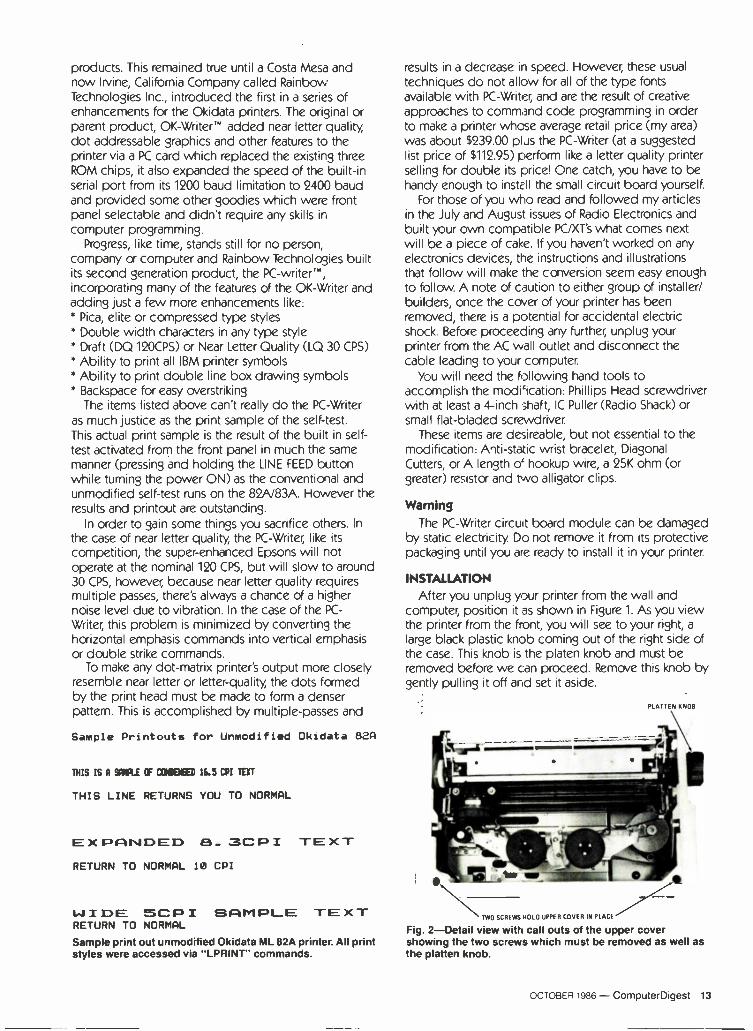
products. This remained true until a Costa Mesa and now Irvine, California Company called Rainbow Technologies Inc., introduced the first in a series of enhancements for the Okidata printers. The original or parent product, OK -Writer- added near letter quality, dot addressable graphics and other features to the printer via a PC card which replaced the existing three ROM chips, it also expanded the speed of the built-in serial port from its 1200 baud limitation to 2400 baud and provided some other goodies which were front panel selectable and didn't require any skills in
computer programming. Progress, like time, stands still for no person,
company or computer and Rainbow Technologies built its second generation product, the PC -writer'", incorporating many of the features of the OK -Writer and adding just a few more enhancements like: * Pica, elite or compressed type styles * Double width characters in any type style * Draft (DO 120CPS) or Near Letter Quality (LQ 30 CPS)
* Ability to print all IBM printer symbols * Ability to print double line box drawing symbols * Backspace for easy overstriking
The items listed above can't really do the PC -Writer as much justice as the print sample of the self -test. This actual print sample is the result of the built in self - test activated from the front panel in much the same manner (pressing and holding the LINE FEED button while turning the power ON) as the conventional and unmodified self -test runs on the 82A/83A. However the results and printout are outstanding.
In order to gain some things you sacrifice others. In
the case of near letter quality, the PC -Writer; like its
competition, the super -enhanced Epsons will not operate at the nominal 120 CPS, but will slow to around 30 CPS, however; because near letter quality requires multiple passes, there's always a chance of a higher noise level due to vibration. In the case of the PC -
Writer, this problem is minimized by converting the horizontal emphasis commands into vertical emphasis or double strike commands.
To make any dot-matrix printer's output more closely resemble near letter or letter -quality, the dots formed by the print head must be made to form a denser pattern. This is accomplished by multiple -passes and
Sample Printouts for Unmodified Okidata 82A
THIS IS A MU OF COCEt® 16.5 CPI TEXT
THIS LINE RETURNS YOU TO NORMAL
EXPANDED 8_ 3CPI TEXT RETURN TO NORMAL 10 CPI
WIDE SCPI SAMPLE TEXT RETURN TO NORMAL
Sample print out unmodified Okidata ML 82A printer. All print styles were accessed via "LPRINT" commands.
results in a decrease in speed. However; these usual
techniques do not allow for all of the type fonts available with PC -Writer; and are the result of creative approaches to command code programming in order to make a printer whose average retail price (my area) was about $239.00 plus the PC -Writer (at a suggested list price of $112.95) perform like a letter quality printer selling for double its price! One catch, you have to be handy enough to instE II the small circuit board yourself.
For those of you who read and followed my articles in the July and August issues of Radio Electronics and built your own compatible PC/XT's what comes next will be a piece of cake. If you haven't worked on any electronics devices, the instructions and illustrations that follow will make the conversion seem easy enough to follow. A note of caution to either group of installer/ builders, once the cover of your printer has been removed, there is a potential for accidental electric shock. Before proceeding any further; unplug your printer from the AC wall outlet and disconnect the cable leading to your computer.
You will need the following hand tools to accomplish the modification: Phillips Head screwdriver with at least a 4 -inch shaft, IC Puller (Radio Shack) or small flat -bladed screwdriver.
These items are desireable, but not essential to the modification: Anti -static wrist bracelet, Diagonal Cutters, or A length o' hookup wire, a 25K ohm (or greater) resistor and two alligator clips.
Warning The PC -Writer circuit board module can be damaged
by static electricity. Do not remove it from its protective packaging until you are ready to install it in your printer.
INSTALLATION After you unplug your printer from the wall and
computer; position it as shown in Figure 1. As you view the printer from the front, you will see to your right, a
large black plastic knob coming out of the right side of the case. This knob is the platen knob and must be removed before we can proceed. Remove this knob by gently pulling it off and set it aside.
PLATTEN KNOB
.. -... _..._. P
:lip -WA- _
TWO SCREWS BOLO UPPER COVER IN PLACE
Fig. 2-Detail view with call outs of the upper cover showing the two screws which must be removed as well as the platten knob.
OCTOBER 1986 - ComputerDigest 13

Remove the access cover by gently lifting it up and set it aside.
Refer to Figure 2 and loosen the two recessed phillips head screws which hold the front upper cover in place. Remove the cover by lifting it up and pushing it back to release the hooks located on the back panel of the printer. Carefully set the cover aside, taking the necessary precautions to avoid losing the two screws.
Turn your printer around as shown in Figure 3 and locate the control circuit board. It is normally located in
the first slot from the rear unless you have the optional high speed serial card. If you have the high speed serial card installed, you will have to remove this card before going any further. If you have the high speed serial card, locate the two hold-down screws one at each side of the circuit board and carefully remove the board to enable you to access the control circuit board.
If you do not have the high speed serial card installed, loosen the two hold-down screws at either end of the control circuit board and carefully lift it up until you can identify the three large ICs located at the top right hand corner (as viewed from the rear) and shown in Figures 4. Using either the small flat bladed screw driver or the IC puller, remove these three 24 -pin ICs by gently prying them loose from their sockets. The ICs are numbered 004, 005 and 006. You may have to remove cable CN5 from its socket on the control board in order to access these 3 ICs. Once you have removed the ICs you may put them aside, they will not be required when you install the PC -Writer module. Before proceeding with the installation, check that capacitors C27, C28 and C29 are at approximately a 60 degree angle relative to the control circuit board, if they are not, bend them as required. Check to see that capacitor C28 is at approximately a 90 -degree angle and correct if need by bending. This will facilitate the installation of the PC -Writer Module.
If you have the anti -static bracelet, place it around your wrist and connect the alligator clip at the end of the wire to a suitable ground connection. If you are wearing a metal watch band, you can use the wire, resistor and two alligator clips to form a similar protective device. Connect one end of the resistor to one of the alligator clips. The other end of the resistor is fastened (twisting is suitable) to a bare end (either
'(,.
4+IMW .
*t` 5 . . (
Ale
ti Fig. 3-Rear view of the printer's control circuit board visible when the upper cover has been removed.
end of the wire), the remaining alligator clip should be attached to the end of the wire and connected to a
suitable ground connection. The reason for these anti- static precautions is to eliminate the chance that static electric discharges could damage the PC -Writer module. Now you may open the PC -Writer container and carefully remove the module. Refer to Figure 5, the PC -Writer and locate it with the arrows pointing upwards and the circuit components facing you. If you are installing the PC -Writer in an Okidata 83A, locate resistor B labeled "CUT FOR ML83A." Using a diagonal cutter, carefully cut the wires attaching this resistor to the circuit board and discard the resistor. Carefully remove the protective foam from the underside of the circuit board, and observe the pins extending from the non -component side.
Align these pins with the corresponding locations of sockets 004 and 006 on the circuit control card. Gently press the module into these two sockets and continue the pressure until all pins have been seated in the sockets. Your PC -Writer does not use socket 005. Check your work and ensure that all pins are firmly seated as
shown in Figure 6. If you had to remove cable CN5, reconnect it at this time. Carefully slide the circuit board down and refasten the two hold down screws located at either end of the circuit board. Be careful not to pinch any wires under the circuit board during this step.
Turn your printer around so that it is facing you and set the front operator control DIP switch as follows:
Position 1
2
3
4
5
6 7
1.
REMOVE & DISCARD
I ,,.
IBM úi1
9 y ir 0"-1.
.; rt . 1 "
s E 'A
ON
X
OFF
X
X
X X
X X
CABLE CM5 ,j,,v\t .1E7
ARó8J150.
- I 1"ó
,\1... Wf.... .U y 1 lL t .
83E80C 4168715.041 >
...+üasul 1
AK-i4}J1
. °=-
I
Fig. 4-Detail view of the ROM's (3) and the cable CN5. The 3 ROM ICs are removed and discarded, the cable CN5 may require disconnection.
14 ComputerDigest - OCTOBER 1986

If you wish, you may refer to Section 4 or Appendix C of the manual which comes with your PC -Writer to select other conditions, however, the conditions selected as shown above (2 on, all others off) are the recommended power -on conditions.
Replace the upper cover by reversing the process used to remove it. Hook the cover at the rear panel and seat it, ensuring that the wire paper guide is flipped forward. Using the Phillips screwdriver tighten the two recessed hold down screws. Replace the access cover and replace the platen knob previously removed. You
have now completed the installation of the PC -Writer. The protective foam may be used to store the 3 ROMs
removed from the printer. Proceed to the following section and test your installation.
Testing
Load your printer with paper. Plug the printer into the AC wall outlet. Press and hold the line feed button while you turn the power switch on. Release the LINE
FEED button and your printer will begin to print the one page document/type sample. This one page will be repeated until you depress the SEL button or turn the printer OFF.
In case of problems If the printer does not operate immediately and
begin the self -test printout, turn the power off,
disconnect the AC power cord and recheck all of the
installation steps.
Exploring your new PC -Writer Now that you have installed the module, the normal
control functions of the Okidata Printer (See Figure 7)
have been enhanced and have additional functions which will be described at this time.
LINE FEED BUTTON -With the printer deselected (RED
LED SEL is OFF), pressing the button for more than one second causes the line feeding paper motion to repeat until the button is released. This can make it easier to move the paper over a short distance to the next top - of -form. It can also be used in conjunction with the TOF (top -of -form) button to advance the paper
HI-SISTUR8 CUT FOR M188A
'ill: T. .. .... D ¡ASP; y w.+ .H vt $ #= rszl sin I>/rTrrr_ «.-.. s ,arr set ... - r - :
* 5f` h r, . J Q.
r ; ' 4. s 4 f
4 r1
qY.,4 J'+;, 2l Fig. 5-The PC WRITER Module with call out for location of Resistor B. This resistor is not used with the wide carriage ML 83A printer.
upwards by small amourts. Holding the TOF SET
button down and gently pressing the LINE FEED button continuously will advance the paper, when you reach the desired position, relax the LINE FEED button and the new top of form will be set.
SEL (Select) BUTTON -Each time this button is
pressed the print head will move to a new position. When the printer is first selected the print head will move to the left margin to recalibrate for proper printing. When you deselect the printer by pressing the button and the RED LED Is off, the print head will move to the center to permit you to install the paper without the need to manually move the print head. It is also possible to put the printer ON-LINE after starting a
form feed action even though the paper is still moving. Briefly press and release the SEL button and the SEL
LED will come on as soon as the paper has stopped moving.
FORM LENGTH ROTAR" SWITCH -This switch now has
several new functions. If you are using the 132 col. 83A, switch setting 6 new selects a page length of 81/2
inches rather than the 8 inch page length shown in the printer manual and repeated on the 83A's access cover. This will allow you to use paper 11 inches wide by 87/2
inches high. The other uses of this rotary switch will be covered under the "Feature Selection" category.
Now that you have installed your PC -Writer, your Okidata Printer wilt provide full emulation of the IBM
Graphics printer and more. How much more will depend on what you elect to set by using escape sequences described in detail in the PC -Writer manual (Section 6.2), how you make use of the front panel Features Selection which will be described in detail and your own specific requirements.
The default setting you made earlier on the DIP
switch located on the form of the operator control panel enables the selection of all of the enhanced functions. If you desire to use only those functions used or supported by the IBM graphics printer, and no more, you would set switch 5 to ON and 1 and 8 to OFF, and not use any of the unique escape sequences for the PC -Writer. A description of some of the possible settings can be found in Section 4 and 6 of your PC -
Writers manual. For the present, let's leave the switch as
,--
F,' '.,,r*+ " 31 (..";-4-- fy,....,---'-47;), `l7 . r Q_ . .. _711':I. . . o t- u
- ". 'I, ii. _. '2111''7,-,......
:°.ii. ^ 1Kt P1 g1t1 x f lIT4{
'/I ! f 1 '
__- . . 1 e: 11.3.1 a -c {
i
1 1
Fig. 6-The PC WRITER Module installed on the control circuit board.
OCTOBER 1986 - ComputerDigest 15

set previously, and enjoy as much of the ease -of selection and feature as possible.
Feature selection The PC -Writer's features can be accessed in two
ways. The first is via traditional computer control mode, this will require that you use the escape sequences unique to your PC -Writer and for the present, we suggest that you confine yourself to the second mode, the user of the now enhanced Front Panel Selection Mode which will allow you access to the most desirable features without the need to program or refer to charts or tables.
FRONT PANEL SELECTION MODE -In this mode, you will use the SEL button, the LINE FEED button and the FORM FEED button and the FORM LENGTH rotary switch. Each of these controls and their function will be explained separately.
Selecting a feature To convert the front panel control to feature
selection, depress the SEL button for one or more seconds to activate the front panel selection mode. This is indicated by an audible tone and the SEL LED
flashing at a rate of about 2 or 3 times per second. To select a feature rotate the FORM LENGTH switch
from its normal forms length setting to the desire setting as listed below:
Setting# Feature Selected 0 Print HELP Menu 1 Letter quality 2 Elite character pitch 3 Compressed character mode 4 Wide characters 5 Shortened characters at 12 lines per inch (1pi) 6 Emphasized printing (bold faced) 7 Double Strike printing 8 Dumb terminal mode 9 Print shifting alphabet test
If position 1 through 8 is selected the SEL LED will indicate if that feature in ON (selected) or OFF. If the feature is ON the SEL LED will be ON more than it is off, if the feature selected is OFF, the LED will be OFF more than it is on. To change the setting or state of the selection, press the LINE FEED button once. Pressing it
:
1. PA
TOF I SET °
SU.
o
FOR UNEl lM ,FEEDr! 1FEE - - _--- ' I
Fig. 7-Detail view of the front panel controls. All controls now have enhanced functions under the PC WRITER.
again will change the selected feature to its opposite setting (off becomes ON, or on becomes OFF). If the FORM LENGTH switch is at the 0 position, pressing the line feed button will print a list (menu) of the features available from PC -Writer and their status (ON or OFF). Position 9 if selected will immediately begin to print a
shifting alphabet test as shown in Table 3. To stop this test, press the SEL button.
Draft quality is selected whenever letter quality is
not selected. The compressed mode has no effect while the Elite character pitch is selected. Pica character pitch of 10 cpi is selected whenever neither elite or compressed mode is selected. Turning off the shortened character mode (Position 5) will also select 6 LPI spacing. In the dumb terminal.mode, all control codes except Carriage Return (CR), Line Feed (LF) and Form Feed (FF) are ignored.
You can also print out the part numbers of the PROMs installed in the module. This information could be helpful whenever you need to discuss either a
problem or performance with a factory representative. To print these parts numbers, press the TOF SET and FORM FEED buttons simultaneously.
Once you have selected the desired features, briefly press the SEL button. The LED lamp will go off and an audible tone will sound to indicate that the normal off line (deselected) mode is in effect. Return the FORMS LENGTH switch to its normal forms length setting and press the SEL button again to place the printer ON- LINE. The printer will now be ready to print using the selected PC -Writer Feature.
While the normal functions of the operator front panel controls are well described and documented in your printer manual, using PC -Writer you can also make power -on selections of these features by pressing and holding the button while turning the printer power on. The buttons and their Power -On features are as follows: Operator Button Feature Activated TOP SET
Compressed character pitch in draft mode FORM FEEDPica character pitch in letter quality mode SELElectronically reverses the operator DIP SW Pos 8 for ON/OFF or OFF/ON, allows both a serial and parallel cable to be connected to the printer (DO NOT USE WITH HI -SPEED SERIAL CARD!) LINE FEEDSeIf-test and demonstration mode. FROM & LINE FEEDDiagnostic Hex dump mode
All features can be deactivated by depressing (deselecting) the SEL button once or when you turn off the printer.
There are many more things you can do with PC -
Writer, but if they were all described here, Rainbow Technologies wouldn't have to print a manual. The manual that comes with PC -Writer has sections on code information which is well structured and complete enough to enable you to really take charge of your new printer and exploit it to the limit, after all that's one of the best reasons for buying an enhancement in the first place.
For more information about PC -Writer and any of Rainbow Technologies other products write to them at: Rainbow Technologies Inc., 17971-E Skypark Circle, Irvine, CA 92714. (714) 261-0228.4W
16 ComputerDigest - OCTOBER 1986

STATE OF SOLID STATE Dual -condition sensing
1
C2
05
)F -- 1M
R4
1 MEG
-i )i+ = Cl
10µF
25V
UREF O
R2
1K
R3
20K
+ 15V
17 ,e)1
R5
47011
()2.5V \_,
l
OSCILLATOR
VOLTAGE
REGULATOR
ICI 3041
DUAL
COMPARATOR
FIG. 1
OFTEN WE NEED TO MONITOR TWO DIF- terent conditions and raise an alarm when either condition falls above or below a normal value. Those conditions might be, for ex- ample, the outputs of a dual -volt- age power supply, indoor and outdoor temperatures, or the high and low levels of the contents of a
tank. The electronics of such a two -
input monitoring circuit has been greatly simplified by the introduc- tion of the 3041 Monitor/Alarm IC by the Microcircuits Division of In - tech. The 3041 is a dual -input cir- cuit designed to monitor two ditterent voltages and give an in- dication it either varies trom the preset level by more than a user- settable predetermined percen- tage. The IC can provide a steady or an oscillating output, depend- ing on the state of pin 4. The
8 -OHM SPEAKER
- VIMR6
10K
TRIM
VIN2 R7
10K
TRIM
steady-state output is suitable for driving an LED, a lamp, or a TTL gate; the oscillating output is suit- able for driving a speaker or a
lightbulb. The 3041 is packaged in an eight -
pin mini -DIP. As shown in Fig. 1, it consists of a dual -input voltage comparator, a voltage regulator, and an oscillator. The 2.5 -volt ref- erence that is supplied by the reg- ulator may vary between 2.2- and 2.7 -volts DC. The reference volt- age is available at pin 3. Maximum current drain (with the alarm on) is 13 mA trom a 5 -volt supply, and 25 mA from a 15 -volt supply. Tem- perature stability is typically +50 ppm/°C.
The dual -input comparator monitors the voltages applied to pins I and 8, and compares them with reference voltage VRI r, which is present at the junction of exter-
ROBERT F. SCOTT, SEMICONDUCTOR EDITOR
nal resistors RI and R2. Actually, the voltage at pin 2 of the IC is used as the reference voltage, but the voltage at the junction of R1 and R2
is a more accurate representation of the voltage to which the com- parator inputs are compared.
Only six discrete components are needed to build a basic monitor/alarm circuit. External re- sistors R1 and R2 are typically 1000 ohms each. Resistor R3 is deter- mined by the desired "trip" toler- ance, the percentage deviation from normal that will cause the alarm to trip. The resistor's value can be calculated as follows:
R3 = (100,000 _ % Tolerance) -1000
The accuracies of resistors R1, R2, and R3 affect the tolerance of the comparator outputs by a factor of 10:1. For example, if the value of R3
is off by 5%, the comparator out- put will be off by 0.5%.
Capacitor CI filters the voltage regulator's output, reduces noise to the comparator, and ensures a
high -resolution trip point. The internal oscillator can be
disabled by grounding pin 4. For an AC output, connect an RC net- work to that pin as shown in Fig. I.
The values shown there will pro- duce an output of about 1000 Hz; other frequencies are easily ob- tainable by using other compo- nents. Intech's data sheet contains a nomograph that aids component selection for various frequencies.
The 3041's open collector output (pin 1) can supply as much as 30 mA of current. The output is oft (high) when both comparator in- puts are within tolerance, and on (low) when either input is out of tclerance. With the component
89

Reg. $125.00 Sale Price
Get A Complete Course In
ELECTRONIC ENGINEERING
8 volumes, over 2000 pages, including all necessary math and physics. 29 examinations to help you gauge your personal pro- gress. A truly great learning experience.
Prepare now to take advan- tage of the growing demand for people able to work at the engin- eering level.
Ask for our brochure giving complete details of content. Use your free information card num- ber, or write us directly. $89.95, Postage Included. Satisfaction guaranteed or money refunded.
Banner Technical Books, Inc. 1203 Grant Ave. Rockford, IL 61103
CIRCLE 176 ON FREE INFORMATION CARD
Power Supplies Discount Prices!
VERSATILE LAB POWER SUPPLY
Al a
ELECTRO INDUSTRIES MODEL 3002A
$9995 0.30 VDC at 0-2A Fully adjustable current limit-
ing Constant voltage/constant current modes - automatic crossover Excellent regulation with low ripple Floating output Built-in short-circuit and overload protection. Options: 10 -Turn Voltage & Cur-
rent Controls, 525 each. Both for S45.
EPSCO MODEL EC -2 POWER SUPPLY
0-16 VDC at 5A Comb. V/A meter Benchtop 1.8 volt/amp load change 0.5% ripple 5A
Reg. 5169.50 Sale Price 513000
Check, Money Order or C.O.D. Add $4.50 per unit for shipping & insurance. Outside U.S. $9.00. IL resi- dents add 7% tax. 15 -Day Money Back Guarantee.
Salen Enterprises P.O. Box 915, Morton Grove, IL
60053 Area 312-465-1424
ATTENTION'.
TR°NICS ELF AN. ilcNNIR
EARN YOUR VI°i..L 1111
B.B.E.E. j, v DEGREE .
THROUGH HOME STUDY Our New and Highly Effective Advanced -Place- ment Program for experienced Electronic Tech- nicians grants credit for previous Schooling and Professional Experience. and can greatly re- duce the time required to complete Program and reach graduation. No residence schooling re- quired for qualified Electronic Technicians. Through this Special Program you can pull all of the loose ends of your electronics background together and earn your B.S.E.E. Degree. Up- grade your status and pay to the Engineering Level. Advance Rapidly! Many finish in 12 months or less. Students and graduates in all 50 States and throughout the World. Established Over 40 Years! Write for free Descriptive Lit- erature.
COOK'S INSTITUTE OF ELECTRONICS ENGINEERING
347 RAYMOND ROAD P.O. BOX 20345 JACKSON, MISSISSIPPI 39209
CIRCLE 191 ON FREE INFORMATION CARD
values shown in Fig. 1, when either VIN., or VIN2 varies more than 5% from VRE1, a 1 -kHz tone will be heard.
The 3041 can be used to monitor negative voltages. To do so, just connect pin 6 to the most negative point rather than to ground. If only one input is used, the other must be connected to the VRLI pin.
Ripple detection The 3041 can be used to detect
ripple or oscillation at the inputs. To do that, connect a capacitor be- tween the arm and the upper end of one of the input potentiome- ters. The DC voltage level is set by adjusting the pot while the AC sig- nal is fed directly to the input through the capacitor. The circuit will respond to a peak AC voltage of 150 mV with a 5% tolerance set- ting, 230 mV with a 10% setting, and 420 mV with a 20% tolerance setting.
The value of the capacitor is de- termined by the value of the pot and by the lowest frequency of the signal that is to he detected. After setting the potentiometer for the desired DC level, measure the re-
sistance between the arm and the high end. Select a capacitor whose reactance at the lowest frequency is small compared with the resis- tance it will be shunting.
For a data sheet and additional information on the 3041, write to Intech, Inc. Microcircuits Div., 2270 Martin Ave., Santa Clara, CA 95050-2781.
New dual JFET op -amp NEC Electronics has introduced
the 1.1.PC812, a new low -offset -volt- age dual-JFET-input op -amp de- signed for stable operation when driving high -capacitance loads. Even when working into a 6800-pF load, the µPC812's output is abso- lutely stable. That stability is the result of using NEC's high-speed (1r = 300 MHz) PNP transistor in the output stage. The high-speed transistor eliminates oscillation problems when sinking current into a large capacitive load.
Other features of the device in- clude low input -offset voltage (3 mV maximum) and low input -off- set voltage temperature drift (7 µV/'C). In addition, the device has output short-circuit protection, in- ternal frequency compensation, and a high slew rate (13 \/µs).
Applications include fast sam- ple -and -hold, high-speed inte- grators, and any circuit requiring high-performance input and out- put characteristics. The µPC812 is available in standard 8 -pin plastic DIP and surface mount packages. Pricing for the DIP package is $0.66 for 100+ lots. NEC Electronics, Inc., P. O. Box 7241, Mountain View, CA 94039.
Quad multiplying D/A Precision Monolithics'
DAC-8408 quad 8 -bit, multiplying CMOS D/A converter with memo- ry is designed for applications that require data -path verification, self diagnostics, and PC -board space savings.
The IC contains four identical 8 - bit DAC's on a single CMOS chip. Each DAC has its own reference input, feedback resistor, data latches, and internal 3 -state buff- ers. The IC uses an 8 -bit TTL/ CMOS-compatible data port that is bus -compatible with most 8 -bit microprocessors, including the 6800, the 8080, the 8085, and the
90
CIRCLE 178 ON FREE INFORMATION CARD

Z80. The port is common to all DAC's in the IC; doing so reduces pin count and allows the device to be packaged in a 28 -pin, 0.6" DIP.
The DAC-8408 features a read/ write capability that allows each DAC's data word to be read from an addressable memory location. By reading the latched register contents back, the controlling computer can execute data -path verification, self -checks, and ana- log output updating.
The device is available in two grades in both military/industrial and commercial temperature ranges. Prices in 100 -piece lots range from $8.03 for the lower - grade commercial devices to $35.82 for the top military grade. Precision Monolithics, P. O. Box 58020, Santa Clara, CA 95052.
New P -channel JFET's
The 2N5460 -2N5465 from Sil- iconix are low-cost P -channel JFET
devices designed for a broad range of applications, including servo amplifiers, analog switches, level shifters, and control loops. Featured are high breakdown volt- ages of 40 to 60 volts, low operat- ing currents of 1 to 9 mA, and high gain (1000 to 6000 µmhos, mini- mum). Fast switching is made pos- sible by the devices' low inter - electrode capacitance (typically 1
to 5 pF). The JFET's come in TO -92 packages. In 1000 piece lots the 40 - volt 2N5460, 2N5461, and 2N5462 are $0.40 each. The 60 -volt 2N5463, 2N5464, and 2N5465 are $0.60 each. Siliconix, Inc., 2201 Laurel - wood Rd., Santa Clara, CA 95054.
High -power Darlingtons The ZTX600 is the latest addition
to Ferranti's family of E -Line (TO -92) NPN Darlington tran- sistors. The new series of high-per- formance, medium -power devices handle collector currents of as much as 1 amp, and that makes them ideal for automotive and in- dustrial applications. Pulsed cur- rents (IcM) of up to 4 amps, and gains (FIFE) up to 100,000 at continu- ous currents ranging from 500-1000 mA are attainable.
The ZTX600 series otters Vc, ratings of 140 to 160 volts. The con- struction of the E -Line package permits high junction temperature operation (200°C) that is usually as -
ROBOTICS
continued from page 84
into the control board; the per- sonality pack provides the CPU and any memory it requires.
The arm used for the robot is an adaptation of the Milton Bradley Robotix series we discussed in the July 1986 issue. Optical encoders are placed on all joints; feedback from them is routed to the control circuitry. Motor control is by means of subminiature mechan- ical rather than solid-state relays.
The mobile platform also in- cludes an allophone speech syn- thesizer. The IC set is available through Radio Shack.
Because of the complexity of the construction details, it is not feasi- ble to present them here. If you are interested in obtaining a full packet of information on the robot (schematic, theory, programming, and mechanical details) drop me a
note and include a self-addressed stamped business envelope. R -E
30 Ways to Help You Qualify for
the Job You Want Free Facts about Career Diplomas and Degrees Now at home in your spare time. without any previous experience. you can train for a money -making career ...even get a Specialized Associate Degree. Call ors- sed for free information on the career field thai Interests you most and how to train for it
1-800-228-5300/DESBB CALL ANYTIME -24 sours a day 7 days a
No cost No obligation No salesman Aral v sd
OR MAIL COUPON TODAY- - - I'CS International Correspondence Schools swNce reap Dept. DES96,Scranton, PA 18515 Send free facts on how I can study at home for the career I have chosen No obligation No salesman wI I visit CHECK ONE CAREER ONLY.
ASSOCIATE IN SPECIALIZED ASSOCIATE IN SPECIALIZED BJSINESS DEGREE TECHNOLOGY DEGREE PROGRAMS PROGRAMS
Business Management Mechacal Engineering Accounting Technologyn,
- Business Management Gvd Engineering technology ally whorl m Marketing -- Electrical Engineering Business Management Technology w th optan n Finance Flectromcs Technology
CAREER DIPLOMA PROGRAMS Computer Programming E'eclncun Agh Scnoo Police Science Catering Gourmet Cooking Art Mrcrocomputer Repair Small Business Management Auto Mechanics Wridhle Forestry Conservation Bookkeeping ' Diesel Mechanics Holes Restaurant Management'" Gun Repair
r Drattrng -"'Motorcycle Repair I Art Conditioning A surveyorg A Maporng
Reingerabon TV VCR Repair Electronics Veterinary Assistant
Travel Agent
these courses are offered by ICS and North American Correspondence
schools NAw1E AGE
CALL TOLL FREE
ADDRESS
CITY STATE ZIP L HNNE NO. I
sociatea with metal -can devices, which can dissipate up to 1.5 watts.
The ZTX600 series is available with several lead configurations and on radial or surface -mount tape for auto -placement. Unit prices are below $0.18 in quantities of 50,000. Ferranti Semiconductor, 87 Modular Ave., Commack, NY 11725.
Four new MOSFET's Four ITT -type MOSFET tran-
sistors that complement its line of N- and P -channel devices have been announced by Ferranti Semi- conductors. The devices, BS170P, BS107P and BS107PT (N -channel), and BS250P (P -channel) are num- bered according to the Pro -Elec- tron or European system. They provide low threshold, low leak- age and fast switching at break- down voltages between 60 and 200 volts. The BS107P and BSIO7PT can withstand lightning surges of 1500
volts. The BS107P costs $0.31 in lots of
1000. The BS107P and BS107PT cost $0.41 and $0.42, respectively, in similar quantities.-Ferranti Semi- conductors, 87 Modular Ave., Commack, NY 11725. R -E
STUN GUN
EQUALIZER The ultimate non -lethal defense weapon. In five seconds can immobilize your attacker, even through heavy clothing. Discharges over forty thousand volts of electricity from a nine volt nickel - cadmium battery. S39.95, Mass 5% sales tax, $3.00 shipping and handling.
1-800-522-2636 FOR ORDERS ONLY
617.871-5611 FOR INFORMATION
Cameo Enterprises, Inc. P.O. Box 63, Accord, MA 02018 CIRCLE 89 ON FREE INFORMATION CARD 91
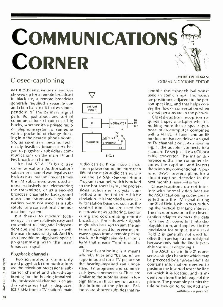
COMMUNICATIONS '; CORNER Closed -captioning IN THI Ul t) DAYS, WHEN TECHNICI \NS showed up for a remote broadcast in black tie, a remote broadcast generally required a separate cue and chit-chat circuit that was inde- pendent of the primary signal path. But just about any sort of communications circuit costs big bucks, whether it's a private radio or telephone system, or someone with a pocketful of change duck- ing into the nearest phone booth. So, as soon as it became tech- nically feasible, broadcasters be- gan to piggyback subsidiary com- munications on the main TV and FM broadcast channels.
The FM SCA (Subsidiary Communications Authorization) subcarrier channel was legal as tar back as 1945, but until recent times the FM subcarriers were used al- most exclusively for telemetering the transmitter, or as a second broadcast channel for background music and "storecasts." FM sub - carriers were not used as a sub- stitute for a conventional commu- nications system.
But thanks to modern tech- nology it is now relatively easy and convenient to integrate indepen- dent cue and control signals with the main broadcast signal. And it's also possible to piggyback special programming with the main broadcast signal.
Piggyback channels Two examples of commonly
used piggyback communications are the television protessional sub - carrier channel and closed -cap- tioning for the hearing -impaired. The professional channel is an au- dio subcarrier that is displaced 102.3 kHz from a TV station's main
TO TV SET
FIG. 1
audio carrier. It can have a max- imum power output no more than 10% ot the main audio carrier. Un- like the TV SAP (Second Audio Program) channel, which is locked to the horizontal sync, the profes- sional subcarrier is crystal con- trolled and limited to ±3 kHz deviation. It is intended specifical- ly for station business such as the control tones that are used for electronic news gathering, and for cuing and coordinating remote broadcasts. Pro subcarrier signals might also he used to aim the an- tenna that is used to receive micro- wave signals from a remote pickup truck, or it might simply turn on a light that means "You're on the air."
Closed -captioning is a means whereby titles and "balloons" are superimposed on a TV picture so the hearing -impaired can under- stand TV programs and commer- cials (yes, commercials). Titles are similar to the subtitles used in for- eign films, in that they run across the bottom ot the picture. Bal- loons are shorter subtitles that re -
HERB FRIEDMAN, COMMUNICATIONS EDITOR
semble the "speech balloons" used in comic strips. The \words are positioned adjacent to the per- son speaking, and that helps con- vey the flow of conversation when several persons are in the picture.
Closed -caption reception re- quires a special adapter which is nothing more than a special-pur- pose microcomputer combined with a VHF/UHF tuner and an RF modulator that can deliver a signal to IV channel 2 or 3. As shown in Fig. 1, the adapter connects to a standard TV set just like a VCR or a cable converter. The major dif- ference is that the computer de- codes the captions and inserts them into the conventional TV pic- ture. (We'll present plans for a
closed -caption decoder in the next month's issue.-Editor)
Closed -captions do not inter- fere with normal video because the ASCII captioning codes are in- serted into the TV signal during line 21 of Field 1, which occurs dur- ing the vertical blanking interval. The microprocessor in the closed - caption adapter extracts the data from line 21, converts it into dis- playable form, and applies it to the modulator for output. (Line 21 of Field 2 is generally not used for other than perhaps a control signal because only half the line is avail- able for ASCII encoding.)
The ASCII data in line 21 repre- sents a single character which may be preceded by a "preamble" that contains information needed to position the inserted text: the line on which it is located, and its in- dentation from the left edge of the picture. The preamble permits the title or balloon to be located any-
cmntinnea! un /tint' 97
92

. . d/ .9 A
KEN WOO ...pacesetter in Amateur radio
, . Í ..
ÍVI I
G
C'r. .. j - ._ I1d'.ie.tiC r ¡¡q ^`^
TriiFj
.`. .
MINIM MINIM
WM/0 -¡ RMM'000 `-
BAf/p
G6_
.NI
R-2000 All -mode receiver Superior engineering, quality, and performance describe Kenwood's multi - mode communications receiver.
The R-2000 receiver has the most often- needed features for the serious or casual shortwave broadcast listener. Listen in on overseas news, music, and commentary. "Listen up" on the VHF public service and Amateur radio frequencies, as well as aircraft and busi- ness band communications with the R-2000 and VC -10 option. The R-2000 has a muting circuit so you can monitor your Amateur radio station's signal quality.
Covers 150 kHz - 30 MHz in 30 bands. All mode: USB, LSB, CW, AM, FM.
Digital VFO's. 50 -Hz. 500 -Hz or 5 -kHz steps. F. LOCK switch.
. W ry 4i.-- T -
w'94S7na` ` , -- ! +~,t1=
J
,: ----e_ ,15.4'950' .....
r'.. Mal - p- lobe
?C O.T,q 'o
_
VO
emer
Ten memories store frequency. band. and mode data. Each memory may be tuned as a VFO. Lithium batt. memory back-uo. Memory scan. Programmable band scan. Fluorescent tube digital display of frequency (100 Hz resolution) or time. Dual 24 -hour quartz clocks, with timer. Three built-in IF filters with NARROW/WIDE selector switch. (CW filter optional.) Squelch circuit. all mode. built-in. Noise blanker built-in. Large front mounted speaker. RF step attenuator. (0-10-20-30 dB.) AGC switch. (Slow -Fast.) "S" meter, with SINPO scale. High and low impedance antenna terminals. 100/120!220/240 VAC operation. RECORD output jack. Timer REMOTE output (not for AC power). Muting terminals.
Service manuals are available for all receivers and 1110,,1 accessories Specd4arrons and prices suoleci ro change V. dnour notice Cr obligation
Optional accessories:
VC -10 VHF converter for R-2000 covers 118-174 MHz YG-455C 500 Hz CW filter for R-2000 I --S-4 Headphones HS -5 Deluxe headphones HS -6 Lightweight headphones HS -7 Micro headphones CCK-1 DC cable kit for 13.8 VDC operation
Additional information on Kenwood all -band receivers is available from authorized dealers.
KENWOOD TRIO-KENWOOD COMMUNICATIONS 1111 West Walnut Street Compton, California 90220
CIRCLE 102 ON FREE INFORMATION CARD
K,

ANTIQUE RADIOS
Antique radio cabinets
I I'ti I IARD TO IAI h AROU I AN I IOU' RA -
dios without also talking about the cabinets of antique radios. Those cabinets are as collectible as the chassis they contain. In the early days of radio, it was not unusual to have an elaborate cabinet for the speaker and none at all for the chassis. Some early speaker cab- inets were so large that there was room inside to mount the chassis, which many listeners did. And many chassis were mounted in cabinets made for purposes totally unrelated to radio.
The antique of the month Speaking of large cabinets, the
massive 1940 Philco Model 41-616 combination radio/phono shown in Fig. I has the largest cabinet in my collection. Measuring 40 inches across and about 48 inches high, it completely dominates my "shack." Usually the shack is used only for quarantine and prelimin- ary inspection. However, that con- sole was too large to carry down to my "museum" (the cellar).
I received the Philco just for re- moving it trom a location where it
was unwanted. Not being one to turn down anything tree, I
planned to restore that monster and then sell it (or trade it) for some older (and smaller) collecti- bles. But, atter repairing the chas- sis and hearing the big -band sounds emanating from the grille cloth, I decided to keep it. Now I
listen to it whenever I work in the shack. My only problem is getting in and out of the shack, because the Philco almost completely blocks the door.
Its 15 -tube chassis has a broad- cast hand and three shortwave
bands; and a 14 -inch dynamic speaker is located under the rec- ord changer.
Antique cabinets Over the years, the radio cab-
inet took the form of everything from a simple box to a huge elab- orately scrolled cabinet. When the chassis was no longer repairable, a
nice cabinet might he converted into a bookcase, a grandfather clock, a lamp, a bird house, a pho- nograph, a secretary, or any of a
number of other things.
«+ F. .1~~~.~.~~1
1
IIG.I
On the other hand, many clocks, etc., had more than enough space to mount a radio chassis and a speaker. These clays many collectors come into posses- sion of an unidentifiable radio built into a clock or some other device by an early radio hobbyist. In tact, the only identifying infor- mation may be the tube numbers. Many readers have indicated that that lack of identification is a com- mon problem.
For many years radio cabinets followed (and sometimes led)
A1 RICHARD D. FITCH,
CONTRIBUTING EDITOR
fashions in furniture design. 01 course, being beautiful was not the only function of a radio cab- inet. In addition to protecting the internal circuitry, the cabinet also provided a baffle arrangement for the loudspeaker.
Both the magnetic loudspeaker and the dynamic cone loud- speaker (both of which were dis- cussed here in the September 1986 issue) sound better when mounted in a cabinet. Because it has trouble reproducing low notes, the magnetic loudspeaker greatly benefits from a battle.
Enclosure design Speaker cabinets weren't used
just for looks and to house the chassis; they were designed to im- prove the sound produced by speakers. So designers spent a
great deal of effort trying to match enclosure and loudspeaker to get the best looks and the best sound. Some designers went to fantastic lengths to come up with better - sounding speaker enclosures. In tact, collectors who dismantle the cabinets of some 1930 -era consol- es may well be battled by the baffle arrangement (pun intended). You may not be able to find the speak- er because of all of the internal parts! Another area of much engi- neering effort was the fabric de- sign of the loosely -woven grille cloth. It was hoped that the grille cloth wouldn't interfere with the sound waves.
Through the 1930's the ability to reproduce bass notes was the most desirable feature, and one 01
the hottest selling points, of many console radios. Bass response was improved by using a large re -
94

producer, by adding bass and tre- ble controls, and by using a well - designed enclosure.
In the developing days of radio, not just the type of speaker, but its location were items of contention among designers. In an effort to improve reproduction, shelves were installed, removed, installed in another location, and so on, in early cabinet designs. Intormation on that type of alteration, and others, could be obtained from the early radio magazines.
For some unknown reason, cab- inets for radio chassis were not very popular. Buying radios in bits and pieces was the beginning of "component" sets, which younger readers may think began with hi -Ii in the 1950's. Actually, component sets are as old as radio itself.
Many speaker cabinets were large enough to use as closets. En- terprising experimenters knew that an oversized speaker cabinet and a cabinet -less chassis could be combined. Even then, as little as 25% of the grille area might be taken up by the speaker.
Ot course, it would have been a
crime to destroy the front of a
beautiful speaker cabinet to mount a chassis with tuning dials, volume controls, etc., protruding through the front. But there were ways around that. To maintain the integrity of the front panel of the cabinet, one place to put the tun- ing knob, volume control, and power switch was on the side. Ot course, the chassis had to have provision for appropriate shaft ex- tenders, as well as for other me- chanical fixes.
Converting a console speaker cabinet to a complete self-con- tained radio was a very popular ac- tivity in the late 1920's. There were thousands of builders, and that ex- plains why many collectors have attractive, professional -looking ra- dios that they can't seem to be able to identity.
The cabinets themselves were made by hundreds of different cabinet makers; many of them didn't bother to label their work. All it took was a few simple altera- tions, such as adding a shell, to he able to mount the chassis in the cabinet.
A homemade tuning knob (with a painted dial) that is mounted on
the side of a cabinet is a good clue that a radio wasn't originally a con- sole radio. Converting those speaker cabinets to console radios surely didn't please the cabinet manufacturers, because the add- ed shelves and other components did little for the cabinet's sound quality. If a back panel was pres- ent, it had to be removed to allow heat dissipation, and heat was something there was plenty of in early chassis with big tubes. Also, an AC -powered amplifier located close to a speaker often created hunt that didn't exist when the speaker was mounted in the cab- inet alone.
Baffle design Sound waves emanating from
the front of the speaker cone must be separated from the out -of - phase sound waves emanating from the rear. One fairly suc- cessful attempt to separate those sound waves looks like a speaker mounted on a paddle. The "pad- dle" is called a battle board, and the assembly was designed to
Learn the IBM PC's secrets with the
\I ICROI'ROI' ESSOR 1/88
Students, engineers, or technicians- Now you can learn micro -processing and understand the technology which made the IBM PC famous. The MPF-1188 features:
extensive documentation 16 -bit central processor full-size keyboard special options
Three tutorial guides cover all capabilities. The ideal training tool! If the IBM PC or micro -processing arc in your future, you owe yourself an MPF-I/88. Invest now!
Only $349.95 Plus-
A Inú ho. tor rNh:t NPF t.aa IulnriW iniM,W . hen wu order . n Pon 7
d..a. 524.90 nlur 0/ Dept. REIrim,
5126 901 Ave NE Seattle, WA 98105-3617
For immediate action call TOLL FREE:
1-800-426.1044 Full money back guarantee.
VISA 01:1 CIRCLE 181 ON FREE INFORMATION CARD
Be an FCC LICENSED
.1" Off ig we&'. No costly school. No commuting to class. The Original Monte -Study course pre- pares you for the "FCC Commercial Radio- telephone License". This valuable license is your "ticket'. to thousands of exciting jobs in Communications. Radio Tv. Micro- wave. Computers. Radar. Avonics and more! You don't need a college degree to qualify. but you do need an FCC License. No Need to Quit Your Job or Go To School
This proven course is easy. fast and low cost! GUARANTEED PASS - You get your FCC License or stoney refunded. Send for FREE facts now. MAIL COUPON TODAY!
commanD PRODUCTIonS FCC LICENSE TRAINING, Dept 90 P.O. Box 2223, San Francisco, CA 94126 Please rash FREE details immediately! NAME ADDRESS CITY STATE ZIP
ELECTRONIC TECHNICIAN!
<om= .,. ", r Earn up to Irk
mom, S30 an hour and more!
Learn at home in spare time. No previous experience needed.
J
SEE YOUR DEALER TODAY
FROM
4Firestik; ANTENNAS ACCESSORIES.)
HERE'S A TIP THAT'S PERFECT!
AM/FM AUTO RADIO AND CB
`Firestik'U GOLDEN SERIES BARE -HANDS TUNABLE "NO TOOLS NEEDED"
HIGH PERFORMANCE ANTENNAS
ALSO ANTENNAS FOR CORDLESS TELEPHONES MONITOR SCANNERS
Dealer & Distributor Inquiries Invited SEND FOR FREE CATALOG
'FlrartIt' Antenna Company 2614 East Adams Phoenix, AZ 85034
7 Name
Street
City
State Zip Serving the CB and
Communication: Market Since 1962.
5 -YEAR REPLACEMENT WARRANTY CIRCLE 100 ON FREE INFORMATION CARD
95

complement the furniture that was in style at that time (the late 1920's).
One battle hoard, the 1928-ish Musicale, was made by Crosley. When first introduced, the Musi- cone sold for under $40.00 com- plete. I hat was quite a buy, when you consider that a magnetic speaker was included. The Musi- cone is an attractive piece of fur- niture with an ornate, scalloped, solid mahogany battle, and a
three-legged stand. Standing about 40 inches tall, the battle of
the Musicone can he adjusted from side to side to accommodate the listener's pleasure.
As with other components of developing radio, there was much controversy over which type of cabinet was best, and how compo- nents should be mounted inside it. Some designers thought that the speaker should be mounted in the top of the cabinet so that sound would he directed at the ears of the listeners in the room. Many readers have sent in photos
CABLE TV * SPECIALS
CONVERTERS
JERROLD: DRZ-301C105-66 Channel Wireless '199.'6
JRX-3 DIC-36 Channel Corded Remote '149.'6 JSX-3 DIC-36 Channel Set Top '129.'5 SB-3-'The Real Thing' '119.'5
MAGNAVOX: 6400-60 Channel Wireless wiParental Lockout for Jerrold systems '199.'5
ZENITH: Z -TAC Cable Add -On '225."
VIEW STAR: EVSC-2000-60 Channel Wireless- with Parental Lockout I 99.95
EVSC-2000A-B-Same as above with A -B Switch '109."
View Star 1000-60 Channel Wireless with Volume '119."
MISCELLANEOUS
OAK: N-12 Mini -Code 89.55
N-12 Mini -Code Vari-Sync '109." N-12 Mini -Code Vari-Sync Plus Auto On -Off '165.0°
JERROLD: 400 & 450 Handheld Transmitters ' 29."
HAMLIN: MLD-1200 ' 99.'5
NEW ITEMS: Standard Components -66 Channel Wireless - with Parental Lockout ' 99./5
Scientific Atlanta Call for Price
Power Zapper Stun Gun, 46, 000V ' 59.t6
K-40 Radar Detector-Dash Model '199." K-40 Radar Detector-Remote '229." ALL UNITS GUARANTEED. QUANTITY PRICES AVAILABLE.
UNITED ELECTRONIC SUPPLY P.O. BOX 1206 ELGIN, ILLINOIS 60121 312-697-0600
of that type of antique radio, such as the Grigsby Grunow Majestic; some RCA models with a phono mounted over the speaker (from about 1933); some RCA Radiolas; the Stromberg-Carlson Highboy, and several Philco models, such as the nine -tube model 908 shown in Fig. 2.
FIG. 2
It may have been a good idea to mount the speakers at ear height, but tuning some of those sets was difficult. You might have to get down on your knees to see the tuning dial, which sometimes was mounted a scant 14 inches above the floor.
So some people used the bot- tom part of the speaker cabinet as a baffle. The speaker faced down- ward, so sound came out of the bottom of the cabinet. That type of cabinet could be used only in rooms with heavily carpeted floors, because the echoes that re- sult could degrade the sound quality.
The speaker -design wars ended in a compromise: Speakers were mounted in the bottom of the front panel lacing forward. The dif- ference in sound (front the upper position) wasn't noticeable, and the radio was much easier to tune when the dial was mounted above the speaker.
Early speaker cabinets often had thin supporting legs, but later the legged cabinets gave way to mod- els that were enclosed almost all the way to the floor. the extra cab- inet, besides conforming to more modern ideas about furniture de- sign, gave the engineers new ways of reinforcing the bass notes. The extra length of the cabinet made it
96 CIRCLE 177 ON FREE INFORMATION CARD

, Get in on ... possible to delay the sound waves (by bouncing them around inside the cabinet) until they were in phase with the waves coming from the tront of the cone.
Troubleshooting hints It you have a cabinet with a "lab-
yrinth," you must remove a felt hood to get at the speaker. Be sure to replace the hood (behind the speaker) and all cabinet parts, or the sound will not he reproduced as the manufacturer intended. Also, speaker cabinets without hacks should stand about six inches from a wall, or in a corner for best sound.
Most early cabinets were made of extremely heavy wood. The "Sonic Arc" baffle made by RCA required a heavy cabinet. So did their model that pumped bass tones through pipes and emitted them in phase through the bottom of the baseboard.
When you dismantle those cab- inets to service the loudspeaker, don't destroy all the early engi- neers' hard work. Be sure to re- place everything just as it was when you finish. Remember: that includes any sound -deadening material, and especially the heavy flat or curved backboards.
Haves and needs We have one "have" this month,
and a copule of "needs." Tony Peterson (800 12th Ave. NE,
Blaine, MN 55434) needs a 1939
Stromberg Carlson, I2 -tube re- mote control unit.
John Kendall (301-877-3593) has a Jackson model 648 tube tester for antique tubes. George E. Kemmet (60-05 70th Ave., Ridgewood, NY 11385) needs someone to repair a
Majestic Model 90.
Help needed I am compiling a list of useful
reading material for inclusion in a
future column. If you have a book, magazine, newsletter, catalog, re- print, or other source of informa- tion that you consider particularly useful, I'd appreciate it if you would let me know about it. Please include a sample issue, or com- plete publication data, including a
source where it can be purchased by our readers. R -E
OVER 2,000 TUBE TYPES
IN -STOCK 78% - 90% off list
Plus thousands of electronic parts
including VCR/Cable Accessories Telephone Accessories Audio Accessories Computer Accessories Capacitors. Resistors, Diodes, etc. Speakers Many other items
Send for FREE Catalog
Steven t". / J
MAIL ORDER ELECTRONICS CORP P O Box 698 Melville. New York 11747
(516) 752-0060
-1 II l u l l
CIRCLE 189 ON FREE INFORMATION CARD
1 1
ELEESFiOiIICS±
,41
j . .,
1. .
t TRAIN TODAY for an exciting money -making career In:
Electronics Engineering Technology Computer Programming Data Processing Information Systems Drafting with CA.D.
NATIONAL EDUCATION CENTERS has 50 cam- puses nationwide, so there'sa Center near you. In as little as 9 months, you can train for a high-tech career. in a state-of-the-art environment. ASK ABOUT OUR BENEFITSI Day and Evening classes. Financial Aid to those who qualify, and Job Placement Assistance! Many of our schools are Approved for Veterans Training, and all are ac- credited members of either N A.TTS. or A.I.C.S. SO DON'T DELAY' For information send In the handy coupon today. Or call 7 days a week -
National TOLL -FREE 1 Education Aso É* ro Centers
WM Ili MI IIIZ National ducation Centers-Headquarters 1732 Reynolds Irvine, CA 92714
The program I am interested in is Year of High School Graduation or G E D
NAME
ADDRESS
CITY/STATE/ZIP I V, PHONE. R E 108 -- MI Wm BM MI MN --Mil/
OMMUNICATIONS CORNER
continued from page 92
where on the screen. It you think that a single
character per line may not provide much information, bear in mind the fact that there are 30 usable fields per second. So in two sec- onds the system can transmit al- most two complete lines of subtitles, which the micro- processor then integrates into a
single display. Characters don't come up on the screen one at a
:ime unless the captioning is being done in real time.
You might wonder whether the adapter can simply strip off the video information and display only text (in the manner of Tele- text). A Teletext bulletin -board is, in tact, one of the options provided by the adapter's function selector. For example, the Teletext mode is used to piggyback news bulletins from the ABC network onto broadcasts, and real-time school news and notices on edu- cational stations. R -E
JAN CRYSTALS Since 1958
General Communication Industry Marine VHF Scanners Amateur Bands CB Standard CB Special Microprocessor Call or Write JAN CRYSTALS P.O. Box 06017 Fort Myers FL 33906-6017
-=.2- (813) 936-2397
CIRCLE 104 ON FREE INFORMATION CARD 97

MARKET CENTER PLANS AND KITS
CATALOG: Hobby/broadcasting/1750 meters ham/ CB: transmitters, amplifiers, antennas, scramblers, bugging devices, more! PANAXIS, Box 130-F10. Paradise, CA 95969.
STEREO TV adapter kit Easily converts any TV, VCR to receive the new stereo TV sound. Contains all parts PCB and instructions to build a quality stereo decoder. For additional information send SASE to SOKOLOWKSI, Box 150. Elmont, NY 11003.
CLASSIFIED AD ORDER FORM
To run your own classified ad, put one word on each of the lines below and send this form along with your check to:
Radio -Electronics Classified Ads, 500-B Bi-County Boulevard, Farmingdale, NY 11735
PLEASE INDICATE in which category of classified advertising you wish your ad to appear. For special headings, there is a surcharge of $23.00. ( ) Plans/Kits ( ) Business Opportunities ( ) For Sale ( ) Education/Instruction ( ) Wanted ( ) Satellite Television ( )
Special Category: $23.00
PLEASE PRINT EACH WORD SEPARATELY, IN BLOCK LETTERS. (No refunds or credits for typesetting errors can be made unless you clearly print or type your copy.) Rates indicated are for standard style classified ads only. See below for additional charges for special ads. Minimum: 15 words.
1 2 3 4 5
6 7 8 9 10
11 12 13 14 15 ($42.75)
16 ($45.60) 17 ($48.45) 18 ($51.30) 19 ($54.15) 20 ($57.00)
21 ($59.85) 22 ($62.70) 23 ($65.55) 24 ($68.40) 25 ($71.25)
26 ($74.10) 27 ($76.95) 28 ($79.80) 29 ($82.65) 30 ($85.50)
31 ($88.35) 32 ($91.10) 33 ($94.05) 34 ($96.90) 35 ($99.75)
We accept MasterCard and Visa for payment of orders. If you wish to use your credit card to pay for your ad fill in the following additional information (Sorry, no telephone orders can be accepted.):
Card Number Expiration Date
Please Print Name Signature
IF YOU USE A BOX NUMBER YOU MUST INCLUDE YOUR PERMANENT ADDRESS AND PHONE NUMBER FOR OUR FILES. ADS SUBMITTED WITHOUT THIS INFORMATION WILL NOT BE ACCEPTED. CLASSIFIED COMMERCIAL RATE: (for firms or individuals offering commercial products or services) S2.85 per word prepaid (no charge for zip code)...MINIMUM 15 WORDS. 5% discount for same ad in 6 issues: 10% discount for same ad in 12 issues within one year: if prepaid. NON-COMMERCIAL RATE: (for individuals who want to buy or sell a personal item) S2.30 per word. prepaid....no minimum. ONLY FIRST WORD AND NAME set in bold caps at no extra charge. Additional bold face (not available as all caps) 50c per word additional (20% premium). Entire ad in boldface, add 20% premium to total price. TINT SCREEN BEHIND ENTIRE AD: add 25% premium to total price. TINT SCREEN BEHIND ENTIRE AD PLUS ALL BOLD FACE AD: add 45% premium to total price. EXPANDED TYPE AD: $4.30 per word prepaid. All other items same as for STANDARD COMMERCIAL RATE. TINT SCREEN BEHIND ENTIRE EXPANDED TYPE AD: add 25% premium to total price. TINT SCREEN BEHIND ENTIRE EXPANDED TYPE AD PLUS ALL BOLD FACE AD: add 45% premium to total price. DISPLAY ADS: 1" , 21/4"- $310.00: 2" x 2'/4"-$620.00: 3" x 21/4"-$930.00. General Information: Frequency rates and prepayment discounts are available. ALL COPY SUBJECT TO PUBLISHERS APPROVAL. ADVERTISEMENTS USING P.O. BOX ADDRESS WILL NOT BE ACCEPTED UNTIL ADVERTISER SUPPLIES PUBLISHER WITH PERMANENT ADDRESS AND PHONE NUMBER. Copy to be in our hands on the 12th of the third month preceding the date of the issue. (i.e., August issue copy must be received by May 12th). When normal closing date falls on Saturday, Sunday or Holiday. issue closes on preceding working day.
CRYSTAL radio sets, plans, parts, kits, catalog S1.00. MIDCO, 660 North Dixie Highway, Hol- lywood. FL 33020.
BUILD this five digit panel meter and square wave generator including an ohms, capacitance and fre- quency meter. Detailed instructions 52.50. BAG- NALL ELECTRONICS, 179 May, Fairfield, CT 06430.
VOICE disguisers! Telephone bugs! FM bugs! Other kits! Send stamped envelope: XANDI, Box 25647, Dept. 60C, Tempe. AZ 85282.
EPROM, EEPROM zapper kit. Stand alone. RS232, parallel. $5.00 plans. $99.00 kit, free literature. MICRO KIT, 6910 Patterson, Caledonia, MI 49316 (616) 791-9333.
BUILD THIS ELECTRONIC
DIGITAL LOCK
only $12.50
thousands of combinations wrong No. alarm use 9-12VDC led indicator control up to 200W good for home and auto security satisfaction guaranteed
very order please add S2.00 for ship. Ding
assembled only $16.50
M.T.F. Box 810301, Houston. TX. 71281
CABLE and Subscription TV secret manual. New expanded edition. Build your own descramblers. converters. Instructions, schematics for: sinewave. inbandoutband gated sync pulse, SSAVI-(HBO. Showtime, Cinemax, UHF, Etc. Send $8.95 to CABLETRONICS, Box 30502R, Bethesda. MD 20814.
CABLE TV Converters: Jerrold Products in- clude "New Jerrold Tri-Mode." SB-3, Hamlin, Oak VN-12, M-35-11, Zenith, Mag- navox, Scientific Atlanta, and more. (Quan- tity discounts) 60 day warranty. Service converters sold here. For fast service C.O.D. orders accepted Send SASE (60 cents postage) or call for info (312) 637-4408. HIGGINS ELECTRONICS, 5143- R, W. Diversey, Chicago, IL 60639. No Illi- nois orders accepted.
PROJECTION TV...Convert your TV to project 7 foot picture. Results comparable to $2,500 proj- ectors. Total cost less then $30. Plans and 8" lens S21.95. Illustrated information free. MACROCOMA- GB, Washington Crossing, PA 18977. Credit card orders 24 hours (215) 736-3979.
MOBILE telephone using your 2 -way radio, plans S9.95. with Pc'brds S24.95. Parts available. CUR- RENT DEVELOPMENT CORP, Box 384, West- moreland, NY 13490.
TELEPHONE bug, FM room bug schematics with detailed construction procedures using Radio Shack's numbered parts. Both. $6.00. Receivers available. SCHEFFIELD ELECTRONICS, 7223 Stony Island, Chicago, IL 60649.
FLASH 6 bright LED's, random pattern. Round etched board plus schematics, $2.79 post-paid. PARAWING, PO Box 65, Menlo Park, CA 94026.
STRANGE stuff. Plans, kits, new items. Build satel- lite dish $69.00. Descramblers. bugs, adult toys. Informational photo package $3.00 refundable. DI- RIJO CORPORATION, Box 212, Lowell, NC 28098.
FOR SALE TUBES new, unused. Send sell -addressed, stamp- ed envelope for list. FALA ELECTRONICS, Box 1376-2, Milwaukee, WI 53201.
LINEAR parts, tubes, transistors -MRF454 $16.00. MRF455 $12.00, MRF477 $11.00. MRF492 S18.00. Catalog. RFPC, Box 700, San Marcos, CA 92069 (619)744-0728.
98

OLDTIME radio programs on high quality tapes. Comedy! Adventure! Music! Free catalog. CARL F.
FROELICH, Heritage Farm. New Freedom, PA 17349.
TV tunable notch filters. free brochure. D.K. VIDEO, Box 63'6025, Margate. FL 33063 (305)752-9202.
TEST equipment. reconditioned. For sale. $1.25 for catalog. WALTER'S, 2697 Nickel. San Pablo, CA 94806 (415)724-0587.
LASERS and nightvision surplus components. Free catalog, M.J. NEAL COMPANY, 6672 Mallard Ct., Orient, OH 43146.
CABLE -TV converters and descramblers. Low prices. quality merchandise. we ship C.O.D. Send S2.00 for catalog. CABLETRONICS UNLIMTED, P.O. Box 266 South Weymouth, MA 02190. (617) 871-6500.
DESCRAMBLER plans for Jerrold. Theory, sche- matic. parts list, waveforms. For speedy delivery send $10.00 cash or money order BAY STATE ELECTRONICS, P.O. Box 63. Accord, MA 02018.
FREE Adapter (Limited offer) with Assort- ment #103 -consisting of Toko Coils 144LY 120k, 520 HN-3000023, BKAN- K555AXX (2); PCB; Transistors 2N3904 (2), BF085 (sub); IC's 7812, 74123, MC1330A1P; Diodes 1N914, 1N5231B. Only $25.00. 10% discount for 5 or more. Ship- ping $3.00/order MCNisa/COD. Toll free 1-800-821-5226 Ext. 426 (orders). JIM RHO- DES, INC., 1025 Ransome Lane, Kingsport, TN 37660.
TUBES, name brands, new. 80°° off list. KIRBY 298 West Carmel Drive, Carmel. IN 46032.
INDIVIDUAL Photofact-folders #1 to #1400. $3.00 postpaid. LOEB, 414 Chestnut Lane, East Meadow. NY 11554.
ELECTRON tubes radio, TV & industrial types - huge inventory Call toll free (800) 221-5802 or write Box ESC TRANSLETERONIC, INC.. 1365 39th St., Brooklyn, NY 11218. (718) 633-2800.
WHOLESALE catalog of unusual money making electronic items. Dealers wanted. Rush $1. CROSLEY (A), Box 840. Champlain, NY 12919.
FREE transistors: Sample of PN2222 and 2N3904 with our Catalog of Budget Priced Electronic Components for hobbyists and industry. Send $2.00 P&H (refundable) BUDGET ELECTRONICS, Box 1477. Moreno Valley. CA 92388 (714) 653-1663.
BUGGED? Wiretapped? Find out fast. Counter- measures equipment catalog $1.00. CAPRI ELEC- TRONICS, Route 1R, Canon, GA 30520.
WHOLESALE car -radio computer telephone audio video acessories antenna catalog (718) 897-0509 D&WR, 68-12 110th St.. Flushing, NY 11375.
SB3 descrambler parts to construct project in Feb 84 Radio -Electronics. $49.95 (Dealer inquires invited). CROSLEY, Box 840. Champlain. NY 12919.
WORLDS best channel 3 notch filter. $39.95. (Deal- er inquires invited). CROSLEY (A), Box 840. Cham- plain. NY 12919.
SPECTACULAR strobe light chasers. stroboscopic devices, Helium -Neon Laser components, scien- tific items. more! Free catalog. ALLEGRO ELEC- TRONIC SYSTEMS, #3R Mine Mountain, Cornwall Bridge. CT 06754.
TUBES: "oldest," latest". Parts, components, sche- matics. SASE for list. STEINMETZ, 7519 Maplewood Ave.. R.E.. Hammond, IN 46324.
ELECTRONICS. $1.50 brings flyer, grab bag. LYNN JOHNSON, 2221 The Alameda #176. Santa Clara, CA 95050.
ANTIQUE radio hobbyists -20 page catalog of tubes, parts, and literature for radio restoration. Send $2.00 to ANTIQUE ELECTRONIC SUPPLY, 688 W. First St., Tempe. AZ 85281.
CABLE -TV converters and equipment. Plans and parts. Build or buy. Free information C&D ELEC- TRONICS, PO Box 1402, Dept. RE. Hope. AR 71801.
CABLE -TV I titi ,
BEAT ANYpLEEpRICES'
WE LL ATT óR WHOLESA
RE "Jr-
any ApVERTISE
-
BONANZA! ITEM
SINGLEUNIT
PRICE 110-UN DEALER
PRICE
RCA 36 CHANNEL CONVERTER (CH. 3 OUTPUT ONLY) 29.95 18.00 ea.
PIONEER WIRELESS CONVERTER (OUR BEST BUY) 88.95 72.00 ea.
LCC-58 WIRELESS CONVERTER 92.95 76.00 ea.
JERROLD 450 WIRELESS CONVERTER (CH.3 OUTPUT ONLY) 105.95 90.00 ea.
SB ADD-ON UNIT 109.95 58.00 ea.
NEW - UNIT FOR SCIENTIFIC ATLANTA Call for specifics _BRAND MINICODE 1N-12) 109.95 58.00 ea.
MINICODE (N-12) VARISYNC 119.95 62.00 ea.
MINICODE VARISYNC W/AUTO ON -OFF 179.95 115.00 ea.
M-35 B (CH. 3 OUTPUT ONLY) 139.95 70.00 ea.
M-35 B W/AUTO ON -OFF (CALL FOR AVAILABILITY) 199.95 125.00 ea.
MLD-1200-3 (CALL IF CH. 2 OUTPUT) 109.95 58.00 ea.
INTERFERENCE FILTERS - CH. 3 24.95 14.00 ea.
JERROLD 400 OR 450 REMOTE CONTROLLER 29.95 18.00 ea.
ZENITH SSAVI CABLE READY (DEALER PRICE BASED ON 5 UNITS) 225.00 185.00 ea.
SPECIFY CHANNEL 2 or 3 OUTPUT Other products available - Please Call
Quantity Item Outpul Channel
Price TOTAL Each PRICE
California Penal Code #593-D forbids us from shipping any cable descrambling unit to anyone residing in the state of California
Prices subject to change without notice
DI CACC DDIF.IT
SUBTOTAL Shipping Add $3 00 per unit
COD & Credit Cards - Add 5%
TOTAL
Name
Address City
State Zio Phone Number (
O Cashier's Check E Money Order O COD E. Visa .2 Mastercard
Accra Exp. Date
Signature
FOR OUR RECORDS:
DECLARATION OF AUTHORIZED USE - I, the undersigned, do hereby declare under penalty of perjury that all products purchaseo, now and in the future, will only be used on cable TV systems with proper authorization from local officials or cable company officials in accordance with all applicable federal and state laws.
Dated' Signed
Pacific Cable Company, Inc. 7325'/2 RESEDA BLVD., DEPT. R-10 RESEDA, CA 91335 ó (818) 716-5914 No Collect Calls( (818) 716-5140 m
IMPORTANT: WHEN CALLING FOR INFORMATION Please have the make and model # of the equipment used in your area. Thank You
cñ
rn
99

Quality Microwave TV Antennas Multi -Channel 1.9 to 2.7 GHz
40de Gain True Parabolic 20 Inch Dish Complete System 599.95 (plus shipping) Dealerships. Qty. Pricing. Replacement Parts
MN a ( PhhllIps-Tech Electronics
P.B. Box 8533 Scottsdale, AI 85252
LIFETIME (602) 947-7700 ISJOOCredit all phone oreers!I
WARRANTY MasterCard Visa COO's
RESTRICTED technical information: Electronic surveillance, schematics, locksmithing, covert sci- ences, hacking, etc. Huge selection. Free bro- chure: MENTOR -Z, 135-53 No. Blvd., Flushing. NY 11354.
TURBO circuit analysis Generates matrix equa- tions for AC, DC and transient analysis. Source code for worst case, plots. Requires MS-DOS and Turbo Pascal or FORTRAN. VISA/MC. $149.00. CLIFFORD VANDER YACHT, Computer Consul- tant, 3778 Hitching Post Road, Jackson, MI 49201, (517)782-2297.
HIGH gain descramblers, CRT automatic dimmer, SCR Tester, plus other unusual electronic devices. Send $3.00 for info. RB ELECTRONICS ENGI- NEERING, PO Box 643, Kalamazoo. MI 49005.
CABLE TV converters manual and wireless Jerrold DRZ DRX Philips volume converters. REDCOAT ELECTRONICS, PO Box 504, Jamaica, NY 11475. (718) 459-5088.
SCIENTIFIC Atlanta stand alone -8500 series (Original units), remote control. Fully guaranteed. $250.00. N.A.S., (213) 631-3552.
FREE electronics parts. All sorts, for inventors. de- signers, experimenters. How and where to get them. No exaggeration. Send single fee $6.95 to AMERICAN TRANS -GLOBAL, Box 7033, Hunt- ingon, WV 25775.
CABLE TV equipment, Scientific Atlanta. Zenith, Jerrold, Oak, send $2.00 for catalog. K.D. VIDEO, P.O. Box 29538 Mips., MN 55429.
SURPLUS software, hardware, audio kits, solar cells, lots of bargains. Free catalog. GIL ELEC- TRONICS, Box 1628-H, Soquel, CA 95073.
DISK drives repaireed. Stop data errors, loss of valuable information- Drivetech will tune up your disk drive $35. IBM type 530. Apple C64 type. Call for others. DRIVETECH, (617) 924-2122. P. O. 234, Boston MA 02258.
SPECIAL purchase sprague capacitors, 20,000 MUF 25V $2.50 ea, 2 for $4.00 postpaid. Unused surplus. CHARLES BARRETT, 5312 Bruckner, Lewisville, TX 75028.
1-4 GHZ equipment VCD's, signal sweep gener- ators, LNA's, detectors. Send SASE. ROENSCH MICROWAVE, RR 1. Brookfield, MO 64628. (816) 895-5431.
SELL blank video cassettes. Super high grade Olympia VHS T-120. Fully guaranteed. Only $3.49 your cost. Add $5.00 shipping and handling for any quantity. STRANDBERG, 1001 S. Elm Street, Greensboro, NC 27406. Telephone (919) 274-3775. Check, M.O., VISA or MasterCard account number & expiration date.
TUBES! 59 cents. Year Guarantee. Free catalog. Tube tester $8.95. CORNELL, 4215 University. San Diego, CA 92105.
DESCRAMBLER manuals. sinewave, gated pulse. SSAVI, $4.00 each, all three $10.00. DMF, 6690 7 Mile. S. Lyon. MI 48178.
CORDLESS -phone interference? We've got the an- swer. Have a radar speeding ticket? We can help. Home phone extension in your car? You can have it. 50 -page color catalog airmailed $3. DBE. P.O. Drawer G. Waikiki, HI 96830.
TI -99 4A software/hardware bargains. Hard to find items Huge selection. Fast service. Free catalog. DYNA, Box 690, Hicksville, NY 11801.
CLONE kits, modems, hard drive kits, disk drives, diskettes and printers, memory. and IC's. Distributor pricing to end users and dealers. For catalog call 1-800-833-2600. In Ohio call 513-531-8866. Free shipping.
TUBES, $2.49. TV, audio. special. 2000 types. SASE brings lists. ADNF, 6690 7 Mile, S. Lyon. MI 48178.
CATALOG: cable converters, both kits and as- sembled units. Built N12 mini -code $98.00, Jer- rold 400 599.00. Pulse descrambler kit (assembles in half hour) $79.00, built $120.00. Satellite descrambler kit $120.00, built $190.00. Surplus components, hobby kits. Send $1.00. MJ INDUSTRY, Box 531, Bronx, NY 10461.
$ S WIN with thoroughbred harness, Greyhound handicapping software...$29.95, en- hanced...$49.95. Professional football handicap- ping system...$39.95. For most computers. Free information. SOFTWARE EXCHANGE, Box 5382RE, W. Bloomfield, MI 48033. (313) 626-7208.
PICTURE flyer lists quality electronics surplus at low prices. Since 1970. Send for the last 3 issues. STAR-TRONICS, Box 683. McMinnville, OR 97128.
WRITE FOR
McGEE'S SPEAKER & ELECTRONICS CATALOG
1001 BARGAINS IN SPEAKERS toll free 1-800-346- 2433 for ordering only.
1901 MCGEE STREET KANSAS CITY, MO. 64108
ATTENTION are you looking for surplus test equip- ment signal generator voltmeters oscilloscope. J.B. ELECTRONICS, 9518 Grand, Franklin Park. IL 60131.
PROGRAMMABLE telephone restrictor lets you selectively restrict outgoing calls from the keypad of any phone. Changeable code overrides system. Fully modular. $89.95. Free brochure. ARUS ELEC- TRONICS,. P. O. Box 662, Chappaqua, NY 10514.
ANTIQUE radio schematics send SASE make model number. A. TORRES, 604 South 11th, Las Vegas, NV 89101.
SQUEEZING additional status lights onto any cram- med control panel is no problem using fiber -optics with remotely located light sources. No need to dis- mantle anything with our "Front -Feed" technique! Kit with detailed instructions, LED's and optical fiber sufficient for many applications: $5.00 ppd. HAND- IKITS, Box 143, Hatboro, PA 19040.
MICROWAVE Antenna tuning and repair service. All makes and models. 90 day warranty. (612) 483-3037.
DECODERS converters new best prices N-1200 channel 2 & 3 $75.00, varisync $85.00, S.B.'s $78.00, quantity discounts. COD's send SASE cata- log. M.D. ELECTRONICS, 5732 South 98 Plaza #1B. Omaha, NE 68134 (402) 331-4957.
SURPLUS militaryzcommercial test and communi- cations equipment -1986 catalog. Send $1. MIL- COM EXCHANGE ELECTRONICS, Box 982 -RE. Orange Park, FL 32067-0982.
Pv : A SINGER'S DREAM! ,=-;
!,t ht h.
- Zr>
st 'v:.1i 1l.
REMOVES VOCALS FROM RECORDS! Now You can sing with the world's best bands!
The Thompson Vocal Eliminator can remove most or virtually all of a lead vocal from a standard stereo record and. leave the background!
Write or call for a free brochure and demo record. LT Sound, Dept. R-1, P.O. Box 338.
Stone Mountains, GA 30086 (4041493.1258
DO IT YOURSELF TV REPAIR NEW...repair any TV...easy. retired serviceman re- veals secrets. Write, RESEARCH, Rt 3. Box 601BR. Colville. WA 99114.
PRINTED -CIRCUIT BOARDS PCB 15 cents sq-in. Free drilling. Quantity dis- counts. Professional work. INTERNATIONAL ENTERPRISE, 6452 Hazelcircle, Simivalley. CA 93063.
GUARANTEED lowest quotes. Quick service. Highest quality. Avg. $0.12/inch FR -4. Prototypes through production quantities. Single, double sided and multilayered boards. Plated through holes. Call or write for quotes. T.O.R.C.C.C., Box 47148. Chi- cago. IL 60647. (312) 342-9171. Electronic projects and components catalog available, send SASE.
INVENTORS INVENTORS! Can you patent and profit from your idea? Call AMERICAN INVENTORS CORPORA- TION for free information. Over a decade of service. 1-800-338-5656. In Massachusetts or Canada call (413) 568-3753.
CABLE -TV DESCRAMBLERS ALL brands available. "We won't be undersold." Dealer inquiries welcome. We ship C.O.D.''. For catalog send $3.00 to CONSUMER VIDEO CORP. (518) 783-5636 M -F 9AM-5PM E.S.T.
SPEAKER REPAIR SPEAKER reconing-radio, hi-fi, musical instru- ment. All work guaranteed. SSI, 725 Archer St., Ft. Wayne. IN 46808 219 -42 -MUSIC.
THE BEST PLACE to BUY. SELL or TRADE NEW and USED EQUIPMENT
NUTS & VOLTS MAGAZINE BOX 111 I -E PLACENTIA. CA 92670
(714) 632.7721 Join Thousands of Readers Nationwide
Every Month ONE YEAR U.S. SUBSCRIPTIONS
- 3rd Class 5I5.00 - Ist Class
535.00 - Lifetime - 3rd Class
EDUCATION & INSTRUCTION F.C.C. Commercial General Radiotelephone Li- cense. Electronics home study. Fast, inexpensive! "Free" details. COMMAND, D-176, Box 2223, San Francisco, CA 94126.
COMPUTER repair career training in 5 months by accredited Florida electronics school. Lifetime placement. Financial assistance if qualified. Call SYSTEMS TECHNOLOGY INSTITUTE. (305) 331-2840.
FCC Commercial general radiotelephone license correspondence course. 60 individual lessons for $89.50. Payment plan. Results guaranteed! Details free. AMERICAN TECHNICAL INSTITUTE, Box 201, Cedar Mountain, NC 28718.
COMPREHENSIVE EVALUATION - and ADVISORY SERVICE For professional electronic technicians by prestigious
NON-PROFIT organization Earn University Degree
(Bachelors or Masters) through Home Study Credit given for
previous schooling and professional experience. Upgrade your
status and lifestyle.
A 6011 PAOFIl CONTINENTAL EDUCATION ASSOCIATES OBGANIlA11011 P.O. Box 1197 - Champlain. NY 12919.1197
EPROM PROGRAMMING HOBBYISTS; Pretested EPROMS sold with your programming installed. Program listing provided. Fast service. Write or call: ROMULUS MICRO - CONTROL, Box 8669. Rockville. MD 20856; (301) 540-8863.
BUY BONDS 100

CRYSTAL RADIO
continued from page 55
dimity from the beginning of the coil to the end.
the coupling coil. L2. is wound in the same manner as the larger coils, but it's wound on a smaller (3`'/ -inch diameter) form. and is made up of 16 turns of 26 - gauge I)CC wire. The anchor spoke has a
single mounting point, so that the coup- ling to 1.3 can be adjusting by pivoting 1.2
around that point. Diode I)I can he just about any ger-
manium diode. Rut if you want to keep your crystal radio authentic -looking, you should mount it in a case like the one shown in Fig 2. Such cases were com- monly used to mount fixed -contact cat - whisker detectors.
the variable capacitor is a 2(0-pF de- vice. It won't he easy to find. so feel free to experiment with its value. Capacitors C I and C3 are fixed -mica types.
Perhaps the most important part of building the receiver is putting up the an- tenna system. For good results, your an- tenna should be as Jong and as high as possible. If you can manage to put up a
75-1oot long-wire antenna, great! Just re- member: your ground system is also very important. A tour -loot copper pipe or rod hammered into the earth can stake a good ground. If )otr can't manage that. try your cold -water pipe.
The wooden base shown in the pho- tographs is about II by 7 inches (it's 3/4
inch thick). The edges are routed for a
smooth appearance. Choose some type of hardwood, such as oak or staple t'tr the base, and sand it well. Stain it according to taste, and then give it a couple of coats of satin -finish polyurethane. (Sand eery lightly) betveen coats.
If you want to finish both sides of the breadboard base at the saute tinte. then use four woodscrews as temporary feet. (Install them where you will he installing the rubber feet.) Finish the bottom of the breadboard first. and then turn it over and finish the top and the sides. The screws will keep the bottom of the hoard from touching anything else. Rehire you give the breadboard a second coat (which we do recommend). just be sure to let the first coat dry thoroughly. Then sand very lightly with super -line -grit paper. and ap- ply the second coat.
When your base is finished, it's time to start mounting pans. The parts on the pro- totype (and the available kit). including the coil taps. are mounted on small Bakelite panels which are. in turn. mounted to the base. 'the stain tuning capacitor. the headphone jack. and the antenna tap switch are mounted to the front panel. which is. in turn, mounted to the base using small "L" brackets.
Operating the receiver Tuning your crystal set can he tricky
business until you get used to it. The tirst step is to set the detector tap to the midway point. and to set the antenna tap sh,itch. SI. to O (minimum inductance) and adjust 1.2 htr maximum coupling to 1.3. When you plug in your high -impedance head- phones. you'll hear one or more stations.
Tune to a station at the locker -frequency end of Cue hand by adjusting the main tuning capacitor. C2. so that its plates are about 2/3 in mesh. 'then reduce the coup- ling between 1.2 and 1.3, until you can
barely hear the station. Advance the an- tenna tap switch until you reach the peak volume for that station. When that station is tuned, you can reduce the coupling fur- ther between 1.2 and 1.3. While that will reduce the volume, it will increase the receiver's selectivity. so you can tune in otner stations on nearby frequencies.
Once you get used to tuning the radio. you can experiment with the detector tap. If sou are in a strong -signal area. you can pr.)hahly get by %ah decreased induc- tance of L3. that will increase the re- ceiver's selectivity also. R -E
Radio- Electronics. BOOKSTORE I 1 150 TV Descrambler $3.00
(Jan.. Feb. 1981)
1 151 Build Your Own Robot ... . 512.00 ' 1152 8 -Ball Satellite TV
Antenna 55.00 I 1 106 Radio -Electronics back issues (1986) $3.00
Write in issues desired I 1
105 Radio -Electronics back issues (1985)..53.50 Write in issues desired
104 Radio -Electronics back issues (1984) .. 54.50 (December 1984 issue is nor available) Write in issues desired
' 1103 Radio -Electronics back issues (1983). 54.50 (Jan., Feb., May are not available) Write in issues desired
1 1102 Radio -Electronics back
issues (1982) 55.00 (January 1982 is not available) Write in issues desired
1101 Radio -Electronics back issues (1981) ..56.00 (Jan.. Feb.. Mar., May. Dec. are not available) Write in issues desired
1153 Etch your own PC boards $3.00 I SP4 Special Projects #4 (Summer 1982) $5.50 I SP5 Special Projects #5 (Winter 1983) $5.50 I SP6 Special Projects #6 (Spring 1983) . $5.50
[ I SP7 Special Projects #7 (Summer 1983) $5.50 I I SP8 Special Projects #8 (Fall 1983) $5.50
I SP9 Special Projects #9 (Winter 1984) . 55.50
SP10 Special Projects #10 (Spring 1984) $5.50 111 Hands -On Electronics #1 $4.50 112 Hands -On Electronics #2 S4.50
t 1 1+3 Hands -On Electronics #3 54.00 [J 1"4 Hands -On Electronics #4 54.00 [ 1 1115 Hands -On Electronics #5 54.00 O 115A Hands -On Electronics #6 $3.50 1-1 116A Hands -On Electronics (Jan -Feb '86) $3.50 [] 1168 Hands -On Electronics (MarApr '86) $3.50
116C Hands -On Electronics (May Jun '86) $3.50 116D Hands -On Electronics (Jul Aug '86) $3.50 116E Hands -On Electronics (Sep Oct '86) $3.50
1 154 How to Repair VCR's. $3.50 155 IBM Typewriter to Computer 53.00
I 1?5 Radio -Electronics Annual 1985 S3.50 126 Radio -Electronics Annual 1986 .... $2.50
i 1 156 How to Make PC Boards $2.00 [ J 157 All About Kits 52.00 [ 1 158 Electro Importing Co. Catalog (1918) $5.95
159 Low Frequency Receiving Techniques Building and using VLF Antennas ... . 56.00
El 150 New Ideas - 42 circuits $3.50 1 1 161 Descrambling (Feb.. 1984) S2.00
1 152 Build Your Own Satellite TV Receiver 57.00 153 Receiving Satellite TV 57.00 154 Modern Electrics (April 1908) 53.00 165 How to Repair CD Disc Players 55.00
1 1 156 Collected Works of Mohamic Ulysses Fips
(62 pages. April Fools Collection).. 510.00
To order any of the items indicated above. check off the ones you want. Complete the order form below, include your payment, check or money order (DO NOT SEND
CASH). and mail to Radio -Electronics. Reprint Depart- ment. 500-B Bi-County Boulevard, rarmingdale. NY
11735. Please allow 4.6 weeks for delivery.
If you need a copy of an article that is in an issue we
indicate is unavailable you can order it directly from us.
We charge 50C per page. Indicate the issue (month 8
yeai). pages and article desired. Include payment in
full, plus shipping and handling charge. Make checks payable to Gernsback Publications, Inc.
ARTICLE
PAGES MONTH YEAR
TOTAL PAGES (n 50C each TOTAL PRICE
MAIL TO: Radio -Electronics Reprint Bookstore, 500-B Bi-County Boulevard, Farmingdale. NY 11735
SHIPPING CHARGES IN USA 8 CANADA
$0.01 to 55.00 $1.00 $30.01 to 40.00 .
55.01 to 510.00 $1.75 $40.01 to 50.00 .
$10.01 to 20.00 $2.75 $50.01 and above
$20.01 to 30.00 53.75 Total price of merchandise Sales Tax (New York State Residents only) ....... ... .. Shipping (see chart)
Name
Address
City State Zip
All payments must be in U.S. funds
. $4.75 OUTSIDE USA 8 CANADA
. 55.75 Multiply Shipping by 2 for sea mail
. $7.00 Multiply Shipping by 4 for air mail
S
S
$
Total Enclosed $
RB06
101

. BLACK BOX DE-SI-FURING THE SOLUTION TO SATELLITE
SCRAMBLING VOL. II AMERICAN AND CANADIAN
Latest Satellite Technology available. Over 100 pages of how to build. Comes with complete schematics Parts lists and suppliers o! parts & kits.
CONTENTS OF MANUAL
4 different types of satellite scrambling Modes of operation How to build a De -Si -Fur Digital audio 8 CRT controllers Digital audio processors Schematic dia.
S29.95
'4. BLACK BOX
DE-SI-FURING (TITHE SOLUTION 7,, TO SATELLITE
SCRAMBLING
To order Vol. II send postal money order only for $29.95 plus $3.00 shipping á handling. CALL ORDER LINE (401) 333-8775. BELLRAE DIST. CO., P.O. Box 41, Warren, RI 02885.
SATELLITE TV CABLE TV Secrets- the outlaw publication the cable companies tried to ban. HBO, Movie Channel, Showtime, descramblers, converters, etc. Sup- pliers list included $8.95. CABLE FACTS, Box 711- R, Pataskala, OH 43062.
CABLE TV Source Book- a complete listing of suppliers for hard -to -find conveners, descramblers, technical information, schematics and much much more. Full refund if not satisfied. Send $4.95 to CABLE, Box 12505-R. Columbus, OH 43212.
PATENTED optical process satellite sound system. For information send $3.00 to: BEDINI ELEC- TRONICS, PO Box 769, San Fernando, CA 91341.
SATELLITE systems S349 00, catalog $2.00. Also: KU band, exports. STARLINK, INC., 2603-16R Artie, Huntsville, AL 35805.
DECODER true! Broadcast stereo TV -VCR com- plete kit PCBrparts $29.95. BILL'S SAT, 451-D, Whitehouse Station, NJ 08889.
"TRIPLE -X" Satellite TV descramblers (Non Ad- dressable). XXX- Adult Movies, Fully as- sembled. $225.00. NAS-SAT, Box 5261, Long Beach, CA 90805, (213) 631-3552.
BUILD your own satellite system and save! Instruc- tions, schematics. parts! Send stamped envelope: XANDI, Box 25647, Dept. 21F, Tempe, AZ 85282.
QUALITY products -low prices -no gimmicks - send for free brochure and 800 number to S.S.E., POB 3833, Ocala, FL 32678.
Pay TV and Satellite Descrambling All New 6th Edition!
Now over 100 pages of working schematics. theory and "hard" information on all the major cable and over the air scrambling systems. Schematics and theory for all 4 satellite de - scrambling systems used currently. HBO, Anik-D. Fantasy, Extasy etc. New sections on digital audio coding and bypassing. Insider information included. Still the most complete source of descrambling info available S14.95. Satellite Systems Under S600, S11.95. MDS Handbook $10. Stun gun schematics S5. En- larged product catalog of PC's, kits and low cost satellite egulment S2.
Shojiki Electronics Corp., 1327R Niagara St., Niagara Falls,'NY 14303. COD's 716-284-2163
NEW satellite descrambler manual -Decode HBO, Showtime, Cinemax. Anik-D, Fantasy, Extasy. Theory. schematics, thorough explanation of digital audio encoding. $10.95. CABLETRONICS, Box 30502RE. Bethesda, MD 20814.
MULTICHANNEL microwave TV antennas high quality low prices 20 inch dish system $45.00. High gain rod system $55.00. DTC DISTRIBUTORS. Box 42010 Phoenix, AZ 85080. (602) 863-2208.
I- In w z O CC
z O Q.
>- o. O U w
CC u.
> z 4 ¢ CC
a
o w
i J 4 O
¢
O u. O ul
i: cc w
w I F O
THE NEW 65/9028 ANSI VIDEO TERMINAL
* FROM LINGER ENTERPRISES A second generation, low cost, high performance, single board for making your own RS232 as a computer console or with'a MODEM the telephone -line computer services. FEATURES:
Uses the new SMC 9028 Video Controller Chip coupled with a
6502A CPU. RS -232 at 16 Baud Rates from 50 to 19,200 On board printer port! 24 X 80 format (50/60 Hz). For 15,750mina Hz (Ho H.) monitors. 3 Terminal Modes: H-19. ADM3A, and ANSI X 3.64-1979 Wide and thin -line graphics. White characters on black back- ground or reversed. Character Attributes: De-Inten. Inverse or Underline. Low Power: 5VDC @ .7A, 12VDC @ 20MA.
* Mini size: 6.5 X 5 inches. Composite or split video. 5 X 8 Dot Matrix characters (U!L case). Answer back capability. Battery backed up status memory. For ASCII parallel keyboard.
VT BOARD!
* mini sized,
Video Terminal. Use for hook up to any of
MICRO SIZE!
r 14,,,i¡
,le
f t t ;
44,-.1:1 F1I IL.. r
rt E
4'441ií¡'
$9995 (Full Kit)
SOURCE DISKETTE: PC/XT FORMAT
514 IN. $15
ADD $40 FOR A&T
Digital Research Computers (OF TEXAS)
P.O. BOX 381450 DUNCANVILLE TX 75138 (214) 225-2309
Call or write for a free catalog on Z-80 or 6809 Single Board
Computers, SS -50 Boards, and other S-100 products.
TERMS. Add 53 00 postage We pay balance Orders under 515 add 75C handling. No C.O.D We accept Vrsa and MasterCard Texas Res add 5-1 8 Tax Foreign orders lexeepl Canada) add 20 P 5 H Orders over 550 add 85C for insurance.
One tree can make 3,000,000 matches.
One match can burn 3,000,00) trees.
Mt it; 1 1 , h. , el
CB MODIFICATIONS increase channels, range, privacy! We specialize
Iin frequency expanders, speech processors, FM
converters, PLL & slider flicks, how-to books, plans, kits. Expert mail -in repairs & conversions. 16 -page catalog $2. Our 11th year!
CBC INTERNATIONAL, P.O. BOX 31500RE. PHOENIX, AZ 85Q46
WANTED INVENTORS! AIM wants -ideas, inventions. new products, improvements on existing products. We present ideas to manufacturers. Confidentiality guaranteed. Call toll free 1- (800) 225-5800 for infor- mation kit.
INVENTIONS, ideas, new products wanted! Indus- try presentation national exposition. Call free 1-800-528-6050. Canada, 1-800-528-6060. X831.
INFARED remote control to work with Oak RTC -56 converter. JAGCO DIST., 1323 N. 95th Ave.. Omaha, NE 68114.
EARN BIG $ doing underwater VIDEO SURVEYS: BUILD YOUR OWN
VEHICLE using our standard line (or custom) cameras,, thrusters. h ace.
FREE CATALOG S v B BITS send SSAE to. P.O. Box 667 Sooke
B.C. VOSINO CANADA
COMMERCIAL equip./HOBBIEST price 10 years exp. to OFFSHORE Ind.
BUSINESS OPPORTUNITIES MECHANICALLY inclined individuals desiring ownership of small electronics manufacturing busi- ness -without investment. Write: BUSINESSES, 92-R, Brighton 11th, Brooklyn, NY 11235.
YOUR own radio station! AM, FM, TV, Cable. Li- censed unlicensed. BROADCASTING, Box 130- F10, Paradise, CA 95969.
PROJECTION TV ... Make $$$'s assembling proj- ectors ... easy ... results comparable to $2500.00 projectors . .. Your total cost less than $30.00.. plans, 8" lens and dealers information $20.50.. .
illustrated information free ... MACROCOMA- GBX, Washington Crossing, PA 18977. Creditcard orders 24 hours (215) 736-2880.
510.00-$360.00 weekly! Become circular mailer. No quotas. Sincerely interested. rush stamped en- velope: NATIONAL MAILING, Box 19759-RA10. San Diego, CA 92119.
ELECTRONIC ASSEMBLY BUSINESS
Start home spare time Investment knowledge or experience unnecessary BIG DEMAND assem- bling electronic devices Sales handled by profes- sionals Unusual business opportunity
FREE: Complete illustrated literature BARTA RE -0 Bun 248
Wain.' Creek Calif 9.1597
DEALERS Wanted! DMM's, solderless bread- boards, soldering tools. Individuals welcome. CEN- TURY INTERNATIONAL COMPANY, Box 29762, Dallas, Tx 75229.
I have over 100 sure fire businesses you can start with little or no investment. Now you can start a part- time business in over 100 different fields including mail order and real estate. Send $1.00 to RICHARD WILSON, 6215 S. Wabash, #304, Chicago, IL 60637 for shipping.
ATTENTION -income opportunities! Need money in a hurry? See amazing profits the first month. Learn a trade techique, secretly in real es- tate. Results guaranteed! A proven realtor's secret. Limited offer! Rush $15.00 or write for details to: RICHARD WILSON, 6215 S. Wabash St.. #304. Chicago, IL 60637.
RECOVER pure gold from old circuit boards, com- puters, electronic junk. Easy method. Send $5.00 RECYCLING, Box 11216R, Reno, NV 89510-1216.
102

#72-380
2190 T'1 f4f 120MHz Frequency
Counter Eight digit LED display Measurement
range:.1Hz-120MHz High input sensitivity of 20mV RMS. For detailed specifications call for a complete Tenma catalog.
#72-375
18995
Imo ;Ealace ; 000
3Y Digit LCD Multimeter
Measures resistance, AC -DC voltage and current Diode and hFe transistor tests Overload protection 10Mohm input impedance
Carrying case included. For detailed specifications call for a complete Tenma catalog.
#72-050
$39180
-111 ,;;-W ':.E4i. J
' -
Tf4P Combination Function Generator and Frequency Counter
Six digit display Output range:.2Hz- 2MHz: seven ranges Counter range..1Hz- 10MHz 5-15V TTL and CMOS output .Wave forms: sine, triangle, square, pulse, and ramp. For detailed specifications call fora
complete Tenma catalog.
mo- *L1
20MHz Dual Trace Oscilloscope Two high quality 10:1 probes included. For detailed
specifications call for a complete Tenma catalog.
#72-320 SPECIAL!
$34995º Terms: 510 minimum order 51 00 charge for orders
under 810 520 minimum charge card order Orders shipped UPS C O D Most orders shipped within 24 hours Sales office open 830 am to 700 pm Saturdays 10Wamto3pm EST
For prepaid orders add S? 75 or shipping and handling
Should shipping and handling charges exceed $275, the balance due will be sent C O D
THE NAME YOU CAN TRUST IN ELECTRONIC TEST EQUIPMENT
Tk N4t' Digital LCR Meter
Measures inductance, capacitance and resistance L = 1pH-200H, C=.1pF-20pF,R= .01 ohm-20rs1ohm
Carrying case Included. For detailed specifications call for a complete Tenma catalog.
#72-370
$149212"°-).
o
TFJ1 J4 0-18V 3A Power Supply
Regulated outputs - constant volt or constant current, both are continuously variable Can be connected in series or parallel for more voltage or current output
Reverse polarity and overload protected Isolated output. For detailed specifications call for a
complete Tenma catalog.
#72-420
$99,50 ea 1,"'" Ttr-k
I
Clamp-On/DMM Measures AC current via
clamp High quality built- in DMM measures DC volts, AC volts, resistance, AC current Peak hold
Data hold Audible continuity buzzer Test leads and carrying case included. For detailed specifications call for a
complete Tenma catalog.
#72-395
$7995 tea I
P' 30A Power Supply Output voltage: 1-15VDC Lighted cross
needle meter: Displays voltage, current and power simultaneously Output current: 30A, 22A continuous Fan cooled. For detailed specifications call for a complete Tenma catalog.
#72-035
$199,09
Be Sure To Call For Your FREE Catalog! Over 6,000 I tems!
We also have ... a fu'I line of test equipment, computer accessories, telephone accessories, speakers, television parts, flybacks. yokes, switches, fuses, lamps, capacitors, resistors, cartridges. styli. wire, CATV equipment, the largest selection of original Japanese semiconductors in the country and more.
IV CM ELECTRONICS 859 E Congress Park Dr. Cestervdle. Ohio 45459-4072 (5131 434-0031
SOURCE NO. RE -25
CALL TOLL FREE 1-800-543-4330 In Ohio 1-800-762-4315 In Alaska and Hawaii 1-800-858-1849
CIRCLE 87 ON FREE INFORMATION CARD 103

I
a
1
I
I A SK SYSTEM ONLY $389! STATIC RAMS
2101 25614 (450ns) 5101 256.4 (450ns)(CMOS) 21021-4 1024.1 1450ns1(LP) 2112 25614 (450ns) 2114 1024.4 (450ns) 21141-4 1024.4 1450nsH1P) 21141-2 1024,4 (20Ons)(1.PI 21141-15 1024,4 1150ns)(LP) TM54044.4 4096.1 (450ns) TMM2016. 150 2048.8 1150ns) TMM2016-100 2048.8 (100ns1 HM6116-4 2048.8 (200ns)1CM051 HM6116-3 2048.8 (15ons)(CMO5) HM6116LP-4 2048.8 (200nsI(CMOS)(LP) HM6116LP-3 2048.8 (15On,HCMOS)(LP) HM6116LP-2 2048.8 (120nslICMOS11LP1 HM6264P-15 8192.8 (150ns)(CMOS) HM62641P-15 8192,8 (150nsI(CMO5)1LP) HM62641P-12 8192,8 (120ns5ICMOS)ILP)
LP -Low power
DYNAMIC RAMS 4116-250 16384.1 4116-200 16384.1 4116-150 16384.1 4116.120 16384.1 MK4332 32768,1 4164-200 6553611 4164-150 6553611 4164-120 65536.1 MCM6665 65536.1 TM54164 65536.1 4164 -REFRESH 65536.1 TMS4416 16384.4 41128.150 131072.1 TM54464-15 65536.4 41256-200 262144.1 41256-150 262144.1 5, Single 5 Volt Supply
1.95 3.95
.99 2.99
.99 1.09 1.49 1.95 1.95 1.49 1.95 1.89 1.95 1.95 2.05 2.95 3.89 3.95 4.49
(250ns) .49 (200ns) .89 11500s) .99 )120ns) 1.49 (200ns) 6.95 1200ns115v1 1.19 1150ns05v) 1.29 (120ns)(5v) 1.95 1200ns1(5v) 1.95 115Ons115v1 1.95 (150ns1(5VI)REFRESH) (15Ons)(5v1 1150ns1(5v) (15Ons)(5v) (200ns)(5v) 1150ns1(5v)
REFRESH
****HIGH-TECH**** EPROMS
NEC V20 UPD70108 $1195 2708 2716 2716-1
1024,8 2048.8 2048.8
(450ns) (45Ons)15V) (350ns)(5V)
4.95 3.49 3.95
REPLACES BOBO TO SPEED UP IBM PC 10.4010 TM52532 4096.8 (450ns)15V) 5.95
HIGH-SPEED ADDRESS CALCULATION 2732 2732A
4096,8 4096.8
(450ns)(5V) (25ons))5V)(21V PGM)
3.95 3.95
IN HARDWARE 2732A-2 27C64
4096.8 8192.8
(200ns)(5V)121V PGM) (250ns)15VI(CM05)
4.25 5.95
PIN COMPATIBLE WITH 8088 2764 8192.8 (450ns)(5V) 3.49
SUPERSET OF 8088 INSTRUCTION SET 2764-250 2764200
8192.8 8192.8
(250ns))5V) (200ns)(5V)
3.95 4.25
LOW POWER CMOS MCM68766 8192.8 (35Ons)(5V)(24 PIN) 17.95
8MHZ V20 UPD70108-8 $13.95 27128 27C256 27256
16384.8 32768,8 32768.8
)25Ons)(5V) (25Ons)(5V)(CMOS) )250ns)(5V)
4.25 10.95
7.49
8MHZ V30 UPD70116-8 $12.95 SV=Single 5 Volt Supply 21v PGM Program at 21 Volt.
****SPOTLIGHT****
ORDER TOLL FREE
800-538-5000
SPECTRONICS FA CORPORATION
/0.
2.95 4.95 Model 5.95 6.95 PE 14 2.95 MoslerCord PE -141 2.95
Pin 1 Refresh PE_24T
8000 6500 1.0 MHZ
8039 8080
1.95 2.95 6502 2.69
8085 2.49 65CO2 a MOS. 12.95 8087-2 169.95 6507 9.95 8087 129.00 6520 1.95 8088 6.95 6522 4.95 8088-2 9.95 6526 26.95 8155 2.49 6532 6.95 8155-2 3.95 6545 6.95 8748 7.95 6551 5.95 8755 14.95 6561 19.95 80286 129.95 6581 34.95 80287 199.95 2.0 MHZ
6502A 2.95 6520A 2.95
8200 6522A 6532A
5.95 11.95
8203 24.95 6545A 7.95 8205 3.29 6551A 6.95 8212 8216
1.49 1.49 3.0 MHz
8224 2.25 65026 6.95 8237 4 95 8237.5 5.49 8250 8251 8251 A
6.95 1.69 1 89
6800 8253 1.89 1.0 MHZ 8253-5 8255 8255-5 8259
1.95 1 69 1.89 1.95
6800 6802 6803 6809
1.95 4.95 9.95 5.95 8259-5
8272 2.29 4 95 6809E
6810 5.95 1.95
8279 8279.5
2 49 2 95 6820
6821 2.95 1.95
8282 8284 8286
3 95 2 95 3 95
6840 6843 6844
6.95 19.95 12.95 8288 4.95 6845 4.95
6847 11.95 6850 1.95
Z-80 280 CPU 7 Mv 1.69
6883
2.0 MHZ
22.95
CRT CONTROLLERS 6845 4 95 68B45 8.95 6847 11 95 HD4650SSP 6.95
' MC1372 2.95 8275 26.95 7220 19.95 CRT5027 12.95 CRT5037 9 95
I TMS9918A 19 95
4.0 MHz 68800 68802
4.95 5.95
280A -CPU 1.79 68809E 6.95 Z80A-CTC 189 68609 6.95 Z80A-DART 5.95 68621 3.95 Z80A-DMA 5.95 68B45 6.95 Z80A-P10 1 89 68650 2.95
Z80A-510 O 5.95 68854 7.95 Z80A-510 1 5.95 Z80A-S10 2 5.95
6.0 MHZ CLOCK Z80B-CPU 180B-CTC
3.75 4.25 CIRCUITS
280B-PIO 4.25 MM5369 1.95 280B -DART 14.95 MM5369-EST 1.95 Z8013-510 0 12.95 MM58167 12.95 Z80B-510, 2 12.95 MM58174 11.95 Z8671 ZILOG 19.95 MSM5832 2.95
DISK CONTROLLERS 1771 1791 1793
4.95 9 95 9 95
1795 12.95 1797 12.95 2791 19.95 2793 19.95 2797 29.95 6843 19.95 8272 4.95 UPD765 4.95 M88876 12.95 M68877 12.95 1691 6.95 2143 6.95
BIT RATE
GENERATORS MC14411 9.95 BR1941 4.95 4702 9.95 COM8116 8.95 MM5307 4.95
DARTS AY5.1013 3.95 AY3-1015 4.95 TR1602 3.95 2651 4.95 IM6402 6.95 IM6403 9.95 IN58250 6.95
SOUND CHIPS 76477 76489 551-263 AV3.8910 AY3-8912 SP1 000
5.95 8.95
39.95 12.95 12.95 39.00
CRYSTALS 32.768 KH.
1.0 MHz 1.8432 2.0 2.097152 2.4576 3.2768 3.579545 4.0 4.032 5.0 5.0688 6.0 6.144 6.5536 8.0
10.0 10.738635 12.0 14 31818 15.0 16.0 17430 18.0 18.432 20.0 22 1184 24 0 32 0
.95 2.95 2.95 1.95 1.95 1.95 1.95 1.95 1.95 1 95 1.95 1.95 1.95 1.95 1 95 1 95 1.95 1.95 1.95 1.95 1.95 1.95 1.95 1.95 1.95 1.95 1.95 1.95 1.95
CRYSTAL OSCILLATORS 1.OMH, 1.8432 2.0 2.4576 2.5 40 5.0688 60 6 144 8.0 10.0 12.0 12.480 15.0 16.0 18432 20.0 24.0
MISC.
5.95 5.95 5.95 5.95 4 95 4.95 4.95 4.95 4.95 4.95 4.95 4 95 4.95 4 95 4.95 4.95 4.95 4.95
TM599531 9.95 TM599532 19.95 111N2003 .79 3242 7.95 3341 4.95 MC3470 1.95 MC3480 8.95 MC3487 2.95 11C90 19.95 2513-001 IIP 6.95 AY5.2376 11.95 AY5.3600 PRO 11.95
741.500 741501 741502 741503 741.504 741505 741508 741509 741510 741511 741512 741513 741514 741.515 741520 741521 741.522 741.527 741.528 741.530 741532 741533 741537 741538 741542 741547 741548 741.551 741573 741574 741575 741.576 741583 741585 741.586 741.590 741592 741.593 741.595 7415107 7415109 7415112 7415122 7415123 7415124 7415125 7415126 7415132 7415133 7415136 7415138 7415139 7415145 7415147 741.5148 7415151 7415153 741.5154 7415155
o 7415156 7415157 7415158 7415160 7415161 7415162 7415163 7415164
74/S00 .16 7415165 .65 .18 7415165 .95 .17 7415163 .95 .18 7415173 .49 .16 7415170 .39 .18 7415175 .39 .18 7415191 .49 .18 7415192 .69 .16 7415193 .69 .22 7415191 .69 .22 7415195 .69 .26 7415195 .59 .39 7415197 .59 .26 7415221 .59 .17 741524) .69 .22 7415241 .69 .22 7415242 .69 .23 7415243 .69 26 7415241 .69
.17 7415245 .79
.18 7415251 .49
.28 7415253 .49
.26 7415253 1.79
.26 7415257 .39
.39 7415253 .49
.75 7415253 1.29
.85 741526) .49
.17 74L5265 .39
.29 7415273 .79
.24 7415273 .39
.29 741528) 1.98
.29 7415283 .59
.49 741529) .89
.49 7415293 .89
.22 7415293 1.49
.39 7415322 3.95
.49 7415323 2.49 39 7415364 1.95
.49 7415365 .39
.34 7415367 .39
.36 7415363 .39
.29 741.5373 .79
.45 7415374 .79
.49 7415375 .95 2.75 741.5377 .79 .39 7415378 1.18 .39 7415390 1.19 .39 7415393 .79 .49 7415541 1.49 .39 7415624 1.95 .39 74L5640 .99 .39 7415645 .99 .99 7415669 1.29 .99 7415670 .89 .99 7415682 3.20 .39 7415683 3.20 .39 7415684 3.20
1.49 7415688 2.40 .59 7415783 22.95 .49 811.595 1.49 .35 811.596 1.49 .29 811597 1.49 .29 811598 1.49 .39 25152521 2.80 .49 25152569 2.80 .39 261531 1.95 .49 261532 1.95
EPROM ERASERS
1`1 P6.141 ºo Timer Capauty Intensity
Ch_ip_ )uW Cm )
I Unit
I Pnce j NO 9 I__ 8.000 1 58300
1 9 I 8.000 _i_YES VES I 12 9.600
_42_119_00_ 517500_,
HIGH SPEED CMOS A new family o) high speed CMOS logic leaturing
the speed of low power Schalk.. ;9ns typical gale propagation delay). ea -awned wnh the advantages of CMOS very low power consumptior 'apen o. noise Immunity. and Improved output drive
74HC00 74HC: Operate at CMOS logic levels and are ideal
for new. all CMOS designs 74HC00 .59 74HC148 1.19 74HCO2 .59 74HC151 .89 74HC04 .59 74HC154 2.49 74HC08 .59 74HC157 .89 74HC10 .59 74HC158 .95 74HC14 .79 74HC163 1.15 74NC20 .59 74HC175 .99 74HC27 .59 74HC240 1.89 74NC30 .59 74HC244 1.89 7411C 32 .69 74HC245 1.89 74 11051 .59 74HC257 .85 7411C 74 .75 74HC259 1.39 74HC85 1.35 741.1C273 1.89 74HC86 .69 74HC299 4.99 7414C 93 1.19 74HC368 .99 74HC107 .79 74HC373 2.29 74HC109 .79 74HC374 2.29 74NC112 .79 74HC390 1.39 74HC125 1.19 74HC393 1.39 74NC132 1.19 74HC4017 1.99 74HC133 .69 74HC4020 1.39 74HC138 .99 74HC4049 .89 74HC139 .99 74HC4050 .89
74HCTOO 741.1CT Direct. drop -m replacements for LS TTL
and c.m la- ,ntermned with 74LS in the same circuit 74HCTOO .69 74HCT166 3.05 74HCTO2 .69 74HCT174 1.09 74HCTO4 .69 74HCT193 1.39 74HCTO8 .69 74HCT194 1.19 74HCT1O .69 74HCT240 2.19 74HCT11 .69 74HCT241 2.19 74HCT27 .69 74HCT244 2.19 74HCT 30 .69 74HCT245 2.19 74HCT32 .79 74HCT257 .99 74HCT74 .85 74HC1259 1.59 74NCT75 .95 74HCT273 2.09 74HC1138 1.15 74HCT367 1.09 74HCT139 1.15 741.1CT373 2.49 74HCT154 2.99 74HCT374 2.49 74NCT157 .99 74HCT393 1.59 74HCT 158 .99 74HCT4017 2.19 74HCT161 1 29 74HCT4040 1.59 74HCT164 1.39 74HCT4060 1.49
74F00 74F00 .69 74674 .79 74F251 1.69 74F02 .69 74F86 .99 74F253 1.69 74604 .79 746138 1.69 746257 1.69 74608 .69 74F139 1.69 746280 1.79 74610 .69 74F157 1.69 746283 3.95 74F32 .69 74F240 3.29 74F373 4.29 74664 .89 74F244 3.29 746374 4.29
VISIT OUR RETAIL STORE LOCATED AT 1256 SOUTH BASCOM AVENUE IN SAN JOSE
evites 1224 S. Bascom Avenue, San Jose, CA 95128
. Toll Free 800-538-5000 (408) 995-5430 FAX (408) 275-8415 Telex 171-110
© COPYRIGHT 1986 JDR MICRODEV10ES THE JDR MICRODEVICES LOGO IS A REGISTERED TRADEMARK OF JOR MICRODEVICES. JOR INSTRUMENTS AND JOR MICRODEVICES ARE TRADEMARKS OF JOR MICRODEVICES.
IBM IS A TRADEMARK OF INTERNATIONAL BUSINESS MACHINES. APPLE IS A TRADEMARK OF APPLE COMPUTER.
JDR Microd HOURS: M -W -F, 9-6 TU-TH, 9-9 SAT,'9-5 PLEASE USE YOUR CUSTOMER NUMBER WHEN ORDERING TERMS: Minimum order 510.00. Foe shipping and handing include 52.50 lo. UPS Ground and 1150 for UPS Air. Orders over 1 lb. and lore.gn orders may require ~hold shipping charges - please contact our MIS department for the amount CA. resider** must nckde applicable *des tu. Al mrchandW le warrnled for 90 days unless othrwle staled. Rica. are subject lo change without nobce. We are not raaponaible lot typcge hind errors. We resin* the right lo limit quninies and to substitute manufacturer. Al merchandise sublet, to prbe sale.
104 CIRCLE 113 ON FREE INFORMATION CARD
I
I
CMOS 4001 .19 14419 4.95 4011 .19 14433 14.95 4012 .25 4503 .49 4013 .35 4511 .69 4015 .29 4516 .79 4016 .29 4518 .85 4017 .49 4522 .79 4018 .69 4526 .79 4020 .59 4527 1.95 4021 .69 4528 .79 4024 .49 4529 2.95 4025 .25 4532 1.95 4027 .39 4538 .95 4028 .65 4541 1.29 4035 .69 4553 5.79 4040 .69 4585 .75 4041 .75 4702 12.95 4042 .59 74C00 .29 4043 .85 74C14 .59 4044 .69 74C74 .59 4045 1.98 74C83 1.95 4046 .69 74C85 1.49 4047 .69 74C95 .99 4049 .29 74C150 5.75 4050 .29 74C151 2.25 4051 .69 74C161 .99 4052 .69 74C163 .99 4053 .69 74C164 1.39 4056 2.19 74C192 1.49 4060 .69 74C193 1.49 4066 .29 74C221 2.49 4069 .19 74C240 1.89 4076 .59 74C244 1.89 4077 .29 74C374 1.99 4081 .22 74C905 10.95 4085 .79 74C911 8.95 4086 .89 74C917 12.95 4093 .49 74C922 4.49 4094 2.49 74C923 4.95 14411 9.95 74C926 7.95 14412 6.95 80C97 .95
EDGECARD CONNECTORS 100 PIN ST 5.100 .125 3.95 100 PIN WW S-100 .125 4.95 62 PIN ST IBM PC .100 1.95 50 PIN ST APPLE .100 2.95 44 PIN ST STD .156 1.95 44 PIN WW STD .156 4.95
DESCRIPTION
HIGH RELIABILITY TOOLED ST IC SOCKETS
HIGH RELIABILITY TO WW IC SOCKETS
COMPONENT CARRIES (DIP HEADERS) RIBBON CABLE DIP PLUGS (IOC)
A 11
7400 7402 7404 7406 7407 7408 7410 7411 7414 7416 7417 7420 7423 7430 7432 7438 7442 7445 7447 7470 7473 7474 7475 7476 7483 7485 7486 7489 7490 7492 7493 7495 7497 74100 74121 74123 74125 74141 74143 74144 74145
7400/9000 .19 .19 .19 .29 .29 .24 .19 .25 .49 .25 .25 .19 .29 .19 29 .29 .49 .69 .89 .35 .34 .33 .45 .35 .50 .59 .35
2.15 .39 .50 .35 .55
2.75 2.29
.29
.49
.45 65
5.95 2.95
.60
74147 74148 74150 74151 74153 74154 74155 74157 74159 74161 74163 74164 74165 74166 74175 74177 74178 74181 74182 74184 74191 74192 74194 74196 74197 74199 74221 74246 74247 74248 74249 74251 74265 74273 74278 74367 74368 9368 9602 9637 96502
SK SYSTEM ONLY 638985! 2.49 1.20 1 35
55 .55
1.49 .75 .55
1.65 .69 .69 .85 .85
1.00 .89 75
1.15 2.25
.75 2.00 1.15
.79
.85
.79
.75 1.35 1.35 1.35 1.25 1.85 1.95 .75
1.35 1.95 3.11
.65
.65 3.95 1.50 2.95 1.95
74500 74502 74503 74504 74505 74S08 74510 74515 74530 74532 74537 74538 74574 74585 74586 745112 745124 74513E 74514C 74S151 745157 745157 745158 745161
74800 .29 745163 .29 745168 .29 745174 .29 745175 .29 745188 .35 745189 .29 .49 .29 .35 .69 .69 .49 .95 .35 .50
2.75 .79 .55 .79 .79 .79 .95
1.29
745195 745196 745197 745226 745240 745241 745244 745257 74S253 745258 745280 745287 745288 745299 745373 745374 745471 745571
1.29 3.95
.79
.79 1.95 1.95 1.49 2.49 2.93 3.99 1.49 1.49 1.49
.79
.79
.95 1.95 1.69 1.69 2.95 1.69 1.69 4.95 2.95
DATA ACO INTERFACE ADC080015.55 8T26 ADC0804 3.49 8728 ADC0809 4.49 8795 ADC0816 14.95 8196 ADC0817 9.95 8T97 ADC0831 8.95 8798 OAC0800 4.49 DM8131 DAC08O6 1.95 DP8304 DAC0808 2.35 DS8833 D AC10_0 8.25 DS8835 D AC1022 5.95 D58836 MC1401L8 2.95 DS8837
36 PIN CENTRONICS MALE
IDCEN36 RIBBON CABLE 6.95 CEN36 SOLDER CUP 4.95
FEMALE IDCEN36 F RIBBON CABLE 7.95 CEN36PC RT ANGLE PC MOUNT 4 95
DIP CONNECTORS CONTACTS
ORDER BY 1-8
AUGAT,+ST 62 79 1
I ICC,, .49 .59
IDP3,
.1_14 1
1 29 1 29
.89
.89 59 .89
2.95 2.29 2 25 1.99
.99 1.65
INTERSIL ICL7106 9.95 IC17107 12.95 ICL7660 2 95 ICL8038 4.95 ICM7207A 5.95 ICM7208 15.95
iCC16
16 18 20 22 1
24 128 i 40y . . . . T .
89 11 09 1 29 1 39 1 43 .1 69 1249
.69 99 99 .999'_ 1.09 1.49
II,7 nRUERIN(, INS TRUCTIONS SEE n SUOMINI4III IF EIE,, IV
D -SUBMINIATURE
DESCRIPTION
SOLDER CUP
RIGHT ANGLE PC SOLDER
1 75 - 12 95
I ORDER BY {--. CONTACTS
1 (- 1 }
9 15 19 25 37 50
MALE '.-0833P,P _r
82 90 251 25 1 80} 3 48
FEMALE .. 0133595 1 15 1 50 1 50 2 35 4 32
_MALE OB33PR 120. 149 . 1 95 265 FEMALE DB,3SR 1 25 1 55
W
2 00 2 79
MALE DBaaPW 1 69 2 56 3 89 5 60 __ I
WIREWRAP W FEMALE D833SW 276 427 6 84 9951 _ 1
IDC MALE 108+3P 2_70 2 95 - .43 98 ..5 70 -
RIBBON CABLE [FEMALE TIDB3 2,S 92 3 20 4 33.6 76.
MOODS METAL MHOOO 125 125 1-.30{ 130
H0003+ 65 1 65 1 --- 1 .65...1 751 95
ORDERING INSTRUCTIONS INSE.I 'HE '.11',10(- 11 -11 ,'1741 IS I', TI') I. SI,' d1
MARKED OF THE ORDER B, RAI+T NI/h BEF. I, 'II EXAMPLE: A I SPIN RIGHT ANGLE MALE I I ,,L DER IV, II 1 (I7 LIHISPR
MOUNTING HARDWARE $1.00
IDC CONNECTORS
VOLTAGE REGULATORS
TO -220 CASE 7805T .49 79051 .59 78087 .49 79081 59 7812T .49 7912T 59 7815T .49 7915T 59
TO -3 CASE 7805K 1.59 7905K 1.69 7812K 1.39 79128 1.49
TO -93 CASE 78105 .49 794.05 69 78L12 .49 79112 1 49
OTHER VOLTAGE RE 3S LM323K SV 3A TO 3 479 LM328K Ad1 SA TO 3 395 78H05K 5V SA 10.3 7 95 78H12K 12V 5A TO -3 8495 78P05K 5V 10A T0.3 1495
IC SOCKETS 1 99 180
8 PIN ST 11 .40 14 PIN ST 11 .39 16 PIN ST 12 .10 18 PIN ST 15 13 20 PIN ST .18 .15 22 PIN ST 15 .12 24 PIN ST .20 .15 28 PIN ST .22 .16 40 PIN ST .30 .72 64 PIN ST 135 1.19
ST SOLDERTAIL 8 PIN WW
14 PIN WW 16 PIN WW 18 PIN WW 20 PIN WIN 22 PIN WW
.59 .79 59 32 .i9 .58 .99 .70
1.09 .38 1.39 1.38
24 PIN WW 1.49 1.35 28 PIN WW 1 69 1.49 40 PIN WW 1.99 1.10
WW WIREWRAP 16 PIN ZIF 4.95 CC LL 24 PIN ZIF 5.95 CL LL 28 PIN ZIF 6.95 CL LL 40 PIN ZIF 9.95 CL LL
ZIF TEXTOOL (ZERO INSERTION FORCI I
AUGAT245T
08375
103315 9 )
-- ---r CONTACTS DESCRIPTION I ORDER BY - T- -
70 20 1 26 34 40 T EO
SOLDER HEADER IDH,,S 82 1 29 1 68 2 20 32 58 324 RIGHT ANGLE SOLDER HEADER IDHo,SR 85 1 35 1 76 2 31 2 72 3.39~
WIN HEADER IDH3+W 1.86 298 384 .4 50 528 6,63
RIGHT ANGLE WW HEADER l IDH3OWR -2.05 13 28 14 22 j4 45 4 80 730 RIBBON HEADER SOCKET IDS"_ T_ 79 99 1 39 1 59 1 99 225
RIBBON HEADER IDM33 15.50 625 700 750 850 RIBBON EDGE CARD IDEa, 1.7512.25 [2 65 12.75 13 80 1.3 9
FI IR (IR(11 RIN,, INS TRII(. U(INS SE I DS IMINIA 71117E 411('VE
HARD TO FIND "SHAPABLE" HEADERS
CAN BE SNAPPED APART TO MAKE ANY SIZE HEADER,
ALL WITH .1" CENTERS
1,40 STRAIGHT LEAD .99 1,40 RIGHT ANGLE 1.49 2340 STRAIGHT LEAD 2.49 2.40 RIGHT ANGLE 2.99
SHORTING BLOCKS
GOLD CONTACTS/ SPACED AT
ICENTERS 1Y lrll 5/$1.00
10150
Dear Mr. Rose: I feel compelled to commend you and your people
for the pleasar.t, polite, willingness to help and professional attitude you have displayed. In these times it is indeed refreshing to deal with a company whose staff consists of people of this caliber. My friends and associates will most certainly be doing business with you again.
Sincerely,) Nicholas Chabra
LINEAR T1066 .99 1/M733 .98 TL071 .69 LM741 .29 TL072 1.09 1.111747 .69 TL074 1.95 LM748 .59 TL081 .59 MC1330 1.69 TL082 .99 MC1350 1.19 TL084 1.49 MC1372 6.95 LM301 .34 LM1414 1.59 LM309K 1.25 LM1458 .49 LM311 .59 LM1488 .49 LM311H .89 LM1489 .49 LM317K 3.49 11311496 .85 LM317T .95 LM1812 8.25 LM318 1.49 LM1889 1.95 LM319 1.25 ULN2003 .79 1111320 see7900 XR2206 3.95 LM322 1.95 XR2211 2.95 LM323K 4.79 XR2240 1.95 LM324 .49 MP02907 1.95 LM331 3.95 1.12917 1.95 LM334 1.19 CA3046 .89 LM335 1.79 CA3081 .99 LM336 1.75 CA3082 .99 LM337K 3.95 CA3086 .80 LM338K 6.95 CA3089 1.95 LM339 .59 CA3130E .99 LM340 3337800 CA3146 1.29 LM3507 4.60 CA3160 1.19 LF353 .59 MC3470 1.95 LF356 .99 MC3480 8.95 LF357 .99 MC3487 2.95 L M358 .59 LM3900 .49 LM380 .89 LM3909 .98 L M383 1.95 LM3911 2.25 LM386 .89 LM3914 2.39 LM393 .45 MC4024 3.49 LM394H 5.95 MC4044 3.99 TL494 4.20 RC4136 1.25 TL497 3.25 RC4558 .69 NE555 .29 LM13600 1.49 NE556 .49 75107 1.49 NE558 1.29 75110 1.95 NE564 1.95 75150 1.95 LM565 .95 75154 1.95 LM566 1.49 75188 1.25 LM567 .79 75189 1.25 NE570 2.95 75451 .39 NE590 2.50 75452 .39 NE592 .98 75453 .39 LM710 .75 75477 1.29 LM723 .49 75492 .79
H=TO-5 CAN, K=70.3 TT0-220
C IODES/OPTO/TRANSISTORS 1N751 25 4N26 .69 1N739 25 4N27 .69 1N4448 25 1.00 4N28 .69 1134)04 10 1.00 4N33 .89 1135302 25 4N37 1.19 KBF74 55 MCT-2 .59 KBLBA .95 MCT.6 1.29 MDA990-2 35 T11.111 .99 N22í2 .25 2N3906 10 PN2222 .10 2N4401 25 2132305 .50 2N4402 .25 2132307 .25 2N4403 .25 2N3)55 .79 2N6045 1.75 2N3304 .10 TIP31 .49
LED DISPLAYS FNd357(359) COM CATHODE 362" 1.25 FND.5001503) COM CATHODE .5" 1.49 FND3507(510) COM ANODE .5" 1.49 MAP -72 COM ANODE 3" .99 MAP -74 COM CATHODE 3" .99 MAr -8940 COM CATHODE .8" 1.99 TIL-: 13 COM CATHODE 3" .45 HP5382.7760 COM CATHODE 43" 1.29 TIL-:11 4+7 HEX W LOGIC .270" 9.95 HP5382.7340 4,7 HEX W 'LOGIC .290" 7.95
DIFFUSED LEDS JUNBO RED JUMBO GREEN JUN60 YELLOW MOL NTING HOW MIN RED
SPD- DPDC DPOT SPS-
o SPS- SPS- TOGGLE ON OFF BCD OUTPUT 10 POSITION 6 PIN DIP
DIP SWITCHES 4 POSITION .85 7 POSITION 5 POSITION .90 8 POSITION 6 POSITION .90 10 POSITION
T11, T71. T11. Ti'. Ti
1 99 .10 .14 .14 .10 .10
SWITCHES MINI TOGGLE ON ON MINI -TOGGLE ON.ON MINI -TOGGLE ON -OFF -ON MINI PUSHBUTTON N O MINI PUSHBUTTON N C
RIBBON CABLE
100.UP .09 .12 .12 .09 .09
1.25 1.50 1.75
.39
.39
.49 1.95
.95
.95 1.29
SINGLE COLOR -COLOR CODEO COYTACT$
1. - 10' I 1' ' 10' 10 .18 1 60 .30 2 7i-1 16 .28 250-A6 440 20 36 -1--í 20 .60 1 5 50
.- 25 --i 45 26 46
.--34 ---:'61 ~0.10 78 7.15
5.40 1 07 9.35 40 ^ 72 6.40 120 1100 I
50 .89 7.50 1 1 50 1 13.25 1
CALL FOR, VOLUME1000TES © COPYRIGHT 1986 JOR MICRODEVICES
CIRCLE 182 ON FREE INFORMATION CARD 105

11
. a T
SK SYSTEM ONLY 538995! BARGAIN HUNTERS CORNER
ENHANCED GRAPHICS' 1017% IBM COMPA TML.E -PA SEES IBM EGA
ADAPTOR DIAGNOSTICS
COMPATIBLE WITH BIN EGA. COLOR GRAPHICS ADAPTOR AND MONOCHROME ADAPTOR DISPLAYS 16 COLORS OUT OF 64 COLORS COMES WITH 25RK OF VIDEO RAM DUAL SCANNING FREQUENCIES WORKS WITH STANDARD OR EGA TYPE RGB MONITORS LIGHT PEN INTERFACE
EGA MONITOR FULL ONE YEAR WARRANTY
EGA AND CGA COMPATIBLE SCANNING FREQUENCIES. 15.75 KH 21.85 KW 14" BLACK MATRIX. NONGLARE SCREEN RESOLUTION: 640 200 640 360 .31mm DOT. 25M1.1: 16 COLORS OUT OF 64
- TEXT SWITCH -GREEN AMBER
NOW ONLY
$259.95
" $ BOTH
"s1 $499.95
SPECIALS END 10/31/86
SOCKET -WRAP I.D.TM r,ti SLIPS OVER WIRE WRAP PINS _ IDENTIFIES PIN NUMBERS ON WRAP ' SIDE OF BOARD E; CAN WRITE ON PLASTIC; SUCH AS IC a e
PINS PART: PCK. OF PRICE P 8 IDWRAP08 10 1.95 - 14 IDWRAP 14 10 1.95 16 IDWRAP 16 10 1.95 v 18 IDWRAP 18 5 1.95 20 IDWRAP 20 5 1.95 ' 22 IDWRAP22 5 1.95 + 24 IDWRAP 24 5 1.95 ., 28 IDWRAP 28 5 1.95 - 40 IDWRAP 40 5 1.95 e
PLEASE ORDER BY NUMBER OF PACKAGES (PCK. OFI
CAPACITORS
TANTALUM 1.0,4 15V .35 .47,, 35V .45 6.8 15V .70 1 0 35V .45 10 15V .80 2.2 35V 65 22 15V 1.35 4.7 35V .85 .22 35V .40 10 35V 100
DISC 10111 50V .05 680 50V .05 22 50V .05 .0011,' 50V .05 27 50V .05 .0022 50V .05 33 50V .05 .005 50V .05 47 50V .05 .01 50V .07 68 50V .05 .02 50V .07 100 50V .05 .05 50V .07 220 50V .05 .1 12V .10 560 50V .05 .1 50V 12
MONOLITHIC .010. 50V .14 .14' 50V .18 .047,4 50V .15 47,,' 50V .25
ELECTROLYTIC RADIAL AXIAL
1,4 25V .14 1,4 50V .14 2.2 35V .15 10 50V .16 4.7 50V .15 22 16V 14 10 50V .15 47 50V .20 47 35V .18 100 35V 25 100 16V .18 220 25V 30 220 35V .20 470 50V 50 470 ' 25V .30 1000 16V 60 2200 16V .70 2200 16V .70 4700 25V 1.45 4700 16V 1.25
b V
ID WRAP 24
PAGE WIRE WRAP WIRE PRECUT ASSORTMENT
IN ASSORTED COLORS 827.50
250ea: 2.5", 4.5", 5.0"
SPOOLS
WIRE WRAP PROTOTYPE CARDS FR -4 EPDXY GLASS LAMINATE
WITH GOLD-PLATED EDGE -CARD FINGERS
100 feet 54.30 250 feet 5725 500 feet 513.25 1000 feet 521.9S
Please specify color Blue. Black. Yellow or Red 6_º
EMI FILTER MANUFACTURED BY CORCOM LOW COST FITS LC -HP BELOW 6 AMP 120 240 VOLT
$4.95 ,"
6 FOOT LINE CORDS LC -2 2 CONDUCTOR LC -3 3CONDUCTOR LC -HP 3 CONDUCTOR W STD
FEMALE SOCKET
MUFFIN FANS 3.15" 50 3.63" SO 3.18" 50
ROTRON ETRI
MASUSHITA
39 99
1 49
11
IBM-PR2 IBM
BOTH CAROS HAVE SILK SCREENED LEGENDS AND INCLUDES MOUNTING BRACKET
IBM-PR1 WITH 5V AND GROUND PLANE .. . 527.95 IBM-PR2 AS ABOVE WITH DECODING LAYOUT 529.95
j P100.1 P100-2 P100-3 P100.4
S-100 BARE . NO FOIL PADS 515.15 HORIZONTAL BUS 521.80 VERTICAL BUS 521.80 SINGLE FOIL PADS PER HOLE 522.75
APPLE P500.1 BARE - NO FOIL PADS 515.15
14.95 P500-3 HORIZONTAL BUS $22.75 14.95 P500-4 SINGLE FOIL PADS PER HOLE 521.80 16.95 7060.45 FOR APPLE Ile AUX SLOT 530.00
FRAME STYLE SWITCHING POWER SUPPLIES TRANSFORMERS
12.6V AC CT 2 AMP 5.95 12.6V AC CT 4 AMP 7.95 12.6V AC CT 8 AMP 10.95 25.2V AC CT 2 AMP 7.95
25 PIN D -SUB GENDER
CHANGERS 1 $7.95 .19511
DATARASE EPROM ERASER $34.95 ERASES 2 IN 10 MINUTES i COMPACT -NO DRAWER
er
THIN METAL SHUTTER PREVENTS UV LIGHT FROM ESCAPING
1/4 WATT RESISTORS 5% CARBON FILM ALL STANDARD VALUES
FROM 1 OHM TO 10 MEG. OHM 10 PCS .ver+ .05 100 PCS sm.; ..m. .02 50 PCS same will.. .025 1000 PCS n.,e,r,e .015
RESISTOR NETWORKS SIP 10 PIN 9 RESISTOR .69 SIP 8 PIN 7 RESISTOR .59 DIP 16 PIN 8 RESISTOR 1.09 DIP 16 PIN 15 RESISTOR 1.09 DIP 14 PIN 7 RESISTOR .99 DIP 14 PIN 13 RESISTOR .99
SPECIALS ON BYPASS CAPACITORS 01 pf CERAMIC DISC 100/55.00
.01 (A MONOLITHIC 100/510.00
.1 1A CERAMIC DISC 100/ 56.50
.1 pf MONOLITHIC 100/512.50
WISH SOLDERLESS BREADBOARDS !ti -- r
PART DIMENSIONS DISTRIBUTION TIE TERMINAL TIE BINDING PRICE] NUMBER STRIPIS) POINTS! STRIP(S) POINTS POSTS
BU .38 . 6 5D' _r _ 1
WBU T 1.38.6.50" - WBU 204.3 3.94 . 8.45" WBU 204 5 13 . 845" - 4
WBU 206 6 88 . 9 06" 5
100 j
I 100 I 2
400 500 I
WBU 208 18 25 9.45' 7 1 700
2 95 630 --- 6 95 1260 2 I 17 95 1260 _3 24 95 1890 4 29 95 2520 a 39 95 j
PS -IBM $69.95 FOR IBM PC -XT COMPATIBLE 135 WATTS 5V In 15.A, 12V(n 4.2A .5V (n SA. .12V (1 SA ONE YEAR WARRANTY
PS IBM
PS -IBM -150 $79,95 FOR IBM PC -XT COMPATIBLE 150 WATTS 12V., 1..2A. -5401 16A .12V G, .5A. -5V i .5A ONE YEAR WARRANTY
PS 130
PS -130 $99.95 130 WATTS SWITCH ON REAR FOR USE IN OTHER IBM TYPE MACHINES 90 DAY WARRANTY
PS -A $49.95 USE TO POWER APPLE TYPE SYSTEMS, 79.5 WATTS 5V In 7A, 12V 50 3A -5V In .54..12V (9 .5A APPLE POWER CONNECTOR
PS A
t 10
1 ,r I i
,
i -
r PS-SPL200 $49.95
1
,e - 5V %25A. 12V (1 3.54 ,\\1T\\1Ls`\ - (n -12Ví lA \N
ULL APPROVED PS SPL200 X11
ALUMINUM ENCLOSURE
r. ' ''\\ ` , f)
í.
BOOKS or STEVE CIARCIA BIULD YOUR OWL.
Z80 COMPUTER $19.95
CIRCUIT CELLAR VOL 1
CIRCUIT CELLAR VOL 2 CIRCUIT CELLAR VOL 3
CIRCUIT CELLAR VOL 4 CIRCUIT CELLAR VOL 5
WBU 208
MICROCOMPUTER HARDWARE HANDBOOK FROM ELCOMP $14.95
517.95 OVER 800 PAGES OF DATA SHEETS $18.95 ON THE MOST COMMONLY USED 518.95 ICs. INCLUDES TTL. CMOS, 741500. 518.95 MEMORY, CPUs. MPU SUPPORT. 519.95 AND MUCH MORE!
LITHIUM BATTERY AS USED IN CLOCK CIRCUITS
J1T 3 VOLT BATTERY 53.95 BATTERY HOLDER 51.49
NEW EDITION!
1986 IC MASTER
THE INDUSTRY STANDARD
$129.95
VISIT OUR RETAIL STORE LOCATED AT 1256 SOUTH BASCOM AVENUE IN SAN JOSE
JDR Microdevices 1224 S. Bascom Avenue, San Jose, CA 95128
Toll Free 800-538-5000 (408) 995-5430 FAX (408) 275-8415 Telex 171-110
e COPYRIGHT 1986 JDR MICRODEVICES THE JOR MICRODEVICES LOGO IS A REGISTERED TRADEMARK OF JDR MICRODEVICES. JDR INSTRUMENTS AND JOR MICRODEVICES ARE TRADEMARKS OF JDR MICRODEVICES. IBM IS A TRADEMARK OF INTERNATIONAL BUSINESS MACHINES. APPLE IS A TRADEMARK OF APPLE COMPUTER.
HOURS: M -W -F, 9-6 TU-TH, 9-9 SAT, 9-5 PLEASE USE YOUR CUSTOMER NUMBER WHEN ORDERING TERMS: MaMnum order 510.00. For snipping and handing Include 5250 for UPS Ground and 57.50 for UPS Air. Orders over 1 It. and tonpn orders may require additional stepping charges - please contact our sales department for he arnoanL CA. ~dents moil Include appllcatl sales laa. A5 mwchandW Is warranted la 90 days unless odlerwlee stated. Prices we 0U6leld to chenge without notice. We an POI ~pomade for typographical errors. We men* the right lo limn wantiein and to su6ah1.41e manufacturer. Al mom -handle subject to prior sale.
106
CIRCLE 183 ON FREE INFORMATION CARD

I
F
A SK SYSTEM ONLY $300°5! DISK DR VES
FOR APPLE COMPUTERS
AP -150 I
$99.95 - ' 1 HT. DIRECT DRIVE 100°. APPLE COMPATIBLE SIX MONTH WARRANTY
BAL-500 - $129.95
TEAC MECHANISM -DIRECT DRIVE 100', APPLE COMPATIBLE FULL ONE YEAR WARRANTY
Il 135
$12AP-9.95 FULL HT SHUGART MECHANISM DIRECT REPLACEMENT FOR APPLE DISK II SIX MONTH WARRANTY
sot -- MAC535 ; - '
$249.95 1
.. 5 3.5' ADD-ON DISK DRIVE 100', MACINTOSH COMPATABLE DOUBLE SIDED 800K BYTE STORAGE HIGH RELIABILITY DRIVE HAS AUTO -EJECT MECHANISM FULL ONE YEAR WARRANTY
1 V
AD -3C $139.95 .-r,
100% APPLE Ilc COMPATIBLE, READY TO PLUG IN, W SHIELDED CABLE & MOLDED 19 PIN CONNECTOR FAST, RELIABLE SLIMLINE DIRECT DRIVE SIX MONTH WARRANTY
DISK DRIVE ACCESSORIES FDD CONTROLLER CARD $49.95 Ilc ADAPTOR CABLE 519.95
ADAPTS STANDARD APPLE DRIVES FOR USE WITH APPLE llc
KB -1000 $79.95 CASE WITH KEYBOARD
FOR APPLE TYPE MOTHERBOARD USER DEFINED FUNCTION KEYS NUMERIC KEYPAD WITH CURSOR CONTROL CAPS LOCK AUTO REPEAT
KEYBOARD -AP $49.95 REPLACEMENT FOR APPLE II KEYBOARD CAPS LOCK KEY. AUTO -REPEAT ONE KEY ENTRY OF BASIC OR CP,M COMMANDS
r........ j i k....... --. a --
EXTENDER CARDS
IBM-PC $45.00 IBM -AT $68.00 APPLE II $45.00 APPLE Ile $45.00 MULTIBUS 586.00
HOLDS 705'." DISKETTES
$895
APPLE COMPATIBLE INTERFACE CARDS
EPROM PROGRAMMER $59.95
4044 MODEL RP525
_
DUPLICATE OR BURN ANY STANDARD 27.. SERIES EPROM EASY TO USE MENU -DRIVEN SOFTWAR4 IS INCLUDED MENU SELECTION FOR 2716 2732. 2732A, 2764 AND 27128 HIGH SPEED WRITE ALGORITHM LED INDICATORS FOR ACTIVITY NO EXTERNAL POWER SUPPLY NEEDED ONE YEAR WARRANTY
16K RAMCARD $39.95
ittnnti . aAW
FULL TWO YEAR WARRANTY
EXPAND YOUR 486 APPLE TO
USE IN PLACE OF APPLE LANGUAGE CARD
BARE PC CARO TI/INSTRUCTIONS 59.95
IC TEST CARD $99.95
QUICKLY TESTS MANY COMMON ICs DISPLAYS PASS OR FAIL ONE YEAR WARRANTY TESTS 4000 SERIES CMOS.
74HC SERIES CMOS. 7400. 74LS. 74L 74H & 74S
300B MODEM $49.95 FOR APPLE OR IBM
INCLUDES ASCII PRO-EZ SOFTWARE
mat FCC APPROVED BELL SYSTEMS 103 COMPATIBLE INCLUDES AC ADAPTOR AUTO -DIAL DIRECT CONNECT
CABLE FOR APPLE Ilc 514.95
; JOYSTICK CR -401 $7.95 FOR ATARI 400. 800. 2600. VIC 20 64 AND APPLE Ile
(IL 3 -WAY SWITCH BOXES SERIAL OR PARALLEL CONNECTS 3 PRINTERS TO ONE COMPUTER OR VICE VERSA ALL LINES SWITCHES HIGH QUALITY ROTARY SWITCH MOUNTED ON PCB GOLD CONTACTS
STURDY METAL ENCLOSURE
S.c+ C-_- ..Ai'
SWITCH -3P CENTRONICS PARALLEL $99 95 SWITCH -3S RS232 SER AL 599 95
oeL PRINTER BUFFERS FREES COMPUTER FOR OTHER TASKS WHILE PRINTING LONG DOCUMENTS STAND ALONE DESIGN. WORKS WITH A VV COMPUTER OR PRIN-ER ALL MODELS FEATURE PRINT PAUSE MEMORY CHECK. GRAPHICS CAPABILI-Y
SP120P PARALLEL $139.95 64K UPGRADABLE TC. 256K LED INDICATOR SHOWS VOLUME OF DATA IN BUFFER
SP120S RS232 SERIAL $159.95 64K UPGRADABLE TE 256K 6 SELECTRALE BAUD RATES. FROM 600B 19.200B
SP110P PARALLEL $249.95 64K UPGRADABLE TC 512K SPOOLS OUTPUT OF UP TO 3 COMPUTERS LED BARGRAPH DISPLAYS AMOUNT OF DATA IN BUFFER RESET FUNCTION CLEARS DATA IN BUFFER REPEAT FUNCTION CAN PRODUCE MULTIPLE COPIES OF A DOCUMENT
SP120
NASHUA DISKETTES DEALS 5' .' SOFT SECTOR
DS/DD WITH HUB RINGS
$990 69Cea 59Ce¿ BON OF 10 BULK 0-1 50 BULK OTT 250
NASHUA DISKETTES WERE JUDGED TO HAVE THE HI. HEST POLISH
AND RECORDED AMPLITUDE OF ANY DISKETTES TESTEC ACCORDING TO
"COMPARING FLOPPY DISKS". BYTE 9 84
N MD2D N MD2F N MD2H
N.FD1 I N-FD2D
DISKFILE i N-3.5SS
DISKETTES NASHUA 51M"
DS DO S 3FT DS OUA[ SOFT DS HD F.)R AT
NASHUA 8" SS DO SOFT DS OD SOFT
NASHUA 3.5" 3 5" SS DC FOR MAC
VERBATIM 5114"
$990 53495 54995
$2735 $3435
53235
V-MD1D SS DC SOFT $2335 V-MD2D DS DC SOFT $2935 V-MD1101) SS DD 111 SECTOR HARD 52335
___Vaslata 120 CPS DOT MATRIX PRINTER
I°2% $169.95 EPSON IBM COMPATIBLE 9 -WIRE PRINTHEAD 120 CPS -BIDIRECTIONAL. 80 COL. FRICTION AND TRACTOR FEED.' PROPORTIONAL SPACING CENTRONICS PARALLEL INTERFACE 8 CHARACTER SETS AND GRAPHICS
e FOOT IBM PRINTER CABLE 59.95
REPLACEMENT RIBBON CARTRIDGE 511.95
514" FLOPPY DISK DRIVES TEAC FD55B'SIR DS/DOIFOR IBMI 5109.95 1 EAC FD -55F 'h HT OS 'WAD (FOR BMI $124.95 TEAC FD-55GFV 'S10 DS HO IFOR IBM AT) 3154.95 TANDON TM100-2 DS DOIFOR IBMI $119.00 TANDON TM50-2 `h HT 05,00 (FOR IBM) 579.95 PIPI-852 OS/OOPOR IBMI 579.95 QUME OT142 '5 M DSiDO (FOR IBMI $79.95
8" FLOPPY DISK DRIVES E D 100-8 SS DO ISA, 801 EOUM 5119.00 ED 200-8 05,00 ¡SA 851REOUM 5159.00
DISK DRIVE ACCESSORIES TEAC SPECIFICATION MANUAL 45.00 TEAC MAINTENANCE MANUAL 325.00 '.a HT MOUNTING HARDWARE $2.95 MOUNTING RAILS FOR IBM AT 34.95 ' V" POWER CABLE FOR 5'." FDDs $2.95 - FDD POWER CONNECTORS 51.19
FV St
T
TEAC FD -55
. ,'11
S Il
! I
TANDON TM100.2
DISK DRIVE ENCLOSURES 1 (AB -APPLE $24.95
APPLE TYPE CABINET W OUT POWER SUPPLY
CAB -1 FH5 $69.95 TULL HT 5 , BEIGE CABINET W POWER SUPPLY
CAB -25V5 $49.95 DUAL SLIMLINE 5 , CABINET W POWER SUPPLY
CAB-2SVB VERTICAL 5209.95 DUAL SLIMLINE 8 CABINET W POWER SUPPLY
CAB-2FH8 IIORIJINT Al 5219.95 OIIAl Full To 8 CABINI T tN POWER SUPPLY
CAB-2SV5 CAB-1FH5
TEST EQUIPMENT FROM JDR INSTRUMENTS
3.5" DISKFILE HOLDS 40 $995
DIGITAL MULTIMETER PEN DPM-1000 $54.95 AUTO RANGING, POLARITY AND DECIMAL! i LARGE 3.5 DIGIT DISPLAY DATA HOLD SWITCH
STRIP POWER STRIP ' - FREEZES READING
UL APPROVED / FAST. UISTE
CON
$12 .95 TINUITY TE
15A CIRCUIT LOW BATTERY BREAKER INDICATOR
49-
` OVERLOAD PROTEC-
44 _-- 20MHZ DUAL TRACE OSCILLOSCOPE
1 _ D1 MODEL 2000 $389.00
35MHZ DUAL TRACE OSCILLOSCOPE MODEL 3500 $549.00 FOR MORE INFORMATION ON THE OSC LLOSCOES, CALL US FOR FREE PRODUCT BRIEFS.
CALL FOR VOLUME QUOTES © COPYRIGHT 1986 JDR MICRODEVICES
CIRCLE 184 ON FREE INFORMATION CARD
107

20 MEGA BYTE HA I I SK SYSTEM ONLY $389.951 SEAGATE ST -225 20 MB HARD DISK SYSTEM CRT MONITORS FOR ALL APPLICATIONS
errdrzder.i;I-_
INCLUDES HARD DISK CONT- -1 ROLLER, CABLES AND IN- 95 --- STRUCTIONS. ALL DRIVES ARE PRE -TESTED AND COME WITH A ONE YEAR WARRANTY. -
XT COMPATIBLE MOTHERBOARD
$129.95 4.77 MHz 8088 CPU, OPTIONAL 8087 CO -PROCESSOR 8 EXPANSION SLOTS OK RAM INSTALLED, EXPANDABLE TO 640K ON -BOARD MEMORY ALL ICs SOCKETED -HIGHEST QUALITY PC BOARD ACCEPTS 2764 OR 27128 ROMS
PRO -BIOS $19.95
- f .`: /
IBM COMPATIBLE INTERFACE CARDS ALL WITH A ONE YEAR WARRANTY
MULTI I/O FLOPPY CARD PERFECT FOR THE 640K MOTHERBOARD
2 DRIVE FLOPPY DISK CONTROLLER 1 RS232 SERIAL PORT; OPTIONAL2nd
$89.95
PARALLEL PRINTER PORT GAME PORT CLOCK CALENDAR SOFTWARE: CLOCK UTILITIES. RAMDISK. SPOOLER
OPTIONAL SERIAL PORT 515 95
MULTIFUNCTION CARD $84.95 ALL THE FEATURES OF AST'S 6 PACK PLUS AT HALF THE PRICE
CLOCK CALENDAR ' {,7 .-----' SERIAL PORT .y PARALLEL PORT A.1 l GAME PORT '' SOFTWARE INCLUDED 1J1ji-^,-'4 . I+..., Lit PRINTER CABLE f99á
64K RAM UPGRADE 9/511 61
COLOR GRAPHICS ADAPTOR FULLY COMPATIBLE WITH IBM COLOR CARD
$69.95 4 VIDEO INTERFACES: RGB. ~14- y ; -0=01111.COMPOSITE COLOR, HI -RES eR RF4' -,r 14.0540 COMPOSITE MONOCHROME, CONNECTOR FOR RF MODULATOR COLOR GRAPHICS MODE: 320. 200 MONO GRAPHICS MODE: 640. 200 LIGHT PEN INTERFACE
MONOCHROME GRAPHICS CARD $89.95 FULLY COMPATIBLE W/IBM MONOCHROME ADAPTOR & HERCULES GRAPHICS
LOTUS COMPATIBLE TEXT MODE: 80 25 GRAPHICS MODE: 720. 348 PARALLEL PRINTER INTERFACE OPTIONAL SERIAL PORT 519.95
.! Y s-,. ,t -; -54"1=1"I= Lr .
1.Y'c
MONOCHROME ADAPTOR $49.95 ANOTHER FANTASTIC VALUE FROM JDR!
IBM COMPATIBLE TTL OUTPUT 720. 350 PIXEL DIPLAY PLEASE NOTE: THIS CARD WILL NOT RUN LOTUS GRAPHICS AND DOES NOT INCLUDE A
PARALLEL PORT
FLOPPY DISK DRIVE ADAPTOR $34.95 .i+ INTERFACES UP TO 4 STANDARD
++ FDDs TO IBM PC OR COMPATIBLES
I -V.,
# 1 INCLUDES CABLE FOR TWO fV l
INTERNAL DRIVES STANDARD DB37 FOR EXTERNAL DRIVES RUNS QUAD DENSITY DRIVES WHEN USED WITH JFORMAT
1200 BAUD MODEMS HAYES COMPATIBLE, AUTO -DIAL. AUTO -ANSWER, AUTO RE -DIAL ON BUSY,
POWER -UP SELF TEST, FULL ONE YEAR WARRANTY
MODEL 12008* MODEL 1200H* SMARTEAM INTERNAL DESIGN 10 INCH CARD SERIAL PORT INCLUDED
INTERNAL DESIGN HALF LENGTH IS"I CARD INCLUDES SPEAKER
EXTERNAL DESIGN WITH POWER SUPPLY LED STATUS INDICATORS
$169.95 $149.95 $169. 'FOR IBM. INCLUDES PC TALK III COMMUNICATIONS SOFTWARE
:ikJDR Microdevi
e. LUXOR
HI -RES RGB MONITOR MODEL 1969528
DIGITAL RGB IBM COMPATIBLE 14" SCREEN 16 TRUE COLORS 25 MM, BANDWIDTH RESOLUTION > 640 262 31mm DOT PITCH
CABLE FOR IBM PC INCLUDED
-
SAKATA COMPOSITE COLOR
MODEL SC -100 TOP RATEO FOR APPLE 13 COMPOSITE VIDEO RESOLUTION 28011 300V INTERNAL AUDIO AMP ONE YEAR WARRANTY
$299.95 $169.95
BUILD YOUR OWN 258K NT COMPATIBLE SYSTEM
NT MOTHERBOARD $129.95 PRO -BIOS $19.85 258K RAM 828.55 180 WAIT POWER SUPPLY $89.95 FLIP -TOP CASE $30.95 DKM-2000 KEYBOARD $59.95 V2 HEIGHT OUME DRIVE' $79.95 FLOPPY DISK CONTROLLER $84.95 LT.GI.[IaI.iI].',N $49.m MONOCHROME MONITOR $99.95
TOTAL $811.10
IBM STYLE COMPUTER CASE To --
A N ATTRACTIVE STEEL CASE WITH A HINGED LID FITS THE
POPULAR PC/XT COMPATIBLE MOTHERBOARDS
SWITCH CUT-OUT ON SIDE FOR PC XT STYLE POWER SUPPLY CUT-OUT FOR 8 EXPANSION SLOTS ALL HARDWARE INCLUDED
$39.95
CENTER SYSTEMS MONOCHROME MODEL KLM-1211
IBM COMPATIBLE TTL INPUT 12" NON GLARE SCREEN P39 GREEN PHOSPHORUS VERY 111011 RESOLUTION 25 MM, BANDWIDTH 1100 LINES ICENTERI
AMBER VERSION $109.95
$99.95
MONITOR STAND
TILTS AND SWIVELS
ONLY $12.95
IBM PRINTER CABLE
f'4 i
' DB25 TO CENTRONCS SHIELDED ICABLE $9.95
/)
IBM COMPATIBLE KEYBOARDS DKM-2000 $59.95 IBM -5151 $79.95
:5150- STYLE KEYBOARD FULLY IBM COMPATIBLE LED STATUS INDICATORS FOR CAPS & NUMBER LOCK 83 KEY - SAME LAYOUT AS IBM PC XT KEYBOARD
POWER SUPPLY
I
NOW ONLY $69.95 FOR IBM PC -XT COMPATIBLE 135 WATTS .5V @ 15A. '12V @ 4.2A -5V @ .5A, -12V @ .5A
150 WATT MODEL $79.95
L
SJl' Ll
REPLACEMENT FOR KEYTRONICS K8.5151' SEPARATE CURSOR & NUMERIC KEYPAD CAPS LOCK & NUMBER LOCK INDICATORS IMPROVED KEYBOARD LAYOUT
DISK DRIVES
TANDON TM50-2
$79.95 1/2 HT DS/DD IBM COMPATIBLE EXTREMELY QUIET!
TEAC FD -550 BS/DD TEAC FD -55F DS/QUAD TEAC FD -558 OS/HD OUME OT -142 OS/DD MOUNTING HARDWARE AT/RAILS
5109.95 5124.95 5154.95
579.95 52.95 54.95
Cp+ 1224 S. Bascom Avenue, San Jose, CA 95128 Toll Free 800-538-5000 (408) 995-5430 FAX (408) 275-8415 Telex 171-110
108 CIRCLE 185 ON FREE INFORMATION CARD © COPYRIGHT 1986 JDR MICRODEVICES
MARK V ELECTRONICS INC., 248 EAST MAIN STREET, SUITE 100. ALHAMBRA. CA 91801. TELEX: 3716914 MARK 5.
INFORMATION: 1-818-282-1196 MAIL ORDERS: P.O. BOX 6610
ALHAMBRA CA 91802.
1-800-423-3483 -OLL FREE FOR ORDERS PAID BY MASTER OR VISA CARD IN CAL.: 1 -800 -521 -MARK
CALL OR WRITE FOR A FREE CATALOG - OVER 60 HOT & WELL -QUALIFIED ITEMS FOR YOUR SELECTION!
LCD THERMOMETER CLOCK NEW!
Features 0 34- DIGITAL thermometer with Hid Low temperature alarm function and 12 hours clock combrnatior. Measuring range 0 F to 160 F or 20 C to 70 C
Resolution reading 1 B F
Dimension' 3.2- 086- 208- T-1 with In/Out Door sensor 520 00
T-2 with Fahrenheit/Celsius measuring 518 00 NOT A KIT'
CORDLESS SOLDERING IRON RECHARGEABLE
Ne1
No. 620
The most perfect handy, lightweight soldering iron for Work shop, Home. Hobby & Outdoor work Includes UL approval charger & cleaning sponge With build in solder point illumination Each set 521 80
TALKING CLOCK ,. NEW FOR 86'
-...run-s-/s./-...s^.n...., OLDEN & BLACK,
AR AVAILABLE)
Talk push button for verve announcement of tome 2 Read out twelve hours sysr.m d'splay'Or hour m.nu M le second Ins .ari
sshl AM & PM
3 0.spHY three display modes of time alarm tome & dale 4 Alarm on off switch wait Puny seconds voice alarm 5 Snoop reminder voice alarm of ihinv seconds artr.r 4 mmules of torsi v.,i ..
alarm 6 Volume two level of voice output 7 Language available English, Mandarin
Mynah 1501 .. . , 525 00 NOT A KIT' .c _ - o-Owawa-
INFRARED REMOTE CONTROL UNIT TY-41 MK3
Kit ... ...... .. ... 525.00 Ass with a ... ... 8.30.00
60W VERSATILE STEREO POWER BOOSTER
0-50V/3A POWER SUPPLY W/SHORT CIRCUIT BREAK
TR -503
Klt . 512 00
o e - o . o - o 0 0 0
150MC Universal Digital Frequency Counter
SM-100
Frequency Range 101-1, 15OMH, Event Counter 0 to 99999999 counts 18 Digit) Input senseiviry KHr range 10Hí - 10Mhr 50mVms
MHT range 1 MH/ - 150MHz 40m V rms Response time 01 second Hold Function Hold the last input signal Power Supnly DC6V Battery or DC9V 750MA A taptOr Dimension 979 611,6- 734' Assembled with tested ..... . 599 00
NF -CR BI-FET IC PRE -AMPLIFIER TA -2800
WITH 3 WAY 1i1{Tp'1`,;'ú.L-uT,
TONE 1'L4a11LT+
CONTROL! Kit 51450 t _ _ - - - - .
MULTIFUNCTIONAL LE[) D.P.M.
3. n .3.' -» '?4rI1? ''_' 1 +- e° / u -zl._'-11.SZ_l : o
550 DO T
Ass. with tested .. . $60.00 VV
SM- 43
MEASUREMENT RANGE DC VOLTAGE lmV 1000V AC VOLTAGE lmV-1000V DIGITAL THERMOMETER 0 C - 100 C
DC CURRENT lurk -2A CAPACITOR METER tpF - IuF FREQUENCY COUNTER 101-, -20K1r DIMENSION 334" - 174.1" 41 16" Kit Assembled with tested
LARGÉ~ 1,
712 DIGIT 06 ?LED DISPLAY
... 529.23 . .. 535.00
Model No
TA -001 TA -006 TA -007 TA -008 TA -10 TA -50 A. B
TA -120 TA -202 TA -300 TA -307
TA -323A TA -327, TA- 400 TA -477 TA -B00 TA -802 TA -820A TA -1000A TA -1500 TA -74008 TA -2500 TA -2200 TA -2800 TA 3000
SM -43
SM-48
SM- 100 TY-43
Desor et ion
1 W Mini Amplifier 6W Mini Ampl,l rer
12W Stereo Power Booster AC/DC SHOULDER AMPLIFIER STEREO PREAMPLIFIER WITH MAGNETIC MIC AMP MULTIPURPOSE MELODY GENERATOR PURE CLASS "A" MAIN POWER AMPLIFIER 70W AC/DC STEREO AMPLIFIER 30W Multi Purpose Single Channel Amp 60W Stereo Power Booster
High Oualny 30W30W Stereo Amplerer 60W IC Stereo Pre.Ampld,er & Power Amplifier 40W TRANSISTORIZED MONO AMPLIFIER 120W MOSF ET POWER AMPLIFIER 160W DC LOW TIM PRE AMPLIFIER & POWER AMP 160W PURE DC ST POWER AMP W SPK PROTECTOR 120W OCL DC PRE MAIN & STEREO AMPLIFIER 100W DYNAMIC CLASS "A" MAIN POWER AMP IMONOI 200W NEW CLASS "A- DC STEREO PRE MAIN AMP ELECTRONIC ECHO AND REVERBERATION AMP HIGH DUALITY MULTI PURPOSE PRE AMPLIFIER DC FET SUPER CLASS "A" PRE AMPLIFIER NF CR WEFT PRE AMP WITH 3P/AY TONE CONTROLI STEREO SIMULATOR
3 1/2 MULTI FUNCTIONAL LED DP M
4 1/2 HIPRECISION D P M
150MC UNIVERSAL DIGITAL FREQUENCY COUNTER 3 1/2 DIGITAL PANEL METER
Assembled Unit Price
Kit 5390 Kit 54 92 Kit 5800 Ass 54800 K it 5600 Kit 510 76 Kit 52500 Ass 560 00 K it 511 07 K r 550 00 Ass 560 00 Krr 514.60 K rt 52950 Kit 51384 Krt 55500 Krt 54985 Kit 53995 Kit 54300 Kit 545 50 Kit 56700 Ass 599 85 Ass 582 00 Kit 53800 Kit 53680 Ass 53000 Kit 52500 Kit 52973 Ass 53500 Kit 53800 Ass 543 00 Ass 59900 Kit 578 00
i
E
E
COLOR LIGHT CONTROLLER TY-23B e`er
..__....__.__. As a result of the advanced technology, this unit can control various colorful light bulbs, the visual effect of which is most suit rble in places like party, disco, electronic game centre and also in fighhngs for advertisement Total output power is 3001W (1000W Ch 1 which means that it can control 30 preces Of 100W or 600 pieces of 5W color light which is enough for mo9 usages Kit Ass with tested ... 575.00 >*
TA -2400A ELECTRONIC ECHO AND REVERBERATION AMPLIFIER
REMIX records yourseN! Ivs/''Mr^'/V^'JJ
. err _- -'
This unit combines the most advanced B.B D technique wile high quality Japan made components. It has the following FEATURES It can generate various reflection and reverberation effects. It Nis 3 special effect controls which include reverberation control, delay control and depth control. Special effect can De made in your record tapes by suing this model. All kind of infield sound elect can be obtained by skilful use
of this control It has LED display to show reflection and reveberat on Ass, with tested
a- - _ C d mA proO W- e. HIGH QUALITY MULTIPURPOSE PRE -AMPLIFIER TA -2500
fVp¿ÚÉ I 11. I I.If This specially designed pre amplrtter includes a professional GRA0HIC EQUALIZER TONE control systi'rn and has a gates of
2,12óB. Frequency response eateMs from. 5Hr to 2OVHr, sr
as lc ensure best performance in whatever adverse ^ondi- hon. It can accept input from various magnetic ctrtridge. record deck, CD player and tuner; it....uput can b^ con- nect rd to all kinds of power arnplilrerl Assembled with tested .... 582.00
i .O - _ OpOw ..* .>-
9
120W MOSFET POWER AMPLIFIER T P 477
TM: amplifier consists of three super low TIM differenr 41
stapes, and Hitachi 2SJ49 7SK 134 match pair 'MOSFET- at output component whose frequency response and (reorient response is superior to the other power transistor. Therefore this amplifier has highftdelny and superior analytic power over the entire Audio Spectrum. It is sizeable for reproducing classic and modern music Heavy Duty Heat Sink with 28
racial fins is included) Kit... .. ........ Metal Cabinet/XFormer (Optional)
Model No Description
TR-355 A. B J 5A REGULATED DC POWI.R SUPPLY TR-503 050V 3A POWER SUPPLY WITH SHORT CIRCUIT BREAK
& OVERLOAD PROTECTOR TR-100 015V 1A REGULATED DC LOWER SUPPLY
TV -1A MK4 BATTERY FLUOPESCENT LIGHT TV -7 ELECTRONIC TOUCH SWITCH TY-11A MULTI FUNCTIONAL CONTROL RELAY
DIGITAL CLOCK WITH TWO TIMER COLOR LED VU METER ELECTRONIC SHOCK HIGH PRECISION SOUND CONTROL SWITCH SUPER SENSITIVE AUDIO LEVEL INDICATOR COLOR LIGHT CONTROLLER
TY-12A TY -13 TY-la TY-18 TY-20 TY-23B
TV -25 SPEAKER PROTECTOR TV -35 FM WIRELESS MICROPHONE TV -36 AC/DC QUARTZ DIGITAL CLOCK TY-38 SOUND OR TOUCH CONTROL SWITCH TV -a1 MKIII INFRARED REMOTE CONTROL UNIT
TY-a2 BAR/DOT LEVEL METER TY-45 BAR/DOT AUDIO LEVEL DISPLAY TV -47 SUPERIOR ELECTRONIC ROULETTE YAMATO 4001 3.5 DIGITAL MULTIME TER T1 LCD THERMr MI r1 n I, .4th 6 U.. OLiCIR SENSOR
12 LCD TEl RMiiMl f ' Lcsx;.5 & Mfni Rd, 8504 TALKING CLOCK MYNAH (GOLDEN OR BLACK) NO 620 CORDLESS SOLDERING IRON RECHARGEABLE
AssAssembled form, it is lolly checked and Inured
. 555.00 523.90/519.68 o o -
Kit Assembled Unit Price
Kit 51068
K it 51130 Ass $6950 Kit S5950 K it 5399 Kit 5550 Krr 5399 Kit 51386 Kit 51750 K n 53 00 K it 57 68 K it 51950 K it 54,500 Ass 57500 Kit 5950 Kit S768 Kit 51692 K rr 51000 Kit 52500 Ass 530 00 Kit 521 00 Kit $3495 Kit 51692 @SET 53380 @SET S2000 @SET 51800 @SET 52500 @SET 52280
TERMS: Minimum order: $10.00. Charge card order $20.00. No C.O.D.! Check & Money order, phone order accept. CA. residents must in- clude 6.5% sales tax. Prices are subject to change without notice. All merchandise subject to prior sale. Shipping & handling: Inside L.A. 5% of total order (Min. $1.50). Outside L.A. 10% of total orde (Min. $2.50), Outside U.S.A. 20% of total order (Min. $5.00). Shipped by UPS ground. HOURS: Mon -Fri 9:30 to 5:00, Sat 9:30 to 1:00 (PACIFIC TIME) NATION-WIDE DISTRIBUTORS WANTED FOR OUR PRODUCTS, QUANTITY DISCOUNTS AVAILABLE! =
CIRCLE 93 ON FREE INFORMATION CARD 109

Mall Order Elecirpnle5 Wo°dwide
e M a i I O rd e r Electronics ameco - ELECTRONICS 8097
7400 COMMODORE CHIPS Pad No. Pace Part No. Price For VIC-20, C-64 and C-128 Personal Computers SN/-.rON .. 19 SN7485N. . . . . . 55 Pad No Price Part No Price Part No. Price 557, 02N . ... SN7404N ...
.. 19 ... 25
511741365 .
SN7489N .
. 35 .. 1.95 6502 MPU w/Clock 2.75 '6526CIA 14.95 '6572 19.95
SN7405N . 29 SN7490N .39 '6507 8 -Bit CPU .. 6.95 '6529SPI 7.95 '6581510 19.95 SN7406N .. . .. 29 5574935 35 '6508 w/RAM 8 1/O 14.95 6551ACIA 3.95 82S100PLA 19.95 SN7407N 29 SN74121N. .. ... 29 '6510CPU 9.95 '6560VIC-I 14.95 '8701 Clock Chip ... 9.95 SN7408N . 25 SN74123N . .49 '6525TPI 9.95 '6567VIC-11 19.95 8721PLA 14.95 SN7410N SN7414N ...
19 ... 45
SN74125N SN74126N .. .. 49 'Specs. Available a 51.50 ea. '6569 VIV 19.95 NOTE 825100 = U17 (C.64)
SN7416N .
SN7417N .. ... 35
. . 35 SN74143N SN74150N
395 129 NEC V20 & V30 CHIPS
SN7420N .. 5N7430N
. 19 . 19
SN74154N SN74158N
..1 25 .. .. 1.39 Replace the 8086 or 8088 in Your IBM-PC and
SN7432N . 29 SN74173N 75 Pa No. Increase Its Speed by up to 403/4! Price SN7438N .. SN7442N .
. 29 .. 45
SN74174N SN74175N ...
59 . . 59 UP070108D-5 (5MHz) V20 Chip (Replaces the 8088) 511.95
SN7445N . .. .69 SN74176N 89 UPD701080-8 (8MHz) V20 Chip (Replaces the 8088-2) 516.95 SN7446N . ... .79 SN74181N . .... 195 UPD701160-8 (8MHz) V30 Chip (Replaces the 8086 or 8086-2) 515.95 SN7447N 55744135 .
SN7472N . .
... .79 .. .79
. 39
SN74189N .
SN74193N .. .
SN74198N ... . 195 .... . 69 . ..135 MICROPROCESSOR COMPONENTS
SN7473N .. ..... SN7474N SN7475N
35 . 35
39
SN74221N SN74273N SNr4365N
.. 89 ... .195
59
MICROPROCESSOR CHIPS Part No Price
6500/6800/68000 Coni. Pan No Price
8000 SI RIES Cont. Part No. Price ..
SN7476N . . .35 SN74367N .... 59 0765ÁC 495 6843 995 8?3 5 695 CDPIHO7CE 695 2651 9 695 Z80. Z80A. 1808. SERIES
6845 . .. 495 6850 1 95 6852 4 75 680001_8 995
8243 8250A 82508(Fo' IBM) 8251A
249 695 7 25 225
74LS 74LS00 .... 19 74LS165 79 741_502 74L504. .
74LS05 .
74LS06 741_507 74LS08 74LS10 74L514 74LS27.. .. 74LS30 .. 741_932 74L542 741_547 ..... 741_573 741_574 74LS75. .
746576. ... 741.885 741586 741_$90 ... 741593 7415123 . .
19 25
.. 25 99 99 19 19 39
... 25 19
.. 25 39
.... 89 35 25 .29
.... 29 .. 49
25 .... .39 .. 39
49
7415166 74LS173 74LS174 74LS175 74LS189 74LS191 .... 741_5193 .... 74LS221 74LS240 7415243 741_5244 741_5245 741_5259 74LS273 741_5279 741_5322 74LS365 74LS366 74L5367 74LS368. ..... 74L5373 741_5374
89 49
. . 39 39
3.95 . 49
69 59
. 69 69 69
. 79
.119 79
. 39 ..295
39 .... 39 ... 39 .. 39
79 ... 79
ZÑ) CTC 170 Z80 DART 495 ZRO PO 1 79 ZROA 185 ZBOA CTC 1 Hit ZROA DART 525 ZATA P10 1 95 280A SIO/0 525
3 95 Z808-CTC 495 ZH H PII) 4 95 6500/6800/68000 SER.
6502 2 75 65CO21CMOS 1095 6520 2 95 652: 195 f53 649 I x51 395 6H0'l 1 95 6802 4 95 6810 1 95 6821 195 6840 1 75
68661 895 8000 SERIES
80C318H 1995 8035 1 95 8073N 2995 80805 3 95 80855 2 75 8086 895 8086-2 1095 8087(5MH1) 129 95 8087-218MH1) 159 95 8088 - 95 8088-2 995 8116 8 95 8155 2 75 8155-2 395 8155 2 75 8202. 9.95 8203 24 95 8212 1.95 8224 225 8228 3 49
8253-5 225 8254 995 8254-2 1195 82555-5 225 8257-5 249 8259-5 249 8272 495 8279-5 295 8741 895 8748 795 8749 995 8751 3895 8'S5 14 95
DATA ACQUISITION ADC:08'i4 349 A000808 895 AD00809 3.95 ADC0816 1495 ADC0817 895 DAC0808 . 195 DAC1008 795 AV , ti 15D 495 AV 0 -u13A 395
74LS125.... .
74LS138 .... 39
39 741_5393 74LS590
.. 79 595 DYNAMIC RAMS Part No Funct on Price
74LS139 39 741_5624 .. 195 41165-15 16 384 x 1 1150,51 89 74LS154 149 74LS629 .. 249 412/3 IPiggyb.lck) 131 072 x 1 1200ns1 595 74LS157 . . 35 74LS640 99 41645-150 6553601 (15005) 1 25 74LS158 35 74L5645 99 41645-200 65 536 x 1 12001051 1 15 74LS163 .. .49 7415670 99 7MS4416-12 16 384 x 4 1120ns1 4 95 74LS164 741.5688 ... 195 MM52R0 40 s 0 1 1200ns1 2107 195 74S/PROMS 8118 10 3)t4 1 1120nsl
41256-150 262 144 x 1 (1501s) 69
2 95 74500 . .. 29 745188' 1.75 50464-15 65 536 x 4 1150ns1 144641 1414641
RAMS 495
74504 35 745189 1 95 STATIC TMM2016-12 2048 x 8 12áasl 1 69 74508 .... ... . 35 745196 . 149
74510 . 29 745240 .149 2102 1024 x 1 1350051 89 74532 . 35 74S244 . 149 2102-2L 1024 x 1 1250ns1 L P 191 L021 149 74S74 .. 49 745253
. . 79 21145 1024 x 4 1450951 99 74585 . . 149 745287' . 1 69 21I4N-L 1024 x 4 145Onsl L P 1 09 74586 . . 35 745288.. 1 69 21145-2 1024x4 1200051
. 1 05 745124.. . 2 75 74S373 . . 1 69 21145-2L 1024x4 1200ns1 LP 149 74S174 .. ... 79 745374 .. . . 1 69 21C14 1024x4 (200051 (CMOS/ 49 745175 ... 79 745472' 3 49 2140 1024 < 4 145ns) 495
5101 256 x 4 14501051 CMOS HM6116P-3 2048 x 8 (1500s1 CMOS
3 95 145 74ALS
HM6116LP-3 2048 x 8 I t 50n5) LP CMOS HM6264P-12 8192 x 8 112005) CMOS.. HM6264LP-12 8192 x 8 I 1209s1 L P CMOS
149 3 49 395
74ALSOO 74ÁL502
35 35
74ALS138. 74ALS 174.
.89 .. . 89
74ÁL504 39 7451_5175 .. 89 HM6264P-15 8192 x 8 1150051 CMOS 329 74AL508 35 74ALS240 179 HM6264LP-15 8192x8 r 150nsi LP CMOS 349 7451_510 35 74ALS244. . . .. 1 79 6514 1024 t 4 (5t'ntii CMOS (UPD444CI PROMS/EPROMS
4 49 74ALS27 74ALS30 74AL532 74AL574
39 35 39 55
74ALS245 .. 74ALS373 74ALS374 74ALS573
. 249 195
...195 . 195
1702A 25( .8 TMS2516 2048 x 8 .450ns125V TMS2532 4096 x 8 i450ns) 25V
595 4 95 595 74F TM525o1 8192x8 145005) 25V .
2708 1024x8 145005). 895 349 74F00 59 74F139 1 29 TMS2716 2048 x 8 14501151 3 voltage 995
74F04 65 74F157 1 29 2716 2048 x 8 i450ns) . 325 74F08 .59 74F193 4 95 2716-1 2048 x n i35Onsi 25V 4 95 74E10 .59 74F240 2 4) 27C16 2048x8 CMOS 6 49 74F32 65 74F244 2 49 ./-4fYi x (450ns) 3 75
74F74 69 14F253 1 79 2732A-20 4rriii.Y 1200051 21V 395 -4F8r, .. 89 74F373 2 95 27325-25 405 i H (25Ons)21V 3 49 745 198 1 19 74F374 295 27325 45 40i^R (450ns) 21V 3 29
27C32 4(Y CMOS 6 49 CD-CMOS 2758 124r8 1450ns) Single 5V 2 95 2764.20 8192 x 8 1200n51 21V 2764 25 8192x8 1250115121V
395 349
C04001 19 CD4081 25 CD4011 . 19 CD4082 . 25 2764A-25 H192x8 1250nsl 125V 3 25 CD4013 . . . . . . 35 CD4093 . . 39 2764 45 8192.8 (450ns) 21V 3 25 CD4016 . . 29 CD4094 . . 1 49 .i7C .1 8192 x 8 CMOS 21V 495 CD4017 49 CD40103 . . 2 95 27128-25 1t>384x8 (250051128K 21V 3 25 CD4018 . . . 69 CD4503 . . 49 27':.'A 25 16.384 x 8 I250151 12 5V 4 95 CD4020 . .59 CD4510 . . 69 07" i?5 32 768 x 8 (2500s, 25661125V) 5 95 C04024 49 CD451 1. . . . . . . . . 69 27C256 25 12768x8 12501s+ 256K 1CMOS) 112 5V) 895 CD4027 39 CD4515 139 27512-25 65 536 x 8 1250nsi 5128 1125V) 24 95 CD4r30 . . . 39 CD4518 . 79 687,4 8192 x 8 1450n5. 25V 15 95 CD4940 65 CD4520. . . . . . . . . 79 68766 0192x8 1350,51 25V 1695 CD4049 29 CD4522. ... . 79 745387 256x4 PROM O C 169 CD4050 ... . .29 CD4538 . . 89 745.171 256x8 PROM TS 495 C04051 65 CD4541. . . . . 89 825173 32 x 8 ROM TS.. 295 CD4052 CD4053 .
65 . 65
CD4543 C04553 .
... 99 495 LOW PROFILE (TIN) SOCKETS WIRE WRAP SOCKETS (GO(0) LEVEE ,3
CD4059 . . 3 49 CD4555. . . 89 Part No. 1-9 10.99 100 -up Part No. 1-9 10.99 100 -up CD4060 89 CD4566 .. 1 95 B ion LP 13 12 I1 Apn WW 55 49 45 C04066 . 29 C04583 . 119 14 pin LP 15 13 11 14 pa WV, 69 65 59 CD4069 . 25 CD4584 59 16 ;on LP 17 15 13 16 pin W V. 75 69 65 CD4070 . . 29 CD4585 ... . 75 24 pin LP 31 30 29 24 01 WV: 1 19 i 09 99 CD4071 25 MC 1441 1 . . 9 95 28 oin LP 39 37 35 281 i V... 1 39 1 29 1 19 CD4072 . . 25 MC 14490P 4 49 41, pan LP 49 46 43 40 ,.i1 WW 1 79 169 1 59 CD4076 . 89 MC14572 . .. .. 89 - SOLOERTAIL STANDARD (GOLD 8 TIN) AND HEADER PLUG SOCKETS ALSO AVAILABLE -
SATELLITE TV DESCRAMBLER
The MM5321 is a TV camera sync generator designed to supply the basic sync functions for either color or mono- chrome 525 line/601-1z interlaced and camera video recorder applications COLOR BURST GATE 8 SYNC
ALLOW STABLE COLOR OPERATION
MM5321 $9.95
DIGITALKER' DT1050 - Applications. Teaching aids, appliances. clocks. automotive. telecommunications, language transla- tions. etc. The 071050 is a standard DIGITALKER kitencoded with 137 separate and useful words 2 tones and 5 different silence durations The words and tones have been assigned discrete addresses, making it possible to output single words Or words concatenated into phrases or even sentences The "voice" output of the 07 1050 is a highly intelligible male voice The DT1050 consnn of a Speech Processor Chip. MM54104 (40 -ion) and two (21 Speech ROMs MM52164SSR1 and MM52164SSR2 (24 -pin) along with a Master Word list and a recommended schematic diagram on the application sheet Part No. Description Price
DT1050 $24.95 MM54104 Processor Chip S 9.95 DT1057-Expands the DT1050 vocabulary from 137 words to over 250 words Includes two 121 ROMs and specs
DT1057 $11.95 INTERSIL
Part No. Price Pad No. Price FE020213 .... 12.95 7207AEV/Kit. ... 849 FE02030 12.95 721 11PL (TTL). . . . 7 95 7106CPL 895 7211MIPL (Micro)... 8.49 7106EV/Kit. . . . 4695 7217111 .. . 10.95 7107CPL 895 72175151 ... . 8.95 7107EV/Kit 4695 '224IPL .. 10.95 7207A1P0 595 '226AEV/Kit . .99.95
74HC HI -SPEED CMOS 74HC00 . 35 74HC 175 . . . . . . . . .89 74HCO2 . . . . . . . . 39 74HC221 . . . . . 1.95 74HC04 .. 39 74HC240 139 74HC08 . .. 39 74HC244 .... ..149 74HC 10 . . . . . . . 39 74HC245 . . . . . 1.59 74HC14 . . 59 74HC253 79 74HC30. . . . . 39 74HC259. 1.19 74HC32 . . . . . . . 45 74HC273. . . . . . 1 79 74HC74 . . . . . 45 74HC373 . . . . . . . . 1 49 74HC75 . 69 74HC374. 149 74HC76 69 74HC393 .. 119 74HC85 1.19 74HC595 .. .. 195 741iC86..... . 59 74HC688 195 74HC 123. . . . . . . . 1.19 74HC4040. . . . 1.19 741-1C125 .99 74HC4049.. . 79 74HC 132. . . . . . .79 74HC4050. . . . . . . . .79 74HC138 . .. 79 74HC4060 119 74HC 139. . . . . 79 74HC451 1. . . . 1.95 74HC 154 . 1 95 74HC4514. . 2 95 74HC163 . . 89 74HC4538 195 74HC 1 74 . . . . .89 74HC4543. . . . . 2.95
74C- CMOS 74C00 29 74C174... .... . 89 74CO2 ... 29 74C175 89 74C04 ... . . .25 74C221 119 74C08 . 35 74C240 1,59 74010 29 74C244 159 74C14.. .. .. 49 74C373 195 74C32 35 740374... .. . 1.95 74C74 49 74C9í2. 795 74085. . 119 74C915 119 74C86. . .. 29 740920 .. ...995 74089. . .. .. 3.95 74C921 .. .. 9 95 74C90 .. 89 74C922 ...... .. 3.95 74C154 295 74C923 ... . 395 74C173 .... .... 89 74C925 .4.95
LINEAR DS0026CN .. .... 1.69 TL074CN . . .79 TLOBICN. 1.09 LM307CN. . . . . . . 45 LM309K . 1.25 LM311CN . 45 LM317T 99 LM318CN. . . 1,19 LM 119N 1.19 LM320K-5 . . . . . 135 LM320T-5. . . . . . . . .59 LM92 K .. ..4.49 LM324N .. 39 LM338K 3.95 LM339N. .. 49 LM340K-5 . 135 L51340K-12 1 35 LM340K-15 .. .. 1 35 LM3407--5 49 LM340T-12 . . 49 LM340T-15 LF347N . . 99 LM348N 69 LF351N . . . 49 LF353N 59 LF355N. 89 LF356N ... . 89 LM35 J 49 LM36019 . 219 LM361N ... 1.59 LM9ROCN ... 109 LM386N-3 . 89 LM387N .. . 99 LM393N .... 45
LM399H. 395 7L497ACN . 2 19 NE540HIC540H1 2.95 NE555V . .. . 29 XR-L555 ... 69 LM556N ... 59 NE558N. .. 119 LM565N .. .. 99 LM567V .89 5E5925 . . .. 89 LM741CN .. .... 29 LM747N .. .59 LM1458CN .. 49 LM1488N . . 69 LM1489N 69 LM 14965. . . . . . 99 LM1871N 1 95 LM1872N ... .. 249 LM18965. 159 ULN2003A . 99 XR2206... . . 395 XR2207 . 2 49 XR2211 . 295 LM2907N 195 LM2917N 18 pin) . . . 1 55 LM39005 .. . . .59 LM3905CN . 119 LM3909N .. 89 LM3914N ..195 LM3916N 195 NE5532 .. .. 99 NE5534. . . . . . 89 75477 . . 119 76477. . . . 395
PARTIAL LISTING OVER 4000 COMPONENTS AND ACCESSORIES IN STOCK! CALL FOR QUANTITY DISCOUNTS
CIRCLE 114 ON FREE INFORMATION CARD

Worldwide r Siñcé1974 QUALITY COMPONENTS COMPETITIVE PRICING
PROMPT DaJVERY .;
COMMODORES COMPATIBLE ACCESSORIES
Now Compatible With C-128! RS232 Adapter for VIC-20, C-64
and C-128
The JI132CM allows connection of standard serial RS232 printers. modems, etc. to your VIC-20. C-64 (excluding the SX-64 Portable). and C-128. A 4 -pole switch allows the in-
n of the 4 control lines. Complete installation and operation instructions included.
Plugs into User Port Provides Standard RS232 signal levels Us.sc sill a 'Transmit Receive. Clear to Send Request to
Sir t P o rin nal Ready Data Set Readyl
JE232CM S39.95 Voice Synthesizer VIC-20 & C-64
Plug -In - Talking in Minutes! JE520CM S99.95
300 Baud Auto Modem Mitey-Mo (Port -64) S54.95
Parallel Printer Interface 2K Surfer, Expandable to 10K!
MW350 (Forvlc-20.0-6400-128) S54.95
TRS-BO° COMPATIBLE ACCESSORIES
E -X -P -A -N -D TRS-80 MEMORY All lots come complete with documentation
TRS-80 MODEL I, III TRS-16K3 200ns (Model Ill) 55.95 TRS-16K4 250ns (Model I) $5.49
TRS-80 COLOR AND COLOR II TRS-64K-2 511.95
New models only - TRS-Coco-Intl. 2-50464's (41464's) 513.49
TRS-80 MODEL 4, 4P TRS-64K-2 511.95 Expands Model 4 from 161(.64K or Model 4P from 64K 12811
TRS-64K-2PAL S29.95 E.p.inds Model 4 from 64K to 1281(
TRS-80 Model 100 NEC Olivetti M1008K 524.95 ea. or 3 for 559.95 Its BO Model 100 Expansion
NEC8KR 524.95 ea. or 3 for 559.95 JE di h I PC -8201A Expansion
OM108K 524.95 ea. or 3 for 559.95 Olin ni Model M10 Crone n n
TANDY 200 M200R 574.95 ea. or 2 for 5129.95 Tandy Model 200 Expansion
UV -EPROM ERASER
Erases all EPROMs. Erases up to 8 chips within 21 minutes (t chip in 15 minutes). Maintains constant exposure distance of Spinal l onductiw loam liner eliminates stall. build up Built in %.defy lock to prevent UV exposure Compact 900 L
x 3 70 W' 2 60 H Complete with holding tray for 8 chips
DE -4 UV -EPROM Eraser. ... $74.95 UVS-11 EL Replacement Bulb.... $17.95
DATA BOOKS 30003 National Linear Data Book (821 514.95 30009 Intersil Data Book (85) 5 9.95 30013 Zilog Data Book (85) $14.95 30032 National Linear Supplement 184) $ 6.95 210830 Intel Memory Handbook (86) 517.95 230843 Intel Microsystem Hndbk. Set (66) 524.95
MUFFIN/SPRITE-STYLE FANS
flult
M ÚF60 (SPN3-t 5-2462) .... 59.95 Howard Industries 14 68 so 60 in.
SU2C7 $9.95 f0 li Rolroir 13 125 square 21 tm,
N . L
111 1311 Color Composite Monitor
for VIC-20 and C-64 Also compatible with other computers with composite output (i.e. Apple II, 11+, Ile') Ideal for color graphics and games
Resolution 260H 3001i Recommended Display Character Number 960 Chareeters 140 Characters . 7a Rows r n 5.' Dot Matte., - CRT 13 diagonal . Sire '4 6 W . 3 5 H
x 15 5 D Weight 25 3 Ins
2 for CMON $129.95 each or $219.95 RCA -3 -DIN (Universal Computer to Monitor Cables for Atari. Commodore 8 TI).... 53.49
NEW PRODUCTS! UCKI=RI;^,4RD Expansion Memory
Half Card and Clock/Calendar for
the Tandy 1000 , r,,.-_..t
tx- r t
The Zuckerboard Expansion Memory Board allows you to expand the memory of your Tandy 1000 )128K Model) as much as 64OKt 256K DRAM chips increase your computer's
' . memory by either 256K or 512K. bringing your total system memory up to either 384K
or 640K The memory board also includes a DMA controller chip Optional clockicalendar plugs directly onto the memory board Manual included
TAN -Clock Clock/Calendar Option (only) S 39.95 TAN-EM256K Includes 256K RAM S 99.95 TAN-EM512K Includes 512K RAM S139.95
MIN u11111 BIG BOARD WE MINN
-t r= ' r 414iAt isi:4 Wili".Iarfi
t :i i"Í dá :";Eli í.
1 MBYTE RAM CARD for Apple II, 11+ and Ile'
r. 'ir.!`...9cc.n -- W. ..
4--.}, .. ..r.
m,t
Introducing a third generation memory card that gives you both great expand - Ability and great versatility at an extraordinary price Versatility to users means that BIG BOARD is compatible with software written for the Synehx SSD (Flashcard) as well as for Jameco's JE868 128K RAM Card Big Board makes available 426K of worksheet space, using the program THE Spreadsheet Version 20 It is compatible with PLUSWORKS XM for running Appleworks on the Apple II Versatility .also means that BIG BOARD comes complete with RAMDISK software for DOS 3.3. ProDOS. Pascal 1 2 and CP/M for Microsoft's Softcard. A separate driver is available for the AppliCard IStarCard)
BIG BOARD -256K 256K RAM S199.95 BIG BOARD -512K 512K RAM S249.95
BIG BOARD -1M 1 Meg RAM $299.95
Íl
$20 Minimum Order - U.S. Funds Only Shipping: Add 5% plus $1.50 Insurance
Send stamped, self-addressed envelope
to receive a Quarterly Sales Flyer - FREE!
10/86
1355 SHOREWAY ROAD, BELMONT,
1 Yr. Warranty!
ebteb %iíi.A
ifalF"" .-tl
External Power Supply for the Commodore 64 Input 117VAC n 60Hz Output 5VDC u
3 Amps. 1 OVAC o 250mA Short circuit pro- tected and current limited Transient spike suppression on 2 auxiliary 110VAC sockets
Switch on front serves as power switch for the Computer and other peripherals
RFI/EMI filtered Adjustable linear regu- lator Has less tha 1 50mV ripple rms at full load 5 Amp primary fuse Two conductor with ground line Color brows Size 7'2"D x Sr' W x 2'2l "H Weight 5 lbs
CPS -10 $39.95
Mail Order Electronics Worldwide
améc( ELECTRONICS
IBM' COMPATIBLE ACCESSORIES
83 -KEY KEYBOARD
,,, li
4,
x{
7 1 :: n /
e^ -
t y a .
r a
- 1..n a rout as nrigin.il BM Pr l.'yli.aril Highly 1 itl.' t ai,. with palm rest- C r mpi. .le wrh rile tnd data JUST PLUG IN'
IK683 SALE $29.95 Build an IBM PC/)T" Compatible!
IBM -64K(2) 64K RAM Chips (18) S 24.98 KB -83 83 -Key Keyboard S 29.95 IBM -FCC Floppy Controller Card S 49.95 IBM -Case Case S 49.95 IBM -MCC Monochrome Card S 79.95 IBM -PS Power Supply S 79.95 FD55B Disk Drive S119.95 IBM-MON Monochrome Monitor S 99.95 IBM -MB Motherboard $139.95
Regular List S674.58 IBM '-Special (Ifni 9 items above) .. S599.95
Additional Add-Ons Available! IBM -KB 83Key Keyboard S 69.95 IBM-ENH Enhanced Keyboard S 99.95 IBM-ICB Integrated Color Board S 99.95 IBM -EGA Enhd. Graphics 256K RAM S299.95 IBM-20MBK 20MB Hard Disk Drive 5499.95
HM 1 r , cur. J n, .m . ii B4 i
Universal NLw. 64K/256K N /i
Printer Buffer
.nerreerieX
Foe UBUFFER Universal Printer Butter s .i ni .1 -d tata area+ hit i .i t data 1 .1 high r ti aril then Jutputs this data I your ilir oler Vol. save ,aluanii r0mt,uter Irme Thu UBUFFER - In be Connected te praclica'iv an. romputer or
nra. Tn..r., ,r. In.,, p ci mum don. t Serial to Se' i ,i t rill'. 1i bailer to Par i.ii.l 4 Parallel
n l n ruil.. Sire 9-' 3 L 4 .V. H
UBUFFER-64K . $199.95 UBUFFER-256K .. $229.95
T IBM . = /. t Compatible!
- ', DISK DRIVES
Included
FD55B Teac Si, DS ',Height S119.95 SA455 Shugart 5i. DS ',-Height S119.95 TM 100-2 Tandon 5'. OS Full -Height 5109.95
JMR 51/4" DISK DRIVE ENCLOSURES Complete with power supply switch
power cord, Iusenoider and connectors
DDE-1FH S69.95 ' ,li Height 5 i Flnpp,
DDE-2HH S79.95 i dl Height 5 . Flopuy Dr ves ._ 5.rpr
HDDE-1FH S199.95
California Residents: Add 6°/o or 6'/2% Sales Tax
MasterCard i
Mall Order Electronics Woddwda
Spec. Sheets - 30C each Prices Subject to Change
I Send S1.00 Postage for a FREE
VISA" 1986 JAMECO CATALOG
c 1986 Jameco Electronics
CA 94002 PHONE ORDERS WELCOME 415-592-8097 Telex: 176043
ameco ELECTRONICS
CIRCLE 114 ON FREE INFORMATION CARD

Radie Ihaek Parts Plagie Hurry in for Exciting NEW Items and NEW '87 Catalog! Computer Connectors
(1)
(2) .~1
(3)
(4)
(5)1
(6) r."-~1 25 -Position Solder -Type D -Subs.
Fig. Type Cat, No. Each
1 Male 276-1547 1.99 2 Female 276-1548 2.99 3 Hood 276-1549 1.99
4) NEW! Multipurpose Hood. Use as standard hood or build a custom gender -changer. 0276-1520 1 79 5) 36 -Position Male Printer Connector. For fast repairs or
extension cables. 0276-1533 5 99 6) NEW! 36 -Position Female Printer Connector. Great or printer cable extensions. 0276-1523 5 99
(7)
Hookup to value! (8)
(7) Set of 4 Test Cables. 30" long. With insu- lated clip at each end. #278-001 3 49 (8) 6 -Ft. AC Line Cord With Three -Prong Plug. 18 -gauge conductors handle up to 10 amps at 125 VAC. SVT jacket. UL listed. #278-1258 .. 2.99 (9) Magnet Wire. 3 -spool set is ideal for winding coils. Includes 40 -ft. of 22 -gauge, 75 -ft. of 26-ga., 200 -ft. of 30-ga. #278-1345 4 49
(lo voice Synthesizer Team (11)
Add Voice to Your Computer (10) SP0256-AL2 Speech Synthesizer. MOS/LSI device with a built -In program is easy to interface with most micros. 28 -pin DIP and complete data. 0276-1784 12.95 (11)CTS256-AL2 Text -to -Speech IC. 8 -bit processor translates ASCII into control data for the chip above. 40 -pin DIP and data. 0276-1786 16.95
Touch -Tone Decoder IC
NEW1
DTMF Receiver in 11Y I
One 18 -Pin DIP SSI 202. Ideal for ham radio autopatching, repeater, link and remote -station control. Features single analog input and eight built-in switched -capacitor filters-no Input filtering Is required. Provides selectable hexadecimal or binary coded 2 of 8 output. Clocked by low-cost colorburst crystal (RS 0272-1310, not incl.). 5 VDC, single supply. With data and circuit examples. 0276.1303 12.95
Biggest & Brightest LEDs (13)
(12) Super -Bright Red LED. Breakthrough! Out- puts 300 mcd at 20 mA yet runs cool. #276-066,99c (13) NEW! Jumbo Red LED. Two LED elements connected cathode -to -cathode in a huge 10 mm housing. Three -lead pinout lets you use separate current limiting resistors. Really big! #276-065,1.19
Top -Quality Memory
(14) (15) (16)
Manufacturer's Best-Why Settle for Lesa? (14) 4164 64K Dynamic RAM. 150 ns access. Add reliable memory today. #276-2506 3 95 (15) NEW! TMS 4256 256K Dynamic RAM. 150 ns access. #276-1252 6 95 (16) NEW! MSM 2764RS 64K EPROM. UV eras- able, 250 ns access. #276-1251 6 95
Hi -Q Cer?mic' Capacitors Low As
39C Pko. of 2
pF WVDC Cat. No 2 -Pack yF WVDC Cat No 2 -Pack
5 50 272-120 39 001 500 272-126 .49 47 50 272-121 39 0047 500 272130 49
100 50 272-123 39 01 500 272-131 49 220 50 272-124 39 047 50 272-134 49 470 50 272-125 39 1 50 272-135 49
Shack© Can Supply Popular Tubes and Almost Any IC
Y
flO,,
cad i "Hotline",
Service From Our Warehouse
II 1
Your nearby Radio Shack store can special -order a wide variety of components for projects and re- pairs. Vacuum tubes, linear and digital ICs, micro- processor and support chips, quartz crystals, transistors, diodes, TV/audio modules, phono styli, cartridges and more. Delivery time for most items is approximately one week. Come in today-we're ready to serve you!
Melody Synthesizer
SEW
Preprogrammed With t 12 Popular Tunes ' r .
UMC 3482. Ideal for musical doorbells, telephone music -on -hold, game and novelty applications. Tunes include Happy Birthday, Oh My Darling Cle- mentine, London Bridge is Falling Down, Home Sweet Home, Row -Row -Row Your Boat. 16 -pin DIP with data and circuit examples. #276-1797 ... 2.99
Urn!stial QI!zzers Battery Guidebook ' ' NEW! 17) Helps You Select
(17) Electronic Chime. Melody -synthesizing IC and speaker combo produce a pleasant "ding -dung" sound. Operates 6 to 18 VDC. 5" leads. 0273-071 6 95 (18) NEW! Tri-Sound Siren. You've never heard a buzzer like this! Contains an IC, driver circuit and 8 -ohm speaker in a compact P/. x 13/,e" case. Three distinctive sounds. 3 VDC. 0273-072 5 95
199 The Right Battery
Learn how batteries work, how to recharge and test them, and how to choose the best values. Includes complete technical data on every type of Radio Shack ENERCELL° batteries. 160 pages. #62-1396
Digital Logic Probe NEWS
The fast way to test TTL, LS and CMOS digital circuits. Color -coded LEDs indicate high, low or pulsed logic states (up to 10 MHz). Simultaneous tone output frees your eyes for faster testing. 36" leads with clips provide power from circuit under test. With instructions. #22-303 16.95
Digital Logic Pulser NEW!
u175,
Together, the pulser and probe make an effective diagnostic team for testing today's digital cir- cuits. Produces single 5 us pulse or a Continuous 5 Hz pulse train at the push of a button. Overload protected. With instructions. #22-304 ... 17.95
Pocket Multitester
SALE! Save
$3 Reg. 10.95
795 Includes Probes and Owner's Manual
ummil
, no. ot
r-wooi eLU--1 S xo,
L.-q1
Q
,na c
Rugged, easy to use, and 274/o off if you hurry! Perfect for beginners and a great second meter for car or toolbox. Features "off" position to protect movement during transit, 8 ranges. Measures to 1000 volts AC/DC. DC current to 150 mA. Resistance to 100,000 ohms. 2000 ohms per volt. Requires "AA" battery. #22.212 /
Over 1000 items in stock: Binding posts, Books, Breadboards, Buzzers, Capacitors, Chokes, Clips, Clad ie IIhaek Connectors, Fuses, Hardware, ICs, Jacks, Knobs, Lamps, MUltltesters, PC Boards, Plugs, Recti- A DIVISION OF TANDY CORPORATION tiers, Relays, Resistors, Switches, Tools, Transformers, Transistors, Wire, Zener Diodes, more! Prices apply at participating Radio Shack stores and dealers
112 CIRCLE 78 ON FREE INFORMATION CARD

l WWI ----_ IN. 1~ --- - - =
~M.r_ ii11~1111.1P-
THE (FIRST NAME IN ELECTRONIC TEST GEAR
e, $ 3 OOFF
00 I Save 530 on the l?,
1- - RAMSEY 20MHz
Dual Trace Oscilloscope
l'i? Unsurpassed quality at an unbeatable price, the
' Ramsey oscilloscope com- pares to others costing
- - -r ti a7 hundreds more. Features - include a Component test- L.....,---- ing Circuit for resistor.
capacitor, digital circuit and diode testing TV video sync filter wide band- width 8 high sensitivity internal graticule front panel trace rotator Z axis
high sensitivity x -y mode regulated power supply built-in calibrator rock solid triggering
s $ 95 high s Inat uhook
on Was 399.95 NOW ONLY 369
NEW RAMSEY T Y 1200 yOM MULTITESTER
Check transistors, diodes and LEDs with this professional quality meter Other features include, decibel scale 20K volt metering system 3-'." mir- rored scale polarity switch 20 measuring ranges safety probes high impact plastic case $1 995 lest leads and
battery included
es
FI
RAMSEY D-4100 COMPACT DIGITAL MULTITESTER
Compact sized reliability and accuracy. This LCD digital multitester easily fits in your pocket, you can take it anywhere. It features lull overload prctection 3' digit LCD readout recessed input lac safety probes diode check 1 in. ' on 2000 hours battery life
52 295 lest leads aril battery included
` rr+rf ! +. rrr T_ 1 la ;10!
e r °© ' `
35 MHz DUAL TRACE OSCILLOSCOPE A heavy duty and accurate scope for service as well as production use. Features include
wide frequency bandwidth optimal sen- sitivity extremely bright display delayed triggering sweep hold off ALT trigger single sweep TV sync 5X magnification
XV or XYZ operation HF/LF noise reduction 3500 Dual Trace Oscilloscope
$4 9 995 Includes 2 high quality probes
ALL OSCILLOSCOPES INCLUDE 2 PROBES
® 15 MHz DUAL TRACE PORTABLE OSCILLOSCOPE Ideal for field; bench applications, this scope can display up to 15 MHz signals.
,r Internal battery pack allows up to 2 hours operation on a single charge. to Features include built-in battery
,_ charger 5X horizontal magnification lb high brightness CRT front panel
trace rotator internal rechargeable rattery pack
2500 Portable Oscilloscope <,0 . -r 401
MINI KITS -EASY TO ASSEMBLE, FUN TO USF BEGINNERS & PROS WILL HAVE A GREAT
TIME WITH THESE KITS
FM MINI MIKE
A super e.gh perror many e F M wire- less mike kit' Transmits a stable signal up to 300 yards with excep- tional audio quality by means OI its built in electret mike Kit includes case. mike. on -oil Switch, antenna. battery and super nstructions This is the finest unit avaitabie FM 3 Kit 514.95 FM 3 Wired and Tested 19.95
FM Wireless Mike Kit
Tansmits up io 300 to any FM broadcast ra dio uses any type of mike Runs on 3 to 9V Type FM -2 has added sensitive mike ;swamp stage
FM -1 Kit 53.95 FM -2 Kit 54.95
Color Organ See music come alive, 3 different lights nicker with music One light each for, high, mid -range and lows Each indi- vidually adjust able and drives up to 300 W runs on 110VAC
Complete kit. ML -1
58.95
Vaco Modulator Kn Ty r \ i
1a1'i. "." n+ 6.i rna .. 5
Led Blinky Kit A great attention get ter which alternately Clashes 2lumbo LEDs I P a for name badge buttons warn r
f are, lights anylh.r gi R i son Sin is vow C. replete kit RL
52.95
Super Sleuth A super sen hive mph tier wFiCh will pick up a pvv tropa, 15 licit' Great t ir mondo ing baby s room or as general pro- p mplder Full 2W or output, runs On 610 '5 roas .ses B'4a chin Speaker Coinf. a .ti .t Brl 9
55.95
CPO -1 Runs on3'2Vdi 1 wall Out 1 KHZ irndlnr CPO Alarm Audit Osi illal o Comm let* kit 52.95
Whisper Ligh KII
An Interesting kit small mike picks up sounds and converts them to light The louder the sound the brighter the light includes mike. Controls up to 300 W. runs on 110 VAC
Complete kit WL-1 56.95
Tone Decoder .A complete tone decO- der on a singe PC board Features 400- 5000 Hz adjustable range via 20 turn pot, voltage regu- lation, 567 IC L,seful for touch- tone burst detection FSK etc Can also be used as a stable tone encoder Runs on 5 to 12 volts Complete kit TD -1 55.95
\l aerr, 1 rTs-` -' -
4 4 995 Includes 2 high quality probes
MINI -100 FREQUENCY COUNTER Features and capabilities of counters costing twice as much compact high sensitivity low Current drain very accurate leadng zero blanking held or shop use ' MHz to 500 1.1117
range diode prot_ued r ' digit dispi iy
$ A 9 05, BATTERY CHARGER NICAD BATTERIES y 3 AND AC ADAPTER INCLUDED
CT -70 7 DIGIT 52 IV1Hz
COUNTER Lab quality at a breakthr ]ugh plc- Features v
3 frequency ranges each with pre amp dual selectable gate times gate activity incite aor 50mV @ ISO MHz typical sensit sit, r.i1L Ire- quency ra de I ppn aceurac,
1 4gá wir
AC aeda
ienlapleuid^s
CT -70 kit. . 599 95 dF r.. u: sack 91
CT -50 8 DIGIT SOC MHz Cn!INTER
CT -50 kit RA -t reserver adapter kit
169°5 wired 1139.95
14.95
!
CT -90 9 DFAT F. C MHz COUNTER The most versatile for less roan $300 Features 3 selectable gate times 9 digits gate indicator
display hold 25mV (d ISO MHz typical sen stir, ty 10 MHz I n.. t i i 'vr l'JW'JV calif -rate n
I ppei accuracy
S 1 4 995 wired includes
AC adapts. CT 90 kit r3V 1 0 1 PPM oven tie BP -4 ni Id ¡ .c+
CT -125 9 WIT 1.? GHz COUNTER S 1 6 995 wired includes
AC adapter
5129.95 59.95
6.95
BP -4 nrcad .. .. . . .. . ..58.95
Universal Timer Kit
Provides the basic parts and PC board required to provide a source of pee ision timing and pulse generation Uses SS5 timer IC and includes a range of parts for most timing needs
UT -5 Kit 55.95
Mad Blaster Kit
Produces LOUD ear shattering and attenlmn getting siren like sound Can supply up to 15 watts Of obnormusaudio Runs on6-15VDC
MB -1 Kit 54.95
Shen KO Produces upward and downward wail characteristic of a police oren 5 W peak audio output runs um 3-15 volts uses 3-45 Ohm speaker Complete kit SAY 3 52.95
60 Mr Tone 0m P.. r; 1
, .[
.w i-B inn w current 125ae
n v 15.50
rB'Aasr r .
1195
30 Watt 2 mtr PWR AMP Simple Class C power amp features 8 times power gain 1 W in for 8 out, 2 W in for 15 out, 4 W en for 30 out Ma. output of 35 W, incredible value. complete with all parts less case and T -R relay
S 95 PA -1. 30 W pwr amp kit 2 2 TR-1. RF sensed T -R relay kit 695
ACCESSORIES FOR RAMSEY COUNTERS Telescopic whip antenna-BNC plug .. S 8.95 High Impedance probe, light loading ... 16.95 Low pass probe, audio use 16.95 Direct probe, general purpose use 13.95 Tilt bail, for CT -70, 90, 125 3.95
Power Supply Kit Complete triple regulated power supply prondes variable 6 to 18 volts at 200 ma and -5 at I Amp Excellent load regulation, good filtering and small size Less transformers. requires 6 3V la 1 A and C 24 VCT Complete kit, F'S-3LTS V 95
DM -700 DIGITAL MULTIMETER Professional quality at a hobbyist price Fea- tures Include 26 ddlerent ranges and 5lunc- lions 3'. digit. '5 inch LED de .play auto- matic decimal placement automatic pO-arily
11995 wired lneluaes AC adapter
DM -700 kit ... . ....... . 599.95 MP -1 probe set .. . 4.95
PS -2 AUDIO MULTIPLIER The PS -2 es handy for Sign resolution audio resolution measurements multiplies Up in Ire- guency great for PL lone measurements multiples by 10 or 100 001 ktz resolution 8 built -en signal preamp/conditioner
$4995 wired
PS -2 kit .
Zwe PHONE ORDERS CALL
716-586-3950 TELEX 466735 RAMSEY CI
i PR -2 COUNTER PREAMP The PR -2 is ideal for measuring weak signals from 10 to 1 000 MHz fiat 25 db gain BNC Connectors great lot sharing RF ideal
ceiver i T V preamp $ 4 4 9 5 wired Includes
AC adapter PR -2 kit . ... ..
PS -10B 1.5 GHz PRESCALER
534 95
Et+nds ter r rise uf ri n e unter ro r
Gil, 2 .tage Dreamp 1., le on,
v 1000 circuit suDei sensitive 150 my 1001(.1 BNC con
rwcirr5 1 Gilz in 1 MIl2 nut dri,.r any cnunper
PS 10-B Prescaler.. 539.95 ..rea MC lode.. AC .a.ni.r
S7995
TERMS: satislaction guaranteed examine for 10 days: 11 not pleased, return In
original lorm for relund add 6% lo shipping add Insurance to a maximum of
:10.00 overseas add 1544 tar surla e mail COO add $2.50 (COO in USA only) orders under S15.00 add $1.50 NT residents add 7% sales lax 90 day parts
warranty on all kits 1 year parts & labor warranty on all wired units.
a a -_____= _ - IV IL= 17
RAMSEY ELECTRONICS, INC. 2575 Baird Rd. Penfield, N.Y. 14526
CIRCLE 70 ON FREE INFORMATION CARD
- u V Featured
thjs issue,'
iced 110°11. E s7
Varometer Super Crystal Radio Kit Cat K-9002
9
Return with us now , to those thrilling days of yesteryear! este ear! Q"
Nkr-. Build a vintage radio with this unique kit! From his hideaway home high in Australia's Blue Mountains, vintage radio enthusiast David Whitby has painstakingly hand-crafted these kits from original designs. Using authentic components (a limited supply discovered recently in an old warehouse). Mr. Whitby has created a kit that is not only entertaining & educational, but. as a genuine piece of radio history, can actually appreciate in values This model, the Varometer Super Crystal Set, is based upon circuitry first used over 60 years ago in naval & other applications where maximum performance was necessary. It uses no power source other than received RF energy from the antenna/earth system which powers the headphones. The design is enhanced by its cove -routed wooden baseboard and gold -type lettered bakelite panel whici carries the aerial tap switch (also vintage). dial, & headphone lack socket. 8ut remember, due to the limited stock of components, production of these kits is strictly limited, so order nowt
Fabulous Foxhunting with the DSE RDF kit! Locate the source of any transmission with this sophisticated radio direction finder from DSE. Similar commercial units may cost hundreds of dollars, but you can build this one yourself and spend the difference on antennas (not included). Complete with detailed construction manual & all hardware for both fixed & mobile installation. Requires only an alligator clip lead & screwdriver to adjust for operation. Feature& 32 unit LED compass Electronic Antenna Switching Unit (ASU) Stable digital circuitry Adjustable ,internal monitor speaker Internal alignment reference Sell -aligning commutating filters 1 70 calibration Specification& 12V operation 50-500 MHz Freq. range Accurate ± 5.6'
Enjoy your home electronics in total comfort! Build a matchbox -sized trans- mitter and its matching receiver (capable of switching a 10 amp load) to control lights appliances etc at distances up to 40 feet.
Transmitter $795 WITH CASE
Cal K-3429
Receiver $ WITH CASE
Cot K-3428
$9995
Cot K-6345
Have you seen the many marvelous DSE kits featured in recent issues of R -E?
January 1986 Australis I Satellite Receiver (No modulator mcludedl Cat K-6316
February 1986 Build a Music Synthesizer Cat K-2669
March 1986 Build a Walkman Amplifier Cat K-2667
April 1986 Build a Teletext Decoder (Cover Story) Cot K-6315
May 1986 Teletext Decoder (Pan 2)
June 1986 HI -Performance Stereo Amp Cot K-3516
July 1986 HI -Performance Amp (Part 2)
August 1986 HI -Performance Amp (Pan 3)
Build a Remote Power Switch Cal K-3428
& Matching Transmitter Cal K-3429
October 1986 Build an Antique Crystal Radio Cat K-9002
s8995 $ 1 995 $1495
$199°°
$29900
532°° 5795
$7995
Dear Enthusiast We also carry parts for many of the other fine build -it -yourself projects in Radio -Electronics. Try us!
1940 Vintage Headphones These rugged yet sensitive phones
1 are the perfect mate for your antique S 95 radio. Manufactured in 1940 by the Standard TelephoneCompany.
Cot C-4001
Short Wave Antenna Kit Expert design, complete with
95 instruction Et ready to assemble. No soldering required.
Build it better with DSE:
Cat K-3490
p5' 1
0010. O VE
C s/
35 OaesW^s0
V
KW1
9c0tdµPso°
bnóQe
dles
aao
m
1
o M 1t
t
a,4
'
l9f easier
5ECFC^4 S9gS
3V n"uM1
3ak8
i`ámmplo^imume
tK
ttonslotm (Col
1-4-'10l0)5jS
Hurry! Only 83 kits left/
with TYRO N W. Remote Control Power Booster N th Now you can control your home electronics fro from anywhere in the room- without line of o f '2995 ex-Aight
or pple ace This eveueozniak) (developed
by ace Steve Wozniak) attaches quickly & easily to your existing infrared
Cat Y-6002 remote (without tools!). Operates a year or more on a 9V alkaline battery (included).
Get the Audio Quality you deserve without breaking your budget!
. p PLAYMASTER" 200W Mosfet Stereo Amp
Feature for feature. dollar foe dollar this kit outperforms the big name competition i Electronic input circuitry handles moving magnet moving coil, CO,h.h. VCR. cassette. tuner. & more Soft -touch controls. de -thump. and toroidal transformers are only a few of its many features Step-by-step instructions make it easy to build (but if, after examination, you decide it's beyond your abilities lust return the kit intact for full refundi(.
5299 [. .... .
Cat K-3516
Build a Mosfe1 at a fraction of the cost of a commercial module! High performance. general purpose units THAT'S with a wide variety of applications. Use with VALUE! 2 or 4 output devices. Fits standard low- cost chassis. SOW RMS max. 100W RMS max.
" 529" 539" ......,. ,.....,.-., w_ Cot K-3441 Cat K-3443
unan oraa Dr Dc POWER 51.1,V connneng ni
15v a r rro.x 0000Dwaw a Vr 75V Cacacorn arq nwxonRKn rr
BP -40 Rect. Diode 8000 Mid 75V Electro Cat 2.3334 $4.50 Cat R-4500 5995

5 7
RADIO -ELECTRONICS Reader's Special Mini Rotary Fan
MADE IN U.S.A.
Perfect for small devices that require forced air cooling. this tittle beauty measures 3W" x 314' x 1%" deep. Mounting holes on 2' radius. The 1 10V AC motor draws only60mA At this special price. it will keep your budget cool. too!
Regularly 312°° $395 ONLY Cat Y-8505
Core, Fan guard not included,
Offer valid thru 10/31/86 Limit 12 per customer
Matching Fan Guard (Cat Y-8506) $1.65
Don't be embarrassed to admit you don't know how to type - learn!
It's not only easy - it's FUNI Type -right' is dedicated to the task of teaching touch typing With its full size 47 -key color -coded keyboard. 56 -page course manual. and instantaneous feed- back. Type -right allows students to proceed from basic finger positions to 45 w.p.m proficiency at their own pace. When a student completes the final lesson with the required speed h accuracy. the LCD screen will display a secret code which can be sent to the manufacturer for an official graduation certificate. For added convenience. Type -right also includes an audiocassette version of the instruction course. Requires 4 "C" batteries
Are you tired of buying fancy blister packaging?
Did you know that DICK SMITH ELECTRONICS carries a huge range of components?
Yes! DSE Is one of 'he words leading component refailers/wholesaler& Whether you're buying one or one million, make us your one -stop shop for polyester capacitors, ceramics, polystyrene, high voltage polycarbonafe, variable caps, ceramics feed throughs. trimmer caps, electrolytics, bi-polar electros. tag tantalums, metal film 1%
resistors, carbon film & wire wound resistor, slider pots, 10 turn trlmpots, Joystick pots, single & duo' gang pots, horizontal & vertical trimpots, RF
chokes, ferrites. toroids, coil formers, transistors, FETs zeners, thyrisfors. diodes. LCD displays bridges power mostets TR. 741.S.74HL 74C/4000 CMOS, voltage regulators, linear IC's, and many hundreds morel
Buy only what yol. need! At Dick Smith Electronics you don't pay for fancy blister packaging!
TYPe-T Ige I tiúfiflaalltlHll....,.
zoimunionnociosig- CIDODUOC100818111,.... 09O9DO©OMI10- \
Type-right s3995 53995 f Typing Tutor Cat Y-1021
e
A frt' fe b6
W vr solda VÓóMPPj\,0
ONLY Ve 8189
J tsr5 atlGn.
visit our ore' :Ds;=;e' 'oaD
a`G\r' ) Seti o0 Wp CeA.oD°E av
oo° st +'em aro á ó crm
ERg:
N BULK Ómpon`est
NTO es C 0 pttE °eg 3óa.aa kn9` h°p
415-36B-810 QooH p ,
pe¿o 5
DSE Soldering Accessories De -Soldering Station This is a professional rack -mount station with excellent facilities - no other piece of equipment we've seen can match its valuer Soldering feature* Light weight, adjustable temperature -controlled eon with grounded tip for safe soldering of MOS devices; LED bar graph readout of temperature at tip: tip retainer threaded away from heat zone Desoldenng features: Rapid , damage -free desoldenng of any size joint; adjustable temperature with LED bar graph readout grounded tip: vacuum gauge for monitoring: easy -to -clean reservoir in handle: filtered vacuum line for trouble -free pump operations.
°349 Cat T-2200 / Noire \.
PTo1 `J° á. f
íTGVó PR
\ Sy7at - - GOniT° (p\P1 aaase
l.gh snssthpi ó \e MN de.
5 i ns °ff apcetoc F\92tab \ 1°in rig
56:0019,1,;.9.20 hatMfdfatwnPe NaeCFresnN m°6s
ñSof: beams:
g nflumgsopua eemensVv` dlsnbh n9 cab itV p0V,1
daY` «arm
s 9116°01-11.' u se min..
ateae ahon 60H \e `-20
-Soldering rip 1/16" De -Soldering Tlp 3/22" De -Soldering rip 1/8 Solder Tip Fine Wedge 1/32" Solder Tlp Med Conical 1/32"
Cot T-2201 Cat 1-2202 Cat T-2203 cat 1-2204 Cat T-2205
Solder Tip Fine Conical 1/64" Cat T2206 Solder Tlp Med. Wedge 1/16" Cat T-2207
Solder Tip 1/8" Cat T2208 Solder rip Long Nose Wedge 3/64" Cat 1-2209
Solder rip Short Wedge 3/64" Cat T-2210
$4.95 $4.95 $4.95 $2.50 $2.50 $2.50 $2.50 $2.50 $2.50 $2.50
DSE 3.5 Digit LCD Voltmeter Module
EW
MAIL ORDERS P.O. Boo 8021, Redwood City, CA 94063
14 -Day Money -Back Guarantee w.. u .onsos,..,ia..,.. i.. ,soon.0 oxlfrrtO n dnxn-won..ufr]Ón.,.i,.,,pmCna-..ernn Vran . ,v5ab e.srfa(]eO xC[EvrFD
Order Toll Free 1-800-332-5373 Call Monday - Friday 7a.m. - 6p.m. Pacific Time. In California call 415-368.1066
Ini.orporates a dualscope analog -to -digital converter, a 100mV reference Er full scale input en a compact package. Excellent for vat meters, current meters. thermometers. capacitance et P.H. meters. Feature& 3.5 digit LCD with `h" digit height 9V battery operation with LO BAT indicator, autozerang: true differential or single -ended input a automatic polarity indication: surface mountable with optional bezel
995 29 Specifications Input sensitivity 200mV: input impedance <100M ohms: power dissipation <20mW (typ.); 15V (max.loperatirrvoltage: P 50C operating temperature: -10 -80 C storage temperature.
45 Digit Module (Cat Q-2202) $59.95
$NllllH ELECT''.!. JICS r CIRCLE 95 ON FREE INFORMATION CARD
Did you get your FREE CATALOG? The yew 1986/7 DICK SMITH ELECTRONICS catalog is 148 colorful pages packed with thousands of fantastic products. in
crediole values. and an exclusive 15 page data section. We shipour catalogs first class mail. so you'll get yours with no delay,
Nome
address
Zro
611E

*QUALITY PARTS*DISCOU PRICES
*FAST SHIPPING!
o
011 1986 01°5'
EDGE CONNECTORS
ALL ARE 1.56 SPACING.
S1lCCf 11/111t4wy{¿ rrrmrmnu,mmmrr--
22 EDGE CONNECTOR $1.25 ea s1ieer lug style 10 for 511.00
22/44 EDGE CONNECTOR
52.00 ea PC style 101o,$18.00 22/44 EDGE CONNECTOR
Snider lug style $2.50 each 28/56 EDGE CONNECTOR
52.50 ea PC style 10 for S22.00 36/72 EDGE CONNECTOR
PC style $3.00 each 43/86 EDGE CONNECTOR
PC style $4.50 each
COMMODORE PRINTER/PLOTTER Commodore Model 1520 Four color X -V plotter Standard VIC serial interface allows easy connection to Commodore 64 computers Up to 80 Characters per line (upper and lower case) in lour sizes
CAT COM-1520 549.95 each EXTRA pen sets 51.50 per set.
SPECIAL PURCHASE
SPECIALS MICRO -CASSETTE MECHANISM 1 AMP 50 VOLT DIODES 154' , 'A, r, EEL 100 for $4.50 1000 for $30.00
SOLDER TAIL I.C. SOCKETS
24 PIN 10 for 52.50 100 for $22.00
1000 for $200.00
TRANSISTORS 2N706 2N2222Á PN2222A 2N2904 2N2905 M32955 2N3065 PMD 10K40 TIP 121 TIP 125
4 for 51.00 31or 51.00 4 for 51.00 3 for $1.00
3 tOr 51.00 $1.50 $1.00 51.00
75c 750
TRANSFORMERS 120 volt
prom:. -.
5.6 volts , 750 ma 6 volts .. 150 ma. 6.3 volt v 600 ma. 12 OCT.. u 200 ma 12 v.CT , 400 ma 12 V.CT 1 amp 12 OCT , 2 amp 12 ACT ., amp 18 vous .. 550 ma 24 OCT. . 200 ma 24 VC.T ,. 1 amp 24 OCT . 2 amp 24 OCT i 3 amp 24 OCT , A amp 36 VCT , 135 ma.
5300 St 25 5300 52 00 53.00
54 00
54.85 5700 53 50 52 50 54.85 S6 75
59.50 511.00 53 00
WALL TRANSFORMERS
all plug directly into 120 vac
outlet
4 VDC @ 70 ma. 6 VAC 15 500 ma. 6 VOC ® 750 ma. 9 VOC ® 500 ma. 12.5 VAC 1g 265 ma. 18 VAC ., to VA and
8.5 VAC .. 1.28 VA 53.50 24 VAC 15a. 3 MULTI-VOLTAGE250m 1'S 500
5.3.00 3.41/2.6,71/2,9 34'h.6,7'h.9 or 12 VDC 57.50
6A- m 52.00 53.50 S4 50 $5.00 53.00
MINI -BOX Pomona 02104
51.00 EACH
Heavyduty black phenolic project boo wdh cover and screws 21e X 1' a X 1' 7
FUSES l 3AG (AGC) SIZE
DMA SIZE 4 AMP
5 of any ONE amperage 75C
ITLL EL((TROfI(S (ORP1 LOS ANGELES, CA STORE 905 S. Vermont Ave. 213 380-8000
VAN NUYS, CA STORE 6228 Sepulveda Blvd. 818 997.1806
} -p
SPECIAL PRICE. TRANSISTOR
p r etransostor
PN156' PN
100 for 58.00 1000 for $60.00
. ' 8(.1 .IUANTI I IFS ,.,AI ABvi
48 KEY ASSEMBLY FOR COMPUTER CR
HOBBYIST
NEWT I KEYBOARDS OrK7nally used On comou ers these Fey boards contain 48 S P S T- anlcal switches Terminatus t0 15 Din eonnecor Frame 4- CAT r KP-48 56.50 each
2 for 211.00
Micro -cassette tape transport for standard MC60 or MC45 micro -cassettes 3 Vdc operation Contains drive motor belt, head, capstan, pinch wheel and other components 3 1 2" X 2 1 4- X 5 8- CATM MCMEC 53.00 each 10 for 527.50
COMPUTER GRADE
CAPACITORS 2,000 mtel. 200 Vde :34'.5 -high $2nn 6,400 mid. 60 Vdc 138-,33.1 high 5.2, 9,700 mid. 50 Vde
1 3 8' . 4 t'2- high gn SO
31,000 mid. '5 Vdc 134', 4' high $2.0 50,000 mid. 00 Vde 3" x 5 3'4- hid^ $4 On
60,000 'old 4C Ode 3' . 5 hqh 53 In 66,000 mild. 15 Vdc 3 . 3 hgh $3 711
86,o00 mid. 33 Vdc 3'.514 11.08 $3 S0
'2I.97 'iril;11. i 5,500 mid. 30 Vde 1 3 8 3 1 2- hnh 5. o' 5,900 mid. 30 Vde 1 3 8, 2 1 4 high $1 01 9,300 mid. 50 Vdc 2-, 4 1 2 hop $: n0 18,000 mid 10 Vdc t 38-.258 high S nn 48,000 mId 10 Vdc 2 12' 3 1 4 high $1 no
100.000 mid 10 Vdc 21 2 high $t -. 185,000 mid. 6 Vde 2 1 2' . 4 1 2' high $1 00
TI SWITCHING POWER SUPPLY - Compact well -regulated switching power supply designed to power Texas Instruments computer y ) equipment 1
INPUT to -25 vac@lamp SPECIAL 1 :,C,'y, T OUTPUT /5vdc(d350ma PRICE.
-1y¡¡", a
Svdc 112amp 1..Y44- -5vdc@200 ma $3.50 .n
SIZE 414 .4', are high each T't_ )_
13.8 VDC REGULATED POWER SUPPLY j/22giV22222 These are solid State lully regulated 13 8 vdc
//iU777, power supplies Both feature 100°e solid state yJconstruction fuse protection and L E O power
3 mdicam, U L listed
0 2 amp constant. 4 amp surge
3 amp constant. 5 amp surge
$20.00 each
$27.50 each
RELAYS 10 AMP SOLIO STATE
0111601 1 42 m OAD 140 va, 10 amp
5,\4
$9.50 EACH 10 FOR $90.00
ULTRA -MINIATURE 5 VDC REIAY
Fujitsu FBR211NED005M20 High sensitivity COIL 120 ohms 1 CONTACTS tamp Mounts in 14 nr DIP socket 5125 each 10 for 51000
MINIATURE 6 VDC RELAY
Aroma? RST - Super Small S PD relay Gold colbalt contacts rated
1 amp @ 30 vdc Highly semiore T TL d re, di . e possibly 12110` - Cod Operate Iron, 4 3 -6 vdc COIL 1200hm5 51,50 each
10 for 513.50
yÓL
13 VDC RELAY CONTACTS S PN C 10 amp 120 vac l Energize cod 10 Open contact COIL 13 kdc 650 ohms
SPECIAL PRICE 51.00 each
4PDT RELAY 14 pit KII style 3 amp contacts USED but fully tested $1.70 each Specify Coil voltage des{ to Either 24 vdc or 120 vac LARGE QUANTITIES AVAILABLE
SOCKETS FOR KH RELAY 75c each
S.P.D.T. (on -on) PC Style non Threaded bushing 756 each 10 for 57.00
S.P.D.T. (on -off -on)
PC style
on threaded bushing 756 each 1010, 57.00
2K 10 TURN MULTI -TURN POT
SPECT ROL MOD 534.7161
55.00 EACH
P. SOLID STATE
BUZZER Star SMB-06L 6 vet TTL compatible $1.00 each 10 for 59.00
± 12 Vdc or 24Vdc POWER SUPPLY 0(11605 MODEL 0012,15 17 Dual plus and minus 12Vde open frame (brier supply (an be used as 24Vdc @ anid INPUT eiiner HS S Vac or 210 Va Fully regulated computer grade supply 7' 41, ,
$12.50 each 10 for $110.00
PHOTO -FLASH CAPACITORS ,it/'
170 ml 330v 75 ea. 4
CATO PPC-170
400 ml 330u
CAT. PPC400 1.00 ea. 800 ml 330v
CAT PPC-800 1.35 ea.
31/2" SPEAKER 8ohm imPedance Full rang.. Speaker B oz magnet 4 diagonal °]p! mounnngcenters
92 50 each 10 for 520 00
SPRING LEVER TERMINALS
Two color coded terminals on ¡k, IZ_q sturdy 2i. . r3 C' 3' baket,te ° 4J plate Great for speaker enclosures or power supplies
75c EACH 10 for $6.00
LINE CORDS
TWO WIRE 6 18/2 SPT-t flat 3 for 51.00 6 18/2 SPT-2 hat 2 tor 51.0C
6 16/2 SIT round 51.25 each THREE WIRE
6 1E03 flat 51.50 each
8 18/3 round 52.00 each
TELEPHONE COUPLING TRANSFORMER Slancor TTPC.8 e Triad 4,304 P
600 ohmsc I .
to 600 ohms c 1
P C board mount 314 1 518 . 14 CAT - Two 52 so each
YE!!C!I FLASH TUBO -Se-3r
3 4' long X 1 8" Ola. Flash tube designed to, use in Compact camera flash ut'IIS Ideal for e' enmento's CAT# FL T-1 2 for 51.00
MINIATURE TOGGLE SWITCHES ALL ARE RATED 5 AMPS @12225 VAC
S.P.D.T. (on -on) Solder lug terminals 51.00 each 10 for 59.00 100 for 580.00
S.PD.T. (on -on) PC lugs 1
threaded bushing 51.00 each 101or 09.00 100 for 580.00
S.PD.T. (on -off -on) Solder lug terminals $1.00 each 10 for 59.00 100 ter 580.00
s
D.PD.T. (on -on) Solder lug terminals $2.00 each 5
10 for $19.00 6E , 10D tor 5180.00
AUTOMOTIVE CASSETTE PLAYER
Ultra Spec DAT-80-CD L -I NEW stereo cassette player with / auto reverse 12 Vdc neg ground 1 wen preamp output
Designed for underdash use in I 1980 Datsuns
515.00 each
CAT ALP -80 case o1 6 - 575.00
MAIL ORDERS TO: P.O. BOX 20406 Los Angeles, CA 90006
TWX - 5101010163 ALL ELECTRONIC
EASYLINK MBX - 62887748 L I vise
RECHARGEABLE NI -CAD BATTERIES r CT D
AAA SIZE 125v SOtm'AH51.85 AA SIZE I ?5V 530.411 $1 85 AA v.ith .older lab $2 00 C SIZE 1 1.'OOrnAH $3 50 SUB -C SIZE s d ;er lab $3 50 D SIZE I .. ;, 10m1AH $3.50
UNIVERSAL CHARGER
Will charge 4 AA I D. or AAA n ads or one 9 volt re cad at
One time $11.00 per charger
STANDARD JUMBO DIFFUSED T 1-3/4
RED 10for51.50 100 for 513.00
GREEN 10 for 02.00 100 for 517.00
YELLOW 10 for $2.00 100 for 517.00
FLASHER LED 5 volt operation red jumbo T 1', size 51.00 each
NEW GREEN FLASHER 0414 LED 4G $100
BI -POLAR 1"1°,Z,15.1 1e
LED HOLDERS Two piece holder for jumbo LEO 10 for 65c 100 for 55.00
CLEAR CLIPLITE LED HOLDER
Make LED a lancy v 'a indicator Clear
77 1
4 for 51.00
a®
D.PS.T. LIGHTED ROCKER SWITCH
115 vac lighted rocker Brio;m m ounts I's note
Orange lens 16 amp 1 ¡1
contact F 1 4 51.50 11 gF
MINI -PUSH BUTTON
normallyS T momentary
MetariC bushing
open 354 each Red button 10 for 53.00
''SNAP ACTION SWITCH
Cherry elect eE-21 N O or N C 0 IA contacts Suitable for alarms and Other low energy circuits 1'e lever
456 EACH 10 FOR $4.20
TOLL FREE ORDERS ONLY OUANTITIES LIMITED 1-800-826-5432 MINIMUM ORDER $10.00 (ORDER ONLY) USA: 53.00 SHIPPING (IN CALIFORNIA: 1-800-258-6666) FOREIGN ORDERS: ALASKA, HAWAII, INCLUDING SUFFICIENT OR INFORMATION SHIPPING (213) 380-8000 CALIF. RES. ADO 61h% NO C.O.D.!
220 Vac COOLING FAN nor RON ttX--A3 Muffin XL
220 Va. - 4 1 8' sonare I5<s metal tram., Ian
CAT. CF -220 56.50 ea 10 for('0 .0 to't.$ -^0 QUANTITIES AVAILABLE
116 CIRCLE 107 ON FREE INFORMATION CARD

I-1 ( F? ? l a,.q __ I__::== _ _ _ -___ __, CORPORATION /1-800-344-4539/ AK, Puerto Rico - 215-091.1674 Telex - 62677914 FAX - 216101 3350 TWO - 9103006962 DIGI KEY CORP
fI NATIONAL SEMICONDUCTOR PANASON EwC INC. INTERSIL AD 256K (262,144 x 1) DRAM
J. W. MILLER AAVID ENGINEI MIW
FactoryFirsfs ATLANTIC SEMICQNDUC .. 15ONS $5.70I1; $39.9519 )IODES DIAMOND EsCW INDUSTRIES ,IGAR YAGEO J. W. 3C CHEMICALS ARIES
TOOL UNGAR AMDEKG.E. MILLER
PLESSEY LUXO
N OK MACHINE VISA EAC, INC. . _ E F JOHNSON
iNTF1RA 7402 rn
743,
TI- DCIRCUITS ' -
1
fai
7m 1_ 7. tm
Ir GRATEDCIsGUITS .Om CMoS
1 .m 10
4074 "
-
1..2.e
TI I.C. SOCKETS I
SDODOCKETIS ; .aaV.r r-.r..-+.r
r1. 13117 ..... _
S C'
... .r_' DISCCAPACITORS-II
®
TANTALUMCAPACITORS
en en ' i IS
11 y li 2 5 22 so 102 SO
- .eié tr 2n 22 10 202 SO
d
-5 -
y4r 04004 ñá
Ir r -` }T- .141-.1 311- .. ' - _ _ _
aw 7m.
*
" - - tn
c:
M0oey
non,.
phs s
AM.wwm 21,13433 I. 133 2T
.mnln.anar 2. -
_ -
0' 10 y10
a4.1 sd ' r r an 35 4.1 75
t t1 - 0 4.601 C
'lm 3 03 ' .15
7r r
non w --+wn 1.33
4.1 ion i, M7A.ni0. 114101 NCO
a °
n
sd
MI. 83 114 IMO 111 V 7.52 !m - l4m :Pan _
5 :v .,, .a
In ea .r.." a.0 a wp
nR 2-4-12
.267 50
:a 23 IIII .2 CO
744144 7142/1
747 523. I IS PIx7tl *'v u "rdn .
X.... 0, 5r
W
no nr-_-rer loos vo 1 31
42 4 10 50 525,3 woo
A aHC0
CMOS ms10 ec..lr.ww
' . 21 n rso a^' ,11.53nr..n.W . 1'I ee
e
5.1 :ir
ow iw
5 SO 132 SD 56.7 50 or so ____ _
ñ_ .w rr '
.. DIP WIRE WRAP
- ono earn.-
a
7m62014t
.77,77r.
7 ¡
a
SOCKETS ' . es r o. .ro.d1o.ro.ro,ro.ro
a IS 01 .
7. 210 SO m 7
36 rm262 133
ee sa 4 n
I uses 7 u
w1 wy .o
14500 . c r..0 - ' aM 7n
r}r 110 355 21
___ 'r~ -"..".we 10 12 IS 10 23, 100001. ens seal
4
ens y 7
} 7.7247 477 ..s77,7 .7 74,10711 95 n71 N 1.140 1
vi. .3110 c.. un u 2.. ...0110.o
dM ro= 110 w wrw.w. 1
i e .50
- I
ernes n GO r w.. 7m 1% Metal Fim Fixed Rlsto7a 1
11.474.40 0141e 0060 5 25 ,25 Imo 92 ID 01 10 - ñ_ tU- :r
1. cenv rm r ' ..rr-._I NO
DM 511 _ - : 11 : 72: 4.,TC55 "' 7.405 01
- 1 ,mm . Mrs
D -449. _, - I
0067 0 47 15 ll 2 70 22 SO 202 SO
191140 um. I 311_ 2 CO 7455117
1. H..PANASOICLSSERIEse, . me
w. 5 A..I 'T' .1 e v`cv n r. 1 r 55 .0 40 31 MOD ii
_ - no« no i n ¡<
49 2 3
I
xi 1r ó n
im 01 !rA. 0 '
220
% 11mI 1 1_....e, 7n n tr. .:v.
nomay --
330
® ñ 7
5
ñµ-
i
MIN 7:. . Silicon Tr7.ton
_::ain.
-ma as. , tl I 54 5 13
é: non 2 2 50 1 21 0 90 614 NO
OA 13 32 Ill 0 ww.woo .s.lenn...
á ." n... m I. a i
MI : i1 a.,a«+: .0 Ii- so .
1____rns - 47..
1nv 101 II2.74
1.51.594 : 'wGs. 7_ Wm 2 CO 6 00 151 20 111.13
]A
_
r } 1
'r tl
__m CAT. NO I.lf
uw0.nw11rVra Ll4OS AD$DIA"15 . eaPI .sr
1411123 I 1s' 1:
*S 14.1(.734 17
7a "e t7r 2 27 111132
o t
m m7 41 1.
un-uIr[sea. a . vlornav ar 1 - -
I Met.e11IedPOlTesteC,7nw Iiá:
4a0.
111::::1*" .'r Pm mr - f 13 20 w. 1.1 1 11 11111 1 PM !
',.......= [a r tmpulmi _i:ó33...1w _ ñi2 74195/5 5
1 10 Iwo 7431. 2ñ
a Iñ
non. a3 i
. m0.»23 1m°R 7.7. a0.1 e LT:-ii18eu.
`
01! m7405 ,Lr
741995 1. 7115., r ' 100 19 al
;r . tr7w ".. ; 1 aÓin c
'.
no
® ® 1,11,1 : blla.
;, :
:onus ; n
n , 2d111p .11
151. 03
;; :ó" ñ ; ;i1
._.,..b ® 1
á 14 S 2224 T.
ñr 34 11, 24 35 211 31
90 0370 1-33 7..rr
40094 1 5
.. tm
401111 75
= ..07 0
4,810 > ;
1.07435456 12 ;:t.
5 5 400
va . ]m
__
u, rn
12334 T. 13 37 3 III A 41 2117
n
p rsa-a tm;1%.2'..r' won l_ ® pº
. iíd 1v"r>..,.nn
14 .1104 45 1.02162 12 1 a a 23 3 X 10¹⁰ 73 25
m COta w '7. 1 tó Im 0 es 00
1 1m 64 72
íai s ñ5yC0 w7 enw:i7 2.1 nsa
l e__m'"^ p mé CAEtT0 $995
.11.11151
14141.
74 VV. ,10
771,44.15 3 5 ,e1 Nson ei 3-4116 v/.w.m n:'`r pm
I 01 e«
_ 0'01 r.e....owreu ear
ne «..r m
I PANASONICV-SERIE5 Ir a l..... . d 70000 CMOO
Í 714 1
4.'...... .' nr, . D Ron _
1
¡r' .w1 ,1..ºv..7My
.ar
.301 5.62v7OUP u. ® r ,.
ie 11557 Se.. nv'w 4.. r =.=.7.1...7.,,,,..., v 1 ..ñ , m rr
"'IL Ya1u
nr c a 7m m moo ®1o7rv 61... SG
.7.7
b H I NECM.IYChpsKw%
ow- _5.. _
1 AMP SILICON RECTIFIERS -
'ep1.wsvr7ad 'sa .: 1.41 O., mf n=ázg.740707
w. ea , o I.IOOM1.100 AETB..m=7as1 m i. a m
u a.4sV
141= . o 1.4
I r ir r
1. r or
vo
'-- }e°m7 mo 1 vn q
. 15510 o e i ,áoO
03, .107 ' '
M. 570, a, 14
. a.m ®®Iá. 5oc 9140
M 2 ....« a n
1 l
a. ® nuM1 111 11 IV et
0 010 11
, . . I á i 635 wts re
oerr 12 112 4. 7020 ' 'r. .na ...1 nos . v. 1n 2m o .,e PO 4, n 5m +I :1 r,
.1..r1 :." 31. Ow 7 aomi1u.. .v.... cuo w 3AMP SILICON RECTIFIERS :6¡0 .15.. ...133
® r 1 ng 4m
r 10 1
1« I NEC Mlcroproceew ChiPa .. 'I1 0003TS1 000 { 7m aTm 1sm0107 0. 74 7
m 51 1 0 14 CO 103 10
: a . t11 104,024 'o w 446
40 0. .
ni r ri7 é nv
- r m10 I 1552 11111O
} n 1 11 20
n 1900 «IX 1 ld .30 0 1ST SO
I I .a1 m0- .nr 110. 40 .447.97 I pp 161 1. m7 e
OáT,I.210 c ú 000.9 s.ch w.« d 0
1m .® wev-4r 1
n a te 27. an a 2ro 31 2 70 23213 .143
r eve ex no, et 111910
a tw a .
16 3 D 21 'i uur'caa Cal No
0112C0 ni765105
610. 0 69
11
1
p n nu .r a - ma V» 73491
94511.
o'su. 1 av s
me
no -os w
511551. 7c .. w
sae iri ..
... '
315 3
..__ . Pa . . . ._. --.
. . .mu.0ur r .. pnONY
'39" . 1 10 rm 51s 1e
The D0p h., ono dre0u01 na a 5479134 10 PION. Mon items sold by 09-0.0 may 33 Donna. for eono doom hero that are not cocoonmbie 501
-ND 1d1o.n91M 0100 00007033. 11.1 MS 0911y00,r 0.3...1041.1 of 1100countGb aem>.n0 ao . I. .nor 0 To 0110 57041 .ad 000* > Theo 1 acts 1. assess SERVICE CHARGES VOLUME DISCOUNT
Ow, WI n.. a1 05079 and mwr.nce 0o 037e..es n Me U.5 A . C.rw,.a M .133 330.0' c.ec.3 0.00'00 m PIc3mn00 00.33 On .er o01y ...wane v 00,0 Ine 00..bean40 U 5 000.E 5.10 Add$2.00 5 0.06E 10.10 NET .
Hon. Ca714* ma Manko. 1006.25.00 Add 10.75 100.000249.10 Len 101/.
WHEN ORDERING 6 PRONE. GAIL 1 500 344 4916 IAN. call 211 11141747 RI MAIL SEND TOUR ORDER TO: 0161.1IT. P O. 6.. 677. TW1 A1n, F.11. MO 51701. 2000.04.10 Add $0.50 250.00.5400.99 Less 155. 000 You m.N P.O by uecn mono. omaar, Mow Crw9e. VISA of C.O.D. OI0IREV GUARANTEE. A woa horn n DnSay...cm,KMae man 03 be ...ce m0 M O'04*0 d a 0. 0006110.10 Add 10.25 0 500.00-0410.10 L.s 205.
$10010 Uo No Chamms 010001. Up Less 255. M 3 moo...or % a..s .o-0 'anon wm a cony or ww *04001. -FAKE%SU4IEC_T TO CTIANg£ Ernavt «MCr.
CIRCLE 82 ON FREE INFORMATION CARD 117

What's New at AMERICAN DESIGN COMPONENTS?
"The Source" of the electro -mechanical components for the hobbyist.
We warehouse 60,000 items at American
Design Components - ex- pensive, often hard -to -find components for sale at a fraction of their original Cost!
You'll find every part you need - either brand new, or removed from equipment (RFE) in excellent condition. But quantities are limited. Order from this ad, or visit our retail showroom and find exactly what you need from the thousands of items on display.
Open Mon. - Sat., 9-5 THERE'S NO RISK. With our full 90 -day warranty,
any purchase can be returned for any reason for full credit or refund.
19" X -Y lit
COLOR .- :44.DISPLAY
, ..
r/r
Originally designed for use in Atari coin - operated games. Contains 3 -gun color tube, focus and brightness controls. Re- quires external X -Y inputs, 250-0-24V transformer for power. May be used for oscilloscopes, reprogrammed for game use, or modified with the use of external vertical and horizontal oscillators to a
rastor scan display or TV monitor for computer use. (IBM compatible.) Trans- former supplied.
Item #5449 $99.00 New
ADAM COMPUTER KIT! (Less printer & w/o cabinet)
......: :- r12i
I 1. r.
Build it yourself from subassemblies. No wiring necessary Bust plugs together). Hook-up diagram included. Includes: Keyboard, 1 cassette digital data drive, 2 game controllers, power supply, all memory boards, and one cassette. Is capable of running CP/M, has built-in word processor. Item #7410 $ 99.00 (complete)
yr
DUAL 3%" DISK DRIVE EXPANSION MODULES
t.
IBM PC Jr. Side -by -side mounting (PC Jr. mounts on top). With floppy disk drive controller board. Contains: 2 Tabor TC-500 3% " disk drives. Total cap. 500K bytes unformatted' Item #8825 $199.00
APPLE Side -by -side mounting with disk storage space in front. Floppy disk controller board capable of hand- ling four disk drives. Contains: 2 Tabor TC-500 3% " disk drives. Total cap. 500K bytes unformatted' Item #8826 $ 199.00
'Total capacity IBM unformatted with special software. Each unit supplied with two 3'/. " flexible diskettes.
IBM PC/XT Stacked mounting, replaces old- fashioned 5'/. " disk drives. Con- tains 2 Tabor TC-500 3%" disk driven. Total cap. 500K bytes un- formatted.' Plugs right into your controller.
Item #8827 $169.00
IBM FORMAT COMPATIBLE 3t " DISK DRIVE .fit ;
Tabor ,' 4 s TC-500 e drivette. % Single -sided, quad density. Capacity:
Unformatted -250/500K bytes Formatted -164K bytes.
80 track/140 TPI, based on 16 sectors. Will work with any 5%" disk controller. Item #8824 $79.95 'Total cap. 500K bytes with special software.
51/4 " DISK DRIVES 96 TPI, DS/QUAD DENSITY
/a HT Tendon #TM55-4
Item #1904 579.50 ea.
or 2 for $150.00
, 11111,15 t; A-,'i. t
;. rr"l 1 . 1 r
FULL HT Tandon #TM101-4
Item #1901 $129.00 ea
MPI 52S (IBM® Compatible) 51/4 " FULL HEIGHT DISK DRIVE
.i, .
Fl:
Double sided/double density, full height drive. 48 T.P.I., 80 tracks. Item #7928 $79.95
2 for $150.00
115 CFM
FAN Í,
SPECIAL! 115 VAC/60 Hz., 21W., 28A., 3100 RPM; 5 -blade model, alu- minum housing. Can be mounted for blowing or exhaust. Dim.: 4",e"sq. x 1 Y. "deep.
Item #5345 55.95 RFE
COLECO VISION KIT /Assemble yourself, diagram incl.)
iii. 4- s. Complete unriithout housing. Can be easily mounted on any base. Contains: game board, 2
controllers, power supply. TV game switch & connecting co- axial Cable.
Item #7411 $19.95
..
ADAM CASSETTES (Assorted)
Buck Rogers, BASIC -plus others! Can be easily erased. Item #7786 - Bakers Dozen
13 for $19,95 New
STEP UP -DOWN AUTO TRANSFORMER 3.5KVA
Y :%;`)
F- el 3.5 KVA with taps at: 100-115- 120/200-208-220.230 & 240V. Ideal for boosting low line volt- age, or for use in converting 115 to 230V and 230 to 115V. Dim. 7"H x 6"W x 5'h deep. Mfr. - Hyde #3575 Item #8006 $ 69.00 New
12/24 VDC 1" THIN MUFFIN - TYPE FAN
55/100 CFM, 8W. Can be mounted for blowing or exhaust. 5 plastic blades with feathered edges, aluminum housing. Brush - less, ball -bearing type. Dimen.: 4",,." sq. x 1" deep Mfr - Céntaur CUQC24K4-601 Item #8541 ' 19.95
PUMPS- COMPRESSORS -BLOWERS -:-MOTORS- POTENTIOMETERS - COUNTERS TIMERS -RELAYS -VOLTAGE REGULATORS -POWER SUPPUES
ADAM PRINTER ADAM COMPUTER 48 -KEY KEYBOARD HI -POWER COMPUTER
Complete, less top cover plate. Friction feed. Takes standard paper 8% " x 11". (Customer returns; tested - operational.) Item #8839 $69.50
TAPE DRIVE
..
)
,- .-..p-mr
Serial format. Search 801PS - Read/Write 20IPS. 12V motor. 5V logic, 8 & 9 pin connector cables. Originally designed for the Adam. Dim: 5"W x 3%"H x 4" deep
Item#6641 $9.95 New
Replace the membrane keyboard on your Timex/Sinclair Z-81 /1000 with this brand new "big com- puter" keyboard from Texas In- struments. Simple to install - complete instructions and sche- matic included. Item #6712 $ 5.95 New
POWER SUPPLY
A;=,., e + 5V @ 20A
- 12V @ .5A + 12V @ 4A
Input: 115/230V Dimensions: 9%"L x 414" deep Mfr - Power Systems PS1554 Item #8543 '19.95
500 VA MICRO -COMPUTER REGULATOR (Protect Your Equipment)
Output: 1 20V/60Hz. Input range: 95-130V 3 3% Sinusoidol wave output contains less than 3% har- monic distortion. Maintains output addi- tionally +5%-10% down to 78V, input. 6 h. line cord. Input with dual 3 -conductor "U" ground output.
AMERICAN DESIGN COMPONENTS, 62 JOSEPH STREET, MOONACHIE, N.J. 07074 YES! Please send me the following items: I ' My check or money order is enclosed
Item How L Charge my credit card. No. Many? Description Price Total ' Visa Master Card Amex - _ Card No.
F)R EE C A qectro
ekceech aGéyecerwc a!
Dim.: 16% "L x 8% "W x 7 y1 "H. Mfr. - Sola #63-13-150.
Item #8007 $199.00 New
Total Shipp ng & handling, we sh p UPS unless
otherwise specified. Add 53 pluk 10% total. Canadian: 53 plus P.O. cost. Charge only.
Sales Tax IN.J. residents only, please add 6% of total)
ORDER TOTAL
Exp. Date
Signature
Telephone. Area Code Number
Name
Address
City
State
MINIMUM ORDER
S15. RE -106
Zip
J All inquiries and tree catalog requests call 201-939-2710.
For all phone orders, call TOLL -FREE 800-524-0809. In New Jersey, 201-939-2710. 118

- ----_ =
DESCRAMBLER PARTS! We stock the exact parts, PC board and AC adaptor for Radio Electronics
February 1984 article on building your own Cable TV Descrambler.
#701 PARTS PACKAGE $29.95 Includes all the original resistors, capacitors, diodes, transistors, integrated circuits, coils, IF transformers (toko BKAN-K5552AXX).
#702 PC BOARD $12.95 Original etched & drilled silk-screened PC board used in the article.
#704 AC ADAPTOR $12.95 Original (14 volts DC @ 285ma) ac adaptor used in the article.
S°P°E°C°I°A°LDS BOTH #701 & #702 NOW$39
ALL THREE #701, #702 & #704 NOW$49 Add $2.50 shipping and handling - $4.50 for Canadian orders
We also offer quantity Discounts on 5 or more units
FREE Reprint of Radio Electronics article (February 1984) on Building Your
Own CABLE TV DESCRAMBLER with any purchase of above.
60 -CHANNEL
CABLE CONVERTER - WITH INFRARED REMOTE CONTROL
SC -60R CONVERTER $69.95 Thousands of these converters sold nationally for 5119.95
We offer you this same type of converter for only S69.95
All converters are NEW. with Full manufacturer's WARRANTY.
FEATURES: Full 60 Channel Capability Cordless Infrared remote control Ultra -Stable Synthesized tuning Microprocessor controlled PLL Works on all TV models, channel 3 output Standard/HRC Switch for compatibility with all Cable Systems Will work with all types of external descramblers
Add $3.50 Shipping and Handling $4.50 on Canadian Orders
ORDER TOLL FREE
1-800-227-8529 v( inside MA 617-695-8699 t X )1 VISA, MASTERCARD or C.O.D.
PISA
JeW LCTBOCHCS, ICIC. P.O. BOX 800R MANSFIELD, MA 02048
CIRCLE 65 ON FREE INFORMATION CARD

ADVERTISING INDEX RADIO -ELECTRONICS does not assume any responsibility for errors that may appear in the index below.
Free Information Number Page 95 Dick Smith Electronics I14-IIS - McGraw IIiIUICES) 28 - "21811" ('V 3 82 Dígi-Key 117 61 Microprocessors (Initd. C'1)5
KI A.I.S. Satellite 45 - Digital Research C puters 11)2 - NR 18-21.37 108 tM(' Sales 34 57 Digilrun 12211 - National Education Centers 97 76 AI' Products 11 199 ESI 81 110 Omnitron 79 107 All Electronics 116 - Elccronic Technology luday C'I)9 195 OrCad Systems 26 - Amazing Devices I2)) 1211 F lephant Electronics 45 - Pacific ('able 99 - tmerican Design Components 118 111,181 Elronix 54,95 1(11 Pomona Electroncs 15 - American Passage 14 IINI I-irestik II 95 197 Migrant Video 45 187 American Reliance 45 121 Fluke Manufacturing CV4 193 Polrtasol 45 77 MK Precision 42 - Fordham Radio I 1 126 RA(: Electronics 5 33 176 Banner Technical Books 'In 194 Fos Marketing 24 7K Radio Shack 112 9K Beckman Industrial 16 - Grantham College of Engineering .... 16 70 Ramsey 113 85 Blue Star Industries 45 62 Ilameg 84 - RE Bookstore 11)1
1119 (' X S Sales 81 86 Heath IS 17K Salen Enterprises 911 - C.O.NI B 28 - 1('S Computer Training 91 186 Satellite TV kVeek Magazine 57 - CIF 8 -II 64,198 IWVFS1l 7 179.1811 Sencore 23.25 89 Cameo Enterprises 91 65 .l. W I19 188 Sitter Hegner 36
54 Chemtr ' s 43 59 .II)( Instruments 17 94 Star Circuits 45 - Command I'roductinlns 9S 113,182 .IDR Micrudevicis 1114.105 189 Steven Mail Order Electronics 97 79 ('ononunications Electronics 1 183.184 .1118 Microdevices I06,1(17 92 Tektronix CV 1
191 Cook's Institute 911 185 .IDR \licrodevices 1115 123 Test Probes 44 - Coup's Satellite Digest 88 114 .lamecu 1 111.1 1 1 102 Trio-kenwuod 93
125 Copper Electronics 16 1114 Jan Crystals 97 177 United Electronic Supply 96 196 ('rusley 45 87 4CM Electronics 103 192 VIP Electronics 44 127 Deco Industries 44.45 93 Mark V. Electronics I09 66 W.S.Jenks 43 56 Del -Phone Industries 44 - Mc(,raw Hill Btunk Club 38 103 Wm B Allen 27
HIGH VOLTAGE TRIPLERS/MULTIPLIERS REPLACEMENT FOR
ECG®/GE°/SK° 500A/ GE527 8 SK3304 8.75 6.95 523/GE528 & SK3306 8.85 7.20 526A/90306 8.85 7.20 528/583906 10.70 8.70 529/GE529 8 SK3307 9.99 3 MIN. 7.95 100 MIN.
OUTPUT TRANSISTORS 165/SK3115 & GE38... 2.25 1.95 1911.75 238/GE37& SK3710... 2.25 1.95 1.75 283/5K3467 2 75 2.35 1.80 2501341P 2 25 1.95 1.75 2SC1172B 2 25 5 MIN. 1.95 50 MIN. 1.55 100 MIN.
AUDIO POWER 10 50 100 10 50 100
TYPE min min min TYPE min min min 15 2/ S K 3 8 9 3 .30.25 .21 196/ S K 3 0 5 4 .49.44.3 9 153/S K3274 .30.25.21 197/SK3083 .59.54.49
RECTIFIER DIODES
TYPE
291/SK3440 292/SK3441
10 50 100 min min min .49.44.39 .49.45.40
100 500 1000 125 1000V/2 SA 7C 6C 50 156 1000V/5A 184 16C 13C 506 DAMPER/HI-VOLT-FAST RECOVERY 29 24 19
SS ADDITIONAL SAVINGS $S TYPE 10 min 50 min 100 min TYPE 10 min 50 min 100 min 102A .35 .32 .29 171 .49 .44 .38 123A .18 .16 .14 184 .38 .33 .28 123AP ... .13 .11 .09 128 .38 .35 .29 198 .60 .54 .49 129 .38 .35 .29 199 .18 .15 .12 130 .59 .55 .49 234 .19 .16 .13 159 16 13 11 375 A4 .42 .39 162 2.25 1.95 1.49 712 .75 .69 .60 163A 2.35 1.99 1.55
FOR A COMPLETE LIST CALL OR WRITE -C.0 O. Orders Welcome (Mtn. Order 5251 DIGITRON ELECTRONICS
110 HILLSIDE AVENUE, SPRINGFIELD, NEW JERSEY 07081 Toll Free 1.800.526.4928 In NJ 201-379-9016 Telex 138441
PRICES SUBJECT TO CHANGE WITHOUT NOTICE. OFFER GOOD WHILE SUPPLY LASTS. ECG is a Trade Mark of Ph1)105 ECG, Dlgitron Ele. not associated with Philips ECG.
ana4ii í7EVICC3
P PLANS -All Parts Available in Stock H LC5 BURNING CUTTIG CO2 LASER ... $20.00 A RUB3 RUBY LASER RAY PISTOL 20.00 S BTC5 1.5 MILLION VOLT TESLA COIL 15.00 co PTG1 PLASMA TORNADO GENERATOR 10.00
A GRA1-GRAVITY GENERATOR 10.00 S MAGNETIC CANNON PROJECTOR 10.00
KITS -Includes Plans and Parts L LHC2K SIMULATED RED/GRN/YEL LIGHT A LASER 34.50
S BTC3K 250.000 VOLT TESLA COIL 159.50 10G1K ION RAY GUN 109.50
E PSP3K PHASOR SHOCK WAVE PISTOL 49.50 R STG1K-STUN/PARALYZING GUN 39.50 S INF1K INFINITY TRANSMITTER 134.50
MFT1K 2-3 MILE RANGE FM VOICE XMTR PC BOARD 49.50
S E C U
T Y
ASSEMBLED AND TESTED PRODUCTS LGU30 RED 1MW PORTABLE HENE LASER 349.50 TCL30 SOLID STATE TESLA COIL 35KV 84.50 IPG50 POCKET PAIN FIELD GENERATOR 64.50 BLS10 BLASTER DEFENSE WEAPON 89.50 ITM10-100KV SHOCK AND STUN GUN 99.50 PPF10 PHASOR PAIN FIELD PORTABLE 249.50 SNP20 SECURITY PHONE LISTENER... 99.50
CATALOG CONTAINING DESCRIPTIONS OF ABOVE PLUS HUNDREDS MORE AVAILABLE FOR
$1.00 OR INCLUDED FREE WITH ALL ABOVE OR- DERS.
PLEASE INCLUDE $3.00 PH ON ALL KITS AND PRODUCTS. PLANS ARE POSTAGE PAID. SEND CHECK. MO. VISA, MC TO.
INFORMATION UNLIMITED P.O. BOX 716, DEPT. N1 AMHERST. NH 03031
Gernsback Publications, Inc. 500-B Bi-County Blvd. Farmingdale, NY 11735 (516) 293-3000 President: Larry Steckler Vice President: Cathy Steckler
For Advertising ONLY 516-293-3(10(1
Larry Steckler publisher
Arline Fishman advertising director
Shelli Weinman advertising associate
Lisa Strassman credit manager
Christina Estrada advertising assistant
SALES OFFICES
EAST/SOUTHEAST Stanley Levitan Eastern Sales Manager Radio -Electronics 259-2.3 57th Avenue Little Neck, NY 11362
718-428-6(137, 516-293-3)1151
MIDWEST/Texas/Arkansas/Okla. Ralph Bergen Midwest Sales Manager Radio-Hectronics 540 Frontage Road -Suite 339 Northfield, IL 601193
312-446-14-14
PACIFIC COAST/ Mountain States Marvin Green Pacific Sales Manager Radio -Electronics 15335 Morrison St. -Suite 227 Sherman Oaks, CA 91403 818-986-20)11
CIRCLE 57 ON FREE INFORMATION CARD

FOR FREE
INFORMATION USE THESE POST-PAID CARDS
1 Print your name, ad- dress and Zip Code on one of the attached postage -paid cards.
2 Circle the number (or numbers) on the card that matches the number at the bottom of each ad or editorial item that you want in- formation on. Advertisers' free infor- mation numbers also appear in the ad index on the facing page.
3 Mail the card. It's Postage -Paid.
The bottom free -informa- tion card is a BUSINESS/ PROFESSIONAL CARD. If
you use this card you MUST complete the spaces for Company Name, Title, and Phone Number. If these are not filled in, the card will not be processed.
NOTE: Use the postcard address for Free Product Informa- tion only. Address all edi- torial inquiries to Editor, Radio -Electronics, 500-B Bi-County Blvd., Farm- ingdale, NY 11735
Radie Electronics
,- )ió ñric
m."4._
,qN )o 101vw.r coa -,:Iriw x axl
.---.11
Elctronics. Your favorite electronics magazine and still getting better
+
a)
ir)
O z
aD 211112 2 le p Zl1º{;l"8
Ñ Ñ Ñ Ñ Ñ Ñ Ñ N Ñp ÑN. Ñ Ñ N CC pp a0 !f 10 10 ( D
O N O N N Ñ NNNNNN N N
v a ó 5,7 ó V4 v 7) íNif ¡ \ ( N
NNNNNNNNNNNNN N C) 10
ÑÑÑN 2Ñh ppppp
esj Ñ N N N N N N N O mISanc 3 8EN51on cr,n,aOo) _ Ó Ó V a Ó2 1n Ñ 21212 2 Ñ f0 10 O
Ñ CO íi M c7 M r ci M M tnn rOi M é V é á V
1n } O) O N C1 U) CO n CO O R N N Ñ Ñ N Ñ
co rnIó)*rnNI8óóó1óóóó lº°'8ao2 2 1m1828
2211 2 ro 1 2 1 2ó 8 2 $ F2 ñ ñ T
? vóv4évá1?01ñN 2 N {y 2Ñ1:111:',22pr51.972yy211p
O) O. N r) V 1A 1O N ao
NO POSTAGE NECESSARY
IF MAILED IN THE
UNITED STATES
BUSINESS REPLY MAIL FIRST CLASS PERMIT NO. 597 BOULDER. CO_ORADO
Radle- Electronicss SUBSCRIPTION SERVICE P.O. Box 51866 BOULDER, COLORADO 80321-1866
III, I I)))I I,,,1, I,1 I.I I III I,,, I I,,, I, I, I
cc, CO
a)
E la z
T C fa a E
U
C o t
2 ñ .a
E
T C 1a
a E O U
O z
E cc
o
o ñ o
Ta
O pp p ( ó 3U) U)
a0 ÑO pp U) (ND t0 10 10 1ó {r,
On n cc=.1
á 057,
aa Ñ y Ñ Ñ
1E
Co
N V C) 10 N col 0) o - N c') < 1f) U) n n I- n n,. ao ao ao co ao ao 00 NNNNNNINNNNNNNN 22:7,22812Ñ NNNNNNNN rni c) r`i
0 V? Ó V U) á N á ó 1ñ NNNNNNNNNNNNZN
N N N 1V N N N N Ñ Ñ Ñ Ñ Ñ Ñ Ñ
N cs,N N N
2 2o`Doano`cómrná)rnrnrnmrn
u.)
N
1O
Ñ
U) U)
V
N
m
N
rn
c0 b 10 ñ ñ ñ ñ ñ ñ ñ ñ On
CC J) O 14 Cl) .A 2 10A 1n UI
CY) CO
381D2 18 ; cN') rN) A C2 1 cn') f'ri (O') á ó é á 4
Ó O N *) V U) U) n CO O)
R N N Ñ Ñ Ñ Ñ
zr,óiñ1.1 111183221216 Cn } o
f? ñ ñ ñ r ano Onf O
m Nw Cl) 31328
(%1 M é a ó á4 v ó v á v 1g) 1ñ
Ñ Ñ Ñ R f') P) 1'4 CN')
O) O.- N r) o U) U) n DD
Q ,

NO POSTAGE NECESSARY
IF MAILED IN THE
UNITED STATES
BUSINESS REPLY MAIL FIRST CLASS PERMIT NO 132 DALTON, MA
POSTAGE WILL BE PAID BY ADDRESSEE
Radio - Electronics. FREE PRODUCT INFORMATION P.O. Box 388 DALTON, MA 01226-9990
Ill II
Ra!füs-
Electronics. 4SK67
Subscribe today to the magazine that keeps you up-to-date with the newest ideas and innovations in electronics. (If you already are a subscriber, do a friend a favor and pass this subscription card along to him.)
check offer preferred 1 Year -12 issues ONLY $16.97 (You save $6.43 off single copy price) Canada -12 issues $22.97
2 Years (SAVE MORE) -24 issues $32.97 (You save $13.83 off single copy price) Canada -12 issues $44.97
ALL SUBSCRIPTIONS PAYABLE IN U.S. FUNDS ONLY
Payment enclosed Bill Me O Check here if you are extending or renewing your subscription
Name (Please Print)
Company Name (If applicable)
Address
City State Zip
Allow 6-8 weeks for delivery of first Issue
For New Ideas In Electronics read Radio - Electronics every month. During the next 12 months Radio -Electronics will carry up to the minute articles on:
Computers Video Solid-state technology Outstanding construction
- projects Satellite TV Telephones Radio Stereo Equipment Reports Test equipment VCR's Servicing Industrial electronics
Ltiectronies '
BUSINESS REPLY MAIL FIRST CLASS PERMIT NO. 132 DALTON, MA
POSTAGE WILL BE PAID BY ADDRESSEE
Radia- Electronics. FREE PRODUCT INFORMATION P.O. Box 388 DALTON,-MA-01226-9990
NO POSTAGE NECESSARY
IF MAILED IN THE
UNITED STATES
1.4-6.-
.ou..n.mhCY '
NEW IDEAS AND INNOVATIONS IN ELECTRONICS APPEAR IN EVERY
ISSUE OF RADIO -ELECTRONICS
KEEP UP TO DATE! DON'T MISS ANY ISSUES!
SUBSCRIBE TODAY!
USE THE ORDER CARD ON YOUR
LEFT!
Hands on Electronics
Formerly Special Projects
Delivers construction article after construction article Exciting col- umns including Jensen on DXing, Freidman on computers, Test bench tips, Noll with Calling All Hams, New Products and more.
iirchtn KS
Computerised Camera,
Sa:°:nte2y
Electronic tte..t,..ct t,ert .._.., l
_..1 SILE 10E0.
III I( t'
SUBSCRIBE TODAY!
USE THE REPLY CARDS ON YOUR LEFT!
IIIItIIIIIIIIIIIIIIIIIIIIIIIIIIIIIIIIIIIIIIIIIIIIIII

S COMIfIG IN MAY
: . _. .«..r::.. ',:, ._. . . .
.. .!:: .,..11,t= y-.?' . , ' .
An electronics revolution is in the making, but you don/ have
to -wait until 2001 to find outhow it will change your life in
the 21st century. Radio-EledtroniC s Will'forecast the coming changes and how they will affect you in the May 1987 issue!
Created by. a special editorial task force-two years in prepa-
' ration-this unique issue, 2001; takes you into the research
I° laboratories of Westinghouse, Texas instruments, Ford and Bell. Labs where the future is being invented today!
You'll gel an advance. look at what's coming in artificial intelligence... new cars and highways (cleaner, quieter and moré efficient)...futulistic energy sources like magneto-hycto- dynamic and particle -beam generators.;. personal commu- nications systems that will give' you instant access to anyone anywhere... super computers and teaching breakthroughs that will multiply your capacity fa learn!
Arthur Clarke introduces 2001. Isaac Asimov explores the
marvels of robotics. But it is not science fiction::Rather iris
. `` ., . `,.
.,..,., ' ,, .
a.
hvTr., .
r ..
;.. ;
emerging technology with a solid foundation iri current re-
search and development.
And its impact will be enormous. It will change the way you
work... he way you think..; the way you live! .
2001 is the kind of special publishing event that can only .
happen orce in any magaz ne's lifetime and it will happen
to Radic Electronics in May,1987.
With ext-a features and extra pages, 2001 will bear a pre-' mium cover cost, but you ccn reserve your copy now at less
than the regular cover cost'by mailing any one of the sub-
scriptionorders in this issue.
2001 is coming in May. Make sure now that you don't miss it!
Radii- Electronic$ ®

Fluke breaks the old mold.
s
`t, ,-_ a ; jf" ... ...'
: - aMM
to , e6
s
The Fluke 37. A bold new shape emerges with more features for the money than any other bench DMM. Period.
Dollar for dollar, the new Fluke 37 is
unbeatable. In addition to its breakthrough design - with built-in handle and storage
compartment - it has all the high-per- formance features of the world's best, most reliable 31/2 digit DMMs.
Autoranging, to eliminate guesswork. Audible Continuity, so you don't have to look at the display. An exclusive analog and digital display, for the best view of
the signal being measured. Superior EMI shielding. And user-friendly features like auto self -test, auto battery test and auto - polarity. All this, plus a two-year warranty.
v
s -
: II
A
3 7m t - -yL-- oi.
fl ^ . e+
rdli ,^ -
And, how many other $229 bench me- ters give you these features? Min -Max recording, for monitoring signals. 38
components dedicated exclusively to input protection. Relative mode, to help you cal- culate changes in readings. And Fluke's
patented Touch Hold, to give you an extra set of hands when you're taking critical measurements.
None. Not at $229. Not at any price. For your nearest distributor or a free
brochure, call toll -free anytime 1-800- 227-3800, Ext. 229. (Outside the U.S., call 1-402-496-1350, Ext. 229.)
FROM THE WORLD LEADER IN DIGITAL MULTIMETERS.
If /
. ror. e z
...i FLUKE 37 522a'
a.-uraq
_ - , mdeTest
OA 1)D,
F,, je I rcu1,, I storage compartment
2 -yea warranty
' Suggested U S NSI pace, effective June 1, 1986
FLUKE IN THE U S AND NON -EUROPEAN COUNTRIES JNn F ue My Co PO Bo. C9090 M S 250C Evelelr W4 982n6 04 «y 12061 356 5400. One, 12061 34' 6100
EUROPEAN HEADQUARTERS F uWe (Ho undl Bv PO Po. 2269 5600 CG E.ne^oven 10401 458045 11.A 51146 e Cp.'iynl 986 J C Inc All r pnq iece.e0 Ae Nn I'M 3'
CIRCLE 121 ON FREE INFORMATION CARD