Broadband cloaking and mirages with flying carpets
26
arXiv:0912.4249v1 [physics.optics] 21 Dec 2009 Acoustic cloaking and mirages with flying carpets Andr´ e Diatta, 1 Guillaume Dupont, 2 S´ ebastien Guenneau, 1,2 and Stefan Enoch 2 December 21, 2009 1 Department of Mathematical Sciences, Peach Street, Liverpool L69 3BX, UK Email addresses: [email protected]; [email protected] 2 Institut Fresnel, UMR CNRS 6133, University of Aix-Marseille III, case 162, F13397 Marseille Cedex 20, France. Email addresses:[email protected]; [email protected]; [email protected]; Abstract This paper extends the proposal of [Phys. Rev. Lett. 101, 203901-4 (2008)] to invisibility carpets for rigid planes and cylinders in the context of pressure acoustic waves propagating in a compressible fluid. Carpets under consideration here do not touch the ground: they levitate in mid-air (or float in mid-water), which leads to approximate cloaking for an object hidden un- derneath, or touching either sides of a square cylinder on, or over, the ground. The tentlike carpets attached to the sides of a square cylinder illustrate how the notion of a carpet on a wall naturally generalizes to sides of other small compact objects. We then extend the concept of flying carpets to circular cylinders and show that one can hide any type of defects under such circular carpets, and yet they still scatter waves just like a smaller cylinder on its own. Interestingly, all these carpets are described by non-singular acoustic parameters. To exemplify this important aspect, we propose a multi-layered carpet consisting of isotropic homogeneous fluids with constant bulk modulus and varying density which works over a finite range of wavelengths. Pacs: 00.00, 20.00, 42.10, 42.79.-e; 02.40.-k; 41.20.-q Keywords:(000.3860) Mathematical methods in physics; (260.2110) Electromagnetic the- ory; (160.3918) Metamaterials; (160.1190) Anisotropic optical materials; invisibility; cloak. 1
Transcript of Broadband cloaking and mirages with flying carpets

arX
iv:0
912.
4249
v1 [
phys
ics.
optic
s] 2
1 D
ec 2
009 Acoustic cloaking and mirages with flying
carpets
Andre Diatta,1 Guillaume Dupont,2
Sebastien Guenneau,1,2 and Stefan Enoch2
December 21, 2009
1Department of Mathematical Sciences, Peach Street, Liverpool L69 3BX, UKEmail addresses: [email protected]; [email protected] Fresnel, UMR CNRS 6133, University of Aix-Marseille III,
case 162, F13397 Marseille Cedex 20, France. Email addresses:[email protected];
[email protected]; [email protected];
Abstract
This paper extends the proposal of [Phys. Rev. Lett. 101, 203901-4
(2008)] to invisibility carpets for rigid planes and cylinders in the context of
pressure acoustic waves propagating in a compressible fluid. Carpets under
consideration here do not touch the ground: they levitate in mid-air (or float
in mid-water), which leads to approximate cloaking for an object hidden un-
derneath, or touching either sides of a square cylinder on, or over, the ground.
The tentlike carpets attached to the sides of a square cylinder illustrate how
the notion of a carpet on a wall naturally generalizes to sides of other small
compact objects. We then extend the concept of flying carpets to circular
cylinders and show that one can hide any type of defects under such circular
carpets, and yet they still scatter waves just like a smaller cylinder on its
own. Interestingly, all these carpets are described by non-singular acoustic
parameters. To exemplify this important aspect, we propose a multi-layered
carpet consisting of isotropic homogeneous fluids with constant bulk modulus
and varying density which works over a finite range of wavelengths.
Pacs: 00.00, 20.00, 42.10, 42.79.-e; 02.40.-k; 41.20.-qKeywords:(000.3860) Mathematical methods in physics; (260.2110) Electromagnetic the-
ory; (160.3918) Metamaterials; (160.1190) Anisotropic optical materials; invisibility; cloak.
1

1 Introduction
There is currently a keen interest in electromagnetic metamaterials withinwhich very unusual phenomena such as negative refraction and focussingeffects involving the near field can occur [1, 2, 3, 4]. A circular cylindercoated with a negative refractive index displays anomalous resonances [5]and can even cloak a set of dipoles located in its close neighborhood [6]. Thedielectric cylinder itself can be made transparent with a plasmonic coating[7].
However, cloaking of arbitrarily sized objects requires anisotropic hetero-geneous media designed using transformation optics [9, 8]. The first exper-imental demonstration of an invisibility cloak was obtained at 8.5GHz andfueled the interest in this new field of optics [10]. Electromagnetic cloaksalso allow for mirage effects [11] and their efficiency very much depend uponthe smoothness of their boundaries [12]. Importantly, mathematicians havealso proposed some models of cloaks, but in the context of inverse problemsin tomography [13, 14] and also further explained what are the appropriateboundary conditions on the inner boundary of cloaks [15, 16]. These latterworks open new vistas in acoustic cloaks, and thus attract growing attentionin the physics and mathematics communities. Whereas cloaking of pressurewaves in two-dimensional [18, 17] and three-dimensional [20, 21] fluids, anti-plane shear waves in cylindrical bodies [22], and flexural waves in thin-elasticplates [23, 24] is well understood by now, cloaking of in-plane coupled shearand pressure elastic waves still remains elusive [26, 25] as the Navier equa-tions do not retain their form under geometric transforms. Such cloaks mightinvolve (complex) pentamode materials such as proposed in [27]. However,it has been know for over ten years that coated cylinders might become neu-tral in the elastostatic limit [28], and this route might well be worthwhilepursuing more actively with e.g. pre-stressed coated elastic cylinders, as thiswould allow for a simple experimental setup.
During the same decade, some theoretical and experimental progress hasbeen made towards a better understanding of band spectra for linear surfacewater waves propagating in arrays of rigid cylinders [34, 29, 30, 31, 32, 33],or over a bottom with periodically drilled holes. Focussing effect of surfacewater waves was also investigated by a handful of research groups in arrays ofcircular and square cylindrical holes [33, 35], as well as using metamaterialsdesigned as fluid networks [36], [37]. However, a further control of surfacewater waves can be obtained via an alternative route, that of transforma-
2

tion acoustics. It has been actually demonstrated that broadband cloakingof surface water waves can be achieved with a structured cloak, with anexperimental confirmation at 10 Hz[38].
In this paper, we focus our analysis on cloaking of pressure waves withcarpets [39] which have recently led to experiments in the electromagneticcontext [40, 41]. Here, we would like to render e.g. pipelines lying at thebottom of the sea or floating in mid-water undetectable for a boat sonar.These pipelines are considered to be infinitely long straight cylinders with across-section which is of circular or square shape. A pressure wave incidentfrom above (the surface of the sea) hits the pipeline, so that the reflectedwave reveals its presence to the sonar boat. We would like to show that wecan hide the pipeline under a cylindrical carpet (a metafluid) so that thesonar only detects the wave reflected by the bottom of the sea.
2 Governing equations for pressure and trans-
verse electric waves
For an inviscid fluid with zero shear modulus, the linearized equations ofstate for small amplitude perturbations from conservation of momentum,conservation of mass, and linear relationship between pressure and densityare
ρ0∂v
∂t= −∇p
∂p
∂t= −λ∇ · v
(1)
where p is the scalar pressure, v is the vector fluid velocity, ρ0 is the unper-turbed fluid mass density (a mass in kilograms per unit volume in meterscube), and λ is the fluid bulk modulus (i.e. it measures the substance’s resis-tance to uniform compression and is defined as the pressure increase neededto cause a given relative decrease in volume, with physical unit in Pascal).This set of equations admits the usual compressional wave solutions in whichfluid motion is parallel to the wavevector.
In cylindrical coordinates with z invariance, and letting the mass densitybe anisotropic but diagonal in these coordinates, the time harmonic acousticequations of state simplify to (the exp(−jωt) convention is used throughout)
∇ ·(
ρ−10 ∇p
)
+ ω2λ−1p = 0 , (2)
3
where ω is the angular pressure wave frequency (measured in radians perunit second). Importantly, this equation is supplied with Neumann boundaryconditions on the boundary of rigid defects (no flow condition).
Cummer and Schurig have shown that this equation holds for anisotropicheterogeneous fluids in cylindrical geometries [18], and they have drawn somecomparisons with transverse electromagnetic waves. In the transverse electricpolarization (longitudinal magnetic field parallel to the cylinder’s axis):
∇ ·(
ε−1r ∇Hz
)
+ ω2ε0µ0Hz = 0 . (3)
where Hz is the longitudinal (only non-zero) component of the magnetic field,εr is the dielectric relative permittivity, ε0µ0 is the inverse of the squarevelocity of light in vacuum, and ω is the angular transverse electric wavefrequency (measured in radians per unit second). Importantly, this equationis supplied with Neumann boundary conditions on the boundary of infiniteconducting defects.
In this paper, we look at such ‘acoustic’ models, for the case of flyingcarpets which are associated with geometric transforms. While we reportcomputations for a pressure field, results apply mutatis mutandis to trans-verse electric waves making the changes of variables
p 7−→ Hz , ρ0 7−→ εr , λ−1 7−→ ε0µ0 , (4)
in (2). However, after geometric transform, (2) will involve an anisotropic(heterogeneous) density ρ and a varying (scalar) bulk modulus λ, see (12),
whereas (3) would involve an anisotropic (heterogeneous) permittivity ε anda varying (scalar) permeability µ, see (10). It is nevertheless possible to workwith a reduced set of parameters, to avoid a varying λ in acoustics (resp. µin optics), as we shall see in the last section of the paper.
3 From transformation optics to transforma-
tion acoustics
Let us consider a map from a co-ordinate system {u, v, w} to the co-ordinatesystem {x, y, z} given by the transformation characterized by x(u, v, w),y(u, v, w) and z(u, v, w).
This change of co-ordinates is characterized by the transformation of thedifferentials through the Jacobian:
4

dxdydz
= Jxu
dudvdw
, with Jxu =∂(x, y, z)
∂(u, v, w). (5)
In electromagnetics, this change of coordinates amounts to replacing thedifferent materials (often homogeneous and isotropic, which corresponds tothe case of scalar piecewise constant permittivity and permeability) by equiv-alent inhomogeneous anisotropic materials described by a transformationmatrix T (metric tensor). The idea underpinning acoustic invisibility [9]is that newly discovered metamaterials should enable control of the pressurewaves by mimicking the heterogeneous anisotropic nature of T with e.g. ananisotropic density, in a way similar to what was recently achieved with thepermeability and permeability tensors in the microwave regime in the contextof electromagnetism [10].
In the sequel, we propose an alternative derivation of the analogies be-tween transformation optics and acoustics first drawn by Cummer and Schurig[18]. Our proof involves a lemma first established in [19] in the context ofduality relations for the Maxwell system in checkerboards. On a geometricpoint of view, the matrix T= JTJ/ det(J) is a representation of the metrictensor. The only thing to do in the transformed coordinates is to replace thematerials (dielectric, homogeneous and isotropic) by equivalent ones whichnow exhibit some magnetism, which are heterogeneous (dependance uponu, v, w co-ordinates) and anisotropic. Their properties are given by [11]
ǫ′ = ǫrT−1 , and µ′ = T−1 . (6)
In transverse electric polarisation, the Maxwell operator in the transformedcoordinates writes as
∇×(
ε′−1∇×Hl
)
− µ0ε0ω2µ′Hl = 0 (7)
where Hl = Hz(x, y)ez, ε′ and µ′ are defined by (6).
We would like to deduce the expression of (3) in the transformed coordi-nates from the vector equation (7). For this, we need the following result:
Property: Let M be a real symmetric matrix defined as follows
M =
m11 m 0m m22 00 0 m33
=
(
M 00 m33
)
. (8)
5

Then we have
∇×(
M∇×(
u(x, y)ez
)
)
= −∇ ·(
M−1det(M)∇u(x, y)
)
ez
.
Indeed, we note that
∇×(
M∇×(
u(x, y)ez
)
)
= −(
∂
∂x
(
m22∂u
∂x− m
∂u
∂y
)
+∂
∂y
(
m11∂u
∂y− m
∂u
∂x
)
)
ez
.
Furthermore, let M′ be defined as
M′ =
(
m′
11 m′
12
m′
21 m′
22
)
. (9)
We have
∇×(
M∇×(
u(x, y)ez
)
)
= −∇ ·(
M′∇u
)
ez ,
if and only if
m′
11
∂u
∂x+ m′
12
∂u
∂y= m22
∂u
∂x− m
∂u
∂y
m′
21
∂u
∂x+ m′
22
∂u
∂y= m11
∂u
∂y− m
∂u
∂x,
which is true if M′ = M−1det(M).Using the above property, from (7), we derive that the transformed equationassociated with (3) reads
∇ · ǫ′−1
T∇Hz + ω2ǫ0µ0T
−1zz Hz = 0 , (10)
with
ǫ′−1
T= ε−1
r T/det(T). (11)
6

Here, T denotes the upper diagonal part of the transformation matrix T andTzz its third diagonal entry.Invoking the one-to-one correspondence (4), we infer that the transformedequation associated with (2) reads
∇ · ρ′−1
T∇p + ω2λ−1T−1
zz p = 0 , (12)
with
ρ′−1
T= ρ−1
0 T/det(T). (13)
In the sequel we will also consider a compound transformation. Let usconsider three coordinate systems {u, v, w}, {X, Y, Z}, and {x, y, z} (possiblyon different regions of spaces). The two successive changes of coordinates aregiven by the Jacobian matrices JxX and JXu so that
Jxu = JxXJXu . (14)
This rule naturally applies for an arbitrary number of coordinate systems.
4 Flying carpets over a flat ground plane
This section is dedicated to the study of carpets levitating above a groundplane, that conceal to certain extent any object placed anywhere underneaththem from plane waves incident from above. The construction of the carpetis a generalization of those considered in [39] to carpets flying over groundplanes or located on either sides of rectangular objects, as shown in Fig. 1with certain altitude y = y0. In the context of pressure waves, this corre-sponds for instance to the physical situation of a carpet which flies in mid-airif y = 0 is the altitude of the ground, or a carpet which floats in mid-watersif y = 0 stands for the bottom of the sea. This formalism allows us to studycarpets which are either flying/floating on their own, or which are touchinga cylindrical object on the ground or in mid-air/water.
4.1 The construction of carpets over horizontal planes
When the carpet is made on the y-axis (we call it a carpet flying above thex-axis), we consider a transformation mapping the region enclosed between
7

Figure 1: (Color online) Construction of a carpet above the x-axis. Thetransformation (15) shrinks the region between the two curves y = y0 (dottedred) and y = y2(x) (dashed blue) and two vertical segments x = x0 and x =x1 into the region between the curves y = y1(x) (solid black) and y = y2(x)(dashed blue) and the vertical segments x = x0 and x = x1 (carpet). Thecurvilinear metric inside the carpet is described by the transformation matrixT, see (19), corresponding to density and bulk modulus of the metafluidgiven by (6). The grey rectangle can be either filled with air/ambient fluid(flying/floating carpet) or be replaced by a rigid cylinder.
two curves (x, y0) and (x, y2(x)) to the one comprised between (x, y1(x)) and(x, y2(x)) as in Fig. 1, where (x, y0) is mapped on (x, y1(x)) and (x, y2(x)) isfixed point-wise, of the form
x′ = xy′ = α(x)y + β(x) with α = y2−y1
y2−y0
and β = y1−y0
y2−y0
y2
z′ = z
(15)
So the inverse of this transformation is given by
x = x′
y = y′−β(x′)α(x′)
z = z′(16)
The above transformation (16) has the following Jacobian matrix
Jxx′ =∂(x, y, z)
∂(x′, y′, z′)=
1 0 0g 1
α0
0 0 1
. (17)
8

in which we have set
g :=∂y
∂x′=
1
α2
(
−αdβ
dx′− (y′ − β)
dα
dx′
)
= −(y2 − y′)(y2 − y0)
(y2 − y1)2
dy1
dx
+(y1 − y′)(y1 − y0)
(y2 − y1)2
dy2
dx. (18)
Hence we get
T−1 = J−1xx′J
−Txx′ det(Jxx′) =
1α
−g 0−g (1 + g2)α 00 0 1
α
. (19)
4.2 Analysis of the metamaterial properties
Let us now look at an interesting feature of the invisibility carpet. Theeigenvalues of T−1 are given by:
i = 1, 2 : λi =1
2α
(
1 + α2 + g2α2 + (−1)i√
−4α2 + (1 + α2 + g2α2)2)
,
λ3 =1
α. (20)
We note that λi, i = 1, 2, and λ3 are strictly positive functions as ob-
viously 1 + α2 + g2α2 >√
−4α2 + (1 + α2 + g2α2)2 and also α > 0. This
establishes that T−1 is not a singular matrix for a two-dimensional carpeteven in the case of curved ground planes, which is one of the main advantagesof carpets over cloaks [39]. The broadband nature of such carpets remainsto be investigated when one tries to mimic their ideal material parameterswith structured media.
The carpets in Fig. 2 and 3 are made of a semi-circle y = y2(x) as anouter curve and a semi-ellipse y = y1(x) as its inner curve, both centered at(a0, b1) with
y0 = b0, y1(x) = b1 + (1 − k0
r0)√
r20 − (x − a0)2,
y2(x) = b1 +√
r20 − (x − a0)2. (21)
9

Plugging the numerical values r0 := 0.2, k0 = 0.1, a0 = 0 in, one gets
g =(5x(50b1(b0 − b1) + 1 − 25x2 + 50y(b1 − b0))
(1 − 25x2)3
2
,
where b0 is the y-coordinate of the ground (typically, the ground can be takenas y = 0, so that b0 = 0) and b1 is the hight, measured on the y-axis fromthe origin, at which the carpet is flying.
4.3 The construction of carpets over vertical planes
We note that for a carpet flying above the y-axis, if we consider the trans-formation mapping the region enclosed between two curves (x0(y), y) and(x2(y), y) to the one comprised between (x1(y), y) and (x2(y), y) as in Fig. 1,where again (x0(y), y) is mapped on (x1(y), y) and (x2(y), y) is fixed point-wise, that is, if
x′ = α(y)x + β(y) with α = x2−x1
x2−x0
and β = x1−x0
x2−x0
x2
y′ = yz′ = z
then the Jacobian of the inverse transformation now reads
Jxx′ =∂(x, y, z)
∂(x′, y′, z′)=
1α
h 00 1 00 0 1
(22)
where h is defined as
h :=∂x
∂y′=
1
α2
(
−αdβ
dy′− (x′ − β)
dα
dy′
)
= −(x2 − x′)(x2 − x0)
(x2 − x1)2
dx1
dy
+(x1 − x′)(x1 − x0)
(x2 − x1)2
dx2
dy. (23)
and hence we get
T−1 =
(1 + h2)α −h 0−h 1
α0
0 0 1α
. (24)
The same analysis as in Section 4.2 literally applies here, as well.
10

4.4 Numerical results for a carpet over a plane
We first look at the case of a pressure plane wave incident upon a flat rigidground plane (Neumann boundary conditions) and a carpet above it. Theinner boundary of the carpet is rigid (Neumann boundary conditions). Wereport these results in Figure 2 where we can see that the altitude y′ = 0.9leads to less scattering than the other two flying carpets. Of course, thecarpet attached to the ground plane leads to perfect invisibility.
We then look at the case of the rigid ground plane with a rigid circularobstacle on top of it. Some Neumann boundary conditions are set on theground plane, the inner boundary of the carpet and the rigid obstacle. Onceagain, we can see in Figure 3 that the altitude y′ = 0.9 for the flying carpetis the optimal one.
Figure 2: (Color online) 2D plot of the real part of the total pressure fieldℜe(p): Scattering by a pressure plane wave of wavelength 0.15 incident fromthe top on a flat ground plane with a carpet above it, here y1(x) = b1 +1/2
√0.04 − x2 and y2(x) = b1 +
√0.04 − x2. (a) carpet touching the ground,
(b) carpet flying at altitude b1 = 0.7, (c) at b1 = 0.9 and (d) at b1 = 1. Theoptimal altitude (for a flying carpet) b1 = 0.9 is noted.
11

Figure 3: (Color online) 2D plot of the real part of the total pressure fieldℜe(p): Scattering by a pressure plane wave of wavelength 0.15 incident fromabove on a circular object of radius r = 0.6 lying on a flat ground plane; (a)obstacle without carpet, (b) with a carpet flying at altitude b1 = 0.7, (c) atb1 = 0.9 and (d) at b1 = 1. The optimal altitude b1 = 0.9 is noted.
4.5 Numerical results for a carpet over a square cylin-
der over a plane
In this paragraph, we would like to render a pipeline lying on the bottomof the sea or floating in mid-water undetectable for a boat with a sonar atrest just above it on the surface of the sea. However, instead of reducingits scattering cross-section like in acoustic cloaks, we rather mimic that ofanother obstacle, say a square rigid cylinder.
In Fig. 4, we plot the total field when the pressure wave of wavelength 0.15is incident from above on a rigid square cylinder of sidelength 0.4. In panel(a) the obstacle touches the ground (e.g. bottom of the sea) at y = −1.26and is centered about x = 0. In panel (b), it has three carpets shaped astents attached to its sides. The construction of the carpets is as follows: Theright-most tent is defined by x0 = 0.2, x1(y) = −y − 0.66, x2(y) = −y − 0.56(upper part) and x1(y) = y + 1.46, x2(y) = y + 1.56 (lower part). The left-most tent is defined by x0 = −0.2, x1(y) = −y − 1.46, x2(y) = −y − 1.56(lower part), and x1(y) = y + 0.66, x2(y) = y + 0.56 (upper part). The
12

pressure and bulk modulus of these left-most and right-most tents is deducedfrom the expression of the transformation matrix for vertical walls, see (24).Finally, the uppermost tent is defined by y0 = −0.86, y1(x) = −x − 0.66,y2(x) = −x−0.56 (right part) and y1(x) = x−0.66, y2(x) = x−0.56 (to theleft). Here, we use the expression of the transformation matrix for horizontalwalls, see (19).
We now look at the case of a floating rigid square cylinder of sidelength0.4 in mid-water (e.g. a pipeline). In panel (c), the obstacle is flying onits own. In panel (d), it has three tentlike carpets on its sides and yet stillscatters the incoming wave as in (c). The construction of the carpets in panel(d) is as follows: The right-most tent is defined by x0 = 0.2, x1(y) = −y+0.4,x2(y) = −y + 0.5 (upper part) and x1(y) = y + 0.4, x2(y) = y + 0.5 (lowerpart). Similarly, the left-most tent is defined by x0 = −0.2, x1(y) = −y−0.4,x2(y) = −y − 0.5 (lower part) and x1(y) = y − 0.4, x2(y) = y − 0.5 (upperpart). Finally, the uppermost tent is defined by y0 = 0.2, y1(x) = −x + 0.4,y2(x) = −x + 0.5 (right) and y1(x) = x + 0.4, y2(x) = x + 0.5(left).
We note that while forward and backward scattering in panels (b) and(d) are not negligible (as would be the case for acoustic cloaks), these areinstantly recognizable as that of a square obstacle on the ground (panel a)or floating in mid-water (panel c). The next question to address is whethersuch a generalized cloaking works at other incidences.
4.6 Numerical results for a carpet over a square cylin-
der over a plane in grazing incidence
We now look at the case of grazing incidence, keeping otherwise the sameconfiguration as in Fig. 4. We note that the total field for the square obstacleis exactly the same with and without the three carpets, which is a furtherevidence that carpets allow for multi-incidence cloaking. Of course, one canhide any object (e.g. a semi-disc) under the carpets in panel (b) and thiswill scatter as a square. However, in the case of a flying object, it is requiredthat the lower boundary of the hidden object be flat (e.g. a semi-disc) inorder to mimic the diffraction pattern associated with a square obstacle.
Taking into account that it should be possible to design broadband car-pets as their material parameters are non-singular, our numerics suggest thatcarpets are thus a very interesting alternative to invisibility cloaks. They caneither reduce the scattering cross section of a rigid object or mimic that of
13
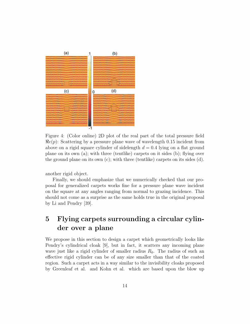
Figure 4: (Color online) 2D plot of the real part of the total pressure fieldℜe(p): Scattering by a pressure plane wave of wavelength 0.15 incident fromabove on a rigid square cylinder of sidelength d = 0.4 lying on a flat groundplane on its own (a); with three (tentlike) carpets on it sides (b); flying overthe ground plane on its own (c); with three (tentlike) carpets on its sides (d).
another rigid object.Finally, we should emphasize that we numerically checked that our pro-
posal for generalized carpets works fine for a pressure plane wave incidenton the square at any angles ranging from normal to grazing incidence. Thisshould not come as a surprise as the same holds true in the original proposalby Li and Pendry [39].
5 Flying carpets surrounding a circular cylin-
der over a plane
We propose in this section to design a carpet which geometrically looks likePendry’s cylindrical cloak [9], but in fact, it scatters any incoming planewave just like a rigid cylinder of smaller radius R0. The radius of such aneffective rigid cylinder can be of any size smaller than that of the coatedregion. Such a carpet acts in a way similar to the invisibility cloaks proposedby Greenleaf et al. and Kohn et al. which are based upon the blow up
14

Figure 5: (Color online) 2D plot of the real part of the total pressure fieldℜe(p): Scattering by a pressure plane wave of wavelength 0.15 incident fromthe right (grazing incidence) on a rigid square cylinder of sidelength d = 0.4lying on a flat ground plane on its own (a); with three tentlike carpets onit sides (b); flying over the ground plane on its own (c); with three tentlikecarpets on its sides (d).
of a small ball (of radius η ≪ 1) rather than a point, thereby leading toapproximate invisibility. However, in our case, the radius of this ball (a discin 2D) is finite, and our claim is that the carpet mimics the electromagneticresponse of the rigid circular cylinder, just like previous carpets did for planes.The circular carpet actually plays the opposite role to the super-scattererof Nicorovici, McPhedran and Milton whereby a cylinder surrounded by acoating of negative refractive index material scatters as a cylinder of diameterlarger than the coating itself [5].
However, whether this coated region is completely empty (e.g. Fig 7(b)) or many objects are hidden inside it (see e.g. Fig. 7(d) where the smallcylinder of radius R0 has actually been put back inside the carpet, along withother objects), such a carpet produces a mirage effect that tricks an externalobserver into believing that this whole region is just the small rigid cylinder.
15

5.1 The construction of circular carpets
The carpet consists of a cylindrical region C(0, R1) of radius R1 to be coatedand the coating itself which is the space between an inner cylinder of radiusR1 and an outer one of radius R2 > R1. As above, the material propertiesof this coating will be deduced by pullback, via a transformation that fixesangles just like in [9]. The transformation in [9] is indeed the particular case,of the one under consideration here, associated with the value R0 = 0 of theradius of an imaginary small cylinder as explained below.
The carpet constructed below is a generalization of the flying carpet stud-ied in the previous section. The geometric transformation we consider here,is a smooth diffeomorphism of the closure of the outside R
3\C(0, R0) of asolid cylinder C(0, R0) of radius R0, where R0 < R1. It coincides with theidentity map outside the solid cylinder C(0, R2), fixing its boundary point-wise, but now maps the region A(R0, R2) between the two coaxial cylindersof respective radii R0 and R2 into the space A(R1, R2) between the cylindersof radii R1 and R2, as in Fig. 6. More precisely, in A(R0, R2) this geometrictransformation can be expressed as
r′ = R1 + α(r − R0) with α = R2−R1
R2−R0
θ′ = θz′ = z
(25)
with inverse
r = R0 + 1α(r′ − R1)
θ = θ′
z = z′
The Jacobian Jrr′ of the latter is
Jrr′ =∂(r, θ, z)
∂(r′, θ′, z′)= diag(
1
α, 1, 1). (26)
Let us denote by Jxr the Jacobian of the change (r, θ, z) 7→ (x, y, z) fromCartesian to polar coordinates and Jrx := J−1
xr . The Jacobian Jxx′ of the abovetransformation in Cartesian coordinates (x′, y′, z′) 7→ (x, y, z) is obtained byapplying the chain rule (14) to get Jxx′ = JxrJrr′Jr′x′, so that the tensor
16

T−1 = J−1xx′J
−Txx′ det(Jxx′) reads
T−1 =
1+(m2−1) cos2(θ)m
(m2−1) sin(θ) cos(θ)
m0
(m2−1) sin(θ) cos(θ)
m
m2+(1−m2) cos2(θ)m
00 0 m
α2
= R(θ) diag(m,1
m,m
α2) R(−θ), (27)
where R(θ) =
cos(θ) − sin(θ) 0sin(θ) cos(θ) 0
0 0 1
is the matrix of the rotation with angle
θ in the xy-plane and m = αrr′
= 1 − R1−R0
(R2−R0)R2
r′.
Figure 6: (Color online) Construction of a circular carpet of inner radiusR1 (solid dark) and outer radius R2 (dashed blue) from cylinder S(0, R0) ofsmaller radius R0 (dotted red). The transformation (25) shrinks the wholehollow cylindrical region A(R0, R2) of inner radius R0 and outer radius R2
into its subset A(R1, R2), the cylinder S(0, R0) being stretched to S(0, R1)whereas S(0, R2) is fixed point-wise. Such a carpet, a metafluid with bulkmodulus and density given by (27) and (6), scatters pressure waves as therigid cylinder S(0, R0).
17

Figure 7: (Color online) 2D plot of the real part of the total pressure fieldℜe(p): Scattering by a plane wave of wavelength 0.15 incident from aboveon a flat ground plane and (a) a circular object of radius R0 = 0.2 flyingat altitude on its own; (b) an empty cylindrical region of radius R1 = 0.5,the ”coated” region, surrounded by a carpet of inner radius R1 and outerradius R2 = 0.7. This hollow cylindrical carpet is designed to behave exactlylike the object in (a) alone, irrespective of the form of any other additionalobject that may be enclosed inside; (c) same object as in (a) with now threeadditional small rigid cylinders touching it. The scattering is clearly differentfrom that in (a); (d) now the three objects in as (c) have been hidden insidethe carpet (b) and yet an outer observer will not be able to tell the scatteringin (a) and in (d) apart.
5.2 Analysis of the metamaterial properties
The tensor T−1 diagonalizes as diag(m, 1m
, mα2 ) where m = 1 − R1−R0
(R2−R0)R2
r′is
bounded from below and above as it satisfies 0 < αR0
R1
≤ m ≤ α. This meansthat the material parameters are not singular, unlike the cloaking case as in[9].
Obviously, one realizes that, when R0 tends to zero, one recovers the casein [9] where the material properties are no longer bounded, but one of themtends to zero whilst another one recedes to infinity, as we approach the innerboundary of the coated region, see also [14].
18
5.3 Mirage effect for a cylinder surrounded by a carpet
We report the results of our simulations in Fig. 7 for a circular pipelinewhich is floating in mid-water, see panel (a). We then replace this pipelineby a circular carpet, see panel (b), which reflects a pressure plane wave fromabove at wavelength 0.5 in exactly the same way. When we add three smallpipelines to the original one, see panel (c), the reflected field is obviouslymuch different. However, when we surround the four pipelines by the circularcarpet, see panel (d), the reflected wave is that of the original pipeline. Such amirage effect, whereby a rigid obstacle hides other ones in its neighborhood,can thus be used for ’sonar illusions’. For instance, an oil pipeline mightreflect pressure waves like a coral barrier so that a sonar boat won’t catch itspresence. Unlike for earlier proposals of approximate cloaks [13, 14] scatteringwaves like a small highly conducting object, we emphasize here that we startthe construction of the circular carpet by a finite size disc.
6 Multilayered circular carpet for broadband
mirage effect
6.1 Reduced material parameters for circular carpets
We now want to simplify the expression of the inverse of the transformationmatrix T in order to avoid a varying (scalar) density (resp. permeabilityin optics). For this, we introduce the reduced matrix T−1
red = diag(α, αm2 ,
1α)
which amounts to multiplying T−1 in (27) by α/m. We deduce from (2) thetransformed governing equation for pressure waves in reduced coordinates:
∇r,θ · diag(1
α,m2
α)∇r,θp + ω2λ−1αp = 0 , (28)
and similarly for transverse electric waves using (3):
∇r,θ · diag(1
α,m2
α)∇r,θHz + ω2ǫ0µ0αHz = 0 , (29)
where m = 1 − R1−R0
(R2−R0)R2
r′and α = R2−R1
R2−R0
.
19

6.2 Homogenized governing equations for optics and
acoustics
To illustrate our paper with a practical example, we finally choose to designa circular carpet using 40 layers of isotropic homogeneous fluids. Thesefluids have constant bulk modulus and varying density. We report thesecomputations in figure 8.
It is indeed well known that the homogenized acoustic equation for sucha configuration takes the following form:
∇r,θ.(ρ−10 ρ−1 ∇r,θHz) + ω2 < λ−1 > p = 0 , (30)
where < λ−1 >=∫ 1
0λ−1(r) dr and with ρ a homogenized rank-2 diagonal
tensor (an anisotropic density) ρ = Diag(ρr, ρθ) given by
ρ = Diag(< ρ−1 >−1
, < ρ >) . (31)
We note that if the cloak consists of an alternation of two homogeneousisotropic layers of fluids of thicknesses dA and dB, with bulk moduli λA andλB and densities ρA and ρB, we have
1
ρr
=1
1 + η
(
1
ρA
+η
ρB
)
,
ρθ =ρA + ηρB
1 + η, < λ−1 >=
1
1 + η
(
1
λA
+η
λB
)
,
where η = dB/dA is the ratio of thicknesses for layers A and B and dA +dB =1.
Using the change of variables
∇r,θ.(ε−1r ε−1 ∇r,θp) + ε0µ0ω
2 Hz = 0 , (32)
where ε is a homogenized rank-2 diagonal tensor (an anisotropic permittivity)ε = Diag(εr, εθ) given by
ε = Diag(< ε−1 >−1
, < ε >) . (33)
20

6.3 Acoustic paradigm: Reduced scattering with larger
scatterer
The acoustic parameters of the proposed layered circular carpet are thereforecharacterized by a spatially varying scalar bulk modulus ρ and a spatiallyvarying rank 2 density tensor ρ given by (33). We can further simplify the
problem by choosing reduced acoustic parameters, so that the bulk modulusλ is now constant, and all the variation is reported on the density, see figure8. More precisely, ρA varies in the range [0.1890; 0.5493] and ρB varies inthe range [1.7987; 2.1472]. We checked that this carpet is broadband as itworks over the range of wavelengths λ ∈ [0.2, 1.4286], see Fig. 8 and Fig. 9:a multilayered carpet of radius 1 surrounding a rigid obstacle of radius 0.32scatters waves just like a rigid obstacle of radius R0 = 0.2. We note that thelower bound for the range of working wavelengths corresponds to the rigidobstacle we want to mimic.
7 Conclusion
In this paper, we have proposed some models of flying carpets which levitate(or float) in mid-air (or mid-water). Such cloaks can be built from acousticmetafluids: as explained by Pendry and Li in a recent work, one can forinstance emulate required anisotropic density and heterogeneous bulk mod-ulus with arrays of rigid plates with a hemispherical sack of gaz attachedto them [42]. But other designs proposed by Torrent and Sanchez-Dehesawould work equally well [17]. However, such flying carpets lead to some ap-proximate cloaking as they do not touch the ground (the inner boundary ofthe carpet in the original design of Pendry and Li is attached to the ground[39]. Interestingly, other authors also looked at quasi-cloaking with simplifiedcarpets [43]. We have also explained how one can hide an object located inthe close neighborhood of a rigid circular cylinder, which in some sense canbe classified as an external cloaking whereby a large scatterer hides smallerones located nearby. Such an ostrich effect (which buries its head in thesand) has already been observed in the context of dipoles and even finite sizeobstacles located closeby a cylindrical perfect lens which displays anomalousresonances [6, 44]. However, here the coating does not contain any negativelyrefracting material, and this is an anisotropy-led rather than plasmonic-typecloaking mechanism. Actually, it is possible to use complementary media to
21

Figure 8: (Color online) 2D plot of the real part of the total pressure fieldℜe(p): Scattering by a plane wave of wavelength 0.2 incident from aboveon a flat ground plane and (a) a circular object of radius R0 = 0.2 flyingat altitude on its own; (b) an empty cylindrical region of radius R1 = 0.32,the ”coated” region consisting of 40 layers of isotropic homogeneous fluid,see closer view in (c), of constant bulk modulus and density ρ, given in (d),surrounded by a carpet of inner radius R1 and outer radius R2 = 1. The redcurves represents the variation of ρθ = m2/α with respect to r ∈ [0.32; 1].The piecewise constant blue curve is a staircase approximation of the redcurve, considering an alternation of 40 layers of density ρA ∈ [0.1890; 0.5493]and ρB ∈ [1.7987; 2.1472] using the homogenized formula (33).
cloak finite size objects (rather than only dipoles) at a finite distance [45].We have discussed some applications, with the sonar boats or radars
cases as typical examples. Another possible application would be protectingparabolic antennas from the negative impact of their ‘supporting cable’. Thefeasibility of such carpets is demonstrated using a homogenization approachenabling us to design a multi-layered acoustic metafluid leading to a mirageeffect over a finite range of wavelengths. We note that the route towardsanamorphism discussed in this paper is very different from the proposal ofNicolet et al. [46] whereby an anisotropic heterogeneous object is placedwithin the coating of a singular cloak to mimic the scattering of another
22

Figure 9: (Color online) 2D plot of the real part of the total pressure fieldℜe(p) for the same geometric and acoustic parameters as in Fig. 8; Scatteringby a plane wave of wavelength 0.5 (a-b) and 1.4286 (c-d), incident from above.
object.Moreover, all computations hold for electromagnetic carpets built with
heterogeneous anisotropic permittivity and scalar permittivity, which couldbe emulated using tapered waveguides as in [47]. We therefore believe thatthe designs we proposed in this paper might foster experimental efforts inapproximate cloaking for both acoustic and electromagnetic waves.
Acknowledgements
AD and SG acknowledge funding from the Engineering and Physical SciencesResearch Council grant EPF/027125/1.
23

References
[1] V.G. Veselago 1967 Usp. Fiz. Nauk 92 517. V.G. Veselago, Sov.Phys.Usp. 10 509 (1968)
[2] J.B. Pendry, Phys. Rev. Lett. 86, 3966-3969 (2000).
[3] Smith, D.R., Padilla, W.J., Vier, V.C., Nemat-Nasser, S.C., Schultz, S.,Phys. Rev. Lett. 84, 4184 (2000)
[4] S.A. Ramakrishna, Rep. Prog. Phys. 68 449 (2005).
[5] N.A. Nicorovici, R.C. McPhedran, G.W. Milton, Phys. Rev. B 49, 8479-8482 (1994).
[6] G. Milton and N.A. Nicorovici, Proc. Roy. Soc. Lond. A 462 3027 (2006).
[7] A. Alu and N. Engheta, Phys. Rev. E 95 016623 (2005).
[8] U. Leonhardt, Science 312 1777-1780 (2006).
[9] J.B. Pendry, D. Shurig, D.R. Smith, Science 312, 1780-1782 (2006).
[10] D. Schurig, J.J. Mock, B.J. Justice, S.A. Cummer, J.B. Pendry, A.F.Starr, D.R. Smith, Science 314, 977-980 (2006).
[11] F. Zolla, S. Guenneau, A. Nicolet, J.B. Pendry, Opt. Lett. 32, 1069-1071(2007).
[12] A. Diatta, S. Guenneau, A. Nicolet and F. Zolla, Optics Express 17,13389 - 13394 (2009).
[13] A. Greenleaf, M. Lassas and G. Uhlmann, Math. Res. Lett. 10, 685-693(2003).
[14] R.V. Kohn, H. Shen, M.S. Vogelius, and M.I. Weinstein, Inverse Prob-lems 24, 015016 (2008).
[15] R. Weder, Journal of Physics A: Mathematical and Theoretical 41,065207 (2008).
[16] R. Weder, Journal of Physics A: Mathematical and Theoretical 41,415401 (2008).
24

[17] D. Torrent and J. Sanchez-Dehesa, New J. Phys. 10 023004 (2008).
[18] S.A. Cummer and D. Schurig, New J. Phys. 9, 45 (2007).
[19] F. Zolla and S. Guenneau, Phys. Rev. E 67, 026610 (2003).
[20] S.A. Cummer, B.I. Popa, D. Schurig, D.R. Smith, J. Pendry, M. Rahm,and A. Starr, Phys. Rev. Lett. 100, 024301 (2008).
[21] H. Chen and C. T. Chan, Appl. Phys. Lett. 91, 183518 (2007).
[22] M. Farhat, S. Guenneau, S. Enoch, A.B. Movchan, F. Zolla and A.Nicolet, New J. Phys. 10, 115030 (2008).
[23] M. Farhat, S. Enoch, S. Guenneau and A.B. Movchan, Phys. Rev. B 79,033102 (2009).
[24] M. Farhat, S. Guenneau and S. Enoch, Phys. Rev. Lett. 103, 024301(2009).
[25] M. Brun, S. Guenneau and A.B. Movchan, Appl. Phys. Lett. 94, 061903,2009 (2009).
[26] G.W. Milton, M. Briane, and J.R. Willis, New J. Phys. 8, 248 (2006).
[27] A.N. Norris, Proc. Roy. Soc. Lond. A 464, 2411 (2008).
[28] D. Bigoni, S.K. Serkov, M. Valentini and A.B. Movchan, Int. J. SolidsStructures 35, 3239 (1998).
[29] T. Chou, Phys. Rev. Lett. 79, 4802 (1997).
[30] T. Chou, J. Fluid. Mech. 369, 333 (1998).
[31] P. McIver, J. Fluid. Mech. 424, 101 (2000).
[32] M. Torres, J.P. Adrados, F.R. Montero de Espinosa, D. Garcia-Pablos,and J. Fayos, Phys. Rev. E 63, 011204 (2000).
[33] X. Hu, Y. Shen, X. Liu, R. Fu, J. Zi, X. Jiang, and S. Feng, Phys. Rev.E 68, 037301 (2003).
[34] L. Feng, X.P. Liu, M.H. Lu, Y.B. Chen, Y.F. Chen, Y.W. Mao, J. Zi,Y.Y. Zhu, S.N. Zhu and N.B. Ming, Phys. Rev. B 73, 193101 (2006).
25

[35] M. Farhat, S. Guenneau, S. Enoch, G. Tayeb, A.B. Movchan, N.V.Movchan, Phys. Rev. E 77, 046308 (2008).
[36] S. Zhang, L. Yin, N. Fang, Phys. Rev. Lett. 102, 194301 (2009).
[37] A. Sukhovich, L. Jing, J.H. Page, Phys. Rev. B 77 014301 (2008).
[38] M. Farhat, S. Enoch, S. Guenneau and A.B. Movchan, Phys. Rev. Lett.101, 134501 (2008).
[39] Li, J. and Pendry, J.B., Phys. Rev. Lett. 101, 203901 (2008).
[40] R. Liu, C. Ji, J.J. Mock, J.Y. Chin, T.J. Cui and D.R. Smith, Science323, 366 (2008).
[41] L.H. Gabrielli, J. Cardenas, C.B. Poitras and M. Lipson, Nature Pho-tonics 3, 461-463 (2009)
[42] J.B. Pendry and J. Li, New J. Physics 10, 115032 (2008).
[43] E. Kallos, C. Argyropoulos and Y. Hao, Phys. Rev. A 79, 063825 (2009).
[44] N.A.P. Nicorovici, R.C. McPhedran, S. Enoch and G. Tayeb, New J.Phys. 10, 115020 (2008).
[45] Y. Lai, H. Chen, Z.Q. Zhang and C.T. Chan, Phys. Rev. Lett. 102,093901 (2009).
[46] A. Nicolet, F. Zolla and C. Geuzaine, (arXiv:0909.0848v1)
[47] I.I. Smolyaninov, V.N. Smolyaninova, A.V. Kildishev and V.M. ShalaevPhys. Rev. Lett. 102, 213901 (2009)
26