Brazilian standards for steel structures fire design
11
Fire Safety Journal 37 (2002) 217–227 Brazilian standards for steel structures fire design Valdir Pignatta e Silva a, *, Ricardo Hallal Fakury b a Escola Polit ! ecnica da Universidade de S * ao Paulo, Sao Paulo, SP, Brazil b Escola de Engenharia da Universidade Federal de Minas Gerais, Belo Horizonte, MG, Brazil Received 28 February 2001; received in revised form 5 July 2001; accepted 22 August 2001 Abstract The aim of this work is introduce to the international scientific community the recently released Brazilian Standards for the design of steel structures under fire situations. They are: ‘‘Steel Structures Fire Design’’ (NBR 14323/1999) and ‘‘Fire Resistance Requirements for Building Construction Elements’’ (NBR 14432/2000). The aim of structure fire design is to prevent the structure from collapsing, allowing enough time for safe evacuation of building occupants, safe fire fighting operations and reduction in damage to neighboring construction. NBR-14323 provides a simplified method for calculation of fire resistance design for steel structural elements. NBR-14432 presents prescriptive recommendations for minimum fire resistance time of construction elements. This Standard also waives fire resistance time requirements depending on building height and area, fire protection devices and occupancy. They also allow the use of alternative methods of fire safety engineering. r 2002 Elsevier Science Ltd. All rights reserved. 1. Introduction Most of the deaths, in a building fire, occur by asphyxia in the early stages. European research [1] shows that the risk of this kind of death is 30 times smaller than that in transport systems. Life risk due to structural failure from fire is even smaller. Despite the low risk of death by fire, protection of human life must always be considered in building design. The inclusion of fire prevention and extinguishing measures and ways of allowing rapid evacuation from burning buildings must be consciously analyzed by both designer and owner, taking into account the specific *Corresponding author. Fax: +5511-3818-5181. E-mail address: [email protected] (V.P. Silva). 0379-7112/02/$ - see front matter r 2002 Elsevier Science Ltd. All rights reserved. PII:S0379-7112(01)00044-3
Transcript of Brazilian standards for steel structures fire design
Fire Safety Journal 37 (2002) 217–227
Brazilian standards for steel structures fire design
Valdir Pignatta e Silvaa,*, Ricardo Hallal Fakuryb
aEscola Polit !ecnica da Universidade de S *ao Paulo, Sao Paulo, SP, BrazilbEscola de Engenharia da Universidade Federal de Minas Gerais, Belo Horizonte, MG, Brazil
Received 28 February 2001; received in revised form 5 July 2001; accepted 22 August 2001
Abstract
The aim of this work is introduce to the international scientific community the recently
released Brazilian Standards for the design of steel structures under fire situations. They are:‘‘Steel Structures Fire Design’’ (NBR 14323/1999) and ‘‘Fire Resistance Requirements forBuilding Construction Elements’’ (NBR 14432/2000). The aim of structure fire design is to
prevent the structure from collapsing, allowing enough time for safe evacuation of buildingoccupants, safe fire fighting operations and reduction in damage to neighboring construction.NBR-14323 provides a simplified method for calculation of fire resistance design for steelstructural elements. NBR-14432 presents prescriptive recommendations for minimum fire
resistance time of construction elements. This Standard also waives fire resistance timerequirements depending on building height and area, fire protection devices and occupancy.They also allow the use of alternative methods of fire safety engineering. r 2002 Elsevier
Science Ltd. All rights reserved.
1. Introduction
Most of the deaths, in a building fire, occur by asphyxia in the early stages.European research [1] shows that the risk of this kind of death is 30 times smallerthan that in transport systems. Life risk due to structural failure from fire is evensmaller.
Despite the low risk of death by fire, protection of human life must always beconsidered in building design. The inclusion of fire prevention and extinguishingmeasures and ways of allowing rapid evacuation from burning buildings must beconsciously analyzed by both designer and owner, taking into account the specific
*Corresponding author. Fax: +5511-3818-5181.
E-mail address: [email protected] (V.P. Silva).
0379-7112/02/$ - see front matter r 2002 Elsevier Science Ltd. All rights reserved.
PII: S 0 3 7 9 - 7 1 1 2 ( 0 1 ) 0 0 0 4 4 - 3
conditions of the building, such as: size, population, occupancy, public authoritiesrequirements and technical standards recommendations for design and equipmentspecification.
Escape routes, including emergency stairs, must be well marked, unobstructed andstructurally safe. In order to preserve human life, the safety of structures exposed tofire in exit routes must be guaranteed during evacuation.
Structural fire safety checking can be waived for buildings from which escape isstraightforward, such as small buildings or single-story buildings, except whenproper preservation is desired.
Large buildings, where evacuation time is difficult to evaluate and where,generally, the exit routes are an integral part of the main structure, must have theirstructural safety checked. Structural fire safety, either for life or building protection,must be checked to ensure that structural collapse is prevented, thus allowingevacuation, repair and refurbishment.
High temperature exposure of structural materials, such as concrete or steel,reduces their strength and rigidity and may lead to structural collapse.
Critical temperature is the temperature that causes collapse. The true criticaltemperature could be determined by tests for each structural element, but, this is noteconomically feasible. Ordinarily, one fixes an arbitrary conventional value ofcritical temperature. A value based on recommendations set by Technical Standardsor Codes, which is on the safe side of the critical temperature is estimated.
Structural safety is assured when steel temperature in fire situation reaches a valueless than the structure critical temperature or, in other words, structural safety isverified if the design value of the effect of the actions is lower than the design value ofeach structural element resistance.
2. The Brazilian Standard ‘‘fire-resistance requirements for building construction
elements’’
In 1996, a study group created by Associa-c*ao Brasileira de Normas T!ecnicas(Brazilian Association of Technical Standards) and consisting of professors fromUniversidade de S*ao Paulo, Universidade Federal de Minas Gerais and Uni-versidade Federal de Ouro Preto presented a draft and, in 1999, two standards wereapproved: NBR 14432 ‘‘Fire Resistance Requirements for Building ConstructionElements [2]’’ and NBR 14323 ‘‘Steel Structures Fire Design’’ [3].
The required performance for construction elements, i.e., structural (concrete,timber or steel) or compartmentation elements, according to Brazilian StandardNBR 14432 are
* to prevent structural collapse, making the safe escape of users possible;* to reduce damage to neighboring property; and* to allow prompt access by the fire brigade, whenever necessary.
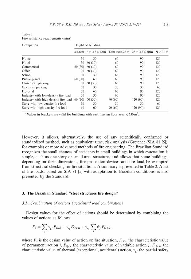
The Standard supplies prescriptive recommendations on the required time for fireresistance under standard fire (ISO 834 [4]). A summary is presented in Table 1.
V.P. Silva, R.H. Fakury / Fire Safety Journal 37 (2002) 217–227218
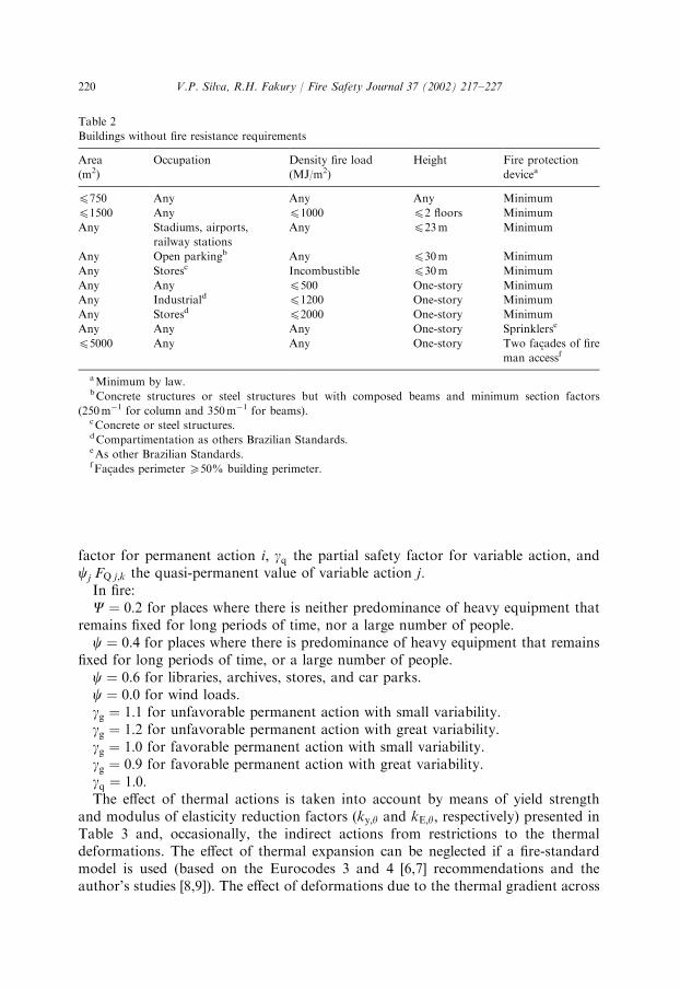
However, it allows, alternatively, the use of any scientifically confirmed orstandardized method, such as equivalent time, risk analysis (Gretener (SIA 81 [5]),for example) or more advanced methods of fire engineering. The Brazilian Standardrecognizes the small chances of accidents in small buildings in which evacuation issimple, such as one-story or small-area structures and allows that some buildings,depending on their dimensions, fire protection devices and fire load be exemptedfrom structural checking for fire situations. A summary is presented in Table 2. A listof fire loads, based on SIA 81 [5] with adaptation to Brazilian conditions, is alsopresented by the Standard.
3. The Brazilian Standard ‘‘steel structures fire design’’
3.1. Combination of actions (accidental load combination)
Design values for the effect of actions should be determined by combining thevalues of actions as follows:
Fd ¼Xi
ggi FGi;k þ gq FQ;exc þ gqXj
cj FQ j;k;
where Fd is the design value of action on fire situation, FGi;k the characteristic valueof permanent action i; FQj;k the characteristic value of variable action j; FQ;exc thecharacteristic value of thermal (exceptional, accidental) action, ggi the partial safety
Table 1
Fire resistance requirements (min)a
Occupation Height of building
hp6m 6mohp12m 12mohp23m 23mohp30m H > 30m
Home 30 30 60 90 120
Hotel 30 60 (30) 60 90 120
Commercial 60 (30) 60 (30) 60 90 120
Office 30 60 (30) 60 90 120
School 30 30 60 90 120
Public places 60 (30) 60 60 90 120
Closed car parking 30 60 (30) 60 90 120
Open car parking 30 30 30 30 60
Hospital 30 60 60 90 120
Industry with low-density fire load 30 30 60 90 120
Industry with high-density fire load 60 (30) 60 (30) 90 (60) 120 (90) 120
Store with low-density fire load 30 30 30 30 60
Store with high-density fire load 60 60 90 (60) 120 (90) 120
aValues in brackets are valid for buildings with each having floor area p750m2.
V.P. Silva, R.H. Fakury / Fire Safety Journal 37 (2002) 217–227 219
factor for permanent action i; gq the partial safety factor for variable action, andcj FQ j;k the quasi-permanent value of variable action j:
In fire:C ¼ 0:2 for places where there is neither predominance of heavy equipment that
remains fixed for long periods of time, nor a large number of people.c ¼ 0:4 for places where there is predominance of heavy equipment that remains
fixed for long periods of time, or a large number of people.c ¼ 0:6 for libraries, archives, stores, and car parks.c ¼ 0:0 for wind loads.gg ¼ 1:1 for unfavorable permanent action with small variability.gg ¼ 1:2 for unfavorable permanent action with great variability.gg ¼ 1:0 for favorable permanent action with small variability.gg ¼ 0:9 for favorable permanent action with great variability.gq ¼ 1:0:The effect of thermal actions is taken into account by means of yield strength
and modulus of elasticity reduction factors (ky;y and kE;y; respectively) presented inTable 3 and, occasionally, the indirect actions from restrictions to the thermaldeformations. The effect of thermal expansion can be neglected if a fire-standardmodel is used (based on the Eurocodes 3 and 4 [6,7] recommendations and theauthor’s studies [8,9]). The effect of deformations due to the thermal gradient across
Table 2
Buildings without fire resistance requirements
Area
(m2)
Occupation Density fire load
(MJ/m2)
Height Fire protection
devicea
p750 Any Any Any Minimum
p1500 Any p1000 p2 floors Minimum
Any Stadiums, airports,
railway stations
Any p23m Minimum
Any Open parkingb Any p30m Minimum
Any Storesc Incombustible p30m Minimum
Any Any p500 One-story Minimum
Any Industriald p1200 One-story Minimum
Any Storesd p2000 One-story Minimum
Any Any Any One-story Sprinklerse
p5000 Any Any One-story Two fa-cades of fire
man accessf
aMinimum by law.bConcrete structures or steel structures but with composed beams and minimum section factors
(250m�1 for column and 350m�1 for beams).cConcrete or steel structures.dCompartimentation as others Brazilian Standards.eAs other Brazilian Standards.fFa-cades perimeter X50% building perimeter.
V.P. Silva, R.H. Fakury / Fire Safety Journal 37 (2002) 217–227220
the depth of an element must be taken into account, but the linear analysis using thetemperature effect reduced modulus of elasticity is allowed.
The bars of a bracing system should be designed by the following combination ofactions:
Fd ¼Xi
ggi FGi;k þ gq FQ;exc þ gq 0:5FW;k;
where FW;k is the characteristic value of wind load.
3.2. Design yield strength on fire
The design value of yield strength in fire is determined by
fyd;fi¼fykga;fi
where fyd;fi is the design value of yield strength in fire, fyk or fy the characteristic valueof yield strength, ga;fi ¼ 1 or 0, the partial safety factor for steel in fire.
To comply with the Brazilian Standard, any scientifically confirmed orstandardized method, is allowed. As an option, it presents a simplified method thatcalculates the fire design resistance of steel structural elements (summary in Section4.3.1) and composite steel–concrete structures (beams, columns and slabs) based onEurocodes 3 and 4 [6,7], adapted [8] to the Brazilian structure standards.
According to ‘‘Steel Structures Fire Design’’ Standard, the temperature of steelstructural elements can be calculated by analytical methods based on heat transfertheory (formulae supplied by the Standard) or experimental analysis.
Table 3
Reduction factors
ya (1C) ky;y ¼ fy;y=fy kE;y ¼ Ey=E
20 1.000 1.000
100 1.000 1.000
200 1.000 0.900
300 1.000 0.800
400 1.000 0.700
500 0.780 0.600
600 0.470 0.310
700 0.230 0.130
800 0.110 0.090
900 0.060 0.068
1000 0.040 0.045
1100 0.020 0.023
1200 0.000 0.000
V.P. Silva, R.H. Fakury / Fire Safety Journal 37 (2002) 217–227 221
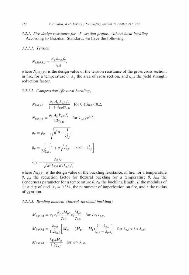
3.2.1. Fire design resistance for ‘‘I’’ section profile, without local bucklingAccording to Brazilian Standard, we have the following.
3.2.1.1. Tension
Ny;fi;y;Rd ¼Ag ky;y fy
ga;fi;
where Ny;fi;y;Rd is the design value of the tension resistance of the gross cross section,in fire, for a temperature y; Ag the area of cross section, and ky;y the yield strengthreduction factor.
3.2.1.2. Compression (flexural buckling)
Nfi;y;Rd ¼ry Ag ky;y fyð1þ l0;yÞga;fi
for 0pl0;yo0:2;
Nfi;y;Rd ¼ry Ag ky;y fy
1:2ga;fifor l0;yX0:2;
ry ¼ by �
ffiffiffiffiffiffiffiffiffiffiffiffiffiffiffiffiffiffiffiffib2y�
1
l20;y
s;
by ¼1
2l20;y1þ a
ffiffiffiffiffiffiffiffiffiffiffiffiffiffiffiffiffiffiffiffiffiffil20;y � 0:04
qþ l20;y
� �;
l0;y ¼cfl=rffiffiffiffiffiffiffiffiffiffiffiffiffiffiffiffiffiffiffiffiffiffiffiffiffiffiffiffiffiffiffiffi
p2 kE;y E=ky;y fyp ;
where Nfi;y;Rd is the design value of the buckling resistance, in fire, for a temperaturey; ry the reduction factor for flexural buckling for a temperature y; l0;y theslenderness parameter for a temperature y; cfl the buckling length, E the modulus ofelasticity of steel, ay ¼ 0:384; the parameter of imperfection on fire, and r the radiusof gyration.
3.2.1.3. Bending moment (lateral–torsional buckling)
Mfi;y;Rd ¼ k1k2ky;yMpc
ga;fipMpc
ga;fifor lplp;y;
Mfi;y;Rd ¼ky;y
1:2ga;fiMpc � ðMpc �MrÞ
l� lp;ylr;y � lp;y
� �for lp;yololr;y;
Mfi;y;Rd ¼kE;yMcr
1:2ga;fifor l > lr;y:
V.P. Silva, R.H. Fakury / Fire Safety Journal 37 (2002) 217–227222
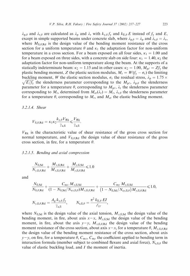
lp;y and lr;y are calculated as lp and lr with ky;y fy and kE;y E instead of fy and E;except in simple supported beams under concrete slab, where lp;y ¼ lp and lr;y ¼ lr;where Mfi;y;Rd is the design value of the bending moment resistance of the crosssection for a uniform temperature y and k1 the adaptation factor for non-uniformtemperature in a cross section. For a beam exposed on all four sides, k1 ¼ 1:00 andfor a beam exposed on three sides, with a concrete slab on side four: k1 ¼ 1:40; k2 theadaptation factor for non-uniform temperature along the beam. At the supports of astatically indeterminate beam: k2 ¼ 1:15 and in other cases: k2 ¼ 1:00;Mpc ¼ Zfy theplastic bending moment, Z the plastic section modulus,Mr ¼ Wðfy � srÞ the limitingbuckling moment, W the elastic section modulus, sr the residual stress, lp ¼ 1:75�ffiffiffiffiffiffiffiffiffiffi
E=fyp
the slenderness parameter corresponding to the Mpc; lp;y the slendernessparameter for a temperature y; corresponding to Mpc; lr the slenderness parametercorresponding to Mr; determined from McrðlrÞ ¼ Mr; lr;y the slenderness parameterfor a temperature y; corresponding to Mr; and Mcr the elastic buckling moment.
3.2.1.4. Shear
Vfi;y;Rd ¼ k1k2ky;yVRk
ga;fipVRk
ga;fi:
VRk is the characteristic value of shear resistance of the gross cross section fornormal temperature, and Vfi;y;Rd the design value of shear resistance of the grosscross section, in fire, for a temperature y:
3.2.1.5. Bending and axial compression
Nfi;Sd
Ny;fi;y;Rdþ
Mx;fi;Rd
Mx;fi;y;Rdþ
My;fi;Sd
My;fi;y;Rdp1:0
and
Nfi;Sd
Nfi;y;Rdþ
Cmx Mx;fi;Sd
ð1�Nfi;Sd=Nex;fi;yÞMx;fi;y;Rdþ
Cmy My;fi;Sd
1�Nfi;Sd=Ney;fi;y�
My;fi;y;Rd
p1:0;
Ny;fi;y;Rd ¼Ag ky;y fy
ga;fi; Ne;fi;y ¼
p2 kE;y EIcfc
;
where Nfi;Sd is the design value of the axial tension, Mx;fi;Sd the design value of thebending moment, in fire, about axis x2x; My;fi;Sd the design value of the bendingmoment, in fire, about the axis y2y; Mx;fi;y;Rd the design value of the bendingmoment resistance of the cross section, about axis x2x; for a temperature y;My;fi;y;Rd
the design value of the bending moment resistance of the cross section, about axisy2y; on fire, for a temperature y; Cmx; Cmy the coefficient applied to bending term ininteraction formula (member subject to combined flexure and axial force), Ne;fi;y thevalue of elastic buckling load, and I the moment of inertia.
V.P. Silva, R.H. Fakury / Fire Safety Journal 37 (2002) 217–227 223
3.3. Example based on the application of the Brazilian Standard simplifiedmethodFcritical temperature calculation
Based on Sections 3.1–3.3 and Table 3, it is possible to determine the criticaltemperature of each structural element. Two examples are presented as follows.
3.3.1. Columns without local bucklingFrom Section 3.2.1.2, we have
Nfi;y;Rd ¼ry Ag ky;y fy
1:2ga;fiXNfi;Sd for l0;yX0:2;
where Nfi;Sd is the design value of tension in fire; hence,
ky;yX1:2Zrry
�ga;figa
;
where
Z ¼Nfi;Sd
NRd;
NRd ¼rAg fy
ga;
r ¼ b�
ffiffiffiffiffiffiffiffiffiffiffiffiffiffiffib2 �
1
l20
s;
b ¼1
2l201þ a20
ffiffiffiffiffiffiffiffiffiffiffiffiffiffiffiffiffiffiffil20 � 0:04
qþ l20
� �;
l0 ¼cflpr
ffiffiffiffifyE
r;
ga;figa
¼ 0:9 and ay ¼ 0:384 ðaccording to the Brazilian StandardÞ:
From Table 3, we havefor 5001Cpyp6001C,
kE;y ¼ 2:05� 0:0029y;
ky;y ¼ 3:33� 0:0031y;
and for 6001Cpyp7001C,
kE;y ¼ 1:39� 0:0018y;
ky;y ¼ 1:91� 0:0024y:
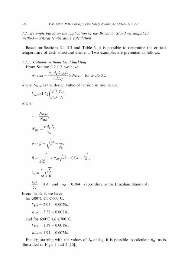
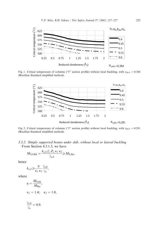
Finally, starting with the values of l0 and Z; it is possible to calculate ycr; as isillustrated in Figs. 1 and 2 [10].
V.P. Silva, R.H. Fakury / Fire Safety Journal 37 (2002) 217–227224
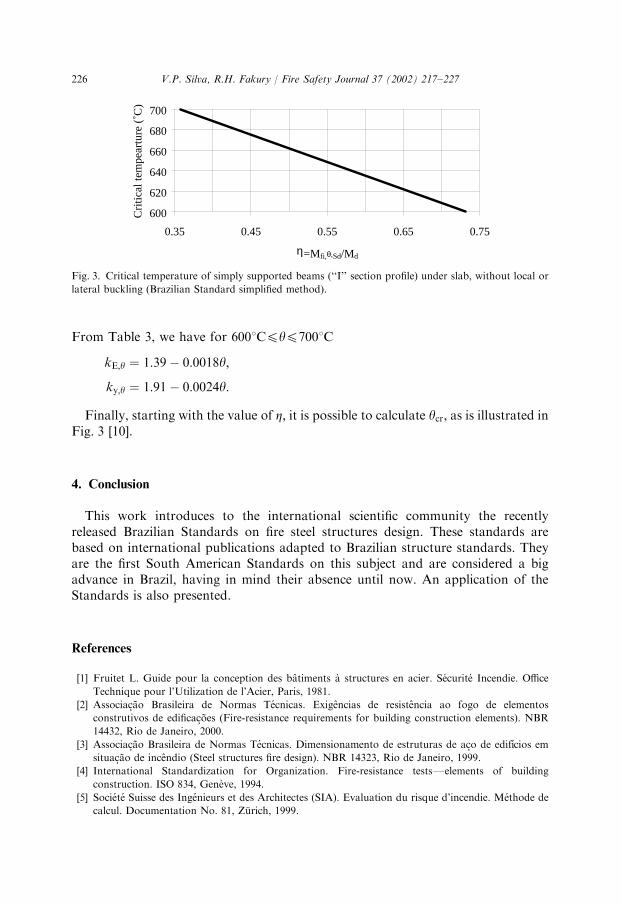
3.3.2. Simply supported beams under slab, without local or lateral bucklingFrom Section 4.3.1.3, we have
Mfi;y;Rd ¼ky;y fy Zx k1 k2
ga;fiXMfi;Sd;
hence
ky;yXZ
k1 k2
ga;figa
;
where
Z ¼Mfi;Sd
MRd;
k1 ¼ 1:4; k2 ¼ 1:0;
ga;figa
¼ 0:9:
500
525
550
575
600
625
0.25 0.5 0.75 1 1.25 1.5 1.75 2
Reduced slenderness (λ0)
0.4
0.45
0.5
0.55
0.6
α20oC=0,281
Cri
tical
tem
pera
ture
(˚C
) η=Nfi,θ,Rd/Nd
Fig. 2. Critical temperature of columns (‘‘I’’ section profile) without local buckling, with a201C ¼ 0:281(Brazilian Standard simplified method).
500
525
550
575
600
625
0.25 0.5 0.75 1 1.25 1.5 1.75 2
Reduced slenderness (λ0)
0.4
0.45
0.5
0.55
0.6
η=Nfi,θ,Rd/Nd
α20oC=0,384
Cri
tical
tem
pera
ture
(˚C
)
Fig. 1. Critical temperature of columns (‘‘I’’ section profile) without local buckling, with a201C ¼ 0:384(Brazilian Standard simplified method).
V.P. Silva, R.H. Fakury / Fire Safety Journal 37 (2002) 217–227 225
From Table 3, we have for 6001Cpyp7001C
kE;y ¼ 1:39� 0:0018y;
ky;y ¼ 1:91� 0:0024y:
Finally, starting with the value of Z; it is possible to calculate ycr; as is illustrated inFig. 3 [10].
4. Conclusion
This work introduces to the international scientific community the recentlyreleased Brazilian Standards on fire steel structures design. These standards arebased on international publications adapted to Brazilian structure standards. Theyare the first South American Standards on this subject and are considered a bigadvance in Brazil, having in mind their absence until now. An application of theStandards is also presented.
References
[1] Fruitet L. Guide pour la conception des b#atiments "a structures en acier. S!ecurit!e Incendie. Office
Technique pour l’Utilization de l’Acier, Paris, 1981.
[2] Associa-c*ao Brasileira de Normas T!ecnicas. Exig#encias de resist#encia ao fogo de elementos
construtivos de edifica-c *oes (Fire-resistance requirements for building construction elements). NBR
14432, Rio de Janeiro, 2000.
[3] Associa-c*ao Brasileira de Normas T!ecnicas. Dimensionamento de estruturas de a-co de edif!ıcios em
situa-c*ao de inc#endio (Steel structures fire design). NBR 14323, Rio de Janeiro, 1999.
[4] International Standardization for Organization. Fire-resistance testsFelements of building
construction. ISO 834, Gen"eve, 1994.
[5] Soci!et!e Suisse des Ing!enieurs et des Architectes (SIA). Evaluation du risque d’incendie. M!ethode de
calcul. Documentation No. 81, Z .urich, 1999.
600
620
640
660
680
700
0.35 0.45 0.55 0.65 0.75
η=Mfi,θ,Sd/Md
Cri
tical
tem
pear
ture
(˚C
)
Fig. 3. Critical temperature of simply supported beams (‘‘I’’ section profile) under slab, without local or
lateral buckling (Brazilian Standard simplified method).
V.P. Silva, R.H. Fakury / Fire Safety Journal 37 (2002) 217–227226
[6] European Committee for Standardization. Design of steel structures. Structural fire design (Part 1.2).
Eurocode 3FENV 1993-1-2, Brussels, 1995.
[7] European Committee for Standardization. Design of composite steel, concrete structures. Structural
fire design (Part 1.2). Eurocode 4FENV 1994-1-2, Brussels, 1994.
[8] Silva, VP. Estruturas de a-co em situa-c*ao de inc#endio (Steel structures in fire). Ph.D. thesis, Escola
Polit!ecnica da Universidade de S*ao Paulo, Sao Paulo, 1997.
[9] Silva, VP. Estruturas de a-co em situa-c*ao de inc#endio (Steel structures in fire). Zigurate Editora, Sao
Paulo, 2001.
[10] Fakury RH, Silva VP, Martins MM. Temperatura cr!ıtica de elementos estruturais de a-co em situa-c*ao
de inc#endio (Critical temperature of steel elements in fire). XXIX Jornadas Sudamericanas de
Ingenieria Estructural. Montevid!eo, 2000.
V.P. Silva, R.H. Fakury / Fire Safety Journal 37 (2002) 217–227 227