Border Gateway Protocol Lab Series
350
Award 1829698 “CyberTraining CIP: Cyberinfrastructure Expertise on High-throughput Networks for Big Science Data Transfers” BORDER GATEWAY PROTOCOL LAB SERIES Book Version: 07-31-2021 Principal Investigator: Jorge Crichigno
-
Upload
khangminh22 -
Category
Documents
-
view
0 -
download
0
Transcript of Border Gateway Protocol Lab Series
Award 1829698 “CyberTraining CIP: Cyberinfrastructure Expertise on High-throughput
Networks for Big Science Data Transfers”
BORDER GATEWAY PROTOCOL LAB SERIES
Book Version: 07-31-2021
Principal Investigator: Jorge Crichigno
Border Gateway Protocol Lab Series
Contents
Lab 1: Introduction to MininetLab 2: Introduction to Free Range Routing (FRR)Lab 3: Introduction to BGPLab 4: Configure and Verify EBGPExercise 1: BGP ConfigurationLab 5: BGP AuthenticationLab 6: Configure BGP with Default RouteLab 7: Using AS_PATH BGP AttributeExercise 2: Controlling Traffic using BGP AS_PATH AttributeLab 8: Configuring IBGP and EBGP Sessions, Local Preference, and MEDLab 8.1: Configuring OSPF, IBGP and EBGP Sessions, Local Preference, and MEDExercise 3: Steering Traffic using BGP Local Preference AttributeLab 9: IBGP, Next Hop and Full Mesh TopologyLab 10: BGP Route ReflectionExercise 4: BGP Next Hop Attribute and Route Reflection
BORDER GATEWAY PROTOCOL
Lab 1: Introduction to Mininet
Document Version: 05-25-2021
Award 1829698 “CyberTraining CIP: Cyberinfrastructure Expertise on High-throughput
Networks for Big Science Data Transfers”
Lab 1: Introduction to Mininet
Page 2
Contents Overview ............................................................................................................................. 3
Objectives............................................................................................................................ 3
Lab settings ......................................................................................................................... 3
Lab roadmap ....................................................................................................................... 3
1 Introduction to Mininet .............................................................................................. 3
2 Invoke Mininet using the CLI ...................................................................................... 5
2.1 Invoke Mininet using the default topology .......................................................... 5
2.2 Test connectivity .................................................................................................. 9
3 Build and emulate a network in Mininet using the GUI ........................................... 10
3.1 Build the network topology ............................................................................... 10
3.2 Test connectivity ................................................................................................ 12
3.3 Automatic assignment of IP addresses .............................................................. 15
3.4 Save and load a Mininet topology ..................................................................... 18
4 Configure router r1 ................................................................................................... 19
4.1 Verify end-hosts configuration........................................................................... 20
4.2 Configure router’s interface ............................................................................... 21
4.3 Verify router r1 configuration ............................................................................ 25
4.4 Test connectivity between end-hosts ................................................................ 26
References ........................................................................................................................ 26
Lab 1: Introduction to Mininet
Page 3
Overview This lab provides an introduction to Mininet, a virtual testbed used for testing network tools and protocols. It demonstrates how to invoke Mininet from the command-line interface (CLI) utility and how to build and emulate topologies using a graphical user interface (GUI) application. Objectives By the end of this lab, you should able to:
1. Understand what Mininet is and why it is useful for testing network topologies. 2. Invoke Mininet from the CLI. 3. Construct network topologies using the GUI. 4. Save/load Mininet topologies using the GUI. 5. Configure the interfaces of a router using the CLI.
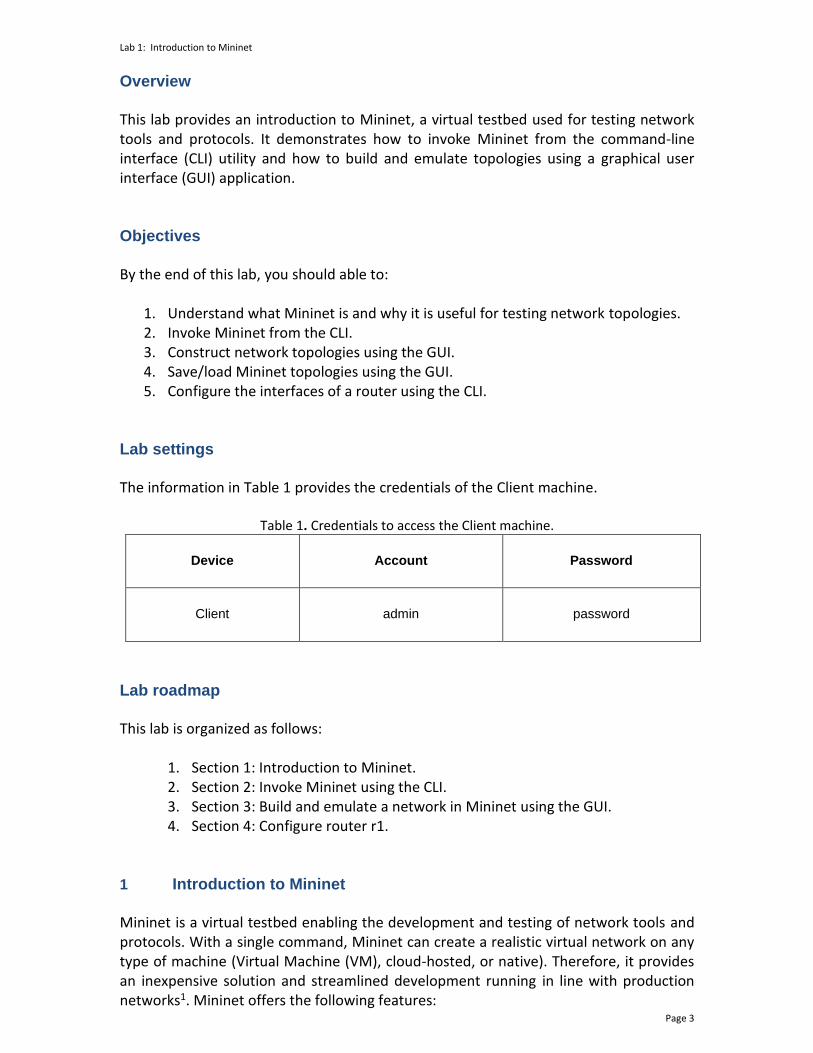
Lab settings The information in Table 1 provides the credentials of the Client machine.
Table 1. Credentials to access the Client machine.
Device
Account
Password
Client admin password
Lab roadmap This lab is organized as follows:
1. Section 1: Introduction to Mininet. 2. Section 2: Invoke Mininet using the CLI. 3. Section 3: Build and emulate a network in Mininet using the GUI. 4. Section 4: Configure router r1.
1 Introduction to Mininet Mininet is a virtual testbed enabling the development and testing of network tools and protocols. With a single command, Mininet can create a realistic virtual network on any type of machine (Virtual Machine (VM), cloud-hosted, or native). Therefore, it provides an inexpensive solution and streamlined development running in line with production networks1. Mininet offers the following features:
Lab 1: Introduction to Mininet
Page 4
• Fast prototyping for new networking protocols.
• Simplified testing for complex topologies without the need of buying expensive hardware.
• Realistic execution as it runs real code on the Unix and Linux kernels.
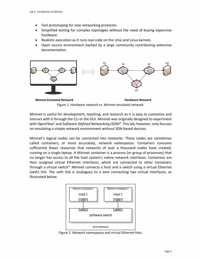
• Open source environment backed by a large community contributing extensive documentation.
Figure 1. Hardware network vs. Mininet emulated network.
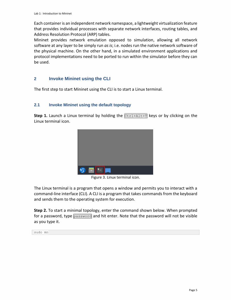
Mininet is useful for development, teaching, and research as it is easy to customize and interact with it through the CLI or the GUI. Mininet was originally designed to experiment with OpenFlow2 and Software-Defined Networking (SDN)3. This lab, however, only focuses on emulating a simple network environment without SDN-based devices. Mininet’s logical nodes can be connected into networks. These nodes are sometimes called containers, or more accurately, network namespaces. Containers consume sufficiently fewer resources that networks of over a thousand nodes have created, running on a single laptop. A Mininet container is a process (or group of processes) that no longer has access to all the host system’s native network interfaces. Containers are then assigned virtual Ethernet interfaces, which are connected to other containers through a virtual switch4. Mininet connects a host and a switch using a virtual Ethernet (veth) link. The veth link is analogous to a wire connecting two virtual interfaces, as illustrated below.
Figure 2. Network namespaces and virtual Ethernet links.
h1 s1 h2s2
s3
Hardware NetworkMininet Emulated Network
Lab 1: Introduction to Mininet
Page 5
Each container is an independent network namespace, a lightweight virtualization feature that provides individual processes with separate network interfaces, routing tables, and Address Resolution Protocol (ARP) tables. Mininet provides network emulation opposed to simulation, allowing all network software at any layer to be simply run as is; i.e. nodes run the native network software of the physical machine. On the other hand, in a simulated environment applications and protocol implementations need to be ported to run within the simulator before they can be used. 2 Invoke Mininet using the CLI The first step to start Mininet using the CLI is to start a Linux terminal. 2.1 Invoke Mininet using the default topology
Step 1. Launch a Linux terminal by holding the Ctrl+Alt+T keys or by clicking on the Linux terminal icon.
Figure 3. Linux terminal icon.
The Linux terminal is a program that opens a window and permits you to interact with a command-line interface (CLI). A CLI is a program that takes commands from the keyboard and sends them to the operating system for execution. Step 2. To start a minimal topology, enter the command shown below. When prompted for a password, type password and hit enter. Note that the password will not be visible as you type it. sudo mn
Lab 1: Introduction to Mininet
Page 6
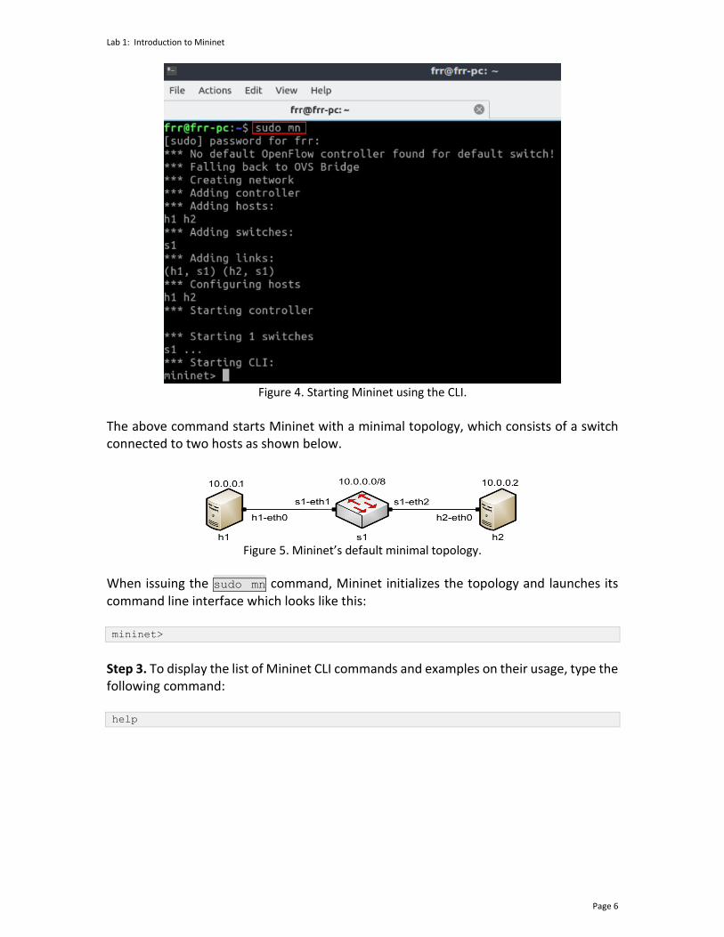
Figure 4. Starting Mininet using the CLI.
The above command starts Mininet with a minimal topology, which consists of a switch connected to two hosts as shown below.
Figure 5. Mininet’s default minimal topology.
When issuing the sudo mn command, Mininet initializes the topology and launches its command line interface which looks like this: mininet>
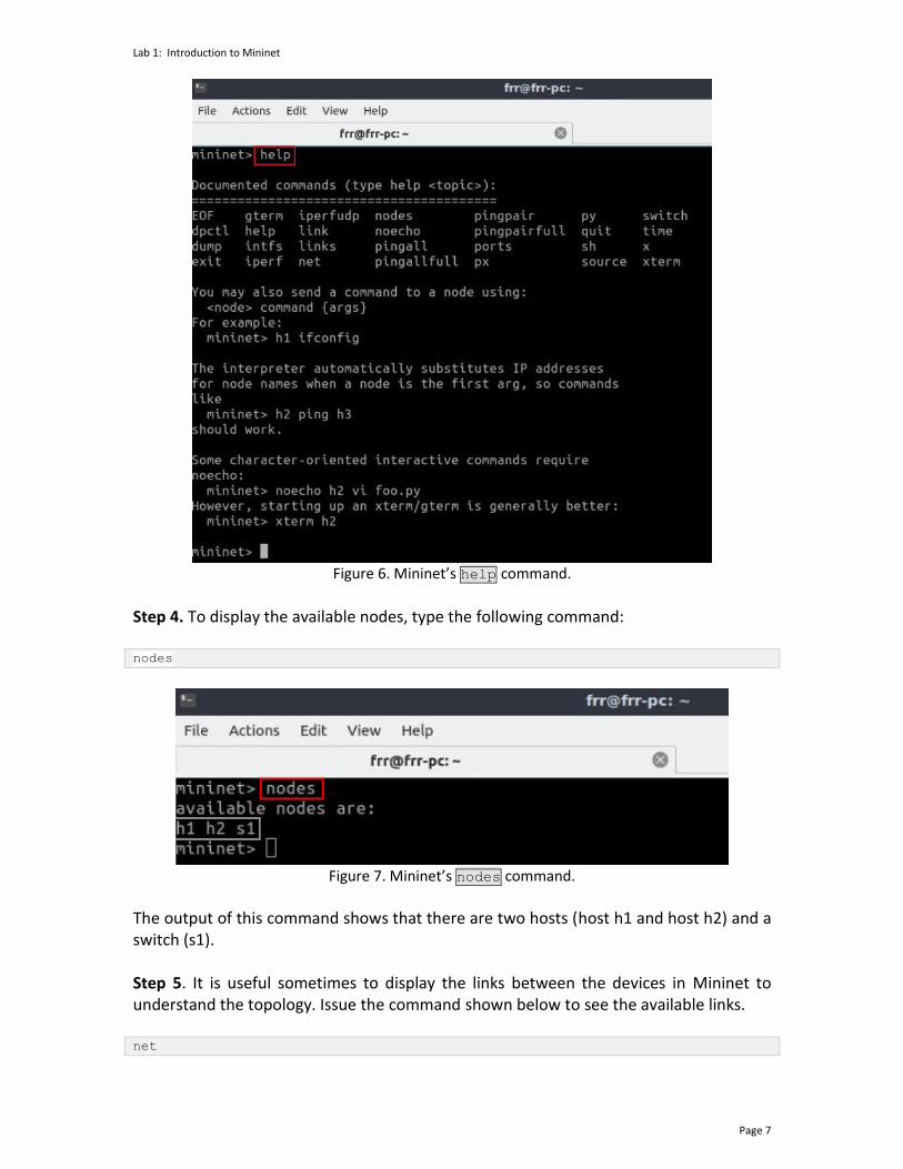
Step 3. To display the list of Mininet CLI commands and examples on their usage, type the following command: help
Lab 1: Introduction to Mininet
Page 7
Figure 6. Mininet’s help command.
Step 4. To display the available nodes, type the following command: nodes
Figure 7. Mininet’s nodes command.
The output of this command shows that there are two hosts (host h1 and host h2) and a switch (s1). Step 5. It is useful sometimes to display the links between the devices in Mininet to understand the topology. Issue the command shown below to see the available links. net

Lab 1: Introduction to Mininet
Page 8
Figure 8. Mininet’s net command.
The output of this command shows that:
1. Host h1 is connected using its network interface h1-eth0 to the switch on interface s1-eth1.
2. Host h2 is connected using its network interface h2-eth0 to the switch on interface s1-eth2.
3. Switch s1: a. has a loopback interface lo. b. connects to h1-eth0 through interface s1-eth1. c. connects to h2-eth0 through interface s1-eth2.
Mininet allows you to execute commands on a specific device. To issue a command for a specific node, you must specify the device first, followed by the command. Step 6. To proceed, issue the command: h1 ifconfig
Figure 9. Output of h1 ifconfig command.

Lab 1: Introduction to Mininet
Page 9
This command executes the ifconfig Linux command on host h1. The command shows host h1’s interfaces. The display indicates that host h1 has an interface h1-eth0 configured with IP address 10.0.0.1, and another interface lo configured with IP address 127.0.0.1 (loopback interface). 2.2 Test connectivity
Mininet’s default topology assigns the IP addresses 10.0.0.1/8 and 10.0.0.2/8 to host h1 and host h2 respectively. To test connectivity between them, you can use the command ping. The ping command operates by sending Internet Control Message Protocol (ICMP) Echo Request messages to the remote computer and waiting for a response or reply. Information available includes how many responses are returned and how long it takes for them to return. Step 1. On the CLI, type the command shown below. This command tests the connectivity between host h1 and host h2. To stop the test, press Ctrl+c. The figure below shows a successful connectivity test. Host h1 (10.0.0.1) sent four packets to host h2 (10.0.0.2) and successfully received the expected responses. h1 ping 10.0.0.2
Figure 10. Connectivity test between host h1 and host h2.
Step 2. Stop the emulation by typing the following command: exit
Lab 1: Introduction to Mininet
Page 10
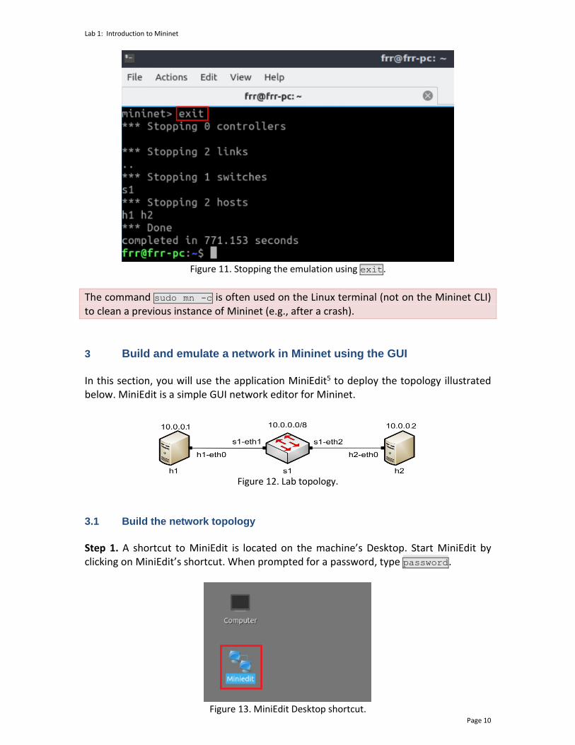
Figure 11. Stopping the emulation using exit.
The command sudo mn -c is often used on the Linux terminal (not on the Mininet CLI) to clean a previous instance of Mininet (e.g., after a crash).
3 Build and emulate a network in Mininet using the GUI In this section, you will use the application MiniEdit5 to deploy the topology illustrated below. MiniEdit is a simple GUI network editor for Mininet.
Figure 12. Lab topology.
3.1 Build the network topology
Step 1. A shortcut to MiniEdit is located on the machine’s Desktop. Start MiniEdit by clicking on MiniEdit’s shortcut. When prompted for a password, type password.
Figure 13. MiniEdit Desktop shortcut.
Lab 1: Introduction to Mininet
Page 11
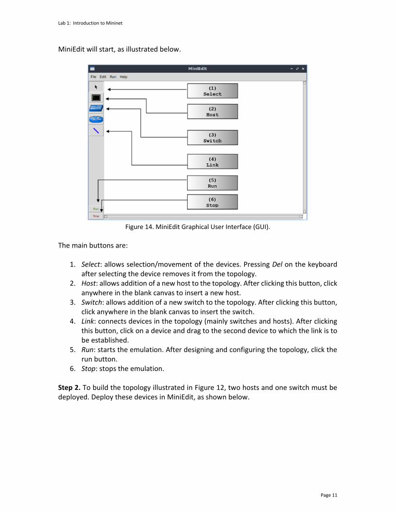
MiniEdit will start, as illustrated below.
Figure 14. MiniEdit Graphical User Interface (GUI).
The main buttons are:
1. Select: allows selection/movement of the devices. Pressing Del on the keyboard after selecting the device removes it from the topology.
2. Host: allows addition of a new host to the topology. After clicking this button, click anywhere in the blank canvas to insert a new host.
3. Switch: allows addition of a new switch to the topology. After clicking this button, click anywhere in the blank canvas to insert the switch.
4. Link: connects devices in the topology (mainly switches and hosts). After clicking this button, click on a device and drag to the second device to which the link is to be established.
5. Run: starts the emulation. After designing and configuring the topology, click the run button.
6. Stop: stops the emulation. Step 2. To build the topology illustrated in Figure 12, two hosts and one switch must be deployed. Deploy these devices in MiniEdit, as shown below.
Lab 1: Introduction to Mininet
Page 12
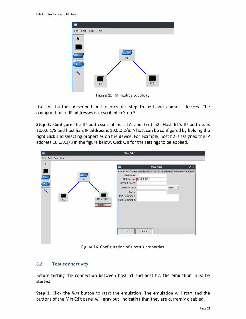
Figure 15. MiniEdit’s topology.
Use the buttons described in the previous step to add and connect devices. The configuration of IP addresses is described in Step 3. Step 3. Configure the IP addresses of host h1 and host h2. Host h1’s IP address is 10.0.0.1/8 and host h2’s IP address is 10.0.0.2/8. A host can be configured by holding the right click and selecting properties on the device. For example, host h2 is assigned the IP address 10.0.0.2/8 in the figure below. Click OK for the settings to be applied.
Figure 16. Configuration of a host’s properties.
3.2 Test connectivity
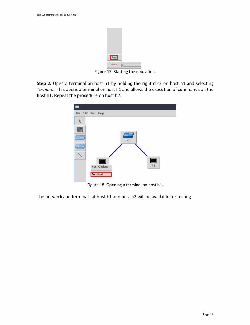
Before testing the connection between host h1 and host h2, the emulation must be started. Step 1. Click the Run button to start the emulation. The emulation will start and the buttons of the MiniEdit panel will gray out, indicating that they are currently disabled.
Lab 1: Introduction to Mininet
Page 13
Figure 17. Starting the emulation.
Step 2. Open a terminal on host h1 by holding the right click on host h1 and selecting Terminal. This opens a terminal on host h1 and allows the execution of commands on the host h1. Repeat the procedure on host h2.
Figure 18. Opening a terminal on host h1.
The network and terminals at host h1 and host h2 will be available for testing.
Lab 1: Introduction to Mininet
Page 14
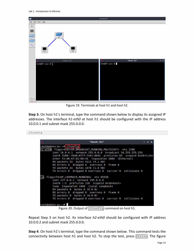
Figure 19. Terminals at host h1 and host h2.
Step 3. On host h1’s terminal, type the command shown below to display its assigned IP addresses. The interface h1-eth0 at host h1 should be configured with the IP address 10.0.0.1 and subnet mask 255.0.0.0. ifconfig
Figure 20. Output of ifconfig command on host h1.
Repeat Step 3 on host h2. Its interface h2-eth0 should be configured with IP address 10.0.0.2 and subnet mask 255.0.0.0. Step 4. On host h1’s terminal, type the command shown below. This command tests the connectivity between host h1 and host h2. To stop the test, press Ctrl+c. The figure
Lab 1: Introduction to Mininet
Page 15
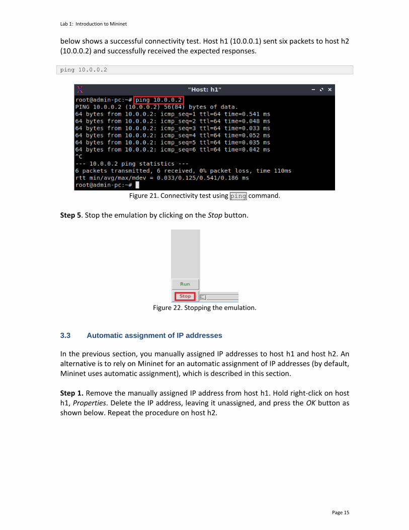
below shows a successful connectivity test. Host h1 (10.0.0.1) sent six packets to host h2 (10.0.0.2) and successfully received the expected responses. ping 10.0.0.2
Figure 21. Connectivity test using ping command.
Step 5. Stop the emulation by clicking on the Stop button.
Figure 22. Stopping the emulation.
3.3 Automatic assignment of IP addresses
In the previous section, you manually assigned IP addresses to host h1 and host h2. An alternative is to rely on Mininet for an automatic assignment of IP addresses (by default, Mininet uses automatic assignment), which is described in this section. Step 1. Remove the manually assigned IP address from host h1. Hold right-click on host h1, Properties. Delete the IP address, leaving it unassigned, and press the OK button as shown below. Repeat the procedure on host h2.

Lab 1: Introduction to Mininet
Page 16
Figure 23. Host h1 properties.
Step 2. Click on Edit, Preferences button. The default IP base is 10.0.0.0/8. Modify this value to 15.0.0.0/8, and then press the OK button.
Figure 24. Modification of the IP Base (network address and prefix length).
Step 3. Run the emulation again by clicking on the Run button. The emulation will start and the buttons of the MiniEdit panel will be disabled. Step 4. Open a terminal on host h1 by holding the right click on host h1 and selecting Terminal.
Lab 1: Introduction to Mininet
Page 17
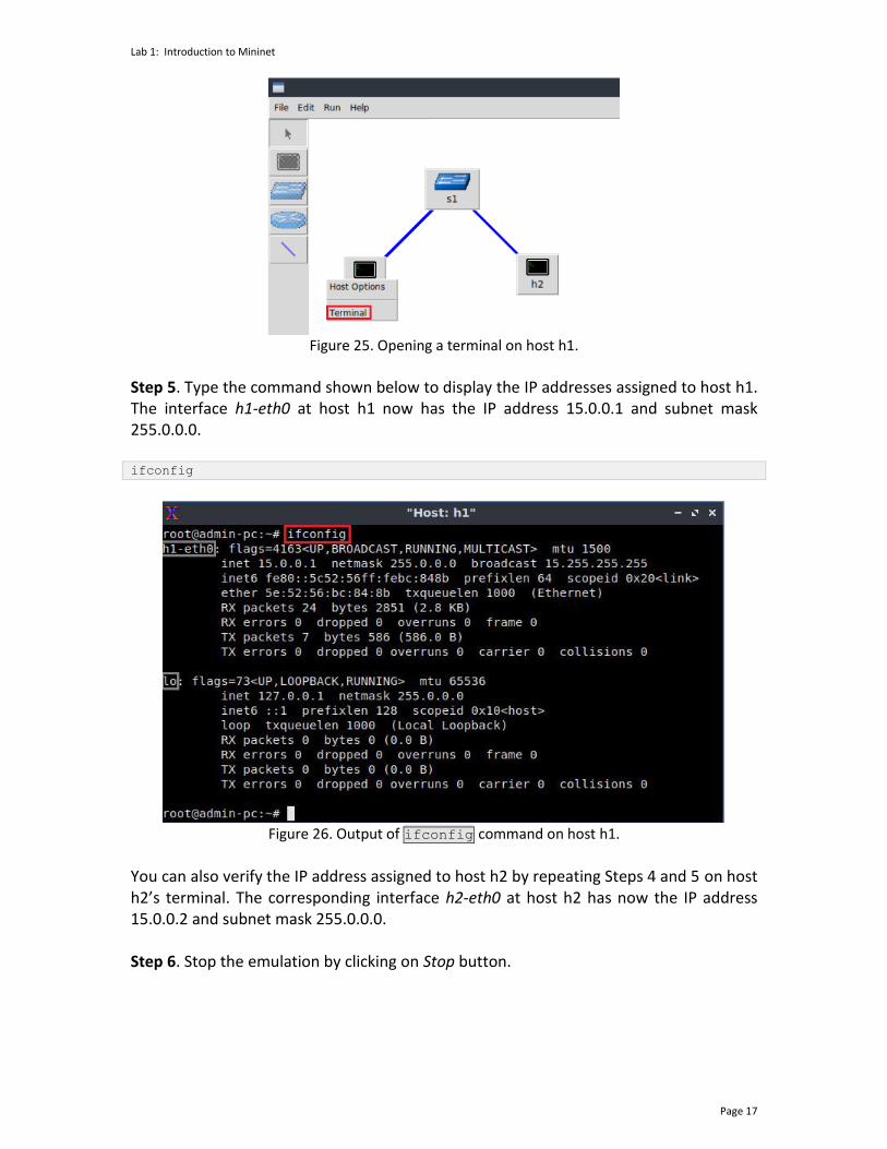
Figure 25. Opening a terminal on host h1.
Step 5. Type the command shown below to display the IP addresses assigned to host h1. The interface h1-eth0 at host h1 now has the IP address 15.0.0.1 and subnet mask 255.0.0.0. ifconfig
Figure 26. Output of ifconfig command on host h1.
You can also verify the IP address assigned to host h2 by repeating Steps 4 and 5 on host h2’s terminal. The corresponding interface h2-eth0 at host h2 has now the IP address 15.0.0.2 and subnet mask 255.0.0.0. Step 6. Stop the emulation by clicking on Stop button.

Lab 1: Introduction to Mininet
Page 18
Figure 27. Stopping the emulation.
3.4 Save and load a Mininet topology
In this section you will save and load a Mininet topology. It is often useful to save the network topology, particularly when its complexity increases. MiniEdit enables you to save the topology to a file. Step 1. Save the current topology by clicking on File then Save. Provide a name for the topology and save it in the local folder. In this case, we used myTopology as the topology name.
Figure 28. Saving the topology.
Step 2. Load the topology by clicking on File then Open. Search for the topology file called lab1.mn and click on Open. A new topology will be loaded to MiniEdit.
Lab 1: Introduction to Mininet
Page 19
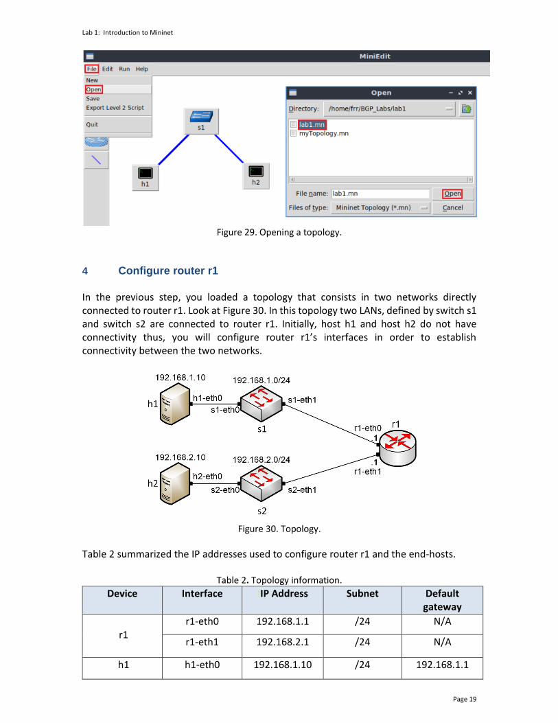
Figure 29. Opening a topology.
4 Configure router r1 In the previous step, you loaded a topology that consists in two networks directly connected to router r1. Look at Figure 30. In this topology two LANs, defined by switch s1 and switch s2 are connected to router r1. Initially, host h1 and host h2 do not have connectivity thus, you will configure router r1’s interfaces in order to establish connectivity between the two networks.
Figure 30. Topology.
Table 2 summarized the IP addresses used to configure router r1 and the end-hosts.
Table 2. Topology information. Device Interface IIP Address Subnet Default
gateway
r1
r1-eth0 192.168.1.1 /24 N/A
r1-eth1 192.168.2.1 /24 N/A
h1 h1-eth0 192.168.1.10 /24 192.168.1.1
Lab 1: Introduction to Mininet
Page 20
h2 h2-eth0 192.168.2.10 /24 192.168.2.1
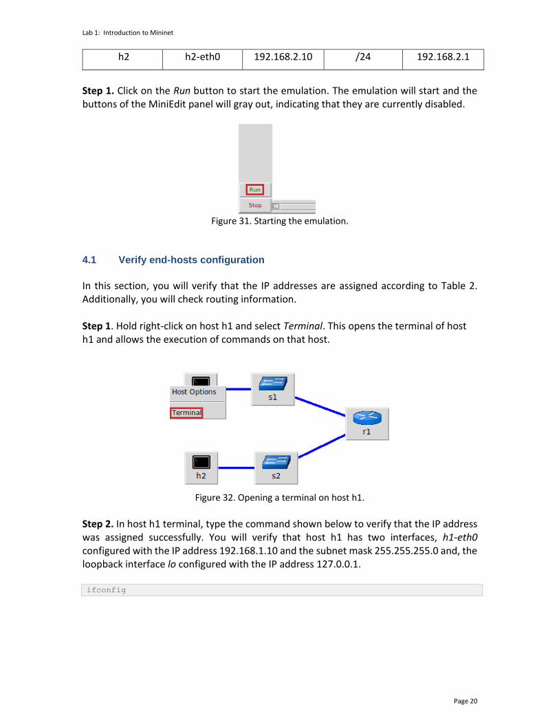
Step 1. Click on the Run button to start the emulation. The emulation will start and the buttons of the MiniEdit panel will gray out, indicating that they are currently disabled.
Figure 31. Starting the emulation.
4.1 Verify end-hosts configuration
In this section, you will verify that the IP addresses are assigned according to Table 2. Additionally, you will check routing information. Step 1. Hold right-click on host h1 and select Terminal. This opens the terminal of host h1 and allows the execution of commands on that host.
Figure 32. Opening a terminal on host h1.
Step 2. In host h1 terminal, type the command shown below to verify that the IP address was assigned successfully. You will verify that host h1 has two interfaces, h1-eth0 configured with the IP address 192.168.1.10 and the subnet mask 255.255.255.0 and, the loopback interface lo configured with the IP address 127.0.0.1. ifconfig
Lab 1: Introduction to Mininet
Page 21
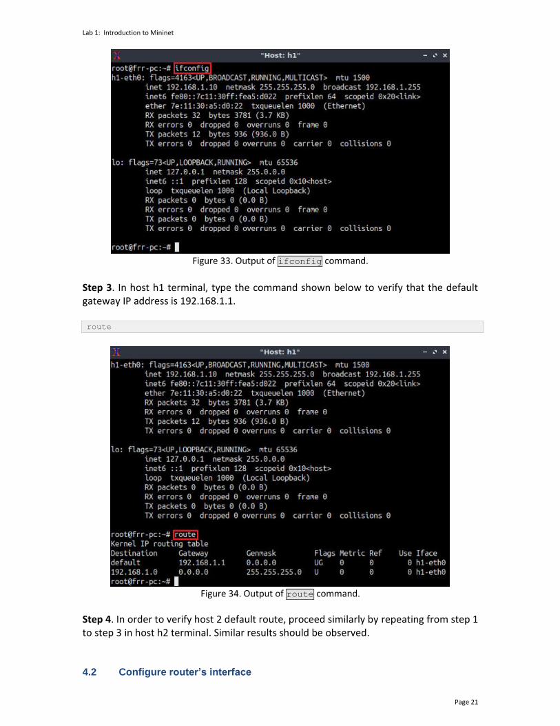
Figure 33. Output of ifconfig command.
Step 3. In host h1 terminal, type the command shown below to verify that the default gateway IP address is 192.168.1.1. route
Figure 34. Output of route command.
Step 4. In order to verify host 2 default route, proceed similarly by repeating from step 1 to step 3 in host h2 terminal. Similar results should be observed. 4.2 Configure router’s interface
Lab 1: Introduction to Mininet
Page 22
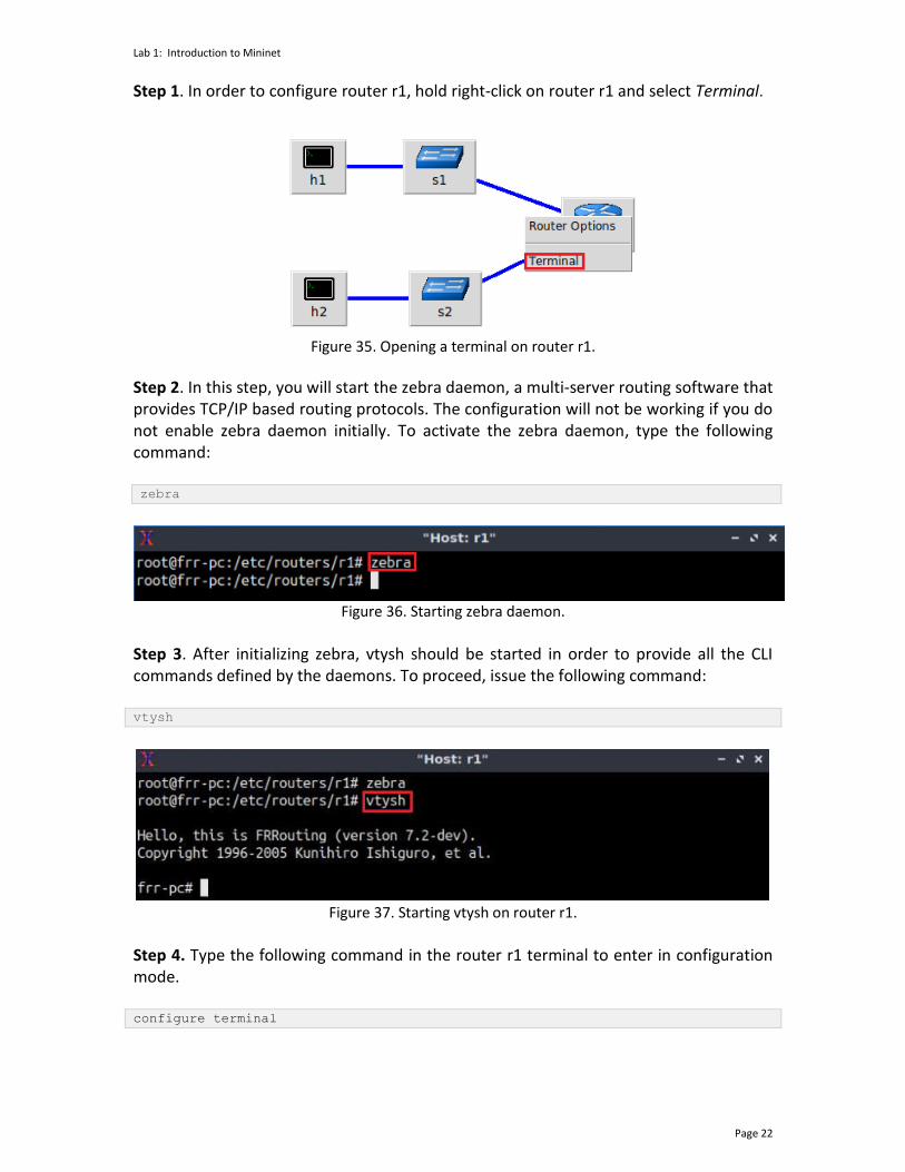
Step 1. In order to configure router r1, hold right-click on router r1 and select Terminal.
Figure 35. Opening a terminal on router r1.
Step 2. In this step, you will start the zebra daemon, a multi-server routing software that provides TCP/IP based routing protocols. The configuration will not be working if you do not enable zebra daemon initially. To activate the zebra daemon, type the following command: zebra
Figure 36. Starting zebra daemon.
Step 3. After initializing zebra, vtysh should be started in order to provide all the CLI commands defined by the daemons. To proceed, issue the following command: vtysh
Figure 37. Starting vtysh on router r1.
Step 4. Type the following command in the router r1 terminal to enter in configuration mode. configure terminal
Lab 1: Introduction to Mininet
Page 23
Figure 38. Entering in configuration mode.
Step 5. Type the following command in the router r1 terminal to configure interface r1-eth0. interface r1-eth0
Figure 39. Configuring interface r1-eth0.
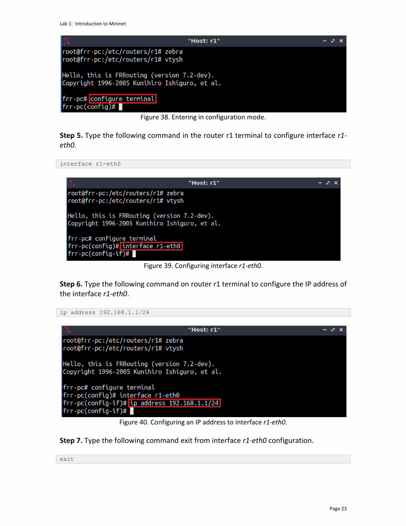
Step 6. Type the following command on router r1 terminal to configure the IP address of the interface r1-eth0. ip address 192.168.1.1/24
Figure 40. Configuring an IP address to interface r1-eth0.
Step 7. Type the following command exit from interface r1-eth0 configuration. exit
Lab 1: Introduction to Mininet
Page 24
Figure 41. Exiting from configuring interface r1-eth0.
Step 8. Type the following command on router r1 terminal to configure the interface r1-eth1. interface r1-eth1
Figure 42. Configuring interface r1-eth1.
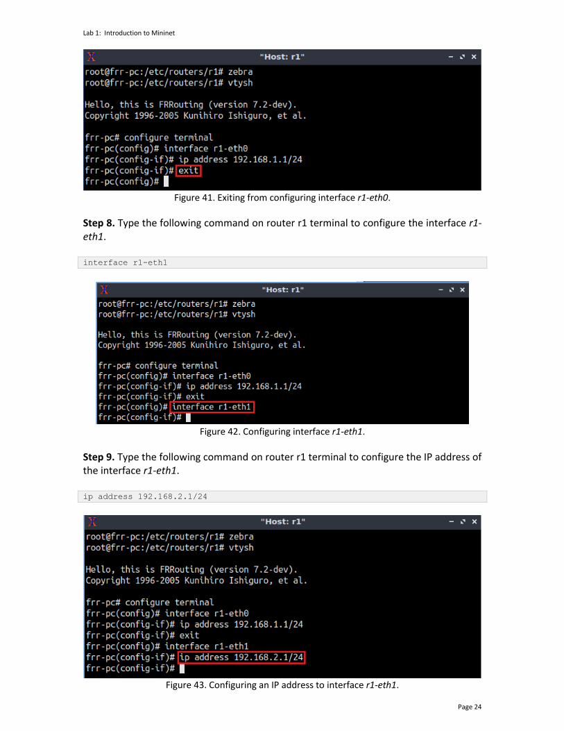
Step 9. Type the following command on router r1 terminal to configure the IP address of the interface r1-eth1. ip address 192.168.2.1/24
Figure 43. Configuring an IP address to interface r1-eth1.
Lab 1: Introduction to Mininet
Page 25
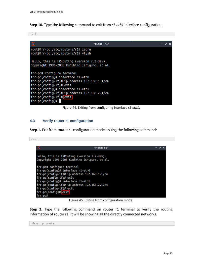
Step 10. Type the following command to exit from r1-eth1 interface configuration. exit
Figure 44. Exiting from configuring interface r1-eth1.
4.3 Verify router r1 configuration
Step 1. Exit from router r1 configuration mode issuing the following command: exit
Figure 45. Exiting from configuration mode.
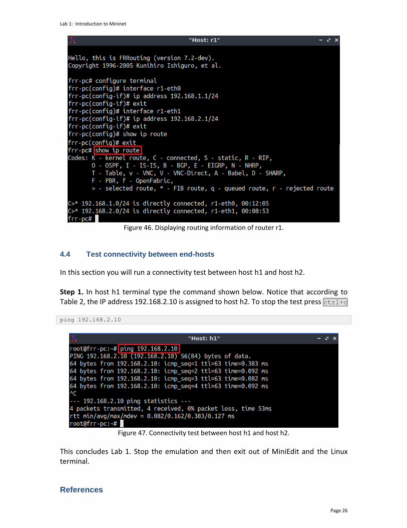
Step 2. Type the following command on router r1 terminal to verify the routing information of router r1. It will be showing all the directly connected networks. show ip route
Lab 1: Introduction to Mininet
Page 26
Figure 46. Displaying routing information of router r1.
4.4 Test connectivity between end-hosts
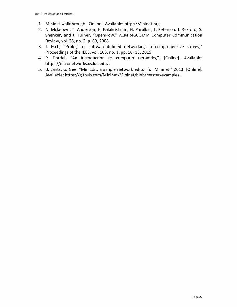
In this section you will run a connectivity test between host h1 and host h2. Step 1. In host h1 terminal type the command shown below. Notice that according to Table 2, the IP address 192.168.2.10 is assigned to host h2. To stop the test press ctrl+c
ping 192.168.2.10
Figure 47. Connectivity test between host h1 and host h2.
This concludes Lab 1. Stop the emulation and then exit out of MiniEdit and the Linux terminal. References
Lab 1: Introduction to Mininet
Page 27
1. Mininet walkthrough. [Online]. Available: http://Mininet.org. 2. N. Mckeown, T. Anderson, H. Balakrishnan, G. Parulkar, L. Peterson, J. Rexford, S.
Shenker, and J. Turner, “OpenFlow,” ACM SIGCOMM Computer Communication Review, vol. 38, no. 2, p. 69, 2008.
3. J. Esch, “Prolog to, software-defined networking: a comprehensive survey,” Proceedings of the IEEE, vol. 103, no. 1, pp. 10–13, 2015.
4. P. Dordal, “An Introduction to computer networks,”. [Online]. Available: https://intronetworks.cs.luc.edu/.
5. B. Lantz, G. Gee, “MiniEdit: a simple network editor for Mininet,” 2013. [Online]. Available: https://github.com/Mininet/Mininet/blob/master/examples.
BORDER GATEWAY PROTOCOL
Lab 2: Introduction to Free Range Routing (FRR)
Document Version: 05-25-2021
Award 1829698 “CyberTraining CIP: Cyberinfrastructure Expertise on High-throughput
Networks for Big Science Data Transfers”

Lab 2: Introduction to Free Range Routing (FRR)
Page 2
Contents Overview ............................................................................................................................. 3
Objectives............................................................................................................................ 3
Lab settings ......................................................................................................................... 3
Lab roadmap ....................................................................................................................... 3
1 Introduction to FRR ..................................................................................................... 3
1.1 FRR architecture ................................................................................................... 4
1.2 FRR and Mininet integration ................................................................................ 5
2 Lab topology................................................................................................................ 6
2.1 Lab settings........................................................................................................... 6
2.2 Open the topology ............................................................................................... 7
2.3 Load the configuration file ................................................................................... 8
2.4 Run the emulation ................................................................................................ 9
2.5 Verify the configuration ..................................................................................... 10
2.6 Test connectivity between end-hosts ................................................................ 13
3 Configure a routing protocol .................................................................................... 14
3.1 Enable a routing daemon ................................................................................... 14
3.2 Configure static route ........................................................................................ 15
3.3 Verify the configuration ..................................................................................... 17
4 Test connectivity and verify routes between end-hosts .......................................... 18
References ........................................................................................................................ 19
Lab 2: Introduction to Free Range Routing (FRR)
Page 3
Overview This lab is an introduction to Free Range Routing (FRR), which is a routing software suite that provides TCP/IP based routing services with routing protocols support. FRR also coordinates tasks such as exchanging routing information with other routers, making routing and policy decisions and, managing packet forwarding. In this lab, you will explore FRR architecture, load basic configuration and conduct connectivity tests within a simple topology. Objectives By the end of this lab, you should be able to:
1. Understand the architecture of FRR. 2. Run FRR daemons in an emulated environment. 3. Enable routing features using the router’s command line. 4. Navigate into FRR terminal using administrative commands. 5. Load a configuration file into the router. 6. Perform a connectivity test between end hosts.
Lab settings The information in Table 1 provides the credentials of the Client.
Table 1. Credentials to access the Client machine.
Device
Account
Password
Client admin password
Lab roadmap This lab is organized as follows:
1. Section 1: Introduction to FRR. 2. Section 2: Lab topology. 3. Section 3: Configure a routing protocol. 4. Section 4: Test connectivity and verify routes between end-hosts.
1 Introduction to FRR Implementing IP routing usually involves buying expensive and vertically integrated equipment from specific companies. This approach has limitations such as the hardware's
Lab 2: Introduction to Free Range Routing (FRR)
Page 4
cost, closed source software, and the training required to operate and configure the devices. Networking professionals, operators, and researchers sometimes are limited by the capabilities of such routing products. Moreover, combining routing functionalities with existing open-source software packages is usually constrained by the number of separate devices deployed. For example, operators could be interested in collecting information about the behavior of routing devices, process them, and make them available. Therefore, to achieve such capabilities, additional storage and scripting capacities are required. Such resources are not available in existing routing products. On the other hand, researchers may be interested in developing routing protocols by extending an existing one without writing a complete implementation from scratch. FRR suite1 is a package of Unix/Linux software that implements standard network routing protocols, such as Routing Information Protocol4 (RIP), Open Shortest Path First5 (OSPF), Border Gateway Protocol6 (BGP), and Intermediate System to Intermediate System IS-IS7. The package also includes a routing information management process to act as an intermediary between the routing protocols and the active routes installed with the kernel. A library provides support for configuration and an interactive command-line interface. The routing protocols supported by FRR can be extended to enable experimentation, logging, or custom processing. Also, libraries and kernel daemons provide a framework to facilitate the development of new routing protocol daemons. A wide range of functionalities can be obtained by combining other software packages to allow integration into a single device and enable innovative solutions to networking problems. FRR is distributed under General Public License v2.0 (GPLv2). The community of operators, vendors, non-profits, and researchers is interested in increasing the visibility of FRR and a potential path to more comprehensive testing and deployment of proposed modifications to routing protocols or new routing protocols. 1.1 FRR architecture
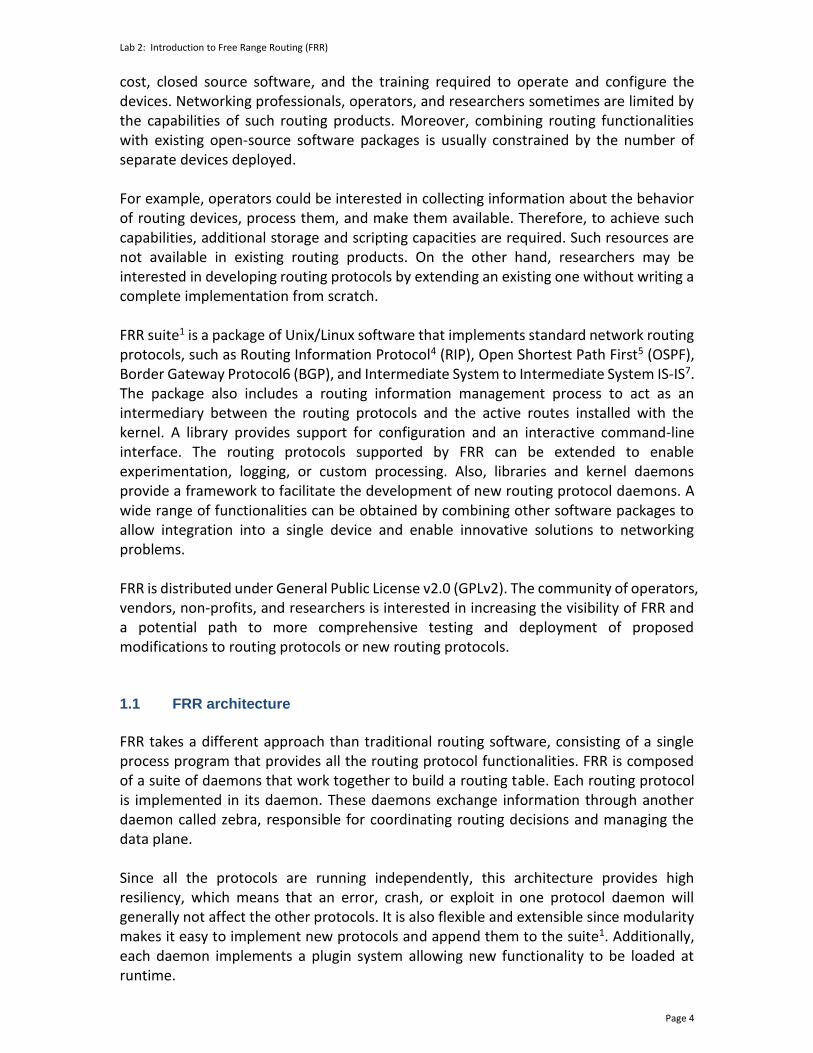
FRR takes a different approach than traditional routing software, consisting of a single process program that provides all the routing protocol functionalities. FRR is composed of a suite of daemons that work together to build a routing table. Each routing protocol is implemented in its daemon. These daemons exchange information through another daemon called zebra, responsible for coordinating routing decisions and managing the data plane. Since all the protocols are running independently, this architecture provides high resiliency, which means that an error, crash, or exploit in one protocol daemon will generally not affect the other protocols. It is also flexible and extensible since modularity makes it easy to implement new protocols and append them to the suite1. Additionally, each daemon implements a plugin system allowing new functionality to be loaded at runtime.
Lab 2: Introduction to Free Range Routing (FRR)
Page 5
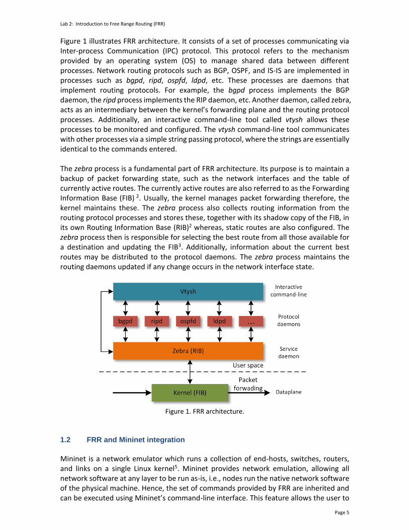
Figure 1 illustrates FRR architecture. It consists of a set of processes communicating via Inter-process Communication (IPC) protocol. This protocol refers to the mechanism provided by an operating system (OS) to manage shared data between different processes. Network routing protocols such as BGP, OSPF, and IS-IS are implemented in processes such as bgpd, ripd, ospfd, ldpd, etc. These processes are daemons that implement routing protocols. For example, the bgpd process implements the BGP daemon, the ripd process implements the RIP daemon, etc. Another daemon, called zebra, acts as an intermediary between the kernel’s forwarding plane and the routing protocol processes. Additionally, an interactive command-line tool called vtysh allows these processes to be monitored and configured. The vtysh command-line tool communicates with other processes via a simple string passing protocol, where the strings are essentially identical to the commands entered. The zebra process is a fundamental part of FRR architecture. Its purpose is to maintain a backup of packet forwarding state, such as the network interfaces and the table of currently active routes. The currently active routes are also referred to as the Forwarding Information Base (FIB) 2. Usually, the kernel manages packet forwarding therefore, the kernel maintains these. The zebra process also collects routing information from the routing protocol processes and stores these, together with its shadow copy of the FIB, in its own Routing Information Base (RIB)2 whereas, static routes are also configured. The zebra process then is responsible for selecting the best route from all those available for a destination and updating the FIB3. Additionally, information about the current best routes may be distributed to the protocol daemons. The zebra process maintains the routing daemons updated if any change occurs in the network interface state.
Figure 1. FRR architecture.
1.2 FRR and Mininet integration
Mininet is a network emulator which runs a collection of end-hosts, switches, routers, and links on a single Linux kernel5. Mininet provides network emulation, allowing all network software at any layer to be run as-is, i.e., nodes run the native network software of the physical machine. Hence, the set of commands provided by FRR are inherited and can be executed using Mininet’s command-line interface. This feature allows the user to
Lab 2: Introduction to Free Range Routing (FRR)
Page 6
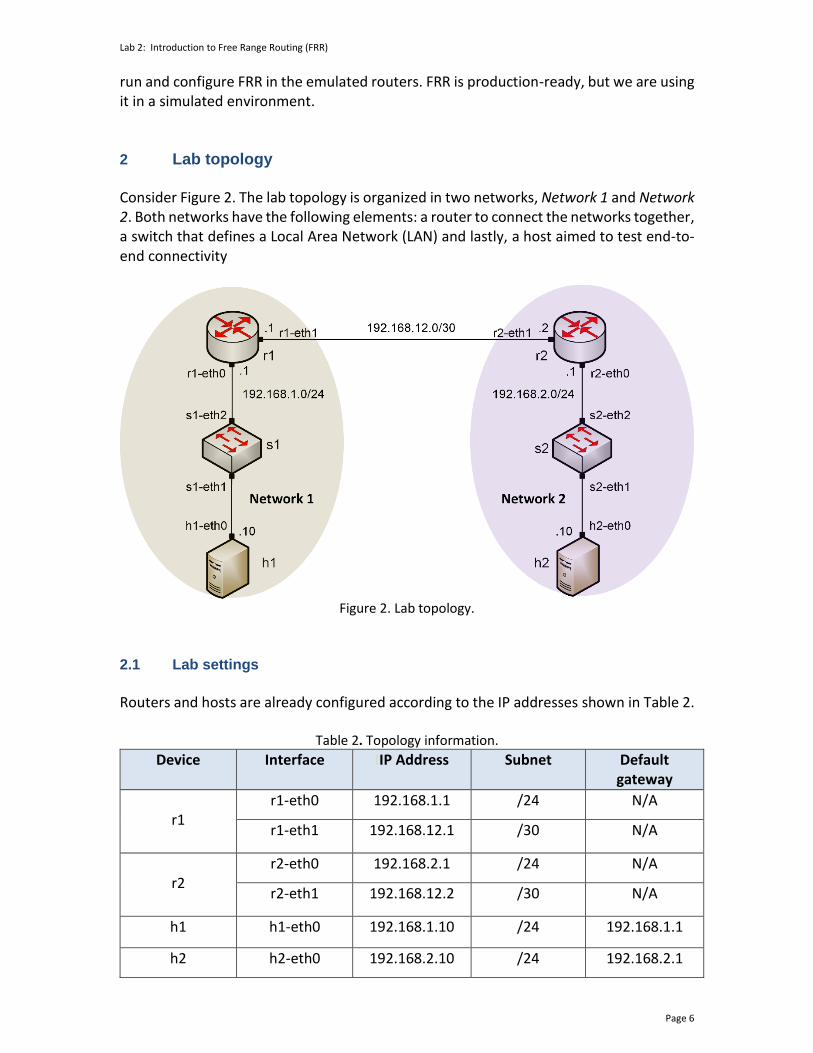
run and configure FRR in the emulated routers. FRR is production-ready, but we are using it in a simulated environment. 2 Lab topology Consider Figure 2. The lab topology is organized in two networks, Network 1 and Network 2. Both networks have the following elements: a router to connect the networks together, a switch that defines a Local Area Network (LAN) and lastly, a host aimed to test end-to-end connectivity
Figure 2. Lab topology.
2.1 Lab settings
Routers and hosts are already configured according to the IP addresses shown in Table 2.
Table 2. Topology information.
Device Interface IIP Address Subnet Default gateway
r1
r1-eth0 192.168.1.1 /24 N/A
r1-eth1 192.168.12.1 /30 N/A
r2
r2-eth0 192.168.2.1 /24 N/A
r2-eth1 192.168.12.2 /30 N/A
h1 h1-eth0 192.168.1.10 /24 192.168.1.1
h2 h2-eth0 192.168.2.10 /24 192.168.2.1

Lab 2: Introduction to Free Range Routing (FRR)
Page 7
2.2 Open the topology
In this section, you will open MiniEdit9 and load the lab topology. MiniEdit provides a Graphical User Interface (GUI) that facilitates the creation and simulation of network topologies in Mininet. This tool has additional capabilities: configuring network elements (IP addresses, default gateway), saving the topology, and exporting a layer 2 model. Step 1. A shortcut to MiniEdit is located on the Client machine’s desktop. Start MiniEdit by clicking on MiniEdit’s shortcut. When prompted for a password, type password.
Figure 3. MiniEdit shortcut.
Step 2. On MiniEdit’s menu bar, click on File, then open to load the lab’s topology. Open the Lab2.mn topology file stored in the default directory, /home/frr/BGP_Labs/lab2 and click on Open.
Figure 4. MiniEdit’s open dialog.
Figure 5 shows the topology used in this lab. To configure the interfaces, you will execute a script that will load the configuration on the routers.

Lab 2: Introduction to Free Range Routing (FRR)
Page 8
Figure 5. Mininet’s topology.
2.3 Load the configuration file
At this point, the topology is loaded. However, the interfaces are not configured. To assign IP addresses to the devices’ interfaces, you will execute a script that loads the configuration to the routers and end devices. Step 1. Click on the icon below to open the Linux terminal.
Figure 6. Opening Linux terminal.
Step 2. Click on the Linux terminal and navigate into BGP_Labs/lab2 directory by issuing the following command. This folder contains a configuration file and the script responsible for loading the configuration. The configuration file will assign the IP addresses to the routers’ interfaces. The cd command is short for change directory, followed by an argument that specifies the destination directory. cd BGP_Labs/lab2
Figure 7. Entering the BGP_Labs/lab2 directory.
Lab 2: Introduction to Free Range Routing (FRR)
Page 9
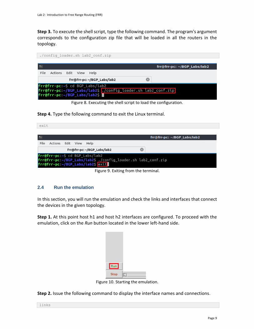
Step 3. To execute the shell script, type the following command. The program's argument corresponds to the configuration zip file that will be loaded in all the routers in the topology. ./config_loader.sh lab2_conf.zip
Figure 8. Executing the shell script to load the configuration.
Step 4. Type the following command to exit the Linux terminal. exit
Figure 9. Exiting from the terminal.
2.4 Run the emulation
In this section, you will run the emulation and check the links and interfaces that connect the devices in the given topology.
Step 1. At this point host h1 and host h2 interfaces are configured. To proceed with the emulation, click on the Run button located in the lower left-hand side.
Figure 10. Starting the emulation.
Step 2. Issue the following command to display the interface names and connections. links

Lab 2: Introduction to Free Range Routing (FRR)
Page 10
Figure 11. Displaying network interfaces.
In Figure 11, the link displayed within the gray box indicates that interface eth2 of switch s1 connects to interface eth0 of host h1 (i.e., s1-eth2<->h1-eth0). 2.5 Verify the configuration
In the following steps, you will verify the IP address to the hosts following Table 2 as the IP addresses are already configured for you. You can verify each host's IP addresses and the routing table of each router to see if the configuration is correct according to the table. Step 1. Hold right-click on host h1 and select Terminal. This opens the terminal of host h1 and allows the execution of commands on that host.
Figure 12. Opening a terminal on host h1.
Step 2. In the host h1 terminal, type the command shown below to verify that the IP address was assigned successfully. You will corroborate that host h1 has two interfaces, h1-eth0 configured with the IP address 192.168.1.10 and the subnet mask 255.255.255.0, and lo with 127.0.0.1. ifconfig
Lab 2: Introduction to Free Range Routing (FRR)
Page 11
Figure 13. Output of ifconfig command.
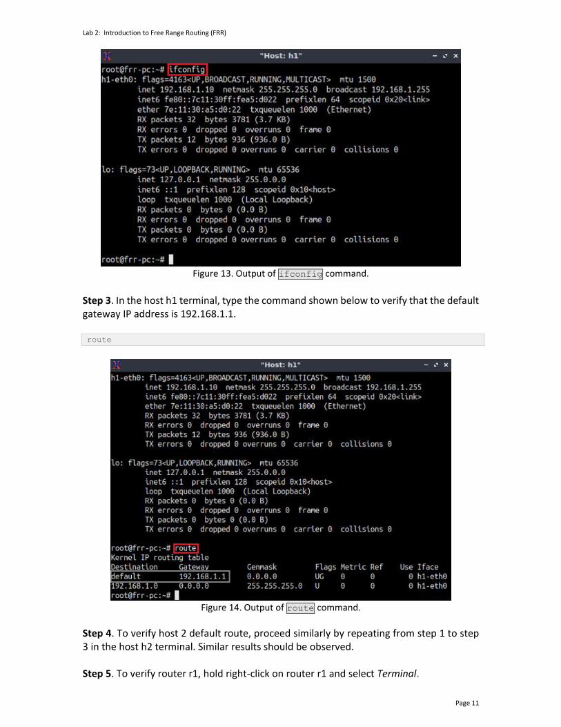
Step 3. In the host h1 terminal, type the command shown below to verify that the default gateway IP address is 192.168.1.1. route
Figure 14. Output of route command.
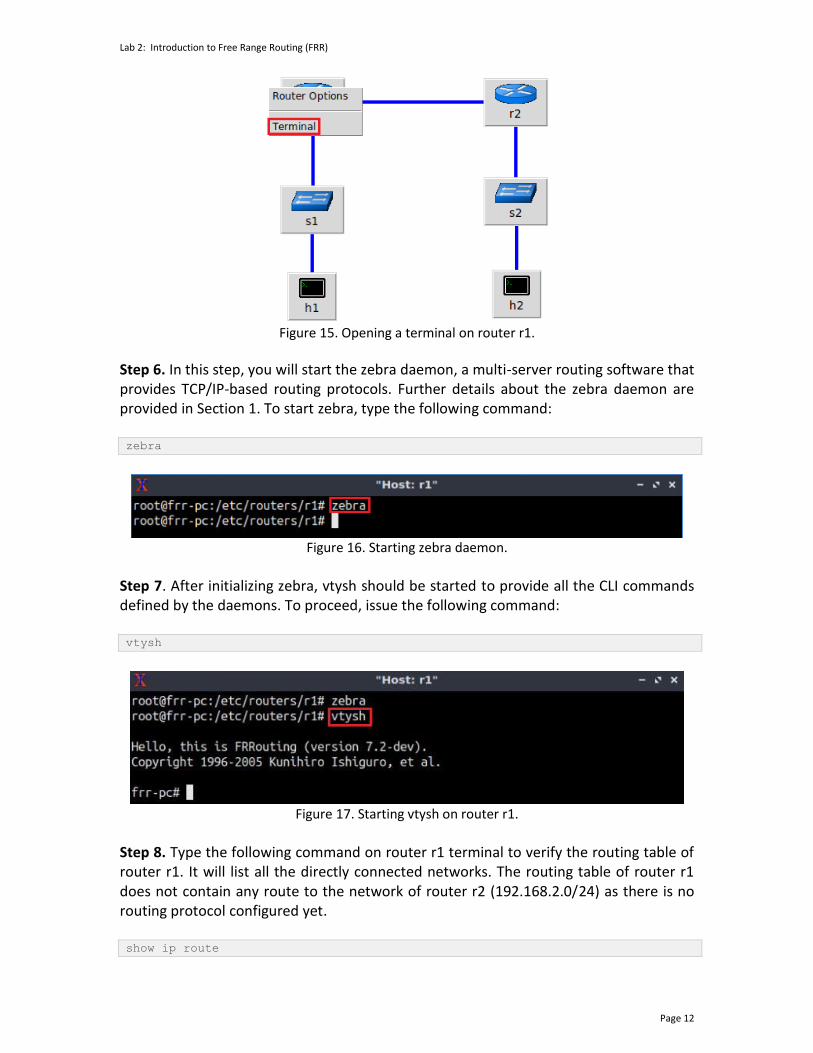
Step 4. To verify host 2 default route, proceed similarly by repeating from step 1 to step 3 in the host h2 terminal. Similar results should be observed. Step 5. To verify router r1, hold right-click on router r1 and select Terminal.
Lab 2: Introduction to Free Range Routing (FRR)
Page 12
Figure 15. Opening a terminal on router r1.
Step 6. In this step, you will start the zebra daemon, a multi-server routing software that provides TCP/IP-based routing protocols. Further details about the zebra daemon are provided in Section 1. To start zebra, type the following command: zebra
Figure 16. Starting zebra daemon.
Step 7. After initializing zebra, vtysh should be started to provide all the CLI commands defined by the daemons. To proceed, issue the following command: vtysh
Figure 17. Starting vtysh on router r1.
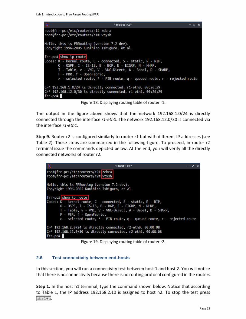
Step 8. Type the following command on router r1 terminal to verify the routing table of router r1. It will list all the directly connected networks. The routing table of router r1 does not contain any route to the network of router r2 (192.168.2.0/24) as there is no routing protocol configured yet. show ip route
Lab 2: Introduction to Free Range Routing (FRR)
Page 13
Figure 18. Displaying routing table of router r1.
The output in the figure above shows that the network 192.168.1.0/24 is directly connected through the interface r1-eth0. The network 192.168.12.0/30 is connected via the interface r1-eth1.
Step 9. Router r2 is configured similarly to router r1 but with different IP addresses (see Table 2). Those steps are summarized in the following figure. To proceed, in router r2 terminal issue the commands depicted below. At the end, you will verify all the directly connected networks of router r2.
Figure 19. Displaying routing table of router r2.
2.6 Test connectivity between end-hosts
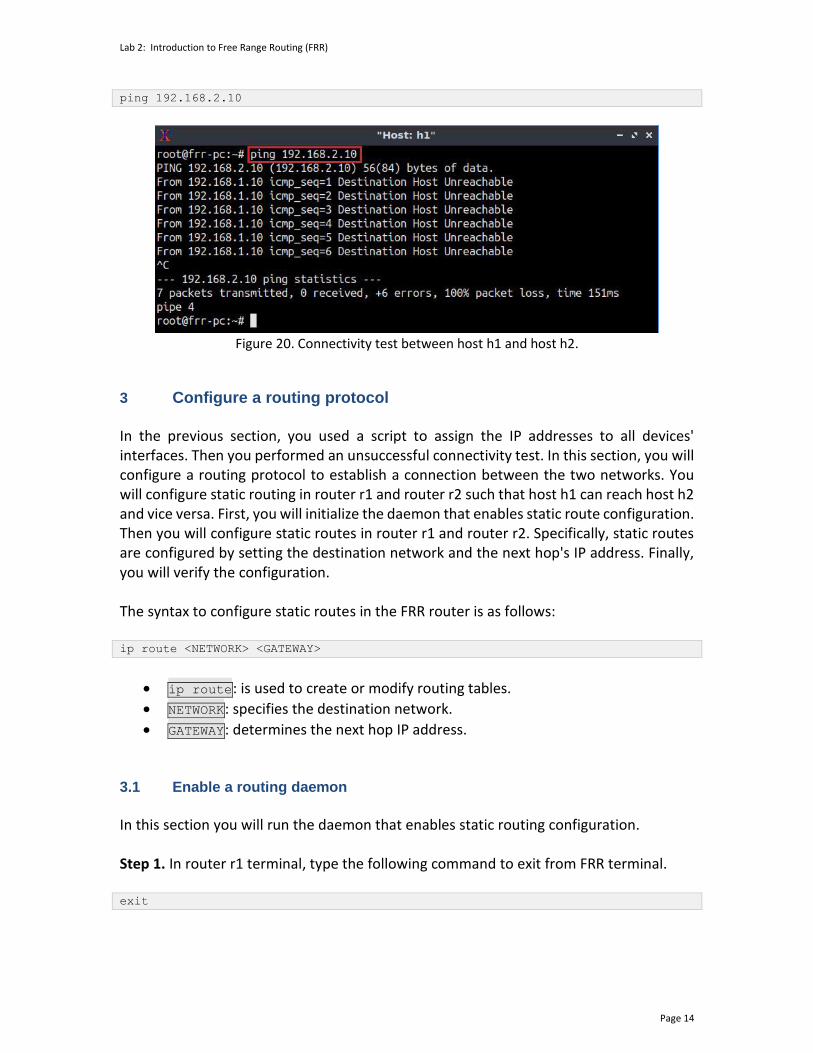
In this section, you will run a connectivity test between host 1 and host 2. You will notice that there is no connectivity because there is no routing protocol configured in the routers. Step 1. In the host h1 terminal, type the command shown below. Notice that according to Table 1, the IP address 192.168.2.10 is assigned to host h2. To stop the test press ctrl+c.
Lab 2: Introduction to Free Range Routing (FRR)
Page 14
ping 192.168.2.10
Figure 20. Connectivity test between host h1 and host h2.
3 Configure a routing protocol In the previous section, you used a script to assign the IP addresses to all devices' interfaces. Then you performed an unsuccessful connectivity test. In this section, you will configure a routing protocol to establish a connection between the two networks. You will configure static routing in router r1 and router r2 such that host h1 can reach host h2 and vice versa. First, you will initialize the daemon that enables static route configuration. Then you will configure static routes in router r1 and router r2. Specifically, static routes are configured by setting the destination network and the next hop's IP address. Finally, you will verify the configuration. The syntax to configure static routes in the FRR router is as follows: ip route <NETWORK> <GATEWAY>
• ip route: is used to create or modify routing tables.
• NETWORK: specifies the destination network.
• GATEWAY: determines the next hop IP address. 3.1 Enable a routing daemon
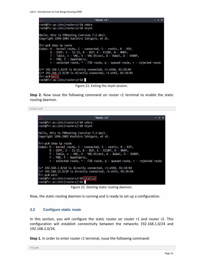
In this section you will run the daemon that enables static routing configuration. Step 1. In router r1 terminal, type the following command to exit from FRR terminal. exit
Lab 2: Introduction to Free Range Routing (FRR)
Page 15
Figure 21. Exiting the vtysh session.
Step 2. Now issue the following command on router r1 terminal to enable the static routing daemon. staticd
Figure 22. Starting static routing daemon.
Now, the static routing daemon is running and is ready to set up a configuration.
3.2 Configure static route
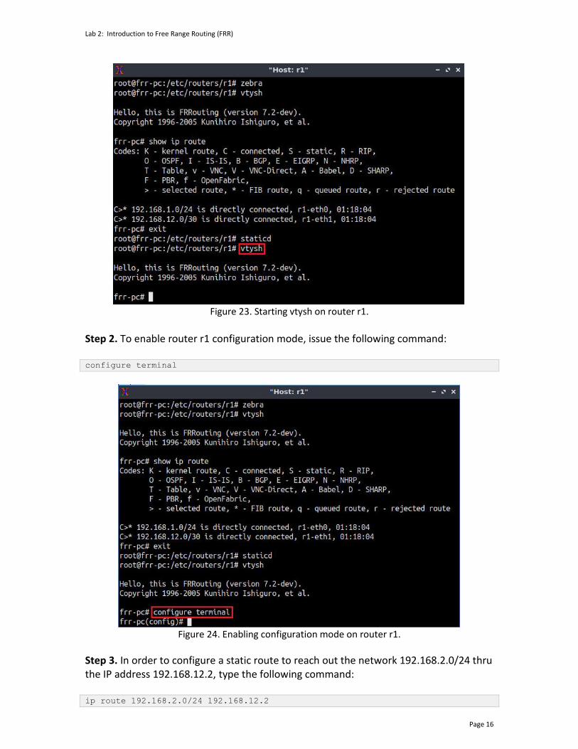
In this section, you will configure the static routes on router r1 and router r2. This configuration will establish connectivity between the networks 192.168.1.0/24 and 192.168.2.0/24. Step 1. In order to enter router r1 terminal, issue the following command: vtysh
Lab 2: Introduction to Free Range Routing (FRR)
Page 16
Figure 23. Starting vtysh on router r1.
Step 2. To enable router r1 configuration mode, issue the following command: configure terminal
Figure 24. Enabling configuration mode on router r1.
Step 3. In order to configure a static route to reach out the network 192.168.2.0/24 thru the IP address 192.168.12.2, type the following command: ip route 192.168.2.0/24 192.168.12.2

Lab 2: Introduction to Free Range Routing (FRR)
Page 17
Figure 25. Configuring a static route on router r1.
Step 4. To exit from configuration mode, issue the following command: exit
Figure 26. Exiting from configuration mode.
Step 5. The figure below summarizes the steps that must be followed in router r2 terminal in order to configure static route. From the perspective of router r2 the network 192.168.1.0 is reachable via the IP address 192.168.12.1.
Figure 27. Configuring static routing on router r2.
3.3 Verify the configuration
In this section, you will verify the configuration on router r1 and router r2.
Lab 2: Introduction to Free Range Routing (FRR)
Page 18
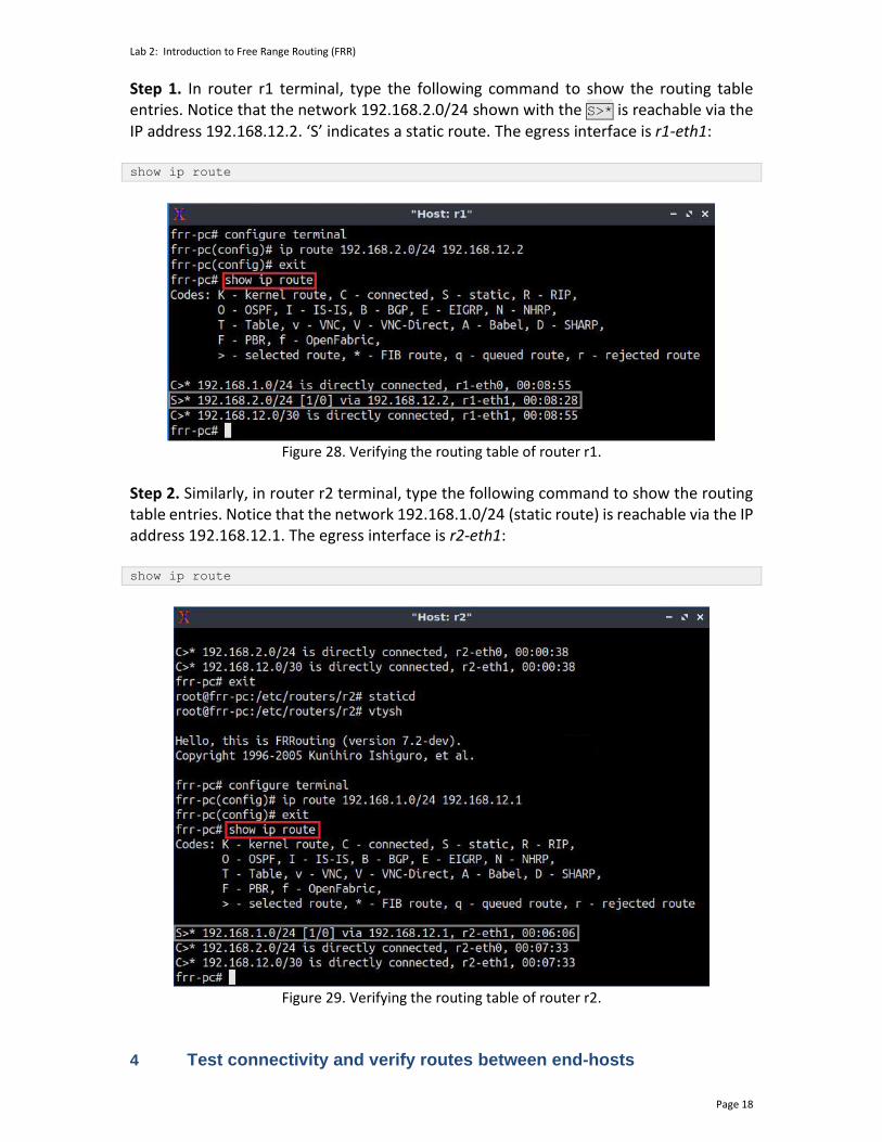
Step 1. In router r1 terminal, type the following command to show the routing table entries. Notice that the network 192.168.2.0/24 shown with the S>* is reachable via the IP address 192.168.12.2. ‘S’ indicates a static route. The egress interface is r1-eth1: show ip route
Figure 28. Verifying the routing table of router r1.
Step 2. Similarly, in router r2 terminal, type the following command to show the routing table entries. Notice that the network 192.168.1.0/24 (static route) is reachable via the IP address 192.168.12.1. The egress interface is r2-eth1: show ip route
Figure 29. Verifying the routing table of router r2.
4 Test connectivity and verify routes between end-hosts
Lab 2: Introduction to Free Range Routing (FRR)
Page 19
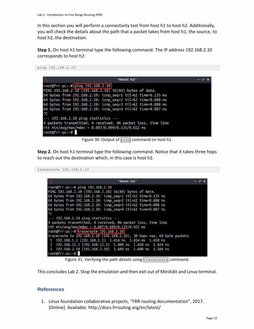
In this section you will perform a connectivity test from host h1 to host h2. Additionally, you will check the details about the path that a packet takes from host h1, the source, to host h2, the destination. Step 1. On host h1 terminal type the following command. The IP address 192.168.2.10 corresponds to host h2: ping 192.168.2.10
Figure 30. Output of ping command on host h1.
Step 2. On host h1 terminal type the following command. Notice that it takes three hops to reach out the destination which, in this case is host h2. traceroute 192.168.2.10
Figure 31. Verifying the path details using traceroute command.
This concludes Lab 2. Stop the emulation and then exit out of MiniEdit and Linux terminal. References
1. Linux foundation collaborative projects, “FRR routing documentation”, 2017. [Online]. Available: http://docs.frrouting.org/en/latest/
Lab 2: Introduction to Free Range Routing (FRR)
Page 20
2. P. Jakma, D. Lamparter. “Introduction to the quagga routing suite,” 2014, IEEE Network 28.
3. K. Ishiguro, “Gnu zebra,”. [Online]. Available: http://www. zebra. org (2002). 4. G. Malkin, “RIP Version 2,” RFC 2453 updated by RFC 4822, 1998. [Online].
Available: http://www.ietf.org/rfc/rfc2453.txt. 5. Mininet walkthrough. [Online]. Available: http://Mininet.org. 6. G. Malkin, R. Minnear, “RIPng for IPv6,” RFC 2080, 1997. [Online]. Available:
http://www.ietf.org/rfc/rfc2080.txt. 7. Y. Rekhter, T. Li, S. Hares, “A border gateway protocol 4 (BGP-4),” RFC 4271
updated by RFCs 6286, 6608, 6793, 2006. [Online]. Available: http://www.ietf.org/rfc/rfc4271.txt.
8. D. Oran, “OSI IS-IS intra-domain routing protocol,” RFC 1142, 1990. [Online]. Available: http://www.ietf.org/rfc/rfc1142.txt.
9. B. Lantz, G. Gee, “MiniEdit: a simple network editor for Mininet,” 2013. [Online]. Available: https://github.com/Mininet/Mininet/blob/master/examples.
BORDER GATEWAY PROTOCOL
Lab 3: Introduction to BGP
Document Version: 05-25-2021
Award 1829698 "CyberTraining CIP: Cyberinfrastructure Expertise on High-throughput
Networks for Big Science Data Transfers"
Lab 3: Introduction to BGP
Page 2
Contents Overview ............................................................................................................................. 3
Objectives............................................................................................................................ 3
Lab settings ......................................................................................................................... 3
Lab roadmap ....................................................................................................................... 3
1 Introduction to BGP .................................................................................................... 3
1.1 Classification of dynamic routing protocols ......................................................... 3
1.2 BGP overview ....................................................................................................... 4
2 Lab topology................................................................................................................ 5
2.1 Lab settings........................................................................................................... 6
2.2 Open the topology and load the configuration ................................................... 6
2.3 Load the zebra daemon and verify configuration ................................................ 9
3 Configure BGP on the routers ................................................................................... 12
3.1 Add BGP neighbors on the routers .................................................................... 13
3.2 Advertise local networks on the routers ............................................................ 18
4 Verify connections .................................................................................................... 21
References ........................................................................................................................ 23

Lab 3: Introduction to BGP
Page 3
Overview This lab presents Border Gateway Protocol (BGP) and describes the concept of Internal BGP (IBGP) and External BGP (EBGP). Furthermore, EBGP will be configured and verified between two Autonomous Systems (ASes) required to exchange routes. Objectives By the end of this lab, you should be able to:
1. Explain the concept of BGP. 2. Differentiate between IBGP and EBGP. 3. Configure and verify EBGP between two ASes.
Lab settings The information in Table 1 provides the credentials to access the Client machine.
Table 1. Credentials to access the Client machine.
Device
Account
Password
Client1 admin password
Lab roadmap This lab is organized as follows:
1. Section 1: Introduction to BGP. 2. Section 2: Lab topology. 3. Section 3: Configure BGP on all routers. 4. Section 4: Verify connections.
1 Introduction to BGP 1.1 Classification of dynamic routing protocols
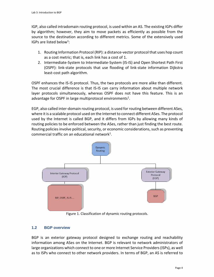
The Internet can be viewed as a collection of networks or ASes that are interconnected. An AS refers to a group of connected networks under a single administrative entity or domain. Figure 1 illustrates dynamic routing protocols, which can be divided into two categories, Interior Gateway Protocol (IGP) and Exterior Gateway Protocol (EGP)1.
Lab 3: Introduction to BGP
Page 4
IGP, also called intradomain routing protocol, is used within an AS. The existing IGPs differ by algorithm; however, they aim to move packets as efficiently as possible from the source to the destination according to different metrics. Some of the extensively used IGPs are listed below1:
1. Routing Information Protocol (RIP): a distance-vector protocol that uses hop count as a cost metric; that is, each link has a cost of 1.
2. Intermediate-System to Intermediate-System (IS-IS) and Open Shortest Path First (OSPF): link-state protocols that use flooding of link-state information Dijkstra least-cost path algorithm.
OSPF enhances the IS-IS protocol. Thus, the two protocols are more alike than different. The most crucial difference is that IS-IS can carry information about multiple network layer protocols simultaneously, whereas OSPF does not have this feature. This is an advantage for OSPF in large multiprotocol environments1. EGP, also called inter-domain routing protocol, is used for routing between different ASes, where it is a scalable protocol used on the Internet to connect different ASes. The protocol used by the Internet is called BGP, and it differs from IGPs by allowing many kinds of routing policies to be enforced between the ASes, rather than just finding the best route. Routing policies involve political, security, or economic considerations, such as preventing commercial traffic on an educational network1.
Figure 1. Classification of dynamic routing protocols.
1.2 BGP overview
BGP is an exterior gateway protocol designed to exchange routing and reachability information among ASes on the Internet. BGP is relevant to network administrators of large organizations which connect to one or more Internet Service Providers (ISPs), as well as to ISPs who connect to other network providers. In terms of BGP, an AS is referred to
Lab 3: Introduction to BGP
Page 5
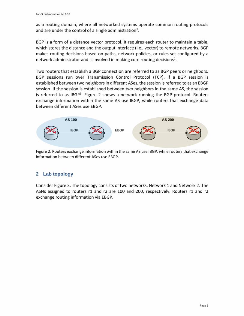
as a routing domain, where all networked systems operate common routing protocols and are under the control of a single administration1. BGP is a form of a distance vector protocol. It requires each router to maintain a table, which stores the distance and the output interface (i.e., vector) to remote networks. BGP makes routing decisions based on paths, network policies, or rules set configured by a network administrator and is involved in making core routing decisions1. Two routers that establish a BGP connection are referred to as BGP peers or neighbors. BGP sessions run over Transmission Control Protocol (TCP). If a BGP session is established between two neighbors in different ASes, the session is referred to as an EBGP session. If the session is established between two neighbors in the same AS, the session is referred to as IBGP1. Figure 2 shows a network running the BGP protocol. Routers exchange information within the same AS use IBGP, while routers that exchange data between different ASes use EBGP.
AS 200
IBGP
AS 100
IBGP EBGP
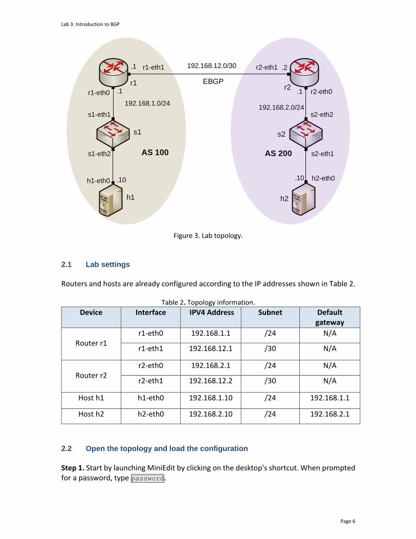
Figure 2. Routers exchange information within the same AS use IBGP, while routers that exchange information between different ASes use EBGP. 2 Lab topology Consider Figure 3. The topology consists of two networks, Network 1 and Network 2. The ASNs assigned to routers r1 and r2 are 100 and 200, respectively. Routers r1 and r2 exchange routing information via EBGP.
Lab 3: Introduction to BGP
Page 6
s1
h1 h2
s2
r1r2
h1-eth0
s1-eth1
s1-eth2
r1-eth0
r1-eth1 r2-eth1
r2-eth0
s2-eth2
s2-eth1
h2-eth0
AS 100 AS 200
.10 .10
.1 .1
.1 .2
192.168.1.0/24192.168.2.0/24
192.168.12.0/30
EBGP
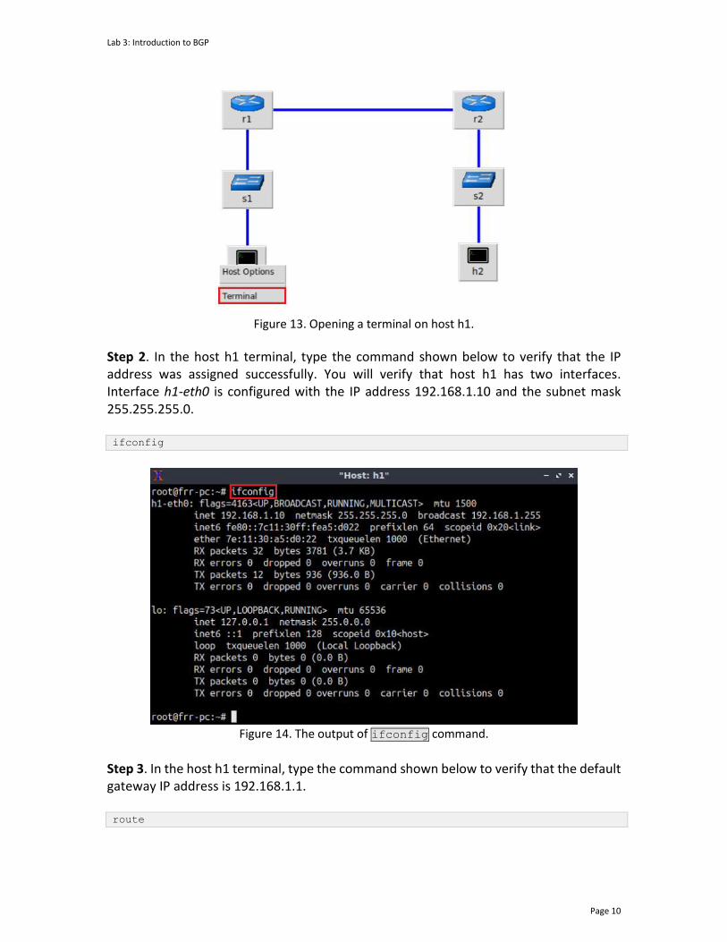
Figure 3. Lab topology.
2.1 Lab settings
Routers and hosts are already configured according to the IP addresses shown in Table 2.
Table 2. Topology information.
Device Interface IIPV4 Address Subnet Default gateway
Router r1
r1-eth0 192.168.1.1 /24 N/A
r1-eth1 192.168.12.1 /30 N/A
Router r2
r2-eth0 192.168.2.1 /24 N/A
r2-eth1 192.168.12.2 /30 N/A
Host h1 h1-eth0 192.168.1.10 /24 192.168.1.1
Host h2 h2-eth0 192.168.2.10 /24 192.168.2.1
2.2 Open the topology and load the configuration
Step 1. Start by launching MiniEdit by clicking on the desktop's shortcut. When prompted for a password, type password.

Lab 3: Introduction to BGP
Page 7
Figure 4. MiniEdit shortcut.
Step 2. On MiniEdit's menu bar, click on File, then open to load the lab's topology. Locate the Lab3.mn topology file in the default directory, /home/frr/BGP_Labs/lab3 and click on Open.
Figure 5. MiniEdit's open dialog.
At this point, the topology is loaded with all the required network components. Next, you will execute a script that will load the configuration of the routers.
Step 3. Open the Linux terminal.
Figure 6. Opening Linux terminal.
Step 4. Click on the Linux's terminal and navigate into BGP_Labs/lab3 directory. This folder contains a configuration file and the script responsible for loading the
Lab 3: Introduction to BGP
Page 8
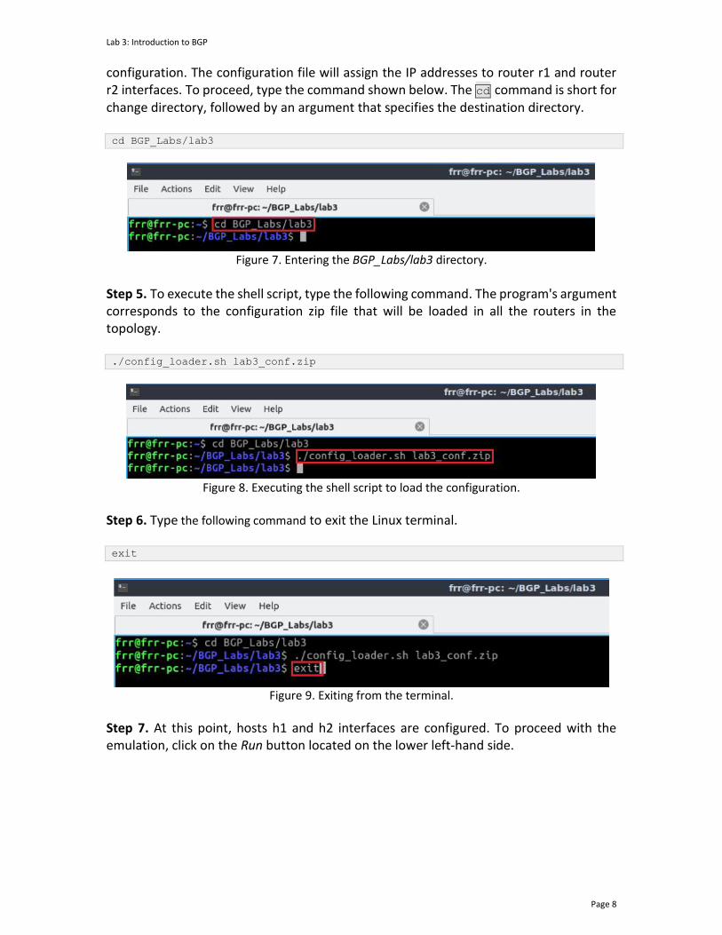
configuration. The configuration file will assign the IP addresses to router r1 and router r2 interfaces. To proceed, type the command shown below. The cd command is short for change directory, followed by an argument that specifies the destination directory. cd BGP_Labs/lab3
Figure 7. Entering the BGP_Labs/lab3 directory.
Step 5. To execute the shell script, type the following command. The program's argument corresponds to the configuration zip file that will be loaded in all the routers in the topology. ./config_loader.sh lab3_conf.zip
Figure 8. Executing the shell script to load the configuration.
Step 6. Type the following command to exit the Linux terminal. exit
Figure 9. Exiting from the terminal.
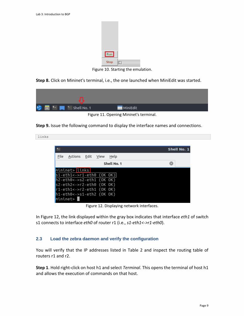
Step 7. At this point, hosts h1 and h2 interfaces are configured. To proceed with the emulation, click on the Run button located on the lower left-hand side.
Lab 3: Introduction to BGP
Page 9
Figure 10. Starting the emulation.
Step 8. Click on Mininet's terminal, i.e., the one launched when MiniEdit was started.
Figure 11. Opening Mininet's terminal.
Step 9. Issue the following command to display the interface names and connections. links
Figure 12. Displaying network interfaces.
In Figure 12, the link displayed within the gray box indicates that interface eth1 of switch s1 connects to interface eth0 of router r1 (i.e., s1-eth1<->r1-eth0). 2.3 Load the zebra daemon and verify the configuration
You will verify that the IP addresses listed in Table 2 and inspect the routing table of routers r1 and r2. Step 1. Hold right-click on host h1 and select Terminal. This opens the terminal of host h1 and allows the execution of commands on that host.
Lab 3: Introduction to BGP
Page 10
Figure 13. Opening a terminal on host h1.
Step 2. In the host h1 terminal, type the command shown below to verify that the IP address was assigned successfully. You will verify that host h1 has two interfaces. Interface h1-eth0 is configured with the IP address 192.168.1.10 and the subnet mask 255.255.255.0. ifconfig
Figure 14. The output of ifconfig command.
Step 3. In the host h1 terminal, type the command shown below to verify that the default gateway IP address is 192.168.1.1. route

Lab 3: Introduction to BGP
Page 11
Figure 15. The output of route command.
Step 4. To verify the host 2 default route, proceed by repeating from step 1 to step 3 on the host h2 terminal. Similar results should be observed. Step 5. You will validate that the router interfaces are configured correctly according to Table 2. To proceed, hold right-click on router r1 and select Terminal.
Figure 16. Opening a terminal on router r1.
Step 6. In this step, you will start the zebra daemon, a multi-server routing software that provides TCP/IP-based routing protocols. The configuration will not be working if you do not enable zebra daemon initially. To start the zebra, type the following command:

Lab 3: Introduction to BGP
Page 12
zebra
Figure 17. Starting zebra daemon.
Step 7. After initializing zebra, vtysh should be started to provide all the CLI commands defined by the daemons. To proceed, issue the following command: vtysh
Figure 18. Starting vtysh on router r1.
Step 8. Type the following command on router r1 terminal to verify the routing table of router r1. It will list all the directly connected networks. The routing table of router r1 does not contain any route to the network of router r2 (192.168.2.0/24) as there is no routing protocol configured yet. show ip route
Figure 19. Displaying routing table of router r1.
Step 9. To verify the routing table of router r2, proceed similarly by repeating from step 5 to step 8 on the router terminal. You will see the directly connected routes in router r2.
3 Configure BGP on the routers
In this section, you will configure BGP to establish a connection between AS 100 and AS 200. To configure the BGP routing protocol, you need to assign BGP neighbors to allow BGP peering to the remote neighbor, in addition to advertising your local networks.
Lab 3: Introduction to BGP
Page 13
3.1 Add BGP neighbors on the routers
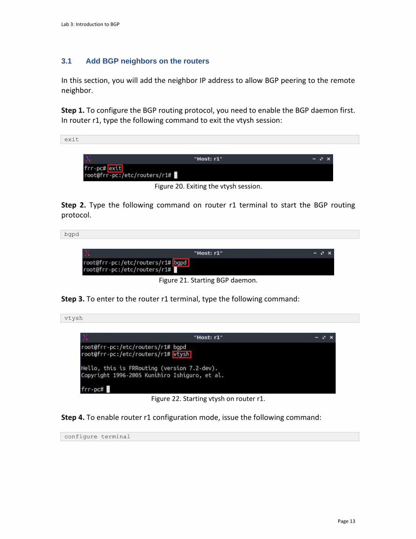
In this section, you will add the neighbor IP address to allow BGP peering to the remote neighbor. Step 1. To configure the BGP routing protocol, you need to enable the BGP daemon first. In router r1, type the following command to exit the vtysh session: exit
Figure 20. Exiting the vtysh session.
Step 2. Type the following command on router r1 terminal to start the BGP routing protocol. bgpd
Figure 21. Starting BGP daemon.
Step 3. To enter to the router r1 terminal, type the following command: vtysh
Figure 22. Starting vtysh on router r1.
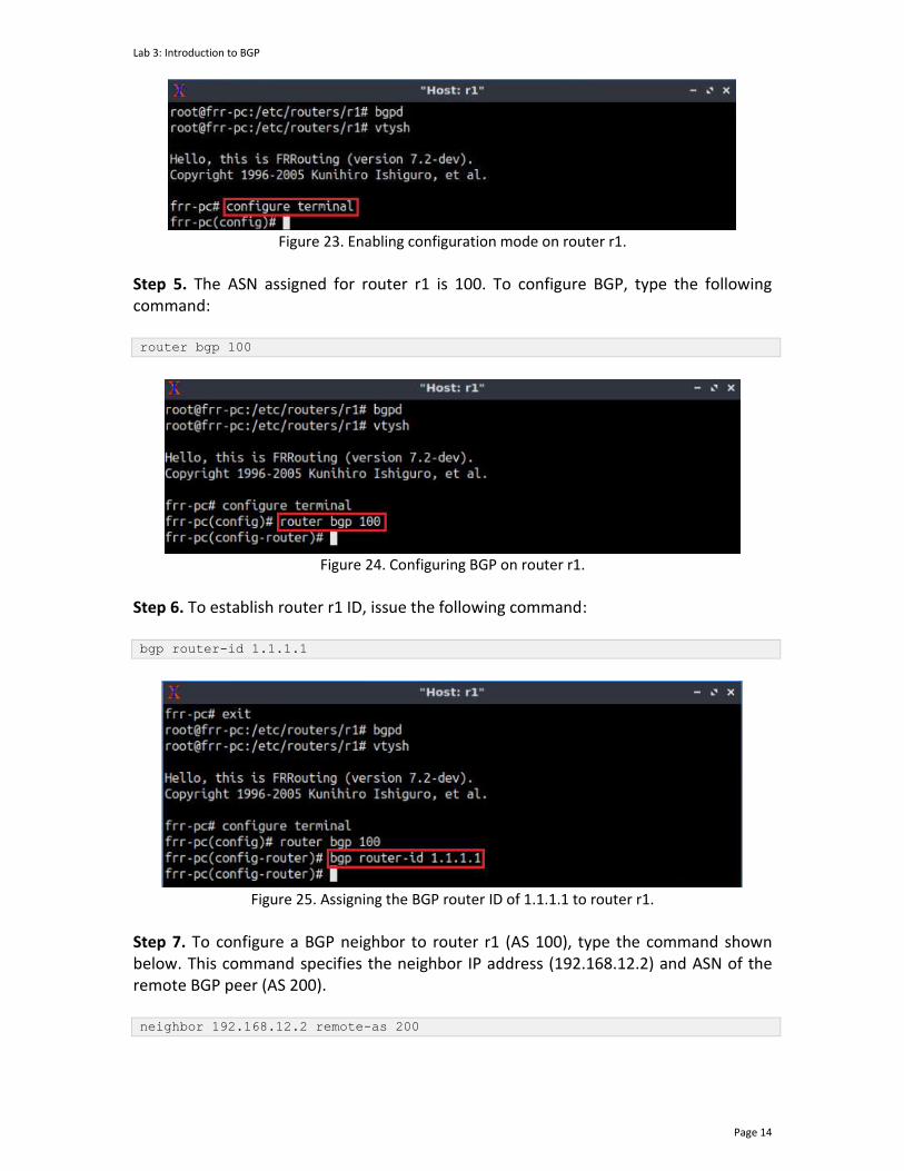
Step 4. To enable router r1 configuration mode, issue the following command: configure terminal
Lab 3: Introduction to BGP
Page 14
Figure 23. Enabling configuration mode on router r1.
Step 5. The ASN assigned for router r1 is 100. To configure BGP, type the following command: router bgp 100
Figure 24. Configuring BGP on router r1.
Step 6. To establish router r1 ID, issue the following command: bgp router-id 1.1.1.1
Figure 25. Assigning the BGP router ID of 1.1.1.1 to router r1.
Step 7. To configure a BGP neighbor to router r1 (AS 100), type the command shown below. This command specifies the neighbor IP address (192.168.12.2) and ASN of the remote BGP peer (AS 200). neighbor 192.168.12.2 remote-as 200

Lab 3: Introduction to BGP
Page 15
Figure 26. Assigning BGP neighbor to router r1.
Step 8. Type the following command to exit from the configuration mode. end
Figure 27. Exiting from configuration mode.
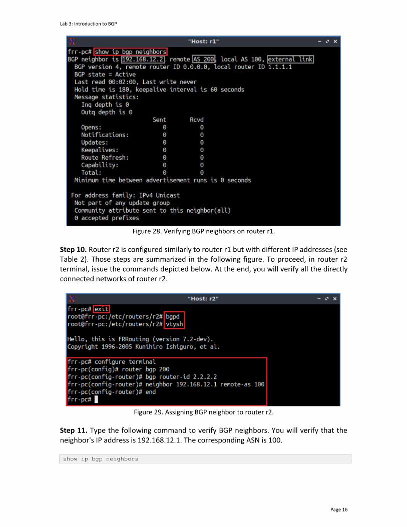
Step 9. Type the following command to verify BGP neighbors. You will verify that the neighbor's IP address is 192.168.12.2. The corresponding ASN is 200. show ip bgp neighbors
Lab 3: Introduction to BGP
Page 16
Figure 28. Verifying BGP neighbors on router r1.
Step 10. Router r2 is configured similarly to router r1 but with different IP addresses (see Table 2). Those steps are summarized in the following figure. To proceed, in router r2 terminal, issue the commands depicted below. At the end, you will verify all the directly connected networks of router r2.
Figure 29. Assigning BGP neighbor to router r2.
Step 11. Type the following command to verify BGP neighbors. You will verify that the neighbor's IP address is 192.168.12.1. The corresponding ASN is 100. show ip bgp neighbors

Lab 3: Introduction to BGP
Page 17
Figure 30. Verifying BGP neighbors on router r2.
Step 12. In the router r2 terminal, perform a connectivity test by running the command shown below. To stop the test, press Ctrl+c. The result will show a successful connectivity test between router r1 and router r2. ping 192.168.12.1
Figure 31. Connectivity test using the ping command.
Step 12. In the router r2 terminal, perform connectivity between router r2 and host h1 by issuing the command shown below. To stop the test, press Ctrl+c. Router r2 cannot reach host h1 as the routing table of router r2 does not contain the network address of host h1. ping 192.168.1.10

Lab 3: Introduction to BGP
Page 18
Figure 32. Connectivity test using the ping command.
3.2 Advertise local networks on the routers
In this section, you will advertise a Local Area Network (LAN) so that the neighbor can receive the network address through EBGP.
Step 1. In router r1 terminal, issue the following command. configure terminal
Figure 33. Enabling configuration mode on router r1.
Step 2. You will advertise the LAN network the router r1 is connected to via BGP. Type the following command to enable BGP configuration mode. router bgp 100
Figure 34. Entering to BGP configuration mode.
Step 3. Issue the following command so that router r1 will advertise the network 192.168.1.0/24: network 192.168.1.0/24
Figure 35. Advertising the network connected to router r1.
Step 4. Type the following command to exit from the configuration mode. end
Lab 3: Introduction to BGP
Page 19
Figure 36. Exiting from configuration mode.
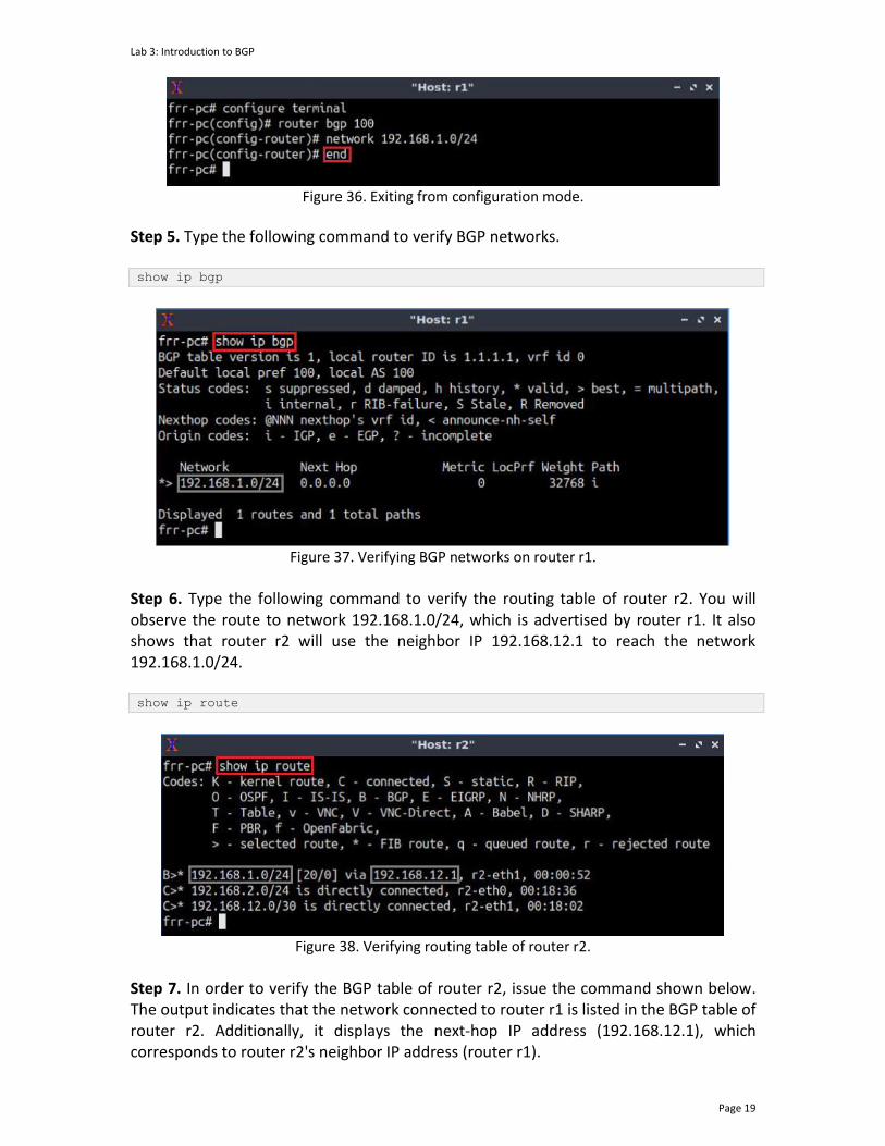
Step 5. Type the following command to verify BGP networks. show ip bgp
Figure 37. Verifying BGP networks on router r1.
Step 6. Type the following command to verify the routing table of router r2. You will observe the route to network 192.168.1.0/24, which is advertised by router r1. It also shows that router r2 will use the neighbor IP 192.168.12.1 to reach the network 192.168.1.0/24. show ip route
Figure 38. Verifying routing table of router r2.
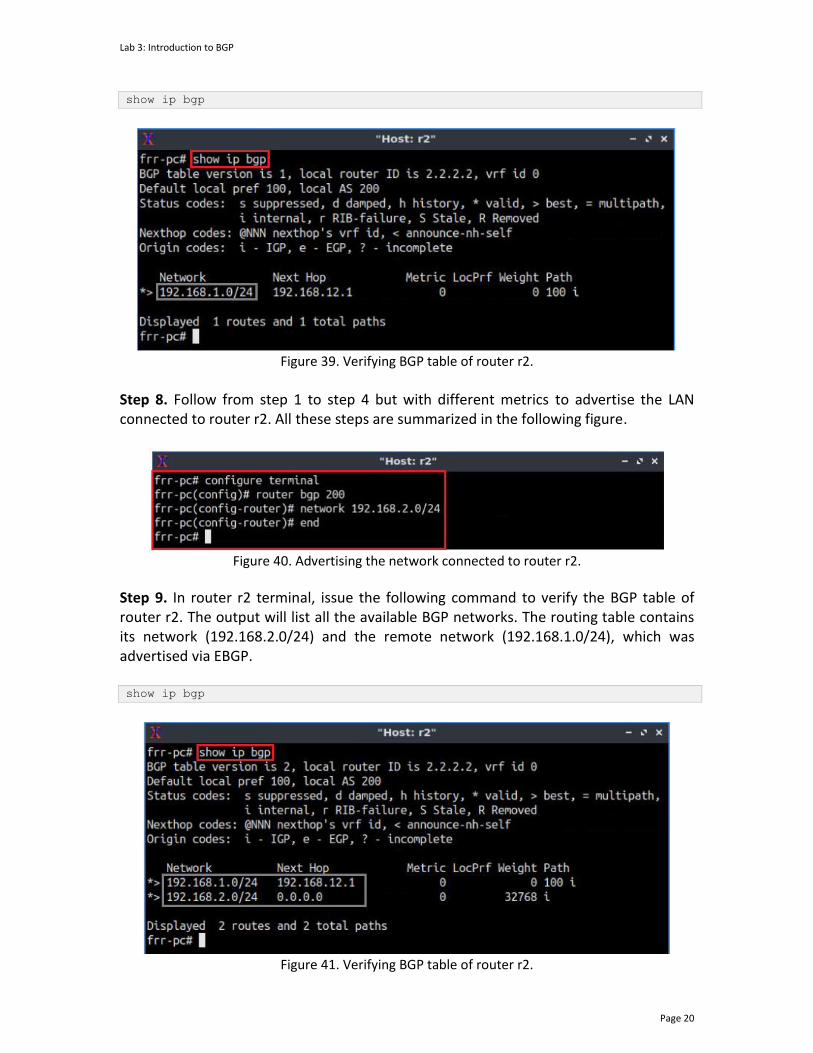
Step 7. In order to verify the BGP table of router r2, issue the command shown below. The output indicates that the network connected to router r1 is listed in the BGP table of router r2. Additionally, it displays the next-hop IP address (192.168.12.1), which corresponds to router r2's neighbor IP address (router r1).
Lab 3: Introduction to BGP
Page 20
show ip bgp
Figure 39. Verifying BGP table of router r2.
Step 8. Follow from step 1 to step 4 but with different metrics to advertise the LAN connected to router r2. All these steps are summarized in the following figure.
Figure 40. Advertising the network connected to router r2.
Step 9. In router r2 terminal, issue the following command to verify the BGP table of router r2. The output will list all the available BGP networks. The routing table contains its network (192.168.2.0/24) and the remote network (192.168.1.0/24), which was advertised via EBGP. show ip bgp
Figure 41. Verifying BGP table of router r2.
Lab 3: Introduction to BGP
Page 21
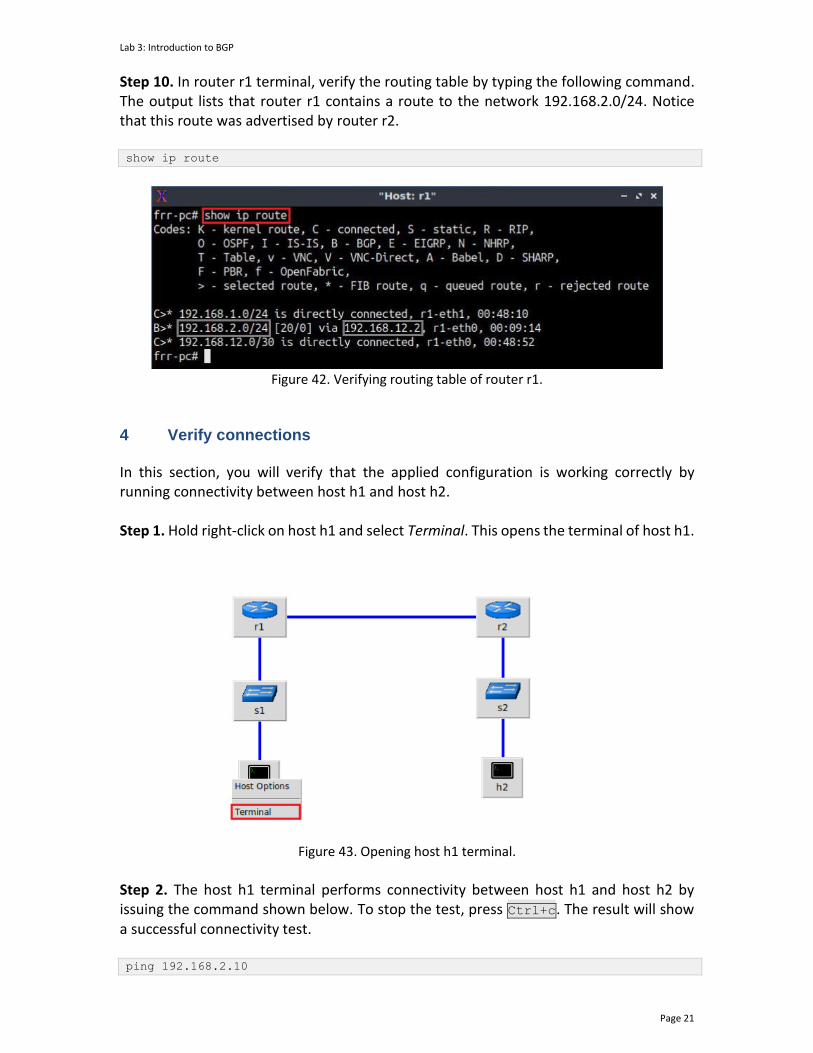
Step 10. In router r1 terminal, verify the routing table by typing the following command. The output lists that router r1 contains a route to the network 192.168.2.0/24. Notice that this route was advertised by router r2. show ip route
Figure 42. Verifying routing table of router r1.
4 Verify connections In this section, you will verify that the applied configuration is working correctly by running connectivity between host h1 and host h2. Step 1. Hold right-click on host h1 and select Terminal. This opens the terminal of host h1.
Figure 43. Opening host h1 terminal.
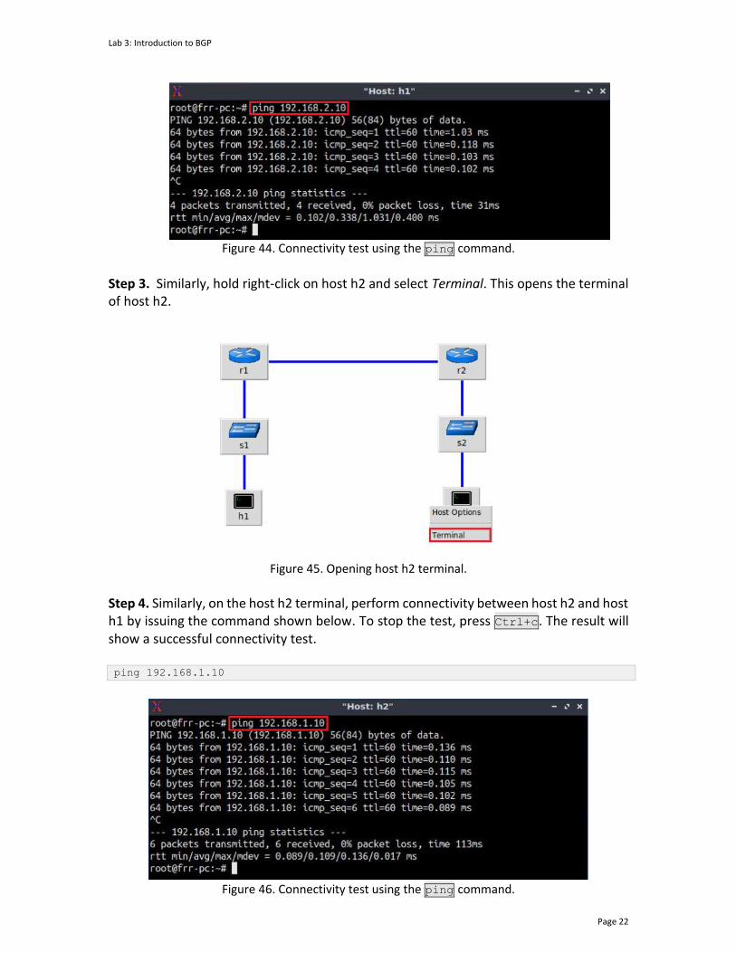
Step 2. The host h1 terminal performs connectivity between host h1 and host h2 by issuing the command shown below. To stop the test, press Ctrl+c. The result will show a successful connectivity test. ping 192.168.2.10
Lab 3: Introduction to BGP
Page 22
Figure 44. Connectivity test using the ping command.
Step 3. Similarly, hold right-click on host h2 and select Terminal. This opens the terminal of host h2.
Figure 45. Opening host h2 terminal.
Step 4. Similarly, on the host h2 terminal, perform connectivity between host h2 and host h1 by issuing the command shown below. To stop the test, press Ctrl+c. The result will show a successful connectivity test. ping 192.168.1.10
Figure 46. Connectivity test using the ping command.
Lab 3: Introduction to BGP
Page 23
This concludes Lab 3. Stop the emulation and then exit out of MiniEdit.
References
1. A. Tanenbaum, D. Wetherall, "Computer networks," 5th Edition, Pearson, 2012. 2. Linux foundation collaborative projects, "FRR routing documentation," 2017
[Online] Available: http://docs.frrouting.org/en/latest/ 3. Y. Rekhter, T. Li, S. Hares, "A border gateway protocol 4 (BGP-4)," RFC 4271
updated by RFCs 6286, 6608, 6793, 2006. [Online]. Available: http://www.ietf.org/rfc/rfc4271.txt.
4. D. Oran, "OSI IS-IS intra-domain routing protocol," RFC 1142, 1990. [Online]. Available: http://www.ietf.org/rfc/rfc1142.txt.
5. B. Lantz, G. Gee, "MiniEdit: a simple network editor for Mininet," 2013. [Online]. Available: https://github.com/Mininet/Mininet/blob/master/examples.
BORDER GATEWAY PROTOCOL
Lab 4: Configure and Verify EBGP
Document Version: 05-25-2021
Award 1829698 "CyberTraining CIP: Cyberinfrastructure Expertise on High-throughput
Networks for Big Science Data Transfers"

Lab 4: Configure and Verify EBGP
Page 2
Contents Overview ............................................................................................................................. 3
Objectives............................................................................................................................ 3
Lab settings ......................................................................................................................... 3
Lab roadmap ....................................................................................................................... 3
1. Introduction ................................................................................................................ 4
1.1. Intradomain and interdomain routing protocols ................................................. 4
1.2. Multiprotocol routing and redistribution of protocols ........................................ 4
2. Lab topology................................................................................................................ 5
2.1. Lab settings........................................................................................................... 6
2.2. Open the topology ............................................................................................... 7
2.3. Load the zebra daemon and verify the configuration ....................................... 10
3. Configure OSPF on router r3 and router r4 .............................................................. 14
4. Configure BGP on all routers .................................................................................... 19
5. Redistribute routes on router r3 and router r4 ........................................................ 26
5.1. Inject BGP routes into OSPF ............................................................................... 26
5.2. Inject OSPF and directly connected routes into BGP ......................................... 30
6. Verify connections .................................................................................................... 33
References ........................................................................................................................ 35
Lab 4: Configure and Verify EBGP
Page 3
Overview This lab presents Border Gateway Protocol (BGP) and describes the steps to configure and verify the operation of External BGP (EBGP) between two Autonomous Systems (ASes) and Open Shortest Path First (OSPF) protocol within an AS. The focus in this lab is to integrate BGP and OSPF routing protocols by using route redistribution. In this lab, the terms BGP and EBGP will be used interchangeably since they will only be running between ASes. This lab is based on the Cisco Certified Network Associate (CCNA) training, laboratory 3.5.3.56. While this laboratory material uses FRR as the router (which includes the routing protocols) and Linux as the control plane operating system, vendors’ operating systems such as Cisco have similar functionality. Objectives By the end of this lab, you should be able to:
1. Explain the concept of BGP. 2. Configure and verify EBGP between two ASes. 3. Enable OSPF redistribution to advertise BGP routes. 4. Enable BGP redistribution to advertise OSPF routes.
Lab settings The information in Table 1 provides the credentials to access the Client machine.
Table 1. Credentials to access the Client machine.
Device
Account
Password
Client admin password
Lab roadmap This lab is organized as follows:
1. Section 1: Introduction. 2. Section 2: Lab topology. 3. Section 3: Configure OSPF on router r3 and router r4. 4. Section 4: Configure BGP on all routers. 5. Section 5: Redistribute routes on router r3 and router r4.
Lab 4: Configure and Verify EBGP
Page 4
6. Section 6: Verify connections.
1. Introduction 1.1. Intradomain and interdomain routing protocols
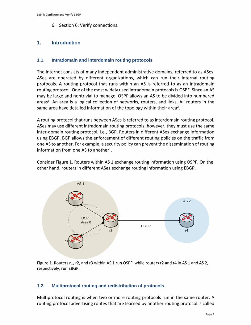
The Internet consists of many independent administrative domains, referred to as ASes. ASes are operated by different organizations, which can run their internal routing protocols. A routing protocol that runs within an AS is referred to as an intradomain routing protocol. One of the most widely used intradomain protocols is OSPF. Since an AS may be large and nontrivial to manage, OSPF allows an AS to be divided into numbered areas1. An area is a logical collection of networks, routers, and links. All routers in the same area have detailed information of the topology within their area2. A routing protocol that runs between ASes is referred to as interdomain routing protocol. ASes may use different intradomain routing protocols; however, they must use the same inter-domain routing protocol, i.e., BGP. Routers in different ASes exchange information using EBGP. BGP allows the enforcement of different routing policies on the traffic from one AS to another. For example, a security policy can prevent the dissemination of routing information from one AS to another1. Consider Figure 1. Routers within AS 1 exchange routing information using OSPF. On the other hand, routers in different ASes exchange routing information using EBGP.
AS 1
r2
AS 2
r4
OSPF
Area 0EBGP
r1
r3
Figure 1. Routers r1, r2, and r3 within AS 1 run OSPF, while routers r2 and r4 in AS 1 and AS 2, respectively, run EBGP.
1.2. Multiprotocol routing and redistribution of protocols
Multiprotocol routing is when two or more routing protocols run in the same router. A routing protocol advertising routes that are learned by another routing protocol is called
Lab 4: Configure and Verify EBGP
Page 5
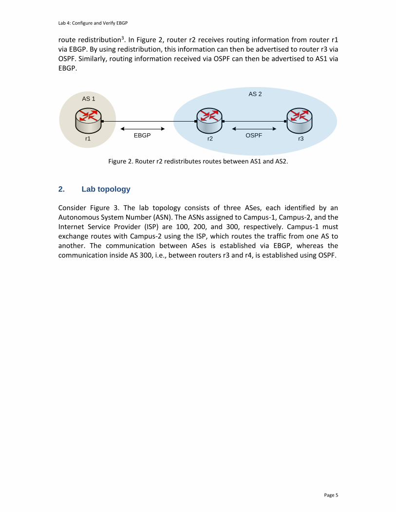
route redistribution3. In Figure 2, router r2 receives routing information from router r1 via EBGP. By using redistribution, this information can then be advertised to router r3 via OSPF. Similarly, routing information received via OSPF can then be advertised to AS1 via EBGP.
AS 1AS 2
r1 r2OSPFEBGP
r3
Figure 2. Router r2 redistributes routes between AS1 and AS2.
2. Lab topology Consider Figure 3. The lab topology consists of three ASes, each identified by an Autonomous System Number (ASN). The ASNs assigned to Campus-1, Campus-2, and the Internet Service Provider (ISP) are 100, 200, and 300, respectively. Campus-1 must exchange routes with Campus-2 using the ISP, which routes the traffic from one AS to another. The communication between ASes is established via EBGP, whereas the communication inside AS 300, i.e., between routers r3 and r4, is established using OSPF.

Lab 4: Configure and Verify EBGP
Page 6
s1
h1 h2
s2
r1 r2
r3 r4
h1-eth0
s1-eth1
s1-eth2
r1-eth0
r1-eth1
r3-eth0
r3-eth1 r4-eth0
r4-eth1
r2-eth0
r2-eth1
s2-eth2
s2-eth1
h2-eth0
Campus-1
AS 100AS 200
AS 300
Campus-2
ISP
.10 .10
.1 .1
.1 .1
.2 .2
.2.1
192.168.1.0/24192.168.2.0/24
192.168.13.0/30
192.168.34.0/30
192.168.24.0/30
OSPF Area 0
EBGP EBGP
Figure 3. Lab topology.
2.1. Lab settings
Routers and hosts are already configured according to the IP addresses shown in Table 2.
Table 2. Topology information.
Device Interface IIPV4 Address Subnet Default gateway
r1 (Campus-1)
r1-eth0 192.168.1.1 /24 N/A
r1-eth1 192.168.13.1 /30 N/A
r2 (Campus-2)
r2-eth0 192.168.2.1 /24 N/A
r2-eth1 192.168.24.1 /30 N/A
r3 (ISP)
r3-eth0 192.168.13.2 /30 N/A
r3-eth1 192.168.34.1 /30 N/A
Lab 4: Configure and Verify EBGP
Page 7
r4 (ISP)
r4-eth0 192.168.34.2 /30 N/A
r4-eth1 192.168.24.2 /30 N/A
h1 h1-eth0 192.168.1.10 /24 192.168.1.1
h2 h2-eth0 192.168.2.10 /24 192.168.2.1
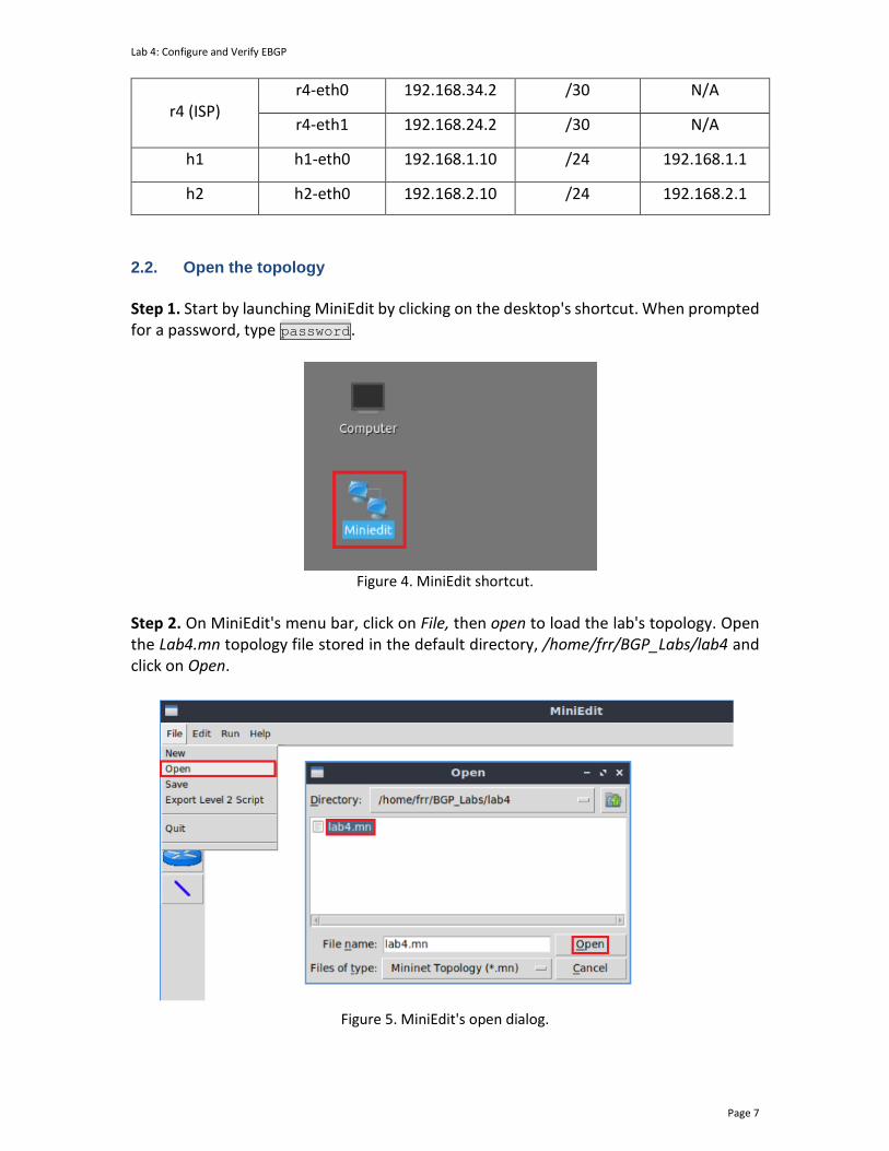
2.2. Open the topology
Step 1. Start by launching MiniEdit by clicking on the desktop's shortcut. When prompted for a password, type password.
Figure 4. MiniEdit shortcut.
Step 2. On MiniEdit's menu bar, click on File, then open to load the lab's topology. Open the Lab4.mn topology file stored in the default directory, /home/frr/BGP_Labs/lab4 and click on Open.
Figure 5. MiniEdit's open dialog.
Lab 4: Configure and Verify EBGP
Page 8
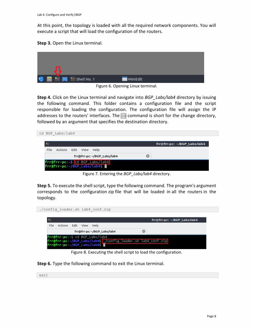
At this point, the topology is loaded with all the required network components. You will execute a script that will load the configuration of the routers.
Step 3. Open the Linux terminal.
Figure 6. Opening Linux terminal.
Step 4. Click on the Linux terminal and navigate into BGP_Labs/lab4 directory by issuing the following command. This folder contains a configuration file and the script responsible for loading the configuration. The configuration file will assign the IP addresses to the routers' interfaces. The cd command is short for the change directory, followed by an argument that specifies the destination directory. cd BGP_Labs/lab4
Figure 7. Entering the BGP_Labs/lab4 directory.
Step 5. To execute the shell script, type the following command. The program's argument corresponds to the configuration zip file that will be loaded in all the routers in the topology. ./config_loader.sh lab4_conf.zip
Figure 8. Executing the shell script to load the configuration.
Step 6. Type the following command to exit the Linux terminal. exit
Lab 4: Configure and Verify EBGP
Page 9
Figure 9. Exiting from the terminal.
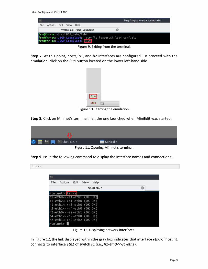
Step 7. At this point, hosts, h1, and h2 interfaces are configured. To proceed with the emulation, click on the Run button located on the lower left-hand side.
Figure 10. Starting the emulation.
Step 8. Click on Mininet's terminal, i.e., the one launched when MiniEdit was started.
Figure 11. Opening Mininet's terminal.
Step 9. Issue the following command to display the interface names and connections. links
Figure 12. Displaying network interfaces.
In Figure 12, the link displayed within the gray box indicates that interface eth0 of host h1 connects to interface eth1 of switch s1 (i.e., h1-eth0<->s1-eth1).
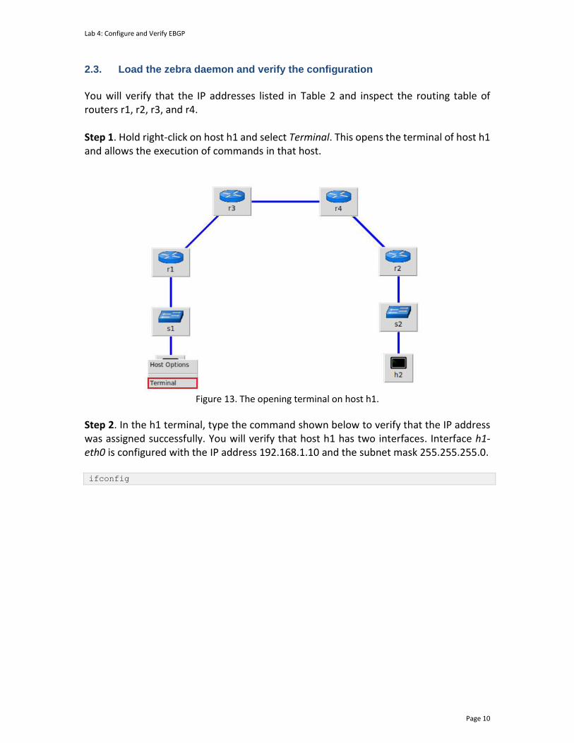
Lab 4: Configure and Verify EBGP
Page 10
2.3. Load the zebra daemon and verify the configuration
You will verify that the IP addresses listed in Table 2 and inspect the routing table of routers r1, r2, r3, and r4. Step 1. Hold right-click on host h1 and select Terminal. This opens the terminal of host h1 and allows the execution of commands in that host.
Figure 13. The opening terminal on host h1.
Step 2. In the h1 terminal, type the command shown below to verify that the IP address was assigned successfully. You will verify that host h1 has two interfaces. Interface h1-eth0 is configured with the IP address 192.168.1.10 and the subnet mask 255.255.255.0. ifconfig

Lab 4: Configure and Verify EBGP
Page 11
Figure 14. The output of the ifconfig command.
Step 3. In the host h1 terminal, type the command shown below to verify that the default gateway IP address is 192.168.1.1. route
Figure 15. The output of route command.
Step 4. To verify host h2, proceed similarly by repeating from step 1 to step 3 in the host h2 terminal. Similar results should be observed. Step 5. You will validate that the router interfaces are configured correctly according to Table 2. To proceed, hold right-click on router r1 and select Terminal.
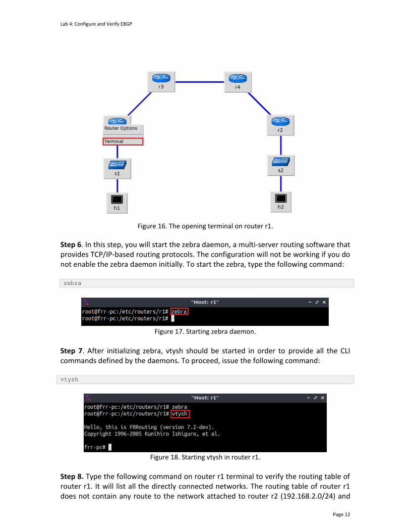
Lab 4: Configure and Verify EBGP
Page 12
Figure 16. The opening terminal on router r1.
Step 6. In this step, you will start the zebra daemon, a multi-server routing software that provides TCP/IP-based routing protocols. The configuration will not be working if you do not enable the zebra daemon initially. To start the zebra, type the following command: zebra
Figure 17. Starting zebra daemon.
Step 7. After initializing zebra, vtysh should be started in order to provide all the CLI commands defined by the daemons. To proceed, issue the following command: vtysh
Figure 18. Starting vtysh in router r1.
Step 8. Type the following command on router r1 terminal to verify the routing table of router r1. It will list all the directly connected networks. The routing table of router r1 does not contain any route to the network attached to router r2 (192.168.2.0/24) and
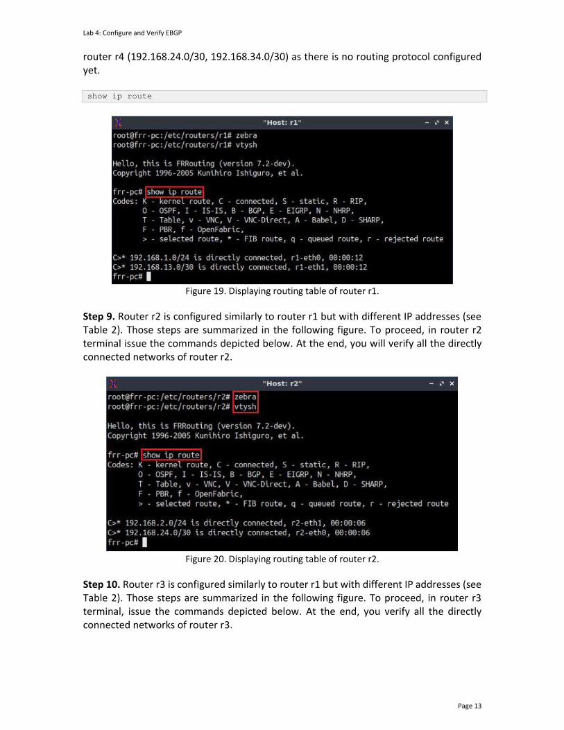
Lab 4: Configure and Verify EBGP
Page 13
router r4 (192.168.24.0/30, 192.168.34.0/30) as there is no routing protocol configured yet. show ip route
Figure 19. Displaying routing table of router r1.
Step 9. Router r2 is configured similarly to router r1 but with different IP addresses (see Table 2). Those steps are summarized in the following figure. To proceed, in router r2 terminal issue the commands depicted below. At the end, you will verify all the directly connected networks of router r2.
Figure 20. Displaying routing table of router r2.
Step 10. Router r3 is configured similarly to router r1 but with different IP addresses (see Table 2). Those steps are summarized in the following figure. To proceed, in router r3 terminal, issue the commands depicted below. At the end, you verify all the directly connected networks of router r3.

Lab 4: Configure and Verify EBGP
Page 14
Figure 21. Displaying routing table of router r3.
Step 11. Router r4 is configured similarly to router r1 but with different IP addresses (see Table 2). Those steps are summarized in the following figure. To proceed, in router r4 terminal, issue the commands depicted below. At the end, you verify all the directly connected networks of router r4.
Figure 22. Displaying routing table of router r4.
3. Configure OSPF on router r3 and router r4 In this section, you will configure the OSPF routing protocol in router r3 and router r4. First, you will enable the OSPF daemon router r3 and router r4. Second, you will establish a single area OSPF classified as area 0 or backbone area. Finally, all the connected networks are advertised. Step 1. To configure the OSPF routing protocol, you need to enable the OSPF daemon first. In router r3, type the following command to exit the vtysh session: exit

Lab 4: Configure and Verify EBGP
Page 15
Figure 23. Exiting the vtysh session.
Step 2. Type the following command on router r3 terminal to enable the OSPF daemon. ospfd
Figure 24. Starting OSPF daemon.
Step 3. To enter to router r3 terminal, issue the following command: vtysh
Figure 25. Starting vtysh on router r3.
Step 4. To enable router r3 configuration mode, issue the following command: configure terminal
Figure 26. Enabling configuration mode on router r3.
Step 5. To configure the OSPF routing protocol, type the command shown below. This command enables OSPF configuration mode where you advertise the networks directly connected to router r3. router ospf

Lab 4: Configure and Verify EBGP
Page 16
Figure 27. Configuring OSPF on router r3.
Step 6. Assign a router ID to router r3 by issuing the following command. ospf router-id 3.3.3.3
Figure 28. Assigning a router ID in router r3.
Step 7. In this step, type the following command to enable the interface r3-eth0, corresponding to 192.168.13.0/30, to participate in the routing process. This network is associated with area 0. network 192.168.13.0/30 area 0
Figure 29. Enabling the interface corresponding to the network 192.168.13.0/30 to participate in the OSPF routing process.
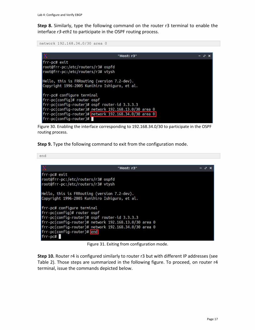
Lab 4: Configure and Verify EBGP
Page 17
Step 8. Similarly, type the following command on the router r3 terminal to enable the interface r3-eth1 to participate in the OSPF routing process. network 192.168.34.0/30 area 0
Figure 30. Enabling the interface corresponding to 192.168.34.0/30 to participate in the OSPF routing process.
Step 9. Type the following command to exit from the configuration mode. end
Figure 31. Exiting from configuration mode.
Step 10. Router r4 is configured similarly to router r3 but with different IP addresses (see Table 2). Those steps are summarized in the following figure. To proceed, on router r4 terminal, issue the commands depicted below.

Lab 4: Configure and Verify EBGP
Page 18
Figure 32. Configuring OSPF on router r4.
Step 11. Type the following command to verify the routing table of router r4. show ip route
Figure 33. Verifying the routing table of router r4.
Consider Figure 32. OSPF advertised three different networks (192.168.13.0/30, 192.168.24.0/30, and 192.168.34.0/30). Router r4 reaches the network 192.168.13.0/30 via the IP address 192.168.34.1. Networks 192.168.24.0/30 and 192.168.34.0/30 have two directly connected available paths from router r4. The Administrative Distance (AD) of the paths advertised through OSPF is 110. The AD is a value used by routers to select the best path when there are multiple available routes to the same destination. A smaller AD is always preferable to routers. The characters >* indicates that the following path is used to reach a specific network. Router r4 prefers directly connected networks over OSPF. Directly connected networks have a lowest administrative distance than any other. Step 12. In the router r3 terminal, test the connectivity between routers r3 and r4 using the ping command. Router r3 should ping the IP address 192.168.24.2 after configuring the OSPF routing protocol. To stop the test, press Ctrl+c. The figure below shows a successful connectivity test. ping 192.168.24.2

Lab 4: Configure and Verify EBGP
Page 19
Figure 34. The output of the ping command on router r3.
4. Configure BGP on all routers In this section, you will configure EBGP in the routers that are hosted in different ASes. You will assign BGP neighbors to allow the routers to exchange BGP routes. Furthermore, routers r1 and r2 will advertise their LANs via BGP. Therefore, router r3 and router r4 will receive route information about LAN 192.168.1.0/24 and 192.168.2.0/24, respectively. Step 1. To configure the BGP routing protocol, you need to enable the BGP daemon first. In router r1, type the following command to exit the vtysh session: exit
Figure 35. Exiting the vtysh session.
Step 2. Type the following command on router r1 terminal to enable and to start the BGP routing protocol. bgpd
Figure 36. Starting BGP daemon.
Step 3. To enter to router r1 terminal, type the following command: vtysh
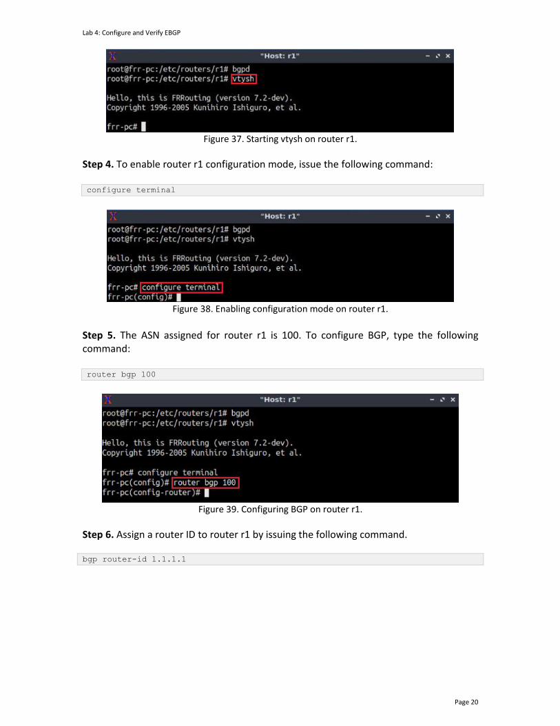
Lab 4: Configure and Verify EBGP
Page 20
Figure 37. Starting vtysh on router r1.
Step 4. To enable router r1 configuration mode, issue the following command: configure terminal
Figure 38. Enabling configuration mode on router r1.
Step 5. The ASN assigned for router r1 is 100. To configure BGP, type the following command: router bgp 100
Figure 39. Configuring BGP on router r1.
Step 6. Assign a router ID to router r1 by issuing the following command. bgp router-id 1.1.1.1
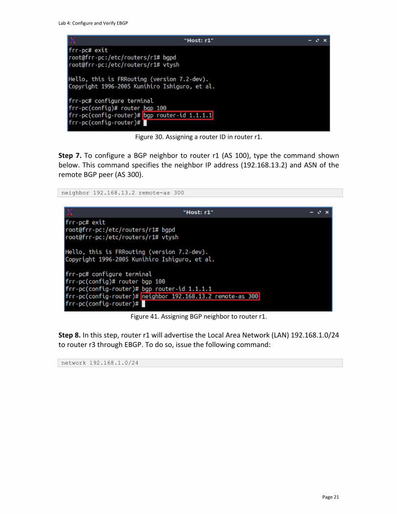
Lab 4: Configure and Verify EBGP
Page 21
Figure 30. Assigning a router ID in router r1.
Step 7. To configure a BGP neighbor to router r1 (AS 100), type the command shown below. This command specifies the neighbor IP address (192.168.13.2) and ASN of the remote BGP peer (AS 300). neighbor 192.168.13.2 remote-as 300
Figure 41. Assigning BGP neighbor to router r1.
Step 8. In this step, router r1 will advertise the Local Area Network (LAN) 192.168.1.0/24 to router r3 through EBGP. To do so, issue the following command: network 192.168.1.0/24
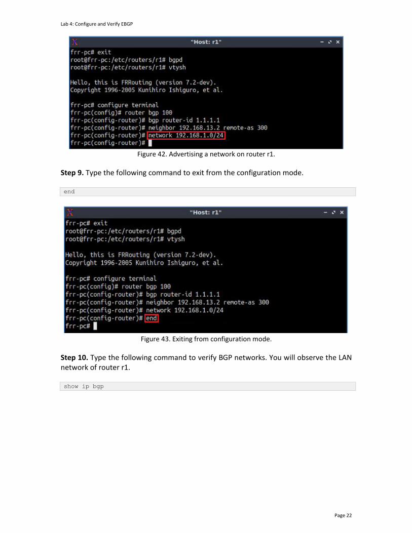
Lab 4: Configure and Verify EBGP
Page 22
Figure 42. Advertising a network on router r1.
Step 9. Type the following command to exit from the configuration mode. end
Figure 43. Exiting from configuration mode.
Step 10. Type the following command to verify BGP networks. You will observe the LAN network of router r1. show ip bgp

Lab 4: Configure and Verify EBGP
Page 23
Figure 44. Verifying BGP networks on router r1.
Step 11. Type the following command to verify BGP neighbors. You will verify that the neighbor's IP address is 192.168.13.2. The corresponding ASN is 300. show ip bgp neighbors
Figure 45. Verifying BGP neighbors on router r1.
Step 12. Follow from step 1 to step 8 but with different metrics to configure BGP in router r2. All these steps are summarized in the following figure.
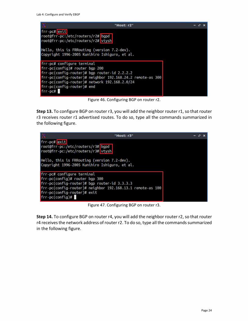
Lab 4: Configure and Verify EBGP
Page 24
Figure 46. Configuring BGP on router r2.
Step 13. To configure BGP on router r3, you will add the neighbor router r1, so that router r3 receives router r1 advertised routes. To do so, type all the commands summarized in the following figure.
Figure 47. Configuring BGP on router r3.
Step 14. To configure BGP on router r4, you will add the neighbor router r2, so that router r4 receives the network address of router r2. To do so, type all the commands summarized in the following figure.
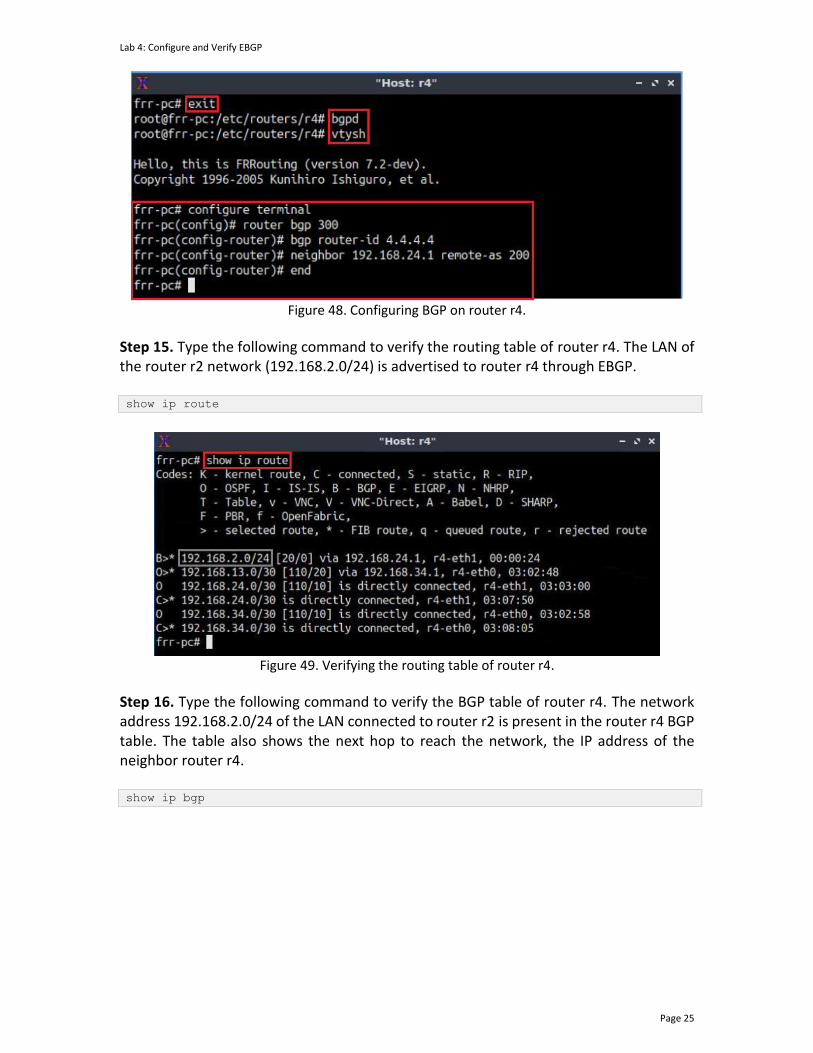
Lab 4: Configure and Verify EBGP
Page 25
Figure 48. Configuring BGP on router r4.
Step 15. Type the following command to verify the routing table of router r4. The LAN of the router r2 network (192.168.2.0/24) is advertised to router r4 through EBGP. show ip route
Figure 49. Verifying the routing table of router r4.
Step 16. Type the following command to verify the BGP table of router r4. The network address 192.168.2.0/24 of the LAN connected to router r2 is present in the router r4 BGP table. The table also shows the next hop to reach the network, the IP address of the neighbor router r4. show ip bgp
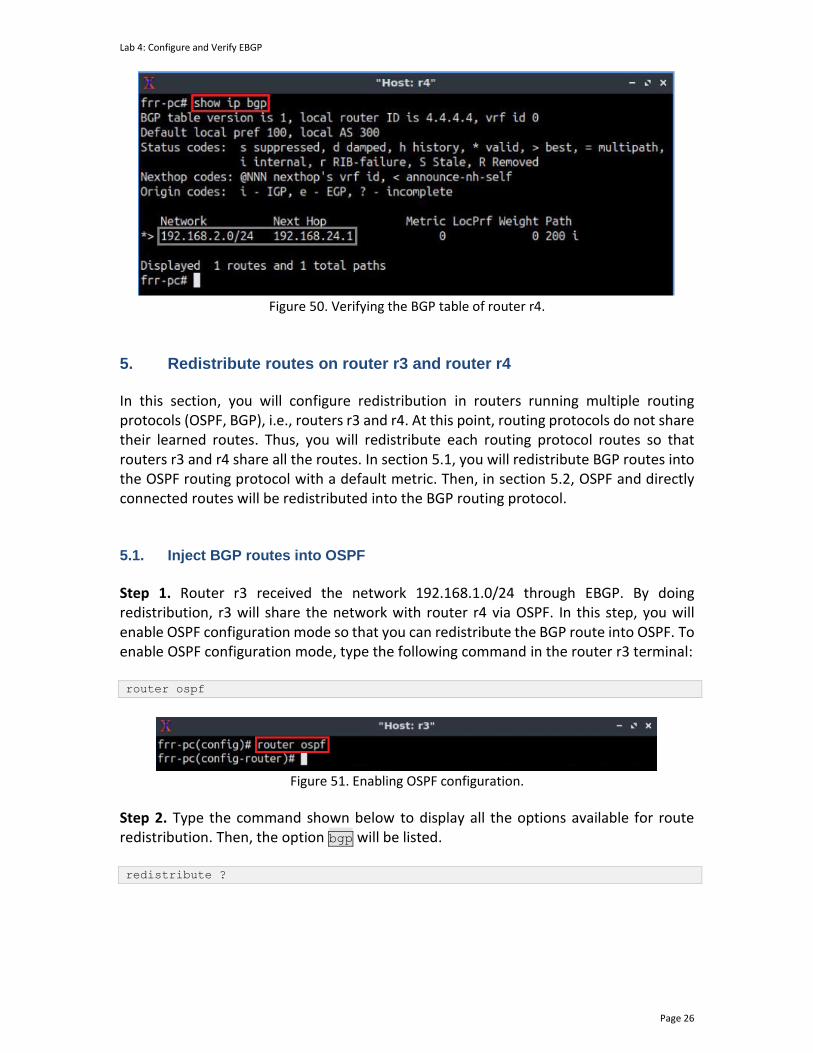
Lab 4: Configure and Verify EBGP
Page 26
Figure 50. Verifying the BGP table of router r4.
5. Redistribute routes on router r3 and router r4 In this section, you will configure redistribution in routers running multiple routing protocols (OSPF, BGP), i.e., routers r3 and r4. At this point, routing protocols do not share their learned routes. Thus, you will redistribute each routing protocol routes so that routers r3 and r4 share all the routes. In section 5.1, you will redistribute BGP routes into the OSPF routing protocol with a default metric. Then, in section 5.2, OSPF and directly connected routes will be redistributed into the BGP routing protocol. 5.1. Inject BGP routes into OSPF
Step 1. Router r3 received the network 192.168.1.0/24 through EBGP. By doing redistribution, r3 will share the network with router r4 via OSPF. In this step, you will enable OSPF configuration mode so that you can redistribute the BGP route into OSPF. To enable OSPF configuration mode, type the following command in the router r3 terminal: router ospf
Figure 51. Enabling OSPF configuration.
Step 2. Type the command shown below to display all the options available for route redistribution. Then, the option bgp will be listed. redistribute ?
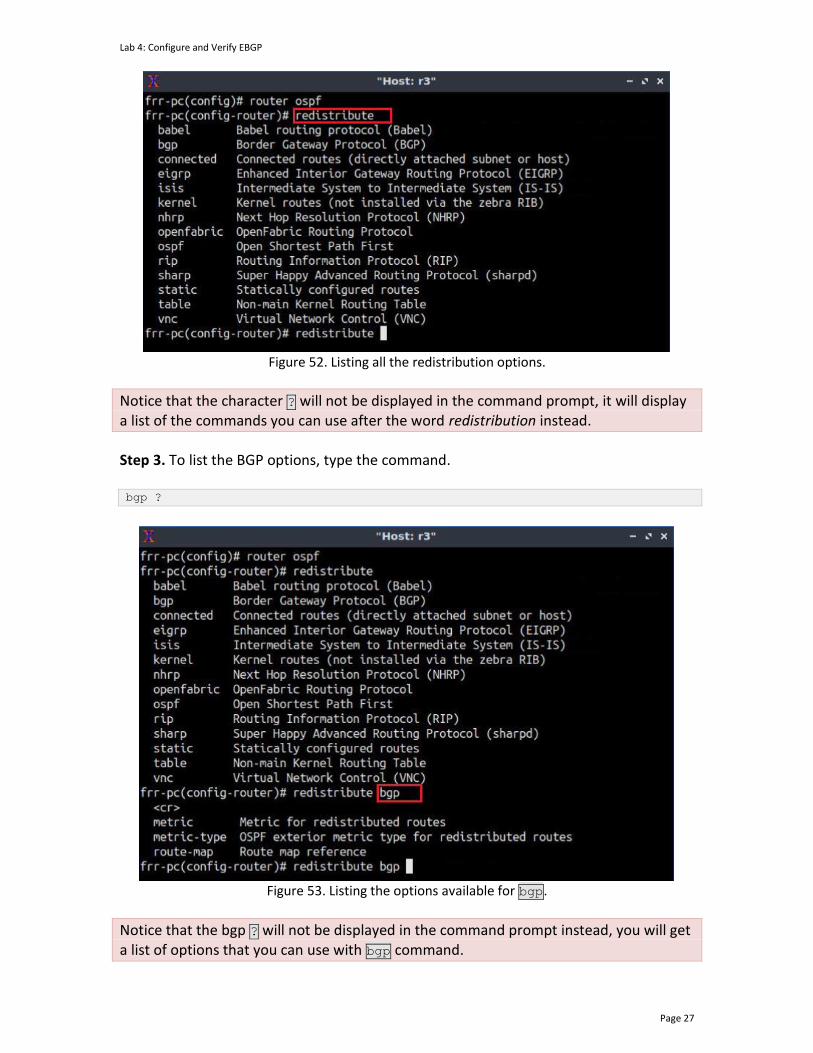
Lab 4: Configure and Verify EBGP
Page 27
Figure 52. Listing all the redistribution options.
Notice that the character ? will not be displayed in the command prompt, it will display a list of the commands you can use after the word redistribution instead.
Step 3. To list the BGP options, type the command. bgp ?
Figure 53. Listing the options available for bgp.
Notice that the bgp ? will not be displayed in the command prompt instead, you will get a list of options that you can use with bgp command.
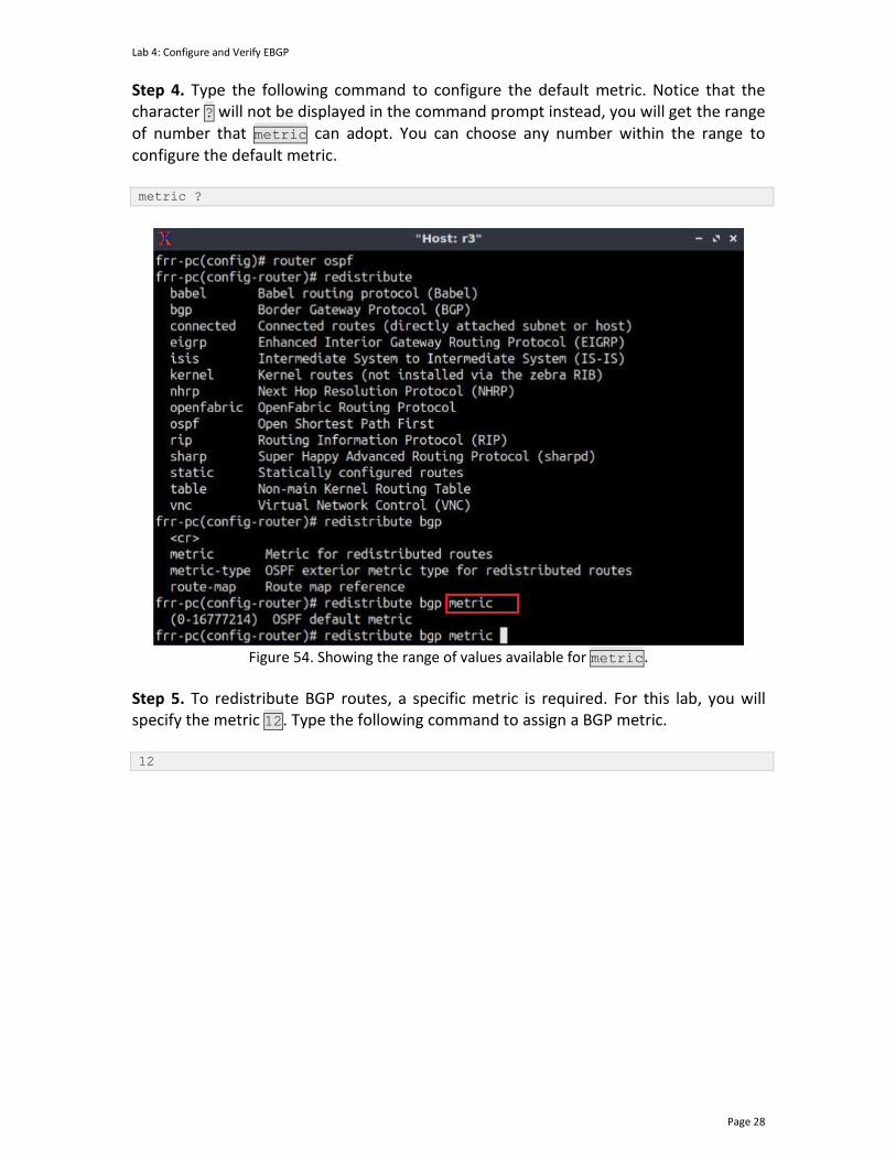
Lab 4: Configure and Verify EBGP
Page 28
Step 4. Type the following command to configure the default metric. Notice that the character ? will not be displayed in the command prompt instead, you will get the range of number that metric can adopt. You can choose any number within the range to configure the default metric. metric ?
Figure 54. Showing the range of values available for metric.
Step 5. To redistribute BGP routes, a specific metric is required. For this lab, you will specify the metric 12. Type the following command to assign a BGP metric. 12
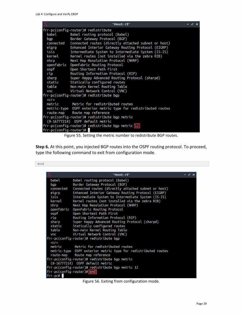
Lab 4: Configure and Verify EBGP
Page 29
Figure 55. Setting the metric number to redistribute BGP routes.
Step 6. At this point, you injected BGP routes into the OSPF routing protocol. To proceed, type the following command to exit from configuration mode. end
Figure 56. Exiting from configuration mode.
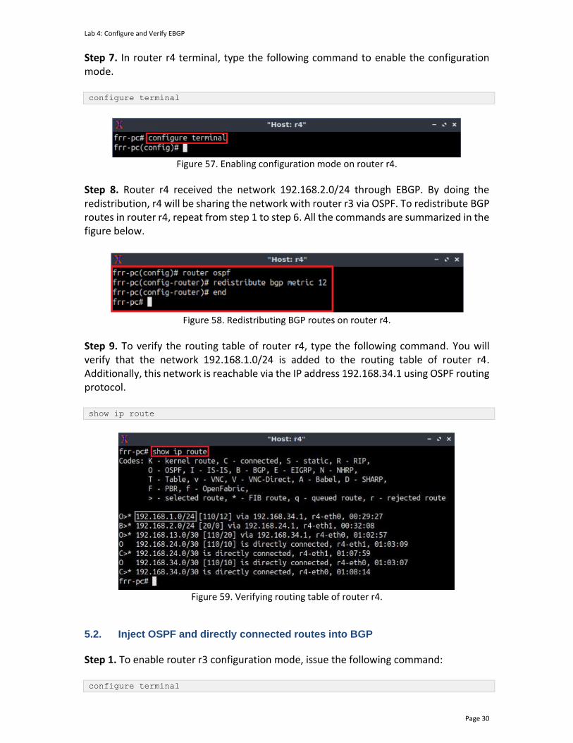
Lab 4: Configure and Verify EBGP
Page 30
Step 7. In router r4 terminal, type the following command to enable the configuration mode. configure terminal
Figure 57. Enabling configuration mode on router r4.
Step 8. Router r4 received the network 192.168.2.0/24 through EBGP. By doing the redistribution, r4 will be sharing the network with router r3 via OSPF. To redistribute BGP routes in router r4, repeat from step 1 to step 6. All the commands are summarized in the figure below.
Figure 58. Redistributing BGP routes on router r4.
Step 9. To verify the routing table of router r4, type the following command. You will verify that the network 192.168.1.0/24 is added to the routing table of router r4. Additionally, this network is reachable via the IP address 192.168.34.1 using OSPF routing protocol. show ip route
Figure 59. Verifying routing table of router r4.
5.2. Inject OSPF and directly connected routes into BGP
Step 1. To enable router r3 configuration mode, issue the following command: configure terminal

Lab 4: Configure and Verify EBGP
Page 31
Figure 60. Enabling configuration mode on router r3.
Step 2. In router r3, you will redistribute the OSPF routes (192.168.2.0/24 and 192.168.24.0/30) into BGP so that router r1 can reach the networks. Additionally, you will redistribute the directly connected routes (192.168.13.0/30, 192.168.34.0/30) so that router r1 can learn the paths to reach the networks. Type the following command to enter BGP configuration mode. router bgp 300
Figure 61. Entering to BGP Configuration mode.
Step 3. Type the following command to redistribute all the OSPF networks. redistribute ospf
Figure 62. Redistributing OSPF routes on router r3.
Step 4. Type the following command to verify the routing table of router r1. You will notice new networks shared by router r3 (192.168.2.0/24 and 192.168.24.0/30). It also shows that router r1 can reach these networks via the IP address 192.168.13.2 using EBGP. show ip route
Figure 63. Verifying routing table of router r1.
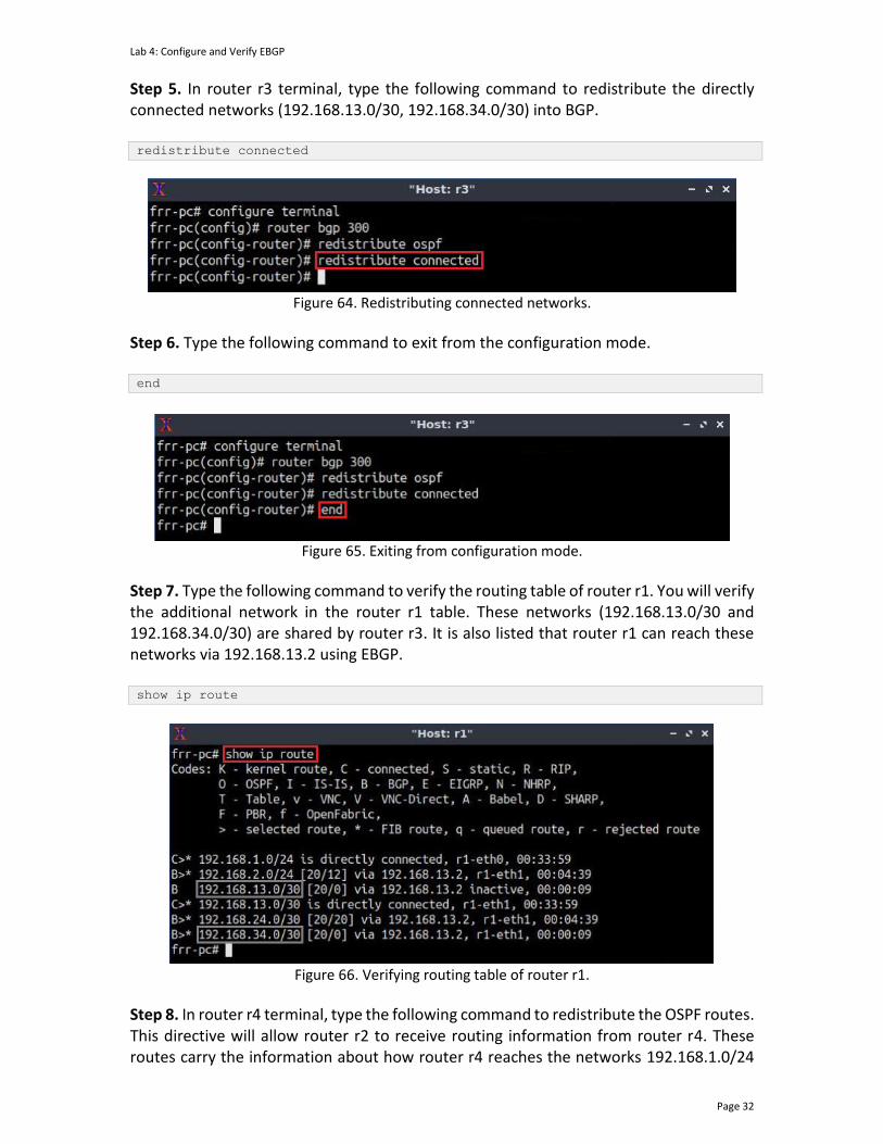
Lab 4: Configure and Verify EBGP
Page 32
Step 5. In router r3 terminal, type the following command to redistribute the directly connected networks (192.168.13.0/30, 192.168.34.0/30) into BGP. redistribute connected
Figure 64. Redistributing connected networks.
Step 6. Type the following command to exit from the configuration mode. end
Figure 65. Exiting from configuration mode.
Step 7. Type the following command to verify the routing table of router r1. You will verify the additional network in the router r1 table. These networks (192.168.13.0/30 and 192.168.34.0/30) are shared by router r3. It is also listed that router r1 can reach these networks via 192.168.13.2 using EBGP. show ip route
Figure 66. Verifying routing table of router r1.
Step 8. In router r4 terminal, type the following command to redistribute the OSPF routes. This directive will allow router r2 to receive routing information from router r4. These routes carry the information about how router r4 reaches the networks 192.168.1.0/24
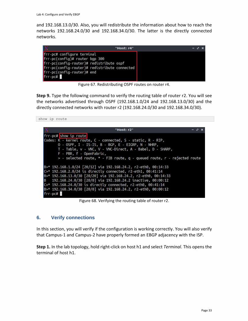
Lab 4: Configure and Verify EBGP
Page 33
and 192.168.13.0/30. Also, you will redistribute the information about how to reach the networks 192.168.24.0/30 and 192.168.34.0/30. The latter is the directly connected networks.
Figure 67. Redistributing OSPF routes on router r4.
Step 9. Type the following command to verify the routing table of router r2. You will see the networks advertised through OSPF (192.168.1.0/24 and 192.168.13.0/30) and the directly connected networks with router r2 (192.168.24.0/30 and 192.168.34.0/30). show ip route
Figure 68. Verifying the routing table of router r2.
6. Verify connections In this section, you will verify if the configuration is working correctly. You will also verify that Campus-1 and Campus-2 have properly formed an EBGP adjacency with the ISP. Step 1. In the lab topology, hold right-click on host h1 and select Terminal. This opens the terminal of host h1.

Lab 4: Configure and Verify EBGP
Page 34
Figure 69. Opening host h1 terminal.
Step 2. Test the connectivity between host h1 and host h2 using the ping command. In host h1, type the command specified below. To stop the test, press Ctrl+c. The figure below shows a successful connectivity test. ping 192.168.2.10
Figure 70. Connectivity test using the ping command.
Step 3. Similarly, hold right-click on host h2 and select Terminal. This opens the terminal of host h2.
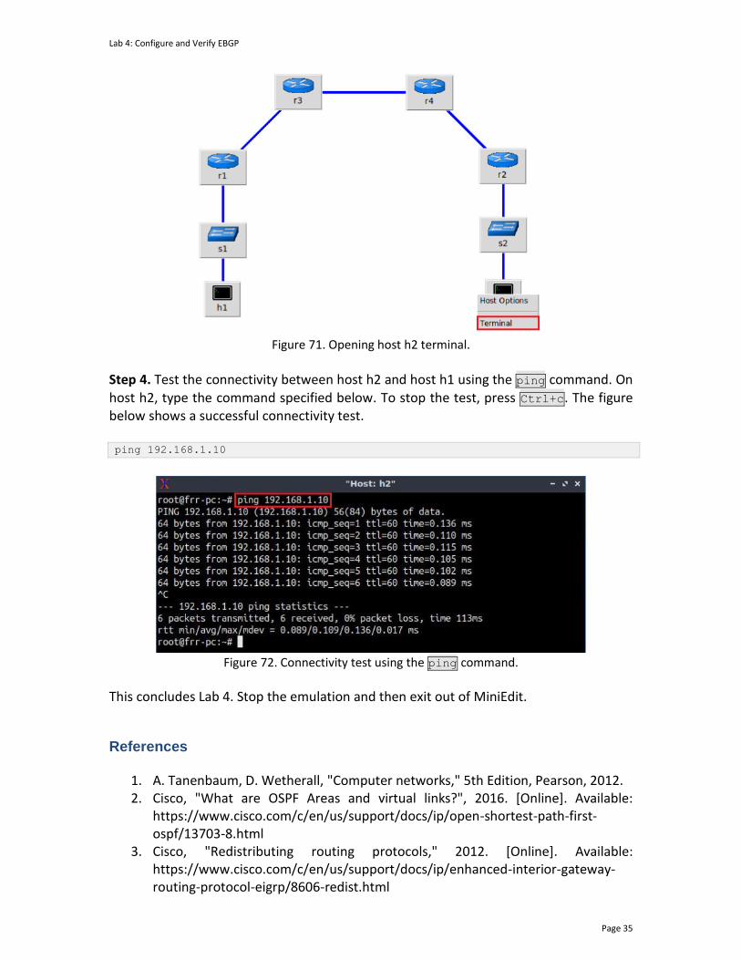
Lab 4: Configure and Verify EBGP
Page 35
Figure 71. Opening host h2 terminal.
Step 4. Test the connectivity between host h2 and host h1 using the ping command. On host h2, type the command specified below. To stop the test, press Ctrl+c. The figure below shows a successful connectivity test. ping 192.168.1.10
Figure 72. Connectivity test using the ping command.
This concludes Lab 4. Stop the emulation and then exit out of MiniEdit.
References
1. A. Tanenbaum, D. Wetherall, "Computer networks," 5th Edition, Pearson, 2012. 2. Cisco, "What are OSPF Areas and virtual links?", 2016. [Online]. Available:
https://www.cisco.com/c/en/us/support/docs/ip/open-shortest-path-first-ospf/13703-8.html
3. Cisco, "Redistributing routing protocols," 2012. [Online]. Available: https://www.cisco.com/c/en/us/support/docs/ip/enhanced-interior-gateway-routing-protocol-eigrp/8606-redist.html

Lab 4: Configure and Verify EBGP
Page 36
4. Linux foundation collaborative projects, "FRR routing documentation," 2017. [Online]. Available: http://docs.frrouting.org/en/latest/
5. D. Teare, B. Vachon, R. Graziani, "Implementing cisco IP Routing (Route), foundation learning guide," CCNP ROUTE 300-101.
6. CCNA, Lab 3.5.3.5, “Configure and Verify eBGP”.
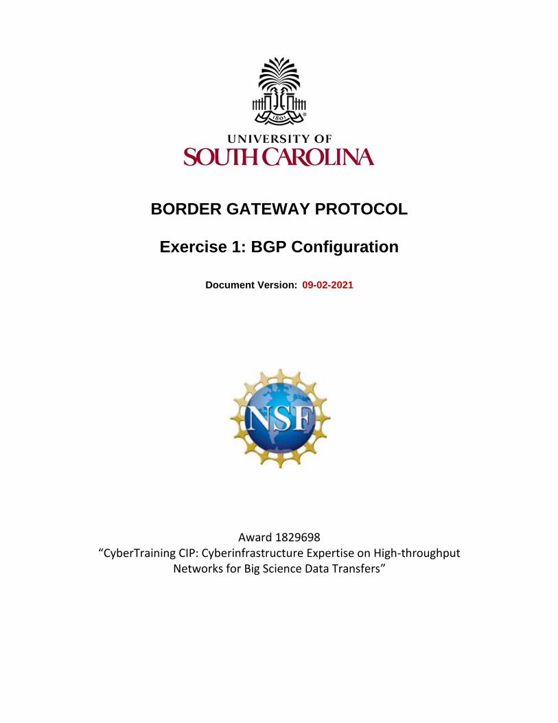
BORDER GATEWAY PROTOCOL
Exercise 1: BGP Configuration
Document Version: 09-02-2021
Award 1829698 “CyberTraining CIP: Cyberinfrastructure Expertise on High-throughput
Networks for Big Science Data Transfers”

Exercise 1: BGP Configuration
Contents 1 Exercise description .................................................................................................... 3
1.1 Topology settings ................................................................................................. 3
1.2 Credentials ........................................................................................................... 4
2 Deliverables ................................................................................................................. 4

Exercise 1: BGP Configuration
1 Exercise description Consider Figure 1. The topology consists of one Internet Service Provider (ISP) in Autonomous System (AS) 300 and two campus networks in ASes 100 and 200. The goal of this exercise is to connect the two campus networks through the ISP via the Border Gateway Protocol (BGP). The topology below is already built. You should use Mininet to emulate the topology and Free Range Routing (FRR) to configure network protocols.
s1
h1
h1-eth0
s1-eth1
s1-eth2
r1-eth0
.10
.1
r1
r3
AS 100
AS 300
173.17.1.0/24
r1-eth1
.1
.2 .2
173.17.13.0/30
s2
h2
h2-eth0
s2-eth1
s2-eth2
r2-eth0
.10
.1
r2
173.17.2.0/24
.1
173.17.23.0/30
r2-eth1
Campus-1
AS 200
Campus-2
ISP
Figure 1. Exercise topology.
1.1 Topology settings
The devices are already configured according to Table 1.
Table 1. Topology information.
Device Interface IIPv4 Address Subnet Default gateway
Router r1
(Campus-1)
r1-eth0 173.17.1.1 /24 N/A
r1-eth1 173.17.13.1 /30 N/A
Router r2
(Campus-2)
r2-eth0 173.17.2.1 /24 N/A
r2-eth1 173.17.23.1 /30 N/A
r3-eth0 173.17.13.2 /30 N/A

Exercise 1: BGP Configuration
Router r3 (ISP-1)
r3-eth1 173.17.23.2 /30 N/A
Host h1
h1-eth0 173.17.1.10 /24 173.17.1.1
Host h2
h2-eth0 173.17.2.10 /24 173.17.2.1
1.2 Credentials
The information in Table 2 provides the credentials to access the Client’s virtual machine.
Table 2. Credentials to access the Client’s virtual machine.
Device
Account
Password
Client admin password
2 Deliverables Follow the steps below to complete the exercise. a) Open MiniEdit and load the topology above. The topology file Exercise1.mn of this exercise is in the directory ~/BGP_Labs/Exercise1 as shown in the figure below. Verify in Mininet terminal that the links conform to the topology figure and settings table above.
Figure 2. Loading the topology file in Mininet.
Exercise 1: BGP Configuration
b) In FRR shell, assign an IP address to each router’s interface. The IP addresses of the interfaces should conform to the topology figure and settings table above. Inspect the routing table and verify the directly connected networks on each router. c) Configure BGP on routers r1, r2, and r3 so that Campus-1 and Campus-2 networks can reach each other. Inspect the BGP and routing tables of the routers and verify the added BGP routes. d) Test the connectivity between the two campus networks by performing a ping test from host h1 to host h2. A successful connectivity test should occur after a correct BGP configuration.
BORDER GATEWAY PROTOCOL
Lab 5: BGP Authentication
Document Version: 05-25-2021
Award 1829698 “CyberTraining CIP: Cyberinfrastructure Expertise on High-throughput
Networks for Big Science Data Transfers”
Lab 5: BGP Authentication
Page 2
Contents Overview ............................................................................................................................. 3
Objectives............................................................................................................................ 3
Lab settings ......................................................................................................................... 3
Lab roadmap ....................................................................................................................... 3
1 Introduction ................................................................................................................ 3
1.1 BGP overview ....................................................................................................... 3
1.2 TCP segment authentication via MD5 .................................................................. 4
1.3 BGP authentication .............................................................................................. 5
2 Lab topology................................................................................................................ 6
2.1 Lab settings........................................................................................................... 6
2.2 Open the topology and load the configuration ................................................... 7
2.3 Load the zebra daemon and verify the configuration ....................................... 10
3 Configure EBGP on the routers ................................................................................. 14
4 Configure and verify MD5 authentication on the routers ........................................ 20
4.1 Configure MD5 authentication .......................................................................... 20
4.2 Verify MD5 authentication ................................................................................. 22
References ........................................................................................................................ 23
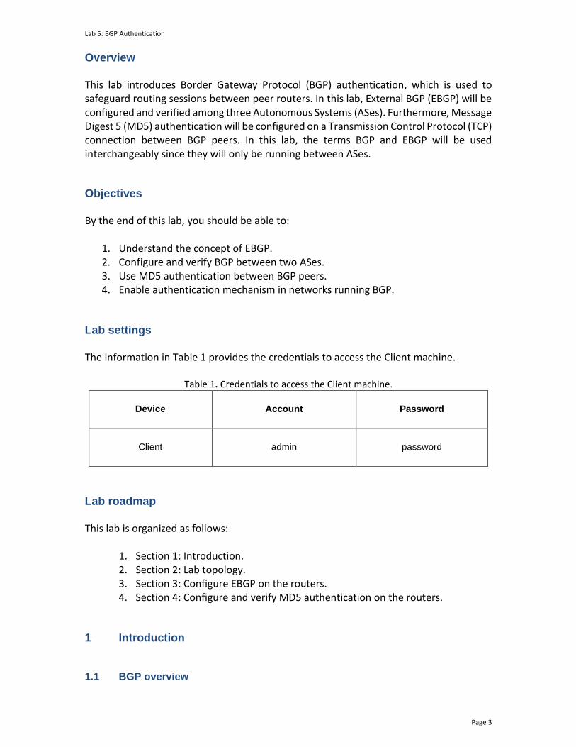
Lab 5: BGP Authentication
Page 3
Overview This lab introduces Border Gateway Protocol (BGP) authentication, which is used to safeguard routing sessions between peer routers. In this lab, External BGP (EBGP) will be configured and verified among three Autonomous Systems (ASes). Furthermore, Message Digest 5 (MD5) authentication will be configured on a Transmission Control Protocol (TCP) connection between BGP peers. In this lab, the terms BGP and EBGP will be used interchangeably since they will only be running between ASes. Objectives By the end of this lab, you should be able to:
1. Understand the concept of EBGP. 2. Configure and verify BGP between two ASes. 3. Use MD5 authentication between BGP peers. 4. Enable authentication mechanism in networks running BGP.
Lab settings The information in Table 1 provides the credentials to access the Client machine.
Table 1. Credentials to access the Client machine.
Device
Account
Password
Client admin password
Lab roadmap This lab is organized as follows:
1. Section 1: Introduction. 2. Section 2: Lab topology. 3. Section 3: Configure EBGP on the routers. 4. Section 4: Configure and verify MD5 authentication on the routers.
1 Introduction
1.1 BGP overview
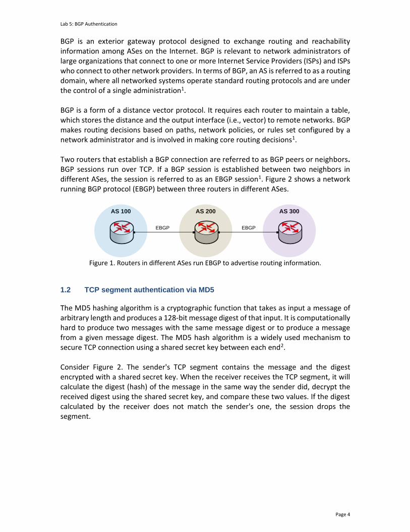
Lab 5: BGP Authentication
Page 4
BGP is an exterior gateway protocol designed to exchange routing and reachability information among ASes on the Internet. BGP is relevant to network administrators of large organizations that connect to one or more Internet Service Providers (ISPs) and ISPs who connect to other network providers. In terms of BGP, an AS is referred to as a routing domain, where all networked systems operate standard routing protocols and are under the control of a single administration1. BGP is a form of a distance vector protocol. It requires each router to maintain a table, which stores the distance and the output interface (i.e., vector) to remote networks. BGP makes routing decisions based on paths, network policies, or rules set configured by a network administrator and is involved in making core routing decisions1. Two routers that establish a BGP connection are referred to as BGP peers or neighbors. BGP sessions run over TCP. If a BGP session is established between two neighbors in different ASes, the session is referred to as an EBGP session1. Figure 2 shows a network running BGP protocol (EBGP) between three routers in different ASes.
AS 100 AS 200 AS 300
EBGP EBGP
Figure 1. Routers in different ASes run EBGP to advertise routing information.
1.2 TCP segment authentication via MD5
The MD5 hashing algorithm is a cryptographic function that takes as input a message of arbitrary length and produces a 128-bit message digest of that input. It is computationally hard to produce two messages with the same message digest or to produce a message from a given message digest. The MD5 hash algorithm is a widely used mechanism to secure TCP connection using a shared secret key between each end2. Consider Figure 2. The sender's TCP segment contains the message and the digest encrypted with a shared secret key. When the receiver receives the TCP segment, it will calculate the digest (hash) of the message in the same way the sender did, decrypt the received digest using the shared secret key, and compare these two values. If the digest calculated by the receiver does not match the sender's one, the session drops the segment.
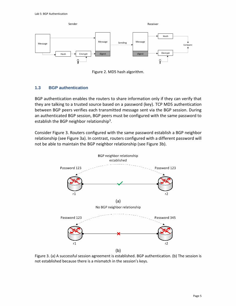
Lab 5: BGP Authentication
Page 5
Message
Hash Encrypt
CompareSending
Sender Receiver
Message
digest
Message
digest
Hash
Decrypt
Figure 2. MD5 hash algorithm.
1.3 BGP authentication
BGP authentication enables the routers to share information only if they can verify that they are talking to a trusted source based on a password (key). TCP MD5 authentication between BGP peers verifies each transmitted message sent via the BGP session. During an authenticated BGP session, BGP peers must be configured with the same password to establish the BGP neighbor relationship3. Consider Figure 3. Routers configured with the same password establish a BGP neighbor relationship (see Figure 3a). In contrast, routers configured with a different password will not be able to maintain the BGP neighbor relationship (see Figure 3b).
(a)
(b)
Figure 3. (a) A successful session agreement is established. BGP authentication. (b) The session is not established because there is a mismatch in the session’s keys.
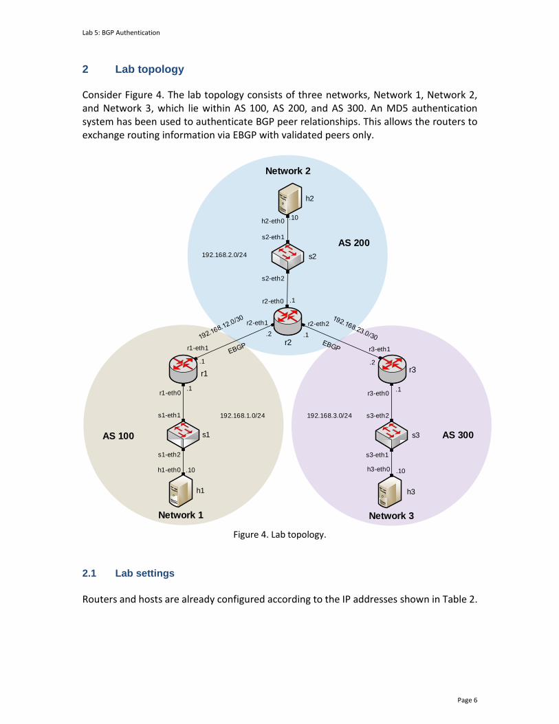
Lab 5: BGP Authentication
Page 6
2 Lab topology Consider Figure 4. The lab topology consists of three networks, Network 1, Network 2, and Network 3, which lie within AS 100, AS 200, and AS 300. An MD5 authentication system has been used to authenticate BGP peer relationships. This allows the routers to exchange routing information via EBGP with validated peers only.
s2
s1 s3
h1
h2
h3
r1r3
Network 1
r1-eth1
r2-eth1
h1-eth0
s1-eth2
s1-eth1
r1-eth0
h2-eth0
s2-eth1
s2-eth2
r2-eth0
r2-eth2
r3-eth1
r3-eth0
s3-eth2
s3-eth1
h3-eth0
AS 200
AS 100 AS 300
.10
.1
.1
.2 .1
.2
.1
.10
.1
.10
192.168.1.0/24 192.168.3.0/24
192.168.2.0/24
Network 3
Network 2
r2
Figure 4. Lab topology.
2.1 Lab settings
Routers and hosts are already configured according to the IP addresses shown in Table 2.
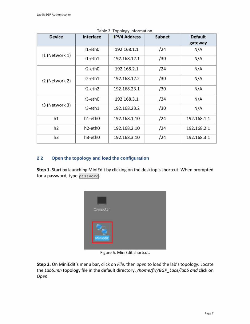
Lab 5: BGP Authentication
Page 7
Table 2. Topology information.
Device Interface IIPV4 Address Subnet Default gateway
r1 (Network 1)
r1-eth0 192.168.1.1 /24 N/A
r1-eth1 192.168.12.1 /30 N/A
r2 (Network 2)
r2-eth0 192.168.2.1 /24 N/A
r2-eth1 192.168.12.2 /30 N/A
r2-eth2 192.168.23.1 /30 N/A
r3 (Network 3)
r3-eth0 192.168.3.1 /24 N/A
r3-eth1 192.168.23.2 /30 N/A
h1 h1-eth0 192.168.1.10 /24 192.168.1.1
h2 h2-eth0 192.168.2.10 /24 192.168.2.1
h3 h3-eth0 192.168.3.10 /24 192.168.3.1
2.2 Open the topology and load the configuration
Step 1. Start by launching MiniEdit by clicking on the desktop’s shortcut. When prompted for a password, type password.
Figure 5. MiniEdit shortcut.
Step 2. On MiniEdit’s menu bar, click on File, then open to load the lab’s topology. Locate the Lab5.mn topology file in the default directory, /home/frr/BGP_Labs/lab5 and click on Open.
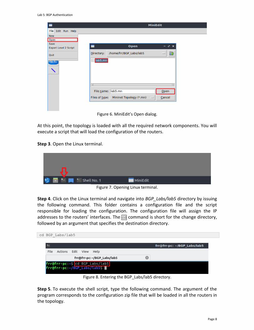
Lab 5: BGP Authentication
Page 8
Figure 6. MiniEdit’s Open dialog.
At this point, the topology is loaded with all the required network components. You will execute a script that will load the configuration of the routers. Step 3. Open the Linux terminal.
Figure 7. Opening Linux terminal.
Step 4. Click on the Linux terminal and navigate into BGP_Labs/lab5 directory by issuing the following command. This folder contains a configuration file and the script responsible for loading the configuration. The configuration file will assign the IP addresses to the routers’ interfaces. The cd command is short for the change directory,
followed by an argument that specifies the destination directory. cd BGP_Labs/lab5
Figure 8. Entering the BGP_Labs/lab5 directory.
Step 5. To execute the shell script, type the following command. The argument of the program corresponds to the configuration zip file that will be loaded in all the routers in the topology.
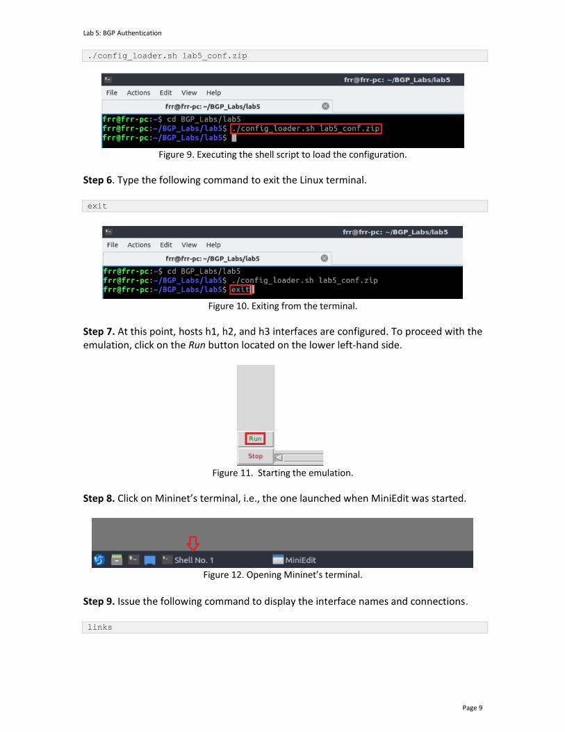
Lab 5: BGP Authentication
Page 9
./config_loader.sh lab5_conf.zip
Figure 9. Executing the shell script to load the configuration.
Step 6. Type the following command to exit the Linux terminal. exit
Figure 10. Exiting from the terminal.
Step 7. At this point, hosts h1, h2, and h3 interfaces are configured. To proceed with the emulation, click on the Run button located on the lower left-hand side.
Figure 11. Starting the emulation.
Step 8. Click on Mininet’s terminal, i.e., the one launched when MiniEdit was started.
Figure 12. Opening Mininet’s terminal.
Step 9. Issue the following command to display the interface names and connections. links
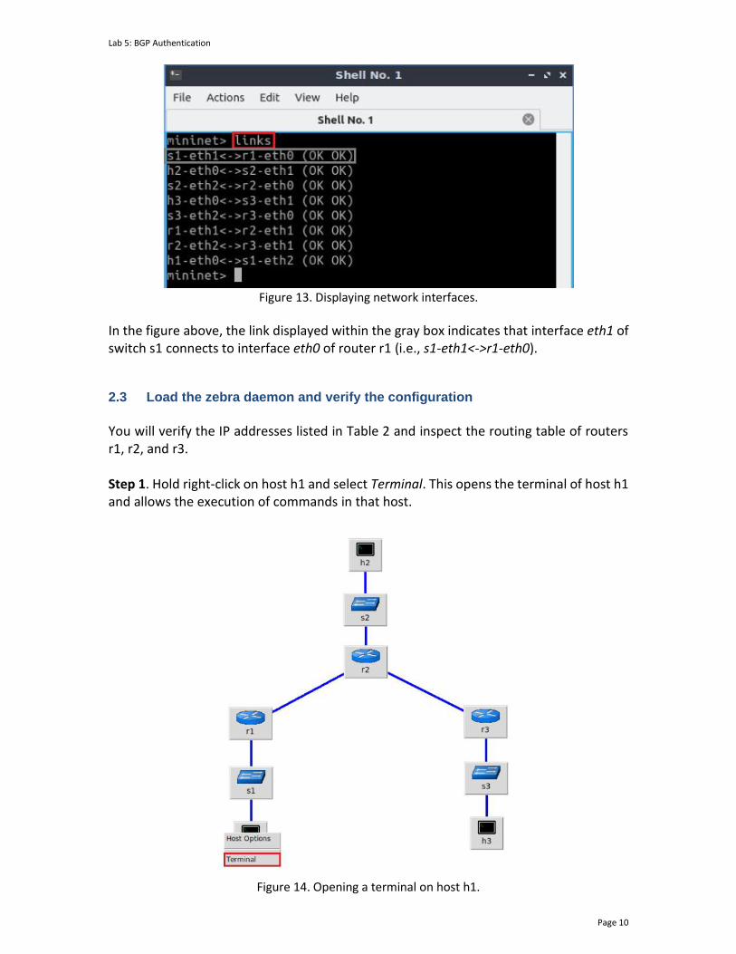
Lab 5: BGP Authentication
Page 10
Figure 13. Displaying network interfaces.
In the figure above, the link displayed within the gray box indicates that interface eth1 of switch s1 connects to interface eth0 of router r1 (i.e., s1-eth1<->r1-eth0).
2.3 Load the zebra daemon and verify the configuration
You will verify the IP addresses listed in Table 2 and inspect the routing table of routers r1, r2, and r3. Step 1. Hold right-click on host h1 and select Terminal. This opens the terminal of host h1 and allows the execution of commands in that host.
Figure 14. Opening a terminal on host h1.
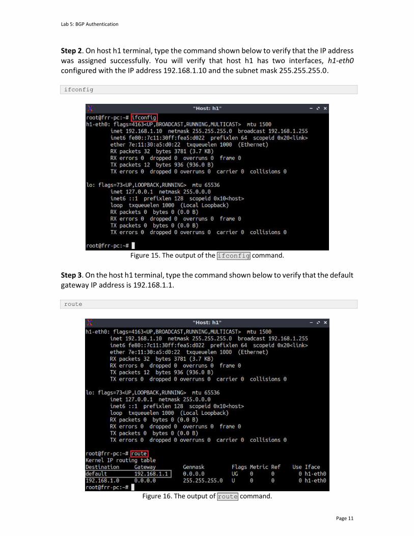
Lab 5: BGP Authentication
Page 11
Step 2. On host h1 terminal, type the command shown below to verify that the IP address was assigned successfully. You will verify that host h1 has two interfaces, h1-eth0 configured with the IP address 192.168.1.10 and the subnet mask 255.255.255.0. ifconfig
Figure 15. The output of the ifconfig command.
Step 3. On the host h1 terminal, type the command shown below to verify that the default gateway IP address is 192.168.1.1. route
Figure 16. The output of route command.
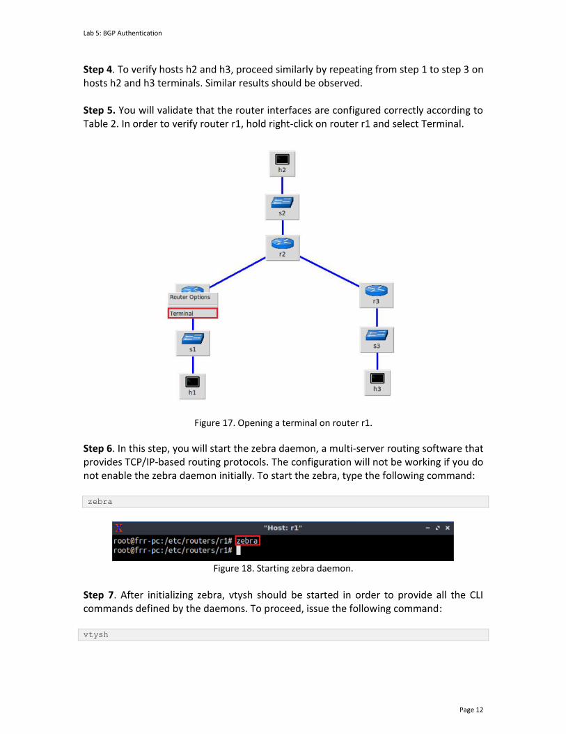
Lab 5: BGP Authentication
Page 12
Step 4. To verify hosts h2 and h3, proceed similarly by repeating from step 1 to step 3 on hosts h2 and h3 terminals. Similar results should be observed. Step 5. You will validate that the router interfaces are configured correctly according to Table 2. In order to verify router r1, hold right-click on router r1 and select Terminal.
Figure 17. Opening a terminal on router r1.
Step 6. In this step, you will start the zebra daemon, a multi-server routing software that provides TCP/IP-based routing protocols. The configuration will not be working if you do not enable the zebra daemon initially. To start the zebra, type the following command: zebra
Figure 18. Starting zebra daemon.
Step 7. After initializing zebra, vtysh should be started in order to provide all the CLI commands defined by the daemons. To proceed, issue the following command: vtysh
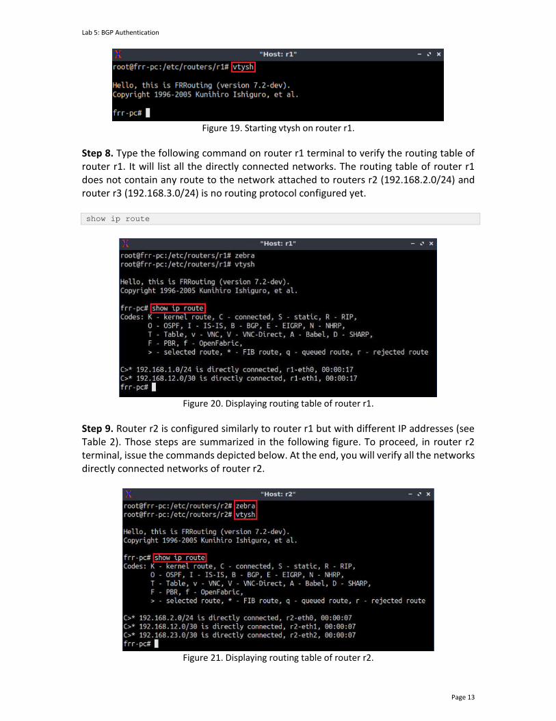
Lab 5: BGP Authentication
Page 13
Figure 19. Starting vtysh on router r1.
Step 8. Type the following command on router r1 terminal to verify the routing table of router r1. It will list all the directly connected networks. The routing table of router r1 does not contain any route to the network attached to routers r2 (192.168.2.0/24) and router r3 (192.168.3.0/24) is no routing protocol configured yet. show ip route
Figure 20. Displaying routing table of router r1.
Step 9. Router r2 is configured similarly to router r1 but with different IP addresses (see Table 2). Those steps are summarized in the following figure. To proceed, in router r2 terminal, issue the commands depicted below. At the end, you will verify all the networks directly connected networks of router r2.
Figure 21. Displaying routing table of router r2.
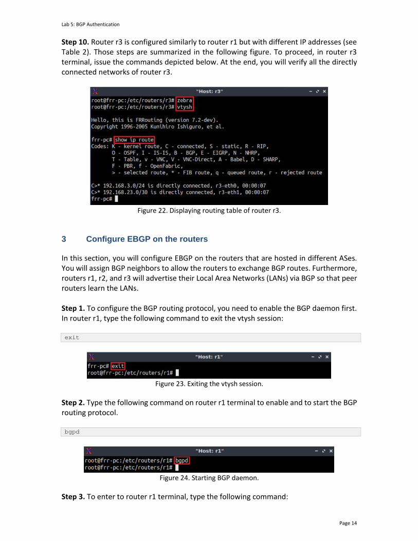
Lab 5: BGP Authentication
Page 14
Step 10. Router r3 is configured similarly to router r1 but with different IP addresses (see Table 2). Those steps are summarized in the following figure. To proceed, in router r3 terminal, issue the commands depicted below. At the end, you will verify all the directly connected networks of router r3.
Figure 22. Displaying routing table of router r3.
3 Configure EBGP on the routers In this section, you will configure EBGP on the routers that are hosted in different ASes. You will assign BGP neighbors to allow the routers to exchange BGP routes. Furthermore, routers r1, r2, and r3 will advertise their Local Area Networks (LANs) via BGP so that peer routers learn the LANs. Step 1. To configure the BGP routing protocol, you need to enable the BGP daemon first. In router r1, type the following command to exit the vtysh session: exit
Figure 23. Exiting the vtysh session.
Step 2. Type the following command on router r1 terminal to enable and to start the BGP routing protocol. bgpd
Figure 24. Starting BGP daemon.
Step 3. To enter to router r1 terminal, type the following command:
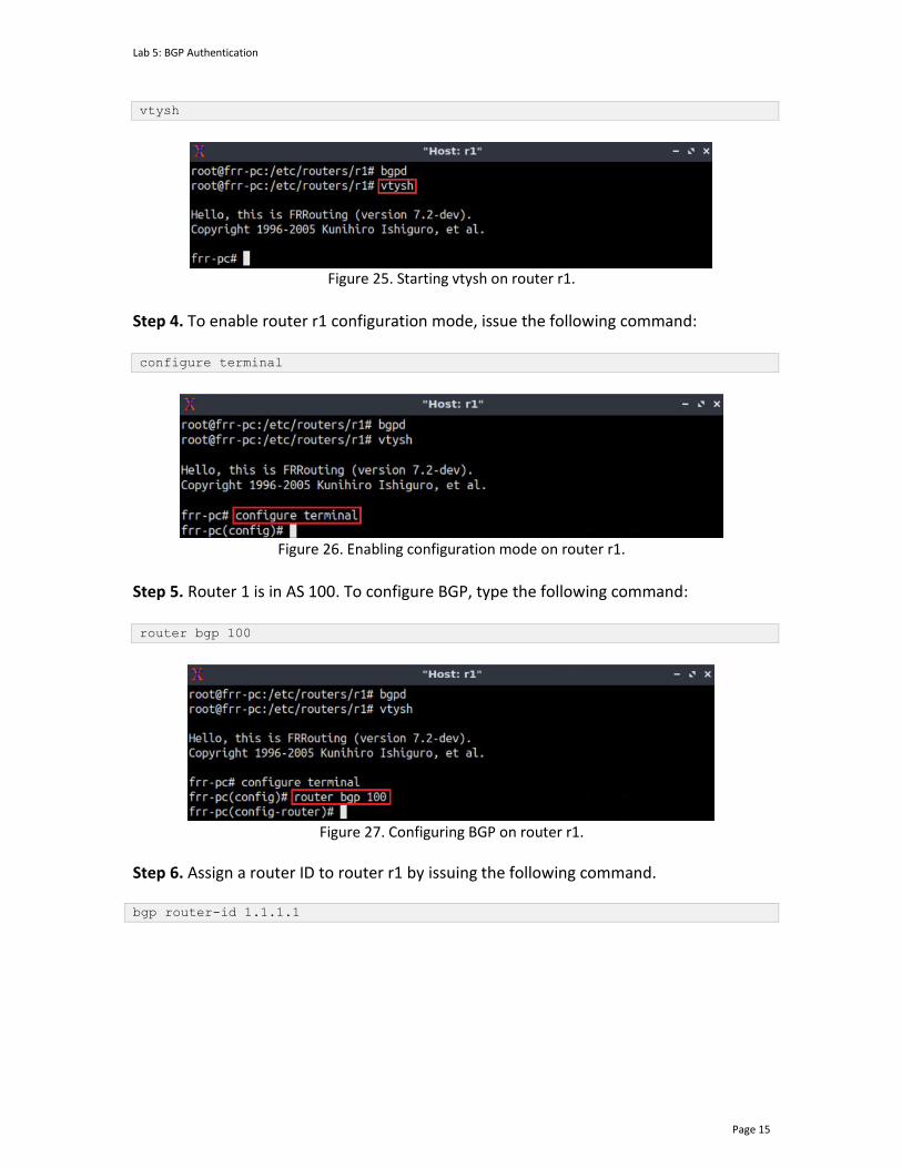
Lab 5: BGP Authentication
Page 15
vtysh
Figure 25. Starting vtysh on router r1.
Step 4. To enable router r1 configuration mode, issue the following command: configure terminal
Figure 26. Enabling configuration mode on router r1.
Step 5. Router 1 is in AS 100. To configure BGP, type the following command: router bgp 100
Figure 27. Configuring BGP on router r1.
Step 6. Assign a router ID to router r1 by issuing the following command. bgp router-id 1.1.1.1
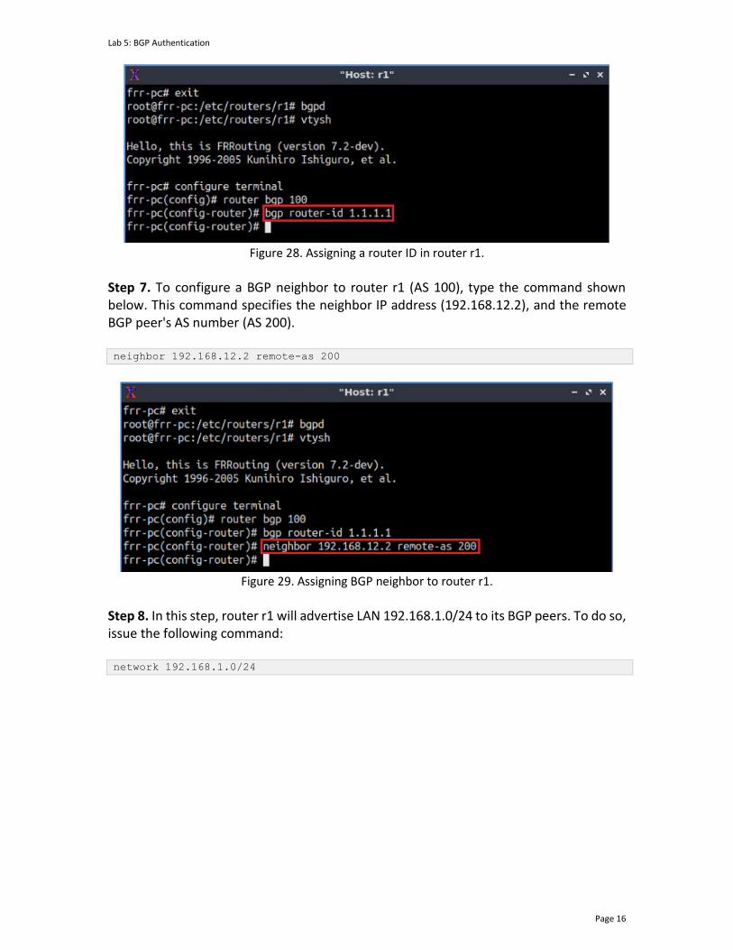
Lab 5: BGP Authentication
Page 16
Figure 28. Assigning a router ID in router r1.
Step 7. To configure a BGP neighbor to router r1 (AS 100), type the command shown below. This command specifies the neighbor IP address (192.168.12.2), and the remote BGP peer's AS number (AS 200). neighbor 192.168.12.2 remote-as 200
Figure 29. Assigning BGP neighbor to router r1.
Step 8. In this step, router r1 will advertise LAN 192.168.1.0/24 to its BGP peers. To do so, issue the following command: network 192.168.1.0/24
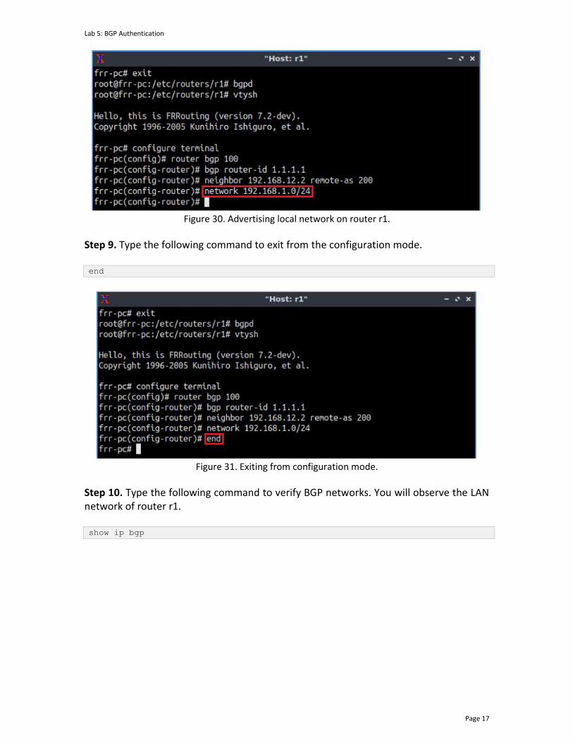
Lab 5: BGP Authentication
Page 17
Figure 30. Advertising local network on router r1.
Step 9. Type the following command to exit from the configuration mode. end
Figure 31. Exiting from configuration mode.
Step 10. Type the following command to verify BGP networks. You will observe the LAN network of router r1. show ip bgp
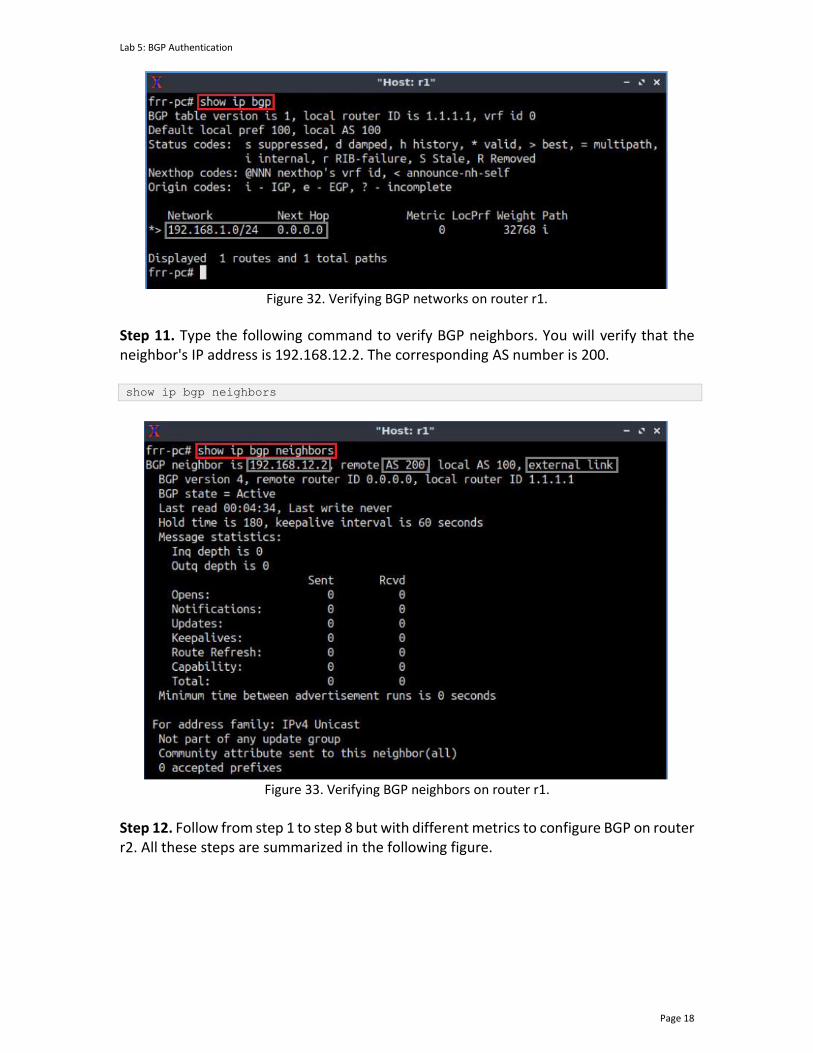
Lab 5: BGP Authentication
Page 18
Figure 32. Verifying BGP networks on router r1.
Step 11. Type the following command to verify BGP neighbors. You will verify that the neighbor's IP address is 192.168.12.2. The corresponding AS number is 200. show ip bgp neighbors
Figure 33. Verifying BGP neighbors on router r1.
Step 12. Follow from step 1 to step 8 but with different metrics to configure BGP on router r2. All these steps are summarized in the following figure.
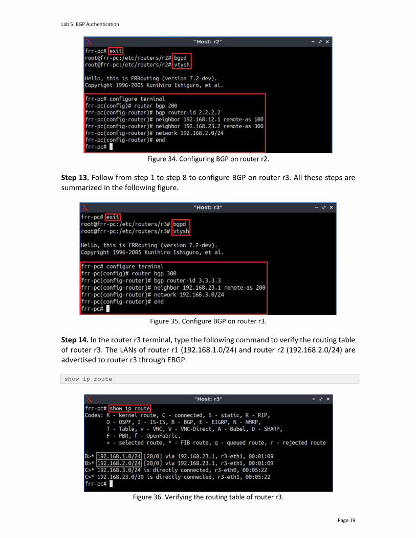
Lab 5: BGP Authentication
Page 19
Figure 34. Configuring BGP on router r2.
Step 13. Follow from step 1 to step 8 to configure BGP on router r3. All these steps are summarized in the following figure.
Figure 35. Configure BGP on router r3.
Step 14. In the router r3 terminal, type the following command to verify the routing table of router r3. The LANs of router r1 (192.168.1.0/24) and router r2 (192.168.2.0/24) are advertised to router r3 through EBGP. show ip route
Figure 36. Verifying the routing table of router r3.
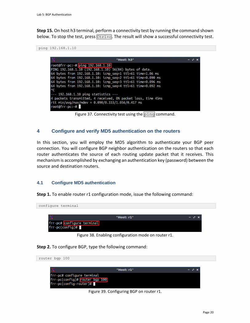
Lab 5: BGP Authentication
Page 20
Step 15. On host h3 terminal, perform a connectivity test by running the command shown below. To stop the test, press Ctrl+c. The result will show a successful connectivity test. ping 192.168.1.10
Figure 37. Connectivity test using the ping command.
4 Configure and verify MD5 authentication on the routers
In this section, you will employ the MD5 algorithm to authenticate your BGP peer connection. You will configure BGP neighbor authentication on the routers so that each router authenticates the source of each routing update packet that it receives. This mechanism is accomplished by exchanging an authentication key (password) between the source and destination routers.
4.1 Configure MD5 authentication
Step 1. To enable router r1 configuration mode, issue the following command: configure terminal
Figure 38. Enabling configuration mode on router r1.
Step 2. To configure BGP, type the following command: router bgp 100
Figure 39. Configuring BGP on router r1.
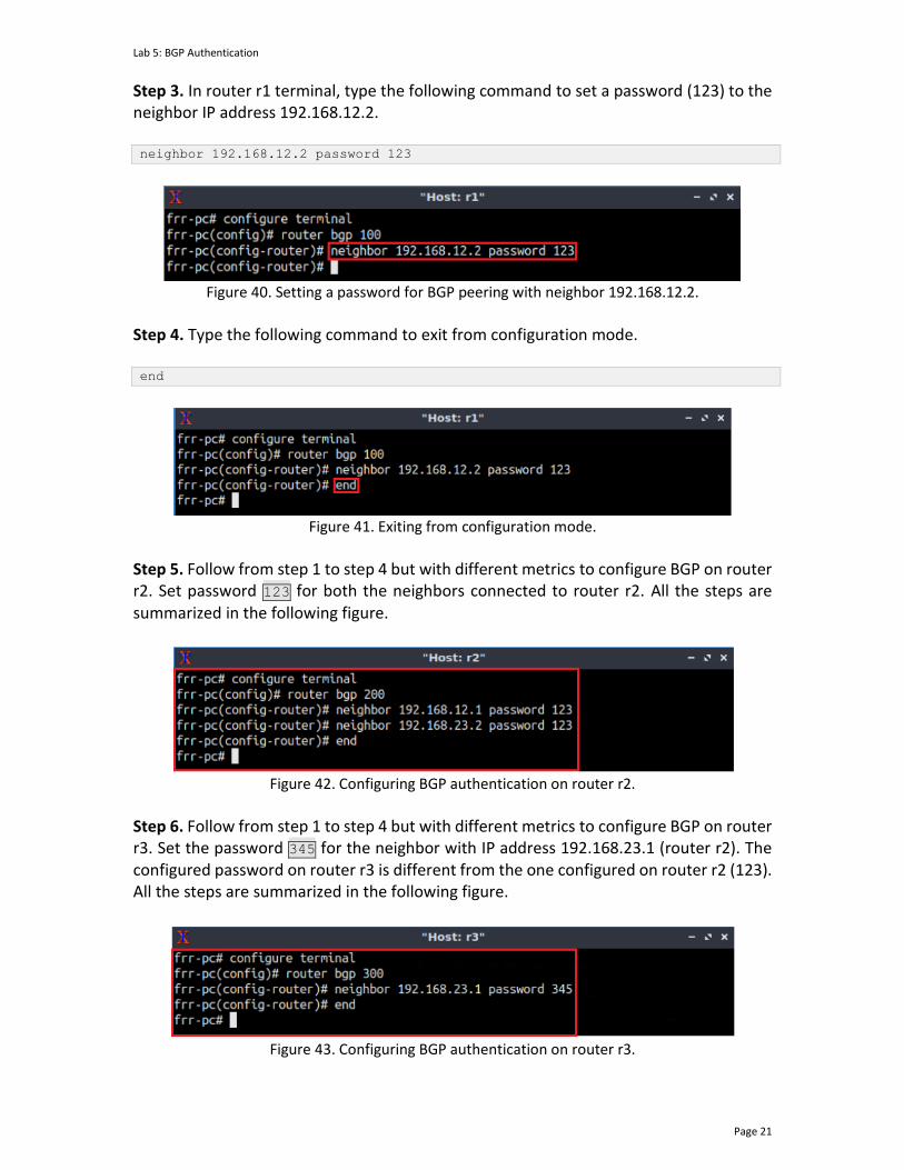
Lab 5: BGP Authentication
Page 21
Step 3. In router r1 terminal, type the following command to set a password (123) to the neighbor IP address 192.168.12.2. neighbor 192.168.12.2 password 123
Figure 40. Setting a password for BGP peering with neighbor 192.168.12.2.
Step 4. Type the following command to exit from configuration mode. end
Figure 41. Exiting from configuration mode.
Step 5. Follow from step 1 to step 4 but with different metrics to configure BGP on router r2. Set password 123 for both the neighbors connected to router r2. All the steps are summarized in the following figure.
Figure 42. Configuring BGP authentication on router r2.
Step 6. Follow from step 1 to step 4 but with different metrics to configure BGP on router r3. Set the password 345 for the neighbor with IP address 192.168.23.1 (router r2). The configured password on router r3 is different from the one configured on router r2 (123). All the steps are summarized in the following figure.
Figure 43. Configuring BGP authentication on router r3.

Lab 5: BGP Authentication
Page 22
4.2 Verify MD5 authentication
Step 1. On the host h3 terminal, perform a connectivity test by running the command shown below. To stop the test, press Ctrl+c. The results show that host h3 cannot reach host h1. ping 192.168.1.10
Figure 44. Connectivity test using the ping command.
Step 2. Type the following command to verify the routing table of router r3. You will notice that the routing table does not contain any route to the networks 192.168.1.0/24 and 192.168.2.0/24. The connection between routers r2 and r3 has dropped as the passwords exchanged between router r2 and router r3 are different. show ip route
Figure 45. Displaying the routing table of router r3.
Step 3. Type the following command to verify the routing table of router r2. The routing table does not have any route to the network 192.168.3.0/24. Router r2 has dropped the connection with router r3 as the password of router r2 did not match with the one configured on router r3. show ip route
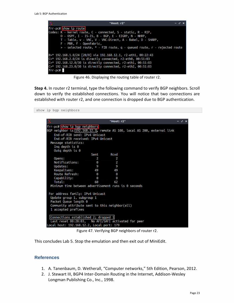
Lab 5: BGP Authentication
Page 23
Figure 46. Displaying the routing table of router r2.
Step 4. In router r2 terminal, type the following command to verify BGP neighbors. Scroll down to verify the established connections. You will notice that two connections are established with router r2, and one connection is dropped due to BGP authentication. show ip bgp neighbors
Figure 47. Verifying BGP neighbors of router r2.
This concludes Lab 5. Stop the emulation and then exit out of MiniEdit.
References
1. A. Tanenbaum, D. Wetherall, “Computer networks,” 5th Edition, Pearson, 2012. 2. J. Stewart III, BGP4 Inter-Domain Routing in the Internet, Addison-Wesley
Longman Publishing Co., Inc., 1998.

Lab 5: BGP Authentication
Page 24
3. Juniper networks, “BGP route authentication,” 2020. [Online]. Available: https://www.juniper.net/documentation/en_US/junos/topics/topic-map/bgp_security.html
4. Cisco, “Configuring authentication for BGP,” 2019. [Online]. Available: https://community.cisco.com/t5/networking-documents/configuring-authentication-for-bgp/ta-p/3108287
5. Cisco, “MD5 authentication between BGP peers configuration example”, 2010. [Online]. Available: https://www.cisco.com/c/en/us/support/docs/ip/border-gateway-protocol-bgp/112188-configure-md5-bgp-00.html#intro
BORDER GATEWAY PROTOCOL
Lab 6: Configuring BGP with Default Routing
Document Version: 05-25-2021
Award 1829698 “CyberTraining CIP: Cyberinfrastructure Expertise on High-throughput
Networks for Big Science Data Transfers”
Lab 6 Configuring BGP with Default Routing
Page 2
Contents Overview ............................................................................................................................. 3
Objectives............................................................................................................................ 3
Lab settings ......................................................................................................................... 3
Lab roadmap ....................................................................................................................... 3
1 Introduction ................................................................................................................ 4
1.1 Multi-homed network .......................................................................................... 4
1.2 Default route ........................................................................................................ 4
1.3 Floating static route ............................................................................................. 5
1.4 Access control list ................................................................................................. 6
2 Lab topology................................................................................................................ 7
2.1 Lab settings........................................................................................................... 8
2.2 Open the topology and load the configuration ................................................... 9
2.3 Load the zebra daemon and verify configuration .............................................. 12
3 Configure BGP on the routers ................................................................................... 16
4 Configure route filters ............................................................................................... 21
4.1 Configure ACL ..................................................................................................... 21
4.2 Verify configuration............................................................................................ 23
5 Configure primary and backup routes using floating static routes .......................... 24
5.1 Configure default routes .................................................................................... 24
5.2 Verify and test the default route ....................................................................... 27
6 Propagate default route using BGP .......................................................................... 28
References ........................................................................................................................ 31
Lab 6 Configuring BGP with Default Routing
Page 3
Overview This lab presents advanced Border Gateway Protocol (BGP) features. The goal of this lab is to create a multihomed network for Internet connectivity with fault tolerance. Thus, External BGP (EBGP) will be configured on all existing routers and route filters will be applied to permit or deny the route advertisement. Furthermore, floating static routes will be used to make one Internet Service Provider (ISP) as a primary provider and the other as a backup provider. Finally, a default route will be propagated from one router to another in different Autonomous Systems (ASes), where it will take effect on the delivered router without being configured manually. This lab is based on the Cisco Certified Network Professional (CCNP) ROUTE Version 7 training, laboratory 7-19. While this laboratory material uses FRR as the router (which includes the routing protocols) and Linux as the control plane operating system, vendors’ operating systems such as Cisco have similar functionality. Objectives By the end of this lab, you should be able to:
1. Explain the concept of default routing. 2. Configure and verify BGP between two ASes. 3. Apply route filters. 4. Set primary and backup routes using floating static routes. 5. Use BGP to propagate a default route.
Lab settings The information in Table 1 provides the credentials to access the Client machine.
Table 1. Credentials to access the Client machine.
Device
Account
Password
Client admin password
Lab roadmap This lab is organized as follows:
1. Section 1: Introduction. 2. Section 2: Lab topology. 3. Section 3: Configure BGP on the routers.
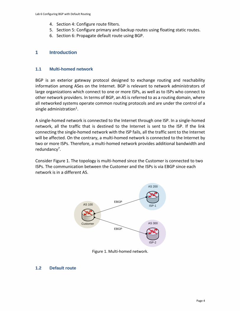
Lab 6 Configuring BGP with Default Routing
Page 4
4. Section 4: Configure route filters. 5. Section 5: Configure primary and backup routes using floating static routes. 6. Section 6: Propagate default route using BGP.
1 Introduction 1.1 Multi-homed network
BGP is an exterior gateway protocol designed to exchange routing and reachability information among ASes on the Internet. BGP is relevant to network administrators of large organizations which connect to one or more ISPs, as well as to ISPs who connect to other network providers. In terms of BGP, an AS is referred to as a routing domain, where all networked systems operate common routing protocols and are under the control of a single administration1. A single-homed network is connected to the Internet through one ISP. In a single-homed network, all the traffic that is destined to the Internet is sent to the ISP. If the link connecting the single-homed network with the ISP fails, all the traffic sent to the Internet will be affected. On the contrary, a multi-homed network is connected to the Internet by two or more ISPs. Therefore, a multi-homed network provides additional bandwidth and redundancy7. Consider Figure 1. The topology is multi-homed since the Customer is connected to two ISPs. The communication between the Customer and the ISPs is via EBGP since each network is in a different AS.
AS 100
Customer
EBGP
AS 200
ISP-1
AS 300
ISP-2
EBGP
Figure 1. Multi-homed network.
1.2 Default route
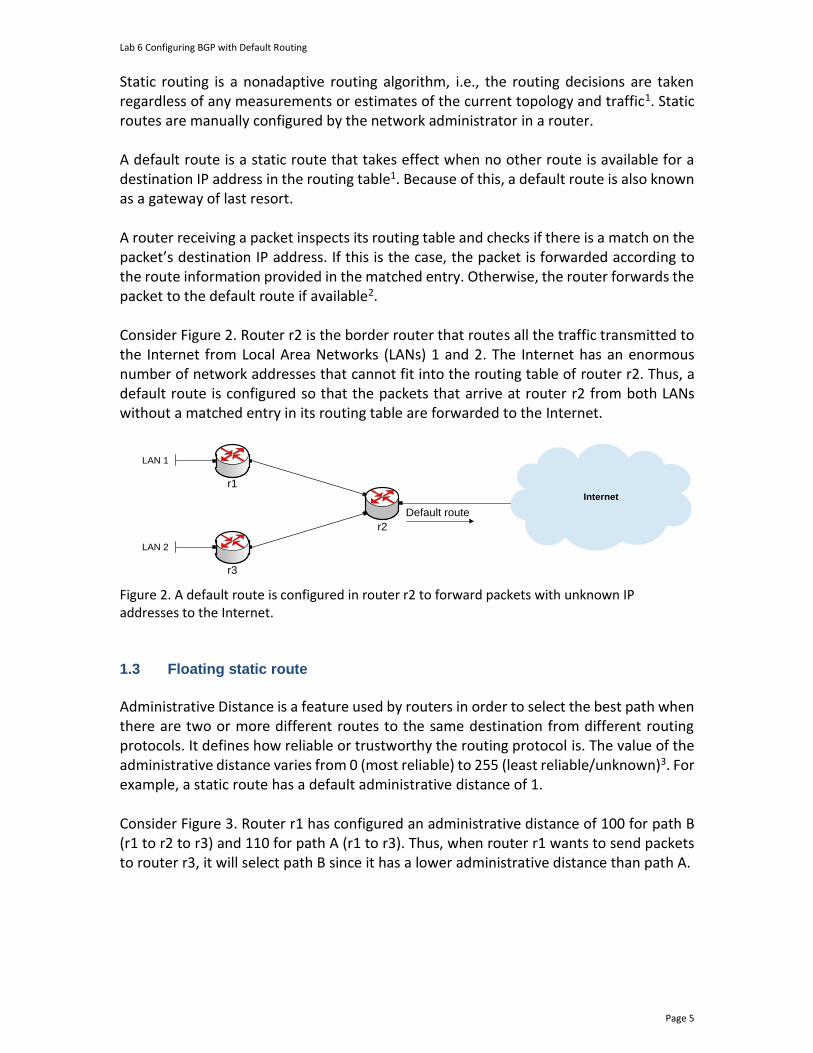
Lab 6 Configuring BGP with Default Routing
Page 5
Static routing is a nonadaptive routing algorithm, i.e., the routing decisions are taken regardless of any measurements or estimates of the current topology and traffic1. Static routes are manually configured by the network administrator in a router. A default route is a static route that takes effect when no other route is available for a destination IP address in the routing table1. Because of this, a default route is also known as a gateway of last resort. A router receiving a packet inspects its routing table and checks if there is a match on the packet’s destination IP address. If this is the case, the packet is forwarded according to the route information provided in the matched entry. Otherwise, the router forwards the packet to the default route if available2. Consider Figure 2. Router r2 is the border router that routes all the traffic transmitted to the Internet from Local Area Networks (LANs) 1 and 2. The Internet has an enormous number of network addresses that cannot fit into the routing table of router r2. Thus, a default route is configured so that the packets that arrive at router r2 from both LANs without a matched entry in its routing table are forwarded to the Internet.
Internet
r2
r1
LAN 1
r3
LAN 2
Default route
Figure 2. A default route is configured in router r2 to forward packets with unknown IP addresses to the Internet.
1.3 Floating static route
Administrative Distance is a feature used by routers in order to select the best path when there are two or more different routes to the same destination from different routing protocols. It defines how reliable or trustworthy the routing protocol is. The value of the administrative distance varies from 0 (most reliable) to 255 (least reliable/unknown)3. For example, a static route has a default administrative distance of 1. Consider Figure 3. Router r1 has configured an administrative distance of 100 for path B (r1 to r2 to r3) and 110 for path A (r1 to r3). Thus, when router r1 wants to send packets to router r3, it will select path B since it has a lower administrative distance than path A.
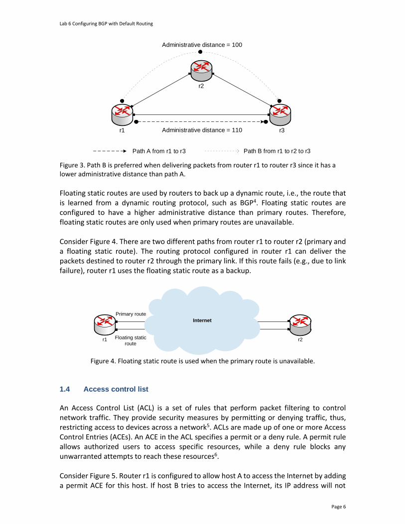
Lab 6 Configuring BGP with Default Routing
Page 6
r2
r1
Administrative distance = 100
Path A from r1 to r3 Path B from r1 to r2 to r3
•
•
• •
•
r3Administrative distance = 110
Figure 3. Path B is preferred when delivering packets from router r1 to router r3 since it has a lower administrative distance than path A.
Floating static routes are used by routers to back up a dynamic route, i.e., the route that is learned from a dynamic routing protocol, such as BGP4. Floating static routes are configured to have a higher administrative distance than primary routes. Therefore, floating static routes are only used when primary routes are unavailable. Consider Figure 4. There are two different paths from router r1 to router r2 (primary and a floating static route). The routing protocol configured in router r1 can deliver the packets destined to router r2 through the primary link. If this route fails (e.g., due to link failure), router r1 uses the floating static route as a backup.
r1
Internet
Primary route
Floating static
route r2
Figure 4. Floating static route is used when the primary route is unavailable.
1.4 Access control list
An Access Control List (ACL) is a set of rules that perform packet filtering to control network traffic. They provide security measures by permitting or denying traffic, thus, restricting access to devices across a network5. ACLs are made up of one or more Access Control Entries (ACEs). An ACE in the ACL specifies a permit or a deny rule. A permit rule allows authorized users to access specific resources, while a deny rule blocks any unwarranted attempts to reach these resources6. Consider Figure 5. Router r1 is configured to allow host A to access the Internet by adding a permit ACE for this host. If host B tries to access the Internet, its IP address will not

Lab 6 Configuring BGP with Default Routing
Page 7
match the ACE permit rule, hence, the packets will not be forwarded. More control over the network traffic can be achieved by configuring multiple ACEs.
Internet
r1s1
Permit host A
Host A
Host B
Figure 5. The ACL configured in router r1 allows only host A to access the Internet.
2 Lab topology Consider Figure 6. The lab topology consists of three ASes, each identified by an Autonomous System Number (ASN). The ASNs assigned to ISP-1, the Campus network, and ISP-2 are 100, 200, and 300, respectively. ISP-1 and ISP-2 provide Internet connectivity to the Campus network. ISP-1 acts as the primary provider as it has a lower administrative distance than ISP-2. ISP-2 will act as a backup provider whenever the primary provider is not available. The communication between ASes is done via EBGP routing protocol.
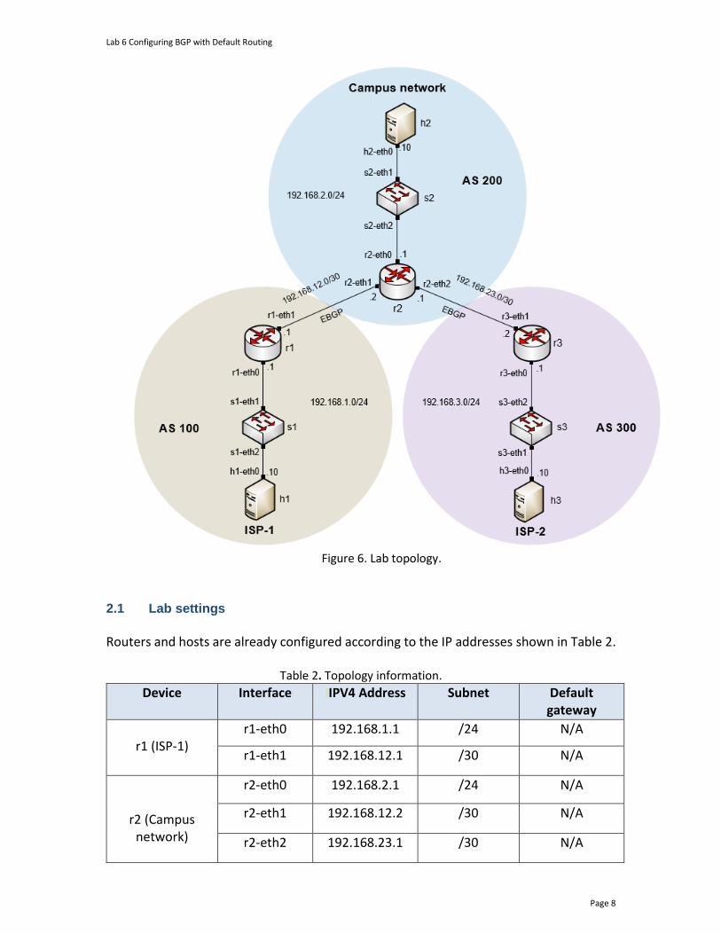
Lab 6 Configuring BGP with Default Routing
Page 8
Figure 6. Lab topology.
2.1 Lab settings
Routers and hosts are already configured according to the IP addresses shown in Table 2.
Table 2. Topology information.
Device Interface IIPV4 Address Subnet Default gateway
r1 (ISP-1)
r1-eth0 192.168.1.1 /24 N/A
r1-eth1 192.168.12.1 /30 N/A
r2 (Campus network)
r2-eth0 192.168.2.1 /24 N/A
r2-eth1 192.168.12.2 /30 N/A
r2-eth2 192.168.23.1 /30 N/A
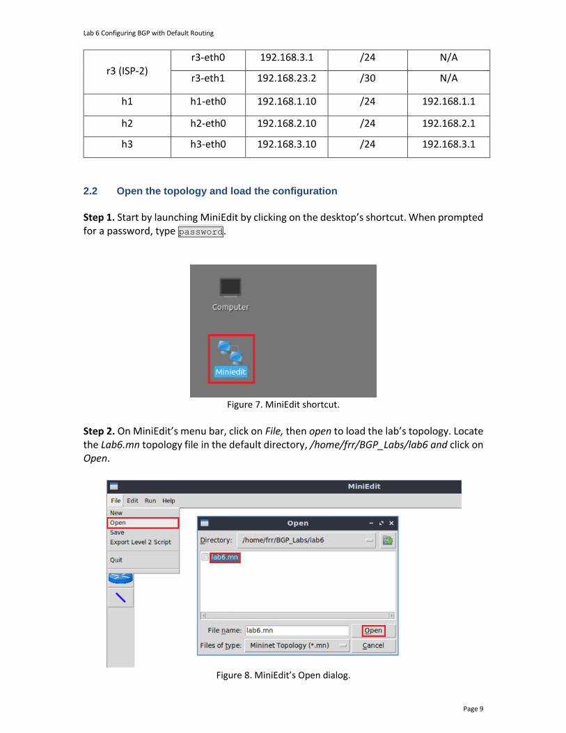
Lab 6 Configuring BGP with Default Routing
Page 9
r3 (ISP-2)
r3-eth0 192.168.3.1 /24 N/A
r3-eth1 192.168.23.2 /30 N/A
h1 h1-eth0 192.168.1.10 /24 192.168.1.1
h2 h2-eth0 192.168.2.10 /24 192.168.2.1
h3 h3-eth0 192.168.3.10 /24 192.168.3.1
2.2 Open the topology and load the configuration
Step 1. Start by launching MiniEdit by clicking on the desktop’s shortcut. When prompted for a password, type password.
Figure 7. MiniEdit shortcut.
Step 2. On MiniEdit’s menu bar, click on File, then open to load the lab’s topology. Locate the Lab6.mn topology file in the default directory, /home/frr/BGP_Labs/lab6 and click on Open.
Figure 8. MiniEdit’s Open dialog.

Lab 6 Configuring BGP with Default Routing
Page 10
At this point, the topology is loaded with all the required network components. You will execute a script that will load the configuration of the routers. Step 3. Open the Linux terminal.
Figure 9. Opening Linux terminal.
Step 4. Click on the Linux terminal and navigate into BGP_Labs/lab6 directory by issuing the following command. This folder contains a configuration file and the script responsible for loading the configuration. The configuration file will assign the IP addresses to the routers’ interfaces. The cd command is short for change directory followed by an argument that specifies the destination directory. cd BGP_Labs/lab6
Figure 10. Entering the BGP_Labs/lab6 directory.
Step 5. To execute the shell script, type the following command. The argument of the program corresponds to the configuration zip file that will be loaded in all the routers in the topology. ./config_loader.sh lab6_conf.zip
Figure 11. Executing the shell script to load the configuration.
Step 6. Type the following command to exit the Linux terminal. exit
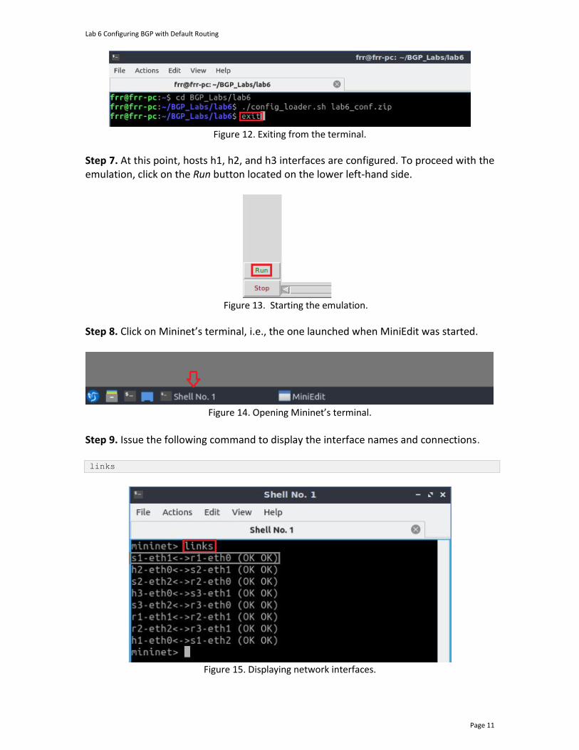
Lab 6 Configuring BGP with Default Routing
Page 11
Figure 12. Exiting from the terminal.
Step 7. At this point, hosts h1, h2, and h3 interfaces are configured. To proceed with the emulation, click on the Run button located on the lower left-hand side.
Figure 13. Starting the emulation.
Step 8. Click on Mininet’s terminal, i.e., the one launched when MiniEdit was started.
Figure 14. Opening Mininet’s terminal.
Step 9. Issue the following command to display the interface names and connections. links
Figure 15. Displaying network interfaces.
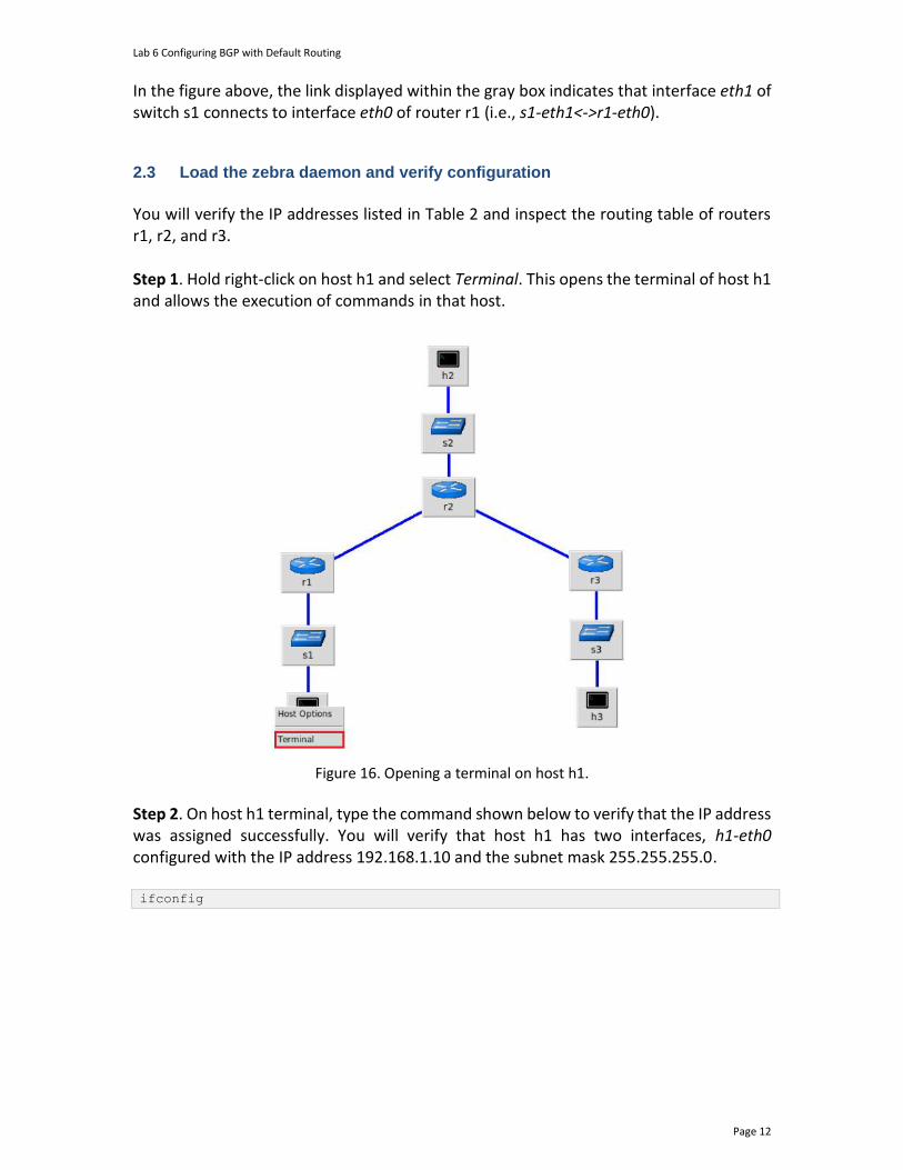
Lab 6 Configuring BGP with Default Routing
Page 12
In the figure above, the link displayed within the gray box indicates that interface eth1 of switch s1 connects to interface eth0 of router r1 (i.e., s1-eth1<->r1-eth0).
2.3 Load the zebra daemon and verify configuration
You will verify the IP addresses listed in Table 2 and inspect the routing table of routers r1, r2, and r3. Step 1. Hold right-click on host h1 and select Terminal. This opens the terminal of host h1 and allows the execution of commands in that host.
Figure 16. Opening a terminal on host h1.
Step 2. On host h1 terminal, type the command shown below to verify that the IP address was assigned successfully. You will verify that host h1 has two interfaces, h1-eth0 configured with the IP address 192.168.1.10 and the subnet mask 255.255.255.0. ifconfig

Lab 6 Configuring BGP with Default Routing
Page 13
Figure 17. The output of the ifconfig command.
Step 3. On host h1 terminal, type the command shown below to verify that the default gateway IP address is 192.168.1.1. route
Figure 18. The output of the route command.
Step 4. In order to verify hosts h2 and h3, proceed similarly by repeating from step 1 to step 3 on hosts h2 and h3 terminals. Similar results should be observed. Step 5. You will validate that the router interfaces are configured correctly according to Table 2. In order to verify router r1, hold right-click on router r1 and select Terminal.
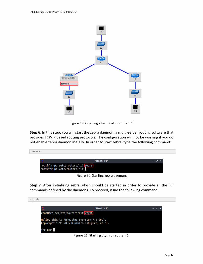
Lab 6 Configuring BGP with Default Routing
Page 14
Figure 19. Opening a terminal on router r1.
Step 6. In this step, you will start the zebra daemon, a multi-server routing software that provides TCP/IP based routing protocols. The configuration will not be working if you do not enable zebra daemon initially. In order to start zebra, type the following command: zebra
Figure 20. Starting zebra daemon.
Step 7. After initializing zebra, vtysh should be started in order to provide all the CLI commands defined by the daemons. To proceed, issue the following command: vtysh
Figure 21. Starting vtysh on router r1.
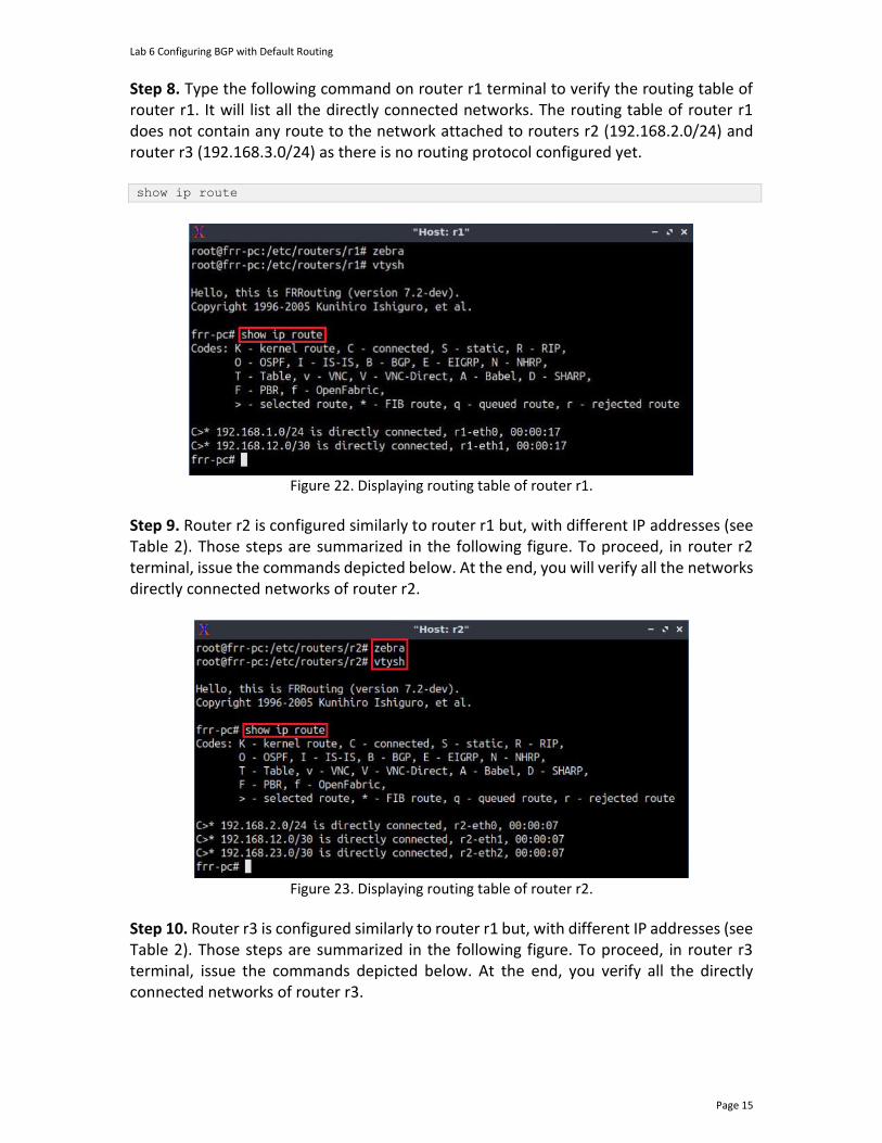
Lab 6 Configuring BGP with Default Routing
Page 15
Step 8. Type the following command on router r1 terminal to verify the routing table of router r1. It will list all the directly connected networks. The routing table of router r1 does not contain any route to the network attached to routers r2 (192.168.2.0/24) and router r3 (192.168.3.0/24) as there is no routing protocol configured yet. show ip route
Figure 22. Displaying routing table of router r1.
Step 9. Router r2 is configured similarly to router r1 but, with different IP addresses (see Table 2). Those steps are summarized in the following figure. To proceed, in router r2 terminal, issue the commands depicted below. At the end, you will verify all the networks directly connected networks of router r2.
Figure 23. Displaying routing table of router r2.
Step 10. Router r3 is configured similarly to router r1 but, with different IP addresses (see Table 2). Those steps are summarized in the following figure. To proceed, in router r3 terminal, issue the commands depicted below. At the end, you verify all the directly connected networks of router r3.
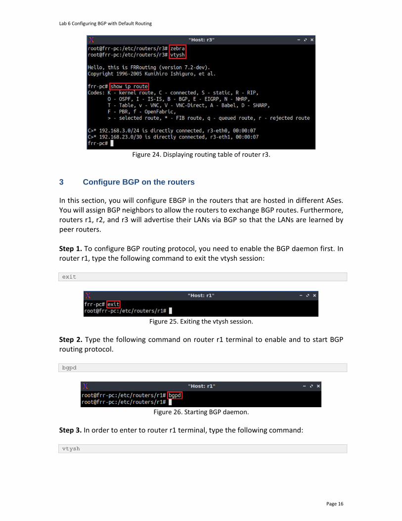
Lab 6 Configuring BGP with Default Routing
Page 16
Figure 24. Displaying routing table of router r3.
3 Configure BGP on the routers In this section, you will configure EBGP in the routers that are hosted in different ASes. You will assign BGP neighbors to allow the routers to exchange BGP routes. Furthermore, routers r1, r2, and r3 will advertise their LANs via BGP so that the LANs are learned by peer routers. Step 1. To configure BGP routing protocol, you need to enable the BGP daemon first. In router r1, type the following command to exit the vtysh session: exit
Figure 25. Exiting the vtysh session.
Step 2. Type the following command on router r1 terminal to enable and to start BGP routing protocol. bgpd
Figure 26. Starting BGP daemon.
Step 3. In order to enter to router r1 terminal, type the following command: vtysh

Lab 6 Configuring BGP with Default Routing
Page 17
Figure 27. Starting vtysh on router r1.
Step 4. To enable router r1 configuration mode, issue the following command: configure terminal
Figure 28. Enabling configuration mode on router r1.
Step 5. The ASN assigned for router r1 is 100. In order to configure BGP, type the following command: router bgp 100
Figure 29. Configuring BGP on router r1.
Step 6. Assign a router ID to router r1 by issuing the following command. bgp router-id 1.1.1.1
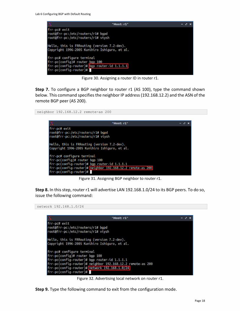
Lab 6 Configuring BGP with Default Routing
Page 18
Figure 30. Assigning a router ID in router r1.
Step 7. To configure a BGP neighbor to router r1 (AS 100), type the command shown below. This command specifies the neighbor IP address (192.168.12.2) and the ASN of the remote BGP peer (AS 200). neighbor 192.168.12.2 remote-as 200
Figure 31. Assigning BGP neighbor to router r1.
Step 8. In this step, router r1 will advertise LAN 192.168.1.0/24 to its BGP peers. To do so, issue the following command: network 192.168.1.0/24
Figure 32. Advertising local network on router r1.
Step 9. Type the following command to exit from the configuration mode.
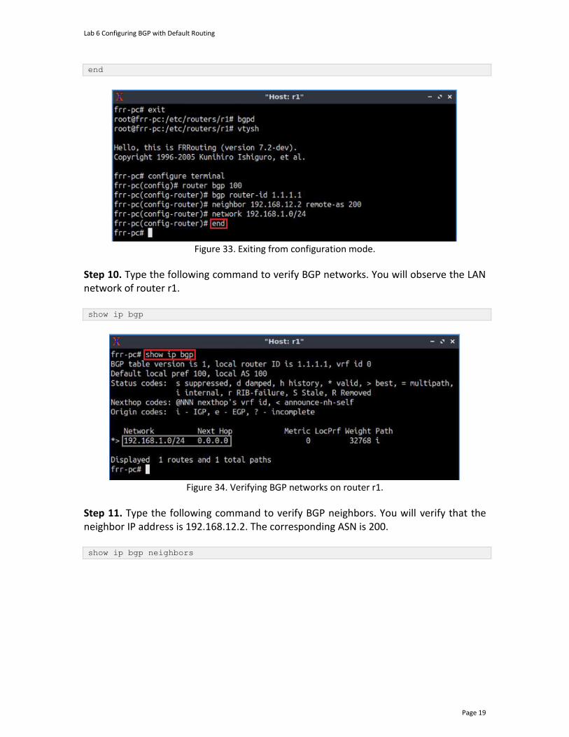
Lab 6 Configuring BGP with Default Routing
Page 19
end
Figure 33. Exiting from configuration mode.
Step 10. Type the following command to verify BGP networks. You will observe the LAN network of router r1. show ip bgp
Figure 34. Verifying BGP networks on router r1.
Step 11. Type the following command to verify BGP neighbors. You will verify that the neighbor IP address is 192.168.12.2. The corresponding ASN is 200. show ip bgp neighbors
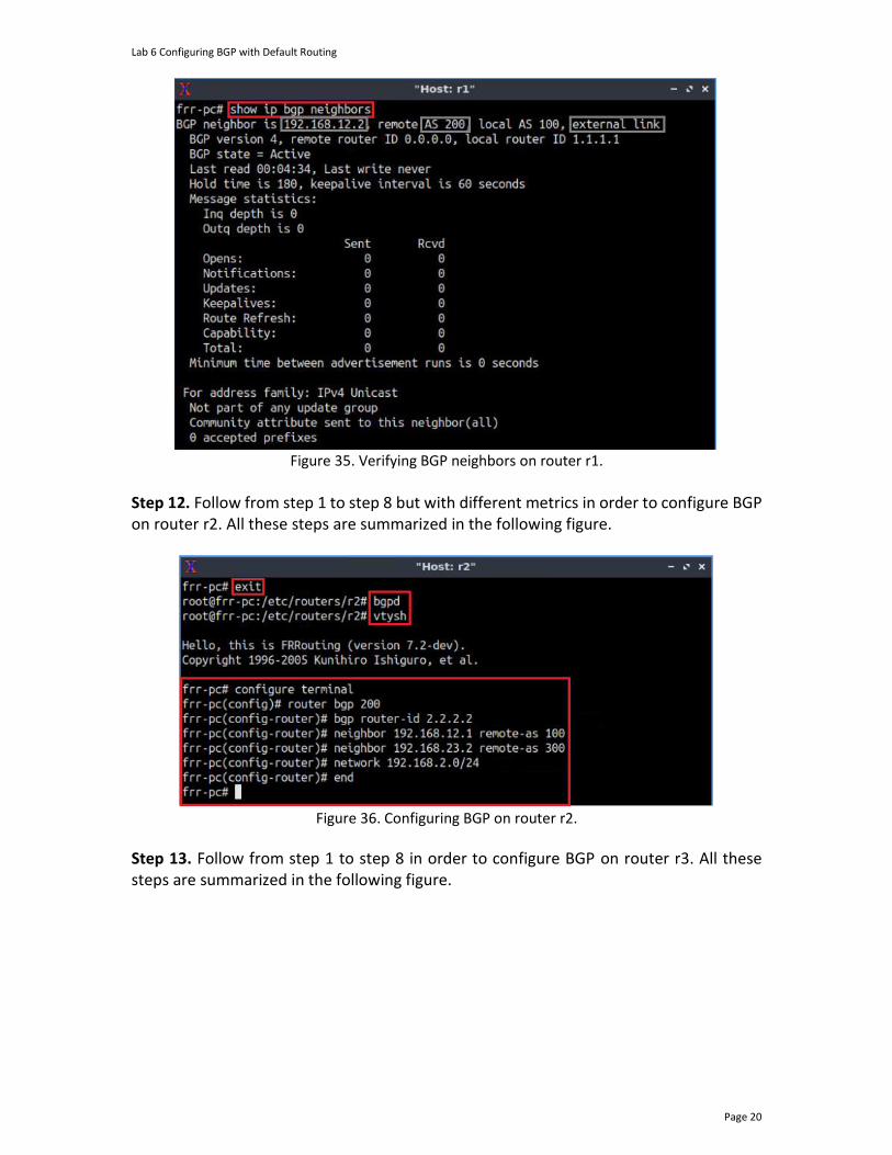
Lab 6 Configuring BGP with Default Routing
Page 20
Figure 35. Verifying BGP neighbors on router r1.
Step 12. Follow from step 1 to step 8 but with different metrics in order to configure BGP on router r2. All these steps are summarized in the following figure.
Figure 36. Configuring BGP on router r2.
Step 13. Follow from step 1 to step 8 in order to configure BGP on router r3. All these steps are summarized in the following figure.
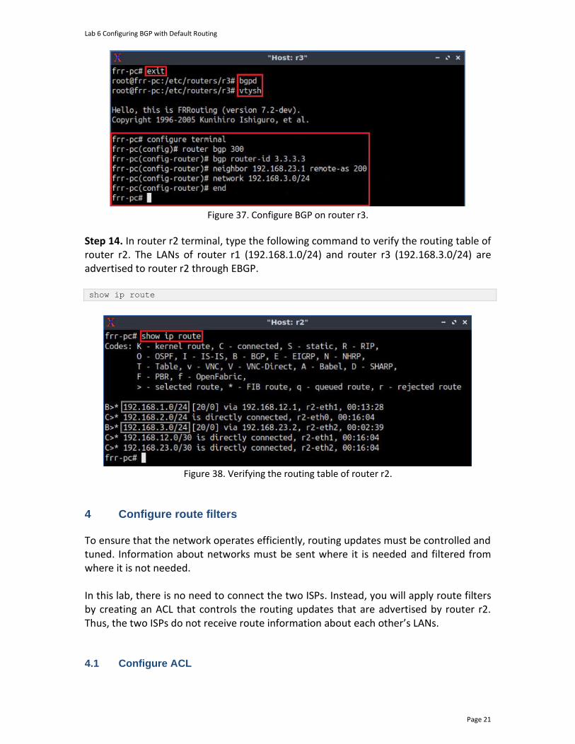
Lab 6 Configuring BGP with Default Routing
Page 21
Figure 37. Configure BGP on router r3.
Step 14. In router r2 terminal, type the following command to verify the routing table of router r2. The LANs of router r1 (192.168.1.0/24) and router r3 (192.168.3.0/24) are advertised to router r2 through EBGP. show ip route
Figure 38. Verifying the routing table of router r2.
4 Configure route filters To ensure that the network operates efficiently, routing updates must be controlled and tuned. Information about networks must be sent where it is needed and filtered from where it is not needed. In this lab, there is no need to connect the two ISPs. Instead, you will apply route filters by creating an ACL that controls the routing updates that are advertised by router r2. Thus, the two ISPs do not receive route information about each other’s LANs. 4.1 Configure ACL

Lab 6 Configuring BGP with Default Routing
Page 22
Step 1. In router r2 terminal, type the following command to enable the configuration mode: configure terminal
Figure 39. Enabling configuration mode on router r2.
Step 2. In this step, you will create an ACL that permits the network 192.168.2.0/24. An ACL must have a number within the range 1-99. In this lab, you will use 1 as the ACL number. Type the following command to configure the ACL in router r2.
access-list 1 permit 192.168.2.0/24
Figure 40. Creating an ACL that permits the LAN of router r2.
Step 3. You will filter the route updates that are advertised by router r2 to its neighbors using the configured ACL. Type the following command to enter BGP configuration mode: router bgp 200
Figure 41. Configuring BGP on router r2.
Step 4. Router r2 must advertise only its LAN (192.168.2.0/24) to the neighbor with IP address 192.168.12.1 (router r1). To do so, type the below command. The distribute-list 1 out option will apply the ACL numbered 1 to filter all outgoing route updates. neighbor 192.168.12.1 distribute-list 1 out
Figure 42. Applying the ACL to router r2 neighbor.
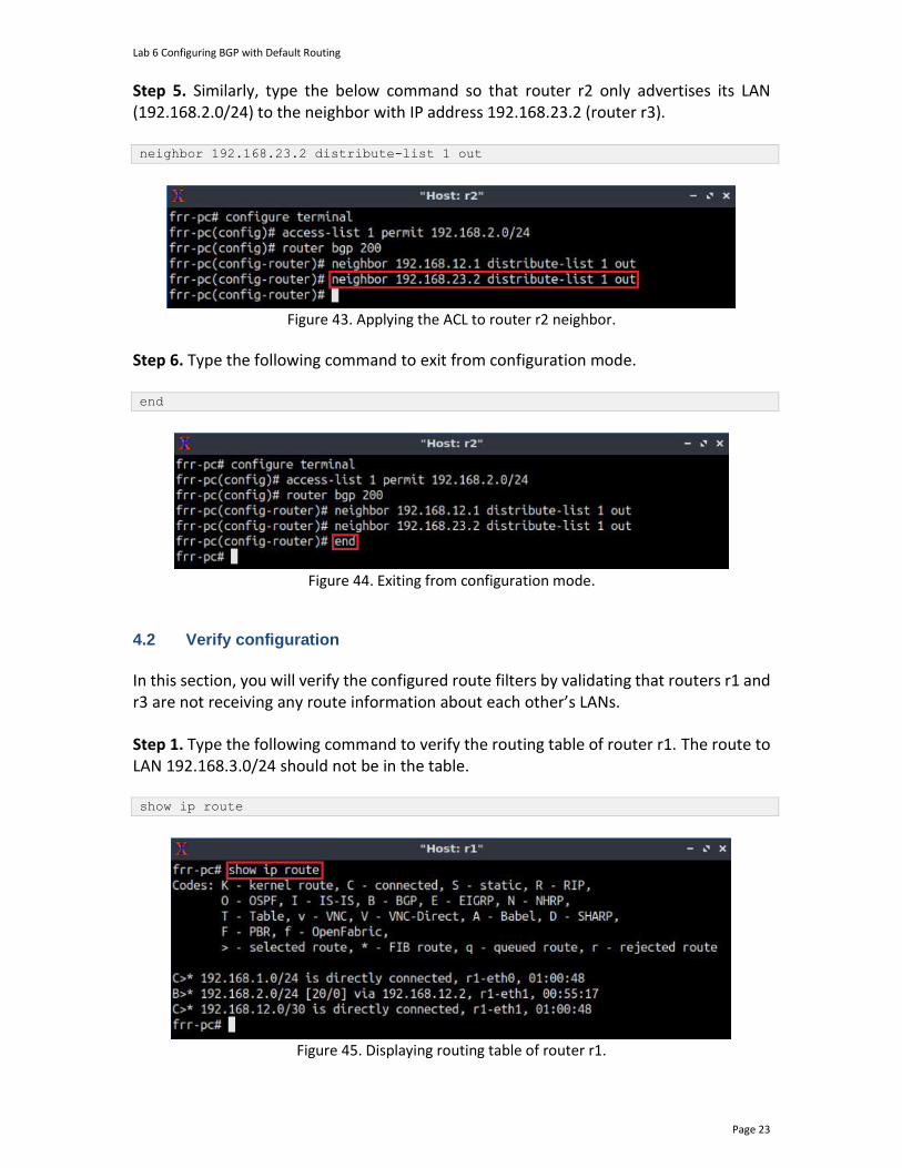
Lab 6 Configuring BGP with Default Routing
Page 23
Step 5. Similarly, type the below command so that router r2 only advertises its LAN (192.168.2.0/24) to the neighbor with IP address 192.168.23.2 (router r3). neighbor 192.168.23.2 distribute-list 1 out
Figure 43. Applying the ACL to router r2 neighbor.
Step 6. Type the following command to exit from configuration mode. end
Figure 44. Exiting from configuration mode.
4.2 Verify configuration
In this section, you will verify the configured route filters by validating that routers r1 and r3 are not receiving any route information about each other’s LANs.
Step 1. Type the following command to verify the routing table of router r1. The route to LAN 192.168.3.0/24 should not be in the table.
show ip route
Figure 45. Displaying routing table of router r1.
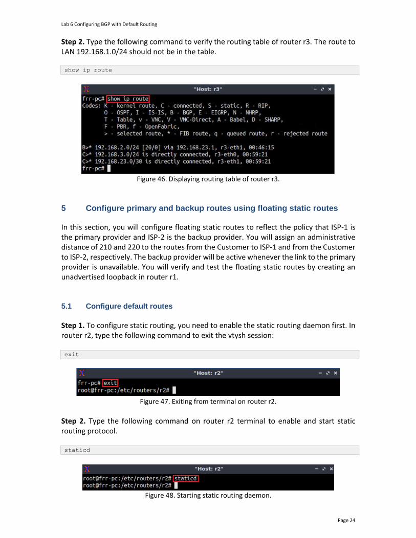
Lab 6 Configuring BGP with Default Routing
Page 24
Step 2. Type the following command to verify the routing table of router r3. The route to LAN 192.168.1.0/24 should not be in the table. show ip route
Figure 46. Displaying routing table of router r3.
5 Configure primary and backup routes using floating static routes
In this section, you will configure floating static routes to reflect the policy that ISP-1 is the primary provider and ISP-2 is the backup provider. You will assign an administrative distance of 210 and 220 to the routes from the Customer to ISP-1 and from the Customer to ISP-2, respectively. The backup provider will be active whenever the link to the primary provider is unavailable. You will verify and test the floating static routes by creating an unadvertised loopback in router r1. 5.1 Configure default routes
Step 1. To configure static routing, you need to enable the static routing daemon first. In router r2, type the following command to exit the vtysh session: exit
Figure 47. Exiting from terminal on router r2.
Step 2. Type the following command on router r2 terminal to enable and start static routing protocol. staticd
Figure 48. Starting static routing daemon.
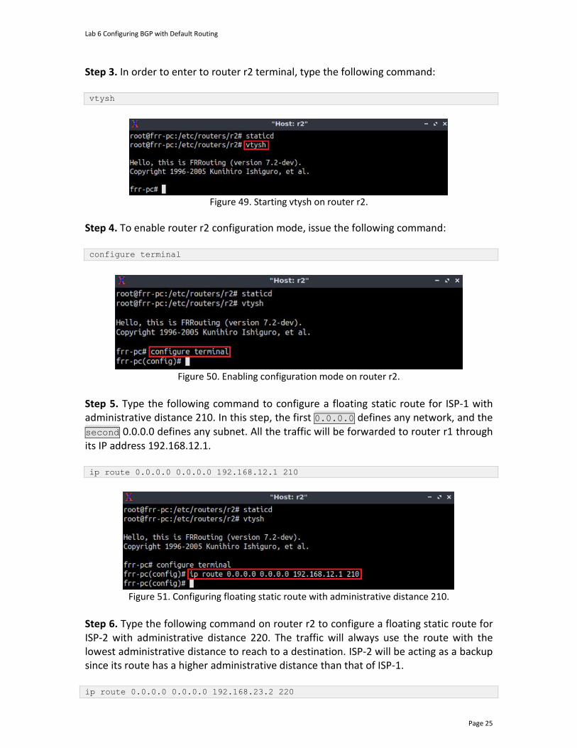
Lab 6 Configuring BGP with Default Routing
Page 25
Step 3. In order to enter to router r2 terminal, type the following command: vtysh
Figure 49. Starting vtysh on router r2.
Step 4. To enable router r2 configuration mode, issue the following command: configure terminal
Figure 50. Enabling configuration mode on router r2.
Step 5. Type the following command to configure a floating static route for ISP-1 with administrative distance 210. In this step, the first 0.0.0.0 defines any network, and the second 0.0.0.0 defines any subnet. All the traffic will be forwarded to router r1 through its IP address 192.168.12.1. ip route 0.0.0.0 0.0.0.0 192.168.12.1 210
Figure 51. Configuring floating static route with administrative distance 210.
Step 6. Type the following command on router r2 to configure a floating static route for ISP-2 with administrative distance 220. The traffic will always use the route with the lowest administrative distance to reach to a destination. ISP-2 will be acting as a backup since its route has a higher administrative distance than that of ISP-1. ip route 0.0.0.0 0.0.0.0 192.168.23.2 220
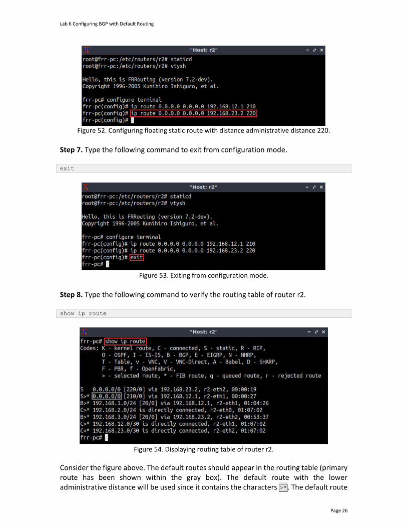
Lab 6 Configuring BGP with Default Routing
Page 26
Figure 52. Configuring floating static route with distance administrative distance 220.
Step 7. Type the following command to exit from configuration mode. exit
Figure 53. Exiting from configuration mode.
Step 8. Type the following command to verify the routing table of router r2. show ip route
Figure 54. Displaying routing table of router r2.
Consider the figure above. The default routes should appear in the routing table (primary route has been shown within the gray box). The default route with the lower administrative distance will be used since it contains the characters >*. The default route
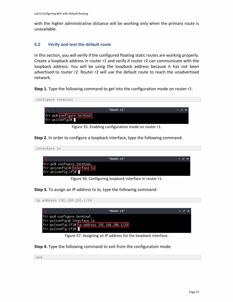
Lab 6 Configuring BGP with Default Routing
Page 27
with the higher administrative distance will be working only when the primary route is unavailable.
5.2 Verify and test the default route
In this section, you will verify if the configured floating static routes are working properly. Create a loopback address in router r1 and verify if router r2 can communicate with the loopback address. You will be using the loopback address because it has not been advertised to router r2. Router r2 will use the default route to reach the unadvertised network. Step 1. Type the following command to get into the configuration mode on router r1. configure terminal
Figure 55. Enabling configuration mode on router r1.
Step 2. In order to configure a loopback interface, type the following command: interface lo
Figure 56. Configuring loopback interface in router r1.
Step 3. To assign an IP address to lo, type the following command: ip address 192.168.100.1/24
Figure 57. Assigning an IP address for the loopback interface.
Step 4. Type the following command to exit from the configuration mode. end
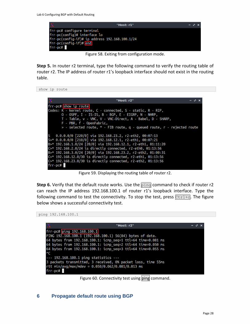
Lab 6 Configuring BGP with Default Routing
Page 28
Figure 58. Exiting from configuration mode.
Step 5. In router r2 terminal, type the following command to verify the routing table of router r2. The IP address of router r1’s loopback interface should not exist in the routing table. show ip route
Figure 59. Displaying the routing table of router r2.
Step 6. Verify that the default route works. Use the ping command to check if router r2 can reach the IP address 192.168.100.1 of router r1’s loopback interface. Type the following command to test the connectivity. To stop the test, press Ctrl+c. The figure below shows a successful connectivity test. ping 192.168.100.1
Figure 60. Connectivity test using ping command.
6 Propagate default route using BGP
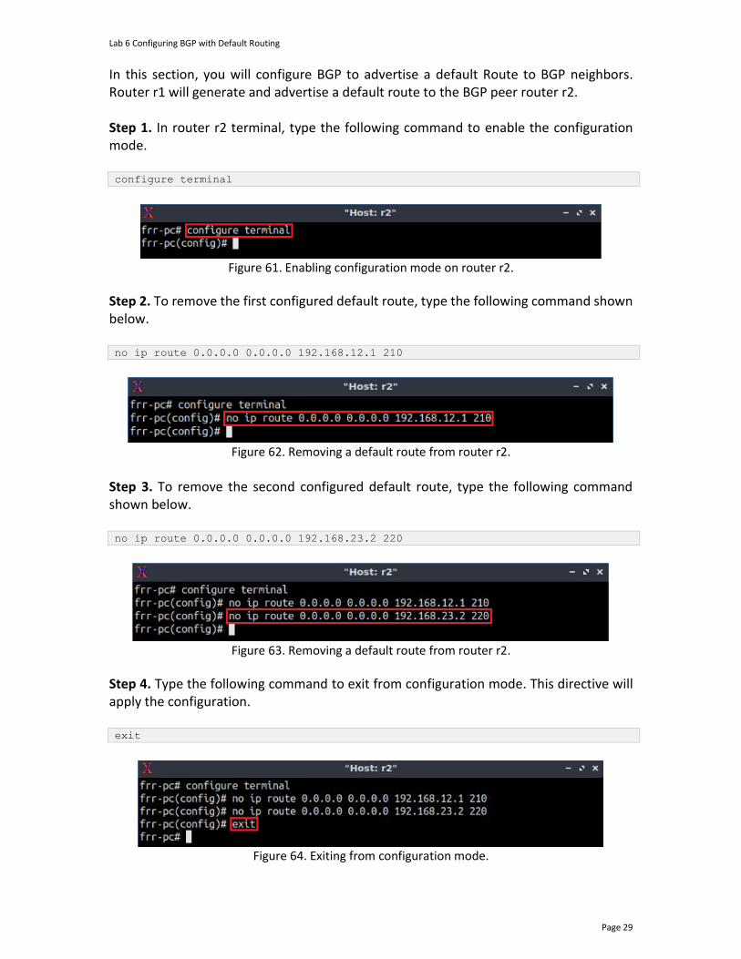
Lab 6 Configuring BGP with Default Routing
Page 29
In this section, you will configure BGP to advertise a default Route to BGP neighbors. Router r1 will generate and advertise a default route to the BGP peer router r2. Step 1. In router r2 terminal, type the following command to enable the configuration mode. configure terminal
Figure 61. Enabling configuration mode on router r2.
Step 2. To remove the first configured default route, type the following command shown below. no ip route 0.0.0.0 0.0.0.0 192.168.12.1 210
Figure 62. Removing a default route from router r2.
Step 3. To remove the second configured default route, type the following command shown below. no ip route 0.0.0.0 0.0.0.0 192.168.23.2 220
Figure 63. Removing a default route from router r2.
Step 4. Type the following command to exit from configuration mode. This directive will apply the configuration. exit
Figure 64. Exiting from configuration mode.
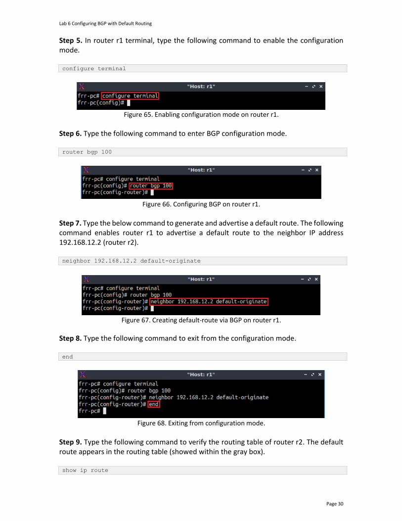
Lab 6 Configuring BGP with Default Routing
Page 30
Step 5. In router r1 terminal, type the following command to enable the configuration mode. configure terminal
Figure 65. Enabling configuration mode on router r1.
Step 6. Type the following command to enter BGP configuration mode. router bgp 100
Figure 66. Configuring BGP on router r1.
Step 7. Type the below command to generate and advertise a default route. The following command enables router r1 to advertise a default route to the neighbor IP address 192.168.12.2 (router r2). neighbor 192.168.12.2 default-originate
Figure 67. Creating default-route via BGP on router r1.
Step 8. Type the following command to exit from the configuration mode. end
Figure 68. Exiting from configuration mode.
Step 9. Type the following command to verify the routing table of router r2. The default route appears in the routing table (showed within the gray box). show ip route
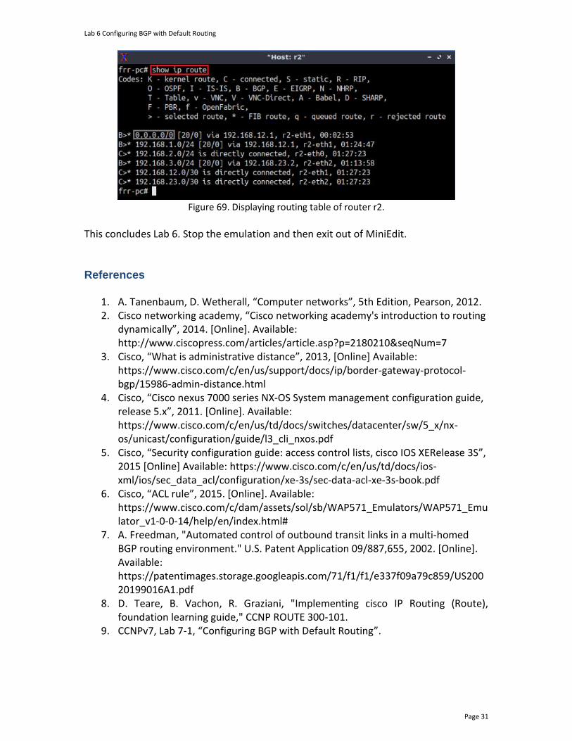
Lab 6 Configuring BGP with Default Routing
Page 31
Figure 69. Displaying routing table of router r2.
This concludes Lab 6. Stop the emulation and then exit out of MiniEdit. References
1. A. Tanenbaum, D. Wetherall, “Computer networks”, 5th Edition, Pearson, 2012. 2. Cisco networking academy, “Cisco networking academy's introduction to routing
dynamically”, 2014. [Online]. Available: http://www.ciscopress.com/articles/article.asp?p=2180210&seqNum=7
3. Cisco, “What is administrative distance”, 2013, [Online] Available: https://www.cisco.com/c/en/us/support/docs/ip/border-gateway-protocol-bgp/15986-admin-distance.html
4. Cisco, “Cisco nexus 7000 series NX-OS System management configuration guide, release 5.x”, 2011. [Online]. Available: https://www.cisco.com/c/en/us/td/docs/switches/datacenter/sw/5_x/nx-os/unicast/configuration/guide/l3_cli_nxos.pdf
5. Cisco, “Security configuration guide: access control lists, cisco IOS XERelease 3S”, 2015 [Online] Available: https://www.cisco.com/c/en/us/td/docs/ios-xml/ios/sec_data_acl/configuration/xe-3s/sec-data-acl-xe-3s-book.pdf
6. Cisco, “ACL rule”, 2015. [Online]. Available: https://www.cisco.com/c/dam/assets/sol/sb/WAP571_Emulators/WAP571_Emulator_v1-0-0-14/help/en/index.html#
7. A. Freedman, "Automated control of outbound transit links in a multi-homed BGP routing environment." U.S. Patent Application 09/887,655, 2002. [Online]. Available: https://patentimages.storage.googleapis.com/71/f1/f1/e337f09a79c859/US20020199016A1.pdf
8. D. Teare, B. Vachon, R. Graziani, "Implementing cisco IP Routing (Route), foundation learning guide," CCNP ROUTE 300-101.
9. CCNPv7, Lab 7-1, “Configuring BGP with Default Routing”.
BORDER GATEWAY PROTOCOL
Lab 7: Using AS_PATH BGP Attribute
Document Version: 05-25-2021
Award 1829698 “CyberTraining CIP: Cyberinfrastructure Expertise on High-throughput
Networks for Big Science Data Transfers”
Lab 7: Using AS_PATH BGP Attribute
Page 2
Contents Overview ............................................................................................................................. 3
Objectives............................................................................................................................ 3
Lab settings ......................................................................................................................... 3
Lab roadmap ....................................................................................................................... 3
1 Introduction ................................................................................................................ 4
1.1 Public and private ASN ......................................................................................... 4
1.2 AS_PATH attribute................................................................................................ 4
1.3 Removing private ASN in BGP .............................................................................. 5
1.4 Route filtering using AS_PATH attribute .............................................................. 5
2 Lab topology................................................................................................................ 6
2.1 Lab settings........................................................................................................... 7
2.2 Open the topology and load the configuration ................................................... 8
2.3 Load the zebra daemon and verify the connectivity ......................................... 10
3 Configure BGP on all routers .................................................................................... 15
4 Remove the private ASN ........................................................................................... 21
5 Use the AS_PATH attribute to filter routes .............................................................. 23
5.1 Configure AS_PATH ACL ..................................................................................... 23
5.2 Verify configuration............................................................................................ 25
References ........................................................................................................................ 27

Lab 7: Using AS_PATH BGP Attribute
Page 3
Overview This lab discusses public and private Autonomous System Numbers (ASNs) that are assigned to Autonomous Systems (ASes) in Border Gateway Protocol (BGP). Additionally, the lab introduces the BGP AS_PATH attribute and explains how to implement a policy that restricts network traffic using this attribute. In this lab, the terms BGP and External BGP (EBGP) will be used interchangeably since they will only be running between ASes. This lab is based on the Cisco Certified Network Professional (CCNP) ROUTE Version 7 training, laboratory 7-210. While this laboratory material uses FRR as the router (which includes the routing protocols) and Linux as the control plane operating system, vendors’ operating systems such as Cisco have similar functionality. Objectives By the end of this lab, you should be able to:
1. Explain the concept of public and private ASN. 2. Configure and verify BGP between two ASes. 3. Remove private ASNs from AS_PATH attribute. 4. Use the AS_PATH attribute to filter BGP routes.
Lab settings The information in Table 1 provides the credentials to access the Client machine.
Table 1. Credentials to access the Client machine.
Device
Account
Password
Client admin password
Lab roadmap This lab is organized as follows:
1. Section 1: Introduction. 2. Section 2: Lab topology. 3. Section 3: Configure BGP on all routers. 4. Section 4: Remove the private ASN. 5. Section 5: Use the AS_PATH attribute to filter routes.
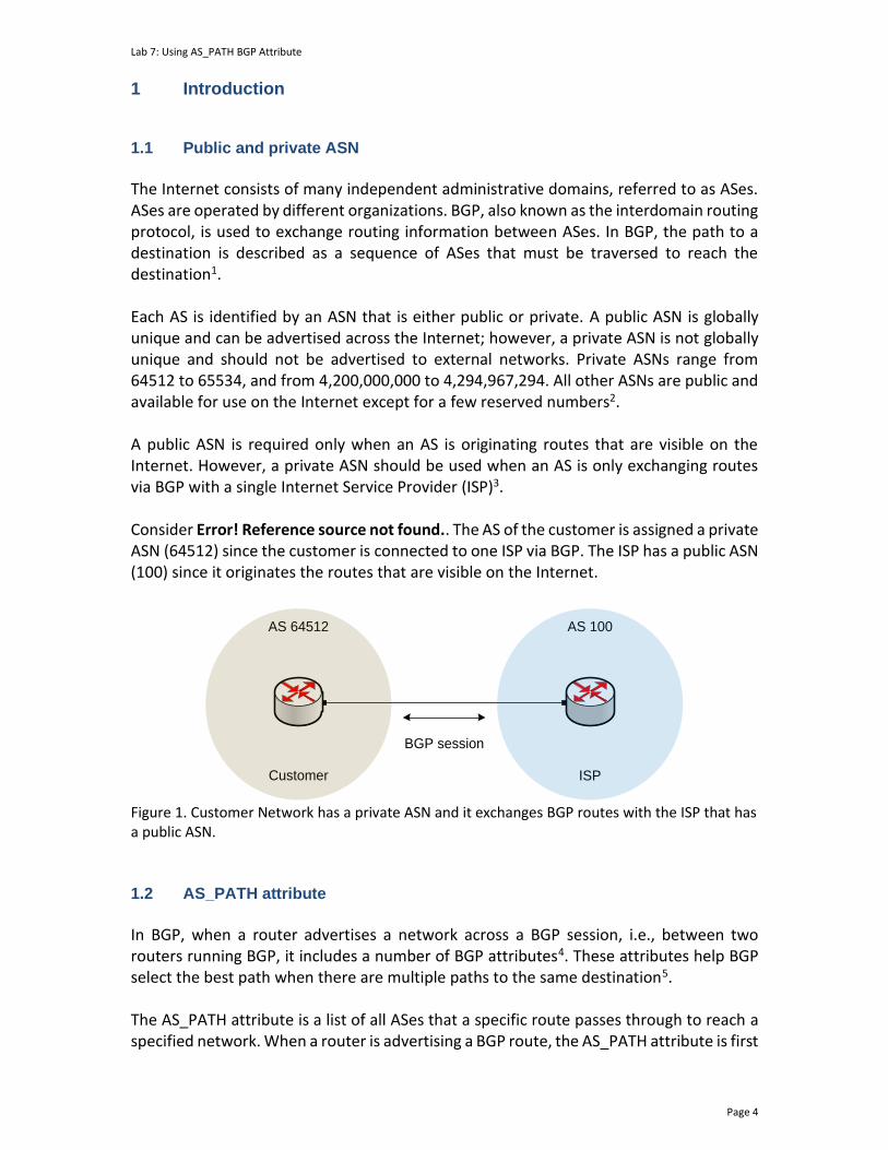
Lab 7: Using AS_PATH BGP Attribute
Page 4
1 Introduction 1.1 Public and private ASN
The Internet consists of many independent administrative domains, referred to as ASes. ASes are operated by different organizations. BGP, also known as the interdomain routing protocol, is used to exchange routing information between ASes. In BGP, the path to a destination is described as a sequence of ASes that must be traversed to reach the destination1. Each AS is identified by an ASN that is either public or private. A public ASN is globally unique and can be advertised across the Internet; however, a private ASN is not globally unique and should not be advertised to external networks. Private ASNs range from 64512 to 65534, and from 4,200,000,000 to 4,294,967,294. All other ASNs are public and available for use on the Internet except for a few reserved numbers2. A public ASN is required only when an AS is originating routes that are visible on the Internet. However, a private ASN should be used when an AS is only exchanging routes via BGP with a single Internet Service Provider (ISP)3. Consider Error! Reference source not found.. The AS of the customer is assigned a private ASN (64512) since the customer is connected to one ISP via BGP. The ISP has a public ASN (100) since it originates the routes that are visible on the Internet.
AS 64512 AS 100
Customer ISP
BGP session
Figure 1. Customer Network has a private ASN and it exchanges BGP routes with the ISP that has a public ASN.
1.2 AS_PATH attribute
In BGP, when a router advertises a network across a BGP session, i.e., between two routers running BGP, it includes a number of BGP attributes4. These attributes help BGP select the best path when there are multiple paths to the same destination5. The AS_PATH attribute is a list of all ASes that a specific route passes through to reach a specified network. When a router is advertising a BGP route, the AS_PATH attribute is first
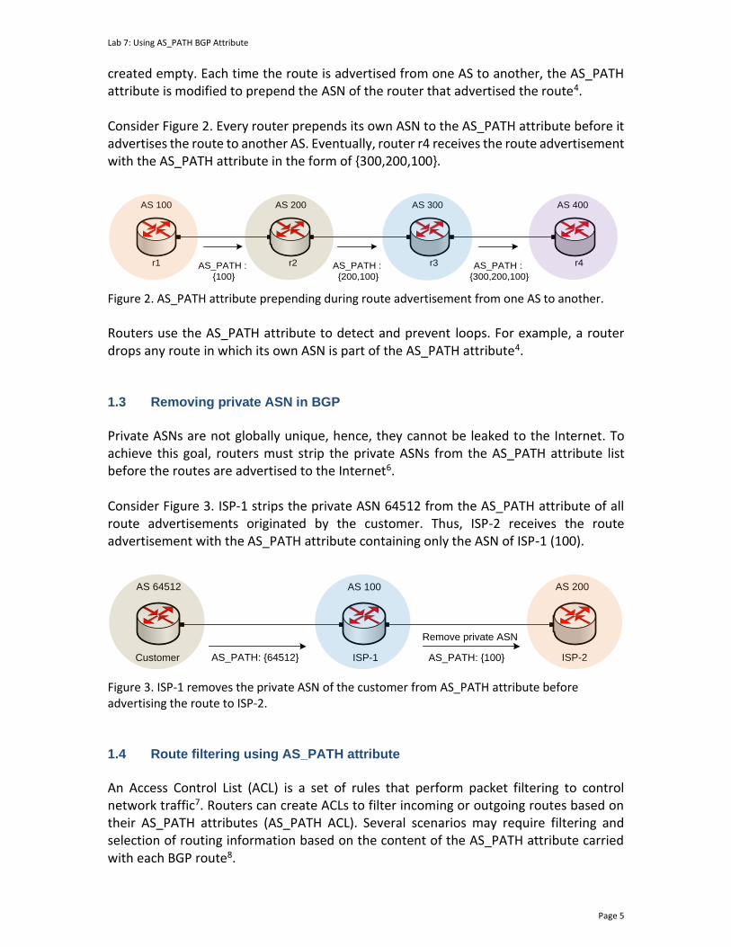
Lab 7: Using AS_PATH BGP Attribute
Page 5
created empty. Each time the route is advertised from one AS to another, the AS_PATH attribute is modified to prepend the ASN of the router that advertised the route4. Consider Figure 2. Every router prepends its own ASN to the AS_PATH attribute before it advertises the route to another AS. Eventually, router r4 receives the route advertisement with the AS_PATH attribute in the form of {300,200,100}.
AS 100 AS 200 AS 300 AS 400
AS_PATH :
{100}
AS_PATH :
{200,100}
AS_PATH :
{300,200,100}
r1 r2 r3 r4
Figure 2. AS_PATH attribute prepending during route advertisement from one AS to another.
Routers use the AS_PATH attribute to detect and prevent loops. For example, a router drops any route in which its own ASN is part of the AS_PATH attribute4. 1.3 Removing private ASN in BGP
Private ASNs are not globally unique, hence, they cannot be leaked to the Internet. To achieve this goal, routers must strip the private ASNs from the AS_PATH attribute list before the routes are advertised to the Internet6. Consider Figure 3. ISP-1 strips the private ASN 64512 from the AS_PATH attribute of all route advertisements originated by the customer. Thus, ISP-2 receives the route advertisement with the AS_PATH attribute containing only the ASN of ISP-1 (100).
AS 64512 AS 100
Customer ISP-1
AS 200
ISP-2AS_PATH: {64512}
Remove private ASN
AS_PATH: {100}
Figure 3. ISP-1 removes the private ASN of the customer from AS_PATH attribute before advertising the route to ISP-2.
1.4 Route filtering using AS_PATH attribute
An Access Control List (ACL) is a set of rules that perform packet filtering to control network traffic7. Routers can create ACLs to filter incoming or outgoing routes based on their AS_PATH attributes (AS_PATH ACL). Several scenarios may require filtering and selection of routing information based on the content of the AS_PATH attribute carried with each BGP route8.
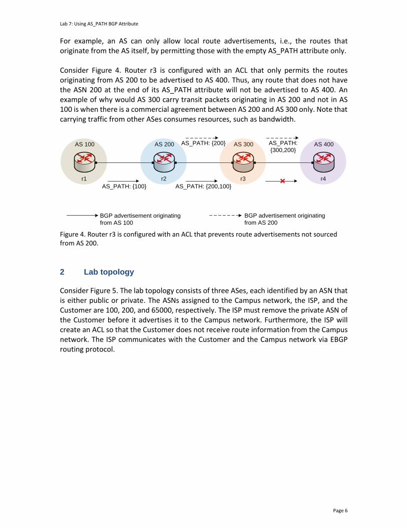
Lab 7: Using AS_PATH BGP Attribute
Page 6
For example, an AS can only allow local route advertisements, i.e., the routes that originate from the AS itself, by permitting those with the empty AS_PATH attribute only. Consider Figure 4. Router r3 is configured with an ACL that only permits the routes originating from AS 200 to be advertised to AS 400. Thus, any route that does not have the ASN 200 at the end of its AS_PATH attribute will not be advertised to AS 400. An example of why would AS 300 carry transit packets originating in AS 200 and not in AS 100 is when there is a commercial agreement between AS 200 and AS 300 only. Note that carrying traffic from other ASes consumes resources, such as bandwidth.
AS 100
r1
AS 200
r2
AS 300
r3
AS 400
r4
AS_PATH: {100} AS_PATH: {200,100}
AS_PATH: {200} AS_PATH:
{300,200}
BGP advertisement originating
from AS 100
BGP advertisement originating
from AS 200
Figure 4. Router r3 is configured with an ACL that prevents route advertisements not sourced from AS 200.
2 Lab topology Consider Figure 5. The lab topology consists of three ASes, each identified by an ASN that is either public or private. The ASNs assigned to the Campus network, the ISP, and the Customer are 100, 200, and 65000, respectively. The ISP must remove the private ASN of the Customer before it advertises it to the Campus network. Furthermore, the ISP will create an ACL so that the Customer does not receive route information from the Campus network. The ISP communicates with the Customer and the Campus network via EBGP routing protocol.

Lab 7: Using AS_PATH BGP Attribute
Page 7
s2
s1 s3
h1
h2
h3
r1r3
Campus network
r1-eth1
r2-eth1
h1-eth0
s1-eth2
s1-eth1
r1-eth0
h2-eth0
s2-eth1
s2-eth2
r2-eth0
r2-eth2
r3-eth1
r3-eth0
s3-eth2
s3-eth1
h3-eth0
AS 200
AS 100 AS 65000
.10
.1
.1
.2 .1
.2
.1
.10
.1
.10
192.168.1.0/24 192.168.3.0/24
192.168.2.0/24
Customer
ISP
r2EBGP EBGP
Figure 5. Lab topology.
2.1 Lab settings
Routers and hosts are already configured according to the IP addresses shown in Table 2.
Table 2. Topology information.
Device Interface IIPV4 Address Subnet Default gateway
r1 (Campus network)
r1-eth0 192.168.1.1 /24 N/A
r1-eth1 192.168.12.1 /30 N/A
r2 (ISP)
r2-eth0 192.168.2.1 /24 N/A
r2-eth1 192.168.12.2 /30 N/A
r2-eth2 192.168.23.1 /30 N/A
r3 (Customer)
r3-eth0 192.168.3.1 /24 N/A
r3-eth1 192.168.23.2 /30 N/A
h1 h1-eth0 192.168.1.10 /24 192.168.1.1
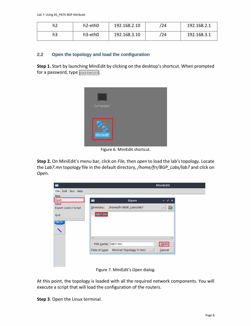
Lab 7: Using AS_PATH BGP Attribute
Page 8
h2 h2-eth0 192.168.2.10 /24 192.168.2.1
h3 h3-eth0 192.168.3.10 /24 192.168.3.1
2.2 Open the topology and load the configuration
Step 1. Start by launching MiniEdit by clicking on the desktop’s shortcut. When prompted for a password, type password.
Figure 6. MiniEdit shortcut.
Step 2. On MiniEdit’s menu bar, click on File, then open to load the lab’s topology. Locate the Lab7.mn topology file in the default directory, /home/frr/BGP_Labs/lab7 and click on Open.
Figure 7. MiniEdit’s Open dialog.
At this point, the topology is loaded with all the required network components. You will execute a script that will load the configuration of the routers. Step 3. Open the Linux terminal.
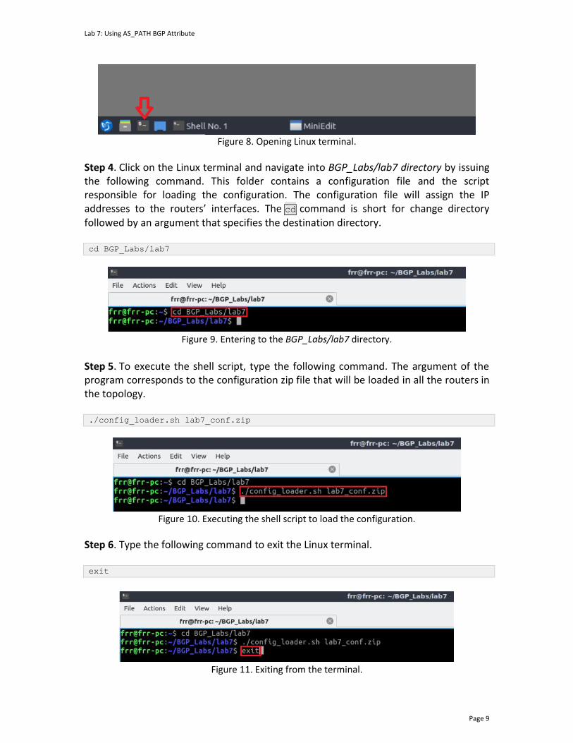
Lab 7: Using AS_PATH BGP Attribute
Page 9
Figure 8. Opening Linux terminal.
Step 4. Click on the Linux terminal and navigate into BGP_Labs/lab7 directory by issuing the following command. This folder contains a configuration file and the script responsible for loading the configuration. The configuration file will assign the IP addresses to the routers’ interfaces. The cd command is short for change directory followed by an argument that specifies the destination directory. cd BGP_Labs/lab7
Figure 9. Entering to the BGP_Labs/lab7 directory.
Step 5. To execute the shell script, type the following command. The argument of the program corresponds to the configuration zip file that will be loaded in all the routers in the topology. ./config_loader.sh lab7_conf.zip
Figure 10. Executing the shell script to load the configuration.
Step 6. Type the following command to exit the Linux terminal. exit
Figure 11. Exiting from the terminal.
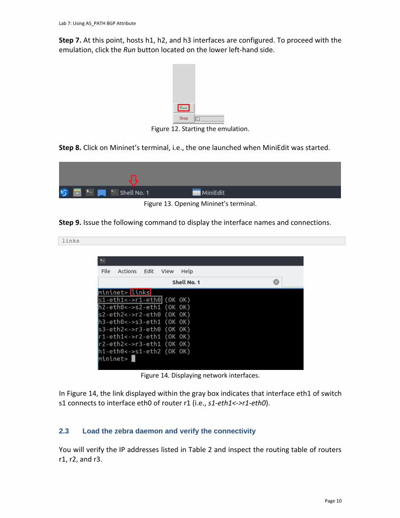
Lab 7: Using AS_PATH BGP Attribute
Page 10
Step 7. At this point, hosts h1, h2, and h3 interfaces are configured. To proceed with the emulation, click the Run button located on the lower left-hand side.
Figure 12. Starting the emulation.
Step 8. Click on Mininet’s terminal, i.e., the one launched when MiniEdit was started.
Figure 13. Opening Mininet’s terminal.
Step 9. Issue the following command to display the interface names and connections. links
Figure 14. Displaying network interfaces.
In Figure 14, the link displayed within the gray box indicates that interface eth1 of switch s1 connects to interface eth0 of router r1 (i.e., s1-eth1<->r1-eth0). 2.3 Load the zebra daemon and verify the connectivity
You will verify the IP addresses listed in Table 2 and inspect the routing table of routers r1, r2, and r3.

Lab 7: Using AS_PATH BGP Attribute
Page 11
Step 1. Hold right-click on host h1 and select Terminal. This opens the terminal of host h1 and allows the execution of commands on that host.
Figure 15. Opening a terminal on host h1.
Step 2. On host h1 terminal, type the command shown below to verify that the IP address was assigned successfully. You will verify that host h1 has two interfaces. Interface h1-eth0 is configured with the IP address 192.168.1.10 with the subnet mask of 255.255.255.0. The loopback interface lo, is configured with the IP address of 127.0.0.1. ifconfig
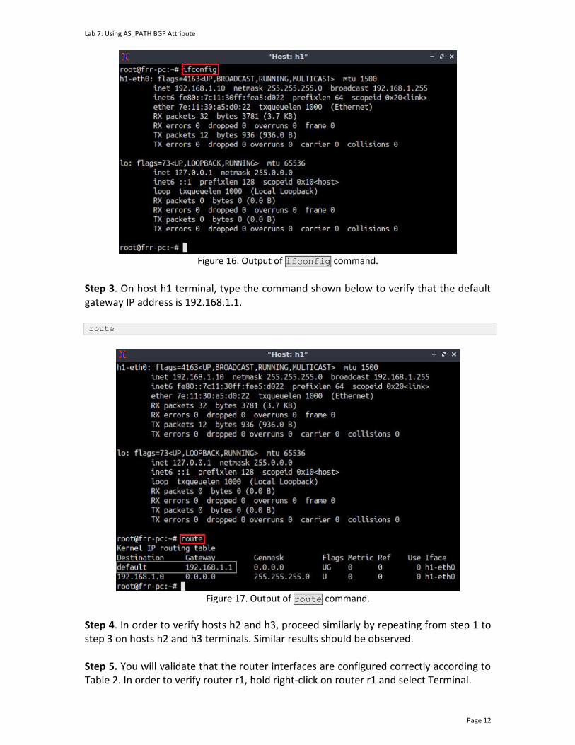
Lab 7: Using AS_PATH BGP Attribute
Page 12
Figure 16. Output of ifconfig command.
Step 3. On host h1 terminal, type the command shown below to verify that the default gateway IP address is 192.168.1.1. route
Figure 17. Output of route command.
Step 4. In order to verify hosts h2 and h3, proceed similarly by repeating from step 1 to step 3 on hosts h2 and h3 terminals. Similar results should be observed. Step 5. You will validate that the router interfaces are configured correctly according to Table 2. In order to verify router r1, hold right-click on router r1 and select Terminal.
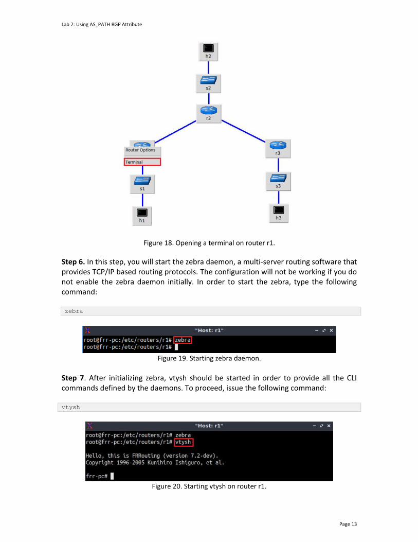
Lab 7: Using AS_PATH BGP Attribute
Page 13
Figure 18. Opening a terminal on router r1.
Step 6. In this step, you will start the zebra daemon, a multi-server routing software that provides TCP/IP based routing protocols. The configuration will not be working if you do not enable the zebra daemon initially. In order to start the zebra, type the following command: zebra
Figure 19. Starting zebra daemon.
Step 7. After initializing zebra, vtysh should be started in order to provide all the CLI commands defined by the daemons. To proceed, issue the following command: vtysh
Figure 20. Starting vtysh on router r1.
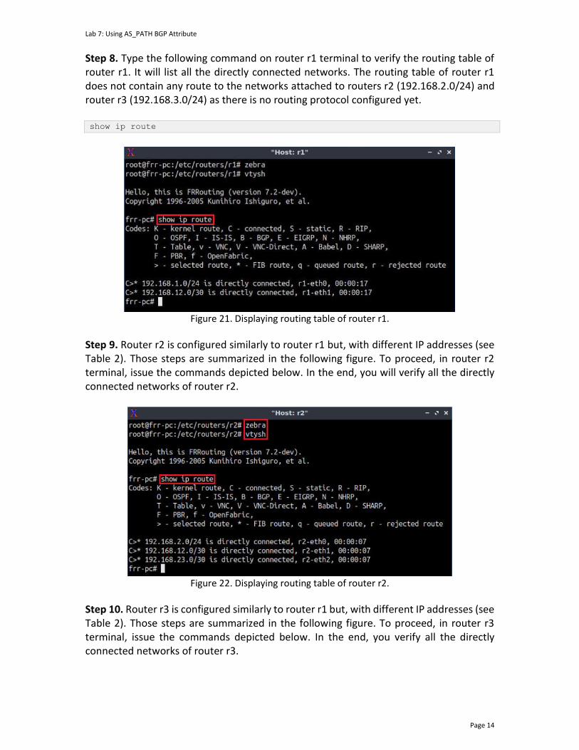
Lab 7: Using AS_PATH BGP Attribute
Page 14
Step 8. Type the following command on router r1 terminal to verify the routing table of router r1. It will list all the directly connected networks. The routing table of router r1 does not contain any route to the networks attached to routers r2 (192.168.2.0/24) and router r3 (192.168.3.0/24) as there is no routing protocol configured yet. show ip route
Figure 21. Displaying routing table of router r1.
Step 9. Router r2 is configured similarly to router r1 but, with different IP addresses (see Table 2). Those steps are summarized in the following figure. To proceed, in router r2 terminal, issue the commands depicted below. In the end, you will verify all the directly connected networks of router r2.
Figure 22. Displaying routing table of router r2.
Step 10. Router r3 is configured similarly to router r1 but, with different IP addresses (see Table 2). Those steps are summarized in the following figure. To proceed, in router r3 terminal, issue the commands depicted below. In the end, you verify all the directly connected networks of router r3.
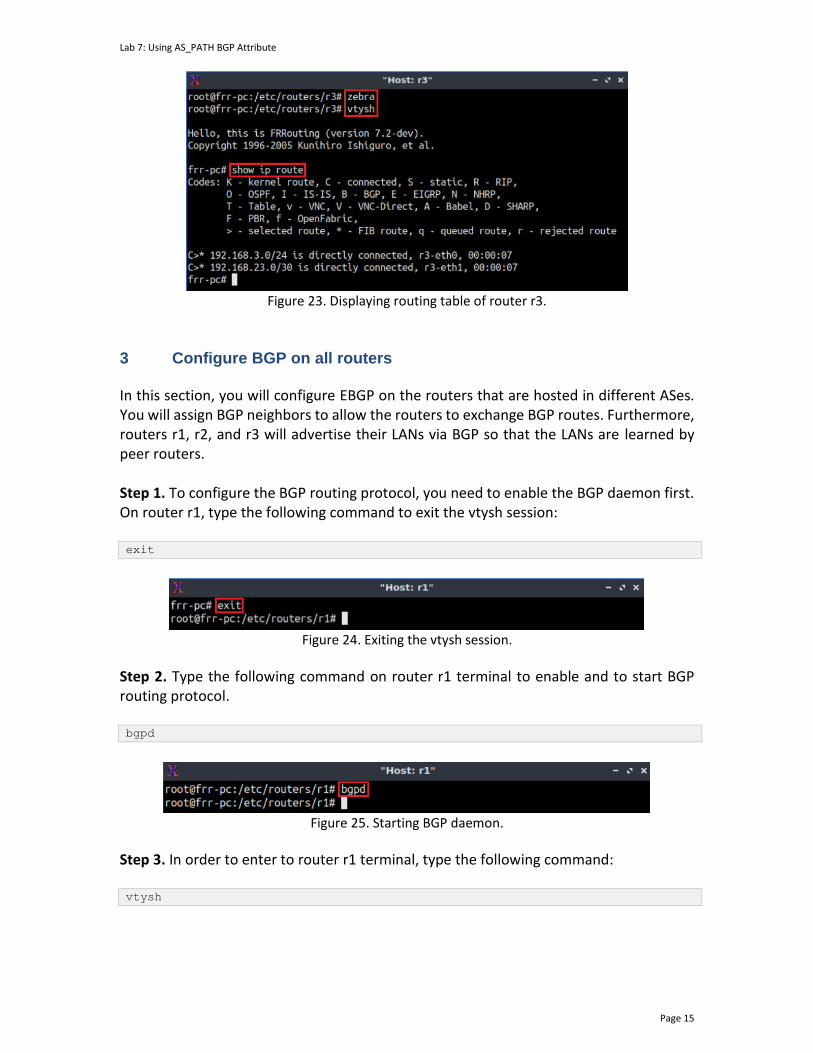
Lab 7: Using AS_PATH BGP Attribute
Page 15
Figure 23. Displaying routing table of router r3.
3 Configure BGP on all routers In this section, you will configure EBGP on the routers that are hosted in different ASes. You will assign BGP neighbors to allow the routers to exchange BGP routes. Furthermore, routers r1, r2, and r3 will advertise their LANs via BGP so that the LANs are learned by peer routers. Step 1. To configure the BGP routing protocol, you need to enable the BGP daemon first. On router r1, type the following command to exit the vtysh session: exit
Figure 24. Exiting the vtysh session.
Step 2. Type the following command on router r1 terminal to enable and to start BGP routing protocol. bgpd
Figure 25. Starting BGP daemon.
Step 3. In order to enter to router r1 terminal, type the following command: vtysh
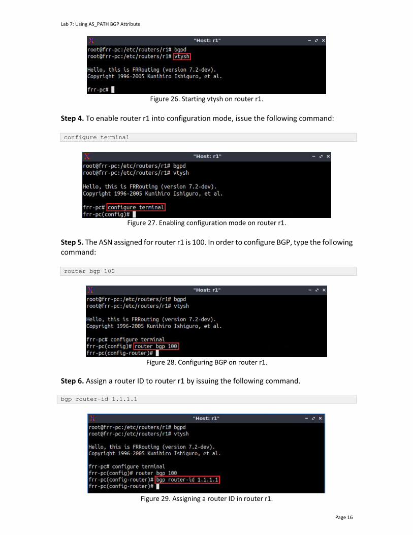
Lab 7: Using AS_PATH BGP Attribute
Page 16
Figure 26. Starting vtysh on router r1.
Step 4. To enable router r1 into configuration mode, issue the following command: configure terminal
Figure 27. Enabling configuration mode on router r1.
Step 5. The ASN assigned for router r1 is 100. In order to configure BGP, type the following command: router bgp 100
Figure 28. Configuring BGP on router r1.
Step 6. Assign a router ID to router r1 by issuing the following command. bgp router-id 1.1.1.1
Figure 29. Assigning a router ID in router r1.

Lab 7: Using AS_PATH BGP Attribute
Page 17
Step 7. To configure a BGP neighbor to router r1 (AS 100), type the command shown below. This command specifies the neighbor IP address (192.168.12.2) and the ASN of the remote BGP peer (AS 200). neighbor 192.168.12.2 remote-as 200
Figure 30. Assigning BGP neighbor to router r1.
Step 8. In this step, router r1 will advertise the LAN 192.168.1.0/24 to its BGP peers. To do so, issue the following command: network 192.168.1.0/24
Figure 31. Advertising local network on router r1.
Step 9. Type the following command to exit from configuration mode. end
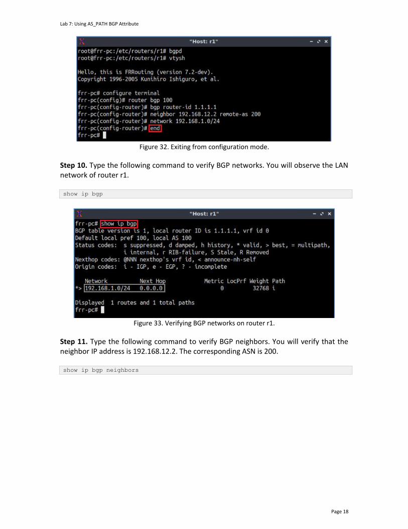
Lab 7: Using AS_PATH BGP Attribute
Page 18
Figure 32. Exiting from configuration mode.
Step 10. Type the following command to verify BGP networks. You will observe the LAN network of router r1. show ip bgp
Figure 33. Verifying BGP networks on router r1.
Step 11. Type the following command to verify BGP neighbors. You will verify that the neighbor IP address is 192.168.12.2. The corresponding ASN is 200. show ip bgp neighbors
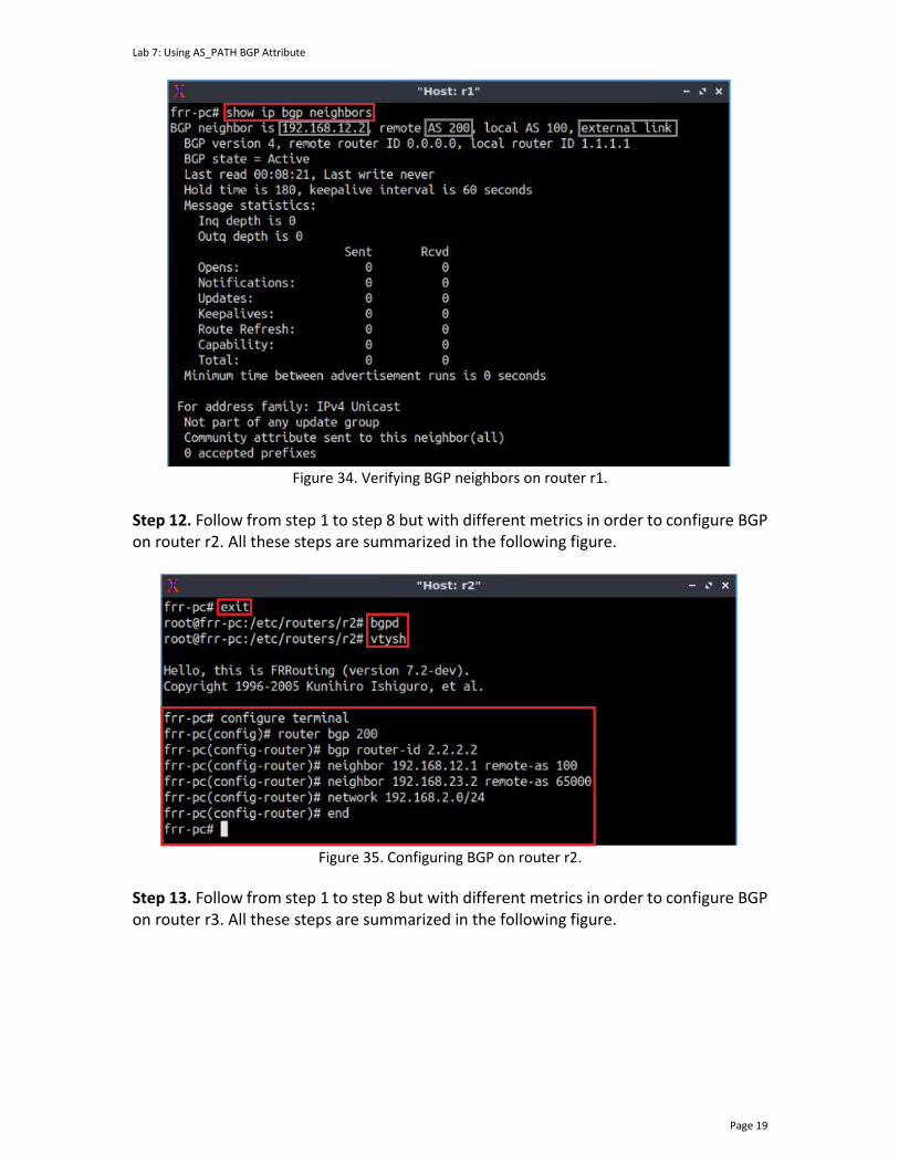
Lab 7: Using AS_PATH BGP Attribute
Page 19
Figure 34. Verifying BGP neighbors on router r1.
Step 12. Follow from step 1 to step 8 but with different metrics in order to configure BGP on router r2. All these steps are summarized in the following figure.
Figure 35. Configuring BGP on router r2.
Step 13. Follow from step 1 to step 8 but with different metrics in order to configure BGP on router r3. All these steps are summarized in the following figure.
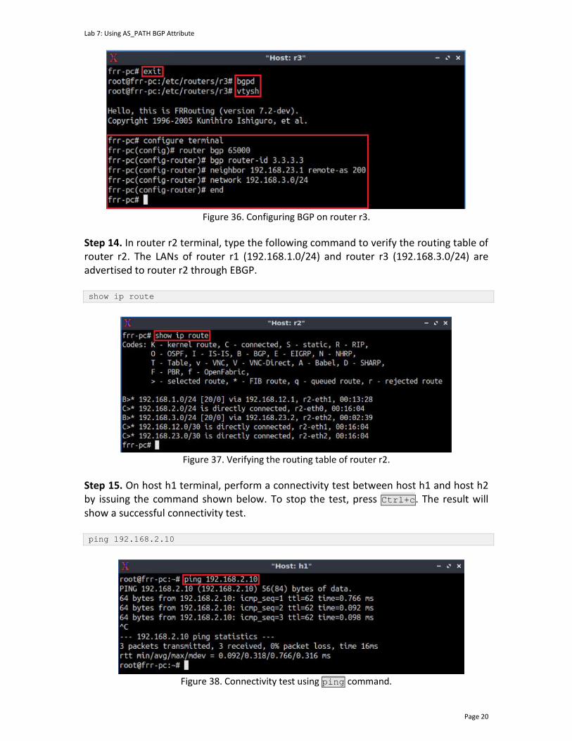
Lab 7: Using AS_PATH BGP Attribute
Page 20
Figure 36. Configuring BGP on router r3.
Step 14. In router r2 terminal, type the following command to verify the routing table of router r2. The LANs of router r1 (192.168.1.0/24) and router r3 (192.168.3.0/24) are advertised to router r2 through EBGP. show ip route
Figure 37. Verifying the routing table of router r2.
Step 15. On host h1 terminal, perform a connectivity test between host h1 and host h2 by issuing the command shown below. To stop the test, press Ctrl+c. The result will show a successful connectivity test. ping 192.168.2.10
Figure 38. Connectivity test using ping command.

Lab 7: Using AS_PATH BGP Attribute
Page 21
Step 16. Test the connectivity between the end-hosts using the ping command. On host h1, type the command specified below. This command tests the connectivity between host h1 and host h3. To stop the test, press Ctrl+c. The figure below shows a successful connectivity test. ping 192.168.3.10
Figure 39. Connectivity test using ping command.
4 Remove the private ASN
BGP private ASNs are not globally unique. If a BGP router receives a route in which its own ASN is part of the AS_PATH attribute, it does not accept the route. ISP needs to ensure that it removes private ASNs from BGP updates to EBGP peers when announcing routing information across the Internet.
Step 1. Type the following command to verify the BGP table of router r1. ASN 65000 is listed in the path to network 192.168.3.0/24. If routers r1 and r3 are within two separate ASes that have the same private ASN, then no connectivity would have been established. show ip bgp
Figure 40. Verifying BGP table of router r1.
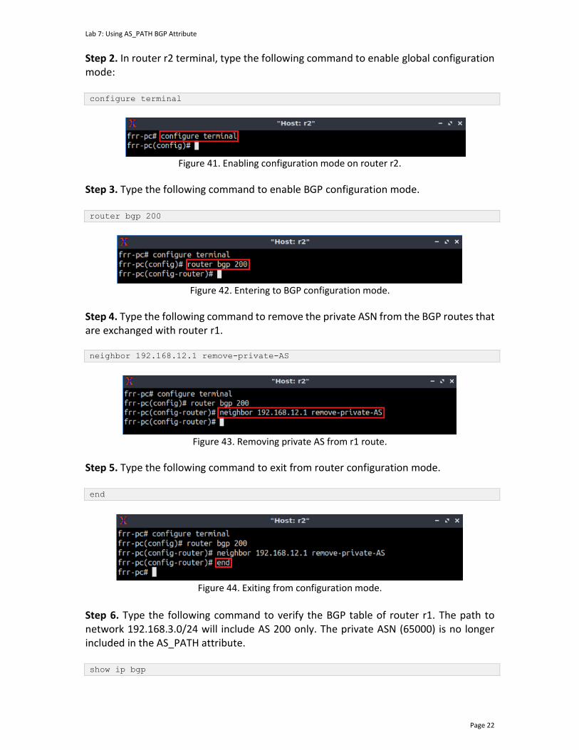
Lab 7: Using AS_PATH BGP Attribute
Page 22
Step 2. In router r2 terminal, type the following command to enable global configuration mode: configure terminal
Figure 41. Enabling configuration mode on router r2.
Step 3. Type the following command to enable BGP configuration mode. router bgp 200
Figure 42. Entering to BGP configuration mode.
Step 4. Type the following command to remove the private ASN from the BGP routes that are exchanged with router r1. neighbor 192.168.12.1 remove-private-AS
Figure 43. Removing private AS from r1 route.
Step 5. Type the following command to exit from router configuration mode. end
Figure 44. Exiting from configuration mode.
Step 6. Type the following command to verify the BGP table of router r1. The path to network 192.168.3.0/24 will include AS 200 only. The private ASN (65000) is no longer included in the AS_PATH attribute. show ip bgp
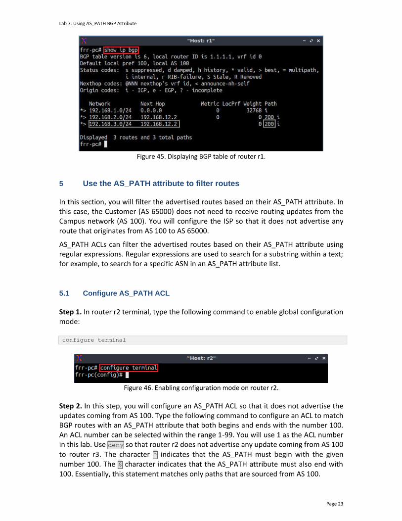
Lab 7: Using AS_PATH BGP Attribute
Page 23
Figure 45. Displaying BGP table of router r1.
5 Use the AS_PATH attribute to filter routes
In this section, you will filter the advertised routes based on their AS_PATH attribute. In this case, the Customer (AS 65000) does not need to receive routing updates from the Campus network (AS 100). You will configure the ISP so that it does not advertise any route that originates from AS 100 to AS 65000.
AS_PATH ACLs can filter the advertised routes based on their AS_PATH attribute using regular expressions. Regular expressions are used to search for a substring within a text; for example, to search for a specific ASN in an AS_PATH attribute list.
5.1 Configure AS_PATH ACL
Step 1. In router r2 terminal, type the following command to enable global configuration mode: configure terminal
Figure 46. Enabling configuration mode on router r2.
Step 2. In this step, you will configure an AS_PATH ACL so that it does not advertise the updates coming from AS 100. Type the following command to configure an ACL to match BGP routes with an AS_PATH attribute that both begins and ends with the number 100. An ACL number can be selected within the range 1-99. You will use 1 as the ACL number in this lab. Use deny so that router r2 does not advertise any update coming from AS 100 to router r3. The character ^ indicates that the AS_PATH must begin with the given number 100. The $ character indicates that the AS_PATH attribute must also end with 100. Essentially, this statement matches only paths that are sourced from AS 100.
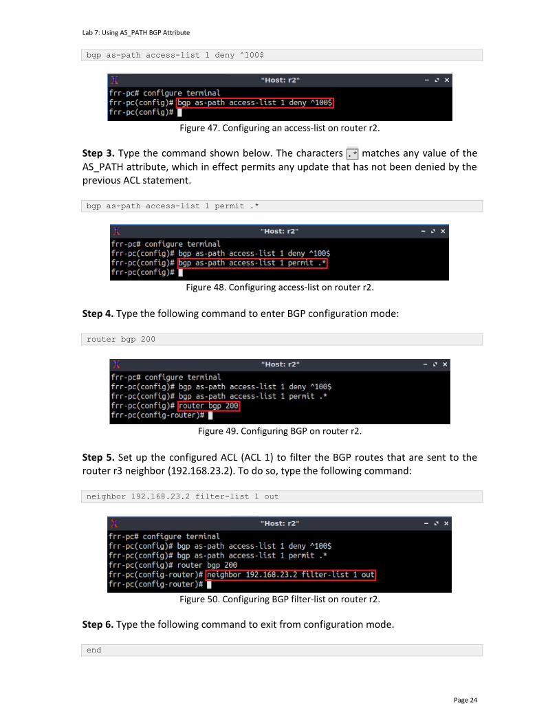
Lab 7: Using AS_PATH BGP Attribute
Page 24
bgp as-path access-list 1 deny ^100$
Figure 47. Configuring an access-list on router r2.
Step 3. Type the command shown below. The characters .* matches any value of the AS_PATH attribute, which in effect permits any update that has not been denied by the previous ACL statement. bgp as-path access-list 1 permit .*
Figure 48. Configuring access-list on router r2.
Step 4. Type the following command to enter BGP configuration mode: router bgp 200
Figure 49. Configuring BGP on router r2.
Step 5. Set up the configured ACL (ACL 1) to filter the BGP routes that are sent to the router r3 neighbor (192.168.23.2). To do so, type the following command: neighbor 192.168.23.2 filter-list 1 out
Figure 50. Configuring BGP filter-list on router r2.
Step 6. Type the following command to exit from configuration mode. end
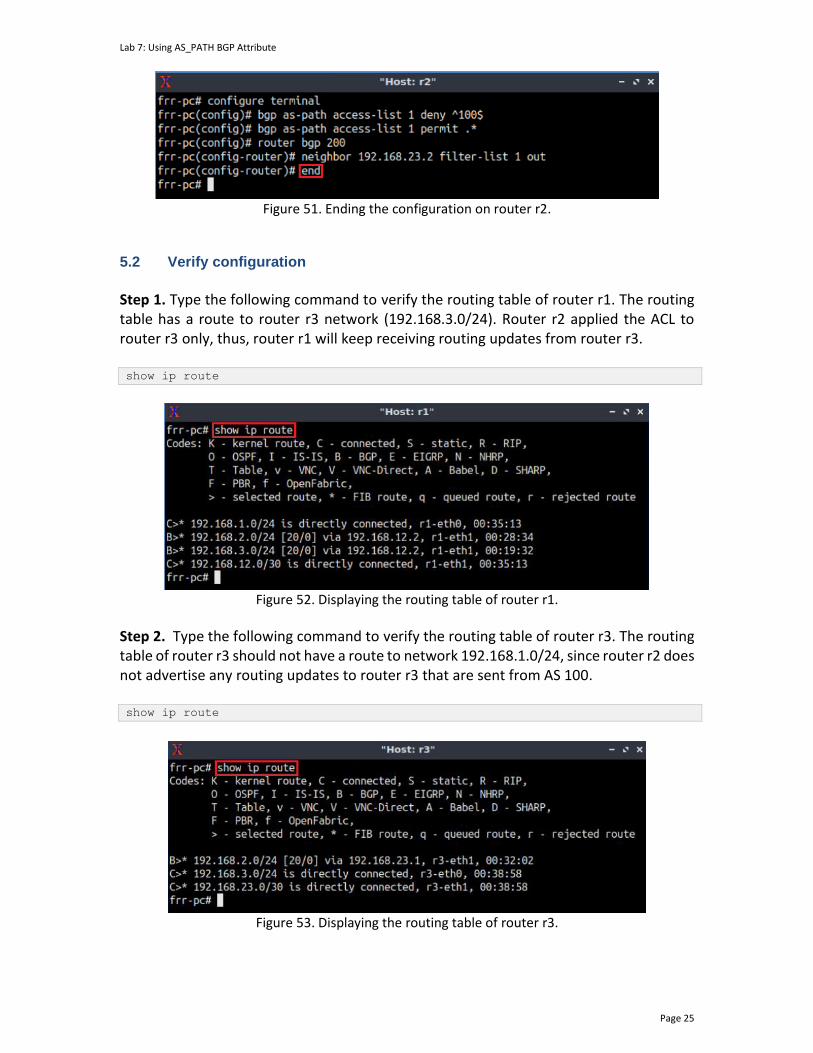
Lab 7: Using AS_PATH BGP Attribute
Page 25
Figure 51. Ending the configuration on router r2.
5.2 Verify configuration
Step 1. Type the following command to verify the routing table of router r1. The routing table has a route to router r3 network (192.168.3.0/24). Router r2 applied the ACL to router r3 only, thus, router r1 will keep receiving routing updates from router r3. show ip route
Figure 52. Displaying the routing table of router r1.
Step 2. Type the following command to verify the routing table of router r3. The routing table of router r3 should not have a route to network 192.168.1.0/24, since router r2 does not advertise any routing updates to router r3 that are sent from AS 100. show ip route
Figure 53. Displaying the routing table of router r3.
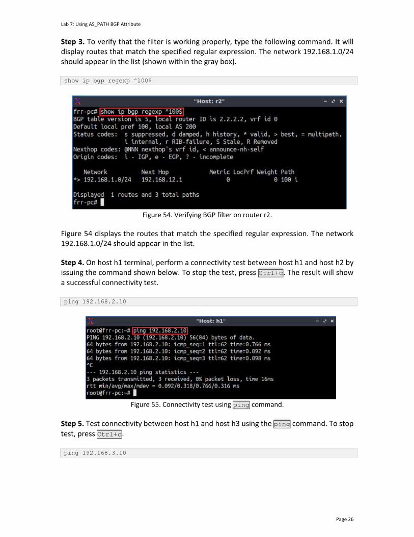
Lab 7: Using AS_PATH BGP Attribute
Page 26
Step 3. To verify that the filter is working properly, type the following command. It will display routes that match the specified regular expression. The network 192.168.1.0/24 should appear in the list (shown within the gray box). show ip bgp regexp ^100$
Figure 54. Verifying BGP filter on router r2.
Figure 54 displays the routes that match the specified regular expression. The network 192.168.1.0/24 should appear in the list.
Step 4. On host h1 terminal, perform a connectivity test between host h1 and host h2 by issuing the command shown below. To stop the test, press Ctrl+c. The result will show a successful connectivity test. ping 192.168.2.10
Figure 55. Connectivity test using ping command.
Step 5. Test connectivity between host h1 and host h3 using the ping command. To stop test, press Ctrl+c. ping 192.168.3.10

Lab 7: Using AS_PATH BGP Attribute
Page 27
Figure 56. Connectivity test using ping command.
Consider Figure 56. Router r1 does have a route to 192.168.3.0/24 so host h1 echo request is reaching host h3. The echo reply from host h3 to host h1 is not successful because router r3 does not have a route to 192.168.1.0/24 due to the configured route filter.
This concludes Lab 7. Stop the emulation and then exit out of MiniEdit. References
1. G. Huston, “Exploring autonomous system numbers”, 2005, [Online] Available: http://wattle.apnic.net/ispcol/2005-08/as.pdf
2. IANA, “Special-purpose autonomous system (AS) numbers”, 2015, [Online] Available: https://www.iana.org/assignments/iana-as-numbers-special-registry/iana-as-numbers-special-registry.xhtml
3. APNIC, “Autonomous system numbers - FAQs”, 2020, [Online] Available: https://www.apnic.net/get-ip/faqs/asn/
4. J. Kurose, K. Ross, “Computer networking, a top-down approach,” 7th Edition, Pearson, 2017.
5. Cisco, “BGP best path selection algorithm”, 2016, [Online] Available: https://www.cisco.com/c/en/us/support/docs/ip/border-gateway-protocol-bgp/13753-25.html#anc2
6. Cisco, “Removing private autonomous system numbers in BGP”, [Online] Available: https://www.cisco.com/c/en/us/support/docs/ip/border-gateway-protocol-bgp/13756-32.html
7. Cisco, “Security configuration guide: access control lists, Cisco IOS XERelease 3S”, 2015 [Online] Available: https://www.cisco.com/c/en/us/td/docs/ios-xml/ios/sec_data_acl/configuration/xe-3s/sec-data-acl-xe-3s-book.pdf
8. Cisco, “Implementing cisco IP routing (ROUTE) foundation learning guide”, Pearson, 2015.
9. D. Teare, B. Vachon, R. Graziani, "Implementing cisco IP Routing (Route), foundation learning guide," CCNP ROUTE 300-101.
10. CCNP, Lab 7-2, “Using AS_PATH BGP Attribute”.
BORDER GATEWAY PROTOCOL
Exercise 2: Controlling Traffic using BGP AS_PATH Attribute
Document Version: 09-02-2021
Award 1829698 “CyberTraining CIP: Cyberinfrastructure Expertise on High-throughput
Networks for Big Science Data Transfers”
Exercise 2: Controlling Traffic using BGP AS_PATH Attribute
Contents 1 Exercise description .................................................................................................... 3
1.1 Topology settings ................................................................................................. 3
1.2 Credentials ........................................................................................................... 4
2 Deliverables ................................................................................................................. 4
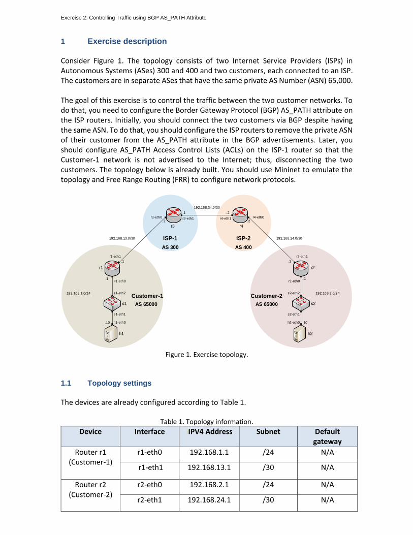
Exercise 2: Controlling Traffic using BGP AS_PATH Attribute
1 Exercise description Consider Figure 1. The topology consists of two Internet Service Providers (ISPs) in Autonomous Systems (ASes) 300 and 400 and two customers, each connected to an ISP. The customers are in separate ASes that have the same private AS Number (ASN) 65,000. The goal of this exercise is to control the traffic between the two customer networks. To do that, you need to configure the Border Gateway Protocol (BGP) AS_PATH attribute on the ISP routers. Initially, you should connect the two customers via BGP despite having the same ASN. To do that, you should configure the ISP routers to remove the private ASN of their customer from the AS_PATH attribute in the BGP advertisements. Later, you should configure AS_PATH Access Control Lists (ACLs) on the ISP-1 router so that the Customer-1 network is not advertised to the Internet; thus, disconnecting the two customers. The topology below is already built. You should use Mininet to emulate the topology and Free Range Routing (FRR) to configure network protocols.
Customer-1
s1
h1
r1
h1-eth0
s1-eth1
s1-eth2
r1-eth0
AS 65000
.10
.1
192.168.1.0/24
.1
r1-eth1
s2
h2
h2-eth0
s2-eth1
s2-eth2
r2-eth0
AS 65000
.10
.1
192.168.2.0/24
r3 r4
r2
r3-eth0 r3-eth1 r4-eth1 r4-eth0
r2-eth1
Customer-2
AS 300
ISP-1
AS 400
ISP-2192.168.13.0/30 192.168.24.0/30
.2
.1
.2
192.168.34.0/30
.1 .2
Figure 1. Exercise topology.
1.1 Topology settings
The devices are already configured according to Table 1.
Table 1. Topology information.
Device Interface IIPV4 Address Subnet Default gateway
Router r1 (Customer-1)
r1-eth0 192.168.1.1 /24 N/A
r1-eth1 192.168.13.1 /30 N/A
Router r2 (Customer-2)
r2-eth0 192.168.2.1 /24 N/A
r2-eth1 192.168.24.1 /30 N/A

Exercise 2: Controlling Traffic using BGP AS_PATH Attribute
Router r3 (ISP-1)
r3-eth0 192.168.13.2 /30 N/A
r3-eth1 192.168.34.1 /30 N/A
Router r4 (ISP-2)
r4-eth0 192.168.24.2 /30 N/A
r4-eth1 192.168.34.2 /30 N/A
Host h1
h1-eth0 192.168.1.10 /24 192.168.1.1
Host h2
h2-eth0 192.168.2.10 /24 192.168.2.1
1.2 Credentials
The information in Table 2 provides the credentials to access the Client’s virtual machine.
Table 2. Credentials to access the Client’s virtual machine.
Device
Account
Password
Client admin password
2 Deliverables Follow the steps below to complete the exercise. a) Open MiniEdit and load the topology above. The topology file Exercise2.mn of this exercise is in the directory ~/BGP_Labs/Exercise2 as shown in the figure below. Do not run MiniEdit.
Figure 2. Loading the topology file in Mininet.

Exercise 2: Controlling Traffic using BGP AS_PATH Attribute
b) In Linux terminal, run the script responsible for loading the IP addresses to the interfaces of the routers as shown in the figure below. The script config_loader.sh takes the IP addresses file Exercise2_conf.zip as an argument, and both files are in the directory ~/BGP_Labs/Exercise2.
Figure 3. Executing the shell script to load the configuration.
c) Run MiniEdit and verify in Mininet terminal that the links conform to the topology figure and settings table above. d) In FRR shell, inspect the routing table and verify the directly connected networks on each router. e) Create a BGP peering between each directly connected ASes. Additionally, advertise Customer-1 and Customer-2 networks via BGP. Inspect the BGP and routing tables of the routers and report the learned BGP routes. Furthermore, test the connectivity between the customers by performing a ping test from host h1 to host h2. Explain the result of the connectivity test. f) Configure the BGP AS_PATH attribute so that the two campus networks can reach each other despite having the same ASN. Inspect the BGP tables of routers r1 and r2 and report the AS_PATH attribute of the learned routes. Test the connectivity between the customers and explain the result of the connectivity test. g) Configure an AS_PATH ACL on router r3 to stop advertising all BGP routes originating from Customer-1 network. Verify your configuration by inspecting the routing table of routers r2 and r4. h) Do the routing tables of routers r1 and r3 change? Explain your answer. i) Test the connectivity between the two customers. Explain the result of the connectivity test by describing how the packets are handled at each traversed hop.
BORDER GATEWAY PROTOCOL
Lab 8: Configuring IBGP and EBGP Sessions, Local Preference, and MED
Document Version: 05-25-2021
Award 1829698 “CyberTraining CIP: Cyberinfrastructure Expertise on High-throughput
Networks for Big Science Data Transfers”
Lab 8: Configuring IBGP and EBGP sessions, Local preference, and MED
Page 2
Contents Overview ............................................................................................................................. 3
Objectives............................................................................................................................ 3
Lab settings ......................................................................................................................... 3
Lab roadmap ....................................................................................................................... 3
1. Introduction ................................................................................................................ 4
1.2 LOCAL_PREF attribute .......................................................................................... 4
1.3 MED attribute ....................................................................................................... 4
2 Lab topology................................................................................................................ 6
2.1 Lab settings........................................................................................................... 7
2.2 Open topology and load the configuration .......................................................... 7
2.3 Load the zebra daemon and Verify Connectivity ............................................... 10
3 Configure BGP on all routers .................................................................................... 14
4.1 Configure EBGP on router r1 .............................................................................. 15
4.2 Configure EBGP and IBGP on router r2 and router r3 ....................................... 18
4 Set and verify BGP LOCAL_PREF on router r2 and router r3 .................................... 23
5 Set and verify BGP MED on router r2 and router r3 ................................................. 27
5.1 Set BGP MED on router r2 and router r3 ........................................................... 27
5.2 Verify configuration............................................................................................ 30
6 Verify the secondary link .......................................................................................... 31
References ........................................................................................................................ 33
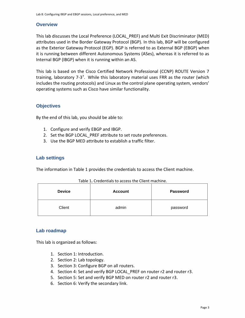
Lab 8: Configuring IBGP and EBGP sessions, Local preference, and MED
Page 3
Overview This lab discusses the Local Preference (LOCAL_PREF) and Multi Exit Discriminator (MED) attributes used in the Border Gateway Protocol (BGP). In this lab, BGP will be configured as the Exterior Gateway Protocol (EGP). BGP is referred to as External BGP (EBGP) when it is running between different Autonomous Systems (ASes), whereas it is referred to as Internal BGP (IBGP) when it is running within an AS. This lab is based on the Cisco Certified Network Professional (CCNP) ROUTE Version 7 training, laboratory 7-37. While this laboratory material uses FRR as the router (which includes the routing protocols) and Linux as the control plane operating system, vendors’ operating systems such as Cisco have similar functionality. Objectives By the end of this lab, you should be able to:
1. Configure and verify EBGP and IBGP. 2. Set the BGP LOCAL_PREF attribute to set route preferences. 3. Use the BGP MED attribute to establish a traffic filter.
Lab settings The information in Table 1 provides the credentials to access the Client machine.
Table 1. Credentials to access the Client machine.
Device
Account
Password
Client admin password
Lab roadmap This lab is organized as follows:
1. Section 1: Introduction. 2. Section 2: Lab topology. 3. Section 3: Configure BGP on all routers. 4. Section 4: Set and verify BGP LOCAL_PREF on router r2 and router r3. 5. Section 5: Set and verify BGP MED on router r2 and router r3. 6. Section 6: Verify the secondary link.
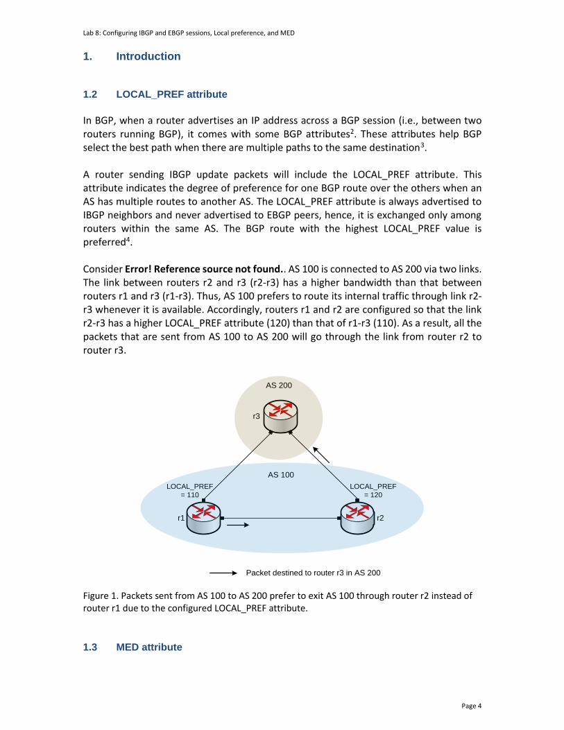
Lab 8: Configuring IBGP and EBGP sessions, Local preference, and MED
Page 4
1. Introduction
1.2 LOCAL_PREF attribute
In BGP, when a router advertises an IP address across a BGP session (i.e., between two routers running BGP), it comes with some BGP attributes2. These attributes help BGP select the best path when there are multiple paths to the same destination3. A router sending IBGP update packets will include the LOCAL_PREF attribute. This attribute indicates the degree of preference for one BGP route over the others when an AS has multiple routes to another AS. The LOCAL_PREF attribute is always advertised to IBGP neighbors and never advertised to EBGP peers, hence, it is exchanged only among routers within the same AS. The BGP route with the highest LOCAL_PREF value is preferred4. Consider Error! Reference source not found.. AS 100 is connected to AS 200 via two links. The link between routers r2 and r3 (r2-r3) has a higher bandwidth than that between routers r1 and r3 (r1-r3). Thus, AS 100 prefers to route its internal traffic through link r2-r3 whenever it is available. Accordingly, routers r1 and r2 are configured so that the link r2-r3 has a higher LOCAL_PREF attribute (120) than that of r1-r3 (110). As a result, all the packets that are sent from AS 100 to AS 200 will go through the link from router r2 to router r3.
AS 100
r1
r3
AS 200
r2
LOCAL_PREF
= 110
Packet destined to router r3 in AS 200
LOCAL_PREF
= 120
Figure 1. Packets sent from AS 100 to AS 200 prefer to exit AS 100 through router r2 instead of router r1 due to the configured LOCAL_PREF attribute.
1.3 MED attribute
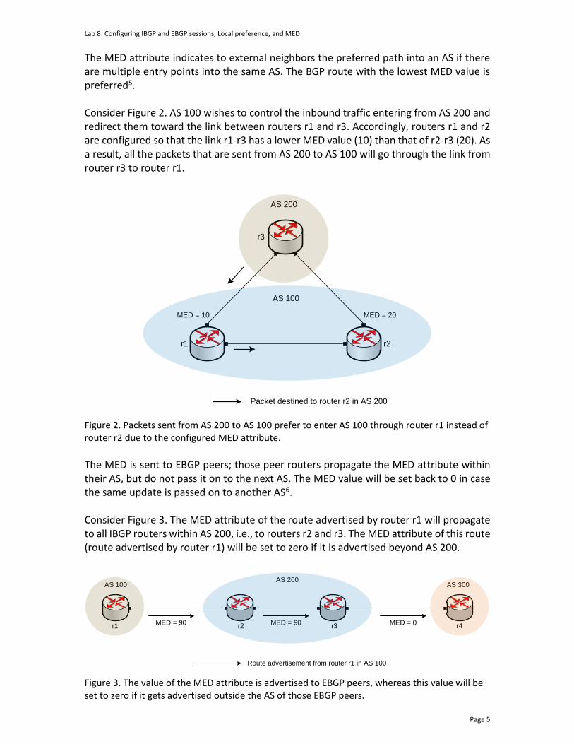
Lab 8: Configuring IBGP and EBGP sessions, Local preference, and MED
Page 5
The MED attribute indicates to external neighbors the preferred path into an AS if there are multiple entry points into the same AS. The BGP route with the lowest MED value is preferred5. Consider Figure 2. AS 100 wishes to control the inbound traffic entering from AS 200 and redirect them toward the link between routers r1 and r3. Accordingly, routers r1 and r2 are configured so that the link r1-r3 has a lower MED value (10) than that of r2-r3 (20). As a result, all the packets that are sent from AS 200 to AS 100 will go through the link from router r3 to router r1.
AS 100
r1
r3
AS 200
r2
MED = 10
Packet destined to router r2 in AS 200
MED = 20
Figure 2. Packets sent from AS 200 to AS 100 prefer to enter AS 100 through router r1 instead of router r2 due to the configured MED attribute.
The MED is sent to EBGP peers; those peer routers propagate the MED attribute within their AS, but do not pass it on to the next AS. The MED value will be set back to 0 in case the same update is passed on to another AS6. Consider Figure 3. The MED attribute of the route advertised by router r1 will propagate to all IBGP routers within AS 200, i.e., to routers r2 and r3. The MED attribute of this route (route advertised by router r1) will be set to zero if it is advertised beyond AS 200.
AS 100AS 200
r1 r2
AS 300
r4MED = 90
Route advertisement from router r1 in AS 100
MED = 90 MED = 0r3
Figure 3. The value of the MED attribute is advertised to EBGP peers, whereas this value will be set to zero if it gets advertised outside the AS of those EBGP peers.
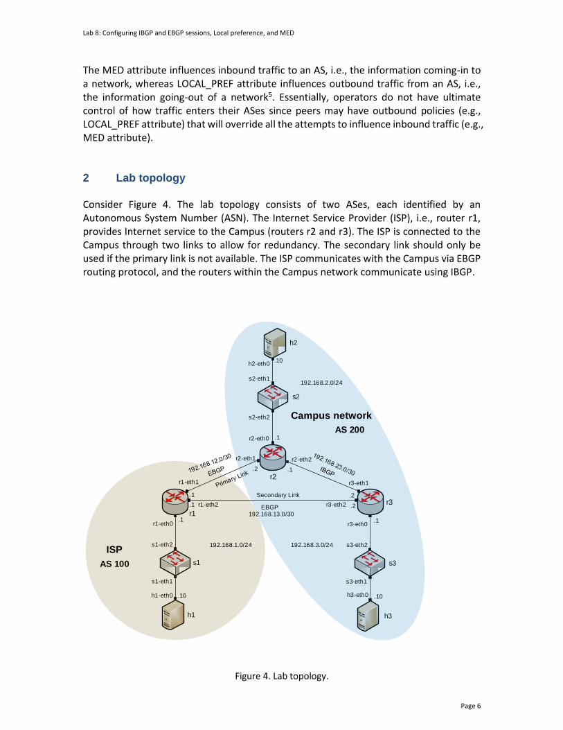
Lab 8: Configuring IBGP and EBGP sessions, Local preference, and MED
Page 6
The MED attribute influences inbound traffic to an AS, i.e., the information coming-in to a network, whereas LOCAL_PREF attribute influences outbound traffic from an AS, i.e., the information going-out of a network5. Essentially, operators do not have ultimate control of how traffic enters their ASes since peers may have outbound policies (e.g., LOCAL_PREF attribute) that will override all the attempts to influence inbound traffic (e.g., MED attribute). 2 Lab topology Consider Figure 4. The lab topology consists of two ASes, each identified by an Autonomous System Number (ASN). The Internet Service Provider (ISP), i.e., router r1, provides Internet service to the Campus (routers r2 and r3). The ISP is connected to the Campus through two links to allow for redundancy. The secondary link should only be used if the primary link is not available. The ISP communicates with the Campus via EBGP routing protocol, and the routers within the Campus network communicate using IBGP.
s2
s1 s3
h1
h2
h3
r1
r3
r1-eth1
r2-eth1
h1-eth0
s1-eth1
s1-eth2
r1-eth0
h2-eth0
s2-eth1
s2-eth2
r2-eth0
r2-eth2
r3-eth1
r3-eth0
s3-eth2
s3-eth1
h3-eth0
AS 100
.10
.1
.1
.2 .1
.2
.1
.10
.1
.10
192.168.1.0/24 192.168.3.0/24
192.168.2.0/24
r2
.1 .2r1-eth2 r3-eth2
192.168.13.0/30
Secondary Link
Campus network
ISP
AS 200
EBGP
Figure 4. Lab topology.
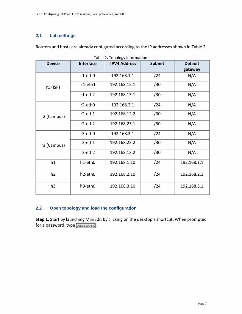
Lab 8: Configuring IBGP and EBGP sessions, Local preference, and MED
Page 7
2.1 Lab settings
Routers and hosts are already configured according to the IP addresses shown in Table 2.
Table 2. Topology information.
Device Interface IIPV4 Address Subnet Default gateway
r1 (ISP)
r1-eth0 192.168.1.1 /24 N/A
r1-eth1 192.168.12.1 /30 N/A
r1-eth2 192.168.13.1 /30 N/A
r2 (Campus)
r2-eth0 192.168.2.1 /24 N/A
r2-eth1 192.168.12.2 /30 N/A
r2-eth2 192.168.23.1 /30 N/A
r3 (Campus)
r3-eth0 192.168.3.1 /24 N/A
r3-eth1 192.168.23.2 /30 N/A
r3-eth2 192.168.13.2 /30 N/A
h1
h1-eth0 192.168.1.10 /24 192.168.1.1
h2
h2-eth0 192.168.2.10 /24 192.168.2.1
h3
h3-eth0 192.168.3.10 /24 192.168.3.1
2.2 Open topology and load the configuration
Step 1. Start by launching MiniEdit by clicking on the desktop’s shortcut. When prompted for a password, type password.
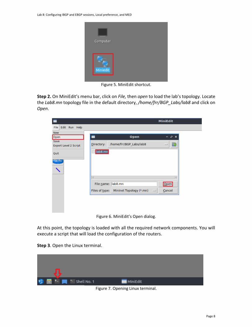
Lab 8: Configuring IBGP and EBGP sessions, Local preference, and MED
Page 8
Figure 5. MiniEdit shortcut.
Step 2. On MiniEdit’s menu bar, click on File, then open to load the lab’s topology. Locate the Lab8.mn topology file in the default directory, /home/frr/BGP_Labs/lab8 and click on Open.
Figure 6. MiniEdit’s Open dialog.
At this point, the topology is loaded with all the required network components. You will execute a script that will load the configuration of the routers.
Step 3. Open the Linux terminal.
Figure 7. Opening Linux terminal.
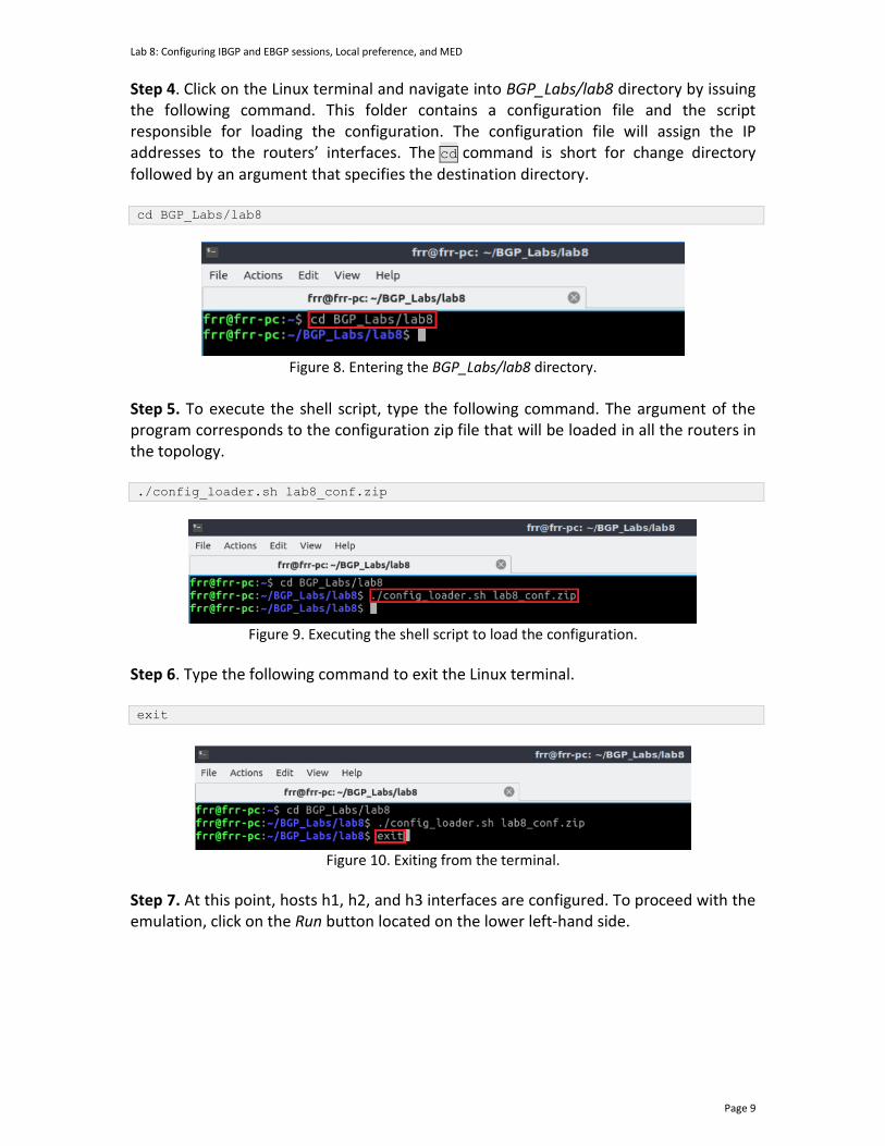
Lab 8: Configuring IBGP and EBGP sessions, Local preference, and MED
Page 9
Step 4. Click on the Linux terminal and navigate into BGP_Labs/lab8 directory by issuing the following command. This folder contains a configuration file and the script responsible for loading the configuration. The configuration file will assign the IP addresses to the routers’ interfaces. The cd command is short for change directory followed by an argument that specifies the destination directory. cd BGP_Labs/lab8
Figure 8. Entering the BGP_Labs/lab8 directory.
Step 5. To execute the shell script, type the following command. The argument of the program corresponds to the configuration zip file that will be loaded in all the routers in the topology. ./config_loader.sh lab8_conf.zip
Figure 9. Executing the shell script to load the configuration.
Step 6. Type the following command to exit the Linux terminal. exit
Figure 10. Exiting from the terminal.
Step 7. At this point, hosts h1, h2, and h3 interfaces are configured. To proceed with the emulation, click on the Run button located on the lower left-hand side.
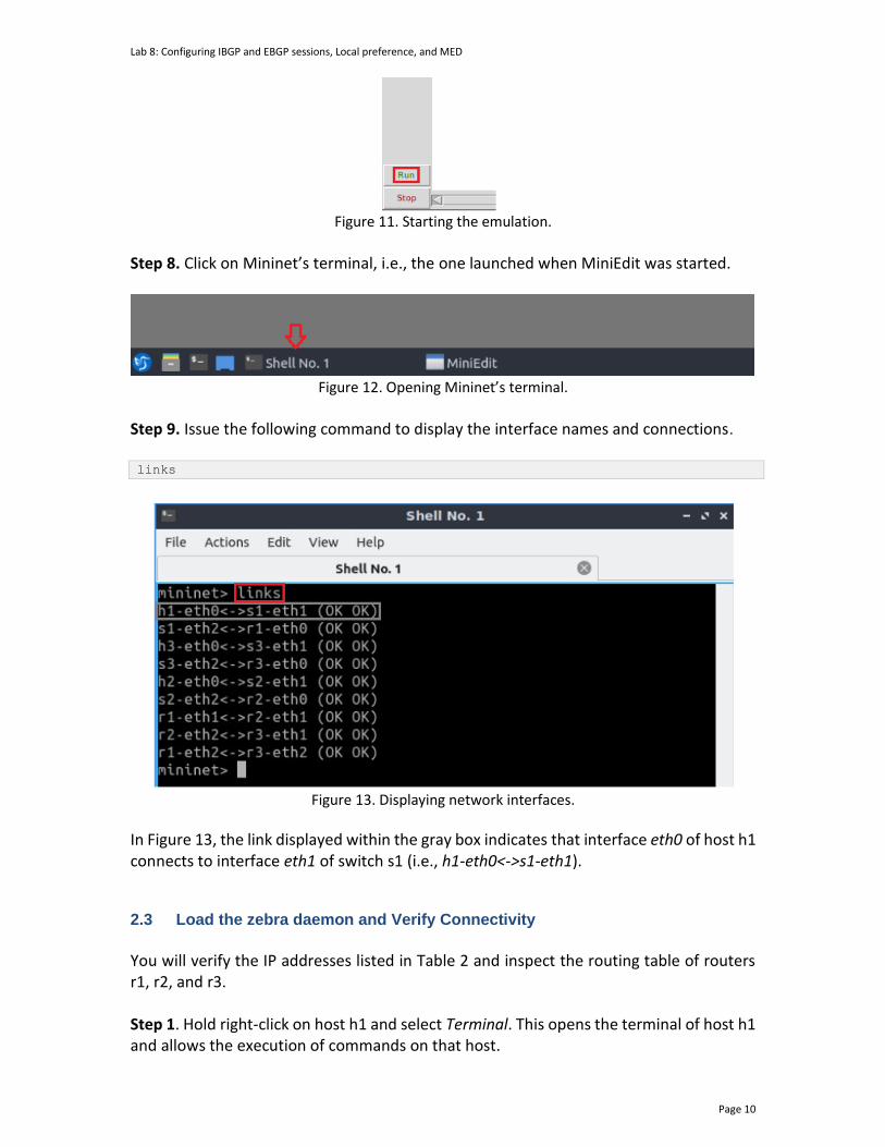
Lab 8: Configuring IBGP and EBGP sessions, Local preference, and MED
Page 10
Figure 11. Starting the emulation.
Step 8. Click on Mininet’s terminal, i.e., the one launched when MiniEdit was started.
Figure 12. Opening Mininet’s terminal.
Step 9. Issue the following command to display the interface names and connections. links
Figure 13. Displaying network interfaces.
In Figure 13, the link displayed within the gray box indicates that interface eth0 of host h1 connects to interface eth1 of switch s1 (i.e., h1-eth0<->s1-eth1). 2.3 Load the zebra daemon and Verify Connectivity
You will verify the IP addresses listed in Table 2 and inspect the routing table of routers r1, r2, and r3. Step 1. Hold right-click on host h1 and select Terminal. This opens the terminal of host h1 and allows the execution of commands on that host.
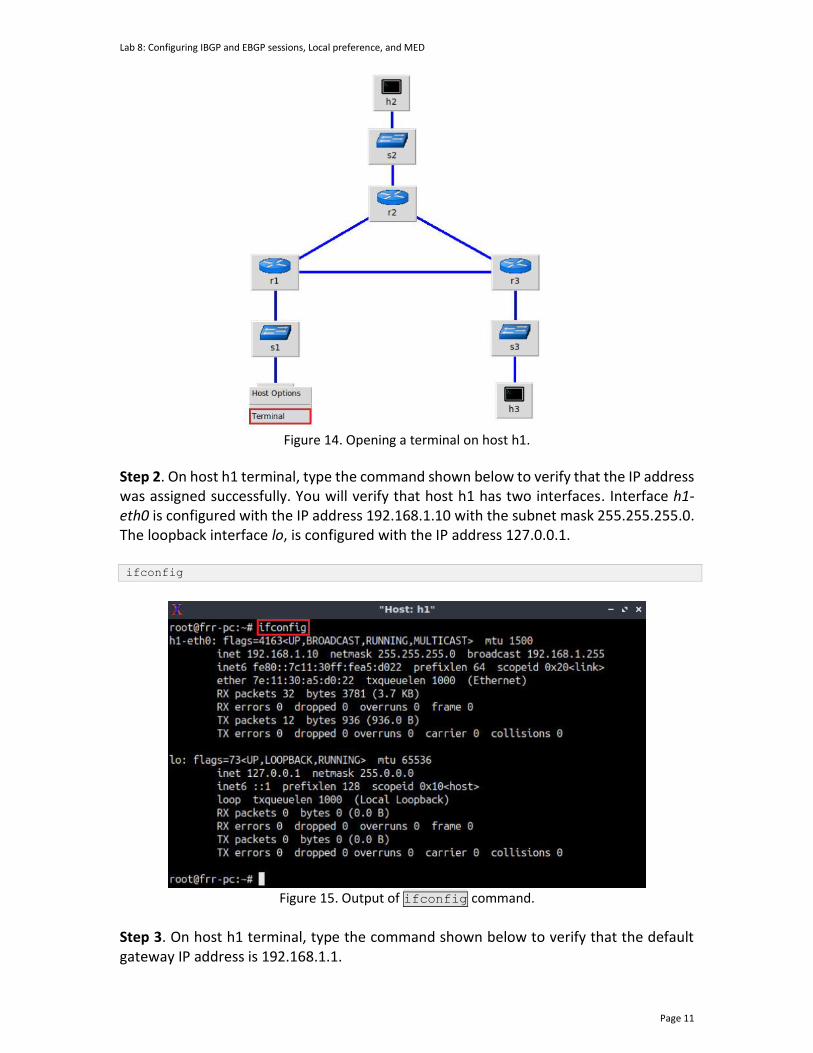
Lab 8: Configuring IBGP and EBGP sessions, Local preference, and MED
Page 11
Figure 14. Opening a terminal on host h1.
Step 2. On host h1 terminal, type the command shown below to verify that the IP address was assigned successfully. You will verify that host h1 has two interfaces. Interface h1-eth0 is configured with the IP address 192.168.1.10 with the subnet mask 255.255.255.0. The loopback interface lo, is configured with the IP address 127.0.0.1. ifconfig
Figure 15. Output of ifconfig command.
Step 3. On host h1 terminal, type the command shown below to verify that the default gateway IP address is 192.168.1.1.

Lab 8: Configuring IBGP and EBGP sessions, Local preference, and MED
Page 12
route
Figure 16. Output of route command.
Step 4. In order to verify hosts h2 and h3, proceed similarly by repeating from step 1 to step 3 in hosts h2 and h3 terminals. Similar results should be observed. Step 5. You will validate that the router interfaces are configured correctly according to Table 2. In order to verify router r1, hold right-click on router r1 and select Terminal.
Figure 17. Opening terminal on router r1.
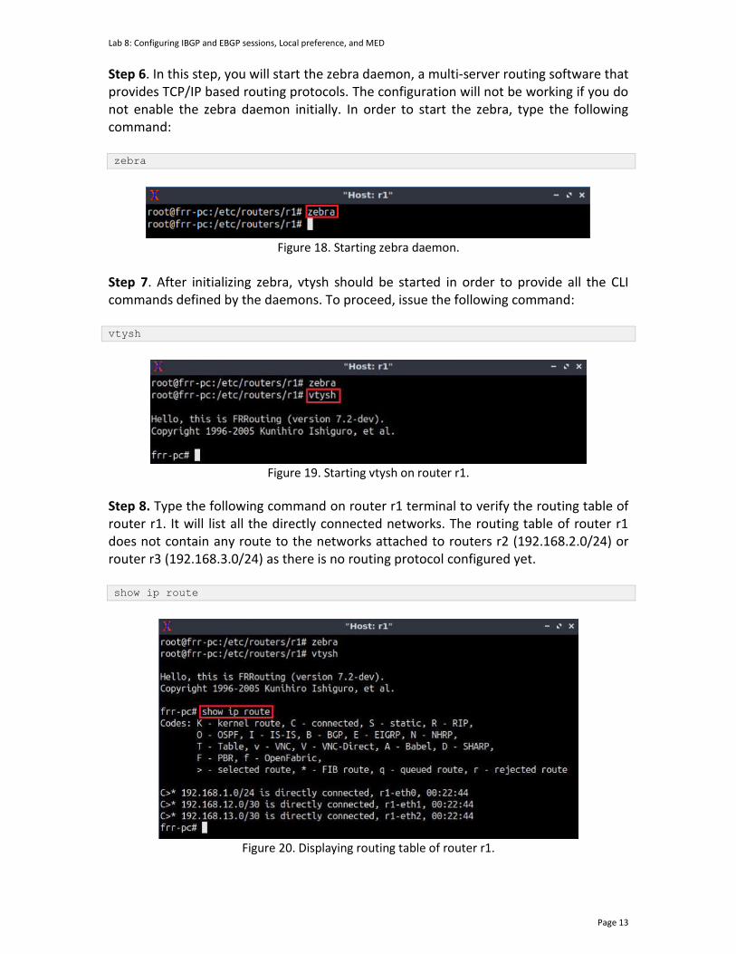
Lab 8: Configuring IBGP and EBGP sessions, Local preference, and MED
Page 13
Step 6. In this step, you will start the zebra daemon, a multi-server routing software that provides TCP/IP based routing protocols. The configuration will not be working if you do not enable the zebra daemon initially. In order to start the zebra, type the following command: zebra
Figure 18. Starting zebra daemon.
Step 7. After initializing zebra, vtysh should be started in order to provide all the CLI commands defined by the daemons. To proceed, issue the following command: vtysh
Figure 19. Starting vtysh on router r1.
Step 8. Type the following command on router r1 terminal to verify the routing table of router r1. It will list all the directly connected networks. The routing table of router r1 does not contain any route to the networks attached to routers r2 (192.168.2.0/24) or router r3 (192.168.3.0/24) as there is no routing protocol configured yet. show ip route
Figure 20. Displaying routing table of router r1.
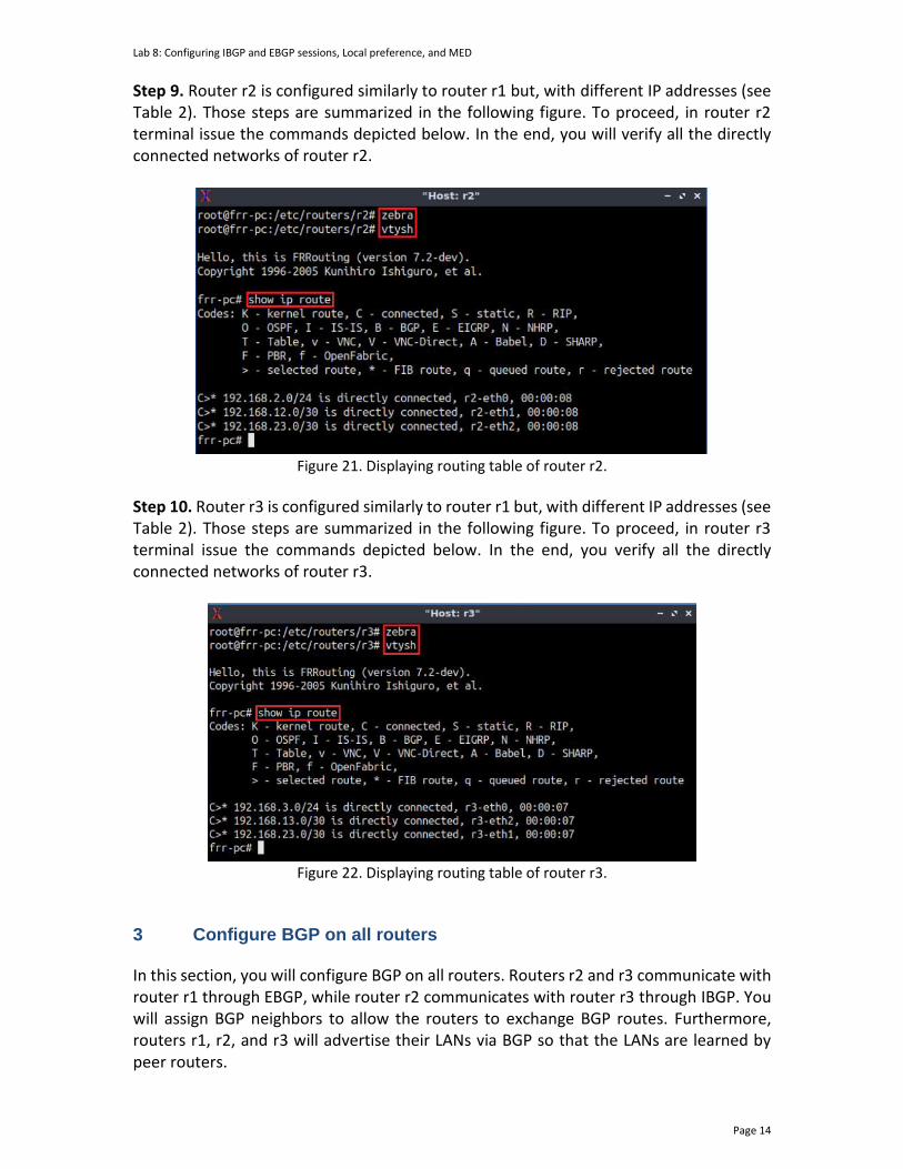
Lab 8: Configuring IBGP and EBGP sessions, Local preference, and MED
Page 14
Step 9. Router r2 is configured similarly to router r1 but, with different IP addresses (see Table 2). Those steps are summarized in the following figure. To proceed, in router r2 terminal issue the commands depicted below. In the end, you will verify all the directly connected networks of router r2.
Figure 21. Displaying routing table of router r2.
Step 10. Router r3 is configured similarly to router r1 but, with different IP addresses (see Table 2). Those steps are summarized in the following figure. To proceed, in router r3 terminal issue the commands depicted below. In the end, you verify all the directly connected networks of router r3.
Figure 22. Displaying routing table of router r3.
3 Configure BGP on all routers
In this section, you will configure BGP on all routers. Routers r2 and r3 communicate with router r1 through EBGP, while router r2 communicates with router r3 through IBGP. You will assign BGP neighbors to allow the routers to exchange BGP routes. Furthermore, routers r1, r2, and r3 will advertise their LANs via BGP so that the LANs are learned by peer routers.
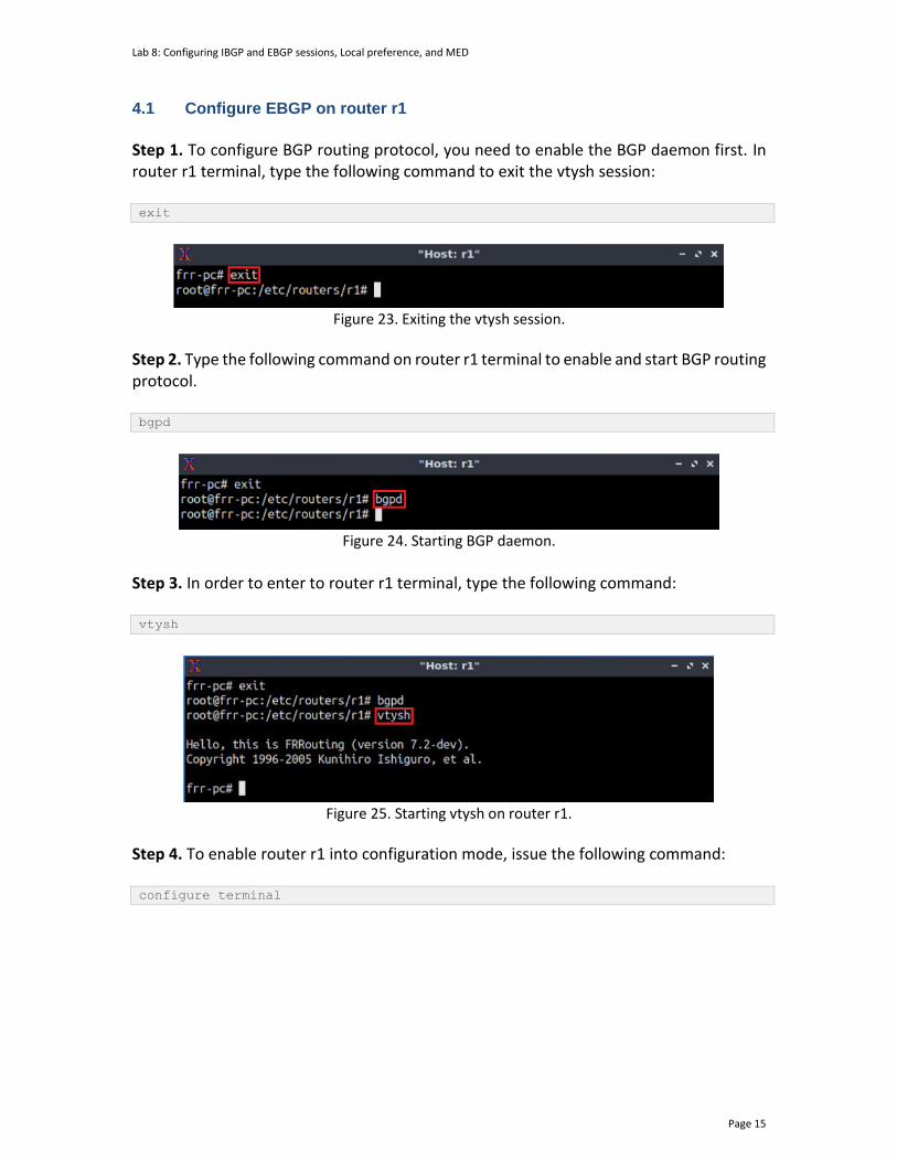
Lab 8: Configuring IBGP and EBGP sessions, Local preference, and MED
Page 15
4.1 Configure EBGP on router r1
Step 1. To configure BGP routing protocol, you need to enable the BGP daemon first. In router r1 terminal, type the following command to exit the vtysh session: exit
Figure 23. Exiting the vtysh session.
Step 2. Type the following command on router r1 terminal to enable and start BGP routing protocol. bgpd
Figure 24. Starting BGP daemon.
Step 3. In order to enter to router r1 terminal, type the following command: vtysh
Figure 25. Starting vtysh on router r1.
Step 4. To enable router r1 into configuration mode, issue the following command: configure terminal
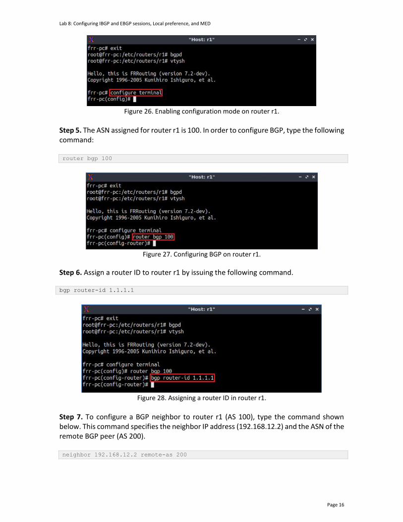
Lab 8: Configuring IBGP and EBGP sessions, Local preference, and MED
Page 16
Figure 26. Enabling configuration mode on router r1.
Step 5. The ASN assigned for router r1 is 100. In order to configure BGP, type the following command: router bgp 100
Figure 27. Configuring BGP on router r1.
Step 6. Assign a router ID to router r1 by issuing the following command. bgp router-id 1.1.1.1
Figure 28. Assigning a router ID in router r1.
Step 7. To configure a BGP neighbor to router r1 (AS 100), type the command shown below. This command specifies the neighbor IP address (192.168.12.2) and the ASN of the remote BGP peer (AS 200). neighbor 192.168.12.2 remote-as 200
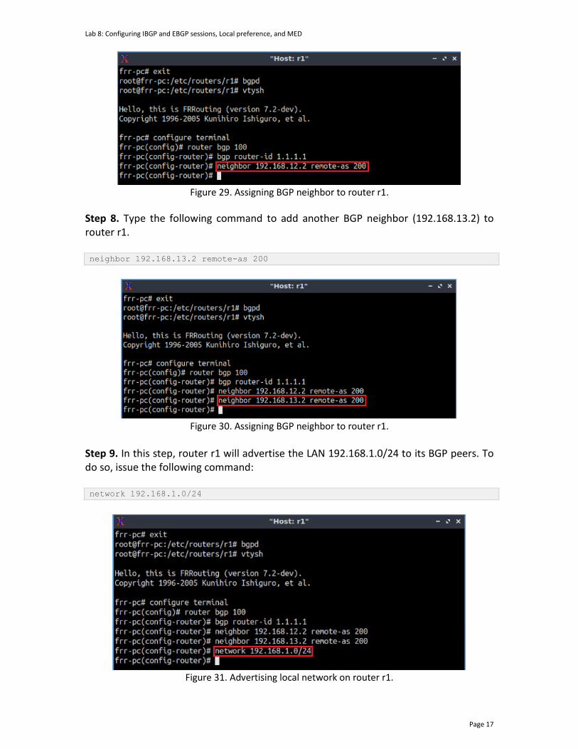
Lab 8: Configuring IBGP and EBGP sessions, Local preference, and MED
Page 17
Figure 29. Assigning BGP neighbor to router r1.
Step 8. Type the following command to add another BGP neighbor (192.168.13.2) to router r1. neighbor 192.168.13.2 remote-as 200
Figure 30. Assigning BGP neighbor to router r1.
Step 9. In this step, router r1 will advertise the LAN 192.168.1.0/24 to its BGP peers. To do so, issue the following command: network 192.168.1.0/24
Figure 31. Advertising local network on router r1.

Lab 8: Configuring IBGP and EBGP sessions, Local preference, and MED
Page 18
Step 10. Type the following command to exit from router configuration mode. end
Figure 32. Exiting from configuration mode.
Step 11. Type the following command to verify BGP networks. You will observe the LAN network of router r1. show ip bgp
Figure 33. Verifying BGP networks on router r1.
4.2 Configure EBGP and IBGP on router r2 and router r3
Step 1. To configure BGP routing protocol, you need to enable the BGP daemon first. In router r2 terminal, type the following command to exit the vtysh session: exit
Figure 34. Exiting the vtysh session on router r2 terminal.
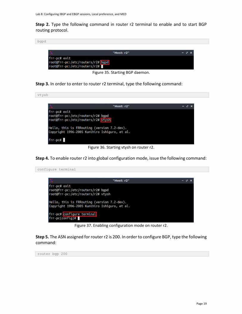
Lab 8: Configuring IBGP and EBGP sessions, Local preference, and MED
Page 19
Step 2. Type the following command in router r2 terminal to enable and to start BGP routing protocol. bgpd
Figure 35. Starting BGP daemon.
Step 3. In order to enter to router r2 terminal, type the following command: vtysh
Figure 36. Starting vtysh on router r2.
Step 4. To enable router r2 into global configuration mode, issue the following command: configure terminal
Figure 37. Enabling configuration mode on router r2.
Step 5. The ASN assigned for router r2 is 200. In order to configure BGP, type the following command: router bgp 200
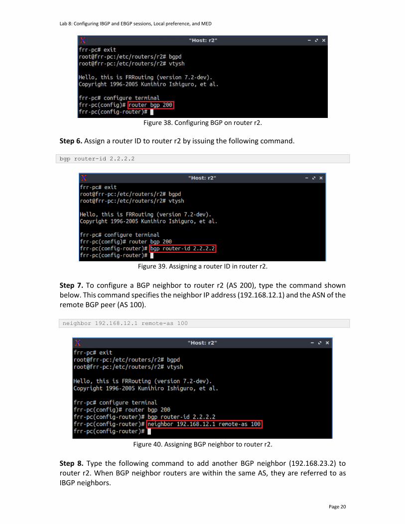
Lab 8: Configuring IBGP and EBGP sessions, Local preference, and MED
Page 20
Figure 38. Configuring BGP on router r2.
Step 6. Assign a router ID to router r2 by issuing the following command. bgp router-id 2.2.2.2
Figure 39. Assigning a router ID in router r2.
Step 7. To configure a BGP neighbor to router r2 (AS 200), type the command shown below. This command specifies the neighbor IP address (192.168.12.1) and the ASN of the remote BGP peer (AS 100). neighbor 192.168.12.1 remote-as 100
Figure 40. Assigning BGP neighbor to router r2.
Step 8. Type the following command to add another BGP neighbor (192.168.23.2) to router r2. When BGP neighbor routers are within the same AS, they are referred to as IBGP neighbors.
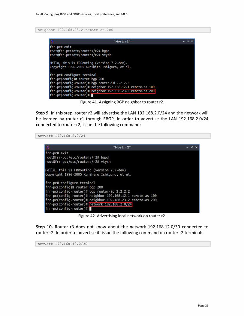
Lab 8: Configuring IBGP and EBGP sessions, Local preference, and MED
Page 21
neighbor 192.168.23.2 remote-as 200
Figure 41. Assigning BGP neighbor to router r2.
Step 9. In this step, router r2 will advertise the LAN 192.168.2.0/24 and the network will be learned by router r1 through EBGP. In order to advertise the LAN 192.168.2.0/24 connected to router r2, issue the following command: network 192.168.2.0/24
Figure 42. Advertising local network on router r2.
Step 10. Router r3 does not know about the network 192.168.12.0/30 connected to router r2. In order to advertise it, issue the following command on router r2 terminal: network 192.168.12.0/30
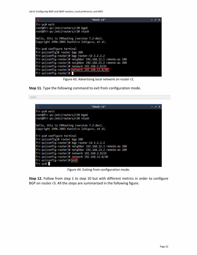
Lab 8: Configuring IBGP and EBGP sessions, Local preference, and MED
Page 22
Figure 43. Advertising local network on router r2.
Step 11. Type the following command to exit from configuration mode. end
Figure 44. Exiting from configuration mode.
Step 12. Follow from step 1 to step 10 but with different metrics in order to configure BGP on router r3. All the steps are summarized in the following figure.

Lab 8: Configuring IBGP and EBGP sessions, Local preference, and MED
Page 23
Figure 45. Configuring BGP on router r3.
Step 13. Type the following command to verify the BGP table of router r3. show ip bgp
Figure 46. Verifying BGP networks on router r3.
Consider the figure above. The BGP table for router r3 contains five networks advertised through BGP. There are two available paths to reach the network 192.168.1.0/24 (through 192.168.12.1 and 192.168.13.1). The character * indicates that the following path is valid, and the character > indicates that the following path is used to reach a specific network. Router r3 reaches with the network 192.168.1.0/24 via 192.168.13.1, which is expected to act as a secondary link in this lab. In the next section, you will configure local-preference attribute to make the link a secondary path.
4 Set and verify BGP LOCAL_PREF on router r2 and router r3
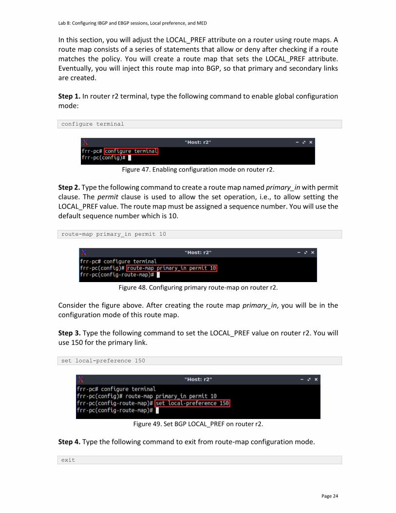
Lab 8: Configuring IBGP and EBGP sessions, Local preference, and MED
Page 24
In this section, you will adjust the LOCAL_PREF attribute on a router using route maps. A route map consists of a series of statements that allow or deny after checking if a route matches the policy. You will create a route map that sets the LOCAL_PREF attribute. Eventually, you will inject this route map into BGP, so that primary and secondary links are created. Step 1. In router r2 terminal, type the following command to enable global configuration mode: configure terminal
Figure 47. Enabling configuration mode on router r2.
Step 2. Type the following command to create a route map named primary_in with permit clause. The permit clause is used to allow the set operation, i.e., to allow setting the LOCAL_PREF value. The route map must be assigned a sequence number. You will use the default sequence number which is 10. route-map primary_in permit 10
Figure 48. Configuring primary route-map on router r2.
Consider the figure above. After creating the route map primary_in, you will be in the configuration mode of this route map.
Step 3. Type the following command to set the LOCAL_PREF value on router r2. You will use 150 for the primary link. set local-preference 150
Figure 49. Set BGP LOCAL_PREF on router r2.
Step 4. Type the following command to exit from route-map configuration mode. exit

Lab 8: Configuring IBGP and EBGP sessions, Local preference, and MED
Page 25
Figure 50. Exiting from route-map configuration mode.
Step 5. To enable router r2 into router configuration mode, issue the following command: router bgp 200
Figure 51. Configuring BGP on router r2.
Step 6. Type the following command to apply the route map primary_in on BGP neighbor router r1 (192.168.12.1). Notice that there is in at the end of the command which specifies that the policy will be applicable for incoming traffic. neighbor 192.168.12.1 route-map primary_in in
Figure 52. Assigning route-map to the BGP neighbor.
Consider the figure above. Router r2 will set a LOCAL_PREF value of 150 for the link between router r2 and router r1 (primary link).
Step 7. Type the following command to exit from configuration mode. end
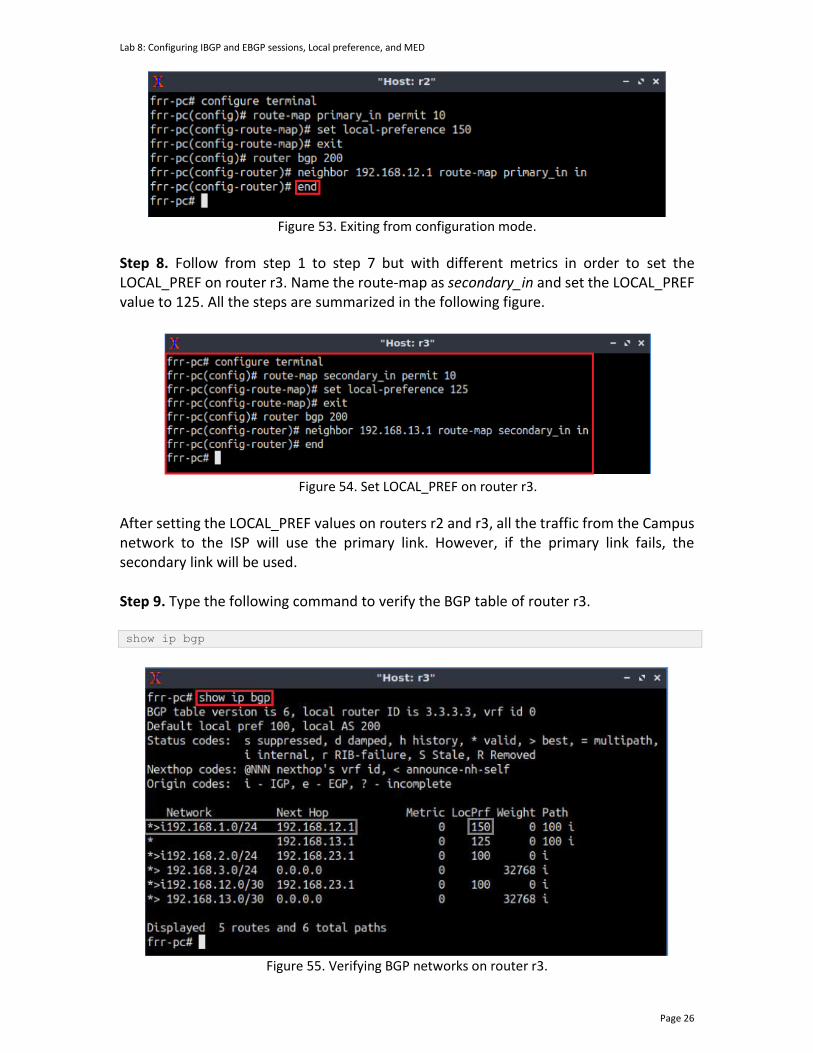
Lab 8: Configuring IBGP and EBGP sessions, Local preference, and MED
Page 26
Figure 53. Exiting from configuration mode.
Step 8. Follow from step 1 to step 7 but with different metrics in order to set the LOCAL_PREF on router r3. Name the route-map as secondary_in and set the LOCAL_PREF value to 125. All the steps are summarized in the following figure.
Figure 54. Set LOCAL_PREF on router r3.
After setting the LOCAL_PREF values on routers r2 and r3, all the traffic from the Campus network to the ISP will use the primary link. However, if the primary link fails, the secondary link will be used. Step 9. Type the following command to verify the BGP table of router r3. show ip bgp
Figure 55. Verifying BGP networks on router r3.
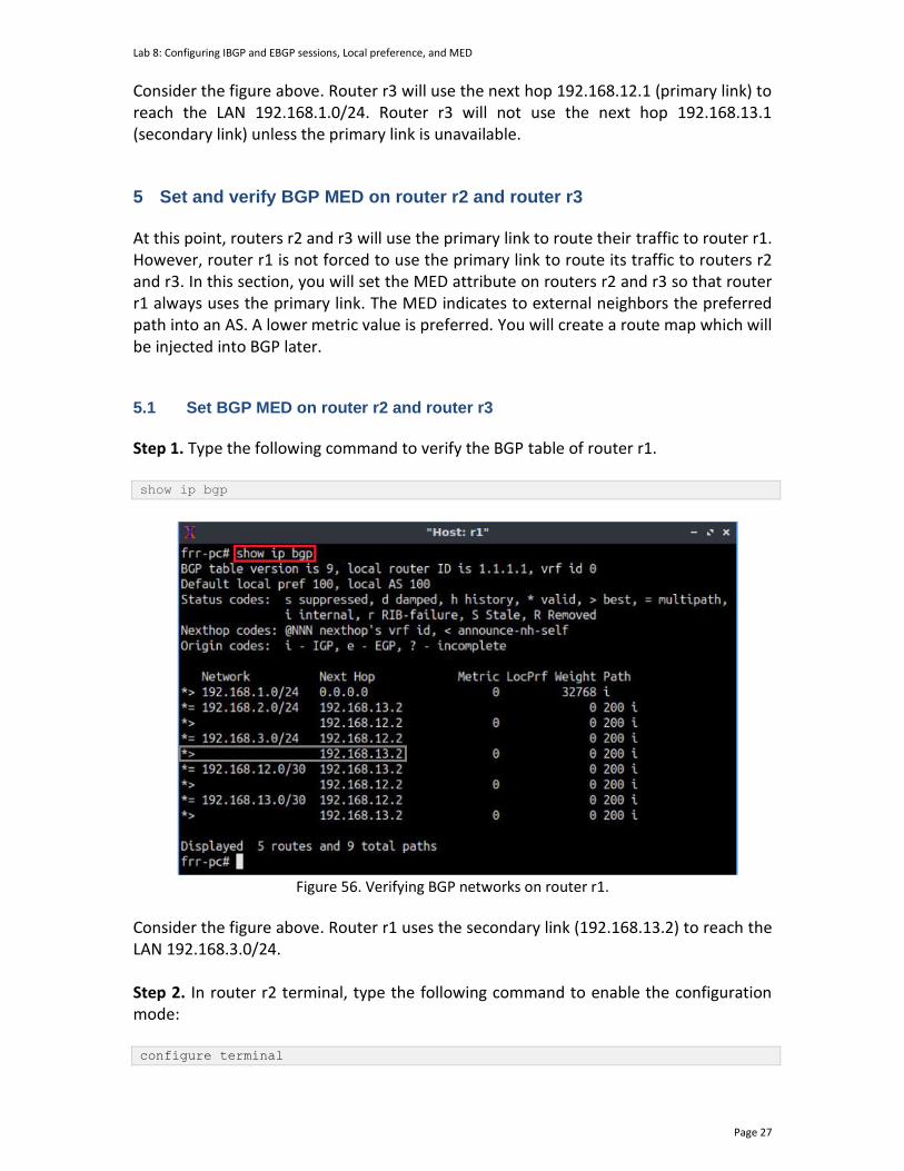
Lab 8: Configuring IBGP and EBGP sessions, Local preference, and MED
Page 27
Consider the figure above. Router r3 will use the next hop 192.168.12.1 (primary link) to reach the LAN 192.168.1.0/24. Router r3 will not use the next hop 192.168.13.1 (secondary link) unless the primary link is unavailable.
5 Set and verify BGP MED on router r2 and router r3
At this point, routers r2 and r3 will use the primary link to route their traffic to router r1. However, router r1 is not forced to use the primary link to route its traffic to routers r2 and r3. In this section, you will set the MED attribute on routers r2 and r3 so that router r1 always uses the primary link. The MED indicates to external neighbors the preferred path into an AS. A lower metric value is preferred. You will create a route map which will be injected into BGP later. 5.1 Set BGP MED on router r2 and router r3
Step 1. Type the following command to verify the BGP table of router r1. show ip bgp
Figure 56. Verifying BGP networks on router r1.
Consider the figure above. Router r1 uses the secondary link (192.168.13.2) to reach the LAN 192.168.3.0/24. Step 2. In router r2 terminal, type the following command to enable the configuration mode: configure terminal
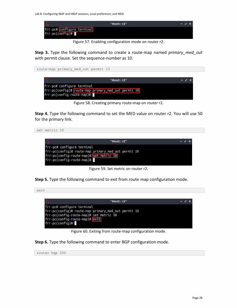
Lab 8: Configuring IBGP and EBGP sessions, Local preference, and MED
Page 28
Figure 57. Enabling configuration mode on router r2.
Step 3. Type the following command to create a route-map named primary_med_out with permit clause. Set the sequence-number as 10. route-map primary_med_out permit 10
Figure 58. Creating primary route-map on router r2.
Step 4. Type the following command to set the MED value on router r2. You will use 50 for the primary link. set metric 50
Figure 59. Set metric on router r2.
Step 5. Type the following command to exit from route map configuration mode. exit
Figure 60. Exiting from route-map configuration mode.
Step 6. Type the following command to enter BGP configuration mode. router bgp 200
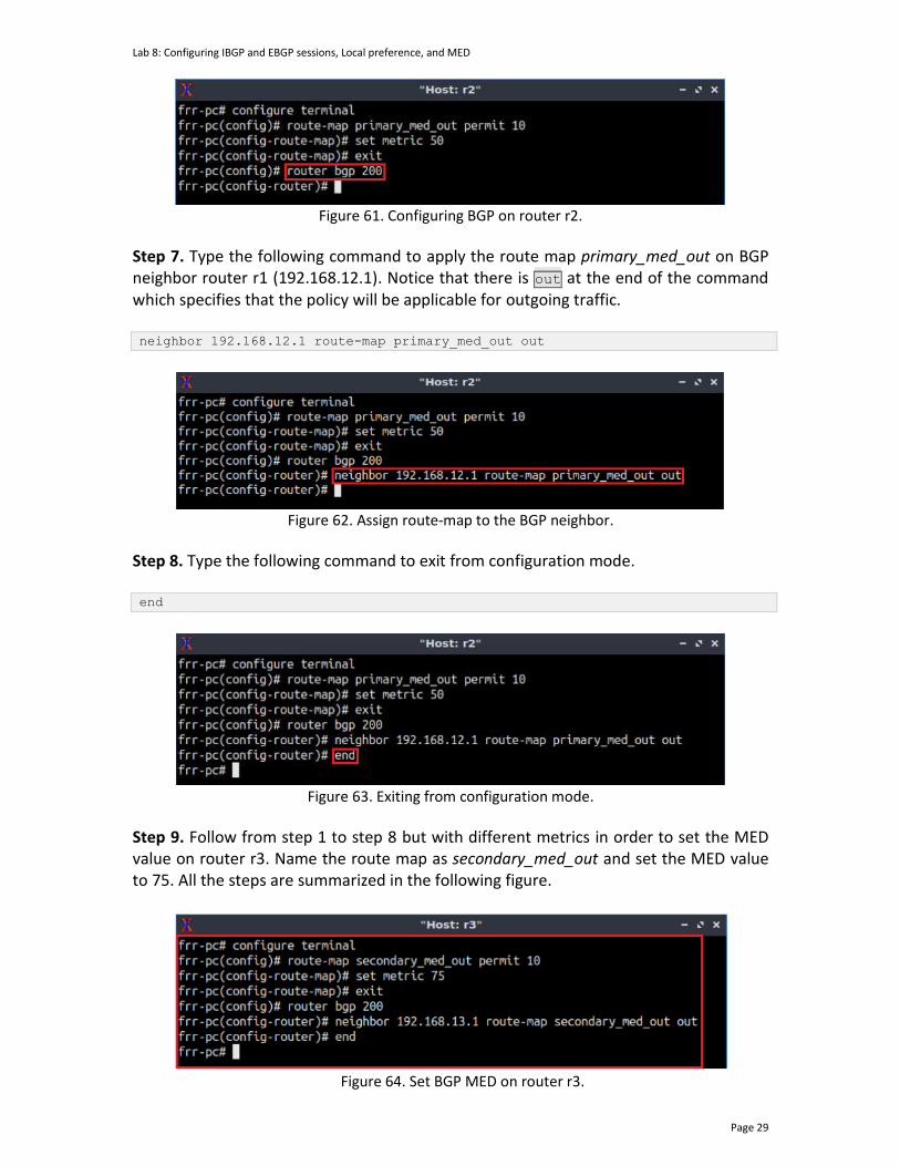
Lab 8: Configuring IBGP and EBGP sessions, Local preference, and MED
Page 29
Figure 61. Configuring BGP on router r2.
Step 7. Type the following command to apply the route map primary_med_out on BGP neighbor router r1 (192.168.12.1). Notice that there is out at the end of the command which specifies that the policy will be applicable for outgoing traffic. neighbor 192.168.12.1 route-map primary_med_out out
Figure 62. Assign route-map to the BGP neighbor.
Step 8. Type the following command to exit from configuration mode. end
Figure 63. Exiting from configuration mode.
Step 9. Follow from step 1 to step 8 but with different metrics in order to set the MED value on router r3. Name the route map as secondary_med_out and set the MED value to 75. All the steps are summarized in the following figure.
Figure 64. Set BGP MED on router r3.
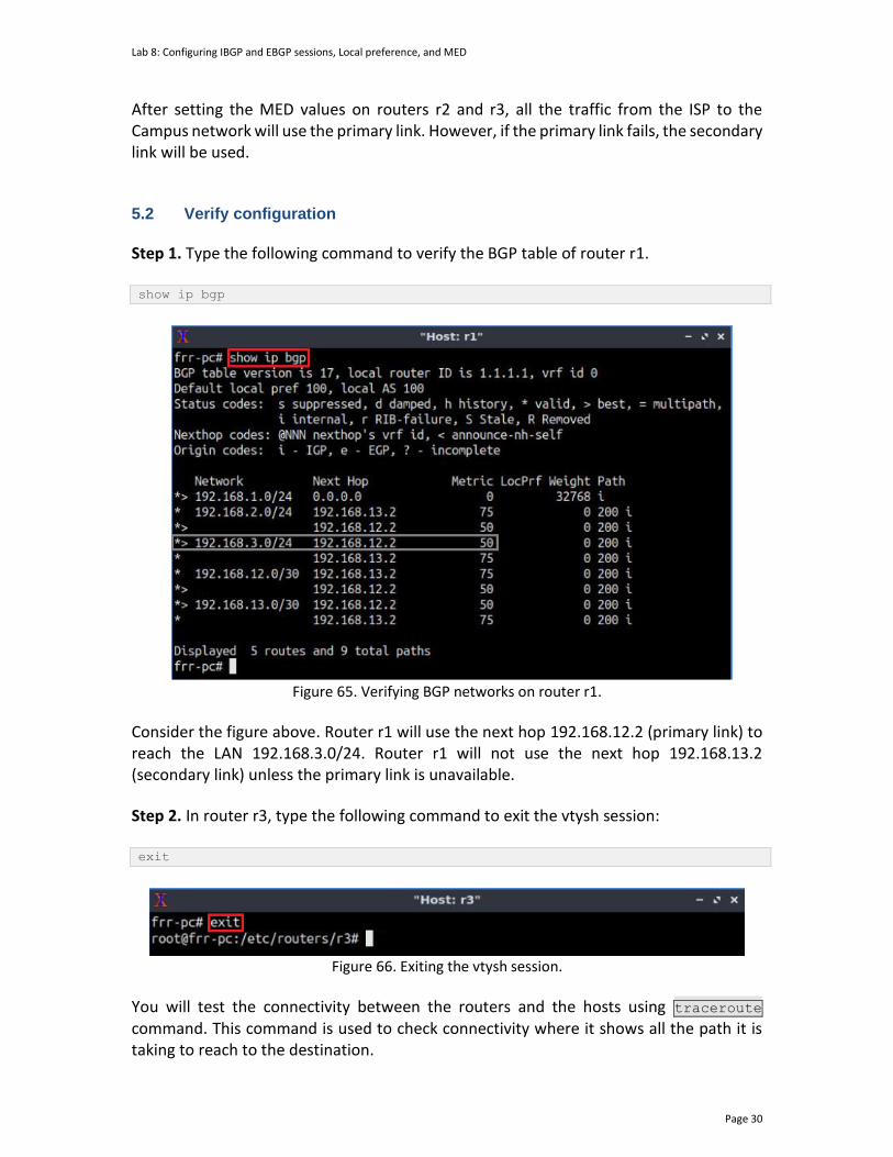
Lab 8: Configuring IBGP and EBGP sessions, Local preference, and MED
Page 30
After setting the MED values on routers r2 and r3, all the traffic from the ISP to the Campus network will use the primary link. However, if the primary link fails, the secondary link will be used. 5.2 Verify configuration
Step 1. Type the following command to verify the BGP table of router r1. show ip bgp
Figure 65. Verifying BGP networks on router r1.
Consider the figure above. Router r1 will use the next hop 192.168.12.2 (primary link) to reach the LAN 192.168.3.0/24. Router r1 will not use the next hop 192.168.13.2 (secondary link) unless the primary link is unavailable.
Step 2. In router r3, type the following command to exit the vtysh session: exit
Figure 66. Exiting the vtysh session.
You will test the connectivity between the routers and the hosts using traceroute command. This command is used to check connectivity where it shows all the path it is taking to reach to the destination.
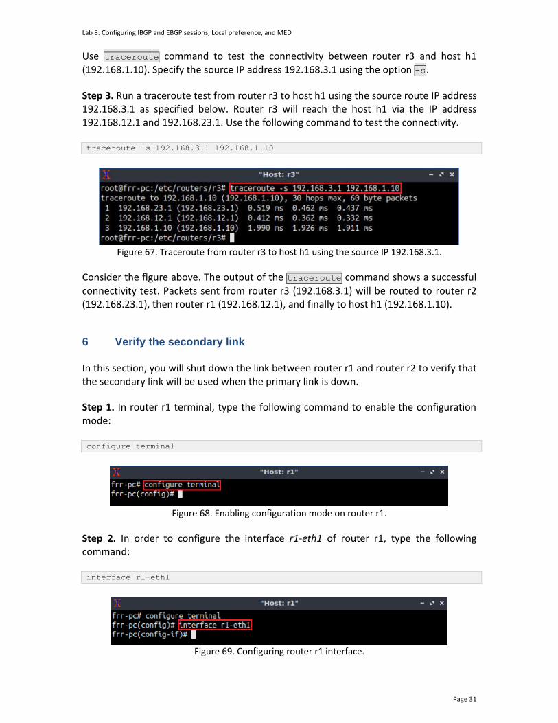
Lab 8: Configuring IBGP and EBGP sessions, Local preference, and MED
Page 31
Use traceroute command to test the connectivity between router r3 and host h1 (192.168.1.10). Specify the source IP address 192.168.3.1 using the option -s.
Step 3. Run a traceroute test from router r3 to host h1 using the source route IP address 192.168.3.1 as specified below. Router r3 will reach the host h1 via the IP address 192.168.12.1 and 192.168.23.1. Use the following command to test the connectivity. traceroute -s 192.168.3.1 192.168.1.10
Figure 67. Traceroute from router r3 to host h1 using the source IP 192.168.3.1.
Consider the figure above. The output of the traceroute command shows a successful connectivity test. Packets sent from router r3 (192.168.3.1) will be routed to router r2 (192.168.23.1), then router r1 (192.168.12.1), and finally to host h1 (192.168.1.10).
6 Verify the secondary link
In this section, you will shut down the link between router r1 and router r2 to verify that the secondary link will be used when the primary link is down.
Step 1. In router r1 terminal, type the following command to enable the configuration mode: configure terminal
Figure 68. Enabling configuration mode on router r1.
Step 2. In order to configure the interface r1-eth1 of router r1, type the following command: interface r1-eth1
Figure 69. Configuring router r1 interface.
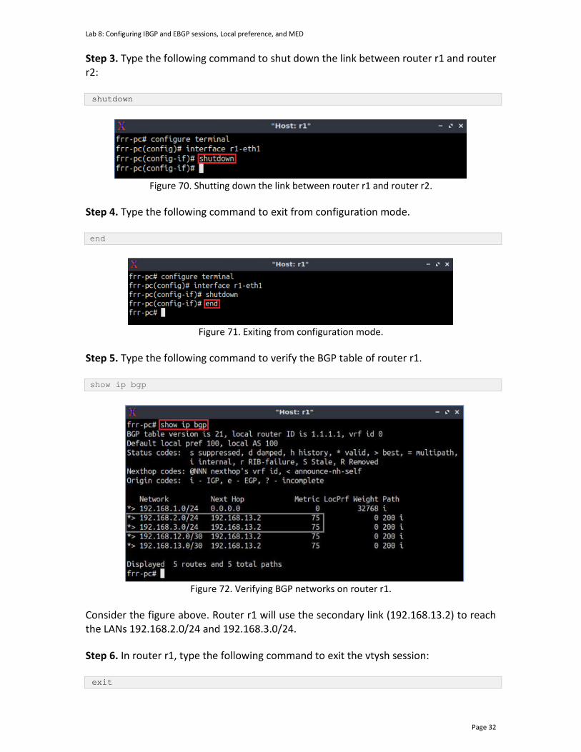
Lab 8: Configuring IBGP and EBGP sessions, Local preference, and MED
Page 32
Step 3. Type the following command to shut down the link between router r1 and router r2:
shutdown
Figure 70. Shutting down the link between router r1 and router r2.
Step 4. Type the following command to exit from configuration mode. end
Figure 71. Exiting from configuration mode.
Step 5. Type the following command to verify the BGP table of router r1. show ip bgp
Figure 72. Verifying BGP networks on router r1.
Consider the figure above. Router r1 will use the secondary link (192.168.13.2) to reach the LANs 192.168.2.0/24 and 192.168.3.0/24.
Step 6. In router r1, type the following command to exit the vtysh session:
exit

Lab 8: Configuring IBGP and EBGP sessions, Local preference, and MED
Page 33
Figure 73. Exiting from terminal on router r1.
Step 7. Perform a traceroute test from router r1 to host h2 using the source route IP address 192.168.1.1 as specified below. traceroute -s 192.168.1.1 192.168.2.10
Figure 74. Traceroute test from router r1 to host h2 using source IP 192.168.1.1.
Consider the figure above. This time router1 will use router r3 (192.168.13.2), i.e., secondary link, to reach host h3. This concludes Lab 8. Stop the emulation and then exit out of MiniEdit. References
1. A. Tanenbaum, D. Wetherall, “Computer networks”, 5th Edition, Pearson, 2012. 2. J. Kurose, K. Ross, “Computer networking, a top-down approach,” 7th Edition,
Pearson, 2017. 3. Cisco, “BGP best path selection algorithm”, 2016. [Online]. Available:
https://www.cisco.com/c/en/us/support/docs/ip/border-gateway-protocol-bgp/13753-25.html#anc2
4. Cisco, “IP routing: BGP configuration guide, Cisco IOS release 15M&T”, 2013. [Online]. Available: https://www.cisco.com/c/en/us/td/docs/ios-xml/ios/iproute_bgp/configuration/15-mt/irg-15-mt-book.pdf
5. Cisco, “Understanding BGP MED attribute”, 2014. [Online]. Available: https://www.cisco.com/c/en/us/support/docs/ip/border-gateway-protocol-bgp/112965-bgpmed-attr-00.html
6. D. Teare, B. Vachon, R. Graziani, "Implementing cisco IP Routing (Route), foundation learning guide," CCNP ROUTE 300-101.
7. CCNP, Lab 7-3, “Configuring IBGP and EBGP Sessions, Local Preference, and MED”.
BORDER GATEWAY PROTOCOL
Lab 8.1: Configuring OSPF, IBGP and EBGP Sessions, Local Preference, and MED
Document Version: 05-25-2021
Award 1829698 “CyberTraining CIP: Cyberinfrastructure Expertise on High-throughput
Networks for Big Science Data Transfers”

Lab 8.1: Configuring IBGP and EBGP sessions, Local preference, and MED
Page 2
Contents Overview ............................................................................................................................. 3
Objectives............................................................................................................................ 3
Lab settings ......................................................................................................................... 3
Lab roadmap ....................................................................................................................... 3
1. Introduction ................................................................................................................ 4
1.1 Intradomain and interdomain routing protocols ................................................. 4
1.2 LOCAL_PREF attribute .......................................................................................... 4
1.3 MED attribute ....................................................................................................... 5
2 Lab topology................................................................................................................ 6
2.1 Lab settings........................................................................................................... 7
2.2 Open topology and load the configuration .......................................................... 8
2.3 Load the zebra daemon and Verify Connectivity ............................................... 11
3 Configure OSPF on router r2 and router r3 .............................................................. 15
4 Configure BGP on all routers .................................................................................... 19
4.1 Configure EBGP on router r1 .............................................................................. 20
4.2 Configure EBGP and IBGP on router r2 and router r3 ....................................... 23
4.3 Advertise networks on router r2 and router r3 through OSPF .......................... 28
5 Set and verify BGP LOCAL_PREF on router r2 and router r3 .................................... 30
6 Set and verify BGP MED on router r2 and router r3 ................................................. 34
6.1 Set BGP MED on router r2 and router r3 ........................................................... 34
6.2 Verify configuration............................................................................................ 37
7 Verify the secondary link .......................................................................................... 38
References ........................................................................................................................ 40
Lab 8.1: Configuring IBGP and EBGP sessions, Local preference, and MED
Page 3
Overview This lab discusses the Local Preference (LOCAL_PREF) and Multi Exit Discriminator (MED) attributes used in the Border Gateway Protocol (BGP). In this lab, BGP and Open Shortest Path First (OSPF) will be configured as the Exterior Gateway Protocol (EGP) and the Interior Gateway Protocol (IGP), respectively. BGP is referred to as External BGP (EBGP) when it is running between different Autonomous Systems (ASes), whereas it is referred to as Internal BGP (IBGP) when it is running within an AS. This lab is based on the Cisco Certified Network Professional (CCNP) ROUTE Version 7 training, laboratory 7-38. While this laboratory material uses FRR as the router (which includes the routing protocols) and Linux as the control plane operating system, vendors’ operating systems such as Cisco have similar functionality. Objectives By the end of this lab, you should be able to:
1. Configure OSPF as the IGP. 2. Configure and verify EBGP and IBGP. 3. Set the BGP LOCAL_PREF attribute to set route preferences. 4. Use the BGP MED attribute to establish a traffic filter.
Lab settings The information in Table 1 provides the credentials to access the Client machine.
Table 1. Credentials to access the Client machine.
Device
Account
Password
Client admin password
Lab roadmap This lab is organized as follows:
1. Section 1: Introduction. 2. Section 2: Lab topology. 3. Section 3: Configure OSPF on router r2 and router r3. 4. Section 4: Configure IBGP on router r2 and router r3. 5. Section 5: Configure and verify EBGP on all routers. 6. Section 6: Set and verify BGP LOCAL_PREF on router r2 and router r3.
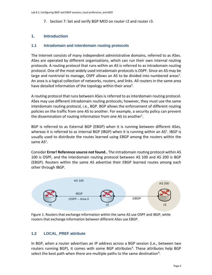
Lab 8.1: Configuring IBGP and EBGP sessions, Local preference, and MED
Page 4
7. Section 7: Set and verify BGP MED on router r2 and router r3. 1. Introduction 1.1 Intradomain and interdomain routing protocols
The Internet consists of many independent administrative domains, referred to as ASes. ASes are operated by different organizations, which can run their own internal routing protocols. A routing protocol that runs within an AS is referred to as intradomain routing protocol. One of the most widely used intradomain protocols is OSPF. Since an AS may be large and nontrivial to manage, OSPF allows an AS to be divided into numbered areas1. An area is a logical collection of networks, routers, and links. All routers in the same area have detailed information of the topology within their area2. A routing protocol that runs between ASes is referred to as interdomain routing protocol. ASes may use different intradomain routing protocols; however, they must use the same interdomain routing protocol, i.e., BGP. BGP allows the enforcement of different routing policies on the traffic from one AS to another. For example, a security policy can prevent the dissemination of routing information from one AS to another1. BGP is referred to as External BGP (EBGP) when it is running between different ASes, whereas it is referred to as Internal BGP (IBGP) when it is running within an AS1. IBGP is usually used to distribute the routes learned using EBGP among the routers within the same AS1. Consider Error! Reference source not found.. The intradomain routing protocol within AS 100 is OSPF, and the interdomain routing protocol between AS 100 and AS 200 is BGP (EBGP). Routers within the same AS advertise their EBGP learned routes among each other through IBGP.
AS 100
IBGP
OSPF – Area 0
AS 200
r1 r2 r3
EBGP
Figure 1. Routers that exchange information within the same AS use OSPF and IBGP, while routers that exchange information between different ASes use EBGP.
1.2 LOCAL_PREF attribute
In BGP, when a router advertises an IP address across a BGP session (i.e., between two routers running BGP), it comes with some BGP attributes3. These attributes help BGP select the best path when there are multiple paths to the same destination4.
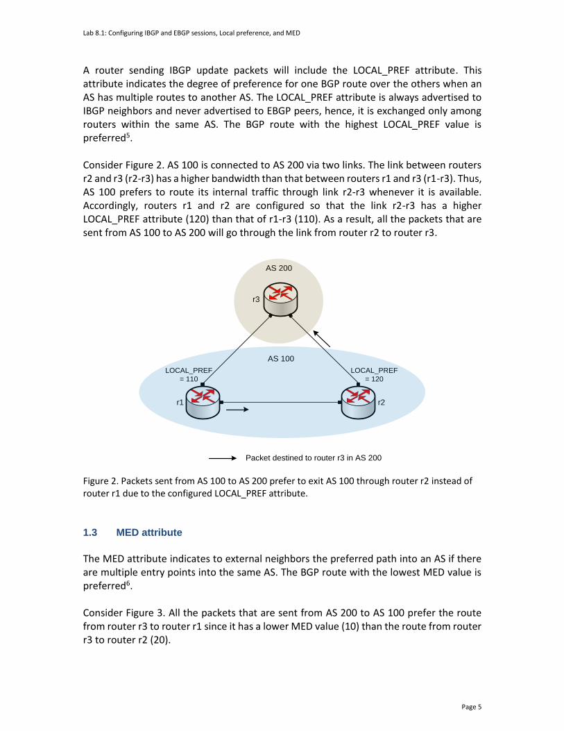
Lab 8.1: Configuring IBGP and EBGP sessions, Local preference, and MED
Page 5
A router sending IBGP update packets will include the LOCAL_PREF attribute. This attribute indicates the degree of preference for one BGP route over the others when an AS has multiple routes to another AS. The LOCAL_PREF attribute is always advertised to IBGP neighbors and never advertised to EBGP peers, hence, it is exchanged only among routers within the same AS. The BGP route with the highest LOCAL_PREF value is preferred5. Consider Figure 2. AS 100 is connected to AS 200 via two links. The link between routers r2 and r3 (r2-r3) has a higher bandwidth than that between routers r1 and r3 (r1-r3). Thus, AS 100 prefers to route its internal traffic through link r2-r3 whenever it is available. Accordingly, routers r1 and r2 are configured so that the link r2-r3 has a higher LOCAL_PREF attribute (120) than that of r1-r3 (110). As a result, all the packets that are sent from AS 100 to AS 200 will go through the link from router r2 to router r3.
AS 100
r1
r3
AS 200
r2
LOCAL_PREF
= 110
Packet destined to router r3 in AS 200
LOCAL_PREF
= 120
Figure 2. Packets sent from AS 100 to AS 200 prefer to exit AS 100 through router r2 instead of router r1 due to the configured LOCAL_PREF attribute.
1.3 MED attribute
The MED attribute indicates to external neighbors the preferred path into an AS if there are multiple entry points into the same AS. The BGP route with the lowest MED value is preferred6. Consider Figure 3. All the packets that are sent from AS 200 to AS 100 prefer the route from router r3 to router r1 since it has a lower MED value (10) than the route from router r3 to router r2 (20).
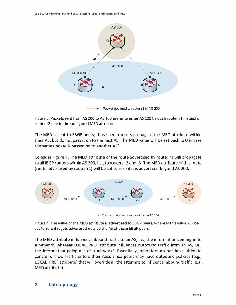
Lab 8.1: Configuring IBGP and EBGP sessions, Local preference, and MED
Page 6
AS 100
r1
r3
AS 200
r2
MED = 10
Packet destined to router r2 in AS 200
MED = 20
Figure 3. Packets sent from AS 200 to AS 100 prefer to enter AS 100 through router r1 instead of router r2 due to the configured MED attribute.
The MED is sent to EBGP peers; those peer routers propagate the MED attribute within their AS, but do not pass it on to the next AS. The MED value will be set back to 0 in case the same update is passed on to another AS7. Consider Figure 4. The MED attribute of the route advertised by router r1 will propagate to all IBGP routers within AS 200, i.e., to routers r2 and r3. The MED attribute of this route (route advertised by router r1) will be set to zero if it is advertised beyond AS 200.
AS 100AS 200
r1 r2
AS 300
r4MED = 90
Route advertisement from router r1 in AS 100
MED = 90 MED = 0r3
Figure 4. The value of the MED attribute is advertised to EBGP peers, whereas this value will be set to zero if it gets advertised outside the AS of those EBGP peers.
The MED attribute influences inbound traffic to an AS, i.e., the information coming-in to a network, whereas LOCAL_PREF attribute influences outbound traffic from an AS, i.e., the information going-out of a network5. Essentially, operators do not have ultimate control of how traffic enters their ASes since peers may have outbound policies (e.g., LOCAL_PREF attribute) that will override all the attempts to influence inbound traffic (e.g., MED attribute). 2 Lab topology
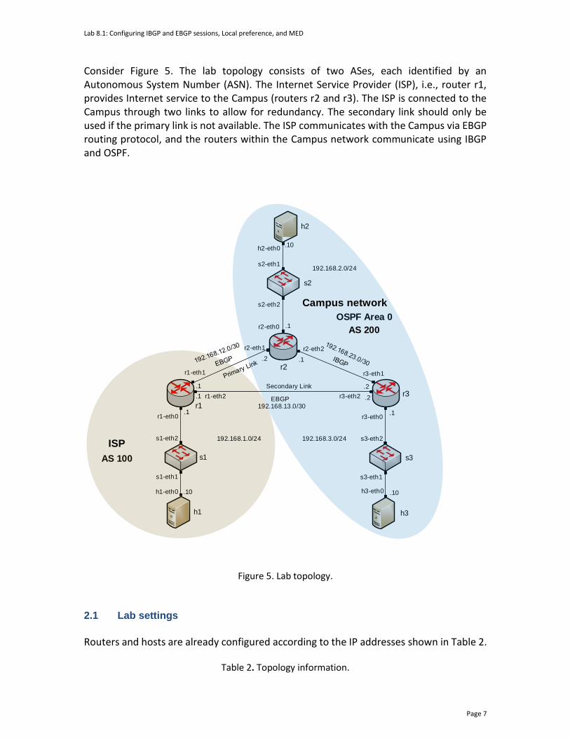
Lab 8.1: Configuring IBGP and EBGP sessions, Local preference, and MED
Page 7
Consider Figure 5. The lab topology consists of two ASes, each identified by an Autonomous System Number (ASN). The Internet Service Provider (ISP), i.e., router r1, provides Internet service to the Campus (routers r2 and r3). The ISP is connected to the Campus through two links to allow for redundancy. The secondary link should only be used if the primary link is not available. The ISP communicates with the Campus via EBGP routing protocol, and the routers within the Campus network communicate using IBGP and OSPF.
s2
s1 s3
h1
h2
h3
r1
r3
r1-eth1
r2-eth1
h1-eth0
s1-eth1
s1-eth2
r1-eth0
h2-eth0
s2-eth1
s2-eth2
r2-eth0
r2-eth2
r3-eth1
r3-eth0
s3-eth2
s3-eth1
h3-eth0
AS 100
OSPF Area 0
.10
.1
.1
.2 .1
.2
.1
.10
.1
.10
192.168.1.0/24 192.168.3.0/24
192.168.2.0/24
r2
.1 .2r1-eth2 r3-eth2
192.168.13.0/30
Secondary Link
Campus network
ISP
AS 200
EBGP
Figure 5. Lab topology.
2.1 Lab settings
Routers and hosts are already configured according to the IP addresses shown in Table 2.
Table 2. Topology information.
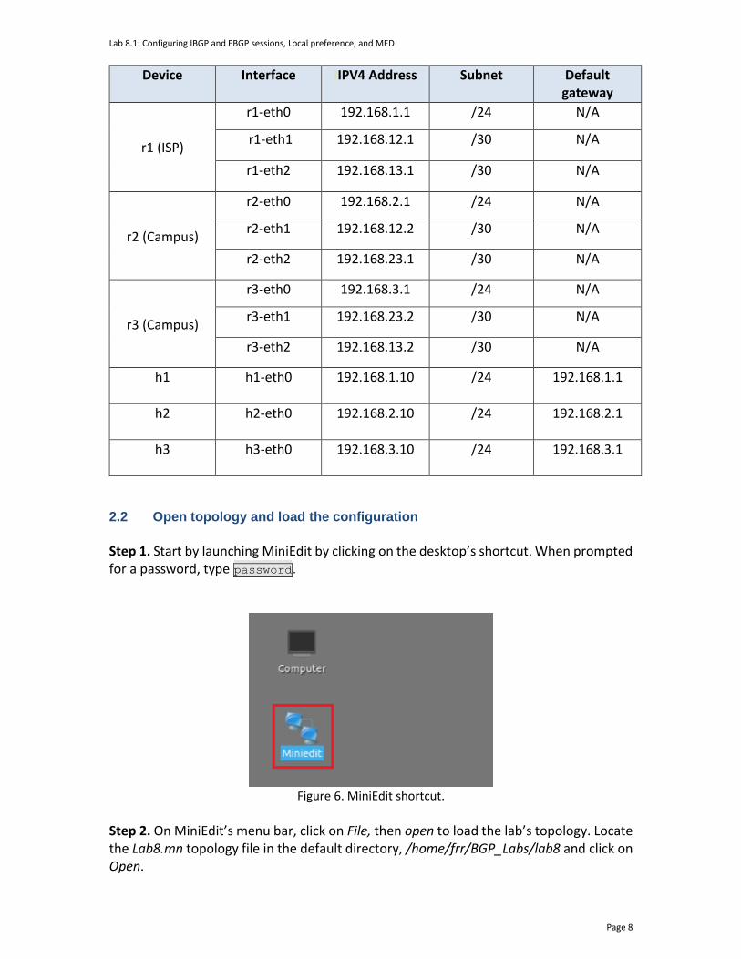
Lab 8.1: Configuring IBGP and EBGP sessions, Local preference, and MED
Page 8
Device Interface IIPV4 Address Subnet Default gateway
r1 (ISP)
r1-eth0 192.168.1.1 /24 N/A
r1-eth1 192.168.12.1 /30 N/A
r1-eth2 192.168.13.1 /30 N/A
r2 (Campus)
r2-eth0 192.168.2.1 /24 N/A
r2-eth1 192.168.12.2 /30 N/A
r2-eth2 192.168.23.1 /30 N/A
r3 (Campus)
r3-eth0 192.168.3.1 /24 N/A
r3-eth1 192.168.23.2 /30 N/A
r3-eth2 192.168.13.2 /30 N/A
h1
h1-eth0 192.168.1.10 /24 192.168.1.1
h2
h2-eth0 192.168.2.10 /24 192.168.2.1
h3
h3-eth0 192.168.3.10 /24 192.168.3.1
2.2 Open topology and load the configuration
Step 1. Start by launching MiniEdit by clicking on the desktop’s shortcut. When prompted for a password, type password.
Figure 6. MiniEdit shortcut.
Step 2. On MiniEdit’s menu bar, click on File, then open to load the lab’s topology. Locate the Lab8.mn topology file in the default directory, /home/frr/BGP_Labs/lab8 and click on Open.

Lab 8.1: Configuring IBGP and EBGP sessions, Local preference, and MED
Page 9
Figure 7. MiniEdit’s Open dialog.
At this point, the topology is loaded with all the required network components. You will execute a script that will load the configuration of the routers.
Step 3. Open the Linux terminal.
Figure 8. Opening Linux terminal.
Step 4. Click on the Linux terminal and navigate into BGP_Labs/lab8 directory by issuing the following command. This folder contains a configuration file and the script responsible for loading the configuration. The configuration file will assign the IP addresses to the routers’ interfaces. The cd command is short for change directory followed by an argument that specifies the destination directory. cd BGP_Labs/lab8
Figure 9. Entering the BGP_Labs/lab8 directory.
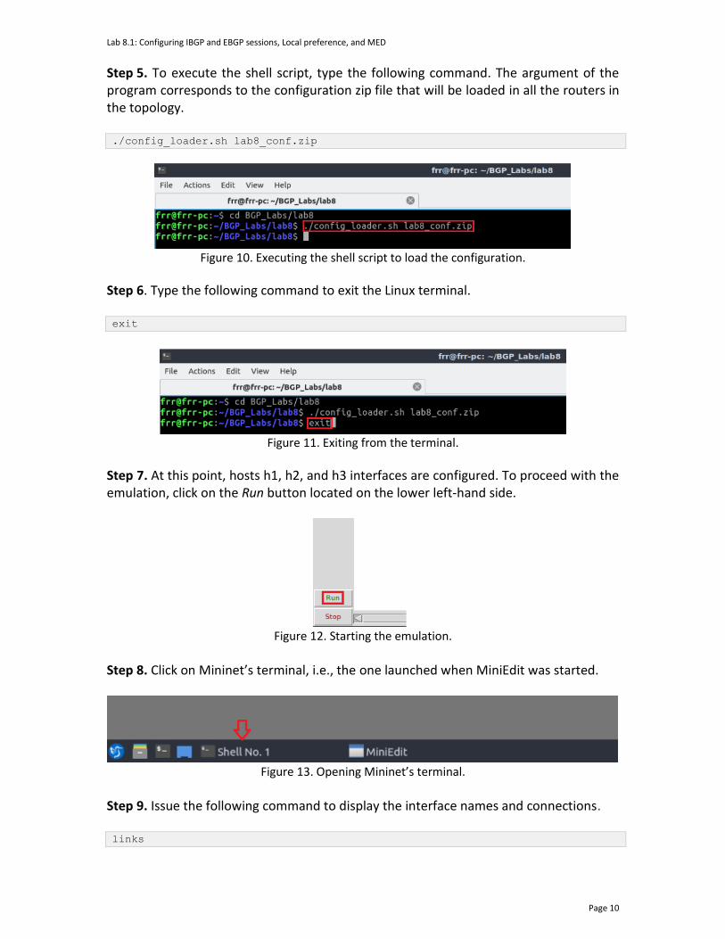
Lab 8.1: Configuring IBGP and EBGP sessions, Local preference, and MED
Page 10
Step 5. To execute the shell script, type the following command. The argument of the program corresponds to the configuration zip file that will be loaded in all the routers in the topology. ./config_loader.sh lab8_conf.zip
Figure 10. Executing the shell script to load the configuration.
Step 6. Type the following command to exit the Linux terminal. exit
Figure 11. Exiting from the terminal.
Step 7. At this point, hosts h1, h2, and h3 interfaces are configured. To proceed with the emulation, click on the Run button located on the lower left-hand side.
Figure 12. Starting the emulation.
Step 8. Click on Mininet’s terminal, i.e., the one launched when MiniEdit was started.
Figure 13. Opening Mininet’s terminal.
Step 9. Issue the following command to display the interface names and connections. links
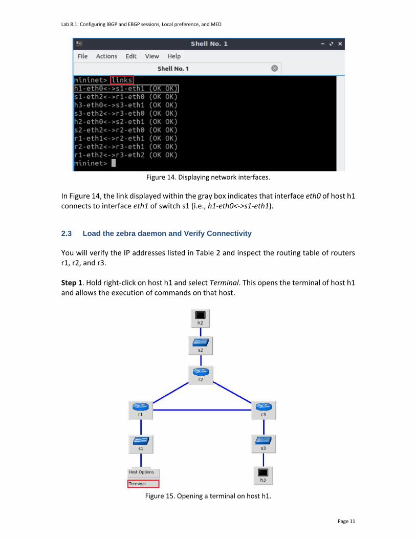
Lab 8.1: Configuring IBGP and EBGP sessions, Local preference, and MED
Page 11
Figure 14. Displaying network interfaces.
In Figure 14, the link displayed within the gray box indicates that interface eth0 of host h1 connects to interface eth1 of switch s1 (i.e., h1-eth0<->s1-eth1). 2.3 Load the zebra daemon and Verify Connectivity
You will verify the IP addresses listed in Table 2 and inspect the routing table of routers r1, r2, and r3. Step 1. Hold right-click on host h1 and select Terminal. This opens the terminal of host h1 and allows the execution of commands on that host.
Figure 15. Opening a terminal on host h1.

Lab 8.1: Configuring IBGP and EBGP sessions, Local preference, and MED
Page 12
Step 2. On host h1 terminal, type the command shown below to verify that the IP address was assigned successfully. You will verify that host h1 has two interfaces. Interface h1-eth0 is configured with the IP address 192.168.1.10 with the subnet mask 255.255.255.0. The loopback interface lo, is configured with the IP address 127.0.0.1. ifconfig
Figure 16. Output of ifconfig command.
Step 3. On host h1 terminal, type the command shown below to verify that the default gateway IP address is 192.168.1.1. route
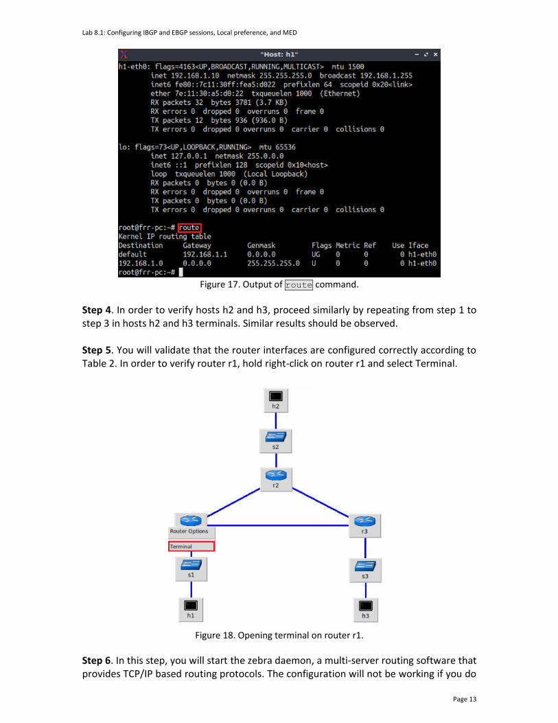
Lab 8.1: Configuring IBGP and EBGP sessions, Local preference, and MED
Page 13
Figure 17. Output of route command.
Step 4. In order to verify hosts h2 and h3, proceed similarly by repeating from step 1 to step 3 in hosts h2 and h3 terminals. Similar results should be observed. Step 5. You will validate that the router interfaces are configured correctly according to Table 2. In order to verify router r1, hold right-click on router r1 and select Terminal.
Figure 18. Opening terminal on router r1.
Step 6. In this step, you will start the zebra daemon, a multi-server routing software that provides TCP/IP based routing protocols. The configuration will not be working if you do
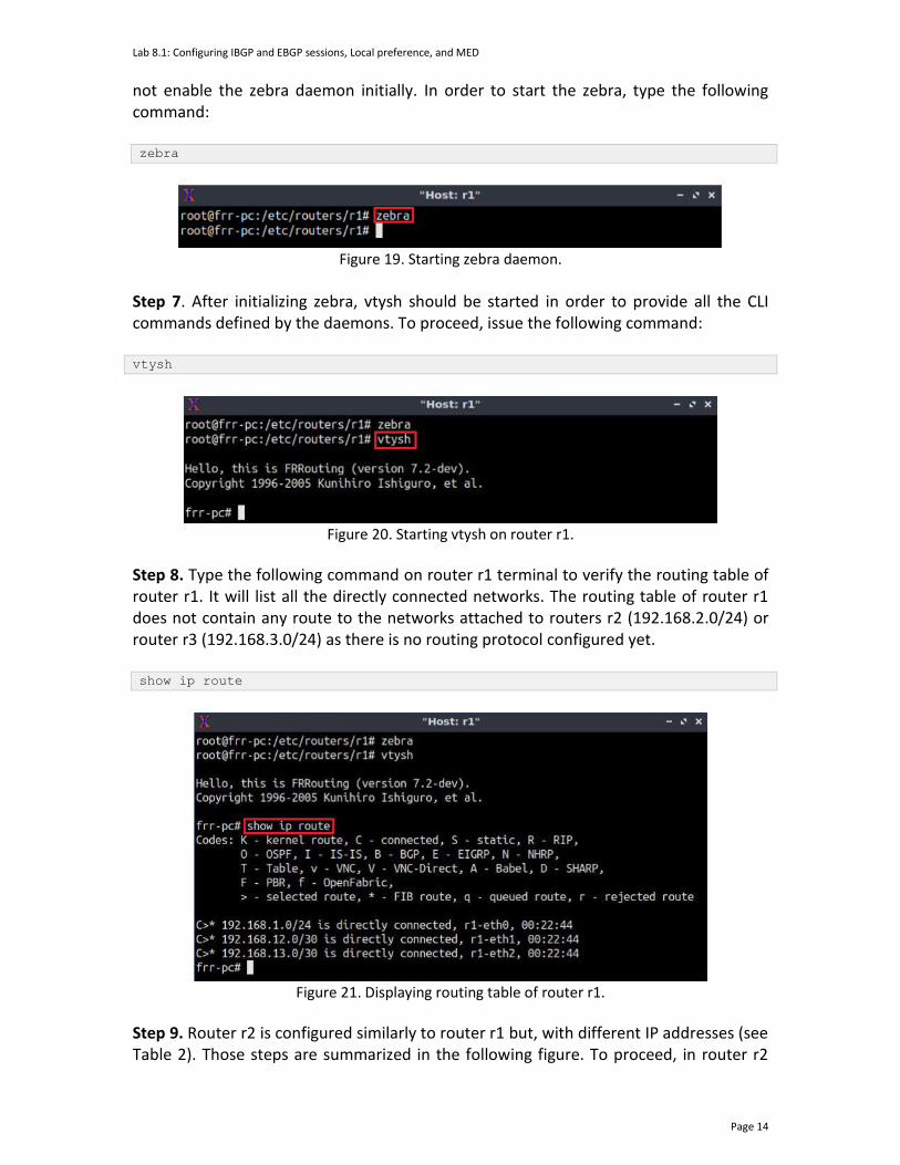
Lab 8.1: Configuring IBGP and EBGP sessions, Local preference, and MED
Page 14
not enable the zebra daemon initially. In order to start the zebra, type the following command: zebra
Figure 19. Starting zebra daemon.
Step 7. After initializing zebra, vtysh should be started in order to provide all the CLI commands defined by the daemons. To proceed, issue the following command: vtysh
Figure 20. Starting vtysh on router r1.
Step 8. Type the following command on router r1 terminal to verify the routing table of router r1. It will list all the directly connected networks. The routing table of router r1 does not contain any route to the networks attached to routers r2 (192.168.2.0/24) or router r3 (192.168.3.0/24) as there is no routing protocol configured yet. show ip route
Figure 21. Displaying routing table of router r1.
Step 9. Router r2 is configured similarly to router r1 but, with different IP addresses (see Table 2). Those steps are summarized in the following figure. To proceed, in router r2

Lab 8.1: Configuring IBGP and EBGP sessions, Local preference, and MED
Page 15
terminal issue the commands depicted below. In the end, you will verify all the directly connected networks of router r2.
Figure 22. Displaying routing table of router r2.
Step 10. Router r3 is configured similarly to router r1 but, with different IP addresses (see Table 2). Those steps are summarized in the following figure. To proceed, in router r3 terminal issue the commands depicted below. In the end, you verify all the directly connected networks of router r3.
Figure 23. Displaying routing table of router r3.
3 Configure OSPF on router r2 and router r3 In this section, you will configure OSPF routing protocol on router r2 and router r3. First, you will enable the OSPF daemon on routers r2 and r3. Second, you will establish a single area OSPF, which is classified as area 0 or backbone area. Finally, the networks 192.168.2.0/24, 192.168.3.0/24, and 192.168.23.0/30 will be advertised in area 0 between router r2 and router r3. Step 1. To configure OSPF routing protocol, you need to enable the OSPF daemon first. In router r2, type the following command to exit the vtysh session.
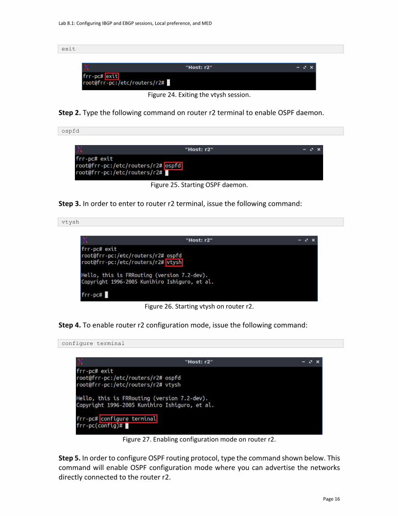
Lab 8.1: Configuring IBGP and EBGP sessions, Local preference, and MED
Page 16
exit
Figure 24. Exiting the vtysh session.
Step 2. Type the following command on router r2 terminal to enable OSPF daemon. ospfd
Figure 25. Starting OSPF daemon.
Step 3. In order to enter to router r2 terminal, issue the following command: vtysh
Figure 26. Starting vtysh on router r2.
Step 4. To enable router r2 configuration mode, issue the following command: configure terminal
Figure 27. Enabling configuration mode on router r2.
Step 5. In order to configure OSPF routing protocol, type the command shown below. This command will enable OSPF configuration mode where you can advertise the networks directly connected to the router r2.
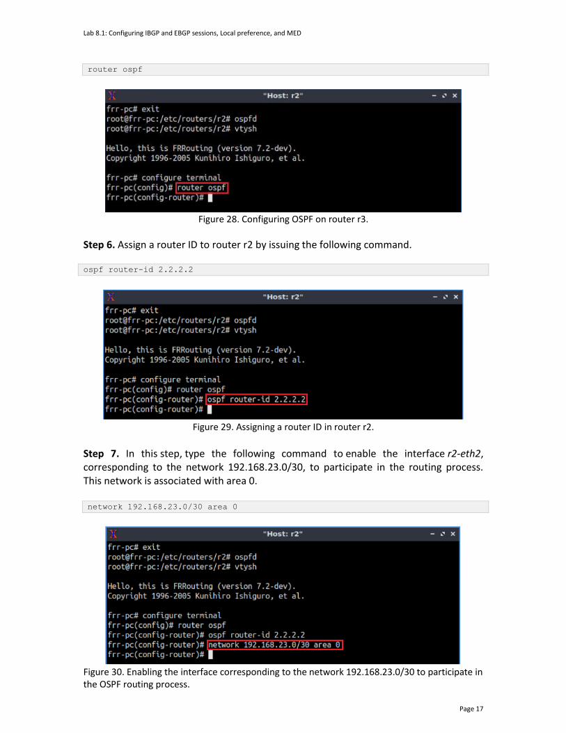
Lab 8.1: Configuring IBGP and EBGP sessions, Local preference, and MED
Page 17
router ospf
Figure 28. Configuring OSPF on router r3.
Step 6. Assign a router ID to router r2 by issuing the following command. ospf router-id 2.2.2.2
Figure 29. Assigning a router ID in router r2.
Step 7. In this step, type the following command to enable the interface r2-eth2, corresponding to the network 192.168.23.0/30, to participate in the routing process. This network is associated with area 0. network 192.168.23.0/30 area 0
Figure 30. Enabling the interface corresponding to the network 192.168.23.0/30 to participate in the OSPF routing process.

Lab 8.1: Configuring IBGP and EBGP sessions, Local preference, and MED
Page 18
Step 8. Similarly, type the following command in router r2 terminal to enable the interface r2-eth0 to participate in the OSPF routing process. network 192.168.2.0/24 area 0
Figure 31. Enabling the interface corresponding to 192.168.2.0/24 to participate in the OSPF routing process.
Step 9. Type the following command to exit from the configuration mode. end
Figure 32. Exiting from configuration mode.
Step 10. Router r3 is configured similarly to router r2 but, with different IP addresses (see Table 2). Those steps are summarized in the following figure. To proceed, on router r3 terminal issue the commands depicted below.
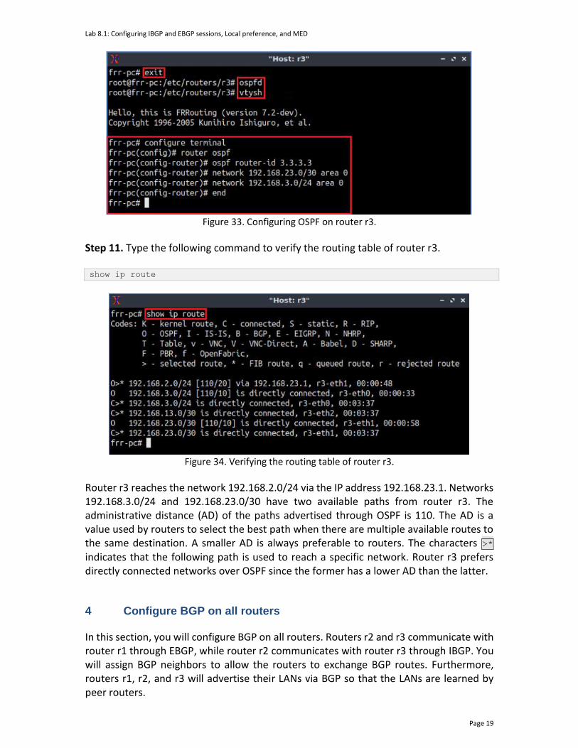
Lab 8.1: Configuring IBGP and EBGP sessions, Local preference, and MED
Page 19
Figure 33. Configuring OSPF on router r3.
Step 11. Type the following command to verify the routing table of router r3. show ip route
Figure 34. Verifying the routing table of router r3.
Router r3 reaches the network 192.168.2.0/24 via the IP address 192.168.23.1. Networks 192.168.3.0/24 and 192.168.23.0/30 have two available paths from router r3. The administrative distance (AD) of the paths advertised through OSPF is 110. The AD is a value used by routers to select the best path when there are multiple available routes to the same destination. A smaller AD is always preferable to routers. The characters >* indicates that the following path is used to reach a specific network. Router r3 prefers directly connected networks over OSPF since the former has a lower AD than the latter.
4 Configure BGP on all routers
In this section, you will configure BGP on all routers. Routers r2 and r3 communicate with router r1 through EBGP, while router r2 communicates with router r3 through IBGP. You will assign BGP neighbors to allow the routers to exchange BGP routes. Furthermore, routers r1, r2, and r3 will advertise their LANs via BGP so that the LANs are learned by peer routers.
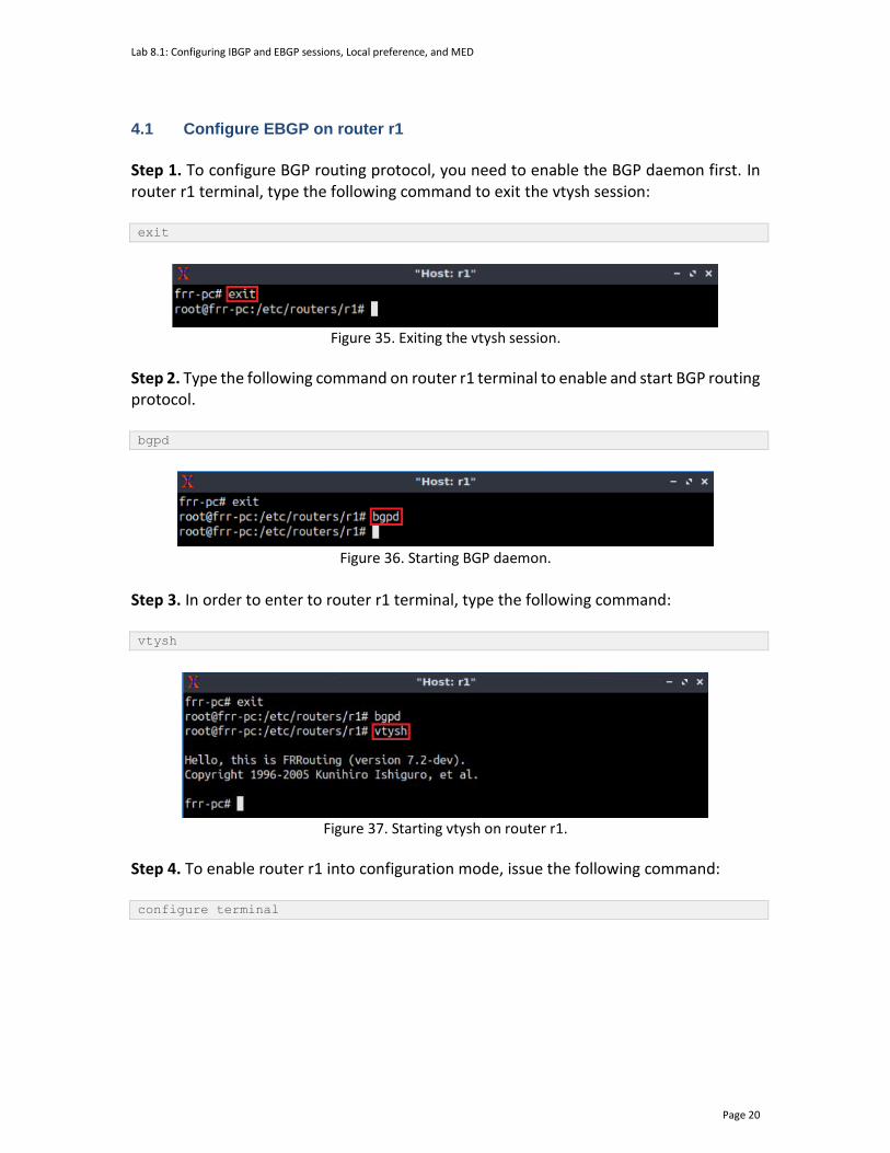
Lab 8.1: Configuring IBGP and EBGP sessions, Local preference, and MED
Page 20
4.1 Configure EBGP on router r1
Step 1. To configure BGP routing protocol, you need to enable the BGP daemon first. In router r1 terminal, type the following command to exit the vtysh session: exit
Figure 35. Exiting the vtysh session.
Step 2. Type the following command on router r1 terminal to enable and start BGP routing protocol. bgpd
Figure 36. Starting BGP daemon.
Step 3. In order to enter to router r1 terminal, type the following command: vtysh
Figure 37. Starting vtysh on router r1.
Step 4. To enable router r1 into configuration mode, issue the following command: configure terminal

Lab 8.1: Configuring IBGP and EBGP sessions, Local preference, and MED
Page 21
Figure 38. Enabling configuration mode on router r1.
Step 5. The ASN assigned for router r1 is 100. In order to configure BGP, type the following command: router bgp 100
Figure 39. Configuring BGP on router r1.
Step 6. Assign a router ID to router r1 by issuing the following command. bgp router-id 1.1.1.1
Figure 40. Assigning a router ID in router r1.
Step 7. To configure a BGP neighbor to router r1 (AS 100), type the command shown below. This command specifies the neighbor IP address (192.168.12.2) and the ASN of the remote BGP peer (AS 200). neighbor 192.168.12.2 remote-as 200

Lab 8.1: Configuring IBGP and EBGP sessions, Local preference, and MED
Page 22
Figure 41. Assigning BGP neighbor to router r1.
Step 8. Type the following command to add another BGP neighbor (192.168.13.2) to router r1. neighbor 192.168.13.2 remote-as 200
Figure 42. Assigning BGP neighbor to router r1.
Step 9. In this step, router r1 will advertise the LAN 192.168.1.0/24 to its BGP peers. To do so, issue the following command: network 192.168.1.0/24
Figure 43. Advertising local network on router r1.

Lab 8.1: Configuring IBGP and EBGP sessions, Local preference, and MED
Page 23
Step 10. Type the following command to exit from router configuration mode. end
Figure 44. Exiting from configuration mode.
Step 11. Type the following command to verify BGP networks. You will observe the LAN network of router r1. show ip bgp
Figure 45. Verifying BGP networks on router r1.
4.2 Configure EBGP and IBGP on router r2 and router r3
Step 1. To configure BGP routing protocol, you need to enable the BGP daemon first. In router r2 terminal, type the following command to exit the vtysh session: exit
Figure 46. Exiting the vtysh session on router r2 terminal.

Lab 8.1: Configuring IBGP and EBGP sessions, Local preference, and MED
Page 24
Step 2. Type the following command in router r2 terminal to enable and to start BGP routing protocol. bgpd
Figure 47. Starting BGP daemon.
Step 3. In order to enter to router r2 terminal, type the following command: vtysh
Figure 48. Starting vtysh on router r2.
Step 4. To enable router r2 into global configuration mode, issue the following command: configure terminal
Figure 49. Enabling configuration mode on router r2.
Step 5. The ASN assigned for router r2 is 200. In order to configure BGP, type the following command: router bgp 200
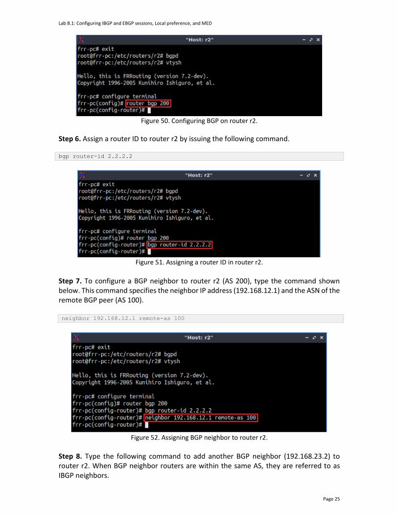
Lab 8.1: Configuring IBGP and EBGP sessions, Local preference, and MED
Page 25
Figure 50. Configuring BGP on router r2.
Step 6. Assign a router ID to router r2 by issuing the following command. bgp router-id 2.2.2.2
Figure 51. Assigning a router ID in router r2.
Step 7. To configure a BGP neighbor to router r2 (AS 200), type the command shown below. This command specifies the neighbor IP address (192.168.12.1) and the ASN of the remote BGP peer (AS 100). neighbor 192.168.12.1 remote-as 100
Figure 52. Assigning BGP neighbor to router r2.
Step 8. Type the following command to add another BGP neighbor (192.168.23.2) to router r2. When BGP neighbor routers are within the same AS, they are referred to as IBGP neighbors.

Lab 8.1: Configuring IBGP and EBGP sessions, Local preference, and MED
Page 26
neighbor 192.168.23.2 remote-as 200
Figure 53. Assigning BGP neighbor to router r2.
Step 9. In this step, router r2 will advertise the LAN 192.168.2.0/24 and the network will be learned by router r1 through EBGP. In order to advertise the LAN 192.168.2.0/24 connected to router r2, issue the following command: network 192.168.2.0/24
Figure 54. Advertising local network on router r2.
Step 10. Type the following command to exit from configuration mode. end
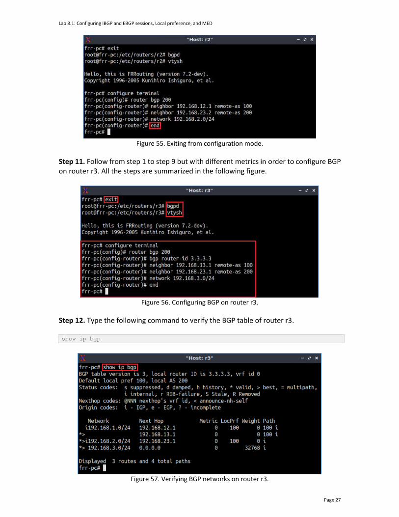
Lab 8.1: Configuring IBGP and EBGP sessions, Local preference, and MED
Page 27
Figure 55. Exiting from configuration mode.
Step 11. Follow from step 1 to step 9 but with different metrics in order to configure BGP on router r3. All the steps are summarized in the following figure.
Figure 56. Configuring BGP on router r3.
Step 12. Type the following command to verify the BGP table of router r3. show ip bgp
Figure 57. Verifying BGP networks on router r3.
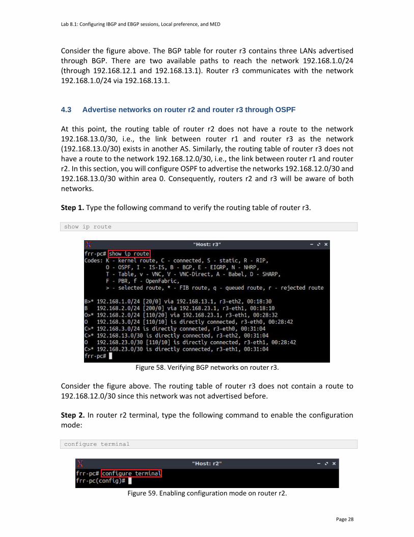
Lab 8.1: Configuring IBGP and EBGP sessions, Local preference, and MED
Page 28
Consider the figure above. The BGP table for router r3 contains three LANs advertised through BGP. There are two available paths to reach the network 192.168.1.0/24 (through 192.168.12.1 and 192.168.13.1). Router r3 communicates with the network 192.168.1.0/24 via 192.168.13.1. 4.3 Advertise networks on router r2 and router r3 through OSPF
At this point, the routing table of router r2 does not have a route to the network 192.168.13.0/30, i.e., the link between router r1 and router r3 as the network (192.168.13.0/30) exists in another AS. Similarly, the routing table of router r3 does not have a route to the network 192.168.12.0/30, i.e., the link between router r1 and router r2. In this section, you will configure OSPF to advertise the networks 192.168.12.0/30 and 192.168.13.0/30 within area 0. Consequently, routers r2 and r3 will be aware of both networks.
Step 1. Type the following command to verify the routing table of router r3. show ip route
Figure 58. Verifying BGP networks on router r3.
Consider the figure above. The routing table of router r3 does not contain a route to 192.168.12.0/30 since this network was not advertised before.
Step 2. In router r2 terminal, type the following command to enable the configuration mode: configure terminal
Figure 59. Enabling configuration mode on router r2.
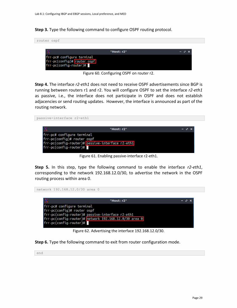
Lab 8.1: Configuring IBGP and EBGP sessions, Local preference, and MED
Page 29
Step 3. Type the following command to configure OSPF routing protocol. router ospf
Figure 60. Configuring OSPF on router r2.
Step 4. The interface r2-eth1 does not need to receive OSPF advertisements since BGP is running between routers r1 and r2. You will configure OSPF to set the interface r2-eth1 as passive, i.e., the interface does not participate in OSPF and does not establish adjacencies or send routing updates. However, the interface is announced as part of the routing network. passive-interface r2-eth1
Figure 61. Enabling passive-interface r2-eth1.
Step 5. In this step, type the following command to enable the interface r2-eth1, corresponding to the network 192.168.12.0/30, to advertise the network in the OSPF routing process within area 0. network 192.168.12.0/30 area 0
Figure 62. Advertising the interface 192.168.12.0/30.
Step 6. Type the following command to exit from router configuration mode. end
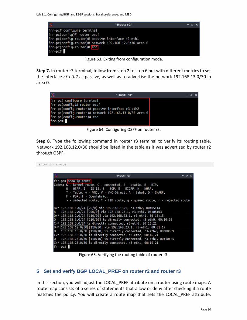
Lab 8.1: Configuring IBGP and EBGP sessions, Local preference, and MED
Page 30
Figure 63. Exiting from configuration mode.
Step 7. In router r3 terminal, follow from step 2 to step 6 but with different metrics to set the interface r3-eth2 as passive, as well as to advertise the network 192.168.13.0/30 in area 0.
Figure 64. Configuring OSPF on router r3.
Step 8. Type the following command in router r3 terminal to verify its routing table. Network 192.168.12.0/30 should be listed in the table as it was advertised by router r2 through OSPF. show ip route
Figure 65. Verifying the routing table of router r3.
5 Set and verify BGP LOCAL_PREF on router r2 and router r3
In this section, you will adjust the LOCAL_PREF attribute on a router using route maps. A route map consists of a series of statements that allow or deny after checking if a route matches the policy. You will create a route map that sets the LOCAL_PREF attribute.
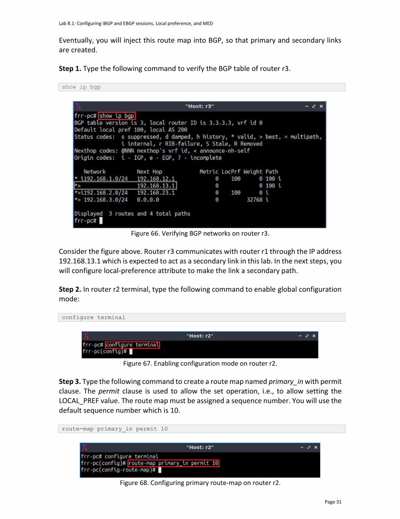
Lab 8.1: Configuring IBGP and EBGP sessions, Local preference, and MED
Page 31
Eventually, you will inject this route map into BGP, so that primary and secondary links are created. Step 1. Type the following command to verify the BGP table of router r3. show ip bgp
Figure 66. Verifying BGP networks on router r3.
Consider the figure above. Router r3 communicates with router r1 through the IP address 192.168.13.1 which is expected to act as a secondary link in this lab. In the next steps, you will configure local-preference attribute to make the link a secondary path. Step 2. In router r2 terminal, type the following command to enable global configuration mode: configure terminal
Figure 67. Enabling configuration mode on router r2.
Step 3. Type the following command to create a route map named primary_in with permit clause. The permit clause is used to allow the set operation, i.e., to allow setting the LOCAL_PREF value. The route map must be assigned a sequence number. You will use the default sequence number which is 10. route-map primary_in permit 10
Figure 68. Configuring primary route-map on router r2.
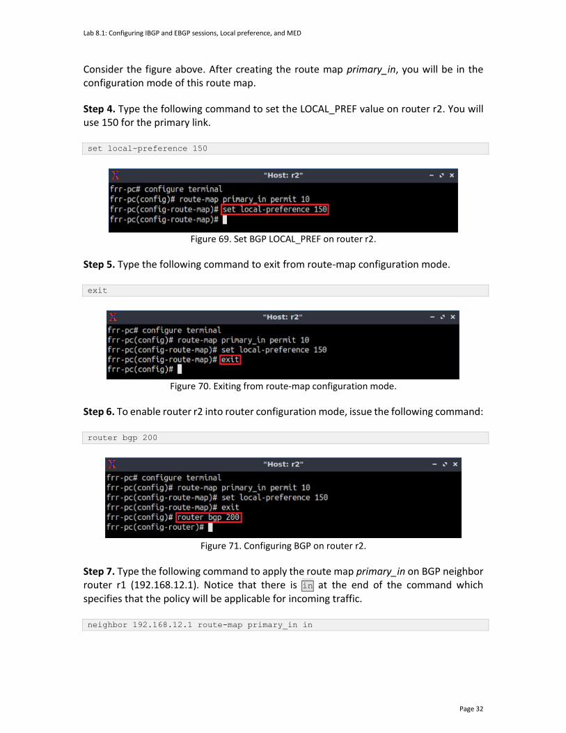
Lab 8.1: Configuring IBGP and EBGP sessions, Local preference, and MED
Page 32
Consider the figure above. After creating the route map primary_in, you will be in the configuration mode of this route map.
Step 4. Type the following command to set the LOCAL_PREF value on router r2. You will use 150 for the primary link. set local-preference 150
Figure 69. Set BGP LOCAL_PREF on router r2.
Step 5. Type the following command to exit from route-map configuration mode. exit
Figure 70. Exiting from route-map configuration mode.
Step 6. To enable router r2 into router configuration mode, issue the following command: router bgp 200
Figure 71. Configuring BGP on router r2.
Step 7. Type the following command to apply the route map primary_in on BGP neighbor router r1 (192.168.12.1). Notice that there is in at the end of the command which specifies that the policy will be applicable for incoming traffic. neighbor 192.168.12.1 route-map primary_in in
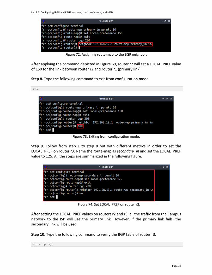
Lab 8.1: Configuring IBGP and EBGP sessions, Local preference, and MED
Page 33
Figure 72. Assigning route-map to the BGP neighbor.
After applying the command depicted in Figure 69, router r2 will set a LOCAL_PREF value of 150 for the link between router r2 and router r1 (primary link).
Step 8. Type the following command to exit from configuration mode. end
Figure 73. Exiting from configuration mode.
Step 9. Follow from step 1 to step 8 but with different metrics in order to set the LOCAL_PREF on router r3. Name the route-map as secondary_in and set the LOCAL_PREF value to 125. All the steps are summarized in the following figure.
Figure 74. Set LOCAL_PREF on router r3.
After setting the LOCAL_PREF values on routers r2 and r3, all the traffic from the Campus network to the ISP will use the primary link. However, if the primary link fails, the secondary link will be used. Step 10. Type the following command to verify the BGP table of router r3. show ip bgp

Lab 8.1: Configuring IBGP and EBGP sessions, Local preference, and MED
Page 34
Figure 75. Verifying BGP networks on router r3.
Consider the figure above. Router r3 will use the next hop 192.168.12.1 (primary link) to reach the LAN 192.168.1.0/24. Router r3 will not use the next hop 192.168.13.1 (secondary link) unless the primary link is unavailable.
6 Set and verify BGP MED on router r2 and router r3
At this point, routers r2 and r3 will use the primary link to route their traffic to router r1. However, router r1 is not forced to use the primary link to route its traffic to routers r2 and r3. In this section, you will set the MED attribute on routers r2 and r3 so that router r1 always uses the primary link. The MED indicates to external neighbors the preferred path into an AS. A lower metric value is preferred. You will create a route map which will be injected into BGP later. 6.1 Set BGP MED on router r2 and router r3
Step 1. Type the following command to verify the BGP table of router r1. show ip bgp
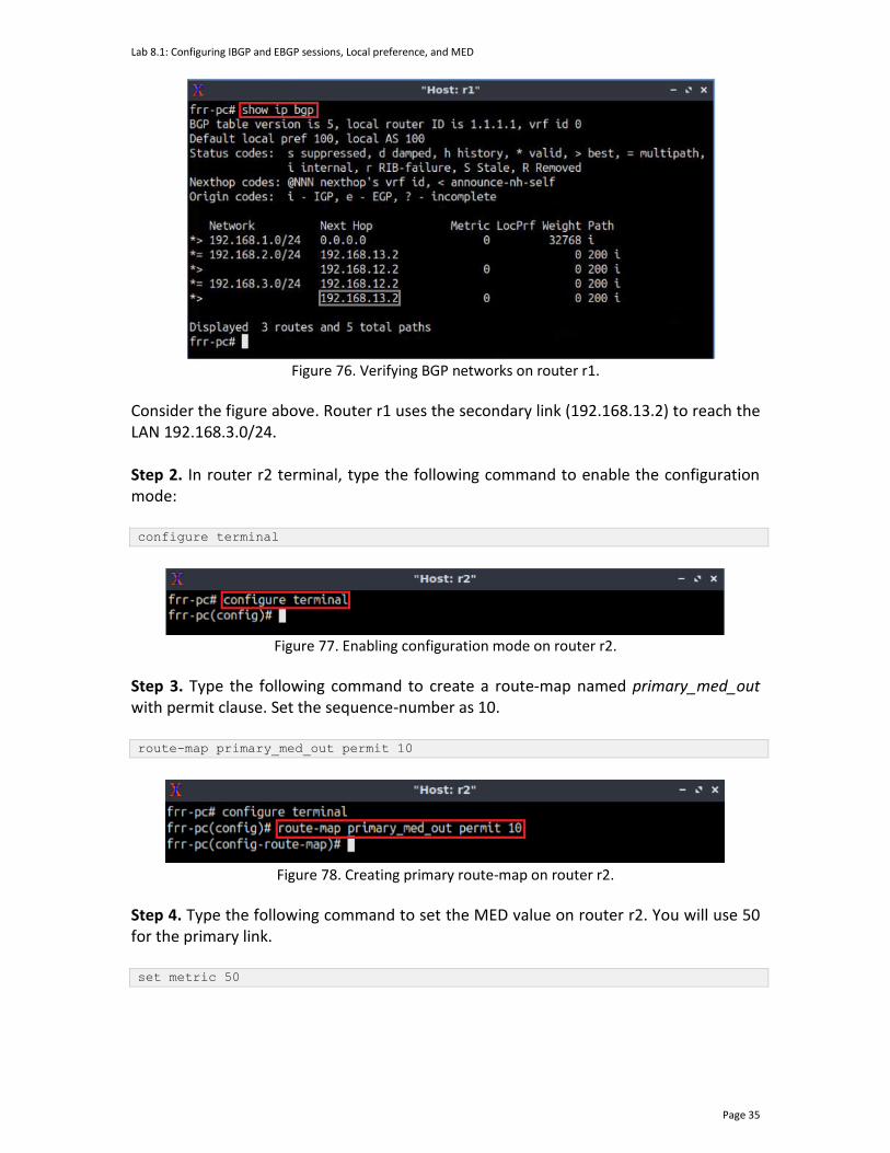
Lab 8.1: Configuring IBGP and EBGP sessions, Local preference, and MED
Page 35
Figure 76. Verifying BGP networks on router r1.
Consider the figure above. Router r1 uses the secondary link (192.168.13.2) to reach the LAN 192.168.3.0/24. Step 2. In router r2 terminal, type the following command to enable the configuration mode: configure terminal
Figure 77. Enabling configuration mode on router r2.
Step 3. Type the following command to create a route-map named primary_med_out with permit clause. Set the sequence-number as 10. route-map primary_med_out permit 10
Figure 78. Creating primary route-map on router r2.
Step 4. Type the following command to set the MED value on router r2. You will use 50 for the primary link. set metric 50

Lab 8.1: Configuring IBGP and EBGP sessions, Local preference, and MED
Page 36
Figure 79. Set metric on router r2.
Step 5. Type the following command to exit from route map configuration mode. exit
Figure 80. Exiting from route-map configuration mode.
Step 6. Type the following command to enter BGP configuration mode. router bgp 200
Figure 81. Configuring BGP on router r2.
Step 7. Type the following command to apply the route map primary_med_out on BGP neighbor router r1 (192.168.12.1). Notice that there is out at the end of the command which specifies that the policy will be applicable for outgoing traffic. neighbor 192.168.12.1 route-map primary_med_out out
Figure 82. Assign route-map to the BGP neighbor.
Step 8. Type the following command to exit from configuration mode. end
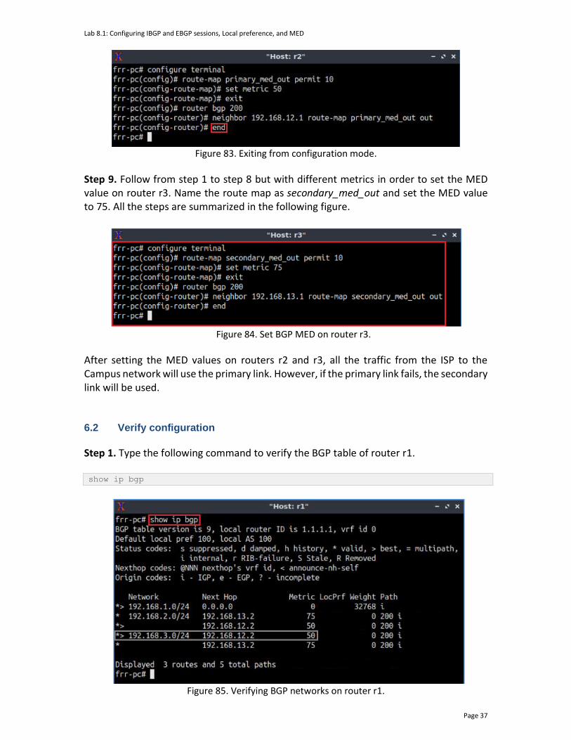
Lab 8.1: Configuring IBGP and EBGP sessions, Local preference, and MED
Page 37
Figure 83. Exiting from configuration mode.
Step 9. Follow from step 1 to step 8 but with different metrics in order to set the MED value on router r3. Name the route map as secondary_med_out and set the MED value to 75. All the steps are summarized in the following figure.
Figure 84. Set BGP MED on router r3.
After setting the MED values on routers r2 and r3, all the traffic from the ISP to the Campus network will use the primary link. However, if the primary link fails, the secondary link will be used. 6.2 Verify configuration
Step 1. Type the following command to verify the BGP table of router r1. show ip bgp
Figure 85. Verifying BGP networks on router r1.
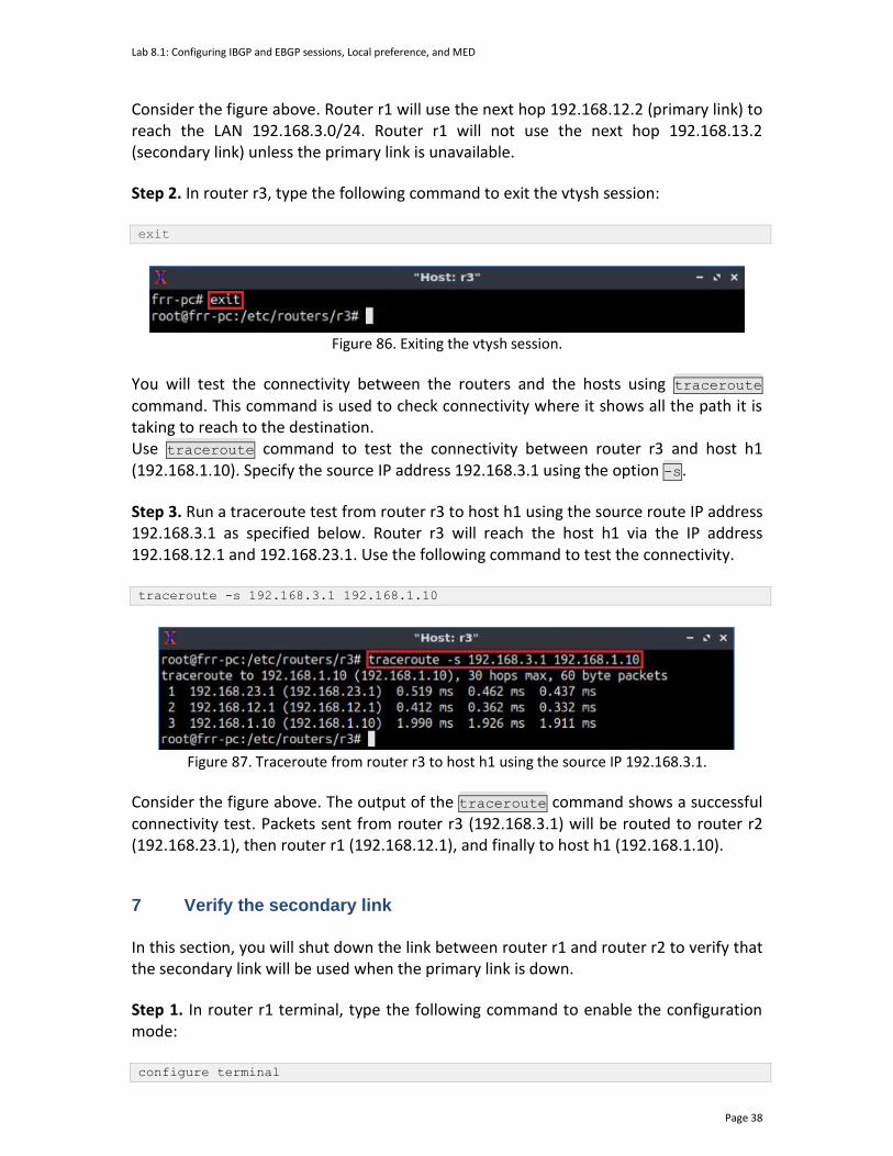
Lab 8.1: Configuring IBGP and EBGP sessions, Local preference, and MED
Page 38
Consider the figure above. Router r1 will use the next hop 192.168.12.2 (primary link) to reach the LAN 192.168.3.0/24. Router r1 will not use the next hop 192.168.13.2 (secondary link) unless the primary link is unavailable.
Step 2. In router r3, type the following command to exit the vtysh session: exit
Figure 86. Exiting the vtysh session.
You will test the connectivity between the routers and the hosts using traceroute command. This command is used to check connectivity where it shows all the path it is taking to reach to the destination. Use traceroute command to test the connectivity between router r3 and host h1 (192.168.1.10). Specify the source IP address 192.168.3.1 using the option -s.
Step 3. Run a traceroute test from router r3 to host h1 using the source route IP address 192.168.3.1 as specified below. Router r3 will reach the host h1 via the IP address 192.168.12.1 and 192.168.23.1. Use the following command to test the connectivity. traceroute -s 192.168.3.1 192.168.1.10
Figure 87. Traceroute from router r3 to host h1 using the source IP 192.168.3.1.
Consider the figure above. The output of the traceroute command shows a successful connectivity test. Packets sent from router r3 (192.168.3.1) will be routed to router r2 (192.168.23.1), then router r1 (192.168.12.1), and finally to host h1 (192.168.1.10).
7 Verify the secondary link
In this section, you will shut down the link between router r1 and router r2 to verify that the secondary link will be used when the primary link is down.
Step 1. In router r1 terminal, type the following command to enable the configuration mode: configure terminal

Lab 8.1: Configuring IBGP and EBGP sessions, Local preference, and MED
Page 39
Figure 88. Enabling configuration mode on router r1.
Step 2. In order to configure the interface r1-eth1 of router r1, type the following command: interface r1-eth1
Figure 89. Configuring router r1 interface.
Step 3. Type the following command to shut down the link between router r1 and router r2:
shutdown
Figure 90. Shutting down the link between router r1 and router r2.
Step 4. Type the following command to exit from configuration mode. end
Figure 91. Exiting from configuration mode.
Step 5. Type the following command to verify the BGP table of router r1. show ip bgp
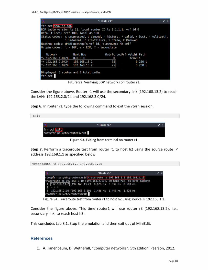
Lab 8.1: Configuring IBGP and EBGP sessions, Local preference, and MED
Page 40
Figure 92. Verifying BGP networks on router r1.
Consider the figure above. Router r1 will use the secondary link (192.168.13.2) to reach the LANs 192.168.2.0/24 and 192.168.3.0/24.
Step 6. In router r1, type the following command to exit the vtysh session:
exit
Figure 93. Exiting from terminal on router r1.
Step 7. Perform a traceroute test from router r1 to host h2 using the source route IP address 192.168.1.1 as specified below. traceroute -s 192.168.1.1 192.168.2.10
Figure 94. Traceroute test from router r1 to host h2 using source IP 192.168.1.1.
Consider the figure above. This time router1 will use router r3 (192.168.13.2), i.e., secondary link, to reach host h3. This concludes Lab 8.1. Stop the emulation and then exit out of MiniEdit. References
1. A. Tanenbaum, D. Wetherall, “Computer networks”, 5th Edition, Pearson, 2012.

Lab 8.1: Configuring IBGP and EBGP sessions, Local preference, and MED
Page 41
2. Cisco, “What are OSPF areas and virtual links?”, 2016. [Online]. Available: https://www.cisco.com/c/en/us/support/docs/ip/open-shortest-path-first-ospf/13703-8.html
3. J. Kurose, K. Ross, “Computer networking, a top-down approach,” 7th Edition, Pearson, 2017.
4. Cisco, “BGP best path selection algorithm”, 2016. [Online]. Available: https://www.cisco.com/c/en/us/support/docs/ip/border-gateway-protocol-bgp/13753-25.html#anc2
5. Cisco, “IP routing: BGP configuration guide, Cisco IOS release 15M&T”, 2013. [Online]. Available: https://www.cisco.com/c/en/us/td/docs/ios-xml/ios/iproute_bgp/configuration/15-mt/irg-15-mt-book.pdf
6. Cisco, “Understanding BGP MED attribute”, 2014. [Online]. Available: https://www.cisco.com/c/en/us/support/docs/ip/border-gateway-protocol-bgp/112965-bgpmed-attr-00.html
7. D. Teare, B. Vachon, R. Graziani, "Implementing cisco IP Routing (Route), foundation learning guide," CCNP ROUTE 300-101.
8. CCNP, Lab 7-3, “Configuring IBGP and EBGP Sessions, Local Preference, and MED - completed”.
BORDER GATEWAY PROTOCOL
Exercise 3: Steering Traffic using BGP Local Preference Attribute
Document Version: 09-02-2021
Award 1829698 “CyberTraining CIP: Cyberinfrastructure Expertise on High-throughput
Networks for Big Science Data Transfers”

Exercise 3: Steering Traffic using BGP Local Preference Attribute
Contents 1 Exercise description .................................................................................................... 3
1.1 Topology settings ................................................................................................. 3
1.2 Credentials ........................................................................................................... 4
2 Deliverables ................................................................................................................. 4
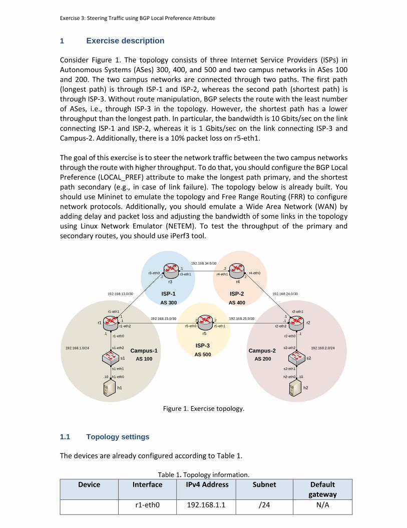
Exercise 3: Steering Traffic using BGP Local Preference Attribute
1 Exercise description Consider Figure 1. The topology consists of three Internet Service Providers (ISPs) in Autonomous Systems (ASes) 300, 400, and 500 and two campus networks in ASes 100 and 200. The two campus networks are connected through two paths. The first path (longest path) is through ISP-1 and ISP-2, whereas the second path (shortest path) is through ISP-3. Without route manipulation, BGP selects the route with the least number of ASes, i.e., through ISP-3 in the topology. However, the shortest path has a lower throughput than the longest path. In particular, the bandwidth is 10 Gbits/sec on the link connecting ISP-1 and ISP-2, whereas it is 1 Gbits/sec on the link connecting ISP-3 and Campus-2. Additionally, there is a 10% packet loss on r5-eth1. The goal of this exercise is to steer the network traffic between the two campus networks through the route with higher throughput. To do that, you should configure the BGP Local Preference (LOCAL_PREF) attribute to make the longest path primary, and the shortest path secondary (e.g., in case of link failure). The topology below is already built. You should use Mininet to emulate the topology and Free Range Routing (FRR) to configure network protocols. Additionally, you should emulate a Wide Area Network (WAN) by adding delay and packet loss and adjusting the bandwidth of some links in the topology using Linux Network Emulator (NETEM). To test the throughput of the primary and secondary routes, you should use iPerf3 tool.
Campus-1
s1
h1
r1
h1-eth0
s1-eth1
s1-eth2
r1-eth0
AS 100
.10
.1
192.168.1.0/24
.1
r1-eth1
s2
h2
h2-eth0
s2-eth1
s2-eth2
r2-eth0
AS 200
.10
.1
192.168.2.0/24
r3 r4
r2
r3-eth0 r3-eth1 r4-eth1
r1-eth2 r2-eth2
r4-eth0
r2-eth1
Campus-2
AS 300
ISP-1
AS 400
ISP-2
192.168.15.0/30.1 .1
192.168.13.0/30 192.168.24.0/30
.2
.1
.2
192.168.34.0/30
.1 .2
r5
r5-eth0 r5-eth1
AS 500
ISP-3
.2 .2192.168.25.0/30
Figure 1. Exercise topology.
1.1 Topology settings
The devices are already configured according to Table 1.
Table 1. Topology information.
Device Interface IIPv4 Address Subnet Default gateway
r1-eth0 192.168.1.1 /24 N/A

Exercise 3: Steering Traffic using BGP Local Preference Attribute
Router r1 (Campus-1)
r1-eth1 192.168.13.1 /30 N/A
r1-eth2 192.168.15.1 /30 N/A
Router r2
(Campus-2)
r2-eth0 192.168.2.1 /24 N/A
r2-eth1 192.168.24.1 /30 N/A
r2-eth2 192.168.25.1 /30 N/A
Router r3 (ISP-1)
r3-eth0 192.168.13.2 /30 N/A
r3-eth1 192.168.34.1 /30 N/A
Router r4 (ISP-2)
r4-eth0 192.168.24.2 /30 N/A
r4-eth1 192.168.34.2 /30 N/A
Router r5 (ISP-3)
r5-eth0 192.168.15.2 /30 N/A
r5-eth1 192.168.25.2 /30 N/A
Host h1
h1-eth0 192.168.1.10 /24 192.168.1.1
Host h2
h2-eth0 192.168.2.10 /24 192.168.2.1
1.2 Credentials
The information in Table 2 provides the credentials to access the Client’s virtual machine.
Table 2. Credentials to access the Client’s virtual machine.
Device
Account
Password
Client admin password
2 Deliverables Follow the steps below to complete the exercise. a) Open MiniEdit and load the topology above. The topology file Exercise3.mn of this exercise is in the directory ~/BGP_Labs/Exercise3 as shown in the figure below. Do not run MiniEdit.
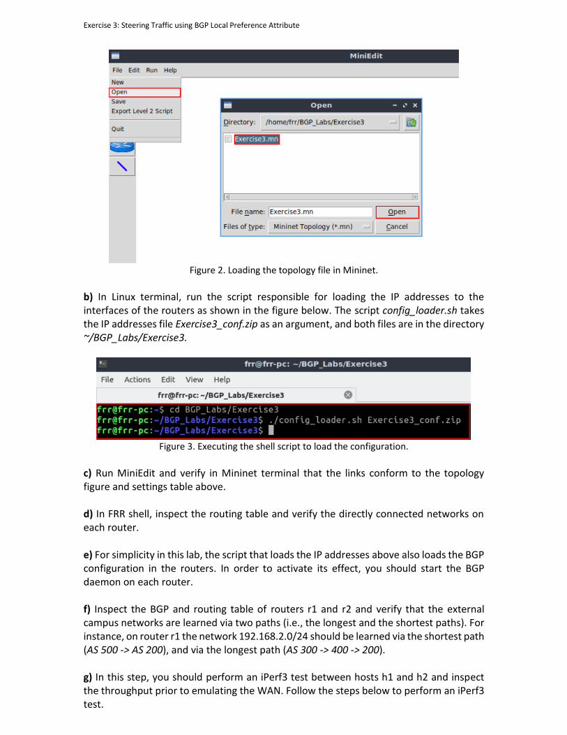
Exercise 3: Steering Traffic using BGP Local Preference Attribute
Figure 2. Loading the topology file in Mininet.
b) In Linux terminal, run the script responsible for loading the IP addresses to the interfaces of the routers as shown in the figure below. The script config_loader.sh takes the IP addresses file Exercise3_conf.zip as an argument, and both files are in the directory ~/BGP_Labs/Exercise3.
Figure 3. Executing the shell script to load the configuration.
c) Run MiniEdit and verify in Mininet terminal that the links conform to the topology figure and settings table above. d) In FRR shell, inspect the routing table and verify the directly connected networks on each router. e) For simplicity in this lab, the script that loads the IP addresses above also loads the BGP configuration in the routers. In order to activate its effect, you should start the BGP daemon on each router. f) Inspect the BGP and routing table of routers r1 and r2 and verify that the external campus networks are learned via two paths (i.e., the longest and the shortest paths). For instance, on router r1 the network 192.168.2.0/24 should be learned via the shortest path (AS 500 -> AS 200), and via the longest path (AS 300 -> 400 -> 200). g) In this step, you should perform an iPerf3 test between hosts h1 and h2 and inspect the throughput prior to emulating the WAN. Follow the steps below to perform an iPerf3 test.
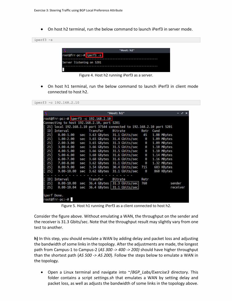
Exercise 3: Steering Traffic using BGP Local Preference Attribute
• On host h2 terminal, run the below command to launch iPerf3 in server mode. iperf3 -s
Figure 4. Host h2 running iPerf3 as a server.
• On host h1 terminal, run the below command to launch iPerf3 in client mode connected to host h2.
iperf3 -c 192.168.2.10
Figure 5. Host h1 running iPerf3 as a client connected to host h2.
Consider the figure above. Without emulating a WAN, the throughput on the sender and the receiver is 31.3 Gbits/sec. Note that the throughput result may slightly vary from one test to another. h) In this step, you should emulate a WAN by adding delay and packet loss and adjusting the bandwidth of some links in the topology. After the adjustments are made, the longest path from Campus-1 to Campus-2 (AS 300 -> 400 -> 200) should have higher throughput than the shortest path (AS 500 -> AS 200). Follow the steps below to emulate a WAN in the topology.
• Open a Linux terminal and navigate into ~/BGP_Labs/Exercise3 directory. This folder contains a script settings.sh that emulates a WAN by setting delay and packet loss, as well as adjusts the bandwidth of some links in the topology above.
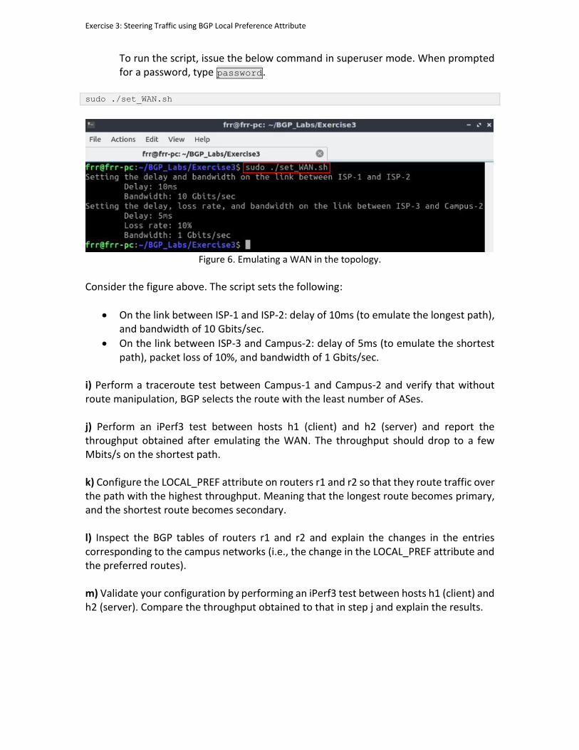
Exercise 3: Steering Traffic using BGP Local Preference Attribute
To run the script, issue the below command in superuser mode. When prompted for a password, type password.
sudo ./set_WAN.sh
Figure 6. Emulating a WAN in the topology.
Consider the figure above. The script sets the following:
• On the link between ISP-1 and ISP-2: delay of 10ms (to emulate the longest path), and bandwidth of 10 Gbits/sec.
• On the link between ISP-3 and Campus-2: delay of 5ms (to emulate the shortest path), packet loss of 10%, and bandwidth of 1 Gbits/sec.
i) Perform a traceroute test between Campus-1 and Campus-2 and verify that without route manipulation, BGP selects the route with the least number of ASes. j) Perform an iPerf3 test between hosts h1 (client) and h2 (server) and report the throughput obtained after emulating the WAN. The throughput should drop to a few Mbits/s on the shortest path. k) Configure the LOCAL_PREF attribute on routers r1 and r2 so that they route traffic over the path with the highest throughput. Meaning that the longest route becomes primary, and the shortest route becomes secondary. l) Inspect the BGP tables of routers r1 and r2 and explain the changes in the entries corresponding to the campus networks (i.e., the change in the LOCAL_PREF attribute and the preferred routes). m) Validate your configuration by performing an iPerf3 test between hosts h1 (client) and h2 (server). Compare the throughput obtained to that in step j and explain the results.
BORDER GATEWAY PROTOCOL
Lab 9: IBGP, Next Hop and Full Mesh Topology
Document Version: 05-25-2021
Award 1829698 “CyberTraining CIP: Cyberinfrastructure Expertise on High-throughput
Networks for Big Science Data Transfers”
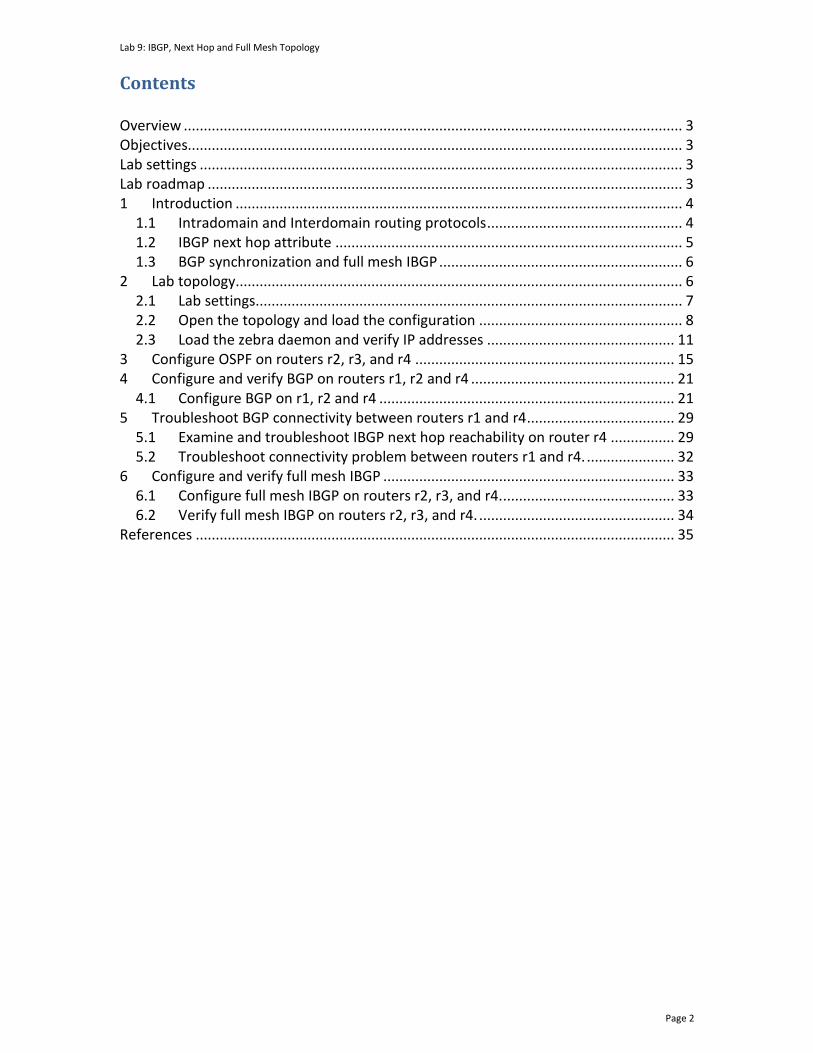
Lab 9: IBGP, Next Hop and Full Mesh Topology
Page 2
Contents Overview ............................................................................................................................. 3
Objectives............................................................................................................................ 3
Lab settings ......................................................................................................................... 3
Lab roadmap ....................................................................................................................... 3
1 Introduction ................................................................................................................ 4
1.1 Intradomain and Interdomain routing protocols ................................................. 4
1.2 IBGP next hop attribute ....................................................................................... 5
1.3 BGP synchronization and full mesh IBGP ............................................................. 6
2 Lab topology................................................................................................................ 6
2.1 Lab settings........................................................................................................... 7
2.2 Open the topology and load the configuration ................................................... 8
2.3 Load the zebra daemon and verify IP addresses ............................................... 11
3 Configure OSPF on routers r2, r3, and r4 ................................................................. 15
4 Configure and verify BGP on routers r1, r2 and r4 ................................................... 21
4.1 Configure BGP on r1, r2 and r4 .......................................................................... 21
5 Troubleshoot BGP connectivity between routers r1 and r4 ..................................... 29
5.1 Examine and troubleshoot IBGP next hop reachability on router r4 ................ 29
5.2 Troubleshoot connectivity problem between routers r1 and r4. ...................... 32
6 Configure and verify full mesh IBGP ......................................................................... 33
6.1 Configure full mesh IBGP on routers r2, r3, and r4. ........................................... 33
6.2 Verify full mesh IBGP on routers r2, r3, and r4. ................................................. 34
References ........................................................................................................................ 35
Lab 9: IBGP, Next Hop and Full Mesh Topology
Page 3
Overview This lab introduces and configures the Border Gateway Protocol (BGP) next hop attribute and explains how this attribute is transmitted in External BGP (EBGP) and Internal BGP (IBGP). Furthermore, the lab presents full mesh topology used in IBGP. In this lab, BGP will be configured as the Exterior Gateway Protocol (EGP) and Open Shortest Path First (OSPF) as the Interior Gateway Protocol (IGP). This lab is based on the Cisco Certified Network Professional (CCNP) ROUTE Version 7 training, laboratory 7-45. While this laboratory material uses FRR as the router (which includes the routing protocols) and Linux as the control plane operating system, vendors’ operating systems such as Cisco have similar functionality. Objectives By the end of this lab, you should be able to:
1. Configure OSPF and BGP. 2. Understand BGP next hop attribute. 3. Troubleshoot and resolve next hop attribute issues in IBGP. 4. Configure full mesh IBGP. 5. Verify the connectivity of the configured topology.
Lab settings The information in Table 1 provides the credentials to access the Client machine.
Table 1. Credentials to access the Client machine.
Device
Account
Password
Client admin password
Lab roadmap This lab is organized as follows:
1. Section 1: Introduction. 2. Section 2: Lab topology. 3. Section 3: Configure OSPF on routers r2, r3, and r4. 4. Section 4: Configure and verify BGP on routers r1, r2 and r4. 5. Section 5: Troubleshoot BGP connectivity between routers r1 and r4.

Lab 9: IBGP, Next Hop and Full Mesh Topology
Page 4
6. Section 6: Configure and verify full mesh IBGP.
1 Introduction 1.1 Intradomain and Interdomain routing protocols
The Internet consists of many independent administrative domains, referred to as Autonomous Systems (ASes). ASes are operated by different organizations, which can run their own internal routing protocols. A routing protocol that runs within an AS is referred to as intradomain routing protocol. One of the most widely used intradomain protocols is OSPF. Since an AS may be large and nontrivial to manage, OSPF allows an AS to be divided into numbered areas1. An area is a logical collection of networks, routers, and links. All routers in the same area have detailed information of the topology within their area2. A routing protocol that runs between ASes is referred to as interdomain routing protocol. ASes may use different intradomain routing protocols; however, they must use the same interdomain routing protocol, i.e., BGP. BGP allows the enforcement of different routing policies on the traffic from one AS to another. For example, a security policy can prevent the dissemination of routing information from one AS to another1. BGP is referred to as External BGP (EBGP) when it is running between different ASes, whereas it is referred to as Internal BGP (IBGP) when it is running within an AS1. IBGP is usually used to distribute the routes learned using EBGP among the routers within the same AS1. IGP handles all internal routes, whereas BGP handles all global Internet routes. IBGP advertises the global BGP prefixes within the AS to other edge routers. This is due to the fact that BGP is more flexible and IGPs are not designed to scale to handle the number of global Internet prefixes that exist in the global Internet routing table4. Consider Figure 1. The intradomain routing protocol within AS 100 is OSPF, and the interdomain routing protocol between AS 100 and AS 200 is BGP (EBGP). Routers within the same AS advertise their EBGP learned routes among each other through IBGP. OSPF is used to determine the fastest route while BGP puts emphasis on determining the best path.
AS 100
IBGP
OSPF – Area 0
AS 200
r1 r2 r3
EBGP

Lab 9: IBGP, Next Hop and Full Mesh Topology
Page 5
Figure 1. Routers that exchange information within the same AS use OSPF and IBGP, while routers that exchange information between different ASes use EBGP.
1.2 IBGP next hop attribute
In BGP, when a router advertises a route across a BGP session, i.e., between two routers running BGP, it includes the next hop attribute in the advertisement. This attribute determines the next hop IP address to use in order to reach a destination. For EBGP, the next hop attribute is updated to be the IP address of the EBGP neighbor. However, for IBGP, the routers do not update this attribute and the next hop that EBGP advertises is propagated into the IBGP domain and by all subsequent IBGP routers3. Consider Figure 2. In an EBGP route advertisement, the next hop attribute will be the IP address of the EBGP neighbor that advertised the route (router r1). The next hop attribute advertised by an EBGP peer (router r1) will be forwarded to all IBGP peers (routers r2 and r3) without being updated.
AS 1AS 2
r1 r2
Route advertisement from router r1
r3Next hop: r1 Next hop: r1
EBGP IBGP
Figure 2. Router r2 advertises an EBGP learned route to its IBGP neighbor (router r3) without updating the next hop attribute.
Routers can be configured to update the next hop attribute before they advertise EBGP learned routes it to their IBGP peers. In Figure 3, router r2 updates the next hop attribute to itself (next-hop-self) before it advertises it to its IBGP peers, i.e., router r3.
AS 1AS 2
r1 r2
Route advertisement from router r1
r3Next hop: r1 Next hop: r2
next-hop-self
EBGP IBGP
Figure 3. Router r2 updates the next hop attribute of the EBGP learned route before it advertises it to router r3.
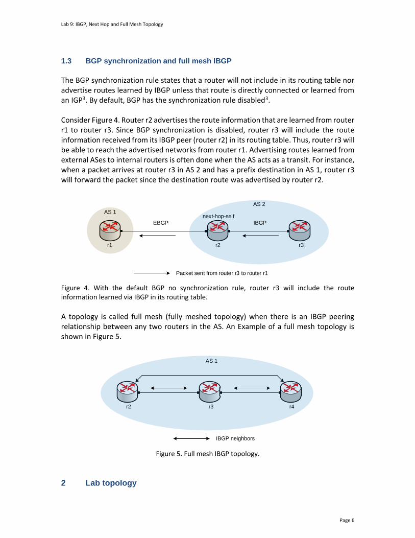
Lab 9: IBGP, Next Hop and Full Mesh Topology
Page 6
1.3 BGP synchronization and full mesh IBGP
The BGP synchronization rule states that a router will not include in its routing table nor advertise routes learned by IBGP unless that route is directly connected or learned from an IGP3. By default, BGP has the synchronization rule disabled3. Consider Figure 4. Router r2 advertises the route information that are learned from router r1 to router r3. Since BGP synchronization is disabled, router r3 will include the route information received from its IBGP peer (router r2) in its routing table. Thus, router r3 will be able to reach the advertised networks from router r1. Advertising routes learned from external ASes to internal routers is often done when the AS acts as a transit. For instance, when a packet arrives at router r3 in AS 2 and has a prefix destination in AS 1, router r3 will forward the packet since the destination route was advertised by router r2.
AS 1
r1
AS 2
r2 r3
next-hop-self
EBGP IBGP
Packet sent from router r3 to router r1
Figure 4. With the default BGP no synchronization rule, router r3 will include the route information learned via IBGP in its routing table.
A topology is called full mesh (fully meshed topology) when there is an IBGP peering relationship between any two routers in the AS. An Example of a full mesh topology is shown in Figure 5.
AS 1
r2 r3 r4
IBGP neighbors
Figure 5. Full mesh IBGP topology.
2 Lab topology
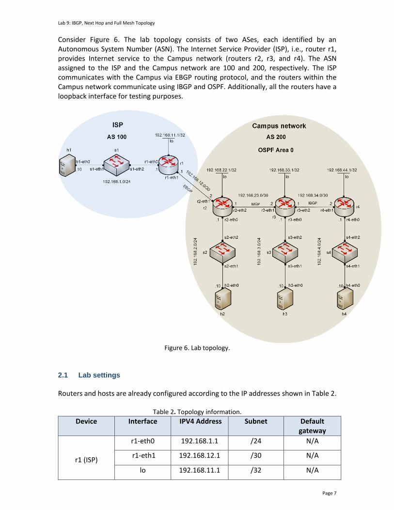
Lab 9: IBGP, Next Hop and Full Mesh Topology
Page 7
Consider Figure 6. The lab topology consists of two ASes, each identified by an Autonomous System Number (ASN). The Internet Service Provider (ISP), i.e., router r1, provides Internet service to the Campus network (routers r2, r3, and r4). The ASN assigned to the ISP and the Campus network are 100 and 200, respectively. The ISP communicates with the Campus via EBGP routing protocol, and the routers within the Campus network communicate using IBGP and OSPF. Additionally, all the routers have a loopback interface for testing purposes.
Figure 6. Lab topology.
2.1 Lab settings
Routers and hosts are already configured according to the IP addresses shown in Table 2.
Table 2. Topology information.
Device Interface IIPV4 Address Subnet Default gateway
r1 (ISP)
r1-eth0 192.168.1.1 /24 N/A
r1-eth1 192.168.12.1 /30 N/A
lo 192.168.11.1 /32 N/A
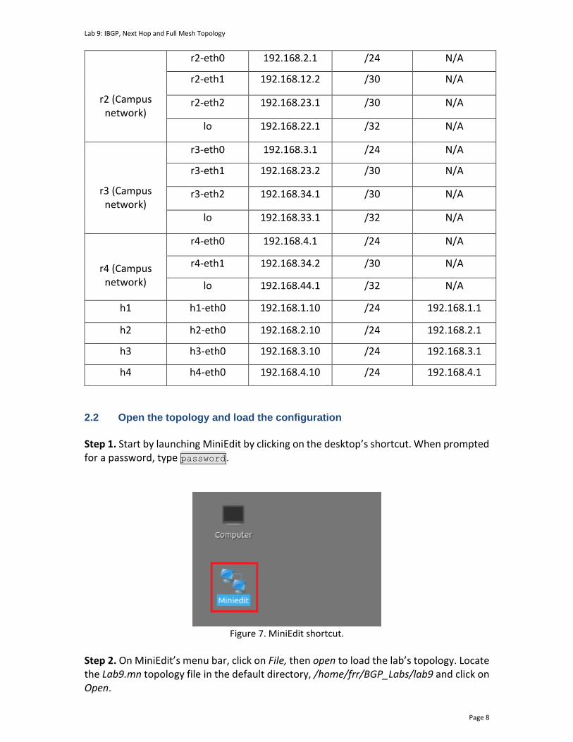
Lab 9: IBGP, Next Hop and Full Mesh Topology
Page 8
r2 (Campus network)
r2-eth0 192.168.2.1 /24 N/A
r2-eth1 192.168.12.2 /30 N/A
r2-eth2 192.168.23.1 /30 N/A
lo 192.168.22.1 /32 N/A
r3 (Campus network)
r3-eth0 192.168.3.1 /24 N/A
r3-eth1 192.168.23.2 /30 N/A
r3-eth2 192.168.34.1 /30 N/A
lo 192.168.33.1 /32 N/A
r4 (Campus network)
r4-eth0 192.168.4.1 /24 N/A
r4-eth1 192.168.34.2 /30 N/A
lo 192.168.44.1 /32 N/A
h1 h1-eth0 192.168.1.10 /24 192.168.1.1
h2 h2-eth0 192.168.2.10 /24 192.168.2.1
h3 h3-eth0 192.168.3.10 /24 192.168.3.1
h4 h4-eth0 192.168.4.10 /24 192.168.4.1
2.2 Open the topology and load the configuration
Step 1. Start by launching MiniEdit by clicking on the desktop’s shortcut. When prompted for a password, type password.
Figure 7. MiniEdit shortcut.
Step 2. On MiniEdit’s menu bar, click on File, then open to load the lab’s topology. Locate the Lab9.mn topology file in the default directory, /home/frr/BGP_Labs/lab9 and click on Open.
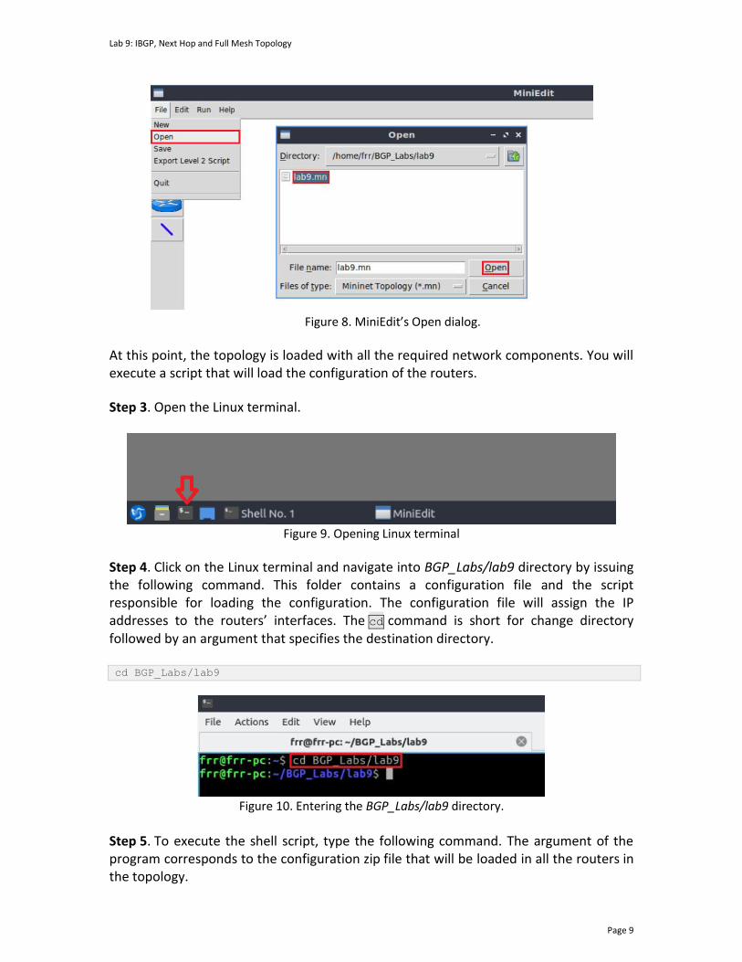
Lab 9: IBGP, Next Hop and Full Mesh Topology
Page 9
Figure 8. MiniEdit’s Open dialog.
At this point, the topology is loaded with all the required network components. You will execute a script that will load the configuration of the routers.
Step 3. Open the Linux terminal.
Figure 9. Opening Linux terminal
Step 4. Click on the Linux terminal and navigate into BGP_Labs/lab9 directory by issuing the following command. This folder contains a configuration file and the script responsible for loading the configuration. The configuration file will assign the IP addresses to the routers’ interfaces. The cd command is short for change directory followed by an argument that specifies the destination directory. cd BGP_Labs/lab9
Figure 10. Entering the BGP_Labs/lab9 directory.
Step 5. To execute the shell script, type the following command. The argument of the program corresponds to the configuration zip file that will be loaded in all the routers in the topology.
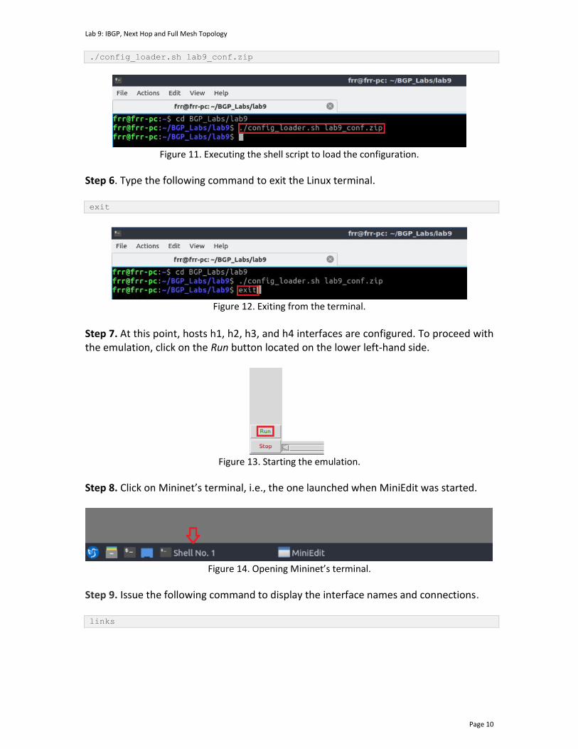
Lab 9: IBGP, Next Hop and Full Mesh Topology
Page 10
./config_loader.sh lab9_conf.zip
Figure 11. Executing the shell script to load the configuration.
Step 6. Type the following command to exit the Linux terminal. exit
Figure 12. Exiting from the terminal.
Step 7. At this point, hosts h1, h2, h3, and h4 interfaces are configured. To proceed with the emulation, click on the Run button located on the lower left-hand side.
Figure 13. Starting the emulation.
Step 8. Click on Mininet’s terminal, i.e., the one launched when MiniEdit was started.
Figure 14. Opening Mininet’s terminal.
Step 9. Issue the following command to display the interface names and connections. links
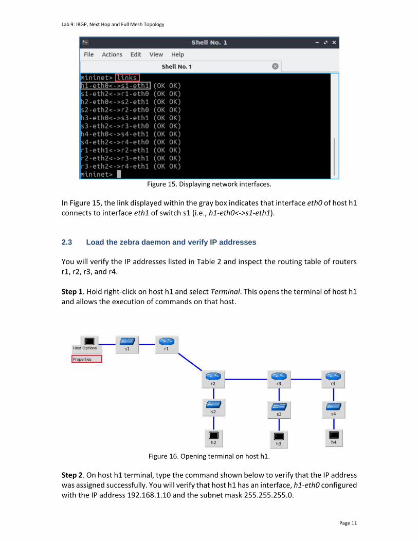
Lab 9: IBGP, Next Hop and Full Mesh Topology
Page 11
Figure 15. Displaying network interfaces.
In Figure 15, the link displayed within the gray box indicates that interface eth0 of host h1 connects to interface eth1 of switch s1 (i.e., h1-eth0<->s1-eth1). 2.3 Load the zebra daemon and verify IP addresses
You will verify the IP addresses listed in Table 2 and inspect the routing table of routers r1, r2, r3, and r4. Step 1. Hold right-click on host h1 and select Terminal. This opens the terminal of host h1 and allows the execution of commands on that host.
Figure 16. Opening terminal on host h1.
Step 2. On host h1 terminal, type the command shown below to verify that the IP address was assigned successfully. You will verify that host h1 has an interface, h1-eth0 configured with the IP address 192.168.1.10 and the subnet mask 255.255.255.0.
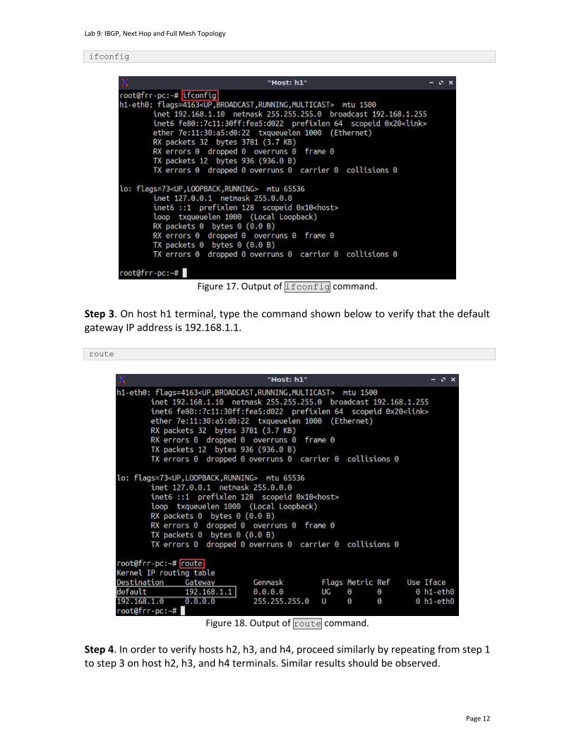
Lab 9: IBGP, Next Hop and Full Mesh Topology
Page 12
ifconfig
Figure 17. Output of ifconfig command.
Step 3. On host h1 terminal, type the command shown below to verify that the default gateway IP address is 192.168.1.1. route
Figure 18. Output of route command.
Step 4. In order to verify hosts h2, h3, and h4, proceed similarly by repeating from step 1 to step 3 on host h2, h3, and h4 terminals. Similar results should be observed.
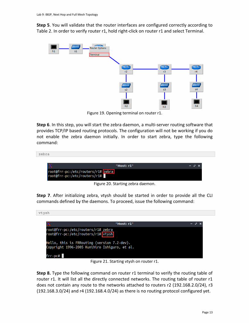
Lab 9: IBGP, Next Hop and Full Mesh Topology
Page 13
Step 5. You will validate that the router interfaces are configured correctly according to Table 2. In order to verify router r1, hold right-click on router r1 and select Terminal.
Figure 19. Opening terminal on router r1.
Step 6. In this step, you will start the zebra daemon, a multi-server routing software that provides TCP/IP based routing protocols. The configuration will not be working if you do not enable the zebra daemon initially. In order to start zebra, type the following command: zebra
Figure 20. Starting zebra daemon.
Step 7. After initializing zebra, vtysh should be started in order to provide all the CLI commands defined by the daemons. To proceed, issue the following command: vtysh
Figure 21. Starting vtysh on router r1.
Step 8. Type the following command on router r1 terminal to verify the routing table of router r1. It will list all the directly connected networks. The routing table of router r1 does not contain any route to the networks attached to routers r2 (192.168.2.0/24), r3 (192.168.3.0/24) and r4 (192.168.4.0/24) as there is no routing protocol configured yet.
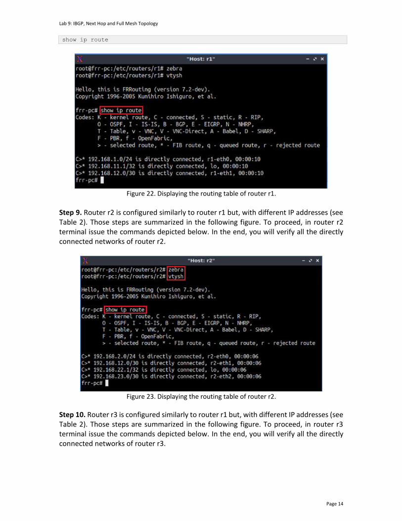
Lab 9: IBGP, Next Hop and Full Mesh Topology
Page 14
show ip route
Figure 22. Displaying the routing table of router r1.
Step 9. Router r2 is configured similarly to router r1 but, with different IP addresses (see Table 2). Those steps are summarized in the following figure. To proceed, in router r2 terminal issue the commands depicted below. In the end, you will verify all the directly connected networks of router r2.
Figure 23. Displaying the routing table of router r2.
Step 10. Router r3 is configured similarly to router r1 but, with different IP addresses (see Table 2). Those steps are summarized in the following figure. To proceed, in router r3 terminal issue the commands depicted below. In the end, you will verify all the directly connected networks of router r3.
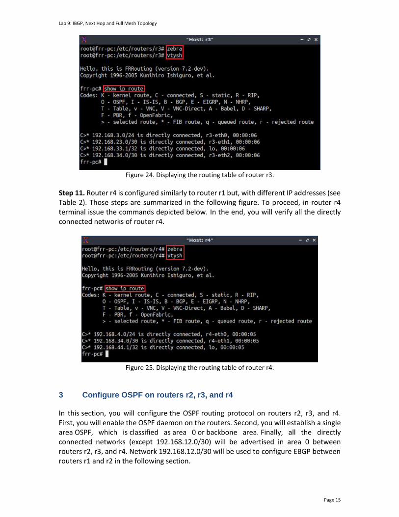
Lab 9: IBGP, Next Hop and Full Mesh Topology
Page 15
Figure 24. Displaying the routing table of router r3.
Step 11. Router r4 is configured similarly to router r1 but, with different IP addresses (see Table 2). Those steps are summarized in the following figure. To proceed, in router r4 terminal issue the commands depicted below. In the end, you will verify all the directly connected networks of router r4.
Figure 25. Displaying the routing table of router r4.
3 Configure OSPF on routers r2, r3, and r4 In this section, you will configure the OSPF routing protocol on routers r2, r3, and r4. First, you will enable the OSPF daemon on the routers. Second, you will establish a single area OSPF, which is classified as area 0 or backbone area. Finally, all the directly connected networks (except 192.168.12.0/30) will be advertised in area 0 between routers r2, r3, and r4. Network 192.168.12.0/30 will be used to configure EBGP between routers r1 and r2 in the following section.

Lab 9: IBGP, Next Hop and Full Mesh Topology
Page 16
Step 1. To configure the OSPF routing protocol, you need to enable the OSPF daemon first. In router r2, type the following command to exit the vtysh session. exit
Figure 26. Exiting the vtysh session.
Step 2. Type the following command on router r2 terminal to enable OSPF daemon. ospfd
Figure 27. Starting OSPF daemon.
Step 3. In order to enter to router r2 terminal, issue the following command: vtysh
Figure 28. Starting vtysh on router r2.
Step 4. To enable router r2 configuration mode, issue the following command: configure terminal
Figure 29. Enabling configuration mode on router r2.
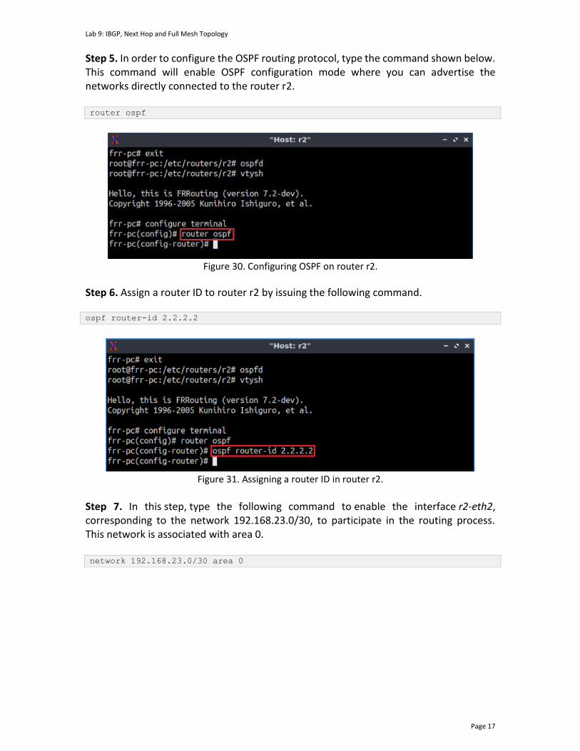
Lab 9: IBGP, Next Hop and Full Mesh Topology
Page 17
Step 5. In order to configure the OSPF routing protocol, type the command shown below. This command will enable OSPF configuration mode where you can advertise the networks directly connected to the router r2. router ospf
Figure 30. Configuring OSPF on router r2.
Step 6. Assign a router ID to router r2 by issuing the following command. ospf router-id 2.2.2.2
Figure 31. Assigning a router ID in router r2.
Step 7. In this step, type the following command to enable the interface r2-eth2, corresponding to the network 192.168.23.0/30, to participate in the routing process. This network is associated with area 0. network 192.168.23.0/30 area 0
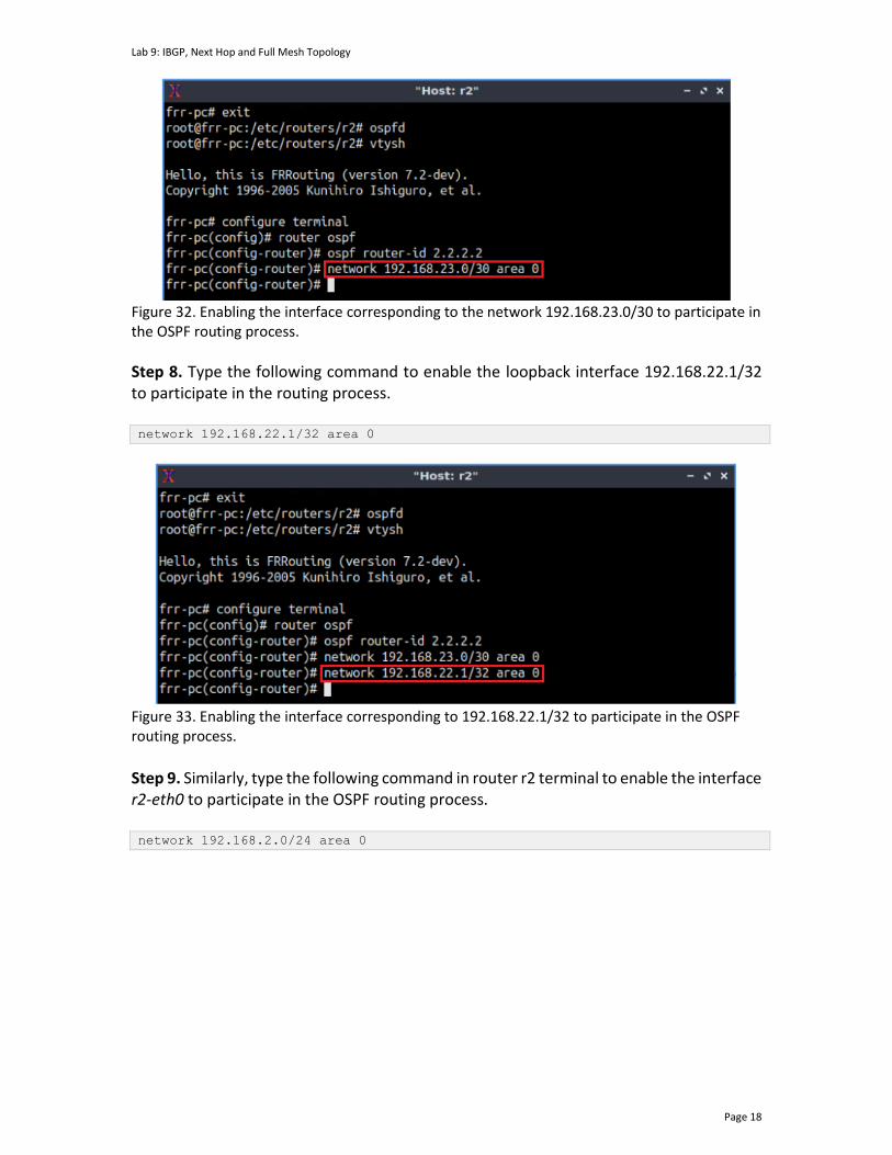
Lab 9: IBGP, Next Hop and Full Mesh Topology
Page 18
Figure 32. Enabling the interface corresponding to the network 192.168.23.0/30 to participate in the OSPF routing process.
Step 8. Type the following command to enable the loopback interface 192.168.22.1/32 to participate in the routing process. network 192.168.22.1/32 area 0
Figure 33. Enabling the interface corresponding to 192.168.22.1/32 to participate in the OSPF routing process.
Step 9. Similarly, type the following command in router r2 terminal to enable the interface r2-eth0 to participate in the OSPF routing process. network 192.168.2.0/24 area 0
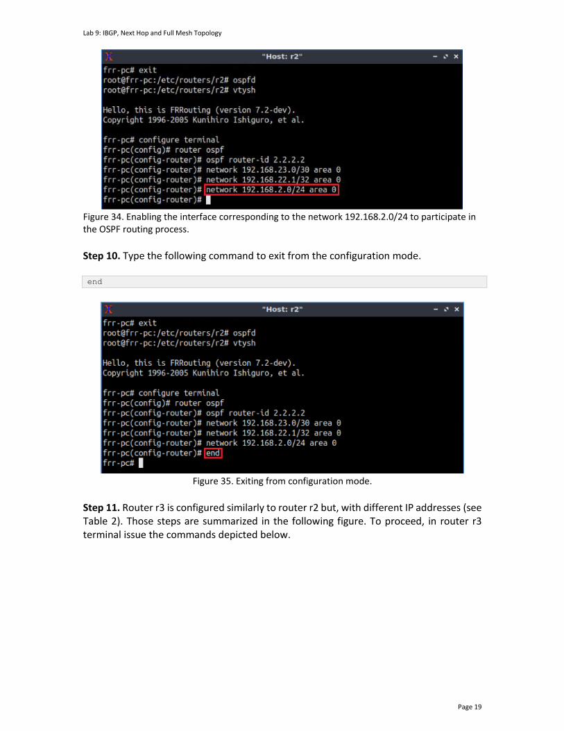
Lab 9: IBGP, Next Hop and Full Mesh Topology
Page 19
Figure 34. Enabling the interface corresponding to the network 192.168.2.0/24 to participate in the OSPF routing process.
Step 10. Type the following command to exit from the configuration mode. end
Figure 35. Exiting from configuration mode.
Step 11. Router r3 is configured similarly to router r2 but, with different IP addresses (see Table 2). Those steps are summarized in the following figure. To proceed, in router r3 terminal issue the commands depicted below.
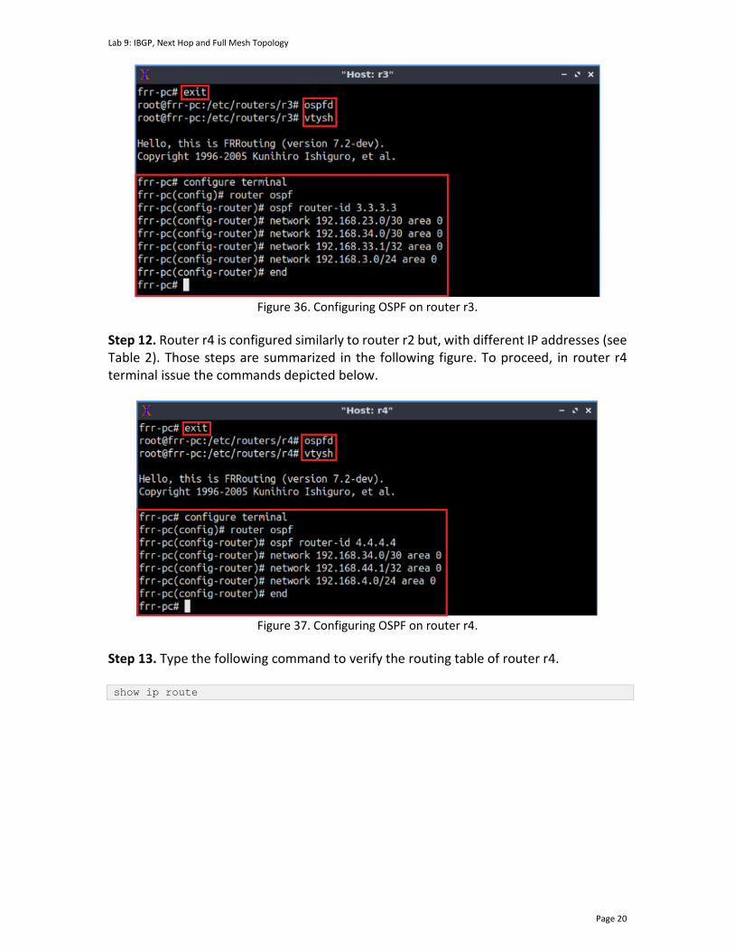
Lab 9: IBGP, Next Hop and Full Mesh Topology
Page 20
Figure 36. Configuring OSPF on router r3.
Step 12. Router r4 is configured similarly to router r2 but, with different IP addresses (see Table 2). Those steps are summarized in the following figure. To proceed, in router r4 terminal issue the commands depicted below.
Figure 37. Configuring OSPF on router r4.
Step 13. Type the following command to verify the routing table of router r4. show ip route
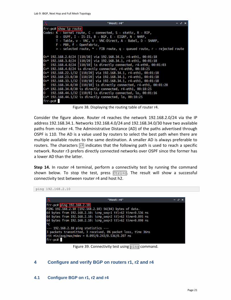
Lab 9: IBGP, Next Hop and Full Mesh Topology
Page 21
Figure 38. Displaying the routing table of router r4.
Consider the figure above. Router r4 reaches the network 192.168.2.0/24 via the IP address 192.168.34.1. Networks 192.168.4.0/24 and 192.168.34.0/30 have two available paths from router r4. The Administrative Distance (AD) of the paths advertised through OSPF is 110. The AD is a value used by routers to select the best path when there are multiple available routes to the same destination. A smaller AD is always preferable to routers. The characters >* indicates that the following path is used to reach a specific network. Router r3 prefers directly connected networks over OSPF since the former has a lower AD than the latter.
Step 14. In router r4 terminal, perform a connectivity test by running the command shown below. To stop the test, press Ctrl+c. The result will show a successful connectivity test between router r4 and host h2. ping 192.168.2.10
Figure 39. Connectivity test using ping command.
4 Configure and verify BGP on routers r1, r2 and r4 4.1 Configure BGP on r1, r2 and r4
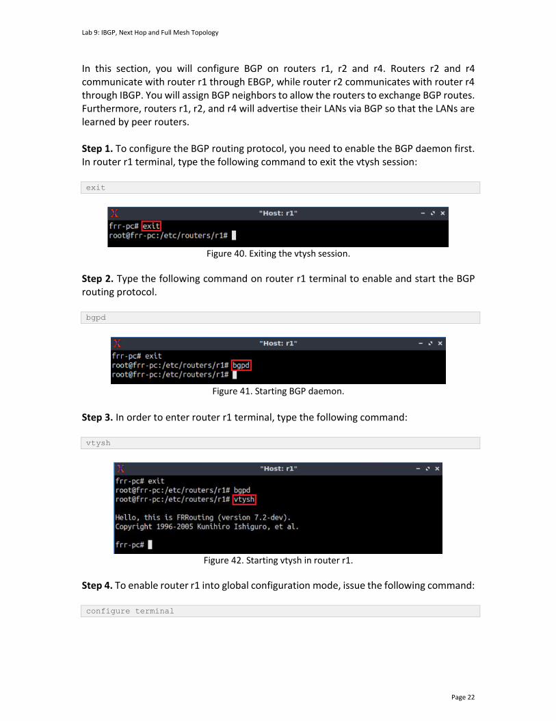
Lab 9: IBGP, Next Hop and Full Mesh Topology
Page 22
In this section, you will configure BGP on routers r1, r2 and r4. Routers r2 and r4 communicate with router r1 through EBGP, while router r2 communicates with router r4 through IBGP. You will assign BGP neighbors to allow the routers to exchange BGP routes. Furthermore, routers r1, r2, and r4 will advertise their LANs via BGP so that the LANs are learned by peer routers. Step 1. To configure the BGP routing protocol, you need to enable the BGP daemon first. In router r1 terminal, type the following command to exit the vtysh session: exit
Figure 40. Exiting the vtysh session.
Step 2. Type the following command on router r1 terminal to enable and start the BGP routing protocol. bgpd
Figure 41. Starting BGP daemon.
Step 3. In order to enter router r1 terminal, type the following command: vtysh
Figure 42. Starting vtysh in router r1.
Step 4. To enable router r1 into global configuration mode, issue the following command: configure terminal

Lab 9: IBGP, Next Hop and Full Mesh Topology
Page 23
Figure 43. Enabling configuration mode in router r1.
Step 5. The ASN assigned for router r1 is 100. In order to configure BGP, type the following command: router bgp 100
Figure 44. Configuring BGP on router r1.
Step 6. Assign a router ID to router r1 by issuing the following command. bgp router-id 1.1.1.1
Figure 45. Assigning a router ID in router r1.
Step 7. To configure a BGP neighbor to router r1 (AS 100), type the command shown below. This command specifies the neighbor IP address (192.168.12.2) and the ASN of the remote BGP peer (AS 200). neighbor 192.168.12.2 remote-as 200
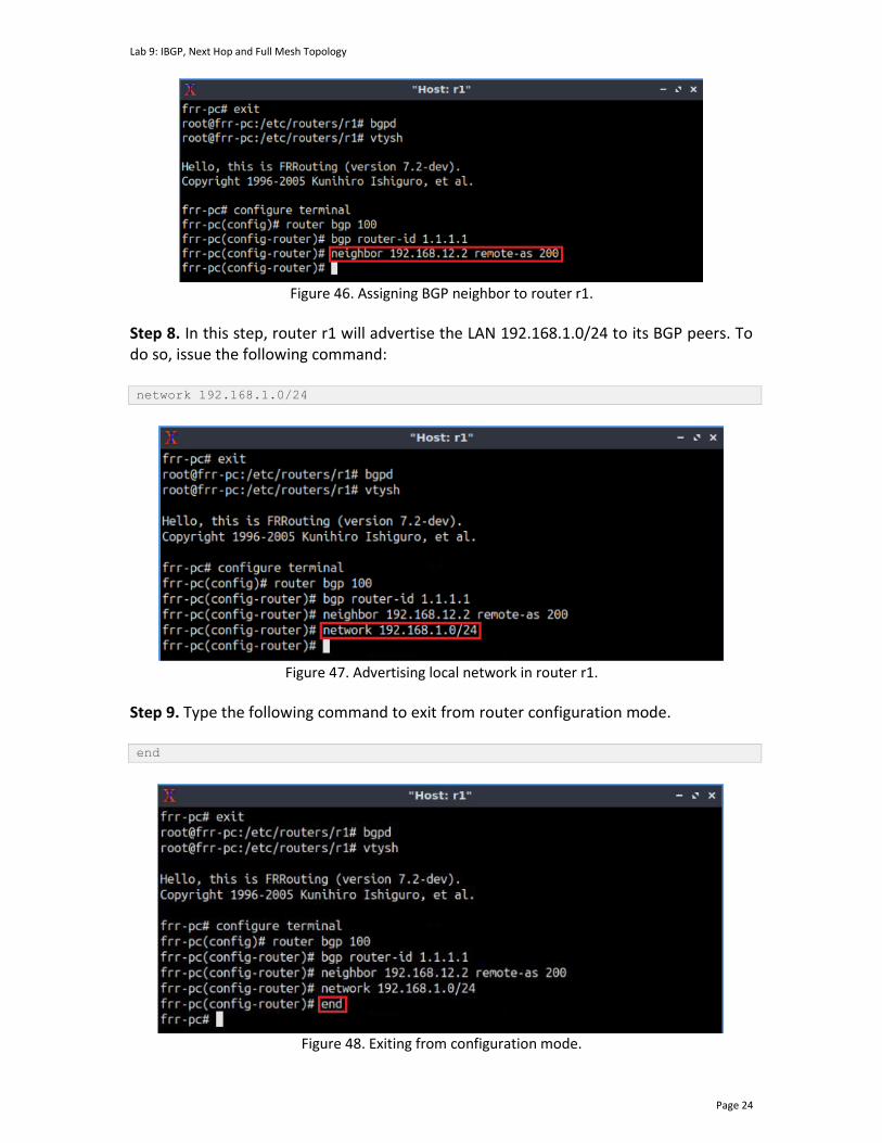
Lab 9: IBGP, Next Hop and Full Mesh Topology
Page 24
Figure 46. Assigning BGP neighbor to router r1.
Step 8. In this step, router r1 will advertise the LAN 192.168.1.0/24 to its BGP peers. To do so, issue the following command: network 192.168.1.0/24
Figure 47. Advertising local network in router r1.
Step 9. Type the following command to exit from router configuration mode. end
Figure 48. Exiting from configuration mode.
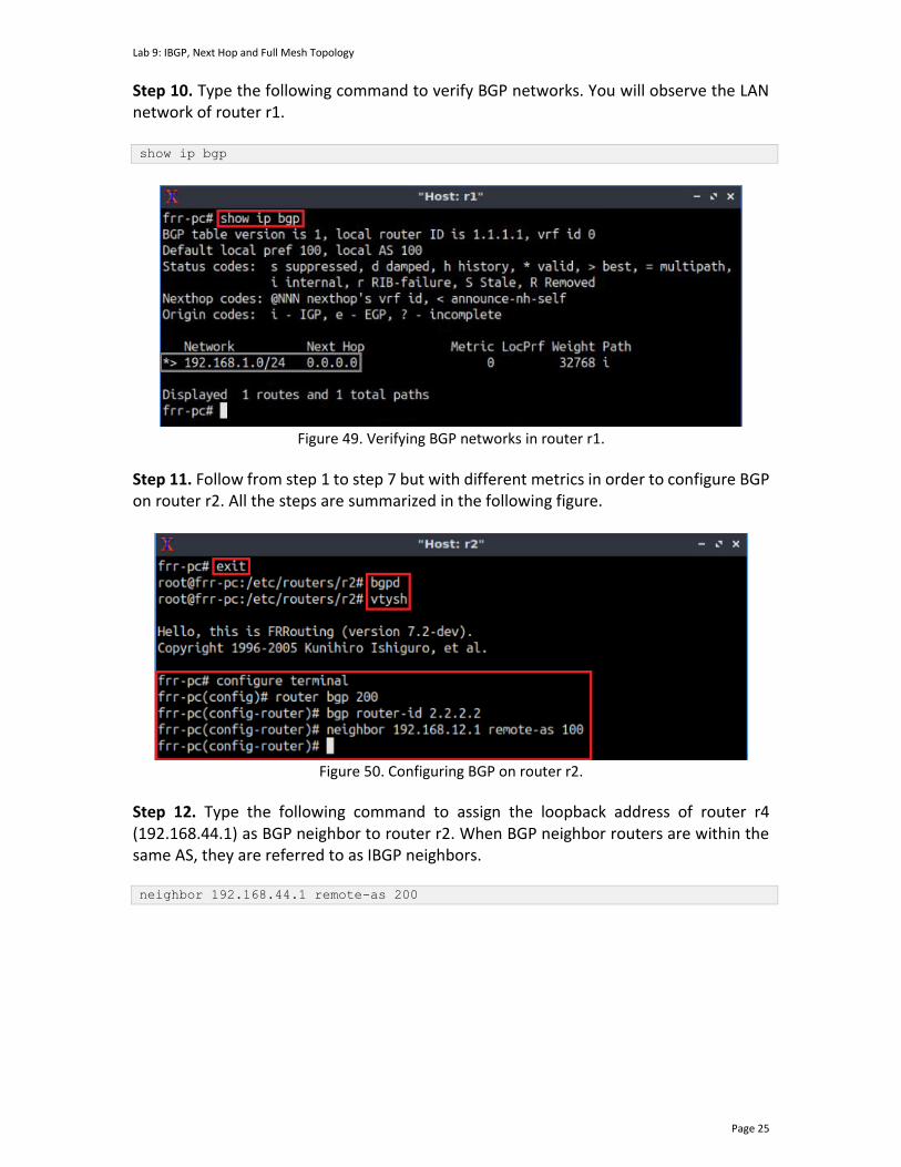
Lab 9: IBGP, Next Hop and Full Mesh Topology
Page 25
Step 10. Type the following command to verify BGP networks. You will observe the LAN network of router r1. show ip bgp
Figure 49. Verifying BGP networks in router r1.
Step 11. Follow from step 1 to step 7 but with different metrics in order to configure BGP on router r2. All the steps are summarized in the following figure.
Figure 50. Configuring BGP on router r2.
Step 12. Type the following command to assign the loopback address of router r4 (192.168.44.1) as BGP neighbor to router r2. When BGP neighbor routers are within the same AS, they are referred to as IBGP neighbors. neighbor 192.168.44.1 remote-as 200

Lab 9: IBGP, Next Hop and Full Mesh Topology
Page 26
Figure 51. Assigning BGP neighbor to router r2.
Step 13. In BGP, the source IP address of BGP packets sent by the router must be the same as the neighbor IP address set on the neighboring router. As you are assigning the loopback as a neighbor address, you must use the loopback address as the source of BGP packets sent to the neighbor. In router r2, type the following command to assign the loopback address lo as the source IP address. neighbor 192.168.44.1 update-source lo
Figure 52. Assigning loopback address as source IP.
Step 14. In this step, router r2 will advertise the LAN 192.168.2.0/24 to its BGP peers. To do so, issue the following command: network 192.168.2.0/24
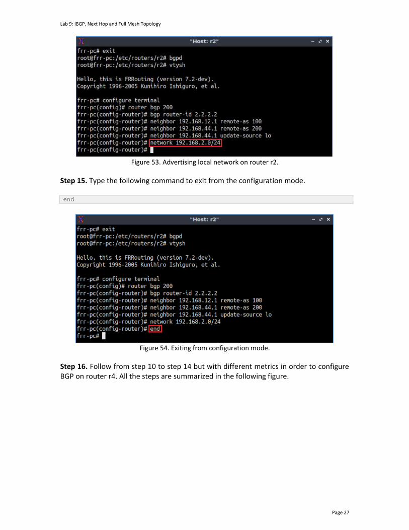
Lab 9: IBGP, Next Hop and Full Mesh Topology
Page 27
Figure 53. Advertising local network on router r2.
Step 15. Type the following command to exit from the configuration mode. end
Figure 54. Exiting from configuration mode.
Step 16. Follow from step 10 to step 14 but with different metrics in order to configure BGP on router r4. All the steps are summarized in the following figure.
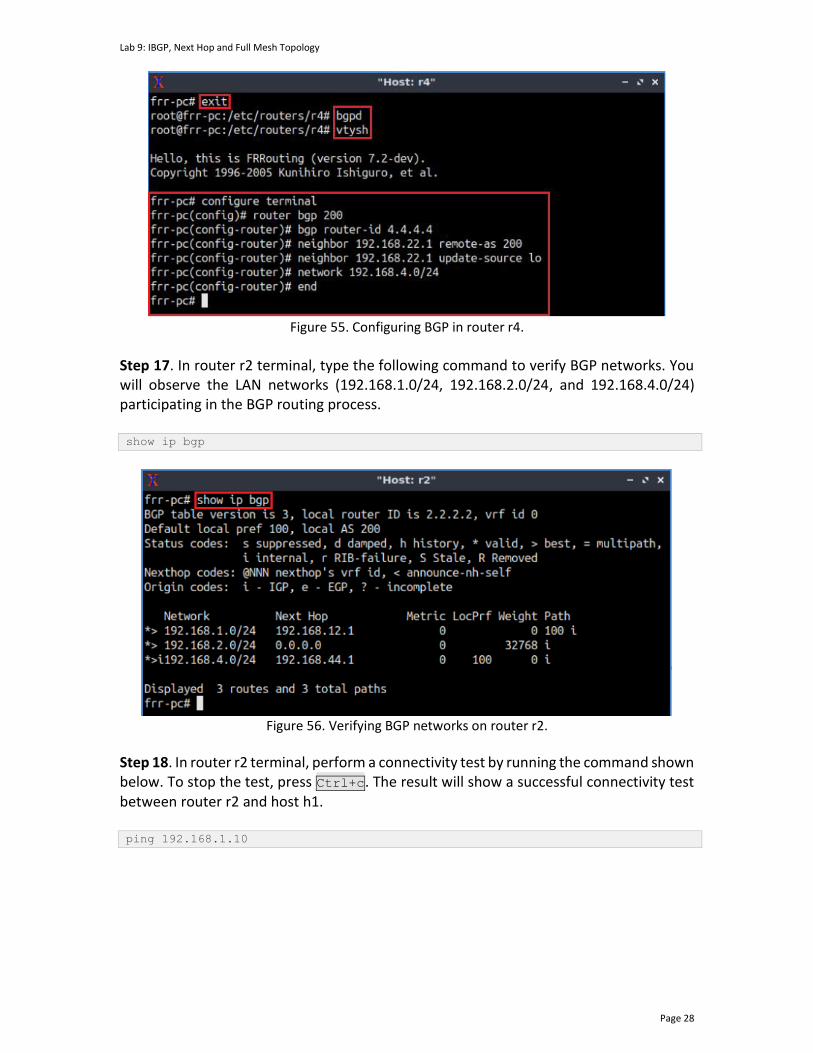
Lab 9: IBGP, Next Hop and Full Mesh Topology
Page 28
Figure 55. Configuring BGP in router r4.
Step 17. In router r2 terminal, type the following command to verify BGP networks. You will observe the LAN networks (192.168.1.0/24, 192.168.2.0/24, and 192.168.4.0/24) participating in the BGP routing process. show ip bgp
Figure 56. Verifying BGP networks on router r2.
Step 18. In router r2 terminal, perform a connectivity test by running the command shown below. To stop the test, press Ctrl+c. The result will show a successful connectivity test between router r2 and host h1. ping 192.168.1.10
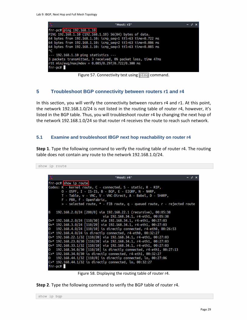
Lab 9: IBGP, Next Hop and Full Mesh Topology
Page 29
Figure 57. Connectivity test using ping command.
5 Troubleshoot BGP connectivity between routers r1 and r4
In this section, you will verify the connectivity between routers r4 and r1. At this point, the network 192.168.1.0/24 is not listed in the routing table of router r4, however, it’s listed in the BGP table. Thus, you will troubleshoot router r4 by changing the next hop of the network 192.168.1.0/24 so that router r4 receives the route to reach such network.
5.1 Examine and troubleshoot IBGP next hop reachability on router r4
Step 1. Type the following command to verify the routing table of router r4. The routing table does not contain any route to the network 192.168.1.0/24. show ip route
Figure 58. Displaying the routing table of router r4.
Step 2. Type the following command to verify the BGP table of router r4. show ip bgp
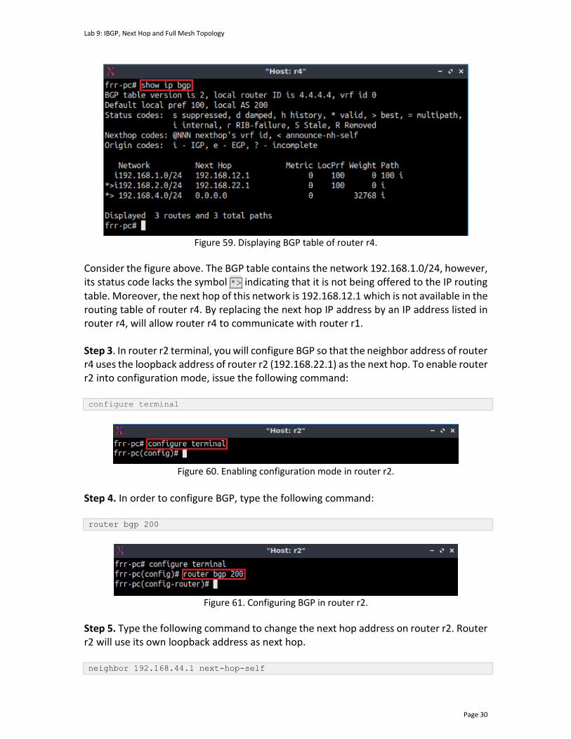
Lab 9: IBGP, Next Hop and Full Mesh Topology
Page 30
Figure 59. Displaying BGP table of router r4.
Consider the figure above. The BGP table contains the network 192.168.1.0/24, however, its status code lacks the symbol *> indicating that it is not being offered to the IP routing table. Moreover, the next hop of this network is 192.168.12.1 which is not available in the routing table of router r4. By replacing the next hop IP address by an IP address listed in router r4, will allow router r4 to communicate with router r1. Step 3. In router r2 terminal, you will configure BGP so that the neighbor address of router r4 uses the loopback address of router r2 (192.168.22.1) as the next hop. To enable router r2 into configuration mode, issue the following command: configure terminal
Figure 60. Enabling configuration mode in router r2.
Step 4. In order to configure BGP, type the following command: router bgp 200
Figure 61. Configuring BGP in router r2.
Step 5. Type the following command to change the next hop address on router r2. Router r2 will use its own loopback address as next hop. neighbor 192.168.44.1 next-hop-self
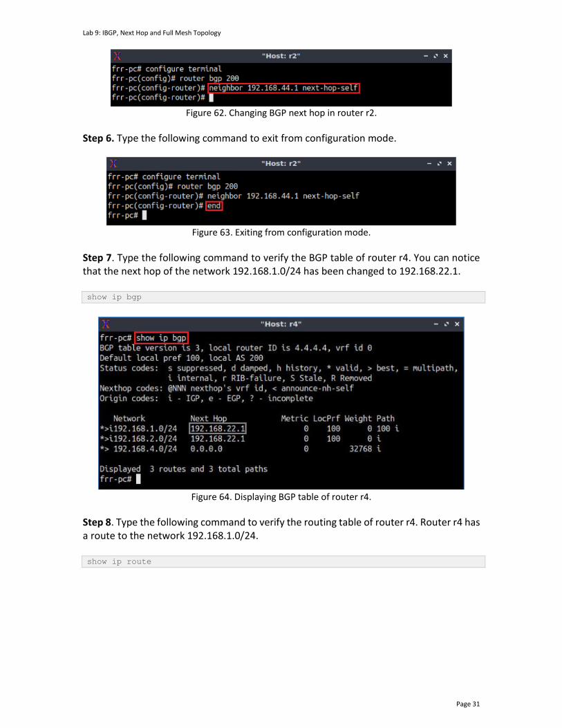
Lab 9: IBGP, Next Hop and Full Mesh Topology
Page 31
Figure 62. Changing BGP next hop in router r2.
Step 6. Type the following command to exit from configuration mode.
Figure 63. Exiting from configuration mode.
Step 7. Type the following command to verify the BGP table of router r4. You can notice that the next hop of the network 192.168.1.0/24 has been changed to 192.168.22.1. show ip bgp
Figure 64. Displaying BGP table of router r4.
Step 8. Type the following command to verify the routing table of router r4. Router r4 has a route to the network 192.168.1.0/24. show ip route
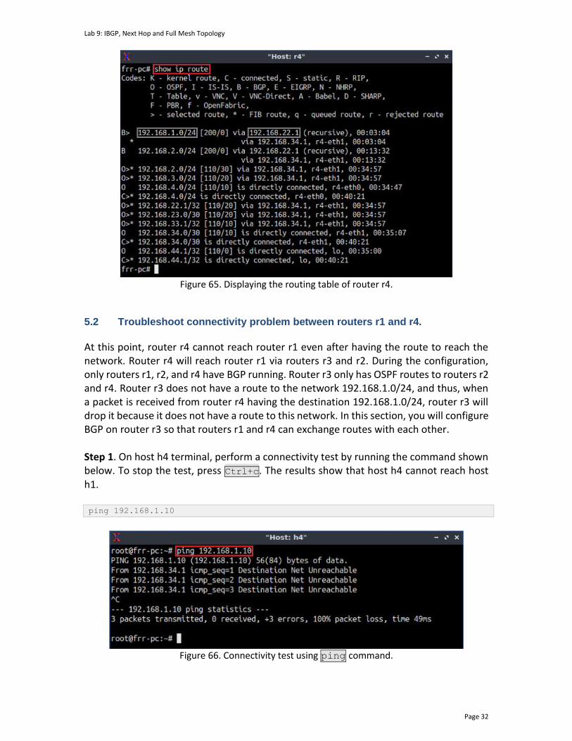
Lab 9: IBGP, Next Hop and Full Mesh Topology
Page 32
Figure 65. Displaying the routing table of router r4.
5.2 Troubleshoot connectivity problem between routers r1 and r4.
At this point, router r4 cannot reach router r1 even after having the route to reach the network. Router r4 will reach router r1 via routers r3 and r2. During the configuration, only routers r1, r2, and r4 have BGP running. Router r3 only has OSPF routes to routers r2 and r4. Router r3 does not have a route to the network 192.168.1.0/24, and thus, when a packet is received from router r4 having the destination 192.168.1.0/24, router r3 will drop it because it does not have a route to this network. In this section, you will configure BGP on router r3 so that routers r1 and r4 can exchange routes with each other. Step 1. On host h4 terminal, perform a connectivity test by running the command shown below. To stop the test, press Ctrl+c. The results show that host h4 cannot reach host h1. ping 192.168.1.10
Figure 66. Connectivity test using ping command.

Lab 9: IBGP, Next Hop and Full Mesh Topology
Page 33
6 Configure and verify full mesh IBGP In this section, you will configure and verify fully meshed IBGP among the routers r2, r3, and r4. 6.1 Configure full mesh IBGP on routers r2, r3, and r4.
Step 1. In router r3 terminal, configure IBGP to peer with routers r2 and r4. All the steps are summarized in the following figure.
Figure 67. Configuring IBGP on router r3.
Step 2. In router r2 terminal, configure IBGP so that it uses the loopback address as the next hop to reach neighbor router r3. All the steps are summarized in the following figure.
Figure 68. Configuring BGP in router r2.
Step 3. In router r4 terminal, configure BGP to peer with router r3. There is no need to change the next hop when configuring BGP, since r4 is not participating in any EBGP session. All the steps are summarized in the following figure.
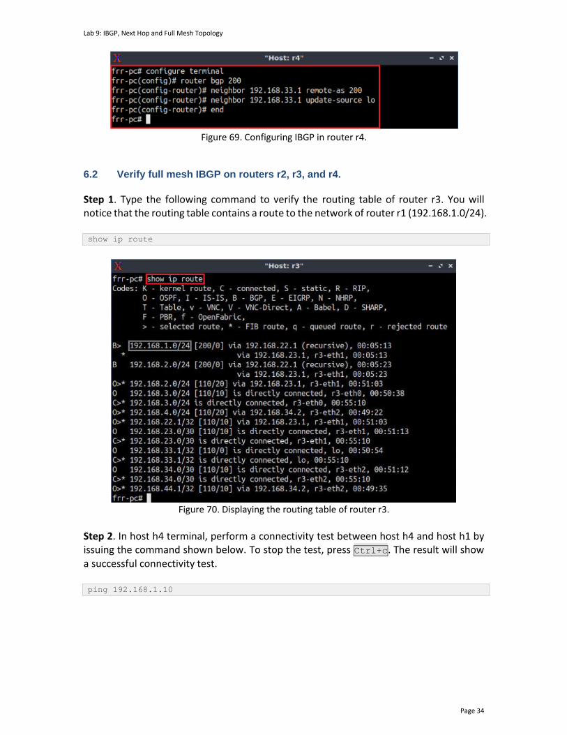
Lab 9: IBGP, Next Hop and Full Mesh Topology
Page 34
Figure 69. Configuring IBGP in router r4.
6.2 Verify full mesh IBGP on routers r2, r3, and r4.
Step 1. Type the following command to verify the routing table of router r3. You will notice that the routing table contains a route to the network of router r1 (192.168.1.0/24). show ip route
Figure 70. Displaying the routing table of router r3.
Step 2. In host h4 terminal, perform a connectivity test between host h4 and host h1 by issuing the command shown below. To stop the test, press Ctrl+c. The result will show a successful connectivity test. ping 192.168.1.10
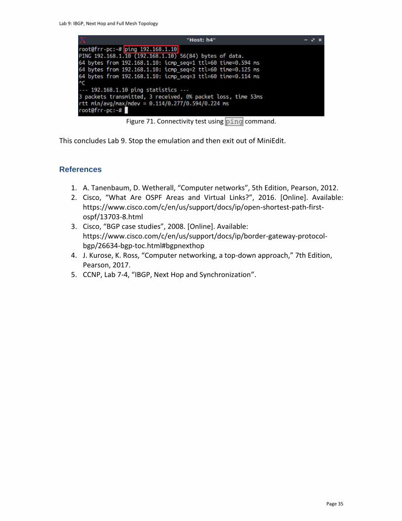
Lab 9: IBGP, Next Hop and Full Mesh Topology
Page 35
Figure 71. Connectivity test using ping command.
This concludes Lab 9. Stop the emulation and then exit out of MiniEdit. References
1. A. Tanenbaum, D. Wetherall, “Computer networks”, 5th Edition, Pearson, 2012. 2. Cisco, “What Are OSPF Areas and Virtual Links?”, 2016. [Online]. Available:
https://www.cisco.com/c/en/us/support/docs/ip/open-shortest-path-first-ospf/13703-8.html
3. Cisco, “BGP case studies”, 2008. [Online]. Available: https://www.cisco.com/c/en/us/support/docs/ip/border-gateway-protocol-bgp/26634-bgp-toc.html#bgpnexthop
4. J. Kurose, K. Ross, “Computer networking, a top-down approach,” 7th Edition, Pearson, 2017.
5. CCNP, Lab 7-4, “IBGP, Next Hop and Synchronization”.

BORDER GATEWAY PROTOCOL
Lab 10: BGP Route Reflection
Document Version: 05-25-2021
Award 1829698 “CyberTraining CIP: Cyberinfrastructure Expertise on High-throughput
Networks for Big Science Data Transfers”
Lab 10: BGP Route Reflection
Page 2
Contents Overview ............................................................................................................................. 3
Objectives............................................................................................................................ 3
Lab settings ......................................................................................................................... 3
Lab roadmap ....................................................................................................................... 3
1 Introduction ................................................................................................................ 3
1.1 BGP overview ....................................................................................................... 3
1.2 BGP route reflectors ............................................................................................. 4
2 Lab topology................................................................................................................ 5
2.1 Lab settings........................................................................................................... 6
2.2 Open the topology and load configuration .......................................................... 7
2.3 Load the zebra daemon and verify IP addresses ............................................... 10
3 Configure and verify IBGP ......................................................................................... 14
3.1 Configure BGP on routers r2, r3 and r4 ............................................................. 14
4 Troubleshoot BGP connectivity between routers r2 and r4 ..................................... 19
5 Configure and verify EBGP ........................................................................................ 23
5.1 Configure EBGP on routers r1 and r2 ................................................................. 23
5.2 Verify the connectivity of the configured topology ........................................... 27
References ........................................................................................................................ 28
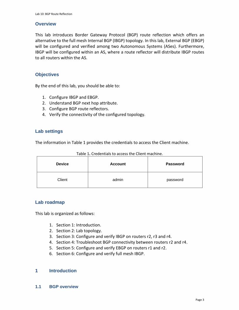
Lab 10: BGP Route Reflection
Page 3
Overview This lab introduces Border Gateway Protocol (BGP) route reflection which offers an alternative to the full mesh Internal BGP (IBGP) topology. In this lab, External BGP (EBGP) will be configured and verified among two Autonomous Systems (ASes). Furthermore, IBGP will be configured within an AS, where a route reflector will distribute IBGP routes to all routers within the AS. Objectives By the end of this lab, you should be able to:
1. Configure IBGP and EBGP. 2. Understand BGP next hop attribute. 3. Configure BGP route reflectors. 4. Verify the connectivity of the configured topology.
Lab settings The information in Table 1 provides the credentials to access the Client machine.
Table 1. Credentials to access the Client machine.
Device
Account
Password
Client admin password
Lab roadmap This lab is organized as follows:
1. Section 1: Introduction. 2. Section 2: Lab topology. 3. Section 3: Configure and verify IBGP on routers r2, r3 and r4. 4. Section 4: Troubleshoot BGP connectivity between routers r2 and r4. 5. Section 5: Configure and verify EBGP on routers r1 and r2. 6. Section 6: Configure and verify full mesh IBGP.
1 Introduction 1.1 BGP overview

Lab 10: BGP Route Reflection
Page 4
BGP is an exterior gateway protocol designed to exchange routing and reachability information among ASes on the Internet. BGP is relevant to network administrators of large organizations which connect to one or more Internet Service Providers (ISPs), as well as to ISPs who connect to other network providers. In terms of BGP, an AS is referred to as a routing domain, where all networked systems operate common routing protocols and are under the control of a single administration1. BGP is a form of distance vector protocol. It requires each router to maintain a table, which stores the distance and the output interface (i.e., vector) to remote networks. BGP makes routing decisions based on paths, network policies, or rule set configured by a network administrator and is involved in making core routing decisions1. Two routers that establish a BGP connection are referred to as BGP peers or neighbors. BGP sessions run over Transmission Control Protocol (TCP). If a BGP session is established between two neighbors in different ASes, the session is referred to as an EBGP session. If the session is established between two neighbors in the same AS, the session is referred to as IBGP1. Figure 1 shows a network running BGP protocol. Routers that exchange information within the same AS use IBGP, while routers that exchange information between different ASes use EBGP.
AS 200
IBGP
AS 100
IBGP EBGP
Figure 1. Routers that exchange information within the same AS use IBGP, while routers that exchange information between different ASes use EBGP.
Essentially, IBGP is needed within the AS to advertise global BGP prefixes to other edge routers, enforce policies, and scale to handle large numbers of prefixes3. 1.2 BGP route reflectors
IBGP routers do not re-advertise routes learned via IBGP to their peers. This behavior is used to prevent routing information cycles, i.e., the circulation of routing information between IBGP peers in a continuous repeated manner2. Consider Figure 2. Router r1 sends a route advertisement to its IBGP neighbor (router r2). Router r2 will not advertise the learned route to its IBGP neighbors (router r3) since it was learned from an IBGP peer (router r1).

Lab 10: BGP Route Reflection
Page 5
Figure 2. In BGP, routers do not advertise routes that are learned via IBGP to their IBGP neighbors.
A topology is called full mesh (fully meshed topology) when there is an IBGP peering relationship between any two routers in the AS. All BGP routers within a single AS must be fully meshed so that any external routing information must be re-distributed to all other routers within that AS. However, when the network topology of the AS is large, it becomes challenging to configure a full mesh IBGP2. A BGP route reflector is an IBGP router that repeats routes learned from IBGP peers to some of its other IBGP peers2. Consider Figure 3. Instead of having a full mesh IBGP topology, route reflection will be configured. The route reflector (router r2) advertises the route learned from its IBGP neighbors to all its clients. Thus, router r3 receives the advertised routes from router r1, and the way around, without establishing IBGP neighbor relationship.
Figure 3. Route reflectors advertise IBGP routes to their IBGP peers.
2 Lab topology Consider Figure 4. The lab topology consists of two ASes, each identified by an Autonomous System Number (ASN). The ISP, i.e., router r1, provides Internet service to the Campus network (routers r2, r3 and r4). The ASN assigned to the ISP and the Campus network are 100 and 200, respectively. The ISP communicates with the Campus via EBGP routing protocol, and the routers within the Campus network communicate using IBGP, where router r3 is a route reflector, and routers r1 and r2 are the clients.

Lab 10: BGP Route Reflection
Page 6
r4
r3
r2
r1
s2 s3 s4
h4h3h2
r2-eth1
r2-eth2 r3-eth1
r2-eth0
s2-eth2
s2-eth1
h2-eth0
r3-eth2
r3-eth0
s3-eth2
s3-eth1
h3-eth0
r4-eth1
r4-eth0
s4-eth2
s4-eth1
h4-eth0
19
2.1
68.2
.0/2
4
19
2.1
68.3
.0/2
4
19
2.1
68.4
.0/2
4
192.168.23.0/30 192.168.34.0/30.2
.1
.10
.1
.10
.1
.10
.1 .2 .1 .2
s1h1
h1-eth0 r1-eth0
s1-eth1 s1-eth2
r1-eth1
.1.1.10
192.168.1.0/24
AS 100
AS 200
IBGP IBGP
ISP
Campus network
Figure 4. Lab topology.
2.1 Lab settings
Routers and hosts are already configured according to the IP addresses shown in Table 2.
Table 2. Topology information.
Device Interface IIPV4 Address Subnet Default gateway
r1 (ISP)
r1-eth0 192.168.1.1 /24 N/A
r1-eth1 192.168.12.1 /30 N/A
r2 (Campus
network)
r2-eth0 192.168.2.1 /24 N/A
r2-eth1 192.168.12.2 /30 N/A
r2-eth2 192.168.23.1 /30 N/A
r3 (Campus
network)
r3-eth0 192.168.3.1 /24 N/A
r3-eth1 192.168.23.2 /30 N/A
r3-eth2 192.168.34.1 /30 N/A
r4 (Campus
network)
r4-eth0 192.168.4.1 /24 N/A
r4-eth1 192.168.34.2 /30 N/A

Lab 10: BGP Route Reflection
Page 7
h1 h1-eth0 192.168.1.10 /24 192.168.1.1
h2 h2-eth0 192.168.2.10 /24 192.168.2.1
h3 h3-eth0 192.168.3.10 /24 192.168.3.1
h4 h4-eth0 192.168.4.10 /24 192.168.4.1
2.2 Open the topology and load configuration
Step 1. Start by launching MiniEdit by clicking on the desktop’s shortcut. When prompted for a password, type password.
Figure 5. MiniEdit shortcut.
Step 2. On MiniEdit’s menu bar, click on File, then open to load the lab’s topology. Locate the Lab10.mn topology file in the default directory, /home/frr/BGP_Labs/lab10 and click on Open.
Figure 6. MiniEdit’s open dialog.
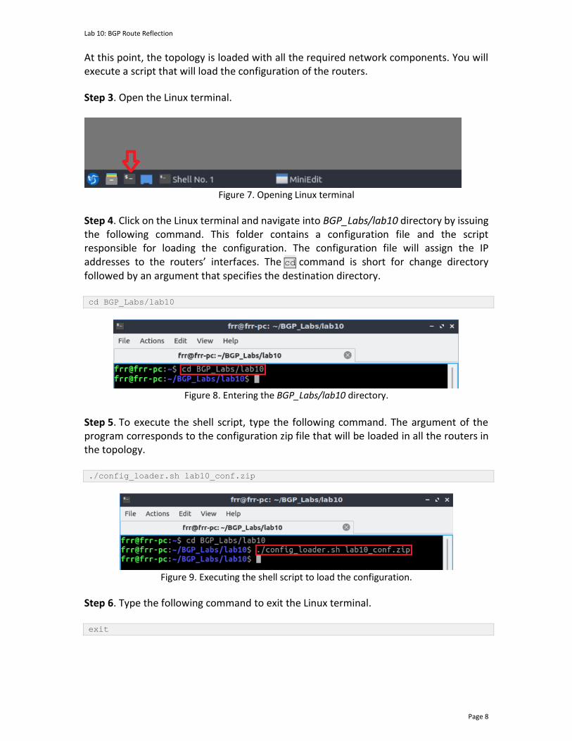
Lab 10: BGP Route Reflection
Page 8
At this point, the topology is loaded with all the required network components. You will execute a script that will load the configuration of the routers.
Step 3. Open the Linux terminal.
Figure 7. Opening Linux terminal
Step 4. Click on the Linux terminal and navigate into BGP_Labs/lab10 directory by issuing the following command. This folder contains a configuration file and the script responsible for loading the configuration. The configuration file will assign the IP addresses to the routers’ interfaces. The cd command is short for change directory followed by an argument that specifies the destination directory. cd BGP_Labs/lab10
Figure 8. Entering the BGP_Labs/lab10 directory.
Step 5. To execute the shell script, type the following command. The argument of the program corresponds to the configuration zip file that will be loaded in all the routers in the topology. ./config_loader.sh lab10_conf.zip
Figure 9. Executing the shell script to load the configuration.
Step 6. Type the following command to exit the Linux terminal. exit
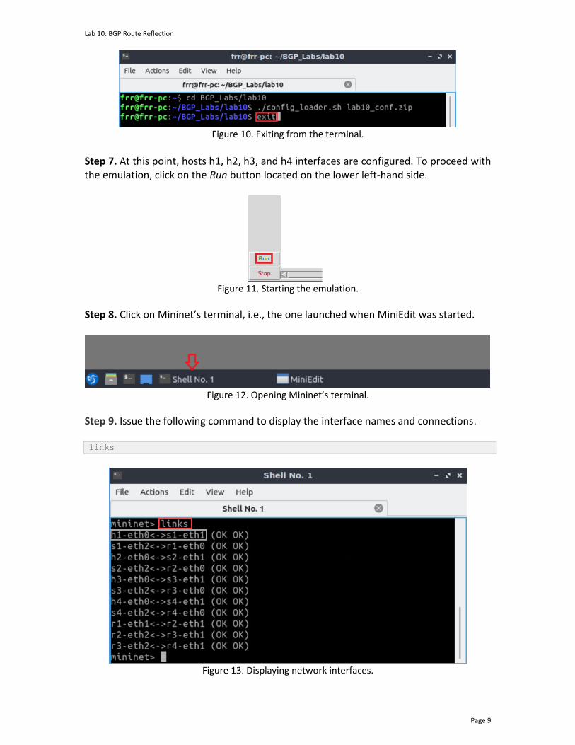
Lab 10: BGP Route Reflection
Page 9
Figure 10. Exiting from the terminal.
Step 7. At this point, hosts h1, h2, h3, and h4 interfaces are configured. To proceed with the emulation, click on the Run button located on the lower left-hand side.
Figure 11. Starting the emulation.
Step 8. Click on Mininet’s terminal, i.e., the one launched when MiniEdit was started.
Figure 12. Opening Mininet’s terminal.
Step 9. Issue the following command to display the interface names and connections. links
Figure 13. Displaying network interfaces.
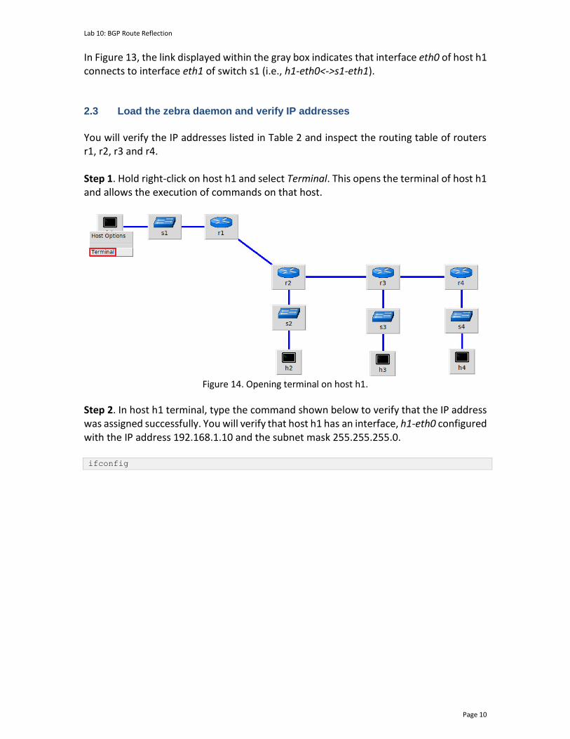
Lab 10: BGP Route Reflection
Page 10
In Figure 13, the link displayed within the gray box indicates that interface eth0 of host h1 connects to interface eth1 of switch s1 (i.e., h1-eth0<->s1-eth1). 2.3 Load the zebra daemon and verify IP addresses
You will verify the IP addresses listed in Table 2 and inspect the routing table of routers r1, r2, r3 and r4. Step 1. Hold right-click on host h1 and select Terminal. This opens the terminal of host h1 and allows the execution of commands on that host.
Figure 14. Opening terminal on host h1.
Step 2. In host h1 terminal, type the command shown below to verify that the IP address was assigned successfully. You will verify that host h1 has an interface, h1-eth0 configured with the IP address 192.168.1.10 and the subnet mask 255.255.255.0. ifconfig

Lab 10: BGP Route Reflection
Page 11
Figure 15. Output of ifconfig command.
Step 3. In host h1 terminal, type the command shown below to verify that the default gateway IP address is 192.168.1.1. route
Figure 16. Output of route command.
Step 4. In order to verify hosts h2, h3 and h4, proceed similarly by repeating from step 1 to step 3 on host h2, h3 and h4 terminals. Similar results should be observed. Step 5. You will validate that the router interfaces are configured correctly according to Table 2. In order to verify router r1, hold right-click on router r1 and select Terminal.

Lab 10: BGP Route Reflection
Page 12
Figure 17. Opening terminal on router r1.
Step 6. Start the zebra daemon, a multi-server routing software that provides TCP/IP based routing protocols. The configuration will not be working if you do not enable the zebra daemon initially. In order to start zebra, type the following command: zebra
Figure 18. Starting zebra daemon.
Step 7. After initializing zebra, vtysh should be started in order to provide all the CLI commands defined by the daemons. To proceed, issue the following command: vtysh
Figure 19. Starting vtysh on router r1.
Step 8. Type the following command on router r1 terminal to verify the routing table of router r1. It will list all the directly connected networks. The routing table of router r1 does not contain any route to the networks attached to routers r2 (192.168.2.0/24), r3 (192.168.3.0/24) and r4 (192.168.4.0/24) as there is no routing protocol configured yet. show ip route
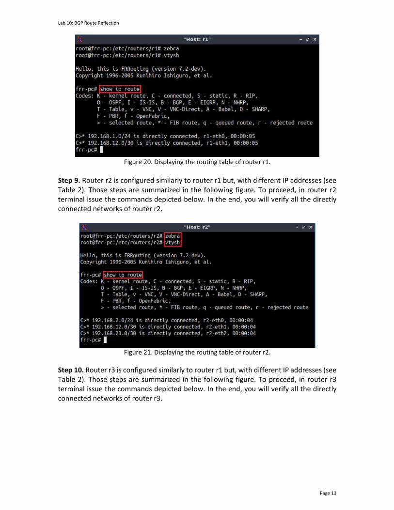
Lab 10: BGP Route Reflection
Page 13
Figure 20. Displaying the routing table of router r1.
Step 9. Router r2 is configured similarly to router r1 but, with different IP addresses (see Table 2). Those steps are summarized in the following figure. To proceed, in router r2 terminal issue the commands depicted below. In the end, you will verify all the directly connected networks of router r2.
Figure 21. Displaying the routing table of router r2.
Step 10. Router r3 is configured similarly to router r1 but, with different IP addresses (see Table 2). Those steps are summarized in the following figure. To proceed, in router r3 terminal issue the commands depicted below. In the end, you will verify all the directly connected networks of router r3.
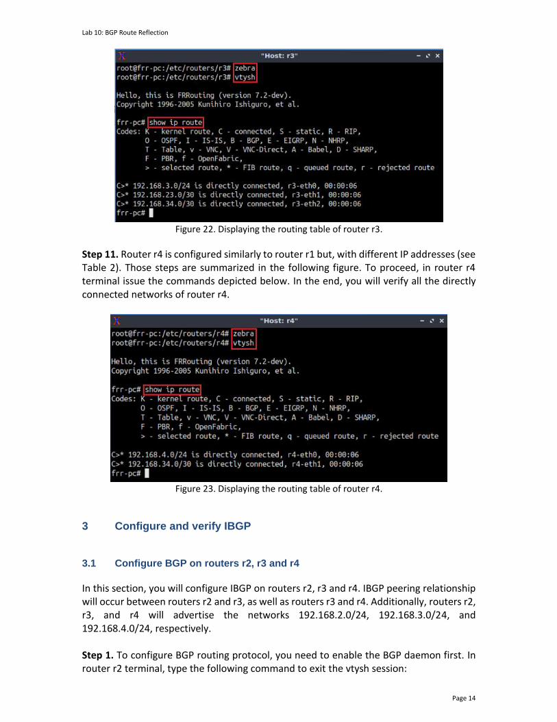
Lab 10: BGP Route Reflection
Page 14
Figure 22. Displaying the routing table of router r3.
Step 11. Router r4 is configured similarly to router r1 but, with different IP addresses (see Table 2). Those steps are summarized in the following figure. To proceed, in router r4 terminal issue the commands depicted below. In the end, you will verify all the directly connected networks of router r4.
Figure 23. Displaying the routing table of router r4.
3 Configure and verify IBGP 3.1 Configure BGP on routers r2, r3 and r4
In this section, you will configure IBGP on routers r2, r3 and r4. IBGP peering relationship will occur between routers r2 and r3, as well as routers r3 and r4. Additionally, routers r2, r3, and r4 will advertise the networks 192.168.2.0/24, 192.168.3.0/24, and 192.168.4.0/24, respectively. Step 1. To configure BGP routing protocol, you need to enable the BGP daemon first. In router r2 terminal, type the following command to exit the vtysh session:
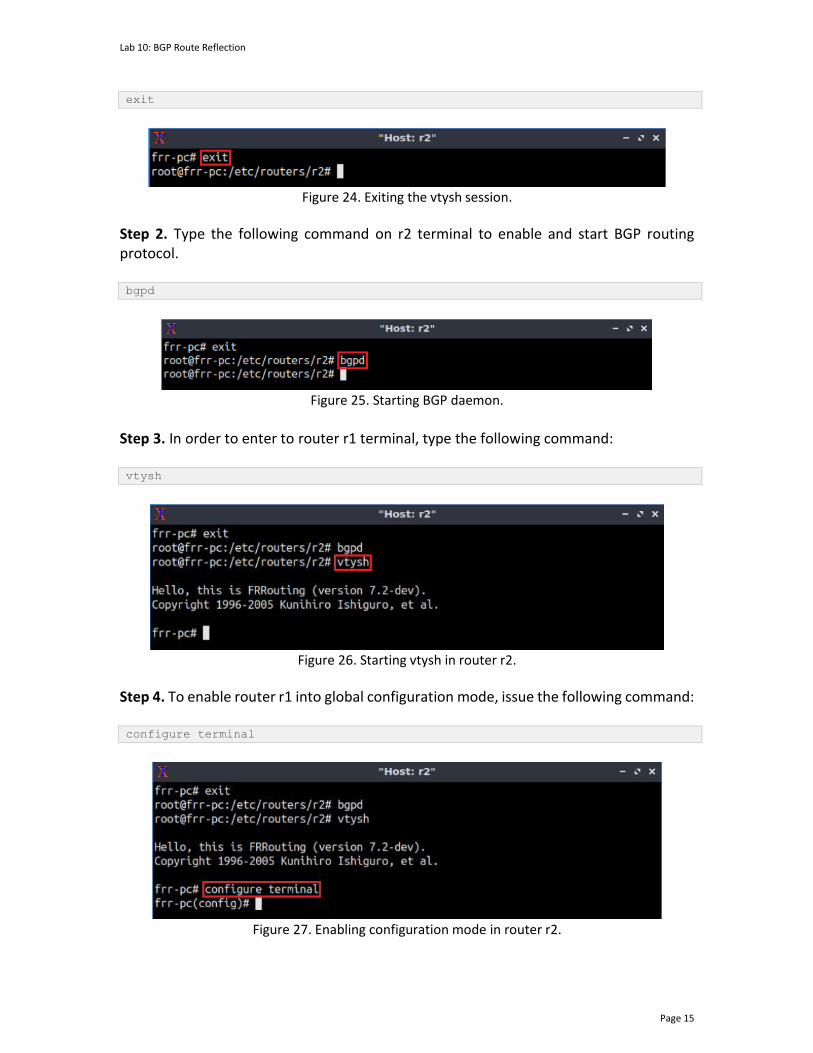
Lab 10: BGP Route Reflection
Page 15
exit
Figure 24. Exiting the vtysh session.
Step 2. Type the following command on r2 terminal to enable and start BGP routing protocol. bgpd
Figure 25. Starting BGP daemon.
Step 3. In order to enter to router r1 terminal, type the following command: vtysh
Figure 26. Starting vtysh in router r2.
Step 4. To enable router r1 into global configuration mode, issue the following command: configure terminal
Figure 27. Enabling configuration mode in router r2.

Lab 10: BGP Route Reflection
Page 16
Step 5. The ASN assigned for router r2 is 200. In order to configure BGP, type the following command: router bgp 200
Figure 28. Configuring BGP on router r2.
Step 6. Assign a router ID to router r2 by issuing the following command. bgp router-id 2.2.2.2
Figure 29. Assigning a router ID in router r2.
Step 7. To configure a BGP neighbor to router r2 (AS 200), type the command shown below. This command specifies the neighbor IP address (192.168.23.2) and the ASN of the remote BGP peer (AS 200). neighbor 192.168.23.2 remote-as 200
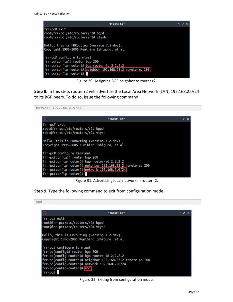
Lab 10: BGP Route Reflection
Page 17
Figure 30. Assigning BGP neighbor to router r2.
Step 8. In this step, router r2 will advertise the Local Area Network (LAN) 192.168.2.0/24 to its BGP peers. To do so, issue the following command: network 192.168.2.0/24
Figure 31. Advertising local network in router r2.
Step 9. Type the following command to exit from configuration mode. end
Figure 32. Exiting from configuration mode.
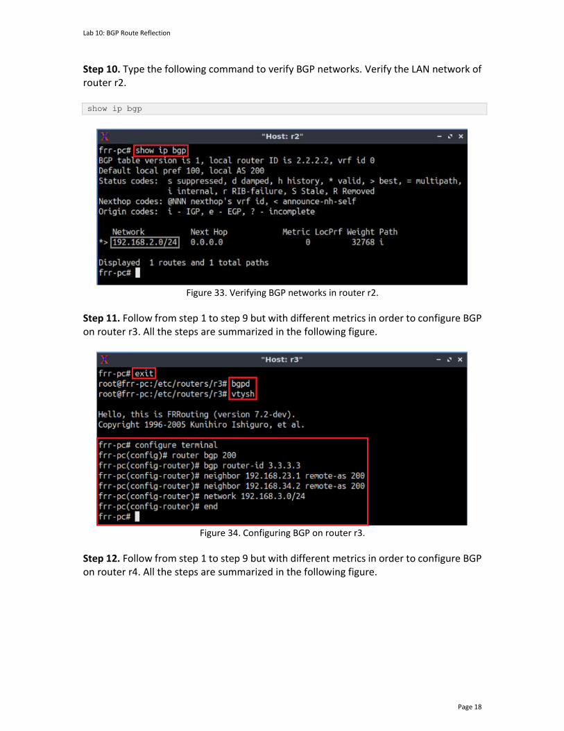
Lab 10: BGP Route Reflection
Page 18
Step 10. Type the following command to verify BGP networks. Verify the LAN network of router r2. show ip bgp
Figure 33. Verifying BGP networks in router r2.
Step 11. Follow from step 1 to step 9 but with different metrics in order to configure BGP on router r3. All the steps are summarized in the following figure.
Figure 34. Configuring BGP on router r3.
Step 12. Follow from step 1 to step 9 but with different metrics in order to configure BGP on router r4. All the steps are summarized in the following figure.
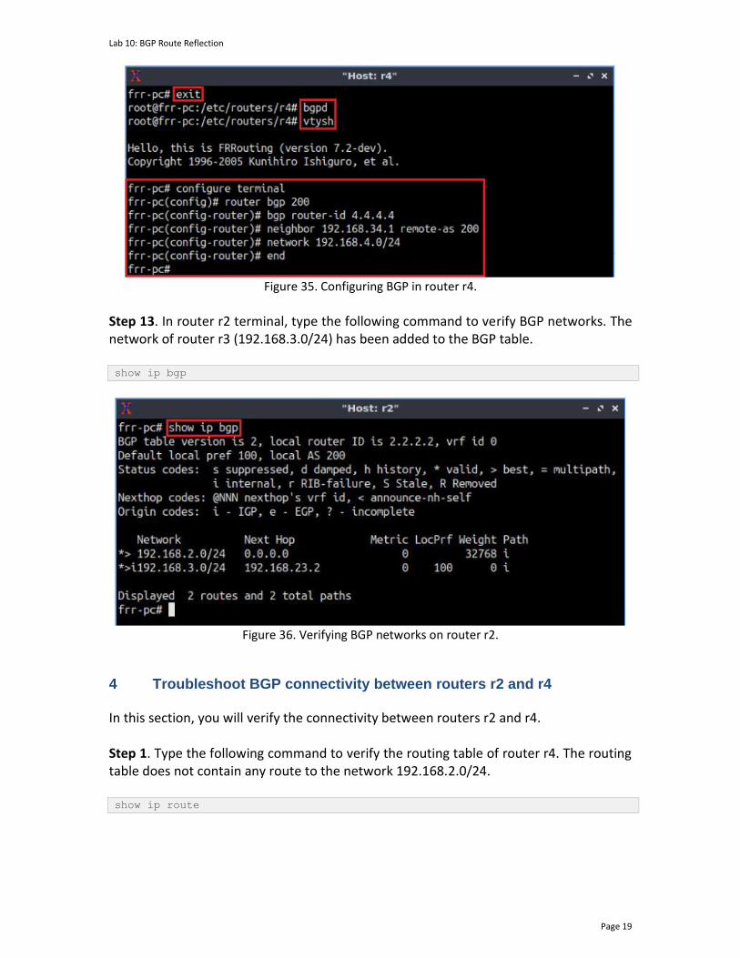
Lab 10: BGP Route Reflection
Page 19
Figure 35. Configuring BGP in router r4.
Step 13. In router r2 terminal, type the following command to verify BGP networks. The network of router r3 (192.168.3.0/24) has been added to the BGP table. show ip bgp
Figure 36. Verifying BGP networks on router r2.
4 Troubleshoot BGP connectivity between routers r2 and r4
In this section, you will verify the connectivity between routers r2 and r4. Step 1. Type the following command to verify the routing table of router r4. The routing table does not contain any route to the network 192.168.2.0/24. show ip route
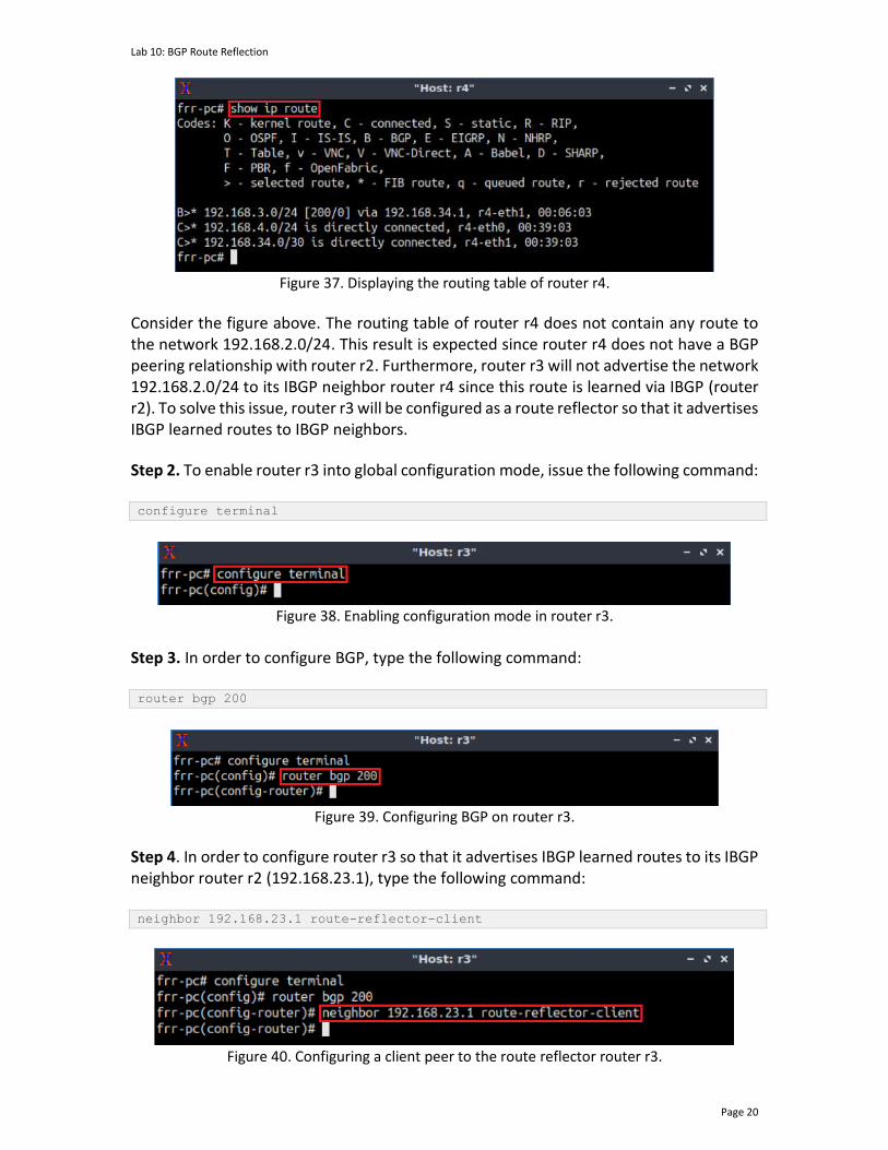
Lab 10: BGP Route Reflection
Page 20
Figure 37. Displaying the routing table of router r4.
Consider the figure above. The routing table of router r4 does not contain any route to the network 192.168.2.0/24. This result is expected since router r4 does not have a BGP peering relationship with router r2. Furthermore, router r3 will not advertise the network 192.168.2.0/24 to its IBGP neighbor router r4 since this route is learned via IBGP (router r2). To solve this issue, router r3 will be configured as a route reflector so that it advertises IBGP learned routes to IBGP neighbors.
Step 2. To enable router r3 into global configuration mode, issue the following command: configure terminal
Figure 38. Enabling configuration mode in router r3.
Step 3. In order to configure BGP, type the following command: router bgp 200
Figure 39. Configuring BGP on router r3.
Step 4. In order to configure router r3 so that it advertises IBGP learned routes to its IBGP neighbor router r2 (192.168.23.1), type the following command: neighbor 192.168.23.1 route-reflector-client
Figure 40. Configuring a client peer to the route reflector router r3.
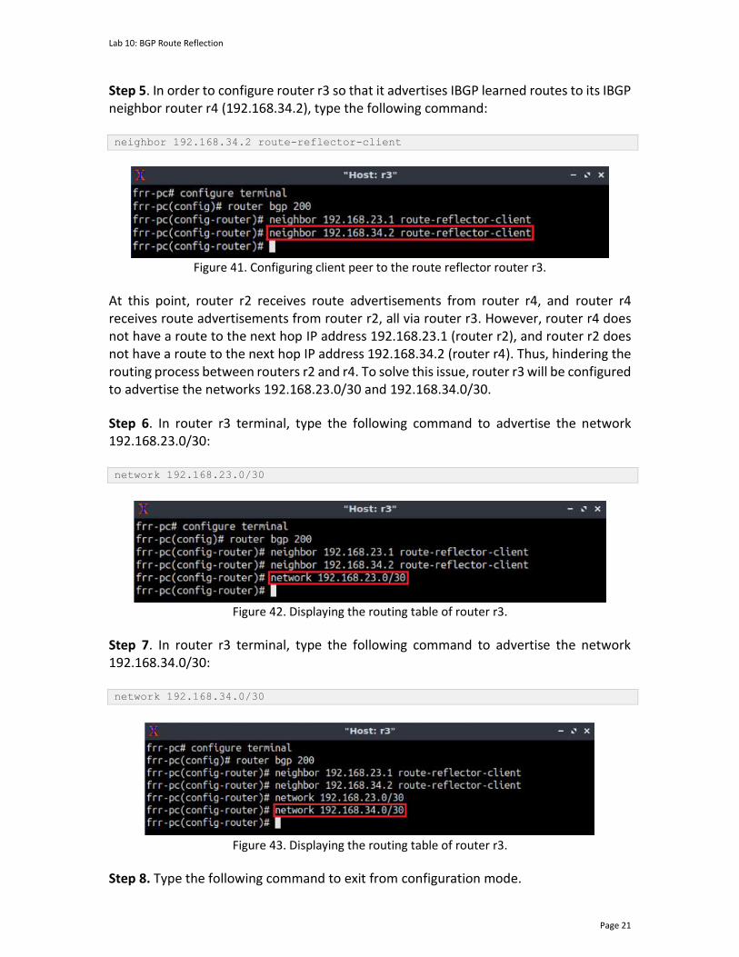
Lab 10: BGP Route Reflection
Page 21
Step 5. In order to configure router r3 so that it advertises IBGP learned routes to its IBGP neighbor router r4 (192.168.34.2), type the following command: neighbor 192.168.34.2 route-reflector-client
Figure 41. Configuring client peer to the route reflector router r3.
At this point, router r2 receives route advertisements from router r4, and router r4 receives route advertisements from router r2, all via router r3. However, router r4 does not have a route to the next hop IP address 192.168.23.1 (router r2), and router r2 does not have a route to the next hop IP address 192.168.34.2 (router r4). Thus, hindering the routing process between routers r2 and r4. To solve this issue, router r3 will be configured to advertise the networks 192.168.23.0/30 and 192.168.34.0/30.
Step 6. In router r3 terminal, type the following command to advertise the network 192.168.23.0/30: network 192.168.23.0/30
Figure 42. Displaying the routing table of router r3.
Step 7. In router r3 terminal, type the following command to advertise the network 192.168.34.0/30: network 192.168.34.0/30
Figure 43. Displaying the routing table of router r3.
Step 8. Type the following command to exit from configuration mode.

Lab 10: BGP Route Reflection
Page 22
end
Figure 44. Exiting from configuration mode.
Step 9. Type the following command to verify the routing table of router r4. show ip route
Figure 45. Displaying the routing table of router r4.
Consider the figure above. The routing table of router r4 has a route to the network 192.168.2.0/24. This route was advertised by the route reflector router r3.
Step 10. In host h4 terminal, perform a connectivity test between host h4 and host h2 by issuing the command shown below. To stop the test, press Ctrl+c. The result will show a successful connectivity test. ping 192.168.2.10
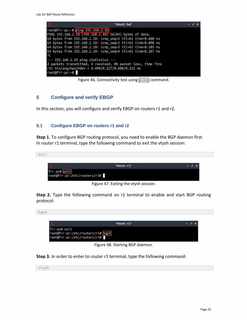
Lab 10: BGP Route Reflection
Page 23
Figure 46. Connectivity test using ping command.
5 Configure and verify EBGP In this section, you will configure and verify EBGP on routers r1 and r2. 5.1 Configure EBGP on routers r1 and r2
Step 1. To configure BGP routing protocol, you need to enable the BGP daemon first. In router r1 terminal, type the following command to exit the vtysh session: exit
Figure 47. Exiting the vtysh session.
Step 2. Type the following command on r1 terminal to enable and start BGP routing protocol. bgpd
Figure 48. Starting BGP daemon.
Step 3. In order to enter to router r1 terminal, type the following command: vtysh

Lab 10: BGP Route Reflection
Page 24
Figure 49. Starting vtysh in router r1.
Step 4. To enable router r1 into global configuration mode, issue the following command: configure terminal
Figure 50. Enabling configuration mode in router r1.
Step 5. The ASN assigned for router r1 is 100. In order to configure BGP, type the following command: router bgp 100
Figure 51. Configuring BGP on router r1.
Step 6. Assign a router ID to router r1 by issuing the following command. bgp router-id 1.1.1.1
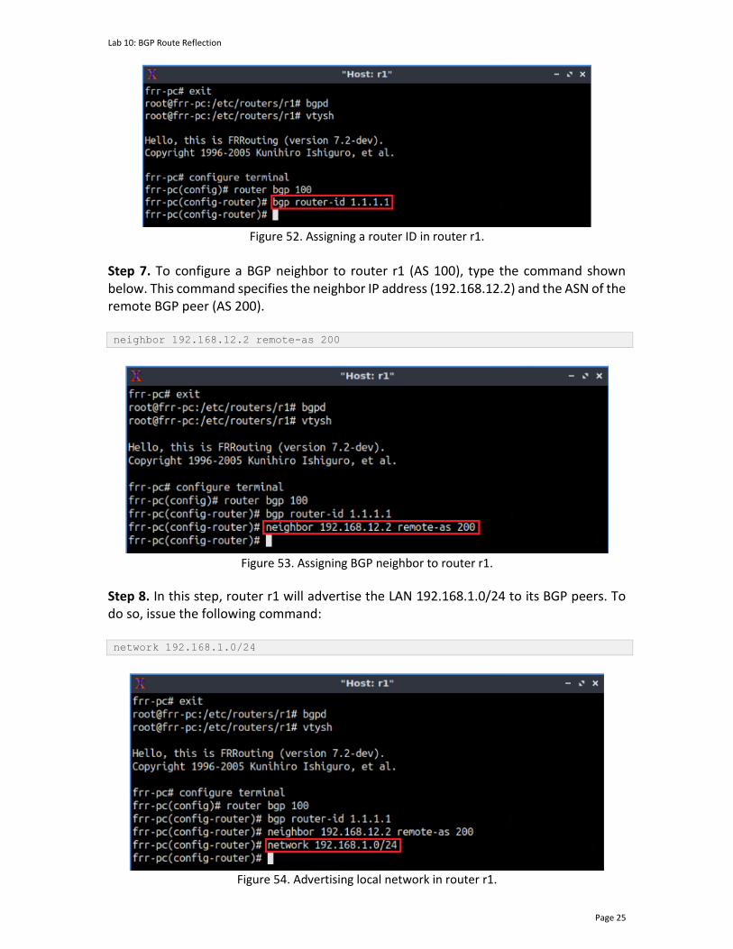
Lab 10: BGP Route Reflection
Page 25
Figure 52. Assigning a router ID in router r1.
Step 7. To configure a BGP neighbor to router r1 (AS 100), type the command shown below. This command specifies the neighbor IP address (192.168.12.2) and the ASN of the remote BGP peer (AS 200). neighbor 192.168.12.2 remote-as 200
Figure 53. Assigning BGP neighbor to router r1.
Step 8. In this step, router r1 will advertise the LAN 192.168.1.0/24 to its BGP peers. To do so, issue the following command: network 192.168.1.0/24
Figure 54. Advertising local network in router r1.

Lab 10: BGP Route Reflection
Page 26
Step 9. Type the following command to exit from configuration mode. end
Figure 55. Exiting from configuration mode.
Step 10. Follow from step 4 to step 6 but with different metrics in order to configure EBGP on router r2. All the steps are summarized in the following figure.
Figure 56. Configuring BGP on router r2.
At this point, routers r1 and r2 are EBGP neighbors and the network 192.168.1.0/24 should be advertised from router r1 to router r2. Additionally, router r2 should advertise EBGP learned routes to its IBGP neighbor routers (router r3).
Step 11. In router r3 terminal, type the following command to verify BGP networks. show ip bgp
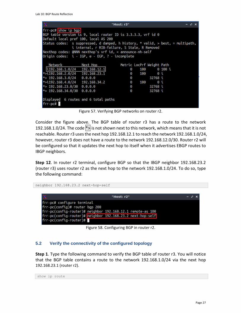
Lab 10: BGP Route Reflection
Page 27
Figure 57. Verifying BGP networks on router r2.
Consider the figure above. The BGP table of router r3 has a route to the network
192.168.1.0/24. The code *> is not shown next to this network, which means that it is not
reachable. Router r3 uses the next hop 192.168.12.1 to reach the network 192.168.1.0/24, however, router r3 does not have a route to the network 192.168.12.0/30. Router r2 will be configured so that it updates the next hop to itself when it advertises EBGP routes to IBGP neighbors.
Step 12. In router r2 terminal, configure BGP so that the IBGP neighbor 192.168.23.2 (router r3) uses router r2 as the next hop to the network 192.168.1.0/24. To do so, type the following command: neighbor 192.168.23.2 next-hop-self
Figure 58. Configuring BGP in router r2.
5.2 Verify the connectivity of the configured topology
Step 1. Type the following command to verify the BGP table of router r3. You will notice that the BGP table contains a route to the network 192.168.1.0/24 via the next hop 192.168.23.1 (router r2). show ip route

Lab 10: BGP Route Reflection
Page 28
Figure 59. Displaying the routing table of router r3.
Step 2. In host h4 terminal, perform a connectivity test between host h4 and host h1 by issuing the command shown below. To stop the test, press Ctrl+c. The result will show a successful connectivity test. ping 192.168.1.10
Figure 60. Connectivity test using ping command.
This concludes Lab 10. Stop the emulation and then exit out of MiniEdit. References
1. A. Tanenbaum, D. Wetherall, “Computer networks”, 5th Edition, Pearson, 2012. 2. T. Bates, E. Chen, R. Chandra, “BGP route reflection: an alternative to full mesh
internal BGP (IBGP)”, 2006. [Online]. Available: https://www.ietf.org/rfc/rfc4456.txt
3. J. Kurose, K. Ross, “Computer networking, a top-down approach,” 7th Edition, Pearson, 2017.
BORDER GATEWAY PROTOCOL
Exercise 4: BGP Next Hop Attribute and Route Reflection
Document Version: 09-02-2021
Award 1829698 “CyberTraining CIP: Cyberinfrastructure Expertise on High-throughput
Networks for Big Science Data Transfers”
Exercise 4: BGP Next Hop attribute and Route Reflection
Contents 1 Exercise description .................................................................................................... 3
1.1 Topology settings ................................................................................................. 3
1.2 Credentials ........................................................................................................... 4
2 Deliverables ................................................................................................................. 4
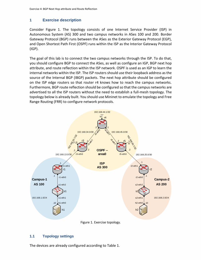
Exercise 4: BGP Next Hop attribute and Route Reflection
1 Exercise description Consider Figure 1. The topology consists of one Internet Service Provider (ISP) in Autonomous System (AS) 300 and two campus networks in ASes 100 and 200. Border Gateway Protocol (BGP) runs between the ASes as the Exterior Gateway Protocol (EGP), and Open Shortest Path First (OSPF) runs within the ISP as the Interior Gateway Protocol (IGP). The goal of this lab is to connect the two campus networks through the ISP. To do that, you should configure BGP to connect the ASes, as well as configure an IGP, BGP next hop attribute, and route reflection within the ISP network. OSPF is used as an IGP to learn the internal networks within the ISP. The ISP routers should use their loopback address as the source of the Internal BGP (IBGP) packets. The next hop attribute should be configured on the ISP edge routers so that router r4 knows how to reach the campus networks. Furthermore, BGP route reflection should be configured so that the campus networks are advertised to all the ISP routers without the need to establish a full-mesh topology. The topology below is already built. You should use Mininet to emulate the topology and Free Range Routing (FRR) to configure network protocols.
s1
h1
h1-eth0
s1-eth1
s1-eth2
r1-eth0
.10
.1
r1
r3
AS 100
OSPF –
area0
192.168.1.0/24
r1-eth1
.1
.2
r3-eth0
.2
192.168.13.0/30
s2
h2
h2-eth0
s2-eth1
s2-eth2
r2-eth0
.10
.1
r2
192.168.2.0/24
.1
192.168.25.0/30
r2-eth1
Campus-1
AS 200
Campus-2
ISP
AS 300
r4
.1
.2
r5
r5-eth0
.2
.1
192.168.34.0/30
.2
192.168.45.0/30
192.168.44.1/32
lolo
lo
Figure 1. Exercise topology.
1.1 Topology settings
The devices are already configured according to Table 1.
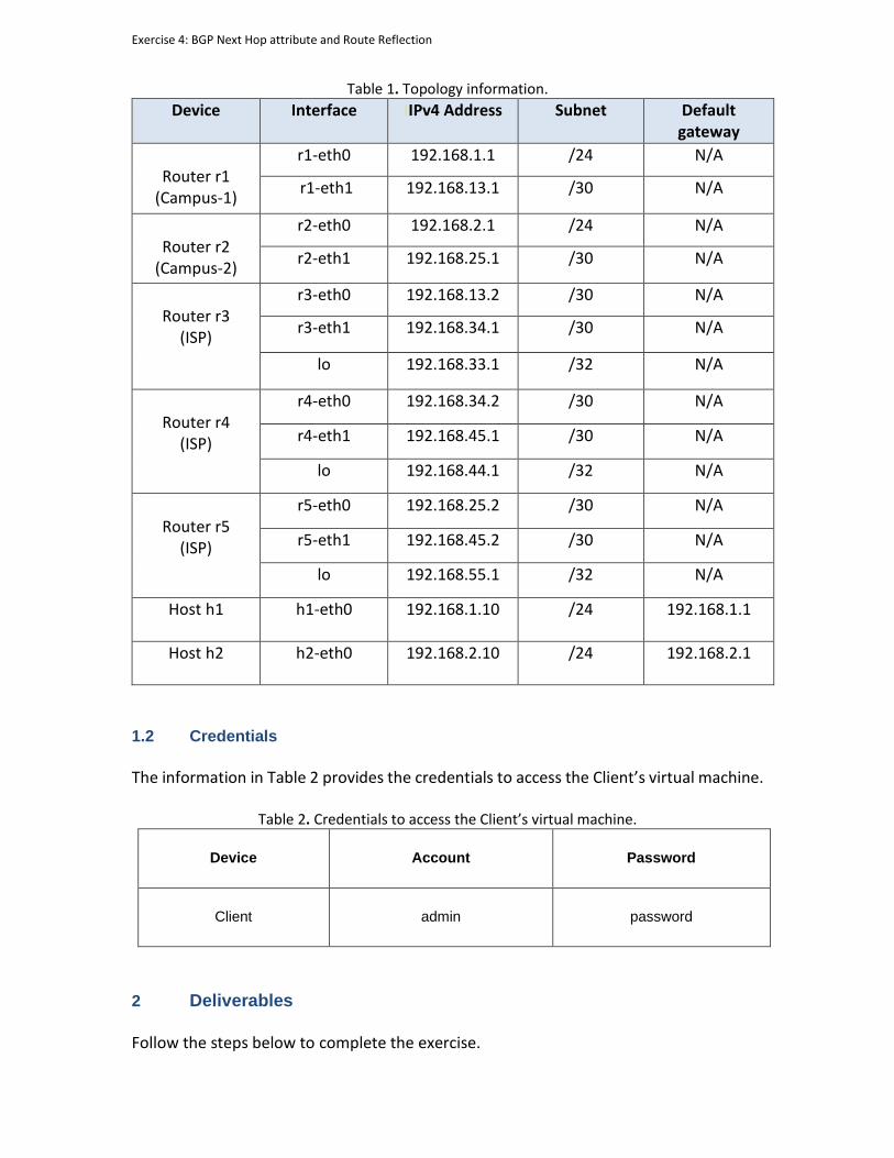
Exercise 4: BGP Next Hop attribute and Route Reflection
Table 1. Topology information.
Device Interface IIPv4 Address Subnet Default gateway
Router r1
(Campus-1)
r1-eth0 192.168.1.1 /24 N/A
r1-eth1 192.168.13.1 /30 N/A
Router r2
(Campus-2)
r2-eth0 192.168.2.1 /24 N/A
r2-eth1 192.168.25.1 /30 N/A
Router r3
(ISP)
r3-eth0 192.168.13.2 /30 N/A
r3-eth1 192.168.34.1 /30 N/A
lo 192.168.33.1 /32 N/A
Router r4
(ISP)
r4-eth0 192.168.34.2 /30 N/A
r4-eth1 192.168.45.1 /30 N/A
lo 192.168.44.1 /32 N/A
Router r5
(ISP)
r5-eth0 192.168.25.2 /30 N/A
r5-eth1 192.168.45.2 /30 N/A
lo 192.168.55.1 /32 N/A
Host h1
h1-eth0 192.168.1.10 /24 192.168.1.1
Host h2
h2-eth0 192.168.2.10 /24 192.168.2.1
1.2 Credentials
The information in Table 2 provides the credentials to access the Client’s virtual machine.
Table 2. Credentials to access the Client’s virtual machine.
Device
Account
Password
Client admin password
2 Deliverables Follow the steps below to complete the exercise.
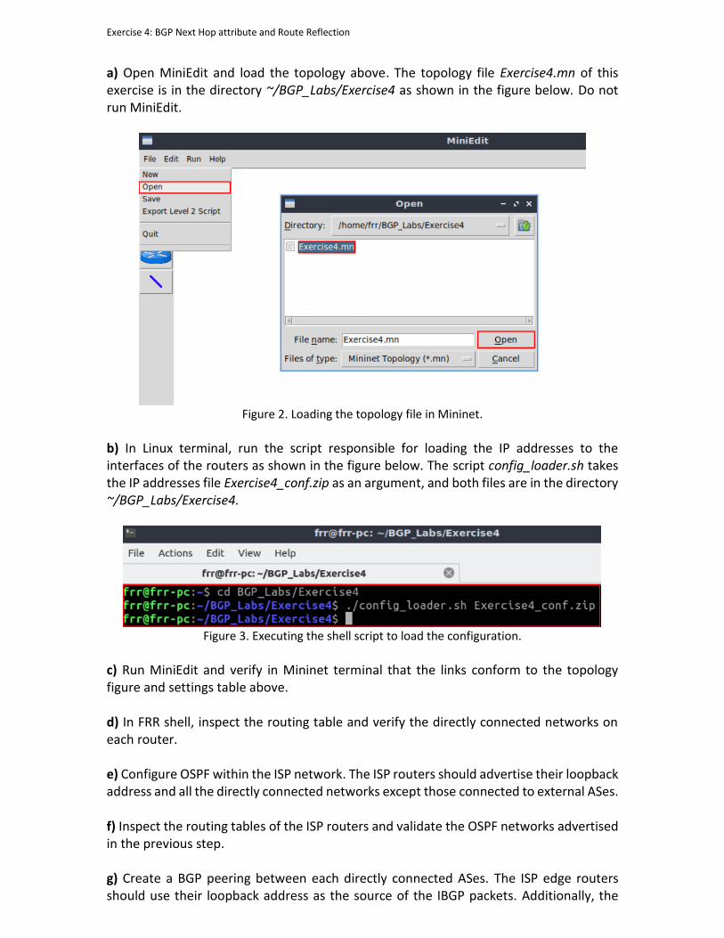
Exercise 4: BGP Next Hop attribute and Route Reflection
a) Open MiniEdit and load the topology above. The topology file Exercise4.mn of this exercise is in the directory ~/BGP_Labs/Exercise4 as shown in the figure below. Do not run MiniEdit.
Figure 2. Loading the topology file in Mininet.
b) In Linux terminal, run the script responsible for loading the IP addresses to the interfaces of the routers as shown in the figure below. The script config_loader.sh takes the IP addresses file Exercise4_conf.zip as an argument, and both files are in the directory ~/BGP_Labs/Exercise4.
Figure 3. Executing the shell script to load the configuration.
c) Run MiniEdit and verify in Mininet terminal that the links conform to the topology figure and settings table above. d) In FRR shell, inspect the routing table and verify the directly connected networks on each router. e) Configure OSPF within the ISP network. The ISP routers should advertise their loopback address and all the directly connected networks except those connected to external ASes. f) Inspect the routing tables of the ISP routers and validate the OSPF networks advertised in the previous step. g) Create a BGP peering between each directly connected ASes. The ISP edge routers should use their loopback address as the source of the IBGP packets. Additionally, the

Exercise 4: BGP Next Hop attribute and Route Reflection
routers in Campus-1 and Campus-2 should advertise their internal network to their BGP neighbor. h) Inspect the BGP and routing tables of the ISP routers. Do the BGP and routing tables of router r4 contain an entry to Campus-1 and Campus-2 networks? Explain your answer. i) Configure the BGP next hop attribute in the ISP edge routers. In particular, the ISP edge routers should use their loopback address as the next hop when advertising external BGP routes. Inspect the BGP and routing tables of router r4 and explain any changes from the previous step. j) Does the routing table of each ISP router contain an entry to both campus networks? Explain your answer. k) Configure BGP route reflection within the ISP network so that the campus networks are advertised to all the ISP routers. Inspect the routing tables of the ISP routers and explain the changes from the previous step. l) Test the connectivity between the two campus networks by performing a ping test from host h1 to host h2. A successful connectivity test should occur after a correct configuration.