Bonding Characteristics of Underfilled Ball Grid Array Packaging
7
Bonding Characteristics of Underfilled Ball Grid Array Packaging Byung-Seung Yim, Jeong Il Lee, Byung Hun Lee, Young-Eui Shin and Jong-Min Kim + School of Mechanical Engineering, Chung-Ang University, Seoul 156-756, Korea In recent years, ball grid array (BGA) package has been widely used in the portable electronic device, which can offer miniaturization and increased functional density. Thus, the failure chances of package under shock and vibration environments have been increased. In this work, we investigate the effect of underfill properties on bonding characteristics of underfilled BGA packaging. Three kinds of underfill materials with different additive content were formulated. Dynamic mechanical analysis (DMA), tensile test and shear test were conducted to examine the material properties of underfill resin such as the storage modulus (EA), glass transition temperature (T g ), mechanical and adhesion strength. In addition, the three-point bending test was conducted for underfilled BGA assemblies to investigate the mechanical reliability of BGA interconnects. The results indicate that the underfill resin should have a proper T g to ensure the mechanical properties, and modulus of toughness of underfill resin acts as an important factor rather than mechanical strength and EA (Stiffness) to ensure the mechanical reliability of BGA assembly. [doi:10.2320/matertrans.MI201407] (Received December 4, 2014; Accepted December 24, 2014; Published February 13, 2015) Keywords: area array packaging, ball grid array package, material property, mechanical reliability, surface mount device, underfill 1. Introduction As the demands for higher input/output (I/O), greater performance, higher density, lighter weight, smaller and thinner size, lower cost and increased functionality of the electronic device has been increased, the use of area array type board-level surface mount device (SMD) package such as ball grid array (BGA) package and chip scale package (CSP) has been increased. 1) Among these area array package type, BGA package is widely used in the portable electronic device such as the mobile phone and personal digital assistant (PDA) to reduce their size, weight and increase their functionality. 2) BGA package is initially designed to eliminate the need for encapsulation, and their high bump height does provide acceptable solder fatigue during thermal cycling. However, many of these devices face serious reliability problems when cyclic creep is induced by high loads generated from the massive heat-sinks supported by them. Dynamic loading induced by mechanical vibration or impact shock results in further reliability problems in BGA interconnects. Underfill is again found to be the solution to the above mentioned reliability problems. 3) Underfill is an adhesive that serves to reinforce the physical and mechanical properties of the solder interconnects between the package and the substrate. The main object of underfilling for BGA assembly is to provide mechanical protection from shock or vibration. The presence of an underfill encapsulant between an electronic device and the underlying substrate potentially reduce the inelastic strain sustained by the solder, and drastically improve the fatigue life of solder interconnects, mainly due to the load transfer from the solder to the encapsulant. 4,5) The most important material properties of underfill to ensure the reliable solder interconnect are storage modulus (EA), adhesion, glass transition temperature (T g ) and coefficient of thermal expansion (CTE). The EA of underfill resin should be sufficiently high to prevent stress concen- trations in the solder bumps by transmitting mechanical load of solder interconnect to the substrate and reducing strain of the solder bumps. The underfill resin should have excellent adhesion with various dissimilar material surface to improve the fatigue life of solder interconnect. When the adhesion strength of underfill resin does not proper, underfill cracking or underfill delamination can be occurred due to the stress. Also, T g of underfill resin should be higher than upper operating temperature of the package because the dramatic changes in material properties such as EA and CTE occur at the T g . 6) Under thermal cyclic condition, the package assembly was repeatedly exposed to thermal expansion and shrinkage due to the rapid temperature changes. Finally, the expansion and shrinkage of package assembly leads to thermo-mechanical stress in the solder interconnect due to the CTE mismatch between the dissimilar materials. 7) In order to minimize the amount of stress from thermal cycling, an ideal underfill resin should have a CTE close to solder or slightly higher than the CTE of the solder. 8) However, CTE is considered to be less important factor than adhesion or modulus in terms of a contribution to the stress redistrib- ution. 6) The reliability of BGA assembly is highly dependent on the material properties of underfill resin. Therefore, the researcher or manufacturer should be considered the material properties of underfill resin depending on the environmental conditions to which the electronic package device is used, when developing or selecting an underfill resin to apply for the electronic package device. In order to ensure the desired reliability performance, a detailed knowledge of variables which play an important role in mechanical reliability between the material properties of the underfill resin is required. However, the data for the important material variables between the material properties of the underfill resin to ensure the mechanical reliability of package interconnect, and relationship between the respective material properties are insufficient. In this work, our investigation focused on the determi- nation of the important material variables of underfill resin to ensure the mechanical reliability for BGA package inter- connect on potable electronic device (e.g. mobile phone or PDA). To investigate the effect of material properties of underfill resin on reliability of BGA package interconnect, we prepared three types of underfill resins with different + Corresponding author, E-mail: 0326kjm@cau.ac.kr Materials Transactions, Vol. 56, No. 7 (2015) pp. 974 to 980 Special Issue on Nanojoining and Microjoining II © 2015 The Japan Institute of Metals and Materials
-
Upload
khangminh22 -
Category
Documents
-
view
0 -
download
0
Transcript of Bonding Characteristics of Underfilled Ball Grid Array Packaging
Bonding Characteristics of Underfilled Ball Grid Array Packaging
Byung-Seung Yim, Jeong Il Lee, Byung Hun Lee, Young-Eui Shin and Jong-Min Kim+
School of Mechanical Engineering, Chung-Ang University, Seoul 156-756, Korea
In recent years, ball grid array (BGA) package has been widely used in the portable electronic device, which can offer miniaturization andincreased functional density. Thus, the failure chances of package under shock and vibration environments have been increased. In this work, weinvestigate the effect of underfill properties on bonding characteristics of underfilled BGA packaging. Three kinds of underfill materials withdifferent additive content were formulated. Dynamic mechanical analysis (DMA), tensile test and shear test were conducted to examine thematerial properties of underfill resin such as the storage modulus (EA), glass transition temperature (Tg), mechanical and adhesion strength.In addition, the three-point bending test was conducted for underfilled BGA assemblies to investigate the mechanical reliability of BGAinterconnects. The results indicate that the underfill resin should have a proper Tg to ensure the mechanical properties, and modulus of toughnessof underfill resin acts as an important factor rather than mechanical strength and EA (Stiffness) to ensure the mechanical reliability of BGAassembly. [doi:10.2320/matertrans.MI201407]
(Received December 4, 2014; Accepted December 24, 2014; Published February 13, 2015)
Keywords: area array packaging, ball grid array package, material property, mechanical reliability, surface mount device, underfill
1. Introduction
As the demands for higher input/output (I/O), greaterperformance, higher density, lighter weight, smaller andthinner size, lower cost and increased functionality of theelectronic device has been increased, the use of area arraytype board-level surface mount device (SMD) package suchas ball grid array (BGA) package and chip scale package(CSP) has been increased.1) Among these area array packagetype, BGA package is widely used in the portable electronicdevice such as the mobile phone and personal digital assistant(PDA) to reduce their size, weight and increase theirfunctionality.2) BGA package is initially designed toeliminate the need for encapsulation, and their high bumpheight does provide acceptable solder fatigue during thermalcycling. However, many of these devices face seriousreliability problems when cyclic creep is induced by highloads generated from the massive heat-sinks supported bythem. Dynamic loading induced by mechanical vibration orimpact shock results in further reliability problems in BGAinterconnects. Underfill is again found to be the solution tothe above mentioned reliability problems.3) Underfill is anadhesive that serves to reinforce the physical and mechanicalproperties of the solder interconnects between the packageand the substrate. The main object of underfilling for BGAassembly is to provide mechanical protection from shock orvibration. The presence of an underfill encapsulant betweenan electronic device and the underlying substrate potentiallyreduce the inelastic strain sustained by the solder, anddrastically improve the fatigue life of solder interconnects,mainly due to the load transfer from the solder to theencapsulant.4,5) The most important material properties ofunderfill to ensure the reliable solder interconnect are storagemodulus (EA), adhesion, glass transition temperature (Tg) andcoefficient of thermal expansion (CTE). The EA of underfillresin should be sufficiently high to prevent stress concen-trations in the solder bumps by transmitting mechanical loadof solder interconnect to the substrate and reducing strain ofthe solder bumps. The underfill resin should have excellent
adhesion with various dissimilar material surface to improvethe fatigue life of solder interconnect. When the adhesionstrength of underfill resin does not proper, underfill crackingor underfill delamination can be occurred due to the stress.Also, Tg of underfill resin should be higher than upperoperating temperature of the package because the dramaticchanges in material properties such as EA and CTE occur atthe Tg.6) Under thermal cyclic condition, the packageassembly was repeatedly exposed to thermal expansion andshrinkage due to the rapid temperature changes. Finally, theexpansion and shrinkage of package assembly leads tothermo-mechanical stress in the solder interconnect due to theCTE mismatch between the dissimilar materials.7) In order tominimize the amount of stress from thermal cycling, an idealunderfill resin should have a CTE close to solder or slightlyhigher than the CTE of the solder.8) However, CTE isconsidered to be less important factor than adhesion ormodulus in terms of a contribution to the stress redistrib-ution.6)
The reliability of BGA assembly is highly dependent onthe material properties of underfill resin. Therefore, theresearcher or manufacturer should be considered the materialproperties of underfill resin depending on the environmentalconditions to which the electronic package device is used,when developing or selecting an underfill resin to apply forthe electronic package device. In order to ensure the desiredreliability performance, a detailed knowledge of variableswhich play an important role in mechanical reliabilitybetween the material properties of the underfill resin isrequired. However, the data for the important materialvariables between the material properties of the underfillresin to ensure the mechanical reliability of packageinterconnect, and relationship between the respective materialproperties are insufficient.
In this work, our investigation focused on the determi-nation of the important material variables of underfill resin toensure the mechanical reliability for BGA package inter-connect on potable electronic device (e.g. mobile phone orPDA). To investigate the effect of material properties ofunderfill resin on reliability of BGA package interconnect,we prepared three types of underfill resins with different+Corresponding author, E-mail: [email protected]
Materials Transactions, Vol. 56, No. 7 (2015) pp. 974 to 980Special Issue on Nanojoining and Microjoining II©2015 The Japan Institute of Metals and Materials
additive content. The dynamic mechanical analysis (DMA),tensile test and shear test were conducted to examine thematerial properties of underfill resin such as the EA, Tg,mechanical and shear strength. In addition, to measure themechanical reliability of BGA package interconnect, thethree-point bending test were conducted.
2. Experimental
2.1 MaterialsTo investigate the effect of material properties of underfill
resin on mechanical reliability of BGA package interconnect,the three kinds of underfill resin (single-liquid no-filler type)were formulated. For the underfill material, epoxy-typethermosetting resin, amine-type curing agent and severaltypes of additives were used. The recommended curingcondition for all underfill resin was 10min at 423K.
2.2 Test method2.2.1 Dynamic mechanical analysis (DMA)
A DMA test was conducted using TT DMA (Tritron Tech.)to investigate the dynamic mechanical properties of formu-lated underfill resins. For the DMA test, the rectangular testspecimens with dimension of 30mm © 10mm © 2.0mmwere prepared. The formulated underfill resins were pouredinto a Teflon mold and then cured for 10min at 423K, andthen the Teflon molds were removed after the curing wascompleted. In DMA test, a single cantilever mode wasselected. The prepared rectangular test specimen was heldhorizontal by two clamps. One clamp was fixed, and the otherapplied a vertical displacement for the specimen. The testspecimens in a nitrogen gas environment were measured inthe fixed frequency mode at an operating frequency of 1.0Hzwith sinusoidal oscillation amplitude of 20 µm. The testsamples were heated in the temperature range from 298K to453K at a heating rate of 3K/min. During the DMA testunder sinusoidal deformation and temperature change, EA,loss modulus (EAA), and mechanical loss factor (tan ¤) of eachtest specimens were collected.2.2.2 Tensile test
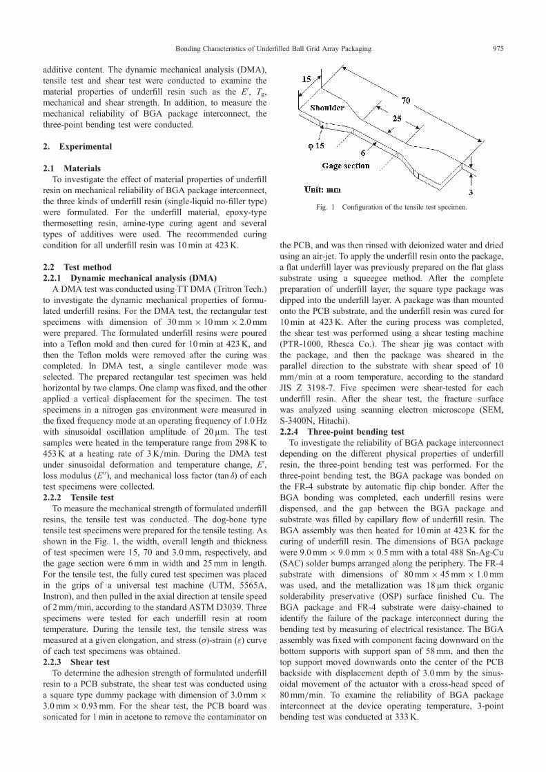
To measure the mechanical strength of formulated underfillresins, the tensile test was conducted. The dog-bone typetensile test specimens were prepared for the tensile testing. Asshown in the Fig. 1, the width, overall length and thicknessof test specimen were 15, 70 and 3.0mm, respectively, andthe gage section were 6mm in width and 25mm in length.For the tensile test, the fully cured test specimen was placedin the grips of a universal test machine (UTM, 5565A,Instron), and then pulled in the axial direction at tensile speedof 2mm/min, according to the standard ASTM D3039. Threespecimens were tested for each underfill resin at roomtemperature. During the tensile test, the tensile stress wasmeasured at a given elongation, and stress (·)-strain (¾) curveof each test specimens was obtained.2.2.3 Shear test
To determine the adhesion strength of formulated underfillresin to a PCB substrate, the shear test was conducted usinga square type dummy package with dimension of 3.0mm ©3.0mm © 0.93mm. For the shear test, the PCB board wassonicated for 1min in acetone to remove the contaminator on
the PCB, and was then rinsed with deionized water and driedusing an air-jet. To apply the underfill resin onto the package,a flat underfill layer was previously prepared on the flat glasssubstrate using a squeegee method. After the completepreparation of underfill layer, the square type package wasdipped into the underfill layer. A package was than mountedonto the PCB substrate, and the underfill resin was cured for10min at 423K. After the curing process was completed,the shear test was performed using a shear testing machine(PTR-1000, Rhesca Co.). The shear jig was contact withthe package, and then the package was sheared in theparallel direction to the substrate with shear speed of 10mm/min at a room temperature, according to the standardJIS Z 3198-7. Five specimen were shear-tested for eachunderfill resin. After the shear test, the fracture surfacewas analyzed using scanning electron microscope (SEM,S-3400N, Hitachi).2.2.4 Three-point bending test
To investigate the reliability of BGA package interconnectdepending on the different physical properties of underfillresin, the three-point bending test was performed. For thethree-point bending test, the BGA package was bonded onthe FR-4 substrate by automatic flip chip bonder. After theBGA bonding was completed, each underfill resins weredispensed, and the gap between the BGA package andsubstrate was filled by capillary flow of underfill resin. TheBGA assembly was then heated for 10min at 423K for thecuring of underfill resin. The dimensions of BGA packagewere 9.0mm © 9.0mm © 0.5mm with a total 488 Sn-Ag-Cu(SAC) solder bumps arranged along the periphery. The FR-4substrate with dimensions of 80mm © 45mm © 1.0mmwas used, and the metallization was 18 µm thick organicsolderability preservative (OSP) surface finished Cu. TheBGA package and FR-4 substrate were daisy-chained toidentify the failure of the package interconnect during thebending test by measuring of electrical resistance. The BGAassembly was fixed with component facing downward on thebottom supports with support span of 58mm, and then thetop support moved downwards onto the center of the PCBbackside with displacement depth of 3.0mm by the sinus-oidal movement of the actuator with a cross-head speed of80mm/min. To examine the reliability of BGA packageinterconnect at the device operating temperature, 3-pointbending test was conducted at 333K.
Fig. 1 Configuration of the tensile test specimen.
Bonding Characteristics of Underfilled Ball Grid Array Packaging 975
3. Results and Discussion
3.1 Dynamic mechanical propertiesUnderstanding of dynamic mechanical properties of
underfill resin is important to achieve reliability of BGApackage interconnect. DMA is a dynamic method ofcharacterizing the viscoelastic properties of a polymericmaterial, which is used to evaluate the effect of temperatureon the mechanical properties of composite materials. Asinusoidal deformation is applied to the material at a setfrequency, and the response corresponding to the appliedinput is measured. From the dynamic response, a complexmodulus consisting of EA and EAA are obtained. The EA isrelated to the energy stored in the system. Stiff and glassymaterials have a high EA. While the EAA is related to the energydissipated or lost during the process and it will go througha maximum value during the glass transition region of thematerial. The tan ¤ is the ratio of the EAA to the EA (EAA/EA), andit is related to the viscoelasticity and damping of a material.The maximum peak in the tan ¤ plots is commonly indicatedas the Tg.6,9,10) The EA of underfill materials should besufficiently high to prevent stress concentrations in the solderbumps, and easily transmit load to the substrate.6)
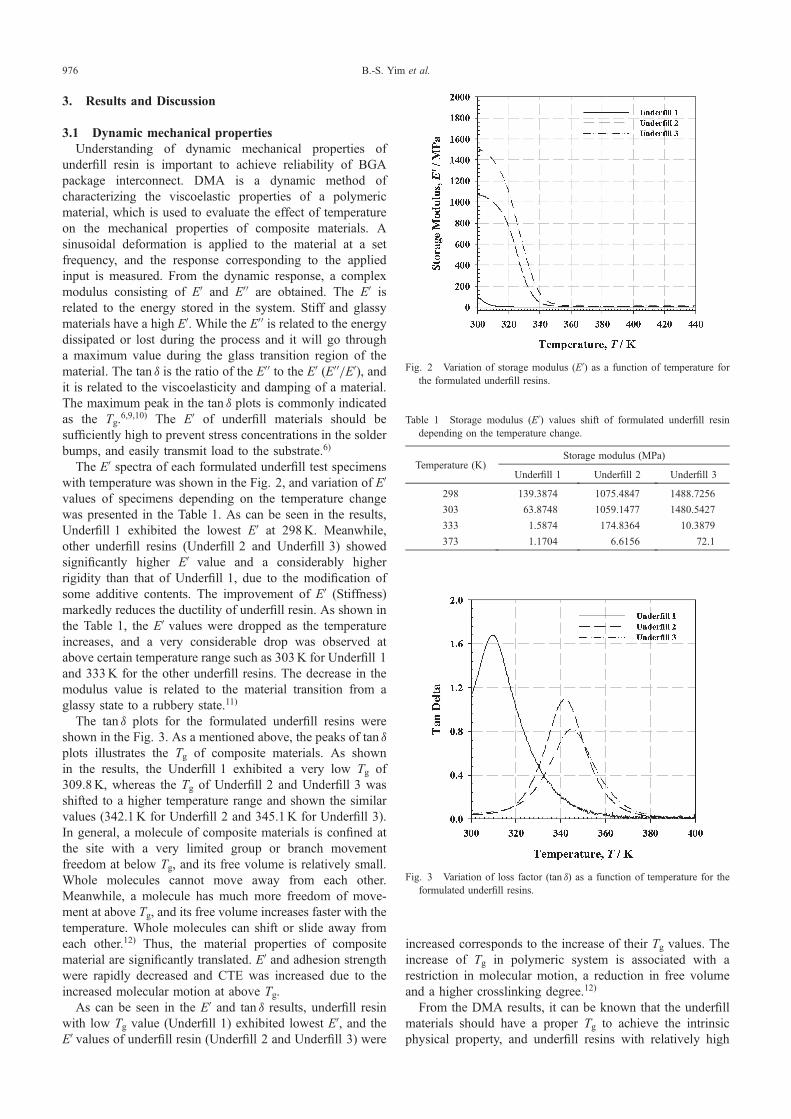
The EA spectra of each formulated underfill test specimenswith temperature was shown in the Fig. 2, and variation of EAvalues of specimens depending on the temperature changewas presented in the Table 1. As can be seen in the results,Underfill 1 exhibited the lowest EA at 298K. Meanwhile,other underfill resins (Underfill 2 and Underfill 3) showedsignificantly higher EA value and a considerably higherrigidity than that of Underfill 1, due to the modification ofsome additive contents. The improvement of EA (Stiffness)markedly reduces the ductility of underfill resin. As shown inthe Table 1, the EA values were dropped as the temperatureincreases, and a very considerable drop was observed atabove certain temperature range such as 303K for Underfill 1and 333K for the other underfill resins. The decrease in themodulus value is related to the material transition from aglassy state to a rubbery state.11)
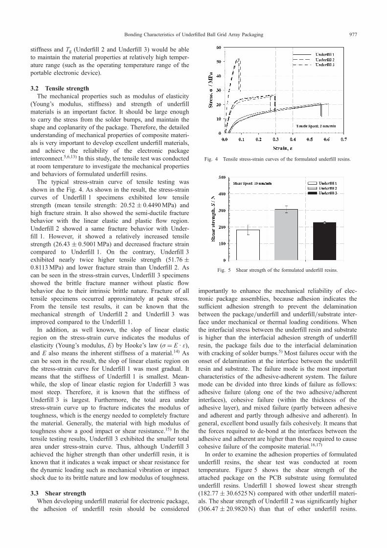
The tan ¤ plots for the formulated underfill resins wereshown in the Fig. 3. As a mentioned above, the peaks of tan ¤plots illustrates the Tg of composite materials. As shownin the results, the Underfill 1 exhibited a very low Tg of309.8K, whereas the Tg of Underfill 2 and Underfill 3 wasshifted to a higher temperature range and shown the similarvalues (342.1K for Underfill 2 and 345.1K for Underfill 3).In general, a molecule of composite materials is confined atthe site with a very limited group or branch movementfreedom at below Tg, and its free volume is relatively small.Whole molecules cannot move away from each other.Meanwhile, a molecule has much more freedom of move-ment at above Tg, and its free volume increases faster with thetemperature. Whole molecules can shift or slide away fromeach other.12) Thus, the material properties of compositematerial are significantly translated. EA and adhesion strengthwere rapidly decreased and CTE was increased due to theincreased molecular motion at above Tg.
As can be seen in the EA and tan ¤ results, underfill resinwith low Tg value (Underfill 1) exhibited lowest EA, and theEA values of underfill resin (Underfill 2 and Underfill 3) were
increased corresponds to the increase of their Tg values. Theincrease of Tg in polymeric system is associated with arestriction in molecular motion, a reduction in free volumeand a higher crosslinking degree.12)
From the DMA results, it can be known that the underfillmaterials should have a proper Tg to achieve the intrinsicphysical property, and underfill resins with relatively high
Fig. 2 Variation of storage modulus (EA) as a function of temperature forthe formulated underfill resins.
Table 1 Storage modulus (EA) values shift of formulated underfill resindepending on the temperature change.
Temperature (K)Storage modulus (MPa)
Underfill 1 Underfill 2 Underfill 3
298 139.3874 1075.4847 1488.7256
303 63.8748 1059.1477 1480.5427
333 1.5874 174.8364 10.3879
373 1.1704 6.6156 72.1
Fig. 3 Variation of loss factor (tan ¤) as a function of temperature for theformulated underfill resins.
B.-S. Yim et al.976
stiffness and Tg (Underfill 2 and Underfill 3) would be ableto maintain the material properties at relatively high temper-ature range (such as the operating temperature range of theportable electronic device).
3.2 Tensile strengthThe mechanical properties such as modulus of elasticity
(Young’s modulus, stiffness) and strength of underfillmaterials is an important factor. It should be large enoughto carry the stress from the solder bumps, and maintain theshape and coplanarity of the package. Therefore, the detailedunderstanding of mechanical properties of composite materi-als is very important to develop excellent underfill materials,and achieve the reliability of the electronic packageinterconnect.5,6,13) In this study, the tensile test was conductedat room temperature to investigate the mechanical propertiesand behaviors of formulated underfill resins.
The typical stress-strain curve of tensile testing wasshown in the Fig. 4. As shown in the result, the stress-straincurves of Underfill 1 specimens exhibited low tensilestrength (mean tensile strength: 20.52 « 0.4490MPa) andhigh fracture strain. It also showed the semi-ductile fracturebehavior with the linear elastic and plastic flow region.Underfill 2 showed a same fracture behavior with Under-fill 1. However, it showed a relatively increased tensilestrength (26.43 « 0.5001MPa) and decreased fracture straincompared to Underfill 1. On the contrary, Underfill 3exhibited nearly twice higher tensile strength (51.76 «0.8113MPa) and lower fracture strain than Underfill 2. Ascan be seen in the stress-strain curves, Underfill 3 specimensshowed the brittle fracture manner without plastic flowbehavior due to their intrinsic brittle nature. Fracture of alltensile specimens occurred approximately at peak stress.From the tensile test results, it can be known that themechanical strength of Underfill 2 and Underfill 3 wasimproved compared to the Underfill 1.
In addition, as well known, the slop of linear elasticregion on the stress-strain curve indicates the modulus ofelasticity (Young’s modulus, E) by Hooke’s law (· = E · ¾),and E also means the inherent stiffness of a material.14) Ascan be seen in the result, the slop of linear elastic region onthe stress-strain curve for Underfill 1 was most gradual. Itmeans that the stiffness of Underfill 1 is smallest. Mean-while, the slop of linear elastic region for Underfill 3 wasmost steep. Therefore, it is known that the stiffness ofUnderfill 3 is largest. Furthermore, the total area understress-strain curve up to fracture indicates the modulus oftoughness, which is the energy needed to completely fracturethe material. Generally, the material with high modulus oftoughness show a good impact or shear resistance.15) In thetensile testing results, Underfill 3 exhibited the smaller totalarea under stress-strain curve. Thus, although Underfill 3achieved the higher strength than other underfill resin, it isknown that it indicates a weak impact or shear resistance forthe dynamic loading such as mechanical vibration or impactshock due to its brittle nature and low modulus of toughness.
3.3 Shear strengthWhen developing underfill material for electronic package,
the adhesion of underfill resin should be considered
importantly to enhance the mechanical reliability of elec-tronic package assemblies, because adhesion indicates thesufficient adhesion strength to prevent the delaminationbetween the package/underfill and underfill/substrate inter-face under mechanical or thermal loading conditions. Whenthe interfacial stress between the underfill resin and substrateis higher than the interfacial adhesion strength of underfillresin, the package fails due to the interfacial delaminationwith cracking of solder bumps.5) Most failures occur with theonset of delamination at the interface between the underfillresin and substrate. The failure mode is the most importantcharacteristics of the adhesive-adherent system. The failuremode can be divided into three kinds of failure as follows:adhesive failure (along one of the two adhesive/adherentinterfaces), cohesive failure (within the thickness of theadhesive layer), and mixed failure (partly between adhesiveand adherent and partly through adhesive and adherent). Ingeneral, excellent bond usually fails cohesively. It means thatthe forces required to de-bond at the interfaces between theadhesive and adherent are higher than those required to causecohesive failure of the composite material.16,17)
In order to examine the adhesion properties of formulatedunderfill resins, the shear test was conducted at roomtemperature. Figure 5 shows the shear strength of theattached package on the PCB substrate using formulatedunderfill resins. Underfill 1 showed lowest shear strength(182.77 « 30.6525N) compared with other underfill materi-als. The shear strength of Underfill 2 was significantly higher(306.47 « 20.9820N) than that of other underfill resins.
Fig. 4 Tensile stress-strain curves of the formulated underfill resins.
Fig. 5 Shear strength of the formulated underfill resins.
Bonding Characteristics of Underfilled Ball Grid Array Packaging 977
Whereas, Underfill 3 exhibited relatively lower shearstrength (226.63 « 5.2003N) than that of Underfill 2.
According to Kuo et al.,5) the mechanical stiffness of theunderfill encapsulant determines the level of reinforcementprovided to the solder interconnect, and the solder inter-connect with stiffer underfill would be more protected fromfatigue failure due to the stress relief. As shown in the DMAand tensile test results, Underfill 3 exhibited the higheststiffness (highest EA and E values). However, Underfill 3showed lower shear strength than that of Underfill 2.
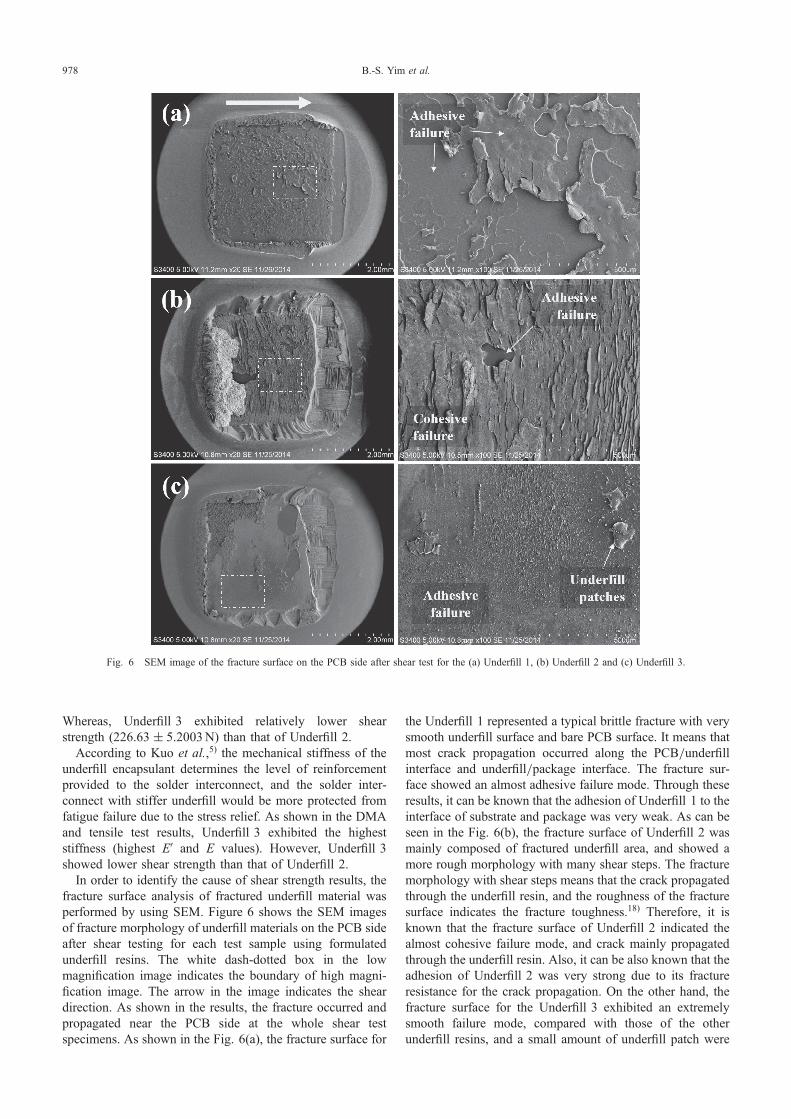
In order to identify the cause of shear strength results, thefracture surface analysis of fractured underfill material wasperformed by using SEM. Figure 6 shows the SEM imagesof fracture morphology of underfill materials on the PCB sideafter shear testing for each test sample using formulatedunderfill resins. The white dash-dotted box in the lowmagnification image indicates the boundary of high magni-fication image. The arrow in the image indicates the sheardirection. As shown in the results, the fracture occurred andpropagated near the PCB side at the whole shear testspecimens. As shown in the Fig. 6(a), the fracture surface for
the Underfill 1 represented a typical brittle fracture with verysmooth underfill surface and bare PCB surface. It means thatmost crack propagation occurred along the PCB/underfillinterface and underfill/package interface. The fracture sur-face showed an almost adhesive failure mode. Through theseresults, it can be known that the adhesion of Underfill 1 to theinterface of substrate and package was very weak. As can beseen in the Fig. 6(b), the fracture surface of Underfill 2 wasmainly composed of fractured underfill area, and showed amore rough morphology with many shear steps. The fracturemorphology with shear steps means that the crack propagatedthrough the underfill resin, and the roughness of the fracturesurface indicates the fracture toughness.18) Therefore, it isknown that the fracture surface of Underfill 2 indicated thealmost cohesive failure mode, and crack mainly propagatedthrough the underfill resin. Also, it can be also known that theadhesion of Underfill 2 was very strong due to its fractureresistance for the crack propagation. On the other hand, thefracture surface for the Underfill 3 exhibited an extremelysmooth failure mode, compared with those of the otherunderfill resins, and a small amount of underfill patch were
Fig. 6 SEM image of the fracture surface on the PCB side after shear test for the (a) Underfill 1, (b) Underfill 2 and (c) Underfill 3.
B.-S. Yim et al.978

observed. The fracture surface exhibited mainly adhesivefailure mode, and the crack propagated along the interfacebetween the underfill and PCB substrate.
Through fracture surface analysis results, it can be knownthat Underfill 2 secured the highest shear strength because ofthe formation of cohesive failure mode. From the tensile testresults, it is known that Underfill 2 had a high modulus oftoughness. Thus, the failure mode of Underfill 2 may beattributed to its high modulus of toughness. On the contrary,Underfill 1 and Underfill 3 exhibited weak shear strength dueto the formation of adhesive failure mode.
Although Underfill 1 exhibited the higher modulus oftoughness in the tensile test results, it showed a weakmechanical strength, as well as extremely low EA due to itslow Tg. Therefore, it can be known that the weak adhesionproperty and fracture manner of Underfill 1 were probablyattributed to its intrinsic weak physical properties. Mean-while, although Underfill 3 achieved the higher mechanicalstrength and stiffness, it showed the brittle fracture mannerand weak modulus of toughness in the tensile test results.Therefore, the failure manner of Underfill 3 may be attributedto its low modulus of toughness.
From shear test results, it is known that the underfillmaterials have a weak adhesion property not only whenunderfill has a weak mechanical strength due to their low Tgbut also when it has a weak modulus of toughness due totheir brittle manner.
3.4 Mechanical reliability propertiesTypical failure of portable electronic device attributed to
the mechanical stress such as board bending, mechanicalstresses and mechanical vibrations. Bending tests are usefulfor evaluating board level assemblies for performance undermechanical stresses.19) During the bending test, the bendingof the package leads to differential bending between the FR-4substrate and the package that must be accommodated by thedeformation of the interconnects.20) The underfill materialcan greatly improve the mechanical reliability of BGAassembly due to the stress distribution during the bendingtest.2)
In this study, three-point bending test was performed at333K to evaluate the reliability of BGA package interconnecton portable electronic device at the device operating temper-ature. Figure 7 shows the bending fatigue cycles to failurefor the BGA assemblies filled with different underfill resinsunder the three-point bending condition. As shown in theresults, Underfill 1 exhibited the lowest bending fatiguelifetime (69.75 « 13.2256 cycles). As shown in the previousexperiments, Underfill 1 had an intrinsic low EA, mechanicaland adhesion strength due to its low Tg. Furthermore, thephysical properties of Underfill 1 were degraded probably atthe temperature condition of bending test (333K) due to itslow Tg. Therefore, it is known that such a result attributed toinefficient stress distribution on the BGA interconnect due toits intrinsic low material properties, and properties degrada-tion of Underfill 1 at the test condition. On the other hand,Underfill 2 showed obviously better mechanical bendingreliability (350.75 « 43.2001 cycles) than other underfilledBGA assembly, and Underfill 3 showed the relatively lowfatigue lifetime (204.25 « 21.0930 cycles) compared with
Underfill 2. Underfill 2 and Underfill 3 could maintain theadhesion strength at the temperature condition of 333K dueto their relatively high Tg compared with Underfill 1. Fromthe previous experiments, it was known that Underfill 2 had ahigh EA, adhesion, proper mechanical strength and modulusof toughness due to its intrinsic semi-ductile nature. Theexcellent adhesion, proper mechanical strength and tough-ness of Underfill 2 would importantly act to improve themechanical fatigue life by the effective stress distribution onthe BGA interconnect and resistance to the fracture underrepetitive bending load. Meanwhile, Underfill 3 indicated aweak mechanical fatigue life due to their brittle nature andlow modulus of toughness, although it achieved the higherstrength than other underfill resin.
4. Conclusion
To ensure the mechanical reliability of BGA packages,material properties of underfill material should be sufficientlyconsidered. In this work, the material properties of underfillmaterial were investigated experimentally to determine theimportant material properties of underfill for the mechanicalreliability of BGA interconnect on potable electronic device.The result show that the underfill material with lowest Tg(Underfill 1) showed weak mechanical and adhesion strengthdue to its intrinsic weak physical property. Also, when theunderfill resins have a similar Tg value, the underfill with highmodulus of toughness (Underfill 2) exhibited more excellentmechanical reliability than that of underfill with excessivemechanical strength, EA and low modulus of toughness(Underfill 3) due to its fracture resistance for the crackpropagation. In addition, it can be known that materialproperties of underfill resin significantly affect for themechanical reliability of BGA assembly.
From the result of the present study, it can be known thatthe stiffness (EA and E) of underfill resin is increased with theincrease of Tg, and the mechanical strength is also increasedby the increased stiffness. However, as the stiffness andmechanical strength increases, the brittle manner is increased,and modulus of toughness is decreased. Thus, the mechanicalreliability of BGA interconnect is deteriorated due to thedecreased toughness. Therefore, the underfill materialsshould have a proper Tg to achieve the intrinsic physicalproperty. Also, when developing or selecting an underfillmaterial for BGA package on potable electronic device, the
Fig. 7 Plots of bending fatigue cycles to failure for the BGA assembliesfilled with different underfill resins.
Bonding Characteristics of Underfilled Ball Grid Array Packaging 979
modulus of toughness of underfill material should moreimportantly considered rather than excessively high me-chanical strength and EA (Stiffness) to ensure the mechanicalreliability of BGA assembly.
Acknowledgements
This research was supported by the LG Electronics R&BDprogram (Development of epoxy solder/flux alternative tounderfill) in 2013 and Basic Science Research Programthrough the National Research Foundation of Korea (NRF)funded by the Ministry of Science, ICT and future Planning(2014007164).
REFERENCES
1) Y. C. Chan, P. L. Tu and K. C. Hung: Microelectron. Reliab. 41 (2001)18671875.
2) E. Yamada and M. Amagai: 9th VLSI Packaging Workshop of Japan,(IEEE, 2008) pp. 5356.
3) L. Wang, S. C. Kang, H. Li, D. F. Baldwin and C. P. Wong: Proc. Int.Symp. on Advanced Packaging Materials: Processes, Properties andInterfaces, (IEEE, 2001) pp. 2936.
4) L. Wang and C. P. Wong: IEEE Trans. Adv. Packag. 22 (1999) 4653.5) C. T. Kuo, M. C. Yip and K. N. Chiang: Microelectron. Reliab. 44
(2004) 627638.
6) J. O. Suh and R. P. Dillon: FY11 NASA Electronic Parts and Packaging(NEPP) Program task report, (2012), pp. 128.
7) B. Han: J. Therm. Stresses 26 (2003) 583613.8) V. Gektin, A. Bar-Cohen and J. Ames: IEEE Trans. Compon. Packag.
Manuf. Technol. A 20 (1997) 317326.9) M. Akay: Compos. Sci. Technol. 47 (1993) 419423.10) K. C. M. Nair, S. Thomas and G. Groeninckx: Compos. Sci. Technol.
61 (2001) 25192529.11) M. Tajvidi, R. H. Falk and J. C. Hermanson: J. Appl. Polym. Sci. 101
(2006) 43414349.12) R. Li: Mater. Sci. Eng. A 278 (2000) 3645.13) S. Kitagoh, H. O. Mitsugi, S. Koyama and I. Shohji: Proc. 35th Int.
Conf. on Electronic Manufacturing Technology, (IEEE, 2012) pp. 14.14) M. P. Groover: Fundamentals of Modern Manufacturing, (John Wiley
& Sons INC, New York, 2010) pp. 4145.15) D. Roylance: Stress-Strain Curves, (Massachusetts Institute of
Technology, 2001 online course) pp. 911.16) Y. C. Lin, X. Chen and Z. P. Wang: Proc. 10th Int. Conf. on Thermal
and Thermomechanical Phenomena in Electronics Systems, (IEEE,2006) pp. 946952.
17) Y. S. Lin, T. F. Yang, W. C. Chen, T. H. Chen, C. C. Cheng and Y. H.Yeh: Proc. 57th Conf. on Electronic Components and Technology,(IEEE, 2007) pp. 501506.
18) B. Francis, V. L. Rao, S. Jose, B. K. Catherine, R. Ramaswamy, J. Joseand S. Thomas: J. Mater. Sci. 41 (2006) 54675479.
19) D. T. Rooney, N. T. Castello, M. Cibulsky, D. Abbott and D. Xie:Microelectron. Reliab. 44 (2004) 275285.
20) B. I. Noh, J. W. Yoon, J. W. Kim, J. B. Lee, N. C. Park, W. S. Hong andS. B. Jung: Int. J. Adhes. Adhes. 29 (2009) 650655.
B.-S. Yim et al.980