BJ_Telux_omskiftere-GB.pdf - MTO electric
98
-
Upload
khangminh22 -
Category
Documents
-
view
2 -
download
0
Transcript of BJ_Telux_omskiftere-GB.pdf - MTO electric


D371E 1102 2009
Contents Page
General Informations 2Technical data 3Basic designs 4 - 8
Cam Switches On-Off switches, Changeover switches 9 -12Star-Delta switches 13 - 15Multi speed switches 16 - 20Control switches 21 - 23Voltmeter selector switches, Ammeter switches 24 - 26Gang switches 27 - 29Multi step switches 30 - 41
Mini-Cam Switches Technical data 42On-Off switches, Changeover switches 43Star-Delta switches 43Control switches 43, 44Voltmeter selector switches, Ammeter switches 44Gang switches, Multi step switches 44, 45
Main switches Switch disconnectors with padlock device 46 - 48Accessories 51Cam switches with padlock device 52
Switch On-Off switches 53, 54disconnectors
Load switches On-Off switches 54Changeover switches 55
Handles and plates Operating knobs and handles 56, 57Escutcheon plates 58 - 61Angles of rotation 61, 62
Optional Extras Drive units 63Door couplings 64Key operated switches 65Padlock devices 66Switch interlocks, Couplings 67, 68Accessories 69, 70
Special switches 71, 96
Technical data Cam switches 73, 74Switch disconnectors 75Load switches 76
Dimensions Cam switches 77 - 80Main and Emergency-Off switches 81 - 84Switch disconnectors, Load switches 85Accessories 86 - 93
Representations 94, 95and Suppliers
2 D371E
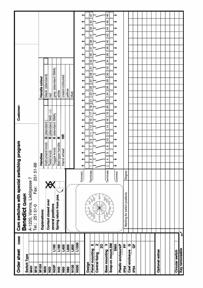
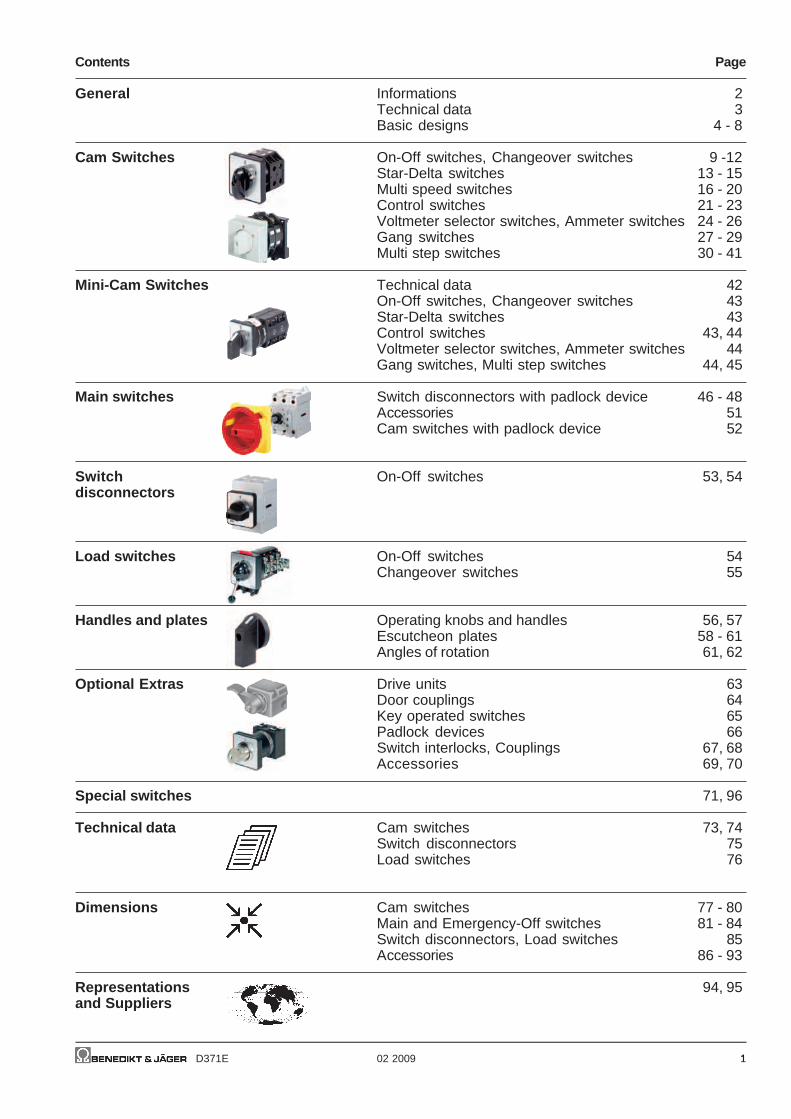
Ratings DesignsPanel moun. Single hole mount. Ø22,5mm Flush mount.
Protection degree from front M10H, M20 IP65 with Plate without Plate IP40in mounted position IP40 IP65 IP65
Rated current M otor PlateTherm. AC3 AC23Ith
open AC21 atUe
3~400V 3~400VTyp A A V kW A kW mm
M4H 10 10 440 2,2 6 3 30 M4H E •♦ M4H Z •♦ M4H ZO •♦ -
M10H 20 20 690 5,5 16 7,5 48 M10H E •♦ M10H Z •♦ M10H ZO •♦ -M10 20 20 440 5,5 16 7,5 48 - - - M10 UP •♦
M20 32 32 690 11 30 15 48 M20 E •♦ M20 Z •♦ M20 ZO •♦ -
N20 32 32 690 11 30 15 64 N20 E •♦ - - N20 UP •♦
N33F 50 50 690 15 45 22 64 N33F E •♦ N33F Z •♦ - -N32 40 40 690 11 30 15 64 - - - -
N40 63 63 690 15 45 22 88 N40 E •♦ - - -N60 85 85 690 25 60 30 88 N60 E •♦ - - -N80 115 115 690 30 85 45 88 N80 E •♦ - - -
L100 125 125 690 15 45 22 88 L100 E •♦ - - -L160 180 180 690 25 60 30 88 L160 E •♦ - - -
N100 150 150 690 40 110 55 132 N100 E •♦ - - -N200 250 250 690 70 140 70 132 N200 E •♦ - - -
L400 400 400 690 70 140 70 132 L400 E •♦ - - -L600 600 400 690 70 140 70 132 L600 E •♦ - - -
L800 800 400 690 70 140 70 132 L800 E •♦ - - -L1200 1200 400 690 70 140 70 132 L1200 E •♦ - - -
Load switch L.. 125 - 1200A
Load switches are primarily employed where resistive or slightlyinductive current loads are to be switched on and off, or switchingtakes place without loading.Load switches are assembled by parallel switching of two or moreof cam switch contacts.With customer built main terminal protection, load switch L.. can alsobe used as main switch.
Four-hole mounting
or single-hole mounting Ø 22,5 mm
or base mounting
or DIN-rail mounting
Escutcheon frame
Handle
Latching mechanism determines
the switch position (30°,45°,60°,90°)
Up to 25
Switching cells - two poles
- double interruption per pole
Drive shaft
of solid aluminium
Escutcheon plate
. . . . E . .
. . . . Z . .
. . . . V. .
. . . . SM . .
Cam Switches 10 - 250A
Cam switches can be used for virtually all purposes, e.g. as motor,main, control or instrument switches. Over and above the switchingprograms mentioned in the list, an effectively limitless number ofspecial programs can be implemented.
- - Cam Switches

D371E 3
DesignsBase mounting DIN-rail Modular Plastic enclosed Motor switch Terminal box Cast enclosedIP40 mounting IP40 ..P.. IP40 horizontal, IP65 enclosed mounting ..G.. IP40
IP40 ..PF.. IP65 IP65 IP65 ..GF.. IP65
- - - - - - - -
M10H V •♦ M10H SM •♦ M10H SMA •♦ - - M10H PM •♦ - -- - - M10 P(F) •♦ - - M10 KE •♦ -M20 V •♦ M20 SM •♦ M20 SMA •♦ - - - - -
N20 V •♦ N20 SM •♦ - N20 P(F) •♦ - N20 PM •♦ N20 KE •♦ N20 G(F) •♦
N33F V •♦ N33F SM •♦ - N33F P(F) •♦ - N33F PM •♦ N33F KE •♦ -- - - - - - - -
N40 V •♦ - - N40 P(F) •♦ N40 PLF •♦ - - -N60 V •♦ - - N60 P(F) •♦ N60 PLF •♦ - - -N80 V •♦ - - N80 P(F) •♦ N80 PLF •♦ - - -
L100 V •♦ - - - - - - -L160 V •♦ - - - - - - -
N100 V •♦ - - N100 P(F) •♦ - - - -N200 V •♦ - - N200 P(F) •♦ - - - -
L400 V •♦ - - - - - - -L600 V •♦ - - - - - - -
L800 V •♦ - - - - - - -L1200 V •♦ - - - - - - -
Ordering
SWITCH TYPE ••
DESIGN ••
SWITCH PROGRAM •NUMBER OF STEPS •NUMBER OF POLES ♦
ACCESSORIES +••
On-Off-switch •• •• A♦
M10H E A3+GFP Changeover switch with Off position •• •• U♦
Changeover switch without Off position •• •• W♦
20A Panel mounting Changeover switch with spring return to Off •• •• UR♦
On-Off-switch 3-pole Reversing switch •• •• WU♦
+ large front plate Star-Delta-switch •• •• SD
Multi speed switch •• •• P..
Start switch •• •• SE♦
Stop switch •• •• SA♦
Voltmeter selector switch •• •• V.
Ammeter selector switch •• •• M..
Gang switch •• •• GR..
Multi step switch without Off position •• •• ST•♦
Multi step switch with Off position •• •• ST0•♦

4 D371E
Switch disconnector LT.. 20 - 160A
Switch disconnectors are to be used as an ON-OFF-switchwhere a high breaking capacity with high contact pressureand in fact better short circuit behavior is necessary. Theseapplications are:
Main switches according to IEC/EN 60204 respectivelyVDE0113 with interlocking device, terminal protection andrestrective contacts.Switch disconnectors according to IEC/EN 60947-3 andVDE 0660 part 107 with break distance for 690V.Motor switches 3-pole or 4-pole; according to IEC/EN60947-3 respectively VDE 0660 part 107, motor switchesseries LT are dimensioned for switching high rated currentAC3 and AC23A.
Main switches andMain switches with Emergency-Stop function
According to standards IEC/EN60204 or VDE0113, all electrical equip-ment of industrial machines must be equipped with a main switch. Thismust permit disconnection of all the electrical equipment during cleaning,maintenance and repair work, and other extended periods when it isstationary.In case of two or more main switches, an interlock system must be used.It is recommended to use a multiple-pole main switch (cam switch).
Main switches have to correspond to:a)Switch disconnector according to IEC/EN 60947-3 and VDE 0660
part 107 for utilization category AC23-B or DC-23B.b)Disconnectors are selected according to thermal rated current. They
must possess a contact that ensures load switching via the contac-tors (see switching program A3-10). This contact must have asufficient AC15 switching capacity.
c)The interruption capacity of the switch must equal or exceed thelocked rotor current of the largest motor plus the total current of allother electrical equipment in the circuit.
Requirements:Interruption of the electrical equipment, with only on and off positionsclearly marked with O and I.It must be lockable in the off setting.The line terminals of the main switch must be protected according toutilization category IP2X.Colour of handle black or grey.Main switches with Emergency-Off function are additional suppliedwith red handles and contrasting yellow escutcheon plates.
Ratings Main Switch Emergency StopPanel mounting Single hole mount. Base mounting
Ø22,5mm with door couplingProtection degree from front IP66 IP66 adjust. installation depth
in mounted position IP66
Rated current M otor PlateTherm. AC3 AC23 SwitchIth
open AC21 bei Ue
3~400V 3~400V disconnectorType A A V kW A kW mm
LTS20 20 20 690 5,5 16 7,5 48 LTS20 EHN1 .. LTS20 ZHN1 .. LTS20 VZVHN4 ..LTS20 EHN4 .. LTS20 VHN4 ..
LTS25 25 25 690 7,5 20 10 48 LTS25 EHN1 .. LTS25 ZHN1 .. LTS25 VZVHN4 ..LTS25 EHN4 .. LTS25 VHN4 ..
LTS32 32 32 690 11 25 12,5 48 LTS32 EHN1 .. LTS32 ZHN1 .. LTS32 VZVHN4 ..LTS32 EHN4 .. LTS32 VHN4 ..
LTS40 40 40 690 15 32 16 48 LTS40 EHN1 .. LTS40 ZHN1 .. LTS40 VZVHN4 ..LTS40 EHN4 .. LTS40 VHN4 ..
LTS63 63 63 690 18,5 45 22 48 LTS63 EHN1 .. - LTS63 VZVHN4 ..LTS63 EHN4 .. LTS63 VHN4 ..
LTS80 80 80 690 18,5 45 22 48 LTS80 EHN1 .. - LTS80 VZVHN4 ..LTS80 EHN4 .. LTS80 VHN4 ..
LTS85 85 85 690 22 60 30 64 LTS85 EHN4 .. - LTS85 VZVHN4 ..LTS85 VHN4 ..
LTS100 100 100 690 30 72 37 64 LTS100 EHN4 .. - LTS100 VZVHN4 ..LTS100 VHN4 ..
LTS125 125 125 690 37 85 45 64 LTS125 EHN4 .. - LTS125 VZVHN4 ..LTS125 VHN4 ..
LT160 160 160 690 45 110 55 88 LT160 EHN34 .. - LT160 VHN34 ..

D371E 5
Main Switch Emergency Stop Main Switch Switch DisconnectorsBase mounting w. for Distribution Plastic Panel mounting Base mounting Panel mounting for Distributiondoor coupling Boards enclosed with door coupling Boardsdepth not adjustable IP40 IP65 IP66 IP66 IP66 IP40IP66
LTS20 VZHN1 .. LTS20 SMAHN1 .. LTS20 PFHN4 .. LTS20 EH1 .. LTS20 VZVH4 .. LTS20 E .. LTS20 SMA ..LTS20 VZHN4 .. LTS20 EH4 .. LTS20 VH4 ..
LTS25 VZHN1 .. LTS25 SMAHN1 .. LTS25 PFHN4 .. LTS25 EH1 .. LTS25 VZVH4 .. LTS25 E .. LTS25 SMA ..LTS25 VZHN4 .. LTS25 EH4 .. LTS25 VH4 ..
LTS32 VZHN1 .. LTS32 SMAHN1 .. LTS32 PFHN4 .. LTS32 EH1 .. LTS32 VZVH4 .. LTS32 E .. LTS32 SMA ..LTS32 VZHN4 .. LTS32 EH4 .. LTS32 VH4 ..
LTS40 VZHN1 .. LTS40 SMAHN1 .. LTS40 PFHN4 .. LTS40 EH1 .. LTS40 VZVH4 .. LTS40 E .. LTS40 SMA ..LTS40 VZHN4 .. LTS40 EH4 .. LTS40 VH4 ..
LTS63 VZHN1 .. LTS63 SMAHN1 .. LTS63 PFHN4 .. LTS63 EH1 .. LTS63 VZVH4 .. LTS63 E .. LTS63 SMA ..LTS63 VZHN4 .. LTS63 EH4 .. LTS63 VH4 ..
LTS80 VZHN1 .. LTS80 SMAHN1 .. LTS80 PFHN4 .. LTS80 EH1 .. LTS80 VZVH4 .. LTS80 E .. LTS80 SMA ..LTS80 VZHN4 .. LTS80 EH4 .. LTS80 VH4 ..
LTS85 VZHN4 .. LTS85 SMAHN1 .. LTS85 PFHN4 .. LTS85 EH4 .. LTS85 VZVH4 .. LTS85 E .. LTS85 SMA ..LTS85 VH4 ..
LTS100 VZHN4 .. LTS100 SMAHN1 .. LTS100 PFHN4 .. LTS100 EH4 .. LTS100 VZVH4 .. LTS100 E .. LTS100 SMA ..LTS100 VH4 ..
LTS125 VZHN4 .. LTS125 SMAHN1 .. LTS125 PFHN4 .. LTS125 EH4 .. LTS125 VZVH4 .. LTS125 E .. LTS125 SMA ..LTS125 VH4 ..
- - LT160 PFHN34 .. LT160 EH34 .. LT160 VH34 .. LT160 E .. -
Switch program
On-Off Switch 3-pole •• •••• A3
On-Off Switch 4-pole •• •••• A4
On-Off Switch 6-pole •• •••• A6
On-Off Switch 8-pole •• •••• A8
Changeover Switches 3-pole •• •••• U3
Changeover Switches 4-pole •• •••• U4
On-Off Switch 3-pole •• •••• T300 (for LT160)On-Off Switch 4-pole •• •••• T400 (for LT160)

6 D371E
Panel mounting designs
Design
Description
Panel mountingFor installation in control panels, ma-chines and equipment.For panel thickness of over 5mm, anextended switch shaft is required(appendix +VW).Protection from front:M10H, M20 IP65all others IP40
Central fixing 22,5mmSwitch for mounting with standard22,5mm mounting holes and 1-4mmpanel thickness.Protection from front: IP65Wrench J7049 necessary
Central fixing 22,5mmSwitch without escutcheon plate ,for installation with standard 22,5mmmounting holes and 1-4mm panelthickness. Protection from front: IP65Wrench J7049 necessary
Flush mounting versionSwitch with white instrument knob,cream escutcheon plate with blackmarkings, for installation in 65mm flushmounting boxes and use of Unitasplate. Supplied with flush mounting box:appendix +UP.Maximum number of cells with: M10FM box 45mm deep 2FM box 65mm deep 4
Flush mounting versionSwitch without flush mounting box andspecial square cover, black markingsand white instrument knob. Suppliedwith flush mounting box: appendix +UP.Max. 4 cells
Possible switch sizesN40
Type N20 N60 N100appendix M10H M20 N33F N80 N200 L...
E X X X X X X
Z X X X 3) - - -
ZO X X - - - -
UP X 1) - - - - -
UP - - X 2) - - -
- Cam Switches
1) Switches are delivered with switch type M102) For switch types N20 only3) For switch types N33F only, max. 3 poles and 3 cells
Switches of the panel mounting designs listed below have protectionfrom front IP40. Where a shaft seal (appendix +WD) is used, theprotection is increased to IP54. Use of a moisture proofing cap(appendix +FR) results in an increase in rear protection to IP54. In thestandard version, the switches are delivered with a square escutcheonplate and black twist knob. Forward mounting is possible for some of
the design E switches. The position of the terminals of the standardswitches is left and right, at switch M10H the terminals are above andbelow. Where a knob insert is turned by 90° (can easily be performedafter delivery), the position of the terminals can be changed.Dimensions see page 75.

D371E 7
Base mounting designs
Design
Description
Base mountingFor screw mounting to the back wall orfloor of distributor boxes, or of applian-ces with removable lids.Additional it is necessary to state theinstallation depth - that is the distancebetween mounting level of the switchand the inside edge of the door(dimension T).
Door couplings see page 62
Snap-on mounting on DIN-railSwitch with square escutcheon plate,for snap-on mounting on standard DINEN 50022 rail.Additional it is necessary to state theinstallation depth - that is the distancebetween mounting level of the switchand the inside edge of the door(dimension T).
Door couplings see page 62
Snap-on mounting on DIN-railwith installation cover for standardopening and toggle knob. The lay-outof the terminals of the standardswitches is above and below.Dimensions for Switch typesM10H SMA .. with1-3 cellsM20 SMA .. with1 or 2 cells
further dimensions see page 76
- Cam Switches
Possible switch sizesN40
Type N20 N60 N100appendix M10H M20 N33F N80 N200 L...
V ... +T/... X X X X X X
SM ... +T/... X X X - - -
SMA X X - - - -
Switches of the designs listed below have protection from front IP40.When a shaft seal (appendix +WD) is used, the front protection typeis increased to IP54. In the standard version, the switches are deliveredwith a square escutcheon plate and black twist knob (design SMA withgrey cover and grey toggle knob). Door couplings are advisable forswitchgear cabinets with hinged doors.
The position of the terminals of the standard switches is left and right,at switch M10H the terminals are above and below. Where a knob insertis turned by 90° (can easily be performed after delivery), the positionof the terminals can be changed.Dimensions see page 76.
8 D371E
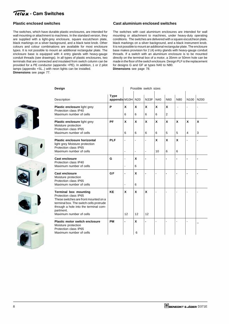
Possible switch sizes
Typeappendix M10H N20 N33F N40 N60 N80 N100 N200
P X X X X X - - -
6 6 6 6 2
PF X X X X X X X X
6 6 6 6 5 5 4 3
PLF - - - X X X - -
- - - 10 6 6
G - X - - - - - -
- 6
GF - X - - - - - -
- 6
KE X X X - - - - -
12 12 12
PM - X - - - - - _
6
Plastic enclosed switches Cast aluminium enclosed switches
Design
Description
Plastic enclosure light greyProtection class IP40Maximum number of cells
Plastic enclosure light greyMoisture protectionProtection class IP65Maximum number of cells
Plastic enclosure horizontallight grey Moisture protectionProtection class IP65Maximum number of cells
Cast enclosureProtection class IP40Maximum number of cells
Cast enclosureMoisture protectionProtection class IP65Maximum number of cells
Terminal box mountingProtection class IP65These switches are front mounted on aterminal box. The switch cells protrudethrough a hole into the terminal com-partment.Maximum number of cells
Plastic motor switch enclosureMoisture protectionProtection class IP65Maximum number of cells
- Cam Switches
The switches, which have durable plastic enclosures, are intended forwall mounting or attachment to machines. In the standard version, theyare supplied with a light-grey enclosure, square escutcheon plate,black markings on a silver background, and a black twist knob. Othercolours and colour combinations are available for most enclosuretypes. It is not possible to mount an additional rectangular plate. Theenclosure base is equipped with 4 entry glands with heavy-gaugeconduit threads (see drawings). In all types of plastic enclosures, twoterminals that are connected and insulated from switch column can beprovided for a PE conductor (appendix +PE). In addition, 1 or 2 pilotlamps (appendix +SL..) with neon lights can be installed.Dimensions see page 77.
The switches with cast aluminium enclosures are intended for wallmounting or attachment to machines, under heavy-duty operatingconditions. The switches are delivered with a square escutcheon plate,black markings on a silver background, and a black instrument knob.It is not possible to mount an additional rectangular plate. The enclosurebase makes provision for 2 (4) entry glands with heavy-gauge conduitthreads. If a switch with an aluminium enclosure is to be mounteddirectly on the terminal box of a motor, a 35mm or 50mm hole can bemade in the floor of the switch enclosure. Design PLF is the replacementfor designs G and GF at types N40 to N80.Dimensions see page 78.

Description Wiring diagram Switching angle Number of cells Type Design Switch Escutcheon↓ Size see page 6-8 pro- plate
↓ AC21 E. Z. V. SMA. P. G. gram
- Cam Switches
Switching programs
D371E 9
On-Off-switches A
1-pole 60° 1 48 20A M10H . x x x x x 1) - . A132A M20 . x x x x - - . A1
64 32A N20 . x - x - x x . A150A N33F . x x x - x x 2) . A1
88 63A N40 . x - x - x - . A1 +00380A N60 . x - x - x - . A1
115A N80 . x - x - - - . A1
132 150A N100 . x - x - - - . A1250A N200 . x - x - - - . A1
2-pole 60° 1 48 20A M10H . x x x x x 1) - . A232A M20 . x x x x - - . A2
64 32A N20 . x - x - x x . A250A N33F . x x x - x x 2) . A2
88 63A N40 . x - x - x - . A2 +00380A N60 . x - x - x - . A2
115A N80 . x - x - - - . A2
132 150A N100 . x - x - - - . A2250A N200 . x - x - - - . A2
3-pole 60° 2 48 20A M10H . x x x x x 1) - . A332A M20 . x x x x - - . A3
64 32A N20 . x - x - x x . A350A N33F . x x x - x x 2) . A3
88 63A N40 . x - x - x - . A3 +00380A N60 . x - x - x - . A3
115A N80 . x - x - - - . A3
132 150A N100 . x - x - - - . A3250A N200 . x - x - - - . A3
4-pole 60° 2 48 20A M10H . x x x x x 1) - . A44. pole early make 32A M20 . x x x x - - . A4
64 32A N20 . x - x - x x . A450A N33F . x - x - x x 2) . A4
88 63A N40 . x - x - x - . A4 +00380A N60 . x - x - x - . A4
115A N80 . x - x - - - . A4
132 150A N100 . x - x - - - . A4250A N200 . x - x - - - . A4
6-pole 60° 3 48 20A M10H . x x x x x 1) - . A632A M20 . x x x x - - . A6
64 32A N20 . x - x - x x . A650A N33F . x - x - x x 2) . A6
88 63A N40 . x - x - x - . A6 +00380A N60 . x - x - x - . A6
115A N80 . x - x - - - . A6
132 150A N100 . x - x - - - . A6250A N200 . x - x - - - . A6
Ordering example: AC21 250A panel mounting, On-Off-switch 6-pole, Escutcheon plate OFF - ON N200 E A6+003
1)Plastic enclosed switches are delivered with switch type M10.2)Cast enclosed switches are delivered with switch type N32.

- Cam Switches
Description Wiring diagram Switching angle Number of cells Type Design Switch Escutcheon↓ Size see page 6-8 pro- plate
↓ AC21 E. Z. V. SMA. P. G. gram
Switching programs
10 D371E
Changeover switches U
1-pole 60° 1 48 20A M10H . x x x x x 1) . U132A M20 . x x x x - - . U1
64 32A N20 . x - x - x x . U150A N33F . x x x - x x 2) . U1
88 63A N40 . x - x - x - . U1 +00780A N60 . x - x - x - . U1
115A N80 . x - x - - - . U1
132 150A N100 . x - x - - - . U1250A N200 . x - x - - - . U1
2-pole 60° 2 48 20A M10H . x x x x x 1) - . U232A M20 . x x x x - - . U2
64 32A N20 . x - x - x x . U250A N33F . x x x - x x 2) . U2
88 63A N40 . x - x - x - . U2 +00780A N60 . x - x - x - . U2
115A N80 . x - x - . U2
132 150A N100 . x - x - - - . U2250A N200 . x - x - - - . U2
3-pole 60° 3 48 20A M10H . x x x x x 1) - . U332A M20 . x x x x - - . U3
64 32A N20 . x - x - x x . U350A N33F . x x x - x x 2) . U3
88 63A N40 . x - x - x - . U3 +00780A N60 . x - x - x - . U3
115A N80 . x - x - - - . U3
132 150A N100 . x - x - - - . U3250A N200 . x - x - - - . U3
4-pole 60° 4 48 20A M10H . x x x x x 1) - . U44. pole early make 32A M20 . x x x x - - . U4
64 32A N20 . x - x - x x . U450A N33F . x - x - x x 2) . U4
88 63A N40 . x - x - x - . U4 +00780A N60 . x - x - x - . U4
115A N80 . x - x - - - . U4
132 150A N100 . x - x - - - . U4250A N200 . x - x - - - . U4
6-pole 60° 6 48 20A M10H . x x x - x 1) - . U632A M20 . x x x - - - . U6
64 32A N20 . x - x - x x . U650A N33F . x - x - x - . U6
88 63A N40 . x - x - x - . U6 +00780A N60 . x - x - x - . U6
115A N80 . x - x - - - . U6
132 150A N100 . x - x - - - . U6250A N200 . x - x - - - . U6
Ordering example: AC21 250A panel mounting, changeover switch 6-pole, Escutcheon plate 1 - OFF - 2 N200 E U6+007
1)Plastic enclosed switches are delivered with switch type M10.2)Cast enclosed switches are delivered with switch type N32.

Description Wiring diagram Switching angle Number of cells Type Design Switch Escutcheon↓ Size see page 6-8 pro- plate
↓ AC21 E. Z. V. SMA. P. G. gram
- Cam Switches
Switching programs
D371E 11
Changeover switches without off W
1-pole 60° 1 48 20A M10H . x x x x x 1) - . W132A M20 . x x x x - - . W1
64 32A N20 . x - x - x x . W150A N33F . x x x - x x 2) . W1
88 63A N40 . x - x - x - . W180A N60 . x - x - x - . W1
115A N80 . x - x - - - . W1
132 150A N100 . x - x - - - . W1250A N200 . x - x - - - . W1
2-pole 60° 2 48 20A M10H . x x x x x 1) - . W232A M20 . x x x x - - . W2
64 32A N20 . x - x - x x . W250A N33F . x x x - x x 2) . W2
88 63A N40 . x - x - x - . W280A N60 . x - x - x - . W2
115A N80 . x - x - - - . W2
132 150A N100 . x - x - - - . W2250A N200 . x - x - - - . W2
3-pole 60° 3 48 20A M10H . x x x x x 1) - . W332A M20 . x x x x - - . W3
64 32A N20 . x - x - x x . W350A N33F . x x x - x x 2) . W3
88 63A N40 . x - x - x - . W380A N60 . x - x - x - . W3
115A N80 . x - x - - - . W3
132 150A N100 . x - x - - - . W3250A N200 . x - x - - - . W3
4-pole 60° 4 48 20A M10H . x x x x x 1) - . W44. pole early make 32A M20 . x x x x - - . W4
64 32A N20 . x - x - x x . W450A N33F . x - x - x x 2) . W4
88 63A N40 . x - x - x - . W480A N60 . x - x - x - . W4
115A N80 . x - x - - - . W4
132 150A N100 . x - x - - - . W4250A N200 . x - x - - - . W4
6-pole 60° 6 48 20A M10H . x x x - x 1) - . W632A M20 . x x x - - - . W6
64 32A N20 . x - x - x x . W650A N33F . x - x - x - . W6
88 63A N40 . x - x - x - . W680A N60 . x - x - x - . W6
115A N80 . x - x - - - . W6
132 150A N100 . x - x - - - . W6250A N200 . x - x - - - . W6
Ordering example: AC21 250A panel mounting, changeover switch without off 6-pole, N200 E W6
1)Plastic enclosed switches are delivered with switch type M10.2)Cast enclosed switches are delivered with switch type N32.
- Cam Switches
Description Wiring diagram Switching angle Number of cells Type Design Switch Escutcheon↓ Size see page 6-8 pro- plate
↓ AC21 E. Z. V. SMA. P. G. gram
Switching programs
12 D371E
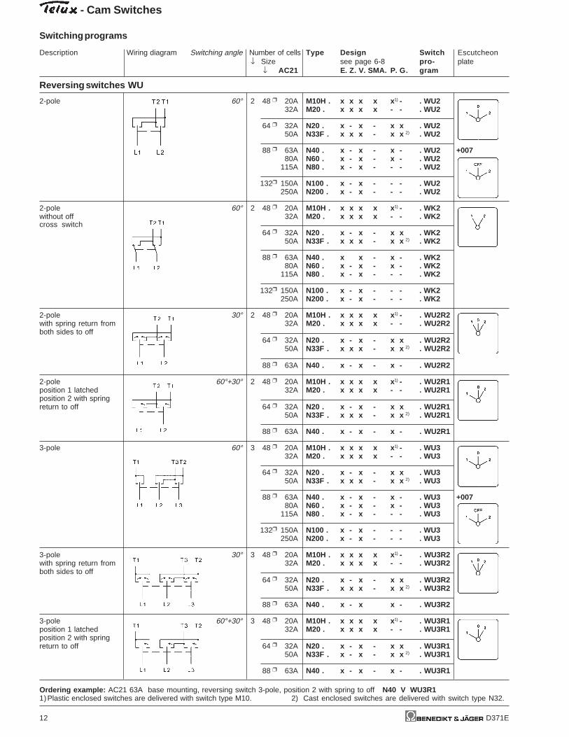
Reversing switches WU
2-pole 60° 2 48 20A M10H . x x x x x 1) - . WU232A M20 . x x x x - - . WU2
64 32A N20 . x - x - x x . WU250A N33F . x x x - x x 2) . WU2
88 63A N40 . x - x - x - . WU2 +00780A N60 . x - x - x - . WU2
115A N80 . x - x - - - . WU2
132 150A N100 . x - x - - - . WU2250A N200 . x - x - - - . WU2
2-pole 60° 2 48 20A M10H . x x x x x 1) - . WK2without off 32A M20 . x x x x - - . WK2cross switch
64 32A N20 . x - x - x x . WK250A N33F . x x x - x x 2) . WK2
88 63A N40 . x x - x - . WK280A N60 . x - x - x - . WK2
115A N80 . x - x - - - . WK2
132 150A N100 . x - x - - - . WK2250A N200 . x - x - - - . WK2
2-pole 30° 2 48 20A M10H . x x x x x 1) - . WU2R2with spring return from 32A M20 . x x x x - - . WU2R2both sides to off
64 32A N20 . x - x - x x . WU2R250A N33F . x x x - x x 2) . WU2R2
88 63A N40 . x - x - x - . WU2R2
2-pole 60°+30° 2 48 20A M10H . x x x x x 1) - . WU2R1position 1 latched 32A M20 . x x x x - - . WU2R1position 2 with springreturn to off 64 32A N20 . x - x - x x . WU2R1
50A N33F . x x x - x x 2) . WU2R1
88 63A N40 . x - x - x - . WU2R1
3-pole 60° 3 48 20A M10H . x x x x x 1) - . WU332A M20 . x x x x - - . WU3
64 32A N20 . x - x - x x . WU350A N33F . x x x - x x 2) . WU3
88 63A N40 . x - x - x - . WU3 +00780A N60 . x - x - x - . WU3
115A N80 . x - x - - - . WU3
132 150A N100 . x - x - - - . WU3250A N200 . x - x - - - . WU3
3-pole 30° 3 48 20A M10H . x x x x x 1) - . WU3R2with spring return from 32A M20 . x x x x - - . WU3R2both sides to off
64 32A N20 . x - x - x x . WU3R250A N33F . x x x - x x 2) . WU3R2
88 63A N40 . x - x x - . WU3R2
3-pole 60°+30° 3 48 20A M10H . x x x x x 1) - . WU3R1position 1 latched 32A M20 . x x x x - - . WU3R1position 2 with springreturn to off 64 32A N20 . x - x - x x . WU3R1
50A N33F . x - x - x x 2) . WU3R1
88 63A N40 . x - x - x - . WU3R1
Ordering example: AC21 63A base mounting, reversing switch 3-pole, position 2 with spring to off N40 V WU3R11)Plastic enclosed switches are delivered with switch type M10. 2) Cast enclosed switches are delivered with switch type N32.

Description Wiring diagram Switching angle Number of cells Type Design Switch Escutcheon↓ Size see page 6-8 pro- plate
↓ AC21 E. Z. V. SMA. P. G. gram
- Cam Switches
Switching programs
D371E 13
Star-Delta switches SD
1 rotary direction 60° 4 48 20A M10H . x x x x x 1) - . SD32A M20 . x x x x - - . SD
64 32A N20 . x - x - x x . SD50A N33F . x - x - x x 2) . SD
88 63A N40 . x - x - x - . SD80A N60 . x - x - x - . SD
115A N80 . x - x - - - . SD
132 150A N100 . x - x - - - . SD250A N200 . x - x - - - . SD
both rotary directions 45° 5 48 20A M10H . x x x x x 1) - . SDR32A M20 . x x x x - - . SDR
64 32A N20 . x - x - x x . SDR50A N33F . x - x - x x 2) . SDR
88 63A N40 . x - x - x - . SDR80A N60 . x - x - x - . SDR
115A N80 . x - x - - - . SDR
132 150A N100 . x - x - - - . SDR250A N200 . x - x - - - . SDR
1 rotary direction 30°+60° 4 48 20A M10H . x x x x x 1) - . SRDspring return from 32A M20 . x x x x - - . SRDto off
64 32A N20 . x - x - x x . SRD50A N33F . x - x - x x 2) . SRD
88 63A N40 . x - x - x - . SRD80A N60 . x - x - x - . SRD
115A N80 . x - x - - - . SRD
132 150A N100 . x - x - - - . SRD250A N200 . x - x - - - . SRD
1 rotary direction 60° 5 48 20A M10H . x x x x x 1) - . SDRUwith clockwise operation 32A M20 . x x x x - - . SDRUand backswitch interlock
64 32A N20 . x - x - x x . SDRU50A N33F . x - x - x x 2) . SDRU
88 63A N40 . x - x - x - . SDRU80A N60 . x - x - x - . SDRU
115A N80 . x - x - - - . SDRU
132 150A N100 . x - x - - - . SDRU250A N200 . x - x - - - . SDRU
Star-Delta selector 60° 4 48 20A M10H . x x x x x 1) - . SDUswitch 32A M20 . x x x x - - . SDU
64 32A N20 . x - x - x x . SDU50A N33F . x - x - x x 2) . SDU
88 63A N40 . x - x - x - . SDU80A N60 . x - x - x - . SDU
115A N80 . x - x - - - . SDU
132 150A N100 . x - x - - - . SDU250A N200 . x - x - - - . SDU
Ordering example: AC21 32A cast enclosed, star-delta selector switch N20 G SDU
1)Plastic enclosed switches are delivered with switch type M10.2)Cast enclosed switches are delivered with switch type N32.

- Cam Switches
Description Wiring diagram Switching angle Number of cells Type Design Switch Escutcheon↓ Size see page 6-8 pro- plate
↓ AC21 E. Z. V. SMA. P. G. gram
Switching programs
14 D371E
Star-Delta switches SD
with double outfeed 60° 4 48 20A M10H . x x x x x 1) - . SDMOphases for use with 32A M20 . x x x x - - . SDMOmanual motor starter
64 32A N20 . x - x - x x . SDMO50A N33F . x - x - x x 2) . SDMO
88 63A N40 . x - x x - . SDMO80A N60 . x - x - x - . SDMO
115A N80 . x - x - - - . SDMO
132 150A N100 . x - x - - - . SDMO250A N200 . x - x - - - . SDMO
with auxiliary contacts 90° 4 48 20A M10H . x x x x x 1) - . SDJ1for contactor control, 32A M20 . x x x x - - . SDJ1without main contacts,automatic zero setting in 64 32A N20 . x - x - x x . SDJ1event of mains break- 50A N33F . x - x - x x 2) . SDJ1down
88 63A N40 . x - x - x - . SDJ180A N60 . x - x - x - . SDJ1
115A N80 . x - x - - - . SDJ1
132 150A N100 . x - x - - - . SDJ1250A N200 . x - x - - - . SDJ1
with auxiliary contacts 90°+30° 4 48 20A M10H . x x x x x 1) - . SDJ2for contactor control, 32A M20 . x x x x - - . SDJ2without main contacts,automatic zero setting in 64 32A N20 . x - x - x x . SDJ2event of mains break- 50A N33F . x - x - x x 2) . SDJ2down, spring return to
88 63A N40 . x - x - x - . SDJ280A N60 . x - x - x - . SDJ2
115A N80 . x - x - - - . SDJ2
132 150A N100 . x - x - - - . SDJ2250A N200 . x - x - - - . SDJ2
as type SDJ1 60° 7 48 20A M10H . x x x - - - . SDRJ1but for both rotary 32A M20 . x x x - - - . SDRJ1directions
64 32A N20 . x - x - x x . SDRJ150A N33F . x - x - - - . SDRJ1
88 63A N40 . x - x - x - . SDRJ180A N60 . x - x - - - . SDRJ1
115A N80 . x - x - - - . SDRJ1
132 150A N100 . x - x - - - . SDRJ1250A N200 . x - x - - - . SDRJ1
with brake position 45°+30° 5 48 20A M10H . x x x x x 1) - . SDB(counter current 32A M20 . x x x x - - . SDBbraking) brake positionis a momentary 64 32A N20 . x - x - x x . SDBoperation 50A N33F . x - x - x x 2) . SDB
88 63A N40 . x - x - x - . SDB80A N60 . x - x - x - . SDB
115A N80 . x - x - - - . SDB
132 150A N100 . x - x - - - . SDB250A N200 . x - x - - - . SDB
Ordering example: AC21 250A panel mounting star-delta switch with brake position N200 E SDB
1)Plastic enclosed switches are delivered with switch type M10.2)Cast enclosed switches are delivered with switch type N32.

Description Wiring diagram Switching angle Number of cells Type Design Switch Escutcheon↓ Size see page 6-8 pro- plate
↓ AC21 E. Z. V. SMA. P. G. gram
- Cam Switches
Switching programs
D371E 15
Split phase switches HP
for starting up 30°+60° 2 48 20A M10H . x x x x x 1) - . HP1single-phase motors 32A M20 . x x x x - - . HP1with split-phase,spring return from 64 32A N20 . x - x - x x . HP1START to Off 50A N33F . x - x - x x 2) . HP1
88 63A N40 . x - x - x - . HP1
for starting up 90°+30° 2 48 20A M10H . x x x x x 1) - . HP2single-phase motors 32A M20 . x x x x - - . HP2with split-phase,spring return from 64 32A N20 . x - x - x x . HP2START to 1 50A N33F . x - x - x x 2) . HP2
88 63A N40 . x - x - x - . HP2
for starting up 60°+30° 3 48 20A M10H . x x x x x 1) - . HPR1single-phase motors 32A M20 . x x x x - - . HPR1with split-phase,both rotary directions 64 32A N20 . x - x - x x . HPR1
50A N33F . x - x - x x 2) . HPR1
88 63A N40 . x - x - x - . HPR1
as type HPR1 60°+30° 4 48 20A M10H . x x x x x 1) - . HPR2with starting and 32A M20 . x x x x - - . HPR2phase-shifting capacitor
64 32A N20 . x - x - x x . HPR250A N33F . x - x - x x 2) . HPR2
88 63A N40 . x - x - x - . HPR2
Ordering example: AC21 63A panel mounting, split phase switch, both rotary directions N40 E HPR1
1)Plastic enclosed switches are delivered with switch type M10.2)Cast enclosed switches are delivered with switch type N32.

- Cam Switches
Description Wiring diagram Switching angle Number of cells Type Design Switch Escutcheon↓ Size see page 6-8 pro- plate
↓ AC21 E. Z. V. SMA. P. G. gram
Switching programs
16 D371E
Multi speed switches P
1 Dahlander winding 60° 4 48 20A M10H . x x x x x 1) - . P611 rotary direction 32A M20 . x x x x - - . P61
64 32A N20 . x - x - x x . P6150A N33F . x - x - x x 2) . P61
88 63A N40 . x - x - x - . P6180A N60 . x - x - x - . P61
115A N80 . x - x - - - . P61
132 150A N100 . x - x - - - . P61250A N200 . x - x - - - . P61
1 Dahlander winding 60° 4 48 20A M10H . x x x x x 1) - . P621 rotary direction 32A M20 . x x x x - - . P62
64 32A N20 . x - x - x x . P6250A N33F . x - x - x x 2) . P62
88 63A N40 . x - x - x - . P62 +00780A N60 . x - x - x - . P62
115A N80 . x - x - - - . P62
132 150A N100 . x - x - - - . P62250A N200 . x - x - - - . P62
1 Dahlander winding 45° 7 48 20A M10H . x x x - - - . P61Rboth rotary directions 32A M20 . x x x - - - . P61R
64 32A N20 . x - x - x - . P61R50A N33F . x - x - - - . P61R
88 63A N40 . x - x - x - . P61R80A N60 . x - x - - - . P61R
115A N80 . x - x - - - . P61R
132 150A N100 . x - x - - - . P61R250A N200 . x - x - - - . P61R
1 Dahlander winding 60° 5 48 20A M10H . x x x x x 1) - . P61RU1 rotary direction, 32A M20 . x x x x - - . P61RUclockwise operation
64 32A N20 . x - x - x x . P61RU50A N33F . x - x - x x 2) . P61RU
88 63A N40 . x - x - x - . P61RU80A N60 . x - x - x - . P61RU
115A N80 . x - x - - - . P61RU
132 150A N100 . x - x - - - . P61RU250A N200 . x - x - - - . P61RU
1 Dahlander winding 60° 5 48 20A M10H . x x x x x 1) - . P61J1 rotary direction, 32A M20 . x x x x - - . P61Jwith auxiliary contactsfor contactor control 64 32A N20 . x - x - x x . P61J
50A N33F . x - x - x x 2) . P61J
88 63A N40 . x - x - x - . P61J80A N60 . x - x - x - . P61J
115A N80 . x - x - - - . P61J
132 150A N100 . x - x - - - . P61J250A N200 . x - x - - - . P61J
Ordering example: AC21 32A cast enclosed, multi speed switch, 1 Dahlander winding, 1 rotary direction N20 G P61
1)Plastic enclosed switches are delivered with switch type M10.2)Cast enclosed switches are delivered with switch type N32.

Description Wiring diagram Switching angle Number of cells Type Design Switch Escutcheon↓ Size see page 6-8 pro- plate
↓ AC21 E. Z. V. SMA. P. G. gram
- Cam Switches
Switching programs
D371E 17
Multi speed switches P
open Dahlander winding 45° 6 48 20A M10H . x x x - x 1) - . P911 rotary direction 32A M20 . x x x - - - . P91low speed withstar-delta-start 64 32A N20 . x - x - x x . P91
50A N33F . x - x - x - . P91
88 63A N40 . x - x - x - . P9180A N60 . x - x - x - . P91
115A N80 . x - x - - - . P91
132 150A N100 . x - x - - - . P91250A N200 . x - x - - - . P91
open Dahlander winding 30° 8 48 20A M10H . x x x - - - . P91Rboth rotary directions 32A M20 . x x x - - - . P91Rlow speed withstar-delta-start 64 32A N20 . x - x - x - . P91R
50A N33F . x - x - - - . P91R
88 63A N40 . x - x - x - . P91R80A N60 . x - x - - - . P91R
115A N80 . x - x - - - . P91R
132 150A N100 . x - x - - - . P91R250A N200 . x - x - - - . P91R
same as type P91 45° 10 48 20A M10H . - - - - - - . P91Sno load return 32A M20 . - - - - - - . P91Sfrom 2 to Off
64 32A N20 . x - x - - - . P91S50A N33F . x - x - - - . P91S
88 63A N40 . x - x - - - . P91S80A N60 . x - x - - - . P91S
115A N80 . x - x - - - . P91S
132 150A N100 . - - - - - - . P91S250A N200 . - - - - - - . P91S
open Dahlander winding 30° 7 48 20A M10H . x x x - - - . P91W1 rotary direction, 32A M20 . x x x - - - . P91Wlow speed withstar-delta-start, with 64 32A N20 . x - x - x - . P91Wadditional start position 50A N33F . x - x - - - . P91W(starting resistor)
88 63A N40 . x - x - x - . P91W80A N60 . x - x - - - . P91W
115A N80 . x - x - - - . P91W
132 150A N100 . x - x - - - . P91W250A N200 . x - x - - - . P91W
Ordering example: AC21 250A panel mounting, multi speed switch, 1 rotary direction, low speed with star-delta-start N200 E P91
1)Plastic enclosed switches are delivered with switch type M10.2)Cast enclosed switches are delivered with switch type N32.
Schaltbild

- Cam Switches
Description Wiring diagram Switching angle Number of cells Type Design Switch Escutcheon↓ Size see page 6-8 pro- plate
↓ AC21 E. Z. V. SMA. P. G. gram
Switching programs
18 D371E
Multi speed switches P
2 separate windings 60° 3 48 20A M10H . x x x x x 1) - . P631 rotary direction 32A M20 . x x x x - - . P63
64 32A N20 . x - x - x x . P6350A N33F . x - x - x x 2) . P63
88 63A N40 . x - x - x - . P6380A N60 . x - x - x - . P63
115A N80 . x - x - - - . P63
132 150A N100 . x - x - - - . P63250A N200 . x - x - - - . P63
2 separate windings 60° 3 48 20A M10H . x x x x x 1) - . P641 rotary direction 32A M20 . x x x x - - . P64
64 32A N20 . x - x - x x . P6450A N33F . x - x - x x 2) . P64
88 63A N40 . x - x - x - . P64 +00780A N60 . x - x - x - . P64
115A N80 . x - x - - - . P64
132 150A N100 . x - x - - - . P64250A N200 . x - x - - - . P64
2 separate windings 60° 5 48 20A M10H . x x x x x 1) - . P66both rotary directions 32A M20 . x x x x - - . P66
64 32A N20 . x - x - x x . P6650A N33F . x - x - x x 2) . P66
88 63A N40 . x - x - x - . P6680A N60 . x - x - x - . P66
115A N80 . x - x - - - . P66
132 150A N100 . x - x - - - . P66250A N200 . x - x - - - . P66
2 separate windings 60° 4 48 20A M10H . x x x x x 1) - . P711 opened 32A M20 . x x x x - - . P711 rotary direction
64 32A N20 . x - x - x x . P7150A N33F . x - x - x x 2) . P71
88 63A N40 . x - x - x - . P7180A N60 . x - x - x - . P71
115A N80 . x - x - - - . P71
132 150A N100 . x - x - - - . P71250A N200 . x - x - - - . P71
2 separate windings 45° 6 48 20A M10H . x x x - x 1) - . P961 rotary direction 32A M20 . x x x - - - . P96low speed withstar-delta-start 64 32A N20 . x - x - x x . P96
50A N33F . x - x - x - . P96
88 63A N40 . x - x - x - . P9680A N60 . x - x - x - . P96
115A N80 . x - x - - - . P96
132 150A N100 . x - x - - - . P96250A N200 . x - x - - - . P96
Ordering example: AC21 250A panel mounting, multi speed switch, 2 separate windings, low speed with star-delta-start N200 E P96
1)Plastic enclosed switches are delivered with switch type M10.2)Cast enclosed switches are delivered with switch type N32.

Description Wiring diagram Switching angle Number of cells Type Design Switch Escutcheon↓ Size see page 6-8 pro- plate
↓ AC21 E. Z. V. SMA. P. G. gram
- Cam Switches
Switching programs
D371E 19
Multi speed switches P
2 separate windings 45° 8 48 20A M10H . x x x - - - . P1221 rotary direction 32A M20 . x x x - - - . P122both speeds withstar-delta-start 64 32A N20 . x - x - x - . P122
50A N33F . x - x - - - . P122
88 63A N40 . x - x - x - . P12280A N60 . x - x - - - . P122
115A N80 . x - x - - - . P122
132 150A N100 . x - x - - - . P122250A N200 . x - x - - - . P122
1 Dahlander winding A 45° 6 48 20A M10H . x x x - x 1) - . P931 normal winding B 32A M20 . x x x - - - . P933 speeds1 rotary direction 64 32A N20 . x - x - x x . P93
50A N33F . x - x - x - . P93
88 63A N40 . x - x - x - . P93 +12780A N60 . x - x - x - . P93
115A N80 . x - x - - - . P93
132 150A N100 . x - x - - - . P93250A N200 . x - x - - - . P93
1 Dahlander winding A 45° 6 48 20A M10H . x x x - x 1) - . P941 normal winding B 32A M20 . x x x - - - . P943 speeds1 rotary direction 64 32A N20 . x - x - x - . P94
50A N33F . x - x - x - . P94
88 63A N40 . x - x - x - . P94 +12780A N60 . x - x - x - . P94
115A N80 . x - x - - - . P94
132 150A N100 . x - x - - - . P94250A N200 . x - x - - - . P94
1 Dahlander winding A 45° 6 48 20A M10H . x x x - x 1) - . P951 normal winding B 32A M20 . x x x - - - . P953 speeds1 rotary direction 64 32A N20 . x - x - x x . P95
50A N33F . x - x - x - . P95
88 63A N40 . x - x - x - . P95 +12780A N60 . x - x - x - . P95
115A N80 . x - x - - - . P95
132 150A N100 . x - x - - - . P95250A N200 . x - x - - - . P95
1 Dahlander winding A 45° 9 48 20A M10H . x x x - - - . P93R1 normal winding B 32A M20 . x x x - - - . P93R3 speedsboth rotary directions 64 32A N20 . x - x - - - . P93R
50A N33F . x - x - - - . P93R
88 63A N40 . x - x - - - . P93R80A N60 . x - x - - - . P93R
115A N80 . x - x - - - . P93R
132 150A N100 . x - x - - - . P93R250A N200 . x - x - - - . P93R
Ordering example: AC21 250A panel mounting, multi speed switch, 1 Dahlander winding A,1 normal winding B, 3 speeds, both rotary directions N200 E P93R
1)Plastic enclosed switches are delivered with switch type M10.2)Cast enclosed switches are delivered with switch type N32.

- Cam Switches
Description Wiring diagram Switching angle Number of cells Type Design Switch Escutcheon↓ Size see page 6-8 pro- plate
↓ AC21 E. Z. V. SMA. P. G. gram
Switching programs
20 D371E
Multi speed switches P
1 Dahlander winding A 45° 9 48 20A M10H . x x x - - - . P94R1 normal winding B 32A M20 . x x x - - - . P94R3 speedsboth rotary directions 64 32A N20 . x - x - - - . P94R
50A N33F . x - x - - - . P94R
88 63A N40 . x - x - - - . P94R80A N60 . x - x - - - . P94R
115A N80 . x - x - - - . P94R
132 150A N100 . x - x - - - . P94R250A N200 . x - x - - - . P94R
1 Dahlander winding A 45° 8 48 20A M10H . x x x - - - . P95R1 normal winding B 32A M20 . x x x - - - . P95R3 speedsboth rotary directions 64 32A N20 . x - x - x - . P95R
50A N33F . x - x - - - . P95R
88 63A N40 . x - x - x - . P95R80A N60 . x - x - - - . P95R
115A N80 . x - x - - - . P95R
132 150A N100 . x - x - - - . P95R250A N200 . x - x - - - . P95R
2 Dahlander windings 30° 8 48 20A M10H . x x x - - - . P1244 speeds 32A M20 . x x x - - - . P1241 rotary direction
64 32A N20 . x - x - x - . P12450A N33F . x - x - - - . P124
88 63A N40 . x - x - x - . P124 +11280A N60 . x - x - - - . P124
115A N80 . x - x - - - . P124
132 150A N100 . x - x - - - . P124250A N200 . x - x - - - . P124
2 Dahlander windings 30° 12 48 20A M10H . x x x - - - . P124R4 speeds 32A M20 . x x x - - - . P124Rboth rotary directions
64 32A N20 . x - x - - - . P124R50A N33F . x - x - - - . P124R
88 63A N40 . x - x - - - . P124R80A N60 . x - x - - - . P124R
115A N80 . x - x - - - . P124R
132 150A N100 . x - x - - - . P124R250A N200 . x - x - - - . P124R
Ordering example: AC21 250A Base mounting, multi speed switch, 2 Dahlander windings, 4 speeds, 1 rotary direction N200 V P124

Description Wiring diagram Switching angle Number of cells Type Design Switch Escutcheon↓ Size see page 6-8 pro- plate
↓ AC21 E. Z. V. SMA. P. G. gram
- Cam Switches
Switching programs
D371E 21
Changeover switches with spring return to off UR
1-pole 30° 1 48 20A M10H . x x x x x 1) - . UR132A M20 . x x x x - - . UR1
64 32A N20 . x - x - x x . UR150A N33F . x - x - x x 2) . UR1
88 63A N40 . x - x - x - . UR1 +264
2-pole 30° 2 48 20A M10H . x x x x x 1) - . UR232A M20 . x x x x - - . UR2
64 32A N20 . x - x - x x . UR250A N33F . x - x - x x 2) . UR2
88 63A N40 . x - x - x - . UR2 +264
3-pole 30° 3 48 20A M10H . x x x x x 1) - . UR332A M20 . x x x x - - . UR3
64 32A N20 . x - x - x x . UR350A N33F . x - x - x x 2) . UR3
88 63A N40 . x - x - x - . UR3 +264
Changeover switches with 1 latched and 1 momentary position UK
1-pole 60°+30° 1 48 20A M10H . x x x x x 1) - . UK1position 1 latched 32A M20 . x x x x - - . UK1position 2 with springreturn 64 32A N20 . x - x - x x . UK1
50A N33F . x - x - x x 2) . UK1
88 63A N40 . x - x - x - . UK1
2-pole 60°+30° 2 48 20A M10H . x x x x x 1) - . UK2position 1 latched 32A M20 . x x x x - - . UK2position 2 with springreturn 64 32A N20 . x - x - x x . UK2
50A N33F . x - x - x x 2) . UK2
88 63A N40 . x - x - x - . UK2
3-pole 60°+30° 3 48 20A M10H . x x x x x 1) - . UK3position 1 latched 32A M20 . x x x x - - . UK3position 2 with springreturn 64 32A N20 . x - x - x x . UK3
50A N33F . x - x - x x 2) . UK3
88 63A N40 . x - x - x - . UK3
Ordering example: AC21 63A panel mounting, changeover switch, position 1 latched, position 2 with spring return, 3-pole: N40 E UK3
1)Plastic enclosed switches are delivered with switch type M10.2)Cast enclosed switches are delivered with switch type N32.

- Cam Switches
Description Wiring diagram Switching angle Number of cells Type Design Switch Escutcheon↓ Size see page 6-8 pro- plate
↓ AC21 E. Z. V. SMA. P. G. gram
Switching programs
22 D371E
Double throw switches with spring return to off WR
1-pole 30° 1 48 20A M10H . x x x x x 1) - . W1R32A M20 . x x x x - - . W1R
64 32A N20 . x - x - x x . W1R50A N33F . x - x - x x 2) . W1R
88 63A N40 . x - x - x - . W1R
2-pole 30° 2 48 20A M10H . x x x x x 1) - . W2R32A M20 . x x x x - - . W2R
64 32A N20 . x - x - x x . W2R50A N33F . x - x - x x 2) . W2R
88 63A N40 . x - x - x - . W2R
3-pole 30° 3 48 20A M10H . x x x x x 1) - . W3R32A M20 . x x x x - - . W3R
64 32A N20 . x - x - x x . W3R50A N33F . x - x - x x 2) . W3R
88 63A N40 . x - x - x - . W3R
Start-Stop switches S
Start-switch,1-pole 30° 1 48 20A M10H . x x x x x 1) - . SE32A M20 . x x x x - - . SE
64 32A N20 . x - x - x x . SE50A N33F . x - x - x x 2) . SE
Start-switch, 2-pole 30° 1 48 20A M10H . x x x x x 1) - . S2E32A M20 . x x x x - - . S2E
64 32A N20 . x - x - x x . S2E50A N33F . x - x - x x 2) . S2E
Start-switch, 3-pole 30° 2 48 20A M10H . x x x x x 1) - . S3E32A M20 . x x x x - - . S3E
64 32A N20 . x - x - x x . S3E50A N33F . x - x - x x 2) . S3E
Bestellbeispiel: AC21 50A base mounting, Start-switch, 3-pole N33F V S3E
1)Plastic enclosed switches are delivered with switch type M10.2)Cast enclosed switches are delivered with switch type N32.

Description Wiring diagram Switching angle Number of cells Type Design Switch Escutcheon↓ Size see page 6-8 pro- plate
↓ AC21 E. Z. V. SMA. P. G. gram
- Cam Switches
Switching programs
D371E 23
Start-Stop switches S
Stop-switch,1-pole 30° 1 48 20A M10H . x x x x x 1) - . SA32A M20 . x x x x - - . SA
64 32A N20 . x - x - x x . SA50A N33F . x - x - x x 2) . SA
88 63A N40 . x - x - x - . SA
Stop-switch, 2-pole 30° 1 48 20A M10H . x x x x x 1) - . S2A32A M20 . x x x x - - . S2A
64 32A N20 . x - x - x x . S2A50A N33F . x - x - x x 2) . S2A
88 63A N40 . x - x - x - . S2A
Stop-switch, 3-pole 30° 2 48 20A M10H . x x x x x 1) - . S3A32A M20 . x x x x - - . S3A
64 32A N20 . x - x - x x . S3A50A N33F . x - x - x x 2) . S3A
88 63A N40 . x - x - x - . S3A
Start-Stop-switch, 30° 1 48 20A M10H . x x x x x 1) - . SEA1-pole 32A M20 . x x x x - - . SEA
64 32A N20 . x - x - x x . SEA50A N33F . x - x - x x 2) . SEA
Start-Stop-switch, 90°+30° 1 48 20A M10H . x x x x x 1) - . S3921-pole 32A M20 . x x x x - - . S392position STARTwith spring return to 1 64 32A N20 . x - x - x x . S392
50A N33F . x - x - x x 2) . S392
Start-Stop-switch, 60°+30° 2 48 20A M10H . x x x x x 1) - . S2EA1-pole for 32A M20 . x x x x - - . S2EAreversing contactors
64 32A N20 . x - x - x x . S2EA50A N33F . x - x - x x 2) . S2EA
Start-Stop-switch, 30° 2 48 20A M10H . x x x x x 1) - . S221-pole for 32A M20 . x x x x - - . S22reversing contactorswith limit switches 64 32A N20 . x - x - x x . S22
50A N33F . x - x - x x 2) . S22
Ordering example: AC21 50A panel mounting, Start-Stop-switch,1-pole for reversing contactors N33F E S2EA
1)Plastic enclosed switches are delivered with switch type M10.2)Cast enclosed switches are delivered with switch type N32.
- Cam Switches
Description Wiring diagram Switching angle Number of cells Type Design Switch Escutcheon↓ Size see page 6-8 pro- plate
↓ AC21 E. Z. V. SMA. P. G. gram
Switching programs
24 D371E
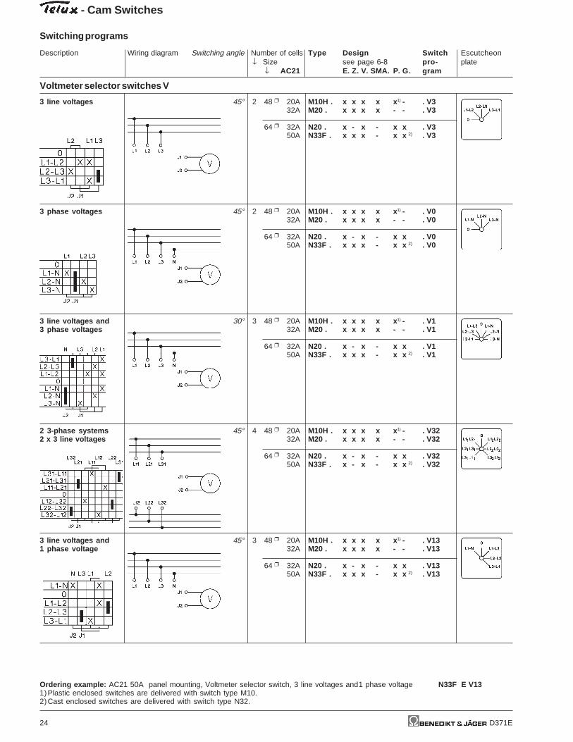
Voltmeter selector switches V
3 line voltages 45° 2 48 20A M10H . x x x x x 1) - . V332A M20 . x x x x - - . V3
64 32A N20 . x - x - x x . V350A N33F . x x x - x x 2) . V3
3 phase voltages 45° 2 48 20A M10H . x x x x x 1) - . V032A M20 . x x x x - - . V0
64 32A N20 . x - x - x x . V050A N33F . x x x - x x 2) . V0
3 line voltages and 30° 3 48 20A M10H . x x x x x 1) - . V13 phase voltages 32A M20 . x x x x - - . V1
64 32A N20 . x - x - x x . V150A N33F . x x x - x x 2) . V1
2 3-phase systems 45° 4 48 20A M10H . x x x x x 1) - . V322 x 3 line voltages 32A M20 . x x x x - - . V32
64 32A N20 . x - x - x x . V3250A N33F . x - x - x x 2) . V32
3 line voltages and 45° 3 48 20A M10H . x x x x x 1) - . V131 phase voltage 32A M20 . x x x x - - . V13
64 32A N20 . x - x - x x . V1350A N33F . x x x - x x 2) . V13
Ordering example: AC21 50A panel mounting, Voltmeter selector switch, 3 line voltages and1 phase voltage N33F E V131)Plastic enclosed switches are delivered with switch type M10.2)Cast enclosed switches are delivered with switch type N32.

Description Wiring diagram Switching angle Number of cells Type Design Switch Escutcheon↓ Size see page 6-8 pro- plate
↓ AC21 E. Z. V. SMA. P. G. gram
- Cam Switches
Switching programs
D371E 25
Ammeter selector switches M
1-pole, for 90° 1 48 20A M10H . x x x x x 1) - . M11current transformer 32A M20 . x x x x - - . M11
64 32A N20 . x - x - x x . M1150A N33F . x x x - x x 2) . M11
88 63A N40 . x - x - x - . M11
2-pole, for 90° 2 48 20A M10H . x x x x x 1) - . M121 current transformer 32A M20 . x x x x - - . M12or direct currentmeasurement 64 32A N20 . x - x - x x . M12
50A N33F . x x x - x x 2) . M12
88 63A N40 . x - x - x - . M1280A N60 . x - x - x - . M12
115A N80 . x - x - - - . M12
132 150A N100 . x - x - - - . M12250A N200 . x - x - - - . M12
1-pole, for 90° 2 48 20A M10H . x x x x x 1) - . M212 current transformers 32A M20 . x x x x - - . M21
64 32A N20 . x - x - x x . M2150A N33F . x x x - x x 2) . M21
88 63A N40 . x - x - x - . M21
2-pole, for 90° 3 48 20A M10H . x x x x x 1) - . M222 current transformers 32A M20 . x x x x - - . M22or direct currentmeasurement 64 32A N20 . x - x - x x . M22in 2 phases 50A N33F . x x x - x x 2) . M22
88 63A N40 . x - x - x - . M2280A N60 . x - x - x - . M22
115A N80 . x - x - - - . M22
132 150A N100 . x - x - - - . M22250A N200 . x - x - - - . M22
1-pole, for 90° 3 48 20A M10H . x x x x x 1) - . M313 current transformers 32A M20 . x x x x - - . M31
64 32A N20 . x - x - x x . M314 50A N33F . x - x - x x 2) . M31
88 63A N40 . x - x - x - . M31
Ordering example: AC21 63A panel mounting, ammeter selector switch, for 3 current transformers 1-pole N40 V M31
1)Plastic enclosed switches are delivered with switch type M10.2)Cast enclosed switches are delivered with switch type N32.

- Cam Switches
Description Wiring diagram Switching angle Number of cells Type Design Switch Escutcheon↓ Size see page 6-8 pro- plate
↓ AC21 E. Z. V. SMA. P. G. gram
Switching programs
26 D371E
Ammeter selector switches M
2-pole, for 90° 6 48 20A M10H . x x x x x 1) - . M323 current transformers 32A M20 . x x x - - - . M32or direct currentmeasurement 64 32A N20 . x - x - x x . M32in 3 phases 50A N33F . x - x - x - . M32
88 63A N40 . x - x - x - . M3280A N60 . x - x - x - . M32
115A N80 . x - x - - - . M32
132 150A N100 . x - x - - - . M32250A N200 . x - x - - - . M32
1-pole, for 90° 4 48 20A M10H . x x x x x 1) - . M414 current transformers 32A M20 . x x x x - - . M41
64 32A N20 . x - x - x x . M4150A N33F . x - x - x x 2) . M41
88 63A N40 . x - x - x - . M41
2-pole, for 90° 6 48 20A M10H . x x x x x 1) - . M424 current transformers 32A M20 . x x x - - - . M42or direct currentmeasurement 64 32A N20 . x - x - x x . M42in 4 phases 50A N33F . x - x - x - . M42
88 63A N40 . x - x - x - . M4280A N60 . x - x - x - . M42
115A N80 . x - x - - - . M42
132 150A N100 . x - x - - - . M42250A N200 . x - x - - - . M42
f. output measurement 90° 5 48 20A M10H . x x x x x 1) - . M2Win 3-phase ystems by 32A M20 . x x x x - - . M2W2-wattmeter method
64 32A N20 . x - x - x x . M2W50A N33F . x - x - x x 2) . M2W
88 63A N40 . x - x - x - . M2W80A N60 . x - x - x - . M2W
115A N80 . x - x - - - . M2W
132 150A N100 . x - x - - - . M2W250A N200 . x - x - - - . M2W
Ordering example: AC21 63A panel mounting, ammeter selector switch, for 4 current transformers 1-pole N40 V M41
1)Plastic enclosed switches are delivered with switch type M10.2)Cast enclosed switches are delivered with switch type N32.
Description Wiring diagram Switching angle Number of cells Type Design Switch Escutcheon↓ Size see page 6-8 pro- plate
↓ AC21 E. Z. V. SMA. P. G. gram
- Cam Switches
Switching programs
D371E 27
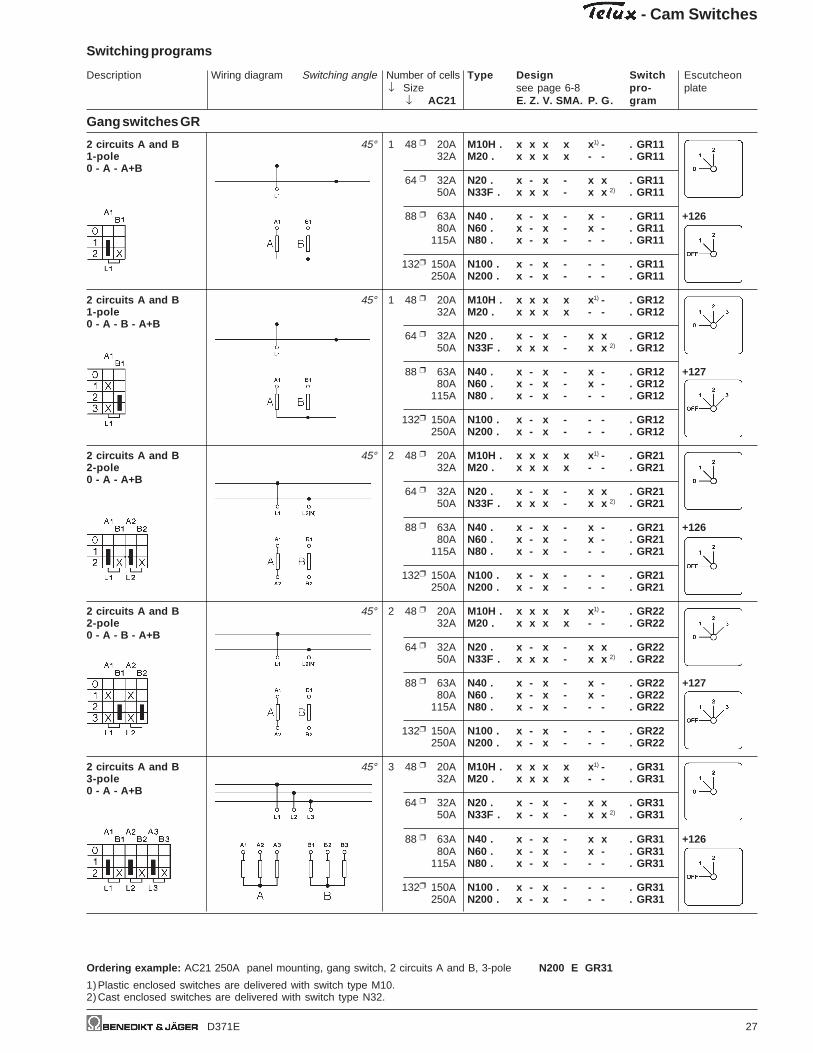
Gang switches GR
2 circuits A and B 45° 1 48 20A M10H . x x x x x 1) - . GR111-pole 32A M20 . x x x x - - . GR110 - A - A+B
64 32A N20 . x - x - x x . GR1150A N33F . x x x - x x 2) . GR11
88 63A N40 . x - x - x - . GR11 +12680A N60 . x - x - x - . GR11
115A N80 . x - x - - - . GR11
132 150A N100 . x - x - - - . GR11250A N200 . x - x - - - . GR11
2 circuits A and B 45° 1 48 20A M10H . x x x x x 1) - . GR121-pole 32A M20 . x x x x - - . GR120 - A - B - A+B
64 32A N20 . x - x - x x . GR1250A N33F . x x x - x x 2) . GR12
88 63A N40 . x - x - x - . GR12 +12780A N60 . x - x - x - . GR12
115A N80 . x - x - - - . GR12
132 150A N100 . x - x - - - . GR12250A N200 . x - x - - - . GR12
2 circuits A and B 45° 2 48 20A M10H . x x x x x 1) - . GR212-pole 32A M20 . x x x x - - . GR210 - A - A+B
64 32A N20 . x - x - x x . GR2150A N33F . x x x - x x 2) . GR21
88 63A N40 . x - x - x - . GR21 +12680A N60 . x - x - x - . GR21
115A N80 . x - x - - - . GR21
132 150A N100 . x - x - - - . GR21250A N200 . x - x - - - . GR21
2 circuits A and B 45° 2 48 20A M10H . x x x x x 1) - . GR222-pole 32A M20 . x x x x - - . GR220 - A - B - A+B
64 32A N20 . x - x - x x . GR2250A N33F . x x x - x x 2) . GR22
88 63A N40 . x - x - x - . GR22 +12780A N60 . x - x - x - . GR22
115A N80 . x - x - - - . GR22
132 150A N100 . x - x - - - . GR22250A N200 . x - x - - - . GR22
2 circuits A and B 45° 3 48 20A M10H . x x x x x 1) - . GR313-pole 32A M20 . x x x x - - . GR310 - A - A+B
64 32A N20 . x - x - x x . GR3150A N33F . x - x - x x 2) . GR31
88 63A N40 . x - x - x x . GR31 +12680A N60 . x - x - x - . GR31
115A N80 . x - x - - - . GR31
132 150A N100 . x - x - - - . GR31250A N200 . x - x - - - . GR31
Ordering example: AC21 250A panel mounting, gang switch, 2 circuits A and B, 3-pole N200 E GR31
1)Plastic enclosed switches are delivered with switch type M10.2)Cast enclosed switches are delivered with switch type N32.

- Cam Switches
Description Wiring diagram Switching angle Number of cells Type Design Switch Escutcheon↓ Size see page 6-8 pro- plate
↓ AC21 E. Z. V. SMA. P. G. gram
Switching programs
28 D371E
Gang switches GR
2 circuits A and B 45° 3 48 20A M10H . x x x x x 1) - . GR323-pole 32A M20 . x x x x - - . GR320 - A - B - A+B
64 32A N20 . x - x - x x . GR3250A N33F . x - x - x x 2) . GR32
88 63A N40 . x - x - x - . GR32 +12780A N60 . x - x - x - . GR32
115A N80 . x - x - - - . GR32
132 150A N100 . x - x - - - . GR32250A N200 . x - x - - - . GR32
3 circuits A, B and C 45° 2 48 20A M10H . x x x x x 1) - . GR141-pole 32A M20 . x x x x - - . GR140 - A - A+B - A+B+C
64 32A N20 . x - x - x x . GR1450A N33F . x - x - x x 2) . GR14
88 63A N40 . x - x - x - . GR14 +12780A N60 . x - x - x - . GR14
115A N80 . x - x - - - . GR14
132 150A N100 . x - x - - - . GR14250A N200 . x - x - - - . GR14
3 circuits A, B and C 45° 3 48 20A M10H . x x x x x 1) - . GR232-pole 32A M20 . x x x x - - . GR230 - A - A+B - A+B+C
64 32A N20 . x - x - x x . GR2350A N33F . x - x - x x 2) . GR23
88 63A N40 . x - x - x - . GR23 +12780A N60 . x - x - x - . GR23
115A N80 . x - x - - - . GR23
132 150A N100 . x - x - - - . GR23250A N200 . x - x - - - . GR23
3 circuits A, B and C 45° 5 48 20A M10H . x x x x x 1) - . GR333-pole 32A M20 . x x x x - - . GR330 - A - A+B - A+B+C
64 32A N20 . x - x - x x . GR3350A N33F . x - x - x x 2) . GR33
88 63A N40 . x - x - x - . GR33 +12780A N60 . x - x - x - . GR33
115A N80 . x - x - - - . GR33
132 150A N100 . x - x - - - . GR33250A N200 . x - x - - - . GR33
Ordering example: AC21 250A panel mounting, gang switch, 3 circuits A, B and C, 3-pole N200 E GR33
1)Plastic enclosed switches are delivered with switch type M10.2)Cast enclosed switches are delivered with switch type N32.
Description Wiring diagram Switching angle Number of cells Type Design Switch Escutcheon↓ Size see page 6-8 pro- plate
↓ AC21 E. Z. V. SMA. P. G. gram
- Cam Switches
Switching programs
D371E 29
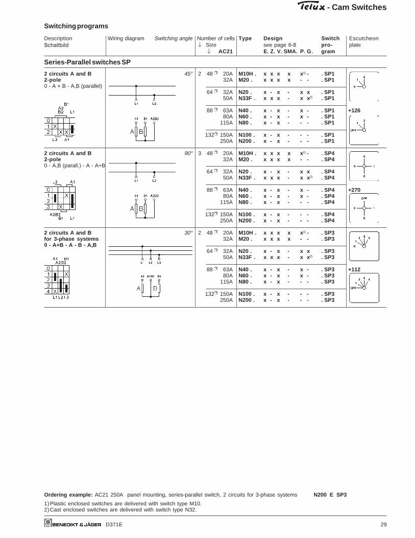
Series-Parallel switches SP
2 circuits A and B 45° 2 48 20A M10H . x x x x x 1) - . SP12-pole 32A M20 . x x x x - - . SP10 - A + B - A,B (parallel)
64 32A N20 . x - x - x x . SP150A N33F . x x x - x x 2) . SP1
88 63A N40 . x - x - x - . SP1 +12680A N60 . x - x - x - . SP1
115A N80 . x - x - - - . SP1
132 150A N100 . x - x - - - . SP1250A N200 . x - x - - - . SP1
2 circuits A and B 90° 3 48 20A M10H . x x x x x 1) - . SP42-pole 32A M20 . x x x x - - . SP40 - A,B (parall.) - A - A+B
64 32A N20 . x - x - x x . SP450A N33F . x x x - x x 2) . SP4
88 63A N40 . x - x - x - . SP4 +27080A N60 . x - x - x - . SP4
115A N80 . x - x - - - . SP4
132 150A N100 . x - x - - - . SP4250A N200 . x - x - - - . SP4
2 circuits A and B 30° 2 48 20A M10H . x x x x x 1) - . SP3for 3-phase systems 32A M20 . x x x x - - . SP30 - A+B - A - B - A,B
64 32A N20 . x - x - x x . SP350A N33F . x x x - x x 2) . SP3
88 63A N40 . x - x - x - . SP3 +11280A N60 . x - x - x - . SP3
115A N80 . x - x - - - . SP3
132 150A N100 . x - x - - - . SP3250A N200 . x - x - - - . SP3
Ordering example: AC21 250A panel mounting, series-parallel switch, 2 circuits for 3-phase systems N200 E SP3
1)Plastic enclosed switches are delivered with switch type M10.2)Cast enclosed switches are delivered with switch type N32.
Schaltbild
- Cam Switches
Description Wiring diagram Switching angle Number of cells Type Design Switch Escutcheon↓ Size see page 6-8 pro- plate
↓ AC21 E. Z. V. SMA. P. G. gram
Switching programs
30 D371E
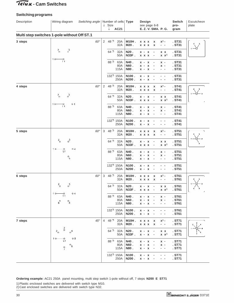
Multi step switches 1-pole without Off ST.1
3 steps 60° 2 48 20A M10H . x x x x x 1) - . ST3132A M20 . x x x x - - . ST31
64 32A N20 . x - x - x x . ST3150A N33F . x x x - x x 2) . ST31
88 63A N40 . x - x - x - . ST3180A N60 . x - x - x - . ST31
115A N80 . x - x - - - . ST31
132 150A N100 . x - x - - - . ST31250A N200 . x - x - - - . ST31
4 steps 60° 2 48 20A M10H . x x x x x 1) - . ST4132A M20 . x x x x - - . ST41
64 32A N20 . x - x - x x . ST4150A N33F . x x x - x x 2) . ST41
88 63A N40 . x - x - x - . ST4180A N60 . x - x - x - . ST41
115A N80 . x - x - - - . ST41
132 150A N100 . x - x - - - . ST41250A N200 . x - x - - - . ST41
5 steps 60° 3 48 20A M10H . x x x x x 1) - . ST5132A M20 . x x x x - - . ST51
64 32A N20 . x - x - x x . ST5150A N33F . x x x - x x 2) . ST51
88 63A N40 . x - x - x - . ST5180A N60 . x - x - x - . ST51
115A N80 . x - x - - - . ST51
132 150A N100 . x - x - - - . ST51250A N200 . x - x - - - . ST51
6 steps 60° 3 48 20A M10H . x x x x x 1) - . ST6132A M20 . x x x x - - . ST61
64 32A N20 . x - x - x x . ST6150A N33F . x x x - x x 2) . ST61
88 63A N40 . x - x - x - . ST6180A N60 . x - x - x - . ST61
115A N80 . x - x - - - . ST61
132 150A N100 . x - x - - - . ST61250A N200 . x - x - - - . ST61
7 steps 45° 4 48 20A M10H . x x x x x 1) - . ST7132A M20 . x x x x - - . ST71
64 32A N20 . x - x - x x . ST7150A N33F . x - x - x x 2) . ST71
88 63A N40 . x - x - x - . ST7180A N60 . x - x - x - . ST71
115A N80 . x - x - - - . ST71
132 150A N100 . x - x - - - . ST71250A N200 . x - x - - - . ST71
Ordering example: AC21 250A panel mounting, multi step switch 1-pole without off, 7 steps N200 E ST71
1)Plastic enclosed switches are delivered with switch type M10.2)Cast enclosed switches are delivered with switch type N32.

Description Wiring diagram Switching angle Number of cells Type Design Switch Escutcheon↓ Size see page 6-8 pro- plate
↓ AC21 E. Z. V. SMA. P. G. gram
- Cam Switches
Switching programs
D371E 31
Multi step switches 1-pole without Off ST.1
8 steps 45° 4 48 20A M10H . x x x x x 1) - . ST8132A M20 . x x x x - - . ST81
64 32A N20 . x - x - x x . ST8150A N33F . x - x - x x 2) . ST81
88 63A N40 . x - x - x - . ST8180A N60 . x - x - x - . ST81
115A N80 . x - x - - - . ST81
132 150A N100 . x - x - - - . ST81250A N200 . x - x - - - . ST81
9 steps 30° 5 48 20A M10H . x x x x x 1) - . ST9132A M20 . x x x x - - . ST91
64 32A N20 . x - x - x x . ST9150A N33F . x - x - x x 2) . ST91
88 63A N40 . x - x - x - . ST9180A N60 . x - x - x - . ST91
115A N80 . x - x - - - . ST91
132 150A N100 . x - x - - - . ST91250A N200 . x - x - - - . ST91
10 steps 30° 5 48 20A M10H . x x x x x 1) - . ST10132A M20 . x x x x - - . ST101
64 32A N20 . x - x - x x . ST10150A N33F . x - x - x x 2) . ST101
88 63A N40 . x - x - x - . ST10180A N60 . x - x - x - . ST101
115A N80 . x - x - - - . ST101
132 150A N100 . x - x - - - . ST101250A N200 . x - x - - - . ST101
11 steps 30° 6 48 20A M10H . x x x - x 1) - . ST11132A M20 . x x x - - - . ST111
64 32A N20 . x - x - x x . ST11150A N33F . x - x - x - . ST111
88 63A N40 . x - x - x - . ST11180A N60 . x - x - x - . ST111
115A N80 . x - x - - - . ST111
132 150A N100 . x - x - - - . ST111250A N200 . x - x - - - . ST111
12 steps 30° 6 48 20A M10H . x x x - x 1) - . ST12132A M20 . x x x - - - . ST121
64 32A N20 . x - x - x x . ST12150A N33F . x - x - x - . ST121
88 63A N40 . x - x - x - . ST12180A N60 . x - x - x - . ST121
115A N80 . x - x - - - . ST121
132 150A N100 . x - x - - - . ST121250A N200 . x - x - - - . ST121
Ordering example: AC21 250A panel mounting, multi step switch 1-pole without off, 12 steps N200 E ST121
1)Plastic enclosed switches are delivered with switch type M10.2)Cast enclosed switches are delivered with switch type N32.

- Cam Switches
Description Wiring diagram Switching angle Number of cells Type Design Switch Escutcheon↓ Size see page 6-8 pro- plate
↓ AC21 E. Z. V. SMA. P. G. gram
Switching programs
32 D371E
Multi step switches 1-pole with Off ST0.1
2 steps 60° 1 48 20A M10H . x x x x x 1) - . ST02132A M20 . x x x x - - . ST021
64 32A N20 . x - x - x x . ST02150A N33F . x x x - x x 2) . ST021
88 63A N40 . x - x - x - . ST021 +42280A N60 . x - x - x - . ST021
115A N80 . x - x - - - . ST021
132 150A N100 . x - x - - - . ST021250A N200 . x - x - - - . ST021
3 steps 45° 2 48 20A M10H . x x x x x 1) - . ST03132A M20 . x x x x - - . ST031
64 32A N20 . x - x - x x . ST03150A N33F . x x x - x x 2) . ST031
88 63A N40 . x - x - x - . ST031 +12780A N60 . x - x - x - . ST031
115A N80 . x - x - - - . ST031
132 150A N100 . x - x - - - . ST031250A N200 . x - x - - - . ST031
4 steps 30° 2 48 20A M10H . x x x x x 1) - . ST04132A M20 . x x x x - - . ST041
64 32A N20 . x - x - x x . ST04150A N33F . x x x - x x 2) . ST041
88 63A N40 . x - x - x - . ST041 +11280A N60 . x - x - x - . ST041
115A N80 . x - x - - - . ST041
132 150A N100 . x - x - - - . ST041250A N200 . x - x - - - . ST041
5 steps 45° 3 48 20A M10H . x x x x x 1) - . ST05132A M20 . x x x x - - . ST051
64 32A N20 . x - x - x x . ST05150A N33F . x x x - x x 2) . ST051
88 63A N40 . x - x - x - . ST051 +42380A N60 . x - x - x - . ST051
115A N80 . x - x - - - . ST051
132 150A N100 . x - x - - - . ST051250A N200 . x - x - - - . ST051
6 steps 45° 4 48 20A M10H . x x x x x 1) - . ST06132A M20 . x x x x - - . ST061
64 32A N20 . x - x - x x . ST06150A N33F . x - x - x x 2) . ST061
88 63A N40 . x - x - x - . ST061 +12880A N60 . x - x - x - . ST061
115A N80 . x - x - - - . ST061
132 150A N100 . x - x - - - . ST061250A N200 . x - x - - - . ST061
Ordering example: AC21 250A panel mounting, multi step switch 1-pole with off, 6 steps N200 E ST061
1)Plastic enclosed switches are delivered with switch type M10.2)Cast enclosed switches are delivered with switch type N32.

Description Wiring diagram Switching angle Number of cells Type Design Switch Escutcheon↓ Size see page 6-8 pro- plate
↓ AC21 E. Z. V. SMA. P. G. gram
- Cam Switches
Switching programs
D371E 33
Multi step switches 1-pole with Off ST0.1
7 steps 45° 4 48 20A M10H . x x x x x 1) - . ST07132A M20 . x x x x - - . ST071
64 32A N20 . x - x - x x . ST07150A N33F . x - x - x x 2) . ST071
88 63A N40 . x - x - x - . ST071 +12980A N60 . x - x - x - . ST071
115A N80 . x - x - - - . ST071
132 150A N100 . x - x - - - . ST071250A N200 . x - x - - - . ST071
8 steps 30° 5 48 20A M10H . x x x x x 1) - . ST08132A M20 . x x x x - - . ST081
64 32A N20 . x - x - x x . ST08150A N33F . x - x - x x 2) . ST081
88 63A N40 . x - x - x - . ST081 +11480A N60 . x - x - x - . ST081
115A N80 . x - x - - - . ST081
132 150A N100 . x - x - - - . ST081250A N200 . x - x - - - . ST081
9 steps 30° 5 48 20A M10H . x x x x x 1) - . ST09132A M20 . x x x x - - . ST091
64 32A N20 . x - x - x x . ST09150A N33F . x - x - x x 2) . ST091
88 63A N40 . x - x - x - . ST091 +11580A N60 . x - x - x - . ST091
115A N80 . x - x - - - . ST091
132 150A N100 . x - x - - - . ST091250A N200 . x - x - - - . ST091
10 steps 30° 6 48 20A M10H . x x x - x 1) - . ST010132A M20 . x x x - - - . ST0101
64 32A N20 . x - x - x x . ST010150A N33F . x - x - x - . ST0101
88 63A N40 . x - x - x - . ST0101 +11680A N60 . x - x - x - . ST0101
115A N80 . x - x - - - . ST0101
132 150A N100 . x - x - - - . ST0101250A N200 . x - x - - - . ST0101
11 steps 30° 6 48 20A M10H . x x x - x 1) - . ST011132A M20 . x x x - - - . ST0111
64 32A N20 . x - x - x x . ST011150A N33F . x - x - x - . ST0111
88 63A N40 . x - x - x - . ST0111 +11780A N60 . x - x - x - . ST0111
115A N80 . x - x - - - . ST0111
132 150A N100 . x - x - - - . ST0111250A N200 . x - x - - - . ST0111
Ordering example: AC21 250A panel mounting, multi step switch 1-pole with off, 11 steps N200 E ST0111
1)Plastic enclosed switches are delivered with switch type M10.2)Cast enclosed switches are delivered with switch type N32.
- Cam Switches
Description Wiring diagram Switching angle Number of cells Type Design Switch Escutcheon↓ Size see page 6-8 pro- plate
↓ AC21 E. Z. V. SMA. P. G. gram
Switching programs
34 D371E
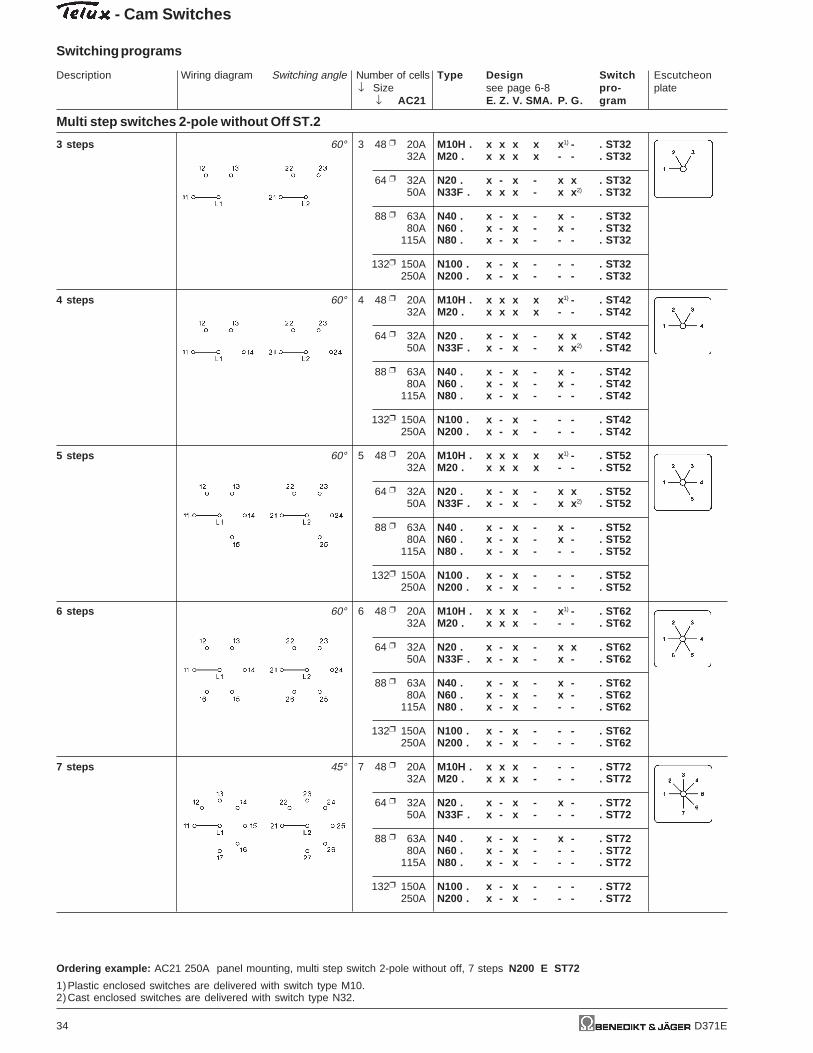
Multi step switches 2-pole without Off ST.2
3 steps 60° 3 48 20A M10H . x x x x x 1) - . ST3232A M20 . x x x x - - . ST32
64 32A N20 . x - x - x x . ST3250A N33F . x x x - x x 2) . ST32
88 63A N40 . x - x - x - . ST3280A N60 . x - x - x - . ST32
115A N80 . x - x - - - . ST32
132 150A N100 . x - x - - - . ST32250A N200 . x - x - - - . ST32
4 steps 60° 4 48 20A M10H . x x x x x 1) - . ST4232A M20 . x x x x - - . ST42
64 32A N20 . x - x - x x . ST4250A N33F . x - x - x x 2) . ST42
88 63A N40 . x - x - x - . ST4280A N60 . x - x - x - . ST42
115A N80 . x - x - - - . ST42
132 150A N100 . x - x - - - . ST42250A N200 . x - x - - - . ST42
5 steps 60° 5 48 20A M10H . x x x x x 1) - . ST5232A M20 . x x x x - - . ST52
64 32A N20 . x - x - x x . ST5250A N33F . x - x - x x 2) . ST52
88 63A N40 . x - x - x - . ST5280A N60 . x - x - x - . ST52
115A N80 . x - x - - - . ST52
132 150A N100 . x - x - - - . ST52250A N200 . x - x - - - . ST52
6 steps 60° 6 48 20A M10H . x x x - x 1) - . ST6232A M20 . x x x - - - . ST62
64 32A N20 . x - x - x x . ST6250A N33F . x - x - x - . ST62
88 63A N40 . x - x - x - . ST6280A N60 . x - x - x - . ST62
115A N80 . x - x - - - . ST62
132 150A N100 . x - x - - - . ST62250A N200 . x - x - - - . ST62
7 steps 45° 7 48 20A M10H . x x x - - - . ST7232A M20 . x x x - - - . ST72
64 32A N20 . x - x - x - . ST7250A N33F . x - x - - - . ST72
88 63A N40 . x - x - x - . ST7280A N60 . x - x - - - . ST72
115A N80 . x - x - - - . ST72
132 150A N100 . x - x - - - . ST72250A N200 . x - x - - - . ST72
Ordering example: AC21 250A panel mounting, multi step switch 2-pole without off, 7 steps N200 E ST72
1)Plastic enclosed switches are delivered with switch type M10.2)Cast enclosed switches are delivered with switch type N32.

Description Wiring diagram Switching angle Number of cells Type Design Switch Escutcheon↓ Size see page 6-8 pro- plate
↓ AC21 E. Z. V. SMA. P. G. gram
- Cam Switches
Switching programs
D371E 35
Multi step switches 2-pole without Off ST.2
8 steps 45° 8 48 20A M10H . x x x - - - . ST8232A M20 . x x x - - - . ST82
64 32A N20 . x - x - x - . ST8250A N33F . x - x - - - . ST82
88 63A N40 . x - x - x - . ST8280A N60 . x - x - - - . ST82
115A N80 . x - x - - - . ST82
132 150A N100 . x - x - - - . ST82250A N200 . x - x - - - . ST82
9 steps 30° 9 48 20A M10H . x x x - - - . ST9232A M20 . x x x - - - . ST92
64 32A N20 . x - x - - - . ST9250A N33F . x - x - - - . ST92
88 63A N40 . x - x - - - . ST9280A N60 . x - x - - - . ST92
115A N80 . x - x - - - . ST92
132 150A N100 . x - x - - - . ST92250A N200 . x - x - - - . ST92
10 steps 30° 10 48 20A M10H . x x x - - - . ST10232A M20 . x x x - - - . ST102
64 32A N20 . x - x - - - . ST10250A N33F . x - x - - - . ST102
88 63A N40 . x - x - - - . ST10280A N60 . x - x - - - . ST102
115A N80 . x - x - - - . ST102
132 150A N100 . x - x - - - . ST102250A N200 . x - x - - - . ST102
11 steps 30° 11 48 20A M10H . x x x - - - . ST11232A M20 . x x x - - - . ST112
64 32A N20 . x - x - - - . ST11250A N33F . x - x - - - . ST112
88 63A N40 . x - x - - - . ST11280A N60 . x - x - - - . ST112
115A N80 . x - x - - - . ST112
132 150A N100 . x - x - - - . ST112250A N200 . x - x - - - . ST112
12 steps 30° 12 48 20A M10H . x x x - - - . ST12232A M20 . x x x - - - . ST122
64 32A N20 . x - x - - - . ST12250A N33F . x - x - - - . ST122
88 63A N40 . x - x - - - . ST12280A N60 . x - x - - - . ST122
115A N80 . x - x - - - . ST122
132 150A N100 . x - x - - - . ST122250A N200 . x - x - - - . ST122
Ordering example: AC21 250A panel mounting, multi step switch 2-pole without off, 12 steps N200 E ST122

- Cam Switches
Description Wiring diagram Switching angle Number of cells Type Design Switch Escutcheon↓ Size see page 6-8 pro- plate
↓ AC21 E. Z. V. SMA. P. G. gram
Switching programs
36 D371E
Multi step switches 2-pole with Off ST0.2
2 steps 60° 2 48 20A M10H . x x x x x 1) - . ST02232A M20 . x x x x - - . ST022
64 32A N20 . x - x - x x . ST02250A N33F . x x x - x x 2) . ST022
88 63A N40 . x - x - x - . ST022 +42280A N60 . x - x - x - . ST022
115A N80 . x - x - - - . ST022
132 150A N100 . x - x - - - . ST022250A N200 . x - x - - - . ST022
3 steps 45° 3 48 20A M10H . x x x x x 1) - . ST03232A M20 . x x x x - - . ST032
64 32A N20 . x - x - x x . ST03250A N33F . x x x - x x 2 . ST032
88 63A N40 . x - x - x - . ST032 +12780A N60 . x - x - x - . ST032
115A N80 . x - x - - - . ST032
132 150A N100 . x - x - - - . ST032250A N200 . x - x - - - . ST032
4 steps 30° 4 48 20A M10H . x x x x x 1) - . ST04232A M20 . x x x x - - . ST042
64 32A N20 . x - x - x x . ST04250A N33F . x - x - x x 2) . ST042
88 63A N40 . x - x - x - . ST042 +11280A N60 . x - x - x - . ST042
115A N80 . x - x - - - . ST042
132 150A N100 . x - x - - - . ST042250A N200 . x - x - - - . ST042
5 steps 45° 6 48 20A M10H . x x x - x 1) - . ST05232A M20 . x x x - - - . ST052
64 32A N20 . x - x - x x . ST05250A N33F . x - x - x - . ST052
88 63A N40 . x - x - x - . ST052 +42380A N60 . x - x - x - . ST052
115A N80 . x - x - - - . ST052
132 150A N100 . x - x - - - . ST052250A N200 . x - x - - - . ST052
6 steps 45° 7 48 20A M10H . x x x - x 1) - . ST06232A M20 . x x x - - - . ST062
64 32A N20 . x - x - x - . ST06250A N33F . x - x - - - . ST062
88 63A N40 . x - x - x - . ST062 +12880A N60 . x - x - - - . ST062
115A N80 . x - x - - - . ST062
132 150A N100 . x - x - - - . ST062250A N200 . x - x - - - . ST062
Ordering example: AC21 250A panel mounting, multi step switch 2-pole with off, 6 steps N200 E ST062
1)Plastic enclosed switches are delivered with switch type M10.2)Cast enclosed switches are delivered with switch type N32.

Description Wiring diagram Switching angle Number of cells Type Design Switch Escutcheon↓ Size see page 6-8 pro- plate
↓ AC21 E. Z. V. SMA. P. G. gram
- Cam Switches
Switching programs
D371E 37
Multi step switches 2-pole with Off ST0.2
7 steps 45° 8 48 20A M10H . x x x - - - . ST07232A M20 . x x x - - - . ST072
64 32A N20 . x - x - x - . ST07250A N33F . x - x - - - . ST072
88 63A N40 . x - x - x - . ST072 +12980A N60 . x - x - - - . ST072
115A N80 . x - x - - - . ST072
132 150A N100 . x - x - - - . ST072250A N200 . x - x - - - . ST072
8 steps 30° 9 48 20A M10H . x x x - - - . ST08232A M20 . x x x - - - . ST082
64 32A N20 . x - x - - - . ST08250A N33F . x - x - - - . ST082
88 63A N40 . x - x - - - . ST082 +11480A N60 . x - x - - - . ST082
115A N80 . x - x - - - . ST082
132 150A N100 . x - x - - - . ST082250A N200 . x - x - - - . ST082
9 steps 30° 10 48 20A M10H . x x x - - - . ST09232A M20 . x x x - - - . ST092
64 32A N20 . x - x - - - . ST09250A N33F . x - x - - - . ST092
88 63A N40 . x - x - - - . ST092 +11580A N60 . x - x - - - . ST092
115A N80 . x - x - - - . ST092
132 150A N100 . x - x - - - . ST092250A N200 . x - x - - - . ST092
10 steps 30° 11 48 20A M10H . x x x - - - . ST010232A M20 . x x x - - - . ST0102
64 32A N20 . x - x - - - . ST010250A N33F . x - x - - - . ST0102
88 63A N40 . x - x - - - . ST0102 +11680A N60 . x - x - - - . ST0102
115A N80 . x - x - - - . ST0102
132 150A N100 . x - x - - - . ST0102250A N200 . x - x - - - . ST0102
11 steps 30° 12 48 20A M10H . x x x - - - . ST011232A M20 . x x x - - - . ST0112
64 32A N20 . x - x - - - . ST011250A N33F . x - x - - - . ST0112
88 63A N40 . x - x - - - . ST0112 +11780A N60 . x - x - - - . ST0112
115A N80 . x - x - - - . ST0112
132 150A N100 . x - x - - - . ST0112250A N200 . x - x - - - . ST0112
Ordering example: AC21 250A panel mounting, multi step switch 2-pole with off, 11 steps N200 E ST0112
- Cam Switches
Description Wiring diagram Switching angle Number of cells Type Design Switch Escutcheon↓ Size see page 6-8 pro- plate
↓ AC21 E. Z. V. SMA. P. G. gram
Switching programs
38 D371E
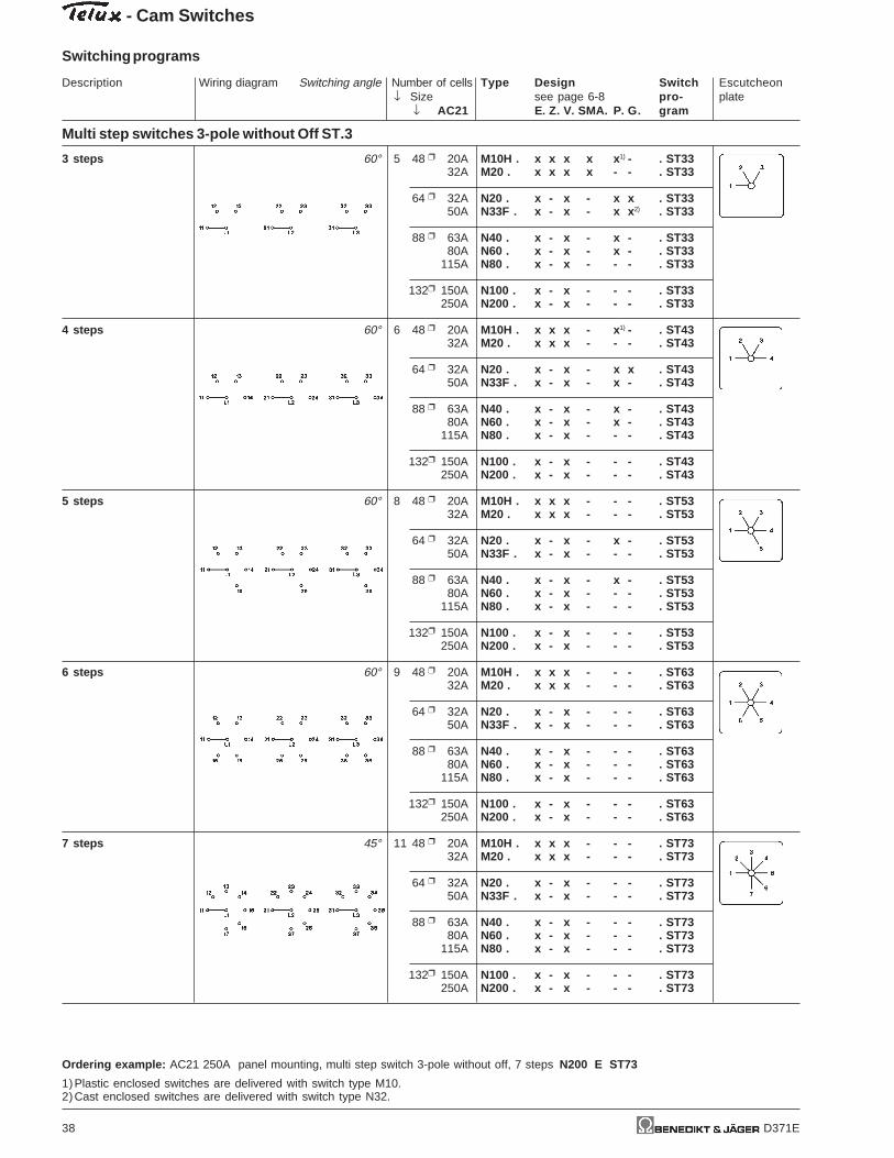
Multi step switches 3-pole without Off ST.3
3 steps 60° 5 48 20A M10H . x x x x x 1) - . ST3332A M20 . x x x x - - . ST33
64 32A N20 . x - x - x x . ST3350A N33F . x - x - x x 2) . ST33
88 63A N40 . x - x - x - . ST3380A N60 . x - x - x - . ST33
115A N80 . x - x - - - . ST33
132 150A N100 . x - x - - - . ST33250A N200 . x - x - - - . ST33
4 steps 60° 6 48 20A M10H . x x x - x 1) - . ST4332A M20 . x x x - - - . ST43
64 32A N20 . x - x - x x . ST4350A N33F . x - x - x - . ST43
88 63A N40 . x - x - x - . ST4380A N60 . x - x - x - . ST43
115A N80 . x - x - - - . ST43
132 150A N100 . x - x - - - . ST43250A N200 . x - x - - - . ST43
5 steps 60° 8 48 20A M10H . x x x - - - . ST5332A M20 . x x x - - - . ST53
64 32A N20 . x - x - x - . ST5350A N33F . x - x - - - . ST53
88 63A N40 . x - x - x - . ST5380A N60 . x - x - - - . ST53
115A N80 . x - x - - - . ST53
132 150A N100 . x - x - - - . ST53250A N200 . x - x - - - . ST53
6 steps 60° 9 48 20A M10H . x x x - - - . ST6332A M20 . x x x - - - . ST63
64 32A N20 . x - x - - - . ST6350A N33F . x - x - - - . ST63
88 63A N40 . x - x - - - . ST6380A N60 . x - x - - - . ST63
115A N80 . x - x - - - . ST63
132 150A N100 . x - x - - - . ST63250A N200 . x - x - - - . ST63
7 steps 45° 11 48 20A M10H . x x x - - - . ST7332A M20 . x x x - - - . ST73
64 32A N20 . x - x - - - . ST7350A N33F . x - x - - - . ST73
88 63A N40 . x - x - - - . ST7380A N60 . x - x - - - . ST73
115A N80 . x - x - - - . ST73
132 150A N100 . x - x - - - . ST73250A N200 . x - x - - - . ST73
Ordering example: AC21 250A panel mounting, multi step switch 3-pole without off, 7 steps N200 E ST73
1)Plastic enclosed switches are delivered with switch type M10.2)Cast enclosed switches are delivered with switch type N32.

Description Wiring diagram Switching angle Number of cells Type Design Switch Escutcheon↓ Size see page 6-8 pro- plate
↓ AC21 E. Z. V. SMA. P. G. gram
- Cam Switches
Switching programs
D371E 39
Multi step switches 3-pole without Off ST.3
8 steps 45° 12 48 20A M10H . x x x - - - . ST8332A M20 . x x x - - - . ST83
64 32A N20 . x - x - - - . ST8350A N33F . x - x - - - . ST83
88 63A N40 . x - x - - - . ST8380A N60 . x - x - - - . ST83
115A N80 . x - x - - - . ST83
132 150A N100 . x - x - - - . ST83250A N200 . x - x - - - . ST83
9 steps 30° 14 48 20A M10H . x - x - - - . ST9332A M20 . x - x - - - . ST93
64 32A N20 . x - x - - - . ST9350A N33F . x - x - - - . ST93
88 63A N40 . x - x - - - . ST9380A N60 . x - x - - - . ST93
115A N80 . x - x - - - . ST93
132 150A N100 . x - x - - - . ST93250A N200 . x - x - - - . ST93
10 steps 30° 15 48 20A M10H . x - x - - - . ST10332A M20 . x - x - - - . ST103
64 32A N20 . x - x - - - . ST10350A N33F . x - x - - - . ST103
88 63A N40 . x - x - - - . ST10380A N60 . x - x - - - . ST103
115A N80 . x - x - - - . ST103
132 150A N100 . x - x - - - . ST103250A N200 . x - x - - - . ST103
11 steps 30° 17 48 20A M10H . x - x - - - . ST11332A M20 . x - x - - - . ST113
64 32A N20 . x - x - - - . ST11350A N33F . x - x - - - . ST113
88 63A N40 . x - x - - - . ST11380A N60 . x - x - - - . ST113
115A N80 . x - x - - - . ST113
132 150A N100 . x - x - - - . ST113250A N200 . x - x - - - . ST113
12 steps 30° 18 48 20A M10H . x - x - - - . ST12332A M20 . x - x - - - . ST123
64 32A N20 . x - x - - - . ST12350A N33F . x - x - - - . ST123
88 63A N40 . x - x - - - . ST12380A N60 . x - x - - - . ST123
115A N80 . x - x - - - . ST123
132 150A N100 . x - x - - - . ST123250A N200 . x - x - - - . ST123
Ordering example: AC21 250A panel mounting, multi step switch 3-pole without off, 12 steps N200 E ST123

- Cam Switches
Description Wiring diagram Switching angle Number of cells Type Design Switch Escutcheon↓ Size see page 6-8 pro- plate
↓ AC21 E. Z. V. SMA. P. G. gram
Switching programs
40 D371E
Multi step switches 3-pole with Off ST0.3
2 steps 60° 3 48 20A M10H . x x x x x 1) - . ST02332A M20 . x x x x - - . ST023
64 32A N20 . x - x - x x . ST02350A N33F . x x x - x x 2) . ST023
88 63A N40 . x - x - x - . ST023 +42280A N60 . x - x - x - . ST023
115A N80 . x - x - - - . ST023
132 150A N100 . x - x - - - . ST023250A N200 . x - x - - - . ST023
3 steps 45° 5 48 20A M10H . x x x x x 1) - . ST03332A M20 . x x x x - - . ST033
64 32A N20 . x - x - x x . ST03350A N33F . x - x - x x 2) . ST033
88 63A N40 . x - x - x - . ST033 +12780A N60 . x - x - x - . ST033
115A N80 . x - x - - - . ST033
132 150A N100 . x - x - - - . ST033250A N200 . x - x - - - . ST033
4 steps 30° 6 48 20A M10H . x x x - x 1) - . ST04332A M20 . x x x - - - . ST043
64 32A N20 . x - x - x x . ST04350A N33F . x - x - x - . ST043
88 63A N40 . x - x - x - . ST043 +11280A N60 . x - x - x - . ST043
115A N80 . x - x - - - . ST043
132 150A N100 . x - x - - - . ST043250A N200 . x - x - - - . ST043
5 steps 45° 9 48 20A M10H . x x x - - - . ST05332A M20 . x x x - - - . ST053
64 32A N20 . x - x - - - . ST05350A N33F . x - x - - - . ST053
88 63A N40 . x - x - - - . ST053 +42380A N60 . x - x - - - . ST053
115A N80 . x - x - - - . ST053
132 150A N100 . x - x - - - . ST053250A N200 . x - x - - - . ST053
6 steps 45° 11 48 20A M10H . x x x - - - . ST06332A M20 . x x x - - - . ST063
64 32A N20 . x - x - - - . ST06350A N33F . x - x - - - . ST063
88 63A N40 . x - x - - - . ST063 +12880A N60 . x - x - - - . ST063
115A N80 . x - x - - - . ST063
132 150A N100 . x - x - - - . ST063250A N200 . x - x - - - . ST063
Ordering example: AC21 250A panel mounting, multi step switch 3-pole with off, 6 steps N200 E ST063
1)Plastic enclosed switches are delivered with switch type M10.2)Cast enclosed switches are delivered with switch type N32.

D371E 41
Multi step switches 3-pole with Off ST0.3
7 steps 45° 12 48 20A M10H . x x x - - - . ST07332A M20 . x x x - - - . ST073
64 32A N20 . x - x - - - . ST07350A N33F . x - x - - - . ST073
88 63A N40 . x - x - - - . ST073 +12980A N60 . x - x - - - . ST073
115A N80 . x - x - - - . ST073
132 150A N100 . x - x - - - . ST073250A N200 . x - x - - - . ST073
8 steps 30° 14 48 20A M10H . x - x - - - . ST08332A M20 . x - x - - - . ST083
64 32A N20 . x - x - - - . ST08350A N33F . x - x - - - . ST083
88 63A N40 . x - x - - - . ST083 +11480A N60 . x - x - - - . ST083
115A N80 . x - x - - - . ST083
132 150A N100 . x - x - - - . ST083250A N200 . x - x - - - . ST083
9 steps 30° 15 48 20A M10H . x - x - - - . ST09332A M20 . x - x - - - . ST093
64 32A N20 . x - x - - - . ST09350A N33F . x - x - - - . ST093
88 63A N40 . x - x - - - . ST093 +11580A N60 . x - x - - - . ST093
115A N80 . x - x - - - . ST093
132 150A N100 . x - x - - - . ST093250A N200 . x - x - - - . ST093
10 steps 30° 17 48 20A M10H . x - x - - - . ST010332A M20 . x - x - - - . ST0103
64 32A N20 . x - x - - - . ST010350A N33F . x - x - - - . ST0103
88 63A N40 . x - x - - - . ST0103 +11680A N60 . x - x - - - . ST0103
115A N80 . x - x - - - . ST0103
132 150A N100 . x - x - - - . ST0103250A N200 . x - x - - - . ST0103
11 steps 30° 18 48 20A M10H . x - x - - - . ST011332A M20 . x - x - - - . ST0113
64 32A N20 . x - x - - - . ST011350A N33F . x - x - - - . ST0113
88 63A N40 . x - x - - - . ST0113 +11780A N60 . x - x - - - . ST0113
115A N80 . x - x - - - . ST0113
132 150A N100 . x - x - - - . ST0113250A N200 . x - x - - - . ST0113
Ordering example: AC21 250A panel mounting, multi step switch 3-pole with off, 11 steps N200 E ST0113
Description Wiring diagram Switching angle Number of cells Type Design Switch Escutcheon↓ Size see page 6-8 pro- plate
↓ AC21 E. Z. V. SMA. P. G. gram
- Cam Switches
Switching programs

42 D371E
Technical data
Type according to AC21A AC15 Motor rating AC3specifications 110V 380V 3 phase 3-pole 1 phase 2-pole
240V 440V Volt 110 220 380 110 220 380General use Pilot Duty 120 240 440 120 240 277 440
M4H IEC, VDE, BS, SEV 10A/500V 2,5A 1,5A kW 0,65 1,5 2,2 0,3 0,55 - 0,75UL, CSA 10A/300V A300 H P 0,75 1 - 0,33 0,75 0,75 -
Type according to Motor rating AC23specifications 3-pole 2-pole
Volt 110 220 380 110 220 380120 240 440 120 240 440
M4H IEC, VDE, BS, SEV kW 0,75 1,8 3 0,37 0,75 1,1UL, CSA H P - - - - - -
additional data for wiring according to UL and CSA
Type type of temp. rating torque value forwire of wire field wiring terminals
M4H copper 60/75°C 0,6Nm / 5lb - inch
wire only
Panel mounting E, IP40 Central fixing Z Central fixing without escutcheon plate ZO
Central fixing 16mm
lock
unlock Central fixing 22mm
Mounting holes
Single hole mountings are generally delivered for a 16mm (.64") mounting.Using the forwarded adapter ring, it is possible to alter the single hole mountings from 22mm (.88"). For that purposethe adapter ring has to be attatched onto the threded part of the body in such a manner, that1. the flat side of the adapter ring shows towards the front seal and2. the inner nose fits into the notch of the body.The adapter ring has to be pushed towards the front seal.
Optional extras ordering for M4H Z ... +SRE M4H Z ... +SA. M4H ZO ... +SA. M4H Z ... +SRE+SA.
code design
Additional escutcheon +SRE E, Z, ZO
plate
Additional escutcheon +SRE2 E, Z, ZO
plate
Key operated switch
with lock KABA +SA1 Z, ZO
with lock Ronis +SA2 Z, ZO
Panel mounting E Central fixing Z, ZO ZO Z
Dimension L for ... cellsType A B D M 1 2 3 4 5 6 7 8
M4H mm 30 28 29,5 12,5 38,5 50,5 62,5 74,5 86,5 98,5 110,5 122,5
Wrench J7400
for switches M4H with central fixing is necessary
Mini-Cam Switches M4H
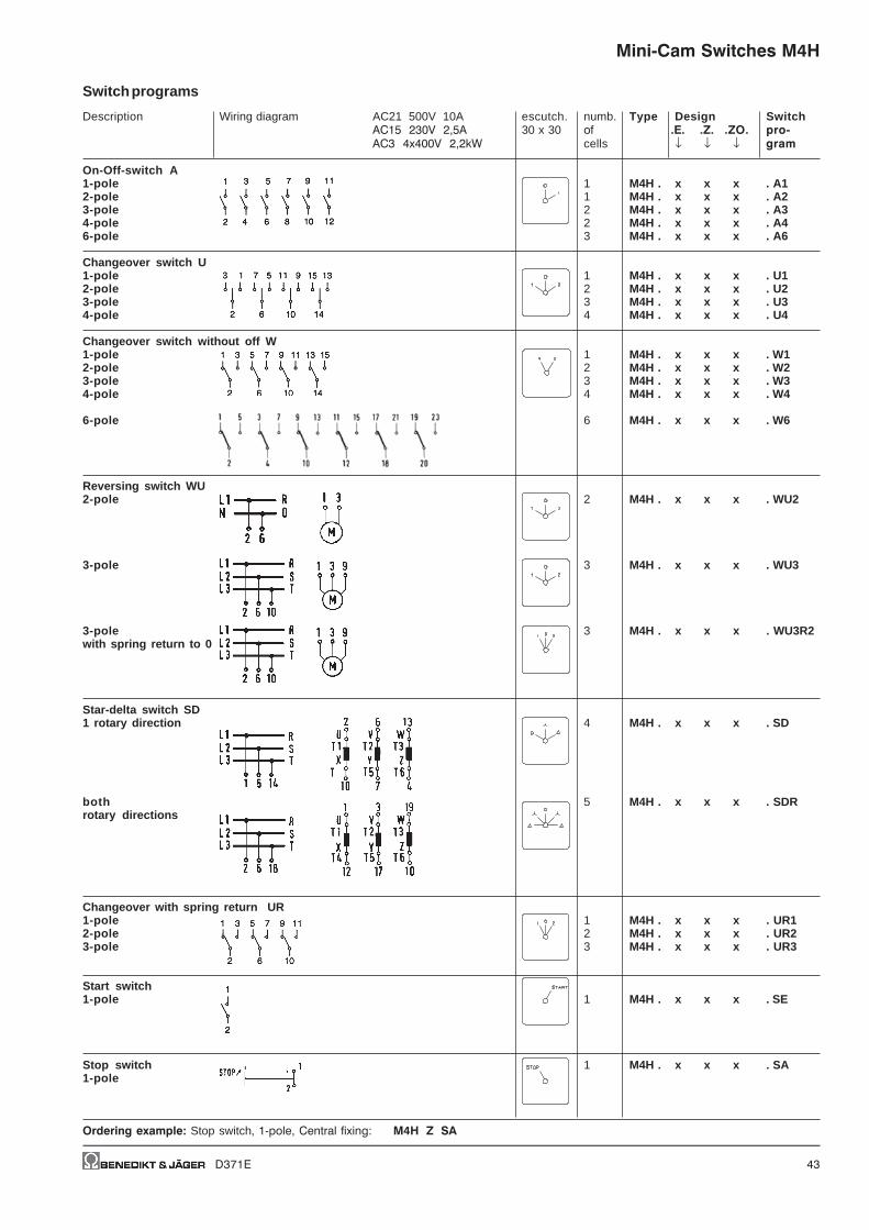
D371E 43
Description Wiring diagram AC21 500V 10A escutch. numb. Type Design SwitchAC15 230V 2,5A 30 x 30 of .E. .Z. .ZO. pro-AC3 4x400V 2,2kW cells ↓ ↓ ↓ gram
On-Off-switch A1-pole 1 M4H . x x x . A12-pole 1 M4H . x x x . A23-pole 2 M4H . x x x . A34-pole 2 M4H . x x x . A46-pole 3 M4H . x x x . A6
Changeover switch U1-pole 1 M4H . x x x . U12-pole 2 M4H . x x x . U23-pole 3 M4H . x x x . U34-pole 4 M4H . x x x . U4
Changeover switch without off W1-pole 1 M4H . x x x . W12-pole 2 M4H . x x x . W23-pole 3 M4H . x x x . W34-pole 4 M4H . x x x . W4
6-pole 6 M4H . x x x . W6
Reversing switch WU2-pole 2 M4H . x x x . WU2
3-pole 3 M4H . x x x . WU3
3-pole 3 M4H . x x x . WU3R2with spring return to 0
Star-delta switch SD1 rotary direction 4 M4H . x x x . SD
both 5 M4H . x x x . SDRrotary directions
Changeover with spring return UR1-pole 1 M4H . x x x . UR12-pole 2 M4H . x x x . UR23-pole 3 M4H . x x x . UR3
Start switch1-pole 1 M4H . x x x . SE
Stop switch 1 M4H . x x x . SA1-pole
Ordering example: Stop switch, 1-pole, Central fixing: M4H Z SA
Switch programs
Mini-Cam Switches M4H

44 D371E
Description Wiring diagram AC21 500V 10A escutch. numb. Type Design SwitchAC15 230V 2,5A 30 x 30 of .E. .Z. .ZO. pro-AC3 4x400V 2,2kW cells ↓ ↓ ↓ gram
Start-Stop switch 1 M4H . x x x . SEA
Start-Stop switch 1 M4H . x x x . S392position START withspring return to 1
Start-Stop switch 2 M4H . x x x . S2EAfor reversingcontactors
Voltmeter selector switch V3 line voltages 2 M4H . x x x . V3
3 phase voltages 2 M4H . x x x . V0
3 line voltages 3 M4H . x x x . V13 phase voltages
Ammeter selector switch A1-pole, 3 current 4 M4H . x x x . M31transformer
Gang switch GR2 circuits A and B 1 M4H . x x x . GR111-pole0 - A - A+B
2 circuits A and B 1 M4H . x x x . GR121-pole0 - A - B - A+B
3 circuits A, B and C 2 M4H . x x x . GR141-pole
Multi step switch without 0 ST3 steps, 1-pole 2 M4H . x x x . ST31
3 steps, 2-pole 3 M4H . x x x . ST32
3 steps, 3-pole 5 M4H . x x x . ST33
Ordering example: Multi step switch without 0, 3 steps, 3-pole, panel mounting: M4H E ST33
Switch programs
Mini-Cam Switches M4H
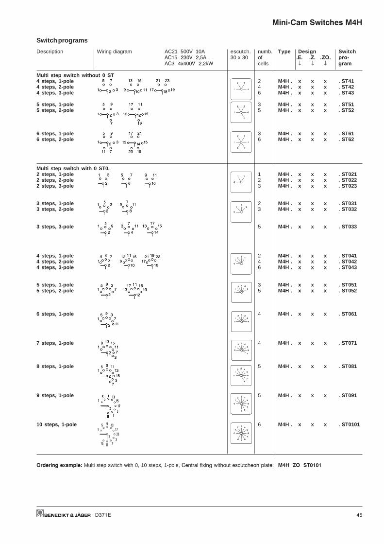
D371E 45
Switch programs
Description Wiring diagram AC21 500V 10A escutch. numb. Type Design SwitchAC15 230V 2,5A 30 x 30 of .E. .Z. .ZO. pro-AC3 4x400V 2,2kW cells ↓ ↓ ↓ gram
Multi step switch without 0 ST4 steps, 1-pole 2 M4H . x x x . ST414 steps, 2-pole 4 M4H . x x x . ST424 steps, 3-pole 6 M4H . x x x . ST43
5 steps, 1-pole 3 M4H . x x x . ST515 steps, 2-pole 5 M4H . x x x . ST52
6 steps, 1-pole 3 M4H . x x x . ST616 steps, 2-pole 6 M4H . x x x . ST62
Multi step switch with 0 ST0.2 steps, 1-pole 1 M4H . x x x . ST0212 steps, 2-pole 2 M4H . x x x . ST0222 steps, 3-pole 3 M4H . x x x . ST023
3 steps, 1-pole 2 M4H . x x x . ST0313 steps, 2-pole 3 M4H . x x x . ST032
3 steps, 3-pole 5 M4H . x x x . ST033
4 steps, 1-pole 2 M4H . x x x . ST0414 steps, 2-pole 4 M4H . x x x . ST0424 steps, 3-pole 6 M4H . x x x . ST043
5 steps, 1-pole 3 M4H . x x x . ST0515 steps, 2-pole 5 M4H . x x x . ST052
6 steps, 1-pole 4 M4H . x x x . ST061
7 steps, 1-pole 4 M4H . x x x . ST071
8 steps, 1-pole 5 M4H . x x x . ST081
9 steps, 1-pole 5 M4H . x x x . ST091
10 steps, 1-pole 6 M4H . x x x . ST0101
Ordering example: Multi step switch with 0, 10 steps, 1-pole, Central fixing without escutcheon plate: M4H ZO ST0101
Mini-Cam Switches M4H
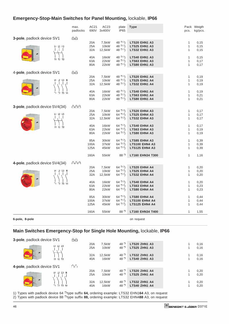
46 D371E
Emergency-Stop-Main Switches for Panel Mounting, lockable, IP66
max. AC21 AC23 plate Type Pack Weigthpadlocks 690V 3x400V IP65 pcs. kg/pcs.
3-pole , padlock device SV120A 7,5kW 48 1) LTS20 EHN1 A3 1 0,1525A 10kW 48 1) LTS25 EHN1 A3 1 0,1532A 12,5kW 48 1) LTS32 EHN1 A3 1 0,15
40A 16kW 48 1) LTS40 EHN1 A3 1 0,1563A 22kW 48 1) LTS63 EHN1 A3 1 0,1780A 22kW 48 1) LTS80 EHN1 A3 1 0,17
4-pole , padlock device SV120A 7,5kW 48 1) LTS20 EHN1 A4 1 0,1925A 10kW 48 1) LTS25 EHN1 A4 1 0,1932A 12,5kW 48 1) LTS32 EHN1 A4 1 0,19
40A 16kW 48 1) LTS40 EHN1 A4 1 0,1963A 22kW 48 1) LTS63 EHN1 A4 1 0,2180A 22kW 48 1) LTS80 EHN1 A4 1 0,21
3-pole , padlock device SV4(34)20A 7,5kW 64 2) LTS20 EHN4 A3 1 0,1725A 10kW 64 2) LTS25 EHN4 A3 1 0,1732A 12,5kW 64 2) LTS32 EHN4 A3 1 0,17
40A 16kW 64 2) LTS40 EHN4 A3 1 0,1763A 22kW 64 2) LTS63 EHN4 A3 1 0,1980A 22kW 64 2) LTS80 EHN4 A3 1 0,19
85A 30kW 64 2) LTS85 EHN4 A3 1 0,39100A 37kW 64 2) LTS100 EHN4 A3 1 0,39125A 45kW 64 2) LTS125 EHN4 A3 1 0,39
160A 55kW 88 LT160 EHN34 T300 1 1,16
4-pole , padlock device SV4(34)20A 7,5kW 64 2) LTS20 EHN4 A4 1 0,2025A 10kW 64 2) LTS25 EHN4 A4 1 0,2032A 12,5kW 64 2) LTS32 EHN4 A4 1 0,20
40A 16kW 64 2) LTS40 EHN4 A4 1 0,2063A 22kW 64 2) LTS63 EHN4 A4 1 0,2380A 22kW 64 2) LTS80 EHN4 A4 1 0,23
85A 30kW 64 2) LTS80 EHN4 A4 1 0,44100A 37kW 64 2) LTS100 EHN4 A4 1 0,44125A 45kW 64 2) LTS125 EHN4 A4 1 0,44
160A 55kW 88 LT160 EHN34 T400 1 1,55
6-pole, 8-pole on request
Main Switches Emergency-Stop for Single Hole Mounting, lockable, IP66
3-pole , padlock device SV120A 7,5kW 48 LTS20 ZHN1 A3 1 0,1625A 10kW 48 LTS25 ZHN1 A3 1 0,16
32A 12,5kW 48 LTS32 ZHN1 A3 1 0,1640A 16kW 48 LTS40 ZHN1 A3 1 0,16
4-pole , padlock device SV120A 7,5kW 48 LTS20 ZHN1 A4 1 0,2025A 10kW 48 LTS25 ZHN1 A4 1 0,20
32A 12,5kW 48 LTS32 ZHN1 A4 1 0,2040A 16kW 48 LTS40 ZHN1 A4 1 0,20
1) Types with padlock device 64 type suffix 64, ordering example: LTS32 EHN164 A3, on request2) Types with padlock device 88 type suffix 88, ordering example: LTS32 EHN488 A3, on request

D371E 47
Emergency-Stop-Main Switches, Base Mounting with Door Clutch, Padlock Device forSingle-Hole Mounting Depth X is adjustable (delivered with Xmax see page 50), IP66
max. AC21 AC23 plate Type Pack Weigthpadlocks 690V 3x400V IP65 pcs. kg/pcs.
3-pole , padlock device SV4 20A 7,5kW 64 LTS20 VZVHN4 A3 1 0,1925A 10kW 64 LTS25 VZVHN4 A3 1 0,1932A 12,5kW 64 LTS32 VZVHN4 A3 1 0,19
40A 16kW 64 LTS40 VZVHN4 A3 1 0,1963A 22kW 64 LTS63 VZVHN4 A3 1 0,2280A 22kW 64 LTS80 VZVHN4 A3 1 0,22
85A 30kW 64 LTS85 VZVHN4 A3 1 0,40100A 37kW 64 LTS100 VZVHN4 A3 1 0,40125A 45kW 64 LTS125 VZVHN4 A3 1 0,40
4-pole , padlock device SV4 20A 7,5kW 64 LTS20 VZVHN4 A4 1 0,2025A 10kW 64 LTS25 VZVHN4 A4 1 0,2032A 12,5kW 64 LTS32 VZVHN4 A4 1 0,20
40A 16kW 64 LTS40 VZVHN4 A4 1 0,2063A 22kW 64 LTS63 VZVHN4 A4 1 0,2680A 22kW 64 LTS80 VZVHN4 A4 1 0,26
85A 30kW 64 LTS85 VZVHN4 A4 1 0,45100A 37kW 64 LTS100 VZVHN4 A4 1 0,45125A 45kW 64 LTS125 VZVHN4 A4 1 0,45
6-pole , padlock device SV4 20A 7,5kW 64 LTS20 VZVHN4 A6 1 0,3225A 10kW 64 LTS25 VZVHN4 A6 1 0,3232A 12,5kW 64 LTS32 VZVHN4 A6 1 0,32
40A 16kW 64 LTS40 VZVHN4 A6 1 0,3263A 22kW 64 LTS63 VZVHN4 A6 1 0,3780A 22kW 64 LTS80 VZVHN4 A6 1 0,37
8-pole , padlock device SV4 20A 7,5kW 64 LTS20 VZVHN4 A8 1 0,3425A 10kW 64 LTS25 VZVHN4 A8 1 0,3432A 12,5kW 64 LTS32 VZVHN4 A8 1 0,34
40A 16kW 64 LTS40 VZVHN4 A8 1 0,3463A 22kW 64 LTS63 VZVHN4 A8 1 0,4580A 22kW 64 LTS80 VZVHN4 A8 1 0,45
in Switches, Base Mounting with Door Clutch, Padlock Device forFour-Hole Mounting Depth T is adjustable (delivered with Tmax see page 50), IP66
3-pole , padlock device SV4(SV34) 20A 7,5kW 64 LTS20 VHN4 A3 1 0,2025A 10kW 64 LTS25 VHN4 A3 1 0,2032A 12,5kW 64 LTS32 VHN4 A3 1 0,20
40A 16kW 64 LTS40 VHN4 A3 1 0,2063A 22kW 64 LTS63 VHN4 A3 1 0,2480A 22kW 64 LTS80 VHN4 A3 1 0,24
85A 30kW 64 LTS85 VHN4 A3 1 0,40100A 37kW 64 LTS100 VHN4 A3 1 0,40125A 45kW 64 LTS125 VHN4 A3 1 0,40
160A 55kW 88 LT160 VHN34 T300 1 1,38
4-pole , padlock device SV4(SV34) 20A 7,5kW 64 LTS20 VHN4 A4 1 0,2125A 10kW 64 LTS25 VHN4 A4 1 0,2132A 12,5kW 64 LTS32 VHN4 A4 1 0,21
40A 16kW 64 LTS40 VHN4 A4 1 0,2163A 22kW 64 LTS63 VHN4 A4 1 0,2880A 22kW 64 LTS80 VHN4 A4 1 0,28
85A 30kW 64 LTS85 VHN4 A4 1 0,45100A 37kW 64 LTS100 VHN4 A4 1 0,45125A 45kW 64 LTS125 VHN4 A4 1 0,45160A 55kW 88 LT160 VHN34 T400 1 1,77
6-pole, 8-pole on request
Emergency-Stop-Main Switches, Base Mounting with Door Clutch, Padlock Device forSingle-Hole Mounting Depth X is not adjustable, IP65 on request 1)
1) For order the installation depth X is necessary, see page 50, Preference value for X: 80, 85, 104, 129 (tolerance -3, +1,5)

48 D371E
PE
PE
PE
PE
Emergency-Stop-Main Switches for Distribution Boards, lockable IP40
max. AC21 AC23 plate Type Pack Weigthpadlocks 690V 3x400V IP65 pcs. kg/pcs.
3-pole , padlock device SV1 20A 7,5kW 52x45 LTS20 SMAHN1 A3 1 0,1525A 10kW 52x45 LTS25 SMAHN1 A3 1 0,1532A 12,5kW 52x45 LTS32 SMAHN1 A3 1 0,15
40A 16kW 52x45 LTS40 SMAHN1 A3 1 0,1563A 22kW 52x45 LTS63 SMAHN1 A3 1 0,1880A 22kW 52x45 LTS80 SMAHN1 A3 1 0,18
80A 30kW 78x45 LTS85 SMAHN1 A3 1 0,37100A 37kW 78x45 LTS100 SMAHN1 A3 1 0,37125A 45kW 78x45 LTS125 SMAHN1 A3 1 0,37
4-pole , padlock device SV1 20A 7,5kW 52x45 LTS20 SMAHN1 A4 1 0,1625A 10kW 52x45 LTS25 SMAHN1 A4 1 0,1632A 12,5kW 52x45 LTS32 SMAHN1 A4 1 0,16
40A 16kW 52x45 LTS40 SMAHN1 A4 1 0,1663A 22kW 52x45 LTS63 SMAHN1 A4 1 0,2180A 22kW 52x45 LTS80 SMAHN1 A4 1 0,21
80A 30kW 78x45 LTS85 SMAHN1 A3 1 0,42100A 37kW 78x45 LTS100 SMAHN1 A3 1 0,42125A 45kW 78x45 LTS125 SMAHN1 A3 1 0,42
6-pole , padlock device SV1(64) 20A 7,5kW 52x45 LTS20 SMAHN1 A6 1 0,2925A 10kW 52x45 LTS25 SMAHN1 A6 1 0,2932A 12,5kW 52x45 LTS32 SMAHN1 A6 1 0,29
40A 16kW 52x45 LTS40 SMAHN1 A6 1 0,2963A 22kW 97x45 LTS63 SMAHN1 A6 1) 1 0,3480A 22kW 97x45 LTS80 SMAHN1 A6 1) 1 0,34
8-pole , padlock device SV164 20A 7,5kW 97x45 LTS20 SMAHN1 A8 1 0,3125A 10kW 97x45 LTS25 SMAHN1 A8 1 0,3132A 12,5kW 97x45 LTS32 SMAHN1 A8 1 0,31
40A 16kW 97x45 LTS40 SMAHN1 A8 1 0,3163A 22kW 126x45 LTS63 SMAHN1 A8 1 0,4280A 22kW 126x45 LTS80 SMAHN1 A8 1 0,42
Maintenance and Safety Switches, in Plastic Enclosure, lockable, IP65
3-pole , padlock device SV4(SV34) 20A 7,5kW 64 LTS20 PFHN4 A3 1 0,3225A 10kW 64 LTS25 PFHN4 A3 1 0,3232A 12,5kW 64 LTS32 PFHN4 A3 1 0,32
40A 16kW 64 LTS40 PFHN4 A3 1 0,3263A 22kW 64 LTS63 PFHN4 A3 1 0,6080A 22kW 64 LTS80 PFHN4 A3 1 0,60
85A 30kW 64 LTS85 PFHN4 A3 1 0,78100A 37kW 64 LTS100 PFHN4 A3 1 0,78125A 45kW 64 LTS125 PFHN4 A3 1 0,78160A 55kW 88 LT160 PFHN34 T300 1 2,09
4-pole , padlock device SV4(SV34) 20A 7,5kW 64 LTS20 PFHN4 A4 1 0,3325A 10kW 64 LTS25 PFHN4 A4 1 0,3332A 12,5kW 64 LTS32 PFHN4 A4 1 0,33
40A 16kW 64 LTS40 PFHN4 A4 1 0,3363A 22kW 64 LTS63 PFHN4 A4 1 0,6480A 22kW 64 LTS80 PFHN4 A4 1 0,64
85A 30kW 64 LTS85 PFHN4 A4 1 0,83100A 37kW 64 LTS100 PFHN4 A4 1 0,83125A 45kW 64 LTS125 PFHN4 A4 1 0,83160A 55kW 88 LT160 PFHN34 T400 1 2,47
6-pole, 8-pole on request
Add-on modules (4th pole, aux. contacts, PE-terminal, terminal cover plates, escutcheon plates) see page 51
1) With padlock device SV164

D371E 49
Main Switches for Panel Mounting, lockable, IP66
max. AC21 AC23 plate Type Pack Weigthpadlocks 690V 3x400V IP65 pcs. kg/pcs.
3-pole , padlock device SV120A 7,5kW 48 1) LTS20 EH1 A3 1 0,1525A 10kW 48 1) LTS25 EH1 A3 1 0,1532A 12,5kW 48 1) LTS32 EH1 A3 1 0,15
40A 16kW 48 1) LTS40 EH1 A3 1 0,1563A 22kW 48 1) LTS63 EH1 A3 1 0,1780A 22kW 48 1) LTS80 EH1 A3 1 0,17
4-pole , padlock device SV120A 7,5kW 48 1) LTS20 EH1 A4 1 0,1925A 10kW 48 1) LTS25 EH1 A4 1 0,1932A 12,5kW 48 1) LTS32 EH1 A4 1 0,19
40A 16kW 48 1) LTS40 EH1 A4 1 0,1963A 22kW 48 1) LTS63 EH1 A4 1 0,2180A 22kW 48 1) LTS80 EH1 A4 1 0,21
6-pole, 8-pole , padlock device SV164 on request
3-pole , padlock device SV4(34)20A 7,5kW 64 2) LTS20 EH4 A3 1 0,1725A 10kW 64 2) LTS25 EH4 A3 1 0,1732A 12,5kW 64 2) LTS32 EH4 A3 1 0,17
40A 16kW 64 2) LTS40 EH4 A3 1 0,1763A 22kW 64 2) LTS63 EH4 A3 1 0,1980A 22kW 64 2) LTS80 EH4 A3 1 0,19
85A 30kW 64 2) LTS85 EH4 A3 1 0,39100A 37kW 64 2) LTS100 EH4 A3 1 0,39125A 45kW 64 2) LTS125 EH4 A3 1 0,39
160A 55kW 88 LT160 EHN34 T300 1 1,16
4-pole , padlock device SV4(34)20A 7,5kW 64 2) LTS20 EH4 A4 1 0,2025A 10kW 64 2) LTS25 EH4 A4 1 0,2032A 12,5kW 64 2) LTS32 EH4 A4 1 0,20
40A 16kW 64 2) LTS40 EH4 A4 1 0,2063A 22kW 64 2) LTS63 EH4 A4 1 0,2380A 22kW 64 2) LTS80 EH4 A4 1 0,23
85A 30kW 64 2) LTS80 EH4 A4 1 0,44100A 37kW 64 2) LTS100 EH4 A4 1 0,44125A 45kW 64 2) LTS125 EH4 A4 1 0,44
160A 55kW 88 LT160 EH34 T400 1 1,55
6-pole, 8-pole , padlock device SV4 on request
Add-on modules see page 51
1) Types with padlock device 64 type suffix 64, ordering example: LTS32 EH164 A3, on request2) Types with padlock device 88 type suffix 88, ordering example: LTS32 EH488 A3, on request

50 D371E
Main Switches, Base Mounting with Door Clutch, Padlock Device for Single-Hole MountingDepth X is adjustable (delivered with Xmax see below), IP66
max. AC21 AC23 plate Type Pack Weigthpadlocks 690V 3x400V IP65 pcs. kg/pcs.
3-pole , padlock device SV4 20A 7,5kW 64 LTS20 VZVH4 A3 1 0,1925A 10kW 64 LTS25 VZVH4 A3 1 0,1932A 12,5kW 64 LTS32 VZVH4 A3 1 0,19
40A 16kW 64 LTS40 VZVH4 A3 1 0,1963A 22kW 64 LTS63 VZVH4 A3 1 0,2280A 22kW 64 LTS80 VZVH4 A3 1 0,22
85A 30kW 64 LTS85 VZVH4 A3 1 0,40100A 37kW 64 LTS100 VZVH4 A3 1 0,40125A 45kW 64 LTS125 VZVH4 A3 1 0,40
4-pole , padlock device SV4 20A 7,5kW 64 LTS20 VZVH4 A4 1 0,2025A 10kW 64 LTS25 VZVH4 A4 1 0,2032A 12,5kW 64 LTS32 VZVH4 A4 1 0,20
40A 16kW 64 LTS40 VZVH4 A4 1 0,2063A 22kW 64 LTS63 VZVH4 A4 1 0,2680A 22kW 64 LTS80 VZVH4 A4 1 0,26
85A 30kW 64 LTS85 VZVH4 A4 1 0,45100A 37kW 64 LTS100 VZVH4 A4 1 0,45125A 45kW 64 LTS125 VZVH4 A4 1 0,45
6-pole, 8-pole on request
Main Switches, Base Mounting with Door Clutch, Padlock Device for Four-Hole MountingDepth T is adjustable (delivered with Tmax see below), IP66
3-pole , padlock device SV4(SV34) 20A 7,5kW 64 LTS20 VH4 A3 1 0,2025A 10kW 64 LTS25 VH4 A3 1 0,2032A 12,5kW 64 LTS32 VH4 A3 1 0,20
40A 16kW 64 LTS40 VH4 A3 1 0,2063A 22kW 64 LTS63 VH4 A3 1 0,2480A 22kW 64 LTS80 VH4 A3 1 0,24
85A 30kW 64 LTS85 VH4 A3 1 0,40100A 37kW 64 LTS100 VH4 A3 1 0,40125A 45kW 64 LTS125 VH4 A3 1 0,40160A 55kW 88 LT160 VH34 T300 1 1,38
4-pole, 6-pole, 8-pole on request
DepthLTS.. VZV.. LTS.. V(HN).. (3, 4-pole)
Type X min X max L Type T min T max L Type T min T max
LTS20-80 VZV.. 3, 4-pole 91 - 190 X - 40±3 LTS20-80 VH.. 111 - 190 T - 60±3 LT160 VH.. 120 - 450LTS20-80 VZV.. 6, 8-pole 111 - 190 X - 60±3 LTS85-125 VH.. 115 - 190 T - 64±3LTS85-125 VZV.. 3, 4-pole 95- 190 X - 44±3
greater X- and T-Dimensions (max. 380mm for LTS..) on request
Ordering Dimension X Ordering Dimension T

D371E 51
N
N
Add-on Modules for main switches and Switch Disconnectors
for switch for designs Type Pack Weightpanel- base- distrib.mounting boards pcs. kg/pcs
4th add-on neutral switching pole
LTS20 to LTS40 x - - N40E 1 0,035LTS63 to LTS80 x - - N80E 1 0,042LTS20 to LTS40 - x x N40V 1 0,035LTS63 to LTS80 - x x N80V 1 0,042
Aux. contact block 1NO + 1NC
LTS20 to LTS125 x x x LH11 1 0,02
Aux. contact block 1NO + 1NC overlapping
LTS20 to LTS125 x x x LH11X 1 0,02
PE-Terminal
LTS20 to LTS80 x - - PE80E 1 0,04LT160 x - - LTXX-E/E 1 0,2
LTS20 to LTS80 - x - PE80V 1 0,04LT160 - x - LTXX-E/V 1 0,2
N-Terminal
LTS20 to LTS80 x - - PEN80E 1 0,04LT160 x - - LTXX-N/E 1 0,2
LTS20 to LTS80 - x - PEN80V 1 0,04LT160 - x - LTXX-N/V 1 0,2
Additional escutcheon plate yellow marked with: HAUPTSCHALTER
48mm LTS.. .HN1.. x x - A91501 1 0,00364mm LTS.. .HN4.. x x - E91501 1 0,005
Additional escutcheon plate yellow marked with: MAIN SWITCH
48mm LTS.. .HN1.. x x - A91524 1 0,00364mm LTS.. .HN4.. x x - E91524 1 0,005
Terminal cover plate 3-pole
LTS20 to LTS40 - x x KLAD40 1 0,005LTS20 bis LTS40 x - - KLAD70 1 0,005LTS63 to LTS80 x x x KLAD70 1 0,005LTS85 to LTS125 x x x KLAD125 1 0,01LT125 to LT160 x x - XX-KLAD3 1 0,02
Terminal cover plate for 4. Pole
Mains LTS63 to LTS80 x x x KLAD70N 1 0,002Load circuit LTS63 to LTS80 x x x KLAD70N1 1 0,002
Terminal cover plate 4-pole
LTS20 to LTS40 - x x KLAD40 1 0,005LTS85 to LTS125 x x x KLAD125 1 0,01LT125 to LT160 x x - XX-KLAD4 1 0,02
Flat Terminal 6,3 x 0,8mm
LTS20 to LTS40 - x x LG11073 10 0,001

52 D371E
Main Switches for panel mounting, Cam Switches
with withoutAC21 AC23 Plate Emergency-Off Emergency-Off
A kW Type Type
2-polig 20 7,5 48 M10H EHN1 A2+731 M10H EH1 A2+7313-polig 20 7,5 48 M10H EHN1 A3+731 M10H EH1 A3+7314-polig 20 7,5 48 M10H EHN1 A4+731 M10H EH1 A4+7316-polig 20 7,5 48 M10H EHN1 A6+731 M10H EH1 A6+731
3-polig 63 22 88 N40 EHN3 A3 N40 EH3 A380 30 88 N60 EHN3 A3 N60 EH3 A3
115 45 88 N80 EHN3 A3 N80 EH3 A3
150 55 132 N100 EHN3 A3 N100 EH3 A3250 70 132 N200 EHN3 A3 N200 EH3 A3
4-polig 63 22 88 N40 EHN3 A4 N40 EH3 A480 30 88 N60 EHN3 A4 N60 EH3 A4
115 45 88 N80 EHN3 A4 N80 EH3 A4
150 55 132 N100 EHN3 A4 N100 EH3 A4250 70 132 N200 EHN3 A4 N200 EH3 A4
6-polig 63 22 88 N40 EHN3 A6 *) N40 EH3 A6 *)80 30 88 N60 EHN3 A6 *) N60 EH3 A6 *)
115 45 88 N80 EHN3 A6 *) N80 EH3 A6 *)
150 55 132 N100 EHN3 A6 *) N100 EH3 A6 *)250 70 132 N200 EHN3 A6 *) N200 EH3 A6 *)
3-polig 20 7,5 64 M10H EHN4 A3 M10H EH4 A332 15 64 N20 EHN4 A3 N20 EH4 A350 22 64 N33F EHN4 A3 N33F EH4 A3
63 22 88 N40 EHN4 A3 N40 EH4 A380 30 88 N60 EHN4 A3 N60 EH4 A3
115 45 88 N80 EHN4 A3 N80 EH4 A3
4-polig 20 7,5 64 M10H EHN4 A4 M10H EH4 A432 15 64 N20 EHN4 A4 N20 EH4 A450 22 64 N33F EHN4 A4 N33F EH4 A4
63 22 88 N40 EHN4 A4 N40 EH4 A480 30 88 N60 EHN4 A4 N60 EH4 A4
115 45 88 N80 EHN4 A4 N80 EH4 A4
6-polig 20 7,5 64 M10H EHN4 A6 M10H EH4 A632 15 64 N20 EHN4 A6 *) N20 EH4 A6 *)50 22 64 N33F EHN4 A6 N33F EH4 A6
63 22 88 N40 EHN4 A6 *) N40 EH4 A6 *)80 30 88 N60 EHN4 A6 *) N60 EH4 A6 *)
115 45 88 N80 EHN4 A6 *) N80 EH4 A6 *)
*) Main terminal protection must be installed by user.
Switches with other switch programs, auxiliary contacts, PE-terminals on request
Main Switches for base mounting
Like main switches for panel mounting Depth T is necessary for orderThe order number changes fromN.. E.. A. to N.. V.. A.
We recommend to use a door coupling , see page 64
Maintenance and Safety Switches, plastic enclosed on request

D371E 53
Switch Disconnectors for Panel Mounting, IP65
AC21 AC23 plate Type Pack Weigth690V 3x400V IP65 pcs. kg/pcs.
On-Off Switches 3-pole20A 7,5kW 48 LTS20 E A3 1 0,1525A 10kW 48 LTS25 E A3 1 0,1532A 12,5kW 48 LTS32 E A3 1 0,15
40A 16kW 48 LTS40 E A3 1 0,1563A 22kW 48 LTS63 E A3 1 0,1780A 22kW 48 LTS80 E A3 1 0,17
85A 30kW 64 LTS85 E A3 1 0,39100A 37kW 64 LTS100 E A3 1 0,39125A 45kW 64 LTS125 E A3 1 0,39
160A 55kW 88 LT160 E T300 1 1,10
On-Off Switches 4-pole20A 7,5kW 48 LTS20 E A4 1 0,1825A 10kW 48 LTS25 E A4 1 0,1832A 12,5kW 48 LTS32 E A4 1 0,18
40A 16kW 48 LTS40 E A4 1 0,1863A 22kW 48 LTS63 E A4 1 0,2180A 22kW 48 LTS80 E A4 1 0,21
85A 30kW 64 LTS85 E A4 1 0,44100A 37kW 64 LTS100 E A4 1 0,44125A 45kW 64 LTS125 E A4 1 0,44
160A 55kW 88 LT160 E T400 1 1,50
6-pole, 8-pole on requestChangeover 3-pole, 4-pole on request
Switch Disconnectors for Distribution Boards
AC21 AC23 plate Type Pack Weigth690V 3x400V IP65 pcs. kg/pcs.
On-Off Switches 3-pole20A 7,5kW 52x45 LTS20 SMA A3 1 0,1525A 10kW 52x45 LTS25 SMA A3 1 0,1532A 12,5kW 52x45 LTS30 SMA A3 1 0,15
40A 16kW 52x45 LTS40 SMA A3 1 0,1563A 22kW 52x45 LTS63 SMA A3 1 0,1780A 22kW 52x45 LTS80 SMA A3 1 0,17
85A 30kW 78x45 LTS85 SMA A3 1 0,37100A 37kW 78x45 LTS100 SMA A3 1 0,37125A 45kW 78x45 LTS125 SMA A3 1 0,37
On-Off Switches 4-pole20A 7,5kW 52x45 LTS20 SMA A4 1 0,1625A 10kW 52x45 LTS25 SMA A4 1 0,1632A 12,5kW 52x45 LTS32 SMA A4 1 0,16
40A 16kW 52x45 LTS40 SMA A4 1 0,1663A 22kW 52x45 LTS63 SMA A4 1 0,2180A 22kW 52x45 LTS80 SMA A4 1 0,21
85A 30kW 78x45 LTS85 SMA A4 1 0,42100A 37kW 78x45 LTS100 SMA A4 1 0,42125A 45kW 78x45 LTS125 SMA A4 1 0,42
6-pole, 8-pole on requestChangeover 3-pole, 4-pole on request
Switch Disconnectors for Base mounting on request
Add-on modules (4th pole, aux. contacts, PE-terminal, terminal cover plates, escutcheon plates) see page 51

54 D371E
- Switch Disconnectors, Load Switches
For switches with the design V.. it is necessary to statethe installation depth - that is, the distance betweenmounting level of the switch and the inside edge of thedoor (dimension T).
Further informations page
Technical Data 76Dimensions 85
On-Off-switches A
Description Wiring diagram Switching angle Number of cells Type Design Switch Escutcheon↓ Size .E. .V. pro- plate
↓ AC21 ↓ ↓ gram
Load Switches for resistive or slightly inductive loads or switching without load
1-pole 60° 2 88 125A L100 . x x . A11 180A L160 . x x . A1
1 132 400A L400 . x x . A13 600A L600 . x x . A12 800A L800 . x x . A13 1200A L1200 . x x . A1
2-pole 60° 2 88 125A L100 . x x . A22 180A L160 . x x . A2
2 132 400A L400 . x x . A23 600A L600 . x x . A24 800A L800 . x x . A26 1200A L1200 . x x . A2
3-pole 60° 4 88 125A L100 . x x . A33 180A L160 . x x . A3
3 132 400A L400 . x x . A36 600A L600 . x x . A36 800A L800 . x x . A39 1200A L1200 . x x . A3
4-pole 60° 4 88 125A L100 . x x . A44. pole early make 4 180A L160 . x x . A4
4 132 400A L400 . x x . A46 600A L600 . x x . A48 800A L800 . x x . A412 1200A L1200 . x x . A4
6-pole 60° 6 88 125A L100 . x x . A66 180A L160 . x x . A6
6 132 400A L400 . x x . A69 600A L600 . x x . A612 800A L800 . x x . A618 1200A L1200 . x x . A6
Switch Disconnectors in Plastic Enclosure, IP65
AC21 AC23 plate Type Pack Weigth690V 3x400V IP65 pcs. kg/pcs.
On-Off Switches 3-pole20A 7,5kW 64 LTS20 PF A3 1 0,3025A 10kW 64 LTS25 PF A3 1 0,3032A 12,5kW 48 LTS32 PF A3 1 0,30
40A 16kW 64 LTS40 PF A3 1 0,3063A 22kW 64 LTS63 PF A3 1 0,5880A 22kW 64 LTS80 PF A3 1 0,58
On-Off Switches 4-pole20A 7,5kW 64 LTS20 PF A4 1 0,3125A 10kW 64 LTS25 PF A4 1 0,3132A 12,5kW 64 LTS32 PF A4 1 0,31
40A 16kW 64 LTS40 PF A4 1 0,3163A 22kW 64 LTS63 PF A4 1 0,6280A 22kW 64 LTS80 PF A4 1 0,62
PE
PE
PE
PE

D371E 55
Description Wiring diagram Switching angle Number of cells Type Design Switch Escutcheon↓ Size .E. .V. pro- plate
↓ AC21 ↓ ↓ gram
Load Switches for resistive or slightly inductive loads or switching without load
Changeover switches U
1-pole 60° 2 88 125A L100 . x x . U12 180A L160 . x x . U1
2 132 400A L400 . x x . U13 600A L600 . x x . U14 800A L800 . x x . U16 1200A L1200 . x x . U1
2-pole 60° 4 88 125A L100 . x x . U24 180A L160 . x x . U2
4 132 400A L400 . x x . U26 600A L600 . x x . U28 800A L800 . x x . U212 1200A L1200 . x x . U2
3-pole 60° 6 88 125A L100 . x x . U36 180A L160 . x x . U3
6 132 400A L400 . x x . U39 600A L600 . x x . U312 800A L800 . x x . U318 1200A L1200 . x x . U3
4-pole 60° 8 88 125A L100 . x x . U44. pole early make 8 180A L160 . x x . U4
8 132 400A L400 . x x . U412 600A L600 . x x . U416 800A L800 . x x . U424 1200A L1200 . x x . U4
Changeover switches without off W
Ordering example: AC1 1200A panel mounting, changeover switch without off 4-pole L1200 E W4
1-pole 60° 2 88 125A L100 . x x . W12 180A L160 . x x . W1
2 132 400A L400 . x x . W13 600A L600 . x x . W14 800A L800 . x x . W16 1200A L1200 . x x . W1
2-pole 60° 4 88 125A L100 . x x . W24 180A L160 . x x . W2
4 132 400A L400 . x x . W26 600A L600 . x x . W28 800A L800 . x x . W212 1200A L1200 . x x . W2
3-pole 60° 6 88 125A L100 . x x . W36 180A L160 . x x . W3
6 132 400A L400 . x x . W39 600A L600 . x x . W312 800A L800 . x x . W318 1200A L1200 . x x . W3
4-pole 60° 8 88 125A L100 . x x . W44. pole early make 8 180A L160 . x x . W4
8 132 400A L400 . x x . W412 600A L600 . x x . W416 800A L800 . x x . W424 1200A L1200 . x x . W4
- Load Switches

56 D371E
Operating Knobs and Handles
All operating knobs can be moved on the hexagonal shaft, to permitadaptation to different sheet thicknesses, etc.
Type N100N40 N200N60 L400
M10 N80 L600M10H N20 L100 L800M20 N33F L160 L1200
Knob movement mm 5 5 7 9Hexagonal shaft dimension mm 5 7 9 12
Ordering example: Cam switch N60 V U3 with ball type handle redOrder type: N60 V U3 +B3Dimensions see page 84
Types of handles
In the standard version, the switches are supplied with a black twistknob or instrument knob (M10H - N33F), except for design SMA, whichhas a grey toggle knob. Switches of size L, which consist of 2 or 3 switchcolumns, come with a black hand wheel. If required, the switch can besupplied with other knobs, which can later easily be exchanged.All operating knobs have an insert, which sets the position of the knobin relation to the switch shaft. This insert can be mounted in 8 differentpositions (at intervals of 45°), causing the angle of each individualswitch setting to be rotated by 45°.
In the standard version, theswitch terminals are positio-ned left and right (exceptM10H). When the knob insertis turned by 90°, the lay-outof the terminals changes totop and bottom.
N100N40 N200N60 L400
M10 N80 L600Knobs and handles Ordering M10H N20 L100 L800Description Colour Code M20 N33F L160 L1200
Instrument knob grey +G1 X XStandard for M10 to N33F black +G2 X X
red +G3 X Xwhite +G5 X X
Twist knob grey +R1 X X X XStandard for N40 to N200 black +R2 X X X X
red +R3 X X X Xwhite +R5 X X Xyellow +R7 X X
Toggle knob grey +K1 X Xblack +K2 X Xred +K3 X Xwhite +K5 X Xblue +K6 X
Ball type handle grey +B1 X X Xblack +B2 X X Xred +B3 X X X
Hand wheel black +HR X
- Cam Switches

- Cam Switches
D371E 57
Escutcheon Plates
TELUX-Cam Switches in designs E, V, P, PF, SM, UP, Z and KE aresupplied with a square escutcheon plate consisting of a black frameand plexi insert plate. The markings are printed in black are on the backof the insert plate. To protect the markings so that they remain easyto read, the back of the insert plate is lined with silver foil. In addition,rectangular plates can be provided for all switch sizes, which can fittedon all switches after mounting.
Square plate Rectangular plate(with square plate)
TELUX-Cam Switches in design SMA, for distribution boards with45mm inside edge of installation cover, is supplied with a grey coverand black markings.
Special engraved markings on escutcheon plates are limited by theavailable space. In the case of relatively large production runs orfrequent use of the text, we recommend ordering of a printing block.This will be invoiced at cost price, and the engraving will not becharged for. This investment generally pays with batches from 50pieces upwards.The "escutcheon plate" column of the selection and ordering tables forswitch programs indicates the standard plate and, in some cases, anadditional plate that is often used for the programs in question. If sucha plate, listed in the selection table, is desired, the appropriate codenumber should be stated when ordering a switch and switch program.
Should only plates or parts of the latter be ordered, the order type isassembled as shown by the following example.
Code letter of switch sizes
M10, M10H, M20 AN20, N33F EN40, N60, N80, L100, L160 HN100, N200, L400, L600, L800, L1200 L
Ordering example: Escutcheon plate silver, complete, for camswitch M10, marked with MAN OFF AUTO, angle of rotation 60°
Order type:
However, if a switch with non-standard lettering is required, onlythree-digit code number for the marking need be added to the ordertype (see next page).
Dimensions see page 86
Description Order typeSwitch size Plate MarkingCode letter Art.No. Code number
Escutcheon plate for designs E, V, P., Z, SM, KE and UPEscutcheon frame black, plexi insert plate silver, markings black
Escutcheon plate complete silver A E H L .82... ... (see pp. 58-60)
Escutcheon plate complete yellow A E H L .90... ... (see pp. 58-60)
Plexi insert plate silver A E H L .85... ... (see pp. 58-60)
Plexi insert plate yellow A E H L .80... ... (see pp. 58-60)
Escutcheon frame black A E H L .8203 -
Rectangular escutcheon plate for designs E, V, Z and SMEscutcheon frame black, plexi insert plate silver, markings black
Rectangular additional escutcheon plate complete silver A E H L .865.. ... (see pp. 58-60)
Rectangular additional escutcheon plate complete yellow A E H L .915.. ... (see pp. 58-60)
Plexi insert plate silver A E H L .885.. ... (see pp. 58-60)
Plexi insert plate yellow A E H L .895.. ... (see pp. 58-60)
Escutcheon frame black A E H L .8503 -
Installation cover for design SMA
grey cover , markings black A - - - .68... ... (see page 60)
A82088
Switch size Plate Marking
Code letter Art.No. for Code number
for M10, M10H standard plate with label
and M20 with markings, MAN OFF AUTO
complete angle of rot. 60°
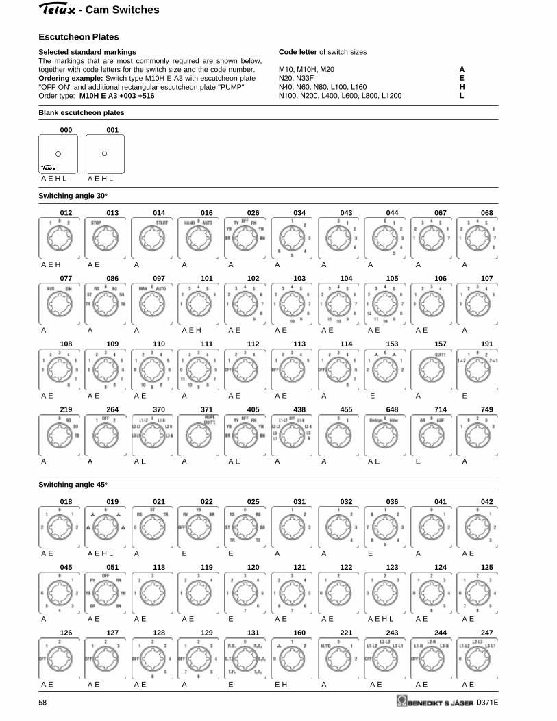
- Cam Switches
58 D371E
Escutcheon Plates
Code letter of switch sizes
M10, M10H, M20 A
N20, N33F E
N40, N60, N80, L100, L160 H
N100, N200, L400, L600, L800, L1200 L
Selected standard markingsThe markings that are most commonly required are shown below,together with code letters for the switch size and the code number.Ordering example: Switch type M10H E A3 with escutcheon plate"OFF ON" and additional rectangular escutcheon plate "PUMP"Order type: M10H E A3 +003 +516
Blank escutcheon plates
000 001
A E H L A E H L
Switching angle 30 o
012 013 014 016 026 034 043 044 067 068
A E H A E A A A A A A A A
077 086 097 101 102 103 104 105 106 107
A A A A E H A E A E A E A E A E A
108 109 110 111 112 113 114 153 157 191
A E A E A E A A E A E A E A E
219 264 370 371 405 438 455 648 714 749
A A A E A A E A A A E E A
Switching angle 45 o
018 019 021 022 025 031 032 036 041 042
A E A E H L A E E A A E A A E
045 051 118 119 120 121 122 123 124 125
A A E A E A E E A E A E A E H L A E A E
126 127 128 129 131 160 221 243 244 247
A E A E A E A E E H A A E A E A E

- Cam Switches
D371E 59
Escutcheon Plates
Switching angle 45 o
248 249 250 303 304 336 412 421 423
A A E A E A E A A A E A E
Switching angle 60 o
002 003 004 006 007 008 009 010 011 015
A E H L A E H L A E H L A E H L A E H L A A A E H L A E H L A E
081 082 088 095 132 133 134 136 140 143
A E A E A E H A E A E H A E A E A A A
162 163 166 175 185 186 195 211 241 251
A E A E A E H L A A E E H L A A E
252 266 273 277 279 292 334 338 355 408
A A E A A A E H A A A E A A
416 417 418 419 420 422 439 446 448 489
A E A E A E A E A E A E A A E A A
634 635 636 675 699 702 706 739 798
A A A E H A A H A A A

- Cam Switches
60 D371E
Escutcheon Plates
Switching angle 90 o
028 029 030 056 083 087 089 144 145 217
A E A E A E A A E H L A E A E A E H E A
230 246 270 330
A E A E A A
Miscellaneous
020 054 071 092 147 148 149 172 225 289
E A A E A E H A E E A E A A
760
A
Rectangular additional escutcheon plates
500 501 503 504 505 506 509 519 520 524
A E H L A E A E A E A A E A E E A E
534 535 542 543 546 549 550 551 552 556
A A A E A A A A A A E E
557
A
Covers for design SMA
001 002 003 004 006 009 012 013 014 015
028 81 82 106 111 122 123 132 143 221
234 243 355 370 416 417 420 636 637 717
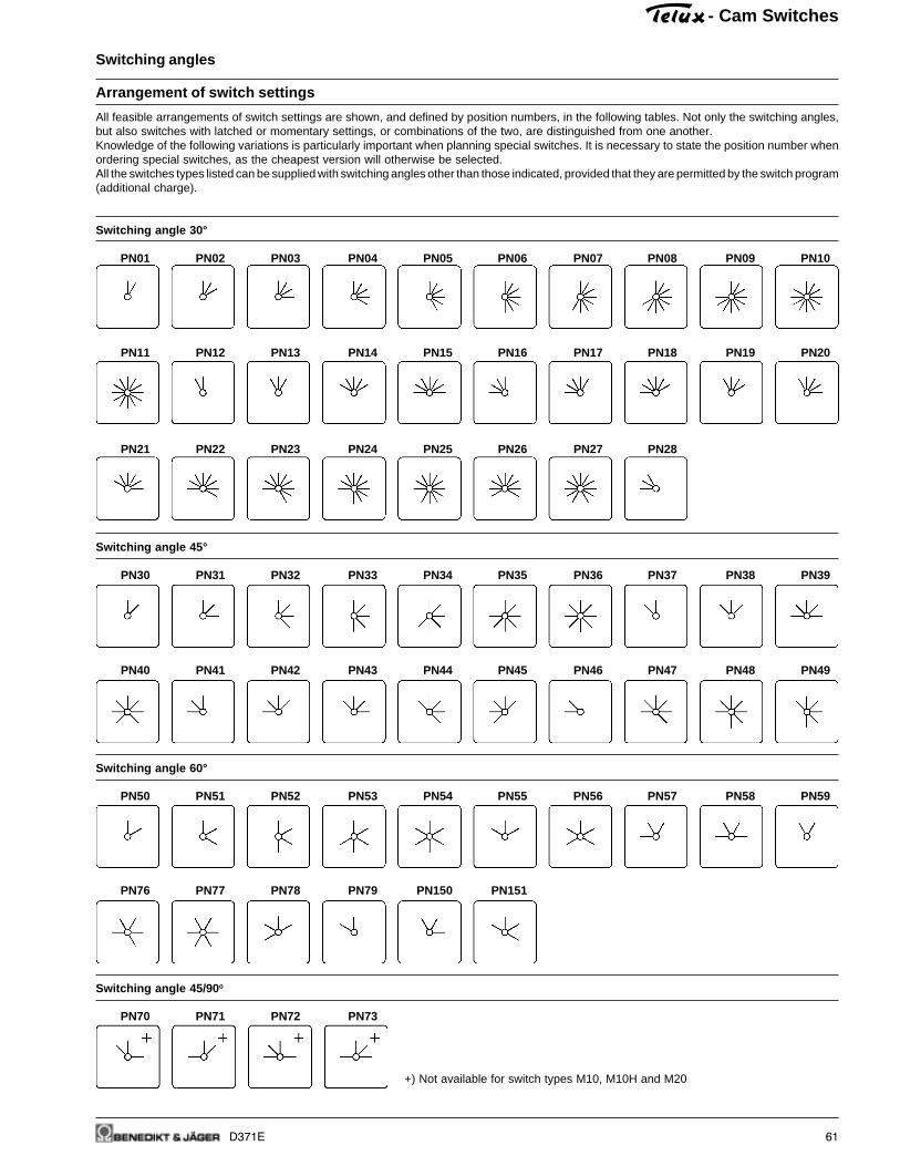
- Cam Switches
D371E 61
Switching angles
Arrangement of switch settings
All feasible arrangements of switch settings are shown, and defined by position numbers, in the following tables. Not only the switching angles,but also switches with latched or momentary settings, or combinations of the two, are distinguished from one another.Knowledge of the following variations is particularly important when planning special switches. It is necessary to state the position number whenordering special switches, as the cheapest version will otherwise be selected.All the switches types listed can be supplied with switching angles other than those indicated, provided that they are permitted by the switch program(additional charge).
Switching angle 30°
PN01 PN02 PN03 PN04 PN05 PN06 PN07 PN08 PN09 PN10
PN11 PN12 PN13 PN14 PN15 PN16 PN17 PN18 PN19 PN20
PN21 PN22 PN23 PN24 PN25 PN26 PN27 PN28
Switching angle 45°
PN30 PN31 PN32 PN33 PN34 PN35 PN36 PN37 PN38 PN39
PN40 PN41 PN42 PN43 PN44 PN45 PN46 PN47 PN48 PN49
Switching angle 60°
PN50 PN51 PN52 PN53 PN54 PN55 PN56 PN57 PN58 PN59
PN76 PN77 PN78 PN79 PN150 PN151
Switching angle 45/90 o
PN70 PN71 PN72 PN73
+) Not available for switch types M10, M10H and M20
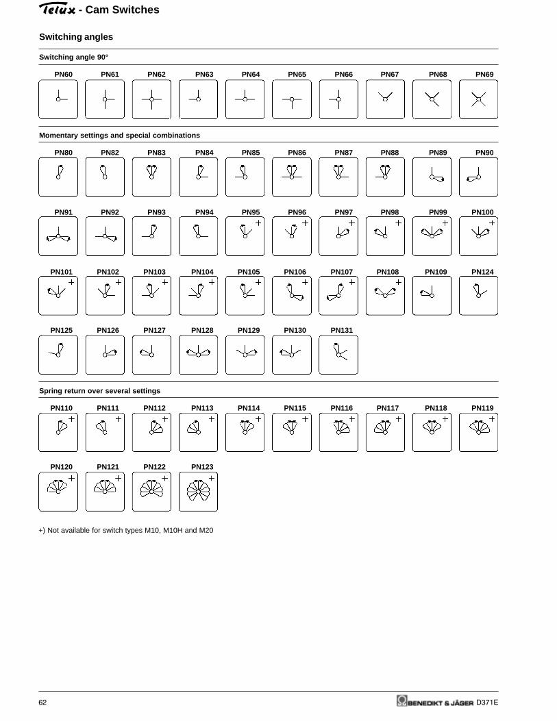
- Cam Switches
62 D371E
Switching angles
+) Not available for switch types M10, M10H and M20
Switching angle 90°
PN60 PN61 PN62 PN63 PN64 PN65 PN66 PN67 PN68 PN69
Momentary settings and special combinations
PN80 PN82 PN83 PN84 PN85 PN86 PN87 PN88 PN89 PN90
PN91 PN92 PN93 PN94 PN95 PN96 PN97 PN98 PN99 PN100
PN101 PN102 PN103 PN104 PN105 PN106 PN107 PN108 PN109 PN124
PN125 PN126 PN127 PN128 PN129 PN130 PN131
Spring return over several settings
PN110 PN111 PN112 PN113 PN114 PN115 PN116 PN117 PN118 PN119
PN120 PN121 PN122 PN123

- Cam Switches
D371E 63
Handles and drive unitsSpecial actuating mechanisms and ancillary attachments can beprovided for many switch sizes and designs. Here, the switch type isfollowed by order code for the ancillary attachment.
Dimensions see page 87
Removable knob driveThe operating knob is designed to beremovable, and can be withdrawn in anysetting. The switch shaft is coveredwhen the knob is withdrawn.
Removable knob drive 2The operating knob is designed to beremovable. It can be withdrawn in onesetting, to be stated when ordering.
Ordering Suitable Suitable forCode for designs switch type
+STGR E M10H, M20, N20, N33FP M10, N20, N33F
+STGR2 E M10H, M20, N20, N33FP M10, N20, N33F
Ordering example: Cam switch N20 GF W3R for foot operationOrder type: N20 GF W3R +FUSS1
1) Cast enclosed switches are delivered with switch type N32

- Cam Switches
64 D371E
Door couplingsDoor couplings are available for switches to be installed in switchgearcabinets or distribution boards with hinged doors. These permit thedoors to be openened without removal of the operating knobs.
Ordering example: Cam switch N100 V A3 with lockable door cou-pling, moisture protected IP65, dimension T=580mmOrder type: N100 V A3 +TK2FR/580
Dimensions see page 88
For switches with door couplings it is necessary to state the installation
depth - that is, the distance between mounting level of the switch and
the inside edge of the door (dimension T).
Ordering Suitable Suitable forCode for designs switch type
+TKE/... V, SM M10H, M20, N20, N33F
+TK2E/... V, SM M10H, M20, N20, N33F
+TK2Z/... V, SM M10H, M20, N20, N33F
+TK/... V N40, N60, N80, N100, N200L100, L160, L400, L600L800
+TKFR/... V N40, N60, N80, N100, N200L100, L160, L400, L600L800
+TK2/... V N40, N60, N80, N100, N200L100, L160, L400, L600L800
+TK2FR/... V N40, N60, N80, N100, N200L100, L160, L400, L600L800
Door couplingProtection class from front: IP655-hole mounting
Door coupling lockedProtection class from front: IP655-hole mountingDoors only open at a given switch set-ting: unless otherwise stated, the "OFF"setting.
Door coupling lockedProtection class from front: IP65Central fixing Ø22mmDoors only open at a given switch set-ting: unless otherwise stated, the "OFF"setting.
Door couplingProtection class from front: IP405-hole mounting
Door couplingProtection class from front: IP655-hole mounting
Door coupling lockedProtection class from front: IP405-hole mountingDoors only open at a given switch set-ting: unless otherwise stated, the "OFF"setting.
Door coupling lockedProtection class from front: IP655-hole mountingDoors only open at a given switch set-ting: unless otherwise stated, the "OFF"setting.

- Cam Switches
D371E 65
Lockable switchesOrdering example: Cam switch N20 E A3 key operatedOrder type: N20 E A3 +SA
Dimensions see page 89 and 90
Key-operated and lockable switches are supplied with two keys.Additional keys or other types of lock on request.
Ordering Suitable Suitable forCode for designs switch type
+SA E, V, SM M10H, M20, N20, N33F
E, V N40, N60P M10, N20, N33F, N40, N60SMA M10H, M20
UP M10
+SA/.
+SA Z, ZO M10H, M20
+SA/.
+SAK E M10H, M20
+SAK/.
+SASI E M10H, M20
P M10, M20
UP M10, M20
+SASO E M10H, M20
P M10, M20
UP M10, M20
Key operated switchLock Willenhal FT101, key removable inall lockable settings.Other types of lock on request.Maximum number of cellsM10 - N33F: 6 N40, N60: 2Key operated switch, key removableonly in some settings. Add letter of settingwhere key is removable to ordering codeaccording to the scetch belove.
Key operated switch IP65Lock Ronis R455, key removable in alllockable settings.Key operated switch, key removableonly in some settings. Add letter of settingwhere key is removable to ordering codeaccording to the scetch above.
Key operated switchLock KABA8, key removable in alllockable settings.Key operated switch, key removableonly in some settings. Add letter of settingwhere key is removable to ordering codeaccording the scetch belove.
Key operated switch with barrelfor special security functionsLock EVVA EHZ50/5 Nickel mattSpecial version which prevents not onlyswitching but also access to the cableends and removal of the switch whenlocked.Maximum number of cellsDesign E, P: 4Design UP : 3
Key operated switch for specialsecurity functions without lockfor use of lock EVVA EHZ50/5 or withsame dimensionsMaximum number of cellsDesign E, P: 4Design UP : 3
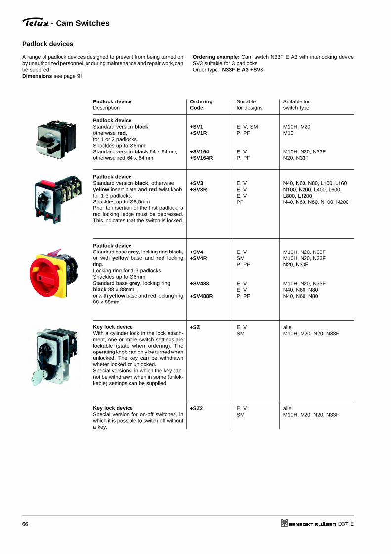
- Cam Switches
66 D371E
Padlock devices
A range of padlock devices designed to prevent from being turned onby unauthorized personnel, or during maintenance and repair work, canbe supplied.Dimensions see page 91
Ordering example: Cam switch N33F E A3 with interlocking deviceSV3 suitable for 3 padlocksOrder type: N33F E A3 +SV3
Padlock deviceDescription
Padlock deviceStandard version black ,otherwise red ,for 1 or 2 padlocks.Shackles up to Ø6mmStandard version black 64 x 64mm,otherwise red 64 x 64mm
Padlock deviceStandard version black , otherwiseyellow insert plate and red twist knobfor 1-3 padlocks.Shackles up to Ø8,5mmPrior to insertion of the first padlock, ared locking ledge must be depressed.This indicates that the switch is locked.
Padlock deviceStandard base grey , locking ring black ,or with yellow base and red lockingring.Locking ring for 1-3 padlocks.Shackles up to Ø6mmStandard base grey , locking ringblack 88 x 88mm,or with yellow base and red locking ring88 x 88mm
Key lock deviceWith a cylinder lock in the lock attach-ment, one or more switch settings arelockable (state when ordering). Theoperating knob can only be turned whenunlocked. The key can be withdrawnwheter locked or unlocked.Special versions, in which the key can-not be withdrawn when in some (unlok-kable) settings can be supplied.
Key lock deviceSpecial version for on-off switches, inwhich it is possible to switch off withouta key.
Ordering Suitable Suitable forCode for designs switch type
+SV1 E, V, SM M10H, M20+SV1R P, PF M10
+SV164 E, V M10H, N20, N33F+SV164R P, PF N20, N33F
+SV3 E, V N40, N60, N80, L100, L160
+SV3R E, V N100, N200, L400, L600,
E, V L800, L1200
PF N40, N60, N80, N100, N200
+SV4 E, V M10H, N20, N33F+SV4R SM M10H, N20, N33F
P, PF N20, N33F
+SV488 E, V M10H, N20, N33FE, V N40, N60, N80
+SV488R P, PF N40, N60, N80
+SZ E, V alleSM M10H, M20, N20, N33F
+SZ2 E, V alleSM M10H, M20, N20, N33F

- Cam Switches
D371E 67
Switch interlocks
A wide range of locks and interlocking devices, designed to preventaccidental or hazardous switching, can be supplied.
Dimensions see page 92
Ordering example: Cam switch N20 E A3 with push button switch lockOrder type: N20 E A3 +DV
Description
Push button interlockThe switch can only be actuated whenthe pushbutton is simultaneously de-pressed (two-handed operation).
Interlock with electrical contactThe switch can only be actuated whenthe pushbutton, which also operates amake and break contact, is actuated (forexternal interlocking devices or safetymeasures).
Magnetic interlockThe switch can only be actuated whenan electromagnet is simultaneously ex-cited. When ordering, voltage and per-centage duty cycle of the magnet collshould be stated.
Circular switchSwitches that have the maximum num-ber of settings for a given switchingangle can be made without a stop posi-tion, permitting direct switching from thelast to the first setting.
Backswitch 1Special version of the circular switch, inwhich the switch can only be turned inone direction.
Backswitch 2Special version of the circular switch, inwhich, in given positions, the switch canonly be operated in one direction.
Ordering Suitable Suitable forCode for designs switch type
+DV E, V all
+ET E, V all
+MV E N20, N33F, N40, N60, N80
N100, N200
+RU all all
+RS1 all all
+RS2 all all

- Cam Switches
68 D371E
Couplings and stop mechanism
Description
Coupling of two columnsFor simultaneous drive of two switchcolumns (with very large number ofswitch cells or limited installation depth).
Coupling of three columnsFor simultaneous drive of three switchcolumns.
Coupling of different switch sizesFor attachment of control switches (au-xiliary contacts) to larger switches.M10H, M20 in sizes E and H.N20 to N80 in size L.
Delayed action switchUsing a delayed action coupling, twoswitch shafts - a main shaft and delayedshaft - can be coupled, such that thedelayed shaft is rotated together withthe main shaft once a given angle ofrotation is reached (e.g. for off-load re-turn of switches used with pole-chan-ging motors).
Second stop mechanismWith switches in which a large numberof contacts is simultaneously operated,use of a second stop mechanism issometimes necessary, in order to ensureprecise switching to the next setting.
Metal stop mechanismfor extreme mecanical stress on thestop mechanism, e.g. where manycontacts are switched at the same time.Not for PN110 to PN123
Ordering Suitable Suitable forCode for designs switch type
+ZK2 E, V all
+ZK3 E, V all
+ZWK E N40, N60, N80, L100, L160N100, N200, L400, L600,L800, L1200
+SK E, V N20, N33F, N40, N60, N80G, GF N20
+RW2 all all
+MRW E, V N40, N60, N80, L100, L160
E, V N100, N200, L400, L600,E, V L800, L1200G, GF N20
A range of couplings and stop mechanisms for trouble-free operationof switches with a very large number of contacts can be supplied.Dimension see page 93
Ordering example: Cam switch N200 V ST0113 spread over threecolumns interconnected by gearsOrder type: N200 V ST0113 +ZK3

- Cam Switches
D371E 69
Special versions
A number of special versions can be supplied for adaptation of switchesto various conditions of use.
Ordering example: Cam switch M10H E U3 with large front plateOrder type: M10H E U3 +GFP
Ordering Suitable Suitable forCode for designs switch type
+WD E, V N20 to L1200SM N20, N33F
+FPWD E, V, SM N20, N33F
+VW/... E, V allSM M10H, M20, N20, N33F
+GFP E, V, SM M10H, N20, N33F
E all+SLR/230 P M10, N20, N33F, N40, N60
+SLR/400 UP M10, N20
+SLG/230+SLG/400
+GK all M10H, M20, N20, N33F
+TR all all
+FEU E N20, N33F
Description
Switch shaft sealingFor increased front protection class onIP54.
Front plate/switch shaft sealingFor increased front protection class onIP65. In this version, a wider hole isrequired for the shaft.Dimensions see page 89
Extended switch shaftFor adaptation of switch designs V andSM to the enclosure depth. State addi-tional shaft length when ordering.
Large front plateSwitch with front plate and operatingknob of the next size (for replacement ofolder, larger switches or aesthetic rea-sons).
Switch with pilot lamplamp red, 230V
lamp red, 400V
lamp green, 230V
lamp green, 400V
Gold plated contactsFor electronic circuits with low voltagesand currents.
Tropical proof type
Neon safety switchFor all-pole switching off of neon adver-tisement circuits by the Fire Brigade.Dimensions see page 91

- Cam Switches
70 D371E
Accessories
Ordering example: Cam switch N20 E A3 with terminal cover plateOrder type: N20 E A3 +KLAD
A number of special versions can be supplied for adaptation of switchesto various conditions of use.Dimensions see page 92
Description
Terminal cover platePrevents accidental touching of live ter-minals (requirement for main switchesaccording to VDE 0113)only for 2 cellsfor all cells
Moisture proofing capsProtection class from rear: IP54.For protection of the switch from dustand moisture (e.g. when installed inmachine pedestals). For switch moun-ting from the front and rear. Conicalcable entry glands.Maximum number of cells:M10H 7
N20 5
N40 4
N60 2
Angled terminalsFor easy connection of inaccessibleswitches.Unless otherwise stated, all terminalsspecified with markings are equipped inthis manner.A distinction is drawn between left andright angled terminals. Seen from theswitch end, the left terminals are locatedabove left and below right; conversely,right terminals are above right and be-low left.
Fast-on connectorsFor 6,3 x 0,8mm plugs.
Earth terminals2 terminals, connected with one ano-ther, insulated from switch column: forearth conductors.
Additional rectangular
escutcheon plate 1 line
Dimensions see page 84
Big additional rectangular
escutcheon plate for 2 lines
Dimensions see page 84
Spare key for key operated switcheswith Lock Willenhal FT101
Spare key for key operated switcheswith Lock Ronis R455
Wrench
for switches with central fixing
Ordering Suitable Suitable forCode for designs switch type
+KLAD E, V N20, N40, N60, N80
N100, N200
+KLAD E, V N33F
+FR E M10H, N20, N40, N60
+WK E,V M20, N20, N40, N60, N80,
N100
+AMPZ E, V M20, N20
+PE E, V, allP, PF M10, N20, N33F, N40, N60
PF N80, N100, N200G, GF N20
SRE E, Z, V, SM all
SRE2 E, V M10H, M20, N20, N33F
J7101 E, V, P M10H, M20, N20, N33F,N40SMA M10H, M20
B4-R455 Z, ZO M10H, M20
J7049 Z, ZO M10H, M20

D371E 71
Switching Programs to Customer Requirements
As a result of their modular construction, TELUX cam switches areparticularly suitable for manufacturing of special variants. Accordingto its function, each pair of contacts in the switch is adapted to thedesired program by appropriate design of the cam plate. In the caseof switches with an overall switching angle of more than 180°, provisionmust made for a cam plate in each switching cell, controlling twoopposite, independent contact pairs with matching programs (does notapply to M10, M10H, M20 and N20).Depending on the desired contact program for the special switch, it mayoften be impossible to make full use of all switching cells, that is, toinclude the maximum possible number of contacts. In determining thenumber of cells or switch length, one-contact cells will sometimes beresorted to.Switch sizes M10, M10H, M20 and N20 are exceptions to this rule.Here, two cam plates can be built into each cell, so that both contactsare independently controlled (full use of the cells with special programs).
In all special switches with overall switching angles of less than 180°,the number of cells required is calculated by having the total numberof contacts in the switching program.When planning for switches with special programs, choice of theoptimum switching angle thus plays an important part. The listing of allthe options for lay-out of switch settings, on pages 59 and 60, shouldbe an aid to planning (position numbers PN).If special markings are to be engraved on the escutcheon plates, it isvital to take account of the available space. It is advisable to useabbreviations.We provide forms (see final page) on request, free of charge, to givea clear overview when special programs are being defined. Switch size,design, type of operating knob and desired switching angle, as well asthe function of the contacts, are entered on these forms. Provision hasalso been made in them for entry of details as to escutcheon plateengravings or other special requirements.
Ordering Example
Order sheet A4 see last page
- Cam Switches

72 D371E
Benedikt & Jäger-Low voltage switchgear are built and tested decisivenational and international specifications. All devices suit all importantspecifications without any test obligation, like VDE 0660, BS 5419 andalso relative to IEC-recommendations.
That is the reason why Benedikt & Jäger-Low voltage switchgear areused all over the world. In order to provide special versions aresometimes limitations to the max. voltages, currents and power ratingsor special markings necessary.
Kind of Category Typical Rated Test conditions for the number Test conditions for makingcurrent fre- infre- applications operational of on-load operating cycles and breaking capacities
quent quent current (normal service) (operation in fault case)oper- oper- Make Break Make Breakation ation I/Ie U/Ue cosϕ Ic/Ie Ur/Ue cosϕ I/Ie U/Ue cosϕ Ic/Ie Ur/Ue cosϕ
AC20A AC20B No-load conditions all values - - - - - - - - - - - -
Alter- Switching of resistive loadsnating AC21A AC21B including moderate all values 1 1 0,95 1 1 0,95 1,5 1,05 0,95 1,5 1,05 0,95Current overloads
Switching of mixed resistiveAC22A AC22B and inductive loads all values 1 1 0,8 1 1 0,8 3 1,05 0,65 3 1,05 0,65
including moderate overloads
Switching of motor loads 0<Ie≤100A 10 1,05 0,45 8 1,05 0,45AC23A AC23B or other highly inductive all values 1 1 0,65 1 1 0,65
loads 100A<Ie 10 1,05 0,35 8 1,05 0,35
Slip-ring motors:AC2 Starting, plugging all values 2,5 1 0,65 2,5 1 0,65 4 1,05 0,65 4 1,05 0,65
Squirrel-cage motors: 0<Ie≤100A Ie≤17A 0,65 Ie≤17A 0,65 0,45 0,45AC3 Starting, switching off all values 6 1 1 0,17 10 1,05 8 1,05
motors during runing 100A<Ie Ie>17A 0,35 Ie>17A 0,35 0,35 0,35
Squirrel-cage motors: 0<Ie≤100A Ie≤17A 0,65 Ie≤17A 0,65 0,45 0,45AC4 Starting, plugging, all values 6 1 6 1 12 1,05 10 1,05
inching 100A<Ie Ie>17A 0,35 Ie>17A 0,35 0,35 0,35
Control of electromagneticAC15 loads (> 72VA) - 10 1 0,7 1 1 0,4 10 1,1 0,3 10 1,1 0,3
I/Ie U/Ue L/R1) Ic/Ie Ur/Ue L/R1) I/Ie U/Ue L/R1) Ic/Ie Ur/Ue L/R1)
DC20A DC20B No-load conditions all values - - - - - - - - - - - -
Direct Switching of resistive loadscurrent DC21A DC21B including moderate all values 1 1 1 1 1 1 1,5 1,05 1 1,5 1,05 1
overloads
Switching of mixed resistiveDC22A DC22B a. induct. loads incl. moderate all values 1 1 2 1 1 2 4 1,05 2,5 4 1,05 2,5
overloads (shunt motors)
Switching of highly inductiveDC23A DC23B loads (e.g. series motors) all values 1 1 7,5 1 1 7,5 4 1,05 15 4 1,05 15
Shunt-motors:DC3 Starting, plugging, all values 2,5 1 2 2,5 1 2 4 1,05 2,5 4 1,05 2,5
inching
Series-motors:DC5 Starting, plugging, all values 2,5 1 7,5 2,5 1 7,5 4 1,05 15 4 1,05 15
inching
Ue Rated operational voltage, U Voltage before make, Ur Recovery voltage, Ie Rated operational current, I Current made, Ic Current broken1) Time in milliseconds (ms)
Technical Data
Note:By plugging, is understood stopping or reversing the motor rapidlyby reversing motor primary connections while the motor is running.
By inching (jogging), is understood energizing a motor once or repeatlyfor short periods to obtain small movements of the driven mechanism.
Utilization Categories
For easier choice of devices and in order to make the comparisonof different products simplier are utilization categories for cam switchesaccording to IEC 947-3, VDE 0660 Part 107 and auiliary contacts
according to IEC 947-5-1 and VDE 0660 Part 200 determind. TheTable below offers divers utilization catagories and assorted testconditions.
- Cam Switches
Count r yCoun t r yCoun t r yCoun t r yCoun t r y North AmericaNorth AmericaNorth AmericaNorth AmericaNorth America Swi tzer landSwi tzer landSwi tzer landSwi tzer landSwi tzer land Russ iaRuss iaRuss iaRuss iaRuss ia
State deputy or private examination UL SEV GOST(state admitted) Canada, USA
Label marking Listedof examination boards
Component
Duty of approvals all switchgear all switchgear all switchgear

D371E 73
Technical Data
Data according to IEC 947-3, IEC 947-5-1, VDE 0660, EN 60947-3, EN 60947-5-1
Type M10 P M10H M20 N20 N33F N40 N60 N80 N100 N200
Rated therm. current Ith open A 20 20 32 32 50 63 85 115 150 250Rated therm. current Ithe encl. A 20 20 32 32 50 63 85 115 150 250
Rated operational voltage Ue V 440 690 1) 690 1) 690 1) 690 1) 690 1) 690 1) 690 1) 690 1) 690 1)
Disconnection property 2)
acc. to VDE, IEC up to V 440 440 440 440 440 690 440 440 690 690
Breaking capacity I eff
3 x 220-440V A 160 160 220 220 260 380 520 740 900 11003 x 500V A - 100 160 160 200 290 380 560 680 850
3 x 660-690V A - 80 120 120 150 150 200 290 520 450 -
Utilization categ. AC21A, AC21BSwitching of resistive loadsincluding moderate overloadsRated operational current Ie A 20 20 32 32 50 63 85 115 150 250
Utilization categ. AC23A, AC23BSwitching of motor loadsor other highly inductive loadsRated current Ie 400V A 16 16 30 30 45 45 60 85 105 135
Power rating 220-240V kW 4 4 7,5 7,5 11 15 22 30 40 403-phase 3-pole 380-440V kW 7,5 7,5 15 15 22 22 30 45 55 70
500V kW - 7,5 15 15 22 22 30 45 55 70660-690V kW - 7,5 15 15 22 18,5 30 45 45 -
Star-Delta-Switchesfor squirrel cage motorsPower rating3-phase 3-pole 220-240V kW 3,7 3,7 7,5 7,5 8 11 15 18,5 37 40
380-415V kW 7,5 7,5 15 15 18,5 18,5 25 30 40 70
Utilization category AC3Switching of three-phase motorsRated current Ie 400V A 12 12 22 22 30 30 50 60 80 135
Power rating 220-240V kW 3 3 5,5 5,5 7,5 7,5 15 18,5 37 403-phase 3-pole 380-440V kW 5,5 5,5 11 11 15 15 25 30 40 70
500V kW - 5,5 11 11 15 15 25 30 40 70660-690V kW - 5,5 11 11 15 15 25 30 40 -
Utilization category AC4squirrel cage motors, inchingPower rating 220-240V kW 0,55 0,55 2,2 2,2 3,7 4 5,5 6 11 18,53-phase 3-pole 380-440V kW 1,5 1,5 4 4 5,5 7,5 11 15 18,5 35
500V kW - 1,5 4 4 5,5 7,5 11 15 22 35660-690V kW - 1,5 4 4 5,5 7,5 11 15 22 -
Utilization category AC15Control of electromagnetic loads,contactors,Rated current Ie
up to 240V A 6 6 12 12 16 - - - - - 380 -440V A 4 4 6 6 7 - - - - -
2-pole in series 500V A - 5 8 8 10 - - - - -
Utilization categ. DC21A, DC21BSwitching of resistive loadsTime constant L/R≤1msRated current Ie
1-pole 30V A 20 20 32 32 40 63 80 100 150 25060V A 4 4 6 6 20 30 30 30 - -
110V A 0,6 0,6 3 3 4 6 6 6 - -
220V A 0,3 0,3 0,8 0,8 0,8 1,3 1,3 1,3 2,5 2,5440V A - - 0,4 0,4 0,4 0,6 0,6 0,6 0,7 0,7
Utilization category DC3 - DC5Switching of shunt motorsand series motorsTime constant L/R≤15msRated current Ie
1-pole 30V A 8 8 13 13 16 25 32 40 60 10060V A 1 1 2,4 2,4 4 12 12 12 - -
110V A 0,3 0,3 0,5 0,5 1,6 2,4 2,4 2,4 - -
Protection class ot terminals IP00 IP20 IP00 IP00 IP20 IP00 IP00 IP00 IP00 IP00
1) suitable for: earthed-neutral systems, overvoltage category I to III, pollution degree 3 (standard-industry): Uimp = 6kV. Data for other conditions on request2) valid for lines with grounded common neutral termination, overvoltage category III , pollution degree 3.
- Cam Switches

74 D371E
Technical Data
Data according to IEC 947-3, IEC 947-5-1, VDE 0660, EN 60947-3, EN 60947-5-1
Type M10 P M10H M20 N20 N33F N40 N60 N80 N100 N200
Cable cross-sectionssolid mm2 1-2,5 1-2,5 1) 1,5-6 1,5-6 2,5-10 2,5-16 1) 6-25 1) 6-35 10-50 1) 50-150flexible mm2 0,75-2,5 0,75-2,51) 1-4 1-4 1,5- 6 2,5-10 1) 6-25 1) 6-35 10-35 1) 35-120flexible w. multicore cable end mm2 0,75-2,5 0,75-1,5 1-4 1-4 1,5- 6 2,5-6 6-16 6-35 10-25 -Conductors to clamp per pole 2 2 2 2 2 2 1 1 1 1
Size of terminal screw M3 M3,5 M4 M4 M4 M5 2xM5 2xM5 2xM6 M10
Tightening torque Nm 0,6-1,2 0,8-1,4 1,2-1,8 1,2-1,8 1,2-1,8 2,5-3 2,5-3 2,5-3 3,5-4,5 10lb.inch 5-11 7-12 11-16 11-16 11-16 22-26 22-26 22-26 31-40 88
Short circuit protectionMax. fuse size gL (gG) A 20 20 35 35 50 63 100 125 160 250
Rated short-time withstand current(1sec. current) A 250 250 400 400 500 800 1000 1400 1800 3000Rated conditionalshort-circuit current kAeff 10 10 10 10 10 10 10 10 10 10
Short-time capacityLoad duration 3s A 100 100 200 200 350 400 600 720 1000 2000
10s A 60 60 130 130 230 250 400 480 600 1200Note: Ratings applies to 30s A 35 35 85 85 110 160 250 300 500 600contacts already closed 60s A 25 25 65 65 80 110 200 250 370 480
Power loss at AC21A A 20 20 32 32 50 63 85 115 150 250per pole W 0,6 0,5 0,9 1,1 1,9 2 2,8 4,4 5,7 21
Switching of capacitive loadsmaximum making capacityup to 500V A 140 140 300 300 350 400 600 700 900 1800
Data according to UL and cUL
Type M10 P M10H M20 N20 N33F N80 N100 N200 L400
Rated voltage V~ 300 600 600 600 600 600 600 600 600
Rated operational current "General Use" A 20 20 35 35 60 115 130 250 350with jumper A 15 - 25 25 40 80 - - -
DOL-Rating 3-phase 110-120V hp 1½ 1½ 5 5 7½ 10 15 15 15200-208V hp 2 2 5 5 10 15 25 25 25220-240V hp 3 3 5 5 15 20 30 30 30
440-480V hp - 5 10 10 25 40 40 60 60550-600V hp - 7½ 15 15 30 50 50 75 75
DOL-Rating 1-phase 110-120V hp ½ ½ 1½ 1½ 3 5 7½ 7½ 7½200-208V hp 1 1 3 3 5 7½ 15 15 15220-240V hp 1½ 1½ 5 5 7½ 10 15 20 20
Fuse size (RK5) Manual Motor Controller A 40 2) 40 80 80 150 200 300 350 3505kA / 600V and Motor Disconnect
Heavy pilot duty AC A300 A600 A600 A600 A600 - - - -
Cable cross sectionssolid AWG 12 - 20 12 - 20 10 - 18 10 - 18 10 - 12 10 - 12 10 - 14 - -flexible AWG 14 - 20 14 - 20 8 - 18 8 - 18 6 - 12 2 - 12 1 - 14 250kcmil 500kcmil
Tightening torque Nm 1.7 1-1.7 1.7-2.8 1.7-2.8 2.3-2.8 2.8 4.5 - -lb.inch 15 9-15 15-25 15-25 20-25 25 40 - -
1) Maximum cable cross-section with prepared conductor2) 5kA / 300V
- Cam Switches

D371E 75
Technical Data
Data according to IEC 947-3, IEC 947-5-1, VDE 0660, EN 60947-3, EN 60947-5-1
Type LTS20 LTS25 LTS32 LTS40 LTS63 LTS80 LTS85 LTS100 LTS125 LT160
Main contactsRated thermal current Ith open A 20 25 32 40 63 80 85 100 125 160Rated thermal current Ithe enclosed A 20 25 32 40 63 80 85 100 110 160
Rated insulation voltage Ui 1) V 690 690 690 690 690 690 1000 5) 1000 5) 1000 5) 1000 3)
Rated operational current Ie AC21A A 20 25 32 40 63 80 85 100 125 160
Making capacity Ieff 3x380-440V A 160 190 220 300 370 440 600 725 850 1050
Breaking capacity 3x220-240V A 160 180 200 250 330 380 480 580 680 9003x380-440V A 160 180 200 250 330 380 480 580 680 8503x660-690V A 80 110 140 170 190 220 250 330 420 340
Disconnection property performed up to V 690 690 690 690 690 690 1000 1000 1000 1000 3)
Motor Switch AC3 3x400V A 12 16 23 30 37 37 45 60 72 85
Motor Switch AC3 3x220-240V kW 3 4 5,5 7,5 11 11 15 18,5 22 30Direct switching of single motors 3x380-440V kW 5,5 7,5 11 15 18,5 18,5 22 30 37 45
3x660-690V kW 5,5 7,5 11 15 18,5 18,5 18,5 22 30 37
Main Switch AC23 3x400V A 16 20 25 32 45 45 60 72 85 110
Motor Switch, AC23A, 3x220-240V kW 4 5,5 7,5 9 15 15 18,5 22 30 30Main Switch, AC23B 3x380-440V kW 7,5 10 12,5 16 22 22 30 37 45 55Safety Switch 3x660-690V kW 5,5 7,5 11 15 18,5 18,5 22 30 37 37
Rated conditional short-circuit current kAeff 10 10 10 10 10 10 10 10 10 30Max. fuse size gL (gG) A 25 35 40 50 63 80 100 100 125 160
Mechanical life x103 200 200 200 200 100 100 100 100 100 100
Rated short-time withstand current (1sec. current) A 250 300 400 500 600 850 1000 1200 1500 3000
Maximum cable cross sectionssolid mm2 10 10 10 10 25 25 50 50 50 95
AWG 8 8 8 8 4 4 0 0 0 3/0
flexible (+ multicore cable end) mm2 6 6 6 6 16 16 35 35 35 70AWG 10 10 10 10 6 6 2 2 2 2/0
Size of terminal screw M3,5 M3,5 M3,5 M3,5 M5 M5 M6 M6 M6 M10Tightening torque Nm 0,8-1,7 0,8-1,7 0,8-1,7 0,8-1,7 2-4 2-4 3,5-4,5 3,5-4,5 3,5-4,5 14
Auxiliary contactsRated insulation voltage Ui 1) V 690 690 690 690 690 690 690 690 690 690
Rated thermal current Ith , Ithe A 10 10 10 10 10 10 10 10 10 16Switching capacity AC15 220-240V A 2,5 2,5 2,5 2,5 2,5 2,5 2,5 2,5 2,5 6
AC15 380-440V A 1,5 1,5 1,5 1,5 1,5 1,5 1,5 1,5 1,5 4
Rated conditional short-circuit current kAeff 3 3 3 3 3 3 3 3 3 3Max. short circuit protection gL (gG) A 10 10 10 10 10 10 10 10 10 16
Maximum cable cross sectionssolid mm2 2,5 2,5 2,5 2,5 2,5 2,5 2,5 2,5 2,5 4
AWG 12 12 12 12 12 12 12 12 12 12
flexible (+ multicore cable end) mm2 2,5 2,5 2,5 2,5 2,5 2,5 2,5 2,5 2,5 2,5AWG 14 14 14 14 14 14 14 14 14 14
Data according to UL and cUL
Type LTS20 LTS25 LTS32 LTS40 LTS63 LTS80 LTS85 LTS100 LTS125 LT160
Rated voltage V 600 600 600 600 600 600 600 600 600 600Ampere-Rating "General use" A 20 25 32 40 63 80 85 100 125 200
DOL-Rating 3-phase 110-120V HP 1 1,5 2 2 3 5 7.5 10 15 20220-240V HP 3 5 5 5 10 10 20 25 30 40440-480V HP 7,5 10 10 10 20 20 40 50 60 60550-600V HP 10 10 15 15 25 25 50 60 60 60
DOL-Rating 1-phase 110-120V HP 1 1 1 1 2 2 3 5 7.5 -200-208V HP 1 2 2 2 3 3 7,5 10 10 -220-240V HP 2 2 3 3 5 5 10 15 15 -
Fuse size (RK5) Manual Motor Controller A 40 50 50 70 90 110 125 125 125 400 4)
5kA / 600V Motor Disconnect A 40 50 50 50 70 70 125 125 125 400 4)
Tightening torque Nm 1,2-2,3 1,2-2,3 1,2-2,3 1,2-2,3 2,8-4 2,8-4 1,7-4,5 1,7-4,5 1,7-4,5 14lb.inch 11-20 11-20 11-20 11-20 24-35 24-35 15-40 15-40 15-40 124
1) suitable for: earthed-neutral systems, overvoltage category I to III, pollution degree 3 (standard-industry): Uimp = 6kV. Data for other conditions on request2) the values after the slash are valid for switches 6-pole or more3) Suitable for no load applications(AC20A) above 690V4)Fuse RK1 / 10kA / 600V 5) Uimp = 8kV

76 D371E
- Cam Switches
Technical Data
Data according to IEC 947-3, IEC 947-5-1, VDE 0660, EN 60947-3, EN 60947-5-1
Type L100 L160 L400 L600 L800 L1200
Rated insulation voltage Ui
V 690 2) 690 2) 690 2) 690 2) 690 2) 690 2)
Rated thermal current Ith open A 125 180 400 600 800 1200Rated thermal current Ithe encl. A 125 180 400 600 800 1200
busbar busbarwith conductor mm2 50 70 40x5 40x10 2x40x10 2x50x10
Utilization category AC21A, AC21BSwitching of resistive loads,including moderate overloadsRated operational current Ie A 125 180 400 400 400 400
Shot-time current-carrying capacityLoad duration 1s - - 4800 6500 8500 10000
3s 800 1200 3600 5000 6500 800010s 500 800 2000 3200 4000 5800
Note: Ratings applies to 30s 320 480 1200 1700 2200 3200contacts already closed 60s 180 380 960 1300 1700 2300
Cable cross-sectionssolid or stranded mm2 25-50 1) cable lug busbar busbar busbar busbarflexible mm2 25-50 1) 70 40x5 40x10 2x40x10 2x50x10flexible with multicore cable end mm2 25-35 - - - - -
Size of terminal screw 2xM5 M8 M12 M16 M16 M16
Number of conductors to clamp per pole 1 1 1 2 1 1
Short circuit protectionMax. fuse size slow, gL (gG) A 125 200 400 630 800 1250
1) Maximum cable cross-section with prepared conductor2) suitable for: earthed-neutral systems, overvoltage category I to III, pollution degree 3 (standard-industry): Uimp = 6kV. Data for other conditions on request
Approvals
Country USA, Canada Switzerland Europe Russia CB/CCA-UL SEV GOST Certificates
Type
Cam Switches (UL-Listed as MANUAL MOTOR CONTROLLER and suitable as MOTOR DISCONNECT)
M10 o - o o oM10H o - o o oM20 o - o o o
N20 o - o o oN33F o - o o o
N40 - - o o oN60 - - o o oN80 o - o o o
N100 o - o o oN200 o - o o oL400 o - o - -
Switch disconnectors (UL-Listed as MANUAL MOTOR CONTROLLER and suitable as MOTOR DISCONNECT)
LTS20 o - o o oLTS25 o - o o oLTS32 o - o o o
LTS40 o - o o oLTS63 o - o o oLTS80 o - o o o
LTS85 o - o - -LTS100 o - o - -
LTS125 o - o - -LT160 o - o - o
o In standard version approved / No testing required CE x In test- Not provided for test till now
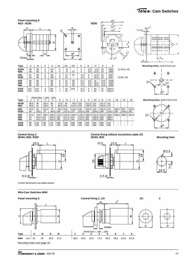
D371E 77
Panel mounting EM10 - N100 N200
Type A B C D D1 D2 D3 E G H K S Mounting holes: built in from ear
M10H 48 36 5 44 1) 5 8 - 4 3,5 9,5 19 SW5 1) 44,5 x 42M20 48 36 5 56 5 8 57 4 3,5 12,5 19 SW5
N20 64 48 5 56 5 12 57 4,2 3 12,5 20 SW7N33F 64 48 5 58 2) 5 12 - 4,2 3 15,5 20 SW7 2) 58 x 58
N40 86 68 7 80 6 12 82 5,2 3,5 18 24,5 SW9N60 86 68 7 80 6 12 82 5,2 3,5 29,5 24,5 SW9N80 86 68 7 80 6 12 82 5,2 3,5 29,5 24,5 SW9
N100 132 110 9 128 7 16 129 6,2 5 30 37 SW12N200 132 110 9 128 7 16 - 6,2 5 40 37 SW12
Dimension L with .. cellsType 1 2 3 4 5 6 7 8 9 10 11 12 13 14 15 Mounting holes: built in from front
M10H 36,5 46 55,5 65 74,5 84 93,5 103 112,5 122 131,5 141 - - -M20 38,5 51 63,5 76 88,5 101 113,5 126 138,5 151 163,5 176 - - -
N20 40,5 53 65,5 78 90,5 103 115,5 128 140,5 153 165,5 178 190,5 203 215,5N33F 44 59,5 75 90,5 106 121,5 137 152,5 168 183,5 199 214,5 230 245,5 261
N40 52,5 70,5 88,5 106,5 124,5 142,5 160,5 178,5 196,5 214,5 232,5 250,5 268,5 286,5 304,5N60 64 93,5 123 152,5 182 211,5 241 270,5 300 329,5 359 388,5 - - -N80 64 93,5 123 152,5 182 211,5 241 270,5 300 329,5 359 388,5 - - -
N100 88 118 148 178 208 238 268 298 328 358 388 418 - - -N200 96 136 176 216 256 296 336 376 416 456 496 536 - - -
Central fixing Z Central fixing without escutcheon plate ZOM10H, M20, N33F M10H, M20 Mounting hole:
Further dimensions see tables above
Mini-Cam Switches M4H
Panel mounting E Central fixing Z, ZO ZO Z
Dimension L with .. cellsType A B D M 1 2 3 4 5 6 7 8
M4H mm 30 28 29,5 12,5 38,5 50,5 62,5 74,5 86,5 98,5 110,5 122,5
Mounting holes see page 42
- Cam Switches

78 D371E
- Cam Switches
Flush mounting UPM10 N20 (dimensions of standard flush wall mounting box see page 90)
Base mounting VM10H - N100 N200
Type A B D D1 D2 E G H I K K1 S Mounting holes: for escutcheon plate
M10 48 36 39 5 8 4 3,5 9,5 6 19 41 SW5M10H 48 36 44 1) 5 8 4,2 3 9,5 6 19 41 SW5 1) 42 x 44,5M20 48 36 56 5 8 4,2 3 12,5 6 19 47 SW5
N20 64 48 56 5 12 4,2 3 12,5 0 20 29 SW7N33F 64 48 58 2) 5 12 4,2 3 15,5 0 20 31,5 SW7 2) 58 x 58
N40 86 68 80 6 12 5,2 3,5 18 - - 38,5 SW9N60 86 68 80 6 12 5,2 3,5 29,5 - - 49,5 SW9N80 86 68 80 6 12 5,2 3,5 29,5 - - 49,5 SW9
N100 132 110 128 7 16 6,2 5 30 - - 79,5 SW12N200 132 110 128 7 16 6,2 5 40 - - 104 SW12
Dimensions L with .. cellsType 1 2 3 4 5 6 7 8 9 10 11 12 13 14 15
M10 34,5 44 53,5 63 72,5 82 91,5 101 110,5 120 129,5 139 - - -M10H 36,5 46 55,5 65 74,5 84 93,5 103 112,5 122 131,5 141 - - -M20 38,5 51 63,5 76 88,5 101 113,5 126 138,5 151 163,5 176 - - -
N20 40,5 53 65,5 78 90,5 103 115,5 128 140,5 153 165,5 178 190,5 203 215,5N33F 44 59,5 75 90,5 106 121,5 137 152,5 168 183,5 199 214,5 230 245,5 261
N40 52,5 70,5 88,5 106,5 124,5 142,5 160,5 178,5 196,5 214,5 232,5 250,5 268,5 286,5 304,5N60 64 93,5 123 152,5 182 211,5 241 270,5 300 329,5 359 388,5 - - -N80 64 93,5 123 152,5 182 211,5 241 270,5 300 329,5 359 388,5 - - -
N100 88 118 148 178 208 238 268 298 328 358 388 418 - - -N200 96 136 176 216 256 296 336 376 416 456 496 536 - - -
Snap-on mounting SM Swich with installation cover SMAM10H - N33F for 35mm DIN-rail mounting according to DIN EN 50022 M10H, M20 for 35mm DIN-rail mounting according to DIN EN 50022
Dimension X with .. cells Dimension Y with .. cellsDimensions see tables above Type 1, 2 3 4 5 1, 2 3 4 5
M10H 44 44 61 76 60 60 75 90M20 44 61 76 76 60 75 90 90

D371E 79
Plastic enclosed switches P, PFM10 - N60 N100, N200
N60, N80
Dimension L with .. cellsType A B C D E F G P 1 2 3 4 5 6
M10 66 64 50 36 5 15,5 26 M20 43 52 62 71 81 90
N20 82 78 57 53 4,5 17 35 M20 66 66 80 94 108 122N33F 112 108 85 50 5 20 50 M25 92 92 92 110 128 146
N40 112 108 85 50 5 20 50 M25 92 92 110 128 146 164N60 112 108 85 50 5 20 50 M25 92 110 - - - -N60 182 180 120 120 5,5 36,5 - 1) - - 165 215 215 -N80 182 180 120 120 5,5 36,5 - 1) 110 110 165 215 215 -
N100 210 310 165 255 6,5 52,5 - 2) 130 130 180 - - -N200 310 310 255 255 6,5 52,5 - 3) 130 180 230 - - -
Motor terminal box mounting KEM10 - N33F Mounting holes
Dimension L with .. cellsType A B C D D1 D2 E F G 2 3 4 5 6
M10 66 64 58 39 4 48 3,2 24 6 22 31,5 41 50,5 60
N20 82 78 71 48 5 57 4,2 34 5 24,5 37 49,5 62 74,5N33F 112 108 100 56 5 70 4,2 49 11 32,5 48 63,5 79 94,5
Plastic enclosed motor starter PMN20
Dimension L with .. cellsTyp P 1 2 3 4 5 6
N20 M25 80 80 80 92,5 105 117,5
- Cam Switches
1) knock outs for M40/M32 + 4x M20 attop and bottomM32/M25 + 4x M20 at the right and lefthand side,
2) 2 flange plates with hole 50,5 at top andbottom
3) 2 flange plates with hole 50,5 at top andbottom, can also be mounted at the rightand left hand side
4) old version

80 D371E
- Cam Switches
Cast aluminium enclosed switches G, GFN20
N20 4 x M25
Plastic enclosure horizontal PLF (Replacement for cast aluminium enclosure G, GF)N40, N60, N80
Type N40 1 - 6 cells N40 7 - 10 cellsN60 1 - 3 cells N60 4 - 6 cellsN80 1 - 3 cells N80 4 - 6 cells
A 182 254B 167 239C 120 190
D - 65P 2 x Ø40,5 (M40) 4 x Ø40,5 (M40)

D371E 81
Switch disconnectors LT(S)
Main Switches, Switch Disconnectors LT(S)..
Panel mounting LT(S).. E(HN)..ON-OFF Switches 3-pole, 4-pole ON-OFF Switches 6-pole, 8-pole Mounting holes
Changeover Switches 3-pole, 4-pole
Single hole mounting LTS.. Z(HN).. MMounting of add-on modules LTS20 - LTS80ON-OFF Switches 3-pole, 4-pole Mounting holes Panel mounting, Single hole mounting
Changeover 3-pole 4-pole 3,4-pole
ON-OFF 3-pole 4-pole 6-pole 8-pole aux. 4. Pole 3-pole 6-pole
Escutch. plate or contact PE 4-pole 8-pole
Type padlock device A B B B B B1 B2 C1 D1 D2 E F G H H
LTS.. 48 , SV1 48 48 62,5 - - 10 14,5 1-5 10 5 36 - 64 54 -LTS.. 64 , SV4, SV164 64 48 62,5 97 126 10 14,5 1-5 10 5 48 - 64 54 74
LTS85-125.. 64 , SV4 64 78 78 - - 10 - 1-5 10 5 48 - 85 60 -
LT125/160 88 , SV34 88 112 150 224 - - - 1-4 13-17 6 68 49,3 108 96 98
Escutcheon plate Padlock devices48 64 SV1 SV164
Padlock devicesSV4 SV488 SV34
Aux. contact LH..
4th Pole
PE-, N-terminal
Aux. contact LH..

82 D371E
Switch disconnectors LT(S)
Main Switches, Switch Disconnectors LT(S)..
Base mounting LTS.. VZV(HN)..ON-OFF Switches 3-pole, 4-pole 6-pole ON-OFF Switches 6-pole, 8-pole Mounting
for LTS20 - 40 only Changeover Switches 3-pole, 4-pole holesL = X - 40±3 L = X - 40±3 L = X - 60±3
Base mounting LT(S).. V(HN)..ON-OFF Switches 3-pole, 4-pole 6-pole ON-OFF Switches 6-pole, 8-pole Mounting
for LTS20 - 40 only Changeover Switches 3-pole, 4-pole holesL = T - 60±3 for LTS20 - 80 only L = X - 60±3 L = T - 80±3 for LTS20 - 80 only
Base mounting LTS.. VZ(HN)..ON-OFF Switches 3-pole, 4-pole 6-pole ON-OFF Switches 6-pole, 8-pole Mounting
for LTS20 - 40 only Changeover Switches 3-pole, 4-pole holes
Changeover 3,4-pole
ON-OFF 3-pole 4-pole 6-pole 8-pole aux. 4.PoleEscutch. plate or contact PE
Type padlock device A B B B B B1 B2 C1 D1 D2 D3 E G K K1 J
LTS20 -40 64 , SV4, SV164 64 48 48 77 97 10 14,5 1-5 10 5 M4 48 64 25 48 70LTS63, 80 64 , SV4, SV164 64 48 62,5 97 126 10 14,5 1-5 10 5 M4 48 64 25 48 70
LTS85-125.. 64 , SV4 64 78 78 - - 10 - 1-5 10 5 M4 48 85 38 - 90
LT125/160 88 , SV34 88 112 150 224 - - - 1-4 13/272) 6 M6 68 108 36 - 120
Base mounting Mounting of Accessories LTS20 - LTS80ON-OFF Switches LTS20 - LTS80 LTS85-125, LT160 Base mounting, for distribution boards3-pole, 4-pole 6-pole, 8-pole 3-pole, 4-pole6-pole LTS20 -40 Changeover Switches
1) Ø 22-25 for LT80(100) VH(N)34 .. only2) Ø 26-30 for LT125(160) VH(N)34 .. only
Aux. contact LH..
4. PolPE-, N-terminal
Aux. contact LH..

D371E 83
Switch disconnectors LT(S)
Main Switches, Switch Disconnectors LT(S)..
Installation cover LT(S).. SMA(HN)..ON-OFF Switches 3-pole, 4-pole ON-OFF Switches 6-pole ON-OFF Switches 6-pole, 8-pole
for LTS20 - 40 only Changeover Switches 3-pole, 4-pole
Changeover 3,4-pole 3,4-pole 3,4-pole
ON-OFF 3-pole 4-pole 6-pole 8-pole aux. 4.pole 3-pole 6-pole 8-pole 3-pole 6-pole 8-pole
contact PE 4-pole 4-pole
Type padlock device B B B B B1 B2 G M M M N N N
LTS20 - 40 SV1, SV164 48 48 77 96 10 14,5 64 60 60 74 52 52 971)
LTS63, 80 SV1, SV164 48 62,5 96 125 10 14,5 64 60 74 74 52 971) 126
LT80.. SV1 70 92 140 - 11 - 80 70 70 70 70 70 -LT100.. SV1 70 92 140 - 11 - 80 70 70 70 70 70 -
1) inclusiv removable cover parts 126mm
Maintenance and Safety Switches LT(S)..PF..
Type Pole A B D1 D2 E F H
LTS20 PFH.. A., LTS40 PFH.. A 3, 4 130 98 2x25,5/20,5 - 75 100 77
LTS63 PFH.. - LTS125 PFH.. A. 3, 4 200 120 40,5/32,5 +16,5 - 95 165 86LTS20 PFH.. A., LTS40 PFH.. A 6 200 120 40,5/32,5 +16,5 - 95 165 86
LTS20 PFH.. A., LTS40 PFH.. A 8 240 160 40,5/32,5 - 130 228 120LTS63 PFH.. A., LTS80 PFH.. A. 6, 8 240 160 40,5/32,5 - 130 228 120
LT125 PFH.., LT160 PF.. 3 300 200 2x50,5 25,5 172 272 172LT125 PFH.., LT160 PF.. 4 300 280 2x50,5 - 254 254 180
Switch Disconnectors in Plastic Enclosure LTS..PF..
Type Pole A B D1 E F H
LTS20 PF A., LTS40 PF A 3, 4 130 98 2x25,5/20,5 75 100 77
LTS63 PF A., LTS80 PF A. 3, 4 200 120 40,5/32,5 +16,5 95 165 86
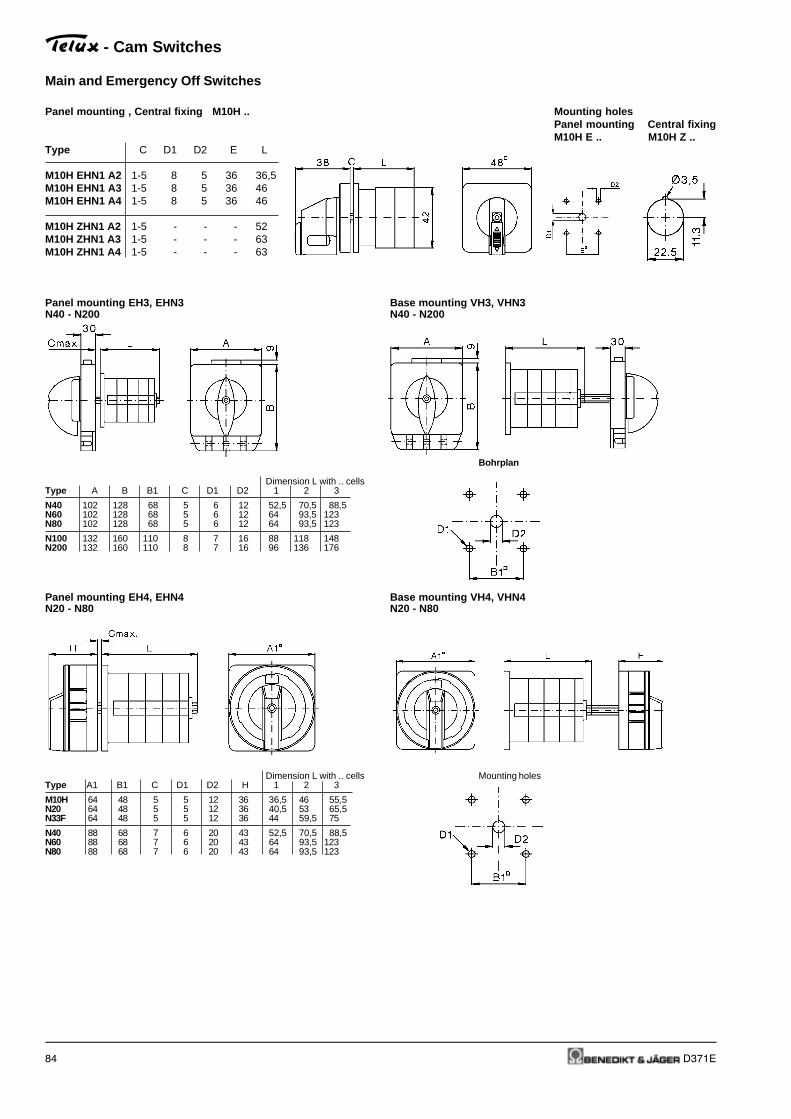
84 D371E
Main and Emergency Off Switches
Panel mounting , Central fixing M10H .. Mounting holesPanel mounting Central fixingM10H E .. M10H Z ..
Type C D1 D2 E L
M10H EHN1 A2 1-5 8 5 36 36,5M10H EHN1 A3 1-5 8 5 36 46M10H EHN1 A4 1-5 8 5 36 46
M10H ZHN1 A2 1-5 - - - 52M10H ZHN1 A3 1-5 - - - 63M10H ZHN1 A4 1-5 - - - 63
Panel mounting EH3, EHN3 Base mounting VH3, VHN3N40 - N200 N40 - N200
Bohrplan
Dimension L with .. cellsType A B B1 C D1 D2 1 2 3
N40 102 128 68 5 6 12 52,5 70,5 88,5N60 102 128 68 5 6 12 64 93,5 123N80 102 128 68 5 6 12 64 93,5 123
N100 132 160 110 8 7 16 88 118 148N200 132 160 110 8 7 16 96 136 176
Panel mounting EH4, EHN4 Base mounting VH4, VHN4N20 - N80 N20 - N80
Dimension L with .. cells Mounting holesType A1 B1 C D1 D2 H 1 2 3
M10H 64 48 5 5 12 36 36,5 46 55,5N20 64 48 5 5 12 36 40,5 53 65,5N33F 64 48 5 5 12 36 44 59,5 75
N40 88 68 7 6 20 43 52,5 70,5 88,5N60 88 68 7 6 20 43 64 93,5 123N80 88 68 7 6 20 43 64 93,5 123
- Cam Switches

D371E 85
Load Switches
Panel mounting EL100 - 400, L800, L1200 L600
Base mounting VL100 - 400, L800, L1200 L600
Type A B C D D1 D2 E G H K K1 M N R S Mounting holes :
L100 86 68 7 80 6 12 5,2 3,5 18 24,5 38,5 103 27 - SW9L160 86 68 7 80 6 12 5,2 3,5 29,5 24,5 38,5 115 - 8,5 SW9
L400 132 110 9 128 7 16 6,2 5 40 37 104 200 40 12,5 SW12L600 132 110 9 128 7 16 6,2 5 40 37 104 180 - 16,5 SW12L800 132 110 9 128 7 16 6,2 5 40 37 104 240 40 16,5 SW12L1200 132 110 9 128 7 16 6,2 5 40 37 104 240 40 16,5 SW12
Dimension L with .. cellsType 1 2 3 4 5 6 7 8 9 10 11 12
L100 52,5 70,5 88,5 106,5 124,5 142,5 160,5 178,5 196,5 214,5 232,5 250,5L160 64 93,5 123 152,5 182 211,5 241 270,5 300 329,5 359 388,5
L400 96 136 176 216 256 296 336 376 416 456 496 536L600 96 136 176 216 256 296 336 376 416 456 496 536L800 96 136 176 216 256 296 336 376 416 456 496 536L1200 96 136 176 216 256 296 336 376 416 456 496 536
- Cam Switches

86 D371E
- Cam Switches
Operating Knobs and Handles
Instrument knob G. Twist knob R.
Type A B C D E
Type A B C D E M10, M10H, M20 20,5 28 25 15 4N20, N33F 24 36 29,5 19 3
M10, M10H, M20 23 28 24 14 4 N40, N60, N80, L100, L160 31 49 41 28 3,5N20, N33F 27 36 32 18 3 N100, N200, L400, L600, L800, L1200 50 75 62 41 2,5
Toggle knob K.
Type A B E
M10, M10H, M20 18,5 28 4N20, N33F 24 36 3
Hand wheel HR Ball type handle B.N100, N200,L400, L600, L800, L1200
Type A B C D E
N20, N33F 53 36,5 64 21 3N40, N60, N80, L100, L160 62 49 82 31 3,5N100, N200, L400, L600, L800, L1200 63 75 110 45 2,5
Code number for colour
grey .1 white .5black .2 blue .6red .3 yellow .7cream-coloured .4 euro-white .8
Escutcheon plates
Escutcheon plate Rectangular additional plate SRE Big rectangular additionalplate SRE2
Type A B Type A B C Type A B C
M10, M10H, M20 48 7,5 M10, M10H, M20 48 12 7,5 M10, M10H, M20 48 69 6N20, N33F 64 7,5 N20, N33F 64 14 7,5 N20, N33F 64 91 6N40, N60, N80, L100, L160 88 8 N40, N60, N80, L100, L160 88 22 8N100, N200, L400, L600, L800, L1200 132 9 N100, N200, L400, L600, L800, L1200 132 31 9

D371E 87
Special drives
Removable knob drive STGR, STGR2M10H - N33F Mounting holes
Type B C D1 D2 D3
M10H, M20 36 5 5 12 18N20, N33F 48 5 5 12 18
Replace dimension D2 with dimension D3 for STGR2Dimension L see page 77
- Cam Switches

88 D371E
Door couplings
Dimension T is a minimum value. In case of order the dimension T is necessary.
Door coupling TK, TKFR Door coupling, lockable TK2, TK2FRN40 - L1200 N40 - L1200
Door coupling TKE, TK2E Mounting holes:M10H, M20, N20, N33F TK, TKFR, TK2, TK2FR
TKE, TK2E
Door coupling, lockable TK2Z Mounting holes:M10H, M20, N20, N33F TKZ
Further dimensions see pages 69 and 70.Dimension T is a minimum value dependent on switch Type and number of cells. For ordering dimension T is necessary
Minimum dimension T with .. cellsType A B C D1 D2 1 2 3 4 5 6 7 8
M10H 48 36 5 5 8 108 117,5 127 136,5 146 155,5 165 174,5M20 48 36 5 5 8 100 112,5 125 137,5 150 162,5 175 187,5
N20 64 48 5 5 10 100 112,5 125 137,5 150 162,5 175 187,5N33F 64 48 5 5 10 103 118,5 134 149,5 165 180,5 196 211,5
N40 88 48 7 6 12 134 152 170 188 206 224 242 260N60 88 48 7 6 12 145,5 175 245,5 234 263,5 293 322,5 352N80 88 48 7 6 12 145,5 175 245,5 234 263,5 293 322,5 352
N100 132 110 9 7 15 202 232 262 292 322 352 382 412N200 132 110 9 7 15 212 252 292 332 372 412 452 492
L100 88 48 7 6 12 - 152 - 188 - 224 - 260L160 88 48 7 6 12 145,5 175 245,5 234 263,5 293 322,5 352
L400 132 110 9 7 15 212 252 292 332 372 412 452 492L600 132 110 9 7 15 - - 292 - - 412 - -L800 132 110 9 7 15 - 252 - 332 - 412 452 492L1200 132 110 9 7 15 - - 292 - - 412 - -
- Cam Switches

D371E 89
Key operated switches SA
Panel mounting E Base mounting VM10 - N60 Mounting holes M10 - N60
Type A B C D D1 D2 F Type A C D F
M10H, M20 48 36 18 17,5 5 18,5 52,5 M10H, M20 48 18 22 57N20, N33F 64 48 10 17,5 5 18,5 52,5 N20, N33F 64 8 22 57 Dimension LN40,N60 88 68 23,5 15 6 18,5 50 Dimension L see page 77 N40,N60 88 15 15 50 see page 78
Central fixing Z Central fixing without escutcheon plate ZOM10H Z ... + SA M10H ZO ... + SA Mounting holes:M20 Z ... + SA M20 ZO ... + SA
Further dimensions see page 77
DIN rail mounting SMA Flush mounting UPM10H, M20 M10
Dimension X with .. cells Dimension Y with .. cells Dimension P with .. cellsType 1 2 3 4 1 2 3 4 Type 1 2
M10H 44 75 75 91 60 90 90 107 M10 47,5 57
M20 59 75 75 91 75 90 90 107
Plastic enclosured switches P, PFM10, N20, N33F, N40, N60
Dimension P with .. cellsType 1 2 3 4
M10 62 71 81 90
N20 66 80 94 108N33F 92 110 110 128
N40 92 110 - -N60 110 - - -
Further dimensions see page 79
- Cam Switches

90 D371E
Key operated switches
Key operated switch SAK Key operated switch SAKPanel mounting E M10H, M20 Mounting holes Base mounting V M10H, M20
Type A B C D D1 D2 F Type A C D F
M10H, M20 48 36 25 21 5 22,5 49 M10H, M20 48 25 21 49
Key operated switch SASIPanel mounting E M10, M20 Mounting holes M10, M20
Type M10 M20
C 20 20 Dimension L see page 77
Key operated switch SASI Key operated switch SASIPlastic enclosured P M10, M20 Flush mounting UP M10, M20
Dimension P with .. cellsTyp 1 2 3 4 P
M10 67 79,5 92 104,5 2xM20M20 79,5 92 104,5 117 2xM20
Flush mounting box UPN20
- Cam Switches

D371E 91
- Cam Switches
Padlock devices
Padlock device SV1 (max. 2 padlocks with stirrup Ø6mm) Padlock device SV164Mounting holes Mounting holes
M10H, M20 design E, V M10H - N33F design E, V
Padlock device SV3 (max. 3 padlocks with stirrup Ø8,5mm)Panel mounting E Base mounting VN20 - N200, L100 - L1200 N20 - N200, L100 - L1200
Further dimensions see page 77 Further dimensions see page 78
Type A B C
N20, N33F 102 128 5N40, N60, N80, L100, L160 102 128 7N100, N200, L400, L600, L800, L1200 132 159 9
Padlock device SV4 (max. 3 padlocks with stirrup Ø6mm) Padlock device SV4 (max. 3 padlocks with stirrup Ø6mm)M10H - N33F N40 - N80, L100 - L160
Padlock device SV488Mounting holes N20, N33F Mounting holesdesign E, V design E, V
Front plate/switch shaft sealing FPWDN20, N33F Mounting holes
Typ B D1 D2
N20, N33F 48 5 17

92 D371E
- Cam Switches
Interlocks
Lock switch SZ, SZ2Panel mounting E Base mounting V Mounting holes
Type A B C D D1 D2 D3 E F G H
M10H, M20 60 36 3 22,5 5 8 18,5 90 40 32 47,5N20, N33F 60 36 3 22,5 5 12 18,5 90 45 32 47,5N40, N60, N80, L100, L160 90 68 4 24 6 12 18,5 142 61 61,5 48N100, N200, L400, L600, L800, L1200 140 110 4 27 7 15 18,5 180 83 90,5 49
Push-button switch lock DVSwitch interlock with electrical contact ETPanel mounting E Base mounting V Mounting holes
Type A B C D D1 D2 D3 E F G
M10H, M20 60 36 3 22,5 5 8 26 90 40 32N20, N33F 60 36 3 22,5 5 12 26 90 45 32N40, N60, N80, L100, L160 90 68 4 25 6 12 29 142 61 61,5N100, N200, L400, L600, L800, L1200 140 110 4 41 7 15 29 180 83 90,5 1) only at +ET
Moisture proofing caps for panel switches FRM10H
Dimension L with .. cellsType 1 2 3 4 5 6 7M10H 55 55 75 75 88 106 106
Moisture proofing caps for panel switches FRN20, N40, N60
Dimension L with .. cellsType A B D E 1 2 3 4 5
N20 60 48 59 5,5 68 68 68 91 91N40 87 68 83 5,5 82 82 117 117 -

D371E 93
Interlocks
Geared switch with two columns ZK2Panel mounting E Base mounting V
Type A B C D E G H Z
M10H, M20 70 170 52 156 5,5 70 43 22N20, N33F 70 170 52 156 5,5 70 43 22N40, N60, N80, L100, L160 170 190 150 168 6,5 100 43 23N100, N200, L400, L600, L800, L1200 180 340 150 310 6,5 140 80 25 Further dimensions see pages 77 and 78
Geared switch with tree columns ZK3Panel mounting E Base mounting V
Type A B C D E G H Z
M10H, M20 70 240 52 226 5,5 70 43 22N20, N33F 70 240 52 226 5,5 70 43 22N40, N60, N80, L100, L160 170 290 150 269 6,5 100 43 23N100, N200, L400, L600, L800, L1200 180 490 150 460 6,5 140 80 25 Further dimensions see pages 77 and 78
Neon safety switch N20 E .. +FEU, N33F E .. +FEU
Further dimensions see pages 77
- Cam Switches

94 D371E
European Representations and Suppliers
Netherlands +31
Hirsch-Driebergen B.V. Tel: 0343 / 515 534Postbus 143 Fax: 0343 / 520 314NL - 3970 AC Driebergen WWW.hirsch-driebergen.nl
Technische Unie B.V. Tel: 020/545 03 45Postfach 900 Fax: 020/643 43 25NL-1180 AX Amstelveen
Poland +48
Dukat Sp. z o.o. Tel: 422 / 152 571Ul. 20 Stycznia 95/5 Fax: 422 / 152 571PL - 95-200 Pabianice
Automatech Sp. z o.o. Tel: 22 / 723 06 62Ul. Ryzowa 84 Fax: 22 / 723 06 06PL - 05-816 Opacz-Kolonia [email protected]
www.automatech.it.pl
Portugal +351
Sotecnica SA Tel: 01/387 64 81Rua do Vale do Pereiro, 8 Fax: 01/658 349P-1296 Lisboa codex Tlx: 16643 soteca p
Sweden +46
Wallin & Co AB Tel: 8 / 860 102Götlundagatan 10 Fax: 8 / 997 050Box 420 [email protected] - 12404 Bandhagen
Switzerland +41
Benedict Swiss AGBenedict Swiss AGBenedict Swiss AGBenedict Swiss AGBenedict Swiss AG Tel: 44 / 213 66 00Grindelstraße 19 Fax: 44 / 213 66 09CH - 8303 Bassersdorf [email protected]
www.benedict-swiss.ch
Belgium +32
Guillaume-Teco SA Tel: 04 / 355 88 26Material Electrique Fax: 04 / 358 21 97Rue de Magnee [email protected] - 4610 Beyne-Heusay www.guillaume-teco.be
Denmark +45
MTO electric a/sMTO electric a/sMTO electric a/sMTO electric a/sMTO electric a/s Tel: 075 / 800 310Andkaervej 26 Fax: 075 / 800 320DK - 7100 Vejle [email protected]
www.mto-electric.dk
France +32
Guillaume-Teco SA Tel: 04 / 355 88 26Material Electrique Fax: 04 / 358 21 97Rue de Magnee [email protected] - 4610 Beyne-Heusay www.guillaume-teco.be
Germany +49
TVB GmbH Tel: 040 / 608 750 22Büro für Elektroanlagen u. Geräte Fax: 040 / 608 750 23Hartje Rüterweg 88 [email protected] - 22399 Hamburg www.tvb-hamburg.de
Great Britain +44
IMO Precision Controls Ltd. Tel: 020 / 8452 64441000 North Circular Road Fax: 020 / 8450 2274GB - NW2 7JP London [email protected]
www.imopc.com
Hungaria +36
Dial-Comp GmbH Tel: 01 / 236 0427Keszkeno u. 46/b. Fax: 01 / 236 0430H - 1131 Budapest [email protected]
www.dialcomp.hu
Italy +39
SIF Trading Tel: 035 / 258 853Via Per Curnasco 64 Fax: 035 / 258 011I - 24127 Bergamo [email protected]

D371E 95
Oversea Representations and Suppliers
Australia +61
Electromatic Technology Systems Tel: 02 / 9698 45 55Pty. Ltd. Fax: 02 / 9699 91 70129 Queen Street, [email protected] NSW 2015AUS
Egypt +20
Economic Co. Tel: 02 / 592 91 80Electrical Commerce & Import Fax: 02 / 590 78 8244, Naguib El-Rihani St. [email protected] - Kairo
Mexico +1
B&J USA Inc.B&J USA Inc.B&J USA Inc.B&J USA Inc.B&J USA Inc. Tel: 919/553 5501120-101 North Tech Drive Fax: 919/553 5565Post Office Box 877Clayton, N.C. 27528 [email protected]
www.bnj-usa.com
Singapore and Malaysia +65
Mecomb Singapore Ltd. Tel: 469 88 33#04-02 Sime Darby Centre Fax: 467 19 05896 Dunearn Road [email protected] - 589472 Singapore
South Africa +27
Deebar Tel: 021 / 873 43 32Mining & Ind. Supplies Fax: 021 / 825 69 84P.O. Box 40325 [email protected] - 2022 Cleveland
Electric Assemblies Tel: 021 / 52 3023Unit 2A Simplex Ind. Park Fax: 021 / 52 2704Engine Road, [email protected] - 7441 Cape Town
Taiwan +886
Vinmajor Enterprise Co., Ltd. Tel: 02 / 2643 61838F-2, No. 306, Section 1 Fax: 02 / 8691 6288Ta-Tung Road, Hsi-Chih [email protected] Hsien, TaiwanR.O.C.
USA +1
B&J USA Inc.B&J USA Inc.B&J USA Inc.B&J USA Inc.B&J USA Inc. Tel: 919/553 5501120-101 North Tech Drive Fax: 919/553 5565Post Office Box 877Clayton, N.C. 27528 [email protected]
www.bnj-usa.com
Zimbabwe +263
Star Delta Electrix Tel: 9 / 715 24Cnr 11th Ave and Fife Str. Fax: 9 / 776 18P.O. Box 3592 [email protected] - Bulawayo
Star Delta Electrix Tel: 4 / 754 792/8-28Graniteside Way, Harare Fax: 4 / 754 790P.O. Box 2753 [email protected] - Harare