Bit Error and Packet Error Probability for Rectangular Mary ...
18
Journal of Engineering and Development, Vol. 11, No. 3, December (2007) ISSN 1813-7822 149 Bit Error and Packet Error Probability for Rectangular Mary-QAM in OFDM Transmission System over Rayleigh Fading Channels Abstract Orthogonal frequency division multiplexing (OFDM) or multicarrier transmission has been shown to be an effective technique to combat multipath fading in wireless communications. It has been successfully used for HF radio applications and has been chosen as the standard for digital audio broadcasting and digital terrestrial TV broadcasting in Europe and high-speed wireless local areas networks. This paper describes the concept behind parallel data transmission and the configuration of an OFDM transmitter and receiver when used four type of rectangular Mary QAM modulation (QAM, 16QAM, 64QAM & 256QAM). Two type of error evaluated (bit error rate BER & packet error rate PER) for two typical channels, AWGN channel & (one or two path) Rayleigh fading channels. For AWGN channel, two curves are plotted (with & without) using guard time and compared with theoretical performance. While different curves are plotted for one path Rayleigh fading channels (with & without) using channel estimation and compared with theoretical performance. We explained how we configured the OFDM transmitter and receiver by using MATLAB computer software. We discussed the results of our extended simulation of OFDM where we simulated the broadband WLAN system by using a pilot system assisted OFDM transmission system. We showed the effectiveness of the pilot system assisted OFDM transmission system for (one or two) path Rayleigh fading channel when using guard time is less than multipath delay spread or greater than multipath delay spread. الخ ـص ـــــــ ةلمتعامد الترددي امي التعدد ألتقسي(OFDM) لمقاومة مؤثرة هو تقنية فعالةتلحامل متعدد ارسا أو ا تأثيرسلكيةت التصام اوت في نظا متعددة الخفراتلمسا اmultipath fading in wireless communication فيلعاليةرددات الراديوية ا الت قنوات(HF radio channels) الرقميويبث الراديلم أساسي لستخدا يعتبر كا والذيسلكذاعة الت اوني في أوربا وفي شبكات محطاتلفزي واللعالية. ية ذات السرع امستقبلةة والمرسلمد بين اللمتعا الترددي اميم التعدد ألتقسيانات في نظا البيسة إرسال في هذا البحث تم دراواع التضمين أنواع منربعة أن و وهي(QAM,16QAM,64QAM&256QAM)modulation . لقد تم حسابAsst. Lect. Ghanim Abd Al-Kareem Al-Rubyai Electrical Engineering Department, College of Engineering Al-Mustansiriya University, Baghdad, Iraq
-
Upload
khangminh22 -
Category
Documents
-
view
1 -
download
0
Transcript of Bit Error and Packet Error Probability for Rectangular Mary ...

Journal of Engineering and Development, Vol. 11, No. 3, December (2007) ISSN 1813-7822
149
Bit Error and Packet Error Probability for Rectangular Mary-QAM in OFDM Transmission System over
Rayleigh Fading Channels
Abstract
Orthogonal frequency division multiplexing (OFDM) or multicarrier transmission
has been shown to be an effective technique to combat multipath fading in wireless
communications. It has been successfully used for HF radio applications and has been
chosen as the standard for digital audio broadcasting and digital terrestrial TV
broadcasting in Europe and high-speed wireless local areas networks.
This paper describes the concept behind parallel data transmission and the
configuration of an OFDM transmitter and receiver when used four type of rectangular
Mary QAM modulation (QAM, 16QAM, 64QAM & 256QAM). Two type of error evaluated
(bit error rate BER & packet error rate PER) for two typical channels, AWGN channel &
(one or two path) Rayleigh fading channels.
For AWGN channel, two curves are plotted (with & without) using guard time and
compared with theoretical performance. While different curves are plotted for one path
Rayleigh fading channels (with & without) using channel estimation and compared with
theoretical performance. We explained how we configured the OFDM transmitter and
receiver by using MATLAB computer software.
We discussed the results of our extended simulation of OFDM where we simulated the
broadband WLAN system by using a pilot system assisted OFDM transmission system. We
showed the effectiveness of the pilot system assisted OFDM transmission system for (one or
two) path Rayleigh fading channel when using guard time is less than multipath delay
spread or greater than multipath delay spread.
ةـــــــالصـالخ
تأثير أو اإلرسال متعدد الحامالت هو تقنية فعالة مؤثرة لمقاومة (OFDM)التعدد ألتقسيمي الترددي المتعامد في multipath fading in wireless communicationالمسارات متعددة الخفوت في نظام االتصاالت الالسلكية
والذي يعتبر كاستخدام أساسي للبث الراديوي الرقمي (HF radio channels)قنوات الترددات الراديوية العالية ية ذات السرع العالية. والتلفزيوني في أوربا وفي شبكات محطات اإلذاعة الالسلك
في هذا البحث تم دراسة إرسال البيانات في نظام التعدد ألتقسيمي الترددي المتعامد بين المرسلة والمستقبلة لقد تم حساب .modulation(QAM,16QAM,64QAM&256QAM) وهي وألربعة أنواع من أنواع التضمين
Asst. Lect. Ghanim Abd Al-Kareem Al-Rubyai
Electrical Engineering Department, College of Engineering
Al-Mustansiriya University, Baghdad, Iraq

Journal of Engineering and Development, Vol. 11, No. 3, December (2007) ISSN 1813-7822
150
لنوعين PER والنوع الثاني نسبة احتمالية خطا الرزمة BERالبت النوع األول نسبة احتمالية خطا . نوعين من األخطاء من القنوات.
عند استخدام وعدم BER & PERحيث تم حساب AWGN channelالنوع األول قناة ضوضاء كاوسي BER & PER كذلك تم حساب مع مقارنة النتائج مع النتائج النظرية للقناة (Guard time)استخدام الفترة الحارسة
عندما تمر اإلشارة بمسار واحد للخفوت وعند استخدام وعدم Rayleigh fading channelsلقناة الترددات العالية Channel estimation استخدام
عند استخدام أحدى طرق BER & PERكذلك تم حساب . مع مقارنة النتائج مع النتائج النظرية للقناةchannel estimation وهيpilot system assisted OFDM عندما تمر اإلشارة بمسار واحد أو مسارين للخفوت
.لقد multipath delay spreadاكبر أو اقل من زمن التشتت Guard timeوكذلك عندما يكون زمن الفترة الحارسة . MATLAB computer softwareتمت عملية المحاكاة باستخدام الحاسبة عن طريق
1. Rayleigh Fading Channel
The path between the base station and mobile station of terrestrial mobile
communications is characterized by various obstacles and reflections. The radio wave
transmitted from a base station radiates in all directions including reflected waves that are
reflected off of various obstacles, diffracted wave, scattering waves and the direct wave from
the base station to the mobile station. Since the path lengths of the direct, reflected, diffracted,
and scattering wave are different, the time each takes to reach the mobile station will be
different. In addition the phase of the incoming wave varies because of reflections. As result,
the receiver receives a superposition consisting of several waves having different phase and
time of arrival. The time of arrival is retarded in comparison with this direct wave is called a
delayed wave. Then; the reception environment characterized by a superposition of delayed
waves is called a multipath propagation environment. In a multipath propagation
environment. The total received signal is a vector sum of individually delayed signals, their
relative phase angles depending on the frequency and the echo amplitudes and delays.
Therefore, since the echo amplitudes and delays are time varying, one observes large
variations of the received signal strength at a single frequency as a function of time, or of the
strength at a given time as a function of frequency; the latter is termed "selective fading".
Another effect of multipath reception is the delay spread of the received signal, consisting of
several components that arrive at different time, with delay differences exceeding one symbol
period Ts, the signal components of the symbol present at the receiver input may be impaired
by components of previously sent symbols. This effect is called intersymbol interference
(ISI). Further more, time variance of the channel is due to Doppler spread, and is realized by
fast fading or slow fading. In the frequency domain, signal distortion due to fast fading
increases as the Doppler spread increases, thus causing the channel impulse response to
change rapidly within the symbol duration. In a slow fading channel, the Doppler spread is
much less than the base band bandwidth and results primarily in a loss in SNR [1,2,3].
2. Orthogonal Frequency Division Multiplexing (OFDM)

Journal of Engineering and Development, Vol. 11, No. 3, December (2007) ISSN 1813-7822
151
The principle of Orthogonal Frequency Division Multiplexing OFDM is to split a high
rate data stream (serial data) into a number of lower rate data streams (parallel data) that are
transmitted parallel over a number of overlapped subcarriers these subcarriers are modulated
with subcarriers spacing, which is selected such that modulated subcarriers are orthogonal
over symbol duration. Increasing symbol duration will result in lower rate parallel subcarriers.
This decreases the relative amount of dispersion in time caused by multipath delay
spread. So that, the Rayleigh fading channel looks flat on each carrier [4,5]
. OFDM allows the
spectrum of each tone to overlap, and because they are orthogonal, they do not interfere with
each other. By allowing the tones to overlap, the overall amount of spectrum required is
reduced, as shown in Fig.(1).
Figure (1) OFDM tones
To maintain orthogonality between tones, it is necessary to ensure that the symbol time
contains one or multiple cycles of each sinusoidal tone waveform. This is normally the case,
because the system numerology is constructed such that tone frequencies are integer multiples
of the symbol period, as is subsequently highlighted, where the tone spacing is 1/T. Viewed as
sinusoids, Fig.(2) shows three tones over a single symbol period, where each tone has an
integer number of cycles during the symbol [3,4,5,6,7]
.
Figure (2) Integer number of sinusoid periods
3. Subcarrier Modulation

Journal of Engineering and Development, Vol. 11, No. 3, December (2007) ISSN 1813-7822
152
In QAM modulation, we considered the use of multiple signal phases and multiple
signal amplitudes, respectively, for transmitting k information bits per symbol (per waveform)
over the (AWGN or Rayleigh fading) channels. Quadrature amplitude modulation (QAM) or
Quadrature amplitude shift keying (QASK) signal is represented as.
)tf2sin(A)tf2cos(A)t(s cT
2scT
2c …………………………………... (1)
0 ≤ t ≤ T , m = 1 , 2 , … , M
where:
Ac & As: are the information signal amplitudes of the Quadrature carriers and
Ttu 2)( , 0 ≤ t ≤T.
Pulse shapes other than rectangular may be used to reduce the spectral occupancy of the
transmitted signal [1]
. Once each subcarrier has been allocated bits for transmission, they are
mapped using a modulation scheme to a subcarrier amplitude and phase, which is represented
by a complex In-phase and Quadrature-phase (IQ) vector. Both the amplitude and the phase
can be changed simultaneously, with some bits of the input information being encoded onto
the amplitude and others onto the phase.
Figure (3-a) shows an example of subcarrier modulation mapping. This example shows
QAM, which maps 2 bits for each symbol. Each combination of the 2 bits of data corresponds
to a unique IQ vector, shown as a dot on the Fig.(3-a). A large number of modulation
schemes are available allowing the number of bits transmitted per carrier per symbol to be
varied.
Subcarrier modulation can be implemented using a lookup table, making it very efficient
to implement. In the receiver, mapping the received IQ vector back to the data word performs
subcarrier demodulation. During transmission, noise and distortion becomes added to the
signal due to thermal noise or multipath fading, signal power reduction and imperfect channel
equalization.
Figure (3-b) shows an example of a received QAM signal in AWGN channel for SNR
of 10 dB. Each of the IQ points is blurred in location due to the channel noise. For each
received IQ vector the receiver has to estimate the most likely original transmission vector.
This is achieved by finding the transmission vector that is closest to the received vector.
Errors occur when the noise exceeds half the spacing between the transmission IQ points,
making it cross over a decision boundary [8]
.

Journal of Engineering and Development, Vol. 11, No. 3, December (2007) ISSN 1813-7822
153
(a) (b)
Figure (3) a. IQ modulation constellation
QAM, with gray coding of the data to each location b. IQ plot for QAM data with added noise
4. Implementation of OFDM using Fast Fourier Transform (FFT)
Figure (4) illustrates the configuration of an OFDM system (transmitter & receiver).
Figure (4) OFDM radio transmission system (transmitter and receiver)
Using digital modulation formal (Mary QAM modulation), the transmitted OFDM
symbol wave form can be represented as:
1N
0K)}t
kf2jexp()k(dRe{)t(s
…………………………… (2)
where:
d(k): is the modulated data symbol
fk: is sub carrier frequency of kth sub carrier which is equal to ( fc + k∆f )
fc: is the carrier frequency
∆f: is sub carrier spacing (bandwidth) equal to (1/NTs)
Ts=1/Rs symbol duration, Rs symbol rate
This expression represents the pass band OFDM signal, if the equivalent complex base
band notation is used the complex base band OFDM signal is written as
1N
0k)ftk2jexp()k(d)t(s
………………………………… (3)
Mary QAM
Modulation
S/P
IFFT Guard
Insertion
Guard
Removal
FFT
P/S
Mary QAM
Demodulation
Tx Data stream Tx
Rx Rx Data stream

Journal of Engineering and Development, Vol. 11, No. 3, December (2007) ISSN 1813-7822
154
If the signal is sampled at a rate of Ts, then (t=nTs), and for orthogonality
(∆f=1/NTs=Rs/N), then Eq3 can be rewritten as:
1N
0k)N/kn2jexp()k(d)n(s
………………………………... (4)
Eq4 is exactly the Inverse Discrete Fourier transform (IDFT) of the data sequence d(k).
Fast Fourier Transform (FFT) algorithm is used to implement the DFT for complexity
reductions in design. For radix-2 FFT, the number of complex calculation is N log2 N while
for DFT, the number of complex calculation is N2. This difference grows for larger numbers
of sub carriers. All operation that occurs in the transmitter is reversed in the receiver [9,10,11]
.
5. Guard Time and Cyclic Extension
The modulated data are fed into an Inverse Fast Fourier Transform (IFFT) and an
OFDM signal is generated. The real part & an imaginary part of an OFDM signal includes
carrier frequencies fi (i = 0 , 1 , 2 , … , N – 1 )with their own frequency f0,
Ts
i
0f
if
…………………………………………………………….. (5)
The signal offered to the receiver contains not only a direct line of sight radio wave, but
also a large number of reflected radio waves that arrive at the receiver at different times.
Delayed signals are a result of reflections from terrain features such as trees, hills, mountains,
vehicles or building. These reflected delayed waves interfere with the direct wave and cause
inter symbol interference (ISI) .One way to eliminate ISI almost completely, a guard time is
introduced for each OFDM symbol. The guard time is chosen larger than the expected delay
spread such that the multipath components form one symbol cannot interfere with the next
symbol. However, the problem of Inter Carrier Interference ICI would arise. ICI is a crosstalk
between different sub carriers, which means that they are no longer orthogonal (orthogonality
is lost). To eliminate ICI, the OFDM symbol is cyclically extended in the guard time, which is
done by taking symbol period samples from the end of OFDM symbol and appending them to
the start of OFDM symbol. This ensures that the OFDM symbol always has integer number of
cycles within the FFT interval, as long as the delay is smaller than the guard time. As a result,
multipath signals with delays smaller than the guard time cannot cause ICI (i.e. the OFDM
symbol with no guard period added, which is equal to the length of the IFFT size used to
generate the signal) has an integer number of cycles. Because of this, placing copies of the
symbol end-to-end results in a continuous signal, with no discontinuities at the joins. Thus by
copying the end of a symbol and appending this to the start results in a longer symbol time.
The total length of the symbol is:

Journal of Engineering and Development, Vol. 11, No. 3, December (2007) ISSN 1813-7822
155
Tf=TG + TFFT …………………………………………………………………. (6)
Figure (5) shows the insertion of a guard period.
Figure (5) Addition of a guard period to an OFDM signal
where:
Tf: is the total length of the symbol in samples,
TG: is the length of the guard period in samples, and
TFFT: is the size of the IFFT used to generate the OFDM signal.
The ratio of the guard time interval to the useful symbol duration is application
dependent. Because the insertion of a guard time will reduce the data throughput, TG is
usually smaller than Ts/4. In practice, these samples (guard time TG) are not enough to make a
real OFDM signal. The reason is that there is no over sampling present. To introduce over
sampling, a number of zero can be added to the input data vector in the middle and one zero
in the start. These are also used to center the spectrum, this ensures the zero data vales are
mapped onto frequencies close to plus & minus half the sampling rate, while the non zero data
values are mapped onto the sub carriers around 0Hz, then, the OFDM vector concatenated to
form a time signal (parallel/serial) conversion. The signal is then passed through the channel.
Channel is modeled by a linear system with frequency response c(t) together with a source of
additive white Gaussian noise [3,5,8,9,10,11,12,13]
.
At receiver, received signal r(t) is filtered by a band pass filter, which is assumed to
have sufficiently wide passband to introduce only negligible distortion in the signal, An
orthogonal detector is then applied to the signal where the signal is down converted to the IF
band. Then the signal is rearranged again into vectors (serial/parallel) conversion and guard
interval is dropped. Fast Fourier Transform (FFT) is computed in order to obtain Fourier
coefficient of the signal (complex vector of symbols) [4,6,13,14]
.
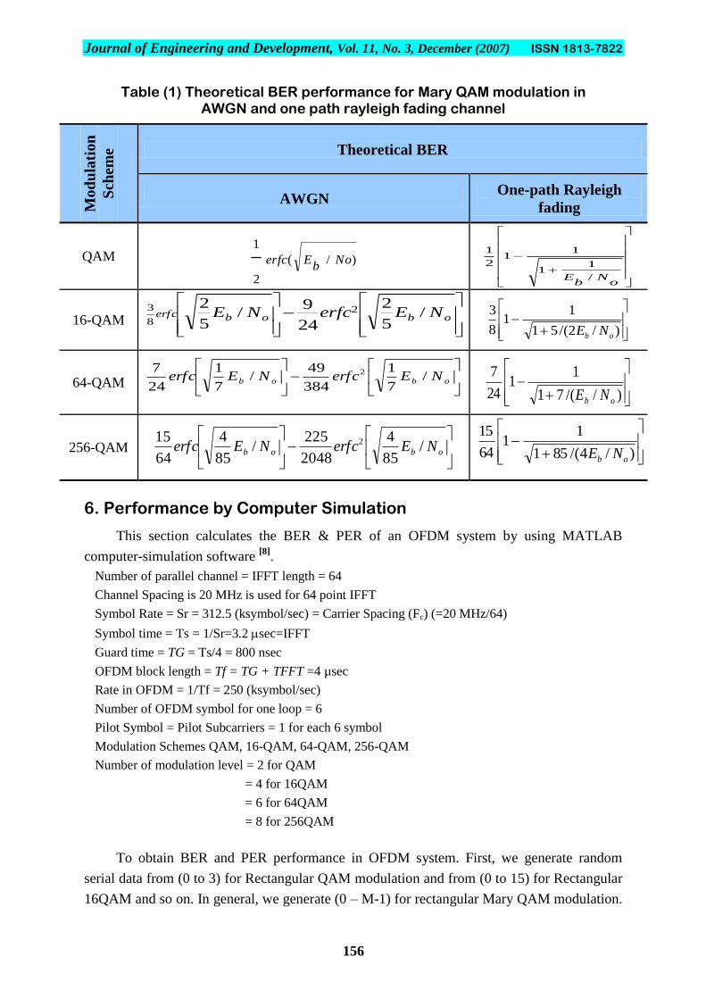
Table (1) shows the theoretical result of BER performance in Rectangular Mary QAM
modulation schemes in AWGN channel and single-path Rayleigh fading channel for OFDM
system [15]
.
Journal of Engineering and Development, Vol. 11, No. 3, December (2007) ISSN 1813-7822
156
Table (1) Theoretical BER performance for Mary QAM modulation in AWGN and one path rayleigh fading channel
Theoretical BER
Mod
ula
tion
Sch
eme
One-path Rayleigh
fading AWGN
oN
bE /
11
11
2
1
)/(
2
1
Nob
Eerfc
QAM
)/2/(51
11
8
3
ob NE
oboberfc NEerfcNE /
5
2
24
9/
5
22
8
3
16-QAM
)//(71
11
24
7
ob NE
obob NEerfcNEerfc /
7
1
384
49/
7
1
24
7 2
64-QAM
)/4/(851
11
64
15
ob NE
obob NEerfcNEerfc /
85
4
2048
225/
85
4
64
15 2 256-QAM
6. Performance by Computer Simulation
This section calculates the BER & PER of an OFDM system by using MATLAB
computer-simulation software [8]
.
Number of parallel channel = IFFT length = 64
Channel Spacing is 20 MHz is used for 64 point IFFT
Symbol Rate = Sr = 312.5 (ksymbol/sec) = Carrier Spacing (Fc) (=20 MHz/64)
Symbol time = Ts = 1/Sr=3.2 sec=IFFT
Guard time = TG = Ts/4 = 800 nsec
OFDM block length = Tf = TG + TFFT =4 µsec
Rate in OFDM = 1/Tf = 250 (ksymbol/sec)
Number of OFDM symbol for one loop = 6
Pilot Symbol = Pilot Subcarriers = 1 for each 6 symbol
Modulation Schemes QAM, 16-QAM, 64-QAM, 256-QAM
Number of modulation level = 2 for QAM
= 4 for 16QAM
= 6 for 64QAM
= 8 for 256QAM
To obtain BER and PER performance in OFDM system. First, we generate random
serial data from (0 to 3) for Rectangular QAM modulation and from (0 to 15) for Rectangular
16QAM and so on. In general, we generate (0 – M-1) for rectangular Mary QAM modulation.

Journal of Engineering and Development, Vol. 11, No. 3, December (2007) ISSN 1813-7822
157
Of length 1 by (number of parallel channel)*(number of OFDM symbol for one
loop)*(modulation level).Then the serial data vector converted into a parallel data vector
consisting of (number of parallel channel) by (number of OFDM symbol for one
loop)*(modulation level) vector to transmit the data in parallel in order to enable parallel
transmission with 64subchannels where each channel modulated using Rectangular
Mary-QAM modulation scheme. Then parallel data on the frequency axis fed into the
64-point IFFT circuit, in the circuit, the parallel data were converted into serial data on the
time axis by using OFDM, then guard interval (cyclic prefix) of 25% of symbol period is
added, were inserted to eliminate ISI caused by multipath fading. Then, the signal transmitted
to the air. The transmitted signal passed through the radio channel (equivalent low pass
system). At the receiver, the received signal is first contaminated by AWGN.
To determine the relationship between Eb/No and BER. That means we must vary the
attenuation level while keeping Eb/No constant. The attenuation level is calculated as follows.
First, energy per bit Eb and noise power density No are defined:
)bit/T.W(
br
powS
Eb …………………………………… (7)
)Hz/W(Sr
pown
No …………………………………………... (8)
where:
Spow , nopw, br and Sr: are the signal power per carrier per symbol.
The noise power per symbol, the bit rate, and the symbol rate, respectively. From
combining Eq.7 and Eq.8 .We get:
npow
Sr
br
Spow
No
Eb
After manipulation, we get:
NoEb
Sr
br
Spownpow …………………………………….. (9)
Since Eb/No is in decibels, Eq.9 can be written as:
)No*10(Eb10
Sr
br
Spownpow
……………………………... (10)
The noise signal must be expressed in voltage and Gaussian noise is normally
distributed equally in in-phase and quadrature-phase channels. Therefore,
Journal of Engineering and Development, Vol. 11, No. 3, December (2007) ISSN 1813-7822
158
npow2
1leveln Attenuatio . At the receiver, the guard interval removed form received
signal. Then the data on the time axis were fed into the 64-point FFT circuit. In the circuit, the
serial data were converted into parallel data on the frequency axis .After that, the demodulated
data were converted into a 1 by (number of parallel channel)*(number of OFDM symbol for
one loop)*(modulation level) Vector. Next, we calculated the bit error rate BER defined as
the number of error data divided by number of transmitted data. At the same time, we
calculated the packet error rate PER. Defined as the error of transmitted data symbol in one
packet. In this case, six OFDM symbol exist in one packet. If more than one of these
transmitted data symbol in one packet makes a mistake, a packet error occurs. The packet
error rate defined as the number of error packet divided by the number of transmitted packet,
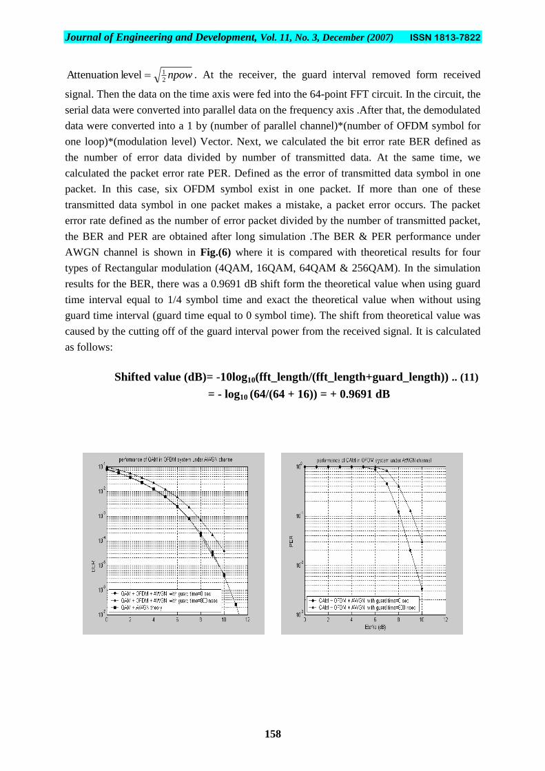
the BER and PER are obtained after long simulation .The BER & PER performance under
AWGN channel is shown in Fig.(6) where it is compared with theoretical results for four
types of Rectangular modulation (4QAM, 16QAM, 64QAM & 256QAM). In the simulation
results for the BER, there was a 0.9691 dB shift form the theoretical value when using guard
time interval equal to 1/4 symbol time and exact the theoretical value when without using
guard time interval (guard time equal to 0 symbol time). The shift from theoretical value was
caused by the cutting off of the guard interval power from the received signal. It is calculated
as follows:
Shifted value (dB)= -10log10(fft_length/(fft_length+guard_length)) .. (11)
= - log10 (64/(64 + 16)) = + 0.9691 dB

Journal of Engineering and Development, Vol. 11, No. 3, December (2007) ISSN 1813-7822
159
(a) (b)
Figure (6) Performance of Mary QAM modulation in OFDM system under AWGN channel (with and without guard time) (a) BER (b) PER

Journal of Engineering and Development, Vol. 11, No. 3, December (2007) ISSN 1813-7822
160
Figure (7) show the BER & PER performance under one-path Rayleigh fading channel
with Doppler shift of 320Hz which means fading period equal to 3.125 msec. In this
simulation, if we cannot compensate for the amplitude and phase fluctuation caused by
propagation characteristics, we cannot recover the data. (BER is closed to 0.5 & PER is
closed to 1).

Journal of Engineering and Development, Vol. 11, No. 3, December (2007) ISSN 1813-7822
161
(a) (b)
Figure (7) Performance of Mary QAM modulation in OFDM system under one path Rayleigh fading channel (without compensator) (a) BER (b) PER
Figure (9) show the BER and PER performance compared with the theoretical value for
one-path Rayleigh fading with Doppler shift of 320Hz which means fading period equal to
3.125 msec., when an assumption ideal channel estimation is achieved (perfect compensation)
after adding 11 zeros in the center of data and zero in the beginning (over sampling present)
before fed into the 64-point IFFT as shown in the Fig.(8) to obtain real OFDM simulation [5]
.
Figure (8) Input and output of IFFT
In this case ,we achieved 52 sub carrier transmission by using an OFDM technique
based on a 64-point IFFT circuit and guard time equal to 1/4 symbol time, i.e. Nominal
Bandwidth 16.25 MHz (=312.5 kHz 52). In the simulation result for the BER, there was a
+0.9691dB shift from the theoretical value. The shift of the value was caused by the cutting
off of the guard interval power form the received signal as shown in Eq.11.
64-point
IFFT
0
1 .
.
.
26
27 .
.
.
37
38 .
.
.
62
63
Null
Null

Journal of Engineering and Development, Vol. 11, No. 3, December (2007) ISSN 1813-7822
162

Journal of Engineering and Development, Vol. 11, No. 3, December (2007) ISSN 1813-7822
163
(a) (b)
Figure (9) Performance of Mary QAM modulation in OFDM system under one path Rayleigh fading channel (with perfect compensator) (a) BER (b) PER
7. Pilot Symbol-Aided OFDM Modulation
It is important to estimate the propagation characteristics in real time .one of the
estimation methods is a pilot-symbol aided OFDM modulation scheme. In this method, pilot
symbols are inserted at the transmitter at fixed time intervals and at the receiver we estimate
the channel characteristics by using the pilot symbol because the level of fluctuation is
independent in each sub carrier channel we can insert pilot carried in all frequency domains at
a known time period. Then, by using the estimated channel characteristics, we can recover the
transmitted data [16]
. This simulation uses one channel estimation symbol and six transmitted
data symbols as one frame (packet) unit. Figure (10) show the BER and PER performance
compared with the theoretical value for one and two path Rayleigh fading channel in channel
estimation compensation. From the BER performance under one-path Rayleigh fading
channel, we found that if we can compensate for the amplitude and phase fluctuation caused
by fading (ideal channel estimation is achieved), we can obtain a 0.9691 dB shift form the
theoretical value as shown in Eq.11. However, if we cannot compensate for the fluctuation,
we cannot recover the data (BER=0.5 & PER=1). On the other hand, if we use a pilot signal-
assisted OFDM transmission scheme, we can obtain ≈ 4dB shift form the theoretical value
this was because we input pilot data of 1/7 in one frame (packet) unit and use high value of
Doppler frequency (fd=320), the fading period is 3.125 ms. So channel estimation is not
accurate enough to follow those fast fading.
In a two path channel, the BER performance of the pilot signal-assisted OFDM system
partly depends on the position of the delayed wave in two-path Rayleigh fading channel. If
the delay time of the delayed wave is equal (500nsec) which is means that, its shorter than the
guard interval which is equal to (800nsec), all fluctuations of the amplitude and phase can be

Journal of Engineering and Development, Vol. 11, No. 3, December (2007) ISSN 1813-7822
164
removed by using pilot signals and the BER performance is the same as that in single-path
Rayleigh fading channel. However, if the delay time is equal to (1000nsec) which is longer
than the guard integral which is equal to (800nsec), ISI contaminates the next symbol and the
BER performance degrades. For two cases, it’s assumed that one delayed wave have mean
power of 1dB smaller than that of the direct wave.

Journal of Engineering and Development, Vol. 11, No. 3, December (2007) ISSN 1813-7822
165
(a) (b)
Figure (10) Performance of Mary QAM modulation in OFDM system under one path rayleigh fading channel (with perfect & CE compensation)
8. Conclusions
This paper describes the concept behind parallel data transmission and the configuration
of an OFDM transmitter and receiver. We explained how we configured the OFDM
transmitter and receiver by using computer simulation. OFDM system uses orthogonal
subcarrier. It achieves high spectral efficiency, saving in bandwidth, and allows separating the
subcarrier without causing any interference with each other. Fast Fourier Transform (FTT) is
used to modulate and demodulate OFDM system to establish the orthogonality in subcarrier
and reduces the complexity needed by the conventional multicarrier modulation system.
Guard time with cyclic extension is inserted for each OFDM symbol to eliminate ISI
completely and reduces ICI.
In OFDM simulation, for AWGN channel, the insertion of guard time caused 0.9691 dB
shift from theoretical value, while for one path Rayleigh fading channel, if we cannot
compensate for the amplitude and phase fluctuation caused is propagation characteristics of
the channel, we cannot recover the data. While, when assumption ideal channel estimation
(perfect compensation) is achieved we have 0.9691 dB shifts from theoretical value.
Finally for simulation of broad band WLAN system by using a pilot symbol assisted
OFDM transmission system in one path Rayleigh fading channel, we can obtain the BER
shifted from theoretical value. While for two path Rayleigh fading channel, the BER depends
on the position of the delayed wave. If the delay time of the delayed wave is shorter than the
guard time, the BER performance is the same as that in single path Rayleigh fading channel.
However, if the delay time is longer than the guard interval, ISI contaminates the next symbol
and the BER performance degrades.
Journal of Engineering and Development, Vol. 11, No. 3, December (2007) ISSN 1813-7822
166
9. References
1. J., Proakis, “Digital Communication”, Second Edition, McGraw Hill Co. Ltd.,
1989.
2. R. S., Kennedy, “Fading Dispersive Communication Channels”, Wiley, 1969.
3. “Orthogonal Frequency Division Multiplex (OFDM) Tutorial”, Intuitive Guide to
Principles of Communication, Charan Langton, 2004. www.complextoreal.com
4. Van Nee, R., and R., Prasad, “OFDM for Wireless Multimedia Communication”,
Norwood, MA: Artech House, 1999.
5. “OFDM for Mobile Data Communication”, International Engineering Consortium,
2005.
6. Prasad, R., “Universal Wireless Personal Communications”, Chapter 10,
Norwood, MA: Artech House, 1998.
7. R. W. Chang, “Orthogonal Frequency Division Multiplexing”, U.S. Patent 3, 488,
445, Filed Nov. 41966, Issued Jan., 1970.
8. Eric Phillip Lawrey, “Adaptive Techniques for Multiuser OFDM”, Thesis, School
of Engineering, James Cook University, December 2001.
9. Richard Van Nee, and Ramjee Prased, “OFDM for Wireless Multimedia
Communications”, Artech House Publisher, Boston, 2000.
10. E., Lawrey, “Multiuser OFDM”, Ph.D. Thesis, James Cook University,
December, 2001.
11. L. J., Cimini, Jr., “Analysis and Simulation of a Digital Mobile Channel using
Orthogonal Frequency Division Multiplexing”, IEEE Trans. on Comm., July
1985, pp. 665-675.
12. Eric Phillip Lawrey, “Adaptive Techniques for Multiuser OFDM”, Thesis,
Submitted by School of Engineering, James Cook University, December 2001.
13. G., Caire, “Wireless Communications”, Eurecom Course Notes, 1999.
14. Speth Fechtel, Fock Meyr, “Optimum Receiver Design for Wireless Broadband
System using OFDM”, IEEE Trans. on Comm., Vol. 47, No. ll, February 1999.
15. Chang, R. W., and R. A., Gibby, “A Theoretical Study of the Performance of an
Orthogonal Multiplexing Data Transmission Scheme”, IEEE Trans., Comm.,
Vol. Com-16, No. 4, August 1968, pp. 527-540.
16. P., Hoeher, S., Kaiser, and P., Robertson, “Pilot Symbol Aided Channel Estimation
in Time and Frequency’, Proc. of Globe Com, 1997, pp. 90-96.