Biofuel Cells Controlled by Logically Processed Biochemical Signals: Towards Physiologically...
11
Biofuel Cells Controlled by Logically Processed Biochemical Signals: Towards Physiologically Regulated Bioelectronic Devices Evgeny Katz* and Marcos Pita [a] # 2009 Wiley-VCH Verlag GmbH & Co. KGaA, Weinheim Chem. Eur. J. 2009, 15, 12554 – 12564 12554 DOI: 10.1002/chem.200902367
-
Upload
independent -
Category
Documents
-
view
1 -
download
0
Transcript of Biofuel Cells Controlled by Logically Processed Biochemical Signals: Towards Physiologically...
Biofuel Cells Controlled by Logically Processed Biochemical Signals:Towards Physiologically Regulated Bioelectronic Devices
Evgeny Katz* and Marcos Pita[a]
� 2009 Wiley-VCH Verlag GmbH & Co. KGaA, Weinheim Chem. Eur. J. 2009, 15, 12554 – 1256412554
DOI: 10.1002/chem.200902367
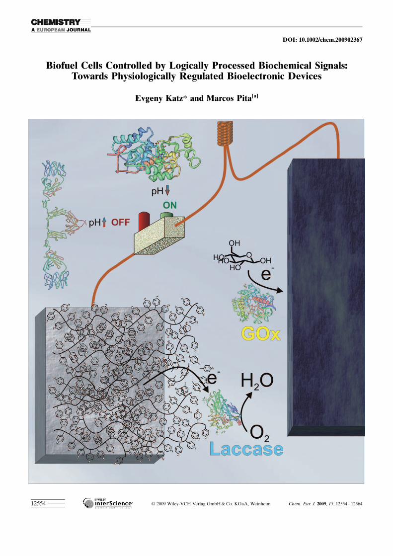
Introduction
Fuel cells are promising electrochemical generators of sus-tainable electrical power produced upon catalytic oxidationof gas or liquid fuels flowing through the cells.[1] Usuallythey operate using noble metals to catalyze redox transfor-mations of the fuel and oxidizer at the electrodes in the cell.Biofuel cells utilize biochemical approaches for catalyzingthese reactions to yield electrical power.[2] They include twobioelectrocatalytic electrodes; an anode for oxidation of or-ganic compounds[3] and a cathode for reduction of oxygen,being an oxidizer consuming electrons transported throughthe electrical circuit from the oxidized fuel.[4] Purified en-zymes[5] or whole microbial cells[6] are used to biocatalyzeredox transformations at the electrodes and/or generate oxi-dizable substrates from raw organic substances. In the lastdecade the major fundamental problems of coupling be-tween the biochemical and electrochemical processes,
mostly related to the efficient interfacial charge transportusing mediated or direct electron transfer between enzymes/microbial cells and electrodes, were solved[7] and the biofuelcells became feasible.[8] Practical application of biofuel cellsis still awaiting for solutions of many difficult engineeringproblems, particularly related to their power efficiency,[9]
long-term operation[10] and miniaturization.[11] Most of theseengineering problems require biochemical, microbiologicalor, in general, biotechnological approaches. One of the im-portant potential applications of the biofuel cells is power-ing implantable biomedical devices.[12] Miniaturized biofuelcells might be implanted in a human body to use naturallyexisting biochemical substances as fuel (e.g., glucose in ablood stream).[13] Adaptive behavior of the implantable bio-fuel cell being self-regulated and producing electrical poweron-demand would be an immense advantage for these bio-electronic devices. Such devices could be based on modifiedelectrodes with switchable/tunable activity.
A large variety of modified electrodes switchable betweenelectrochemically active and inactive states by various physi-cal and/or chemical signals were reported in the last two de-cades,[14] however very few of them were used in biofuelcells.[15] Different mechanisms were involved in the transi-tion of the electrode interfaces between the active and inac-tive states depending on the properties of the modified sur-faces and the nature of the applied signals. The activity ofthe switchable electrodes was usually controlled by physicalsignals (optical,[16] electrical[17] or magnetic[18]), which cannotprovide direct communication between the electrodes andtheir biochemical environment. Switchable electrodes con-trolled by biochemical rather than physical signals areneeded to design a biofuel cell adjustable to its biochemicalenvironment according to the presence or absence of bio-chemical substances. A new approach became possible whena polymer-modified electrode switchable between ON/OFFstates by pH values[19] was coupled to biochemical reactionsgenerating pH changes in situ.[20] This allowed transductionof biochemical input signals (e.g., glucose concentration) tothe pH changes governing the electrochemical activity ofthe switchable electrode.[21] Using the concept of Booleanlogic gates[22] and biocomputing networks based on enzymat-ic reactions,[23] the complexity of the enzyme system control-ling the electrode activity was scaled up. Finally, the switcha-ble electrodes controlled by complex multi-enzyme systems,being reversibly activated-inactivated by various patterns ofdifferent biochemicals,[24] were assembled in a biofuel cellproducing electrical power depending on the biochemicalenvironment.[25–27] The present paper uncovers a new area offundamental research activity in biofuel cell studies—thecoupling of biofuel cells with biocomputing systems to yield“smart” bioelectronic devices generating electrical poweron-demand upon logic processing of biochemical signals.
Abstract: Biofuel cells with a switchable power releasecontrolled by biochemical signals, which can be logicallyprocessed by biomolecular computing systems, havebeen designed. The switchable properties of the biofuelcells were based on the polymer-brush-modified electro-des with the activity dependent on the solution pHvalue. The pH changes generated in situ by biocatalyticreactions allowed the reversible activation—inactivationof the bioelectrocatalytic interfaces—thus affecting theactivity of the entire biofuel cells. Boolean logic opera-tions performed by either enzyme- or immune-basedsystems were functionally integrated with the switchablebiocatalytic process allowing logic control over them.Scaling up the complexity of the biocomputing systemsto complex multi-component logic networks with abuilt-in “program” resulted in the control of the bio-electronic systems by multi-signal patterns of biochemi-cal inputs. Future implantable biofuel cells producingelectrical power on-demand depending on physiologicalconditions are feasible, as the result of the presentresearch.
Keywords: biocomputing · fuel cells · Boolean logic ·enzymes · immune agents
[a] Prof. E. Katz, Dr. M. PitaDepartment of Chemistry and Biomolecular Scienceand NanoBio Laboratory (NABLAB)Clarkson University, Potsdam NY 13699-5810 (USA)Fax: (+1) 315-268-6610E-mail : [email protected]
Chem. Eur. J. 2009, 15, 12554 – 12564 � 2009 Wiley-VCH Verlag GmbH & Co. KGaA, Weinheim www.chemeurj.org 12555
CONCEPT
Polymer Brush-Modified Electrodes Switchable bypH Changes
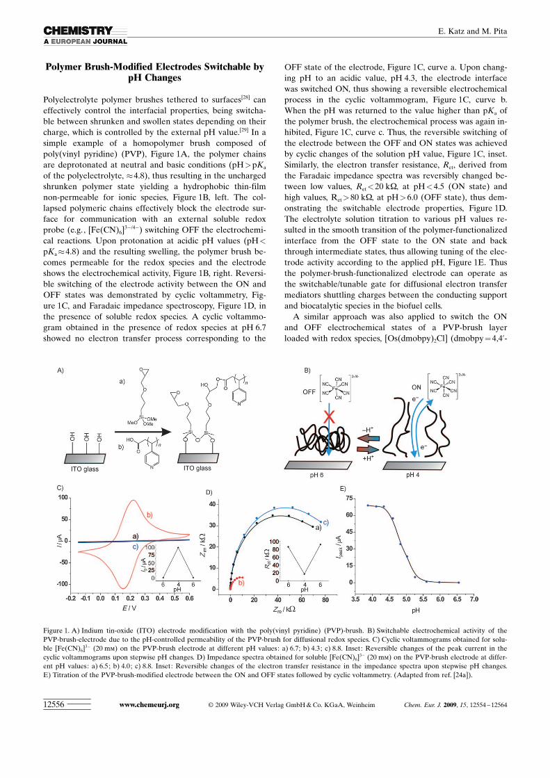
Polyelectrolyte polymer brushes tethered to surfaces[28] caneffectively control the interfacial properties, being switcha-ble between shrunken and swollen states depending on theircharge, which is controlled by the external pH value.[29] In asimple example of a homopolymer brush composed ofpoly(vinyl pyridine) (PVP), Figure 1A, the polymer chainsare deprotonated at neutral and basic conditions (pH>pKa
of the polyelectrolyte, �4.8), thus resulting in the unchargedshrunken polymer state yielding a hydrophobic thin-filmnon-permeable for ionic species, Figure 1B, left. The col-lapsed polymeric chains effectively block the electrode sur-face for communication with an external soluble redoxprobe (e.g., [Fe(CN)6]
3�/4�) switching OFF the electrochemi-cal reactions. Upon protonation at acidic pH values (pH<
pKa�4.8) and the resulting swelling, the polymer brush be-comes permeable for the redox species and the electrodeshows the electrochemical activity, Figure 1B, right. Reversi-ble switching of the electrode activity between the ON andOFF states was demonstrated by cyclic voltammetry, Fig-ure 1C, and Faradaic impedance spectroscopy, Figure 1D, inthe presence of soluble redox species. A cyclic voltammo-gram obtained in the presence of redox species at pH 6.7showed no electron transfer process corresponding to the
OFF state of the electrode, Figure 1C, curve a. Upon chang-ing pH to an acidic value, pH 4.3, the electrode interfacewas switched ON, thus showing a reversible electrochemicalprocess in the cyclic voltammogram, Figure 1C, curve b.When the pH was returned to the value higher than pKa ofthe polymer brush, the electrochemical process was again in-hibited, Figure 1C, curve c. Thus, the reversible switching ofthe electrode between the OFF and ON states was achievedby cyclic changes of the solution pH value, Figure 1C, inset.Similarly, the electron transfer resistance, Ret, derived fromthe Faradaic impedance spectra was reversibly changed be-tween low values, Ret<20 kW, at pH<4.5 (ON state) andhigh values, Ret>80 kW, at pH>6.0 (OFF state), thus dem-onstrating the switchable electrode properties, Figure 1D.The electrolyte solution titration to various pH values re-sulted in the smooth transition of the polymer-functionalizedinterface from the OFF state to the ON state and backthrough intermediate states, thus allowing tuning of the elec-trode activity according to the applied pH, Figure 1E. Thusthe polymer-brush-functionalized electrode can operate asthe switchable/tunable gate for diffusional electron transfermediators shuttling charges between the conducting supportand biocatalytic species in the biofuel cells.
A similar approach was also applied to switch the ONand OFF electrochemical states of a PVP-brush layerloaded with redox species, [Os ACHTUNGTRENNUNG(dmobpy)2Cl] (dmobpy=4,4’-
Figure 1. A) Indium tin-oxide (ITO) electrode modification with the poly(vinyl pyridine) (PVP)-brush. B) Switchable electrochemical activity of thePVP-brush-electrode due to the pH-controlled permeability of the PVP-brush for diffusional redox species. C) Cyclic voltammograms obtained for solu-ble [Fe(CN)6]
3� (20 mm) on the PVP-brush electrode at different pH values: a) 6.7; b) 4.3; c) 8.8. Inset: Reversible changes of the peak current in thecyclic voltammograms upon stepwise pH changes. D) Impedance spectra obtained for soluble [Fe(CN)6]
3� (20 mm) on the PVP-brush electrode at differ-ent pH values: a) 6.5; b) 4.0; c) 8.8. Inset: Reversible changes of the electron transfer resistance in the impedance spectra upon stepwise pH changes.E) Titration of the PVP-brush-modified electrode between the ON and OFF states followed by cyclic voltammetry. (Adapted from ref. [24a]).
www.chemeurj.org � 2009 Wiley-VCH Verlag GmbH & Co. KGaA, Weinheim Chem. Eur. J. 2009, 15, 12554 – 1256412556
E. Katz and M. Pita
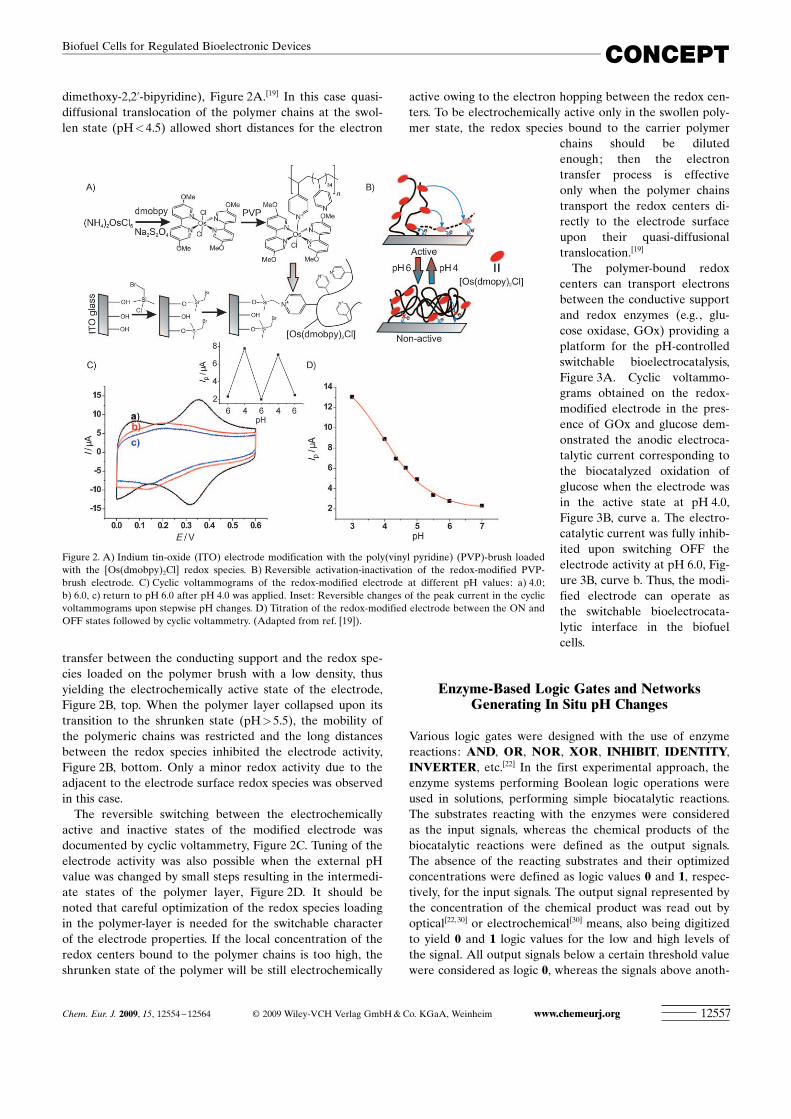
dimethoxy-2,2’-bipyridine), Figure 2A.[19] In this case quasi-diffusional translocation of the polymer chains at the swol-len state (pH<4.5) allowed short distances for the electron
transfer between the conducting support and the redox spe-cies loaded on the polymer brush with a low density, thusyielding the electrochemically active state of the electrode,Figure 2B, top. When the polymer layer collapsed upon itstransition to the shrunken state (pH>5.5), the mobility ofthe polymeric chains was restricted and the long distancesbetween the redox species inhibited the electrode activity,Figure 2B, bottom. Only a minor redox activity due to theadjacent to the electrode surface redox species was observedin this case.
The reversible switching between the electrochemicallyactive and inactive states of the modified electrode wasdocumented by cyclic voltammetry, Figure 2C. Tuning of theelectrode activity was also possible when the external pHvalue was changed by small steps resulting in the intermedi-ate states of the polymer layer, Figure 2D. It should benoted that careful optimization of the redox species loadingin the polymer-layer is needed for the switchable characterof the electrode properties. If the local concentration of theredox centers bound to the polymer chains is too high, theshrunken state of the polymer will be still electrochemically
active owing to the electron hopping between the redox cen-ters. To be electrochemically active only in the swollen poly-mer state, the redox species bound to the carrier polymer
chains should be dilutedenough; then the electrontransfer process is effectiveonly when the polymer chainstransport the redox centers di-rectly to the electrode surfaceupon their quasi-diffusionaltranslocation.[19]
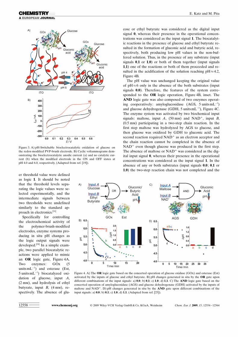
The polymer-bound redoxcenters can transport electronsbetween the conductive supportand redox enzymes (e.g., glu-cose oxidase, GOx) providing aplatform for the pH-controlledswitchable bioelectrocatalysis,Figure 3A. Cyclic voltammo-grams obtained on the redox-modified electrode in the pres-ence of GOx and glucose dem-onstrated the anodic electroca-talytic current corresponding tothe biocatalyzed oxidation ofglucose when the electrode wasin the active state at pH 4.0,Figure 3B, curve a. The electro-catalytic current was fully inhib-ited upon switching OFF theelectrode activity at pH 6.0, Fig-ure 3B, curve b. Thus, the modi-fied electrode can operate asthe switchable bioelectrocata-lytic interface in the biofuelcells.
Enzyme-Based Logic Gates and NetworksGenerating In Situ pH Changes
Various logic gates were designed with the use of enzymereactions: AND, OR, NOR, XOR, INHIBIT, IDENTITY,INVERTER, etc.[22] In the first experimental approach, theenzyme systems performing Boolean logic operations wereused in solutions, performing simple biocatalytic reactions.The substrates reacting with the enzymes were consideredas the input signals, whereas the chemical products of thebiocatalytic reactions were defined as the output signals.The absence of the reacting substrates and their optimizedconcentrations were defined as logic values 0 and 1, respec-tively, for the input signals. The output signal represented bythe concentration of the chemical product was read out byoptical[22,30] or electrochemical[30] means, also being digitizedto yield 0 and 1 logic values for the low and high levels ofthe signal. All output signals below a certain threshold valuewere considered as logic 0, whereas the signals above anoth-
Figure 2. A) Indium tin-oxide (ITO) electrode modification with the poly(vinyl pyridine) (PVP)-brush loadedwith the [Os ACHTUNGTRENNUNG(dmobpy)2Cl] redox species. B) Reversible activation-inactivation of the redox-modified PVP-brush electrode. C) Cyclic voltammograms of the redox-modified electrode at different pH values: a) 4.0;b) 6.0, c) return to pH 6.0 after pH 4.0 was applied. Inset: Reversible changes of the peak current in the cyclicvoltammograms upon stepwise pH changes. D) Titration of the redox-modified electrode between the ON andOFF states followed by cyclic voltammetry. (Adapted from ref. [19]).
Chem. Eur. J. 2009, 15, 12554 – 12564 � 2009 Wiley-VCH Verlag GmbH & Co. KGaA, Weinheim www.chemeurj.org 12557
CONCEPTBiofuel Cells for Regulated Bioelectronic Devices
er threshold value were definedas logic 1. It should be notedthat the threshold levels sepa-rating the logic values were se-lected experimentally, and theintermediate signals betweentwo thresholds were undefinedsimilarly to the standard ap-proach in electronics.[31]
Specifically for controllingthe electrochemical activity ofthe polymer-brush-modifiedelectrodes, enzyme systems pro-ducing in situ pH changes asthe logic output signals weredeveloped.[24] In a simple exam-ple, two parallel biocatalytic re-actions were applied to mimican OR logic gate, Figure 4A.Two enzymes: GOx (5units mL�1) and esterase (Est,5 units mL�1) biocatalyzed oxi-dation of glucose, input A,(2 mm), and hydrolysis of ethylbutyrate, input B, (4 mm), re-spectively. The absence of glu-
cose or ethyl butyrate was considered as the digital inputsignal 0, whereas their presence in the operational concen-trations was considered as the input signal 1. The biocatalyt-ic reactions in the presence of glucose and ethyl butyrate re-sulted in the formation of gluconic acid and butyric acid, re-spectively, both producing low pH values in the non-buf-fered solution. Thus, in the presence of any substrate (inputsignals 0,1 or 1,0) or both of them together (input signals1,1) one of the reactions or both of them proceeded and re-sulted in the acidification of the solution reaching pH�4.2,Figure 4B.
The pH value was unchanged keeping the original valueof pH�6 only in the absence of the both substrates (inputsignals 0,0). Therefore, the features of the system corre-sponded to the OR logic operation, Figure 4B, inset. TheAND logic gate was also composed of two enzymes operat-ing cooperatively: amyloglucosidase (AGS, 5 units mL�1)and glucose dehydrogenase (GDH, 5 unitsmL�1), Figure 4C.The enzyme system was activated by two biochemical inputsignals: maltose, input A, (50 mm) and NAD+ , input B,(0.5 mm) participating in a two-step chain reaction. In thefirst step maltose was hydrolyzed by AGS to glucose, andthen glucose was oxidized by GDH to gluconic acid. Thesecond reaction required NAD+ as an electron acceptor andthe chain reaction cannot be completed in the absence ofNAD+ even though glucose was produced in the first step.The absence of maltose or NAD+ was considered as the dig-ital input signal 0, whereas their presence in the operationalconcentrations was considered as the input signal 1. In theabsence of any or both substrates (input signals 0,0 ; 0,1 or1,0) the two-step reaction chain was not completed and the
Figure 3. A) pH-Switchable bioelectrocatalytic oxidation of glucose onthe redox-modified PVP-brush electrode. B) Cyclic voltammograms dem-onstrating the bioelectrocatalytic anodic current (a) and no catalytic cur-rent (b) when the modified electrode in the ON and OFF states atpH 4.0 and 6.0, respectively. (Adapted from ref. [19]).
Figure 4. A) The OR logic gate based on the concerted operation of glucose oxidase (GOx) and esterase (Est)activated by the inputs of glucose and ethyl butyrate. B) pH changes generated in situ by the OR gate upondifferent combinations of the input signals: a) 0,0 ; b) 0,1; c) 1,0 ; d) 1,1. C) The AND logic gate based on theconcerted operation of amyloglucosidase (AGS) and glucose dehydrogenase (GDH) activated by the inputs ofmaltose and NAD+ . D) pH changes generated in situ by the AND gate upon different combinations of theinput signals: a) 0,0 ; b) 0,1; c) 1,0 ; d) 1,1. (Adapted from ref. [25]).
www.chemeurj.org � 2009 Wiley-VCH Verlag GmbH & Co. KGaA, Weinheim Chem. Eur. J. 2009, 15, 12554 – 1256412558
E. Katz and M. Pita
pH value was not changed. In the presence of the both sub-strates (input signals 1,1) the reaction proceeded until thevery end, resulting in the formation of gluconic acid andacidification of the solution reaching pH�4.3, Figure 4D.Therefore, the features of the system corresponded to theAND logic operation, Figure 4D, inset.
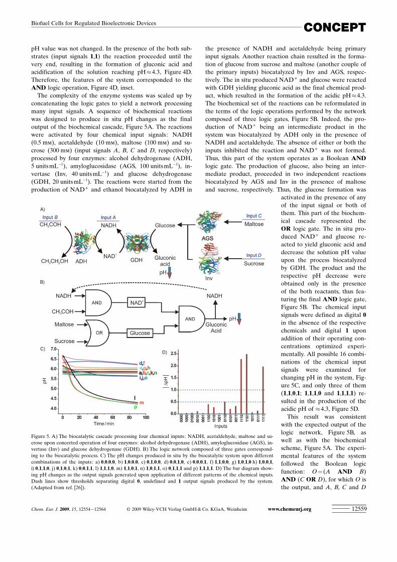
The complexity of the enzyme systems was scaled up byconcatenating the logic gates to yield a network processingmany input signals. A sequence of biochemical reactionswas designed to produce in situ pH changes as the finaloutput of the biochemical cascade, Figure 5A. The reactionswere activated by four chemical input signals: NADH(0.5 mm), acetaldehyde (10 mm), maltose (100 mm) and su-crose (300 mm) (input signals A, B, C and D, respectively)processed by four enzymes: alcohol dehydrogenase (ADH,5 units mL�1), amyloglucosidase (AGS, 100 units mL�1), in-vertase (Inv, 40 units mL�1) and glucose dehydrogenase(GDH, 20 units mL�1). The reactions were started from theproduction of NAD+ and ethanol biocatalyzed by ADH in
the presence of NADH and acetaldehyde being primaryinput signals. Another reaction chain resulted in the forma-tion of glucose from sucrose and maltose (another couple ofthe primary inputs) biocatalyzed by Inv and AGS, respec-tively. The in situ produced NAD+ and glucose were reactedwith GDH yielding gluconic acid as the final chemical prod-uct, which resulted in the formation of the acidic pH�4.3.The biochemical set of the reactions can be reformulated inthe terms of the logic operations performed by the networkcomposed of three logic gates, Figure 5B. Indeed, the pro-duction of NAD+ being an intermediate product in thesystem was biocatalyzed by ADH only in the presence ofNADH and acetaldehyde. The absence of either or both theinputs inhibited the reaction and NAD+ was not formed.Thus, this part of the system operates as a Boolean ANDlogic gate. The production of glucose, also being an inter-mediate product, proceeded in two independent reactionsbiocatalyzed by AGS and Inv in the presence of maltoseand sucrose, respectively. Thus, the glucose formation was
activated in the presence of anyof the input signal or both ofthem. This part of the biochem-ical cascade represented theOR logic gate. The in situ pro-duced NAD+ and glucose re-acted to yield gluconic acid anddecrease the solution pH valueupon the process biocatalyzedby GDH. The product and therespective pH decrease wereobtained only in the presenceof the both reactants, thus fea-turing the final AND logic gate,Figure 5B. The chemical inputsignals were defined as digital 0in the absence of the respectivechemicals and digital 1 uponaddition of their operating con-centrations optimized experi-mentally. All possible 16 combi-nations of the chemical inputsignals were examined forchanging pH in the system, Fig-ure 5C, and only three of them(1,1,0,1; 1,1,1,0 and 1,1,1,1) re-sulted in the production of theacidic pH of �4.3, Figure 5D.
This result was consistentwith the expected output of thelogic network, Figure 5B, aswell as with the biochemicalscheme, Figure 5A. The experi-mental features of the systemfollowed the Boolean logicfunction: O = (A AND B)AND (C OR D), for which O isthe output, and A, B, C and D
Figure 5. A) The biocatalytic cascade processing four chemical inputs: NADH, acetaldehyde, maltose and su-crose upon concerted operation of four enzymes: alcohol dehydrogenase (ADH), amyloglucosidase (AGS), in-vertase (Inv) and glucose dehydrogenase (GDH). B) The logic network composed of three gates correspond-ing to the biocatalytic process. C) The pH changes produced in situ by the biocatalytic system upon differentcombinations of the inputs: a) 0,0,0,0, b) 1,0,0,0, c) 0,1,0,0, d) 0,0,1,0, e) 0,0,0,1, f) 1,1,0,0, g) 1,0,1,0 h) 1,0,0,1,i) 0,1,1,0, j) 0,1,0,1, k) 0,0,1,1, l) 1,1,1,0, m) 1,1,0,1, n) 1,0,1,1, o) 0,1,1,1 and p) 1,1,1,1. D) The bar diagram show-ing pH changes as the output signals generated upon application of different patterns of the chemical inputs.Dash lines show thresholds separating digital 0, undefined and 1 output signals produced by the system.(Adapted from ref. [26]).
Chem. Eur. J. 2009, 15, 12554 – 12564 � 2009 Wiley-VCH Verlag GmbH & Co. KGaA, Weinheim www.chemeurj.org 12559
CONCEPTBiofuel Cells for Regulated Bioelectronic Devices
are the input signals. After completing the enzyme-reactionsresulting in the logically controlled acidic medium (pH 4.1–4.5), the pH value was reset to the initial value (pH�6) bythe formation of ammonia upon hydrolysis of urea (5 mm)biocatalyzed by urease (10 units mL�1), thus performing theReset function. The logically generated pH changes in thesystems produced by the enzyme reactions activated by dif-ferent patterns of biochemical signals were coupled with thereversible activation/inactivation of the polymer-brush-modified electrodes described above and later used to as-semble the switchable biofuel cells.
Biofuel Cells Controlled by Logically ProcessedBiochemical Signals
As soon as the pH-switchable bioelectrocatalytic electrodesand the pH-change-producing enzyme logic systems wereformulated, the biofuel cells controlled by the logically pro-cessed biochemical signals became feasible.[25–27] In order tocontrol the biofuel cell activity only one switchable bioelec-trocatalytic electrode is enough, since the power productionin the biofuel cells requires simultaneous operation of bothelectrodes: The cathode and anode for the oxygen reductionand the biofuel oxidation, respectively. It should be notedthat in most of the known biofuel cells the cathode reactionis the same—bioelectrocatalytic oxygen reduction, whereasthe anodic process might differ substantially depending onthe used biofuel and the applied biocatalyst. This makesmore practical to control the activity of the bioelectrocata-lytic oxygen reduction at the modified cathode beingswitched between the ON and OFF states by the enzyme in-duced pH changes, Figure 6.
The described above PVP-brush functionalized with the[Os ACHTUNGTRENNUNG(dmobpy)2Cl] redox centers was used to generate thepH-switchable interface capable for mediating electrontransport with enzymes only being in the ON state at pH<
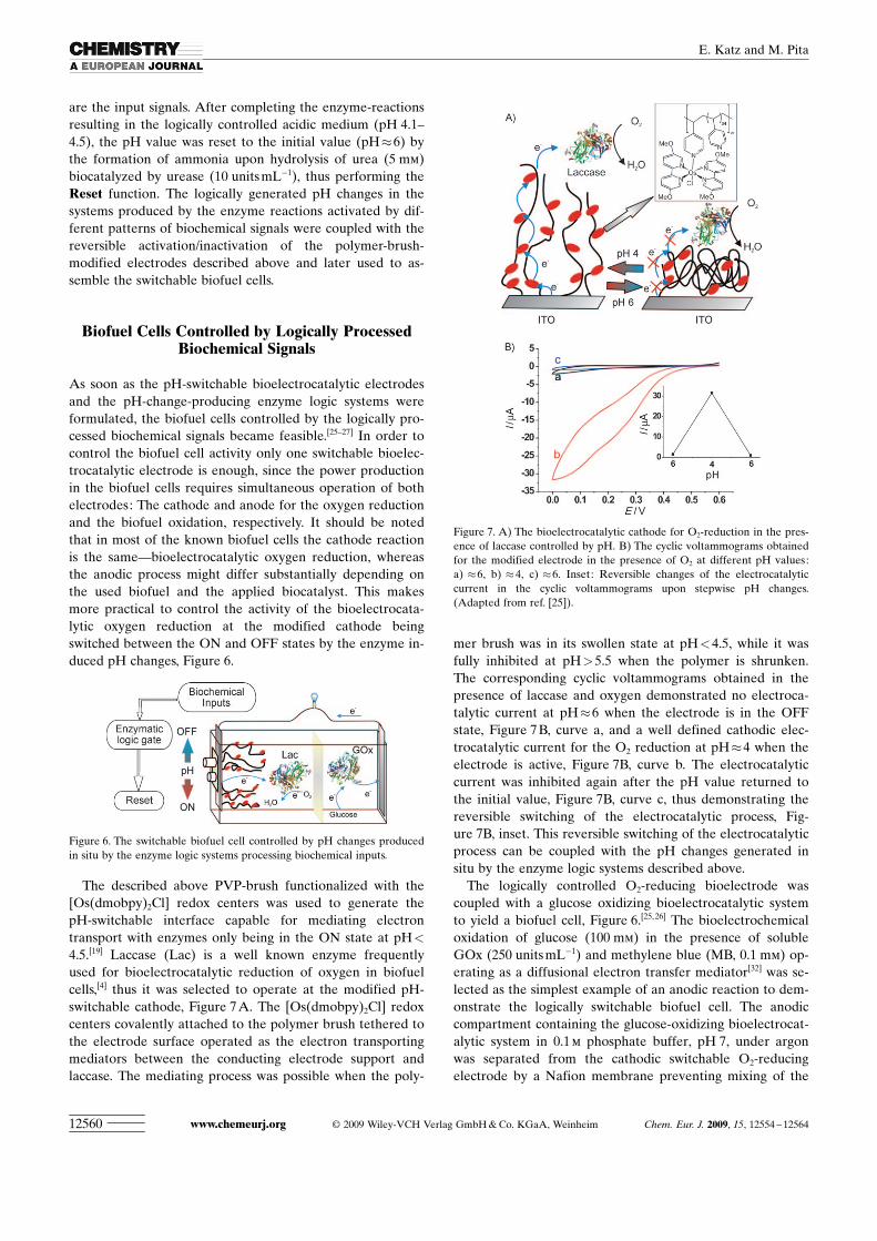
4.5.[19] Laccase (Lac) is a well known enzyme frequentlyused for bioelectrocatalytic reduction of oxygen in biofuelcells,[4] thus it was selected to operate at the modified pH-switchable cathode, Figure 7 A. The [OsACHTUNGTRENNUNG(dmobpy)2Cl] redoxcenters covalently attached to the polymer brush tethered tothe electrode surface operated as the electron transportingmediators between the conducting electrode support andlaccase. The mediating process was possible when the poly-
mer brush was in its swollen state at pH<4.5, while it wasfully inhibited at pH>5.5 when the polymer is shrunken.The corresponding cyclic voltammograms obtained in thepresence of laccase and oxygen demonstrated no electroca-talytic current at pH�6 when the electrode is in the OFFstate, Figure 7 B, curve a, and a well defined cathodic elec-trocatalytic current for the O2 reduction at pH�4 when theelectrode is active, Figure 7B, curve b. The electrocatalyticcurrent was inhibited again after the pH value returned tothe initial value, Figure 7B, curve c, thus demonstrating thereversible switching of the electrocatalytic process, Fig-ure 7B, inset. This reversible switching of the electrocatalyticprocess can be coupled with the pH changes generated insitu by the enzyme logic systems described above.
The logically controlled O2-reducing bioelectrode wascoupled with a glucose oxidizing bioelectrocatalytic systemto yield a biofuel cell, Figure 6.[25,26] The bioelectrochemicaloxidation of glucose (100 mm) in the presence of solubleGOx (250 units mL�1) and methylene blue (MB, 0.1 mm) op-erating as a diffusional electron transfer mediator[32] was se-lected as the simplest example of an anodic reaction to dem-onstrate the logically switchable biofuel cell. The anodiccompartment containing the glucose-oxidizing bioelectrocat-alytic system in 0.1 m phosphate buffer, pH 7, under argonwas separated from the cathodic switchable O2-reducingelectrode by a Nafion membrane preventing mixing of the
Figure 6. The switchable biofuel cell controlled by pH changes producedin situ by the enzyme logic systems processing biochemical inputs.
Figure 7. A) The bioelectrocatalytic cathode for O2-reduction in the pres-ence of laccase controlled by pH. B) The cyclic voltammograms obtainedfor the modified electrode in the presence of O2 at different pH values:a) �6, b) �4, c) �6. Inset: Reversible changes of the electrocatalyticcurrent in the cyclic voltammograms upon stepwise pH changes.(Adapted from ref. [25]).
www.chemeurj.org � 2009 Wiley-VCH Verlag GmbH & Co. KGaA, Weinheim Chem. Eur. J. 2009, 15, 12554 – 1256412560
E. Katz and M. Pita
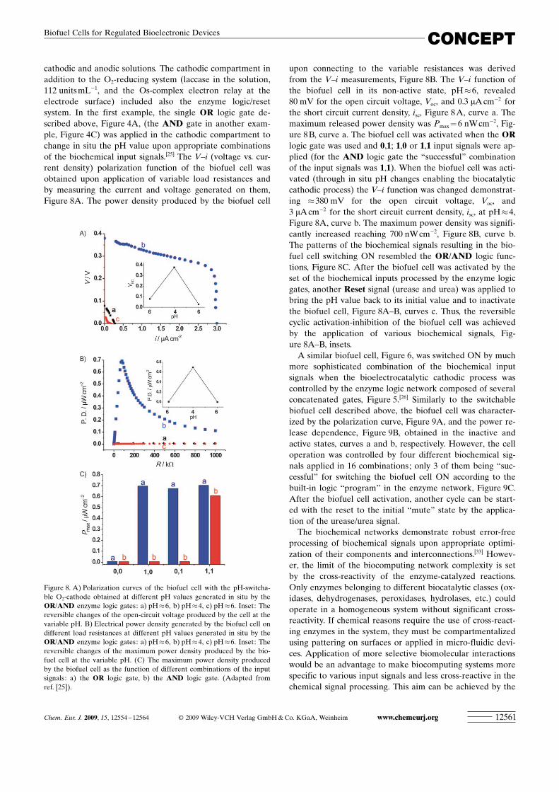
cathodic and anodic solutions. The cathodic compartment inaddition to the O2-reducing system (laccase in the solution,112 units mL�1, and the Os-complex electron relay at theelectrode surface) included also the enzyme logic/resetsystem. In the first example, the single OR logic gate de-scribed above, Figure 4A, (the AND gate in another exam-ple, Figure 4C) was applied in the cathodic compartment tochange in situ the pH value upon appropriate combinationsof the biochemical input signals.[25] The V–i (voltage vs. cur-rent density) polarization function of the biofuel cell wasobtained upon application of variable load resistances andby measuring the current and voltage generated on them,Figure 8A. The power density produced by the biofuel cell
upon connecting to the variable resistances was derivedfrom the V–i measurements, Figure 8B. The V–i function ofthe biofuel cell in its non-active state, pH�6, revealed80 mV for the open circuit voltage, Voc, and 0.3 mA cm�2 forthe short circuit current density, isc, Figure 8 A, curve a. Themaximum released power density was Pmax = 6 nWcm�2, Fig-ure 8 B, curve a. The biofuel cell was activated when the ORlogic gate was used and 0,1; 1,0 or 1,1 input signals were ap-plied (for the AND logic gate the “successful” combinationof the input signals was 1,1). When the biofuel cell was acti-vated (through in situ pH changes enabling the biocatalyticcathodic process) the V–i function was changed demonstrat-ing �380 mV for the open circuit voltage, Voc, and3 mA cm�2 for the short circuit current density, isc, at pH�4,Figure 8A, curve b. The maximum power density was signifi-cantly increased reaching 700 nW cm�2, Figure 8B, curve b.The patterns of the biochemical signals resulting in the bio-fuel cell switching ON resembled the OR/AND logic func-tions, Figure 8C. After the biofuel cell was activated by theset of the biochemical inputs processed by the enzyme logicgates, another Reset signal (urease and urea) was applied tobring the pH value back to its initial value and to inactivatethe biofuel cell, Figure 8A–B, curves c. Thus, the reversiblecyclic activation-inhibition of the biofuel cell was achievedby the application of various biochemical signals, Fig-ure 8A–B, insets.
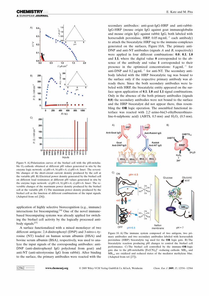
A similar biofuel cell, Figure 6, was switched ON by muchmore sophisticated combination of the biochemical inputsignals when the bioelectrocatalytic cathodic process wascontrolled by the enzyme logic network composed of severalconcatenated gates, Figure 5.[26] Similarly to the switchablebiofuel cell described above, the biofuel cell was character-ized by the polarization curve, Figure 9A, and the power re-lease dependence, Figure 9B, obtained in the inactive andactive states, curves a and b, respectively. However, the celloperation was controlled by four different biochemical sig-nals applied in 16 combinations; only 3 of them being “suc-cessful” for switching the biofuel cell ON according to thebuilt-in logic “program” in the enzyme network, Figure 9C.After the biofuel cell activation, another cycle can be start-ed with the reset to the initial “mute” state by the applica-tion of the urease/urea signal.
The biochemical networks demonstrate robust error-freeprocessing of biochemical signals upon appropriate optimi-zation of their components and interconnections.[33] Howev-er, the limit of the biocomputing network complexity is setby the cross-reactivity of the enzyme-catalyzed reactions.Only enzymes belonging to different biocatalytic classes (ox-idases, dehydrogenases, peroxidases, hydrolases, etc.) couldoperate in a homogeneous system without significant cross-reactivity. If chemical reasons require the use of cross-react-ing enzymes in the system, they must be compartmentalizedusing pattering on surfaces or applied in micro-fluidic devi-ces. Application of more selective biomolecular interactionswould be an advantage to make biocomputing systems morespecific to various input signals and less cross-reactive in thechemical signal processing. This aim can be achieved by the
Figure 8. A) Polarization curves of the biofuel cell with the pH-switcha-ble O2-cathode obtained at different pH values generated in situ by theOR/AND enzyme logic gates: a) pH�6, b) pH�4, c) pH�6. Inset: Thereversible changes of the open-circuit voltage produced by the cell at thevariable pH. B) Electrical power density generated by the biofuel cell ondifferent load resistances at different pH values generated in situ by theOR/AND enzyme logic gates: a) pH�6, b) pH�4, c) pH�6. Inset: Thereversible changes of the maximum power density produced by the bio-fuel cell at the variable pH. (C) The maximum power density producedby the biofuel cell as the function of different combinations of the inputsignals: a) the OR logic gate, b) the AND logic gate. (Adapted fromref. [25]).
Chem. Eur. J. 2009, 15, 12554 – 12564 � 2009 Wiley-VCH Verlag GmbH & Co. KGaA, Weinheim www.chemeurj.org 12561
CONCEPTBiofuel Cells for Regulated Bioelectronic Devices
application of highly selective biorecognition (e.g., immune)interactions for biocomputing.[34] One of the novel immune-based biocomputing systems was already applied for switch-ing the biofuel cell activity by the logically processed anti-body signals.[27]
A surface functionalized with a mixed monolayer of twodifferent antigens: 2,4-dinitrophenyl (DNP) and 3-nitro-l-ty-rosine (NT) loaded on human serum albumin (HSA) andbovine serum albumin (BSA), respectively, was used to ana-lyze the input signals of the corresponding antibodies: anti-DNP (anti-dinitrophenyl IgG polyclonal from goat) andanti-NT (anti-nitrotyrosine IgG from rabbit). After bindingto the surface, the primary antibodies were reacted with the
secondary antibodies: anti-goat-IgG-HRP and anti-rabbit-IgG-HRP (mouse origin IgG against goat immunoglobulinand mouse origin IgG against rabbit IgG, both labeled withhorseradish peroxidase, HRP, 0.05 mg mL�1 each antibody)to attach the biocatalytic HRP tag to the immune-complexesgenerated on the surfaces, Figure 10A. The primary anti-DNP and anti-NT antibodies (signals A and B, respectively)were applied in four different combinations: 0,0 ; 0,1; 1,0and 1,1, where the digital value 0 corresponded to the ab-sence of the antibody and value 1 corresponded to theirpresence in the optimized concentrations: 8 mg mL�1 foranti-DNP and 0.2 mg mL�1 for anti-NT. The secondary anti-body labeled with the HRP biocatalytic tag was bound tothe surface only if the respective primary antibody was al-ready there. Since the both secondary antibodies were la-beled with HRP, the biocatalytic entity appeared on the sur-face upon application of 0,1; 1,0 and 1,1 signal combinations.Only in the absence of the both primary antibodies (signals0,0) the secondary antibodies were not bound to the surfaceand the HRP biocatalyst did not appear there, thus resem-bling the OR logic operation. The assembled functional in-terface was reacted with 2,2’-azino-bis(3-ethylbenzothiazo-line-6-sulphonic acid) (ABTS, 0.5 mm) and H2O2 (0.5 mm).
Figure 9. A) Polarization curves of the biofuel cell with the pH-switcha-ble O2-cathode obtained at different pH values generated in situ by theenzyme logic network: a) pH�6, b) pH�4, c) pH�6. Inset: The reversi-ble changes of the short-circuit current density produced by the cell atthe variable pH. B) Electrical power density generated by the biofuel cellon different load resistances at different pH values generated in situ bythe enzyme logic network: a) pH�6, b) pH�4, c) pH�6. Inset: The re-versible changes of the maximum power density produced by the biofuelcell at the variable pH. C) The maximum power density produced by thebiofuel cell as the function of different combinations of the input signals.(Adapted from ref. [26]).
Figure 10. A) The immune system composed of two antigens, two pri-mary antibodies and two secondary antibodies labeled with horseradishperoxidase (HRP) biocatalytic tag used for the OR logic gate. B) Thebiocatalytic reaction producing pH changes to control the biofuel cellperformance. C) The biofuel cell controlled by the immune-OR-logicgate due to the pH-switchable [Fe(CN)6]
3�-reducing cathode. MBox andMBred are oxidized and reduced states of the mediator methylene blue.(Adapted from ref. [27]).
www.chemeurj.org � 2009 Wiley-VCH Verlag GmbH & Co. KGaA, Weinheim Chem. Eur. J. 2009, 15, 12554 – 1256412562
E. Katz and M. Pita
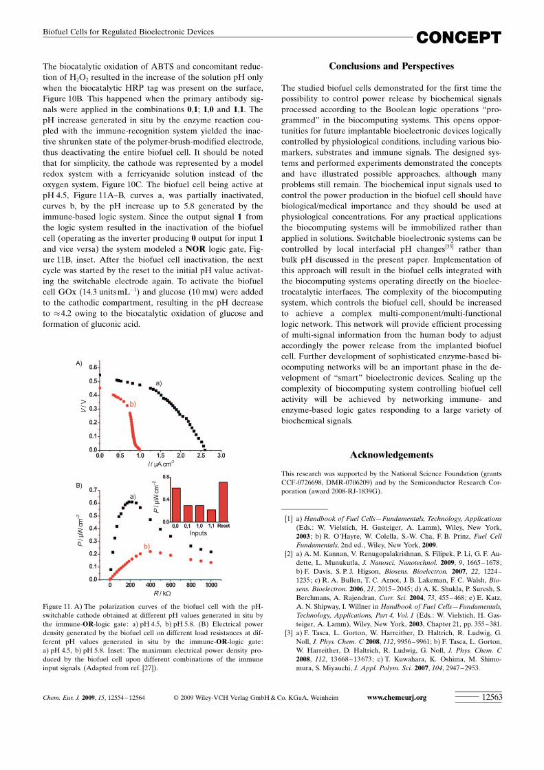
The biocatalytic oxidation of ABTS and concomitant reduc-tion of H2O2 resulted in the increase of the solution pH onlywhen the biocatalytic HRP tag was present on the surface,Figure 10B. This happened when the primary antibody sig-nals were applied in the combinations 0,1; 1,0 and 1,1. ThepH increase generated in situ by the enzyme reaction cou-pled with the immune-recognition system yielded the inac-tive shrunken state of the polymer-brush-modified electrode,thus deactivating the entire biofuel cell. It should be notedthat for simplicity, the cathode was represented by a modelredox system with a ferricyanide solution instead of theoxygen system, Figure 10C. The biofuel cell being active atpH 4.5, Figure 11A–B, curves a, was partially inactivated,curves b, by the pH increase up to 5.8 generated by theimmune-based logic system. Since the output signal 1 fromthe logic system resulted in the inactivation of the biofuelcell (operating as the inverter producing 0 output for input 1and vice versa) the system modeled a NOR logic gate, Fig-ure 11B, inset. After the biofuel cell inactivation, the nextcycle was started by the reset to the initial pH value activat-ing the switchable electrode again. To activate the biofuelcell GOx (14.3 units mL�1) and glucose (10 mm) were addedto the cathodic compartment, resulting in the pH decreaseto �4.2 owing to the biocatalytic oxidation of glucose andformation of gluconic acid.
Conclusions and Perspectives
The studied biofuel cells demonstrated for the first time thepossibility to control power release by biochemical signalsprocessed according to the Boolean logic operations “pro-grammed” in the biocomputing systems. This opens oppor-tunities for future implantable bioelectronic devices logicallycontrolled by physiological conditions, including various bio-markers, substrates and immune signals. The designed sys-tems and performed experiments demonstrated the conceptsand have illustrated possible approaches, although manyproblems still remain. The biochemical input signals used tocontrol the power production in the biofuel cell should havebiological/medical importance and they should be used atphysiological concentrations. For any practical applicationsthe biocomputing systems will be immobilized rather thanapplied in solutions. Switchable bioelectronic systems can becontrolled by local interfacial pH changes[35] rather thanbulk pH discussed in the present paper. Implementation ofthis approach will result in the biofuel cells integrated withthe biocomputing systems operating directly on the bioelec-trocatalytic interfaces. The complexity of the biocomputingsystem, which controls the biofuel cell, should be increasedto achieve a complex multi-component/multi-functionallogic network. This network will provide efficient processingof multi-signal information from the human body to adjustaccordingly the power release from the implanted biofuelcell. Further development of sophisticated enzyme-based bi-ocomputing networks will be an important phase in the de-velopment of “smart” bioelectronic devices. Scaling up thecomplexity of biocomputing system controlling biofuel cellactivity will be achieved by networking immune- andenzyme-based logic gates responding to a large variety ofbiochemical signals.
Acknowledgements
This research was supported by the National Science Foundation (grantsCCF-0726698, DMR-0706209) and by the Semiconductor Research Cor-poration (award 2008-RJ-1839G).
[1] a) Handbook of Fuel Cells—Fundamentals, Technology, Applications(Eds.: W. Vielstich, H. Gasteiger, A. Lamm), Wiley, New York,2003 ; b) R. O�Hayre, W. Colella, S.-W. Cha, F. B. Prinz, Fuel CellFundamentals, 2nd ed., Wiley, New York, 2009.
[2] a) A. M. Kannan, V. Renugopalakrishnan, S. Filipek, P. Li, G. F. Au-dette, L. Munukutla, J. Nanosci. Nanotechnol. 2009, 9, 1665 –1678;b) F. Davis, S. P. J. Higson, Biosens. Bioelectron. 2007, 22, 1224 –1235; c) R. A. Bullen, T. C. Arnot, J. B. Lakeman, F. C. Walsh, Bio-sens. Bioelectron. 2006, 21, 2015 –2045; d) A. K. Shukla, P. Suresh, S.Berchmans, A. Rajendran, Curr. Sci. 2004, 73, 455 – 468; e) E. Katz,A. N. Shipway, I. Willner in Handbook of Fuel Cells—Fundamentals,Technology, Applications, Part 4, Vol. 1 (Eds.: W. Vielstich, H. Gas-teiger, A. Lamm), Wiley, New York, 2003, Chapter 21, pp. 355 –381.
[3] a) F. Tasca, L. Gorton, W. Harreither, D. Haltrich, R. Ludwig, G.Noll, J. Phys. Chem. C 2008, 112, 9956 –9961; b) F. Tasca, L. Gorton,W. Harreither, D. Haltrich, R. Ludwig, G. Noll, J. Phys. Chem. C2008, 112, 13668 –13673; c) T. Kuwahara, K. Oshima, M. Shimo-mura, S. Miyauchi, J. Appl. Polym. Sci. 2007, 104, 2947 –2953.
Figure 11. A) The polarization curves of the biofuel cell with the pH-switchable cathode obtained at different pH values generated in situ bythe immune-OR-logic gate: a) pH 4.5, b) pH 5.8. (B) Electrical powerdensity generated by the biofuel cell on different load resistances at dif-ferent pH values generated in situ by the immune-OR-logic gate:a) pH 4.5, b) pH 5.8. Inset: The maximum electrical power density pro-duced by the biofuel cell upon different combinations of the immuneinput signals. (Adapted from ref. [27]).
Chem. Eur. J. 2009, 15, 12554 – 12564 � 2009 Wiley-VCH Verlag GmbH & Co. KGaA, Weinheim www.chemeurj.org 12563
CONCEPTBiofuel Cells for Regulated Bioelectronic Devices
[4] a) P. Kavanagh, P. Jenkins, D. Leech, Electrochem. Commun. 2008,10, 970 –972; b) J. Gallaway, I. Wheeldon, R. Rincon, P. Atanassov,S. Banta, S. C. Barton, Biosens. Bioelectron. 2008, 23, 1229 –1235;c) W. Nogala, E. Rozniecka, I. Zawisza, J. Rogalski, M. Opallo,Electrochem. Commun. 2006, 8, 1850 – 1854; d) N. Mano, V. Sou-kharev, A. Heller, J. Phys. Chem. B 2006, 110, 11 180 –11 187.
[5] a) M. J. Cooney, V. Svoboda, C. Lau, G. Martin, S. D. Minteer,Energy Environ. Sci. 2008, 1, 320 –337; b) J. A. Cracknell, K. A. Vin-cent, F. A. Armstrong, Chem. Rev. 2008, 108, 2439 –2461; c) S. D.Minteer, B. Y. Liaw, M. J. Cooney, Curr. Opin. Biotechnol. 2007, 18,228 – 234; d) Q. Liu, X. H. Xu, G, L. Ren, W. Wang, Prog. Chem.2006, 18, 1530 –1537; e) J. Kim, H. F. Jia, P. Wang, Biotechnol. Adv.2006, 24, 296 –308.
[6] a) O. Schaetzle, F. Barriere, K. Baronian, Energy Environ. Sci. 2008,1, 607 – 620; b) N. Lu, S. G. Zhou, J. R. Ni, Prog. Chem. 2008, 20,1233 – 1240; c) Z. W. Du, H. R. Li, T. Y. Gu, Biotechnol. Adv. 2007,25, 464 – 482; d) G. Yi, Z. Xin, Prog. Chem. 2007, 19, 74– 79; e) B. E.Logan, J. M. Regan, Trends Microbiol. 2006, 14, 512 –518; f) B. E.Logan, B. Hamelers, R. A. Rozendal, U. Schrorder, J. Keller, S. Fre-guia, P. Aelterman, W. Verstraete, K. Rabaey, Environ. Sci. Technol.2006, 40, 5181 – 5192; g) S. K. Chaudhuri, D. R. Lovley, Nat. Biotech-nol. 2003, 21, 1229 – 1232.
[7] a) I. Willner, E. Katz, Angew. Chem. 2000, 112, 1230 – 1269; Angew.Chem. Int. Ed. 2000, 39, 1180 – 1218; b) “Bioelectrochemistry”: E.Katz, A. N. Shipway, I. Willner in Encyclopedia of Electrochemistry,Vol. 9 (Eds.: G. S. Wilson, A. J. Bard, M. Stratmann), Wiley-VCH,Weinheim, 2002, Chapter 17, pp. 559 –626; c) J. F. Rusling, R. J. For-ster, J. Colloid Interface Sci. 2003, 262, 1 –15; d) A. Heller, J. Phys.Chem. 1992, 96, 3579 – 3587; e) A. L. Ghindilis, P. Atanasov, E. Wil-kins, Electroanalysis 1997, 9, 661 – 674.
[8] a) D. Ivnitski, B. Branch, P. Atanassov, C. Apblett, Electrochem.Commun. 2006, 8, 1204 – 1210; b) F. Barriere, P. Kavanagh, D.Leech, Electrochim. Acta 2006, 51, 5187 – 5192; c) A. Ramanavicius,A. Kausaite, A. Ramanaviciene, Biosens. Bioelectron. 2005, 20,1962 – 1967; d) N. Yuhashi, M. Tomiyama, J. Okuda, S. Igarashi, K.Ikebukuro, K. Sode, Biosens. Bioelectron. 2005, 20, 2145 –2150; e) N.Mano, A. Heller, J. Electrochem. Soc. 2003, 150, A1136 –A1138;f) E. Katz, I. Willner, A. B. Kotlyar, J. Electroanal. Chem. 1999, 479,64– 68.
[9] a) N. Mano, Chem. Commun. 2008, 2221 –2223; b) Y. Liu, S. J.Dong, Electrochem. Commun. 2007, 9, 1423 –1427; c) U. Schroder,Phys. Chem. Chem. Phys. 2007, 9, 2619 –2629; d) S. Wilkinson, J.Klar, S. Applegarth, Electroanalysis 2006, 17, 2001 – 2007; e) B. R.Ringeisen, E. Henderson, P. K. Wu, J. Pietron, R. Ray, B. Little, J. C.Biffinger, J. M. Jones-Meehan, Environ. Sci. Technol. 2006, 40,2629 – 2634; f) N. Mano, F. Mao, A. Heller, J. Electroanal. Chem.2005, 574, 347 – 357; g) N. Mano, F. Mao, A. Heller, Chem.Commun. 2004, 2116 – 2117.
[10] a) M. Pellissier, F. Barriere, A. J. Downard, D. Leech, Electrochem.Commun. 2008, 10, 835 – 838; b) M. J. Moehlenbrock, S. D. Minteer,Chem. Soc. Rev. 2008, 37, 1188 –1196; c) C. Kang, H. Shin, A.Heller, Bioelectrochemistry 2006, 68, 22–26.
[11] a) X. C. Li, H. J. Zhou, P. Yu, L. Su, T. Ohsaka, L. Q. Mao, Electro-chem. Commun. 2008, 10, 851 – 854; b) M. Togo, A. Takamura, T.Asai, H. Kaji, M. Nishizawa, Electrochim. Acta 2007, 52, 4669 –4674; c) K. G. Lim, G. T. R. Palmore, Biosens. Bioelectron. 2007, 22,941 – 947; d) M. B. Fischback, J. K. Youn, X. Y. Zhao, P. Wang, H. G.Park, H. N. Chang, J. Kim, S. Ha, Electroanalysis 2006, 18, 2016 –2022; e) N. Mano, F. Mao, A. Heller, ChemBioChem 2004, 5, 1703 –1705; f) A. Heller, Phys. Chem. Chem. Phys. 2004, 6, 209 – 216.
[12] S. Calabrese Barton, J. Gallaway, P. Atanassov, Chem. Rev. 2004,104, 4867 –4886.
[13] A. Heller, Anal. Bioanal. Chem. 2006, 385, 469 –473.[14] a) M. Pita, E. Katz, Electroanalysis 2009, 21, 252 –260; b) E. Katz, B.
Willner, I. Willner, Biosens. Bioelectron. 1997, 12, 703 –719; c) M.Motornov, R. Sheparovych, E. Katz, S. Minko, ACS Nano 2008, 2,
41– 52; d) A. H. Flood, R. J. A. Ramirez, W. Q. Deng, R. P. Muller,W. A. Goddard, J. F. Stoddart, Aust. J. Chem. 2004, 57, 301 – 322.
[15] E. Katz, I. Willner, J. Am. Chem. Soc. 2003, 125, 6803 – 6813.[16] a) I. Willner, M. Lion-Dagan, S. Marx-Tibbon, E. Katz, J. Am.
Chem. Soc. 1995, 117, 6581 –6592; b) N. G. Liu, D. R. Dunphy, P.Atanassov, S. D. Bunge, Z. Chen, G. P. Lopez, T. J. Boyle, C. J.Brinker, Nano Lett. 2004, 4, 551 –554; c) Z. F. Liu, K. Hashimoto, A.Fujishima, Nature 1990, 347, 658 –660.
[17] a) L. Zheng, L. Xiong, Colloids Surf. A 2006, 289, 179 – 184; b) V. I.Chegel, O. A. Raitman, O. Lioubashevski, Y. Shirshov, E. Katz, I.Willner, Adv. Mater. 2002, 14, 1549 – 1553.
[18] a) E. Katz, R. Baron, I. Willner, J. Am. Chem. Soc. 2005, 127, 4060 –4070; b) E. Katz, L. Sheeney-Haj-Ichia, I. Willner, Chem. Eur. J.2002, 8, 4138 – 4148; c) R. Laocharoensuk, A. Bulbarello, S. Manni-no, J. Wang, Chem. Commun. 2007, 3362 –3364; d) O. A. Loaiza, R.Laocharoensuk, J. Burdick, M. C. Rodriguez, J. M. Pingarron, M.Pedrero, J. Wang, Angew. Chem. 2007, 119, 1530 –1533; Angew.Chem. Int. Ed. 2007, 46, 1508 – 1511.
[19] T. K. Tam, M. Ornatska, M. Pita, S. Minko, E. Katz, J. Phys. Chem.C 2008, 112, 8438 – 8445.
[20] M. Pita, S. Minko, E. Katz, J. Mater. Sci. 2009, 20, 457 –462.[21] T. K. Tam, J. Zhou, M. Pita, M. Ornatska, S. Minko, E. Katz, J. Am.
Chem. Soc. 2008, 130, 10888 – 10889.[22] a) G. Strack, M. Pita, M. Ornatska, E. Katz, ChemBioChem 2008, 9,
1260 – 1266; b) R. Baron, O. Lioubashevski, E. Katz, T. Niazov, I.Willner, J. Phys. Chem. A 2006, 110, 8548 –8553; c) R. Baron, O.Lioubashevski, E. Katz, T. Niazov, I. Willner, Angew. Chem. 2006,118, 1602 –1606; Angew. Chem. Int. Ed. 2006, 45, 1572 – 1576.
[23] a) G. Strack, M. Ornatska, M. Pita, E. Katz, J. Am. Chem. Soc.2008, 130, 4234 – 4235; b) T. Niazov, R. Baron, E. Katz, O. Liouba-shevski, I. Willner, Proc. Natl. Acad. Sci. USA 2006, 103, 17 160 –17163.
[24] a) M. Privman, T. K. Tam, M. Pita, E. Katz, J. Am. Chem. Soc. 2009,131, 1314 – 1321; b) X. Wang, J. Zhou, T. K. Tam, E. Katz, M. Pita,Bioelectrochemistry 2009, 77, 89 –73.
[25] L. Amir, T. K. Tam, M. Pita, M. M. Meijler, L. Alfonta, E. Katz, J.Am. Chem. Soc. 2009, 131, 826 – 832.
[26] T. K. Tam, M. Pita, M. Ornatska, E. Katz, Bioelectrochemistry 2009,76, 4 –9.
[27] T. K. Tam, G. Strack, M. Pita, E. Katz, J. Am. Chem. Soc. 2009, 131,11670 –11671.
[28] J. R�he, M. Ballauff, M. Biesalski, P. Dziezok, F. Grçhn, D. Johann-smann, N. Houbenov, N. Hugenberg, R. Konradi, S. Minko, M. Mo-tornov, R. R. Netz, M. Schmidt, C. Seidel, M. Stamm, T. Stephan, D.Usov, H. Zhang, Adv. Polym. Sci. 2004, 165 79 –150.
[29] a) S. Minko, Polym. Rev. 2006, 46, 397 –420; b) I. Luzinov, S. Minko,V. V. Tsukruk, Prog. Polym. Sci. 2004, 29, 635 –698.
[30] a) K. M. Manesh, J. Hal�mek, M. Pita, J. Zhou, T. K. Tam, P. San-thosh, M.-C. Chuang, J. R. Windmiller, D. Abidin, E. Katz, J. Wang,Biosens. Bioelectron. 2009, 24, 3569 – 3574; b) M. Pita, J. Zhou,K. M. Manesh, J. Hal�mek, E. Katz, J. Wang, Sens. Actuators B2009, 139, 631 –636.
[31] G. Bostock, Programmable Logic Devices. Technology and Applica-tions, McGraw-Hill, New York, 1988.
[32] P. N. Bartlett, P. Tebbutt, R. C. Whitaker, Prog. React. Kinet. 1991,29, 55 –155.
[33] a) D. Melnikov, G. Strack, M. Pita, V. Privman, E. Katz, J. Phys.Chem. B 2009, 113, 10472 – 10479; b) V. Privman, M. A. Arugula, J.Hal�mek, M. Pita, E. Katz, J. Phys. Chem. B 2009, 113, 5301 – 5310;c) V. Privman, G. Strack, D. Solenov, M. Pita, E. Katz, J. Phys.Chem. B 2008, 112, 11777 –11 784.
[34] G. Strack, S. Chinnapareddy, D. Volkov, J. Hal�mek, M. Pita, I. So-kolov, E. Katz, J. Phys. Chem. B 2009, 113, 12154 –12159.
[35] M. Pita, T. K. Tam, S. Minko, E. Katz, ACS Appl. Mater. Interfaces2009, 1, 1166 –1168.
Published online: October 28, 2009
www.chemeurj.org � 2009 Wiley-VCH Verlag GmbH & Co. KGaA, Weinheim Chem. Eur. J. 2009, 15, 12554 – 1256412564
E. Katz and M. Pita